
SECTION 6C3-2C - FUNCTIONAL CHECKS -
GEN III V8 ENGINE
IMPORTANT:
Before performing any Service Operation or other procedure described in this Section, refer to Section 00
CAUTIONS AND NOTES in this VX Service Information for correct workshop practices with regards to
safety and/or property damage.
The following pages are to be used when there is a custom er complaint and there are no diagnostic trouble codes
set, or one or m ore of the Tech 2 Sc an tool data values are not within the typical values. T hey are als o to be used
when instruc ted from a DT C table. Befor e using these tables you should use the symptom s tables which m ay lead
you to using this Section.
The purpose of these tables is to diagnosis Powertrain Control Module (PCM) controlled components or
subsystems that do not have diagnostic trouble codes assigned to them. Another purpose of these tables are for
technicians who feel confident that a particular part of the subsystem is not operating properly and wants to only
check that particular item for proper operation without going through lengthy diagnostic procedures.
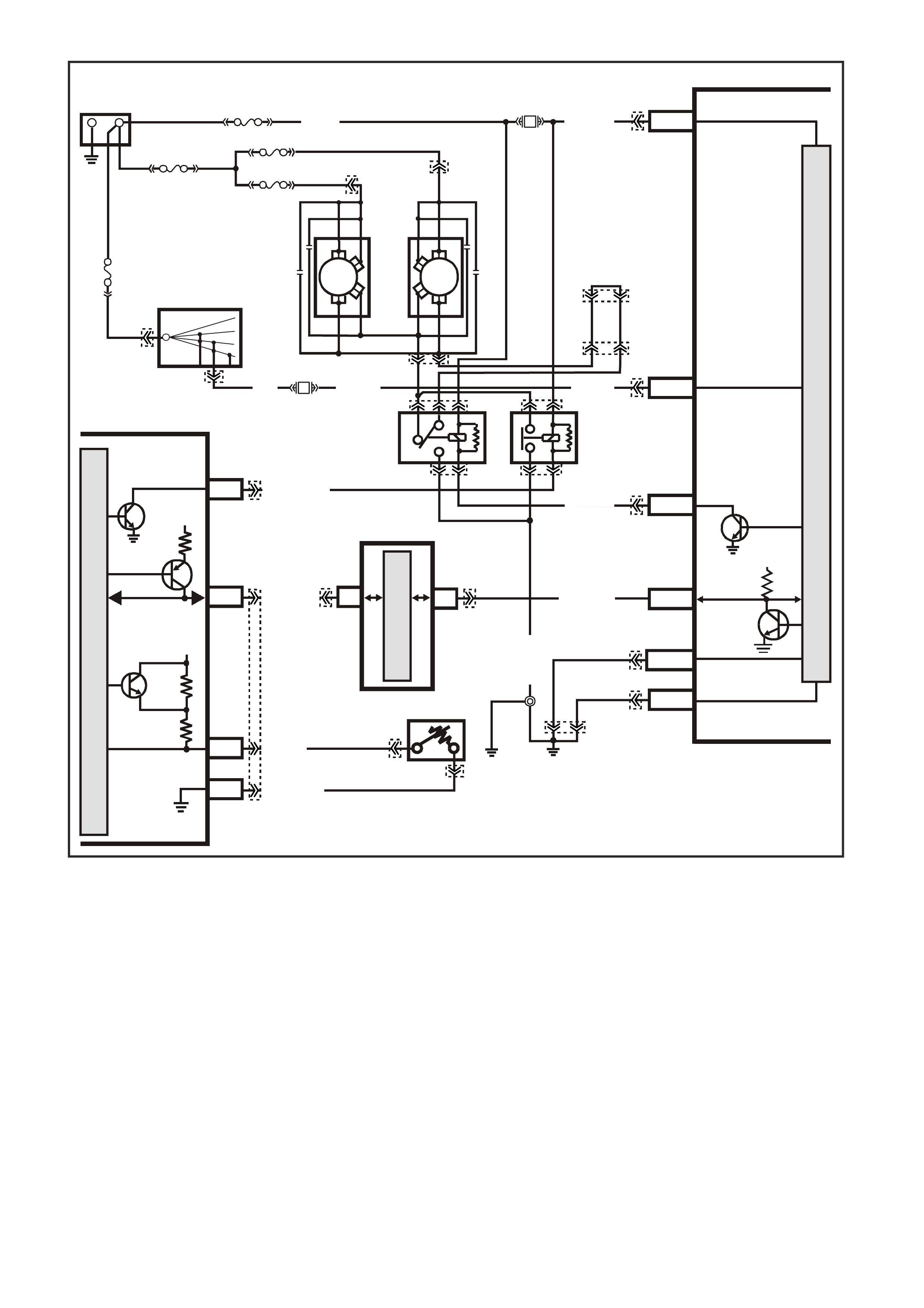
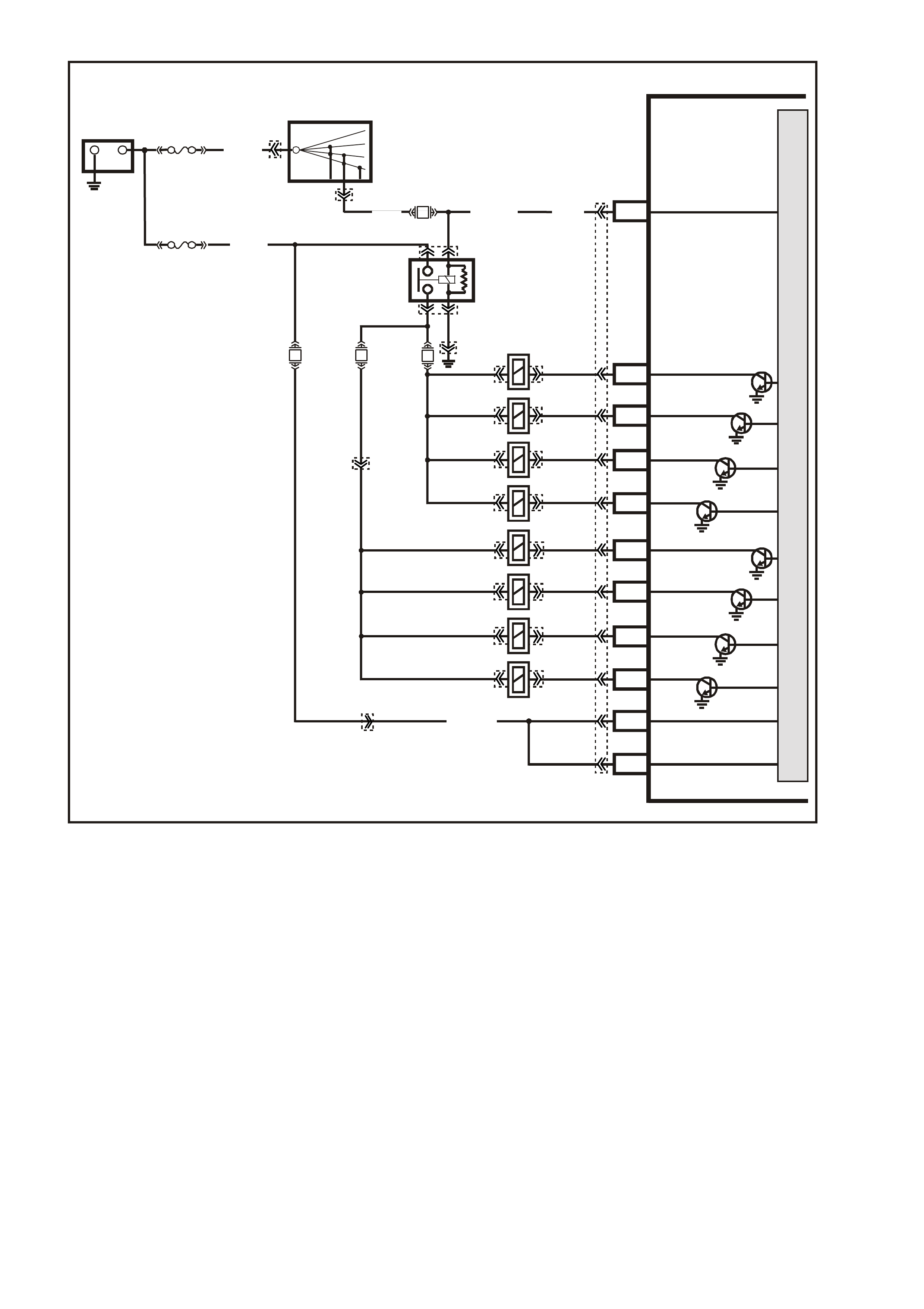
GEN III V8 PCM ENGINE COOLING FAN CONTROL
Circuit Description:
The GEN III V8 engine has two, two speed electric engine cooling fan motors which provide the prim ary m eans of
moving air through the radiator. The cooling fans are used to cool engine coolant flowing through the radiator and
the refrigerant flowing through the A/C condenser.
The engine cooling fan high speed relay is controlled by the PCM. The PCM controls the earth path for the engine
cooling fan high speed relay.
The low s peed of the engine c ooling f an is c ontrolled by the PCM through special Data Communication to the BCM.
The BCM controls the earth path for the engine cooling fan low speed relay.
Both relays are used to control the earth paths to the electric motors that drive both fans.
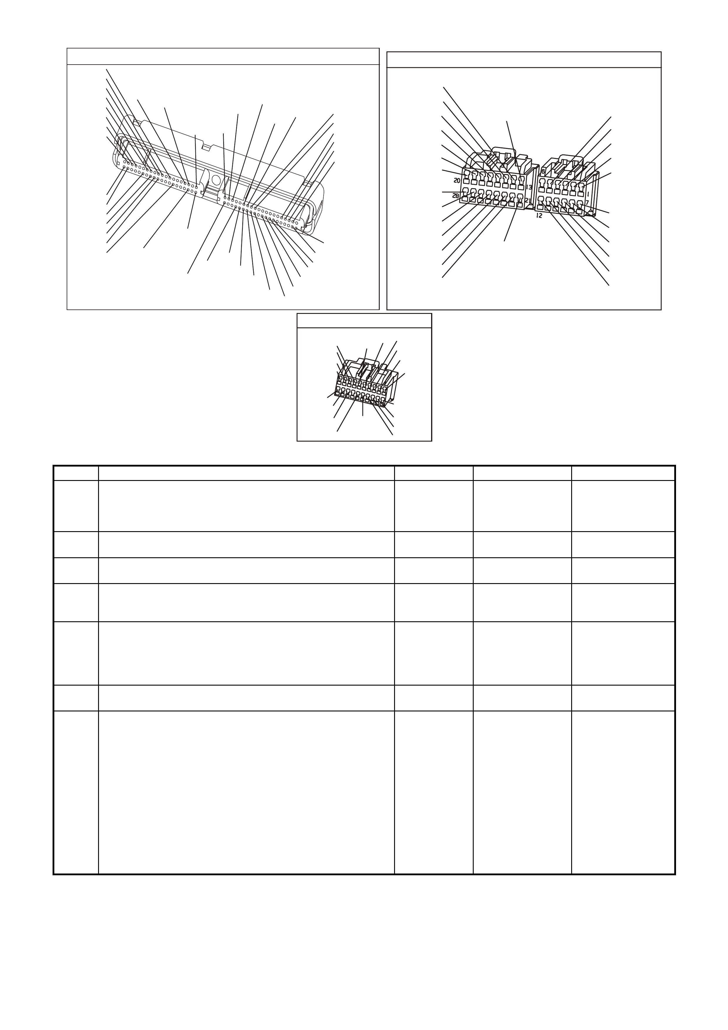
R/B (1221) E2/D2
IGNITION
LOW
SPEED FAN
M
I
C
R
O
P
R
O
C
E
S
S
O
R
BATTERY M AIN P O WER
HIGH SERIES
BCM TERMINALS
NOMINATED FIRST
BCM
15a 15 50
30 OFF/ON
LOCK
ACC
IGN
START
4359
E20/D6
B7/B7
P (3)
IGNITION SWITCH
O/B (473)
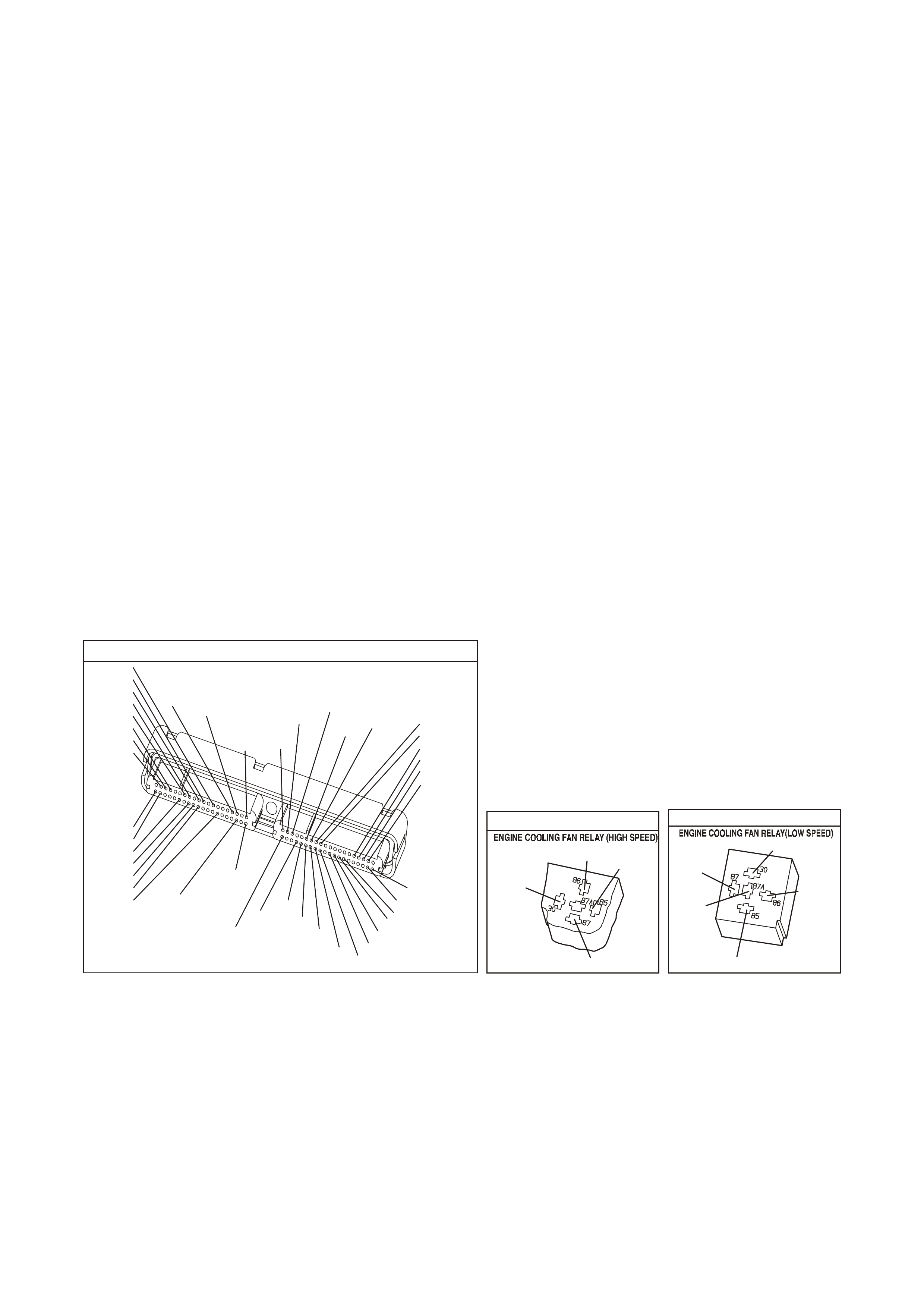
87A
30
87
85
86
87
30
85
86
ENGINE
COOLING
FAN 1
ENGINE
COOLING
FAN RELAY
(LOW SPEED)
ENGINE
COOLING
FAN RELAY
(HIGH SPEED)
P/B (39)
B/Y
(533)
O/Y
(250)
F14
R
YB
G
BLU/W (304)
R/B (1049)
HIGH
CURRENT EARTH
B/Y
(155) A1/A5 ELECTRONIC EARTH
B/G
(151)
LOC.
E2 LOC.
E3
B10/B11
B/R (157)
J1-58
GEN III PCM
PIM
J2-33
HIGH
SPEED FAN
BLUE
FUSIBLE
LINK
LOC.
E1
F31
A5/A6
O/B (740)
ENGINE
COOLING
FAN 2
+-
BATTERY FS
FT FAN 2
FU FAN 1
(1040)
R
(203)
R
(001)
R
(001)
O/B
(208)
O/BLU
(204)
FJ
R
(001)
R
(2H)
6
7
M
I
C
R
O
CLASS 2 SERIAL DATA
UART SERIAL DATA
7V
CLASS 2
SERIAL DATA
SERIAL
DATA
5V
GY /B (455)
J1-74 Y (41O)
COOLANT TEMP
SENSOR
ETC SENSOR
SIGNAL
5V
4k
348
Ω
Ω
J1-80
SENSOR
EARTH
M
I
C
R
O
P/B (39)
YE140
YE139
YB44
YB44
YE139
YE103
YE103 YE43
YE43
YE104
YB176
YB165
YB163
YB163
YB174
YB174
YB176
YB165
YE114
YE65
YB215YB215
YE65
YE122
YE123
YE118
YB176
YB165
YE140
Low Speed Engine Cooling Fan
The engine cooling fan low speed relay is energised by the BCM. The PCM determines when to enable the low
speed engine cooling fan based on inputs from the A/C request signal, vehicle speed and engine coolant
temperature. The engine cooling low speed fan will be turned ON when:
• A/C request indicated (YES) and
• Vehicle speed less than 30 Km/h
or
• Coolant temper ature is greater than a s pecified value and will rem ain on until coolant tem perature reduces to a
predetermined value.
High Speed Engine Cooling Fan
The high speed engine cooling fan is controlled by the PCM based on input from the Engine Coolant Tem perature
Sensor (ECT). The PCM will only turn ON
the high s peed engine c ooling fan if the low speed engine cooling f an has been ON for 2 s econds and the following
conditions are satisfied.
• There is a BCM message response fault which will cause a DTC to set.
• An engine coolant temperature sensor failure is detected, such as DTC P0117, P0118, P1114, P1115.
• Coolant temperature greater than a specified value.
If the low speed fan was OFF when the criteria was met to turn the fan high speed ON, the high speed fan will
operate 5 seconds af ter the low speed f an. T he engine c ooling f an High speed relay can also be enabled by the A/C
Refrigerant Pressure Sensor. The A/C Refrigerant Pressure Sensor will provide a signal to the PCM when A/C
pressure becomes to high approximately 2600 kPa.
For replacement of the cooling fan motor, refer to Section 6B3 ENGINE COOLING - in VX Service Information.
Test Description
Numbers below refer to step numbers on the diagnostic table.
2. This entire diagnos tic proc edur e must begin with a cold engine - at ambient air temperatur e. If the c oolant is hot
when diagnosis is performed, replacement of good parts will result. The fans should not be running if engine
coolant temperature is less than 99°C and air conditioning is not ON.
10. On A/C equipped vehicles, the engine cooling f an High speed relay should be energised by the PCM, as soon
as the PCM energises the A/C clutch.
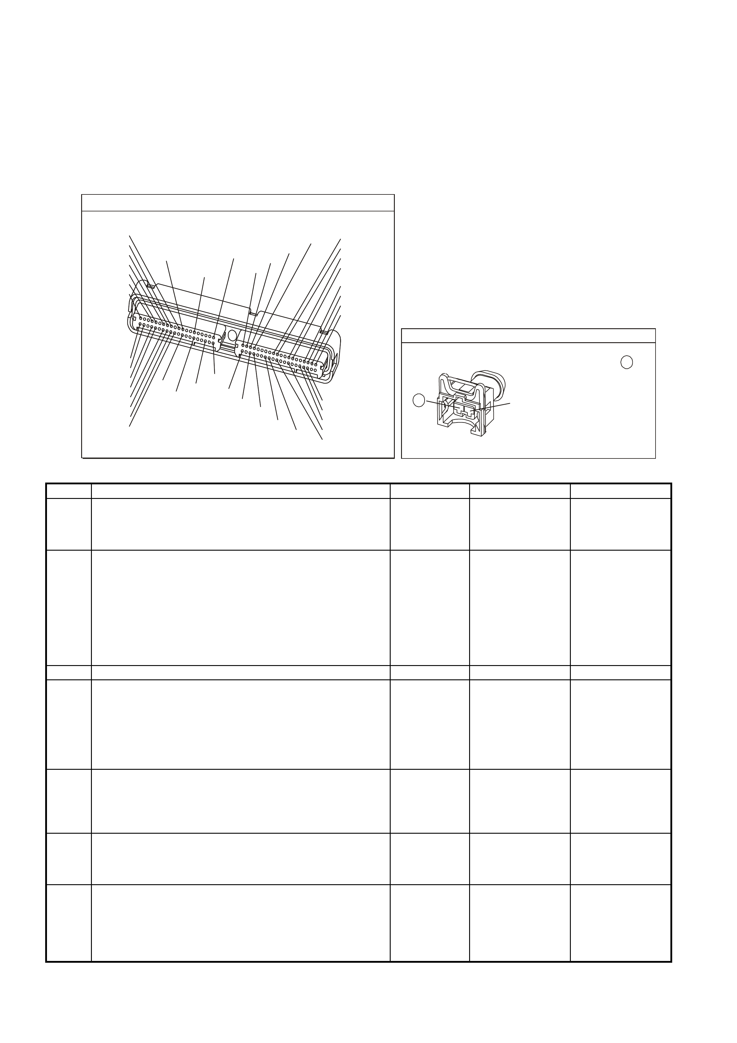
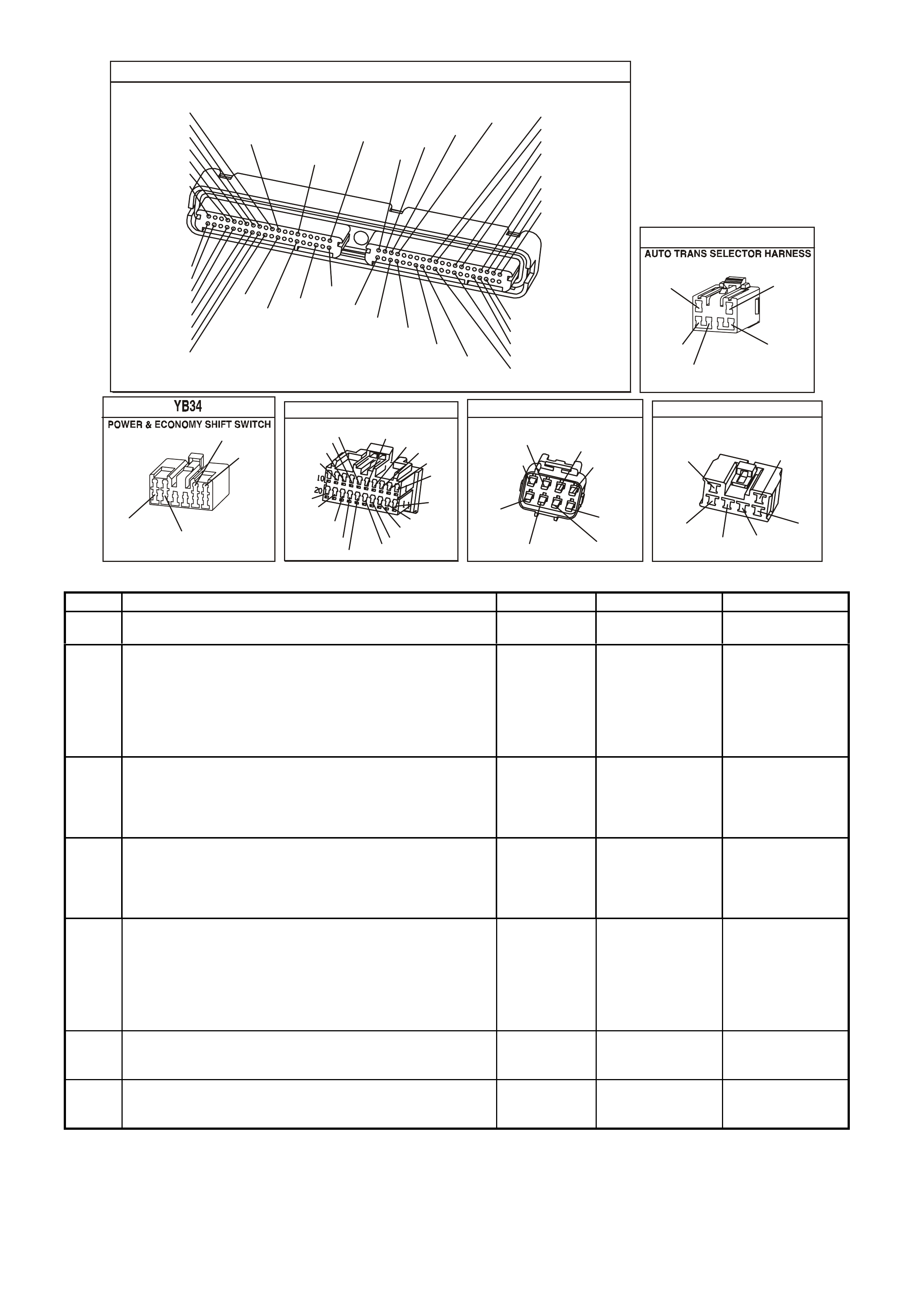
YE123
P.C.M CONNECTOR 2
(750)
(1228)
(1229)
(465)
(121)
(259)
G/B
BR
G/W
GY/BLU
R
B/R
(418)
BR
(59)
(832)
G
T
(831)
(417)
(472)
(976) (974)
(432)
(428)
(631)
BLU BR G/Y
BLU/W
LG
BR/W
W/B
LG W
(977)
Y
(971)
BLU/W W
B/R
(750)
(304)
(792)
(1223)
(1222)
(123)
(1227)
(469)
(331)
Y/B
LG
V/W
B/Y
G/O BR/W
(1687)
GY/B
(366)
LG/B
GY/R
(422)
V
(442)
(444)
(443)
(975)
(972)
(978)
(1224)
(973)
(959)
LG/W
LG/B
LBLU/B
GY
(773)
BR/Y
BLU
G
Y/B
LBLU
(958)
BR
(441)
LBLU
1
41
40
80
J2
RED
Y
(838)
YE 43
B/R
(157)
BLU/W
(304)
O/B
(740)
O/Y
(250)
YE 103
(1040)
O/Y
(250)
ENGINE 12V BUS
BLU/Y
(533)
O/B
(473)
B/R
(157)

GEN III V8 PCM engine cooling fan CONTROL
STEP ACTION VALUE YES NO
1 Did you perform the Powertrain On-Board Diagnostic (OBD)
System Check? Go to Step 2. Go to Powertrain
OBD System Check
Table in Section
6C3-2A
2 1. Ignition ON, engine stopped.
2. Engine coolant temperature below 99°C.
Are both engine cooling fan motors running ?
Go to Step 3 Go to Step 9
3 1. Ignition OFF.
2. Remove the Engine Cooling Fan High Speed Relay.
3. Ignition ON.
Do both fans continue to run ?
Go to Step 4 Go to Step 5
4 1. Ignition ON.
2. Remove Engine Cooling Fan Low Speed Relay.
Do both fans continue to run?
Go to Step 13 Go to Step 16
5 1. Ignition ON.
2. Probe Engine Cooling Fan High Speed Relay harness
connector circuit 304 with a test light to +12 volts.
Is the test light ON?
Go to Step 6 Go to Step 8
6 1. Ignition OFF.
2. Disconnect PCM RED connector.
3. Ignition ON.
4. Using test light, probe Engine Cooling Fan High Speed Relay
harness connector circuit 304 with a test light connected to
+12 volts.
Is the test light ON?
Go to Step 14 Go to Step 7
7 1. Replace PCM.
2. Refer to Section 6C3-3 Service Operations of the VX Series
Service Information, for PCM Reprogramming and PCM/PIM
Security Link Procedure.
Is action complete?
System OK
8 Replace Engine Cooling Fan High Speed Relay. System OK
9 1. Ignition ON.
2. Using the Tech 2 scan tool, Select HIGH FAN relay control.
3. Turn ON HIGH FAN with scan tool.
Do both cooling fans operate in high fan mode?
Go to Step 20 Go to Step 23
10 Is the vehicle equipped with A/C? Go to Step 11 Go to Step 12
11 1. Start engine, allow to idle.
2. Turn A/C ON.
3. The fans should run when the A/C clutch engages.
Do the fans run when A/C clutch is engaged?
Go to Step 12 Go to Step 9
12 The engine cooling fan circuits are OK. System OK
13 1. Connect a test light to +12 volts.
2. Probe circuits 533 and 250 of Engine Cooling Fan Low
Speed Relay.
Is the test light ON?
Go to Step 15 Go to Step 18
14 Repair short to earth in circuit 304. System OK
15 Repair short to earth in circuit 533 and/or circuit 250. System OK
16 1. Ignition ON.
2. Probe Engine Cooling Fan Low Speed Relay harness
connector circuit 473 with a test light connected to +12 volts.
Is the test light ON?
Go to Step 17 Go to Step 21

STEP ACTION VALUE YES NO
17 1. Ignition OFF.
2. Check for short to earth on circuit 473.
Was a short to earth found?
System OK Go to Step 18
18 Replace the BCM, refer to Section 12J-1 Low Series Body
Control Module in VX Service Information or Section 12J-2 High
Series Body Control Module in VX Service Information.
System OK
19 1. Reinstall Engine Cooling Fan High Speed Relay.
2. Ignition ON.
3. Using the scan tool, Select LOW FAN.
4. Turn ON LOW FAN with Scan Tool.
Does the engine cooling motor run?
Go to Step 10 Go to Step 40
20 1. Ignition ON.
2. Using the scan tool; Select HIGH FAN relay control.
3. Turn ON HIGH FAN with scan tool.
4. While fan is running, remove Engine Cooling Fan High
Speed Relay.
Did the cooling fan motor reduce to a lower running speed ?
Go to Step 19 If engine cooling
motor turned OFF
Go to Step 40
21 Check for short to earth in circuit 250.
Was a problem found? System OK Go to Step 22
22 Replace Engine Cooling Fan Low Speed Relay.
Is action complete? System OK
23 Check fusible links FS, FT, FU, and Blue fusible link for open.
Was a problem found? Go to Step 29 Go to Step 24
24 1. Ignition OFF.
2. Remove Engine Cooling Fan High Speed Relay.
3. Ignition ON.
4. Probe relay socket, circuit 39 with test light connected to
earth.
Is test light ON?
Go to Step 25 Go to Step 31
25 1. Ignition ON.
2. Probe Engine Cooling Fan High Speed Relay socket circuit
304 with a test light connected to +12 volts.
3. Using scan tool, Select HIGH FAN, enable fan ON with
up/down arrows.
Is test light ON?
Go to Step 26 Go to Step 30
26 1. Ignition ON.
2. Reinstall Engine Cooling Fan High Speed Relay.
3. Back-probe Engine Cooling Fan High Speed Relay harness
connector circuit 250 with test light connected to +12 volts.
4. Using scan tool, Select HIGH FAN, enable fan ON.
Is test light ON?
Go to Step 27 Go to Step 32
27 1. Ignition ON.
2. Disconnect both electric cooling fan wiring harness
connectors.
3. Probe both fan harness connectors, circuits 533 and 250 with
a test light to +12 volts.
4. Using scan tool, Select HIGH FAN, enable fan ON.
Is test light ON for both circuits ?
Go to Step 28 Go to Step 34
28 Probe both fan harness connector power feed circuits with a test
light connected to earth.
Is test light ON for all circuits ?
Go to Step 33 Go to Step 35

STEP ACTION VALUE YES NO
29 1. Check for short to earth that caused fusible link to blow.
2. Check that the engine cooling fan motor is not drawing too much
current.
Is action complete ?
System OK
30 Check for open in circuit 304 from relay to PCM, or faulty PCM
connection.
Was a problem found?
System OK Go to Step 36
31 Repair open or short to earth in circuit 39.
Replace fuse if blown. System OK
32 With test light connected to +12 volts, back probe Engine Cooling
Fan High Speed Relay harness connector circuit 157.
Does test light illuminate?
Go to Step 37 Go to Step 38
3 Check for poor connection at both fan motors. If OK, replace the
electric fan motor that did not operate. System OK
34 Check for open in circuits 533 or 250.
Was a problem found? System OK Go to Step 38
35 Repair open circuit in fan motor power circuit that did not light test
light. System OK
36 1. Replace PCM.
2. Refer to Section 6C3-3 Service Operations of the VX Series
Service Information, for PCM Reprogramming and PCM/PIM
Security Link Procedure.
Is action complete?
System OK
37 Replace Engine Cooling Fan High Speed Relay. System OK
38 Check both relays for open in earth circuit 157.
Was a problem found? System OK Go to Step 39
39 Replace Engine Cooling Fan Low Speed Relay. System OK
40 1. Ignition OFF.
2. Remove Engine cooling Low Speed Relay.
3. Probe relay socket, circuit 250 with a test light connected to +12
volts.
Is test light ON ?
Go to Step 45 Go to Step 41
41 1. Ignition OFF.
2. Remove Engine Cooling Fan Low Speed Relay
3. Ignition ON.
4. Probe relay socket, circuits 1040 with test light connected to earth
Is test light ON ?
Go to Step 42 Go to Step 47
42 1. Ignition ON.
2. Probe Engine cooling Low Speed Relay socket, circuit 473 with a
test light connected to +12 volts.
3. Using scan tool, Select LOW FAN, enable fan ON.
Is test light ON?
Go to Step 43 Go to Step 46
43 1. Ignition ON.
2. Reinstall Engine Cooling Fan Low Speed Relay.
3. Back-probe low speed cooling fan relay wiring harness connector,
circuit 533 with test light connected to +12 volts.
4. Using scan tool, Select LOW FAN, enable fan ON.
Is test light ON?
Go to Step 48 Go to Step 44
44 1. Ignition OFF.
2. Disconnect both electric cooling fan wiring harness connectors.
3. Probe both wiring harness connector circuits 533 with test light
connected to +12 volts.
4. Using scan tool, Select LOW FAN, enable fan ON.
Is test light ON?
Go to Step 52 Go to Step 50

STEP ACTION VALUE YES NO
45 Repair short to earth in circuit 250.
Is action complete? System OK
46 1. Ignition ON.
2. Using scan tool, Select LOW FAN, enable fan ON.
3. Backprobe BCM terminal 7 with a test light connected to +12
volts.
Is test light ON?
Go to Step 51 Go to Step 53
47 Repair open in circuit which causes test light not to come ON.
Is action complete? System OK
48 Replace Engine Cooling Fan Low Speed Relay.
Is action complete? System OK
59 Repair short to earth System OK
50 Repair open in circuits 533 or 250.
Is action complete? System OK
51 Repair open in circuit 473 between BCM and Engine Cooling Fan
Low Speed Relay.
Is action complete?
System OK
52 Replace Engine cooling motor that did not operate.
Refer to Section 6B3 Engine Cooling - in VX Service Information.
Is action complete?
System OK
53 Check for faulty connection at BCM, if OK replace BCM.
Is action complete? System OK
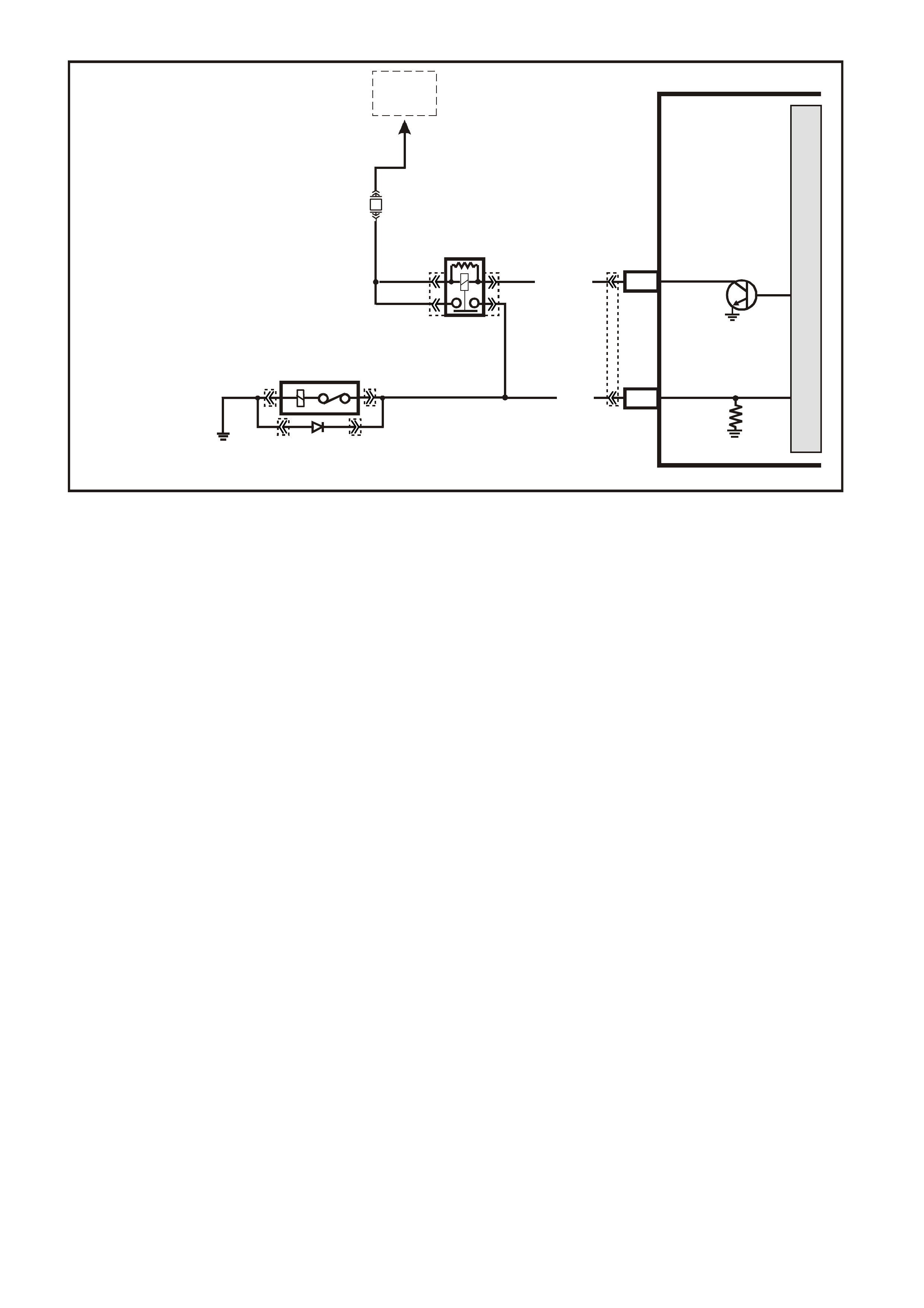
GEN III V8 PCM A/C REQUEST CIRCUIT DIAGNOSIS
Circuit Description
The A/C clutch relay is PCM c ontrolled to delay A/C clutch engagem ent after the A/C is turned ON. T his allows the
PCM to adjust engine RPM before the A/C clutch engages. The PCM will engage the A/C clutch any tim e A/C has
been requested unless any of the following conditions exist:
• High coolant temperature.
• Low A/C system pressure.
• High A/C system pressure.
• Wide open throttle.
• High engine RPM.
• Open A/C Pressure sensor earth circuit.
When the heater and A/C control is placed in the A/C mode, a 12 volt signal is sent to the PCM. W hen the PCM
receives this s ignal the PCM will earth the A/C clutc h relay control circ uit to ener gise the A/C relay. This is shown on
the scan tool as A/C request YES.
W hen a request for A/C has been detected by the PCM, the PCM will earth the A/C clutch relay control circuit, the
relay contacts will close, and current will flow through the relay to the A/C compressor clutch.
When A/C request has been detec ted by the PCM, the cooling fan(s ) will be turned O N when A/C pr ess ur e is above
a predetermined pressure.
Diagnostic Aids
• Ensure no PCM DTC(s) are stored before using this table. The PCM will not activate the A/C clutch with a
stored DTC. Also, if the A/C Refrigerant Pressure Sensor earth circuit is open, the A/C clutch will not engage
and the cooling fan will be on High speed, but no DTC will set.
Test Description
2. A/C DTCs will disable the A/C system. Repair A/C DTCs before proceeding.
3. This test determines if the A/C power fuse is open. If this fuse is open, the instrument panel, and the blower
relay will also be inoperative.
5. The request circuit is shorted to a voltage if the scan tool displays A/C request as YES.
7. This test checks to see if the A/C control unit is capable of supplying the proper voltage.
8. This test checks the continuity between the BCM and the A/C control unit.
9. If the A/C Refrigerant Pressure Sensor earth circuit is open, this will cause the A/C clutch not to engage.
4360
PCM
A/C RELAY
J2-43
LG/B (366)
YE101
YE105YE105
YE120 YE120
YE101
YE123
A/C CLUTCH
CONTROL
TO
EFI
RELAY
M
I
C
R
O
F33
LOC. E5/E15
B/R 750
A/C
COMPRESSOR
J2-18
G (59) A/C RELAY STATUS
YE123
P.C.M CONNECTOR 2
(750)
(1228)
(1229)
(465)
(121)
(259)
G/B
BR
G/W
GY/BLU
R
B/R
(418)
BR
(59)
(832)
G
T
(831)
(417)
(472)
(976)(974)
(432)
(428)
(631)
BLUBR G/Y
BLU/W
LG
BR/W
W/B
LG W
(977)
Y
(971)
BLU/WW
B/R
(750)
(304)
(792)
(1223)
(1222)
(123)
(1227)
(469)
(331)
Y/B
LG
V/W
B/Y
G/OBR/W
(1687)
GY/B
(366)
LG/B
GY/R
(422)
V
(442)
(444)
(443)
(975)
(972)
(978)
(1224)
(973)
(959)
LG/W
LG/B
LBLU/B
GY
(773)
BR/Y
BLU
G
Y/B
LBLU
(958)
BR
(441)
LBLU
1
41
40
80
J2
RED
Y
(838)
YB175
B.C.M CONNECTOR 3
BERLINA & CALAIS
LBLU
Y/R
O/BLU
B
BLU/W
W/BLU
(43)
(39)
(97)
(83)
(94)
O/W
Y/B
B/R
(161)
(143)
(640)
(1150)
(260)
(1144)
(840)
Y
P/B
GY
LBLU
(494)
W
(160)
V/R
R/B
W/G
B/Y
GY/B
(229)
(1221)
(1220)
(556)
(96)
(261)
G/W
Y
Y/B
W
W/R
(266)
(1220)
(272)
(717)
(308)
BR/G
(271)
R/W
GY/R
(1391)
B.C.M CONNECTOR 3
EXECUTIVE
YB164
(83)
(97)
W/G
(229)
B/G
W/BLU
(266)
(1144)
P/BLU
G/W
BLU/W
(1220)
(494)
BR/G
GY
(1220)
B
GY
(1391)
LBLU
(151)
(271)
R/B
R/W
(1150)
(291)
V/R
(8)
O
P/B
B/R
Y
GY/R
(1221)
(94)
(39)
(44)
(248)
10
20
1
11
GEN III V8 PCM A/C Request Circuit Diagnosis
Step Action Value(s) Yes No
1 Did you perform the Powertrain On-Board Diagnostic
(OBD) System Check? Go to Step 2 Go to Powertrain
OBD System
Check Table in
Section 6C3-2A
2 Are any A/C DTCs set? Go to applicable
DTC table Go to Step 3
3 Check for blown F13 fuse.
Is fuse OK? Go to Step 5 Go to Step 4
4 Repair short to earth in F13 fuse circuit.
Replace fuse.
Is action complete?
System OK
5 1. Install the Tech 2 scan tool.
2. Idle the engine with the A/C OFF, blower switch ON.
3. Monitor A/C request on the Engine Data List using the
scan tool.
Does the scan tool indicate A/C request as ON?
Go to Step 10 Go to Step 6
6 Idle the engine with the A/C ON, blower switch ON.
Does the scan tool indicate A/C request as YES? System OK Go to Step 7
7 1. Turn OFF the ignition.
2. Disconnect the BCM connector:
- YB175 High Series
- YB164 Low Series
3. Turn ON the ignition leaving the engine off, with the
A/C ON, blower switch ON.
4. Back probe the A/C request circuit at the BCM
harness connector terminal using a DMM J 39200
connected to earth:
- ECC: Pin 9 (High series)
- Non ECC: Pin 3 (Low Series)
Does the DMM display near the specified value when A/C
is enabled?
Non-ECC
system B+
ECC System
2 to 4 Volts
Go to Step 12 Go to Step 8

Step Action Value(s) Yes No
8 3. Turn OFF the ignition.
4. Check the A/C request circuit for continuity between
the A/C control module and the BCM using a DMM
J 39200.
Does the DMM indicate continuity?
Go to Step 9 Go to Step 11
9 Refer to Section 2 Air conditioning in VX Service
Information for further diagnosis.
Is the action complete?
System OK
10 Inspect the A/C request circuit for an open or short to
voltage.
Did you find a problem and correct it?
System OK Go to Step 13
11 Repair the open A/C request circuit between the A/C
control unit and the BCM.
Is the action complete?
System OK
12 1. Replace PCM.
2. Refer to Section 6C3-3 of the VX Series Service
Information for PCM Reprogramming and PCM/PIM
Security Link Procedure.
Is action complete?
System OK
13 Inspect the A/C refrigerant pressure earth circuit for an
open.
Was a problem found?
System OK Go to Step 9
GEN III V8 PCM A/C REFRIGERANT PRESSURE SENSOR CIRCUIT DIAGNOSIS
Circuit Description
The PCM cycles the A/C com pressor clutch to optim ise the perform ance of the A/C system. The PCM determines
when to cycle the A/C compressor clutch by monitoring the A/C Refrigerant Pressure Sensor.
The A/C Refrigerant Pressure Sensor is also used by the PCM to enable the engine cooling fans when the A/C
compressor head pressure reaches a predetermined value.
The PCM energis es the A/C com pres sor clutch when the engine speed is less than 4800 RPM and the A/C system
is requested. If you request the A/C at engine speeds greater than 4800 RPM, the PCM will not energise the A/C
compressor clutch until the engine speed decreases to less than 4000 RPM.
Any one of the following conditions disables the A/C compressor clutch.
• The Throttle is commanded to Wide Open Throttle (WOT).
• The A/C head pressure is greater than 2895 kPa (420 psi).
• The A/C head pressure is less than 176 kPa (25 psi).
• The ignition voltage is less than 10 volts.
• The engine speed is greater than 4800 rpm.
• The engine coolant temperature is greater than 125°C (257°F).
The PCM also disables the A/C compressor when certain DTCs set.
Diagnostic Aids
• Inspect the harness between the A/C clutch and PCM for intermittent connections. While the engine is
operating with the A/C enabled, move related electrical connectors and harnesses. This may aid in locating an
intermittent fault.
• For an intermittent, refer to Section 6C3-2B Symptoms of the VX Series Service Information.
Test Description
The numbers below refer to the step numbers on the diagnostic table.
2. This step checks if the PCM can turn the A/C compressor ON.
3. This step checks for an A/C Refrigerant Pressure Sensor that is at a fixed value (stuck).
4. Inspect the A/C clutch status c irc uit bef or e replac ing the A/C Ref riger ant Pr ess ur e Sensor . Also, a low ref r igerant
charge in the A/C system can cause an A/C system performance condition.
5. Check the connections at the compressor first if the scan tool indicates that the A/C clutch is ON.
6. The PCM’s A/C clutch status circuit may not detect voltage when the A/C is commanded ON if the B+ supply
circuit to the A/C relay is intermittent. Inspect the relay connections and operation.
G3PCM001PT
PCM
M
I
C
R
O
J2-14
J2-57
A/C
PRESSURE
SENSOR
J1-45
SENSOR EARTH
A/C PRESSURE
SENSOR SIGNAL
5V
V/W (415)
YE122
YE123YE113
G/O (469)
G/B (259)
C
B
A
TO
IAT SENSOR
P.C.M CONNECTOR 1
YE122
(776)
(1049)
(897)
(1230)
(848)
(1226)
(772)
(647)
(632)
40
(844)
(815)
80
J1
P/B
(845)
V/W
BLU
O
(633)
(846)
B/Y
B/R
(416)
(86)
(69)
(455)
(740)
GY
BR
G
GY
(646)
(410)
GY
(842)
(1225)
V
Y
(750)
P
41
O
(774)
BR/Y
BLU
Y
B/R
B
BLU/Y
(841)
BLUE
(414)
G/W
BLU
LG
LBLU/B
1
(847)
(415)
(740)
(452)
BLU
BR
Y
(750)
(826)
(421)
Y
V/W
B/W
(334)
(771)
(39)
Y
R/W
LBLU
W
BLU/W
(843)
(643)
LBLU/W
G
GY/B
BLU/B
(413)
(1413)
(1412)
(412)
GY
V
GY/B
G
(335)
YE123
P.C.M CONNECTOR 2
(750)
(1228)
(1229)
(465)
(121)
(259)
G/B
BR
G/W
GY/BLU
R
B/R
(418)
BR
(59)
(832)
G
T
(831)
(417)
(472)
(976)(974)
(432)
(428)
(631)
BLUBR G/Y
BLU/W
LG
BR/W
W/B
LG W
(977)
Y
(971)
BLU/WW
B/R
(750)
(304)
(792)
(1223)
(1222)
(123)
(1227)
(469)
(331)
Y/B
LG
V/W
B/Y
G/OBR/W
(1687)
GY/B
(366)
LG/B
GY/R
(422)
V
(442)
(444)
(443)
(975)
(972)
(978)
(1224)
(973)
(959)
LG/W
LG/B
LBLU/B
GY
(773)
BR/Y
BLU
G
Y/B
LBLU
(958)
BR
(441)
LBLU
1
41
40
80
J2
RED
Y
(838)
A/C COMPRESSOR
(59)
G
(750)
B/R
A
1
2
A/C PRESSURE TRANSDUCER
YE113
(469)
(415)
(259)
G/B B
V/W
G
(59)
B/R
(750)
GEN III V8 PCM A/C REFRIGERANT PRESSURE SENSOR CIRCUIT DIAGNOSIS
Step Action Value(s) Yes No
1 Did you perform the Powertrain On-Board Diagnostic
(OBD) System Check? Go to Step 2 Go to Powertrain
OBD System
Check Table in
Section 6C3-2A
2 IMPORTANT: If DTCs P0530, and P1546 are set, use
those tables.
1. Idle the engine.
2. Turn ON the A/C.
Does the A/C clutch engage?
Go to Step 3 Go to Step 5
3 1. Observe the A/C High Side pressure display on the
Engine Data List using the scan tool.
2. Turn OFF the A/C for 10 seconds.
3. Turn ON the A/C for 10 seconds.
Did the A/C High Side pressure increase more than the
specified value when the A/C controls were turned ON?
27 kPa
(4 psi) Refer to
Diagnostic Aids Go to Step 4
4 Does the scan tool indicate the A/C clutch ON? Go to Step 7 Go to Step 6
5 Repair the intermittent A/C clutch circuit from the A/C
relay to the splice.
Is the action complete?
System OK Go to Step 11
6 1. Turn OFF the ignition.
2. Disconnect the A/C compressor clutch harness
connector.
3. Probe the A/C compressor clutch B+ supply circuit to
the battery earth using a test lamp J 34142-B.
4. Idle the engine.
5. Turn ON the A/C.
Does the test lamp illuminate?
Go to Step 8 Go to Step 12

Step Action Value(s) Yes No
7 Probe the A/C compressor clutch B+ supply circuit to the
A/C compressor clutch earth circuit using a test lamp
Does the test lamp illuminate?
Go to Step 9 Go to Step 11
8 Repair the faulty A/C clutch connection or the open A/C
clutch coil.
Is the action complete?
System OK
9 Repair the open or the shorted A/C clutch B+ supply
circuit.
Is the action complete?
System OK
10 Repair the open A/C clutch earth circuit.
Is the action complete? System OK
11 Inspect the A/C refrigerant pressure earth circuit for an
open.
Was a problem found?
System OK Go to Step 10

GEN3 0101
FUEL INJECTOR
TESTER
LOW VEHICLE BATTERY
READY TO TEST
TEST IN PROGRESS
AMPERAGE SUPPLY SELECTOR SWITCH
PUSH TO START TEST
Coil Test
4 amp
2.5 amp
0.5 amp
Balance Test
4 amp
0.5-2.5
amp
1
2
GEN III V8 PCM FUEL INJECTOR BALANCE TEST
1. First Reading
2. Second Reading
Test Description
Caution: Wrap a shop towel around the fuel pressure connection in order to reduce the risk of fire and
personal injury. The towel will absorb any fuel leakage that occurs during the connection of the fuel
pressure gauge. Place the towel in an approved container when the connection of the fuel pressure gauge
is complete.
4. The engine coolant temperature must be below the operating temperature in order to avoid irregular fuel
pressure readings due to Hot Soak fuel boiling.
5. The fuel pressure should be within the specified range. If the fuel pressure is not within the specified range, go
to Fuel System Diagnosis in Section 6C3-2A.
6. The fuel pressure should reach a steady value. If the fuel pressure does not reach a steady value, go to Fuel
System Diagnosis.
7. If the pressure drop value for each fuel injector is within 10 kPa (1.5 psi) of the average pressure drop value, the
fuel injectors are flowing properly. Calculate the pressure drop value for each fuel injector by subtracting the
second pressure reading from the first pressure reading. Refer to the illustration above.
GEN III V8 PCM Fuel Injector Balance Test
Step Action Value(s) Yes No
1 Did you perform the Powertrain On-Board Diagnostic
(OBD) System Check? Go to Step 2 Go to Powertrain
OBD System
Check Table in
Section 6C3-2A
2 Did you perform the Fuel Injector Coil Test Procedure? Go to Step 3 Go to Fuel Inj.
Coil Test - ECT
Between
10-35°C in this
Section
3 Is the engine coolant temperature above the specified
value? 94°C (201°F) Go to Step 4 Go to Step 5

Step Action Value(s) Yes No
4 Allow the engine to cool below the specified value.
Is the engine coolant temperature below the specified
value?
94°C (201°F) Go to Step 5
5 Caution: Wrap a shop towel around the fuel pressure
connection in order to reduce the risk of fire and
personal injury. The towel will absorb any fuel
leakage that occurs during the connection of the fuel
pressure gauge. Place the towel in an approved
container when the connection of the fuel pressure
gauge is complete.
1. Connect the SD28018 fuel pressure gauge to the fuel
pressure test port.
2. Energise the fuel pump using the scan tool.
3. Place the bleed hose of the fuel pressure gauge into
an approved petrol container.
4. Bleed the air out of the fuel pressure gauge.
5. Observe the reading on the fuel pressure gauge.
Is the fuel pressure within the specified limits?
380-440 kPa
(55-62 psi) Go to Step 6 Go to
Fuel System
Diagnosis in
Section 6C3-2B
6 Turn the fuel pump OFF.
Does the fuel pump remain constant? Go to Step 7 Go to
Fuel System
Diagnosis in
Section 6C3-2B
7 1. Connect the J 39021 fuel injector tester to a fuel
injector.
2. Set the amperage supply selector switch on the fuel
injector tester to the Balance Test 0.5-2.5 amp
position.
3. Turn the fuel pump ON then OFF in order to
pressurise the fuel system.
4. Record the fuel pressure indicated by the fuel
pressure gauge after the fuel pressure stabilises. This
is the 1st pressure reading (refer to (1) in the
illustration).
5. Energise the fuel injector by depressing the Push to
Start Test button on the fuel injector tester.
6. Record the fuel pressure indicated by the fuel
pressure gauge after the fuel pressure gauge needle
has stopped moving. This is the 2nd pressure reading
(refer to (2) in the illustration).
7. Repeat Steps 1 through 6 for each fuel injector.
8. Subtract the 2nd pressure reading from the 1st
pressure reading for one fuel injector. The result is the
pressure drop value.
9. Obtain a pressure drop value for each fuel injector.
10. Add all of the individual pressure drop values. This is
the total pressure drop.
11. Divide the total pressure drop by the number of fuel
injectors. This is the average pressure drop.
Does any fuel injector have a pressure drop value that is
either higher than the average pressure drop or lower
than the average pressure drop by the specified value?
10 kPa
(1.5 psi) Go to Step 8 Go to Symptoms
8 NOTE: Do not repeat any portion of this test before
running the engine in order to prevent the engine from
flooding.
Re-test any fuel injector that does not meet the
specification. Refer to procedure in Step 7.
Does any fuel injector still have a pressure drop value
that is either higher than the average pressure drop or
lower than the average pressure drop by the specified
value?
10 kPa
(1.5 psi) Go to Step 9 Go to Symptoms
9 Replace the faulty fuel injector(s). Refer to Fuel Injector
Replacement in Section 6C3-3.
Is the replacement complete?
System OK
GEN3 0102
FUEL INJECTO R
TESTER
AMPERAG E SUPPLY SELECTOR SWITCH
PUS H TO START TEST
LOW VEHICLE BATTERY
READY TO TEST
TES T IN PROGR E SS
J 39021
B+
J 39 2 00 DM M
V-DC mA
V-AC A
OFF µ A
mV
Coil Test
4 amp
2.5 amp
0.5 amp
Balance Test
4 amp
0.5-2.5
amp
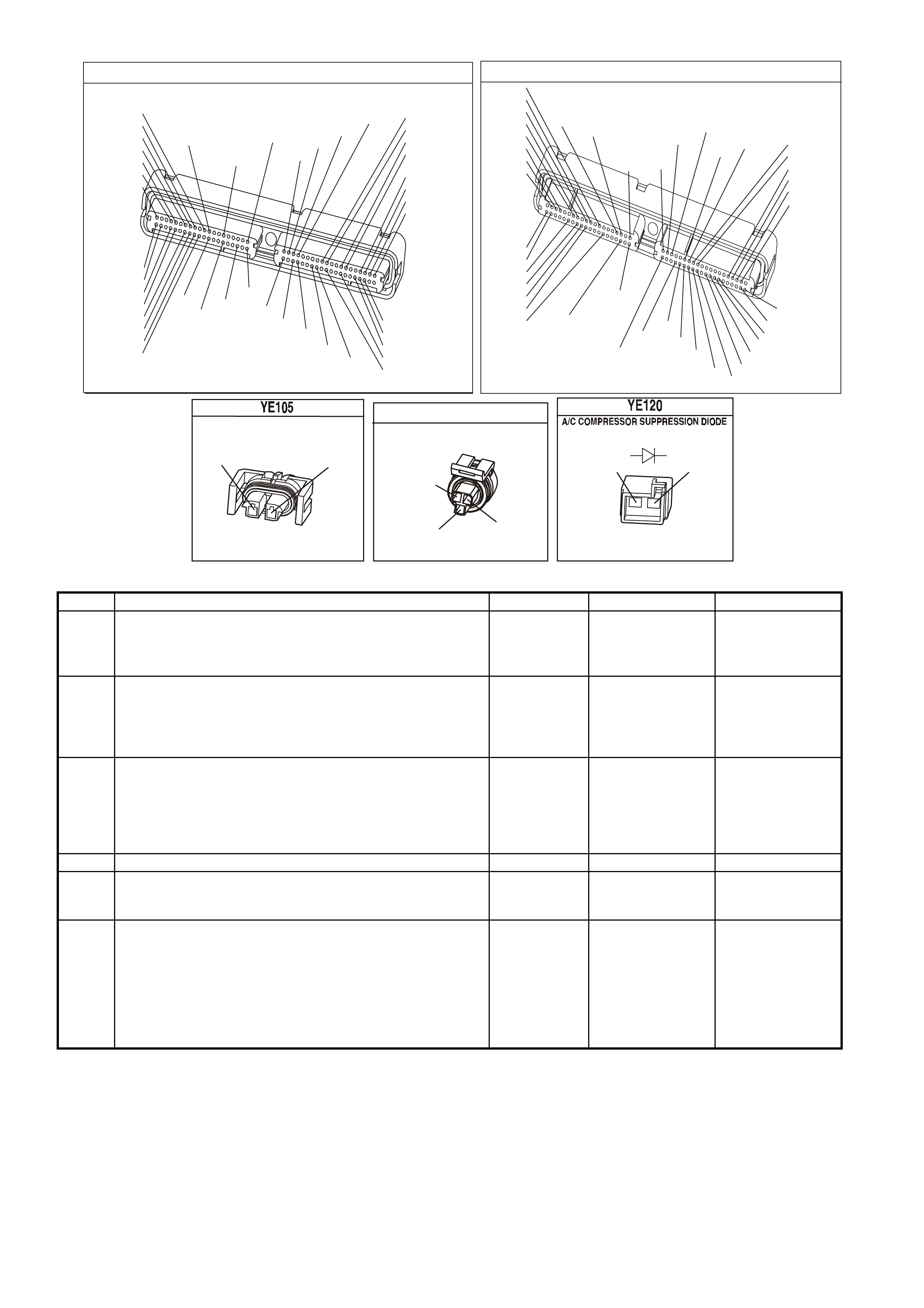
GEN III V8 PCM FUEL INJECTOR COIL TEST - ECT BETWEEN 10 - 35°C
Test Description
Caution: Wrap a shop towel around the fuel pressure connection in order to reduce the risk of fire and
personal injury. The towel will absorb any fuel leakage that occurs during the connection of the fuel
pressure gauge. Place the towel in an approved container w hen the connection of the fuel pressure gauge
is complete.
2. The engine c oolant temperature af fects the ability of the fuel injec tor tester to detect a faulty fuel injec tor. If the
engine coolant temperature is NOT between 10°C and 35°C (50°F and 95°F), go to Fuel Inj. Coil Test - ECT
Outside 10-35°C.
3. The first second of the voltage displayed by the DMM may be inaccurate due to the initial current surge.
Therefore, record the lowest voltage displayed by the DMM after the first second of the test. The voltage
displayed by the DMM should be within the specif ied range ( refe r to the exam ple). T he voltage dis played by the
DMM m ay increase throughout the test as a fuel injector windings warm and the resistance of the fuel injector
windings changes. An erratic voltage reading (large fluctuations in voltage that do not stabilise) indicates an
intermittent connection within the fuel injector.
Examples
Resistance
Ohms Voltage Specification at
10°C-35°C (50°F-95°F)
11.4 - 12.6 5.5 - 6.6 V
Fuel Injector
Number Voltage
Reading
Pass/Fail
1 6.3 P
2 5.9 P
3 6.2 P
4 6.1 P
5 4.8 F
6 6.0 P
7 5.0 F
8 5.3 F

GEN III V8 PCM FUEL INJECTOR COIL TEST - ECT BETWEEN 10 - 35°C
Step Action Value(s) Yes No
1 Did you perform the Powertrain On-Board Diagnostic
(OBD) System Check? Go to Step 2 Go to Powertrain
OBD System
Check Table in
Section 6C3-2A
2 1. Connect the Tech 2 scan tool.
2. Check the engine coolant temperature.
Is the engine coolant temperature within the specified
value?
10°C - 35°C
(50°F - 95°F) Go to Step 3 Go to Fuel Inj.
Coil Test - ECT
Outside 10-35°C
in this Section
3 1. Turn the ignition ON
NOTE: In order to prevent flooding of a single cylinder
and possible engine damage, relieve the fuel pressure
before performing the fuel injector coil test procedure.
2. Relieve the fuel pressure. Refer to the Fuel Pressure
Relief Procedure.
3. Access the fuel injector electrical connectors as
required.
4. Connect the J 39201 fuel injector tester to B+ and
earth.
5. Set the amperage supply selector switch on the fuel
injector tester to the Coil Test 0.5 amp position.
6. Connect the leads from the J 39200 Digital Multi-
Meter (DMM J 39200) to the fuel injector tester. Refer
to the illustration associated with the test description.
7. Set the DMM to the tenths scale (0.0).
8. Connect the fuel injector tester to a fuel injector.
IMPORTANT: Check the engine coolant temperature
again in order to ensure that the correct Table is being
used.
9. Press the Push to Start Test button on the fuel
injector tester.
10. Observe the voltage reading on the DMM.
IMPORTANT: The voltage reading may rise during the
test.
11. Record the lowest voltage observed after the first
second of the test.
12. Repeat Steps 8 through 11 for each fuel injector.
Did any fuel injector have an erratic voltage reading
(large fluctuations in voltage that do not stabilise) or
voltage readings outside of the specified value?
5.5-6.6 V Go to Step 4 Go to Fuel
Injector Balance
Test in this
Section
4 Replace the faulty fuel injector(s). Refer to Fuel Injector
Replacement in Section 6C3-3 of the VX Series Service
Information.
Is the replacement complete?
Go to
Fuel
Injector Balance
Test in this
Section
GEN3 0102
FUEL INJECTO R
TESTER
AMPERAGE SUPPLY SEL ECT O R SWITCH
PUS H TO START TEST
LOW VEHICLE BATTERY
READY TO TEST
TES T IN PROGR E SS
J 39021
B+
J 39 2 00 DM M
V-DC mA
V-AC A
OFF µ A
mV
Coil Test
4 amp
2.5 amp
0.5 amp
Balance Test
4 amp
0.5-2.5
amp
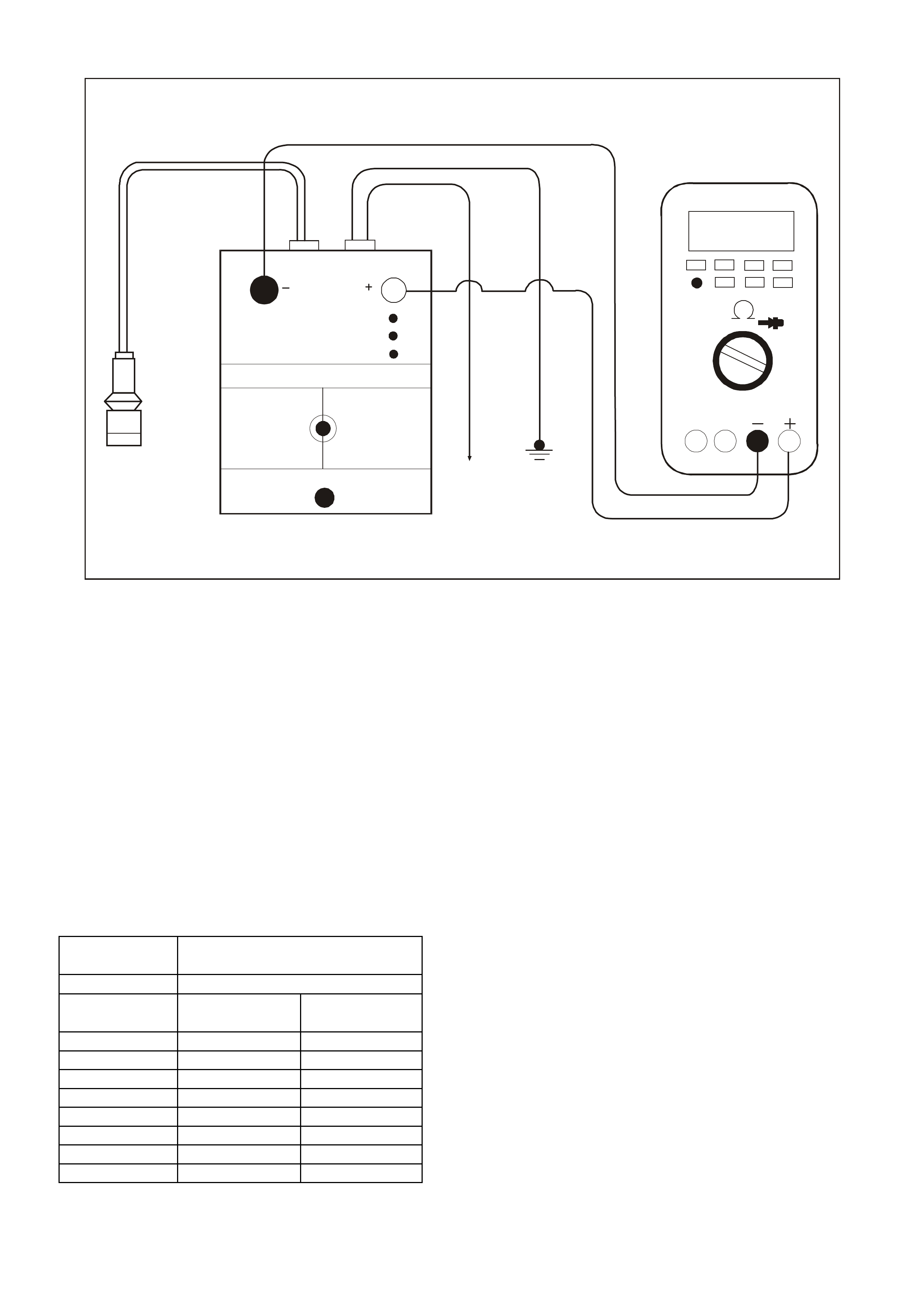
GEN III V8 PCM FUEL INJECTOR COIL TEST - ECT OUTSIDE 10 - 35°C
Test Description
Caution: Wrap a shop towel around the fuel pressure connection in order to reduce the risk of fire and
personal injury. The towel will absorb any fuel leakage that occurs during the connection of the fuel
pressure gauge. Place the towel in an approved container w hen the connection of the fuel pressure gauge
is complete.
2. The engine coolant tem perature aff ects the ability of the fuel injector tes ter to detect a faulty fuel injec tor. If the
engine coolant temperature is NOT outside 10°C and 35°C (50°F and 95°F), go to Fuel Inj Coil Test - ECT
Between 10-35°C in this Section.
3. The first second of the voltage displayed by the DMM may be inaccurate due to the initial current surge.
Therefore, record the lowest voltage displayed by the DMM after the first second of the test. The voltage
displayed by the DMM may increase throughout the test as the f uel injector windings warm and the resistance
of the fuel injector windings changes. An erratic voltage reading (large fluctuations in voltage that do not
stabilise) indicates an intermittent connection within the fuel injector.
From the voltages rec orded, identify the highest voltage, excluding any voltages above 9.5 volts. Subtract each
voltage that is not above 9.5 volts from the highest voltage. Record each subtracted value (refer to the
Exam ple) . T he s ubtr act ed value f or any fuel injec tor with a subtr acted value that is greater than 0.6 volt is faulty.
Replace the fuel injector. A fuel injector with a recorded voltage above 9.5 volts is also faulty. Replace the fuel
injector.
Examples
Highest Voltage
Reading Acceptable Subtracted
Value Above/Below
10°C-35°C (50°F-95°F)
7.1 V 0.6 V
Injector
Number
Voltage Subtracted
Value
Pass/Fail
1 9.8 -- F
2 6.6 0.5 P
3 6.9 0.2 P
4 5.8 1.3 F
5 7.0 0.1 P
6 7.1 0.0 P
7 9.6 -- F
8 6.0 1.1 F

GEN III V8 PCM FUEL INJECTOR COIL TEST - ECT OUTSIDE 10 - 35°C
Step Action Value(s) Yes No
1 Did you perform the Powertrain On-Board Diagnostic
(OBD) System Check? Go to Step 2 Go to Powertrain
OBD System
Check Table in
Section 6C3-2A
2 1. Connect the Tech 2 scan tool.
2. Check the engine coolant temperature.
Is the engine coolant temperature outside the specified
value?
10°C - 35°C
(50°F - 95°F) Go to Step 3 Go to Fuel Inj
Coil Test - ECT
Between
10-35°C in this
Section
3 1. Turn the ignition off.
Note: In order to prevent flooding of a single cylinder and
possible engine damage, relieve the fuel pressure before
performing the fuel injector coil test procedure.
2. Relieve the fuel pressure. Refer to the Fuel Pressure
Relief Procedure in Section 6C3-3 of the VX Series
Service Information.
3. Access the fuel injector electrical connectors as
required.
4. Connect the J 39201 fuel injector tester to B+ and
earth.
5. Set the amperage supply selector switch on the fuel
injector tester to the Coil Test 0.5 amp position.
6. Connect the leads from the J 39200 Digital Multi-
Meter (DMM J 39200) to the fuel injector tester. Refer
to the illustration associated with the test description.
7. Set the DMM to the tenths scale (0.0).
8. Connect the fuel injector tester to a fuel injector.
IMPORTANT: Check the engine coolant temperature
again in order to ensure that the correct Table is being
used.
9. Press the Push to Start Test button on the fuel
injector tester.
10. Observe the voltage reading on the DMM.
IMPORTANT: The voltage reading may rise during the
test.
11. Record the lowest voltage observed after the first
second of the test.
12. Repeat Steps 8 through 11 for each fuel injector.
13. Identify the highest voltage reading recorded from the
highest voltage reading recorded.
14. Subtract any other voltage reading recorded from the
highest voltage reading recorded.
15. Repeat Step 14 for all the remaining fuel injectors.
Is any value that resulted from subtracting greater than
the specified value?
0.6 V Go to Step 4 Go to Fuel
Injector Balance
Test in this
Section
4 Replace any fuel injector that had any of the following:
• A subtracted value exceeding 0.6 volts.
• An initial reading above 9.5 volts.
• An erratic reading.
Refer to Fuel Injector Replacement in Section 6C3-3 of
the VX Series Service Information.
Is the replacement complete?
Go to Fuel
Injector Balance
Test in this
Section
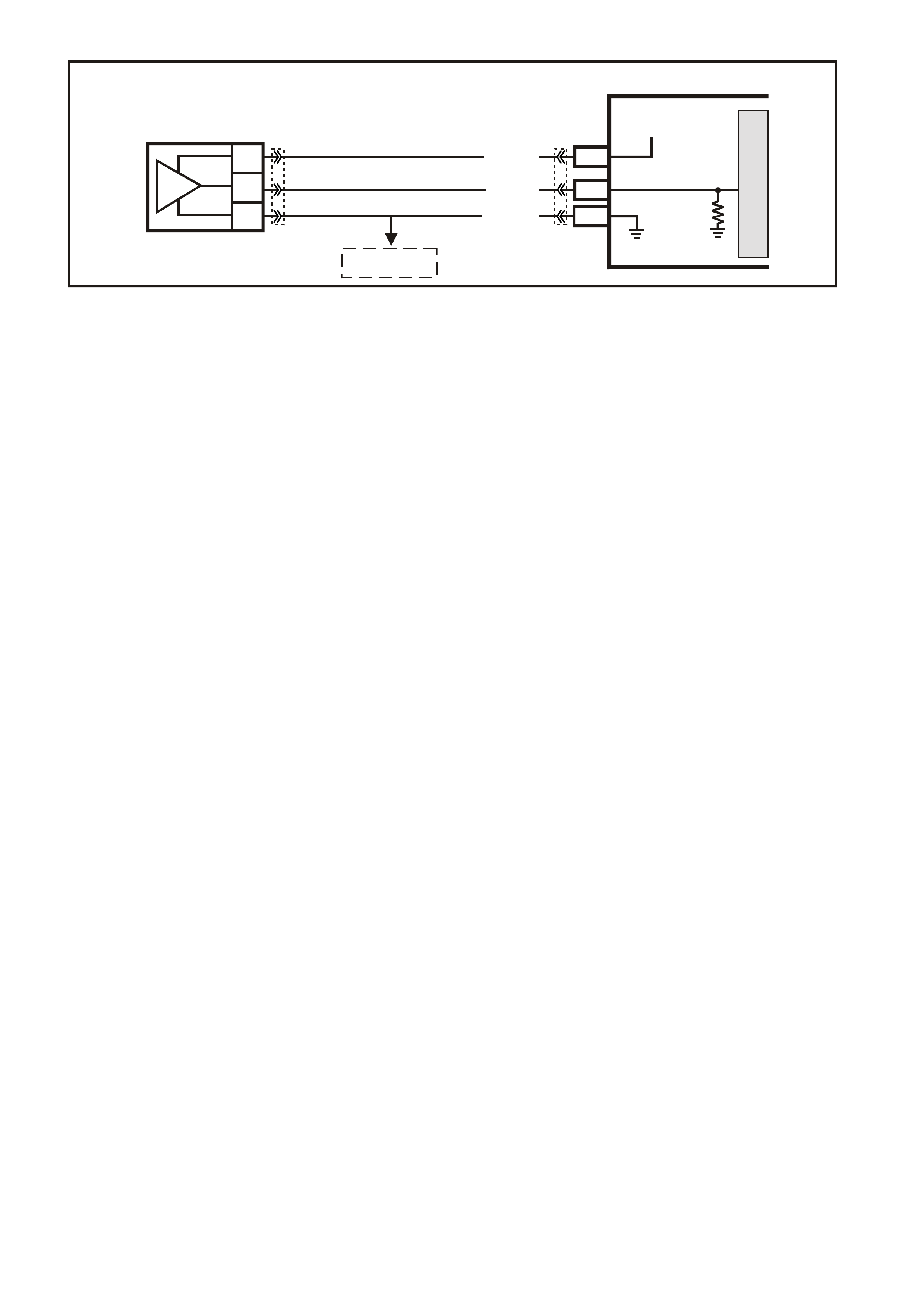
GEN III V8 PCM FUEL INJECTOR CIRCUIT DIAGNOSIS
Circuit Description
The PCM will enable an injector on the intake stroke of each cylinder. Individual cylinder fuel control is referred to as
Sequential Multiport Fuel Injector (SFI).
Battery voltage is supplied directly to the fuel injectors. The PCM controls each injector by earthing the control circuit
via an internal switch called a driver. The primary function of the driver is to supply the earth for the component
being controlled.
Diagnostic Aids
• If an injector is disconnected while the engine is operating the injector driver will be disabled for the entire
ignition cycle.
• When the injector driver is disabled, an engine misfire will be apparent.
• For an intermittent condition, refer to Section 6C3-2B Symptoms of the VX Series Service Information.
G3PCM017PT
PCM
J1-19
J1-36
J1-04
J1-03
J1-44
J1-76
J1-37
J1-20
J1-43
J1-77
J1-57
INJECTOR 1
INJECTOR 2
INJECTOR 7
INJECTOR 8
BATTERY
BATTERY
INJECTOR 5
INJECTOR 6
INJECTOR 3
INJECTOR 4
IGNITION
M
I
C
R
O
P
R
O
C
E
S
S
O
R
+
-
BATTERY
FS
(1040)
O/Y
(479)
B/W
(152)
FJ
LOC. E1
LOC. E3
R (2H)
15a 15 50
30 OFF/ON
LOCK
ACC
IGN
START
IGNITION SWITCH
P (3) P/B (39) P (39)
EFI
RELAY
F14
F35
F34F31 BLU
(841)
V
(843)
GY
(845)
P/B
(847)
G
(842)
BR/Y
(844)
Y
(846)
LG
(848)
O (740)
O/B
(740)
R
(481)
L/G
(482)
YE39
YB44
YB44
YE111
YE112
YE122
YE39
YE77 YE77
YE79 YE79
YE83 YE83
YE78 YE78
YE80 YE80
YE82 YE82
YE84 YE84
YE81 YE81
YE114
Test Description
The numbers below refer to the step numbers on the diagnostic table.
2. This step determines if a malfunction is present. For any test that requires probing the PCM or a component
harness connector, use the Connector Test Adapter Kit J 35616-A. Using this kit prevents damage to the
harness connector terminals.
5. There are two ways to isolate a malfunctioning injector circuit.
6. Check injector connections before replacing the injector. A faulty connection causes an inoperative injector.
9. Check for an ignition feed circuit that is shorted to earth.
10. Disconnecting the PCM allows using the DMM J39200 to check continuity of the circuits. This will aid in
locating an open or shorted circuit.
P.C.M CONNECTOR 1
YE122
(776)
(1049)
(897)
(1230)
(848)
(1226)
(772)
(647)
(632)
40
(844)
(815)
80
J1
P/B
(845)
V/W
BLU
O
(633)
(846)
B/Y
B/R
(416)
(86)
(69)
(455)
(740)
GY
BR
G
GY
(646)
(410)
GY
(842)
(1225)
V
Y
(750)
P
41
O
(774)
BR/Y
BLU
Y
B/R
B
BLU/Y
(841)
BLUE
(414)
G/W
BLU
LG
LBLU/B
1
(847)
(415)
(740)
(452)
BLU
BR
Y
(750)
(826)
(421)
Y
V/W
B/W
(334)
(771)
(39)
Y
R/W
LBLU
W
BLU/W
(843)
(643)
LBLU/W
G
GY/B
BLU/B
(413)
(1413)
(1412)
(412)
GY
V
GY/B
G
(335)
YE77
1.YE77 INJECTOR 1 BLU (841). LG (482)
2.YE78 INJECTOR 2 G (842). R (481)
3.YE79 INJECTOR 3 V (843). LG (482)
4.YE80 INJECTOR 4 BR/Y (844). R (481)
5.YE81 INJECTOR 5 GY (845). LG (482)
6.YE82 INJECTOR 6 Y (846). R (481)
7.YE83 INJECTOR 7 P/B (847). LG (482)
8.YE84 INJECTOR 8 LG (848). R (481)
A
A
INJECTORS
GEN III V8 PCM FUEL INJECTOR CIRCUIT DIAGNOSIS
Step Action Value(s) Yes No
1 Did you perform the Powertrain On-Board Diagnostic
(OBD) System Check? Go to Step 2 Go to Powertrain
OBD System
Check Table in
Section 6C3-2A
2 IMPORTANT: This table assumes that there are no
Ignition Coil/Module circuit malfunctions or mechanical,
and DTCs P0351, P0352, P0353, P0354, P0355, P0356,
P0357, P0358 are not set.
1. Install the Tech 2 scan tool.
2. Start and idle the engine.
3. Monitor all the Ignition Coils on the Engine Data List
(there are a total of 8) using a scan tool.
Are any of the Ignition Coil indicating FAULT?
Go to Step 3 Refer to
Diagnostic Aids
3 Are the injector fuses OK? Go to Step 4 Go to Step 7
4 1. Turn OFF the ignition.
2. Disconnect the injector(s) harness that the Ignition
Coil FAULT was indicating.
3. Turn ON the ignition leaving the engine OFF.
4. Using a test lamp J 34142-B connected to earth,
probe the injector harness ignition feed circuit.
Does the test lamp illuminate?
Go to Step 5 Go to Step 9
5 1. Turn OFF the ignition.
2. Connect the injector test lamp (J 34730-2C) to isolate
the injector harness.
3. Start the engine and idle.
Does the test lamp flash?
Go to Step 6 Go to Step 10
6 1. Inspect the injector harness terminals for correct
terminal tension.
2. Replace terminal as necessary.
Does the terminal need replacing?
System OK Go to Step 14
7 1. Turn OFF the ignition.
2. Disconnect the injector harness connectors related to
the fuse that was open.
3. Using a test lamp J 34142-B connected to B+, probe
the injector harness ignition feed circuit.
Does the test lamp illuminate?
Go to Step 12 Go to Step 8

Step Action Value(s) Yes No
8 Measure the resistance of each injector that is powered
by the fuse that is open using a DMM J 39200.
Does any injector measure less than the specified value?
11.4Ω Go to Step 14 Go to Step 13
9 Repair the injector ignition feed circuit to isolated injector.
Is the action complete? System OK
10 1. Turn OFF the ignition.
2. Disconnect the PCM BLUE connector.
3. Check the injector driver circuit for an open or short to
earth.
Is the injector driver circuit open or shorted to earth?
Go to Step 11 Go to Step 15
11 Repair injector driver circuit for an open or short to earth.
Is the action complete? System OK
12 Repair the earthed ignition feed circuit to the injectors.
Is the action complete? System OK
13 Repair intermittent short to earth in the injector ignition
feed circuit.
Is the action complete?
System OK
14 Replace the faulty injector(s) that was isolated. Refer to
Fuel Injector Replacement.
Is the action complete?
System OK
15 1. Replace PCM.
2. Refer to Section 6C3-3 of the VX Series Service
Information for PCM Reprogramming and PCM/PIM
Security Link Procedure.
Is action complete?
System OK
16 Inspect the appropriate injector circuit for the following:
• Poor connections at the injector and the PCM
terminal
• Intermittent short to earth
• Intermittent opens
If a problem is found, repair the circuit as necessary.
Did you find and correct the condition?
System OK Intermittent
condition. Go to
Section 6C3-2B
Symptoms of the
VX Series
Service
Information
GEN III V8 PCM ELECTRONIC IGNITION SYSTEM DIAGNOSIS
Circuit Description
A Crankshaft Position (CKP) sensor determines the engine crankshaft position. The sensor is mounted and
protrudes into the r ear of the engine bloc k. T he sens or is near a s lotted wheel on the crankshaf t. T he r otation of the
slotted wheel causes a magnetic flux change in the sensor. This produces a voltage signal from the electronic
Ignition Control Module (ICM). The signal creates the reference pulses needed by the Powertrain Control Module
(PCM). These signals trigger the correct ignition coil to fire, at the correct time.
The ignition system on this engine uses an individual ignition coil/module for each cylinder. The PCM controls the
ignition system operation. There ar e eight Ignition Control (IC) circuits , one per cylinder, that c onnect the PCM and
the ignition coil/modules. Each ignition coil/module has a power feed, a chassis earth circuit, and a reference low
circuit. T he PCM causes a spar k to occur by earthing the IC circuit, which s ignals the ignition module to trigger the
ignition coil and fire the spark plug. The PCM controls the sequencing and timing.
Diagnostic Aids
The following may cause an intermittent:
• Check for poor connections. Check for adequate terminal tension.
• Corrosion
• Incorrectly routed harness
• Rubbed through wire insulation
• Broken wire inside the insulation
• Using Freeze Fram e/Failure Records data m ay aid in locating an interm ittent condition. If you cannot duplicate
the DTC, the information included in the Freeze Frame /Failure Records data can help determ ine the distance
traveled since the DTC set. The Fail Counter and Pass Counter can also help determine how many ignition
cycles the diagnostic reported a pas s and/or f ail. Oper ate vehicle within the s am e freeze fram e condition (RPM,
load, vehicle speed, temperature etc.) that you observed. This will isolate when the DTC failed.
• For an intermittent condition, refer to Section 6C3-2B Symptoms of the VX Series Service Information.
Test Description
The numbers below refer to the step numbers on the diagnostic table.
3. Monitoring the Engine Data List Ignition Coil determines if a fault is present.
4. A good indication that the fuse is open is all the Ignition Coils are indicating FAULT on one side of the engine.
Inspect the ignition feed circuit for a earthed circuit.
8. If the fuse is open and no problem can be found with the ignition coil/module circuits, inspect the injector circuits
for being earthed. Fuse F34 and fuse F35 feeds the ignition coil/module circuits and injector circuits.
R.H.IGNITION MO DULE
LG
(976)
(959)
VR
(481)
LBLU
(978)
B/R
(750)
(972)
Y/B
(974)
W
L.H. IG NITION MODULE
(958)
(973)
BR
BLU
(971)
(482)
W
LG
B/R
(750)
Y
(977)
(975)
G
G3PCM012PT
PCM
M
I
C
R
O
A
C
B
CRANKSHAFT
POSITION
SENSOR
J1-02LBLU/W (646)
J1-21
SENSOR EARTH
12V
J1-12BLU (643)
CRANKSHAFT POSITION
SENSOR
SIGNAL
MAGNETO
RESISTIVE
INTEGRATED
CIRCUIT
IC
LBLU/B (64 7)
YE67 YE122

GEN III V8 PCM ELECTRONIC IGNITION SYSTEM DIAGNOSIS
Step Action Value(s) Yes No
1 Did you perform the Powertrain On-Board Diagnostic
(OBD) System Check? Go to Step 2 Go to Powertrain
OBD System
Check Table in
Section 6C3-2A
2 Are DTCs P0335, P0336, P0351-P0358 set? Go to Applicable
DTC table Go to Step 3
3 IMPORTANT: This table assumes that there are no
Ignition Coil/Module circuit malfunctions or mechanical,
and DTCs P0351, P0352, P0353, P0354, P0355, P0356,
P0357, P0358 are not set.
1. Install the scan tool.
2. Start and idle the engine.
3. Monitor all the Ignition Coils on the Engine Data List
(There are a total of 8). using a scan tool.
Are any of the Ignition Coils indicating FAULT?
Go to Step 4 Intermittent
Condition. Go to
Diagnostic Aids
4 1. Turn ON the ignition leaving the engine OFF
2. Using a test light connected to earth, probe both sides
of both Ignition/Injector fuses.
Does test light illuminate at both terminals of both fuses?
Go to Step 5 Go to Step 8
5 1. Turn OFF the ignition.
2. Disconnect the ignition coil 8-way harness connector
for the Ignition Coil module that is indicating FAULT.
3. Turn ON the ignition leaving the engine OFF.
4. Probe the ignition feed circuit at the 8-way harness
connector using a test lamp J 34142-B connected
battery to earth.
Does the test lamp illuminate?
Go to Step 6 Go to Step 10
6 Using a test lamp J 34142-B probe the ignition feed
circuit at the 8-way connector to the ignition coil/module
earth circuit.
Does the test lamp illuminate?
Go to Step 7 Go to Step 13
7 Using a test lamp J 34142-B probe the ignition feed
circuit at the ignition coil/module electrical 8-way
connector to the ignition coil/module reference low circuit.
Does the test lamp illuminate?
Go to Step 21 Go to Step 17
8 1. Inspect for an open ignition coil/module fuse.
2. Locate and repair the ignition feed circuit for a earthed
circuit if the fuse is open.
3. Replace the fuse.
Did you find and correct the problem?
System OK Go to Step 9
9 Repair open in the ignition feed circuit between the EFI
relay and the splice.
Is the action complete?
System OK
10 1. Disconnect the ignition 8-way coil/module harness
connector for the Ignition Coil that is indicating
FAULT.
2. Probe the ignition feed circuit at the ignition
coil/module main 8-way connector using a test lamp
J 34142-B connected to battery earth.
Does the test lamp illuminate?
Go to Step 11 Go to Step 12
11 Repair the open circuit between the splice and the
ignition coil/module connector.
Is the action complete?
System OK
12 Repair the open ignition feed circuit between the fuse
block (open fuse) and splice.
Is the action complete?
System OK
13 1. Disconnect the ignition 8-way coil/module harness
connector for the Ignition Coil that is indicating
FAULT.
2. Using a test light J3414-B probe the ignition feed
circuit at the ignition coil/module 8-way connector to
the ignition coil/module earth circuit.
Does the test lamp illuminate?
Go to Step 14 Go to Step 16

Step Action Value(s) Yes No
14 1. Check for a poor connection at the ignition
coil/module electrical 8-way connector.
2. Repair poor connections as necessary.
Did you find and correct the problem?
System OK Go to Step 15
15 Repair the open earth circuit between the main 8-way
connector and the ignition coil/module connector.
Is the action complete?
System OK
16 Repair the open earth circuit between the earth and the
main 8-way connector.
Is the action complete?
System OK
17 1. Disconnect the ignition 8-way coil/module harness
connector for the Ignition Coil that is indicating
FAULT.
2. Probe the ignition feed circuit at the ignition
coil/module 8-way connector using a test lamp
J 34142-B connected to battery earth.
Does the test lamp illuminate?
Go to Step 18 Go to Step 20
18 1. Check for a poor connection at the 8-way ignition
coil/module electrical connector.
2. If a poor connection is found, repair as necessary.
Did you find and correct a problem?
System OK Go to Step 19
19 Repair the open reference low circuit between the main
8-way connector and the ignition coil/module connector.
Is the action complete?
System OK
20 Repair the open reference low circuit between the PCM
and the splice.
Is the action complete?
System OK
21 1. Check for poor connections at the ignition coil/
module 8-way harness connector, ignition coil/
module harness connector, and splices.
2. Repair poor connections as necessary.
Did you find and correct the problem?
System OK Go to Step 22
22 Replace ignition coil/module.
Is the action complete? System OK
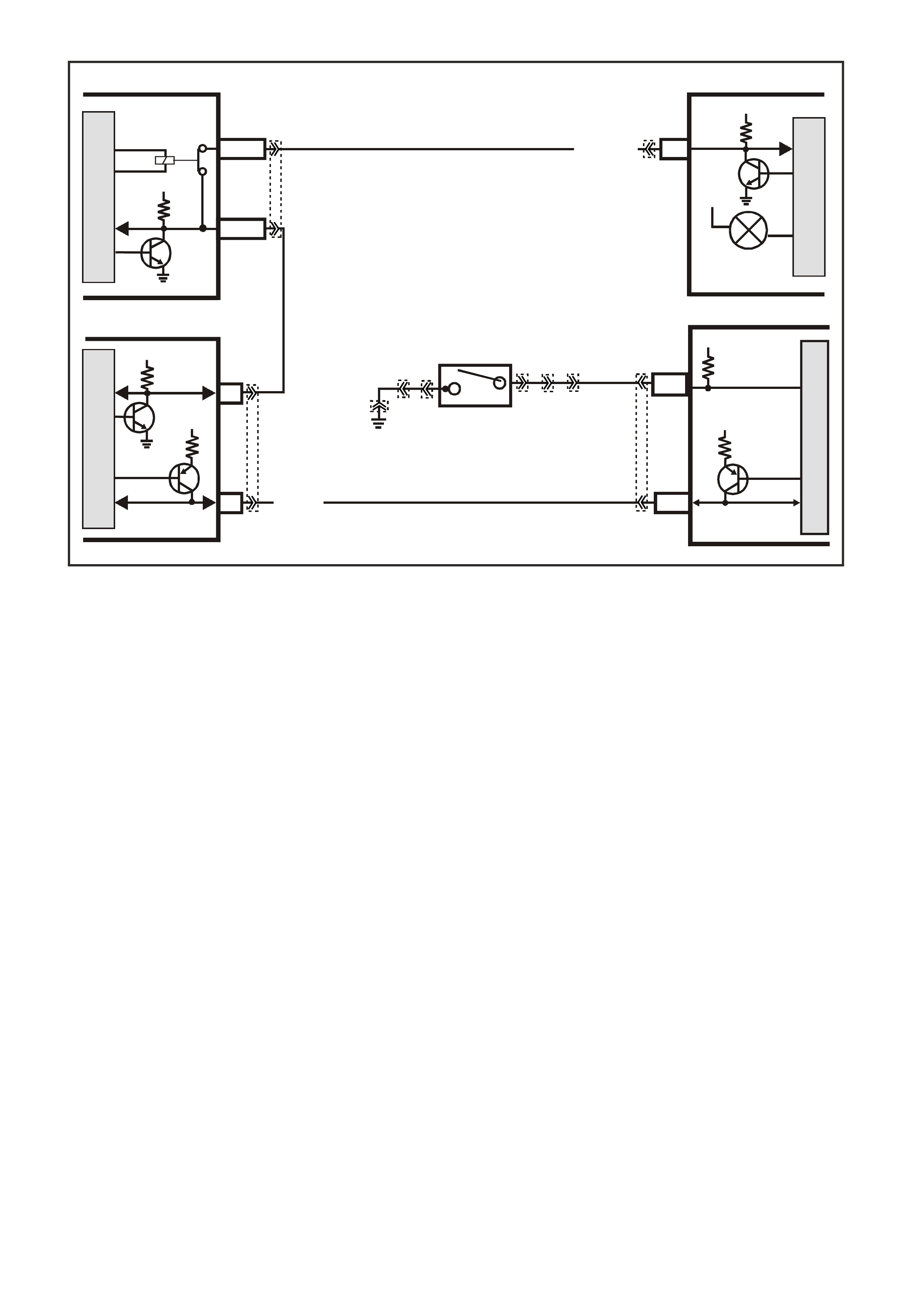
GEN III V8 PCM AUTOMATIC TRANSMISSION ECONOMY/POWER SWITCH
CIRCUIT DESCRIPTION:
The driver can select three transmission shift modes, ECONOMY or POWER or CRUISE using a dash or centre
console mounted switch for Economy/Power, and a cruise switch located on the steering column. The
Economy/Power switch is wired to the PCM and allows the driver to choose the Economy mode, for the best fuel
econom y in all driving conditions through the incr eased use of T CC. Power m ode provides later upshif ts and higher
line pressure in the transmission.
The PCM s ends out a buf f er ed voltage s ignal, about 12 volts, and monitors the s tatus of this cir cuit. O nc e the driver
selects Power, the switch momentarily pulls low the buffered 12 volts, and the PCM will interpret this as a Power
selection and adjust the transmission shift pattern accordingly, and instructs the instrument panel to turn ON the
Power lamp. If while driving, the driver selects the Economy position, again the buffered 12 volts is momentarily
pulled low, and the PCM will adj ust the transm ission shift pattern and ins truct the instrum ent panel to turn OFF the
Power lamp.
When the key is turned ON, the PCM shift mode is set to the last mode that was previously selected
(Economy/Power). The cruise control is set to OFF at every key ON cycle.
In cruise mode operation, when the driver activates the cruise control, the Power lamp and power mode will turn
OFF (if vehicle was in power mode) and the transmission shift pattern will switch to cruise shift pattern. When in
cruise mode the PCM will modify the transmission calibration so that earlier downshift and later upshift points are
provided.
For replacement of the Economy/Power switch, refer to Section 7C4 Automatic Transmission - On Vehicle
Servicing in VX Service Information.
TEST DESCRIPTION:
The numbers below refer to step numbers on the diagnostic Table.
2. This step tests for proper operation of the transmission POWER switch, the wiring and the PCM.
3. This step tests for proper POWER lamp illumination.
5. This step determines if the switch is faulty.
8. Some interior parts must be removed to disconnect and replace the transmission switch, Refer to
Section 1A2 - Body Dimensions in VX Service Information.
4369
M
I
C
R
O
M
I
C
R
O
INSTRUMENTBCM
12 SERIAL
DATA
5V
POWER
ECONOMY
LAMP
12V
G/W (1220)
YB175
YB164
YB215 YE122
YE114
YE112
YB66
YB30
YB30
YB34 YB34
J1-58
M
I
C
R
O
CLASS 2
SERIAL DATA
PCM
7V
R/B (1221)
PIM
UART
SERIAL
DATA
5V
6
Y (1049)
7V
7
CLASS 2
SERIAL DA TA
M
I
C
R
O
E2/D2
E9/D3
SERIAL
DATA
MAIN
SERIAL
DATA AUX.
HIGH SERIES
BCM TERMINALS
NOMINATED FIRST
5V
J1-71
BLU
LOC. E 3
(774)
POWER/ECONOMY
SWITCH
12V
P.C.M CONNECTOR 1
YE122
(776)
(1049)
(897)
(1230)
(848)
(1226)
(772)
(647)
(632)
40
(844)
(815)
80
J1
P/B
(845)
V/W
BLU
O
(633)
(846)
B/Y
B/R
(416)
(86)
(69)
(455)
(740)
GY
BR
G
GY
(646)
(410)
GY
(842)
(1225)
V
Y
(750)
P
41
O
(774)
BR/Y
BLU
Y
B/R
B
BLU/Y
(841)
BLUE
(414)
G/W
BLU
LG
LBLU/B
1
(847)
(415)
(740)
(452)
BLU
BR
Y
(750)
(826)
(421)
Y
V/W
B/W
(334)
(771)
(39)
Y
R/W
LBLU
W
BLU/W
(843)
(643)
LBLU/W
G
GY/B
BLU/B
(413)
(1413)
(1412)
(412)
GY
V
GY/B
G
(335)
YB30
(774)
(8)
BLU
GY
(1429)
BR/W
(151)
B/G
(19)
R/W
BLU
(774)
B/G
(151)
(19)
(8)
BR/W
GY
YB66
INSTRUMENTS
T
BLU/B
BR/W
(234)
(25)
(14)
(10)
(875)
(155)
(1340)
G/W
(44)
(121)
(8)
(30)
BLU/Y
G
O/Y
P/BLU
BR/R
V/W
(33)
(946)
(1220)
(88)
(15)
(123)
(85)
(19)
GY
W
V/R
BR
BR/O
Y/R
B/Y
LBLU
BLU
ENGINE CONNECTOR 3
YE112
(1221)
(42)
(121)
BR/BLU
BR/R
R/BO/B
LG
P/B
BLU
(740)
(24)
(39)
(774)
LBLU
(411)
S/C ONLY
LOCATION E3 EARTH CONNECTOR
RIGHT HAND INNER FENDER
YE114
(151)
B/G
(157)
B/R
(150) (155)
BB/Y
(152)
B/W
(157)
B/R
GEN III V8 PCM AUTOMATIC TRANSMISSION ECONOMY/POWER SWITCH
STEP ACTION VALUE YES NO
1 Was the On-Board Diagnostic (OBD) System Check
performed? Go to Step 2 Go to OBD
System Check
2 1. With the engine OFF, turn the ignition switch to the
RUN position.
2. Install the scan tool.
3. Depress the Transmission POWER switch and
observe the scan tool display.
Does the scan tool display change between the Power
or Economy mode?
Go to Step 3 Go to Step 5
3 Is the POWER lamp ON, when the scan tool displays
POWER? Go to Step 4 Go to
Instruments in
Section 12C in
VX Service
Information.
4 Does the POWER lamp go off, when the scan tool
displays ECONOMY? No Problem
found with switch
operation.
Go to
Instruments in
Section 12C in
VX Service
Information.
5 1. Disconnect the POWER switch from the wiring
harness connector.
2. Using a fused jumper wire, connect the two terminals
of the POWER switch wiring harness connector
together.
Does the scan tool display change between the Power
or Economy mode?
Go to Step 7 Go to Step 6
6 Using a fused jumper wire, connect circuit 774 to earth.
Does the scan tool display change between the Power
or Economy mode?
Go to Step 10 Go to Step 9
7 Check the POWER switch connector for a poor terminal
connection.
Was a problem found?
Verify the Repair Go to Step 8

STEP ACTION VALUE YES NO
8 Replace the faulty POWER/ECONOMY switch.
Is the action complete? Verify the Repair
9 Check for an open or short to Earth in circuit 774, or a
faulty PCM connection for circuit 774.
Was a problem found?
Verify the Repair Go to Step 11
10 Repair open in Earth circuit 151at Power/Economy
switch.
Is action complete?
Verify the Repair
11 Replace PCM.
Refer to Section 6C1-3 Service Operations of the VX
Series Service Information, for PCM Programming and
Security Link procedure.
Is action complete?
Verify the Repair

GEN III V8 PCM INSTRUMENT PANEL GEAR INDICATOR CHECK
Circuit Description
The transmission PRNDL switch is a multi-signal switch assembly that signals the PCM the gear selected. The
PCM will then determine the signal from the PRNDL switch and send a com m and via serial data com m unication to
the instrument panel cluster to illuminate the correct gear indicator lamp.
The PRNDL switch uses four discrete circuits to pull four PCM voltages low in various combinations to indicate each
gear r ange. The voltage level of the c ircuits is represented as Closed = earthed, and Open = open c ircuit. The f our
states displayed represents decoder P, A, B, and C inputs.
The scan tool will display all four circuits (P, A, B, C) and the appropriate Open and Closed to represent the gear
selected. If the gear selected does not match the Open/Closed Table as displayed below on the Scan T ool, or the
instrument panel cluster gear lamp does not light up for the gear selected, there is a fault in the PRNDL select
circuit or in the instrument panel (IP) cluster.
PCM
J1-32
J1-72
PRNDL P
PRNDL A
C
SWITCH P
SWITCH A
SWITCH B
SWITCH C
LOC. E5/E15
A
D
B
P. R. N. D. L. SWITCH
12V
12V
J2-62
J1-34
PRNDL B
PRNDL C
12V
12V
BLU/W (771)
Y (77 2 )
GY (773)
W (776)
B/R (750)
M
I
C
R
O
INSTRUMENTS
M
I
C
R
O
12V
P
R
N
1
2
3
D
12 SERIAL
DATA
5V
E9/D3
BCM
SERIAL
DATA AUX.
M
I
C
R
O
5V
E2/D2
R/B (1221)
SERIAL
DATA
MAIN
M
I
C
R
O
PIM
6
UART
SERIAL
DATA
5V
7
7V
CLASS 2
SERIAL DATA
J1-58
7V
CLASS 2
SERIAL DATA
4371
Y (1049)
YB20
YE122
YE123
YE122
YB66
YB175
YB215
YB164
YB35
G/W (1220)
Y (1049)

Diagnostic Aids
• Monitor the Scan Tool while moving related connectors and wiring harness. If a failure is indicated, the scan
data will change states f rom either Closed to Open or O pen to Closed. Moving the gear selector slowly through
each gear while monitoring the scan tool may also help isolate the problem.
• Any circuitry that is suspected as causing the interm ittent complaint, should be thoroughly checked for backed
out term inals, im proper m ating, brok en locks , improperly form ed or damaged ter minals, poor ter minal to wiring
connection or physical damage to the wiring harness.
• When a fault has occurred, the PCM defaults to 3rd gear until a correct combination is received by the PCM.
Therefore, some selected gear positions may not be possible until the fault is repaired.
Test Description
Numbers below refer to step numbers on the diagnostic Table.
4. Any circuitry that is suspected as causing the interm ittent complaint, should be thoroughly checked for backed
out term inals, im proper m ating, brok en locks , improperly form ed or damaged ter minals, poor ter minal to wiring
connection or physical damage to the wiring harness.
5. An invalid circuit will cause the PRNDL dis play to go out. J umper ing each circuit to ear th simulates the PRNDL
switch operation and checks the circuitry and PCM. W hile the PRNDL switch is disconnected and the circuits
are not jumpered to earth, the s can tool should indicate a Open value. A value that is indic ated as Closed with
no jumper to earth indicates a earthed circuit or faulty PCM.
TRANSMISSION RANGE / PRNDL SWITCH VALID INPUT COMBINATIONS
GEAR POSITION
SELECTED
SCAN TOOL PRNDL DISPLAY
(P, A, B, C)
P A B C
PARK (P) LOW
(0) LOW
(0) HIGH
(12) HIGH
(12)
REVERSE (R) HIGH
(12) LOW
(0) LOW
(0) HIGH
(12)
NEUTRAL (N) LOW
(0) HIGH
(12) LOW
(0) HIGH
(12)
DRIVE 4 (D) HIGH
(12) HIGH
(12) LOW
(0) LOW
(0)
DRIVE (3) LOW
(0) LOW
(0) LOW
(0) LOW
(0)
DRIVE 2 (2) HIGH
(12) LOW
(0) HIGH
(12) LOW
(0)
DRIVE 1 (1) LOW
(0) HIGH
(12) HIGH
(12) LOW
(0)
P.C.M CONNECTOR 1
YE122
(776)
(1049)
(897)
(1230)
(848)
(1226)
(772)
(647)
(632)
40
(844)
(815)
80
J1
P/B
(845)
V/W
BLU
O
(633)
(846)
B/Y
B/R
(416)
(86)
(69)
(455)
(740)
GY
BR
G
GY
(646)
(410)
GY
(842)
(1225)
V
Y
(750)
P
41
O
(774)
BR/Y
BLU
Y
B/R
B
BLU/Y
(841)
BLUE
(414)
G/W
BLU
LG
LBLU/B
1
(847)
(415)
(740)
(452)
BLU
BR Y
(750)
(826)
(421)
Y
V/W
B/W
(334)
(771)
(39)
Y
R/W
LBLU
W
BLU/W
(843)
(643)
LBLU/W
G
GY/B
BLU/B
(413)
(1413)
(1412)
(412)
GY
V
GY/B
G
(335)
Y E123
P.C.M CONNECTOR 2
(750)
(1228)
(1229)
(465)
(121)
(259)
G/B
BR
G/W
GY/BLU
R
B/R
(418)
BR
(59)
(832)
G
T
(831)
(417)
(472)
(976) (974)
(432)
(428)
(631)
BLU BR G/Y
BLU/W
LG
BR/W
W/B
LG W
(977)
Y
(971)
BLU/W W
B/R
(750)
(304)
(792)
(1223)
(1222)
(123)
(1227)
(469)
(331)
Y/B
LG
V/W
B/Y
G/O BR/W
(1687)
GY/B
(366)
LG/B
GY/R
(422)
V
(442)
(444)
(443)
(975)
(972)
(978)
(1224)
(973)
(959)
LG/W
LG/B
LBLU/B
GY
(773)
BR/Y
BLU
G
Y/B
LBLU
(958)
BR
(441)
LBLU
1
41
40
80
J2
RED
Y
(838)
YB 66
INSTRUMENTS
T
BLU/B
BR/W
(234)
(25)
(14)
(10)
(875)
(155)
(1340)
G/W
(44)
(121)
(8)
(30)
BLU/Y
G
O/Y
P/BLU
BR/R
V/W
(33)
(946)
(1220)
(88)
(15)
(123)
(85)
(19)
GY
W
V/R
BR
BR/O
Y/R
B/Y
LBLU
BLU
PRNDL SWITCH
(772)
(776)
Y
W
(773)
(771)
BLU/W
GY
NEUTRAL START & BACK-UP SW ITCH
(1434)
GY/BLU
(24)
LG GY
(434)
(750)
B/R
(42)
BR/BLU

GEN III V8 PCMINSTRUMENT PANEL GEAR INDICATOR CHECK
STEP ACTION VALUE YES NO
1 Did you perform the Powertrain On-Board Diagnostic
(OBD) System Check? Go to Step 2. Go to Powertrain
OBD System
Check Table in
Section 6C3-2A
2 1. Ignition ON, engine OFF.
2. Install a scan tool.
3. Move the gear selector through all its ranges.
Does the scan tool indicate an INVALID in any of the
ranges?
Go to Step 3 Go to Step 10
3 Compare the scan tool values with the Transmission
Range Switch Valid Input Combinations table.
Are all the circuit indicated as Open?
Go to Step 4 Go to Step 5
4 Chec k the transm ission PRNDL switch earth
circuit for an open or poor connection and repair if
necessary.
Was a problem found?
Verify Repair Go to Step 5
5 1. Moving the gear selector through all its ranges and
note which circuit did not correspond with the
Transmission Range Switch Valid Input Combination
table.
2. Disconnect the PRNDL switch electrical connector.
3. Jumper the circuit with the incorrect value to earth.
Does the jumpered circuit go from a OPEN value to a
CLOSED value?
Go to Step 8 Go to Step 6
6 Check the affected circuit for an open or short to earth
and repair as necessary.
Was a problem found?
Verify Repair Go to Step 7
7 Check for a poor connection at the PCM connector and
repair as necessary.
Was a problem found?
Verify Repair Go to Step 9
8 Repl ace the PRNDL switch.
Is action complete? Verify Repair
9 Replace the PCM.
Is action complete? Verify Repair
10 Does the scan tool indicate the same gear as the
instrument cluster? System OK,
refer to Diagnostic
Aids
Go to step 11
11 Remove the instrument cluster and inspect indicator
lamp for being burnt.
Was a problem found?
Verify Repair Go to Step 12
12 Replace the instrument cluster.
Is action complete? Verify Repair
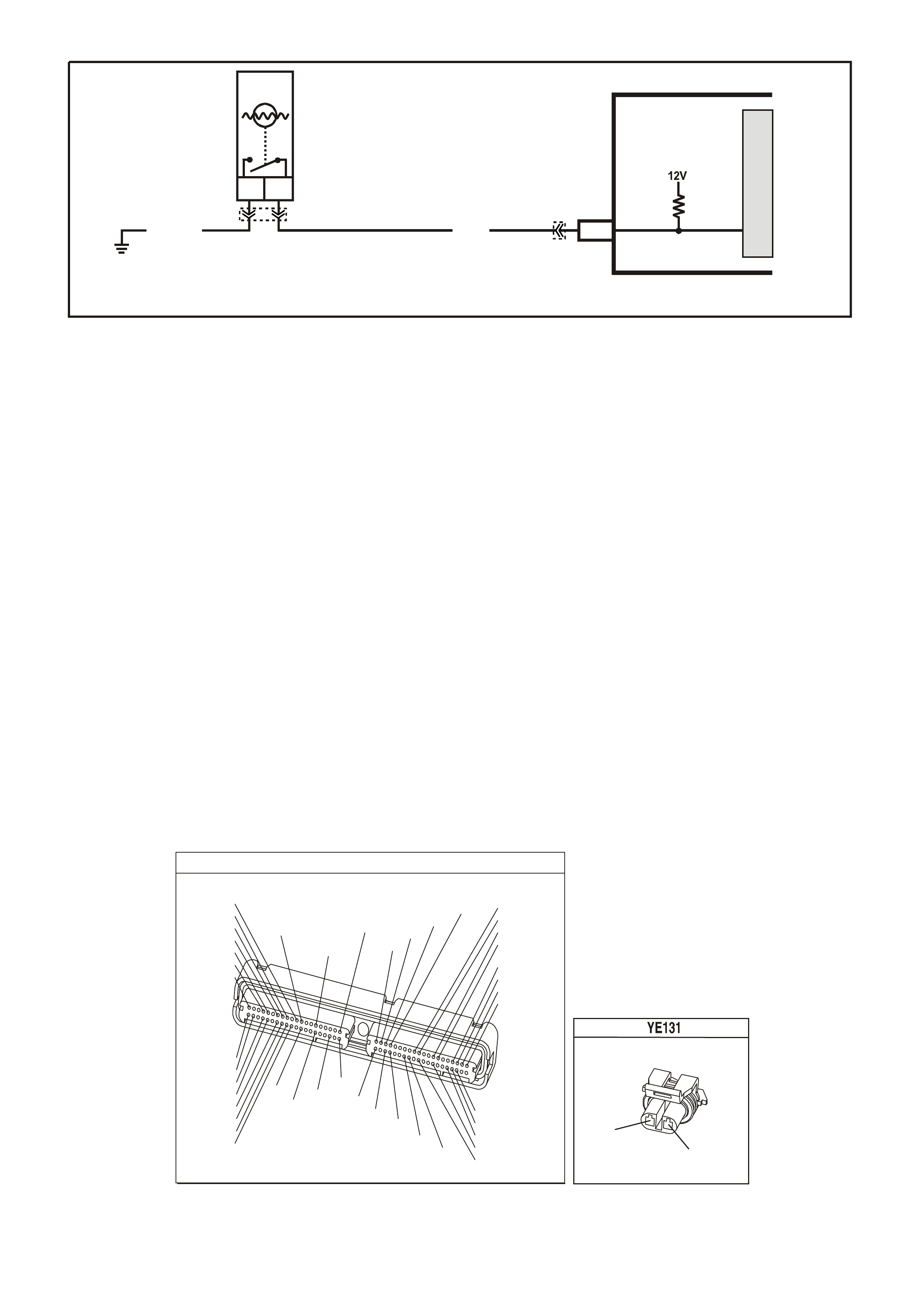
GEN III V8 PCMENGINE COOLANT LEVEL SWITCH DIAGNOSIS
Circuit Description
The engine coolant level switch is located in the coolant sur ge tank and is a f loat type s ensor. T he PCM supplies a
voltage to the engine coolant level switch which is a normally open switch.
When the coolant level is within an acceptable range the switch is closed. The switch opens when the engine
coolant level drops below an predetermined amount. W hen the PCM does not detect a earth signal (switch open)
from the engine coolant level switch, the PCM will send a serial data m essage to the instrum ent cluster. which will
turn ON the Low Coolant lamp.
Diagnostic Aids
• The following may cause an intermittent:
- Poor connection: Check for adequate terminal tension.
- Corrosion
- Incorrectly routed harness
- Broken wire inside the insulation.
• For an intermittent, refer to Section 6C3-2B Symptoms of the VX Series Service Information.
• If the Low Coolant lam p does not illum inate, and the engine coolant level s witch diagnosis table does not f ind a
problem with the switch, either the Low Coolant bulb is open or there is a problem with the instrument cluster.
Test Description
Numbers below refer to step numbers on the diagnostic Table.
4. This step checks the engine coolant level switch signal between the PCM and the Switch.
6. This step checks the engine coolant level switch earth circuit between the PCM and the Switch.
9. This step checks the engine coolant level switch signal for a short to earth.
10. This step checks for an open in the engine coolant level switch signal circuit between the PCM and the switch.
P.C.M CONNECTOR 1
YE122
(776)
(1049)
(897)
(1230)
(848)
(1226)
(772)
(647)
(632)
40
(844)
(815)
80
J1
P/B
(845)
V/W
BLU
O
(633)
(846)
B/Y
B/R
(416)
(86)
(69)
(455)
(740)
GY
BR
G
GY
(646)
(410)
GY
(842)
(1225)
V
Y
(750)
P
41
O
(774)
BR/Y
BLU
Y
B/R
B
BLU/Y
(841)
BLUE
(414)
G/W
BLU
LG
LBLU/B
1
(847)
(415)
(740)
(452)
BLU
BR Y
(750)
(826)
(421)
Y
V/W
B/W
(334)
(771)
(39)
Y
R/W
LBLU
W
BLU/W
(843)
(643)
LBLU/W
G
GY/B
BLU/B
(413)
(1413)
(1412)
(412)
GY
V
GY/B
G
(335)
COOLANT LEVEL S ENSOR
(69)
(750)
G
B/R
G3PCM013PT
J1-30
BA
LOW COOLANT
LEVEL SWITCH
LOW COOLANT LEVEL
SWITCH SIGNAL
PCM
G (69)B/R (750)
LOC. E5/E15
M
I
C
R
O
YE122
YE131

GEN III V8 PCMEngine Coolant Level Switch diagnosis
STEP ACTION VALUE YES NO
1 Did you perform the Powertrain On-Board Diagnostic
(OBD) System Check? Go to Step 2. Go to Powertrain
OBD System
Check Table in
Section 6C3-2A
2 IMPORTANT: This table assumes the coolant level is at
the correct level or the coolant level is low and the Low
Coolant Lamp did not illuminate. If the coolant level is low
refer to Section 6B3 Engine Cooling in VX Service
Information for further diagnosis of the cooling system.
Turn ON the ignition leaving the engine OFF.
Do the instrument panel warning indicator lamps
illuminate?
Go to Step 3 Go to Section
12C Instrument
Panel Cluster
diagnosis in
Section 14C in
VX Service
Information
3 Is the customer concerned that the Low Coolant lamp is
on at all times? Go to Step 4 Go to Step 7
4 1. Disconnect the Engine Coolant Level Switch.
2. Measure the voltage of the Engine Coolant Level
Switch signal circuit using a DMM connected to
battery earth.
Does the DMM display near the specified value?
B+ Go to Step 5 Go to Step 10
5 1. Jumper the engine coolant level switch signal circuit
to earth using a fused jumper wire.
2. Monitor the Low Coolant level state using the scan
tool.
Does the scan tool display Low Coolant Level as OFF?
Go to Step 6 Go to Step 17
6 Jumper the engine coolant level switch signal circuit to
the Engine Coolant Level Switch earth circuit using a
fused jumper wire.
Does the scan tool display Low Coolant Level as OFF?
Go to Step 11 Go to Step 15
7 1. Disconnect the Engine Coolant Level Switch.
2. Measure the voltage of the Engine Coolant Level
Switch signal circuit using a DMM connected to earth.
Does the DMM display near the specified value?
B+ Go to Step 8 Go to Step 9
8 1. Jumper the Engine Coolant Level Switch signal circuit
to earth using a fused jumper wire.
2. Monitor the Low Coolant level state using the scan
tool.
Does the scan tool display Low Coolant Level as YES?
Go to Step 17 Go to Step 12
9 1. Turn OFF the ignition.
2. Disconnect the BLUE PCM connector.
3. Check continuity of the Engine Coolant Level Switch
signal circuit using a DMM connected to earth.
Does the DMM display continuity?
Go to Step 13 Go to Step 17
10 1. Turn OFF the ignition.
2. Disconnect the BLUE PCM connector.
3. Check continuity of the Engine Coolant Level Switch
signal circuit using a DMM connected to earth.
Does the DMM display continuity?
Go to Step 16 Go to Step 14

STEP ACTION VALUE YES NO
11 1. Check for poor connection at the Engine Coolant
Level Switch harness connector.
2. If you find a poor connection, repair as necessary.
Was a problem found?
System OK Go to Step 12
12 Replace the Engine Coolant Level Switch. Refer to
Section 6B3 Coolant Surge Tank Replacement in VX
Service Information .
Is action complete?
System OK
13 Check for short to earth in the Engine Coolant Level
Switch signal circuit.
Was a problem found?
System OK Go to Step 17
14 Repair the engine coolant level switch circuit for an open.
Is action complete? System OK
15 Repair the engine coolant level switch earth circuit for an
open.
Is action complete?
System OK
16 1. Check for poor connection at PCM connector.
2. If you find a poor connection, repair as necessary.
Was a problem found?
System OK Go to Step 17
17 1. Replace PCM.
2. Refer to Section 6C3-3 of the VX Series Service
Information for PCM reprogramming and PCM/PIM
Security Link Procedure.
Is action complete?
System OK
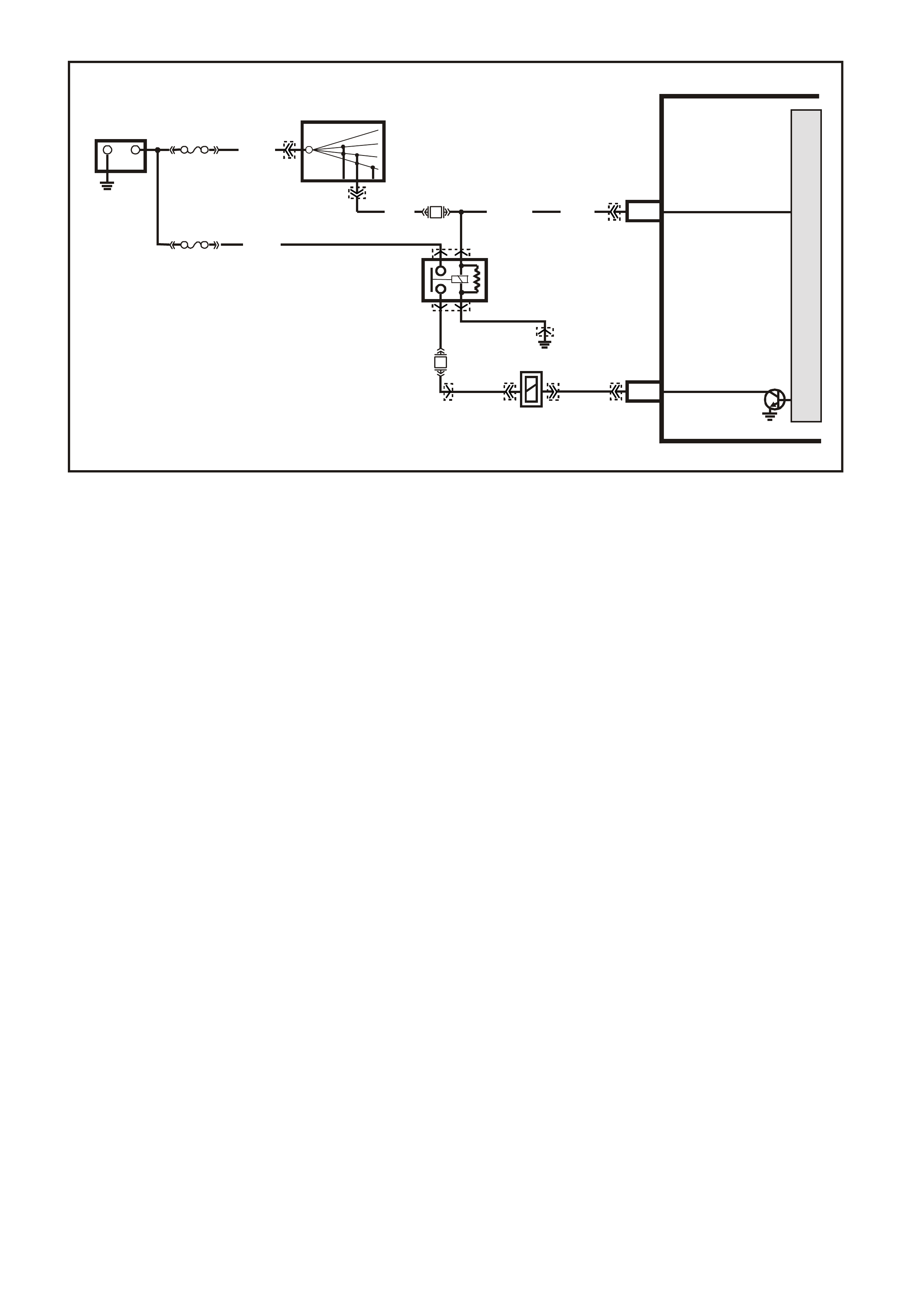
GEN III V8 ENGINE MANUAL TRANSMISSION REVERSE INHIBIT SOLENOID DIAGNOSIS
Circuit Description
The EFI (Engine Cont.) relay supplies an ignition voltage through fuse F32 to the Reverse Inhibit solenoid. The PCM
controls the solenoid by earthing the control circuit via an internal switch called a driver. The driver supplies the
earth for the component being controlled. Each driver has a fault line which the PCM monitors. When the PCM
commands a component ON, the voltage of the control circuit should be low (near 0 volts). When the PCM
commands the control circuit to a component OFF, the voltage potential of the circuit should be high (near battery
voltage).
When the Reverse Inhibit solenoid is energised, the operator can shift the transmission into reverse. The PCM
enables the Reverse Inhibit s olenoid whenever vehicle s peed is below 3 km /h. W hen the vehicle speed is above 5
km/h, the PCM de-energises the solenoid, which prevents the operator from shifting the transmission into reverse.
Diagnostic Aids
• Monitor a Tech 2 scan tool while moving related connectors and wiring harness. If a failure is indicated, the
scan data will change states from either Low to High, or from High to Low. Moving the gear selector slowly
through each gear while monitoring the scan tool may also help isolate the problem.
• Any circuitry that is suspected as causing the interm ittent complaint, should be thoroughly checked for backed
out term inals, im proper m ating, brok en locks , improperly form ed or damaged ter minals, poor ter minal to wiring
connection or physical damage to the wiring harness.
• If the Revers e Inhibit Solenoid elec tr ically is work ing pr oper ly, but the transm iss ion will not shif t into r evers e, the
problem may be inside the transmission. Refer to Manual Transmission for further diagnosis of the Reverse
Inhibit operation.
Test Description
The numbers below refer to the step numbers on the diagnostic table.
2. This step checks to see if the transmission can be shifted into reverse while the speedometer is indicating
vehicle speed.
3. This step indicates if the Tech 2 scan tool will indicate the ON and OFF state of the reverse lock-out solenoid.
G3PCM043PT
PCM
J1-19
J2-44
REVERSE INHIBIT
SOLENOID
IGNITION
M
I
C
R
O
+-
BATTERY
FS
LOC. E1
(1040)
FJ
R (2H)
15a 15 50
30 OFF/ON
LOCK
ACC
IGN
START
IGNITION SWITCH
REVERSE INHIBIT
SOLENOID
P (3) P/B (3 9) P (39)
YE122
YE39
YB44
YB44
YE39
YB125 YB125
YE123
YE114
YE110
B/W
152
O/Y
(479)
EFI
RELAY
F14
F32 LOC. E 3
Y
(838)
P/BLU
(339)
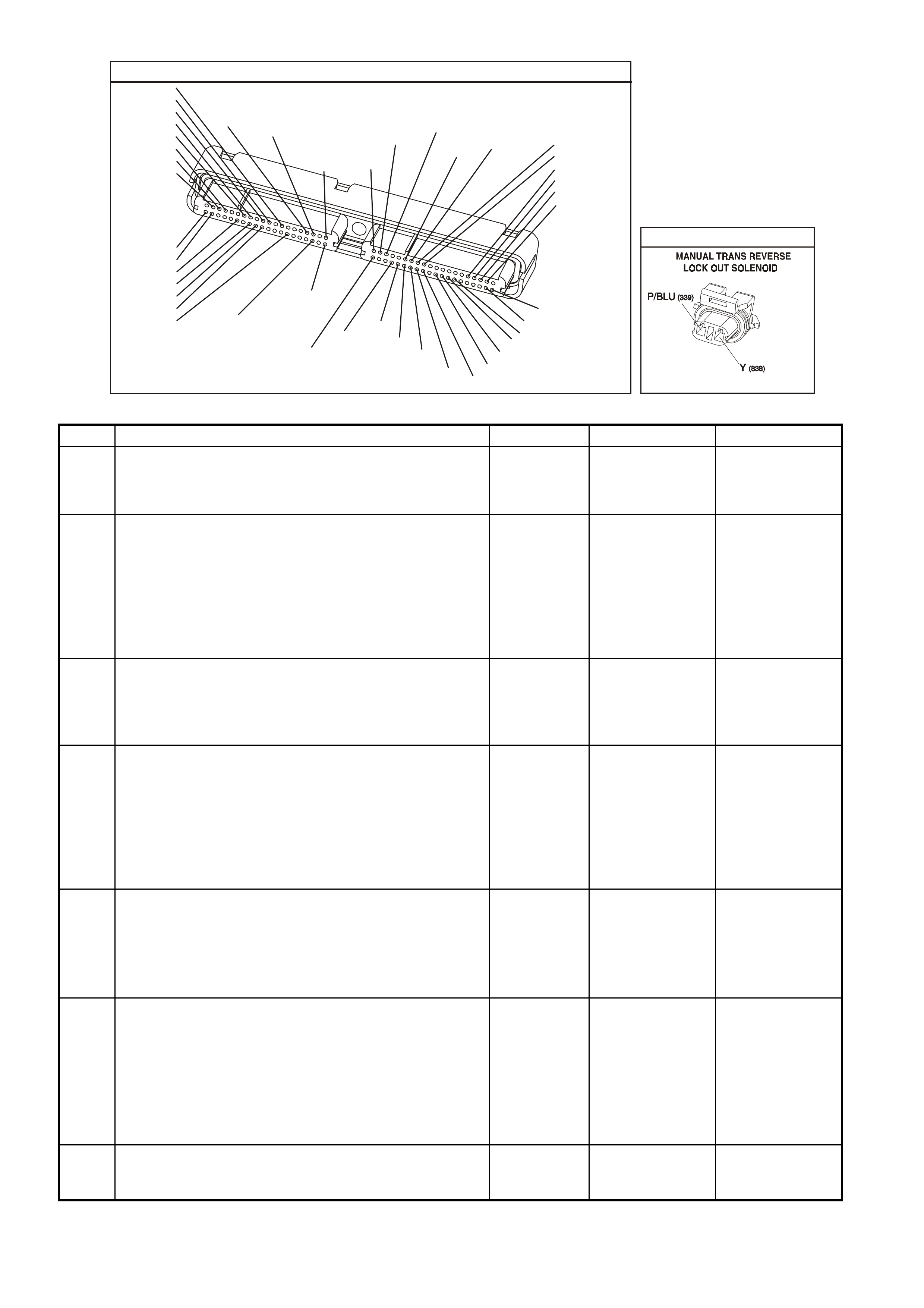
YE123
P.C.M CONNECTOR 2
(750)
(1228)
(1229)
(465)
(121)
(259)
G/B
BR
G/W
GY/BLU
R
B/R
(418)
BR
(59)
(832)
G
T
(831)
(417)
(472)
(976)(974)
(432)
(428)
(631)
BLUBR G/Y
BLU/W
LG
BR/W
W/B
LG W
(977)
Y
(971)
BLU/WW
B/R
(750)
(304)
(792)
(1223)
(1222)
(123)
(1227)
(469)
(331)
Y/B
LG
V/W
B/Y
G/O BR/W
(1687)
GY/B
(366)
LG/B
GY/R
(422)
V
(442)
(444)
(443)
(975)
(972)
(978)
(1224)
(973)
(959)
LG/W
LG/B
LBLU/B
GY
(773)
BR/Y
BLU
G
Y/B
LBLU
(958)
BR
(441)
LBLU
1
41
40
80
J2
RED
Y
(838)
YB125
GEN III V8 PCMMANUAL TRANSMISSION REVERSE INHIBIT SOLENOID Diagnosis
Step Action Value(s) Yes No
1 Did you perform the Powertrain On-Board Diagnostic
(OBD) System Check? Go to Step 2 Go to Powertrain
OBD System
Check Table in
Section 6C3-2A
2
1. Raise drive wheels off ground and support vehicle.
2. Install Tech 2 scan tool and select Engine Data.
3. Ignition ON, engine running.
4. Shift the transmission into first gear and slowly
release the clutch to allow the drive wheels to rotate
to 5 - 15 km/h.
5. While speedometer is reading 5 - 15 km/h, depress
clutch and try to shift into reverse gear.
Were you unable to shift into reverse gear?
Go to Step 3 Go to Step 4
3 While the speedometer is reading 5 - 15 km/h, the Tech
2 scan tool should indicate Reverse Lock-out as OFF,
and when the speedometer is reduced to 3 km/h or lower
the Tech 2 scan tool should indicate ON.
Did the Tech 2 reading show as indicated?
Go to Step 4 Go to Step 6
4 1. Turn OFF the ignition.
2. Disconnect the RED PCM connector.
3. Turn ON the ignition.
4. Measure the current from the solenoid control circuit
in the PCM harness connector to earth for 2 minutes
using a DMM J 39200 on 10 amp scale.
Does the current-draw measure less than the value
shown (but not 0)?
1.5A No trouble found.
Go to Diagnostic
Aids
Go to Step 5
5 1. Turn OFF the ignition.
2. Disconnect the solenoid.
3. Measure the resistance from the solenoid control
circuit in the PCM harness connector to earth using a
DMM J 39200.
Does the DMM display infinite resistance?
Go to Step 13 Go to Step 11
6 1. Turn OFF the ignition.
2. Disconnect the reverse lock-out solenoid.
3. Connect a test lamp J 34142-B between the terminals
in the solenoid harness connector.
4. Ignition ON engine running.
5. Rotate drive wheels to 5 - 15 km/h and then below 3
km/h.
Does the test lamp turn ON and OFF?
Go to Step 9 Go to Step 7
7 Probe the ignition feed circuit in the solenoid harness
connector with the test lamp connected to earth.
Does the test lamp illuminate?
Go to Step 8 Go to Step 12

Step Action Value(s) Yes No
8 1. Turn OFF the ignition.
2. Reconnect the solenoid.
3. Disconnect the RED PCM connector.
4. Turn ON the ignition.
5. Probe the solenoid control circuit in the PCM harness
connector with a fused jumper wire connector to
earth.
Does the solenoid operate?
Go to Step 10 Go to Step 11
9 Check the connections at the solenoid.
Did you find and correct the condition? Verify Repair Go to Step 13
10 Check the connection at the PCM.
Was a problem found? Verify Repair Go to Step 14
11 Repair open or short to earth or short to voltage in the
solenoid control circuit.
Is the repair complete?
Verify Repair
12 Repair the faulty solenoid ignition feed circuit.
Is the repair complete? Verify Repair
13 Replace the solenoid.
Is action complete? Verify Repair
14 1. Replace PCM.
2. Refer to Section 6C3-3 of the VX Series Service
Information for PCM reprogramming and PCM/PIM
Security Link Procedure.
Is action complete?
Verify Repair
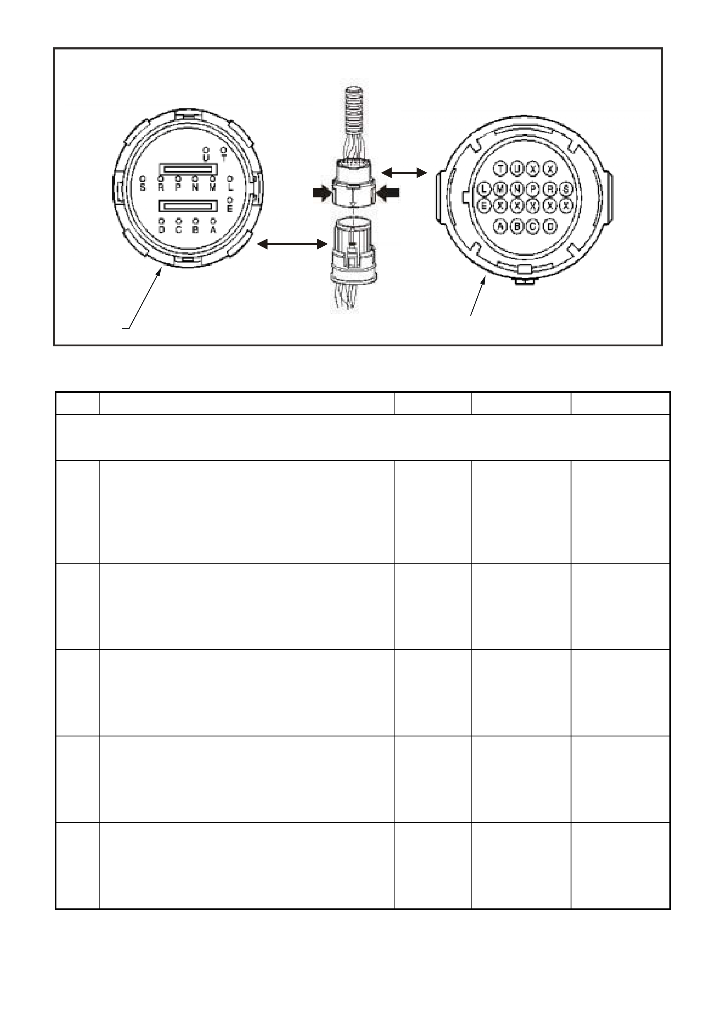
1. Automatic Transmission Wiring Harness Connector Engine Side YB 129.
2. Automatic Transmission Wiring Harness Connector Transmission Side YB129
GEN III V8 PCM AUTOMATIC TRANSMISSION WIRING HARNESS CHECK
Step Action Value(s) Yes No
IMPORTANT: This procedure cannot be used for checking the automatic transmission fluid pressure (TFP) manual valve
position switch circuit, or the automatic transmission fluid temperature (TFT) sensor circuit. Refer to the TFP Manual Valve
Position Switch Resistance Check in this Section, for those circuits.
1 1. Install the J 39775 jumper harness on the
transmission side of the 20-way connector.
2. Using a J 39200 digital multimeter (DMM) and a
J 35616 connector test adapter kit, measure the
resistance between terminals A and E (1-2 shift
solenoid (A) valve).
Is the resistance within the specified range?
19-24 ohm
@ 20°C
(68 °F)
24-31 ohm
@ 100°C
(212°F)
Go to Step 3
Go to Step 2
2 1. Disconnect the 1-2 shift solenoid (SS) valve from the
automatic transmission wiring harness assembly.
2. Using the J 39200 DMM, measure the resistance of
the 1-2 SS valve.
Is the resistance within the specified range?
19-24 ohm
@ 20°C
(68 °F)
24-31 ohm
@ 100 °C
(212°F)
Go to Step 14
Go to Step 16
3 Measure the resistance between terminals B and E (2-3
shift solenoid (B) valve).
Is the resistance within the specified range?
19-24 ohm
@ 20°C
(68°F)
24-31 ohm
@ 100°C
(212°F)
Go to Step 5
Go to Step 4
4 1. Disconnect the 2-3 shift solenoid (SS) valve from the
A/T wiring harness assembly.
2. Using the J 39200 DMM, measure the resistance of
the 2-3 SS valve.
Is the resistance within the specified range?
19-24 ohm
@ 20°C
(68°F)
24-31 ohm
@ 100°C
(212°F)
Go to Step 14
Go to Step 16
5 Measure the resistance between terminals T and E
(torque converter clutch solenoid valve).
Is the resistance within the specified range?
21-26 ohm
@ 20°C
(68°F)
26-33 ohm
@ 100°C
(212°F)
Go to Step 6
Go to Step 14
4372
1
2

Step Action Value(s) Yes No
6 Measure the resistance between terminals U and E
(torque converter clutch pulse width modulation solenoid
valve).
Is the resistance within the specified range?
10-11 ohm
@ 20°C
(68°F)
13-15 ohm
@ 100°C
(212°F)
Go to Step 8
Go to Step 7
7 1. Disconnect the TCC PWM solenoid valve from the A/T
wiring harness assembly.
2. Using the J 39200 DMM, measure the resistance of
the TCC PWM solenoid valve.
Is the resistance within the specified range?
10-11 ohm
@ 20°C
(68°F)
13-15 ohm
@ 100°C
(212°F)
Go to Step 14
Go to Step 16
8 Measure the resistance between terminals S and E (3-2
shift solenoid valve assembly).
Is the resistance within the specified range?
20-24 ohm
@ 20°C
(68°F)
29-32 ohm
@ 100°C
(212°F)
Go to Step 10
Go to Step 9
9 1. Disconnect the 3-2 shift solenoid (SS) valve assembly
from the A/T wiring harness assembly.
2. Using the J 39200 DMM, measure the resistance of
the 3-2 SS valve assembly.
Is the resistance within the specified range?
20-24 ohm
@ 20°C
(68°F)
29-32 ohm
@ 100°C
(212°F)
Go to Step 14
Go to Step 16
10 Measure the resistance between terminals C and D
(pressure control solenoid valve).
Is the resistance within the specified range?
3-5 ohm @
20°C (68°F)
4-7 ohm @
100°C
(212°F)
Go to Step 12
Go to Step 11
11 1. Disconnect the pressure control (PC) solenoid valve
from the A/T wiring harness assembly.
2. Using the J 39200 DMM, measure the resistance of
the PC solenoid valve.
Is the resistance within the specified range?
3-5 ohm @
20°C (68°F)
4-7 ohm @
100°C
(212°F)
Go to Step 14
Go to Step 16
12 Using the J 39200 DMM and the J 35616 connector test
adapter kit, measure the resistance from terminals A, B,
C, D, E, S, T and U of the A/T wiring harness assembly at
the transmission 20-way connector to the transmission
case.
Is the resistance more than the specified value?
250 K ohm
System OK
Go to Step 13

Step Action Value(s) Yes No
13 1. Disconnect the A/T wiring harness assembly from all
the components.
2. Measure the resistance from all the component
terminals to the transmission case.
Is the resistance more than the specified value?
250 K ohm
Go to Step 14
Go to Step 16
14 Inspect for high resistance or a short.
• Inspect the A/T wiring harness assembly at the
transmission 20-way connector, and the component
connectors for the following conditions:
- Insufficient electrical connections
- Backed out, or damaged terminals
- A damaged terminal
- Reduced terminal tension
- A chafed wire that could short to bare metal or
other wiring
- A broken wire inside the insulation
- Moisture intrusion
- Corrosion
• If diagnosing for a possible intermittent condition,
move or massage the A/T wiring harness assembly
while observing the test equipment for a change.
Did you find high resistance or a short?
Go to Step 1
Go to Step 15
15 Replace the A/T wiring harness assembly.
Is the replacement complete?
Go to Step 1
16 Replace the faulty component.
Is the replacement complete?
Go to Step 1
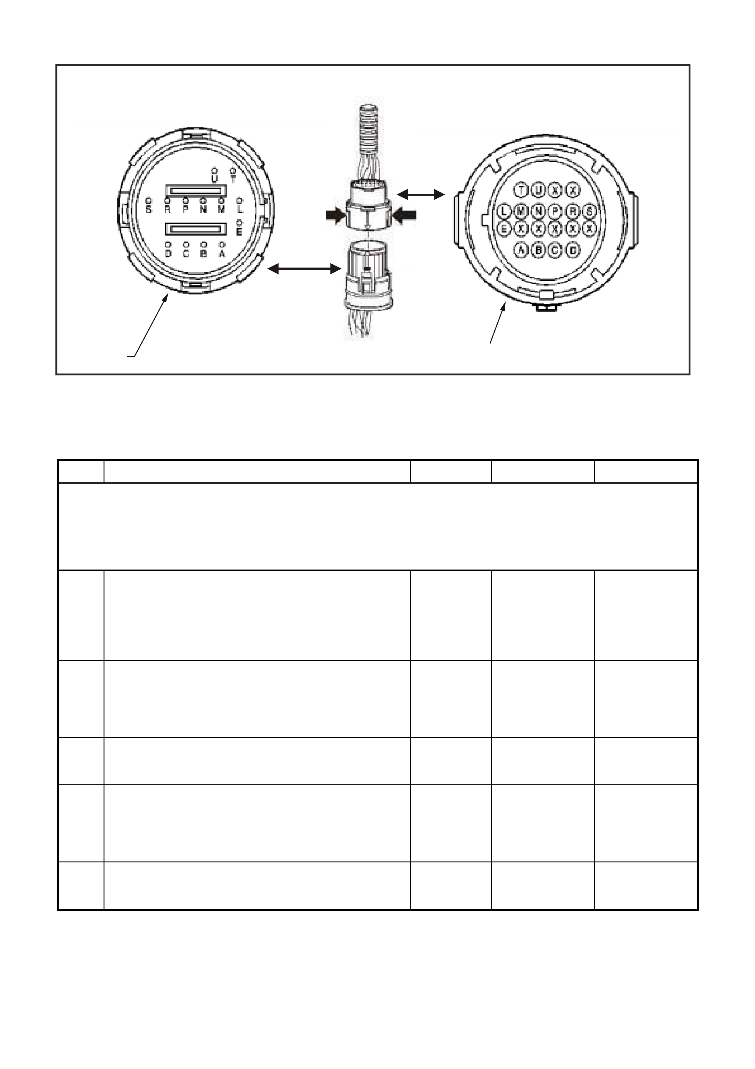
1. Automatic Transmission Wiring Harness Connector Engine Side YB 129.
2. Automatic Transmission Wiring Harness Connector Transmission Side YB129.
GEN III V8 PCM AUTOMATIC TRANSMISSION FLUID PRESSURE (TFP) VALVE POSITION
SWITCH RES ISTANCE CHE CK
Step Action Value(s) Yes No
IMPORTANT:
Whenever the transmission 20-way connector is disconnected and the engine is running, multiple DTCs will set. Be sure to
clear these codes when you are finished with this procedure.
This procedure tests the automatic Transmission Fluid Pressure (TFP) manual valve position switch circuits and the
automatic Transmission Fluid Temperature (TFT) sensor circuit. Do not use this procedure to test other automatic
transmission circuits. Refer to the Automatic Transmission Wi ring Harness Check in this Section.
1 1. Install the J 39775 jumper harness on the
transmission side of the 20-way connector.
2. Using the J 39200 digital multimeter (DMM) and the
J 35616 connector test adapter kit, measure the
resistance from terminal N to the transmission case.
Is the resistance greater than the specified value?
50 K ohm Go to Step 3 Go to Step 2
2 1. Disconnect the TFP manual valve position switch from
the A/T wiring harness assembly.
2. Measure the resistance from terminal C of the TFP
manual valve position switch to the switch housing.
Is the resistance greater than the specified value?
50 K ohm
Go to Step 16 Go to Step 19
3 Measure the resistance from terminal R to the
transmission case.
Is the resistance less than the specified value?
200 ohm
Go to Step 5 Go to Step 4
4 1. Disconnect the TFP manual valve position switch from
the A/T wiring harness assembly.
2. Measure the resistance from terminal E of the TFP
manual valve position switch to the switch housing.
Is the resistance less than the specified value?
200 ohm
Go to Step 16 Go to Step 19
5 Measure the resistance from terminal P to the
transmission case.
Is the resistance greater than the specified value?
50 K ohm
Go to Step 7 Go to Step 6
4372
1
2

Step Action Value(s) Yes No
6 1. Disconnect the TFP manual valve position switch from
the A/T wiring harness assembly.
2. Measure the resistance from terminal D of the TFP
manual valve position switch to the switch housing.
Is the resistance greater than the specified value?
50 K ohm
Go to Step 16 Go to Step 19
7 1. Start the engine.
2. Allow the engine to idle.
3. Set the parking brake.
4. Place the gear selector in R (reverse).
5. Measure the resistance from terminal N to the
transmission case.
Is the resistance less than the specified value?
200 ohm
Go to Step 8 Go to Step 16
8 1. Place the gear selector in 1 (first).
2. Measure the resistance from terminal N to the
transmission case.
Is the resistance less than the specified value?
200 ohm
Go to Step 9 Go to Step 16
9 1. Place the gear selector in 3 (third).
2. Measure the resistance from terminal R to the
transmission case.
Is the resistance greater than the specified value?
50 K ohm Go to Step 10 Go to Step 16
10 1. Place the gear selector in D (drive).
2. Measure the resistance from terminal P to the
transmission case.
Is the resistance less than the specified value?
200 ohm Go to Step 11 Go to Step 16
11 1. Place the gear selector in 2 (second).
2. Measure the resistance from terminal P to the
transmission case.
Is the resistance greater than the specified value?
50 K ohm Go to Step 12 Go to Step 16
12 1. Turn the ignition OFF.
IMPORTANT: The resistance of the TFT sensor is
temperature dependent, and therefore varies far more
than any other device. Refer to Transmission Fluid
Temperature Sensor in this Section.
2. Measure the resistance from terminal L to terminal M
(TFT sensor) of the J 39775 jumper harness.
Is the resistance within the specified range?
3088-3942
ohm @ 20°C
(68°F)
159-198 ohm
@ 100°C
(212°F)
Go to Step 13 Go to Step 14
13 1. Measure the resistance from terminal L to the
transmission case.
2. Measure the resistance from terminal M to the
transmission case.
Are both resistances greater than the specified value?
10 M ohm System OK Go to Step 14
14 1. Disconnect the TFP manual valve position switch from
the A/T wiring harness assembly.
IMPORTANT: The resistance of the TFT sensor is
temperature dependent, and therefore varies far more
than any other device. Refer to Transmission Fluid
Temperature Sensor in this Section.
2. Using the J 39200 DMM, measure the resistance
between terminal A and terminal B of the TFP manual
valve position switch (TFT sensor).
Is the resistance within the specified range?
3088-3942
ohm @ 20°C
(68°F)
159-198 ohm
@ 100°C
(212°F)
Go to Step 15 Go to Step 19

Step Action Value(s) Yes No
15 1. Measure the resistance from TFP manual valve
position switch terminal A to the transmission case.
2. Measure the resistance from TFP manual valve
position switch terminal B to the transmission case.
Are both resistances greater than the specified value?
10 M ohm Go to Step 16 Go to Step 19
16 1. Inspect for high resistance or a short:
Inspect the A/T wiring harness assembly for poor
electrical connections at the automatic transmission
20-way connector, and at the TFP manual valve
position switch. Look for the following conditions:
- A backed out terminal
- A damaged terminal
- Reduced terminal tension
- Moisture intrusion
- Corrosion
2. If diagnosing for an intermittent condition, massage
the wiring harness while watching the test equipment
for a change.
Did you find high resistance or a short?
Go to Step 1 Go to Step 17
17 1. Disconnect the TFP manual valve position switch from
the A/T wiring harness assembly.
2. Inspect the following circuits for an open or short:
- Circuit 1224
- Circuit 1225
- Circuit 1226
- Circuit 1227
Did you find an open or shorted condition?
Go to Step 18 Go to Step 19
18 1. Replace the A/T wiring harness assembly.
Refer to Section 7C4 Control Valve Body and Wiring
Harness Replacement in VX Service Information .
Is the replacement complete?
Go to Step 1
19 1. Replace the TFP manual valve position switch.
2. Refer to Section 7C4 Valve Body and Pressure Switch
Replacement in VX Service Information.
Is the replacement complete?
Go to Step 1
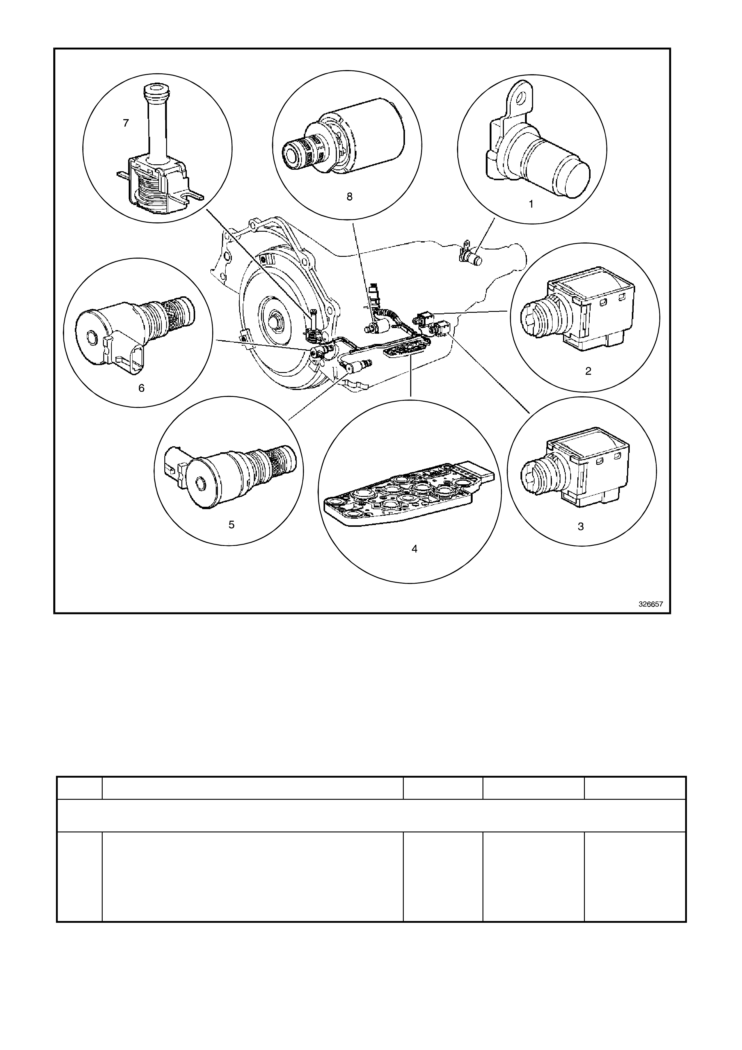
1. Vehicle Speed Sensor (VSS)
2. Shift Solenoid B (SS) Valve
3. Shift Solenoid A (SS) Valve
4. Automatic Transmission Fluid Pressure (TFP) Manual Valve Position Switch
5. Shift Solenoid (SS) Valve Assembly
6. Torque Converter Clutch Pulse Width Modulation (TCC PWM) Solenoid Valve
7. Torque Converter Clutch (TCC) Solenoid Valve
8. Pressure Control Solenoid (PCS) Valve
GEN III V8 PCM AUTOMATIC TRANSMISSION FUNCTIONAL CHECK PROCEDURE
Step Action Value(s) Yes No
The Functional Test Procedure is the first step in diagnosing mechanical or hydraulic transmission conditions and provides
procedures and references to the Symptom Diagnosis tables in this Section for specific diagnostic information.
1 IMPORTANT: Engine performance can greatly affect
transmission performance. Ensure that the complaint is
not the result of poor engine performance before
continuing.
Verify the customer complaint.
Has the customer complaint been verified?
Go to Step 2

Step Action Value(s) Yes No
2 IMPORTANT: Many transmissions have default actions
that take place once a DTC fault is detected. These
actions may be interpreted as being a transmission
concern.
Has the Powertrain On Board Diagnostic (OBD) System
Check been performed?
Go to Step 3 Go to Powertrain
OBD System
Check Table in
Section 6C3-2A
3 1. Perform a visual inspection. Look for the following
conditions:
- Vehicle damage
- Transmission oil pan damage. Refer to Section 7C4
On-Vehicle Servicing in VX Service Information .
- Worn or damaged suspension parts. Refer to
Section 3 Front Suspension, in VX Service
Information.
- Worn or damaged steering parts. Refer to Section
9A Steering, in VX Service Information.
- Transmission range selector linkage damaged or
out of adjustment. Refer to Section 7C4 Shift Cable
Adjustment in VX Service Information.
- Loose, worn, damaged or missing:
- mounts or struts
- brackets
- mounting hardware
Refer to Section 7C4 Transmission Assembly
Removal in VX Service Information.
2. Transmission cooler or cooler line restrictions. Refer
to Transmission Cooler Reverse Flush and Flow Rate
Check, Section 7C4 in VX Service Information.
3. Fluid leaks. Refer to Fluid Leak Checking Procedure,
Section 7C4 in VX Service Information.
Was an item identified that needs service?
Go to the
Appropriate
Repair or
Diagnosis
Section
Go to Step 4
4 Perform the Transmission Fluid Checking Procedure,
Section 7C3 in VX Service Information.
Is the procedure complete?
Go to Step 5 Go to
Transmission
Fluid Checking
Procedure in
Section 7C3 in
VX Service
Information
5 Perform the Road Test Procedure. Refer to Section 7C3
in VX Service Information.
Did the vehicle exhibit any objectionable condition?
Go to Step 6 System OK
6 Did the vehicle exhibit objectionable torque converter
operation? Go to Step 15 Go to Step 7

Step Action Value(s) Yes No
7 Did the vehicle exhibit a noise condition? Go to Symptom
Diagnosis Table
(Noise and
Vibration
Diagnosis) in
Section 7C3 in
VX Service
Information
Go to Step 8
8 Did the vehicle exhibit a vibration condition? Go to Step 9 Go to Step 10
9 Did the vibration occur only during TCC apply or release? Go to Step 15 Go to Symptom
Diagnosis Table
(Noise and
Vibration
Diagnosis) in
Section 7C3 in
VX Service
Information
10 Did the vehicle exhibit a shift speed condition such as
low or high shift speeds? Go to Symptom
Diagnosis Table
(Shift Speed
Diagnosis) in
Section 7C3 in
VX Service
Information
Go to Step 11
11 Did the vehicle exhibit any of the following shift quality
(feel) conditions?
• Harsh, soft, delayed or no engagement
• Harsh, soft or delayed shifts
• Shift shudder, flare or tie-up
Go to Step 12 Go to Step 13
12 Perform the Line Pressure Check Procedure . Refer to
Section 7C3 in VX Service Information.
Is the line pressure within specification?
Go to Symptom
Diagnosis Table
(Shift Quality
(Feel) Diagnosis)
in Section 7C3 in
VX Service
Information
Go to Symptom
Diagnosis Table
(Fluid Diagnosis)
in Section 7C3 in
VX Service
Information

Step Action Value(s) Yes No
13 Did the vehicle exhibit any of the following shift pattern
conditions?
• No upshift or downshift
• Only one or two forward gears
• No First, Second, Third or Fourth gear
• Slipping
• Non-first gear start
Go to Symptom
Diagnosis
(Shift Pattern
Diagnosis) in
Section 7C3 in
VX Service
Information
Go to Step 14
14 Did the vehicle exhibit any of the following range
performance conditions?
• No Park, Reverse or Drive
• No engine braking
• No gear selection
• Incorrect gear selection
Go to Symptom
Diagnosis Table
(Range
Performance
Diagnosis) in
Section 7C3 in
VX Service
Information
System OK
15 1. Refer to Torque Converter Diagnosis Procedure.
2. Did the vehicle exhibit any of the following TCC
conditions?
- Stuck on or off
- Early or late engagement
- Incorrect apply or release
- Soft or harsh apply
- Clunk or shudder
- No torque multiplication
- Excessive slip
- Poor acceleration
- Engine stalls
Go to Symptom
Diagnosis Table
(Torque
Converter
Diagnosis) in
Section 7C3 in
VX Service
Information
System OK