
SECTION 7C1 - HYDRA-MATIC 4L60-E AUTOMATIC
TRANSMISSION: GENERAL INFORMATION
IMPORTANT
Before p erforming any Serv ice Operation or oth er procedure described in t his Section, refer to Section
00 CAUTIONS AND NOTES for correct workshop practices with regard to safety and/or property
damage.
1. SECTION DESCRIPTIONS
A multi-Section approach to the Hydra-matic 4L60-E Automatic Transmission continues to be used for VX Series
vehicles.
SECTION 7C1: HYDRA-MATIC AUTOMA TIC TRANSMISSION: GENERAL INFORMATION
The purpos e of this Sec tion is to provide an over view of this automatic tr ansmission, by briefly describing what each
of the various sub-sections contains.
Essentially, the automatic transmission fitted to VX Series vehicles is a carry-over unit from the previous model.
Even so, an overview of the transmission features is provided here, that includes;
• A general description of the transmission, its operation and control, as well as transmission identification
information.
• A glossary of generic terms that are used
• Some notes that address safe workshop practices
• Service notes relating to fasteners and consumable items used at various stages throughout this Section.
SECTION 7C2 HYDRA-MATIC AUTOMATIC TRANSMISSION:- ELECTRICAL DIAGNOSIS
As the electrical systems and diagnosis for this transmission are controlled by the Powertrain Control Module
(PCM), this material is included in Section 6C1 (V6 Engine and V6 Supercharged engine) and
Section 6C3 (GEN III V8 engine) POWERTRAIN MANAGEMENT, in the VX Series Service Information.
SECTION 7C3 HYDRA-MATIC AUTOMATIC TRANSMISSION:- GENERAL DIA GNOSIS
As distinc t f r om sect ion 7C2, this Sec tion c ontains inf or mation that will assist in the diagnos is of the m ec hanic al and
hydraulic components in the 4L60-E automatic transmission.
SECTION 7C4 HYDRA-MATIC AUTOMATIC TRANSMISSION:-ON-VEHICLE SERVICING
For VX Series vehicles, this Section details changes to either update procedures or detail changes that affect the
servicing of the transmission.
SECTION 7C5 HYDRA-MATIC AUTOMATIC TRANSMISSION:-UNIT REPAIR
Section 7C5 for VX Series vehicles has been updated and is reproduced in its entirety to reflect recent internal
changes to the transmission. These procedures detail the disassembly, inspection, overhaul and assembly
operations of the mechanical components, once the transmission is removed from the vehicle. Also included is
information relating to the measurement of certain clearances, the correct use of special tools and torque
specifications required for reassembly.
Techline
Techline

2. TRANSMISSION OPERATION - OVERVIEW
2.1 GENERAL DESCRIPTION
The Hydra-matic 4L60-E is a fully automatic, four speed, rear wheel drive transmission. It consists primarily of a four
element torque converter, two planetary gear sets, various clutches, an oil pump and a control valve body.
The four elem ent torque converter contains a pum p, a turbine, a pressure plate splined to the turbine and a stator
assembly. The torque converter acts as a fluid coupling to transmit power smoothly from the engine to the
transmission. It also hydraulically provides additional torque multiplication when required. When applied, the
pressure plate provides a mechanical, locked coupling of the engine to the transmission.
The two planetary gear sets provide the four forward gear ratios and reverse. Changing of the gear ratios is fully
automatic and is accomplished through the use of various electronic sensors that provide input signals to the
Powertrain Control Module (PCM). The PCM inter prets thes e signals to send c urrent to the var ious solenoids inside
the transmission.
By using electronics, the PCM controls shift points, shift feel and torque converter clutch apply and release, to
provide proper gear ranges for maximum fuel economy and vehicle performance.
Five m ultiple-dis c clutc hes, one roller clutch, a s prag clutch and a brak e band provide the f riction elem ents required
to obtain the various ratios with the planetary gear sets.
An hydraulic system (the control valve body), pressurised by a vane type pump, provides the working pressure
needed to operate the clutch pistons, band servo and automatic controls.
The general arrangement of both the majority of mechanical and hydraulic components is shown in the sectioned
view, Fig. 7C1-1.
With traditional, hydraulically controlled transmissions, the gear shifts are controlled by the opposing pressures of
hydraulic fluid in a complex system of spring-loaded valves. In this electronically controlled Hydra-matic 4L60-E
transmission, gear shift points and shift feel are determined by electrical signals sent from the Powertrain Control
Module (PCM).
The PCM proc ess es data every 25 millisec onds f rom various sensor s, such as throttle position, vehicle speed, gear
range, temperature, engine load, barometric pressure and other inputs. Using this data, a signal is transmitted to
the valve body shift solenoids, which activate the shift valves for precise shift control. Shift points are therefore
precisely controlled and are identical from vehicle to vehicle.
Shift feel is also elec tronica lly controlled by the PCM, by signals sent to the Var iable Force Solenoid, which c ontrols
fluid line pres sur e and it is this pres s ure that prec is ely determines how the shif ts will feel. In this way, the Powertrain
Control Module (PCM) electronically synchronises the engine and transmission into a single, integrated powertrain
system, for optimum performance, shift timing, fuel efficiency and emission control.
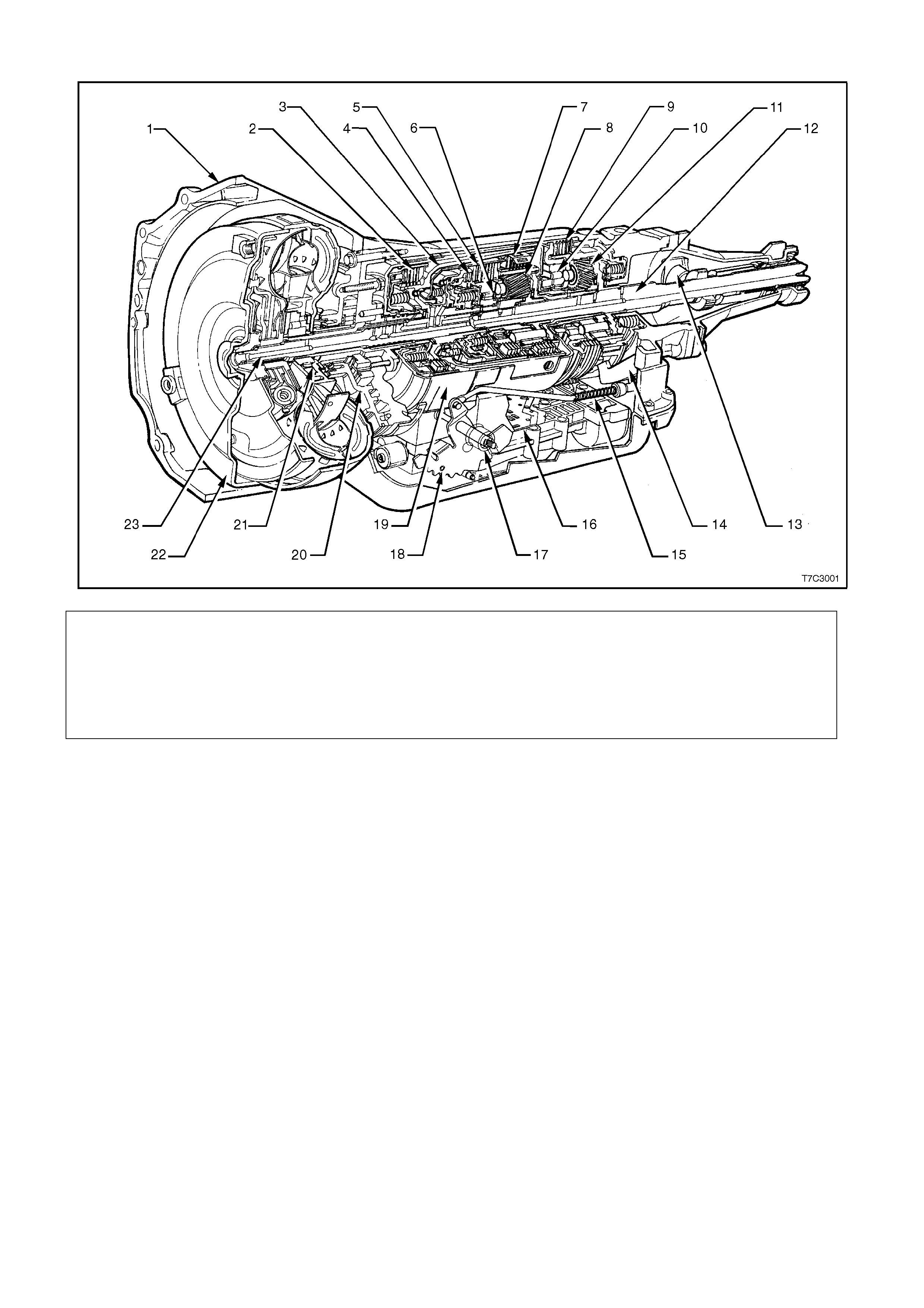
Legend
1. Case As sembly 9. Low and Reverse Clutch 17. Manual Shaft
2. Reverse Input Cl utch 10. Low Roller Clutch As sembly 18. Inside Detent Lever
3. Input Clut ch Housing 11. Reaction Planetary Gear Set 19. 2 - 4 Band Assembly
4. Overrun Clutch 12. Output Shaft 20. Pump Assembly
5. Forward Clutch 13. Speed Sensor 21. Stator Rol l er Cl utch
6. Forward Clutch Sprag Assembl y 14. Parking Pawl 22. Torque Converter Assembly
7. 3 - 4 Clutch 15. Parking Lock Actuator Assembl y 23. Turbine Shaft
8. Input Pl anetary Gear Set 16. Control Valve As sembly
Figure 7C1-1
TRANSMISSION IDENTIFICATION
An Adhesive label is attached to the upper surface of the central case section of the transmission case and also
stamped into a machined surface at the rear, underside of the transmission centre case as shown next.
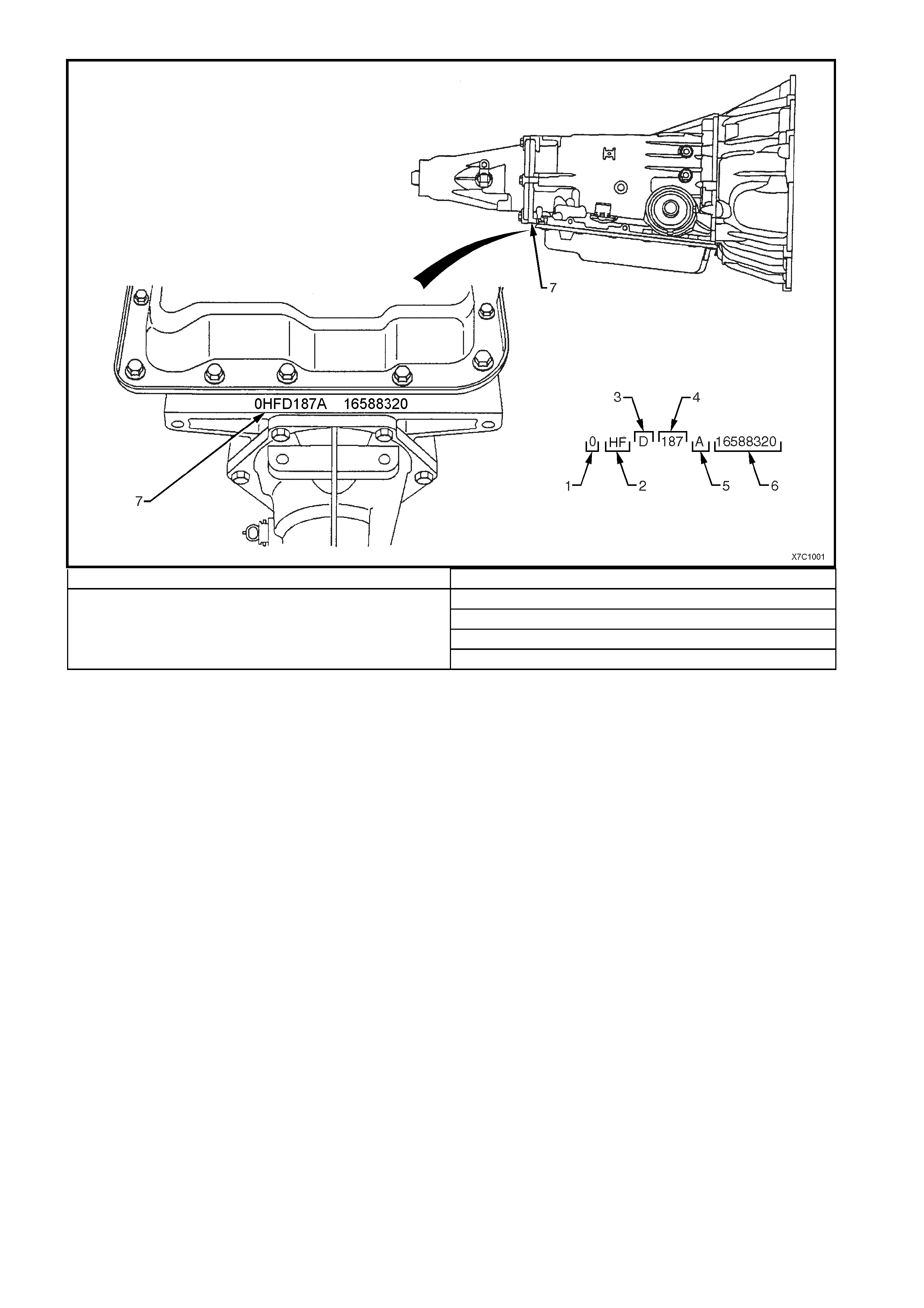
1. Model Year (‘0’ = 2000) 3. Transmission Model Identifier (‘D’ = 4L60-E)
4. Julian Date (or Day of the Year)
5. Shift Built (A, B, J = First Shift; C, H, W = Second Shift
6. Individual Transmission Serial Number
2. Model:
V6 - 3.8 litre............................................... HF
V6 Supercharged....................................... HN
GEN III V8 ................................................. HP 7. Transmission Identification Number Location
Figure 7C1-2
Reference to Fig. 7C-3, shows the application of the various components that are applied in each of the available
modes.
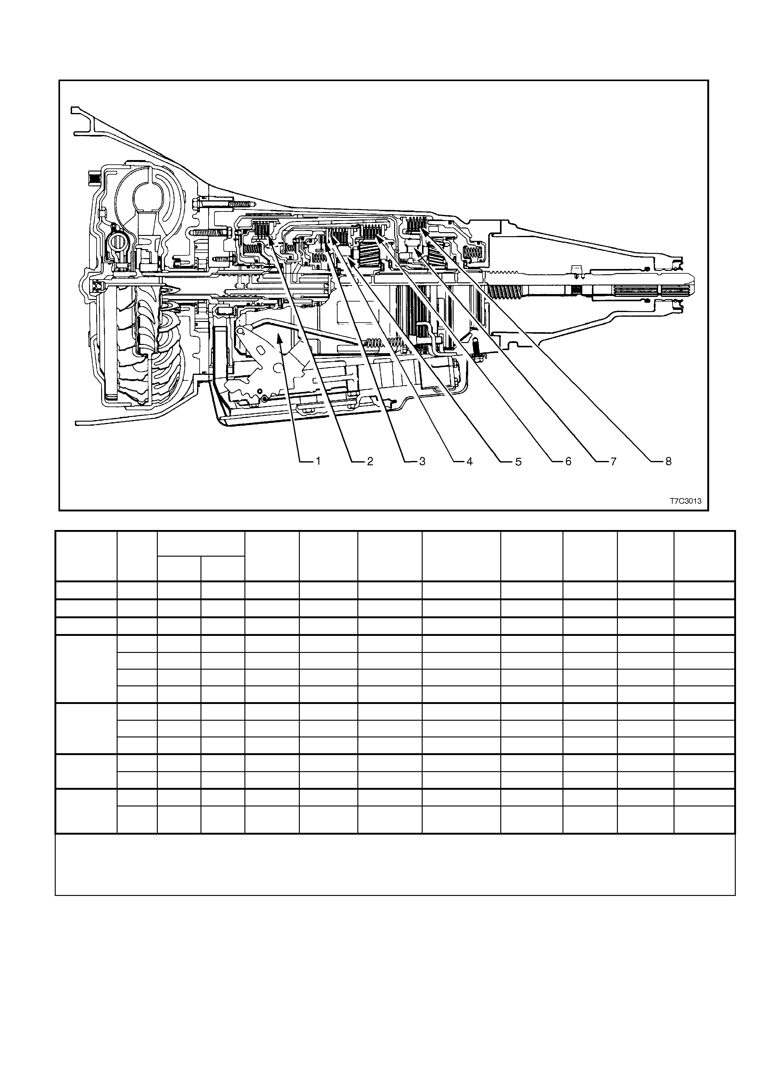
RANGE REFERENCE CHART
RANGE GEAR SHIFT
SOLENOID 2-4 BAND REVERSE
INPUT OVERRUN
CLUTCH FORWARD
CLUTCH FORWARD
SPRAG CL. 3-4
CLUTCH LOW/
ROLLER LOW/
REVERSE
1 - 2
2 - 3 (#1) CLUTCH
(#2) (#3) (#4) ASSEMBLY
(#5) (#6) CLUTCH
(#7) CLUTCH
(#8)
PARK On * On * APPLIED
REVERSE On * On * APPLIED APPLIED
NEUTRAL On * On *
1ST On On APPLIED HOLDING HOLDING
d 2ND OFF On APPLIED APPLIED HOLDING
3RD OFF OFF APPLIED HOLDING APPLIED
4TH On OFF APPLIED APPLIED APPLIED
1ST On On APPLIED HOLDING HOLDING
3 2ND OFF On APPLIED APPLIED HOLDING
3RD OFF OFF APPLIED APPLIED HOLDING APPLIED
2 1ST On On APPLIED APPLIED HOLDING HOLDING
2ND OFF On APPLIED APPLIED APPLIED HOLDING
1 1ST On On APPLIED APPLIED HOLDING HOLDING APPLIED
2ND
** OFF On APPLIED APPLIED APPLIED HOLDING
* SHIFT SOLENOID STATE IS A FUNCTION OF VEHICLE SPEED AND MAY CHANGE IF A VEHICLE SPEED INCREASES
SUFFICIENTLY IN PARK, REVERSE OR NEUTRAL. HOWEVER, THIS DOES NOT AFFECT TRANSMISSION OPERATION.
** IN MANUAL FIRST, SECOND GEAR IS ONLY AVAILABLE ABOVE APPROXIMATELY 70 KM/H TO PREVENT ENGINE
OVERSPEEDING.
Figure 7C1-3

3. TRANSMISSION DEFI NI TIONS AND ABBREVIATIONS
The following definitions and abbreviations are provided to establish a common language and assist the user in
describing transmission related conditions. The use of these terms and/or conditions can be found in the various
parts of the automatic transmission section of the VX Series Service Information, but more particularly, in
Section 7C3 HYDRAULIC/MECHANICAL DIAGNOSIS in VT Series I Service Information.
3.1 DEFINITIONS
The following definitions have been arranged in alphabetical order and are intended to assist the user with an
explanation of their m eaning, in order to gain the max imum benefit from those Sections of this Service Inform ation
CD that deal with the Hydra-matic 4L60-E, automatic transmission. There are additional, unique definitions in
Section 7C3 HYDRAULIC/MECHANICAL DIAGNOSIS that should also be referred to when using that particular
information.
Accumulator - A component of the transmission that absorbs hydraulic pressure during the apply of a clutch or
band. Accumulators are designed to control the quality of a shift from one gear range to anther. within
Adaptive Learning - Programming within the PCM that automatically adjusts hydraulic pressures in order to
compensate for changes in the transmission (i.e. component wear).
Applied - An 'Apply Component' that is holding another component to which it is splined or assembled to. Also
referred to as "engaged".
Apply Components - Hydraulically operated clutches, servo’s, bands and mechanical one-way roller or sprag
clutches that drive or hold members of a planetary gear set.
Apply Plate - A steel clutch plate in a clutch pack, located next to the (apply) piston.
Backing Plate - A steel plate in a c lutch pack that is usually the last plate in that clutch ass em bly (furthest f rom the
clutch piston).
Band - An apply component that cons ists of a flex ible strip of steel and f riction mater ial that wraps around a drum.
When applied, it tightens around the drum and prevents the drum from rotating.
Brake Switch - An electrical device that provides signals to the Powertrain Control Module (PCM), based on the
position of the brake pedal. The PCM uses this information to apply or release the torque converter clutch (TCC).
Centrifugal Force - A force that is imparted on an object (due to rotation) that increases as that object moves
further away from a centre-point of rotation.
Checkball - A spherical, hydraulically controlled component (usually of steel) that either seals or opens fluid circuits.
It is also referred to as a check valve.
Clutch Pack - An assembly of components generally consisting of clutch plates, an apply plate and a backing plate.
Clutch Plate - An hydraulically activated component that has two basic designs : ( 1) all s teel, or ( 2) a s teel c or e with
friction material bonded to one or two sides of the plate.
Control Valve Body - A machined metal casting that contains valve trains and other hydraulically controlled
components that shift the transmission.
Coupling Speed - The speed at which a vehicle is travelling and no longer requires torque multiplication through
the torque converter. At this point, the stator 'free wheels' to allow fluid leaving the turbine to flow directly to the
pump. (Also see Torque Converter).
De-energise(d) - To interrupt the electrical current that flows to an electronically controlled device, making it
electrically inoperable.
Direct Drive - A condition in a gears set where the input speed and input torque equals the output speed and output
torque. The gear ratio through the gear set is 1:1.
Downshift - A change in a gear ratio where both input speed and torque increases.
Duty Cycle - In reference to an electronically controlled solenoid, it is the amount of time (expressed as a
percentage) that current flows through the solenoid coil.
Energise(d) - To supply a current to an electronically controlled device, enabling it to perform its designed function.
Engine Compression Braking - A condition where compression f rom the engine is used with the transmission to
decrease vehicle speed.
Exhaust - The release of fluid pressure from a hydraulic circuit. (The words 'exhausts' and 'exhausting' are also
used and have the same intended meaning.)
Fail-Safe Mode - A condition whereby a component (i.e. engine or transmission) will partially function even if its
electrical circuit is disabled.
Fluid - In this Section of the VX Series Service Inform ation, 'fluid' refers primarily to Autom atic Transm ission Fluid
(or ATF) and, for the Hydra-matic 4L60-E transmission, the only recommended fluid is Dexron III®.
Fluid Pressure - A pressure that is consistent throughout a given fluid circuit.

Force - A measurable effort that is exerted on an object (component).
Freewheeling - A condition where power is lost through a driving or holding device (i.e. roller or sprag clutches).
Friction Material - A heat and wear resistant fibrous material, bonded to clutch plates and bands.
Gear - A round, toothed device that is used for transmitting torque through other components.
Gear Range - A specific speed to torque ratio at which the transmission is operating (i.e. 1st gear, 2nd gear etc.).
Gear Ratio - Revolutions of an input gear as compared to the revolutions of an output gear. It can also be
expressed as the number of teeth on a gear as compared to the number of teeth on a gear that it is in mesh with.
Hydraulic Circuit - A fluid passage which often includes the mechanical components in that circuit designed to
perform a specific function.
Input - A starting point for torque, revolutions or energy into another component of the transmission.
Internal Gear - The outer m ost m em ber of a gear s et that has gear teeth in c onstant m esh with the planetary pinion
gears of the gear set.
Land (Valve Land) - The larger diameters of a spool valve that contact the valve bore or bushing.
Line Pressure - The main fluid pressure in a hydraulic system created by the pump and pressure regulator valve.
Manual Valv e - A spool valve that distributes fluid to various hydraulic circuits and is mechanically linked to the gear
sele ctor lever.
Orifice - A restricting device (usually a hole in the spacer plate) for controlling pressure build up into another circuit.
Overdrive - An operating condition in the gear set allowing output speed to be higher than input speed and output
torque to be lower than input torque.
Overrunning - The function of a one-way mechanical clutch that allows the clutch to freewheel during certain
operating conditions of the transmission.
Pinion Gears - Pinion gears ( housed in a car rier) that ar e in constant m es h with a circum f erential internal gear and
centralised sun gear.
Planetary Gear Set - An ass em bly of gears that consis ts of an internal gear, planet pinion gears with a carrier, and
a sun gear.
Powertrain Control Module (PCM) - An electronic device that manages the vehicle's engine and automatic
transmission functions.
Pressure - A measurable force that is exerted on an area and expressed as kilopascals (kPa).
Pulse Width Modulated (PWM) - An electronic signal that continuously cycles the ON and OFF time of a device
(such as a solenoid) while varying the amount of ON time.
Race (Inner or Outer) - A highly polished steel surface that contacts bearings or sprag or roller elements.
Reduction (Gear Reduction) - An oper ating condition in the gear set allowing output speed to be lower than input
speed and output torque to be higher than input torque.
Residual Fluid Pressure - Excess pressure contained within an area after the supply pressure has been
terminated.
Roller Clutch - A mechanical clutch (holding device) consisting of roller bearings assembled between inner and
outer races.
Servo - A spring loaded device consisting of a piston in a bore that is operated (stroked) by hydraulic pressure to
apply or release a band.
Spool Valve - A round hydraulic control valve often containing a variety of land and valley diameters.
Sprag Clutch - A mechanical clutch (holding device consisting of "figure eight" like elements assembled between
inner and outer races.
Throttle Position - The travel of the throttle plate that is expressed in percentages and measured by the Throttle
Position Sensor (TP Sensor).
Torque - A measurable twisting force expressed in terms of Newton metres (Nm).
Torque Converter - A component of an automatic transmission, (attached to the engine flexplate) that transfers
torque from the engine to the transmission through a fluid coupling.
Variable Capacity Pump - The device that provides fluid for operating the hydraulic circuits in the transmission.
The amount of fluid supplied varies depending on vehicle operating conditions.

3.2 ABBREVIATIONS
PCM – Powertrain Control Module.
CPL – Check Powertrain Lamp.
TCC – Torque Converter Clutch.
TP Sensor – Throttle Position Sensor.
ECT Sensor – Engine Coolant Temperature Sensor.
VS Sensor – Vehicle Speed Sensor.
TFP VAL. POSITION SW. – Transmission Fluid Pressure Manual Valve Position Switch
RWD – Rear Wheel Drive.
2WD – Two Wheel Drive.
PSA – Transmission Fluid Pressure Switch Assembly.
TTS – Transmission Temperature Sensor.

4. SERVICE NOTES
In the interests of safety to personnel, equipm ent and to the vehicle and its com ponents, the following notes should
be read and adhered to whenever servicing operations are to be carried out on the Hydra-matic 4L60-E automatic
transmission. In addition, s ome of this inf or mation also ref er s to the adher enc e to sound workshop prac tices and, to
achieve the design life of affected components, it is also recommended that these points are taken into account.
4.1 FASTENERS
• Always reinstall fasteners at the same locations as they were removed.
• If a fastener requires replac ement, always use a part of the cor rect part num ber or of equal size and strength or
stronger.
• Tighten fasteners to correct torque value when required. Torque values are specified for dry, unlubricated
fastener threads.

4.2 GENERAL WORKSHOP PRACTICE
• Keep work area and tools clean.
• To avoid unnecessary contamination, always clean the exterior of the transmission before removing any parts.
• Do not use wiping cloths or rags because of the risk of lint being trapped in the transmission.
• Do not use solvents on:
− neoprene seals.
− composition faced clutch plates.
− thrust washers.
• Always use protective eye wear when using compressed air on components.
• Blow out all passages with compressed air. Only probe small passages with soft, thin wire.
• Handle parts with care to avoid nicks and scratches.
• Do not remove Teflon oil seal rings unless damaged or performing a complete overhaul.
• Expand internal snap rings and compress external snap rings to maximise retention and security.
• Lubricate all internal parts with transmission fluid (Only use Dexron III), as they are being installed.
• When installing cap screws into aluminium castings:
− always use a torque wrench.
− always dip screw threads in transmission fluid (Only use Dexron® III).
− Stripped or damaged threads in aluminium castings may be reconditioned by using commercially available
thread inserts.
• Once removed, replace all gaskets, seals and O-rings with new parts and:
− always use seal protectors where indicated and do not use gasket cement or sealant on any joined face
unless specified to do so.