
SECTION 0A - GENERAL INFORMATION
IMPORTANT
Before performing any Service Operation or other procedure described in this Section, refer to Section
00 CAUTIONS AND NOTES for correct workshop practices with regard to safety and/or property damage.
1. GENERAL INFORMATION
1.1 VX SERIES II MODELS
1.2 VU SERIES II MODELS
1.3 MY2002 WH SERIES II MODELS
1.4 MY2003 WH SERIES II UPDATE
2. MODEL AVAILABILITY AND BASE
EQUIPMENT
3. POWERTRAIN COMBINATIONS
4. TRANSMISSION RATIOS
5. ENGINE DATA
6. EXTERIOR DIMENSIONS
7. VEHICLE WEIGHTS
8. SERIAL NUMBERS
8.1 LOCATION OF IDENTIFICATION PLATES
8.2 SAFETY COMPLIANCE PLATE
8.3 BODY AND OPTION IDENTIFICATION PLATE
8.4 FUEL CONSUMPTION LABEL
8.5 VEHICLE IDENTIFICATION NUMBER
PLATE LOCATION
8.6 VEHICLE IDENTIFICATION
NUMBERING SYSTEM
MY2002 VX/VU/WH SERIES II MODELS
MY2003 WH SERIES II MODELS
8.7 ENGINE SERIAL NUMBER
8.8 MANUAL TRANSM ISSION SERIAL NUMBER
V6 ENGINE – 5 SPEED
GEN III V8 ENGINE – 6 SPEED
8.9 AUTOMATIC TRANSMISSION
SERIAL NUMBER
MY2002 VX/VU/WH SERIES II MODELS
MY2003 WH SERIES II MODELS
8.10 FINAL DRIVE IDENTIFICATION
9. ADDITIONAL GENERAL INFORMATION
9.1 ELECTRICAL TRANSIENTS AND
RADIO FREQUENCY INTERFERENCE
ELECTRICAL TRANSIENTS
RADIO FREQUENCY INTERFERENCE
9.2 STATIC ELECTRICITY
9.3 PUSH OR TOW STARTING
10. CONSOLI DATED TOOL LIST
MY2002 VX/VU/WH SERIES II MODELS
MY2003 WH SERIES II MODELS
Techline
Techline
Techline
Techline
Techline
Techline
Techline

1.GENERAL I NFORMATI ON
1.1 VX SERIES II MODELS
All Series II Models ( Produc tion Option A9W) are an ornamentation and trim update of the VX, VU and WH Series
Models.
The following items have been updated in VX Series II Models:
• The engine bay fuse and relay panel has been revised.
• Executive and Acclaim Models are fitted with a new grille and/or paint treatment and new covers on steel
wheels.
• Berlina and Calais Models are fitted with modif ied grille with new paint or chrom e treatment and new badges
repositioned above the decor panel.
• Anthracite trim to replace pewter.
• Low pile velour bolster fabric for seats.
• New steering column switches.
• New colour coded leather seat options for S, SS and Calais Models in a variety of colours.
• Berlina Models are fitted with the twilight sentinel as fitted to VX Series Calais.
• Calais Models are fitted with a boot luggage net similar to that fitted to WH Series Models.
• New fuel pump for vehicles fitted with normally aspirated V6 engine.
• Executive, Acclaim, S and SS Models are fitted with the audible alarm as fitted to VX Series Calais.

1.2 VU SERIES II MODELS
The following items have been updated in VU Series II Models:
• The engine bay fuse and relay panel has been revised.
• Anthracite trim to replace pewter.
• Low pile velour bolster fabric for seats.
• New steering column switches.
• New fuel pump for vehicles fitted with normally aspirated V6 engine.
• New grille and/or paint treatment and new covers for steel wheels.
• S and SS are fitted with the audible alarm as fitted to VX Series Calais.
• New colour coded leather seat options for S and SS Models in a variety of colours.

1.3 MY2002 WH SERIES II MODELS
The following items have been updated in WH Series II Models:
• The engine bay fuse and relay panel has been revised.
• New alloy wheels for Statesman and Caprice.
• New more formal grille design for Statesman.
• Revised badging, nameplates and decals.
• Revised chrome treatment on drip and belt mouldings.
• New chrome licence plate surround.
• Revised headlamp housing and reflector.
• The three passenger rear seat previously standard on Statesman is now also standard on Caprice and the two
passenger rear seat is now optional.
• New steering wheel with woodgrain inserts.
• Revised instrument cluster graphics and background.
• New anthracite and two-tone shale trim.
• Caprice is fitted with new stainless steel rocker panel covers.
• Revised pattern and colour for woodgrain components.
• Multi-link rear suspension standard.
• Level ride suspension available as option only.
• The 2003 Model Year update was introduced during October 2002.

1.4 MY2003 WH SERIES II UPDATE
The MY2003 WH Series II update is a minor mechanical upgrade of the MY2002 WH Series II. The major
changes to the MY2003 WH Series II are:
• New condenser, radiator and cooling fans fitted to all Models.
• New engine cooling vent hose and radiator outlet hose fitted to all Models with the GEN III V8 engine.
• New radiator inlet hose fitted to all Models with the V6 or V6 Supercharged engines.
• New air conditioning discharge hose fitted to all Models.
• New air conditioning liquid line fitted to all Models.
• New power steering fluid cooler with extra fins fitted to all Models with GEN III V8 engine.
• Revised automatic transmission with new force motor and quick connect fittings for all Models with the V6 or
V6 Supercharged engine.
• New heavy-duty automatic tr ansmiss ion with revis ed 3- 4 clutc h, new for ce motor and quic k connec t f ittings f or
all Models with the GEN III V8 engine.
• Revised side and floor panels for improved occupant protection.
• Modified floor carpet and deadener to accommodate the revisions to the side and floor panels.
• New load limiting seat belts for improved occupant safety.
• A revised Vehicle Identification Numbering (VIN) System.

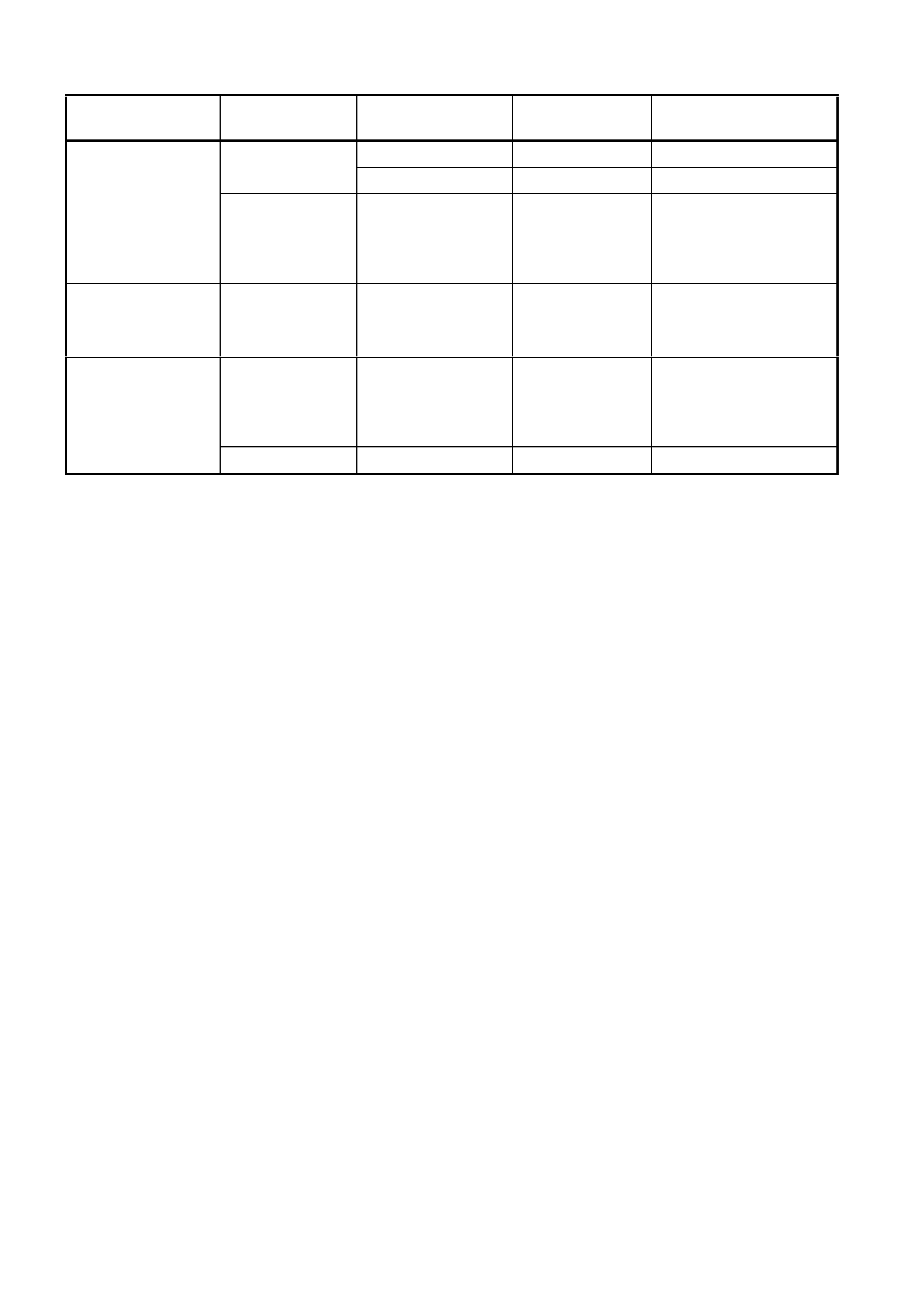
2. MODEL AVAILABILITY AND BASE EQUIPMENT
MODEL
NAME BODY
STYLE MODEL
CODE
NUMBER
OF
DOORS ENGINE TRANSMISSION
TYPE
FINAL
DRIVE
RATIO
Executive Sedan 8VK69 Four 3.8 SEFI V6 5 SPEED
MANUAL 3.08:1
Executive Wagon 8VK35 Four 3.8 SEFI V6 5 SPEED
MANUAL 3.07:1
Utility Utility 8VK80 Two 3.8 SEFI V6 5 SPEED
MANUAL 3.08:1
Acclaim Sedan 8VK69 Four 3.8 SEFI V6 4 SPEED
AUTOMATIC 3.08:1
Acclaim Wagon 8VK35 Four 3.8 SEFI V6 4 SPEED
AUTOMATIC 3.07:1
S Sedan 8VK69 Four 3.8 SEFI V6 5 SPEED
MANUAL 3.08:1
S Utility 8VK80 Two 3.8 SEFI V6 5 SPEED
MANUAL 3.08:1
SS Sedan 8VK69 Four 5.7 SEFI V8 6 SPEED
MANUAL 3.46:1
SS Utility 8VK80 Two 5.7 SEFI V8 6 SPEED
MANUAL 3.46:1
Berlina Sedan 8VL69 Four 3.8 SEFI V6 4 SPEED
AUTOMATIC 3.08:1
Berlina Wagon 8VL35 Four 3.8 SEFI V6 4 SPEED
AUTOMATIC 3.08:1
Calais Sedan 8VX69 Four 3.8
S/CHARGED
V6
4 SPEED
AUTOMATIC 3.07:1
Statesman Sedan 8W Y19 Four 3.8 SEFI V6 4 SPEED
AUTOMATIC 3.08:1
Caprice Sedan 8WZ19 Four 5.7 SEFI V8 4 SPEED
AUTOMATIC 3.07:1
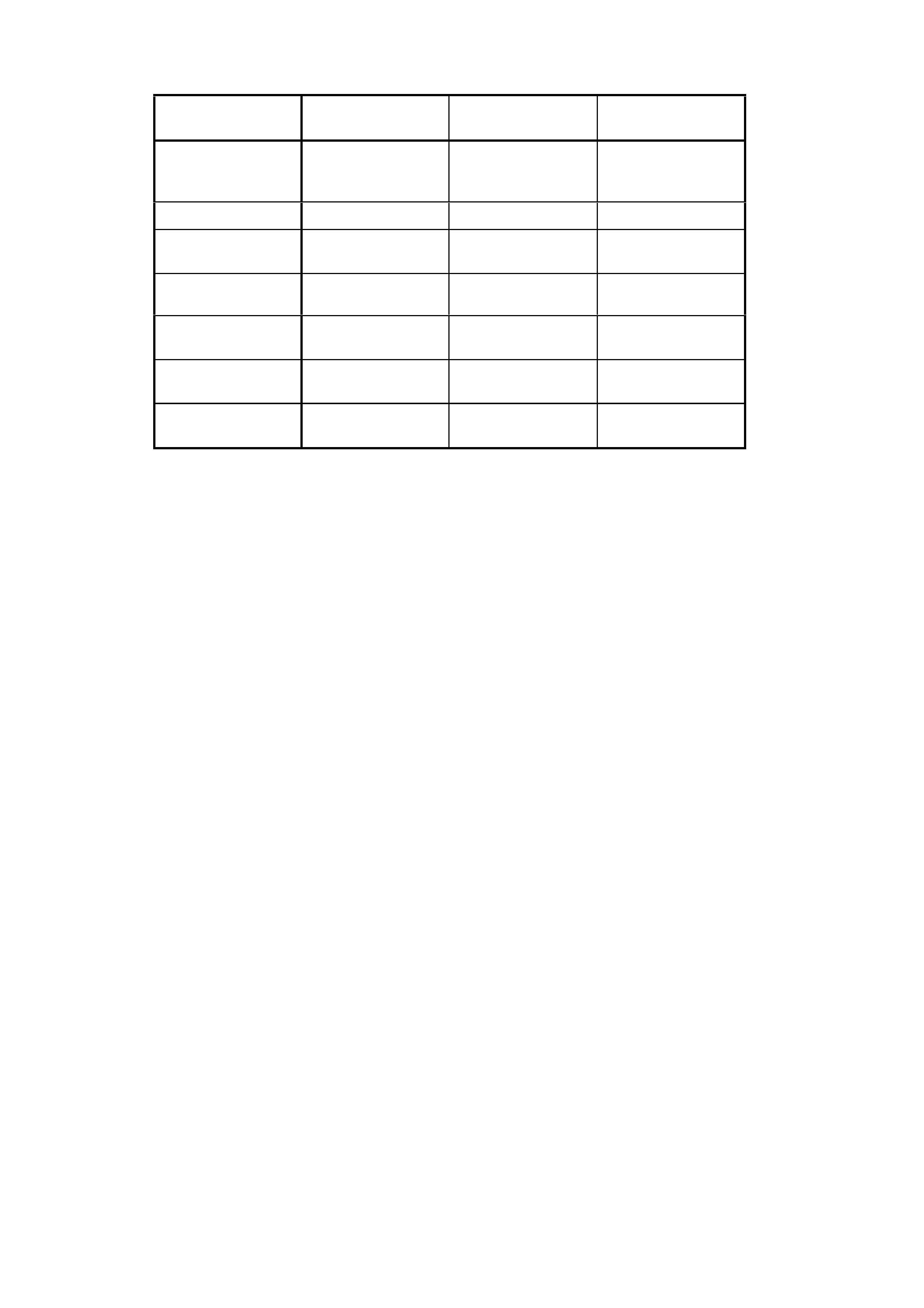
3. POWERTRAIN COMBINATIONS
ENGINE TRANSMISSION
TYPE MODEL
AVAILABILITY FIRST GEAR
RATIO FINAL DRIVE RATIO
Utility 3.83:1 3.46:1
5 Speed Manual Executive 3.83:1 3.08:1
3.8 LITRE PFI V6
4 Speed Automatic
Executive
Berlina
Calais
Statesman
Caprice
3.06:1 3.08:1
3.8 LITRE PFI V6
SUPERCHARGED 4 Speed Automatic Berlina
Calais
Statesman
Caprice
3.06:1 3.07:1
4 Speed Automatic
Executive
Berlina
Calais
Statesman
Caprice
3.06:1 3.07:1
5.7 LITRE PFI
GEN III V8
6 Speed Manual Executive 2.66:1 3.46:1

4. TRANSMISSION RATIOS
5 SPEED
MANUAL 6 SPEED
MANUAL 4 SPEED
AUTOMATIC
V6 engine only V8 engine only V6 & V8 engine
1ST 3.829:1 2.66:1 3.06:1
2ND 2.199:1 1.78:1 1.63:1
3RD 1.401:1 1.30:1 1.000:1
4TH 1.00:1 1.00:1 0.70:1
5TH 0.809:1 0.74:1 -
6TH - 0.50:1 -
REV 3.456:1 2.90:1 2.29:1
5. ENGINE DATA
ENGINE
DESIGNATION 3.8 LITRE PFI 3.8 LITRE
SUPERCHARGED 5.7 LITRE PFI
GEN III V8
Piston
Displacement
Nom. - cm3 3791 3791 5667
Compression Ratio 9.4:1 8.5:1 10.1:1
Number of
Cylinders 6 6 8
Bore x Stroke mm 96.5 X
86.3 96.5 X
86.3 99 X 92
Taxable H.P.
RAC OR SAE 34.7 34.7 48.6
Power kW
DIN @ RPM 152 kW @ 5200 171 kW @ 5200
PULP* 225 kW @ 5200
Torque Nm
DIN @ RPM 305 Nm @ 3600 375 Nm @ 3000
PULP* 460 Nm @ 4400
*PULP – Premium Unleaded Petrol
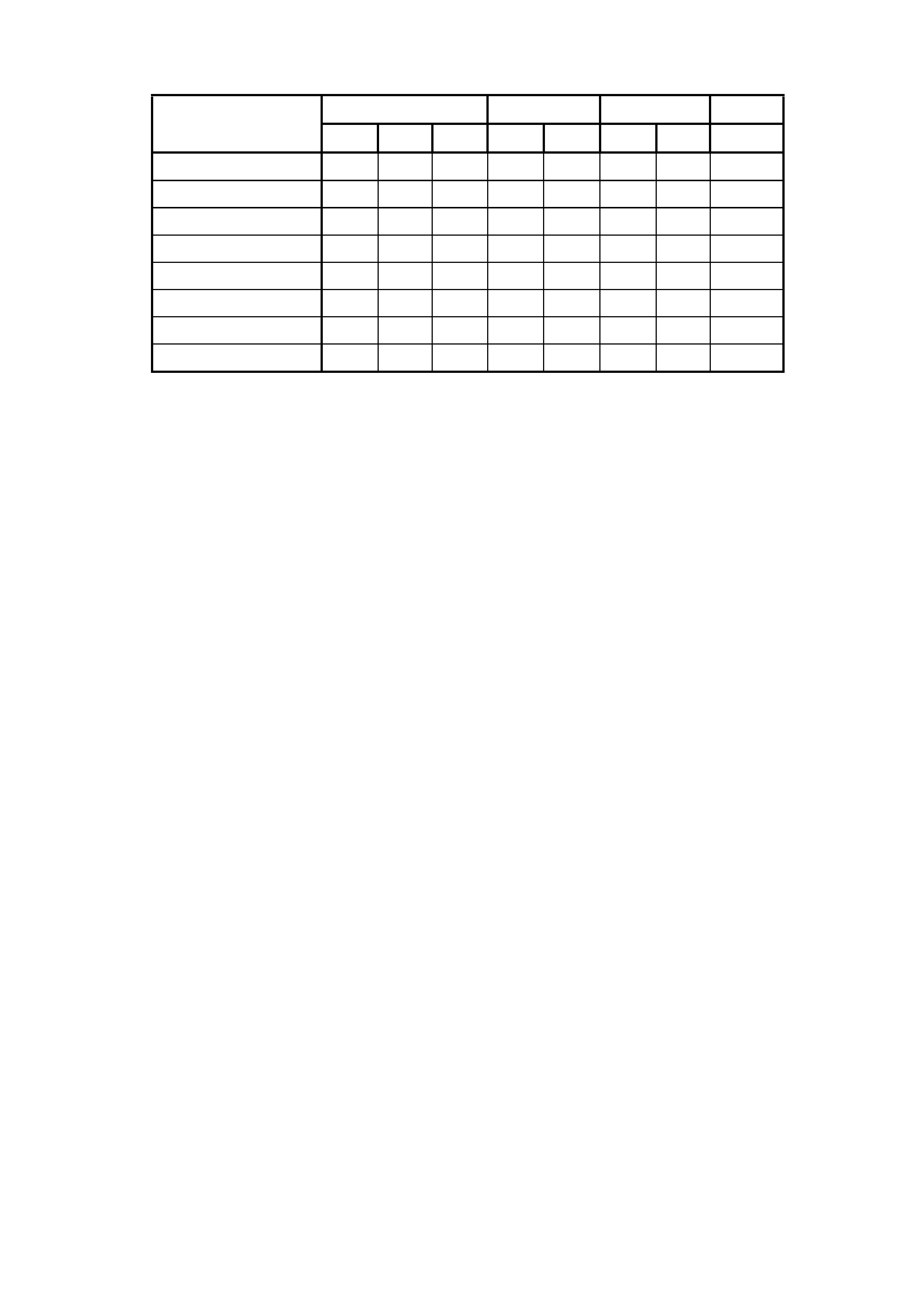
6. EXTERIOR DIME NSI O NS
SWB SEDAN LWB SEDAN WAGON UTILITY
BODY DIMENSIONS 8VK69 8VL69 8VX69 8WY19 8WZ19 8VK35 8VL35 8VK80
VEHICLE LENGTH 4891 4964 4964 5237 5237 5046 5046 5049
VEHICLE WIDTH 1824 1824 1824 1845 1845 1824 1824 1845
VEHICLE HEIGHT 1425 1425 1425 1459 1459 1521 1521 1484
WHEELBASE 2788 2788 2788 2939 2939 2939 2939 2939
OVERHANG - FRONT 933 972 972 986 986 933 972 933
OVERHANG - REAR 1169 1203 1203 1312 1312 1174 1174 1178
TREAD - FRONT 1569 1569 1569 1559 1559 1569 1569 1569
TREAD - REAR 1587 1587 1587 1577 1577 1587 1587 1587
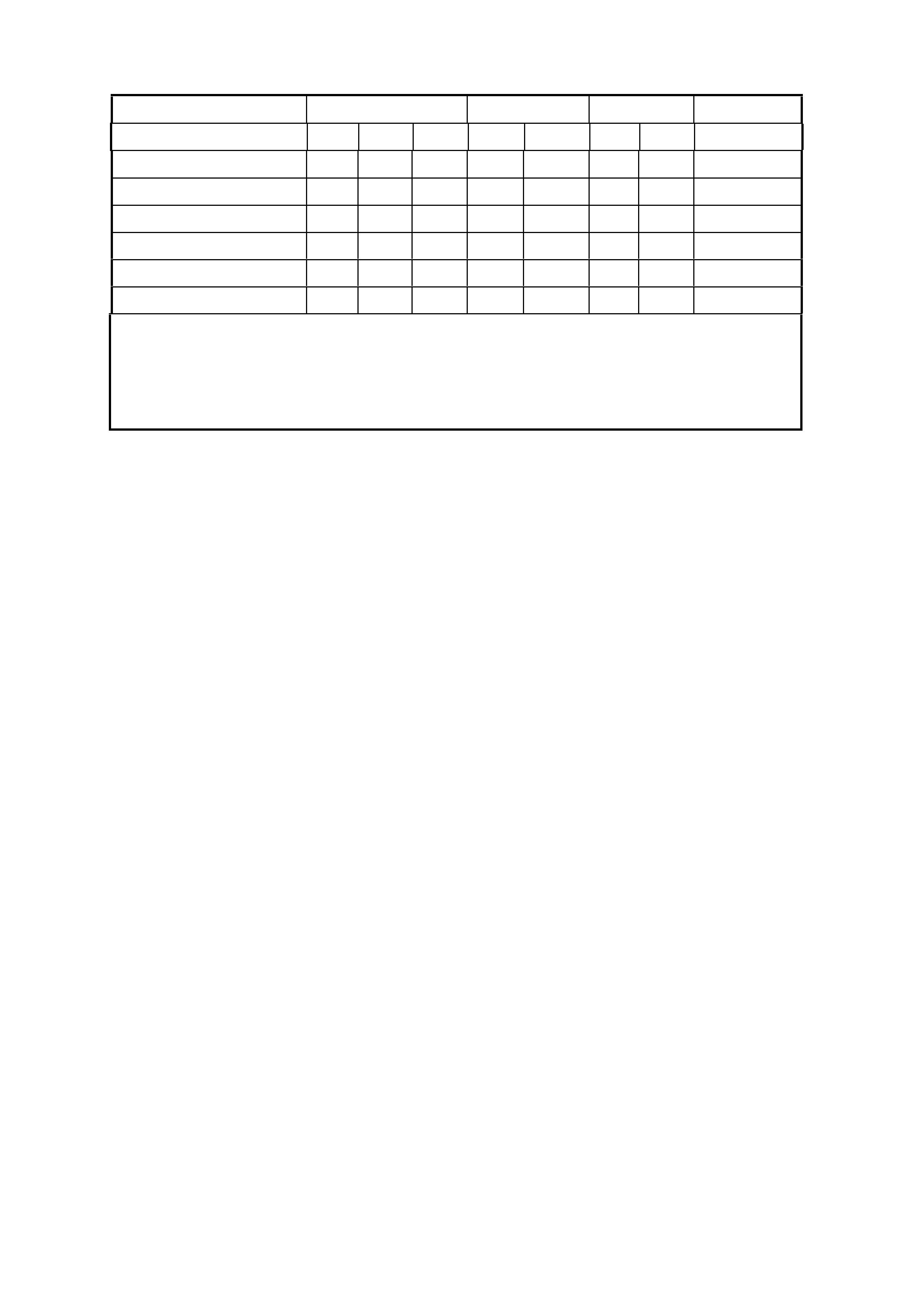
7. VEHICLE WEIGHTS
VEHICLE WEIGHTS SWB SEDAN LWB SEDAN WAGON UTILITY
8VK69 8VL69 8VX69 8WY19 8WZ19 8VK35 8VL35 8VK80
KERB MASS - V6 1521 1580 1636 1690 1695 1577 1642 1494
KERB MASS - V8 1597 1638 1682 1732 1739 1651 1700 1557
RE AR AXLE LOAD - V 6 1140 1140 1140 1149 1154 1240 1240 1350
RE AR AXLE LOAD - V 8 1140 1140 1140 1157 1161 1240 1240 1350
PAYLOA D (5 Pass. + Cargo) 408 408 408 408 408 408 408 N/A
PAYLOA D (2 Pass. + Cargo) N/A N/A N/A N/A N/A N/A N/A 790
NOTE: All figures are estimates only. Weights as listed do not include option packs.
Payload figures must include luggage, goods, passengers and a full tank of fuel.
If you are towing, then the weight on the tow bar ball must also be included.
Maximum Rear Axle Load is maximum for all conditions.
8. SERIAL NUMBERS
The c om plete vehicle and various c om ponents of the vehicle are identif ied by num ber plates or num bers stam ped
into the part. It is essential that when compiling warranty claims or product and field reports, the vehicle
identification number (VIN) is quoted in conjunction with the identification number of the component affected.
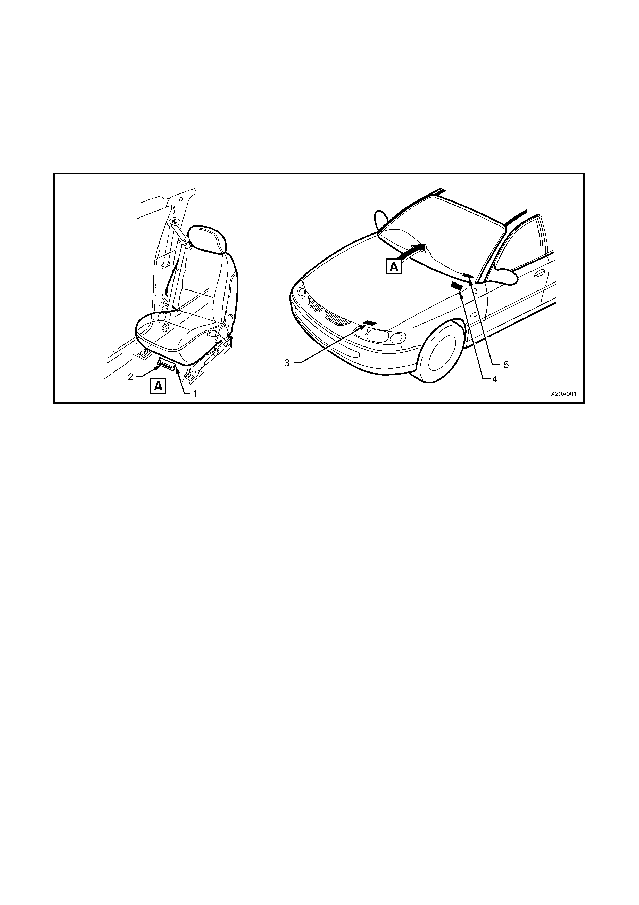
8.1 LOCATION OF IDENTIFICATION PLATES
Identification plates are attached to the upper left side of the dash panel (4), front radiator support panel (3), and
under the windshield lower left corner (5). The Vehicle Identification Number is also stamped into the floor (2)
below the front right-hand seat, refer to Figure 0A-1.
Figure 0A-1
Legend
1. Carpet flap (under RH front seat)
2. Vehicle Identification Number
(stamped under RH front seat)
3. Body and Option Identification Plate
(front upper panel)
4. Safety Compliance Plate
(engine side of dash panel)
5. Vehicle Identification Number Plate
(under windshield)
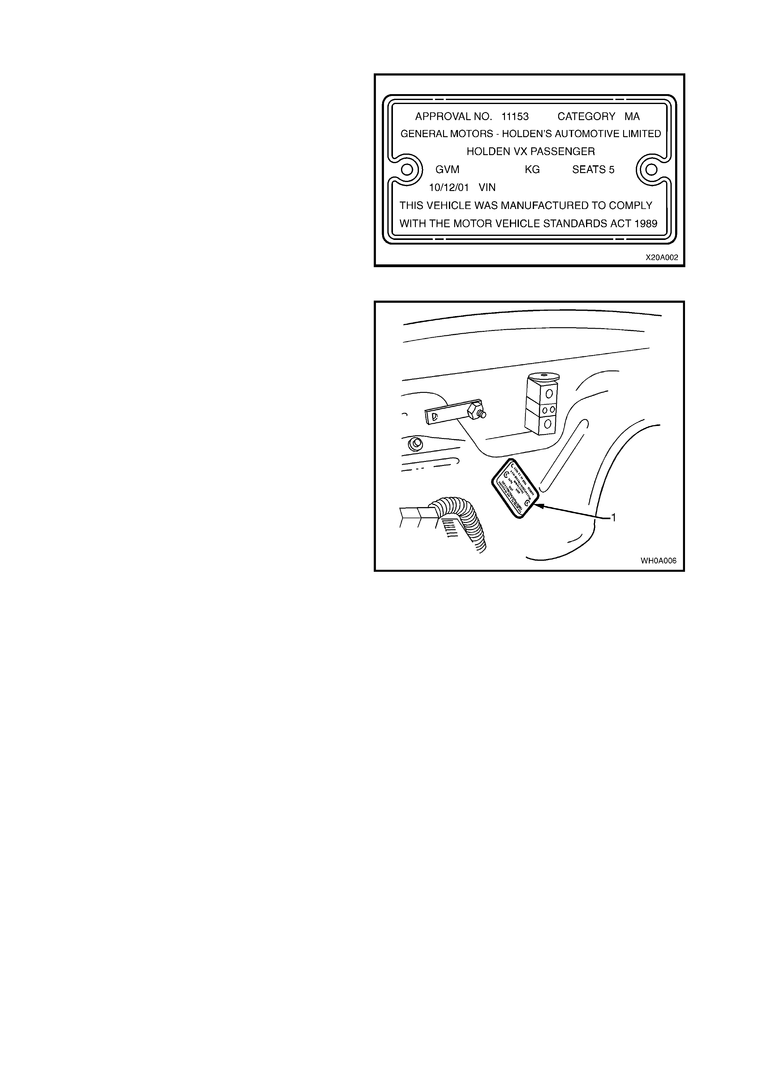
8.2 SAFETY COMPLIANCE PLATE
Plate stamped with the following information, refer
to Figure 0A-3:
COMPLIANCE PLATE APPROVAL NUMBER.
VEHICLE CATEGORY CODE.
NAME APPEARING ON COMPLIANCE PLATE
APPROVAL.
MAKE/MODEL.
GROSS VEHICLE MASS (KG)
SEATING CAPACITY.
DATE OF MANUFACTURE (* Variable
information).
VEHICLE IDENTIFICATION NUMBER (* Variable
information).
Figure 0A-2
Legend
1. Safety Compliance Plate.
Figure 0A-3
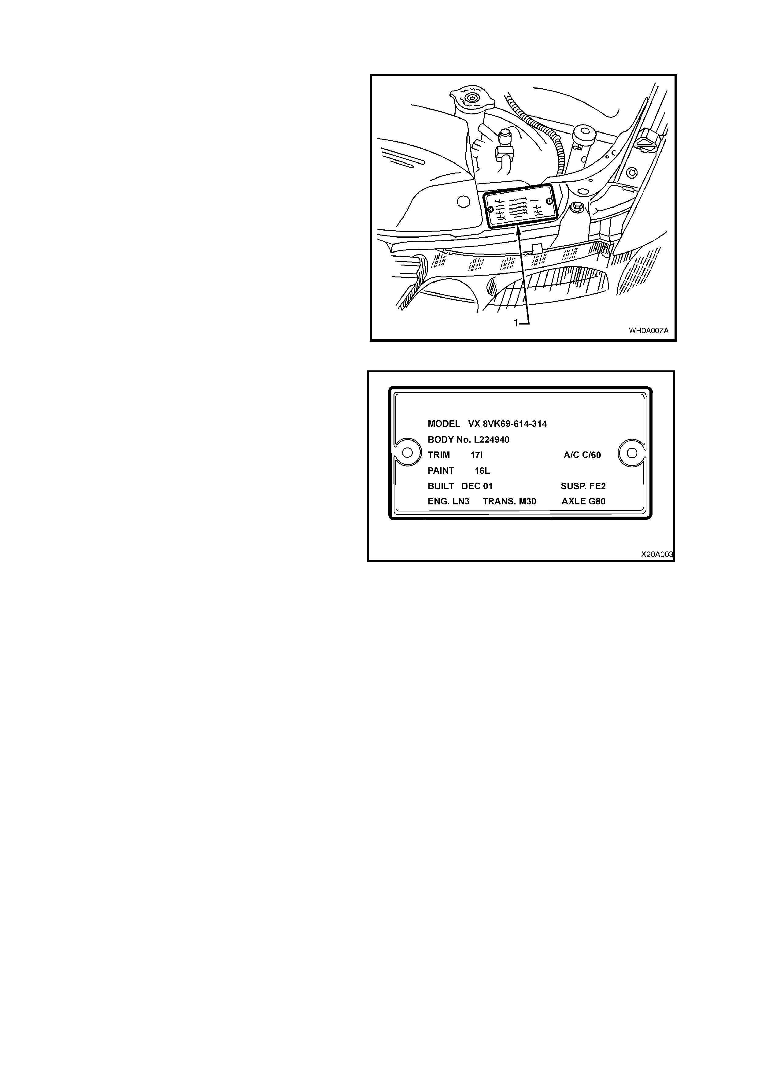
8.3 BODY AND OPTION IDENTIFICATION PLATE
The body and option identification plate (1) is
stamped with the following information, refer to
Figure 0A-5.
Figure 0A-4
MODEL
Combination of letters and numbers identifying the
body style, the mechanical pack and smart pack
options.
NOTE: A listing of Production Option numbers and
Smart Pack Option numbers can be found by
referring to the latest spare parts information
(Partfinder) for the applicable model.
BODY
Production build number, in continuous sequence
regardless of model, body type and series.
TRIM
Trim combination.
PAINT
Exterior paint material and colour identification.
BUILT
The date of manufacture by calendar month and
year in which the body shell and power train are
conjoined and the vehicle is driven or moved from
the production line.
SUSP
Suspension option code identification number, e.g.
FE2.
ENGINE, TRANSMISSION AND AXLE
Identification option codes for specific engine,
transmission and final drive.
A/C
Identification option code C60 identifies vehicles
fitted with air conditioning.
Figure 0A-5
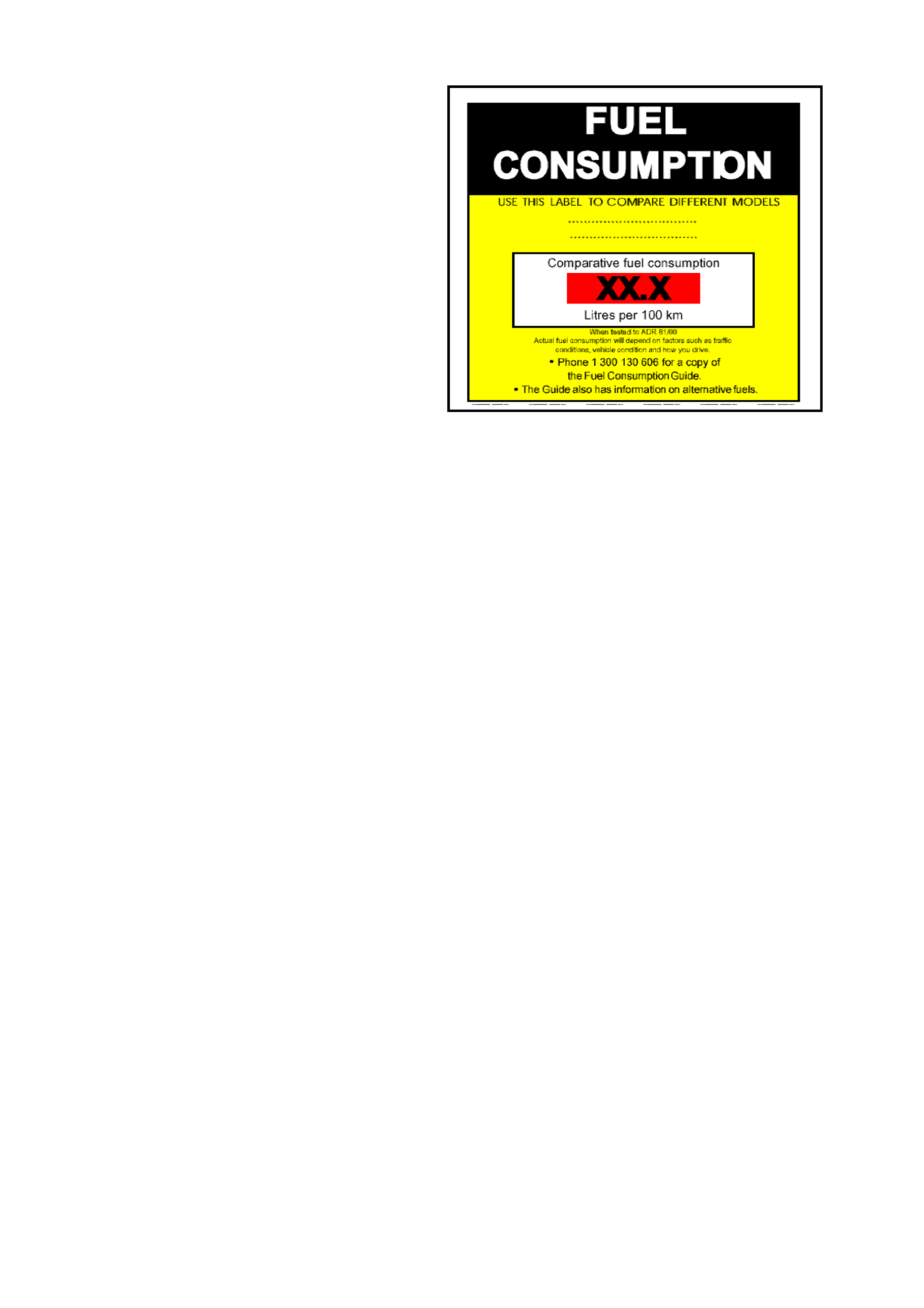
8.4 FUEL CONSUMP TION LABEL
ADR 81/00 requires that from 1st January 2001, a
label similar to that shown in Figure 0A–6 is
attached to the windscreen of any new vehicle
which is displayed for sale.
The f uel c onsumption f igures quoted are the results
of tests carried out in accordance with an
Australian standard for fuel consumption testing.
Each vehicle is tested under identical conditions.
The results therefore enable a comparison to be
made between vehicles.
This label should be removed from the windscreen
immediately prior to the vehicle being delivered to
the owner.
Figure 0A-6
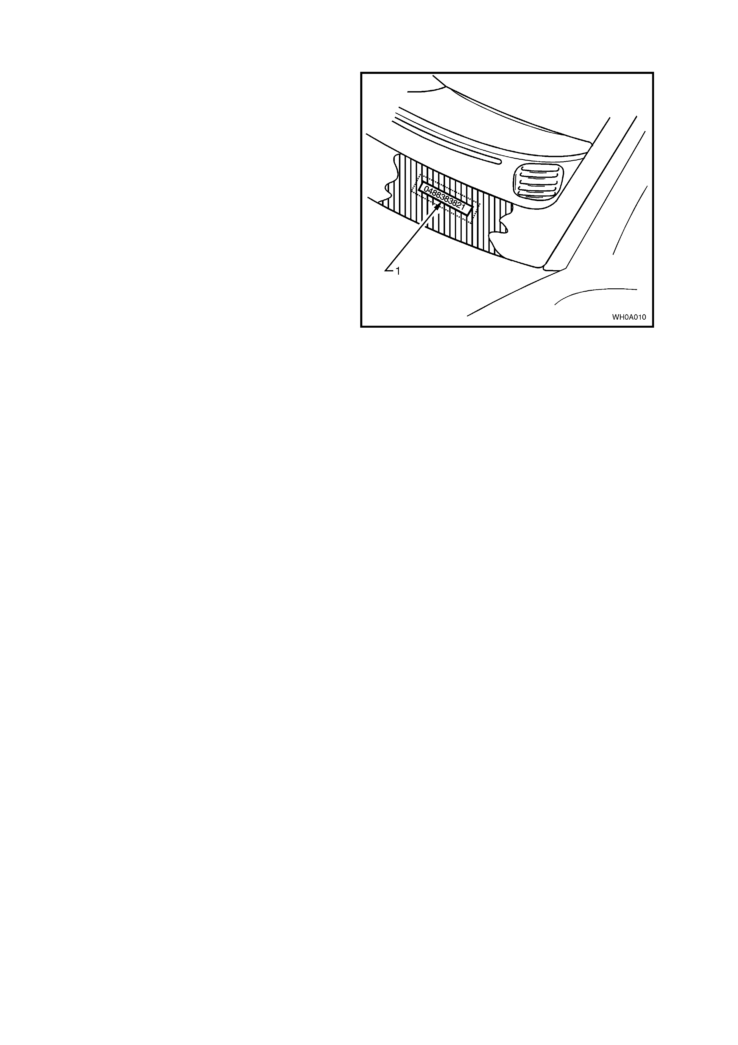
8.5 VEHICLE IDENTIFICATION NUMBER PLATE LOCATION
The body mounted Vehicle Identification Number
(VIN) plate (1) is located under the windscreen and
is viewed through the windscreen aperture.
The VIN plate is secured to the body by unique
rosette headed rivets.
NOTE: The VIN is also stamped into the floor
sheetmetal under the front RH seat, refer to
8.1 LOCATION OF IDENTIFICATION PLATES in
this Section.
Figure 0A-7

8.6 VEHICLE IDE NTIFICATION NUMBERING SYSTEM
A new Vehicle Identification Numbering (VIN) system was introduced with the introduction of the MY2003 WH
Series II dur ing O ctober 2002. However, all VX and VU Ser ies II, along with the MY2002 WH Ser ies II us ed the VIN
system as pr evious ly used in VX/VU/WH Series I. Figure 0A-8 provides the details of the MY2002 type VIN system,
while Figure 0A-9 provides details of the new VIN system used on all MY2003 WH Series II.
Techline
MY2002 VX/VU/WH SERIES II MODELS
The Vehicle Identification Numbering (VIN) System is based on the uniform Car Model Designation
System. The reason for this is to identify the vehicle in one coded series of Characters.
The significance of these characters or blocks of characters are explained below, using as an example
identification number 6H8 VX K 69 H 1 L 123456.
MODEL DESIGNATION
WMI Code
Model Series Code
Degree of Luxury
BODY STYLE CODE
ENGINE CODE
MODEL YEAR CODE
ASSEMBLY PLANT CODE
SERIAL SEQUENCE NUMBER
6H8 VX K 69 H 1 L 123456
MODEL DESIGNATION
WMI Code
6H8 – World manufacturer’s identifier allocated to Holden
Model Series Code
VU - VU Series
VX - VX Series
WH - WH Series
Degree of Lux ury
K – Executive (including Utility, Acclaim, S and SS)
L – Berlina
X – Calais
Y – Statesman
Z – Caprice
BODY STYLE CODE
19 – LWB Sedan
35 – Wagon
69 – SWB Sedan
80 – Utility
ENGINE CODE
A – signifies 3.8 V6 engine
R – signifies 3.8 Supercharged V6 engine
F – signifies 5.7 GEN III V8 engine
MODEL YEAR CODE
1 = 2001
2 = 2002
This Letter relates to GM Internal Operation Only.
ASSEMBLY PLANT CODE
Australian Assembly Plant Identification Code:
L – Adelaide (Elizabeth)
SERIAL (Sequence ) NUMBER
123456 – Sequential Production Serial Number
NOTE: This designates the Serial Unit Number at the Vehicle Plant, starting at (000001)
and continuing in numerical sequence regardless of vehicle type.
Figure 0A-8
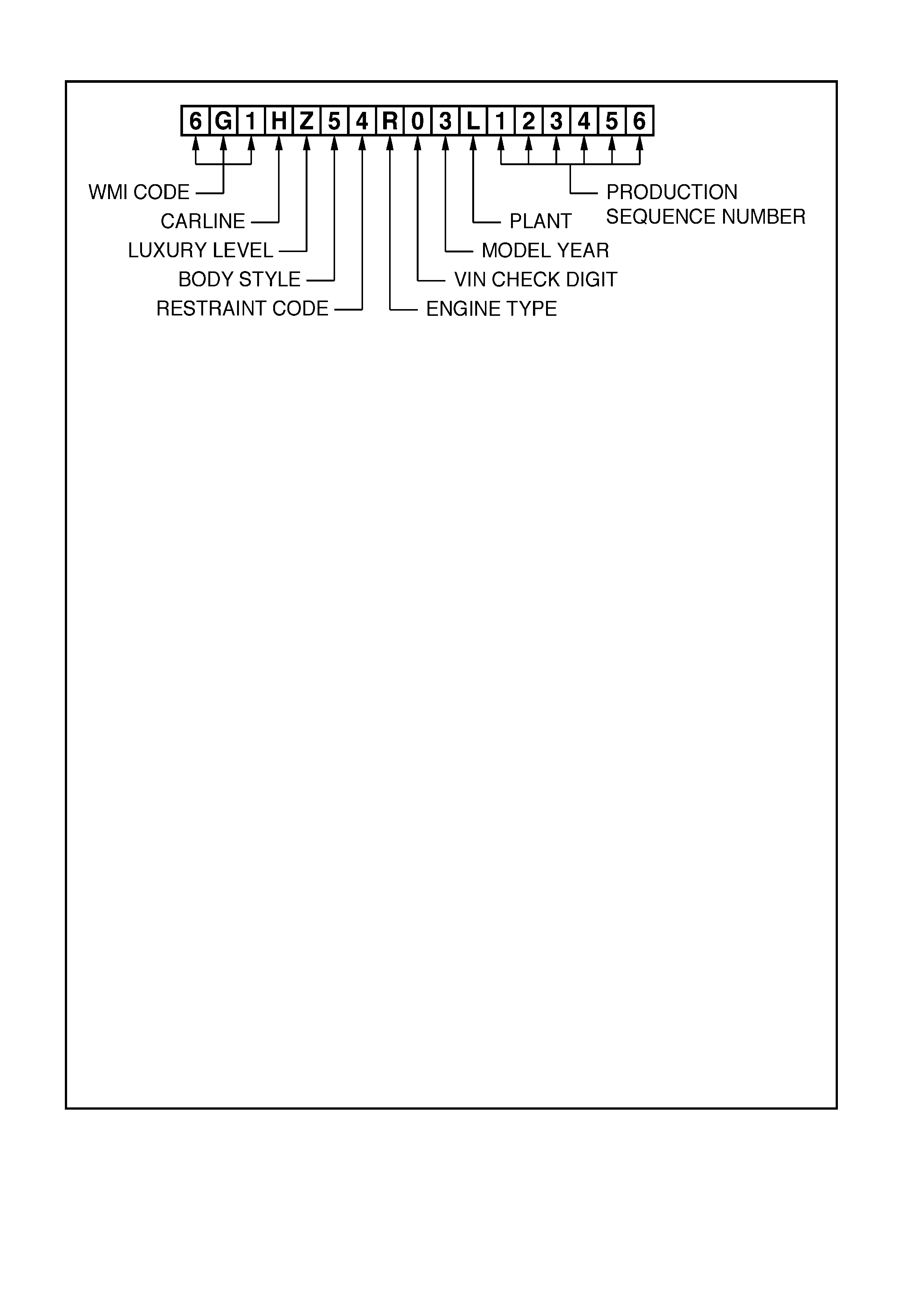
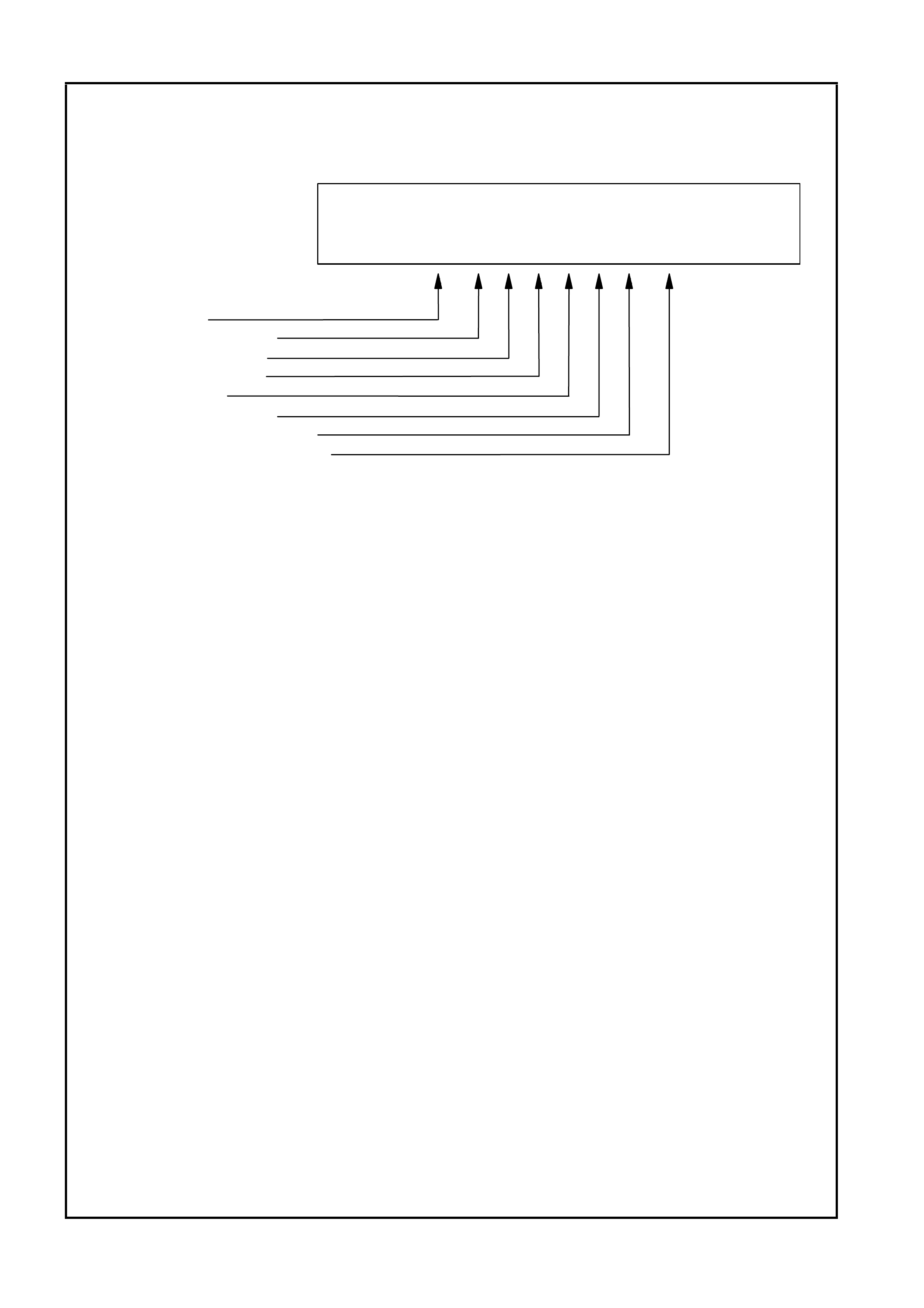
MY2003 WH SERIES II MODELS
WMI CODE: 6 – Oceania
G – Australia
1 – Holden
CARLINE: H – WH Series
LUXURY LEVEL: Y – Statesman
Z – Caprice
BODY STYLE: 5 – 4 door sedan (19)
RESTRAINT CODE: 1 – Active (manual) seat belts
2 – Active (manual) seat belts with driver & passenger inflatable restraint
system – frontal
3 – Active (manual) seat belts with driver inflatable restraint system – frontal
4 – Active (manual) seat belts with driver & passenger inflatable restraint
system – frontal and side
ENGINE TYPE: A – 3.8 litre V6 engine
R – 3.8 litre V6 engine supercharged
F – 5.7 litre GEN III V8 engine
VIN CHECK DIGIT: Calculated check digit
MODEL YEAR: 3 – 2003
PLANT: L – Adelaide (Elizabeth) South Australia
PRODUCTION SEQUENCE NUMBER:
123456 – Sequential Production Serial Number
NOTE: The pr oduc tion s equence number is s equentially allocated to each vehicle,
regardless of vehicle type.
Figure 0A-9
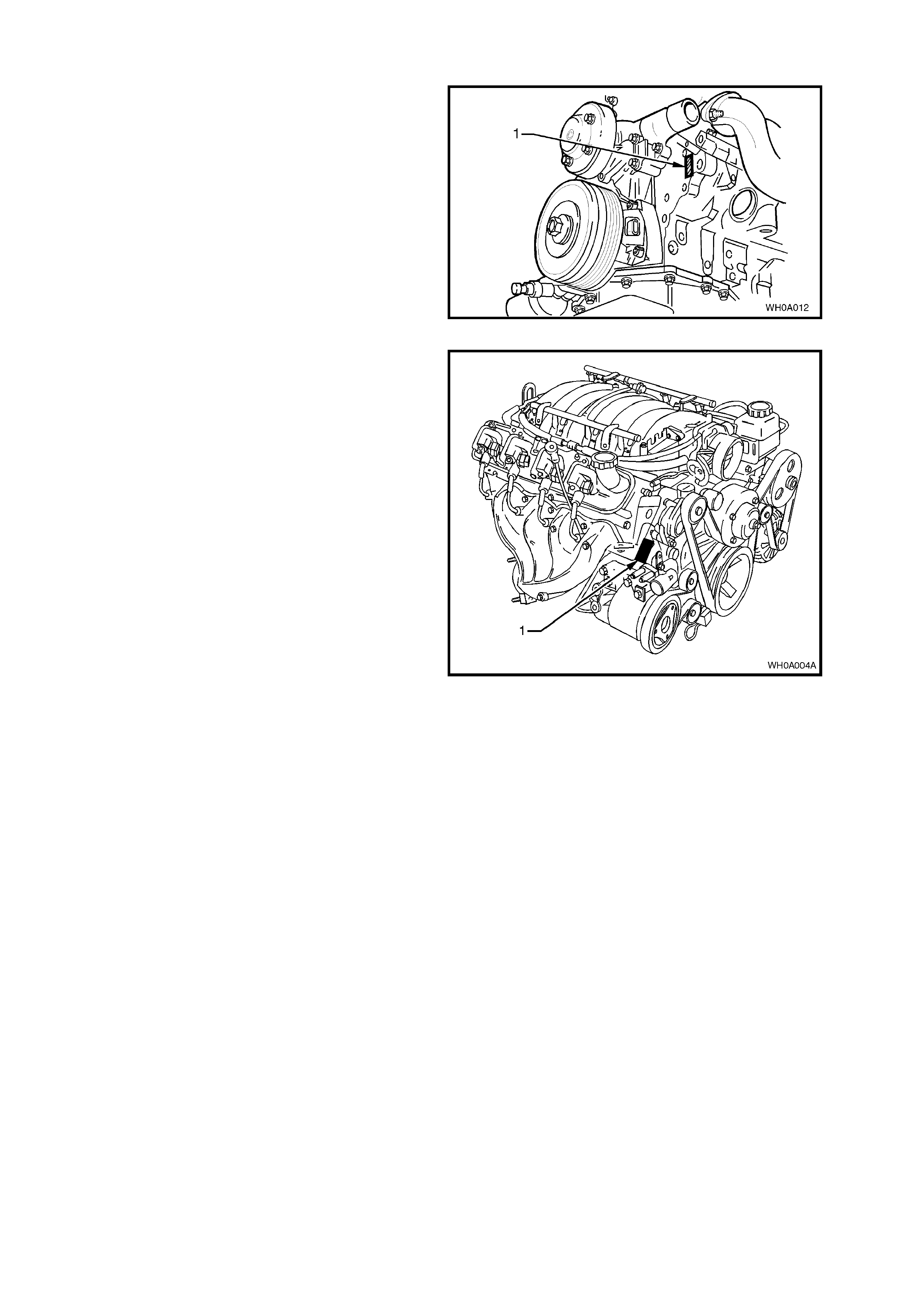
8.7 ENGINE SERIAL NUMBER
The engine number (1) for the 3.8 V6 engine is
stamped on the front face of the engine, below the
ignition coil pack as illustrated in Figure 0A-10.
Figure 0A-10
The 5.7 litre GEN III V8 engine number (1) is
stamped on a pad located adjacent to the engine
coolant outlet pipe, refer to Figure 0A-11.
The engine number is prefixed by the letters 'VF'.
Figure 0A-11
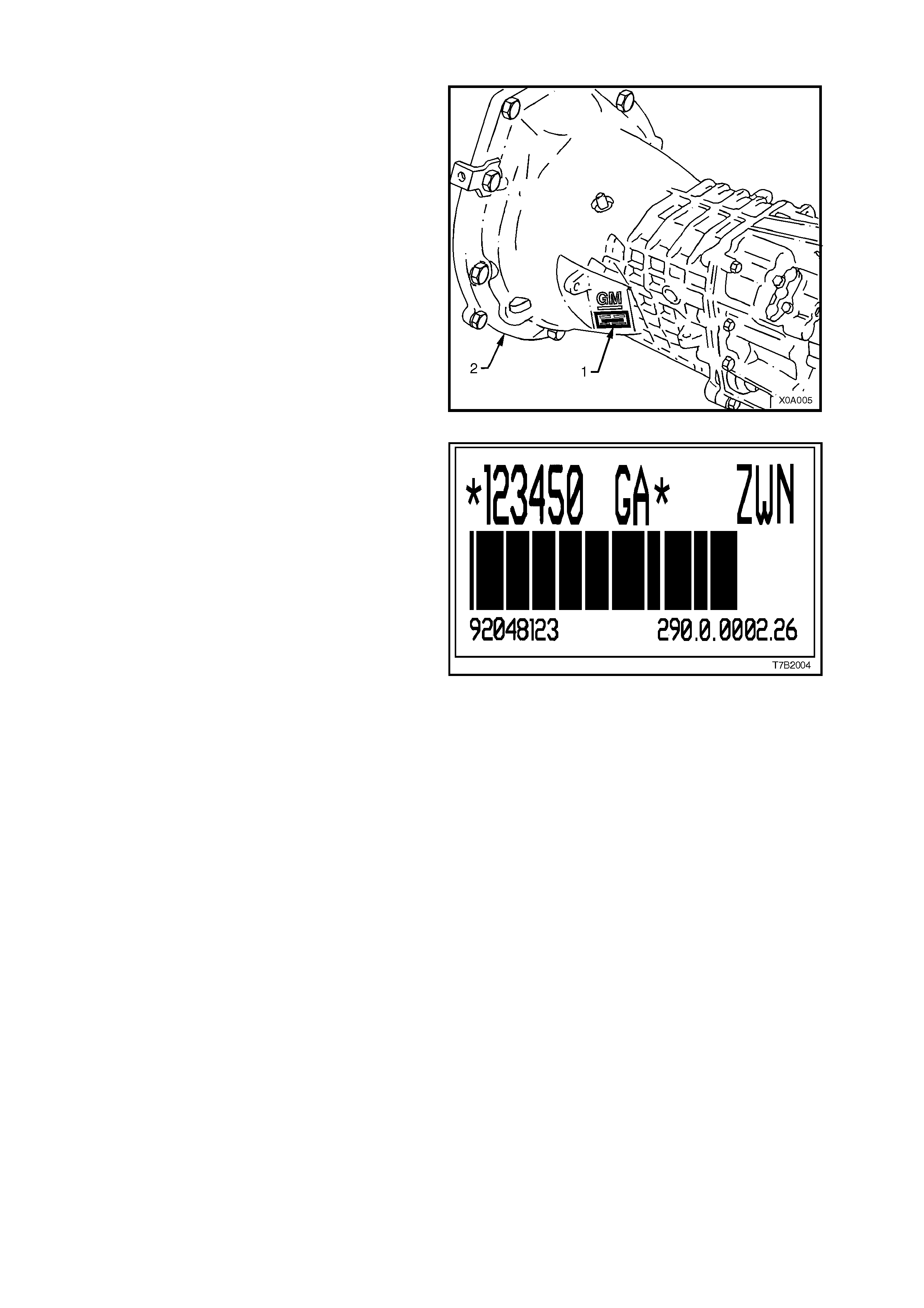
8.8 MANUAL TRANSMISSION SERIAL NUMBER
V6 ENGINE – 5 SPEED
The serial number for the Getrag 5 speed manual
transmission is located on a self-adhesive decal
attached to the left side of the transmission front
housing, refer to Figure 0A-12. This number
provides coded information which could be
significant to parts interpretation and should be
referred to when ordering replacement
components, refer to Figure 0A-13.
Figure 0A-12
Figure 0A-13

GEN III V8 ENGINE – 6 SPEED
The Borg-W arner (Tremec) T56 six speed manual
transmission serial number is located on a self-
adhesive decal attached to the top of the
transmission case, refer to Figure 0A-14.
This number provides coded information which
could be significant to parts interpretation and
should be referred to when ordering replacement
parts.
Figure 0A-14
In addition, an identification tag is attached to the
transmission under an extension-housing bolt, on
the right-hand side, refer to Figure 0A-15.
Figure 0A-15
Techline
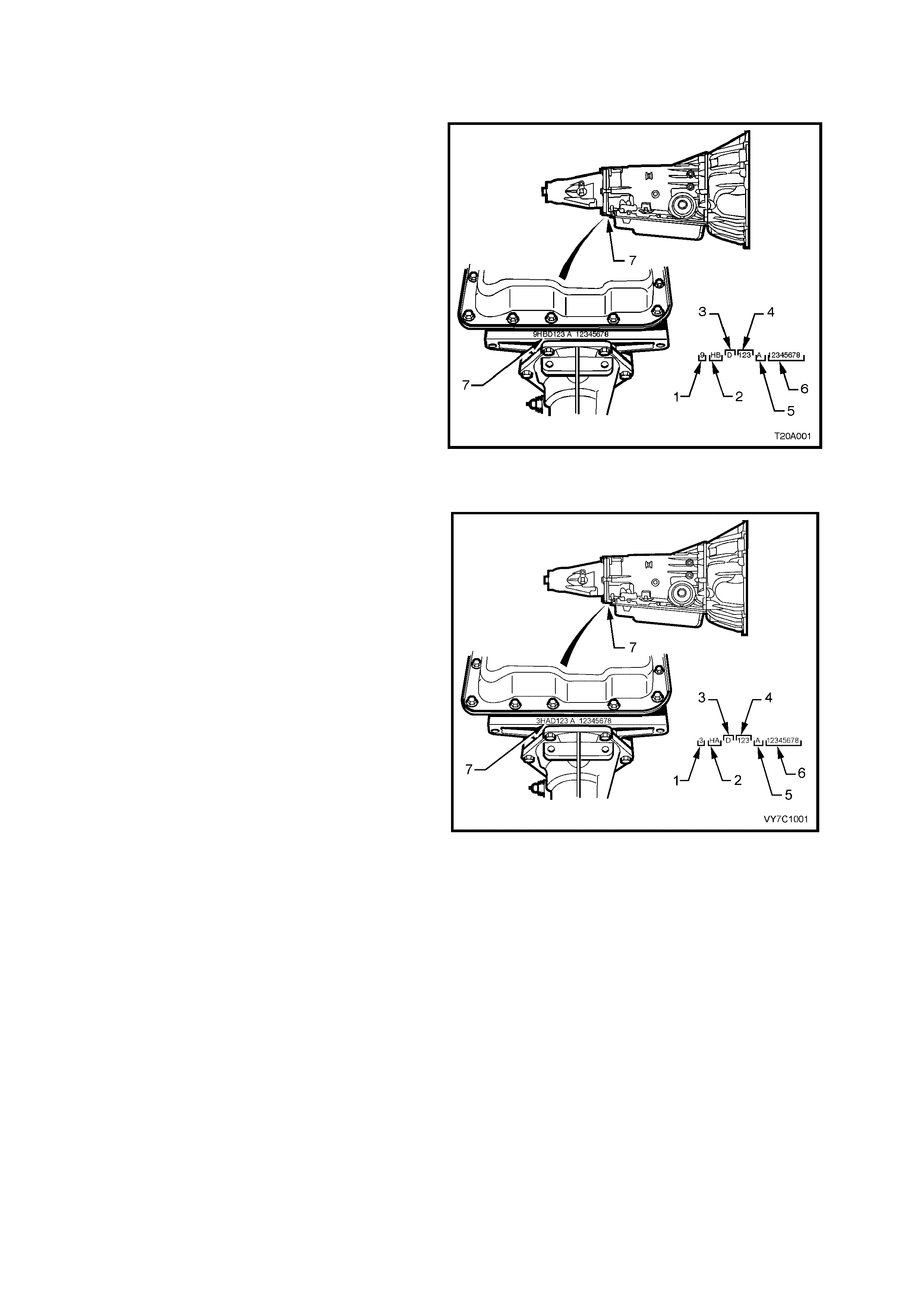
8.9 AUTOMATIC TRANSMISSION SERIAL NUMBER
MY2002 VX/VU/WH SERIES II MODELS
The MY2002 4L60-E automatic transmission serial
number is stamped into a machined surface at the
rear underside of the transmission centre case (7),
refer to Figure 0A-16.
Legend
1. Model Year ‘2’ = 2002
‘1’ = 2001
2. Model: HP 5.7 litre GEN III V8
HF 3.8 Normally aspirated V6
HN 3.8 Supercharged V6
3. Transmission Model Identifier (D = 4L60-E)
4. Julian Date (or day of year)
5. Shift Built (A, B, J = first shift;
C, H, W = second shift)
6. Individual Transmission Serial Number
7. Transmission Identification Number Location
Figure 0A-16
MY2003 WH SERIES II MODELS
The MY2003 4L60-E automatic transmission
application and identification can be determined
from the stamping in the rear of the transmission
case at the rear, in the location shown (7), refer to
Figure 0A-17.
The coded number can be interpreted from the
following breakdown;
1. Model Year ‘3’ = 2003
2. Model: HA 5.7 litre GEN III V8
HF 3.8 Normally aspirated V6
HN 3.8 Supercharged V6
3. Transmission Model Identifier (D = 4L60-E)
4. Julian Date (or day of year)
5. Shift Built (A, B, J = first shift;
C, H, W = second shift)
6. Individual Transmission Serial Number
7. Transmission Identification Number Location
Figure 0A-17
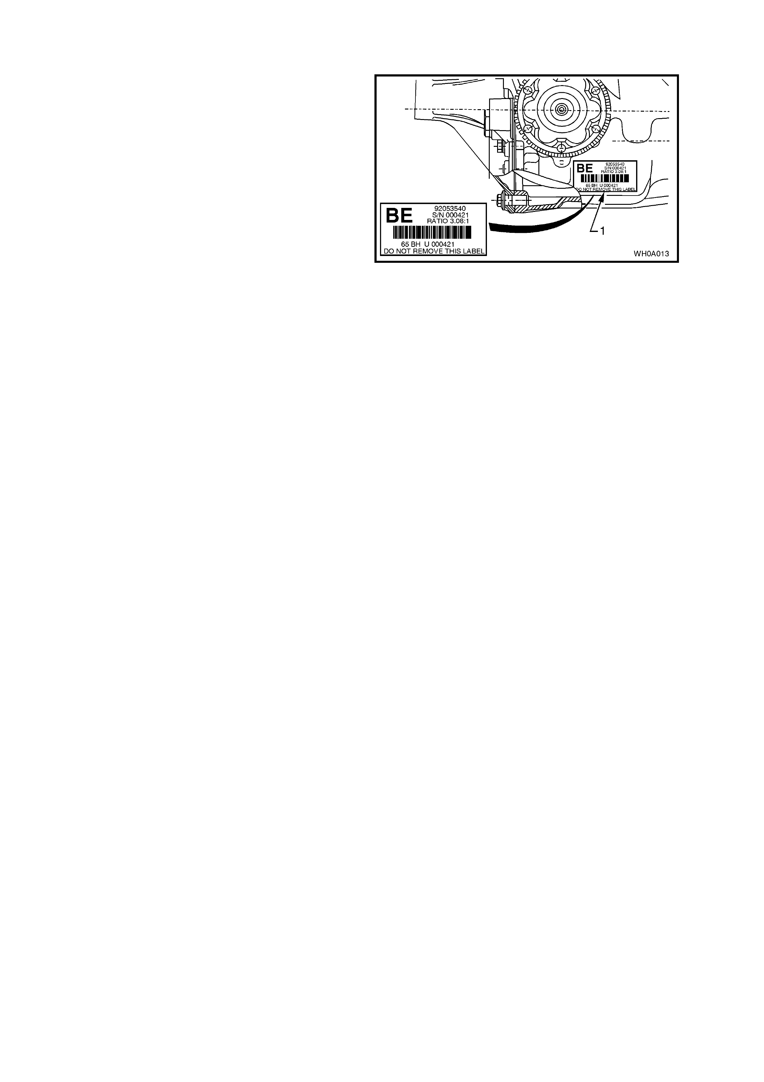
8.10 FINAL DRIVE IDENTIFICATION
An identif ication tag (1) is adhered to the final drive
assembly to the RHS of the c arr ier hous ing, refer to
Figure 0A-18. The tag carries the Holden part
number for the final drive assembly, the final drive
ratio and the serial number of the final drive
assembly.
Figure 0A-18
9. ADDI TIONAL GENERAL I NFORMATION
9.1 ELE CTRICAL TRANSI ENTS AND RADIO FRE Q UENCY INTERFERENCE
Electronic circuits are used in VX, VU and W H Series II Models to perform a number of functions associated with
electronic c ruise c ontrol, electr onic engine and trans m ission contr ol systems etc. Thes e circuits can be damaged or
malfunction as a result of electrical transients or excessive radio frequency (RF) radiation.
ELECTRICAL TRANSIENTS
Electrical transients are high voltage spikes, produced by the sudden switching or interruption of electric currents.
Older s tyle tim ing lights and batter y chargers c an produc e s erious trans ients , hence, it is important to us e only good
quality equipment suitable for use with electronic systems.
It is also good practice to ensure that the battery is disconnected before using a battery charger.
Indiscriminate fitting of solenoids, indicators or relays can also cause transients.
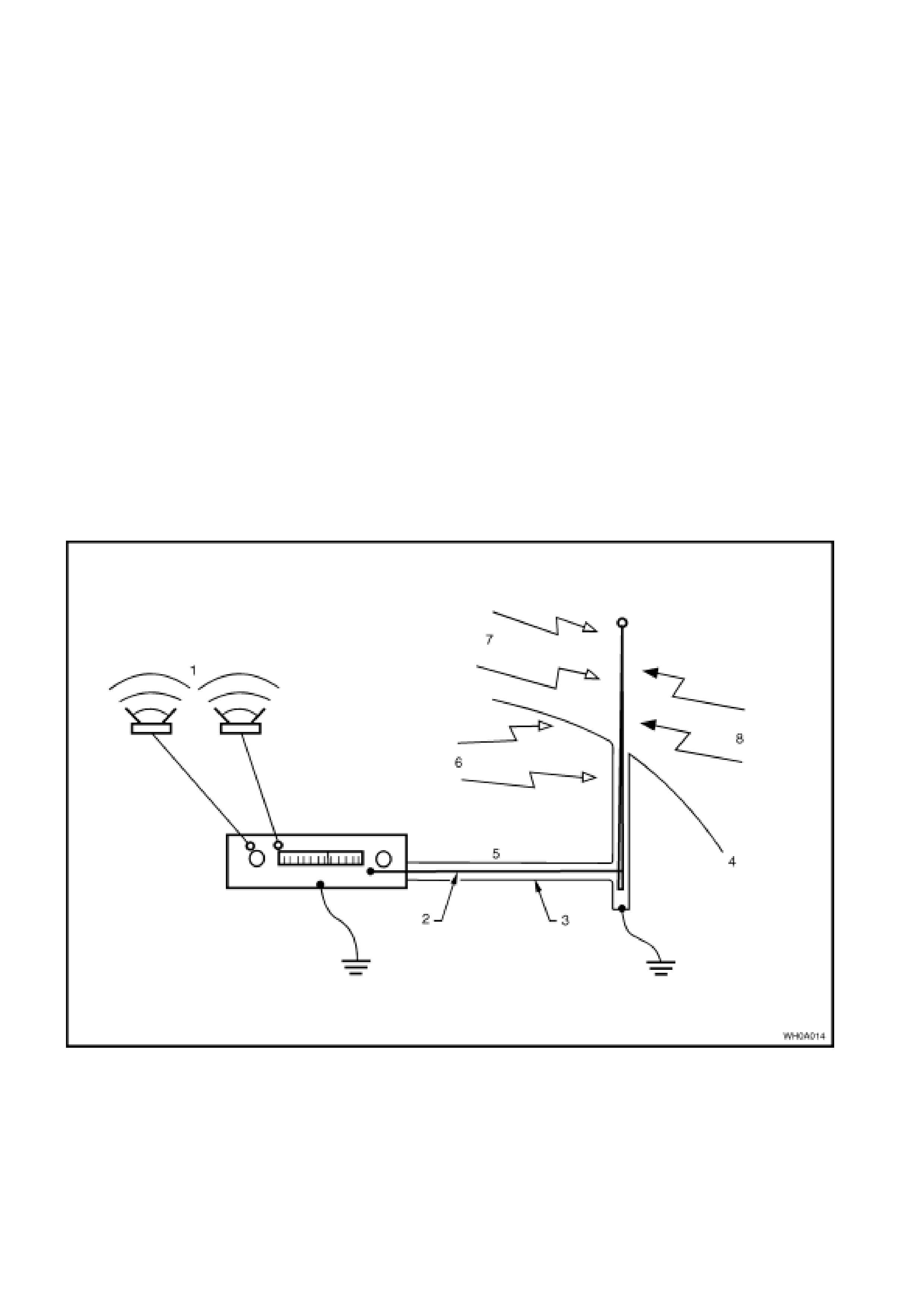
RADIO FREQUENCY INTERFERENCE
One of the chief sources of RF interference is the ignition system. Other sources include CB radio and radio
telephones. The following are normally used to suppress RF interference.
Resistors e.g. High Tension Cables and Connectors.
Capacitors and Choke Coils.
Metal Braid for screening leads or suppression covers made from conductive material for screening equipment.
To prevent damage to equipment:
• Do not replace interference suppressed high tension ignition cables or connectors with unsuppressed types.
• Do not remove or reposition interference suppression filters or capacitors.
Figure 0A-19
Legend
1. Music
2. Core
3. Braid
4. Body
5. Antenna cable
6. Internal Interference
7. Signal from station
8. External interference

9.2 STATIC ELECTRICITY
Care should be exercised when handling electronic equipment e.g. the powertrain control module (PCM), to avoid
touching the terminals unnecessarily. Static electricity, which is present on every person, can cause damage to
some electronic components.

9.3 PUSH OR TOW STARTING
Do not push or tow start VX , VU or W H Series II vehicles . Push or tow starting can result in unburned fuel passing
through the exhaust to the catalytic converter, causing damage to the converter.
10. CONSOLIDATED TOOL LIST
MY2002 MODELS
Special tools for MY2002 VX, VU and WH Series II Models carry over from VT Series II Models. For information
concerning Special Tools refer to Section 0A in the VT Series II Service Manual in conj unction with Section 0A in
the VT Series I Service Information.
MY2003 UPDATE MODELS
Apart from the tools listed below, the special tools for MY2003 WH Series II Update Models carry over from VT
Series II Models. For information concerning Special Tools refer to Section 0A in the VT Series II Service
Information.
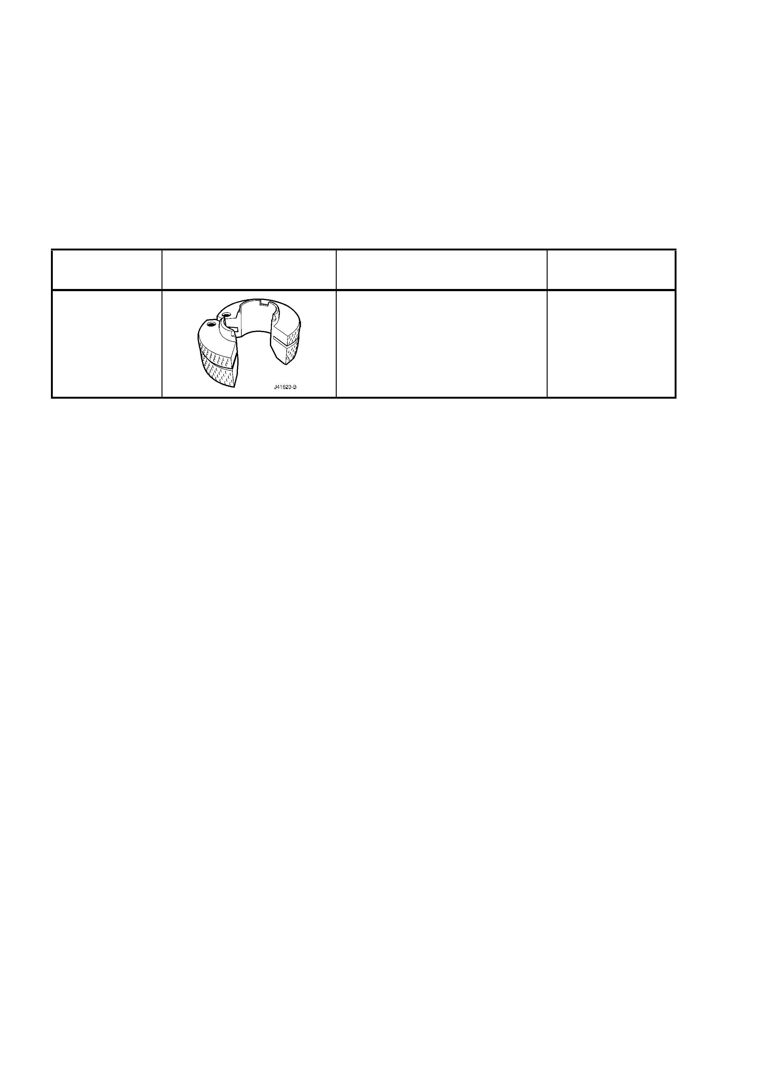
TOOL
NUMBER ILLUSTRATION DESCRIPTION CLASSIFICATION
J41623-B
COOLER PIPE QUICK-
CONNECT
RELEASE TOOL
New release.
Mandatory