
SECTION 1A7 – SEAT & SEAT BELT ASSEMBLIES
IMPORTANT:
Before performing any Service Operation or other procedure described in this Section, refer to Section
00 CAUTIONS AND NOTES for correct workshop practices with regard to safety and/or property damage.
1. GENERAL I NFORMATI O N
1.1 VX AND VU SERIES II MODELS
The seats and seat belts fitted to VX/VU Series II Models carry over from VX Series I Models, noting the following:
• New plain bolster trim fabric has been introduced for Executive, Utility Acclaim, S and SS Models.
• A unique leather trim (Production Option W J7), that utilises hook and loop for the attachm ent of the trim cover
to pad on the front seat back and cushion, has been introduced for S Sedan and SS Sedan and Utility Models.
• The pewter trim colour in VX/VU Series I Models has been replaced by Anthracite in VX/VU Series II Models.
For inf orm ation relating to s eats and seat belts fitted to VX/VU Series II Models not provided in this section, r efer to
Section 1A7 SEAT AND SEAT BELT ASSEMBLIES in the VT Series II Service Information in conjunction with
Section 1A7 SEAT AND SEAT BELT ASSEMBLIES in the VT Series I Service Information.
Techline
Techline
Techline

1.2 WH SERIES II MODELS
The seats and seat belts fitted to WH Series II Models carry over from WH Series I Models, noting the following:
• The three passenger rear seat fitted as standard equipment on Statesman Models has a revised long nose
cushion design.
• The three passenger rear seat as fitted to Statesman is now also standard for Caprice (two position rear seat
optional).
• New trim fabric has been introduced for Statesman.
• New leather trim colours have been introduced.
For information relating to seats and seat belts fitted to W H Series II Models not provided in this section, refer to
Section 1A7 SEATS AND SEAT BELT ASSEMBLIES in the WH Series I Service Information in conjunction with
Section 1A7 SEATS AND SEAT BELTS in the VT Series I and VT Series II Service Information.
2. SERVICE OPERATIONS
2.1 FRONT SE AT BACK COVER - S AND SS LEATHER SEAT
REMOVE
CAUTION: Before performing any Service
Operation on a front seat assembly fitted with
side impact airbags, ensure the SRS is
disabled. Refer to Section 12M
SUPPLEMENTAL RESTRAINT SYSTEM in the
VT Series I Service Information.
CAUTION: Accessory and after market seat
covers MUST NOT be fitted to a vehicle with
side impact airbag s unless appro ved b y Holden
Ltd. Seat covers that are not approved by
Holden Ltd. could greatly inhibit the
performance of the side impact airbag and
occupants safety in the event of side impact
airbag deployment.
NOTE: Clean hands are ess ential when working on
the body interior trim.
1. Remove the front seat back pad and cover
assembly, refer 2.5 FRONT SEAT BACK PAD
AND COVER ASSEMBLY in Section 1A7
SEAT AND SEAT BELT ASSEMBLIES of the
VT Series II Service Information.
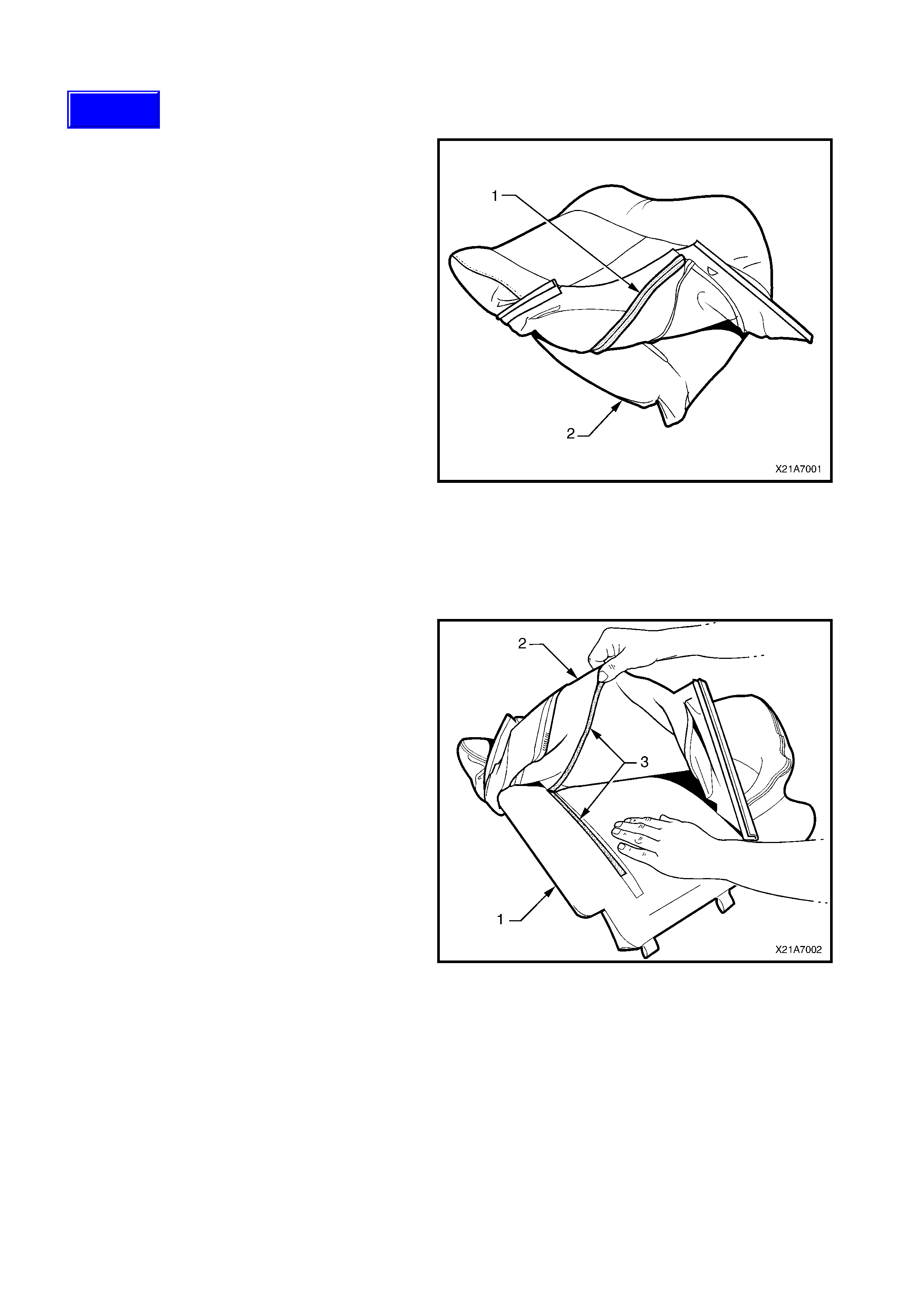
2. Fold the lower corners of the seat back cover
(1) over the seat back pad (2).
Figure 1A7-1
3. While holding the front seat back pad (1), pull
the lower corners of the seat back cover (2)
upwards and away from the front seat pad to
disengage the hook and loop strips (3).
4. Pull the front seat back cover up and over the
upper edge of the front seat back pad.
Figure 1A7-2
Techline
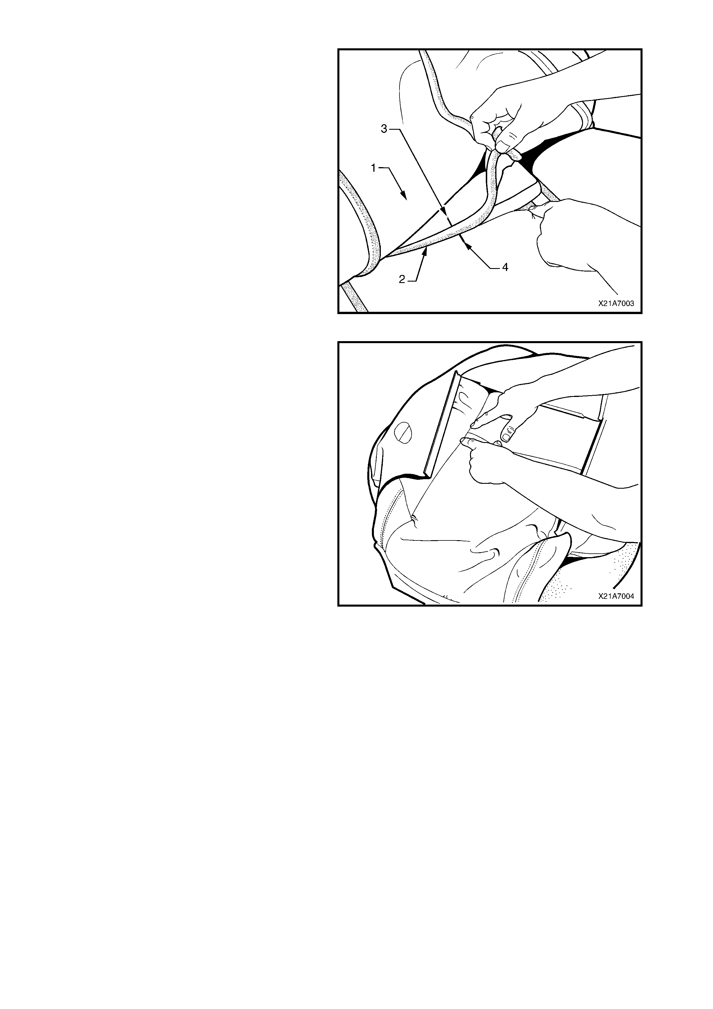
REINSTALL
1. With the seat back cover (1) folded at the
central horizontal strip of hook and loop (2),
align the centre m ark (3) on the front seat back
cover with the centre m ark (4) on the seat back
pad.
2. Press the seat back cover firmly into the
corresponding groove in the seat back pad to
engage the hook and loop.
Figure 1A7-3
3. With the seat cover folded at the two vertical
strips of hook and loop, press the seat back
cover firmly into the corresponding grooves in
the seat back pad.
Figure 1A7-4
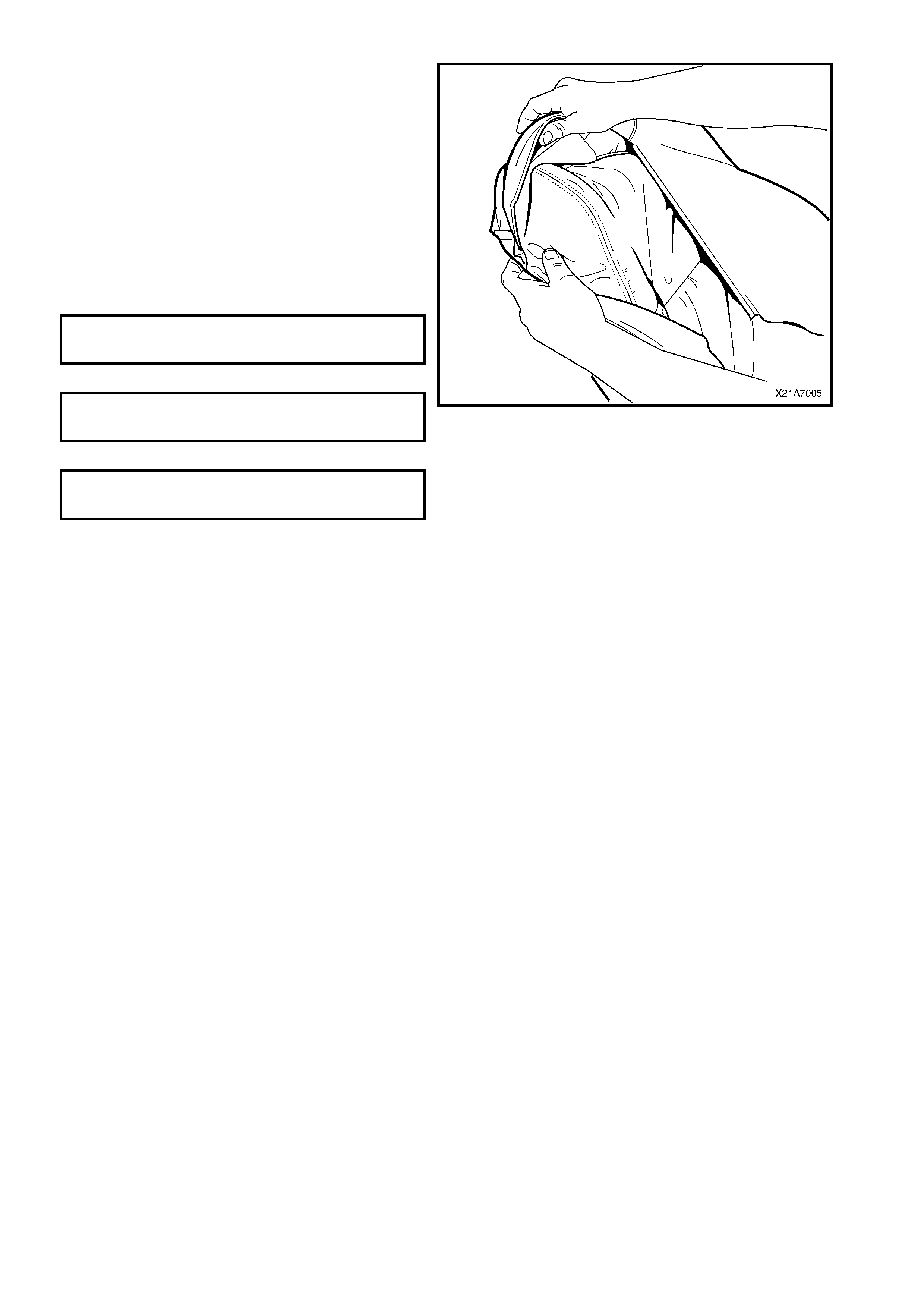
4. Roll the upper corners of the front seat back
cover over the seat back pad.
5. Roll the sides of the seat back cover over the
seat back pad.
6. Roll the lower corners of the seat back cover
over the seat back pad.
7. Reassemble the rear seat back pad and cover
to the seat frame, refer to 2.5 FRONT SEAT
BACK PAD AND COVER ASSEMBLY in the
VT Series II Service Information.
8. Install the front seat, refer to
2.1 FRONT BUCKET SEAT ASSEMBLY in the
VT Series II Service Information.
FRONT SEAT TO FLOOR
ATTACHING BOLT 35 – 50 Nm
TORQUE SPECIFI CATION
FRONT SEAT OUTER GUIDE RAIL COVER
ATTACHING S CRE W 1.0 – 3.0 Nm
TORQUE SPECIFI CATION
FRONT SE A T SIDE I NNER COVER
ATTACHING S CRE W 1.0 – 3.0 Nm
TORQUE SPECIFI CATION
Figure 1A7-5
2.2 FRONT SEAT CUSHION COVER - S AND SS LEATHER SEAT
REMOVE
CAUTION: Before performing any Service
Operation on a front seat assembly fitted with
side impact airbags, ensure the SRS is
disabled. Refer to Section 12M
SUPPLEMENTAL RESTRAINT SYSTEM in the
VT Series I Service Information.
CAUTION: Accessory and after market seat
covers MUST NOT be fitted to a vehicle with
side impact airbag s unless appro ved b y Holden
Ltd. Seat covers that are not approved by
Holden Ltd. could greatly inhibit the
performance of the side impact airbag and
occupants safety in the event of side impact
airbag deployment.
NOTE: Clean hands are ess ential when working on
the body interior trim.
1. Remove the front seat cushion pad and cover
assembly , refer to 2.7 FRONT SEAT
CUSHION PAD AND COVER ASSEMBLY in
Section 1A7 SEAT AND SEAT BELT
ASSEMBLIES of the VT Series II Service
Information.
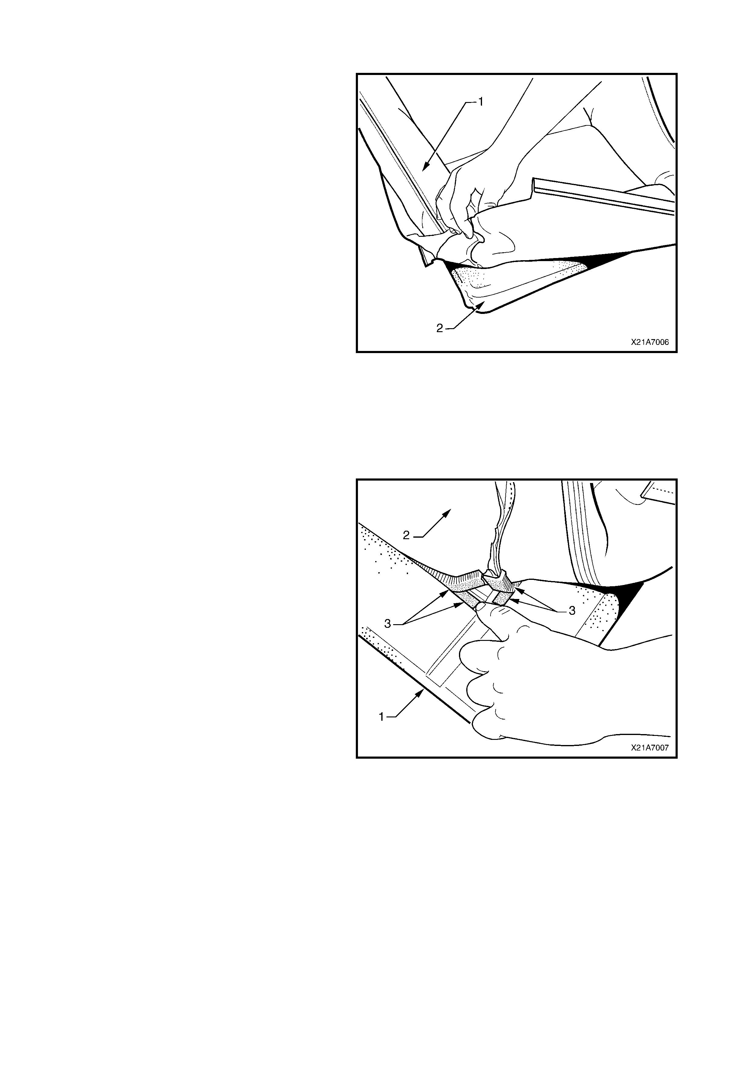
2. Fold the rear c orners of the seat c ushion cover
over the seat cushion pad.
Figure 1A7-6
3. While holding the front seat cushion pad (1),
pull the rear corners of the seat cushion cover
(2) forwards and away from the front seat
cushion pad to disengage the hook and loop
strips (3).
4. Pull the front seat cover up and over the
forward edge of the front seat cushion pad.
Figure 1A7-7
REINSTALL
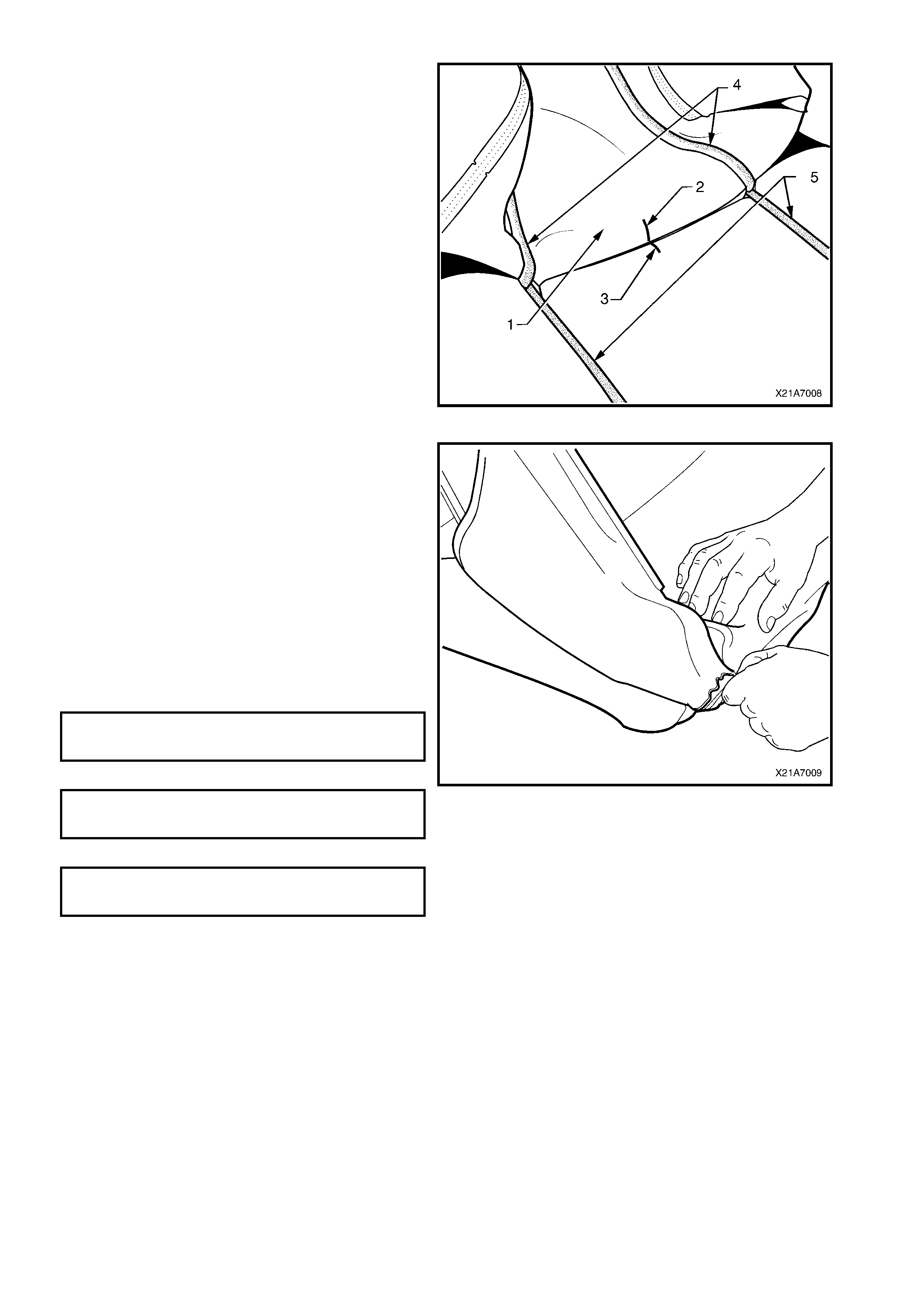
1. With the seat cushion cover (1) folded at the
central horizontal strip of hook and loop, align
the centre mark (2) on the front seat cushion
cover with the centre mark (3) on the seat
cushion pad.
2. Press the f olded edge of the front s eat cu shion
cover firmly into the corresponding groove in
the seat cushion pad to engage the hook and
loop.
3. With the seat cover folded at the two vertical
strips of hook and loop (4), pr ess the s eat back
cover firmly into the corresponding grooves (5)
in the seat back pad.
Figure 1A7-8
4. Roll the front corners of the front seat cushion
cover over the seat cushion pad.
5. Roll the sides of the seat cushion cover over
the seat cushion pad.
6. Roll the rear corners of the seat cushion cover
over the seat cushion pad.
7. Reassemble the rear seat cushion pad and
cover assembly to the seat frame, refer to
2.7 FRONT SEAT CUSHION PAD AND
COVER ASSEMBLY in the VT Series II
Service Information.
8. Install the front seat, refer to
2.1 FRONT BUCKET SEAT ASSEMBLY in the
VT Series II Service Information.
FRONT SEAT TO FLOOR
ATTACHING BOLT 35 – 50 Nm
TORQUE SPECIFI CATION
FRONT SEAT OUTER GUIDE RAIL COVER
ATTACHING S CRE W 1.0 – 3.0 Nm
TORQUE SPECIFI CATION
FRONT SE A T SIDE I NNER COVER
ATTACHING S CRE W 1.0 – 3.0 Nm
TORQUE SPECIFI CATION
Figure 1A7-9

3. TORQUE WRENCH SPECIFICATIONS
Nm
Front seat to floor attaching bolt ........................................... 35 - 50
Front seat outer guide rail cover attaching screw................. 1.0 - 3.0
Front seat inner side cover attaching screw ......................... 1.0 - 3.0