
SECTION 12B - LIGHTING SYSTEM
IMPORTANT:
Before performing any Service Operation or other procedure described in this Section, refer to Section
00 CAUTIONS AND NOTES for correct workshop practices with regard to safety and/or property damage.
1. GENERAL I NFORMATI O N
1.1 VX SERIES II MODELS
The lighting system fitted to VX Series II Models carries over from VX Series I Models, noting the following:
• The turn signal and headlamp control switch has been revised.
For information relating to the lighting system used on VX Series II Models not covered in this section, refer to
Section 12B LIGHTING SYSTEM in the VX Series I Service Information, in conjunction with Section 12B LIGHTING
SYSTEM in the VT Series I and VT Series II Service Information.
Techline
Techline

1.2 VU SERIES II MODELS
The lighting system fitted to VU Series II Models carries over from VU Series I Models, noting the following:
• The turn signal and headlamp control switch has been revised.
For information relating to the lighting system used on VU Series II Models not covered in this section, refer to
Section 12B LIGHTING SYSTEM in the VU Series I Service Information, in conjunction with Section 12B LIGHTING
SYSTEM in the VT Series I and VT Series II and VX Series I Service Information.

1.3 WH SERIES II MODELS
The lighting system fitted to WH Series II Models carries over from WH Series I Models, noting the following:
• The turn signal and headlamp control switch has been revised.
• The headlamp lens and housing fitted to WH Series II Models has been revised for improved headlamp
performance.
• The Statesman V8 International (Production Option A8X) that was introduced during March 2002,has been
fitted with a projector type headlamp and turn signal assembly. Except for the deletion of the black out
treatm ent, this ass em bly carries over f rom the proj ector type headlamp and turn s ignal assem bly as fitted to V2
Series Models. For information regarding the service operations (including high and low beam bulb
replacement) for the projector type headlamp assembly as fitted to WH Series II Statesman V8 International,
refer to Section 12B LIGHTING SYSTEM in the V2 Series Service Information.
For information relating to the lighting system used on WH Series II Models not covered in this section, refer to
Section 12B LIGHTING SYSTEM in the WH Series I Service Information.
Techline
2. SERVICE OPERATIONS
2.1 HEADLAMP AND TURN SIGNAL SWITCH
REMOVE
CAUTION: Disable the SRS (Air Bag).
Refer to DISABLING THE SRS,
Section 12M SUPPLEMENTAL RESTRAINT
SYSTEM of the VT Series I Service Information.
1. Disconnect battery earth lead.
2. Remove ignition key from ignition switch.
3. Lower fuse panel cover.
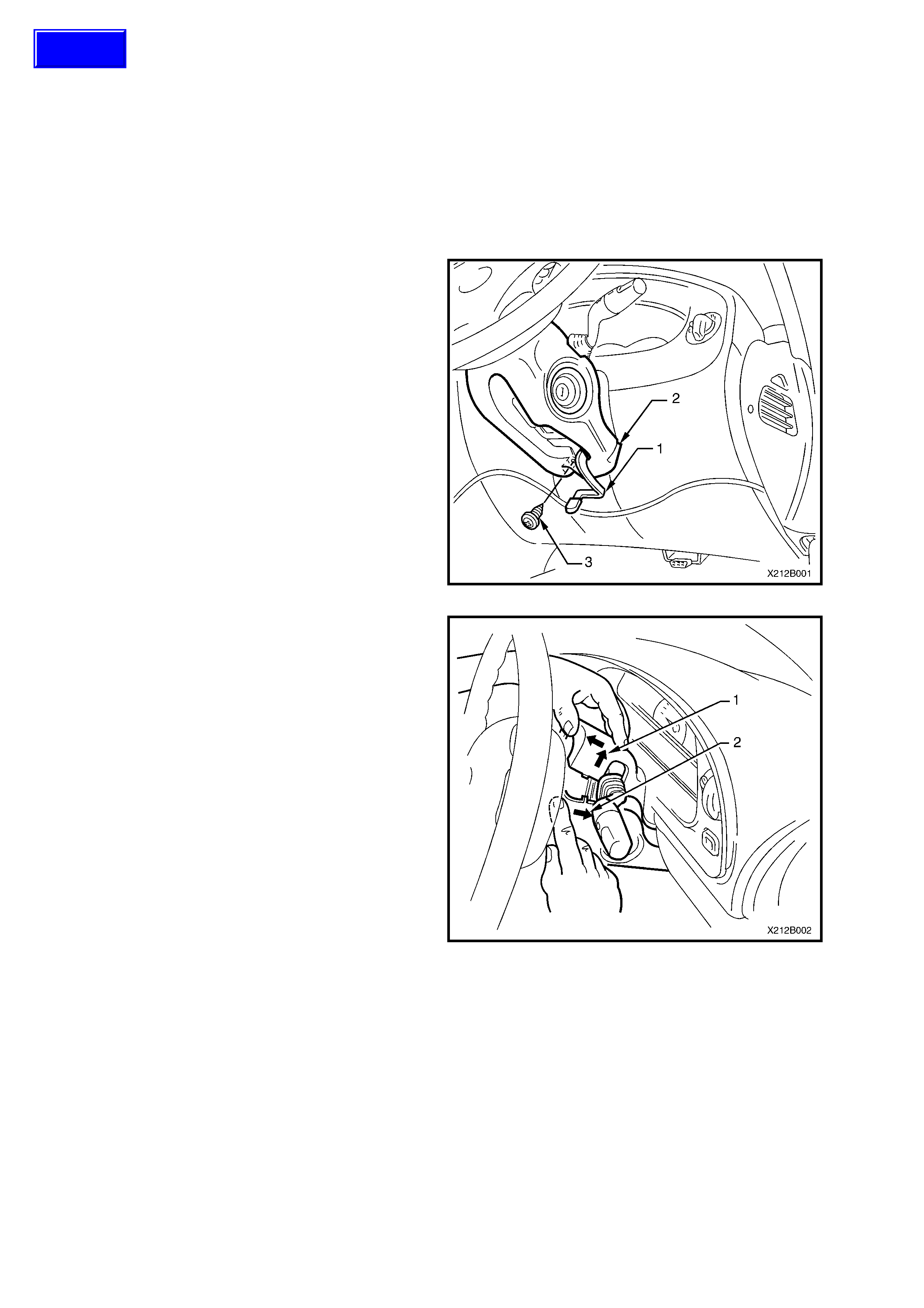
4. Release steering column height adjusting lever
(1) and completely lower steering column.
5. Place a clean shop rag over and around
steering column upper cover (2). This prevents
any possibility of dam age to cover s hould there
be any contact with lower edge of instrument
facia while removing the cover.
6. Remove steering column lower cover to
steering column attaching screw (3).
Figure 12B-1
7. Insert finger between the steering wheel and
the lower cover as shown in Fig. 12B-2 and
apply a small amount of pressure (pushing
towards instrument cluster).
8. Pull steering column upper cover (1) up and
toward steering wheel at the same time pulling
lower cover (2) down and away from steering
wheel. This will release the steering column
lower cover end retainers from mating slots in
upper cover (refer item 4, Fig 12C-1).
9. Remove steering column covers.
Figure 12B-2
Techline
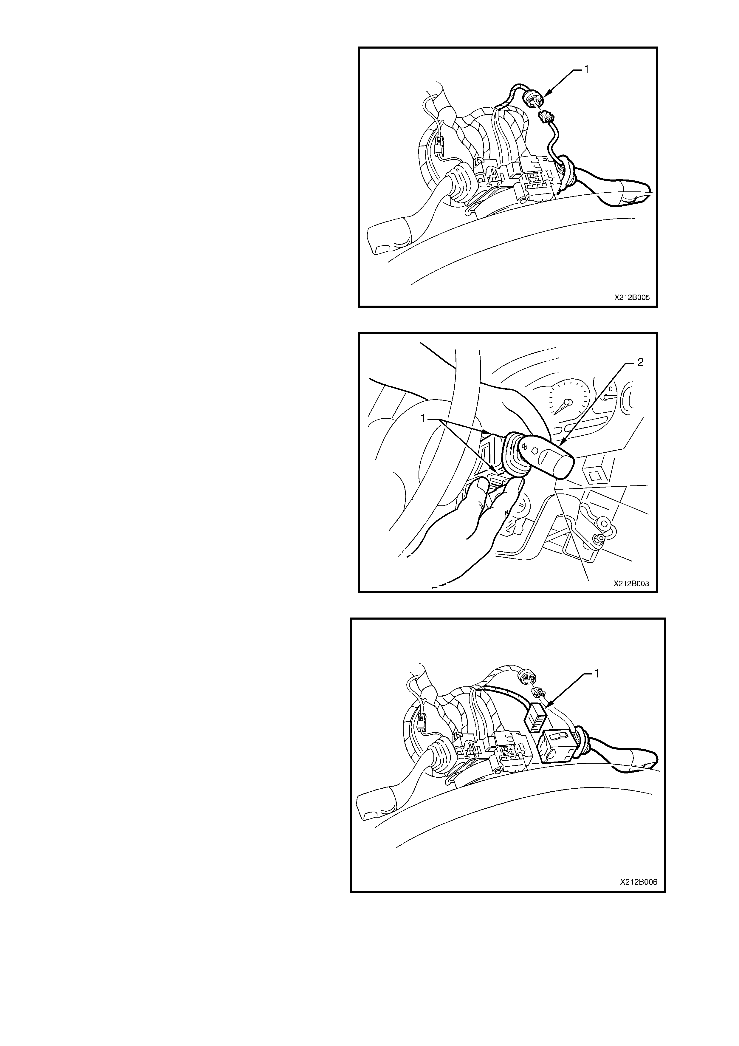
10. On headlamp and turn signal control switch
with integrated cruise control switch,
disconnect wiring harness to cruise control
switch harness connector (1).
Figure 12B-3
11. Depress retaining tangs (1) on turn signal and
headlamp control switch assembly (2) and
withdraw switch from the steering column.
Figure 12B-4
12. Depress wiring harness connector retaining
tangs and pull the turn signal and headlamp
control switch connector (1) from rear of turn
signal and headlamp switch.
Figure 12B-5
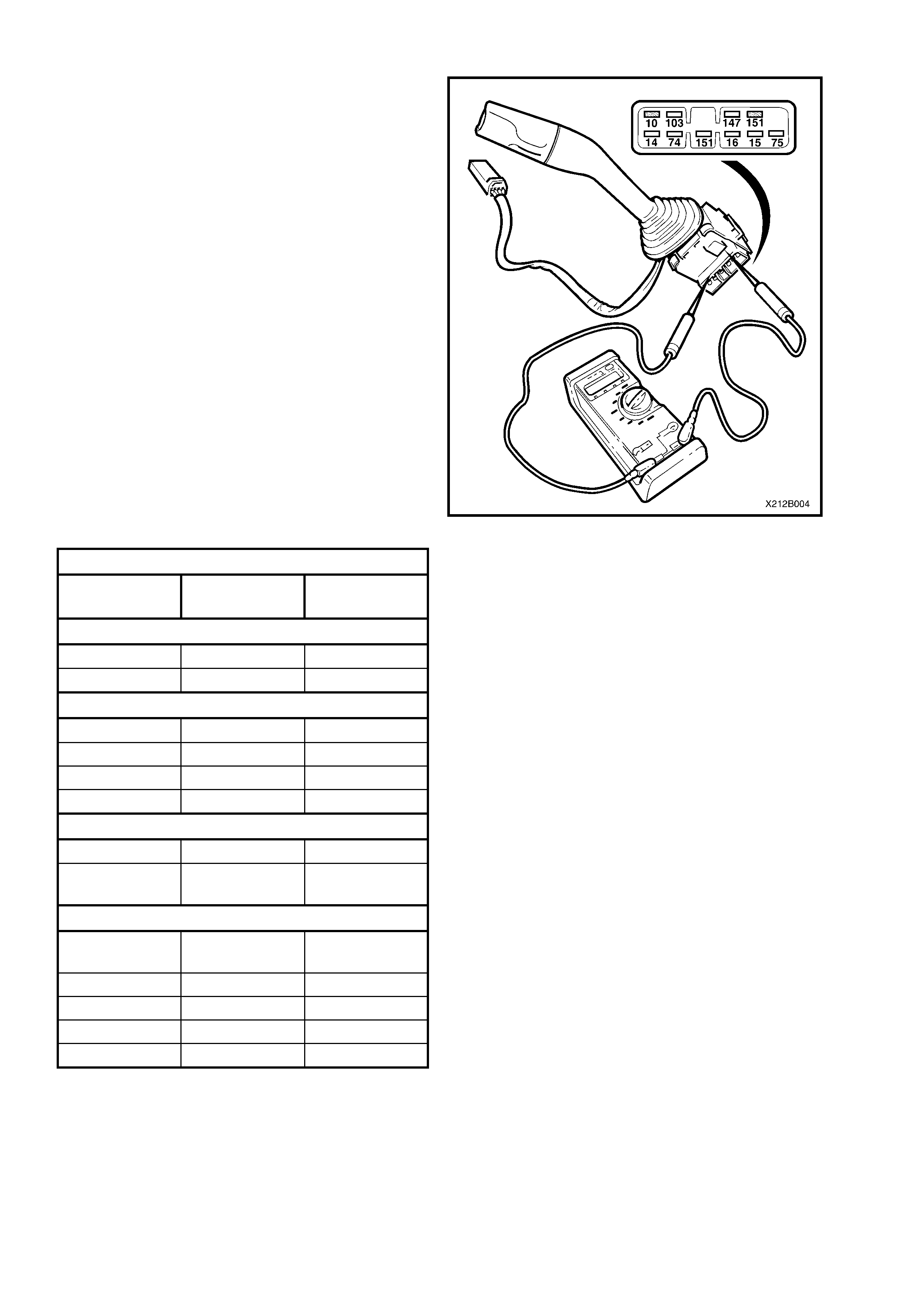
TESTING SWITCH
Using an ohmm eter, check switch contacts at eac h
switch position as indicated in the following chart.
If continuity between switch terminals is not as
specified, replace switch assembly.
NOTE: Switch terminal numbering is as shown in
Fig. 12B-6.
Figure 12B-6
HEADLAMP AND TURN SIGNAL SWITCH
Switch
Terminals Switch
Position Indication if
O.K.
Cornering Lamp c ontacts
151 & 75 Right Turn Continuity
151 & 74 Left Turn Continuity
Turn Signal Contacts
16 & 15 Neutral Open Circuit
16 & 14 Neutral Open Circuit
16 & 15 Right Turn Continuity
16 & 14 Left Turn Continuity
Headlamp Flash Contacts
151 & 10 Flash Position Continuity
151 & 10 High Beam or
Neutral Open Circuit
Headlamp High Beam Contacts
147 & 10 Flash or
Neutral Open Circuit
147 & 10 High Beam Continuity
147 & 103 Neutral Continuity
147 & 103 High Beam Open Circuit
147 & 103 Flash Continuity
REINSTALL
Installation of the switch ass embly is the reverse of the
removal procedure, noting the following:
1. Check switch operation once installed.
IMPORTANT: Enable the SRS (Air Bag).
Refer to ENABLING THE SRS,
Section 12M SUPPLEMENTAL RESTRAINT
SYSTEM of the VX Series Service Information.