SECTION 12J-1 - LOW SERIES BODY
CONTROL MODULE
IMPORTANT
Before performing any Service Operation or other procedure described in this Section, refer to Section
00 CAUTIONS AND NOTES for correct workshop practices with regard to safety and/or property damage.
1. GENERAL DESCRI PTI O N
1.1 VX SERIES II MODELS
The information relating to Low Series Body Control Modules (BCMs) as fitted to VX Series II Models carries over
from VX Series I Models, noting the following:
• As the alar m func tion has been enabled on all VX Series II Models, a new Low and Mid Series BCM has been
introduced for all VX Series II Executive, Acclaim, S and SS Models. The new BCM identification is detailed
below.
Type Level ID
LOW 1 20
MID 1 21
A revis ion has occur ed to som e cir cuits pr otected by fuses protec ted by fuses F29, F30 and F31. When conduc ting
diagnostic procedures as detailed in Section 12J-1 LOW SERIES BODY CONTROL MODULE in the VX Series I,
VT Series II or VT Series I Service Information, ensure to do so in conjunction with the wiring diagrams in
Section 12P – WIRING DIAGRAMS in this Service Information.
For further inform ation relating to the Low Series BCMs fitted to VX Series II Models, refer to Section 12J-1 LOW
SERIES BODY CONTROL MODULE in the VX Series I Service Information, in conjunction with Section 12J-1 LOW
SERIES BODY CONTROL MODULE in the VT Series I and VT Series II Service Information
Techline
Techline
Techline
Techline

1.2 VU SERIES II MODELS
The inform ation relating to Low Series Body Control Modules (BCMs) as fitted to VU Series II Models carries over
from VX Series I Models, noting the following:
• As the alarm func tion has been enabled on VU Series II S and SS Models , a new Low and Mid Series BCM has
been introduced for VU Series II S and SS Models. The new BCM identification is detailed below.
Type Level ID
LOW 1 20
NOTE: The alarm function is not available for VU Series II Models that have been fitted with the Liquefied
Petroleum Gas (LPG) system (Production Option KL7).
• A revision has occured to some circuits protected by fuses protected by fuses F29, F30 and F31. When
conducting diagnostic procedures as detailed in Section 12J-1 LOW SERIES BODY CONTROL MODULE in
the VX Series I, VT Series II or VT Series I Service Inf orm ation, ensure to do so in c onjunction with the wiring
diagrams in Section 12P – WIRING DIAGRAMS in this Service Information.
For further inform ation relating to the Low Series BCMs fitted to VU Series II Models, refer to Section 12J-1 LOW
SERIES BODY CONTROL MODULE in the VX Series I Service Information, in conjunction with Section 12J-1 LOW
SERIES BODY CONTROL MODULE in the VT Series I and VT Series II Service Information.
NOTE: Two levels of Low Series BCM have been released for VX and VU Series II Models; a LOW level for
vehicles without power operated windows and a MID level for vehicles with power operated windows. If a service
operation or diagnostic procedure requires that a Low Series BCM be replaced, ensure that the correct level of BCM
is reinstalled for the particular level of vehicle.

2. SERVICE OPERATIONS
All inform ation regarding the s ervice operations f or the Low Series BCM as f itted to VX/VU Series II Models c arries
over from the information provided in 2. SERVICE OPERATIONS in Section 12J-1 LOW SERIES BODY
CONTROL MODULE in the VT Series II Service Information, noting the following:
• The entry deterrent system fitted to VT Series II Models with a Low Series BCM and the HSPO accessory alarm
kit is fitted as standard equipment on all VX Series II and VU Series II S and SS Models.
• A revision has occured to some circuits protected by fuses protected by fuses F29, F30 and F31.
For detailed information regarding the changes to the circuits protected by fuses F29, F30 and F31, refer to
Section 12N FUSES, REL AYS AND WIRING HARNESSES and Section 12P WIRING DIAGRAMS in this Service
Information
For information regarding the service operations for the Low Series BCM as fitted to VX/VU Series II Models,
refer to 2. SERVICE OPERATIONS in Section 12J-1 LOW SERIES BODY CONTROL MODULE in the
VT Series II Service Information, in conjunction with the information provided in 2. SERVICE OPERATIONS in
Section 12J-1 LOW SERIES BODY CONTROL MODULE in the VT Series I Service Information and
Section 12P – WIRING DIAGRAMS in this Service Information.

3. TECH 2 DIAGNOSIS FOR BCM
All information regarding TECH 2 diagnosis for the BCM carries over from the information provided in 3. TECH 2
DIAGNOSIS FOR BCM in Section 12J-1 LOW SERIES BODY CONTROL MODULE in the VT Series II Service
Information, noting the following:
• The entry deterrent system fitted to VT Series II Models with a Low Series BCM and the HSPO accessory alarm
kit is fitted as standard equipment on all VX Series II Models and VU Series II S and SS Models.
For information regarding the TECH 2 DIAGNOSIS for the Low Series BCM as fitted to VX/VU Series II
Models, refer to 3. TECH 2 DIAGNOSIS FOR BCM in Section 12J-1 LOW SERIES BODY CONTROL MODULE in
the VT Series II Service Information, in conjunction with the information provided in 3. TECH 2 DIAGNOSIS FOR
BCM in Section 12J-1 LOW SERIES BODY CONTROL MODULE in the VT Series I Service Information and
Section 12P – WIRING DIAGRAMS in this Service Information.

4. DIAGNOSIS
All inform ation r egarding the diagnosis of the Low Series BCM as fitted to VX/VU Series II Models carr ies over from
the inform ation provided in 2. DIAGNOSIS in Sect ion 12J-1 LOW SERIES BODY CONTROL M ODULE in the VX
Series I Service Information, noting the following:
• The entry deterrent system fitted to VT Series II Models with a Low Series BCM and the HSPO accessory alarm
kit is fitted as standard equipment on all VX Series II Models and VU Series II S and SS Models.
• A revision has occured to som e circuits protected by fuses protected by fuses F29, F30 and F31. For detailed
inform ation regarding thes e changes, ref er to Section 12N F USES, RELAYS AND WIRING HARNESSES and
Section 12P WIRING DIAGRAMS in this Service Information
For information regarding the diagnosis for the Low Series BCM as fitted to VX/VU Series II Models not covered
in this section, refer to 2. DIAGNOSIS in Section 12J-1 LOW SERIES BODY CONTROL MODULE in the
VX Series I Service Information, in conjunction with the information provided in 4. DIAGNOSIS in Section
12J-1 LOW SERIES BODY CONTROL MODULE in the VT Series I and VT Series II Service Information and
Section 12P – WIRING DIAGRAMS in this Service Information.
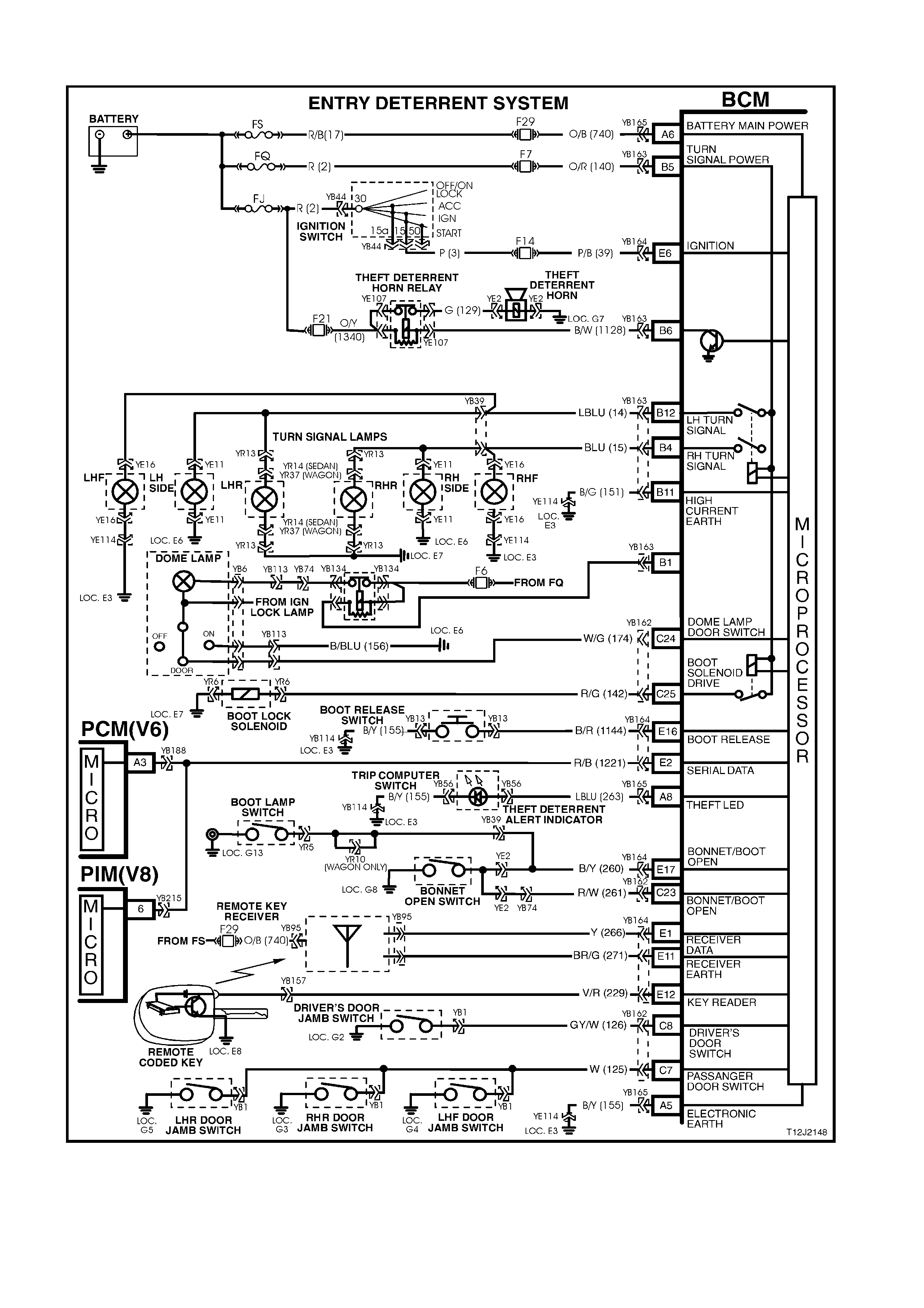
4.1 E N TRY DETERRENT
Figure 12J-1-1

CIRCUIT DESCRIPTION
The entry deterrent system, incorporated in the BCM, is designed to deter unwanted access to the vehicle's
passenger compartment by providing audible and visual warning (alarm) of illegal entry to the vehicle.
Arming of the theft and entry deterrent systems is by pressing the lock button on the remote coded key.
NOTE: The entry deterrent system does not arm passively .
For sedan Models, the remote coded key also incorporates a boot release function button.
ARMING OPERATION
The entry deterrent system is armed by pressing the lock button on the remote coded k ey. The output signal from
the key, via the remote receiver, activates the microprocessor within the BCM (via circuit 266), providing that the
ignition is OFF and the vehicle road speed input indicates speed is zero.
Note: One c ontinuous pres s of a button on the r emote coded key should cause only one arm/disar m operation. It is
not possible to arm the system or remote lock the doors with the driver's door open.
When the system is armed, the following actions take place:
1. All doors lock (and tailgate on station wagon).
2. All indicator lamps flash once.
3. The power antenna retracts.
4. The power window system deactivates.
5. The dome lamp is switched off (provided it has not been turned on by another sy stem).
6. The theft deterrent alert indicator LED flashes (refer to theft deterrent system operation description).
TRIGGERED OPERATION
Once the entry deterrent system is armed, it is triggered by any one of the following inputs:
1. The boot or bonnet being opened (circuit 260).
2. The drivers door being opened (circuit 126).
3. Any other door being opened (circuit 125).
4. Ignition being switched on (circuit 39).
If any of the previous conditions exist at the time of the system arming, they will be ignored until the fault condition is
cleared.
Once triggered, the system will operate as follows:
1. Flash all indicator lamps at a rate of one flash every tw o seconds.
2. Pulse the theft deterrent horn at a rate of one pulse per second.
3. Flash the dome lamp at a rate of one flash every two seconds.
NOTE: The indicator lamps and dome lamp should flash alternately.
Flashing of the indicators and dome lamp, and sounding of the horn/s will continue for a period of 30 seconds.
DISARMING PROCEDURE
The system is disarmed by:
A. Pressing the unlock button on the remote coded key. The RF output signal from remote coded key, via the
remote receiver, activates the microprocessor within the BCM (via circuit 266).
Upon disarming the following actions take place:
1. All doors (and tailgate on station wagon) unlock.
2. All indicators lamps flash twice, however if the system has been triggered since being armed, they will flash
three times.
3. The dome lamp is activated for 30 seconds (normal delay cancellation conditions apply).
4. If the system has been triggered since being armed, the theft deterrent alert indicator LED will flash a code
indicating the triggered source, otherwise it will be turned off. This flashing code will be cancelled once the
ignition is switched on.
B. If the remote coded key is not working (eg. flat battery), turning the ignition on allows the BCM to provide a
power supply to the remote coded key to enable reading of the key security code.
FLASH CODES
The s ystem triggered f lash codes em itted by the theft deterrent alert indicator LED f lash at a defined flash rate with
a 1.5 second between codes. Codes are repeated twice before moving to the next code.
Three flashes – bonnet or boot
Four flashes - passenger door
Five flashes - driver's door
Six flashes - ignition on
TEST DESCRIPTION
The numbers below refer to step numbers in the following diagnostic chart.
1-14. Functional check of system to help isolate fault.
15. Uses TECH 2 to check DRIVER’S DOOR OPEN signal at microprocessor at BCM.
16. Checks DRIVER’S DOOR OPEN signal at input to BCM.
17. Uses TECH 2 to activate entry deterrent horn to determine if fault is with output of BCM.
18. Checks theft deterrent horn output drive from BCM.
19. Checks circuit 1128.
20. Checks theft deterrent horn relay.
21. Determines if fault is with individual passenger door jamb switch.
22. Uses TECH 2 to check PASSENGER DOOR OPEN signal at microprocessor of BCM.
23. Checks PASSENGER DOOR OPEN signal at input to BCM.
24. Uses TECH 2 to check BOOT OPEN signal at microprocessor of BCM.
25. Checks BOOT OPEN signal at input to BCM.
26. Checks circuit 162 and boot lamp switch (including earth).
27. Uses TECH 2 to check BONNET OPEN signal at microprocessor of BCM.
28. Checks BONNET OPEN signal at input to BCM.
29. Checks circuit 260 and bonnet switch (including earth).
30. Uses TECH 2 to check IGNITION ON signal at microprocessor of BCM.
31. Checks IGNITION ON signal at input to BCM.
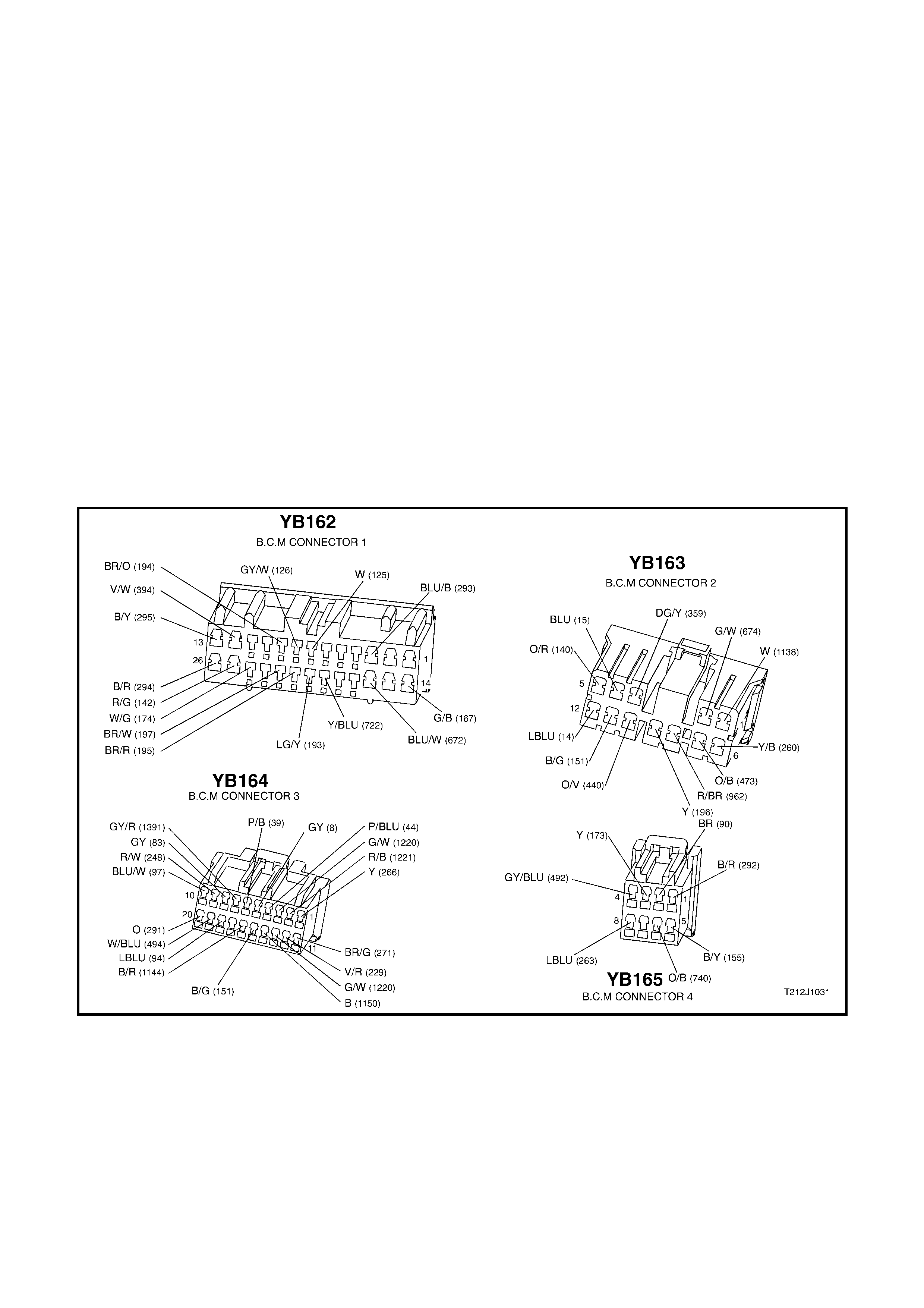
Figure 12J-1-2

ENTRY DETERRENT
STEP ACTION VALUE YES NO
1. • Ensure all windows are in the down position.
• Close all doors.
• Arm the system by operating the LOCK button on the
remote coded key.
• Do all doors lock?
Go to Step 2. Go to central
door locking
system
diagnosis, refer
to 4.3 CENTRAL
DOOR LOCKING
in Section 12J-1,
LOW SERIES
BCM in the VT
Series II Service
Information.
2. • When the LOCK button on the remote coded key
was pressed in Step 1, did all indicators flash at
once?
Go to Step 3. Go to theft
deterrent
diagnosis, refer
to 4.4 THEFT
DETERRENT in
Section 12J-1,
LOW SERIES
BCM in the VT
Series II Service
Information.
3. • When the LOCK button on the remote coded key
was pressed in Step 1, did the theft deterrent LED
begin to flash (assuming vehicle was fully
disarmed)?
Go to Step 4. Go to theft
deterrent
diagnosis, refer
to 4.4 THEFT
DETERRENT in
Section 12J-1,
LOW SERIES
BCM in the VT
Series II Service
Information.
4. • Allow ten seconds for the entry deterrent system to
arm, then lift driver’s door snib and open driver’s
door.
• Is horn triggered?
Go to Step 5. Go to Step 15.
5. • In Step 4, do both indicators and dome lamp flash
once every two seconds? Go to Step 6. Replace BCM,
refer to 2.1 LOW
SERIES BCM in
Section 12J-1,
LOW SERIES
BODY
CONTROL
MODULE in the
VT Series II
Service
Information.
Recheck and
verify repair.
6. • Disarm the alarm by pressing the UNLOCK button on
the remote coded key.
• Do indicators flash three times and the theft
deterrent LED emit a flash code of five?
Go to Step 7. Replace BCM,
refer to 2.1 LOW
SERIES BCM in
Section 12J-1,
LOW SERIES
BODY
CONTROL
MODULE in the
VT Series II
Service
Information.
Recheck and
verify repair.

ENTRY DETERRENT, Cont.
STEP ACTION VALUE YES NO
7. • Turn ignition from OFF - ON - OFF to cancel flash
code (set in Step 4).
• Arm the system by pressing the LOCK button on the
remote coded key.
• Allow ten seconds for the entry deterrent system to
arm, then test the front passenger door input by
opening the passenger door to trigger alarm, then
disarm the system by operating the UNLOCK button
on the remote coded key. Observe the theft deterrent
LED flash code, then cancel the code by cycling the
ignition (OFF - ON - OFF).
Repeat this action for both the rear passenger doors.
• Does the opening of each passenger door (when
system is armed) trigger alarm?
Go to Step 8. Go to Step 21.
8. • While observing the flash code in Step 7, did the
theft deterrent LED emit a flash code of four for each
passenger door?
Go to step 9. Replace BCM,
refer to 2.1 LOW
SERIES BCM in
Section 12J-1,
LOW SERIES
BODY
CONTROL
MODULE in the
VT Series II
Service
Information.
Recheck and
verify repair.
9. • Arm the system by pressing the LOCK button on the
remote coded key.
• Allow ten seconds for the entry deterrent system to
arm, then open the boot/tailgate using either the
emergency release handle behind the rear seat
(sedan) or the key and button on the tailgate
(wagon).
• Is alarm triggered?
Go to Step 10. Go to Step 24.
10. • Disarm the alarm by pressing the UNLOCK button on
the remote coded key.
• Is the theft deterrent LED emitting a flash code of
three?
Go to Step 11. Replace BCM,
refer to 2.1 LOW
SERIES BCM in
Section 12J-1,
LOW SERIES
BODY
CONTROL
MODULE in the
VT Series II
Service
Information.
Recheck and
verify repair.
11. • Arm the system by pressing the LOCK button on the
remote coded key.
• Allow ten seconds for the entry deterrent system to
arm, then open the bonnet.
• Is alarm triggered?
Go to Step 12. Go to Step 27.

ENTRY DETERRENT, Cont.
STEP ACTION VALUE YES NO
12. • Disarm the alarm by pressing the UNLOCK button on
the remote coded key.
• Is the theft deterrent LED emitting a flash code of
three?
Go to Step 13. Replace BCM,
refer to 2.1 LOW
SERIES BCM in
Section 12J-1,
LOW SERIES
BODY
CONTROL
MODULE in the
VT Series II
Service
Information.
Recheck and
verify repair.
13. • Arm the system by pressing the LOCK button on the
remote coded key and allow ten seconds for the
entry deterrent system to arm.
• Place a thick piece of paper over the slip ring contact
pin on the remote coded key.
• From outside the vehicle (doors closed), insert the
key into the ignition switch and turn to the ON
position.
• Is the alarm triggered?
Go to Step 14. Go to Step 30.
14. • Disarm the alarm by pressing the UNLOCK button on
the remote coded key.
• Is the theft deterrent LED emitting a flash code of
six?
System OK. Replace BCM,
refer to 2.1 LOW
SERIES BCM in
Section 12J-1,
LOW SERIES
BODY
CONTROL
MODULE in the
VT Series II
Service
Information.
Recheck and
verify repair.
15. • Disarm the alarm by pressing the UNLOCK button on
the remote coded key.
• Connect TECH 2 to the DLC.
• Select BODY / BODY CONTROL MODULE / DATA
DISPLAY.
• Scroll to DRIVERS DOOR screen display.
• Open and close the driver’s door.
• Does the screen display the state of the driver’s door
(open or closed)?
Replace BCM,
refer to 2.1 LOW
SERIES BCM in
Section 12J-1,
LOW SERIES
BODY
CONTROL
MODULE in the
VT Series II
Service
Information.
Recheck and
verify repair.
Go to Step 16.
16. • Back probe BCM connector YB162, terminal C8,
circuit 126 (Grey/White wire) with a Voltmeter to
earth.
• Open and close the driver’s door.
• Are voltages as specified?
Door open -
0 volts
Door closed -
3 volts
Replace BCM,
refer to 2.1 LOW
SERIES BCM in
Section 12J-1,
LOW SERIES
BODY
CONTROL
MODULE in the
VT Series II
Service
Information.
Recheck and
verify repair.
Check and repair
circuit 126 and
driver’s door
jamb switch.
Recheck and
verify repair.

ENTRY DETERRENT, Cont.
STEP ACTION VALUE YES NO
17. • Disarm the alarm by pressing the UNLOCK button on
the remote coded key.
• Connect TECH 2 to DLC.
• Select BODY / BODY CONTROL MODULE /
MISCELLANEOUS TESTS / SECURITY SYSTEM /
THEFT HORN.
• Conduct test as instructed by TECH 2.
• Does the theft deterrent system horn sound?
System OK. Go to Step 18.
18. • Back probe BCM connector YB163, terminal B6,
circuit 1128 (Black/White wire) with a Voltmeter to
earth.
• Disarm the alarm by pressing the UNLOCK button on
the remote coded key.
• Repeat THEFT HORN test as per Step 17.
• Is voltage as specified?
Approx.
1 volt ON
Approx
12 volts OFF
Go to Step 19. Replace BCM,
refer to 2.1 LOW
SERIES BCM in
Section 12J-1,
LOW SERIES
BODY
CONTROL
MODULE in the
VT Series II
Service
Information.
Recheck and
verify repair.
19. • Back probe theft deterrent horn relay connector
YE107, terminal 2, circuit 1128 (Black/White wire)
with a Voltmeter to earth.
• Disarm the alarm by pressing the UNLOCK button on
the remote coded key.
• Repeat THEFT HORN test as per Step 17.
• Is voltage as specified?
Approx. 1
volt on
Approx 12
volts off
Go to Step 20. Check and repair
open in circuit
1128. Recheck
and verify repair.
20. • Replace theft deterrent horn relay with a known
functional one.
• Repeat Step 17 again.
• Does the theft deterrent horn sound?
Replace horn
relay. Recheck
and verify repair.
Check and repair
fuse F21, circuits
1340 and 129 or
theft deterrent
horn. Recheck
and verify repair.
21. • In Step 7, did at least one passenger door trigger the
alarm? Check and repair
fault in circuit 125
between suspect
door and door
jamb switch.
Recheck and
verify repair.
Go to Step 22.
22. • Disarm the alarm by pressing the UNLOCK button on
the remote coded key.
• Connect TECH 2 to the DLC.
• Select BODY / BODY CONTROL MODULE / DATA
DISPLAY.
• Scroll to PASSENGER DOOR screen display.
• Open and close the passenger door.
• Does the screen display state the status of the door
(ie. Open/Closed)?
Replace BCM,
refer to 2.1 LOW
SERIES BCM in
Section 12J-1,
LOW SERIES
BODY
CONTROL
MODULE in the
VT Series II
Service
Information.
Recheck and
verify repair.
Go to Step 23.

ENTRY DETERRENT, Cont.
STEP ACTION VALUE YES NO
23. • Back probe BCM connector YB162, terminal C7,
circuit 125 (White wire) with a Voltmeter to earth.
• Open any passenger door.
• Is voltage as specified?
Below
0.5 volt Replace BCM,
refer to 2.1 LOW
SERIES BCM in
Section 12J-1,
LOW SERIES
BODY
CONTROL
MODULE in the
VT Series II
Service
Information.
Recheck and
verify repair.
Check and repair
open in circuit
125. Recheck
and verify repair.
24. • Disarm the alarm by pressing the UNLOCK button on
the remote coded key.
• Connect TECH 2 to the DLC.
• Select BODY / BODY CONTROL MODULE / DATA
DISPLAY.
• Scroll to BOOT SWITCH screen display.
• Open and close the boot lid.
• Does the screen display state the of the boot switch
(will display open when boot lid closed)?
Replace BCM,
refer to 2.1 LOW
SERIES BCM in
Section 12J-1,
LOW SERIES
BODY
CONTROL
MODULE in the
VT Series II
Service
Information.
Recheck and
verify repair.
Go to Step 25.
25. • Back probe BCM connector YB164, terminal E17,
circuit 260 (Black/Yellow wire) with a Voltmeter to
earth.
• Open boot.
• Is voltage as specified?
Below
0.5 volts Replace BCM,
refer to 2.1 LOW
SERIES BCM in
Section 12J-1,
LOW SERIES
BODY
CONTROL
MODULE in the
VT Series II
Service
Information.
Recheck and
verify repair.
Go to Step 26.
26. • Back probe boot/tailgate lamp switch connector YR5,
circuit 260 (Black/Yellow wire) with a Ohmmeter to
earth.
• Open boot/tailgate.
• Is value as specified?
Below 1 ohm Check and repair
open in circuit
260. Recheck
and verify repair.
Check and
repair/replace
boot switch
(including switch
earth). Recheck
and verify repair.
27. • Disarm the alarm by pressing the UNLOCK button on
the remote coded key.
• Connect TECH 2 to the DLC.
• Select BODY / BODY CONTROL MODULE / DATA
DISPLAY.
• Scroll to BOOT SWITCH screen display.
• Open and close bonnet.
• Does the screen display the state of the bonnet
switch (will display open when bonnet is closed)?
NOTE: As the bonnet and boot/tailgate share an input to
the BCM, the BOOT SWITCH display also reflects the
state of the bonnet, and if either one is opened, it will be
diplayed as BOOT SWITCH CLOSED.
Replace BCM,
refer to 2.1 LOW
SERIES BCM in
Section 12J-1,
LOW SERIES
BODY
CONTROL
MODULE in the
VT Series II
Service
Information.
Recheck and
verify repair.
Go to Step 28.

ENTRY DETERRENT, Cont.
STEP ACTION VALUE YES NO
28. • Disconnect BCM connectors YB164 YB162 and back
probe harness end of terminals E17 and C23,
circuits 260 (Black/Yellow wire) and 261 (Red/White
wire) with an Ohmmeter to earth.
• Open bonnet.
• Are values as specified?
Below 1 ohm
(both circuits) Replace BCM,
refer to 2.1 LOW
SERIES BCM in
Section 12J-1,
LOW SERIES
BODY
CONTROL
MODULE in the
VT Series II
Service
Information.
Recheck and
verify repair.
Go to Step 29.
29. • Reconnect BCM connectors YB164 and YB162.
• Open Bonnet.
• Back probe bonnet switch connector YE2, circuit 260
(Black/Yellow wire) with an Ohmmeter to earth.
• Is value as specified?
Below 1 ohm Check and repair
open in circuits
260. Recheck
and verify repair.
Check and
repair/replace
bonnet switch
(including switch
earth). Recheck
and verify repair.
30. • Disarm the alarm by pressing the UNLOCK button on
the remote coded key.
• Connect TECH 2 to the DLC.
• Select BODY / BODY CONTROL MODULE / DATA
DISPLAY.
• Scroll to IGNITION SWITCH screen display.
• Turn ignition ON.
• Does the screen display IGNITION ON?
Replace BCM,
refer to 2.1 LOW
SERIES BCM in
Section 12J-1,
LOW SERIES
BODY
CONTROL
MODULE in the
VT Series II
Service
Information.
Recheck and
verify repair.
Go to Step 31.
31. • Back probe BCM connector YB164, terminal E6,
circuit 39 (Pink/Black wire) with a Voltmeter to earth.
• Turn ignition ON.
• Is voltage as specified?
12 volts
(ignition on) Replace BCM,
refer to 2.1 LOW
SERIES BCM in
Section 12J-1,
LOW SERIES
BODY
CONTROL
MODULE in the
VT Series II
Service
Information.
Recheck and
verify repair.
Check and repair
open in circuit 39
(including fuse
F14 and ignition
switch). Recheck
and verify repair.