
SECTION 12N - FUSES, RELAYS AND
WIRING HARNESSES
IMPORTANT:
Before performing any Service Operation or other procedure described in this Section, refer to
Section 00 CAUTIONS AND NOTES for correct workshop practices with regard to safety and/or
property damage.
1. GENERAL I NFORMATI O N
1.1 VX SERIES II MODELS
The fuses, relays and wiring harnesses fitted to VX Series II Models carry over from VX Series I Models,
noting the following:
• The engine cooling fan circuit breakers have been relocated from a separate housing located on the
right-hand side of the radiator support panel to the engine compartment fuse and relay panel.
• As a result of the above, the engine compartment fuse and relay panel along with the engine
compartment wiring harness have been revised.
• The door jamb switches are now single terminal for all positions in all models.
• Circuits protected by fuse F29, F30 and F31 have been revised.
For inf ormation relating to the f uses, relays and wiring harnesses fitted to VX Series II Models not covered
in this Section, refer to Section 12N FUSES, RELAYS AND WIRING HARNESSES in the VX Series I
Service Information in conjunction with Section 12N FUSES RELAYS AND WIRING HARNESSES in the
VT Series I and VT Series II Service Information. For all fuse and circuit breaker circuit protection details
for VX Series II Models, refer to Section 12P WIRING DIAGRAMS in this Service Information in
conjunction with Section 12P WIRING DIAG RAMS in the VT Series I , VT Series II and VX Series I Service
Information.

1.2 VU SERIES II MODELS
The fuses, relays and wiring harnesses fitted to VU Series II Models carry over from VU Series I Models,
noting the following:
• The engine cooling fan circuit breakers have been relocated from a separate housing located on the
right-hand side of the radiator support panel to the engine compartment fuse and relay panel.
• As a result of the above, the engine compartment fuse and relay panel along with the engine
compartment wiring harness have been revised.
• The door jamb switches are now single terminal for all positions in all models.
• Circuits protected by fuse F29, F30 and F31 have been revised.
For inf ormation relating to the f uses, relays and wir ing harnesses fitted to VU Series II Models not covered
in this Section, refer to Section 12N FUSES, RELAYS AND WIRING HARNESSES in the VU Series
Service Information in conjunction with Section 12N FUSES RELAYS AND WIRING HARNESSES in the
VT Series I, VT Series II and VX Series I Service Information. For all fuse and circuit breaker circuit
protection details for VU Series II Models, refer to Section 12P WIRING DIAGRAMS in this Service
Information, in conjunction with Section 12P WIRING DIAGRAMS in the VT Series I, VT Series II,
VX Series I and VU Series I Service Information.

1.3 WH SERIES II MODELS
The f uses, relays and wiring harnesses fitted to WH Series II Models carry over f rom W H Series I Models,
noting the following:
• The engine cooling fan circuit breakers have been relocated from a separate housing located on the
right-hand side of the radiator support panel to the engine compartment fuse and relay panel.
• The level ride r elay has been relocated f rom the f use and relay panel ass embly, behind the instrum ent
panel lower right-hand side cover to the engine compartment fuse and relay panel.
• As a result of the above, the engine compartment fuse and relay panel along with the engine
compartment wiring harness have been revised and the fuse and relay panel inside the vehicle
passenger compartment has a spare relay mounting where the level ride relay was previously installed.
• The door jamb switches are now single terminal for all positions in all models.
• Circuits protected by fuse F29, F30 and F31 have been revised.
For inf orm ation relating to the f uses, r elays and wiring harnesses fitted to WH Series II Models not cover ed
in this Section, refer to Section 12N FUSES, RELAYS AND WIRING HARNESSES in the WH Series I
Service Information in conjunction with Section 12N FUSES RELAYS AND WIRING HARNESSES in the
VT Series I and VT Series II Service Information. For all fuse and circuit breaker circuit protection details
for WH Series II Models, refer to Section 12P WIRING DIAGRAMS in this Service Information in
conjunction with Section 12P WIRING DIAGRAMS in the VT Series I, VT Series II, VX Series I, and
WH Series I Service Information.
1.4 FUSES AND CIRCUIT BREAKERS
FUSES
All vehicle electrical circuits are protected against damage which might occur because of short circuits or
overloads in the wiring system. Protection is provided by a fuse, circuit breaker or fusible link.
Fuses are the blade type mini-fuse, with the current rating in am ps indicated on top of the fuse assembly,
above the element, or by the colour of the fuse.
To determine whether or not a fuse has blown, remove the suspect fuse and examine the element in the
fuse for a break.
NOTE: A blown fuse is caused by a fault. Replace a blown fuse only with a fuse of the sam e rating. If the
replacement fuse blows, rectify the fault before replacing the fuse again.
CURRENT RATING
(AMPS) FUSE COLOUR
3 VIOLET
5 TAN
7.5 BROWN
10 RED
15 BLUE
20 YELLOW
25 WHITE
30 GREEN
Fuses are located in two positions on VX, VU and W H Series II Models. One group is located in the fuse
and relay panel assembly, inside the vehicle passenger compartment, behind the instrument panel lower
right-hand side cover as per VT Series II Models.
For inf orm ation relating to these f uses, r efer to Sec tion 12N FUSES, RELAYS AND WIRING HARNESSES
in the VT Series II Ser vice Inform ation, in conjunc tion with the inform ation provided in Section12N FUSES,
RELAYS AND WIRING HARNESSES in the VT Series I, VX Series I and WH Series I Service Information.
The second group of fuses is located in the engine
compartment fuse and relay panel assembly,
situated forward of the right-hand side front
suspension strut tower.
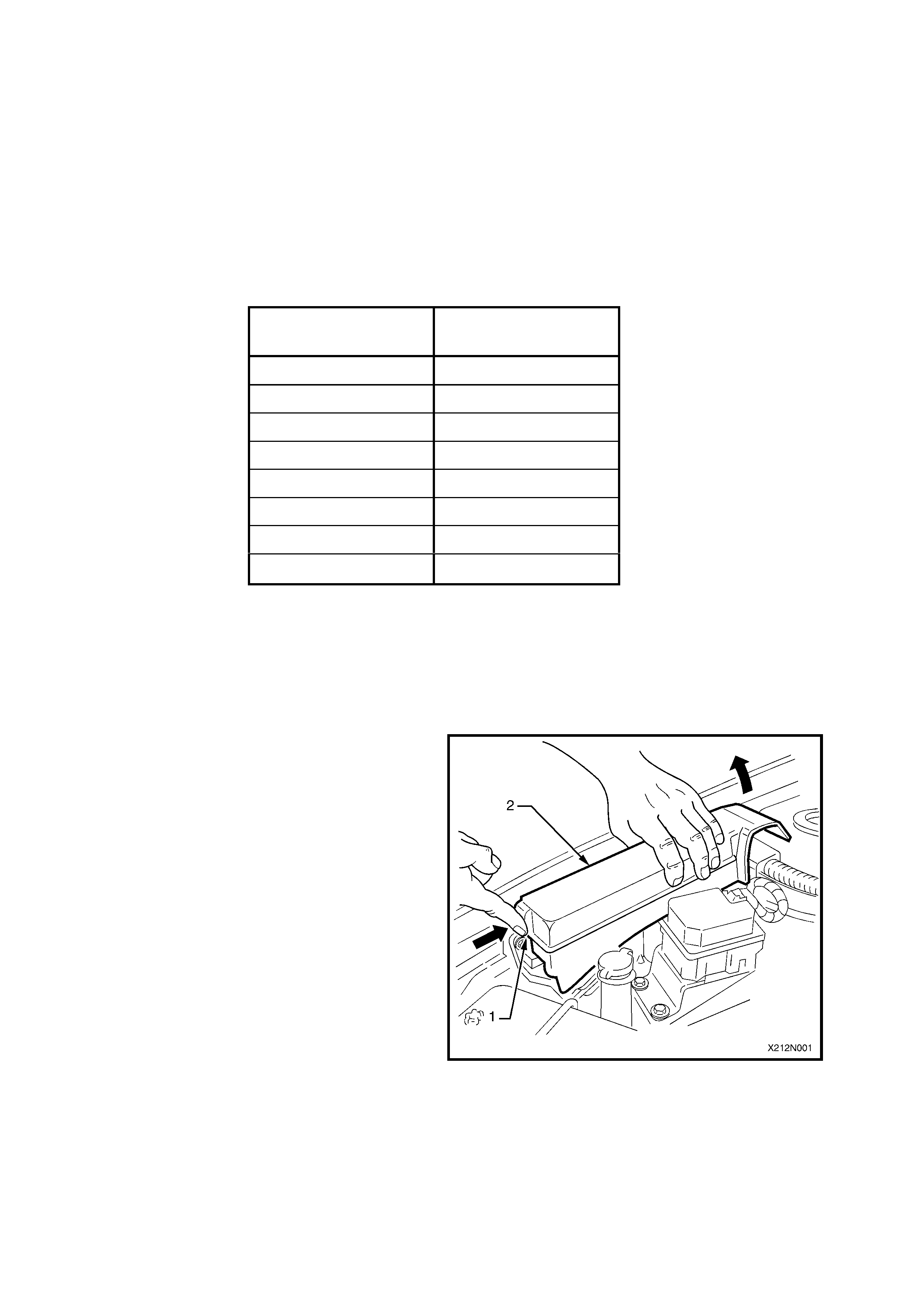
Access to the engine compartment fuse and relay
panel assembly is by first depressing the cover
retaining tang (1), refer to Fig. 12N-1 and then
lifting the cover (2) up and out of the panel
assembly.
Figure 12N-1
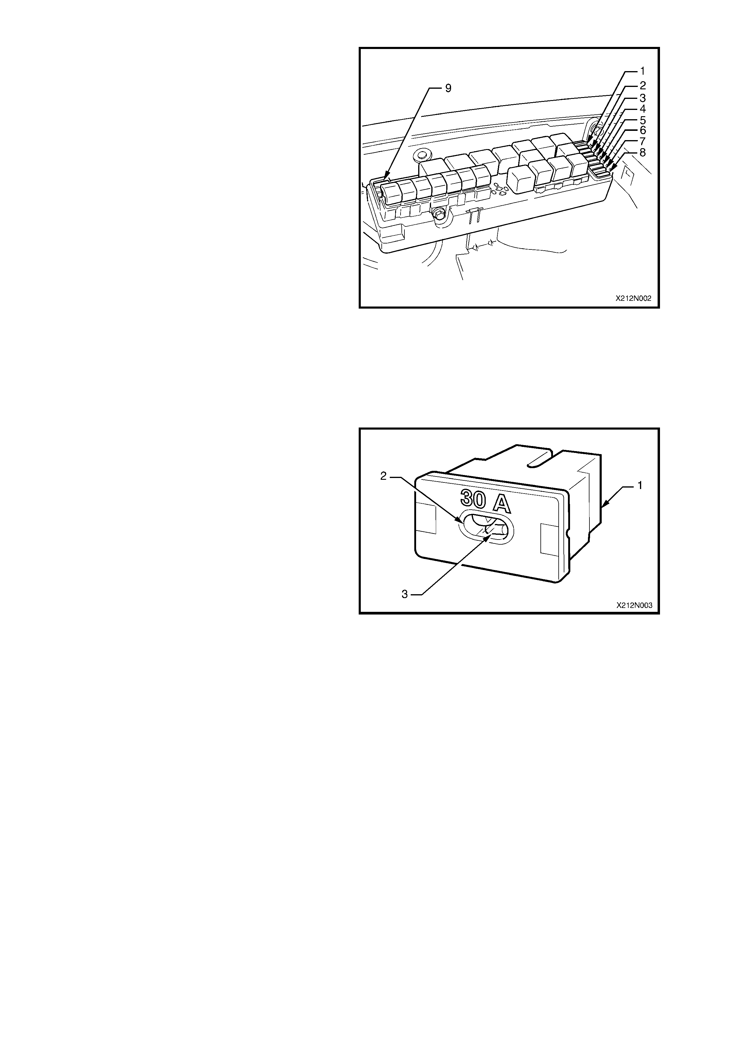
Fig. 12N-2 illustrates the engine com partment fuse
and relay panel assembly for VX, VU and WH
Series II Models.
Refer to the legend below for nominating fuse
number and each system protected by that fuse.
A label on the inside of the cover indicates the
circuits protected by each fuse, as well as
nominating relay function.
Use the fuse remover in the passenger
compartment fuse and relay panel assembly to
remove these fuses.
Legend
1. F28 – Fuel pump (15A)
2. F29 – Engine control/BCM (10A)
3. F30 – RH headlamps (20A)
4. F31 – LH headlamps (20A)
5. F32 – Automatic transmission (15A)
6. F33 – Engine sensors (15A)
7. F34 – Injectors/Ignition (15A)
8. F35 – Injectors/Ignition (15A)
9. F36 – Throttle actuator – GEN III V8 (25A)
Figure 12N-2
FUSIBLE LINKS
The chassis and engine electrical wiring is
protected against short circuit damage by fusible
links.
The fusible links are contained in the engine
compartment fuse and relay panel assembly,
situated forward of the right-hand side front
suspension strut tower.
The fusible links (1) are a plug in type, with an
inspection window (2) which allows a visual check
of the condition of the fusible link element (3). To
determine whether or not a fusible link has blown,
examine the fusible link element for a break.
All fusible links can be easily removed by pulling
them out of their housing sockets. Ensure when
installing replacement fusible links that they are
pressed firmly into the correct fuse panel location
NOTE: A blown fusible link is caused by a fault.
Replace a blown fusible link only with a fusible link
of the same current rating. Fusible link current
rating is indicated on top of the assem bly, adjacent
to the ins pection window. If the replacem ent fusible
link blows, rectify the fault before replacing the
fusible link again.
Figure 12N-3
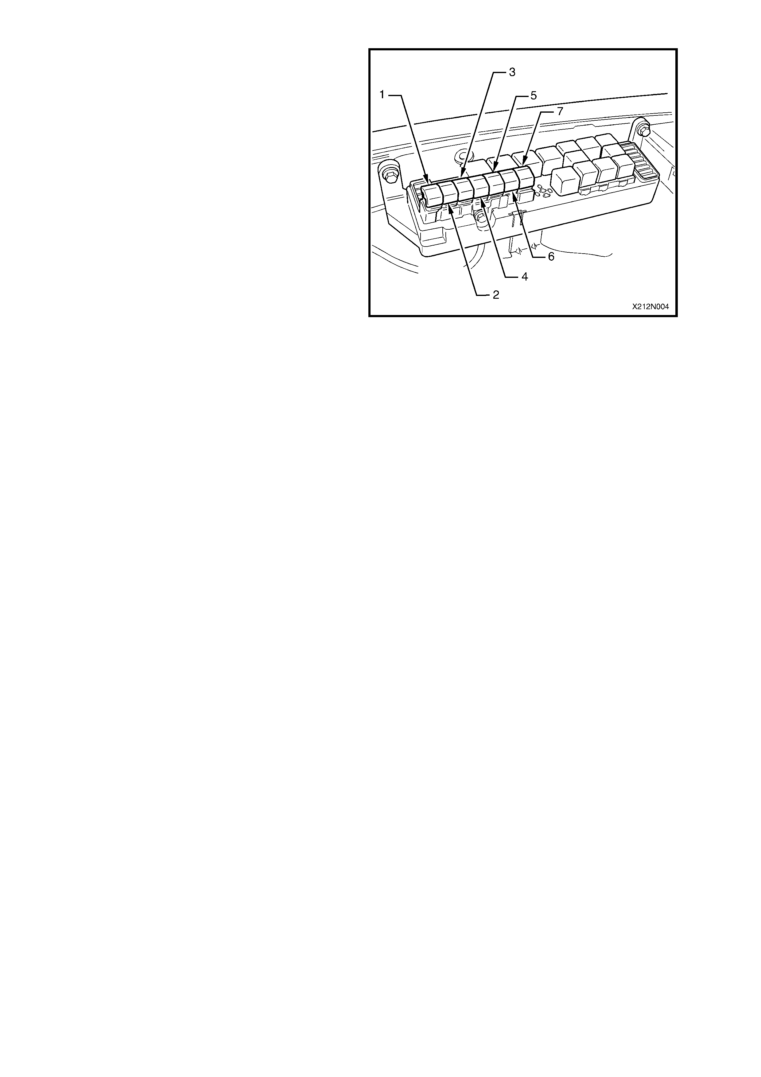
Fig. 12N-4 illustr ates the f usible link locations in the
engine compartment fuse and relay panel
assembly.
Refer to the legend below for fusible link
identification and circuit protection functions.
Legend
1. FU – Primary radiator cooling fan (30A)
2. FQ – Lighting (60A)
3. FR – ABS (60A)
4. FS – Engine (60A)
5. FJ – Main (60A)
6. FY – Blower (40A)
7. FT – Secondary radiator cooling fan (30A)
Figure 12N-4
1.5 RELAYS
There ar e two gr oups of relays on VX, VU and W H
Series II Models.
One group of relays is located in the passenger
com par tment fuse and relay panel assembly, inside
the vehicle passenger compartment, behind the
instrument panel lower right-hand side cover.
A label on the inside of the cover nominates each
relay function as well as indicating the circuits
protected by each fuse.
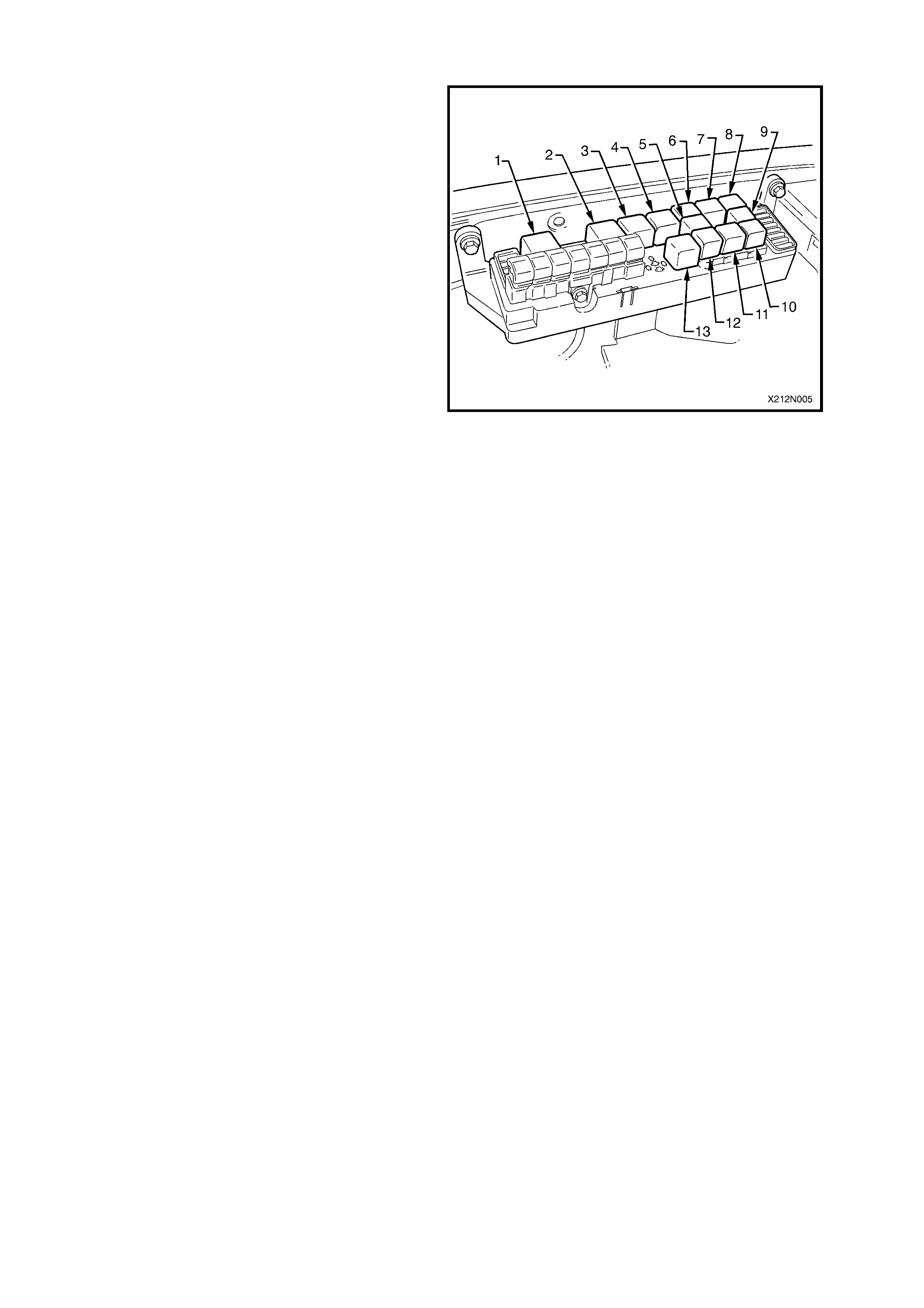
Additional relays are located in the engine
compartment fuse and relay panel assembly, refer
to Fig. 12N-5. Access to the relays in the engine
compartment fuse and relay panel assembly can
be achieved by removing the panel assembly
cover, refer to Fig. 12N-1.
Refer to the legend below for relay identification.
Legend
1. YE49 – Start relay
2. YE47 – Headlamp relay (High beam)
3. YE39 – EFI relay
4. YE43 – Radiator fan relay (High speed)
5. YE101 – A/C compressor relay
6. YE41 – Horn relay
7. YE107 – Theft horn relay
8. YE44 – Fog lamp relay
9. YE147 – Level ride relay (WH Series II only)
10. YE96 – Fuel pump relay
11. YE76 – Front wiper relay
12. YE102 – Headlamp relay (Low beam)
13. YE103 – Radiator fan relay (Low speed)
Figure 12N-5


3. WIRING INSTALLATION DIAGRAMS
3.1 VX SERIES II MODELS
For all wiring installation diagrams, refer to Section 12N FUSES, RELAYS AND WIRING HARNESSES in
the VX Series I Service Information, in conjunction with Section 12N FUSES, RELAYS AND WIRING
HARNESSES in the VT Series II and VT Series I Service Information.
For more detailed information regarding wiring diagrams, refer to Section 12P WIRING DIAGRAMS.

3.2 VU SERIES II MODELS
For all wiring installation diagrams, refer to Section 12N FUSES, RELAYS AND WIRING HARNESSES in
the VU Series I Service Information, in conjunction with Section 12N FUSES, RELAYS AND WIRING
HARNESSES in the VX Series I, VT Series II and VT Series I Service Information.
For more detailed information regarding wiring diagrams, refer to Section 12P WIRING DIAGRAMS.

3.3 WH SERIES II MODELS
For all wiring installation diagrams, refer to Section 12N FUSES, RELAYS AND WIRING HARNESSES in
the WH Series I Service Information, in conjunction with Section 12N FUSES, RELAYS AND WIRING
HARNESSES in the VT Series II and VT Series I Service Information.
For more detailed information regarding wiring diagrams, refer to Section 12P WIRING DIAGRAMS.