
SECTION 6B2 - COOLING SYSTEM -
V6 SUPERCHARGED ENGINE
IMPORTANT
Before perfo rming any Service O peration or oth er procedu re described in t his Sectio n, refer to Section 00
CAUTIONS AND NOTES for correct workshop practices with regard to safety and/or property damage.
1. GENERAL INFORMATION
2. SERVICE OPERATIONS
2.1 SERVICE NOTES
2.2 COOLING SYSTEM HOSES
SERVICE NOTES
3. TORQUE WRENCH SPECIFICATIONS
Techline
Techline
1. GENERAL I NFORMATION
The cooling system for VX and WH Series II Models fitted with a V6 Supercharged engine carries over from VT
Series I Models, noting the following:
• A new condensor, radiator and fan module (CRFM) was introduced into WH Series II Models as part of the
MY2003 update during October 2002.
The inf ormation provided in this Section only applies to WH Series II Models fitted with the revised cooling system .
For information regarding either the earlier type cooling system or the unchanged portion of the revised cooling
system, refer to Section 6B1-2 ENGINE COOLING - V6 SUPERCHARGED ENGINE in the VT Series I Service
Information.
The cooling system for WH Series II vehicles, fitted with the V6 Supercharged engine differs from the naturally
aspirated V6 engines with revised plumbing and additional bleeder points.
The radiator and fan module has been completely re-designed and, in this respect, is the same as the revised
assem bly fitted to WH Series II Models with a V6 engine. T heref ore, for all servic e operations related to the r evised
radiator and/or cooling fans not covered in this Section, refer to Section 6B1-1 ENGINE COOLING – V6 ENGINE in
the VT Series I Service Information.
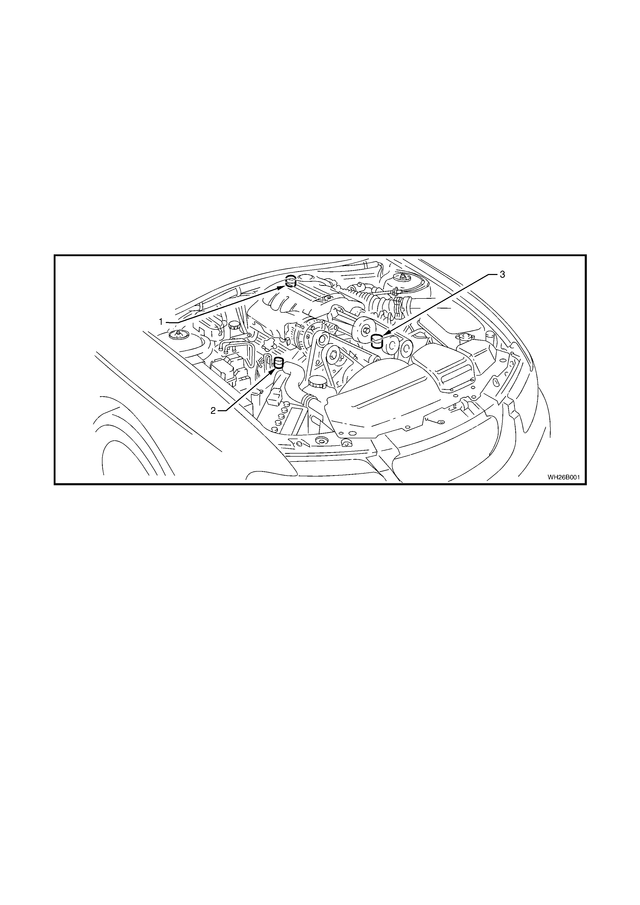
Figure 6B2-1
Legend:
1. Thermostat Cover Bleeder Screw
2. Radiator Inlet Pipe Bleeder Screw
3. Coolant Bypass Housing Bleeder Screw

2. SERVICE OPERATIONS
Cooling system service operations carry over in general from those described in Section 6B1-2 ENGINE COOLING
- V6 SUPERCHARGED ENGINE, in conjunction with Section 6B1-1 ENGINE COOLING - V6 ENGINE, in the VT
Series I Service Information except for the following operations.
2.1 SERVICE NOTES
1. Before removing the radiator cap, allow the engine to cool, then place a shop rag over the radiator cap and
slowly turn the cap anti-clockwise, without pressing down until the cap reaches the first 'stop'. This is the
pressur e relief stop, which will allow any rem aining press ure within the system to escape. T hen press down on
cap and continue to rotate the cap anti-clockwise until it can be removed.
2. The vehicle is fitted with radiator electric cooling fans. W hen working around the engine compartm ent with the
engine running or with the ignition 'ON', keep clear of the fan as it may start operating without warning.
3. The cooling system requires little care except for maintaining the coolant to the correct level in the recovery
reservoir and periodic servicing at the time or distance intervals as outlined in the MY 2003 VY and V2 Series
Owner's Handbook.
Periodic servicing includes:
a. Checking the coolant level, refer to 2.3 CHECKING AND FILLING COOLING SYSTEM in Section 6B1-2
ENGINE COOLING – V6 SUPERCHARGED ENGINE in the VT Series I Service Information.
b. Checking the coolant concentration, refer to 2.2 GLYCOL COOLANT MAINTENANCE – Testing Coolant
Concentration in Section 6B1-1 ENGINE COOLING – V6 ENGINE in the VT Series I Service Information.
c. Pressure test the cooling system and radiator cap, refer to 2.7 PRESSURE TESTING in Section 6B1
ENGINE COOLING – V6 ENGINE in the VT Series I Service Information.
d. Tighten the hose clamps and inspect all hoses, refer to 2.2 COOLING SYSTEM HOSES in this Section.
Replace hoses if swollen or deteriorated.
CAUTION: Always wear protective safety glasses when working with spring type hose clamps.
Failure to do so could result in eye injury.
e. Clean out the c ooling system, ref er to 2.4 CLEANING COOLING SY STEM – COOLING SYSTEM FLUSH,
in Section 6B1-1 ENGINE COOLING – V6 ENGINE in the VT Series I Service Information and refill the
cooling system, refer to 2.3 CHECKING AND FILLING COOLING SYSTEM in Section 6B1-2 ENGINE
COOLING – V6 SUPERCHARGED ENGINE in the VT Series I Service Information.
4. To reduce environmental impact and maintenance cost, whenever the coolant is drained from any engine, the
service r ecor ds are to be c hec k ed to deter mine when the coolant was last c hanged. If mor e than six months life
is left before the next coolant change, then the following procedure is to be followed:
a. W hen draining the coolant from the engine, use a clean container of at least 12 litres capacity and ensure
that the coolant is not contaminated in the draining process.
b. After repairs have been completed, refill the engine cooling system with the drained coolant.
c. Top up as required, using a 50/50 mix of clean water and the recommended coolant, which is ‘New Formula
Long Life All Seasons Coolant’. Refer to 2.2 GLYCOL COOLANT MAINTENANCE in Section 6B1-1
ENGINE COOLING – V6 ENGINE in the VT Series I Service Information and 2.3 CHECKING AND
FILLING COOLING SYSTEM in Section 6B1-2 ENGINE COOLING – V6 SUPERCHARGED ENGINE in
the VT Series I Service Information, for the necessary procedures and further information.
2.2 COOLING SYSTEM HOSES
SERVICE NOTES:
1. Coolant hoses are installed as shown in the following illustration.
2. Hose connections should be thoroughly cleaned before installing any new hose.
3. Following hose/s ins tallation, always ref ill the c ooling system with the corr ec t type and concentration of coolant.
Refer to 2.3 CHECKING AND FILLING COOLING SYSTEM in Section 6B1-2 ENGINE COOLING – V6
SUPERCHARGED ENGINE in the VT Series I Service Information.
CAUTION: Always wear protective safety glasses when working with spring type hose clamps. Failure to do
so could result in eye injury.
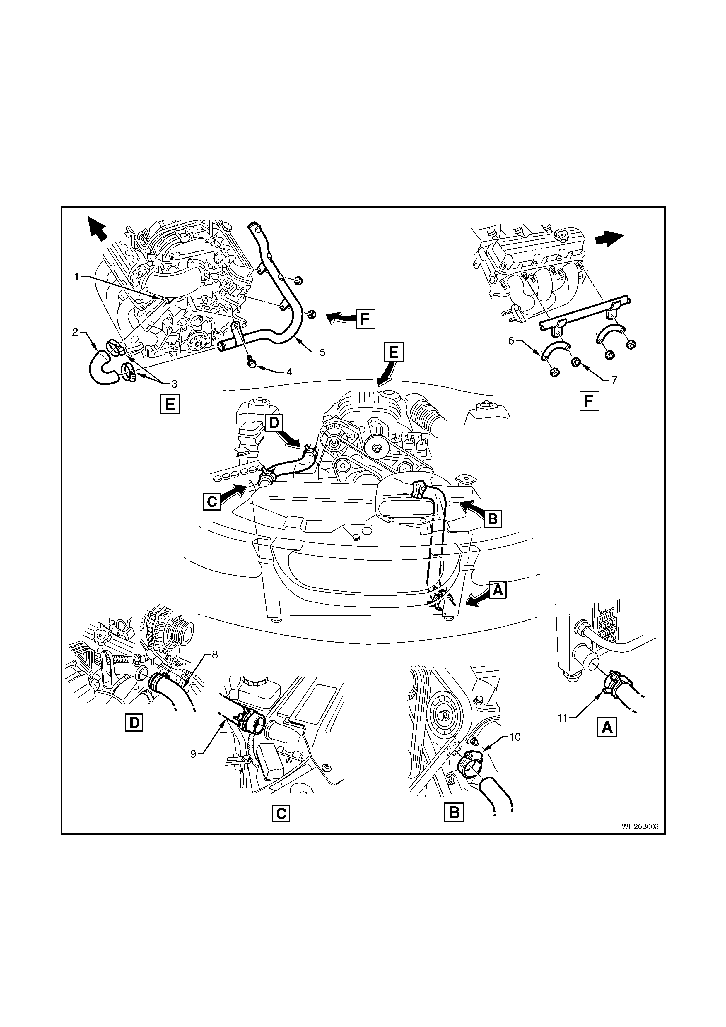
Figure 6B2-2
Legend
1. Coolant Outlet
2. Coolant Outlet Hose
3. Hose Clamps
4. Screw
5. Radiator Inlet Pipe
6. Plate
7. Plate Nut
8. Radiator Inlet Hose
9. Radiator Inlet Hose Clamps
(2 places)
10. Radiator Outlet Hose Clamps
(2 places)
11. Radiator Outlet Hose

3. TORQUE WRENCH SPECIFICATIONS
Nm
Radiator inlet pipe retaining nuts and screw......................... 25
Coolant Hose Clamps........................................................... 3