
SECTION 0A - GENERAL INFORMATION
IMPORTANT
Before perfo rming any Service Operat ion or oth er procedure described in this Section , refer to Section 00
CAUTIONS AND NOTES for correct workshop practices with regard to safety and/or property damage.
CONTENTS
1. GENERAL INFORMATION
1.1 HOIST PAD LOCATIONS
2. MODEL AVAILABILITY AND EQUIPMENT
2.1 DOMESTIC
2.2 BRAZIL
2.3 GULF STATES
2.4 SOUTH AFRICA
3. MAJOR OPTION CODES
4. POWERTRAIN COMBINATIONS
5. TRANSMISSION RATIOS
6. ENGINE DATA
7. EXTERIOR DIMENSIONS
8. VEHICLE WEIGHTS
9. SERIAL NUMBERS – DOMESTIC
9.1 LOCATION OF IDENTIFICATION PLATES
9.2 SAFETY COMPLIANCE PLATE
9.3 BODY AND OPTION
IDENTIFICATION PLATE
9.4 VEHICLE IDENTIFICATION NUMBER
VIN PLATE
VIN BODY STAMPING
9.5 VEHICLE IDENTIFICATION
NUMBERING SYSTEM
9.6 FUEL CONSUMPTION LABEL
10. SERIAL NUMBERS – BRAZIL
10.1 LOCATION OF IDENTIFICATION PLATES
10.2 BODY AND OPTION
IDENTIFICATION PLATE
10.3 MAUNUFACTURER LABEL
10.4 PAINT LABEL
10.5 VIS LABEL
10.6 VEHICLE IDENTIFICATION NUMBER
VIN PLATE
VIN BODY STAMPING
10.7 VEHICLE IDENTIFICATION
NUMBERING SYSTEM
11. SERIAL NUMBERS – GULF STATES
11.1 LOCATION OF IDENTIFICATION PLATES
11.2 SAFETY COMPLIANCE LABEL
11.3 BODY AND OPTION
IDENTIFICATION PLATE
11.4 VEHICLE IDENTIFICATION NUMBER
VIN PLATE
VIN BODY STAMPING
11.5 VEHICLE IDENTIFICATION
NUMBERING SYSTEM
12. SERIAL NUMBERS – SOUTH AFRICA
12.1 LOCATION OF IDENTIFICATION PLATES
12.2 SAFETY COMPLIANCE PLATE
12.3 BODY AND OPTION
IDENTIFICATION PLATE
12.4 VEHICLE IDENTIFICATION NUMBER
VIN PLATE
VIN BODY STAMPING
12.5 VEHICLE IDENTIFICATION
NUMBERING SYSTEM
13. ENGINE SERIAL NUMBERS
13.1 V6 ENGINE
13.2 GEN III V8 ENGINE
14. TRANSM ISSION SERIAL NUMBER
14.1 AUTOMATIC TRANSMISSION
14.2 MANUAL TRANSMISSION – 5 SPEED
14.3 MANUAL TRANSMISSION – 6 SPEED
15. FINAL DRIVE ASSEMBLY SERIAL
NUMBER
16. CONSOLIDATED TOOL LIST
Techline
Techline
Techline
Techline
Techline
Techline
Techline

1. GENERAL I NFORMATION
The MY2003 VY Ser ies and V2 Ser ies II vehicles ar e a major m odel upgrade. T he main changes ar e summ arised
in the following list. Additional and more detailed information is provided in the relevant Section in this Service
Information package.
• New hood, fenders, quarter panels and rear compartment lid.
• New front and rear lamp units.
• New bumper fascias.
• Low wind-noise exterior mirrors.
• New grille inserts, badges and side mouldings.
• New alloy wheels or wheel trims.
• Revised interior trim colours and materials.
• New instrument panel and console with 2.25 DIN specification audio sy stem.
• Reverse Parking Aid (RPA) system availability for sedans and coupe.
• New multi-function display instruments.
• Modular condenser-radiator-fan assembly.
• New steering wheel and airbag.
• Stand-alone navigation system (option).
• Wider interior mirror.
• Twilight sentinel for Level 1 models.
• New spoilers for S and SS models.
• Sunglass holder with reading lamps for Level 2 and 3 models.
• New fog lamps for Level 3 models.
• Mobile phone stowage provision for Level 3 models.
This Sect ion contains inf or mation about vehic le hoisting, model availability, model options, powertrain com binations ,
transmission ratios, engine data and exterior dimensions and vehicle numbering.
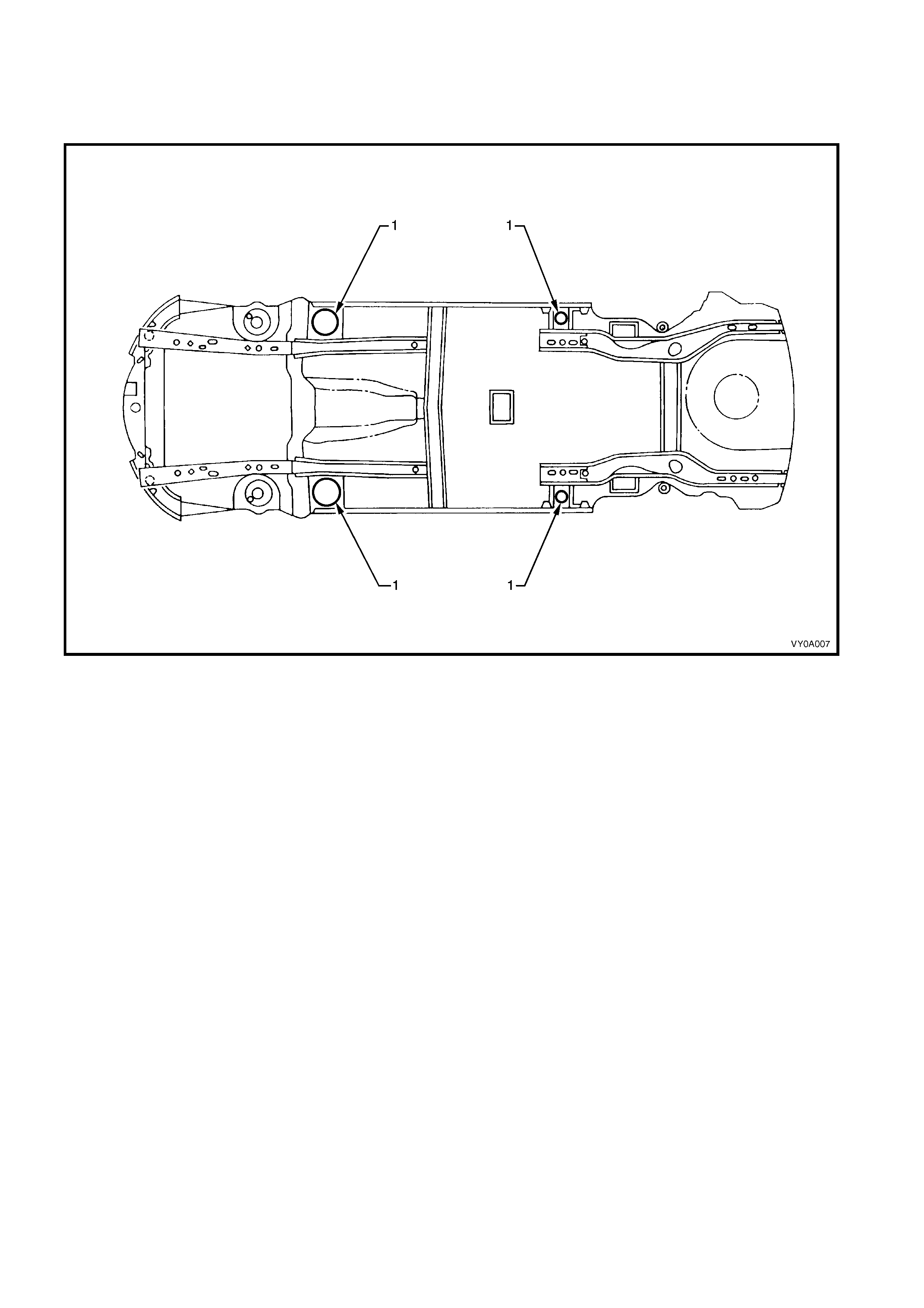
1.1 HOIST PAD LOCATIONS
When using a trolley jack to raise the vehic le, it is im portant that the jac k be positioned under the su spension c ross
member or hoist pad (1) locations. Do not jack under the suspension control arm. The vehicle should always be
supported by jack stands at the hoist pad locations when raised.
Figure 0A-1
2. MODEL AVAILABILITY AND EQUIPMENT
NOTE: For tyre and wheel information, refer to Section 10 WHEELS AND TYRES.
2.1 DOMESTIC
BRAND NAME MODEL NAME LUXURY LEVEL
(DESCRIPTION) MODEL NO. BODY STYLE
(DOORS) ENGINE
(OPTION)
8VK69 Sedan (4)
V6, (V6 S/C),
(V8)
Executive Level 1
(Base) 8VK35 Wagon (5) V6, (V8)
8VK69 Sedan (4) V6
Acclaim Level 1
(Safety / family) 8VK35 Wagon (5) V6, (V8)
S Level 1
(Base sport) 8VK69 Sedan (4) V6, (V6 S/C)
SV8 Level1
(Base sport) 8VK69 Sedan (4) V8
Holden
Commodore
SS Level 1
(Sport) 8VK69 Sedan (4) V8
— Level 1
(Base) 8VK80 Utility (2) V6
S Level 1
(Base sport) 8VK80 Utility (2) V6, (V8)
Holden Utility
SS Level 1
(Sport) 8VK80 Utility (2) V8
8VL69 Sedan (4)
V6, (V6 S/C),
(V8)
Holden Berlina — Level 2
(Upmarket) 8VL35 Wagon (5)
(V6), V6 S/C,
(V8)
Holden Calais — Level 3
(Luxury sport) 8VX69 Sedan (4)
V6, (V6 S/C),
(V8)
CV6 Level 1
(Sport) 8VK37 Coupe (2) V6 S/C
Holden Monaro CV8 Level 3
(Luxury sport) 8VX37 Coupe (2) V8

2.2 BRAZIL
BRAND NAME MODEL NAME LUXURY LEVEL
(DESCRIPTION) MODEL NO. BODY STYLE
(DOORS) ENGINE
(OPTION)
Chevrolet Omega CD Level 3
(Luxury) 1VX69 Sedan (4) V6
2.3 GULF STATES
BRAND NAME MODEL NAME LUXURY LEVEL
(DESCRIPTION) MODEL NO. BODY STYLE
(DOORS) ENGINE
(OPTION)
1VK69 Sedan (4) V6
LS Level 1
(Base) 1VK35 Wagon (5) V6
LTZ Level 2
(Upmarket) 1VL69 Sedan (4) V6
S Level 1
(Base sport) 1VK69 Sedan (4) V6
SS Level 1
(Sport) 1VK69 Sedan (4) V8
S Level 1
(Sport) 1VK37 Coupe (2) V6
Chevrolet Lumina
SS Level 3
(Luxury sport) 1VX37 Coupe (2) V8

2.4 SO UTH AFRICA
BRAND NAME MODEL NAME LUXURY LEVEL
(DESCRIPTION) MODEL NO. BODY STYLE
(DOORS) ENGINE
(OPTION)
LS Level 1
(Base) 1VK69 Sedan (4) V6
S Level 1
(Base sport) 1VK69 Sedan (4) V6
SS Level 1
(Sport) 1VK69 Sedan (4) V8
LTZ Level 2
(Upmarket) 1VL69 Sedan (4) V6
Chevrolet Lumina
SS Level 1
(Sport) 1VK80 Utility (2) V8
3. M AJOR OPTION CODES
OPTION CODE DESCRIPTION OPTION CODE DESCRIPTION
9C1 Police options pack KL7 LPG
9C3 Police options pack, LHD L67 Engine, 3.8 V6 supercharged
A8V Police options Pack, SS LN3 Engine, 3.8 V6
A9D S vehicles LS1 Engine, 5.7 GEN III V8
A9E SV8 vehicles M30 Transmission, 4 speed automatic
A9F SS vehicles M35 Transmission, 5 speed manual
C60 HVAC manual control MM6 Transmission, 6 speed manual
C61 HVAC automatic control (ECC) NC6 Performance exhaust, V8
CJ2 HVAC dual zone NW9 Traction control (with ABS)
FE1 Suspension, soft ride UY4 Navigation system
FE2 Suspension, sports CF5 Sunroof, Holden By Design
FR1 Suspension, country pack CC5 Sunroof
G80 Differential (LSD) T82 Headlamps-on
JL9 Anti-lock brake system (ABS) UE1 Telematics

4. POWERTRAIN COMBINATIONS
ENGINE TRANSMISSION
TYPE FIRST GEAR
RATIO RE AR AXLE RATIO
5 Speed Manual 3.83:1 3.08:1
V6
3.8 LITRE PFI 4 Speed Automatic 3.06:1 3.08:1
V6
3.8 LITRE PFI
SUPERCHARGED 4 Speed Automatic 3.06:1 3.08:1
4 Speed Automatic 3.06:1 3.08:1 V8
5.7 LITRE PFI
(GEN III) 6 Speed Manual 2.66:1 3.46:1

5. TRANSMISSION RATIOS
4 SPEED
AUTOMATIC 5 SPEED MANUAL 6 SPEED MANUAL
1ST 3.06:1 3.83:1 2.66:1
2ND 1.63:1 2.20:1 1.78:1
3RD 1.00:1 1.40:1 1.30:1
4TH 0.70:1 1.00:1 1.00:1
5TH - 0.81:1 0.74:1
6TH - - 0.50:1
REV 2.29:1 3.46:1 2.90:1
6. ENGINE DATA
ENGINE
DESIGNATION V6 – 3.8 LITRE PFI V6 – 3.8 LITRE
SUPERCHARGED V8 – 5.7 LITRE PFI
(GEN III)
Number of
Cylinders 6 6 8
Piston
Displacement
Nom. - cm3 3791 3791 5667
Compression
Ratio 9.4:1 8.5:1 10.1:1
Bore x Stroke -
mm 96.5 x 86.3 96.5 x 86.3 99 x 92
Taxable H.P.
RAC OR SAE 34 34 48.6
Power kW /
Torque Nm
(ECE) 152 / 305 171 / 375
225 / 460 (*1)
235 / 465 (*2)
220 / 446 (*3)
242 / 468 (*4)
*1 Excluding Gulf States
*2 Performance exhaust (excluding Gulf States)
*3 Low output (Gulf States)
*4 High output (Gulf States)
7. EXTERIOR DIM ENSIONS
SEDAN
LEVEL 1
BODY DIMENSIONS Except S
& SS S & SS LEVEL 2 LEVEL 3
VEHICLE LENGTH 4891 4903 4964 4964
VEHICLE WIDTH
(EXCLUDING
MOULDING) 1824 1824 1824 1824
VEHICLE HEIGHT 1425 1425 1425 1425
WHEELBASE 2788 2788 2788 2788
OVERHANG – FRONT 933 943 972 972
OVERHANG REAR 1169 1171 1203 1203
TRACK – FRONT 1569 1569 1569 1569
TRACK - REAR 1587 1587 1587 1587
WAGON BODY
DIMENSIONS LEVEL 1 LEVEL 2 UTILITY COUPE
VEHICLE LENGTH 5046 5084 5049 4802
VEHICLE WIDTH
(EXCL. MOULDING) 1824 1824 1845 1824
VEHICLE HEIGHT 1521 1521 1484 1400
WHEELBASE 2938 2938 2939 2788
OVERHANG – FRONT 933 972 933 943
OVERHANG – REAR 1174 1174 1178 1071
TRACK – FRONT 1569 1569 1569 1569
TRACK – REAR 1587 1587 1587 1587
8. VEHICLE WEIGHTS
SEDAN WAGON
VEHICLE WEIGHTS LEVEL1 LEVEL 2 LEVEL 3 LEVEL 1 LEVEL 2
KERB MASS – V6 1543 1584 1642 1606 1655
KERB MASS – V8 1628 1639 1667 1685 1711
RE AR AXLE LOAD V6 1167 1167 1167 1315 1315
RE AR AXLE LOAD V8 1167 1167 1167 1315 1315
PAYLOA D
(5 Pass. + Cargo) 408 408 408 480 480
UTILITY COUPE
(DOMESTIC) COUPE
(GULF STATES)
VEHICLE WEIGHTS LEVEL 1
(Auto) LEVEL 1
(Manual) LEVEL 1
(Auto) LEVEL 3
(Auto) LEVEL 1
(Manual) LEVEL 1
(Auto)
KERB MASS – V6 1519 1497 — — 1549 1572
KERB MASS – V6 S/C — — 1603 — — —
KERB MASS – V8 1590 1583 — 1652 — 1640
RE AR AXLE LOAD V6 1390 1390 1004 — 1004 —
RE AR AXLE LOAD V8 1390 1390 — 1016 — 1016
PAYLOAD
(4 Pass. + Cargo) — — 326 326 326 326
PAYLOAD
(2 Pass. + Cargo) 790 790 — — — —
NOTE 1: Figures are estimates only for base models and are measured in kilograms.
NOTE 2: Payload figures include luggage, goods, pass engers, roof r ack load and a full tank of fuel.
When towing, the weight on the tow bar ball must also be included.
NOTE 3: Maximum rear axle load is the maximum for all conditions.
9. SERIAL NUMBERS – DOMESTIC
The com plete vehicle and various components of the vehicle are identified by num ber plates or numbers stamped
into the body. It is essential that when compiling warranty claims or product and field reports, that the Vehicle
Identification Number (VIN) is quoted in conjunction with the identification number of the component affected.
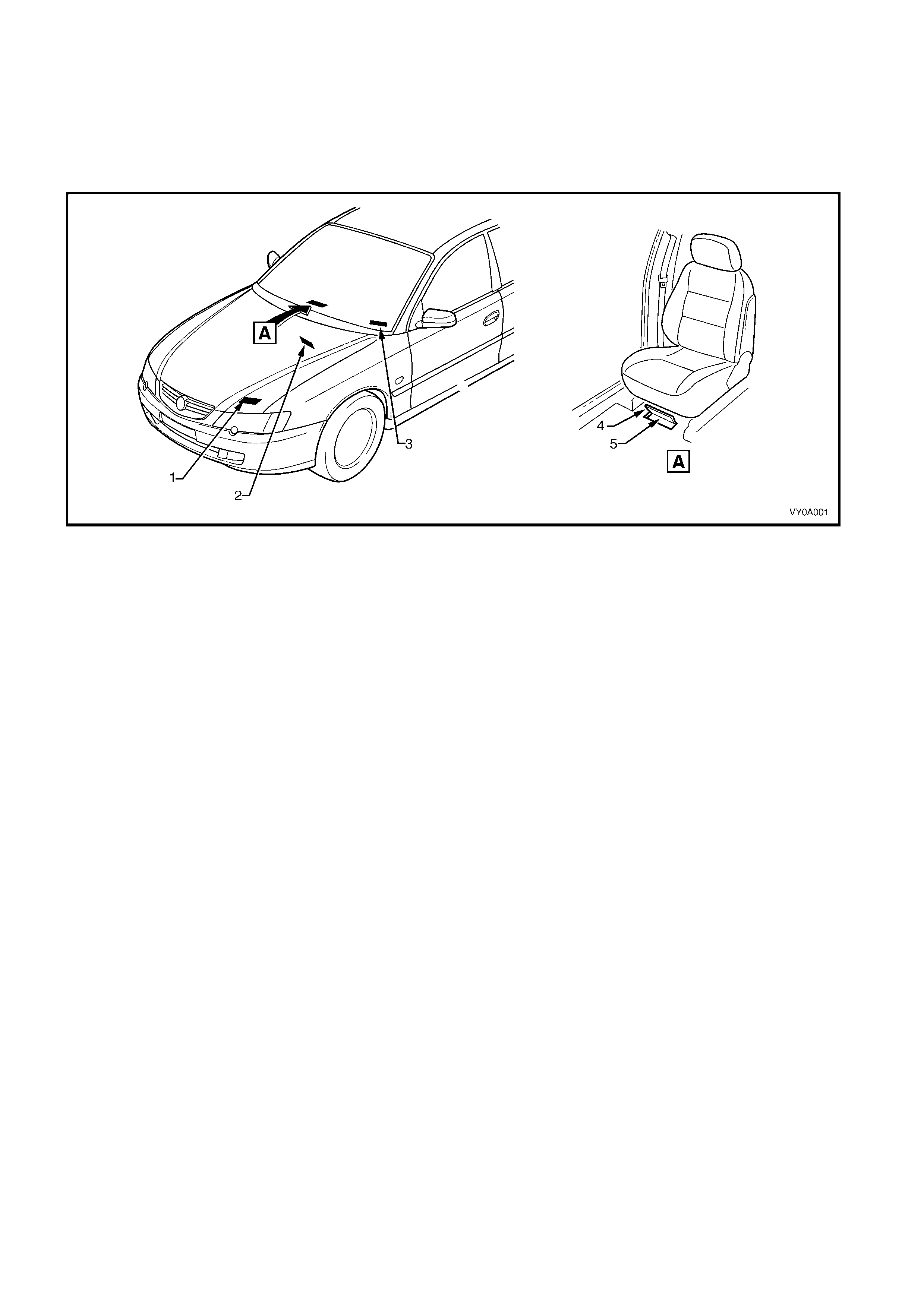
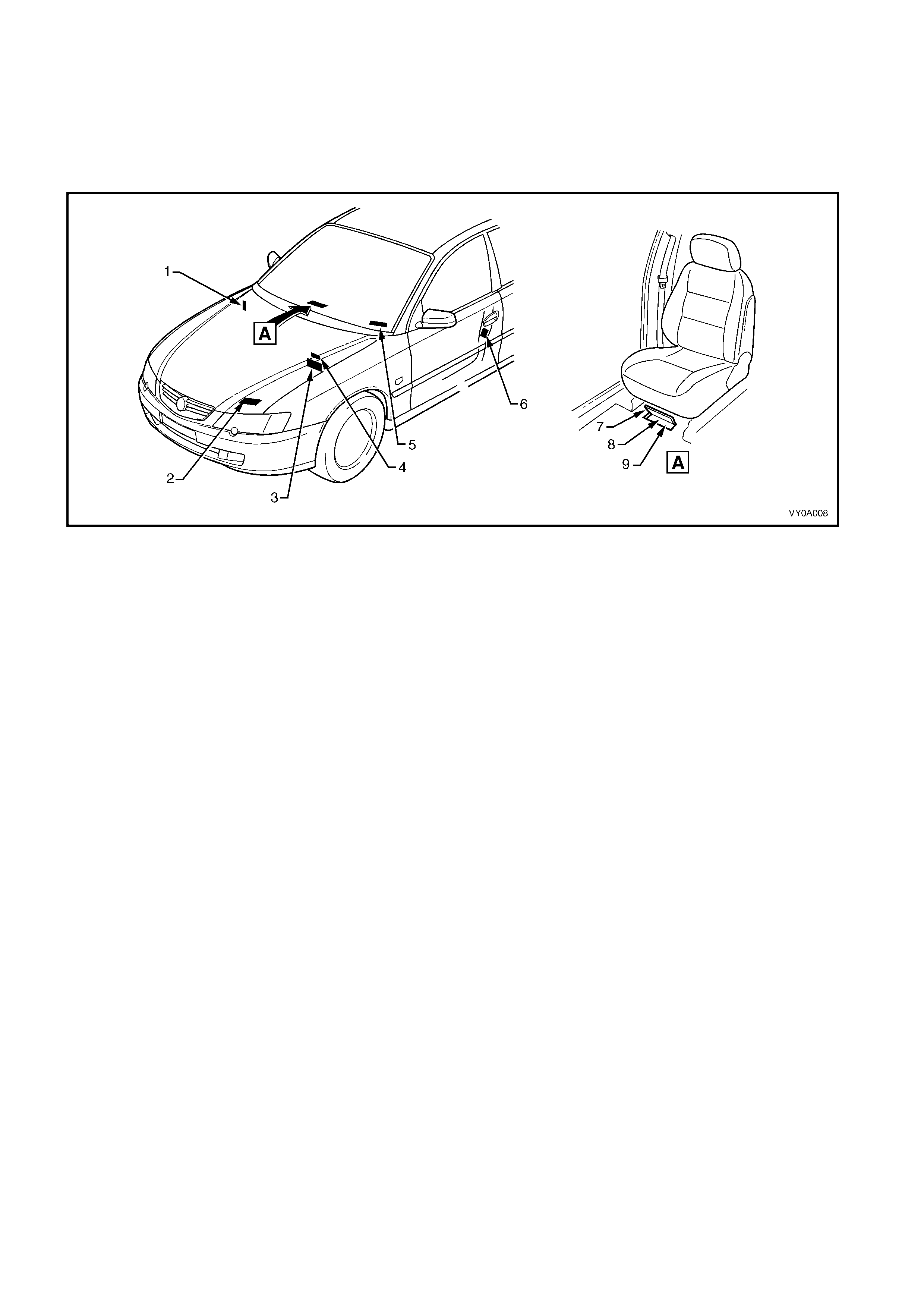
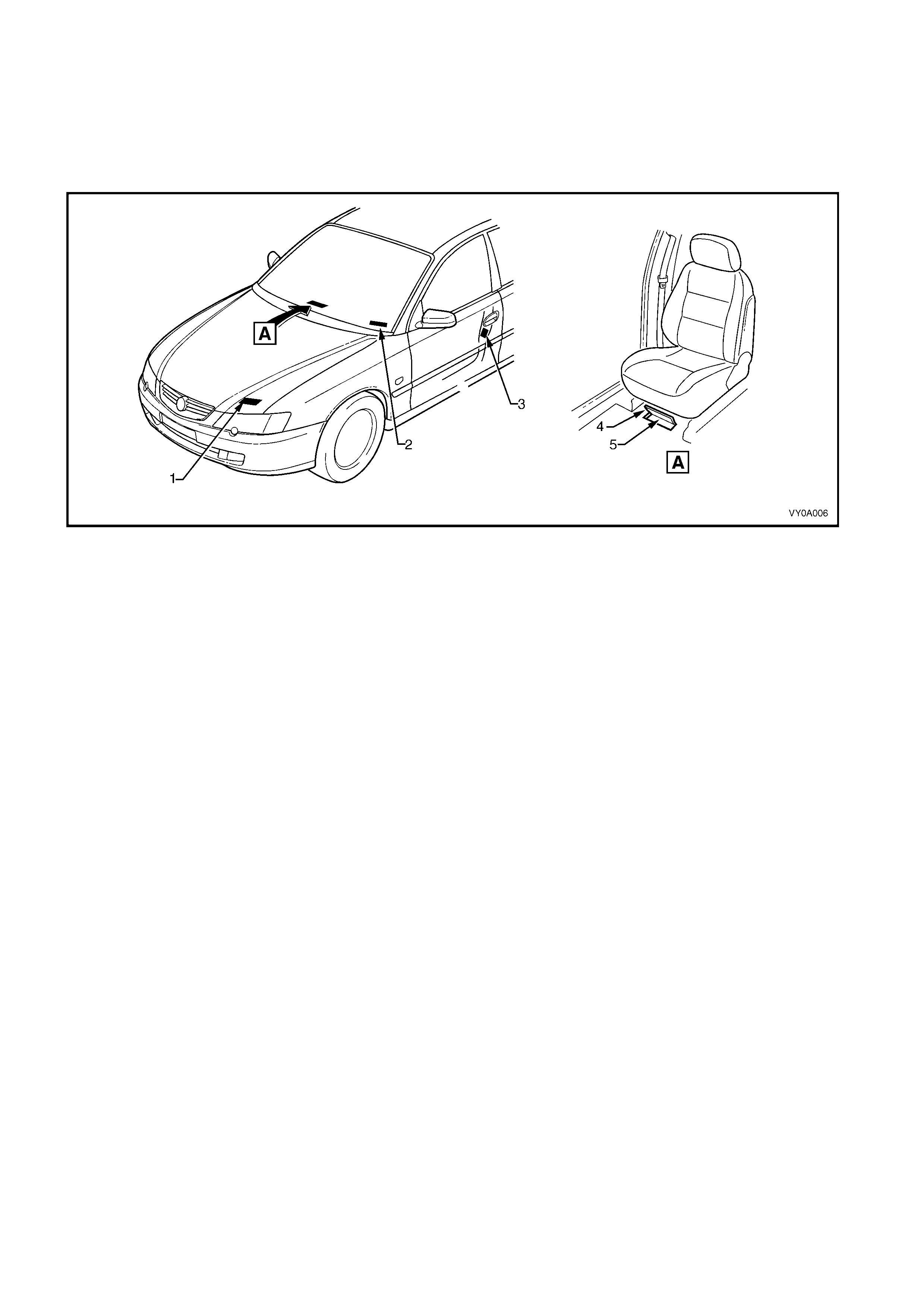
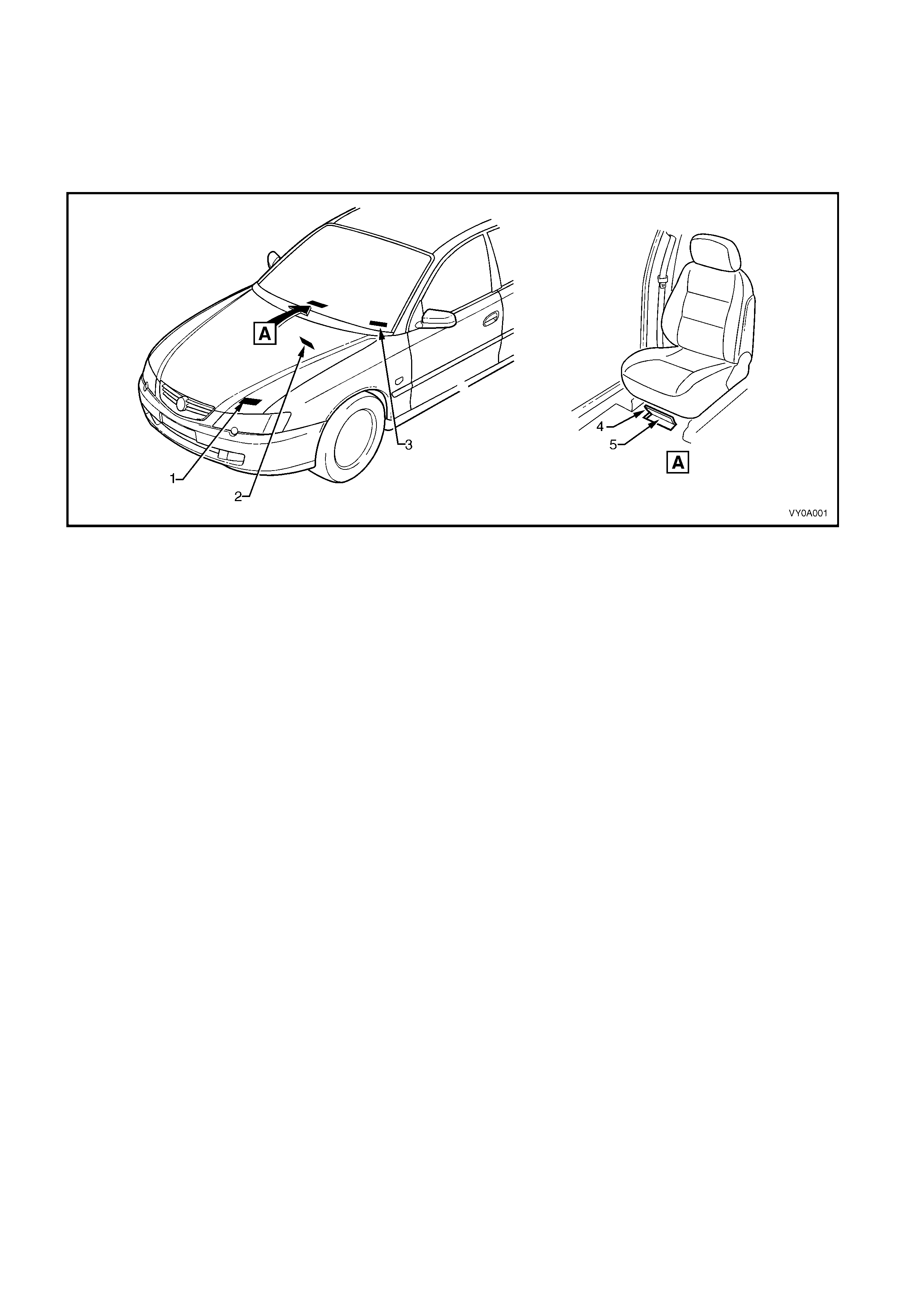
9.1 LOCATION OF IDENTIFICATION PLATES
Figure 0A-2
Legend
1. Body And Option Identification Plate – Left-Hand Side
of the Front Panel Upper
2. Safety Compliance Plate – Dash Panel Assembly
3. Vehicle Identification Number Plate – Under
Windscreen Carpet Flap
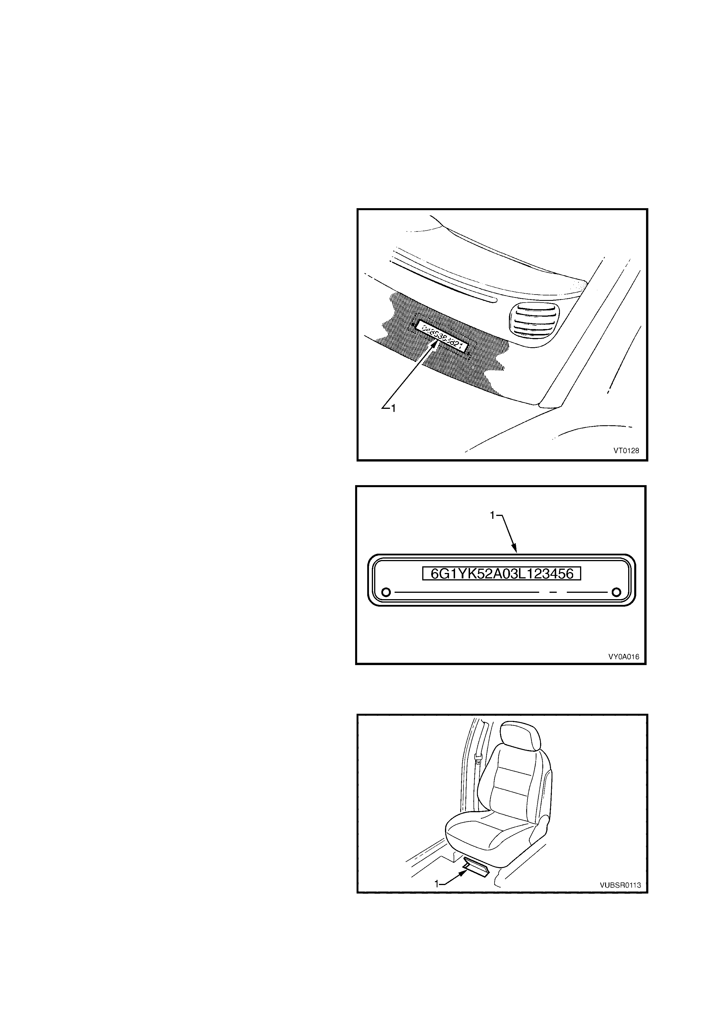
4. Vehicle Identification Number – Under Front Seat

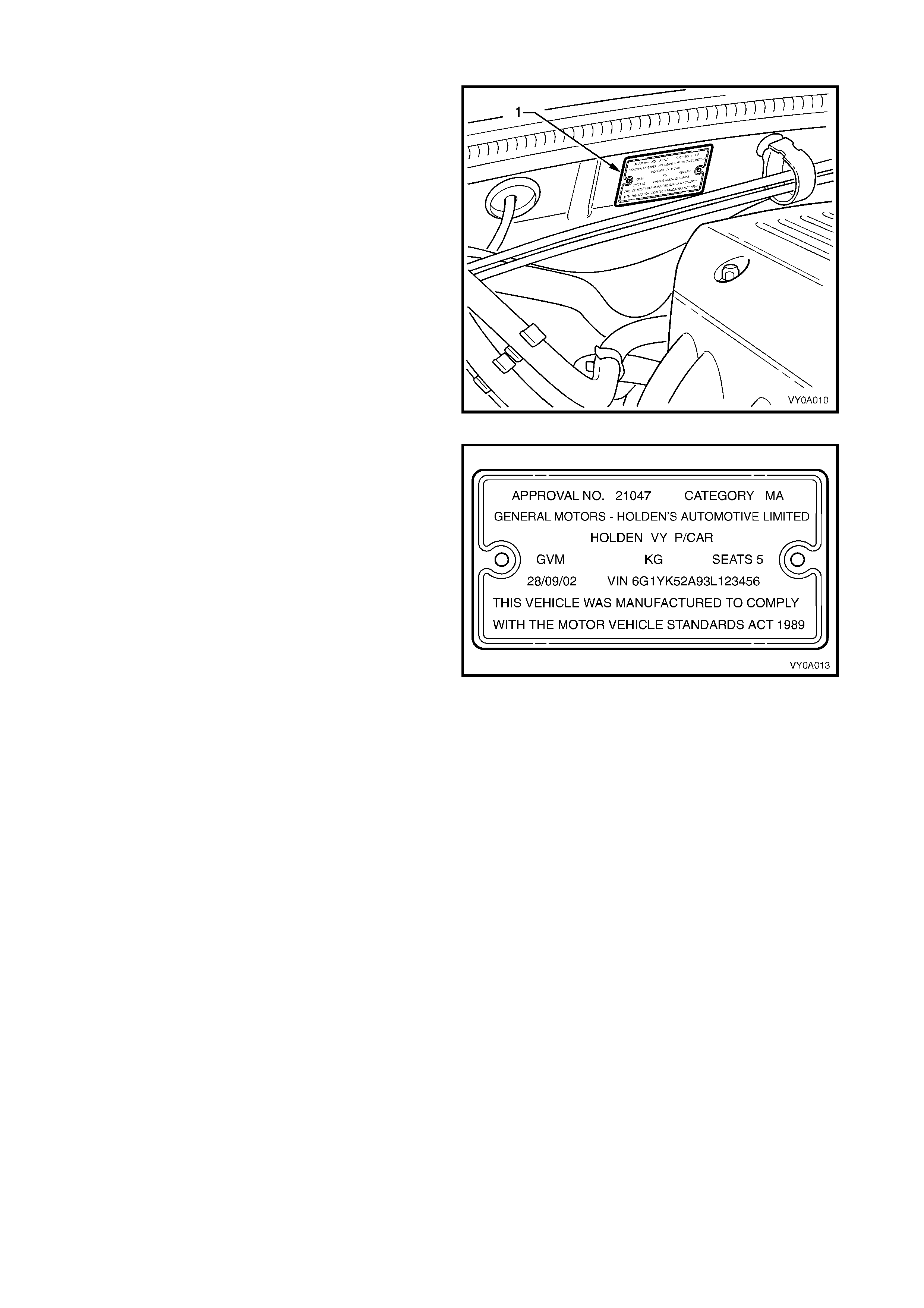
9.2 SAFETY COMPLIANCE PLATE
The safety compliance plate is located on the dash
panel assembly within the engine compartment.
Figure 0A-3
The safety compliance plate is stamped with the
following information:
• Compliance plate approval number.
• Vehicle category code.
• Name appearing on compliance plate approval.
• Make / Model.
• Gross vehicle mass. This is the maximum loaded
mass at which the vehicle complies with the
approved design rules. Not required for passenger
vehicles. (Required for utility.)
• Seating capacity.
• Number of adult positions for which seat belts are
provided.
• Date of manufacture.
• The day, month and year that the vehicle is
manufactured.
• Vehicle Identification Number (VIN).
Figure 0A-4

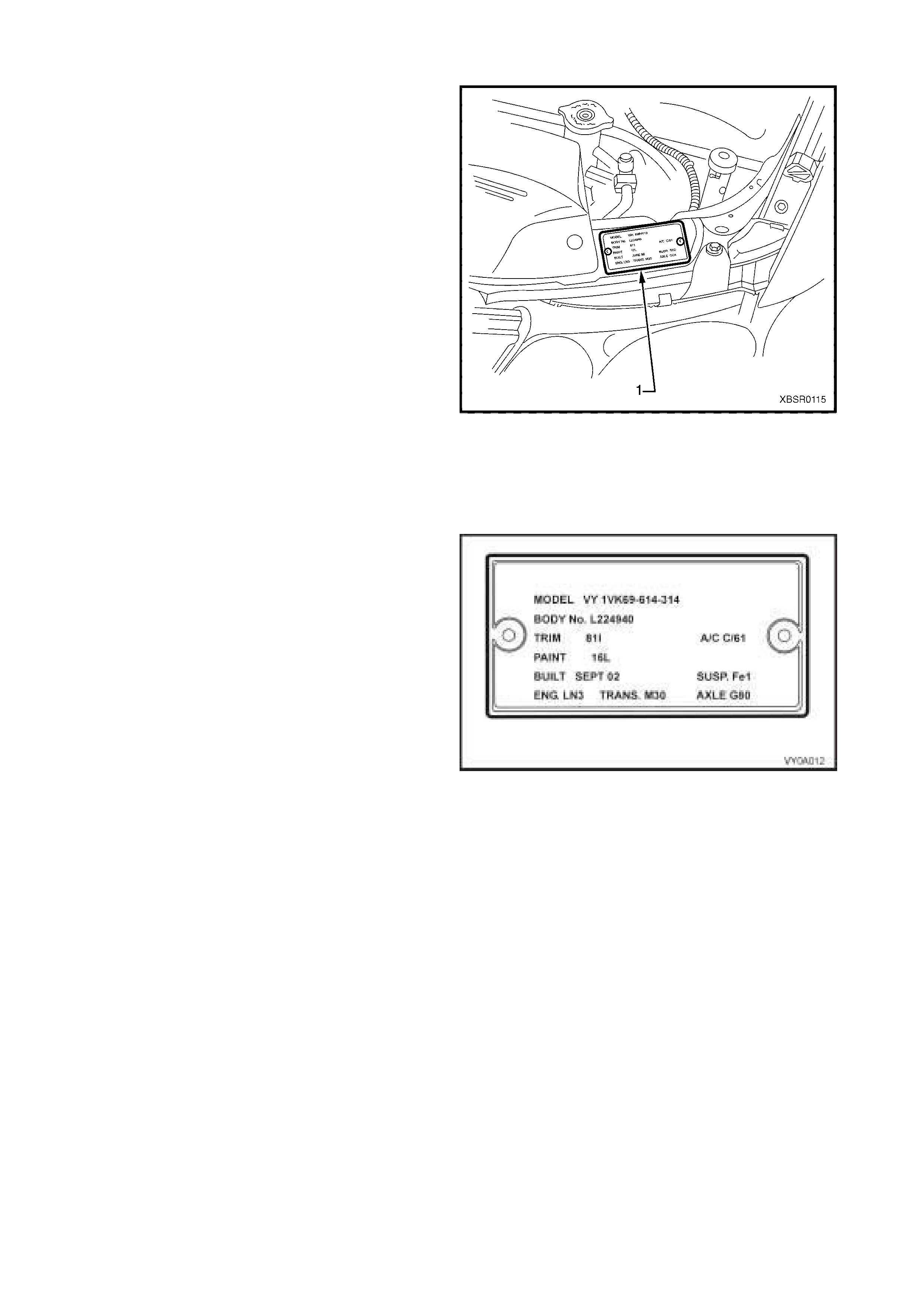
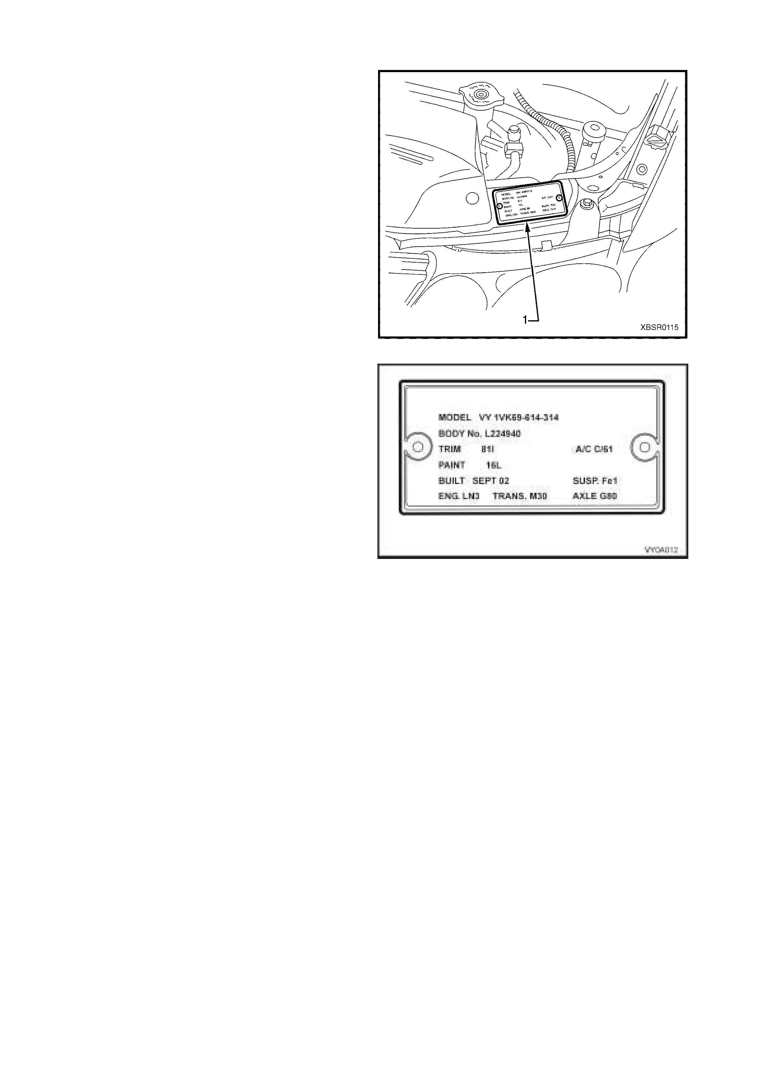
9.3 BODY AND OPTION IDENTIFICATION PLATE
The Body and Option Identification Plate (1) is located
on the front panel assembly and is stamped with the
following information.
Model
Combination of letters and numbers identifying the
body style, the mechanical pack and smart pack
options.
A listing of production and smart pack option numbers
can be found by referring to the latest spare parts
information for the applicable model.
Body
Production build number; run in continuous sequence
regardless of model, body type and series.
Trim
Trim combination.
Paint
Exterior paint material and colour identification.
Built
The date of manufacture by calendar month and year
in which the body shell and power train are conjoined
and the vehicle is driven or moved from the produc tion
line.
Susp
Suspension option code identification.
FE1 identifies vehicles with standard suspension.
FE2 identifies vehicles with sport suspension.
Engine, Transmission and Axle.
Identification option codes for specific engine,
transmission and rear axle.
A/C
C60 identifies vehicles fitted with air conditioning.
C61 Identifies vehicles fitted with automatic climate
control air conditioning.
Figure 0A-5
Figure 0A-6
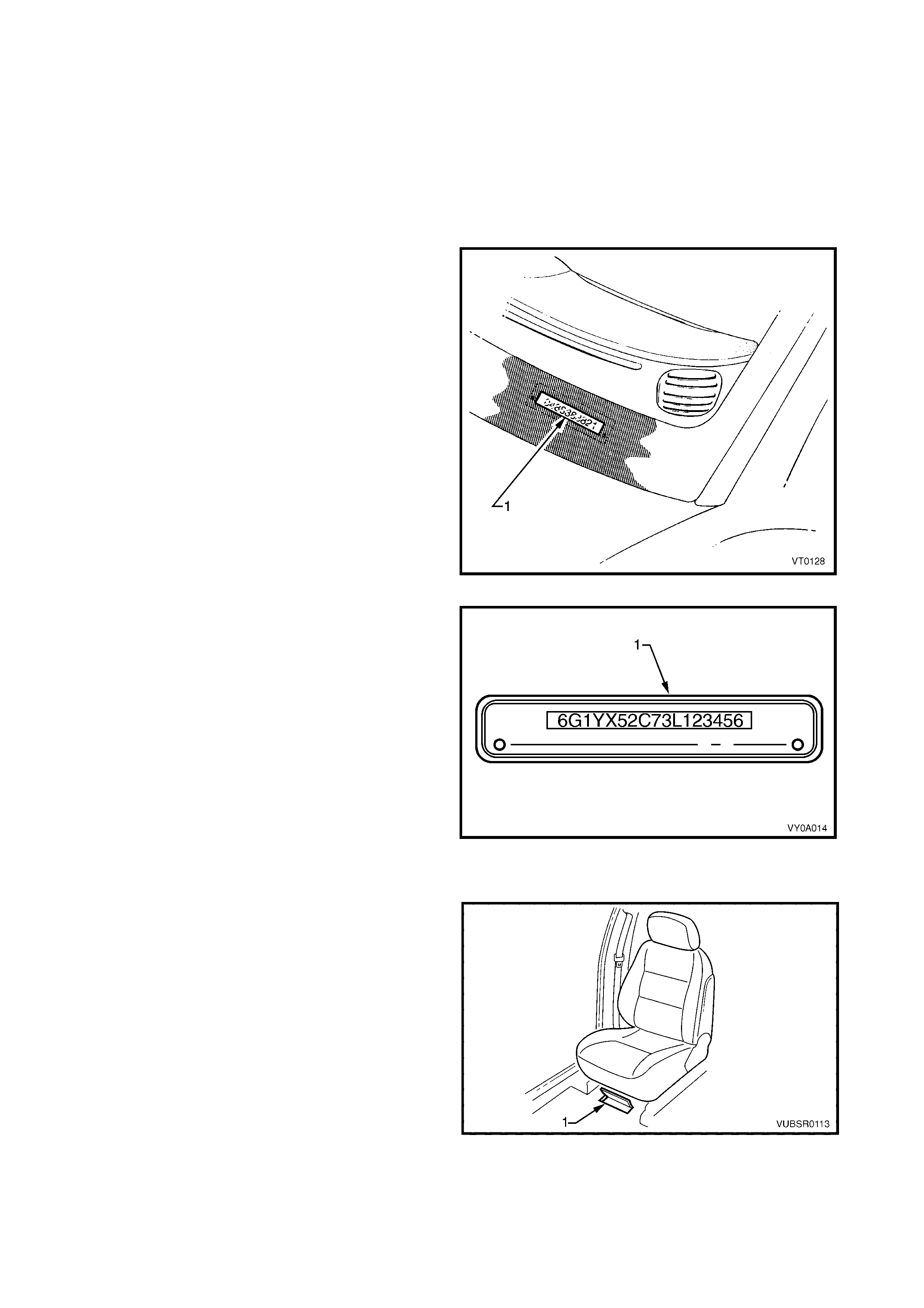
9.4 VEHICLE IDENTIFICATION NUMBER
The Vehicle Identif ication Num bering (VIN) system is based on the unif orm Car Model Des ignation Sys tem . T his
identifies the vehicle in one coded series of characters.
The Vehicle Identification Number is positioned in the following locations.
1. VIN plate under the windscreen – viewed through the windscreen aperture.
2. Body and option identification plate – left-hand side of the front panel upper.
3. Safety compliance plate – dash panel.
4. Stamping in the front floor panel under the front right-hand seat.
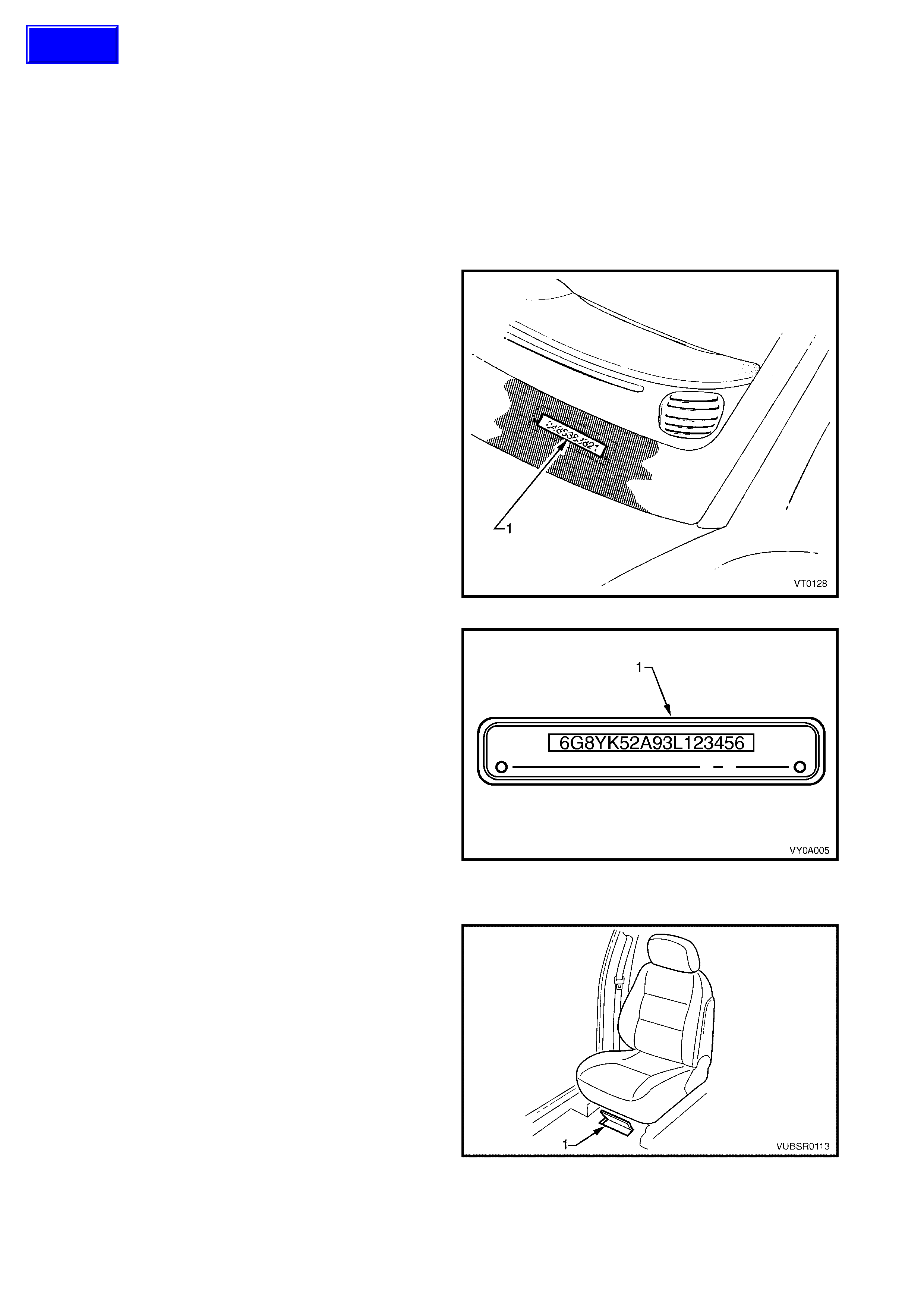
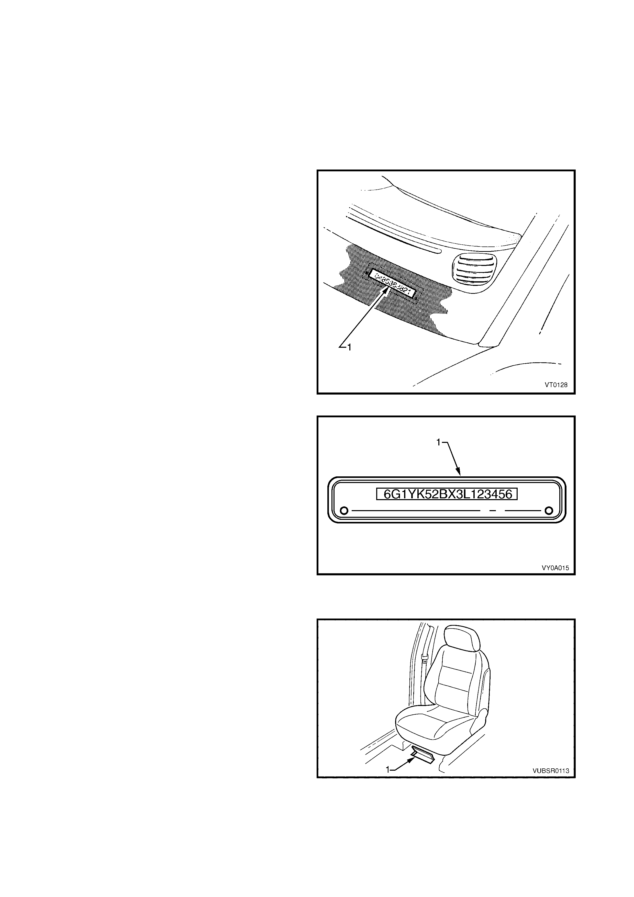
VIN PLATE
The VIN Plate (1) is located under the windscreen and
is viewed through the windscreen aperture.
Figure 0A-7
Figure 0A-8 shows the VIN plate (1) that is located
under the windscreen aperture and is attached to the
dash panel assembly with unique rosette headed
rivets.
Figure 0A-8
VIN BODY STAMPING
The VIN is stam ped into the f ront floor panel under the
right-hand f r ont s eat. The VIN ( 1) is vis ible by lifting the
carpet flap.
NOTE 1: If the front floor panel assembly is to be
replaced, the VIN will be lost. Contact your local Road
Traffic Authority prior to replacing the panel to obtain
the correct procedure for renumbering the vehicle.
NOTE 2: A replacement body shell assembly is
stamped during manufacture with a unique VIN that
identifies it as a replacement part.
NOTE 3: If an error is made to the VIN stamping
during manufacture, it is lined out so that it remains
legible and the correct number is stamped underneath.
Figure 0A-9
Techline
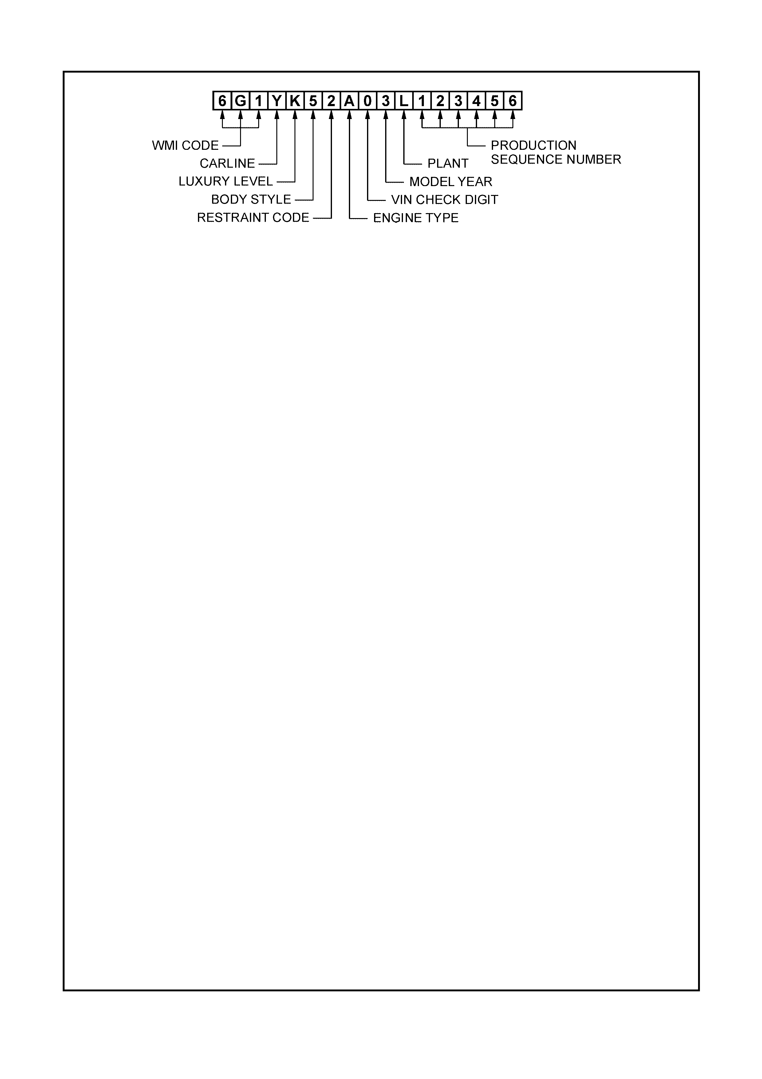
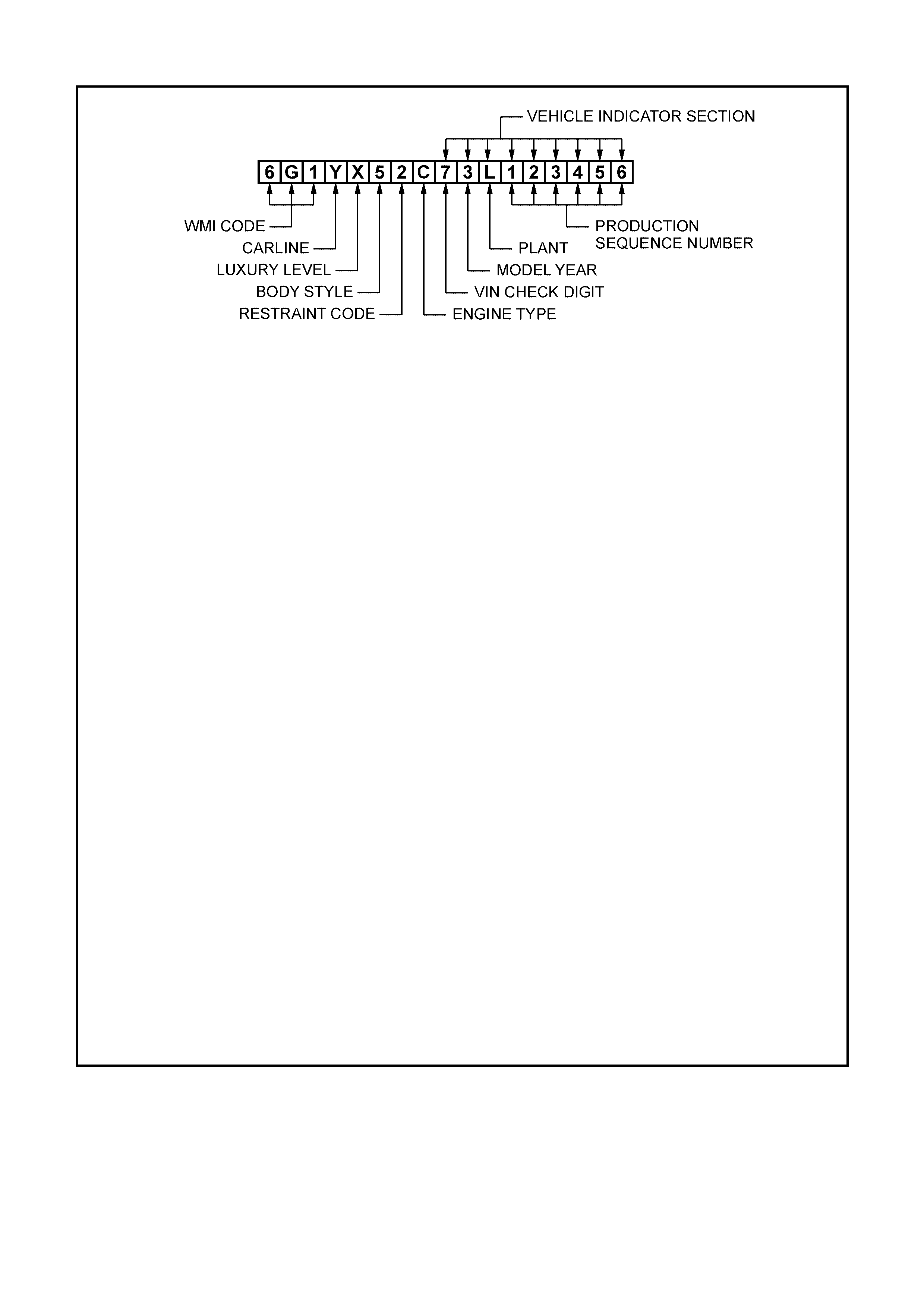
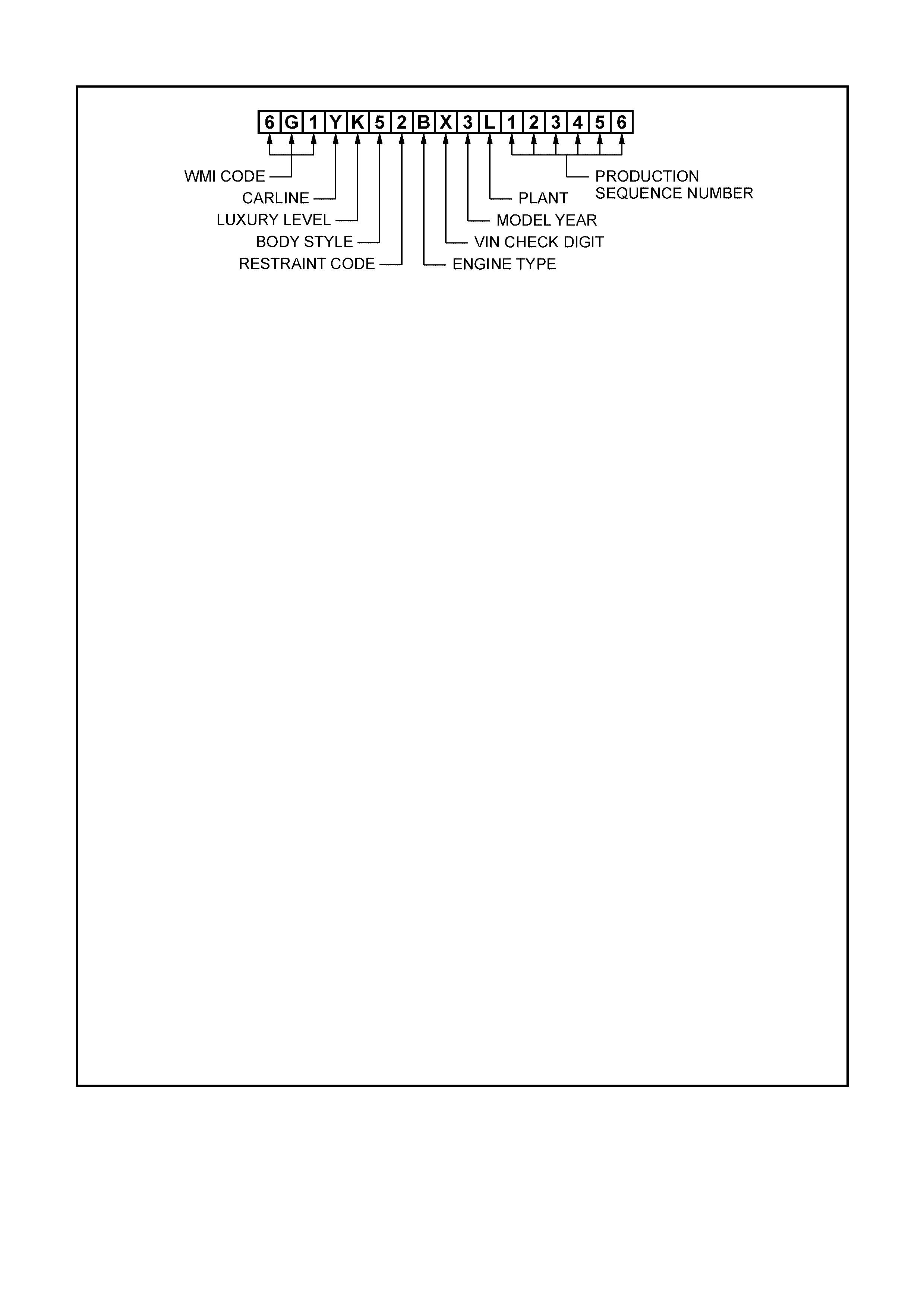
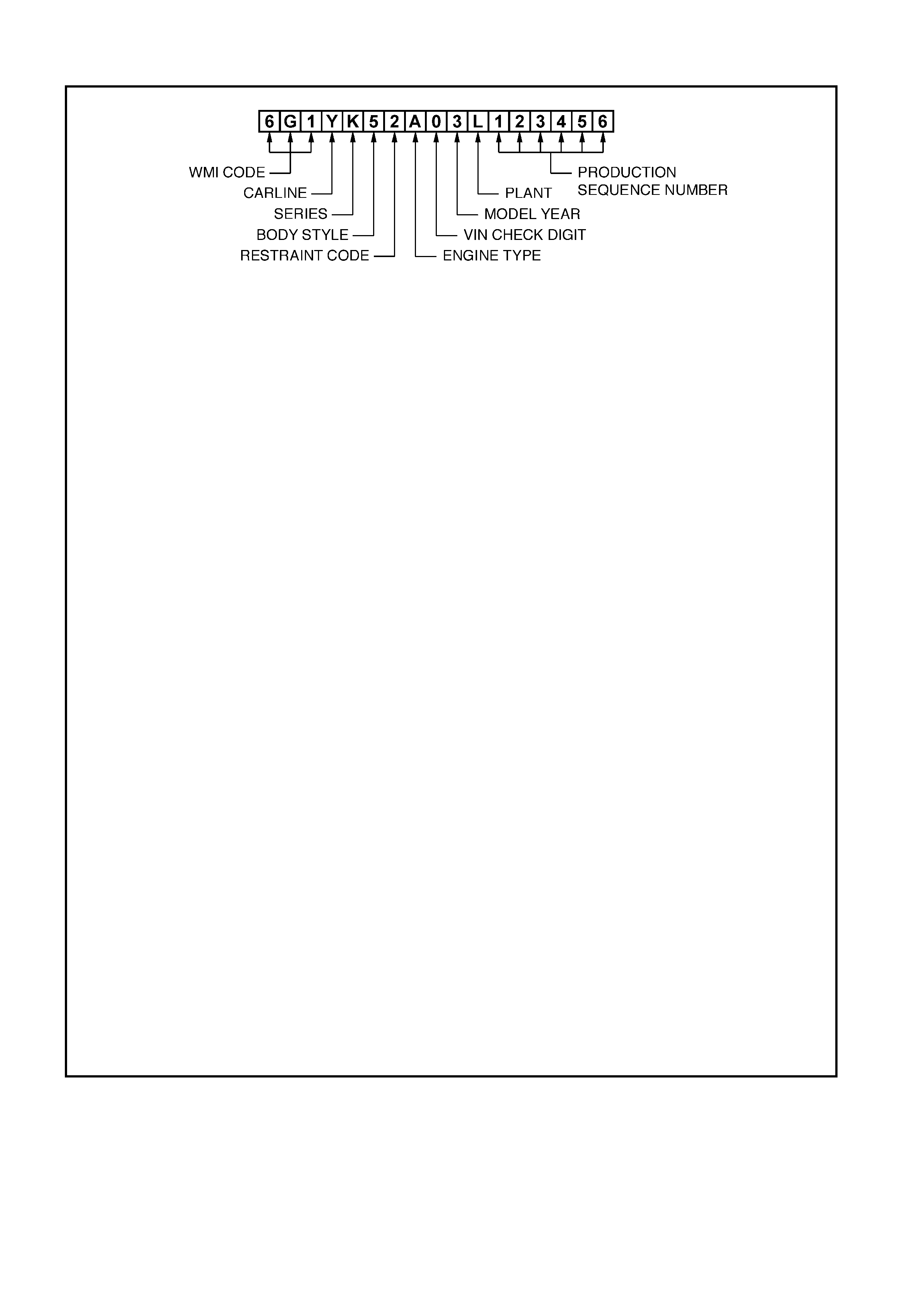
9.5 VEHICLE IDE NTIFICATION NUMBERING SYSTEM
WMI CODE: 6 – Oceania
G – Australia
1 – Holden
CARLINE: Y – VY series
2 – V2
LUXURY LEVEL: K – Level 1
L – Level 2
X – Level 3
BODY STYLE: 1 – 2 door coupe (37)
4 – 2 door utility (80)
5 – 4 door sedan (69)
8 – 5 door station wagon (35)
RESTRAINT CODE: 1 – Active (manual) seat belts
2 – Active (manual) seat belts with driver & passenger inflatable restraint
system – frontal
3 – Active (manual) seat belts with driver inflatable restraint system – frontal
4 – Active (manual) seat belts with driver & passenger inflatable restraint
system – frontal and side
ENGINE TYPE: A – 3.8 litre V6 engine (domestic variant)
R – 3.8 litre V6 engine supercharged
F – 5.7 litre GEN III V8 engine
VIN CHECK DIGIT: Calculated check digit
MODEL YEAR: 3 – 2003
4 – 2004
PLANT: L – Adelaide (Elizabeth) South Australia
PRODUCTION SEQUENCE NUMBER:
123456 – Sequential Production Serial Number
NOTE: The pr oduc tion s equence number is sequentially allocated to each vehicle,
regardless of vehicle type.
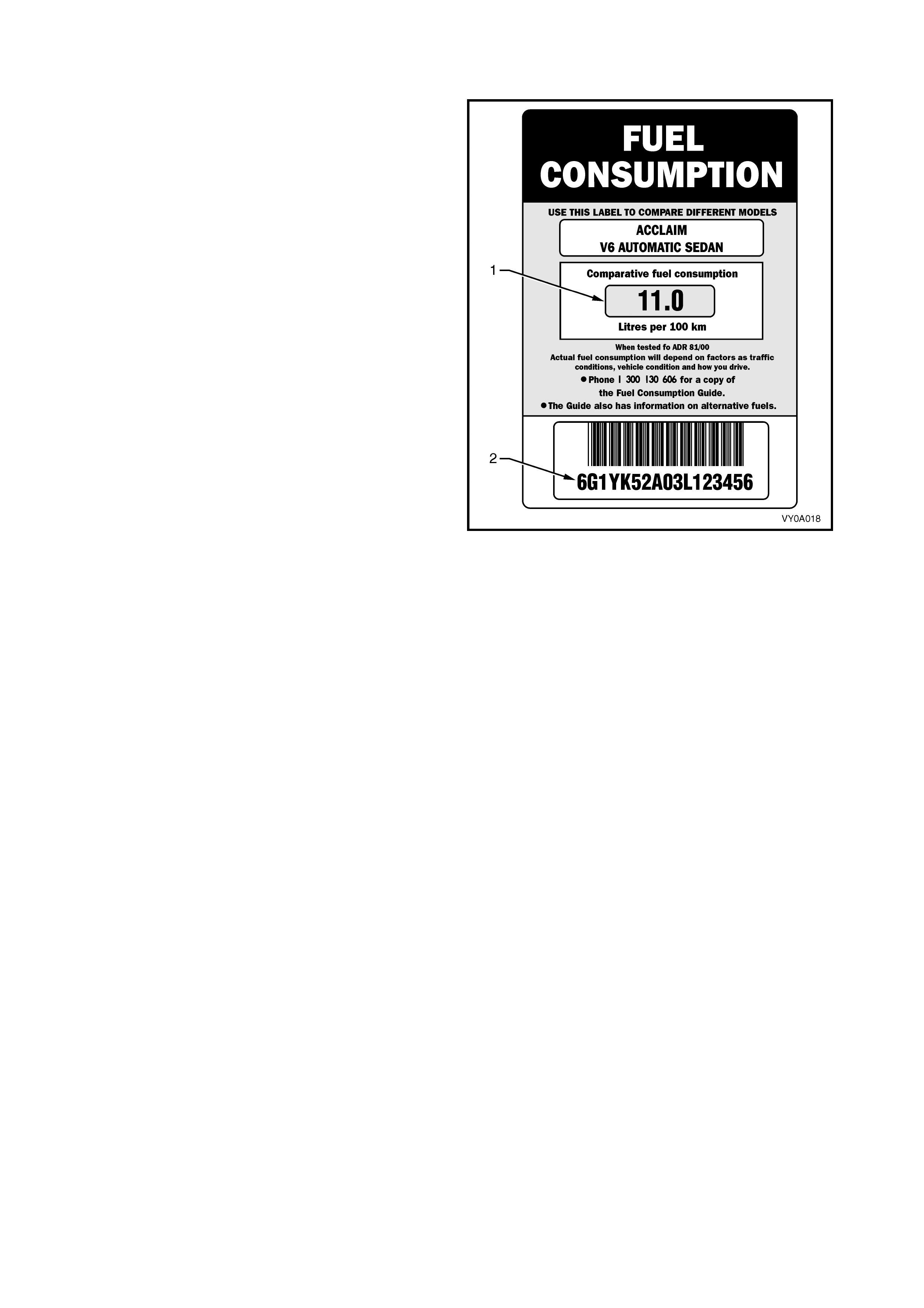
9.6 FUEL CONSUMPTION LABEL
ADR 81/00 requires that from 1 January 2001, a label
sim ilar to that shown in Figure 0A- 10 is attached to the
windscreen of any new vehicle which is displayed for
sale.
The fuel consumption label figures (1) quoted are the
results of tests carried out in accordance with the City
Cycle test procedure of AS2877 – 1986, an Australian
standard for fuel consumption testing. Each vehicle is
tested under identical conditions. The tests therefore
enable a comparison to be made between vehicles.
The label should be removed from the windscreen
immediately prior to the vehicle being delivered to the
owner.
The number on the lower por tion of the label (2) s hould
match the Vehicle Identification Number.
Figure 0A-10
10. SERIAL NUMBERS – BRAZIL
The com plete vehicle and various components of the vehicle are identified by num ber plates or numbers stamped
into the body. It is essential that when compiling warranty claims or product and field reports, that the Vehicle
Identification Number (VIN) is quoted in conjunction with the identification number of the component affected.
10.1 LOCATION OF IDENTIFICATION PLATES
Figure 0A-11
Legend
1. VIS Label – Right-Hand A-pillar
2. Body and Option Identification Plate – Left-Hand Side
of the Front Panel Upper
3. Manufacturer Label
4. Vehicle Indicator Section Label – Left-Hand
Suspension Tower
5. Vehicle Identification Number Plate – Under
Windscreen
6. Paint Label – Left-Hand B-pillar
7. Carpet Flap
8. Vehicle Identification Number – Under Front Seat
9. VIS Label – Under Front Seat
10.2 BODY AND OPTION IDENTIFICATION PLATE
The Body and Option Identification Plate (1) is located
on the front panel assembly and is stamped with the
following information.
Model
Combination of letters and numbers identifying the
body style, the mechanical pack and smart pack
options.
A listing of production and smart pack option numbers
can be found by referring to the latest spare parts
information for the applicable model.
Body
Production build number; run in continuous sequence
regardless of model, body type and series.
Trim
Trim combination.
Paint
Exterior paint material and colour identification.
Built
The date of manufacture by calendar month and year
in which the body shell and power train are conjoined
and the vehicle is driven or moved f rom the production
line.
Figure 0A-12
Susp.
Suspension option code identification.
FE1 identifies vehicles with standard suspension.
FE2 identifies vehicles with sport suspension.
Engine, Transmission and Axle
Identification option codes for specific engine,
transmission and rear axle.
A/C
C60 identifies vehicles fitted with air conditioning.
C61 Identifies vehicles fitted with automatic climate
control air conditioning.
Figure 0A-13
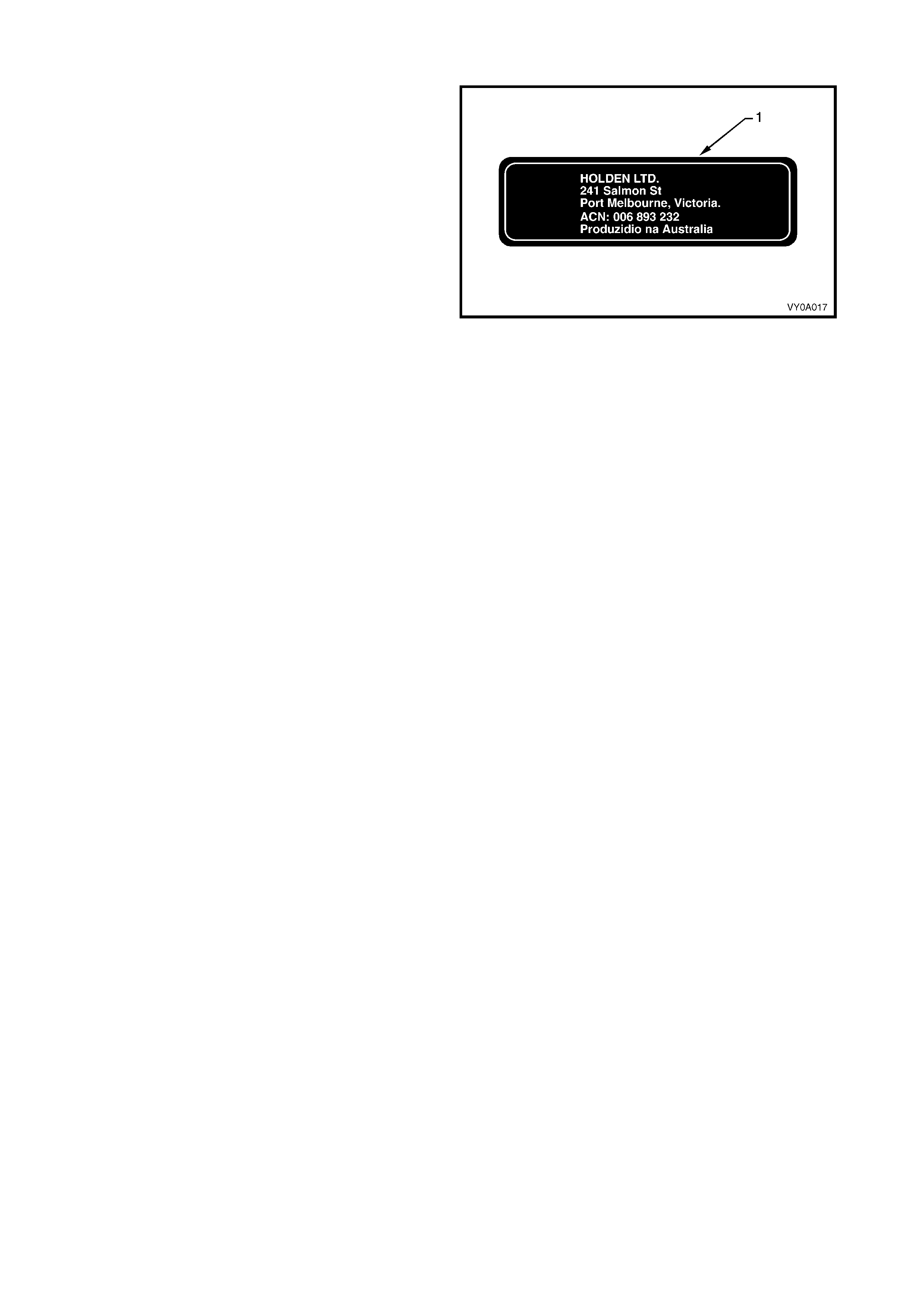
10.3 MANUFACTURER LABEL
The manufacturer label (1) is located on the left-hand
front suspension tower and contains information about
the vehicle manufacturer.
Figure 0A-14
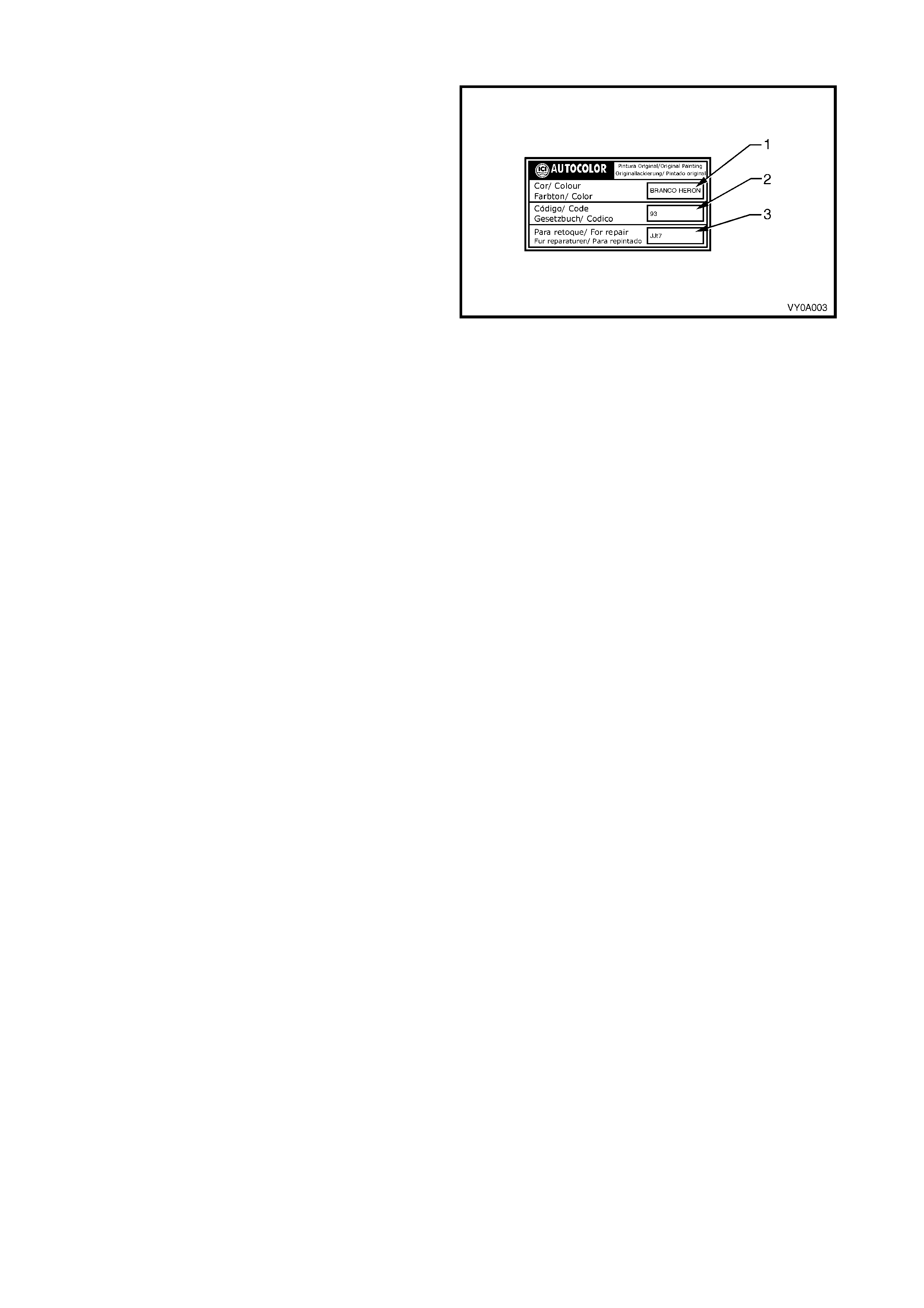
10.4 PAINT LABEL
The paint label is located on the left-hand B-pillar and
contains the paint colour (1), paint code (2) and repair
paint (3) for the vehicle.
The paint code enables the original paint colour to be
matched with refinish paint.
NOTE: T he paint on the vehicle m ay not exactly match
the original colour due to fade, in which case paint
colour m atching will be required. As this is an acquired
skill, it is a task that must be performed by qualified
individuals.
Figure 0A-15
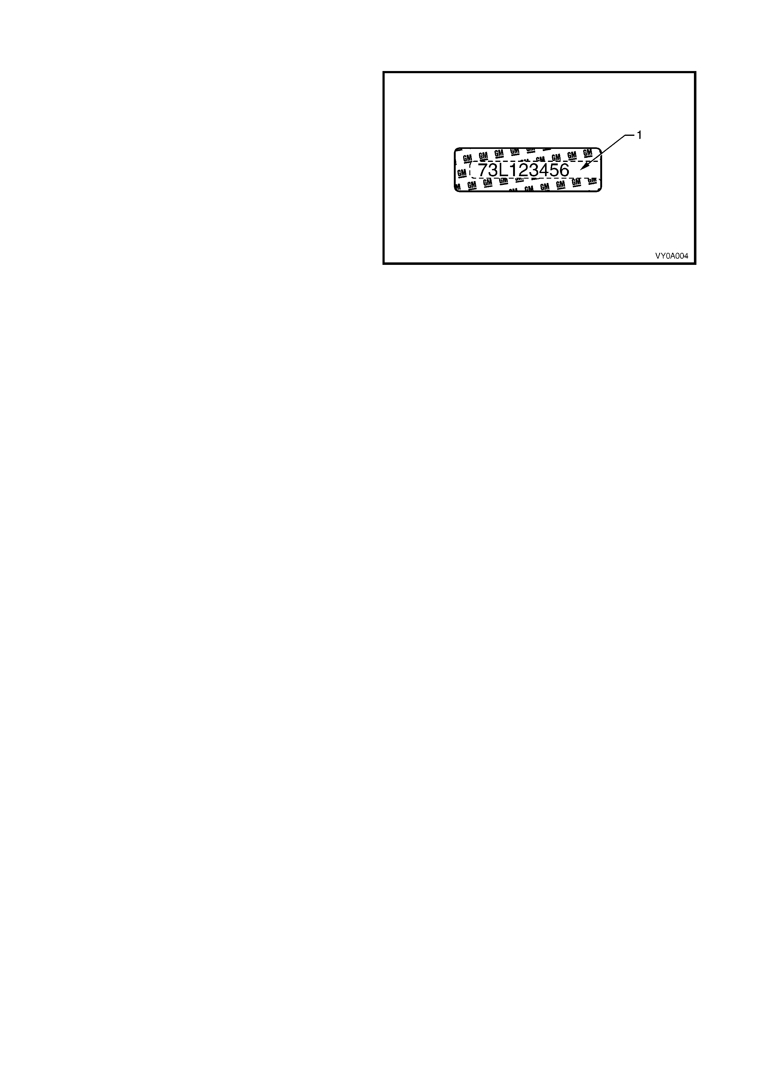
10.5 VIS LABEL
Vehicle Indicator Section (VIS) labels are located
under the right front seat, on the front left strut tower
and on the right-hand A-pillar.
The VIS label contains the last nine characters of the
VIN (1).
Figure 0A-16
10.6 VEHICLE IDENTIFICATION NUMBER
The Vehic le Identification Number ing (VIN) s ystem is bas ed on the unif or m Car Model Des ignation System. This
identifies the vehicle in one coded series of characters.
The Vehicle Identification Number is positioned in the following locations.
1. VIN plate under the windscreen – viewed through the windscreen aperture.
2. Body and option identification plate – left-hand side of the front panel upper.
3. Stamping in the front floor panel under the front right-hand seat.
VIN PLATE
The VIN Plate (1) is located under the windsc reen and
is viewed through the windscreen aperture.
Figure 0A-17
Figure 0A-18 shows the VIN plate (1) that is located
under the windscreen aperture and is attached to the
dash panel assembly with unique rosette headed
rivets.
Figure 0A-18
VIN BODY STAMPING
The VIN is stam ped into the f ront floor panel under the
right-hand f r ont s eat. The VIN ( 1) is vis ible by lifting the
carpet flap.
NOTE 1: If the front floor panel assembly is to be
replaced, the VIN will be lost. Contact your local Road
Traffic Authority prior to replacing the panel to obtain
the correct procedure for renumbering the vehicle.
NOTE 2: A replacement body shell assembly is
stamped during manufacture with a unique VIN that
identifies it as a replacement part.
NOTE 3: If an error is made to the VIN stamping
during manufacture, it is lined out so that it remains
legible and the correct number is stamped underneath.
Figure 0A-19
10.7 VE HICLE IDE NTIFICATION NUMBERING SYSTEM
WMI CODE: 6 – Oceania
G – Australia
1 – Chevrolet
CARLINE: Y – VY series
LUXURY LEVEL: X – Level 3
BODY STYLE: 5 – 4 door sedan (69)
RESTRAINT CODE: 1 – Active (manual) seat belts
2 – Active (manual) seat belts with driver & passenger inflatable restraint
system – frontal
3 – Active (manual) seat belts with driver inflatable restraint system – frontal
4 – Active (manual) seat belts with driver & passenger inflatable restraint
system – frontal and side
ENGINE TYPE: C – 3.8 litre V6 engine (Brazil variant)
VIN CHECK DIGIT: Calculated check digit
MODEL YEAR: 3 – 2003
4 – 2004
PLANT: L – Adelaide (Elizabeth) South Australia
PRODUCTION SEQUENCE NUMBER:
123456 – Sequential Production Serial Number
NOTE: The pr oduc tion s equence number is sequentially allocated to each vehicle,
regardless of vehicle type.
11. SERIAL NUMBERS – GULF STATES
The com plete vehicle and various components of the vehicle are identified by num ber plates or numbers stamped
into the body. It is essential that when compiling warranty claims or product and field reports, that the Vehicle
Identification Number (VIN) is quoted in conjunction with the identification number of the component affected.
11.1 LOCATION OF IDENTIFICATION PLATES
Figure 0A-20
Legend
1. Body And Option Identification Plate – Left-Hand Side
of the Front Panel Upper
2. Vehicle Identification Number Plate – Under
Windscreen
3. Safety Compliance Label – Left-Hand B-pillar
4. Carpet Flap
5. Vehicle Identification Number – Under Front Seat
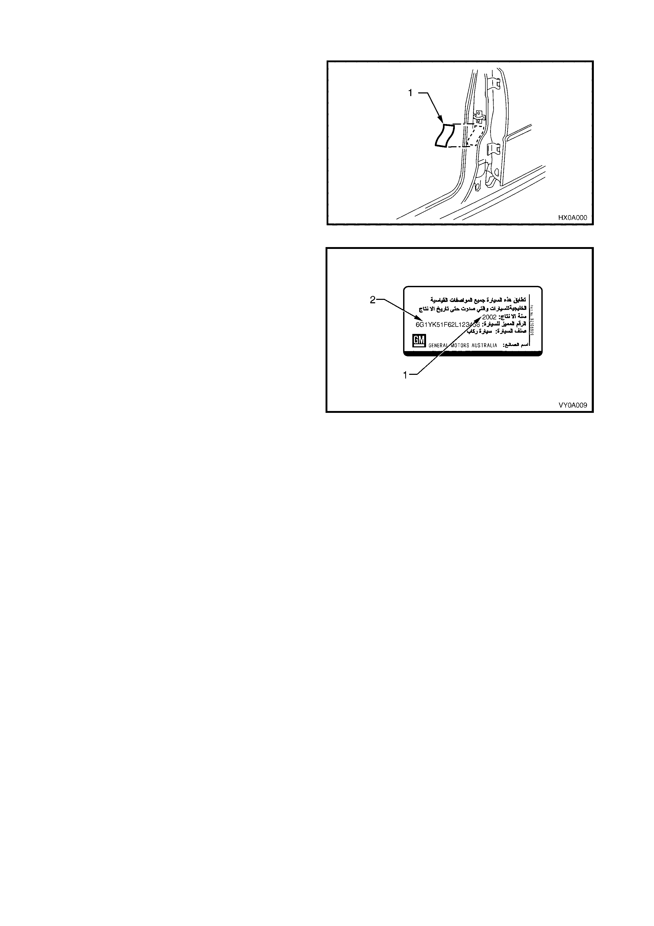
11.2 S AFETY COMPLIANCE LABE L
The safety compliance label (1) is attached to the B-
pillar.
Figure 0A-21
The safety compliance label contains the following
information:
• Vehicle conformity statement
• Date of Manufacture (1)
• Vehicle Identification Number (2)
• Category of vehicle: passenger car
• Manufactured by: General Motors Corporation
Figure 0A-22

11.3 BODY AND OPTION IDENTIFICATION PLATE
The Body and Option Identification Plate (1) is located
on the front panel assembly and is stamped with the
following information.
Model
Combination of letters and numbers identifying the
body style, the mechanical pack and smart pack
options.
A listing of production and smart pack option numbers
can be found by referring to the latest spare parts
information for the applicable model.
Body
Production build number; run in continuous sequence
regardless of model, body type and series.
Trim
Trim combination.
Paint
Exterior paint material and colour identification.
Built
The date of manufacture by calendar month and year
in which the body shell and power train are conjoined
and the vehicle is driven or moved from the produc tion
line.
Susp.
Suspension option code identification.
FE1 identifies vehicles with standard suspension.
FE2 identifies vehicles with sport suspension.
Engine, Transmission and Axle
Identification option codes for specific engine,
transmission and rear axle.
A/C
C60 identifies vehicles fitted with air conditioning.
C61 Identifies vehicles fitted with automatic climate
control air conditioning.
Figure 0A-23
Figure 0A-24
11.4 VEHICLE IDENTIFICATION NUMBER
The Vehicle Identif ication Num bering (VIN) system is bas ed on the uniform Car Model Designation System. T his
identifies the vehicle in one coded series of characters.
The Vehicle Identification Number is positioned in the following locations.
1. VIN plate under the windscreen – viewed through the windscreen aperture.
2. Body and option identification plate – left-hand side of the front panel upper.
3. Stamping in the front floor panel under the front right-hand seat.
VIN PLATE
The VIN Plate (1) is located under the windscreen and
is viewed through the windscreen aperture.
Figure 0A-25
Figure 0A-26 shows the VIN plate (1) that is located
under the windscreen aperture and is attached to the
dash panel assembly with unique rosette headed
rivets.
Figure 0A-26
VIN BODY STAMPING
The VIN is stam ped into the f ront floor panel under the
right-hand f r ont s eat. The VIN ( 1) is vis ible by lifting the
carpet flap.
NOTE 1: If the front floor panel assembly is to be
replaced, the VIN will be lost. Contact your local Road
Traffic Authority prior to replacing the panel to obtain
the correct procedure for renumbering the vehicle.
NOTE 2: A replacement body shell assembly is
stamped during manufacture with a unique VIN that
identifies it as a replacement part.
NOTE 3: If an error is made to the VIN stamping
during manufacture, it is lined out so that it remains
legible and the correct number is stamped underneath.
Figure 0A-27
11.5 VE HICLE IDE NTIFICATION NUMBERING SYSTEM
WMI CODE: 6 – Oceania
G – Australia
1 – Chevrolet
CARLINE: Y – VY series
2 – V2 series
LUXURY LEVEL: K – Level 1
L – Level 2
BODY STYLE: 5 – 4 door sedan (69)
8 – 5 door station wagon (35)
RESTRAINT CODE: 1 – Active (manual) seat belts
2 – Active (manual) seat belts with driver & passenger inflatable restraint
system – frontal
3 – Active (manual) seat belts with driver inflatable restraint system – frontal
4 – Active (manual) seat belts with driver & passenger inflatable restraint
system – frontal and side
ENGINE TYPE: B – 3.8 litre V6 engine (Gulf States variant)
F – 5.7 litre GEN III V8 engine
VIN CHECK DIGIT: Calculated check digit
MODEL YEAR: 3 – 2003
4 – 2004
PLANT: L – Adelaide (Elizabeth) South Australia
PRODUCTION SEQUENCE NUMBER:
123456 – Sequential Production Serial Number
NOTE: The pr oduc tion s equence number is sequentially allocated to each vehicle,
regardless of vehicle type.
12. SERIAL NUMBERS – SOUTH AFRICA
The com plete vehicle and various components of the vehicle are identified by num ber plates or numbers stamped
into the body. It is essential that when compiling warranty claims or product and field reports, that the Vehicle
Identification Number (VIN) is quoted in conjunction with the identification number of the component affected.
12.1 LOCATION OF IDENTIFICATION PLATES
Figure 0A-28
Legend
1. Body And Option Identification Plate – Left-Hand Side
of the Front Panel Upper
2. Safety Compliance Plate – Dash Panel Assembly
3. Vehicle Identification Number Plate – Under
Windscreen
4. Carpet Flap
5. Vehicle Identification Number – Under Front Seat
12.2 SAFETY COMPLIANCE PLATE
The safety compliance plate is located on the dash
panel assembly within the engine compartment.
Figure 0A-29
The safety compliance plate is stamped with the
following information:
• Compliance Plate Approval Number.
• Vehicle Category Code.
• Name Appearing On Compliance Plate Approval.
• Make/Model.
• Gross Ve hicle Mass.
• This is the maximum loaded mass at which the
vehicle complies with the approved design rules.
Not required for passenger vehicles. (Required for
utility .)
• Seating Capacity.
• Number of adult positions for which seat belts are
provided.
• Date Of Manufacture.
• The day, month and year that the vehicle is
manufactured.
• Vehicle Identification Number.
Figure 0A-30
12.3 BODY AND OPTION IDENTIFICATION PLATE
The Body and Option Identification Plate (1) is located
on the front panel assembly and is stamped with the
following information.
Model
Combination of letters and numbers identifying the
body style, the mechanical pack and smart pack
options.
A listing of production and smart pack option numbers
can be found by referring to the latest spare parts
information for the applicable model.
Body
Production build number; run in continuous sequence
regardless of model, body type and series.
Trim
Trim combination.
Paint
Exterior paint material and colour identification.
Built
The date of manufacture by calendar month and year
in which the body shell and power train are conjoined
and the vehicle is driven or moved from the produc tion
line.
Susp.
Suspension option code identification.
FE1 identifies vehicles with standard suspension.
FE2 identifies vehicles with sport suspension.
Engine, Transmission and Axle
Identification option codes for specific engine,
transmission and rear axle.
A/C
C60 identifies vehicles fitted with air conditioning.
C61 Identifies vehicles fitted with automatic climate
control air conditioning.
Figure 0A-31
Figure 0A-32
12.4 VEHICLE IDENTIFICATION NUMBER
The Vehicle Identif ication Num bering (VIN) system is bas ed on the uniform Car Model Designation System. T his
identifies the vehicle in one coded series of characters.
The Vehicle Identification Number is positioned in the following locations.
1. VIN plate under the windscreen – viewed through the windscreen aperture.
2. Body and option identification plate – left-hand side of the front panel upper.
3. Safety compliance plate – dash panel.
4. Stamping in the front floor panel under the front right-hand seat.
VIN PLATE
The VIN Plate (1) is located under the windscreen and
is viewed through the windscreen aperture.
Figure 0A-33
Figure 0A-34 shows the VIN plate (1) that is located
under the windscreen aperture and is attached to the
dash panel assembly with unique rosette headed
rivets.
Figure 0A-34
VIN BODY STAMPING
The VIN is stam ped into the f ront floor panel under the
right-hand f r ont s eat. The VIN ( 1) is vis ible by lifting the
carpet flap.
NOTE 1: If the front floor panel assembly is to be
replaced, the VIN will be lost. Contact your local Road
Traffic Authority prior to replacing the panel to obtain
the correct procedure for renumbering the vehicle.
NOTE 2: A replacement body shell assembly is
stamped during manufacture with a unique VIN that
identifies it as a replacement part.
NOTE 3: If an error is made to the VIN stamping
during manufacture, it is lined out so that it remains
legible and the correct number is stamped underneath.
Figure 0A-35
12.5 VE HICLE IDE NTIFICATION NUMBERING SYSTEM
WMI CODE: 6 – Oceania
G – Australia
1 – Chevrolet
CARLINE: Y – VY series
LUXURY LEVEL: K – Level 1
L – Level 2
BODY STYLE: 5 – 4 door sedan (69)
8 – 5 door wagon (35)
8 – 2 door utility (80)
RESTRAINT CODE: 1 – Active (manual) seat belts
2 – Active (manual) seat belts with driver & passenger inflatable restraint
system – frontal
3 – Active (manual) seat belts with driver inflatable restraint system – frontal
4 – Active (manual) seat belts with driver & passenger inflatable restraint
system – frontal and side
ENGINE TYPE: A – 3.8 litre V6 engine (domestic variant)
F – 5.7 litre GEN III V8 engine
VIN CHECK DIGIT: Calculated check digit
MODEL YEAR: 3 – 2003
4 – 2004
PLANT: L – Adelaide (Elizabeth) South Australia
PRODUCTION SEQUENCE NUMBER:
123456 – Sequential Production Serial Number
NOTE: The pr oduc tion s equence number is sequentially allocated to each vehicle,
regardless of vehicle type.
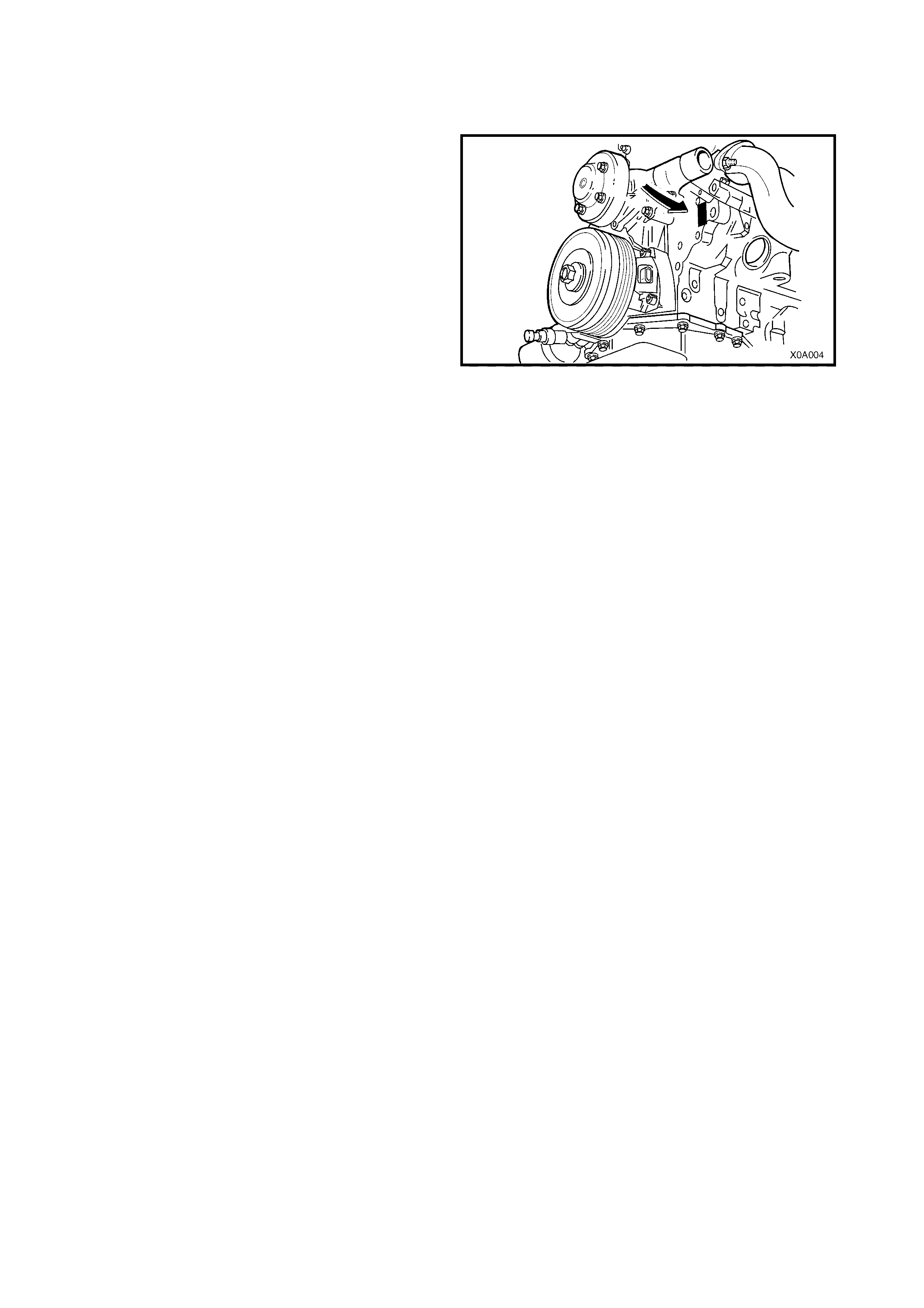
13. ENGINE SERIAL NUMBERS
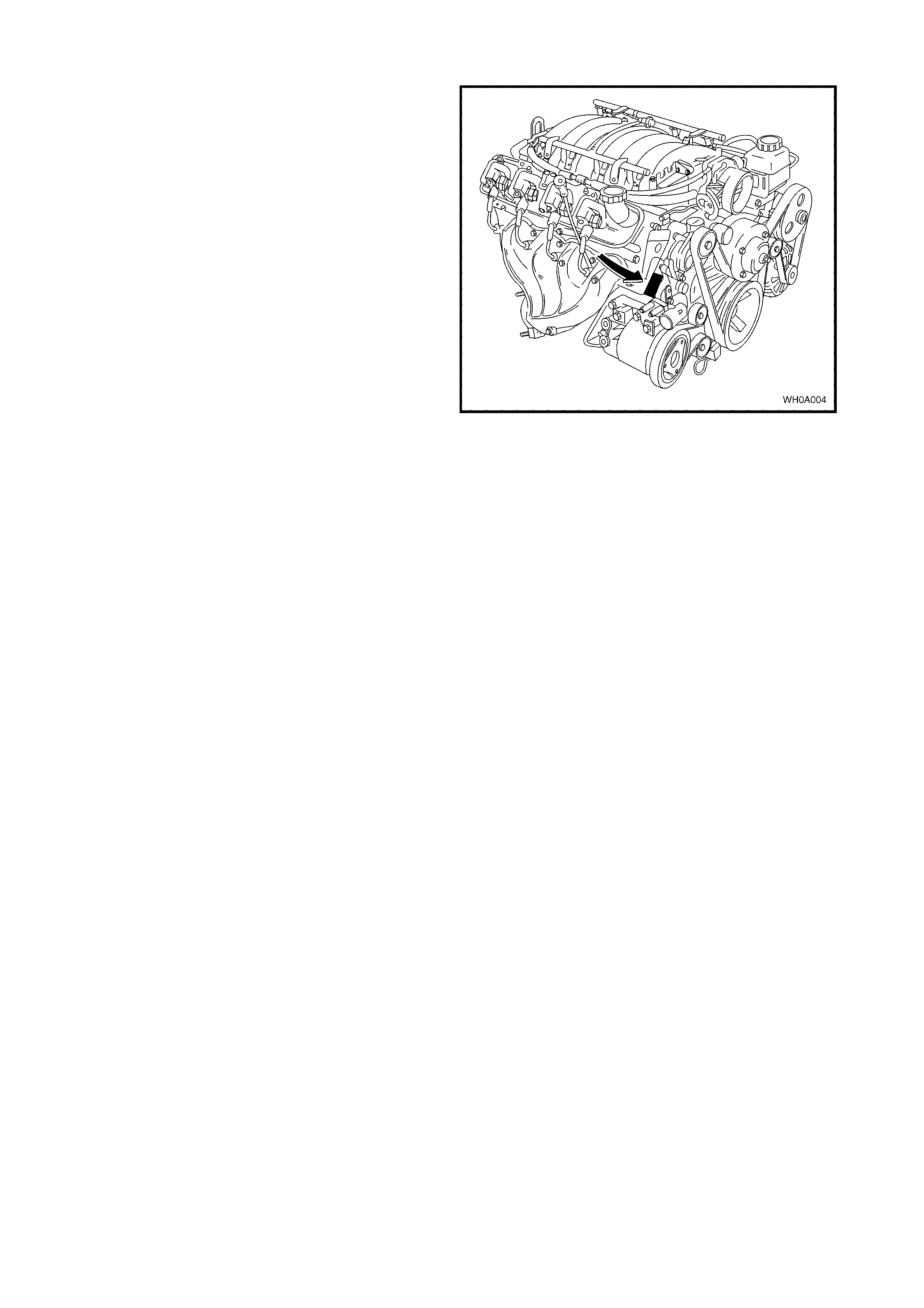
13.1 V6 ENGINE
The engine serial number for the 3.8 litre V6 and V6
supercharged engines is stamped on a pad that is
located adjacent to the engine coolant outlet pipe and
below the ignition coil.
Figure 0A-36
13.2 GEN III V8 ENGINE
The 5.7 litre Gen III V8 engine serial number is
stamped on a pad that is located adjacent to the
engine coolant outlet pipe and below number 2 cylinder
spark plug.
Figure 0A-37
14. TRANSMISSION SERIAL NUMBER
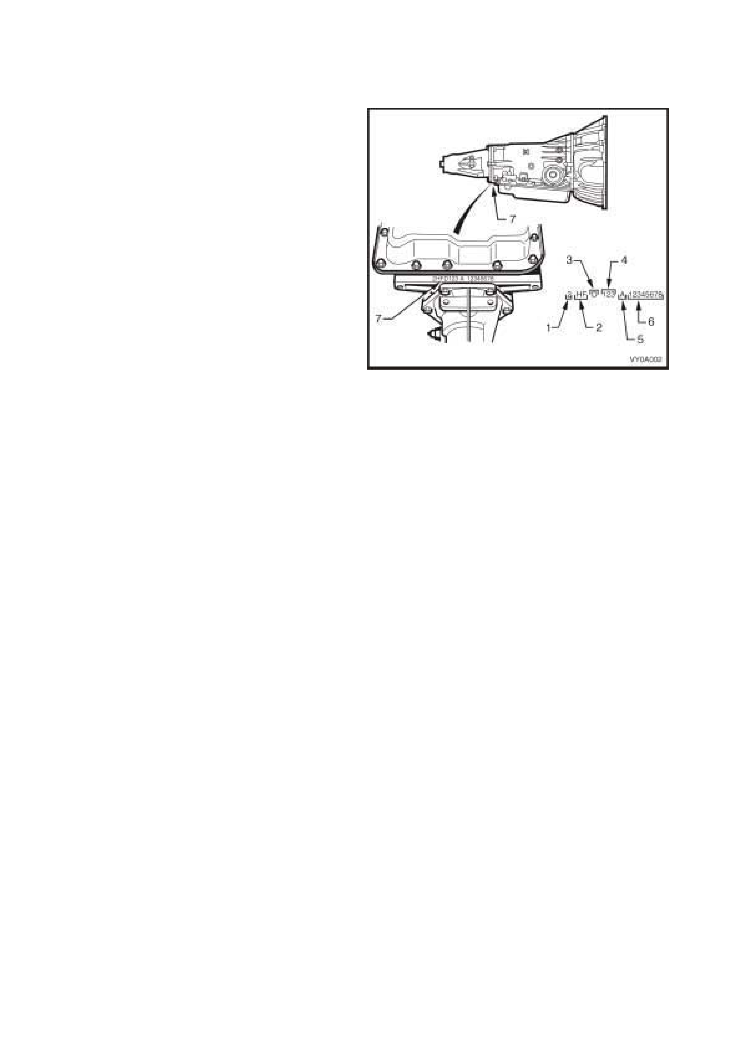
14.1 AUTOMATIC TRANSMISSION
The automatic transmission serial number is stamped
into a machined surface at the rear underside of the
transmission centre case.
1. Model Year (‘2’ = 2002, ‘3’ = 2003, ‘4’ = 2004)
2. Model: V8 – 5.7 litre......................... HA
V6 – 3.8 litre ........................ HF
V6 Supercharged – 3.8 litre. HN
3. Transmission Model Identifier (D = 4L60-E).
4. Julian Date (or day of year).
5. Shift Built (A, B, J = first shift;
C, H, W = second shift).
6. Individual Transmission Serial Number.
7. Transmission Identification Number Location.
Figure 0A-38
14.2 MANUAL TRANSMISSION – 5 SPEED
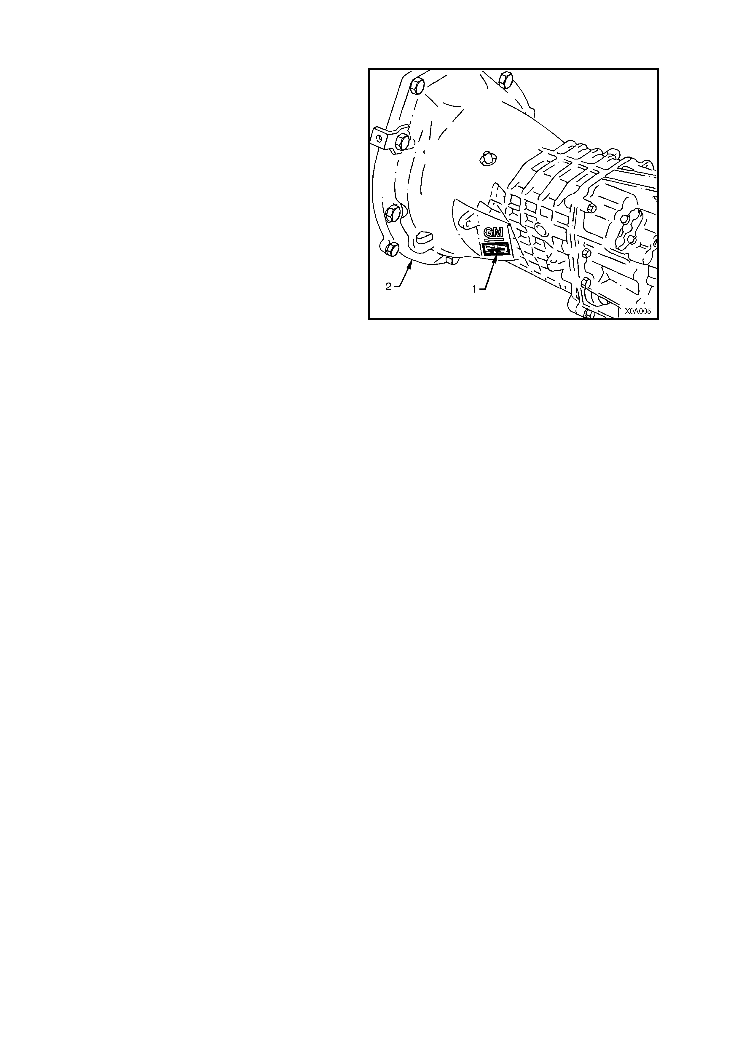
The Getrag five speed manual transmission serial
number is located on a self-adhesive label (1)
attached to the left side of the transmission front
cover.
This number provides coded information that could be
significant to parts interpretation and should be
referred to when ordering replacement parts.
NOTE: if this label is removed or becomes
unreadable, the serial number is also stamped onto
the lower left-hand side of the transmission front
cover (2).
Figure 0A-39
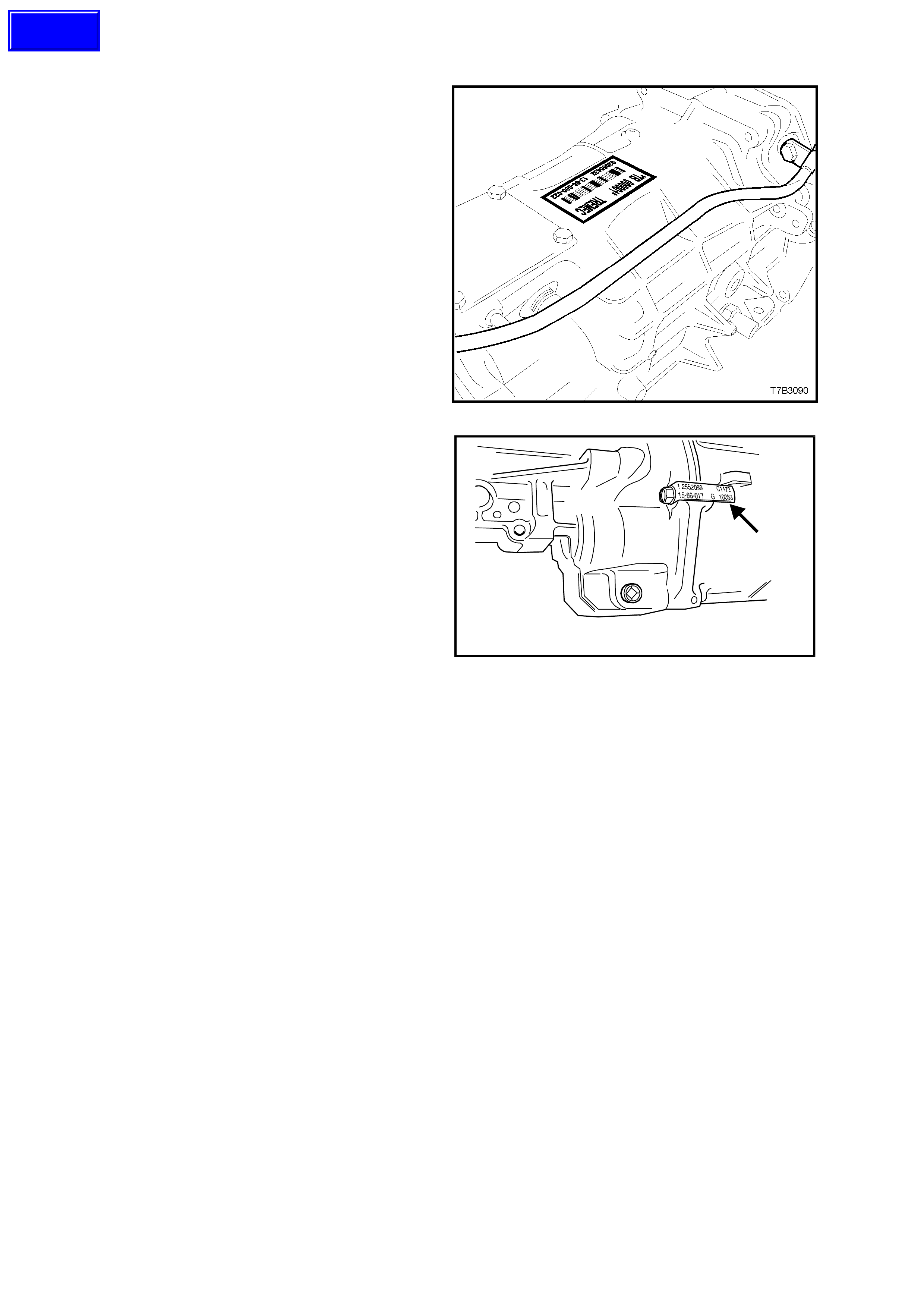
14.3 MANUAL TRANSMISSION – 6 SPEED
The Borg-W arner (Tremec) T56 six speed manual
transmission serial number is located on a self-
adhesive decal attached to the top of the
transmission case.
This num ber provides coded information that could
be significant to parts interpretation and should be
referred to when ordering replacement parts.
In addition, an identification tag is attached to the
transmission under an extension housing bolt, on
the right-hand side.
Figure 0A-40
T20A002
Figure 0A-41
Techline
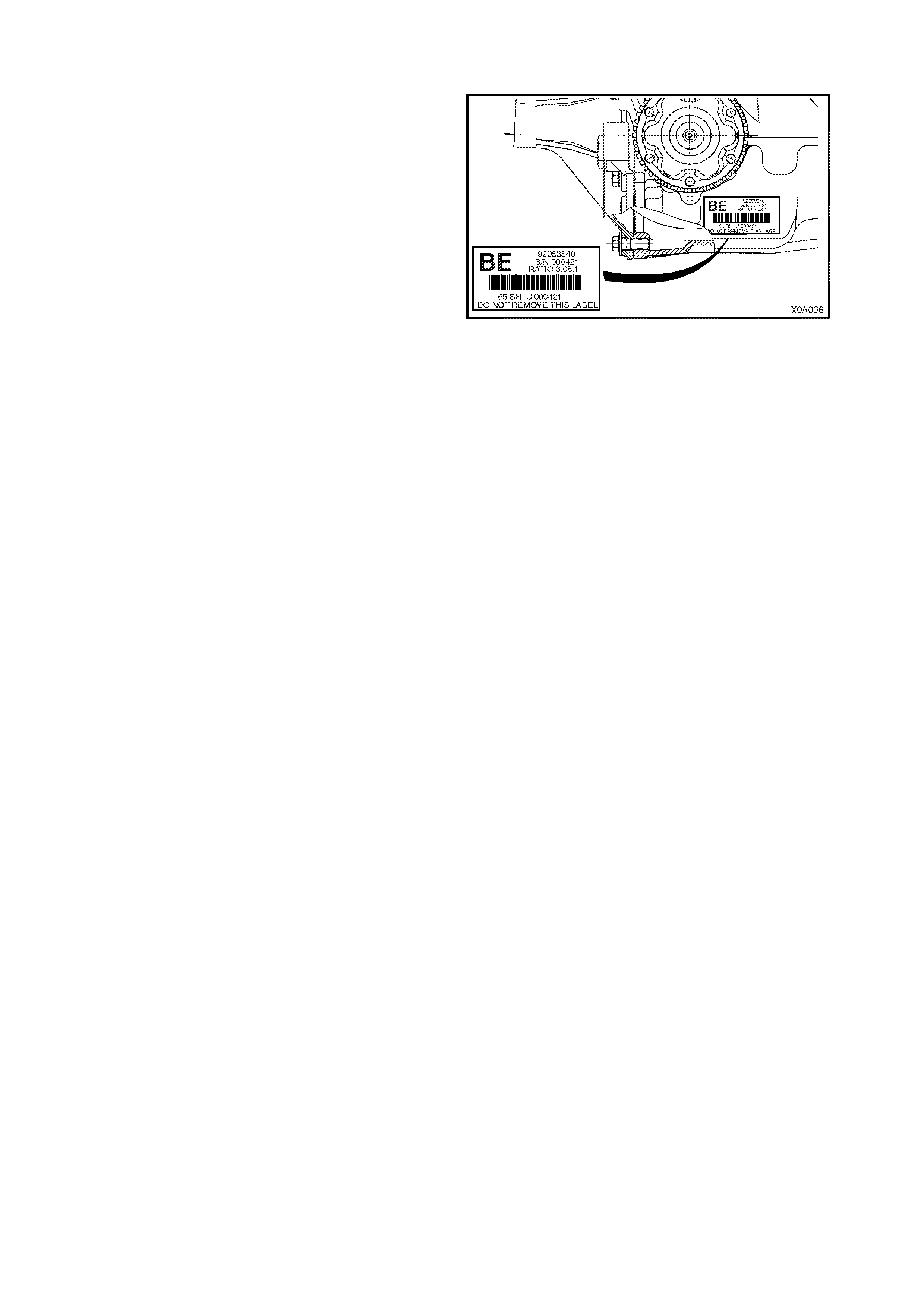
15. FINAL DRIVE ASSEMBLY SERI AL NUMBER
An identification tag is adhered to the final drive
assembly to the right-hand side of the carrier housing.
The tag carries the Holden part number for the
assem bly, the final drive ratio and the s erial number of
the assembly.
Figure 0A-42
16. CONSOLIDATED TOOL LIST
The f ollowing pages lis t and illus tr ate the spec ial s er vice tools r equired f or us e on MY2003 VY Series & MY2003 V2
Series II vehicles. The tools are listed in numerical then alphabetical order and are classified into the following
categories:
Mandatory: When required to perform routine maintenance operations and adjustments, or are required to carry
out fault diagnosis procedures.
Desirable: These tools should be considered for purchase since their use will greatly facilitate performing
designated tasks and permit achievement of standard times.
Unique: These tools are those that must be employed when overhauling major assemblies or performing
relatively large tasks.
Available: Are those tools that are of a general natur e for which comm ercially available equivalents exis t, or tools
which have had previous application.
Unless otherwise specified, all tools are available from:
SPX Australia PTY. LTD.
Service Solutions
28 Clayton Road
Notting Hill, Victoria, 3168
Telephone: (03) 9544 6222
Facsimile: (03) 9544 5222
Email: [email protected]
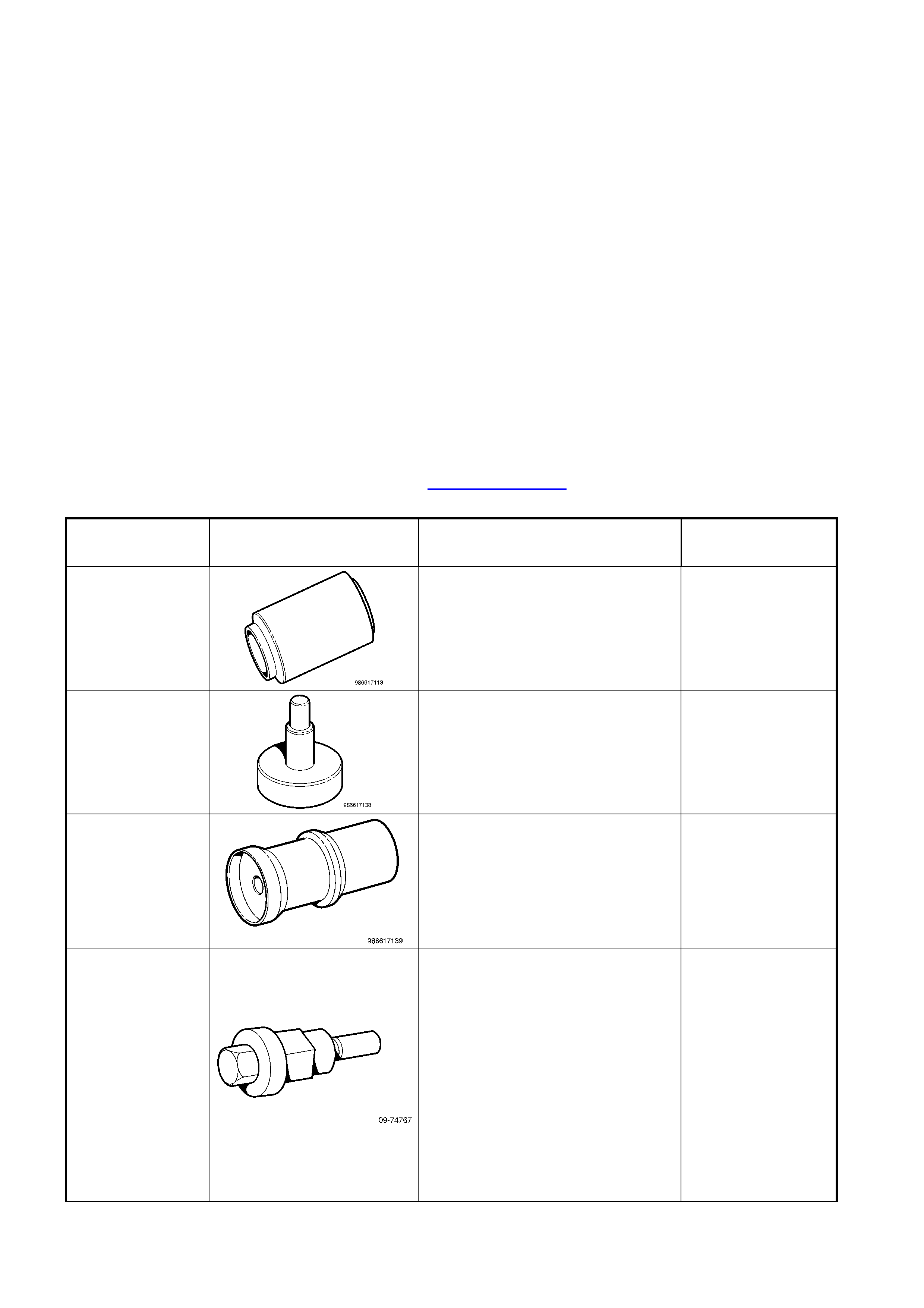
TOOL NUMBER ILLUSTRATION DESCRIPTION TOOL
CLASSIFICATION
0 986 617 113
REMOVER
Used in conjunction with tool no.
0 986 617 138 for the removal of
the starter motor drive-end stop-
ring and retainer.
Unique
0 986 617 138
REMOVER
Used in conjunction with tool no.
0 986 617 113 for the removal of
the starter motor drive-end stop-
ring and retainer.
Unique
0 986 617 139
ASSEMBLY TOOL
Used to assist in brush plate
assembly on starter motors.
Unique
09-74767 A/C CLUTCH HUB AND DRIVE
PLATE INSTALLER
Used for installing A/C clutch drive
plate and hub assembly.
Available from:
The Aftermarket Department
Air International P/L
80 Turner Street
Port Melbourne
Victoria, 3207
Mandatory
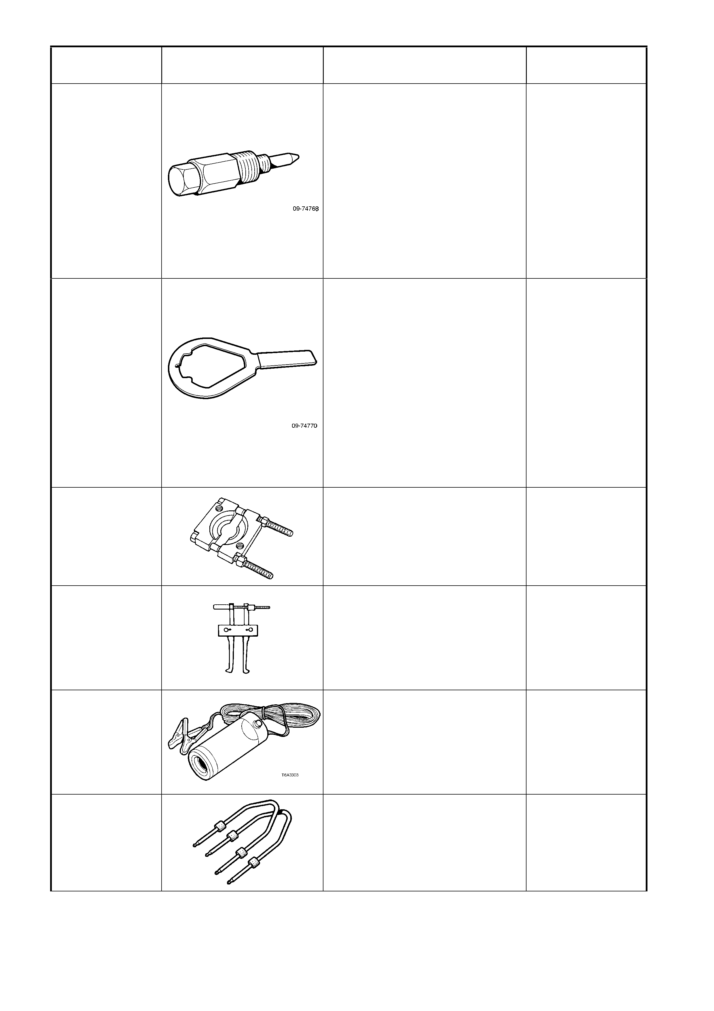
TOOL NUMBER ILLUSTRATION DESCRIPTION TOOL
CLASSIFICATION
09-74768 A/C CLUTCH HUB AND DRIVE
PLATE REMOVER
Used for removing A/C clutch drive
plate and hub assembly.
Available from:
The Aftermarket Department
Air International P/L
80 Turner Street
Port Melbourne
Victoria, 3207
Desirable
09-74770 A/C CLUTCH HUB HOLDER
Used for holding A/C clutch
hub/drive plate during A/C clutch
drive plate and hub assembly
removal and installation.
Available from:
The Aftermarket Department
Air International P/L
80 Turner Street
Port Melbourne
Victoria, 3207
Desirable
1123
(J22912-01)
(E6673)
PRESS PLATES
Used for many applications for
pressing on and off components.
Previously released.
Desirable
1150
PULLER
Used in conjunction with forcing
screw E6661S and adaptor AU412
to remove side bearing cups from
the screw adjusters.
Previously released.
Unique
16296
(J42220)
BLACK LIGHT, LEAK DETECTION
LAMP
Used in conjunction with dye, Tool J
28431-B to locate the source of
various vehicle fluid leaks.
Previously released.
Desirable
179 1308 0000
RADIO REMOVAL TOOL
On VY, used for removing
navigation system processor from
its mounting location.
Previously released.
Mandatory
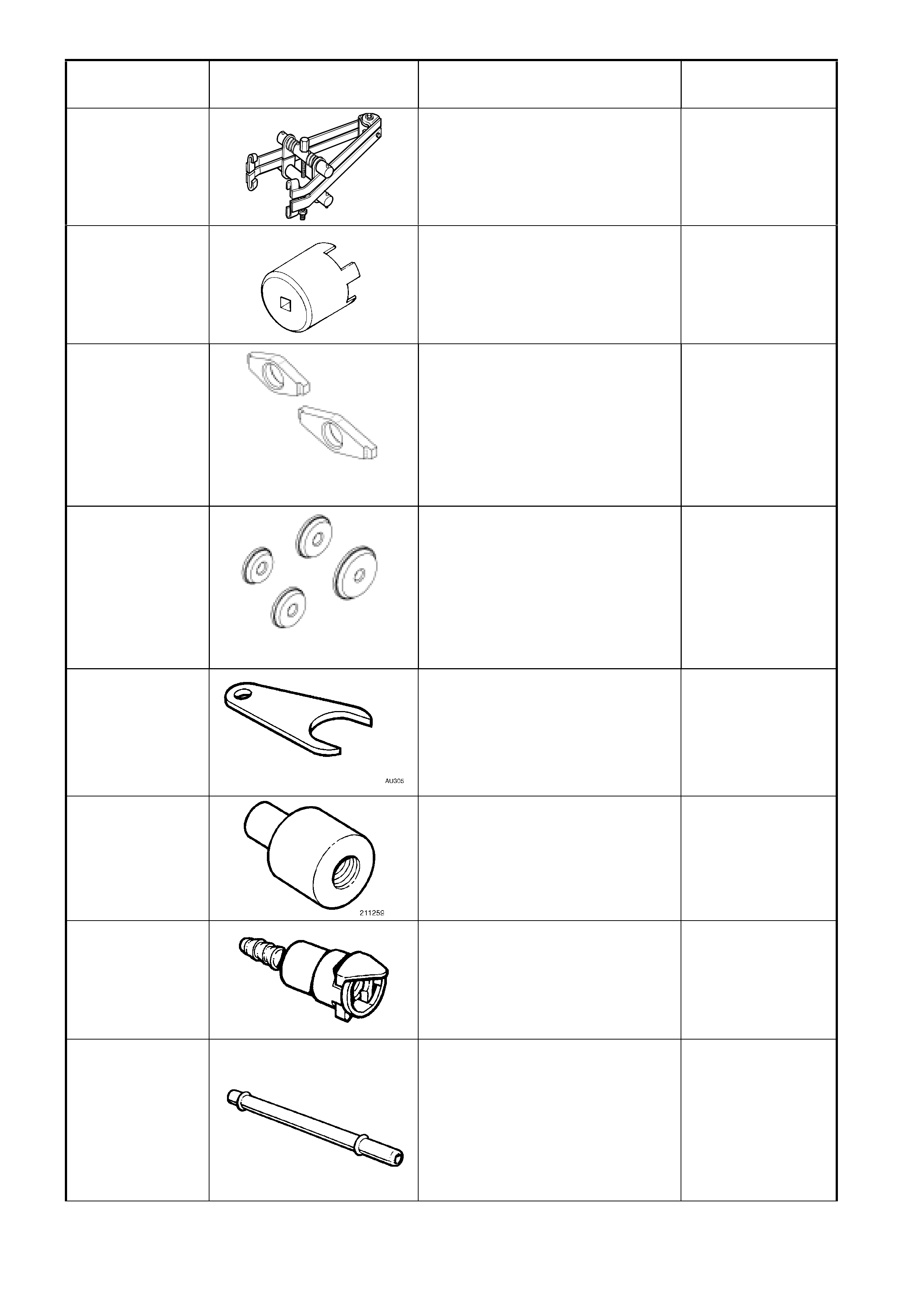
TOOL NUMBER ILLUSTRATION DESCRIPTION TOOL
CLASSIFICATION
180
(6072)
SPRING COMPRESSOR
Used for front spring removal and
reinstallation off vehicle.
Previously released.
Desirable
205-463
(AU407)
SCREW ADJUSTER SOCKET
Used for checking and adjusting
final drive side bearings.
Previously released.
Unique
205-551
ADAPTORS
Used to remove the pinion bearing
cups, in conjunction with
Remover/Installer E9293.
205-551-1 is required for 3.07:1
and 3.46:1 assemblies.
New release.
Unique
205-552
ADAPTORS
Used to install the pinion bearing
cups, in conjunction with
Remover/Installer E9271.
205-552-2 is required for 3.07:1
and 3.46:1 assemblies.
New release.
Unique
211-258
TIE ROD WRENCH
Used to tighten tie rod assembly
from steering rack.
New release.
Unique
211-259
LOWER PINION BEARING
REMOVER
Used in conjunction with Driver
Handle AU355-A.
Previously released.
Unique
212157
COUPLER
Used in conjunction with hose
AU470 and gauge AU338 for
checking fuel pressure.
Previously released.
Mandatory
216812 TUBE
Used in conjunction with hose
SD28057 and coupler 212157 and
gauge SD28018 (or AU338) for
checking fuel system pressure.
Part of AU470
Previously released.
Mandatory
TOOL NUMBER ILLUSTRATION DESCRIPTION TOOL
CLASSIFICATION
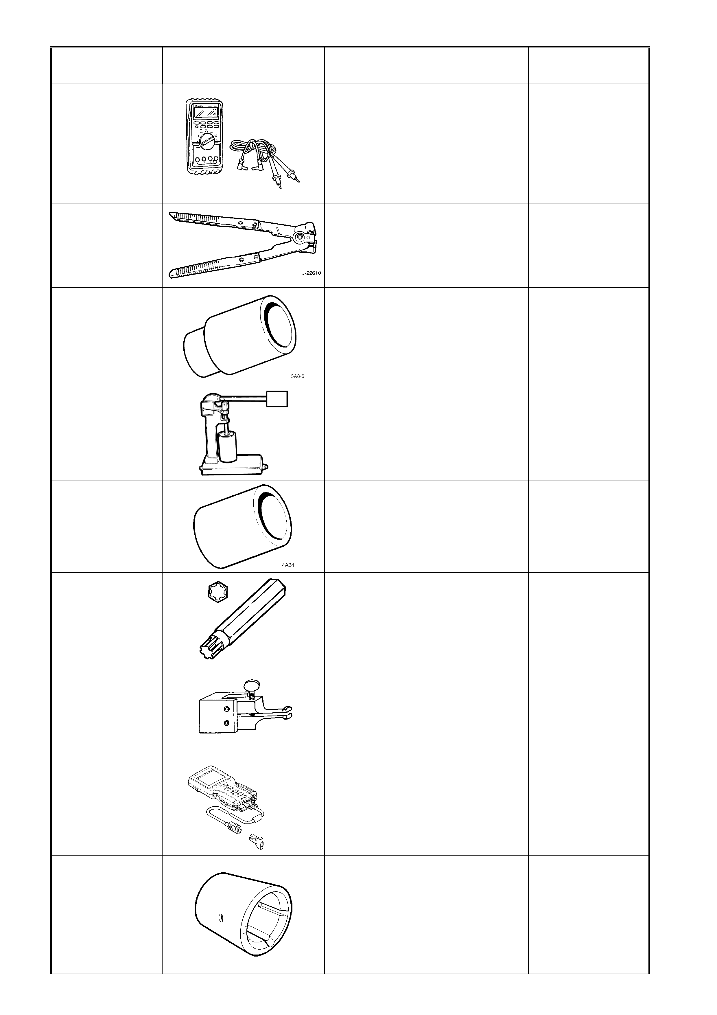
3588
(J39200)
DIGITAL MULTIMETER
Used for various measurement
functions. Must have at least
10 MΩ input impedance and be
capable of reading frequencies.
Previously released (or use
commercial equivalent).
Available
3A13
(E1896)
(J22610)
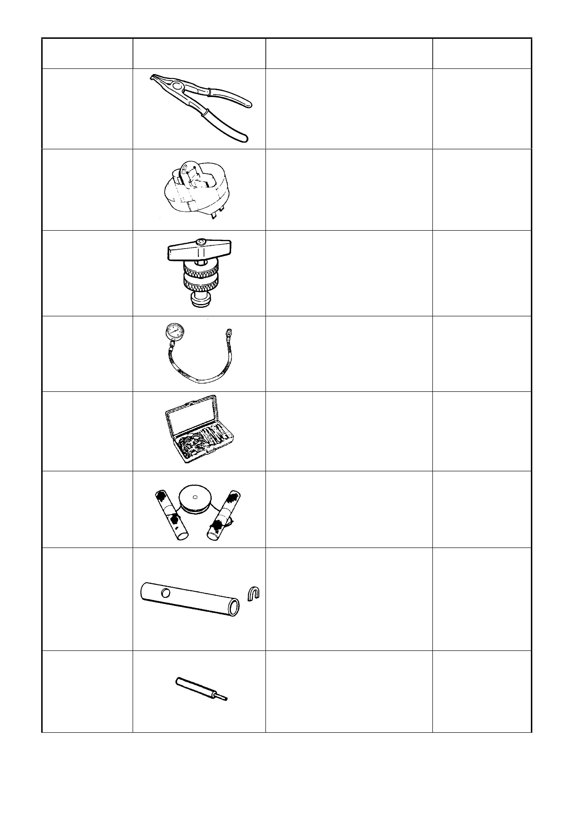
KEYSTONE CLAMP PLIERS
Used to tighten the sliding joint boot
clamp.
Previously released.
Available
3A8-6
(E1891-6)
SLEEVE
Used to install the 1st/2nd gear
synchromesh hub to the mainshaft.
Previously released.
Unique
49 U012 005
(6A23)
T6A3114b
VALVE LIFTER TESTER
Used in conjunction with testing
fluid Kent Moore No. E1151.
Previously released.
Unique
4A24
(E1662)
SLEEVE
Used to install the bearing cup into
the input shaft gear.
Previously released.
Unique
6194
(J41510)
#50 TORX PLUS BIT
Used for tightening torque
converter housing to transmission
main case attaching bolts.
Previously released.
Unique
6A22-2
SPIGOT BEARING REMOVER
Alternatively, use J23907 or E6668
which includes its own slide
hammer.
Previously released.
Desirable
7000086I
TECH 2 DIAGNOSTIC SCAN
TOOL
Used for diagnosis of vehicle
electrical system.
Previously released.
Mandatory
700-4208
PASS-THRU CONNECTOR
RELEASE TOOL
Used to release the four locking
tangs on the Pass-Thru electrical
connector from the automatic
transmission case.
New release
Available
TOOL NUMBER ILLUSTRATION DESCRIPTION TOOL
CLASSIFICATION
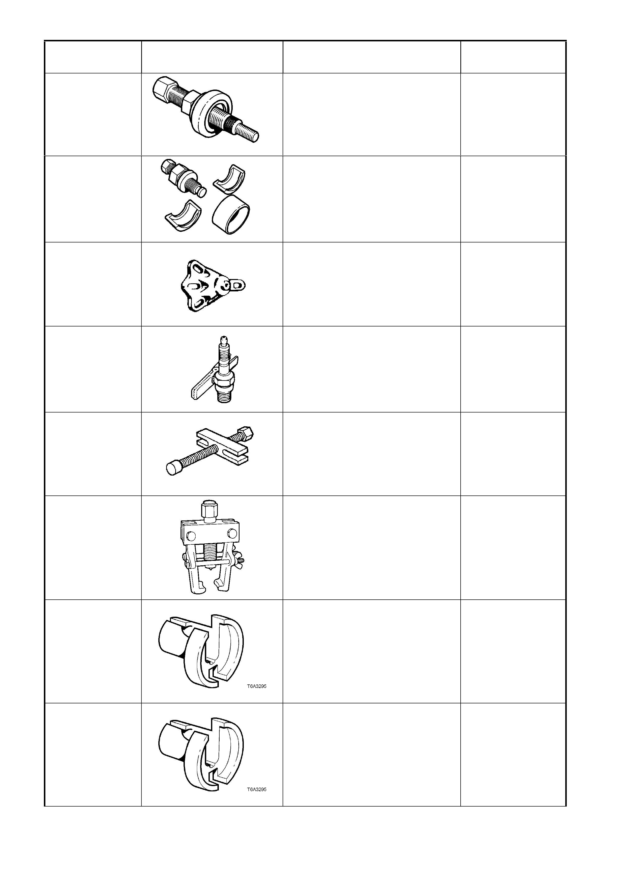
7005
POWER STEERING PUMP
PULLEY INSTALLER
Previously released.
Desirable
7185
POWER STEERING PUMP
PULLEY REMOVER
Previously released.
Desirable
7208 REAR AXLE REMOVAL ADAPTOR
Used in conjunction with E6662B
for L.S.D. torque check.
Previously released.
Unique
7230
(ST-125)
HEI TESTER (TEST PLUG)
Used in diagnostic checks with
engine management system.
Previously released.
Mandatory
7245
(J1859-A)
STEERING WHEEL PULLER
Used in conjunction with E1408 to
remove steering wheel (or use
commercially available equivalent).
Previously released.
Mandatory
7311
(9A10)
(E1465)
TIE ROD BALL JOINT REMOVER
Used to disconnect steering tie rod
ball joints from steering knuckle.
Previously released.
Desirable
7370
QUICK CONNECT RELEASE
TOOL – 5/16”
Used for releasing fuel hose quick
connects at the dash panel and fuel
rail connections, once the fuel
system has been depressurised.
Previously released.
Mandatory
7371
QUICK CONNECT RELEASE
TOOL – 3/8”
Used for releasing fuel hose quick
connects at the dash panel and fuel
rail connections, once the fuel
system has been depressurised.
Previously released.
Mandatory
TOOL NUMBER ILLUSTRATION DESCRIPTION TOOL
CLASSIFICATION
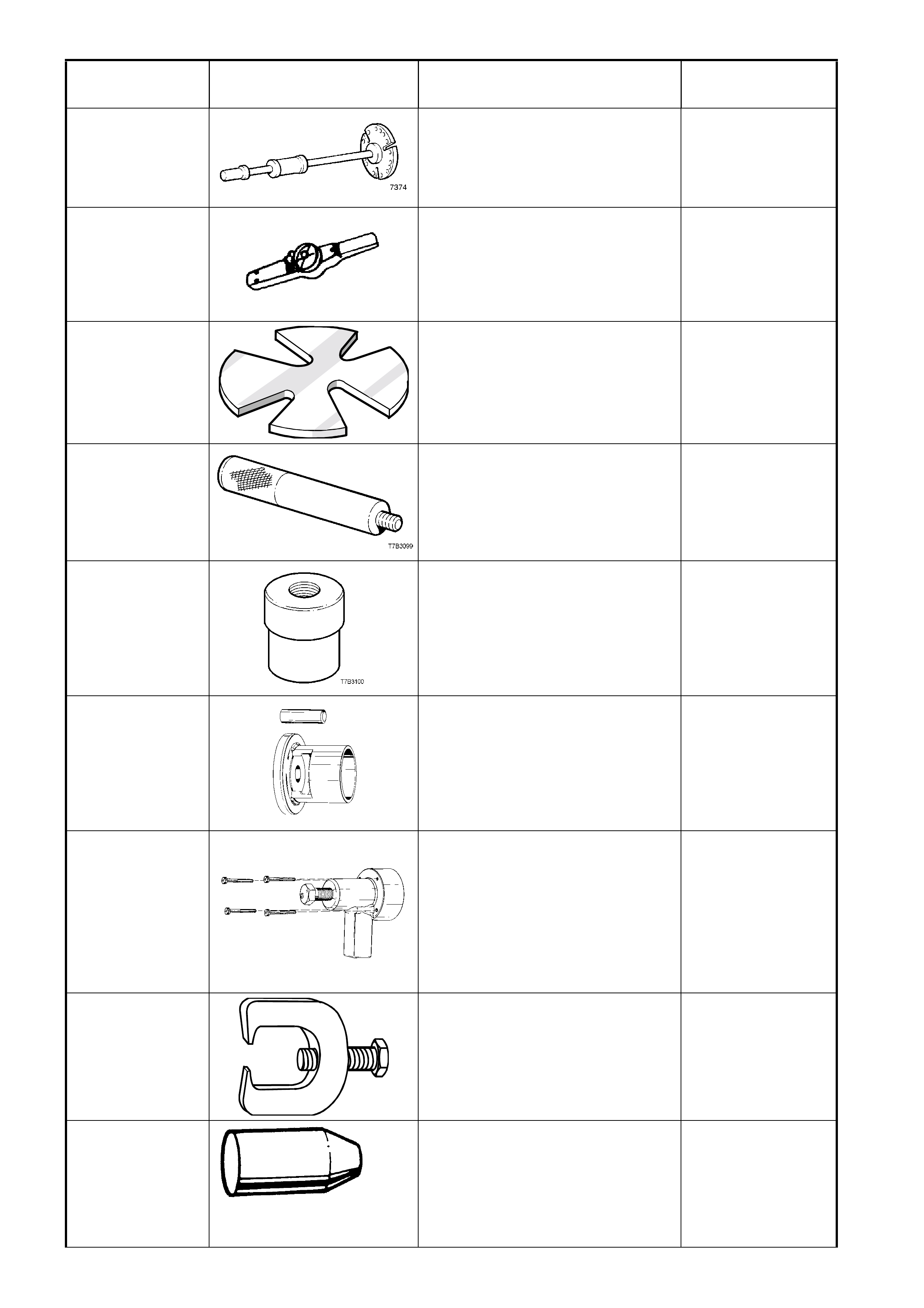
7374 SLIDE HAMMER & PLATE
Used to remove inner axle shafts
from the rear axle assembly .
Previously released.
Desirable
7380
(J25765-A)
PRE-LOAD GAUGE (3/8” DRIVE)
Used for many applications.
Previously released.
(0-150 in lbs)
Mandatory
7A42
PRESS PLATES
Previously released.
Desirable
7AT2
(E1502)
DRIVER HANDLE
Used in conjunction with 7AT5 to
remove/install the slip yoke bushing
in the extension housing.
Previously released.
Unique
7AT5
(E1505)
(J23062-14)
SLIP YOKE BUSH REMOVER/
INSTALLER
Used in conjunction with 7AT2 to
remove/install the slip yoke bushing
in the extension housing.
Previously released.
Unique
9981 066 600
BEARING ASSEMBLY FIXTURE
Used for pressing generator
bearings on at the same time. Tool
available from Robert Bosch
Australia.
Previously released.
Unique
9981 066 601 ROTOR BEARING REMOVAL
TOOL
Used for removing rotor from drive
end housing.
Tool available from Robert Bosch
Australia.
Previously released.
Unique
9A10
(7311)
(E1465)
STEERING LINKAGE BALL STUD
REMOVER
Previously released.
Desirable
9A23
(E1483)
EXPANDER - SLEEVE SEALS
Used for expanding steering gear
rotary valve and sleeve assembly
seals before installation.
Previously released.
Unique
TOOL NUMBER ILLUSTRATION DESCRIPTION TOOL
CLASSIFICATION
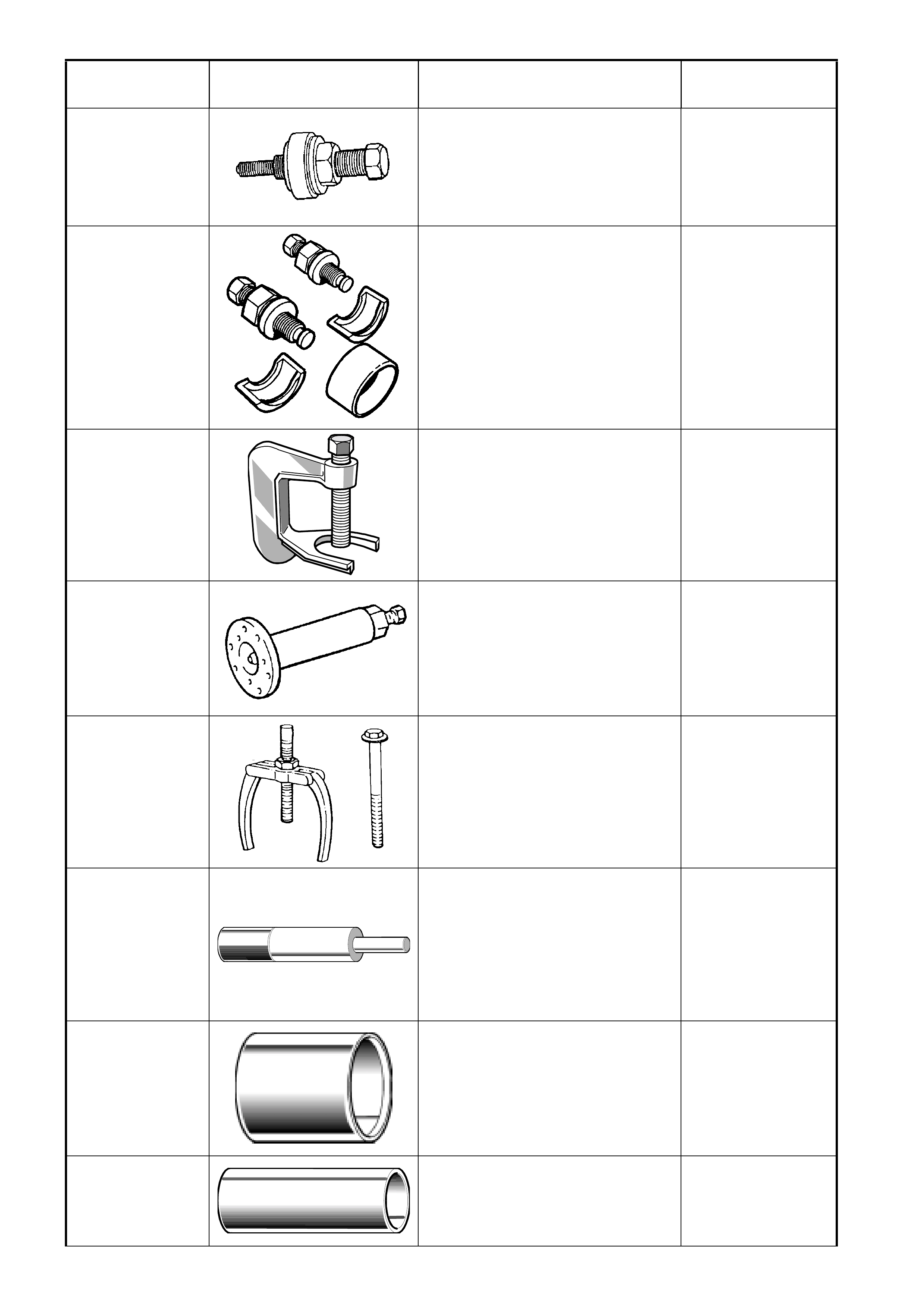
A7005
(J25033-B)
(E9239A)
POWER STEERING PUMP
PULLEY
RE-INSTALLER
Previously released.
Desirable
A7185 POWER STEERING PUMP
PULLEY
REMOVER – GEN III
Previously released.
Mandatory
AJ24292-C
PRESS TOOL
Used to remove wheel studs from
front wheel hub assembly.
Previously released.
Unique
AKM-628-A EXTRACTOR TOOL
Used to remove the mainshaft
flange and to separate the two
transmission housings on
disassem bly.
Previously released.
Unique
AMKM-557
PULLER
Previously released.
Used for removing bushing from
crossmember front mounting.
Previously released.
Desirable
AU158 FRONT LOWER CONTROL ARM
ROD BUSHING REMOVER AND
INSTALLER MANDREL
Used in conjunction with KM158-2
for removing bush and AU159 and
KM157-2 for installing.
Previously released.
Desirable
AU158-2
FRONT LOWER CONTROL ARM
ROD BUSHING INSTALLING
SUPPORT SLEEVE
Used in conjunction with AU158
and AU159.
Previously released.
Desirable
AU159 FRONT LOWER CONTROL ARM
ROD BUSHING REPLACER
SLEEVE
Previously released.
Desirable
TOOL NUMBER ILLUSTRATION DESCRIPTION TOOL
CLASSIFICATION
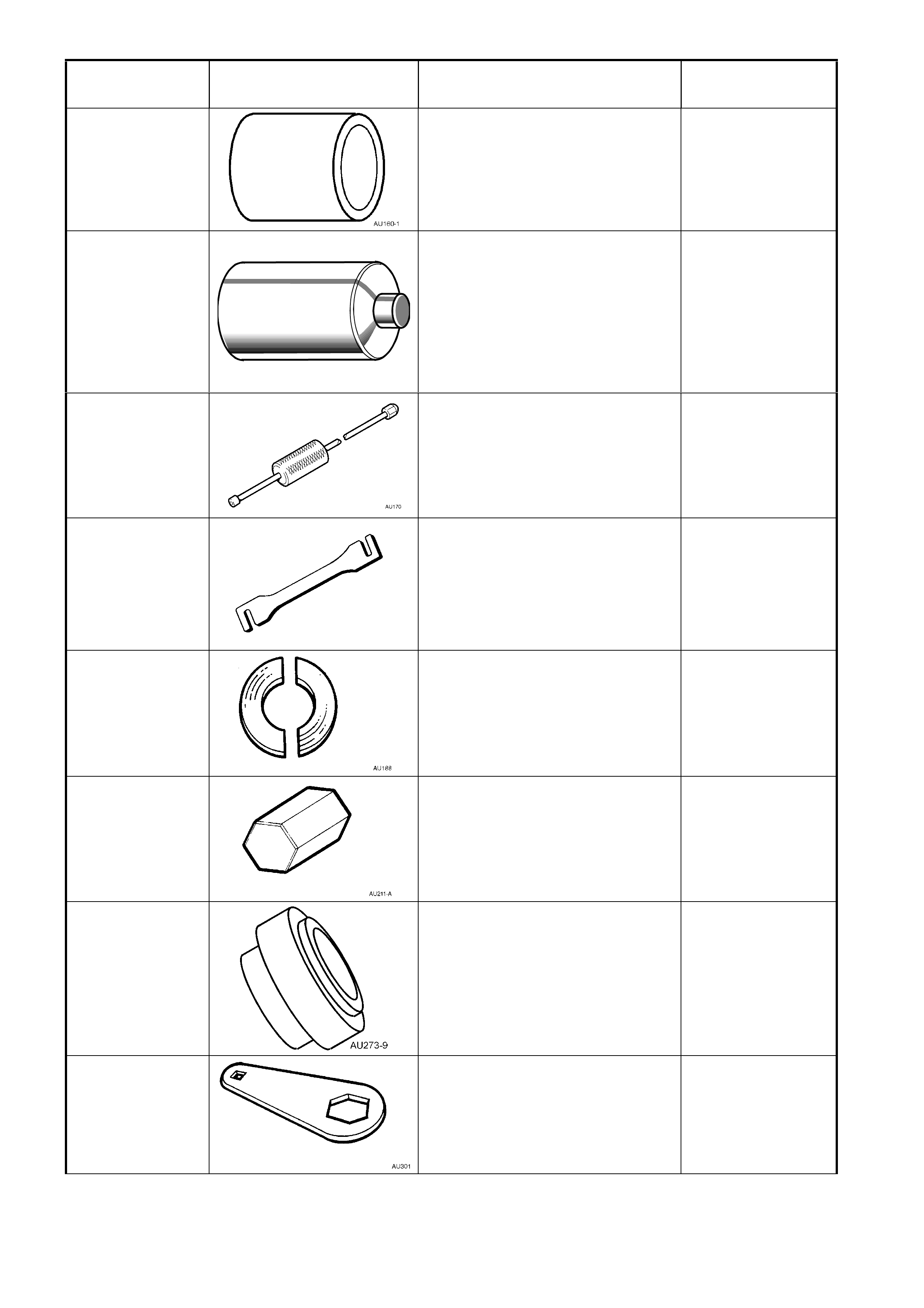
AU160-1
SUPPORT
Used to support front lower control
arm when installing a new inner
insulator.
Previously released.
Desirable
AU162 FRONT LOWER CONTROL ARM
PIVOT BUSHING
REMOVAL MANDREL
Used in conjunction with AU160-1
and KM157-2.
Previously released.
Desirable
AU170
DOOR HINGE SLEEVE
REMOVER
Used for removing door hinge pivot
sleeves.
Previously released.
Available
AU184 DOOR HINGE SETTING TOOL
Used to adjust door alignment.
Previously released.
Desirable
AU188
PRESS PLATES
Previously released.
Unique
AU211-A
(E9326-8)
RACK PAD ADJUSTING SCREW
WRENCH
Previously released.
Desirable
AU273-9
ADAPTOR
Used in replacement of propeller
shaft centre bearing
Previously released.
Unique
AU301
(E9326-7)
RACK PAD ADJUSTING SCREW
LOCK NUT WRENCH
Previously released.
Desirable
TOOL NUMBER ILLUSTRATION DESCRIPTION TOOL
CLASSIFICATION
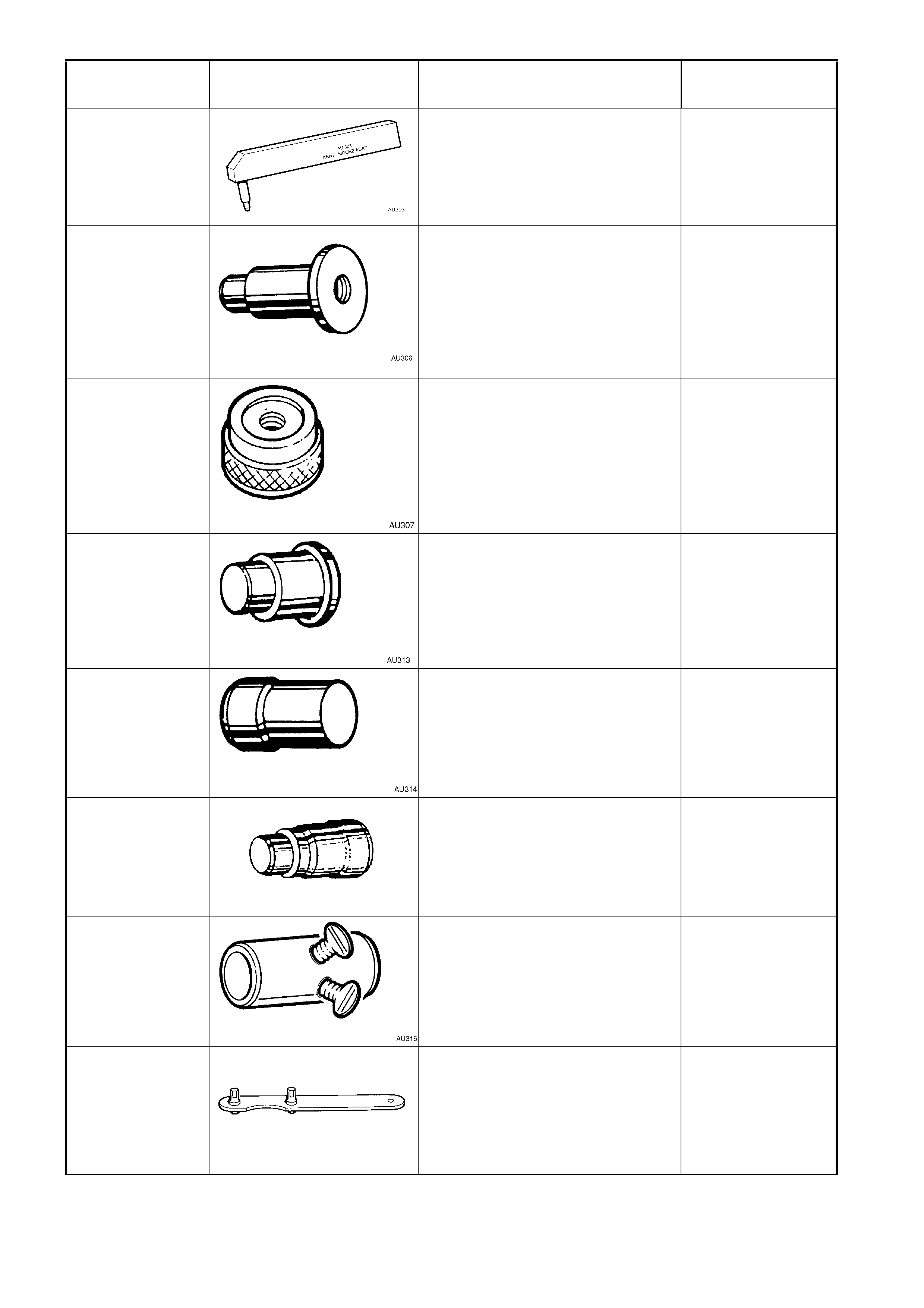
AU303
DOOR HINGE SLEEVE
INSTALLER
Used to install door hinge pivot
sleeves.
Previously released.
Available
AU306 LOWER PINION BEARING
REMOVER
Used in conjunction with driver
handle AU355-A (or M523-1) to
remove steering gear pinion lower
bearing.
Previously released.
Unique
AU307 LOWER PINION BEARING
INSTALLER
Used to install steering gear pinion
lower bearing.
Previously released.
Unique
AU313 UPPER PINION POWER
STEERING FLUID SEAL
INSTALLER
Previously released.
Used to install valve housing
bearing.
Unique
AU314 VALVE HOUSING SEAL AND
BEARING REMOVER
Previously released.
Unique
AU315-A
STEERING GEAR VALVE
HOUSING SEAL AND BEARING
INSTALLER
Previously released.
Unique
AU316 PRE-LOAD ADAPTOR
Previously released.
Unique
AU320
(AU448)
CRANKSHAFT BALANCER
HOLDING TOOL
Previously released.
Desirable
TOOL NUMBER ILLUSTRATION DESCRIPTION TOOL
CLASSIFICATION
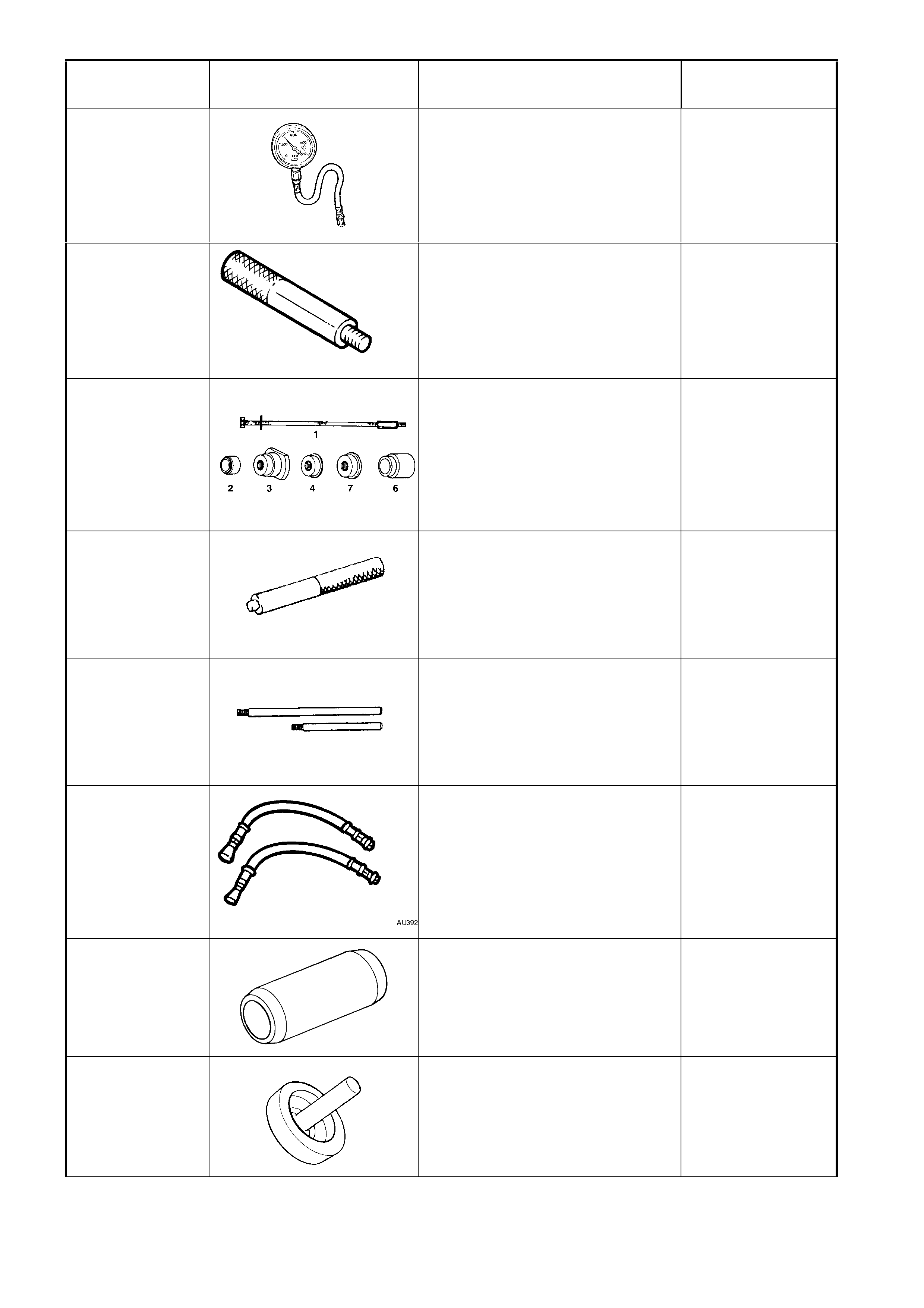
AU338
(SD28018)
FUEL PRESSURE GAUGE - HIGH
PRESSURE
Used for checking fuel system
pressure in conjunction with
AU453.
Previously released.
Mandatory
AU355-A DRIVER HANDLE
Previously released as KM523-1.
Used in conjunction with AU306
and AU315.
Previously released.
Unique
AU384-B PULLER SCREW
Used in conjunction with AU384-2,
AU384-3, AU384-4, AU384-7 and
AU384-6A to remove / install
camshaft and balance shaft
bearings.
Previously released.
Desirable
AU385-4
REMOVER / INSTALLER
Used to remove and install bushes
into rear suspension stabiliser bar.
Previously released.
Desirable
AU388 CONNECTING ROD GUIDE
TOOLS
Used in conjunction with AU388-1
and AU388-2.
Previously released.
Unique
AU392 PRESSURE HOSE SET
Comprises:
AU392-1, hose with male end
fitting.
AU392-2, hose with female end
fitting.
Previously released.
Mandatory
AU408
DUMMY ARBOUR
Used in conjunction with dummy
pinion from E9300A.
Previously released.
Unique
AU409
PRESS FIXTURE
Used to install needle bearings into
screw adjusters. Used in
conjunction with AU411.
Previously released.
Unique
TOOL NUMBER ILLUSTRATION DESCRIPTION TOOL
CLASSIFICATION
AU410
SEAL INSTALLER
Used to install inner axle seals to
screw adjusters.
Previously released.
Unique
AU411
BEARING AND CUP REMOVER
Used in conjunction with AU409.
Previously released.
Unique
AU412
ADAPTOR
Used in conjunction with forcing
screw E6661S and puller 1150 to
remove side bearing cups from
screw adjusters.
Previously released.
Unique
AU416
TOR X BIT
Used to remove and reinstall upper
rear brake backing plate to trailing
arm bolts.
Previously released.
Unique
AU424
CRANKSHAFT BALANCER
PULLER
Puller bolts must be 70 mm x 1/4”
NF.
Previously released.
Mandatory
AU425 COOLING SYSTEM FILLER TUBE
Used to ensure coolant level is
correct.
Previously released.
Mandatory
AU435 COOLANT TESTER
Used to check condensation.
Previously released.
Mandatory
AU440 CONTRACTOR - SLEEVE SEALS
Previously released.
Unique
TOOL NUMBER ILLUSTRATION DESCRIPTION TOOL
CLASSIFICATION
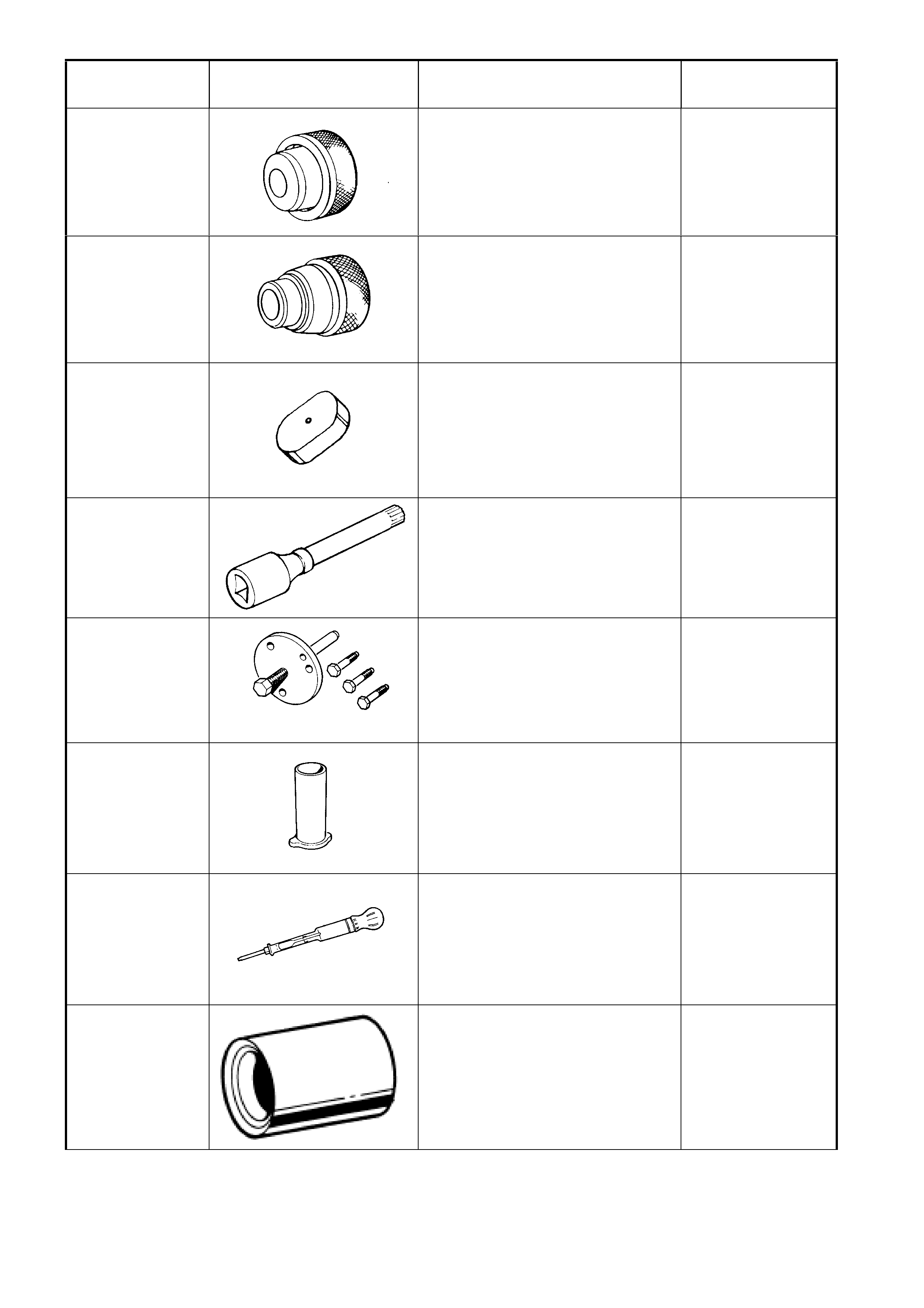
AU453 FUEL GAUGE SCHRADER
ADAPTOR
Used for checking system fuel
pressure in conjunction with
AU338.
Previously released.
Mandatory
AU454 GEAR REMOVER PLATES
Used to remove 3rd/4th
synchromesh assembly, 3rd speed
gear, 2nd speed gear and related
components from the mainshaft.
Previously released.
Unique
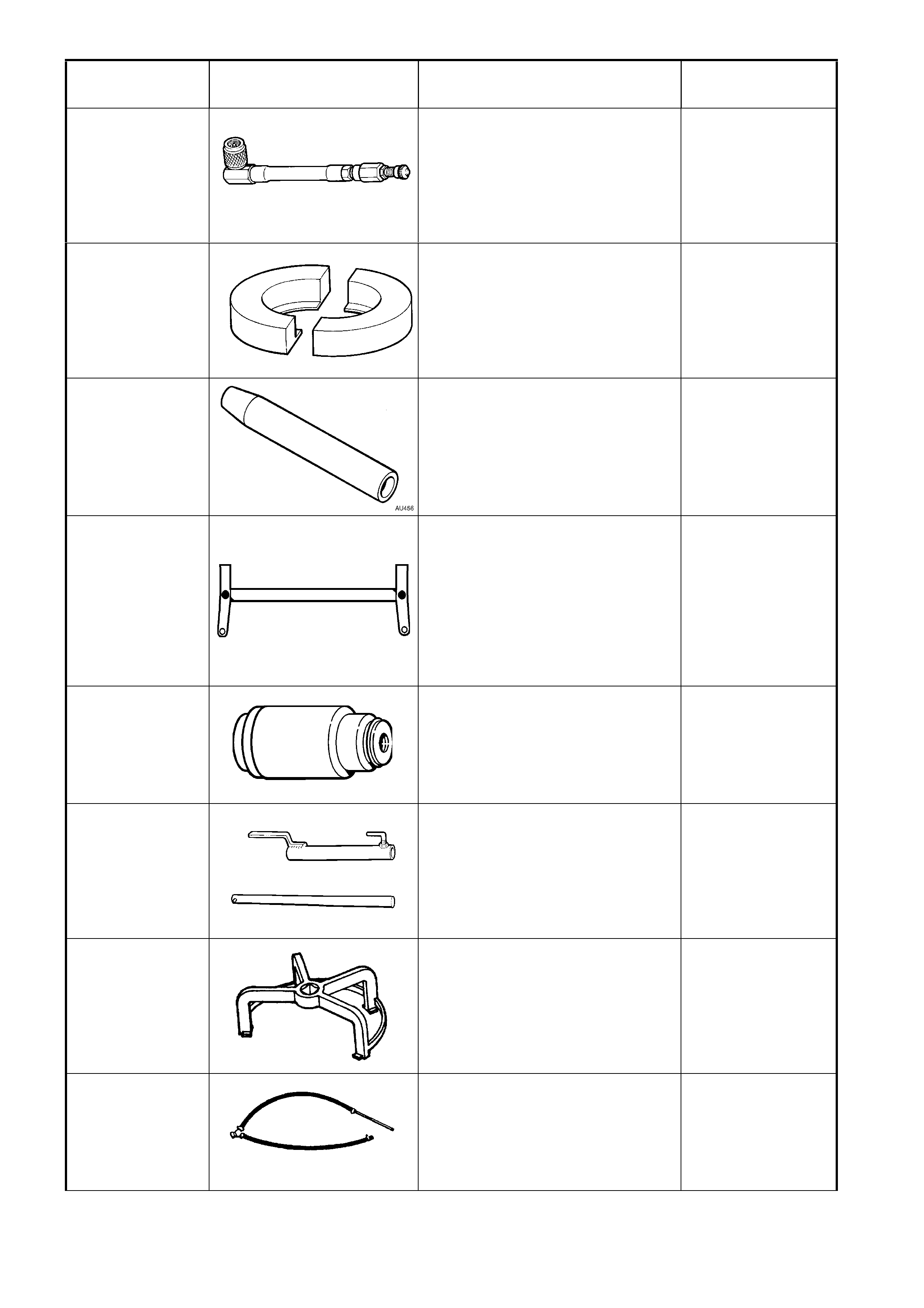
AU456 RACK SEAL PROTECTOR - LONG
Used when overhauling steering
gear.
Previously released.
Unique
AU458 REAR CROSSMEMBER
CENTERING TOOL
Used when any service operation
requires removal / reinstallation of
frame assembly - rear suspension,
or when checking rear end
alignment.
Previously released.
Desirable
AU460 INSTALLER - INNER RACK SEAL
AND SPACER
Used in conjunction with driver
handle AU355-A.
Previously released.
Unique
AU462
SELECT LEVER SPRING AND
BUSH INSTALLER
Used to load the select lever spring
and components for reassembly
into transmission rear housing.
Previously released.
Unique
AU469
(J39765)
FUEL SENDER LOCKNUT
WRENCH
This tool is used for removal of the
modular fuel sender assembly
retaining ring.
Previously released.
Mandatory
AU470
(SD28057)
FUEL PRESSURE GAUGE HOSE
Used in conjunction with gauge
AU338 (or SD28018) to check fuel
pressure.
Previously released.
Mandatory
TOOL NUMBER ILLUSTRATION DESCRIPTION TOOL
CLASSIFICATION
AU471
(SD28280B)
DRIVER’S SIDE AIRBAG DUMMY
LOAD
Used when carrying out airbag
electronic diagnostic checks.
Previously released.
Mandatory
AU485
AU485
DUMMY LOAD
Used for side-impact inflatable
restraint (side-impact airbag) and
seat belt pretensioner.
Previously released.
Mandatory
AU505
(AU435)
COOLING SYSTEM
HYDROMETER
Used for testing coolant
concentration level.
Previously released.
Mandatory
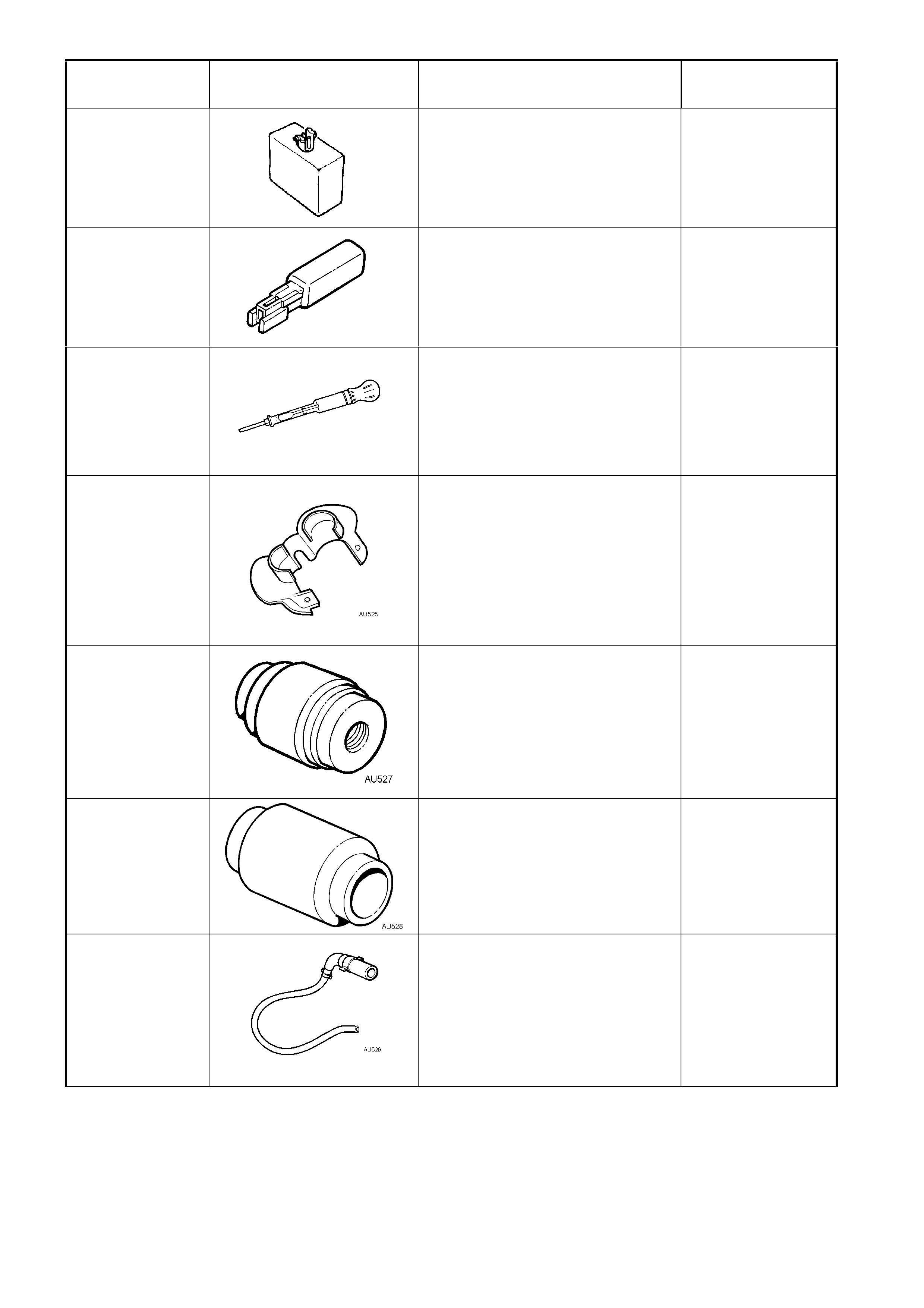
AU525
QUICK CONNECT RELEASE
TOOL
Use to release the quick connect
fittings on the automatic
transmission fluid cooler lines at the
radiator end, when the vehicle is so
equipped.
Previously released.
Mandatory
AU527
INTERMEDIATE PINION
BEARING AND POWER
STEERING FLUID SEAL
INSTALLER
Used in conjunction with driver
handle AU355-A.
Previously released.
Unique
AU528
UPPER PINION BEARING AND
POWER STEERING FLUID SEAL
INSTALLER
Previously released.
Unique
AU529
CLUTCH SLAVE CYLINDER
BLEED TOOL
Used to bleed air from the Central
Slave Cylinder fitted to the T56, 6
speed manual transmission
available for the GEN III V8 engine.
Previously released.
Desirable
TOOL NUMBER ILLUSTRATION DESCRIPTION TOOL
CLASSIFICATION
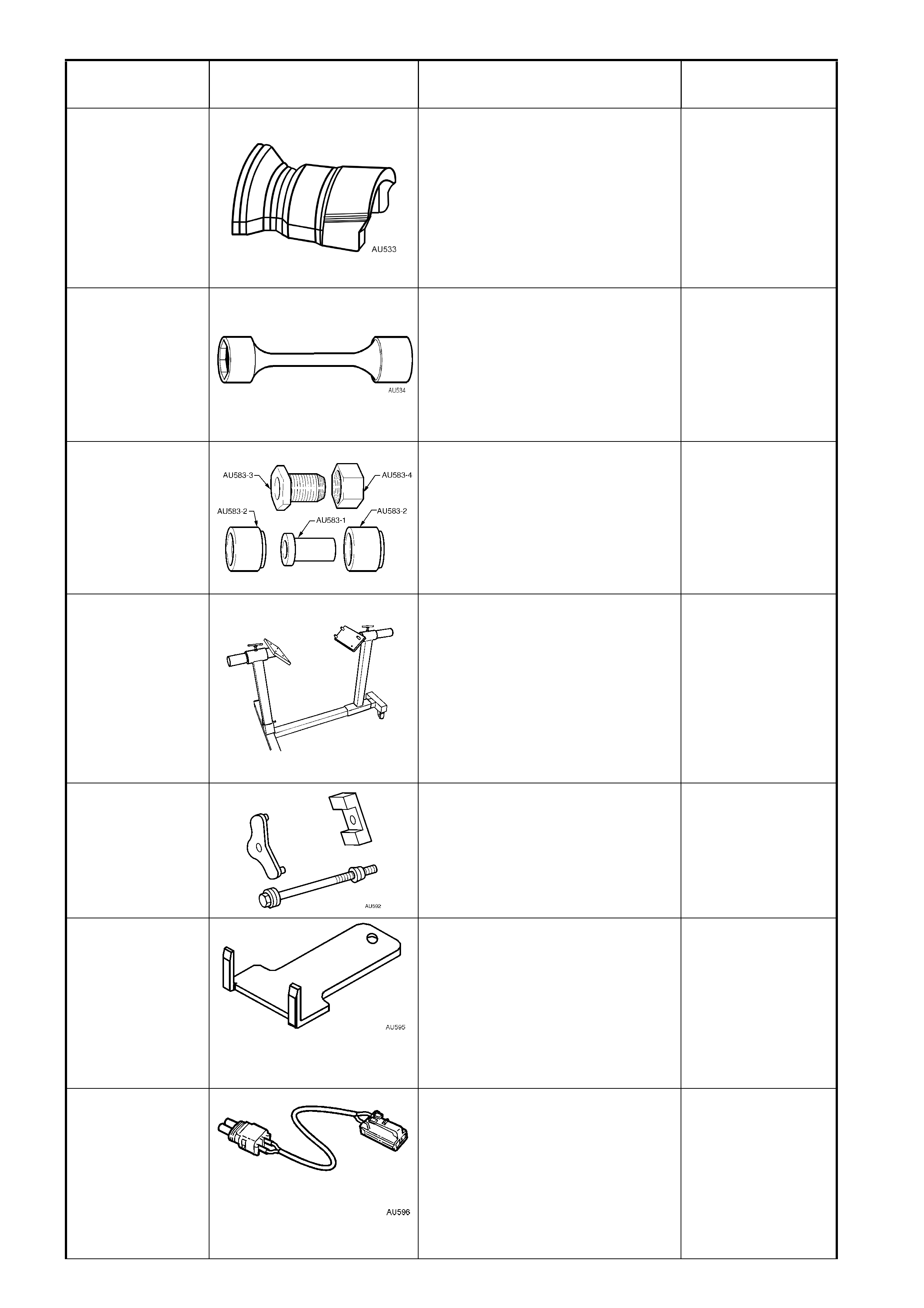
AU533
QUICK CONNECT FITTING
RELEASE TOOL
Released in two sizes:
Red for 5/16” fittings and
Blue for 3/8” fittings.
Also available commercially under
P/N AUSP45.
Previously released.
Mandatory
AU534 TORQUE LIMITING SOCKET
Used in conjunction with an impact
gun to tighten wheel nuts.
Previously released.
Mandatory
AU583 SELECTOR SHAFT SEAL
REMOVER/ INSTALLER
Use to remove and install the
manual shaft oil seal, with the
transmission installed in the
vehicle.
Previously released.
Unique
AU591
GEN III ENGINE STAND
Engine stand specifically designed
to accommodate the GEN III
engine.
Comes complete with mounting
heads and detachable stand.
Commercially available.
Previously released.
Available
AU592
INSTALLER
Used for installing new & existing
bushes into rear suspension
crossmember front mounting for on
vehicle operation.
Previously released.
Desirable
AU595
STEERING WHEEL INFLATABLE
RESTRAINT (DRIVER’S AIRBAG)
MODULE REMOVAL TOOL
Used for removing the steering
wheel inflatable restraint (driver’s
airbag) module from the steering
wheel hub.
New release.
Mandatory
AU596 DEPLOYMENT HARNESS
ADAPTOR FOR SEAT BELT
PRETENSIONER
Used in conjunction with
deployment harness J213526-1 for
deploying seat belt pretensioner
when removed from the vehicle.
New release.
Available
TOOL NUMBER ILLUSTRATION DESCRIPTION TOOL
CLASSIFICATION
BT3373-F
BELT TENSION GAUGE
Used when checking drive and
accessory belt tension and
adjustment.
Previously released.
Desirable
BT8653-A
(E7115)
ANGLE WRENCH
Used to tighten component
fasteners when angle torque is
required.
Previously released.
Mandatory
E1152
(6A24)
VALVE LIFTER ASSEMBLY
TOOLS
Used to assist assembly of valve
lifters.
Previously released.
Unique
E1178B
AIR LINE ADAPTOR - 14MM
(TAPERED SEAT)
Used to apply air pressure to
engine cylinder during various
service operations or diagnostic
checks.
Previously released.
Desirable
E1312
(7A42)
PRESS PLATES
Used in many applications for
pressing on and off components.
Previously released.
Desirable
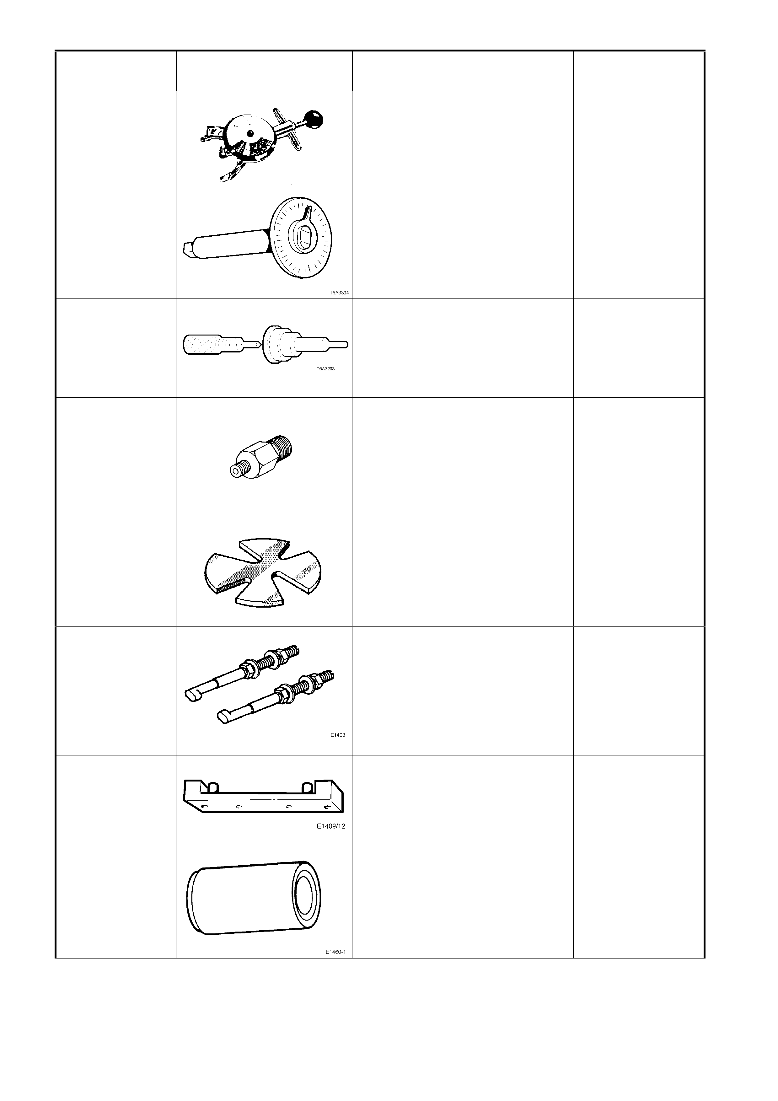
E1408 STEERING WHEEL PULLER
LEGS
Used in conjunction with a suitable
steering wheel puller such as
J1858-A or 7245 for removing
steering wheel.
Previously released.
Desirable
E1409A
(9A6-1)
REAR MAIN SEAL HOUSING
ALIGNING TOOL
Used for aligning rear main seal
housing on V6 engine.
Previously released.
Desirable
E1460-1 POWER STEERING PUMP
SHAFT SEAL INSTALLER
Previously released.
Unique
TOOL NUMBER ILLUSTRATION DESCRIPTION TOOL
CLASSIFICATION
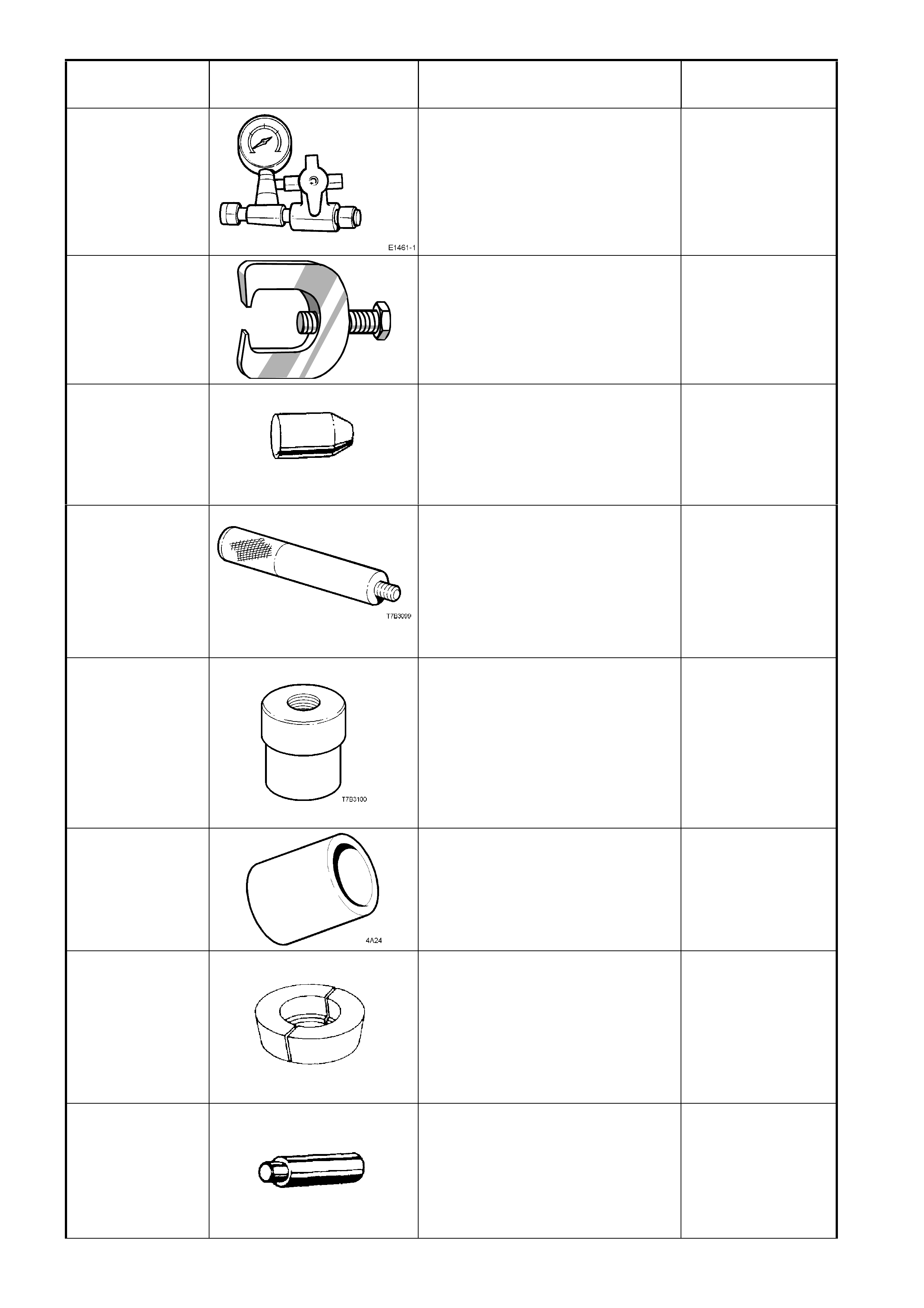
E1461-1 PRESSURE GAUGE ASSEMBLY
Previously released.
Mandatory
E1465
(9A10)
(7311)
STEERING LINKAGE BALL STUD
REMOVER
Previously released.
Desirable
E1483
(9A23)
EXPANDER – SLEEVE SEALS
Used for expanding steering gear
rotary valve and sleeve assembly
seals before installation.
Previously released.
Unique
E1502
(7AT2)
DRIVER HANDLE
Used in conjunction with 7AT5 to
remove/install the slip yoke bushing
in the extension housing on the
Tremec 6 speed manual
transmission.
Previously released.
Unique
E1505
(7AT5)
SLIP YOKE BUSH
REMOVER/INSTALLER
Used in conjunction with 7AT2 to
remove/install the slip yoke bushing
in the extension housing on the
Tremec 6 speed manual
transmission.
Previously released.
Unique
E1662
(4A24)
SLEEVE
Used to install the bearing cup into
the input shaft gear on the Tremec
6 speed manual transmission.
Previously released.
Unique
E1673A15
ADAPTOR
Used in conjunction with puller
E1673MT and stepped plug
E1673B16 to remove the rear
pinion bearing on
3.08:1 assemblies.
Previously released.
Unique
E1673B16
STEPPED PLUG
Used in conjunction with puller
E1673MT and adaptors E1673A15
/ E1673N15 to remove bearings
from the final drive assembly.
Previously released.
Unique
TOOL NUMBER ILLUSTRATION DESCRIPTION TOOL
CLASSIFICATION
E1673MT
BASIC PULLER
Used in conjunction with adaptors
to remove bearings from the final
drive assembly .
Previously released.
Unique
E1673N15
ADAPTOR
Used in conjunction with puller
E1673MT and stepped plug
E1673B16 to remove the side
bearings from differential case.
Previously released.
Unique
E1673S15 ADAPTOR
Used with puller E1673MT to
remove the rear pinion bearing on
3.07:1 and 3.46:1 assemblies.
Previously released.
Unique
E1891-6
(3A8-6)
SLEEVE
Used to install the 1st/2nd gear
synchromesh hub to the mainshaft
on the Tremec 6 speed manual
transmission. Part of E1891A Kit.
Previously released.
Unique
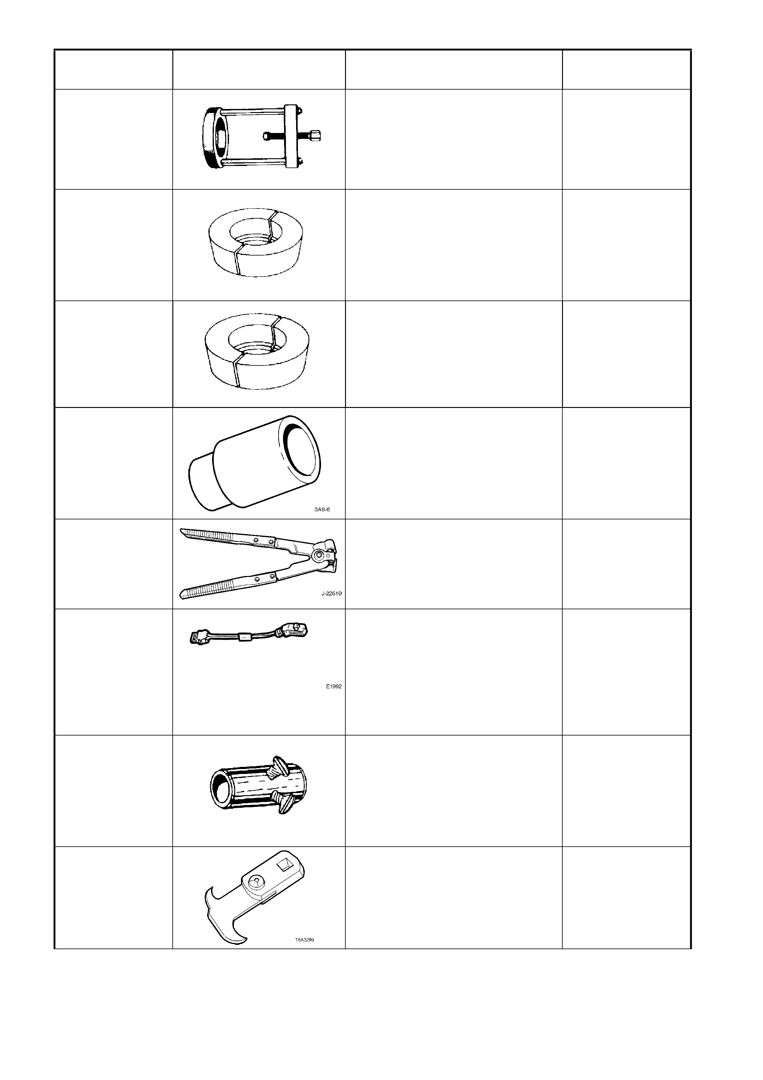
E1896
(3A13)
(J22610)
KEYSTONE CLAMP PLIERS
Used to tighten the sliding joint boot
clamp.
Previously released.
Available
E1992 DEPLOYMENT HARNESS
ADAPTOR
Used in conjunction with
deployment harness J213526-1 for
deploying OPS / SRS components
when removed from the vehicle
Previously released.
Available
E19M25
(AU316)
PRE-LOAD ADAPTOR
Used to measure steering gear
input shaft / steering mechanism
turning torque in conjunction with a
suitable torque wrench.
Previously released.
Unique
E308
(56750)
(49V012001)
SEAL REMOVER
Used as a universal seal remover.
Previously released.
Available
TOOL NUMBER ILLUSTRATION DESCRIPTION TOOL
CLASSIFICATION
E3C10AER PINION REAR BEARING
REPLACER
Used to install the pinion bearing
during final drive overhaul.
Previously released.
Unique
E6661S
FORCING SCREW
Used in conjunction with puller
1150 and adaptor AU412.
Previously released.
Unique
E6662B
TORQUE WRENCH ADAPTOR
Used in conjunction with 7208 to
check breakaway torque of L.S.D.
differential.
Previously released.
Desirable
E6673
(J22912-1)
PRESS PLATES
Previously released.
Desirable
E7110 PRESS PLATE
Previously released.
Used for supporting stabilizer shaft
link while pressing out or installing
bushing.
Available
E7115
(BT8653-A)
ANGLE WRENCH
Used to tighten component
fasteners when angle torque is
required.
Previously released.
Mandatory
E8803-10
RACK SEAL TEST ADAPTOR
Used in conjunction with hand
vacuum pump J-23738-A to assess
rack seal serviceability.
Previously released.
Mandatory
E8803-11 RACK END SEAL/BUSH
INSTALLER
Used to install rack end seal and
bush.
Previously released.
Unique
TOOL NUMBER ILLUSTRATION DESCRIPTION TOOL
CLASSIFICATION
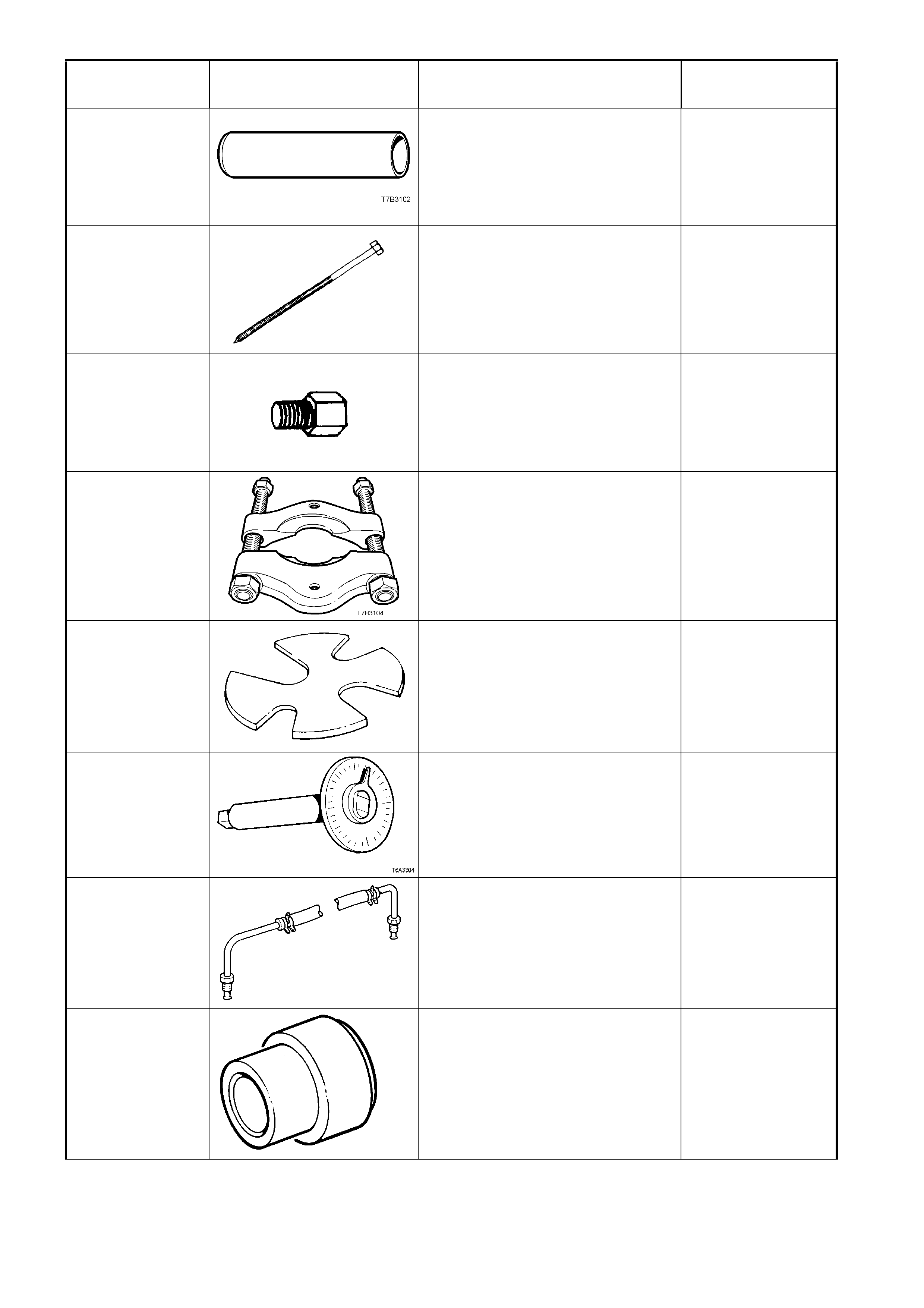
E8803-6 RACK SEAL PROTECTOR -
SHORT
Previously released.
Unique
E8803-7
RACK PISTON TOOL
Used to rotate the end bushing to
remove/install retaining wire clip.
Previously released.
Unique
E8803-9 RACK PISTON SEAL EXPANDER
Used to expand the rack piston seal
prior to installation.
Previously released.
Unique
E9055
(17-010A)
PINION OIL SEAL INSTALLER
Used to install the pinion oil seal.
Previously released.
Unique
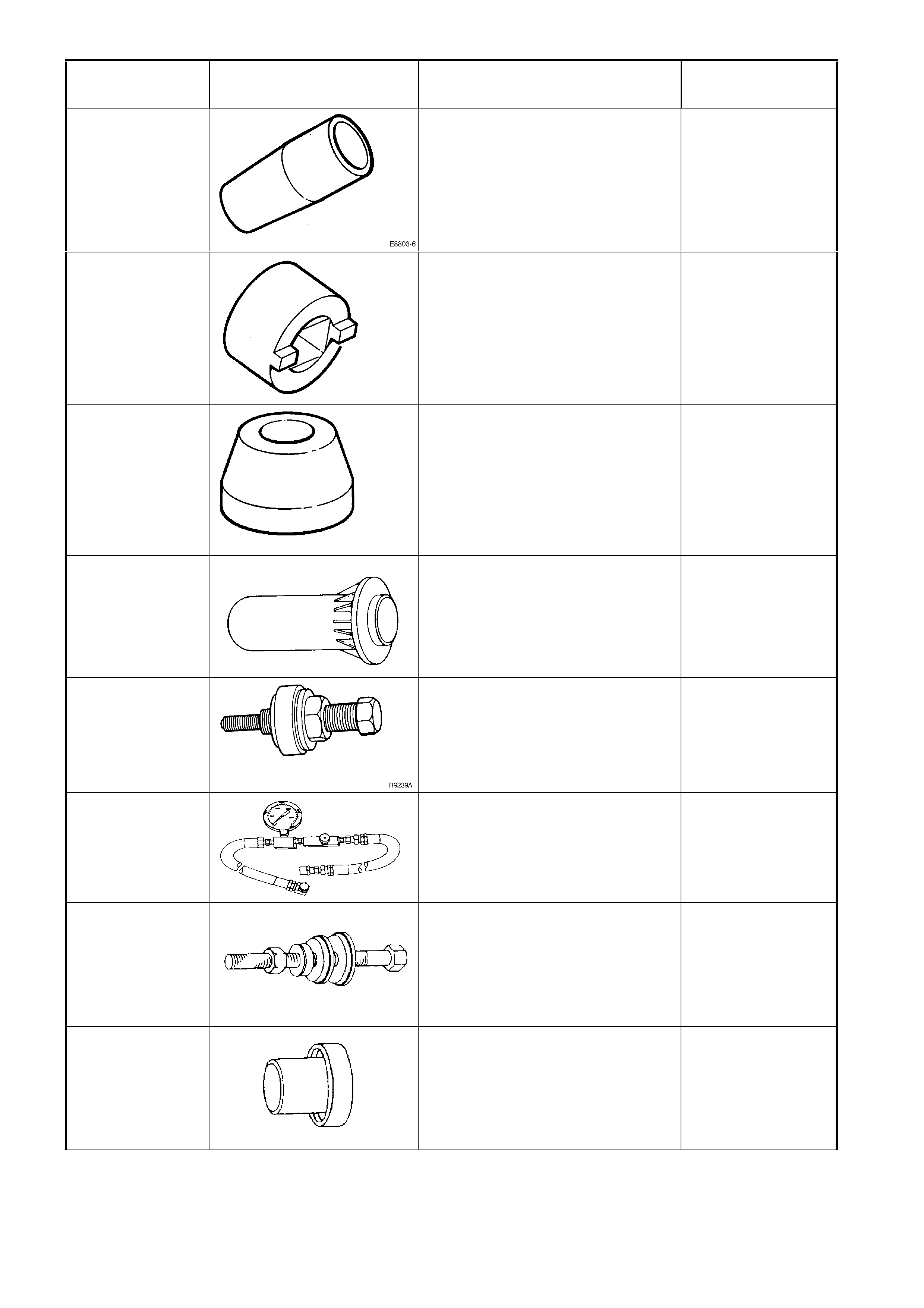
E9239
(J25033-B)
POWER STEERING PUMP
PULLEY INSTALLER
Previously released.
Desirable
E9254GMH
(E1461-1)
PRESSURE HOSE & GAUGE SET
Used for checking power steering
system pressures.
Previously released.
Mandatory
E9271 PINION BEARING CUP
INSTALLER
Previously released.
Unique
E9277 SIDE BEARING INSTALLER
Used to install the bearings to the
differential case.
Previously released.
Unique
TOOL NUMBER ILLUSTRATION DESCRIPTION TOOL
CLASSIFICATION
E9293 PINION BEARING CUP
REMOVER
Previously released.
Unique
E9300A PINION HEIGHT SETTING
GAUGE
Used in conjunction with Dummy
Arbor AU408 to check pinion height
on final drive assembly.
Previously released as E9300, this
set now has an additional spacer to
be used on the 3.07:1 and 3.46:1
ratio, final drive assemblies.
Previously released.
Unique
E9326-7
(AU301)
RACK PAD ADJUSTING SCREW
LOCK NUT WRENCH
Previously released.
Desirable
E9326-8
(AU211-A)
RACK PAD ADJUSTING SCREW
WRENCH
Previously released.
Desirable
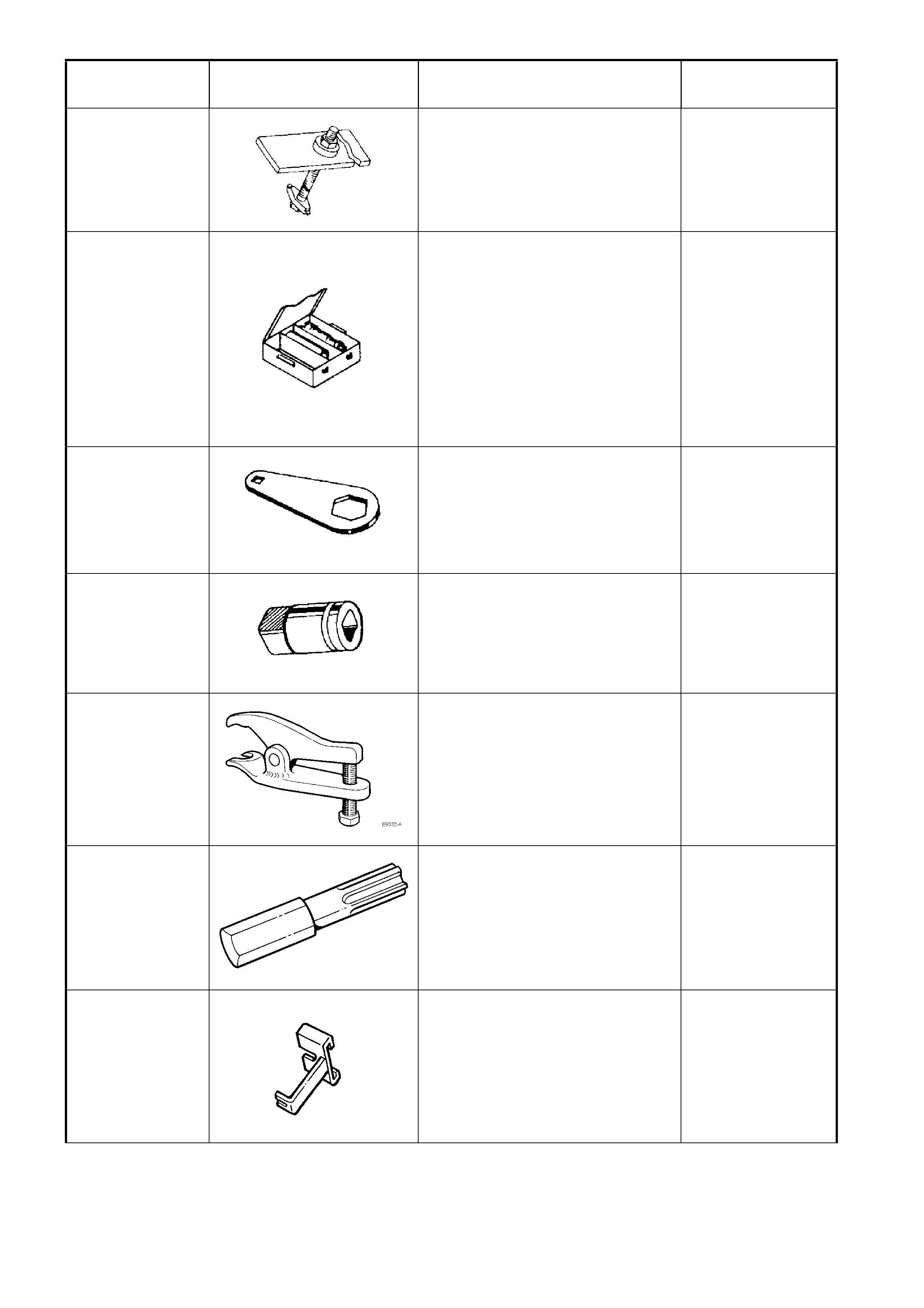
E9332-A
SOCKET ASSEMBLY RELEASE
TOOL
Previously released.
Used to release the front lower
control arm socket from the
steering knuckle or the rear
suspension control arm.
Desirable
ETX30H
T30H TORX BIT
Used in conjunction with Torx bit
holder J25359-8 (or ETX55HLD)
Also commercially available as a
T30H Torx bit.
Previously released.
Mandatory
GM24505373
BY-PASS VALVE ACTUATOR
SETTING TOOL
Used for checking and setting
adjustment of by-pass valve
actuator used with V6
supercharged engine.
Previously released.
Desirable
TOOL NUMBER ILLUSTRATION DESCRIPTION TOOL
CLASSIFICATION
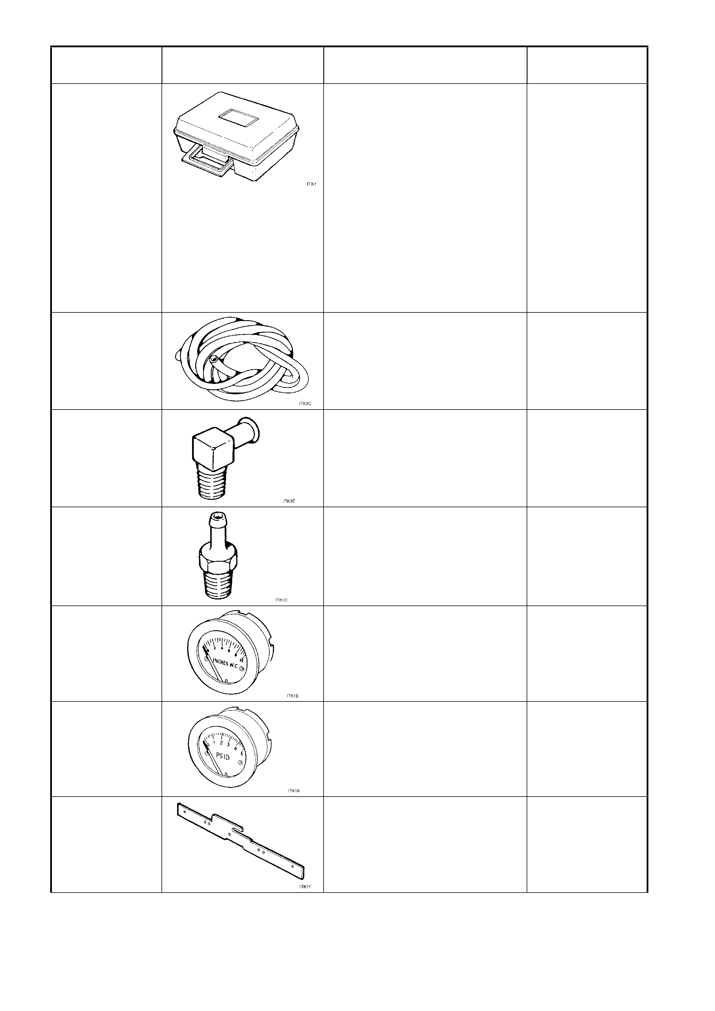
ITK-1
LPG TEST KIT
AVAILABLE FROM:
IMPCO TECHNOLOGIES
1 - 3 TAUNTON DRIVE
CHELTENHAM VIC. 3192
ALL CORRESPONDENCE TO:
P.O.BOX 45, CHELTENHAM VIC.
3192
TELEPHONE: (03) 9584 5644
FAX: (03) 9583 0696
The LPG test kit contains the
following tools.
Previously released.
Available
ITK-1
(c)
PRESSURE GAUGE HOSE
Part of LPG test kit ITK-1.
Available
ITK-1
(e)
PRESSURE GAUGE HOSE
CONNECTOR FOR INCHES W.C.
PRESSURE GAUGE
Part of LPG test kit ITK-1.
Available
ITK-1
(d)
PRESSURE GAUGE HOSE
CONNECTOR FOR PSID
PRESSURE GAUGE
Part of LPG test kit ITK-1.
Available
ITK-1
(b)
PRESSURE GAUGE INCHES
W.C.
Part of LPG test kit ITK-1.
Available
ITK-1
(a)
PSID PRESSURE GAUGE
Part of LPG test kit ITK-1.
Available
ITK-1
(f)
SECONDARY DIAPHRAGM
LEVER ADJUSTMENT GAUGE
Part of LPG test kit ITK-1.
Available
TOOL NUMBER ILLUSTRATION DESCRIPTION TOOL
CLASSIFICATION
J1859-A
(7245)
STEERING WHEEL PULLER
Previously released.
Mandatory
J21008-A SELF POWERED TEST LIGHT
Used during electrical circuit
diagnostic checks (or use
commercially available equivalent).
Previously released.
Mandatory
J213200
DIGITAL MULTIMETER
Used for various measurement
functions. Must have at least
10 MΩ input impedance and be
capable of reading capacitance.
Previously released (or use
commercial equivalent).
Available
J213526-1
DEPLOYMENT HARNESS
Used in conjunction with
deployment harness adaptors
E1992 and AU596 for deploying
OPS / SRS components when
removed from the vehicle
Previously released
Available
J21368
OIL PUMP ALIGNMENT BAND
Used to align the oil pump cover to
oil pump body before tightening the
bolts.
Previously released.
Unique
J21426
(7AT-6)
SEAL INSTALLER
Used to install the rear extension
housing oil seal.
Previously released.
Unique
J21427-01 PULLER ADAPTOR
Used in conjunction with J8433-1,
J41558 and J41816-2 to remove
the crankshaft timing gear sprocket
on GEN III V8 engine.
Used in conjunction with J8433 to
remove the output speed sensor
ring from the mainshaft.
Previously released.
Unique
J21465-15
REMOVER
Used in conjunction with slide
hammer J6125-1B to remove the
stator shaft front bushing.
Previously released
Unique
TOOL NUMBER ILLUSTRATION DESCRIPTION TOOL
CLASSIFICATION
J21465-2
INSTALLER
Used in conjunction with driver
J8092 to install the front stator shaft
bush
Previously released
Unique
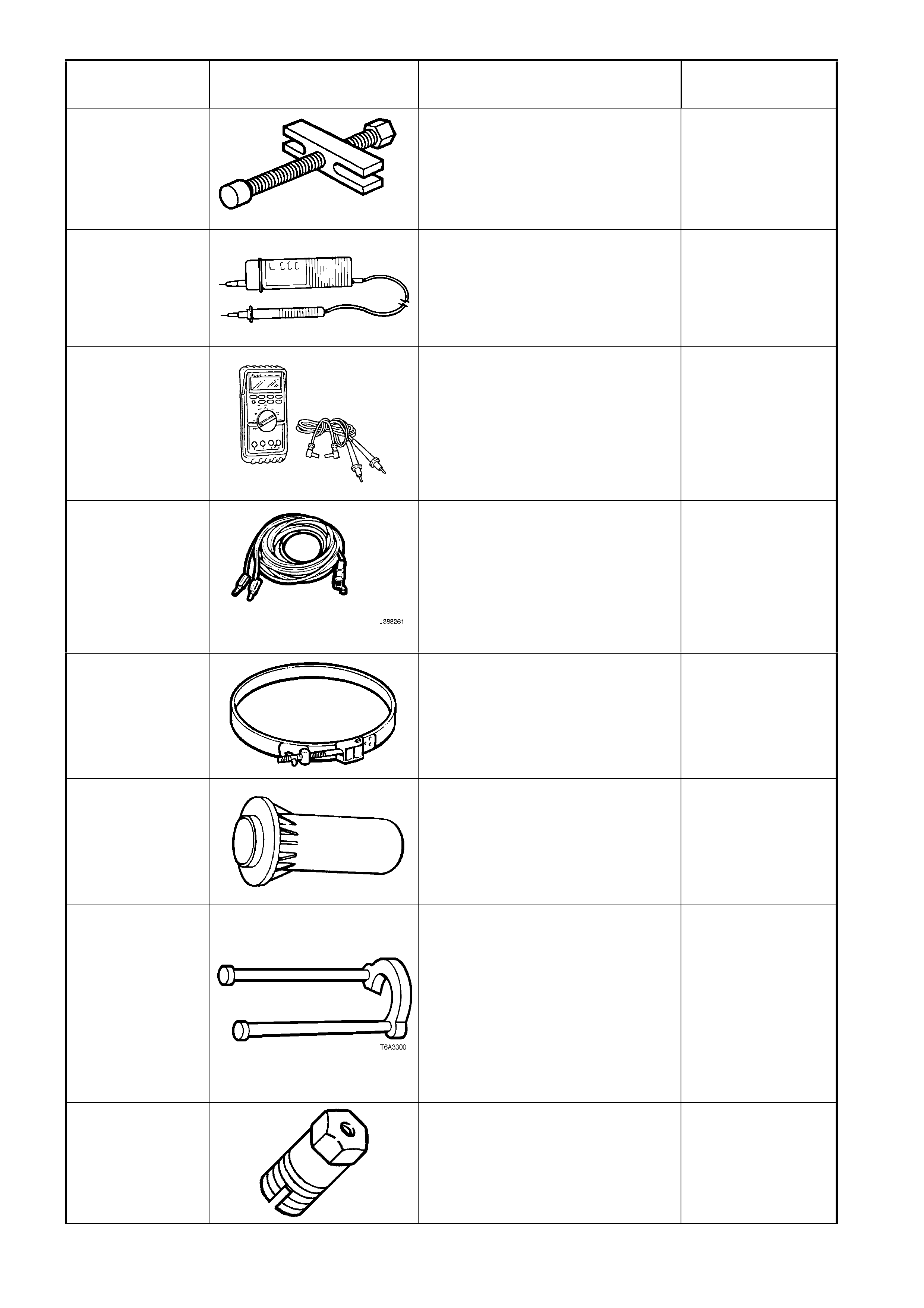
J21867
PRESSURE GAUGE AND HOSE
ASSEMBLY
Used for checking automatic
transmission oil pressure.
Previously released.
Mandatory
J22610
(3A13)
(E1896)
KEYSTONE CLAMP PLIERS
Used to tighten the sliding joint boot
clamp.
Previously released.
Available
J22794
T6A3256a
ADAPTOR
Used to facilitate the application of
air pressure to a cylinder when
replacing a valve spring or valve
stem oil seal with the cylinder head
installed.
Previously released.
Desirable
J22912-01
(E6673)
PRESS PLATES
Used in a number of different
applications in removing bearings
and other transmission components
when pressing operations are
required.
Previously released.
Desirable
J23062-14
BUSH REMOVER
Used in conjunction with driver
handle J8092 to remove and install
extension housing rear bush.
Previously released.
Unique
J23327
CLUTCH SPRING COMPRESSOR
Used to compress automatic
transmission clut ch assembly
springs during transmission
overhaul.
Previously released.
Unique
J23327-1
CLUTCH SPRING COMPRESSOR
Needed to compress the clutch,
before dismantling.
Plate J42628 is also required.
Previously released
Unique
TOOL NUMBER ILLUSTRATION DESCRIPTION TOOL
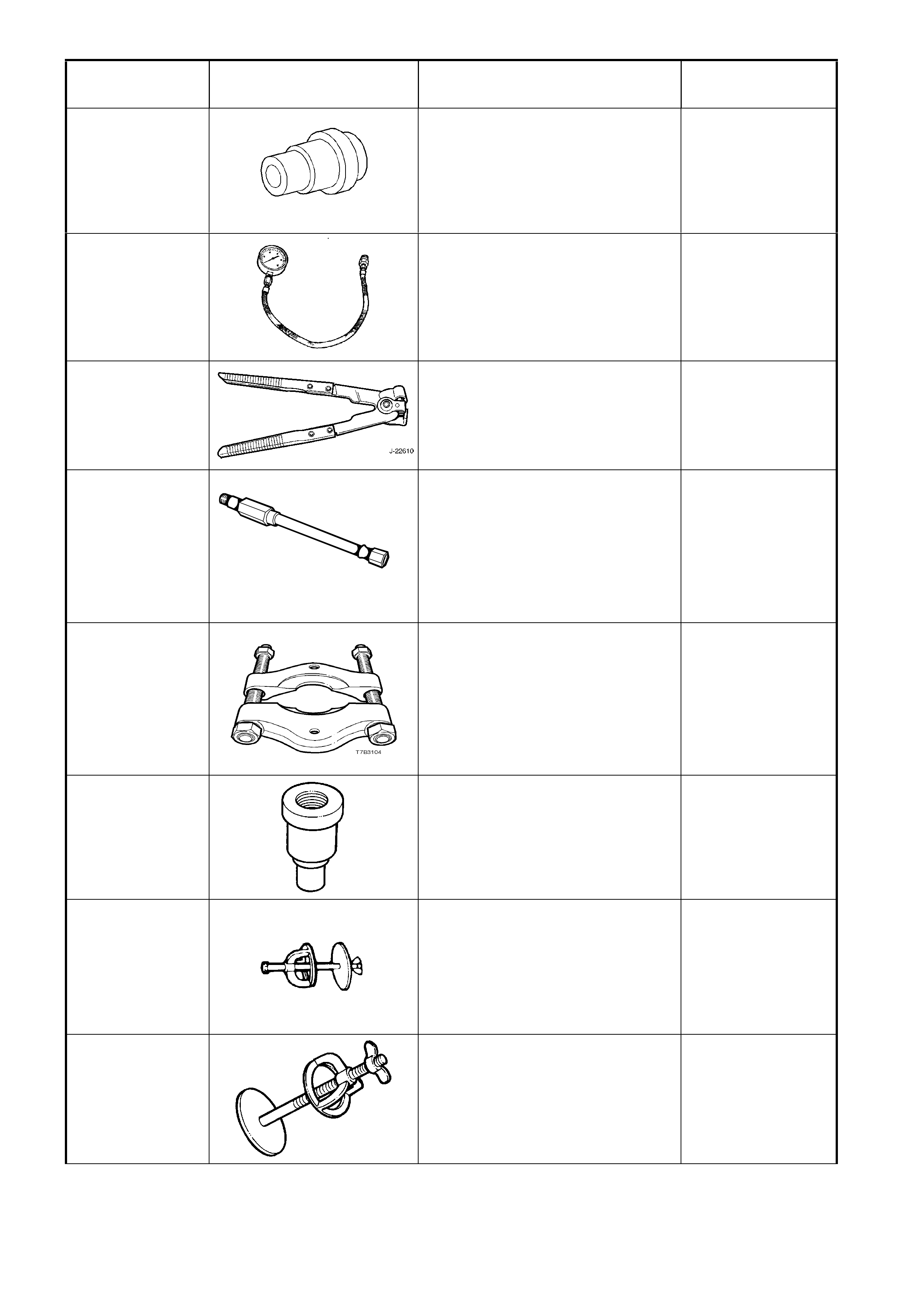
CLASSIFICATION
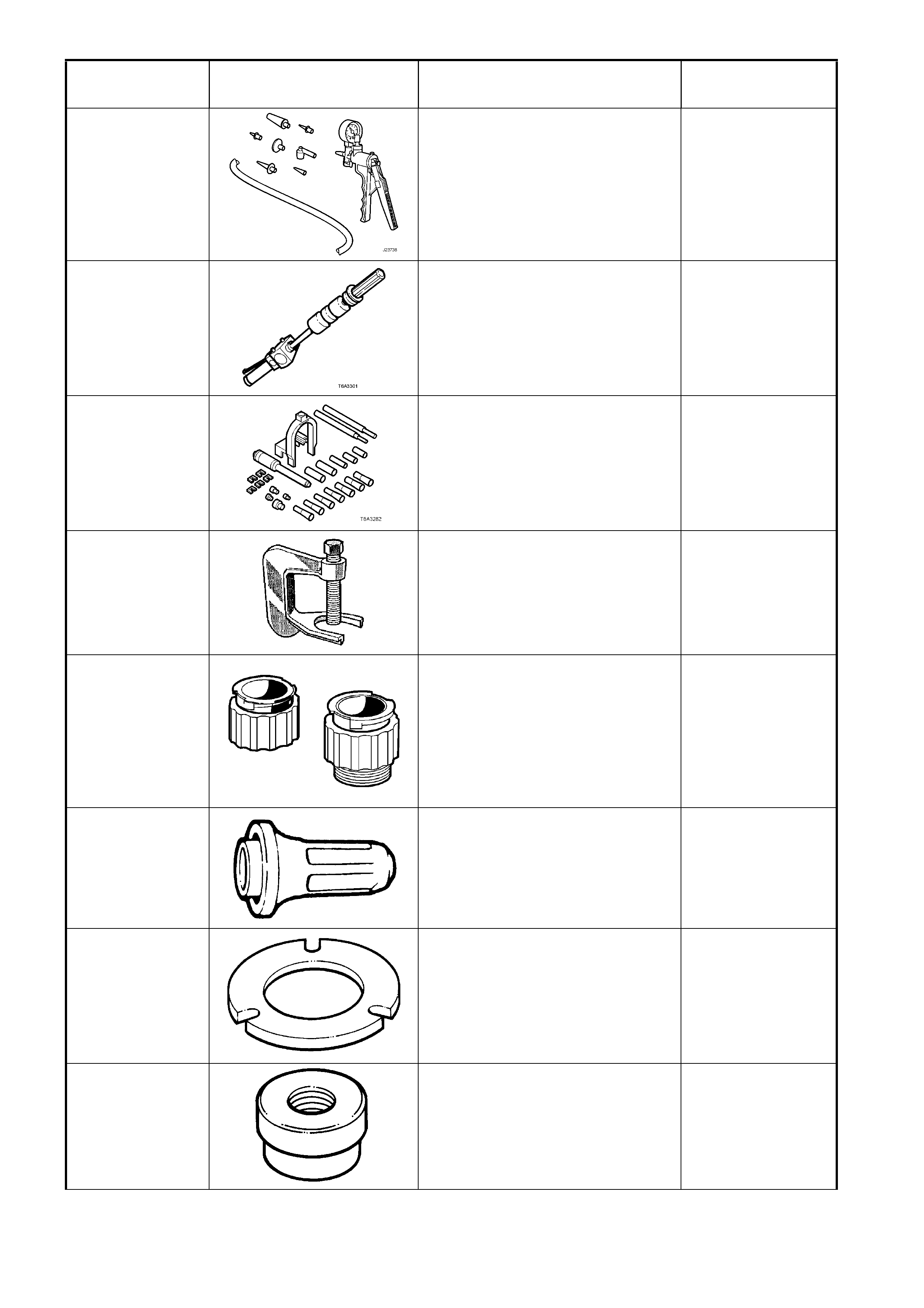
J23738-A
HAND VACUUM PUMP (20 IN. HG
MINIMUM)
Used for applications where a
controlled vacuum is required to be
applied.
Previously released and also
commercially available.
Mandatory
J23907
(6A22-2)
(7A28)
SLIDE HAMMER
Used in conjunction with a number
of different pullers to remove
bushes and bearing cups in the
transmission.
Previously released.
Unique
J24086-C
PISTON PIN
REMOVER/INSTALLER
Universal tool containing selective
components to suit multiple engine
applications.
Previously released.
Unique
J24292-C
(C4150-A)
(AJ24292-C)
PRESS TOOL
Used to remove rear wheel studs
from the trunnion flange.
Previously released.
Unique
J24460-92
COOLING SYSTEM TEST
ADAPTORS
Used to pressure test the screw-on
cooling system pressure cap and
the cooling system on GEN III V8
engines.
Previously released.
Mandatory
J25016
OIL PUMP SEAL INSTALLER
Used to install automatic
transmission oil pump seal.
Previously released.
Unique
J25018-A
CLUTCH SPRING COMPRESSOR
ADAPTOR
Used in conjunction with J23327 to
compress clutch springs during
automatic transmission overhaul.
Previously released.
Unique
J25019-12
BUSH INSTALLER
Used in conjunction with driver
handle J8092.
Previously released.
Unique
TOOL NUMBER ILLUSTRATION DESCRIPTION TOOL
CLASSIFICATION
J25019-14
BUSH REMOVER
Used in conjunction with slide
hammer J6125-1B.
Previously released.
Unique
J25019-16
BUSH REMOVER
Used in conjunction with slide
hammer J6125-1B.
Previously released.
Unique
J25019-9
BUSH INSTALLER
Used in conjunction with driver
handle J8092.
Previously released.
Unique
J25025-B
DIAL INDICATOR STAND AND
GUIDE PIN SET
Used in many applications.
Previously released.
Unique
J25359-19 NO. 15 TORX BIT
Used to remove Powertrain Control
Module access cover screws.
Previously released.
Mandatory
J25359-8 TOR X BIT HOLDER
Commercially available.
Previously released.
Mandatory
J25765-A DIAL TYPE TORQUE WRENCH
Previously released or use
commercially available equivalent,
capable of measuring from
0.4 - 6.0 Nm.
Previously released.
Mandatory
J26125-B
(AU354)
SLIDE HAMMER
Used in conjunction with 6A22-2 to
remove spigot bearing from rear of
crankshaft.
To remove rear bearing cap on V6
engines, two J26125-B must be
used.
Previously released.
Desirable
TOOL NUMBER ILLUSTRATION DESCRIPTION TOOL
CLASSIFICATION
J26568
(AU435)
REFRACTOMETER
Used for testing coolant
concentrate.
Previously released.
Mandatory
J28431-B
FLUID DYE
Used in conjunction with black light,
leak detection lamp 16296 to locate
various types of vehicle fluid leaks.
Supplied in packs of 24, 1 ounce
bottles.
Previously released.
Desirable
J28458
SEAL PROTECTOR AND
DIAPHRAM RETAINER
INSTALLER
Used to protect the power piston
seal and install the diaphragm
retainer on the 4L60-E automatic
transmission.
Previously released.
Unique
J28540-A
SEAL INSTALLER
Used for installing front cover oil
seal on V6 engines.
Previously released.
Unique
J29369-2
UNIVERSAL BUSH REMOVER
Used in conjunction with slide
hammer J23907.
Previously released.
Unique
J29882
INNER OVERRUN CLUTCH SEAL
PROTECTOR
Used to protect the inner, forward
clutch piston seal from damage
during installation.
Previously released.
Unique
J29883
INNER FORWARD CLUTCH SEAL
PROTECTOR
Used to protect the inner, forward
clutch piston seal from damage
during installation.
Previously released.
Unique
J3289-20
HOLDING FIXTURE BASE
Used in conjunction with either
MK480 or dealer fabricated bracket
to hold the final drive assembly.
Used in conjunction with
transmission holding fixture
J39430.
Previously released.
Unique
TOOL NUMBER ILLUSTRATION DESCRIPTION TOOL
CLASSIFICATION
J33017
PULLEY & BEARING ASSEMBLY
TOOL
Used in conjunction with J33013-C
to reinstall A/C compressor clutch
pulley and bearing assembly.
Previously released.
Desirable
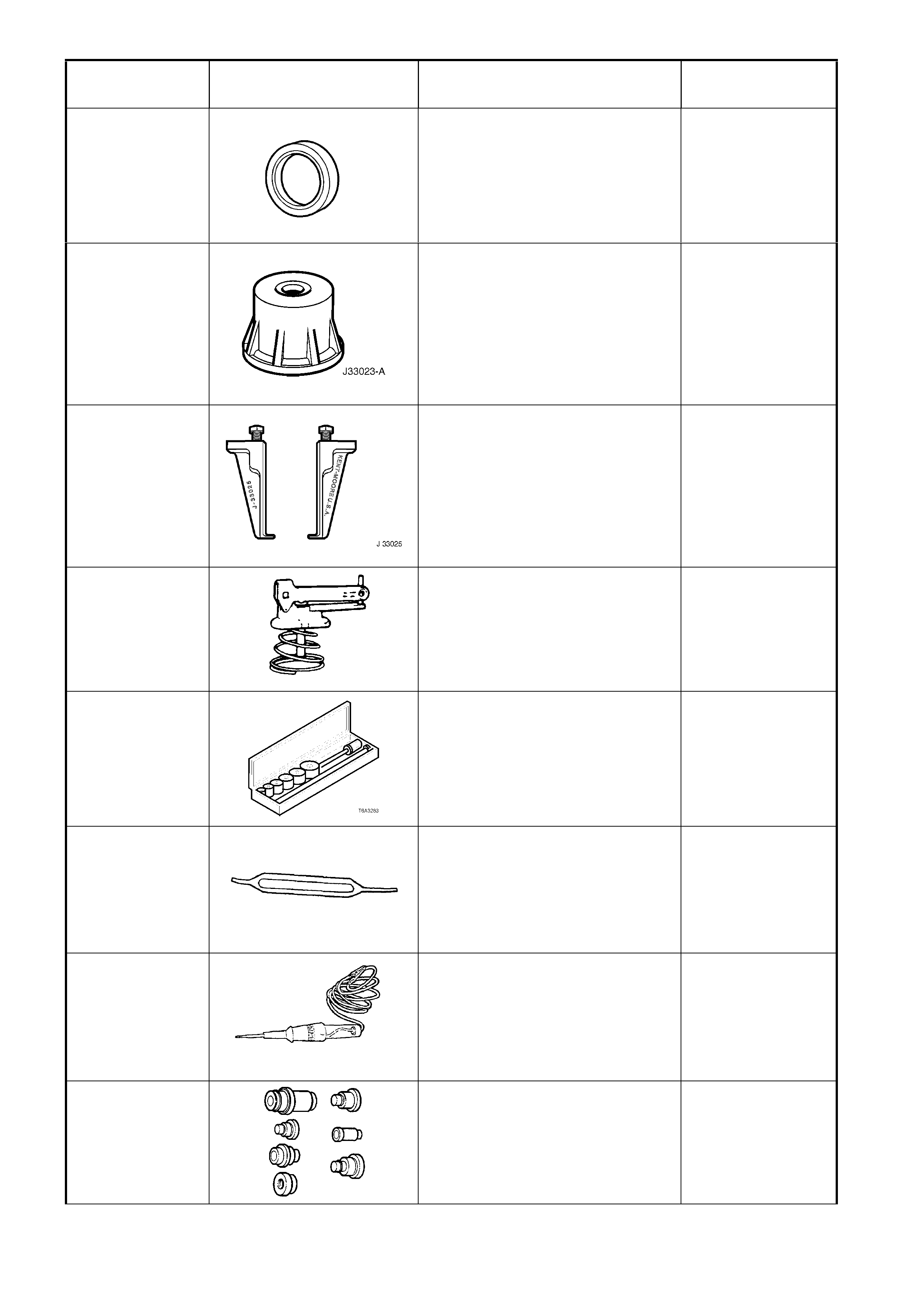
J33023-A
PULLER PILOT
Used in conjunction with J8433-1
for removing clutch rotor and
bearing assembly from A/C
compressor shaft.
Previously released.
Desirable
J33025
CLUTCH COIL PULLER LEGS
Used in conjunction with J8433-1
for removing clutch rotor and
bearing assembly from A/C
compressor shaft.
Previously released.
Desirable
J33037
2 - 4 BAND APPLY PIN TOOL
Used to check the selective apply
pin length.
Previously released.
Unique
J33049
CAMSHAFT BEARING
REMOVER/INSTALLER
Universal tool containing selective
components to suit multiple engine
applications.
Previously released.
Unique
J33095 MICRO PACK TERMINAL
REMOVER
Used for the safe removal of Micro-
Pack connector terminals.
Previously released.
Unique
J34142-B
(CT-40-C)
UNPOWERED TEST LIGHT
Must have current draw of less than
0.3 Amp.
Commercially available.
Previously released.
Mandatory
J34196-B
BUSH REMOVER / INSTALLER
SET
Used to remove / install various
bushings in automatic transmission.
Previously released.
Unique
TOOL NUMBER ILLUSTRATION DESCRIPTION TOOL
CLASSIFICATION
J34627
SNAP RING PLIERS
Specific purpose is to assist in the
removal/replacement of the output
shaft snap ring.
Previously released
Unique
J34730-2C
(BT-8329)
(ST-8329)
INJECTOR TEST LIGHT
Used to check for power and the
control circuit of the fuel injector, for
proper operation.
Previously released.
Mandatory
J35138
TORQUE CONVERTER END
PLAY
To be used in conjunction with
commercially available magnetic
stand and dial indicator.
Previously released.
Unique
J35314-A
(BT-8515)
EXHAUST BACK PRESSURE
GAUGE (WITH ADAPTOR)
Used to check the exhaust system
back pressure.
Previously released.
Unique
J35616-A
(KM609)
CONNECTOR TEST ADAPTOR
KIT
Used when carrying out electrical
diagnostic circuit checks.
Previously released.
Desirable
J36020
WINDSCREEN REMOVAL TOOL
AND PIANO WIRE
Previously released.
Unique
J36352 SPEED SENSOR INSTALLER
AND GAUGING TOOL
Used to correctly install the output
speed sensor ring to the mainshaft.
Comprises sleeve, J36352-6 and
C-washer J36352-4.
Previously released.
Unique
J36400-5 WEATHER PACK TERMINAL
REMOVER
Used for the safe removal of
Weather-Pack connector terminals.
Previously released.
Desirable
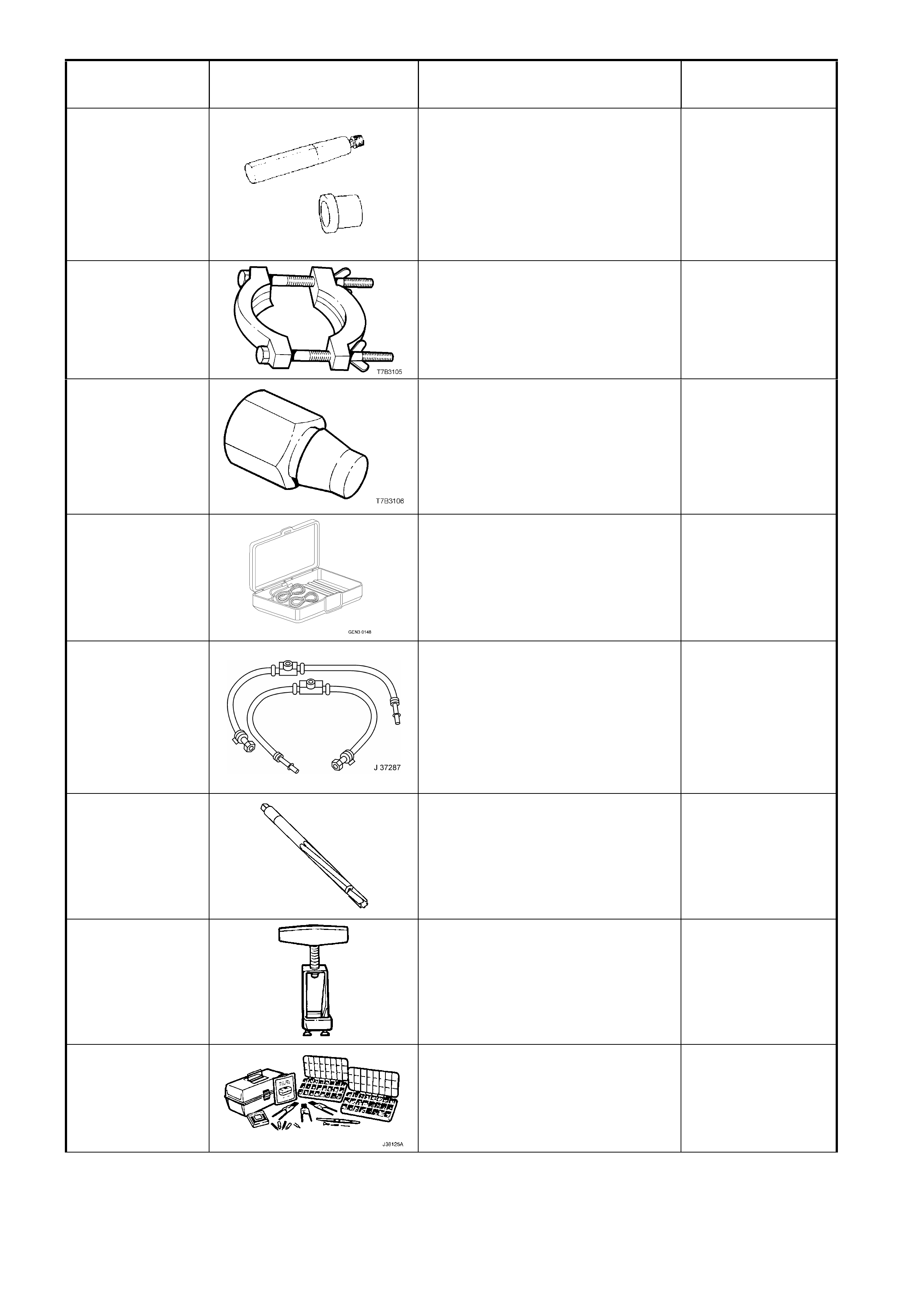
TOOL NUMBER ILLUSTRATION DESCRIPTION TOOL
CLASSIFICATION
J36418-B
TURBINE SHAFT SEAL
INSTALLER AND RESIZER
Used to install and re-size the
turbine shaft seal. Comprises
J36418-1B installer and J36418-2A
resizer.
Previously released
Unique
J36513
PRESS PLATES
Used to press 1st/2nd speed
synchromesh assembly and 2nd
gear from the mainshaft.
Previously released.
Unique
J36800
BUSHING REMOVER
Used to remove the shift rail
bushes in the adaptor plate and
extension housing, in conjunction
with slide hammer J23907.
Previously released.
Unique
J37027-A
IAC MOTOR ANALYSER
Used to manually operate and
check the idle air control valve
system operation.
Previously released.
Mandatory
J37287
INLET AND RETURN FUEL LINE
SHUT-OFF ADAPTORS
Used in conjunction with the fuel
pressure gauge for restricting the
fuel supply and return lines for
testing.
Previously released.
Mandatory
J37378-1
VALVE GUIDE REAMER
Used to ream worn valve guides to
suit oversize valve stem.
Previously released.
Unique
J37789-A
OIL PUMP REMOVER
Used in conjunction with J39119 to
remove the oil pump assembly.
Previously released
Unique
J38125-A
TERMINAL REPAIR KIT
Must be used when repairing
OPS / SRS wiring.
Previously released.
Available
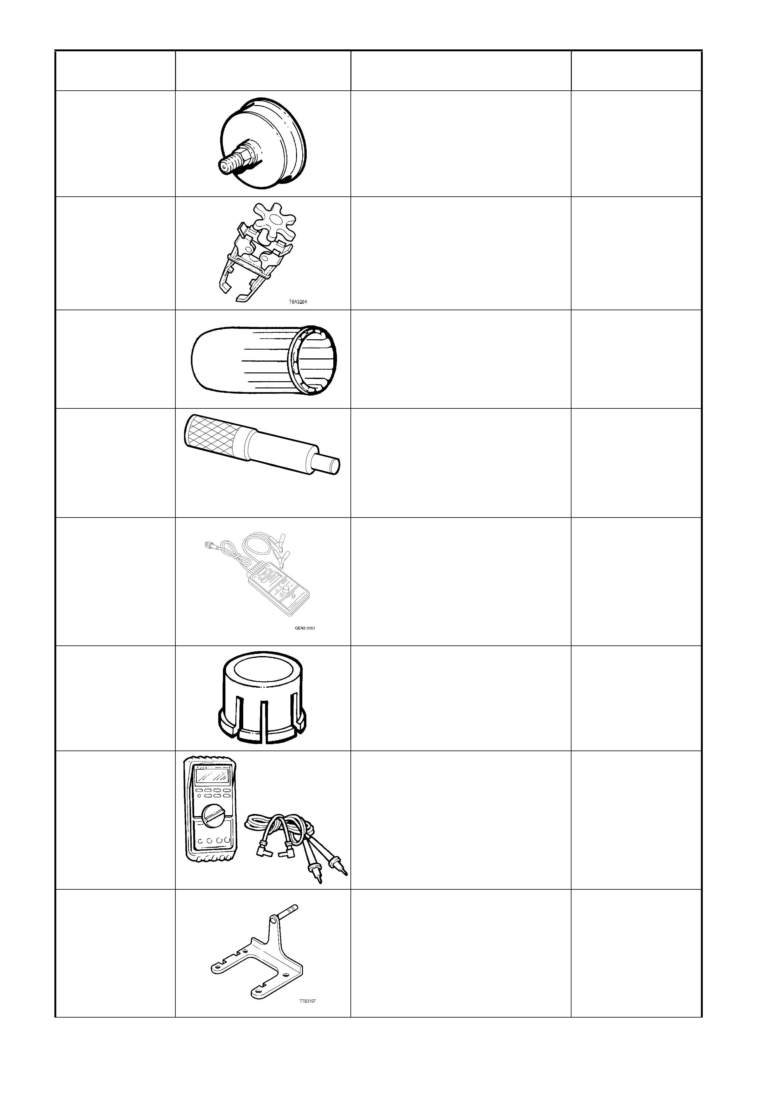
TOOL NUMBER ILLUSTRATION DESCRIPTION TOOL
CLASSIFICATION
J38196-AUS-A
MANDREL COLLAR
Used to install the rear crankshaft
seal to the rear plate.
Use with E1409A aligner.
Previously released.
Desirable
J38606
(KD2078)
VALVE SPRING COMPRESSOR
Used in conjunction with spark plug
adaptor J22794 to remove valve
springs with cylinder head/s
installed.
Previously released.
Desirable
J38735-3
STATOR SHAFT SEALING RING
INSTALLER
Used in conjunction with J39855-1
to install the stator shaft seal.
Previously released
Unique
J38836
T6A3 1 89 b
PILOTED DRIVER
Used to install the spigot bush in
the crankshaft on GEN III V8
engines.
Previously released.
Unique
J39021
FUEL INJECTOR COIL/BALANCE
TESTER
Used in conjunction with a digital
multi-meter for testing fuel injector
coils, and cylinder injector balance
testing.
Previously released.
Mandatory
J39119
OIL PUMP REMOVER ADAPTOR
Used to remove oil pump in
conjunction with J37789-A.
Previously released.
Unique
J39200
(3588)
DIGITAL MULTIMETER
Tool no. J39200 previously
released, or use commercially
available equivalent. Must have 10
meg ohm input impedance.
Previously released.
Available
J39430
TRANSMISSION HOLDING
FIXTURE
Used in conjunction with holding
fixture base J3289-20 to mount the
transmission to the bench for unit
repair operations.
Previously released.
Unique
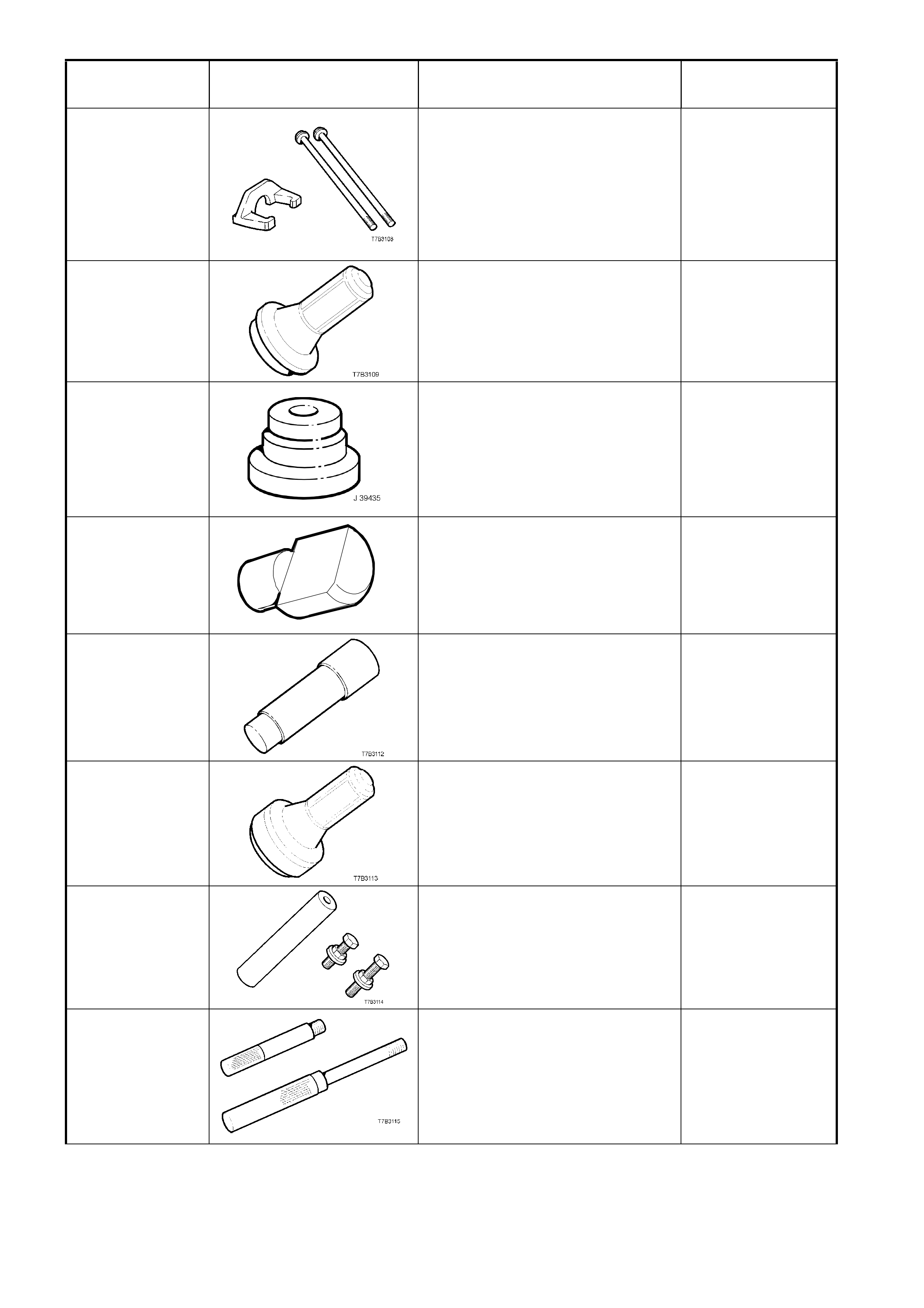
TOOL NUMBER ILLUSTRATION DESCRIPTION TOOL
CLASSIFICATION
J39431-1 & 2
REMOVER AND BOLTS
Used to remove the speedometer
pulse ring and the 5th/6th speed,
compound driven gear, in
conjunction with universal bridge
puller J8433.
Previously released.
Unique
J39433
SEAL INSTALLER
Used to install the input shaft oil
seal.
Previously released.
Desirable
J39435
BEARING CUP INSTALLER
Used to install the rear mainshaft
and rear countershaft bearing cup,
in conjunction with driver handle
J8092.
Previously released.
Unique
J39437
J 39437
BUSHING INSTALLER
Used to install the selector shaft
bushes in the adaptor plate, and
transmission case.
Previously released.
Unique
J39439-1
BUSHING REMOVER/INSTALLER
Used to remove shift shaft bushes
from the transmission case and
extension housing.
Previously released.
Unique
J39440
REAR SEAL AND BOOT
INSTALLER
Used to install the rear extension
seal.
Previously released.
Desirable
J39441
GEAR INSTALLER
Used to install the 5th / 6th
compound driven gear and the
speedometer pulse ring.
Previously released.
Unique
J39444-1 & 2
END PLAY RODS
Used to check the end float of the
countershaft gear (J39444-1) and
countershaft gear extension
(J39444-2).
Previously released.
Unique
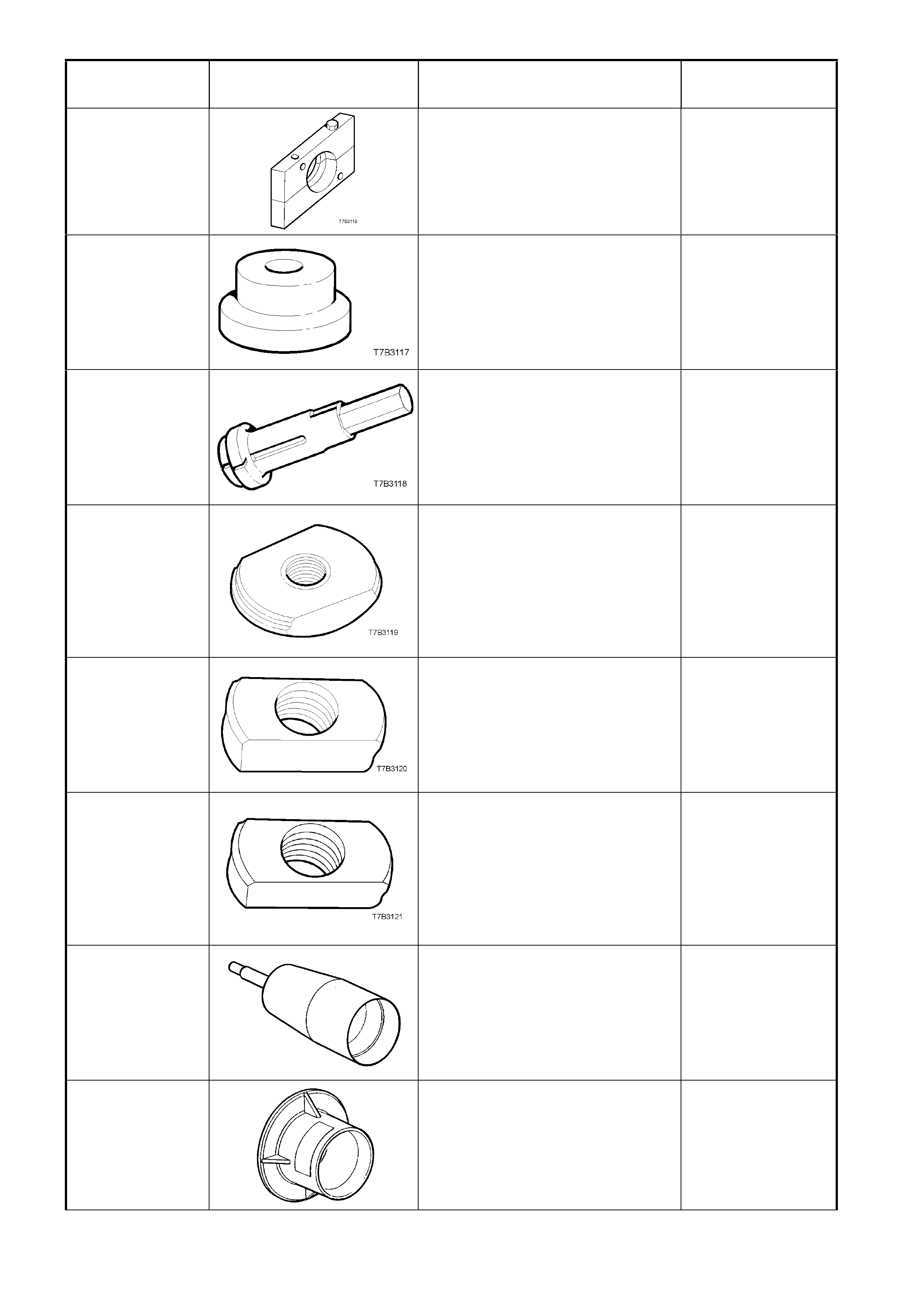
TOOL NUMBER ILLUSTRATION DESCRIPTION TOOL
CLASSIFICATION
J39511
SPLIT PLATE
Used to remove the front
countershaft gear bearing.
Previously released.
Unique
J39546
BEARING CUP INSTALLER
Used to install the rear mainshaft
roller bearing cup. Used in
conjunction with driver handle J
8092.
Previously released.
Unique
J39594 BEARING CUP REMOVER
Used in conjunction with slide
hammer J23907 to remove the
mainshaft pilot bearing cup in the
input shaft gear.
Previously released.
Unique
J39789
BEARING CUP REMOVER
Used to press out the rear
mainshaft roller bearing cup from
the extension housing. Used in
conjunction with driver handle
J8092.
Previously released.
Unique
J39790
BEARING CUP REMOVER
Used to press out the rear
mainshaft bearing cup from the
transmission case, in conjunction
with driver handle J8092.
Previously released.
Unique
J39791
BEARING CUP REMOVER
Used to press out the rear
countershaft bearing cup from the
transmission case. Use in
conjunction with driver handle
J8092.
Previously released.
Unique
J39855-1
STATOR SHAFT SEAL
EXPANDER
Used in conjunction with J38735-3
to expand the stator shaft seal prior
to installation.
Previously released.
Unique
J39855-2
STATOR SHAFT SEAL RESIZER
Used to re-size the stator shaft seal
after installation.
Previously released
Unique
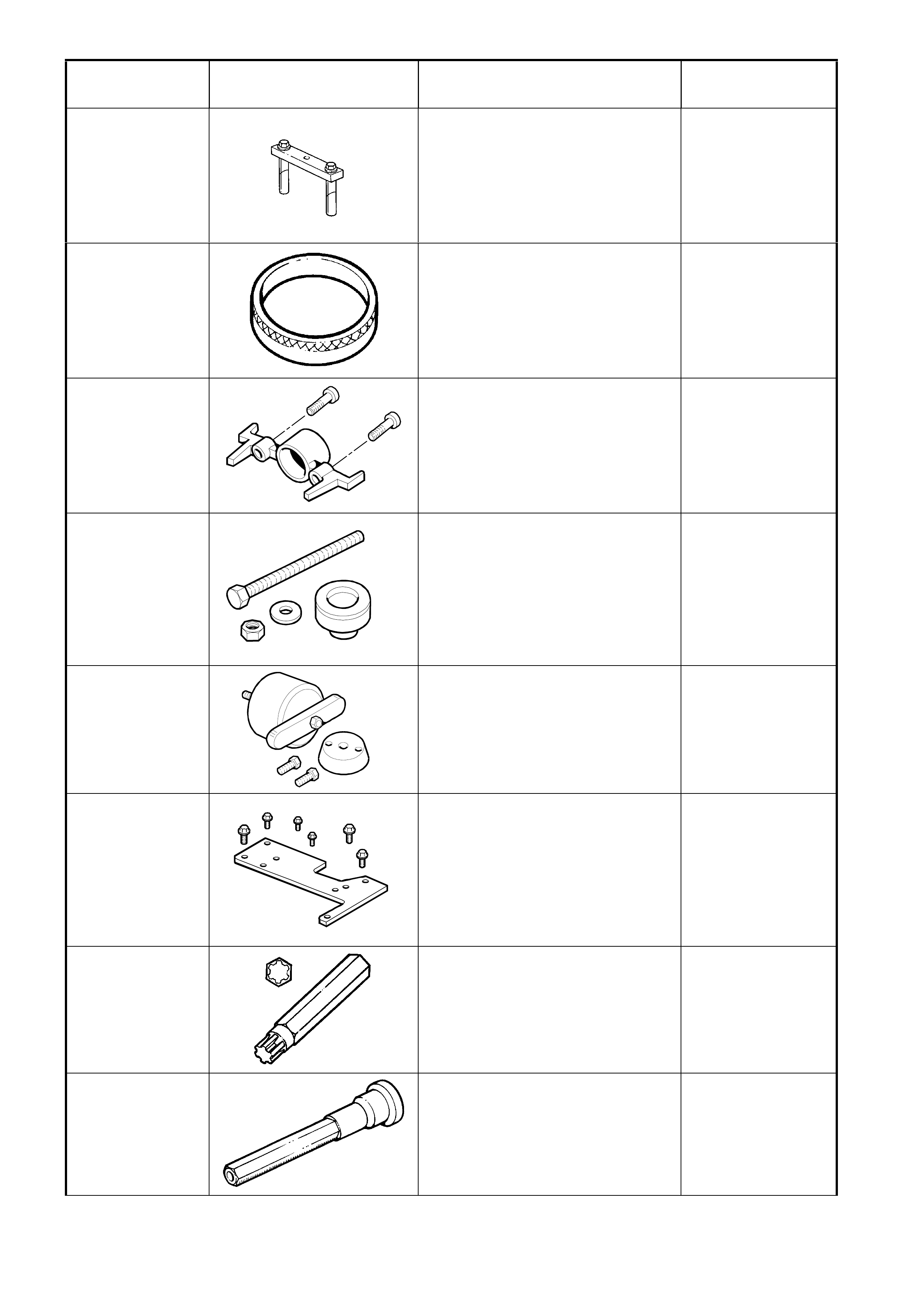
TOOL NUMBER ILLUSTRATION DESCRIPTION TOOL
CLASSIFICATION
J41348
MAIN BEARING CAP PULLER
Used in conjunction with slide
hammer 7374 (or J6125-B) to
remove main bearing caps on V6
engine.
Previously released.
Unique
J41349
REAR MAIN HOUSING ALIGNING
TOOL
Used when checking alignment of
rear seal housing on V6 engine.
Used in conjunction with E1409A.
Previously released.
Desirable
J41476
T6A3257a
FRONT AND REAR COVER
ALIGNMENT TOOL
Used to align both the front and
rear engine covers during
installation on GEN III V8 engine.
Previously released.
Desirable
J41478
T6A3258a
CRANKSHAFT FRONT OIL SEAL
INSTALLER
Threaded bolt, nut and washer are
also used in conjunction with J
41665 to install the crankshaft
balancer on GEN III V8 engine.
Previously released.
Desirable
J41479
T6A3259a
CRANKSHAFT REAR OIL SEAL
INSTALLER
For GEN III engine.
Previously released.
Desirable
J41480
T6A3260a
FRONT AND REAR COVER
ALIGNMENT TOOL
Used in conjunction with alignment
tool J 41476, to correctly align the
front and rear engine covers on
GEN III V8 engines.
Previously released.
Desirable
J41510
(6194)
#50 TORX PLUS BIT
Used to loosen and tighten the
torque converter housing to
transmission case bolts.
Previously released
Unique
J41512
(J42863)
VALVE STEM INSTALLATION
TOOL
Used to install valve stem seals on
V6 engines.
Previously released.
Desirable
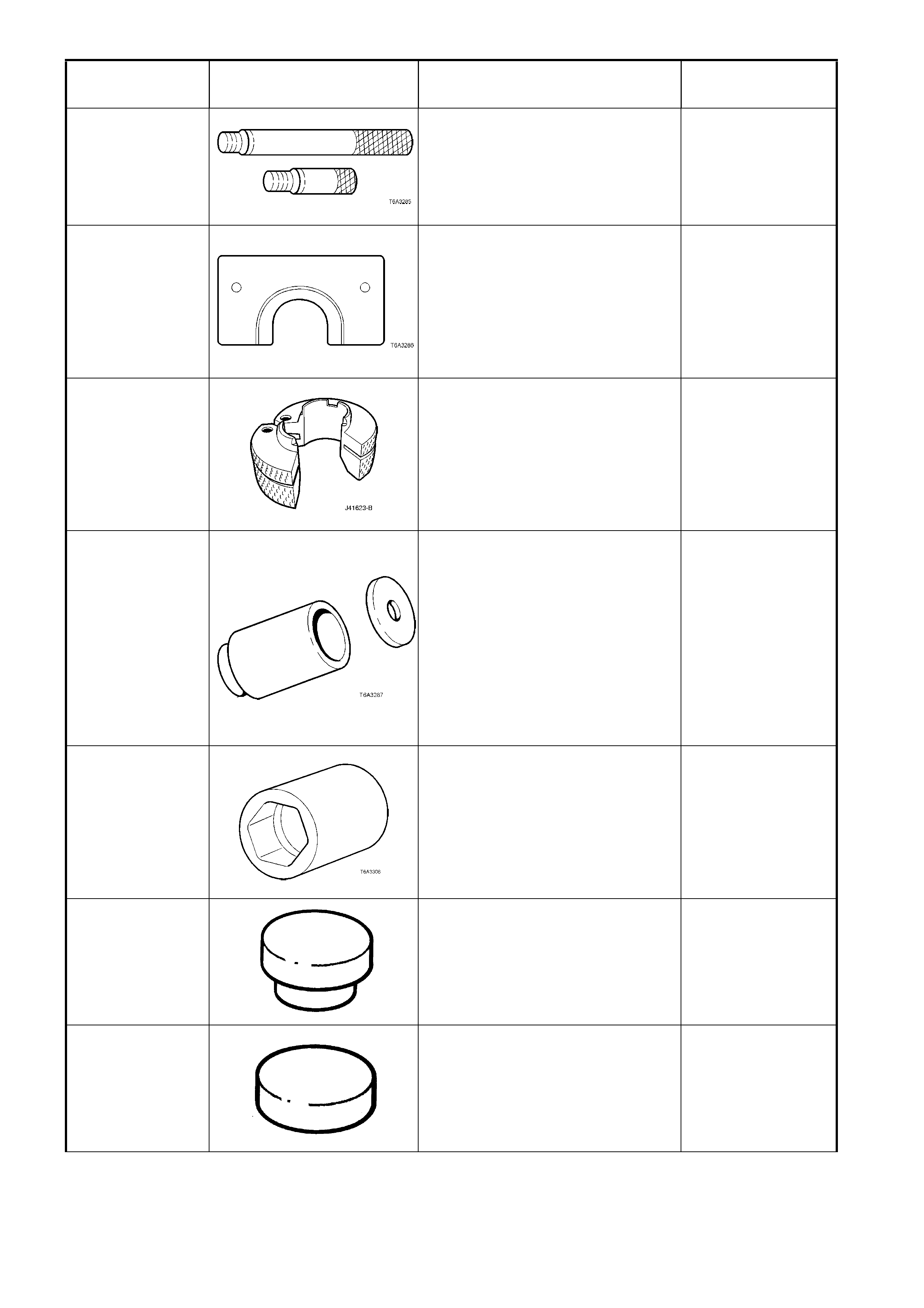
TOOL NUMBER ILLUSTRATION DESCRIPTION TOOL
CLASSIFICATION
J41556 CONNECTING ROD GUIDES
Used to assist in piston and
connecting rod installation on GEN
III V8 engine.
Previously released.
Desirable
J41558 CRANKSHAFT SPROCKET
REMOVER
Used in conjunction with the bolts
from J21427-01 and pulley puller J
8433, to remove the crankshaft
sprocket on GEN III V8 engine.
Previously released.
Desirable
J41623-B
COOLER LINE DISCONNECT
TOOL
Used to disconnect the automatic
transmission fluid cooler lines at the
transmission end, Quick Connect
fittings.
New release.
Mandatory
J41665 CRANKSHAFT BALANCER
INSTALLER
Comprises stepped sleeve,
J41665-1 and end plate J41665-2.
Used in conjunction with the
threaded bolt, nut and washer of
tool J41478, to install the
crankshaft balancer and sprocket
on GEN III V8 engine.
Previously released.
Desirable
J41712
OIL PRESSURE SENSOR
SOCKET
Used in conjunction with 3/8” drive
socket equipment to
remove/reinstall oil pressure
sensor.
Previously released.
Desirable
J41778-1
OIL PUMP BUSH INSTALLER
Used in conjunction with a bench
press.
Part of J41778 kit.
Previously released.
Unique
J41778-2
SUPPORT PLATE
Used to support the oil pump during
bush installation.
Part of J41778 kit.
Previously released.
Unique
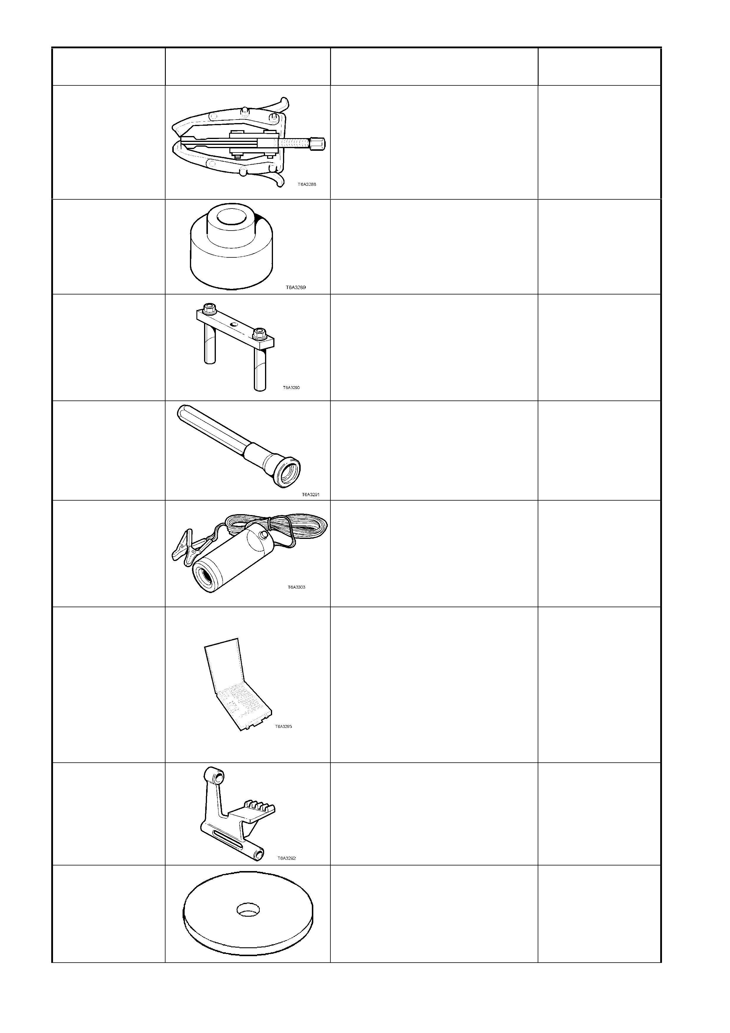
TOOL NUMBER ILLUSTRATION DESCRIPTION TOOL
CLASSIFICATION
J41816 THREE LEGGED PULLER
Used in conjunction with J 41816-2
to remove crankshaft balancer on
GEN III V8 engine.
Also commercially available.
Previously released.
Desirable
J41816-2
ADAPTOR
Used in conjunction with puller
J41816 to remove crankshaft
balancer on GEN III V8 engine.
Previously released.
Desirable
J41818
CRANKSHAFT BEARING CAP
REMOVER
Used in conjunction with slide
hammer J6125-1B to remove main
bearing caps on GEN III V8 engine.
Previously released.
Desirable
J42078
VALVE STEM OIL SEAL
INSTALLER
Used to install valve stem oil seals
for GEN III V8 engine.
Previously released.
Desirable
J42220 BLACK LIGHT, LEAK DETECTION
LAMP
Used in conjunction with dye, Tool J
28431-B to locate the source of
various vehicle fluid leaks.
Previously released.
Desirable
J42385
THREAD REPAIR KIT
Comprises:
Cylinder Head/Rear Main
Bearing Cap Kit J 42385-
100
General Kit J 42385-200
Fixtures/Hardware Kit J 42385-
300
Previously released.
Unique
J42386
FLYWHEEL HOLDING TOOL
Used for GEN III V8 engine.
Previously released.
Desirable
J42628
PLATE
Used in conjunction with clutch
spring compressor, J23327-1.
Previously released
Unique
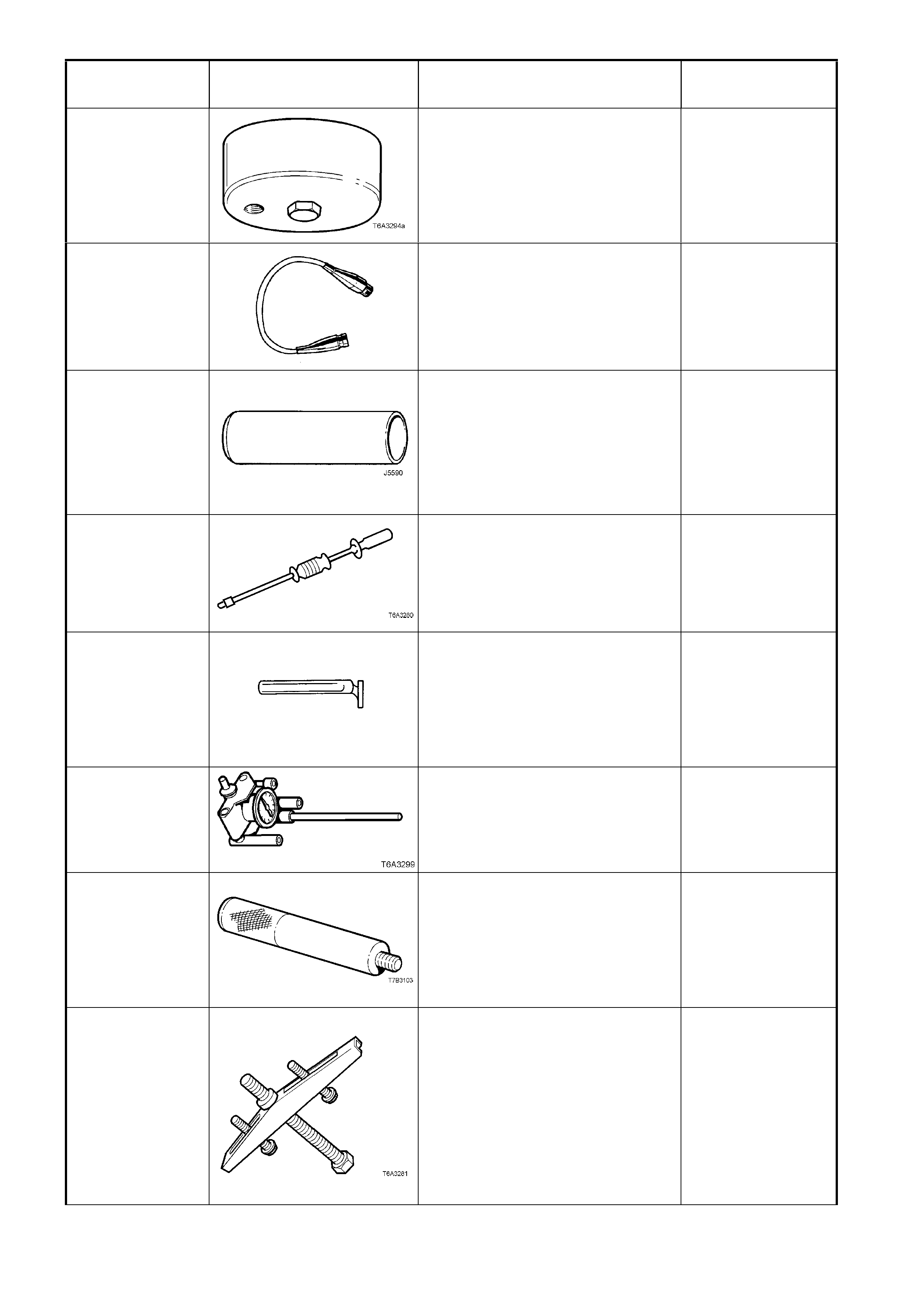
TOOL NUMBER ILLUSTRATION DESCRIPTION TOOL
CLASSIFICATION
J42907
OIL PRESSURE ADAPTOR
Fitted to the oil filter adaptor and
used in conjunction with a
commercially available oil pressure
gauge and hose.
Previously released.
Desirable
J44152
(J39775)
JUMPER HARNESS
Used for checking automatic
transmission during diagnostic
checks.
Previously released.
Mandatory
J5590 PRESS TUBE
Used to install various components,
using a hydraulic press.
Previously released for 4L60-E
automatic transmission.
Previously released.
Unique
J6125-1B SLIDE HAMMER
Used for a number of bush removal
and bearing cap removal
operations.
Previously released.
Unique
J8080
BEARING REMOVER AND
INSTALLER
Used to remove engine bearings
from engine with crankshaft still
installed.
Previously released.
Unique
J8087 CYLINDER BORE CHECKING
GAUGE
Previously released.
Unique
J8092 DRIVER HANDLE
Used in conjunction with various
other tools for removal and
installation of various bearing cups
and bushes.
Previously released.
Unique
J8433
UNIVERSAL BRIDGE PULLER
Used in conjunction with J39431-1
& 2 to remove the speedometer
pulse ring and the 5th/6th speed,
compound driven gear.
Used in conjunction with J21427-01
to remove the output speed sensor
ring from the mainshaft.
Previously released.
Unique
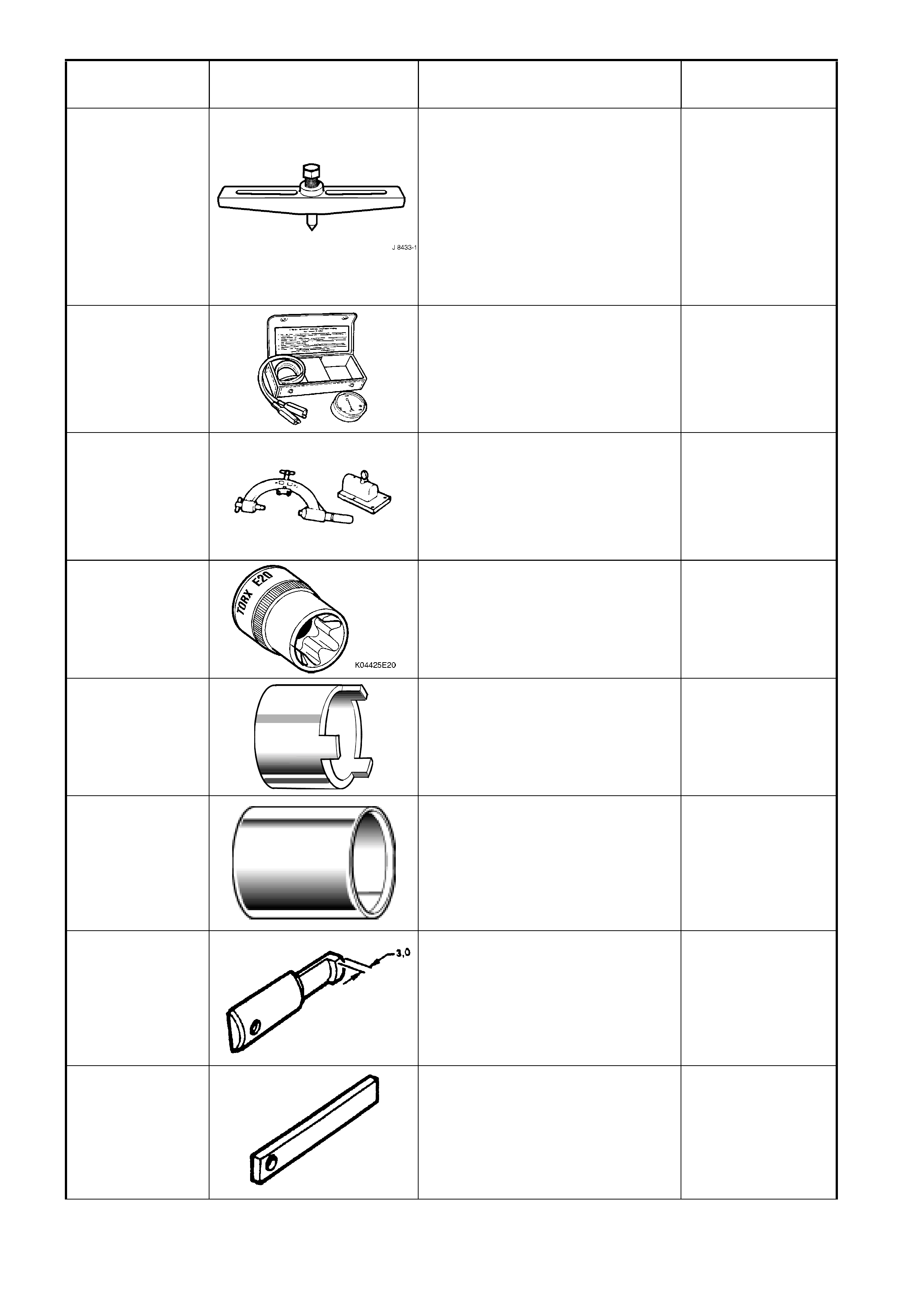
TOOL NUMBER ILLUSTRATION DESCRIPTION TOOL
CLASSIFICATION
J8433-1 PULLER BAR
Used for removing clutch rotor and
bearing assembly from A/C
compressor shaft.
Used to remove GEN III V8 engine
crankshaft timing gear sprocket, in
conjunction with J41558 and
J41816-2.
Previously released.
Unique
J8681-A
UNIVERSAL SHORT FINDER
Used during electrical circuit
diagnostic checks for detecting
short circuits.
Previously released.
Desirable
J8763-02 HOLDING FIXTURE
Used in conjunction with holding
fixture base J3289-20 to hold
automatic transmission.
Previously released.
Unique
K04425E20
E 20 TORX SOCKET
Previously released or use
commercially available equivalent.
Desirable
KM157-2
FRONT LOWER CONTROL ARM
PIVOT BUSHING INSTALLER
Used in conjunction with AU158
and AU159.
Previously released.
Desirable
KM158-2
FRONT LOWER CONTROL ARM
ROD BUSHING INSTALLING
SUPPORT SLEEVE
Previously released for ‘V’ car.
Used in conjunction with AU158
and AU159.
Desirable
KM328-7-A PULLER LEGS
Modify as detailed. Use with spacer
KM-328-9 and slide hammer KM-
328-B to remove bearings from the
transmission case.
Previously released.
Unique
KM328-9
SPACER
Used in conjunction with legs KM-
328-7-A and slide hammer KM-328-
B.
Previously released.
Unique
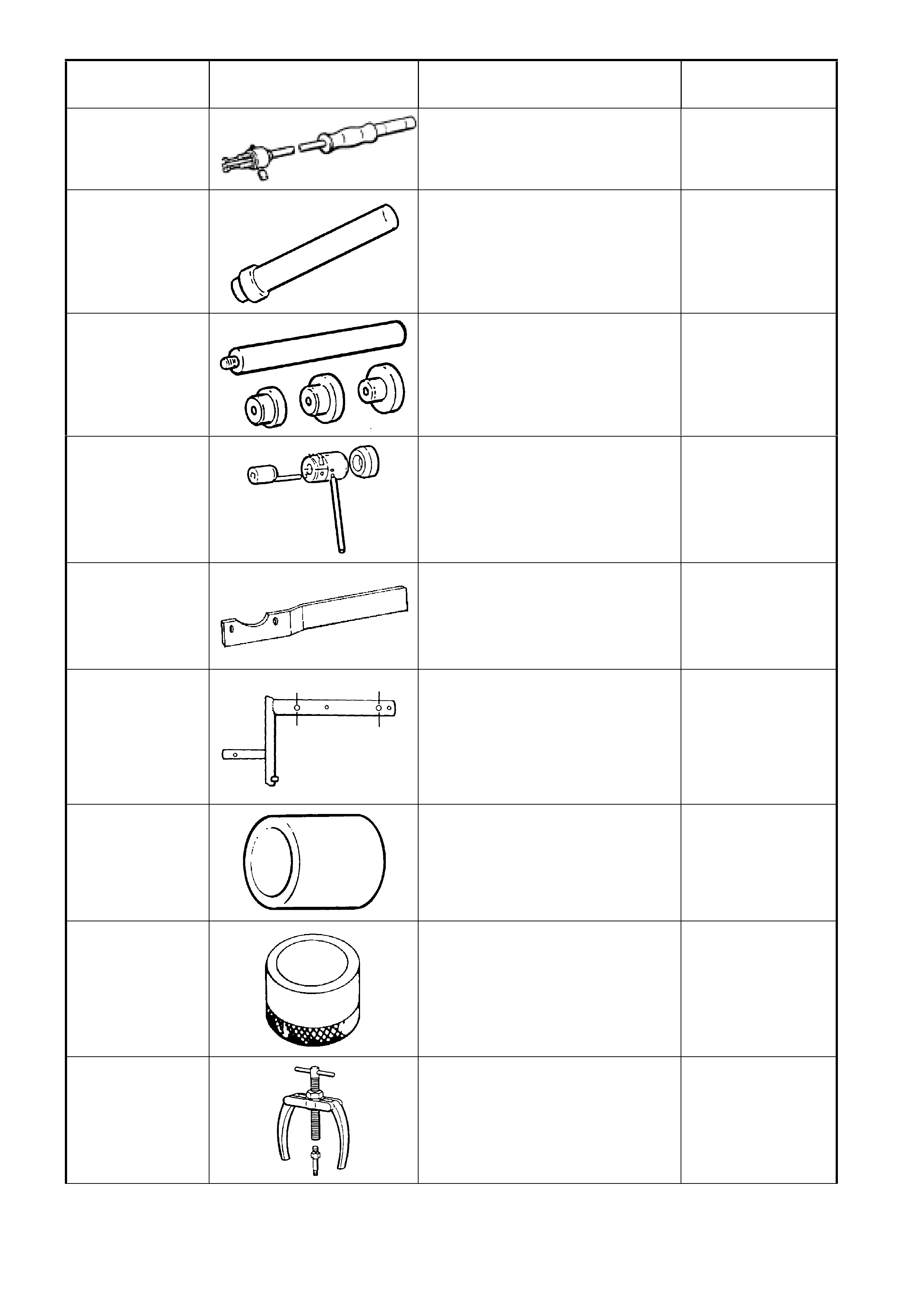
TOOL NUMBER ILLUSTRATION DESCRIPTION TOOL
CLASSIFICATION
KM328-B SLIDE HAMMER
Includes cup KM328-5-A and pin.
Previously released.
Unique
KM409-A
INSTALLER
Used to install the shift rod bearing
into the front transmission housing.
Previously released
Unique
KM454-A REMOVER / INSTALLER
Used to remove and install gear
bearing cups.
Previously released.
Unique
KM461-C
INSTALLER
Used to assemble the two manual
transmission housings on
reassembly.
Previously released.
Unique
KM468-B HOLDING BAR
Used to hold front wheel hub from
rotating.
Previously released.
Unique
KM480 HOLDING FIXTURE
Modify by drilling two 14mm holes
as shown. Fixture originally
released for THM 125 automatic
transaxle (‘J” car).
Previously released.
Unique
KM-500-3
SLEEVE
Used for various pressing
operations.
Previously released.
Unique
KM508-2
INSTALLING SLEEVE
Used to install new bush in shock
absorber lower mount.
Previously released.
Unique
KM556-1-A
PULLER
Part of puller kit KM556-A.
Previously released.
Unique
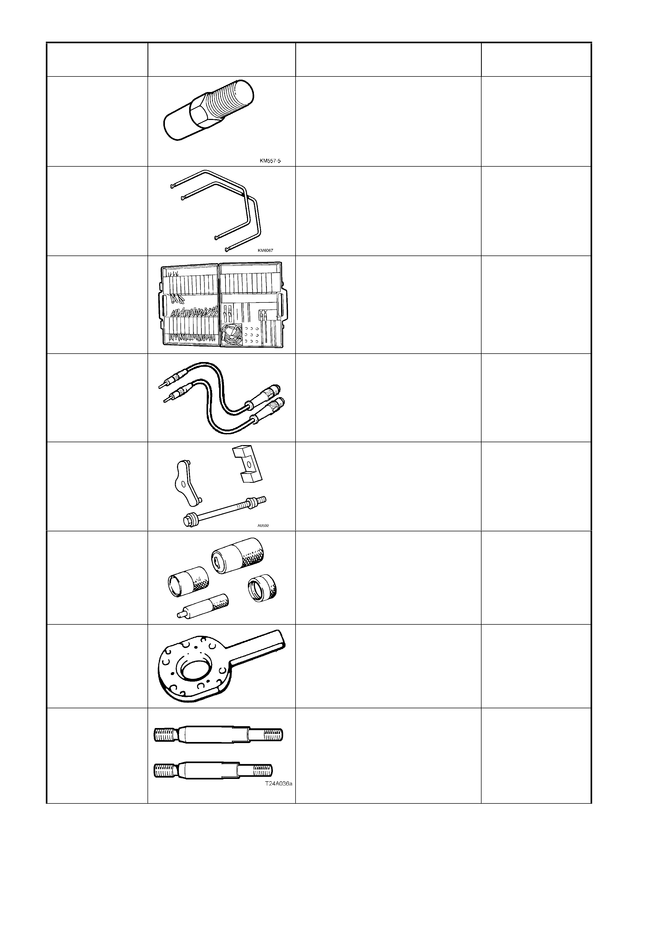
TOOL NUMBER ILLUSTRATION DESCRIPTION TOOL
CLASSIFICATION
KM557-5
ADAPTOR
Previously released.
Used in conjunction with puller
AMKM-557 for removing bushing
from crossmember front mounting.
Desirable
KM6067
RADIO REMOVAL TOOL
Used for removing VY audio unit
from its mounting location.
New tool for VY.
Mandatory
KM-609
(J35616-A)
ELECTRONIC KIT
Used in conjunction with a
multimeter for measuring voltages
and resistances without damaging
wiring harness connectors.
Desirable
KM609-20
TEST LEADS
Used when carrying out diagnostic
circuit check on the OPS / SRS
system.
Previously released.
Mandatory
KM618
INSTALLER
Used for installing new bushing into
crossmember front mounting for off
vehicle operation.
Previously released.
Available
KM619
REMOVER/INSTALLER
Used to press bushing from and
into rear suspension control arms.
Previously released.
Desirable
KM620-1A
FLANGE HOLDING TOOL
Modified tool used to hold the
transmission output flange while
removing flange nut.
Previously released.
Unique
KM620-7-AUS SUPPORTS
The two revised length supports are
required when using KM620-B for
service operations on the rear
trunnion and/or bearing.
Previously released.
Desirable
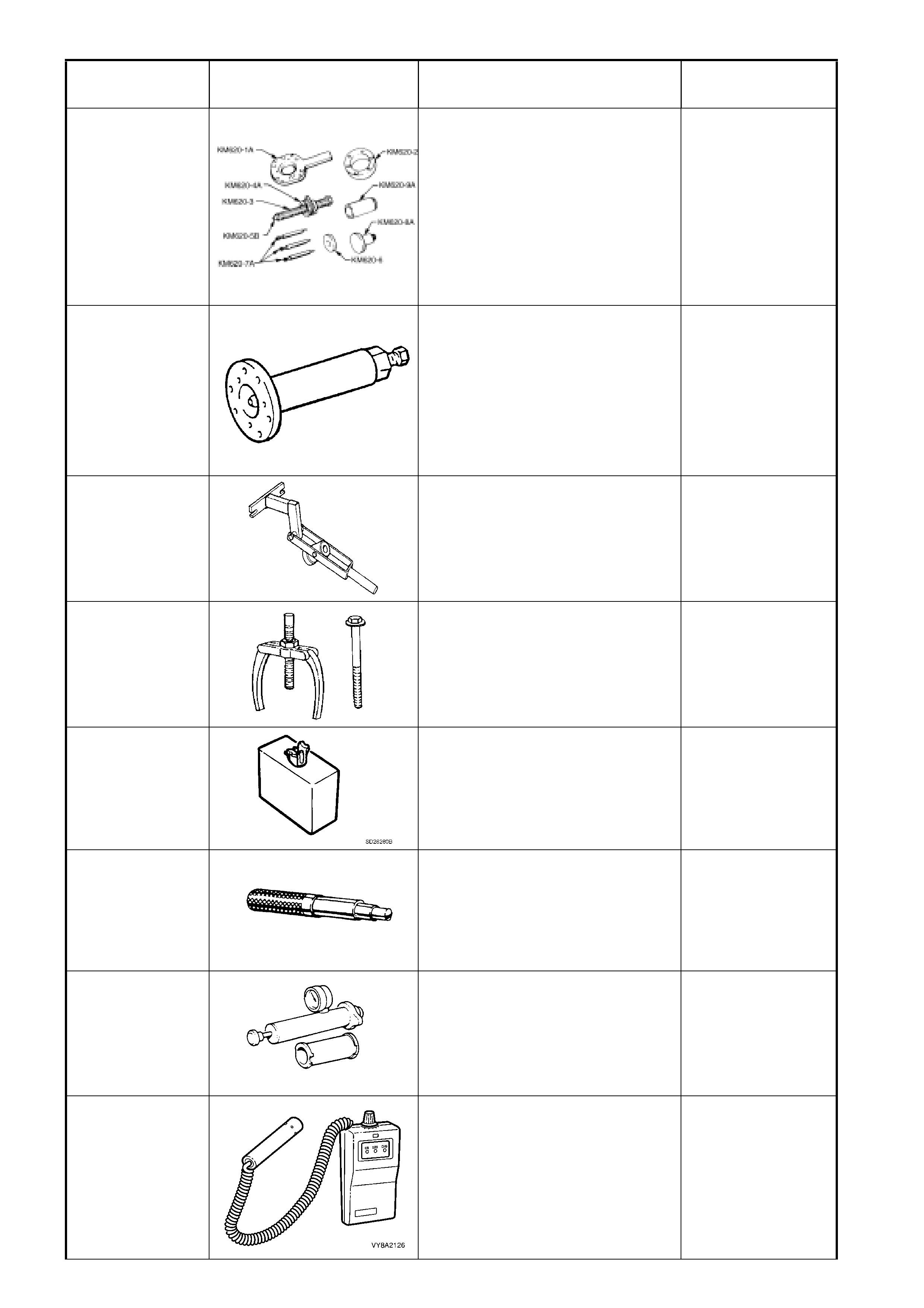
TOOL NUMBER ILLUSTRATION DESCRIPTION TOOL
CLASSIFICATION
KM620-B REMOVER/INSTALLER
Used for removing and installing
trunnion flange and rear wheel
bearing. KM620-1A is also used to
hold the pinion flange.
NOTE: Holes in KM620-1A,
stamped with a ‘B’ must be
enlarged to 12.5 mm.
Previously released.
Unique
KM-628-A EXTRACTOR TOOL
Used to remove the final drive
pinion flange. Also used for several
disassembly operations on the V6
manual transmission. Each of the
three mounting holes must be
enlarged to 12.5 mm.
Previously released.
Unique
KM-632-A
CLUTCH PRESSURE PLATE
LOADING TOOL
Used for clutch removal and
reinstallation.
Previously released.
Desirable
MKM557-A
PULLER
Used for removing bush from
crossmember front mounting.
Previously released.
Desirable
SD28280B
(AU471)
DUMMY LOAD
For steering wheel inflatable
restraint (drivers airbag) and
instrument panel inflatable restraint
(passenger airbag).
Mandatory
N/A CLUTCH CENTERING TOOL
Previously released.
Available
N/A
COOLING SYSTEM PRESSURE
TESTER
Used in conjunction with adaptors
J24460-92. Commercially available.
Previously released.
Mandatory
N/A ELECTRONIC GAS LEAK
DETECT OR
Commercially available.
Available
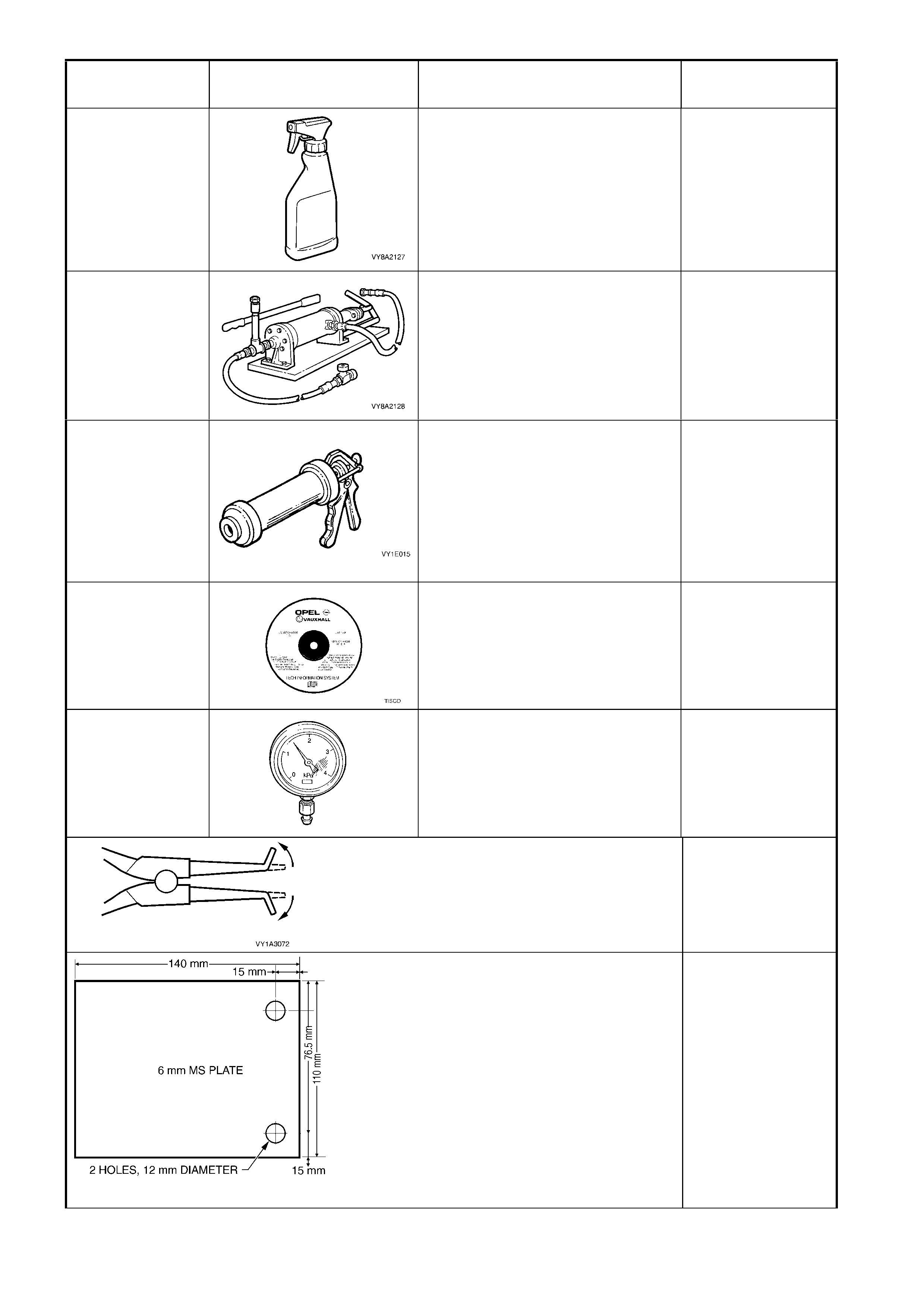
TOOL NUMBER ILLUSTRATION DESCRIPTION TOOL
CLASSIFICATION
N/A LEAK TEST FOAMING AGENT
Commercially available (such as
Gameco Leak Checktm)
Available
N/A LPG TANK UNLOADING PUMP
Commercially available.
Available
N/A SAE 677 BARREL GUN &
FOLLOWER PLATE
Used to apply dash panel assembly
two-part silicone adhesive.
Previously available, refer parts
catalogue.
Desirable
N/A
TECHNICAL INFORMATION
SYSTEM (TIS) CD ROM
Only available to Authorised
Dealers.
Mandatory
N/A
VACUUM GAUGE
Vacuum gauge with scale of 0 to
-4kPa. Used for checking P.C.V.
valve operation and function.
Previously released.
Mandatory
ACCESSORY SOCKET REMOVAL TOOL
Modified commercially available external circlip
pliers. Used for removing the floor console
accessory power socket from its retaining bezel.
Dealer Fabricated
DIAL INDICATOR PLATE
Dealer fabricated:
1. Fabricated from 6 mm Mild Steel Plate
2. If using the brake caliper bolts to fasten,
then a 17 mm spacer will need to be
installed on each bolt, prior to installing.
Dealer Fabricated
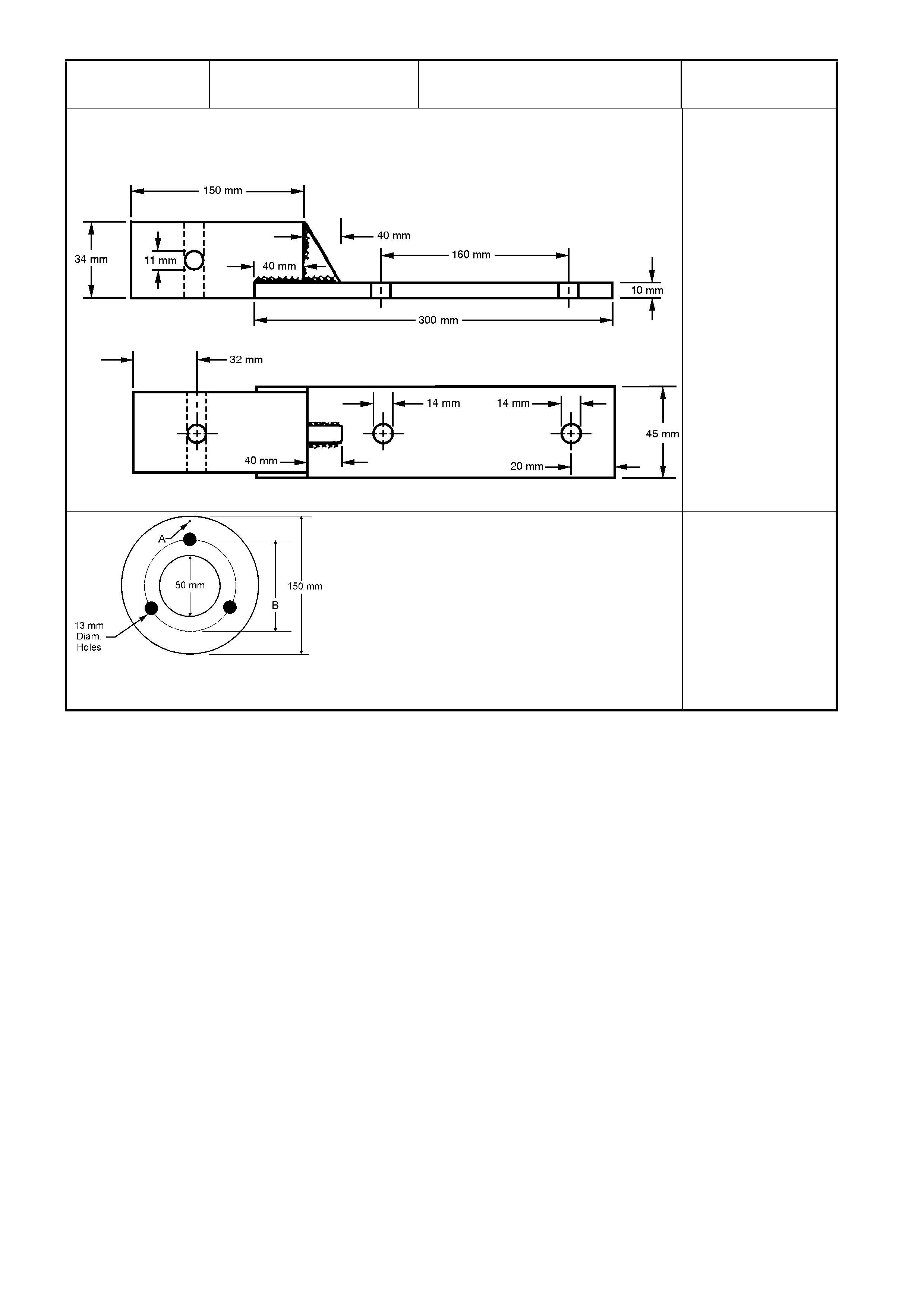
TOOL NUMBER ILLUSTRATION DESCRIPTION TOOL
CLASSIFICATION
DIFFERENTIAL CARRIER HOLDING FIXTURE
If KM480 is not available, fabricate a holding
fixture as shown.
Dealer Fabricated
PINION FLANGE PULLEY
Dealer fabricated:
1. Made from a 13 mm thick piece of wood.
2. Drill a small hole at 'A' and attach a one
metre length of string at this point.
3. Drill two 10 mm holes as shown in the
figure.
Dealer Fabricated