
SECTION 0C - TECH 2
IMPORTANT
Before performing any Service Operation or other procedure described in this Section, refer to Section 00
Cautions And Notes for correct workshop practices with regard to safety and/or property damage.
CONTENTS
1. GENERAL INFORMATION
1.1 FEATURES OF THE TECH 2
DISPLAY
SCREEN AREAS
KEYPAD
PCMCIA CARD
VEHICLE COMMUNICATION INTERFACE
MODULE
SERIAL PORTS
ADAPTERS FOR TECH 2
1.2 CONNECTIONS
2. PROGRAMMING TECH 2
2.1 GENERAL INFORMATION
STANDARD UPDATE
CUSTOM UPDATE
3. USING TECH 2 ON THE VEHICLE
3.1 CONNECTING THE TECH 2 TO THE VEHICLE
3.2 ENGINE APPLICATION MENU
V6 ENGINE TECH 2 FUNCTIONS
SERVICE PROGRAMMING SYSTEM
BCM LINK TO PCM
SUPERCHARGED V6 ENGINE TECH 2
FUNCTIONS
BCM LINK TO PCM
V8 GEN III ENGINE TECH 2 FUNCTIONS
SERVICE PROGRAMMING SYSTEM
BCM LINK TO PCM/PIM
3.3 TRANSMISSION APPLICATION MENU
V6 TRANSMISSION TECH 2 FUNCTIONS
SERVICE PROGRAMMING SYSTEM
BCM LINK TO PCM
SUPERCHARGED V6 TRANSMISSION TECH 2
FUNCTIONS
BCM LINK TO PCM
V8 GEN III TRANSMISSION TECH 2
FUNCTIONS
SERVICE PROGRAMMING SYSTEM
BCM LINK TO PCM/PIM
3.4 CHASSIS APPLICATION MENU
ABS/ETC TECH 2 FUNCTIONS
AWD ABS – TC TECH 2 FUNCTIONS
3.5 BODY APPLICATION MENU
BODY CONTROL MODULE
BCM TECH 2 FUNCTIONS
POWERTRAIN INTERFACE MODULE
PIM TECH 2 FUNCTIONS
AWD PIM TECH 2 FUNCTIONS
SUPPLEMENTAL RESTRAINT SYSTEM (SRS)
SRS TECH 2 FUNCTIONS
INSTRUMENT
INSTRUMENT TECH 2 FUNCTIONS
OCCUPANT CLIMATE CONTROL
OCC TECH 2 FUNCTIONS
AUDIO SYSTEM
AUDIO SYSTEM TECH 2 FUNCTIONS
TELEMATICS MODULE
TELEMATICS TECH 2 FUNCTIONS
3.6 VEHICLE DTC CHECK
4. TIS APPROVAL
4.1 GENERAL INFORMATION
4.2 SECURITY ACCESS
4.3 VEHICLE THEFT DETERRENT LEARN
5. SERVICE PROGRAMMING SYSTEM (SPS)
5.1 GENERAL INFORMATION
5.2 SPS PROCESS
6. TECH 2 DIAGNOSIS
6.1 GENERAL INFORMATION
7. SPECIAL TOOLS
Techline
Techline
Techline
Techline
Techline
Techline
Techline
Techline
1. GENERAL I NFORMATI O N
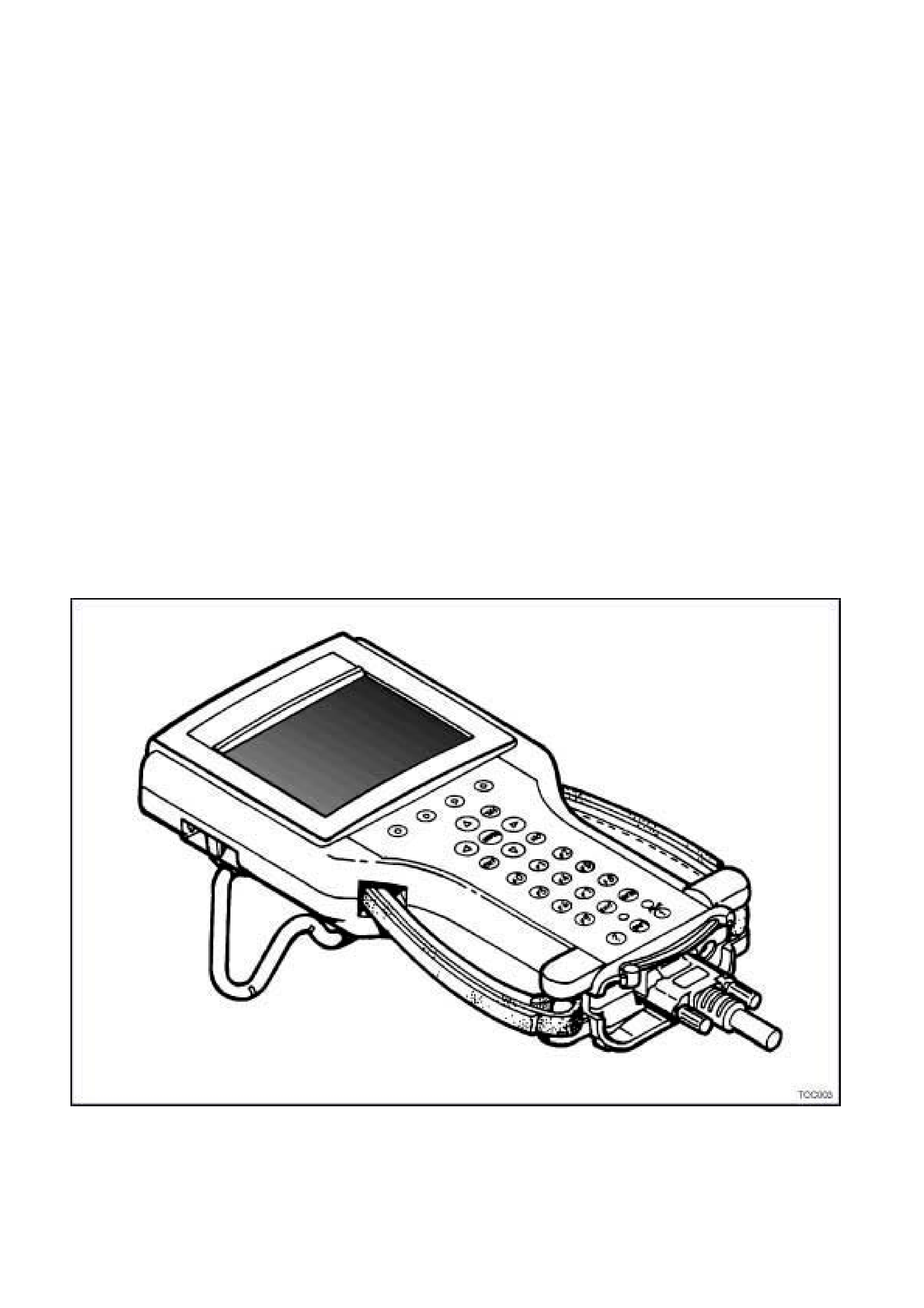
The TECH 2 is a hand-held diagnostic computer designed specifically to help you diagnose and repair electronic
systems used on Holden vehicles.
When the TECH 2 is attached to a vehicle it can be a very versatile tool. W ith its large, easy-to-read display, the
TECH 2 guides you step-by-step through the testing procedur es . You respond to the T ECH 2 through the keyboard
commanding it to:
Conduct the test you want to run
Retrieve the diagnostic data you want
Control the function you want to monitor
The TECH 2 gets its power from the vehicle to be tested and communicates or interfaces with the vehicle
electronic systems through the Data Link Connector (DLC). TECH 2 can communicate with the following control
modules, if the vehicle is equipped with these systems.
Body Control Module (BCM).
Powertrain Control Module (PCM).
Powertarin Interface Module (PIM)
Instrument
Supplemental Restraint System (SRS).
Antilock Braking System / Electronic Traction Control System (ABS/ETC).
Occupant Climate Control (OCC)
Audio System (“Radio”)
Telematics
When connected to the DLC, the TECH 2 can read Diagnostic Trouble Codes (DTCs) and diagnostic data.
Depending on the application selected, TECH 2 can also control some systems for troubleshooting or automatic
testing.
Figure 0C-1 TECH 2
1.1 FEATURES OF THE TECH 2
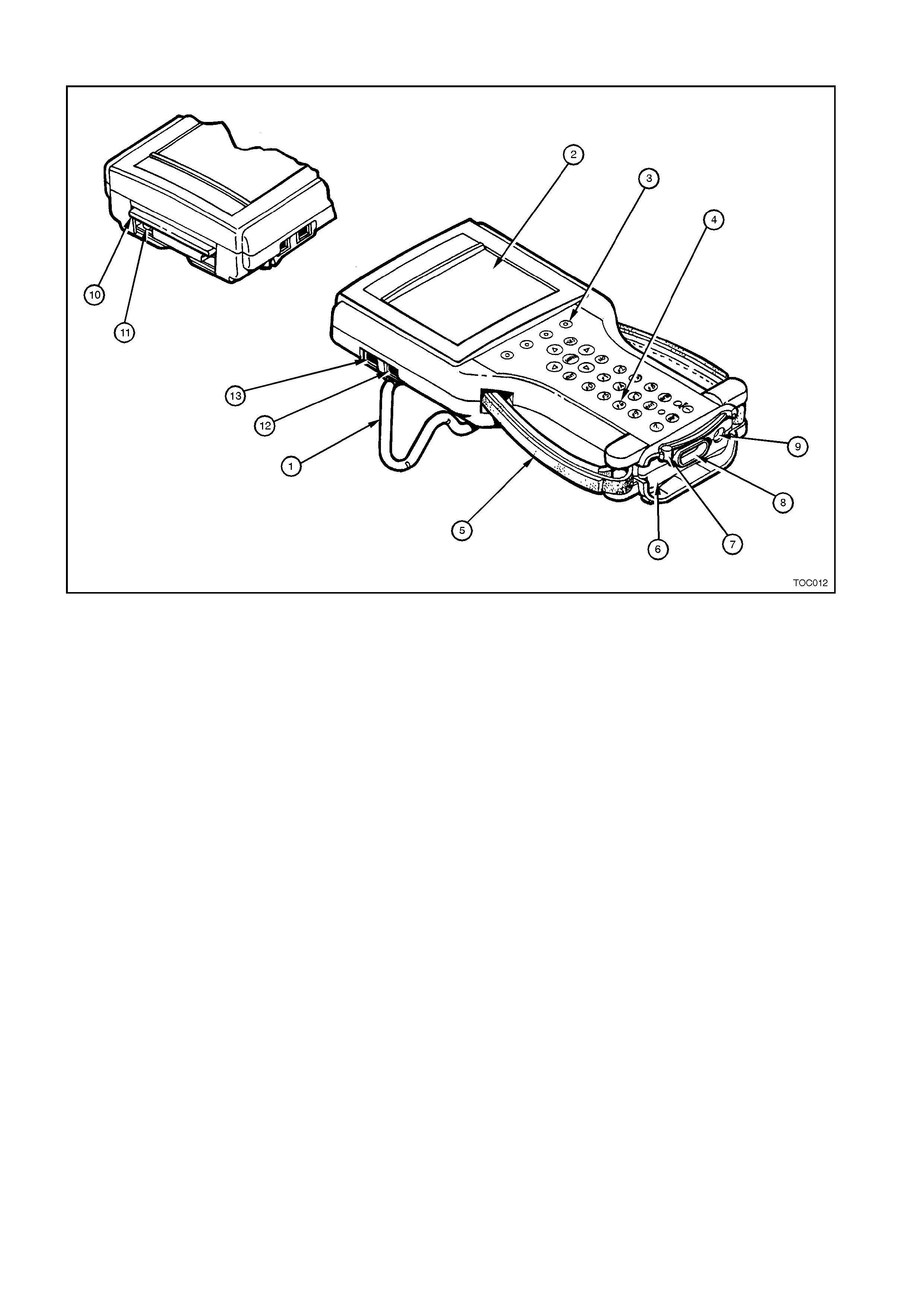
Figure 0C-2 Features of TECH 2
Legend:
1. Tilt Stand 6. Vehicl e Comm uni cation Interface (V CI) 11. PCMCIA Releas e Button
2. Display 7. VCI Latching Lever 12. RS-232 Com munication Port
3. Soft Keys 8. DLC Connector 13. RS-485 Comm unication Port
4. Keypad 9. Power Jack
5. Adjustable Hand Strap 10. PCMCIA Cover
DISPLA Y
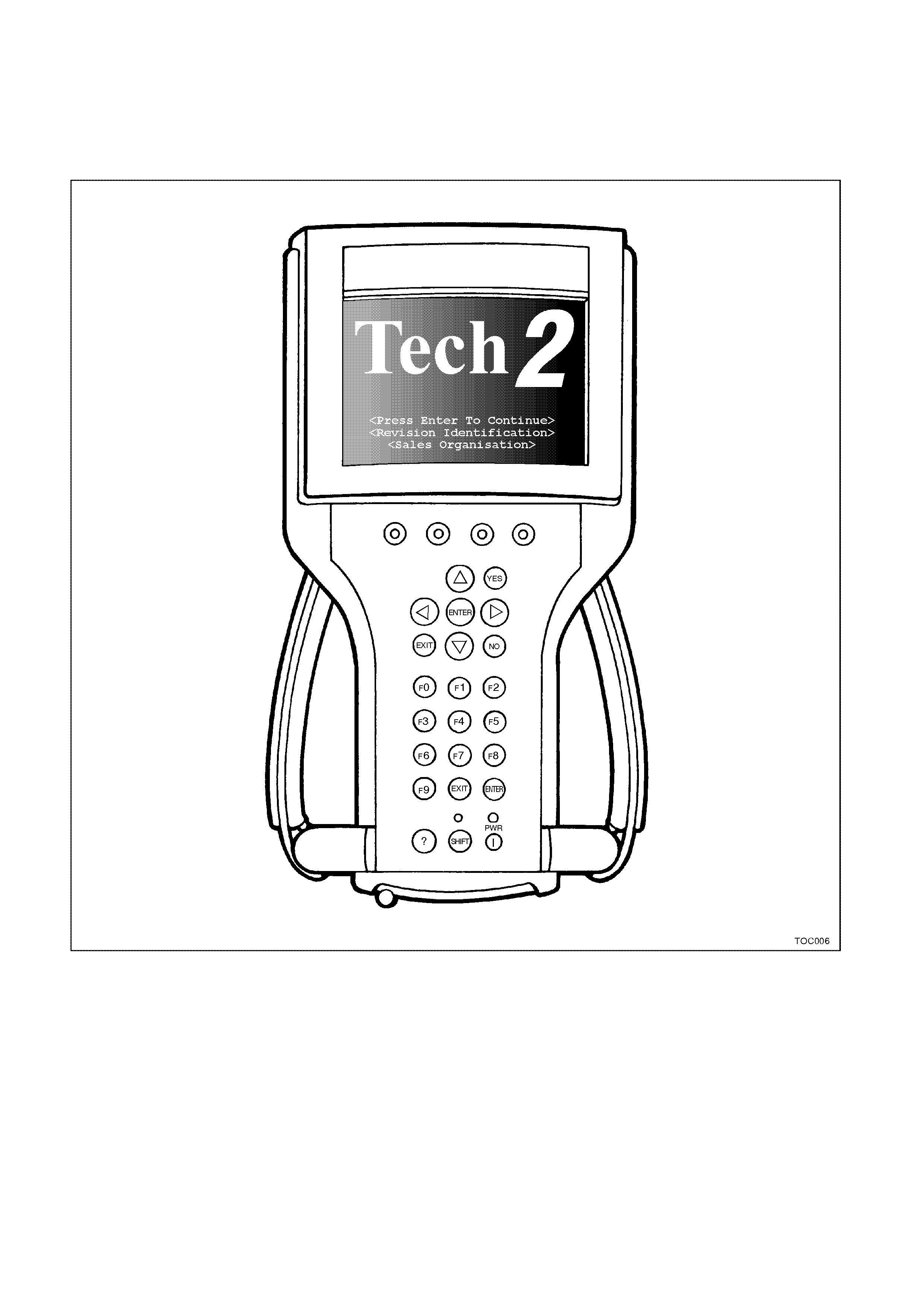
A large screen, Monochrom e Liquid Crystal Display (LCD) which measures 100 x 76 mm is used on the TECH 2.
This allows nine parameters to be seen on screen at the same time. The screen has graphics capabilities which
allow graphs to be plotted on the s cr een to aid diagnos is . T he tool may, in the future, allow som e additional graphic
images to be displayed which will help diagnose vehicle systems.
The TECH 2 has an adjustable contrast control to allow the user to change brightness and contrast of the display.
Figure 0C-3 TECH 2 Display
SCREEN AREAS
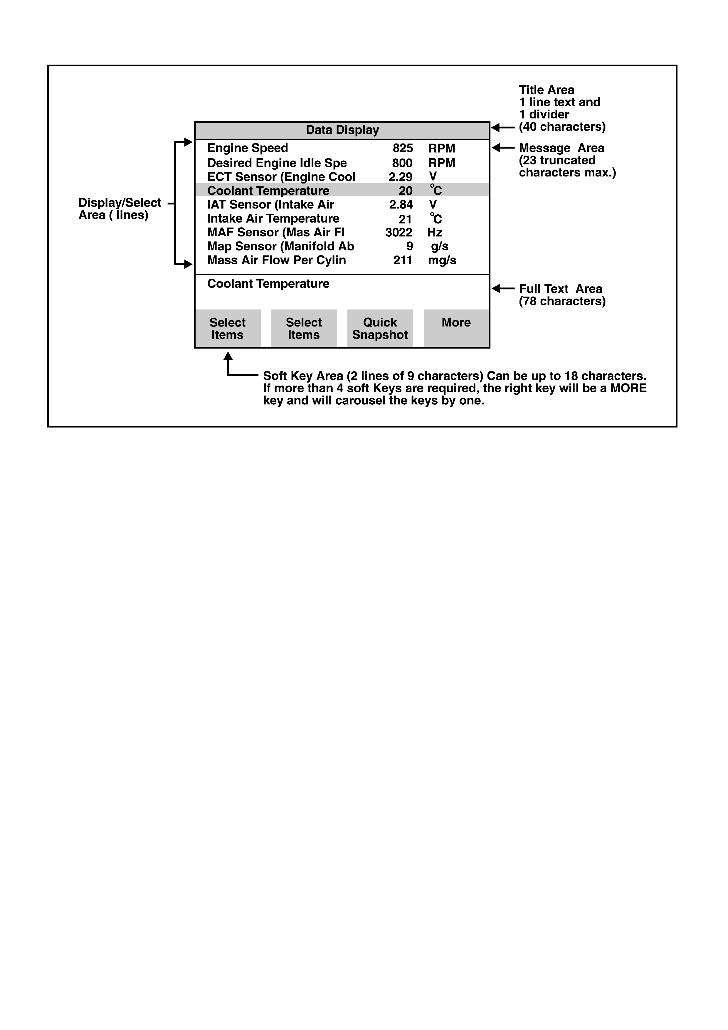
Figure 0C-4 TECH 2 Screen Areas
The screen is broken down into five ar eas. By looking at the inform ation which is displayed in each area, the user
may use the tool more efficiently.
• Title area
• Message area
• Display/select area
• Full text area*
• Soft key area
*The "full text" area is always a complete description of the highlighted line in the "display/select" area.
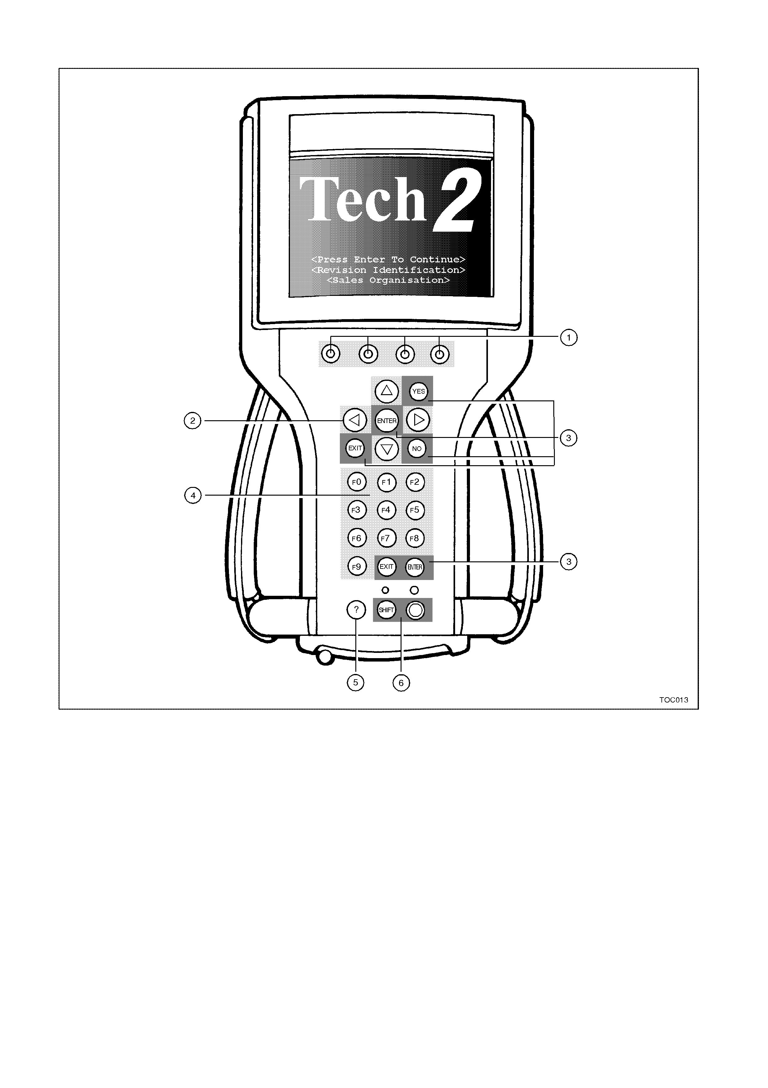
KEYPA D
Figure 0C-5 Keypad
Legend:
1. Soft Keys 3. Action Keys 5. Help Key
2. Selection Keys 4. Function Keys 6. Control Keys

Keypad Layout
The keypad of the TECH 2 contains 27 keys. W ithin these keys are 23 keys which are pre-defined and four keys
which are referred to as soft keys. The soft key usage will change depending on which part of an application is
being used. Following is a definition of the key usage for the pre-defined keys.
Soft Keys
There are four keys on the TECH 2 which will have changing usage within an application. Soft key functions are
software dr iven. This m eans that the sof t key function m ay change in different ar eas of the sof tware. The left mos t
soft key at the Main Menu will be used to Clear Vehicle, while in Snapshot the same key position may change
Units. The ability of the soft keys to perform different tool operations at different times increases the versatility of
the TECH 2.
Selection Keys
The arr ow keys are used for s creen m ovement to m ak e a selection. T here are four ar row keys. The Up and Down
arrows move the highlight bar one line at a time. If they are held, the highlight bar will scroll. The Left and Right
arrow keys will move the highlight a page at a time. Left arrow moves the highlight up (previous page) and Right
arrow moves the highlight down (next page). The arrow keys are used to move the highlight bar to a position to
make a selection, or to move the display to allow more information to be viewed.
Action Keys
There are a group of keys which are referred to as Action keys. As the name implies, action keys will make an
action take place on the TECH 2 tool. The action keys are YES, NO, ENTER, and EXIT.
YES — Confirms a positive response to a question.
NO — Confirms a negative response to a question.
ENTER (2 keys) — Indicates a selection has been made.
EXIT (2 keys) — Returns user to a previous menu selection.
Function Keys
The function keys (F0 - F9) allow direct selection of a choice from a menu.
Help Key
Help (?) accesses a tool help function which is specific to the current operation of the TECH 2.
Control Keys
There ar e two keys which are us ed to c ontrol the TECH 2 itself . These are the SHIF T and PWR ( Power) keys. The
SHIFT key will access screen contrast control. To adjust contrast during the current power cycle of the TECH 2,
use the following procedure.
Press the SHIFT key (The yellow light will turn on).
Use the Up arrow to Increase screen brightness and contrast or the Down arrow to Decrease screen brightness
and contrast.
Press the SHIFT key (the yellow light will turn off).
This procedure will only adjust the contrast for the duration of this power cycle of the TECH 2. If the power is turned
off and then back on again, the contr as t will change to a def ault value. The default setting is covered in the T ECH 2
User’s Guide.
Be aware that if the yellow SHIFT light is on, only the Up/Down arrow keys and the EXIT keys are active.
There is a PW R ( Power) switch for TECH 2 which will control turning the TECH 2 on and of f. A green indicator will
illuminate when the TECH 2 is switched on.
Thumb Action
The T ECH 2 is des igned for one handed oper ation. The unit is balanced to allow one hand to com fortably hold and
operate the tool. Straps on the sides of the tool are adjustable to help hold the TECH 2 in one hand. The keypad
configuration is designed for thumb usage while holding the tool in either the left or right hand. It is suggested to
use the select ion and action k eys instead of the f unction k eys as som e TECH 2 s creens require m ak ing selec tions
from a list on screen. In these cases there may not be a function key equivalent.
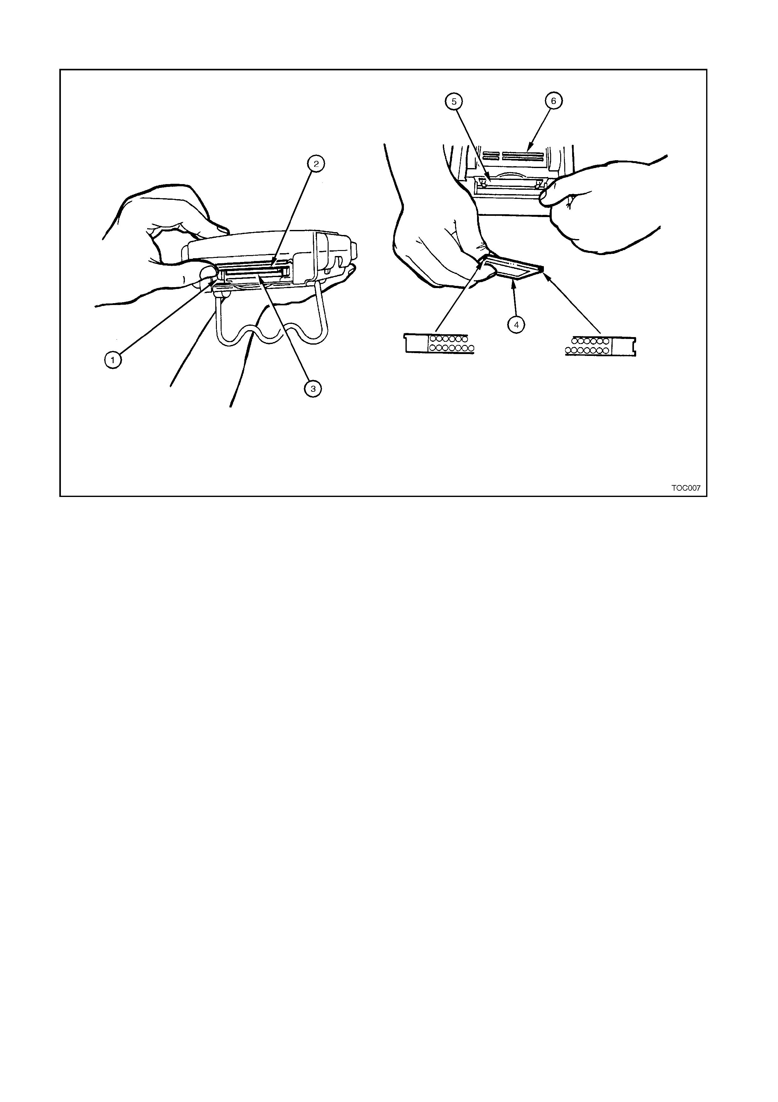
PCMCIA CARD
Figure 0C-6 PCMCIA Card
Legend:
1. PCMCIA Release Button 3. Empty Lower PCMCIA Slot 1 5. PCMCIA Cover
2. In Use Upper PCMCIA Slot 0 4. TECH 2 PCMCIA Card 6. Underneath Side of TECH 2
The TECH 2 uses a Personal Computer Mem ory Card Industry Association (PCMCIA) standard memory card for
storage of diagnostic functions and applications. The memory card has a capacity of 10 or 32 Megabytes. The
PCMCIA card is accessed through a door on top of the TECH 2, and should not norm ally require removal. There
are two PCMCIA s lots in TECH 2, s lot zero which is closes t to the s c reen and the s ec ond slot which is identif ied as
slot one. The card is ejected by pushing the arrow button pointing to card to be removed. Cards are notched to
allow insertion only one way. When re-inserting the card make sure that it fully seats into the TECH 2.
If you are using a 32 Megabyte PCMCIA c ard the c ard s hould be ins talled into s lot zero. If you are using 2 PCMCIA
cards, one in eac h slot, you can switch between cards by pressing the SHIFT key, then press either the RIGHT or
LEFT ar row k ey. T ECH 2 will then toggle between the card in s lot 1 to the car d in s lot 2. Onc e T ECH 2 has toggled
between cards, press the SHIFT key again.
The TECH 2 is capability of storing two snapshots. This will allow comparison of bef ore/after type conditions on a
vehicle being serviced.
NOTE: The PCMCIA card is sensitive to magnetism and static electricity so care should be taken in the
handling of the card.
A write protect slide mechanism is on the top edge of the card. The correct position is to the middle of the card
(unlocked). If the write protect is in the locked position, snapshots will not be able to be stored, and Service
Programming System (SPS) will not work.
TECH 2 and PCMCIA card can be updated by connecting to Technical Information System (TIS).
The software that operates the TECH 2 is stored on the PCMCIA card. The contents of the card are not distinct
applications. All of the applications share a single database of information on the PCMCIA card.
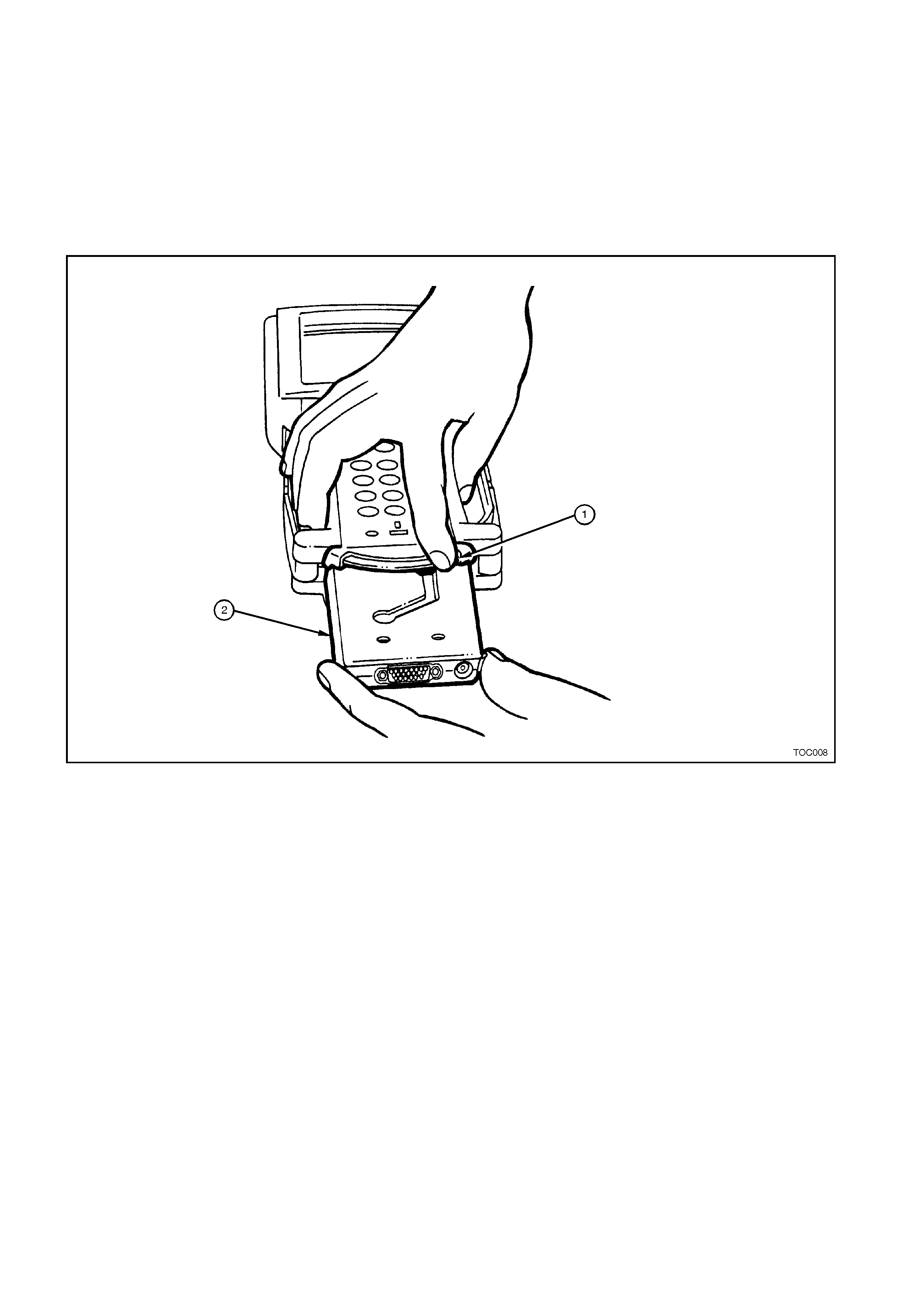
VEHICLE COMMUNICATION INTERFACE MODULE
The TECH 2 us es a Vehicle Comm unication Interfac e (VCI) module, located in the bottom of the unit to act as an
interfac e between the vehicle and the inter nal work ings of the T ECH 2. T his allows the T ECH 2 to com m unic ate to
many different types of data systems on vehicles.
Data is transmitted between the vehicle and the TECH 2 thr ough the DLC cable. Power f or the T ECH 2 is also sent
through the VCI module. Power can either come through the DLC cable or from the power jack on the bottom of
the VCI module. Internally, the VCI module protects the TECH 2 against reverse polarity power connections.
During norm al usage of the T ECH 2, there is no reas on to remove the VCI m odule. In the future, if dif ferent types
of data communication are used on the vehicle, the VCI module could be changed to extend the useful life of the
TECH 2 even further. To remove the VCI module, refer to the TECH 2 User's Guide.
Figure 0C-7 VCI Module
Legend:
1. VCI Module Lever (moved all the way to the right) 2. VCI Module
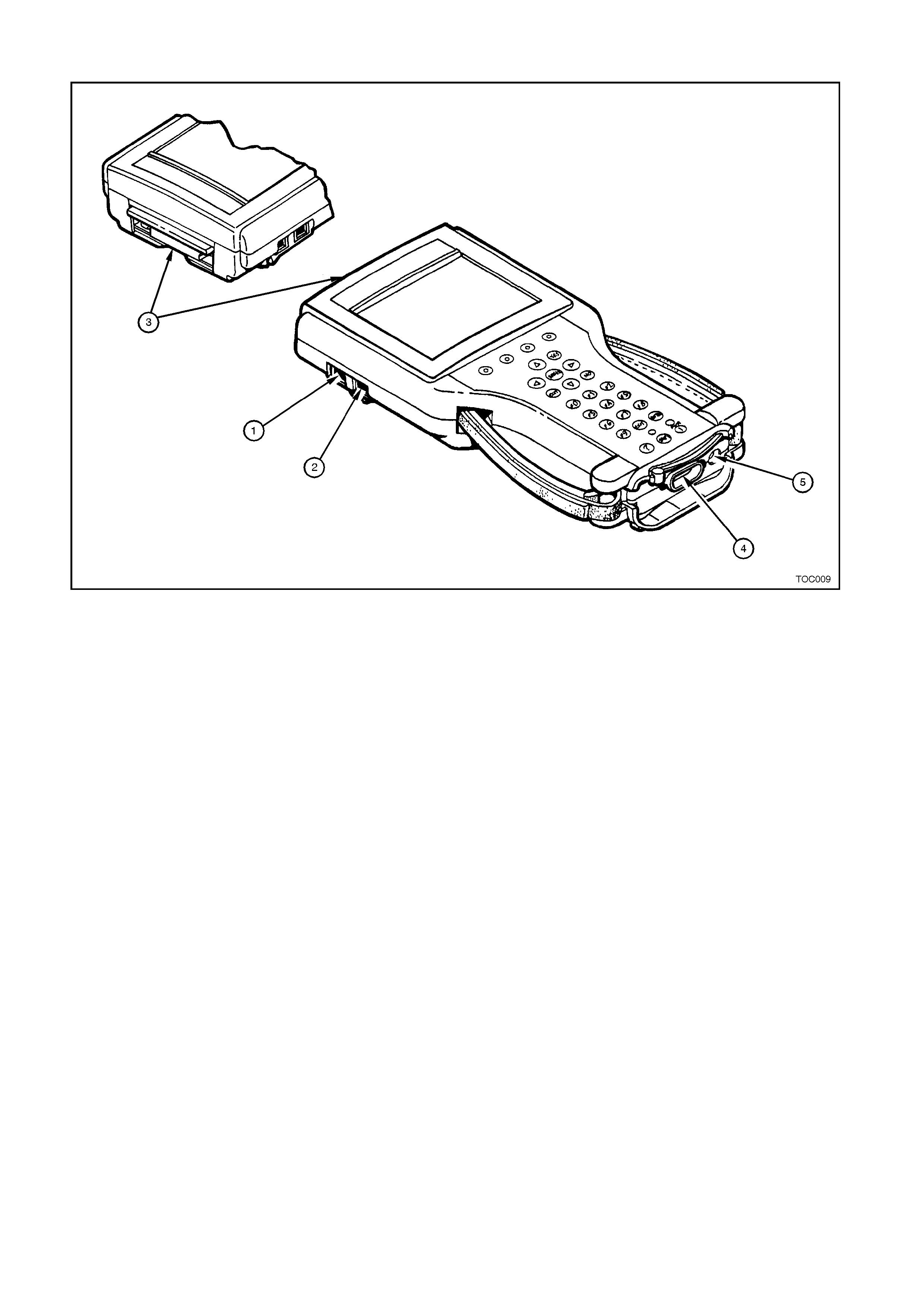
SERIAL PORTS
Figure 0C-8 Serial Ports
Legend:
1. RS-485 Port 3. PCMCIA Slots 5. Power Jack Connector
2. RS-232 Port 4. DLC Connector
TECH 2 also has two serial port connections for com munication to other computers. These ports are the RS-232
and the RS-485. The RS-232 is used for connecting to T IS for updating the contents of applications on the TECH
2. To perform Service Programming System with the TECH 2 the RS-232 port is also used.
The RS-485 is currently not used, but may in the future allow for other tool capabilities.
ADAPTERS FOR TECH 2
The TECH 2 includes a selection of cables and adapters to accommodate a variety of operating conditions and
functions.
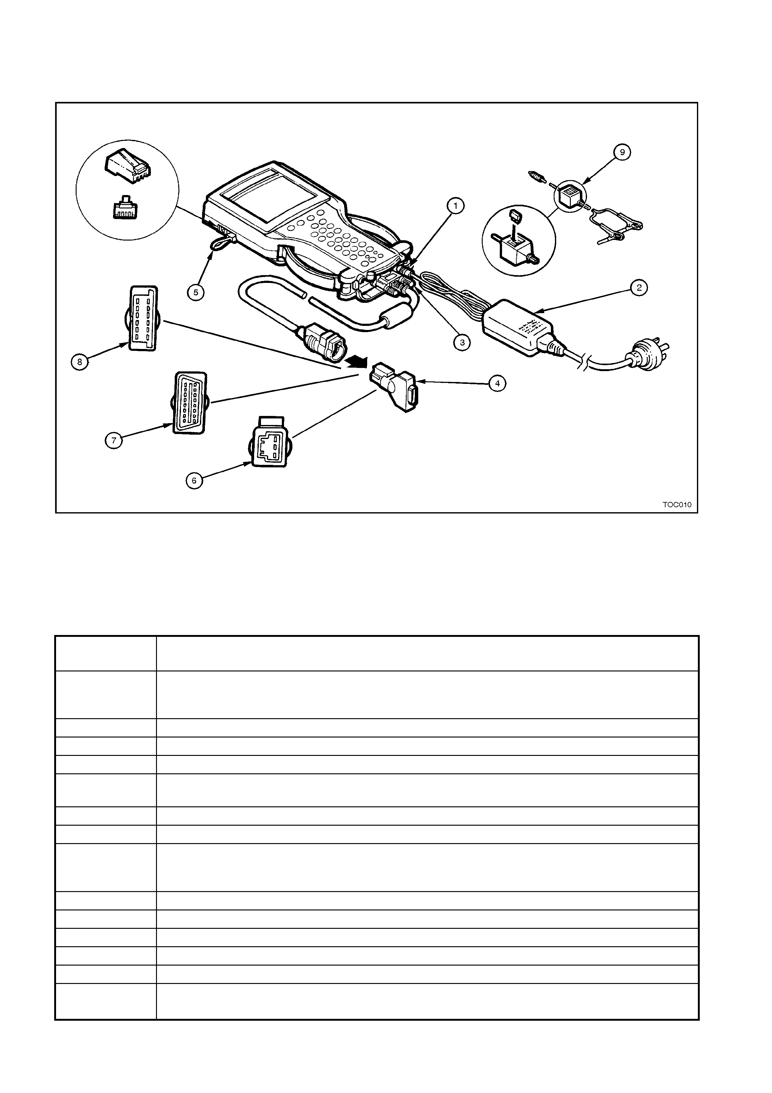
Figure 0C-9 Adapters for TECH 2
Legend:
1. Power Jack 4. DLC Loopback Connector 7. SAE 16/19 Pin Adapter
2. Power Supply 5. RS-232 Loopback Connector 8. NAO 12/19 Pin Adapter
3. DLC Cable 6. Opel/Isuzu/Geo 3/19 Pin Adapter 9. Battery Power Cable
Product
Number Product Name
3000115 Universal 100 - 240 Volt AC power supply with 3000114 wall socket cable. This adapter
should only be used for powering the TECH 2 while away from the vehicle such as while
connected to a TIS.
3000095 DLC Cable.
3000096 Cigarette Lighter Power Cable - Supplies 12V power to the TECH 2.
3000097 Battery Power Cable - Supplies 12V power to the TECH 2.
3000098 SAE 16/19 Pin Adapter - Connects the TECH 2 to some 1995 vehicles, and most 1996
and newer vehicles.
3000099 NAO 12/19 Adapter - Allows the TECH 2 to connect on vehicles built prior to 1996.
3000102 Opel/Isuzu/Geo 3/19 Adapter.
3000109 DLC Loopback Connector - Used to diagnose the DLC capability of the TECH 2. It can
either be connected to the end of the DLC cable or to the DLC cable connection point on
the tool.
3000110 RS-232 Cable.
3000111 RS-232 DB9 Adapter.
3000112 RS-232 Loopback Connector - Used to diagnose the RS-232 function of the TECH 2.
3000116 Storage Case.
3000117 10 Megabyte PCMCIA Card
3000118
J-45080 32 Megabyte PCMCIA Card
1.2 CONNECTIONS
To use the TECH 2 (4), proper connections will need
to be made. T hese connections include power and the
DLC (1). Power for the TECH 2 normally comes from
the DLC. If no power is available at the DLC, or if using
the TECH 2 away from the vehicle, another source of
power should be used. On-vehicle power connection
may also come from the cigarette lighter adapter or
from the battery clip adapter. When using one of the
adapters (2), connect to the jack at the back of the
DLC cable (3) connection. The 12V adapters have
fuses in them to help protect the TECH 2 wiring.
The TECH 2 AC power adapter should NOT be used
while the TECH 2 is connected to a vehicle as data
errors may occur. Instead, the AC power adapter is
designed to be used while away from vehicle. The
TECH 2 will work between 8-20 volts and about 0.75
amps.
The TECH 2 will also at times be required to be
connected to a Personal Computer (PC) to
communicate with the Technical Information System
(TIS). This connection is made via the RS-232
communication port. A hardware key is required when
the Service Programming System (SPS) is being
utilised.
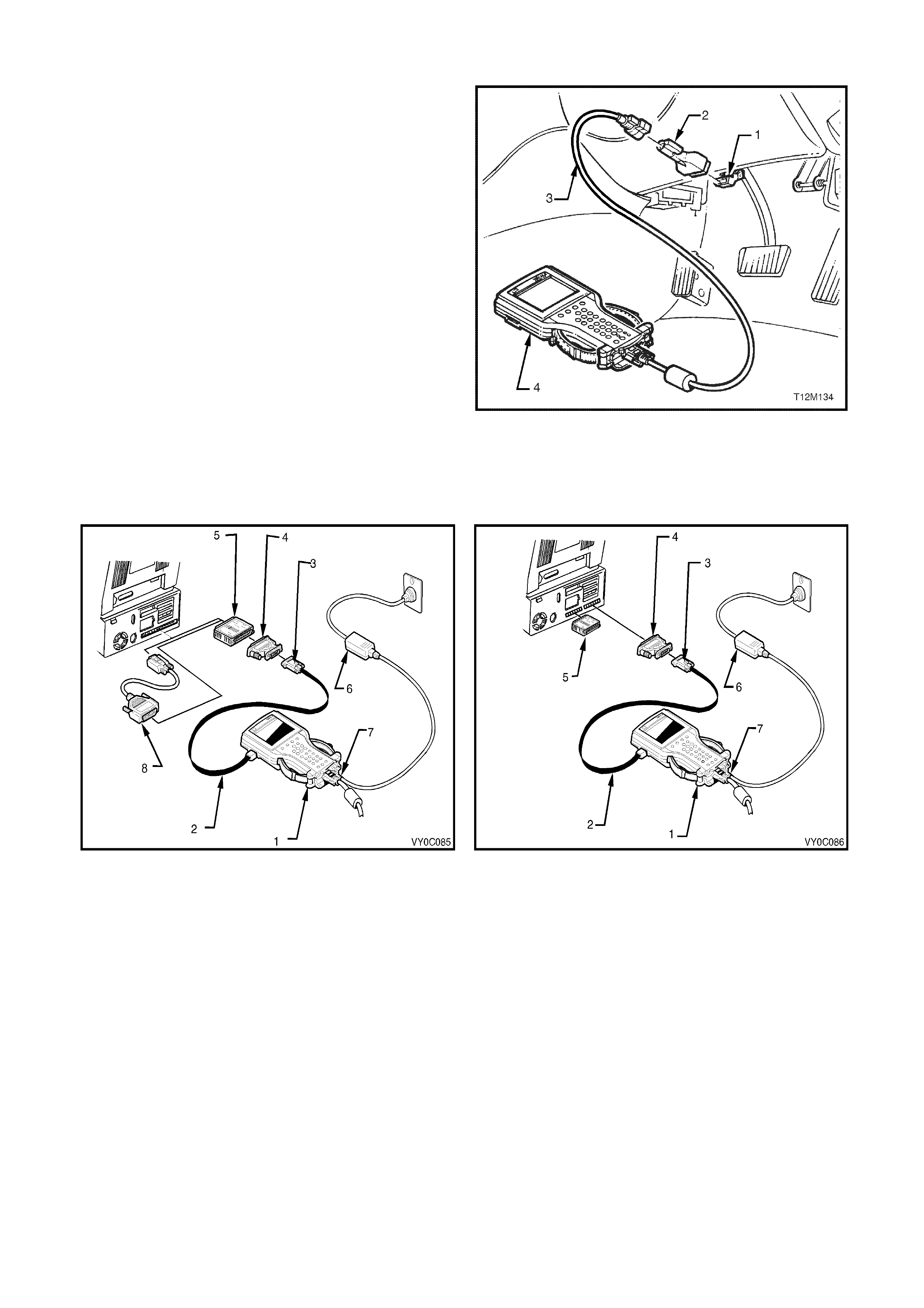
Figure 0C-10 Connecting TECH 2 to the DLC
Figure 0C-11 Connecting TECH 2 to TIS 2000
Figure 0C-12 Connecting TECH 2 to NAO TIS 2000
Legend:
1. Tech 2 5. Hardware Key
2. RS 232 Cable 6. Power Supply
3. DB9 Adapter 7. Power Jack Connector
4. 25/9 Pin Adapter 8. 9/25 Pin Adapter
2. PROGRAMM ING TECH 2
2.1 GENERAL INFORMATION
Before TECH 2 can be used on a vehicle it will
have to be programmed with the latest software.
TECH 2 programming is used to update TECH 2.
TIS 2000 contains the current T ECH 2 applications
(program ) and one preceding version. TECH 2 can
be programmed using the following procedure.
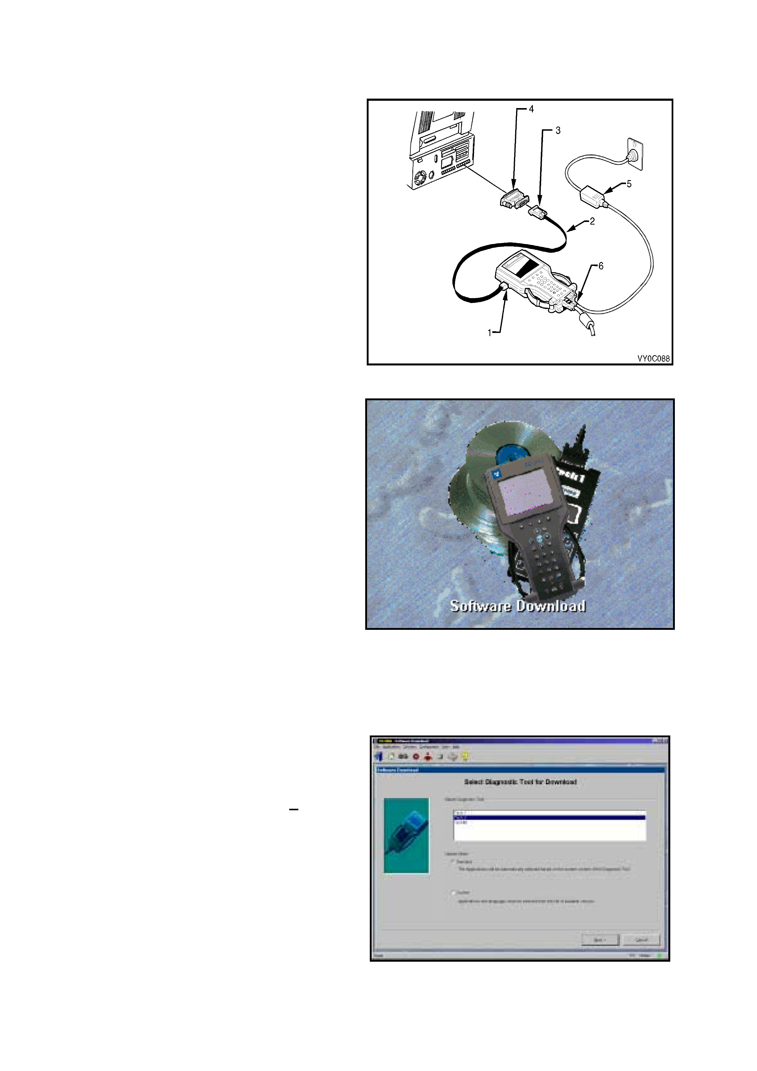
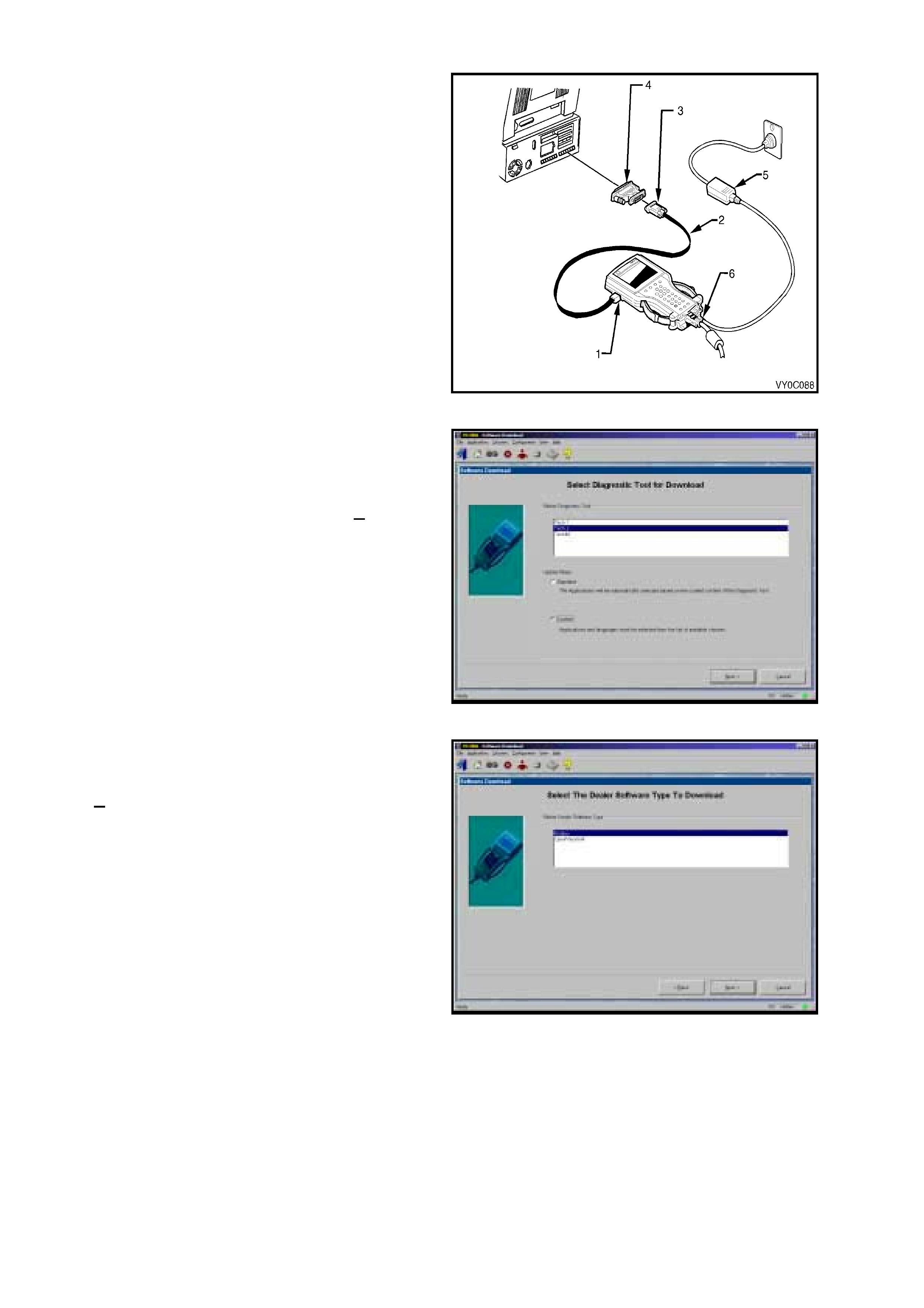
1. Connect the RS-232 cable (2) to the TECH 2
RS-232 communication port (1).
2. Connect the other end of the RS-232 cable (2)
to the DB-9 adapter (3) and then connect the
DB-9 adapter to the serial communication port
of your computer.
NOTE: If your computer has a 25 pin serial
com munication port you will need to fit the 25/9 pin
adapter (4) between the nine pin DB-9 adapter (3)
and the computers serial communication port.
3. Connect the AC power supply (5) to the TECH
2 power jack (6).
4. Press the PWR button to turn on TECH 2.
Figure 0C-13 Connecting TECH 2 to the PC
5. From the TIS 2000 Main Menu, click on the
Software Download icon.
There are two download modes: Standard and
Custom.
Standard installs the latest software version of
the currently programmed language and make
onto the TECH 2.
Custom allows you to perform backdating,
install different make software or alternate
languages onto the TECH 2.
STANDARD UPDATE
The procedure for performing a standard TECH 2
update using the TIS 2000 Software Download is
as follows:
1. Connect the TECH 2 to the PC using the RS-
232 cable, DB-9 adapter and the 25/9 pin
adapter if required.
2. Power up the TECH 2 using the AC power
supply that comes standard with the TECH 2 kit.
TECH 2 must be at the Title Screen.
Figure 0C-14 Software Download Icon
3. At the TIS 2000 Select Diagnostic Tool for
Download screen highlight your selection
(TECH 2) and select the Standard update
mode.
After making your selections, click Next>. A
message will appear indicating the PC is
reading the contents of the diagnostic tool.
Figure 0C-15 Select Diagnostic Tool for Download
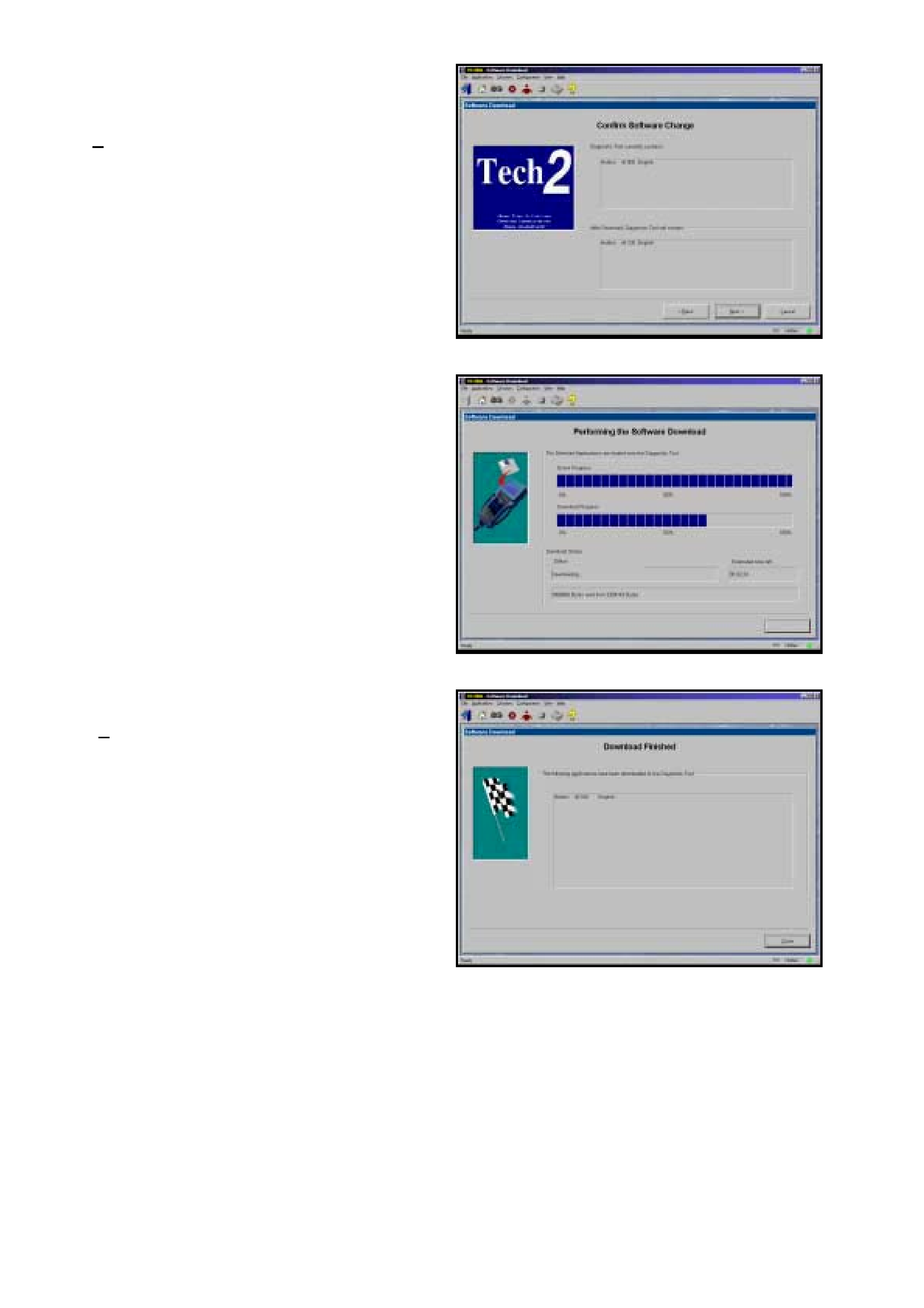
4. The PC will display a Conf irm Software Change
screen showing what software version the
TECH 2 currently contains and what it will
contain after the software download. Click
Next> to continue.
Figure 0C-16 Confirm Software Changes
5. A Performing the Software Download screen
will appear. It tracks the status of the software
download.
Figure 0C-17 Software Download
6. When the software download is complete, a
Download Finished screen appears. Click on
Close to close the application. The scan tool
now contains the latest software.
Figure 0C-18 Download Finished
CUSTOM UPDATE
A custom update is used to backdate the TECH 2,
install Non-Holden software or install different
language software. After selecting Custom as the
update mode from the selection screen, do the
following:
1. Connect the TECH 2 to the PC using the RS-
232 cable (2), DB-9 adapter (3) and the 25/9
pin adapter (4) if required.
2. Power up the TECH 2 using the AC power
supply (5) that comes standard with the TECH
2 kit.
TECH 2 must be at the Title Screen.
Figure 0C-19 Connecting TECH 2 to the PC
3. At the TIS 2000 Select Diagnostic Tool for
Download screen highlight your selection
(TECH 2) and select the Custom update
mode.
After making your selections, click Next>. A
message will appear indicating the PC is
reading the contents of the diagnostic tool.
Figure 0C-20 Select Diagnostic Tool for Download
4. The Select The Dealer Software Type to
Download screen will then be displayed.
Select the desired software type and the click
Next> to continue.
Figure 0C-21 Select The Dealer Software Type to Download
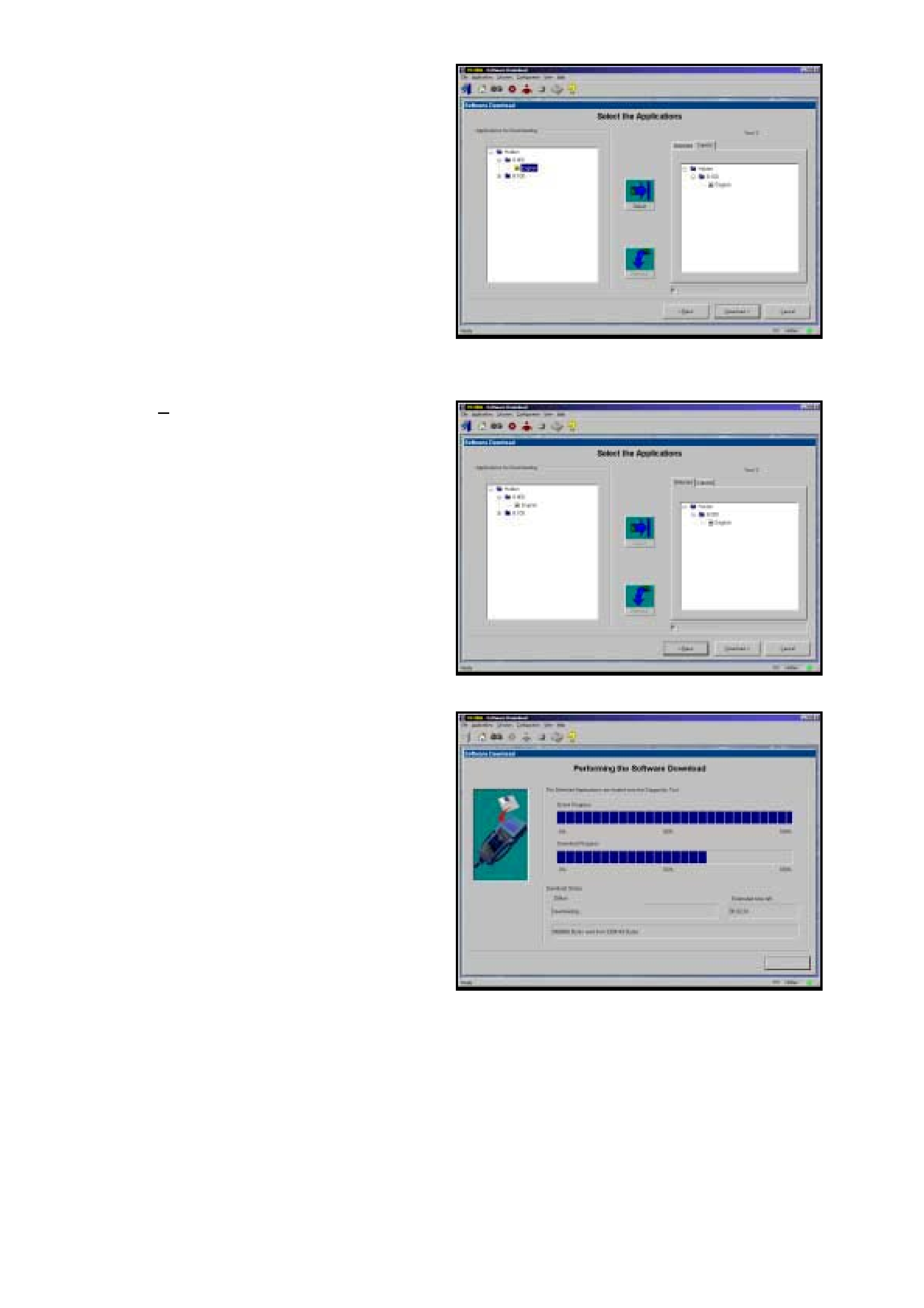
5. A Select the Applications screen will appear.
The left side of the screen lists software
release numbers . Click on the “+” sign to see a
list of different languages for each release.
6. Select the desired software version and
language by either double-clicking or clicking
the Select icon. The selected software will
appear in the right side of the screen.
To compare the current and selected TECH 2
software, click on the Current or Selected
tabs on the right side of the screen.
Figure 0C-22 Select The Application
7. Click on Download> to begin the update.
Figure 0C-23 Selected Software
8. A Perf orming t he Soft ware Dow nload screen
will appear. It tracks the status of the software
download.
Figure 0C-24 Software Download

9. When the software download is complete, a
Download Finished screen appears. Click on
Close to close the application. The TECH 2
now contains the selected software.
Figure 0C-25 Download Finished
3. USING TECH 2 ON THE VEHICLE
3.1 CONNECTING THE TECH 2 TO THE VEHICLE
Note: T he f o llowing T IS 2000 and TECH 2 scr een dis plays may very with different applications and ver s ions of TIS
2000 and TECH 2 software.
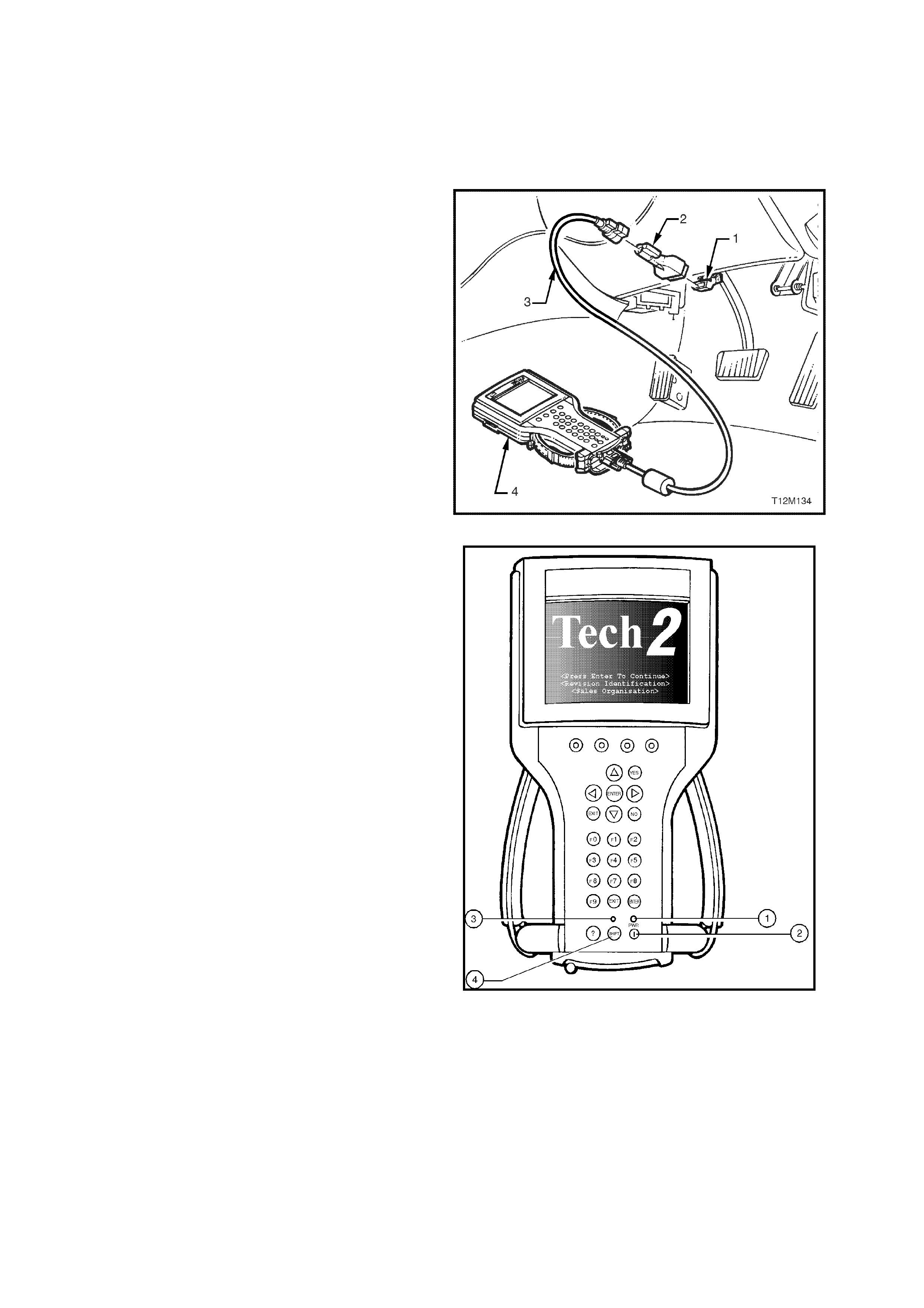
1. Connect TECH 2 (4) to the vehicle DLC (1),
with the DLC cable (3) and the 16/19 pin
adapter (2).
Figure 0C-26 Connecting the TECH 2 to the Vehicle
2. Switch the unit on by pressing the power button
(2). A green light ( 1) should c ome on indicating
that the tool is receiving power.
NOTE: At this time the technician should see the
Power On Self Test (POST) run. The POST is a
built in diagnostic self test for the TECH 2 that
should find most common system faults. The
POST is run on every power up to ensure the best
operation of the tool. After the completion of the
POST, the TECH 2 unit will briefly show the POST
results. If POST passes, the tool will continue onto
the title scr een. If POST f ails, r esults of all test s will
be displayed, and this should show which test
failed. POST failures may be classified as fatal or
non-fatal. A fatal error will not allow the user to
continue using the tool. Failur e of the keypad would
be an example of a fatal error. Non-fatal errors
found during the POST will allow continued use of
the TECH 2, but with some limitations. If either a
fatal or non-fatal error occurs, refer to the
Troubleshooting section of the TECH 2 User's
Guide.
Legend:
1. Power Status Indicator Li ght
2. PWR (Power) Key
3. SHIFT Key St atus Indicator Light
4. SHIFT Key
3. At the TECH 2 title screen press the ENTER
key to continue.
Figure 0C-27 TECH 2 PWR and SHIFT Keys
4. A selection can be made from the Main Menu,
either by using a function key or by using the
arrow keys to highlight a menu choice and
pressing ENTER.
NOTE: You will then need to supply some
additional inform ation to the TECH 2. This requires
navigation through a series of lists (called picklis ts).
On some menus or picklists, the user can use a
function k ey to make a m enu selec tion, but m ost of
the picklists require using the selection and action
keys. If a m istak e is m ade in the selection process,
or if a different application or function is desired,
press EXIT to back up one level. Within an
application, there may be soft keys which are
available for use. These soft keys allow access to
additional tool functions without exiting a current
tool function. Soft keys are made up of sets which
will appear together. To see the next set of soft
keys, select the More soft key.
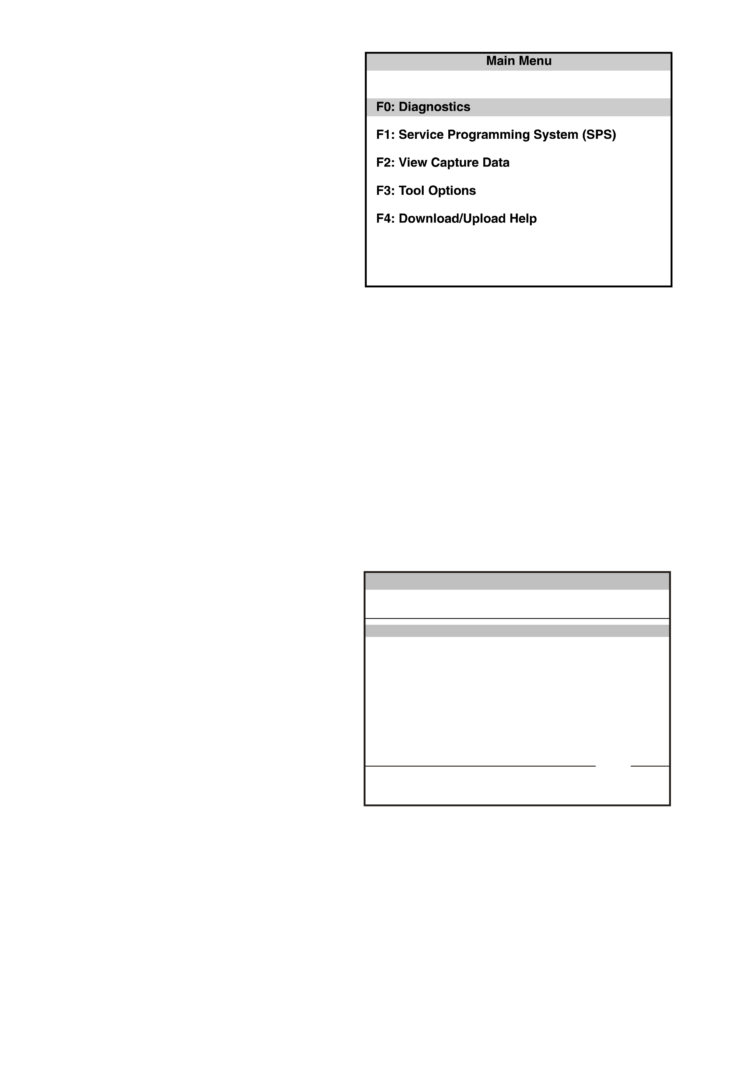
The TECH 2 Main Menu contains the following:
F0: Diagnostics
Contains all func tions to test, diagnos e, m onitor
and program the different vehicle systems.
Figure 0C-28 TECH 2 Main Menu
F1: Service Programming System (SPS)
SPS is used in conjunction with Technical Information System (TIS) 2000 to program vehicle control units.
F2: View Capture Data
Contains all functions to work with one or two previously recorded snapshots on one or two vehicles. This
function is to enable the viewing of captured data without a vehicle.
F3: Tool Options
Contains the TECH 2 self test, set clock, set units, set screen contrast and Getting Started.
F4: Download/Upload Help
Contains help information on the downloading and uploading from the TECH 2 to the TIS 2000.
5. Select the correct Model Year, 2003 with the
arrow keys and the press ENTER. The Main
Menu Vehicle Identification screen will then be
displayed.
V ehicle Identification
Se lec t on e of the fo llowing
Model Year(s)
(3)
(2)
(1)
(Y)
(X)
(W)
(V)
2003
2002
2001
2000
1999
1998
1997
(3) 20 0 3
VY0C035
1 / 7
Figure 0C-29 TECH 2 Vehicle Identification Menu

6. Select the correct Vehicle Type, VY
Commodore with the arrow keys and the press
ENTER. The System Select Menu will then be
displayed.
Main Menu
Se lec t on e of the fo llowing
V ehicle Type(s)
VY0C005
VY Commodore
V2 M onaro
YG Cruze
Corsa-C
Astra-G
Zafira
VU Utility
WH Statesman & Caprice
Corsa-C Combo
VY Commmodore 1 / 12
Figure 0C-30 TECH 2 Vehicle Identification
7. The desired system can be selected from the
System Select Menu with the function keys or
with arrow keys and then press ENTER.
F0: Engine
Contains all functions to test, diagnose, and
monitor the engine systems that communicate
with the TECH 2 via the Powertrain Control
Module (PCM).
F1: Transmission
Contains all func tions to test , diagnose, monitor
and program the transmission systems that
communicate with the TECH 2 via the
Powertrain Control Module (PCM).
F2: Chassis
Contains all f unc tions to test, diagnose, m onitor
and program the vehicles chassis systems;
ABS and Electronic Traction Control modules.
F3: Body
Contains all f unc tions to test, diagnose, m onitor
and program the vehicles body systems; Body
Control Module, Powertrain Interface Module,
Occupant Climate Control, Instruments,
Supplemental Restraint System, Audio System
and Telematics.
F4: Vehicle DTC Check
T his func tion allow you to check all m odules on
the the UART serial data circuit for Diagnostic
Trouble Codes (DTC). There is also a function
to clear all DTCs.
Note: This function does not display or
clear V8 GEN III PCM DTCs.
VY0C013
System Select Menu
(3) 2003 VY Com modore
F0: E n gine
F1: Transmission
F2: Chassis
F3: Body
F4: V ehicle DTC Check
Figure 0C-31 TECH 2 System Select Menu

3.2 ENGINE APPLICATION MENU
1. Select the correct engine from the Vehicle
Identification menu with the arrow keys, then
press ENTER.
V ehicle Identification
Se lec t on e of the fo llowing
Engine
V6
V8 GEN III
V6
VY0C014
1 / 2
Figure 0C-32 Vehicle Identification Menu
2. Turn on the ignition and press the Confirm soft
key.
3. The Engine identification screen will then
display the PCM identification information,
which will vary depending upon engine type
and soft ware level. Press the Confirm soft key,
the engine application menu will then be
displayed.
Confirm
Engine
(3) 2003 VY Comm odore
V6
Turn On Ignition!
VY0C001
Figure 0C-33 Turn Ignition ON
NOTE: If TECH 2 is able to communicate with
the PCM the Engine identification information
will be displayed. If TECH 2 is unable to
communicate with the PCM, TECH 2 will display
“Waiting for Data” if a V8 GEN III was selected
or “No Communication With Vehicle” if V6 was
been selected.
The following functions can be selected from the
engine application menu:
F0: Normal Mode
F1: Diagnostic Trouble Codes
F2: Data Display
F3: Snapshot
F4: Miscellaneous Tests
F5: Function Tests
F7: Stall Data
NOTE: Functions may vary depending on the
application selected. For further information refer
to:
Section 6C1 POWERTRAIN MANAGEMENT
V6 ENGINE
Section 6C2 POWERTRAIN MANAGEMENT
V6 SUPERCHARGED ENGINE
Section 6C3 POWERTRAIN MANAGEMENT
GEN III V8 ENGINE.
Engine
(3) 2003 VY Comm odore
En gine : V6
Part Number
Identifier 92104263
131
Part Number
VY0C016
Confirm
Figure 0C-34 Typical V6 Engine Identification

V6 ENGINE TECH 2 FUNCTIONS
F0: NORMAL MODE
In this test m ode, T ECH 2 will display various engine and transm ission data par ameters that are being transm itted
to other control modules via the serial data normal mode message.
F1: DIAGNOSTIC TROUBLE CODES
In this test mode, DTCs stored by the PCM can be displayed or cleared. When F1: Diagnostic Trouble Codes is
selected there are an additional four modes:
F0: Read Current DTC: All current DTC(s) will be displayed.
F1: Read History DTC The PCM is capable of storing history data for four DTC’s.
F2: Clear Current DTC: Clears all current DTC(s) in the PCM memory.
F3: Clear History DTC: Clears all History DTC(s) and History data, also clears all current DTCs and Stall Data.
F2: DATA DISPLAY
This mode displays data parameters for the engine being diagnosed. When entering this mode, there are three
modes;
F0: All Data: In this test mode, the TECH 2 continuously monitors and displays all engine data parameters.
F1: Inputs: In this test mode, the TECH 2 continuously monitors and displays all engine input data parameters.
F1: Outputs: In this test mode, the TECH 2 continuously monitors and displays all engine output data parameters.
F3: Snapshot
In this test mode, the TECH 2 scan tool captures data before and after a selected snapshot triggering condition
which may or may not set a DTC.
F4: MISCELLANEOUS TESTS
In this test mode, the TECH 2 performs software override commands of the PCM, to assist in problem isolation
during diagnostics.
F0: Output Tests
F0: Fuel Pump: Fuel Pump Relay can be commanded on and off.
F1: A/C Clutch: A/C Compressor Clutch can be commanded on and off.
F2: Check Powertrain Lamp: Check Powertrain Lamp can be commanded on and off.
F3: High Fan: High Speed Cooling Fan operation can be commanded on and off.
F4: Canist er Purge: Canister Purge can be commanded on (99%) and off (0%).
F5: Starter Relay: Starter Relay can be commanded on and off. When the relay is commanded OFF the
engine will not crank when the ignition is turned to the start position. When the relay is commanded ON the
engine should crank when the ignition is turned to the start position.
F1: IAC System
F0: RPM Control: Used to c omm and the desired engine s peed in 25 RPM increm ents from 600 RPM to 1675
RPM.
F1: IAC Control: Used to control IAC steps from 0 to 220 in 25 step increments.
F2: IAC Reset: Used to reset IAC if the PCM’s IAC position is lost or if IAC has been replaced.
F3: Base Idle: This test mode puts the engine management system into a defined state of operation so as to
allow the technician to m onitor and adjust the base idle RPM setting. Fir st the IAC valve is r eset, then the IAC
steps are set to zero, then the bypass spark mode is commanded.
F2: EGR Control:
Used to control the EGR valve for 0% to 100% in steps of 25%.
F3: Reset Cells
Resets all Long Term Fuel Trim values to 0%
F4: Bypass Spark
Used to command either Bypass or EST modes.
F5: Air Fuel Ratio
Used to command the air fuel ratio from 11.7:1 to 17.7:1.
F6: LPG FCV Test
Used to command the LPG FCV from 0% to 100% in steps of 10%.

F7: LPG Enable Test
Used to enable the LPG operating m ode. W hen c omm anded ON the PCM will s witch to the LPG mode. When
commanded OFF, the PCM will switch to the Petrol operating mode, refer following note.
NOTE: The PCM will only toggle between the Petrol and LPG mode if the ignition is on and the engine is not
running or if the engine speed is greater that 1200 RPM.
F5: FUNCTION TESTS
In this test m ode, TECH 2 perf orms var ious automated tests to assist in problem isolation during trouble shooting.
To operate any of the Function Tests, simply select the appropriate test mode from the Function Test application
menu and f ollow the TECH 2 sc reen ins tr uc tions. When the F unc tion T es ts option is selec ted, the f ollowing options
will become available.
F0: IAC Circuit: T his f unction autom atic ally cycles the IAC valve in and out a c alibrated num ber of steps and cycle
times, and compares the initial IAC valve steps to the end IAC valve steps to determine if the IAC valve is
controlling RPM properly and not losing steps.
Preconditions: Coolant temperature greater than 80°C, vehicle speed zero km/h, engine running at idle, air
conditioning turned off and engine cooling fans turned on.
F1: O2 Sensor: This f unc tion allows you to command either a ric h or lean mixt ure, while monitoring the O2 Sens or
voltages to determine if they are operating correctly.
Preconditions: Vehicle speed less than two km/h, engine running at idle, air conditioning turned off.
F2: Power Balance: This function automatically turns off each injector sequentially for five seconds, while the
engine RPM is monitored. At the end of the test the minimum RPM for each cylinder is displayed.
Preconditions: Vehic le speed less than two km /h, engine running at idle, air conditioning turned of f and the engine
cooling fans are turned on.
F3: Wirin g Harness: During this function test TECH 2 monitors the following inputs: RPM, ECT, MAF, TPS,
Battery Voltage, Injector Voltage and VSS. If a c hange occurs in these c ircuits greater than the lim its listed below,
the TECH 2 logs the failure and prompts the technician to check the appropriate circuit.
Parameter RPM ECT IAT MAF TPS Bat. V Inj. V VSS
Tolerance 100 RPM 0.5 V 0.5 V 300 Hz 0.5 V 2 V 2 V 2 km/h
Preconditions: Engine running, vehicle speed less than two km/h.
F4: Low Fan: This function automatically sends out a Low Fan request to the BCM. The PCM Low Fan request
and the BCM response are displayed during the Test.
Preconditions: None, the test will time out after five seconds
F5: LPG Set Up: This function is used to set up the LPG system. During this test the PCM will command a fixed
spark and idle speed and a FCV duty cycle of 40%. This will then enable you to adjust the idle mixture while
monitoring the O2 sensor voltage.
Preconditions: Vehic le speed less than two km /h, engine running at idle, air conditioning turned of f and the engine
cooling fans are turned on.
F6: STALL DATA
If an engine stall has occu rred the PCM will capture eleven data par am eters. T hese data param eters are display in
this mode. The PCM will store the first stall parameters, and then count the numbers of stalls after the first.
SERVICE PROGRAMMING SYSTEM
The VY V6 non supercharged engine us es a PCM that does not c ontain a rem ovable PROM, it us es an EEPROM
(Flash Mem ory) which is non rem ovable. The PCM is program med f rom the factor y with the proper calibrations for
vehicle operation. In the event that the PCM is r eplaced, or an updated calibration is required to c orrect a vehicle's
operating condition, a new calibration will have to be down loaded to the PCM EEPROM (Flash Memory). Down
loading is accomplished through the vehicle DLC using the TECH 2 Service Programming System (SPS) and the
Technical Information System (TIS) 2000. For further SPS information refer to 5. SERVICE PROGRAMMING
SYSTEM in this Section.
BCM LINK TO PCM
If the PCM and/or BCM have been r eplaced, the m odules m us t be secur ity link ed to eac h other. If the procedur e is
not performed, the vehicle will not crank or run.
• For additional information regarding TECH 2 and this linking procedure, refer to
3.5 BODY APPLICATION MENU – BODY CONTROL MODULE in this Section.

SUPERCHARGED V6 ENGINE TECH 2 FUNCTIONS
F0: NORMAL MODE
In this test m ode, T ECH 2 will display various engine and transm ission data par ameters that are being transm itted
to other control modules via the normal mode message via the on the serial data circuit.
F1: DIAGNOSTIC TROUBLE CODES
In this test mode, DTCs stored by the PCM can be displayed or cleared. When F1: Diagnostic Trouble Codes is
selected there are an additional four modes:
F0: Read Current DTC: All current DTC(s) will be displayed.
F1: Read History DTC: The PCM is capable of storing history data for four DTC’s.
F2: Clear Current DTC: Clears all current DTC(s) in the PCM memory.
F3: Clear History DTC: Clears all History DTCs and History data, also clears all current DTCs and Stall Data.
F2: DATA DISPLAY
This mode displays data parameters for the engine being diagnosed. When entering this mode, there are three
modes;
F0: All Data: In this test mode, the TECH 2 continuously monitors and displays all engine data parameters.
F1: Inputs: In this test mode, the TECH 2 continuously monitors and displays all engine input data parameters.
F1: Outputs: In this test mode, the TECH 2 continuously monitors and displays all engine output data parameters.
F3: SNAPSHOT
In this test mode, the TECH 2 scan tool captures data before and after a selected snapshot triggering condition
which may or may not set a DTC.
F4: MISCELLANEOUS TESTS
In this test mode, the TECH 2 performs software override commands of the PCM, to assist in problem isolation
during diagnostics.
F0: Output Tests
F0: Fuel Pump: The fuel pump tes t allows the user to tur n on and of f the f uel pump relay using the TECH 2 on
and off soft keys. If turned off while the engine is running, the engine will stall.
Preconditions: Vehicle speed must be less than two km/h.
F1: Fuel Pump Speed: (Supercharged Engine Only): This test allows the user to toggle between either low
speed or high speed fuel pump operation using the HIGH SPEED and LOW SPEED soft keys.
F2: A/C Clutch: In this tes t mode the user c an c ommand the PCM to turn the air c onditioning c lutch on and of f
using the TECH 2 on and off soft keys.
F3: Ch eck Powertrain L amp: In this test m ode, the user can com m and the PCM to tur n the check powertrain
lamp on and off using the TECH 2 on and off soft keys.
F4: High Fan: In this mode, the user can command the PCM to turn the engine cooling fan high speed relay
on or off for 15 seconds using the TECH 2 ON and OFF soft keys.
F5: Canister Purge: In this test mode, the user can command the PCM to turn the canister purge solenoid
valve on and off using the TECH 2 on and off soft key s.
F6: Starter Relay: In this m ode, the user can com mand the PCM to turn the starter relay on and off using the
TECH 2 on and of f s of t keys. If the starter r elay is turned off the engine s hould not be able to be cr anked. If the
relay is turned on the engine should be able to be cranked.
F1: IAC SYSTEM
F0: RPM Control: This test mode allows the user to increase or decrease the desired RPM in steps of 25
RPM with the dec rease and inc rease s oft k eys, with a minim um of 600 RPM to a m ax imum of 1675 RPM. T he
start value will be at 1150 RPM.
Preconditions: Engine running, vehicle speed less than two km/h.
F1: IAC Control: This test mode allows the user to increase or decrease the IAC valve in increments of 25
steps with the TECH 2 decrease and increase soft keys. With a minimum of 0 steps and a maximum of 250
steps. The start value will be the idle steps.
Preconditions: Engine running, vehicle speed less than two km/h.
F2: IAC Reset: This test m ode allows the user to perf orm an IAC valve r eset. Each press of the reset soft key
will actuate the TECH 2 command to reset the IAC valve.
Preconditions: Vehicle speed less than two km/h.
F3: Base Idle: This test mode puts the engine management system in a defined state of operation so as to
allow the technician to monitor and adjust the base idle engine rpm setting. First the IAC valve is reset, then the
IAC steps are set to zero, then the bypass spark mode is commanded.

The engine cooling fans will be commanded on if the coolant temperature exceeds 100°C. The base idle speed
should not be adjusted while the engine cooling fans are on.
Preconditions: Engine running, vehicle speed less than two km/h.
F2: Reset Cells
This test mode allows the user to command the PCM to perform a Long Term Fuel Trim (LTFT) reset. Each
press of the TECH 2 reset soft key will command an LTFT reset.
F3: Bypass Spark:
This test mode allows the user to com mand bypass s park control or EST with the TECH 2 EST and BYPASS
soft keys.
F4: Air Fuel (A/F) Ratio:
T his test mode allows the user to c ontr ol the A/F r atio f rom 11.7 : 1 to 17.7 : 1. The test s tarts at an A/F r atio of
14.7 : 1. The user will be able to increase or decrease the A/F ratio with the TECH 2 increase and decrease
soft keys.
Preconditions: Engine running, vehicle speed less than two km/h.
F5: Boost Control Solenoid
This test m ode allows the user to control the operation of the boost control solenoid f rom 0 % to 100 %. Each
press of the TECH 2 increase or decrease soft keys will alter the PWM signal by 10 %.
Preconditions: Engine running, vehicle speed less than two km/h.
F5: FUNCTION TESTS
In this test m ode, TECH 2 perf orms var ious automated tests to assist in problem isolation during trouble shooting.
To operate any of the Function Tests, simply select the appropriate test mode from the Function Test application
menu and f ollow the TECH 2 sc reen ins tr uc tions. When the F unc tion T es ts option is selec ted, the f ollowing options
will become available.
F0: IAC CIRCUIT
This function automatically cycles the IAC valve in and out a calibrated number of steps and cycle times, and
com par es the initial IAC valve s teps to the end IAC valve steps to deter mine if the IAC valve is c ontro lling RPM
properly and not losing steps.
Preconditions: Coolant temperature greater than 80°C, vehicle speed zero km/h, engine running at idle, air
conditioning turned off and engine cooling fans turned on.
F1: O2 SENSOR
This function determines if the oxygen sensors are detecting a lean or rich condition. The air/fuel ratio can be
set to 13.0 or 16.0 using the TECH 2 rich and lean s of t keys, the left and right oxygen sensor voltages can then
be monitored to determine if they are responding to the change in air/fuel ratio.
Preconditions: Vehicle speed less than two km/h, engine running at idle, air conditioning turned off and the
oxygen sensors are ready.
F2: POWER BALANCE:
This function automatically turns off each injector sequentially for five seconds, while the engine RPM is
monitored. At the end the test the minimum RPM for each cylinder is displayed.
Preconditions: Vehicle speed less than two km/h, engine running at idle, air conditioning turned off and the
engine cooling fans are turned on.
F3: WIRING HARNESS
During this func tion test T ECH 2 m onitors the following inputs: RPM, ECT, MAF, TPS, Battery Voltage, Injector
Voltage and VSS. If a change occurs in these circuit greater than the lim its listed below, the TECH 2 logs the
failure and prompts the technician to check appropriate circuit.
Parameter RPM ECT IAT MAF TPS Bat. V Inj. V VSS
Tolerance 100 RPM 0.5 V 0.5 V 300 Hz 0.5 V 2 V 2 V 2 km/h
Preconditions: Engine running, vehicle speed less than two km/h.
F4: LOW FAN
In this func tion test the user c an comm and the PCM to send a m ess age to the BCM via the serial date norm al
mode m essage, to turn the low speed fan on or off with the TECH 2 on and off soft keys. This command will
time out after five seconds.
F6: FIELD SERVICE
In this test mode, with the ignition on and the engine not running, the TECH 2 will ground the diagnostic test
terminal. The system will then display all DTCs by causing the check powertrain lamp to flash.

F7: STALL DATA
If an engine stall has occu rred the PCM will capture eleven data par am eters. T hese data param eters are display in
this mode. The PCM will store the first stall parameters, and then count the numbers of stalls after the first.
BCM LINK TO PCM/PIM
If the PCM and/or BCM have been r eplaced, the m odules m us t be secur ity link ed to eac h other. If the procedur e is
not performed, the vehicle will not crank or run.
• For additional information regarding TECH 2 and this linking procedure, refer to
3.5 BODY APPLICATION MENU – BODY CONTROL MODULE in this Section.
V8 GEN III ENGINE TECH 2 FUNCTIONS
F0: DIAGNOSTIC TROUBLE CODES
In this test mode, DTCs stored by the PCM maybe displayed or cleared. When F0: Diagnostic Trouble Codes is
selected there are an additional four modes:
F0: Read DTC Info Ordered By Priority: DTC(s) will be displayed in numerical order.
F1: Clear DTC Information: Clears all DTC(s) in the PCM memory. Also clears Freeze Frame/Failure
Records, so before clearing DTC(s), be sure to retrieve Freeze Frame / Failure Record information.
F2: DTC Information: Shows DTC(s) which are set that match the criteria. Each DTC has it's own page of
information. If multiple DTCs are set, the user must page through the display of codes.
F0: History: This DTC search will display only DTC(s) that are stored in the PCM memory as valid faults.
F1: MIL SVS or Message Requested: This DTC search will display only DTC(s) for which the PCM is
requesting the Check Powertrain Lamp to turn "ON".
F2: Last Test Failed: This DTC search will display only DTC(s) that failed the last time the test ran.
F3: Test Failed Since Code Cleared: This DTC search will display all DTC(s) that have reported a test
failure since the last time DTC(s) were cleared.
F4: Not Ran Since Code Cleared: This DT C searc h will display only DT Cs that have not ran s ince DT Cs
were last cleared. Any displayed DTCs have not run, therefore their condition (passing or failing) is
unknown.
F5: Failed This Ignition: This DTC search will display all DTCs that have failed at least once during the
current ignition cycle.
F3: Freeze Frame / Failure Records: Shows Freeze Frame / Failure Records information. Freeze Frame /
Failure Records are types of snapshots stored in the memory of the PCM and contain 32 data parameters.
F1: DATA DISPLAY
This mode displays data parameters for the controller being diagnosed. W hen entering this mode, there are two
modes;
F0: Engine Data: In this test mode, the TECH 2 continuously monitors and displays system data, such as:
engine speed, engine coolant temperature etc.
F1: Fuel Trim Data: In this test mode, the T ECH 2 scan tool continuously monitor s and displays system data,
such as: engine speed data, engine coolant temperature, heated oxygen sensor, Fuel Trim Cell etc.
F2: SNAPSHOT
In this test m ode, the TECH 2 scan tool captures data before and after a snapshot triggering condition which
may or may not set a DTC.
F3: MISCELLANEOUS TESTS
In this test mode, the TECH 2 scan tool performs software override commands of the PCM, to assist in problem
isolation during diagnostics.
F0: Output Tests
F0: Fuel Pump: Fuel Pump Relay can be commanded on and off.
F1: A/C Clutch: A/C Compressor Clutch can be commanded on and off.
F2: Check Powertrain Lamp: Check Powertrain Lamp can be commanded on and off.
F3: High Fan: High Speed Cooling Fan operation can be commanded on and off.
F4: Canist er Purge: Canister Purge can be commanded on (100%) and off (0%).
F1: IAC System
F0: RPM Control: Used to control engine RPM from 600 RPM to 1675 RPM.
F1: IAC Control: Used to control IAC steps from 0 to 120.
F2: IAC Reset: Used to reset IAC if the IAC is lost or if IAC has been replaced.
F3: Base Idle: Used to set the engine to base idle.
F2: Reset Cells
Resets all Long Term Fuel Trim values to 0%
F3: 02 Loop Sta tus
With the engine running, Open or Closed Loop fuel control can be commanded.

F4: FUNCTION TESTS
In this test m ode, TECH 2 perf orms var ious automated tests to assist in problem isolation during trouble shooting.
To operate any of the Function Tests, simply select the appropriate test mode from the Function Test application
menu and follow the ins tructions as per T ECH 2. When the Func tion Tes ts option is s elected, the f ollowing options
will become available.
F0: IAC Circuit: This function automatically cycles the IAC valve in and out a calibrated number of steps and
cycle times , and com par es the initial IAC valve steps to the end IAC valve steps to determ ine if the IAC valve is
controlling RPM properly and not losing steps.
Preconditions: Coolant temperature greater than 80°C, vehicle speed zero km/h, engine running at idle, air
conditioning turned off and engine cooling fans turned on.
F1: Power Balance: This function automatically turns off each injector sequentially for five seconds, while the
engine RPM is monitored. At the end of the test the minimum RPM for each cylinder is displayed.
Preconditions: Vehicle speed less than two km/h, engine running at idle, air conditioning turned off and the
engine cooling fans are turned on.
F3: Wiring Harness: During this function test TECH 2 monitors the following inputs: RPM, ECT, MAF, TPS,
Battery Voltage, Injector Voltage and VSS. If a change occurs in these circuits greater than the limits listed
below, the TECH 2 logs the failure and prompts the technician to check the appropriate circuit.
Parameter RPM ECT MAF TPS IAT Bat. V Inj. V VSS
Tolerance 100 RPM 0.5 V 300 Hz 0.5 V 0.5 V 2 V 2 V 2 km/h
Preconditions: Engine running, vehicle speed less than two km/h.
F4: Fuel Injector Balance: This function is designed to check the fuel flow through each injector while the
engine is not running. A f uel pressure gauge has to be c onnected to the fuel rail. TECH 2 first turns on the f uel
pump. After pressure is established the fuel pump is turned off again and the injector is turned on for a
predetermined time. Pressure drop has to be read afterwards on the fuel gauge for each injector. This can be
performed only once per injector.
Preconditions: Vehicle speed less than 2 km/h, engine not running.
SERVICE PROGRAMMING SYSTEM
The VY GEN III V8 PCM does not c ontain a removable PRO M, it uses an EEPROM (Flash Memor y) which is non
removable. The PCM is programmed from the factory with the proper calibrations for vehicle operation. In the event
that the PCM is replaced, or an updated calibration is required to correct a vehicle's operating condition, a new
calibration will have to be down loaded to the PCM EEPROM (Flash Memory). Down loading is accomplished
through the vehicle DLC using the TECH 2 Service Programming
System (SPS) and the Technical Information System (TIS) 2000. For further SPS information refer to
5. SERVICE PROGRAMMING SYSTEM in this Section.
BCM LINK TO PCM/PIM
If one or m ore of PCM, PIM or BCM have been replaced, the m odules m ust be security link ed to each other. If the
procedure is not performed, the vehicle will not crank or run.
For additional information regarding TECH 2 and this linking procedure, refer to
3.5 BODY APPLICATION MENU – BODY CONTROL MODULE in this Section.
3.3 TRANSMISSION APPLICATION MENU
1. Select the correct transmission from the
Vehicle Identific ation menu with the arrow k eys,
then press ENTER and follow the screen
instructions.
V ehicle Identification
Se lec t on e of the fo llowing
Transmisssion
Automatic Transmission
GEN III A utom atic Transmission
Automatic Transmission
VY0C031
1 / 2
Figure 0C-35 Vehicle Identification Menu
2. Turn on the ignition and press the Confirm soft
key.
2. The Transmission Identification screen will then
display the Part Number and Identifier. This
information will vary with engine type and
software level. Press the Confirm sof t key, the
transmission application menu will then be
displayed.
Transmission
(3) 2003 VY Comm odore
Transmission
Turn Ignition On!
VY0C017
Confirm
Figure 0C-36 Transmission Identification
NOTE: If TECH 2 is able to communicate with
the PCM the Transmission identification
information will be displayed. If TECH 2 is
unable to communicate with the PCM, TECH 2
will display “Waiting for Data” if a GEN III
Automatic Transmission was selected
or
“No Communication With Vehicle” if Automatic
Transmission was been selected.
The following functions are available in the
transmission application menu:
F0: Normal Mode
F1: Diagnostic Trouble Codes
F2: Data Display
F3: Snapshot
F4: Miscellaneous Tests
F5: Function Tests
NOTE: Functions may vary depending on the
application selected. For further information refer
to:
Section 6C1 POWERTRAIN MANAGEMENT
V6 ENGINE
Section 6C2 POWERTRAIN MANAGEMENT
V6 SUPERCHARGED ENGINE
Section 6C3 POWERTRAIN MANAGEMENT
GEN III V8 ENGINE.
Transmission
(3) 2003 VY Comm odore
Transmission
Part Number
Identifier 09356445
301
Part Number
VY0C018
Confirm
Figure 0C-37 Typical Transmission Identification

V6 TRANSMISSION TECH 2 FUNCTIONS
F0: NORMAL MODE
In this test m ode, T ECH 2 will display various engine and transm ission data par ameters that are being transm itted
to other control modules via the normal mode message via the on the serial data circuit.
F1: DIAGNOSTIC TROUBLE CODES
In this test mode, DTCs stored by the PCM can be displayed or cleared. W hen F0: Diagnostic Trouble Codes an
there are an additional four modes:
F0: Read Current DTC: All current DTC(s) will be displayed.
F1: Read History DTC The PCM is capable of storing history data for four DTC’s.
F2: Clear Current DTC: Clears all current DTC(s) in the PCM memory.
F3: Clear History DTC: Clears all History DTC(s) and History data, also clears all current DTC(s) and Stall
Data.
F2: DATA DISPLAY
This mode displays data parameters for the engine being diagnosed. When entering this mode, there are three
modes;
F0: All Data: In this test mode, the TECH 2 continuously monitors and display s all engine data parameters.
F1: Inputs: In this test mode, the TECH 2 continuously monitors and displays all transmission input data
parameters.
F1: Outputs: In this test mode, the TECH 2 continuously monitors and displays all transmission output data
parameters.
F3: SNAPSHOT
In this test mode, the TECH 2 scan tool captures data before and after a snapshot triggering condition which
may or may not set a DTC.
F4: MISCELLANEOUS TESTS
In this test mode, the TECH 2 performs software override commands of the PCM, to assist in problem isolation
during diagnostics.
F0: Shift Solenoids
1-2 Shift Solenoid A
This test allows the user to turn on and off the 1-2 Shift Solenoid A. T ECH 2 takes control of both solenoids (A
and B), so in this case solenoid B will be turned off.
Preconditions and running conditions: Engine not running.
2-3 Shift Solenoid B
This test allows the user to turn on and off the 2-3 Shift Solenoid B. T ECH 2 takes control of both solenoids (A
and B), so in this case solenoid A will be turned off.
Preconditions and running conditions: Engine not running.
3-2 Downshift Solenoid
This test allows the user to turn on and off the 3-2 Downshift Solenoid.
Preconditions and running conditions: Engine not running.
Gear Control: This function allows the user to incrementally command shift solenoid states to correspond to
relative gear states. Only single shift increments or decrements will be allowed and the test has a lim it of 4200
RPM.
Preconditions and running conditions: Engine running, transmission in Drive.
Pressure Control Solenoid (PCS):
This function allows the user to control state of the pressur e control solenoid in incr ements of 100 m A. The test
will start at a value of 0.5A.
Preconditions and running conditions: Vehicle speed less than 2 km/h
TCC Solenoid
This test allows the user to turn on-off the TCC On-Off Solenoid.
Preconditions and running conditions: Engine not running.
TCC PWM Solenoid
The user will have the ability to control the TCC PWM duty cycle. Although it is possible to command a full
range of solenoid duty cycle, this function will only turn on and off the solenoid; 100% and 0% PWM.
Preconditions and running conditions: Engine not running.
TCC Apply
This test performs an on - off control of the TCC. TECH 2 commands the PCM to apply the TCC.
Preconditions and running conditions: None.

F5: FUNCTION TESTS
In this test m ode, TECH 2 perf orms var ious automated tests to assist in problem isolation during trouble shooting.
To operate any of the Function Tests, simply select the appropriate test mode from the Function Test application
menu and follow the ins tructions as per T ECH 2. When the Func tion Tes ts option is s elected, the f ollowing options
will become available.
Transmission Fluid Pressure (TFP)
The Transmission Fluid Pressure (TFP) function test will prove the different gear shift states. Therefore it is
required to selec t eac h gear manually and the according states of the T F P s witches ar e c hec k ed. The res ult will
be displayed as Test Passed ! or Test Failed !.
Preconditions and running conditions: Vehicle speed less than 2 km/h, engine running at idle.
Wiring Harness
This f unc tion determines if the parameters ( RPM, VSS, TFP A, T F P B, TFP C, Shif t A, Shif t B, PCS, TFT , TCC)
are remaining stable if the wiring harness is wiggled.
Preconditions and running conditions: Vehicle speed less than 2 km/h, engine running at a stable idle.
Limits :
Parameter RPM VSS TFP A TFP B TFP C Shift A Shift B PCS TFT TCC
Tolerance 100 RPM 2 km/h NCOS NCOS NCOS NCOS NCOS 0.5 A 0.5 V NCOS
NCOS = No Change of State
SERVICE PROGRAMMING SYSTEM
The VY V6 PCM does not contain a removable PROM, it uses an EEPROM (Flash Memory) which is non
removable. The PCM is programmed from the factory with the proper calibrations for vehicle operation. In the event
that the PCM is replaced, or an updated calibration is required to correct a vehicle's operating condition, a new
calibration will have to be down loaded to the PCM EEPROM (Flash Memory). Down loading is accomplished
through the vehicle DLC using the TECH 2 Service Programming System (SPS) and the Technical Information
System (TIS) 2000. For further SPS information refer to
5. SERVICE PROGRAMMING SYSTEM in this Section.
BCM LINK TO PCM
If the PCM and/or BCM have been r eplaced, the m odules m us t be secur ity link ed to eac h other. If the procedur e is
not performed, the vehicle will not crank or run.
For additional information regarding TECH 2 and this linking procedure, refer to
3.5 BODY APPLICATION MENU – BODY CONTROL MODULE in this Section.
SUPERCHARGED V6 TRANSMISSION TECH 2 FUNCTIONS
F0: NORMAL MODE
In this test m ode, T ECH 2 will display various engine and transm ission data par ameters that are being transm itted
to other control modules via the normal mode message via the on the serial data circuit.
F1: DIAGNOSTIC TROUBLE CODES
In this test mode, DTCs stored by the PCM can be displayed or cleared. W hen F0: Diagnostic Trouble Codes an
there are an additional four modes:
F0: Read Current DTC: All current DTC(s) will be displayed.
F1: Read History DTC :The PCM is capable of storing history data for four DTC’s, TECH 2 will display this
data whren this mode is selected.
F2: Clear Current DTC: Clears all current DTC(s) in the PCM memory.
F3: Clear History DTC: Clears all History DTC(s) and History data, also clears all current DTC(s) and Stall
Data.
F2: DATA DISPLAY
This mode displays data parameters for the engine being diagnosed. When entering this mode, there are three
modes;
F0: All Data: In this test mode, the TECH 2 continuously monitors and displays all transmission data parameters.
F1: Inputs: In this test mode, the TECH 2 continuously monitors and displays all transmission input data
parameters.
F1: Outputs: In this test mode, the TECH 2 continuously monitors and displays all transmission output data
parameters.
F3: Snapshot
In this test m ode, the TECH 2 scan tool captures data before and af ter a snapshot triggering c ondition whic h may
or may not set a DTC.
F4: MISCELLANEOUS TESTS
In this test mode, the TECH 2 performs software override commands of the PCM, to assist in problem isolation
during diagnostics.

F0: Shift Solenoids
F0: 1-2 Shift Solenoid A
This test allows the user to turn on and of f the 1-2 Shif t Solenoid A. T ECH 2 tak es contr ol of both solenoids (A
and B), so in this case solenoid B will be turned off.
Preconditions: Vehicle speed less than 2 km/h.
F1: 2-3 Shift Solenoid B
This test allows the user to turn on and of f the 2-3 Shif t Solenoid B. T ECH 2 tak es contr ol of both solenoids (A
and B), so in this case solenoid A will be turned off.
Preconditions: Vehicle speed less than 2 km/h.
F2: 3-2 Downshift Solenoid
This test allows the user to turn on and off the 3-2 Downshift Solenoid.
Preconditions: Vehicle speed less than 2 km/h.
F3: Gear Control:
This function allows the user to incrementally command shift solenoid states to correspond to relative gear
states. Only single shift increments or decrements will be allowed and the test has a limit of 4200 RPM.
Preconditions: Engine running, transmission in Drive.
F1: Pressure Control Solenoid (PCS):
This function controls the state of the pressure control solenoid in increments of 100 mA. The test will start at a
value of 0.5A.
Engine running, vehicle speed less than 2 km/h.
F2: Torque Converter Clutch (TCC):
These functions control the state of the TCC Solenoids.
F1: TCC Solenoid
This test allows the user to command the control of the TCC On-Off Solenoid, ON and OFF.
Preconditions: Vehicle speed less than 2 km/h.
F2: TCC PWM Solenoid
The user will have the ability to control the TCC PWM duty cycle. Although it is possible to command a full
range of solenoid duty cycle, this function will only turn on and off the solenoid; 100% and 0% PWM.
Preconditions: Vehicle speed less than 2 km/h.
F3: TCC Apply
This test allows the user to command the PCM to apply the TCC.
Preconditions: None.
F5: FUNCTION TESTS
In this test m ode, TECH 2 perf orms var ious automated tests to assist in problem isolation during trouble shooting.
To operate any of the Function Tests, simply select the appropriate test mode from the Function Test application
menu and follow the ins tructions as per T ECH 2. When the Func tion Tes ts option is s elected, the f ollowing options
will become available.
F0: Transmission Fluid Pressure (TFP)
The Transmission Fluid Pressure (TFP) function test will prove the different gear shift states. Therefore it is
required to select each gear manually and the according states of the TFP switches are checked. The result
will be displayed as Test Passed ! or Test Failed !.
Preconditions: Vehicle speed less than 2 km/h, engine running.
F1: Wiring Harness
This function determines if the parameters (RPM, VSS, TFP A, TFP B, TFP C, Shift A, Shift B, PCS, TFT,
TCC) are remaining stable if the wiring harness is wiggled.
Preconditions: Vehicle speed less than 2 km/h, engine running at a stable idle.
Limits:
Parameter RPM VSS TFP A TFP B TFP C Shift A Shift B PCS TFT TCC
Tolerance 100 RPM 2 km/h NCOS NCOS NCOS NCOS NCOS 0.5 A 0.5 V NCOS
NCOS = No Change of State
BCM LINK TO PCM
If the PCM and/or BCM have been r eplaced, the m odules m us t be secur ity link ed to eac h other. If the procedur e is
not performed, the vehicle will not crank or run. For additional information regarding TECH 2 and this linking
procedure, refer to 3.5 BODY APPLICATION MENU – BODY CONTROL MODULE in this Section.

V8 GEN III TRANSMISSION TECH 2 FUNCTIONS
F0: DIAGNOSTIC TROUBLE CODES
In this test m ode, DTCs stored by the PCM maybe displayed or cleared. W hen F0: Diagnostic Trouble Codes an
there are an additional four modes:
F0: Read DTC Info Ordered By Priority: DTC(s) will be displayed in numerical order.
F1: Clear DTC Information: Clears all DTC(s) in the PCM memory. Also clears Freeze Frame/Failure
Records, so before clearing DTC(s), be sure to retrieve Freeze Frame / Failure Record information.
F2: DTC Information: Shows DTC(s) which are set that match the criteria. Each DTC has it's own page of
information. If multiple DTCs are set, the user must page through the display of codes.
F0: History: This DTC search will display only DTC(s) that are stored in the PCM memory as Valid Faults.
F1: MIL SVS or Message Requested: This DTC search will display only DTC(s) for which the PCM is
requesting the Check Powertrain Lamp to turn "ON".
F2: Last Test Failed: This DTC search will display only DTC(s) that failed the last time the test ran.
F3: Test Failed Sin ce Code Cleared: T his DTC s earch will display all DTC(s ) that have reported a tes t f ailure
since the last time DTCs were cleared.
F4: Not Ran Since Code Cleared: This DTC search will display only DTC(s) that have not ran since DTC(s)
were last cleared. Any displayed DTC(s) have not run, therefore their condition (passing or failing) is
unknown.
F5: Failed This Ignition: This DTC search will display all DTC(s) that have failed at least once during the
current ignition cycle.
F3: Freeze Frame / Failure Records: Shows Freeze Frame / Failure Records information. Freeze Frame /
Failure Records are types of snapshots stored in the memory of the PCM and contain 32 data parameters.
F1: DATA DISPLAY
This mode displays data parameters for the controller being diagnosed. W hen entering this mode, there are two
modes;
F0: T ransmission Dat a: In this test m ode, the TECH 2 continuously monitor s and displays transmis sion data,
such as: engine speed, transmission coolant temperature etc.
F1: 1-2 Adapt Data: In this test mode, the TECH 2 scan tool continuously monitors and displays 1-2 shift adapt
data, such as: Adapt Cell, Adapt Pressure.
F2: 2-3 Adap t Data In this test m ode, the T ECH 2 scan tool c ontinuously m onitor s and displays 2-3 shif t adapt
data, such as: Adapt Cell, Adapt Pressure.
F3: SNAPSHOT
In this test mode, the TECH 2 scan tool captures data before and after a snapshot triggering condition which
may or may not set a DTC.
F4: MISCELLANEOUS TESTS
In this test mode, the TECH 2 performs software override commands of the PCM, to assist in problem isolation
during diagnostics.
F0: Shift Solenoids
F0: 1-2 Shift Solenoid A
T his test allows the user to turn on and off the 1- 2 Shift Solenoid A. TECH 2 takes control of both solenoids
(A and B), so in this case solenoid B will be turned off.
Preconditions: No vehicle speed.
F1: 2-3 Shift Solenoid B
T his test allows the user to turn on and off the 2- 3 Shift Solenoid B. TECH 2 takes control of both solenoids
(A and B), so in this case solenoid A will be turned off.
Preconditions: No vehicle speed.
F2: 3-2 Downshift Solenoid
This test allows the user to turn on and off the 3-2 Downshift Solenoid.
Preconditions: No vehicle speed.
F1: Gear Control
This function allows the user to incrementally command shift solenoid states to correspond to relative gear
states. Only single shift increments or decrements will be allowed and the test has a limit of 4200 RPM.
Preconditions and running conditions: Engine running, transmission in Drive.
Preconditions and running conditions: Engine running and vehicle speed less than 2 km/h

F2: Torque Converter Clutch (TCC)
F0: TCC Solenoid
This test allows the user to command the control of the TCC On-Off Solenoid, ON and OFF.
Preconditions and running conditions: Engine not running.
F1: TCC PWM Solenoid
The user will have the ability to control the TCC PWM duty cyc le. Although it is pos sible to comm and a f ull
range of solenoid duty cycle, this function will only turn on and off the solenoid; 100% and 0% PWM.
Preconditions and running conditions: Engine not running.
F2: TCC Apply
This test allows the user to command the PCM to apply the TCC.
Preconditions: Vehicle speed above 30 kph.
F3: Pressure Control Solenoid (PCS)
T his f unc tion allows the us er to c ontr ol st ate of the pres s ur e contr ol s olenoid in incr ements of 100 m A. The
test will start at a value of 0.5A.
F4: Reset TAP Cells
This test allow the user to reset the Transmission Adapt (TAP) cells by pressing the Reset soft key.
Preconditions: None
F5: FUNCTION TESTS
In this test m ode, TECH 2 perf orms var ious automated tests to assist in problem isolation during trouble s hooting.
To operate any of the Function Tests, simply select the appropriate test mode from the Function Test application
menu and follow the ins tructions as per T ECH 2. When the Func tion Tes ts option is s elected, the f ollowing options
will become available.
Transmission Fluid Pressure (TFP)
The Transmission Fluid Pressure (TFP) function test will prove the different gear shift states. Therefore it is
required to select each gear manually and the according states of the TFP switches are checked. The result
will be displayed as Test Passed ! or Test Failed !.
Preconditions and running conditions: Vehicle speed less than 2 km/h, engine running at idle.
Wiring Harness
This function determines if the parameters (RPM, VSS, TFP A, TFP B, TFP C, Shift A, Shift B, PCS, TFT,
TCC) are remaining stable if the wiring harness is wiggled.
Preconditions and running conditions: Vehicle speed less than 2 km/h, engine running at a stable idle.
Limits :
Parameter RPM VSS TFP A TFP B TFP C Shift A Shift B PCS TFT TCC
Tolerance 100 RPM 2 km/h NCOS NCOS NCOS NCOS NCOS 0.5 A 0.5 V NCOS
NCOS = No Change of State
SERVICE PROGRAMMING SYSTEM
The VY GEN III V8 PCM does not c ontain a removable PROM, it us es an EEPROM (Flash Mem ory) which is non
removable. The PCM is programmed from the factory with the proper calibrations for vehicle operation. In the event
that the PCM is replaced, or an updated calibration is required to correct a vehicle's operating condition, a new
calibration will have to be down loaded to the PCM EEPROM (Flash Memory). Down loading is accomplished
through the vehicle DLC using the TECH 2 Service Programming
System (SPS) and the Technical Information System (TIS) 2000. For further SPS information refer to
5. SERVICE PROGRAMMING SYSTEM in this Section.
BCM LINK TO PCM/PIM
If one or m ore of PCM, PIM or BCM have been replaced, the m odules m ust be security link ed to each other. If the
procedure is not performed, the vehicle will not crank or run.
For additional information regarding TECH 2 and this linking procedure, refer to
3.5 BODY APPLICATION MENU – BODY CONTROL MODULE in this Section.
3.4 CHASSIS APPLICATION MENU
1. Select ABS/ETC from the Vehicle
Identification menu with the arrow keys, then
press ENTER and f ollow the instr uc tions on the
screen.
V ehicle Identification
Se lec t on e of the fo llowing
Chassis
ABS/ETC
ABS/ETC
VY0C033
1 / 1
Figure 0C-38 Vehicle Identification Menu
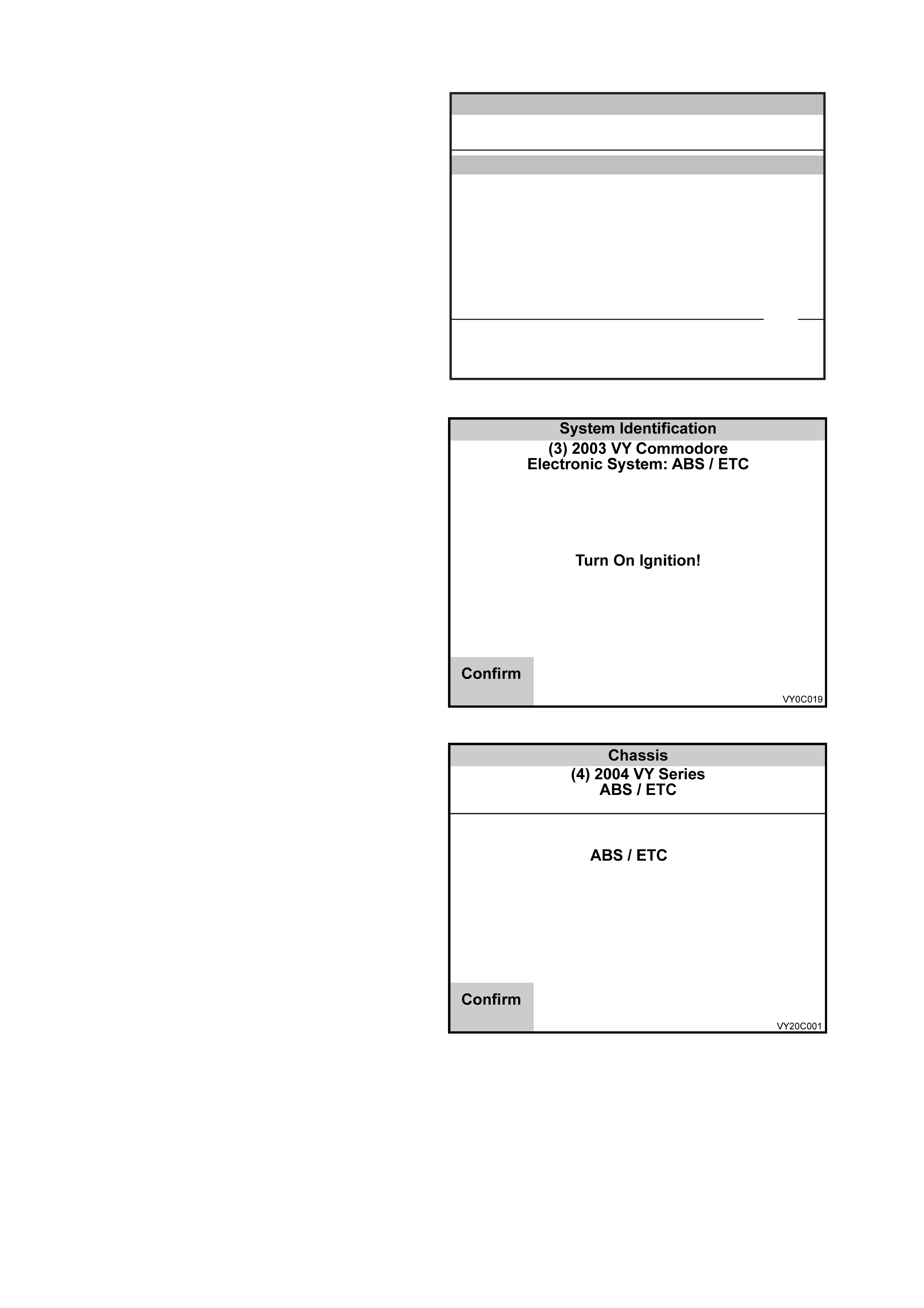
2. Turn on the ignition and press the Confirm soft
key.
3. TECH 2 will then determine the type of system
fitted that is to the vehicle, either rear wheel
drive ABS/ET C or All W heel Drive (AW D) ABS
– TC and display one of the following screens.
Figure 0C-39 System Identification
4. If TECH 2 detects a rear wheel drive ABS/ETC
system, the screen opposite will be displayed.
5. Press the Confirm Soft key to continue and
refer to ABS/ETC T ECH 2 FUNCTIONS in this
Section.
Figure 0C-40 ABS/ETC Identification

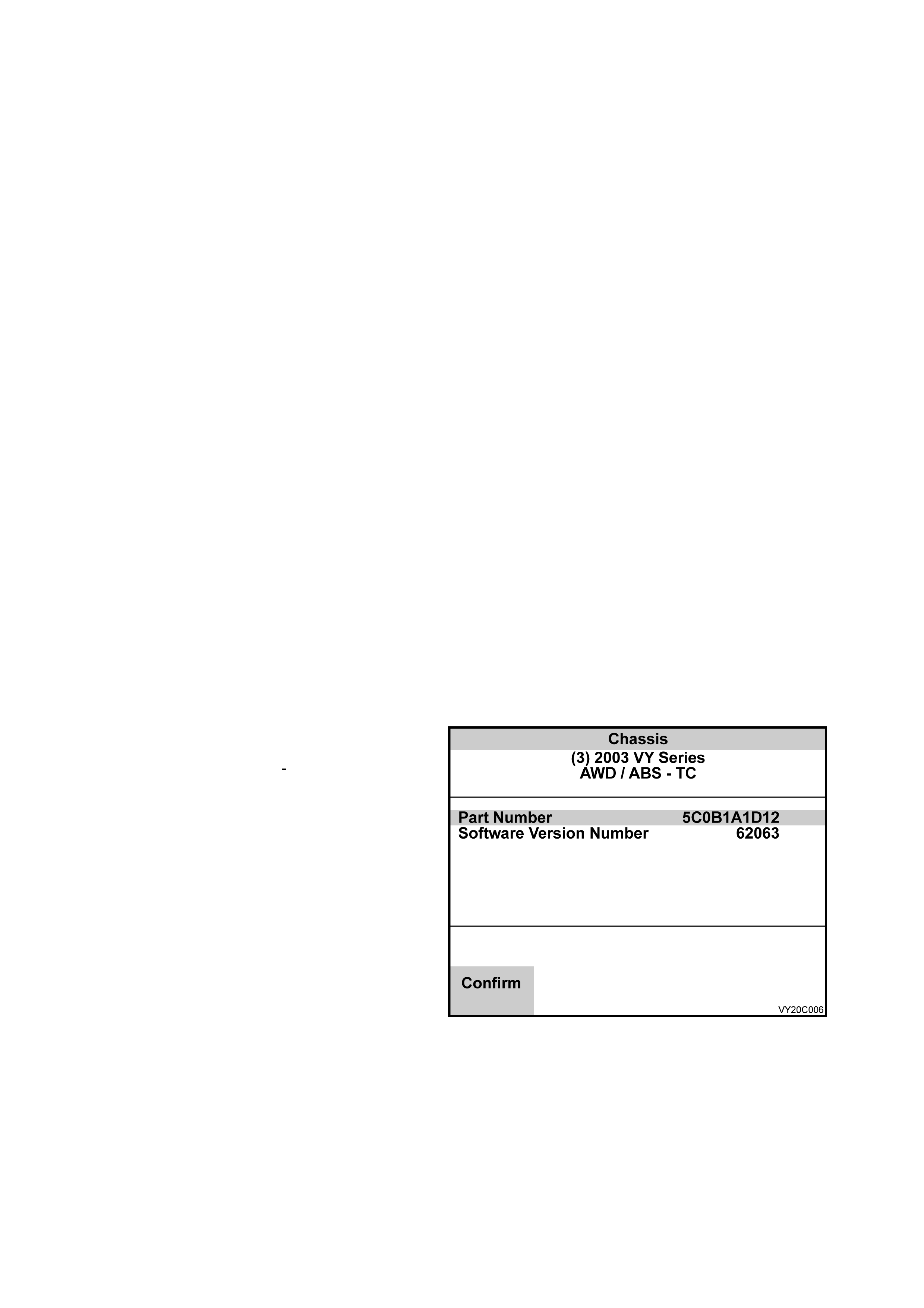
6. If TECH 2 detects an All Wheel Drive ABS –
TC system, the screen opposite will be
displayed.
7. Press the Confirm Soft key to continue and
refer to AWD ABS - TC TECH 2 FUNCTIONS
in this section.
Figure 0C-41 AWD ABS - TC Identification
ABS/ETC TECH 2 FUNCTIONS
The System identifi cation screen will then display
the control module Partnumber, System
Identification and if the system is an ABS or an
ABS/ETC system.
Press the Confirm soft key, and the ABS/ETC
application menu will then be displayed.
The following functions are available in the
ABS/ETC chassis application menu:
F0: Normal Mode
F1: Diagnostic Trouble Codes
F2: Data Display
F3: Snapshot
F4: Miscellaneous Tests
NOTE: Functions may vary depending on the
application s elected. For fur ther inf orm ation ref er to
Section 5B ABS & ABS/TCS.
Chassis
(3) 2003 VY Comm odore
ABS / ETC
Part Number
System ID
System
92104263
12
ABS/ETC
Part Number
VY0C089
Confirm
1 / 7
Figure 0C-42 System Identification
ABS/ETC TECH 2 FUNCTIONS
F0: NORMAL MODE
In this tes t mode, T ECH 2 will dis play various ABS/ET C data par ameters that are being tr ans mitted to other contr ol
modules via the serial data circuit normal mode message.
F1: DIAGNOSTIC TROUBLE CODES
F0: Read DTC’s:
Displays a listing of all (if any) DTC’s num bers that have been set by the ABS or ABS/ETC control m odule will
be displayed. To obtain further inform ation about a particular DT C, press the relevant f unction key and a DTC
data list will be displayed. From the information provided in this data list, you can determine when the DTC
occurred and the operating conditions of the system at the time.
F1 Clear DTC’s
DTC’s can be cleared by selecting F1 Clear Codes and pressing the ENTER key.
F2: DATA DISPLAY
If the F2: DATA DISPLAY mode is selected, an additional application menu will appear giving the operator the
option of selecting ABS or ABS/ETC data while the system is either active or disabled.
F0: Active ABS/ETC
While the two data lists offer similar information, the active data list has the advantage of monitoring the ABS or
ABS/ETC systems while it they are operational, aiding in the diagnosis of intermittent faults.
F1: ABS/ETC Disabled
If the disabled data list is selected, the ABS warning lamp will be illuminated and the system will become
disabled.
F3: SNAPSHOT
The snapshot mode will help to identify problems caused by speed sensor signals that may cause intermittent
operation of the ABS or ABS/ETC systems.
The SNAPSHOT mode captures data before and after a forced manual trigger condition.
F4: MISCELLANEOUS TESTS
In the miscellaneous tests mode, functional tests are available on the ABS and ABS/ETC systems that will help
identify proper operation. In this mode, error conditions can be further identified by testing and observing the test
results.
In the miscellaneous tests mode the following tests can be performed:
F0: Solenoids
These tests indicate whether a specific solenoid valve in the hydraulic modulator releases and holds pressure to
assigned hydraulic wheel circuits. When this mode is selected the following tests are available.
Front Left Solenoid Valve Test
Front Right Solenoid Valve Test
Rear Solenoid Valve Test (ABS Only)
Rear Left Solenoid Valve Test (ABS/ETC Only)
Rear Right Solenoid Valve Test (ABS/ETC Only)
TC Solenoid Valve Test (ABS/ETC Only)
F1: Auto Test
The auto test is performed automatically by the control module once during each ignition cycle when the vehicle
reaches approximately 12 km/h. When selected, TECH 2 can also command the ABS/ETC control module to
perform this test. The auto test cycles each solenoid valve and the pump motor briefly to check component
operation. If any error is detected during this test, the control module will set a DTC and the ABS and or TRAC OFF
warnings will be illuminated.
F2: Brake Bleed
This function assists the technician to bleed the brake hydraulic system and is divided into two parts for each
hydraulic circuit; a primary bleed and a secondary bleed. A primary bleed is a manual bleed of each hydraulic
circuit. During the secondary bleed, the ABS or ABS/ETC control module, via a TECH 2 command, activates the
solenoid and pump motor so that any air in these components is expelled.
AWD ABS - TC TECH 2 FUNCTIONS
The AWD / ABS – TC System identification
screen will display the control module Part Number
and Software Version Number.,
Press the Confirm soft key, and the ABS – TC
application menu will then be displayed.
The following functions are available in the ABS
– TC chassis application menu:
F0: Normal Mode
F1: Diagnostic Trouble Codes
F2: Data Display
F3: Snapshot
F4: Miscellaneous Tests
NOTE: Functions may vary depending on the
application s elected. For fur ther inf orm ation ref er to
Section 5B AWD ABS - TC.
Figure 0C-43 System Identification

F1: DIAGNOSTIC TROUBLE CODES
The following functions will be available in this mode:
F0: Read DTC Information: If this mode is selected, a listing of all (if any) DTCs that have been set by the
ABS – TC module will be displayed. The TECH 2 will also display if the DTC is Current or History.
F2: Read Additional DTC Information as Stored: In this mode TECH 2 will display the follow additional DTC
information, stored by the control module when the DTC was set. Data for up to six DTCs can be stored and
displayed.
DTC Number
DTC Description
DTC Status Current/History
ABS Active Yes/No
Stop Lamp Switch Active Yes/No
Vehicle Speed km/h
Ignition Cycles 0 - 255
F2: Clear DT C Information: DT Cs can be c leared in this m ode by simply selecting F2: Clear DT C Inform ation
and pressing the Yes Soft Key.
F2: DATA DISPLAY
This mode displays data parameters for the ABS – TC system. W hen F2: Data Display is selected there are two
modes available.
F0: Instrument
In this data display, the TECH 2 continuously monitors and displays all ABS – TC system data parameters.
F1: System Identificatio n
In this data display, the TECH 2 displays the ABS – TC system identification information.
F3: SNAPSHOT
The snapshot mode will help to identify problems caused by speed sensor signals that may cause intermittent
operation of the ABS - TC system.
The SNAPSHOT mode captures data before and after a forced manual trigger condition.
F4: MISCELLANEOUS TESTS
In the miscellaneous tests mode, functional tests are available on the ABS – TC system that will help identify
proper operation. In this mode, error conditions can be further identified by testing and observing the test results.
In the miscellaneous tests mode the following tests can be performed:
F0: Solenoids
These tests indicate whether a specific solenoid valve in the hydraulic modulator releases and holds pressure to
assigned hydraulic wheel circuits. When this mode is selected the following tests are available.
Front Left Solenoid Valve Test
Front Right Solenoid Valve Test
Rear Right Solenoid Valve Test
Rear Left Solenoid Valve Test
Front Left TC Valve Test
Front Right TC Valve Test
Rear Right TC Valve Test
Rear Left TC Valve Test
F1: Brake Bleed
This function assists the technician to bleed the brake hydraulic system and is divided into two parts for each
circuit; a primary bleed and a secondary bleed. A primary bleed is a manual bleed of each hydraulic circuit.
During the secondary bleed, the ABS - TC control module, via a TECH 2 command, activates the solenoids
and pump motor so that any air in these components is expelled.

3.5 BODY APPLICATION MENU
BODY CONTROL MODULE
1. Select Body Control Module from the Vehicle
Identification menu with the arrow keys, then
press ENTER.
V ehicle Identification
Se lec t on e of the fo llowing
Body
Body Control Module
Powertrain Interface Module
SRS
Instrument
Occupant Climate Control
Audio System
Telematics Module
Body Control Module
VY0C055
1 / 7
Figure 0C-44 Vehicle Identification Menu
2. Turn on the ignition and press the Confirm soft
key.
3. The System Identification screen will then
display the following information:
System Identification
(3) 2003 VY Comm odore
Body Control Module
VY0C021
Turn On Ignition!
C 18 SE L
Confirm
Figure 0C-45 System Identification
Identifier
Partnumber
Software Version Number
Production Date
TAG Number
VAP Process Number
Barcode (BCM Level)
Barcode (Serial Number)
Press the Confirm soft key, the BCM
application menu will then be displayed.
The following functions are available in the
BCM application menu:
F0: Normal Mode
F1: Diagnostic Trouble Codes
F2: Data Display
F3: Snapshot
F4: Miscellaneous Tests
F5: Program
F6: Security
NOTE: Functions may vary depending on the
application s elected. For fur ther inf orm ation ref er to
Section 12J BODY CONTROL MODULE.
Confirm
Body
(3) 2003 VY Comm odore
Body Control Module
VY0C064
Identifier
Partnumber
Software Version Number
Production Date
TAG Number
VAP Process Number
0401
92084596
012400
140502
655616
12
Identifier 1 / 8
Figure 0C-46 System Identification

BCM TECH 2 FUNCTIONS
NOTE: Depending on the level of BCM som e functions may not be available. Functions that are available f or each
level of BCM can be identified by the following abbreviations:
ALL = All levels of BCM
HI = High
LU = Lux
MI = Mid
MIAL = Mid with alarm enabled
LO = Low
LOAL = Low with alarm enabled
F0: NORMAL MODE
In this mode, the TECH 2 monitors the communication between control modules on the serial data line. The
inform ation dis played on the TECH 2 scr een in this m ode is what the BCM is com munic ating to the other m odules
via the serial data circuit normal mode message.
F1: DIAGNOSTIC TROUBLE CODES
The following functions will be available in this mode:
Read DTC Information (All): A listing of all (if any) DTC’s that have been set by the BCM will be displayed,
TECH 2 will also display the following information for the five most recent DTCs.
Times Occurred and the Ignition Cycles since the DTC was last set.
Read Alarm Code Information (HI, LU, MIAL & LOAL): A des cription of stor ed alarm c odes (if any) and if the
Alarm Code is Trigged or History.
Clear DTC and Alarm Code Information (HI, LU, MIAL & LOAL): Simply select this option, then press the
Enter button on TECH 2 and confirm the action as instructed by T ECH 2. Performing this function will clear all
DTCs information and alarm codes.
Clear DTC Information (MI & LO): Simply select this option, then press the Enter button on TECH 2 and
confirm the action as instructed by TECH 2. Performing this function will clear all DTCs information.
F2: DATA DISPLAY (ALL)
This m ode displays data param eters for the BCM being diagnos ed. When entering this m ode, the num ber s of data
list available will depend on the level of the BCM.
NOTE: W hen the TECH 2 first communicates with the BCM, it also determines what level of BCM is fitted to the
vehicle and therefore only the relevant data list will be displayed.
The BCM has four main data lists, Inputs and Outputs, BCM Internal Status, Serial Data Inputs and System
Identification. The information in these data list contains all the serial data available to the TECH 2, the remaining
data lists contain system specific information for the four main data lists.
Inputs and Outputs (All)
In this test mode, the TECH 2 continuously monitors and displays all BCM input and output data parameters.
BCM Internal Status (All)
In this test mode, the TECH 2 continuously monitors and displays the status of all BCM functions.
Serial Data Inputs (All)
In this test mode, the TECH 2 continuously monitors and displays all BCM serial data inputs used by the BCM.
User Settings (All except Hi)
In this test mode, the TECH 2 continuously monitors and display s the current BCM user settings.
Priority 1 User settings (Hi)
In this test mode, the TECH 2 continuously monitors and display s the current priority 1 BCM user settings.
Priority 2 User settings (HI)
In this test mode, the TECH 2 continuously monitors and display s the current priority 2 BCM user settings.
Alarm / Theft Deterrent (All except MIAL & LOAL)
In this test m ode, the T ECH 2 continuous ly monitors and displays all BCM alarm and theft deter rent system inputs,
outputs and system status information.
Theft Deterrent (MIAL & LOAL)
In this test mode, the TECH 2 continuously monitors and displays all BCM theft deterrent system inputs, outputs
and system status information.

Central Door Locking (All)
In this test mode, the TECH 2 continuously monitors and displays all central door locking system inputs, outputs
and status information.
Power Windows (All except LO & LOAL)
In this test mode, the TECH 2 continuously monitors and displays all power window system inputs, outputs and
status information.
Wipres (All)
In this test mode, the TECH 2 continuously monitors and displays all wiper system inputs, outputs and status
information.
Headlamps (All)
In this test m ode, the TECH 2 continuously monitors and displays all headlamp system inputs, outputs and status
information.
Instrument Illumination (All)
In this test m ode, the T ECH 2 continuous ly monitors and dis plays all instrum ent illum ination system inputs , outputs
and status information.
Interior Illumination (All)
In this test mode, the TECH 2 continuously monitors and displays all interior illumination system inputs, outputs and
status information.
Rear Lamp Failure (Hi)
In this test mode, the TECH 2 continuously monitors and displays all interior rear lamp failure system inputs,
outputs and status information.
Air Conditioning Interface (All except Hi & LUX)
In this test mode, the TECH 2 continuously monitors and displays all interior air conditioning interface inputs,
outputs and status information.
Low Speed Cooling Fan (HI & LUX)
In this test mode, the TECH 2 continuously monitors and displays all low speed cooling fan inputs, outputs and
status information.
Antenna (HI & LUX)
In this test mode, the TECH 2 continuously monitors and displays all antenna inputs, outputs and status
information.
System Identification (All)
In this test mode, the TECH 2 continuously and displays the BCM identification information. This data list is the
same as the information displayed on the system identification screen.
F3: SNAPSHOT
In this test mode, TECH 2 captures BCM data before and after a selected trigger point. The purpose of the
SNAPSHOT test mode is to help isolate an interm ittent or transient problem by storing BCM data param eters just
before and just after a problem occurs. Snapshot is available for all data lists.
F4: MISCELLANEOUS TESTS
In this test mode, TECH 2 performs various functional tests to assist in problem isolation during trouble shooting.
When entering this mode, the num ber s of tes ts available will depend on the level of the BCM. The relevant data lis t
is also displayed during the Test.
When the TECH 2 first communicates with the BCM, it also determines what level of BCM is fitted to the vehicle
and therefore only the relevant miscellaneous tests will be display ed.
Additional application menu screens will be displayed for Lamps, Wiper Tests, and Security Systems.
Lamps: If lam ps are s elec ted, an additional applic ation menu will be displayed offering additional functional tests of
the vehicle’s lighting system.
Interior Lamp (All): W ith the dome lamp switch in either the Door or On position, TECH 2 can com mand the
BCM to switch on and off the interior lighting.
Preconditions: Ignition and Interior lamp ON.
Headlamps (All): In this mode with the ignition off and the headlamps and park lamps turned on, TECH 2
commands the BCM to switch off and on the vehicle park lamps and headlamps.
Preconditions: Ignition OFF and Headlamps ON.
Indicators (All): In this mode, TECH 2 commands the BCM to switch ON and OFF the turn signal indicator
lamps, including the warning lamps in the instrument cluster.
Precondition: Ignition and Headlamps ON.

Instrument Illumination (All): In this mode, TECH 2 commands the BCM to brighten or dim the instrument
cluster and trip computer illumination lamps.
Precondition: Ignition ON.
Auto Lights On (ALL): In this mode, with the ignition on and the headlamp switch in the Auto position, TECH 2
commands the BCM to turn the headlamps on and off.
Precondition: Headlamps Switch in the Auto position.
Rear Lamp Bulb Fail (HI): In this m ode and with ignition switched O N, TECH 2 c om m ands the BCM to switch
on and off Rear Lamp Bulb Failure Warning in the instrument cluster.
Precondition: Ignition ON.
Rear Stop Lamp Bulb Fail (HI): In this mode and with ignition switched ON, T ECH 2 comm ands the BCM to
switch on and off Rear Stop Lamp Failure Warning in the instrument cluster.
Precondition: Ignition ON.
Rear Lamp Fuse Fail (H I): In this mode and with ignition s witched ON, TECH 2 commands the BCM to switch
on and off Rear Lamp Fuse Failure Warning in the instrument cluster.
Precondition: Ignition ON.
Low Speed Cooling Fan (ALL): In this mode, T ECH 2 com mands the BCM to switch on and then off , (will switch
off automatically after approx imately four seconds pr ovided the PCM is not commanding the low fan on) the engine
cooling low speed fan relay.
Precondition: Ignition ON.
Data Bus Isolator (ALL): In this mode, the BCM data bus isolator switch can be opened or closed.
To check if the data bus isolator is operating, while commanding the data bus isolator open with TECH 2, start
engine and monitor the trip c omputers “ins tant f uel c onsumption” display while varying the engine speed. When the
data bus isolator switch is opened, the trip computers instant fuel consumption display will not update.
Precondition: Ignition ON.
Central Lock ing (ALL): In this mode, TECH 2 commands the BCM to operate all door lock actuators.
Precondition: Ignition OFF.
Rear Compartment (ALL): In this mode, TECH 2 commands the BCM to activate the sedan rear compartment
lock actuator.
Precondition: Ignition ON.
Wipers (ALL): If Wipers is s elected, an additional application m enu will be displayed of fering extra func tional tests
of the vehicles wiper system.
Front Wipers (ALL): In this mode, the front windshield wipers can be driven On and Off.
Precondition: Ignition ON.
Rear Wipers (LU, MI & MIAL): In this mode, the rear screen wipers can be driven On and Off.
Precondition: Ignition ON.
Power Windows (HI, LU, MI & MIAL): If Power Windows is selected, an additional application menu will be
displayed offering extra functional tests of the vehicles window system.
Driver’s Window Down (HI, LU, MI & MIAL): In this mode, the driver’s window can be driven down.
NOTE: Before entering and conducting this test, ensure that driver's window is fully up.
Precondition: Ignition ON.
Front Passenger’s Window Down (HI, LU, MI& MIAL): In this mode, the front passenger's window can be
driven down.
NOTE: Before entering and conducting this test, ensure that the front passenger's window is fully up.
Precondition: Ignition ON.
Power Window Relay (HI, LU, MI& MIAL): In this m ode, TECH 2 can command the BCM to turn the power
window relay ON and OFF.
Precondition: Ignition ON.
Antenna (HI, LU): In this mode, TECH 2 commands the BCM to raise or lower the antenna.
Precondition: Ignition ON.
Horn (ALL): In this mode, the horn can be commanded ON and OFF.
Precondition: Ignition ON.
Interior Illumination Relay (ALL): In this mode, TECH 2 commands the interior illumination relay ON or OFF.
Preconditions: Ignition and Interior Light ON.

Accessory Relay (ALL): In this mode, TECH 2 commands the accessory relay on or off.
Precondition: Ignition OFF.
A/C LED (M I, MIAL, LO & LOAL): In this mode, TECH 2 commands the BCM to switch the A/C On/Off switch LED
ON and OFF.
Precondition: Ignition ON.
Heated Rear Window (MI, M IAL, LO & LOAL): In this mode, the r ear window demister c an be turned on and off.
When switched on, the heated rear window switch LED is illuminated and the relay can be heard to operate.
Precondition: Ignition ON.
Security System (ALL): If the security system mode is selected, an additional application menu will be displayed
offering additional functional tests of the vehicles security system.
Security LED (ALL): In this m ode, TECH 2 com mands the BCM to turn the thef t deterrent alert indicator LED
ON and OFF.
Precondition: Ignition ON.
Theft Deterrent Horn, (HI, LUX, MIDAL, LOAL): In this mode, the theft deterrent horn can be commanded
ON and OFF.
Precondition: Ignition ON.
Key Priority (HI): In this m ode, the prior ity key status can be switched fr om priority one to priority two or priority
two to priority one.
Precondition: Ignition ON.
F5: PROGRAM
In this test mode, T ECH 2 allows the progr amm ing of var ious f eatur es by turning the feature On or Of f, or adjusting
settings (ie. Battery Saver Shutdown Time). For High Series BCMs the settings are only changed for the priority key
that is in the ignition when the programming function occurs.
To operate any of the programming features, simply select the appropriate function to be changed from the
Program Application Menu and follow the screen instructions.
When the Program option is selected, the following will become available.
User Settings
Once User Setting has been selected TECH 2 will display a list containing all current User Setting. To change a
setting scr oll to the setting you wis h to change and the pres s the Modif y Sof t Key or the ENTER k ey. T hen enter or
select the setting you require and the press ENTER. Once you have changed the setting to the required values
press the Program Soft Key and the values you have selected will be programmed in to the BCM. The following is a
list of the programmable user settings.
Precondition: Ignition ON.
Instrument Illumination (ALL): The instrument illumination memory can be set from 35% to 100%.
Headlamps Off Delay Time: The headlamps off delay time can be adjusted from 0 to 180 seconds. The
default headlamps of delay time is one second.
Approach Illumination Delay Time: The approach illumination delay time can be adjusted from 0 to 90
seconds. The default approach illumination delay time is 30 seconds.
Auto Headlamp: All vehicles will have the auto headlamps sensitivity set to a default value of normal. If the
driver requests the lights to come on later (when it is darker), the sensitivity of the twilight sentinel should be
adjusted to “late”. If the driver requests the lights to come on earlier (when it is lighter), the sensitivity of the
twilight sentinel should be adjusted to “Early”.
Interior Lamp T imeout: The interior lam p tim eout can be adj usted f rom 0 to 255 sec onds. T he default inter ior
lamp timeout is 30 seconds.
Ignition Off Interior Lamp Timeout: The ignition off interior lamp timeout can be adjusted from 1 to 255
seconds. The default interior lamp timeout is 30 seconds.
Two Stage Un lock: The two stage door unlock feature can be turned ON or OFF. When turned ON, one press
of remote coded k ey unlock button will unlock the dr iver’s door only, a second press will open all doors. When
turned OFF, one press of remote coded key unlock button will unlock all doors.
Autolock in Drive: The autolock in drive feature can be turned ON or OFF. When turned ON, all doors will
lock when drive or reverse is selected, only for vehicles equipped with automatic transmissions.
Door Lock Indication: The door lock indication can be change form indicators only to indicators and horn.
Accessory Relay Timeout : T he acce ssor y relay tim e tim eout can be changed f rom ignition of f to driver’s door
open. If the ignition off is selected the accessory relay will be turned of when the ignition is switched off. If
driver’s door is selec ted then the ac c es so ry relay will be turned of onc e the ignition is turned off and the driver’s
door is opened or is open.

OPTIONS
Once O ptions has been s elec ted T ECH 2 will display a list containing all current Options. To change a setting scroll
to the setting you wish to change and the press the Modify Soft Key or the ENTER key. Then enter or select the
option you require and the press Modify. Once you have changed the Options to the required values press the
Program Soft Key and the values you have selected will be program med in to the BCM. The following is a list of the
programmable Options.
Precondition: Ignition ON.
Antenna Height Memory (HI, LU): The antenna height m emory can be turned ON or OF F, when ON the BCM
will return the antenna mast to the las t know antenna m ast height, each time the radio is tur ned on. When OF F
the antenna mast will fully extend each time the radio is switched ON.
Pre-Delivery Mode (ALL): Pre-delivery mode is a function of the battery saver feature, when enabled the
vehicle to enter battery saver mode after only three minutes, regardless of the battery saver setting. When
disabled the normal batter saver setting will be used.
Battery Saver Shutdown Time (ALL): In this mode the batter y saver shutdown mode time c an be changed to
switch off after 3 minutes to 255 minutes. The default battery saver shutdown time is 65 minutes.
Rear Wiper Continuous in Reverse (LU, MI & MIAL): The rear wiper continuous in reverse be enabled or
disabled. By disabling this feature, it will prevent the rear wiper continuously sweeping the tailgate sc reen when
the front intermittent wiper is activated and reverse gear is selected.
Set Key to Priority 1 (HI): The remote key in the ignition switch can be set to become the priority one key.
Provided it is not already the priority one key.
Intermittent Wiper Speed (MI, MIAL, LO & LOAL): In this mode, the intermittent speed can be changed from
Fixed (8 seconds) to Variable, when in the variable mode the wiper dwell will vary from 8 seconds to 3 seconds
dependant on the road speed of the vehicle.
Learn BCM Settings (ALL): In this mode the TECH 2 will read and store the current BCM User Settings.
Program Learnt BCM Settings (ALL): In this m ode the current us er settings stored in T ECH 2 from “Learn BCM
Settings” can be programmed into a new BCM, provided the BCM has the same identifier.
F6: SECURITY
In this test mode, TECH 2 provides the user with the capability of: linking the BCM to the PCM/PIM, reading
security information and programming security features.
NOTE: A precondition to all security features is: The vehicle security number must be entered and the theft
deterrent system must be disarmed and the ignition must be switched On with a programm ed remote coded key.
When linking the BCM to the PCM/PIM or programming a remote key TIS approval is also required.
When the security option is selected, the following choices will become available.
BCM Link to PCM/PIM (ALL): If BCM, PCM or PIM is replaced, the BCM must be linked to the PCM/PIM
otherwise, the vehicle will be immoblised.
TIS approval (TIS 2000 Security Access) must be obtained and the BCM security num ber entered into TECH 2 to
allow the BCM to PCM/PIM linking.
Security Information (ALL): In this mode, the radio pin, mechanical key number and the serial number of the
Hardware Key that was used when the BCM to PCM/PIM link was performed is also displayed.
PROGRAM (ALL)
In this mode, the following can be information or features can be programmed or enabled.
Radio PIN (All) Allows programming of the radio PIN number. If a BCM is replaced, the radio PIN number
should be obtained from the original BCM or security card and then programmed into the replacement BCM.
Mech anical Key Number (ALL) Allows program ming of the mechanic al key number. If a BCM is replac ed, the
mec hanical k ey num ber should be obtained f rom the original BCM or s ecurity car d and then programm ed into
the replacement BCM.
Alarm Enable (M I, LO): In this m ode the alarm option can be enabled. After enabling the alar m option, T ECH
2 will exit the system and the technician will then have to reselect the system in order for TECH 2 to make
changes to the data list and available functions.
NOTE: Once the alarm has been enabled it cannot be disabled.
Program Remote Key (ALL)
This mode allow you to program a new rem ote k ey. T IS approval (enable progr amm ing) m ust be obtained and
the BCM s ec urity num ber enter ed into T ECH 2 to allow k ey program ming. During remote k ey program ming the
serial number of the Hardware Key used during enable programming is stored in the BCM.
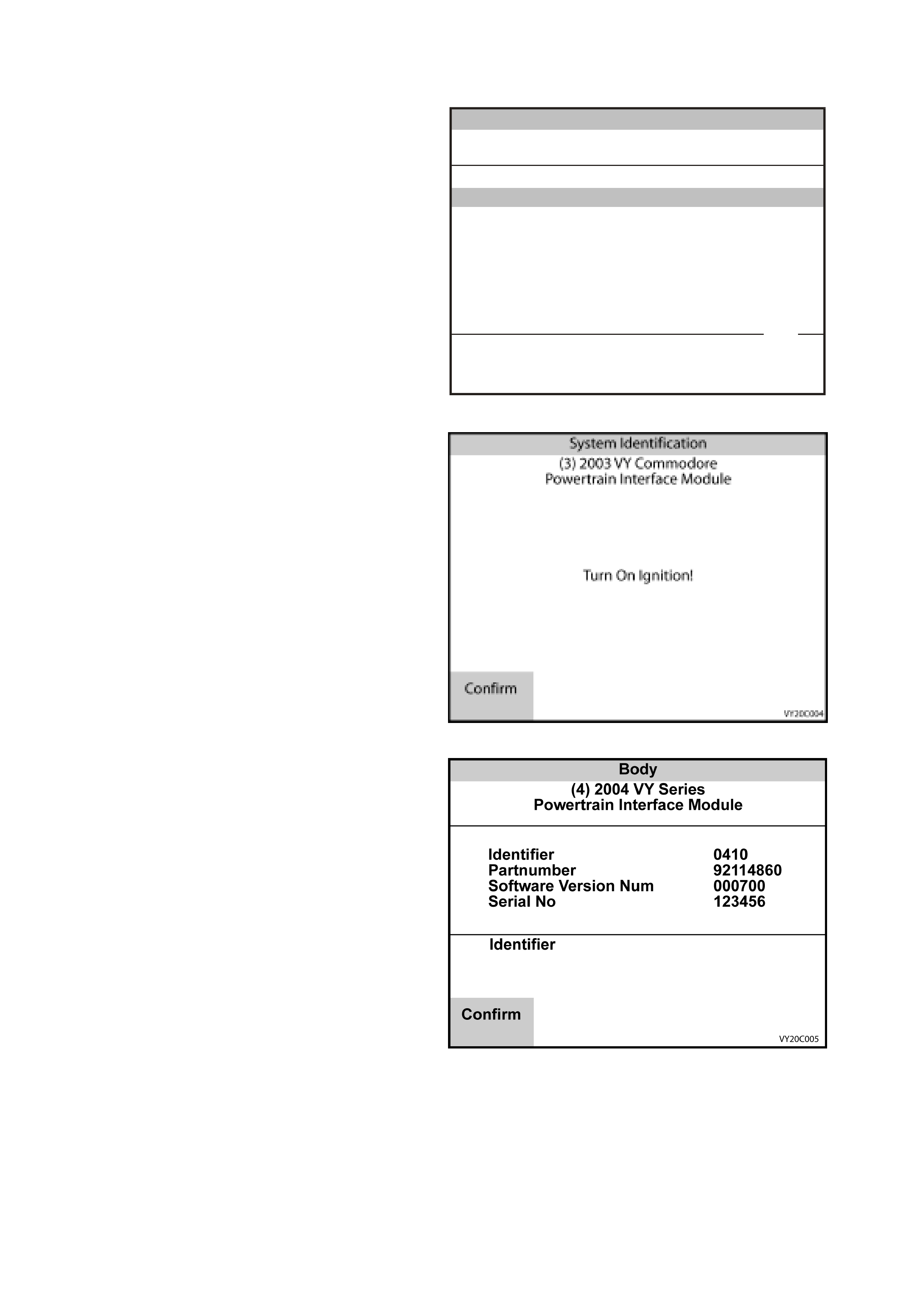
POWERTRAIN INTERFACE MODULE
1. Select Powertrain Interface Module from the
Vehicle Identification menu with the arrow
keys, then press ENTER.
V ehicle Identification
Se lec t on e of the fo llowing
Body
Body Control Module
Powertrain Interface Module
SRS
Instrument
Occupant Climate Control
Audio System
Telematics Module
Powertrain Interface Module
VY0C057
2 / 7
Figure 0C-47 Vehicle Identification Menu
2. Turn on the ignition and press the Confirm soft
key.
3. TECH 2 will then determine the type of PIM is
fitted to the vehicle, either r ear wheel drive PIM
or an All W heel Drive (AWD) PIM, and display
one of the following screens.
Figure 0C-48 System Identification
4. If TECH 2 detects a rear wheel drive PIM, the
screen opposite will be displayed.
5. Press the Confirm Soft key to continue and
refer to PIM TECH 2 FUNCTIONS in this
Section.
Figure 0C-49 System Identification
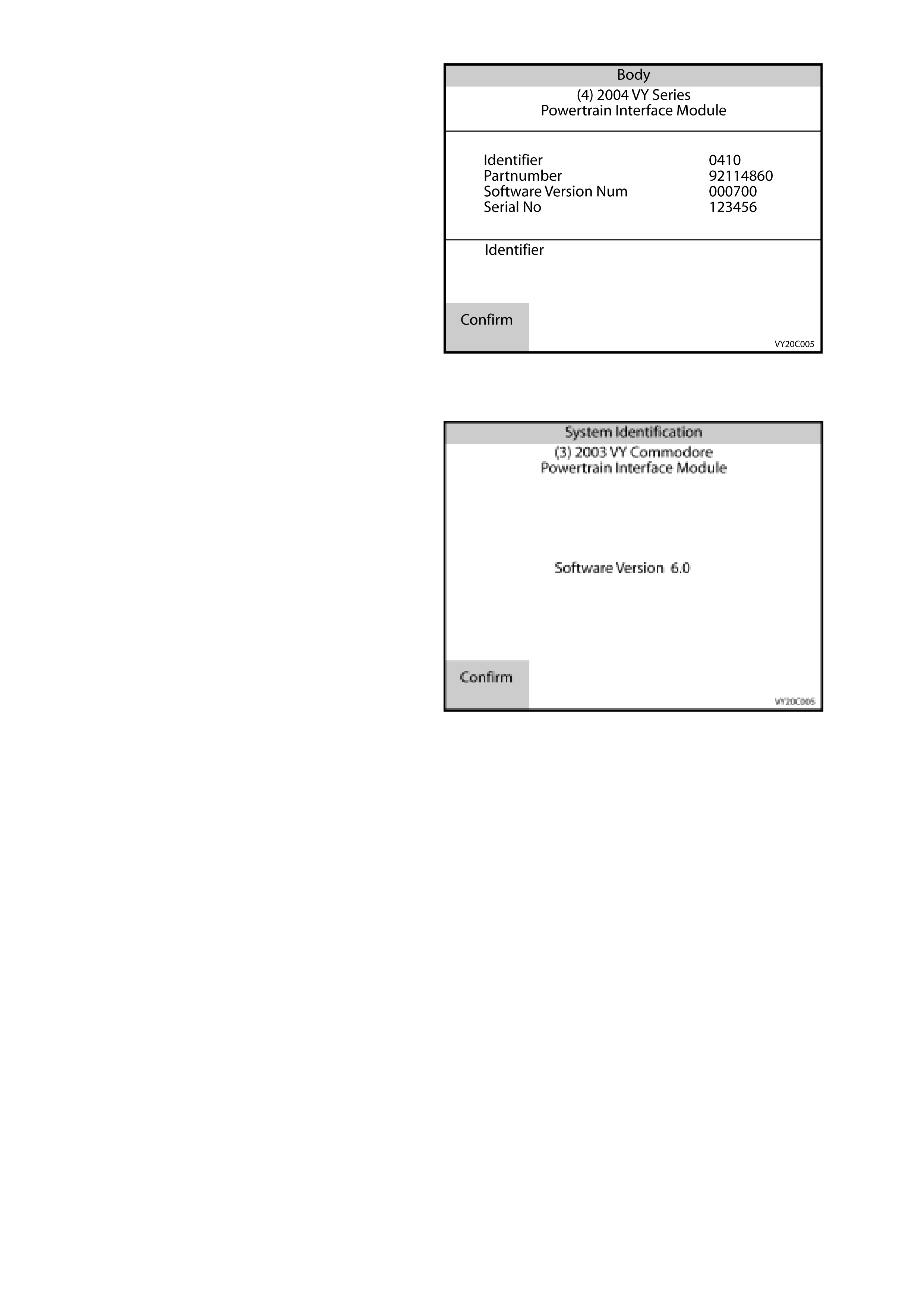
6. If TECH 2 detects an All W heel Drive PIM, the
screen opposite will be displayed.
7. Press the Confirm Soft key to continue and
refer to AWD PIM TECH 2 FUNCTIONS in this
Section.
Figure 0C-50 System Identification
PIM TECH 2 FUNCTIONS
The System Identifi cation screen will then display
the following information:
Software Version
Press the Confirm soft key, and the Powertrain
Interface Module application menu will then be
displayed.
The following functions are available in the
Powertrain Interface Module application menu:
F0: Normal Mode
F1: Diagnostic Trouble Codes
F2: Data Display
F3: Snapshot
F4: Miscellaneous Tests
For further information refer to
Section 6C3 POWERTRAIN MANAGEMENT
GEN III V8 ENGINE .
Figure 0C-51 System Identification
F0: NORMAL MODE
In this test m ode, TECH 2 will display various data parameter s that are being tr ansmitted to other control modules
via the serial data circuit normal mode message.
F1: DIAGNOSTIC TROUBLE CODES
In this test mode, PIM DTCs can be displayed or cleared. W hen F0: Diagnostic Trouble Codes is selected there
are an additional two modes:
F0: Read Current DTC Information: All current PIM DTC(s) will be displayed.
F1: Clear Current DTC Information: Clears all current PIM DTC(s).
F2: DATA DISPLAY
In this test mode, the TECH 2 continuously monitors and displays all PIM data parameters.
F3: SNAPSHOT
In the “F3: Snapshot” mode, TECH 2 enables the user to capture data before and after a forced manual trigger.
F4: MISCELLANEOUS TESTS
In this test mode, the TECH 2 performs software override commands of the PIM, to assist in problem isolation
during diagnostics.
F0: Output Tests
Starter Relay: The starter relay can be commanded on and off. If the starter relay is commanded off the
engine will not crank when the ignition key is turned to the start position.
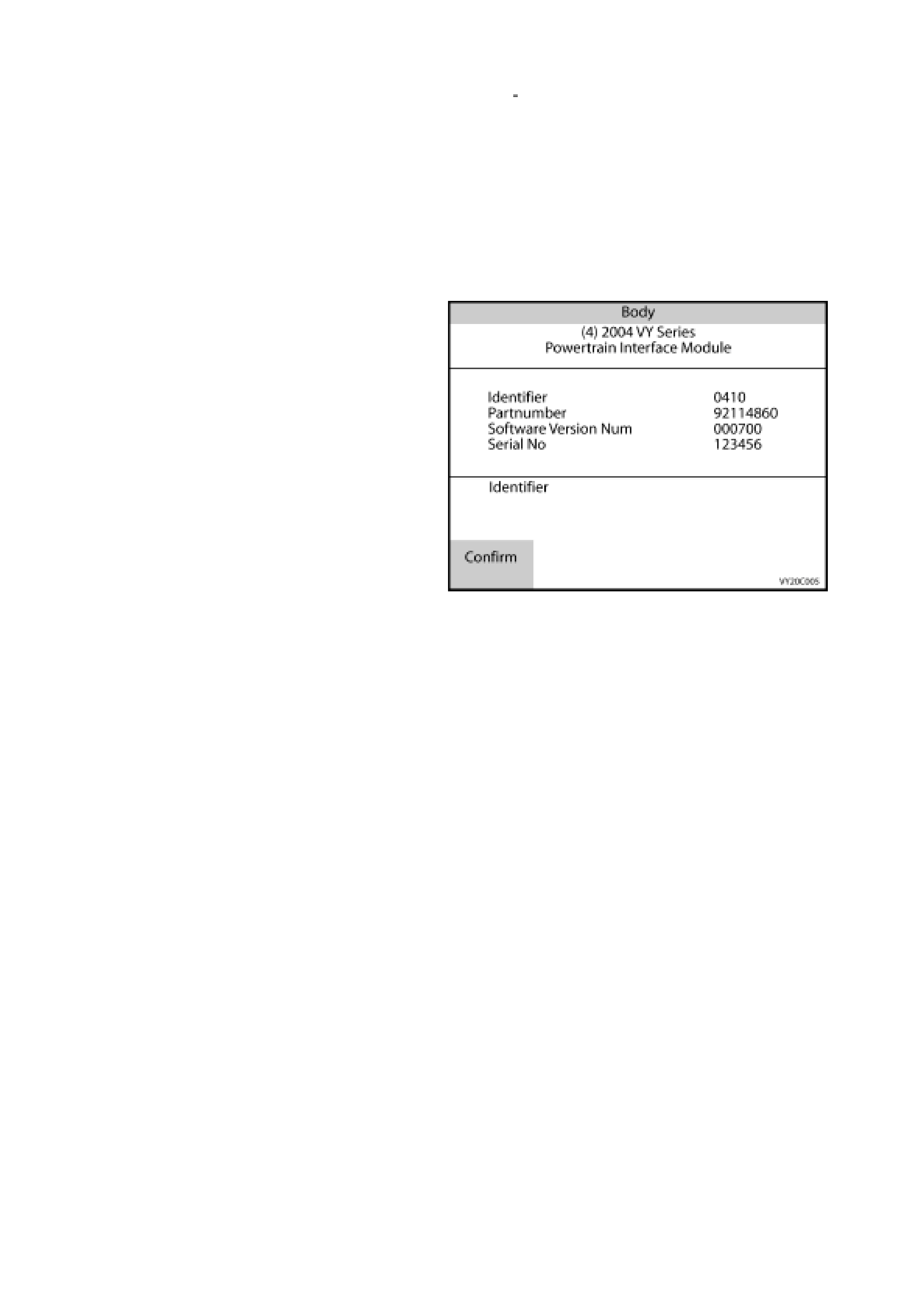
F5: SECURITY
In this test mode, TECH 2 provides the user with the capability of: linking the BCM to the PCM/PIM.
A precondition to all security features is: The vehicle security number must be entered and the theft deterrent
system must be disarmed and the ignition must be switched on with a programmed remote coded key. When
linking the BCM to the PCM/PIM, or programming a remote key, TIS approval is also required.
F0: BCM Link to PCM/PIM (ALL): In this test mode, TECH 2 provides the user with the capability of linking the
BCM to the PCM/PIM. If the BCM, PCM or PIM is replaced, the BCM must be linked to the PCM/PIM
otherwise, the vehicle will be immobilised.
T IS appr oval (TIS 2000 Sec ur ity Access ) mus t be obtained and the BCM s ecur ity number entered into TECH 2
to allow the BCM to PCM/PIM linking.
AWD PIM TECH 2 FUNCTIONS
The System Identification screen will display the
following information:
Identifier
Part Number
Software Version Number
Serial Number
Press the Confirm soft key, and the Powertr ain
Interface Module application menu will then be
displayed.
The following functions are available in the
Powertrain Interface Module application menu:
F0: Normal Mode
F1: Diagnostic Trouble Codes
F2: Data Display
F3: Snapshot
F4: Miscellaneous Tests
F5: Security
For further information refer to
Section 6C3 POWERTRAIN MANAGEMENT
GEN III V8 ENGINE .
Figure 0C-52 System Identification
F0: NORMAL MODE
F0: PCM Normal Mode
In this test m ode, TECH 2 will display various engine and transm ission data parameters that are being continually
transmitted to other control modules via the serial data circuit normal mode message.
F1: ABS Normal Mode
In this test m ode, TECH 2 will display various ABS data param eters that are being continually transm itted to other
control modules via the serial data circuit normal mode message.
F1: DIAGNOSTIC TROUBLE CODES
In this test mode, PIM DTCs can be displayed or cleared. W hen F0: Diagnostic Trouble Codes is selected there
are an additional two modes:
F0: Read DTC Information: A listing of all (if any) DTC’s that have been set by the PIM will be displayed.
TECH 2 will also display the following DTC information.
Times Occurred and the Ignition Cycles since the DTC was last set.
F1: Clear DTC Information: Clears all current PIM DTC(s).
F2: DATA DISPLAY
F0: Data List
In this mode, the TECH 2 continuously monitors and displays all PIM data parameters.
F1: System Identification
In this mode, the TECH 2 continuously and displays the PIM identification information. This data list is the
same as the information displayed on the system identification screen.
F3: SNAPSHOT
In the F3: Snapshot mode, TECH 2 enables the user to capture data before and after a forced manual trigger.

F4: MISCELLANEOUS TESTS
In this test mode, the TECH 2 performs software override commands of the PIM, to assist in problem isolation
during diagnostics.
F0: Output Tests
F0: Starter Relay: T he starter relay can be com manded on and off . If the starter relay is com manded of f,
the engine will not crank when the ignition key is turned to the start position.
Precondition: Ignition ON
F1: Low Traction Warning: The Low Traction warning can be commanded on and off. When commanded
on, the Low Traction warning in the instrument should be displayed.
Precondition: Engine Running
F2: ABS Warning: The ABS warning can be commanded on and off. When commanded on the ABS
warning in the instrument should be displayed.
Precondition: Ignition ON
F2: Brake Fail Warning: The Brake Fail warning can be commanded on and off. When commanded on
the ABS warning in the instrument should be displayed.
Precondition: Ignition ON, Park Brake Released.
F5: SECURITY
In this test mode, TECH 2 provides the user with the capability of linking the BCM to the PCM/PIM.
A precondition to all security features is: The vehicle security number must be entered and the theft deterrent
system must be disarmed and the ignition must be switched on with a programmed remote coded key. When
linking the BCM to the PCM/PIM, or programming a remote key, TIS approval is also required.
F0: BCM Link to PCM/PIM (ALL): In this test mode, TECH 2 provides the user with the capability of linking the
BCM to the PCM/PIM. If the BCM, PCM or PIM is replaced, the BCM must be linked to the PCM/PIM
otherwise, the vehicle will be immobilised.
T IS appr oval (TIS 2000 Sec ur ity Access ) mus t be obtained and the BCM s ecur ity number entered into TECH 2
to allow the BCM to PCM/PIM linking.
SUPPLEMENTAL RESTRAINT SYSTEM (SRS)
1. Select SRS from the Vehicle Identification
menu with the arrow keys, then press ENTER.
V ehicle Identification
Se lec t on e of the fo llowing
Body
Body Control Module
Powertrain Interface Module
SRS
Instrument
Occupant Climate Control
Audio System
Telematics Module
SRS
VX0C058
3 / 7
Figure 0C-53 Vehicle Identification Menu

2. Turn on the ignition and press the Confirm soft
key.
System Identification
(3) 2003 V Y Co m modore
SRS
VX0C027
Tu r n O n Ig n it io n !
C 18 S E L
Confirm
Figure 0C-54 System Identification
3. The System Identification screen will then
display the following information:
Part number
Production Date
Module Type
VAP Process Number
Vehicle Identification Number
4. Press the Confirm soft key, the SRS
application menu will then be displayed.
The f ollowing f unctions are available in the SRS
application menu:
F0: Normal Mode
F1: Diagnostic Trouble Codes
F2: Data Display
F3: Snapshot
F4: Program
NOTE: Functions may vary depending on the
application s elected. For fur ther inf orm ation ref er to
Section 12M SUPPLEMENTAL RESTRAINT
SYSTEM.
System Identification
(3) 2003 V Y Co m modore
SRS
Partnumber
Prod uction Date
Module Type
VAP P rocess N um ber
V
e hicle Id e ntificatio n N o
Partnumber
92092018
290102
81
12
821217
Confirm
VY0C028
1 / 5
Figure 0C-55 Typical System Identification Data
SRS TECH 2 FUNCTIONS
F0: NORMAL MODE
In this mode, the TECH 2 monitors the communication between control modules on the serial data line. The
information displayed on the TECH 2 screen in this mode is what the Sensing Diagnostic Module (SDM) is
communicating to the other modules via the serial data line.
F1: DIAGNOSTIC TROUBLE CODES
In this test m ode, DT Cs s tored by the SRS SDM can be displayed or c leared. When F1: Diagnostic T rouble Codes
is selected there is an additional two modes:
F0: Read DTC Information - If this mode is selected, a listing of all (if any) DTCs that have been set will be
displayed. Inform ation displayed with the DTC number/s that have been set is; a short description of what the
DTC is and whether it is a current (fault present) or history (stored, but not necessarily on this ignition cycle)
DTC.
F1: Clear DTC Information - DTCs can be cleared in this mode by simply selecting F1: Clear DTC
Information, pressing the ENTER button on TECH 2 and confirming the action as instructed by TECH 2.
F2: DATA DISPLAY
In this test mode, TECH 2 displays the status of inputs and outputs of the SRS. NOTE: When the TECH 2 is
communicating with the SRS SDM, it also determines what type of SDM is fitted to the vehicle and therefore only
the relevant data list parameters will be displayed.
F3: SNAPSHOT
In the “F3: Snapshot” mode, TECH 2 enables the user to capture data before and after a forced manual trigger.
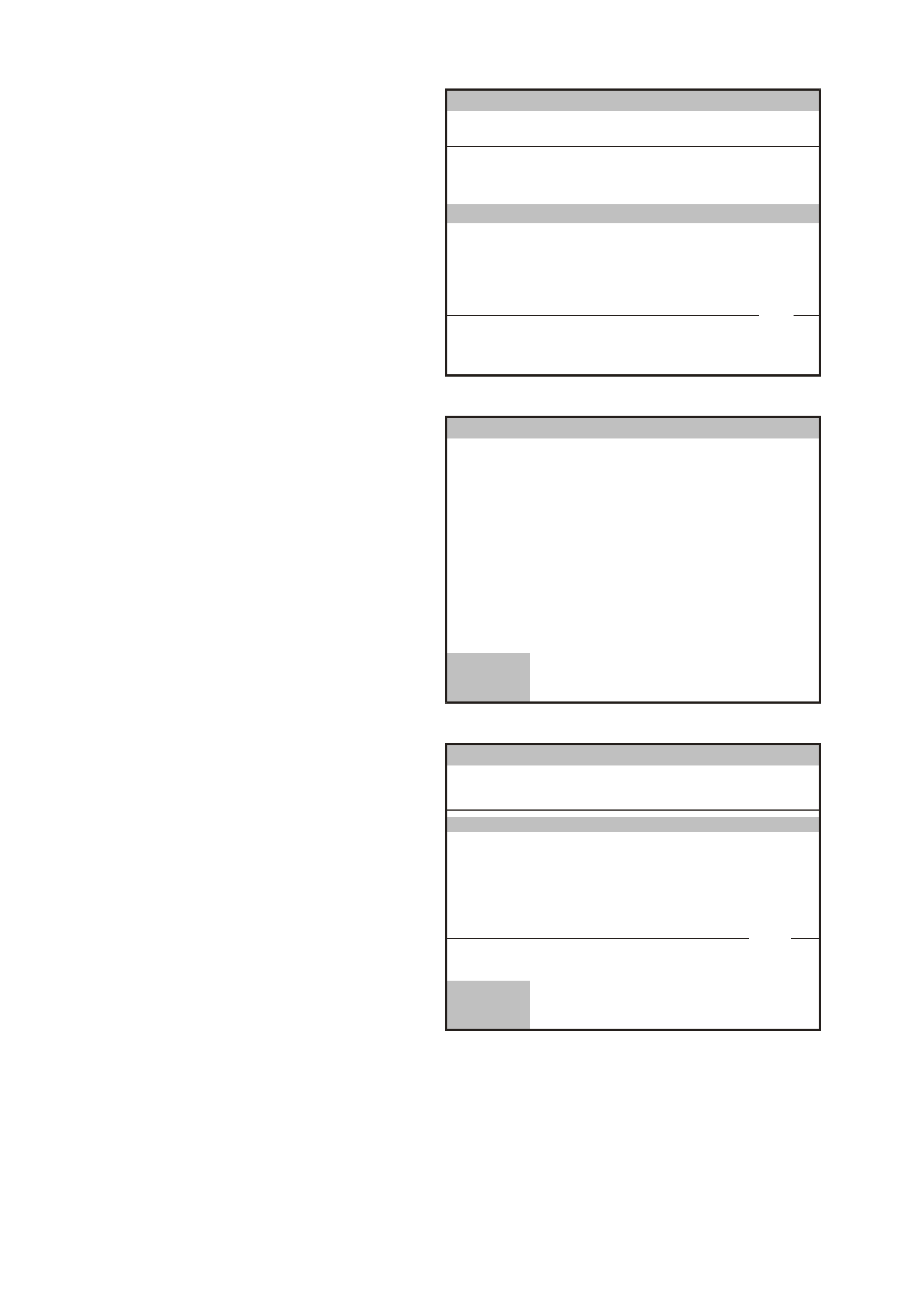
INSTRUMENT
1. Select Instrument from the Vehicle
Identification menu with the arrow keys, then
press ENTER.
V ehicle Identification
Se lec t on e of the fo llowing
Body
Body Control Module
Powertrain Interface Module
SRS
Instrument
Occupant Climate Control
Audio System
Telematics Module
Instrument
VY0C059
4 / 7
Figure 0C-56 Vehicle Identification Menu
2. Turn on the ignition and press the Confirm soft
key.
3. The System Identification screen will then
display the following information:
Identifier
Part Number
Production Date
Software Version
Indtrument Type
Fuel Calibration
Code version
Code Index
VAP Process Number
TIS Hardware Key Serial Number
TAG Number
Country
4. Press the Confirm soft key again, the
Instrument application menu will then be
displayed.
The following functions are available in the
Instrument application menu:
F0: Normal Mode
F1: Diagnostic Trouble Codes
F2: Data Display
F3: Snapshot
F4: Miscellaneous Tests
F5: Program
NOTE: Functions may vary depending on the
application s elected. For fur ther inf orm ation ref er to
Section 12C INSTRUMENTS.
System Identification
(3) 2003 V Y Co m modore
Instrument
VX0C024
Tu r n O n Ig n it io n !
C 18 S E L
Confirm
Figure 0C-57 System Identification
System Identification
(3) 2003 V Y Co m modore
Instrument
Identifier
Part Number
Prod uction Date
Software Version
Instrument Type
F ue l ca lib ratio n
Identifier
104
92083706
010100
03002
Level 3
92120109
Confirm
VY0C025
1 / 12
Figure 0C-58 Typical System Identification Data

INSTRUMENT TECH 2 FUNCTIONS
F0: NORMAL MODE
In this mode, the TECH 2 monitors the communication between control modules on the serial data line. The
information displayed on the TECH 2 screen in this mode is what the instruments is communicating to the other
modules via the serial data circuit normal mode message.
F1: DIAGNOSTIC TROUBLE CODES
The following functions will be available in this mode:
F0: Read DTC Information: If this mode is selected, a listing of all (if any) DTCs that have been set by the
instrument cluster will be displayed. The TECH 2 will also display if the DTC is Current or History
F1: Clear DT C Information: DT C can be cleared in this mode by simply selecting F1: Clear DTC Information
and pressing the Yes Soft Key.
F2: DATA DISPLAY
This mode displays data parameter s for the instr ument being diagnosed. W hen F 2: Data Display is selected there
are four modes available.
F0: Instrument
In this data display the TECH 2 continuously monitors and displays all instrument data parameters.
F1: Trip Computer
In this data display the TECH 2 continuously monitors and displays all trip computer data parameters.
F2: Configuration
In this data display the TECH 2 displays the current instrument Configuration and options.
F3: System Identificatio n
In this data display the TECH 2 displays the instrument identification information.
F3: SNAPSHOT
In this test mode, TECH 2 captures the selected data list data before and after a selected trigger point. The
purpose of the snapshot test m ode is to help isolate an interm ittent or transient problem by s toring instrum ent data
parameters just before and just after a problem occurs.
F4: MISCELLANEOUS TESTS
Miscellaneous T es ts allows f or the testing of various c omponents of the ins tr ument clus ter, s uc h as warning lamps,
switches and gauges to assist in problem isolation during trouble shooting. When this mode is selected, the
following options will become available. To exit any miscellaneous test press the Quit Soft Key or the EXIT Key.
Warnings
Provides a m eans of testing the correc t operation of var ious warning in the instrum ent. The f ollowing warnings
can be tested using TECH 2:
Check Powertrain, Check Oil, Engine Tem perature, Low Coolant, Alternator, Park Brake And Br ake Fail, SRS
Airbag Fault, Seat Belt, ABS Fault, Traction Control Off, Low Fuel, Very Low Fuel, Low Fuel LPG, Very Low
Fuel LPG, Rear Park Lamp Bulb Fail, Rear Brake Bulb Fail, Rear Lamp Fuse Fail, Over Speed and the Rest
Reminder.
Status Indicators
Provides a means of testing the correct operation of various status indicators in the instrument. The following
warnings can be tested using TECH 2:
Shift Mode, Cruise Enabled, Cruise Active, Low Traction, LPG in Use, Gear Change,
Chime
The operation of the chime can be tested, this test causes a 1 kHz tone will be emitted from the instrument.
PRNDL
The operation of the automatic transmission gear shift lever display pattern can be tested by sequentially
illuminating the P, R, N, D, 3, 2 and 1.
Trip Computer Buttons
Once this m ode is selected, the Mode, Set, Up and Down trip com puter buttons c an be emulated pr essing the
appropriate Sof t Key. When the Up or Down Sof t Key is press ed the c urrent instrum ent display will increase or
decrease by three increments.
Gauge Control Tests
Allows the T ECH 2 user to force known values into the speedom eter, tac hometer, engine c oolant temper ature
gauge and fuel gauge to verify their correct operation.

F0: Speedometer: This function controls the speedometer. Commanded vehicle speed can be
adjusted up or down in 20 km/h steps from 0 km/h to a maximum value of 220 km/h. The test is
conducted using the Up and Down soft keys.
F1: Tachometer: This functions controls the tachom eter. Comm anded engine speed can be adjus ted
up and down in 1000 RPM steps with a max im um value of 6000 RPM. T he test is conducted us ing the
Up and Down soft keys.
F2: Temperature Gauge: This function controls the temperature gauge. There are three steps when
testing the temperature gauge; cold, mid and hot. The test is conducted using the Up and Down soft
keys.
F3: Fuel Gauge: This function controls the fuel gauge. There are three steps when testing the fuel
gauge; empty, half and full. The test is conducted using the Up and Down soft keys.
Input Overrides
Allows the TECH 2 user to simulate various inputs to the instrument, in this way the user can determine if an
incorrect input is effecting instrument operation. The following inputs ca be simulated.
Vehicle Speed, Engine RPM, Alternator, Low Traction, ABS, Cruise Control Active and Cruise Control Enabled.
Illumination
There are three separate illumination segments within the instrument, MFD / LCDs, Pointers and Dials This
function c ontrols allows the us er to individually control these segm ents . T he illum ination of the following can be
adjusted in increments of 20% from 0% to 100%.
F0: MFD / LCD
F1: Pointers
F2: Dials
Self Test
Once the self test is activated by pressing the On Sof t Key the Instrum ent will perform the following. Pressing
the Off Soft key will deactivate the self test. For the actual Self Test patterns displayed refer to Section 12C
INSTRUMENTS.
• The temperature gauge and the fuel gauge are set to the half-way mark (50%).
• The tachometer is set to 3000 RPM.
• The speedometer is set to 100 km/h.
• The chime is activated at 1 kHz.
• The telltale LEDs that are driven by microprocessor are illuminated. These are SRS, Brake Park/Fail,
Seat Belt and Shift Up (HSV only).
• All segments of the MFD and the side LCDs (triple-window cluster only) are illuminated.
MFD Tests
When either of the following tests are selected using either the Pattern 1 or Pattern 2 Soft Keys the TECH 2
commands the instrument to display an MFD test pattern. For the actual MFD patterns displayed refer to
Section 12C INSTRUMENTS.
LCD Tests
When either of the following tests are selected using either the Pattern 1 or Pattern 2 Soft Keys the TECH 2
commands the instrument to display an LCD test pattern. For the actual LCD patterns displayed refer to
Section 12C INSTRUMENTS.
F5: PROGRAM
In this test m ode, T ECH 2 allows the programm ing of var ious instrum ent features and configuration by enabling or
disabling the feature. When the F5: Program option is selected, the following choices will become available.
F0: Fuel Gauge Calibration
In this mode, the current fuel gauge calibration code index and version are displayed, as well as providing the
operator the option of reprogramming the instrument with a fuel gauge calibration code file. Each fuel gauge
calibration code file is specific for the fuel tank size and fuel sender unit resistance and can be identified by a
specific part number and the Code Index and version number. For further information refer to Section 12C
INSTRUMENTS.
F1: Configuration
Once Configuration has been selected TECH 2 will display a list containing all current instrument configuration
settings. Selection requir ed will be f lashing at the top of the s creen and the setting that needs to be c onfigured will
have <select> displayed to the right of the configuration setting.

To change a setting s croll to the s etting and the press the Modify Soft Key or the ENTER key. Then enter or s elect
the option you requir e and then press ENT ER or the Modify Soft Key. Onc e you have c hanged the conf iguration to
the required settings press the Program Soft Key and the settings you have s elected will be programm ed in to the
instrument.
Not all settings are available for all configurations.
The following is a list of the Configuration Settings.
Precondition: Ignition ON.
1. Country
• Australia / New Zealand
• Middle East
• South Africa
• Brazil
• Indonesia
• Other
2. Engine Type
• V6 and V6 SC (Supercharged)
• V6 LPG
• V8
• V8 AWD
3. Speedometer Pulses
Used to set the speedometer Pulses Per Kilometre (PPK) for the correct vehicle type and tyre size.
For PPK values refer to Section 12C INSTRUMENTS.
4. SRS Configuration
• No SRS
• 2 Loop SRS (a 2-loop system is for vehicles with pre-tensioners only)
• 3 Loop SRS (a 3-loop system is for vehicles with pre-tensioners and driver’s air bag only)
• 4 Loop SRS (a 4-loop system is for vehicles with pre-tensioners, driver’s air bag and front passenger’s air
bag only).
• 6 Loop SRS (a 6-loop s ystem is for vehic les with pr e-tensioners, driver ’s air bag, f ront passenger’s air bag
and side air bags)
5. Transmission
• Manual
• Automatic
6. LPG Fitted
• Yes / No
7. Police Mode
• Yes / No
For Police vehicles only , Press the No soft Key, for all other vehicles Press the No soft key.
At the completion of the configuration selection summary screen will be displayed, if you wish to program these
configur ation s ettings pr es s the Pr ogr am Soft Key, if you do not wish to progr am these options pres s the Abort Soft
Key .
F2: Odometer
Used to program the odometer reading into a new instrument.
Caution: Once an Instrument has been programmed to greater than 100 km it cannot be programmed
again.
It is only possible to program the instrument odometer reading if the current odometer presently reads less than
100 km and only after TIS approval (Enable Programming) has been obtained from TIS 2000.
F3: Speedometer Calibration
If the Police Mode has been turned On, the speedometer calibration option will be available.
This allows the speedometer to be calibrated in increments of 1%.
F4: Reset Service Interval
Used to reset the Service Interval reminder if it is active.
F5: Reset Trip Computer Setting
Used to reset the following trip computer settings.
• Trip Distance Calibration
• Fuel Used Calibration
• LPG Used Calibration
F6: Reset to Vehicle Build Settings
Used to reset the instrument to the settings it was programmed with when the vehicle was built.
OCCUPANT CLIMATE CONTROL
1. Select Occupant Climate Control from the
Vehicle Identification menu with the arrow
keys, then press ENTER.
V ehicle Identification
Se lec t on e of the fo llowing
Body
Body Control Module
Powertrain Interface Module
SRS
Instrument
Occupant Climate Control
Audio System
Telematics Module
Electronic Climate Control
VY0C060
5 / 7
Figure 0C-59 Vehicle Identification Menu
2. Turn on the ignition and press the Confirm soft
key.
3. The System Identification screen will then
display the following information:
Software Version
Hardware Version
EEPROM Version
Production Date
Identifier
Part Number
VIN
Code Index
Code Version
Zone Configuration
Drive Configuration
Press the Confirm soft key, the Occupant
Climate Control (OCC) application menu will
then be displayed. The following functions are
available in the OCC application menu:
F0: Normal Mode
F1: Diagnostic Trouble Codes
F2: Data Display
F3: Snapshot
F4: Miscellaneous Tests
F5: Program
NOTE: Functions may vary depending on the
application s elected. For fur ther inf orm ation ref er to
Section 2F AIR CONDITIONING - OCC
DIAGNOSTICS.
Body
(3) 2003 VY Comm odore
Occupant Climate Control
VY0C022A
Turn On Ignition!
Confirm
Figure 0C-60 System Identification
Body
(3) 2003 VY Comm odore
Occupant Climate Control
VY0C023
Software Version
Hardware Version
EEPRO M Version
Production Date
Identifier
Partnumber
Software Version
070502
1
104
101
92084229
080502
C 18 SEL
Confirm
1 / 11
Figure 0C-61 Typical System Identification Data

OCC TECH 2 FUNCTIONS
F0: NORMAL MODE
In this test mode, TECH 2 will display various OCC data parameters that are being transmitted to other control
modules via the serial data circuit normal mode message.
F1: DIAGNOSTIC TROUBLE CODES (DTC)
If F1: Diagnostic Trouble Codes is selected, a selection list is displayed which contains:
F0: Read DTC Information: In this mode, a listing of all (if any) Diagnostic Trouble Codes, and if the DTC is
Current or History.
NOTE: If any DTC’s are set, reference should be made to the relevant diagnostic charts in
Section 2F AIR CONDITIONING - OCC DIAGNOSTICS.
F2: Clear DTC Information: In this mode, DTC’s will be cleared once F2: Clear DTC Information has been
selected.
F2: DATA DISPLAY
If the F2: Data Display mode is selec ted, an additional menu will appear giving the oper ator the option of selec ting
the OCC data list or OCC switch data.
F0: Data list: This data list displays inputs and outputs of the OCC.
F1: Switch Data: T his data list provides the operator with OCC switch data, this allow the operator to test the
function of each OCC m odule switch. T o test the OCC switches; ac tivate each switch on the O CC m odule and
view the TECH 2 screen to see if display changes status from OFF to ON.
NOTE: The O CC module buttons will need to be held down when carrying out this test due to a slight delay in
information transfer.
F2: System Identification: This data list provides OCC sy stem identification information.
F3: Air Mix Door Calibration Positions: This data list allow you to display and if required snapshot the last
Program Air Mix Door calibration values. These values will only change after a Calibrate Air Mix Door
programming function has been performed.
F3: SNAPSHOT
In this test mode, the TECH 2 captures OCC data before and after a selected trigger point.
F4: MISCELLANEOUS TESTS
In the Miscellaneous Test mode, functional tests are available on the OCC systems that will help identify proper
operation. In this mode, error conditions can be further identified by testing and observing the results.
In the Miscellaneous Test mode, the following tests can be performed:
Drivers Air Mix Door
The purpose of this test is to m onitor the face vent to verify that a temperature change takes place when opening
and closing the air mix door, indicating both air mix motor and door movement.
Pre-conditions: Engine running at operating temperature.
The Drivers Side Air Mix Door test can be conducted by using the increase/decrease soft keys on TECH 2 open
and close the air mix door.
When the door is open (increase), the temperature at the centre vent should increase.
When the door is closed (decrease), the temperature at the centre vent should decrease.
Passenger Air Mix Door
The purpose of this test is to m onitor the face vent to verify that a temperature change takes place when opening
and closing the air mix door, indicating both air mix motor and door movement.
Pre-conditions: Engine running at operating temperature.
The Passenger Side Air Mix Door test can be conducted by using the increase/decrease soft keys on TECH 2 open
and close the air mix door.
When the door is open (increase), the temperature at the centre vent should increase.
When the door is closed (decrease), the temperature at the centre vent should decrease.
NOTE: This test is not available on single zone systems.
Blower Speed
The purpose of this test is to ensure that all blower speeds are preset and the blower motor circuit is functional.
Pre-condition: Engine running
Using the increase soft key on TECH 2, command the blower fan to maximum.
Using the decrease soft key on TECH 2, command the blower fan to minimum.
NOTE: Percentage values (%) are dependant on vehicle battery voltage.

Maximum Fan Relay
The purpose of this test is to ensure a circuit exists between the OCC module, the relay and the blower fan.
The Maximum Fan Relay test can be conducted by using the On soft key to activate the relay and maximum fan
speed and the Off soft key to deactivate relay and turn blower speed off.
LCD Display Test
The purpos e of this tes t is to ensur e all segments are dis played on the OCC module LCD s c reen. Us ing the O n/Off
soft keys on TECH 2, to activate and deactivate the LCD full segment display.
Outlet Mode
The purpose of this test is to ensure that vacuum solenoids, vacuum supply and mode doors are functional.
Pre-condition - Engine running.
The Outlet Mode test can be conducted by using the Next Mode and Previous Mode Soft Keys on TECH 2 to select
through each mode position:
Foot (When the Foot Mode is selected, air is distributed from the floor).
Foot/Face (When the Foot/Face Mode is selected, air is distributed from the floor and the face vents).
Face (On dual zone systems, when the Face is selected, air will be distributed from the left, right
and the centre face vent).
Demist/Foot (When the Demist/Foot Mode is selected, air is distributed from demist ducts and the floor).
Demist (only). (When the Demist Mode is selected, air is distributed from demist ducts only).
The O CC Module LCD indicates the operating m ode, in each m ode the blower fan speed four will autom atically be
selected.
Illumination
The purpose of this test is to check operation of circuit from OCC illumination.
The brightnes s of the O CC display, can be controlled f r om 0% to 100%. This is achieved by using the Increase and
Decrease Soft Keys.
Front Demist LED
The purpose of this test is to check operation of the Front Demist LED.
The Fr ont Demist LED tes t can be conducted by pressing the On and Of f Sof t Keys to com m and the LED ON and
OFF.
Rear Demist LED
The purpose of this test is to check operation of the Rear Demist LED.
The Rear Demist LED test can be conducted by pressing the ON and OFF Soft Keys to command the LED ON and
OFF.
Rear Demist Relay
The purpose of this test is to check operation of circuit from OCC control module to relay.
The Rear Dem ist Relay test can be conducted by pressing the On and Of f Soft Keys to com mand the heated rear
window relay ON and OFF.
A/C Request
The purpose of this test is to ensure OCC Module, wiring, compressor relay and compressor clutch are functional.
Pre-condition: Engine running.
The A/C Request test can be conducted by using the On and Off Soft Keys to command the A/C Compressor
Clutch ON and OFF.
Blower fan speed four will automatically be selected.
NOTE: A three second delay until compressor clutch engagement will occur, this is normal.
Solenoids
Purpose of test: To ensure the OCC Module, electrical circuit is OK. This test allows you to test the following:
Face 1 Solenoid
Face 2 Solenoid
Foot 1 Solenoid
Foot 2 Solenoid
Fresh / Recirculation Recirc Solenoid
Water Valve Solenoid
Using the On and Off soft keys to command the solenoid ON and OFF and listen or feel for the solenoids being
activated (clicking).

F5: PROGRAM
In this mode, TECH 2 allows the programming of the OCC control module.
When the Program option is selected, the following two choices will be available:
F0: Calibrate Air Mix Door - In this mode, the air mix door(s) may be re-calibrated/programmed so they drive to
the full hot and full cold stops.
The calibration mode drives the air mix doors to their minimum and maximum positions and compares the actual
voltage values to known base values. If they are outside the minimum and maximum values stored in the OCC
memory, the OCC will use the new calibrated values.
W hen the air mix doors are re-calibrated TECH 2 will display the percentage of variation between the base value
and the pre-calibrated value. If this variation is greater than 5%, a noticeable difference should be felt and could
have contributed to a customer complaint.
If the air m ix doors calibration error s TECH 2 will display an Air Mix Door Calibration Error , and s et an air m ix door
calibration error DTC. If a error does occur press the Confirm Soft Key and TECH 2 will display an Air Mix Door
Calibra tion Error Data List.
F1: Program Code Index - In this mode, the current code index and code version are displayed, as well as
providing the operator the option of reprogramming the code index.
NOTE : Although OCC control modules are supplied with a pre-programmed code version, in some cases the
TECH 2 software version maybe latter, therefore, all new OCC control modules should be reprogrammed using
TECH 2. If the OCC software version is latter than the TECH 2 version, TECH 2 will display “TECH 2 does not
include data for this code index”, indicating that programming will not be necessary.
AUDIO SYSTEM
1. Select Audio System from the Vehicle
Identification menu with the arrow keys, then
press ENTER.
V ehicle Identification
Se lec t on e of the fo llowing
Body
Body Control Module
Powertrain Interface Module
SRS
Instrument
Occupant Climate Control
Audio System
Telematics Module
Audio System
VY0C080
6 / 7
Figure 0C-62 Vehicle Identification Menu
1. Turn on the ignition and press the Confirm soft
key.
Body
(3) 2003 VY Comm odore
Audio System
VY0C022
Turn On Ignition!
C 18 SEL
Confirm
Figure 0C-63 System Identification

3. The System Identification screen will then
display the following information:
Identifier
Partnumber
Production Date
Main Software Version
Panel Software Version
Serial Number
VAP Process Number
Code Index
Code Version
VIN Digit 1-10
VIN Digits 11-17
Press the Confirm soft key, the engine application
menu will then be displayed.
The following functions are available in the BCM
application menu:
F0: Normal Mode
F1: Diagnostic Trouble Codes
F2: Data Display
F3: Snapshot
F4: Miscellaneous Tests
F5: Program
NOTE: Functions may vary depending on the
application s elected. For fur ther inf orm ation ref er to
Section 12D RADIO, HORN BAR CONTROLS
AND CASSETTE PLAYER.
Body
(3) 2003 VY Comm odore
Audio System
Identifier
Partnumber
Production Date
Main Softwa re V ersion
Panel Software Version
Serial Number
Identifier
101
92084575
10222
2201
1A22
123456
VY0C062
Confirm
1 / 11
Figure 0C-64 System Identification (Typical)
AUDIO SYSTEM TECH 2 FUNCTIONS
F0: NORMAL MODE
In this test mode, TECH 2 will display various audio system data parameters that are being transmitted to other
control modules via the normal mode message on the serial data circuit.
F1: DIAGNOSTIC TROUBLE CODES
F0: Read Current DTC Information
When this function is selected TECH 2 will display all current DTC(s).
NOTE: If any DTCs are set, reference should be made to the relevant diagnostic charts in
Section 12D RADIO, HORN BAR CONTROLS AND CASSETTE PLAYER.
F2: Clear DTC Information
Once this function has been selected, DTC(s) can be cleared by simply pressing the Yes Soft Key.
F2: DATA DISPLAY
F0: Data List
In this test mode, the TECH 2 continuously monitors and displays all audio system data parameters.
F1: System Identificatio n
In this test mode, the TECH 2 displays the audio system identification information.
F3: SNAPSHOT
In this test m ode, the TECH 2 captures audio system data displays inform ation before and after a Manual Trigger
point.
F4: MISCELLANEOUS TEST
Miscellaneous test are available on the audio system that will help identify proper operation. In these test error
conditions can be further identified by testing and observing the results.
In the Miscellaneous Test mode, the following tests can be performed:
Speed Dependant Volume
The pur pose of this tes t is to manually control the speed dependant volume. T ECH 2 simulates an incr eas e in road
speed the audio volume should then increase accordingly, by using the Decrease and Increase Soft Keys.
Note: This test will not be available at start of production, but will be introduced in a later version of software.
Precondition: Turn the Radio On.

Priority Key Selection
The purpose of this test is to switch the audio system between priorities one and two. The Audio system can be
switched from priority one to priority two or priority two to priority one using the Priority 1 and Priority 2 Soft Keys.
Note: This test will not be available at start of production, but will be introduced in a later version of software.
Illumination
This miscellaneous test allows you to control the brightness of the audio display, from 35% to 100%. This is
achieved by using the Up and Down Soft Keys.
Note: This test will not be available at start of production, but will be introduced in a later version of software.
Antenna (Main / Diversity)
This miscellaneous test allows you to switch between the main and diversity antennas. This is achieved by using
the Main Antenna and Divers. Antenna Soft Keys.
Precondition: Turn the Radio On.
Antenna Up / Down
This miscellaneous test allows you to command the antenna Up or Down using the Up and Down Soft Keys.
Precondition: Turn the Radio On.
LED
In this miscellaneous test the LED can be commanded Off and On, using the Off and On Soft Keys.
Precondition: Turn the Radio Off.
Display
In this misc ellaneous test all the segments in the audio display can be turned Of f and O n us ing the Off and O n Sof t
Keys.
Precondition: Turn the Radio On.
Power (On / Off)
In this miscellaneous test the audio system can be commanded Off and On using the Off and On Soft Keys.
Radio Band
In this miscellaneous test the radio can be commanded to switch between FM and AM. When the FM soft key is
pressed the radio will switch to FM1 Preset 1, if the AM soft key is pressed the radio will switch to AM 1 Preset 1.
Precondition: Turn the Radio On.
Preset Memory
In this m iscellaneous tes t, the each individual radio pr eset can be s elected. T his is achieved by using the Next and
Back Soft Keys.
Note: This test will not be available at start of production, but will be introduced in later version of software.
Precondition: Turn the Radio On.
Audio
In this miscellaneous test, the bass and treble of each individual channel can be controlled. This is achieved by
using the appropriate Soft Keys.
Precondition: Turn the Radio On.
CD Function
In this miscellaneous test the CD functions can be controlled. This is achieved by using the appropriate Soft Keys.
Precondition: Turn the Radio On.
Eject CD
This test allows you to ejec t all CDs of a s ingle CD. T his is achieved by using the Eject All and Ej ec t Single CD s of t
keys. During this test the current CD status is displayed. At the beginning of the test, if there is no CD in the unit,
the user will be prompt to insert a CD.
Precondition: Turn the Radio On.
Audio Source
In this miscellaneous test, the audio source can be switched from Tuner to CD to external Source eg. Phone or
DVD. This is achieved by using the Radio, CD or External Source Soft Keys.
Note: This test will not be available at start of production, but will be introduced in a later version of software.
Precondition: Turn the Radio On.
F5: PROGRAM
F0: Program Antenna
The Audio Head Units are delivered to the assembly plant with the antenna drive disabled. This programming
mode allows the Antenna Drive to be enabled by pressing the Okay Soft Key.
F1: Program Code Index - In this mode, the current code index and code version are displayed, as well as
providing the operator the option of reprogramming the code index.

TELEMATICS MODULE
1. Select Telematics Module from the Vehicle
Identification menu with the arrow keys, then
press ENTER.
V ehicle Identification
Se lec t on e of the fo llowing
Body
Body Control Module
Powertrain Interface Module
SRS
Instrument
Occupant Climate Control
Audio System
Telematics Module
Telematics Module
VY0C103
7 / 7
Figure 0C-65 Vehicle Identification Menu
2. Turn on the ignition and press the Confirm soft
key.
3. The System Identification screen will then
display the following information:
Identifier
(Diagnostic Data Identifier)
Partnumber
(telematics module part number)
Production Date
(telematics module production date)
Software Version Number
(telematics module software version number)
Serial Number
(telematics module serial number)
Code Index
(software index number)
Code Version
(software version number)
VAP Process Number
(vehicle assembly plant process number)
TIS Hardware Key Number
(TIS 2000 Hardware Key Number)
VIN Digit 1-10
(Vehicle Identification Number digits 1-10)
VIN Digit 11-17
(Vehicle Identification Number digits 11-17)
Press the Confirm soft key, the telematics module
application menu will then be displayed.
The following functions are available in the
telematics module application menu:
F0: Data Display
F1: Snapshot
F2: Miscellaneous Tests
F3: Additional Functions
F4: Program
NOTE: Functions may vary depending on the
application s elected. For fur ther inf orm ation ref er to
the Section 12K TELEMATICS in this Service
Information.
System Identification
(3) 2003 VY Comm odore
Telematics Module
VY0C104
Turn On Ignition!
C 18 SEL
Confirm
Figure 0C-66 System Identification
Body
(3) 2003 VY Comm odore
Telematics Module
Identifier
Partnumber
Production Date
Software Version
Serial Number
Code Index
Code Version
Identifier
101
92084575
10222
2201
123456
1
1
VY0C105
Confirm
1 / 11
Figure 0C-67 System Identification

TELEMATICS TECH 2 FUNCTIONS
F0: DATA DISPLAY
F0: Inputs and Outputs: In this test m ode, T ECH 2 displays the status of inputs and outputs of the telem atics
module.
F1: Global Positioning System: In this tes t m ode, T ECH 2 displays the telematics m odule Global Positioning
System (GPS) information.
F2: GSM: In this test mode, TECH 2 displays the telematics module Global System for Mobile (GSM)
Communications information.
F2: GSM Call Register: In this test mode, TECH 2 displays the telematics module Global System for Mobile
(GSM) Communications Call Register information. The Call Register contains the last ten calls the telematics
module has made or has received.
F2: System Identification: In this test mode, TECH 2 displays telematics module system identification
information.
F1: SNAPSHOT
In the F1: Snapshot mode, TECH 2 enables the user to capture data before and after a forced manual trigger.
F2: MISCELLANEOUS TESTS
Miscellaneous Tests allows for the testing of various components of the telematics system, such as the status
LEDs, radio mute or fuel pump circuit to assist in problem isolation during trouble shooting. Each test will run for
five seconds. Further activation of the soft key will run the test for another five seconds. When this mode is
selected, the following options will become available.
Fuel Pump Circuit: Provides a means of activating and deactivating the fuel pump isolation circuit.
Precondition: System not in pre delivery mode.
Red Status LED: Provides a means of turning the red status LED on and off.
Precondition: System not in pre delivery mode.
Green Status LED: Provides a means of turning the green status LED on and off.
Precondition: System not in Pre delivery mode.
Keypad Supply Voltage: This test provides the means of turning the supply voltage from the telematics
module to the keypad on and off.
Precondition: System not in pre delivery mode.
Audio System Mute: Provides a means of activating and deactivating the telematics audio system mute
circuit. When activated, the radio should mute and display “Phone”.
Precondition: System not in pre delivery mode.
Backup Battery Charger: Provides a means of activating and deactivating the telematics backup battery
charging circuit.
Precondition: System not in pre delivery mode.
Unlock Doors: Pr ovides a means of unlock ing the doors. T ECH 2 will first reques t you to lock all doors . Once
all the doors are loc k ed, and the unlock sof t k ey is depressed, the telem atics m odule will send a request to the
BCM via the serial data bus, and the BCM will then unlock all doors.
Precondition: System not in pre delivery mode.
Indicators: Provides a means of flas hing the indicators. When this test is activated, the telem atics m odule will
send a request to the BCM to tur n the indicators on and of f, and the BCM will then com mand the indicators on
and off.
Precondition: System not in pre delivery mode.
Audio Output: Provides a means of switching between the two audio outputs, either the audio system or the
RHF speaker. W hen the Audio System soft key is depressed, the telematics m odule will generate a test tone
that will be sent to the Audio Head Unit (AHU).
Precondition: System not in pre delivery mode.
F3: ADDITIONAL FUNCTIONS
In this test mode, TECH 2 allows you to reset the GSM Call Register, Backup Battery Timer and the Telematics
Module.
F0: GSM Call Register Reset: This function allows you to reset the GSM call register.
F1: Backup Battery Timer Reset: This function allows you to reset the backup battery timer. This function
should only be carried out if the backup battery has been replaced.
NOTE: TIS Approval is required to reset the back up battery timer.
F2: Telematics Module Reset: This function allows you to reset the telematics module.
F3: SIM Reset: This func tion allows will res et the SIM number, T ECH 2 will res et the SIM num ber if required. If
TECH 2 determines that a SIM Number reset is not required, SIM Reset Not Required will be displayed.

F4: PROGRAM
In this m ode, T ECH 2 allows the program m ing of the telem atics m odule. When the Pr ogram option is selected, the
following three choices will be available:
F0: Program Code Index: In this m ode, the code index and program m ed code version are displayed, as well
as providing the operator the option of reprogramming the code version.
Code Index: The code index identifies the telematics software level. A higher num ber indicates the latest
version of software.
Code Version: The code version identifies the calibration level, and each software level may have different
code versions. A higher number indicates the latest version of calibration.
F2: Operating Mode: This programming mode allows you to select the system operating mode via the
appropriate soft key.
Service Mode: In this mode only the Holden Assist button will operate.
Active: In this mode, the telematics module is fully functional.
Sleep: In this mode, the telematics module only monitors the inputs required for it to be “woken” from sleep
mode.
Pre Delivery Mode: Vehicles will be deliver ed to the retailer with the telem atics m odule in the pre delivery
mode. In the pre delivery mode the telematics system is turned off. The pre delivery mode must be
disabled and the telematics module placed in service mode during the pre delivery inspection.
NOTE: TIS Approval is required to disable or enable pre delivery mode.

3.6 VE HICLE DTC CHECK
In this test mode, TECH 2 will display if any DTCs
are stored in the following control modules: BCM,
PCM, INS, ABS, SRS, OCC, and Radio.
In the example displayed opposite there are DTCs
set in the PCM and there is no data from the
Instruments. This means that Tech 2 can
com munic ate with all of the control modules except
the Instruments.
If any DTCs are set you should refer to the
diagnostics for each control module.
If No Data is displayed then TECH 2 cannot
communicate with the control module, and you
should refer to the diagnostic for that module. If a
vehicle is not fitted with a specific system, then
TECH 2 will always display No Data for that
module.
Pressing the Clear All Soft Key will clear all DTCs.
This should only be done after all faults have been
rectified.
V ehicle DTC Check
(3) 2003 VY Comm odore
VY0C087
BCM DTC Status
PCM DTC Status
INS DTC Status
ABS DTC Status
SRS DTC Status
OCC DTC Status
Ra dio DT C St atus
No DTCs
DTCs Set
No DTCs
No Data
No DTCs
No DTCs
No DTCs
Clear All
1 / 7
Figure 0C-68 Vehicle DTC Check

4. TIS APPROVAL
4.1 GENERAL INFORMATION
Certain programming functions performed with Tech 2 are prohibited without TIS approval. TIS approval can be
obtained in two ways depending of the type of TIS 2000 system you are using. The two types of TIS approval are
Security Access (Opel Vauxhall TIS 2000) and Vehicle Theft Deterrent (VTD) Learn (NAO TIS 2000).
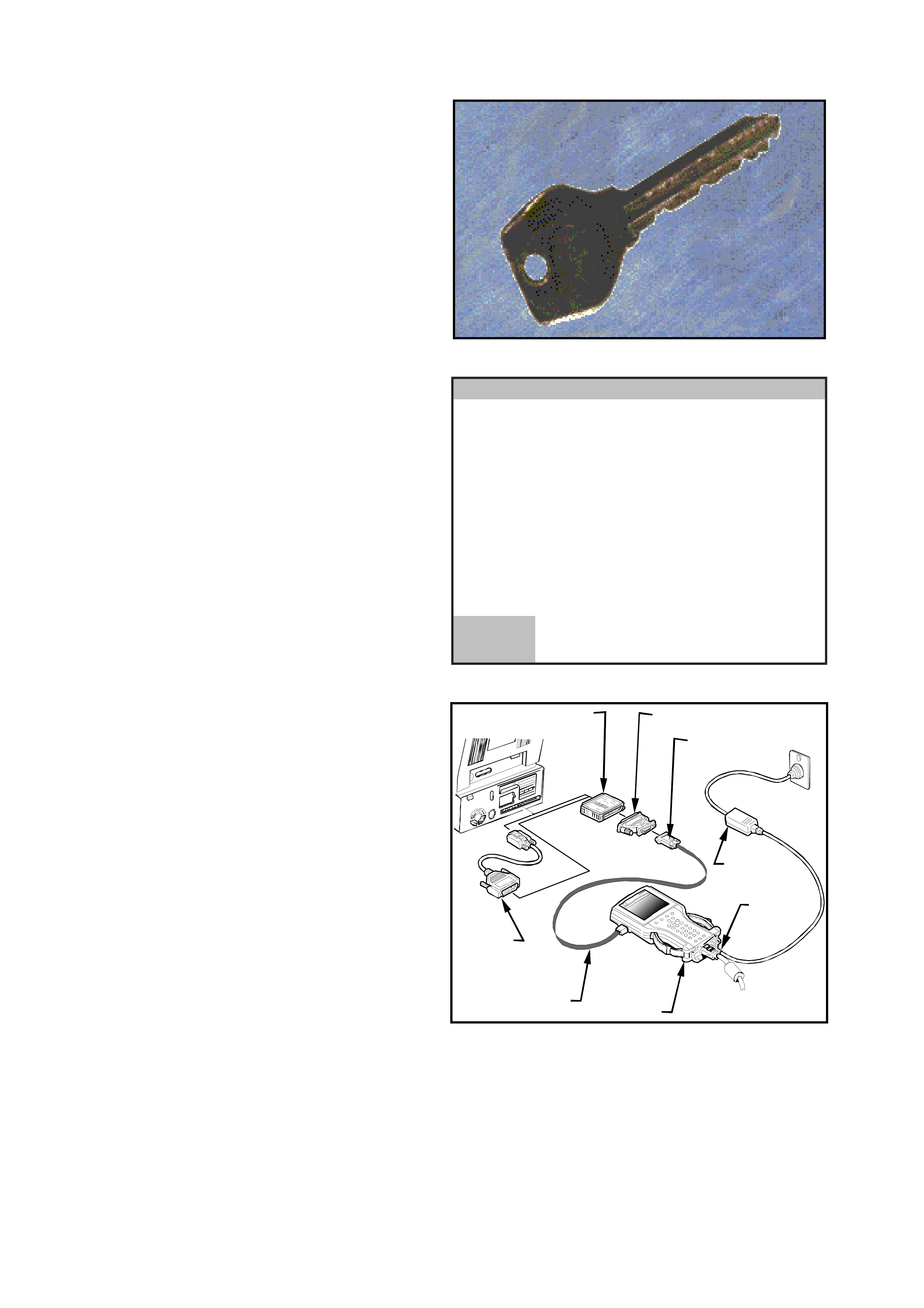
4.2 SECURITY ACCESS
Security Access is used in order to prevent
unauthorised persons from programming certain
security functions.
Figure 0C-69 Security Access Icon
After a Tech 2 security programming function has
been selected, the Tech 2 will display: Please get
programming approval from TIS!
To enable these programming procedures they
mus t be approved by the TIS 2000 Security Acc ess
function and Tech 2 must be connected to TIS
2000 using the RS232 interface and a registered
hardware key. Without this hardware key, an error
message is given by TIS 2000.
The Security Access procedure is as follows:
Confirm
BCM Link To PCM/PIM
Please get programming approval from
TIS!
VY0C093
(3) 2003 VY Comm odore
Body Control Module
Figure 0C-70 Tech 2 Programming Approval
1. Connect the Tec h 2 to the PC using the RS232
cable and the hardware key .
Connect the RS-232 cable ( 2) to the T ech 2 (1)
RS-232 c om m unication port. Connect the other
end of the RS-232 cable to the DB-9 adapter
(3) and then connect the DB-9 adapter (3) to
the 25/9 pin adapter (4). Connect the 25/9 pin
adapter to the Hardware Key (5) and then
connect the Hardware Key to the serial port of
a Personal Computer (PC) with TIS 2000
installed.
NOTE: If your PC has a 9 pin ser ial comm unic ation
port you will need to fit the 9/25 pin adapter (6)
between the hardware key (5) and the serial port of
the TIS 2000 PC.
2. Connect the power supply (7) to the TECH 2
power supply jack (8) . Pr ess the PWR button to
turn on Tech 2. Tech 2 should now be at the
title display screen.
54
6
3
8
7
1
2
Figure 0C-71 Connecting Tech 2 to the TIS 2000 PC
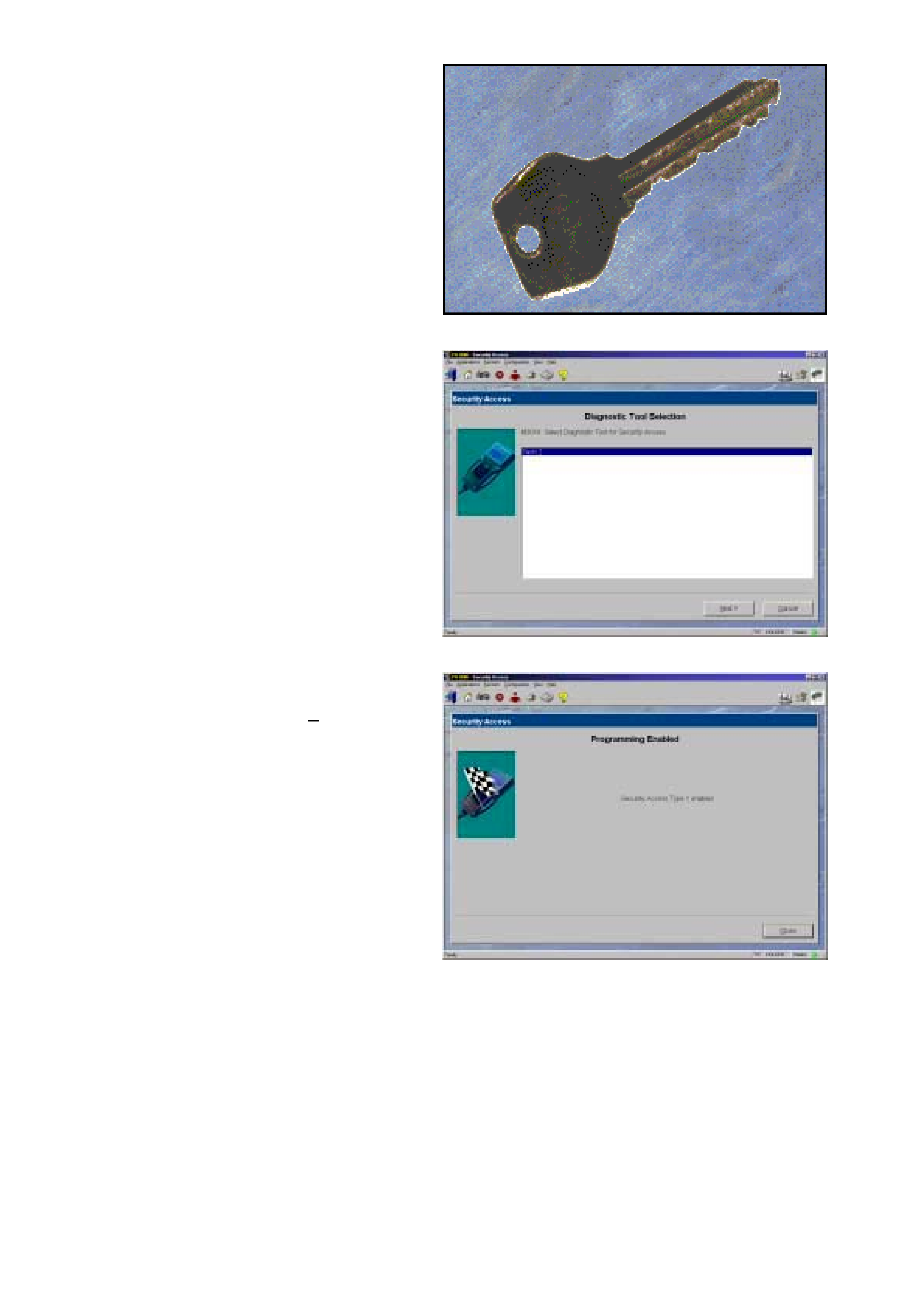
3. From the TIS 2000 Main Menu, click on the
Security Access icon to start the application.
Figure 0C-72 Enable Programming Icon
4. Select diagnostic tool (Tech 2) for Security
Access.
5. Select Next> to continue.
Figure 0C-73 Diagnostic Tool Selection
6. W hen the proc ess is com plete, a Progr am m ing
Enabled Security Access Type 1 enabled
screen appears. Click on the Close button to
close the application.
7. Reconnect the Tech 2 to the vehicle DLC and
reselect the progr amming func tion, you will now
be aloud to complete the programming
function.
Figure 0C-74 Programming Enabled
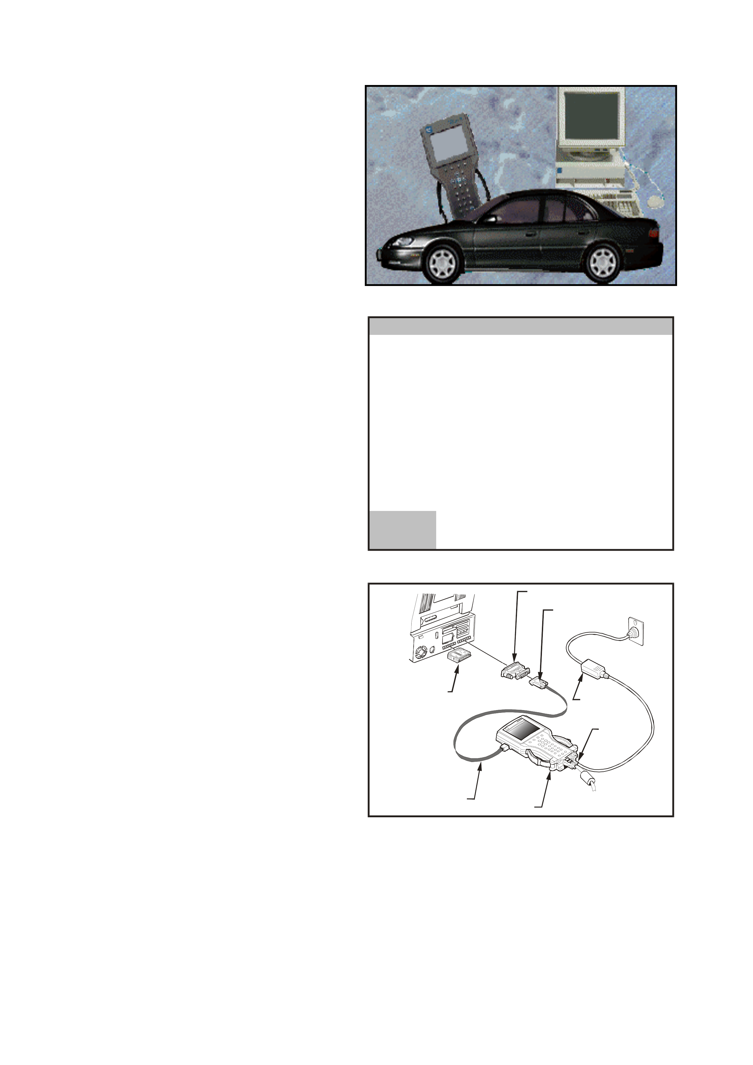
4.3 VEHICLE THEFT DETERRENT LEARN
Vehicle Theft Deterrent (VTD) Learn is used in
order to prevent unauthorised persons from
programming certain security functions.
Figure 0C-75 Enable Programming Icon
After a Tech 2 security programming function has
been selected, the Tech 2 will display: Please get
programming approval from TIS!
To enable these programming procedures, they
must be approved by the TIS 2000 VTD Learn
function and Tech 2 must be connected to TIS
2000 using the RS232 interface and a registered
hardware key. Without this hardware key, an error
message is given by TIS 2000.
The VTD Learn procedure is as follows:
Confirm
BCM Link To PCM/PIM
Please get programming approval from
TIS!
VY0C093
(3) 2003 VY Comm odore
Body Control Module
Figure 0C-76 Tech 2 Programming Approval
1. Connect the RS-232 cable (2) to the T ech 2 (1)
RS-232 c om m unication por t. Connect the other
end of the RS-232 cable to the DB-9 adapter
(3) and then connect the DB-9 adapter (3) to
the serial port of the TIS 2000 Personal
Computer (PC) with TIS 2000 installed. The
hardware key (5) must be installed in the
parallel port of the TIS 2000 PC.
NOTE: If your PC has a 9 pin ser ial comm unic ation
port you will need to fit the 9/25 pin adapter (4)
between the DB-9 adapter (3) and the ser ial port of
the TIS 2000 PC.
2. Connect the power supply (7) to the TECH 2
power supply jack (8).
3. Press the PWR button to turn on Tech 2. Tech
2 should now be at the title display screen.
VY0C086
5
4
3
7
6
1
2
Figure 0C-77 Connecting Tech 2 to the TIS 2000 PC
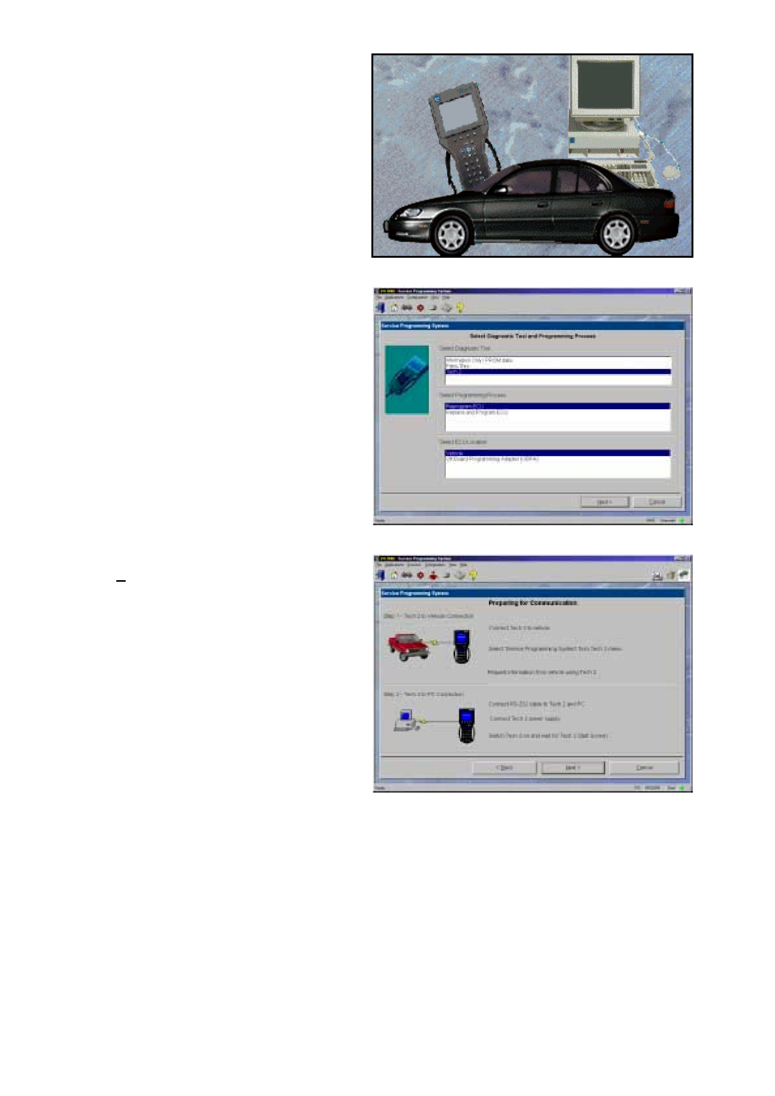
4. From the TIS 2000 Main Menu, click on the
Service Programming System (SPS) icon to
start the application.
Figure 0C-78 SPS Icon
5. From the Select Diagnostic Tool and
Programming Process screen select the
following:
Select Diagnostic Tool Tech 2
Select Programming
Process Reprogram ECU
Select ECU Location Vehicle
Figure 0C-79 Diagnostic Tool and Programming Process
6. At the Preparing for Communication screen
select Next> to continue.
Figure 0C-80 Preparing For Communication
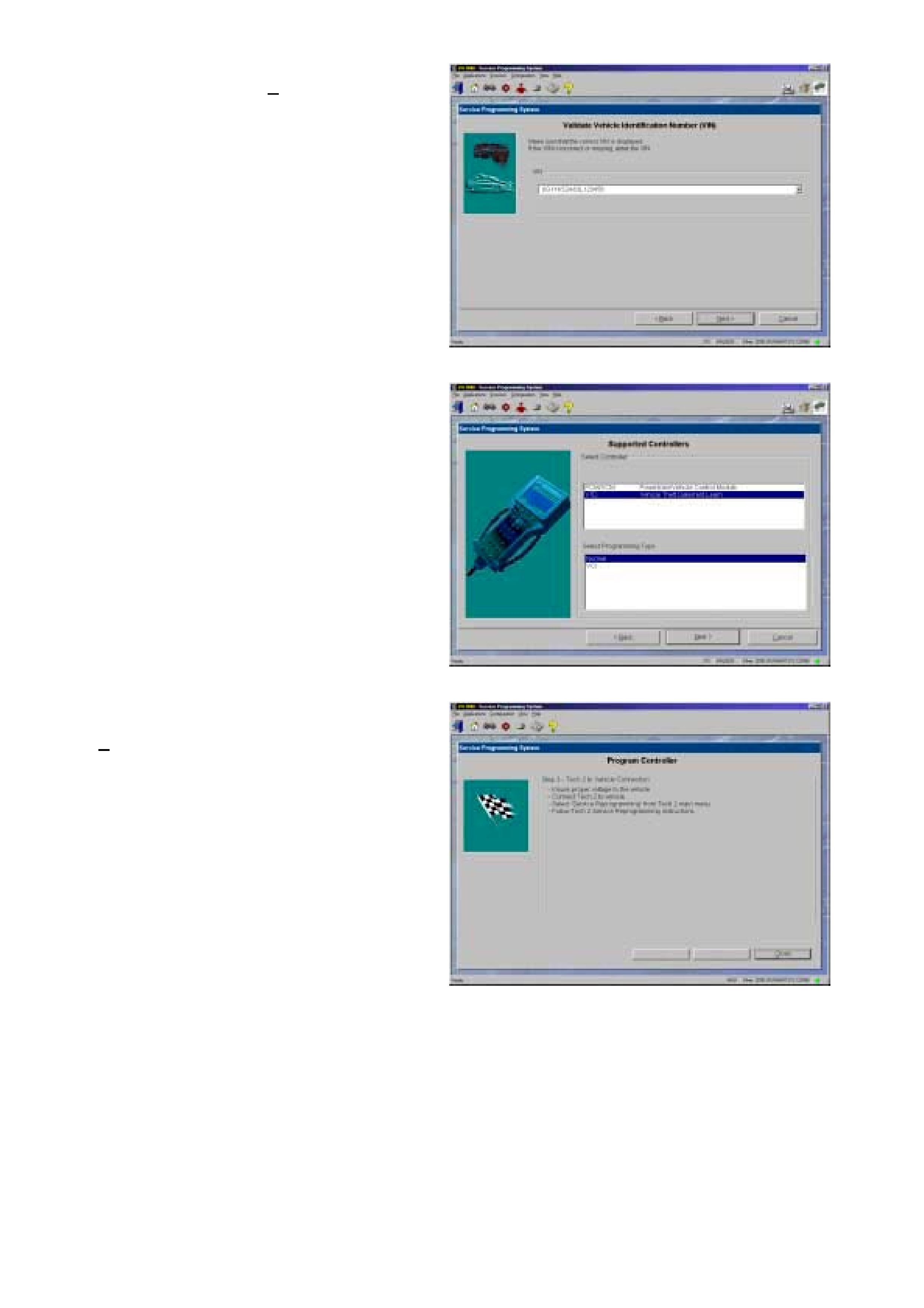
7. The Vehicle Identification Number (VIN) will
then be displayed select Next> to continue.
Figure 0C-81 Validate Vehicle Identification (VIN)
8. At the Supported Controllers screen select the
following:
Select Controller
VTD Vehicle Theft Deterrent Learn
Select Programming Type
Normal
Figure 0C-82 Supported Controllers
9. When the process is complete, the Program
Controller scr een will be displayed. Click on the
Close button to close the application.
10. Reconnect the Tech 2 to the vehicle DLC and
reselect the progr amming func tion, you will now
be aloud to complete the programming
function.
Figure 0C-83 Program Controller

5. SERVICE PROGRAMMING SYSTEM (SPS)
5.1 GENERAL INFORMATION
On the MY 2003 VY and V2 Series Models equipped with either a GEN III V8 engine or a V6 Non Supercharged
Engine, the PCM does not contain a removable PROM, it uses an EEPROM (Flash Memory) which is non
removable. The PCM is programmed from the factory with the proper calibrations for vehicle operation. In the event
that the PCM is replaced, or an updated calibration is required to correct a vehicle's operating condition, the PCM
will have to be program m ed with the new calibration. Progr am m ing is acc om plished through the vehic le DLC using
the TECH 2 Service Programming System (SPS) and TIS 2000.
A service replacement PCM will not be programmed. DTC P0601 indicates that the PCM is not programm ed and
DTC P0602 indic ates that pr ogramming has malf unctioned. F or further DTC infor mation and diagnostic procedures
refer to Section 6C1 POWERTRAIN MANAGEMENT V6 for V6 Non Supercharged Engines or Section 6C3-2
POWERTRAIN MANAGEMENT GEN III V8 for GEN III V8 Engines.
NOTE: If you are installing a new PCM ensure that the correct PCM is fitted to the vehicle. Refer to the
latest parts listing for part number identification.
The following T IS 2000 and TECH 2 screen displays will vary with different applications and versions of TIS 2000
and TECH 2 software.
Techline
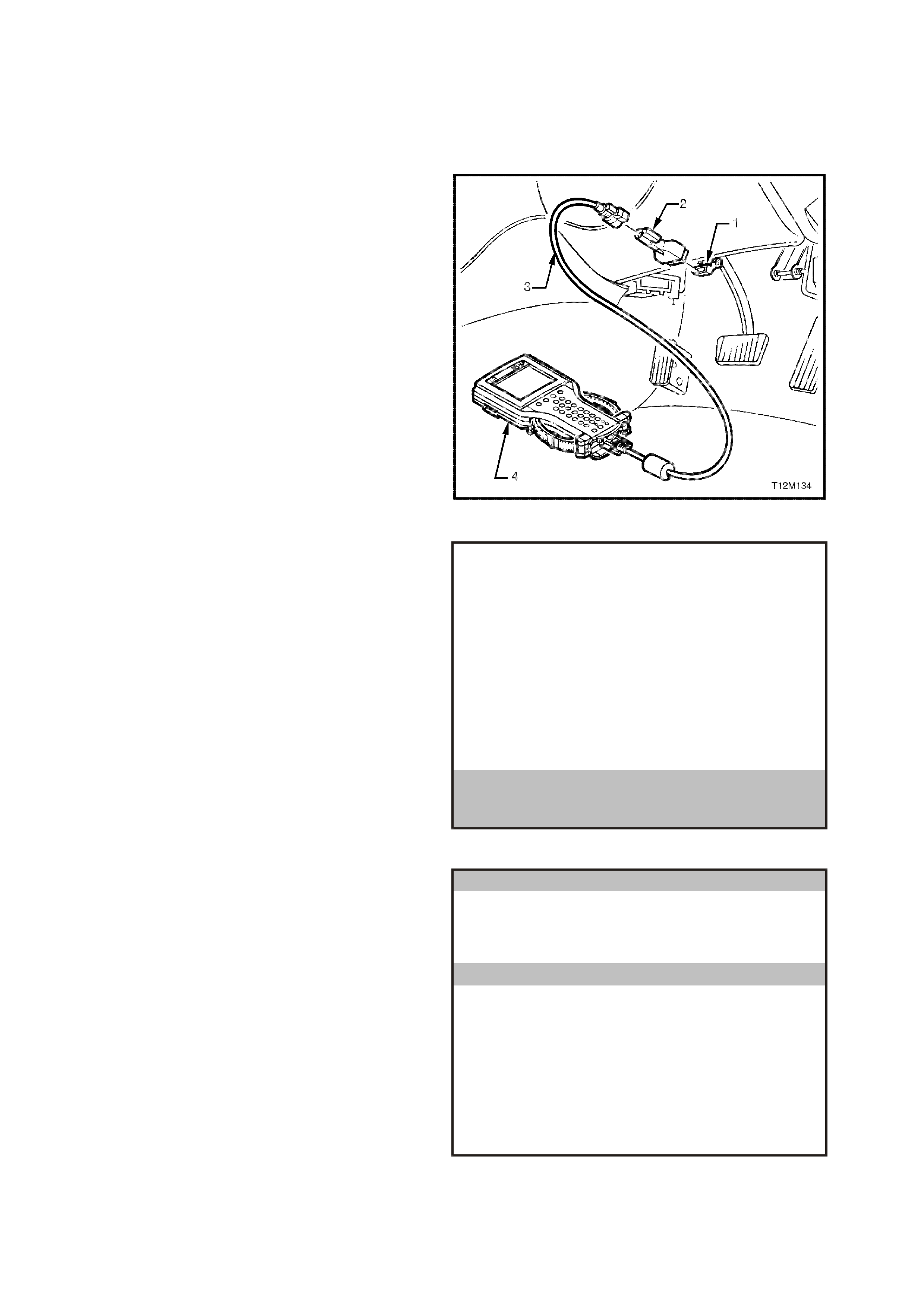
5.2 SPS PROCESS
CAUTION: Before performing SPS inspect the
TECH 2 DLC cable and the DLC connector and
terminals for damage. Any damage that causes
an open circuit during the programming
procedure could result in irreparable damage to
the PCM.
Battery voltage must be between 12 and 14
volts. The vehicle to be programmed must not
be connected to a battery charger during the
programming procedure. Incorrect battery
voltage could cause programming failure
and/or PCM failure.
1. Connect DLC cable (3) to TECH 2 (4), DLC
adapter (2) to DLC cable (3) and then DLC
adapter to DLC (1).
Press the TECH 2 PWR button to turn on
TECH 2.
Figure 0C-84 Connecting TECH 2 to the DLC
2. When the TECH 2 title screen is displayed,
press ENTER to continue.
VX0C000
Pr ess [ENTE R ] to continue.
Software Version 11.300
Holden 1997 - 2003
2
Tech
VY0C084
Figure 0C-85 TECH 2 Title Screen
3. Select F1: Service Programming System
(SPS).
Main Menu
VX0C001
F0: Diagnostics
F1: Service Programming System (SPS )
F2: View Capture Data
F3: Tool Options
F4: Download/Upload Help
Figure 0C-86 Main Menu

4. Select F0: Request Info and follow the
instructions on the screen.
Service Programming System (SPS)
Version 2.004
ECU to be programmed must be installed
b efore request info.
Tech 2 is ready to ready for data upload to TIS!
VY0C002
F 0: Re qu es t In fo
Figure 0C-87 F0: Request Info
5. If there is data already stored, TECH 2 will
display the stored data.
If there is no data stored in TECH 2 then the
following Model Year selection screen (Figure
0C-83) will be displayed.
Press the Continue Soft Key to request new
information.
Confirm Con tinue Keep Data
Service Programming System (SPS)
Version 2.004
Continue and request new info?
Data already stored in Tech 2!
VIN:
Hardware:
Software:
6G1YK52A63L123456
--------------
92083995
VY0C090
Figure 0C-88 Data Already Stored in TECH 2
6. Select the correct Model Year for the vehicle
you ar e work ing on. F or VY selec t (3) 2003 with
the arrow keys and the press ENTER.
Main Menu
Se lec t on e of the fo llowing
Model Year(s)
VY0C081
(3)
(2)
(1)
(Y)
(X)
(W)
(V)
(3)
2003
2002
2001
2000
1999
1998
1997
1 / 7
2003
Figure 0C-89 Model Year Selection

7. Select the appropriate vehicle eg. VY
Commodore with the arrow keys and then
press ENTER.
V ehicle Identification
Se lec t on e of the fo llowing
V ehicle Type(s)
VY0C082
V2 Moraro
VY Commodore
VY Calais
VY Utility
WH Statesman
WH C aprice
Corsa-C
Corsa-C Combo
Astra-G
VY Commmodore 1 / 13
Figure 0C-90 Vehicle Identification
(Opel Vaxhall TIS 2000)
V ehicle Identification
Se lec t on e of the fo llowing
V ehicle Type(s)
VY0C082
Chevrolet Lumina
Chevrolet Caprice
Chevrolet Statesman
Chevrolet Utility
Chevrolet Lumina 1 / 4
Figure 0C-91 Vehicle Identification
(NAO TIS 2000)
8. Select F0: Engine and then press ENTER.
System Selection Menu
VY0C094
(3) 2003 VY Com modore
F0: E n gine
Figure 0C-92 System Selection

9. Select the appropriate engine for the vehicle
you are working eg. 3.8L V6 on with the arrow
keys and then press ENTER.
V ehicle Identification
Se lec t on e of the fo llowing
Engine
VY0C095
5.7L V8
3.8L V6
3.8L V6 1 / 2
Figure 0C-93 Vehicle Type Selection
10. Turn off Ignition!
Turn the ignition off and then press the Okay
soft key to continue.
Okay
Service Programming System (SPS)
Version 2.004
Turn of f Ignition !
VY0C096
Figure 0C-94 Service Programming System (SPS)
11. When Ignition switched off! is displayed,
ensure that the ignition is switched off and then
press the Okay soft key to continue.
Service Programming System (SPS)
Version 2.004
Ignition switched off!
VY0C097
Okay
Figure 0C-95 Service Programming System (SPS)

12. Turn off all power consuming devices!
(i.e. A/C. Radio, Headlamps etc).
Turn on ignition with engine off!
Be sure the battery is fully charged?
Press the Okay soft key to continue.
Note: The battery must be fully charged and it
MUST not be connected to a battery charger
during the SPS process.
Okay
Service Programming System (SPS)
Version 2.004
Turn on ign ition with en gine off.
Be sure that battery is fully charged.
Turn off all power consuming devices!
VY0C098
Figure 0C-96 Service Programming System (SPS)
11. The TECH 2 will then read and display the
Vehicle Identification Number (VIN) and ECU
data.
When the TECH 2 screen opposite is
displayed;
Turn off TECH 2.
Turn off Ignition.
Disconnect TECH 2 from the DLC.
NOTE: If programming a Service Replacement
PCM the VIN will not be displayed.
Service Programming System (SPS)
Version 2.004
Turn off Ignition ! Disconnect Tech 2
from vehicle and connect it to TIS
Existing ECU Data!
VIN:
Hardware:
Software:
6G1YK52A63L123456
16269020
92118901
VY0C083
Figure 0C-97 Typical ECU Data
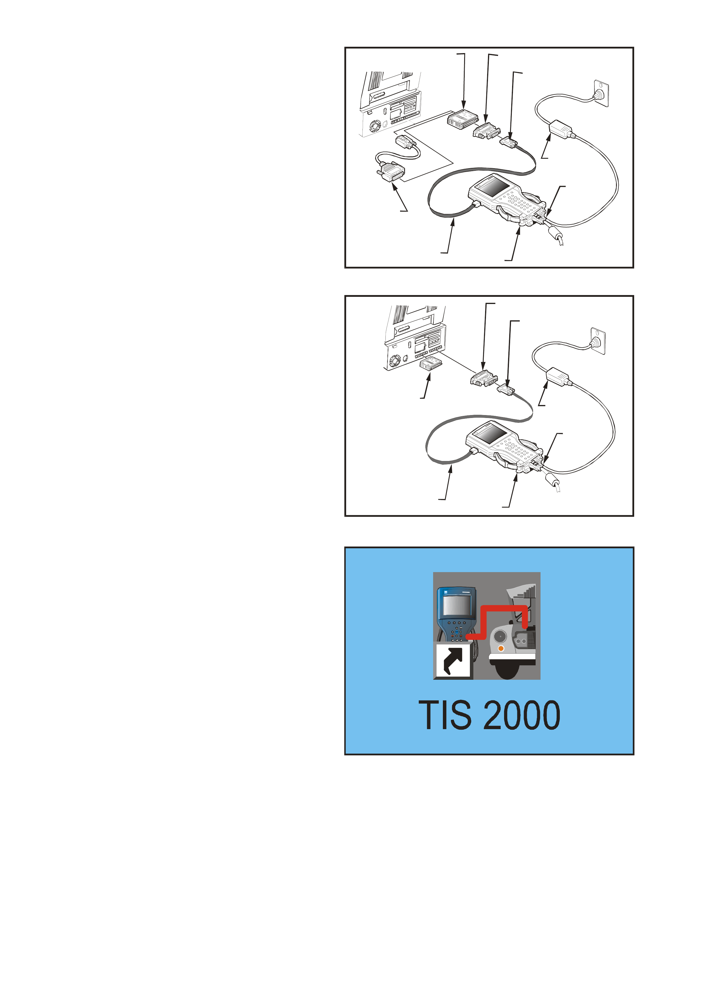
12. Connect the RS-232 cable (2) to the TECH 2
(1) RS-232 communication port. Connect the
other end of the RS-232 cable to the DB-9
adapter (3) and then connect the DB-9 adapter
(3) to the 25/9 pin adapter (4). Connect the
25/9 pin adapter to the hardware key (5) and
then connect the hardware key to the serial
port of a Personal Computer (PC) with TIS
2000 installed.
If your PC has a 9 pin serial communication
port you will need to fit the 9/25 pin adapter (8)
between the hardware key (5) and the serial
port of the TIS PC. Connect the power supply
(6) to the T ECH 2 power s upply jack (7). Pres s
the PWR button to turn on TECH 2. TECH 2
should now be at the title display screen.
NOTE: If you are using NAO TIS 2000 the
hardware key (5) is installed in the PC parallel
port. Refer figure 0C-93.
VY0C085
54
8
3
7
6
1
2
Figure 0C-98 Connecting TECH 2 to TIS 2000
VY0C086
5
4
3
7
6
1
2
Figure 0C-99 Connecting TECH 2 to NAO TIS 2000
13. Open TIS 2000 by double clicking the TIS 2000
Icon.
Figure 0C-100 TIS 2000 Icon
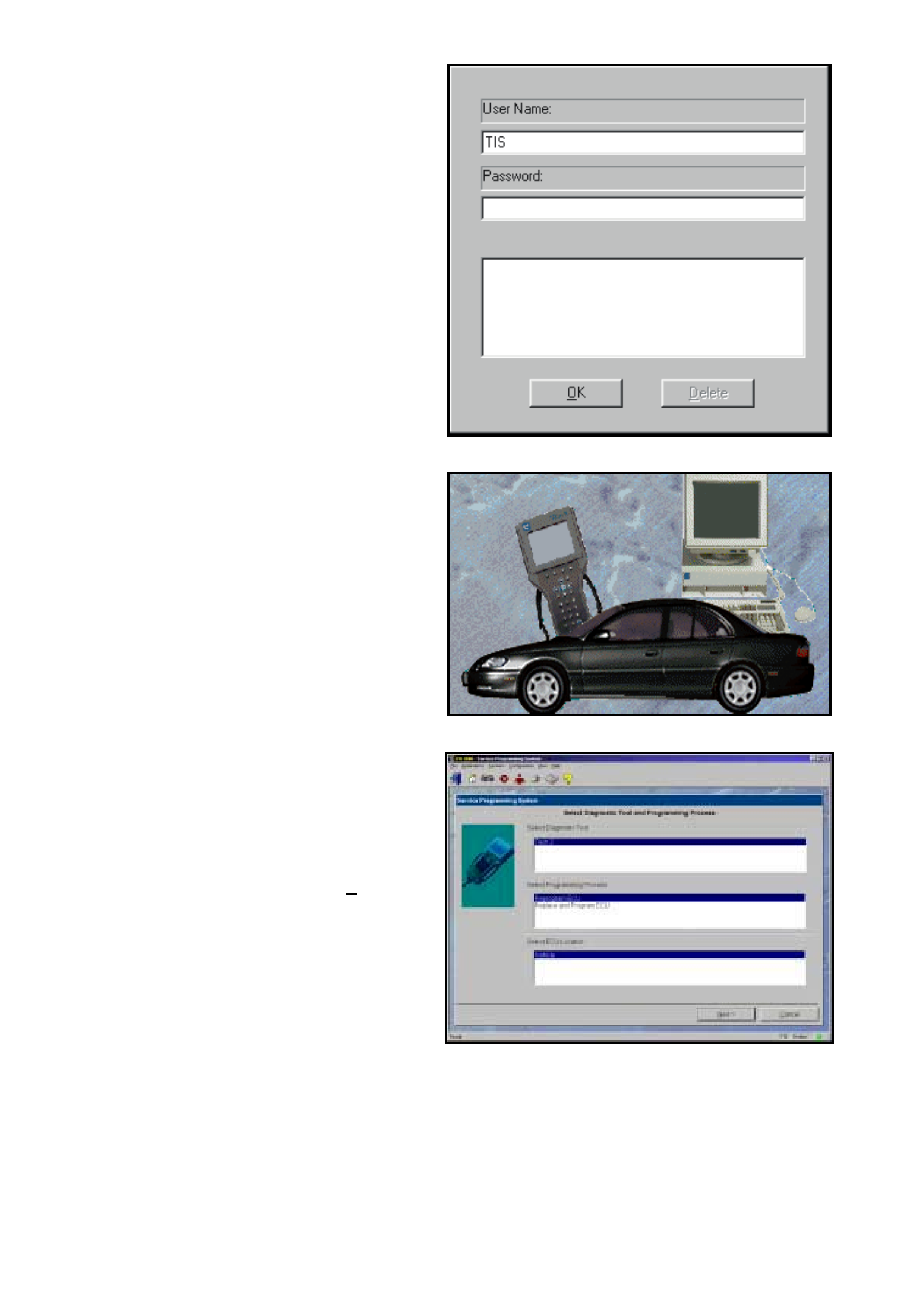
14. The default user of TIS2000 is called "TIS".
This user does not have a password. Click the
"OK" icon to continue.
Figure 0C-101 TIS User
15. From the TIS 2000 Main Menu click on the
SPS icon to start the SPS application.
NOTE: If TIS 2000 does not detect a hardware
key the following error message will be
displayed.
Access to Service Programming Server was
denied. No Hardware Key was found!
Figure 0C-102 SPS Icon
16. At Select Diagnostic Tool and Programming
Process click on desired selections for:
• Diagnostic tool being used: TECH 2.
• Whether you are reprogramming an existing
control unit or programming a new control unit.
• Select ECU location: Vehicle.
17. After making your selections, select Next>.
Figure 0C-103 Select Diagnostic Tool and Programming
Process
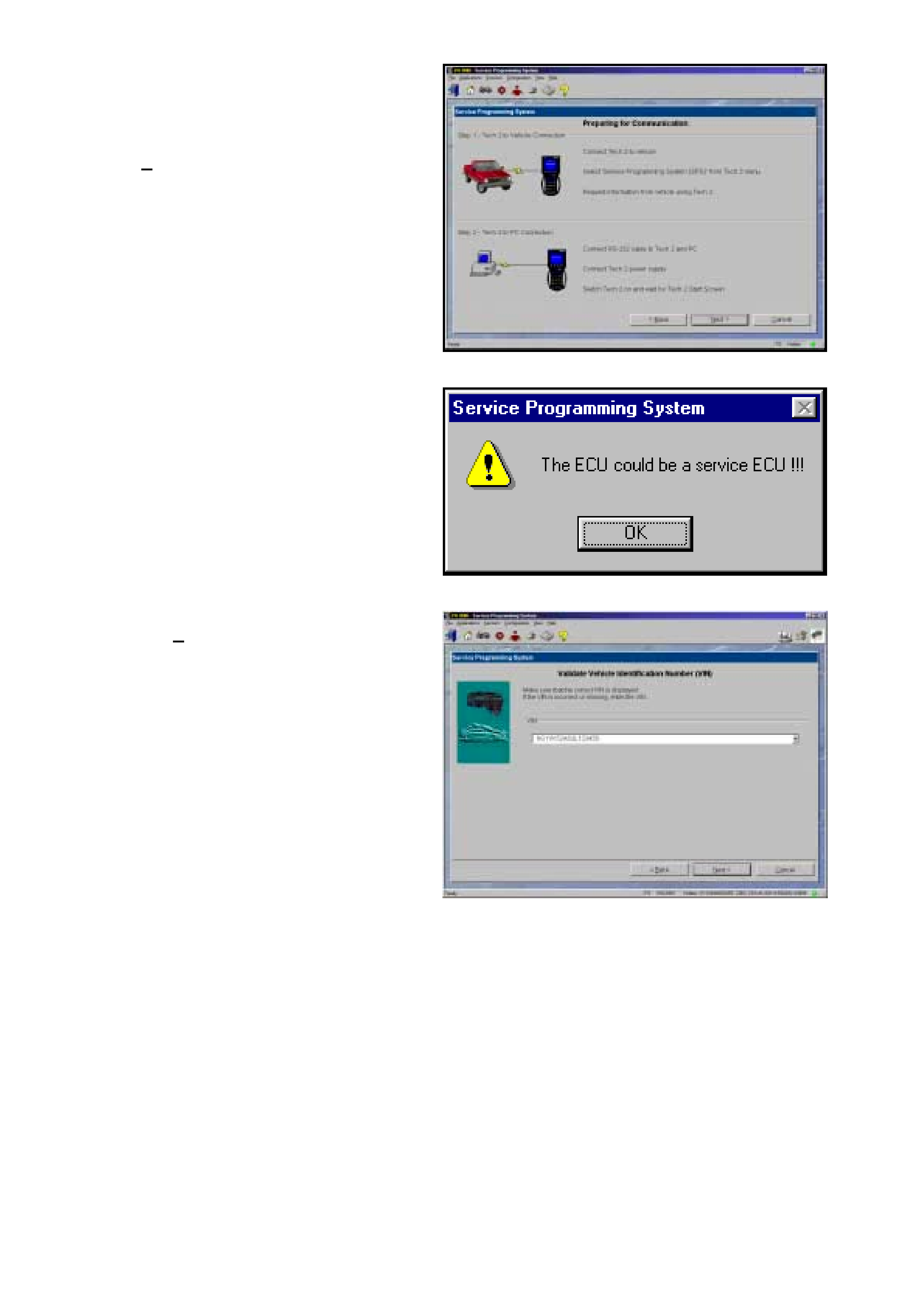
18. At this point you should have already
Requested Info from the Vehicle and TECH 2
should be connected to the serial port of a
Personal Computer (PC) with TIS 2000
installed.
Select Next>. to continue.
Figure 0C-104 Connecting Diagnostic Tool
19. If a Service ECU has been installed the
warning opposite will be displayed at this time,
select OK to continue.
Figure 0C-105 Service ECU Warning
20. Confirm VIN or enter correct VIN, if required,
then select Next>.
Figure 0C-106 Validate Vehicle Identification Screen
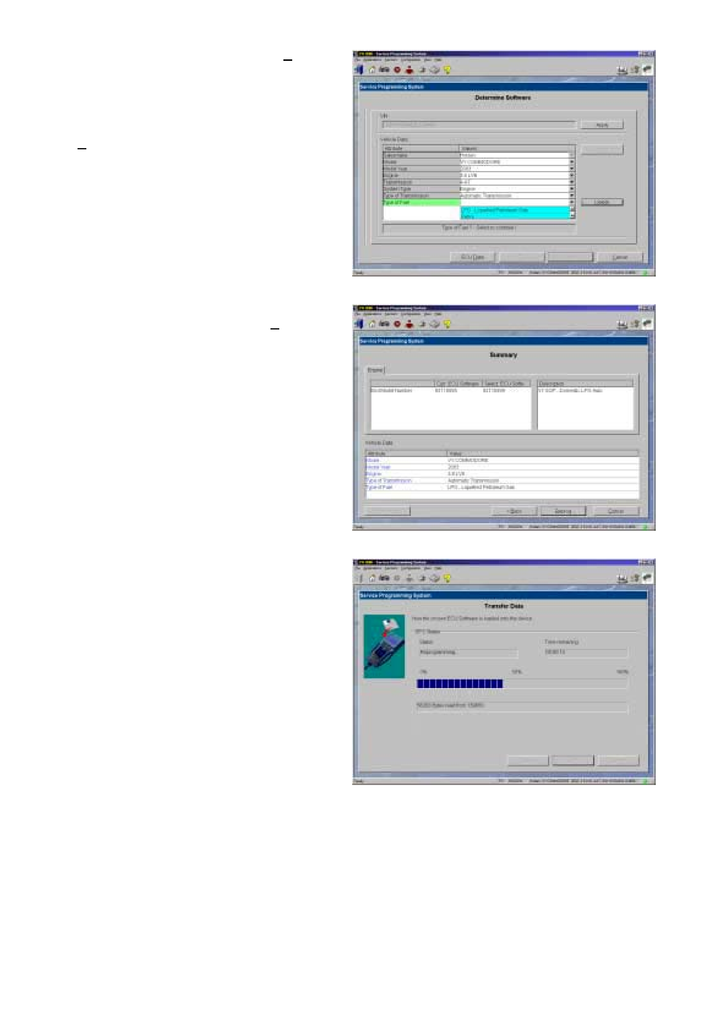
21. If the vehicle data is correct Select Next> to
continue.
22. If you wish to change any of the programming
options, select the option you wish to change
and then select delete. A list of the options
available will then be displayed and the select
Next> to continue
Note: the options selected must match the
vehicle.
Figure 0C-107 Validate Vehicle Data
23. A Summary screen will appear, allowing you to
confirm your selection. Select Reprog to
continue.
Figure 0C-108 Summary Screen
24. A Transfer Data screen will appear. Select
Reprog button to initiate download of new
calibration file to TECH 2. T he screen will track
progress of download.
Figure 0C-109 Transfer Data
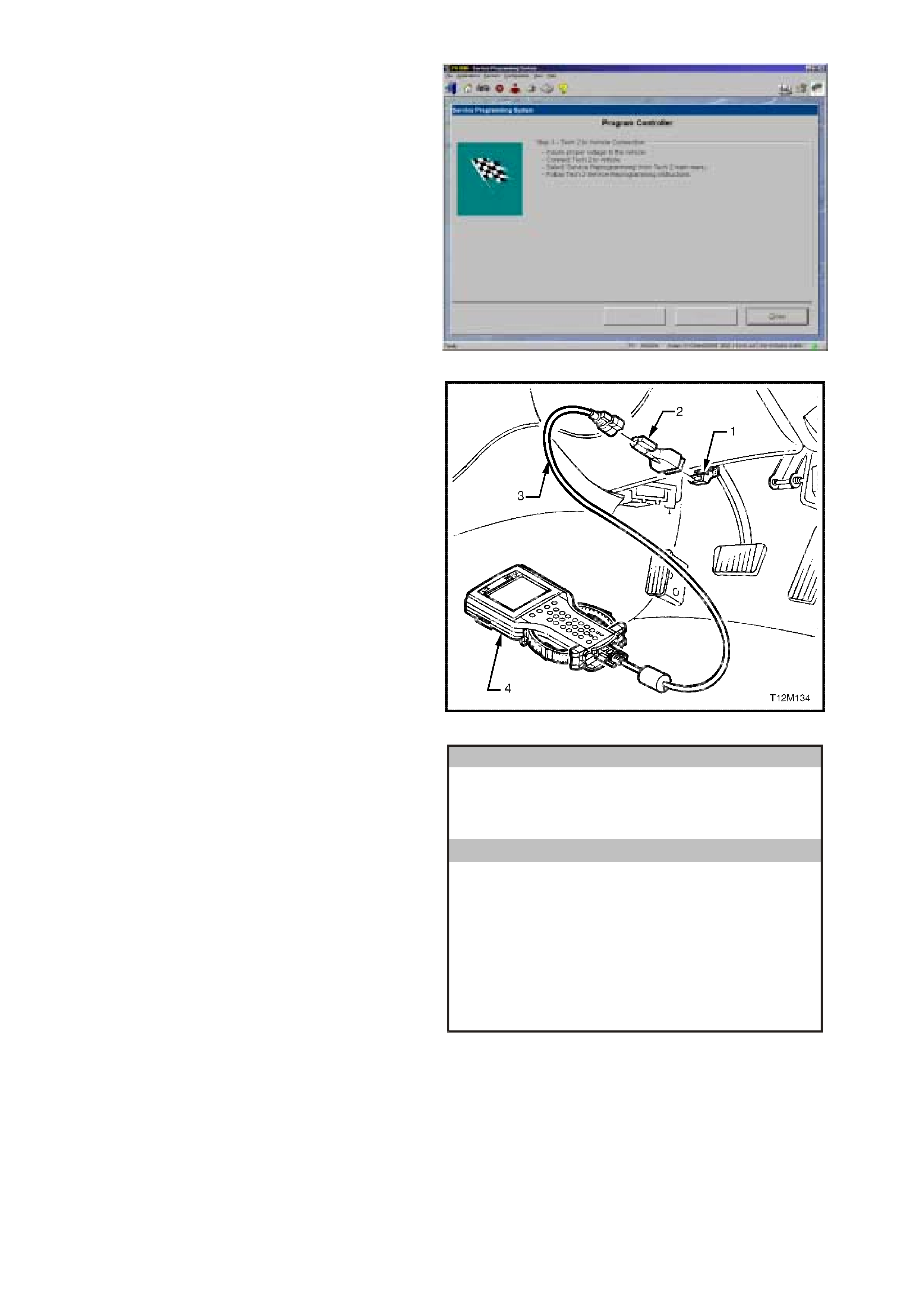
25. After download is complete a screen will
appear instructing you to connect TECH 2 to
vehicle to complete programming process.
Close the SPS application to retur n to TIS 2000
main menu; power down and then disconnect
TECH 2 from PC.
26. Return to the vehicle and complete the SPS
process.
Figure 0C-110 Download Complete
27. Reconnect TECH 2 to the DLC.
Press the TECH 2 PWR button to turn on
TECH 2.
When the TECH 2 title screen is displayed,
press ENTER to continue.
Legend:
1. DLC
2. DLC Adapter
2. DLC Cable
3. TECH 2
Figure 0C-111 Connecting TECH 2 to the DLC (Typical)
28. Select F1: Service Programming System
(SPS).
Main Menu
VX0C001
F0: Diagnostics
F1: Service Programming System (SPS )
F2: View Capture Data
F3: Tool Options
F4: Download/Upload Help
Figure 0C-112 Main Menu

29. F1: Program ECU will be flashing. TECH 2 is
ready for ECU programming.
Select F1: Program ECU and follow the
instructions on the TECH 2 screen.
Service Programming System (SPS)
Version 2.004
ECU to be programmed must be installed
b efore request info.
Tech 2 is ready is ready for ECU programming!
VY0C099
F 0: Re qu es t In fo
F1: Program ECU
Figure 0C-113 Service Programming System (SPS)
30. Turn off all power consuming devices!
(i.e. A/C, Radio, headlamps etc.).
Turn on ignition with engine off!
Be sure the battery is fully charged?
Press the Okay soft key to continue.
Note: The battery must be fully charged and it
MUST not be connected to a battery charger
during the SPS process.
Okay
Service Programming System (SPS)
Version 2.004
Turn on ign ition with en gine off.
Be sure that battery is fully charged.
Turn off all power consuming devices!
VY0C098
Figure 0C-114 Service Programming System (SPS)
31. TECH 2 will begin programming the ECU. The
screen display will indicate the progress of the
download as a percentage.
Service Programming System (SPS)
Version 2.004
Programming in Progress
D o w nloa din g ca l ib ra ti on file
Progress
45%
Software Module 1
Line 0A
VY0C100
Figure 0C-115 Programming in Progress

32. Programming successful ! will be displayed
when programming is completed.
Press the Exit soft key.
Turn off and disconnect TECH 2
Turn off Ignition.
NOTE: If a Service PCM or a PCM from
another vehicle has been installed, a BCM to
PCM/PIM Link will have to be performed. Refer
BCM TO PCM/PIM LINKING procedure in
Section 12J BODY CONTROL MODULE.
Service Programming System (SPS)
Version 2.004
Programming Successful !
Press [Exit] Key
VY0C092
Figure 0C-116 Programming Successful
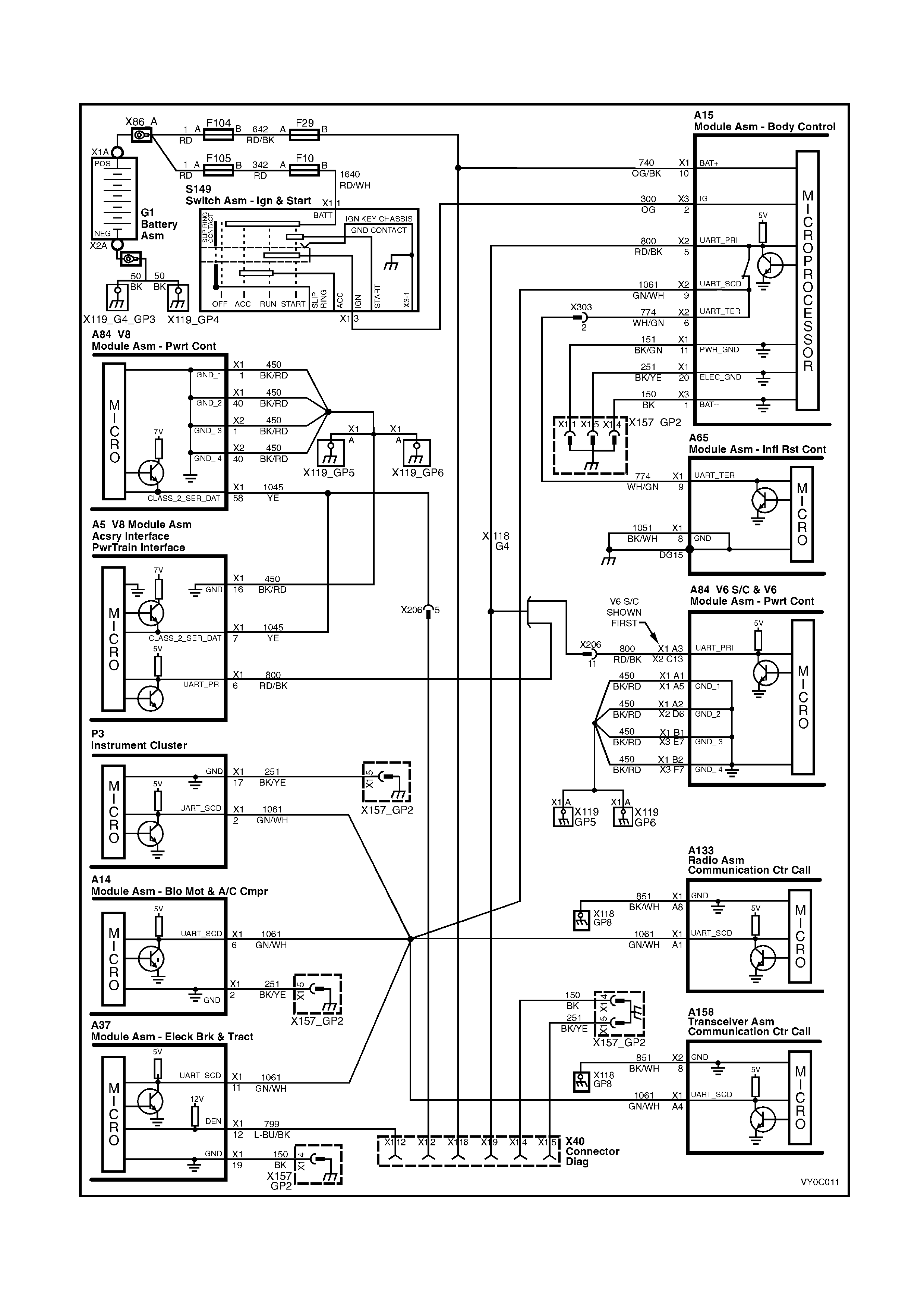
6. TECH 2 DIAGNOSIS
Figure 0C-117 Serial Data Circuit
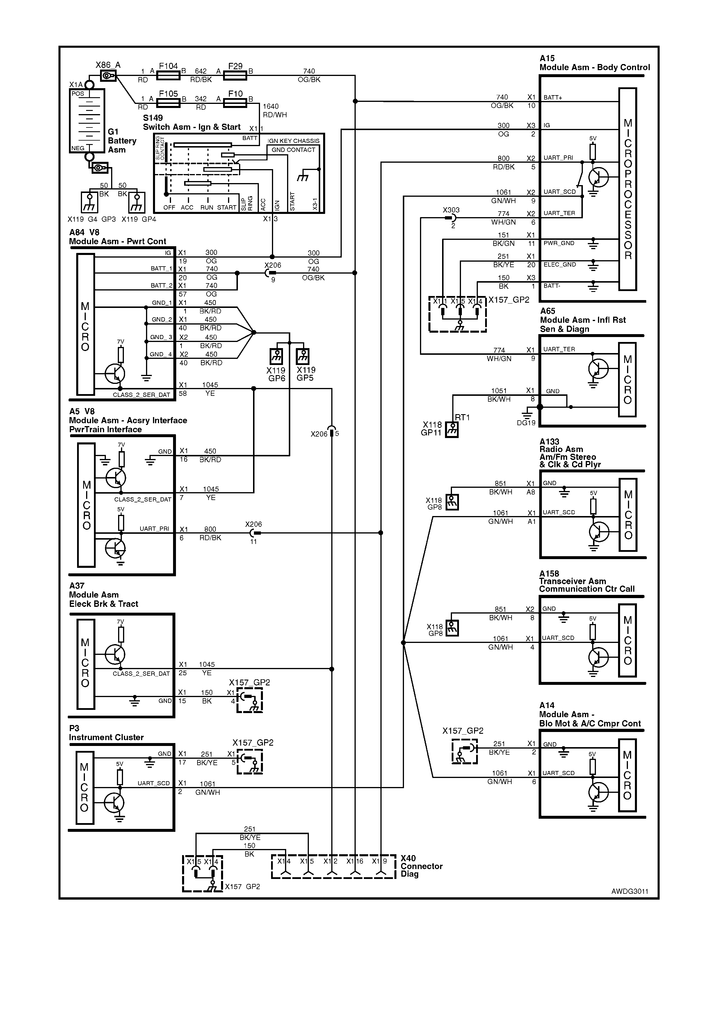
Figure 0C-118 V8 AWD Serial Data Circuit

6.1 GENERAL INFORMATION
TECH 2 c omm unic ates with the vehic le via the Primary, Secondary and Tertiary UART serial data bus c irc uits . T he
primary serial data circuit 800 (Red/Black wire) is connected to terminal 9 of the DLC (X40), the PCM and the BCM.
All other modules except the SDM are connec ted to the secondary serial data circuit 1061 ( Green/White wire), the
SDM is connected to the tertiary serial data circuit 744 (W hite/Green wire). Both the secondary and tertiary serial
data circuit are connected to the primary serial data circuit via the BCM serial data bus isolator. The serial data
ground circuit is via terminal 5 of the DLC and circuit 251.
The power supply f or TECH 2 is from fus ible link F104 and f use F29 via circ uit 740 (OG/BK wire) to ter minal 16 of
the DLC. The ground circuit is via terminal 4 and circuit 150 (Black wire).
TECH 2 com m unicates with the following control m odules, via the UART s erial data bus circ uit 800, 1061 and 774
if the vehicle is equipped with these sy stems.
• Body Control Module (BCM).
• Powertrain Control Module (PCM) - V6 Engines.
Engine and Automatic Transmission
• Powertrain Interface Module (PIM) - V8 GEN III Engine.
• Instrument (INS).
• Supplemental Restraint System (SRS).
• Antilock Braking System / Electronic Traction Control System.
• Audio System (Audio Head Unit).
• Telematics Module
TECH 2 communicates with the GEN III V8 PCM and the AWD ABS – T C module via the Class 2 serial data circuit
1045. Circuit 1045 is connected to terminal 2 of the DLC (X40).
TEST DESCRIPTION
The numbers below refer to step numbers on the facing page diagnostic chart.
1. Checks if TECH 2 is being powered up.
2. Checks if TECH 2 is programmed with the latest version software.
3. Check s if TECH 2 can com m unic ate with BCM If T ECH 2 can com m unic ate with BCM, serial data circuit 800 is
OK.
4. Checks continuity of serial data ground circuit.
5. Checks if fusible link F104 is OK.
6. Checks if fuse F29 is OK.
7. Checks if battery voltage is available for TECH 2.
8. Checks if an ground circuit is available for TECH 2.
9. All vehicle c irc uits have been found to be OK, f ault must be with TECH 2 or an intermitted fault is causing TECH
2 not to operate correctly.
X40
Figure 0C-119

TECH 2 DIAGNOSTIC CHART
STEP ACTION VALUE YES NO
1. 1. Connect TECH 2 to the vehicle DLC, (X40) with the
DLC cable and the 16/19 pin adapter.
2. Switch on TECH 2 by pressing the PWR button.
Does a green light above the PWR button come ON?
Go to Step 2. Go to Step 5.
2. 1. Does TECH 2 Title Screen illuminate and display:
TECH 2
Press [ENTER] To Continue
Software Version: 12.400
Holden 1997 - 2003
(Software Version should be greater than 12.400)
Go to Step 3. Program TECH 2
refer 2.
PROGRAMMING
TECH 2 in this
Section.
3. 1. At the TECH 2 title screen press the Enter key.
2. Select F0: Diagnostics / 2003 / VY Commodore /
F3: Body / Body Control Module.
3. Turn on ignition and press the confirm soft key.
Does TECH 2 display the BCM System Identification
Data?
TECH 2 is
functioning
correctly, refer to
system specific
diagnostics, if you
cannot
communicate with
a specific control
module.
Go to Step 4.
4. 1. Using an ohmmeter check continuity of circuit 251
(Black/Yellow wire) between DLC (X40) terminal 5
and a known good ground.
Is there continuity?
Go to BCM
Diagnosis
SERIAL DATA
COMMUNICATION
Section 12J BCM.
Repair open in
circuit 251 between
DLC terminal 5 and
ground connector
X157_GP2.
5. Is Fusible link F104 OK? Go to Step 6. Replace fusible link
and check cause of
blown fusible link.
Verify Repair.
6. Is Fuse F29 OK? Go to Step 7. Replace fuse and
check cause of
blown fuse.
Verify Repair.
7. 1. Check for voltage between DLC (X40) terminals 4
and 16.
Is voltage at specified value?
B+ Go to Step 9. Go to Step 8.
8. 1. Ignition off.
2. Check for voltage between DLC (X40) terminals 16
and a known good ground.
Is voltage above specified value?
B+ Repair open in
circuit 150 between
DLC Connector
terminal 4 and
ground connector
X157_GP2.
Verify Repair.
Repair open in
circuit 740 and 642
between DLC
connector X40
terminal 16 and
fusible link F104.
Verify Repair.
9. 1. Perform TECH 2 Self Test using 240 V AC power
supply. (Refer to TECH 2 User’s Guide).
Does TECH 2 pass Self Test?
Check for incorrect
terminal sizing of
DLC X40 or
intermittent fault in
DLC circuits.
Send TECH 2 out
for repair.
7. SPECIAL TOOLS
TOOL NO. REF
IN TEXT TOOL DESCRIPTION COMMENTS
TECH 2 TECH 2
Previously released
Technical Information
Sy stem
(TIS) 2000
TIS 2000 CD ROM
V
ersion 32.0B
Tech 2 Ver.
Holden 11.200
May
2002
CD No 1
TIS2000
Data Copyright 2001 All
rights reserved SOFTWARE
copyright 2001 Service
Opera ti o ns Gen er al Mo to r s
Corp All Rights Reserved
This disc contains cop
y
ri
g
hted
material. Any reproduction or
publication of th i s inf o r mat io n
wit h out th e exp res sed wri t t e n
permission of Adam Opel
A
G,Russelsheim, is prohibited
Released Monthly