
SECTION 1A1 - BODY
IMPORTANT
Before performing any Service Operation or other procedure described in this Section, refer to
Section 00 CAUT IONS AND NOT ES for correct workshop practices w ith regard to safety and/or property
damage.
CONTENTS
1. GENERAL DESCRIPTION
2. GENERAL SERVICE OPERATIONS
2.1 WATER & DUST LEAK DIAGNOSIS
2.2 BODY LUBRICATION
2.3 LOCK CYLINDERS & KEYS
2.4 PLASTIC COMPONENTS
3. WHEELHOUSE LINERS
3.1 FRONT WHEELHOUSE LINER
REMOVE
REINSTALL
3.2 REAR WHEELHOUSE LINER, SEDAN &
WAGON
REMOVE
REINSTALL
3.3 REAR WHEELHOUSE LINER, COUPE &
ULTILITY
REMOVE
REINSTALL
4. FUEL FILLER DOORS
4.1 FUEL FILLER DOOR ASSEMBLY,
SEDAN & COUPE
REMOVE
DISASSEMBLE
REINSTALL
4.2 FUEL FILLER DOOR ASSEMBLY, WAGON
REMOVE
DISASSEMBLE
REINSTALL
4.3 FUEL FILLER DOOR ASSEMBLY, UTILITY
REMOVE
REINSTALL
4.4 FUEL FILLER DOOR CABLE ASSEMBLY, RHD
SEDAN & WAGON
COUPE
4.5 FUEL FILLER DOOR LOCK ACTUATOR
ASSEMBLY, LHD
SEDAN & WAGON
COUPE
DIAGNOSIS
WIRING SCHEMATIC
CONNECTOR VIEWS
5. DRAIN TUBES, UTILITY
5.1 REAR FLOOR PANEL DRAIN TUBE, UTILITY
REMOVE
REINSTALL
5.2 REAR WINDOW PANEL DRAIN TUBE
ASSEMBLY, UTILITY
REMOVE
REINSTALL
6. TORQUE WRENCH SPECIFICATIONS
Techline
Techline
Techline

1. GENERAL DESCRIPTION
The MY 2003 VY Series is a major upgrade of the MY 2002 VX Series and marks the integration of the MY 2002
VU Series Utility into the one model designation.
The major body changes at the front include new bumper fascias, radiator grilles, headlamps, fenders and hood.
At the rear, m ajor changes are lim ited to the bumper fascias on W agon and Utility SS models. For the Sedan, the
rear changes are more substantial with a new rear compartment lid and license plate applique, rear quarter and
other rear panels, tail lamps and bumper fascias.
Exterior ornamentation changes are made across the board.
On the inside, all models gain a completely new instrument panel and console along with minor trim upgrades.
Also included in this publication is the MY 2003 V2 Series Coupe. This vehicle only receives m inor revisions when
compared to its predecessor externally, however it gains the new instrument panel and console from the MY 2003
VY Series.
For this public ation, the c ontents of the Body Sections have been rearranged. This Section contains non-s heetmetal
components, not related to components in other Sections.
Section 1A4 now includes the hood and all of its related components, including the release mechanism. The rear
compartment lid for both Sedan and Coupe along with the Wagon liftgate and Utility endgate and their related
components are also included in Section 1A4.
The body structure components can now be found in Section 1B Sheetmetal, along with the fender, Utility rear
compartment bolt-on sheetmetal components and other minor sheetmetal body components.

2. GENERAL SERVICE OPERATIONS
2.1 WATER AND DUST LEAK DIAG NOSIS
Diagnosis of body leaks is com plicated by the fac t that the appearanc e of dus t or water at one point can be c aused
by seepage through any one, or more, of many possible locations.
As an example of this indirect entry, the cause of wet front floor coverings may be due to water entering past the
door weatherstr ip, through the door inner panel, between the windshield and its adhes ive com pound or through any
one of the joins in the body structure. Therefore, the point or points of water or dust entry must be established
before effective resealing can be carried out.
W ater leak diagnosis is usually performed by having an assistant spray a gentle fan of water from a hose around
the suspected area until the leak can be generated. Removal of various trim components from the inside may be
required to determ ine point of entry. Narrowing down the water spray to the point of greatest water flow will assist in
determining the point of entry.
Dust entry quite often requires the following of signs of dust entry around seals or vent inlets or outlets, etc.
Once detected, repair the area by replacing faulty components or applying the correct sealer or adhesive as
specified in the MY 2003 VY & V2 Series BODY STRUCTURE REPAIR MANUAL.
Techline
2.2 BODY LUBRICATION
The moving mechanical parts of the body which have metal to metal contact are lubricated at assembly.
Operating conditions, whether normal or otherwise, determine the effective life of the lubricant and for this reason
lubrication in service is important. Equally important is the type of lubricant to be used.
IMPORTANT: Careless or excessive application of body lubricants can result in staining of the paint finish
and interior trim, can damage clothing, and can become a trap for dirt. Use lubricants sparingly and remove
excess material immediately.
Listed below are the body lubrication points. For the recommended lubricants and maintenance schedule refer to
Section 0B LUBRICATION & SERVICING.
PARTS READILY ACCESSIBLE:
• Hood Pilot Pin Assembly
• Hood Lock Assembly
• Hood Hinges
• Door Hinge Pins
• Door Check Assemblies
• Door Lock Cylinder
• Door Lock Striker
• Door Lock Assembly Fork
• Rear Compartment Lid Hinge
• Rear Compartment Lid Latch
• Liftgate or Endgate Hinge
• Liftgate Lock Cylinder
• Liftgate or Endgate Latch
• Ignition Lock Cylinder
• Instrument Panel Compartment Lock Cylinder
PARTS CONCEALED NECESSITATING
DISASSEMBLY:
• Door Window Regulator
• Door Window Guides & Runners
• Door Lock Mechanism
• Rear Compartment Lid Lock Mechanism
• Liftgate or Endgate Lock Mechanism
• Front Seat Adjuster
• Driver’s Seat Height Adjuster
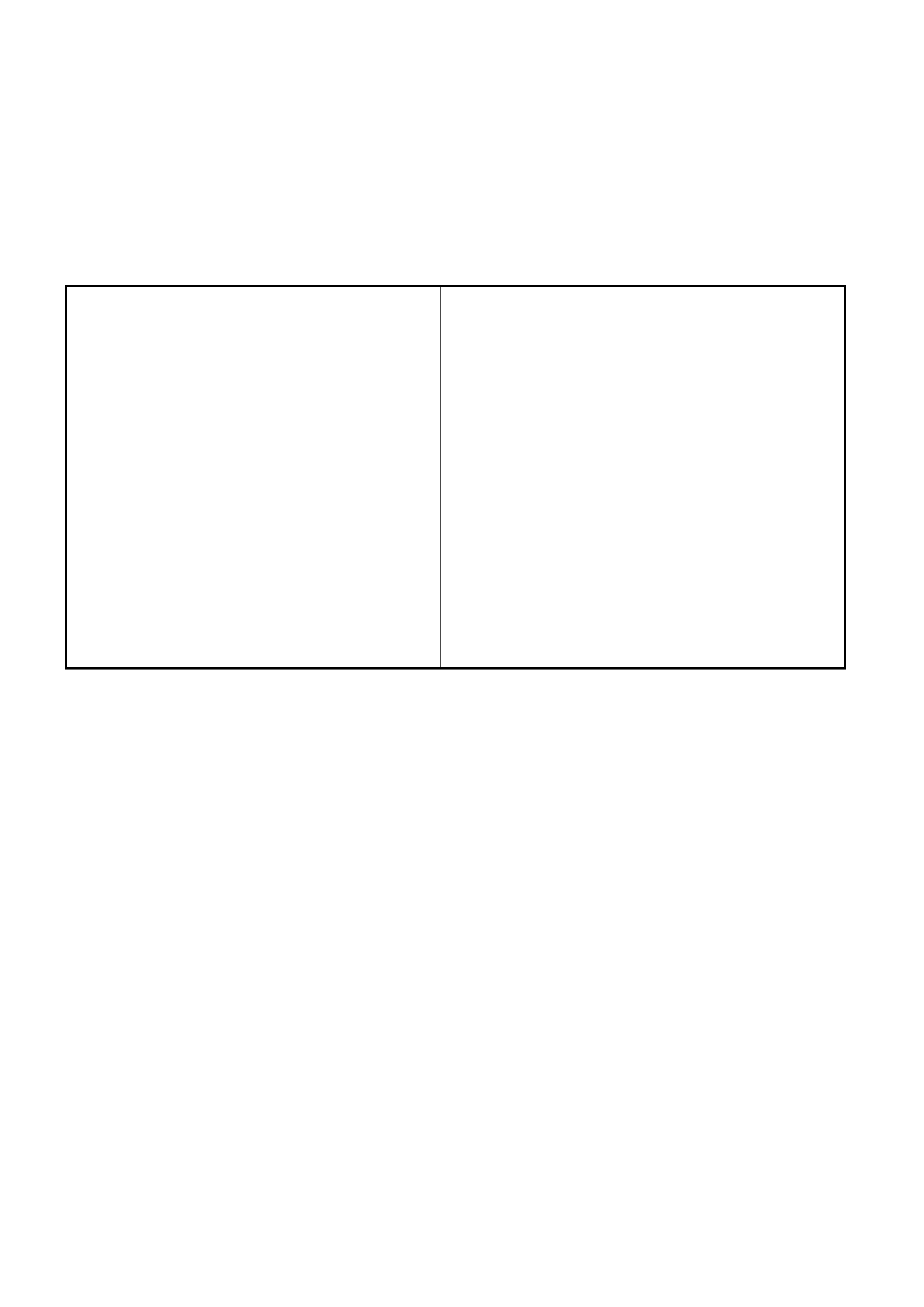
2.3 LOCK CYLINDE RS & KEYS
A com mon-key locking system is used which operates
the door and ignition locks. A unique key is provided
for the instrument panel compartment.
The door and ignition key features a remote function
that activates the central locking system and anti-theft
system from a distance of several metres.
Inserting the key into the lock cylinder incorporated in
the driver’s door handle also performs the same
function.
A separate button on the remote key for Sedan and
Coupe models opens the rear compartment lid. The
liftgate lock for Wagon models is operated as part of
the central locking system.
The k ey identif ication number is located on the vehicle
security card, stored with the owner’s manual. It is
essential that this key number be available should a
replacement key be required.
In the event of replacement, the BCM will require
reprogramming to accept the new key, refer
Section 12J, BODY CONTROL MODULE for
reprogramming and further information regarding the
anti-theft system.
For service procedures for the driver’s door lock
cylinder refer to Section 1A5, 2.8 – FRONT DOOR
OUTSIDE HANDLE ASSEMBLY.
For service procedures for the ignition lock cylinder
refer to Section 9A, STEERING.
Figure 1A1-1
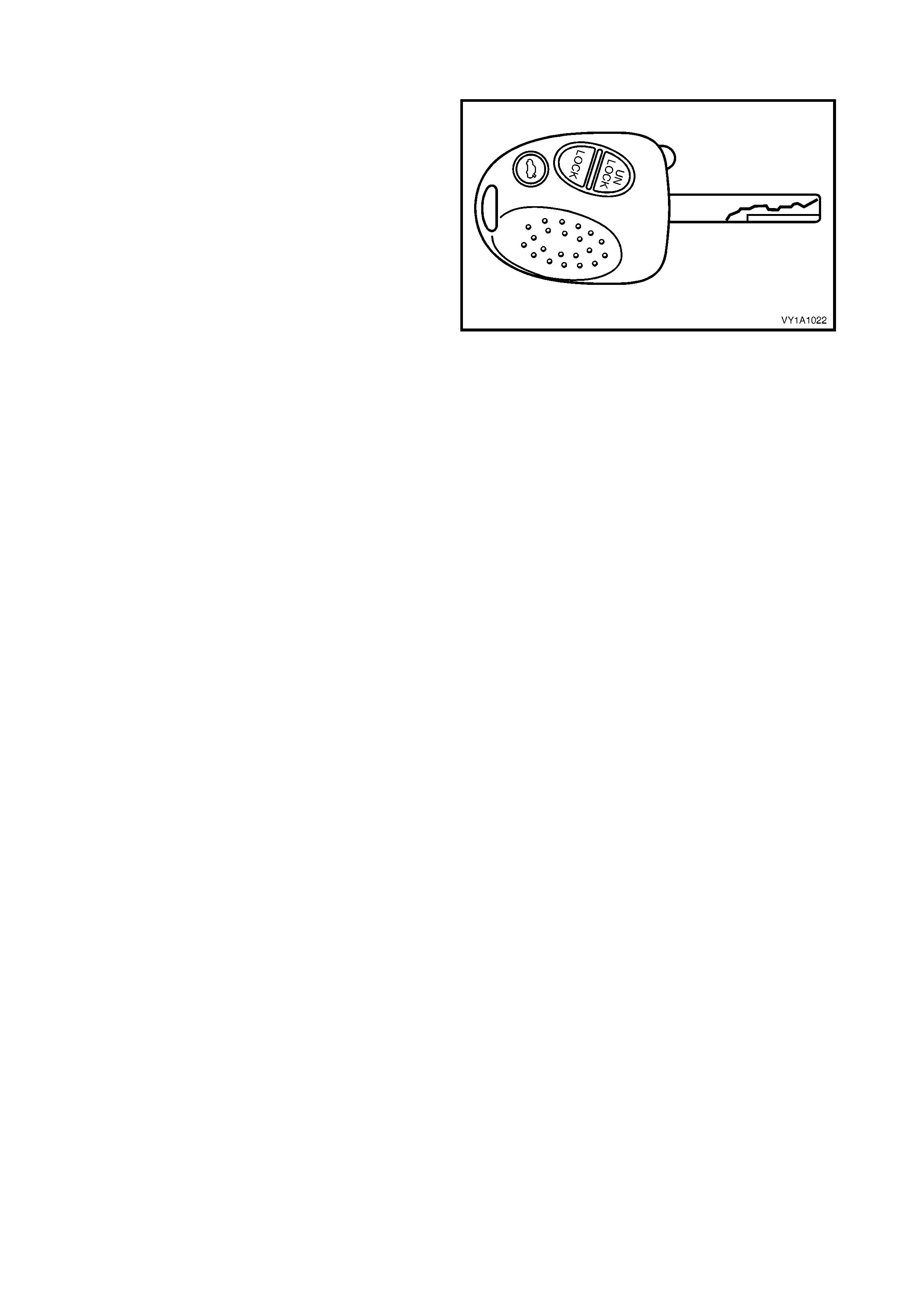
2.4 PLASTIC COMPONENTS
Plastic components are used throughout the vehicle. The following chart is included to assist with the
identification and composition of common components.
NOTE: Most components are also identified with the material code in an inconspicuous place.
COMPONENT CODE EXAMPLE
Exteri or / Engine Compartment:
Front Bumper Fascia PP
Front Bumper Access Hole Cover, Level 1 PP
Radiator Grille Assembly:
– Painted
– Unpainted
ABS
ASA
Lower Radiator Grille PP
Front Foglamp Bezel Assembly:
– Inner
– Outer
ASA
ABS
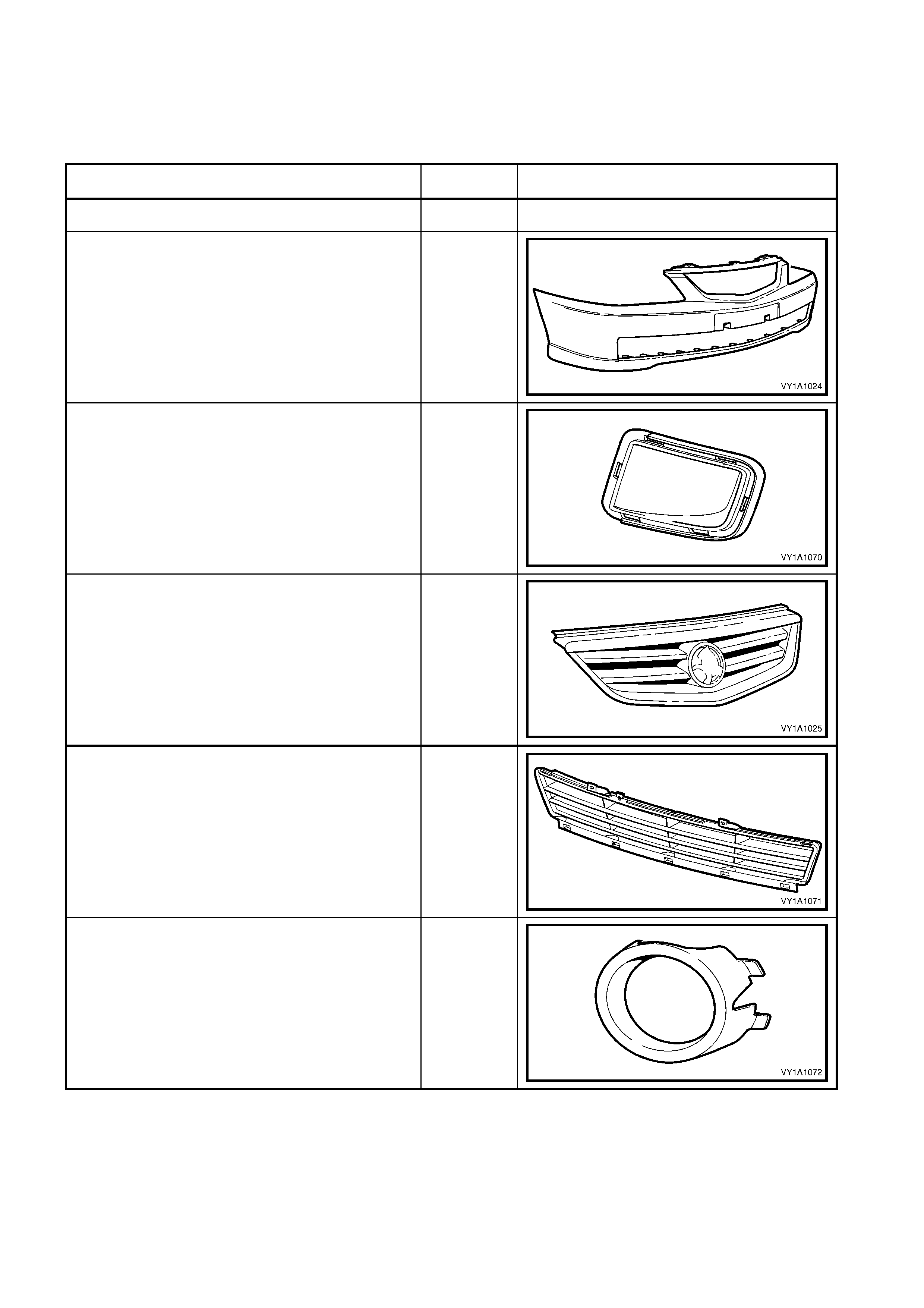
Headlamp Assembly:
– Lens
– Housing
PC
PP/T30
Upper Radiator Air Baffle PP
Radiator Surge Tank Assembly:
– V6
– V8
PP
PE
Wheelhouse Liner:
– Front
– Rear
PP
Plenum Cover Assembly PP
Outside Rear View Mirror Housing:
– Painted
– Unpainted
ABS
ASA / PC
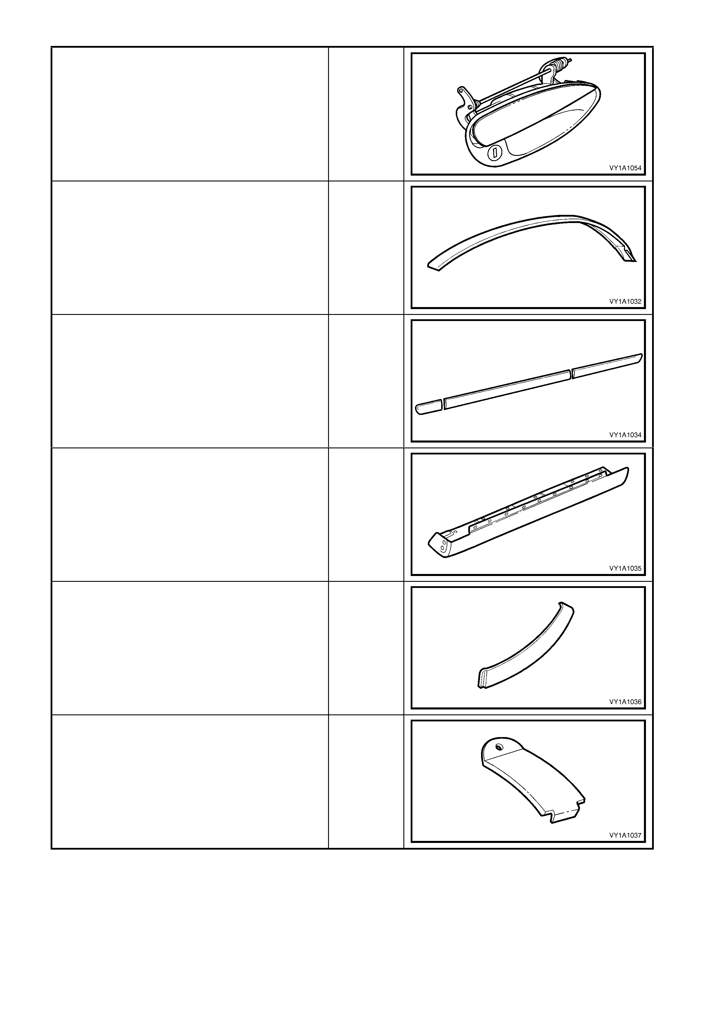
Door Handle Assembly PA 66
Roof Panel Joint Moulding Assembly:
– Sedan & Coupe
– Front, Wagon
– Utility
PVC
PVC
PP
Body Side Moulding:
– Fender
– Front Door
– Rear Door
– Quarter Panel
ASA
Rocker Panel Moulding Assembly PP
Quarter Panel Belt Moulding, Sedan PPE/PA-
M20
Roof Panel Joint Finish Moulding, Wagon PP M20
Rear Quarter Window Moulding, Utility ABS / PC-
M6
Rear Window Side Moulding Assembly, Utility ABS / PC-
M6
Rear Window Upper Moulding Assembly,
Utility ABS / PC-
M6
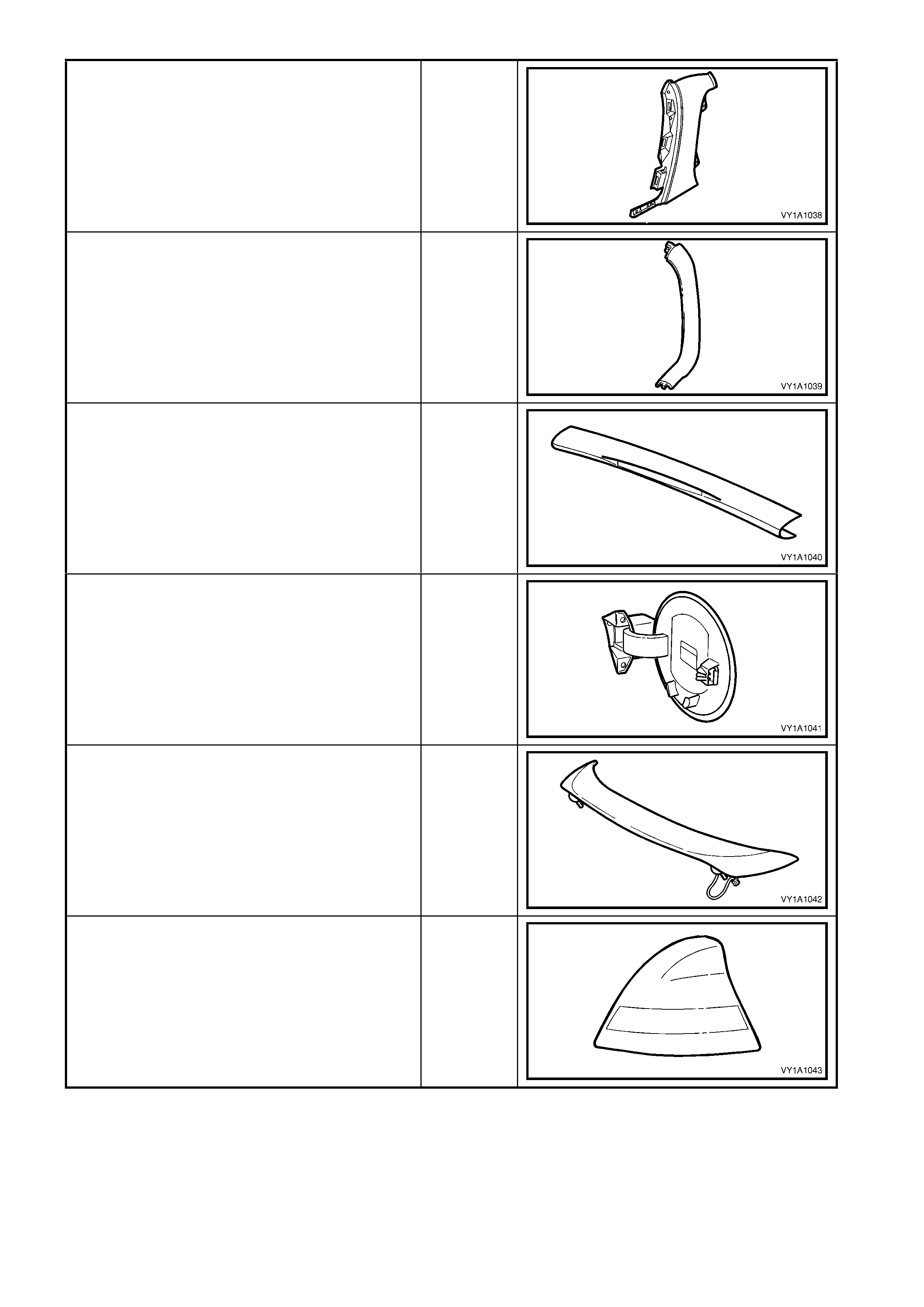
Fuel Filler Door PPE / PA
Rear Spoiler Assembly ABS
Tail lamp Assembly:
– Lens
– Housing
PMMA
ABS
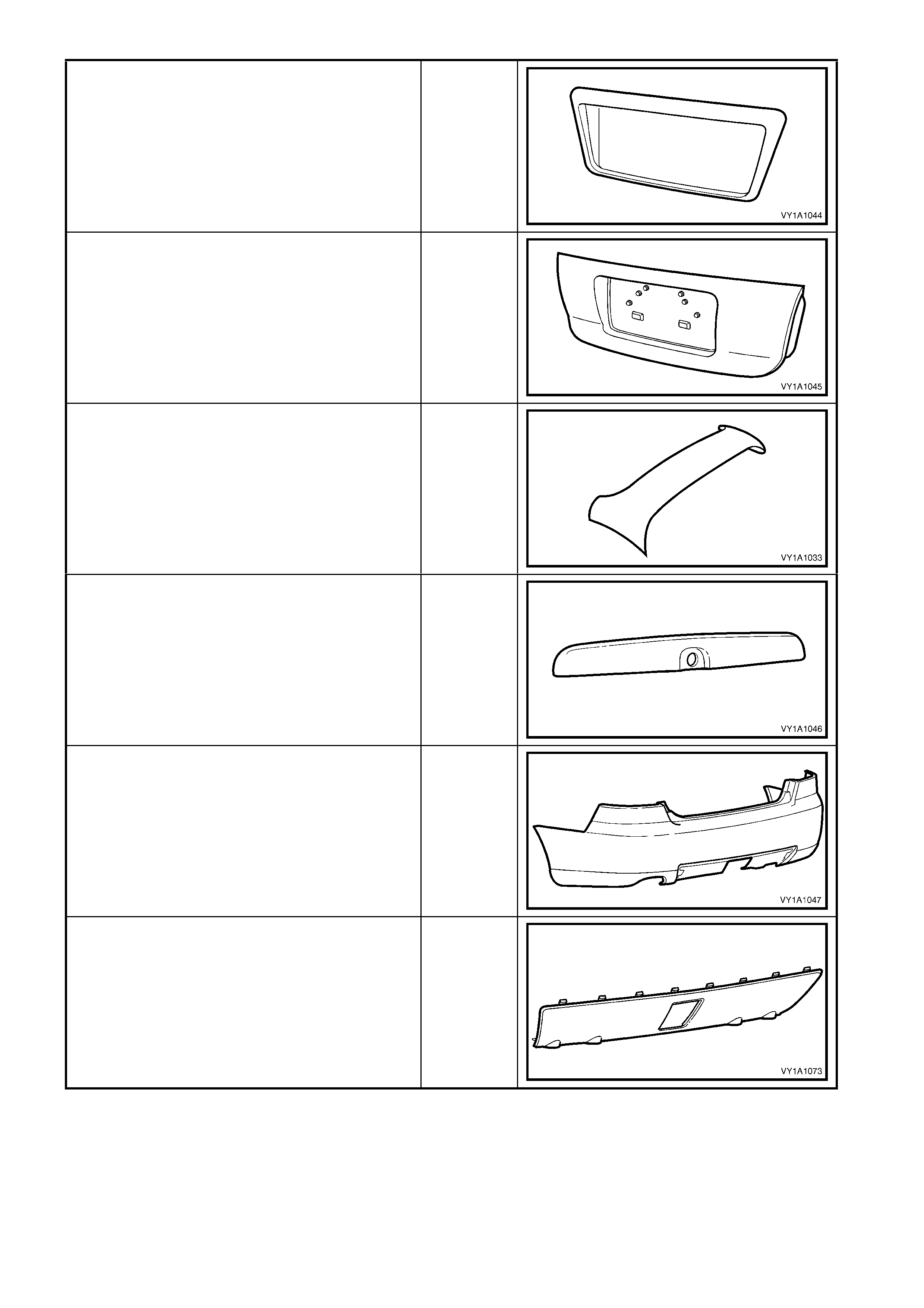
Rear Compartment Lid Applique Assembly,
Sedan ABS
Rear Compartment Lid Applique Assembly,
Coupe ABS
Liftgate Air Deflector Assembly , Wagon PC/ABS
Liftgate Handle Assembly, Wagon ABS
Rear Bumper Fascia PP
Rear Bumper Fascia Insert, Sedan PP
Interior:
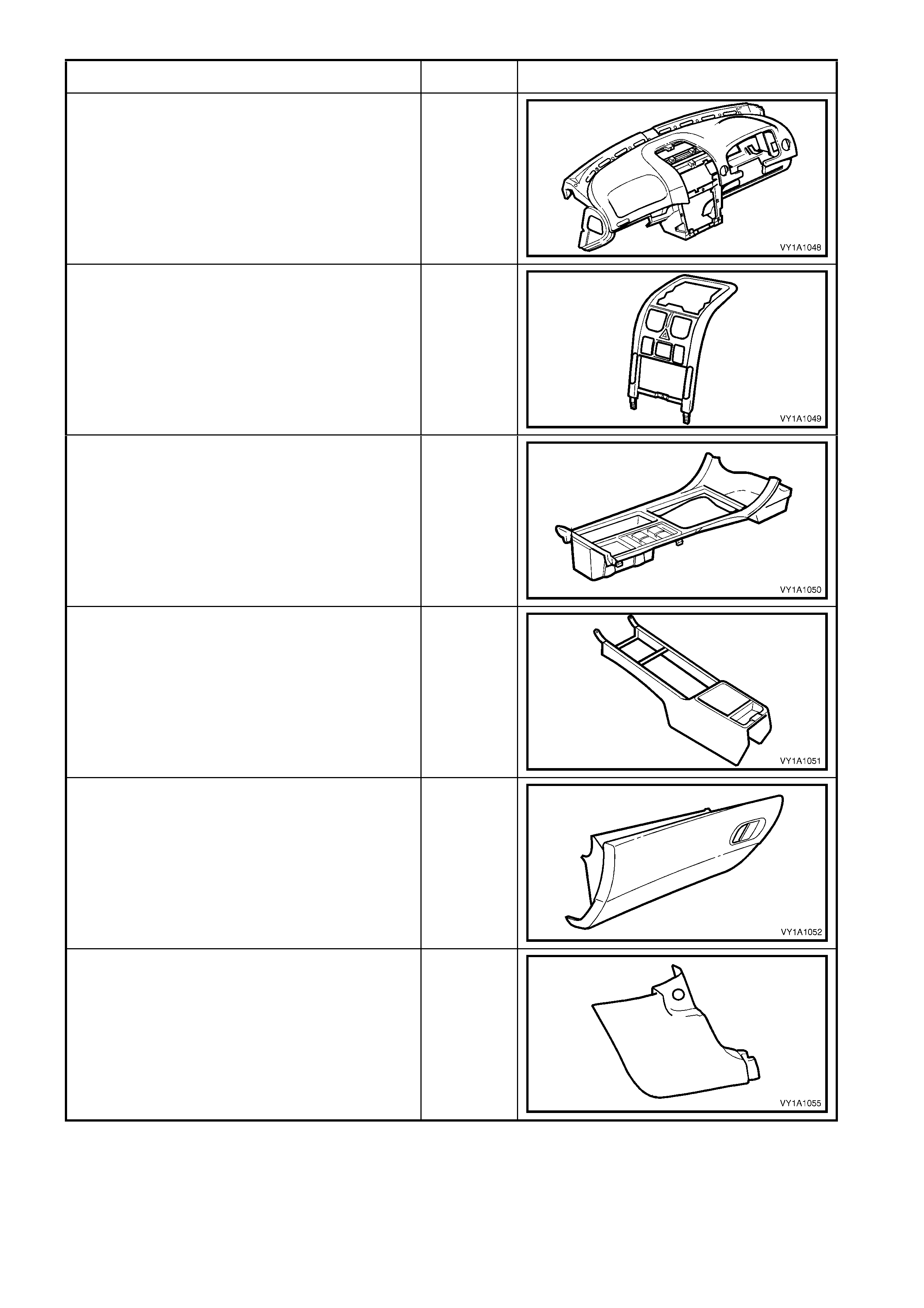
Instrument Panel Pad Assembly:
– Carrier
– Pad Substrate
– Foam
– Skin
ABS
ABS
PP
PVC/ABS
Instrument Panel Centre Trim Assembly PC/ABS
Floor Console Cover Assembly PC/ABS
Front Floor Console PP
Instrument Panel Compartment PP
Hinge Pillar Trim PP
Windscreen Side Garnish PP
Centre Pillar Upper Trim PP
Centre Pillar Lower Trim PP
Side Sill Trim Plate PP
Side Sill Trim PP
Body Lock Pillar Garnish, Sedan PP
Body Lock Pillar Garnish, Wagon PP
Body Lock Pillar Lower Trim, Wagon PP
Body Rear Corner Garnish, Wagon PP
Quarter Inner Trim Upper, Wagon PP
Liftgate Window Upper Garnish, Wagon PP
Liftgate Window Lower Garnish, Wagon PP
Rear End Trim Panel PP
The repair procedure for plastic body parts must conform with the type of plastic material.
Precautions to be taken with plastic parts are detailed in the following chart.
Code Material
Name Heat Resisting
Temp* °C Resistance to
Alcohol or Gasoline Notes
ABS Acrylonitrile
Butadiene
Styrene Resin
80 Alcohol is harmless if applied only
for short time in small amounts (i.e.
quick wiping to remove grease)
Avoid gasoline and
organic or aromatic
solvents.
ASA Acrylate
Styrene
Acrylonitrile
80 Alcohol is harmless if applied only
for short time in small amounts (i.e.
quick wiping to remove grease)
Avoid gasoline and
organic or aromatic
solvents.
PC Polycarbonate 120 Alcohol is harmless. Avoid gasoline, brake
fluid, wax, wax removers
and organic solvents.
PMMA Polymethyl
Methacrylate 80 Alcohol is harmless if applied only
for short time in small amounts. Avoid dipping or
immersing in alcohol,
gasoline, solvents, etc.
PE Polyethylene 80 Alcohol and gasoline are harmless. Most solvents are
harmless.
PP /
PP67 Polypropylene 80 Alcohol and gasoline are harmless. Most solvents are
harmless.
PPE Polyphenylene
Ether 100 Alcohol and gasoline are harmless
if applied only for a short time in
small amounts (i.e. quick wiping to
remove grease)
Avoid dipping or
immersing in alcohol,
gasoline, solvents, etc.
PU Polyurethane
Foam 100 Alcohol and gasoline are harmless
if applied only for a short time in
small amounts (i.e. quick wiping to
remove grease)
Avoid dipping or
immersing in alcohol,
gasoline, solvents, etc.
PVC Polyvinyl
Chloride 80 Alcohol and gasoline are harmless
if applied only for short time in small
amounts. (i.e. quick wiping to
remove grease)
Avoid dipping or
immersing in alcohol,
gasoline, solvents, etc.
TPO Thermoplastic
Olefin 80 Alcohol is harmless.
Gasoline is harmless if applied only
for short time in small amounts.
Most solvents are
harmless but avoid
dipping or immersing in
alcohol, gasoline,
solvents, etc.
PPE/
PA-M20 Modified
Poly propylene
Ether &
Poly amide
Alloy
190 Alcohol and gasoline are harmless
if applied only for a short time in
small amounts (i.e. quick wiping to
remove grease)
Avoid dipping or
immersing in alcohol,
gasoline, solvents, etc.
∗ Temperatures higher than those listed here may result in material deformation.
3. WHEELHOUSE LINERS
3.1 FRONT WHE ELHOUSE LINER
LT Section No. – 12-425
For the left-hand side, two types of front wheelhouse liner are available depending on engine type. The coolant
reservoir for V6 engines is located next to the wheelhouse liner and effectively acts as part of the liner. As the
GEN III V8 engine has its c oolant r eser voir loc ated in the engine c ompartment, the wheelhouse liner is ex tended
to fill the void.
REMOVE
1. Remove the front road wheel, refer Section 10,
WHEELS & TYRES.
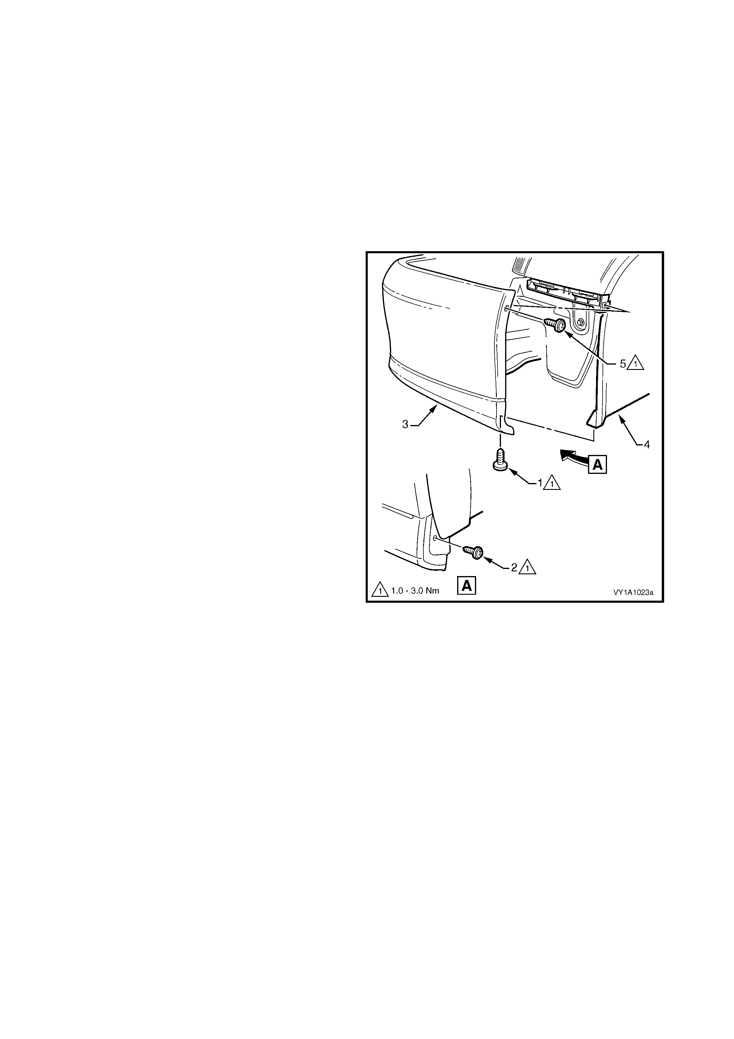
2. Remove the screw (1) or for S and SS vehicles
(2), attaching the f ront bum per fas cia assem bly (3)
to the front wheelhouse liner (4).
3. If required, also remove the screw (5) attaching
the fascia assembly to the vehicle to aid in removal
of the liner.
4. Remove the screws (1) attaching the liner (2) to
the fender, two places, refer Figure 1A1-3.
5. For vehicles with GEN III V8, remove the sc rew (3)
attaching the liner shown View A.
6. Remove the retainers (4) attaching the liner to the
vehicle:
• four places right-hand side,
• four places left-hand side V6, or
• three places left-hand side GEN III V8.
7. Remove the liner.
Figure 1A1-2
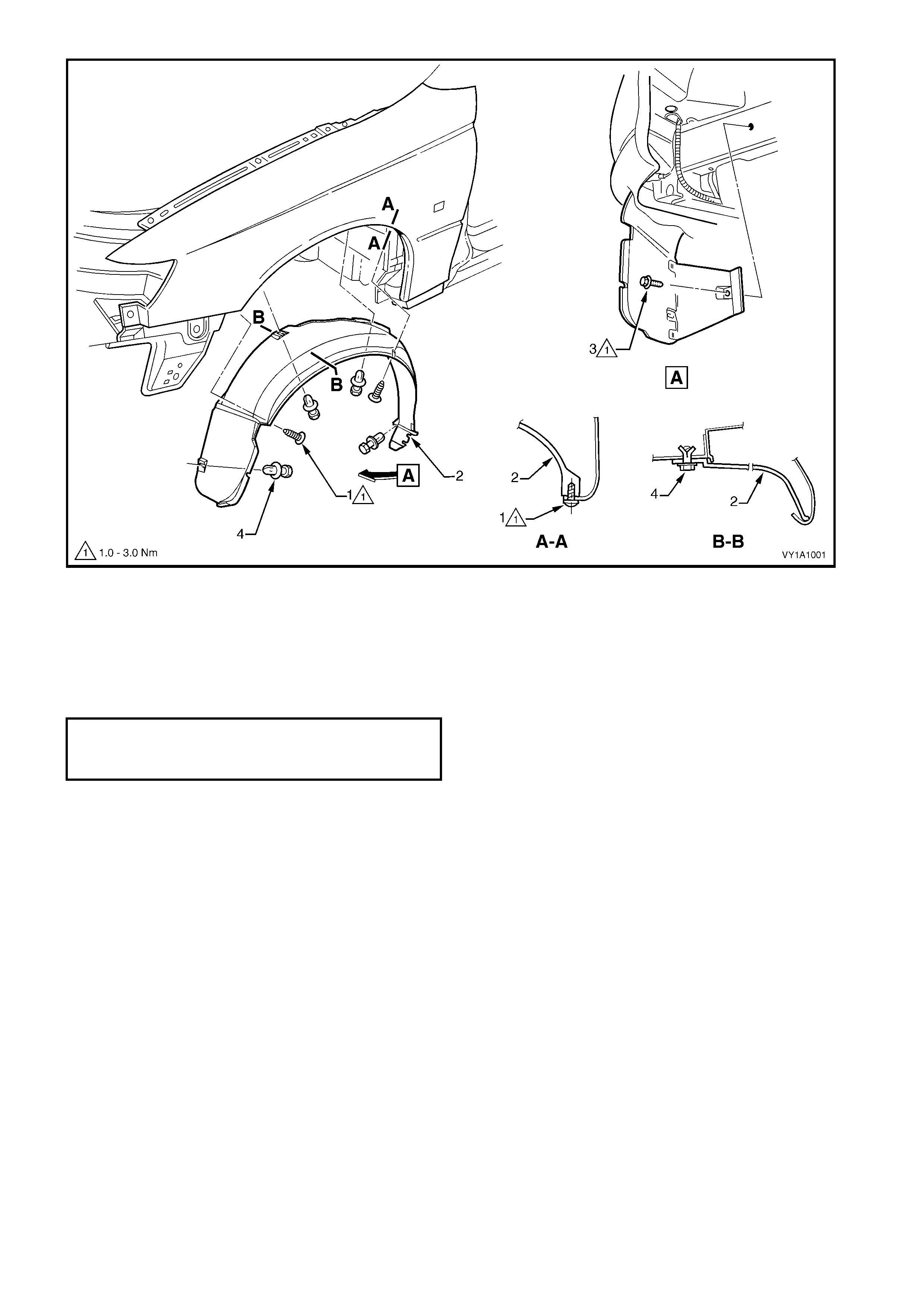
Figure 1A1-3
REINSTALL
1. Install the wheelhouse liner ensuring it is correctly
positioned as shown in Figure 1A1-3.
2. Install the screws attaching the liner and tighten to
the specified torque.
3. Install the retainers attaching the liner to the
vehicle.
4. Install the road wheel, refer Section 10, WHEELS
& TYRES.
FRONT WHEELHOUSE
LINER ATTACHING SCREW
TORQUE SPECIFICATION 1.0 – 3.0 Nm
3.2 REAR WHEELHOUSE LINER, SEDAN & W AGON
LT Section No. –
Newly designed rear wheelhouse liners are fitted on Sedan and Wagon models . The liners now cover the entire
wheelhouse and provide an additional reduction in noise transmittance into the passenger compartment.
REMOVE
1. Remove the rear road wheel, refer Section 10,
WHEELS & TYRES.
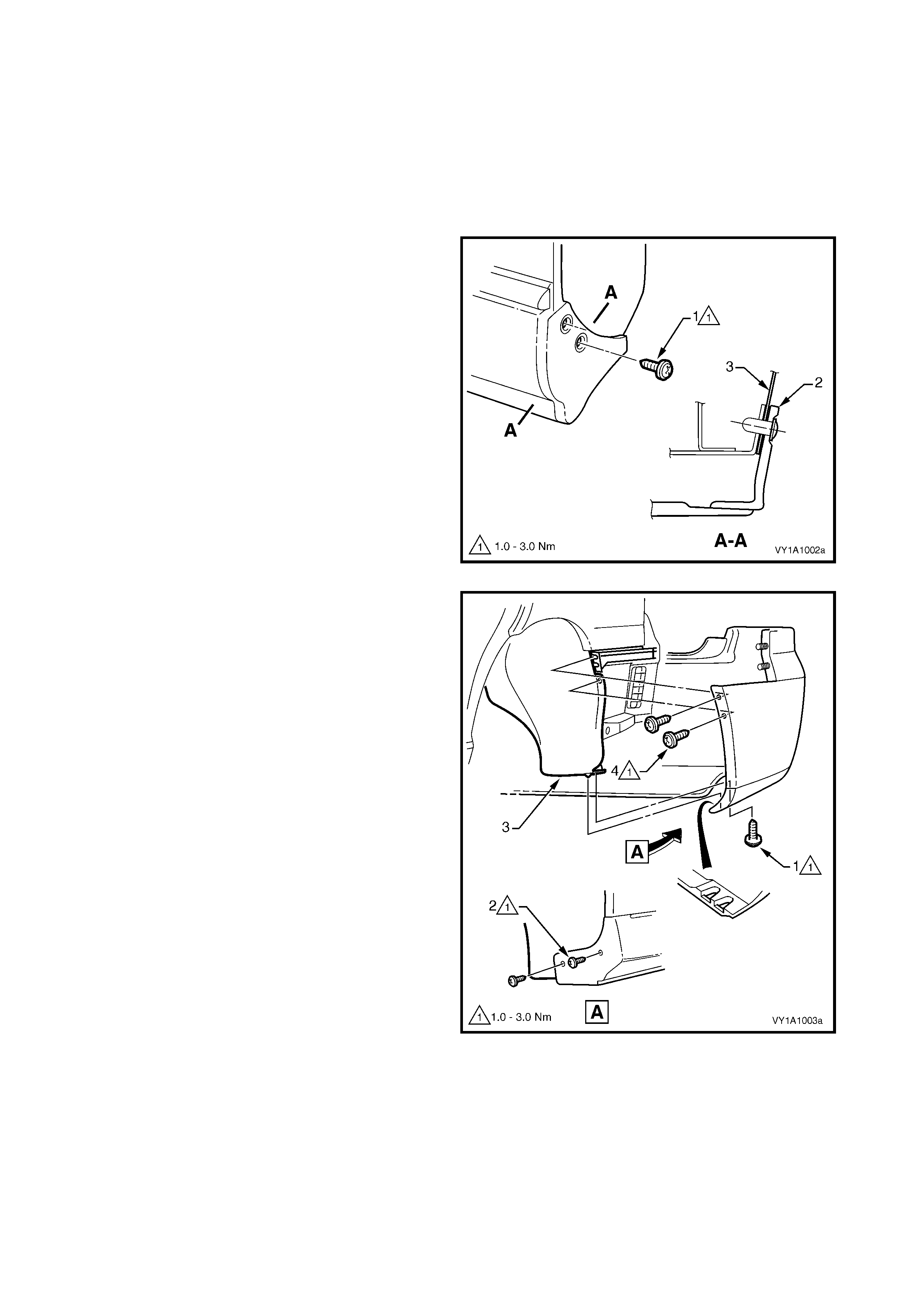
2. Remove the screw (1) two places, attaching the
rocker panel moulding assembly (2) and rear
wheelhouse liner (3).
Figure 1A1-4
3. Remove the screw (1), or for S and SS vehicles
(2) two places, attaching the rear bumper fascia
assembly to the wheelhouse liner (3).
4. Remove the two screws (4) attaching the fascia
assembly to the liner and rear bumper fascia
guide.
5. Carefully partially unclip the bumper fascia from
the fasc ia guide, and disengage the locating lug at
the base of the liner for all vehicles except S and
SS.
6. Remove the r etainer s ( 1 & 2) attaching the liner (3)
to the wheelhouse panel, refer Figure 1A1-6.
7. Manipulate the liner from behind the rocker panel
moulding assembly and bumper fascia and
remove.
Figure 1A1-5
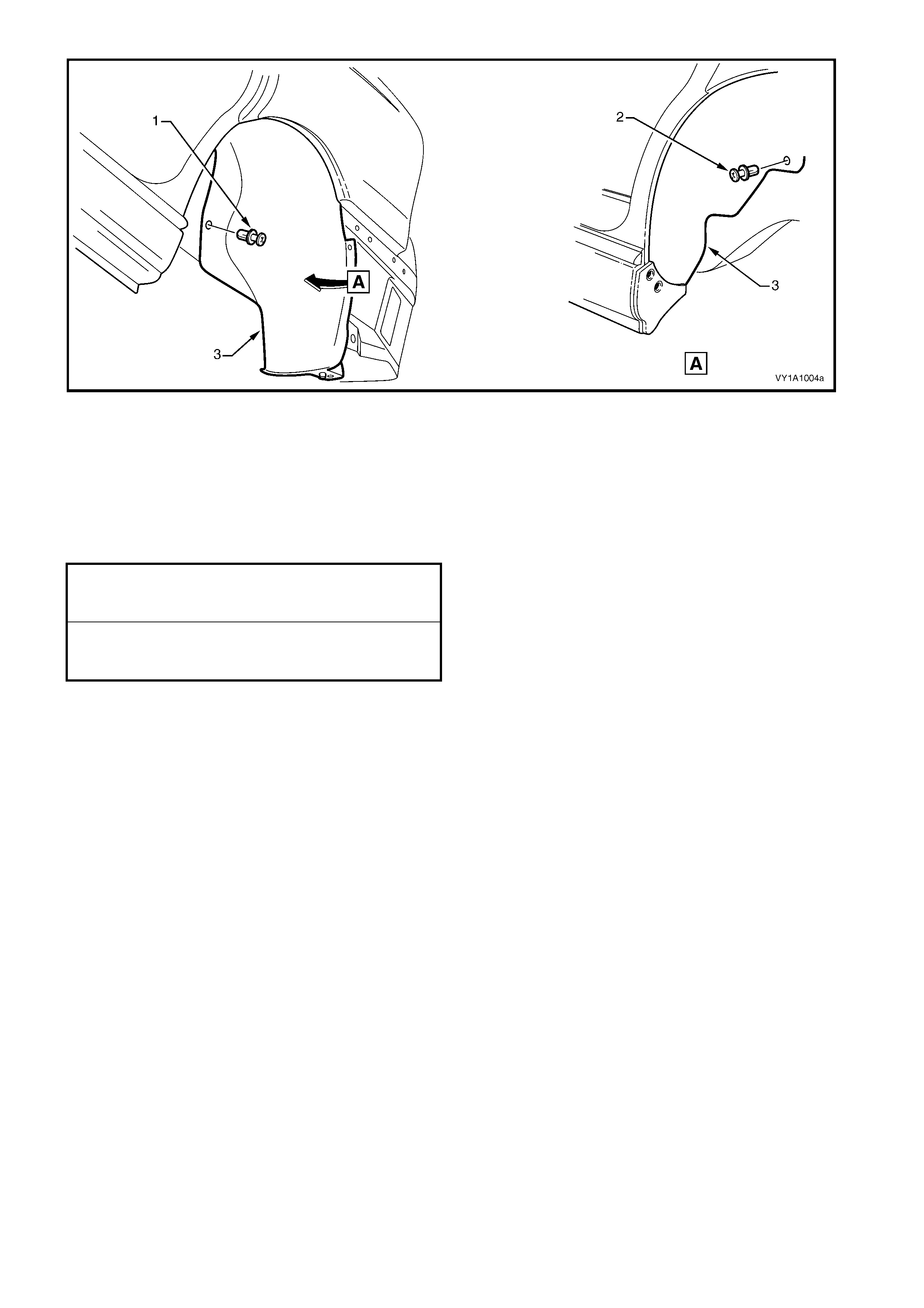
Figure 1A1-6
REINSTALL
1. Install the liner, ensuring it is c orrectly located behind the rock er panel m oulding assem bly and rear bumper
fascia assembly.
2. Install the retainers attaching the liner to the body.
3. Install the screws attaching the rocker panel moulding assembly and bumper fascia and tighten to the
specified torque.
4. Install the rear road wheel, refer Section 10, WHEELS & TYRES.
ROCKER PANEL MOULDING
ASSEMBLY ATTACHING SCREW
TORQUE SPECIFICATION 1.0 – 3.0 Nm
REAR BUMPER FASCIA
ASSEMBLY ATTACHING SCREW
TORQUE SPECIFICATION 1.0 – 3.0 Nm

3.3 REAR WHEELHOUSE LINER, COUPE & UTILITY
LT Section No. –
REMOVE
1. Remove the rear road wheel, refer Section 10,
WHEELS & TYRES.
2. Remove the two screws (1) attaching the rear
bumper fascia (2) at the wheel-arch opening.
3. Remove the two screws (3) attaching the rear
bumper fascia to the wheelhouse liner and rear
bumper fascia guide.
4. Carefully partially unclip the fascia from the fascia
guide.
Figure 1A1-7
5. Remove the screw (1) and retainer (2) attaching
the rear wheelhouse liner (3) to the vehicle.
NOTE: Some vehicles may have a screw in place of
the retainer.
6. Manipulate the liner from within the wheelhouse
and remove.
Figure 1A1-8
REINSTALL
1. Install the rear wheelhouse liner ensuring it is correctly located behind the rear bumper fascia.
2. Install the screw and retainer attaching the liner to the vehicle and tighten the screw to the specified torque.
3. Install the screws attaching the rear bumper fascia and tighten to the specified torque.
4. Install the rear road wheel, refer Section 10, WHEELS & TYRES.
REAR WHEELHOUSE
LINER ATTACHING SCREW
TORQUE SPECIFICATION 1.0 – 3.0 Nm
REAR BUMPER FASCIA
ASSEMBLY ATTACHING SCREW
TORQUE SPECIFICATION 1.0 – 3.0 Nm
Techline
4. FUEL FILLER DOORS
4.1 FUEL FILLER DOOR ASSEMBLY, SEDAN & COUPE
LT Section No. – 03-028
The fuel filler door is painted the vehicle’s body colour. The door assembly is serviced with the moulding and
lock spring unattached, which allows the door to be painted, then the moulding and lock spring fitted as
described in this procedure.
The moulding is attached to the door with adhesive. Therefore if repairing paintwork on the filler door, the
moulding will require masking or removal and replacing with a new part, which is available individually.
Paint the door using the correct materials and techniques for PPE/PA resin (Polyphenylene/Polyamide). As the
mater ials and techniques required dif fer between paint brands, ref er to the technical data supplied by your paint
manufacturer.
NOTE: If the fuel filler door is being replaced, the warning labels affixed to the inside of the door must also be
replaced.
REMOVE
1. Open the fuel filler door by operating the release
lever (RHD vehicles) or by operating the release
button on the instrument panel (LHD vehicles).
2. Remove the fuel filler cap and cover the opening
with a rag as required.
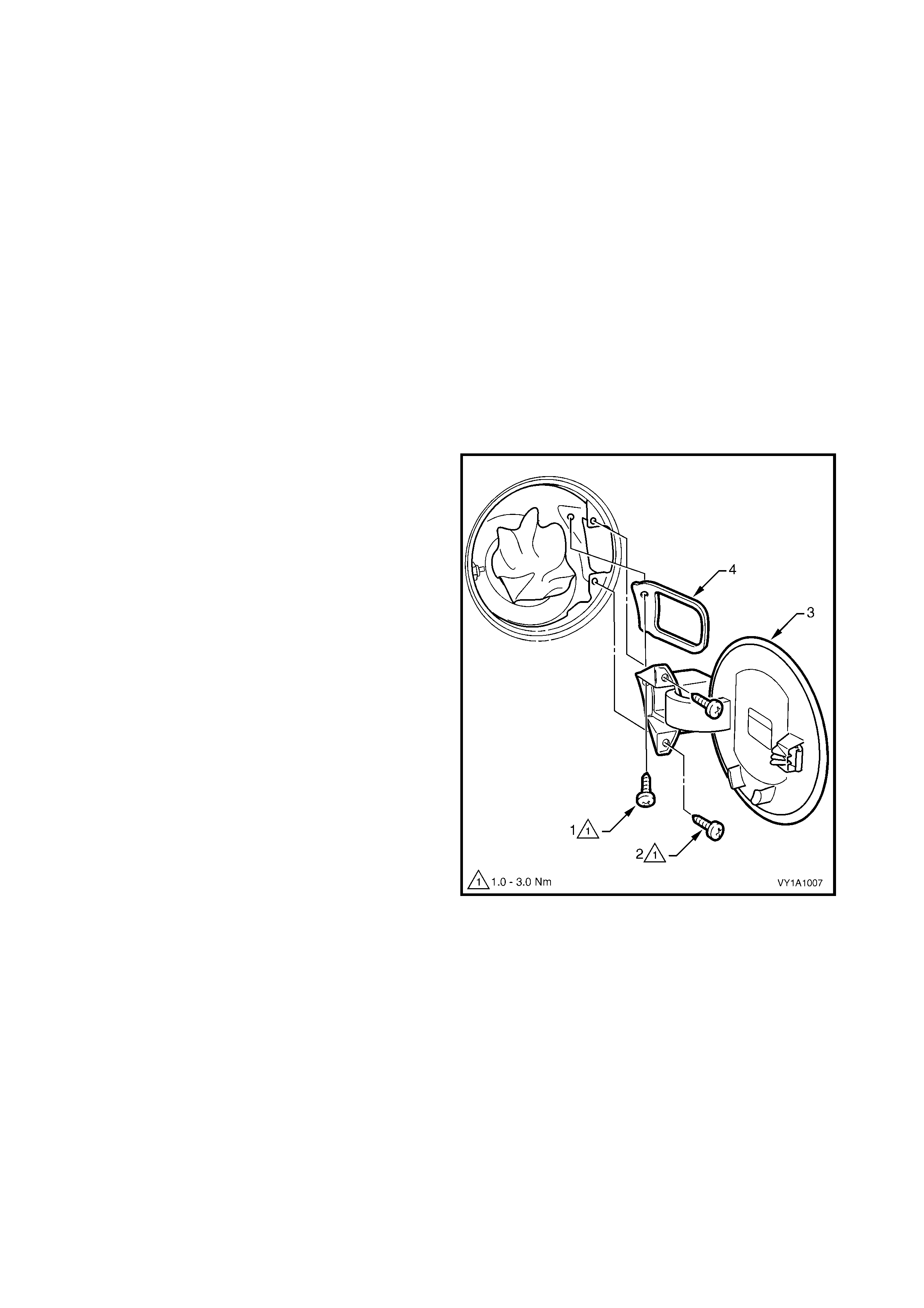
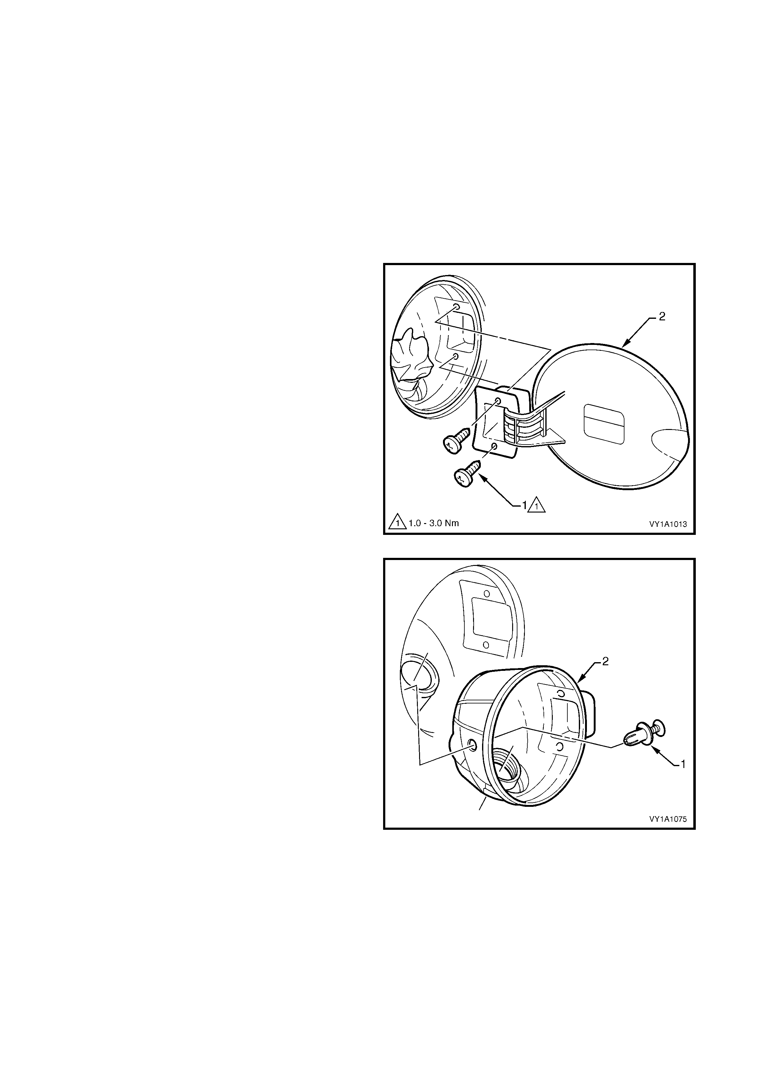
3. Remove the inner screw (1) and the two screws
(2), attaching the fuel filler door assembly (3).
4. Remove the door assembly by withdrawing it
rearward, ensuring the gasket (4) is also removed.
NOTE: When withdrawing the fuel filler door from the
fuel f iller pocket, a slight inter ference between the rear
edge of the plastic hinge s ec tion and the fuel filler neck
may occur. In this instance it will be necessary to flex
the rear edge of the fuel filler door hinge slightly.
Figure 1A1-9
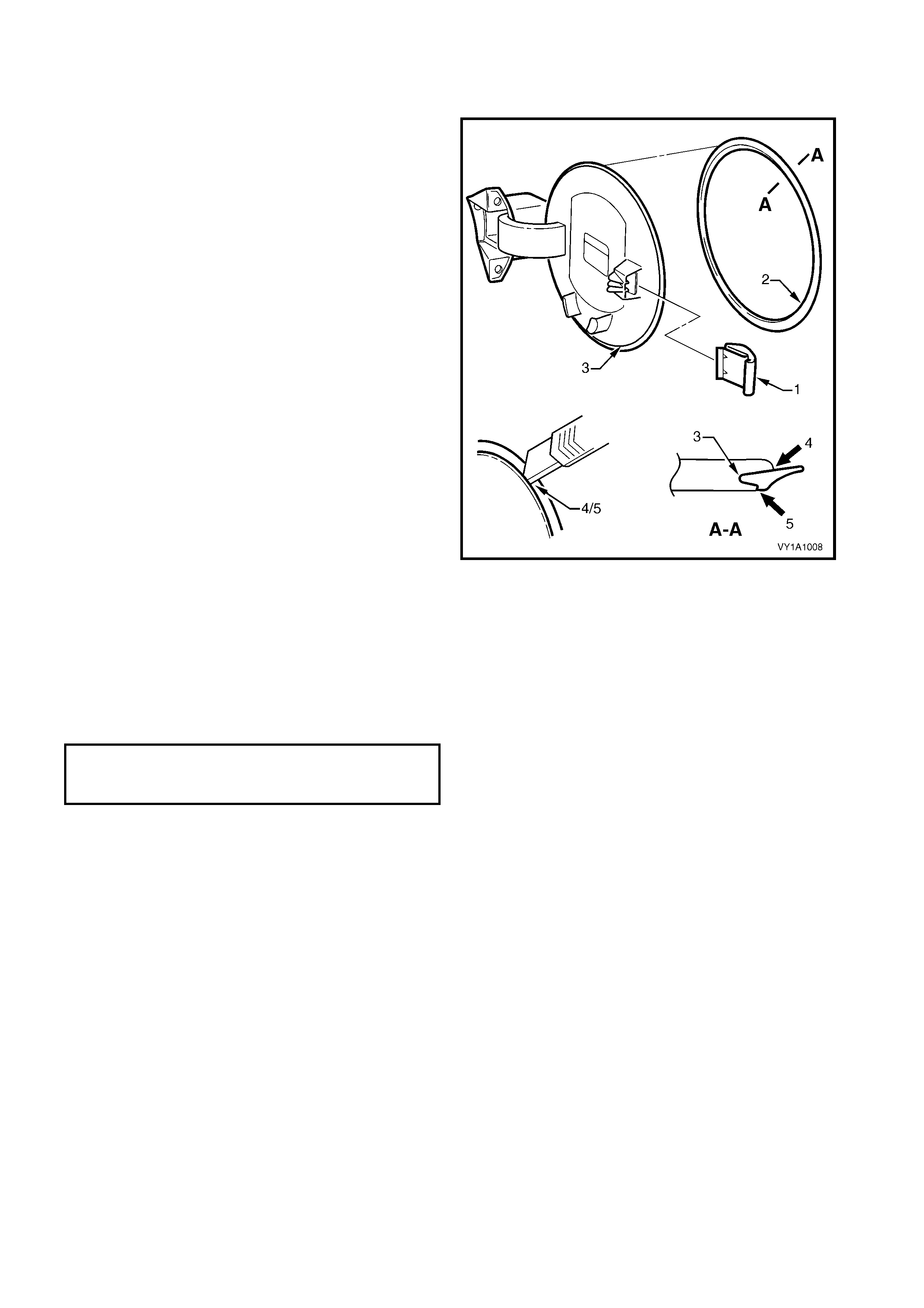
DISASSEMBLE
LOCK SPRING
NOTE: T he lock spring is not designed to be removed
it has several barbs that will cut into its mounting
surface.
1. Remove the lock spring (1) by inserting a small
screwdriver and levering the spring outwards.
2. To install, push the spring onto the mounting tab
fully.
MOULDING
1. The moulding (2) is seated in the recess (3)
around the circumference of the door and is
affixed with superglue gel. Removal may be
difficult, but by carefully peeling the moulding from
the door, it is possible to remove the moulding. It
will not be able to be reused.
NOTE: To aid removal, the moulding can be cut
around the inner (4) and outer sides (5) using a sharp
knife.
2. To install the moulding, carefully apply Loctite 454
(Superglue Gel) or equivalent into the fuel filler
door recess around the complete circumference.
IMPORTANT: Use of superglue can be harmful and
can damage paintwork. Carefully read and follow all
directions and cautions with the product prior to its use.
3. Ensuring it is correctly orientated, immediately fit
the moulding into the recess and leave for the
adhesive to cure.
Figure 1A1-10
REINSTALL
Installation of the fuel filler door assembly is the
reverse of removal, noting the following.
1. Ensure the screws are tightened to the specified
torque.
2. If a new door ass em bly is being installed, following
painting of the door flap, install the moulding and
lock spring onto the flap as described in
DISASSEMBLE in this procedure.
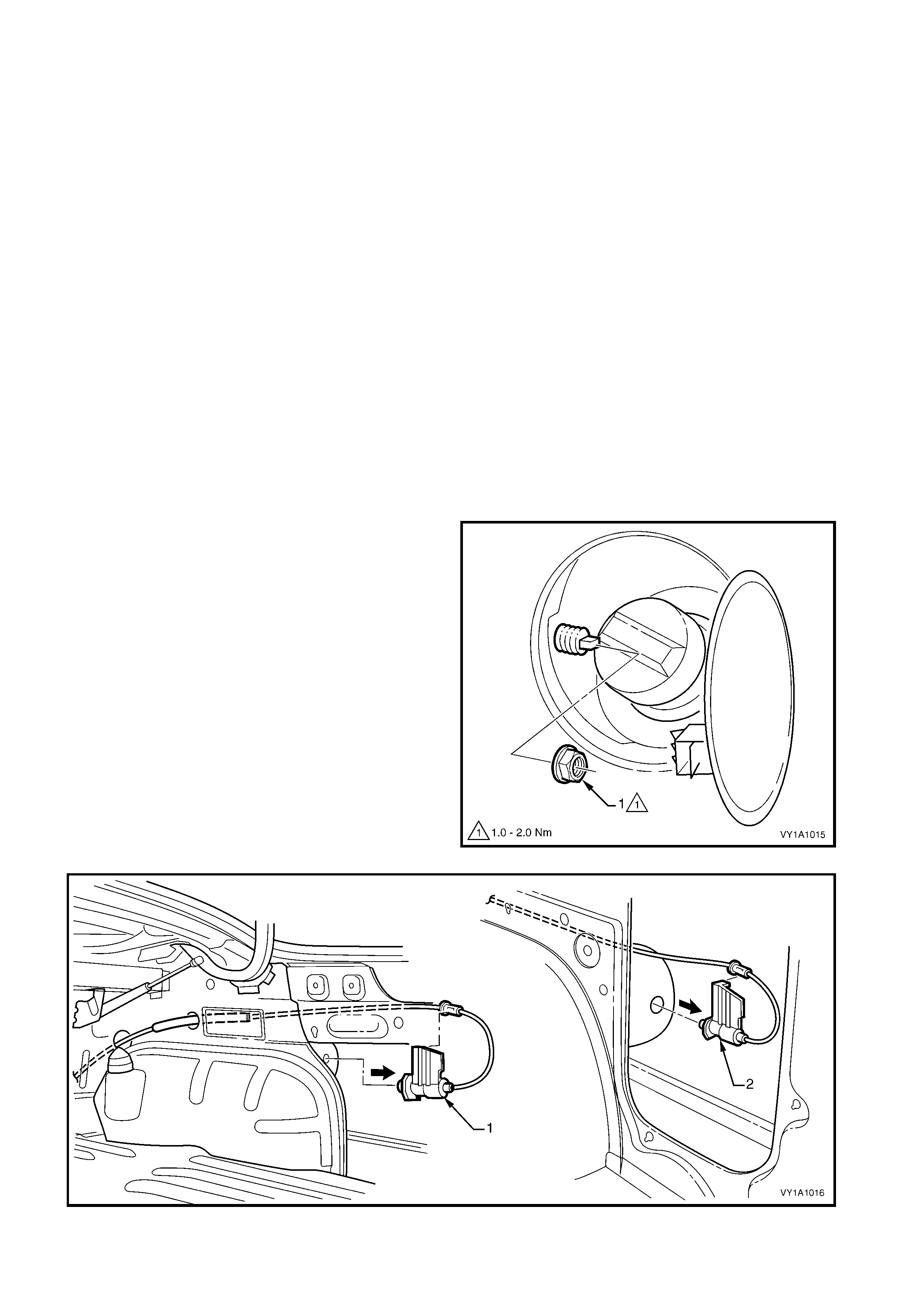
3. If the door has been replaced, apply the labels in
the positions shown, A – all vehicles except
supercharged V6 and LPG, B – vehicles with
supercharged V6, C – vehicles with LPG, refer
Figure 1A1-11.
NOTE: Prior to affixing the label(s) ensure the surface
is clean and dry. Avoid touching the back of the label.
4. Ensure the fuel filler door closes without the need
of excess force and is flush with the surrounding
panel.
FUEL TANK FILLER
DOOR ATTACHING SCREW
TORQUE SPECIFICATION 1.0 – 3.0 Nm
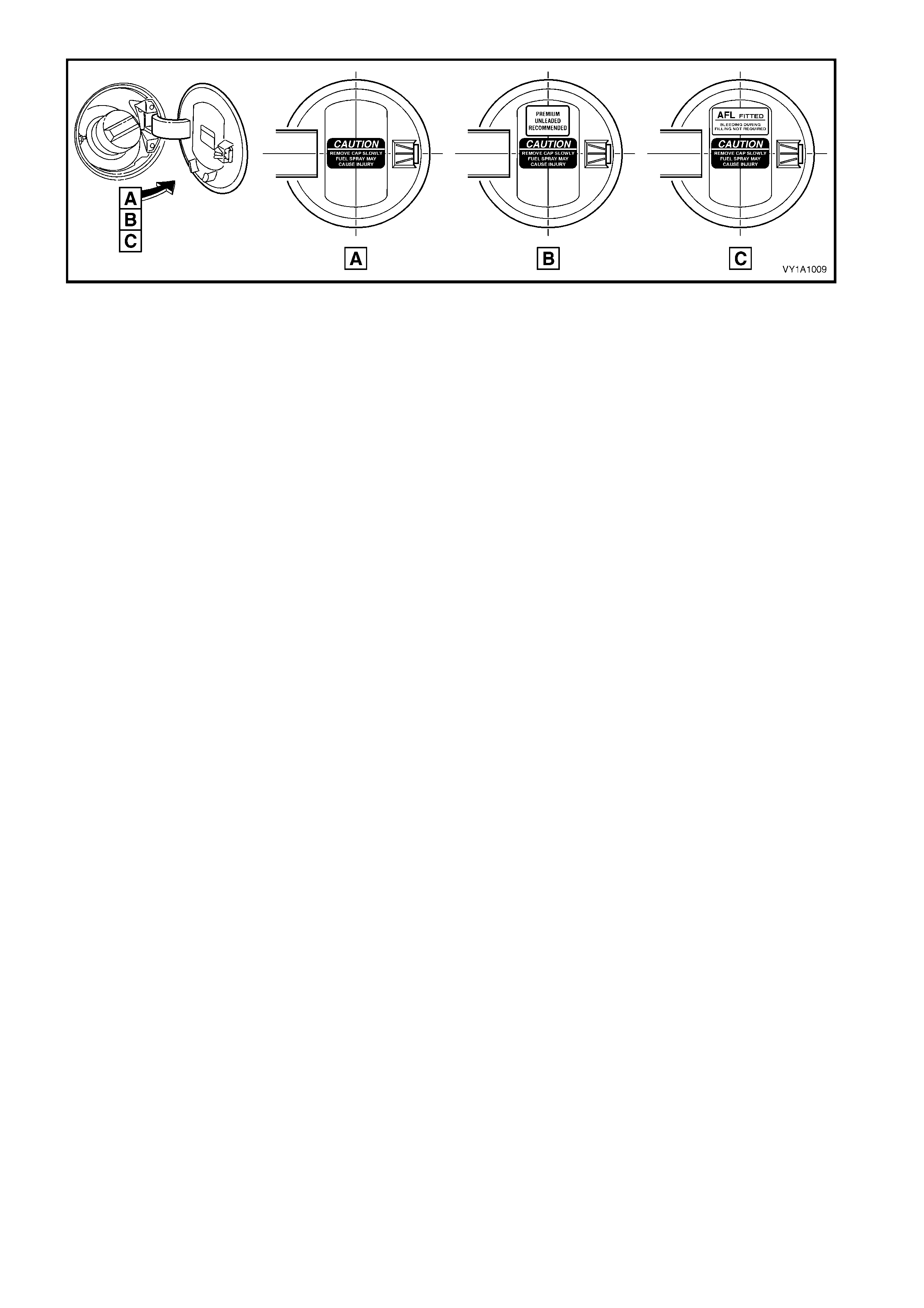
Figure 1A1-11

4.2 FUEL FILLER DOOR ASSEMBLY, WAGON
LT Section No. – 03-028
The fuel filler door is painted the vehicle’s body colour. The door assembly is serviced with the moulding
unattached, which allows the door to be painted, then the moulding fitted as described in this procedure.
The moulding is attached to the door flap with adhesive. Therefore if repairing paintwork on the filler door, the
moulding will require masking or removal and replacing with a new part, which is available individually.
Paint the door using the correct materials and techniques for PPE/PA resin (Polyphenylene/Polyamide). As the
mater ials and techniques required dif fer between paint brands, ref er to the technical data supplied by your paint
manufacturer.
NOTE: If the fuel filler door is being replaced, the warning labels affixed to the inside of the door must also be
replaced.
REMOVE
1. Open the fuel filler door, by operating the release
lever (RHD vehicles) or by operating the release
button on the instrument panel (LHD vehicles).
2. Remove the fuel filler cap and cover the opening
with a rag as required.
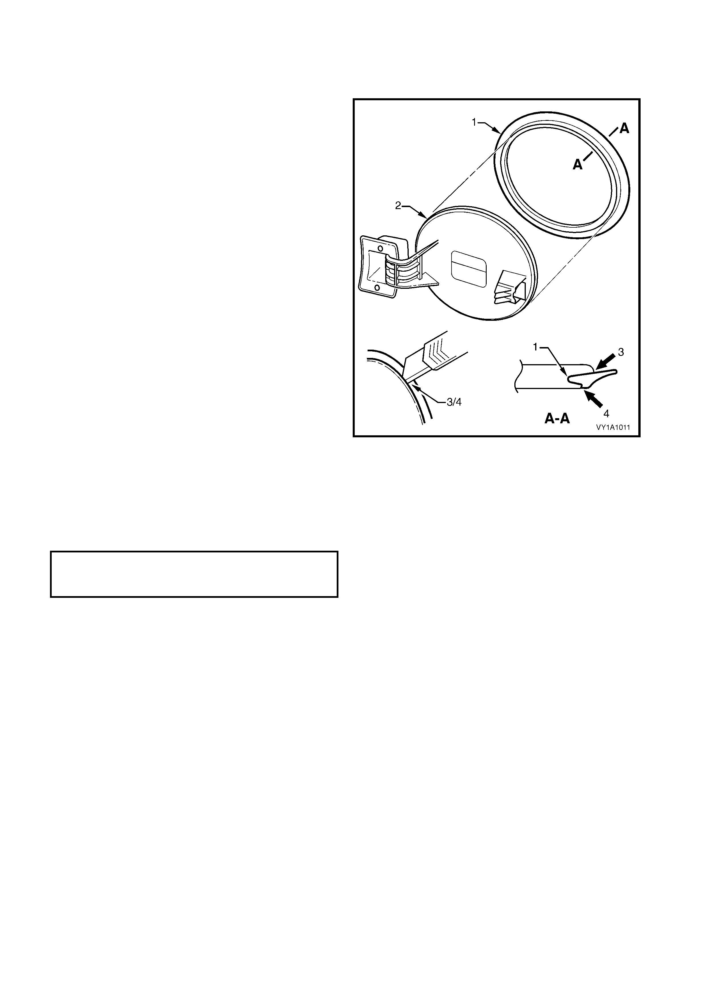
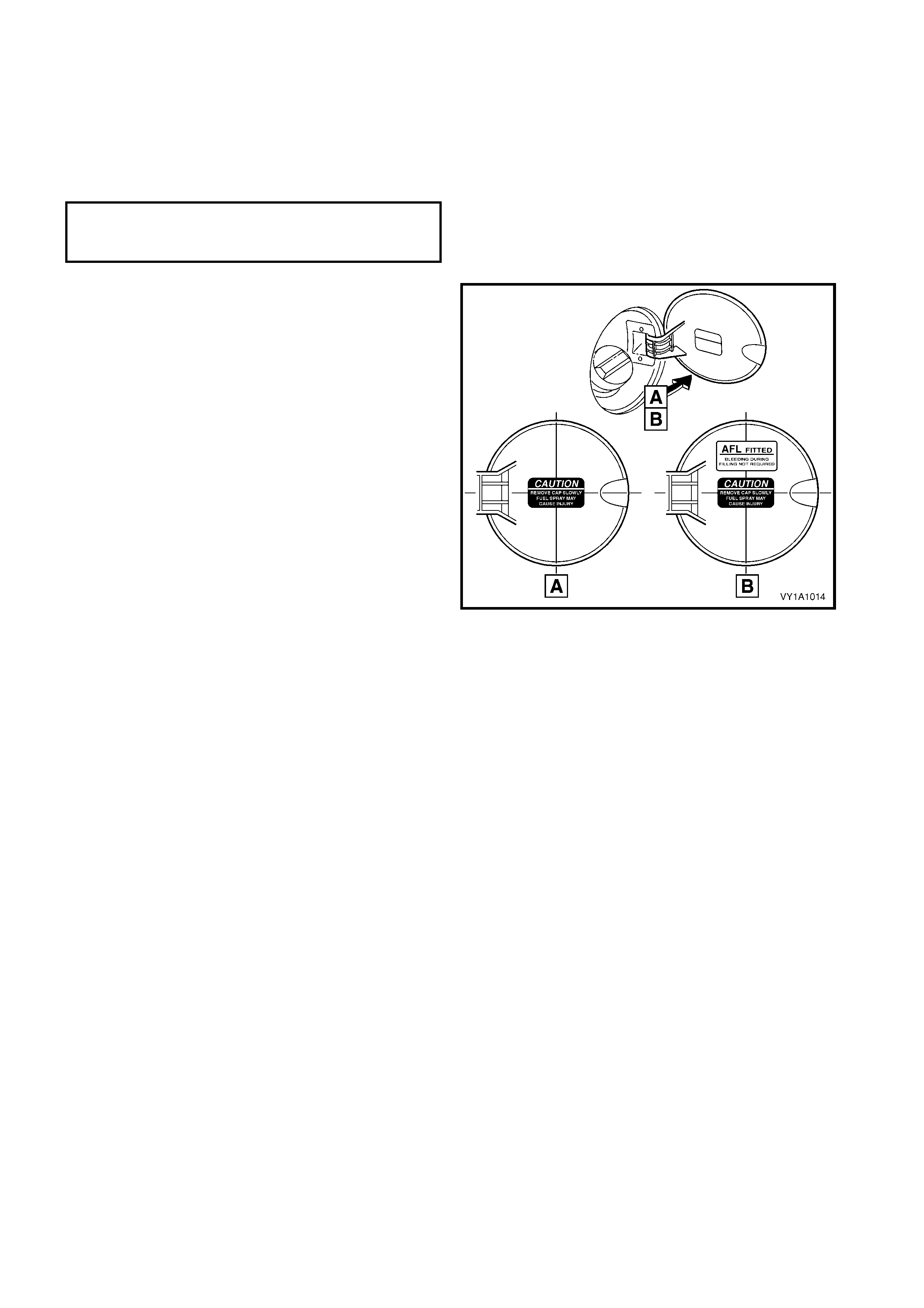
3. Rem ove the two screws (1) attaching the fuel filler
door assembly.
4. Remove the door assembly by withdrawing it
rearward, ensuring the gasket (2) is also removed.
Figure 1A1-12
DISASSEMBLE
MOULDING
1. The moulding (1) is seated in the recess (2)
around the circumference of the door and is
affixed with superglue gel. Removal may be
difficult, but by carefully cutting around the inner
(3) and outer sides (4) of the moulding using a
sharp knife, it is possible to remove the moulding.
It will not be able to be reused.
2. To install the moulding, carefully apply Loctite 454
(Superglue Gel) or equivalent into the fuel filler
door recess around the complete circumference.
IMPORTANT: Use of superglue can be harmful and
can damage paintwork. Carefully read and follow all
directions and cautions with the product prior to its use.
3. Ensuring it is correctly orientated, fit the moulding
into the recess and leave for the adhesive to cure.
Figure 1A1-13
REINSTALL
Installation of the fuel filler door assembly is the
reverse of removal, noting the following.
1. Ensure the screws are tightened to the specified
torque.
2. If a new door ass em bly is being installed, following
painting of the door, install the moulding onto the
flap as described in DISASSEMBLE in this
procedure.
3. If the door has been replaced, apply the labels in
the positions shown, A – all vehicles except
supercharged V6 and LPG, B – vehicles with
supercharged V6, C – vehicles with LPG, refer
Figure 1A1-14.
NOTE: Prior to affixing the label(s) ensure the surface
is clean and dry. Avoid touching the back of the label.
4. Ensure the fuel filler door closes without the need
of excess force and is flush with the surrounding
panel.
FUEL TANK FILLER
DOOR ATTACHING SCREW
TORQUE SPECIFICATION 1.0 – 3.0 Nm
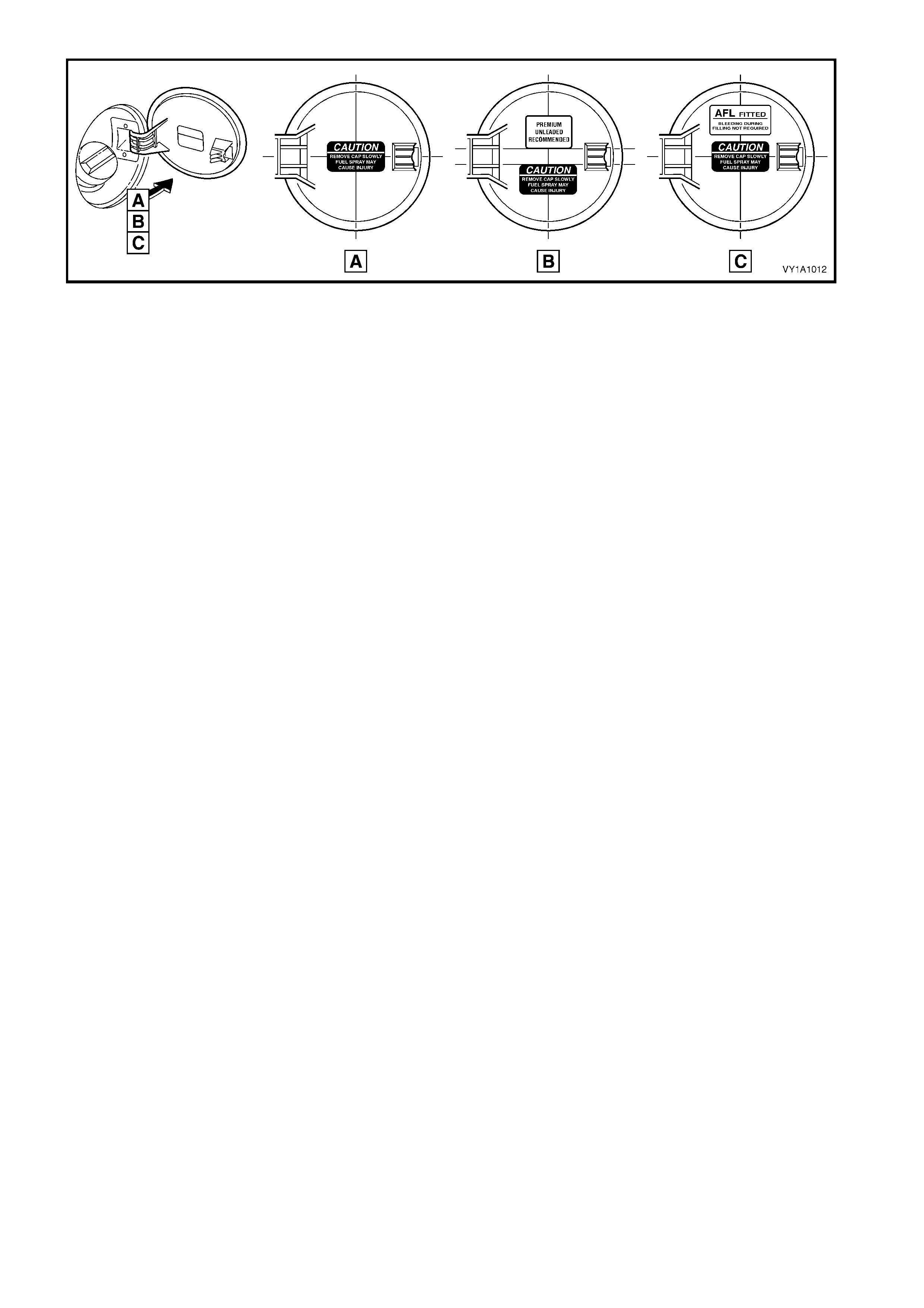
Figure 1A1-14
4.3 FUEL FILLER DOOR ASSEMBLY, UTILITY
LT Section No. – 03-028
The f uel filler door is painted the vehic le’s body colour . Paint the door assem bly using the c orrect m aterials and
techniques for PPE/PA resin (Polyphenylene/Polyamide). As the materials and techniques required differ
between paint brands, refer to the technical data supplied by your paint manufacturer.
NOTE: If the fuel filler door is being replaced, the warning labels affixed to the inside of the door must also be
replaced.
REMOVE
1. Open the fuel filler door by hand.
2. Remove the fuel filler cap and cover the opening
with a rag as required.
3. Rem ove the two screws (1) attaching the fuel filler
door assembly.
4. Remove the door assembly by withdrawing it
rearward.
5. If required, remove the fuel filler pipe seal (2) by
sliding the seal over the filler neck.
Figure 1A1-15
6. If required, remove the retainer (1) from the inner
opening of the fuel filler pipe seal (2).
7. Remove the seal by sliding it over the filler neck.
Figure 1A1-16
REINSTALL
Installation is the reverse of removal, noting the
following.
1. Ensure the retainer is seated correctly in the fuel
filler pipe seal.
2. Tighten the screws to the specified torque.
3. If the door has been replaced, apply the labels in
the positions shown, A – all vehicles except with
LPG, B – vehicles with LPG.
NOTE: Prior to affixing the label(s) ensure the surface
is clean and dry. Avoid touching the back of the label.
4. Ensure that when the fuel filler door is closed it
aligns with the surrounding panel.
Figure 1A1-17
FUEL TANK FILLER
DOOR ATTACHING SCREW
TORQUE SPECIFICATION 1.0 – 3.0 Nm
4.4 FUEL FILLER DOOR CABLE ASSEMBLY, RHD
SEDAN & WAGON
LT Section No. – 03-028
If required, first remove the following components:
1. Right-hand side sill trim and seat adjuster outer front cover, refer Section 1A8, 2.4 SIDE SILL TRIM &
PLATE for Sedan or 3.4 SIDE SILL TRIM & PLATE for Wagon.
2. Rear seat cushion assemblies, refer Section 1A7, SEAT ASSEMBLIES.
NOTE: For W agon m odels, rem ove the right-hand r ear seat bolster as sem bly and f old the rear seat bac kres t to
the horizontal position.
3. For Sedan models , the right-hand quarter inner rear side carpet, refer Section 1A8, 2.17 QUART ER INNER
REAR SIDE CARPET.
4. For Wagon models:
• body lock pillar lower trim, refer Section 1A8, 3.6 BODY LOCK PILLAR LOWER TRIM, and
• right-hand quarter inner trim upper, refer Section 1A8, 3.8 RIGHT-HAND QUARTER INNER TRIM
UPPER,
• quarter inner trim panel assembly, refer Section 1A8, 3.11 QUARTER INNER TRIM PANEL
ASSEMBLY.
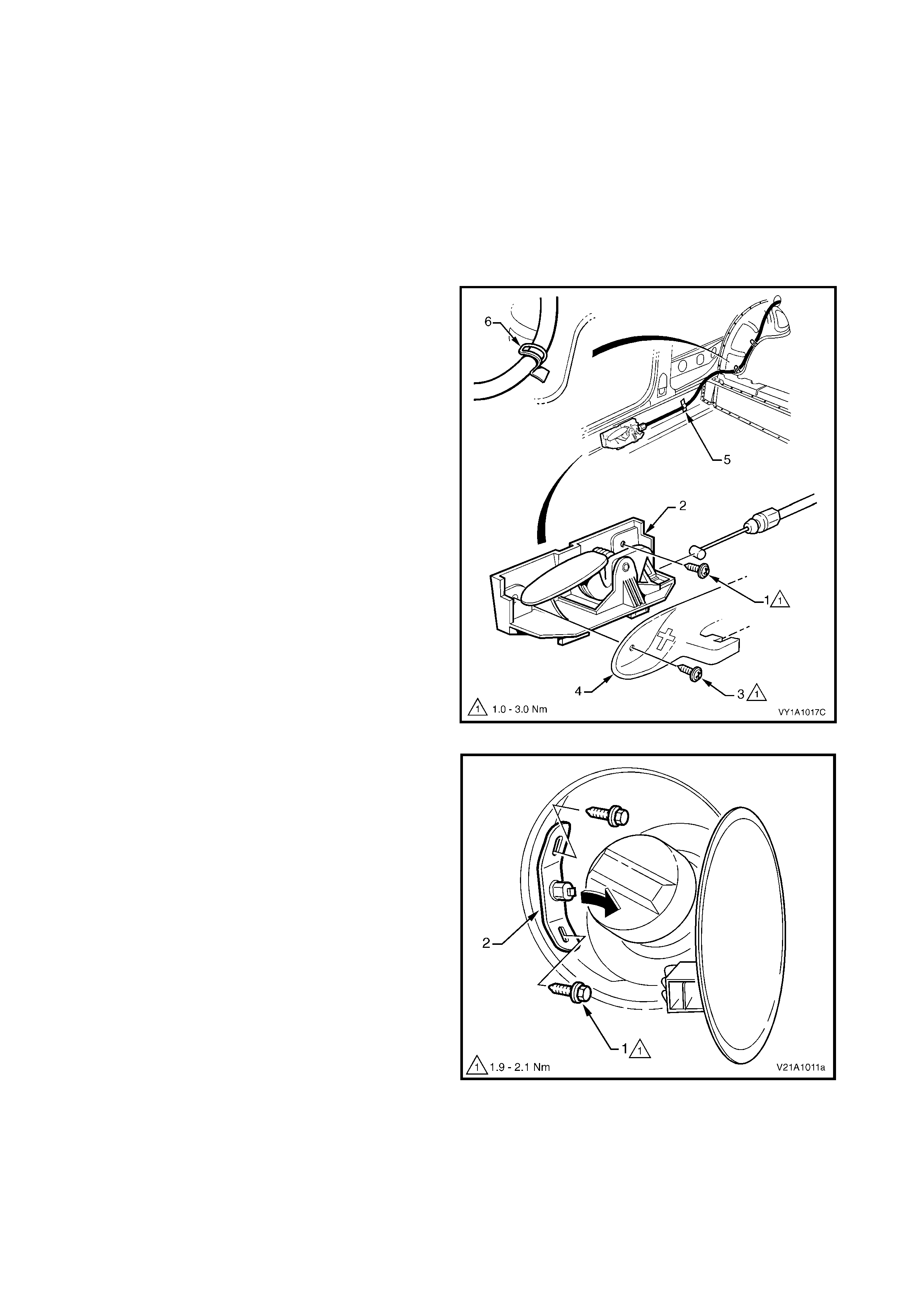
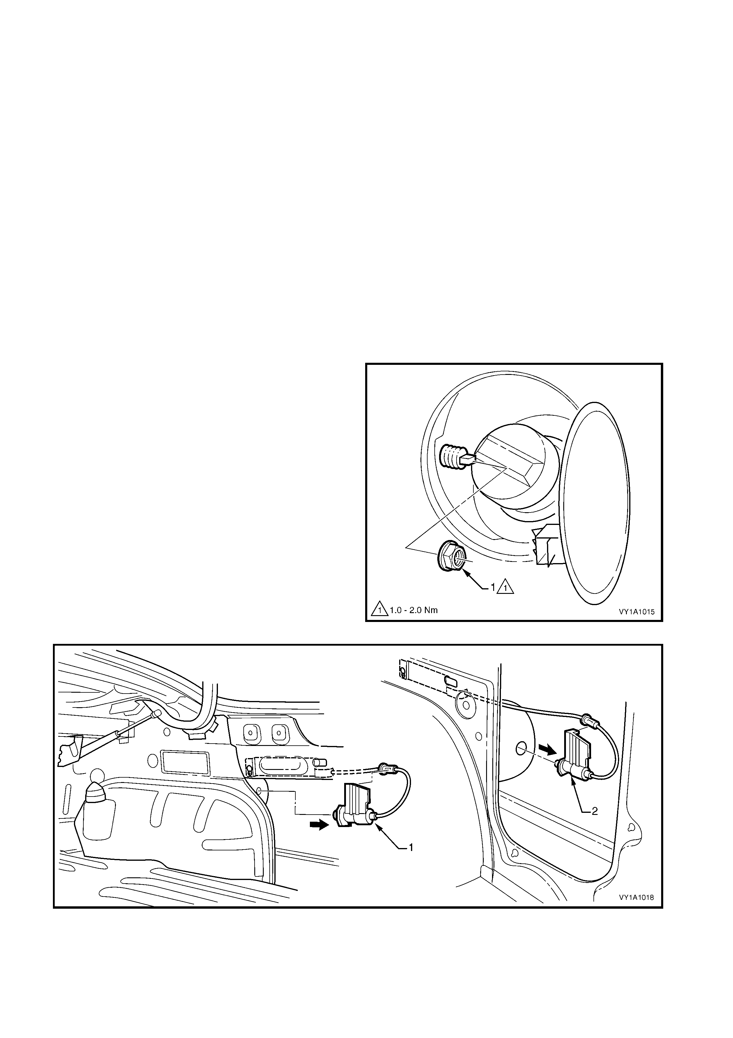
REMOVE
1. Open the fuel filler door by operating the release
lever.
2. From within the fuel filler housing, remove the nut
(1) attaching the fuel filler door cable assembly.
3. From within the rear compartment, withdraw the
cable assembly (1 Sedan, 2 W agon) from the fuel
filler housing, refer Figure 1A1-19.
Figure 1A1-18
Figure 1A1-19
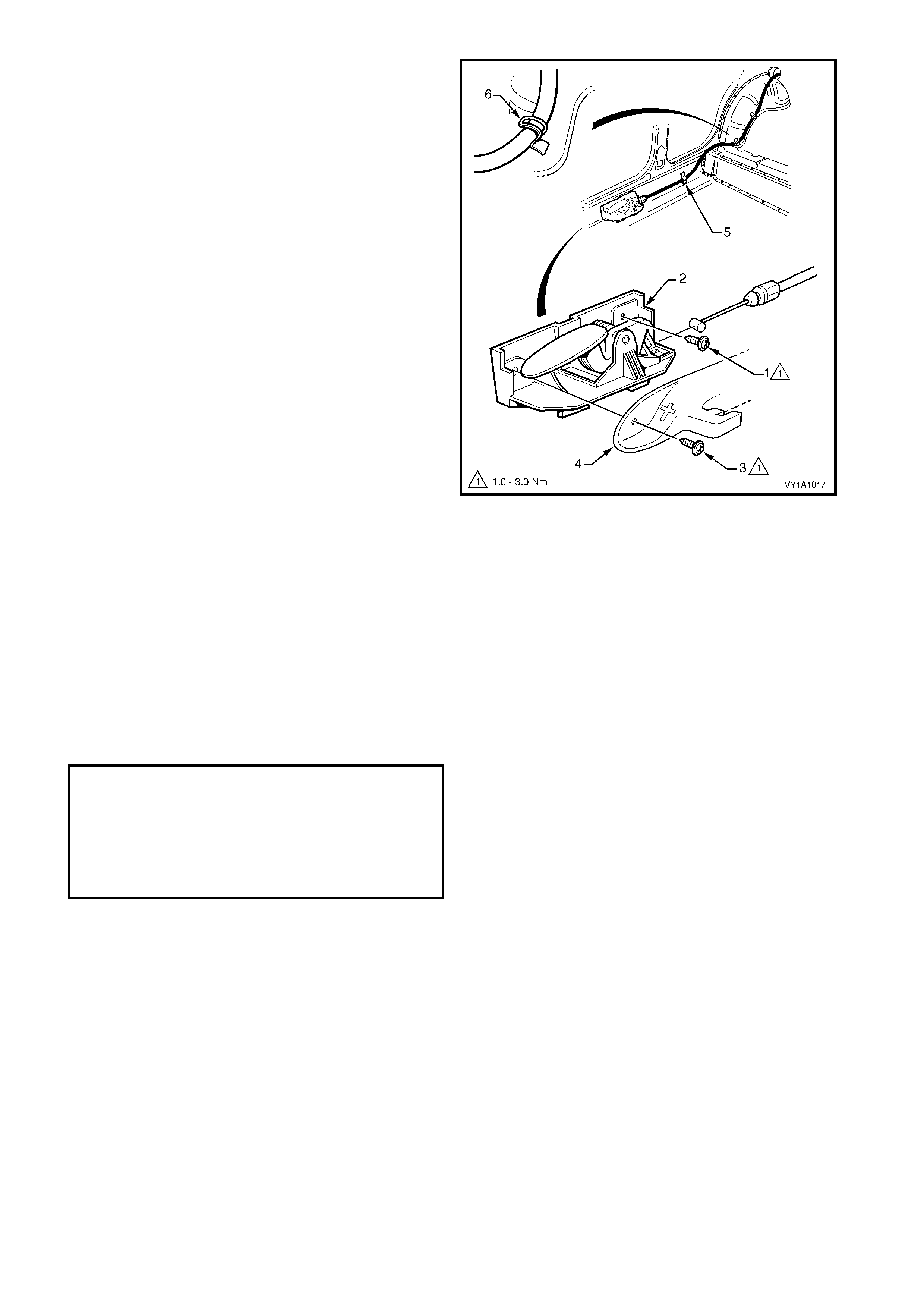
4. From inside the vehicle, remove the screw (1)
attaching the cable assembly lever (2) to the
rocker panel.
NOTE: T he previous ly removed sc rew (3) attaches the
seat adjuster outer front cover (4) and the cable
assembly lever.
5. Remove the tape (5) and bend the retaining tabs
(6) to release the cable assembly.
6. Remove the cable assembly from the vehicle,
feeding it through the back panel upper for Sedan
models.
7. If required, unclip the cable from the release lever.
Figure 1A1-20
REINSTALL
1. Installation is the reverse of removal. Ensure the
components are tightened to the specified torque.
NOTE 1: Ensure the cable assembly is routed
correctly and is fitted with the tab up as shown in
Figure 1A1-19.
NOTE 2: Ensure the cable assembly operates
correctly and the plunger completely retracts prior to
closing the fuel filler door. If satisfactory, close the door
ensuring it does not require excess force. The door
should spring ajar when the release is operated.
FUEL TANK FILLER DOOR
CABLE ASSEMBLY LATCH NUT
TORQUE SPECIFICATION 1.0 – 2.0 Nm
FUEL TANK FILLER DOOR
CABLE ASSEMBLY RELEASE
LEVER ATTACHING SCREW
TORQUE SPECIFICATION 1.0 – 3.0 Nm
COUPE
If required, first remove the following components:
1. Right-hand side sill trim and seat adjuster outer front cover, refer Section 1A8, 4.1 SIDE SILL TRIM &
PLATE.
2. Rear seat cushion assemblies, refer Section 1A7, SEAT ASSEMBLIES.
3. Right-hand quarter inner rear side carpet, refer Section 1A8, 4.14 QUARTER INNER REAR SIDE
CARPET.
REMOVE
1. Open the fuel filler door by operating the release
lever.
2. From inside the vehicle, remove the screw (1)
attaching the cable assembly lever (2) to the
rocker panel.
NOTE: T he previous ly removed sc rew (3) attaches the
seat adjuster outer front cover (4) and the cable
assembly lever.
3. Remove the tape (5) and bend the retaining tabs
(6) to release the cable assembly.
4. Unclip the cable from the release lever.
5. Pull the cable through the back panel upper into
the rear compartment.
Figure 1A1-21
6. From within the fuel filler housing, remove the two
screws (1) attaching the cable assembly (2).
7. Withdraw the cable assembly from the fuel filler
housing.
Figure 1A1-22
REINSTALL
1. Installation is the reverse of removal. Tighten the
screws to the specified torque.
NOTE 1: Ensure the cable assembly is routed
correctly.
NOTE 2: Ensure the cable assembly operates
correctly and the plunger completely retracts prior to
closing the fuel filler door. If satisfactory, close the door
ensuring it does not require excess force. The door
should spring ajar when the release is operated.
FUEL TANK FILLER DOOR
CABLE ASSEMBLY LATCH SCREW
TORQUE SPECIFICATION 1.9 – 2.1 Nm
FUEL TANK FILLER DOOR
CABLE ASSEMBLY RELEASE
LEVER ATTACHING SCREW
TORQUE SPECIFICATION 1.0 – 3.0 Nm
4.5 FUEL FILLER DOOR LOCK ACTUATOR ASSEMBLY, LHD
SEDAN & WAGON
LT Section No. – 03-028
NOTE: For removal of the fuel filler door switch assembly, refer to the disassembly procedure in
Section 1A3, 3.12 INSTRUMENT CLUSTER TRIM ASSEMBLY.
If required, first remove the following components:
1. F or Sedan, the right-hand quarter inner rear side carpet, refer Sect ion 1A8, 2.17 QUARTER INNER REAR
SIDE CARPET.
2. For Wagon models:
• body lock pillar lower trim , refer Section 1A8, 3.6 BODY LOCK PILLAR LOWER TRIM, and
• right-hand quarter inner trim upper, refer Section 1A8, 3.8 RIGHT-HAND QUARTER INNER TRIM
UPPER,
• quarter inner trim panel assembly, refer Section 1A8, 3.11 QUARTER INNER TRIM PANEL
ASSEMBLY.
REMOVE
1. Open the fuel filler door by operating the fuel filler
door switch on the instrument panel.
2. From within the fuel filler housing, remove the nut
(1) attaching the fuel filler door lock actuator
assembly.
3. From within the rear compartment, withdraw the
actuator assembly (1 Sedan, 2 Wagon) from the
fuel filler housing, refer Figure 1A1-24.
Figure 1A1-23
Figure 1A1-24
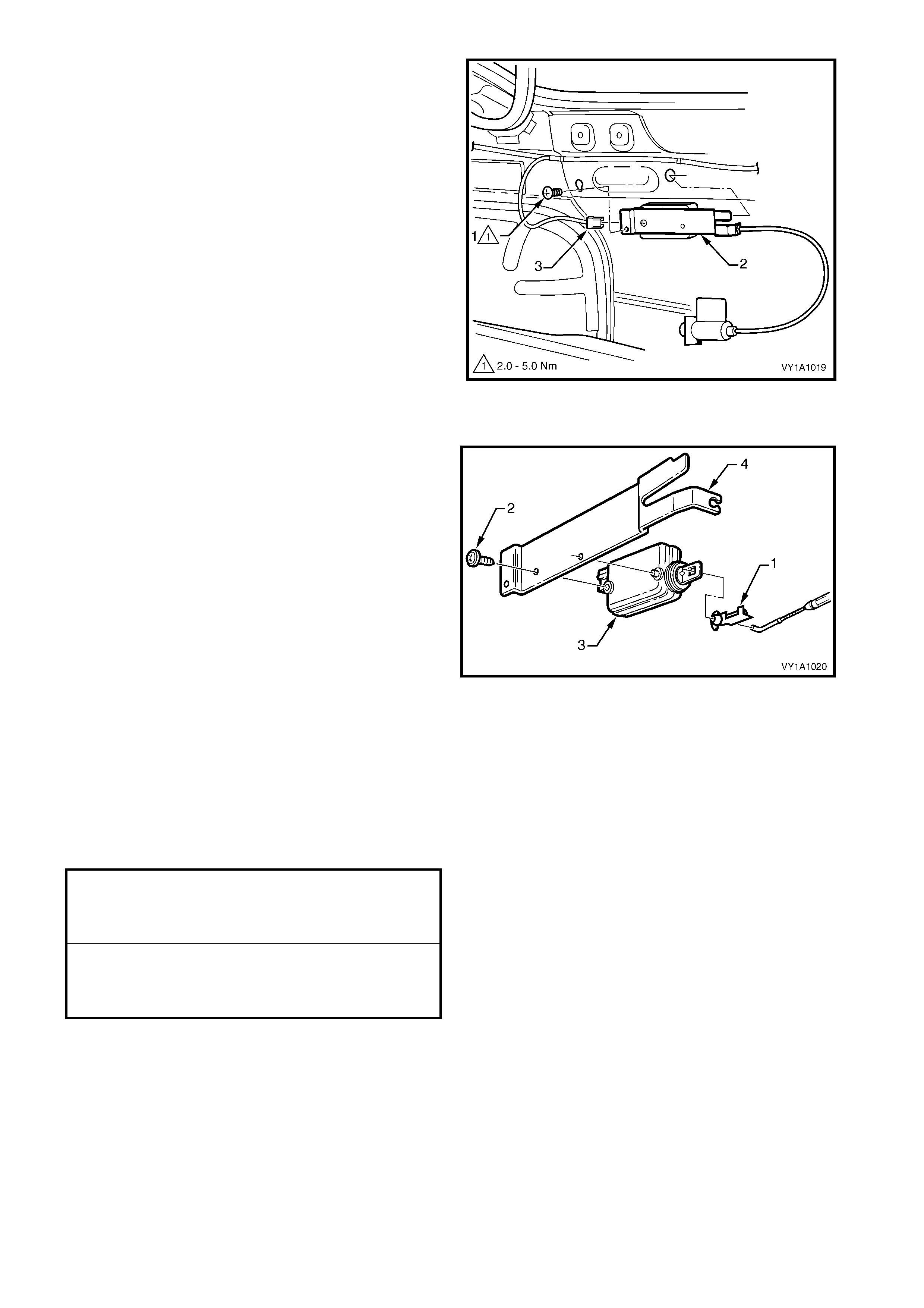
4. Loosen or remove the screw (1) attaching the
actuator assembly (2) to the side panel inner.
NOTE: Sedan shown, other models similar.
5. Slide the front of the assembly up and remove
from the keyhole.
6. Withdraw the rear tab from its locating hole.
7. Disconnect the wiring connector (3) and remove
the assembly.
Figure 1A1-25
DISASSEMBLE
1. Unclip the retainer (1) from the cable end by
raising the locking tab. Withdraw the cable from
the actuator.
2. Remove the screw (2) attac hing the actuator (3) to
the mounting plate (4).
Figure 1A1-26
REINSTALL
1. Installation is the reverse of removal. Ensure the
components are tightened to the specified torque.
NOTE: Ensure the actuator assembly operates
correctly and the plunger completely retracts prior to
closing the fuel filler door. If satisfactory, close the door
ensuring it does not require excess force. The door
should spring ajar when the release is operated.
FUEL TANK FILLER
DOOR LOCK ACTUATOR
ASSEMBLY LATCH NUT
TORQUE SPECIFICATION 1.0 – 2.0 Nm
FUEL TANK FILLER DOOR
LOCK ACTUATOR ASSEMBLY
ATTACHING SCREW
TORQUE SPECIFICATION 2.0 – 5.0 Nm
COUPE
LT Section No. –
NOTE: For removal of the fuel filler door switch assembly, refer to the disassembly procedure in
Section 1A3, 3.12 INSTRUMENT CLUSTER TRIM ASSEMBLY.
If required, first remove the following components:
1. Right-hand quarter inner rear side carpet, refer Section 1A8, 4.14 QUARTER INNER REAR SIDE
CARPET.
2. Right-hand quarter inner trim panel assembly, refer Section 1A8, 4.2 QUARTER INNER TRIM PANEL
ASSEMBLY.
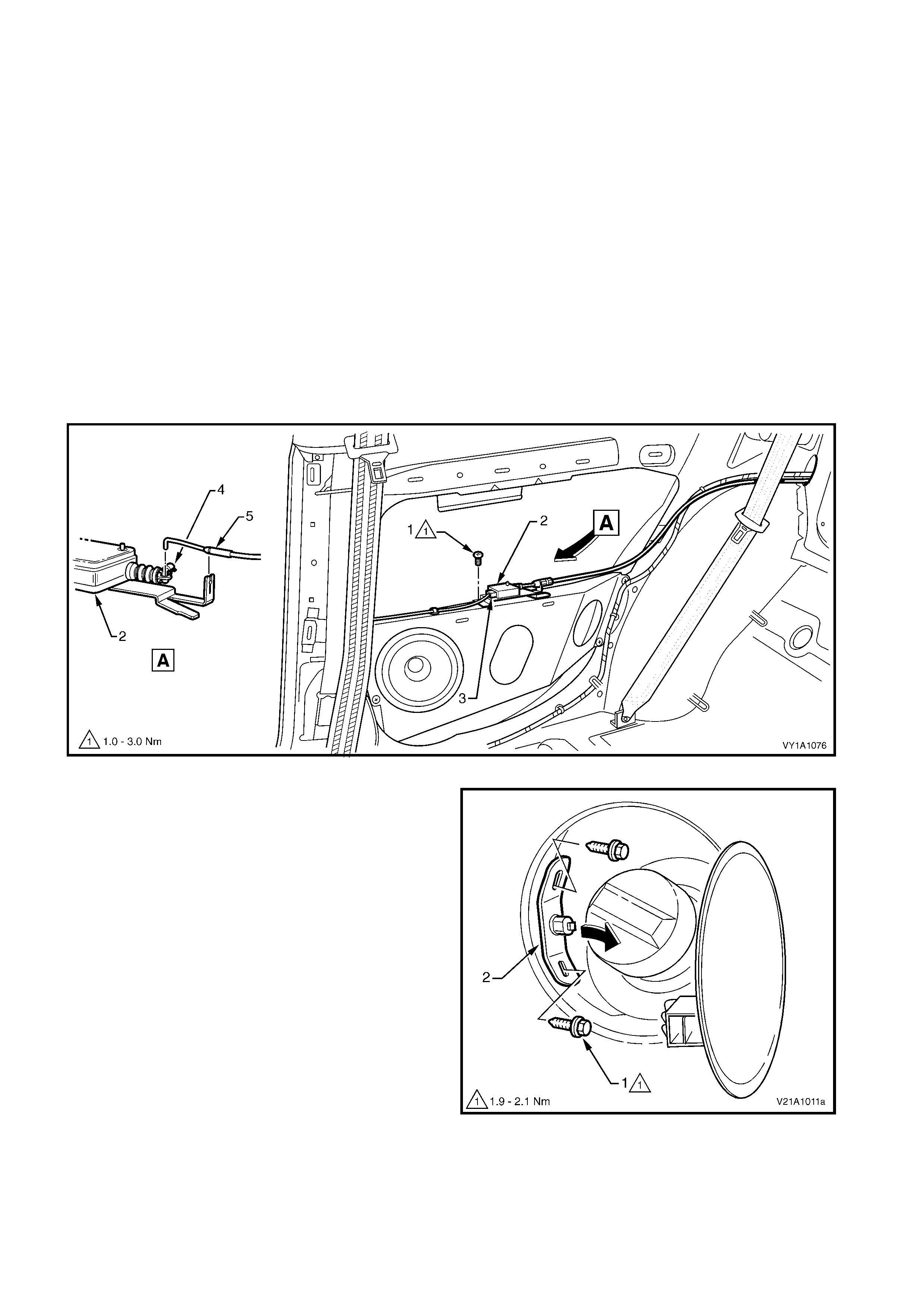
REMOVE
1. Open the fuel filler door by operating the fuel filler door switch on the instrument panel.
2. Rem ove the screw (1) attaching the actuator assembly (2) to the speaker mounting bracket, refer to Figure
1A1-27.
3. Disconnect the wiring connector (3) from the actuator assembly.
4. Open the retainer (4) and remove the cable (5) from the actuator assembly.
5. Remove the actuator assembly and if required, feed the cable into the rear compartment.
Figure 1A1-27
6. From within the fuel filler housing, remove the two
screws (1) attaching the cable assembly (2).
7. Withdraw the cable assembly from the fuel filler
housing.
Figure 1A1-28
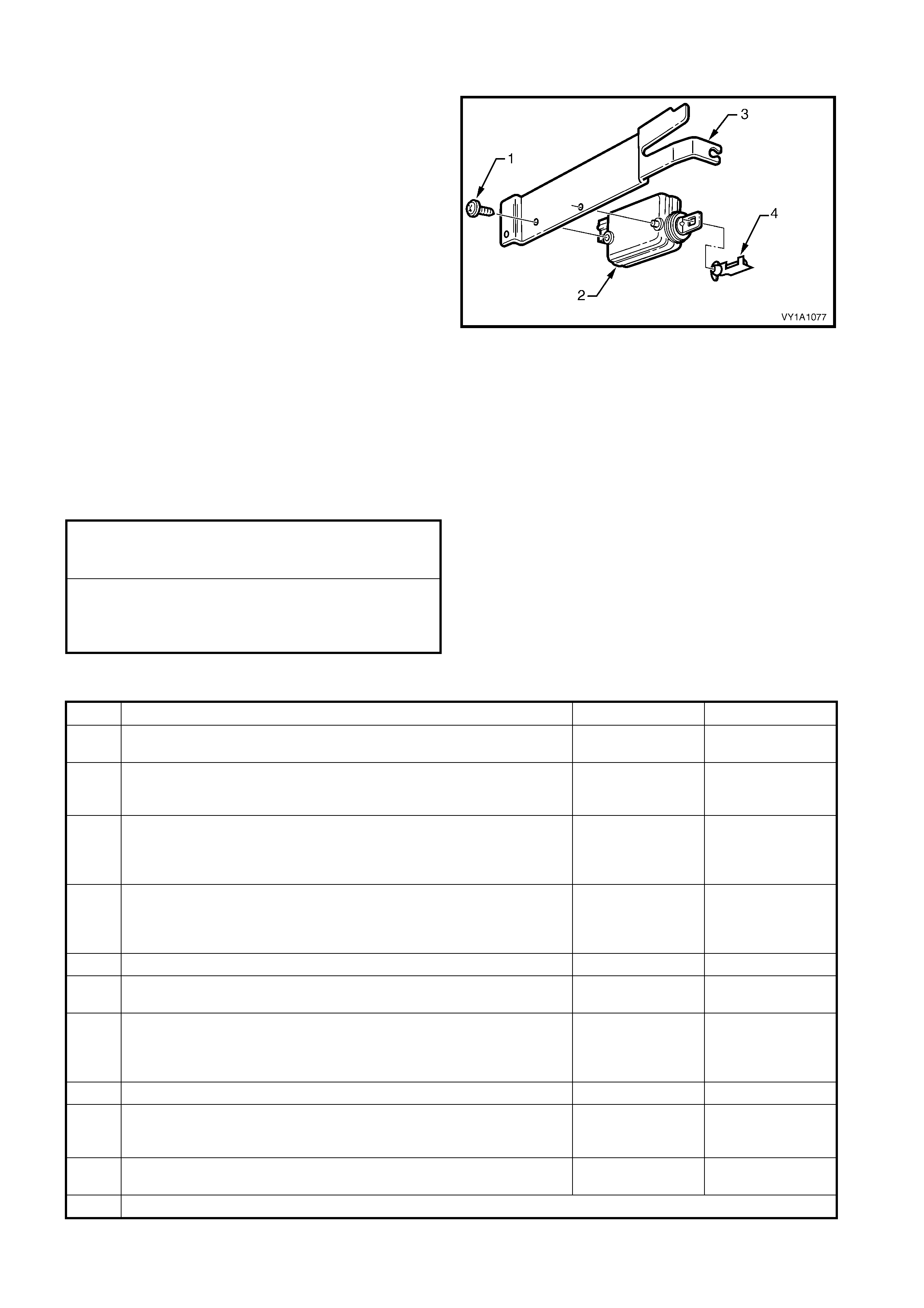
DISASSEMBLE
1. Remove the screw (1) attac hing the actuator (2) to
the mounting plate (3).
2. Unclip the retainer (4) from the actuator.
REASSEMBLE
Assem bly is the revers e of the disass em bly procedure.
Tighten the screw securely.
Figure 1A1-29
REINSTALL
1. Installation is the reverse of removal. Ensure the
components are tightened to the specified torque.
NOTE: Ensure the actuator assembly operates
correctly and the plunger completely retracts prior to
closing the fuel filler door. If satisfactory, close the door
ensuring it does not require excess force. The door
should spring ajar when the release is operated.
DIAGNOSIS
STEP ACTION YES NO
1 Press the fuel filler door release switch. Does the fuel filler door
open? OK. End Go to 2
2 Press the fuel filler door release switch. Does the actuator emit a
clicking sound? Door jammed or
cable broken.
Repair or replace
Go to 3
3 Check Fuse 105 in the engine compartment fuse and relay panel
assembly. Is it OK? Go to 4 Replace fuse.
If the fuse blows
again test for a
short to ground.
4 Check Fuse 20 in the passenger compartment fuse and relay panel
assembly. Is it OK? Go to 5 Replace fuse.
If the fuse blows
again test for a
short to ground.
5 Ground the switch connector S191 pin 3. Does the actuator operate? Go to 6 Go to 7
6 Ground the switch connector S191 pin 5 and press the switch.
Does the actuator operate? Repair circuit 151. Replace switch. *
7 Ground connector Y10 pin 3. Does actuator operate? Repair circuit
1447 between the
actuator and
switch.
Go to 8
8 Check for B+ at the actuator connector Y10 pin 1 Replace actuator. Go to 9
9 Check for B+ at connector X42 pin 22 in the passenger compartment
fuse and relay panel assembly Repair circuit 440
between fuse 20
and the actuator
Go to 10
10 Check for B+ at connector X18 pin 104 in the engine compartment
fuse and relay panel assembly. Repair circuit 342 Repair circuit 1
* Also check the suppression diode for continuity between pins A to B but not B to A.
FUEL TANK FILLER DOOR
CABLE ASSEMBLY LATCH SCREW
TORQUE SPECIFICATION 1.9 – 2.1 Nm
FUEL TANK FILLER DOOR
LOCK ACTUATOR ASSEMBLY
ATTACHING SCREW
TORQUE SPECIFICATION 2.0 – 5.0 Nm
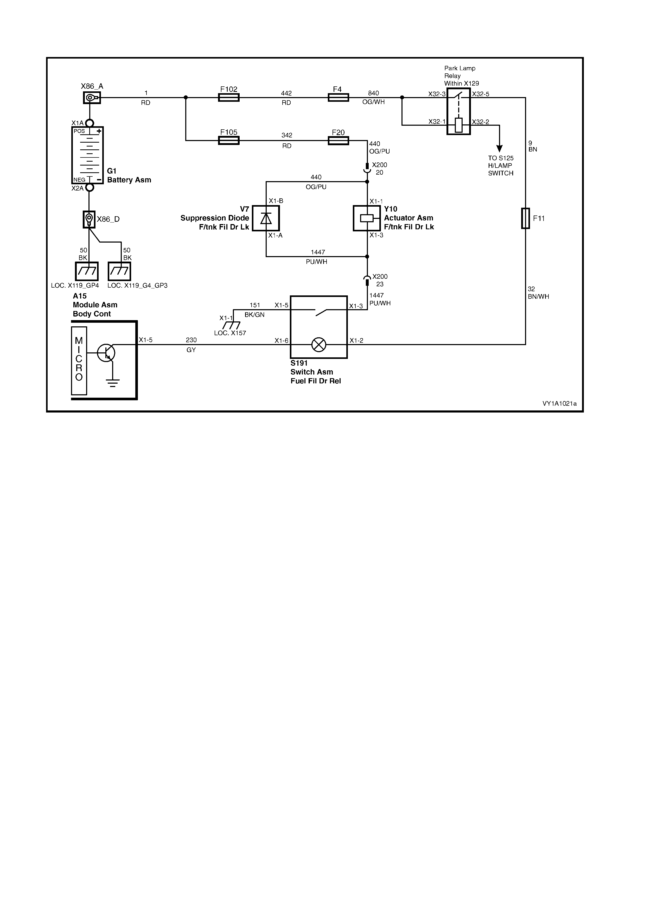
WIRING SCHEMATIC
Figure 1A1-30

CONNECTOR VIEWS
Figure 1A1-31
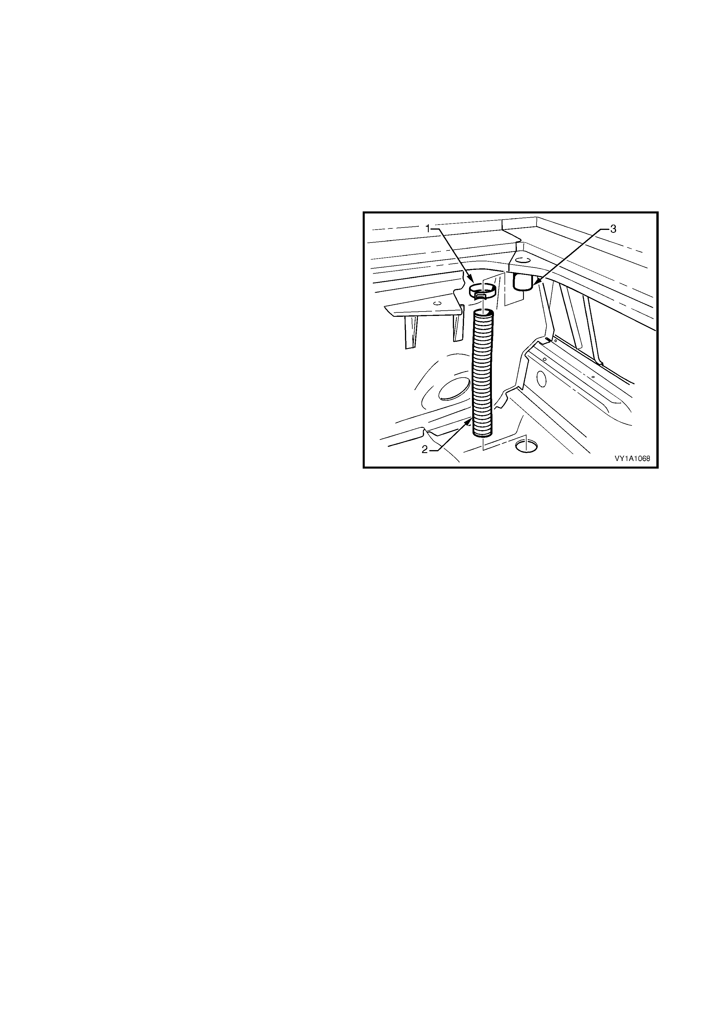
5. DRAIN TUBES, UTILITY
5.1 REAR FLOOR PANEL DRAIN TUBE, UTILITY
NOTE: If the tube becomes blocked or restricted, clear the obstruction with a length of wire.
LT Section No. –
1. If required, first remove the front load floor panel, refer Section 1B, 2.7 FRONT LOAD FLOOR PANEL.
NOTE: Although not shown, the drain tube can be removed with the fuel tank in place.
REMOVE
1. Using a pair of pliers, loosen the clamp (1) and
slide it down the rear floor panel drain tube (2).
2. Prise the tube from the floor panel outlet (3).
3. W ithdraw the tube from the hole in the floor panel
and remove.
Figure 1A1-32
REINSTALL
Installation is the reverse of removal. Ensure the tube
and clamp are correctly seated.
5.2 REAR WINDOW PANEL DRAIN TUBE ASSEMBLY, UTILITY
NOTE: If the tube becomes blocked or restricted clear the obstruction with a long length of wire.
LT Section No. –
If required, first remove the following components:
1. Rear window side moulding assembly, refer Section 1A9, 4.10 REAR WINDOW SIDE MOULDING
ASSEMBLY.
2. Rear quarter window moulding, refer Section 1A9, 4.11 REAR QUARTER WINDOW MOULDING.
3. Front load floor panel, refer Section 1B, 2.7 FRONT LOAD FLOOR PANEL.
NOTE: Although not shown, the drain tube can be removed with the fuel in place.
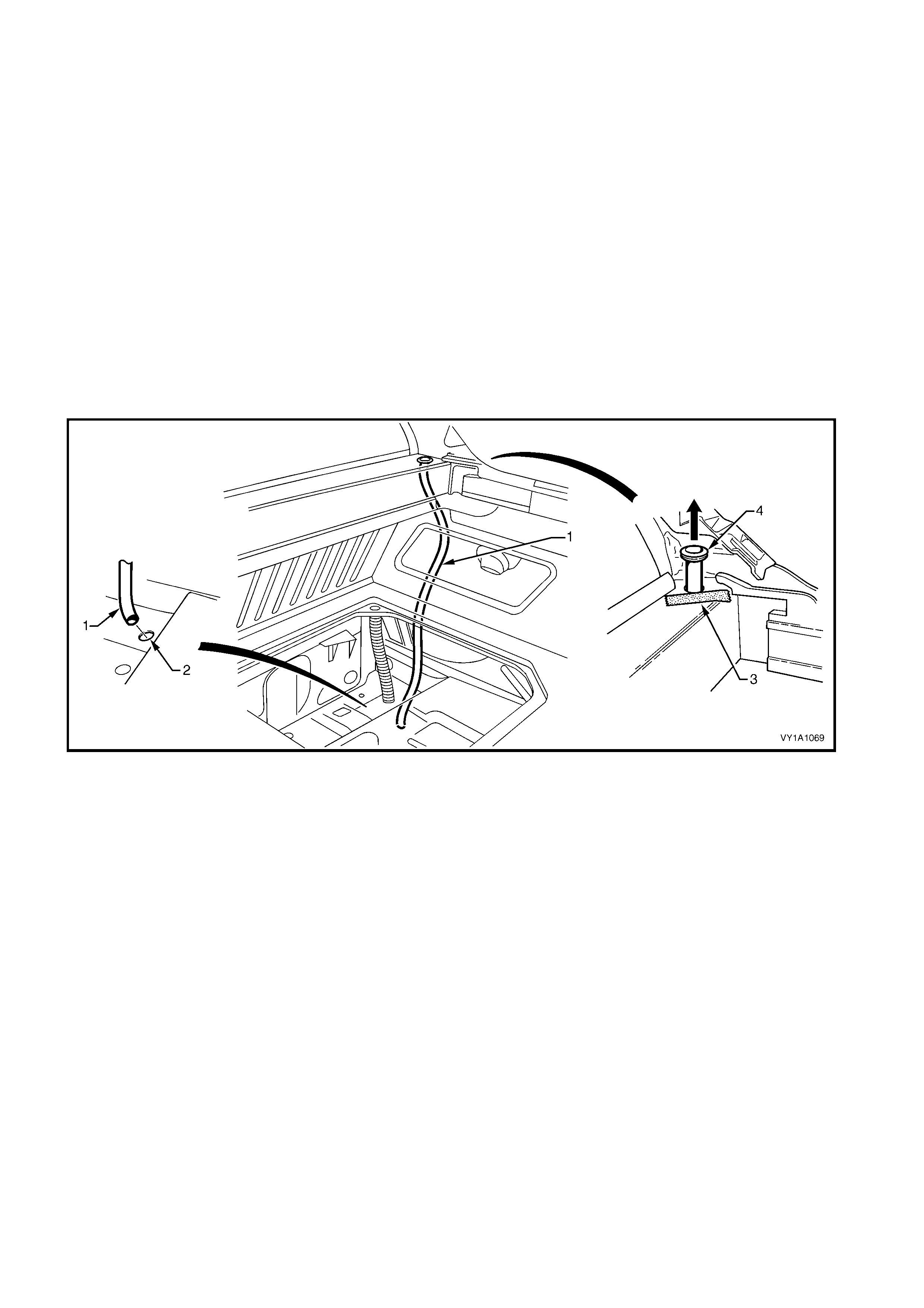
REMOVE
1. Withdraw the rear window panel drain tube assembly (1) from the hole in the floor panel (2), refer Figure
1A1-33.
2. Protect the paintwork on the panel adjacent to the tube assembly with a piece of tape (3).
3. Using a fine flat blade screwdriver, prise the tube assembly grommet (4) from the panel.
4. Withdraw the tube assembly through the hole in the panel and remove.
Figure 1A1-33
REINSTALL
Installation is the reverse of removal. Ensure the tube is correctly seated.

6. TORQUE WRENCH SPECIFICATIONS
Front wheelhouse liner attaching screw .........................................................1.0 – 3.0 Nm
Rear wheelhouse liner attaching screw..........................................................1.0 – 3.0 Nm
Rocker panel moulding assembly attaching screw.........................................1.0 – 3.0 Nm
Rear bumper fascia assembly attaching screw..............................................1.0 – 3.0 Nm
Fuel filler door attaching screw.......................................................................1.0 – 3.0 Nm
Fuel filler door cable assembly latch nut.........................................................1.0 – 2.0 Nm
Fuel filler door cable assembly release lever attaching screw .......................1.0 – 3.0 Nm
Fuel filler door cable assembly latch screw, Coupe........................................1.9 – 2.1 Nm
Fuel filler door lock actuator assembly attaching nut......................................1.0 – 2.0 Nm
Fuel filler door lock actuator assembly attaching screw .................................2.0 – 5.0 Nm