
SECTION 1A2 - BODY DIMENSIONS
IMPORTANT
Before perfo rming any Service O perat ion or o th er pro cedu re describ ed in th is Section, refer to Section
00 CAUTIONS AND NOTES for correct workshop practices with regard to safety and/or property
damage.
CONTENTS
1. GENERAL DESCRIPTION
2. SERVICE OPERATIONS
2.1 UNDERBODY DIMENSIONS – PROJECTED
SEDAN
WAGON
COUPE
UTILITY
2.2 UPPERBODY DIMENSIONS – ACTUAL
FRONT – ALL MODELS
SIDE & INTERIOR – SEDAN
SIDE & INTERIOR – WAGON
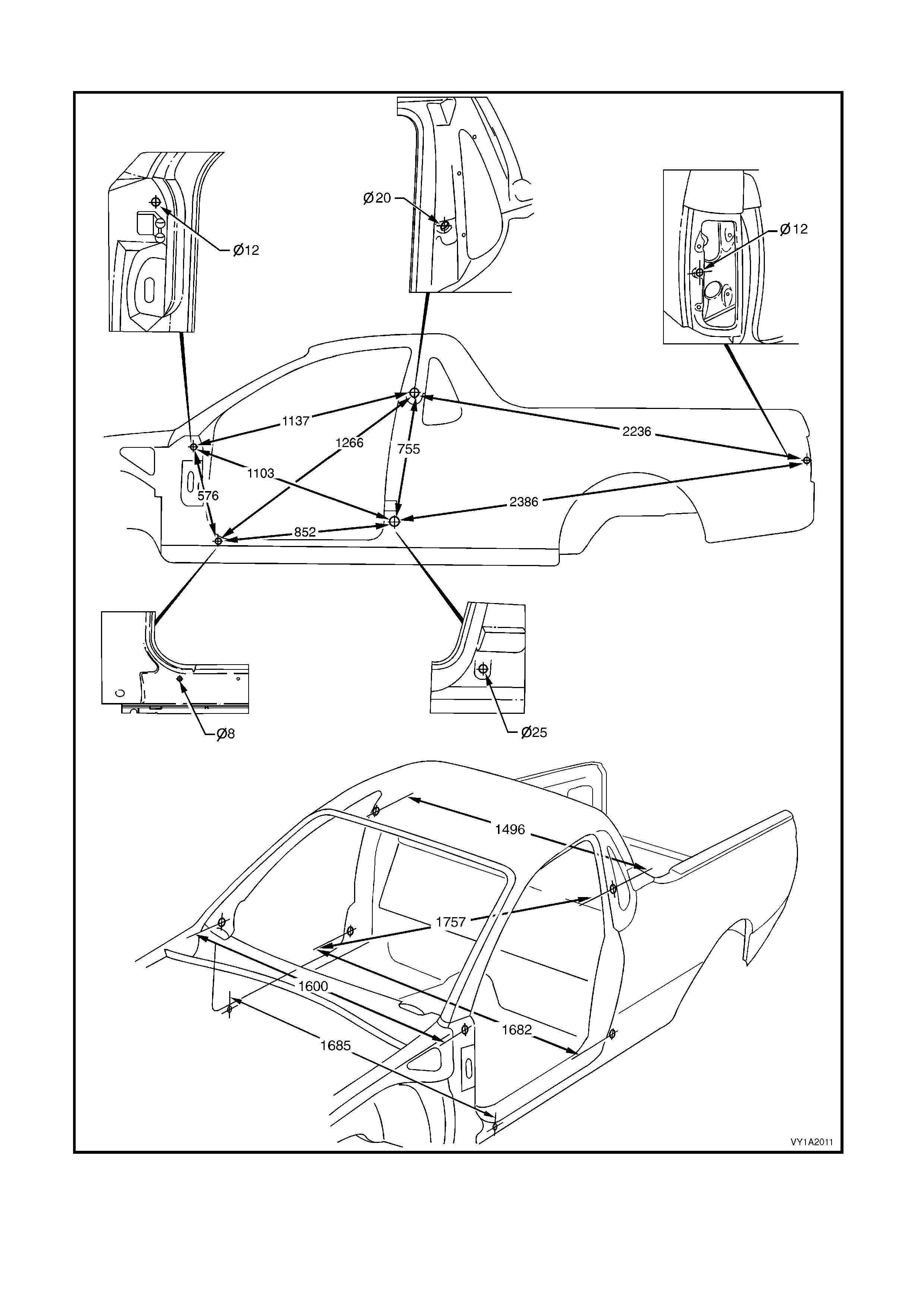
SIDE & INTERIOR – COUPE
SIDE & INTERIOR – UTILITY
RE AR – SEDAN
REAR – WAGON
REAR – UTILITY
REAR – COUPE
2.3 SUSPENSION FRAMES & TRANS-
MISSION SUPPORT ALIGNMENT
FRONT SUSPENSION FRAME ASSEMBLY
TRANSMISSION SUPPORT
REAR SUSPENSION FRAME ASSEMBLY
3. TORQUE WRENCH SPECIFICATIONS
4. SPECIAL TOOLS

1. GENERAL DESCRIPTION
Correct alignment of the body structure is essential to ensure the vehicle performs as intended. A body structure
that is outside design tolerances can suffer difficult operation and poor fitment of the doors, hood, rear compartment
lid, liftgate or endgate. Suspension performance and vehicle handling can also suffer and noise vibration and
harshness may become evident.
The body structure should therefore be aligned to within ± 1.5 mm of dimensions specified in this Section.
As a m inimum, these dimens ions s hould be ac c urately check ed with a trammel gauge cons isting of a parallel bar or
rod fitted with two adjustable trammels.
In preparation f or an underbody alignment chec k , the vehicle m ust be c orrec tly set-up on a level surfac e, preferably
using a measuring or jigging system specifically designed for the task of checking and correcting vehicle body
alignment.
Note that the dim ens ions provided for the underbody are projected: the meas uring points are tr ans posed onto a two
dimensional (flat) surface and the measurements are taken along the one plane.
All upperbody measurements are actual: the distance from point to point.
Incorrect alignment of the suspension frames and transmission support can also have an adverse affect on the
vehicle’s performance and introduce noise vibration and harshness.
Any time a suspension frame or the transmission support is removed, it must be aligned as described in this
Section.
2. SERVICE OPERATIONS
2.1 UNDERBODY DIME NSIONS – PROJECTED
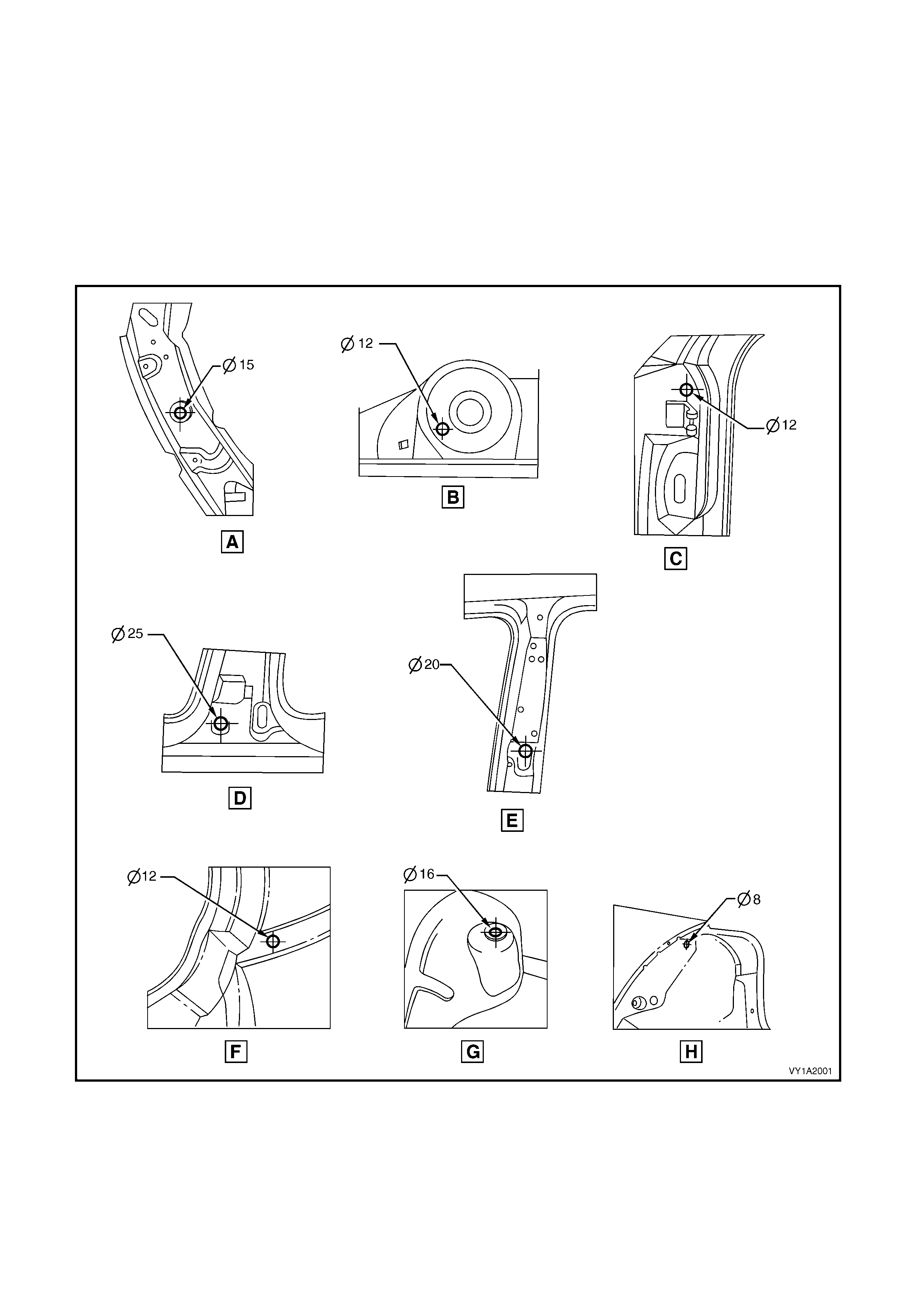
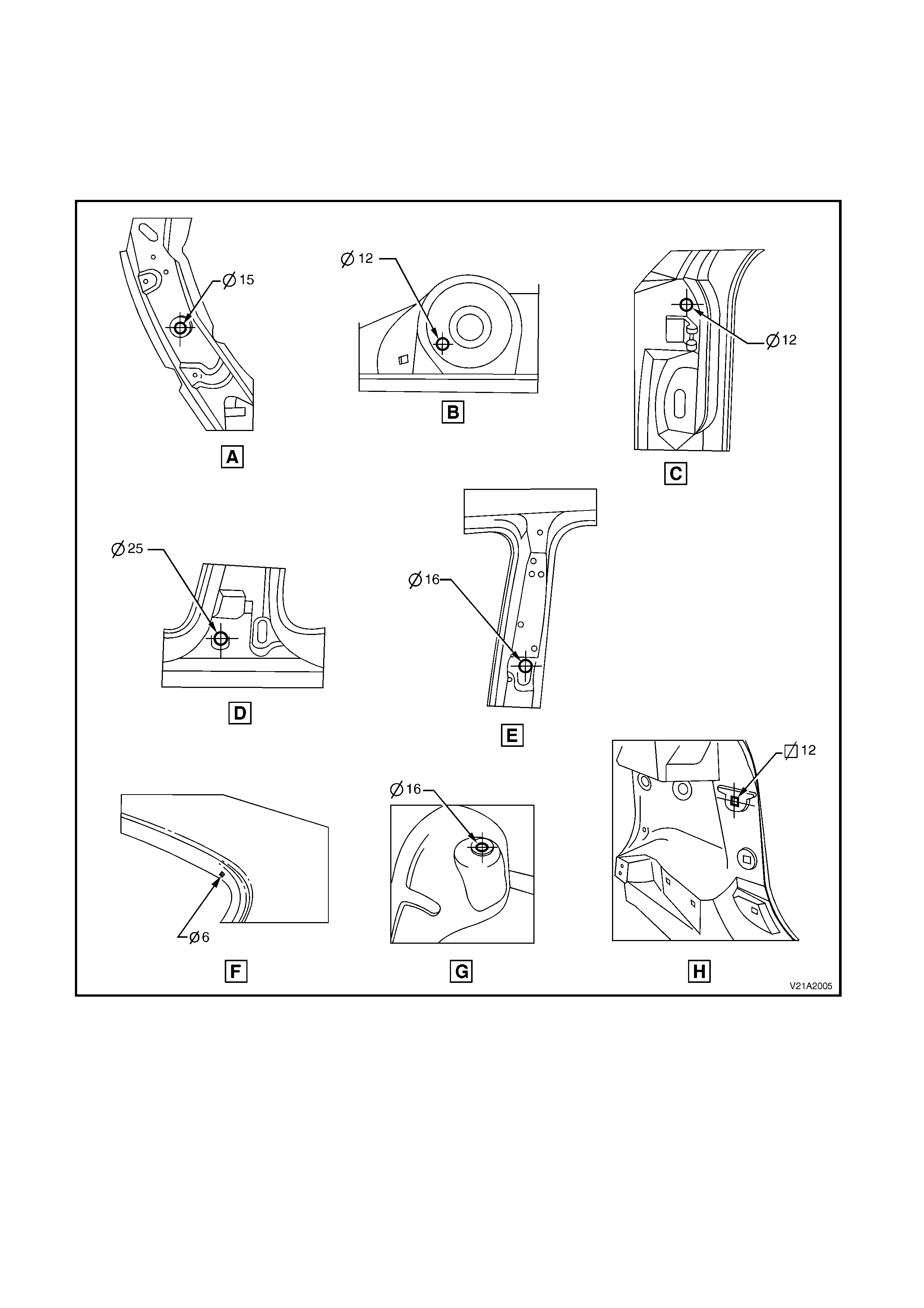
SEDAN
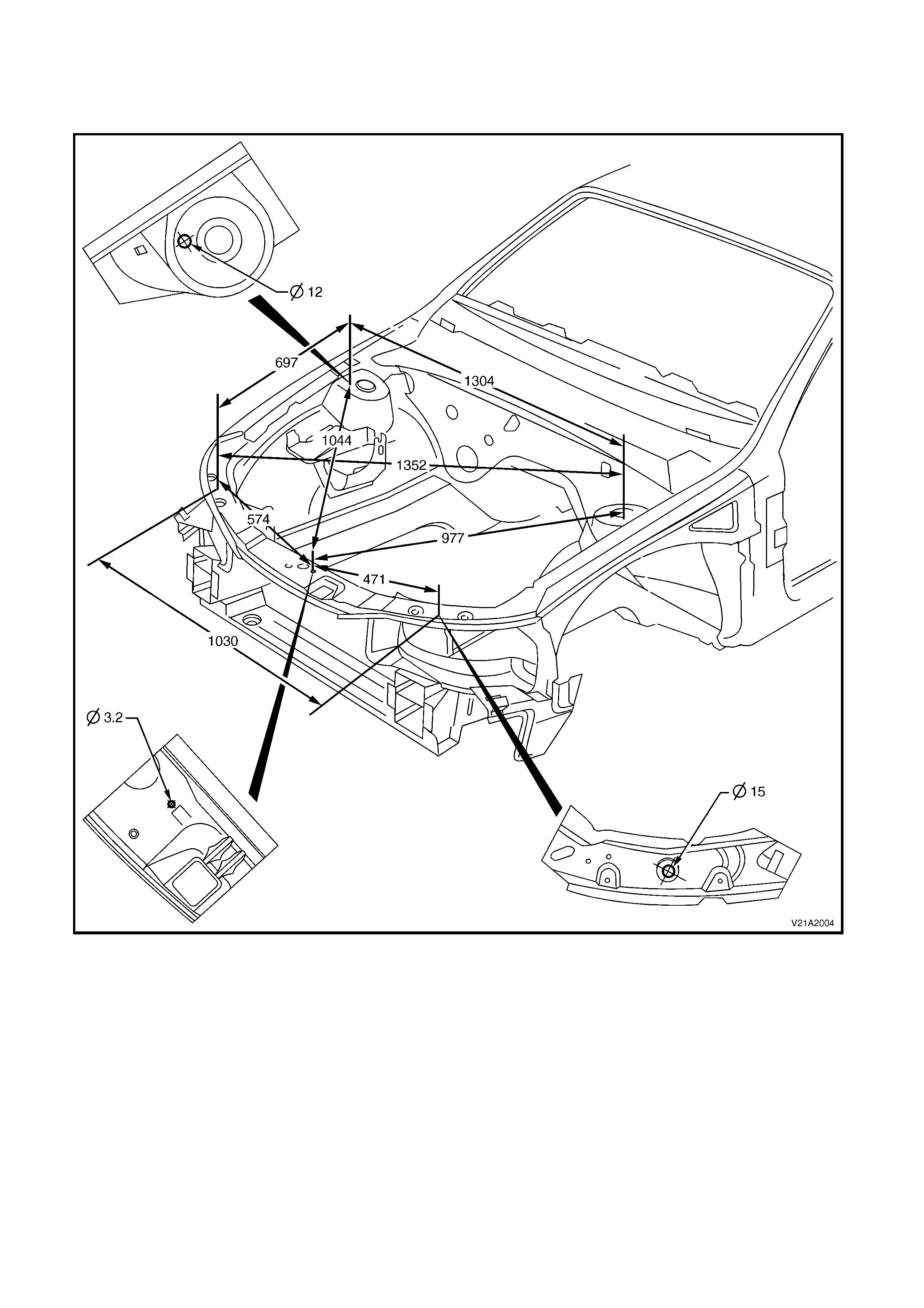
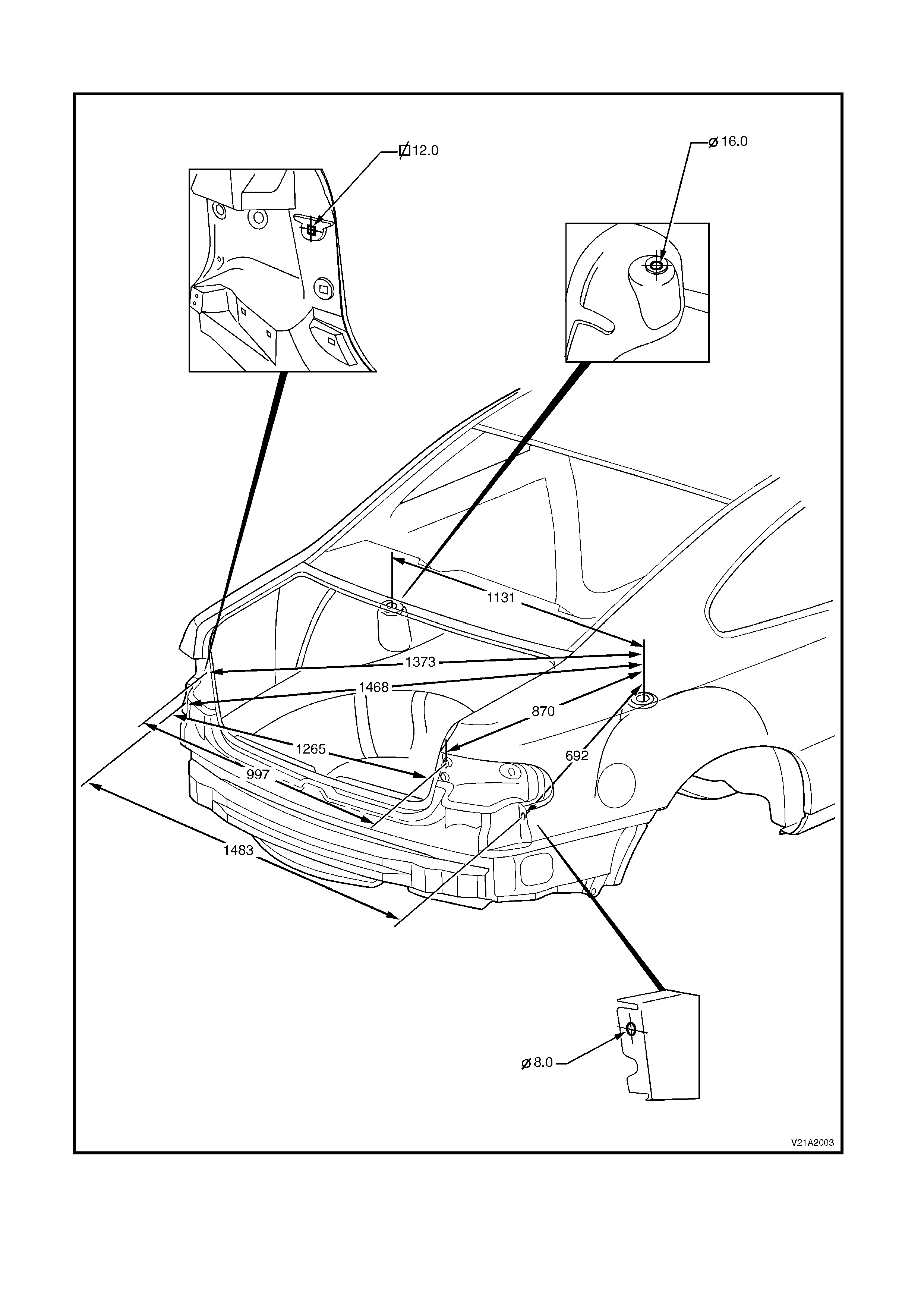
All dimensions are given in mm and are measured from the centre of holes, on the outer side of the metal surface.
The main datum surface (1) is the underside of the front side rail assembly, refer to Figure 1A2-2.
The main datum hole (2) is a 19 mm hole on the underside of the front side rail assembly, refer to Figure 1A2-2.
The dash panel assembly attaching hole (3) in Figure 1A2-2 is the datum hole also depicted at View C in
Figure 1A2-1.
Figure 1A2-1
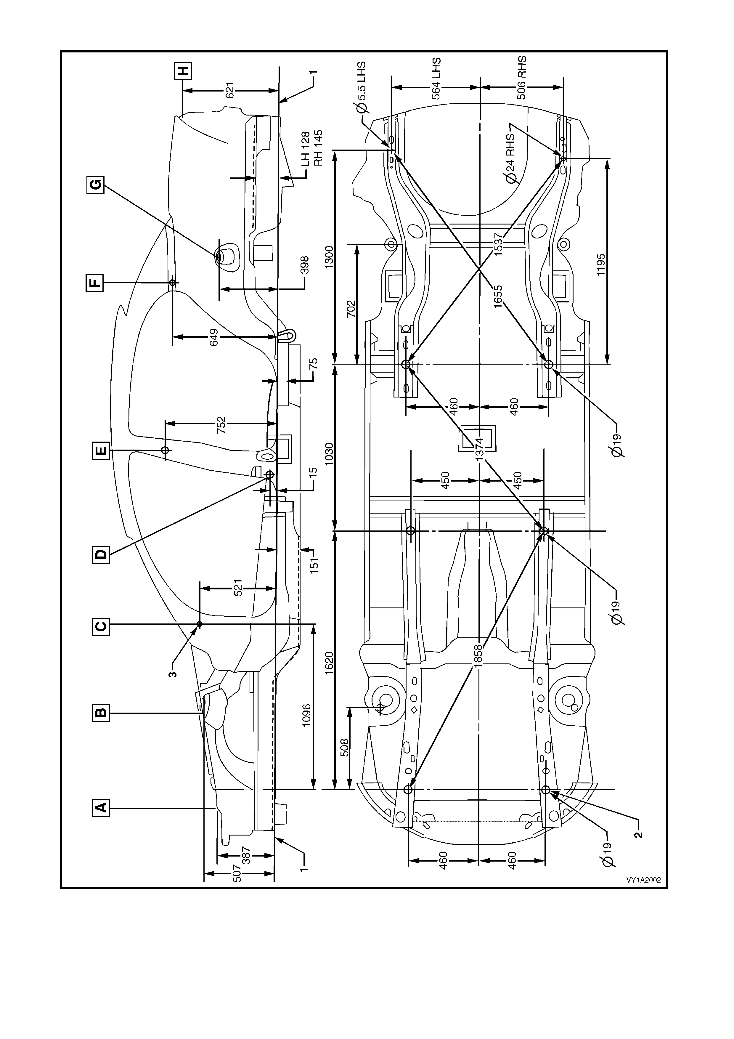
Figure 1A2-2
WAGON
All dimensions are given in mm and are measured from the centre of holes, on the outside of the metal surface.
The main datum surface (1) is the underside of the front side rail assembly, refer to Figure 1A2-4.
The main datum hole (2) is a 19 mm hole on the underside of the front side rail assembly, refer to Figure 1A2-4.
The dash panel assembly attaching hole (3) in Figure 1A2-4 is the datum hole also depicted at View C in
Figure 1A2-3.
Figure 1A2-3
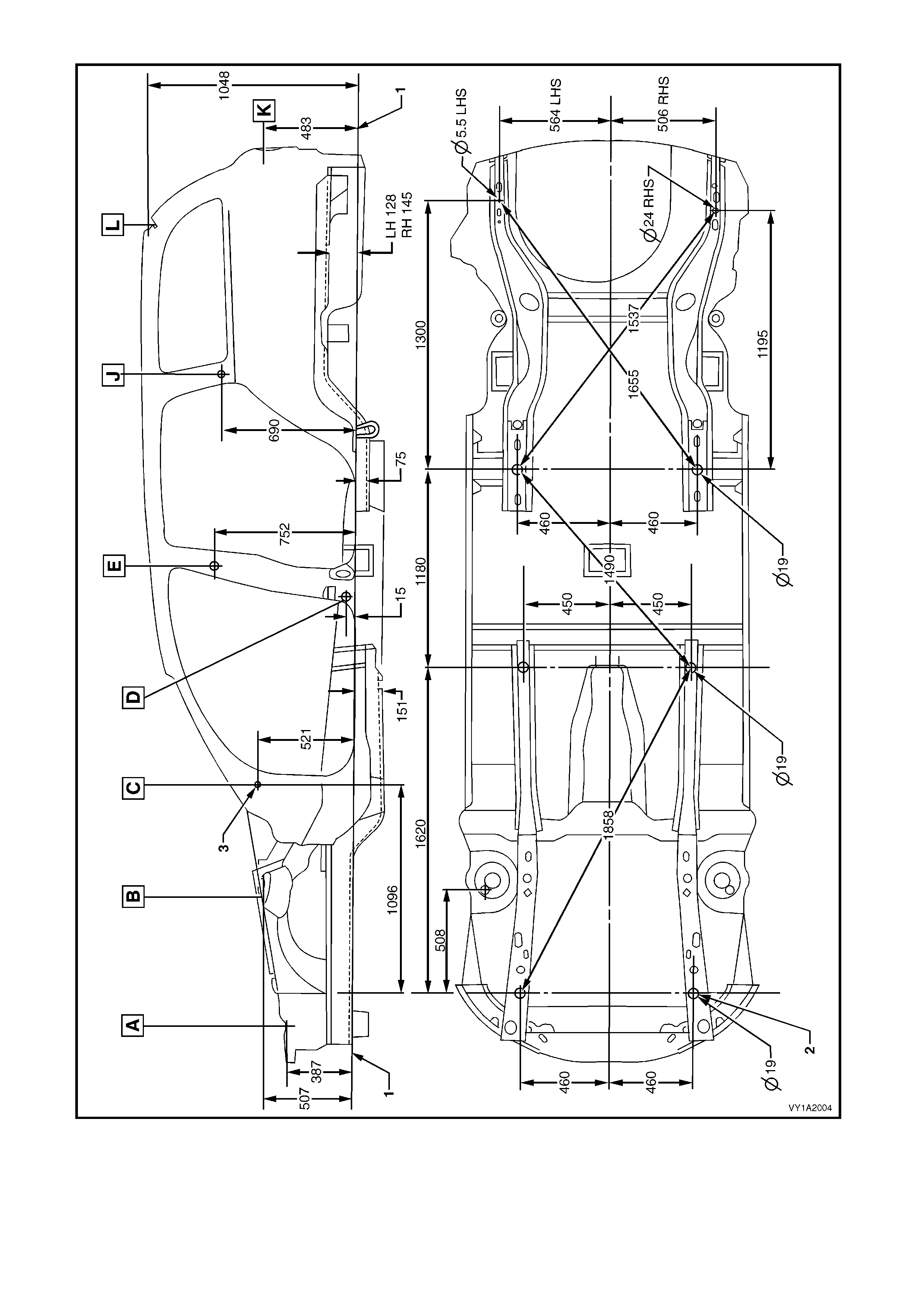
Figure 1A2-4
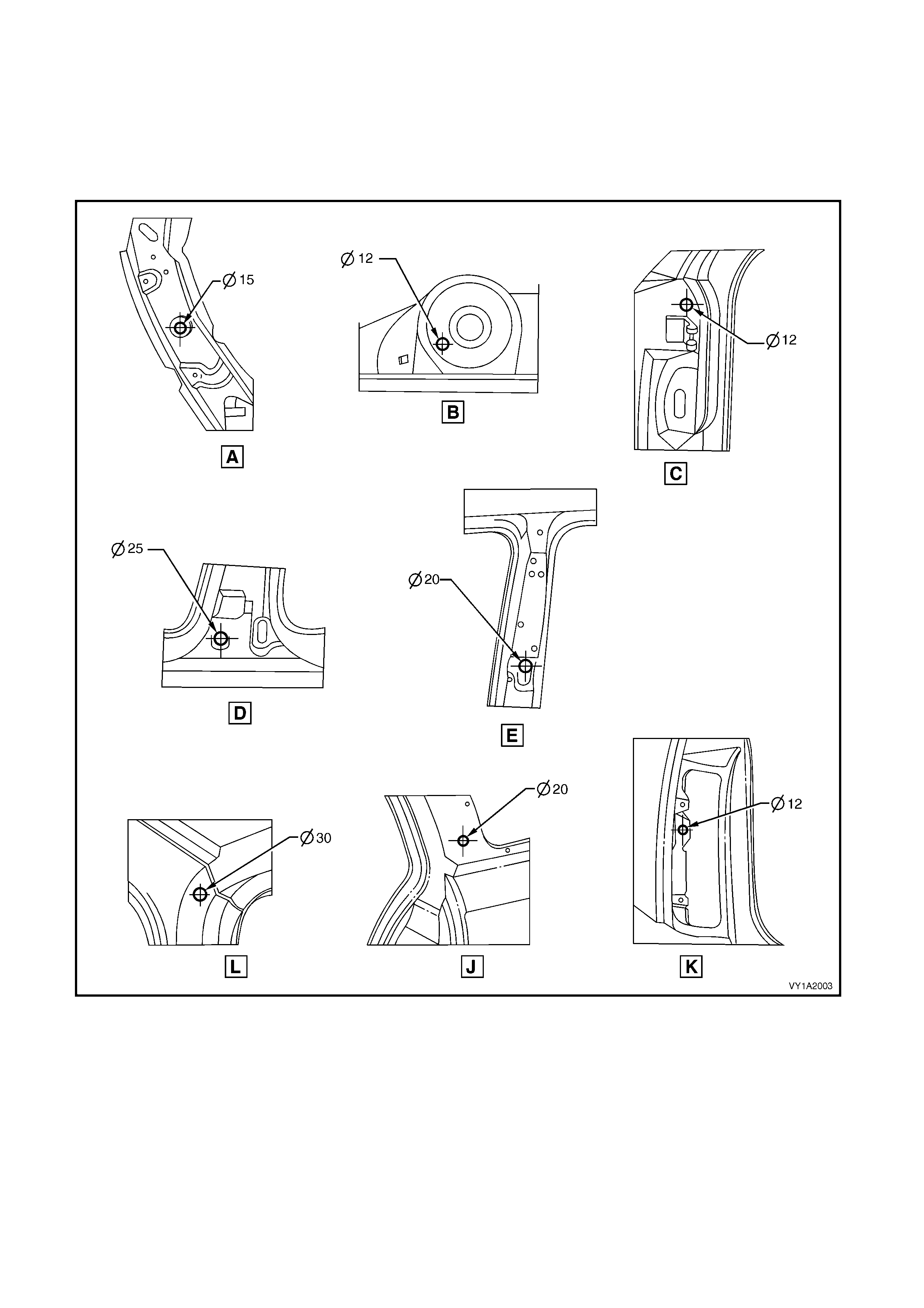
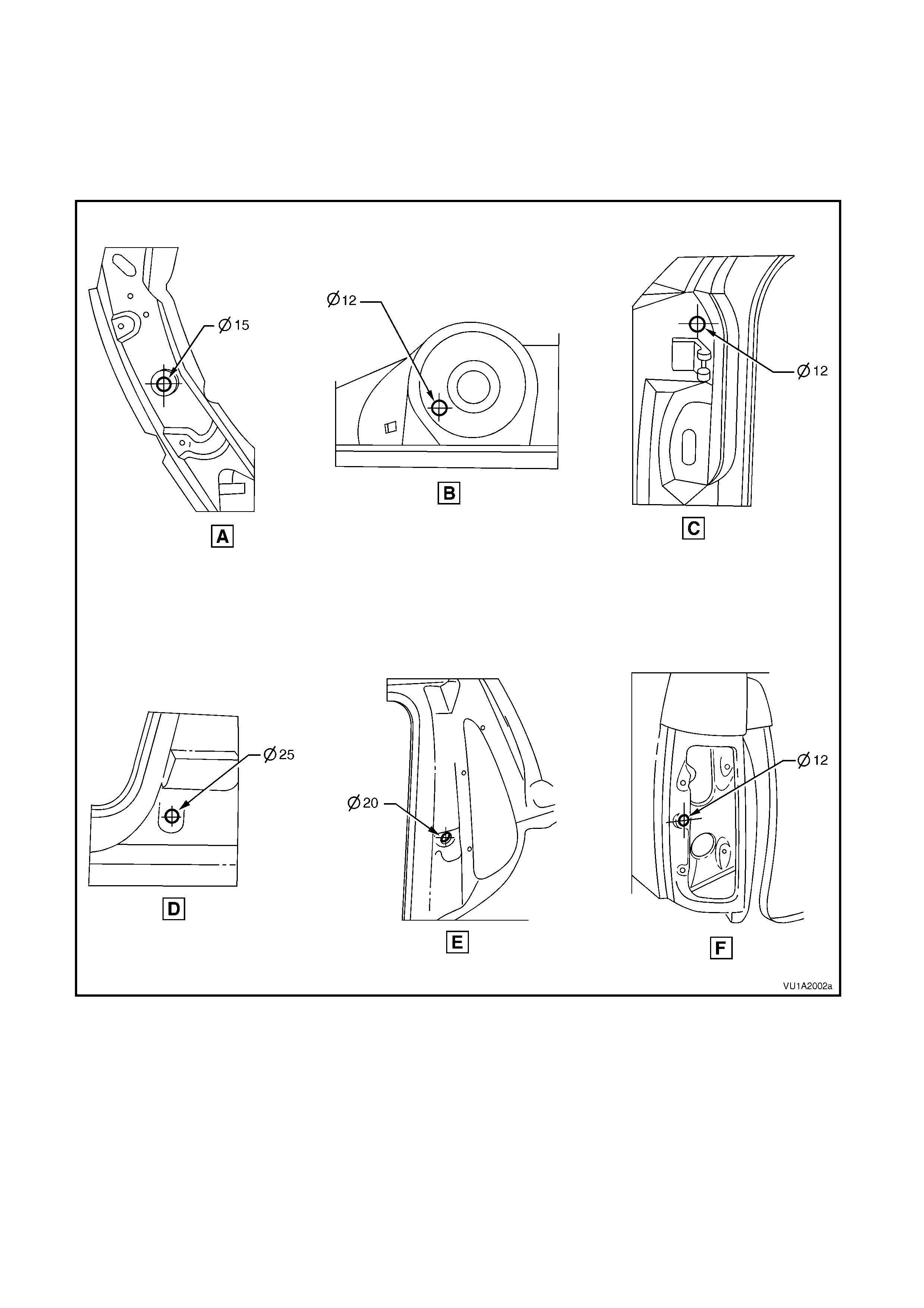
COUPE
All dimensions are given in mm and are measured from the centre of holes, on the outside of the metal surface.
The main datum surface (1) is the underside of the front side rail assembly, refer to Figure 1A2-6.
The main datum hole (2) is a 19 mm hole on the front side rail assembly, refer to Figure 1A2-6.
The dash panel assembly attaching hole (3) in Figure 1A2-6 is the datum hole also depicted at View C in
Figure 1A2-5.
Figure 1A2-5
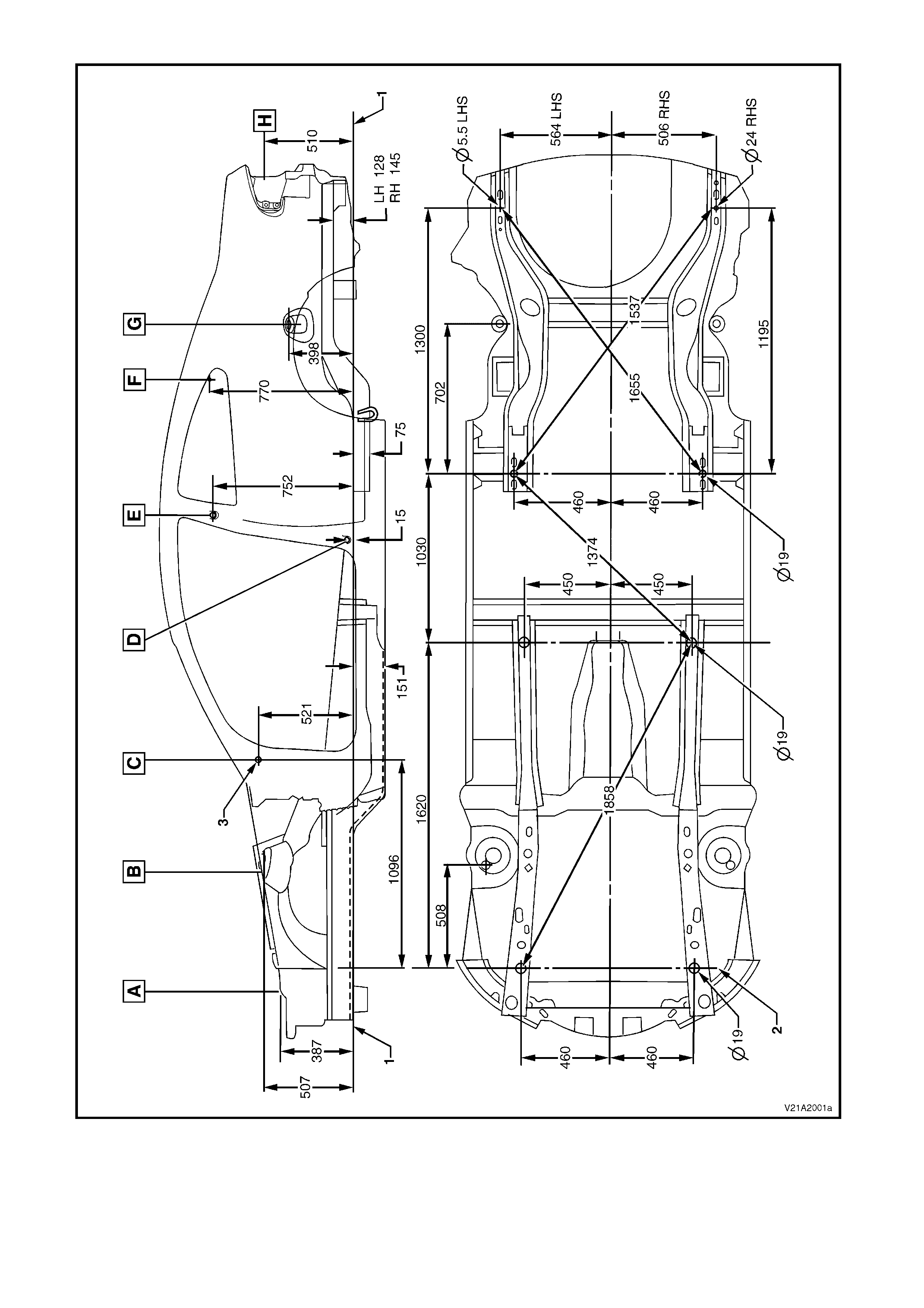
Figure 1A2-6
UTILITY
All dimensions are given in mm and are measured from the centre of holes, on the outside of the metal surface.
The main datum surface (1) is the underside of the front side rail assembly, refer to Figure 1A2-8.
The main datum hole (2) is a 19 mm hole on the underside of the front side rail assembly, refer to Figure 1A2-8.
The dash panel assembly attaching hole (3) in Figure 1A2-8 is the datum hole also depicted at View C in
Figure 1A2-7.
Figure 1A2-7
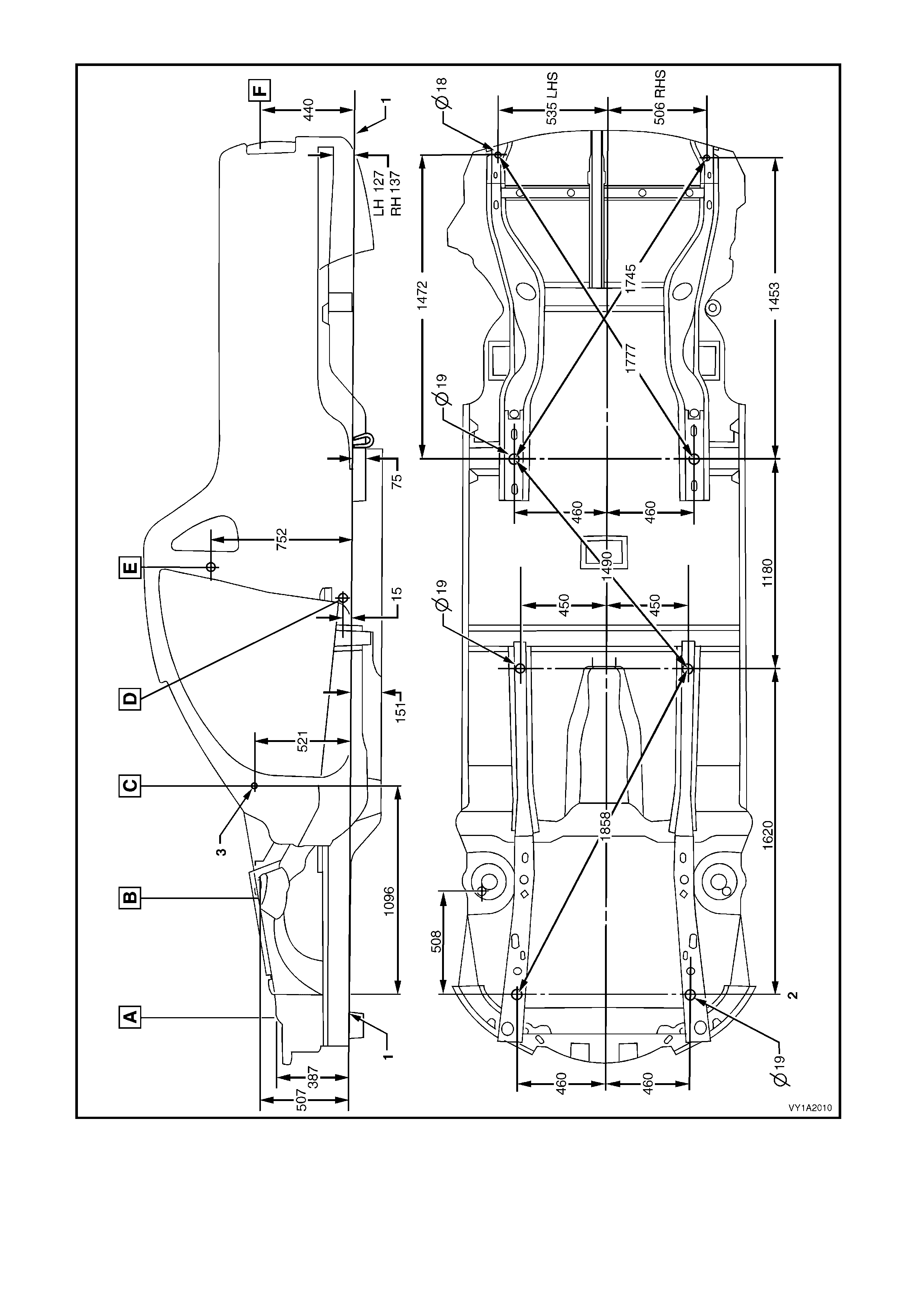
Figure 1A2-8
2.2 UPP ERBODY DIMENSIONS – ACTUAL
FRONT – ALL MODELS
Figure 1A2-9
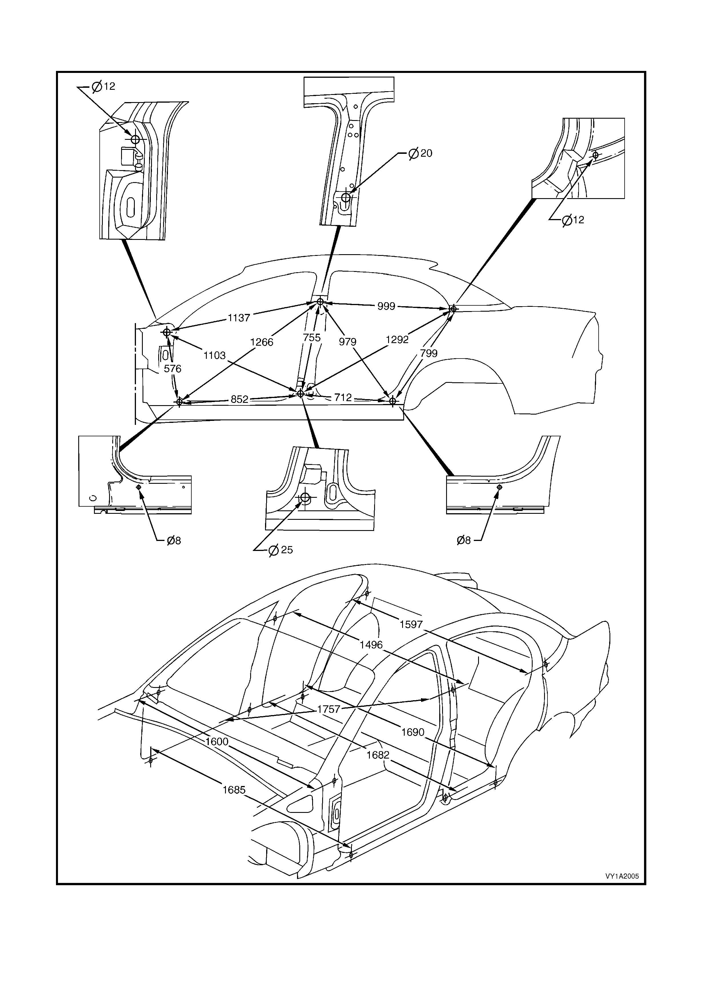
SIDE & INTERIOR – SEDAN
Figure 1A2-10
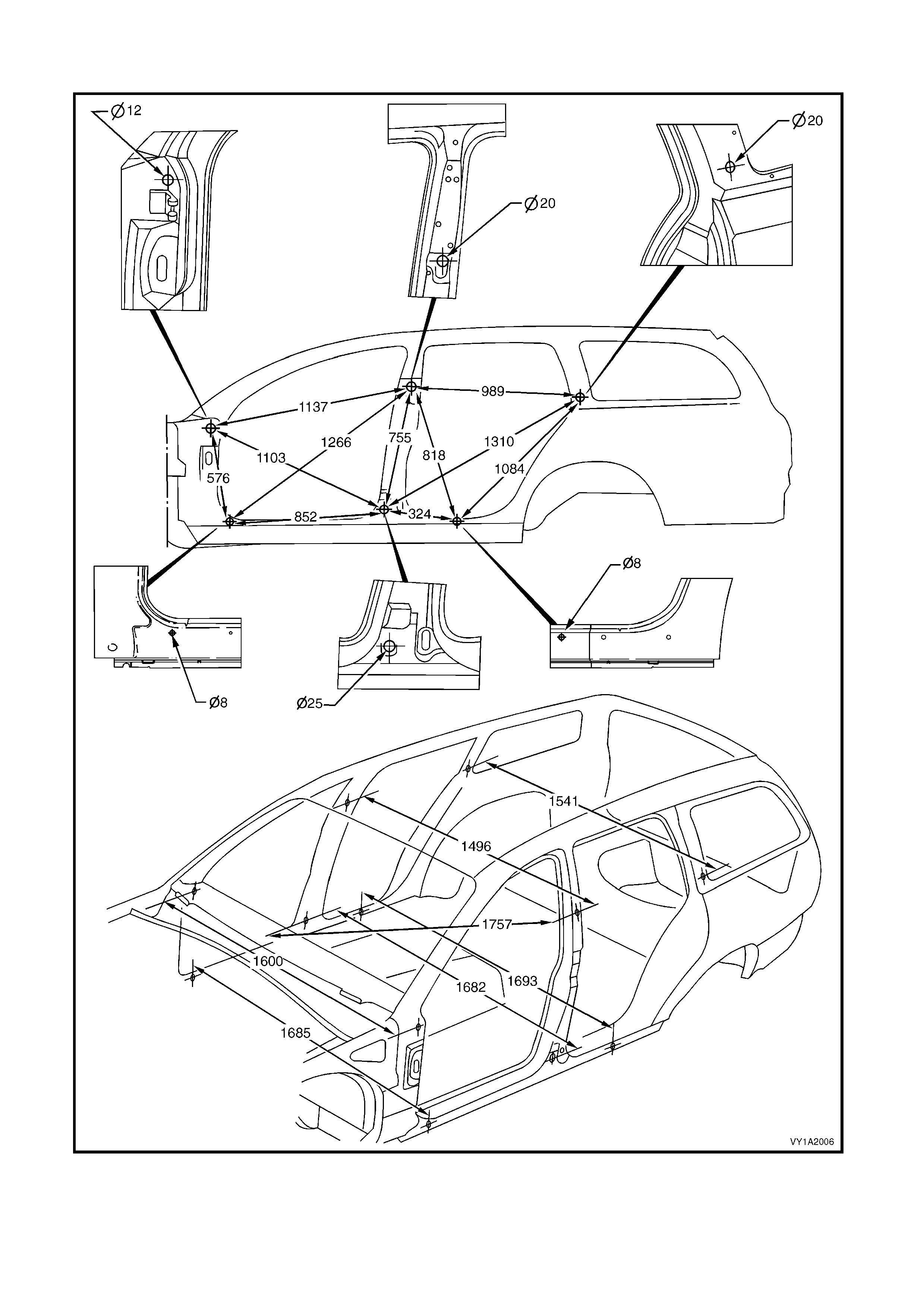
SIDE & INTERIOR – WAGON
Figure 1A2-11
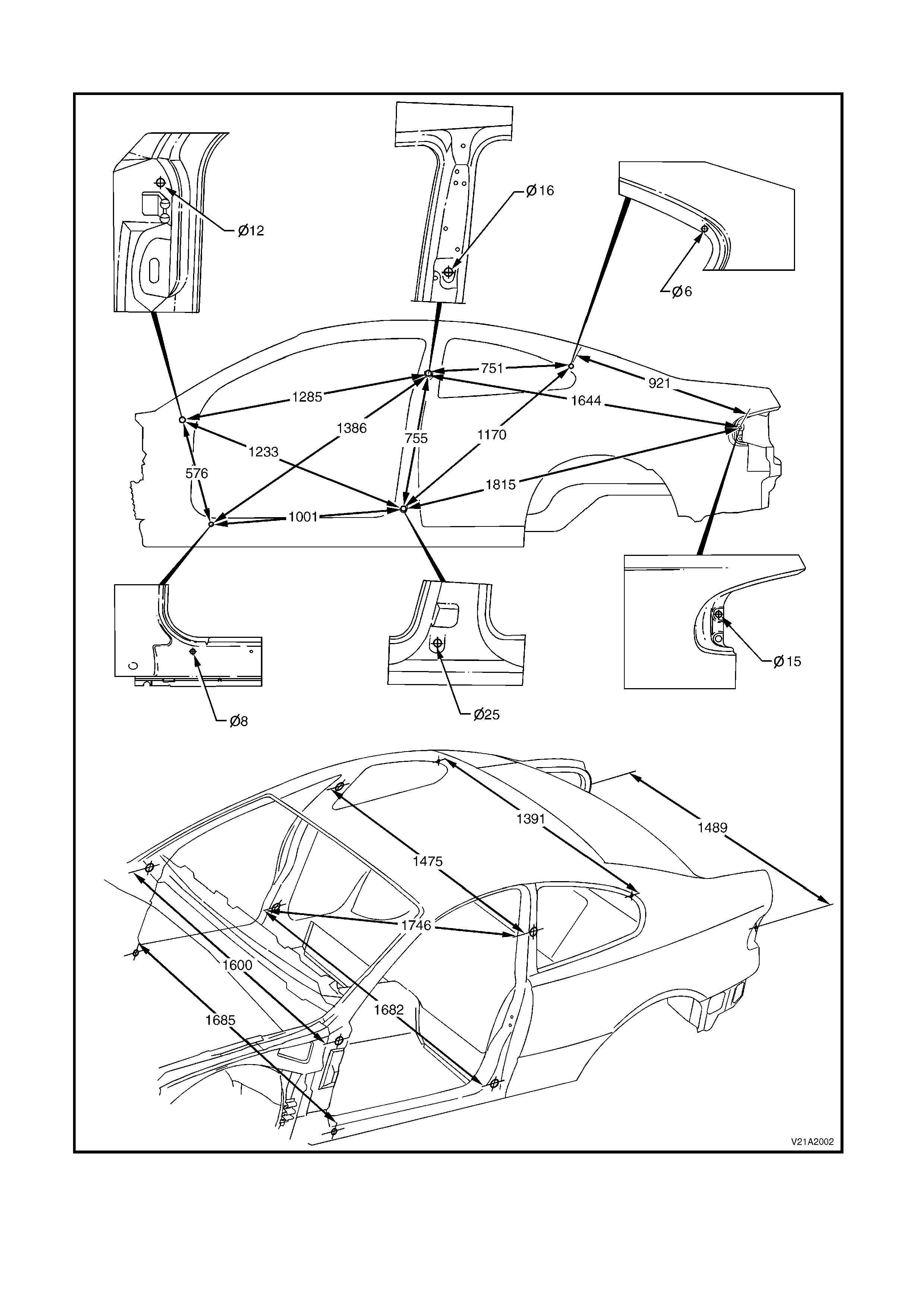
SIDE & INTERIOR – COUPE
Figure 1A2-12
SIDE & INTERIOR – UTILITY
Figure 1A2-13
REAR – SEDAN
Figure 1A2-14
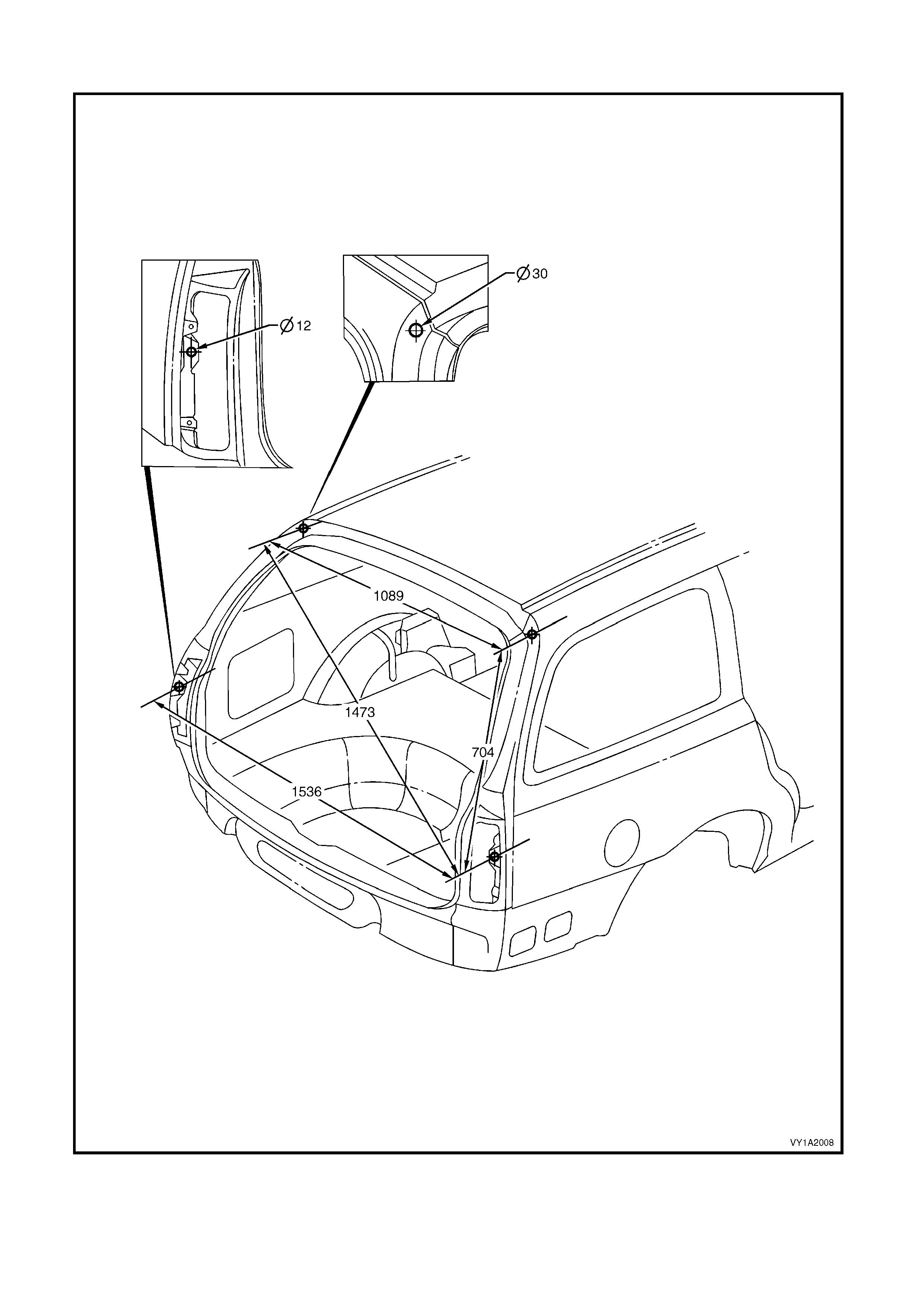
REAR – WAGON
Figure 1A2-15
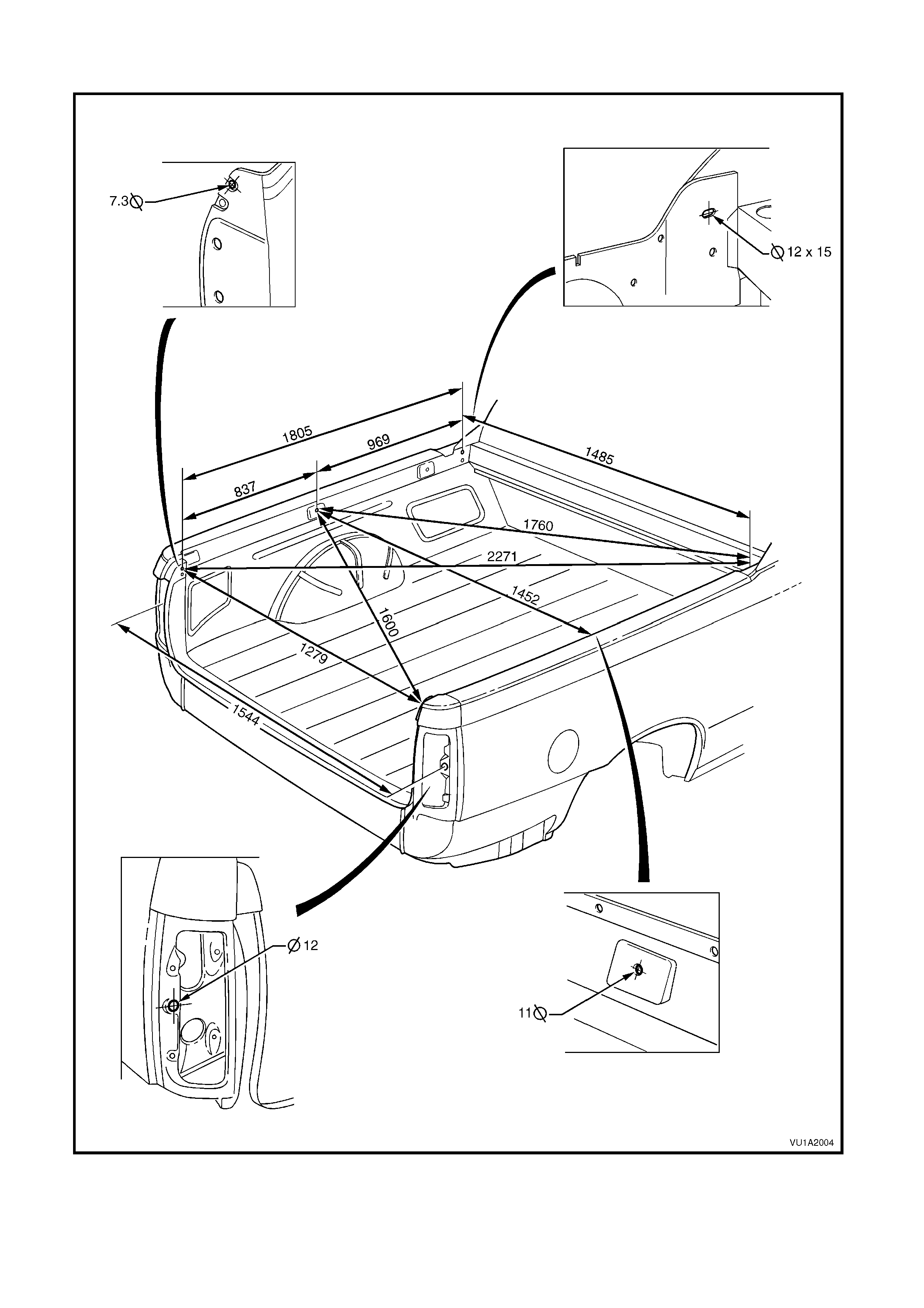
REAR – UTILITY
Figure 1A2-16
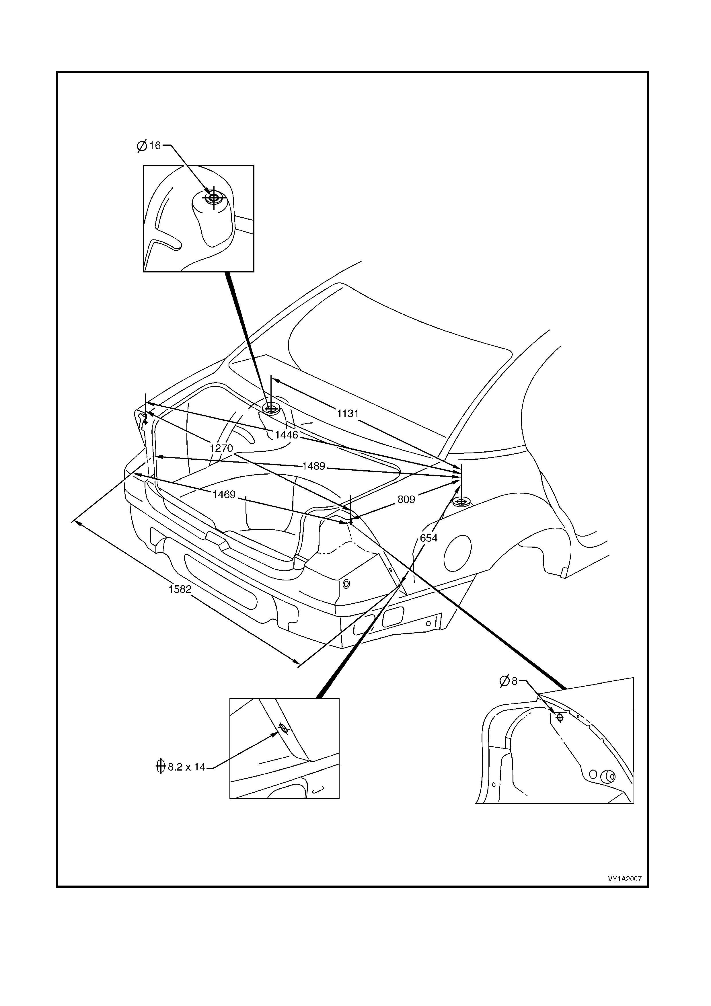
REAR – COUPE
Figure 1A2-17
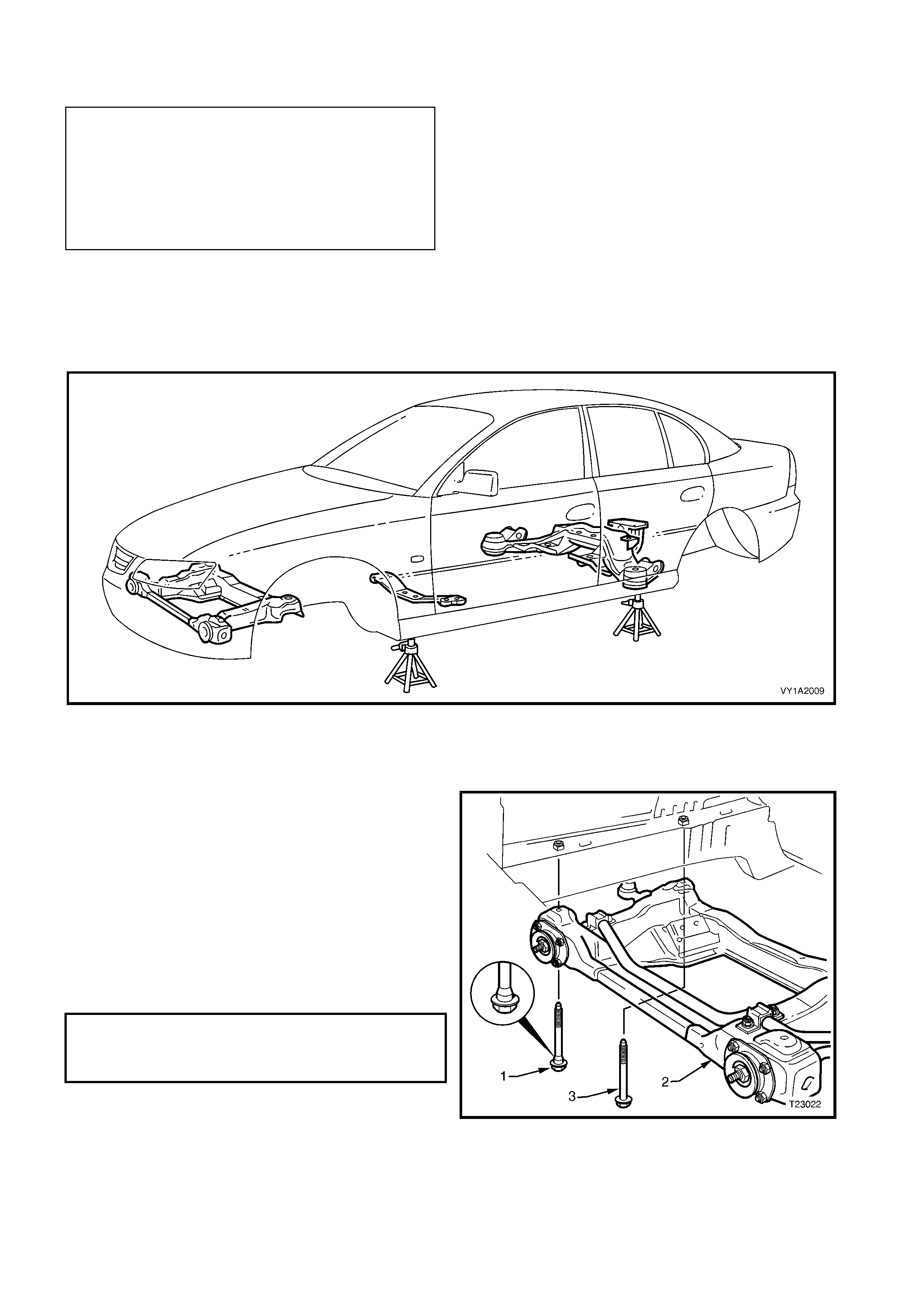
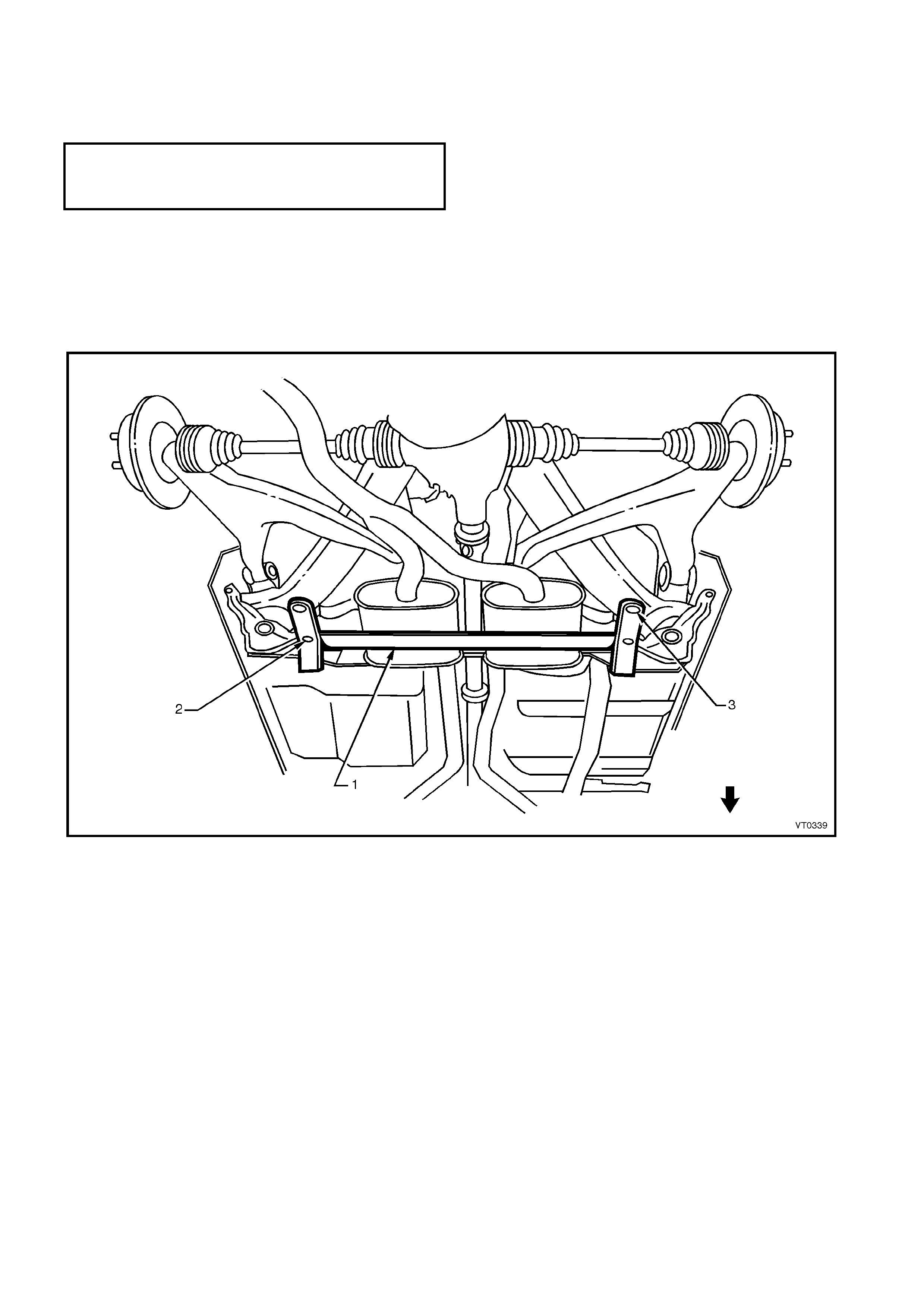
2.3 SUSPENSION FRAMES & TRANSMISSION SUPPORT ALIGNMENT
The front suspension frame assembly (1), transmission support (2) and rear suspension frame assembly (3) as
shown in F igure 1A2- 18 will require r e- alignment if they have been removed dur ing repair work, or if they have been
disturbed as a result of a vehicle collision.
Correct underbody alignment is essential as any mis-alignment can adversely affect suspension perform ance. The
underbody alignment should therefore be checked and aligned, if required, to the dimensions specified in this
Section prior to performing the following alignment procedures.
Figure 1A2-18
FRONT SUSPENSION FRAME ASSEMBLY
LT Section No. 06-200
When reinstalling the frame assembly, install the two
front, black coloured, stepped shank bolts (1) and
tighten to the correct torque specification. This will
correctly align the frame assem bly (2) to the front side
rail assemblies.
Install the two rear, silver coloured, straight shanked
bolts (3) to the two rear positions and tighten them to
the correct torque specification.
NOTE: Prior to installation of the frame assembly,
ensure the vehicle underbody alignment is within
specification.
Figure 1A2-19
NOTE: The following fasteners MUST be replaced
when performing this operation:
+
++
+
Front suspension frame assembly mounting
bolts.
+
++
+
Rear suspension frame assembly attaching
bolts.
+
++
+
Final drive rear mount attaching screws.
FRONT SUSPENSION FRAME
ASSEMBLY MOUNTING BOLT
TORQUE SPECIFICATION 120.0 – 125.0 Nm
TRANSMISSION SUPPORT
LT Section No. 04-020
1. Using chassis stands, support vehicle at hoist pad
locations.
2. From underneath the vehicle, support the
transmission with a trolley jack. Raise the jack
slightly to take some weight off the transmission
mount.
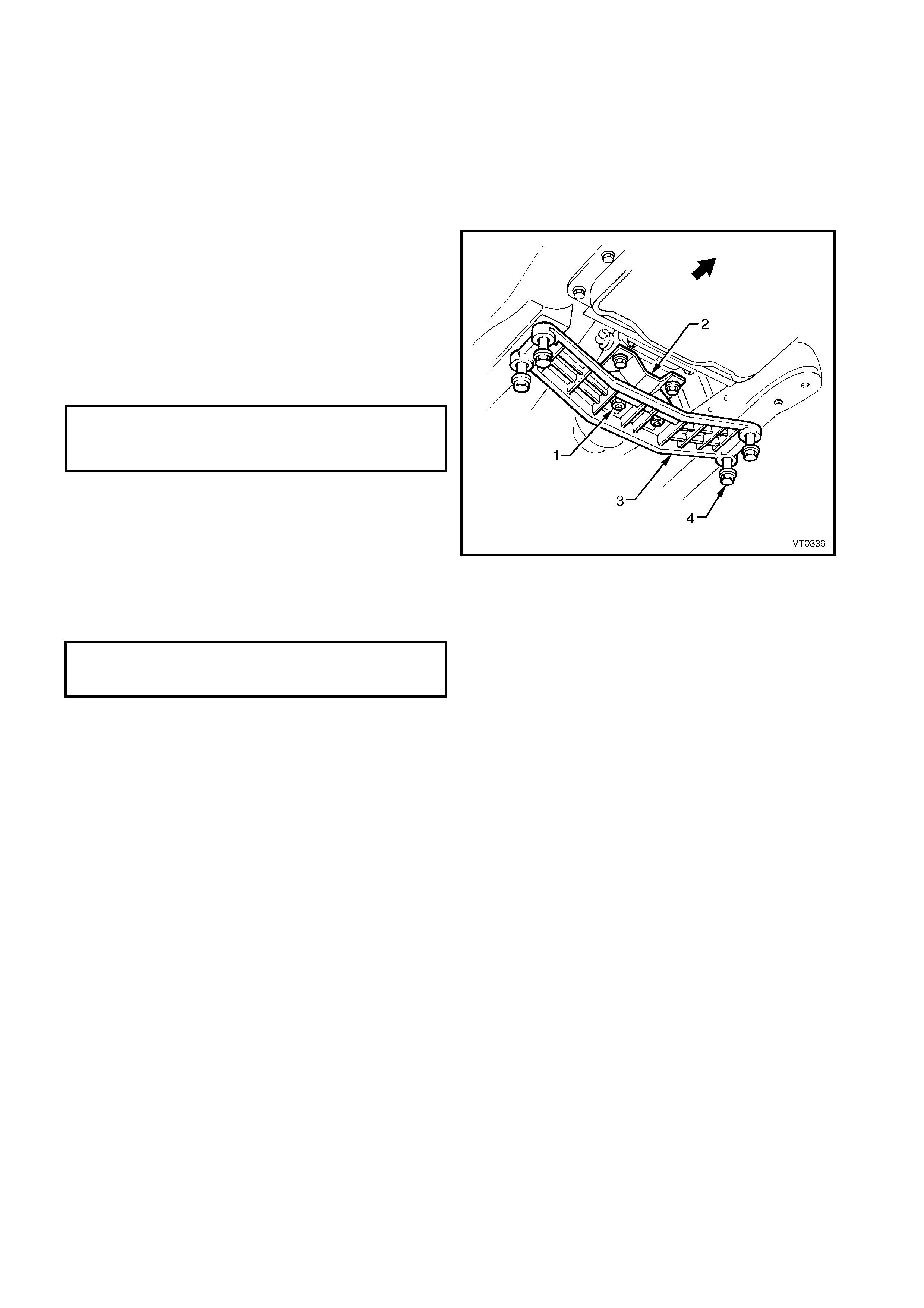
3. Remove the two nuts (1) securing the transmission
mount assembly (2) to the transmission support
(3).
4. Loosen the four bolts (4) attaching the
transmission support to the underbody.
5. Centralise the transmission support within the bolt
holes.
6. Tighten the four bolts.
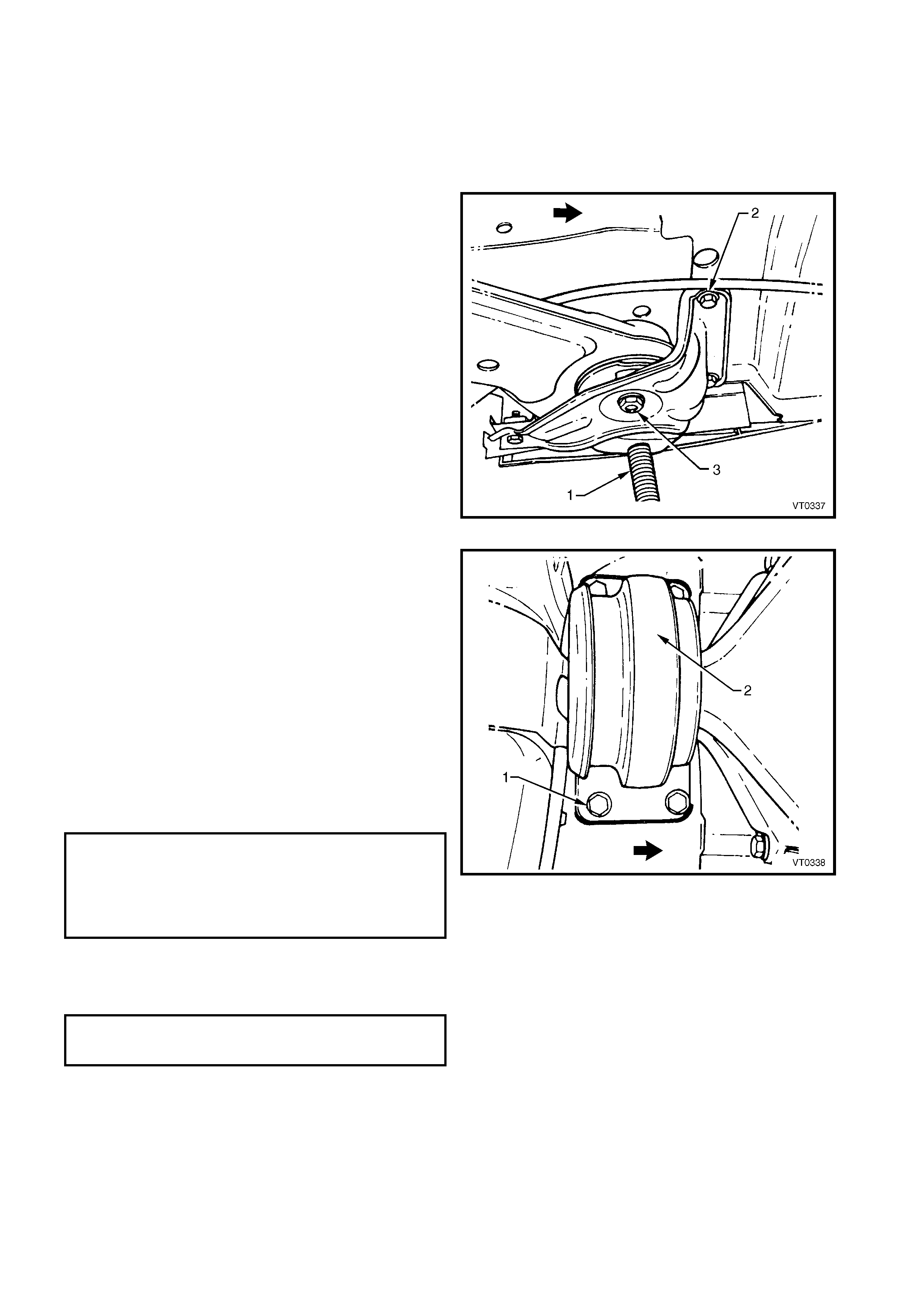
7. With the help of an assistant, manoeuvre the
transmission to ensure that the studs (1) (from
which the M8 nuts have been removed) protruding
through the transmission support are centralised
within the stud holes.
8. Reinstall the M8 nuts securing the transmission
mount to the transmission support and tighten to
the specified torque.
9. Gently lower the trolley jack and remove from
under the vehicle.
10. Remove the vehicle from the chassis stands.
Figure 1A2-20
TRANSMISSION MOUNT NUT
TORQUE SPECIFICATION 20.0 – 30.0 Nm
TRANSMISSION SUPPORT
MOUNTING BOLT
TORQUE SPECIFICATION 50.0 – 65.0 Nm
REAR SUSPENSION FRAME ASSEMBLY
LT Section No. 07-150A
NOTE. The rear suspension frame assembly centering
tool needs to be held in position during the alignment
procedure. Therefore, assistance will be required to
complete this operation.
1. Using chassis stands (1), support the vehicle at
hoist pad locations.
2. Remove the wheels, refer to Section 10,
WHEELS AND TYRES.
3. Remove intermediate muffler and pipe assembly
together with rear muffler and pipe assembly.
Refer to Section 8B, EXHAUST SYSTEM.
4. From underneath the vehicle, support the final
drive assembly with a trolley jack. Raise the jack
slightly to take some of the weight off the final
drive mount.
5. Loosen the three M10 screws (2) attaching the
rear suspension support insulator bracket to the
vehicle, LH and RH side.
6. Loosen the rear frame assembly M14 attaching
bolts (3) LH and RH side.
Figure 1A2-21
7. Loosen the four scr ews (1) attaching the final drive
rear mount (2).
8. Fit rear suspension centering tool No AU 458 (1),
refer to Figure 1A2-23.
NOTE: The rear crossmember centering tool locates
into 19 mm diameter body datum holes (2) positioned
forward of the rear suspension frame assembly.
9. With the help of an assistant, manoeuvre the rear
suspension assembly until the location pins (3) of
the rear crossmember centering tool engage the
alignment holes on the rear frame assembly.
10. Tighten the rear frame assembly M14 attaching
bolts LH and RH side to the specified torque, refer
to (3) Figure 1A2-21.
11. Tighten the f our s c rews (1) attac hing the f inal dr ive
rear mount (2), refer to Figure 1A2-22.
Figure 1A2-22
REAR SUSPENSION FRAME
ASSEMBLY ATTACHING BOLT
TORQUE SPECIFICATION Stage 1 125 Nm
Stage 2 Turn 30°- 45°
Min. total 135 Nm
FINAL DRIVE REAR MOUNT ATTACHING
SCREWS TORQUE SPECIFICATION 30.0 – 45.0 Nm
12. Tighten to the specified torque, the three M10
screws (2) attaching the rear suspension support
insulator bracket to the vehicle, LH and RH side,
refer to Figure 1A2-21.
13. Remove the rear crossmember centering tool.
14. Gently lower trolley jack and remove from under
vehicle.
15. Fit the wheels. Refer to Section 10, WHEELS
AND TYRES.
16. Remove vehicle from chassis stands.
Figure 1A2-23
REAR SUSPENSION SUPPORT INSULATOR
BRACKET ATTACHING SCREWS
TORQUE SPECIFICATION 60.0 – 85.0 Nm

3. TORQUE WRENCH SPECIFICATIONS
+
++
+
Front suspension frame assembly mounting bolt .................................................. 120 – 125 Nm
Transmission support mounting bolt...................................................................... 50 – 65 Nm
Transmission mount nuts....................................................................................... 20 – 30 Nm
+
++
+
Rear suspension frame assembly attaching bolt................................................... 125 Nm
30° – 45°
Min. total of 135 Nm
+
++
+
Final drive rear mount attaching screws................................................................ 30 – 45 Nm
Rear suspension support insulator bracket attaching screws................................ 60 – 85 Nm
+
++
+
Must be replaced

4. SPECIAL TOOLS
TOOL NUMBER ILLUSTRATION DESCRIPTION TOOL
CLASIFICATION
AU 458 REAR CROSSMEMBER
CENTERING TOOL
Used When Any Service Operation
Requires Removal / Reinstallation
Of The Frame Assembly - Rear
Suspension, Or When Checking
Rear End Alignment
Previously Released.
DESIRABLE