
SECTION 1A3 - INSTRUMENT PANEL
& CONSOLE
IMPORTANT
Before performing any Service Operation or other procedure described in this Section, refer to Section
00 CAUTIONS AND NOTES for correct workshop practices with regard to safety and/or property damage.
CONTENTS
1. GENERAL DESCRIPTION
FLOOR CONSOLE COMPONENTS
INSTRUMENT PANEL COMPONENTS
2. SERVICE OPERATIONS – FLOOR CONSOLE
2.1 FLOOR CONSOLE COVER ASSEMBLY
REMOVE
DISASSEMBLE
REASSEMBLE
REINSTALL
2.2 INSTRUMENT PANEL LOWER
EXTENSION SIDE TRIM
REMOVE
REINSTALL
2.3 FLOOR CONSOLE ASSEMBLY
REMOVE
DISASSEMBLE
REASSEMBLE
REINSTALL
3. SERVICE OPERATIONS – INSTRUMENT PANEL
3.1 INSTRUMENT PANEL LOWER TRIM
PLATE ASSEMBLY
REMOVE
REINSTALL
3.2 INSTRUMENT PANEL COMPARTMENT
ASSEMBLY
REMOVE
DISASSEMBLE
REASSEMBLE
REINSTALL
3.3 INSTRUMENT PANEL COMPARTMENT
LAMP AND SWITCH
REMOVE
REINSTALL
3.4 INSTRUMENT PANEL LOWER TRIM PANEL
REMOVE
REINSTALL
3.5 INSTRUMENT PANEL LOWER TRIM
PANEL RETAINER
REMOVE
REINSTALL
3.6 RADIO ASSEMBLY
REMOVE
REINSTALL
3.7 INSTRUMENT PANEL CENTRE TRIM ASSEMBLY
REMOVE
DISASSEMBLE
REINSTALL
3.8 INSTRUMENT PANEL LOWER COMPARTMENT
OR ASHTRAY ASSEMBLY
REMOVE
REINSTALL
3.9 INSTRUMENT PANEL LOWER EXTENSION
REMOVE
REINSTALL
3.10 MANUAL HVAC CONTROLLER
REMOVE
REINSTALL
3.11 RADIO HOUSING AND RADIO BRACKET
ASSEMBLY
REMOVE
REINSTALL
3.12 INSTRUMENT CLUSTER TRIM ASSEMBLY
REMOVE
DISASSEMBLE
REINSTALL
3.13 IN-CAR AIR TEMPERATURE SENSOR
REMOVE
REINSTALL
3.14 INSTRUMENT CLUSTER
REMOVE
REINSTALL
3.15 HEADLAMP SWITCH
REMOVE
REINSTALL
3.16 TRIP COMPUTER SWITCH
REMOVE
REINSTALL
3.17 INSTRUMENT PANEL OUTER COVER
REMOVE
REINSTALL
3.18 WINDSHIELD DEFROSTER GRILLE
REMOVE
REINSTALL
3.19 REMOTE KEY RECEIVER & HEADLAMP
AUTO CONTROL / SUNLOAD SENSOR
REMOVE
REINSTALL
3.20 INSTRUMENT PANEL SPEAKER
REMOVE
REINSTALL
3.21 INSTRUMENT PANEL PAD ASSEMBLY
REMOVE
DISASSEMBLE
REASSEMBLE
REINSTALL
3.22 INSTRUMENT PANEL BRACKETS & BRACES
INSTRUMENT PANEL COMPARTMENT
BRACKET
INSTRUMENT PANEL LOWER BRACKET
INSTRUMENT PANEL OUTER UPPER
BRACKET
LOWER RADIO BRACKET
STEERING COLUMN BRACKET INNER
BRACE
STEERING COLUMN BRACKET OUTER
BRACE
4. TORQUE WRENCH SPECIFICATIONS
5. SPECIAL TOOLS
Techline
Techline
Techline
Techline
Techline
Techline
Techline

1. GENERAL DESCRIPTION
Completely new instrument panel and floor consoles are fitted to MY 2003 VY and V2 series vehicles. The
Instrument panel houses the instr ument clus ter within a hood, while the centre f asc ia, which integrates with the floor
console, houses components such as the new double DIN sized audio system, controls for manual or electronic
climate control, centre vent outlets and new cup-holders for Level 2 and 3 vehicles.
The soft-touch instrument panel pad is attached to a dash panel carrier. Several brackets and braces form the
back bone of the instrum ent panel pad and carrier ass embly and support other com ponents such as the ins trument
panel inflatable restraint (if fitted) and fuse panel.
All models now include an instrument panel lower trim plate assembly, fitted between the instrument and dash
panels on each side of the vehicle. Sound-deadening foam is applied to the plate which provides an effective
reduction in noise transmittance. Where fitted, the stepwell lamps are mounted to the plate assembly.
The large instrument panel compartment is illuminated and can be locked with a unique key. As with previous
models , a large lower tr im panel is fitted on the driver’s side which c an be opened to provide ac c es s to the f us e and
relay panel.
For right-hand drive vehicles two storage compartments are provided, one on the instrument panel at the front of
the console and the other at the rear of the console (except utility). As an option for right-hand drive and as standard
for left-hand drive vehicles, an ashtray and cigar lighter assembly replaces the storage compartments.
A large storage com par tm ent with trim m ed arm r est is inc orporated in the f loor cons ole. An acces sory power sock et
is provided within the storage compartment providing a 12-volt power supply when the ignition switch is in accessory
or run positions.
Depending on model level or options f itted, the console m ay also include power side window switches, a c up-holder
for Level 1 vehicles, mobile phone holder for Level 2 and 3 vehicles and auxiliary switches for functions such as
LPG, traction control for manual transmission vehicles and a lights-out function for vehicles with police option pack.
The floor consoles for right and left-hand drive are virtually common as the hand-brake rem ains on the right-hand
side of the transmission tunnel. An air duct is fitted to the underside of the console on all models except utility, which
provides ventilation to the rear seat passengers through the rear air outlet housing at the end of the console. For
utility vehicles, a storage bin is provided at the rear of the console in place of the rear air outlet housing.
The instrument panel for left-hand drive vehicles is a mirror of the right-hand drive instrument panel, with a few
exceptions. The body control m odule remains on the r ight-hand s ide of the vehic le, mounted vertic ally for right-hand
drive or horizontally for left-hand drive. A fuel filler door release switch is m ounted in the left-hand drive instrum ent
cluster trim.
NOTE: The information that is provided in this Section is to be used for both left and right-hand drive vehicles.
Although the information shown is primarily right-hand drive, it is to be mirrored for left-hand drive vehicles unless
otherwise specified.
Refer to Figure 1A3-1 for an illustration of the console components and Figure 1A3-2 for the instrument panel
components fitted to MY 2003 VY and V2 Series II vehicles. Note that these diagrams do not show switches or
electrical components.
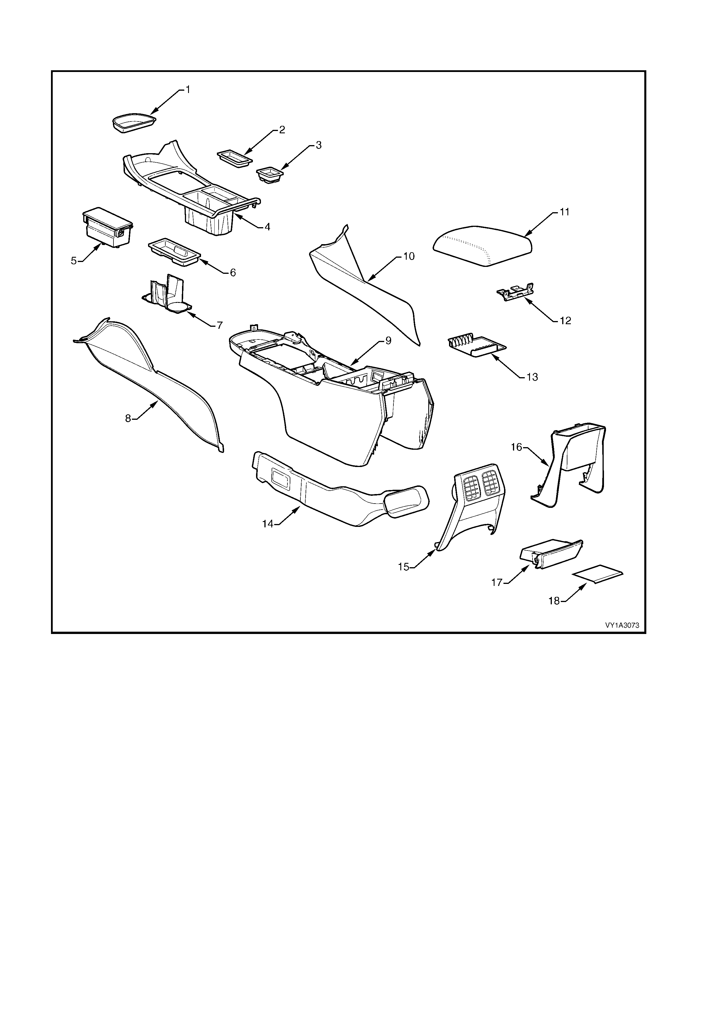
FLOOR CONSOLE COMPONENTS
Figure 1A3-1
Legend
1. Floor Console Front Compartment Liner 10. Instrument Panel Lower Extension Side Trim, RH
2. Floor Console Liner 11. Armrest Assembly
3. Auxiliary Switch Liner or Bezel 12. Floor Console Compartment Armrest Hinge
4. Floor Console Cover 13. Floor Console Compartment Liner
5. Mobile Phone Compartment, Level 2 & 3 14. Floor Console Rear Air Duct
6. Floor Console Storage Tray, Where Fitted 15. Floor Console Rear Air Outlet Housing Assembly, Except
Utility
7. Cup Holder, Level 1 16. Floor Console Rear Upper Compartment Assembly
8. Instrument Panel Lower Extension Side Trim, LH 17. Floor Console Rear Compartment or Ashtray Assembly
9. Floor Console 18. Floor Console Rear Compartment Liner
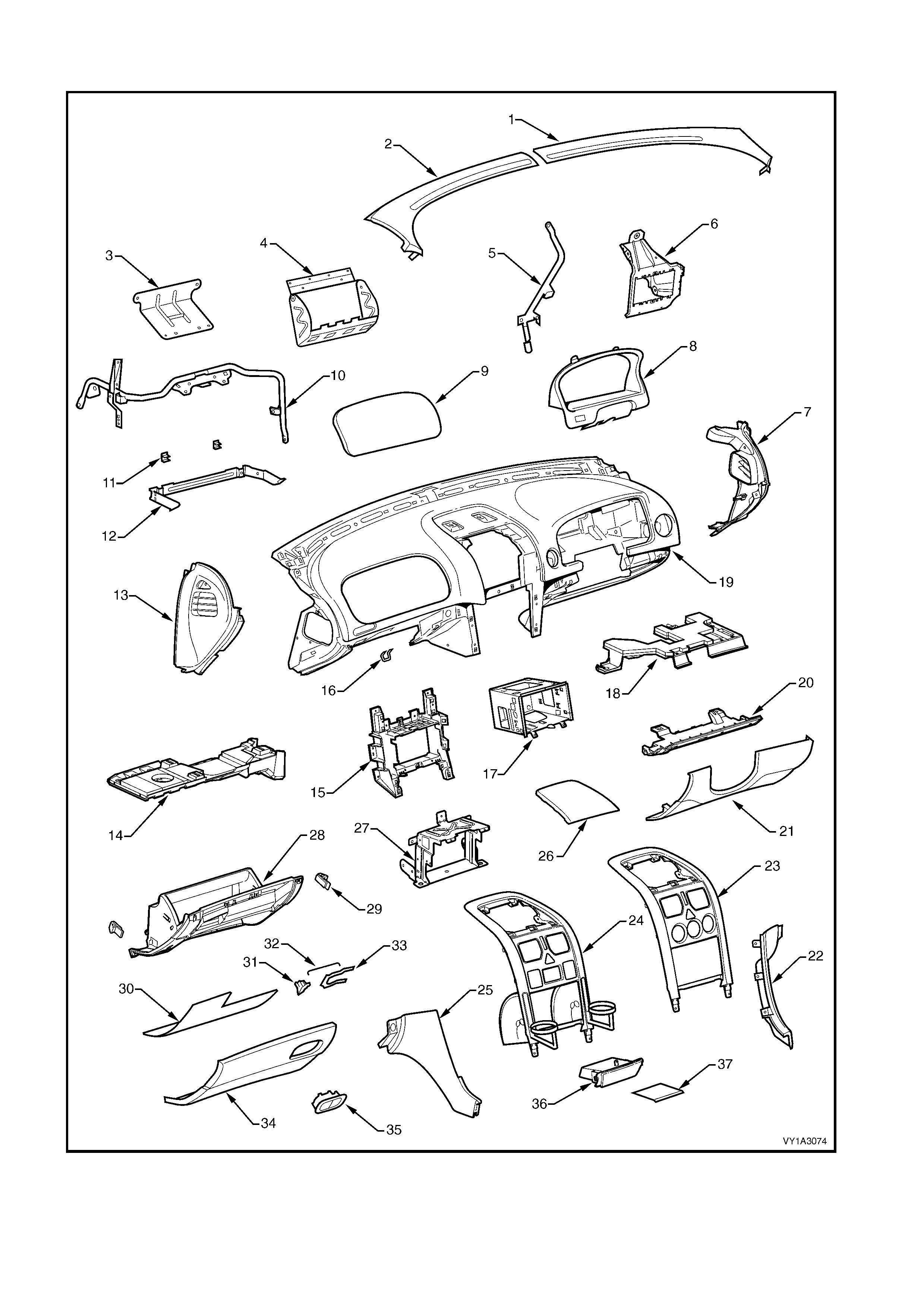
INSTRUMENT PANEL COMPONENTS
Figure 1A3-2

Legend
1. Windshield Defroster Grille, RH 20. Instrument Panel Lower Trim Panel Retainer
2. Windshield Defroster Grille, LH 21. Instrument Panel Lower Trim Panel Assembly
3. Instrument Panel Outer Upper Bracket * 22. Instrument Panel Lower Extension, RH
4. Instrument Panel Inflatable Restraint Bracket 23. Instrument Panel Centre Trim Assembly, Level 1
5. Steering Column Bracket Inner Brace 24. Instrument Panel Centre Trim Assembly, Level 2 & 3
6. Steering Column Bracket Outer Brace 25. Instrument Panel Lower Extension, LH
7. Instrument Panel Outer Cover, RH 26. Instrument Panel Upper Centre Trim Panel
8. Instrument Cluster Trim Assembly 27. Lower Radio Bracket
9. Instrument Panel Inflatable Restraint Opening Trim
Cover 28. Instrument Panel Compartment
10. Instrument Panel Lower Bracket 29. Instrument Panel Compartment Bumper Stop
11. Instrument Panel Compartment Hinge 30. Instrument Panel Compartment Liner
12. Instrument Panel Compartment Bracket 31. Instrument Panel Compartment Latch Assembly
13. Instrument Panel Outer Cover, LH 32. Instrument Panel Compartment Latch Rod
14. Instrument Panel Lower Trim Plate Assembly, LH 33. Instrument Panel Compartment Latch Retainer
15. Radio Bracket Assembly 34. Instrument Panel Compartment Door
16. Instrument Panel Compartment Lock Striker 35. Instrument Panel Compartment Latch Actuator
17. Radio Housing 36. Instrument Panel Lower Compartment or Ashtray Assembly
18. Instrument Panel Lower Trim Plate Assembly, RH 37. Instrument Panel Lower Compartment Liner
19. Instrument Panel Pad Assembly
* Vehicles without an instrument panel inflatable restraint
module
2. SERVICE OPERATIONS – FLOOR CONSOLE
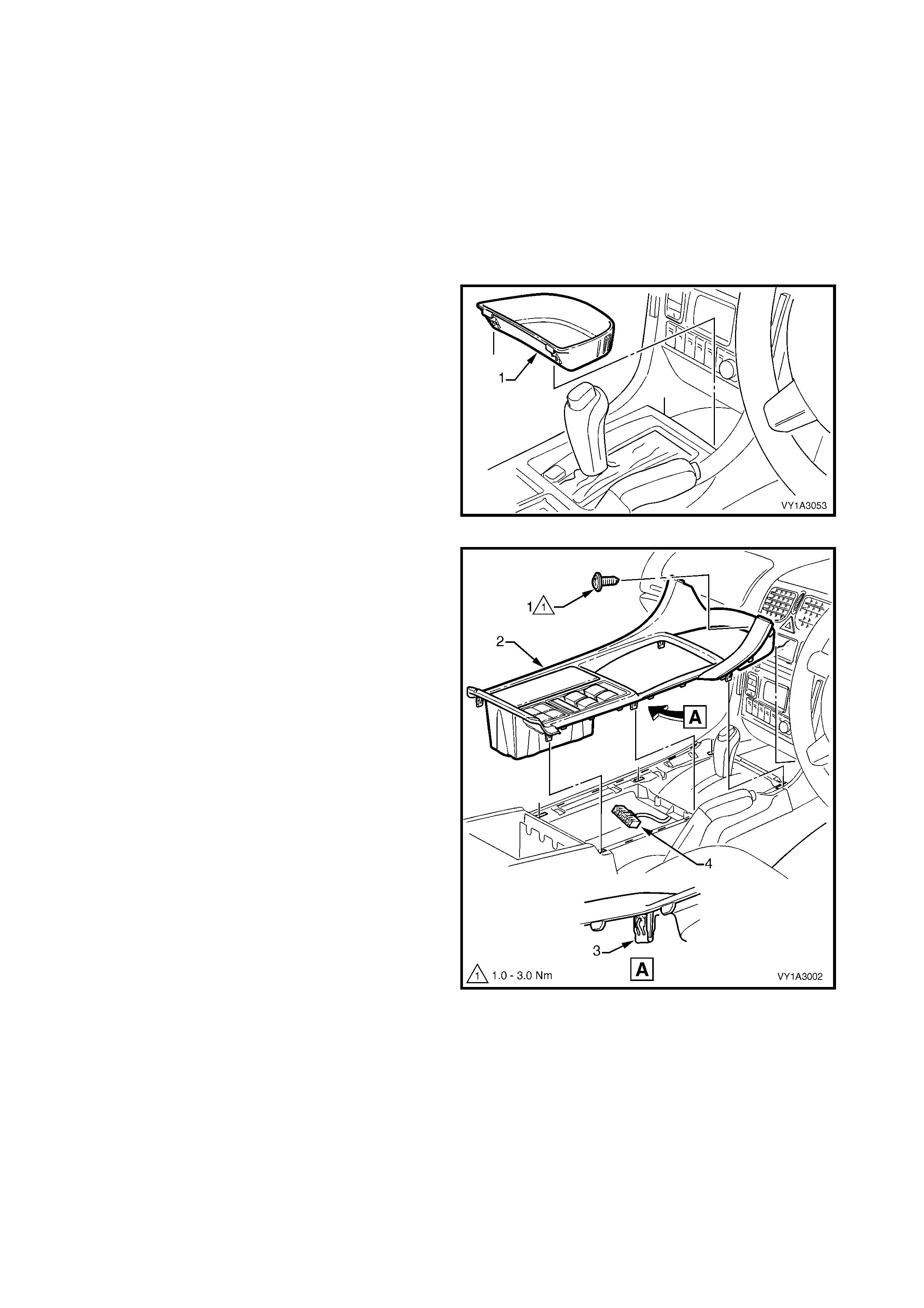
2.1 FLOOR CONSOLE COVER ASSEMBLY
LT Section –
As required, first remove the following components:
1. Navigation remote control assembly, refer to Section 12L, 3.2 NAVIGATION REMOTE CONTROL
ASSEMBLY.
2. Navigation escutcheon, refer to Section 12L, 3.3 NAVIGATION DISPLAY ASSEMBLY.
REMOVE
1. Remove the floor console front compartment liner
(1) by lifting upwards to disengage it from the
console cover.
Figure 1A3-3
2. Remove the screw (1) slightly to the right of centre,
attaching the floor console cover assembly (2).
NOTE: Vehicles fitted with Navigation System do not
have this screw.
3. Prise the cover assembly from the floor console,
six places (3).
4. Lift the cover assembly up from the rear,
disconnect the wiring connector (4) from the side
window switch assembly and any auxiliary
switches if fitted, and remove the cover assembly.
Figure 1A3-4
DISASSEMBLE
Disassemble the components from the underside of
the console cover, where fitted.
SIDE WINDOW SWITCH ASSEMBLY
1. Depress the six retaining tabs securing the side
widow switch assembly (1), where fitted.
2. Remove the switch assembly from the console
cover.
Figure 1A3-5
FLOOR CONSOLE LINER
1. Remove the f loor console liner (1), where fitted, by
disengaging the retaining lug securing the liner to
the cover assembly.
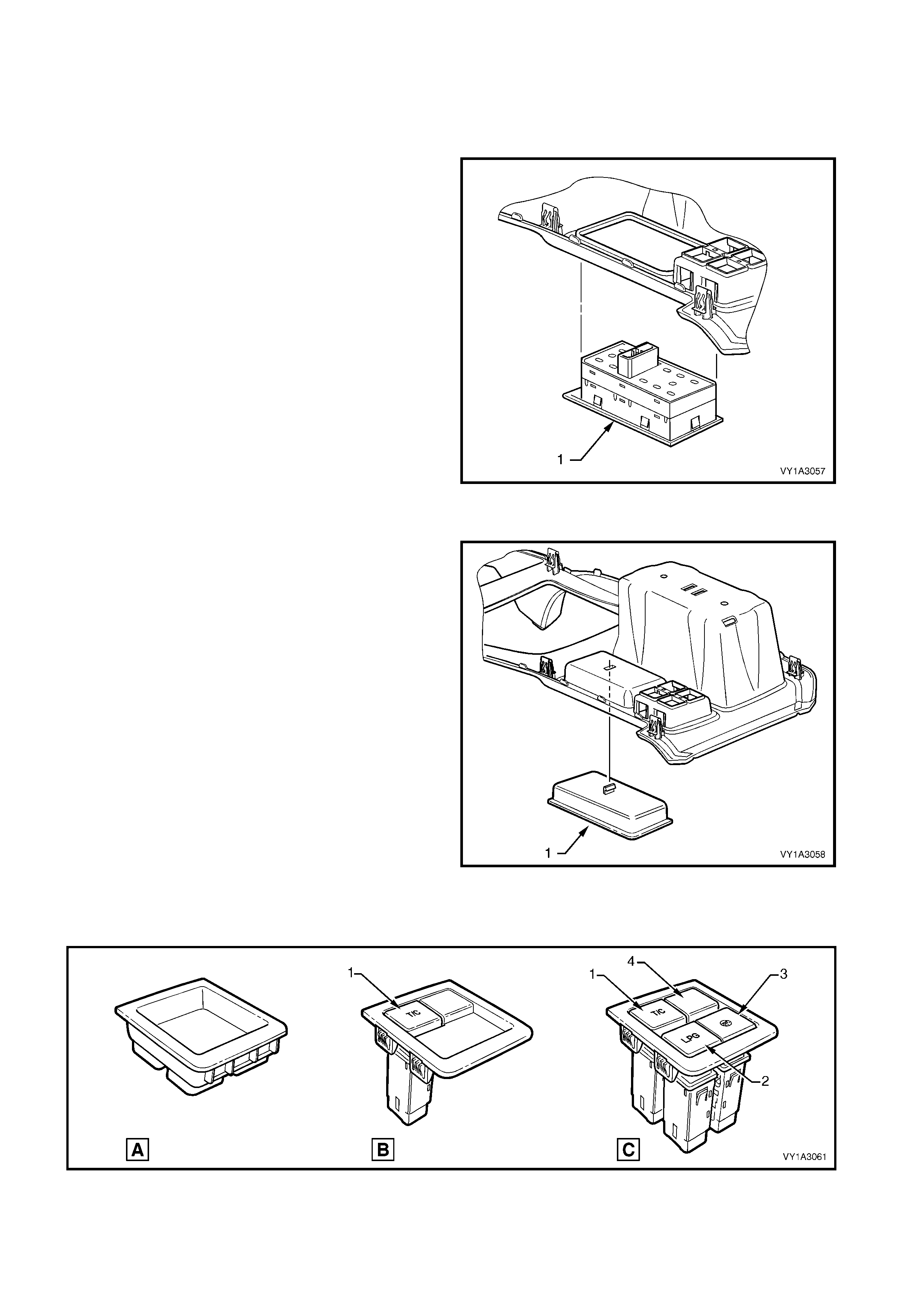
AUXILIARY SWITCH LINER OR AUXILIARY
SWITCH AND BEZEL
1. Depending on options fitted, the location shown in
Figure 1A3-7 will be fitted with either:
a. An auxiliary switch liner (A) where no auxiliary
switches are fitted,
b. A one cavity auxiliary switch bezel (B) when
fitted with a manual transmission traction
control switch (1) only, or
c. A four cavity auxiliary switch bezel (C) when
fitted with:
- an LPG switch (2), or
- a police lights-out switch (3), or
- a manual transmission traction control
switch and LPG and/or police lights-out
switch(s).
In this configuration, empty cavities are fitted
with switch blank(s) (4).
Figure 1A3-6
Figure 1A3-7
2. Auxiliary switch liner (1):
a. Remove the liner by disengaging the retaining
lug securing the liner to the cover assembly.
3. Auxiliary switch bezel (2, one or four cavity type):
a. Depress the four tabs securing the auxiliary
switch bezel to the cover assembly and
remove.
b. Depress the two tabs s ecuring the switch(s) or
blanks to the cover assembly and remove the
switch or blank.
NOTE: T he switches can only fit in the one location as
shown in Figure 1A3-7.
Figure 1A3-8
FLOOR CONSOLE STORAGE TRAY AND CUP
HOLDER
1. Lift out the floor console storage tray (1), if fitted
and remove.
2. Remove the cup holder (2), fitted to Level 1
vehicles, by disengaging the retaining lug s ecuring
the liner to the cover assembly.
Figure 1A3-9
MOBILE PHONE COMPARTMENT
1. Remove the two screws (1) attaching the mobile
phone com partment ass embly (2), fitted to Level 2
and 3 vehicles.
2. Remove the compartment assembly from the
console cover.
Figure 1A3-10
REASSEMBLE
Reassembly is the reverse of removal noting the following:
1. Ensure correct orientation of the console components.
2. Tighten the screws, if fitted, to the specified torque
REINSTALL
Reinstallation of the floor console cover assembly is the reverse of removal noting the following:
1. If the vehicle is fitted with Navigation System, modify the front section of the floor console cover assembly,
refer to Section 12L, 3.8 FITTING A NEW FLOOR CONSOLE COVER ASSEMBLY.
2. Tighten the screw to the specified torque.
FLOOR CONSOLE COVER
ASSEMBLY ATTACHING SCREW
TORQUE SPECIFICATION 1.0 – 3.0 Nm
MOBILE PHONE COMPARTMENT
ASSEMBLY ATTACHING SCREW
TORQUE SPECIFICATION 1.0 – 3.0 Nm
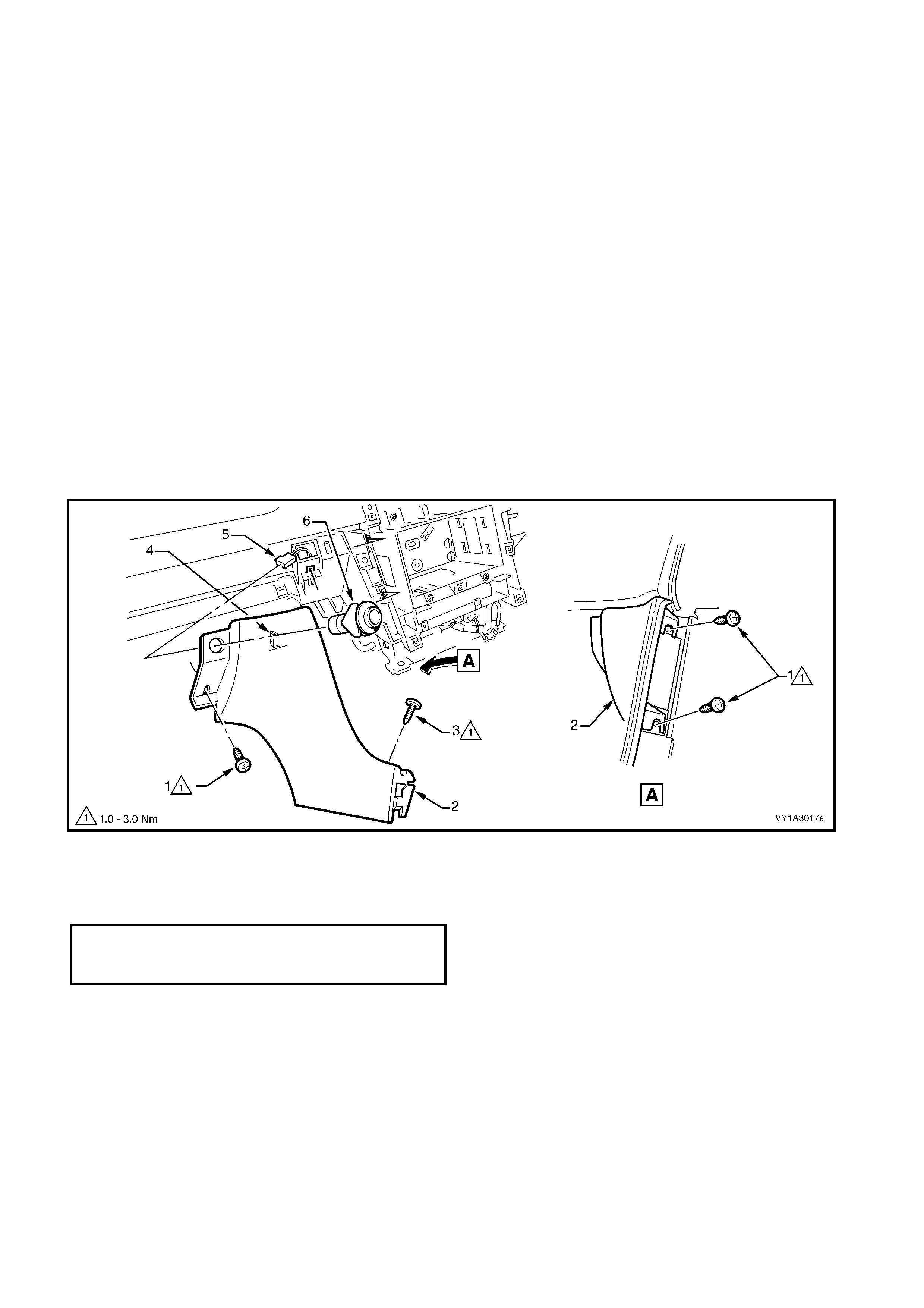
2.2 INSTRUMENT PANEL LOWER EXTENSION SIDE TRIM
LT Section –
REMOVE
1. Move the front seats to their rearmost position. For the left-hand side, move the front to the uppermost
position.
2. Referring to Figure 1A3-11, for the left-hand side:
a. Remove the screw (1) attaching the instrument panel lower extension side trim (2) to the floor console.
b. Open the instrument panel c ompartm ent (RHD) or instrum ent panel lower trim panel (LHD) and remove
the two screws (3) attaching the side trim to the instrument panel.
c. Remove the side trim.
Figure 1A3-11
3. Referring to Figure 1A3-12, for the right-hand side:
a. Open the instrument panel lower trim panel (RHD) or instrum ent panel com partment (LHD) and remove
the two screws (1) attaching the instrument panel lower extension side trim (2) to the instrument panel.
b. Prise the rear of the trim panel downward to disengage it from the floor console retaining clip (3).
c. Remove the side trim.
Figure 1A3-12
REINSTALL
Reinstallation is the reverse of removal. Ensure the trim panel is correctly seated and tighten the screws to the
specified torque.
INSTRUMENT PANEL LOWER EXTENSION
SIDE TRIM PANEL ATTACHING SCREW
TORQUE SPECIFICATION 1.0 – 3.0 Nm
2.3 FLOOR CONSOLE ASSEMBLY
LT Section –
As required, first remove the following components:
1. Floor console cover assembly, refer to 2.1 FLOOR CONSOLE COVER ASSEMBLY.
2. Left-hand and right-hand instrument panel lower extension side trims, refer to 2.2 INSTRUMENT PANEL
LOWER EXTENSION SIDE TRIM.
REMOVE
1. Remove the f loor c ons ole c ompartment liner (1) by
carefully grasping the liner and disengaging the
two lugs (2).
Figure 1A3-13
2. For automatic transmission vehicles, remove the
screw ( 1), four plac es, attaching the c onsole to the
automatic transmission selector assembly.
Figure 1A3-14
Techline
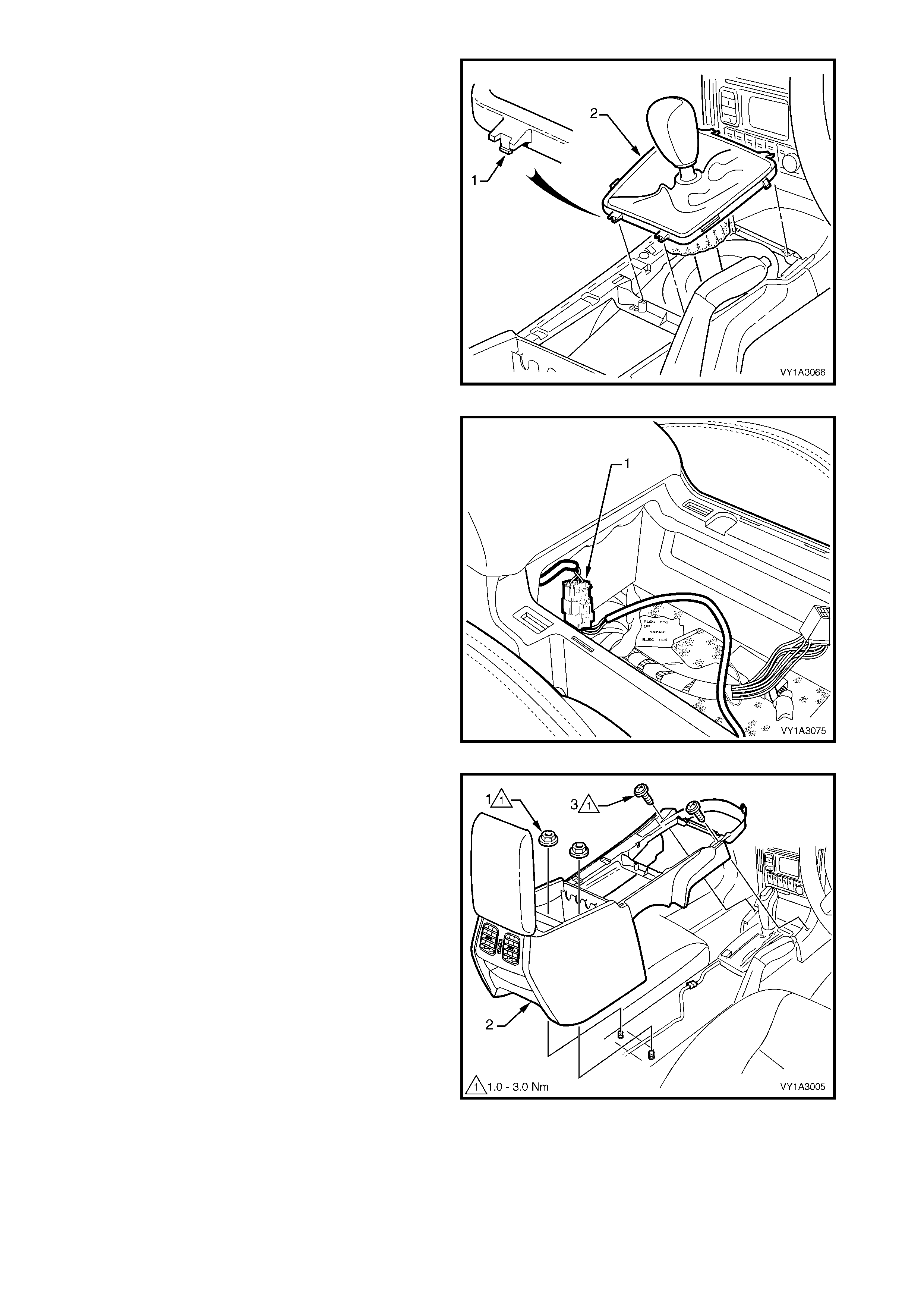
3. For manual transmission vehicles, use a fine flat-
blade screwdriver to disengage the lug (1),
attaching the manual transmission gear lever boot
assembly (2) to the console, two places front and
rear.
4. Remove the boot assembly from the console and
raise it over the gear knob. Remove the console
over the boot assembly when the remaining
fasteners are removed.
IMPORTANT: Do not attem pt to r emove the gear knob
from the gear lever shaft as it is glued in place. The
gear knob, boot assembly and lever shaft can be
removed from the transmission if required, refer to
Section 7B MANUAL TRANSMISSION.
Figure 1A3-15
5. Disconnect the console wiring connector (1) from
the front of the console storage bin.
Figure 1A3-16
6. Remove the two nuts (1) attaching the floor
console (2) to the vehicle floor.
7. Remove the two screws (3) attaching the front of
the console to the instrument panel assembly.
8. Lift the rear of the console upward and remove.
NOTE: The console rear air duct will disconnect from
the console front air duct during removal. The rear air
duct will remain with the console.
Figure 1A3-17
DISASSEMBLE
For details of the floor console wiring harness routing
and attachment, refer to Section 120, FUSES,
RELAYS & WIRING HARNESSES .
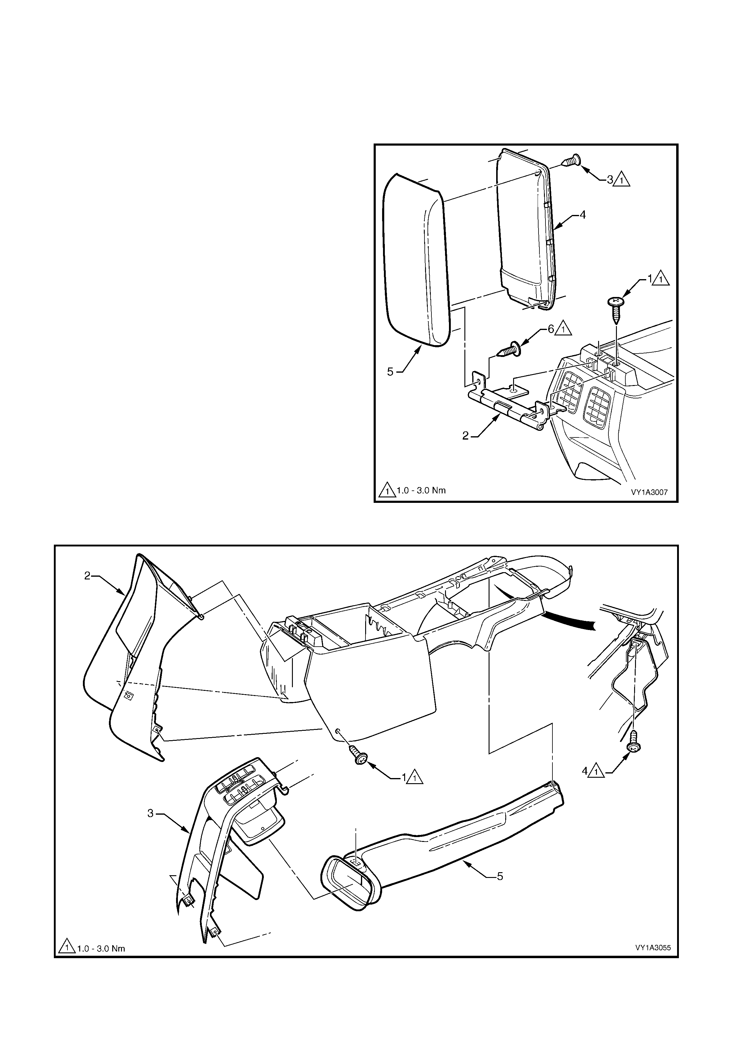
ARMREST ASSEMBLY
1. Remove the screw (1), two places, attaching the
floor console compartment armrest hinge (2) and
armrest assembly to the floor console.
2. Slide the armrest assembly rearward to remove
the hinge from the floor console.
3. Remove the screw (3), four places, attaching the
armrest inner (4) to the armrest outer (5).
4. Unclip the inner at three places along each side
and remove from the outer.
5. Remove the screw (6), two places attaching the
hinge to the outer and remove.
REAR AIR OUTLET HOUSING ASSEMBLY OR
REAR UPPER COMPARTMENT ASSEMBLY
1. Referring to Figure 1A3-19:
a. Remove the screw (1), one place each side,
attaching the floor console rear upper
com partm ent assem bly for utility models (2) or
the floor console rear air outlet housing
assembly (3) to the floor console.
b. Remove the compartment or housing by
swinging the lower edge rearward and
detaching the upper tangs.
c. Remove the screw (4) attaching the floor
console rear air duct (5) to the floor console
and remove the duct.
Figure 1A3-18
Figure 1A3-19
FLOOR CONSOLE REAR COMPARTMENT
1. Remove the floor console rear compartment liner
(1) from within the floor console rear compartment
(2).
2. Remove the screw (3), two places attaching the
compartment to the rear air outlet housing
assembly (4).
3. Tilt the compartment downwards slightly and
disengage the two lugs (5) from beneath the
compartment and remove.
Figure 1A3-20
FLOOR CONSOLE LINER AND COMPARTMENT
LAMP ASSEMBLY OR LAMP OPENING COVER
1. Lift out the floor console liner (1), if fitted.
2. Prise the rear edge of either the floor console
compartment lamp opening cover (2) or floor
console compartment lamp assembly (3).
3. If f itted, disc onnec t the lamp wiring connectors and
remove the lamp assembly.
4. If fitted, prise the floor console compartment lamp
switch (4) from the console, disconnect the wiring
connectors and remove the switch.
Figure 1A3-21
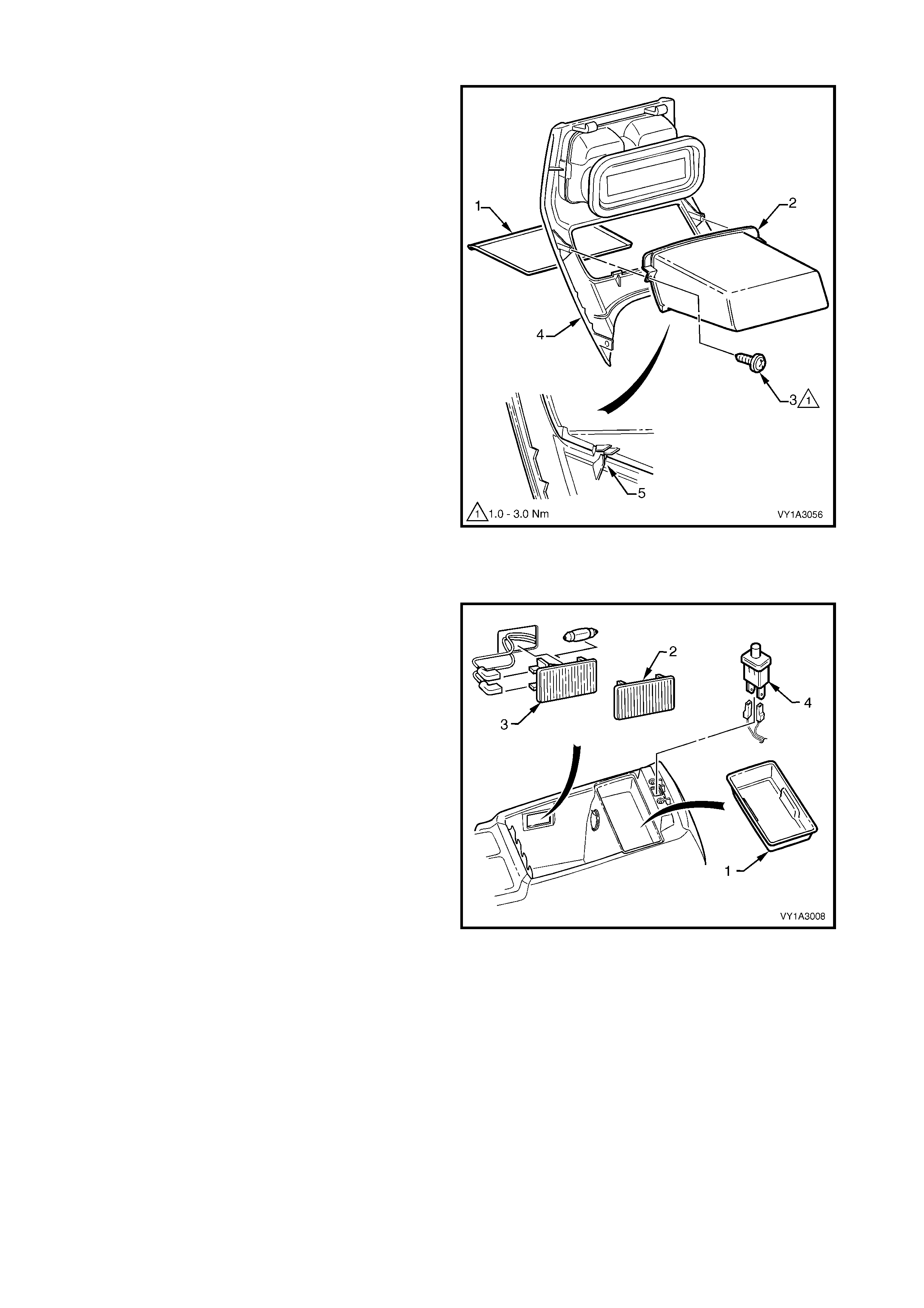
ACCESSORY POWER SOCKET
1. To remove the accessory power socket, a pair of
external circlip pliers will need to be modified.
Bend the tips of the pliers outward to between 60°
and 90°.
2. Referring to Figure 1A3-23:
a. From within the console compartment, insert
the circlip pliers (1) into the socket (2) and
locate the tips of the pliers onto the retaining
tab (3), two places.
b. Open the plier tips to depress the tabs, and
prise the soc ket f r om the bezel with a fine, flat-
blade screwdriver.
c. Withdraw the socket, disconnect the wiring
connector and remove the socket.
Figure 1A3-22
Figure 1A3-23
3. From within the console compartment, carefully
withdraw the bezel and cover.
NOTE: The socket must be removed before
performing this step as its removal releases the bezel
retaining tabs.
IMPORTANT: Take care as the tabs can break.
4. If required, slide the cover from the bezel.
Figure 1A3-24
REASSEMBLE
Reassembly of the floor console is the reverse of
disassembly noting the following:
1. The accessory power socket can only be installed
in the one orientation.
2. Tighten all fasteners to the specified torque.
REINSTALL
Reinstallation of the floor console assembly is the
reverse of removal noting the following:
1. If the vehicle is fitted with Navigation System
and a new floor console is being installed,
ensure the navigation remote control
presenter wedge Nutserts are fitted, refer to
Section 12L, 3.9 FITTING A NEW FLOOR
CONSOLE ASSEMBLY.
2. Tighten all fasteners to the correct torque
specifications.
3. Ensure the floor console assembly is correctly
seated against the instrument panel lower
extensions before tightening screws; tighten the
front screws first.
FLOOR CONSOLE ATTACHING
SCREW TORQUE SPECIFICATION 1.0 – 3.0 Nm
FLOOR CONSOLE ATTACHING
NUT TORQUE SPECIFICATION 1.0 – 3.0 Nm
FL OOR CO NSOLE TO A UTOMATIC
TRANSMISSION SELECTOR ASSEMBLY
ATTACHING SCREW
TORQUE SPECIFICATION 1.0 – 3.0 Nm
FLOOR CONSOLE REAR COMPARTMENT
ATTACHING SCREW
TORQUE SPECIFICATION 1.0 – 3.0 Nm
FLOOR CONSOLE REAR AIR DUCT
ATTACHING SCREW
TORQUE SPECIFICATION 1.0 – 3.0 Nm
FLOOR CONSOLE REAR AIR OUTLET
HOUSING ASSEMBLY ATTACHING
SCREW TORQUE SPECIFICATION 1.0 – 3.0 Nm
FLOOR CONSOLE REAR UPPER
COMPARTMENT ASSEMBLY ATTACHING
SCREW TORQUE SPECIFICATION 1.0 – 3.0 Nm
FLOOR CONSOLE COMPARTMENT
ARMREST HINGE ATTACHING
SCREW TORQUE SPECIFICATION 1.0 – 3.0 Nm
FLOOR CONSOLE COMPARTMENT
ARMREST INNER ATTACHING
SCREW TORQUE SPECIFICATION 1.0 – 3.0 Nm

3. SERVICE OPERATIONS – INSTRUM ENT PANEL
3.1 INSTRUMENT PANEL LOWER TRIM PLATE ASSEMBLY
LT Section –
REMOVE
DRIVER SIDE, ALL VEHICLES
1. For autom atic transm ission vehicles, rem ove the retainer (1) attaching the ins trument panel lower trim plate
assembly (2) to the HVAC unit, refer Figure 1A3-25.
NOTE: The area shown A is removed for manual transmission vehicles.
2. Prise the insert and remove the retainer (3), two places, attaching the plate assembly to the instrument
panel.
3. Lower the plate assembly slightly and withdraw the lug (4) from the pedal bracket.
4. If fitted, remove the stepwell lamp (5) by rotating the socket and removing from the plate assembly.
5. Remove the plate assembly.
Figure 1A3-25
PASSENGER SIDE, RIGHT-HAND DRIVE VEHICLES
1. Grasp the instrument panel lower trim plate assembly (1) and carefully pull downward to disengage the
retaining clip (2), three places, refer Figure 1A3-26.
2. Lower the plate assembly slightly and if fitted remove the stepwell lamp (3), by rotating the socket and
removing from the plate assembly.
3. Remove the plate assembly.
Figure 1A3-26
PASSENGER SIDE, LEFT-HAND DRIVE VEHICLES
1. Grasp the inner end of the instrument panel lower trim plate assembly (1) and carefully pull downwards to
disengage the retaining clip (2), two places, refer Figure 1A3-27.
2. Withdraw the plate assembly from the hinge pillar trim panel, disengaging the lug (3), two places.
NOTE: The rear lug has a hook that engages the hinge pillar trim panel.
3. Lower the plate assembly slightly and if fitted remove the stepwell lamp (4), by rotating the socket and
removing from the plate assembly.
4. Remove the plate assembly.
Figure 1A3-27
REINSTALL
Reinstallation of the instrument panel lower trim plate assembly is the reverse of removal.
3.2 INSTRUMENT PANEL COMPARTMENT ASSEMBLY
LT Section – 09-140
REMOVE
1. Open the ins trum ent panel com par tm ent assem bly
(1).
2. Using a fine flat-blade screwdriver, flatten the
instrument panel compartment bumper stop (2)
each side, and carefully open the compartment
assembly fully.
3. From the inside of the compartment assembly,
push outwards on the bumper stop (2), and slide
the bumper from the lug (3). Repeat for the
opposite side.
4. Close the compartment assembly a third of the
way and grasping each side pull rearward to
disengage the compartment assembly from each
instrument panel compartment hinge (4).
IMPORTANT: T ake c are when disengaging the hinges
as removing the compartment assembly on the wrong
angle may cause damage.
NOTE: For removal of the instrument panel
compartment hinges refer to 3.22 INSTRUMENT
PANEL BRACKETS & BRACES.
5. As required, remove the two screws (5) attaching
the instrument panel compartment lock striker (6)
and remove the striker.
Figure 1A3-28
DISASSEMBLE
1. From the rear side of the compartment assembly,
remove the screw (1), six places, attaching the
instrument panel compartment (2) to the
instrument panel compartment door (3).
2. Lower the upper edge of the door and withdraw the
retaining tabs along the lower edge from the
compartment.
3. Remove the door and instrument panel
compartment liner (4).
Figure 1A3-29
Techline
Techline
4. Unclip the instrum ent panel com partm ent latch rod
(1) from the instrument panel compartment latch
actuator assembly (2) and instrument panel
compartment latch assembly (3).
5. Remove the three screws (4) attaching the latch
assembly to the door.
6. Depr es s the two tangs on the retainer (5) and s lide
the retainer from the actuator assembly.
7. Remove the actuator assembly.
Figure 1A3-30
8. If required, remove the lock cylinder from the
actuator assembly by ins erting the key and turning
to the locked position (clockwise).
9. Insert a fine flat-blade screwdriver into the cavity
on the back of the actuator and depress the pin
(1).
10. While holding the pin depressed, turn the key
clockwise quarter of a turn.
11. Withdraw the cylinder.
NOTE: Replacement lock cylinders are supplied
complete with key.
REASSEMBLE
Reassembly is the reverse of disassembly noting the
following:
1. Tighten the screws to the specified torque.
Figure 1A3-31
INSTRUMENT PANEL COMPARTMENT
LATCH ASSEMBLY ATTACHING SCREW
TORQUE SPECIFICATION 1.0 – 3.0 Nm
INSTRUMENT PANEL COMPARTMENT
DOOR ATTACHING SCREW
TORQUE SPECIFICATION 1.0 – 3.0 Nm
2. If installing the lock cylinder, insert the key and fit
the lock cylinder into its cavity in the vertical
position and rotate anti-clockwise half a turn.
3. Check the operation of the lock and actuator.
Figure 1A3-32
REINSTALL
Reinstallation of the instrument panel compartment
assembly is the reverse of removal. As required, adjust
the instrument panel compartment lock striker to
provide secure closing of the instrument panel
compartment and tighten the screws to the specified
torque.
INSTRUMENT PANEL COMPARTMENT
LOCK STRIKER ATTACHING SCREW
TORQUE SPECIFICATION 1.0 – 3.0 Nm
3.3 INSTRUME NT PANEL COMP ARTMENT LAMP & SWITCH
LT Section – 02-780
REMOVE
INSTRUMENT PANEL COMPARTMENT LAMP
SWITCH
1. From either side of the instrument panel
compartment lamp switch (1), carefully insert a
fine flat blade screwdriver and prise the switch
from the instrument panel.
2. Disconnect the wiring harness connectors and
remove the switch.
INSTRUMENT PANEL COMPARTMENT LAMP
1. From the right-hand side of the instrument panel
compartment lamp (2), carefully insert a fine flat
blade screwdriver.
2. Prise the lam p fr om the instrum ent panel and slide
it out of its cavity.
3. Disconnect the wiring harness connectors and
remove the lamp.
4. If required, remove the globe (3).
Figure 1A3-33
REINSTALL
Reinstallation is the reverse of removal.
3.4 INSTRUMENT PANEL LOWER TRIM PANEL ASSEMBLY
LT Section – 09-200
REMOVE
1. Grasp the upper edge of the instrument panel
lower trim panel as sem bly ( 1) and pull outwards to
disengage the three retaining clips (2).
2. Swing the panel assembly open.
3. Holding each side of the panel assembly, pull
rearwards to disengage it from the instrument
panel lower trim panel retainer (3), two places.
Figure 1A3-34
REINSTALL
Reinstallation is the reverse of removal.
NOTE: Ensure each retaining clip is aligned correctly
prior to pushing the panel assembly into place.
3.5 INSTRUMENT PANEL LOWER TRIM PANEL RETAINER
LT Section – 09-200
As required, first remove the following components:
1. Driver side instrument panel lower trim plate assembly, refer to 3.1 INSTRUMENT PANEL LOWER TRIM
PLA TE ASSEMBLY.
2. Instrument panel lower trim panel assembly, refer to 3.4 INSTRUMENT PANEL LOWER TRIM PANEL.
REMOVE
1. Remove the screw (1), two places, attaching the data link connector (2) to the instrument panel lower trim
panel retainer (3), refer to Figure 1A3-35, A – left-hand drive or B – right-hand drive.
2. For right-hand drive vehicles, remove the two screws (4 & 5) attaching the retainer to the air duct.
3. For left-hand drive vehicles, remove the screw (4) attaching the retainer to the air duct.
4. Rem ove the sc rew (6) , three places , attac hing the retainer to the inst rum ent panel ass em bly and instrument
panel.
5. Slide the retainer downward to disengage the two lugs from the instrument panel assembly as shown at
Section A-A and remove the retainer.
Figure 1A3-35
REINSTALL
Reinstallation is the reverse of removal. Tighten the
screws to the specified torque.
DATA LINK CONNECTOR
ATTACHING SCREW
TORQUE SPECIFICATION 1.0 – 3.0 Nm
INSTRUMENT PANEL LOWER
TRIM PANEL RETAINER
ATTACHING SCREW
TORQUE SPECIFICATION 1.0 – 3.0 Nm
3.6 RADIO ASSEMBLY
LT Section – 09-440
REMOVE
1. Ins er t Spec ial T ool KM6067 ( 1) into the holes eac h
side of the radio assembly.
2. While holding outward pressure on the tools
(toward each outer side of the vehicle), pull the
radio assembly from the radio housing.
NOTE: The wiring connectors remain attached to the
radio housing and will disconnect on removal of the
radio.
3. For service and diagnosis of the radio
assembly refer to Section 12D ENTERTAINMENT
SYSTEM.
Figure 1A3-36
REINSTALL
1. Insert the radio assembly into the housing.
2. Push the unit home to engage the retaining clips
and wiring connectors.
NOTE: The Special Tool is not required.
3.7 INSTRUMENT PANEL CENTRE TRIM ASSEMBLY
LT Section – 09-300
As required, first remove the following components:
1. Floor console cover assembly, refer to 2.1 FLOOR CONSOLE COVER ASSEMBLY.
2. Radio assembly, refer to 3.6 RADIO ASSEMBLY.
REMOVE
Referring to Figure 1A3-37:
1. Carefully prise the front edge of the instrument panel upper centre trim panel (1), and pull upward to
disengage the retaining clips at each corner from the centre trim assembly (2).
NOTE: A fine flat blade screwdriver may be used; however take steps to ensure the trims are not marked or
damaged.
2. Remove the lower screw (3), two places, attaching the centre trim assembly to the instrument panel.
3. Remove the upper screws (4 & 5), two places each, attaching the centre trim assembly to the instrument
panel.
4. Remove the centre trim assembly, disengaging the four clips (6), far enough to disconnect the wiring
connectors from the rear of the hazard warning switch and where fitted, the OCC control module.
NOTE: If manual HVAC is fitted, the manual HVAC controller remains attached to the instrument panel.
5. Remove the centre trim assembly.
Figure 1A3-37
DISASSEMBLE
NOTE: Depending on model not all of the following components will be fitted.
Referring to Figure 1A3-38:
1. Remove the s c rew ( 1) , one place each side, attac hing the OCC c ontr ol module (2) and c up holder ass embly
(3) to the cen tre trim (4).
2. Remove the screw (5), one place each side, attaching the OCC control module to the centre trim and
remove the control assembly.
3. Remove the screw (6) attaching the cup holder assembly to the centre trim and remove the cup holder.
4. Remove the four screws (7) attaching the instrument panel centre air outlet housing assembly (8) to the
centre trim and remove the housing assembly and hazard warning switch (9).
5. Unclip the hazard warning switch from the instrument panel centre air outlet housing assembly.
NOTE 1: For service and diagnosis of the OCC control module refer to Section 2E HVAC OCCUPANT
CLIMATE CONTROL (A UTO A/C).
NOTE 2: For service and diagnosis of the hazard warning switch refer to Section 12B, 3.25 HAZARD
WARNING SWITCH ASSEMBLY.
Figure 1A3-38
REINSTALL
Reinstallation is the reverse of removal. Tighten all screws to the specified torque.
INSTRUMENT PANEL CUP HOLDER
ASSEMBLY ATTACHING SCREW
TORQUE SPECIFICATION 1.0 – 3.0 Nm
OCC CONTROL MODULE ATTACHING
SCREW TORQUE SPECIFICATION 1.0 – 3.0 Nm
INSTRUMENT PANEL CENTRE AIR OUTLET
HOUSING ASSEMBLY ATTACHING
SCREW TORQUE SPECIFICATION 1.0 – 3.0 Nm
INSTRUMENT PANEL CENTRE TRIM
ASSEMBLY ATTACHING SCREW
TORQUE SPECIFICATION 1.0 – 3.0 Nm
3.8 INSTRUMENT PANEL LOWER COMPARTMENT OR ASHTRAY ASSEMBLY
LT Section – 09-300
NOTE: W here fitted, an instrument panel ashtray assembly replaces the instrument panel lower compartment.
Removal of both components is the same, however each has its own disassembly procedure, which is described
in this Section.
As required, remove the following components:
1. Floor console cover assembly, refer to 2.1 FLOOR CONSOLE COVER ASSEMBLY.
2. Radio assembly, refer to 3.6 RADIO ASSEMBLY.
3. Instrument panel centre trim assembly, refer to 3.7 INSTRUMENT PANEL CENTRE TRIM ASSEMBLY.
REMOVE
1. Rem ove the screw (1), three places, attaching the
instrument panel lower compartment assembly or
ashtray assembly (2) to the instrument panel.
2. Slide the compartment or ashtray assembly
outward to remove.
NOTE: If an ashtray assembly is fitted, disconnect the
wiring connector (3).
Figure 1A3-39
REINSTALL
Reinstallation is the reverse of removal. Tighten the
screws to the specified torque.
INSTRUMENT PANEL LOWER
COMPARTMENT OR ASHTRAY ASSEMBLY
SCREW TORQUE SPECIFICATION 1.0 – 3.0 Nm
3.9 INSTRUMENT PANEL LOWER EXTENSION
LT Section – 09-300
As required, first remove the following components:
1. Floor console cover assembly, refer to 2.1 FLOOR CONSOLE COVER ASSEMBLY.
2. Radio assembly, refer to 3.6 RADIO ASSEMBLY.
3. Instrument panel centre trim assembly, refer to 3.7 INSTRUMENT PANEL CENTRE TRIM ASSEMBLY.
4. Instrument panel lower compartment assembly or instrument panel ashtray assembly, refer to
3.8 INSTRUMENT PANEL LOWER COMPARTMENT OR ASHTRAY ASSEMBLY.
REMOVE
Referring to Figure 1A3-40:
1. Remove the three screws (1) attaching the instrument panel lower extension (2) to the instrument panel.
2. For the left-hand side, remove the screw (3) attaching the floor console front duct.
3. Grasp the top of the extension and pull rearwards to release the clip (4).
4. If fitted, dis connec t the wiring connector ( 5) f r om the rear c ompartment lid releas e switch (6) and remove the
panel.
5. If r equired, r emove the r ear c ompartment lid releas e s witch by depressing the tabs on the back of the switch
and pushing it out of the extension.
NOTE: For service and diagnosis of the rear compartment lid release switch refer to Section 12J BODY
CONTROL MODULE.
Figure 1A3-40
REINSTALL
Reinstallation is the reverse of removal. Tighten the screws to the specified torque.
INSTRUMENT PANEL LOWER
EXTENSION SIDE TRIM ATTACHING
SCREW TORQUE SPECIFICATION 1.0 – 3.0 Nm
3.10 MANUAL HVAC CONTROLLE R
LT Section – 08-155A
NOTE: For removal of OCC control module refer to 3.7 INSTRUMENT PANEL CENTRE TRIM ASSEMBLY -
DISASSEMBLE.
As required, first remove the following components:
1. Floor console cover assembly, refer to 2.1 FLOOR CONSOLE COVER ASSEMBLY.
2. Radio assembly, refer to 3.6 RADIO ASSEMBLY.
3. Instrument panel centre trim assembly, refer to 3.7 INSTRUMENT PANEL CENTRE TRIM ASSEMBLY.
REMOVE
Referring to Figure 1A3-41:
1. From the rear of the controller, open the push-rod locking tab (1) and disconnect the control rod (2).
2. Remove the screw (3), two places each side, attaching the manual HVAC controller (4) to the instrument
panel.
3. Pull the control assembly outwards slightly to access the rear.
4. Disconnect the two vacuum hose connections (5 & 6) and two wiring connectors (7).
5. Remove the control assembly.
NOTE: For service and diagnosis of the manual HVAC controller, refer to Section 2C HVAC CLIMATE
CONTROL (MANUAL A/C) – SERVICING & DIAGNOSIS.
Figure 1A3-41
REINSTALL
1. Install the two wiring connectors and the lower then upper vacuum hose connections.
2. Push the control rod toward the HVAC unit (front of vehicle) fully.
3. Seat the control assembly in position.
4. Install the four screws and tighten to the specified torque.
5. Rotate the heat control knob to the full cold position.
6. Position the locking tab so that it will close upward.
7. Connect the control rod to the controller lever and close the locking-tab.
8. Check for correct operation.
MANUAL HVAC CONTROLLER
ATTACHING SCREW
TORQUE SPECIFICATION 1.0 – 3.0 Nm
3.11 RADIO HOUSING & RADIO BRACKET ASSEMBLY
LT Section –
For the radio housing, as required first remove the following components:
1. Floor console cover assembly, refer to 2.1 FLOOR CONSOLE COVER ASSEMBLY.
2. Radio assembly, refer to 3.6 RADIO ASSEMBLY.
3. Instrument panel centre trim assembly, refer to 3.7 INSTRUMENT PANEL CENTRE TRIM ASSEMBLY.
For the radio bracket, as required first remove the above components, the radio housing and the following
components:
1. Instrument panel lower compartment assembly or instrument panel ashtray assembly, refer to
3.8 INSTRUMENT PANEL LOWER COMPARTMENT OR ASHTRAY ASSEMBLY.
2. Left-hand and Right-hand instrument panel lower extension, refer to 3.9 INSTRUMENT PANEL LOWER
EXTENSION.
3. Manual HVAC controller if fitted, refer to 3.10 MANUAL HVAC CONTROLLER.
REMOVE
Referring to Figure 1A3-42:
1. Remove the screw (1) from the rear face of the radio housing (2) attaching the housing to the instrument
panel.
2. Remove the screw (3), two places, attaching the front edge of the radio housing.
3. Lift the retaining tab (4), two places in the top of the housing and one place at the bottom.
4. Withdraw the hous ing f r om the brac ket assembly far enough to allow access to the r adio and antenna wiring
connectors.
NOTE: If ther e is not suf fic ient length in the radio harness , either unclip the connector fr om within the housing or
remove the passenger side instrument panel lower extension side trim and unclip the harness from the vehicle
floor.
5. From the rear of the housing, unclip the radio wiring connector (5), if not previously done, the antenna
connector (6) and if fitted, the diversity antenna connector (7) from the housing.
6. Unattach the antenna lead(s) and remove the housing.
Figure 1A3-42
Referring to Figure 1A3-43:
7. Remove the screws (1, 2, 3 & 4), two places each side, attaching the radio bracket assembly (5) to the
instrument panel.
8. Remove the bracket assembly from its locating tabs.
Figure 1A3-43
REINSTALL
Reinstallation is the reverse of removal. Tighten the screws to the specified torque.
NOTE: To avoid operational problems, ensure the radio wiring and antenna connectors are installed correctly.
RADIO BRACKET ASSEMBLY
ATTACHING SCREW
TORQUE SPECIFICATION 1.0 – 3.0 Nm
RADIO HOUSING
ATTACHING SCREW
TORQUE SPECIFICATION 1.0 – 3.0 Nm
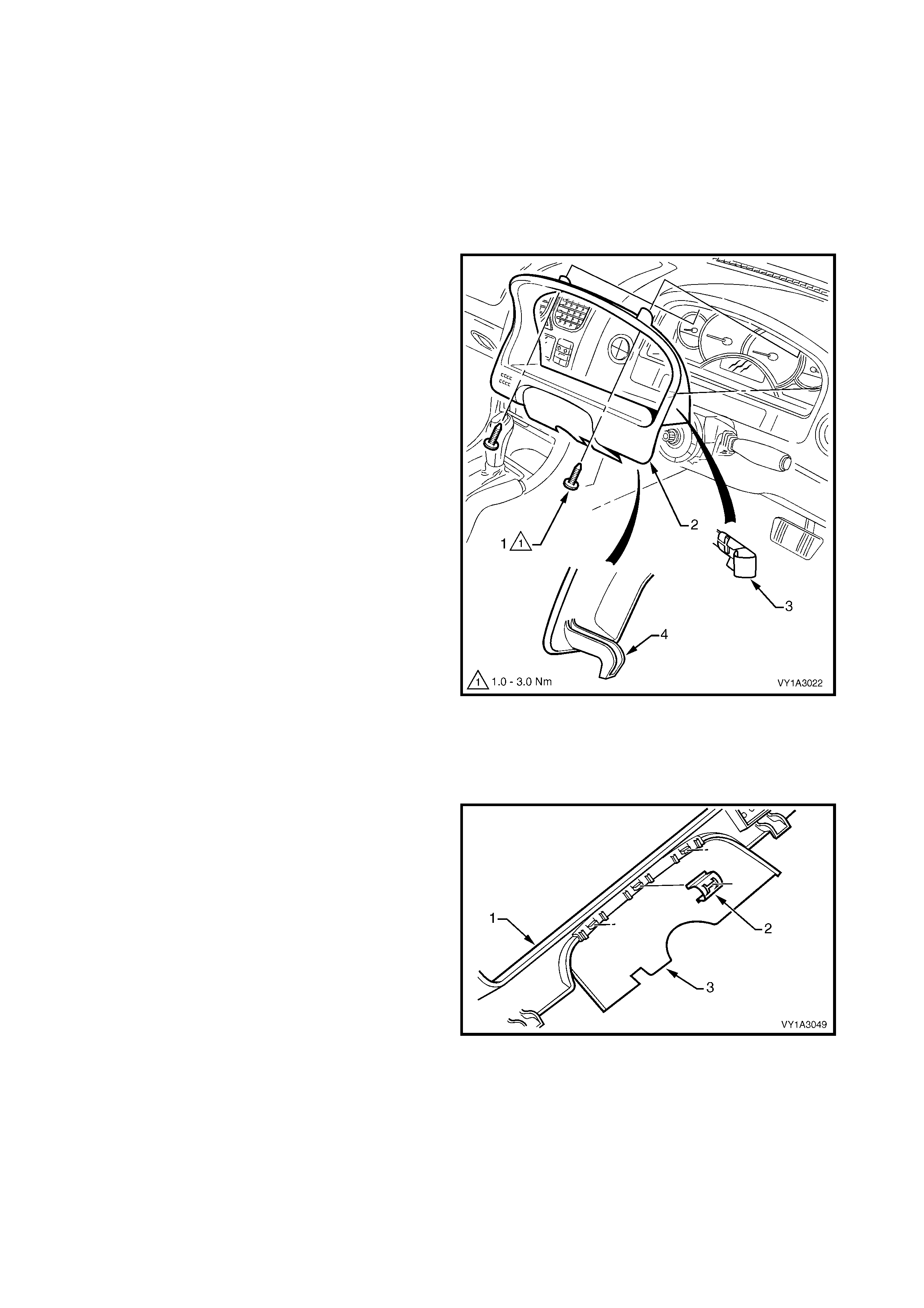
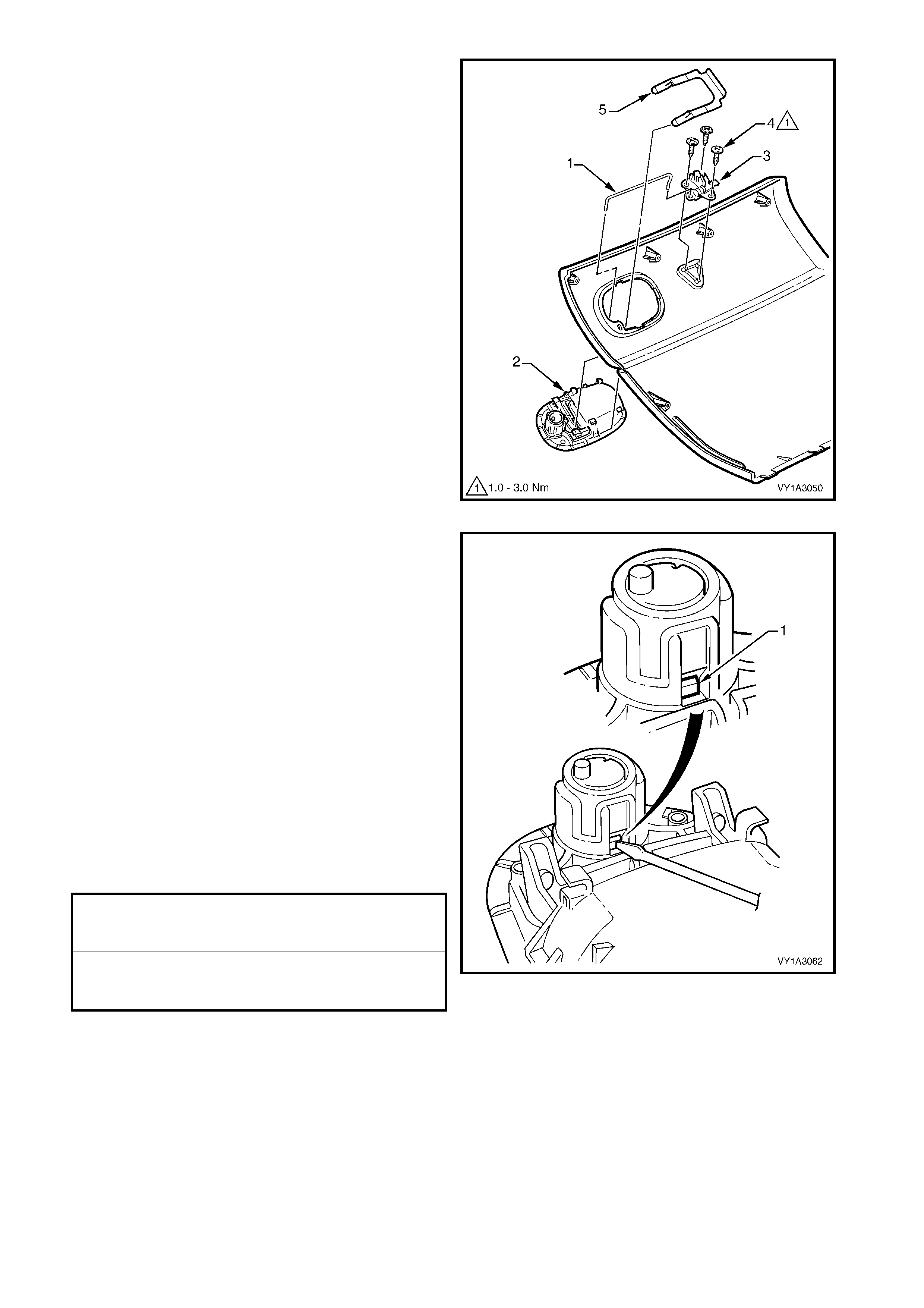
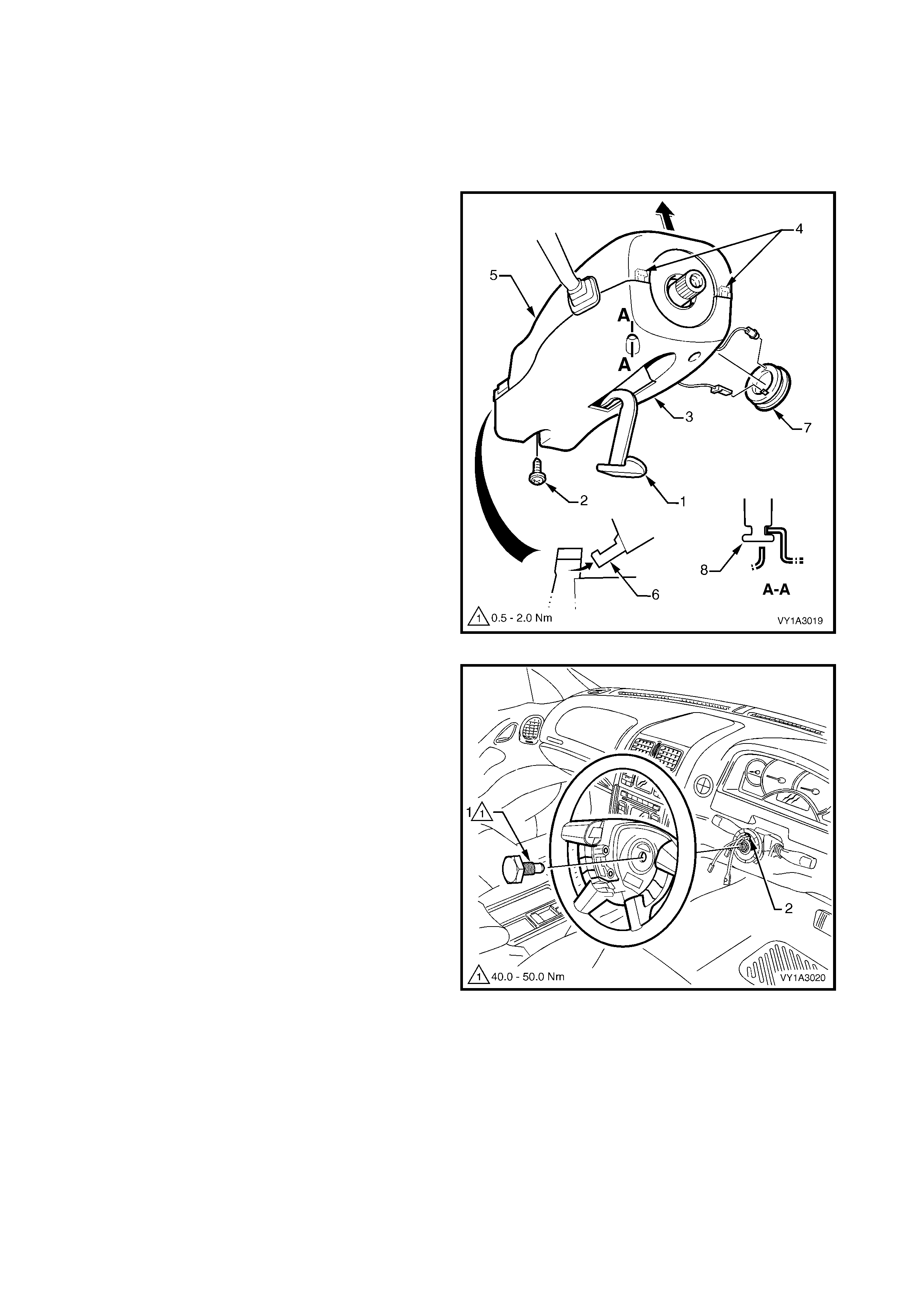
3.12 INSTRUMENT CLUSTER TRIM ASSEMBLY
LT Section – 09-100
REMOVE
NOTE: The steering wheel has been removed for
clarity; the cluster trim can be removed with steering
column, covers and steering wheel installed.
1. Release the s teering column adj ustment lever and
move the column to its lowest position.
2. Remove the two screws (1) attaching the
instrument cluster trim assembly (2) to the
instrument panel.
3. Depress the top of the trim assembly slightly and
tilt the top of the trim assembly out of the
instrument panel pad, disengaging the retaining
clips (3) each side.
4. Unhooking each lug (4) from the instrument panel
pad.
5. For left-hand drive vehicles, disconnect the fuel
tank filler door lock release switch wiring
connector.
6. Remove the trim assembly.
Figure 1A3-44
DISASSEMBLE
REMOVE – INSTRUMENT PANEL STEERING
COLUMN OPENING FILLER
1. From the rear of the instrument cluster trim
assembly (1), prise the retainers (2), three places,
attaching the instrument panel steering column
opening filler (3).
2. Remove the filler from the trim assembly.
REINSTALL – INSTRUMENT PANEL STEERING
COLUMN OPENING FILLER
1. Fit the filler to the trim assembly, ensuring it is
correctly seated on each lug.
2. Attach the three retainers securely.
Figure 1A3-45
REMOVE – FUEL FILLER DOOR RELEASE SWITCH
ASSEMBLY, LHD
1. From the rear of the instrument cluster trim
assembly (1), depr ess the tab eac h s ide of the f uel
filler door release switch (2) to unclip the switch
assembly.
2. Rem ove the switch ass em bly from the f ace s ide of
the trim assembly.
NOTE: F or diagnosis of the f uel filler door switch, r efer
to Section 1A1, 4.5 FUEL TANK FILLER DOOR
LOCK ACTUATOR ASSEMBLY, LHD.
REINSTALL – FUEL FILLER DOOR RELEASE
SWITCH ASSEMBLY, LHD
1. Install the switch assembly from the face side of
the trim assembly, ensuring it clicks into place
securely.
Figure 1A3-46
REINSTALL
Reinstallation of the instrument cluster trim assembly
is the reverse of removal. Ensure the cluster trim and
filler are seated correctly Tighten the screws to the
specified torque.
INSTRUMENT CLUSTER TRIM
ASSEMBLY ATTACHING SCREW
TORQUE SPECIFICATION 1.0 – 3.0 Nm
3.13 IN-CAR AIR TEMPERATURE SENSOR
LT Section –
As required, first remove the instrument cluster trim assembly, refer to 3.12 INSTRUMENT CLUSTER TRIM
ASSEMBLY.
REMOVE
1. Remove the screw (1) attaching the in-car air
temperature sensor (2) to the instrument panel.
2. Extract the sensor assembly from the cavity and
disconnect the air tube and wiring connector.
3. Remove the sensor assembly.
NOTE: For service and diagnosis of the sensor
assembly refer to Section 2F HVAC OCCUPANT
CLIMATE CONTROL (AUTO A/C) - DIAGNOSTICS.
Figure 1A3-47
REINSTALL
Reinstallation is the reverse of removal. Tighten the
screws to the specified torque.
IN-CAR AIR TEMPERATURE
SENSOR ATTACHING SCREW
TORQUE SPECIFICATION 1.0 – 3.0 Nm
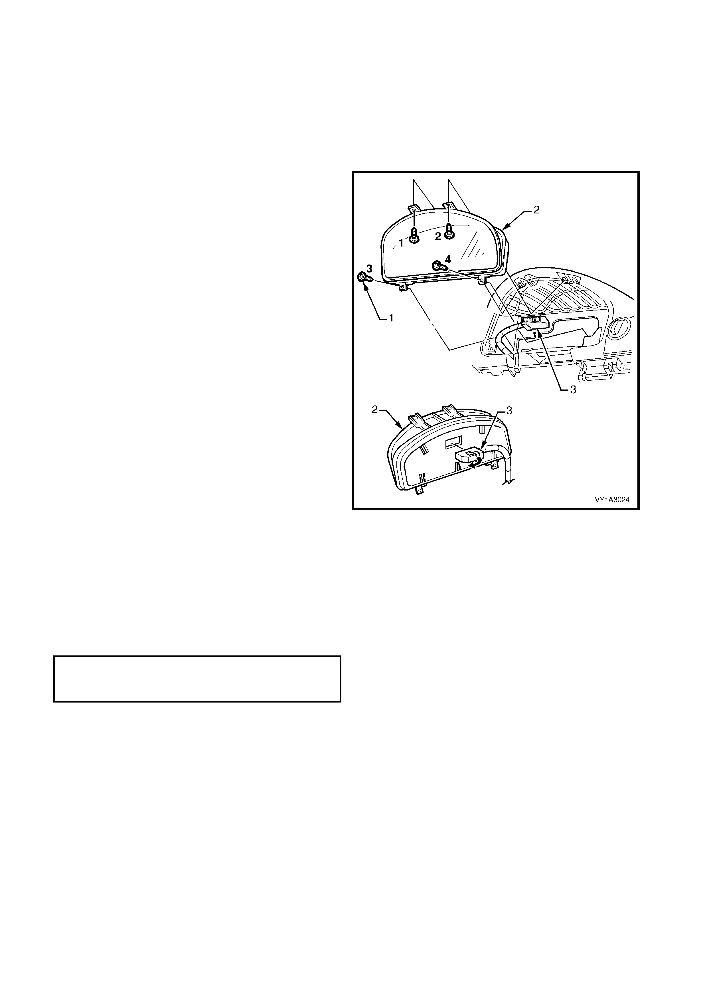
3.14 INSTRUMENT CLUSTER
LT Section – 09-100
As required, first remove the following components:
1. Instrument cluster trim assembly, refer to 3.12 INSTRUMENT CLUSTER TRIM ASSEMBLY.
2. In-car air temperature sensor, if fitted, refer to 3.13 IN-CAR AIR TEMPERATURE SENSOR.
REMOVE
1. Remove the four screws (1) attaching the
instrument cluster (2) to the instrument panel.
2. Roll the top of the cluster from its cavity.
3. Using a fine f lat blade screwdriver, open the wiring
connector locking tab (3) on the back of the
cluster.
4. Remove the cluster assembly.
NOTE: For service and diagnosis of the instrument
cluster refer to Section 12C INSTRUMENTS.
Figure 1A3-48
REINSTALL
Reinstallation is the reverse of removal.
NOTE: Ensure the locking tab on the wiring connector
is fully closed.
IMPORTANT: Tighten the screws in the correct
sequence, refer to Figure 1A3-48, to the specified
torque.
INSTRUMENT CLUSTER
ATTACHING SCREW
TORQUE SPECIFICATION 1.0 – 3.0 Nm
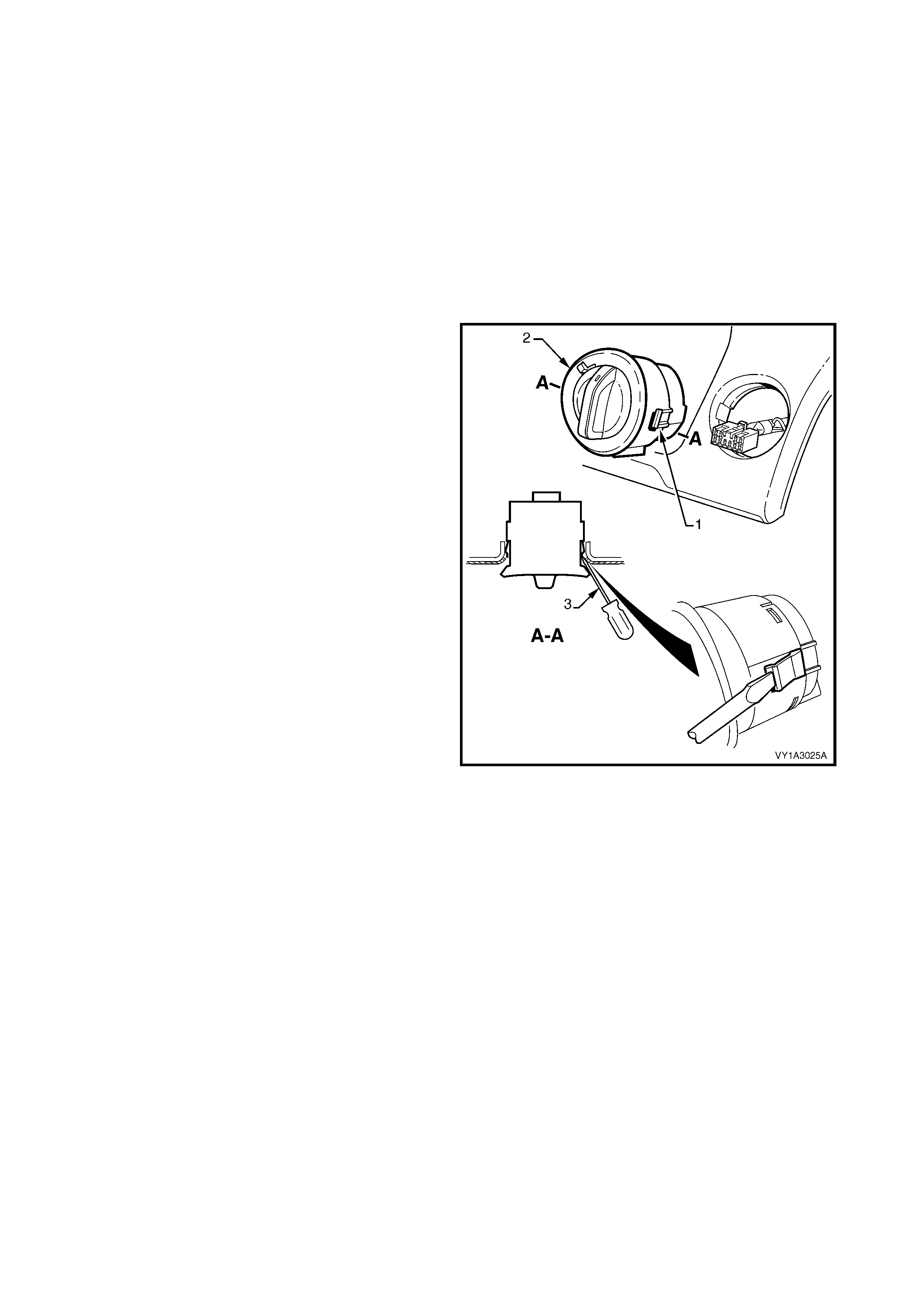
3.15 HEADLAMP SWITCH
LT Section – 02-800
As required, first remove following components:
1. Instrument cluster trim assembly, refer to 3.12 INSTRUMENT CLUSTER TRIM ASSEMBLY.
2. Right-hand instrument panel outer cover, refer to 3.17 INSTRUMENT PANEL OUTER COVER.
3. The driver’s side outer duct, refer to Section 2B, 18.2 HVAC SYSTEM DUCTS.
REMOVE
IMPORTANT: Care m ust be exercis ed when rem oving
the headlamp switch as the retaining clip and locating
guide will catch and damage the instrument panel
outer material.
1. Squeeze the retaining clips (1) on either side of the
headlamp switch assembly (2) and carefully push
the assembly part way from the cavity.
2. Insert a fine blade screwdriver (3) as shown and
hold the retaining clip depressed while slowly
manipulating the switch from its cavity. Repeat for
the opposite side and for the locating guide
underneath as required.
3. Disconnect the wiring connector and remove the
switch assembly.
NOTE: For service and diagnosis of the headlamp
switch assembly refer to Section 12B LIGHTING
SYSTEM.
Figure 1A3-49
REINSTALL
Reinstallation is the reverse of removal. Ensure the
retaining clips are correctly seated.
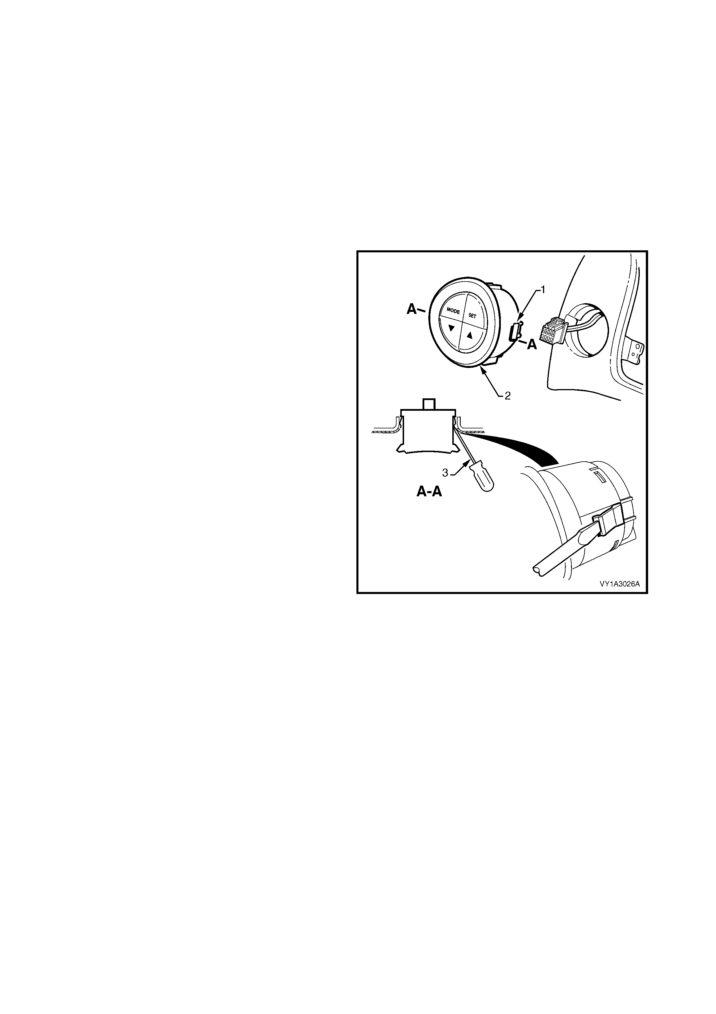
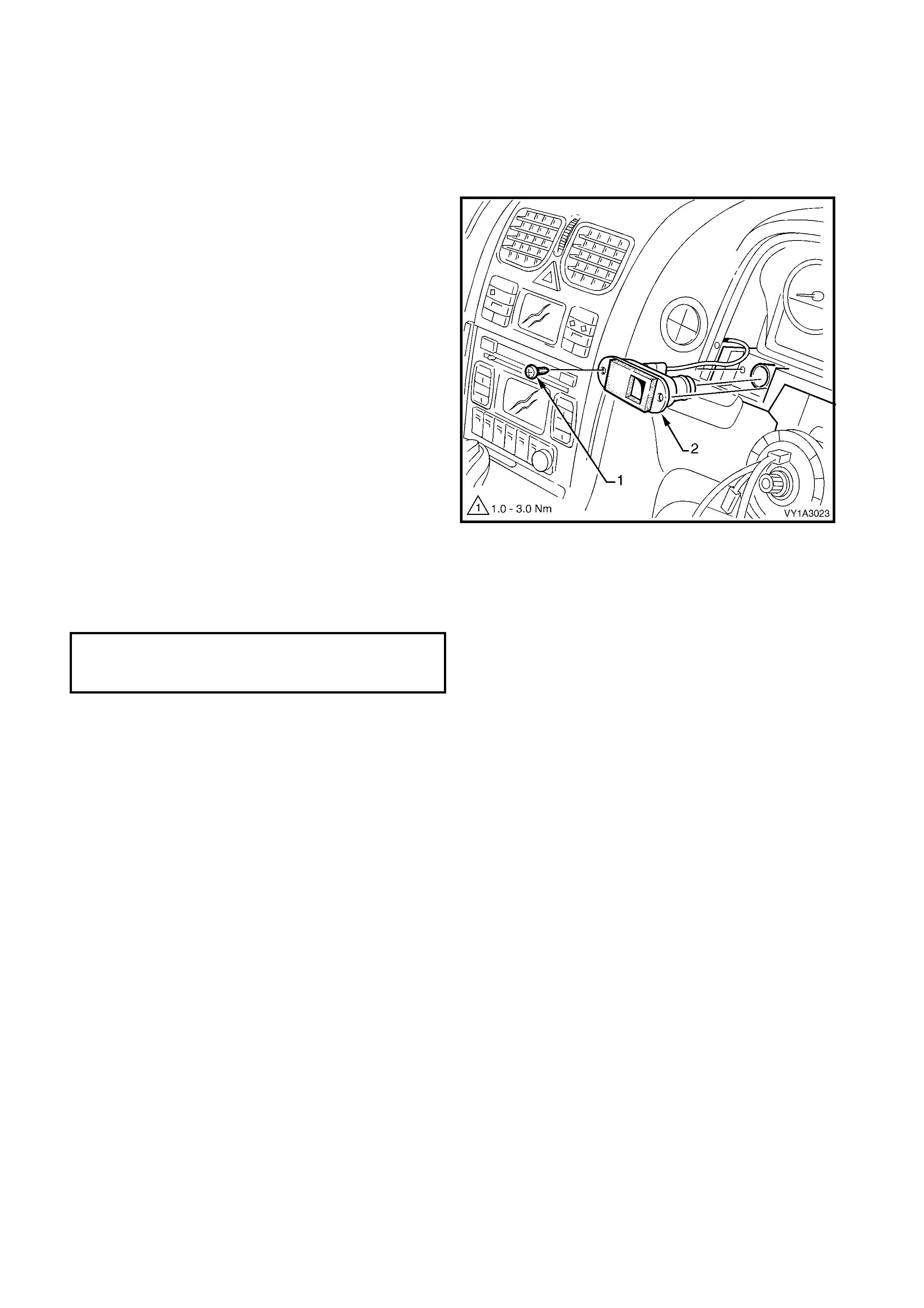
3.16 TRIP COMP UTER SWITCH
LT Section – 02-800
As required, first remove the following components:
1. Instrument cluster trim assembly, refer to 3.12 INSTRUMENT CLUSTER TRIM ASSEMBLY.
2. Instrument panel centre trim assembly, refer to 3.7 INSTRUMENT PANEL CENTRE TRIM ASSEMBLY.
3. Manual HVAC controller, refer to 3.10 MANUAL HVAC CONTROLLER.
REMOVE
IMPORTANT: Care m ust be exercis ed when rem oving
the trip computer switch as the retaining clip and
locating guide will catch and damage the instrument
panel outer material.
1. Squeeze the retaining clips ( 1) on either side of the
trip computer switch assembly (2) and carefully
push the assembly part way out.
2. Insert a fine flat blade screwdriver (3) as shown
and hold the r etaining clips depres sed while slowly
manipulating the switch from its cavity. Repeat for
the opposite side and for the locating guide
underneath as required.
3. Disconnect the wiring connector and remove the
switch assembly.
NOTE: For service and diagnosis of the trip computer
switch refer to Section 12C INSTRUMENTS.
Figure 1A3-50
REINSTALL
Reinstallation of the trip switch is the reverse of
removal. Ensure the retaining clips are correctly
seated.
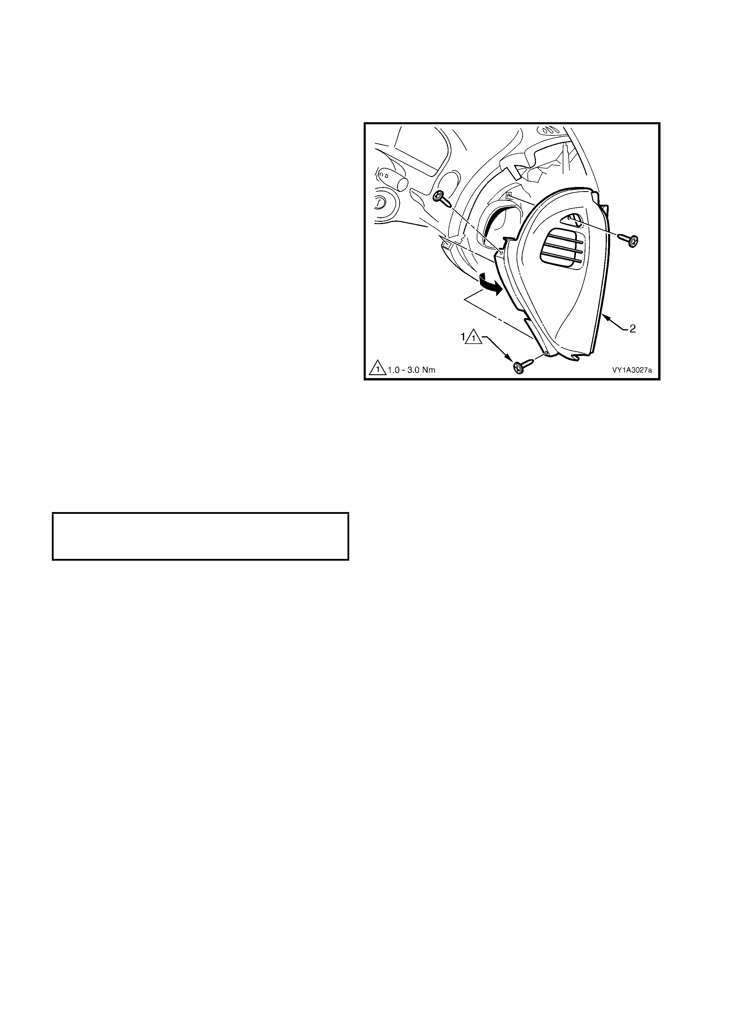
3.17 INS TRUMENT PANEL OUTER COVER
LT Section – 09-135
REMOVE
1. Remove the three screws (1) attaching the either
the right-hand (shown) or left-hand instrument
panel outer cover (2) to the instrument panel.
2. Remove the cover by rotating outward to
disengage the ventilation ducts.
Figure 1A3-51
REINSTALL
Reinstallation of the instrument panel outer cover is
the reverse of removal. Tighten the screws to the
specified torque.
NOTE: Ensure the ventilation ducts are correctly
seated and any seals are in place.
INSTRUMENT PANEL OUTER COVER
ATTACHING SCREW
TORQUE SPECIFICATION 1.0 – 3.0 Nm
3.18 WINDSHIELD DEFROSTE R GRILLE
LT Section – 09-125
1. As required, first remove the instrument panel outer cover from the appropriate side(s), refer to
3.17 INSTRUMENT PANEL OUTER COVER.
REMOVE
Referring to Figure 1A3-52:
1. Remove the screw (1) attaching each windshield defroster grille (2) to the instrument panel.
2. Carefully remove the grille by unclipping (3), four places, at an angle equal to the windshield.
NOTE: As the grille is retained securely, removal may prove difficult. If required, a hook (such as an Allen key
held with vice-grips) can be used to assist removal. Insert the hook at the inner then outer end of the vent
opening. Ensure it is hooked under the grille and not the sheetmetal below.
Figure 1A3-52
REINSTALL
Reinstallation is the reverse of removal, noting the following:
1. Ensure the remote key receiver & headlamp auto control / sunload sensor (4) is correctly seated prior to
installing the grille assembly.
2. Ensure the four clips are correctly seated prior to installing the screw.
3. Tighten the screws to the specified torque.
WI NDSHIELD DEFROSTER
GRILLE ATTACHING SCREW
TORQUE SPECIFICATION 1.0 – 3.0 Nm
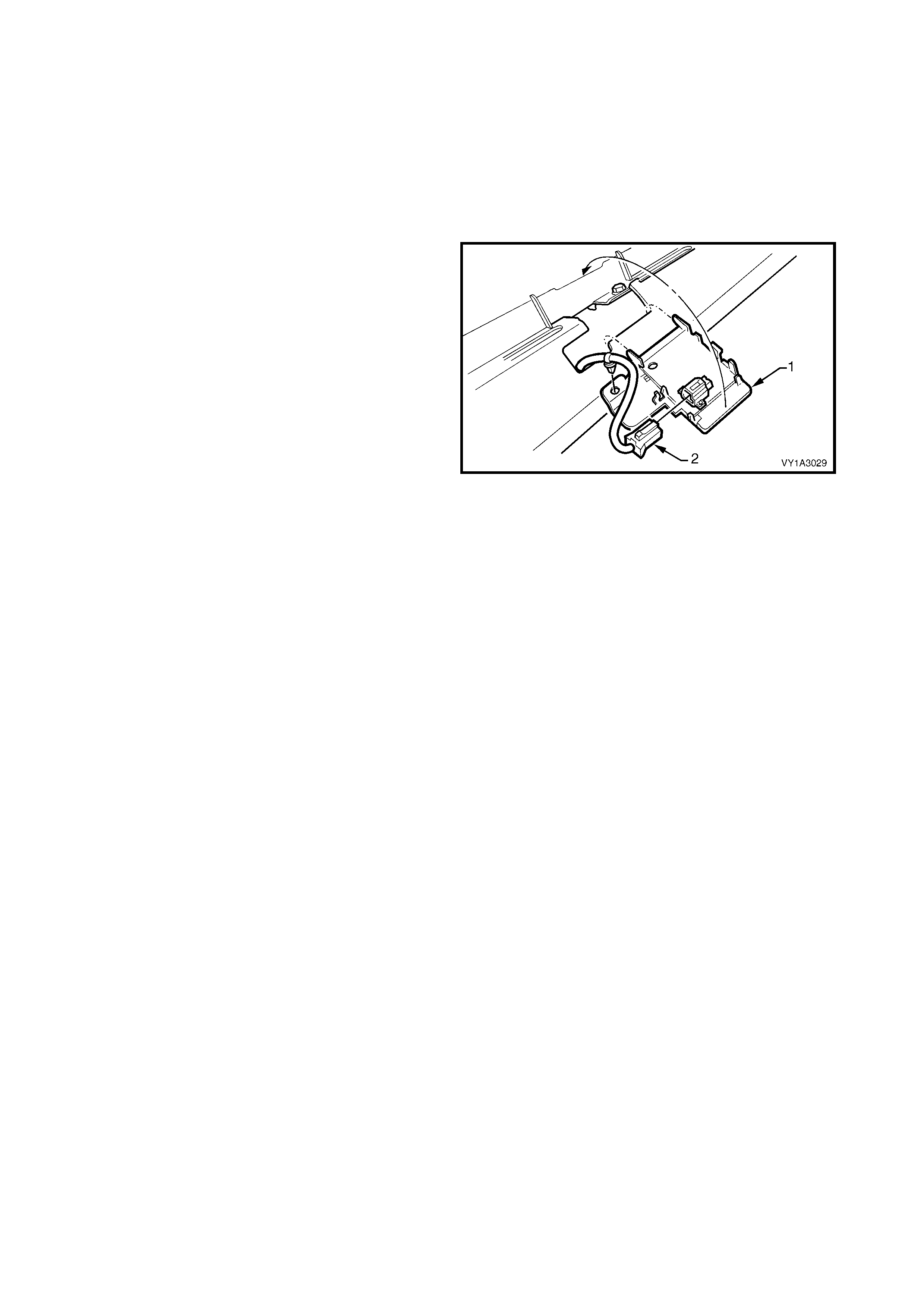
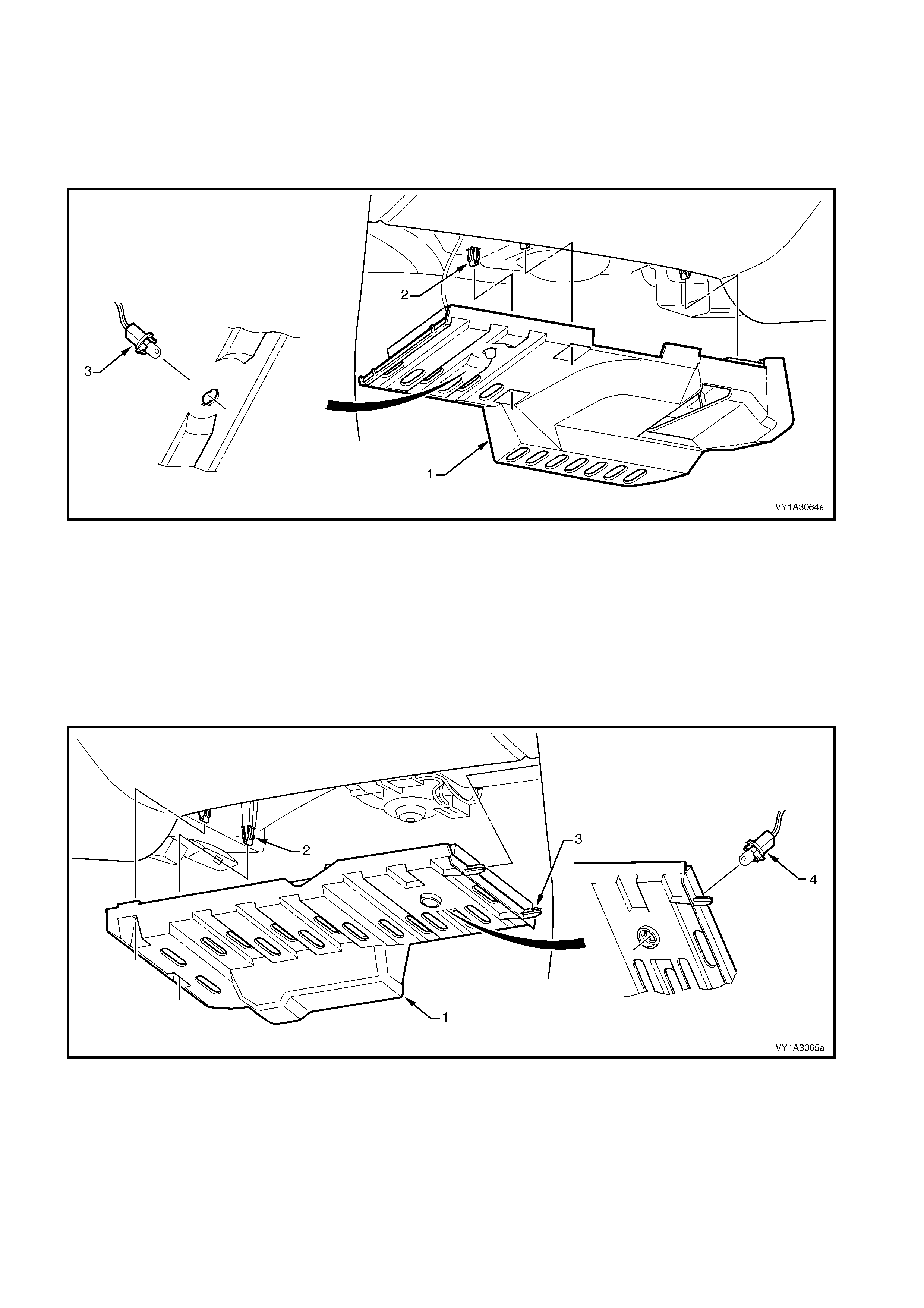
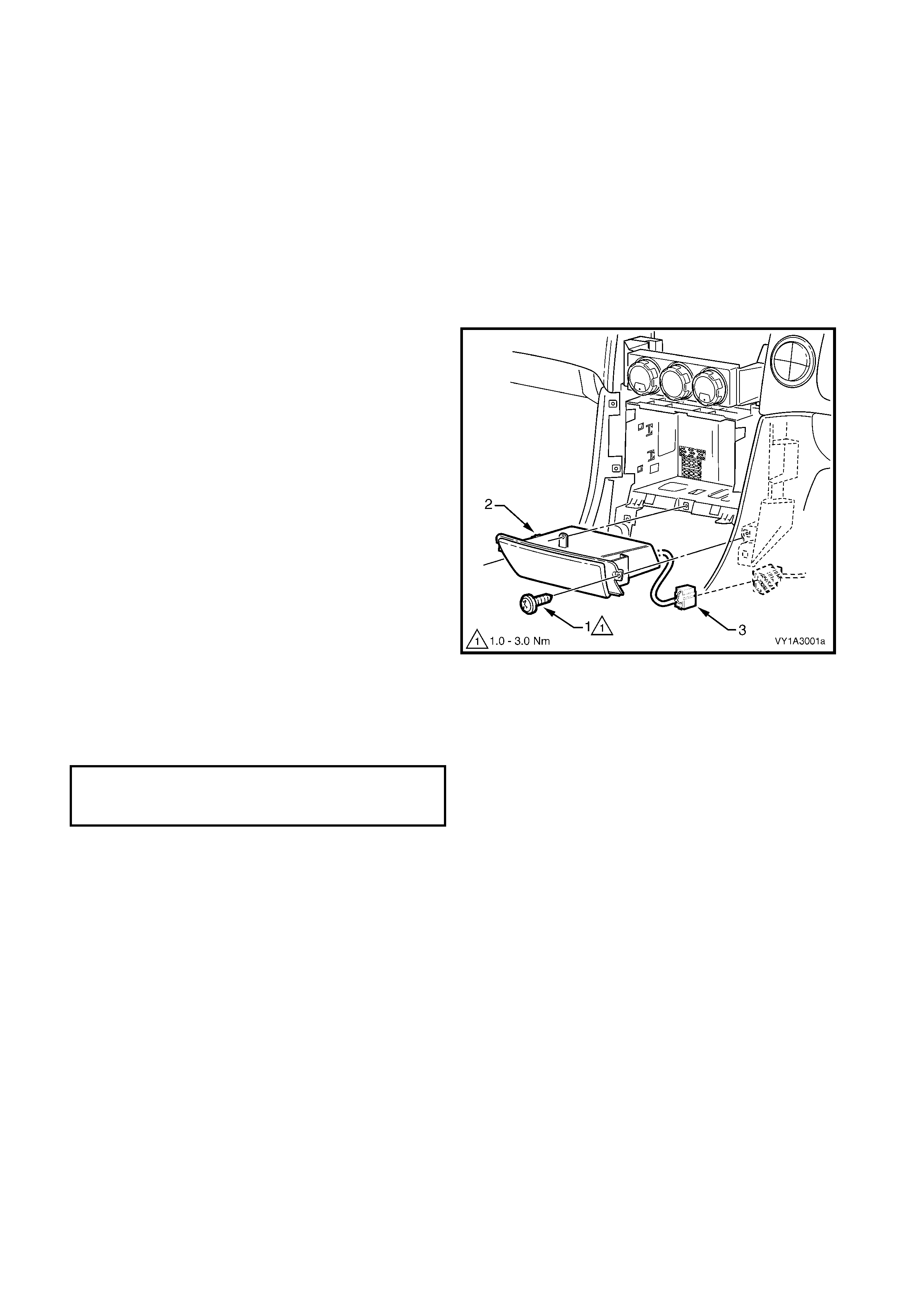
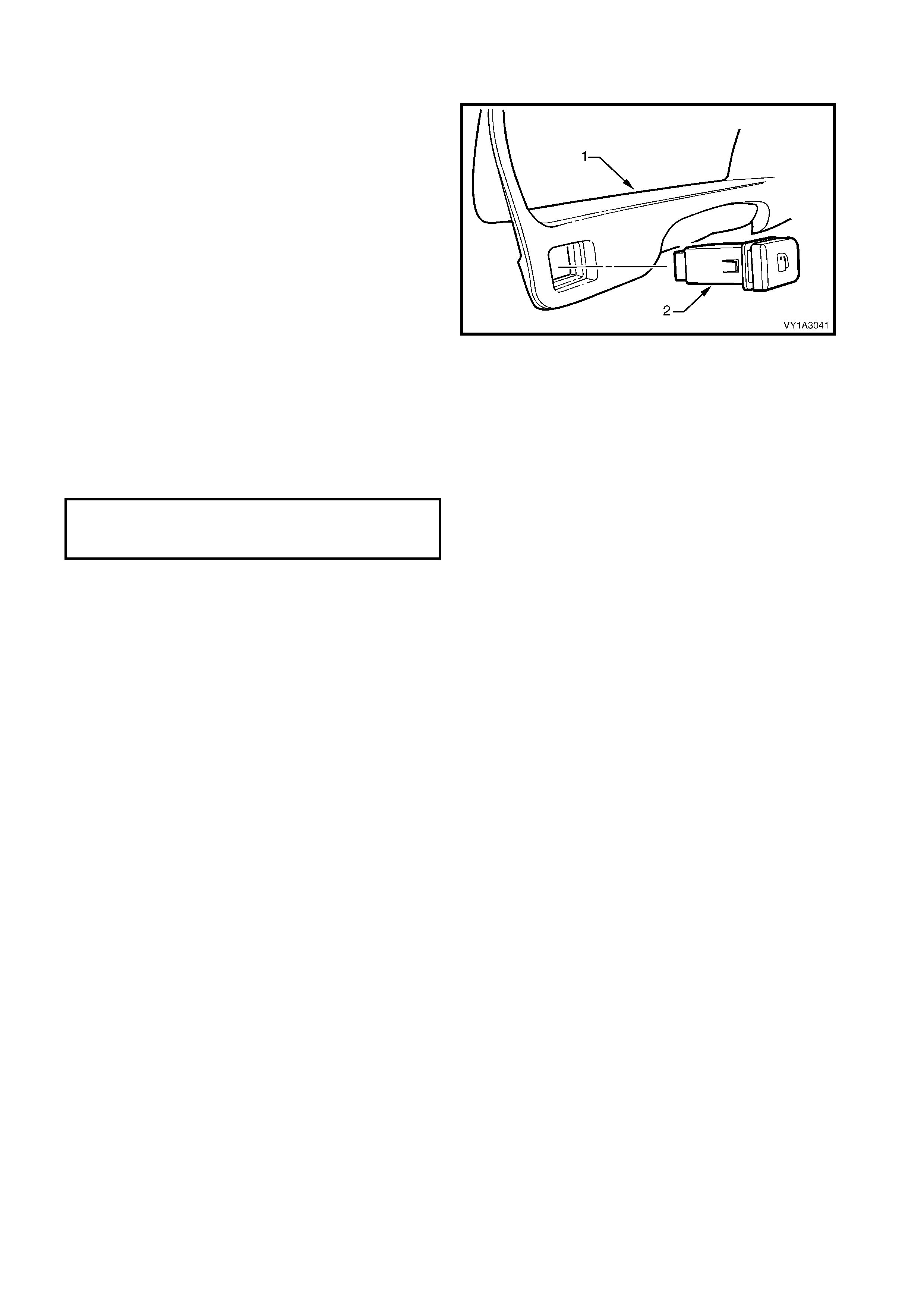
3.19 RE MOTE KEY RECEIVER & HE ADLAMP AUTO CONTROL / SUNLOAD SENSOR
LT Section – 08-155A
As required, first remove the following components:
1. Instrument panel outer cover from both sides, refer to 3.17 INSTRUMENT PA NEL OUTER COVER.
2. Windshield defroster grille assembly from both sides, refer to 3.18 WINDSHIELD DEFROSTER GRILLE
ASSEMBLY.
REMOVE
1. Carefully unclip the receiver and sensor (1) from
the instrument panel.
2. Disconnect the wiring connector (2), unclip the
wiring harness from the sensor assembly and
remove.
NOTE 1: For service and diagnosis of the remote key
receiver & headlamp auto control sensor refer to
Section 12J BODY CONTROL MODULE.
NOTE 2: For service and diagnosis of the sunload
sensor, refer to Section 2D HVAC OCCUPANT
CLIMATE CONTROL (AUTO A/C).
Figure 1A3-53
REINSTALL
Reinstallation of the sens or assem bly is the r everse of
removal.
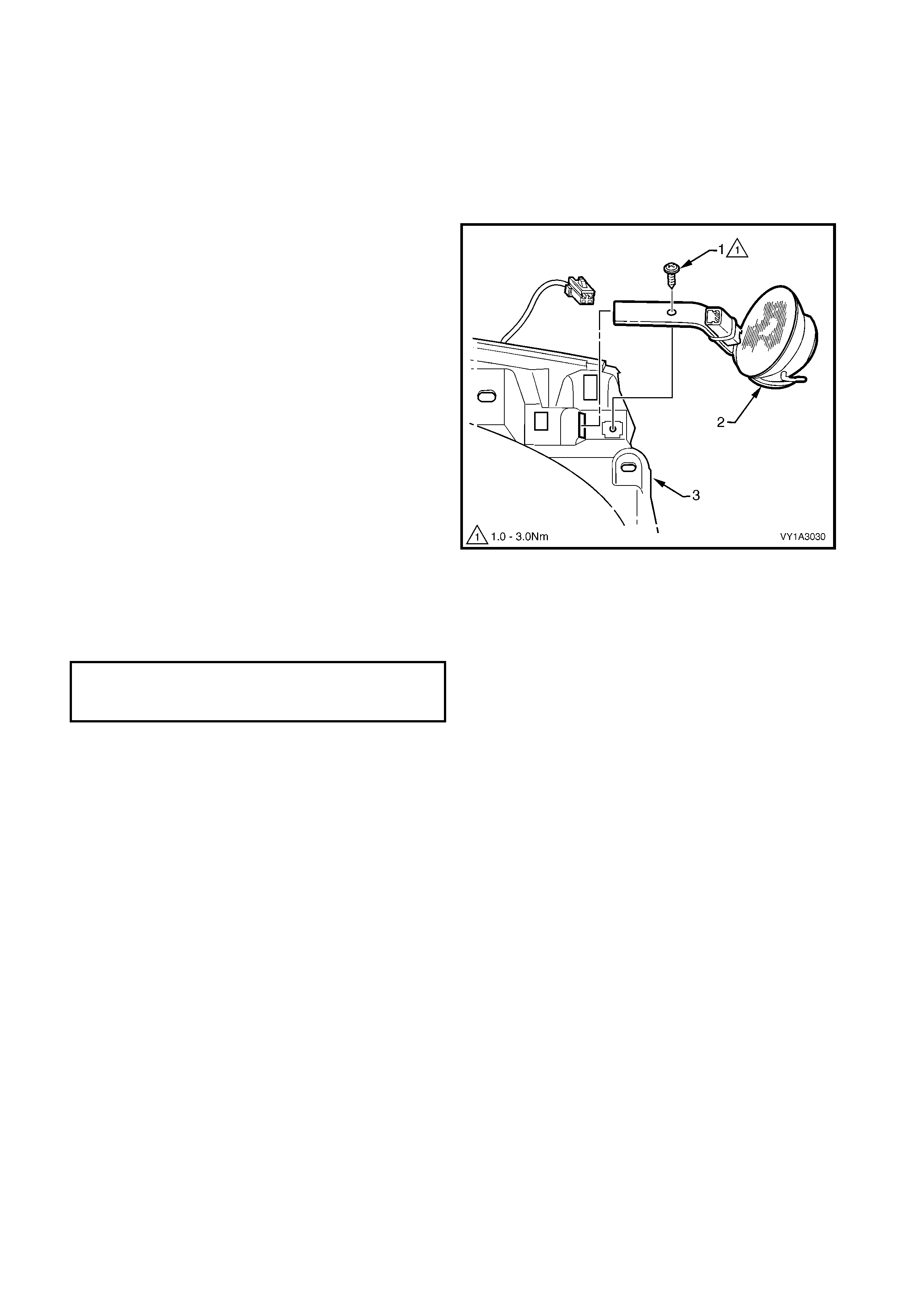
3.20 INSTRUMENT PANEL SPEAKER
LT Section – 09-500
As required, first remove the following components on the applicable side:
1. Instrument panel outer cover, refer to 3.17 INSTRUMENT PANEL OUTER COVER.
2. Windshield defroster grille assembly, refer to 3.18 WINDSHIELD DEFROSTER GRILLE ASSEMBLY.
REMOVE
1. Remove the screw (1) attaching the instrument
panel speaker (2) to the instrument panel (3).
2. Disconnect the wiring connector and remove the
speaker by withdrawing it from the slot in the
instrument panel.
NOTE: For service and diagnosis of the instrument
panel speaker refer to Section 12D
ENTERTAINMENT SYSTEM.
Figure 1A3-54
REINSTALL
Reinstallation is the reverse of removal. Tighten the
screw to the specified torque.
INSTRUMENT PANEL SPEAKER
ATTACHING SCREW
TORQUE SPECIFICATION 1.0 – 3.0 Nm

3.21 INSTRUMENT PANEL PAD ASSEMBLY
LT Section – 09-125
As required, first remove the following components:
1. Floor console assembly, refer to 2.3 FLOOR CONSOLE ASSEMBLY.
2. Driver and passenger side instrum ent panel lower trim plate assembly, refer to 3.1, INSTRUMENT PANEL
LOWER TRIM PLATE ASSEMBLY.
3. Instrument panel compartment assembly, refer to 3.2 INSTRUMENT PANEL COMPARTMENT
ASSEMBLY.
4. Instrument panel compartment lamp and instrument panel compartment lamp switch, refer to
3.3 INSTRUMENT PANEL COMPARTMENT LAMP & SWITCH.
5. Instrument panel lower trim panel, refer to 3.4 INSTRUMENT PANEL LOWER TRIM PANEL.
6. Instrument panel lower trim panel retainer, refer to 3.5 INSTRUMENT PANEL LOWER TRIM PANEL
RETAINER.
7. Radio assembly, refer to 3.6 RADIO ASSEMBLY.
8. Instrument panel centre trim assembly, refer to 3.7 INSTRUMENT PANEL CENTRE TRIM ASSEMBLY.
9. Instrument panel lower compartment or ashtray assembly, refer to 3.8 INSTRUMENT PANEL LOWER
COMPARTMENT or ASHTRAY ASSEMBLY.
10. Instrument panel lower extension, refer to 3.9 INSTRUMENT PANEL LOWER EXTENSION.
11. Manual HVAC controller, where fitted, refer to 3.10 MANUAL HVAC CONTROLLER.
12. Radio housing and radio bracket assembly, refer to 3.11 RADIO HOUSING AND RADIO BRACKET
ASSEMBLY.
13. Instrument cluster trim assembly, refer to 3.12 INSTRUMENT CLUSTER TRIM ASSEMBLY.
14. In-car air temperature sensor, if fitted, refer to 3.13 IN-CAR AIR TEMPERATURE SENSOR.
15. Instrument cluster, refer to 3.14 INSTRUMENT CLUSTER.
16. Headlamp switch, refer to 3.15 HEADLAMP SWITCH.
17. Trip Switch, refer to 3.16 TRIP SWITCH.
18. Left-hand and right-hand instrument panel outer covers, refer to 3.17 INSTRUMENT PANEL OUTER
COVER.
19. Left-hand and right-hand windshield defroster grille assemblies, refer to 3.18 WINDSHIELD DEFROSTER
GRILLE.
20. Rem ote key receiver & headlamp auto control / sunload sensor, refer to 3.19 REMOT E KEY RECIEVER &
HEADLAMP AUTO CONTROL / SUNLOAD sensor.
21. Instrument panel speaker, refer to 3.20 INSTRUMENT PANEL SPEAKER.
REMOVE
IMPORTANT: Disconnection of the battery
affects certain vehicle electronic systems. Refer to
Section 00, 5. BATTERY DISCONNECTION
PROCEDURES before disconnecting the battery.
1. Disconnect the battery.
2. Release the steering column adjustment lever (1)
and move the column to its lowest position.
3. From below the steering column, remove the
screw (2 ) attaching the lower cover (3).
NOTE: The covers can be removed with the steering
wheel installed, however it is not shown for clarity.
4. Depress the face of the lower cover inwards to
disengage the tabs (4) and lift the steering colum n
upper cover (5).
5. Raise the upper cover as high as possible to
disengage the lugs (6) and remove the cover.
6. Push the outer ring of the theft deterrent receiver
assembly (7) into the steering column lower cover.
7. Slide the lower cover rearward to disengage it from
the lugs (8) and remove the cover.
8. Remove the steering wheel inflatable restraint
module, refer to Section 12M OCCUPANT
PROTECTION SYSTEM.
NOTE: Special Tool required.
Figure 1A3-55
9. Place the road wheels in the straight-ahead
position and lock the steering column.
10. Remove the screw (1).
11. Remove the steering wheel, disconnecting and
feeding the wires through the aperture as required.
NOTE: A puller should not be required, however if the
wheel assembly cannot be removed fairly easily, use
puller J1859-A and legs E1408.
12. Check that the green indicator (2) on the inflatable
restraint module coil assembly has engaged the
inner clock spring to lock it in the central position.
Figure 1A3-56
13. Disconnect the wiring connectors from the rear of
the turn signal switch assem bly (1) and windshield
wiper & washer switch assembly.
14. Depress the two tabs (2) securing the switch and
slide from the steering column assembly. Repeat
for the other switch.
NOTE 1: For service and diagnosis of the turn signal
switch assembly refer to Section 12B LIGHTING
SYSTEM.
NOTE 2: For service and diagnosis of the windshield
wiper & washer switch assembly refer to Section 12N
WIPERS / WASHERS & HORN.
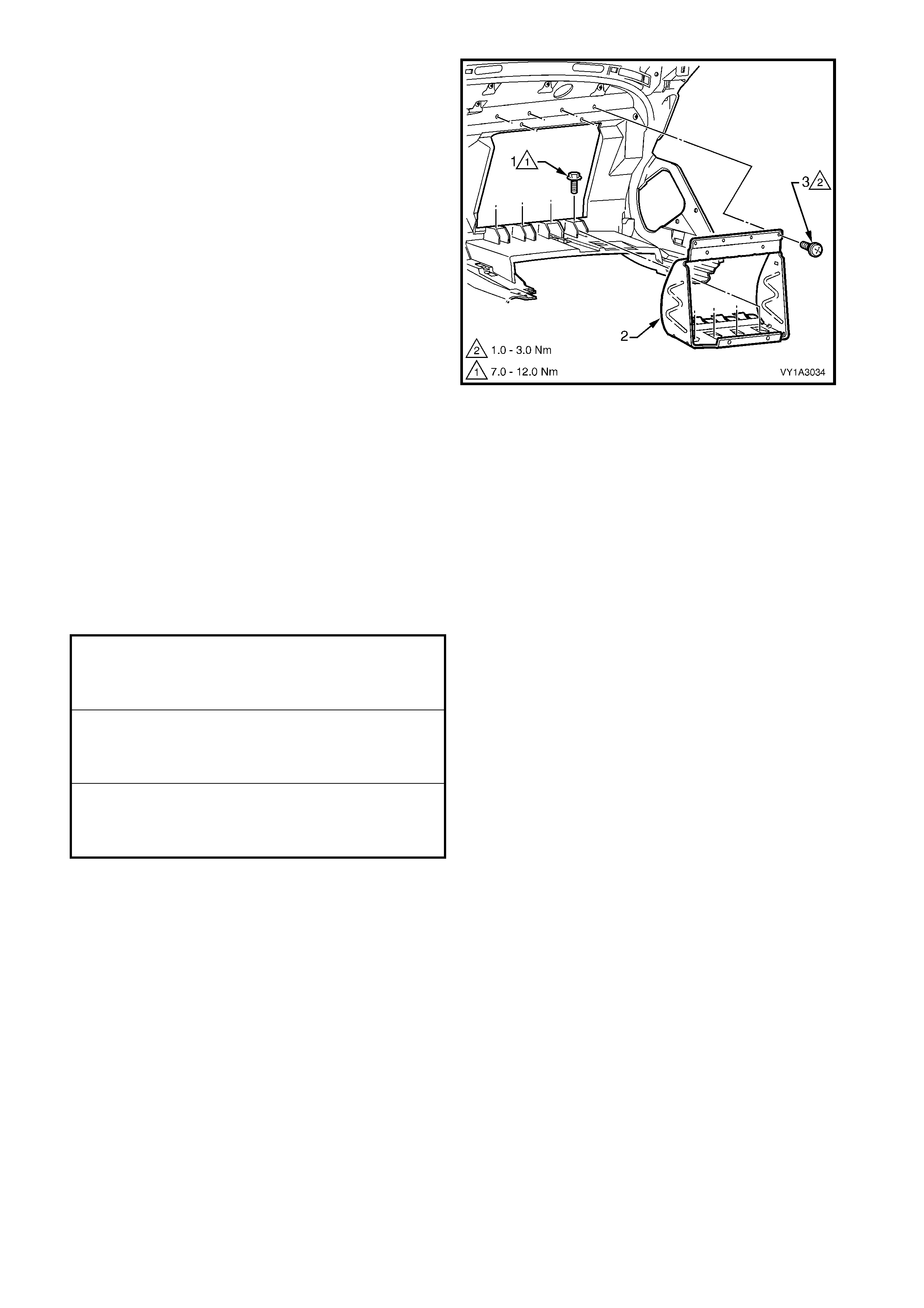
15. Remove the two inner screws (1) attaching the
instrument panel inflatable restraint (2) or
instrument panel outer upper bracket (3) and
instrument panel lower bracket (4) to the
instrument panel inflatable restraint bracket (5),
refer to Figure 1A3-58.
NOTE: View A is for vehicles with an instrum ent panel
inflatable restraint. View B is for vehicles without an
instrument panel inflatable restraint.
Figure 1A3-57
Figure 1A3-58
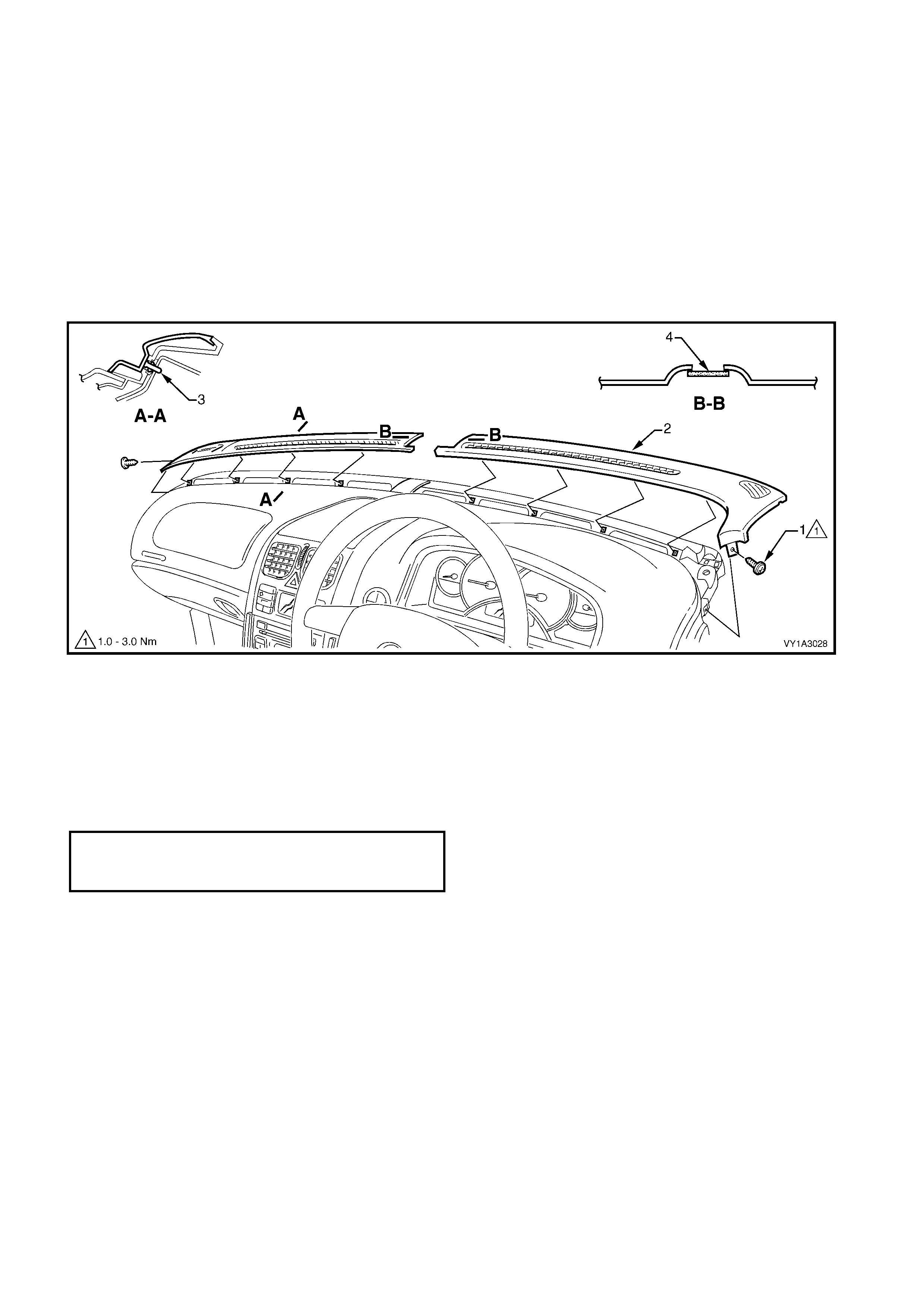
16. Referring Figure 1A3-59, remove the following screws attaching the instrument pad assembly:
a. left-hand end (1) one place,
b. to the left-hand air duct (2) one place,
c. passenger side lower (3 & 4) two places each,
d. left of centre (5) one place,
e. driver side lower (6) one place,
f. within the instrument cluster hood (7), one place,
g. to the right-hand air duct (8) one place,
h. right-hand end (9) one place,
i. along the upper edge (10), five places.
17. With the aid of an assistant, carefully lift the pad assembly out of the vehicle and place on a soft surface.

Figure 1A3-59
DISASSEMBLE
NOTE: The instrument panel pad is attached to the
carrier with screws and adhesive and is not serviced.
1. From the rear side of the instrument panel pad
assembly, remove the four screws (1) attaching
the instrument panel inflatable restraint opening
trim cover (2) to the instrument panel inflatable
restraint bracket (3).
2. While pushing on the trim cover, detach the four
tabs (4) and remove the trim cover.
Figure 1A3-60
3. From the rear side of the instrument panel pad
assembly, remove the screw (1), four places,
attaching the instrument panel inflatable restraint
bracket (2) to the pad assembly.
4. Remove the screw (3) , six places, and r emove the
bracket from the pad assembly.
Figure 1A3-61
REASSEMBLE
1. Fit the bracket in position, ensuring the lower
screw hole tabs ar e correctly positioned in the pad
assembly.
2. Install the upper and lower screws and tighten to
the specified torque.
3. Locate the trim cover in the pad assem bly opening
and align the trim cover with the four tabs.
4. Push the trim cover into position, install the four
screws and tighten to the specified torque.
INSTRUMENT PANEL INFLATABLE
RESTRAINT BRACKET LOWER
ATTACHING SCREW
TORQUE SPECIFICATION 7.0 – 12.0 Nm
INSTRUMENT PANEL INFLATABLE
RESTRAINT BRACKET UPPER
ATTACHING SCREW
TORQUE SPECIFICATION 1.0 – 3.0 Nm
INSTRUMENT PANEL INFLATABLE
RESTRAINT OPENING TRIM COVER
ATTACHING SCREW
TORQUE SPECIFICATION 7.0 – 12.0 Nm
REINSTALL
Reinstallation of the instrument panel pad assembly is
the reverse of removal noting the following:
1. Ensure the wiring connectors are located through
their correct cavity, refer to Section 12O FUSES &
WIRING HARNESS.
2. Tighten the screws to the specified torque.
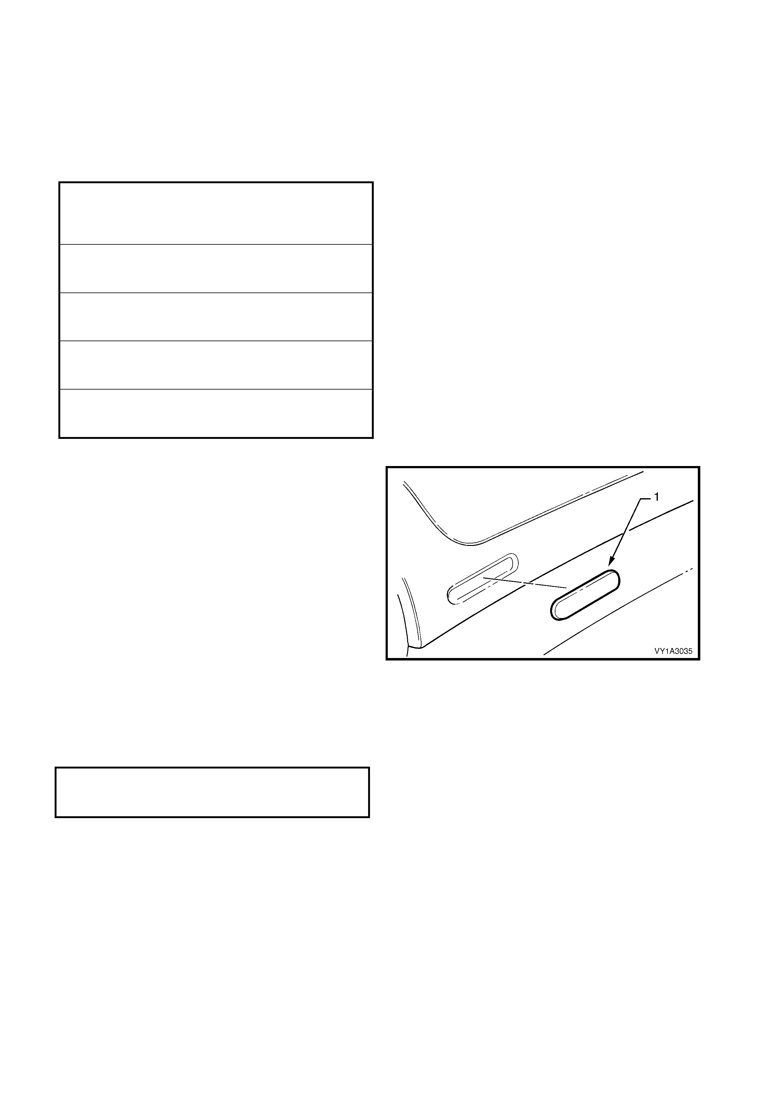
3. If a new instrument panel pad assembly is being
installed, fit a new nameplate (1). Clean the
surface with wax and grease remover such as
Prepsol or equivalent and affix the emblem
centrally in its recess.
NOTE: Press the emblem firmly for at least 10
seconds.
4. Install the windshield wiper switch assembly and
turn signal switch assembly, ensure they are
correctly seated.
5. Connect the wiring connectors to the back of the
switches and ensure the wiring is correctly routed,
refer to Section 12O FUSES & WIRING
HARNESS.
6. Install the steer ing colum n covers in the revers e of
removal. Tighten the screw to the specified torque.
NOTE: Ensure the turn signal / wiper switch boots are
seated correctly.
Figure 1A3-62
INSTRUMENT PANEL INFLATABLE
RESTRAINT TO INSTRUMENT PANEL
LOWER BRACKET SCREW
TORQUE SPECIFICATION 7.0 – 12.0 Nm
INSTRUMENT PANEL PAD ASSEMBLY
SIDE ATTACHING SCREW
TORQUE SPECIFICATION 1.0 – 3.0 Nm
INSTRUMENT PANEL PAD ASSEMBLY
TO AIR DUCT ATTACHING SCREW
TORQUE SPECIFICATION 1.0 – 3.0 Nm
INSTRUMENT PANEL PAD ASSEMBLY
LOWER ATTACHING SCREW
TORQUE SPECIFICATION 1.0 – 3.0 Nm
INSTRUMENT PANEL PAD ASSEMBLY
UPPER ATTACHING SCREW
TORQUE SPECIFICATION 7.0 – 12.0 Nm
STEERING COLUMN LOWER
COVER ATTACHING SCREW
TORQUE SPECIFICATION 0.5 – 2.0 Nm

7. Ensure the road wheels are in the straight-ahead
position and that the green indictor on the s teering
wheel inflatable restraint coil assembly is visible.
8. Install the steering wheel assembly in its correct
orientation, feeding the wires through the aperture.
9. Apply Loctite 242 or equivalent to the thread of the
steering wheel screw thread.
10. Tighten the screw to the specified torque.
11. Connect the wiring connectors as required.
12. Install the steering wheel inflatable restraint
module, refer to Section 12M OCCUPANT
PROTECTION SYSTEM.
STEERING WHEEL ASSEMBLY
ATTACHING SCREW
TORQUE SPECIFICATION 40.0 – 50.0 Nm
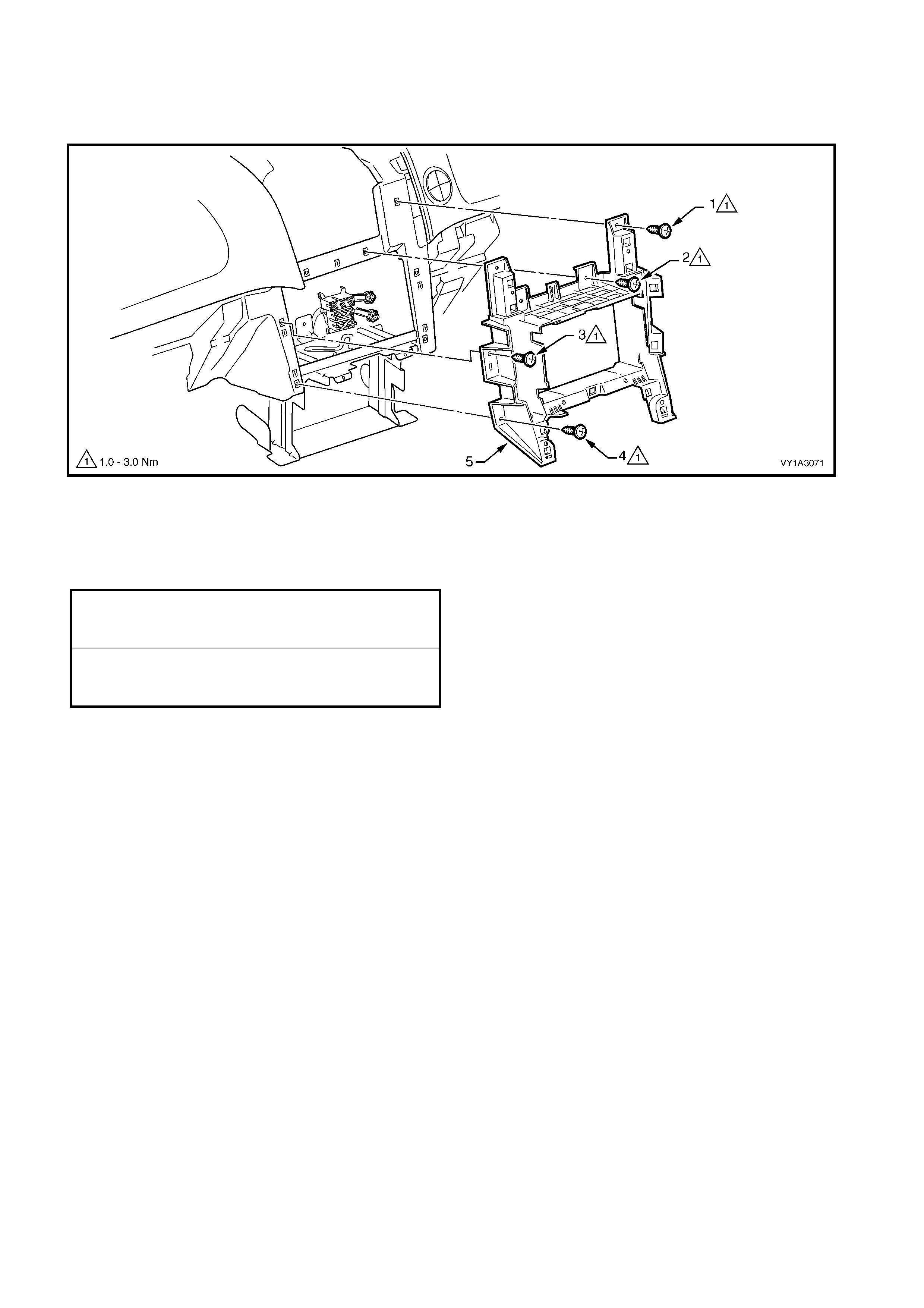
3.22 INSTRUMENT PANEL BRACKE TS & BRACES
LT Section –
Figure 1A3-63
Legend
1. Instrument Panel Compartment Bracket
2. Instrument Panel Lower Bracket
3. Instrument Panel Outer Upper Bracket
4. Lower Radio Bracket
5. Steering Column Bracket Inner Brace
6. Steering Column Bracket Outer Brace
INSTRUMENT PANEL COMPARTMENT BRACKET
REMOVE
1. Remove the instrument panel compartment, refer
to 3.2 INSTRUMENT PANEL COMPARTMENT
ASSEMBLY.
2. Remove the sc rew (1) attaching the HVAC unit (2)
to the instrument panel compartment bracket (3).
3. Remove the screw (4), two places, attaching the
bracket to the instrument panel lower bracket (5)
and remove the bracket.
4. As required, prise each instrument panel
compartment hinge (6) from the bracket.
Figure 1A3-64
REINSTALL
Reinstallation is the reverse of removal. Tighten the
screws to the specified torque.
NOTE: Take care not to over-tighten the screw
attaching the HVAC unit as the bracket can be easily
damaged.
INSTRUMENT PANEL COMPARTMENT
BRACKET ATTACHING SCREW
TORQUE SPECIFICATION 1.0 – 3.0 Nm
INSTRUMENT PANEL LOWER BRACKET
As required, first remove the following components:
1. Instrument panel pad assembly, refer to 3.21 INSTRUMENT PANEL PAD ASSEMBLY.
2. Instrument panel compartment bracket as previously described.
3. Telematics module, if fitted, refer to Section 12K TELEMATICS.
4. Navigation speaker assembly, if fitted, refer to Section 12L, 3.4 NAVIGATION SPEAKER ASSEMBLY.
REMOVE
Referring to Figure 1A3-65:
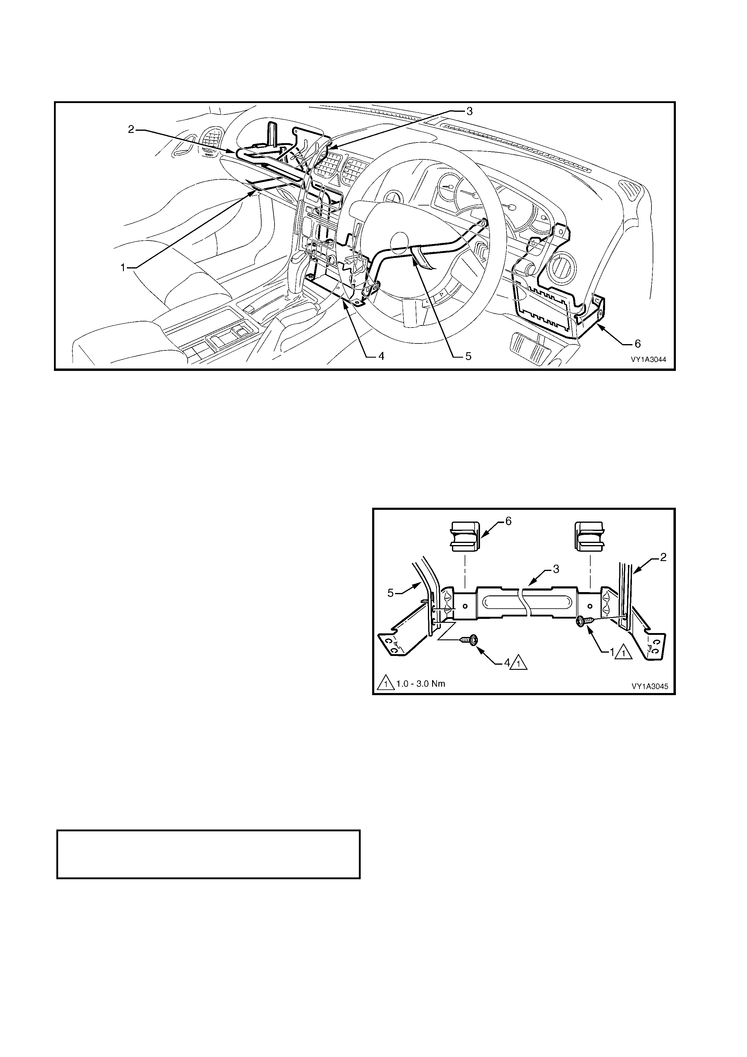
1. Remove the screws (1 & 2) attaching the
instrument panel lower bracket (3) to the lower
radio bracket.
2. Remove the screws (4 & 5) attaching the bracket
to the vehicle.
3. Remove the two screws (6) attaching the bracket
to the instrument panel inflatable restraint or
instrument panel outer upper bracket (vehicles
without instrument panel inflatable restraint),
unattach the wiring harness(s) as required and
remove the bracket.
Figure 1A3-65
REINSTALL
Reinstallation is the reverse of removal. Tighten the
screws to the specified torque.
INSTRUMENT PANEL LOWER BRACKET
ATTACHING SELF-TAPPING SCREW
TORQUE SPECIFICATION 1.0 – 3.0 Nm
INSTRUMENT PANEL LOWER
BRACKET ATTACHING SCREW
TORQUE SPECIFICATION 7.0 – 12.0 Nm
INSTRUMENT PANEL OUTER UPPER BRACKET
NOTE: The instrument panel outer upper bracket is
only fitted to vehicles without an instrument panel
inflatable restraint module.
REMOVE
1. Remove instrument panel pad assembly, refer to
3.21 INSTRUMENT PANEL PAD ASSEMBLY.
2. Remove the screw (1), two places, attaching the
instrument panel outer upper bracket (2) to the
instrument panel lower bracket.
3. Remove the nut (3), two places, attaching the
bracket to the dash panel assembly and remove
the bracket.
REINSTALL
Reinstallation is the reverse of removal. Tighten the
screws to the specified torque.
Figure 1A3-66
LOWER RADIO BRACKET
As required, first remove the following components:
1. Instrument panel pad assembly, refer to 3.21 INSTRUMENT PANEL PAD ASSEMBLY.
2. Navigation display assembly, if fitted, refer to Section 12L, 3.3 NAVIGATION DISPLAY ASSEMBLY.
REMOVE
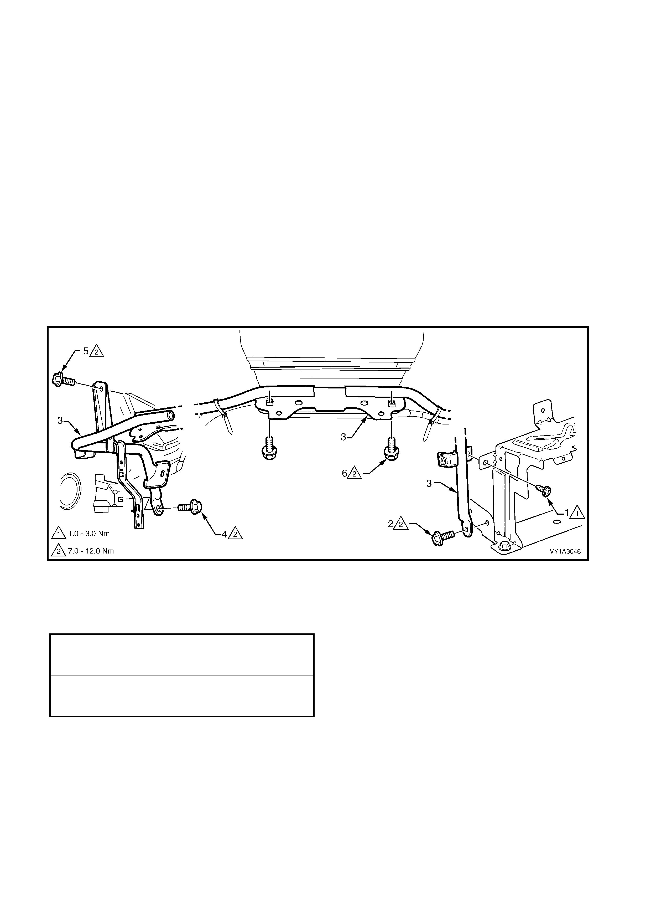
1. Withdraw the floor console front duct from the
HVAC unit.
2. Unclip the wiring connector (1) from the lower
radio bracket (2).
3. From the driver’s side, remove the screw (3),
attaching the steering column bracket inner brace
(4) to the lower bracket.
4. Remove the s cr ew (5), attac hing the HVAC unit (6)
to the bracket.
5. From the passenger side, rem ove the screws ( 7 &
8) attac hing the instrum ent panel lower brack et (9)
to the bracket.
6. Remove the screw (10), two places, attaching the
bracket to the vehicle and remove the bracket.
REINSTALL
Reinstallation is the reverse of removal. Tighten the
screws to the specified torque.
Figure 1A3-67
STEERING COLUMN BRACKET INNER
BRACE ATTACHING SCREW
TORQUE SPECIFICATION 7.0 – 12.0 Nm
HVAC UNIT ATTACHING SCREW
TORQUE SPECIFICATION 7.0 – 12.0 Nm
INSTRUMENT PANEL LOWER BRACKET
ATTACHING SELF-TAPPING SCREW
TORQUE SPECIFICATION 1.0 – 3.0 Nm
INSTRUMENT PANEL LOWER
BRACKET ATTACHING SCREW
TORQUE SPECIFICATION 7.0 – 12.0 Nm
LOWER RADIO BRACKET
ATTACHING SCREW
TORQUE SPECIFICATION 7.0 – 12.0 Nm
INSTRUMENT PANEL UPPER OUTER
BRACKET ATTACHING SCREW
TORQUE SPECIFICATION 7.0 – 12.0 Nm
INSTRUMENT PANEL UPPER OUTER
BRACKET ATTACHING NUT
TORQUE SPECIFICATION 15.0 – 25.0 Nm
STEERING COLUMN BRACKET INNER BRACE
As required, first remove the instrument panel pad assembly, refer to 3.21 INSTRUMENT PANEL PAD
ASSEMBLY.
REMOVE
1. Remove the screw (1) attaching the steering
column bracket inner brace (2) to the lower radio
bracket (3).
2. Remove the screw (4) attaching the brace to the
steering column bracket (5).
3. Remove the brace.
REINSTALL
Reinstallation is the reverse of removal. Tighten the
screws to the specified torque.
Figure 1A3-68
STEERING COLUMN BRACKET OUTER BRACE
As required remove the following components:
1. Instrument panel pad assembly, refer to 3.21 INSTRUMENT PANEL PAD ASSEMBLY.
2. Body control module, refer to Section 12J BODY CONTROL MODULE.
3. Fuse & relay block, refer to Section 12O FUSES & WIRING HARNESS.
REMOVE
1. For left-hand drive vehicles, remove the hood
primary latch release lever, refer to Section 1A4,
2.8 HOOD PRIMARY LATCH ASSEMBLY and
also remove the wiring harness connector.
2. Remove the screw (1) attaching the steering
column bracket outer brace (2) to the vehicle.
3. Remove the screw (3) attaching the brace to the
steering column bracket.
4. Remove the screw (4) attaching the brace to the
dash panel and remove the brace.
REINSTALL
Reinstallation is the reverse of removal. Tighten the
screws to the specified torque.
Figure 1A3-69
STEERING COLUMN BRACKET
INNER BRACE ATTACHING SCREW
TORQUE SPECIFICATION 7.0 – 12.0 Nm
STEERING COLUMN BRACKET
OUTER BRACE ATTACHING SCREW
TORQUE SPECIFICATION 7.0 – 12.0 Nm

4. TORQUE WRENCH SPECIFICATIONS
Mobile phone compartment assembly screw.............................................................. 1.0 – 3.0 Nm
Floor console cover assembly screw.......................................................................... 1.0 – 3.0 Nm
Instrument panel lower extension side trim screw...................................................... 1.0 – 3.0 Nm
Floor console rear compartment screw ...................................................................... 1.0 – 3.0 Nm
Floor console rear air duct screw................................................................................ 1.0 – 3.0 Nm
Floor console rear air outlet housing assembly screw................................................ 1.0 – 3.0 Nm
Floor console rear upper compartment assembly screw............................................ 1.0 – 3.0 Nm
Floor console compartment armrest hinge screw....................................................... 1.0 – 3.0 Nm
Floor console compartment armrest inner screw........................................................ 1.0 – 3.0 Nm
Floor Console screw ................................................................................................... 1.0 – 3.0 Nm
Floor console nut......................................................................................................... 1.0 – 3.0 Nm
Floor console to automatic transmission selector assembly screw............................ 1.0 – 3.0 Nm
Instrument panel compartment latch assembly screw................................................ 1.0 – 3.0 Nm
Instrument panel compartment door screw ................................................................ 1.0 – 3.0 Nm
Instrument panel compartment lock striker screw ...................................................... 1.0 – 3.0 Nm
Data link connector screw........................................................................................... 1.0 – 3.0 Nm
Instrument panel lower trim panel retainer screw....................................................... 1.0 – 3.0 Nm
Instrument panel cup holder assembly screw............................................................. 1.0 – 3.0 Nm
OCC control module screw......................................................................................... 1.0 – 3.0 Nm
Instrument panel centre air outlet housing assembly screw....................................... 1.0 – 3.0 Nm
Instrument panel centre trim assembly screw............................................................. 1.0 – 3.0 Nm
Instrument panel lower compartment or ashtray assembly screw.............................. 1.0 – 3.0 Nm
Instrument panel lower extension side trim screw...................................................... 1.0 – 3.0 Nm
Manual HVAC controller screw................................................................................... 1.0 – 3.0 Nm
Radio bracket assembly screw................................................................................... 1.0 – 3.0 Nm
Radio housing screw................................................................................................... 1.0 – 3.0 Nm
Instrument cluster trim assembly screw...................................................................... 1.0 – 3.0 Nm
In-car air temperature sensor screw........................................................................... 1.0 – 3.0 Nm
Instrument cluster screw............................................................................................. 1.0 – 3.0 Nm
Instrument panel outer cover screw............................................................................ 1.0 – 3.0 Nm
Windshield defroster grille screw................................................................................ 1.0 – 3.0 Nm
Instrument panel speaker screw................................................................................. 1.0 – 3.0 Nm
Instrument panel inflatable restraint bracket lower screw........................................... 7.0 – 12.0 Nm
Instrument panel inflatable restraint bracket upper screw.......................................... 1.0 – 3.0 Nm
Instrument panel inflatable restraint opening trim cover screw................................... 7.0 – 12.0 Nm
Instrument panel inflatable restraint to instrument panel lower bracket screw........... 7.0 – 12.0 Nm
Instrument panel pad assembly side screw................................................................ 1.0 – 3.0 Nm
Instrument panel pad assembly to air duct screw....................................................... 1.0 – 3.0 Nm
Instrument panel pad assembly lower screw.............................................................. 1.0 – 3.0 Nm
Instrument panel pad assembly upper screw ............................................................. 7.0 – 12.0 Nm
Steering column lower cover screw............................................................................ 0.5 – 2.0 Nm
Steering wheel assembly screw.................................................................................. 40.0 – 50.0 Nm
Instrument panel compartment bracket screw............................................................ 1.0 – 3.0 Nm
Instrument panel lower bracket self-tapping screw..................................................... 1.0 – 3.0 Nm
Instrument panel lower bracket screw ........................................................................ 7.0 – 12.0 Nm
Instrument panel upper outer bracket screw............................................................... 7.0 – 12.0 Nm
Instrument panel upper outer bracket nut................................................................... 15.0 – 25.0 Nm
Steering column bracket inner brace screw................................................................ 7.0 – 12.0 Nm
HVAC unit to lower radio bracket screw...................................................................... 7.0 – 12.0 Nm
Instrument panel lower bracket self-tapping screw..................................................... 1.0 – 3.0 Nm
Instrument panel lower bracket screw ........................................................................ 7.0 – 12.0 Nm
Lower radio bracket screw.......................................................................................... 7.0 – 12.0 Nm
Steering column bracket inner brace screw................................................................ 7.0 – 12.0 Nm
Steering column bracket outer brace screw................................................................ 7.0 – 12.0 Nm
5. SPECIAL TOOLS
TOOL NUMBER ILLUSTRATION DESCRIPTION TOOL
CLASIFICATION
KM6067 RADIO REMOVAL TOOL
Used for removing VY audio unit
from its mounting location.
New tool for VY.
Mandatory
– ACCESSORY SOCKET REMOVAL
TOOL
Modified commercially available
external circlip pliers. Used for
removing the floor console
accessory power socket from its
retaining bezel.
Refer to 2.3 FLOOR CONSOLE
ASSEMBLY
Dealer Fabricated