
SECTION 1A4 - HOOD, REAR COMPARTMENT LID,
LIFTGATE & ENDGATE
IMPORTANT
Before perfo rming any Service O peration or oth er procedu re described in t his Sectio n, refer to Section 00
CAUTIONS AND NOTES for correct workshop practices with regard to safety and/or property damage.
CONTENTS
1. GENERAL DESCRIPTION
2. SERVICE OPERATIONS – HOOD
2.1 HOOD FRONT MOULDING ASSEMBLY
REMOVE
REINSTALL
2.2 HOOD SECONDARY LATCH
ASSEMBLY
REMOVE
REINSTALL
2.3 HOOD PRIMARY LATCH STRIKER
ASSEMBLY
REMOVE
REINSTALL
2.4 HOOD INSULATOR
REMOVE
REINSTALL
2.5 UNDER-HOOD LAMP ASSEMBLY
REMOVE
REINSTALL
2.6 HOOD STRUT ASSEMBLY
REMOVE
REINSTALL
2.7 HOOD & HINGE ASSEMBLIES
REMOVE
REINSTALL
ADJUST
2.8 HOOD PRIMARY LATCH ASSEMBLY
HOOD PRIMARY LATCH SPRING
HOOD PRIMARY LATCH RELEASE CABLE
ASSEMBLY, RHD
HOOD PRIMARY LATCH RELEASE CABLE
ASSEMBLY, LHD
3. SERVICE OPERATIONS – REAR
COMPARTMENT
3.1 REAR COMPARTMENT LID CARPET
REMOVE
REINSTALL
3.2 REAR COMPARTMENT LID APPLIQUE
ASSEMBLY, SEDAN
REMOVE
DISASSEMBLE
REINSTALL
3.3 REAR COMPARTMENT LID APPLIQUE
ASSEMBLY, COUPE
REMOVE
DISASSEMBLE
REINSTALL
3.4 REAR SPOILER ASSEMBLY
REMOVE
DISASSEMBLE
REINSTALL
3.5 REAR COMPARTMENT LID LATCH
ASSEMBLY
REMOVE
REINSTALL
3.6 REAR COMPARTMENT LID ACTUATOR
ASSEMBLY
REMOVE
REINSTALL
3.7 REAR COMPARTMENT LID RELEASE
CABLE ASSEMBLY
REMOVE
REINSTALL
3.8 REAR COMPARTMENT LID STRUT
ASSEMBLY
REMOVE
REINSTALL
3.9 REAR COMPARTMENT LID ASSEMBLY
REMOVE
REINSTALL
ADJUST
3.10 REAR COMPARTMENT LID HINGE
ASSEMBLY
REMOVE
REINSTALL
3.11 REAR COMPARTMENT LID STRIKER
ASSEMBLY
REMOVE
REINSTALL
3.12 REAR COMPARTMENT LID WEATHERSTRIP
REMOVE
REINSTALL
4. SERVICE OPERATIONS – LIFTGATE, WAGON
4.1 LIFTGATE WINDOW LOWER GARNISH
REMOVE
REINSTALL
4.2 LIFTGATE LOWER TRIM PANEL
REMOVE
REINSTALL
4.3 LIFTGATE INSIDE HANDLE
REMOVE
REINSTALL
4.4 LIFTGATE WINDOW UPPER GARNISH
REMOVE
REINSTALL
4.5 LIFTGATE HANDLE ASSEMBLY
REMOVE
DISASSEMBLE
REINSTALL
4.6 LIFTGATE HANDLE PUSH BUTTON
ASSEMBLY
REMOVE
DISASSEMBLE
REASSEMBLE
REINSTALL
4.7 LIFTGATE LATCH ASSEMBLY
REMOVE
REINSTALL
Techline
Techline

4.8 LIFTGATE ACTUATOR ASSEMBLY
REMOVE
REINSTALL
4.9 LIFTGATE AIR DEFLECTOR ASSEMBLY
REMOVE
REINSTALL
4.10 REAR WINDOW WIPER ASSEMBLY
REMOVE
REINSTALL
4.11 REAR WINDOW WASHER NOZZLE &
HOSE ASSEMBLIES
REMOVE
REINSTALL
4.12 HIGH MOUNT STOP LAMP ASSEMBLY
REMOVE
REINSTALL
4.13 LIFTGATE STRUT ASSEMBLY
REMOVE
REINSTALL
4.14 LIFTGATE ASSEMBLY
REMOVE
DISASSEMBLE
REINSTALL
ADJUST
4.15 LIFTGATE STRIKER ASSEMBLY
ADJUST
REMOVE
REINSTALL
4.16 LIFTGATE WEATHERSTRIP
REMOVE
REINSTALL
5. SERVICE OPERATIONS – ENDGATE, UTILITY
5.1 ENDGATE INNER PANEL ACCESS
HOLE COVER
REMOVE
REINSTALL
5.2 ENDGATE LOCK ANCHOR PLATE ASSEMBLY
REMOVE
REINSTALL
5.3 ENDGATE LATCH ASSEMBLY &
ENDGATE LATCH BRACKET ASSEMBLY
REMOVE
REINSTALL
5.4 ENDGATE STRIKER & ENDGATE
CABLE ASSEMBLY
REMOVE
REINSTALL
5.5 ENDGATE UPPER MOULDING ASSEMBLY
REMOVE
REINSTALL
5.6 ENDGATE ASSEMBLY
REMOVE
REINSTALL
ADJUST
5.7 ENDGATE HINGE ASSEMBLY
REMOVE
REINSTALL
5.8 ENDGATE WEATHERSTRIP
REMOVE
REINSTALL
6. TORQUE WRENCH SPECIFICATIONS

1. GENERAL DESCRIPTION
This Section describes the service procedures for the hood assembly, rear compartment lid assembly fitted to
Sedan & Coupe, the liftgate ass embly fitted to W agon and the endgate assem bly f itted to Utility. T o aid the user of
this m anual, associated c omponents previously located in other Sections, suc h as the rear spoiler s, etc. have been
integrated into this Section.
Sedan, Wagon and Utility models share a common hood that features new styling. Domestic Model Level 3 vehicles
feature a hood front moulding that integrates with the radiator grille when the hood is closed. Minor changes have
been made to the hinges to accommodate the new plenum cover.
For Coupe, the hood carries-over from V2 Series 1 and other than minor styling changes, from a servicing
perspective, is the same as Sedan, Wagon and Utility vehicles.
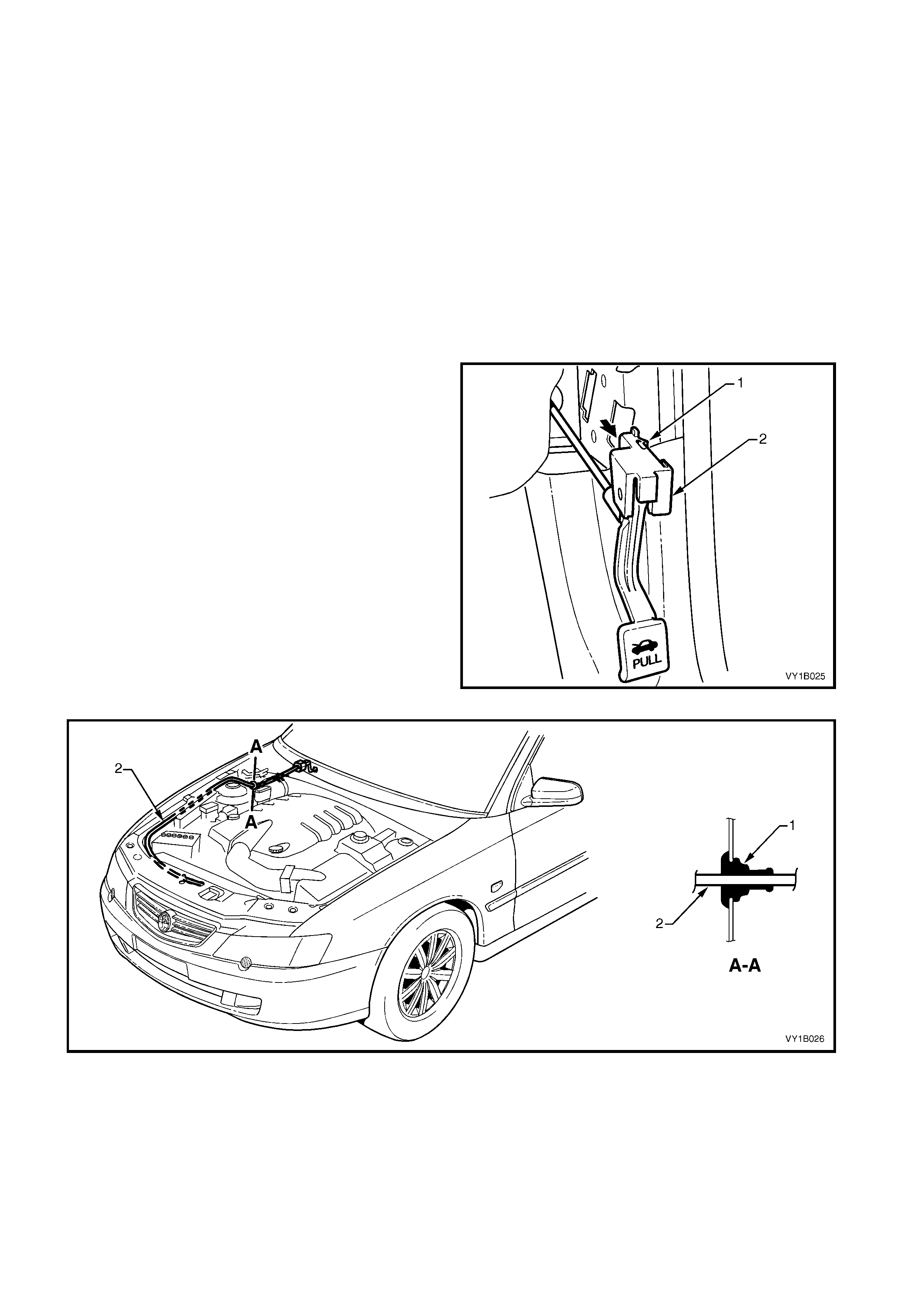
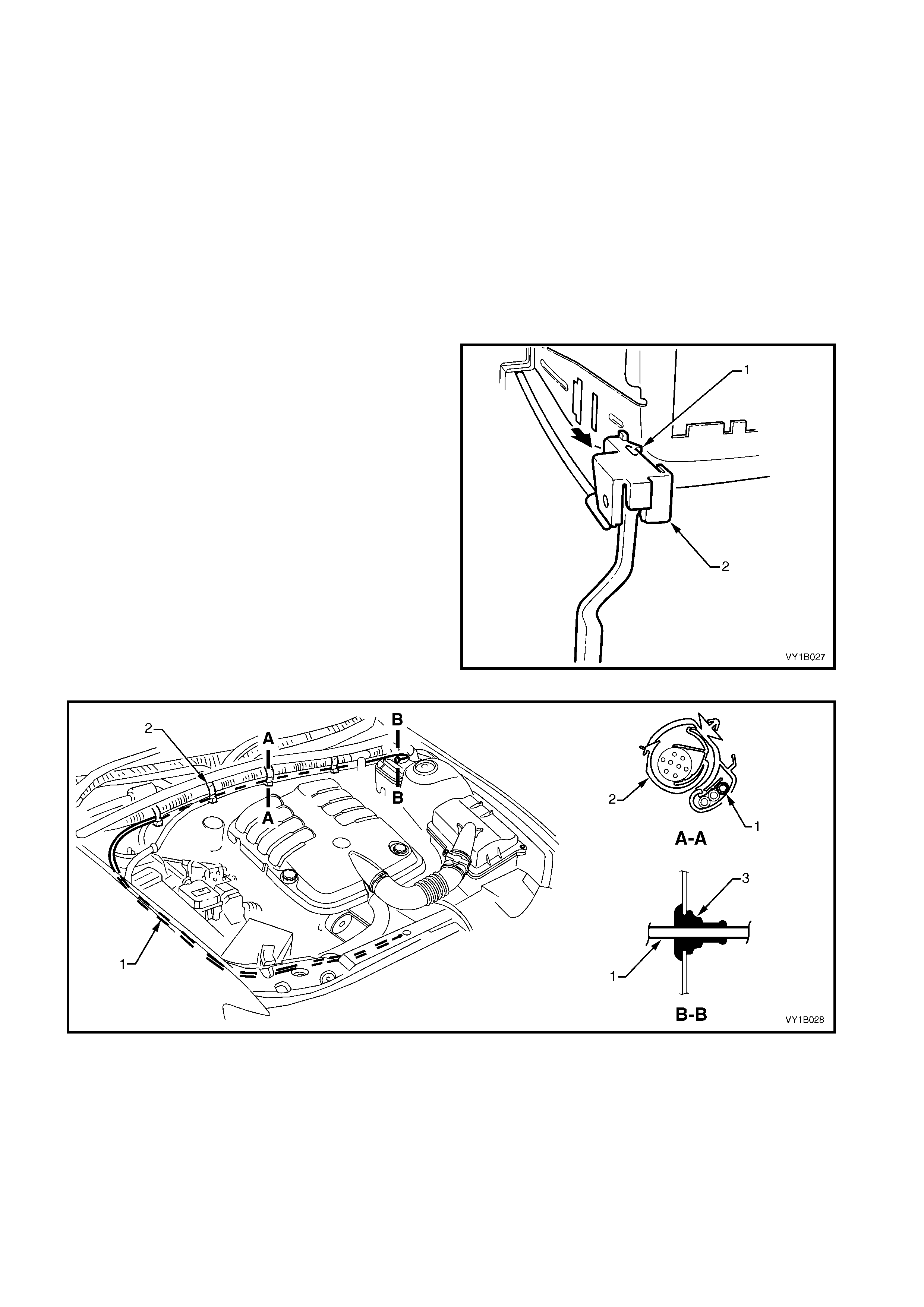
The hood release mechanism is common to all models and utilises a cable and lever arrangement. The release
lever is located below the driver’s side end of the instrument panel. For left-hand drive vehicles, the routing of the
cable extends from the right-hand to left-hand side of the engine compartment, across the dash panel assembly.
As with the hood, the rear compartment lid and attaching parts for Coupe are carry-over. A completely new rear
compartment lid is fitted to Sedan, which features new styling and a new applique assembly. Hinges carry-over.
Depending on model level, one of two styles of spoiler assemblies may be fitted. Both incorporate a high-mount
stop lamp.
The rear com partment lid latc h assem bly is operated by an actuator, which is controlled by a release switch located
in the instrument panel compartment, or by a button on the ignition key. A rear compartment lid release cable is
fitted to provide entry to the rear compartment in the event of power failure. A handle that operates the release is
accessible from behind the rear seat centre for Sedan or under the RH rear seat headrest for Coupe.
The lif tgate f or Wagon and endgate for utility are carry-over, with a few minor changes. T he liftgate latch is operated
via the pus h-button, which is part of the handle assem bly. Loc king is provided through the vehic le’s central lock ing
system or manually with the key.
2. SERVICE OPERATIONS – HOOD
2.1 HOOD FRONT MOULDING ASSEMBLY
LT Section No. -
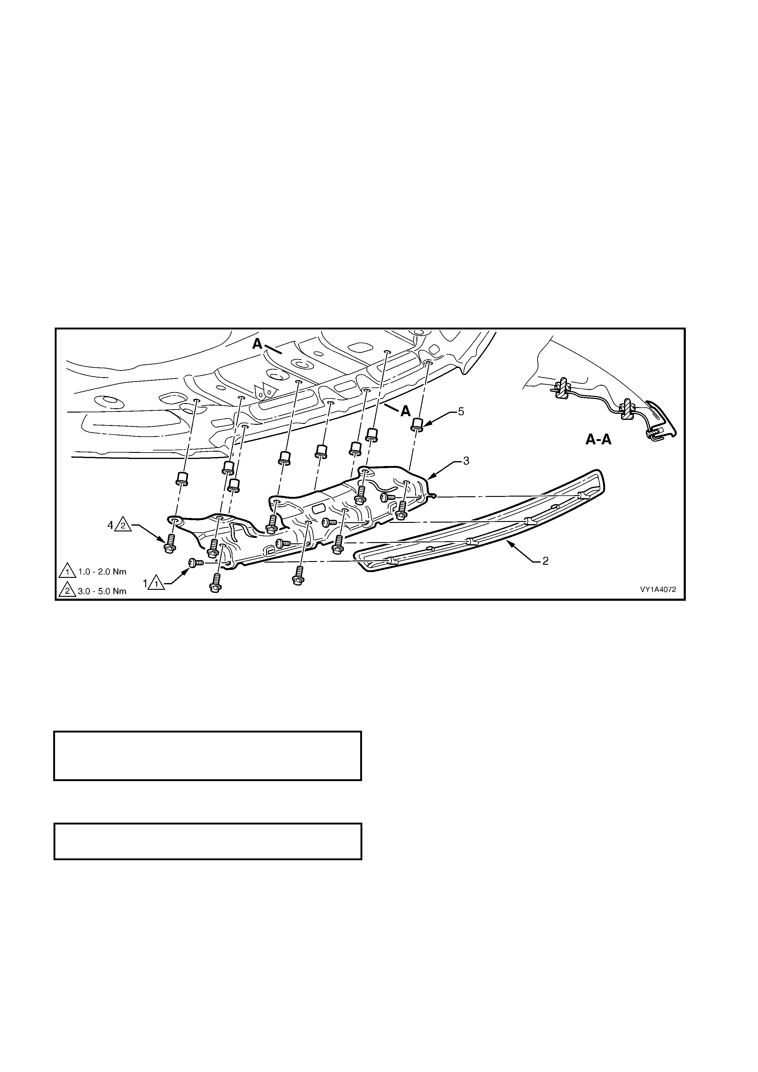
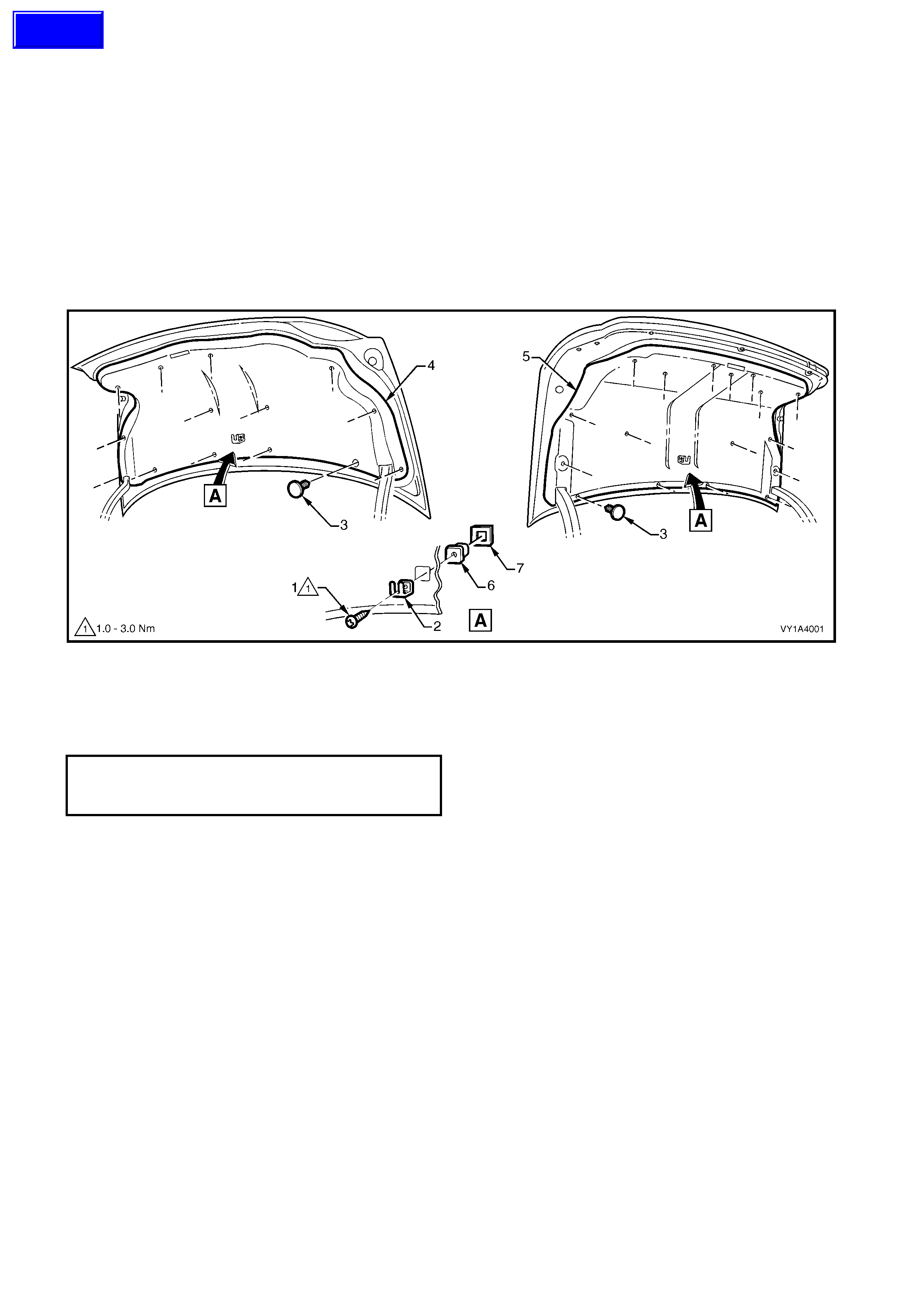
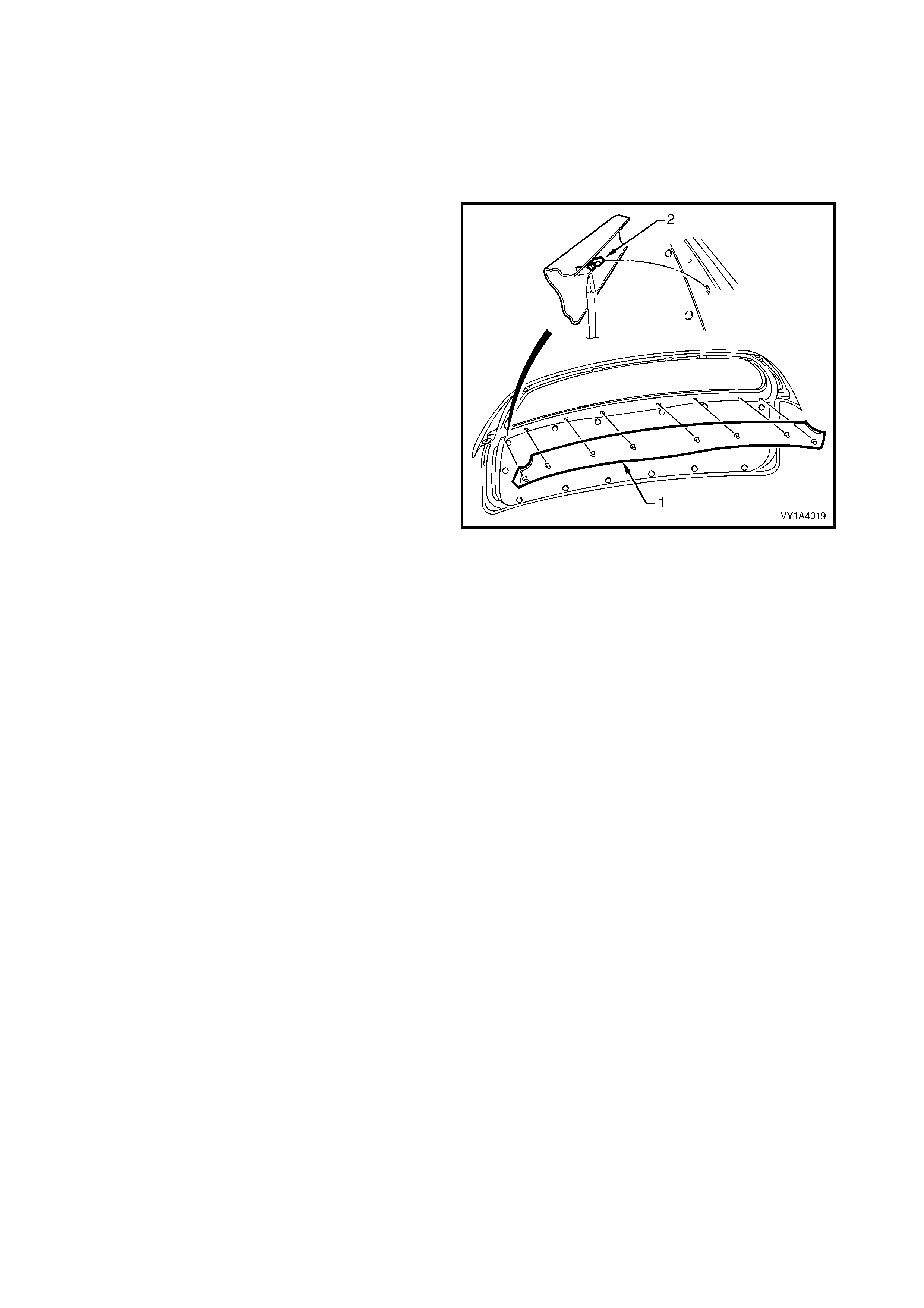
The hood front moulding assembly is fitted to domestic Model Level 3 vehicles and consists of the hood
moulding (1) and mounting bracket (2), refer to Figure 1A4-1. The following procedure describes removing the
parts sequentially, however if required the assembly can be removed from the hood with the moulding still
attached.
REMOVE
1. Raise the hood.
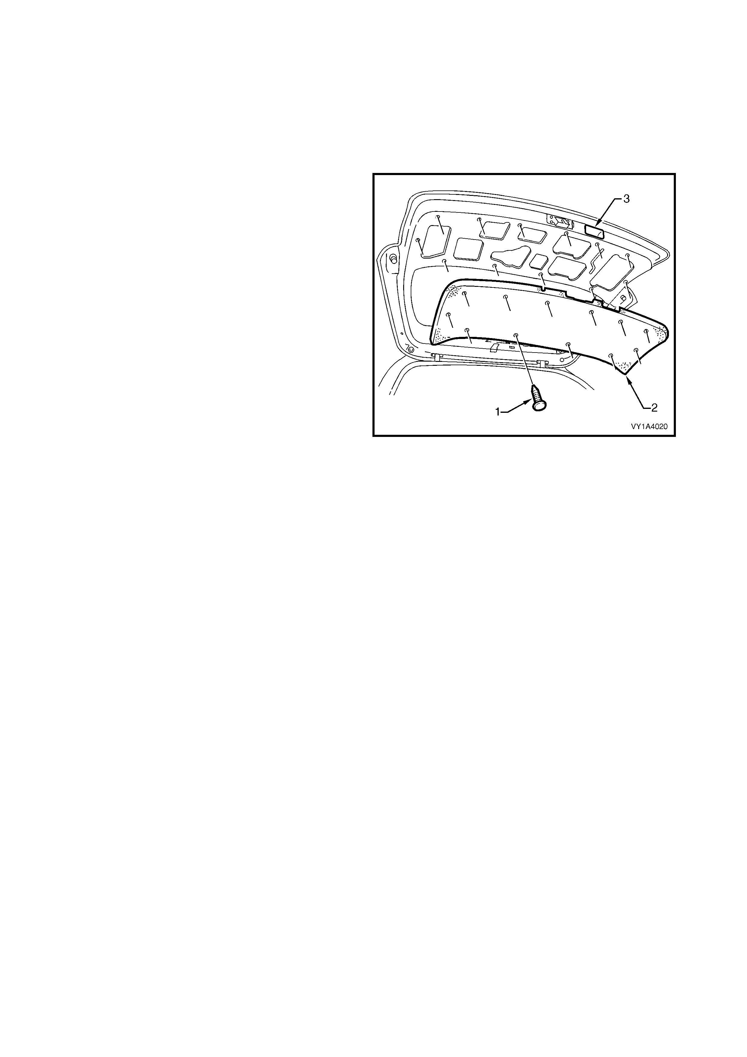
2. Remove the three screws (1) attaching the front moulding (2) to the mounting bracket (3), refer to Figure
1A4-1.
3. Unclip the moulding from the mounting bracket and remove.
4. Remove the eight screws (4) attaching the mounting bracket to the hood inner panel and remove the
bracket.
Figure 1A4-1
REINSTALL
1. If a new hood has been fitted, install eight M5 Nutserts (5) into the holes in the hood inner panel, using a
commercially available Nutsert gun, refer to Figure 1A4-1.
IMPORTANT: Use the correct Nutserts for this application. Some generic Nutserts may not be suitable.
2. Fit the mounting bracket and start the eight screws. Tighten to the specified torque.
3. Clip the moulding onto the mounting bracket, fit the three screws and tighten to the specified torque.
HOOD MOULDING MOUNTING
BRACKET SCREW
TORQUE SPECIFICATION 3.0 – 5.0 Nm
HOOD MOULDING ATTACHING SCREW
TORQUE SPECIFICATION 1.0 – 2.0 Nm
2.2 HOOD SECONDARY LATCH ASSEMBLY
LT Section No. – 12-050
REMOVE
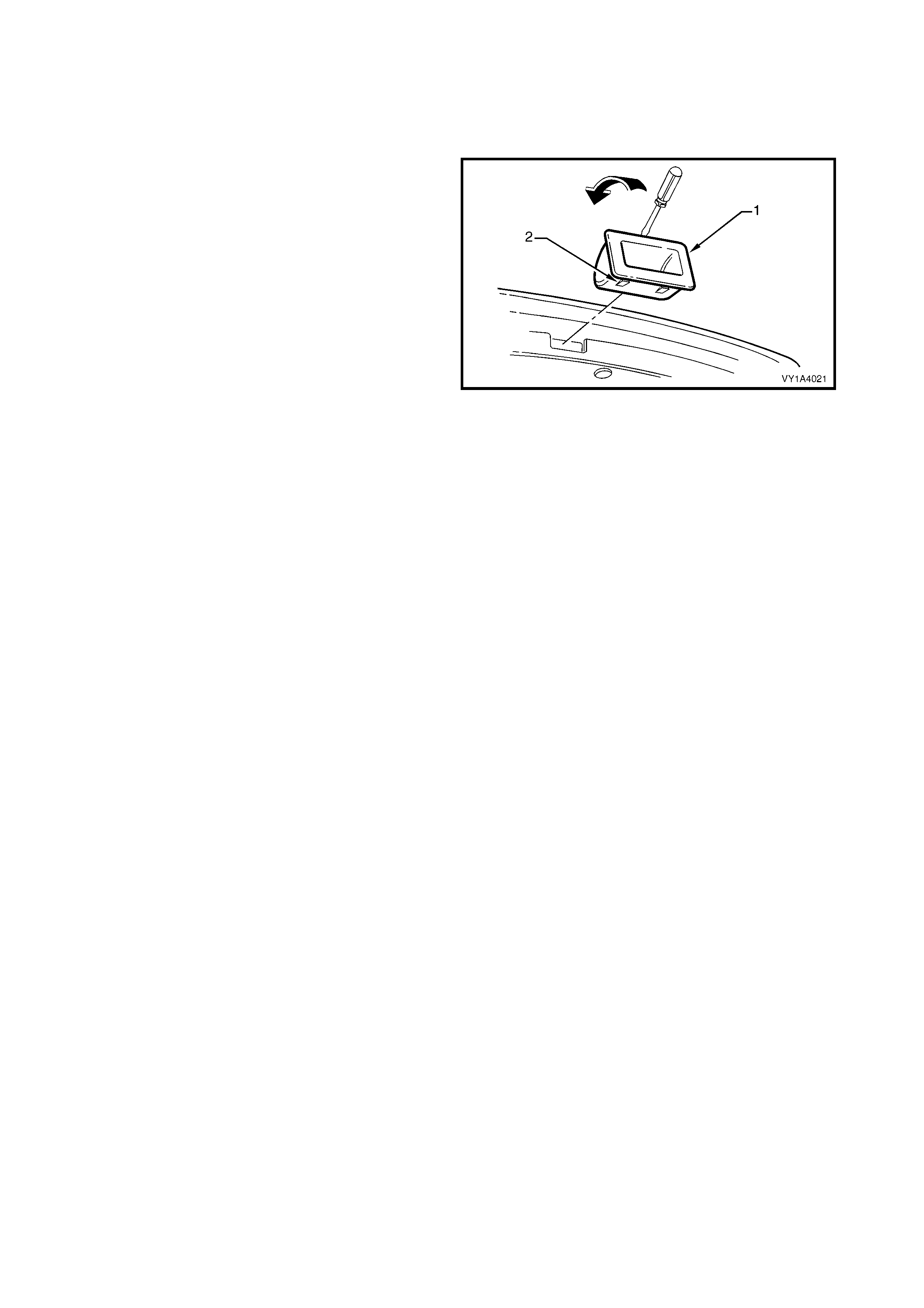
1. Raise the hood.
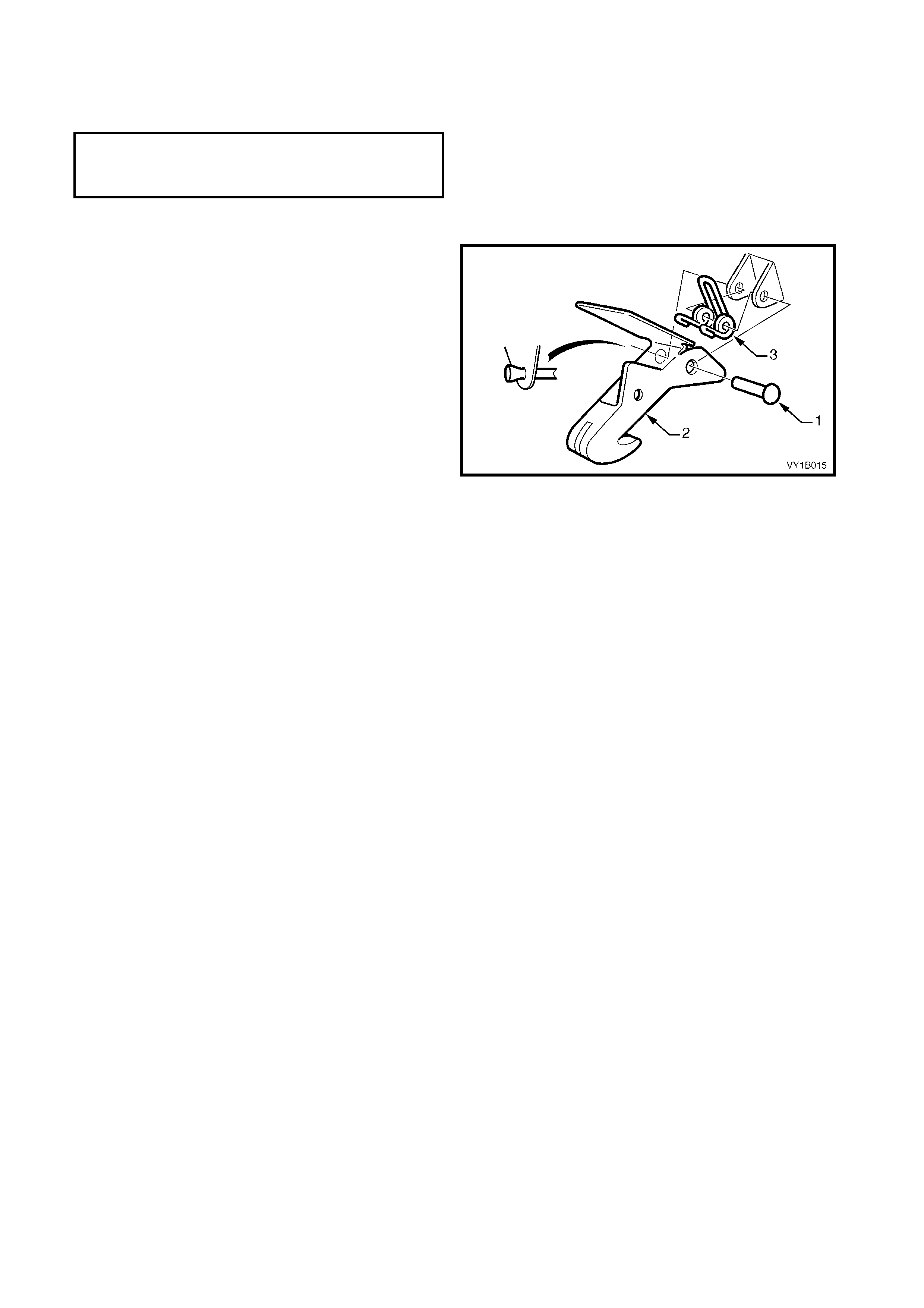
2. Carefully cut the end of the secondary latch rivet
(1) securing the hood secondary latch (2) and
hood secondary latch spring (3) to the hood
assembly.
NOTE: Take care not to damage the paintwork.
3. Using a pin punc h, extract the rivet, also rem oving
the latch and spring.
Figure 1A4-2
REINSTALL
1. Assemble the spring in the latch ensuring it is
correctly orientated, refer to Figure 1A4-2.
2. While holding the latch and spring in position on
the hood, insert a new rivet.
NOTE: Lubricate the rivet prior to assembly with NLGI
No. 1 lithium grease or equivalent.
3. Crimp the rivet end to secure it in place.
4. Test the secondary latch operation.
N
O
TE: The
f
ollowing component WILL RE
Q
UIRE
REPLACEMENT when performing this operation.
§ Secondary latch rivet.
2.3 HOOD PRIMARY LATCH STRIKER ASSEMBLY
LT Section No. – 12-050
REMOVE
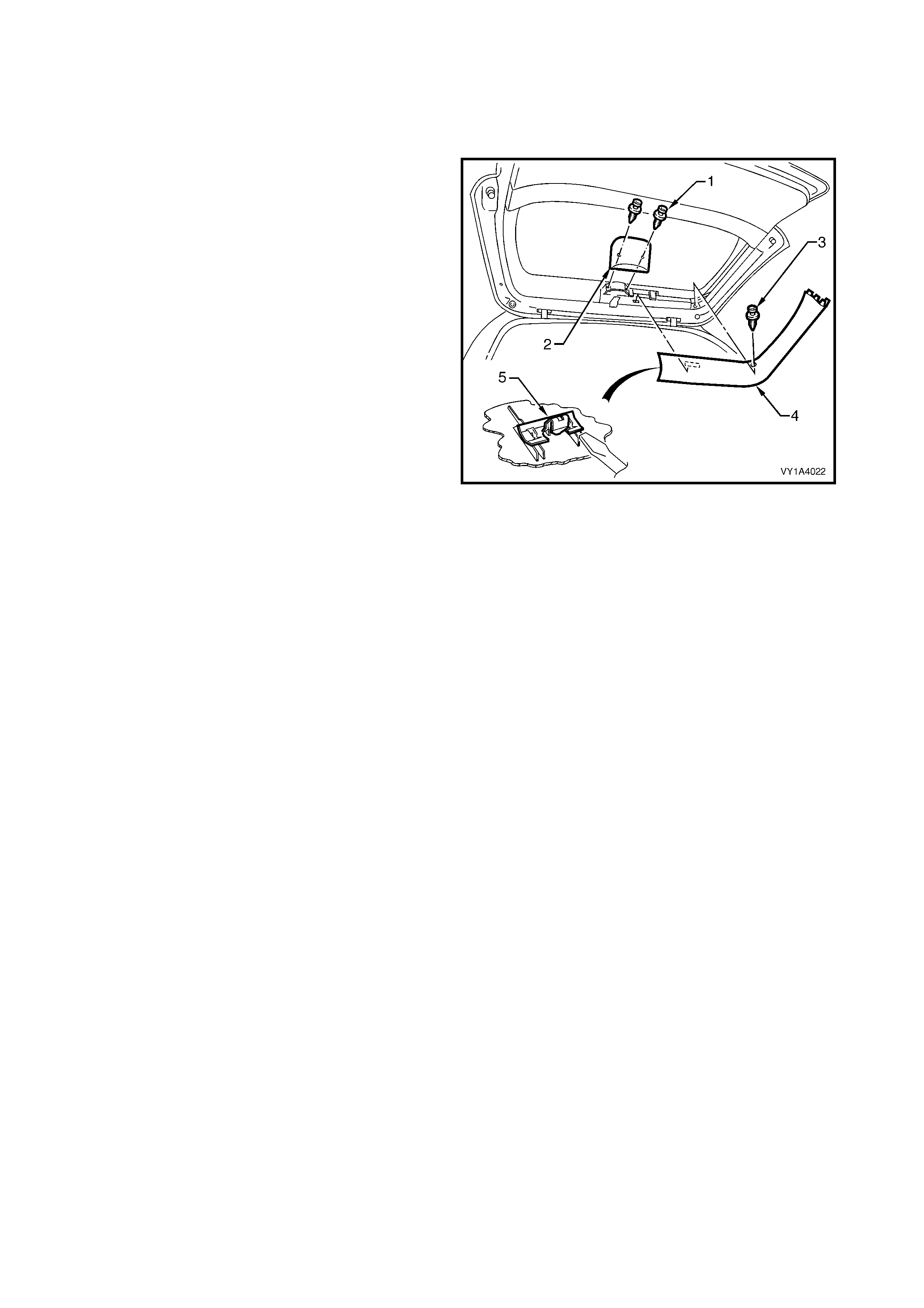
1. Raise the hood.
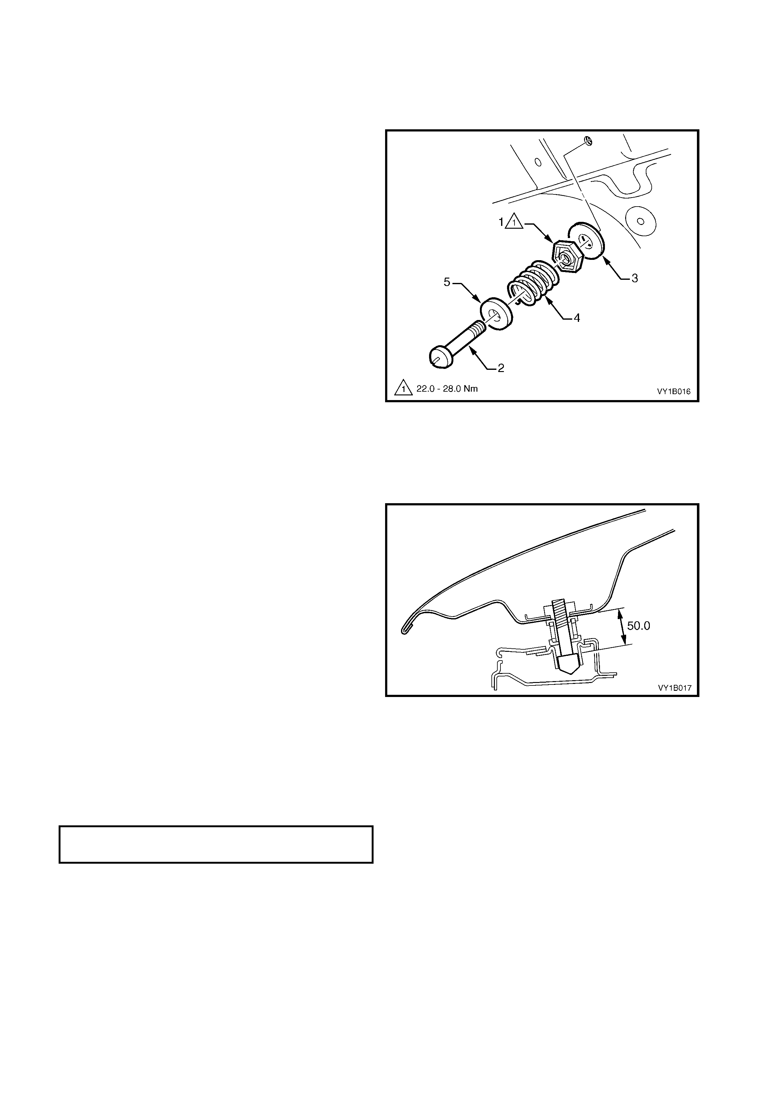
2. Loosen the hood primary latch striker nut (1).
3. Using a flat-blade screwdriver, unscrew the hood
primary latch striker bolt (2) ensuring the washer
(3) hood pop-up spring ( 4) and hood pop- up spr ing
retainer (5) remain on the bolt.
4. If required, secure the nut in a vice and
disassemble the components.
Figure 1A4-3
REINSTALL
1. Secure the hood primary latch striker nut in a vice
and assemble the components in their correct
order, refer to Figure 1A4-3.
2. Install the latch striker assembly on the hood and
tighten the bolt to achieve a nominal length of 50
mm.
3. Apply lubricant to the end of the bolt such as NLGI
No. 1 lithium grease or equivalent.
4. Close the hood by dropping from a height of
approximately 300 mm.
IMPORTANT: Do not push the hood closed as
damage to the panel surface may occur. If it doesn’t
close on the first attempt, try again from a slightly
greater height.
5. Check the height difference between the front of
the hood and fenders.
6. Open the hood and adjust the latch striker
assembly length by loosening and holding the nut
while rotating the bolt with a flat-blade screwdriver.
NOTE: As requir ed also set the hood adj ust bum per to
align the hood height.
7. Tighten the nut to the specified torque.
Figure 1A4-4
HOOD PRIMARY LATCH STRIKER NUT
TORQUE SPECIFICATION 22.0 – 28.0 Nm
2.4 HOOD INSULATOR
LT Section – 12-050
REMOVE
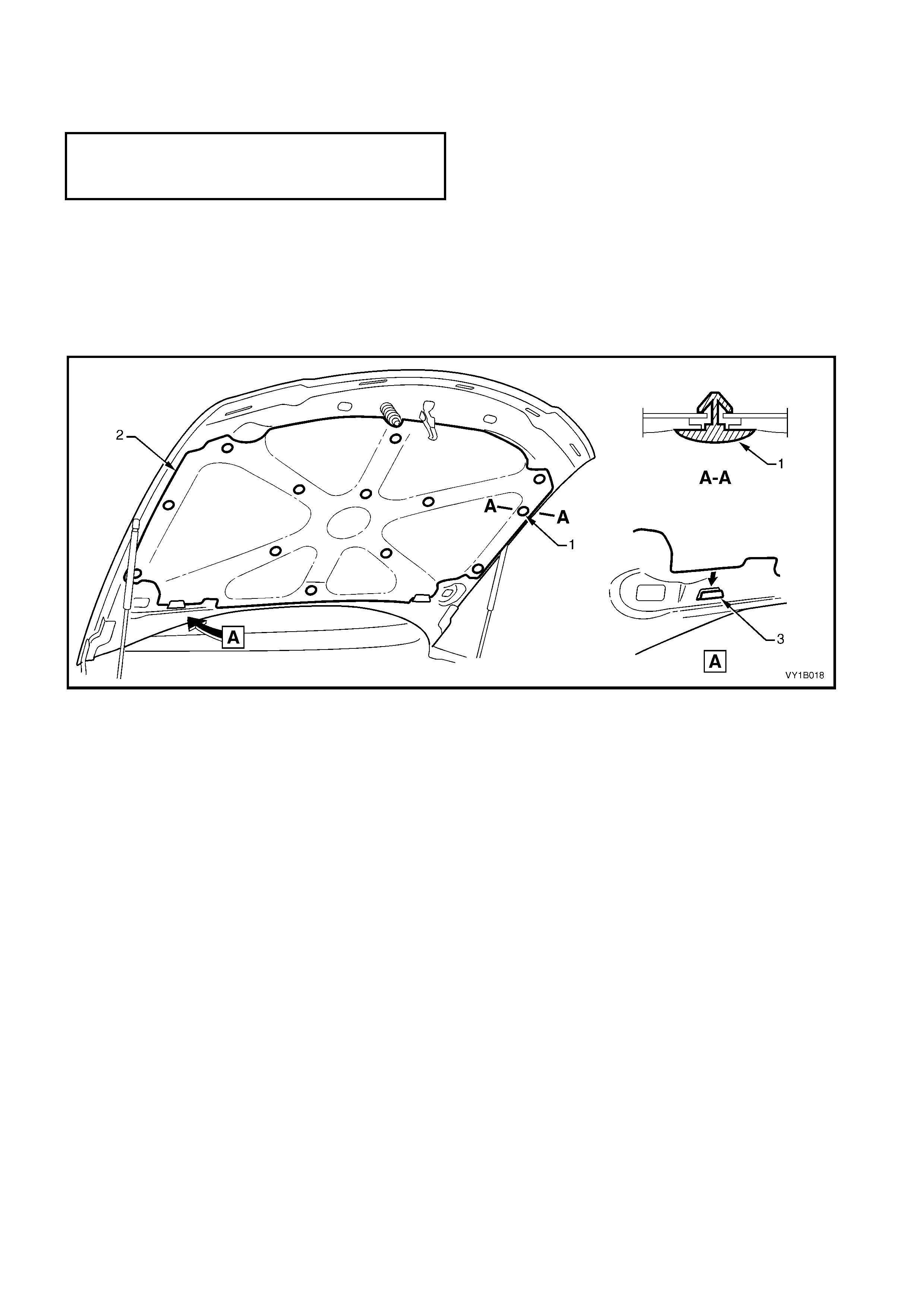
1. Raise the hood.
2. Beginning at the rear of the hood and working toward the front, remove the hood insulator retainer (1), 13
places, attaching the hood insulator (2) to the hood assembly, refer to Figure 1A4-5.
NOTE: Take care not to crush or damage the insulator.
3. Slide the insulator from the slots (3) in the hood inner panel and remove.
Figure 1A4-5
REINSTALL
Reinstallation is the reverse of removal.
N
O
TE: The
f
ollowing components MAY RE
Q
UIRE
REPLACEMENT when performing this operation.
§ Hood insulator retainer.
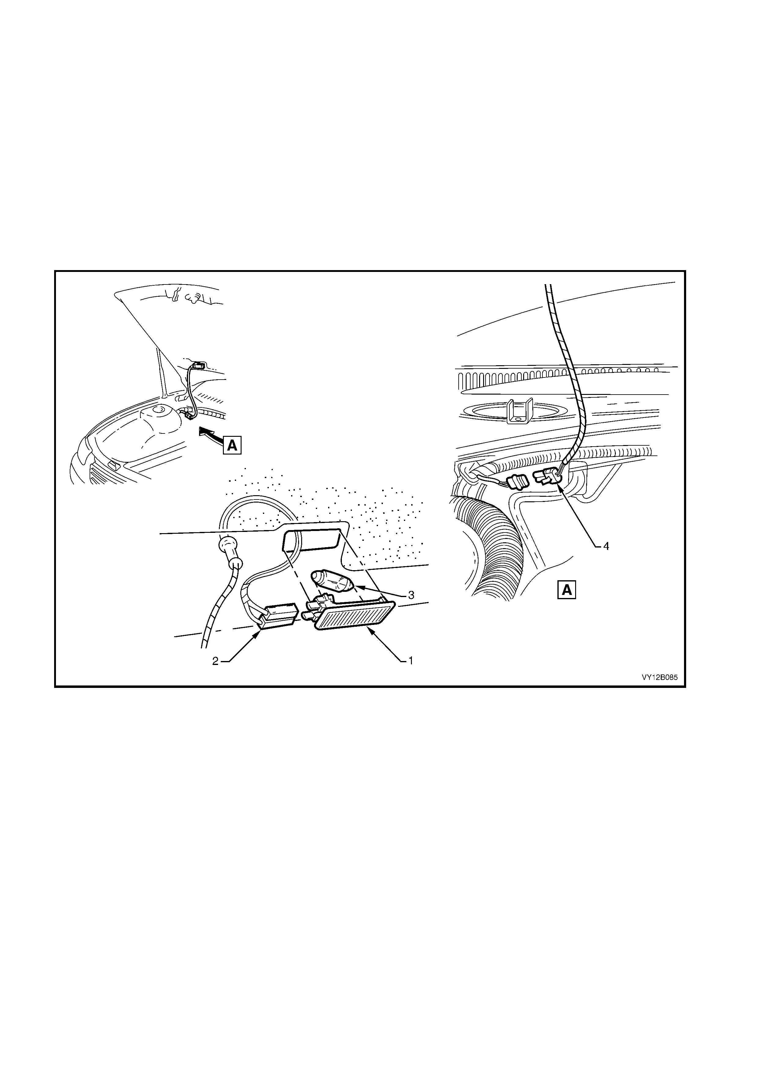
2.5 UNDER-HOOD LAMP ASSEMBLY
LT Section –
The under-hood lamp assembly is only fitted to select vehicles and is operated with the park lamps.
REMOVE
1. Remove the fusible link F102 from within the engine compartment fuse & relay panel.
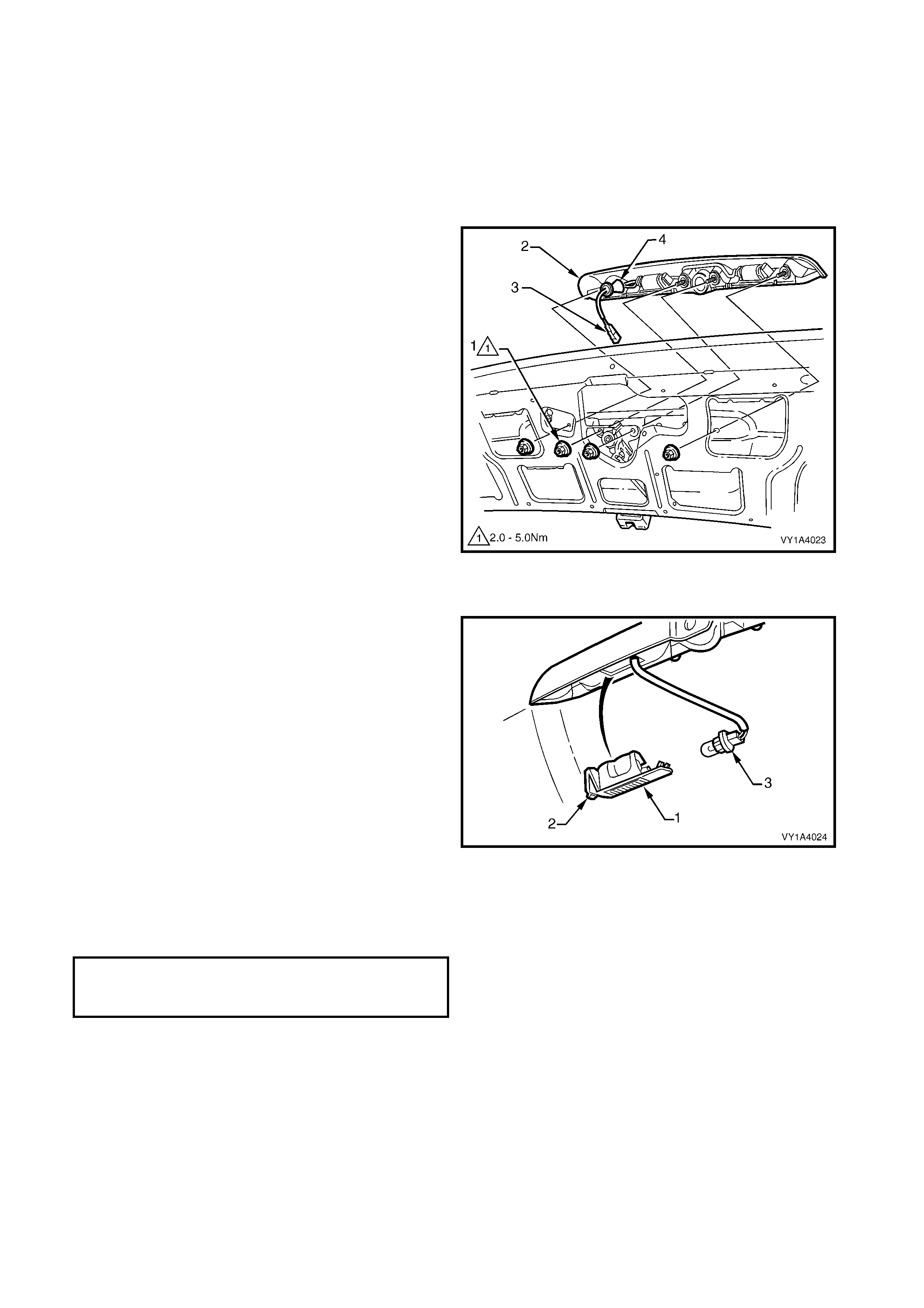
2. Pris e the under-hood lam p as sem bly (1) f rom the under side of the hood us ing a fine blade s crewdriver r efer
to Figure 1A4-6.
3. Disconnect the wiring harness connectors (2) from the lamp assembly.
4. If required, remove the bulb (3) from the assembly by depressing the metal contact.
5. Disconnect the under-hood wiring harness connector from the body harness (4).
6. Remove the grommet from the hood and withdraw the wiring.
Figure 1A4-6
REINSTALL
Reinstallation is the reverse of the removal procedure.
2.6 HOOD STRUT ASSEMBLY
LT Section No. – 12-050
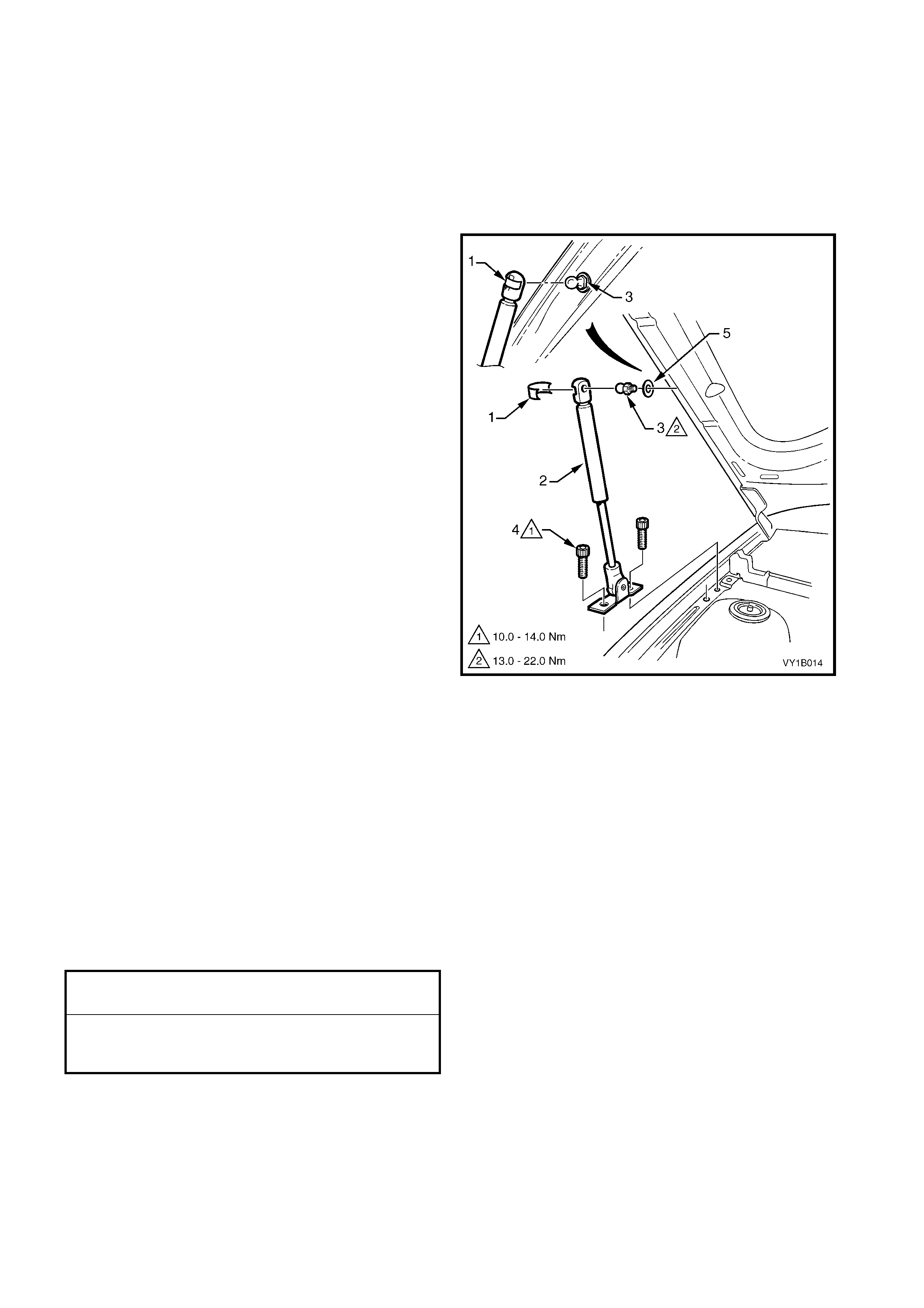
CAUTION: The hood struts contain pressurised
gas and should not be subjected to extreme heat,
pressure or physical damage as personal injury
can result.
REMOVE
1. Adequately support the hood.
2. Using a fine flat-blade screwdriver, remove the
retainer ( 1) sec ur ing the hood str ut as sembly (2) to
the hood strut pin (3).
NOTE: Tak e car e as the retainer c an spr ing of f and be
easily lost.
3. Remove the two Torx head screws (4) attaching
the strut assembly to the fender.
4. Disconnect the strut assembly from the hood and
remove.
5. If required, unscrew the pin and washer (5) from
the hood.
Figure 1A4-7
REINSTALL
1. Install the hood strut pin and washer onto the
hood, if removed, and tighten to the specified
torque.
2. Apply a small amount of lithium based grease to
the inside of the strut ball cup.
3. Install the retainer into the strut assembly.
4. Align the strut end to the pin and push into place.
5. Install the screws attaching the strut assembly to
the fender and tighten to the specified torque.
6. Remove the support and check for correct
operation.
HOOD STRUT PIN
TORQUE SPECIFICATION 13.0 – 22.0 Nm
HOOD STRUT ASSEMBLY TO
FENDER ATTACHING SCREW
TORQUE SPECIFICATION 10.0 – 14.0 Nm
2.7 HOOD & HINGE ASSEMBLIES
LT Section – 12-425
As required, first remove the following components:
1. Hood front moulding assembly, where fitted, refer
to 2.1 HOOD FRONT MOULDING ASSEMBLY.
2. Hood secondary latch assembly, refer to
2.2 HOOD SECONDARY LATCH ASSEMBLY.
3. Hood primary latch striker assembly, refer to
2.3 HOOD PRIMARY LATCH STRIKER
ASSEMBLY.
4. Hood insulator, refer to 2.4 HOOD INSULATOR.
5. Under-hood lamp assembly, refer to
2.5 UNDER-HOOD LAMP ASSEMBLY.
REMOVE
1. Raise and support the hood.
2. If required, from each side of the hood unscrew
and remove the hood adjust bumper (1).
3. Disconnect the hood strut assemblies from only,
refer to 2.6 HOOD STRUT ASSEMBLY.
Figure 1A4-8
4. Remove the hood from the vehicle with the aid of
an assistant by one of the following methods:
• Remove the single s crew (1) each side joining
the upper (2) and lower (3) hinge sections.
This method is best if the same hood
assembly is to be reinstalled as alignment is
not altered.
When removing the hood, slide it out of the
locating tabs (4).
• Remove the two screws (5) each side
attaching the hinges to the hood.
This m ethod is best if a new hood assem bly is
to be fitted.
• Remove the plenum cover assembly, refer
to Section 12N, 2.5 PLENUM COVER
ASSEMBLY – EXCEPT COUPE, or
2.6 PLENUM COVER ASSEM BLY – COUPE,
and then r emove the two screws (6) eac h side
attaching the hinges to the body.
Figure 1A4-9

REINSTALL
1. Install the hinges, if removed, by aligning them with any existing mark s, if possible. Otherwise, install with the
screws centrally in their holes, refer to Figure 1A4-9.
2. With the aid of an assistant slide the hood onto the hinges.
3. Install the screws as required.
4. If the single screw attaching the upper and lower hinge sections was removed, ensure the hinge sections are
correctly seated together and temporarily tighten the screws, refer to Figure 1A4-9.
5. If the hood was removed from the hinges, temporarily tighten the screws in alignment with the old marks or,
align the bolts centrally in their holes.
6. Install the hood adjust bumpers to their original position or half way along the thread, refer to Figure 1A4-8.
7. Install or reconnect the strut assemblies, refer to 2.8 HOOD STRUT ASSEMBLY.
8. Adjust the hood to the vehicle as described in the following procedure.
9. Tighten all screws to the specified torque.
10. Install the remaining hood components as required.
ADJUST
Correct alignment of the hood is critical to its operation and to the aesthetics of the vehicle. However, if the fenders
are not correctly positioned, the hood cannot be aligned.
Depending on the repairs performed, it may be advantageous to perform a measurement check between the
fenders prior to adjusting the hood.
Fender Alignment
1. Chec k that the m argins between the fr ont door s and fender s are c orrect. If not rec tify before proceeding, r efer
to Section 1B, 2.4 FENDER.
NOTE: Paint damage may occur. Use care and touch-up any paint damage as required.
2. Measure the distance between the rear of the fenders (1). This should be the width of the rear of the engine
hood plus 8.0 mm. If not adjust the fenders as required, refer to Section 1B, 2.4 FENDER.
3. Measure the distance between the fr ont of the fenders ( 2). This should be the width of the f ront of the engine
hood plus 8.0 mm. If not, adjust the fenders as required, refer to Section 1B, 2.4 FENDER.
4. Measure the distance between a suitable point at the rear of the LH fender and front of the RH fender (3). Note
the length.
5. Measure the distance between the opposite fender points (4). This measurement is to be within 1.5 mm of
result (3).
6. If the measurements are correct, align the hood as follows. If not adjust the fenders as required, refer to
Section 1B, 2.4 FENDER.
Engine Hood Alignment
1. If fitted, remove the hood primary latch striker assembly, refer to 2.3 HOOD PRIMARY LATCH STRIKER
ASSEMBLY.
2. Carefully close the hood, ensuring each side does not contact the fenders.
3. Check the alignment of the hood for:
• Length. Compare to the front edge of the fenders. They should be equal at point A.
• W idth of gap. Compar e the gap between the hood and fender each side. The gap s pecification is 4.0 m m
+0.5 mm / -1.0 mm.
• Consistency of gap. Com pare the width of gap between the hood and fender at the f ront, middle and rear
each side. It should be even.
• Height. Compare the hood to the fenders at each corner. The hood height specifications is -1 mm ±1.0
mm.
HOOD ASSEMBLY ATTACHING SCREW
TORQUE SPECIFICATION 10.0 – 25.0 Nm

4. Open the hood and as required:
• Loosen the screws attaching hood to the hinge for fore and aft adjustment, refer to Figure 1A4-9.
• Loosen the screws attaching the hinges to the body for rear height adjustment. If required, this also
provides fore and aft adjustment, refer to Figure 1A4-9.
• Turn the hood adjust bum per clockwise to lower the fr ont of the hood, or anti-c lockwise to rais e the hood,
refer to Figure 1A4-8.
NOTE: Do not m ake all adjus tments at once. Perfor m one adj ustment, c arefully close the hood, check its position
and make further adjustments until correct alignment is achieved.
5. Install the latch striker assembly, refer to 2.3 HOOD PRIMARY LATCH STRIKER ASSEMBLY.
6. Lower the hood while watching that the latch striker assembly aligns in the lock aperture.
7. Have an as sistant hold the hood r elease lever open, c heck the latch s trik er bolt does not foul the lock and that
the hood alignment does not alter. Adjust the latch striker bolt position as required.
8. Close the hood by dropping from a height of approximately 300 mm.
IMPORTANT: Do not push the hood closed as damage to the panel surface may occur. If it doesn’t close on the
first attempt, try again from a slightly greater height.
9. Check the height difference between the front of the hood and fenders.
10. As required, open the hood and adjust the latch strik er bolt length by loosening the hood primary latch strik er
nut slightly and rotating the bolt with a flat-blade sc rewdriver, refer to F igure 1A4-3, and/or adjusting the hood
adjust bumpers, refer to Figure 1A4-8.
11. Tighten the hood primary latch striker nut and recheck.
12. Check that all screws and nuts are tightened to their specified torque.
HOOD ASSEMBLY ATTACHING SCREW
TORQUE SPECIFICATION 10.0 – 25.0 Nm
HOOD PRIMARY LATCH STRIKER NUT
TORQUE SPECIFICATION 22.0 – 28.0 Nm
2.8 HOOD PRIMARY LATCH ASSEMBLY
LT Section – 12-050
HOOD PRIMARY LATCH SPRING
Remove
1. Raise the hood assembly.
2. Remove the radiator upper shroud, refer to
Section 6B1, 3.14 RADIATOR for V6 and V6 S/C
engines or Section 6B3, 2.15 COOLING FANS &
SHROUD ASSEMBLY for GEN III V8 engines.
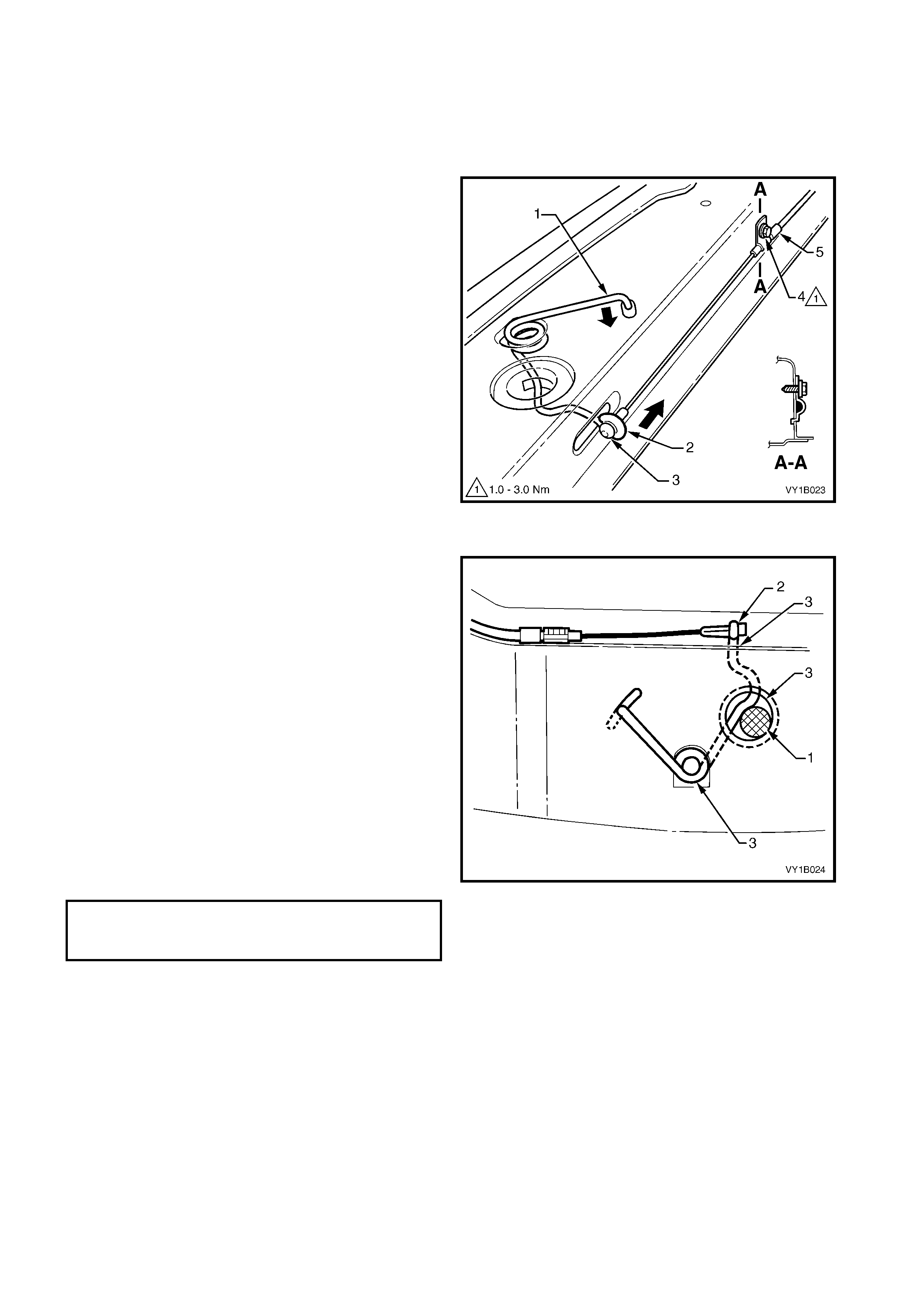
3. Us ing a pair of pliers, gr asp the hood prim ar y latch
spring at point (1) and carefully disengage from the
front panel in the direction shown.
4. Slide the cable end of the spring (2) to the open
position in the direction shown to clear the latch
hole.
5. Unhook the hood primary latch release cable
assembly (3) from the spring.
6. Grasp the end of the spring at point (1), rotate to
vertical and manipulate the section of the spring
within the front panel out through the spring coil
hole.
Figure 1A4-10
Reinstall
Reinstallation is the reverse of removal noting the
following:
1. Check the cable adjustment by inserting a 16 mm
pin (1) between the spring and latch hole and
check there is no clearance between the inner
cable ferrule and spring (2).
2. If required, loosen the cable retainer screw (4,
Figure 1A4-10) and adjust the cable as required.
NOTE: Ensure the outer cable ferrule (5, Figure 1A4-
10) is positioned before the retainer.
3. Tighten the retainer screw to the specified torque,
remove the 16 mm pin and check for correct
operation.
4. Apply NLGI Lithium based grease or equivalent to
the spring slot, the latch assembly hole to a depth
of the spring slot, and to the spring coils, refer to
points (3).
Figure 1A4-11
HOOD PRIMARY LATCH RELEASE
CABLE RETAINER SCREW
TORQUE SPECIFICATION 1.0 – 3.0 Nm
HOOD PRIMARY LATCH RELEASE CABLE ASSEMBLY, RHD
As required, first remove the following components:
1. Remove the radiator upper shroud, refer to Section 6B1, 3.14 RADIATOR for V6 and V6 S/C engines or
Section 6B3, 2.15 COOLING FANS & SHROUD ASSEMBLY for GEN III V8 engines.
2. Right-hand instrument panel outer cover, refer to Section 1A3, 3.17 INSTRUMENT PANEL OUTER
COVER.
3. Unattach the wiring harness conduit from the RH strut tower, refer to Section 12O, FUSES AND WIRING
HARNESSES.
Remove
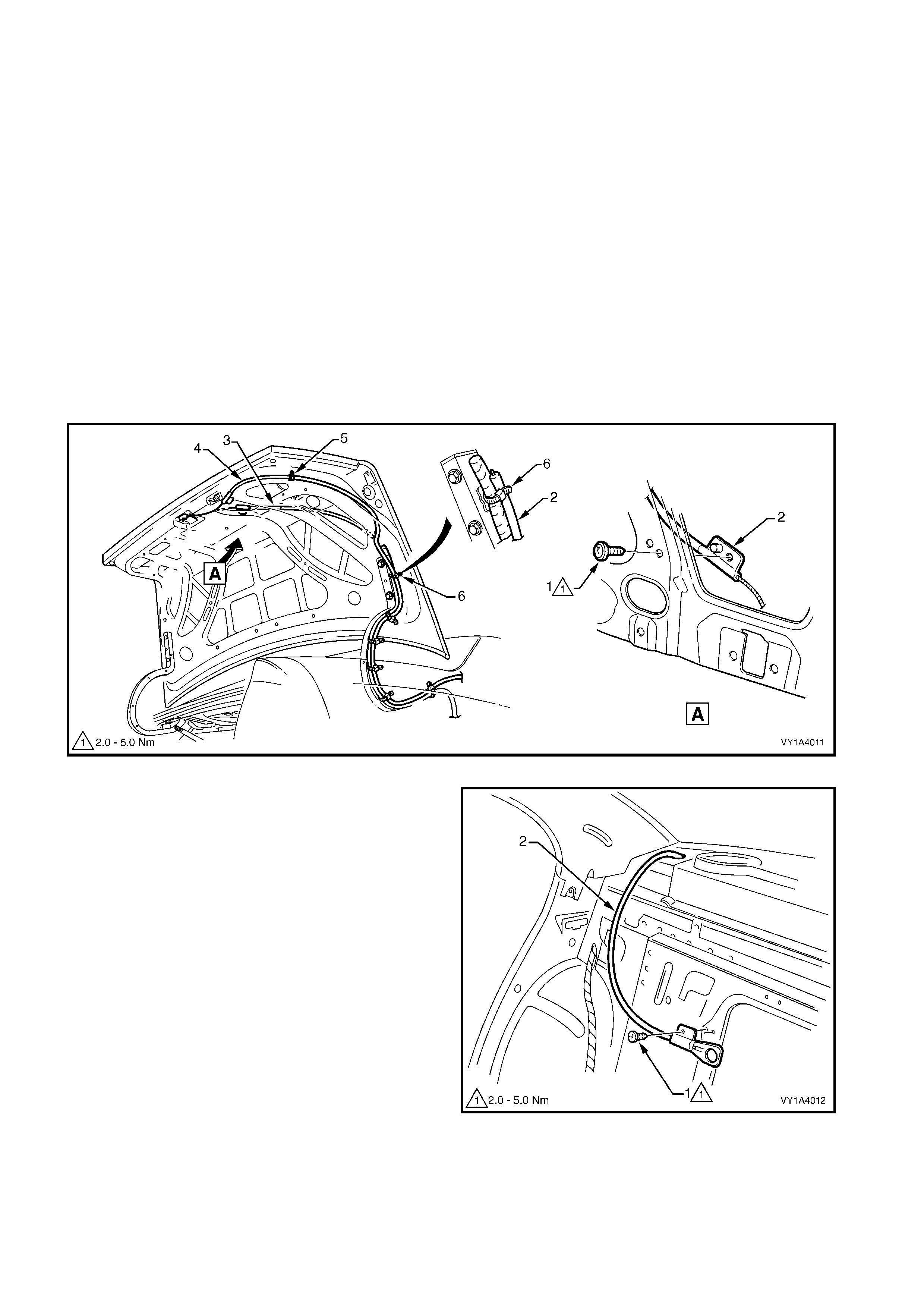
1. Raise the hood.
2. Remove the hood primary latch release cable
retainer screw, refer to (4, Figure 1A4-10) and
unhook the release cable assembly from the hood
primary latch spring.
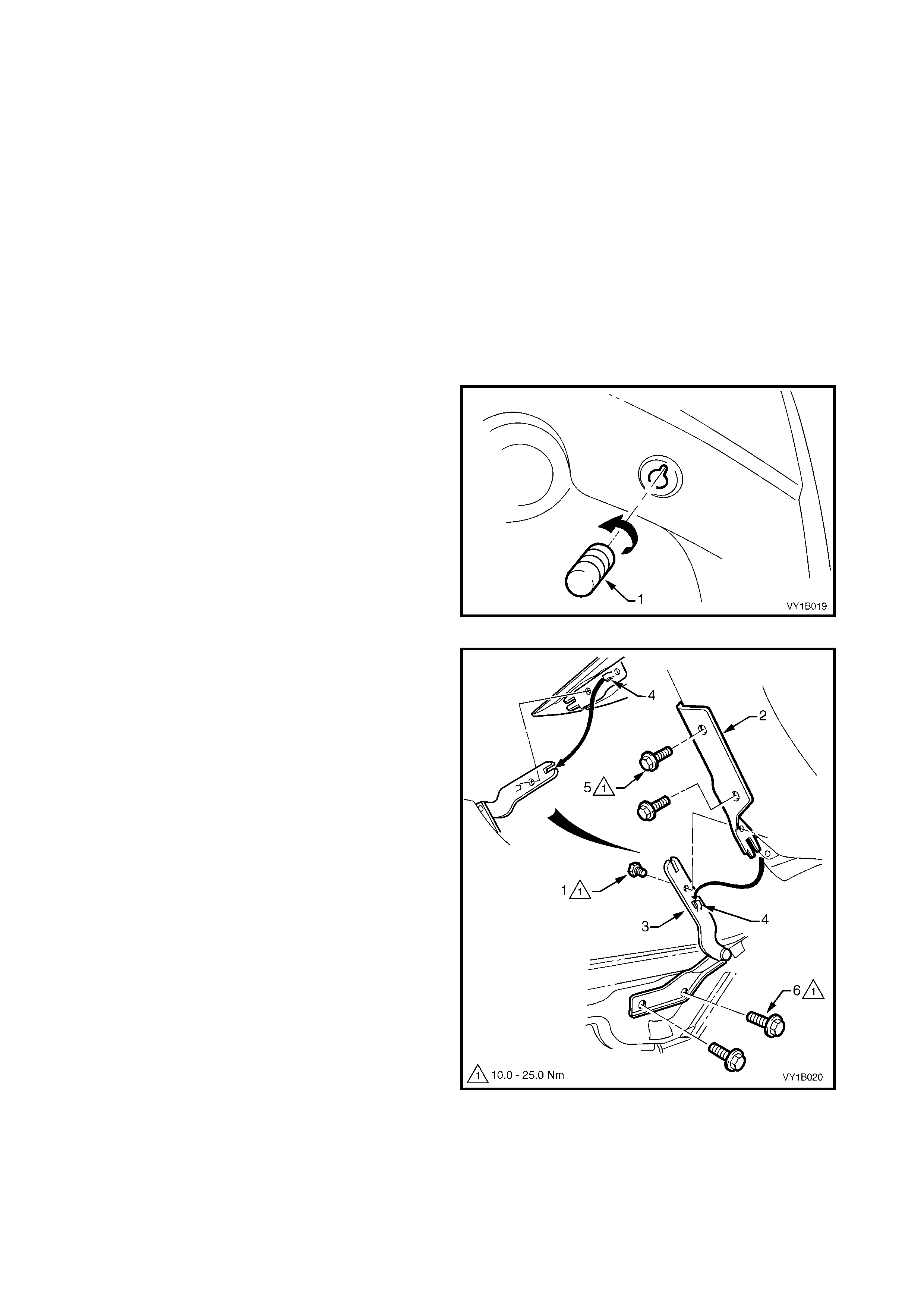
3. Using a fine flat-blade screwdriver, lever the
retaining tabs (1) top and bottom on the hood
release lever assembly (2) and slide the lever
assembly rearward.
4. From within the engine compartment, push the
grommet (1) through the dash panel, refer to
Figure 1A4-13.
5. Withdraw the cable assembly (2) from behind the
fuse and relay box and into the passenger
compartment.
Figure 1A4-12
Figure 1A4-13
Reinstall
Reinstallation is the reverse of removal noting the following:
1. Ensure the cable assembly is correctly routed and there are no sharp bends in the cable, refer to Figure
1A4-13.
2. Attach a spring scale to the lower edge of the release lever. The effort required to release the hood should
not exceed 40N.
HOOD PRIMARY LATCH RELEASE CABLE ASSEMBLY, LHD
As required, first remove the following components:
1. Remove the radiator upper shroud, refer to Section 6B1, 3.14 RADIATOR for V6 and V6 S/C engines or
Section 6B3, 2.15 COOLING FANS & SHROUD ASSEMBLY for GEN III V8 engines.
2. Left-hand Instrument panel outer cover, refer to Section 1A3, 3.17 INSTRUMENT PANEL OUTER COVER.
3. Unattach the wiring harness from the right-hand strut tower, refer to Section 12O, FUSES AND WIRING
HARNESSES.
Remove
1. Raise the hood.
2. Remove the hood primary latch release cable
retainer screw , refer to (4, Figure 1A4-10) and
unhook the release cable assembly from the hood
primary latch spring.
3. Using a fine flat-blade screwdriver, lever the
retaining tabs (1) top and bottom on the release
lever bracket (2) and slide the lever assembly
rearward.
4. From within the engine compartment, remove the
cable assembly (1) from the wiring harness
retainers (2), four places, refer to Figure 1A4-15.
5. Push the grommet (3) through the dash panel.
6. Withdraw the c able as sembly from behind the f us e
& relay box, across the dash panel and into the
passenger compartment.
Figure 1A4-14
Figure 1A4-15
Reinstall
Reinstallation is the reverse of removal noting the following:
1. Ensure the cable assembly is correctly routed and there are no sharp bends in the cable.
2. Attach a spring scale to the lower edge of the release lever. The effort required to release the hood should
not exceed 40N.
3. SERVICE OPERATIONS – REAR COMPARTM ENT LID
3.1 REAR COMPARTMENT LID CARPET
LT Section No. – 14-480
REMOVE
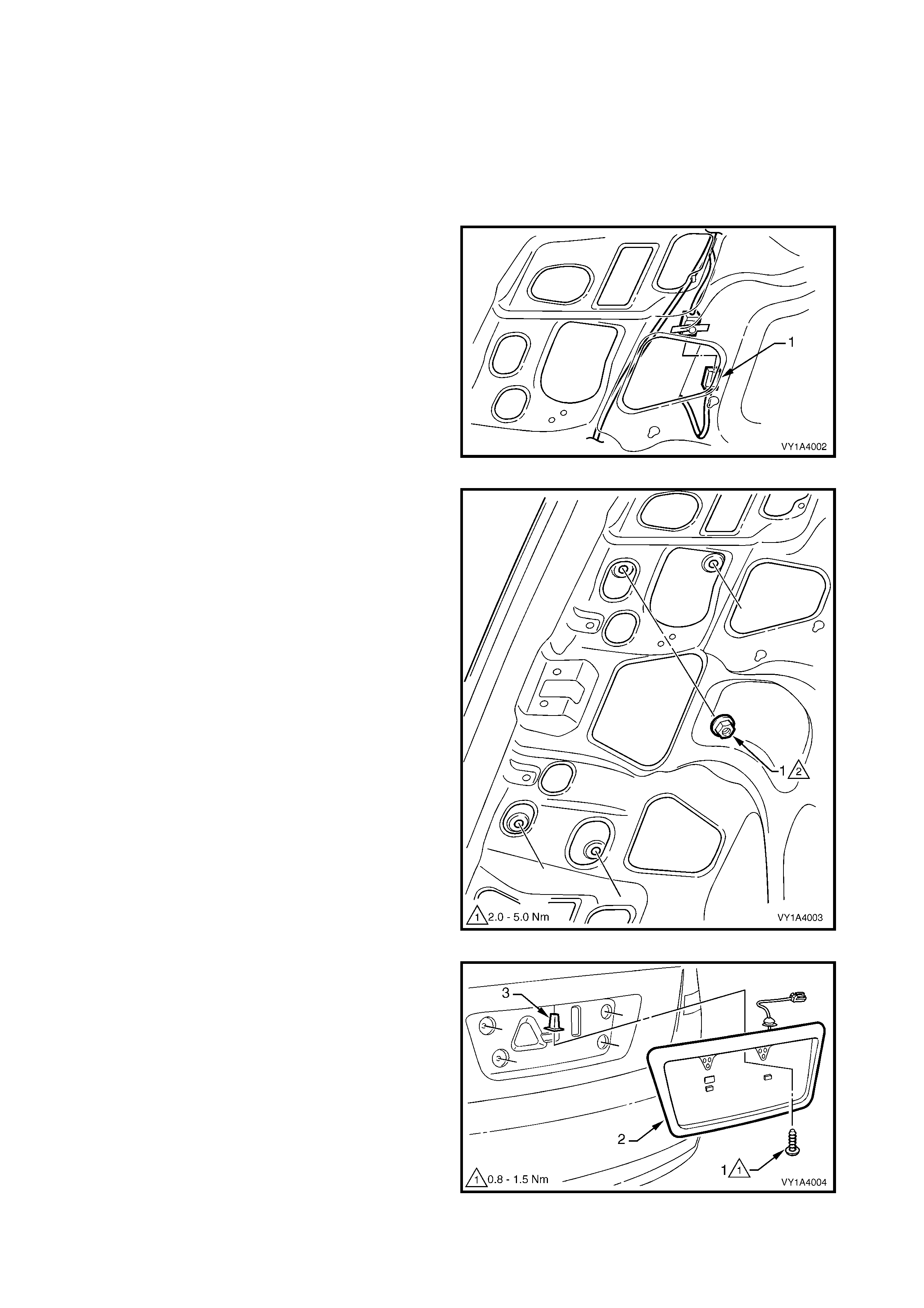
1. Remove the screw (1) attaching the spare wheel stowage cover hook (2), refer to Figure 1A4-16.
2. Using a suitable trim c lip r emoval tool, remove the retainers ( 3) attac hing the r ear c ompartment lid carpet (4)
Sedan 14 places, or (5) Coupe 17 places.
3. Remove the carpet from the rear compartment lid.
4. If required, prise the nut (6) and washer (7) from the rear compartment lid with a fine flat-blade screwdriver.
Figure 1A4-16
REINSTALL
1. Reinstallation is the reverse of rem oval. Tighten the spare wheel stowage cover hook screw to the s pecified
torque.
SPARE WHEEL STOWAGE COVER
HOOK ATTACHING SCREW
TORQUE SPECIFICATION 1.0 – 3.0 Nm
Techline
3.2 REAR COMPARTMENT LID APPLIQUE ASSEMBLY, SEDAN
LT Section No. 02-375
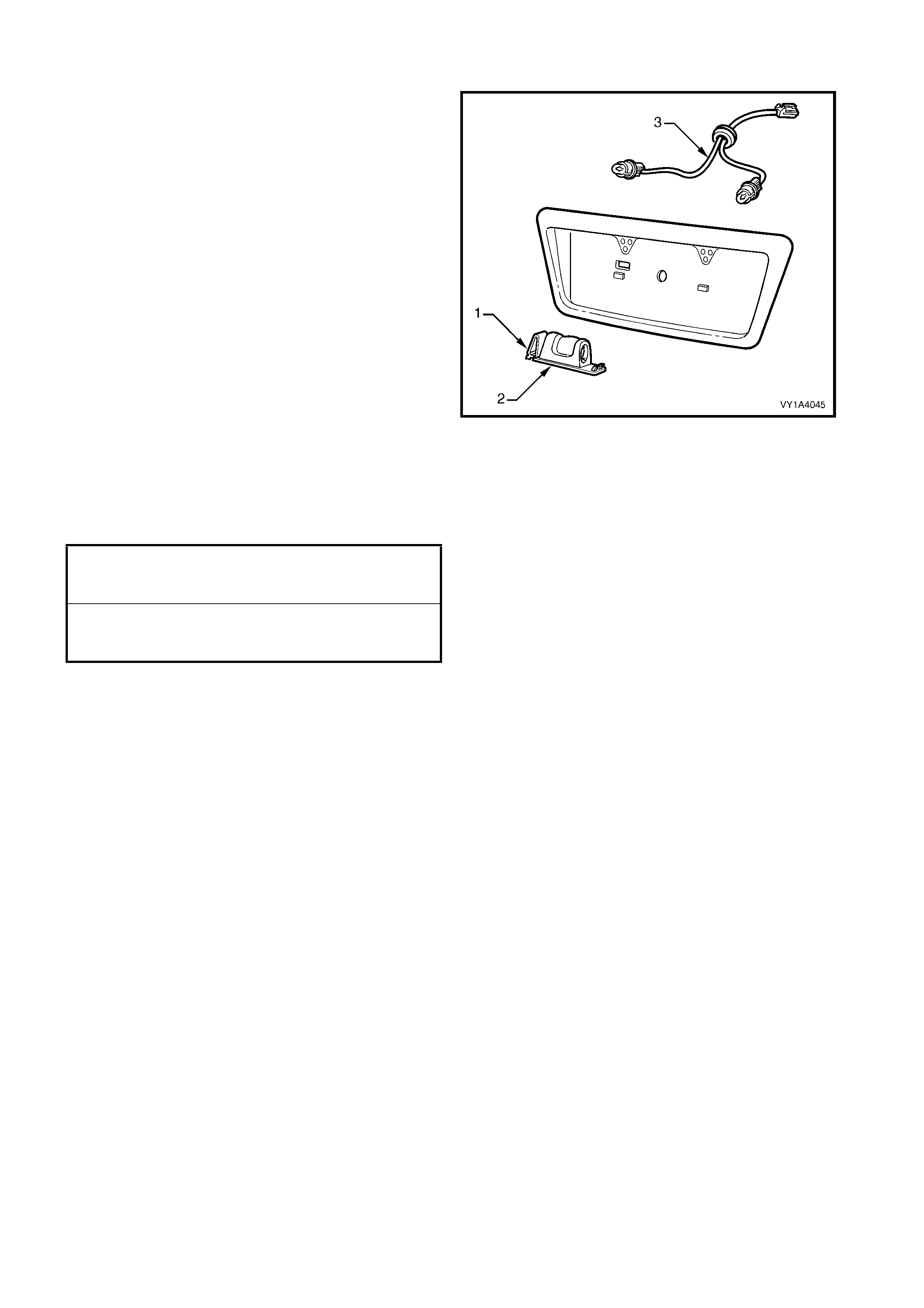
As required, first remove the following components:
1. Rear compartment lid carpet, refer to 3.1 REAR COMPARTMENT LID CARPET.
2. Licence plate.
REMOVE
1. From within the rear compartment lid cavity,
disconnect the lic ence plate lamp wiring connec tor
(1).
Figure 1A4-17
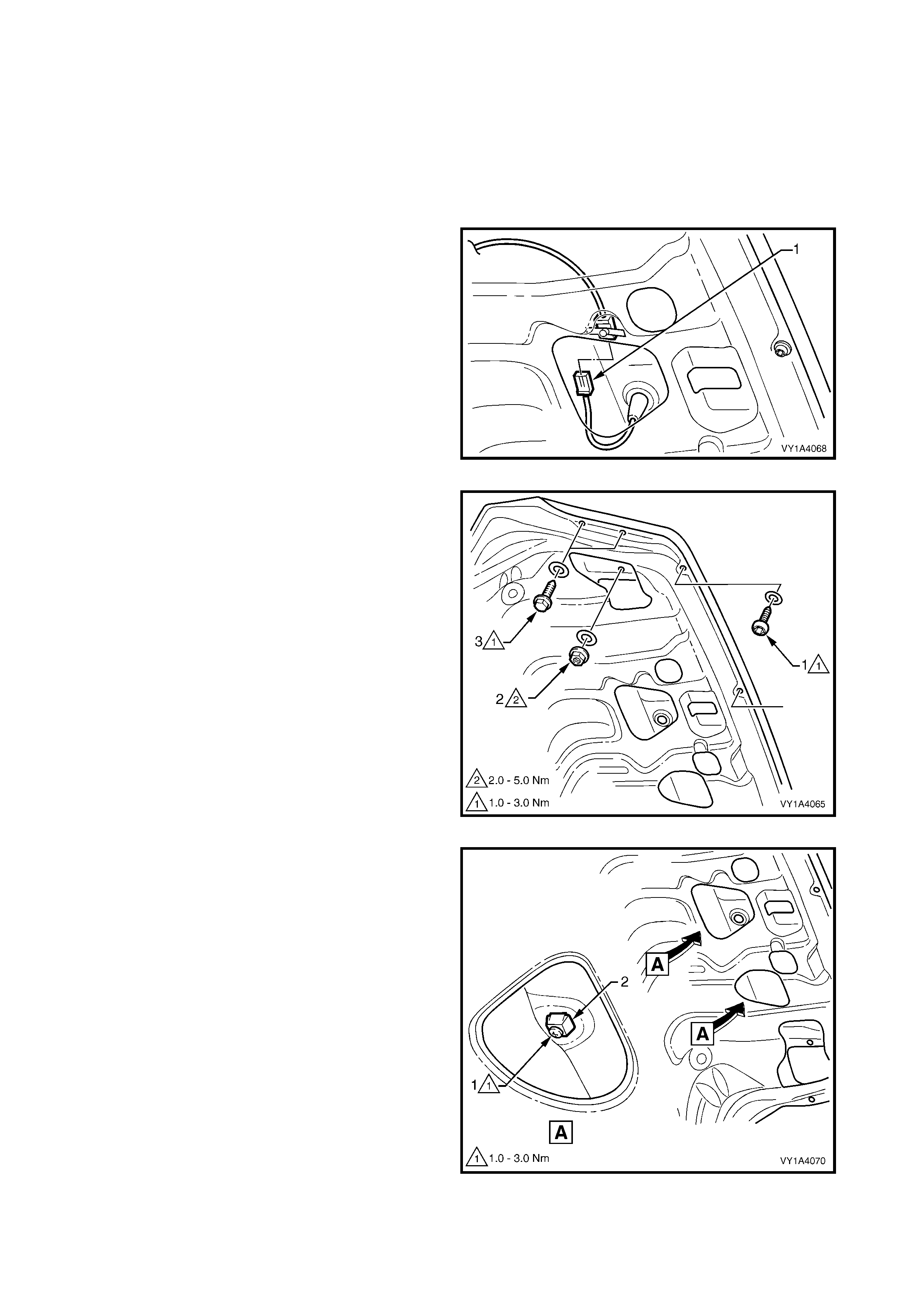
2. From within the rear compartment lid cavity,
remove the nut (1), four places, attaching the
applique assembly to the rear compartment lid.
Figure 1A4-18
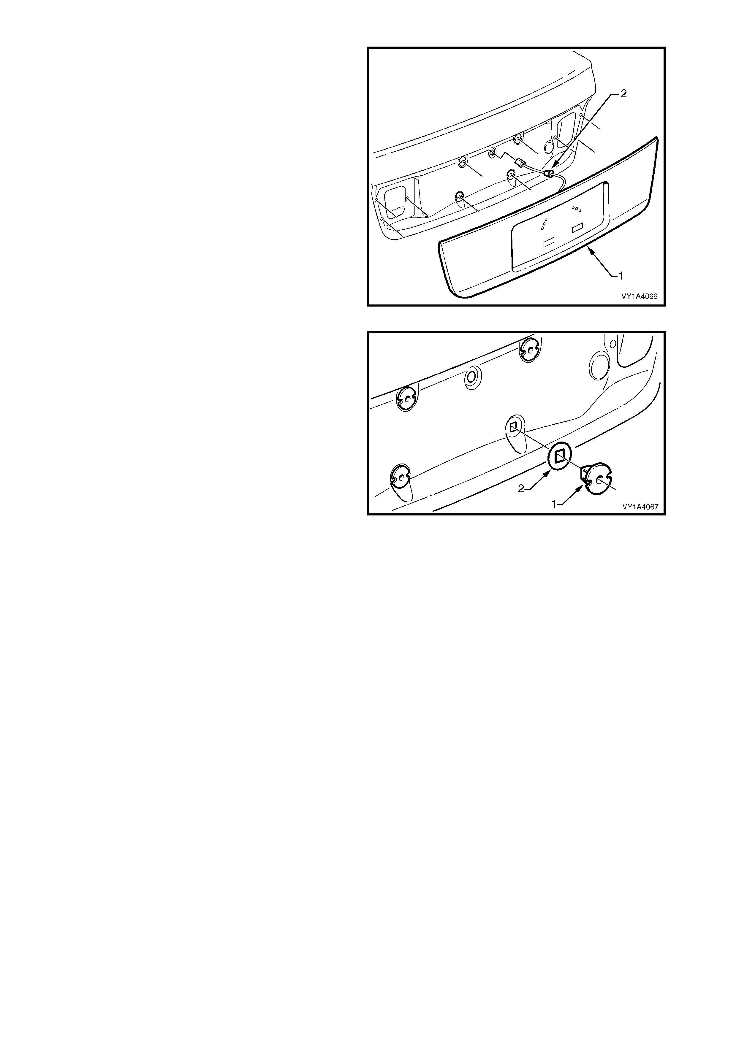
3. Remove the screw (1) attaching the applique
assembly (2) to the rear compartment lid.
4. Withdraw the applique assembly from the rear
compartment lid, remove the wiring harness
grommet and withdraw the wiring harness.
5. Remove the applique assembly.
6. If required, remove the retainer (3) from the rear
compartment lid.
Figure 1A4-19
DISASSEMBLE
1. Depress the tab (1) and lower the rear licence
plate lamp housing ass em bly (2) from the applique
assembly.
2. Rotate the bulb socket and remove from the
housing assembly.
3. Remove the housing assembly and repeat for the
opposite side.
4. Remove the licence plate lamp harness assembly
(3) from the rear of the applique assembly.
Figure 1A4-20
REINSTALL
1. Reinstallation is the reverse of removal. Ensure
the seals are c or rec tly fitted and tighten the screws
and nuts to the specified torque.
REAR COMPARTMENT LID APPLIQUE
ASSEMBLY ATTACHING SCREW
TORQUE SPECIFICATION 0.8 – 1.5 Nm
REAR COMPARTMENT LID APPLIQUE
ASSEMBLY ATTACHING NUT
TORQUE SPECIFICATION 2.0 – 5.0 Nm
3.3 REAR COMPARTMENT LID APPLIQUE ASSEMBLY, CO UPE
LT Section No. 02-375
As required, first remove the following components:
1. Rear compartment lid carpet, refer to 3.1 REAR COMPARTMENT LID CARPET.
2. Licence plate.
REMOVE
1. From within the rear compartment lid cavity,
disconnect the lic ence plate lamp wiring connec tor
(1).
Figure 1A4-21
2. Remove the Torx Head screw (1) and seal, three
places along the lower edge of the rear
compartment lid.
3. Remove the nut (2) and seal from within the rear
compartment lid cavity, one place each side.
4. Remove the screw (3) and seal, two places, each
side of the rear compartment lid.
Figure 1A4-22
5. Either:
• Remove the screw (1) from the retainer within
the rear compartment lid cavity, four places, or
• Depress the tab (2) each side to disengage
the retainer from the rear compartment lid
panel, four places.
Figure 1A4-23
6. Remove the applique assembly (1) away from the
rear compartment lid.
7. Remove the wiring harness grommet (2) and
withdraw the wiring harness.
8. Remove the applique assembly.
Figure 1A4-24
9. If not removed with the applique assembly, as
required carefully prise the four retainers (1) and
seals (2) from the rear compartment lid using a
fine, flat-blade screwdriver.
Figure 1A4-25
DISASSEMBLE
Referring to Figure 1A4-26:
1. Depress the tab (1) and lower the rear licence plate lamp housing assembly (2) from the applique assembly.
2. Rotate the bulb socket and remove.
3. Remove the housing assembly and repeat for the opposite side.
4. Remove the licence plate lamp harness assembly (3) from the rear of the applique assembly.
5. Carefully remove the rear compartment lid applique upper seal (4).
NOTE: The seal is attached with adhesive.
6. Remove rear compartment lid applique gasket (5) from each side of the applique assembly.
7. If not already done so, remove the screw (6) attaching the retainer (7) and seal to the applique assembly,
four places.
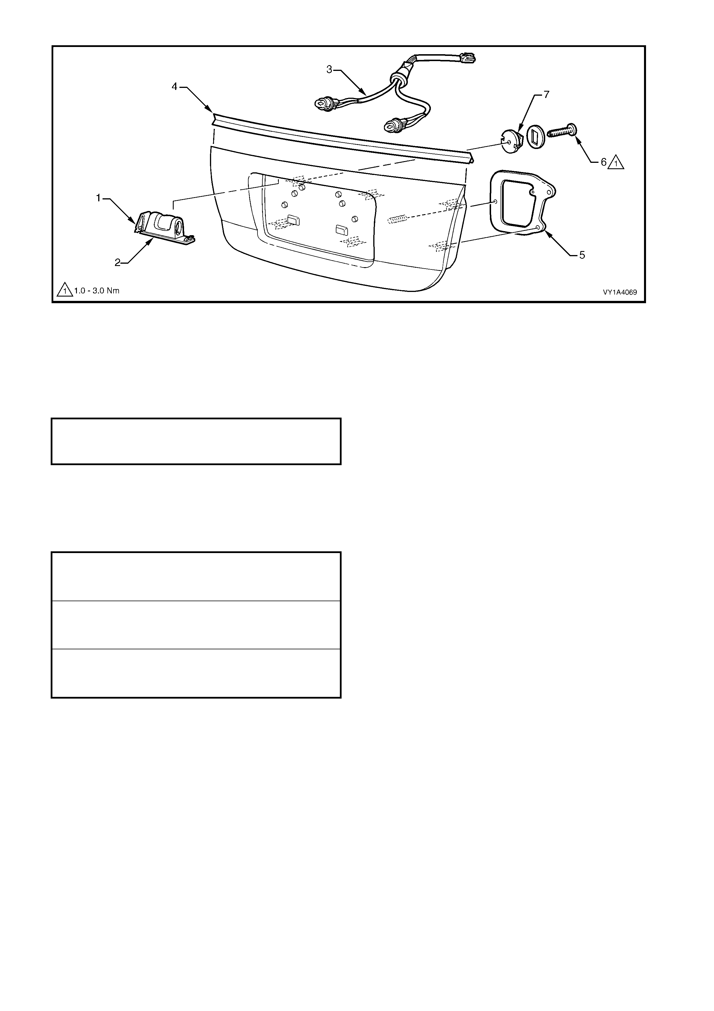
Figure 1A4-26
REINSTALL
1. Attach the removed components as required.
NOTE: Ensure the upper seal is affixed correctly to the applique assembly.
2. Fit the four retainers and seals (7, Figure 1A4-26) to the applique assem bly with the screws (6) and tighten
to the specified torque.
3. Feed the licence plate lam p wiring harness through its hole in the rear compar tment lid and fit the grom met
in position.
4. Install the applique assembly onto the rear compartment lid, ensuring the four retainers snap into position.
5. Install the nuts and screws, ensuring the seals are correctly fitted and tighten to the specified torque.
REAR COMPARTMENT LID APPLIQUE
ASSEMBLY RETAINER ATTACHING
SCREW TORQUE SPECIFICATION 1.0 – 3.0 Nm
REAR COMPARTMENT LID APPLIQUE
ASSEMBLY LOWER ATTACHING
SCREW TORQUE SPECIFICATION 1.0 – 3.0 Nm
REAR COMPARTMENT LID APPLIQUE
ASSEMBLY ATTACHING NUT
TORQUE SPECIFICATION 2.0 – 5.0 Nm
REAR COMPARTMENT LID APPLIQUE
ASSEMBLY OUTER ATTACHING
SCREW TORQUE SPECIFICATION 1.0 – 3.0 Nm
3.4 REAR SPOILER ASSEMBLY
LT Section No. 10-350
As required, first remove the rear compartment lid
carpet, refer to 3.1 REAR COMPARTMENT LID
CARPET.
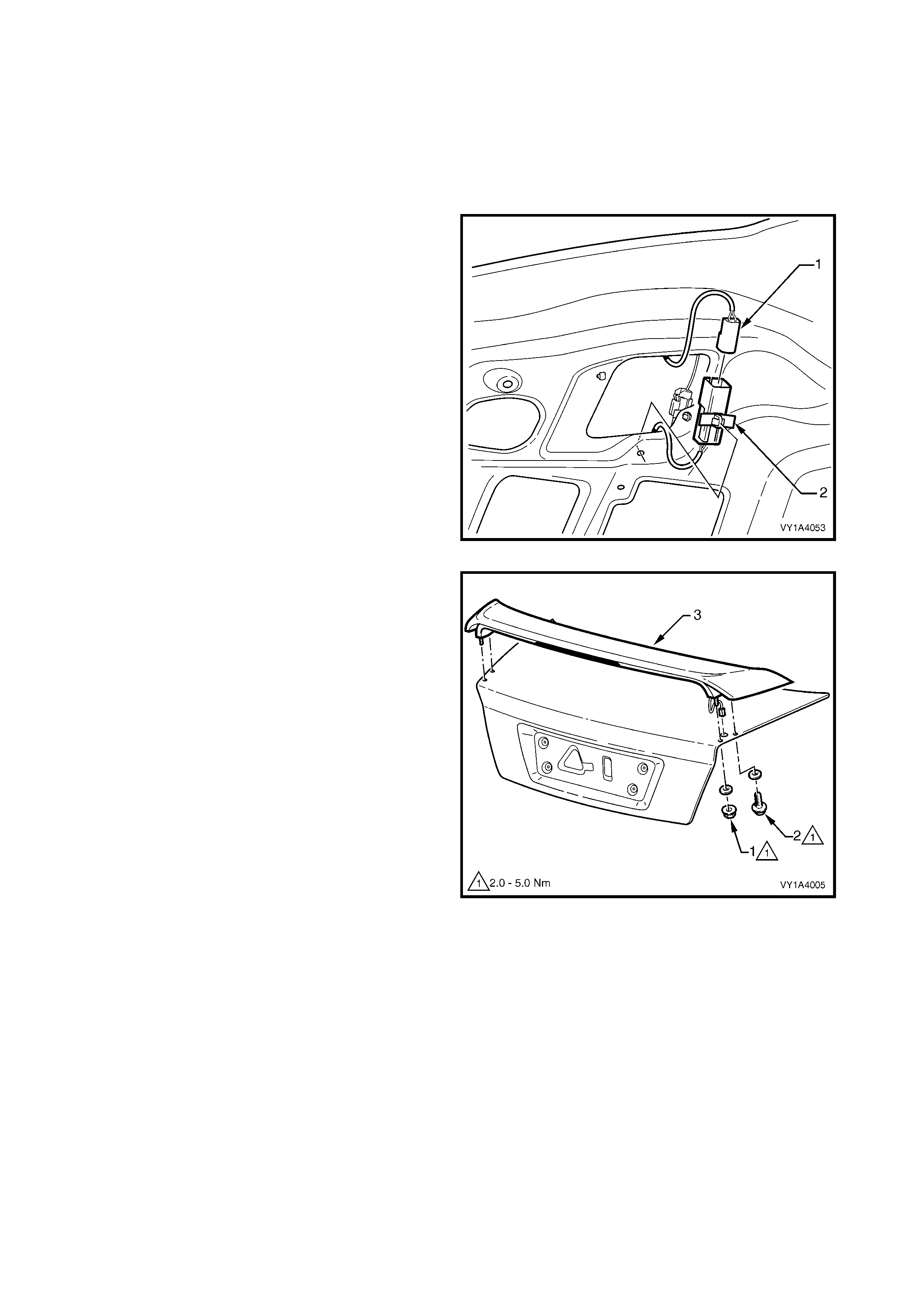
REMOVE
1. From within the rear compartment lid cavity,
disconnect the s poiler wiring harness connector (1).
The body wiring harness side of the connector is
attached to the rear compartment lid with a clip (2).
Figure 1A4-27
2. Remove the nut (1), screw (2) and seals attaching
the spoiler (3) to the rear compartment lid.
3. Remove the spoiler while withdrawing the high
mount stop lamp connector from the rear
compartment lid cavity.
Figure 1A4-28
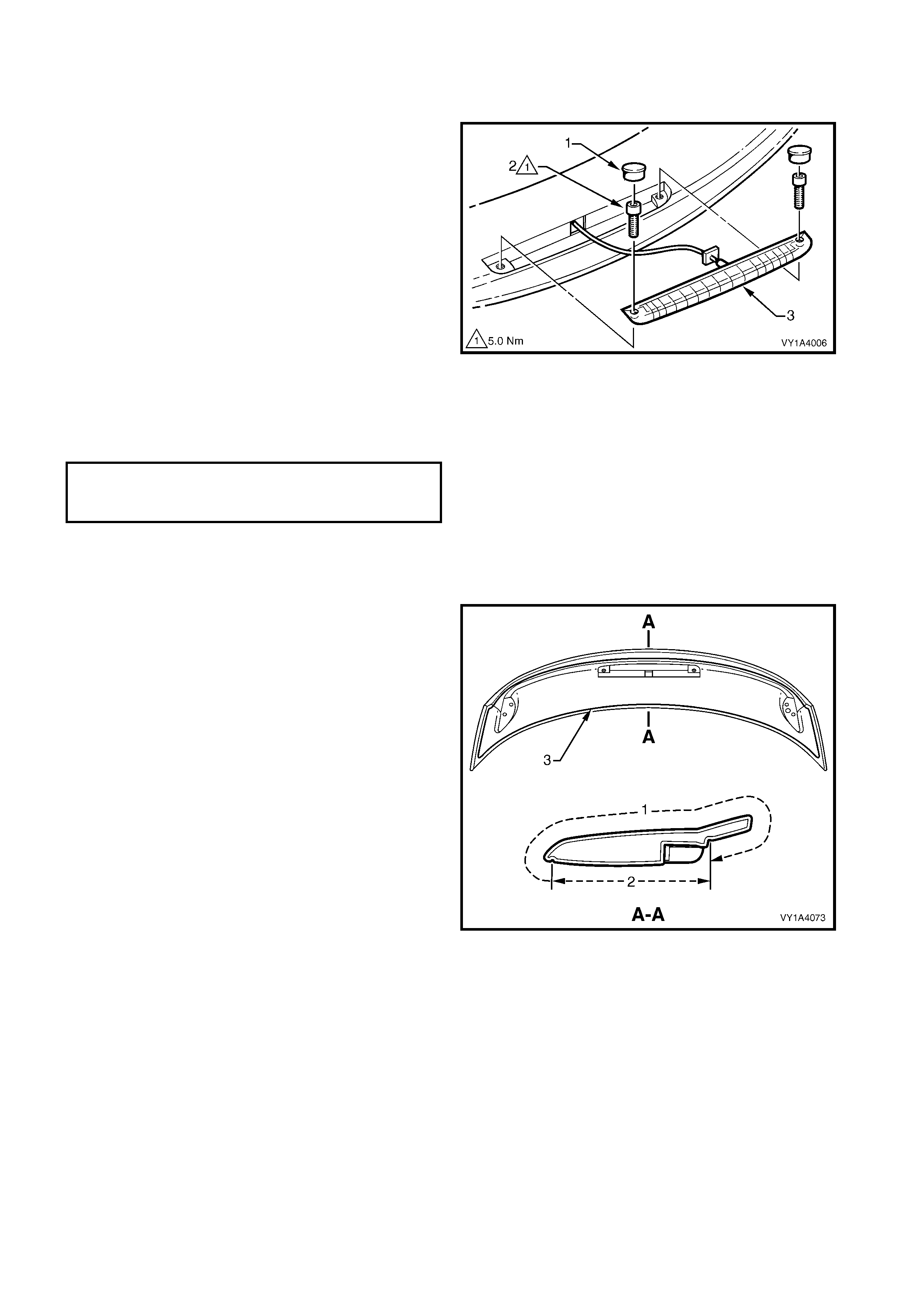
DISASSEMBLE
Remove – High Mount Stop Lamp Assembly
1. Prise the screw caps (1) from the underside of the
spoiler and remove the two scr ews (2) attaching the
high mount stop lamp assembly (3) to the spoiler.
2. To aid reinstallation, tie a length of string to the
wiring connector.
3. Withdraw the wiring harness through the spoiler,
untie the string and remove the lamp assembly.
Leave the string in the cavity.
Reinstall – High Mount Stop Lamp Assembly
1. Tie the string to the wiring connector and pull
through the s poiler cavity or , manipulate the wiring
harness through the cavity. If required, make a
hook from a length of wire to aid pulling the
connector through.
2. Install the screws and tighten to the specified
torque. Fit the caps.
Figure 1A4-29
REINSTALL
The rear spoiler fitted to S vehicles is fully painted in
the vehicle’s body colour.
For SS vehicles the area (1) is painted in the vehicle’s
body colour, while the underside area (2) is painted
sk irt black. A gr oove (3) in the underside of the spoiler
is used as the colour separation point.
A new spoiler is to be painted prior to installation,
and while the painting procedures for the rear spoiler
are relatively straight-forward, the correct steps must
be followed for refinishing ABS plastic. Refer to
Section 1D BUMPER BARS for further information on
plastic painting or refer to your paint manufacturer.
NOTE: If the rear compartment lid has not been
replaced, proceed to Step 11.
1. Construct a drilling template by printing Figure
1A4-31.
NOTE: Ensure it prints the correct size, compare the
scale.
Figure 1A4-30
HIGH MOUNT STOP LAMP
ASSEMBLY ATTACHING
SCREW TORQUE SPECIFICATION 5.0 Nm
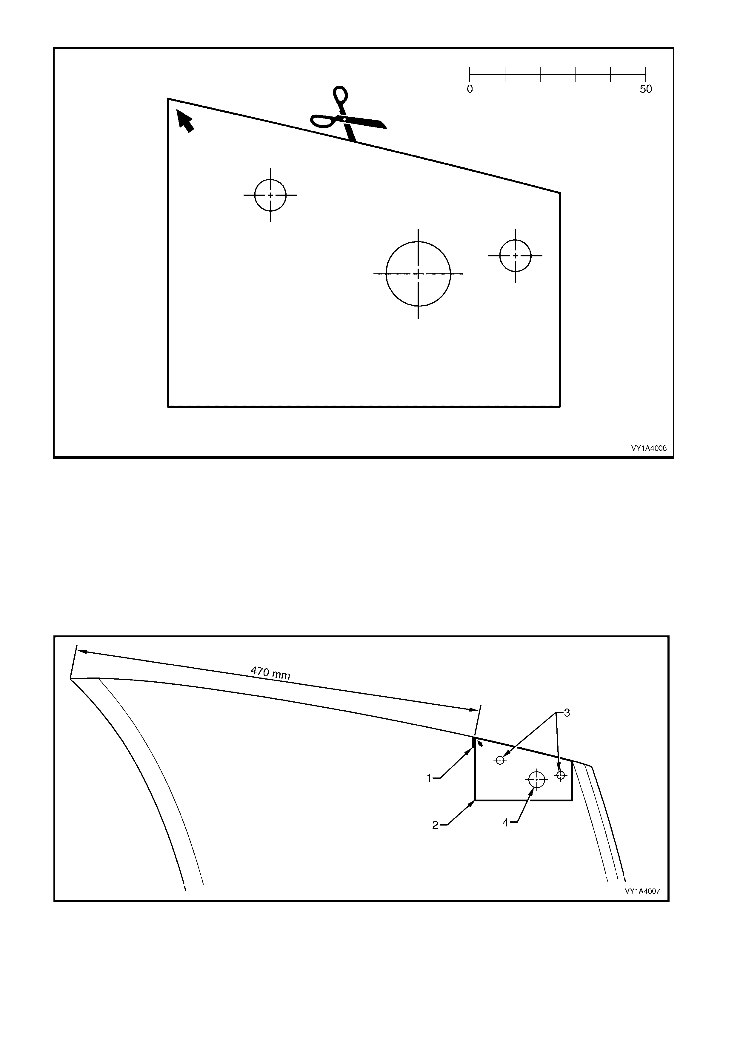
Figure 1A4-31
2. Referring to Figure 1A4-32, place a mark (1) on the right-hand outer edge of the rear compartment lid,
measuring 470 mm from the front corner in a straight line.
NOTE: If the r ear com partment lid is painted, protect the paintwork in the area of the m ounting and wiring holes
with masking tape.
3. Place the template (2) on the rear compartment lid, aligning the corner with the arrow to the mark (1) and the
edge of the template with the edge of the rear compartment lid.
4. Mark the centre of the two mounting holes (3) and for the right-hand side only, the wiring harness hole (4).
5. Turn the template over and repeat steps 2 – 5 for the LH side.
IMPORTANT: Mark the mounting holes only, the wiring harness hole is for the right-hand side only.
Figure 1A4-32

6. Sit the spoiler in position on the rear com partm ent lid and check the m ounting studs align with the mounting
hole marks. Adjust as required.
7. Open the rear compartment lid slightly and place a block of wood under the drilling locations.
8. Car efully drill the m ounting holes. Initially drill 3.0 mm pilot holes , followed by 9.0 m m holes. Drill through the
inner and outer rear compartment lid panels
9. Carefully drill the wiring harness hole on the RH side only. Initially drill a 3.0 mm hole, then drill out to
18.0 mm. Drill through the outer panel only.
10. Debur the drill holes and remove all swarf. Apply primer to the bare metal as required.
11. Fit the spoiler to the rear compartment lid, feeding the high mount stop lamp harness through its hole.
12. Install the seals, screws and nuts onto the studs and hand tighten.
13. Check alignment of spoiler on rear compartment lid and tighten the screws and nuts to the specified torque.
14. Connect the wiring connector within the rear compartment lid cavity and clip onto the inner panel as shown in
Figure 1A4-27.
15. Check high mount stop lamp operation.
16. Refit the rear compartment lid carpet refer to 3.1 REAR COMPARTMENT LID CARPET.
REAR SPOILER ASSEMBLY
ATTACHING NUT & SCREW
TORQUE SPECIFICATION 2.0 – 5.0 Nm

3.5 REAR COMPARTMENT LID LATCH ASSEMBLY
LT Section No. 12-680
As required, first remove the rear compartment lid
carpet, refer to 3.1 REAR COMPARTMENT LID
CARPET.
REMOVE
1. Remove the two screws (1) attaching the latch
assembly (2) to the rear compartment lid.
2. Withdraw the latch assembly from the panel far
enough to enable disconnection of the actuator rod
(3) and rear compartment lid release cable (4).
3. Remove the latch assembly.
Figure 1A4-33
REINSTALL
Reinstallation is the reverse of removal noting the following:
1. Tighten the screws to the specified torque.
2. Lubricate the latch assembly with NLGI No.1 Lithium Grease.
3. Prior to closing the rear compartment lid, manually close the latch and check operation of the latch assembly
via the rear compartment lid release switch and the rear compartment lid release cable assembly. If
operation is satisfactory, close the rear compartment lid and recheck operation. If required adjust the rear
compartment lid striker, refer to 3.11 REAR COMPARTMENT LID STRIKER ASSEMBLY.
REAR COMPARTMENT LID LATCH
ASSEMBLY ATTACHING NUT
TORQUE SPECIFICATION 2.0 – 5.0 Nm
3.6 REAR COMPARTMENT LID ACTUATOR ASSEMBLY
LT Section No. 12-680
NOTE: T he rear com partm ent lid actuator assem bly is
controlled by the BCM. For diagnosis refer to
Section 12J, BODY CONTROL MODULE.
As required, first remove the rear compartment lid
carpet, refer to 3.1 REAR COMPARTMENT LID
CARPET.
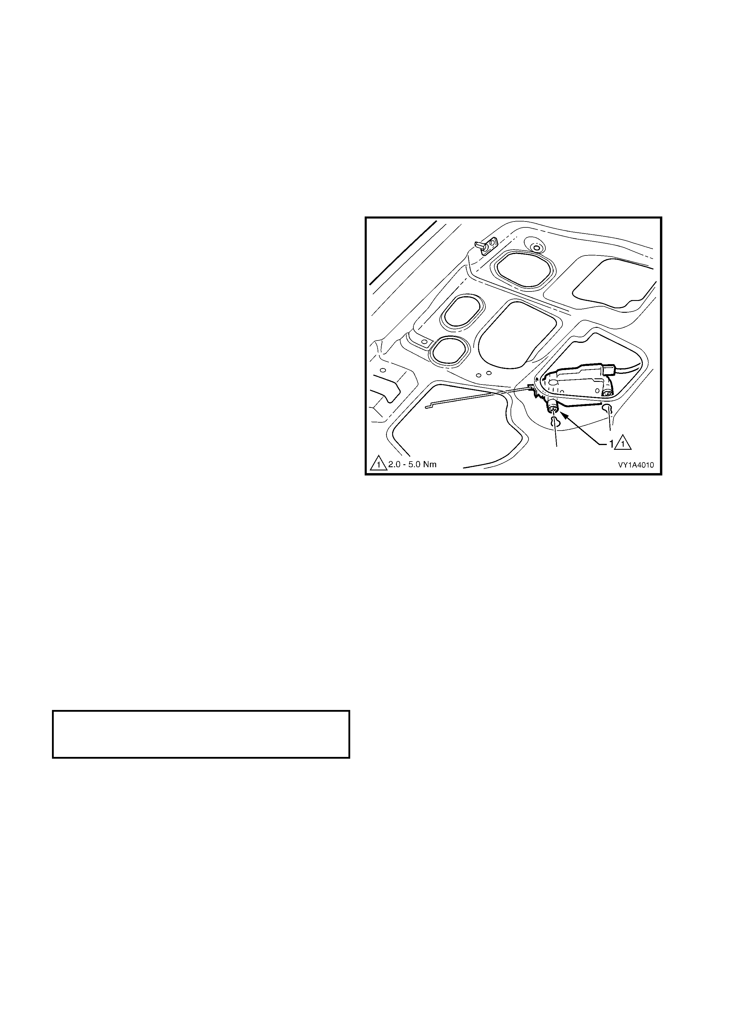
REMOVE
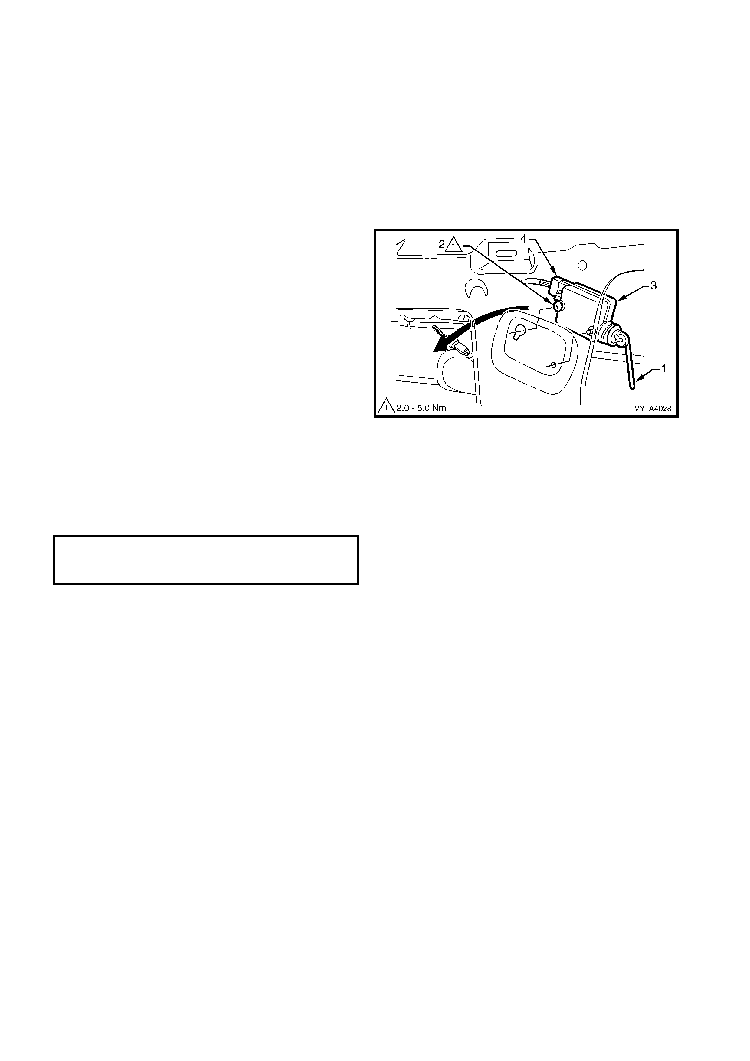
1. Loosen the two screws (1) attaching the actuator
assembly (2) to the rear compartment lid.
2. If required, disconnect the connecting rod from the
rear compartment lid latch assembly.
3. Withdraw the actuator assembly from the keyhole
slots in the panel.
4. Remove the actuator assembly from the panel
cavity far enough to enable the wiring harness
connector (3) to be disconnected.
5. Remove the actuator assembly.
Figure 1A4-34
REINSTALL
Reinstallation is the reverse of removal noting the
following:
1. Tighten the screws to the specified torque.
2. Prior to clos ing the rear c ompartm ent lid, m anually
close the latch and check operation of the latch
assembly via the rear compartment lid release
switch and the rear compartment lid cable
assem bly latc h release. If operation is satisfac tory,
close the rear compartment lid and recheck
operation If required adjust the rear compartment
lid latch striker, refer to 3.11 REAR
COMPARTMENT LID STRIKER ASSEMBLY.
REAR COMPARTMENT LID ACTUATOR
ASSEMBLY ATTACHING SCREW
TORQUE SPECIFICATION 2.0 – 5.0 Nm
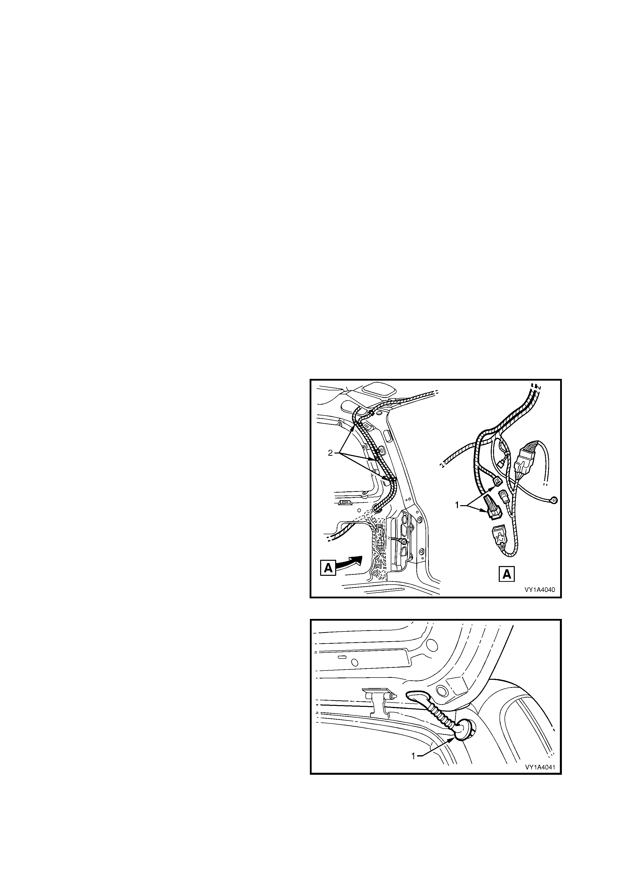
3.7 REAR COMPARTMENT LID RELEASE CABLE ASSEMBLY
LT Section No. 12-680
As required, first remove the following components:
1. Rear compartment lid carpet, refer to 3.1 REAR COMPARTMENT LID CARPET.
2. Rear compartment lid latch assembly, refer to 3.5 REAR COMPARTMENT LID LATCH ASSEMBLY.
3. Right-hand rear seat backrest, refer to Section 1A7, SEAT ASSEMBLIES.
4. Partial removal of the rear window trim panel assembly for Sedan only, refer to Section 1A8, 2.9 REAR
WINDOW TRIM PANEL ASSEMBLY.
REMOVE
1. Remove the screw (1) attaching the rear compartment lid release cable assembly (2) to the rear
compartment lid, refer to Figure 1A4-35 (Sedan shown, Coupe similar).
NOTE: Routing of the cable within the rear compartment lid cavity differs for Sedan (3) and Coupe (4).
2. For Coupe, remove the retainer (5) attaching the cable assembly to the rear compartment lid.
3. Remove the straps (6) attaching the cable assembly to the rear compartment lid wiring harness.
4. Withdraw the cable assembly from the rear compartment lid cavity and lay it on the rear compartment floor.
Figure 1A4-35
5. For Sedan:
• From within the RH rear passenger
compartment, remove the screw (1) attaching
the cable assembly to the back panel - upper.
• Carefully feed the cable assembly into the
passenger compartment and remove.
Figure 1A4-36
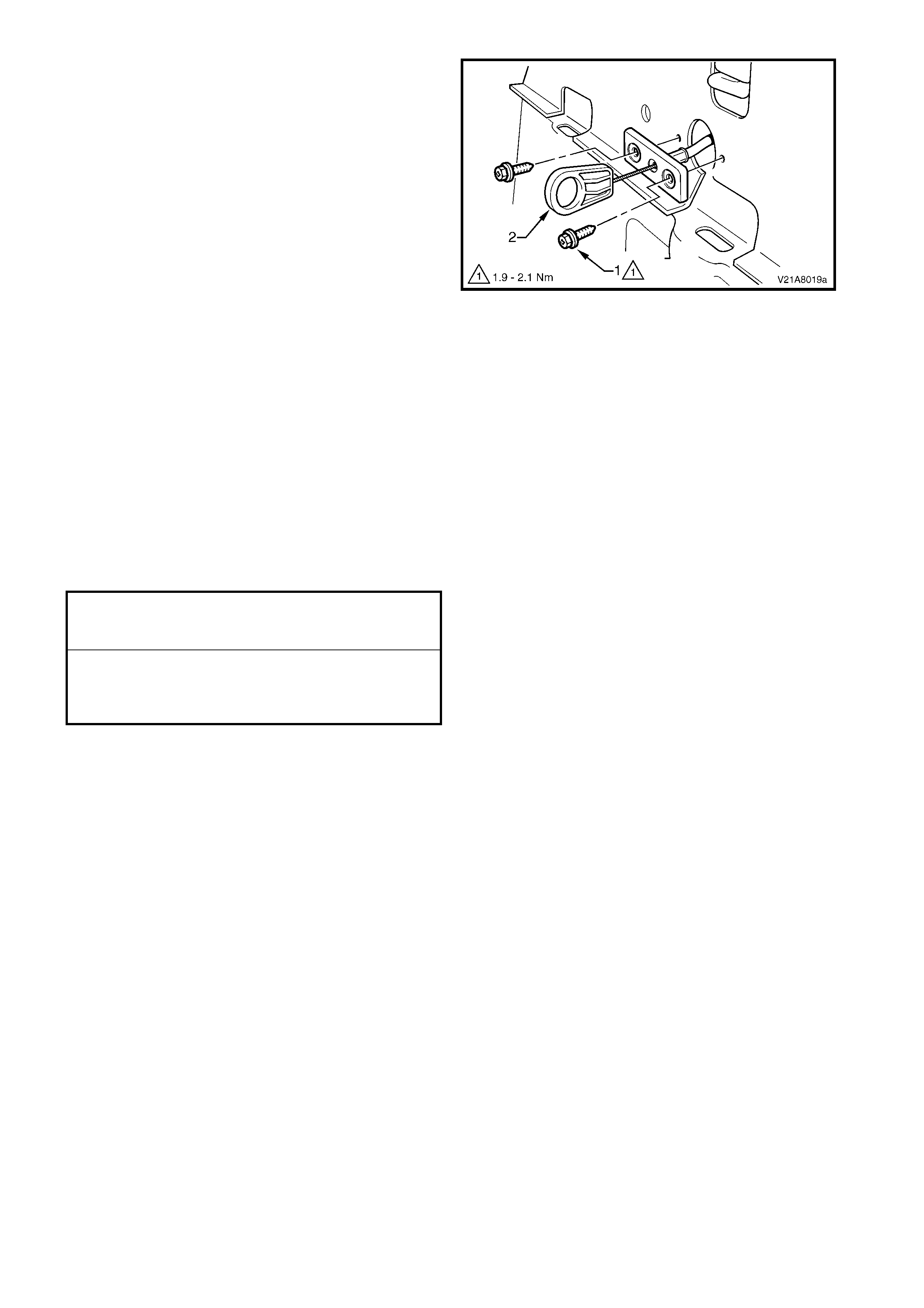
6. For Coupe:
• From within the RH rear passenger
compartment, remove the two screws (1)
attaching the cable assembly (2) to the back
panel - upper.
• Carefully feed the cable assembly into the
passenger compartment and remove.
Figure 1A4-37
REINSTALL
Reinstallation is the reverse of removal noting the
following:
1. Tighten the screws to the specified torque.
2. Prior to clos ing the rear c ompartm ent lid, m anually
close the latch and check operation of the latch
assembly via the rear compartment lid release
switch and the rear compartment lid release cable
assembly. If operation is satisfactory, close the
rear compartment lid and recheck operation If
required adjust the rear compartment lid latch
striker, refer to 3.11 REAR COMPARTMENT LID
STRIKER ASSEMBLY.
REAR COMPARTMENT LID RELEASE
CABLE ASSEMBLY ATTACHING SCREW
TORQUE SPECIFICATION 2.0 – 5.0 Nm
REAR COMPARTMENT LID RELEASE
CABLE ASSEMBLY TO BACK PANEL
UPPER ATTACHING SCREW
TORQUE SPECIFICATION, COUPE 1.9 – 2.1 Nm
3.8 REAR COMPARTMENT LID STRUT ASSEMBLY
LT Section No. 12-660
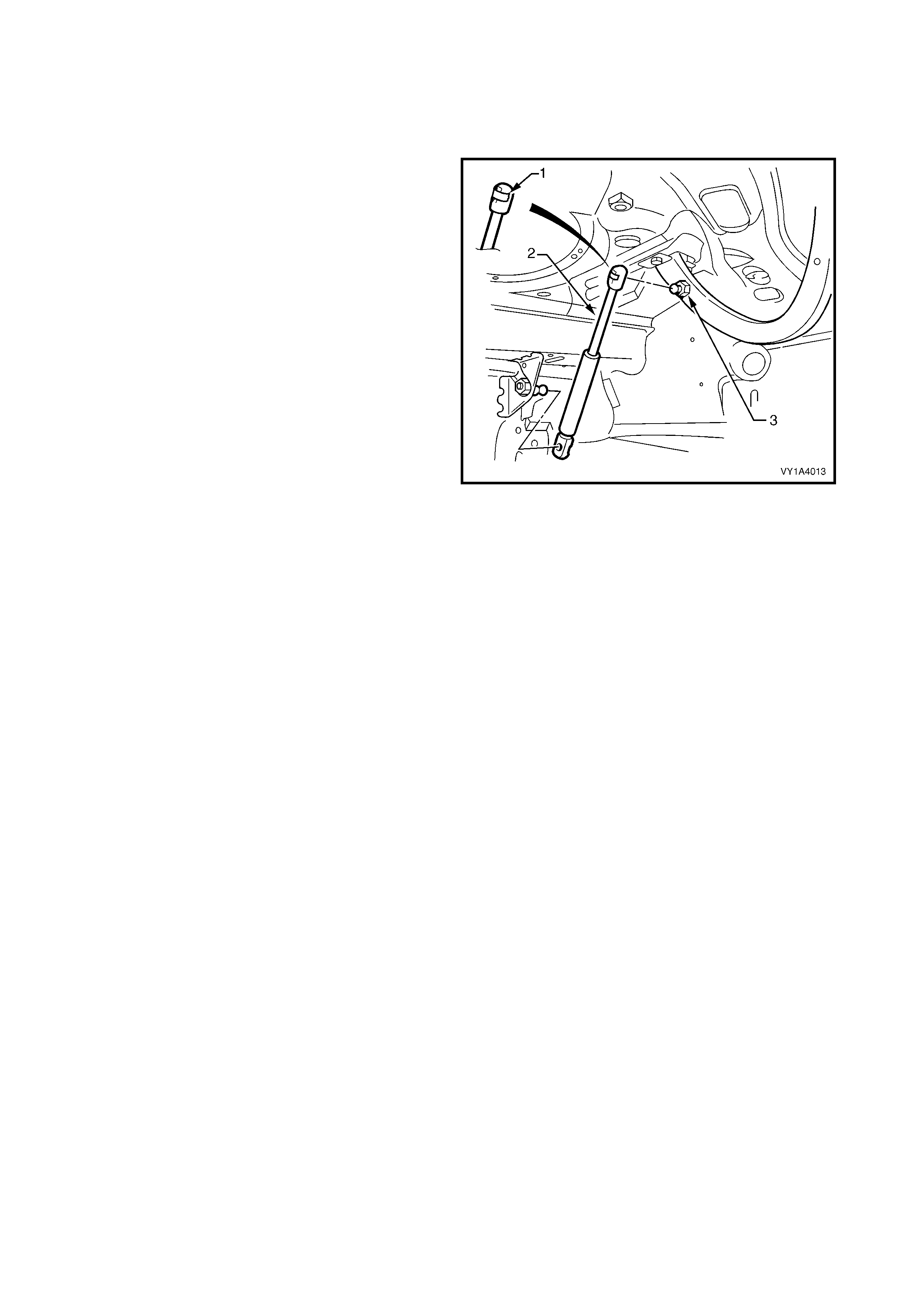
REMOVE
1. Support the rear compartment lid securely.
2. Using a fine, flat blade screwdriver, prise the
retainer (1) from the rear compartm ent lid strut end
(2).
3. Pull the strut assembly from the ball stud (3).
4. Repeat for the opposite end if required.
Figure 1A4-38
REINSTALL
NOTE: If a rear compartment lid strut assembly is
replaced, ensure the correct type is specified as
vehicles with a rear spoiler require stronger units.
1. Apply a small amount of lithium based grease to
the inside of the strut ball cup.
2. Install the retainer onto the strut end, if removed.
3. Align the strut with the ball stud and push into
place.
4. Repeat for the opposite end if required.
3.9 REAR COMPARTMENT LID ASSEMBLY
LT Section No. 12-660
As required, first remove the following components:
1. Rear compartment lid carpet, refer to 3.1 REAR COMPARTMENT LID CARPET.
2. Rear compartment lid applique assembly, refer to 3.2 REAR COMPARTMENT LID APPLIQUE
ASSEMBLY, SEDAN or 3.3 REAR COMPARTMENT LID APPLIQUE ASSEMBLY, COUPE.
3. Rear spoiler assembly if fitted, refer to 3.4 REAR SPOILER ASSEMBLY.
4. Rear compartment lid latch assembly, refer to 3.5 REAR COMPARTMENT LID LATCH ASSEMBLY.
5. Rear compartment lid actuator assembly, refer to 3.6 REAR COMPARTMENT LID ACTUATOR
ASSEMBLY.
6. Rear compartment lid release cable assembly from the rear compartment lid only, refer to
3.7 REAR COMPARTMENT LID RELEASE CABLE ASSEMBLY.
7. Badges and emblems, refer to Section 1A9, EXTERIOR ORNAMENTATION.
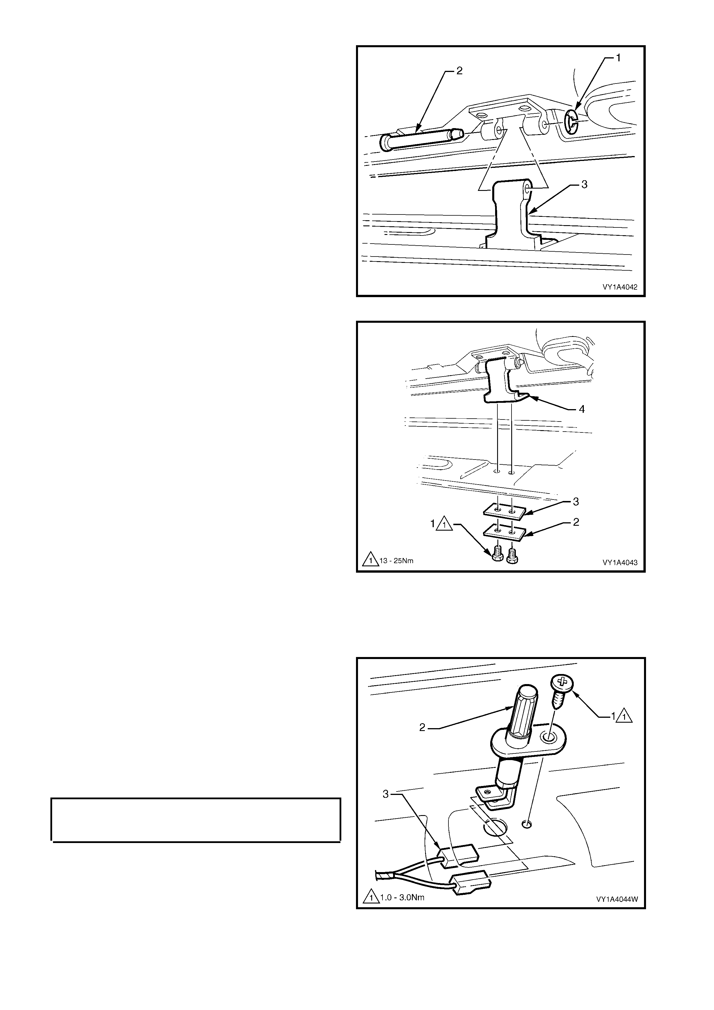
REMOVE
1. Remove the screw (1) attaching the rear
compartment courtesy lamp switch assembly (2) to
the rear compartment lid.
2. Withdraw the switch and disconnect the wiring
connectors (3).
3. Remove the body wiring harness assembly from
the rear compartment lid only. If required, refer to
Section 12O, FUSES AND WIRING
HARNESSES.
Figure 1A4-39
4. Unscrew the rear compartment lid bumper (1) from
each side of the rear compartment lid.
Figure 1A4-40
5. Mark the position of the rear compartment lid
screws (1) on the hinges to aid installation.
6. With the aid of an assistant to support the other
side of the rear compartment lid, remove the two
screws each side attaching the rear compartment
lid to the hinges.
7. Carefully lift the rear compartment lid from the
vehicle.
Figure 1A4-41
REINSTALL
1. With the aid of an assistant, lift the rear compartment lid into position.
2. Align the rear compartment lid with the screw holes in the hinges and install the four attaching screws, do not
tighten.
3. Align the s crew heads with the m ark s pr eviously made and tem porar ily tighten the scr ews. If no mark s exis t,
align the screws centrally in their holes.
4. Install the rear compartment lid bumper each side, setting them fully in.
5. Carefully close the rear compartment lid ensuring it does not contact the surrounding panels.
6. If required, adjust the position of the rear compartment lid, refer to the following procedure, ADJUST.
7. Tighten the rear compartment lid attaching screws to the specified torque.
8. Reinstallation of the remaining components is the reverse of removal.
NOTE: Ensure the body wiring harness assem bly is correctly routed and attached within the rear compartment
lid, refer to Section 12O, FUSES AND WIRING HARNESSES.
ADJUST
Correct alignment of the rear com partment lid is critical to its operation and to the aesthetics of the vehicle. T he
following components allow adjustment of the rear compartment lid:
• Rear compartment lid bumper: Provides vertical adjustment at the rear of the rear compartment lid.
• Rear compartment lid to hinge screws and rear compartment lid hinge to body screws: Provide forward,
rearward and skew adjustment of the rear compartment lid.
• Rear com partment lid s triker ass embly: Provides vertical and sideways adj ustment of the rear com partment
lid.
Whenever alignment is required, perform adjustment in the following order.
1. If fitted, remove the rear compartment lid striker assembly, refer to 3.11 REAR COMPARTMENT LID
STRIKER ASSEMBLY.
2. Ensure the rear compartment lid weatherstrip assembly is installed and the rear compartment lid bumpers
are fitted and set fully in.
3. Carefully close the rear compartment lid, watching each side does not contact the vehicle.
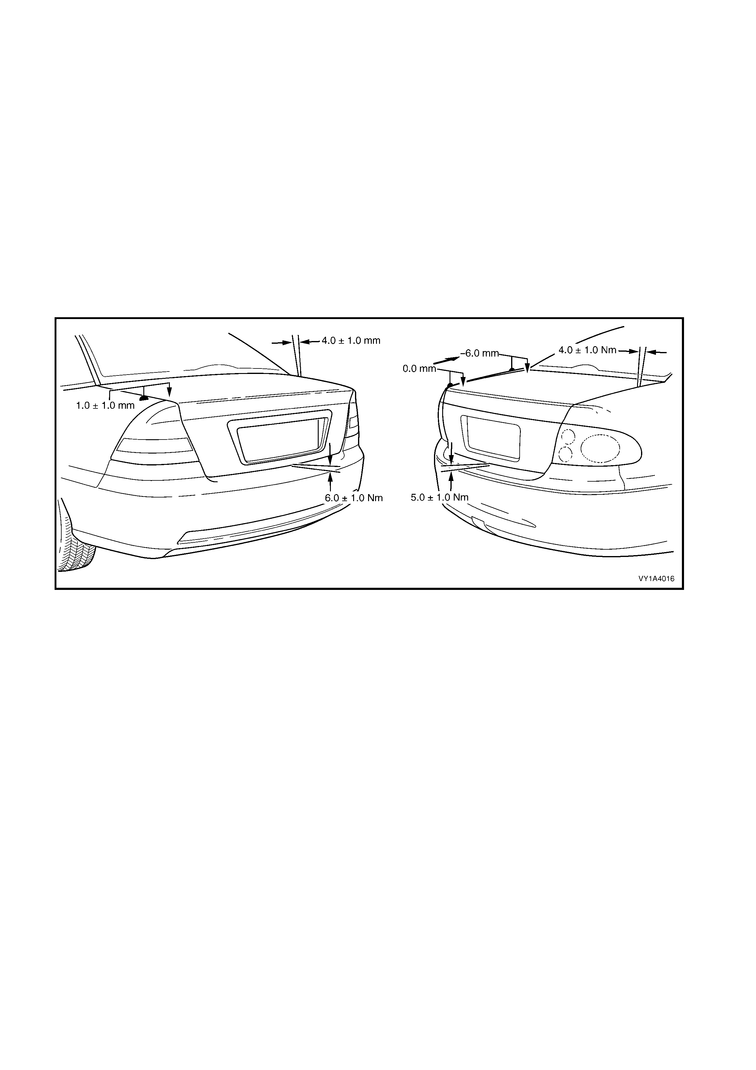
4. Referring to Figure 1A4-42, check the alignment of the rear compartment lid for:
• Length. Compare to the tail lamps. They should be equal.
• Width of gap. Compare the gap between the rear c ompartment lid and quarter panel eac h s ide. T he gap
specification is 4.0 mm ±1.0 mm.
• Consistency of gap. Compare the width of gap between the rear compartment lid and quarter panel at
the front, middle and rear each side. It should be even.
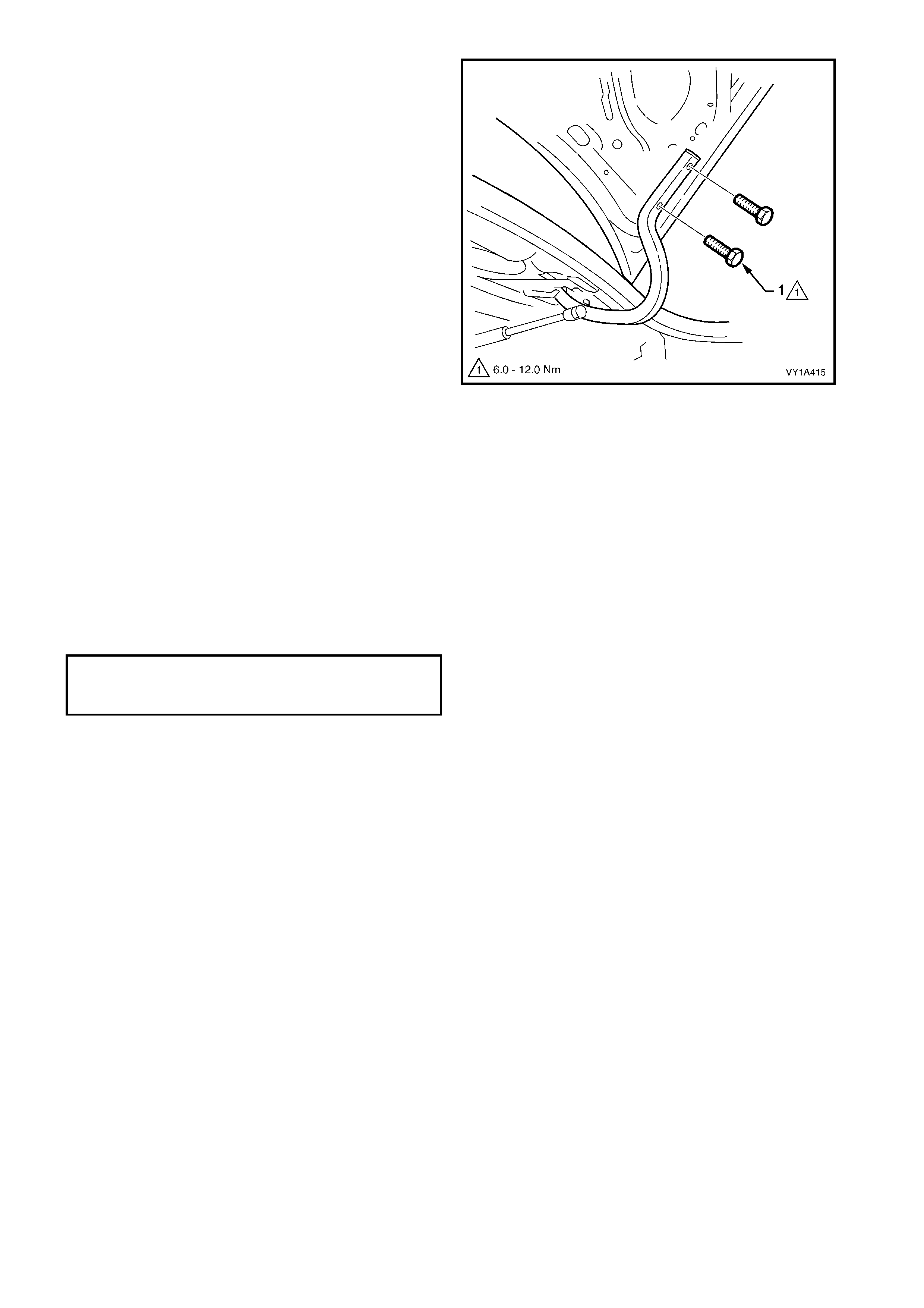
REAR COMPARTMENT LID
ATTACHING SCREW
TORQUE SPECIFICATION 6.0 – 12.0 Nm
5. Open the rear compartment lid and as required, loosen the screws attaching rear compartment lid to the
hinge assembly for fore, aft and skew adjustment, refer to Figure 1A4-41.
NOTE 1: Do not make all adjustments at once. Perform one adjustment, carefully close the hood, check its
position and make further adjustments until correct alignment is achieved.
NOTE 2: If further adjustment is required, loosen the screws attaching the rear compartment lid hinge to the
body and adjust the position of the hinge, refer to 3.10 REAR COMPARTMENT HINGE ASSEMBLY.
6. Install the rear compartment lid striker assembly, refer to 3.11 REAR COMPARTMENT LID STRIKER
ASSEMBLY.
7. Close the rear compartment lid watching that the striker does not pull the rear compartment lid to one side
changing the panel gaps. If it does, move the striker as required.
8. Check the height difference between the rear com partment lid and quarter panel each side. For Sedan the
specification is 1.0 mm ± 1.0 mm. For Coupe it is level at the rear of the rear compartment lid, tapering to
6.0 m m below the quarter panel at the f ront. The rear compartm ent lid to rear bum per fascia ass embly gap
specification is 6.0 mm ± 1.0 mm for Sedan or 5.0 mm ± 1.0 mm Coupe, refer to Figure 1A4-42.
9. As required, open the rear compartment lid, adjust the striker and/or bumper and recheck.
10. Check that all screws are tightened to their specified torque, refer to the appropriate procedures.
Figure 1A4-42
3.10 REAR COMPARTMENT LID HINGE ASSEMBLY
LT Section No. 12-660
As required, first remove the following components:
1. Partial removal of the rear window panel trim assembly, refer to Section 1A8, 2.9 REAR WINDOW TRIM
PANEL ASSEMBLY.
2. Rear compartment lid strut assembly from the hinge, refer to 3.8 REAR COMPARTMENT LID STRUT
ASSEMBLY.
3. Rear Compartment lid assembly, refer to 3.9 REAR COMPARTMENT LID ASSEMBLY.
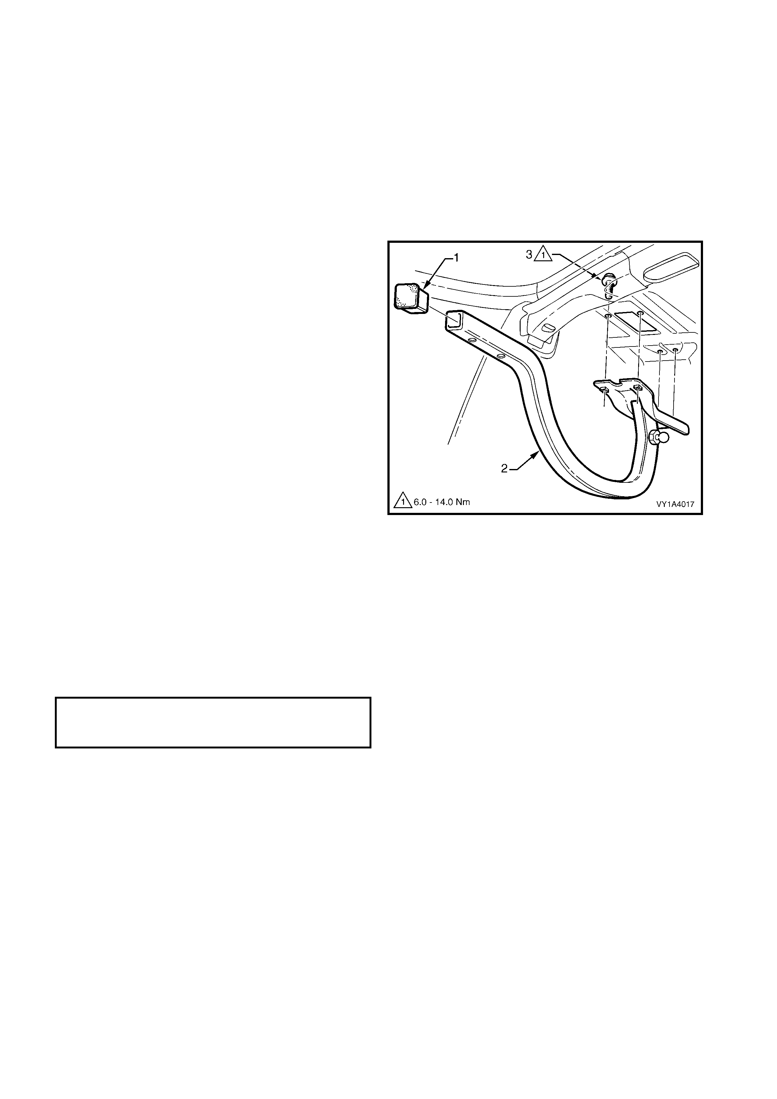
REMOVE
1. If required, prise the rear compartment lid hinge
cap (1) from the end of the hinge assembly (2).
2. If fitted, remove the sound deadener sheet from
above the hinge screws.
3. Have an assistant hold the hinge assembly.
4. From within the passenger compartment remove
the four screws (3) attaching the hinge assembly
to the vehicle.
5. Remove the hinge assembly.
Figure 1A4-43
REINSTALL
1. With the aid of an assistant, lift the rear
compartment lid hinge into position.
2. Install the screws, aligning them with the old marks
or centrally in their holes.
3. Install and align the rear compartment lid, refer to
3.9 REAR COMPARTMENT LID ASSEMBLY.
4. Tighten the screws to the specified torque.
REAR COMPARTMENT LID HINGE
ASSEMBLY ATTACHING SCREW
TORQUE SPECIFICATION 6.0 – 14.0 Nm

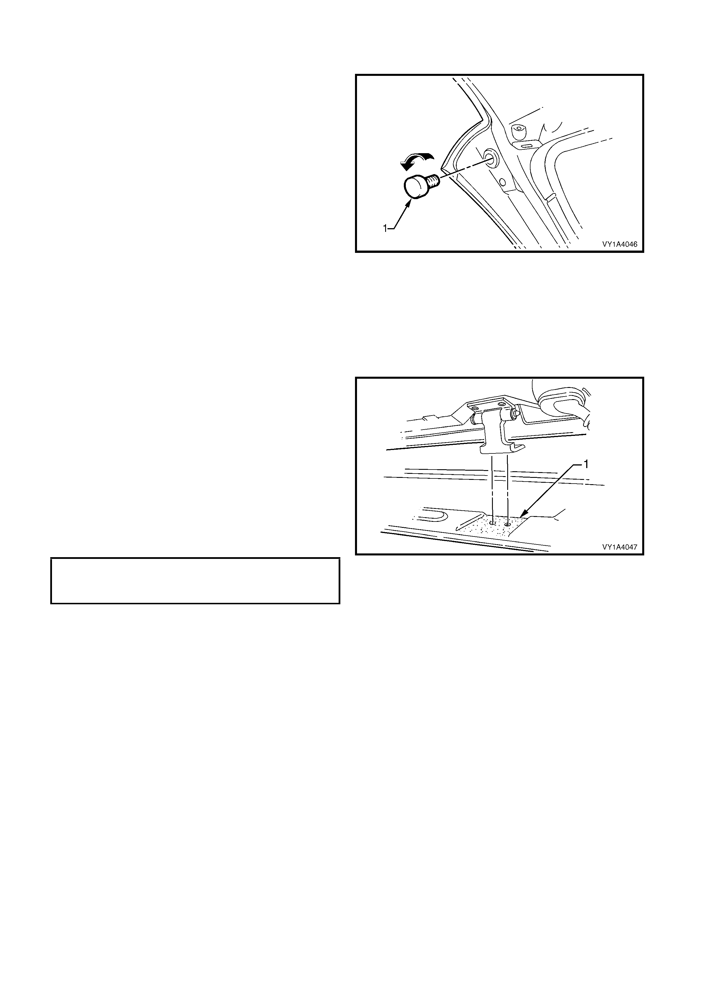
3.11 REAR COMPARTMENT LID STRIKER ASSEMBLY
LT Section No. 12-680
As required, first remove rear end trim panel, refer to
Section 1A8, 3.19 REAR END TRIM PANEL.
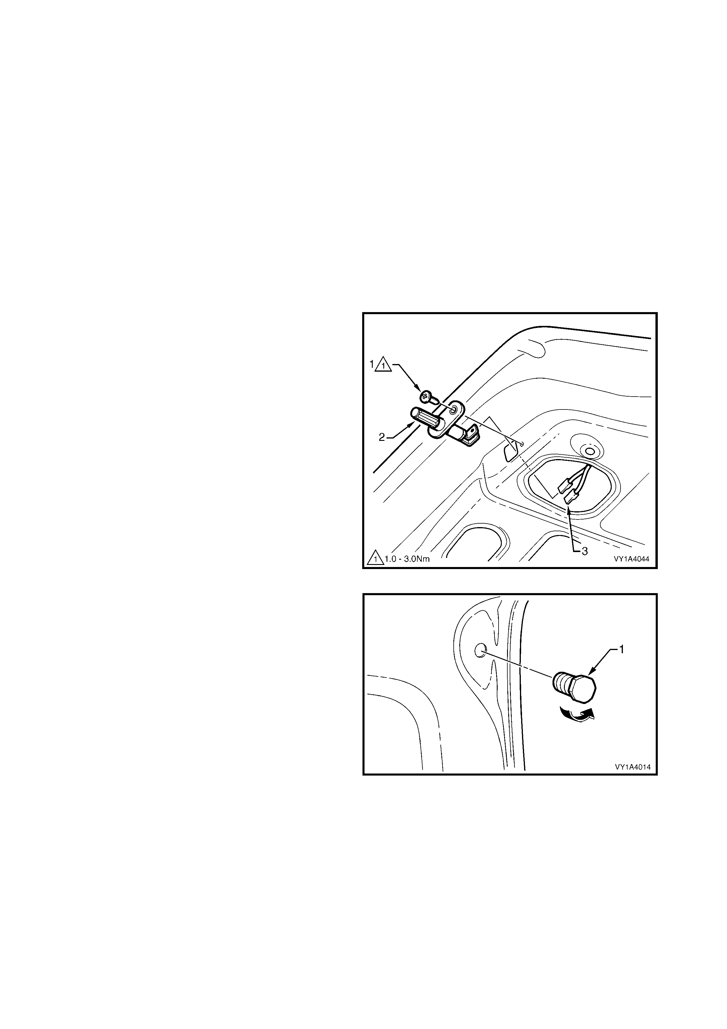
REMOVE
1. Mark the position of the striker with a pencil.
2. Remove the screw (1) attaching the striker
assembly (2) to the vehicle and remove the striker.
Figure 1A4-44
REINSTALL
1. Reinstallation is the reverse of removal.
NOTE: As required, adjust the pos ition of the strik er to
obtain correct rear compartment lid alignment, refer to
3.9 REAR COMPARTMENT LID ASSEMBLY –
ADJUST.
2. Tighten the screw to the specified torque.
REAR COMPARTMENT LID STRIKER
ASSEMBLY ATTACHING SCREW
TORQUE SPECIFICATION 15.0 – 35.0 Nm
3.12 RE AR COMPARTMENT LID WEATHERSTRIP
LT Section No. 11-600
As required, f irst rem ove the rear end trim panel, refer
to Section 1A8, 3.19 REA R END TRIM PANEL.
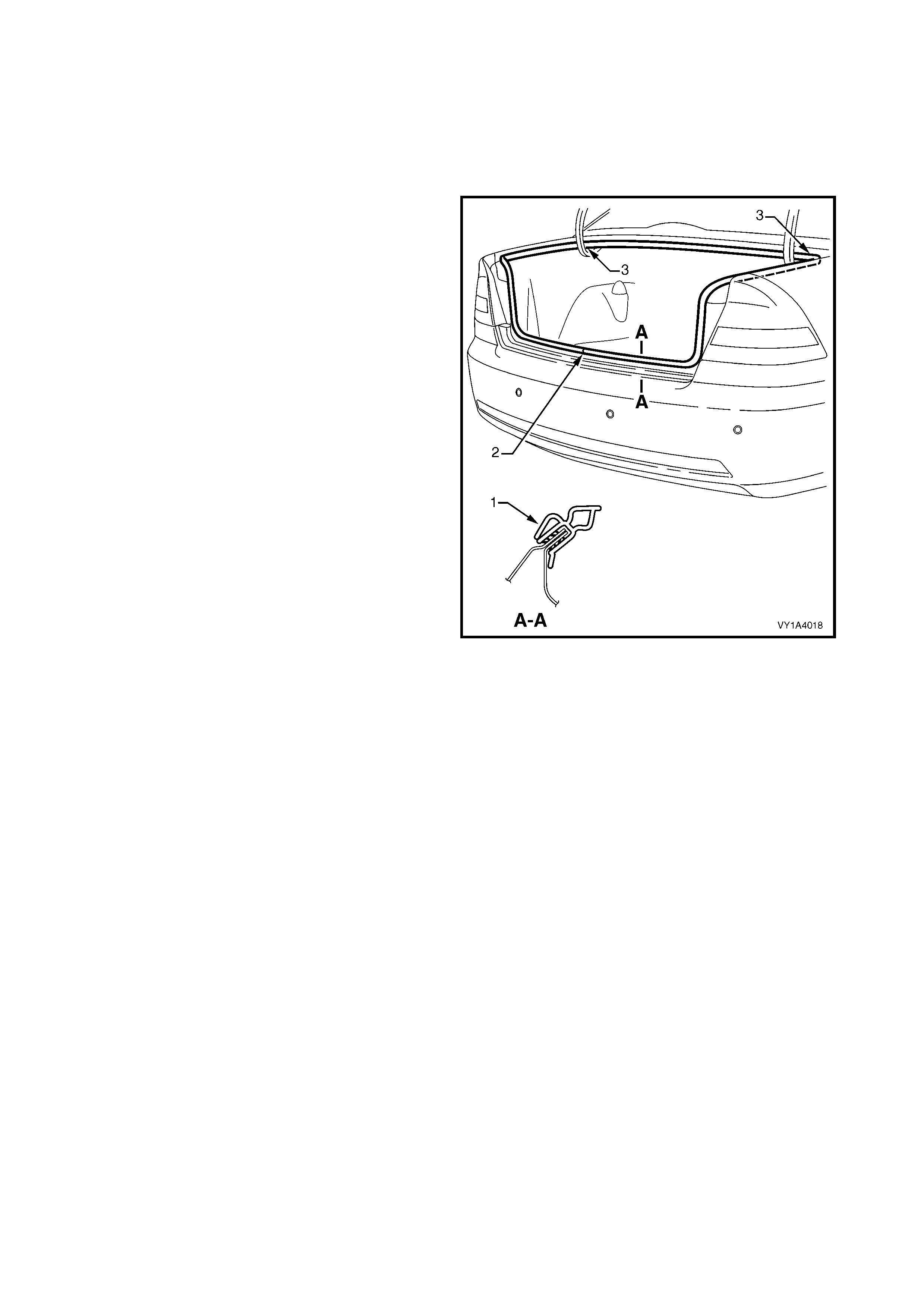
REMOVE
1. Gr asp the weatherstr ip assem bly and c arefully pull
it from the body flange. Start at one point and
continue along its length.
2. Remove the weatherstrip from the vehicle, over
the rear compartment lid.
NOTE: Sedan shown, Coupe similar.
Figure 1A4-45
REINSTALL
1. Lay the weatherstrip on the f loor and ensure the L-
shaped lip (1) is to the inside, refer to Figure 1A4-
45.
2. Locate the weatherstrip join (2) which is to be
aligned with the striker assembly.
3. Fit the weatherstrip over the rear compartment lid
and push onto the body flange, beginning at the
join.
NOTE: Allow crowding of the weatherstrip in each
corner (3) to avoid short cutting of the corners.
4. SERVICE OPERATIONS – LIFTGATE, WAGON
4.1 LIFTGATE WINDOW LOWER GARNISH
LT Section No. – 14-500
REMOVE
1. Beginning at one end of the liftgate window lower
garnish (1), insert a flat blade screwdriver behind
the garnish at the retaining clip (2).
2. Repeat for the seven remaining clips, carefully
prising the garnish from the liftgate assembly.
3. If required, prise the clips from the garnish with a
flat blade screwdriver.
Figure 1A4-46
REINSTALL
1. If refitting the clips, ensure their correct orientation.
2. Align the clips with their holes in the liftgate panel
and clip the garnish onto the liftgate.
4.2 LIFTGATE LOWER TRIM PANEL
LT Section No. – 14-500
As required, first remove the liftgate window lower
garnish, refer to 4.1 LIFTGATE WINDOW LOWER
GARNISH.
REMOVE
1. Using a suitable trim clip removal tool, carefully
prise the retainer (1), 14 places, attaching the
liftgate lower trim panel (2) to the liftgate assembly.
2. Rem ove the panel, sliding it fr om under the liftgate
inside handle (3).
Figure 1A4-47
REINSTALL
1. Install the panel, sliding it under the liftgate inside
handle.
2. Fit the 14 retainers, pushing them in firmly.
4.3 LIFTGATE INSIDE HANDLE
LT Section No. –
REMOVE
1. Insert a flat blade screwdriver between the liftgate
assembly and the rear edge of the liftgate inside
handle (1).
NOTE: Place a rag between the sc rewdriver and panel
to protect the paintwork.
2. Carefully lever the screwdriver in the direction
shown to release the retaining tabs (2) from the
liftgate assembly.
3. Remove the handle.
Figure 1A4-48
REINSTALL
1. Install the handle ensuring the retaining tabs are
correctly seated.
4.4 LIFTGATE WINDOW UPPER GARNISH
LT Section No. – 14-500
REMOVE
1. Rem ove the two retainers (1) and remove the high
mount stop lamp cover (2).
2. Remove the retainer (3) from either the left-hand
or right-hand liftgate window upper garnish (4).
3. Insert a flat blade screwdriver behind the garnish
at the clip (5). Push on the clip tab and carefully
prise the clip and garnish from the liftgate
assembly.
4. Remove the garnish from the liftgate, also
detaching it fr om the lif tgate window lower garnish,
if not removed.
5. If required, prise the clip from the garnish.
Figure 1A4-49
REINSTALL
1. If refitting the clip, ensure its correct orientation.
2. Clip the garnis h onto the lif tgate, ins tall the retainer
and reinstall the high mount stop lamp cover.
4.5 LIFTGATE HANDLE ASSEMBLY
LT Section No. – 02-385
As required, first remove the following components:
1. Liftgate window lower garnish, refer to 4.1 LIFTGATE WINDOW LOWER GARNISH.
2. Liftgate lower trim panel, refer to 4.2 LIFTGATE LOWER TRIM PANEL.
REMOVE
1. From within the liftgate cavity, remove the four
nuts (1) attaching the liftgate handle assembly (2)
to the liftgate assembly.
NOTE: The two inner nuts also attach the liftgate
handle push button assembly.
2. Dis connec t the licence plate lam p wiring connector
(3) from within the liftgate cavity .
3. Remove the handle assembly away from the
liftgate assembly and remove the licence plate
lamp wiring harness grommet (4).
4. Withdraw the licence plate lamp wiring harness
and remove the handle assembly.
Figure 1A4-50
DISASSEMBLE
1. Remove each r ear lic enc e plate lam p ass embly ( 1)
from the handle assembly by pushing on the tab
(2) and removing the housing assembly in the
direction shown.
2. Rotate the bulb socket (3) and remove from the
lamp housing.
3. Remove the wiring from the rear of the handle
assembly.
Figure 1A4-51
REINSTALL
1. Reinstallation is the reverse of removal. Tighten
the handle assembly nuts to the specified torque.
LIFTGATE HANDLE ASSEMBLY
ATTACHING NUT
TORQUE SPECIFICATION 2.0 – 5.0 Nm
4.6 LIFTGATE HANDLE PUSH BUTTON ASSEMBLY
LT Section No. – 12-680
NOTE: A new liftgate handle push button assembly is supplied un-coded and will require disassembly and
sending to an authorised locksmith for coding to the vehicle’s keys.
As required, first remove the following components:
1. Liftgate window lower garnish, refer to 4.1 LIFTGATE WINDOW LOWER GARNISH.
2. Liftgate lower trim panel, refer to 4.2 LIFTGATE LOWER TRIM PANEL.
REMOVE
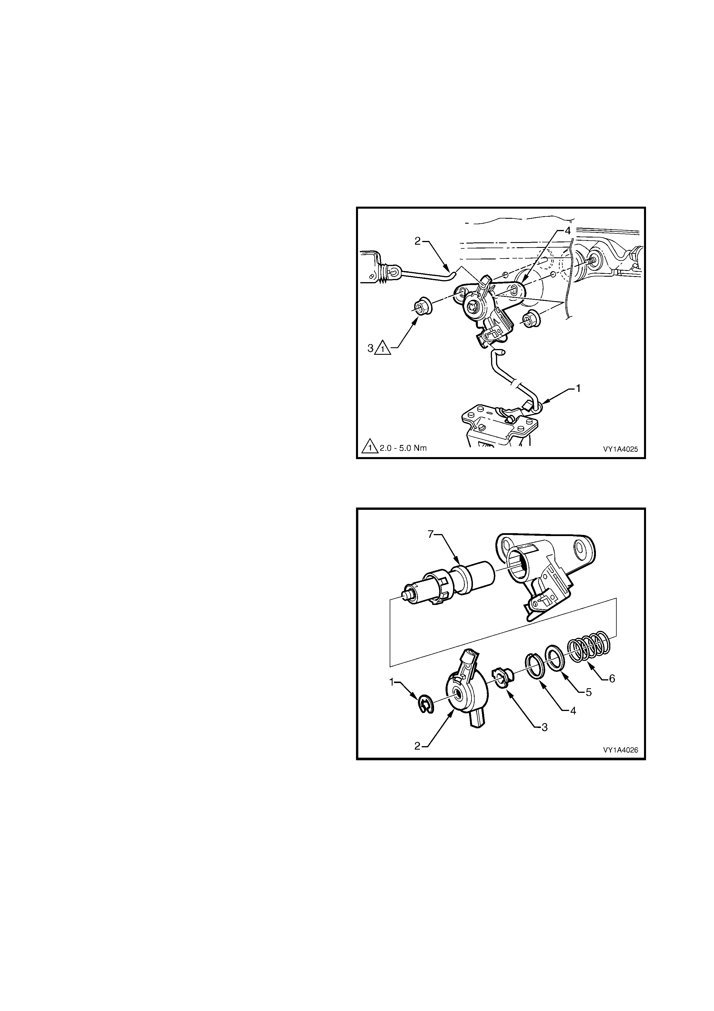
1. Disconnect the liftgate lock connecting rod (1) from
the latch assembly.
2. Disconnect the actuator connecting rod (2) from
the push button assembly.
3. F rom within the liftgate cavity, rem ove the two nuts
(3) attaching the push button assembly (4) to the
liftgate assembly.
NOTE: The two inner nuts also attach the liftgate
handle assembly.
4. Remove the push button assembly.
Figure 1A4-52
DISASSEMBLE
1. Remove the push button assembly components in
the following order:
• E-clip (1),
• Latch actuator cover (2),
• Drive cam (3),
• Spring clip (4),
• Washer (5),
• Spring, (6), and
• Lock cylinder assembly (7).
2. The lock cylinder assembly can be further
disassembled to enable coding as follows,
referring to Figure 1A4-54:
• Insert the key and turn from position A to B.
• Turn back slightly to position C and cover the
ball hole in the housing (1) with a finger. This
will stop the ball (2) from jumping out.
• Withdraw the lock barrel (3) from the housing
until the ball is released. Remove the ball and
spring (4) and completely remove the barrel.
• Remove each of the tumblers (5) and spring
(6) as required.
Figure 1A4-53
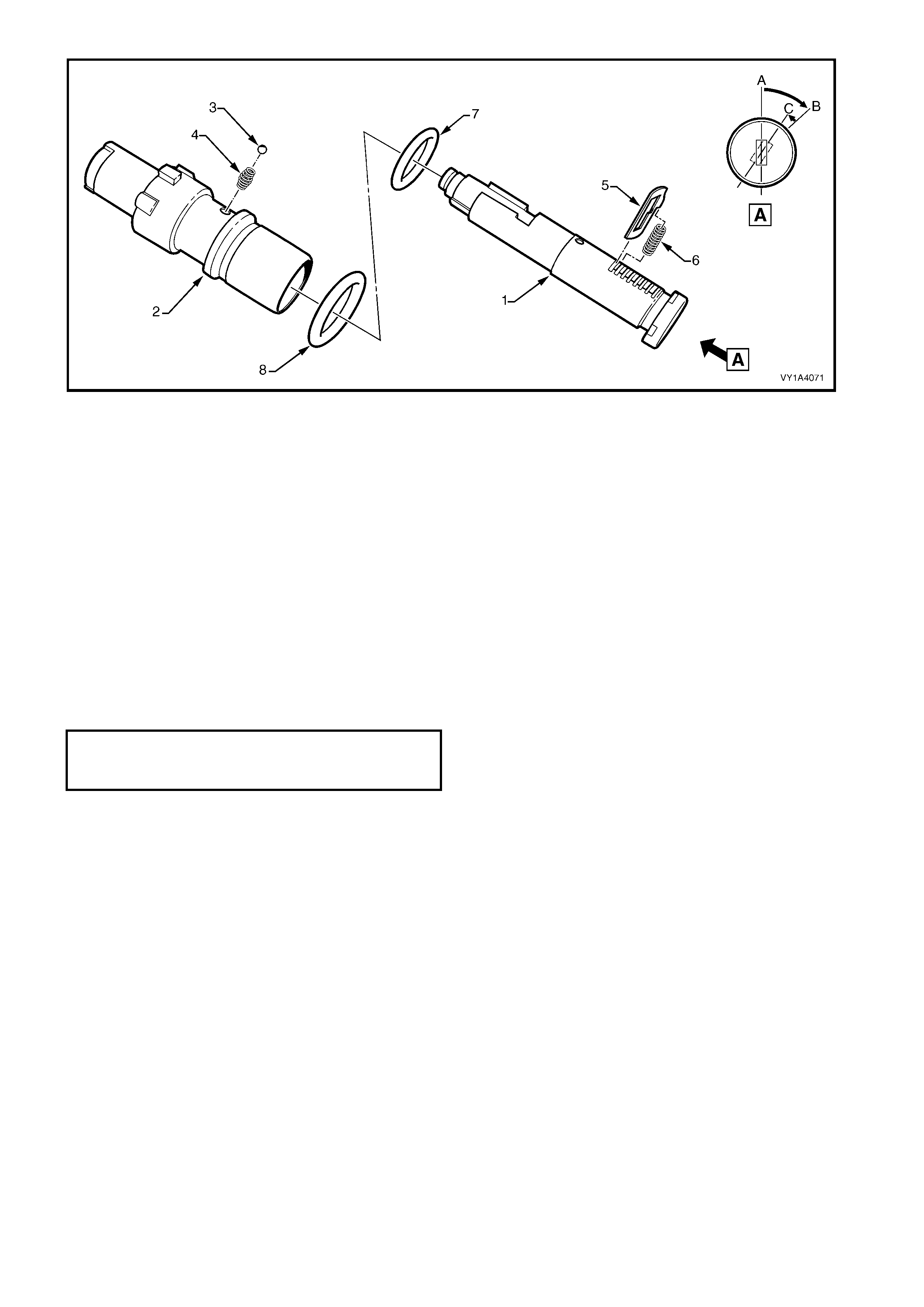
Figure 1A4-54
REASSEMBLE
If a new assembly is being fitted, a kit is supplied which
can be sent to an authorised locksmith for coding to
the vehicle’s keys.
Reassem ble the push button assembly components in
the reverse sequence to their disassembly.
REINSTALL
Reinstallation is the reverse of removal noting the
following.
1. The slotted holes in the push button assembly
provide adjustment of the latch connecting rod.
2. Tighten the nuts to the specified torque and test for
correct operation of the push button assembly prior
to installing the trim components.
LIFTGATE HANDLE ASSEMBLY
ATTACHING NUT
TORQUE SPECIFICATION 2.0 – 5.0 Nm
4.7 LIFTGATE LATCH ASSEMBLY
LT Section No. – 12-680
As required, first remove the following components:
1. Liftgate window lower garnish, refer to 4.1 LIFTGATE WINDOW LOWER GARNISH.
2. Liftgate lower trim panel, refer to 4.2 LIFTGATE LOWER TRIM PANEL.
REMOVE
1. From within the liftgate cavity, disconnect the push
button assembly connecting rod (1).
2. Remove the four screws (2) attaching the liftgate
latch assembly (3) to the liftgate assembly.
3. Remove the latch assembly from the liftgate cavity.
Figure 1A4-55
REINSTALL
Reinstallation is the reverse of removal. Tighten the
screws to the specified torque and test for correct
operation of the lock assembly prior to installing the
trim components.
LIFTGATE LATCH ASSEMBLY
ATTACHING SCREW
TORQUE SPECIFICATION 2.0 – 5.0 Nm
4.8 LIFTGATE ACTUATOR ASSEMBLY
LT Section No. – 12-680
NOTE: The liftgate actuator assembly is part of
the central locking system. For diagnosis refer to
Section 12J, BODY CONTROL MODULE.
As required, first remove the following components:
1. Liftgate window lower garnish, refer to 4.1 LIFTGATE WINDOW LOWER GARNISH.
2. Liftgate lower trim panel, refer to 4.2 LIFTGATE LOWER TRIM PANEL.
REMOVE
1. Disconnect the connecting rod (1) from the push
button assembly.
2. Loos en the scr ew (2) and slide the lif tgate actuator
assembly (3) from its keyhole slot.
3. Remove the actuator assembly from the liftgate
cavity as shown and disconnect the wiring
connector (4).
Figure 1A4-56
REINSTALL
Reinstallation is the reverse of removal. Tighten the
screw to the specified torque and test for correct
operation of the lock assembly prior to installing the
trim components.
LIFTGATE ACTUATOR
ASSEMBLY ATTACHING SCREW
TORQUE SPECIFICATION 2.0 – 5.0 Nm
4.9 LIFTGATE AIR DEFLECTOR ASSEMBLY
LT Section No. – 10-350
As required, first remove the high mount stop lamp
cover and liftgate window upper garnish, refer to
4.4 LIFTGATE WINDOW UPPER GARNISH.
REMOVE
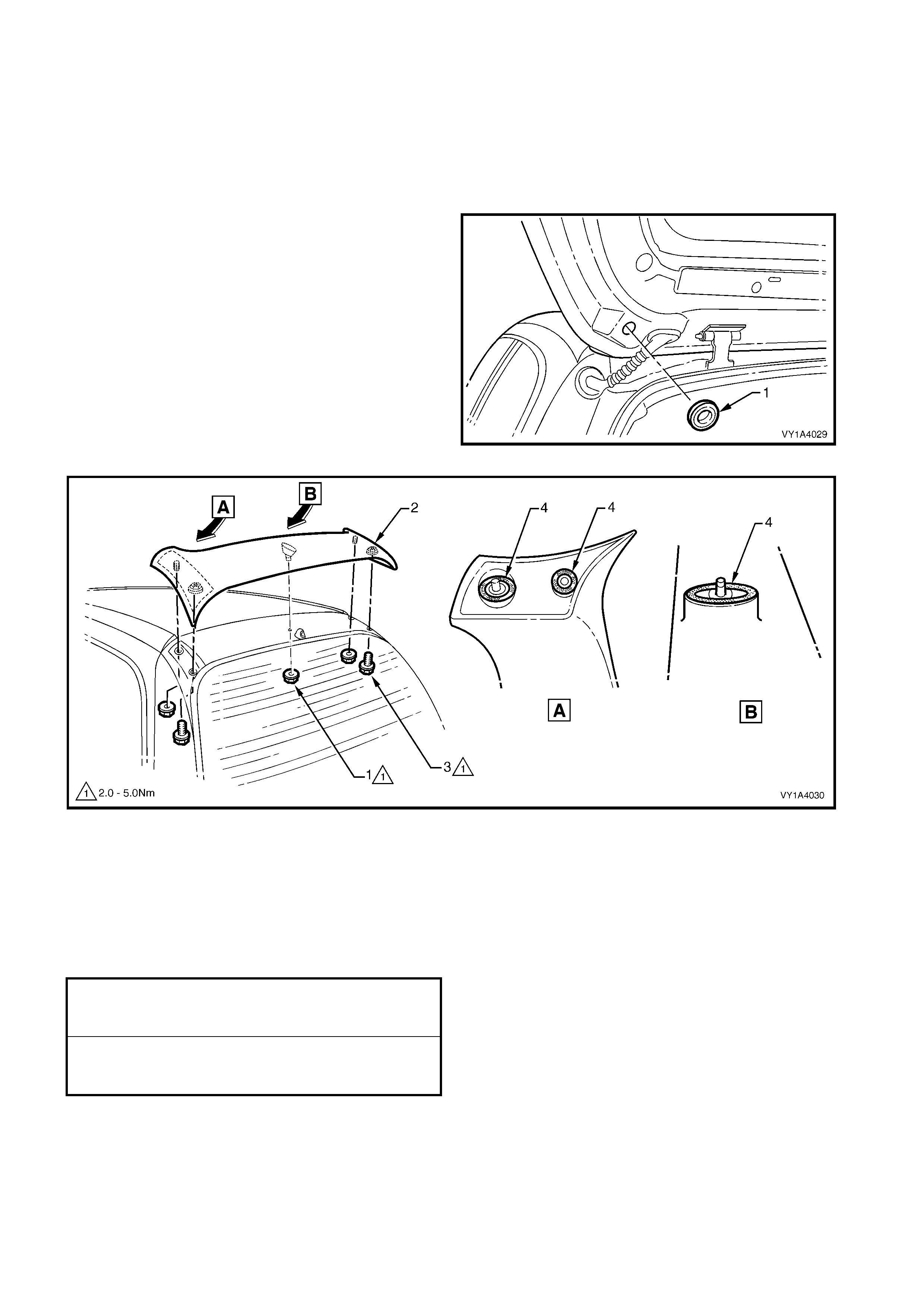
1. Remove the plug (1) from each side of the liftgate
assembly.
2. Remove the thr ee nuts (1) attaching the liftgate air
deflector assembly (2) to the liftgate assembly,
refer to Figure 1A4-58.
3. Remove the two sc rews (3) attaching the deflec tor
assembly to the liftgate assembly and remove the
deflector assembly.
NOTE: Take care when removing the deflector
assembly not to damage the seals (4) as they are not
serviced.
Figure 1A4-57
Figure 1A4-58
REINSTALL
Reinstallation is the reverse of removal. Tighten the
nuts and screws to the specified torque.
NOTE: Prior to installation, ensure the seals are not
damaged, if in doubt apply a small amount of non-
hardening sealer.
LIFTGATE AIR DEFLECTOR
ASSEMBLY ATTACHING NUT
TORQUE SPECIFICATION 2.0 – 5.0 Nm
LIFTGATE AIR DEFLECTOR
ASSEMBLY - ATTACHING SCREW
TORQUE SPECIFICATION 2.0 – 5.0 Nm
4.10 REAR WINDOW WIPER ASSEMBLY
LT Section No. – 10-525
NOTE: The following procedure describes the
replacement of the liftgate components of the wiper
assembly. For further information refer to Section
12N, WIPERS / WASHERS & HORN.
As access to the rear window wiper motor assembly is required, first remove the following components:
1. Liftgate window lower garnish, refer to 4.1 LIFTGATE WINDOW LOWER GARNISH.
2. Liftgate lower trim panel, refer to 4.2 LIFTGATE LOWER TRIM PANEL.
REMOVE
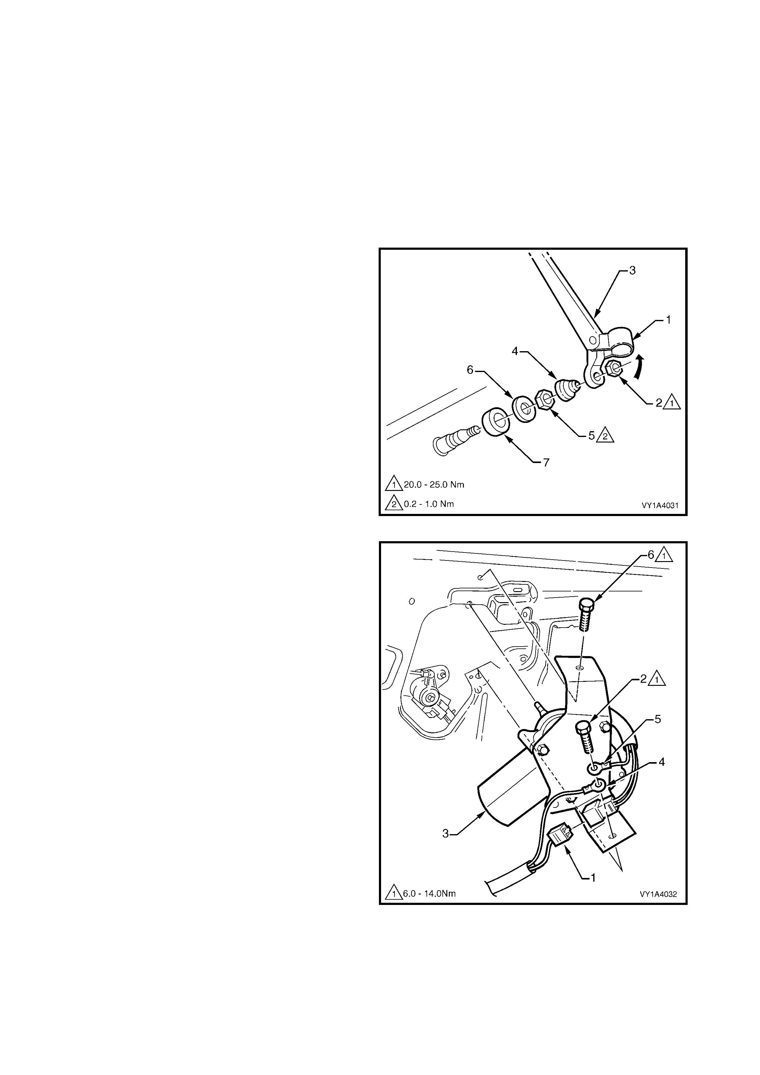
1. Lift the cap (1) and remove the nut (2) attaching
the rear window wiper arm assembly (3) to the
wiper pivot shaft.
2. Remove the cover (4), nut (5), cap (6) and spacer
(7) from the wiper pivot shaft.
Figure 1A4-59
3. Disconnect the wiring harness connector (1).
4. Remove the screw (2) attaching the rear window
wiper motor assembly (3), liftgate harness earth
connection (4) and motor assembly earth
connection (5) to the liftgate assembly.
5. Remove the screw (6) and remove the motor
assembly from the liftgate assembly.
Figure 1A4-60
REINSTALL
Reinstallation is the reverse of removal noting the
following.
1. Ens ure the com ponents and ear th connections are
assembled in the correct order.
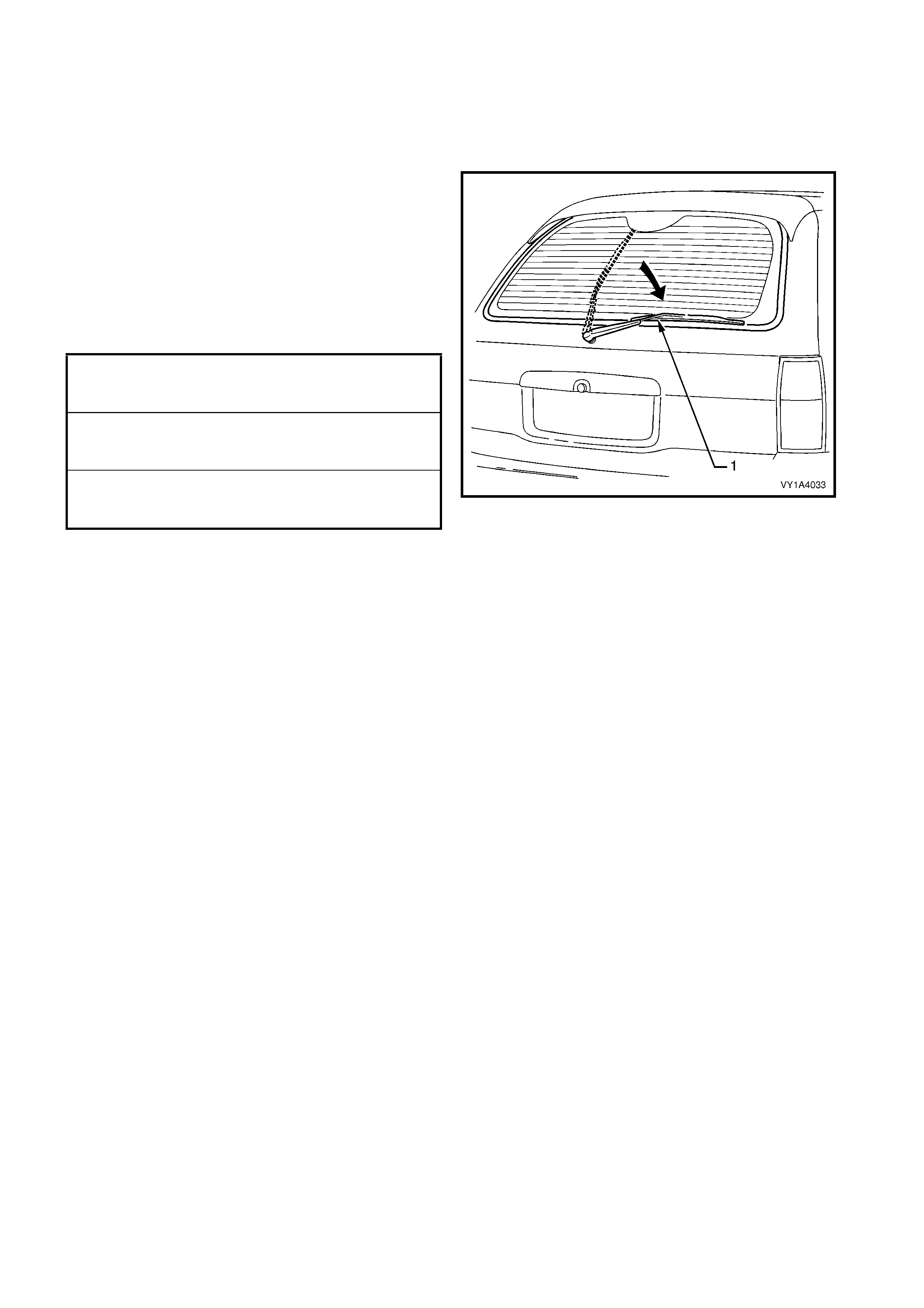
2. When installing the rear window wiper arm
assem bly (1), fit the ar m onto the wiper pivot shaft
in the vertical position and with the blade set onto
the glass, rotate the arm clockwise until the blade
rests slightly above the liftgate window moulding.
3. Tighten the screws and nuts to the specified
torque.
4. Test for correct operation of the wiper assembly
prior to installing the trim components.
Figure 1A4-61
REAR WINDOW WI PER ARM
ASSEMBLY ATTACHING NUT
TORQUE SPECIFICATION 20.0 – 25.0 Nm
REAR WINDOW WIPER MOTOR
ASSEMBLY ATTACHING NUT
TORQUE SPECIFICATION 0.2 – 1.0 Nm
REAR WINDOW WIPER MOTOR
ASSEMBLY ATTACHING SCREW
TORQUE SPECIFICATION 6.0 – 14.0 Nm
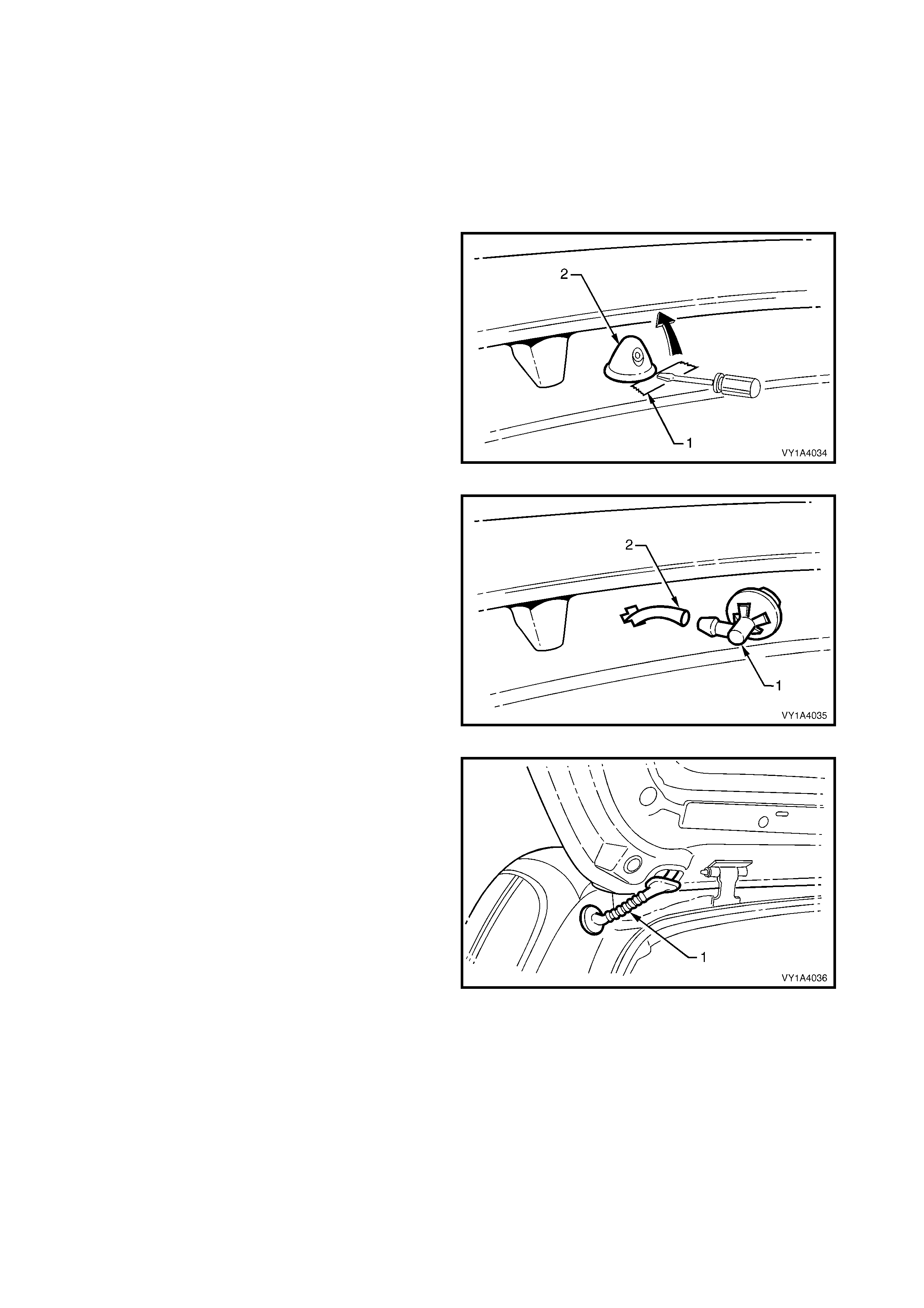
4.11 REAR WINDOW WASHER NOZZLE & HOSE ASSEMBLIES
LT Section No. – 10-500
NOTE: The following procedure describes the
replacement of the liftgate components of the rear
window washer system. F or fur ther inf orm ation ref er to
Section 12N, WIPERS /WASHERS & HORN.
REMOVE
1. Place a piece of tape (1) or similar on the
paintwork adjacent to the rear window washer
nozzle assembly (2) and using a fine flat blade
screwdriver prise the nozzle from the liftgate
assembly.
Figure 1A4-62
2. Disconnect the nozzle assembly (1) from the rear
window washer hose assembly (2).
Figure 1A4-63
3. Remove the grommet (1) from the liftgate
assembly and withdraw the washer hose from the
liftgate.
NOTE: If further disassembly of the rear
window washer system is required, refer to
Section 12N, WIPERS /WASHERS & HORN.
Figure 1A4-64
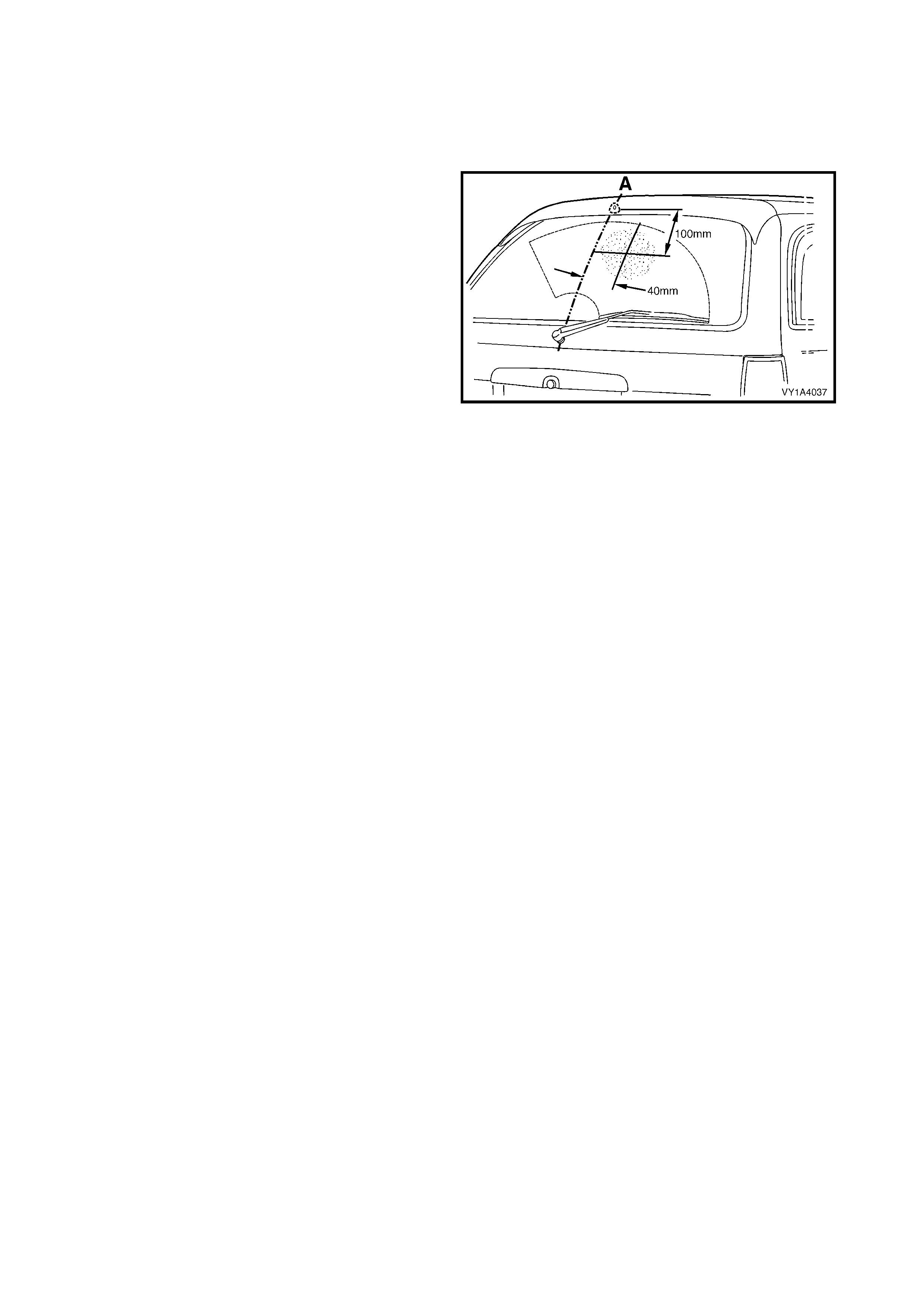
REINSTALL
Reinstallation is the reverse of removal noting the
following.
1. Ensure the nozzle assembly is correctly seated to
avoid water leaking into the liftgate cavity.
2. Test the operation of the washer. The spray from
the nozzle should strike the window within the 100
mm diameter area shown shaded.
3. If adjustment is required, insert a pin or fine piece
of wire into the nozzle jet and adjust as required.
Figure 1A4-65
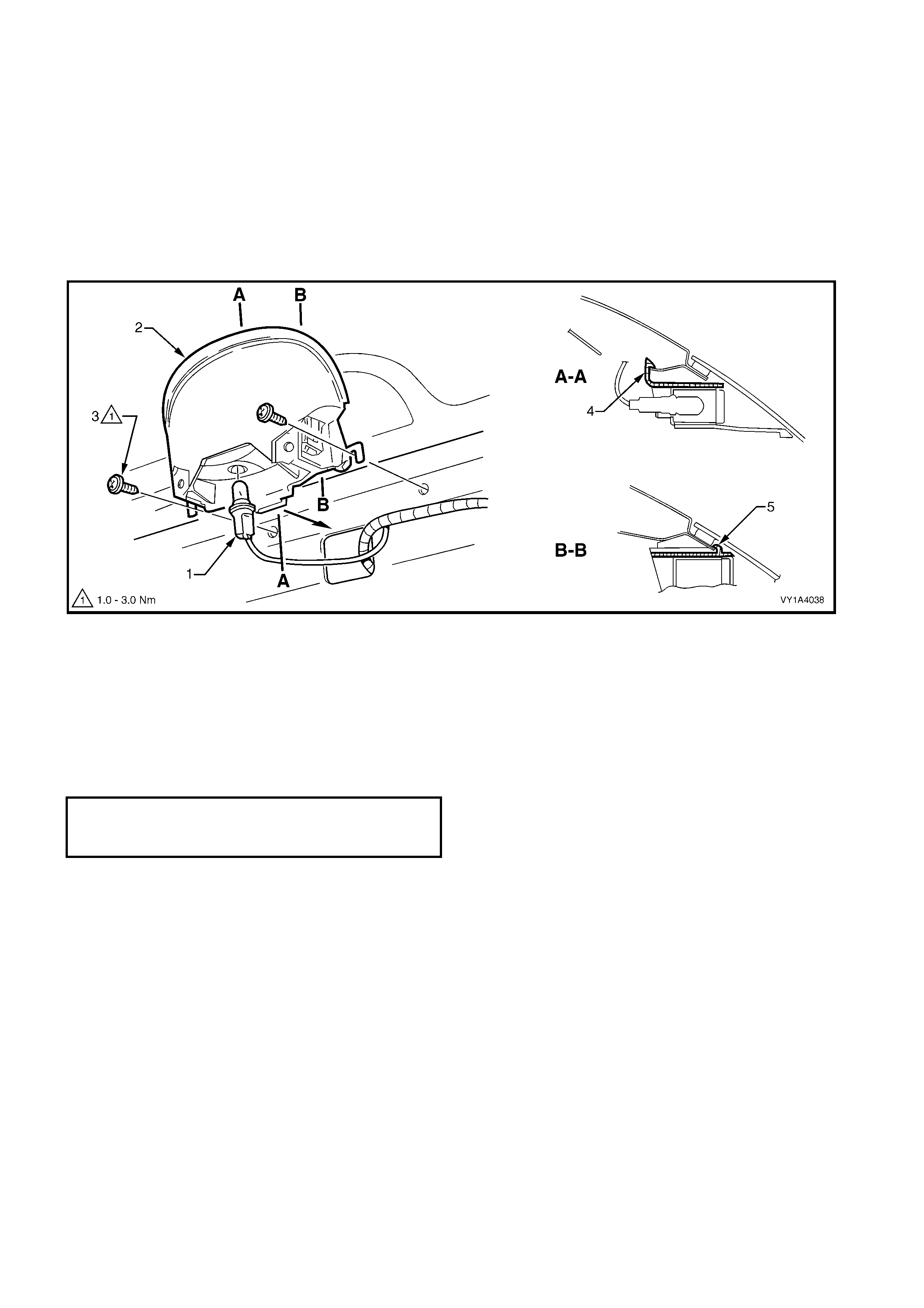
4.12 HIGH MOUNT STOP LAMP ASSEMBLY
LT Section No. – 02-350
As required, first remove the high mount stop lamp cover and liftgate window upper garnish, refer to
4.4 LIFTGATE WINDOW UPPER GARNISH.
REMOVE
1. Twist and remove the lamp socket (1) from the high mount stop lamp assembly (2), refer to Figure 1A4-66.
2. Remove the two screws (3) attaching the lamp assembly to the liftgate assembly.
3. Pr ise the lock ing tab ( 4) back s lightly, release the locking tabs (5) eac h side and rem ove the lam p as sem bly
from the liftgate assembly.
Figure 1A4-66
REINSTALL
Reinstallation is the reverse of removal noting the following.
1. Ensure the lamp assembly is correctly located by inserting locking tab (4) and pushing the lamp assembly
toward the window to engage the locking tabs (5), refer to Figure 1A4-66.
2. Tighten the screws to the specified torque.
3. Test for correct operation of the lamp assembly prior to installing the cover and garnishes.
HIGH MOUNT STOP LAMP
ASSEMBLY ATTACHING SCREW
TORQUE SPECIFICATION 1.0 – 3.0 Nm
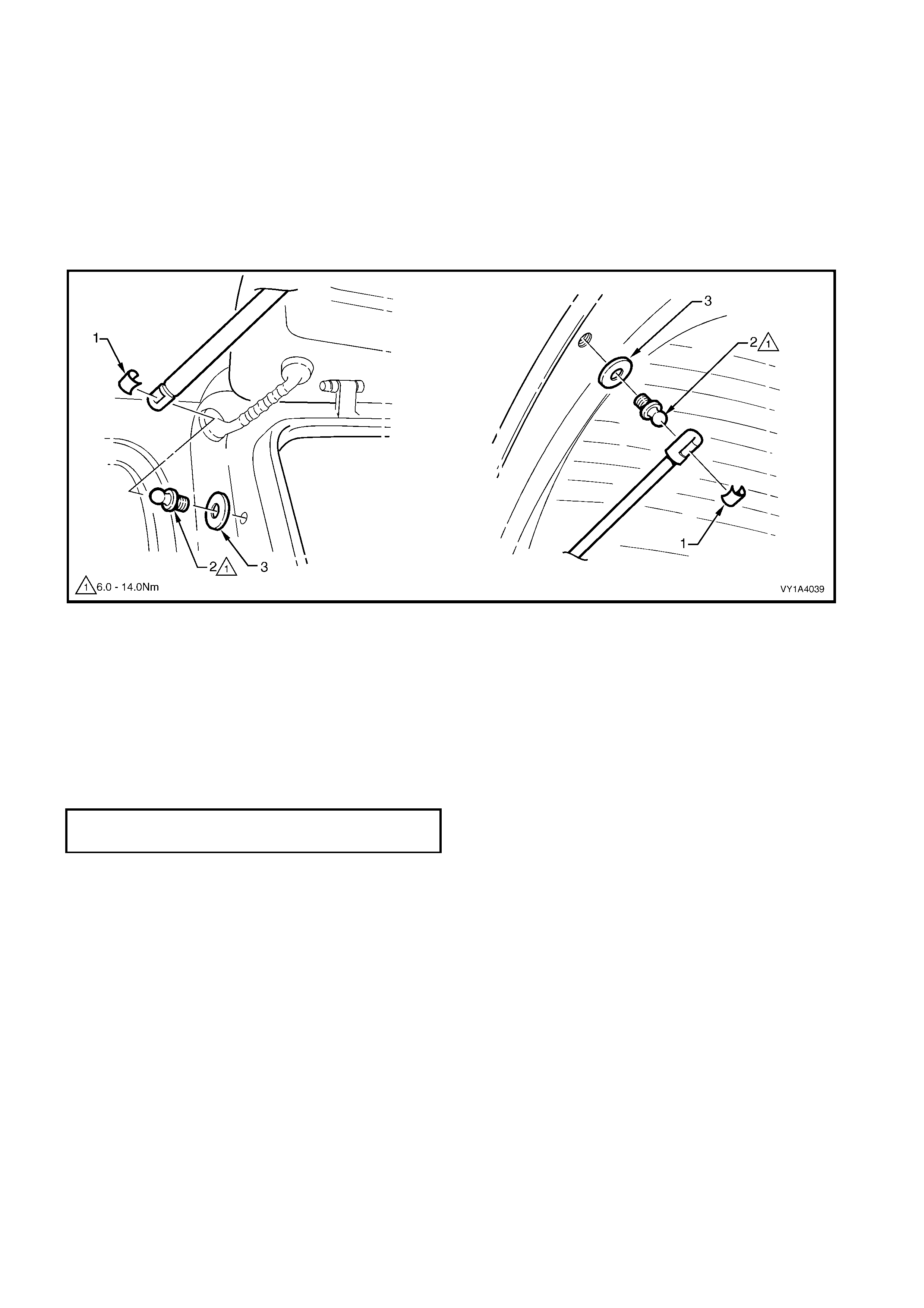
4.13 LIFTGATE STRUT ASSEMBLY
LT Section No. – 12-500
REMOVE
1. Support the liftgate assembly securely.
2. Using a fine, flat blade screwdriver, prise the retainer (1) from the strut end.
3. Pull the strut assembly from the ball stud (2).
4. Repeat for the opposite end as required.
5. If required, remove the ball stud and washer (3) from the liftgate assembly or vehicle.
Figure 1A4-67
REINSTALL
1. If removed, install the ball stud and washer. Tighten to the specified torque.
2. Apply a small amount of lithium based grease to the inside of the strut ball cup.
3. Install the retaining clip onto the strut end.
4. Align the strut with the ball stud and push into place.
NOTE: The strut assembly must be installed with the cylinder end attached to the vehicle.
5. Repeat for the opposite end if required.
LIFTGATE BALL STUD
TORQUE SPECIFICATION 6.0 – 14.0 Nm
4.14 LIFTGATE ASSEMBLY
LT Section No. – 12-500
As required, first remove the following components:
1. Liftgate window lower garnish, refer to 4.1 LIFTGATE WINDOW LOWER GARNISH.
2. Liftgate lower trim panel, refer to 4.2 LIFTGATE LOWER TRIM PANEL.
3. Liftgate inside handle, refer to 4.3 LIFTGATE INSIDE HANDLE.
4. High mount stop lamp cover and liftgate window upper garnish, refer to 4.4 LIFTGATE WINDOW UPPER
GARNISH.
5. Liftgate handle assembly, refer to 4.5 LIFTGATE HANDLE ASSEMBLY.
6. Liftgate handle push button assembly, refer to 4.6 LIFTGATE HANDLE PUSH BUTTON ASSEMBLY.
7. Liftgate latch assembly, refer to 4.7 LIFTGATE LATCH A SSEMBLY.
8. Liftgate actuator assembly , refer to 4.8 LIFTGATE ACTUATOR ASSEMBLY.
9. Liftgate air deflector assembly, refer to 4.9 LIFTGATE AIR DEFLECTOR ASSEMBLY.
10. Rear window wiper assembly, refer to 4.10 REAR WINDOW WIPER ASSEMBLY.
11. Rear window washer nozzle and hose assemblies, refer to 4.11 REAR WINDOW WASHER NOZZLE &
HOSE ASSEMBLIES.
12. High mount stop lamp assembly, refer to 4.12 HIGH MOUNT STOP LAMP ASSEMBLY.
13. Liftgate strut assembly from the liftgate, refer to 4.13 LIFTGATE STRUT ASSEMBLY.
14. Liftgate window assembly, refer to Section 1A6, 5.2 LIFTGATE WINDOW ASSEMBLY, WAGON.
15. Badges and emblems, refer to Section 1A9, EXTERIOR ORNAMENTATION.
REMOVE
1. Partially remove the right-hand quarter inner trim
upper refer to Section 1A8, 3.8 QUARTER INNER
TRIM UPPER.
2. Partially remove the right-hand body rear corner
garnish, refer to Section 1A8, 3.9 BODY REAR
CORNER GARNISH.
3. Disconnect the two liftgate assembly wiring
harness connectors (1).
4. Unclip the liftgate harness, three places (2).
Figure 1A4-68
5. Remove the right-hand grommet (1) from the
vehicle and withdraw the harness from the pillar
cavity.
Figure 1A4-69
6. Remove the liftgate hinge pin retainer (1) from
each side of the vehicle.
7. Have an ass istant hold the other s ide of the lif tgate
and withdraw each liftgate hinge pin (2).
8. Remove the liftgate assembly leaving the liftgate
hinge (body side) (3) in position.
Figure 1A4-70
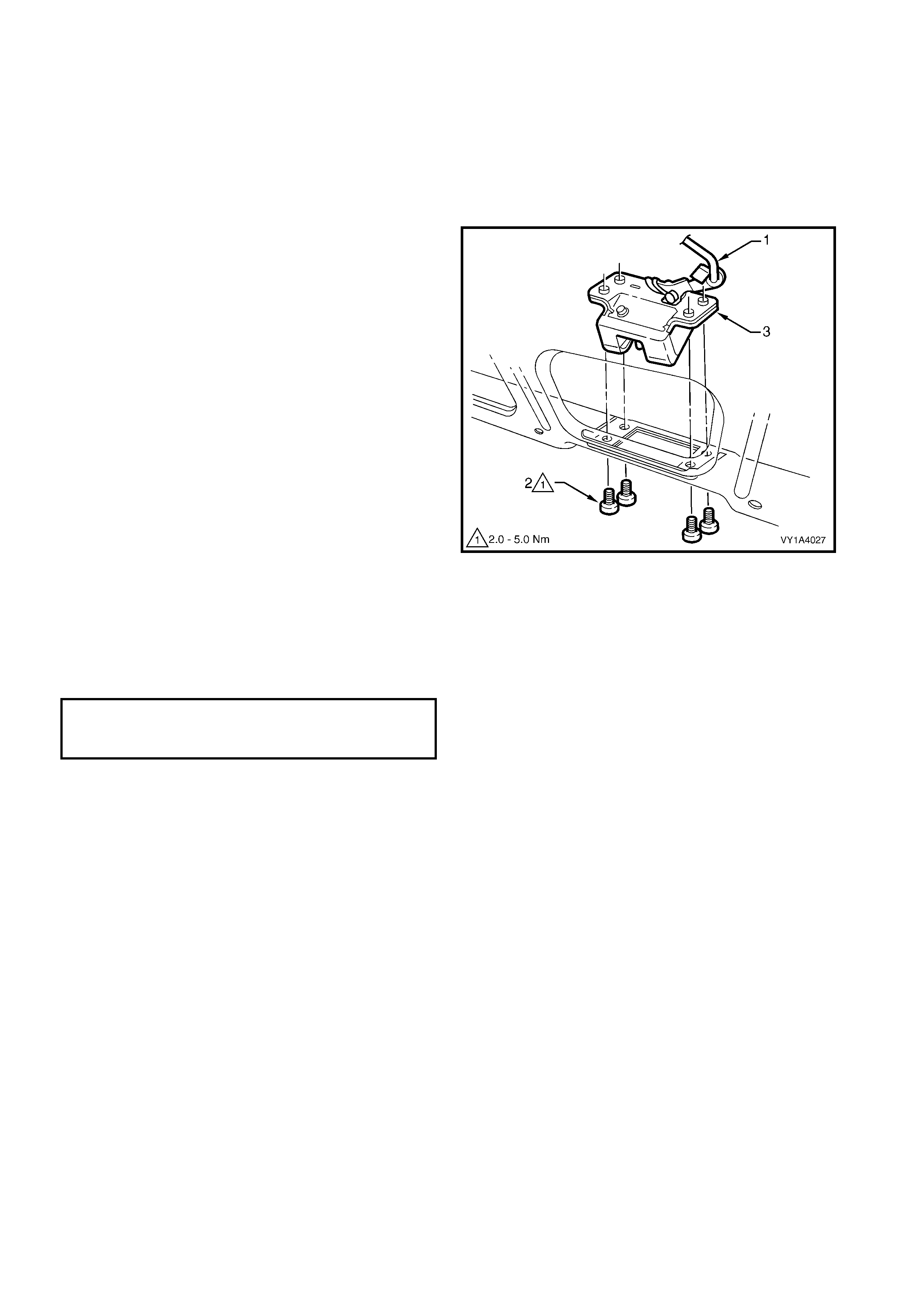
NOTE: As an alternative:
1. Remove the rear window upper garnish, refer to
Section 1A8, HEADLING & TRIM.
2. Remove the two screws (1), plate (2) and seal (3).
3. Remove the liftgate assembly with the liftgate
hinge (body side) (4).
Figure 1A4-71
DISASSEMBLE
Remove – Rear Compartment Courtesy Lamp
Switch Assembly
1. Remove the screw (1) attaching the switch
assembly (2) to the liftgate assembly.
2. W ithdraw the switch assembly and disconnect the
liftgate harness wiring connectors (3).
Reinstall – Rear Compartment Courtesy Lamp
Switch Assembly
1. Reinstallation is the reverse of removal. Tighten
the screw to the specified torque.
LIFTGATE HARNESS ASSEMBLY
For wiring harness assembly attachment and routing
information refer to Section 12O, FUSES AND
WIRING HARNESSES.
Figure 1A4-72
REAR COMPARTMENT COURTESY LAMP
SWITCH ASSEMBLY ATTACHING
SCREW TORQUE SPECIFICATION 1.0 – 3.0 Nm
Remove – Liftgate Bumper
1. Remove the liftgate bumper (1) each side by
unscrewing in the direction shown.
Reinstall –Liftgate Bumper
1. Install the bumper, screwing it all the way in. To set
the bumper to its correct position, refer to the
following liftgate adjustment procedure.
Figure 1A4-73
REINSTALL
Reinstallation is the reverse of removal noting the
following.
1. If the liftgate was removed from the liftgate hinge
pin, lubricate the pin with lithium based grease
prior to installation.
2. If the liftgate was removed with the liftgate hinge
(body side), apply sealer suc h as Lord Fusor #800
or #801 or equivalent to the area shown (1).
3. Set the two bumpers to the full-in position then
adjust to achieve the required alignment of the
liftgate, refer to the following adjustment
procedure.
4. Test the operation of the wiper, washer, high
mount stop lam p, r ear com par tm ent courtesy lamp
switch and lock mechanism before installing the
trim panels.
5. Tighten all screws to the specified torque.
Figure 1A4-74
ADJUST
Correct alignment of the liftgate is critical to its operation and to the aesthetics of the vehicle. The following
components allow adjustment of the liftgate:
• Liftgate bumper: Provides adjustment at the outer area of the liftgate assembly.
• Liftgate hinge (body side) screws: Provide forward, rearward and skew adjustment of the liftgate assembly.
• Liftgate striker assembly: Provides vertical and sideways adjustment of the liftgate assembly.
Whenever alignment is required, perform adjustment in the following order.
1. If fitted, remove the liftgate striker assembly, refer to 4.15 LIFTGATE STRIKER ASSEMBLY.
2. Ensure the liftgate weatherstrip assembly is installed and the liftgate bumpers are fitted and set fully in.
3. Carefully close the liftgate, watching the top and each side does not contact the vehicle.
4. Referring to Figure 1A4-75, check the alignm ent of the liftgate for width and consistency of gap to the roof
panel, quarter panel each side, tail lamps and rear bumper fascia.
LIFTGATE HINGE (BODY SIDE)
ATTACHING SCREW
TORQUE SPECIFICATION 13.0 – 25.0 Nm
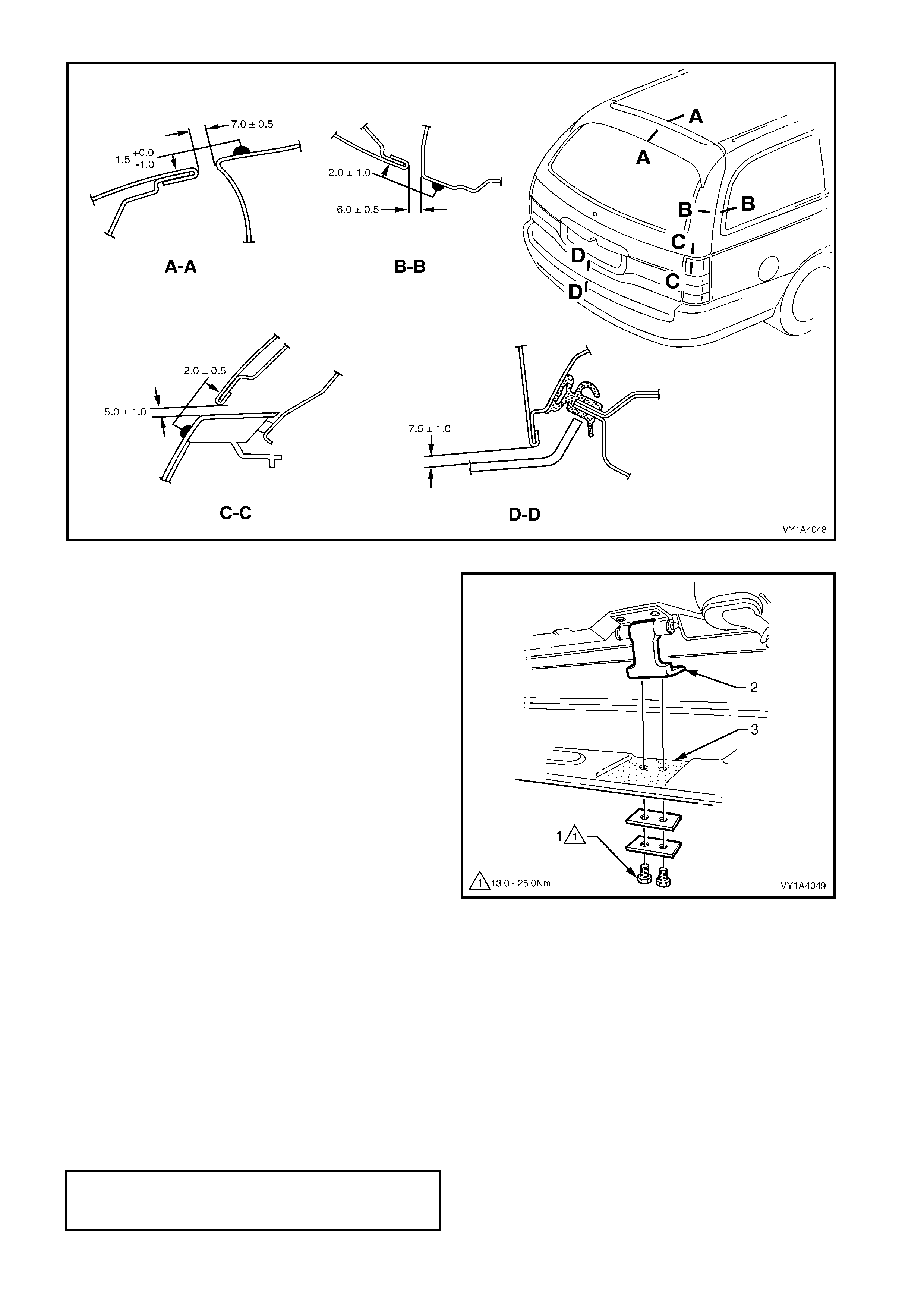
Figure 1A4-75
5. If the gap between the liftgate and r oof panel is not
within specification and/or is not parallel to the
quarter panel each side, open the liftgate and
adjust the position of the liftgate hinge(s)
• Remove the rear window upper garnish, refer
to Section 1A8, 3.10 REAR WINDOW UPPER
GARNISH.
• Loosen the two screws (1) attaching the
liftgate hinge (2).
• Lift the hinge away from the body and apply
sealer such as Lord Fusor #800 or #801 or
equivalent to the area shown (3).
• Adjust the position of the hinge, tighten the
screws and recheck the liftgate alignment.
NOTE: Do not make all adjustments at once. Perform
one adjustment, carefully close the liftgate, check its
position and make further adjustments until correct
alignment is achieved.
6. If the gap between the liftgate and roof panel is
within specific ation and the liftgate is parallel to the
quarter panel each side, open the liftgate and
adjust the liftgate bumpers to provide a slightly
greater gap at the lower edge of the liftgate above
each tail lamp. T his allows for the str iker to pull the
liftgate in slightly when closed.
Figure 1A4-76
7. Install the liftgate striker assembly, refer to
4.15 LIFTGATE STRIKER ASSEMBLY.
8. Close the liftgate, watching that the striker does
not pull the lif tgate to one side, changing the panel
gaps. If it does, move the striker as required.
9. Tighten all screws to their specified torque.
LIFTGATE HINGE (BODY SIDE)
ATTACHING SCREW
TORQUE SPECIFICATION 13.0 – 25.0 Nm
4.15 LIFTGATE STRIKER ASSEMBLY
ADJUST
LT Section No. – 12-500
1. Insert a Torx bit driver through the opening in the
rear end panel seal into the striker assembly
screw.
2. Loosen the screws and reposition the striker
assembly as required.
3. Tighten the screws and check alignment of the
liftgate assembly, refer to 4.14 LIFTGATE
ASSEMBLY.
4. When correct, tighten the striker assembly screws
to the specified torque.
Figure 1A4-77
REMOVE
LT Section No. – 12-680
1. As required, remove the rear end trim panel, refer to Section 1A8, 3.19 REAR END TRIM PANEL.
2. Remove the rear end panel seal (1) from the
striker assembly (2).
3. Mark the position of the striker assembly on the
surrounding panel with a marker pen.
4. Using a Torx bit driver remove the screws (3)
attaching the striker assembly.
5. Remove the striker assembly.
Figure 1A4-78
REINSTALL
Reinstallation is the reverse of removal noting the
following.
1. Align the striker assembly to the pen mark and if
required, adjust the position of the striker prior to
installing the trim components, refer to the
previous adjustment procedure.
2. Tighten the striker assembly screws to the
specified torque.
LIFTGATE STRIKER ASSEMBLY
ATTACHING SCREW
TORQUE SPECIFICATION 13.0 – 25.0 Nm
LIFTGATE STRIKER ASSEMBLY
ATTACHING SCREW
TORQUE SPECIFICATION 13.0 – 25.0 Nm
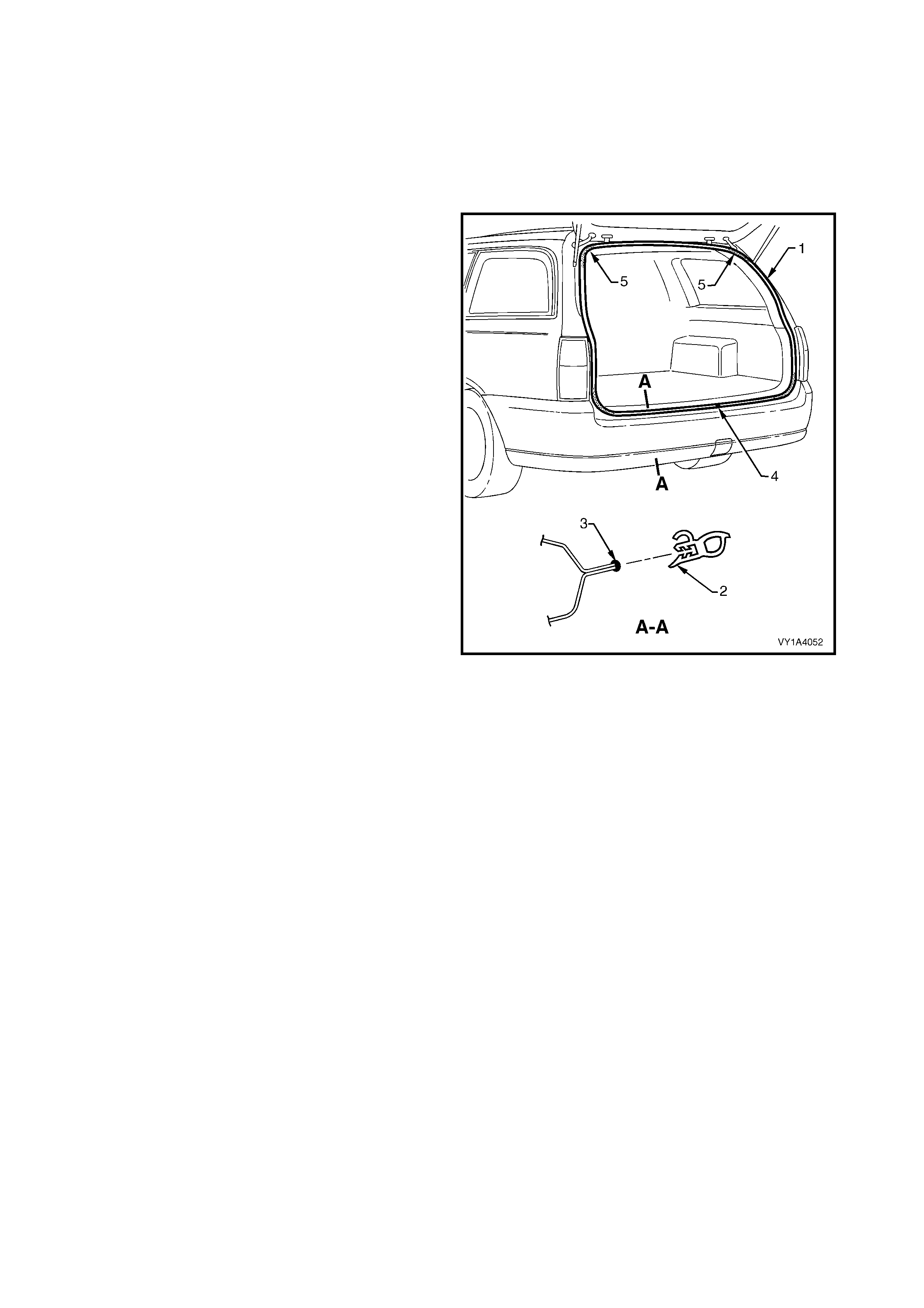
4.16 LIFTGATE WEATHERSTRIP
REMOVE
LT Section No. – 11-600
1. W hile not necessary, removal of the adjacent trim
panels will make installation of the weatherstrip
assembly easier.
2. Grasping the weatherstrip assembly (1) carefully
pull it from the body flange. Start at one point and
continue along its length.
3. Remove the weatherstrip assembly from the
vehicle.
Figure 1A4-79
REINSTALL
1. Lay the weatherstrip assembly on the floor and
ensure the longer side of the weatherstrip (2) is to
the outside, refer to Figure 1A4-79.
2. Apply a small bead of non-hardening windscreen
sealer suc h as butyl-m astic or equivalent (3) to the
weatherstrip flange.
3. Locate the weatherstrip join (4) which is to be
aligned with the striker assembly.
4. Fit the weatherstrip onto the body flange and
beginning at the join, push it into position.
NOTE: Allow crowding of the weatherstrip in each
corner (5) to avoid short cutting of the corners. If
required crimp the weatherstrip to ensure a tight fit
onto the flange.
5. SERVICE OPERATIONS – ENDGATE, UTILITY
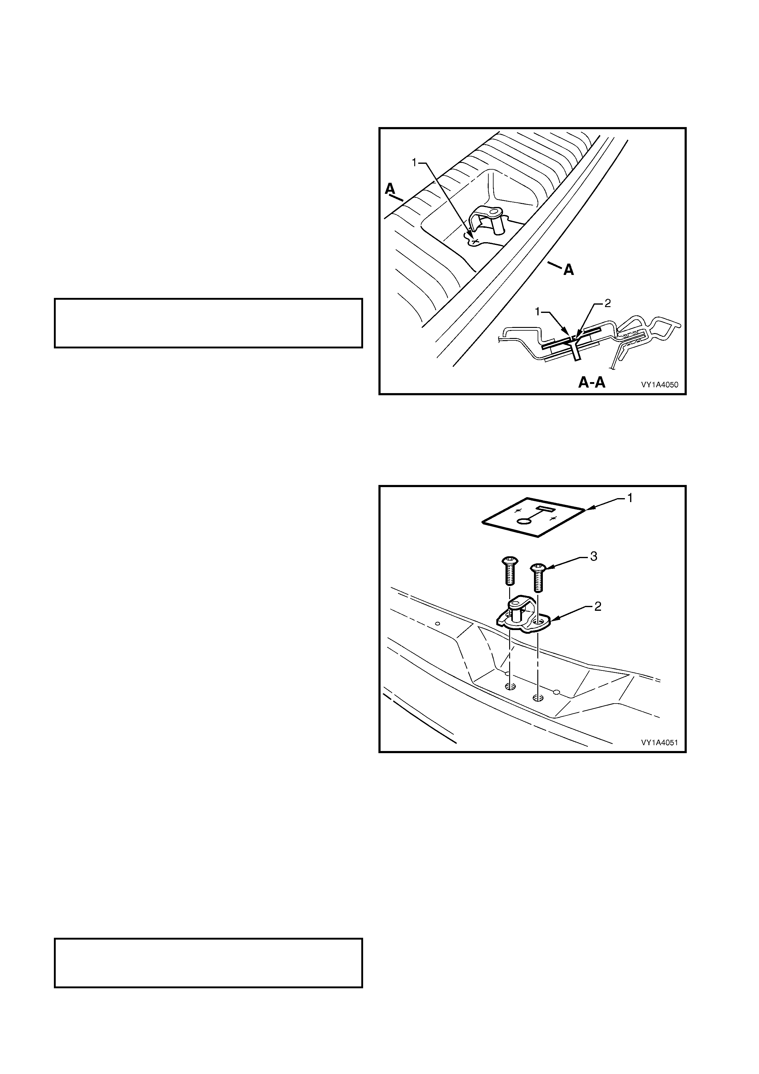
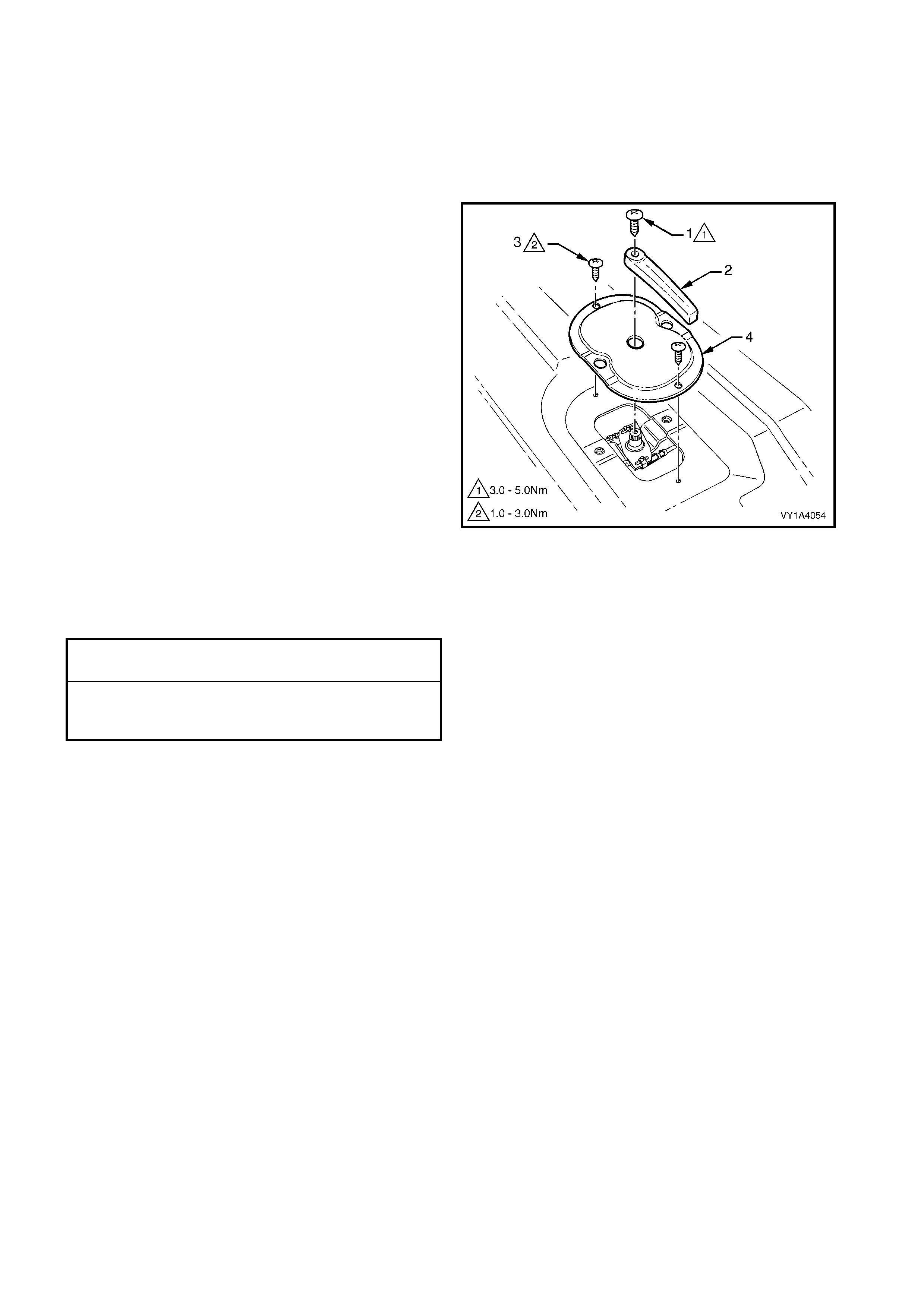
5.1 ENDGATE INNER PANEL ACCESS HOLE COVER
LT Section No. – 12-685
REMOVE
1. Remove the screw (1) attaching the endgate
handle (2).
2. Remove the screw (3), two places, attaching the
endgate inner panel access hole cover (4).
Figure 1A4-80
REINSTALL
Reinstallation is the reverse of removal. Ensure the
screws are tightened to the specified torque.
ENDGATE HANDLE ATTACHING SCREW
TORQUE SPECIFICATION 3.0 – 5.0 Nm
ENDGATE INNER PANEL ACCESS HOLE
COVER ATTACHING SCREW
TORQUE SPECIFICATION 1.0 – 3.0 Nm
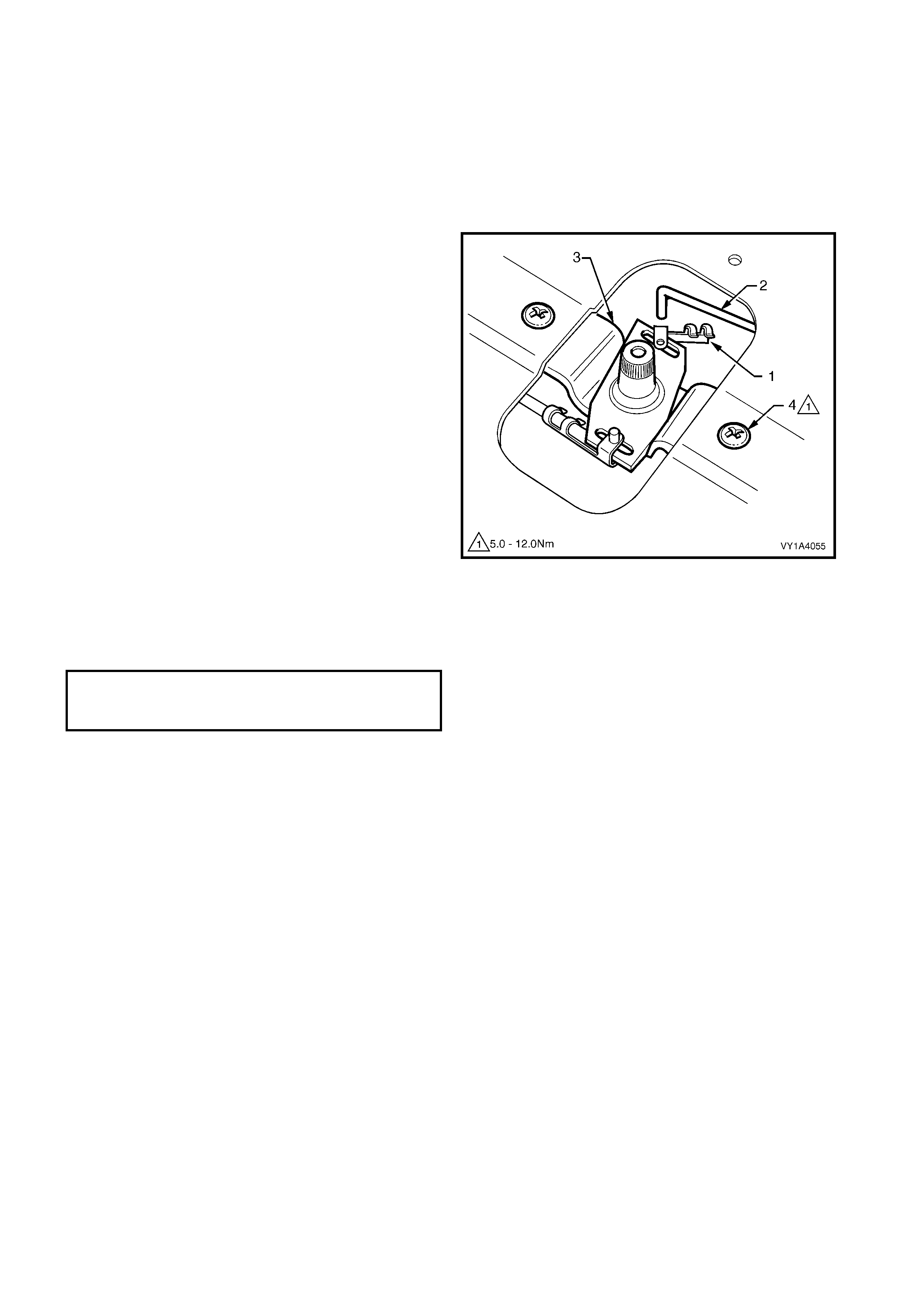
5.2 ENDGATE LOCK ANCHOR PLATE ASSEMBLY
LT Section No. – 12-685
1. As required, first remove the endgate handle and
endgate inner panel access hole cover, refer to
5.1 ENDGATE INNER PANEL ACCESS HOLE
COVER.
REMOVE
1. Unclip the retainer (1) from the endgate latch
assembly (2). Repeat for the other side.
2. Disconnect the latch assem blies from the endgate
lock anchor plate assembly (3).
3. Remove the two screws (4) attaching the plate
assembly to the endgate assembly.
4. Remove the plate assembly from the endgate
assembly cavity.
Figure 1A4-81
REINSTALL
Reinstallation is the reverse of removal. Ensure the
screws are tightened to the specified torque.
ENDGATE LOCK ANCHOR PLATE
ASSEMBLY ATTACHING SCREW
TORQUE SPECIFICATION 5.0 – 12.0 Nm
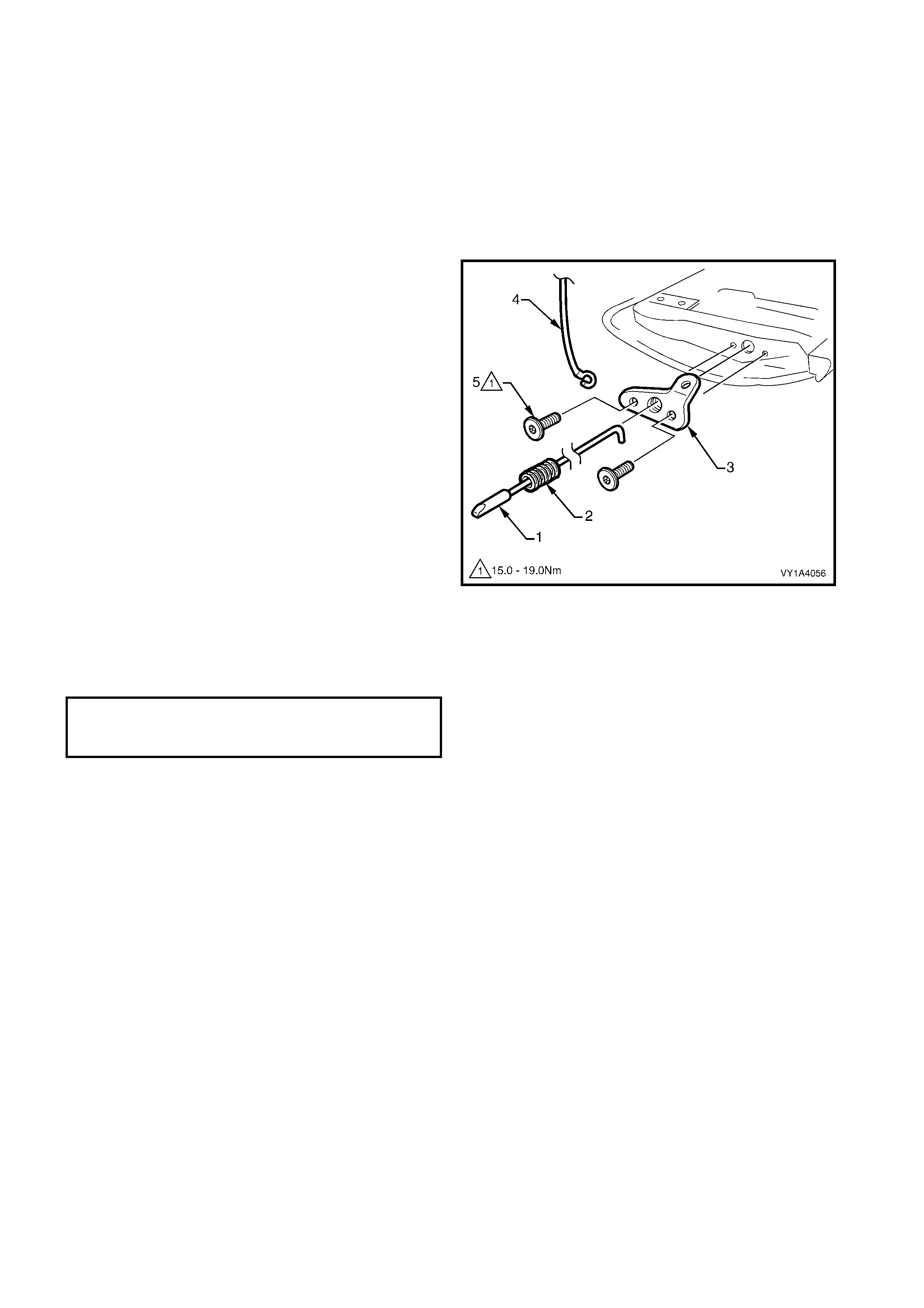
5.3 ENDGATE LATCH ASSEMBLY & ENDGATE LATCH BRACKET ASSEMBLY
LT Section No. – 12-685
As required, first remove the following components:
1. Endgate handle and endgate inner panel access hole cover, refer to 5.1 ENDGATE INNER PANEL
ACCESS HOLE COVER.
2. Unclip the retainer and disconnect the endgate latch assembly from the endgate lock anchor plate assembly,
refer to 5.2 ENDGATE LOCK ANCHOR PLATE ASSEMBLY.
REMOVE
1. Withdraw the endgate latch assembly (1) and
spring (2) from the endgate latch bracket
assembly (3).
2. Have an assistant support the endgate and
unhook the endgate cable assembly (4) from the
bracket assembly.
3. Remove the Torx-head screws (5) attaching the
bracket assembly to the endgate assembly and
remove the bracket assembly.
Figure 1A4-82
REINSTALL
Reinstallation is the reverse of removal. Ensure the
screws are tightened to the specified torque.
ENDGATE LATCH BRACKET
ASSEMBLY ATTACHING SCREW
TORQUE SPECIFICATION 15.0 – 19.0 Nm
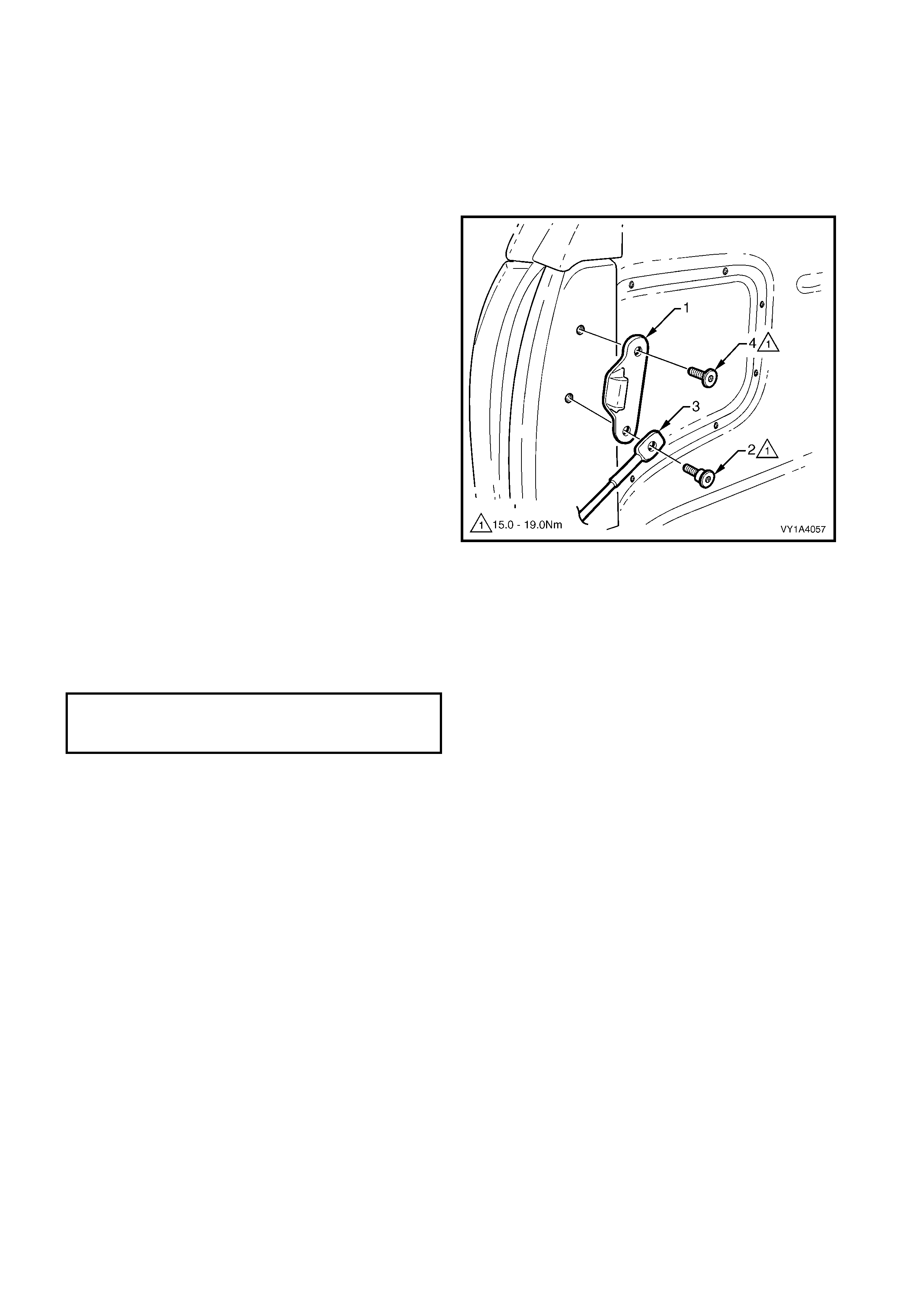
5.4 ENDGATE STRIKER & ENDGATE CABLE ASSEMBLY
LT Section No. – 12-685
REMOVE
1. Open the endgate and disconnect the endgate
cable assembly from the endgate latch bracket
assembly.
2. Mark the position of the endgate striker (1) with a
marker pen as required.
3. Remove the lower screw (2) attaching the cable
assembly (3) and striker to the vehicle. Remove
the cable assembly.
4. Remove the upper screw (4) attaching the striker
to the vehicle and remove the striker.
Figure 1A4-83
REINSTALL
Reinstallation is the reverse of removal. Ensure the
screws are tightened to the specified torque.
NOTE: The longer, shanked screw (2) is for the lower
cable assembly and striker hole.
ENDGATE STRIKER (& ENDGATE CABLE
ASSEMBLY) ATTACHING SCREW
TORQUE SPECIFICATION 15.0 – 19.0 Nm

5.5 ENDGATE UPPER MOULDING ASSEMBLY
LT Section No. – 12-480
REMOVE
1. If fitted, prise the plug (1) from the endgate upper
moulding assembly (2), five places.
2. Remove the five sc r ews (3) attaching the moulding
assembly to the endgate assembly and remove
the moulding, carefully cutting the sealer (4) along
the lower inside edge of the moulding.
3. If required, prise the cap (5) from the moulding.
Figure 1A4-84
REINSTALL
Reinstallation is the reverse of removal noting the
following:
1. Ensure the screws are tightened to the specified
torque.
2. To the lower inside edge of the moulding
assem bly, apply a bead of sealer (1) such as Lor d
(Fusor) #122, #123, # 125 or #126 or 3M Automix
8307 or 8308.
3. Smooth over the sealer to provide a neat, clean
finish.
Figure 1A4-85
ENDGATE UPPER MOULDING
ASSEMBLY ATTACHING SCREW
TORQUE SPECIFICATION 3.0 – 8.0 Nm
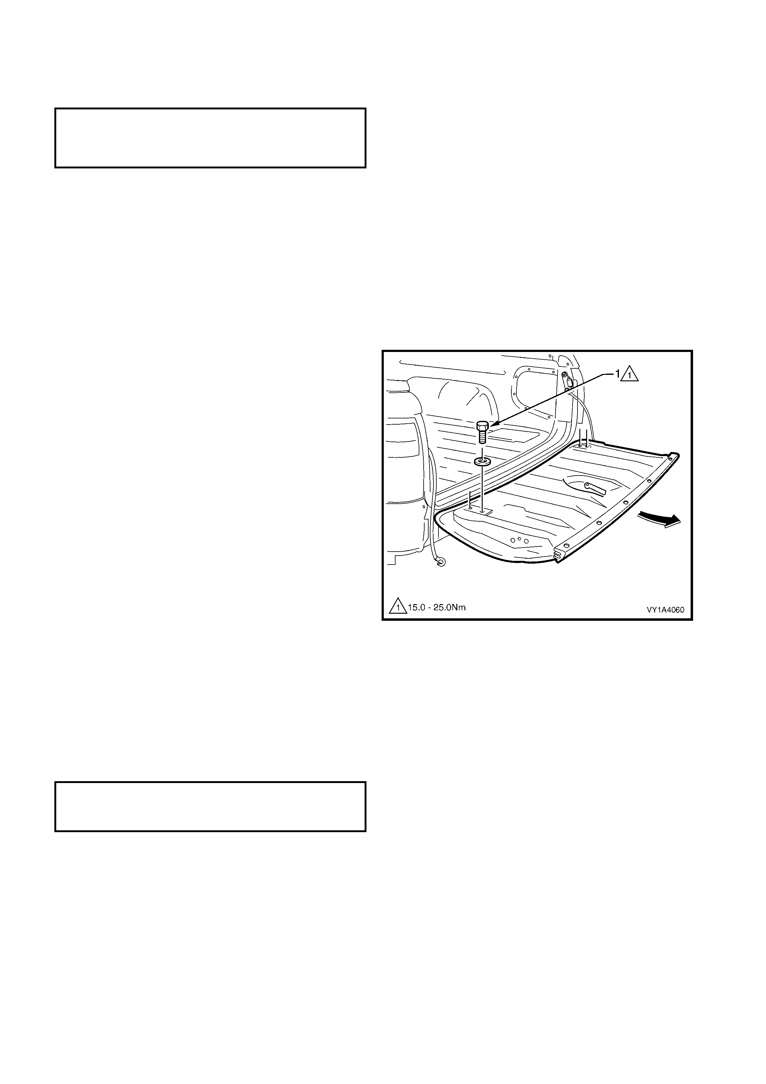
5.6 ENDGATE ASSEMBLY
LT Section No. – 12-500
As required, first remove the following components:
1. Endgate handle and endgate inner panel access hole cover, refer to 5.1 ENDGATE INNER PANEL
ACCESS HOLE COVER.
2. Endgate lock anchor plate assembly, refer to 5.2 ENDGATE LOCK ANCHOR PLATE ASSEMBLY.
3. Endgate latch assembly and endgate latch bracket as sembly, refer to 5.3 ENDGATE LATCH ASSEMBLY &
ENDGATE LATCH BRACKET ASSEMBLY.
4. Endgate upper moulding assembly, refer to 5.5 ENDGATE UPPER MOULDING ASSEMBLY.
5. Badges and emblems, refer to Section 1A9, EXTERIOR ORNAMENTATION.
REMOVE
1. Mark the position of the endgate screws with a
marker pen as required.
2. W ith an assistant supporting the endgate, remove
the four screws (1) and washers attaching the
endgate assembly to the hinge assemblies.
3. Remove the endgate assembly by sliding it
rearwards from the hinge assemblies.
Figure 1A4-86
REINSTALL
Reinstallation is the reverse of removal noting the
following:
1. Align the endgate screws with the pen marks or
adjust the endgate as described in the following
procedure, ADJUST.
2. Tighten the screws to the specified torque.
NOTE: If the Endgate assembly is replaced the
following component will be required:
+
++
+
Endgate hook label
ENDGATE ASSEMBLY
ATTACHING SCREW
TORQUE SPECIFICATION 15.0 – 25.0 Nm
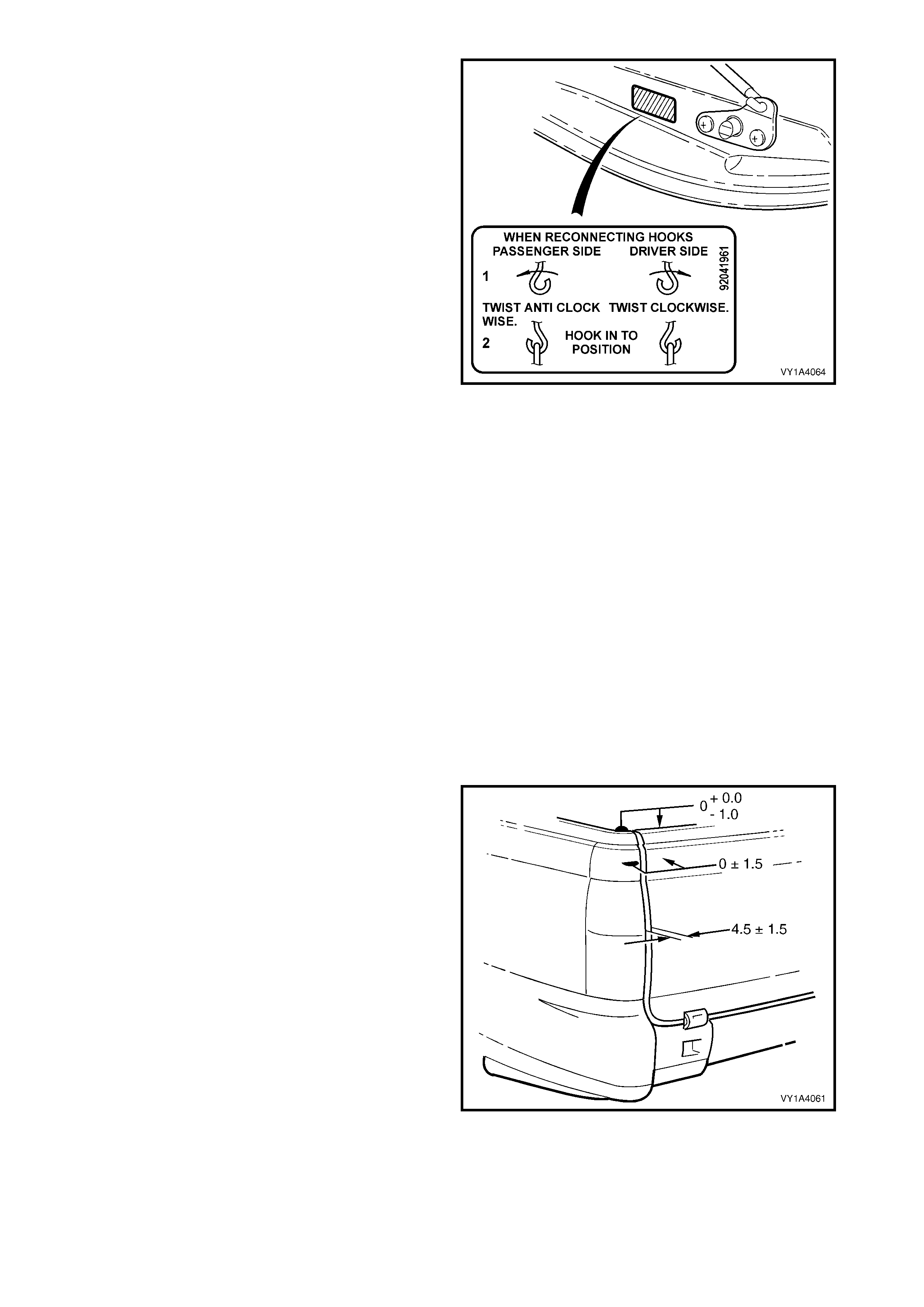
3. Install the endgate hook label to the left-hand side
of the endgate inner panel as shown.
Figure 1A4-87
ADJUST
Correct alignment of the endgate as s embly is critical to
its operation and to the aesthetics of the vehicle. The
following components allow adjustment of the liftgate:
• Endgate hinge assembly screws (endgate and
body side): Provide vertical, horizontal and skew
adjustment.
• Endgate striker latch: Provides adjustment
flushness of the endgate assembly to the vehicle.
Whenever alignment is required, perform adjustment
in the following order.
1. Remove the endgate striker, refer to
5.4 ENDGATE STRIKER & ENDGATE CABLE
ASSEMBLY.
2. Ensure the endgate weatherstrip assembly is
installed.
3. Carefully close the endgate, watching each side
does not contact the vehicle.
4. Check the alignment of the endgate for height,
flushnes s, width and cons istenc y of gap to the side
panel outer and tail lamps.
5. As required, loosen the hinge assembly attaching
screws and reposition the endgate. If enough
adjustment cannot be obtained, loosen the lower
hinge assembly screws, refer to 5.7 ENDGATE
HINGE ASSEMBLY and reposition the hinge.
6. Install the endgate striker, refer to 5.4 ENDGATE
STRIKER & ENDGATE CABLE ASSEMBLY.
7. Close the endgate, and adjust the position of the
striker to provide flushness of the endgate to the
side panel outer and tail lamps.
8. Check that all screws are tightened to their
specified torque.
Figure 1A4-88
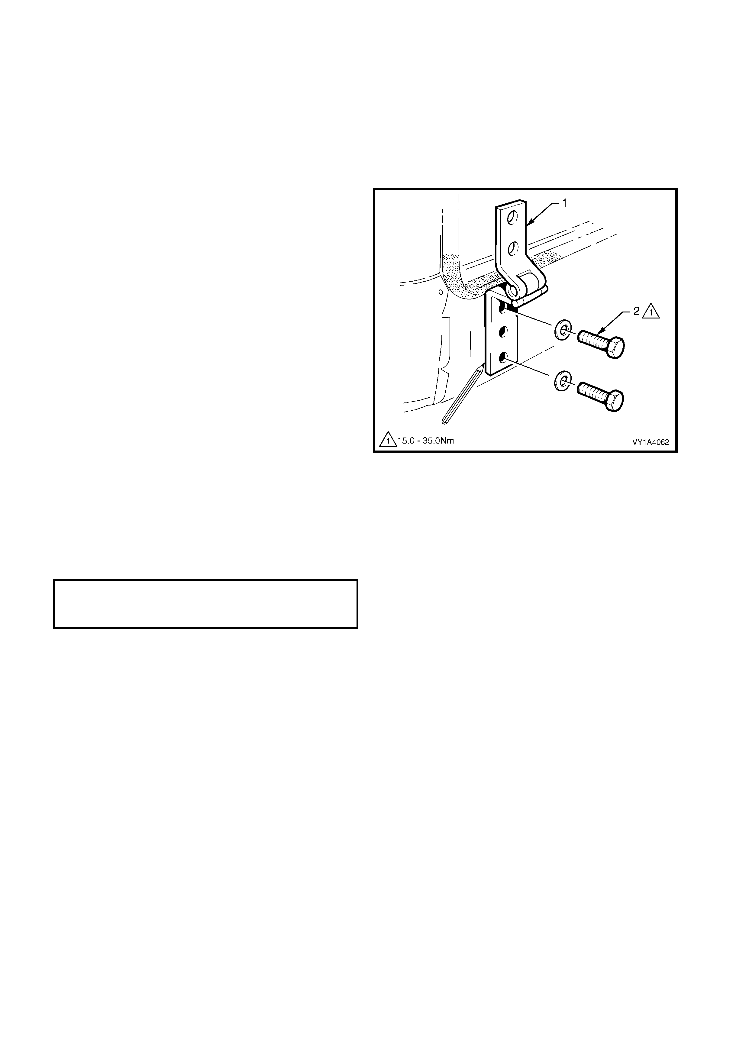
5.7 ENDGATE HINGE ASSEMBLY
LT Section No. – 12-685
1. As required, first remove the rear bumper
fascia, either one or both sides as required,
refer to Section 1D, 2.7 REAR BUMPER
FASCIA, UTLITY.
REMOVE
1. Close the endgate if installed.
2. Mark the position of the hinge assembly (1) with a
marker pen as required.
3. Rem ove the two scr ews (2) and washers attac hing
the hinge assembly to the vehicle.
4. Remove the hinge assembly from the vehicle.
Figure 1A4-89
REINSTALL
Reinstallation is the reverse of removal. Align the hinge
assembly with the pen marks or adjust the endgate,
refer to 5.6 ENDGATE A SSEMBLY.
Tighten the screws to the specified torque.
ENDGATE HINGE ASSEMBLY
ATTACHING SCREW
TORQUE SPECIFICATION 15.0 – 35.0 Nm
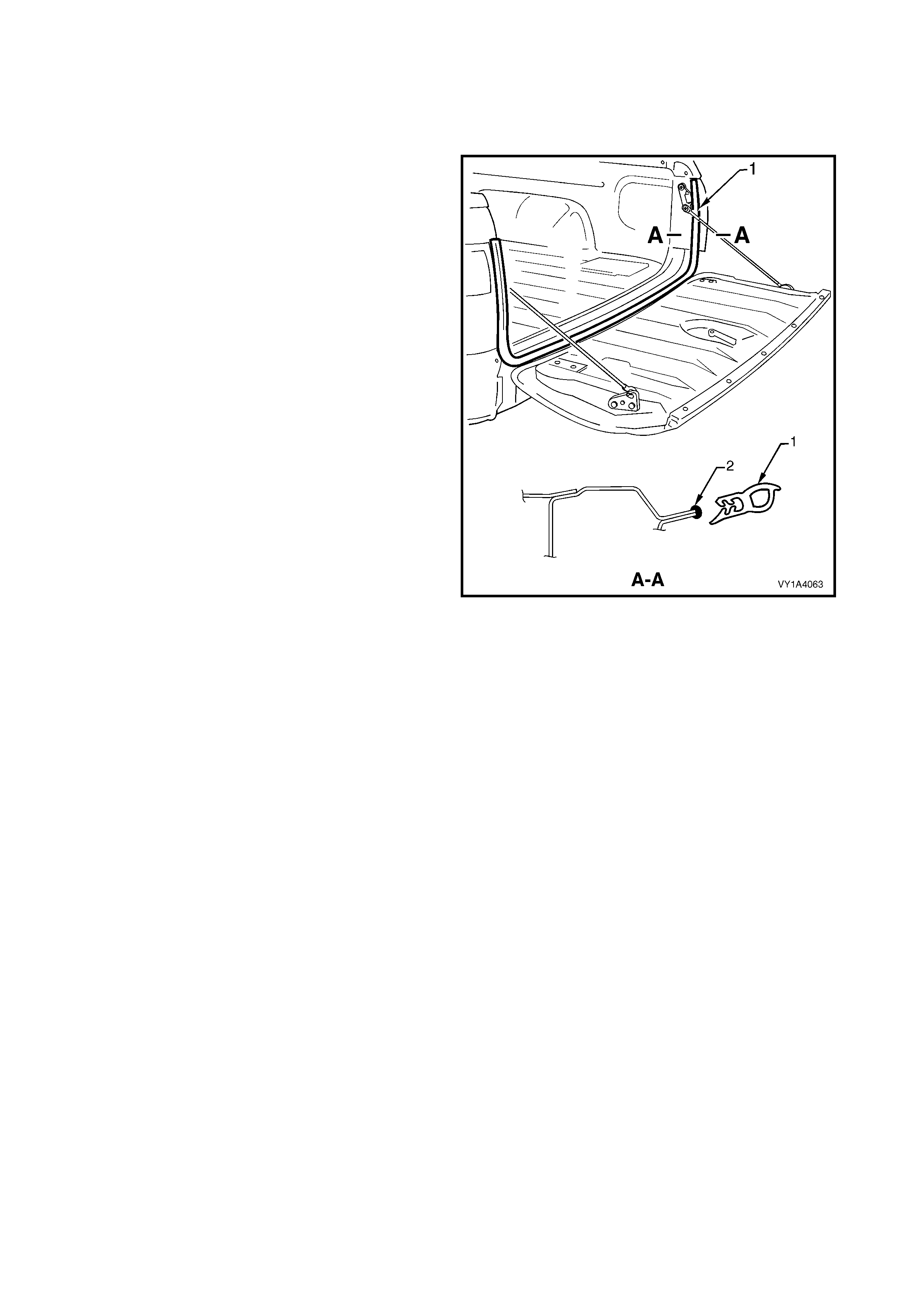
5.8 ENDGATE WEATHERS TRIP
REMOVE
LT Section No. – 11-600
1. Grasping the weatherstrip assembly (1) carefully
pull it from the body flange. Start at one end and
continue along its length.
2. Remove the weatherstrip assembly from the
vehicle.
Figure 1A4-90
REINSTALL
1. Apply a small bead of non-hardening windscreen
sealer suc h as butyl mastic or equivalent (2) to the
weatherstrip flange.
2. Ensure the weatherstrip assembly is correctly
oriented and beginning at one end, fit the
weatherstrip onto the body flange seating it against
the quarter panel rear moulding.
NOTE: Allow crowding of the weatherstrip in each
corner to avoid short cutting of the corners. If required
crimp the weatherstrip to ensure a tight fit onto the
flange.

6. TORQUE WRENCH SPECIFICATIONS
HOOD
Hood moulding mounting bracket screw ..................................................................................3.0 – 5.0 Nm
Hood moulding attaching screw................................................................................................1.0 – 2.0 Nm
Hood primary latch striker nut...................................................................................................22.0 – 28.0 Nm
Hood strut pin ...........................................................................................................................13.0 – 22.0 Nm
Hood strut assembly to fender attaching screw........................................................................10.0 – 14.0 Nm
Hood assembly attaching screw...............................................................................................10.0 – 25.0 Nm
Hood primary latch release cable retainer screw......................................................................1.0 – 3.0 Nm
REAR COMPARTMENT LID, SEDAN & COUPE
Spare wheel stowage cover hook attaching screw...................................................................1.0 – 3.0 Nm
Rear compartment lid applique assembly attaching screw, Sedan..........................................0.8 – 1.5 Nm
Rear compartment lid applique assembly attaching nut, Sedan...............................................2.0 – 5.0 Nm
Rear compartment lid applique assembly retainer attaching screw, Coupe.............................1.0 – 3.0 Nm
Rear compartment lid applique assembly lower attaching screw, Coupe ................................1.0 – 3.0 Nm
Rear compartment lid applique assembly attaching nut, Coupe..............................................2.0 – 5.0 Nm
Rear compartment lid applique assembly outer attaching screw, Coupe.................................1.0 – 3.0 Nm
Rear spoiler assembly attaching screw & nut...........................................................................2.0 – 5.0 Nm
High mount stop lamp assembly attaching screw ....................................................................5.0 Nm
Rear compartment lid latch assembly attaching nut.................................................................2.0 – 5.0 Nm
Rear compartment lid actuator assembly attaching screw.......................................................2.0 – 5.0 Nm
Rear compartment lid release cable assembly attaching screw...............................................2.0 – 5.0 Nm
Rear compartment lid release cable assembly to back panel upper attaching screw, Coupe .1.9 – 2.1 Nm
Rear compartment lid attaching screw.....................................................................................6.0 – 12.0 Nm
Rear compartment lid hinge assembly attaching screw...........................................................6.0 – 14.0 Nm
Rear compartment lid striker assembly attaching screw..........................................................15.0 – 35.0 Nm
LIFTGATE, WAGON
Liftgate handle assembly attaching nut ....................................................................................2.0 – 5.0 Nm
Liftgate latch assembly attaching screw...................................................................................2.0 – 5.0 Nm
Liftgate actuator assembly attaching screw..............................................................................2.0 – 5.0 Nm
Liftgate air deflector assembly attaching nut ............................................................................2.0 – 5.0 Nm
Liftgate air deflector assembly attaching screw........................................................................2.0 – 5.0 Nm
Rear window wiper arm assembly attaching nut ......................................................................20.0 – 25.0 Nm
Rear window wiper motor assembly attaching nut ...................................................................0.2 – 1.0 Nm
Rear window wiper motor assembly attaching screw...............................................................6.0 – 14.0 Nm
High mount stop lamp assembly attaching screw ....................................................................1.0 – 3.0 Nm
Liftgate ball stud........................................................................................................................6.0 – 14.0 Nm
Rear compartment courtesy lamp switch assembly attaching screw.......................................1.0 – 3.0 Nm
Liftgate hinge (body side) attaching screw................................................................................13.0 – 25.0 Nm
Liftgate striker assembly latch attaching screw ........................................................................13.0 – 25.0 Nm
ENDGATE, UTILITY
Endgate handle attaching screw...............................................................................................3.0 – 5.0 Nm
Endgate inner panel access hole cover attaching screw..........................................................1.0 – 3.0 Nm
Endgate lock anchor plate assembly attaching screw..............................................................5.0 – 12.0 Nm
Endgate latch bracket assembly attaching screw.....................................................................15.0 – 19.0 Nm
Endgate striker (& endgate cable assembly) attaching screw..................................................15.0 – 19.0 Nm
Endgate moulding assembly attaching screw...........................................................................3.0 – 8.0 Nm
Endgate assembly attaching screw..........................................................................................15.0 – 25.0 Nm
Endgate hinge assembly attaching screw ................................................................................15.0 – 35.0 Nm