
SECTION 1A5 - FRONT & REAR DOOR ASSEMBLIES
IMPORTANT
Before performing any Service Operation or other procedure described in this Section, refer to Section 00
CAUTIONS AND NOTES for correct workshop practices with regard to safety and/or property damage.
CONTENTS
1 GENERAL DESCRIPTION
2 FRONT DOOR SERVICE OPERATIONS
2.1 FRONT DOOR HINGE LUBRICATION
2.2 FRONT DOOR LOCK STRIKER
REMOVE
REINSTALL
2.3 ADJUST FRONT DOOR ASSEMBLY
2.4 FRONT DOOR WINDOW REGULATOR
HANDLE ASSEMBLY
REMOVE
REINSTALL
2.5 FRONT DOOR INSIDE HANDLE
ASSEMBLY (REMOTE)
REMOVE
REINSTALL
2.6 FRONT DOOR TRIM PANEL ASSEMBLY
REMOVE
DISASSEMBLE
REINSTALL
2.7 FRONT DOOR LOCK ASSEMBLY
REMOVE
DISASSEMBLE
ADJUST
REINSTALL
2.8 FRONT DOOR OUTSIDE HANDLE
ASSEMBLY
REMOVE
DISASSEMBLE - DRIVER’S DOOR
ASSEMBLE
REINSTALL
RESET
2.9 FRONT DOOR WINDOW REGULATOR
ASSEMBLY
REMOVE
REINSTALL
2.10 FRONT WINDOW INNER FILLER
ASSEMBLY
REMOVE
REINSTALL
2.11 FRONT DOOR BELT OUTER REVEAL
MOULDING ASSEMBLY
REMOVE
REINSTALL
2.12 FRONT WINDOW GUIDE ASSEMBLY
REMOVE
REINSTALL
2.13 FRONT DOOR GUIDE CHANNEL
ASSEMBLY
REMOVE
REINSTALL
2.14 FRONT DOOR WINDOW ASSEMBLY
REMOVE
REINSTALL
ADJUST
2.15 FRONT DOOR WEATHERSTRIP
ASSEMBLIES
REMOVE
REINSTALL
2.16 FRONT DOOR WINDOW FRAME
UPPER SCALP MOULDING
REMOVE
REINSTALL
2.17 FRONT DOOR WIRING HARNESS ASSEMBLY
2.18 FRONT DOOR ASSEMBLY
REMOVE
DISASSEMBLE
REINSTALL
ADJUST
2.19 FRONT DOOR OPENING WEATHERSTRIP
ASSEMBLY, EXCEPT COUPE
REMOVE
REINSTALL
2.20 FRONT DOOR OPENING WEATHERSTRIP
ASSEMBLY, COUPE
REMOVE
REINSTALL
3 REAR DOOR SERVICE OPERATIONS
3.1 REAR DOOR HINGE LUBRICATION
3.2 REAR DOOR LOCK STRIKER
REMOVE
REINSTALL
3.3 ADJUST REAR DOOR ASSEMBLY
3.4 REAR WINDOW REGULATOR HANDLE
ASSEMBLY
REMOVE
REINSTALL
3.5 REAR DOOR INSIDE HANDLE
ASSEMBLY (REMOTE)
REMOVE
REINSTALL
3.6 REAR DOOR TRIM PANEL ASSEMBLY
REMOVE
DISASSEMBLE
REINSTALL
3.7 REAR DOOR LOCK ASSEMBLY
REMOVE
DISASSEMBLE
ADJUST
REINSTALL
3.8 REAR DOOR OUTSIDE HANDLE ASSEMBLY
REMOVE
REINSTALL
3.9 REAR WINDOW INNER FILLER ASSEMBLY
REMOVE
REINSTALL
3.10 REAR DOOR BELT OUTER REVEAL
MOULDING ASSEMBLY
REMOVE
REINSTALL
3.11 REAR DOOR CHANNEL ASSEMBLY
REMOVE
REINSTALL
3.12 REAR DOOR WINDOW ASSEMBLY
REMOVE
REINSTALL
ADJUST
Techline
Techline
Techline
Techline
Techline
Techline
Techline

3.13 REAR DOOR WINDOW REGULATOR
ASSEMBLY
REMOVE
REINSTALL
3.14 REAR DOOR STATIONARY WINDOW
ASSEMBLY
REMOVE
REINSTALL
3.15 REAR DOOR WEATHERSTRIP
ASSEMBLIES
REMOVE
REINSTALL
3.16 REAR DOOR WINDOW FRAME UPPER
SCALP MOULDING
REMOVE
REINSTALL
3.17 REAR DOOR WIRING HARNESS ASSEMBLY
3.18 REAR DOOR ASSEMBLY
REMOVE
DISASSEMBLE
REINSTALL
ADJUST
3.19 REAR DOOR OPENING
WEATHERSTRIP ASSEMBLY
REMOVE
REINSTALL
4 TORQUE WRENCH SPECIFICATIONS
5 SPECIAL TOOLS

1. GENERAL DESCRIPTION
The front and rear door assemblies consist of an outer panel which are hemmed over the inner panel at their outer
edges. Structural adhesive is applied within the hemmed joint and joint sealer, hand putty and cavity wax are used
for the pr evention of corr osion. A rolled up per door fram e retains the sliding gl ass run channe ls. Door hinge m ale
sections are welde d to the door inner panel f acings and the f em ale sections to th e body pillar s. A door c heck and
hold open link is located between the door assemblies and the body pillars.
For the front doors sliding windows are operated by double arm scissor type window regulators, attached to the
glass lifter channels and door inner panel. Cable type mechanisms attached to the door inner panel and glass
lifter channels operate the rear door sliding windows.
Electrically operated front sliding windows are available on all models and, for Sedan and Wagon, electrically
operated rear sliding windows are also available.
Lift-bar exterior door handles operate the fork type door locks in conjunction with door lock striker bolts.
A two key locking system uses a master key (with inbuilt remote security features) to operate all locks on the
vehicle. A secondary key, operates the glove compartment only. A snib locking button operates the door locks
internally.
The f ront door lock c ylinder , fitted onl y to th e dri ver’s door , is of the ‘free turn ing’ desig n which pre vents unlo ck ing
of the door by objec ts ot her than t he c or rec t key. If a n y obj ect, exc ept the cor r ect k e y, is ins er ted into th e lock , the
cylinder will rotate without unlocking the door.
Electric door lock actuators and electric external rear vision mirrors are standard features.
The front door trims feature a map pocket, air vents with side window defog, radio speaker grille, courtesy lamp
(where fitted) and a cloth or leather insert. On Sedan and Wagon, rear door trims feature a radio speaker grille,
courtesy lamp (where fitted) and a cloth or leather insert.
Door weatherstrips incorporate plastic clips which reta in the weatherstrip in holes located around the outer lo wer
edge of the door inner panel. The upper section of the weatherstrip is retained in a channel which is an integral
part of the rolled section upper door frame.
2. FRONT DOOR SERVICE OPERATIONS
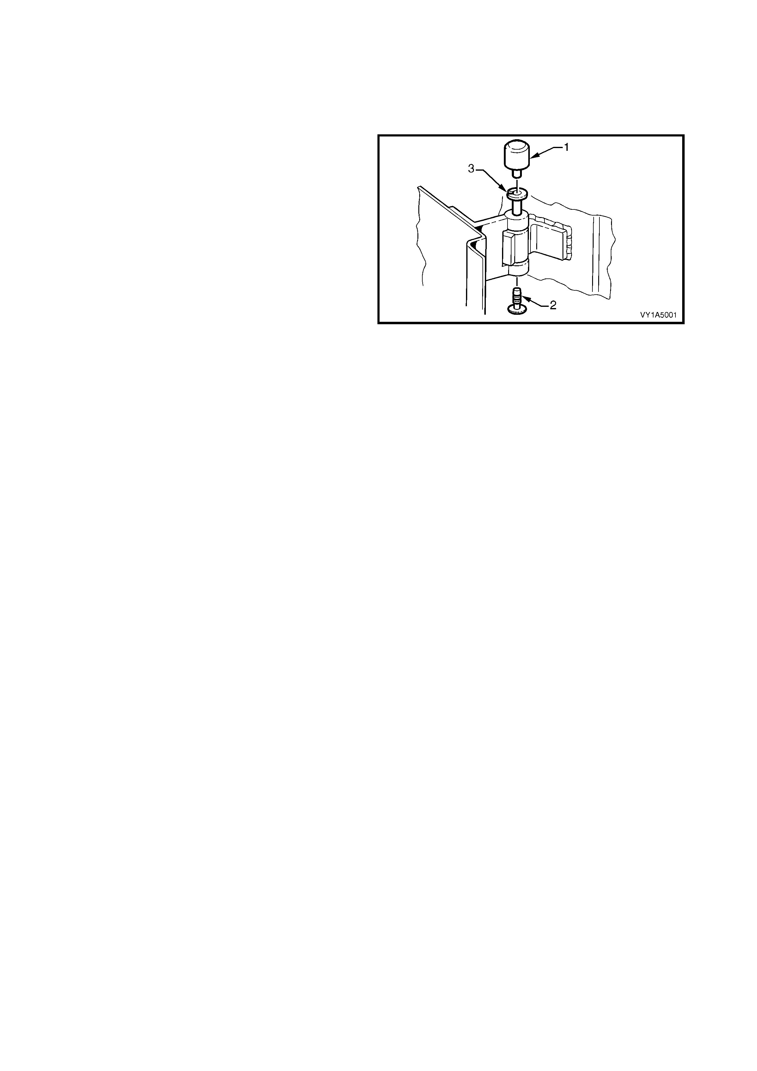
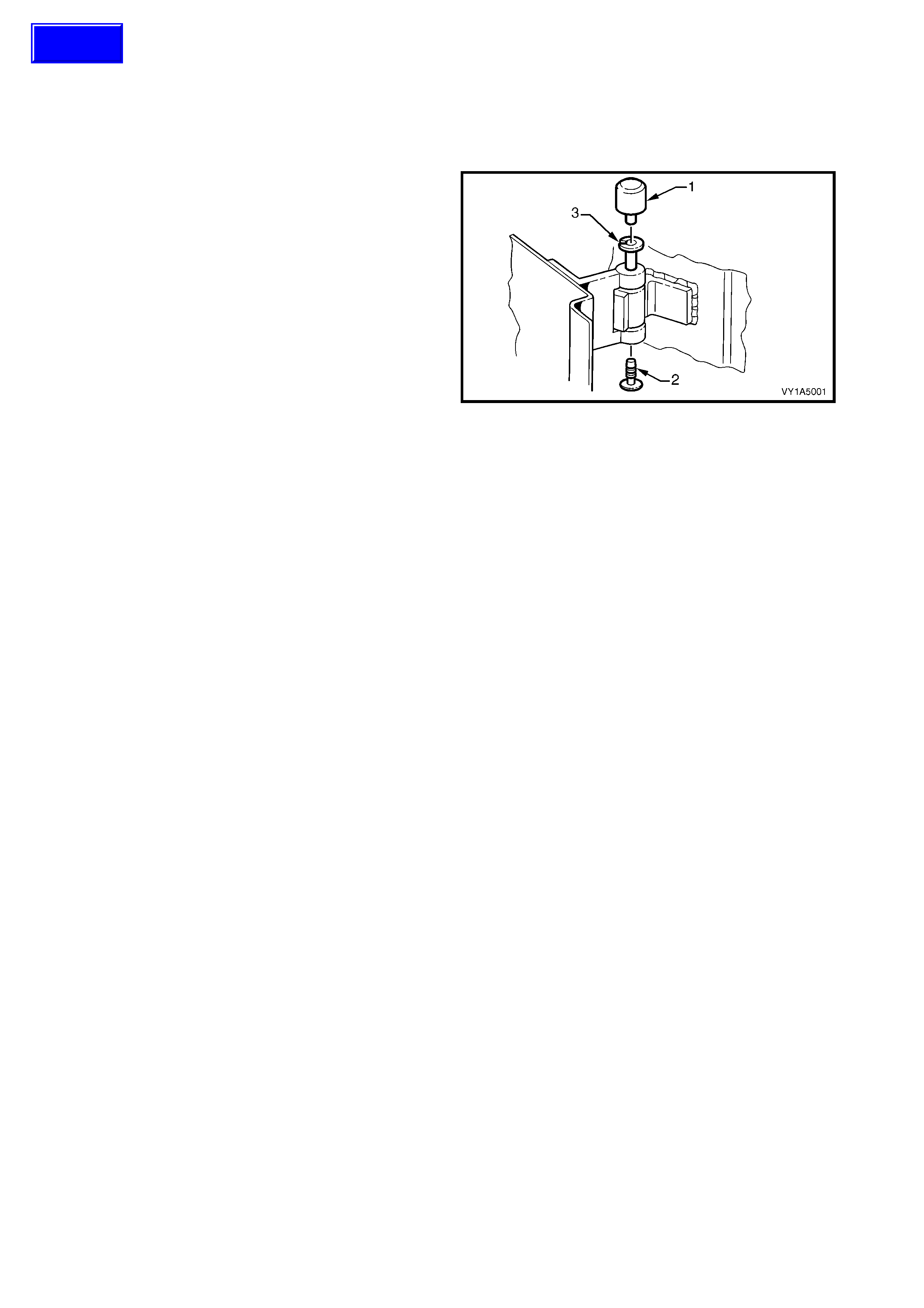
2.1 FRONT DOOR HINGE LUBRICATION
LT Section No. –
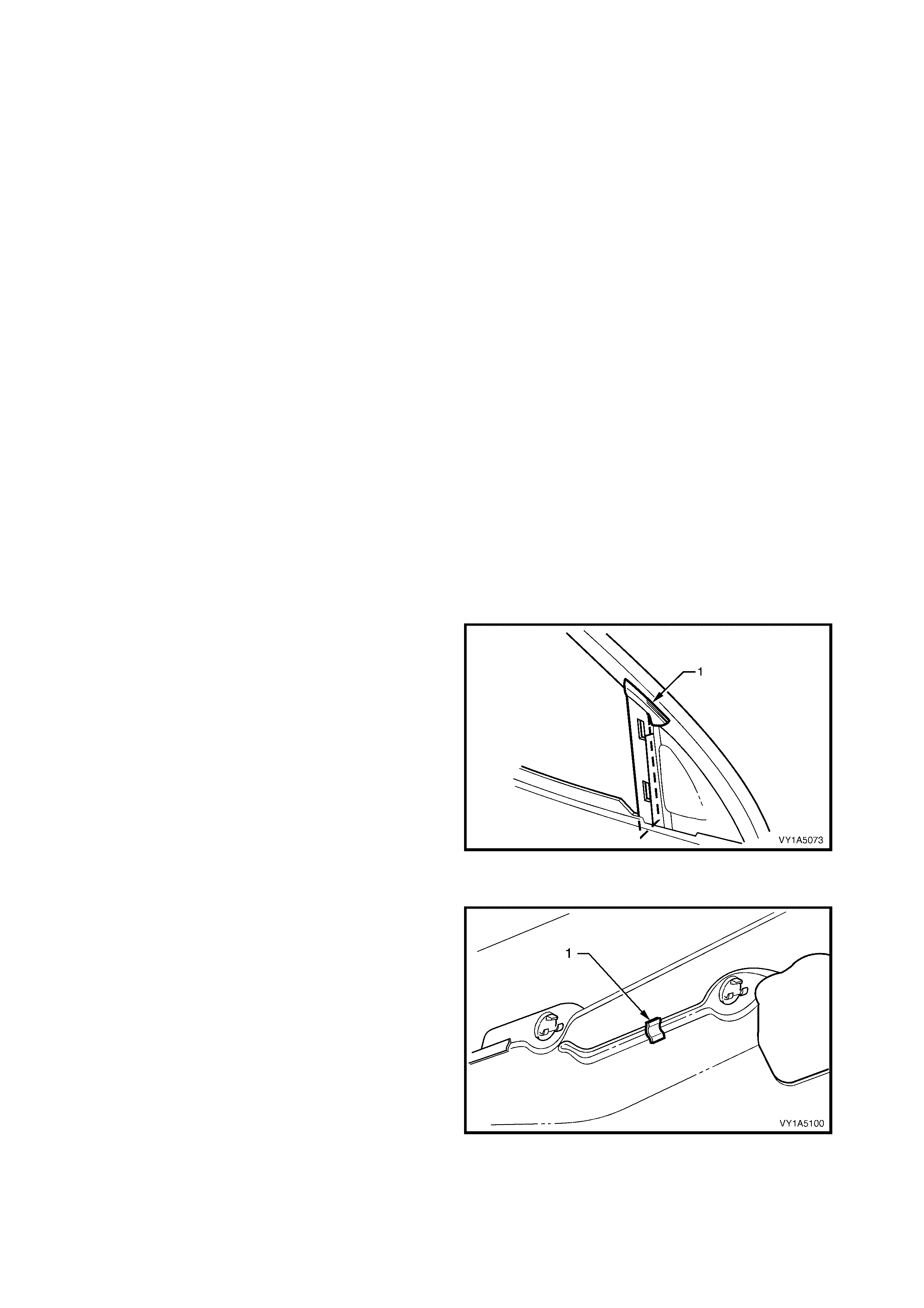
1. Remove the front hinge pin cap (1) and the front
hinge plug (2) from the front hinge pin (3) on the
upper and lower hinges.
2. Using a grease gun, inject into the front hinge pin
Lithium base grease NLGI No. 1 (with 9 % zinc
oxide) or equivalent.
3. Reinstall the cap and plug.
4. Wipe off any excess grease.
Figure 1A5-1
2.2 FRONT DOOR LOCK STRIKER
LT Section No. – 11-725
REMOVE
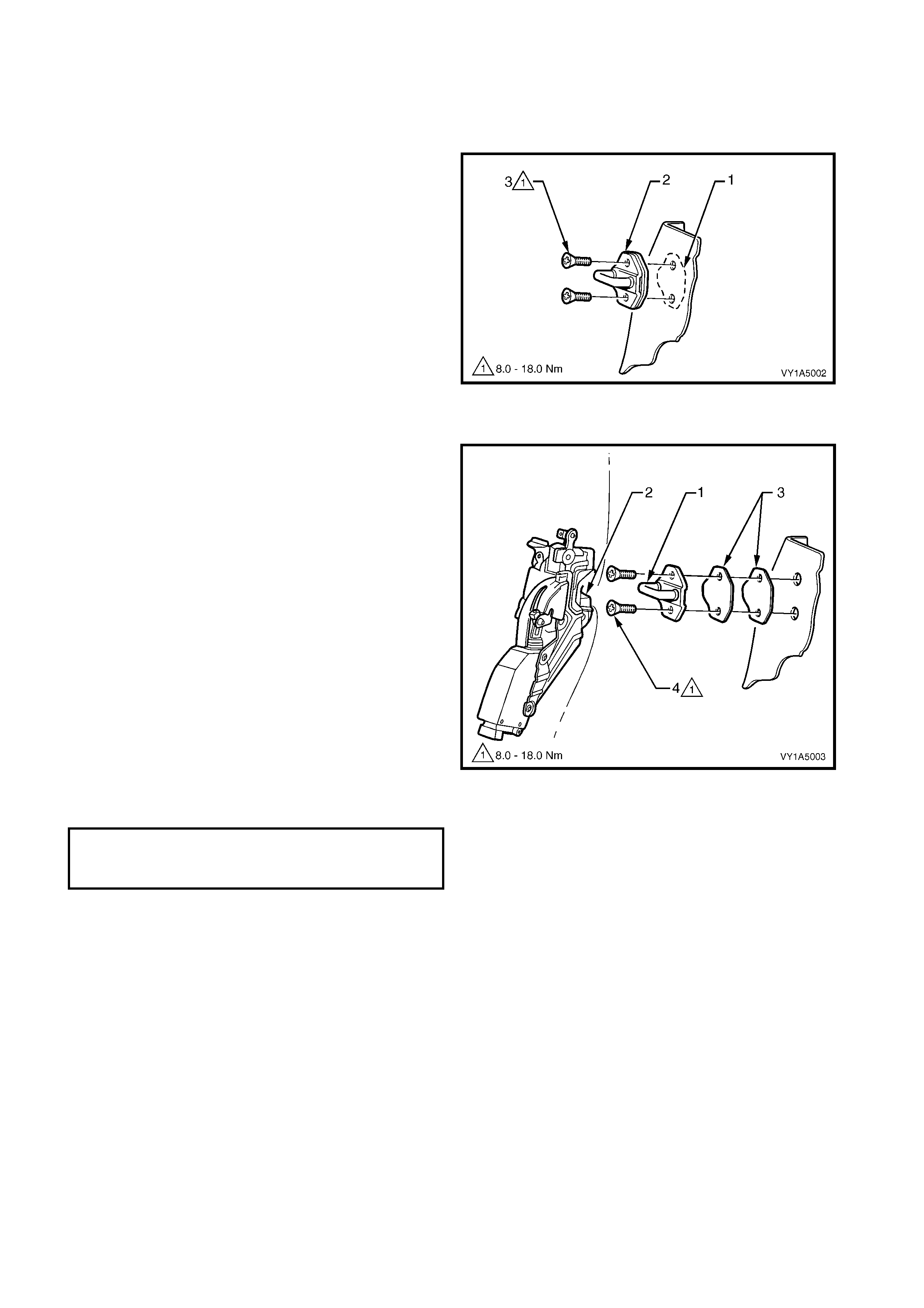
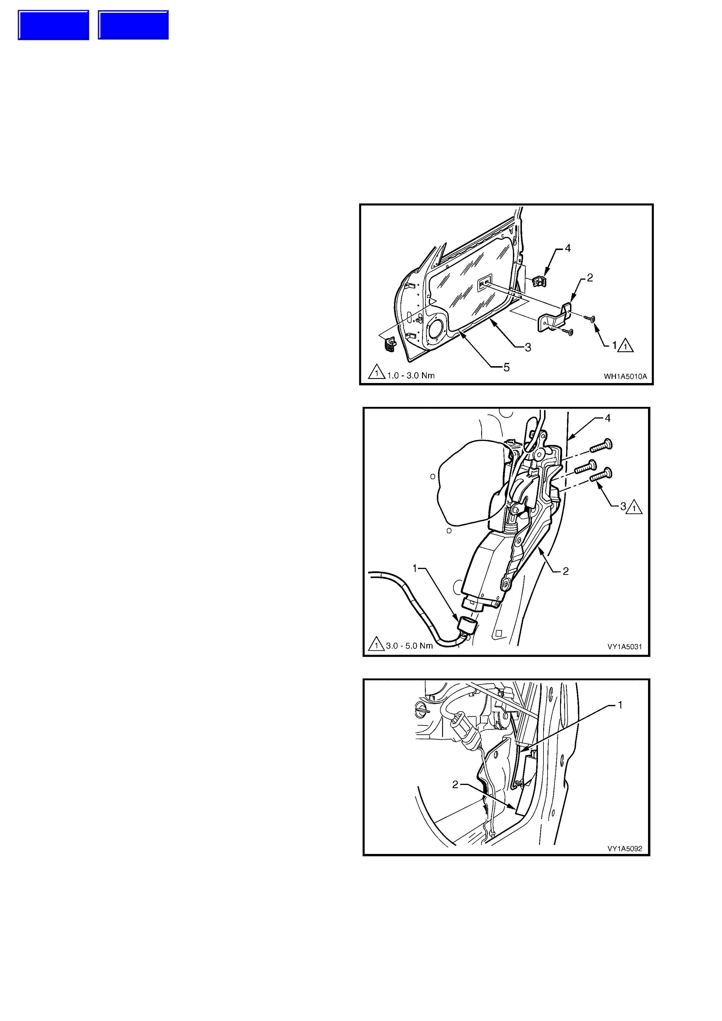
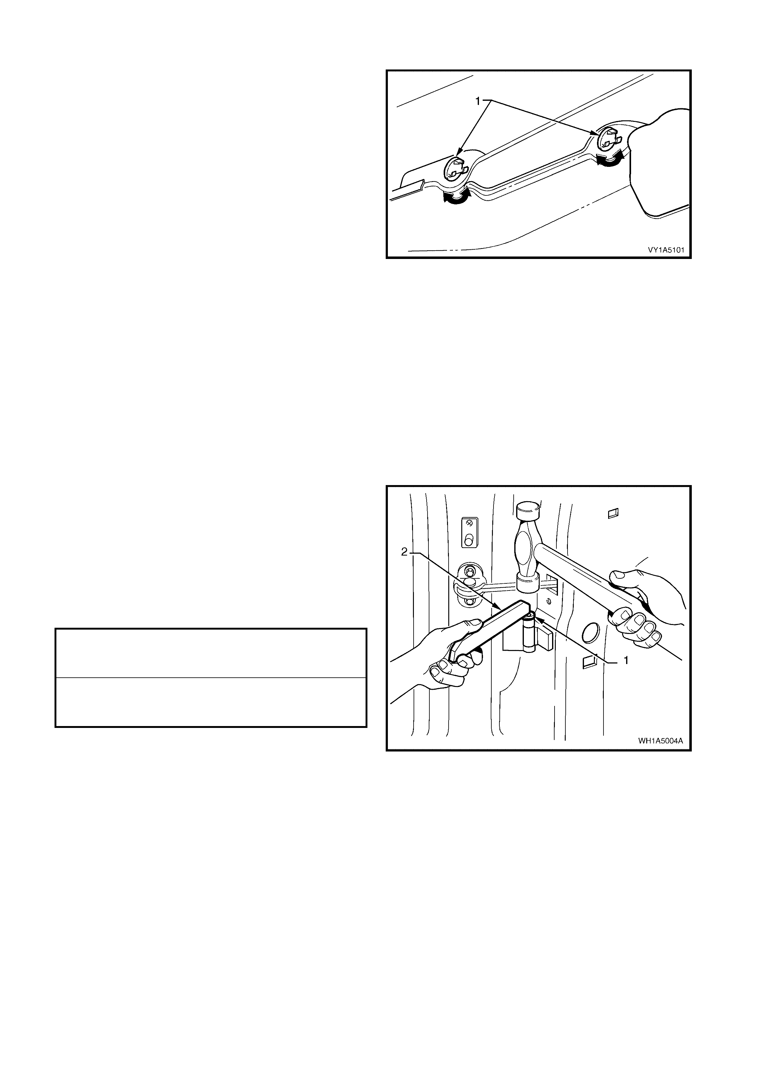
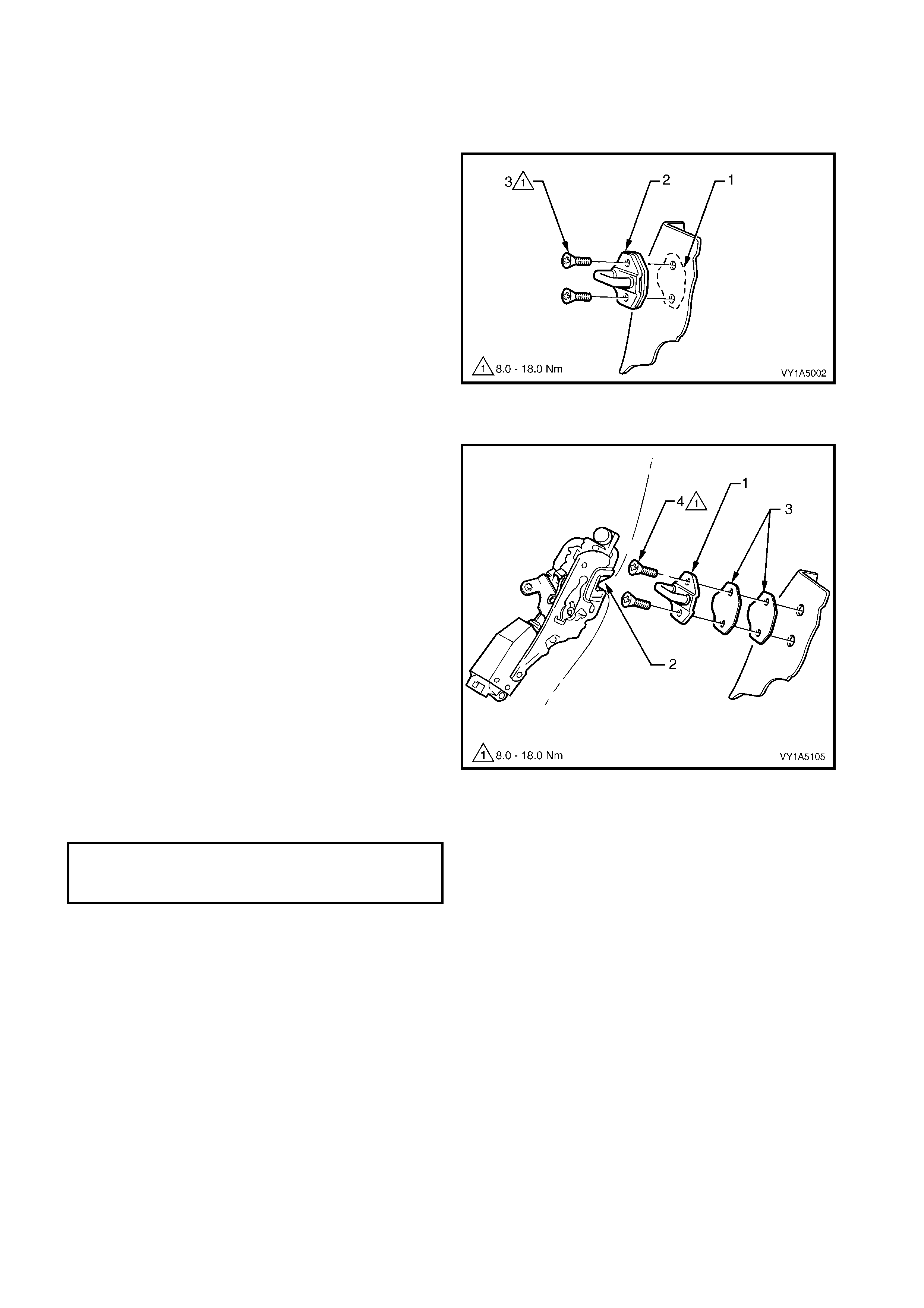
1. Pencil scribe (1) the location of the door lock
striker assembly (2) on to the body pillar before
removal, to facilitate installation.
2. Using a Torx bit (30 T), remove two retaining
screws. (3)
3. Remove the striker and spacer plates, if fitted.
Figure 1A5-2
REINST ALL
1. Align the door lock striker assembly (1), so that the
bridge of the striker locates centrally in the door
fork lock ass embly (2) as t he door is being clos ed.
Firmly tighten the striker assembly.
2. Correct engagement can be achieved by vertical
or horizontal adjustment of the door lock
striker assembly. The door must not ‘Ride’ on
the striker. Add or delete the door lock striker
washer (3) between the striker assembly and
body pillar to achieve correct engagement of the
striker assembly to the lock. Also refer to
2.3 ADJUST FRONT DOOR ASSEMBLY.
TIP: It is sound practice to remove the door lock striker
assembly and allow the door to hang free on the
hinges. Set th e hin ges as neces s ar y to achieve c orr ect
alignment and uniform margins, then reinstall the
striker and adjust.
3. When correct alignment of the striker assembly is
achieved, tighten the striker assembly retaining
screw (4) to the correct torque specification.
Figure 1A5-3
STRIKER ASSEMBLY
RETAINING SCREW
TORQUE SPECIFICATION 8.0 – 18.0 Nm
2.3 ADJUST FRONT DOOR ASSEMBLY
LT Section No. – 12-460
Attention should be given to uniform margins and alignment between the door and surrounding parts when
adjustments are being performed.
Uniform margins and alignment of the doors in relation to the body opening can be achieved by
setting the appropriate door hinge. Refer to MY2003 VY & V2 Series Service Manual Supplement,
Body Structure Repair Manual for specifications.
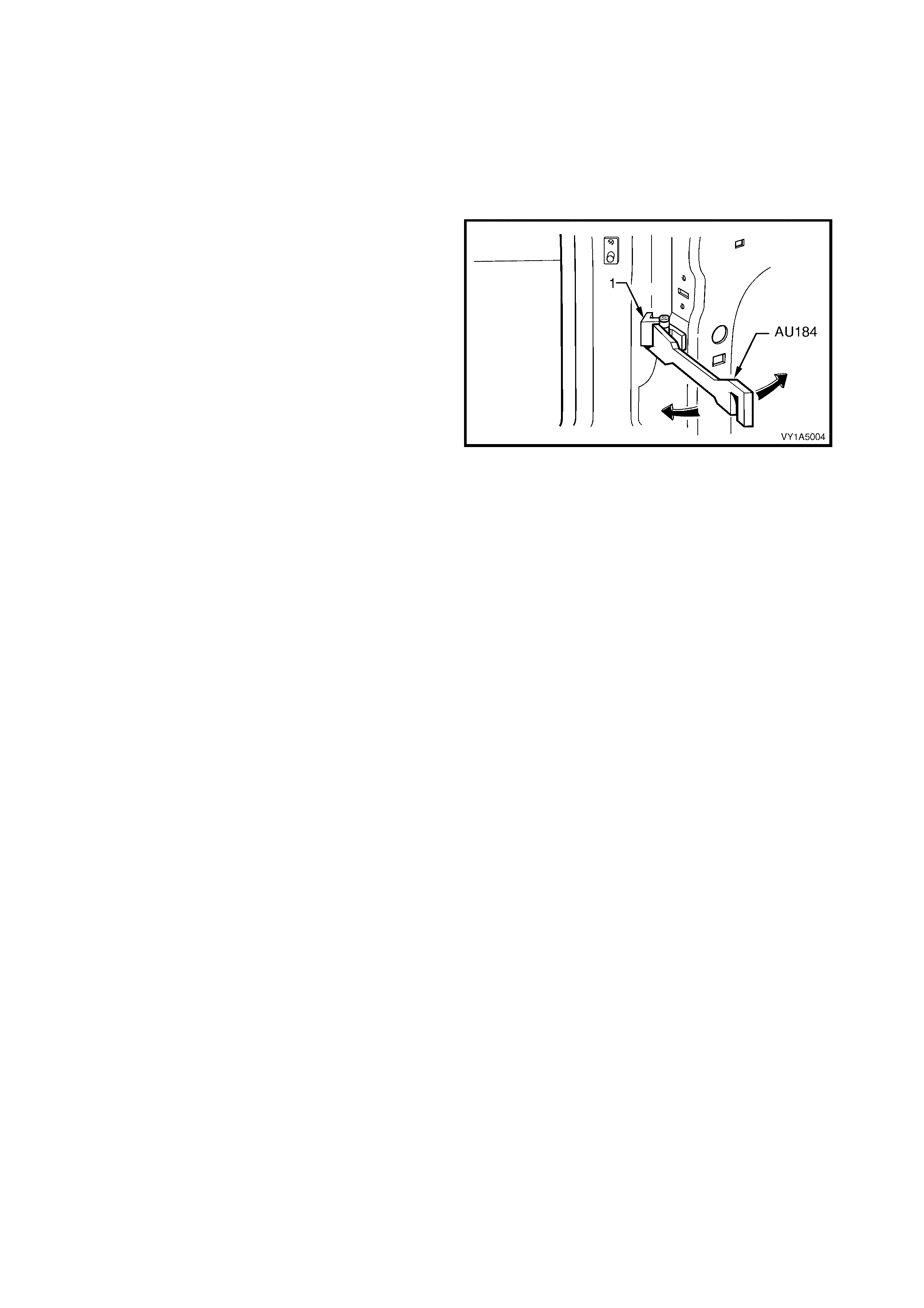
Use Tool No AU184 to set door hinges by slightly
bending the front door hinge (1) noting the following:
1. Take care when adjusting the doors not to
misalign the hinge pins. Any significant
misalignment will cause the pins to shear when
the door is opened or closed.
2. Excessive bending or levering of the window
frame will cause damage.
3. Final adjustment must take place when all the
door components and seals are installed.
IMPORTANT: Adjust the doors with the striker
assembly removed. The striker assembly should only
be fitted o nce satisf actor y alignment is achieve d. The y
must NOT be used to pull the door into the correct
position.
Figure 1A5-4
2.4 FRONT WINDOW REGU LATOR HA ND LE A SSEM B LY
LT Section No. – 11-675
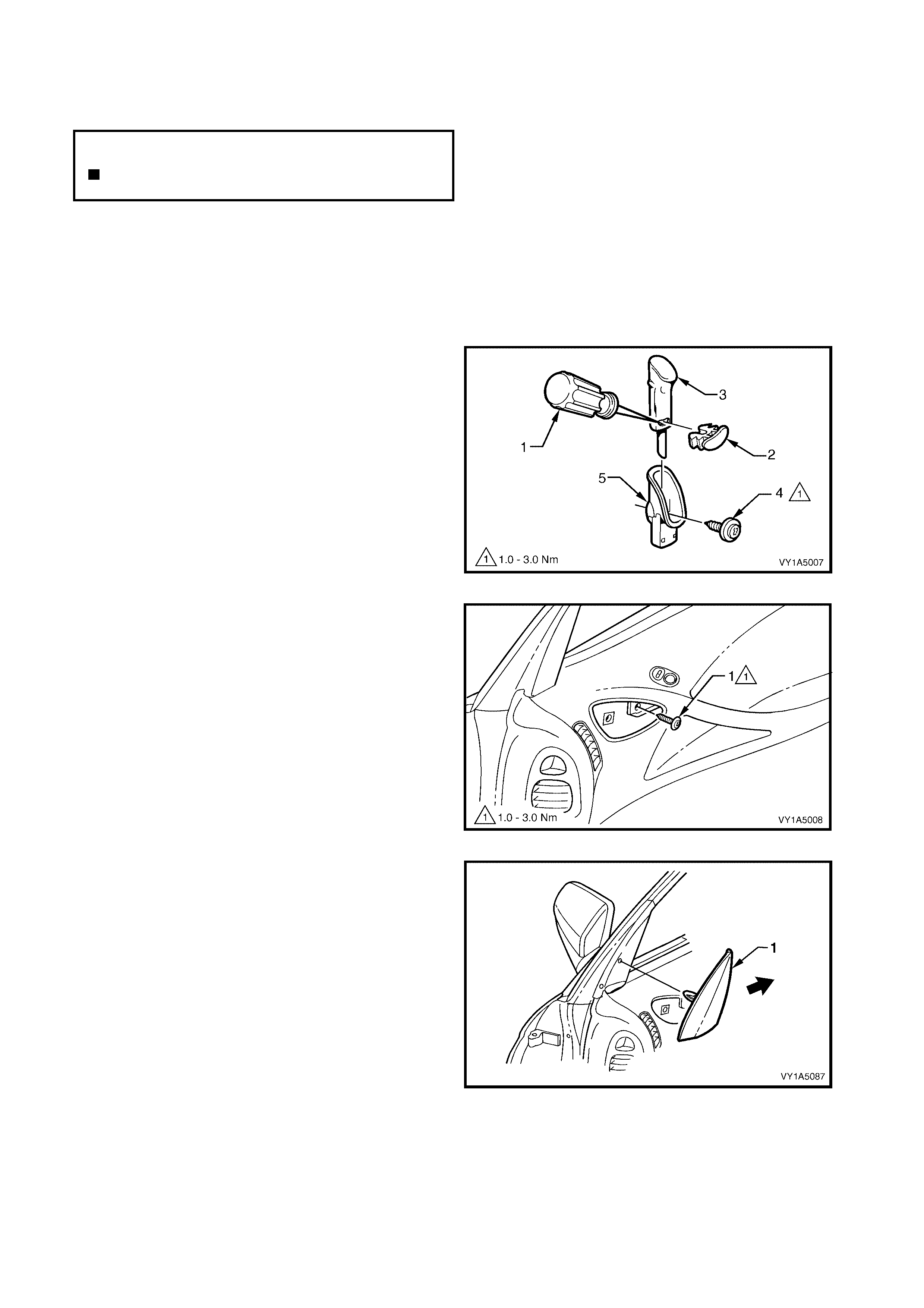
REMOVE
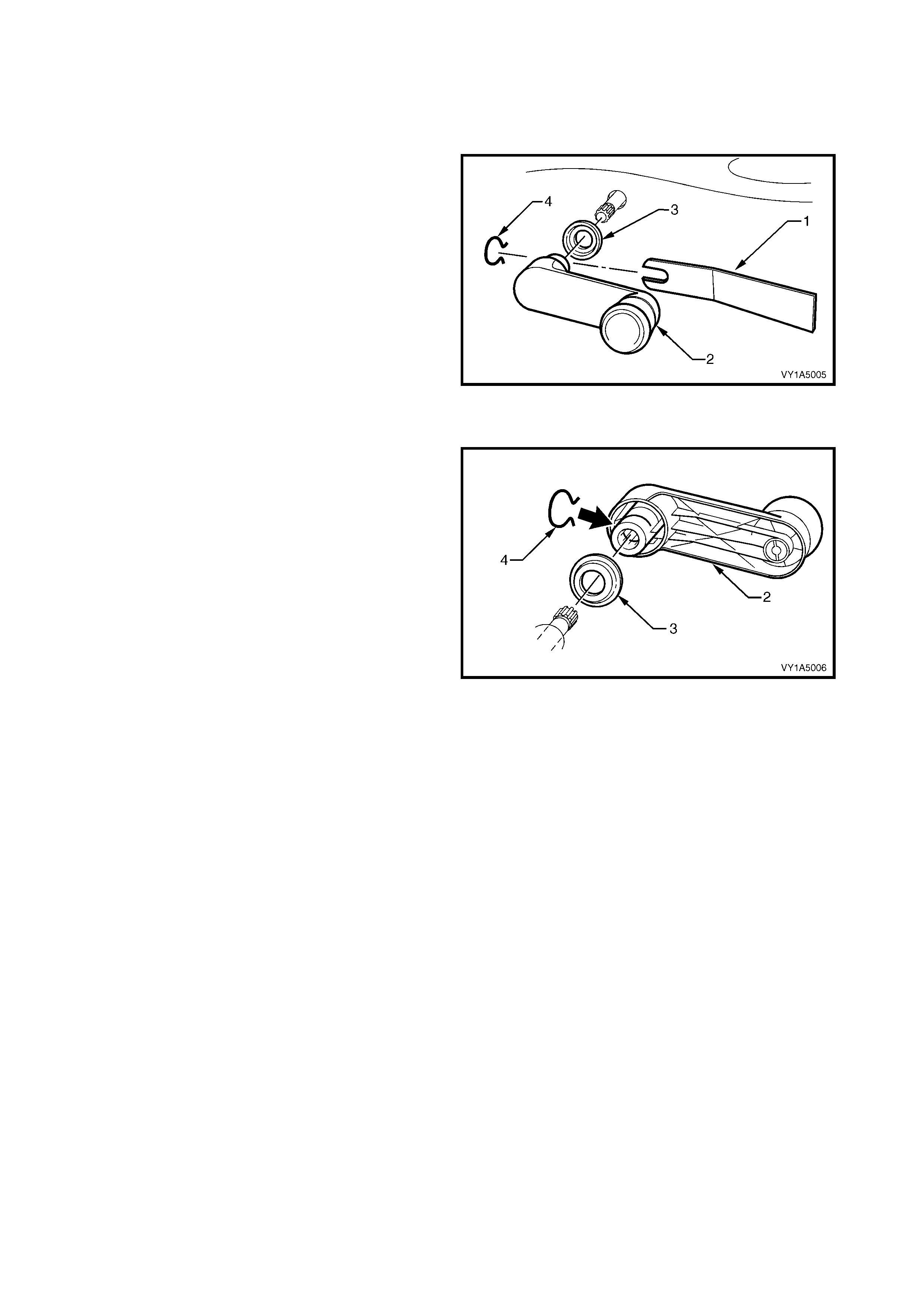
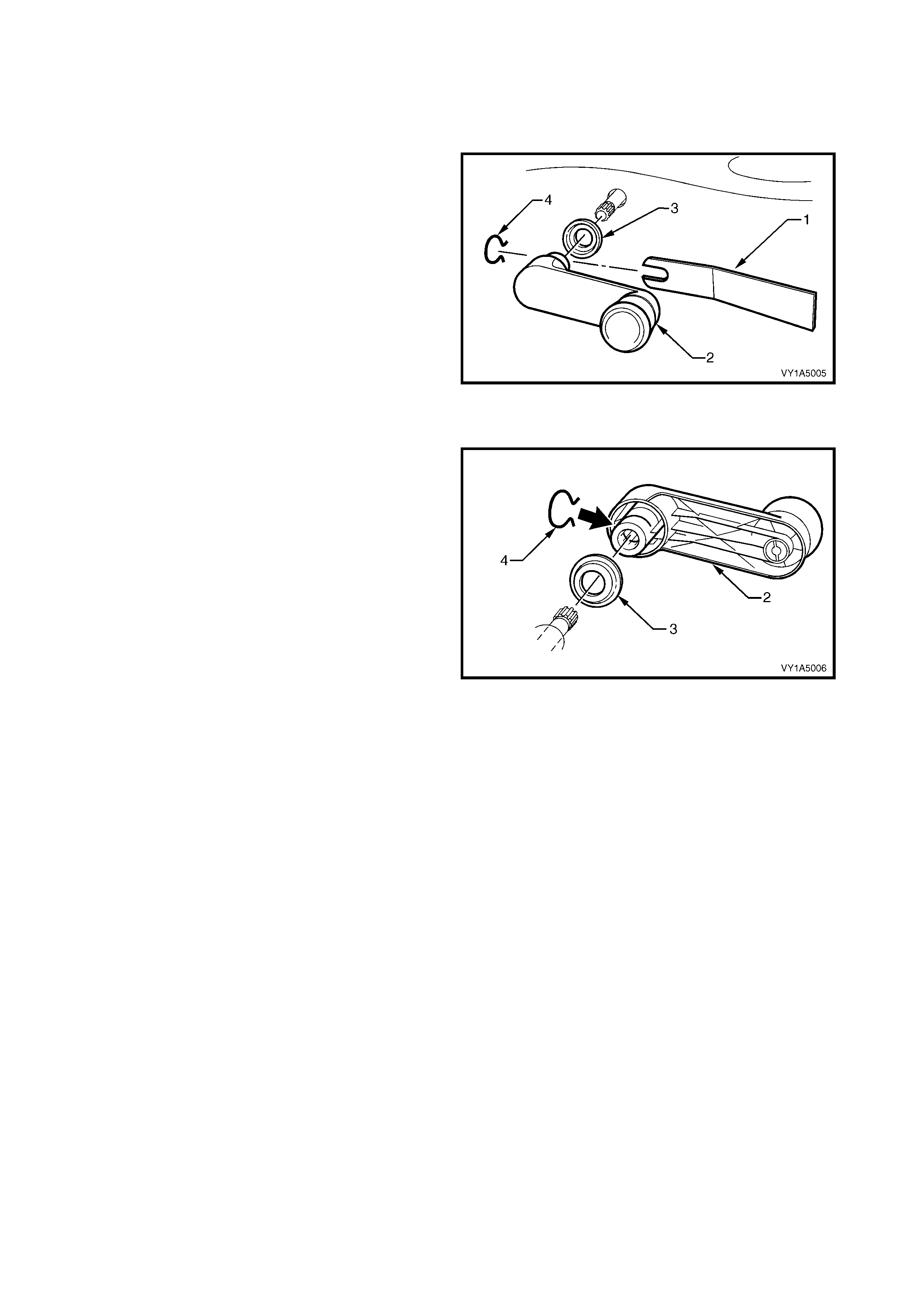
1. Insert a commercially available window regulator
handle removal tool (1), between the base of the
front door window regulator handle (2), and the
window regulator handle washer (3), in line with
the arm of the handle.
2. Disengage the front window regulator handle clip
(4), then remove the handle.
NOTE: Take care when disengaging the front window
regulator handle clip that it does not spring off.
Figure 1A5-5
REINST ALL
1. Locate the front window regulator handle clip (4),
in the window regulator handle (2), with the open
ends of the clip facing the handle arm.
NOTE : Make sure both the front door win dows are at
the same height before fitting the handle assemble.
2. Fit the window regulator handle washer (3).
3. Ensure that the handle is positi oned symm etric ally
with the handle on the opposite door, then press
the handle ont o the window regula tor splines, unt il
the clip engages the groove at the base of the
splines.
Figure 1A5-6
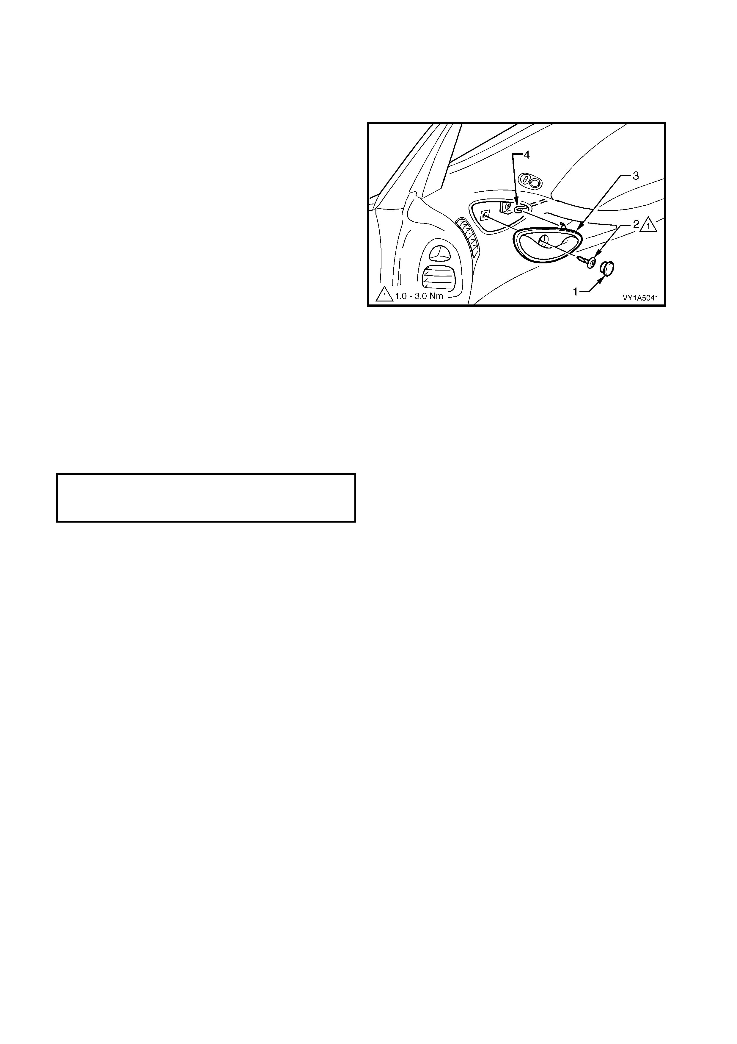
2.5 FRONT DOOR INSIDE HANDLE ASSEMBLY (REMOTE)
LT Section No. – 11-360
REMOVE
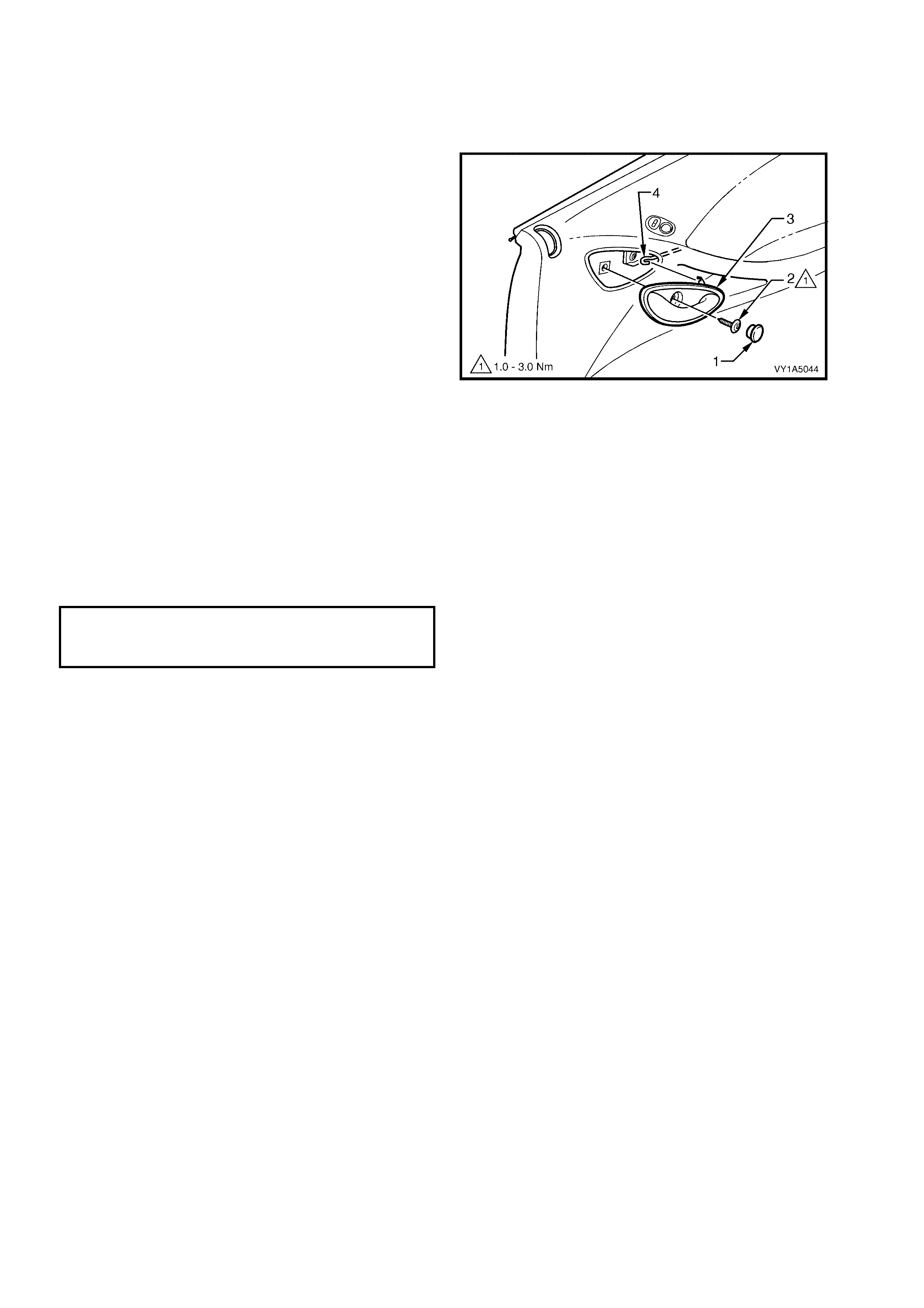
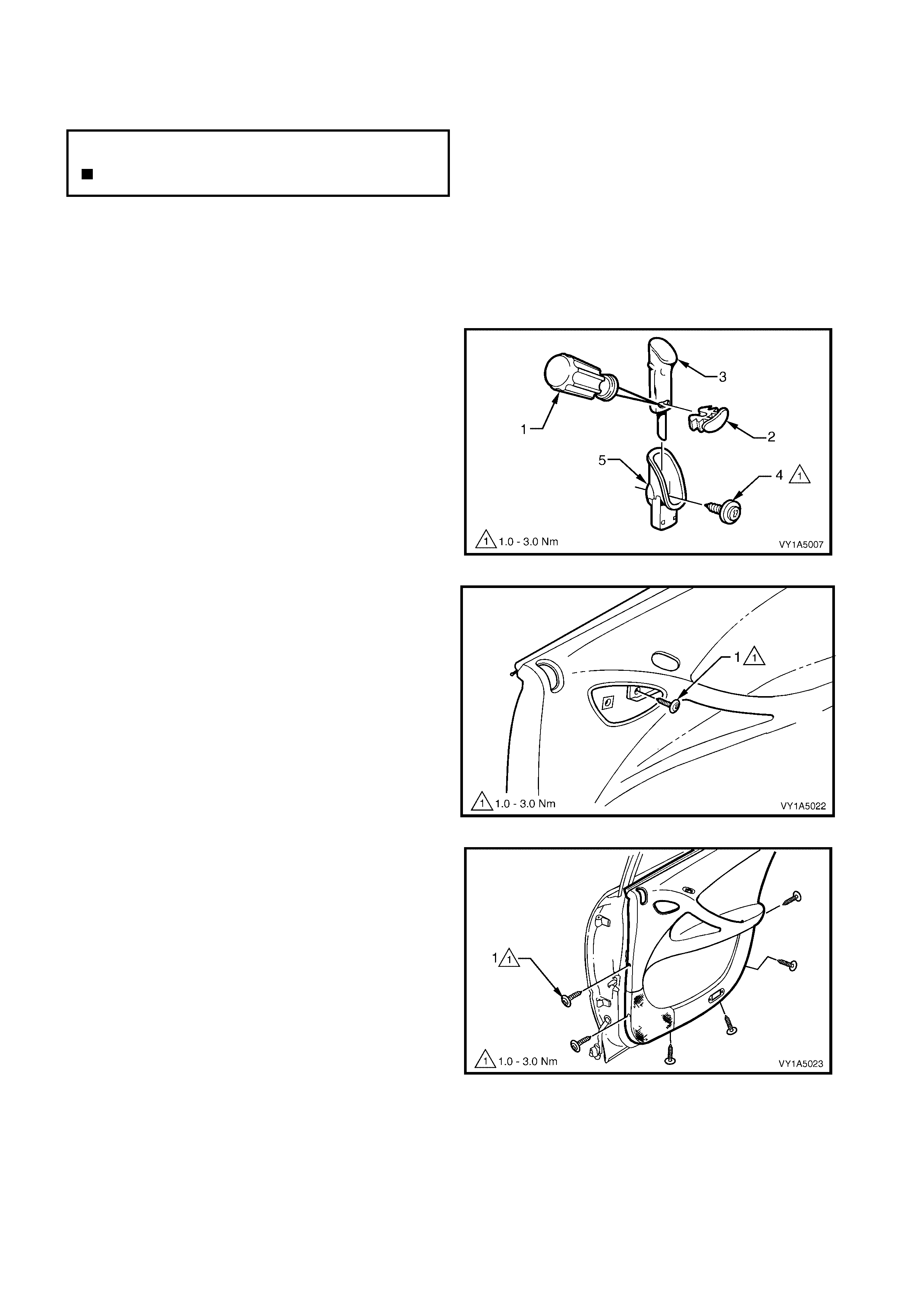
1. Prise off the front door inside handle bolt finisher
cap (1).
2. Remove the screw (2) securing the front door
inside handle assembly (remote) (3) to the front
door trim.
3. Remove the handle assembly in a forward
direction and unhook the front inside handle rod
(4) from the handle assembly.
Figure 1A5-7
REINST ALL
Reinstal lation of the front door ins ide hand le assem bly
(remote) is the reverse of the removal, refer Figure
1A5-7, noting the following:
1. Ensure the handle assembly and remote rod are
engaged before final fitment.
2. Tighten the retaining screw to the correct torque
specification.
FRONT DOOR INSIDE HANDLE
ASSEMBLY (REMOTE) SCREW
TORQUE SPECIFICATION 1.0 – 3.0 Nm
2.6 FRONT DOOR TRIM PANEL ASSEMBLY
LT Section No. – 14-220
If required, first remove the following components,
1. Front door window regulator handle assembly (where fitted), refer to 2.4 FRONT DOOR WINDOW
REGULATOR HANDLE ASSEMBLY.
2. Front door inside handle assembly (remote), refer to 2.5 FRONT DOOR INSIDE HANDLE ASSEMBLY
(REMOTE).
REMOVE
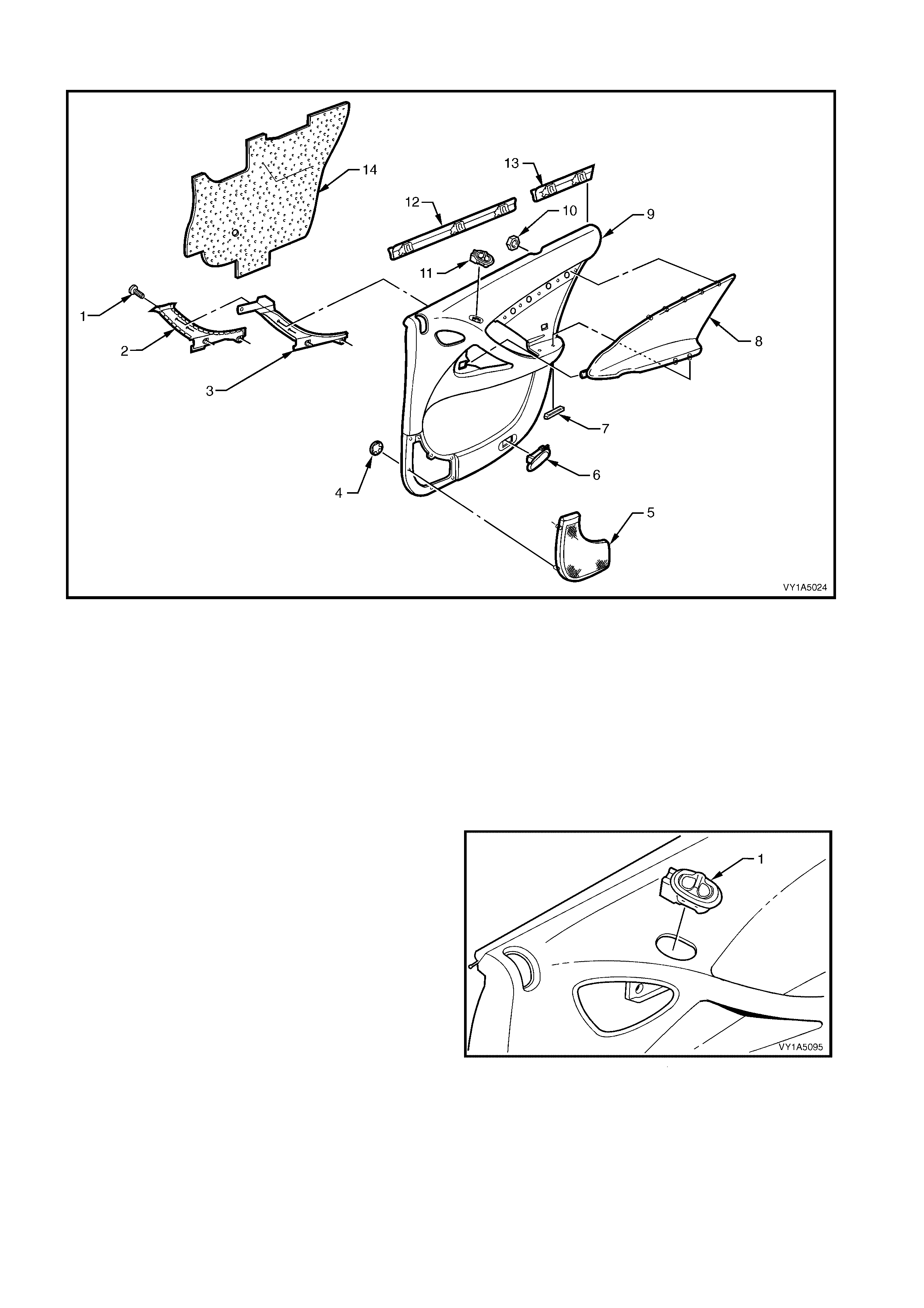
1. Using a s mall f lat bladed screwdr iver or sc ribe (1) ,
gently pris e the or ange f ron t door loc k ing rod k nob
retainer (2) from the front door locking rod knob
assembly (3), taking care not to damage the knob
assembly. Remove the knob assembly.
NOTE: The orange front door locking rod knob
retainer, will be damaged during this operation and
must be replaced.
2. Lift the knob assembly up, removing it from the
door locking rod.
3. Remove the screw (4) securing the front door
locking rod ferrule (5) to the door trim panel
assem bl y and remove the f er rule.
Figure 1A5-8
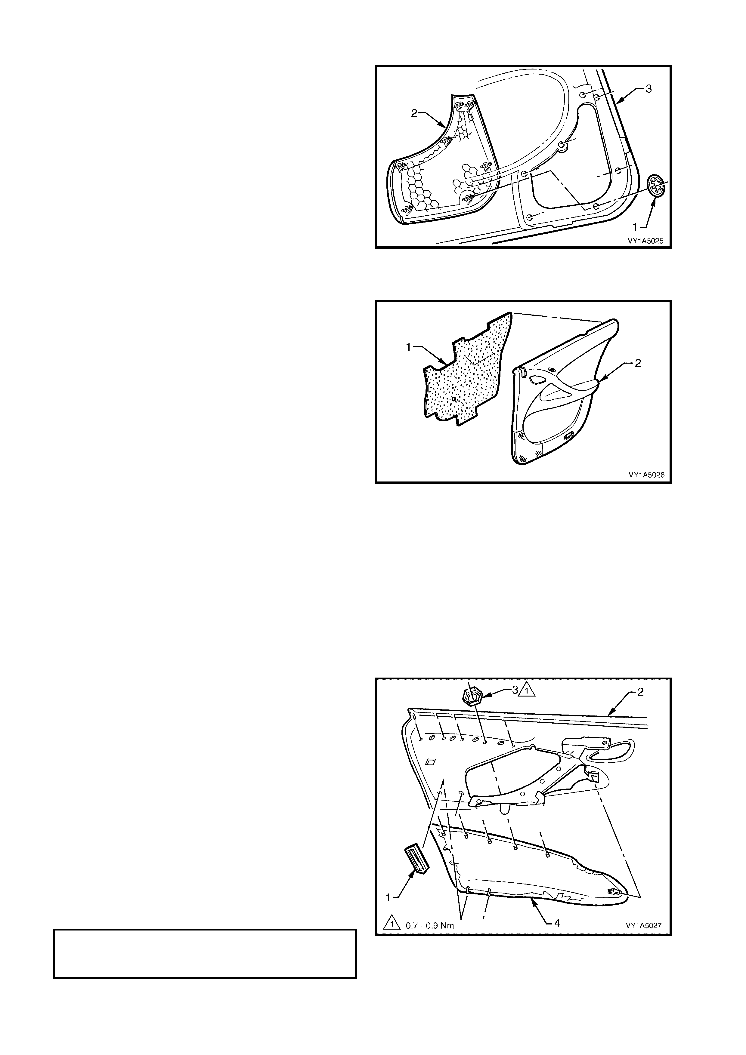
4. Remove the front door trim retaining screw (1)
from the handle assembly aperture.
Figure 1A5-9
5. Gently prise the front edge of the side window
outlet defogger (1) and remove to the rear.
Figure 1A5-10
N
O
TE: The
f
ollowing component WILL RE
Q
UIRE
REPLACEMENT when performing this operation.
Front door locking rod knob retainer .
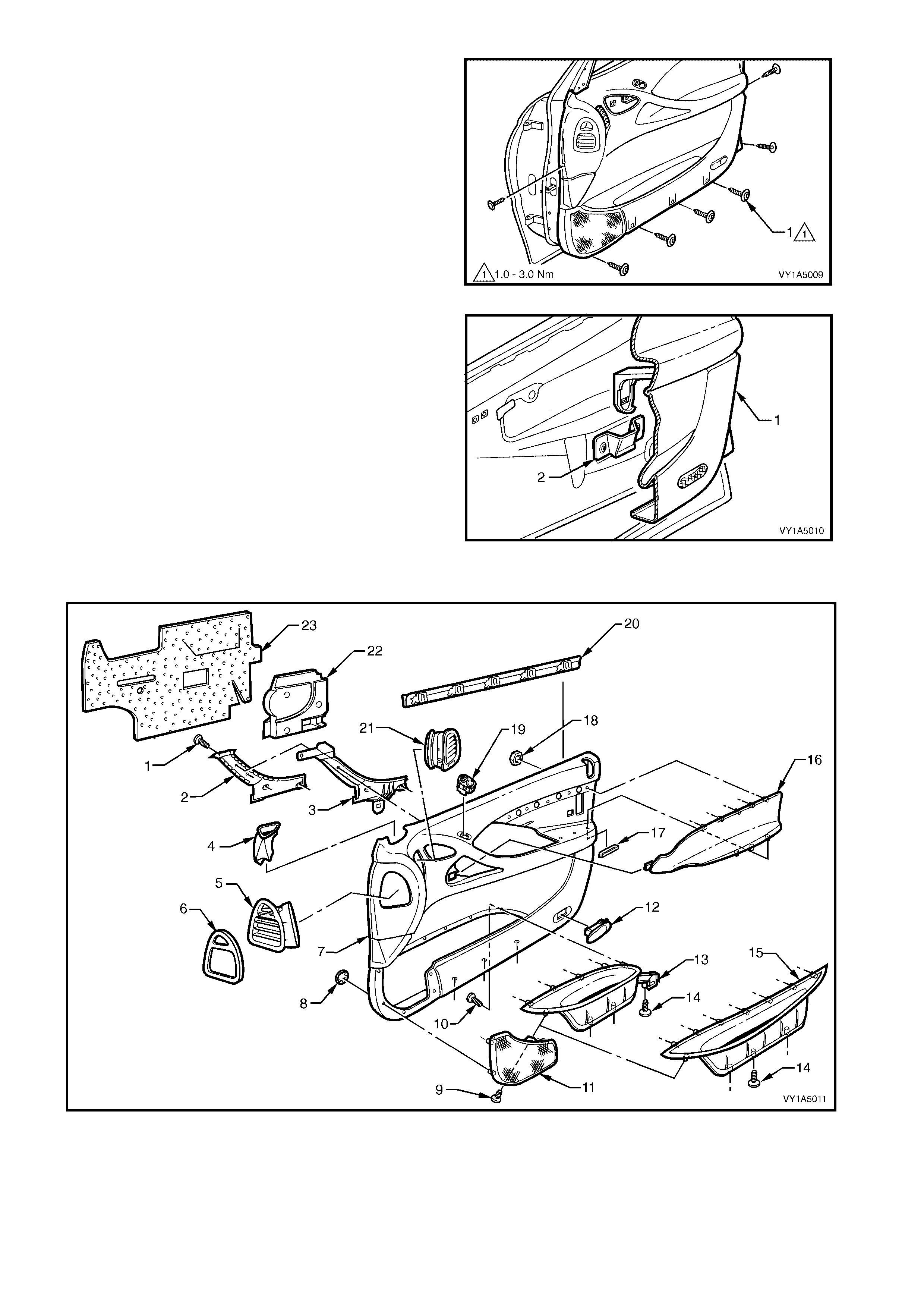
6. Remove the seven screws (1), securing the front
door trim panel assembly to the door inner panel.
7. Lift the top of the panel assembly, up and out of
the door inner channel.
Figure 1A5-11
8. Unclip the panel assembly (1) from the front pull
handle bracket (2) except Coupe, by pushing in
and lifting the centre of the panel assembly at
armrest height.
NOTE: Wiring harness connectors are still connected.
9. While supporting the panel assembly, disconnect
all the wiring harn ess conn ec tors .
10. Remove the panel assembly.
Figure 1A5-12
DISASSEMBLE
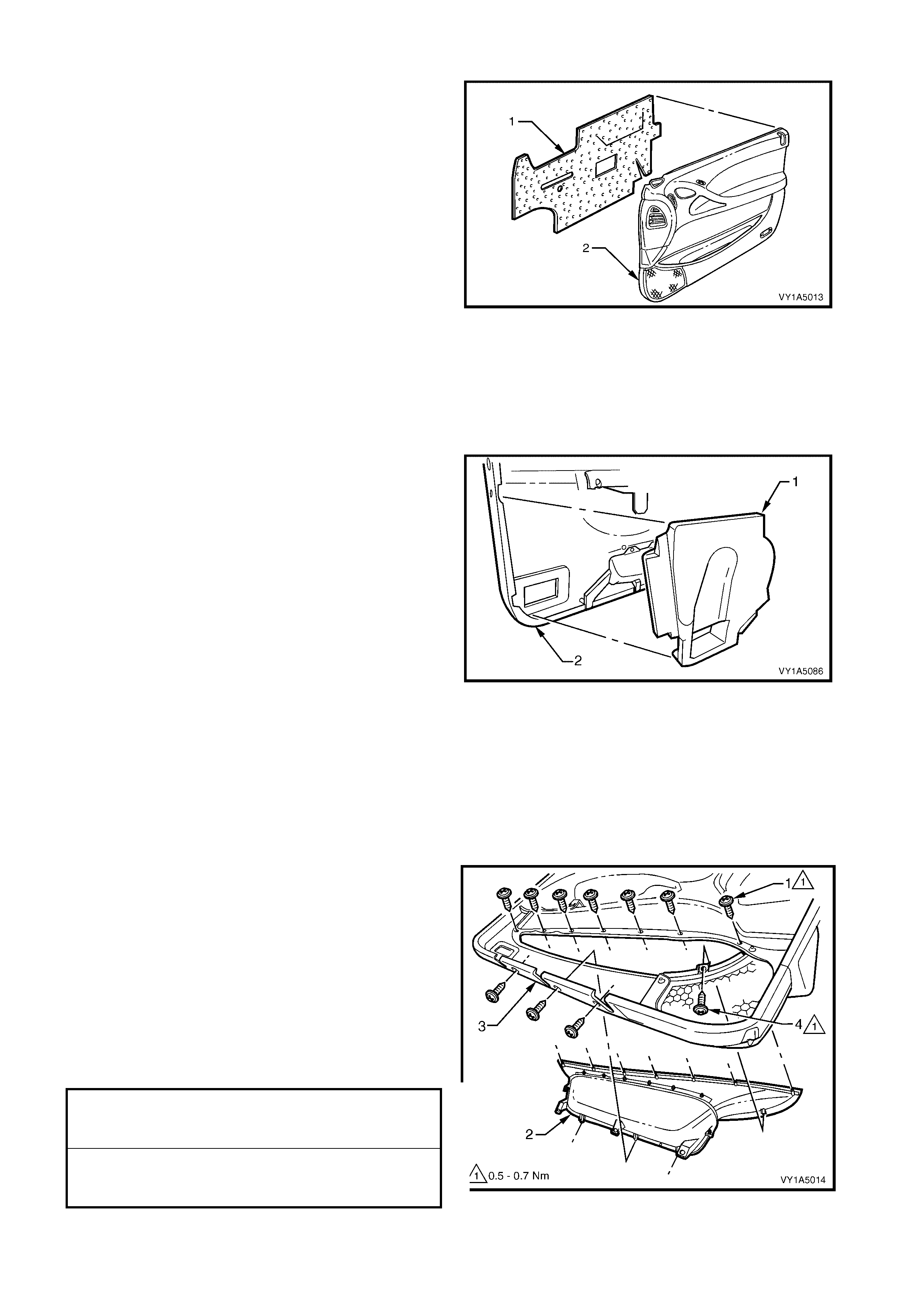
Figure 1A5-13
Legend
1. Front Door Inside Handle Screw (4 places)
2. Front Door Inside Handle Cover
3. Front Door Inside Handle Bracket
4. Side Window Defogger Air Duct
5. Front Door Air Duct Assembly
6. Front Door Air Duct Seal
7. Front Door Trim Foundation Assembly
8. Radio Front Door Speaker Grille Retainer (6 Places)
9. Radio Front Door Speaker Grille Screw
10. Pocket Assembly Screw (7 Places With Side Impact
Airbags, 5 Places Without Side Impact Airbags)
11. Radio Front Door Speaker Grille
12. Front Door Courtesy Lamp
13. Front Door Map Pocket Assembly (Vehicles Without
Side Impact Airbags)
14. Pocket Assembly Screw (3 Places)
15. Front Door Map Pocket Assembly (Vehicles With Side
Impact Airbags)
16. Front Door Armrest Insert Assembly
17. Insert Assembly Door Armrest Clip (3 Places), (Coupe,
5 Places)
18. Insert Assembly Door Armrest Clip (5 Places) (Coupe,
7 Places)
19. Rear View Mirror Switch (Driver’s Side Only)
20. Front Window Inner Sealing Strip Assembly
21. Front Door Air Outlet Assembly
22. Lower Side Impact Insert (Coupe and Vehicles Without
Side Impact Airbags)
23. Front Door Insulator Assembly
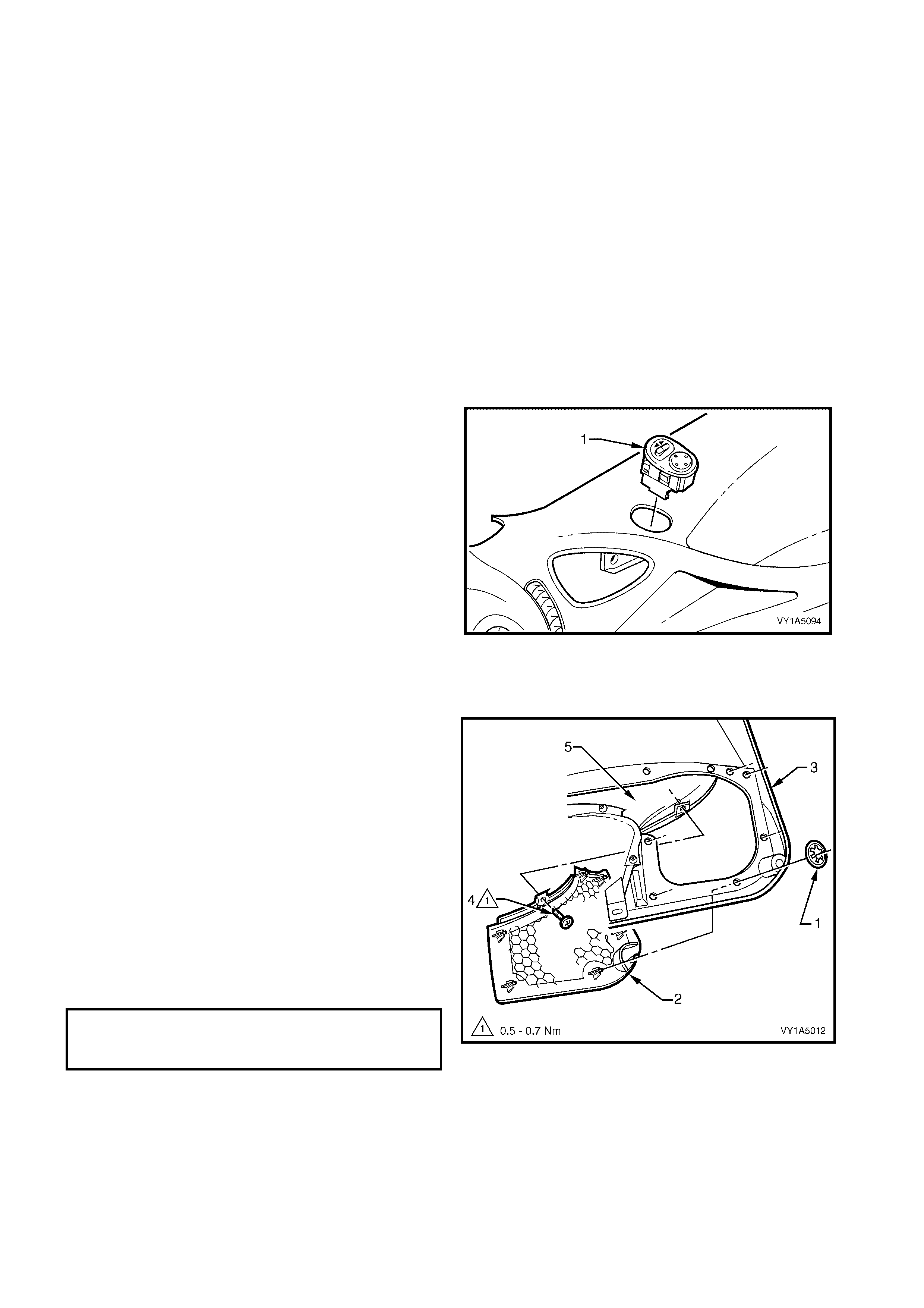
Remove – Rear View Mirror Switch
1. From behind the door trim assembly, push the rear
view mirror switch (1), free by depressing the
tangs.
2. Remove the switch.
NOTE: For further information regarding Service and
Diagnosis of the ex ternal r ear v ision m irr or and s witch,
refer to Section 12H REAR VIEW MIRRORS.
Reinstall – Rear View Mirror Switch
Reinstallation of the rear view mirror switch is the
reverse of removal, noting the following.
1. Press the s witch assem bly firm ly into the door trim
assem bly.
Figure 1A5-14
Remove – Radio Front Door Speaker Grille
1. Remove six clips (1) securing the radio front door
speaker grille (2) to the front door trim (3).
NOTE: Take care when removing clips, not to break
the speaker grille shafts on which the clips are
attached.
2. Remove the s crew (4) atta ching the r adio speak er
grille to the front door map pocket assembly (5).
3. Remove the radio speaker grille.
Reinstall – Radio Front Door Speaker Grille
Reinstallation of the radio speaker grille is the re verse
of the removal, noting the following:
1. Tighten retaining screw to the correct torque
specification.
Figure 1A5-15
RADIO FRONT DOOR SPEAKER
GRILLE RETAINING SCREW
TORQUE SPECIFICATION 0.5 – 0.7 Nm
Remove – Front Door Insulator Assembly
1. Remove the front door insulator assembly (1),
from the back of the front door trim panel
assembly (2), by peeling the insulator slowly
across the panel.
NOTE: Take care not to tear the insulator. Retain as
much adhesive as possible on the insulator. Do not
fold the insulator and store in a flat location with the
adhesive facing away from objects.
Reinstall – Front Door Insulator Assembly
1. Locate the insulator assembly centrally within the
front door trim panel assembly, and press firmly
into position.
NOTE: If required, apply additional hot melt adhesive
with a high softening point (eg. 90°c).
Figure 1A5-16
Remove – Lower Side Impact Insert
NOTE: Only for Coupe and vehicles without side impact airbags.
1. Peel back the insulator assembly from the lower rear portion of the door trim assembly, allowing access to
the lower side impact insert, refer this Section.
2. Remove the lower side impact insert (1) from the
back of the front door trim panel assembly (2), by
pulling the insert slowly away from the panel
assembly, allowing the adhesive to stay on the
insert.
Reinstall – Lower Side Impact Insert
Reinstallation of the lower side impact insert, is the
reverse of the removal, noting the following:
1. Press the lower side impact insert, firmly into
position.
NOTE: If required apply additional hot melt adhesive
with a high softening point (eg. 90°c).
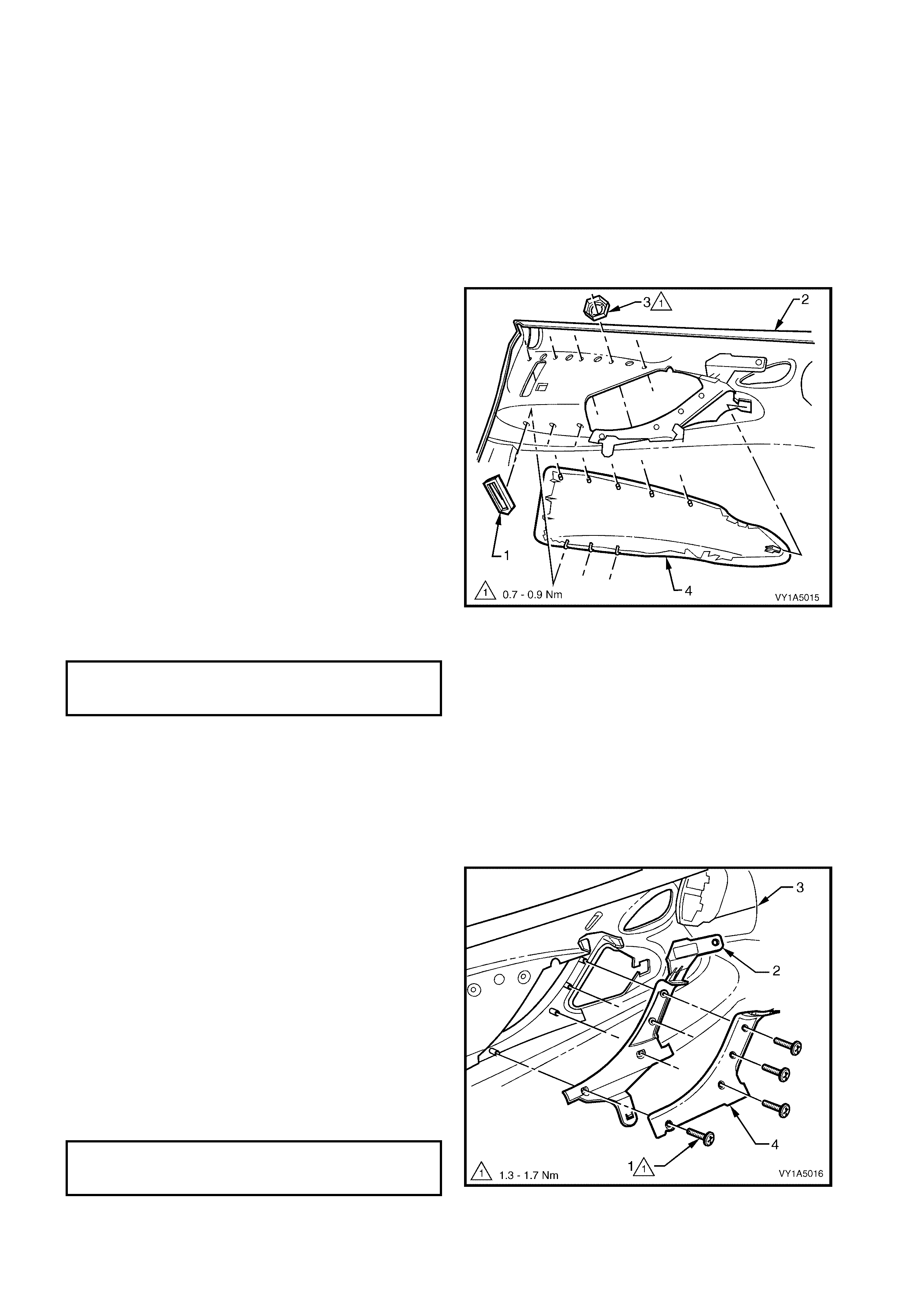
Figure 1A5-17
Remove – Front Door Map Pocket Assembly
1. Peel back the insulator assembly from the lower
portion of the door trim ass embly, allo wing access
to the door map pocket assembly attaching
screws, refer this Section.
2. If required, remove the lower side impact insert,
refer this Section.
3. Remove ten screws (1) for vehicles with side
impact airbags, or remove eight screws (1) for
vehicles without side im pact airbags, attac hing the
pocket assembly (2) to the panel assembly (3).
4. Remove the s crew (4) atta ching the r adio speak er
grille, to the pocket assembly.
5. Remove the pocket assembly.
Reinstall – Front Door Map Pocket Assembly
Reinstal lation of the poc ket assem bly is the revers e of
the removal procedure, noting the following:
1. Tighten all retaining screws to the correct torque
specification.
Figure 1A5-18
FRONT DOOR MAP POCKET
ASSEMBLY RETAINING SCREW
TORQUE SPECIFICATION 0.5 – 0.7 Nm
RADIO FRONT DOOR SPEAKER
GRILLE RETAINING SCREW
TORQUE SPECIFICATION 0.5 – 0.7Nm
Remove – Front Door Armrest Insert Assembly
IMPORTANT: Take care when removing the clips, as
the rotating action will cut-off the front door armrest
insert assembly shaft, to which the clips are attached,
requiring a replacement insert assembly to be fitted.
1. Peel back the insulator assembly from the lower
portion of the door tr im assem bly, allowi ng access
to the insert assembly attaching parts, refer this
Section.
2. Remove the lower side impact insert, refer this
Section.
3. Rem ove the clips (1), three places (five places for
Coupe), by sliding them away from panel
assembly (2).
4. Remove the nuts (3), f ive places (s even places f or
Coupe), attaching the armrest to the door trim
panel assembly.
5. Before removal, pry the armrest insert assembly
(4) a way from the panel as sembl y. Slide the i nsert
assembly to the rear of the panel assembly and
remove.
Reinstall – Armrest Insert Assembly
Reinstallation of the insert assembly is the reverse of
the removal procedure, noting the following.
1. The insert assembly, must be sitting flush against
the panel assembly, along the entire top
contacting surface.
2. Tighten all retaining nuts to the correct torque
specification.
Figure 1A5-19
Remove – Front Door Inside Handle Assembly
(Pull)
1. Remove the armrest insert assembly, refer this
Section.
2. Remove the lower side impact insert, refer this
Section.
3. Remove four screws (1) attaching the front door
inside handle bracket (2) to the panel assembly
(3).
4. Remove the front door inside handle assembly.
5. Peel off the cover (4), from the front door inside
handle brac k et.
Reinstall – Front Door Inside Handle Assembly
(Pull)
Reinstal lation of the hand le ass embl y is the rev erse of
the removal procedure, noting the following:
1. Tighten all retaining screws to the correct torque
specification.
Figure 1A5-20
ARMREST INSERT ASSEMBLY
RETAINING NUT
TORQUE SPECIFICATION 0.7 – 0.9 Nm
FRONT DOOR INSIDE HANDLE
ASSEMBLY (PULL) SCREW
TORQUE SPECIFICATION 1.3 – 1.7 Nm
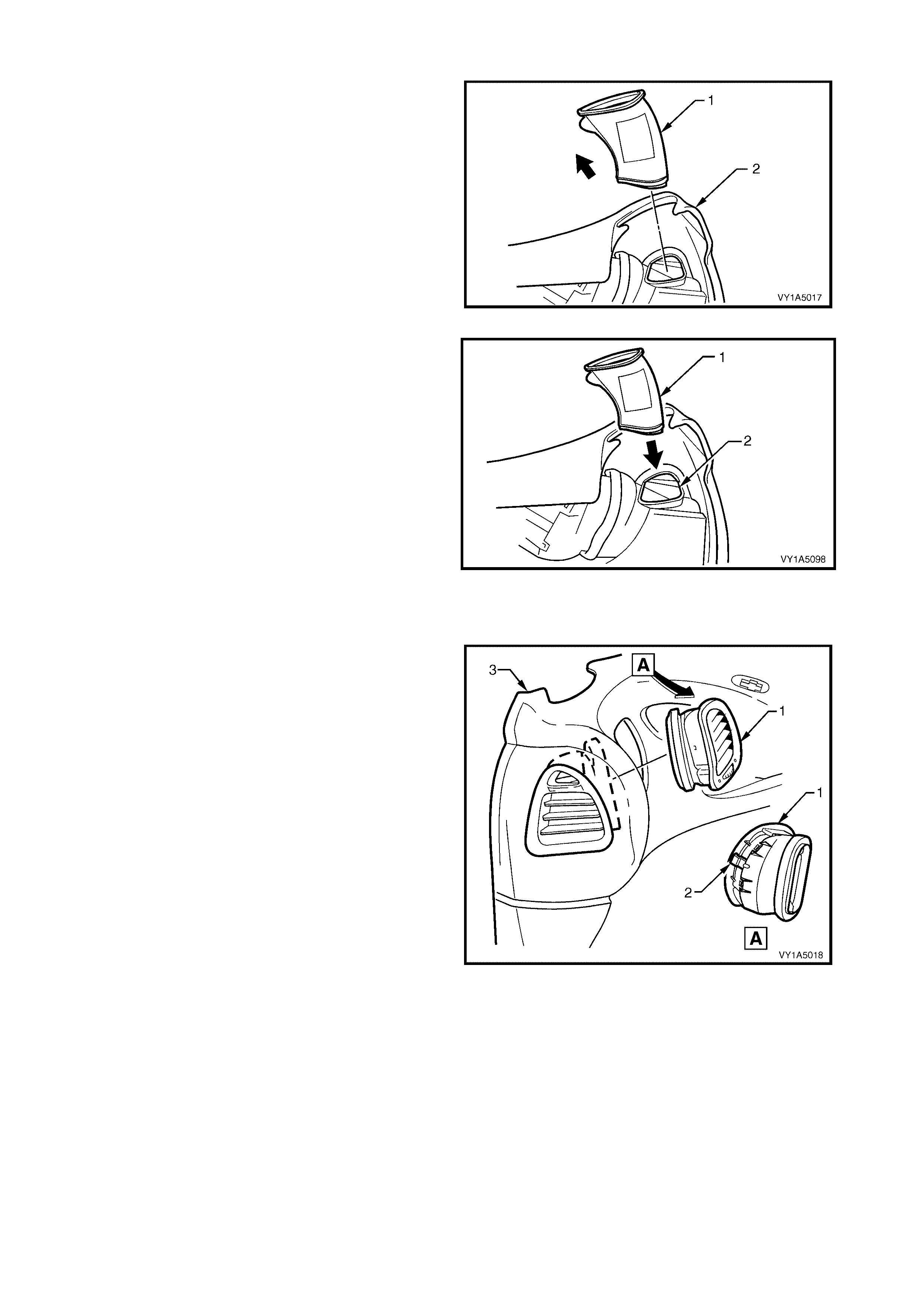
Remove – Side Window Defogger Air Duct
1. Remove the side window defogger air duct (1) by
pulling upwards, out of the panel assembly (2).
Figure 1A5-21
Reinstall – Side Window Defogger Air Duct
Reinstal lation of the defogg er air duc t is the r everse of
the removal, noting the following:
1. Align the defogger air duct (1) with the opening
aperture in the duct assembly (2), making sure
they form a tight seal.
Figure 1A5-22
Remove – Front Door Air Outlet Assembly
1. Remove the front door air outlet assembly (1) by
pushing on the spring clip retainer (2) to release
the housing from the panel assembly (3).
2. Remove the air out let hous i ng.
Reinstall – Front Door A ir Outlet Assembly
1. Align the outlet assembly with the opening in the
panel assembly and push in firm ly.
Figure 1A5-23
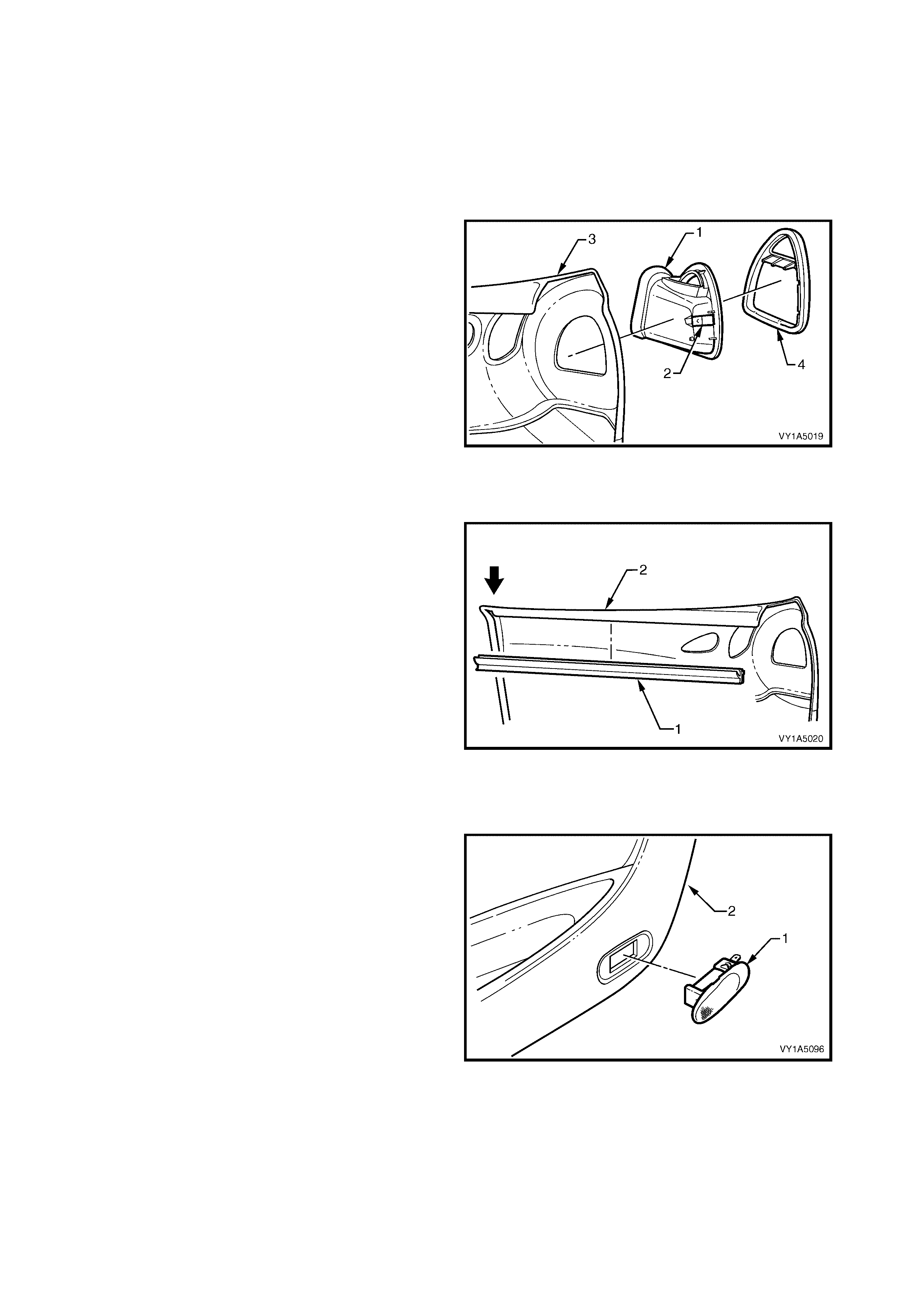
Remove – Front Door Air Duct Assembly
1. Remove the side window defogger air duct, refer
this Section.
2. Remove the front door air outlet assembly, refer
this Section.
3. Peel back the insulator assembly from the front
upper portion of the panel assembly, allowing
access to the duct a ssembly, refer this Section.
4. Release the front door air duct assembly (1) from
the panel assembly (3), by pushing on the spring
clip retainer (2).
5. Remove the duct ass embly.
6. Remove the seal from the door vent duct (4).
Reinstall – Front Door Air Duct Assembly
1. Refit the seal to the duct assembly.
2. Align the outlet assembly with the opening in the
panel assembly and push in firmly.
Figure 1A5-24
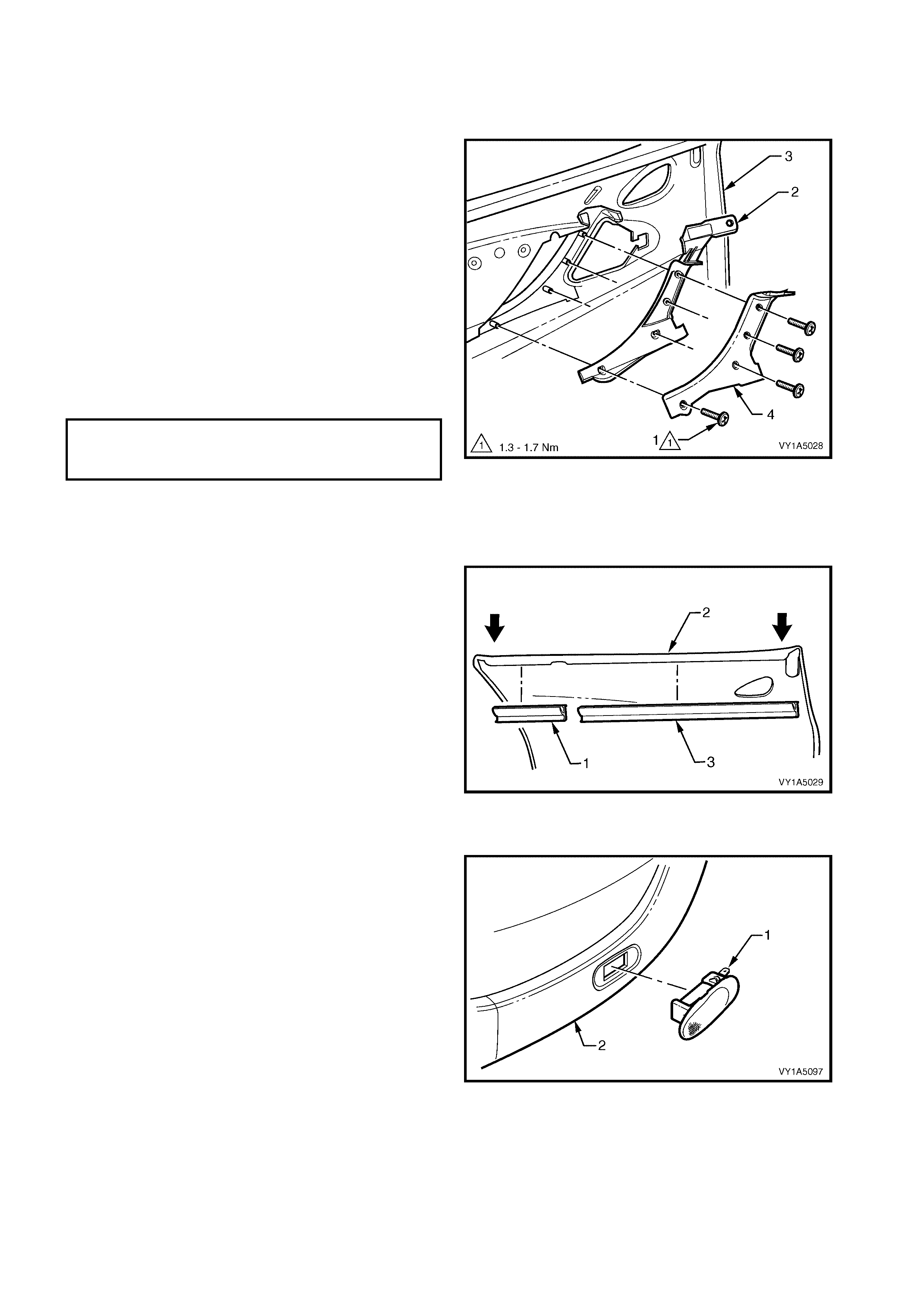
Remove – Front Door Sealing Strip Assembly
1. Remove the front door inner sealing strip
assembly (1) from the panel assembly (2), by
pushing down on one end and progressively
moving along the sealing strip.
Reinstall – Front Door Sealing Strip Assembly
Reinstallation of the sealing strip assembly is the
reverse of the removal, noting the following:
1. Align sealing strip assembly with the edge of the
panel assembly.
Figure 1A5-25
Remove – Front Door Courtesy Lamp (where
fitted)
1. From the back of the door trim (1), depress the
retaining tangs securing the door courtesy lamp
(2) to the trim.
2. Push the lamp out of its aperture and remove.
NOTE: For s ervice and dia gnosis of the door courtes y
lamp refer Section 12B LIGHTING SYSTEMS.
Reinstall – Front Door Courtesy Lamp
1. Push the door courtesy lamp into its aperture in
the door trim f irm ly and ensure the r etaining ta ngs
are secured to the trim.
Figure 1A5-26

REINST ALL
Reinstallation of panel assembly is the reverse of the
removal procedure, noting the following:
1. Connect the front door wiring harness connectors
to the rear view mirror switch and the front door
courtesy lamp, (where fitted).
2. Ensure the - front door inside handle assembly
(remote) and the front inside handle rod, are
engaged before final fitment, refer
2.5 FRONT DOOR INSIDE H ANDLE ASSEMBLY
(REMOTE).
3. Tighten all retaining screws to the correct torque
specification.
NOTE: Screws along the bottom of the front door trim
are wax-tip sealing screws, refer Figure 1A5-11.
4. Use a new front door locking rod knob retainer,
refer Figure 1A5-8.
5. Fit the rear edge of the side window outlet
defogger, before pushing retaining clip into the
upper frame, refer Figure 1A5-10.
FRONT DOOR INSIDE HANDLE
ASSEMBLY (REMOTE) SCREW
TORQUE SPECIFICATION 1.0 – 3.0 Nm
FRONT DOOR TRIM PANEL
ASSEMBLY RETAINING SCREW
TORQUE SPECIFICATION 1.0 – 3.0 Nm
FRONT DOOR LOCKING ROD
FERRULE RETAINING SCREW
TORQUE SPECIFICATION 1.0 – 3.0 Nm
2.7 FRONT DOOR LOCK ASSEMBLY
LT Section No. – 11-360
1. Remove the front door window regulator handle assembly (where fitted), refer to 2.4 FRONT DOOR
WINDOW REGULATOR HANDLE ASSEMBLY.
2. Remove the front door inside handle assembly (remote), refer to 2.5 FRONT DOOR INSIDE HANDLE
ASSEMBLY (REMOTE).
3. Remove the front door trim panel assembly refer to 2.6 FRONT DOOR TRIM PANEL ASSEMBLY.
REMOVE
NOTE: The front door water shield ne ed only be partl y
removed to allow access to complete this procedure,
however as required remove the following
components:
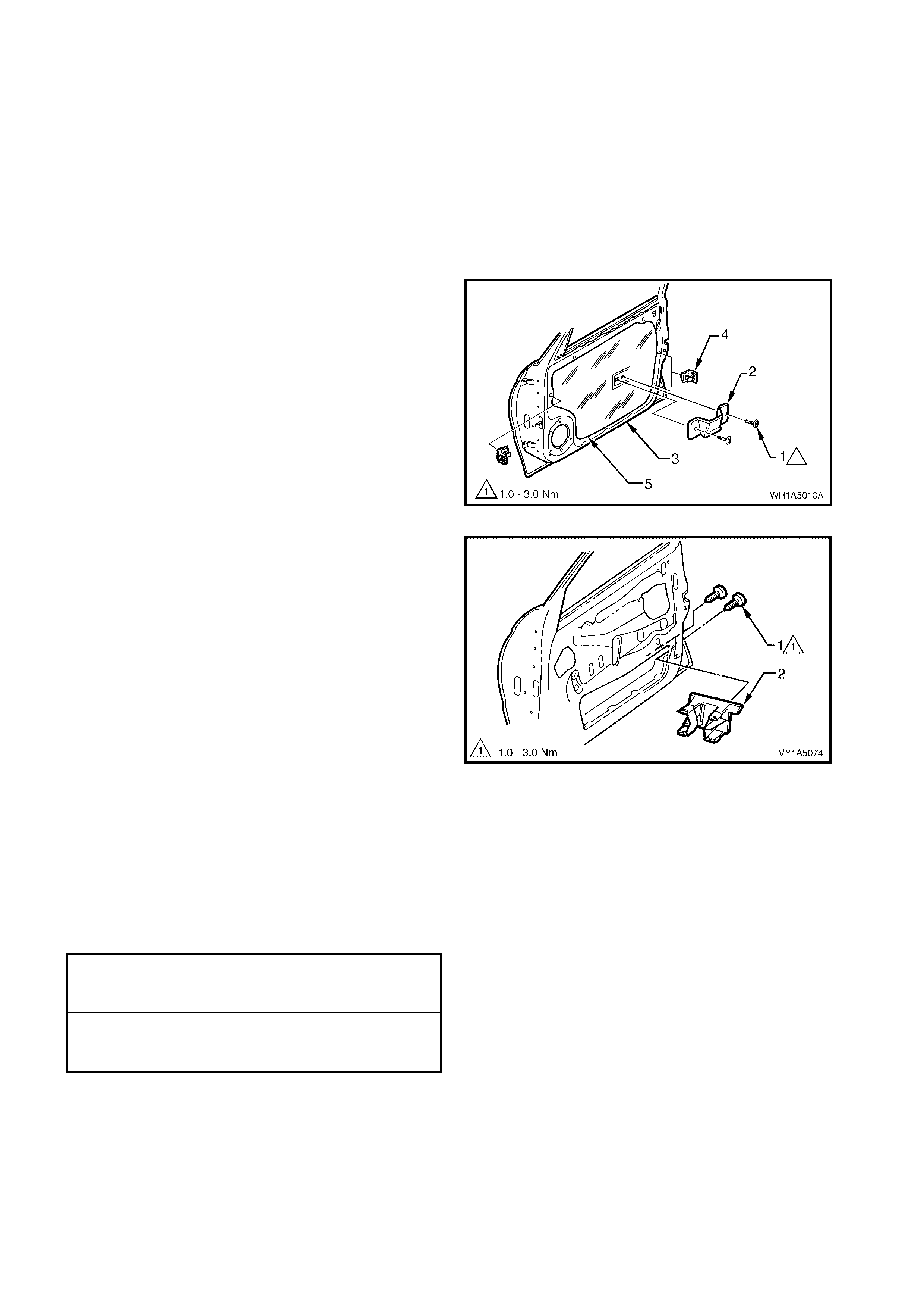
1. Remove the t wo screws (1) securing the f ront side
pull bracket (2) except Coupe, to the front door
inner panel (3) and remove the bracket.
2. Remove the three front door brackets (4) from the
door inner panel by levering out the centre pin of
the bracket.
3. Carefully peel off the front door water shield (5)
from the front door inner panel.
Figure 1A5-27
4. Disconnect the door harness electrical connector
(1) from the front door lock assembly (2).
5. Remove the three screws (3) securing the front
door lock assembly to the door inner panel (4).
Figure 1A5-28
6. For the driver’s door only, disconnect the front
door lock cylinder rod (1) from the front door lock
assembly (2) by releasing the rod retainer.
Figure 1A5-29
Techline
Techline
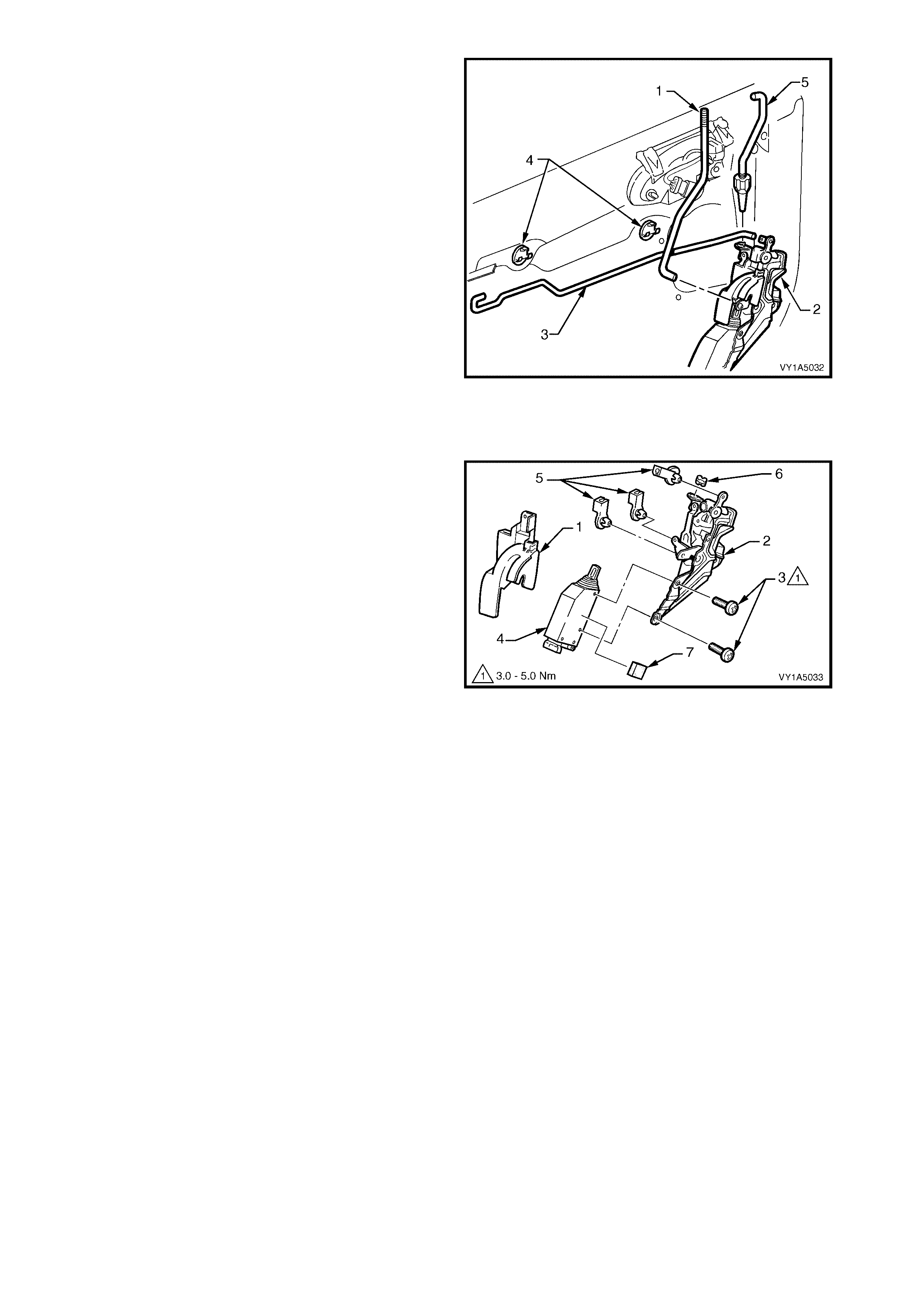
7. Disconnect the front door locking rod (1) from the
front door lock assembly (2) by releasing the rod
retainer, and then remove the rod.
8. Disconnect th e front ins ide handle rod ( 3) from the
lock assembly by releasing the rod retainer. If
required, remove the rod by disengaging it from
the two front door inside handle rod clips (4).
9. The front door outside handle rod assembly (5) will
disengage from the lock assembly, when the lock
assembly is being removed.
10. Remove the assembly through the aperture in the
door inner panel.
Figure 1A5-30
DISASSEMBLE
Remove – Front Door Lock Actuator Assembly
1. Rem ove the ant i-thef t cov er ( 1) fr om the fr ont door
lock assembly (2).
2. Remove the t wo s c rews ( 3) s ec uring th e f ront door
lock actuator assembly (4) to the lock assembly.
3. Remove the three retaining clips (5), and the door
lock bush (6) from the lock assembly.
4. If required remove the front door lock actuator
insulator (7), from the actuator assembly.
Reinstall – Front Door Lock Actuator Assembly
Reinstal lation of the f ront door lock actuator ass embly,
is the reverse of the removal procedure, noting the
following:
1. Adjust the position of the actuator assembly as
described below.
Figure 1A5-31
ADJUST
Adjustment of the door lock and actuator is critical to ensure correct operation of the electric door lock system.
The following adjustment procedure is to be performed if a diagnostic test in Section 12J Body Control
Module suggests that the door lock and actuator assembly may be incorrectly adjusted, or if any of the following
symptoms occur:
• Ineffective deadlock operation.
• Failure to lock and unlock.
• Door lock actuator motors oscillate, ie. machine gunning.
If not already done so, remove the front door lock assembly, refer to 2.7 FRONT DOOR LOCK ASSEMBLY.
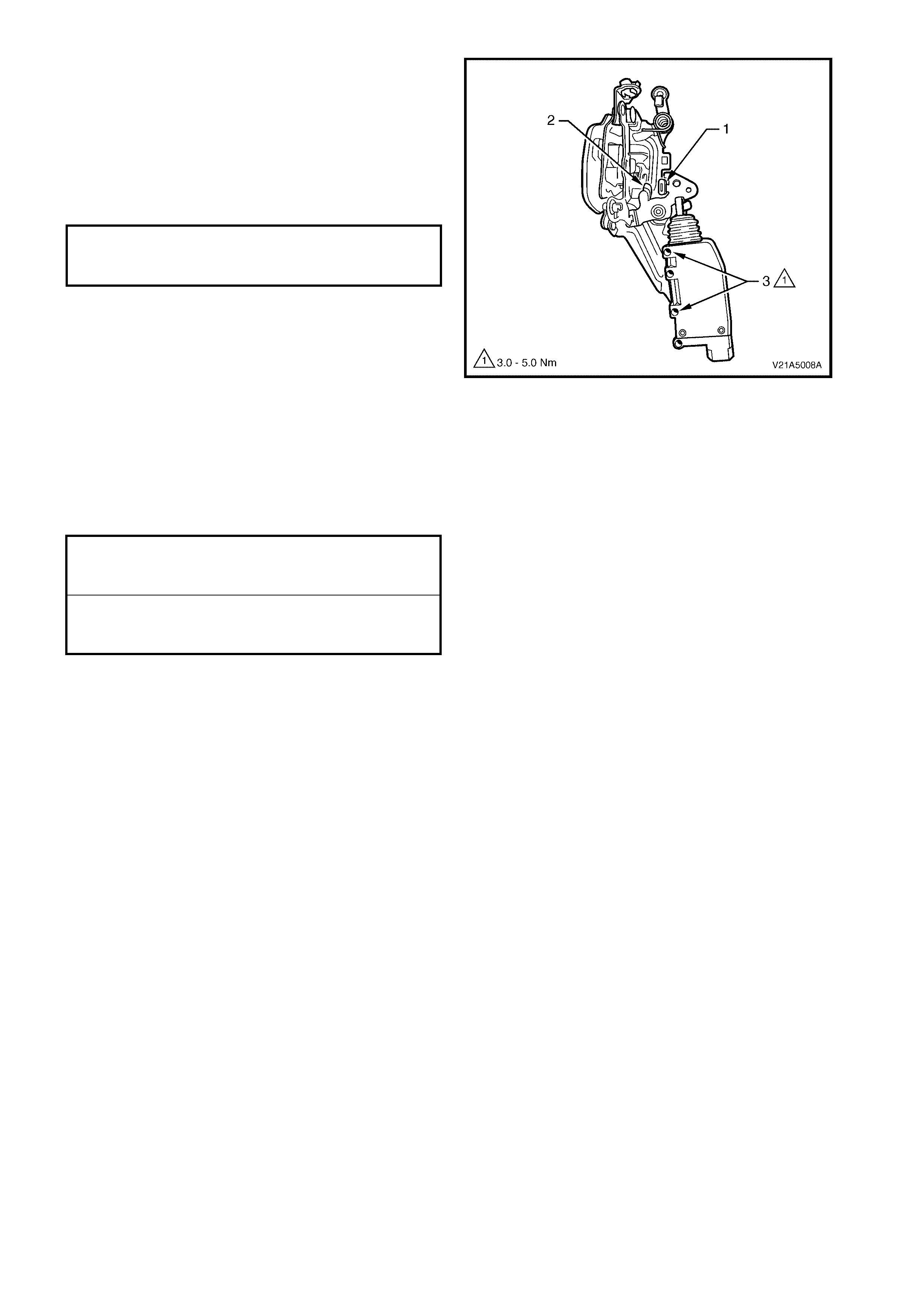
1. Us ing the d oor loc king butt on r o d le ver , LOCK an d
UNLOCK the actuator mechanism, checking that
the actuator lever (1) rests on the rubber pad (2).
2. If required, loosen the screws (3) and reposition
the actuator assem bly until the r equire d position is
achieved.
3. Tighten the actuator screws securely, without
moving its position.
Figure 1A5-32
REINST ALL
Reinstallation of the front door lock assembly is the
reverse of the removal procedure, noting the following:
1. Tighten all retaining screws to the correct torque
specification.
2. Ensure the front door outside handle rod
assembly, is engaged correctly with the front door
lock assembly, refer Figure 1A5-30.
3. Ensure the front door seal is correctly fitted to the
door panel.
FRONT DOOR LOCK AC TUATOR
ASSEMBLY RETAINING SCREW
TORQUE SPECIFICATION 3.0 – 5.0 Nm
FRONT DOOR LOCK ASSEMBLY
RETAINING SCREW
TORQUE SPECIFICATION 3.0 – 5.0 Nm
FRONT SIDE PULL BRACKET
RETAINING SCREW
TORQUE SPECIFICATION 1.0 – 3.0 Nm
2.8 FRONT DOOR OUTSIDE HANDLE ASSEMBLY
LT Section No. – 11-360
1. Remove the door window regulator handle assembly, (where fitted), refer to 2.4 FRONT DOOR WINDOW
REGULATOR HANDLE ASSEMBLY.
2. Remove the front door inside handle assembly, refer to 2.5 FRONT DOOR INSIDE HANDLE ASSEMBLY
(REMOTE).
3. Remove the front door trim panel assembly, refer to 2.6 FRONT DOOR TRIM PANEL ASSEMBLY.
REMOVE
NOTE: The front door water shield, need only be
partly removed to allow access to complete this
procedure, however as required remove the following
components:
1. Remove the t wo screws (1) securing the f ront side
pull bracket (2) except Coupe, to the front door
inner panel (3) and remove the bracket.
2. Remove the three front door brackets (4) from the
door inner panel by levering out the centre pin of
the bracket.
3. Carefully peel off the front door water shield (5)
from the front door inner panel.
Figure 1A5-33
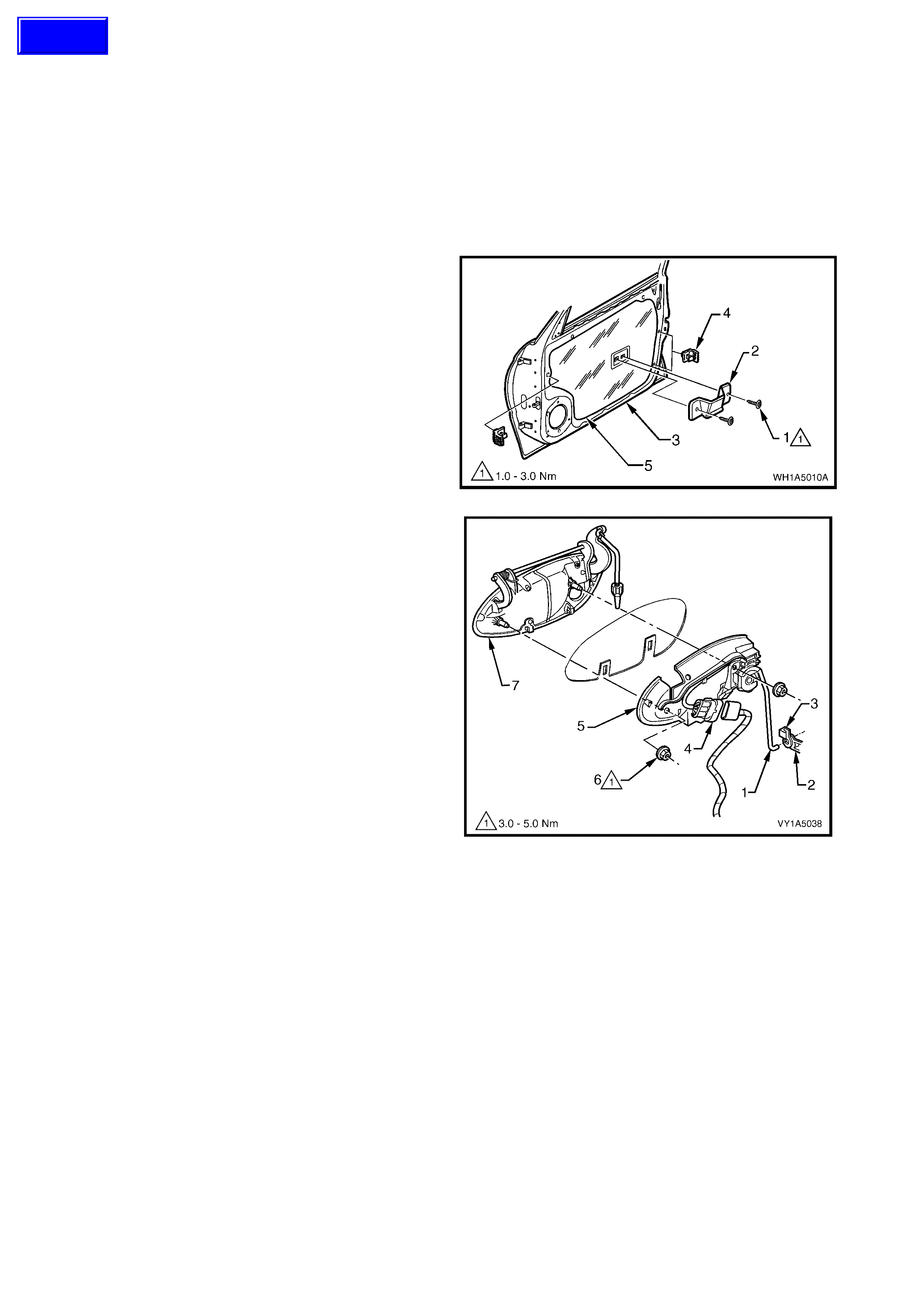
4. For the driver’s door only; disconnect the front
door lock cylinder rod (1) from the door lock
assembly (2) by releasing the lock cylinder
retainer (3).
5. On the driver’s door only, disconnect the door
wiring harness from the door lock micro-switch
wiring harness connector (4).
6. Remove the two handle retaining nuts (6), and
remove the front door outside handle assembly
(7), and the front door outside handle bracket
assembly (5).
NOTE 1: The front door outside handle bracket
assembly on the driver’s door is an assembly, and
consists of a micro-switch, door lock cylinder and
bracket.
NOTE 2: To test the door micro-switch, refer to
Section 12J BODY CONTROL MO DULE.
Figure 1A5-34
Techline
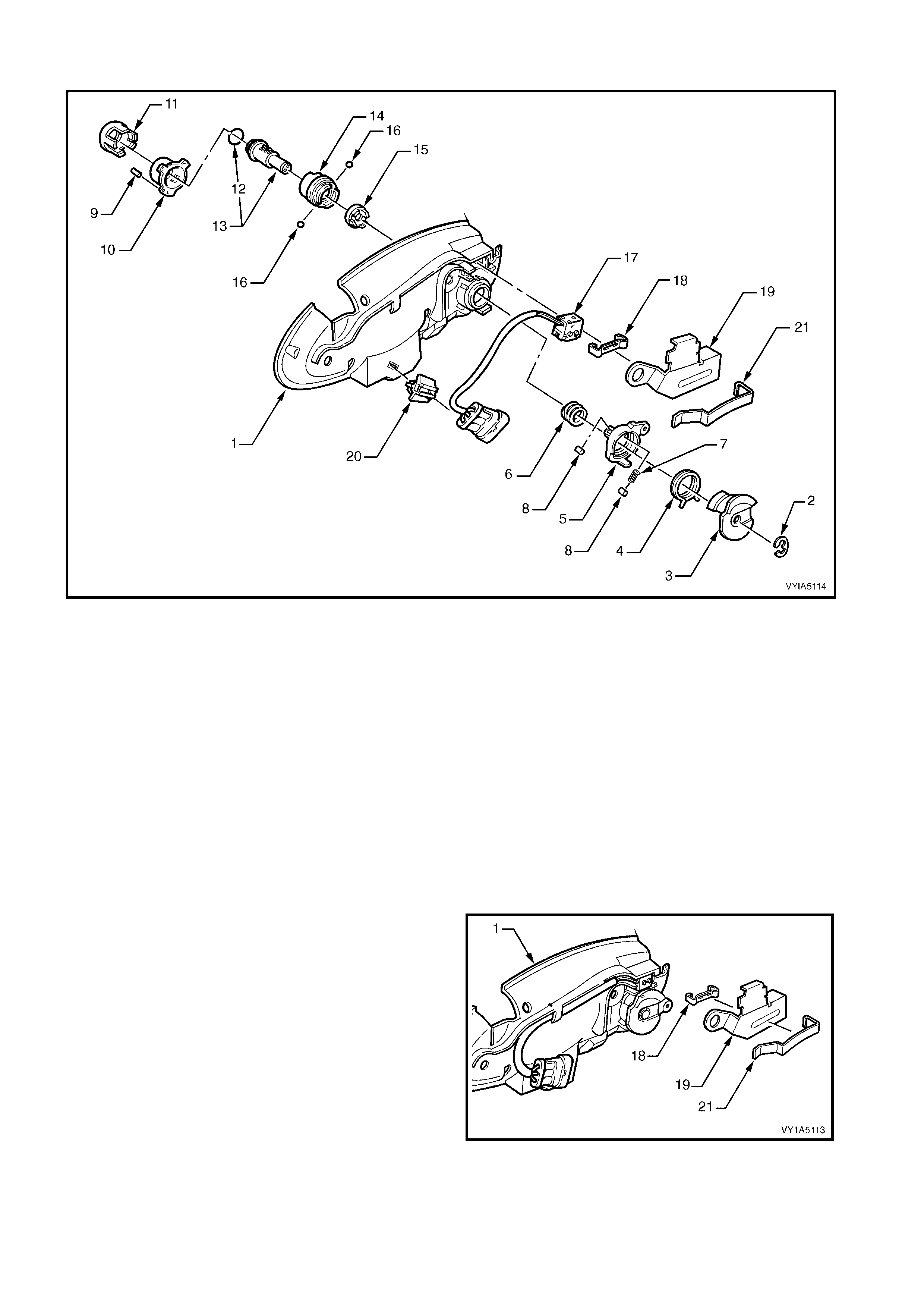
DISASSEMBLE – DRIVER’S SIDE
Figure 1A5-35
Legend
1. Front Door Outside Handle Bracket
2. Lock Barrel Clip
3. Door Lock Micro Switch Control Cam
4. Torsion Door Lock Spring
5. Door Lock Lever
6. Thrust Door Lock Clutc h Spring
7. Roller Spring
8. Door Lock Lever Roller
9. Door Lock Barrel Housing Pin
10. Door Lock Barrel Housing
11. Door Lock Housing Cover
NOTE: For specific procedure refer below.
12. O-Ring
13. Front Door Lock Cylinder Assembly
14. Cylinder Lock Sleeve
15. Door Lock Barrel Sleeve
16. Door Lock Clutch Balls
17. Electric Door Lock Switch Micro
18. Door Lock Micro Switch Clip
19. Door Lock Barrel Shield
20. Micro Switch Cable Retaining Clip
21. Lock Shield To Bracket Clip
1. Using a small screwdriver, gently remove the clip
lock shield (21) away from the front door outside
handle bracket assembly (1) and r emove the door
lock barrel shield (19).
2. Using a small s crewdriver, gent ly remove the do or
lock micro switch clip (18) away from the front
door outside handle bracket assembly.
Figure 1A5-36
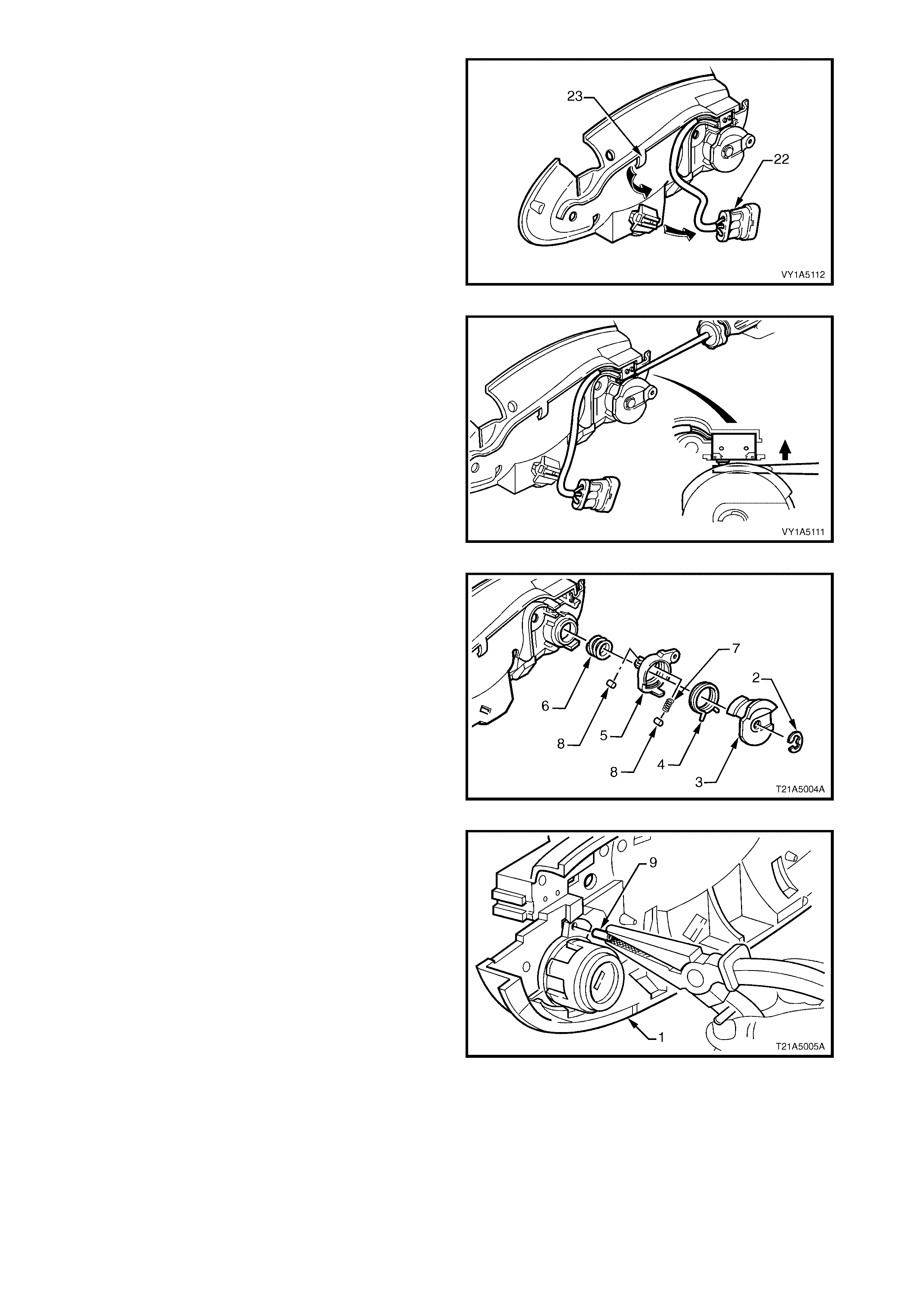
3. Slide the micro switch wiring harness connector
(22) off the connector retaining bracket and feed
the wiring harness out from under the bracket
assembly retainer (23).
Figure 1A5-37
4. Using a small flat bladed screwdriver, push the
two mic ro switch cont acts in and r em ove the m icro
switch assembly .
Figure 1A5-38
5. Remove the clip (2) and slide the cam (3), spring
(4), and lever (5) away from the lock assembly.
NOTE: Be careful not to lose the spring (7) and
rollers (8).
6. Remove the spring (6) from the lock assembly.
Figure 1A5-39
7. Using a suitable pair of pliers, pull the door lock
barrel housing pin (9) out of the front door outside
handle brac k et (1).
Figure 1A5-40
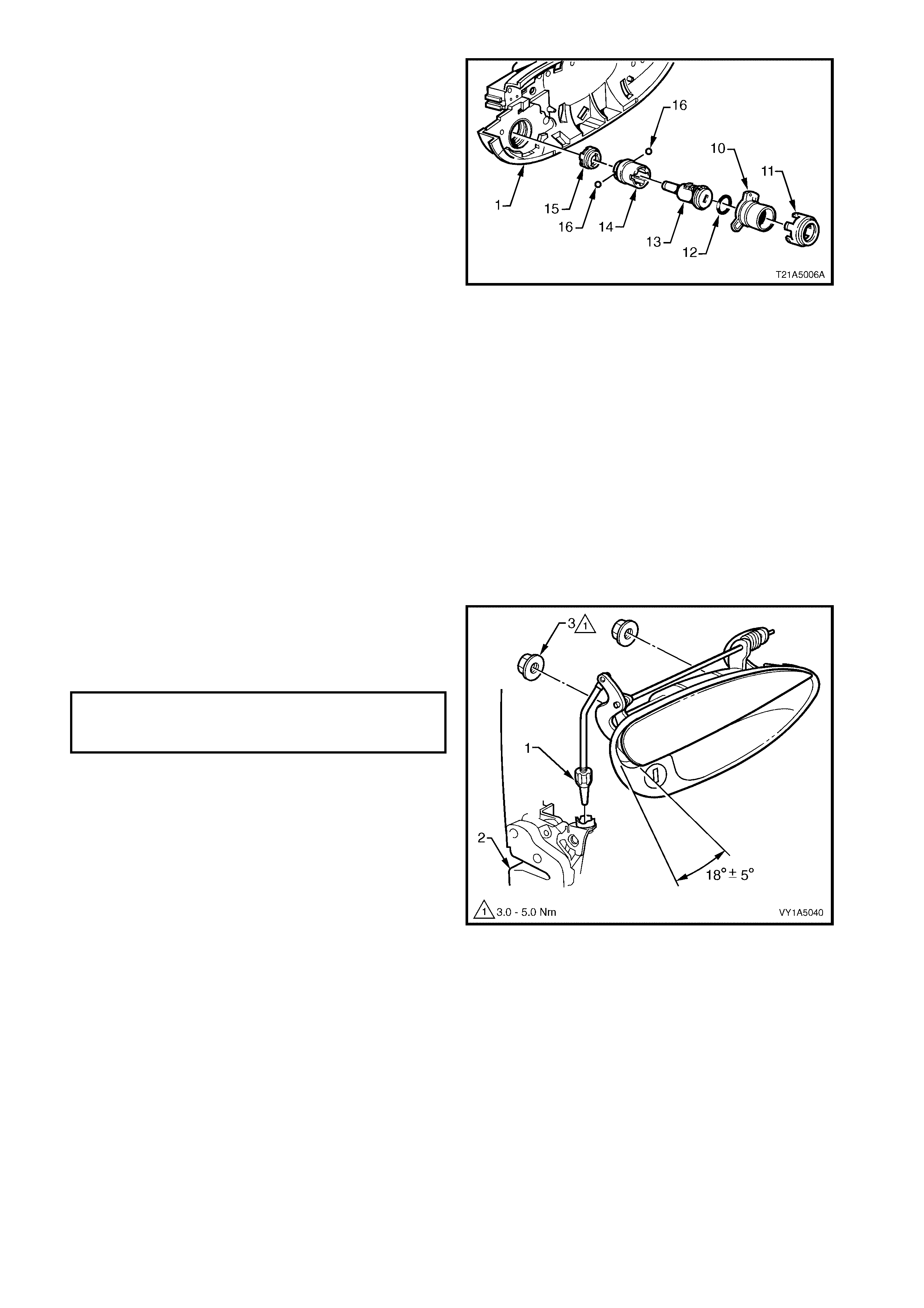
8. Rotate the cover (11), housing (10), O-ring (12),
cylinder assembly (13), sleeve (14), and coupling
(15) in an anti-clockwise direction, being careful
not to lose the two balls (16) while removing from
the door outside handle bracket (1).
Figure 1A5-41
ASSEM BLE
Assem bly of the front door outside handle assem bly is
the reverse of the removal procedure, noting the
following:
1. Lock cylinder service replacement kits are
supplied un-coded, which facilitates re-coding of
the lock cylinder to match the original key. It is
recommended that the overhaul and re-coding of
the lock cylinder is sublet and performed by an
authoris ed locksmith.
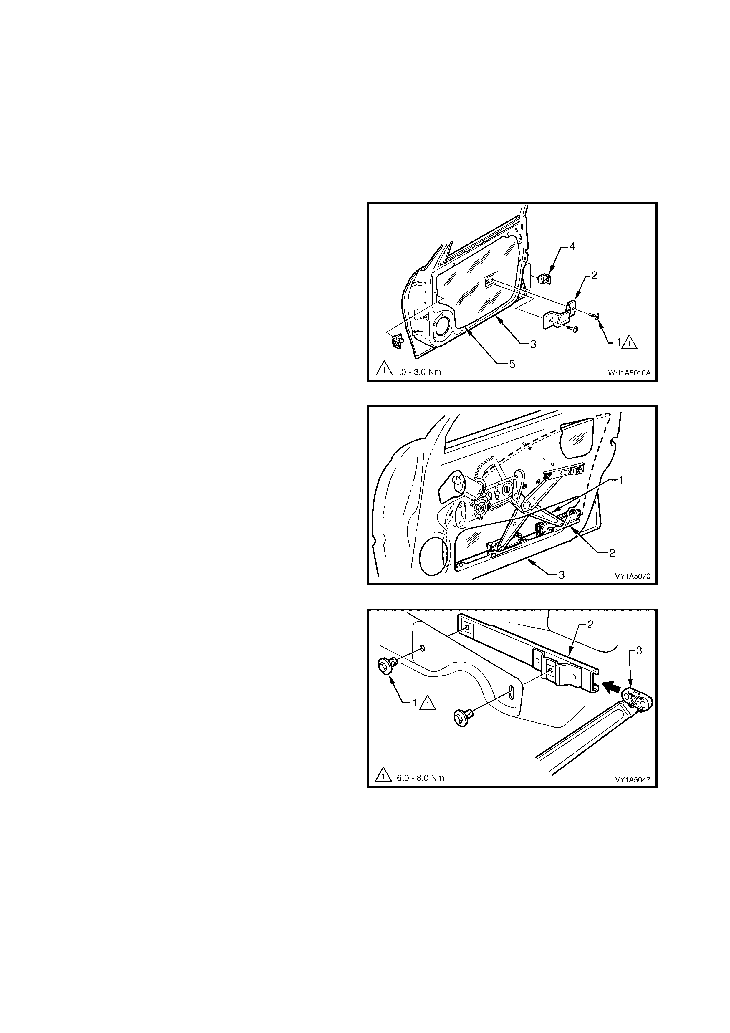
REINST ALL
Reinstallation of the front door outside handle
assembly is the reverse of the removal procedure,
noting the following:
1. Ensure that the adjusting nut (1) is seated in the
lock and actuator assembly (2) before installing
the front door outside handle assembly retaining
nuts (3).
2. Check and if necessary, adjust the handle
assembly adjusting nut to allow latch
disengagement with striker when the exterior d oor
handle openi ng is 18° ± 5° from the rest position.
3. Ensure the front door water shield is correctly
fitted to the door panel.
Figure 1A5-42
RESET (‘FREE TURN’ LOCK CYLINDER)
NOTE: If the ‘free turn’ lock cylinder becomes misaligned due to the insertion of the incorrect key, a foreign
object or if the correct key is not inserted fully when turned, the following procedure will need to be carried out.
1. Inser t the k ey full y into the l ock , preferabl y in the vert ical pos iti on and turn the k ey slo wly anti-c lock wise unti l
a click is felt.
2. Then slowly turn the key clockwise until a click is felt.
3. Return the key to the vertical position (if not already there) and withdraw the key.
4. Reinsert the key at the vertical position and check if the key will lock and unlock the vehicle.
NOTE: If the key does not work properly, keep the key in the lock and turn the key 180° anti-clockwise, then
repeat the proced ur e.
FRONT DOOR HANDLE ASSEMBLY
OUTSIDE RETAINING NUT
TORQUE SPECIFICATION 3.0 – 5.0 Nm
2.9 FRONT DOOR WINDOW REGULATOR ASSEMBLY
LT Section No. – 11-675
1. Remove the front door window regulator handle assembly (where fitted), refer to 2.4 FRONT DOOR
WINDOW REGULATOR HANDLE ASSEMBLY.
2. Remove the front door inside handle assembly (remote), refer to 2.5 FRONT DOOR INSIDE HANDLE
ASSEMBLY (REMOTE).
3. Remove the front door trim panel assembly refer to 2.6 FRONT DOOR TRIM PANEL ASSEMBLY.
REMOVE
1. Remove the t wo screws (1) securing the f ront side
pull bracket (2) except Coupe, to the front door
inner panel (3) and remove the bracket.
2. Remove the three front door brackets (4) from the
door inner panel by levering out the centre pin of
the bracket.
3. Carefully peel off the front door water shield (5)
from the front door inner panel.
Figure 1A5-43
4. Prior to commencing the following procedures,
lower the window assembly, to a position where
the regulator guide runners (1) and the window
guide rails (2) are visible through the aperture in
the door inner panel (3).
Figure 1A5-44
5. Remove the two att aching scr ews ( 1) securing the
front windo w r egu lat or c ha nne l as s embly (2) to th e
door inner panel.
6. Slide the channel out of the regulator assembly
(3).
7. Remove the channel assembly from the door
assem bly upper opening.
Figure 1A5-45
8. Disconnect the regulator assembly wiring harness
connector (1) from the door harness (where fitted).
9. While having an assistant support the window
glass, drill out the four rivets (2) securing the
regulator assembly (3) to the door panel, (using a
5mm drill bit).
10. Slide the runners out of window assembly (4).
11. Raise the window glas s by hand.
12. Remove the window regulator assembly through
the door inner panel aperture.
13. Place a wooden chock inside the door panel to
hold the window assembly up, while replacing the
window regulator assembly.
Figure 1A5-46
REINST ALL
Reinstallation of the front door regulator assembly is
the reverse of the removal procedure, noting the
following:
1. Ins tal l th e f r ont door window re gul ator h and le s h af t
seal (1) (where fitted), to the regulator assembly
(2), before installing into the door panel.
NOTE: The fr ont door wind o w washer ( 3) a nd the fr ont
door window regulator handle assembly (4) are to be
installed after the trim panel assembly, (where fitted).
2. Locate the regulator assembly inside the door.
Insert the regulator arms into the glass channels.
Align the attaching holes in the regulator with the
corresponding holes in the door inner panel, refer
Figure 1A5-46.
3. Attach the regulator assembly to the door inner
panel using 5mm rivets.
NOTE: The attaching holes in the door panel may
have been enlarged, when the rivets were drilled out.
Washers may be inserted when refitting the regulator
assem bly.
4. Install the front window regulator channel
assembly. Adjust the front door window and
regulator as per the adjustment procedure, refer
2.14 FRONT DOOR WINDOW A SSEMBLY.
5. Tighten all retaining screws to the correct torque
specification.
6. Ensure all frictional surfaces of the window
regulator assembly and associated parts are
adequately lubricated with Lithium base grease
NLGI No. 1 (with 9 % zinc oxide) or equivalent.
7. Ensure the front door water shield is correctly
fitted to the door panel, refer Figure1A5-43.
Figure 1A5-47
FRONT SIDE PULL BRACKET
RETAINING SCREW
TORQUE SPECIFICATION 1.0 – 3.0 Nm
FRONT WINDOW REGULATOR
CHANNEL ASSEMBLY RETAINING
SCREW TORQUE SPECIFICATION 6.0 – 8.0 Nm
2.10 FRONT WI NDOW INNER FILLER ASSEMBLY
LT Section No. –
REMOVE
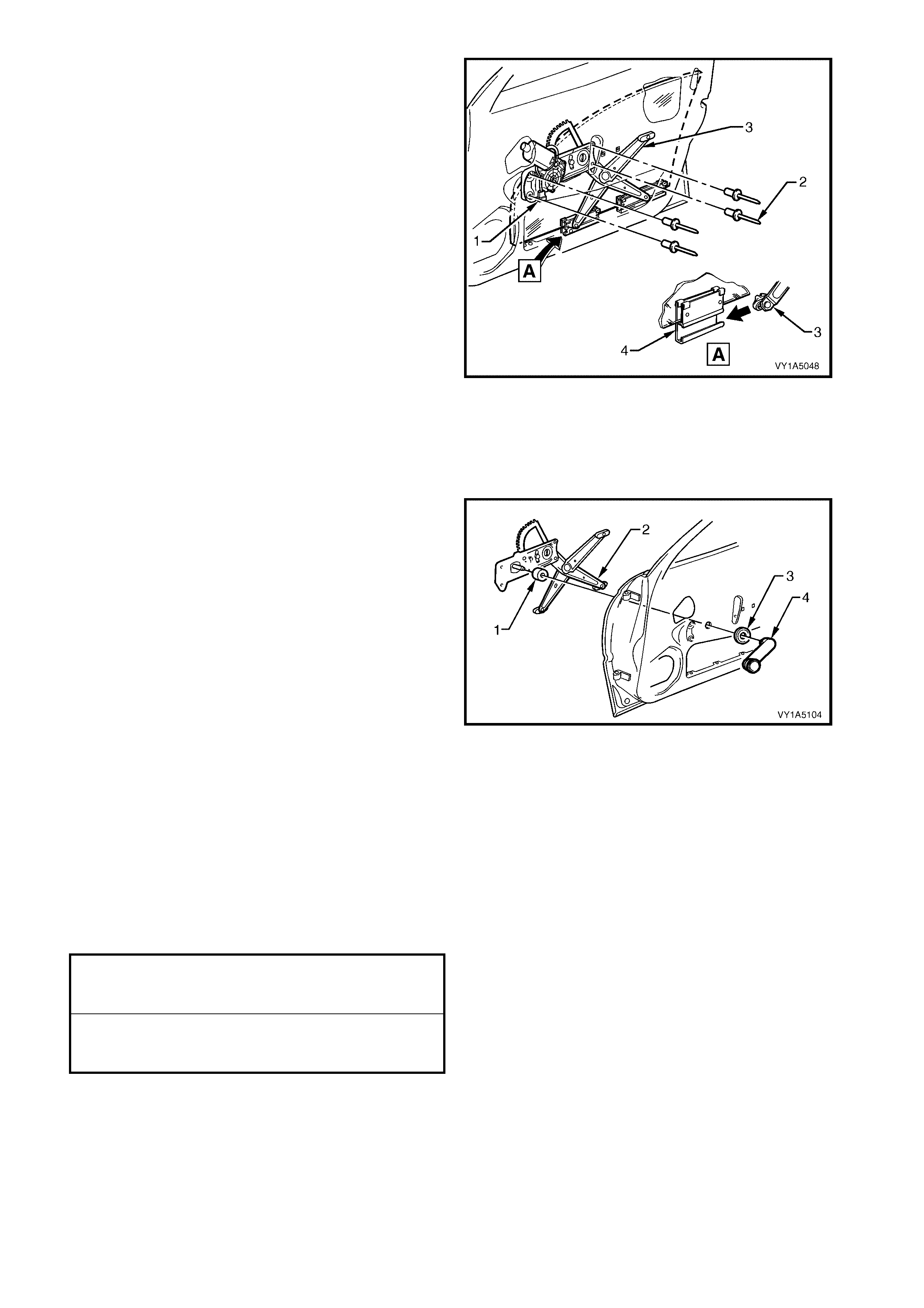
1. Gently prise out the filler assembly retainer (1),
from the rear inner sealing strip front filler
assembly (2).
2. Remove filler assembly from the rear of the front
door.
Figure 1A5-48
REINST ALL
Reinstallation of the filler assembly retainer, is the
reverse of the removal.
2.11 FRONT DOOR BELT OUTER REVEAL MOULDING ASSEMBLY
LT Section No. – 11-650
REMOVE
1. Lower the windo w ass embly.
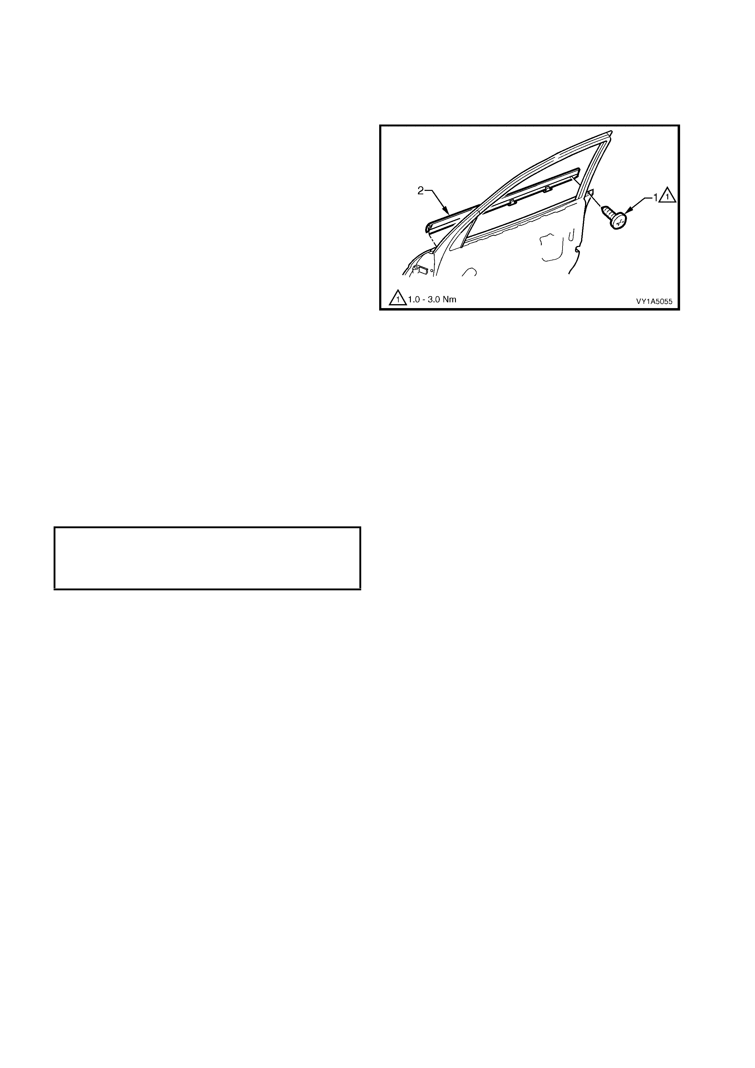
2. Remove the moulding assembly retaining screw
(1).
3. Start ing at the rear of the door , prise the f ront door
belt outer reveal moulding assembly (2), in an
upward dir ection f rom the door. Slid e the m oulding
assembly out from underneath the rear vision
mirror assembly.
NOTE: Take care not to damage the moulding or the
plastic retaining clips.
Figure 1A5-49
REINST ALL
Reinstallation of the front door belt outer reveal
moulding assembly, is the reverse of removal, refer
Figure 1A5-49, noting the foll o wing:
1. Slide the front door belt outer reveal moulding
assembly, under the rear vision mirror assembly.
2. Align the rear of the moulding with the rear of the
door. Using the palm of the hand, firmly tap the
assembly down, over the door outer upper flange.
3. Tighten the retaining screw to the correct torque
specification.
FRONT SIDE WINDOW BELT OUTER
REVEAL MOULDING ASSEMBLY
RETAINING SCREW
TORQUE SPECIFICATION 1.0 – 3.0 Nm
2.12 FRONT WINDOW GUIDE ASSEMBLY
LT Section No. –
1. Have the window in the up position.
2. Remove the front door window regulator handle assembly (where fitted), refer to 2.4 FRONT DOOR
WINDOW REGULATOR HANDLE ASSEMBLY.
3. Remove the front door inside handle assembly (remote), refer to 2.5 FRONT DOOR INSIDE HANDLE
ASSEMBLY (REMOTE).
4. Remove the front door trim panel assembly refer to 2.6 FRONT DOOR TRIM PANEL ASSEMBLY.
REMOVE
NOTE: The front door water shield ne ed only be partl y
removed to allow access to complete this procedure.
1. Remove the t wo screws (1) securing the f ront side
pull bracket (2) except Coupe, to the front door
inner panel (3) and remove the bracket.
2. If required remove the three front door brackets (4)
from the door inner panel by levering out the
centre pin of the bracket.
3. Carefully peel off the front door water shield (5)
from the front door inner panel.
Figure 1A5-50
4. Remove the two screws (1) securing the front
window guide assembly (2).
5. Remove the guide assembly through the opening
in the door inner panel.
Figure 1A5-51
REINST ALL
Reinstallation of the front window guide assembly is
the reverse of the removal noting the following:
1. Ensure the front door water shield is correctly
fitted to the door panel.
2. Tighten all retaining screws to the correct torque
specification.
FRONT PULL BRACKET
RETAINING SCREW
TORQUE SPECIFICATION 1.0 – 3.0 Nm
FRONT DOOR GLASS GUIDE
ASSEMBLY RETAINING SCREW
TORQUE SPECIFICATION 1.0 – 3.0 Nm

2.13 FRONT DOOR GUIDE CHANNEL ASSE MBLY
LT Section No. – 11-625
1. Remove the front door window regulator handle assembly (where fitted), refer to 2.4 FRONT DOOR
WINDOW REGULATOR HANDLE ASSEMBLY.
2. Remove the front door inside handle assembly (remote), refer to 2.5 FRONT DOOR INSIDE HANDLE
ASSEMBLY (REMOTE).
3. Remove the front door trim panel assembly refer to 2.6 FRONT DOOR TRIM PANEL ASSEMBLY.
REMOVE
1. Remove the t wo screws (1) securing the f ront side
pull bracket (2) except Coupe, to the front door
inner panel (3) and remove the bracket.
2. Remove the three front door brackets (4) from the
door inner panel by levering out the centre pin of
the bracket.
3. Carefully peel off the front door water shield (5)
from the front door inner panel. (2).
Figure 1A5-52
4. Peel back the outside rear view mirror seal (1) to
gain excess to screws.
5. Remove the three screws (2) securing the outside
rear view mirror assembly (3) to the door panel.
While supporting the mirror, disconnect the wiring
harness connector (4) and remove the mirror.
NOTE: For service and diagnosis of the rear view
mirror, refer to Section 12H REAR VIEW MIRRORS.
Figure 1A5-53
6. Remove the three screws (1) securing the front
door speaker assembly (2) to the door inner panel.
7. Remove the speak er assembly far enough to gain
access to the wiring harness connector (3).
8. Disconnect wiring harness connector and remove
speaker assembly.
NOTE: For service and diagnosis of the door speaker
assembly, refer to Section 12D ENTERTAINMENT
SYSTEM.
Figure 1A5-54
9. Remove the two front door inner panel belt
seals (1).
Figure 1A5-55
10. Carefully remove the front window upper
weatherstrip assembly (1) from the front window
channel guide assembly (2).
NOTE: It is not necessary to remove the weatherstrip
assembly completely, only from the front window
channel guide assembly.
Figure 1A5-56
11. Partially remove the front door upper weatherstrip
assem bly (1) f rom the lip o n the d oor u pper f ram e,
to allow excess to the sealing front window
channel guide cap (2).
NOTE: It is not necessary to remove the weatherstrip
assembly completely.
Figure 1A5-57
12. Carefully peel back the sealing front window
channel guide cap (1) away from the guide
channel assembly (2).
Figure 1A5-58
13. Remove the three bolts (1) securing the front
window channel guide assembly (2) to the door
panel (3).
NOTE: The front window down stop nut (4) is not
welded to the door and when the guide assembly
retaining bolt is removed, this nut may become lost.
Figure 1A5-59
14. Rem ove the front wind ow channel g uide ass embl y
(1) from the door assembly (2) in an upward
directi on, disenga ging the windo w assembl y slid es
(3) from the guide assembly.
Figure 1A5-60
REINST ALL
Reinstallation of the front door guide channel assembly is the reverse of the removal procedure noting the
following:
1. Tighten all retaining screws to the correct torque specification.
2.
3.
4.
2. If required before installing the door inner trim panel, adjust the front door window and regulator, refer
2.14 FRONT DOOR WINDOW A SSEMBLY.
3. Ensure the front door water shield is correctly fitted to the door panel.
FRONT DOOR GUIDE CHANNEL ASSEMBLY
GLASS CHANNEL RETAINING
SCREW TORQUE SPECIFICATION 6.0 – 8.0 Nm
FRONT SIDE PULL RETAINING
BRACKET SCREW
TORQUE SPECIFICATION 1.0 – 3.0 Nm
OUTSIDE REAR VIEW MIRROR
ASSEMBLY RETAINING SCREW
TORQUE SPECIFICATION 2.5 – 3.5 Nm
FRONT DOOR RADIO SPEAKER
ASSEMBLY RETAINING SCREW
TORQUE SPECIFICATION 1.5 – 3.0 Nm

2.14 FRONT DOOR WINDOW ASSEMBLY
LT Section No. – 11-020
1. Remove the front door window regulator handle assembly (where fitted), refer to 2.4 FRONT DOOR
WINDOW REGULATOR HANDLE ASSEMBLY.
2. Remove the front door inside handle assembly (remote), refer to 2.5 FRONT DOOR INSIDE HANDLE
ASSEMBLY (REMOTE).
3. Remove the front door trim panel assembly refer to 2.6 FRONT DOOR TRIM PANEL ASSEMBLY.
4. Remove the window regulator assembly, refer to 2.9 FRONT DOOR WINDOW REGULATOR ASSEMBLY.
5. Remove the front door belt outer reveal moulding assembly, refer to 2.11 FRONT DOOR BELT OUTER
REVEAL MOULDING ASSEMBLY.
6. Remove the front door guide channel assembly, refer to 2.13 FRONT DOOR GUIDE CHANNEL
ASSEMBLY.
REMOVE
1. Lift the f ront door windo w assembl y (1) up t hrough
the door belt opening and slide to the rear.
Figure 1A5-61
REINST ALL
Reinstal lation of the fr ont door win dow ass em bly is the
reverse of the removal procedure noting the following:
1. Ensure all frictional surfaces of the window
regulator assembly and associated parts are
adequately lubricated with Lithium base grease
NLGI No. 1 (with 9 % zinc oxide) or equivalent.
2. Install the front window regulator channel
assembly (1).
NOTE: The initial attachment is to be loose. Tighten
the screw (2) to the specified tor que when the glass is
installed and in the down position, refer to ADJUST in
this Section.
Figure 1A5-62
FRONT SIDE WINDOW CHANNEL
ASSEMBLY RETAINING
SCREW PRELIMINARY
TORQUE SPECIFICATION 6.0 – 8.0 Nm
3. Ins tal l th e f r ont door window re gul ator h and le s h af t
seal (1) (where fitted), to the regulator assembly
(2), before installing into the door panel.
NOTE: The fr ont door wind o w washer ( 3) a nd the door
window regulator handle assembly (4) are to be
installed after the trim panel assembly, (where fitted).
4. Before installing the front door inner trim panel,
adjust the front door window and regulator as per
the following adjustment procedure, refer Figure
1A5-64.
5. Ensure the front door seal is correctly fitted to the
door panel, refer Figure1A5-52.
Figure 1A5-63
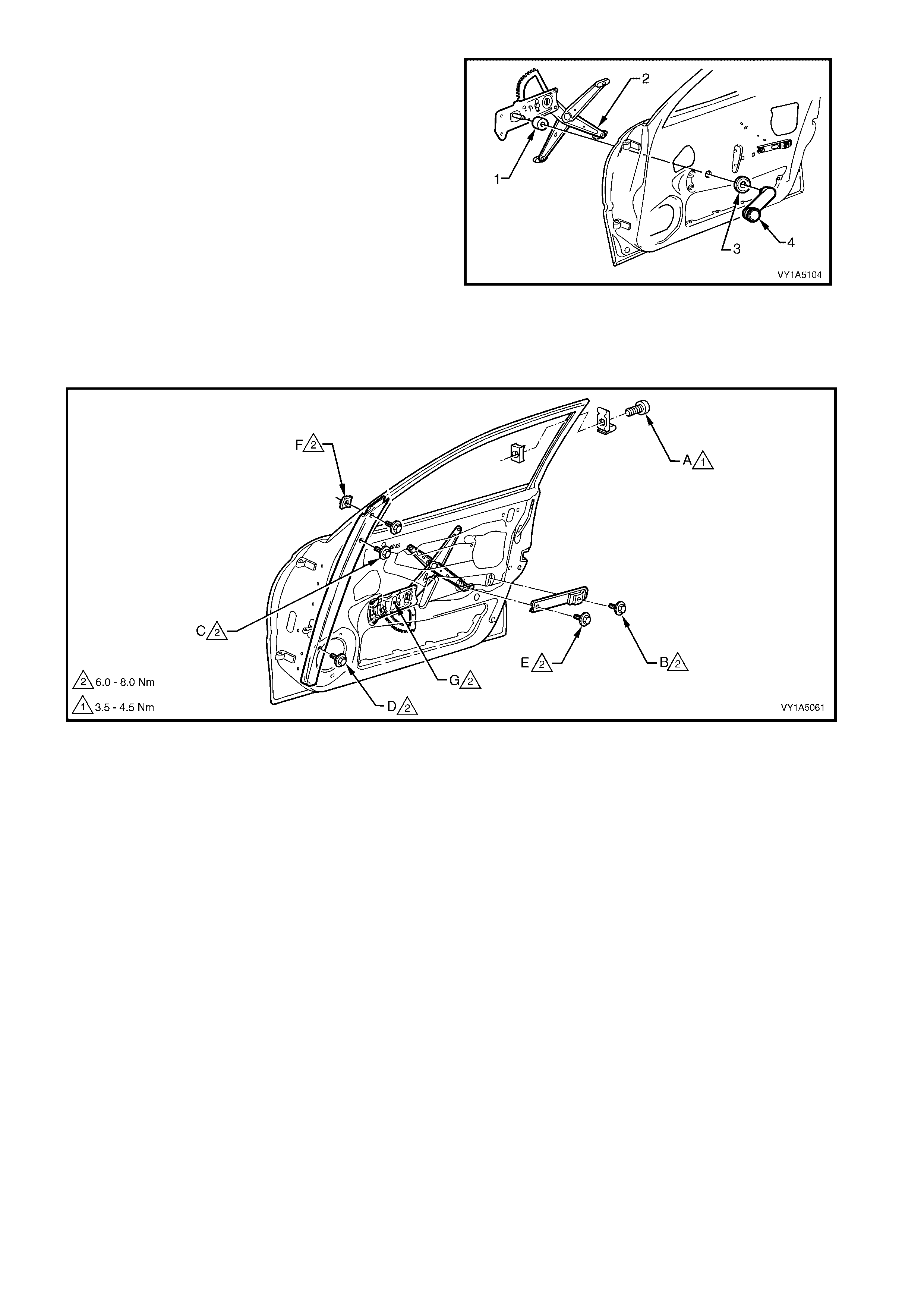
ADJUST
NOTE: Figure 1A5-64 shows the screw locations for
the following window assembly adjustment procedure.
Figure 1A5-64
Legend
A. Front Window Stop Assembly Attaching Screw
B. Front Window Regulator Rear Channel Assembly
Attaching Screw
C. Front Window Channel Centre Guide Assembly
Attaching Screw
D. Front Window Channel Lower Guide Assembly
Attaching Screw
E. Front Window Regulator Front Channel Assembly
Attaching Screw
F. Front Window Stop Screw
G. Regulator Assembly Front Window Stop
1. Adjust the front window stop assembly, point (A),
at the rear of the door s o that th ere is a 1 m m gap
below the highest possible end stop position.
Tighten the attaching screw to the specified
torque.
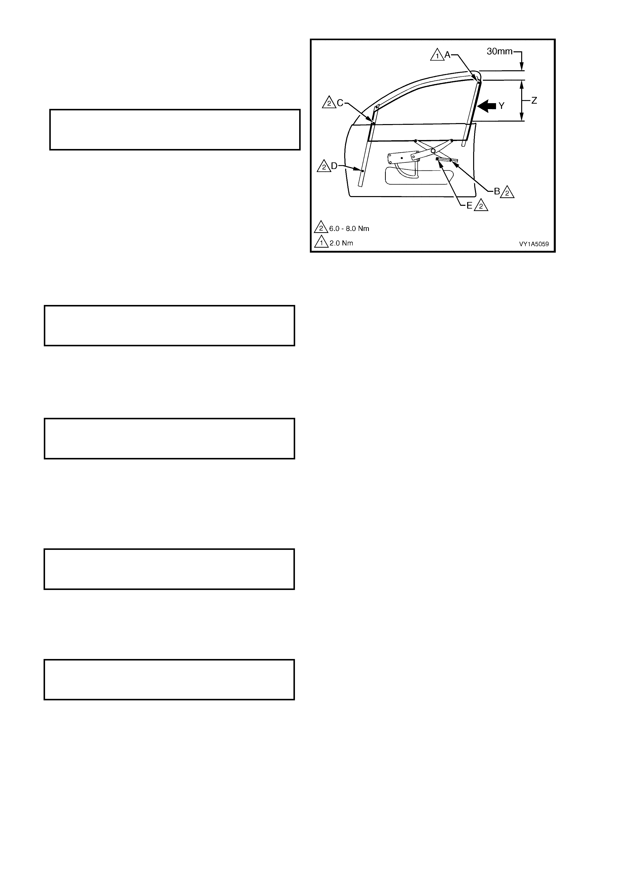
2. W ind the front door window assembly, up through
area (Z) ‘, while at the s ame tim e, pressing the ra il,
which is bonded to the rear edge of the window
assembly, in the direction of arrow (Y). Continue
winding the window assembly up until it the
window assembly is approximately 30 mm before
the closed position.
3. Secure the front window regulator channel
assembly, in position, without imposing any
stresses, by tightening the rear attaching screw,
point (B), to the specified torque.
4. Tighten the window channel guide assembly
centre attaching screw, point (C), to the specified
torque. Ensure that the window assembly is held
approximately 30 mm before the closed position.
Figure 1A5-65
5. Wind the window assembly to approximately 30
mm above the do or belt moul ding assem bly, while
at the same time, pressing the rear edge of the
window assembly, in the direction of arrow (Y).
Tighten the lower attaching screw, point (D), on
the guide assembly to the specified torque.
6. Secure the front window regulator channel
assembly in position without imposing any stress,
by tightening the front attaching screw, point (E),
to the specified torque.
FRONT WINDOW STOP ASSEMBLY
ADJUSTING SCREW PRELIMINARY
TORQUE SPECIFICATION 2.0 Nm
FRONT WINDOW CHANNEL ASSEMBLY
RETAINING REAR SCREW
TORQUE SPECIFICATION 6.0 – 8.0 Nm
FRONT CHANNEL GUIDE
ASSEMBLY RETAINING CENTRE
SCREW TORQUE SPECIFICATION 6.0 – 8.0 Nm
FRONT CHANNEL GUIDE
ASSEMBLY RETAINING LOWER
SCREW TORQUE SPECIFICATION 6.0 – 8.0 Nm
FRONT WINDOW CHANNEL ASSEMBLY
RETAINING FRONT SCREW
TORQUE SPECIFICATION 6.0 – 8.0 Nm
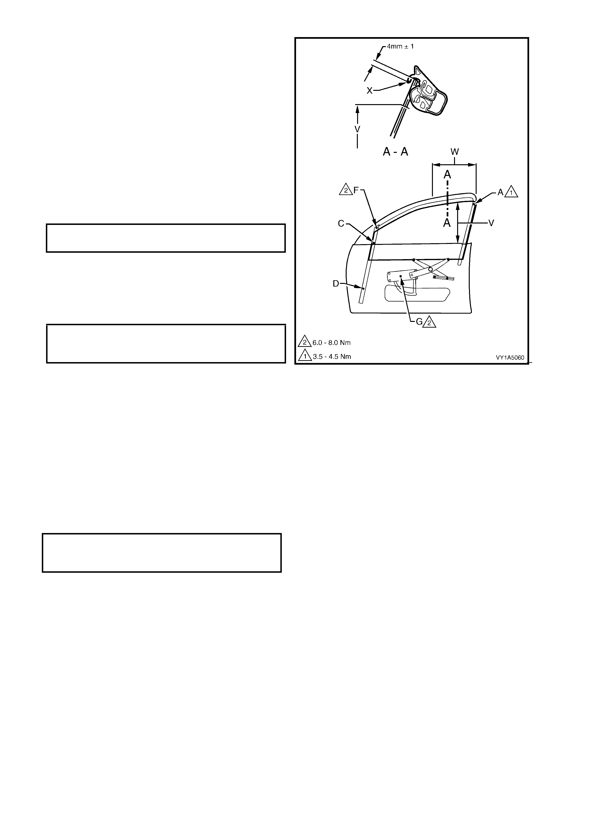
7. Wind the windo w ass embly up to a pos ition where
the upper edge of the window assembly is flush
with the up per edg e of the door m irror housing, as
seen from the outside. In this position, the upper
edge of the window assembly must be parallel
with point (X) on the front window upper
weatherstrip assembly, over area (W).
8. Check the cranking load of the window assembly
in area (V). If the window assembly binds, or the
motor load sounds excessive, re-adjust the
window assembly by correcting the guide
assembly attaching, points (C) and (D).
9. Adjust the front window stop screw, point (F), so
that the stop contacts with the window assembly.
Tighten attaching screw to the specified torque.
10. With the window in the closed position, adjust the
front window regulator assembly stop, point (G),
so that it contacts the toothed sector of the
regulator assembly and then tighten the screw to
the specified torque.
11. Check the upper edge of the window to ensure
that the lip of the glass run channel, point (X), is
parallel over the area (W).
The upper edge of the window must be 4 mm
above the lip of the glass run channel, point (X),
over the area (W).
If either th e dev iation in par allel ism or the ins ertion
depth exceeds 1 mm from specification, the stop
assemblies at points (A), and (F), must be
readjusted.
13. Tighten the window stop screw, point (A), to the
specified torque.
Figure 1A5-66
FRONT WINDOW ST OP
ASSEMBLY ADJUSTING SCREW
TORQUE SPECIFICATION 3.5 - 4.5Nm
REGULATOR ASSEMBLY FRONT
WINDOW DOWN STOP ADJUSTING
NUT TORQUE SPECIFICATION 6.0 – 8.0 Nm
FRONT WINDOW STOP ADJUSTING
SCREW TORQUE SPECIFICATION 6.0 – 8.0 Nm
2.15 FRONT DOOR WEATHERSTRIP ASSEMBLIES
LT Section No. – 11-650
Figure 1A5-67
Legend
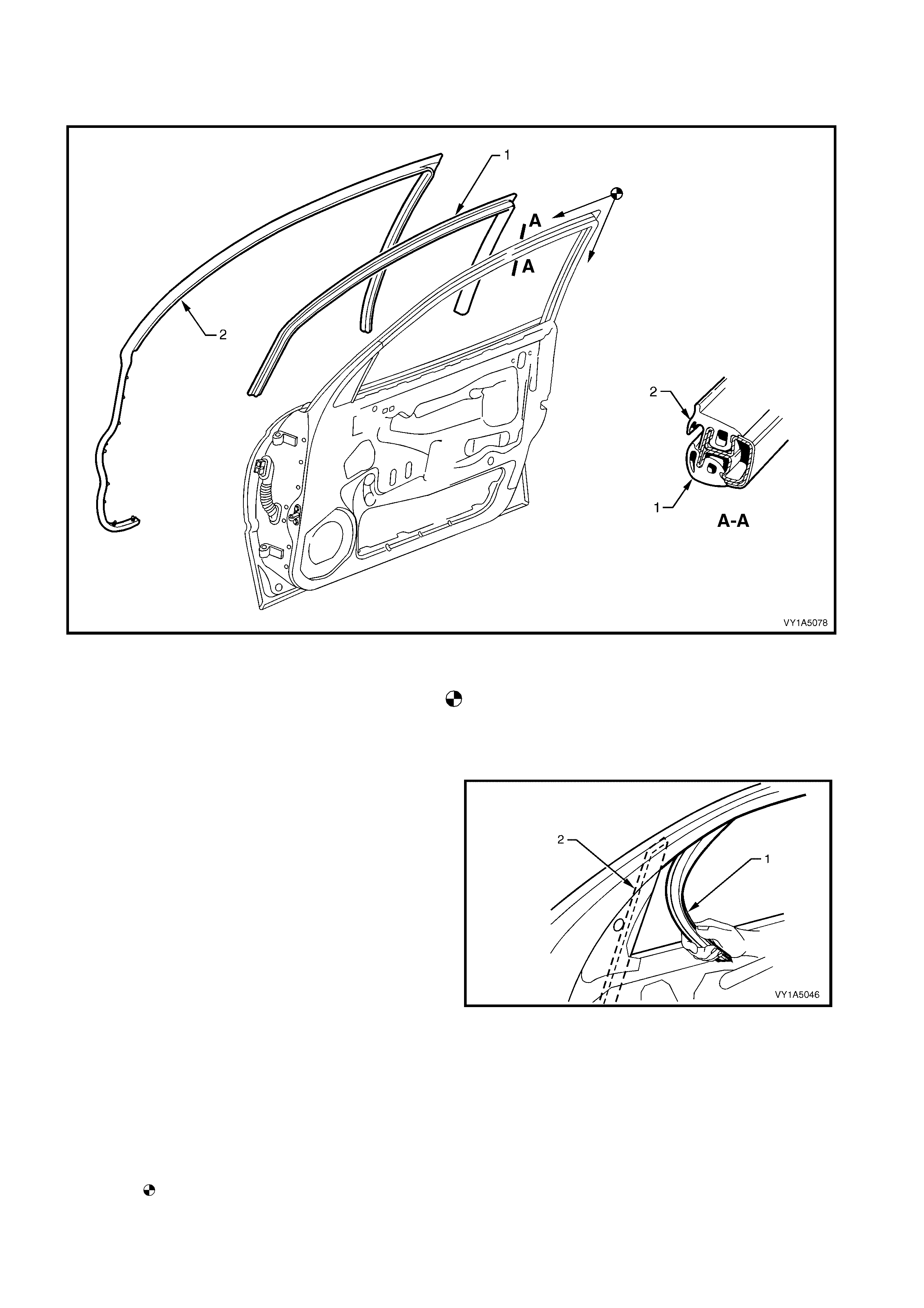
1. Front Door Window Upper Weatherstrip Assembly.
2. Front Door Upper Weatherstrip Assembly. Install Weatherstrip Corner Aligning Locating Marks On
Door Frame, Then Proceed In Direction Of Arrows.
REMOVE
1 With the window glass lowered, starting at the
guide ra ils (2), progressi vely peel the door window
upper weatherstrip assembly (1) away from the
door windo w frame.
2 Pull the weatherstrip u p and out, at the rear of the
door.
3 Progressively remove the front door upper
weatherstrip assembly, from the lip on the door
upper frame, refer Figure 1A5-67.
4 Carefully remove the weatherstrip from the belt
line, allowing the retainer clips to pull out of the
weatherstrip and remain in the door panel.
5 Remove th e r et ai ner cl ips f rom the door panel with
a clip removal tool and refit them back into the
weatherstrip ready for reinstallation.
Figure 1A5-68
REINST ALL
Reinstal lation is the re verse of the removal proc edure,
refer Figure 1A5-67, noting the following:
1. When installing t he weatherstrips, start installation
process from the top corner of the door frame as
shown .
2.16 FRONT DOOR WINDOW FRAME UPPER SCALP MOULDING
LT Section No. – 11-650
IMPORTANT: Prior to commencing any of the following procedures, lower the window assembly, to its down
position.
1. Remove the front door window regulator handle assembly (where fitted), refer to 2.4 FRONT DOOR
WINDOW REGULATOR HANDLE ASSEMBLY.
2. Remove the front door inside handle assembly (remote), refer to 2.5 FRONT DOOR INSIDE HANDLE
ASSEMBLY (REMOTE).
3. Remove the front door trim panel assembly refer to 2.6 FRONT DOOR TRIM PANEL ASSEMBLY.
4. Partially remove the front door weatherstrip assembly and remove the front door upper weatherstrip
assembly, refer to 2.15 FRONT DOOR WEATHERSTRIP ASSEMBLY.
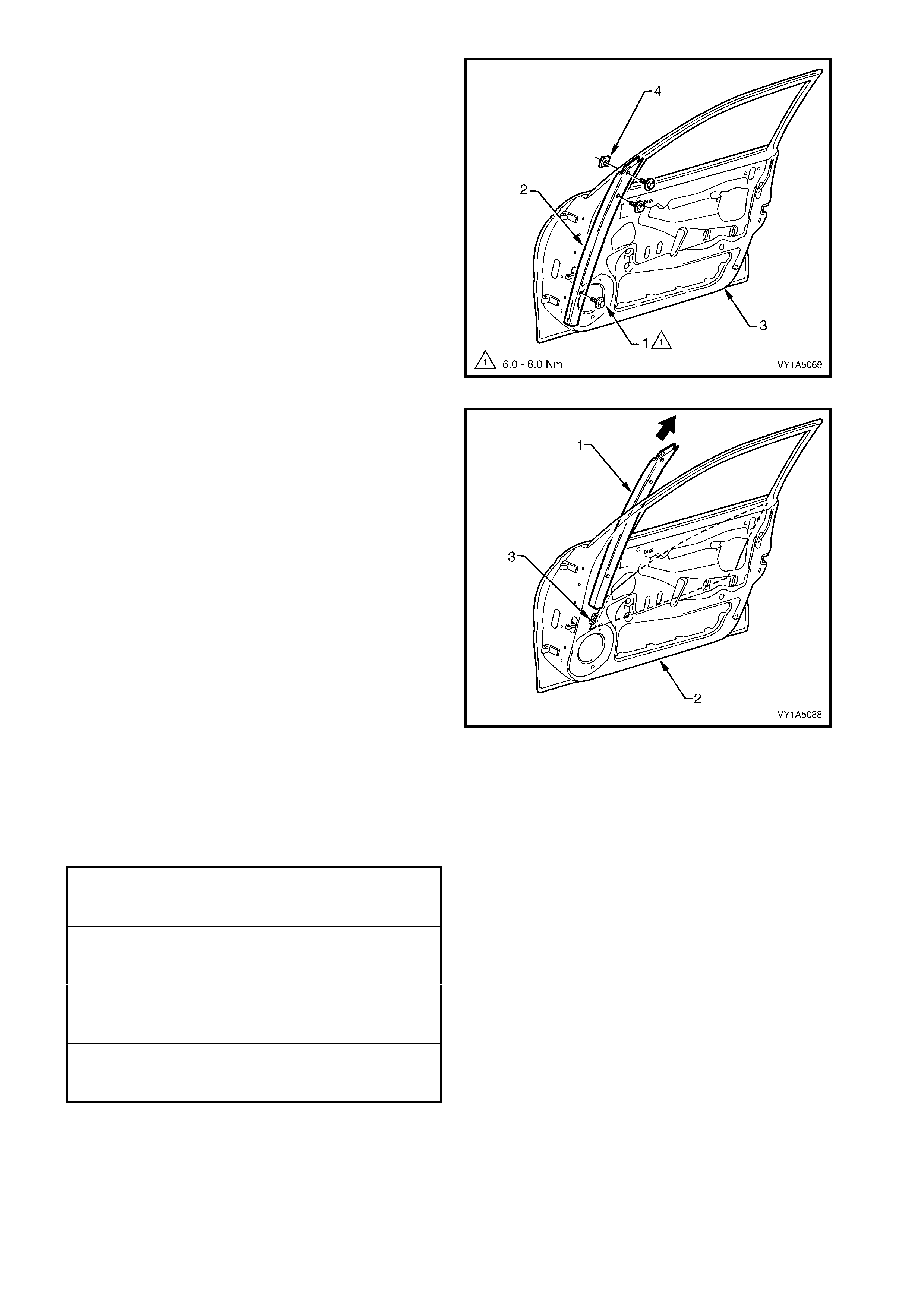
REMOVE
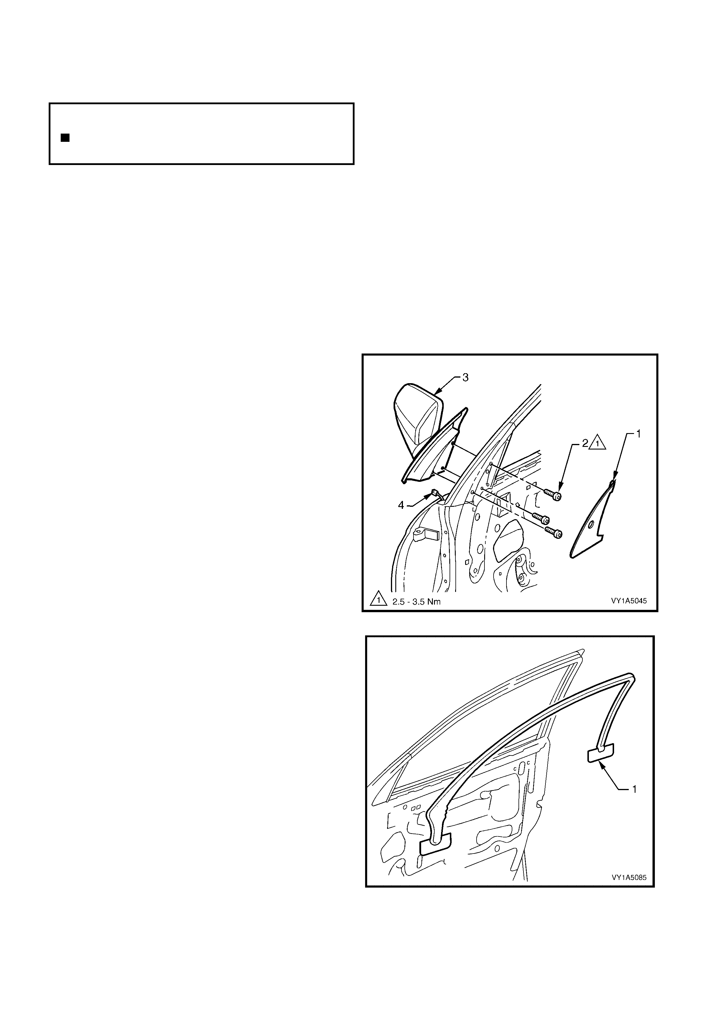
1. Peel back the outside rear view mirror seal (1) to
gain excess to the screws.
2. Remove the three screws (2) securing the outside
rear view mirror assembly (3) to the door panel.
While supporting the mirror, disconnect the wiring
harness connector (4) and remove the mirror.
Figure 1A5-69
3. W ith the aid of a k nife, progress ively peel th e front
door window frame upper scalp moulding (1),
away from around the door window frame,
separating the adhesive from the frame.
4. Clean the surface of the door frame with Prepsol
or equivalent as required.
NOTE: The front door window frame upper scalp
moulding will be damaged during this operation and
must be replaced.
Figure 1A5-70
N
O
TE: The
f
ollowing component WILL RE
Q
UIRE
REPLACEMENT when performing this operation.
Front door window frame upper scalp moulding
assembly.

REINST ALL
Reinstallation of the front door window frame upper
scalp moulding will require a new self adhesive
moulding assembly, refer Figure 1A5-70.
1. Tighten all retaining screws to the correct torque
specification.
OUTSIDE REAR VIEW MIRROR
ASSEMBLY RETAINING SCREW
TORQUE SPECIFICATION 2.5 – 3.5 Nm

2.18 FRONT DOOR ASSEMBLY
LT Section No. – 12-460
REMOVE
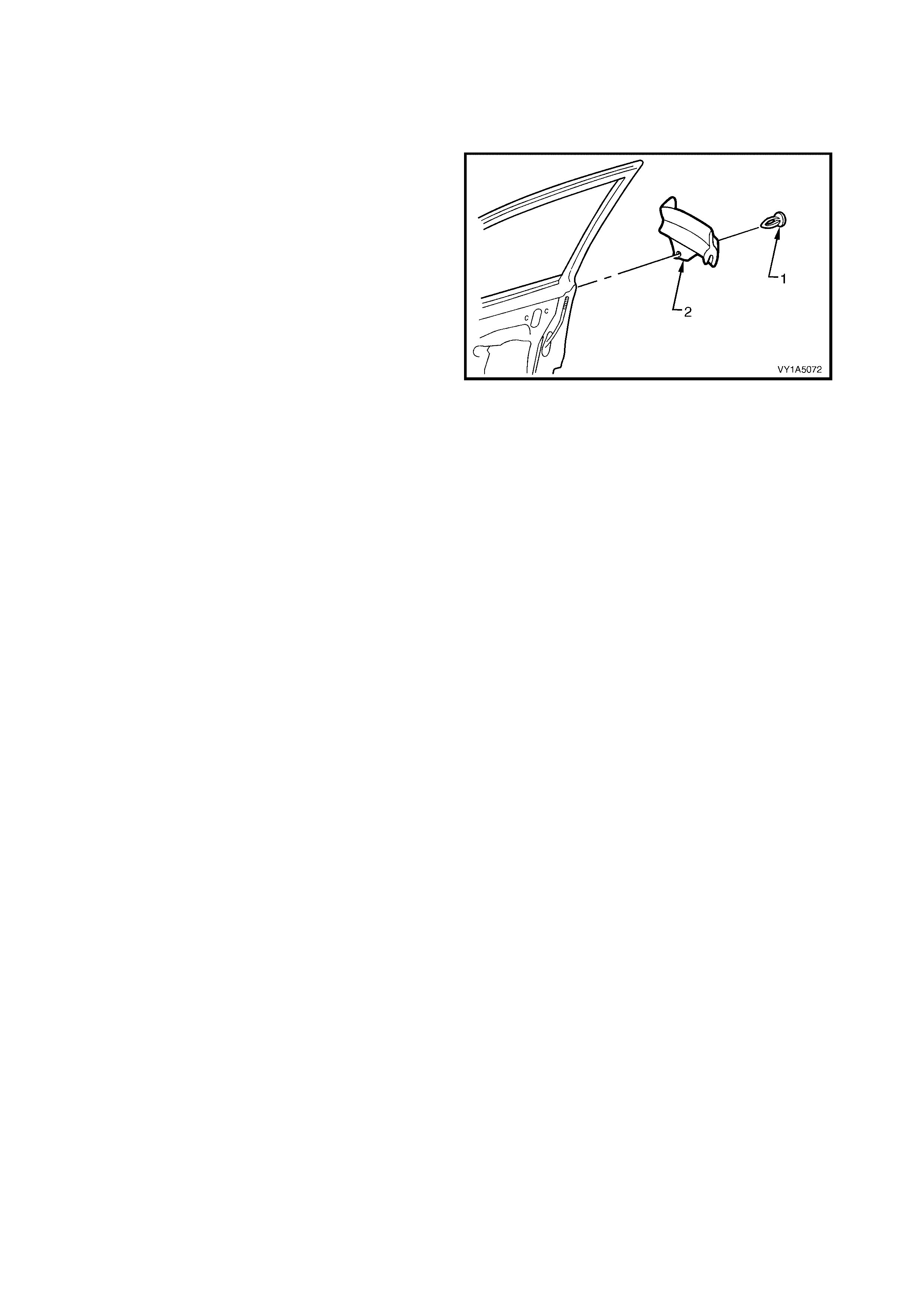
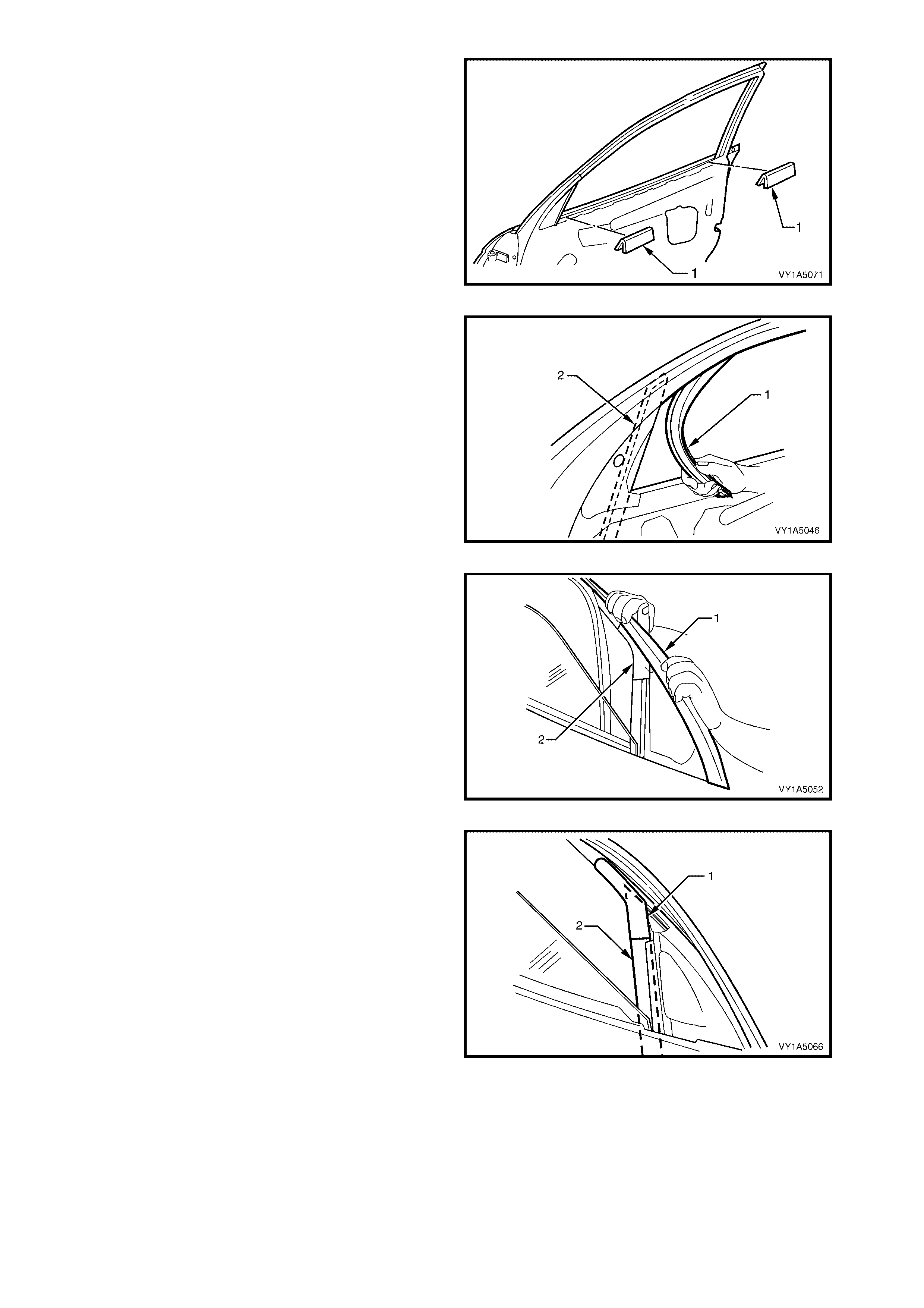
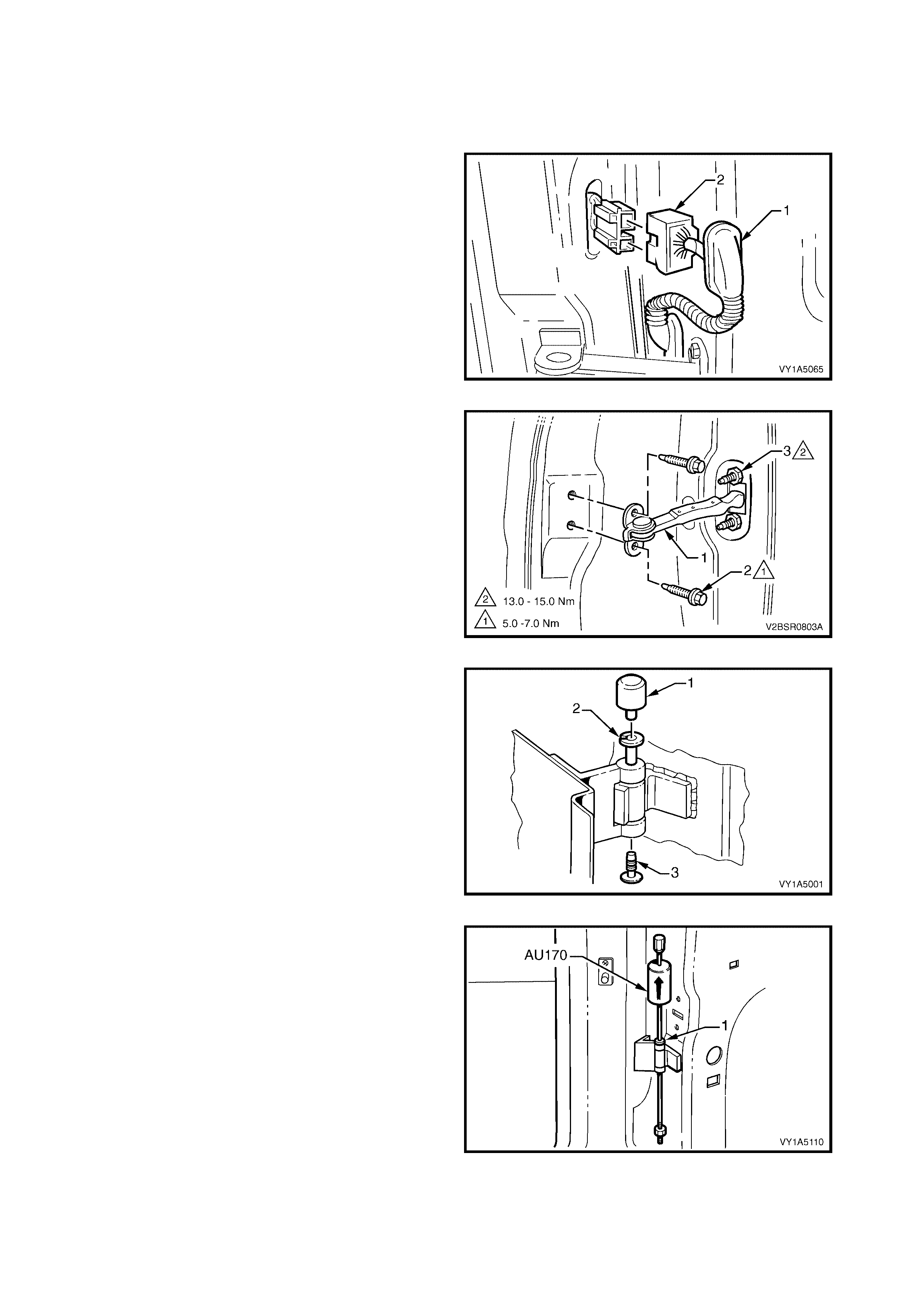
1. Remove the grommet (1) from the door wiring
harness connector plug (2).
2. Depress the tabs and gently pull on the wiring
harness to withdraw the connector from the body.
3. Disconnect the connector.
Figure 1A5-71
4. Remove the front door check assembly (1) from
the vehicle by removing the two screws (2).
NOTE 1: If required, remove the two nuts (3),
attaching the check assembly to the door, allowing
access to the hinge pins.
NOTE 2: Ensure the door cannot swing freely causing
damage.
Figure 1A5-72
5. Remove the front hinge pin cap (1) and the front
hinge plug (3) from the front hinge pin (2) on the
upper and lower hinges.
6. Have an assistant support the door or support the
base of the door on a wooden block and a trolley
jack.
Figure 1A5-73
7. Using the Tool No. AU170, drive the lower and
then the upper hinge pivot sleeves (1) from the
hinges.
8. Remove the door assembly.
Figure 1A5-74
DISASSEMBLE
As required remove the following components, refer to the appropriate Sections:
1. Front door window regulator handle assembly (where fitted), refer to 2.4 FRONT DOOR WINDOW
REGULATOR HANDLE ASSEMBLY.
2. Front door inside handle assembly (remote), refer to 2.5 FRONT DOOR INSIDE HANDLE ASSEMBLY
(REMOTE).
3. Front door trim panel assembly, refer to 2.6 FRONT DOOR TRIM PANEL ASSEMBLY.
4. Front door lock assembly, refer to 2.7 FRONT DOOR LOCK ASSEMBLY.
5. Front door outside handle assembly, refer to 2.8 FRONT DOOR OUTSIDE HA NDLE A SSEMBLY.
6. Window regulator assembly, refer to 2.9 FRONT DOOR WINDOW REGULATOR ASSEMBLY.
7. Front window inner filler assembly, refer to 2.10 FRONT WINDOW INNER FILLER ASSEMBLY.
8. Front door belt outer reveal moulding assembly, refer to 2.11 FRONT DOOR BELT OUTER REVEAL
MOULDING ASSEMBLY.
9. Front door guide assembly, refer to 2.12 FRONT DOOR GUIDE ASSEMBLY.
10. Front door guide channel assembly, refer to 2.13 FRONT DOOR GUIDE CHANNEL ASSEMBLY.
11. Front door window assembly, refer to 2.14 FRONT DOOR WINDOW ASSEMBLY.
12. Front door weatherstrip assembly, refer to 2.15 FRONT DOOR WEATHERSTRIP ASSEMBLY.
13. Front door window frame upper scalp moulding, refer to 2.16 FRONT DOOR WINDOW FRAME UPPER
SCALP MOULDING.
14. Front door wiring harness assembly, refer to 2.17 FRONT DOOR WIRING HARNESS ASSEMBLY.
15. Front door opening weatherstrip assembly, refer to 2.19 FRONT DOOR OPENING WEATHERSTRIP
ASSEMBLY, EXCEPT COUPE and 2.20 FRONT DOOR OPENING WEATHERSTRIP ASSEMBLY,
COUPE.
16. Front door body side moulding, for Sedan refer to Section 1A9, 2.11 BODY SIDE MOULDINGS, and for
Wagon refer to Section 1A9, 3.12 BODY SIDE MOULDINGS.
Remove – Front Door Window Channel Seal
1. Carefully remove the front door window channel
seal (1) from the front door panel upper frame.
Reinstall – Front Door Window Channel Seal
Reinstal lation of the fr ont door windo w channe l seal, is
the reverse of the removal.
Figure 1A5-75
Remove – Front Door Deadener
1. Prise the front door deadener (1), from the front
door panel inner.
Reinstall – Front Door Deadener
Reinstallation of the - front door deadener, is the
reverse of the removal.
NOTE: If reusing the s ame part, appl y a sm all amount
of contact adhesive.
Figure 1A5-76
Remove – Front Door Inside Handle Rod Clip
1. Remove the two front door inside handle rod clips
(1), by turning 90°and then removing from the front
door panel inner.
Reinstall – Front Door Inside Handle Rod Clip
Reinstallation of the front door inside handle rod clip,
is the reverse of the removal.
Figure 1A5-77
REINST ALL
IMPORTANT: If using a new door panel assembly it
must be prepared to maintain original manufacturers
specifications. This includes the application of joint
sealer, hand putty and cavity wax. Refer to the
MY2003 V Y & V 2 Series Ser vice Manual Su pplement,
Body Structure Repair Manual for specifications.
Reinstal lation of the fr ont door as sem bl y is the revers e
of the removal procedure, noting the following:
1. Apply Lithium base grease NLGI No. 1 (with 9 %
zinc oxide) or equivalent, to the hinge pivot
sleeves prior to installation.
2. Using Tool No. AU303 (2), and a hammer, install
the hinge pivot sleeves (1).
3. Check the fit of the door and adjust as required,
refer to ADJUST in this Section.
NOTE: Make allowances in the adjustment if the trim
and hardwar e are not insta l led.
4. Tighten all retaining screws to the correct torque
specification.
5. Reinstall the trim and hardware as required.
6. Connect and install the door wiring harness
connector to the body wiring harness and refit the
grommet.
7. Refit the hinge pivot sleeve dust caps, refer
Figure 1A5-73.
Figure 1A5-78
CHECK ASSEMBLY TO PILLAR
RETAINING SCREW
TORQUE SPECIFICATION 5.0 – 7.0 Nm
CHECK ASSEMBLY TO
DOOR RETAINING NUT
TORQUE SPECIFICATION 13.0 – 15.0

ADJUST
Attention s hould b e give n to unif orm m argins and alig nm ent between t he door an d surr ounding p arts when door
adjustments are being carried out.
Uniform margins and alignment of the front and rear doors in relation to the body opening can be achieved by
setting the appropriate door hinge. Refer to MY2003 VY & V2 Series Service Manual Supplement,
Body Structure Repair Manual for specifications.
Adjust hi nges in conjunc tion with a djustm ent to the lock striker to ac hieve an acce ptable door closing ef fort with
correct door lock to striker engagement, refer to 2.2 FRONT DOOR LOCK STRIKER.
Use Tool No AU184 to set door hinges by slightly
bending the front door hinge (1) noting the following:
1. Take care when adjusting the doors not to
misalign the hinge pins. Any significant
misalignment will cause the pins to shear when
the door is opened or closed.
2. Excessive bending or levering of the window
frame will cause damage.
3. Final adjustment must take place when all the
door components and seals are installed.
IMPORTANT: Adjust doors with striker assembly
removed. Striker assembly should only be fitted once
satisf actory alignm ent is achieve d. They mu st NOT be
used to pull the door into the correct position.
Figure 1A5-79
2.19 FRONT DOOR OPENING WEATHERSTRIP ASSEMBLY, EXCEPT COUPE
LT Section No. – 11-600
As required, remove the following components :
1. Side sill trim and plate, quarter trim panel assembly, centre pillar upper trim, windshield side garnish and
hinge pillar trim, refer to Section 1A8 HEADLINING & INTERIOR TRIM.
2. Instrument panel outer cover, refer to Section 1A3 INSTRUMENT PA NEL & CONSOLE.
REMOVE
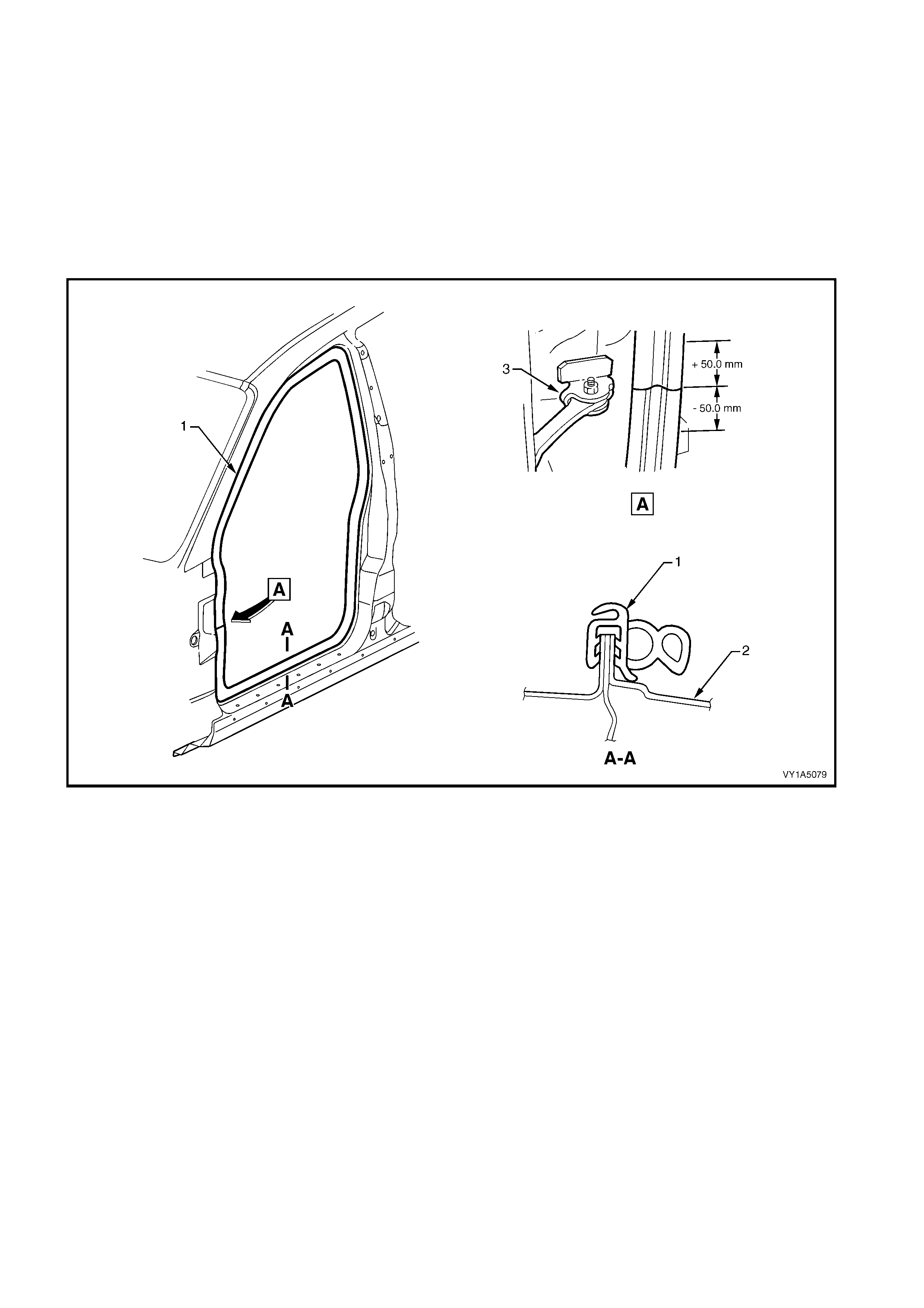
1. Gently prise the weatherstrip (1) from the door
opening.
Figure 1A5-80
Legend
1. Front Door Weatherstrip Assembly 2. Door Opening Frame 3. Front Hinge Check Assembly
REINST ALL
Reinstallation of the front door weatherstrip assembly,
is the reverse of the removal procedure, noting the
following:
1. Align identification mark on weatherstrip with the
front hinge check assembly (3) in the door frame
opening (2) ± 50 mm as shown, refer Figure
1A5-80.
NOTE: Allow crowding of the weatherstrip in all
corners of the door opening frame (2). Ensure
weatherstrip does not short cut corners and foul the
door trim.
2. Ensure the weatherstrip lip sits over trim panels.
3. Tighten all trim attaching screws to the correct
torque specification, refer to Section 1A8,
HEADLINING AND INTERI OR TRIM.
2.20 FRONT DOOR OPENING WEATHERSTRIP ASSEMBLY, COUPE
LT Section No. – 11-600
As required, remove the following components:
1. Moulding - Windshield Si de G ar nis h, Pan el - Body Hinge Pi ll ar Trim , Panel - Cent re Pillar Upp er T r im , Panel
Assembly - Quarter Trim, Retainer Assembly - Front & Rear Door Opening Floor Carpet, refer to
Section 1A8 HEADLINING & INTERIOR TRIM.
2. Cover - Instrument Outer Trim, refer to Section 1A3 INSTRUMENT PANEL & CONSOLE.
REMOVE
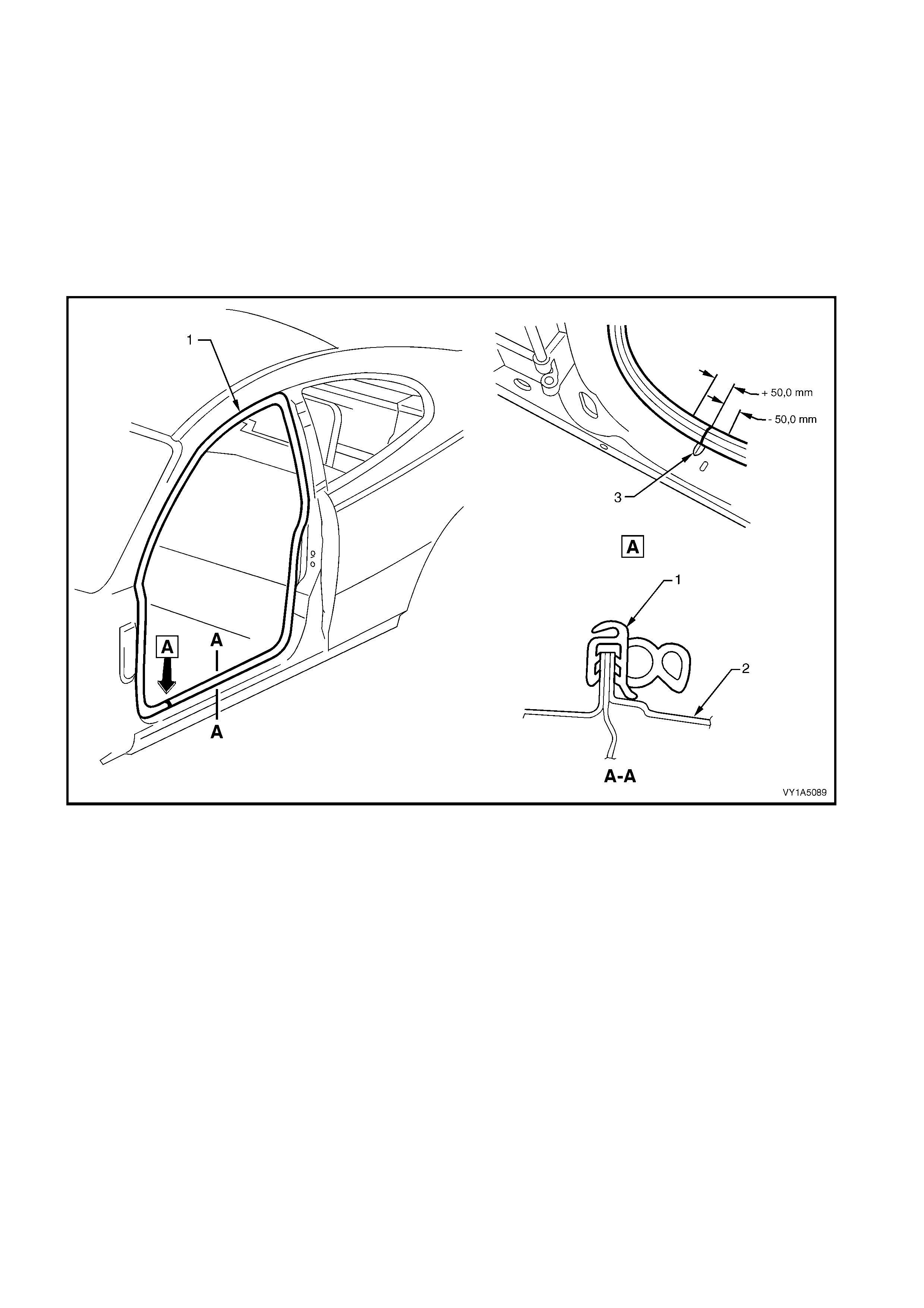
1. Gently prise the weatherstrip (1) from the door
opening.
Figure 1A5-81
Legend
1. Front Door Weatherstrip Assembly 2. Door Opening Frame 3. Door Frame Dart
REINST ALL
Reinstallation of the front door weatherstrip assembly,
is the reverse of the removal procedure, noting the
following:
1. Align the identification mark on the weatherstrip
with the centre line of the dart (3) in the door frame
opening (2) ± 50 mm, refer to Figure 1A5-81.
NOTE: Allow crowding of the weatherstrip in all
corners of the door opening frame (2). Ensure
weatherstrip does not short cut corners and foul the
door trim.
2. Ensure the weatherstrip lip sits over trim panels.
3. Tighten all trim attaching screws, to the correct
torque specification, refer to Section 1A8
HEADLINING & INTERIOR TRIM.
3. REAR DOOR SERVICE OPERATIONS
3.1 REAR DOOR HINGE LUBRICATION
LT Section No. –
1. Remove the rear hinge pin cap (1) and the rear
hinge plug (2) from the rear hinge pin (3) on the
upper and lower hinges.
2. Using a grease gun, inject into the rear hinge pin
Lithium base grease NLGI No. 1 (with 9 % zinc
oxide) or equivalent.
3. Reinstall the cap and plug.
4. Wipe off any excess grease.
Figure 1A5-82
Techline
3.2 REAR DOOR LOCK STRIKER
LT Section No. – 11-725
REMOVE
1. Pencil scribe (1) the location of the rear door lock
striker assembly (2) on to the body pillar before
removal, to facilitate installation.
2. Using a Torx bit (30 T), remove two retaining
screws (3).
3. Remove the striker and spacer plates, if fitted.
Figure 1A5-83
REINST ALL
1. Align the rear door lock striker assembly (1), so
that the brid ge of the strik er locat es c entra lly in the
door fork lock assembly (2) as the door is being
closed. Firmly tighten the striker assembly.
2. Correct engagement can be achieved by vertical
or horizontal adjustment of the door lock striker
assembly. The door must not ‘Ride’ on the striker.
Add or delete the door lock striker washer (3)
between the striker assembly and body pillar to
achieve correct engagement of the striker
assembly to the lock. Also refer to
3.3 ADJUST REAR DOOR ASSEMBLY.
TIP: It is sound practice to remove the door lock striker
assembly and allow the door to hang free on the
hinges. Set th e hin ges as neces s ar y to achieve c orr ect
alignment and uniform margins, then reinstall the
striker and adjust.
3. When the correct alignment of the striker
assem bly is ach ieved, tig hten the s trik er assem bly
retaining screw (4) to the correct torque
specification.
Figure 1A5-84
STRIKER ASSEMBLY
RETAINING SCREW
TORQUE SPECIFICATION 8.0 – 18.0 Nm

3.3 ADJUST REAR DOOR ASSEMBLY
LT Section No. – 12-460
Attention should be given to uniform margins and alignment between the door and surrounding parts when
adjustments are being performed.
Uniform margins and alignment of the doors in relation to the body opening can be achieved by
setting the appropriate door hinge. Refer to MY2003 VY & V2 Series Service Manual Supplement,
Body Structure Repair Manual for specifications.
Use Tool No AU184 to the set door hinges by slightly
bending the rear door hinge (1) noting the following:
1. Take care when adjusting the doors not to
misalign the hinge pins. Any significant
misalignment will cause the pins to shear when
the door is opened or closed.
2. Excessive bending or levering of the window
frame will cause damage.
3. Final adjustment must take place when all the
door components and seals are installed.
IMPORTANT: Adjust doors with the striker assembly
removed. Striker assembly should only be fitted once
satisf actory alignm ent is achieve d. They mu st NOT be
used to pull the door into the correct position.
Figure 1A5-85
3.4 REAR WINDOW REGULATOR HANDLE ASSEMBLY
LT Section No. – 11-675
REMOVE
1. Insert a commercially available window regulator
handle removal tool (1) between the base of rear
door window regulator the handle assembly (2),
and the rear door window washer (3), in line with
the arm of the handle.
2. Disengage the rear door window regulator handle
clip (4), then remove the handle.
NOTE: Take care when disengaging the rear door
window regulator handle clip that it does not spring off.
Figure 1A5-86
REINST ALL
1. Locate the rear door window regulator handle clip
(4), in the rear door inside handle assembly (2),
with the open ends of the clip facing the handle
arm.
NOTE : Make sure both rear door windows are at the
same height before fitting handle assemble.
2. Fit the rear door window washer (3).
3. Ensure that the handle is positi oned symm etric ally
with the handle on the opposite door, then press
the handle ont o the window regula tor splines, unt il
the clip engages the groove at the base of the
splines.
Figure 1A5-87
3.5 REAR DOOR INSIDE HANDLE ASSEMBLY (REMOTE)
LT Section No. – 11-725
REMOVE
1. Prise off the rear door inside handle bolt finisher
cap (1).
2. Remove the screw (2) securing the rear door
inside handle assembly (remote) (3) to the rear
door trim.
3. Remove the handle assembly in a forward
direction and unho ok the rear insid e ha ndl e rod ( 4)
from the handle assembly.
Figure 1A5-88
REINST ALL
Reinstallation of the rear door inside handle assembly
(remote) handle is the reverse of the removal, refer
Figure 1A5-88, noting the foll o wing:
1. Ensure the rear door inside handle assembly
(remote) and rem ote rod are engaged before final
fitment.
2. Tighten the all retaining screw to the correct
torque specification.
REAR DOOR INSIDE HANDLE
ASSEMBLY (REMOTE) RETAINING
SCREW TORQUE SPECIFICATION 1.0 – 3.0 Nm
3.6 REAR DOOR TRIM PANEL ASSEMBLY
LT Section No. – 14-270
Remove the following components,
1. Rear window regulator handle assembly, refer to 3.4 REAR WINDOW REGULATOR HANDLE
ASSEMBLY.
2. Rear door inside handle assembly, refer to 3.5 REAR DOOR INSIDE HANDLE ASSEMBLY (REMOTE).
REMOVE
1. Using a s mall f lat bladed screwdr iver or sc ribe (1) ,
gently pr ise the ora nge rear door locking r od knob
retainer (2) from the rear door locking rod knob
assembly (3), taking care not to damage the knob
assembly. Remove the knob assembly.
NOTE: The orange - rear door locking rod knob
retainer, will be damaged during this operation and
must be replaced.
2. Lift the knob assembly up, removing it from the
door locking rod.
3. Remove the screw (4) securing the rear door
locking rod ferrule (5) to the door trim panel
assem bl y and remove the f er rule.
Figure 1A5-89
4. Remove the rear door trim retaining screw (1) from
the rear door inside aper t ur e handle ass embly.
Figure 1A5-90
5. Remove six screws (1) securing the panel
assembly to the door panel.
6. Lift the top of the panel assembly up and out of the
door inner channel.
NOTE: Wiring harness connectors are still connected.
7. While supporting the panel assembly, disconnect
all the wiring harn ess conn ec tors .
8. Remove the panel assembly.
Figure 1A5-91
N
O
TE: The
f
ollowing component WILL RE
Q
UIRE
REPLACEMENT when performing this operation.
Rear door locking rod knob retainer.
DISASSEMBLE
Figure 1A5-92
Legend
1. Rear Door Inside Handle Screw (4 Places)
2. Rear Door Inside Handle Cover
3. Rear Door Inside Handle Bracket
4. Radio Rear Door Speaker Grille Retainer (7 Places)
5. Rear Door Radio Grille Speaker
6. Rear Door Courtesy Lamp
7. Door Armrest Insert Assembly Clip. (2 Places)
8. Rear Door Inside Armrest Insert Assembly
9. Rear Door Trim Panel Foundation Assembly
10. Insert Assembly Door Armrest Clip (5 Places)
11. Rear Door Window Switch
12. Rear Window Inner Front Sealing Strip
13. Rear Window Inner Rear Sealing Strip
14. Rear Door Insulator Assembly
Remove – Rear Door Window Switch
1. From behind the door trim assembly, push the rear
door window switch (1), free by depressing tangs.
2. Remove the switch.
NOTE: For further information regarding Service and
Diagnosis of the rear door power window switch, refer
to Section 12J BODY CONTROL MODULE.
Reinstall – Rear Door Window Switch
Reinstallation of the rear door window switch is the
reverse of removal, noting the following.
1. Press the s witch assem bly firm ly into the door trim
assem bly.
Figure 1A5-93
Remove – Radio Speaker Grille
1. Remove the seven c lips (1) securing the rear d oor
radio grille speaker (2) to the door trim (3).
NOTE: Take care when removing clips, not to break
the speaker grille shafts on which the clips are
attached.
2. Remove the radio speaker grille.
Reinstall – Radio Speaker Grille
Reinstal lation of the s peak er gril le is the r evers e of th e
removal.
Figure 1A5-94
Remove – Rear Door Insulator Assembly
1. Remove the rear door insu lator assembly (1) from
the back of the rear door trim panel assembly, (2)
by peeling the insulator slowly across the panel.
NOTE: Take care not to tear the insulator. Retain as
much adhesive as possible on the insulator. Do not
fold the insulator and store in a flat location with the
adhesive facing away from objects.
Reinstall – Rear Door Insulator Assembly
Locate the insulator assembly centrally within the rear
door trim panel assembly, and press firmly into
position.
NOTE: If required apply additional hot melt adhesive
with a high softening point (eg.90°c).
Figure 1A5-95
Remove – Rear Door Armrest Insert Assembly
IMPORTANT: Take care when removing the clips, as
the rotating action will cut-off the rear door armrest
insert assembly shaft, to which the clips are attached,
requiring a replacement insert assembly be fitted.
1. Peel back the insulator assembly, from the upper
portion of the rear door trim assembly, allowing
access to the insert assembly attaching parts,
refer this Section.
2. Remove two clips (1) by sliding them away from
the panel assembly (2).
3. Remove the nuts (3), five places, attaching the
armrest insert (4) to the panel assembly.
4. Before removal, prise the armrest insert away from
the panel ass embl y. Sli de the arm rest insert to the
rear of panel assembly and remove.
Reinstall – Rear Door Armrest Insert Assembly
Reinstallation of the insert assembly is the reverse of
the removal, noting the following.
1. The insert assembly must be sitting flush against
the panel assembly, along the entire top
contacting surface.
2. Tighten all retaining nuts to the correct torque
specification.
Figure 1A5-96
ARMREST INSERT ASSEMBLY
RETAINING NUT
TORQUE SPECIFICATION 0.7 – 0.9 Nm
Remove – Rear Door Inside Handle Assembly
(Pull)
1. Remove the insert ass embly arm r est. ref er this
Section.
2. Remove four screws (1) attaching the handle
reinforcement bracket (2) to the panel assembly
(3).
3. Remove the rear door inside handle assembly.
4. Peel off the cover (4), from the handle
reinforcement bracket.
Reinstall – Rear Door Inside Handle Assembly
(Pull)
Reinstal lation of the hand le ass embl y is the rev erse of
the removal procedure, noting the following:
1. Tighten all the retaining screws to the correct
torque specification.
Figure 1A5-97
Remove – Rear Window Inner Front and Rear
Sealing Strip
1. By pushing down on one end, progressively
rem ove the r ear window i n ner rear seal in g s tr i p (1)
from the panel assembly (2).
2. Repeat this procedure for the rear window inner
front sealing strip (3).
Reinstall – Rear Window Inner Front and Rear
Sealing Strip
Reinstallation of the sealing strip is the reverse of the
removal, noting the following:
1. Align sealing strip with the edge of door trim.
Figure 1A5-98
Remove – Rear Door Courtesy Lamp (where fitted)
1. From the back of the rear door trim (1), depress
the retaini ng tangs s ecurin g the rear door c ourtes y
lamp (2) to the trim.
2. Push the lamp out of its aperture and remove.
NOTE: For service and diagnosis of the rear door
courtesy lamp refer Section 12B LIGHTING
SYSTEMS.
Reinstall – Rear Door Courtesy Lamp
1. Push the rear door courtesy lamp into its aperture
in the rear door trim firmly and ensure the retaining
tangs are secured to the trim.
Figure 1A5-99
REAR DOOR INSIDE HANDLE
ASSEMBLY (PULL) RETAINING
SCREW TORQUE SPECIFICATION 1.3 – 1.7 Nm

REINST ALL
Reinstallation of the panel assembly is the reverse of
the removal procedure, noting the following:
1. Connect the rear door wiring harness connectors
to the door window switch as s em bly, (if f itted) , an d
the rear door courtesy lamp, (where fitted).
2. Ensure the rear door handle assembly and the
rear inside handle rod, are engaged before final
fitment, refer 3.5 REAR DOOR INSIDE HANDLE
ASSEMBLY (REMOTE).
3. Tighten all retaining screws to the correct torque
specification.
NOTE: Screws along b ottom of front door trim are wax
tip sealing screws, refer Figure 1A5-91
4. Use a new rear door locking rod knob retainer,
refer Figure1A5-89.
REAR DOOR TRIM PANEL
ASSEMBLY RETAINING SCREW
TORQUE SPECIFICATION 1.0 – 3.0 Nm
REAR DOOR LOCKING ROD
FERRULE RETAINING SCREW
TORQUE SPECIFICATION 1.0 – 3.0 Nm
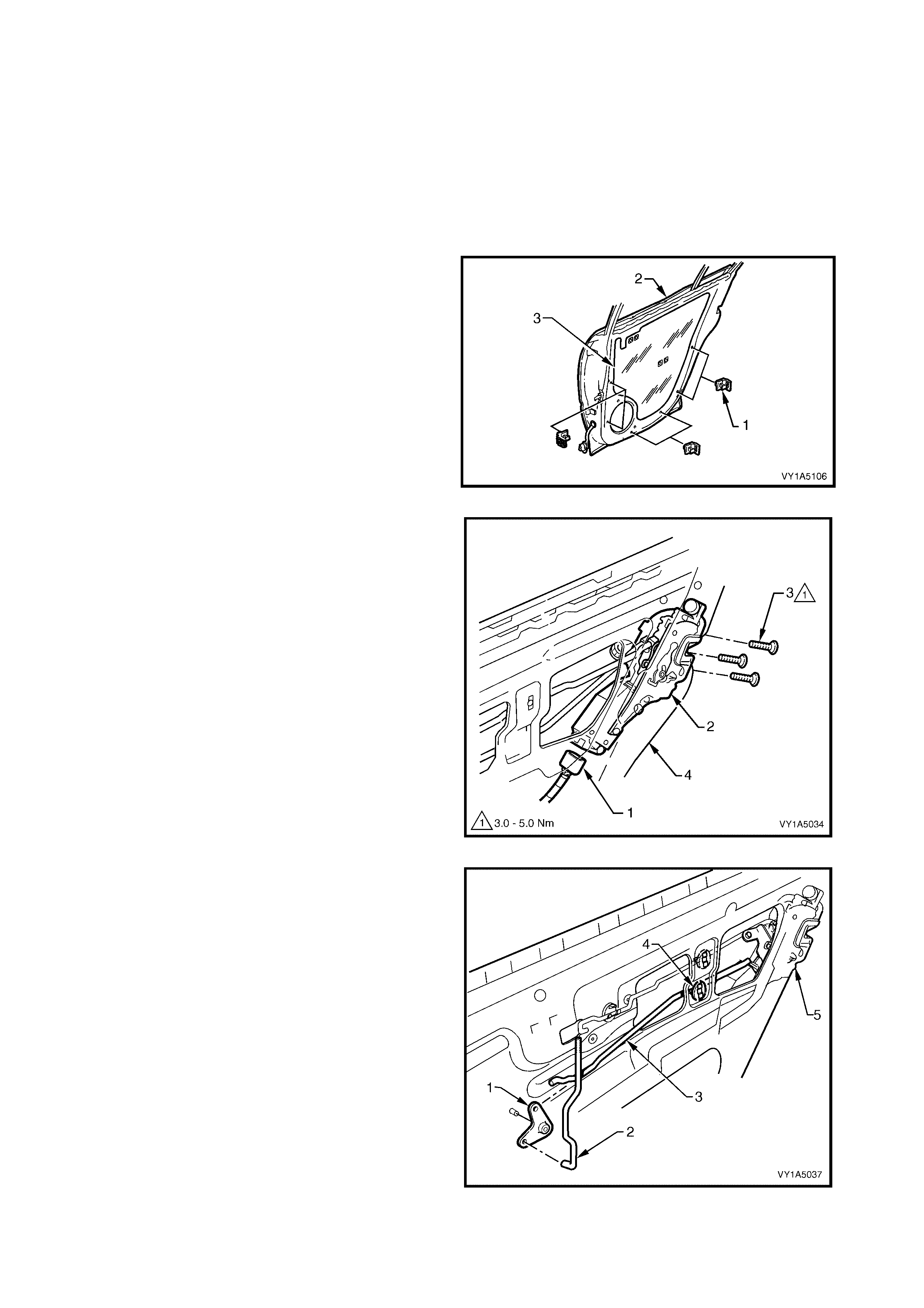
3.7 REAR DOOR LOCK ASSEMBLY
LT Section No. – 11-725
1. Remove the rear window regulator handle assembly (where fitted), refer to 3.4 REAR WINDOW
REGULATOR HANDLE ASSEMBLY.
2. Remove the rear door inside handle assembly, refer to 3.5 REAR DOOR INSIDE HANDLE ASSEMBLY
(REMOTE).
3. Remove the rear door trim panel assembly, refer to 3.6 REAR DOOR TRIM PANEL ASSEMBLY.
REMOVE
NOTE: The rear door water shield ne ed only be partly
removed to allow access to complete this procedure.
1. If required remove the six rear door brackets to the
panel (1) by levering out the centre pin of the
bracket.
2. Carefully peel off the rear door water shield (3)
from the rear door inner panel (2).
Figure1A5-100
3. Disconnect the door harness electrical connector
(1) from the rear door lock assembly (2).
4. Remove the three screws (3) securing the rear
door lock assembly to the door inner panel (4).
Figure 1A5-101
5. Lever the bell crank assembly (1) with the rear
door lock rod (2) from the pivot shaft.
6. Remove the rear door locking bell crank rod (3)
from the retainer (4) and lock assembly (5).
Figure 1A5-102
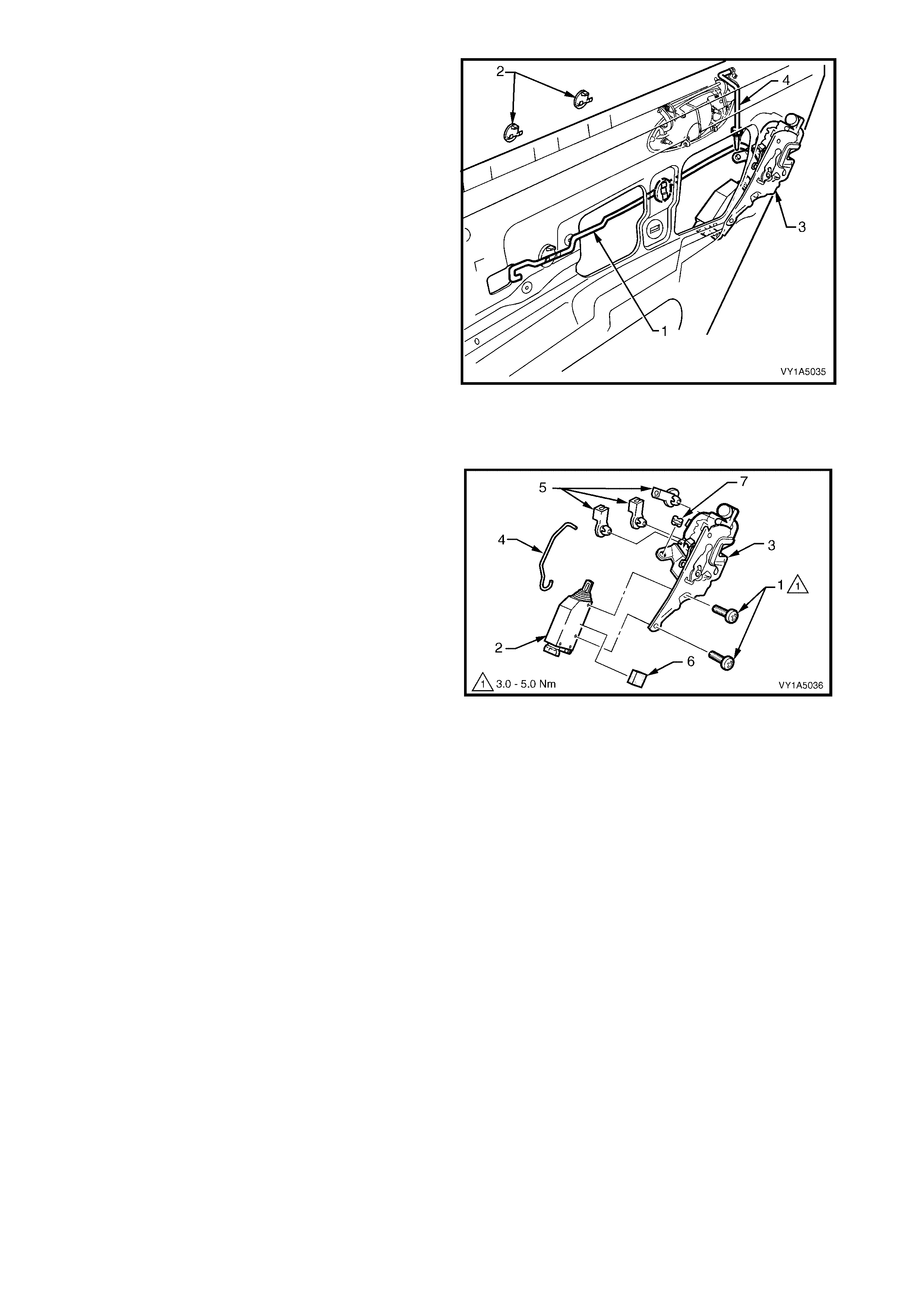
7. Disconnect the rear door inside handle rod (1)
from the two rear door inside handle rod clips (2),
and disengage the rod from the rear door lock
assembly (3) by releasing the rod retainer.
8. The rear door outside hand le rod assem bly (4) will
disengage from the rear door lock assembly (1),
when removing the lock assembly. Also refer
Figure 1A5-108 .
9. Rem ove the lock as sembl y through the apert ure in
the door inner panel.
Figure 1A5-103
DISASSEMBLE
Remove – Rear Door Lock A ctuator Assembly
1. Remove the two sc rews (1) s ecuring the rear door
lock actuator assembly (2) to the rear door lock
assembly (3).
2. Disassemble the actuating rod (4) from the
actuator assembly (2) and the lock assembly.
3. Remove the three retaining clips (5) and the door
lock bush (7) from the lock assembly.
4. If required remove the rear door lock actuator
insulator (6) from the actuator assembly.
Reinstall – Rear Door Lock Actuator Assembly
Reinstallation of the rear door lock actuator assembly,
is the reverse of the removal procedure, noting the
following:
1. Adjust position of the actuator assembly as
described below.
Figure 1A5-104
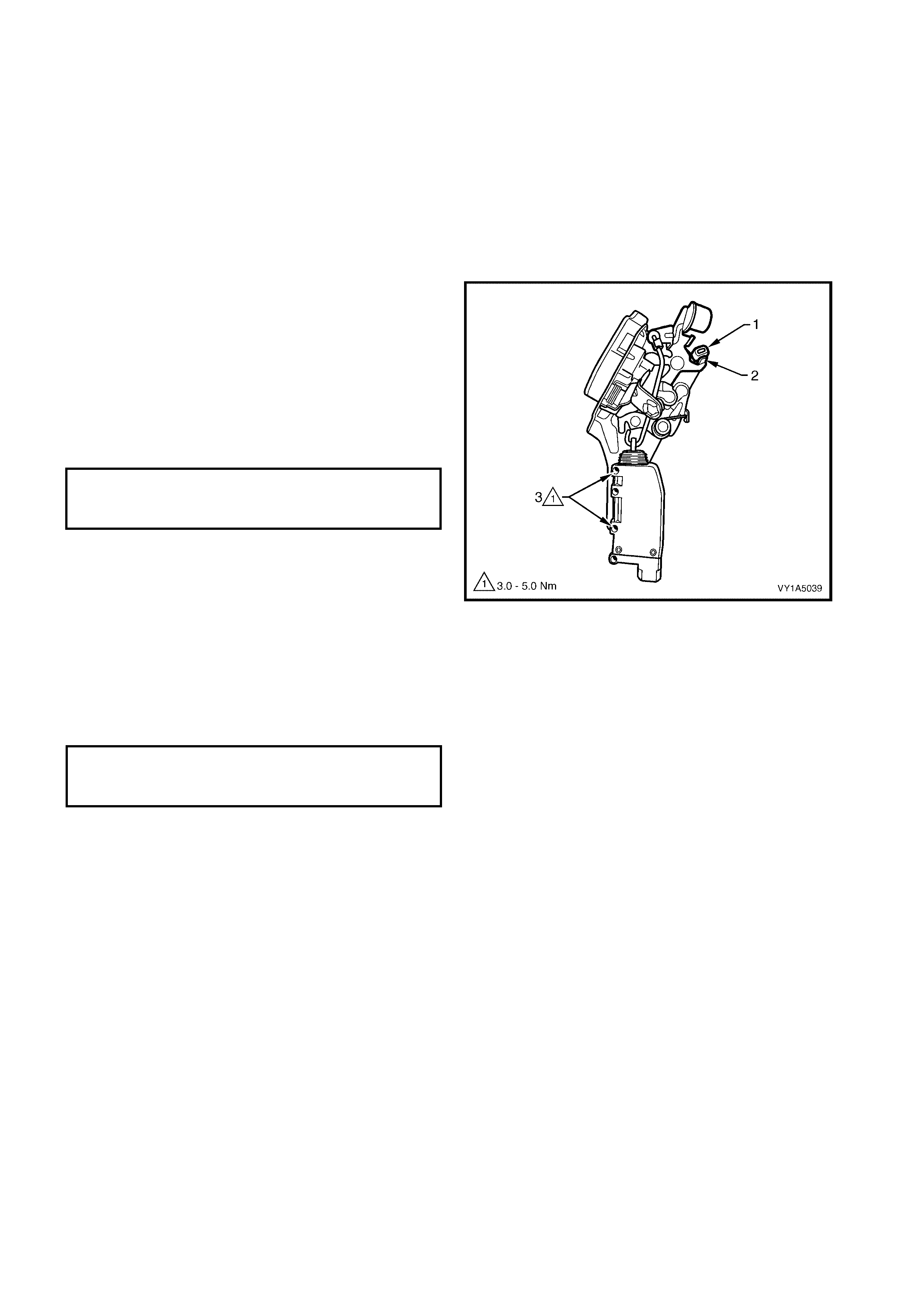
ADJUST
Adjustment of the each door lock and actuator assembly is critical to ensure correct operation of the electric
door lock system.
The following adjustment procedure is to be performed if a diagnostic test in Section 12J Body Control
Module suggests that the door lock and actuator may be incorrectly adjusted, or if any of the following
symptoms occur:
• Ineffective deadlock operation.
• Failure to lock and unlock.
• Door lock actuator motors oscillate, i.e. machine gunning.
If not already done so, remove rear door lock assembly, refer to 3.7 REAR DOOR LOCK ASSEMBLY.
1. Us ing the d oor loc king butt on r o d le ver , LOCK an d
UNLOCK the actuator mechanism, checking that
the actuator bump stop (1) rests on the actuator
lever (2).
2. If required, loosen screws (3) and reposition the
actuator motor until the required position is
achieved.
3. Tighten the actuator assembly screws securely,
without moving its position.
Figure 1A5-105
REINST ALL
Reinstallation of the rear door lock assembly is the
reverse of the removal procedure, noting the following:
1. Tighten all retaining screws to the correct torque
specification.
2. Ensure rear door outside handle rod assembly, is
engaged correctly with the rear door lock
assembly, refer Figure 1A5-108.
3. Ensur e the rear door water shield is corr ectl y fitted
to the door panel.
REAR DOOR LOCK ACTUATOR
ASSEMBLY RETAINING SCREW
TORQUE SPECIFICATION 3.0 – 5.0 Nm
REAR DOOR LOCK ASSEMBLY
RETAINING SCREWS
TORQUE SPECIFICATION 3.0 – 5.0 Nm
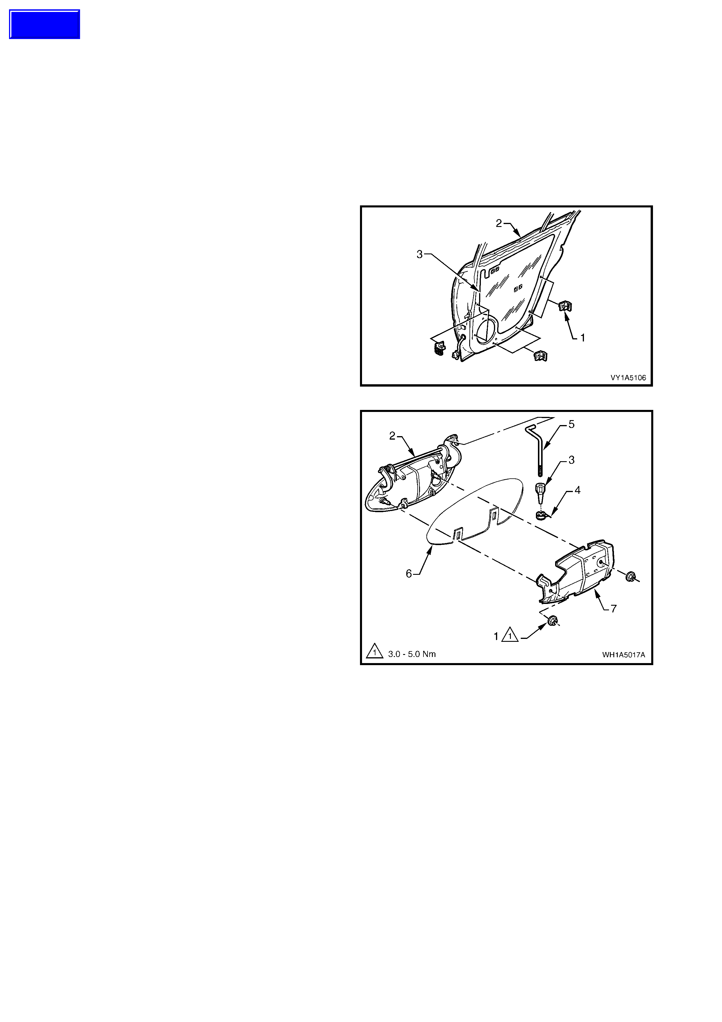
3.8 REAR DOOR OUTSIDE HANDLE ASSEMBLY
LT Section No. – 11-725
1. Remove the rear window regulator handle assembly (where fitted), refer to 3.4 REAR WINDOW
REGULATOR HANDLE ASSEMBLY.
2. Remove the rear door inside handle assembly, refer to 3.5 REAR DOOR INSIDE HANDLE ASSEMBLY
(REMOTE).
3. Remove the rear door trim panel assembly, refer to 3.6 REAR DOOR TRIM PA NEL ASSEMBLY.
REMOVE
NOTE: The rear door water shield ne ed only be partly
removed to allow access to complete this procedure.
1. If required remove the six rear door brackets (1)
from the panel (2) by levering out the centre.
2. Carefully peel off the rear door water shield (3)
from the rear door inner panel (2).
Figure 1A5-106
3. Remove the two door handle retaining nuts (1),
and remove the rear door outside handle
assembly (2).
Figure 1A5-107
Techline
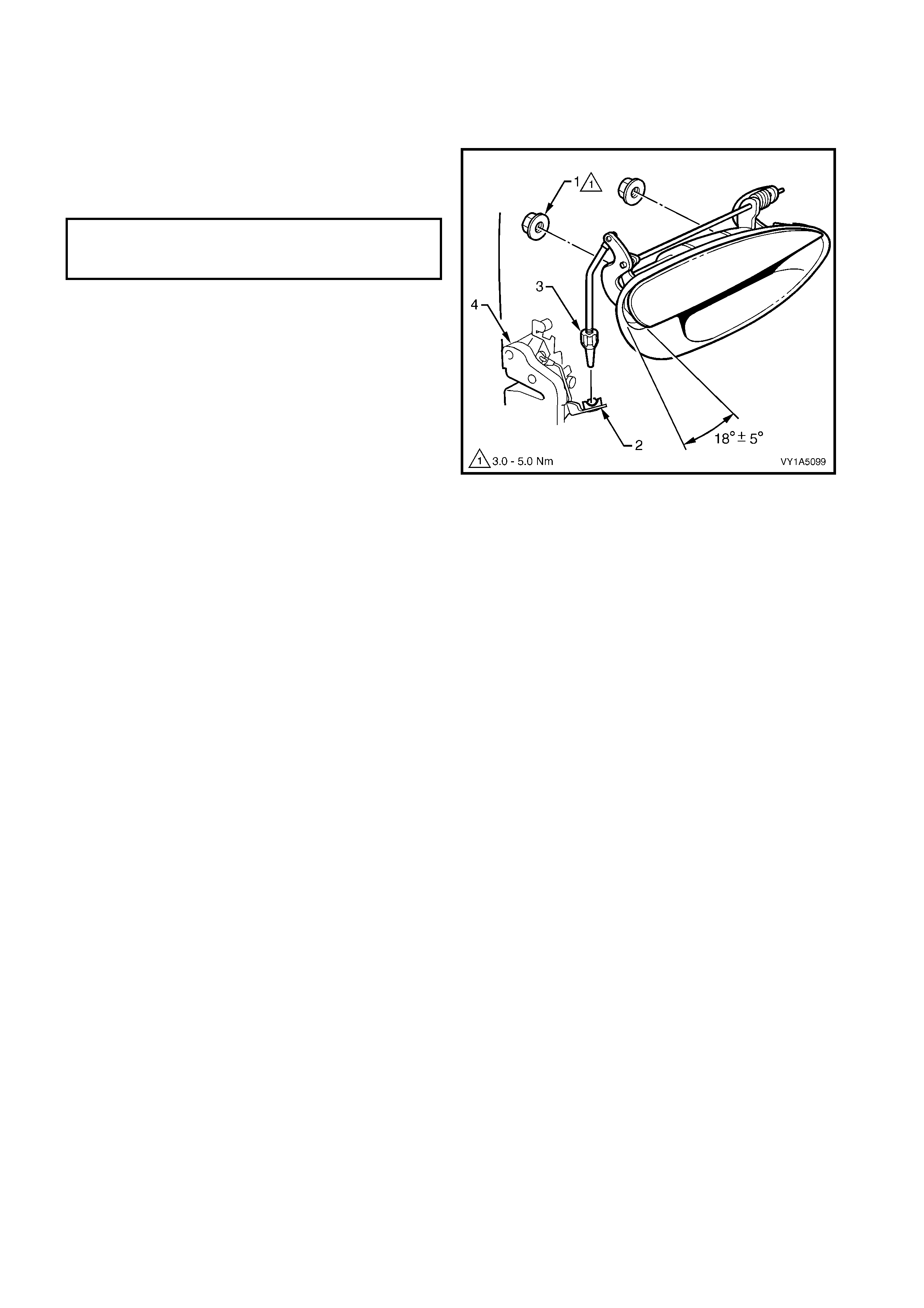
REINST ALL
Reinstallation of the rear door outside handle
assembly is the reverse of the removal procedure,
noting the following:
1. Ensure that the adjuster nut (3) is seated in the
lock assembly (4) before installing the handle
assembly retaining nuts (1).
2. Check and if necessary, adjust the handle
assembly adjustment nut to allow latch
disengagement with striker when the handle
opening is 18° ± 5° from the rest position.
3. Ensur e the rear door water shield is corr ectl y fitted
to the door panel.
Figure 1A5-108
DOOR OUTSIDE HANDLE
ASSEMBLY RETAINING NUT
TORQUE SPECIFICATION 3.0 – 5.0 Nm
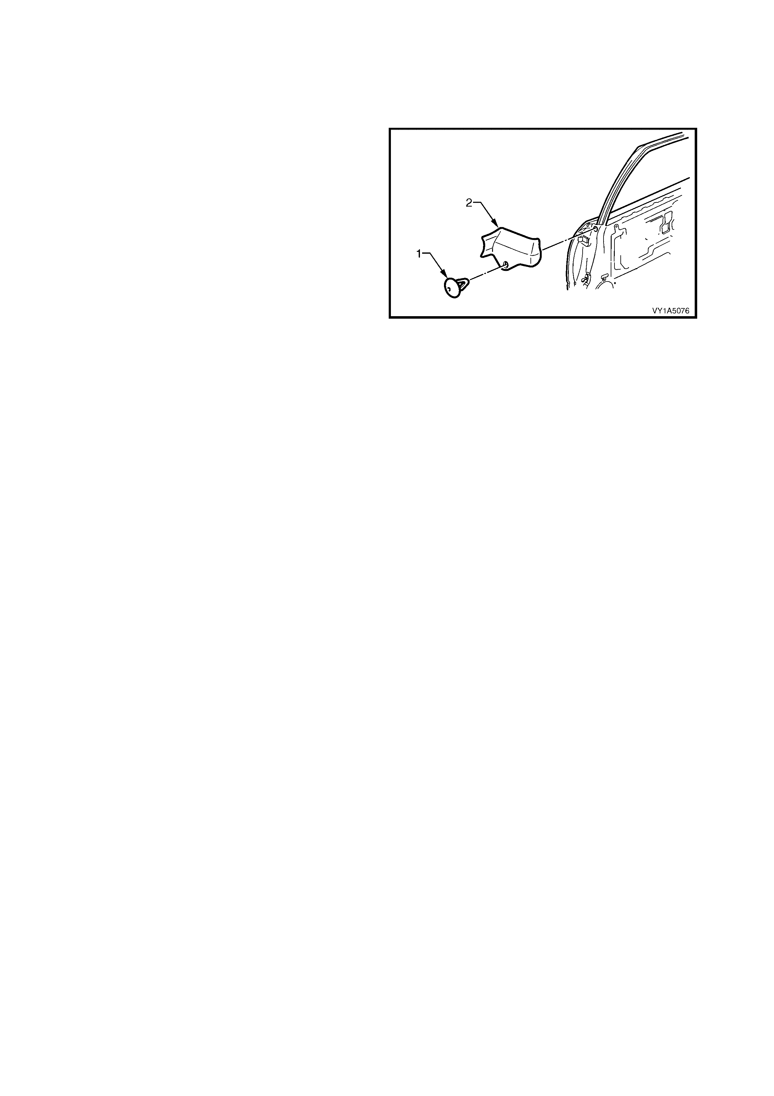
3.9 REAR WINDOW INNER FILLER ASSEMBLY
LT Section No. –
REMOVE
1. Gently prisey out the filler assembly retainer (1),
from the rear window inner filler assembly (2).
2. Remove filler assembly from the front of the rear
door.
Figure 1A5-109
REINST ALL
Reinstallation of the filler assembly retainer, is the
reverse of the removal.
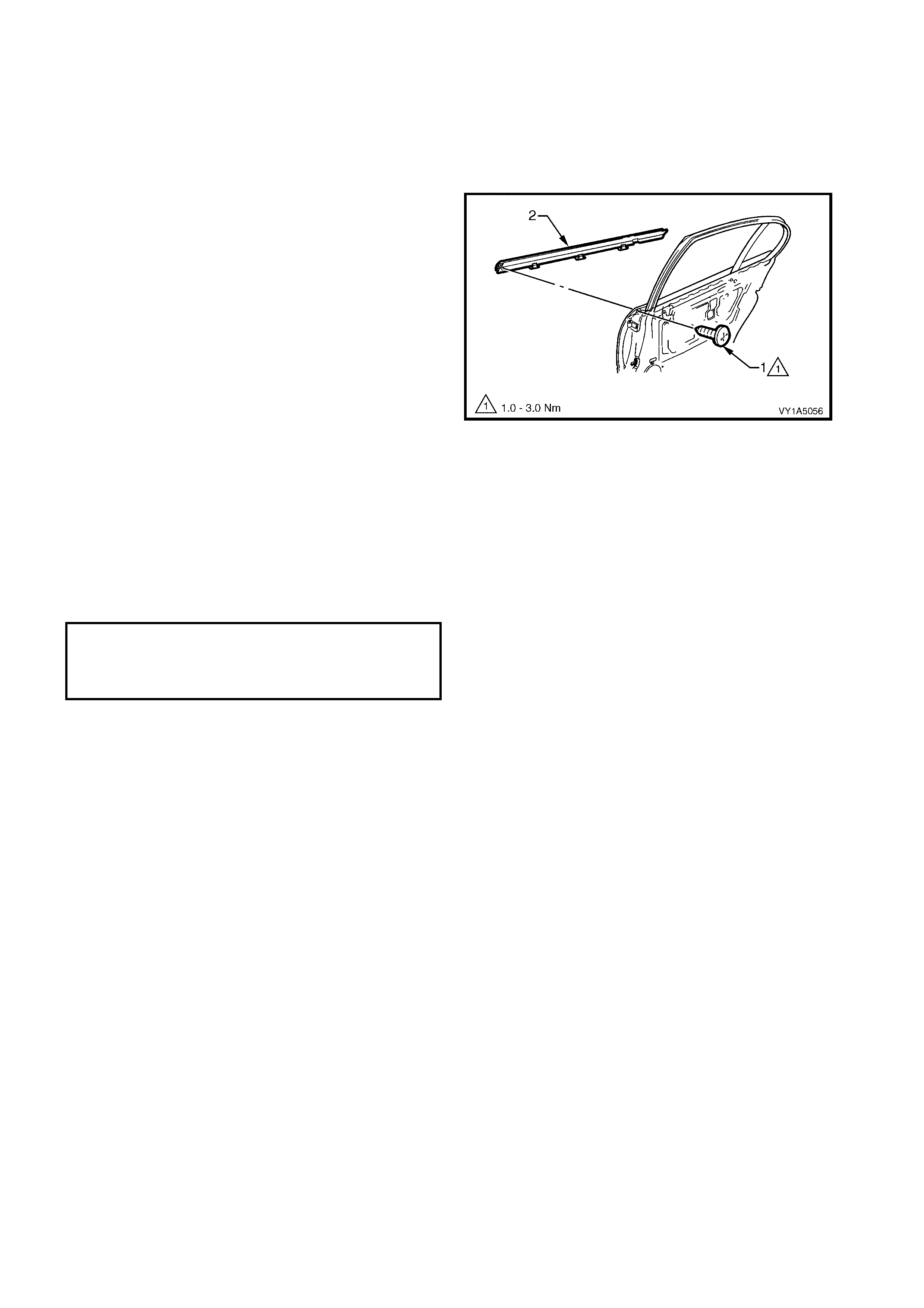
3.10 REAR DOOR BELT OUTER REVEAL MOULDING ASSEMBLY
LT Section No. – 11-775
IMPORTANT: Prior to commencing any of the following procedures, lower the window assembly to its down
position.
REMOVE
1. Remove the retaining moulding assembly
screw (1 ).
2. Start ing at the f ront of the door, prise the r ear door
belt outer reveal moulding assembly (2), in an
upward direction off the door.
NOTE: Take care not to damage the moulding or the
plastic retaining clips.
Figure 1A5-110
REINST ALL
Reinstallation of the rear door belt outer reveal
moulding assembly, is the reverse of removal, refer
Figure 1A5-110, noting the following:
1. Locate the rear door belt outer reveal moulding
assembly over the top of the door outer panel,
then using the palm of the hand, firmly tap the
assembly down, over the door outer upper flange.
REAR WINDOW BELT OUTER
REVEAL MOULDING ASSEMBLY
RETAINING SCREW
TORQUE SPECIFICATION 1.0 – 3.0 Nm

3.11 REAR DOOR CHANNEL ASSEMBLY
LT Section No. – 11-020
1. Remove the rear window regulator handle assembly (where fitted), refer to 3.4 REAR WINDOW
REGULATOR HANDLE ASSEMBLY.
2. Remove the rear door inside handle assembly, refer to 3.5 REAR DOOR INSIDE HANDLE ASSEMBLY
(REMOTE).
3. Remove the rear door trim panel assembly, refer to 3.6 REAR DOOR TRIM PA NEL ASSEMBLY.
4. Remove the rear door belt outer reveal moulding assembly, refer to 3.10 REAR DOOR BELT OUTER
REVEAL MOULDING ASSEMBLY.
5. Partly remove the rear door upper weatherstrip assembly, refer to 3.15 REAR DOOR WEATHERSTRIP
ASSEMBLY.
REMOVE
1. If required remove the six rear door brackets (1)
from the panel (2) by levering out the centre.
2. Carefully peel off the rear door water shield (3)
from the rear door inner panel (2).
Figure 1A5-111
3. Remove the rear door inner panel belt front seal
(1), and t he rear door inner panel b elt r ear sea l (2)
from the door assembly.
Figure 1A5-112
4. Carefully remove rear window upper weatherstrip
assembly (1), from the rear window rear channel
assembly (2).
NOTE: It is not necessary to remove the weatherstrip
assembly completely, only from the rear window rear
channel assembly.
Figure 1A5-113
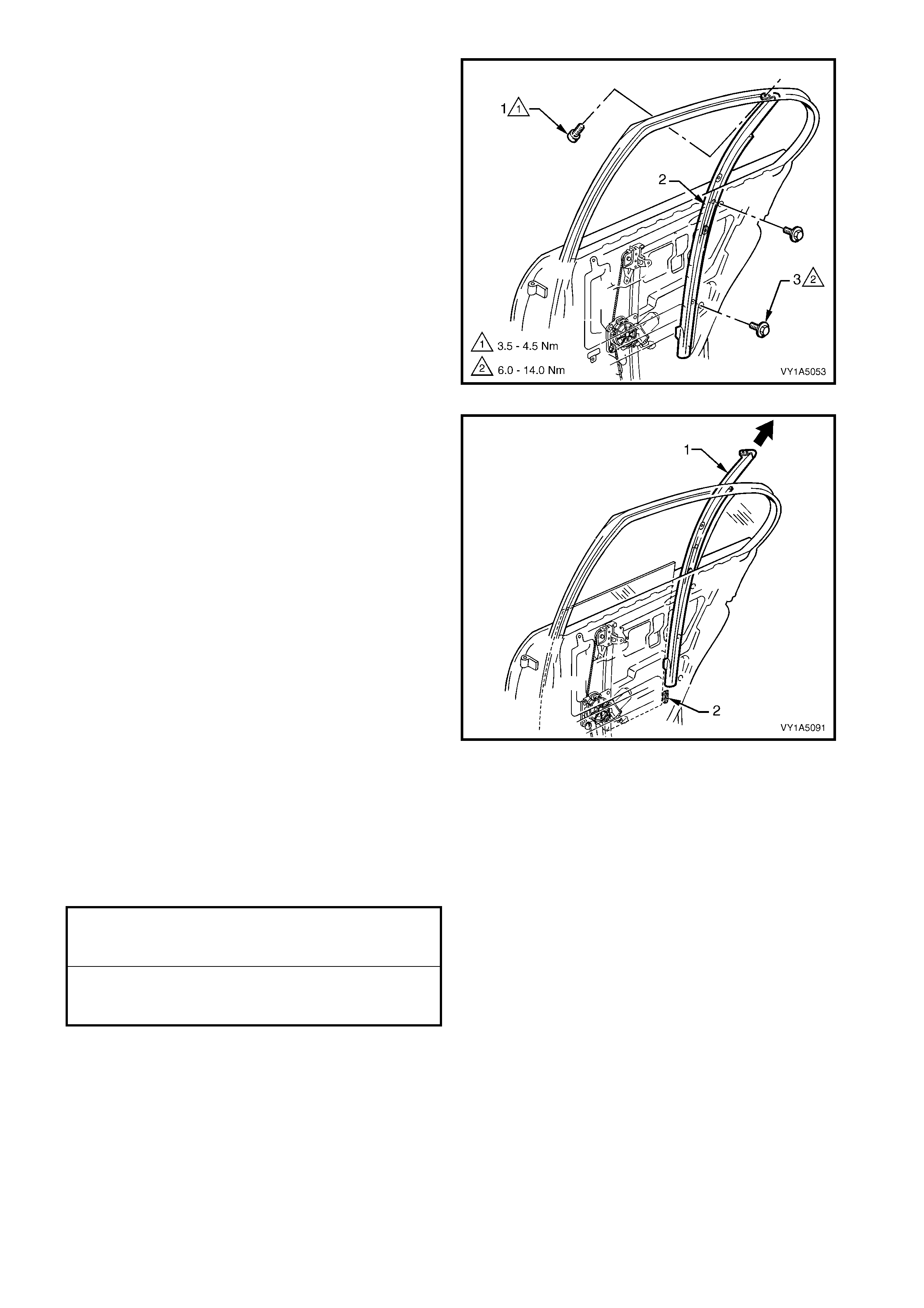
5. Remove the screw (1) securing the rear window
rear channel assembly (2) to the top of the rear
door.
6. Remove the two screws (3) securing the channel
assembly (2) to the door panel.
Figure 1A5-114
7. Remove the rear window channel assembly (1),
from the door in an upward direction, disengaging
the window assembly (2) from the channel.
Figure 1A5-115
REINST ALL
Reinstal lation of the r ear door guide c hann el ass em bly
is the reverse of the removal procedure, noting the
following:
1. Tighten all retaining screws to the correct torque
specification.
2. If required before installing door inner trim
panel, adjust the rear door window and regulator
as per the adjustment procedure, refer
3.12 REAR DOOR WINDOW ASSEMBLY.
3. Ensure the rear door water shield, is correctly
sealed against door inner panel.
REAR WINDOW REAR UPPER
CHANNEL ASSEMBLY RETAINING
SCREWS TORQUE SPECIFICATION 3.5 – 4.5 Nm
REAR WINDOW REAR LOWER
CHANNEL ASSEMBLY RETAINING
SCREWS TORQUE SPECIFICATION 6.0 – 14.0 Nm
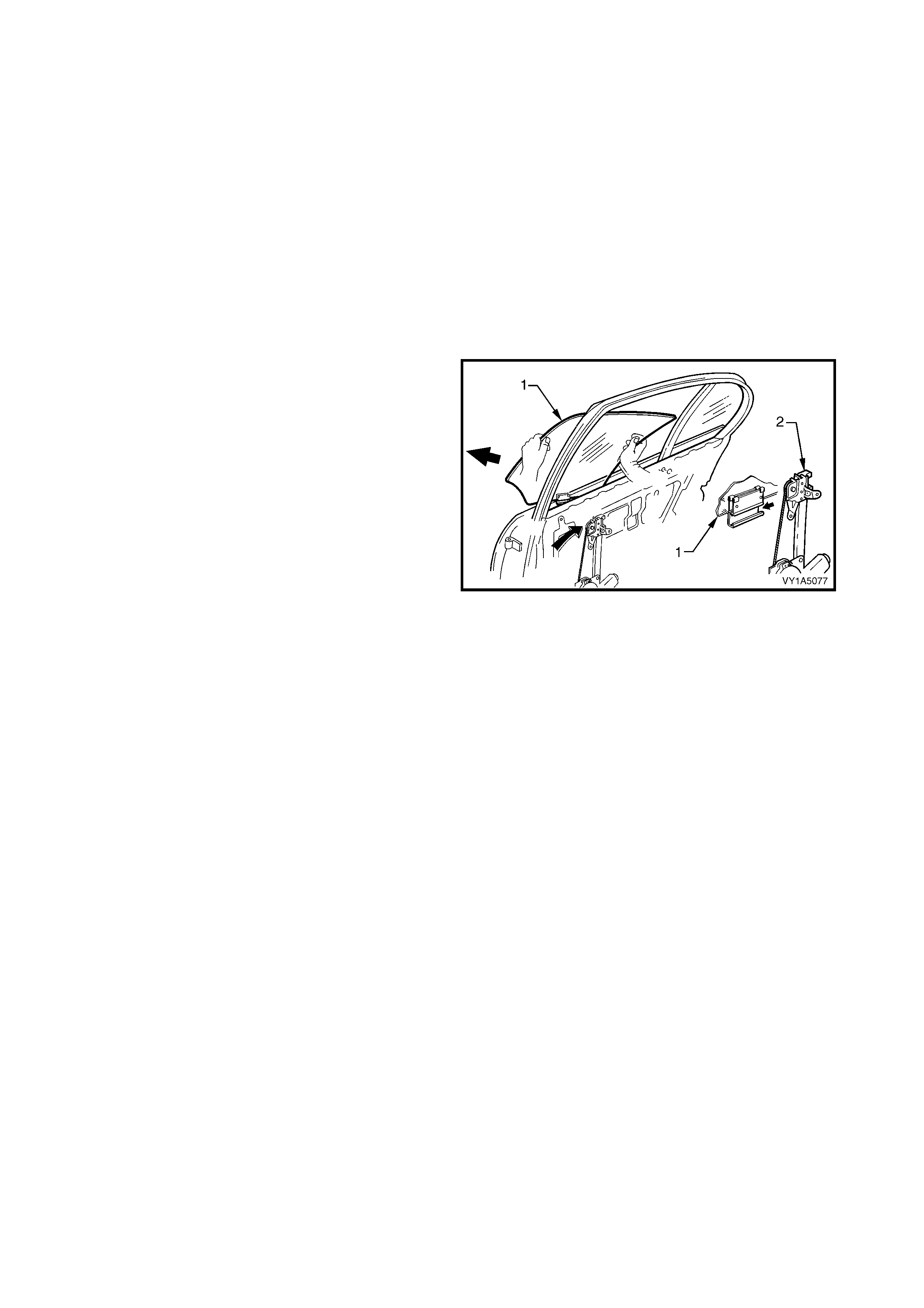
3.12 REAR DOOR WINDOW ASSEMBLY
LT Section No. – 11-750
1. Remove the rear window regulator handle assembly (where fitted), refer to 3.4 REAR WINDOW
REGULATOR HANDLE ASSEMBLY.
2. Remove the rear door inside handle assembly, refer to 3.5 REAR DOOR INSIDE HANDLE ASSEMBLY
(REMOTE).
3. Remove the rear door trim panel assembly, refer to 3.6 REAR DOOR TRIM PA NEL ASSEMBLY.
4. Remove the rear door window inner filler assembly, refer to 3.9 REAR WINDOW INNER FILLER
ASSEMBLY.
5. Remove the rear door belt outer reveal moulding assembly, refer to 3.10 REAR DOOR BELT OUTER
REVEAL MOULDING ASSEMBLY.
6. Remove the rear door guide channel assembly, refer to 3.11 CHANNEL A SSEMBLY - REAR DOOR.
REMOVE
1. Raise the rear door window assembly (1).
2. Slide the window assembly forward at an angle of
45° while disengaging it from the regulator
assembly (2).
Figure 1A5-116
REINST ALL
Reinstallation of the rear door window assem bly is the
reverse of the removal, noting the following:
1. Ensure all frictional surfaces of the window
regulator assembly and associated parts are
lubricated with Lithium base grease NLGI No. 1
(with 9 % zinc oxide) or equi val ent.
2. If required, adjust the window assembly by
referring to the following procedure.
ADJUST
1. Figure 1A5-117 shows the screw locations for the
following window assembly adjustment procedure.
Loosen screws (B & C).
NOTE: The rear window down stop, nut and front
screw (A) ar e not fitted as s tandard but are a vailable if
required.

Figure 1A5-117
Legend
A. Rear Window Down Stop Assembly Attaching Front
Screw (Available For Service If Required)
B. Rear Window Regulator Channel Assembly Upper
Attaching Screw
C. Rear Window Regulator Lower Channel Assembly
Attaching Screw
2. Wind the rear door window assembly, up through
area (Z) while at the same time, pressing the rail,
which is bonded to the front edge of the window, in
the direction of arrow (Y). Continue winding the
window up until it is approximately 30 mm before
the closed position.
3. Push the channel assembly rearward, in the
direction of arrow (X), and tighten the channel
assembly attaching screws, points (B) and (C) to
the specified torque.
Figure 1A5-118
REAR WINDOW CHANNEL ASSEMBLY
RETAINING REAR SCREW
TORQUE SPECIFICATION 6.0 – 8.0 Nm
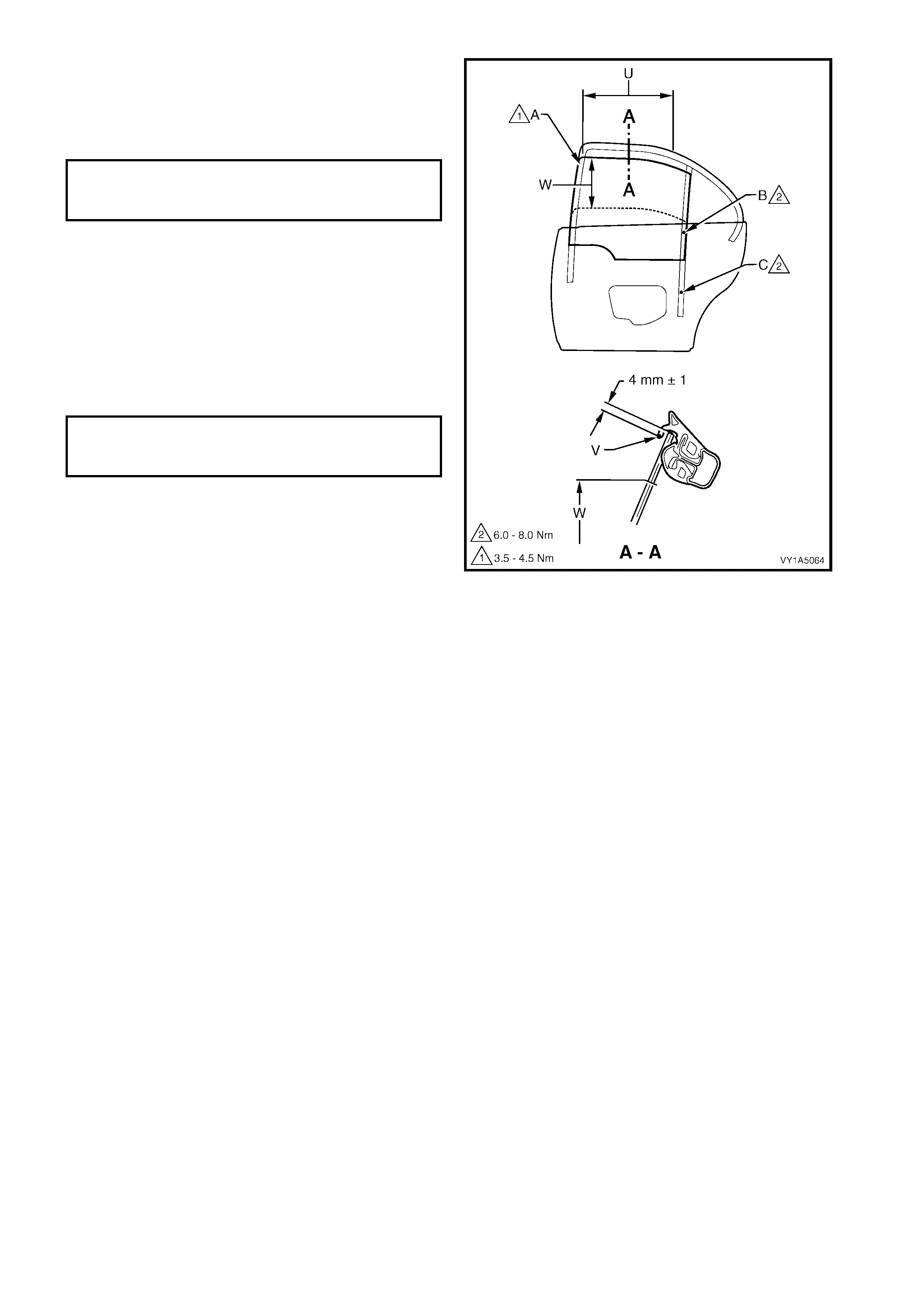
4. Check the cranking load of the window assembly
in area W. If the window assembly binds, or the
motor load sounds excessive, re-adjust the
window assembly by correcting the channel
assembly attaching, points (B) and (C).
5. Check the upper edge of the window to ensure
that the lip of the wind ow run c hannel, p oint (V), is
parallel over the area (U).
6. Check the insertion depth of the window is 4 mm
above the l ip of the wind ow run chann el, point ( V),
over the area (U).
7. Tighten the attachment screw for end stop, point
(A) to the specified torque.
Figure 1A5-119
REAR WINDOW CHANNEL
ASSEMBLY RETAINING REAR SCREW
TORQUE SPECIFICATION 6.0 – 8.0 Nm
REAR WINDOW STOP
ASSEMBLY ADJUSTING SCREW
TORQUE SPECIFICATION 3.5 – 4.5 Nm
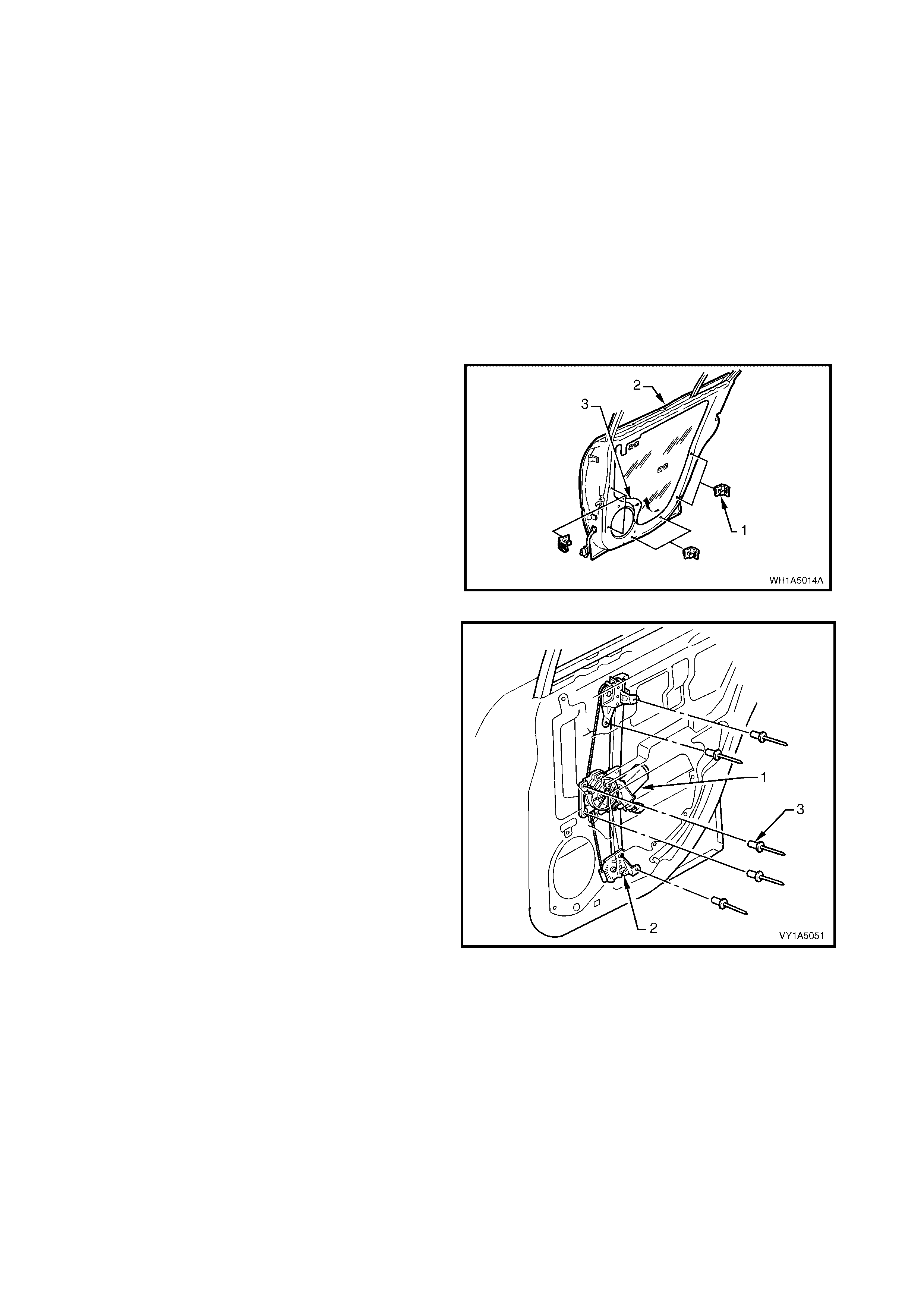
3.13 RE AR DOOR WINDOW REGULATOR AS SEMBLY
LT Section No. – 11-810
1. Remove the rear window regulator handle assembly (where fitted), refer to 3.4 REAR WINDOW
REGULATOR HANDLE ASSEMBLY.
2. Remove the rear door inside handle assembly, refer to 3.5 REAR DOOR INSIDE HANDLE ASSEMBLY
(REMOTE).
3. Remove the rear door trim panel assembly, refer to 3.6 REAR DOOR TRIM PA NEL ASSEMBLY.
4. Remove the rear window inner filler assembly, refer to 3.9 - REAR WINDOW INNER FILLER ASSEMBLY.
5. Remove the rear door belt outer reveal moulding assembly, refer to 3.10 REAR DOOR BELT OUTER
REVEAL MOULDING ASSEMBLY.
6. Remove the rear door guide channel assembly, refer to 3.11 REAR DOOR CHANNEL ASSEMBLY.
7. Remove the rear door window assembly, refer to 3.12 REAR DOOR. WINDOW ASSEMBLY
REMOVE
1. If required remove the six rear door brackets (1)
from the panel (2) by levering out the centre.
2. Carefully peel off the rear door water shield (3)
from the rear door inner panel (2).
Figure 1A5-120
3. Disc onnect the regu lator ass embl y, wiring harness
connector (1) from the regulator assembly (2),
(where fitted).
4. Drill out the five rivets (3) securing the regulator
assembly (2) to the d oor panel, (usin g a 5mm drill
bit).
5. Remove window regulator through the aperture in
the door inner panel.
Figure 1A5-121
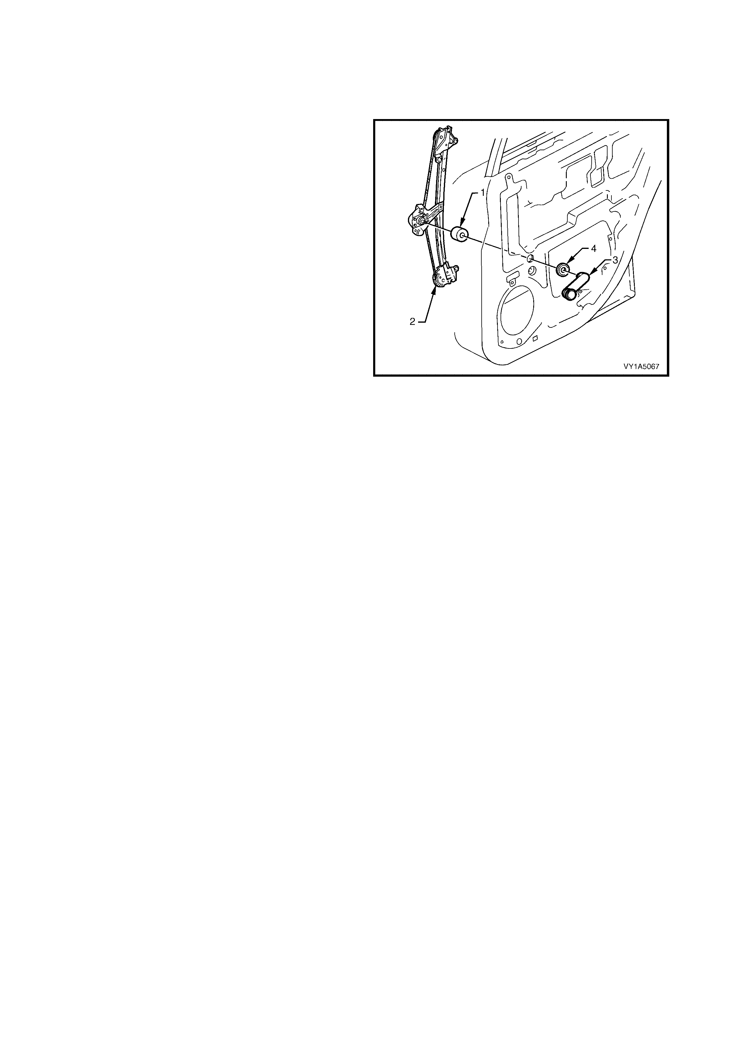
REINST ALL
Reinstallation of the rear door regulator assembly is
the reverse of the removal, refer Figure 1A5-121,
noting the following:
1. Install the rear do or window reg ulator handle s haft
seal (1) (where fitted), to regulator assembly (2),
before installing into the door panel.
2. Locate the regulator assembly inside the door,
aligning the attaching holes in the regulator with
the corresponding holes in the door inner panel,
refer Figure 1A5-121.
3. Attach the regulator assembly to the door inner
panel using 5mm rivets.
NOTE: The attaching holes may have been enlarged
in the door panel when the rivets were drilled out on
removal of the regulator assembly. Washers may be
inserted when ref itt ing the regu lator as sembl y
4. Adjust the rear door window and regulator as per
the following adjustment procedure, refer
3.12 REAR DOOR WINDOW ASSEMBLY.
5. Ensure all frictional surfaces of the window
regulator assembly and associated parts are
adequately lubricated with a Lithium base grease
NLGI No. 1 (with 9 % zinc oxide) or equivalent.
6. Ensure the rear door seal is correctly fitted to the
door panel, refer Figure 1A5-120.
NOTE: The rear door ins id e ha nd le as sembl y (remote)
(3) and rear door window washer (4) are to be
installed after trim panel assembly, (where fitted).
Figure 1A5-122
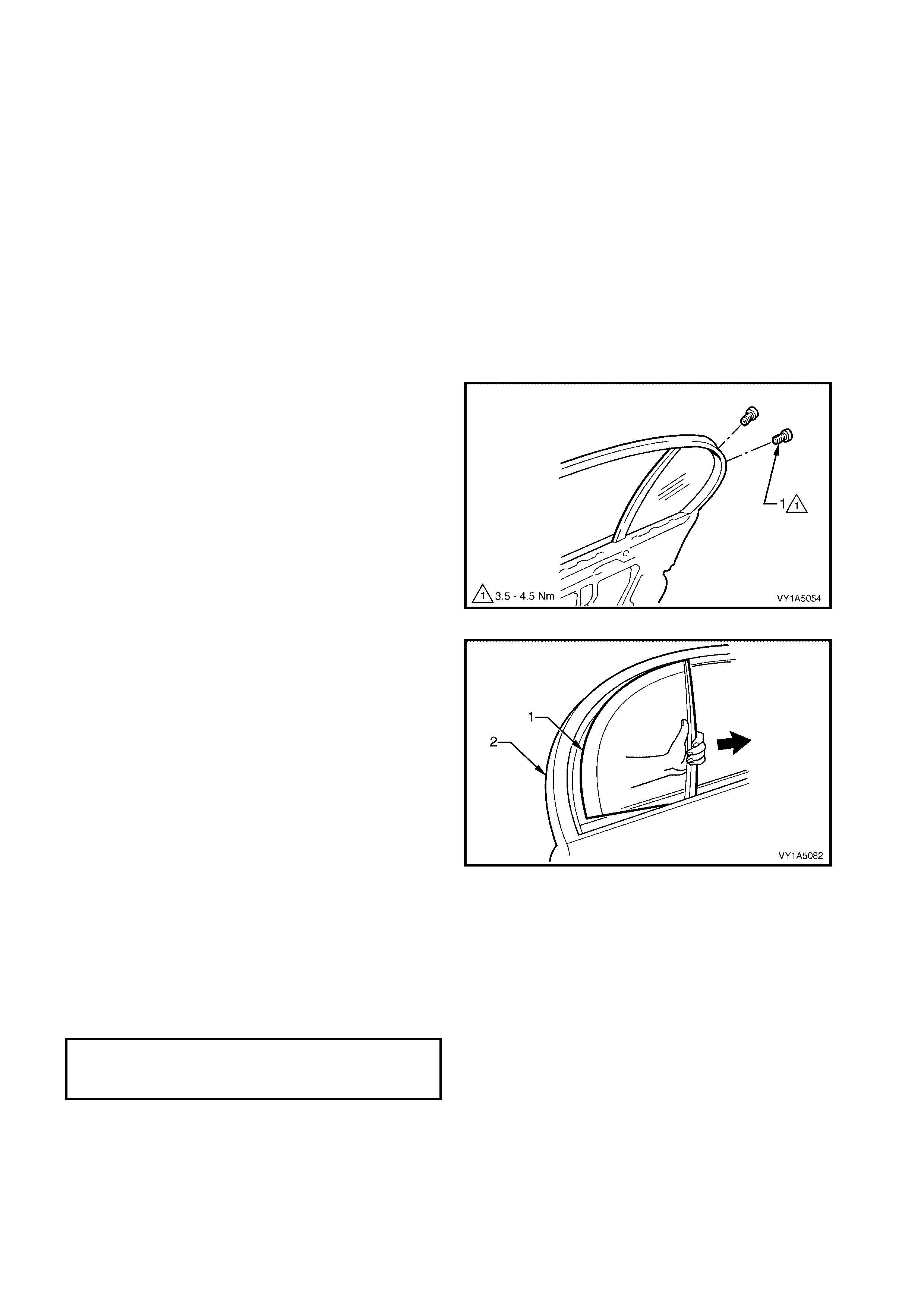
3.14 REAR DOOR STATIONARY WINDOW ASSEMBLY
LT Section No. – 11-020
1. Remove the rear window regulator handle assembly (where fitted), refer to 3.4 REAR WINDOW
REGULATOR HANDLE ASSEMBLY.
2. Remove the rear door inside handle assembly, refer to 3.5 REAR DOOR INSIDE HANDLE ASSEMBLY
(REMOTE).
3. Remove the rear door trim panel assembly, refer to 3.6 REAR DOOR TRIM PA NEL ASSEMBLY.
4. Remove the rear door window inner filler assembly, refer to 3.9 REAR WINDOW INNER FILLER
ASSEMBLY.
5. Remove the rear door belt outer reveal moulding assembly, refer to 3.10 REAR DOOR BELT OUTER
REVEAL MOULDING ASSEMBLY.
6. Remove the rear door guide channel assembly, refer to 3.11 CHANNEL A SSEMBLY - REAR DOOR.
7. Remove the rear door window assembly, refer to 3.12 REAR DOOR WINDOW ASSEMBLY.
REMOVE
1. For Sedan only, roll back a section of the rear door
weatherstrip around the rear door window
assembly stationary area, to gain access to the
two fixing screws (1) securing the window
assembly.
2. Remove both screws.
Figure 1A5-123
3. Pry the inner section of the rear door window
assem bly stationar y rubber ( 1), from its position i n
the door upper frame (2) and slide the window
assembly toward the front of vehicle.
4. Remove the stationary window assembly.
Figure 1A5-124
REINST ALL
Reinstal lation of rear door stationar y window ass em bly
is reverse of removal procedure, refer Figure 1A5-124
noting the following:
Tighten all retaining screws to the correct torque
specification.
REAR DOOR STATIONARY WINDOW
ASSEMBLY RETAINING
SCREWS TORQUE SPECIFICATION 3.5 – 4.5 Nm

3.15 REAR DOOR WEAT HERSTRIP ASSEMBLIES
LT Section No. – 11-775
Figure 1A5-125
Legend
1. Rear Door Window Upper Weatherstrip Assembly
2. Rear Upper Weatherstrip Assembly
3. Double-Sided Tape
install Weatherstrip Corner Aligning Locating Marks On
Door Frame, Then Proceed In Direction Of Arrows.
REMOVE
1. W ith the window glass lowered, progr essivel y peel
the rear do or wind o w upper weather str ip ass embly
(1) away from around the door window frame,
refer Figure 1A5-125.
2. Pull the weather strip up a nd out, at t he rear of th e
door.
3. Progressively remove the rear upper weatherstrip
assembly (2) from the lip on the door upper frame.
4. Carefully remove the weatherstrip from the belt
line, allowing the retainer clips to pull out of the
weatherstrip and remain in the door panel.
5. Remove th e r et ai ner c l ips f r om the door pa nel with
a clip removal tool and refit them back into the
weatherstrip ready for reinstallation.
REINST ALL
1. Reinstallation is the reverse of the removal, refer
Figure 1A5-125, noting the following:
2. When installing t he weatherstrips, start installation
process from the top corner of the door frame as
shown.
3. Reapply double-sided tape (3) if required, refer
Figure 1A5-125 .
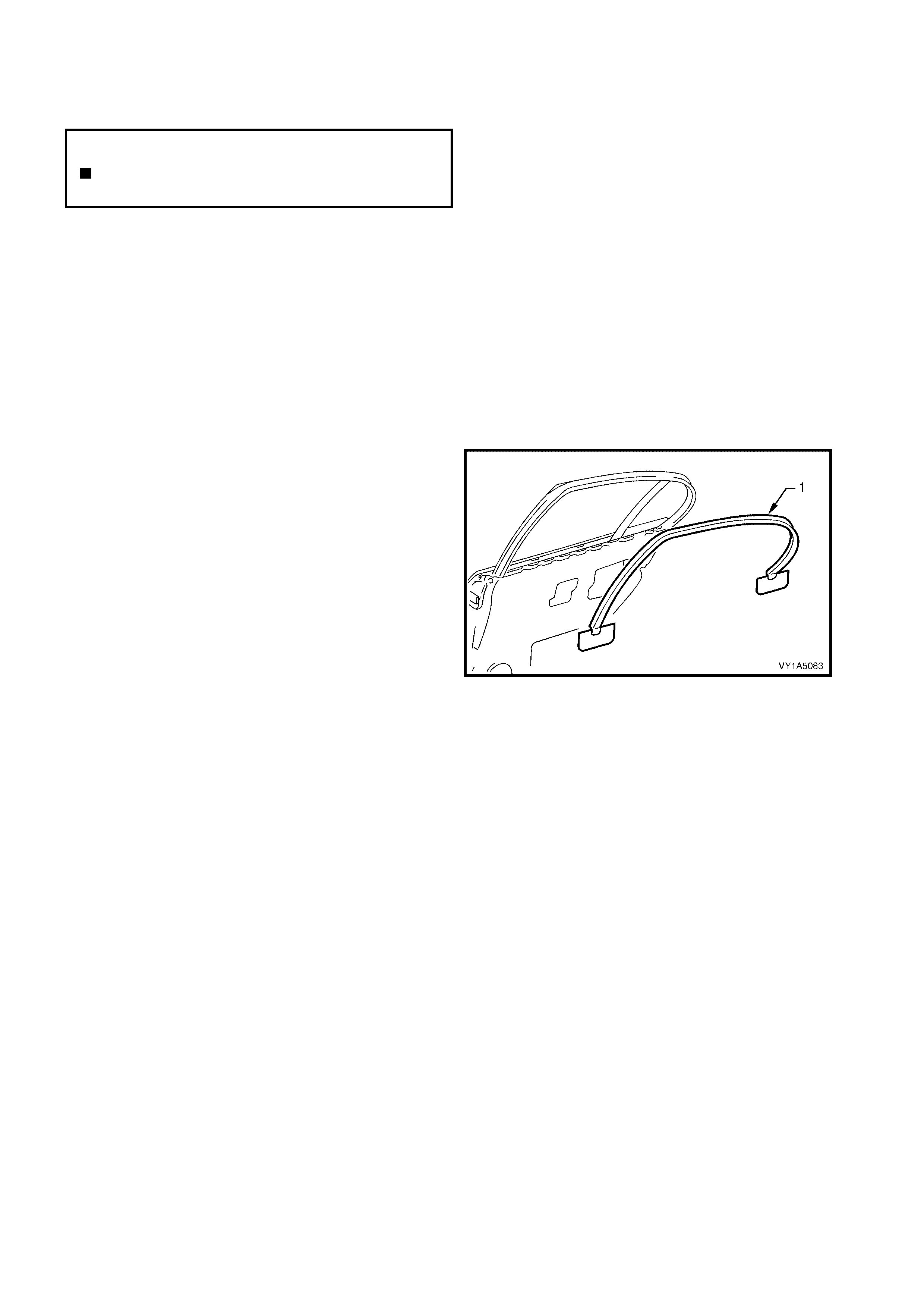
3.16 REAR DOOR WINDOW FRAME UPPER SCALP MOULDING
LT Section No. – 11-775
IMPORTANT: Prior to commencing any of the following procedures, lower the window assembly, to its down
position.
1. Remove the rear window regulator handle assembly (where fitted), refer to 3.4 REAR WINDOW
REGULATOR HANDLE ASSEMBLY.
2. Remove the rear door inside handle assembly, refer to 3.5 REAR DOOR INSIDE HANDLE ASSEMBLY
(REMOTE).
3. Remove the rear door trim panel assembly, refer to 3.6 REAR DOOR TRIM PA NEL ASSEMBLY.
4. Partially remove the rear door weatherstrip assembly and remove the rear door upper weatherstrip
assembly, refer to 3.15 REAR DOOR WEATHERS TRIP ASSEMBLY.
REMOVE
1. With the aid of a k nife, progressively peel the rear
door window frame upper scalp moulding (1),
away from around the door window frame,
separating the adhesive from the frame.
2. Clean the surface of the door frame with Prepsol
or equivalent as required.
NOTE: The rear door window frame upper scalp
moulding, will be damaged during this operation and
must be replaced.
Figure 1A5-126
REINST ALL
Reinstallation is the reverse of removal, refer Figure
1A5-126, noting the following.
1. Use a new self adhesive rear door window frame
upper scalp moulding.
N
O
TE: The
f
ollowing component WILL RE
Q
UIRE
REPLACEMENT when performing this operation.
Moulding assembly - rear side door window
frame upper scalp.

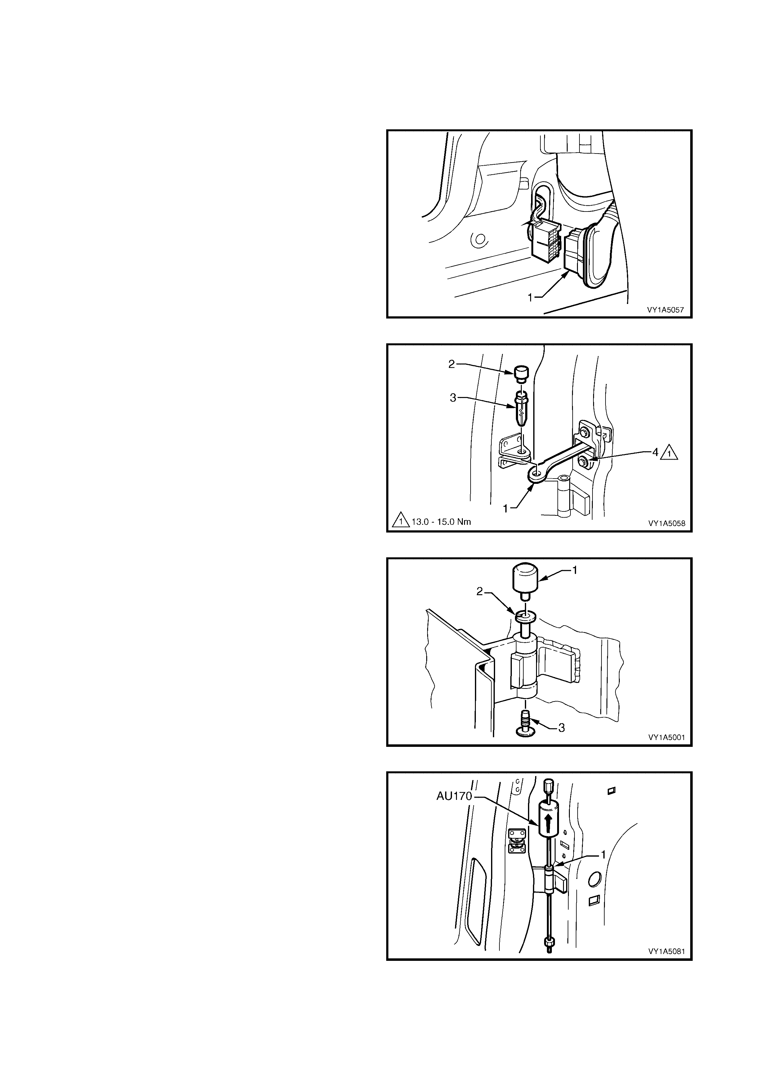
3.18 REAR DOOR ASSEMBLY
LT Section No. – 12-460
REMOVE
1. Remove the grommet and door wiring harness
connector plug assembly (1).
2. Depress the tabs and gently pull on the wiring
harness to withdraw the connector from the body.
3. Disconnect the connector.
Figure 1A5-127
3. Disconnect the rear door c heck as sembly (1) from
the vehicle, by removing the rear door check link
brack et c over (2) a nd t hen the r e ar door chec k link
pin (3).
NOTE 1: If required, remove the two screws (4)
attaching the check-link assembly to the door to allow
access to the hinge pins.
NOTE 2: Ensure the door cannot swing freely causing
damage.
Figure 1A5-128
4. Remove the rear hinge pin cap (1) and the rear
hinge plug (3) from the rear hinge pin (2) on the
upper and lower hinges.
5. Have an assistant support the door or support the
base of the door on a wooden block and a trolley
jack.
Figure 1A5-129
6. Using Tool No. AU170, drive the lower and then
the upper hinge pivot sleeves (1) from the hinges.
7. Remove the door assembly.
Figure 1A5-130

DISASSEMBLE
As required remove the following components, refer to the appropriate Sections:
1. Rear window regulator handle assembly (where fitted), refer to 3.4 REAR WINDOW REGULATOR
HANDLE ASSEMBLY.
2. Rear door inside handle assembly, refer to 3.5 REAR DOOR INSIDE HANDLE ASSEMBLY (REMOTE).
3. Rear door trim panel assembly, refer to 3.6 REAR DOOR TRIM PANEL ASSEMBLY.
4. Rear door lock assembly , refer to 3.7 REAR DOOR LOCK ASSEMBLY.
5. Rear door outside handle assembly, refer to 3.8 REAR DOOR OUTSIDE HANDLE ASSEMBLY.
6. Rear door window inner filler assembly, refer to 3.9 REAR WINDOW INNER FILLER ASSEMBLY.
7. Rear door belt outer reveal moulding assembly, refer to 3.10 REAR DOOR BELT OUTER REVEAL
MOULDING ASSEMBLY.
8. Rear door guide channel assembly, refer to 3.11 CHANNEL ASSEMBLY - REAR DOOR.
9. Rear door window assembly, refer to 3.12 REAR DOOR WINDOW ASSEMBLY.
10. Rear door window regulator assembly, refer to 3.13 REAR DOOR WINDOW REGULA TOR ASSEMBLY.
11. Rear door stationary window assembly, refer to 3.14 REAR DOOR STATIONARY WINDOW ASSEMBLY.
12. Rear door weatherstrip assembly, refer to 3.15 REAR DOOR WEATHERSTRIP ASSEMBLY.
13. Rear door moulding assembly, refer to 3.16 REAR DOOR MOULDING ASSEMBLY.
14. Rear door wiring harness assembly, refer to 3.17 REAR DOOR WIRING HARNESS ASSEMBLY.
15. Rear door opening weatherstrip assembly, refer to 3.19 REAR DOOR OPENING WEATHERSTRIP
ASSEMBLY.
16. Rear door body side moulding, for Sedan refer to Section 1A9, 2.11 BODY SIDE MOULDINGS, and for
Wagon refer to Section 1A9, 3.12 BODY SIDE MOULDINGS.
Remove – Radio Rear Door Speaker
1. Remove the three screws (1) securing the radio
rear door speaker (2) to the door inner panel,
disconnect and remove speaker assembly.
NOTE: For Service and Diagnosis refer Section 12D
ENTERTAINMENT SYSTEM.
Reinstall – Radio Rear Door Speaker
Reinstallation of the rear door speaker, is the reverse
of the removal, refer Figure 1A5-131, noting the
following.
1. Tighten all retaining screws to the correct torque
specification.
Figure 1A5-131
Remove – Rear Door Deadener
1. Prise the rear door deadener (1), from the rear
door panel inner.
Reinstall – Rear Door Deadener
Reinstal lat ion of the r ear do or dea den er , is the re vers e
of the removal.
NOTE: If reusing the s ame part, appl y a sm all amount
of contact adhesive.
Figure 1A5-132
RADIO REAR DOOR
SPEAKER RETAINING SCREWS
TORQUE SPECIFICATION 1.0 – 3.0 Nm
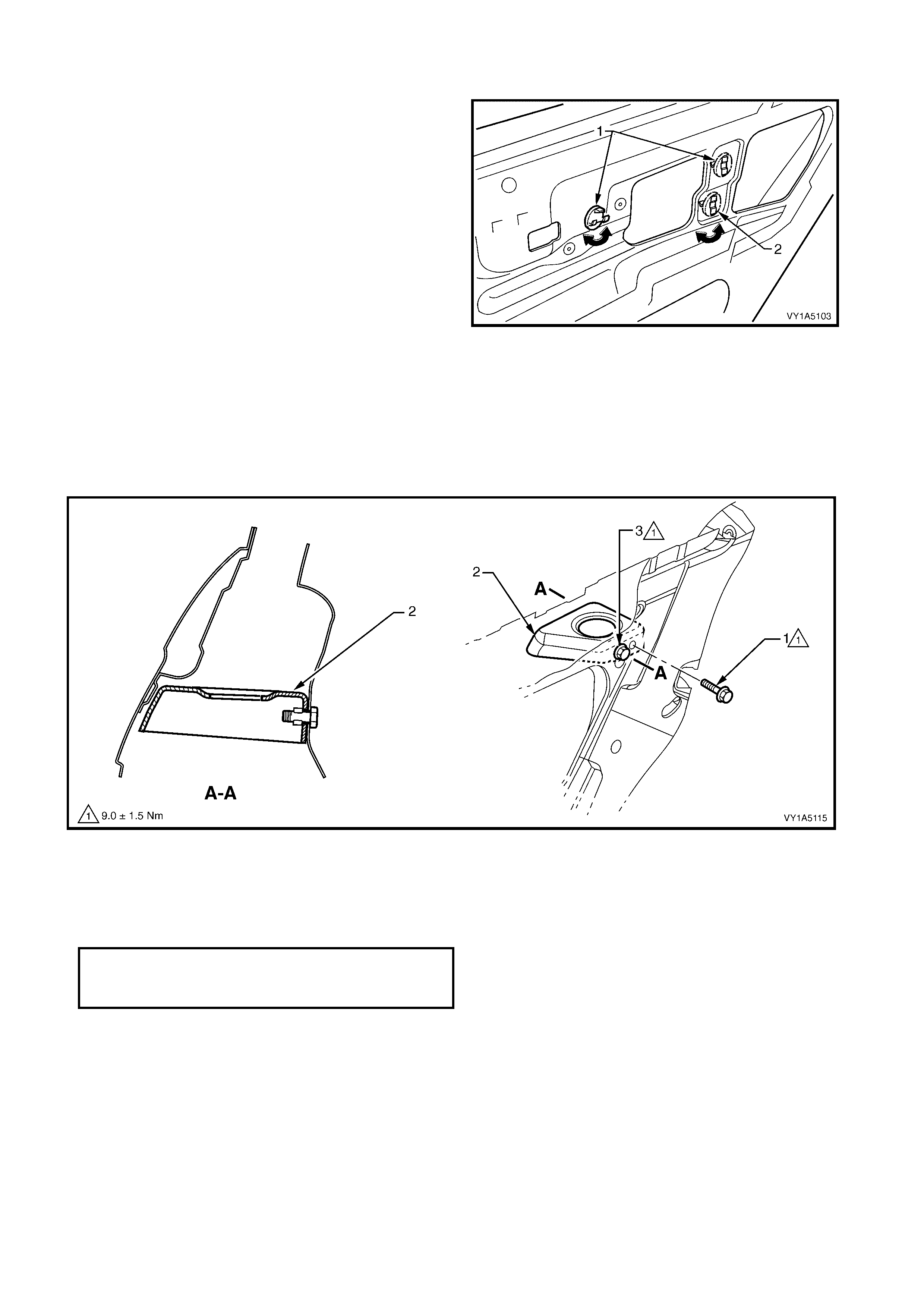
Remove – Rear Door Locking Rods Clip
1.
Remove the two rear door inside handle rod clip
(1), by turning thru 90° and then rem ovi ng one from
the inside and one from the outside of the rear
door panel inner.
2.
Remove the rear door lock rod clip, bell crank rod
(2), b y t urning thr u 90°and then removi ng from the
inside of the rear door panel inner.
Reinstall – Rear Door Locking Rods Clip
Reinstallation of the rear door inside handle rod clip,
and the rear door lock rod clip, bell crank rod, is the
reverse of the removal.
Figure 1A5-133
Remove – Rear Door Inner Panel Reinforcement
1.
Remove the screw (1) attaching the rear door inner panel reinforcement (2) to the door assembly, refer to
Figure 1A5-134 .
2.
Loosen the screw (3) and slide the reinforcement down withdrawing the screw from the key-hole slot into
the door cavity.
3.
Remove the reinforcement from the door cavity.
Figure 1A5-134
Reinstall – Rear Door Inn er Pan el Reinf orc ement
Reinstallation of the rear door inner panel reinforcement is the reverse of the removal noting the following.
1.
Tighten the screws to the correct torque specification.
REAR DOOR INNER PANEL
REINFORCEMENT RETAINING SCREW
TORQUE SPECIFICATION 9.0 ± 1.5 Nm

REINSTALL
IMPORTANT: If using a new door panel assembly it
must be prepared to maintain original manufacturers
specifications, this includes the application of joint
sealer, hand putty and cavity wax. Refer to the
MY2003 V Y & V2 Series Ser vice Manua l Su pplement,
Series Body Structure Repair Manual for
specifications.
Reinstal lation of the rear door assem bly is the rever se
of the removal operation, noting the following:
1. Appl y a Lithium bas e grease NLGI No. 1 (with 9 %
zinc oxide) or equivalent, to the hinge pivot
sleeves prior to installation.
2. Use Tool No. AU303 (2), to install the hinge pivot
sleeves (1).
3. Check the fit of the door and adjust as required,
referring below.
NOTE: Make allowances in the adjustment if the trim
and hardwar e are not insta l led.
4. Tighten all retaining screws to the correct torque
specification.
5. Reinstall the trim and hardware as required.
6. Connect and install the door wiring harness
connector to the body wiring harness and refit the
grommet.
7. Refit the hinge pivot sleeve dust caps, refer
Figure 1A5-129.
Figure 1A5-135
ADJUST
Attention should be given to uniform margins and alignm ent between the door and surrounding parts when door
adjustments are being carried out.
Uniform margins and a lignm ent of front and re ar doors in relation to th e body op ening can be ac hieved b y setting
the appropri ate door hinge. Refer to MY200 3 VY & V 2 Series Servic e Man ual Suppl em ent, Bod y Structure Repair
Manual for specifications.
Adjust hinges in conjunction with adjustment to lock striker to achieve an acceptable door closing effort with
correct door lock to striker engagement, refer to 3.2 STRIKER REAR DOOR LOCK.
Use Tool No AU184 to set door hinges by slightly
bending the door hinge flaps (1) noting the following:
1. Take care when adjusting the doors not to
misalign the hinge pins. Any significant
misalignment will cause the pins to shear when
the door is opened or closed.
2. Excessive bending or levering of the window
frame will cause damage.
3. Final adjustment must take place when all the
door components and seals are installed.
IMPORTANT: Adjust doors with striker plates
removed. Striker plates should only be fitted once
satisf actory alignm ent is achieve d. They m ust NOT be
used to pull the door into the correct position.
Figure 1A5-136
RADIO REAR DOOR
SPEAKER RETAINING SCREW
TORQUE SPECIFICATION 1.0 – 3.0 Nm
CHECK ASSEMBLY TO DOOR
RETAINING SCREW
TORQUE SPECIFICATION 13.0 – 15.0
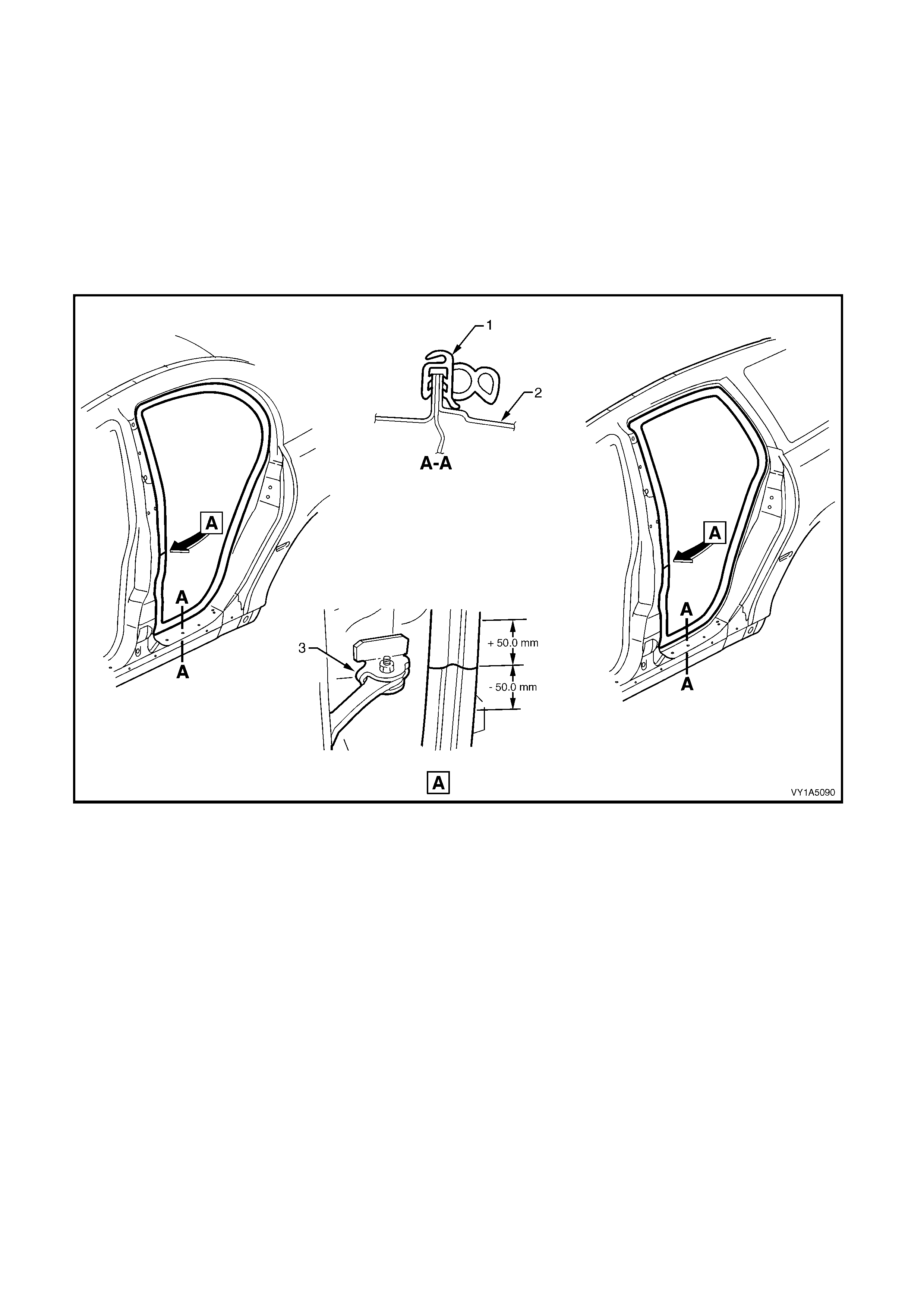
3.19 REAR DOOR OPENING WEATHERSTRIP ASSEMBLY
LT Section No. – 11-600
As required, remove the following components:
1
Moulding - Body Lock Pillar Garnish, Panel - Body Lock Pillar Lower Trim (Wagon only), Panel - Body
Lock Pillar Upper Trim (Utility only), Panel - Centre Pillar Lower Trim, Panel - Centre Pillar
Upper Trim, Retainer Assembly - Front & Rear Side Door Opening Floor Carpet, refer to
Section 1A8 HEADLINING & INTERIOR TRIM.
REMOVE
1. Gently prise the weatherstrip from the door
opening.
Figure 1A5-137
Legend
1. Rear Door Weatherstri p Assembly 2. Door Opening Frame 3. Rear Hinge Check Assembly
REINSTALL
Reinstallation of the rear door weatherstrip assembly,
is the reverse of the removal procedure, noting the
following:
1. Align identification mark on weatherstrip with the
check assembly - rear hinge (3) in the door frame
opening (2) ± 50 mm as shown, refer to Figure
1A5-.
NOTE: Allow crowding of the weatherstrip in all
corners of the door opening frame. Ensure
weatherstrip does not short cut corners and foul door
the trim.
2. Ens ur e weat her str ip lip sits over tr im panels.
3. Tighten all trim attaching screws to the
correct torque specification, refer to
Section 1A8, HEADLINING AND INTERIOR
TRIM.

4 TORQUE WRENCH SPECIFICATIONS
FRONT DOOR
Striker assembly retaining screw..............................................................................8.0 – 18.0 Nm
Front door locking rod ferrule retaining screw..........................................................1.0 – 3.0 Nm
Front door inside handle assembly (remote) retaining screw...................................1.0 – 3.0 Nm
Front door trim panel assembly retaining screw.......................................................1.0 – 3.0 Nm
Radio front door speaker grille retaining screw........................................................0.5 – 0.7 Nm
Front door map pocket assembly retaining screws..................................................0.5 – 0.7 Nm
Armrest insert assembly retaining nut .....................................................................0.7 – 0.9 Nm
Front door inside handle assembly (pull) retaining screws ......................................1.3 – 1.7 Nm
Front side pull bracket retaining screws...................................................................1.0 – 3.0 Nm
Front door lock assembly retaining screws ..............................................................3.0 – 5.0 Nm
Front door lock actuator assembly retaining screws ................................................3.0 – 5.0 Nm
Front door handle assembly outside retaining nut....................................................3.0 – 5.0 Nm
Front window regulator channel assembly retaining screws....................................6.0 – 8.0 Nm
Front side window belt outer reveal moulding assembly retaining screw ................1.0 – 3.0 Nm
Front door glass guide assembly retaining screws ..................................................1.0 – 3.0 Nm
Outside rear view mirror assembly retaining screws................................................2.5 – 3.5 Nm
Radio front door speaker assembly retaining screws...............................................1.0 – 3.0 Nm
Front door glass guide channel retaining screws.....................................................6.0 – 8.0 Nm
Front window stop assembly adjusting sc rew ..........................................................2.0 Nm
Front window channel assembly retaining rear screw..............................................6.0 – 8.0 Nm
Front channel guide assembly retaining centre screw.............................................6.0 – 8.0 Nm
Front channel guide assembly retaining lower screw...............................................6.0 – 8.0 Nm
Front window channel assembly retaining front screw.............................................6.0 – 8.0 Nm
Front window down stop adjusting nut .....................................................................6.0 – 8.0 Nm
Regulator assembly front window down stop adjusting nut......................................6.0 – 8.0 Nm
Front window stop assembly adjusting screw ..........................................................3.5 – 4.5 Nm
Check assembly to pillar retaining screw .................................................................5.0 – 7.0 Nm
Check assembly to door retaining nuts ....................................................................13.0 – 15.0 Nm
REAR DOOR
Striker assembly retaining screw.................................................................................8.0 – 18.0 Nm
Rear door locking rod ferrule retaining screw..............................................................1.0 – 3.0 Nm
Rear door inside handle assembly (remote) retaining screw......................................1.0 – 3.0 Nm
Rear door trim panel assembly retaining screw ..........................................................1.0 – 3.0 Nm
Armrest insert assembly retaining nut .........................................................................0.7 – 0.9 Nm
Rear door inside handle assembly (pull) retaining screws..........................................1.3 – 1.7 Nm
Rear door lock assembly retaining screws..................................................................3.0 – 5.0 Nm
Rear door lock actuator assembly retaining screws....................................................3.0 – 5.0 Nm
Door outside handle assembly retaining nut ...............................................................3.0 – 5.0 Nm
Rear window belt outer reveal moulding assembly retaining screw ...........................1.0 – 3.0 Nm
Rear window rear upper channel assembly retaining screws.....................................3.5 – 4.5 Nm
Rear window rear lower channel assembly retaining screws......................................6.0 – 14.0 Nm
Rear door stationary window assembly retaining screws............................................3.5 – 4.5 Nm
Rear window stop assembly adjusting front screw......................................................2.0 Nm
Rear window channel assembly retaining rear screw .................................................6.0 – 8.0 Nm
Rear window stop assembly adjusting screw..............................................................3.5 – 4.5 Nm
Rear Door Inner Panel Reinforcement........................................................................9.0 ± 1.5 Nm
Radio rear door speaker retaining screws...................................................................1.0 – 3.0 Nm
Check assembly to door retaining screw.....................................................................13.0 – 15.0 Nm
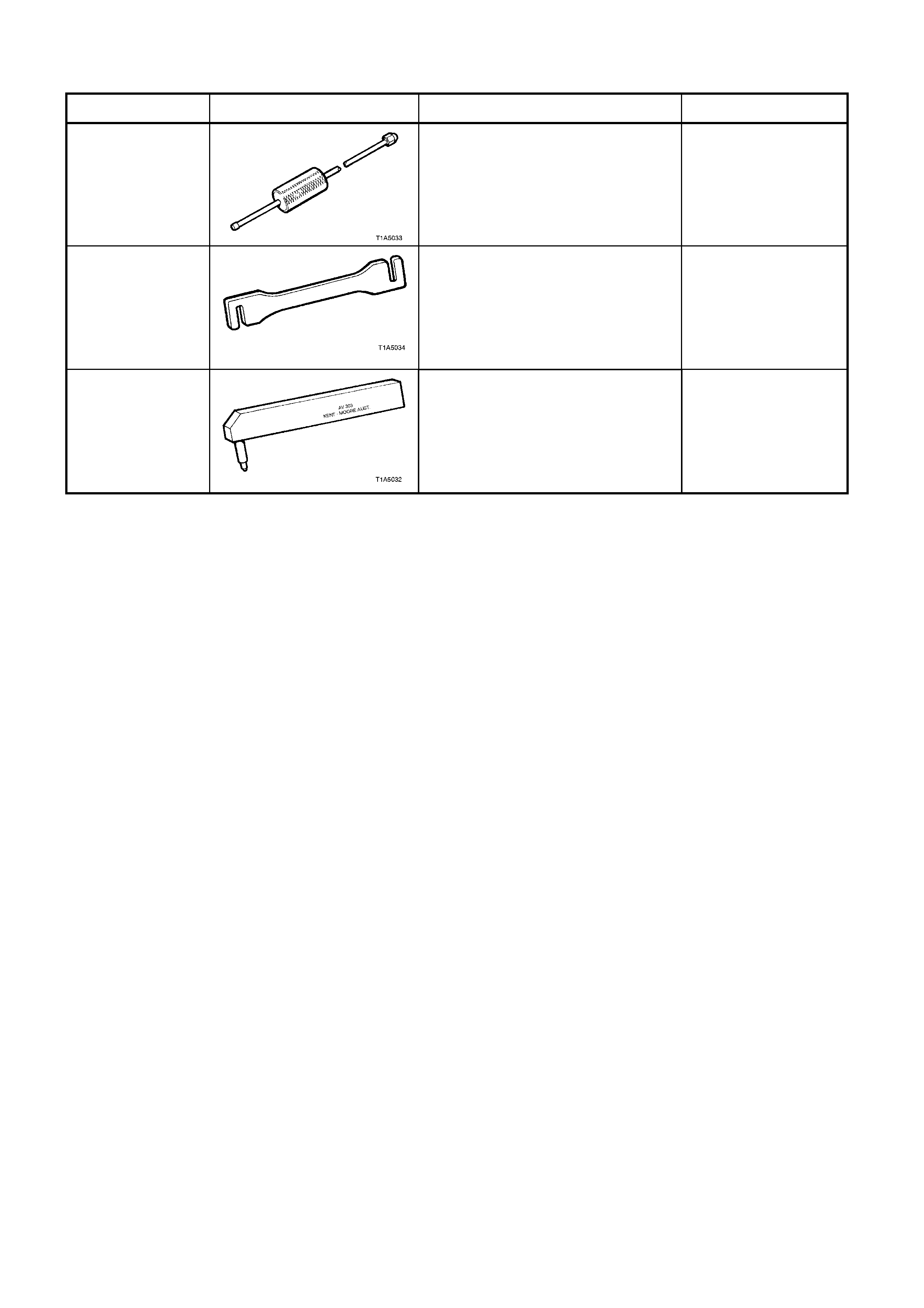
5 SPECIAL TOOLS
TOOL NUMBER ILLUSTRATION DESCRIPTION CLASSIFICATION
AU170 DOOR HINGE PIN REMOVAL
TOOL
Used for removing door hinge pivot
sleeves
Available
AU184
DOOR HINGE SETTING TOOL
Used to adjust door alignment Desirable
AU303
DOOR HINGE SLEEVE
INSTALLER
Used to install door hinge pivot
sleeves
Available