
SECTION 1A6 - STATIONARY WINDOWS
IMPORTANT
Before perfo rming any Service O perat ion or o th er pro cedu re describ ed in th is Section, refer to Section
00 CAUTIONS AND NOTES for correct workshop practices with regard to safety and/or property
damage.
CONTENTS
1. GENERAL DESCRIPTION
2. SERVICE NOTES
2.1 MINOR WATER LEAK CORRECTION -
BONDED WINDOWS
3. SERVICE OPERATIONS - FRONT
3.1 WINDSHIELD ASSEMBLY
REMOVE
REINSTALL - SHORT METHOD
REINSTALL - LONG METHOD
4. SERVICE OPERATIONS - SIDE
4.1 QUARTER WINDOW ASSEMBLY, WAGON
REMOVE
REINSTALL
4.2 QUARTER WINDOW ASSEMBLY, UTILITY
REMOVE
REINSTALL
4.3 QUARTER WINDOW ASSEMBLY, COUPE
REMOVE
REINSTALL
5. SERVICE OPERATIONS - REAR
5.1 REAR WINDOW ASSEMBLY,
SEDAN AND COUPE
REMOVE
REINSTALL - SHORT METHOD
REINSTALL - LONG METHOD
5.2 LIFTGATE WINDOW ASSEMBLY, WAGON
REMOVE
REINSTALL - SHORT METHOD
REINSTALL - LONG METHOD
5.3 REAR WINDOW ASSEMBLY, UTILITY
REMOVE
REINSTALL - SHORT METHOD
REINSTALL - LONG METHOD
6. TORQUE WRENCH SPECIFICATIONS
7. SPECIAL TOOLS
Techline
Techline

1. GENERAL DESCRIPTION
The windshield ass em bly, which is lam inated and f eatures a tinted upper band, is bonded to the vehicle body in the
window opening with urethane.
The rear window assembly for Sedan, Coupe, Utility and the liftgate window assembly for the Wagon, all have an
electrically heated demist facility, and are also bonded in the window openings with urethane.
The quarter window assembly for Coupe, Utility and Wagon utilise a self-adhesive foam weatherstrip to seal the
window to the window opening. Plastic nuts are used to secured the window to the vehicle.
Toughened safety glass is used for all the windows except the windshield assembly.
For replacement of urethane bonded windows, urethane service kits have been developed and must be used to
maintain original installation requirements. Windows installed with urethane require either partial or complete
removal of the urethane when replacing the window.
Two diff e rent ins tallation methods ar e us ed when replacing the windshield assembly, rear window assembly and the
liftgate window assem bly: a ‘short m ethod’ and a ‘long m ethod’. Partial r em oval of the ur ethane is ref erred to as the
‘short method’. Complete removal of the urethane is known as the ‘long method’.
The short method is to be used when after the window removal, the original urethane remaining on the window
opening flanges, c an serve as a bas e for the new window. This m ethod would be used in cases where replacem ent
of cracked windshields or removal of windows that are intact. The amount of urethane left in the window opening
can be controlled during window removal, leaving the maximum amount of original urethane intact on the body
opening flange.
The long method is to be used when after the window removal, the original urethane remaining on the window
opening f langes, c annot s erve as a base f or the r eplacement window. This method would be used in c ases needing
metal work and / or paint refinishing in the window opening, or in cases where the window has been previously
replaced using the short method. In such instances, the build up of urethane could position the window too high in
the body opening. In these cases, the original urethane must be completely removed and replaced with new
urethane following the long method window installation.
For service procedures related to the rear door fixed window, refer to Section 1A5, 3.14 REAR DOOR
STATIONARY WINDOW ASSEMBLY.
The windshield and Sedan and Coupe rear window become structural members of the vehicle once the urethane
adhesive cures, and aid in vehicle rigidity. The windshield also plays an important role in occupant protection by
supporting the pass enger airbag dur ing deployment. It is im perative that the procedures in this Section for replacing
bonded windows are followed, as incorrect installation may lead to injury or death.
2. SERVICE NOTES
CAUTION: Safety glasses and work gloves must be worn at all times when operating with glass.
IMPORTANT: Only use urethane adhesive such as Betaseal 15685 or equivalent for water leak correction on
bonded windows.
Skinning ( partial c uring) of the ur ethane commences af ter expos ur e to the atmospher e. At 23 degrees Cels ius and
50 percent relative humidity, skinning commences after 30 minutes. Complete curing of the urethane at this
temperature and humidity takes 72 hours.
Urethane service kits are available from most windshield agents. Manufacturer’s instructions should always be
followed.
Window assemblies should be installed in the window opening within 5 minutes of the application of urethane.
2.1 MINOR WATER LEAK CORRECTION -BONDED W INDOWS
LT Section No. – 11-020
1. Secure protective covering with masking tape
adjacent to the leak suspect area.
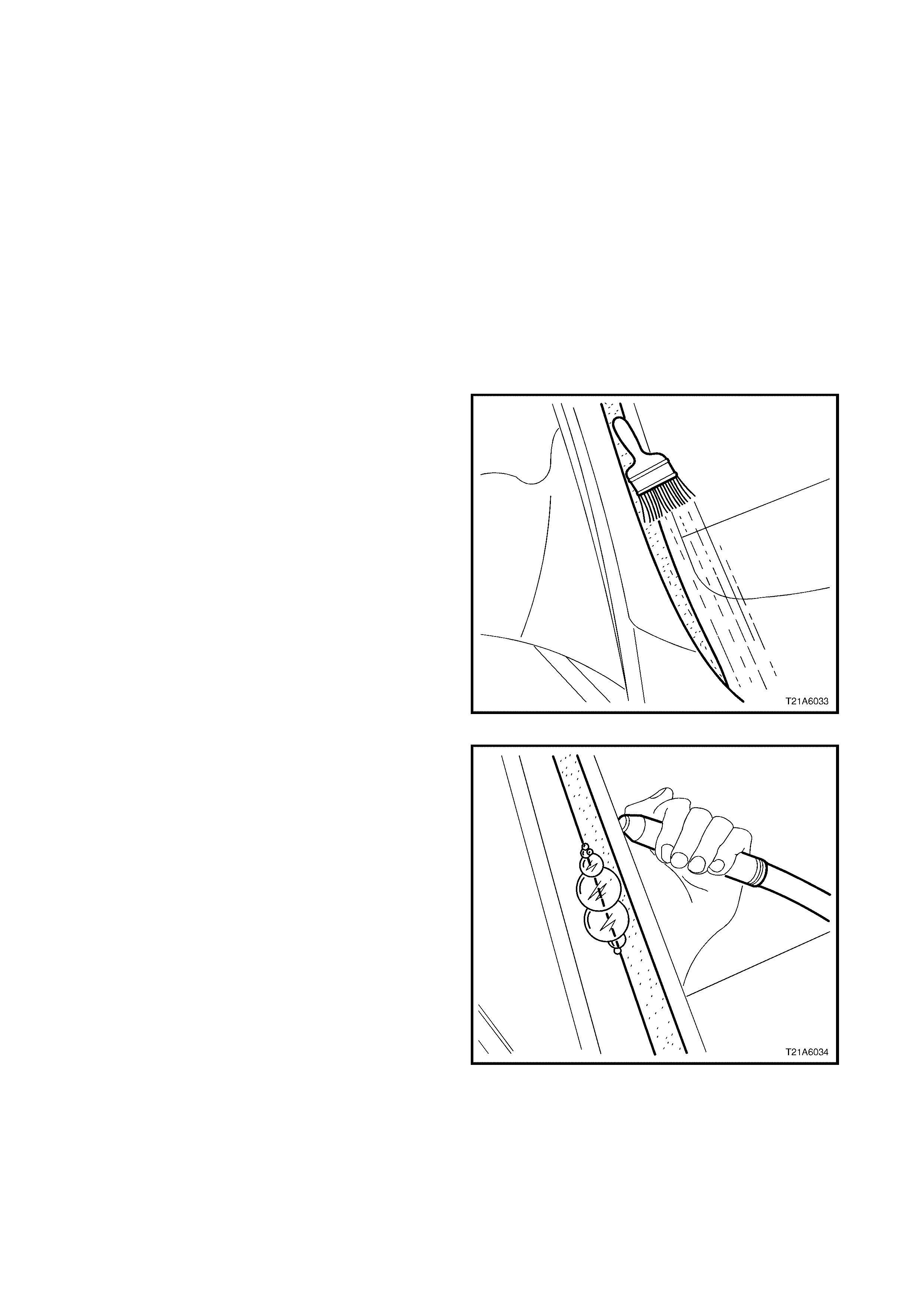
2. To determine the precise location of the water
leak, use the air and soap bubble leak test. The
soap and water solution can be applied with either
a spray applicator or brush.
Figure 1A6-1
3. Locate an air-hose nozzle on the inside of the
windshield or rear window assembly. Have an
assistant outside the vehicle and apply a soapy
water solution opposite the air s ource. As a low air
pressure (60 kPa) is applied, soap bubbles will
form on the outside of the window, indicating the
location of the leak.
4. If the suspec t leak ar ea is not obvious, com m ence
the testing acros s the top and down the sides until
the leak location has been determined.
5. Using a spatula, work fresh urethane such as
Betaseal 15685 or equivalent, in and around the
leak area.
NOTE: It is only necessary to remove dus t and foreign
matter, as water activates the curing process of
urethane.
6. Leak test the repair , using the air/ soap bubble leak
test or a non-pressurised water leak test.
Remove the mask ing tape and protective covers, then
clean the window assembly and adjacent paint and
trim surfaces.
Figure 1A6-2
3. SERVICE OPERATIONS - FRONT
CAUTION 1: Safety glasses and work gloves must be worn at all times when operating with glass.
CAUTION 2: Care must be taken during any operation involving the windshield assembly removal or
installation, not to exert any load on the windshield. Failure to observe this may result in damage to the
window.
IMPORTANT: Only use urethane adhesive such as Betaseal 15685 or equivalent for windshield installation. The
windshield plays an important r ole in occ upant pr otection by supporting the pass enger air bag during deployment. It
is imperative that the procedures in this Section for replacing bonded windows are followed, as incorrect
installation may lead to injury or death.
3.1 WINDSHIELD ASSEMBLY
LT Section No. – 11-020
The windshield ass embly removal pr ocedur e is the s ame for both the s hort and long ins tallation methods , with one
exception. If the short method installation is to be used, care must be taken during the windshield removal to
ensure that an even sur f ac e of the or iginal remaining urethane ex is ts in the body opening. This is required to serve
as a base for the new urethane bead and the replacement windshield.
To prevent damage and to m inim ise clean up of the paint f inish and the trim , m ask -up and place protective covers
over parts adjacent to the windshield.
If required, remove the following components:
1. Windshield wiper arm assembly, refer to Section 12N, 2.3 WIPER WASHERS AND HORN.
2. Plenum cover assembly, refer to Section 12N, 2.5 WIPER WASHERS AND HORN.
3. Instrument panel end cap covers, and the windshield defroster grille assembly, refer to
Section 1A3 INSTRUMENT PANEL AND CONSOLE.
4. W indshield side garnish, f or Sedan refer to Section 1A8, 2.5 WINDSHIELD SIDE GARNISH, for W agon refer
to Section 1A8, 3.5 WINDSHIELD SIDE GARNISH, for Coupe refer to Section 1A8, 4.4 WINDSHIELD SIDE
GARNISH and for Utility refer to Section 1A8, 5.5 WINDSHIELD SIDE GARNISH.
5. Internal rear-view mirror, refer to Section 12H, 2.4 INTERNEL REAR-VIEW MIRROR.
REMOVE
IMPORTANT: Note that on all vehicles a keyless entry control m odule is installed between the left and right-hand
windshield defroster grille assembly, located on the instrument panel. While it is not necessary to remove the
module, care must be taken to avoid damage during windshield removal.
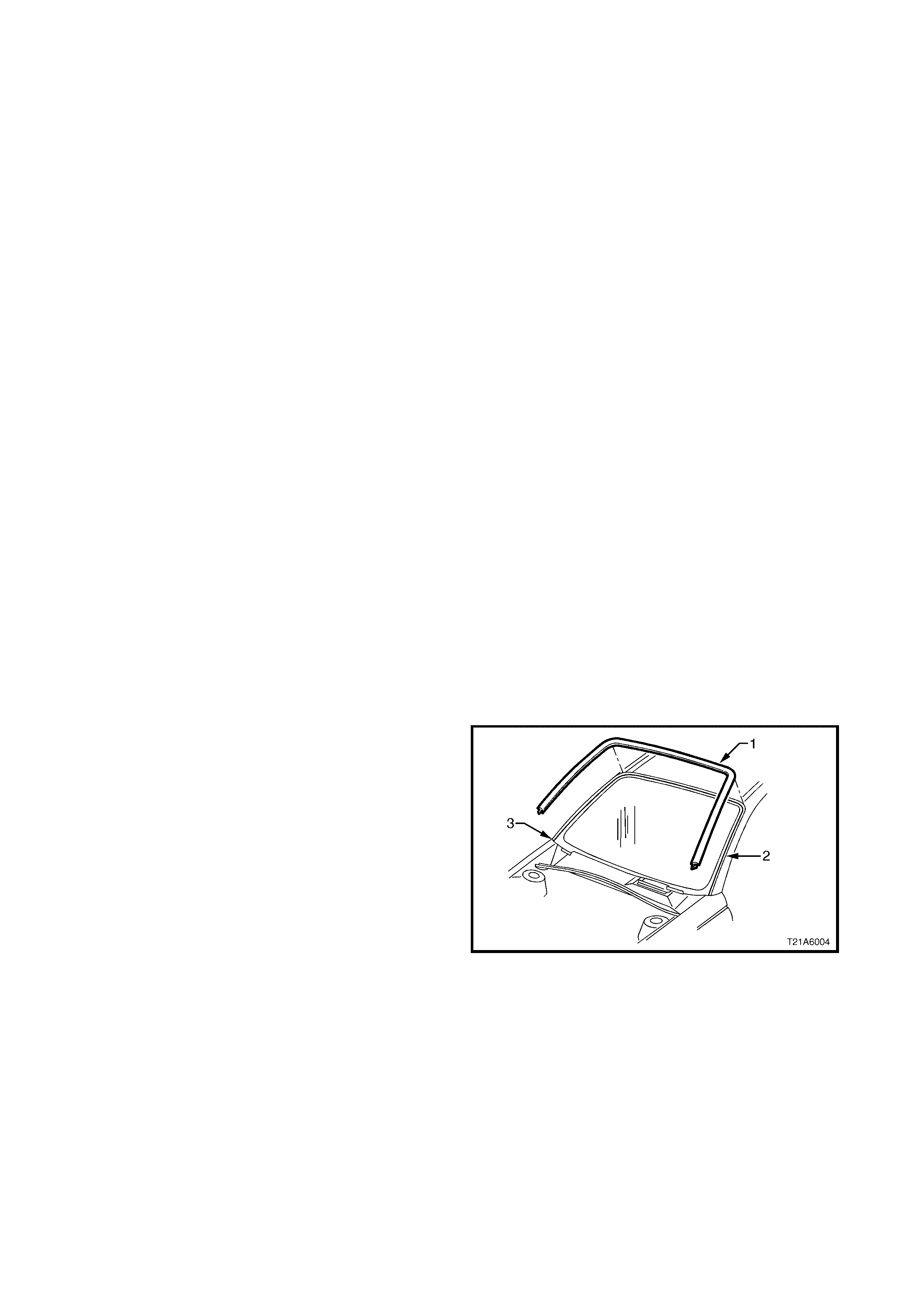
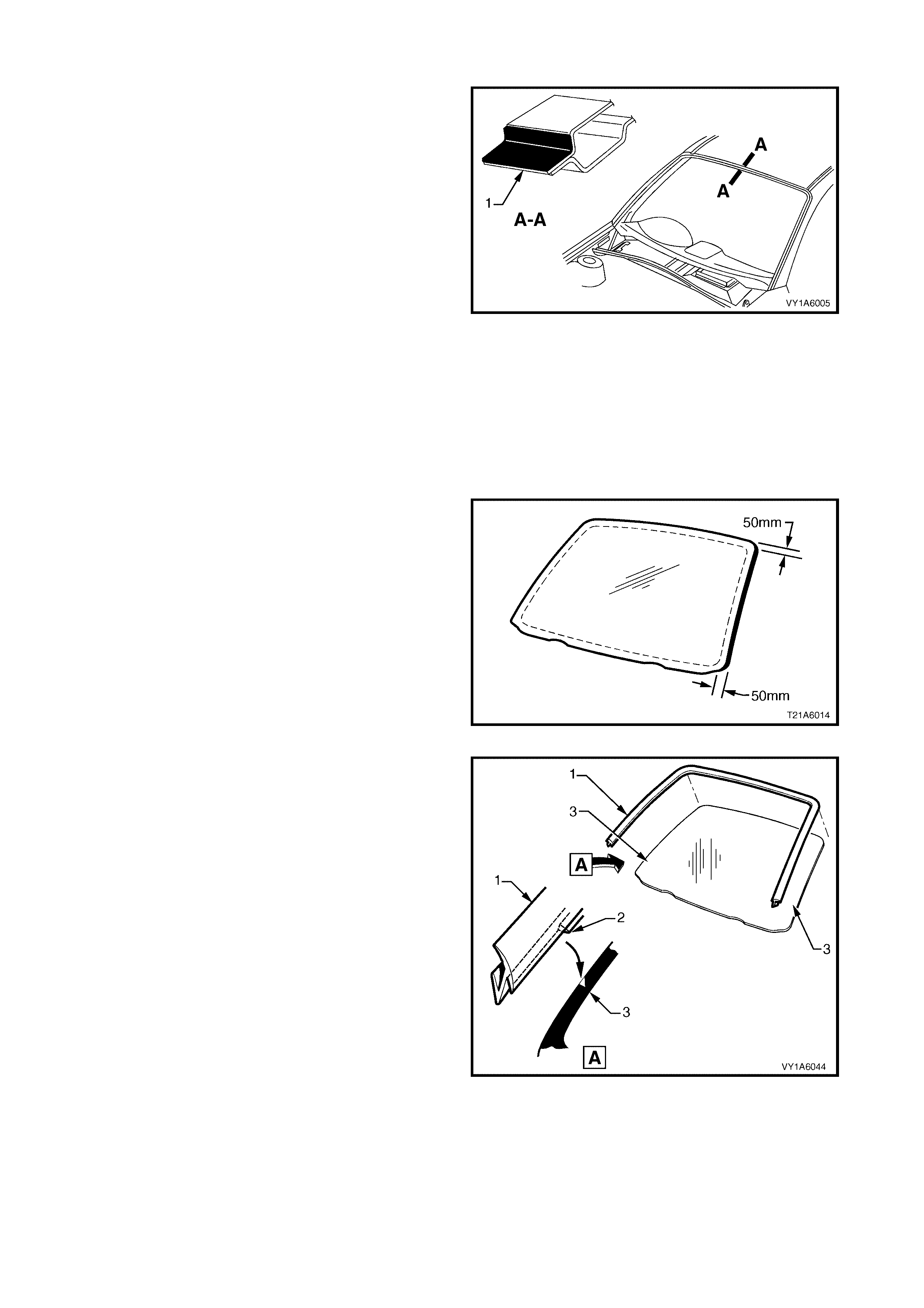
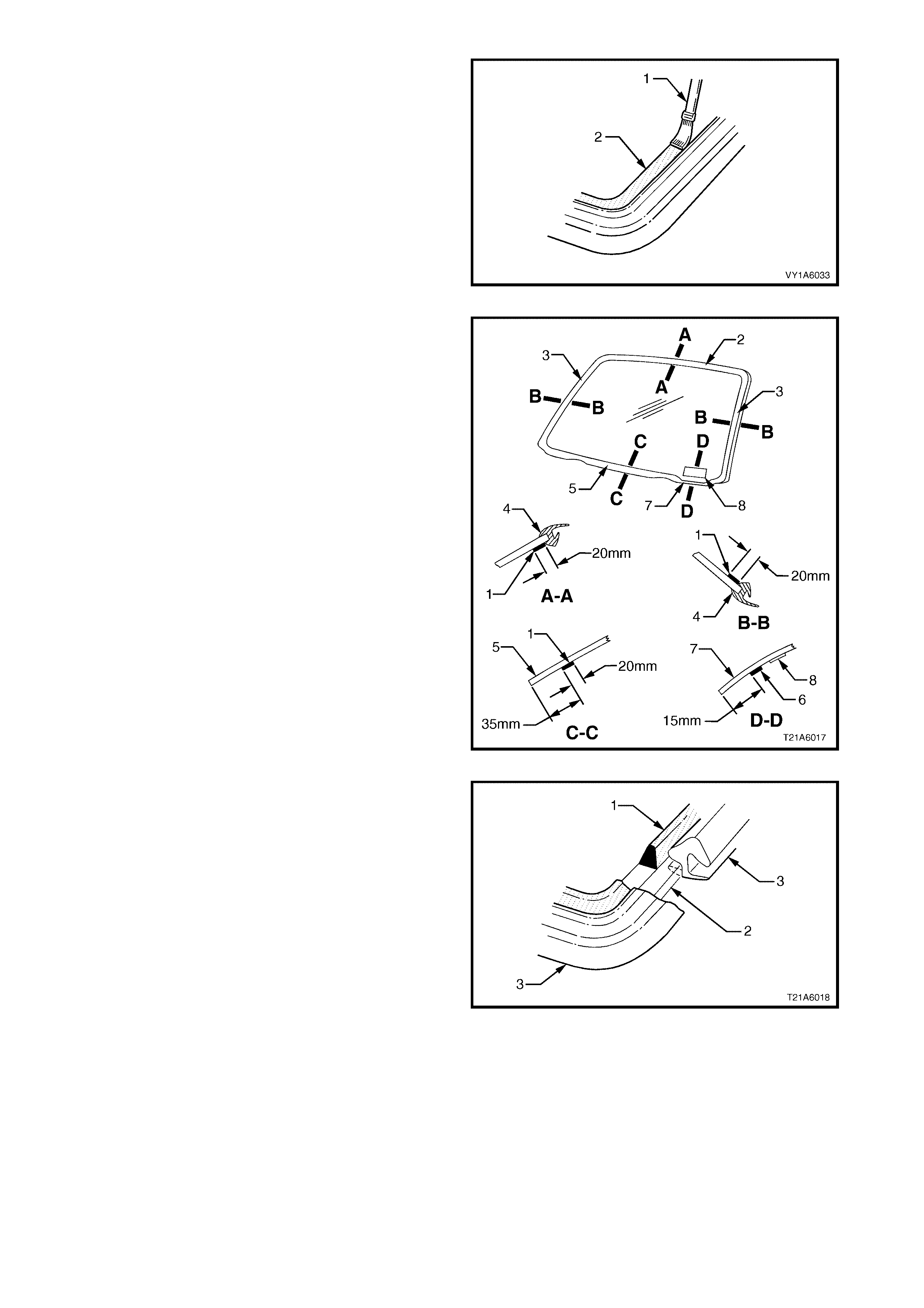
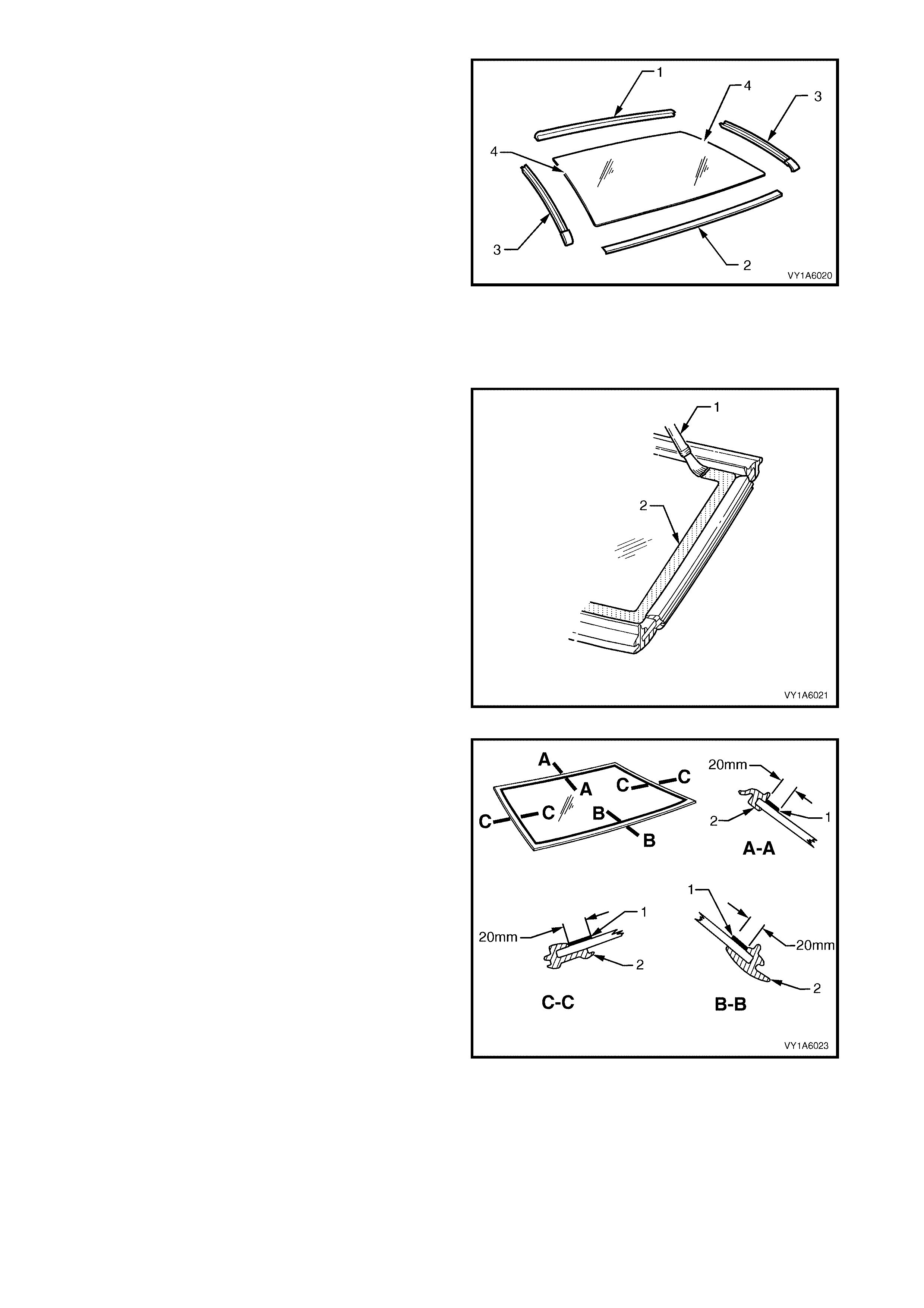
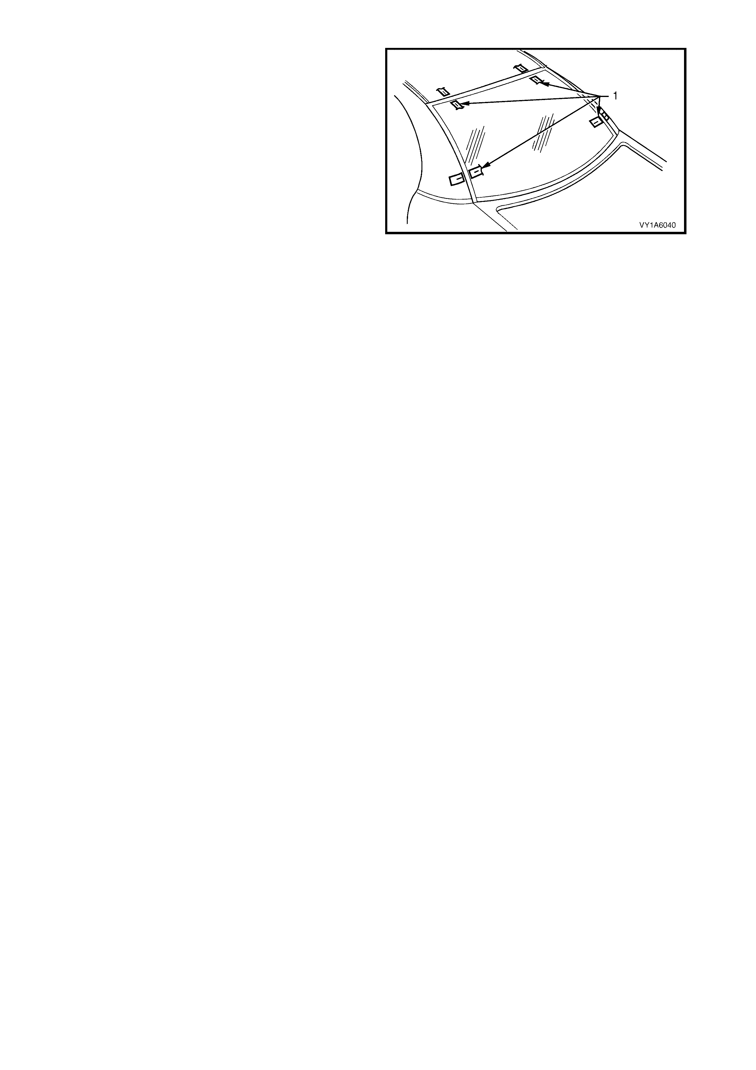
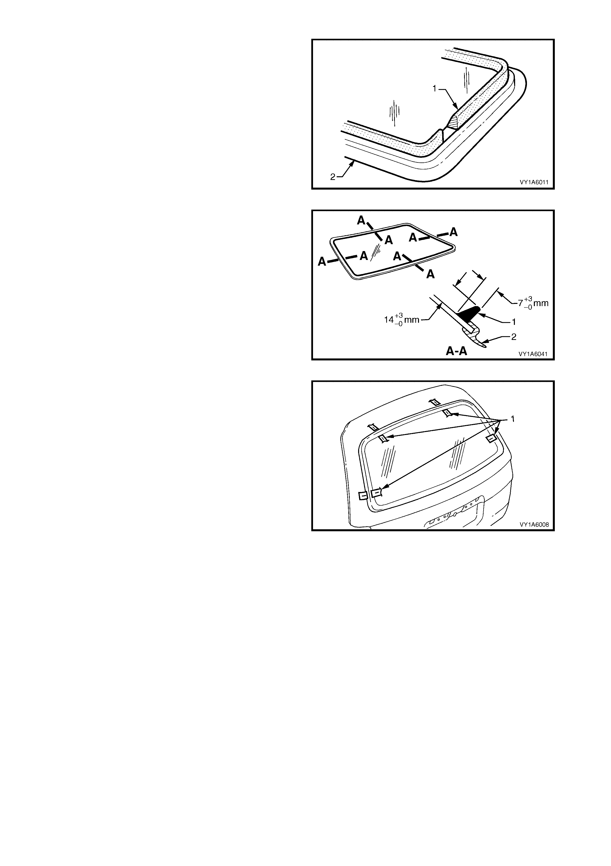
1. Remove the windshield reveal moulding assembly
(1) by pulling the moulding from the windshield to
the body join (2), starting at the lower corner (3)
and working around the windshield.
2. Should the windshield be broken, caref ully rem ove
all fragments of glass from the windshield opening.
3. Using special tool J36020 thread one end of the
piano wire through the urethane, starting at the
windshield upper corner, pulling the end of the wire
through with pliers
Figure 1A6-3
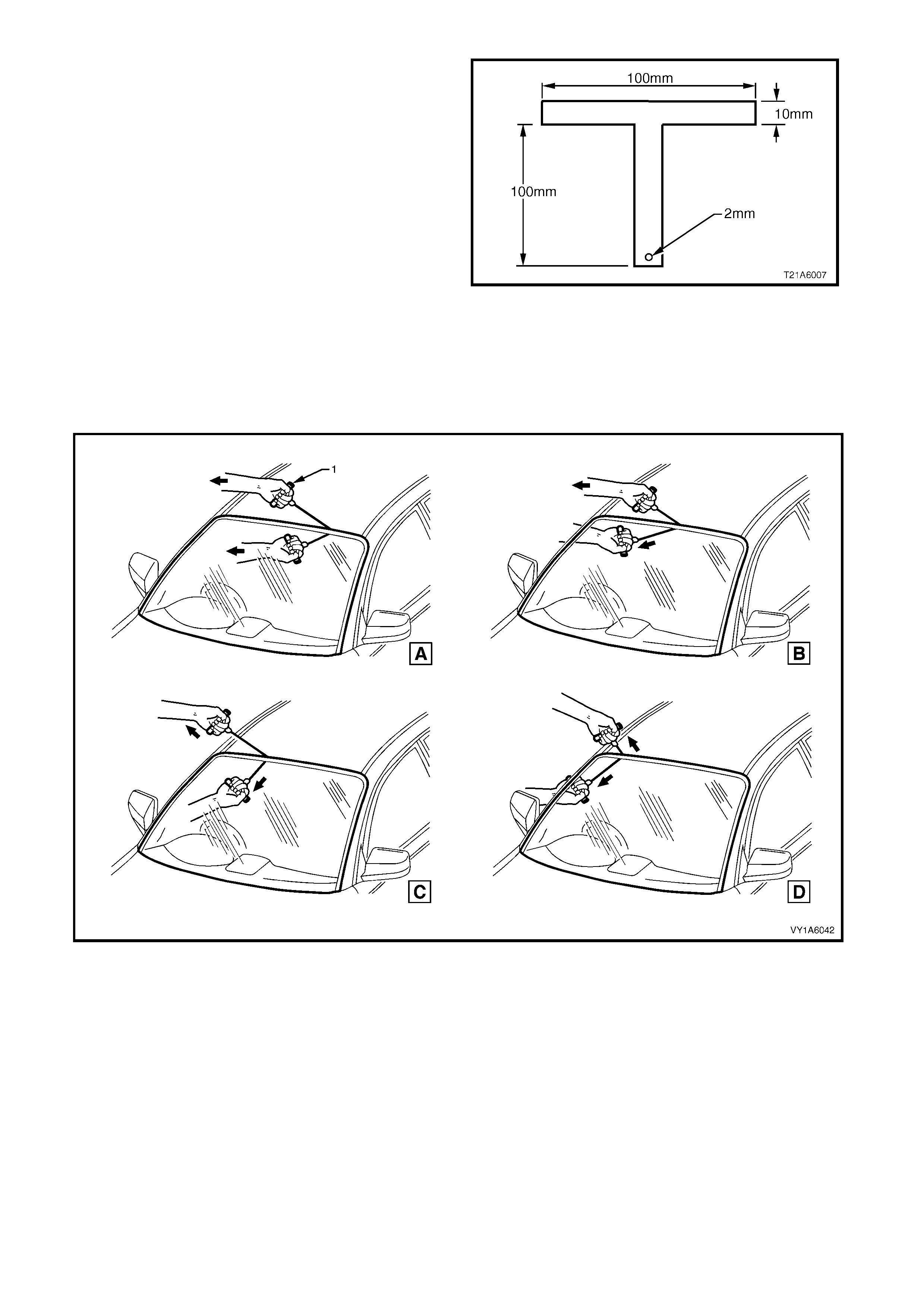
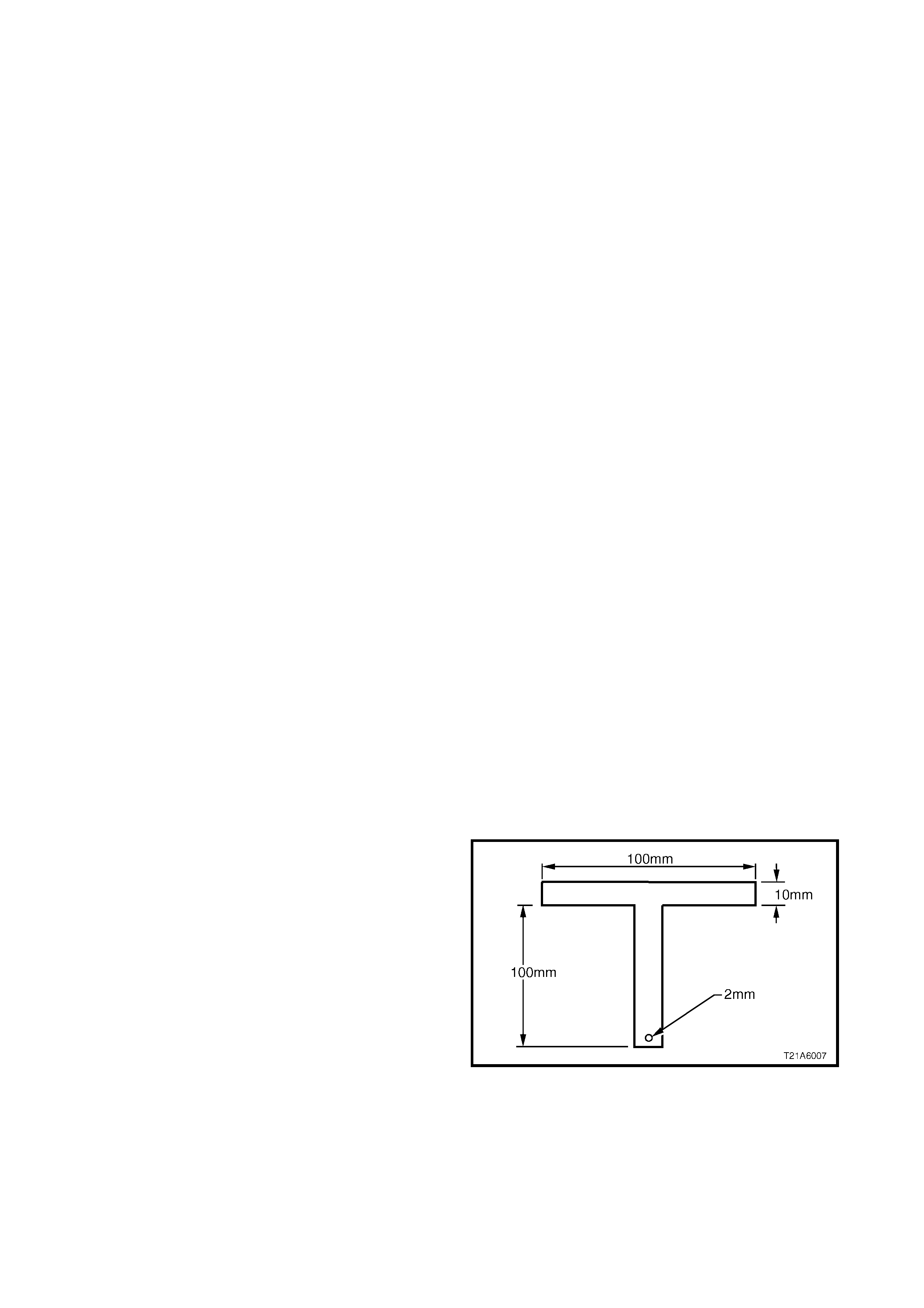
4. Alternately, manufacture two T-handles to the
dimensions shown. Secure at least 700mm of
piano wire to one handle, thread the other end of
the wire through the urethane as previously
described.
NOTE: Ens ure that the headlining and other trim item s
are not damaged.
5. Connect the wire to the remaining T-handle and
with the aid of an assistant, com menc e cutting the
urethane bead, keeping the outside T-handle (1)
parallel to the edge of the windshield using the full
length of the wire to prevent heat build up in the
wire.
NOTE: To minimise the damage to the interior of the
vehicle, the operator inside the vehicle should act as
an anchor point. Holding the T-handle as close as
possible to the windshield at all times, (especially along
the lower edge of the windshield), while the outside
operator pulls the wire up to the interior T-handle in a
‘walking’ motion, refer to Figure 1A6-5.
Figure 1A6-4
Figure 1A6-5
6. Carefully lift the windshield out of the body
opening. If there is evidence of the windshield
adhering to the urethane, cut the area again with
the piano wire.
7. With the exception of Coupe, remove the two
windshield locators f rom the windshield reinforcing
flange, refer Figure 1A6-6. Retain for reinstallation
of the windshield.
8. If the original windshield is to be installed again,
place the windshield on a clean protected surface
or a holding fixture.
NOTE 1: The use of suction cups will greatly assist any handling of the windshield.
NOTE 2: All traces of urethane must be removed from the windshield. It is not necessary to remove all traces of
the original urethane f rom the body opening, unless the ‘long m ethod’ of reinstallation is being used. However , any
original urethane remaining must be smooth and firm.
REINSTALL - SHORT METHOD
CAUTION: Ensure that door windows are partially lowered to eliminate pressure build up which can be
caused by slamming doors. A curing time of 24 hours is recommended, although the vehicle may be
driven after 5 hours providing it is driv en only on a smooth road at speeds not exceeding 80 km/h with the
door windows partially lowered.
Description
The short method installation involves the maximum amount of the original urethane being left intact on the body
opening to form a sound base for the replacement urethane and windshield.
This method is recommended when replacing a cracked or broken windshield, or a leak condition that cannot be
overcome by using minor water leak repair procedures, refer to 2.1 MINOR WATER LEA K CORRECTION.
If m aterial other than ur ethane has been used f or pr evious ser vicing of the windshield, the long m ethod installation
procedure (complete removal of adhesive) is mandatory to achieve an effective window to metal bond.
CAUTION 1: Care should be taken to ensure that the windshield does not strike the windshield opening.
Chipped edges can lead to subsequent breakage of the windshield.
CAUTION 2: Do not use petroleum based solvents to clean the window assembly - rear or the rear opening
flange, as the presence of the oil in the solvent will prevent the adhesion of the new urethane.
Preparation
1. Using a sharp scraper, carefully remove any
original urethane from around the windshield.
Clean the windshield to be installed with a suitable
oil free cleaning agent.
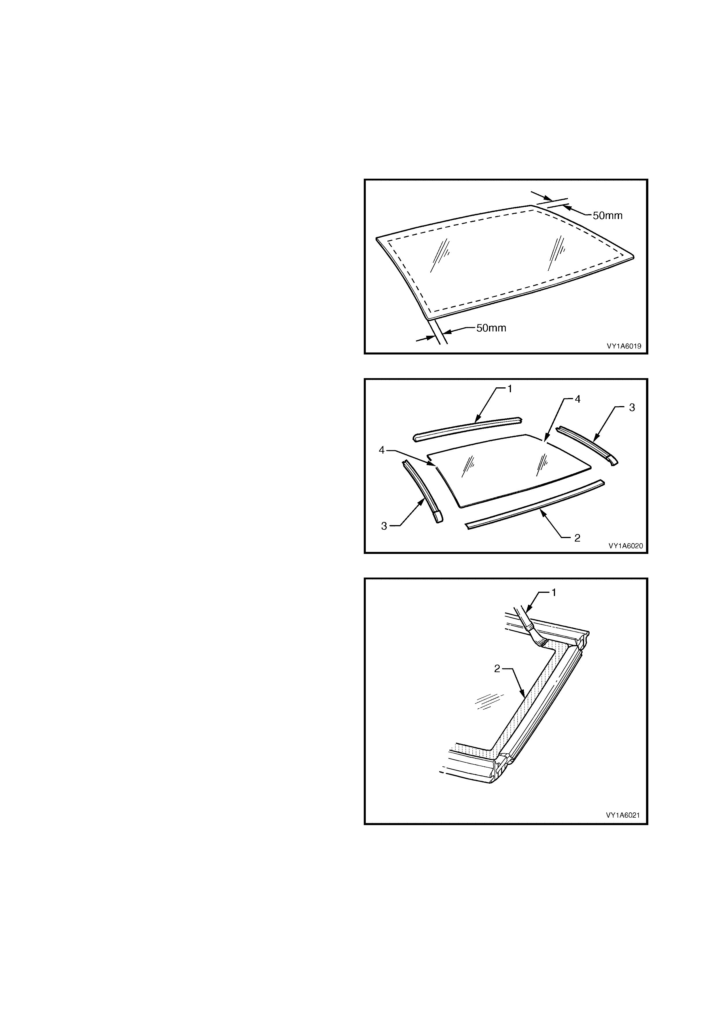
• Sedan, Wagon and Utility: Check for correct
alignment buy temporarily placing the
windshield in the body opening. Place the
windshield locator (1) between the lower
windshield edge (2) and the reinforcing flange
(3), to correctly locate the windshield.
• Coupe: Check for correct alignment buy
temporarily placing the windshield, on to the
extrusion ( 4) fitted to the reinf orcing flange (3) .
If required place windshield locator (1)
between the lower windshield edge (2) and the
extrusion to correctly locate the windshield in
the body opening.
2. Ensure the windshield is centralised in the body
opening left to right, by checking that the gaps
between the windshield and body opening are
even on both sides of the vehicle.
3. With masking tape (5), mark the outer top and side
of the windshield pillar and the roof.
NOTE: This procedure will assist in the alignment of
the windshield in the correct horizontal and vertical
plane during final windshield installation.
4. Remove and place the windshield face down on a
clean protected surface or fixture.
Figure 1A6-6
Reinstall
1. Thoroughly clean the inner surface and edges of
the windshield to which the urethane is to be
applied, using clean lint-free cloths and a suitable
oil free cleaning solvent.
CAUTION: Do not use petroleum b ased solven ts to
clean the windshield, or the body opening flange
as the presence of the oil in the solvent will
prevent the adhesion of the new urethane.
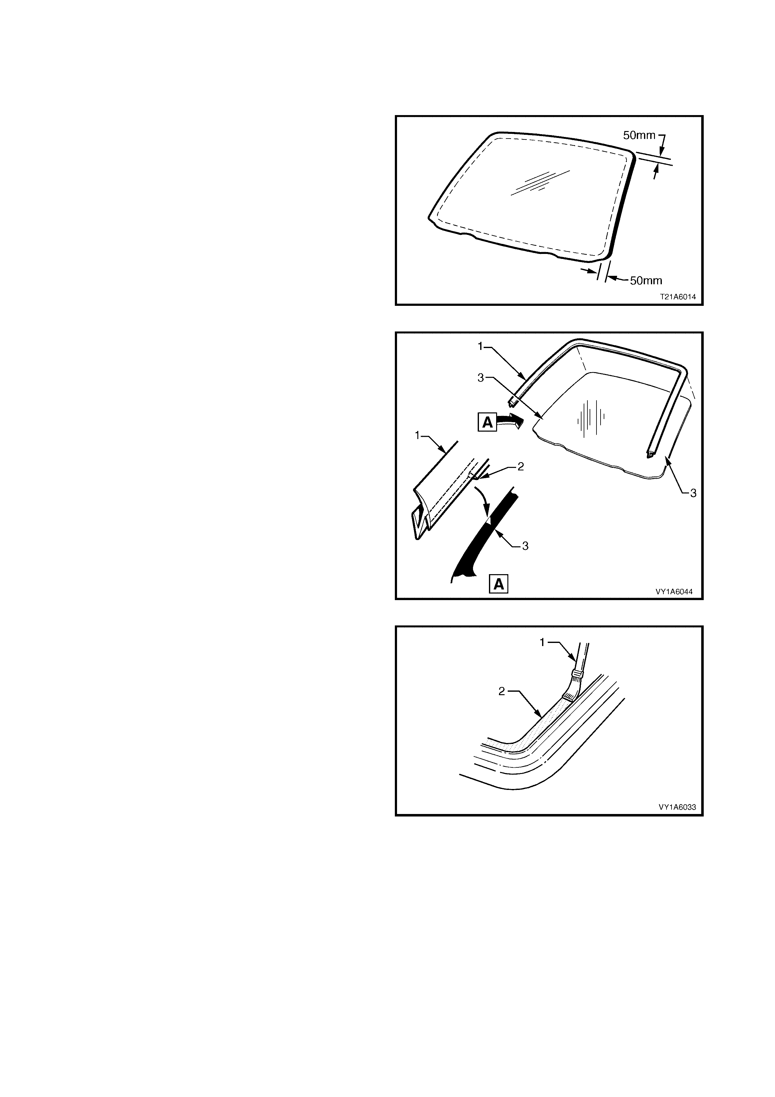
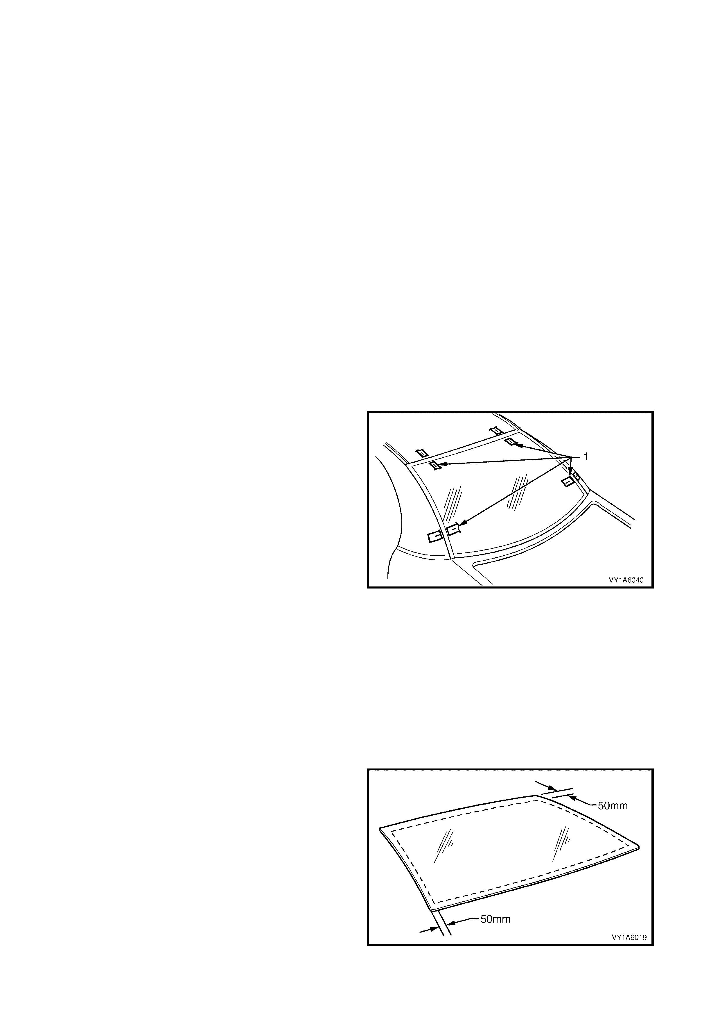
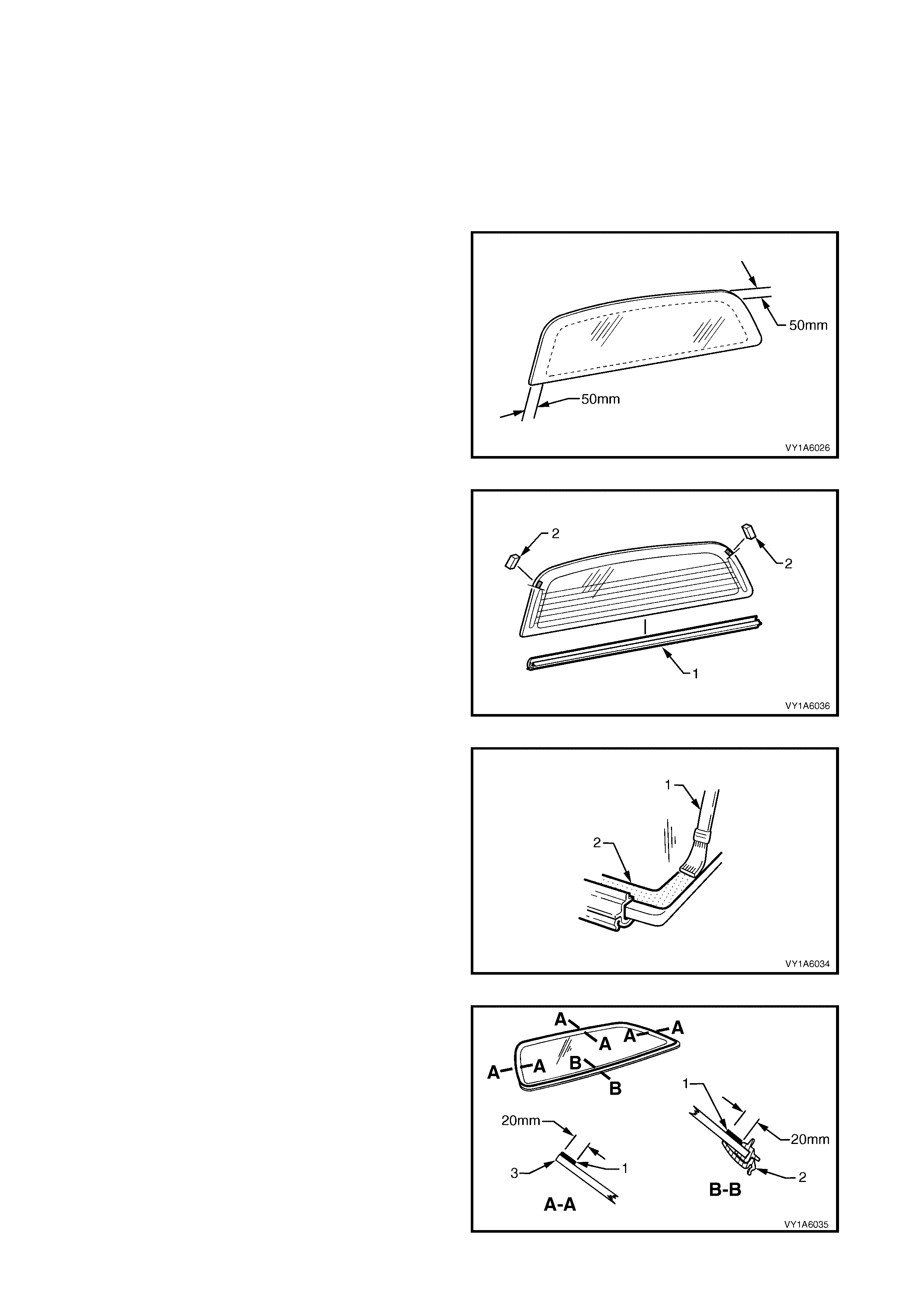
2. Apply clear windshield adhesive primer, over the
width of the solid black ceram ic pattern (or a width
of 50 mm), to the inner surface around the
perimeter of the windshield. Immediately wipe off
with a lint-free cloth.
Figure 1A6-7
3. Check the condition of the windshield reveal
moulding ass em bly (1). Discard and r eplace with a
new moulding if damaged.
4. Fit the moulding assembly to the sides and upper
section of the windshield. Ensure that the notch of
the moulding (2) is aligned with the ‘V’ locating
mar k (3) on the lower portion of the right-hand and
the left-hand side of the windshield.
5. Check the condition of the original urethane
around the windshield opening flange for voids or
looseness.
6. Cut away any loose pieces of urethane.
7. Using a suitable spatula, spread fresh urethane
smoothly into any voids or uneven sections.
Figure 1A6-8
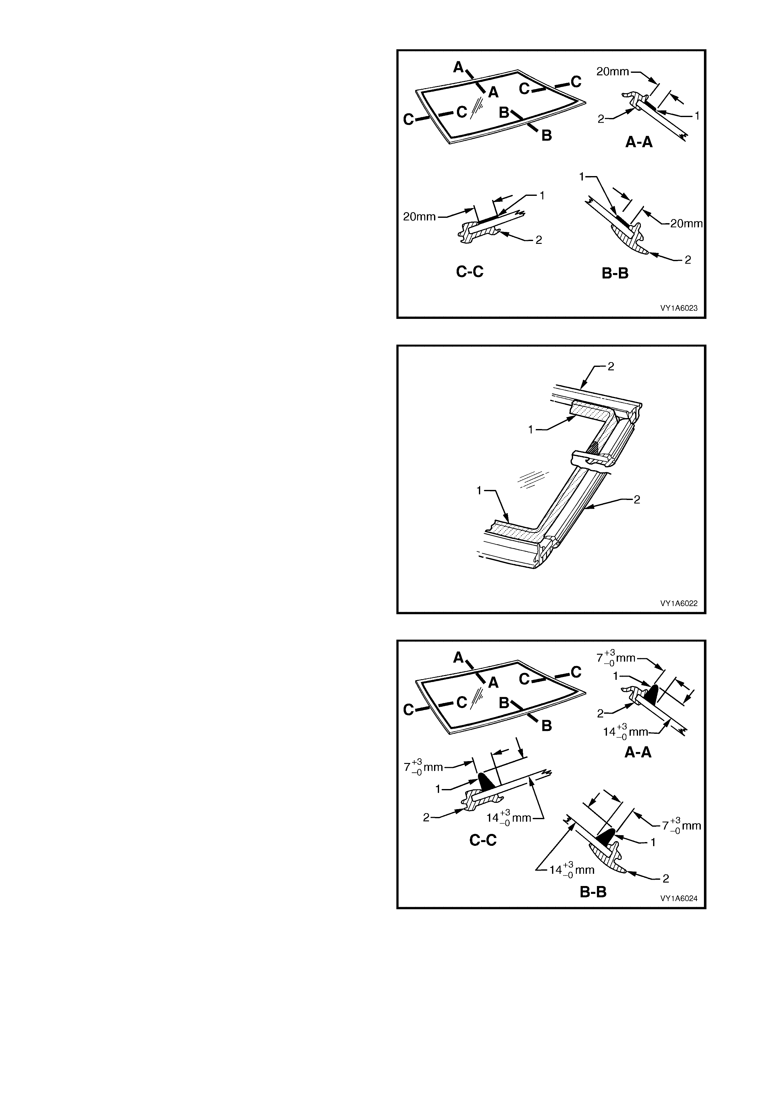
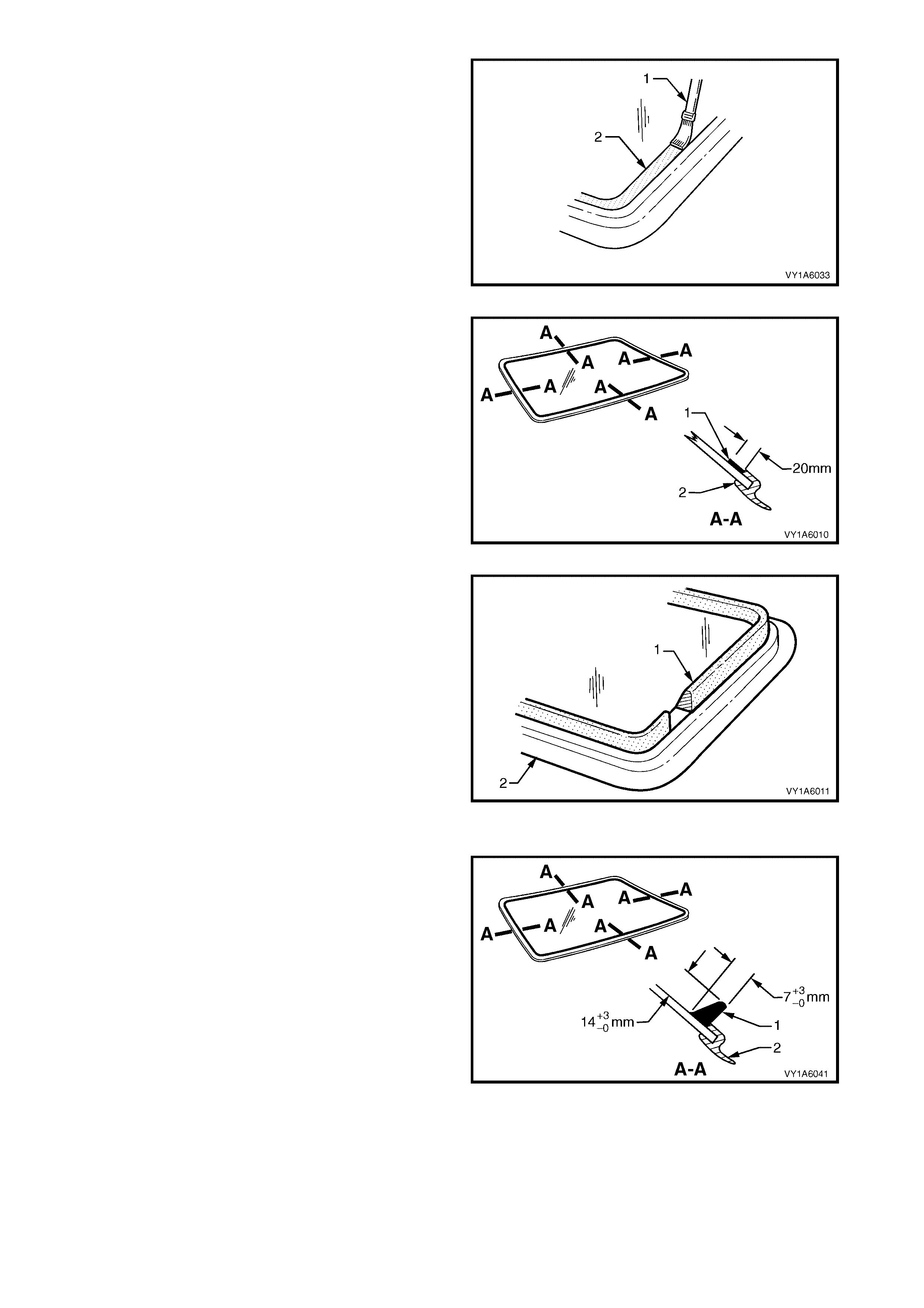
8. Use the applic ator (1) inc luded in the service kit, to
apply black windshield adhesive primer (2) to the
windshield as described in the following step.
Figure 1A6-9
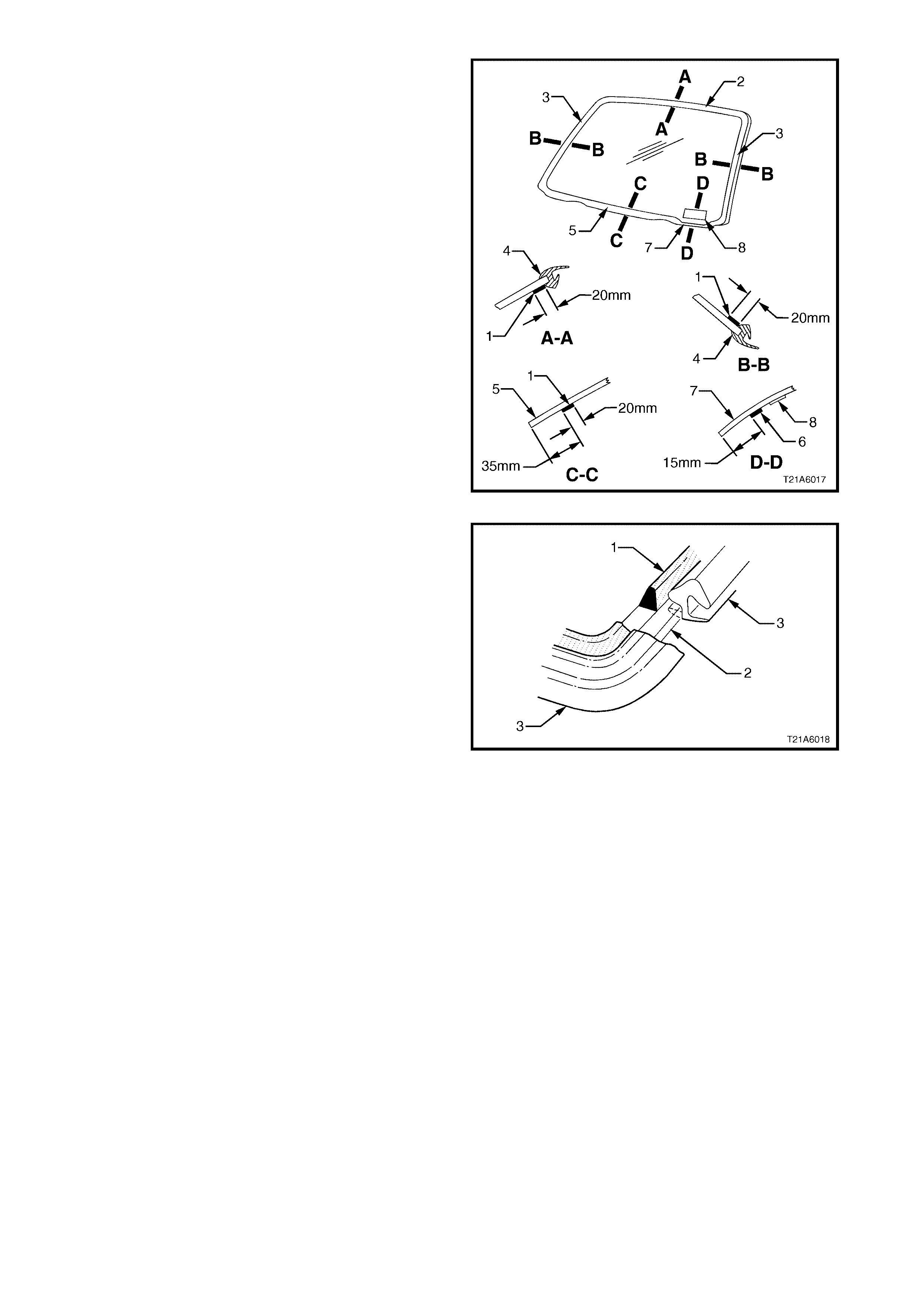
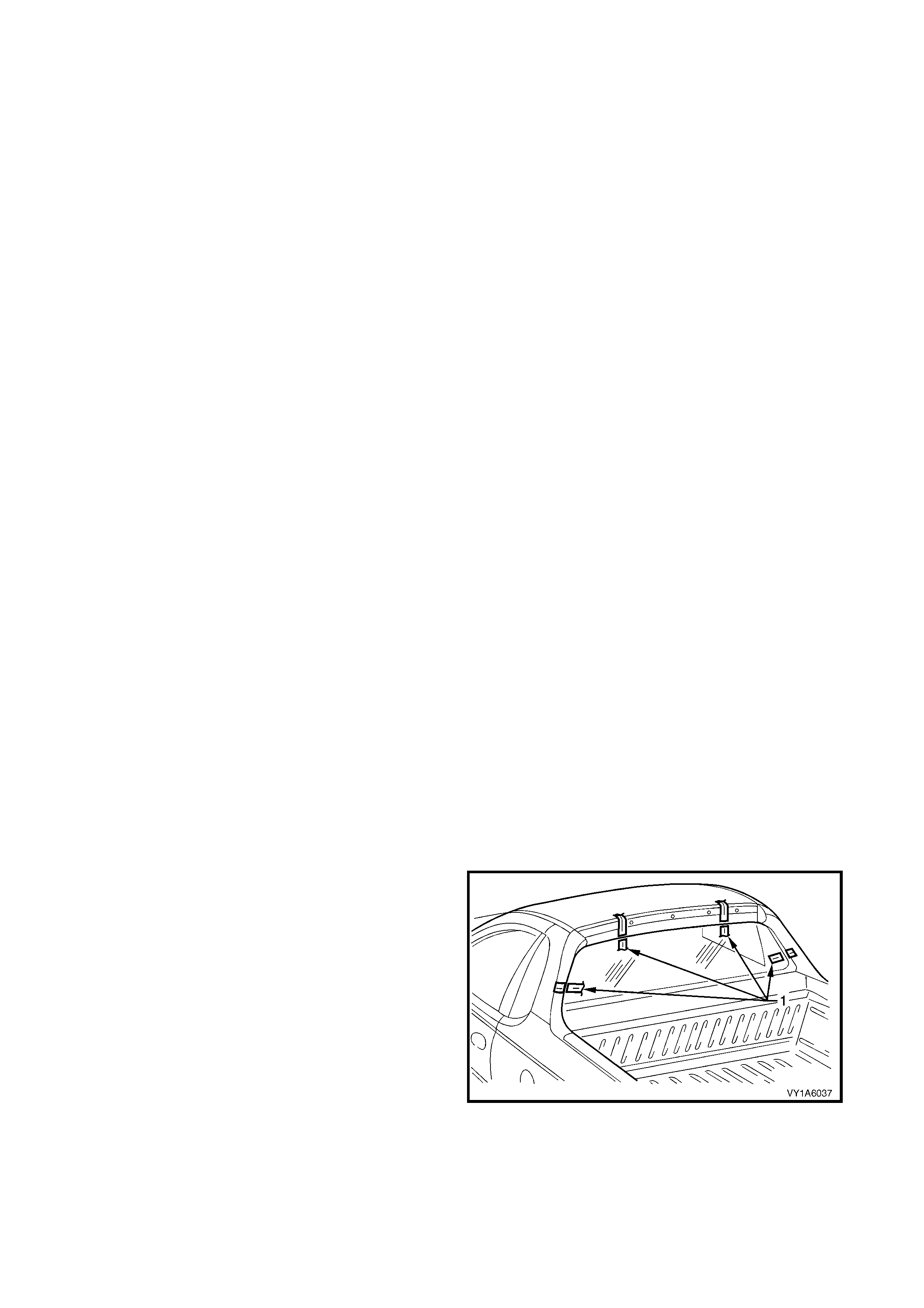
9. Apply black windshield adhesive primer (1) to the
inner s urf ac e of the upper s ect ion (2) and sides (3)
of the windshield over a width of 20 mm inboard
from the moulding (4). Repeat this proces s 35 m m
from the bottom edge (5) of the windshield. Ensure
that a suitably reduced application of primer (6) is
applied 15 mm from the lower edge of the
windshield (7) adjacent to the VIN plate (8).
Figure 1A6-10
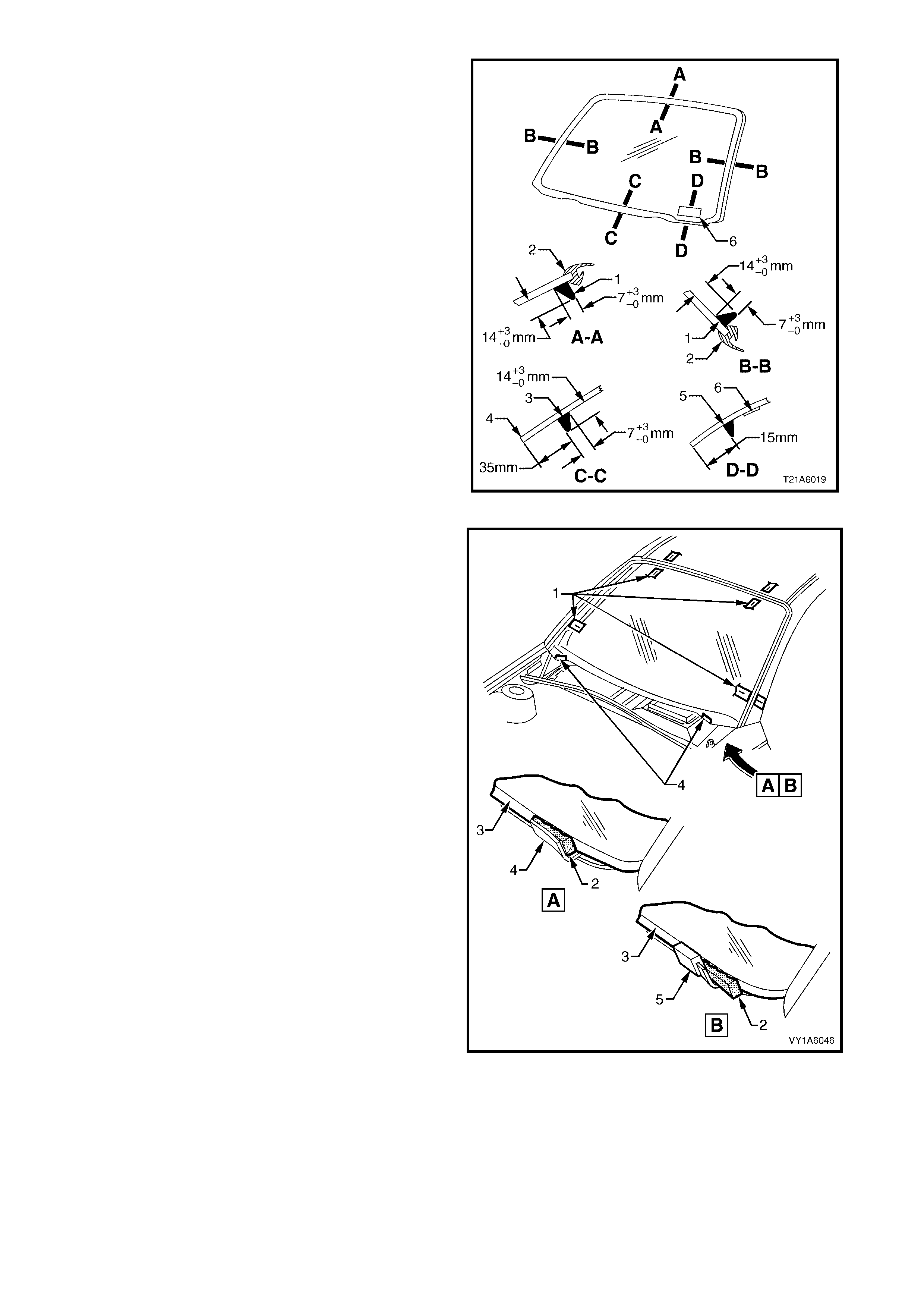
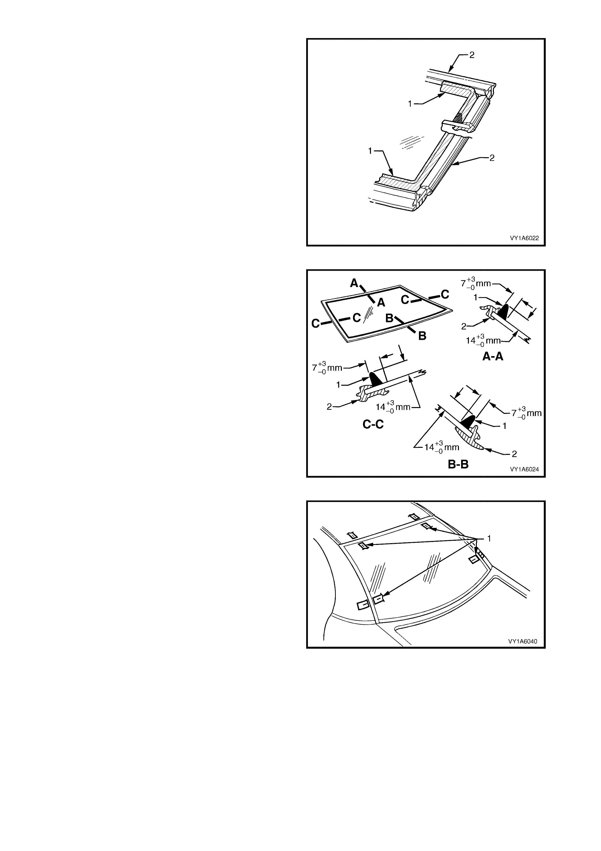
10. Using a hand or automatic applicator, apply a
smooth continuous bead of windshield adhesive
(urethane) (1), such as Betaseal 15685 or
equivalent, to the windshield (2) along the inside
edge of the moulding (3). The bead dimensions
are shown in Figure 1A6-12.
NOTE: 1 Depending on the amount of urethane
remaining on the windshield opening flange, the
amount of the new urethane should be reduced
accordingly, while maintaining adequate strength and
sealing properties. The dimensions shown are the
maximum allowable and are only for reference.
NOTE: 2 In cold weather, the placement of cartridges
adjacent to a sourc e of warm th will ass ist in the flow of
urethane when using a hand applicator.
Figure 1A6-11

IMPORTANT: On the lower section of the body
opening, care must be taken to ensure the urethane
bead diameter is such that when compressed by the
windshield installation, the Vehicle Identification
Number plate is not obscured.
11. Apply urethane (1) adjacent to the moulding (2)
and 35 mm inboard (3) from the lower edge of the
windshield (4). A suitably reduced amount of
urethane (5) s hould be applied adjacent to the VIN
plate (6) to ensure that the VIN is not obscured
when the windshield is installed.
12. For ease of installation and to avoid unnecessary
stress on related components, it is recommended
that the interior mirror assembly be fitted
to the windshield prior to installation of the
windshield to the vehicle, refer to Section 12H,
2.4 INTERNEL REAR-VIEW MIRROR.
Figure 1A6-12
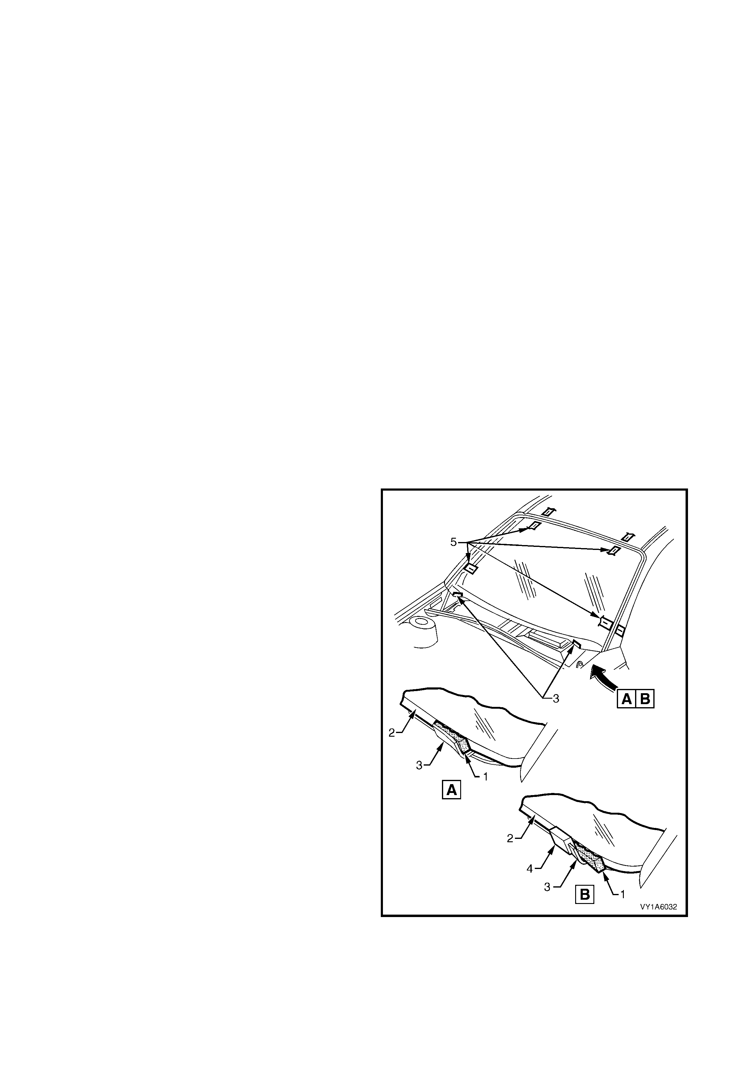
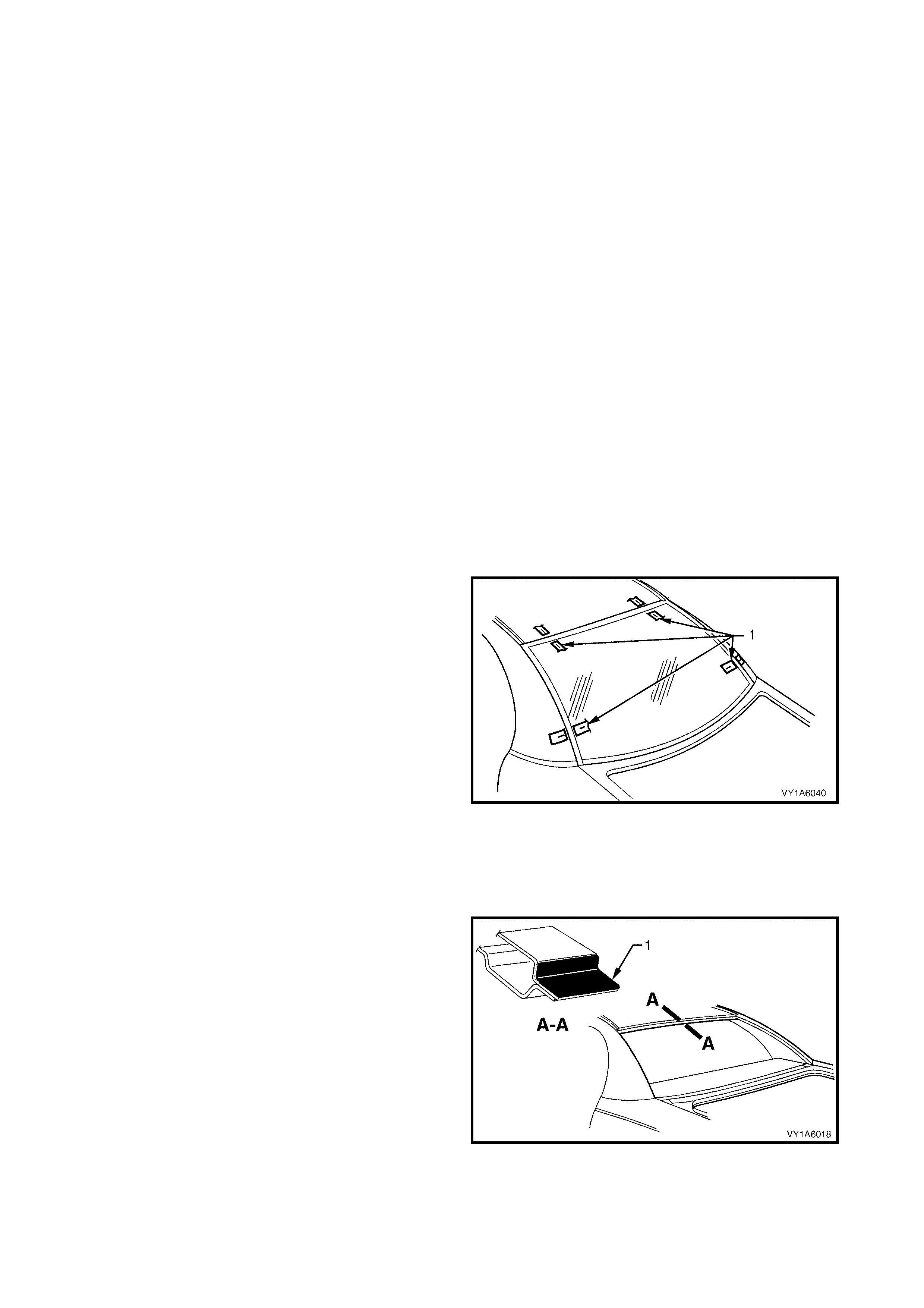
13. With the aid of an assistant, install the windshield
using the previously attached masking tape (1) on
the roof and windshield pillar to ensure accurate
installation.
• Sedan, Wagon and Utility: Use a windshield
locator (2) , between the lower windshield edge
(3) and the reinf orcing f lange (4) in two places,
to locate the windshield vertically in the
windshield opening.
• Coupe: If requir ed, use a windshield locator (2)
between the lower windshield edge (3) and the
extrusion (5) to correctly locate the windshield
in the body opening.
14. Press windshield firmly into position.
15. Check effectiveness of sealing from inside the
vehicle. Should any gaps in the sealing ex is t, apply
additional urethane to fill these gaps.
16. Wait two hours then water test the windshield,
using a moderate spray of water.
NOTE: Do not direct a heavy stream of water onto
freshly applied urethane. If a water leak is evident,
apply additional urethane to the leak area, using a
spatula to work the urethane into the source of the
leak.
17. Clean off any excess urethane using Prepsol or
white spirit. Clean the windshield, then rem ove the
masking tape previously installed.
18. Reinstall the trim and hardware as required.
Figure 1A6-13
REINSTALL – LONG METHOD
CAUTION: Ensure that door windows are partially lowered to eliminate pressure build up which can be
caused by slamming doors. A curing time of 24 hours is recommended, although the vehicle may be
driven after 5 hours, providing it is driven only on a smooth road at speeds not exceeding 80 km/h with
the door windows partially lowered.
Description
The long method for the windshield replacement is used when the original urethane adhesive material cannot
serve as a base for the replacement windshield.
This method should be used on vehicles requiring metal or paint repair to the windshield opening, when the
original adhesive is completely removed and replaced with new urethane for the windshield installation.
This method is also used when the windshield has been previously replaced using the short method. In such
instances, the build-up of urethane could position the windshield too high in the opening.
CAUTION 1: Do not use petroleum based solvents to clean the windshield or the opening flange, as the
presence of the oil in the solvent will prevent the adhesion of the new urethane.
CAUTION 2: Care should be taken to ensure that the windshield does not strike the windshield opening.
Chipped edges can lead to subsequent breakage of the windshield.
Preparation
1. Using a sharp scraper, carefully remove any original urethane from around the windshield. Clean the
windshield to be installed with a suitable oil free cleaning agent.
2. Using a knife or sharp scraper, remove the original urethane from around the entire perimeter of the
windshield opening flange. Avoid the removal of paint when removing urethane from opening flange.
Body Opening Check
1. Thoroughly check the windshield opening flange for any irregularities before installing the windshield.
2. To check for correct alignment, temporarily place the windshield in the windshield opening. If necessary,
reform the windshield opening flange to produce a uniform flange to the windshield contour.
• Sedan, Wagon and Utility: Check for correct
alignment buy temporarily placing the
windshield in the body opening. Place the
windshield locator (1) between the lower
windshield edge (2) and the reinforcing flange
(3), to correctly locate the windshield.
• Coupe: Check for correct alignment buy
temporarily placing the windshield, on to the
extrusion ( 4) fitted to the reinf orcing flange (3) .
If required place windshield locators (1)
between the lower windshield edge and the
extrusion to correctly locate the windshield in
the body opening.
3. Ensure the windshield is centralised in the body
opening left to right, by checking that the gaps
between the windshield and body opening are
even on both sides of the vehicle.
4. With masking tape (5), mark the outer top and side
of the windshield pillar and the roof.
5. NOTE: This procedure will assist in the alignment
of the windshield in the correct horizontal and
vertical plane during final windshield installation.
6. Remove and place the windshield face down on a
clean protected surface or fixture.
Figure 1A6-14
Reinstall
IMPORTANT: Flange primer is NOT required if using
the recommended urethane adhesive Betaseal 15685.
If not using Betaseal 15685, and are using an
equivalent system, refer to technical data supplied by
the manufacturer.
If requir ed by the m anufactur er, apply f lange primer (1)
as directed.
Figure 1A6-15
1. Thoroughly clean the inner surface and edges of
the windshield to which the urethane is to be
applied, using clean lint-free cloths and a suitable
oil free cleaning solvent.
CAUTION: Do not use petroleum b ased solven ts to
clean the windshield, or the body opening flange
as the presence of the oil in the solvent will
prevent the adhesion of the new uretha ne.
2. Apply clear windshield adhesive primer, over the
width of the solid black ceram ic pattern (or a width
of 50 mm), to the inner surface around the
perimeter of the windshield. Immediately wipe off
with a lint-free cloth.
Figure 1A6-16
3. Check the condition of the windshield reveal
moulding ass em bly (1). Discard and r eplace with a
new moulding if damaged.
4. Fit the moulding assembly to the sides and upper
section of the windshield. Ensure that the notch of
the moulding (2) is aligned with the ‘V’ locating
mar k (3) on the lower portion of the right-hand and
the left-hand side of the windshield.
Figure 1A6-17
5. Use the applic ator (1) inc luded in the service kit, to
apply black windshield adhesive primer (2) to the
windshield as described in the following step.
Figure 1A6-18
6. Apply black windshield adhesive primer (1) to the
inner s urf ac e of the upper s ect ion (2) and sides (3)
of the windshield over a width of 20 mm inboard
from the moulding (4). Repeat this proces s 35 m m
from the lower edge (5) of the windshield. Ensure
that a suitably reduced application of primer (6) is
applied 15 mm from the lower edge of the
windshield (7) adjacent to the VIN plate (8).
Figure 1A6-19
7. Using a hand or automatic applicator, apply a
smooth continuous bead of windshield adhesive
(urethane) (1), such as Betaseal 15685 or
equivalent, to the windshield (2) along the inside
edge of the moulding (3). The bead dimensions
are shown in Figure 1A6-21.
Figure 1A6-20
IMPORTANT: On the lower section of the body
opening, care must be taken to ensure the urethane
bead diameter is such that when compressed by the
windshield installation, the Vehicle Identification
Number plate is not obscured.
8. Apply urethane (1) adjacent to the moulding (2)
and 35 mm inboard (3) from the lower edge of the
windshield (4). A suitably reduced amount of
urethane (5) s hould be applied adjacent to the VIN
plate (6) to ensure that the VIN is not obscured
when the windshield is installed.
NOTE: In cold weather, the placement of cartridges
adjacent to a sourc e of warm th will ass ist in the flow of
urethane when using a hand applicator.
9. For ease of installation and to avoid unnecessary
stress on related components, it is recommended
that the interior mirror assembly be fitted to the
windshield prior to installation of the windshield to
the vehicle, refer to Section 12H, 2.4 INTERNEL
REAR-VIEW MIRROR.
Figure 1A6-21
10. With the aid of an assistant, install the windshield
using the previously attached masking tape (1) on
the roof and windshield pillar to ensure accurate
installation.
• Sedan, Wagon & Utility: Use a windshield
locator (2) , between the lower windshield edge
(3) and the reinf orcing f lange (4) in two places,
to locate the windshield vertically in the
windshield opening.
• Coupe: If requir ed, use a windshield locator (2)
between the lower windshield edge (3) and the
extrusion (5) to correctly locate the windshield
in the body opening.
11. Press windshield firmly into position.
12. Check effectiveness of sealing from inside the
vehicle. Should any gaps in the sealing exist, apply
additional urethane to fill these gaps.
13. Wait two hours then water test the windshield,
using a moderate spray of water.
NOTE: Do not direct a heavy stream of water onto
freshly applied urethane. If a water leak is evident,
apply additional urethane to the leak area, using a
spatula to work the urethane into the source of the
leak.
14. Clean off any excess urethane using Prepsol or
white spirit. Clean the windshield, then rem ove the
masking tape previously installed.
15. Reinstall the trim and hardware as required.
Figure 1A6-22
4. SERVICE OPERATIONS - SIDE
CAUTION 1: Safety glasses and work gloves must be worn at all times when operating with glass.
CAUTION 2: Care must be taken during any operation involv ing the w indow assembly - quarter removal or
installation, not to exert any load on the window. Failure to observe this may result in damage to the
window.
4.1 QUARTER WINDOW ASSEMBLY, WAGON
LT Section No. – 11-030
If required, first remove the following components:
1. Rear door opening weatherstrip assembly, refer to Section 1A5, 3.19 REAR DOOR OPENING
WEATHERSTRIP ASSEMBLY.
2. Body lock pillar garnish, refer to Section 1A8, 3.7 BODY LOCK PILLAR GARNISH.
3. Body rear corner garnish, refer to Section 1A8, 3.9 BODY REAR CORNER GARNISH.
4. Quarter inner trim panel assembly, refer to Section 1A8, 3.11 QUARTER INNER TRIM PANEL ASSEMBLY.
REMOVE
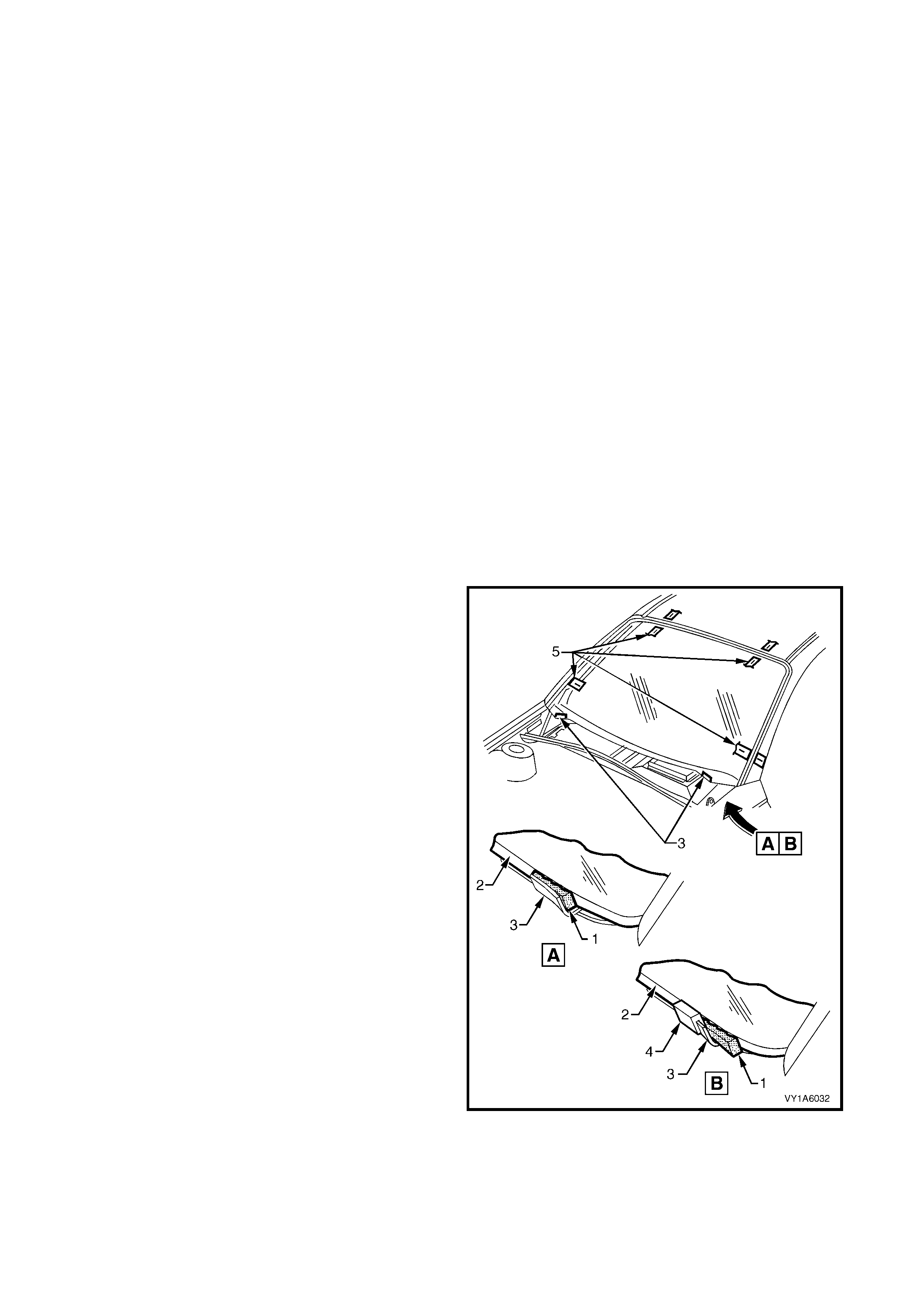
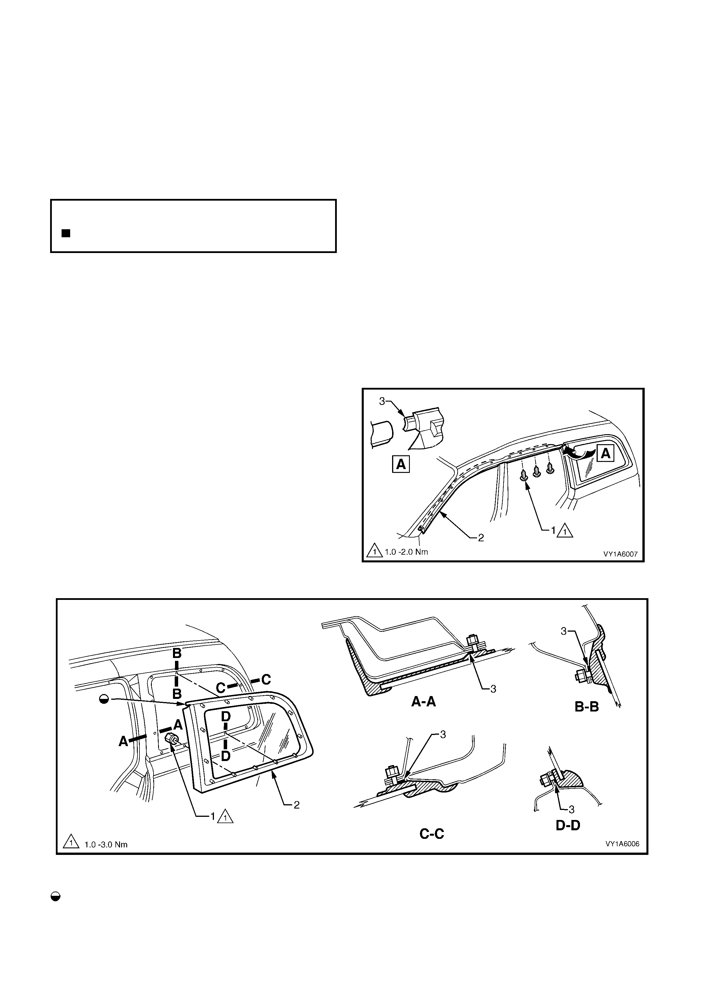
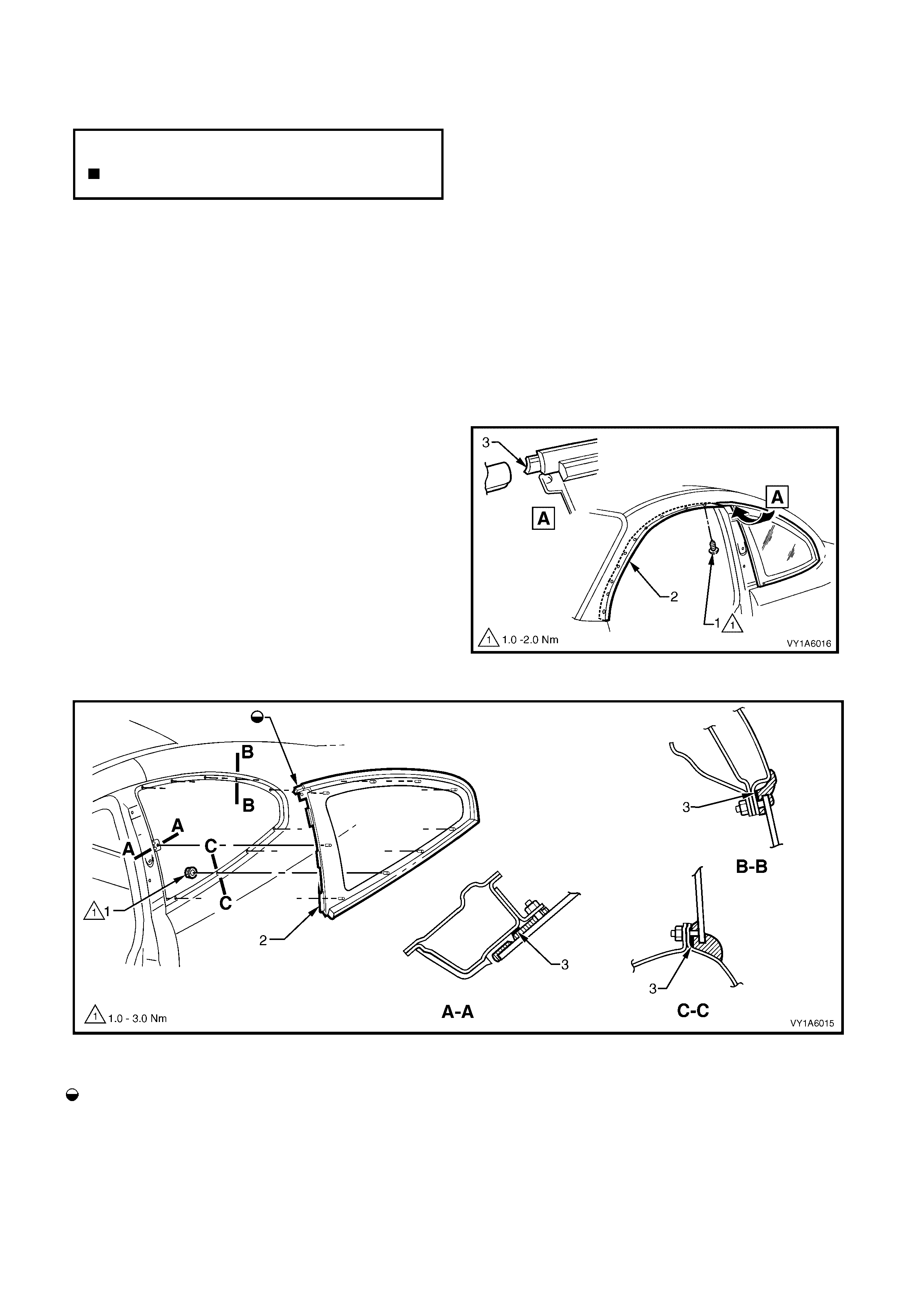
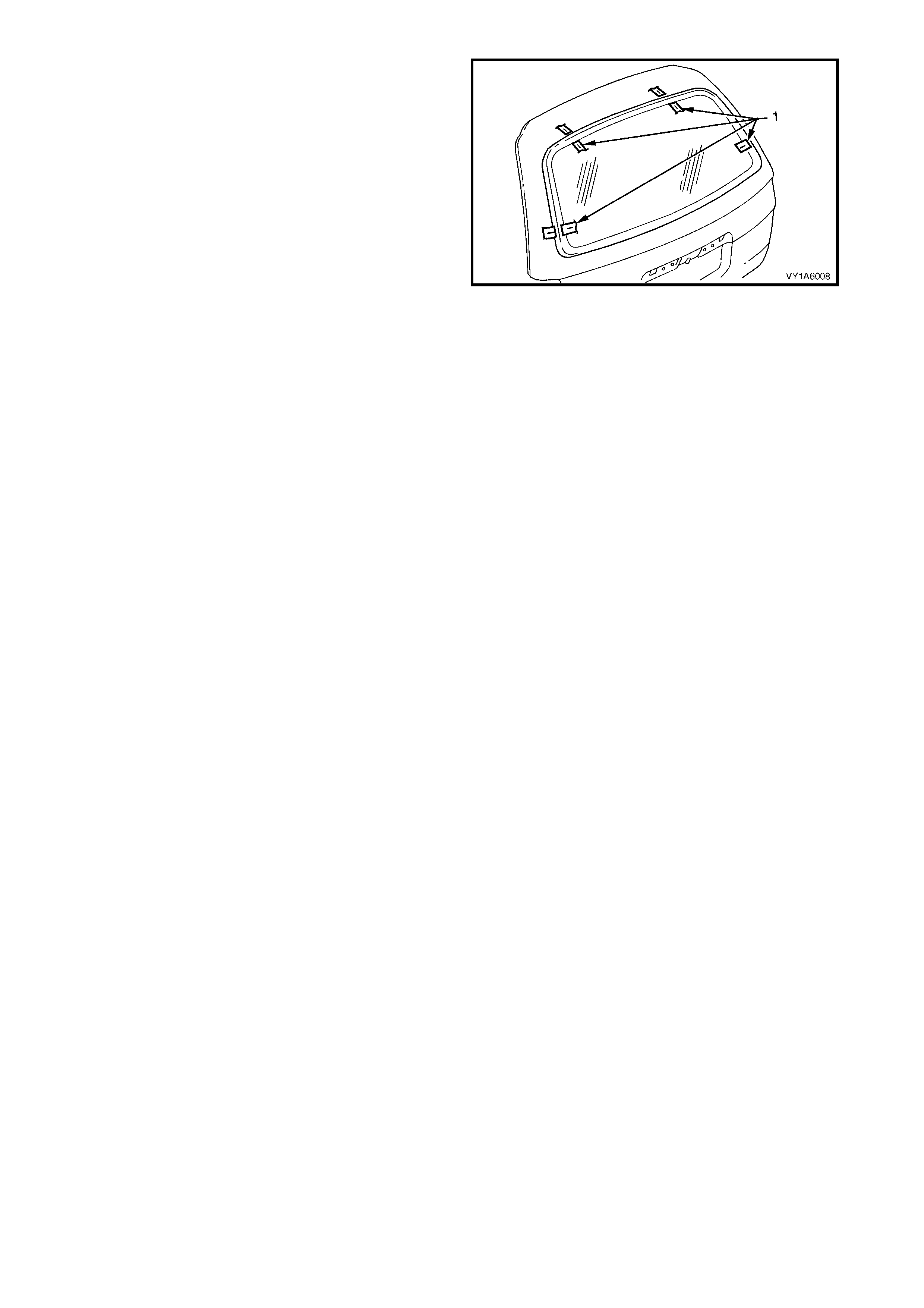
1. Remove the screws (1) and partially remove the
rear section of the door frame opening moulding
(2) wher e it joins the quarter window assem bly tab
(3).
2. Remove the quarter window nut (1) thirteen
places, securing the quarter window assembly (2)
to the body opening, refer Figure 1A6-24.
NOTE: The quarter window nut will be damaged during
this operation and must be replaced, to retain a
watertight seal.
3. Carefully lift the window from the vehicle.
CAUTION: Take care when removing the quarter
window from the body opening, that the attaching
pins are clear of the outer body.
Figure 1A6-23
Figure 1A6-24
legend
Tab To Engage With Moulding
Assembly Front And Rear Side Door
Opening Frame Reveal
1. Nut - Quarter Wi ndow (13 Places)
2. Window Assembly - Quarter 3. Foam Seal
NOTE: Sectional views show installed condition.
N
O
TE: The
f
ollowing component WILL RE
Q
UIRE
REPLACEMENT when performing this operation.
Quarter window nut.

REINSTALL
Reinstallation of the quarter window assembly is the
reverse of the removal noting the following:
1. Use new quarter window nuts (thirteen places).
2. Leave the nuts loose, until the door fram e opening
moulding is fastened into position.
3. Position the quarter window assembly and tighten
the nuts to the correct torque specification.
4. Reinstall the trim and hardware as required.
QUARTER WINDOW ASSEMBLY
RETAINING NUT
TORQUE SPECIFICATION 1.0 – 3.0 Nm
DOOR FRAME OPENING MOULDING
RETAINING SCREWS
TORQUE SPECIFICATION 1.0 – 2.0Nm
4.2 QUARTER WINDOW ASSEMBLY, UTILITY
LT Section No. – 11-025
If required, first remove the following components:
1. Front door opening weatherstrip assembly, refer to Section 1A5, 2.19 FRONT DOOR OPENING
WEATHERSTRIP ASSEMBLY.
2. Centre pillar lower trim, refer to Section 1A8, 5.2 CENTRE PILLAR LOWER TRIM.
3. Body lock pillar upper trim refer to Section 1A8, 5.3 BODY LOCK PILLAR UPPER TRIM.
4. Centre pillar upper finisher, refer to Section 1A9, 4.8 CENTRE PILLAR UPPER FINISHER.
REMOVE
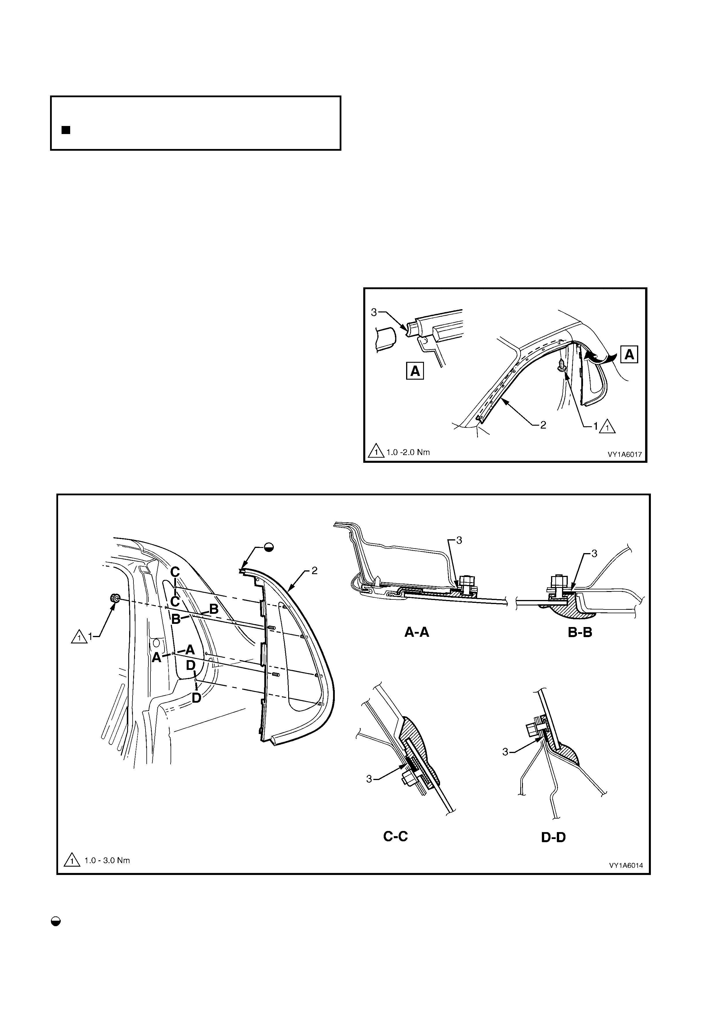
1. Remove the screws (1) and partially remove the
rear section of the door frame opening moulding
(2) where it joins the quarter window assem bly tab
(3).
2. Remove the quarter window nut (1) six places,
securing the quarter window assembly (2) to the
body opening, refer Figure 1A6-26.
NOTE: The quarter window nut will be damaged during
this operation and must be replaced, to retain a
watertight seal.
3. Carefully lift the window from the vehicle.
CAUTION: Take care when removing the quarter
window from the body opening, that the attaching
pins are clear of the outer body.
Figure 1A6-25
Figure 1A6-26
Legend
Tab To Engage Wit h Moulding - Door
Frame Opening 1. Nut - Quarter Window (6 Places)
2. Wi ndow As sembly - Quarter 3. Foam Seal
NOTE: Sectional views show installed condition.
N
O
TE: The
f
ollowing component WILL RE
Q
UIRE
REPLACEMENT when performing this operation.
Quarter window nut.

REINSTALL
Reinstallation of the quarter window assembly is the reverse of the removal noting the following:
1. Use new quarter window nuts (six places).
2. Leave the nuts loose, until the door frame opening moulding is fastened into position.
3. Position the quarter window assembly and tighten the nuts to the correct torque specification.
4. Reinstall the trim and hardware as required.
QUARTER WINDOW ASSEMBLY
RETAINING NUT
TORQUE SPECIFICATION 1.0 – 3.0 Nm
DOOR FRAME OPENING MOULDING
RETAINING SCREWS
TORQUE SPECIFICATION 1.0 – 2.0 Nm
4.3 QUARTER WINDOW ASSEMBLY, COUPE
LT Section No. –
If required, first remove the following components:
1. Front door opening weatherstrip assembly, refer to Section 1A5, 2.20 FRONT DOOR OPENING
WEATHERSTRIP ASSEMBLY.
2. Partially remove the side sill trim and plate, refer to Section 1A8, 4.1 SIDE SILL TRIM AND PLATE.
3. Quarter trim panel assembly, refer to Section 1A8, 4.2 QUARTER TRIM PANEL ASSEMBLY.
4. Centre pillar upper trim assembly, refer to Section 1A8, 4.3 CENTRE PILLAR UPPER TRIM ASSEMBLY.
5. Body rear corner garnish, refer to Section 1A8, 4.5 BODY REAR CORNER GARNISH.
6. Centre pillar upper finisher, refer to Section 1A9, 5.8 CENTRE PILLAR UPPER FINISHER.
REMOVE
1. Remove the screws (1) and partially remove the
rear section of the door frame opening moulding
(2) wher e it joins the quarter window assem bly tab
(3).
2. Remove the quarter window nut (1) nine places,
securing the quarter window assembly (2) to the
body opening, refer Figure 1A6-28.
NOTE: The quarter window - nut will be damaged
during this operation and m ust be replaced, to r etain a
watertight seal.
3. Carefully lift the window from the vehicle.
CAUTION: Take care when removing the quarter
window from the body opening, that the attaching
pins are clear of the outer body.
Figure 1A6-27
Figure 1A6-28
Legend
Tab To Engage Wit h Moulding - Door
Frame Opening 1. Nut - Quarter Window (9 Places)
2. Wi ndow As sembly - Quarter 3. Foam Seal
NOTE: Sectional views show installed condition.
N
O
TE: The
f
ollowing component WILL RE
Q
UIRE
REPLACEMENT when performing this operation.
Quarter window nut.

REINSTALL
Reinstallation of the quarter window assembly is the reverse of the removal noting the following:
1. Use new quarter window nuts (thirteen places).
2. Leave the nuts loose, until the door frame opening moulding is fastened into position.
3. Position the quarter window assembly and tighten the nuts to the correct torque specification.
1.
4. Reinstall the trim and hardware as required.
QUARTER WINDOW ASSEMBLY
RETAINING NUT
TORQUE SPECIFICATION 2.0 – 2.5 Nm
DOOR FRAME OPENING MOULDING
RETAINING SCREWS
TORQUE SPECIFICATION 1.0 – 2.0 Nm
5. SERVICE OPERATIONS - REAR
CAUTION 1: Safety glasses and work gloves must be worn at all times when operating with glass.
CAUTION 2: Care must be taken during any operation involving the window assembly - rear removal or
installation, not to exert any load on the window. Failure to observe this may result in damage to the
window.
IMPORTANT: Only use ur ethane adhesive suc h as Betaseal 15685 or equivalent f or rear window installation. It is
imperative that the procedure in this Section for replacing bonded windows are followed, as incorrect installation
may lead to injury or death.
5.1 REAR WINDOW ASSEMBLY, SEDAN AND COUPE
LT Section No. – 11-020
The rear window assembly removal procedure is the same for both the short and long installation methods, with
one exception. If the short method installation is to be used, care must be taken during the rear window removal to
ensure that an even surface of the original remaining urethane exists in the body opening, to serve as a base for
the new urethane bead and the replacement rear window.
To prevent damage and to m inim ise clean up of the paint f inish and the trim , m ask -up and place protective covers
over parts adjacent to the rear window.
If required, remove the following components:
1. Roof panel joint finish moulding, refer to Section 1A9, 2.7 ROOF JOINT MOULDING Sedan and 5.6 ROOF
JOINT MOULDING Coupe.
2. Body lock pillar garnish, for Sedan refer to Section 1A8, 2.6 BODY LOCK PILLAR GARNISH.
3. Rear window upper garnish, for Sedan refer to Section 1A8, 2.7 REAR WINDOW UPPER GARNISH.
4. Body rear corner garnish, for Coupe refer to Section 1A8, 4.5 BODY REAR CORNER GARNISH.
REMOVE
IMPORTANT: Note that on all vehicles a high mount s top lam p ass em bly is installed in the rear window trim panel
assem bly. Car e must be tak en to avoid damage to the lamp as sembly during window removal procedur e. It is not
necessary to remove the lamp assembly, but to ensure that it is clear of any debris before window installation.
1. Carefully disconnect the rear window electrical
demister connectors and cellular telephone
antenna if fitted.
2. Should the rear window be broken, carefully
remove all fragments of glass from the window
opening.
3. Using special tool J36020 thread one end of the
piano wire through the urethane, starting at the
windshield upper corner, pulling the end of the wire
through with pliers
4. Alternately, manufacture two T-handles to the
dimensions shown. Secure at least 700mm of
piano wire to one handle, thread the other end of
the wire through the urethane as previously
described.
NOTE: Ens ure that the headlining and other trim item s
are not damaged.
5. Connect the wire to the remaining T-handle and
with the aid of an assistant, com menc e cutting the
urethane bead, keeping the outside T-handle (1)
parallel to the edge of the window using the full
length of the wire to prevent heat build up in the
wire.
NOTE: To minimise the damage to the interior of the
vehicle, the operator inside the vehicle should act as
an anchor point. Holding the T-handle as close as
possible to the window at all times, while the outside
operator pulls the wire up to the interior T-handle in a
‘walking’ motion, refer to Figs.1A6-30.
Figure 1A6-29
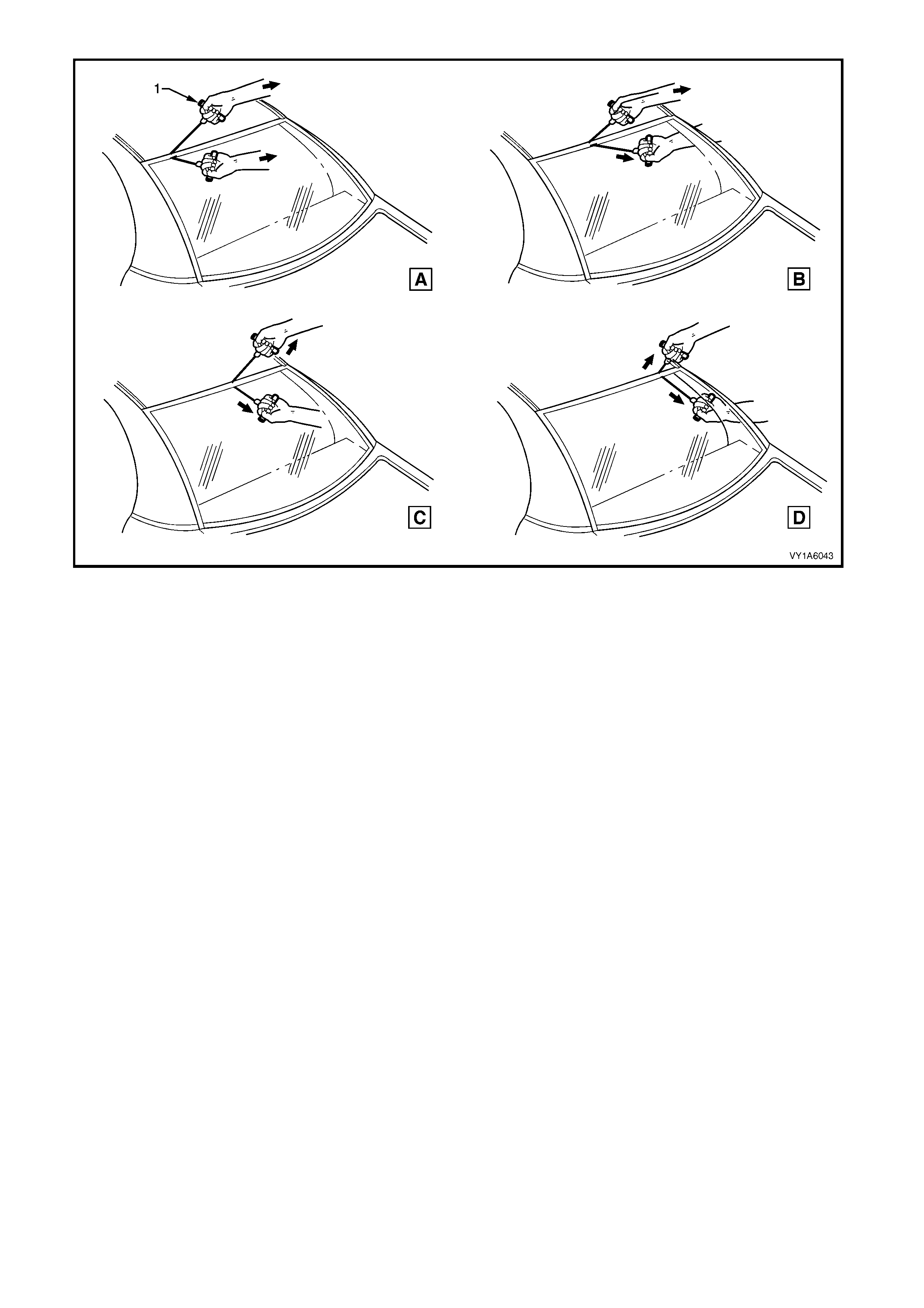
Figure 1A6-30
6. Carefully lift the rear window out of the rear
opening. If there is evidence of the window
adhering to the urethane, cut the area again with
the piano wire.
7. If the original rear window is to be installed again,
place the window on a clean protected surface or a
holding fixture.
NOTE 1: The use of suction cups will greatly assist
any handling of the rear window.
NOTE 2: All traces of ur ethane must be removed f rom
the rear window. It is not necessary to remove all
traces of the original urethane from the body opening,
unless the ‘long m ethod’ of reins tallation is being used.
However, any original urethane remaining must be
smooth and firm.
REINSTALL - SHORT METHOD
CAUTION: Ensure that door windows are partially lowered to eliminate pressure build up which can be
caused by slamming doors. A curing time of 24 hours is recommended, although the vehicle may be
driven after 5 hours, providing it is driven only on a smooth road at speeds not exceeding 80 km/h with
the door windows partially lowered.
Description
The short method installation involves the maximum amount of the original urethane being left intact on the rear
window opening to form a sound base for the replacement urethane and rear window assembly.
This method is recommended when replacing a cracked or broken window, or a leak condition that cannot be
overcome by using minor water leak repair procedures, refer to 2.1 MINOR WATER LEA K CORRECTION.
If material other than urethane has been used for previous servicing of the rear window, the long method
installation procedure (complete removal of adhesive) is mandatory to achieve an effective window to metal bond.
CAUTION 1: Care should be taken to ensure that the rear window does not strike the rear window
opening. Chipped edges can lead to subsequent breakage of the window.
CAUTION 2: Do not use petroleum based solvents to clean the rear window assembly or the rear opening
flange, as the presence of the oil in the solvent will prevent the adhesion of the new urethane.
Preparation
1. Using a sharp scraper, carefully remove any
original urethane from around the rear window.
Clean the rear window to be installed with a
suitable oil free cleaning agent.
2. To check for correct alignment, temporarily place
the rear window in the body opening.
3. Ensure the rear window is centralised in the body
opening left to right, by checking that the gaps
between the rear window and body opening are
even on both sides of the vehicle.
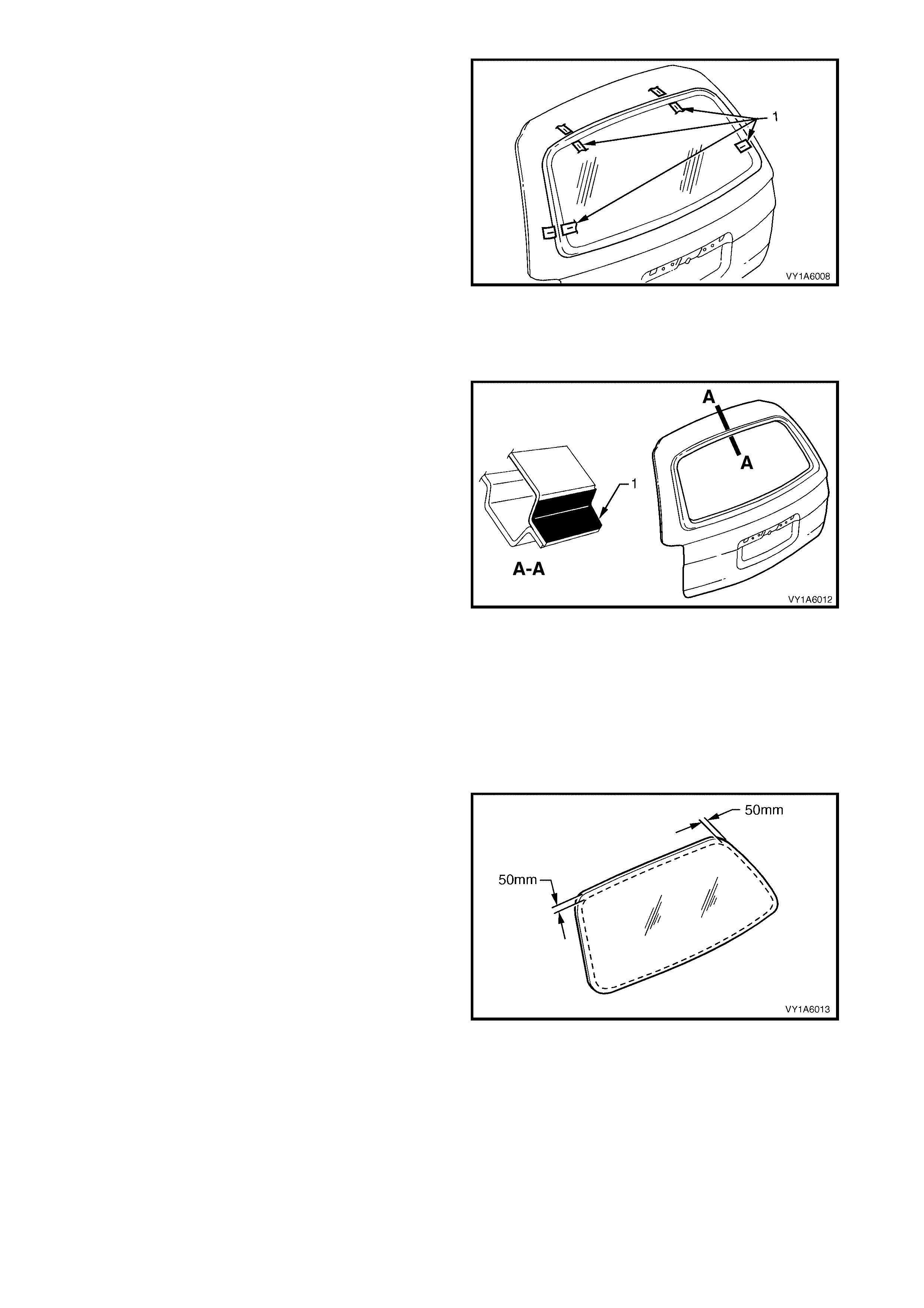
4. With masking tape (1), mark the outer top of the
roof and the rear quarter panel.
NOTE: This procedure will assist in the alignment of
the window in the correct horizontal and vertical plane
during final window installation.
5. Remove and plac e the rear window assem bly fac e
down on a clean protected surface or fixture.
Figure 1A6-31
Reinstall
1. Thoroughly clean the inner surface and edges of
the rear window assem bly to which the urethane is
to be applied, using clean lint-free cloths and a
suitable oil free cleaning solvent.
CAUTION: Do not use petroleum b ased solven ts to
clean the rear window assembly, or the rear
opening flange as the presence of the oil in the
solvent will prevent the adhesion of the new
urethane.
2. Apply clear window adhesive primer, over the
width of the solid black ceram ic pattern (or a width
of 50 mm), to the inner surface around the
perim eter of the rear window. Im m ediately wipe of f
with a lint-free cloth.
Figure 1A6-32
3. Check the condition of the rear window mouldings .
Discard and replace with new mouldings if
damaged.
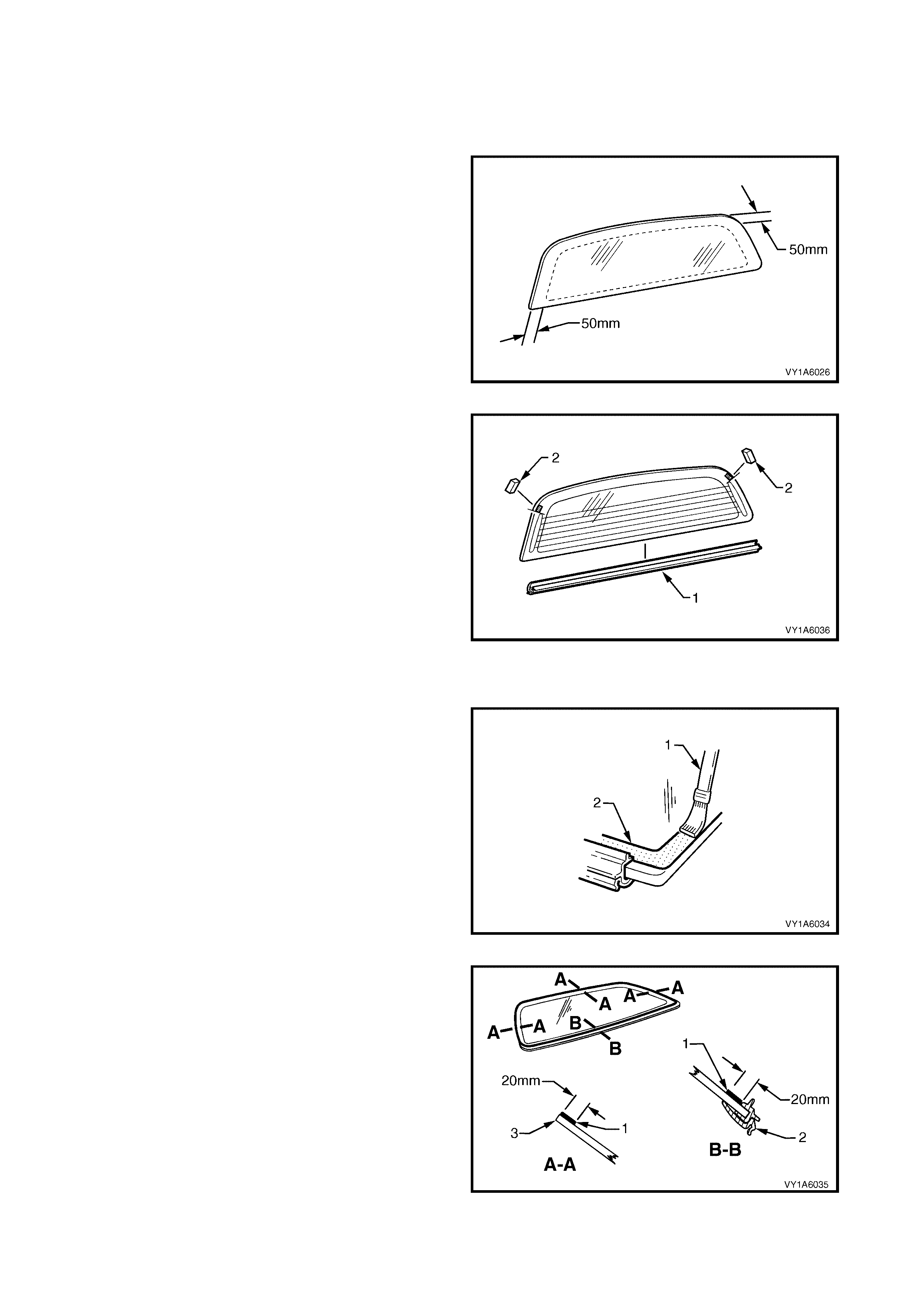
4. Install the rear window upper reveal moulding (1)
and the rear window lower reveal moulding (2)
over the edge of the window. Ensure the
mouldings are fitted correctly to the window.
5. Install the rear window side moulding retainer (3)
two places. Ensure the retainers are positioned to
alignment marks (4), and are fitted correctly to
edge of the window.
6. Check the condition of the original urethane
around the window opening flange for voids or
looseness.
7. Cut away any loose pieces of urethane.
8. Using a suitable spatula, spread fresh urethane
smoothly into any voids or uneven sections.
Figure 1A6-33
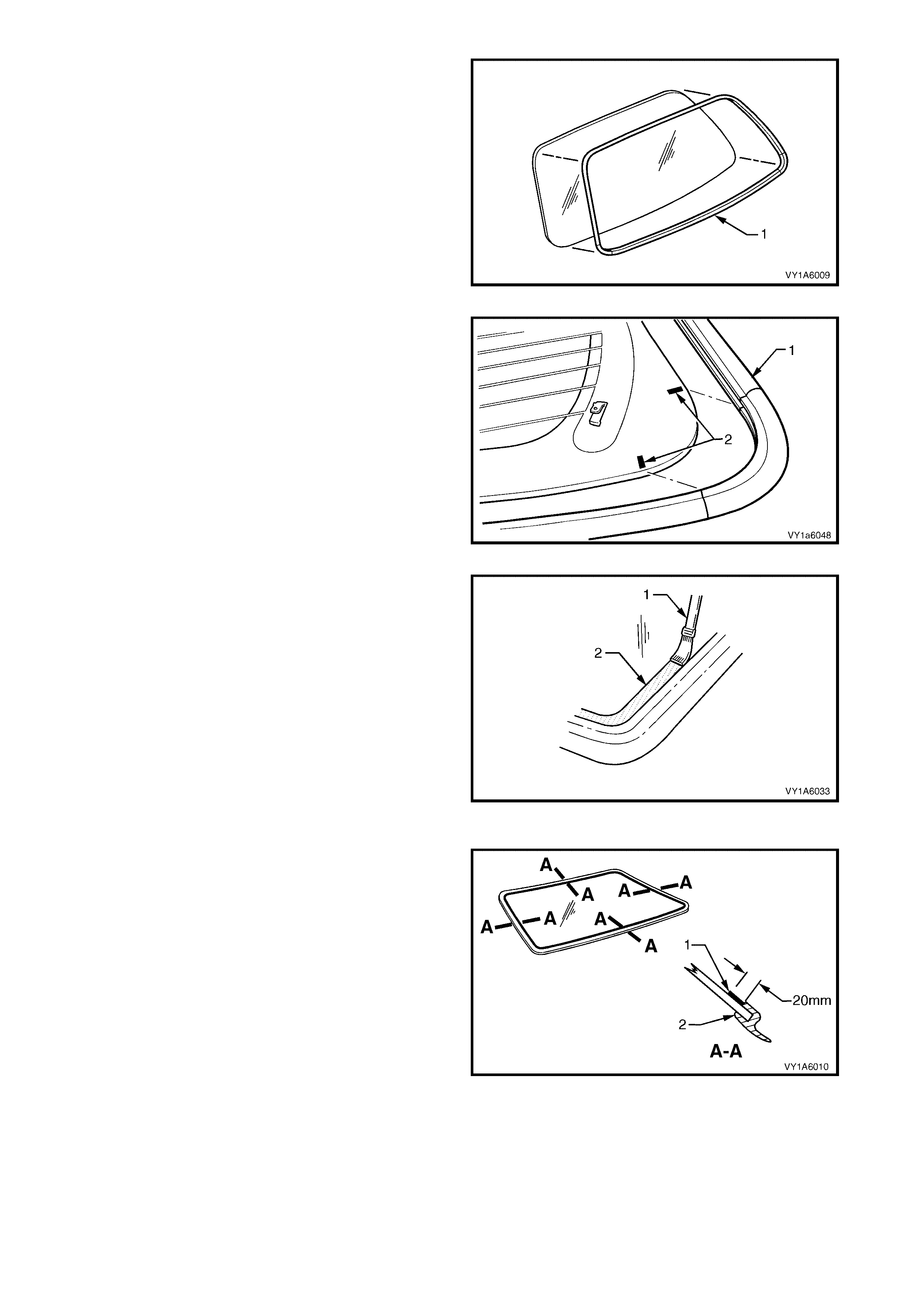
1. Use the applic ator (1) inc luded in the service kit, to
apply black window adhesive prim er (2) to the rear
window as described in the following step.
Figure 1A6-34
2. Apply black window adhesive primer (1) to the
inner surface, around the perimeter of the rear
window over a width of 20 mm, along the inside
edge of the window moulding (2).
Figure 1A6-35
3. Using a hand or automatic applicator, apply a
smooth continuous bead of window adhesive
(urethane) (1), such as Betaseal 15685 or
equivalent, around the perimeter of the window,
along the inside edge of the mouldings (2). The
bead dimensions are shown in Figure 1A6-37.
NOTE: 1 Depending on the amount of urethane
remaining on the body opening flange, the amount of
the new urethane should be reduced accor dingly, while
maintaining adequate strength and sealing properties.
The dimensions shown are the maximum allowable
and are only for reference.
NOTE: 2 In cold weather, the placement of cartridges
adjacent to a sourc e of warm th will ass ist in the flow of
urethane when using a hand applicator.
Figure 1A6-36
Figure 1A6-37
4. With the aid of an ass istant, ins tall the r ear window
assembly, using the previously attached masking
tape (1) on the roof and the rear quarter panel to
ensure accurate installation.
NOTE: Ensure the rear window is centralised in the
body opening left to right by checking that the gaps
between the window moulding and body opening are
even on both sides of the vehicle.
5. Press the rear window firmly into position.
6. Check effectiveness of sealing from inside the
vehicle. Should any gaps in the sealing exist, apply
additional urethane to fill these gaps.
7. Wait two hours then water test the rear window,
using a moderate spray of water.
NOTE: Do not direct a heavy stream of water onto
freshly applied urethane. If a water leak is evident,
apply additional urethane to the leak area, using a
spatula to work the urethane into the source of the
leak.
8. Clean off any excess urethane using Prepsol or
white spirit. Clean the rear window, then remove
the masking tape previously installed.
9. Connect the electrical demist connectors and
cellular telephone antenna if fitted.
10. Reinstall the trim and hardware as required.
Figure 1A6-38
REINSTALL - LONG METHOD
CAUTION: Ensure that door windows are partially lowered to eliminate pressure build up which can be
caused by slamming doors. A curing time of 24 hours is recommended, although the vehicle may be
driven after 5 hours, providing it is driven only on a smooth road at speeds not exceeding 80 km/h with
the door windows partially lowered.
Description
The long m ethod for the rear window assem bly replac ement is used when the original urethane adhesive m aterial
cannot serve as a base for the replacement rear window.
This method should be used on vehicles requiring metal or paint repair to the rear window opening, when the
original adhesive is completely removed and replaced with new urethane for the window installation.
This method is also used when the rear window has been previously replaced using the short method. In such
instances, the build-up of urethane could position the window assembly too high in the opening.
CAUTION: Do not use petroleum based solvents to clean the rear window or the rear opening flange, as
the presence of the oil in the solvent will prevent the adhesion of the new urethane.
Preparation
1. Us ing a s har p sc r aper, c ar ef ully rem ove any original urethane fr om around the rear window. Clean the window
to be installed with a suitable oil free cleaning agent.
2. Using a knife or sharp scraper, remove the original urethane from around the entire perimeter of the window
opening flange. Avoid the removal of paint when removing urethane from opening flange.
Rear Window Opening Check
1. Thoroughly check the rear window opening flange for any irregularities before installing the rear window
assembly.
CAUTION: Care should be taken to ensure that the rear window does not strike the rear window opening.
Chipped edges can lead to subsequent breakage of the window assembly.
2. To check for correct alignment, temporarily place
the rear window in the body opening.
3. If necessary, reform the rear window opening
flange to produce a uniform flange to the window
contour.
4. Ensure the rear window is centralised in the body
opening left to right, by checking that the gaps
between the rear window and body opening are
even on both sides of the vehicle.
5. With masking tape (1), mark the outer top of the
roof and the rear quarter panel.
NOTE: This procedure will assist in the alignment of
the window in the correct horizontal and vertical plane
during final window installation.
6. Remove and plac e the rear window assem bly fac e
down on a clean protected surface or fixture.
Figure 1A6-39
Reinstall
IMPORTANT: Flange primer is NOT required if using
the recommended urethane adhesive Betaseal 15685.
If not using Betaseal 15685, and are using an
equivalent system, refer to technical data supplied by
the manufacturer.
If requir ed by the m anufactur er, apply f lange primer (1)
as directed.
Figure 1A6-40
1. Thoroughly clean the inner surface and edges of
the rear window assembly to which the urethane is
to be applied, using clean lint-free cloths and a
suitable oil free cleaning solvent.
CAUTION: Do not use petroleum b ased solven ts to
clean the rear window assembly, or the rear
opening flange as the presence of the oil in the
solvent will prevent the adhesion of the new
urethane.
2. Apply clear window adhesive primer, over the width
of the solid black ceramic pattern (or a width of
50 mm), to the inner surface around the perimeter
of the rear window. Im mediately wipe off with a lint-
free cloth.
Figure 1A6-41
3. Check the condition of the rear window mouldings.
Discard and replace with new mouldings if
damaged.
4. Install the rear window upper reveal moulding (1)
and the rear window lower reveal moulding ( 2) over
the edge of the window. Ensure the mouldings are
fitted correctly to the window.
5. Install the rear window side moulding retainer (3)
two places. Ensure the retainers are positioned to
alignment marks (4), and are fitted correctly to edge
of the window.
Figure 1A6-42
6. Use the applicator (1) included in the service kit, to
apply black window adhesive primer (2) to the rear
window as described in the following step.
Figure 1A6-43
7. Apply black window adhesive prim er ( 1) to the inner
surf ace, around the perim eter of the window over a
width of 20 mm, along the inside edge of the
window moulding (2).
Figure 1A6-44
8. Using a hand or automatic applicator, apply a
smooth continuous bead of window adhesive
(urethane) (1), such as Betaseal 15685 or
equivalent, around the perimeter of the window,
along the inside edge of the mouldings (2). The
bead dimensions are shown in Figure 1A6-46.
NOTE: In cold weather, the placement of cartridges
adjacent to a source of warmth will assist the flow of
urethane when using a hand applicator.
Figure 1A6-45
Figure 1A6-46
9. W ith the aid of an assistant, install the rear window
assembly, using the previously attached masking
tape (1) on the roof and the rear quarter panel to
ensure accurate installation.
NOTE: Ensure the rear window is centralised in the
body opening left to right by checking that the gaps
between the window moulding and the body opening
are even on both sides of the vehicle.
10. Press the rear window firmly into position.
11. Check effectiveness of sealing from inside the
vehicle. Should any gaps in the sealing exist, apply
additional urethane to fill these gaps.
12. Wait two hours then water test the rear window,
using a moderate spray of water.
NOTE: Do not direct a heavy stream of water onto
freshly applied urethane. If a water leak is evident,
apply additional urethane to the leak area, using a
spatula to work the urethane into the source of the
leak.
13. Clean off any excess urethane using Prepsol or
white spirit. Clean the rear window, then remove the
masking tape previously installed.
14. Connect the electrical demist connectors and
cellular telephone antenna if fitted.
15. Reinstall the trim and hardware as required.
Figure 1A6-47
5.2 LIFTGATE WINDOW ASSEMBLY, WAGON
LT Section No. – 11-030
The liftgate window ass embly removal pr ocedure is the s ame f or both the short and the long inst allation methods,
with one exception. If the short method installation is to be used, more care must be taken during the liftgate
window removal to ensur e that an even surfac e of the original rem aining urethane exis ts in the liftgate opening, to
serve as a base for the new urethane bead and the replacement liftgate window.
To prevent damage and to m inim ise clean up of the paint f inish and the trim , m ask -up and place protective covers
over parts adjacent to the liftgate.
If required, remove the following components:
1. Rear window w iper arm assembly, refer to Section 1A4, 4.10 REAR WINDOW WIPERS ASSEMBLY.
2. High mount stop lamp, refer to Section 1A4, 4.12 HIGH MOUNT STOP LAMP ASSEMBLY.
3. Liftgate window lower garnish, refer to Section 1A4, 4.1 LIFTGATE WINDOW LOWER GARNISH.
4. Liftgate window upper garnish, refer to Section 1A4, 4.4 LIFTGATE WINDOW UPPER GARNISH.
5. Liftgate Air Deflector Assembly, refer to Section 1A4, 4.9 LIFTGATE AIR DEFLECTOR ASSEMBLY.
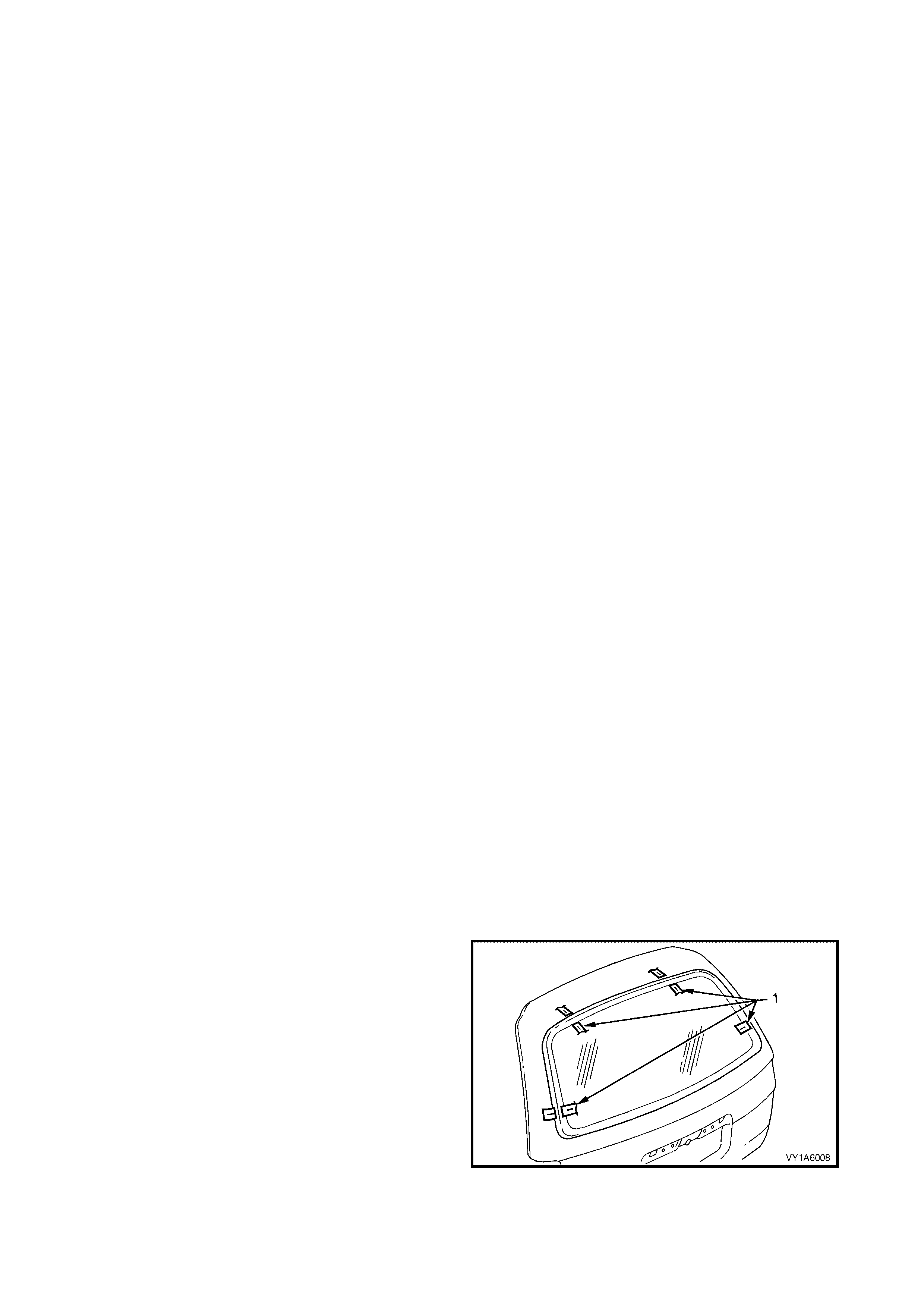
REMOVE
1. Carefully disconnect the liftgate window assembly electrical demister connectors.
2. Should the liftgate window be broken, carefully remove all fragments of glass from the window opening.
3. If the window is intact, carefully cut out the liftgate window by following the procedure set out in Steps 3 to 6,
refer to 5.1 REAR WINDOW ASSEMBLY, SEDAN AND COUPE.
REINSTALL - SHORT METHOD
CAUTION: Ensure that door windows are partially lowered to eliminate pressure build up which can be
caused by slamming doors. A curing time of 24 hours is recommended, although the vehicle may be
driven after 5 hours, providing it is driven only on a smooth road at speeds not exceeding 80 km/h with
the door windows partially lowered.
Description
The s hort method ins tallation involves the maximum amount of the or iginal ur ethane being lef t intac t on the lif tgate
opening to form a sound base for the replacement urethane and liftgate window assembly.
This method is recommended when replacing a cracked or broken window, or a leak condition that cannot be
overcome by using minor water leak repair procedures, refer to 2.1 MINOR WATER LEA K CORRECTION.
If material other than urethane has been used for previous servicing of the liftgate window, the long method
installation procedure (complete removal of adhesive) is mandatory to achieve an effective window to metal bond.
CAUTION 1: Care should be taken to ensure that the liftgate window does not strike the liftgate window
opening. Chipped edges can lead to subsequent breakage of the window.
CAUTION 2: Do not use petroleum based solvents to clean the liftgate window assembly or the liftgate
opening flange, as the presence of the oil in the solvent will prevent the adhesion of the new urethane.
Preparation
1. Using a sharp scraper, carefully remove any
original urethane from around the liftgate window.
Clean the liftgate window to be installed with a
suitable oil free cleaning agent.
2. To check for correct alignment, temporarily place
the liftgate window in the liftgate opening.
3. Ensure the liftgate window is centralised in the
liftgate opening left to right, by checking that the
gaps between the liftgate window and liftgate
opening are even on both sides of the vehicle.
4. With masking tape (1), mark the outer top and side
of the liftgate.
NOTE: This procedure will assist in the alignment of
the window in the correct horizontal and vertical plane
during final window installation.
5. Remove and place the liftgate window assembly
face down on a clean protected surface or fixture.
Figure 1A6-48
Reinstall
6. Thoroughly clean the inner surface and edges of
the liftgate window assem bly to which the urethane
is to be applied, using clean lint-free cloths and a
suitable oil free cleaning solvent.
CAUTION: Do not use petroleum b ased solven ts to
clean the liftgate window assembly, or the rear
opening flange as the presence of the oil in the
solvent will prevent the adhesion of the new
urethane.
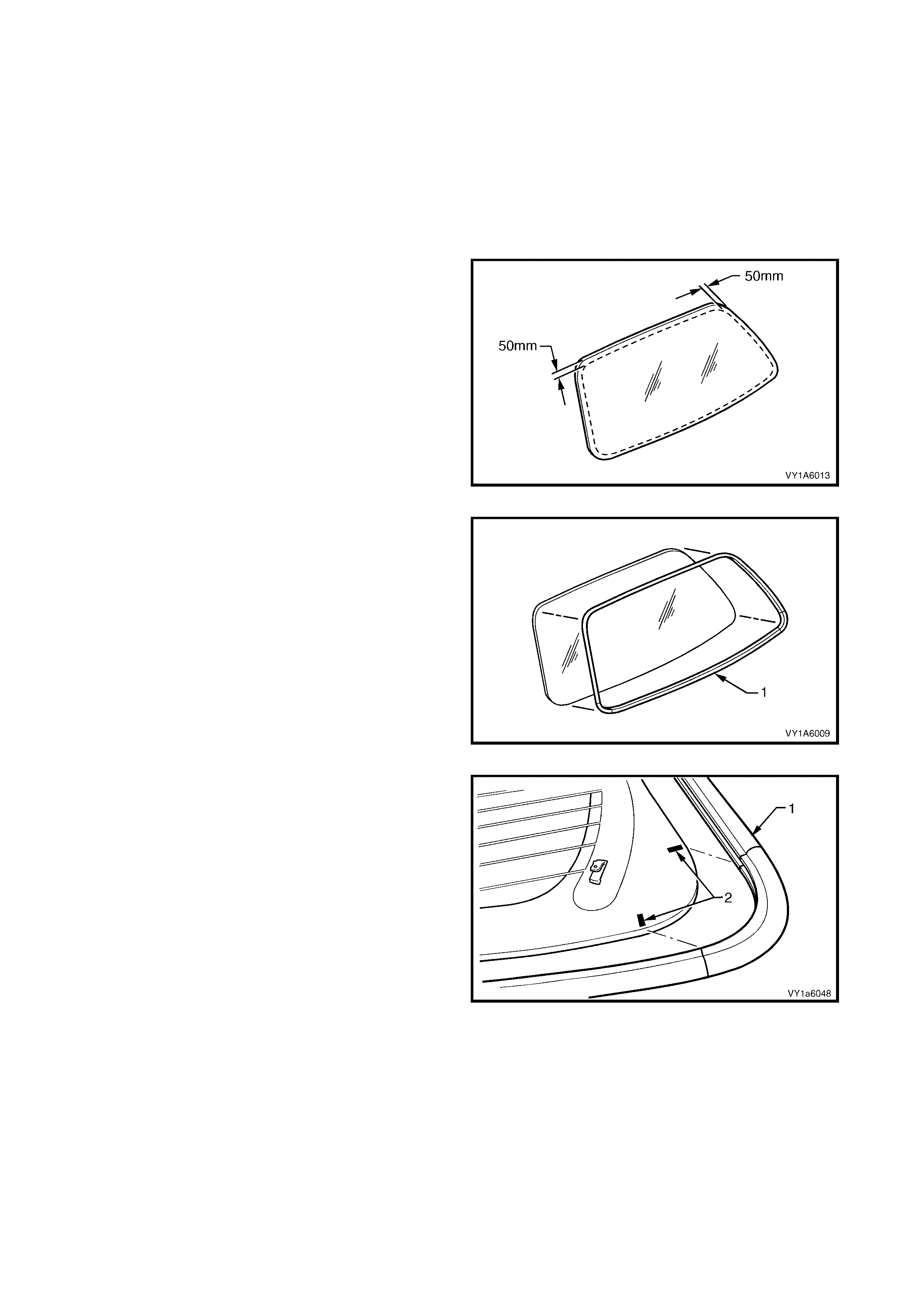
7. Apply clear window adhesive primer, over the
width of the solid black ceram ic pattern (or a width
of 50 mm), to the inner surface around the
perimeter of the liftgate window. Immediately wipe
off with a lint-free cloth.
Figure 1A6-49
8. Check the condition of the liftgate window reveal
moulding (1) and replace if damaged.
Figure 1A6-50
9. Align the window moulding corner (1) with the
alignment marks (2) on the underside of the
window in both the left hand and right hand lower
corners.
10. Ensure the moulding is fitted correctly to the
window.
11. Check the condition of the original urethane
around the liftgate opening flange for voids or
looseness.
12. Cut away any loose pieces of urethane.
13. Using a suitable spatula, spread fresh urethane
smoothly into any voids or uneven sections.
Figure 1A6-51
14. Use the applicator ( 1) included in the servic e kit, to
apply black window adhesive primer (2) to the
liftgate window as described in the following step.
Figure 1A6-52
15. Apply black window adhesive primer (1) to the
inner surface, around the perimeter of the liftgate
window over a width of 20 mm, along the inside
edge of the window moulding (2).
Figure 1A6-53
16. Using a hand or automatic applicator, apply a
smooth continuous bead of window adhesive
(urethane) (1), such as Betaseal 15685 or
equivalent, around the perimeter of the window,
along the inside edge of the moulding (2). The
bead dimensions are shown in Figure 1A6-37.
NOTE: 1 Depending on the amount of urethane
rem aining on the liftgate opening f lange, the am ount of
the new urethane should be reduced accor dingly, while
maintaining adequate strength and sealing properties.
The dimensions shown are the maximum allowable
and are only for reference.
NOTE: 2 In cold weather, the placement of cartridges
adjacent to a sourc e of warm th will ass ist in the flow of
urethane when using a hand applicator.
Figure 1A6-54
Figure 1A6-55
17. With the aid of an assistant, install the liftgate
window assembly, using the previously attached
masking tape (1) on the outer top and side of the
liftgate to ensure accurate installation.
NOTE: Ensure the liftgate window is centralised in the
liftgate opening left to right by checking that the gaps
between the window m oulding and the liftgate opening
are even on both sides of the vehicle
18. Press the liftgate window firmly into position.
19. Check effectiveness of sealing from inside the
vehicle. Should any gaps in the sealing exist, apply
additional urethane to fill these gaps.
20. W ait two hours then water test the liftgate window,
using a moderate spray of water.
NOTE: Do not direct a heavy stream of water onto
freshly applied urethane. If a water leak is evident,
apply additional urethane to the leak area, using a
spatula to work the urethane into the source of the
leak.
21. Clean off any excess urethane using Prepsol or
white spirit. Clean the lif tgate window, then rem ove
the masking tape previously installed.
22. Connect the electrical demist.
23. Reinstall the trim and hardware as required.
Figure 1A6-56
REINSTALL - LONG METHOD
CAUTION: Ensure that door windows are partially lowered to eliminate pressure build up which can be
caused by slamming doors. A curing time of 24 hours is recommended, although the vehicle may be
driven after 5 hours, providing it is driven only on a smooth road at speeds not exceeding 80 km/h with
the door windows partially lowered.
Description
The long method for the liftgate window assembly replacement is used when the original urethane adhesive
material cannot serve as a base for the replacement liftgate window.
This method should be used on vehicles requiring metal or paint repair to the liftgate window opening, when
original adhesive is completely removed and replaced with new urethane for the window installation.
This method is also used when the liftgate window has been previously replaced using the short method. In such
instances, the build-up of urethane could position the window assembly too high in the opening.
CAUTION: Do not use petroleum based solvents to clean the liftgate window or the liftgate opening flange,
as the presence of the oil in the solvent will prevent the adhesion of the new urethane.
Preparation
1. Using a sharp scraper, carefully remove any original urethane from around the liftgate window. Clean the
window to be installed with a suitable oil free cleaning agent.
2. Using a knife or sharp scraper, remove the original urethane from around the entire perimeter of the liftgate
opening flange. Avoid the removal of paint when removing urethane from opening flange.
Liftgate Window Opening Check
1. Thoroughly check the liftgate window opening flange for any irregularities before installing the liftgate window
assembly.
CAUTION: Care should be taken to ensure that the liftgate window does not strike the liftgate window
opening. Chipped edges can lead to subsequent breakage of the window assembly.
2. To check for correct alignment, temporarily place
the liftgate window in the liftgate opening.
3. If necessary, reform the liftgate opening flange to
produce a uniform flange to the window contour.
4. Ensure the liftgate window is centralised in the
liftgate opening left to right, by checking that the
gaps between the liftgate window and liftgate
opening are even on both sides of the vehicle.
5. With masking tape (1), mark the outer top and side
of the liftgate.
NOTE: This procedure will assist in the alignment of
the window in the correct horizontal and vertical plane
during final window installation.
6. Remove and place the liftgate window assembly
face down on a clean protected surface or fixture.
Figure 1A6-57
Reinstall
IMPORTANT: Flange primer is NOT required if using
the recommended urethane adhesive Betaseal 15685.
If not using Betaseal 15685, and are using an
equivalent system, refer to technical data supplied by
the manufacturer.
If requir ed by the m anufactur er, apply f lange primer (1)
as directed.
Figure 1A6-58
24. Thoroughly clean the inner surface and edges of
the liftgate window assem bly to which the urethane
is to be applied, using clean lint-free cloths and a
suitable oil free cleaning solvent.
CAUTION: Do not use petroleum b ased solven ts to
clean the liftgate window, or the liftgate opening
flange as the presence of th e oil in the solvent will
prevent the adhesion of the new uretha ne.
25. Apply clear window adhesive primer, over the
width of the solid black ceram ic pattern (or a width
of 50 mm), to the inner surface around the
perimeter of the liftgate window. Immediately wipe
off with a lint-free cloth.
Figure 1A6-59
26. Check the condition of the liftgate window reveal
moulding (1) and replace if damaged.
Figure 1A6-60
27. Align the window moulding corner (1) with the
alignment marks (2) on the underside of the
window in both the left hand and right hand lower
corners.
28. Ensure the moulding is fitted correctly to the
window.
Figure 1A6-61
29. Use the applicator ( 1) included in the servic e kit, to
apply black window adhesive primer (2) to the
liftgate window as described in the following step
Figure 1A6-62
30. Apply black window adhesive primer (1) to the
inner surface, around the perimeter of the liftgate
window over a width of 20 mm, along the inside
edge of the window moulding (2).
Figure 1A6-63
31. Using a hand or automatic applicator, apply a
smooth continuous bead of window adhesive
(urethane) (1), such as Betaseal 15685 or
equivalent, around the perimeter of the window,
along the inside edge of the moulding (2). The
bead dimensions are shown in Figure 1A6-65.
NOTE: In cold weather, the placement of cartridges
adjacent to a source of warmth will assist the flow of
urethane when using a hand applicator.
Figure 1A6-64
Figure 1A6-65
32. With the aid of an assistant, install the liftgate
window assembly, using the previously attached
masking tape (1) on the outer top and side of the
liftgate to ensure accurate installation.
NOTE: Ensure the liftgate window is centralised in the
liftgate opening left to right by checking that the gaps
between the window m oulding and the liftgate opening
are even on both sides of the vehicle.
33. Press liftgate window firmly into position.
34. Check effectiveness of sealing from inside the
vehicle. Should any gaps in the sealing ex is t, apply
additional urethane to fill these gaps.
35. W ait two hours then water test the liftgate window,
using a moderate spray of water.
NOTE: Do not direct a heavy stream of water onto
freshly applied urethane. If a water leak is evident,
apply additional urethane to the leak area, using a
spatula to work the urethane into the source of the
leak.
36. Clean off any excess urethane using Prepsol or
white spirit. Clean the liftgate window, then rem o ve
the masking tape previously installed.
37. Connect the electrical demist connectors.
38. Reinstall the trim and hardware as required.
Figure 1A6-66
5.3 REAR WINDOW ASSEMBLY, UTILITY
LT Section No. – 11-030
The rear window assembly removal procedure is the same for both the short and the long installation methods,
with one exception. If the short method installation is to be used, care must be taken during the rear window
rem oval to ens ure that an even s ur f ac e of the original r emaining urethane exis ts in the body opening, to serve as a
base for the new urethane bead and the replacement rear window.
To prevent damage and to m inim ise clean up of the paint f inish and the trim , m ask -up and place protective covers
over parts adjacent to the rear window.
If required, remove the following components:
1. Rear window upper moulding assembly, refer to Section 1A9, 4.10 REAR WINDOW UPPER MOULDING.
2. Body lock pillar upper trim, refer to Section 1A8, 5.3 BODY LOCK PILLAR UPPER TRIM.
REMOVE
1. Carefully disconnect the rear window electrical demister connectors and cellular telephone antenna if fitted.
2. Should the rear window be broken, carefully remove all fragments of glass from the window opening.
3. If the window is intact, caref ully cut out the rear window by f ollowing the procedure set out in Steps 3 to 6, refer
to 5.1 REAR WINDOW ASSEMBLY, SEDAN AND COUPE.
REINSTALL - SHORT METHOD
CAUTION: Ensure that door windows are partially lowered to eliminate pressure build up which can be
caused by slamming doors. A curing time of 24 hours is recommended, although the vehicle may be
driven after 5 hours, providing it is driven only on a smooth road at speeds not exceeding 80 km/h with
the door windows partially lowered.
Description
The short method installation involves the maximum amount of the original urethane being left intact on the rear
window opening to form a sound base for the replacement urethane and rear window assembly.
This method is recommended when replacing a cracked or broken window, or a leak condition that cannot be
overcome by using minor water leak repair procedures, refer to 2.1 MINOR WATER LEA K CORRECTION.
If material other than urethane has been used for previous servicing of the rear window, the long method
installation procedure (complete removal of adhesive) is mandatory to achieve an effective window to metal bond.
CAUTION 1: Care should be taken to ensure that the rear window does not strike the rear window
opening. Chipped edges can lead to subsequent breakage of the window.
CAUTION 2: Do not use petroleum based solvents to clean the rear window assembly or the rear opening
flange, as the presence of the oil in the solvent will prevent the adhesion of the new urethane.
Preparation
1. Using a sharp scraper, carefully remove any
original urethane from around the rear window.
Clean the rear window to be installed with a
suitable oil free cleaning agent.
2. To check for correct alignment, temporarily place
the rear window in the body opening.
3. Ensure the rear window is centralised in the body
opening left to right, by checking that the gaps
between the rear window and body opening are
even on both sides of the vehicle.
4. With masking tape (1), mark the outer top of the
roof and the rear quarter panel.
NOTE: This procedure will assist in the alignment of
the window in the correct horizontal and vertical plane
during final window installation.
5. Remove and plac e the rear window assem bly fac e
down on a clean protected surface or fixture.
Figure 1A6-67
Reinstall
6. Thoroughly clean the inner surface and edges of
the rear window assem bly to which the urethane is
to be applied, using clean lint-free cloths and a
suitable oil free cleaning solvent.
CAUTION: Do not use petroleum b ased solven ts to
clean the rear window assembly, or the rear
opening flange as the presence of the oil in the
solvent will prevent the adhesion of the new
urethane.
7. Apply clear window adhesive primer, over the
width of the solid black ceram ic pattern (or a width
of 50 mm), to the inner surface around the
perim eter of the rear window. Im m ediately wipe of f
with a lint-free cloth.
Figure 1A6-68
8. Check the condition of the rear window reveal
moulding (1) and replace if damaged.
9. Install the moulding over the edge of the window.
Ensure the moulding is fitted correctly to the
window.
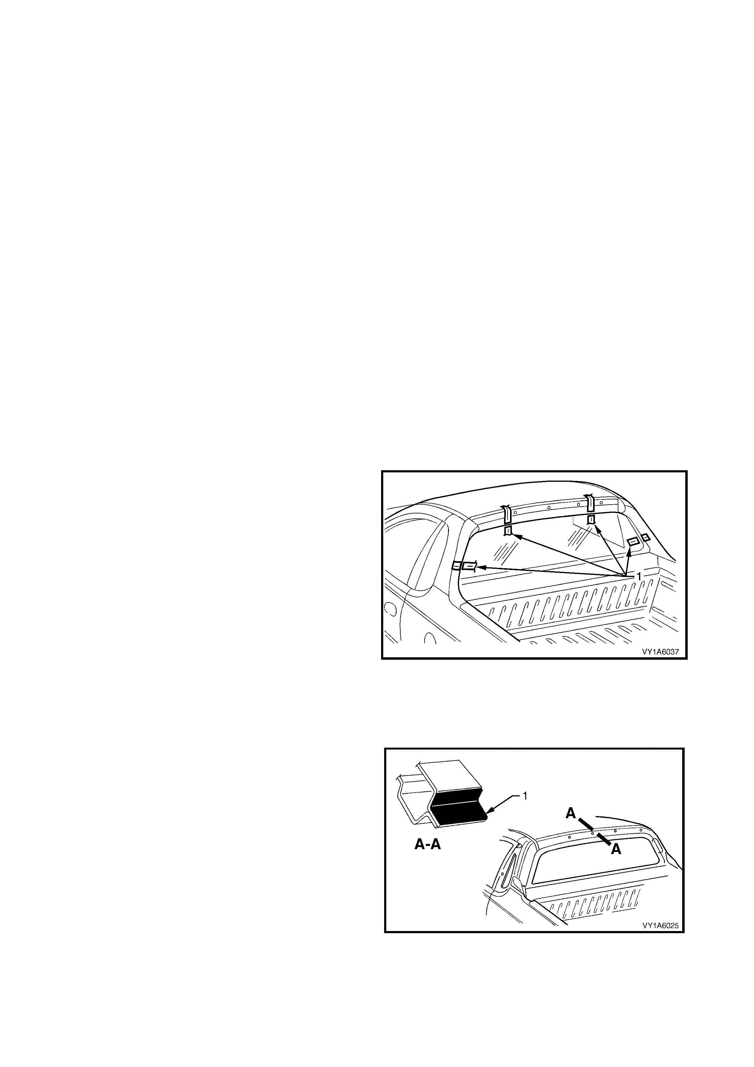
10. Fit the two self adhesive rear window spacers (2),
ensuring they are positioned on edge of the
window adjacent to the end of the bus bar on the
right and left-hand side.
11. Check the condition of the original urethane
around the window opening flange for voids or
looseness.
12. Cut away any loose pieces of urethane.
13. Using a suitable spatula, spread fresh urethane
smoothly into any voids or uneven sections.
Figure 1A6-69
14. Use the applicator ( 1) included in the servic e kit, to
apply black window adhesive prim er (2) to the rear
window as described in the following step.
Figure 1A6-70
15. Apply - black window adhesive primer (1), to the
inner surface of the rear window over a width of
20 mm, along the inside edge of the rear window
reveal moulding (2). Continue around the
remaining perimeter of the rear window (3) and
inboard of the rear window spacers.
Figure 1A6-71

16. Using a hand or automatic applicator, apply a
smooth continuous bead of window adhesive
(urethane) (1), such as Betaseal 15685 or
equivalent, around the perimeter of the window
along the inside edge of the rear window reveal
moulding (2). Continue around the remaining
perimeter of the rear window (3) inboard of the
rear window spacers. The bead dimensions are
shown in Figure1A6-73.
NOTE: 1 Depending on the amount of urethane
remaining on the body opening flange, the amount of
the new urethane should be reduced accor dingly, while
maintaining adequate strength and sealing properties.
The dimensions shown are the maximum allowable
and are only for reference.
NOTE: 2 In cold weather, the placement of cartridges
adjacent to a sourc e of warm th will ass ist in the flow of
urethane when using a hand applicator.
Figure 1A6-72
Figure 1A6-73
17. With the aid of an ass ist ant, install the r ear window
assembly, using the previously attached masking
tape (1) on the roof and the rear quarter panel to
ensure accurate installation.
NOTE: Ensure the rear window is centralised in the
body opening left to right by checking that the gaps
between the window moulding and body opening are
even on both sides of the vehicle.
18. Press the rear window firmly into position.
19. Check effectiveness of sealing from inside the
vehicle. Should any gaps in the sealing exist, apply
additional urethane to fill these gaps.
20. Wait two hours then water test the rear window,
using a moderate spray of water.
NOTE: Do not direct a heavy stream of water onto
freshly applied urethane. If a water leak is evident,
apply additional urethane to the leak area, using a
spatula to work the urethane into the source of the
leak.
21. Clean off any excess urethane using Prepsol or
white spirit. Clean the rear window, then remove
the masking tape previously installed.
22. Connect the electrical demist connectors and
cellular telephone antenna if fitted.
23. Reinstall the trim and hardware as required.
Figure 1A6-74
REINSTALL - LONG METHOD
CAUTION: Ensure that door windows are partially lowered to eliminate pressure build up which can be
caused by slamming doors. A curing time of 24 hours is recommended, although the vehicle may be
driven after 5 hours, providing it is driven only on a smooth road at speeds not exceeding 80 km/h with
the door windows partially lowered.
Description
The long m ethod for the rear window assem bly replac ement is used when the original urethane adhesive m aterial
cannot serve as a base for the replacement rear window.
This method should be used on vehicles requiring metal or paint repair to the rear window opening, when the
original adhesive is completely removed and replaced with new urethane for the window installation.
This method is also used when the rear window has been previously replaced using the short method. In such
instances, the build-up of urethane could position the window assembly too high in the opening.
CAUTION: Do not use petroleum based solvents to clean the rear window or the rear opening flange, as
the presence of the oil in the solvent will prevent the adhesion of the new urethane.
Preparation
1. Us ing a s har p sc r aper, c ar ef ully rem ove any original urethane fr om around the rear window. Clean the window
to be installed with a suitable oil free cleaning agent.
2. Using a knife or sharp scraper, remove the original urethane from around the entire perimeter of the window
opening flange. Avoid the removal of paint when removing urethane from opening flange.
Rear Window Opening Check
1. Thoroughly check the rear window opening flange for any irregularities before installing the rear window
assembly.
CAUTION: Care should be taken to ensure that the rear window does not strike the rear window opening.
Chipped edges can lead to subsequent breakage of the window assembly.
2. To check for correct alignment, temporarily place
the rear window in the body opening.
3. If necessary, reform the rear window opening
flange to produce a uniform flange to the window
contour.
4. Ensure the rear window is centralised in the body
opening left to right, by checking that the gaps
between the rear window and body opening are
even on both sides of the vehicle.
5. With masking tape (1), mark the outer top and side
of the roof and the rear quarter panel.
NOTE: This procedure will assist in the alignment of
the window in the correct horizontal and vertical plane
during final window installation.
6. Remove and place the rear window assembly face
down on a clean protected surface or fixture.
Figure 1A6-75
Reinstall
IMPORTANT: Flange primer is NOT required if using
the recommended urethane adhesive Betaseal 15685.
If not using Betaseal 15685, and are using an
equivalent system, refer to technical data supplied by
the manufacturer.
If requir ed by the m anufactur er, apply f lange primer (1)
as directed.
Figure 1A6-76
7. Thoroughly clean the inner surface and edges of
the rear window assem bly to which the urethane is
to be applied, using clean lint-free cloths and a
suitable oil free cleaning solvent.
CAUTION: Do not use petroleum b ased solven ts to
clean the rear window assembly, or the rear
opening flange as the presence of the oil in the
solvent will prevent the adhesion of the new
urethane.
8. Apply clear window adhesive primer, over the
width of the solid black ceram ic pattern (or a width
of 50 mm), to the inner surface around the
perim eter of the rear window. Im m ediately wipe of f
with a lint-free cloth.
Figure 1A6-77
9. Check the condition of the rear window reveal
moulding (1) and replace if damaged.
10. Install the moulding over the edge of the window.
Ensure the moulding is fitted correctly to the
window.
11. Fit the two self adhesive rear window spacers (2),
ensuring they are positioned on edge of the
window adjacent to the end of the bus bar on the
right and left-hand side.
Figure 1A6-78
12. Use the applicator ( 1) included in the servic e kit, to
apply black window adhesive prim er (2) to the rear
window as described in the following step.
Figure 1A6-79
13. Apply - black window adhesive primer (1), to the
inner surface of the rear window over a width of
20 mm, along the inside edge of the rear window
reveal moulding (2). Continue around the
remaining perimeter of the rear window (3) and
inboard of the rear window spacers.
Figure 1A6-80
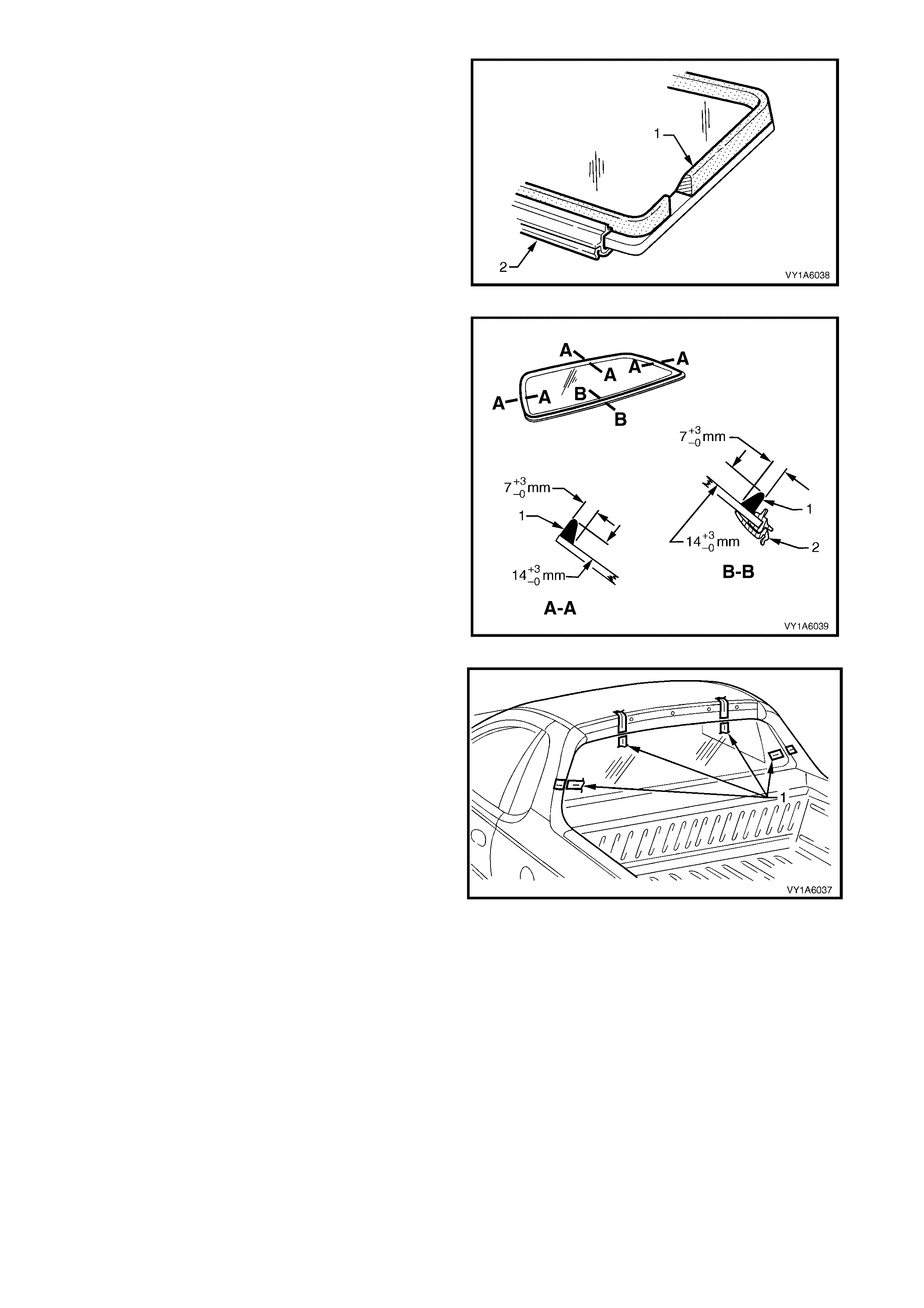
14. Using a hand or automatic applicator, apply a
smooth continuous bead of window adhesive
(urethane) (1), such as Betaseal 15685 or
equivalent, around the perimeter of the window
along the inside edge of the rear window reveal
moulding (2). Continue around the remaining
perimeter of the rear window (3) inboard of the
rear window spacers. The bead dimensions are
shown in Figure 1A6-82.
NOTE: In cold weather, the placement of cartridges
adjacent to a source of warmth will assist the flow of
urethane when using a hand applicator.
Figure 1A6-81
Figure 1A6-82
15. With the aid of an ass ist ant, install the r ear window
assembly, using the previously attached masking
tape (1) on the roof and the rear quarter panel to
ensure accurate installation.
NOTE: Ensure the rear window is centralised in the
body opening left to right by checking that the gaps
between the window moulding and body opening are
even on both sides of the vehicle.
16. Press rear window firmly into position.
17. Check effectiveness of sealing from inside the
vehicle. Should any gaps in the sealing exist, apply
additional urethane to fill these gaps.
18. Wait two hours then water test the window
assembly, using a moderate spray of water.
NOTE: Do not direct a heavy stream of water onto
freshly applied urethane. If a water leak is evident,
apply additional urethane to the leak area, using a
spatula to work the urethane into the source of the
leak.
19. Clean off any excess urethane using Prepsol or
white spirit. Clean the rear window, then remove
the masking tape previously installed.
20. Connect the electrical demist connectors and
cellular telephone antenna if fitted.
21. Reinstall the trim and hardware as required.
Figure 1A6-83

6. TORQUE WRENCH SPECIFICATIONS
Quarter window assembly retaining nut - Wagon and Utility ....................................1.0 – 3.0 Nm
Quarter window assembly retaining nut - Coupe......................................................2.0 – 2.5 Nm
Door frame opening moulding retaining screw.........................................................1.0 – 2.0 Nm
7. SPECIAL TOOLS
TOOL NUMBER ILLUSTRATION DESCRIPTION CLASSIFICATION
J36020
WINDSCREEN REMOVAL TOOL
AND PIANO WIRE
Previously released.
Unique