
SECTION 1A7 - SEAT ASSEMBLIES
IMPORTANT
Before perfo rming any Service O perat ion or o th er pro cedu re describ ed in th is Sectio n, ref er to Section 00
CAUTIONS AND NOTES for correct workshop practices with regard to safety and/or property damage.
CONTENTS
1. GENERAL INFORMATION
1.1 GENERAL DESCRIPTION
1.2 FRONT SEAT ASSEMBLY,
FOUR-WAY ELECTRIC
1.3 FRONT SEAT ASSEMBLY, EIGHT-WAY
EXCEPT COUPE
1.4 EZ-ENTRY SYSTEM, COUPE
OCCUPANT SENSING MAT
1.5 FRONT SEAT ASSEMBLY, EIGHT-WAY
COUPE – NON MEMORY
1.6 FRONT SEAT ASSEMBLY, EIGHT-WAY
COUPE – MEMORY
MEMORY SETS
MEMORY BUTTONS
PRIORITY RECALL FUNCTION
2. SERVICE OPERATIONS - FRONT
SEAT, EXCEPT COUPE
2.1 FRONT SEAT USAGE CHART -
EXCEPT COUPE
HOW TO USE THIS CHART
2.2 FRONT SEAT ASSEMBLY
REMOVE
REINSTALL
2.3 FRONT SEAT OUTER SIDE COVER
REMOVE
REINSTALL
2.4 FRONT SEAT ADJUSTM ENT SWITCH
REMOVE
REINSTALL
2.5 FRONT SEAT INNER SIDE COVER
REMOVE
REINSTALL
2.6 FRONT SEAT-BACK LOWER COVER
ASSEMBLY AND LUMBAR SUPPORT
ADJUSTER KNOB
REMOVE
DISASSEMBLE
REINSTALL
2.7 FRONT SEAT HEAD RESTRAINT
ASSEMBLY
REMOVE
DISASSEMBLE
REASSEMBLE
REINSTALL
2.8 FRONT SEAT HEAD RESTRAINT GUIDE
REMOVE
REINSTALL
2.9 FRONT SEAT-BACK PAD AND
COVER ASSEMBLY
REMOVE
DISASSEMBLE
REASSEMBLE
REINSTALL
2.10 FRONT SEAT-BACK FRAME ASSEMBLY
REMOVE
DISASSEMBLE
REINSTALL
2.11 SIDE IMPACT AIRBAG ASSEMBLY
2.12 FRONT SEAT CUSHION PAD AND
COVER ASSEMBLY
REMOVE
DISASSEMBLE
REASSEMBLE
REINSTALL
2.13 FRONT SEAT CUSHION FRAME ASSEMBLY
REMOVE
DISASSEMBLE
REASSEMBLE
REINSTALL
2.14 FRONT SEAT ADJUSTER ASSEMBLY
REMOVE
REINSTALL
2.15 FRONT SEAT LIFT MOTORS
2.16 FRONT SEAT FORE / AFT MOVEMENT
MOTOR
2.17 FRONT SEAT RECLINING MOTOR,
GEARBOX AND POTENTIOMETERS
ASSEMBLY
2.18 DRIVE MOTOR POTENTIOM ETERS
3. DIAGNOSTICS - FRONT SEAT,
EXCEPT COUPE
PREREQUISITES
3.1 MECHANICAL DIAGNOSIS –TWO-WAY/
FOUR-WAY SEAT
LUMBER SUPPORT INOPERATIVE
SEAT RECLINE FORWARD AND / OR
BACK FUNCTION IS INOPERATIVE
SEAT FORE / AFT FUNCTION IS
INOPERATIVE OR IS NOT SMOOTH
3.2 ELECTRICAL DIAGNOSIS – FOUR-WAY
SEAT, NON-MEMORY
WIRING DIAGRAM – FOUR-WAY SEAT,
NON-MEMORY
CONNECTOR CHART – FOUR-WAY SEAT,
NON-MEMORY
NEITHER SEAT ADJ USTMENT SWITCH
FUNCTIONS OPERATE
NONE OF THE DRIVER’S FOUR-WAY
SEAT ADJUSTMENT SWITCH
FUNCTIONS OPERATE
FRONT / REAR OF THE DRIVER’S SEAT
DOES NOT RAISE AND / OR LOWER
NONE OF THE PASSENGER’S FOUR-WAY
SEAT ADJUSTMENT SWITCH FUNCTIONS
OPERATE
FRONT / REAR OF THE PASSENGER’S
SEAT DOES NOT RAISE AND / OR LOWER
Techline
Techline
Techline
Techline
Techline
Techline
Techline
Techline

3.3 FOUR-WAY SEAT ADJUSTMENT
SWITCH TEST
TEST
3.4 MECHANICAL DIAGNOSIS – EIGHT-
WAY SEAT, NON-MEMORY
LUMBER SUPPORT INOPERATIVE
3.5 ELECTRICAL DIAGNOSIS –
EIGHT-WAY SEAT, NON-MEMORY
WIRING DIAGRAM – EIGHT-WAY
SEAT, NON-MEMORY
CONNECTOR CHART - EIGHT-WAY
SEAT, NON-MEMORY
NEITHER SEAT ADJ USTMENT SWITCH
FUNCTIONS OPERATE
NONE OF THE DRIVER’S EIGHT-WAY
SEAT ADJUSTMENT SWITCH
FUNCTIONS OPERATE
FRONT / REAR OF THE DRIVER’S SEAT
DOES NOT RAISE AND / OR LOWER
DRIVER’S SEAT FORE / AFT FUNCTION
IS INOPERATIVE OR NOT SMOOTH
DRIVER’S SEAT RECLINE FORWARD
AND / OR AFT FUNCTION IS
INOPERATIVE
NONE OF THE PASSENGER’S
EIGHT-WAY SEAT ADJUSTMENT
SWITCH FUNCTIONS OPERATE
FRONT / REAR OF THE PASSENGER’S
SEAT DOES NOT RAISE AND / OR
LOWER
PASSENGER’S SEAT FORE / AFT
FUNCTION IS INOPERATIVE OR NOT
SMOOTH
PASSENGER’S SEAT RECLINE
FORWARD AND / OR AFT FUNCTION IS
INOPERATIVE
3.6 EIGHT-WAY SEAT ADJUSTMENT
SWITCH TEST
TEST
4. SERVICE OPERATIONS - FRONT
SEAT, COUPE
4.1 FRONT SEAT USAGE CHART - COUPE
HOW TO USE THIS CHART
4.2 FRONT SEAT ASSEMBLY
REMOVE
REINSTALL
4.3 FRONT SEAT OUTER SIDE COVER
REMOVE
REINSTALL
4.4 EIGHT-WAY SEAT ADJUSTMENT SWITCH
REMOVE
REINSTALL
4.5 MEMORY POSITION SWITCH
REMOVE
REINSTALL
4.6 FRONT SEAT CONTROL MODULE,
EIGHT-WAY MEMORY SEAT
REMOVE
REINSTALL
4.7 EZ-ENTRY MODULE, EIGHT-WAY
NON-MEMORY SEAT
REMOVE
REINSTALL
4.8 FRONT SEAT INNER SIDE COVER
REMOVE
REINSTALL
4.9 FRONT SEAT-BACK LOWER COVER
ASSEMBLY AND LUMBAR SUPPORT
ADJUSTER KNOB
REMOVE
DISASSEMBLE
REINSTALL
4.10 FRONT SEAT HEAD RESTRAINT ASSEMBLY
REMOVE
DISASSEMBLE
REASSEMBLE
REINSTALL
4.11 FRONT SEAT HEAD RESTRAINT GUIDE
REMOVE
REINSTALL
4.12 EZ-ENTRY LEVER ARM, ESCUTCHEON
AND SEAT RETURN SWITCH
ASSEMBLY
REMOVE
REINSTALL
4.13 EZ-ENTRY CABLE AND SWITCH ASSEMBLY
4.14 FRONT SEAT-BACK PAD AND
COVER ASSEMBLY
REMOVE
DISASSEMBLE
REASSEMBLE
REINSTALL
4.15 FRONT SEAT-BACK FRAME ASSEMBLY
REMOVE
DISASSEMBLE
REINSTALL
4.16 SIDE IMPACT AIRBAG ASSEMBLY
4.17 FRONT SEAT CUSHION PAD AND
COVER ASSEMBLY
REMOVE
DISASSEMBLE
REASSEMBLE
REINSTALL
4.18 FRONT SEAT CUSHION FRAME ASSEMBLY
REMOVE
DISASSEMBLE
REASSEMBLE
REINSTALL
4.19 FRONT SEAT ADJUSTER ASSEMBLY
4.20 FRONT SEAT LIFT MOTORS
4.21 FRONT SEAT FORE / AFT
MOVEMENT MOTOR
4.22 FRONT SEAT RECLINING MOTOR,
GEARBOX AND POTENTIOMETER ASSEMBLY
4.23 DRIVE MOTOR POTENTIOM ETERS
5. DIAGNOSTICS - FRONT SEAT, COUPE
PREREQUISITES
5.1 MECHANICAL DIAGNOSIS -FRONT SEAT
LUMBER SUPPORT INOPERATIVE
EZ-ENTRY LEVER FUNCTION
INOPERATIVE
5.2 ELECTRICAL SELF TEST DIAGNOSIS -
EIGHT-WAY SEAT, NON-MEMORY
EZ-ENTRY DIAGNOSTICS
5.3 ELECTRICAL DIAGNOSIS – EIGHT-WAY
SEAT, NON-MEMORY
NEITHER SEAT ADJ USTMENT SWITCH
FUNCTIONS OPERATE

5.4 ELECTRICAL DIAGNOSIS – DRIVERS
EIGHT-WAY SEAT, NON-MEMORY
WIRING DIAGRAM - DRIVERS EIGHT-WAY
SEAT, NON-MEMORY
CONNECTOR CHART – DRIVER'S
EIGHT-WAY SEAT, NON-MEMORY
NONE OF THE DRIVER’S EIGHT-WAY
SEAT ADJUSTM ENT SWITCH
FUNCTIONS OPERATE
FRONT / REAR OF THE DRIVER’S SEAT
DOES NOT RAISE AND / OR LOWER
DRIVER’S SEAT FORE / AFT FUNCTION
IS INOPERATIVE OR NOT SMOOTH
DRIVER’S SEAT RECLINE FORWARD
AND / OR AFT FUNCTION IS
INOPERATIVE
DRIVER’S SEAT EZ-ENTRY SWITCH
FUNCTION IS INOPERATIVE
DRIVER’S SEAT RETURN SWITCH
FUNCTION IS INOPERATIVE
DRIVER’S SEAT TRACK MOTOR POSITION
SENSOR POTENTIOMETER TEST
DRIVER’S SEAT OCCUPANT SENSING
MAT TEST
5.5 ELECTRICAL DIAGNOSIS –
PASSENGER’S EIGHT-WAY SEAT,
NON-MEMORY
WIRING DIAGRAM - PASSENGER’S
EIGHT-WAY SEAT, NON-MEMORY
CONNECTOR CHART – PASSENGER’S
EIGHT-WAY SEAT, NON-MEMORY
NONE OF THE PASSENGER’S EIGHT-
WAY SEAT ADJUSTMENT SWITCH
FUNCTIONS OPERATE
FRONT / REAR OF THE PASSENGER’S
SEAT DOES NOT RAISE AND / OR
LOWER
PASSENGER’S SEAT FORE / AFT
FUNCTION IS INOPERATIVE OR
NOT SMOOTH
PASSENGER’S SEAT RECLINE
FORWARD AND / OR AFT FUNCTION
IS INOPERATIVE
PASSENGER’S SEAT EZ-ENTRY SWITCH
FUNCTION IS INOPERATIVE
PASSENGER’S SEAT RETURN SWITCH
FUNCTION IS INOPERATIVE
PASSENGER’S SEAT TRACK MOTOR
POSITION SENSOR POTENTIOMETER
TEST
PASSENGER’S SEAT OCCUPANT
SENSING MAT TEST
5.6 ELECTRICAL SELF TEST DIAGNOSIS -
EIGHT-WAY SEAT, MEMORY
EZ-ENTRY AND MEMORY DIAGNOSTICS
5.7 ELECTRICAL DIAGNOSIS – EIGHT-WAY
SEAT, MEMORY
NEITHER SEAT ADJUSTMENT
SWITCH FUNCTIONS OPERATE
5.8 ELECTRICAL DIAGNOSIS – DRIVERS
EIGHT-WAY SEAT, MEMORY
WIRING DIAGRAM - DRIVERS EIGHT-
WAY SEAT, MEMORY
CONNECTOR CHART – DRIVER'S
EIGHT-WAY SEAT, MEMORY
NONE OF THE DRIVER’S EIGHT-WAY
SEAT ADJUSTM ENT SWITCH
FUNCTIONS OPERATE
FRONT / REAR OF THE DRIVER’S SEAT
DOES NOT RAISE AND / OR LOWER
DRIVER’S SEAT FORE / AFT FUNCTION IS
INOPERATIVE OR NOT SMOOTH
DRIVER’S SEAT RECLINE FORWARD
AND / OR AFT FUNCTION IS
INOPERATIVE
DRIVER’S SEAT EZ-ENTRY SWITCH
FUNCTION IS INOPERATIVE
DRIVER’S SEAT RETURN SWITCH
FUNCTION IS INOPERATIVE
DRIVER’S SEAT TRACK MOTOR POSITION
SENSOR POTENTIOMETER TEST
DRIVER’S SEAT RECLINE MOTOR POSITION
SENSOR POTENTIOMETER TEST
DRIVER’S SEAT FRONT LIFT MOTOR POSITION
SENSOR POTENTIOMETER TEST
DRIVER’S SEAT REAR LIFT MOTOR POSITION
SENSOR POTENTIOMETER TEST
DRIVER’S SEAT OCCUPANT SENSING
MAT TEST
DRIVER’S SEAT MEMORY POSITION
SWITCH TEST
5.9 MEMORY POSITION SWITCH TEST
TEST
6. SERVICE OPERATIONS - REAR SEAT, SEDAN
6.1 REAR SEAT USAGE CHART - SEDAN
HOW TO USE THIS CHART
6.2 REAR SEAT CUSHION ASSEMBLY
REMOVE
DISASSEMBLE
REINSTALL
6.3 REAR SEAT-BACK ASSEMBLY
REMOVE
DISASSEMBLE
REINSTALL
6.4 REAR SEAT-BACK HEAD RESTRAINT
ASSEMBLY
REMOVE
DISASSEMBLE
REASSEMBLE
REINSTALL
6.5 REAR SEAT-BACK HEAD RESTRAINT GUIDE
REMOVE
REINSTALL
6.6 REAR SEAT-BACK CENTRE, ARMREST
ASSEMBLY
REMOVE
DISASSEMBLE
REASSEMBLE
REINSTALL
6.7 REAR SEAT CENTRE BACK ASSEMBLY
REMOVE
DISASSEMBLE
REINSTALL
6.8 REAR SEAT CENTRE BACK, LOCK STRIKER
REMOVE
REINSTALL
7. SERVICE OPERATIONS - REAR
SEAT, WAGON
7.1 REAR SEAT USAGE CHART - WAGON
HOW TO USE THIS CHART
7.2 REAR SEAT CUSHION ASSEMBLY
REMOVE
DISASSEMBLE
REINSTALL

7.3 REAR SEAT BOLSTER ASSEMBLY
REMOVE
REINSTALL
7.4 REAR SEAT-BACK ASSEMBLY
REMOVE
DISASSEMBLE
REINSTALL
7.5 REAR SEAT-BACK HEAD RESTRAINT
ASSEMBLY
REMOVE
DISASSEMBLE
REASSEMBLE
REINSTALL
7.6 REAR SEAT-BACK HEAD RESTRAINT
GUIDE
REMOVE
REINSTALL
7.7 REAR SEAT-BACK ARMREST
ASSEMBLY
REMOVE
DISASSEMBLE
REASSEMBLE
REINSTALL
7.8 REAR SEAT-BACK ARMREST HINGE
ASSEMBLY AND CENTRE COVER
REMOVE
REINSTALL
7.9 REAR SEAT CENTRE SUPPORT
REMOVE
REINSTALL
7.10 REAR SEAT-BACK LOCK STRIKER
REMOVE
REINSTALL
8. SERVICE OPERATIONS - REAR SEAT,
COUPE
8.1 REAR SEAT CUSHION ASSEMBLY
REMOVE
DISASSEMBLE
REINSTALL
8.2 REAR SEAT-BACK ASSEMBLY
REMOVE
DISASSEMBLE
REINSTALL
8.3 REAR SEAT HEAD RESTRAINT
ASSEMBLY
REMOVE
REINSTALL
8.4 REAR SEAT HEAD RESTRAINT GUIDE
REMOVE
REINSTALL
9. TORQUE WRENCH SPECIFICATIONS
1. GENERAL INFORMATION
This seat ass em bly Section for the MY2003 VY Series & MY2003 V2 Series II service inf orm ation has been divided
into seven s ections: Front Seat, ex cept Coupe; Diagnosis Fr ont Seat, except Coupe; Front Seat, Coupe; Diagnos is
Front Seat, Coupe; Rear Seat, Sedan; Rear Seat, Wagon and Rear Seat, Coupe.
At the start of each Section, usage charts are provided for domestic and export markets to aid the seat
identification. T he charts include the vehicle m odel, trim f abric, trac k ass embly, the addition of lumber support, side
airbag and the construction of the trim covers to the trim pads.
For the rear s eats these c harts inc lude the addition of headres ts and an armrest. T he charts are com plim ented with
illustrations of the complete breakdown of each of the individual seat combinations available.
A four- way electric adjustable driver s eat (f r ont up and down, and rear up and down) is fitted as standard equipm ent
to all models except Level 3 and Coupe.
An eight-way elec tric adjus table driver and passenger seat, fitted to Level 3 and optional on som e Level 2 left-hand
drive vehicles, has four extra movements over the four-way, (fore/aft movement and seat-back recliner).
Coupe models are fitted with eight-way electrically adjustable driver and passenger seats, which also include side
impac t airbags and an EZ -entry feature. In addition, the dr iver’s seat in the CV8 is fitted with an integrated mem ory
seat system. Leather trim is standard on all Coupe models.
All other front seats provide manual fore/aft adjustment only.
For f ront and rear s eats, there are two methods of cover as sem bly c onstruction, Surebond and Hook and Loop. All
vehicles with leather trim, plus all Level 2, 3 and coupe have Hook and loop construction.
Surebond cover assemblies are not serviced as they are glued to the seat-back pad. Hook and Loop cover
assemblies are fully serviced and attached in the groves of the seat pad and the corresponding cover.
The rear seat fitted to the Coupe m odel is a new two-passenger design, with a unique construction and adjustable
rear head restraints.
While the remove and replace of the front seatbelt pretensioner assembly is included in this section
for completeness, specific seatbelt and seatbelt pretensioner service procedures are combined in
Section 12M OCCUPANT PROTECTION SYSTEM.
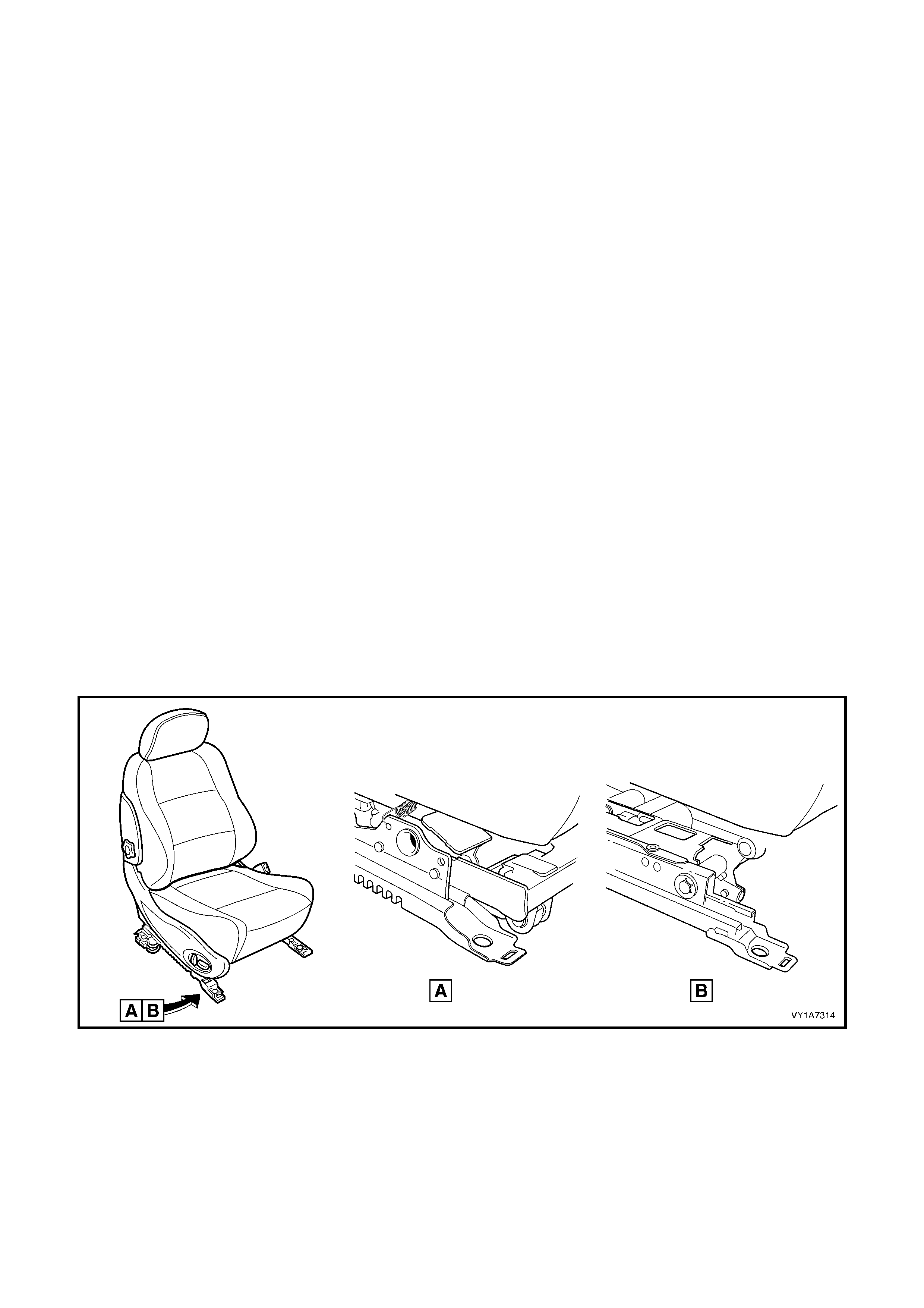
During production of the MY 2003 VY Series vehicles, the front s eat as semblies gained a revised front seat adjus ter
assembly, refer to Figure 1A7-1
This change to the f r ont s eat ass emblies af fected some ser vice oper ations . Where there are changes to the service
procedures, the seat assemblies prior to the running change are referred to as "early type" View A and additional
information has been added to cover the late type seat adjuster assembly, View B.
Figure 1A7-1
These following Cautions apply to service operations detailed in this Section.
CAUTION 1: Accessory and after m arket seat covers MUST NOT be fitted to any vehicle with side airbags unless
approved by the manufactur er. Non-approved seat c overs m ay inhibit the operation of the side airbag, reducing the
protection otherwise provided to the occupants during a side-impact collision.
CAUTION 2: Befor e perform ing any servic e operation on a front seat ass embly, ensure the SRS is disabled. Refer
to Section 12M OCCUPANT PROTECTION SYSTEM.
IMPORTANT: Some of the procedures relating to memory seat diagnosis detailed in 5. DIAGNOSTICS – FRONT
SEAT, COUPE, require the use of both the Priority 1 Key and the Priority 2 Key.

1.1 GENERAL DESCRIPTION
The four-way electric adjustable driver seat (front up and down, and rear up and down), is controlled by two lift
motor and gearbox assemblies. Each can be operated independently of the other, or operated together to raise or
lower the complete seat assembly.
The eight-way electric adjus table driver and pas senger seats have four extra m ovem ents over the four-way: f ore/af t
movement and seat-back recliner. In addition to the two motor and gearbox assemblies described previously, a
fore/af t m ovem ent m otor dr ives two gearboxes which control s eat forward or rearward positioning. The fourth mo tor
controls the seat-back recliner position.
Each lif t m otor and gear box ass em bly is bolted to the inboard side of the seat height adj ust ass em bly. W hen the lif t
motor is operating, it drives the gearbox which draws in or extends out the mating worm shaft which in turn operates
on a lever and cross-brace. The cross-brace is connected to another lever on the opposite side of the seat height
adjust assem bly and this allows the raising or lowering of that section of the seat. Reversing the polarity on the lift
motor terminals causes the motor to operate in the reverse direction and the seat moves in the opposite direction.
To control seat fore/aft movement, a worm shaft is attached to each seat rail with the movement motor and
gearboxes attached to the seat height adjust assembly. Components making up the adjuster and guide rail
assembly are not serviced due to safety regulations.
The s eat-bac k recliner angle is adj us ted by a recliner m otor attac hed to the inner f r ame. T he motor output shaf t has
a drive gear which is meshed with a driven gear attached to the seat-back frame. Motor operation causes rotation of
the drive gear which turns the driven gear and seat-back frame, thereby altering the seat-back recliner angle.
Reversing the polarity on the recliner motor terminals causes the motor to drive in the reverse direction and the
seat-back m oves in the oppos ite direc tion. Components mak ing up the s eat-bac k recliner mechanis m assembly are
not serviced due to safety regulations.
The Coupe eight-way electric front seat motor and gearboxes have the same function as the Level 3 vehicle. The
front s eat als o incor porates an EZ -entr y feature that provides a s imple one touch mechanis m to m ove the f r ont seat
and allow rear seat passengers to enter or exit the vehicle. A lever on the outer upper corner of the seat-back
disengages the seat-back locking mechanism. An internal micro switch senses when the lever is operated and
signals to the m odule that the EZ-entry f eature has been activated, which in turn drives the seat forward. The seat
fore and af t position is m onitored by a potentiometer (incor porated into the fore/aft drive m otor) and recorded in the
seat module. Once the seat-back is returned to the locked position, the operator must press and hold the seat
return switch to m ove the seat rearwards. When the seat reaches the last recorded location, the af t movem ent will
pause for approximately three seconds before continuing to the fully rearward position.
An internal occupant sensing mat is incorporated into the Coupe front seat cushions. The occupant sensing mat
signals to the seat c ontro l module whenever the seat is oc cupied with a weight in exces s of 15 kg. The module then
prevents the seat from driving forward should the EZ-entry lever be operated.
In addition, the driver’s seat in the CV8 is fitted with an integrated memory seat system. On key-less entry to the
vehicle, the m emory seat system in conj unction with the Body Control Module (BCM) recognises which ignition key
has been used (Priority 1 or Priority 2) and adjusts the seat accordingly .
The memory seat system allows the driver to adjust the seat position to any of the positions stored in memory by
pressing one of the three memory buttons.
Audio and visual feedback for the various functions of the memory seat system is provided. The system has a
green LED and an audio c hime located in the s eat ass embly which are used to indicate m emory saves, the rec all of
priority memory numbers and for seat diagnostic procedures.
All coupe f r ont s eats contain a seat c ontr ol module under the lower side c over. T he s eat c ontrol module f itted to the
memory type seat has a non-volatile memory, so that disconnecting the battery supply from the module does not
erase the seat memory settings.
W atchdog tim ers in the memory seat system lim it the time a seat drive motor can operate. The lift and m ovement
motors are limited to 25 seconds, while the recliner motor is limited to 50 seconds.
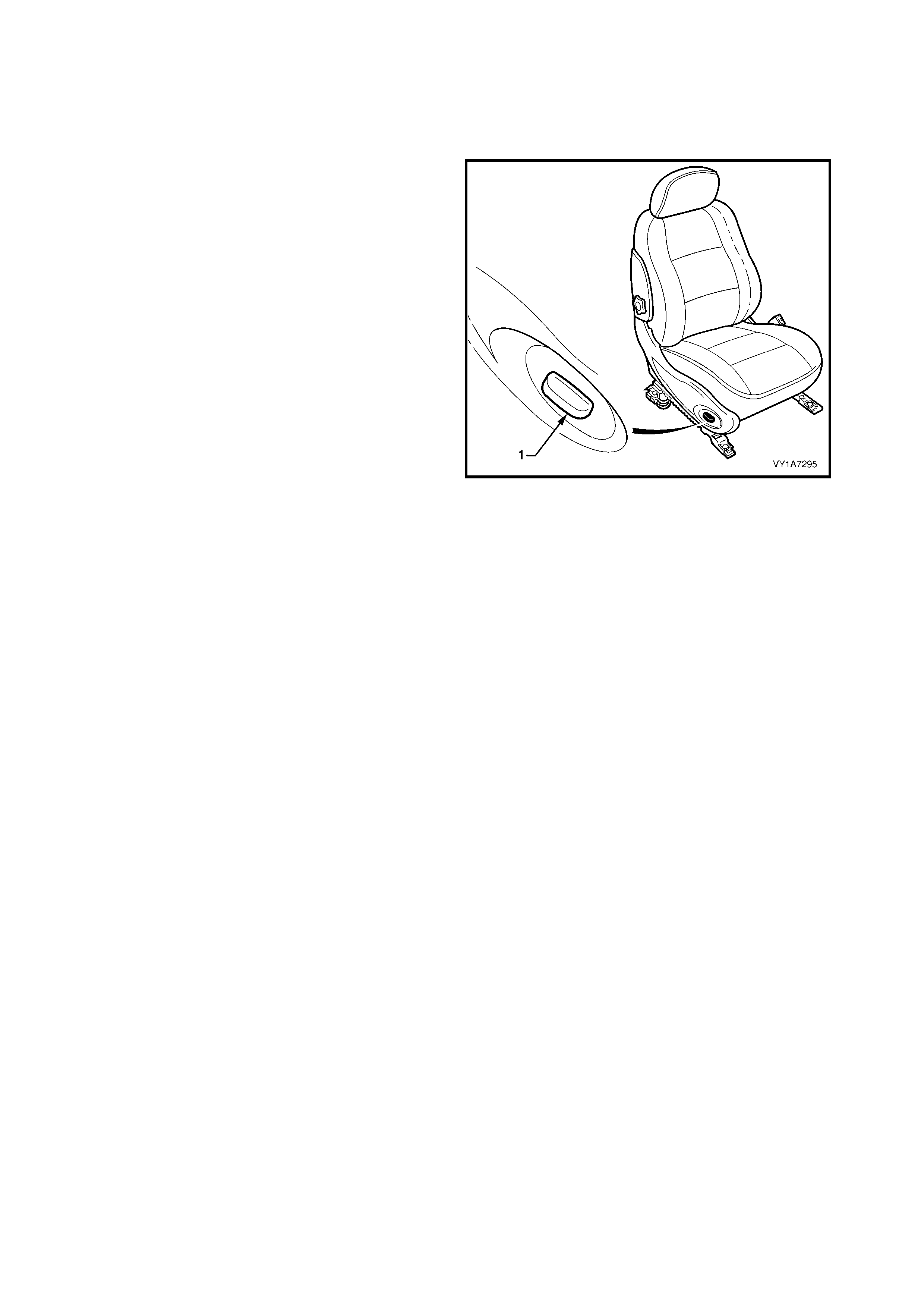
1.2 FRONT SEAT ASSEMBLY, FOUR-WAY ELECTRIC
CAUTION: For reasons of personal safety, the vehicle must only be driven when the seat is adjusted to
the co rrect d riv ing posit ion . Do n ot adju st t he d riv er’s seat when th e v ehicle is mo v ing as th e seat co uld
move away from the driving position, ca using loss of control.
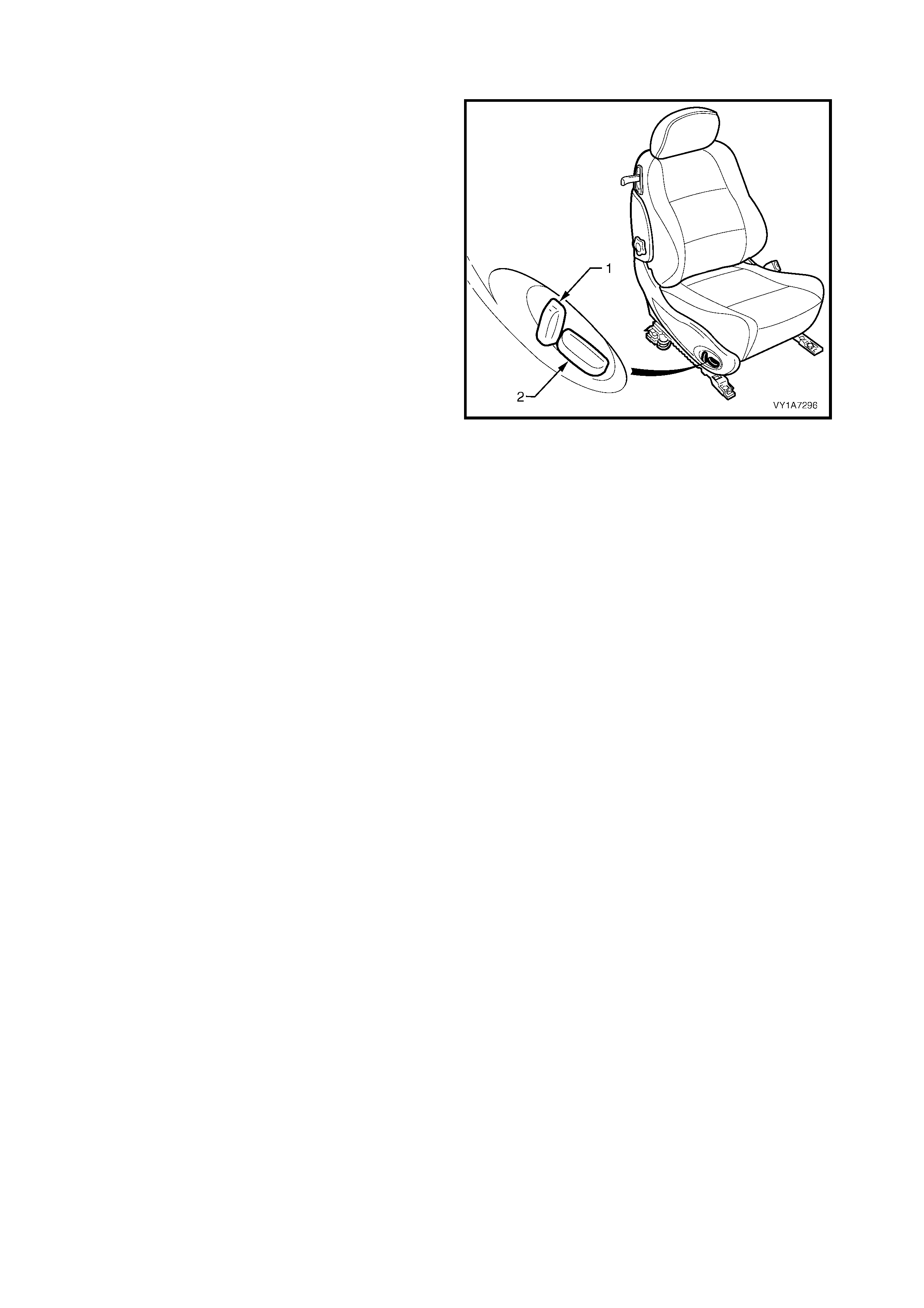
A seat control adjustment switch (1) is fitted to the
outside of each seat frame. This switch assembly
provides independent control of front and/or rear seat
height (up and down movement).
During seat adjustment, the drive motors will stop
operating at end of travel via an internal thermal cut-
out switch, even if the seat adjustment switch is held
on.
Figure 1A7-2
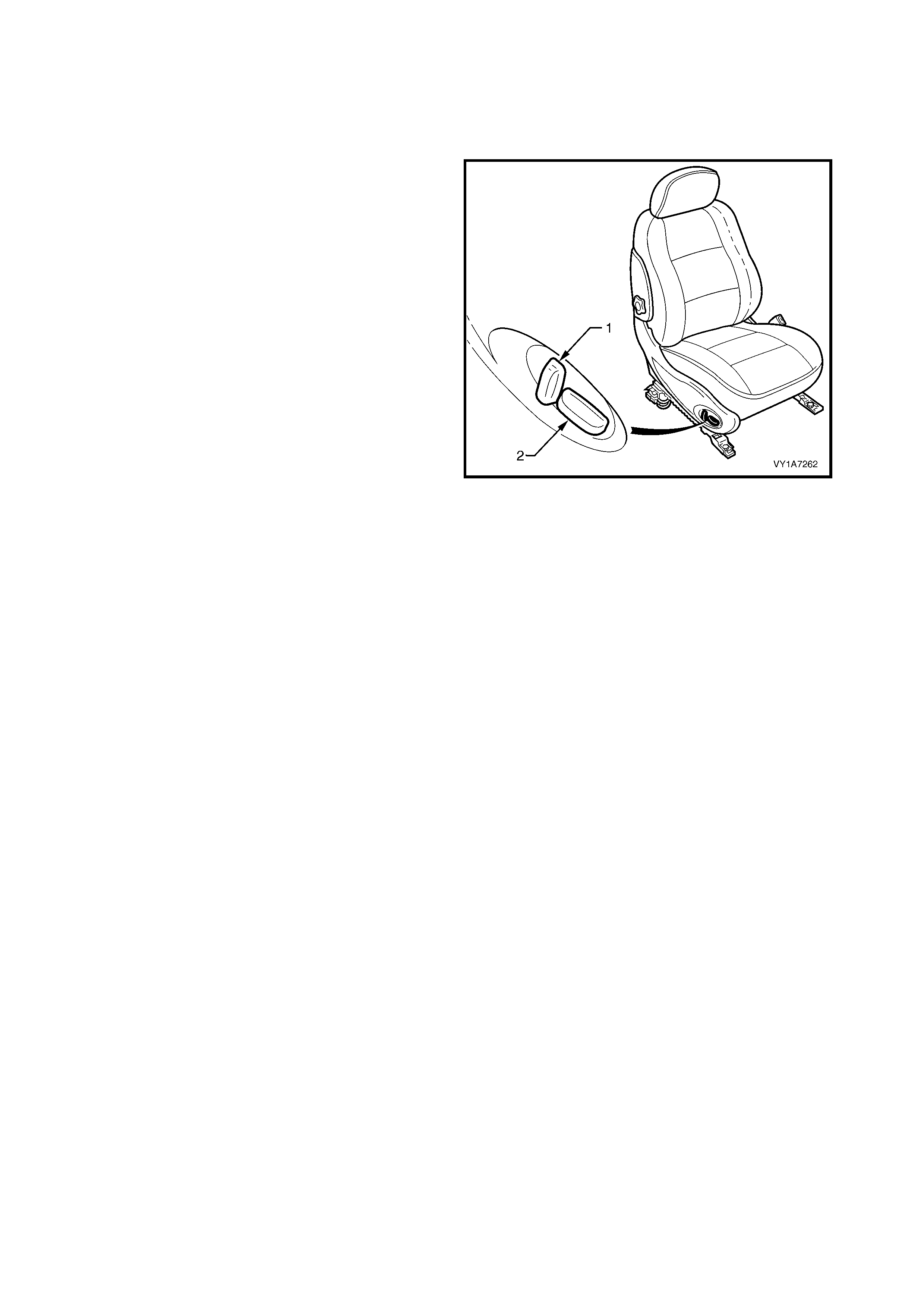
1.3 FRONT SEAT ASSEMBLY, EIGHT-WAY EXCEPT COUPE
CAUTION: For reasons of personal safety, the vehicle must only be driven when the seat is adjusted to
the co rrect d riv ing posit ion . Do n ot adju st t he d riv er’s seat when th e v ehicle is mo v ing as th e seat co uld
move away from the driving position, ca using loss of control.
A seat control adj ustm ent switch is fitted to the outside
of each seat frame. This switch assembly provides
independent control of:
1. Vertical switch - seat-back recliner angle.
2. Horizontal switch - front and rear cushion height
(up and down movement) of the seat along with
fore/ aft movement.
During seat adjustment, the drive motors will stop
operating at end of travel via an internal thermal cut-
out switch, even if the seat adjustment switch is held
on.
Figure 1A7-3
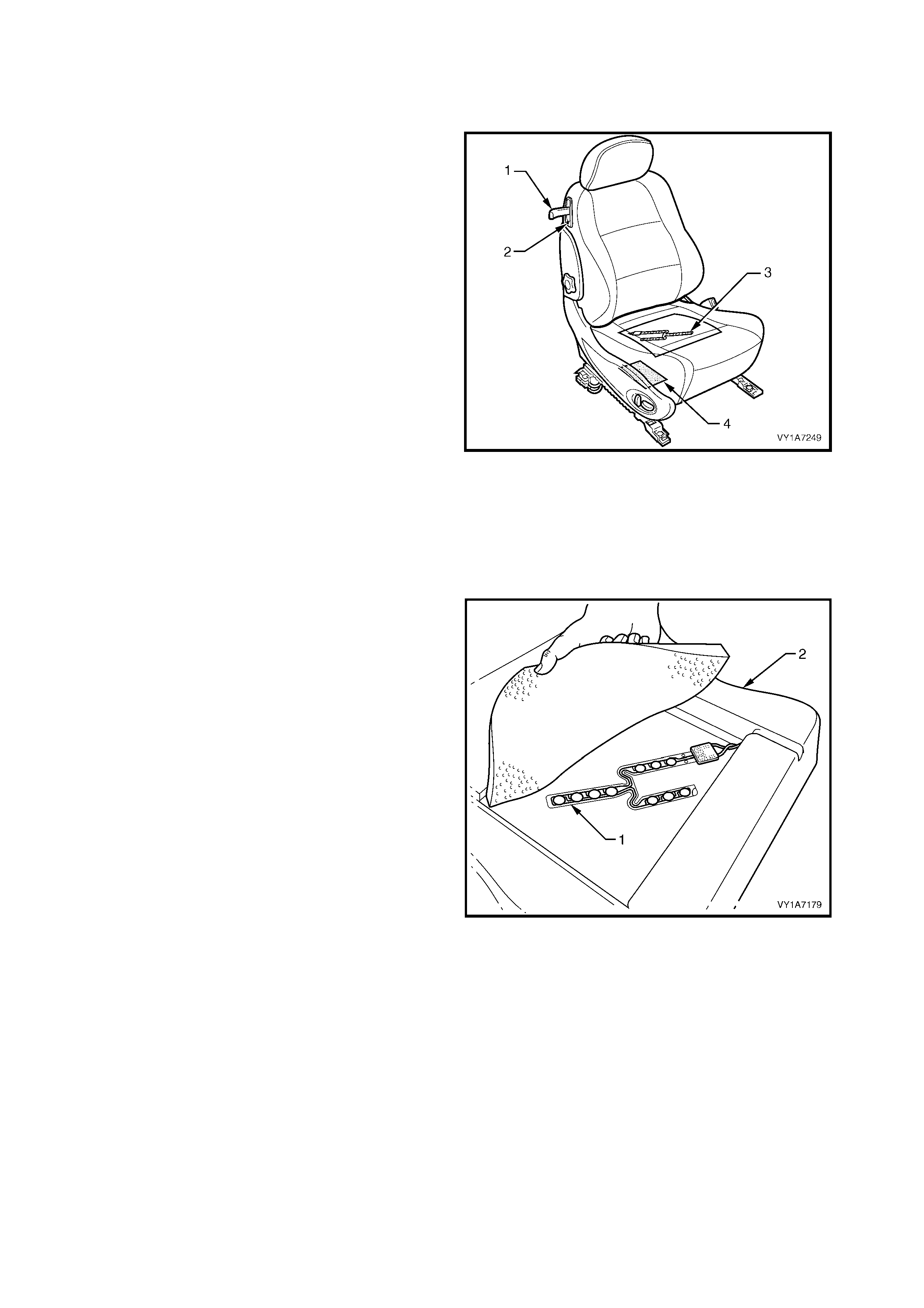
1.4 EZ-ENTRY SYSTEM, COUPE
OCCUPANT SENSING MAT
1. The EZ-entry system provides a one touch
mechanism to move the front seat and allow rear
seat passengers to enter or exit the vehicle. The
EZ-entry system comprises:
• An EZ-entry lever (1) on the upper outer side
of the front seat.
• A return button (2) in the EZ-entry lever
escutcheon.
• An internal occupant sensing mat (3).
• The front seat control module (4) located
under the seat.
2. When the EZ-entry lever is un-latched, the seat-
back collapses forward and the seat automatically
launches to the full forward position.
3. The seat will return to the pr e-launch pos ition once
the lever is latched (i.e. the seat-back is returned
to the upright position) and the seat return switch
is pressed and held.
4. If a passenger (or load in excess of 15 kg) is
present in the seat or enters the seat while it is
automatically moving, the movement will cease. If
weight detection causes the EZ-entry function to
cease, a period of one second must pass without
weight before a restart will commence.
Figure 1A7-4
5. The occupant sensing mat (1) is installed inside
the front seat cushions (2). The occupant sensing
mat is a pressure switch with a nominal high or
open circuit condition with no weight on the seat.
The resistance decreases as the weight is
increased. An integral diode is provided within the
occupant sensing mat and is used by the module
to verify connection of the occupant sensing mat
prior to the automatic forward movement of the
seat during the operation of the EZ-entry function.
The module will test whether for the following
conditions on the occupant sensing mat:
• Either line connected to ground or battery.
• Either line open circuited.
6. Detection of weight over the occupant s ensing m at
(seat cushion) will cause the seat m odule to either
cancel an autom atic forward m ovement or prevent
an automatic forward movement from
commencing. The module should detect a
minimum weight on the seat of 15 kg.
Figure 1A7-5
1.5 FRONT SEAT ASSEMBLY, EIGHT-WAY COUPE – NON MEMORY
A seat control adj ustm ent switch is fitted to the outside
of each seat frame. This switch assembly provides
independent control of:
1. Vertical switch - seat-back recliner angle.
2. Horizontal switch - front and rear cushion height
(up and down movement) of the seat along with
fore/ aft movement.
During seat adjustment, the drive motors will stop
operating at end of travel via an internal thermal cut-
out switch, even if the seat adjustment switch is held
on.
The eight-way position switch is disabled during
automatic movement requested by operation of the
EZ-entry function. The switch will be enabled once the
automatic movement is completed or cancelled. The
eight-way position switch is monitored by the module
during automatic movement, and if the switch is
operated, the automatic movement will be cancelled
and the seat will enter the manual mode.
Figure 1A7-6

1.6 FRONT SEAT ASSEMBLY, EIGHT-WAY COUPE – MEMORY
The memory seat system comprises:
• the seat control module located under the seat lower side cover (refer to Fig. 1A7-3);
• the m em ory pos ition switch, which includes m em ory buttons and associated LED, located on the side of the
driver’s seat (refer to Fig. 1A7-6);
• the ignition keys;
• the body control module (BCM).
The s eat control module has five mem ory sets which allows up to f ive individual seat settings to be s tored. Two
of these memory settings are associated with the priority keys and the remaining three settings correspond to
the memory buttons 1, 2 and 3 located on the side of the driver’s seat.
The memory seat system has two modes of operation; a low-current sleep mode and an awake mode. A
5 minute tim er cir cuit switches the system between m odes as required, and the cur rent m ode is indic ated by the
green LED on the side of the seat. When the LED is illuminated the system is in awake mode, and when the
LED is extinguished, the system is in sleep mode.
The sleep mode is entered when:
• the ignition key is in the OFF position, and
• there are no active priority signals, and
• there are no manual seat adjustments for 5 minutes.
The awake mode is entered when:
• the ignition key is in the IGN position, or
• the priority signals are active, or
• there is a manual seat adjustment, or
• a seat memory button is pressed.
Entering the awake mode resets the 5 minute timer.
MEMORY S ETS
There are five memory sets, as follows:
• Memory set P1 – Priority Key 1,
• Memory set P2 – Priority Key 2,
• Memory set 1 – Button 1 on seat,
• Memory set 2 – Button 2 on seat, and
• Memory set 3 – Button 3 on seat.
Each memory set comprises four co-ordinates for the seat position (in seat control module); seat cushion front
height, seat cushion rear height, seat stroke and backrest position.
A priority key setting can also be stored and recalled by use of one of the three memory buttons on the seat.
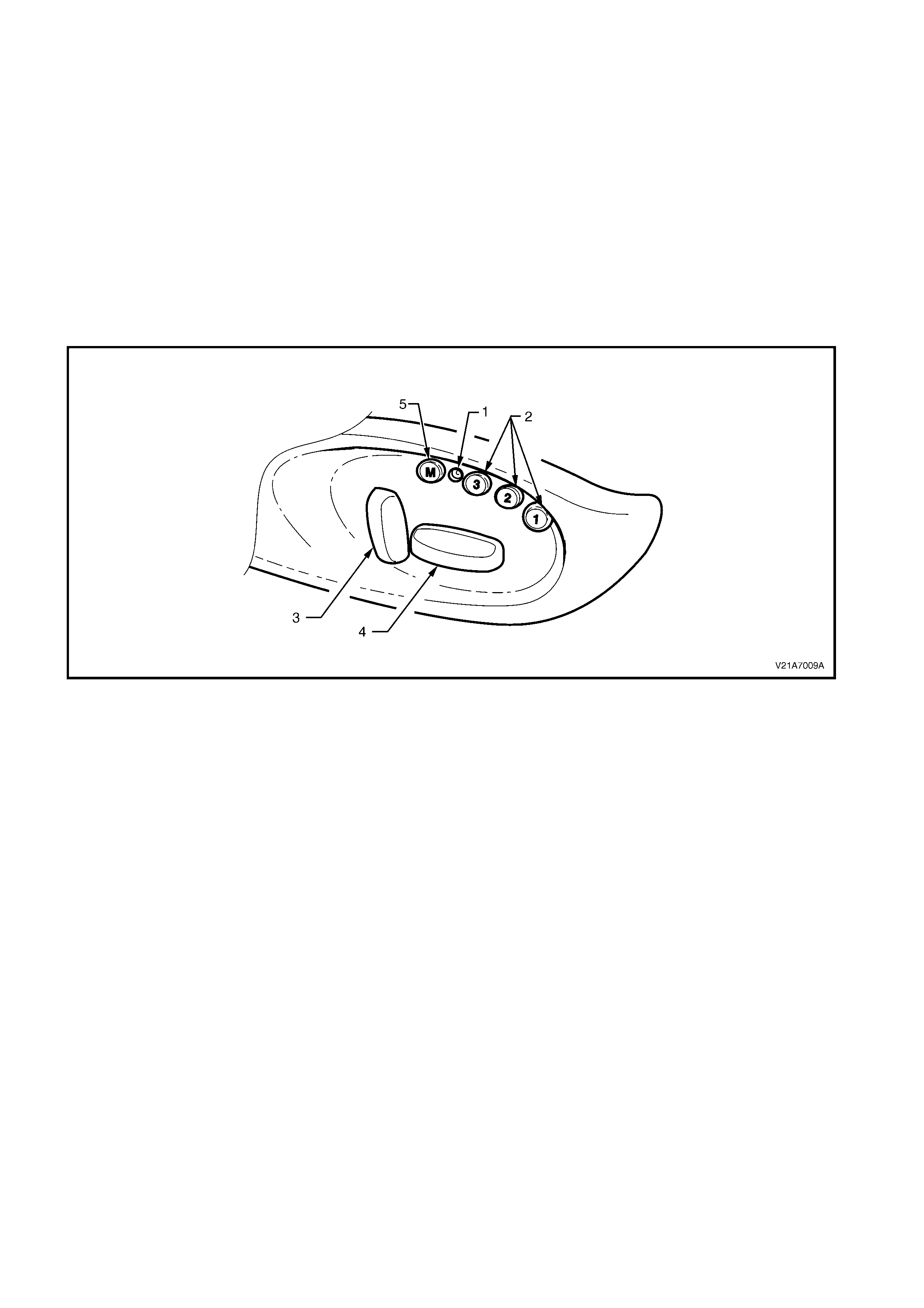
MEMORY BUTTONS
The three memory recall buttons, the memory store button and the associated LED are located on the seat lower
side cover close to the front edge of the seat. The memory recall buttons are labelled 1, 2 and 3.
Press and hold a s eat mem ory button to recall the m emory position. Once the s eat has reached the m em orised
position the button can be released. If the button is released before the seat reaches the memorised position,
the seat will simply stop moving. Even though the seat may then be adjusted to a new position, pressing a button
will return the seat to the memory position stored for that button.
To change a mem ory position, adjust the seat with the seat control switch, then press the memory store button
(M) (confir med by a single c hime) followed by the desired m emor y button ( 1, 2 or 3) within 5 seconds. A double
chime will be heard when a new memory is stored.
For safety reasons, no memory button recall is allowed when the ignition is on. However, if a recall is initiated
and the ignition is then set to on, the seat movement recalled from memory will continue until completed.
Pressing any other button after a memory recall is initiated will terminate the recall move.
Figure 1A7-7
Legend
1. Diagnostic LED
2. Memory Recall Buttons
3. Seat-back Recliner Button
4. Fore/Aft/Up/Down/Tilt Adjust Button
5. Memory Store Button
PRIORITY RECALL FUNCTION
The priority recall signals generated by the BCM wake up the memory seat system to recall the last saved
priority seat positions associated with the ignition key in use (Priority 1 or Priority 2).
For safety reasons, the priority recall function is ac tivated only when the ignition switch is in the OFF position. No
automatic movement of the system occurs when the ignition switch is set to IGN. If a priority move has been
initiated before the ignition tr ansition from O F F to IG N, the system c ompletes the move befor e dis abling the one-
touch or priority recall function.
After the ignition switch is set to IGN, the system notes the active priority key number used. The system only
updates the current memory when the driver makes a manual adjustment to the seat. The update includes the
current seat position.
When the seat is adjusted by the driver using the manual buttons, the current priority memory is updated
immediately after the movement stops.

2. SERVICE OPERATIONS – FRONT SEAT, EXCEPT COUPE
2.1 FRONT SEAT USAGE CHART - EXCEPT COUPE
HOW TO USE THIS CHART
Thirteen front seat configurations are used in MY2003 VY Series Sedan Wagon and Utility vehicles. The
following usage chart is provided to help determine the seat type fitted to the vehicle. This is important prior to
repairs being performed as the failed / damaged part may not be serviceable.
To determine the seat fitted to the vehicle, obtain the vehicle model, which seat requires attention and the seat
cover fabric. Then establish if the vehicle has a side impact airbag and/or manually adjustable lumber support.
Using the chart will lead to the elimination of all other seat combinations, allowing the identification of the type
and the construction of the seat. Finally, refer to the Figure shown in TYPE for a component breakdown of the
front seat assembly.
1. VEHICLE – Vehicle model identification.
2. SEATING – Driver front seat or passenger front seat.
3. FABRIC – Cloth or leather seat covers.
4. TRACK – Indicates the number of directions the electric seat track can be moved, except for the two way
which is manually operated.
5. LUMBER – If the front seat-back is fitted with a manually adjust lumber support.
6. SIAB – If the front seat is fitted with a side impact airbag.
7. CONSTRUCTION – Surebond refers to the seat cover being glued to the seat pad and only serviced as a
cover and pad ass embly. Hook and Loop refer s to the seat c over being able to be attached or removed from
the seat pad and both being serviced as separate parts.
8. TYPE – Identif ies the seat type and provides ref er enc e to the f ollowing illustrations which s how a break down
of the serviced component for each rear seat assembly.
Techline

DOMESTIC
VEHICLE SEATING FABRIC TRACK LUMBER SIAB CONSTRUCTION TYPE
(Refer to)
Driver Leather / Cloth 8 Way Yes Yes Hook & Loop 1 (Figure 1A7-8)
Calais Passenger Leather / Cloth 8 Way Yes Yes Hook & Loop 1 (Figure 1A7-8)
Driver Leather / Cloth 4 Way Yes Yes Hook & Loop 2 (Figure 1A7-9)
Berlina Passenger Leather / Cloth 2 Way Yes Yes Hook & Loop 6 (Figure 1A7-13)
Driver Cloth 4 Way Yes No Surebond 3 (Figure 1A7-10)
Passenger Cloth 2 Way No No Surebond 10 (Figure 1A7-17)
Driver Cloth 4 Way Yes Yes Surebond 4 (Figure 1A7-11)
Executive
Passenger Cloth 2 Way No Yes Surebond 11 (Figure 1A7-18)
Driver Cloth 4 Way Yes Yes Surebond 4 (Figure 1A7-11)
Acclaim Passenger Cloth 2 Way Yes Yes Surebond 9 (Figure 1A7-16)
Driver Cloth 4 Way Yes No Surebond 3 (Figure 1A7-10)
Passenger Cloth 2 Way Yes No Surebond 8 (Figure 1A7-15)
Driver Cloth 4 Way Yes Yes Surebond 4 (Figure 1A7-11)
Passenger Cloth 2 Way Yes Yes Surebond 9 (Figure 1A7-16)
Driver Leather 4 Way Yes No Hook & Loop 5 (Figure 1A7-12)
Passenger Leather 2 Way Yes No Hook & Loop 7 (Figure 1A7-14)
Driver Leather 4 Way Yes Yes Hook & Loop 2 (Figure 1A7-9)
S Sedan
Passenger Leather 2 Way Yes Yes Hook & Loop 6 (Figure 1A7-13)
Driver Cloth 4 Way Yes No Surebond 3 (Figure 1A7-10)
Passenger Cloth 2 Way Yes No Surebond 8 (Figure 1A7-15)
Driver Cloth 4 Way Yes Yes Surebond 4 (Figure 1A7-11)
Passenger Cloth 2 Way Yes Yes Surebond 9 (Figure 1A7-16)
Driver Leather 4 Way Yes No Hook & Loop 5 (Figure 1A7-12)
Passenger Leather 2 Way Yes No Hook & Loop 7 (Figure 1A7-14)
Driver Leather 4 Way Yes Yes Hook & Loop 2 (Figure 1A7-9)
SS
Sedan
Passenger Leather 2 Way Yes Yes Hook & Loop 6 (Figure 1A7-13)
Driver Cloth 4 Way Yes No Surebond 3 (Figure 1A7-10)
Passenger Cloth 2 Way No No Surebond 10 (Figure 1A7-17)
Driver Cloth 4 Way Yes Yes Surebond 4 (Figure 1A7-11)
SV8
Passenger Cloth 2 Way No Yes Surebond 11 (Figure 1A7-18)
Driver Cloth 2 Way Yes No Surebond 8 (Figure 1A7-15)
Utility Passenger Cloth 2 Way No No Surebond 10 (Figure 1A7-17)
Driver Cloth 4 Way Yes No Surebond 3 (Figure 1A7-10)
S Utility Passenger Cloth 2 Way Yes No Surebond 8 (Figure 1A7-15)
Driver Cloth 4 Way Yes No Surebond 3 (Figure 1A7-10)
Passenger Cloth 2 Way Yes No Surebond 8 (Figure 1A7-15)
Driver Leather 4 Way Yes No Hook & Loop 5 (Figure 1A7-12)
SS Utility
Passenger Leather 2 Way Yes No Hook & Loop 7 (Figure 1A7-14)

BRAZIL
VEHICLE SEATING FABRIC TRACK LUMBER SIAB CONSTRUCTION TYPE
(Refer to)
Driver Leather 8 Way Yes Yes Hook & loop 1 (Figure 1A7-8)
Omega
CD Passenger Leather 8 Way Yes Yes Hook & loop 1 (Figure 1A7-8)
GULF STATES
VEHICLE SEATING FABRIC TRACK LUMBER SIAB CONSTRUCTION TYPE
(Refer to)
Driver Leather / Cloth 8 Way Yes No Hook & Loop 12 (Figure 1A7-19)
Lumina
LTZ Passenger Leather / Cloth 8 Way Yes No Hook & Loop 12 (Figure 1A7-19)
Driver Cloth 8 Way Yes No Surebond 13 (Figure 1A7-20)
Passenger Cloth 8 Way Yes No Surebond 13 (Figure 1A7-20)
Driver Cloth 4 Way Yes No Surebond 3 (Figure 1A7-10)
Lumina
LS
Passenger Cloth 2 Way Yes No Surebond 8 (Figure 1A7-15)
Driver Cloth 4 Way Yes No Surebond 3 (Figure 1A7-10)
Lumina S Passenger Cloth 2 Way Yes No Surebond 8 (Figure 1A7-15)
Driver Cloth 4 Way Yes No Surebond 3 (Figure 1A7-10)
Passenger Cloth 4 Way Yes No Surebond 3 (Figure 1A7-10)
Driver Leather 4 Way Yes No Hook & Loop 5 (Figure 1A7-12)
Lumina
SS
Passenger Leather 4 Way Yes No Hook & Loop 5 (Figure 1A7-12)
SOUTH AFRICA
VEHICLE SEATING FABRIC TRACK LUMBER SIAB CONSTRUCTION TYPE
(Refer to)
Driver Leather 4 Way Yes Yes Hook & Loop 2 (Figure 1A7-9)
Lumina
LTZ Passenger Leather 2 Way Yes Yes Hook & Loop 6 (Figure 1A7-13)
Driver Cloth 4 Way Yes No Surebond 3 (Figure 1A7-10)
Lumina
LS Passenger Cloth 2 Way Yes No Surebond 8 (Figure 1A7-15)
Driver Cloth 4 Way Yes No Surebond 3 (Figure 1A7-10)
Lumina S Passenger Cloth 2 Way Yes No Surebond 8 (Figure 1A7-15)
Driver Leather 4 Way Yes Yes Hook & Loop 2 (Figure 1A7-9)
Lumina
SS Passenger Leather 2 Way Yes Yes Hook & Loop 6 (Figure 1A7-13)
INDONESIA
VEHICLE SEATING FABRIC TRACK LUMBER SIAB CONSTRUCTION TYPE
(Refer to)
Driver Leather / Cloth 4 Way Yes Yes Hook & Loop 2 (Figure 1A7-9)
Lumina
LTZ Passenger Leather / Cloth 2 Way Yes Yes Hook & Loop 6 (Figure 1A7-13)
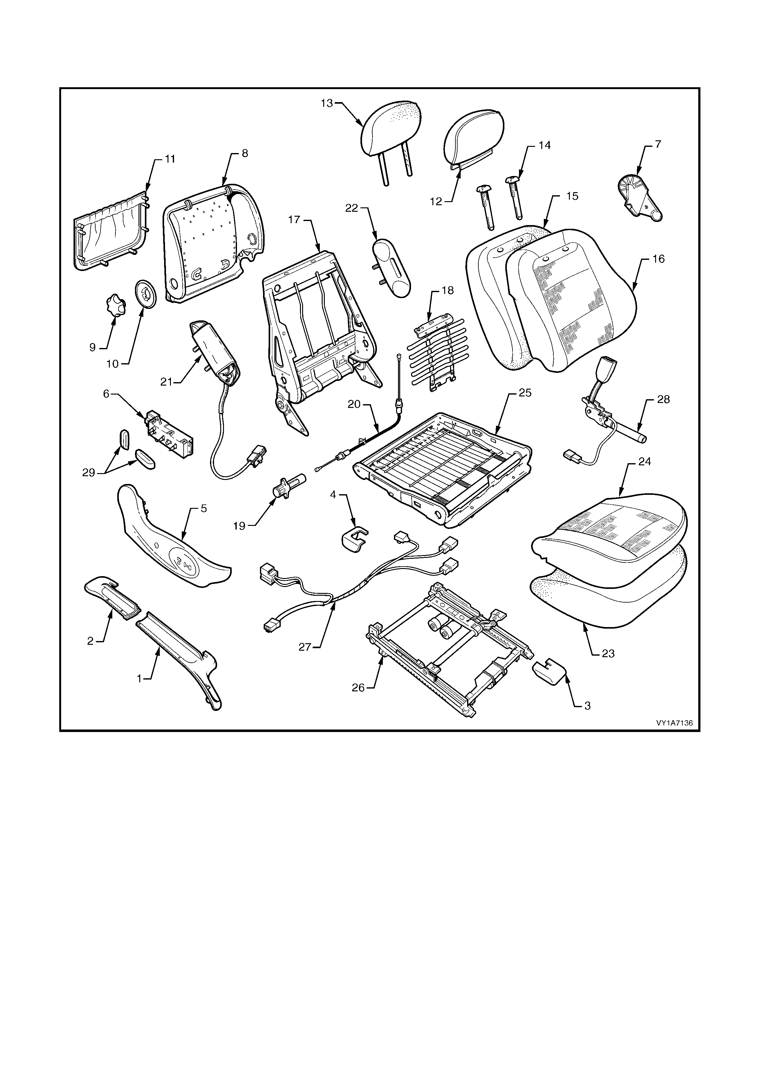
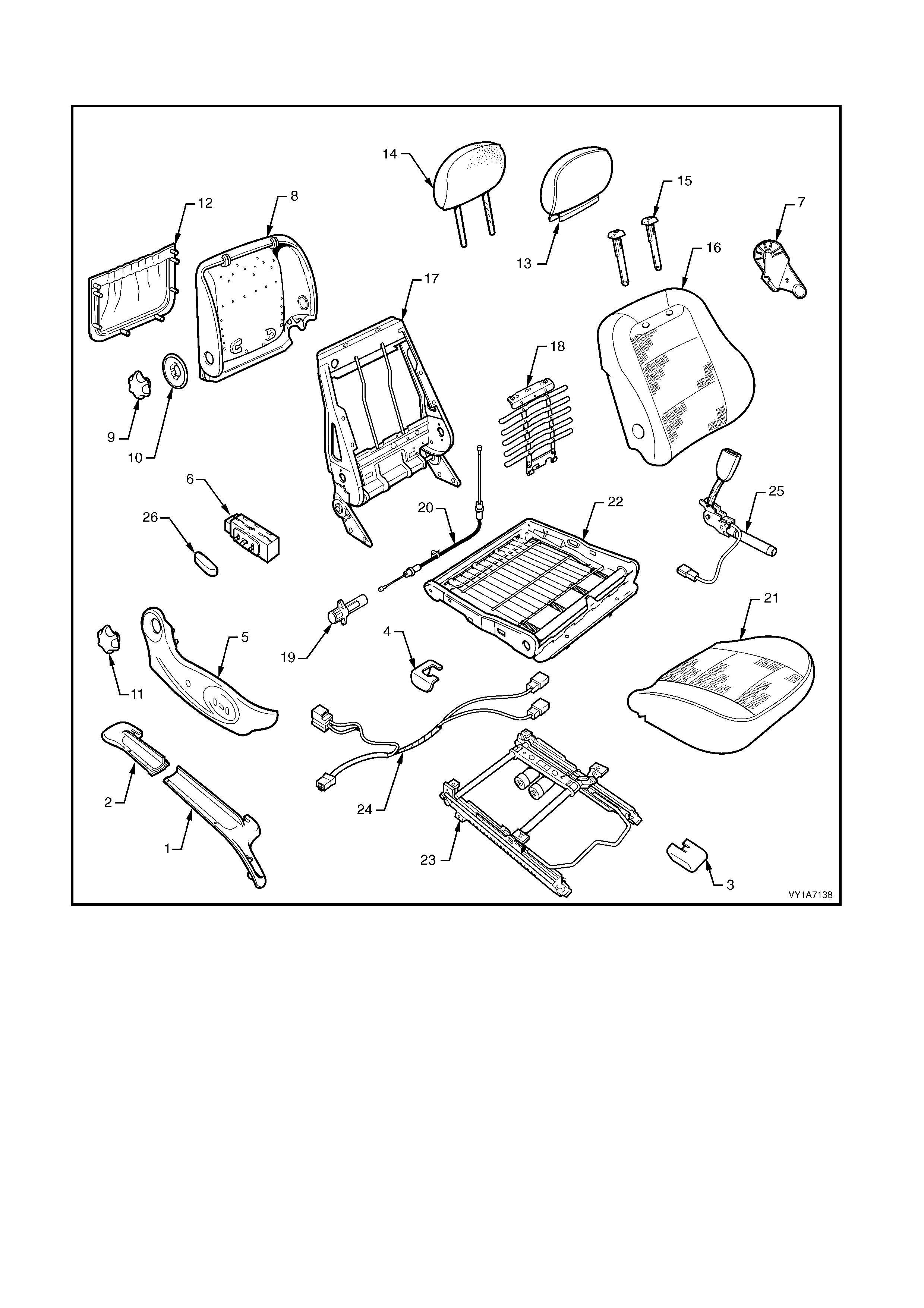
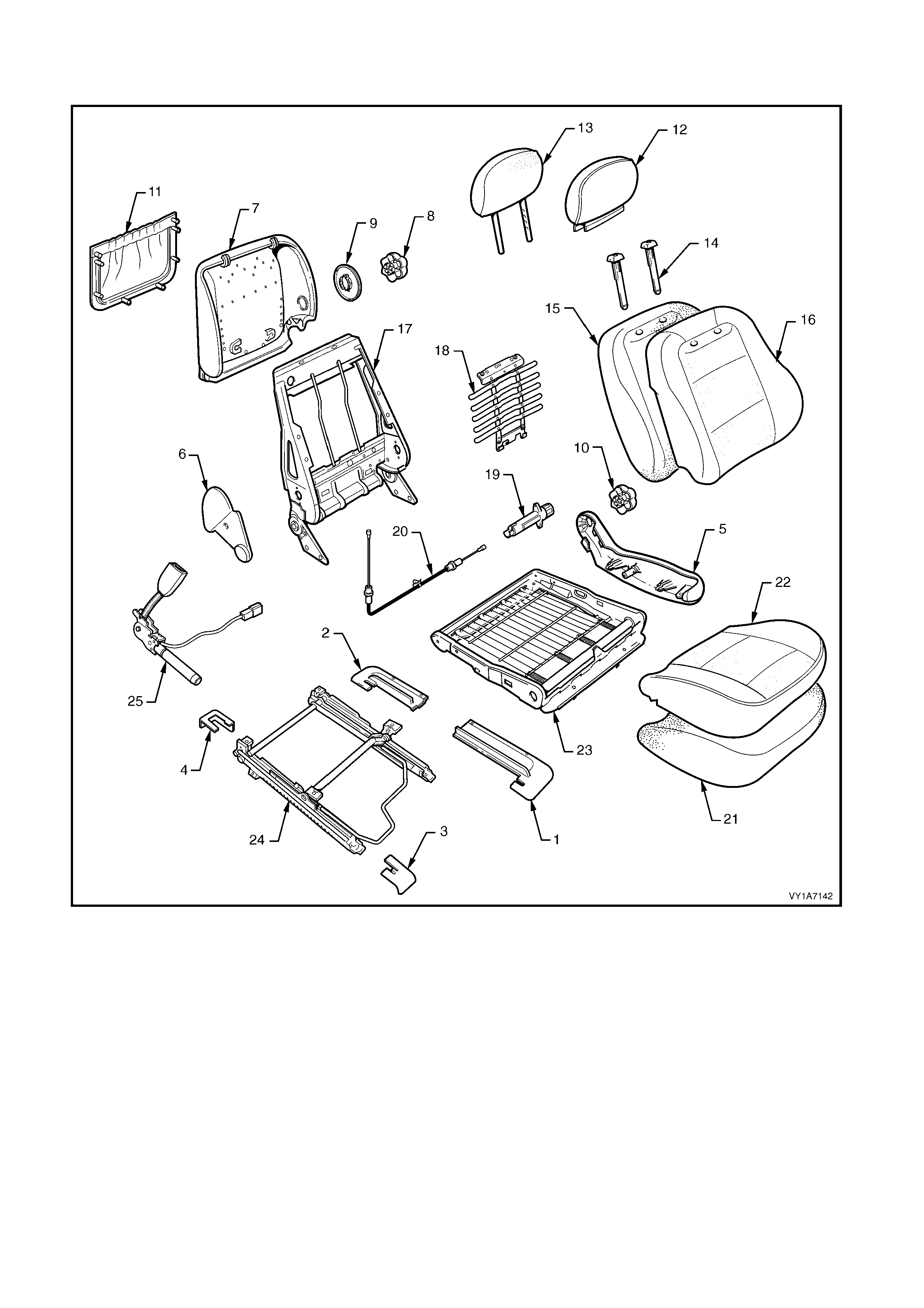
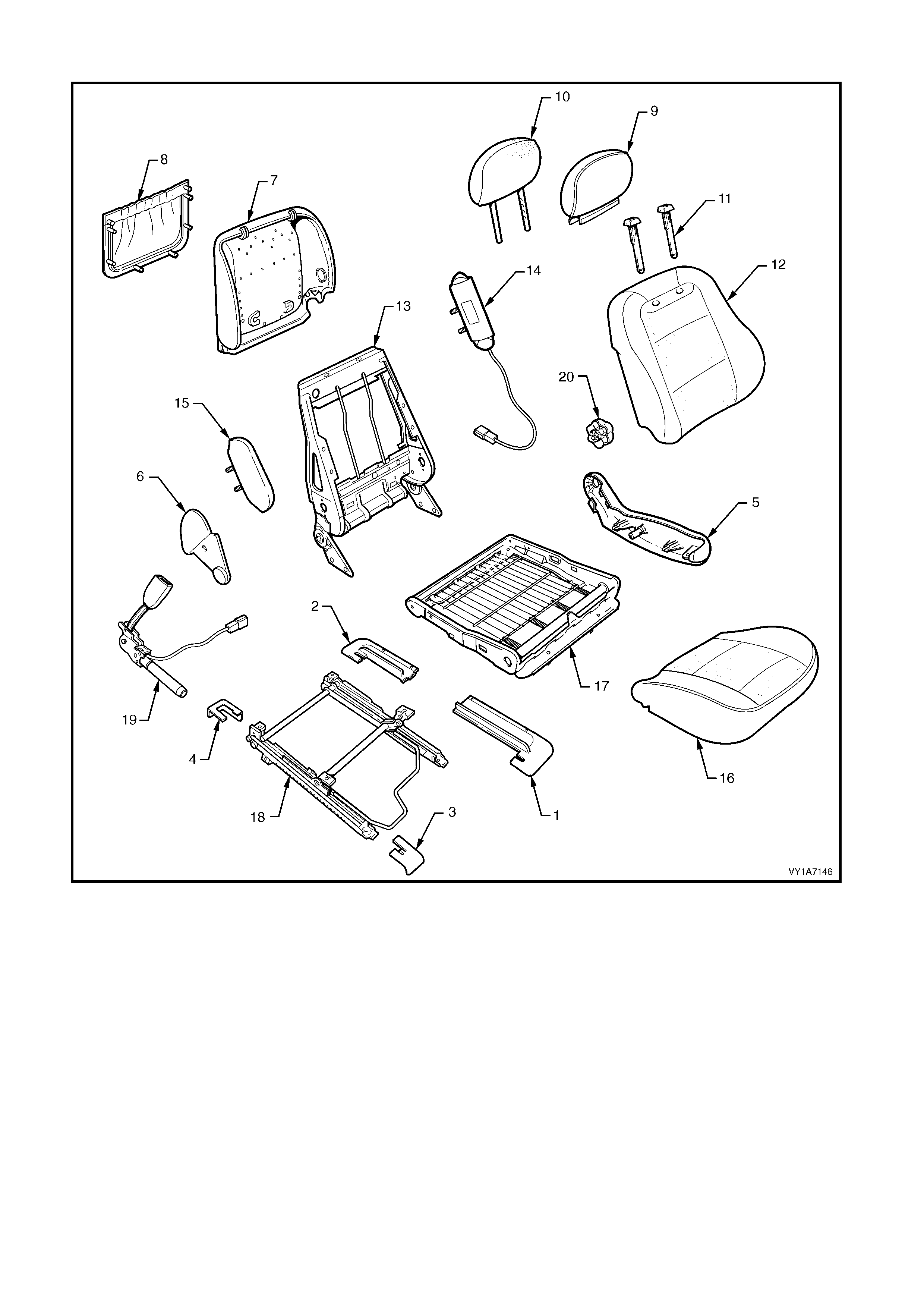
Type 1: Front Seat Assembly - 8 Way Adjust - with SIAB - with Lumber - Hook & Loop
Right-hand Shown
Figure 1A7-8
Legend
1. Seat Adjuster Outer Front Cover
2. Front Seat Outer Lower Rear Cover
3. Front Inner Guide Rail Cover
4. Rear Inner Guide Rail Cover
5. Front Seat Outer Side Cover
6. Front Seat Adjustment Switch - Eight-way - Non Memory
7. Front Seat Inner Side Cover
8. Front Seat-back Lower Cover
9. Lumbar Support Adjuster Knob
10. Lumber Support Adjuster Knob Adapter
11. Front Seat-back Lower Cover Pocket
12. Front Seat Head Restraint Cover
13. Front Seat Head Restraint Pad Assembly
14. Front Seat Head Restraint Guide - 2 Places
15. Front Seat-back Pad
16. Front Seat-back Cover
17. Front Seat-back Frame Assembly
18. Lumbar Support Assembly
19. Lumbar Support Assembly Adjuster
20. Lumbar Support Adjuster Cable
21. Side Impact Airbag
22. Front Seat Foam Block Insert Assembly
23. Front Seat Cushion Pad
24. Front Seat Cushion Cover
25. Front Seat Cushion Frame Assembly
26. Adjuster & Guide Rail Assembly - Eight-way *
27. Guide Rail Assembly Wiring Harness
28. Seatbelt Buckle & Pretensioner Assembly
29. Adjustment Knobs
* Early type shown.
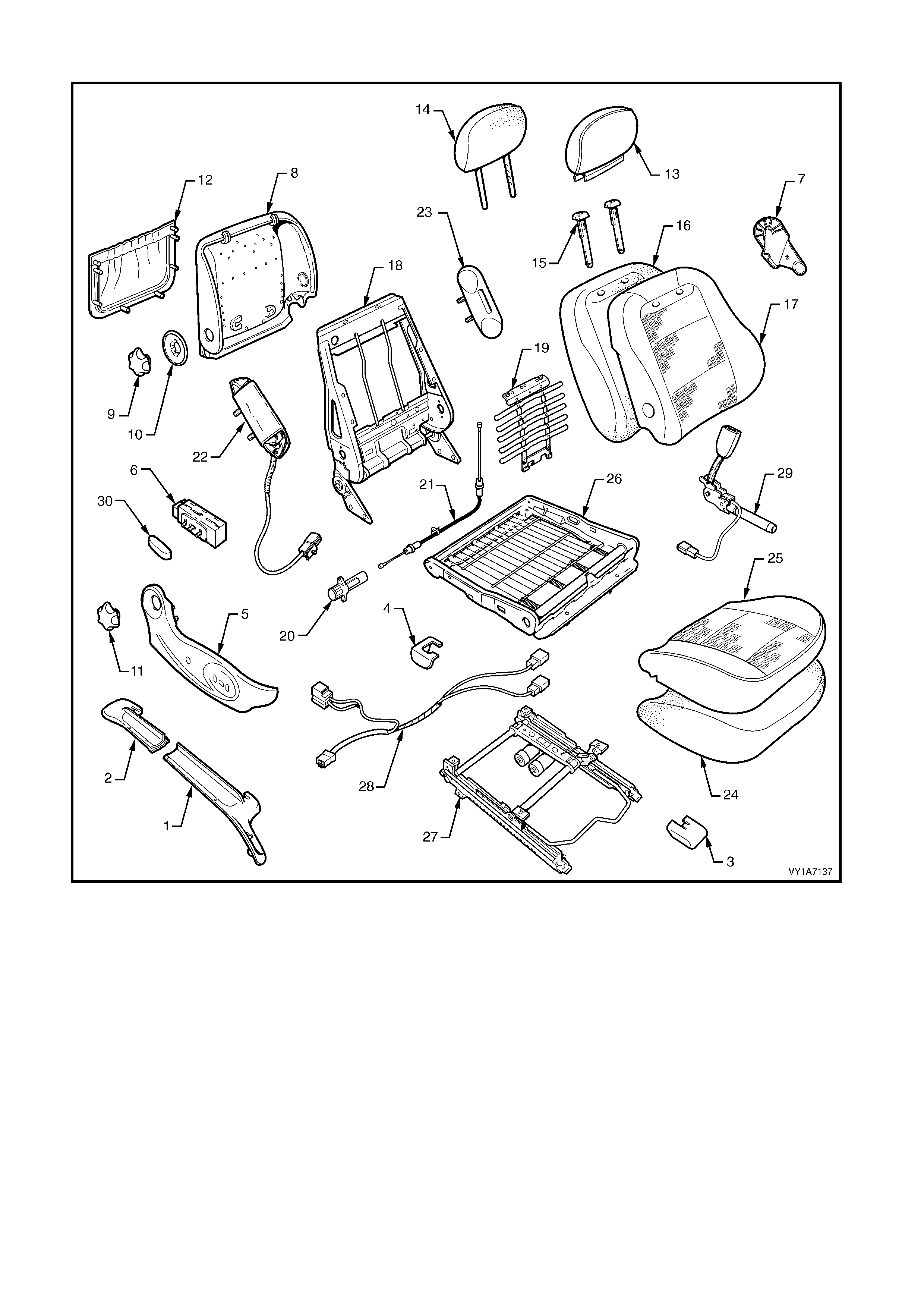
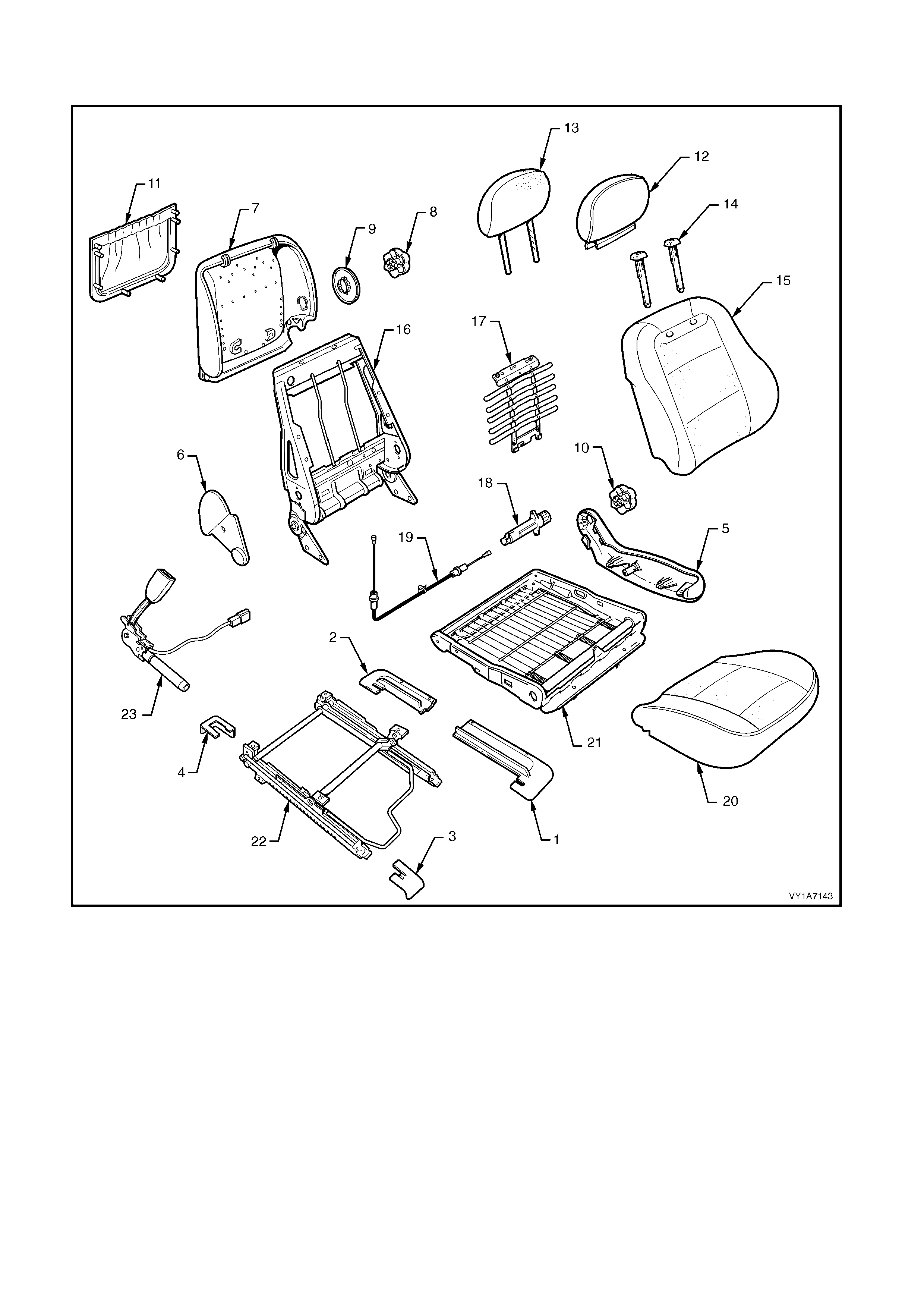
Type 2: Front Seat Assembly - 4 Way Adjust - with SIAB - with Lumber - Hook & Loop
Figure 1A7-9
Legend
1. Seat Adjuster Outer Front Cover
2. Front Seat Outer Lower Rear Cover
3. Front Inner Guide Rail Cover
4. Rear Inner Guide Rail Cover
5. Front Seat Outer Side Cover
6. Front Seat Adjustment Switch - Four-way
7. Front Seat Inner Side Cover
8. Front Seat-back Lower Cover
9. Lumbar Support Adjuster Knob
10. Lumber Support Adjuster Knob Adapter
11. Recliner Adjuster Knob
12. Front Seat-back Lower Cover Pocket
13. Front Seat Head Restraint Cover
14. Front Seat Head Restraint Pad Assembly
15. Front Seat Head Restraint Guide (2 Places)
16. Front Seat-back Pad
17. Front Seat-back Cover
18. Front Seat-back Frame Assembly
19. Lumbar Support Assembly
20. Lumbar Support Assembly Adjuster
21. Lumbar Support Adjuster Cable
22. Side Impact Airbag
23. Front Seat Foam Block Insert Assembly
24. Front Seat Cushion Pad
25. Front Seat Cushion Cover
26. Front Seat Cushion Frame Assembly
27. Adjuster & Guide Rail Assembly- Four-way *
28. Guide Rail Assembly Wiring Harness
29. Seatbelt Buckle & Pretensioner Assembly
30. Adjustment Knob
* Early type shown.
Type 3: Front Seat Assembly - 4 Way Adjust - No SIAB - with Lumber - Surebond
Right-hand Shown
Figure 1A7-10
Legend
1. Seat Adjuster Outer Front Cover
2. Front Seat Outer Lower Rear Cover
3. Front Inner Guide Rail Cover
4. Rear Inner Guide Rail Cover
5. Front Seat Outer Side Cover
6. Front Seat Adjustment Switch - Four-way
7. Front Seat Inner Side Cover
8. Front Seat-back Lower Cover
9. Lumbar Support Adjuster Knob
10. Lumber Support Adjuster Knob Adapter
11. Recliner Adjuster Knob
12. Front Seat-back Lower Cover Pocket
13. Front Seat Head Restraint Cover
14. Front Seat Head Restraint Pad Assembly
15. Front Seat Head Restraint Guide - 2 Places
16. Front Seat-back Cover and Pad Assembly
17. Front Seat-back Frame Assembly
18. Lumbar Support Assembly
19. Lumbar Support Assembly Adjuster
20. Lumbar Support Adjuster Cable
21. Front Seat Cushion Cover and Pad
22. Front Seat Cushion Frame Assembly
23. Adjuster & Guide Rail Assembly - Four-way *
24. Guide Rail Assembly Wiring Harness
25. Seatbelt Buckle & Pretensioner Assembly
26. Adjustment Knob
* Early type shown.
Type 4: Front Seat Assembly - 4 Way Adjust - with SIAB - with Lumber - Surebond
Figure 1A7-11
Legend
1. Seat Adjuster Outer Front Cover
2. Front Seat Outer Lower Rear Cover
3. Front Inner Guide Rail Cover
4. Rear Inner Guide Rail Cover
5. Front Seat Outer Side Cover
6. Front Seat Adjustment Switch - Four-way
7. Front Seat Inner Side Cover
8. Front Seat-back Lower Cover
9. Lumbar Support Adjuster Knob
10. Lumber Support Adjuster Knob Adapter
11. Recliner Adjuster Knob
12. Front Seat-back Lower Cover Pocket
13. Front Seat Head Restraint Cover
14. Front Seat Head Restraint Pad Assembly
15. Front Seat Head Restraint Guide - 2 Places
16. Front Seat-back Cover and Pad Assembly
17. Front Seat-back Frame Assembly
18. Lumbar Support Assembly
19. Lumbar Support Assembly Adjuster
20. Lumbar Support Adjuster Cable
21. Side Impact Airbag
22. Front Seat Foam Block Insert Assembly
23. Front Seat Cushion Cover and Pad
24. Front Seat Cushion Frame Assembly
25. Adjuster & Guide Rail Assembly - Four-way *
26. Guide Rail Assembly Wiring Harness
27. Seatbelt Buckle & Pretensioner Assembly
28. Adjustment Knob
* Early type shown.
Type 5: Front Seat Assembly - 4 Way Adjust - No SIAB - with Lumber - Hook & Loop
Right-hand Shown
Figure 1A7-12
Legend
1. Seat Adjuster Outer Front Cover
2. Front Seat Outer Lower Rear Cover
3. Front Inner Guide Rail Cover
4. Rear Inner Guide Rail Cover
5. Front Seat Outer Side Cover
6. Front Seat Adjustment Switch - Four-way
7. Front Seat Inner Side Cover
8. Front Seat-back Lower Cover
9. Lumbar Support Adjuster Knob
10. Lumber Support Adjuster Knob Adapter
11. Recliner Adjuster Knob
12. Front Seat-back Lower Cover Pocket
13. Front Seat Head Restraint Cover
14. Front Seat Head Restraint Pad Assembly
15. Front Seat Head Restraint Guide - 2 Places
16. Front Seat-back Pad
17. Front Seat-back Cover
18. Front Seat-back Frame Assembly
19. Lumbar Support Assembly
20. Lumbar Support Assembly Adjuster
21. Lumbar Support Adjuster Cable
22. Front Seat Cushion Pad
23. Front Seat Cushion Cover
24. Front Seat Cushion Frame Assembly
25. Adjuster & Guide Rail Assembly - Four-way *
26. Guide Rail Assembly Wiring Harness
27. Seatbelt Buckle & Pretensioner Assembly
28. Adjustment Knob
* Early type shown.
Type 6: Front Seat Assembly - 2 Way Adjust - with SIAB - with Lumber - Hook & Loop
Left-hand Shown
Figure 1A7-13
Legend
1. Seat Adjuster Outer Front Cover
2. Front Seat Outer Lower Rear Cover
3. Front Inner Guide Rail Cover
4. Rear Inner Guide Rail Cover
5. Front Seat Outer Side Cover
6. Front Seat Inner Side Cover
7. Front Seat-back Lower Cover
8. Lumbar Support Adjuster Knob
9. Lumber Support Adjuster Knob Adapter
10. Recliner Adjuster Knob
11. Front Seat-back Lower Cover Pocket
12. Front Seat Head Restraint Cover
13. Front Seat Head Restraint Pad Assembly
14. Front Seat Head Restraint Guide - 2 Places
15. Front Seat-back Pad
16. Front Seat-back Cover
17. Front Seat-back Frame Assembly
18. Lumbar Support Assembly
19. Lumbar Support Assembly Adjuster
20. Lumbar Support Adjuster Cable
21. Side Impact Airbag
22. Front Seat Foam Block Insert Assembly
23. Front Seat Cushion Pad
24. Front Seat Cushion Cover
25. Front Seat Cushion Frame Assembly
26. Adjuster & Guide Rail Assembly - Two Way *
27. Seatbelt Buckle & Pretensioner Assembly
* Early type shown.
Type 7: Front Seat Assembly - 2 Way Adjust - No SIAB - with Lumber - Hook & Loop
Left-hand Shown
Figure 1A7-14
Legend
1. Seat Adjuster Outer Front Cover
2. Front Seat Outer Lower Rear Cover
3. Front Inner Guide Rail Cover
4. Rear Inner Guide Rail Cover
5. Front Seat Outer Side Cover
6. Front Seat Inner Side Cover
7. Front Seat-back Lower Cover
8. Lumbar Support Adjuster Knob
9. Lumber Support Adjuster Knob Adapter
10. Recliner Adjuster Knob
11. Front Seat-back Lower Cover Pocket
12. Front Seat Head Restraint Cover
13. Front Seat Head Restraint Pad Assembly
14. Front Seat Head Restraint Guide - 2 Places
15. Front Seat-back Pad
16. Front Seat-back Cover
17. Front Seat-back Frame Assembly
18. Lumbar Support Assembly
19. Lumbar Support Assembly Adjuster
20. Lumbar Support Adjuster Cable
21. Front Seat Cushion Pad
22. Front Seat Cushion Cover
23. Front Seat Cushion Frame Assembly
24. Adjuster & Guide Rail Assembly - Two Way *
25. Seatbelt Buckle & Pretensioner Assembly
* Early type shown.
Type 8: Front Seat Assembly - 2 Way Adjust - No SIAB - with Lumber - Surebond
Left-hand Shown
Figure 1A7-15
Legend
1. Seat Adjuster Outer Front Cover
2. Front Seat Outer Lower Rear Cover
3. Front Inner Guide Rail Cover
4. Rear Inner Guide Rail Cover
5. Front Seat Outer Side Cover
6. Front Seat Inner Side Cover
7. Front Seat-back Lower Cover
8. Lumbar Support Adjuster Knob
9. Lumber Support Adjuster Knob Adapter
10. Recliner Adjuster Knob
11. Front Seat-back Lower Cover Pocket
12. Front Seat Head Restraint Cover
13. Front Seat Head Restraint Pad Assembly
14. Front Seat Head Restraint Guide - 2 Places
15. Front Seat-back Cover and Pad Assembly
16. Front Seat-back Frame Assembly
17. Lumbar Support Assembly
18. Lumbar Support Assembly Adjuster
19. Lumbar Support Adjuster Cable
20. Front Seat Cushion Cover and Pad
21. Front Seat Cushion Frame Assembly
22. Adjuster & Guide Rail Assembly - Two Way *
23. Seatbelt Buckle & Pretensioner Assembly
* Early type shown.
Type 9: Front Seat Assembly - 2 Way Adjust - with SIAB - with Lumber - Surebond
Left-hand Shown
Figure 1A7-16
Legend
1. Seat Adjuster Outer Front Cover
2. Front Seat Outer Lower Rear Cover
3. Front Inner Guide Rail Cover
4. Rear Inner Guide Rail Cover
5. Front Seat Outer Side Cover
6. Front Seat Inner Side Cover
7. Front Seat-back Lower Cover
8. Lumbar Support Adjuster Knob
9. Lumber Support Adjuster Knob Adapter
10. Recliner Adjuster Knob
11. Front Seat-back Lower Cover Pocket
12. Front Seat Head Restraint Cover
13. Front Seat Head Restraint Pad Assembly
14. Front Seat Head Restraint Guide - 2 Places
15. Front Seat-back Cover and Pad Assembly
16. Front Seat-back Frame Assembly
17. Lumbar Support Assembly
18. Lumbar Support Assembly Adjuster
19. Lumbar Support Adjuster Cable
20. Side Impact Airbag
21. Front Seat Foam Block Insert Assembly
22. Front Seat Cushion Cover and Pad Assembly
23. Front Seat Cushion Frame Assembly
24. Adjuster & Guide Rail Assembly - Two Way *
25. Seatbelt Buckle & Pretensioner Assembly
* Early type shown.
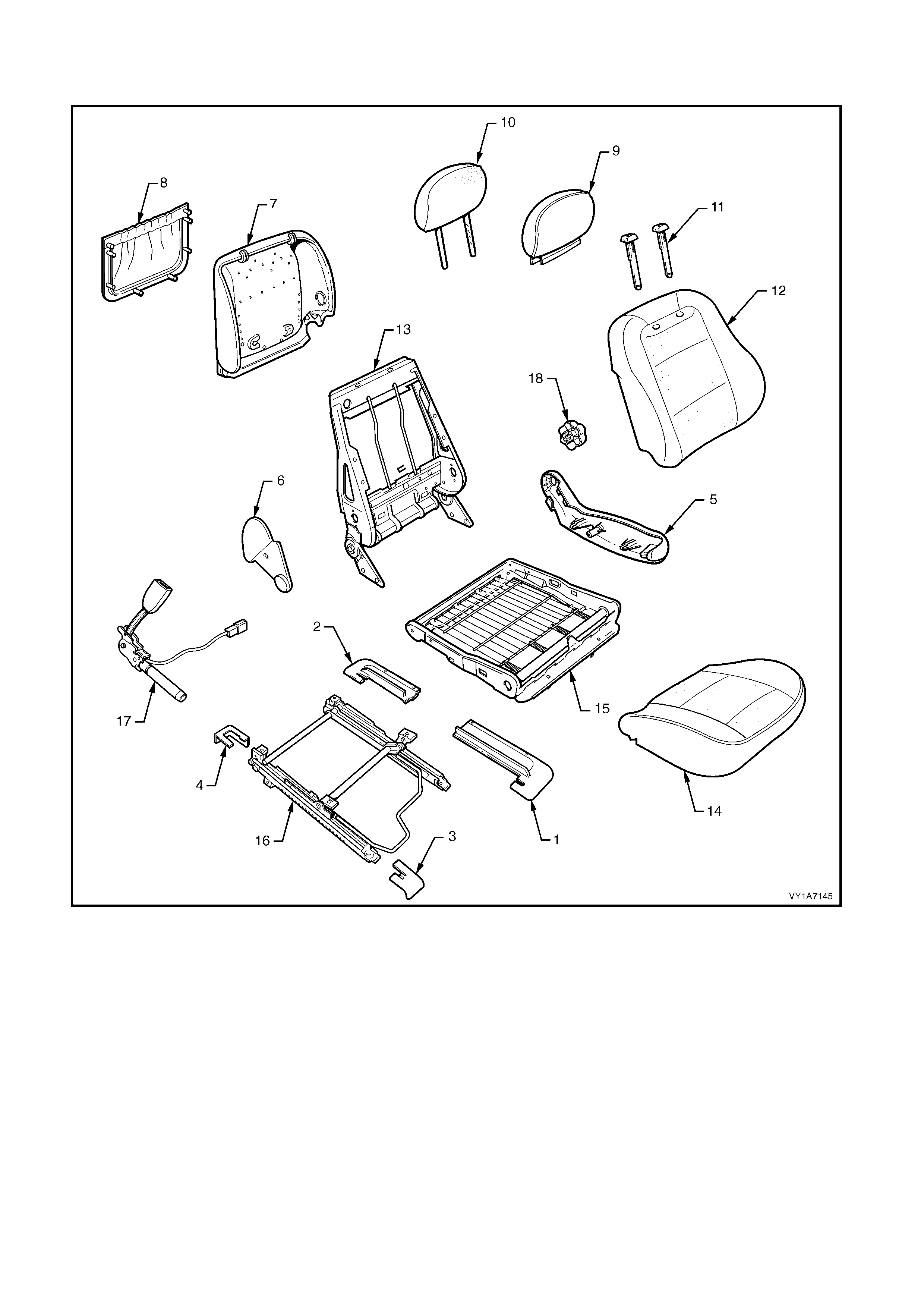
Type 10: Front Seat Assembly - 2 Way Adjust - No SIAB - No Lumber - Surebond
Left-hand Shown
Figure 1A7-17
Legend
1. Seat Adjuster Outer Front Cover
2. Front Seat Outer Lower Rear Cover
3. Front Inner Guide Rail Cover
4. Rear Inner Guide Rail Cover
5. Front Seat Outer Side Cover
6. Front Seat Inner Side Cover
7. Front Seat-back Lower Cover
8. Front Seat-back Lower Cover Pocket
9. Front Seat Head Restraint Cover
10. Front Seat Head Restraint Pad Assembly
11. Front Seat Head Restraint Guide - 2 Places
12. Front Seat-back Cover and Pad Assembly
13. Front Seat-back Frame Assembly
14. Front Seat Cushion Cover and Pad
15. Front Seat Cushion Frame Assembly
16. Adjuster & Guide Rail Assembly - Two Way *
17. Seatbelt Buckle & Pretensioner Assembly
18. Recliner Adjuster Knob
* Early type shown.
Type 11: Front Seat Assembly - 2 Way Adjust - with SIAB - No Lumber - Surebond
Figure 1A7-18
Legend
1. Seat Adjuster Outer Front Cover
2. Front Seat Outer Lower Rear Cover
3. Front Inner Guide Rail Cover
4. Rear Inner Guide Rail Cover
5. Front Seat Outer Side Cover
6. Front Seat Inner Side Cover
7. Front Seat-back Lower Cover
8. Front Seat-back Lower Cover Pocket
9. Front Seat Head Restraint Cover
10. Front Seat Head Restraint Pad Assembly
11. Front Seat Head Restraint Guide - 2 Places
12. Front Seat-back Cover and Pad Assembly
13. Front Seat-back Frame Assembly
14. Side Impact Airbag
15. Front Seat Foam Block Insert Assembly
16. Front Seat Cushion Cover and Pad
17. Front Seat Cushion Frame Assembly
18. Adjuster & Guide Rail Assembly - Two Way *
19. Seatbelt Buckle & Pretensioner Assembly
20. Lumbar Support Adjuster Knob
* Early type shown.

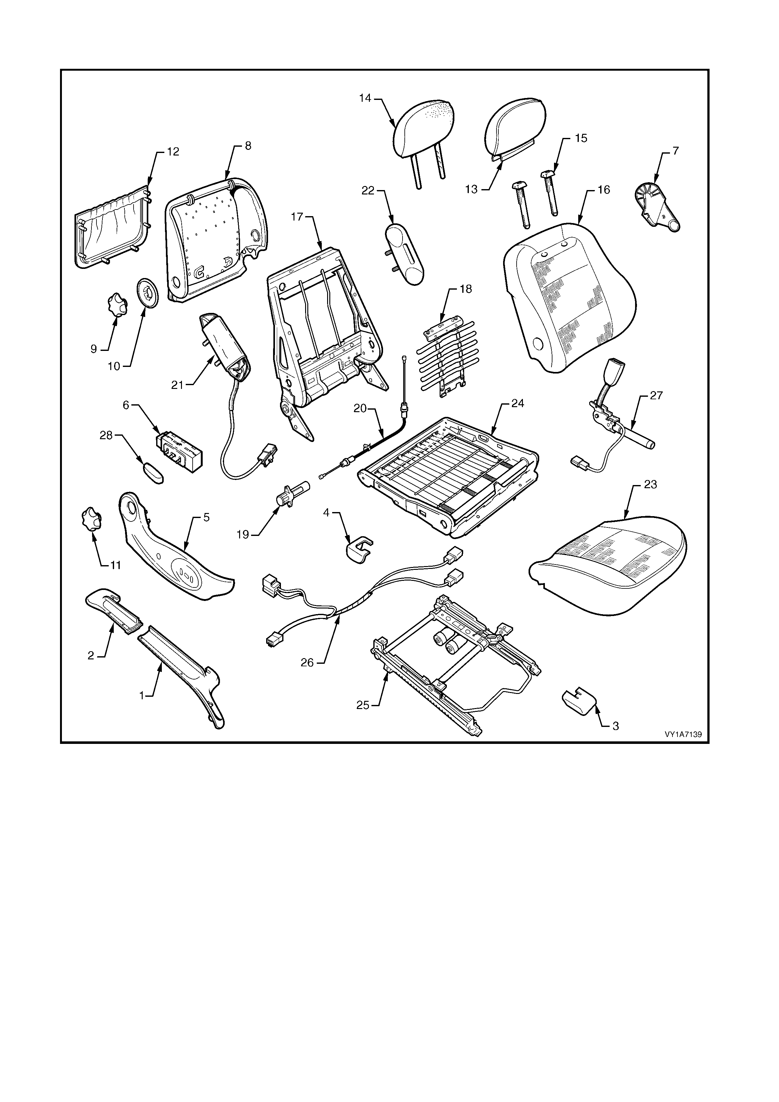
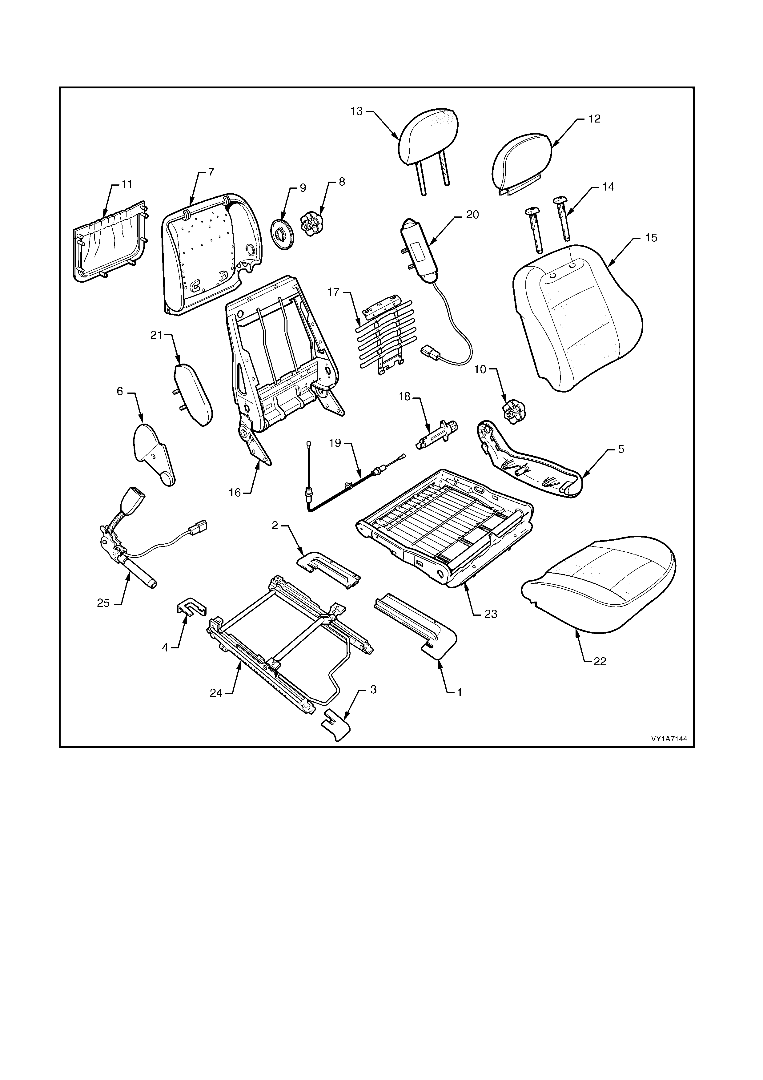
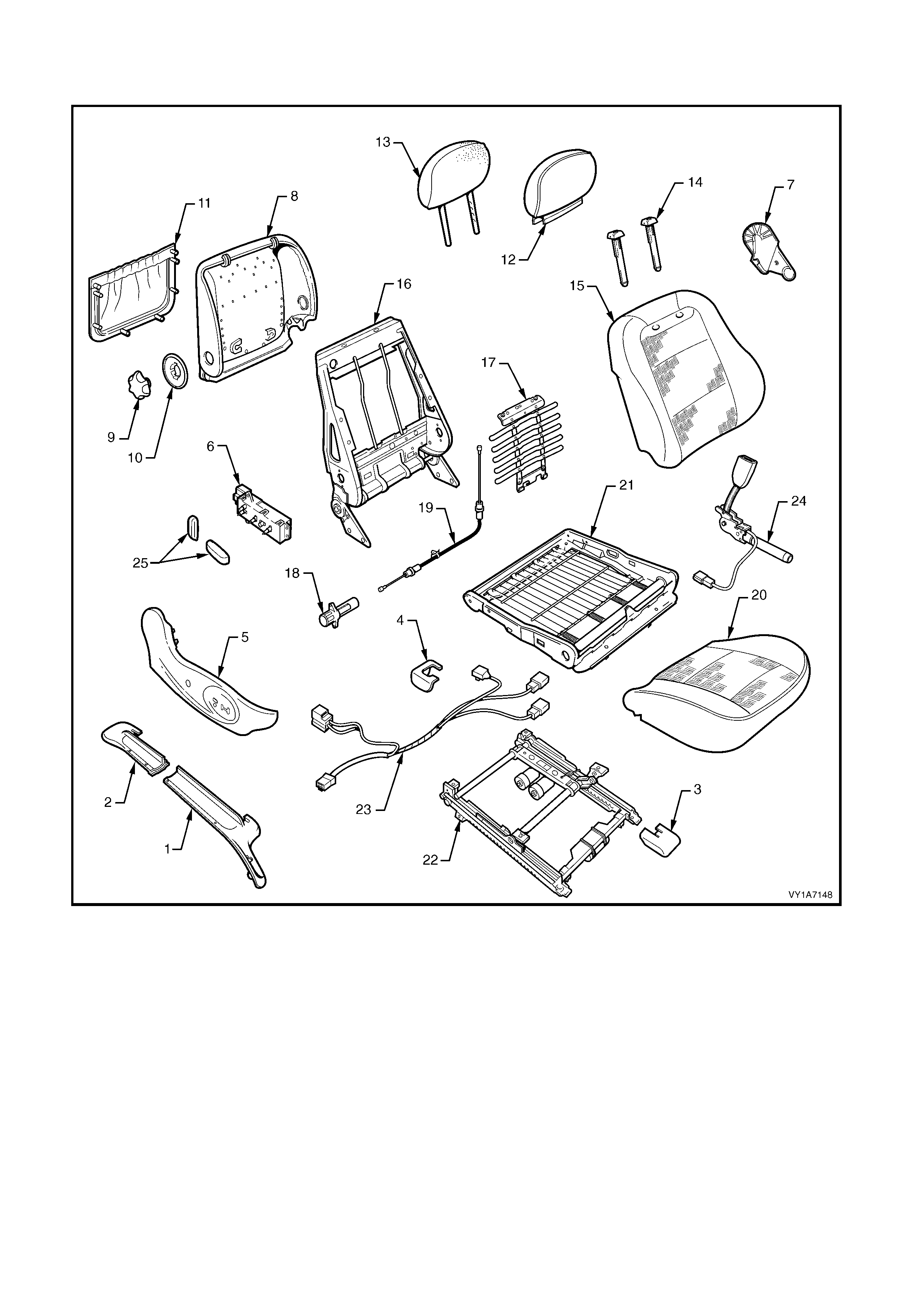
Type 12: Front Seat Assembly - 8 Way Adjust - No SIAB - with Lumber - Hook & Loop
Right-hand Shown
Figure 1A7-19
Legend
1. Seat Adjuster Outer Front Cover
2. Front Seat Outer Lower Rear Cover
3. Front Inner Guide Rail Cover
4. Rear Inner Guide Rail Cover
5. Front Seat Outer Side Cover
6. Front Seat Adjustment Switch - Eight-way -
Non Memory
7. Front Seat Inner Side Cover
8. Front Seat-back Lower Cover
9. Lumbar Support Adjuster Knob
10. Lumber Support Adjuster Knob Adapter
11. Front Seat-back Lower Cover Pocket
12. Front Seat Head Restraint Cover
13. Front Seat Head Restraint Pad Assembly
14. Front Seat Head Restraint Guide - 2 Places
15. Front Seat-back Pad
16. Front Seat-back Cover
17. Frame Assembly - Front Seat-back
18. Lumbar Support Assembly
19. Lumbar Support Assembly Adjuster
20. Lumbar Support Adjuster Cable
21. Front Seat Cushion Pad
22. Front Seat Cushion Cover
23. Front Seat Cushion Frame Assembly
24. Adjuster & Guide Rail Assembly- Eight-way *
25. Guide Rail Assembly Wiring Harness
26. Seatbelt Buckle & Pretensioner Assembly
27. Adjustment Knobs
* Early type shown.
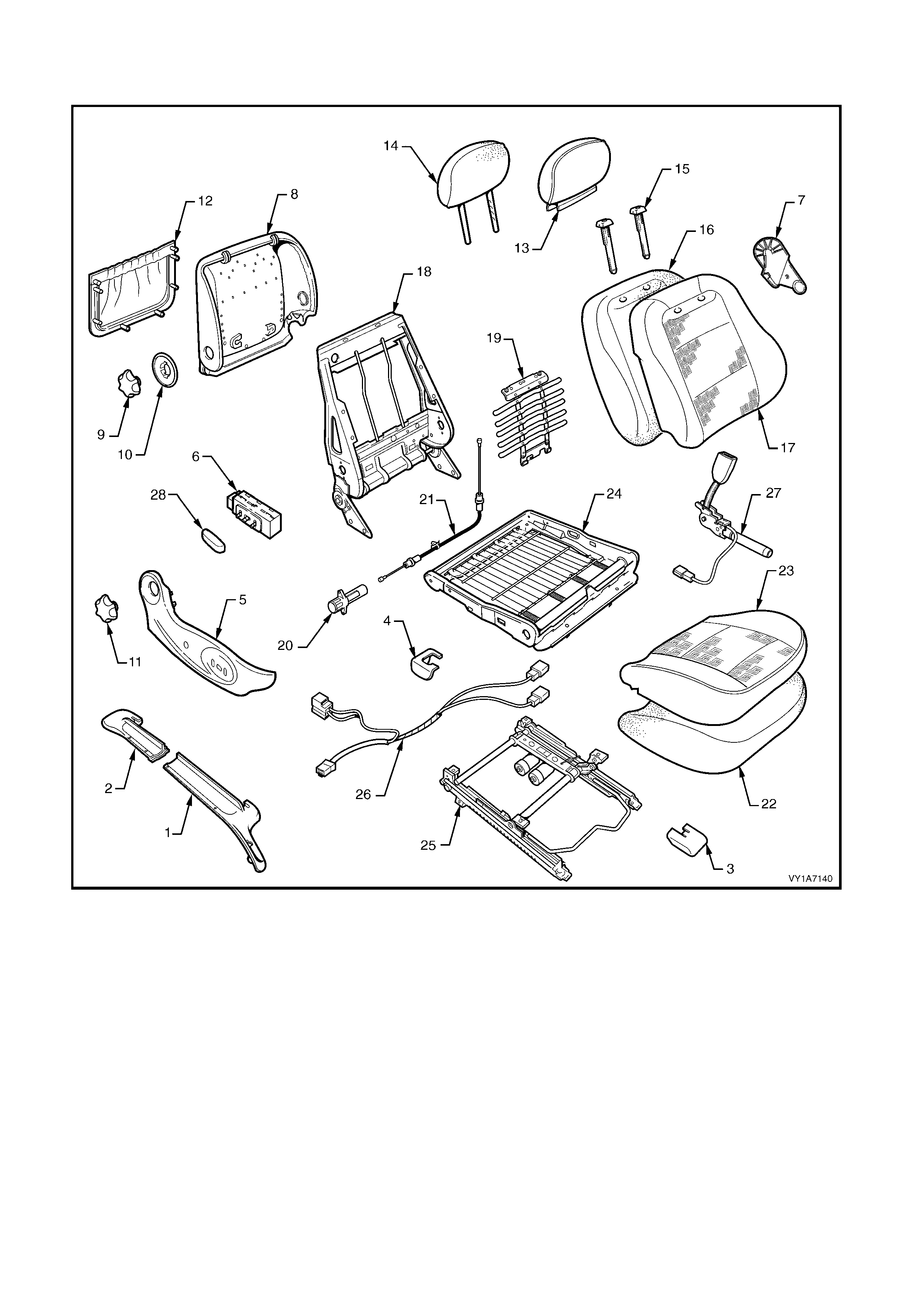
TYPE 13: Front Seat Assembly - 8 Way Adjust - No SIAB - with Lumber - Surebond
Right-hand Shown
Figure 1A7-20
Legend
1. Seat Adjuster Outer Front Cover
2. Front Seat Outer Lower Rear Cover
3. Front Inner Guide Rail Cover
4. Rear Inner Guide Rail Cover
5. Front Seat Outer Side Cover
6. Front Seat Adjustment Switch - Eight-way - Non Memory
7. Front Seat Inner Side Cover
8. Front Seat-back Lower Cover
9. Lumbar Support Adjuster Knob
10. Lumber Support Adjuster Knob Adapter
11. Front Seat-back Lower Cover Pocket
12. Front Seat Head Restraint Cover
13. Front Seat Head Restraint Pad Assembly
14. Front Seat Head Restraint Guide - 2 Places
15. Front Seat-back Cover and Pad Assembly
16. Front Seat-back Frame Assembly
17. Lumbar Support Assembly
18. Lumbar Support Assembly Adjuster
19. Lumbar Support Adjuster Cable
20. Front Seat Cushion Cover and Pad
21. Front Seat Cushion Frame Assembly
22. Adjuster & Guide Rail Assembly- Eight-way *
23. Guide Rail Assembly Wiring Harness
24. Seatbelt Buckle & Pretensioner Assembly
25. Adjustment Knobs
* Early type shown.
2.2 FRONT SEAT ASSEMBLY
LT Section No. – 14-295
CAUTION 1: Before performing any service operation on a front seat assembly fitted with side impact
airbags, ensure the occupant protection system is disabled, refer to Section 12M OCCUPANT
PROTECTION SYSTEM.
CAUTION 2: Accessory and after market seat covers MUST NOT be fitted to a vehicle with side impact
airbags, unless approved by the vehicle manufacturer. Seat covers that are not approved by the vehicle
manufacturer could greatly inhibit the performance of the side impact airbag and the occupant’s safety in
the event of side impact airbag deployment.
IMPORTANT 1: If the seat assembly is to be dissembled and it has an electric seat height adjuster, adjust the
seat assembly to its highest position before disconnecting the power to the seat.
IMPORTANT 2: Disconnection of the battery affects certain vehicle electronic systems. Refer to
Section 00, 5. BATTERY DISCONNECTION PROCEDURES before disconnecting the battery.
NOTE: Clean hands are essential when working on the interior trim.
REMOVE
1. Disconnect the battery.
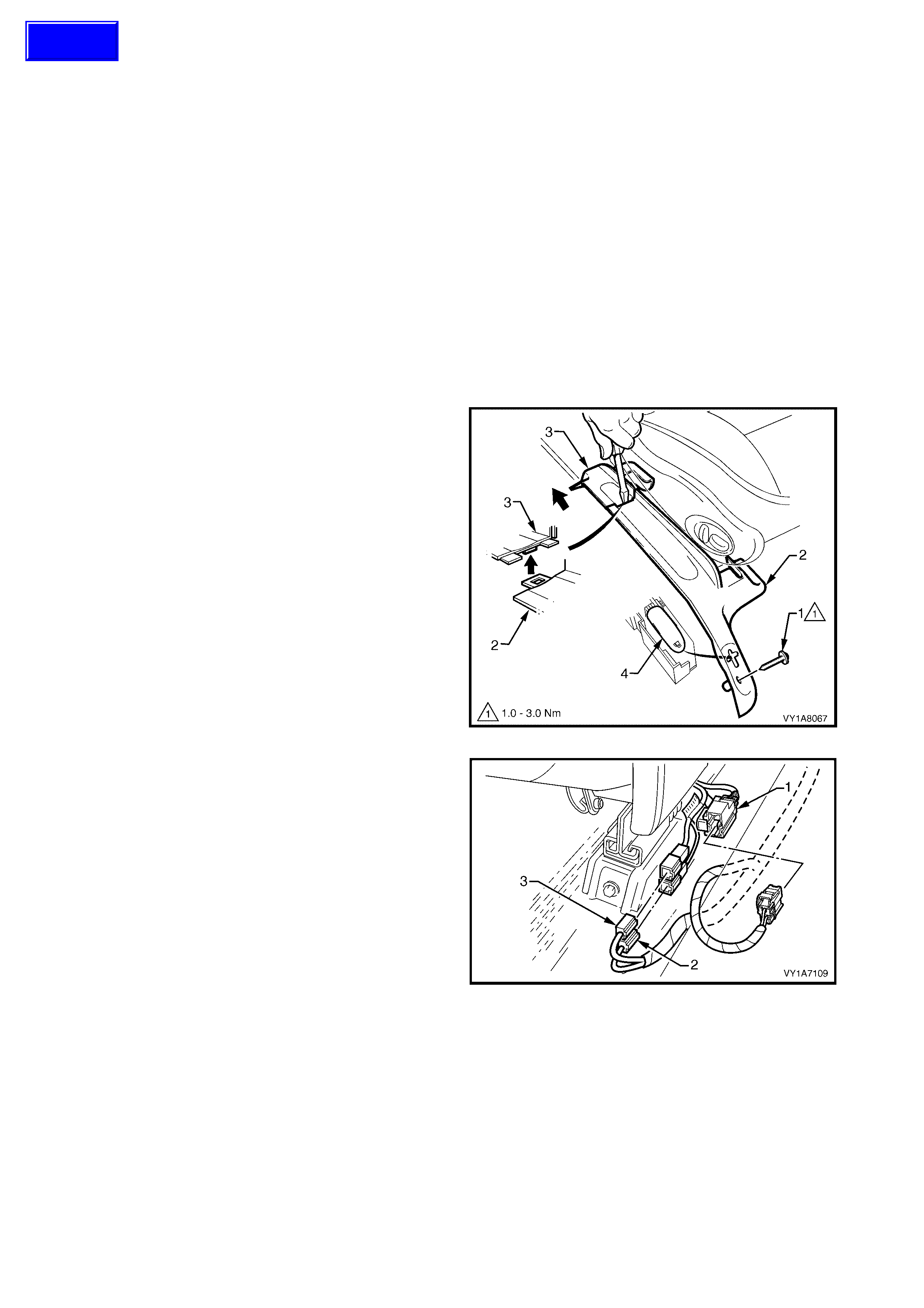
2. For the driver’s s eat on right-hand drive sedan and
wagon vehicles, remove the screw (1) attaching the
seat adjuster outer front cover (2).
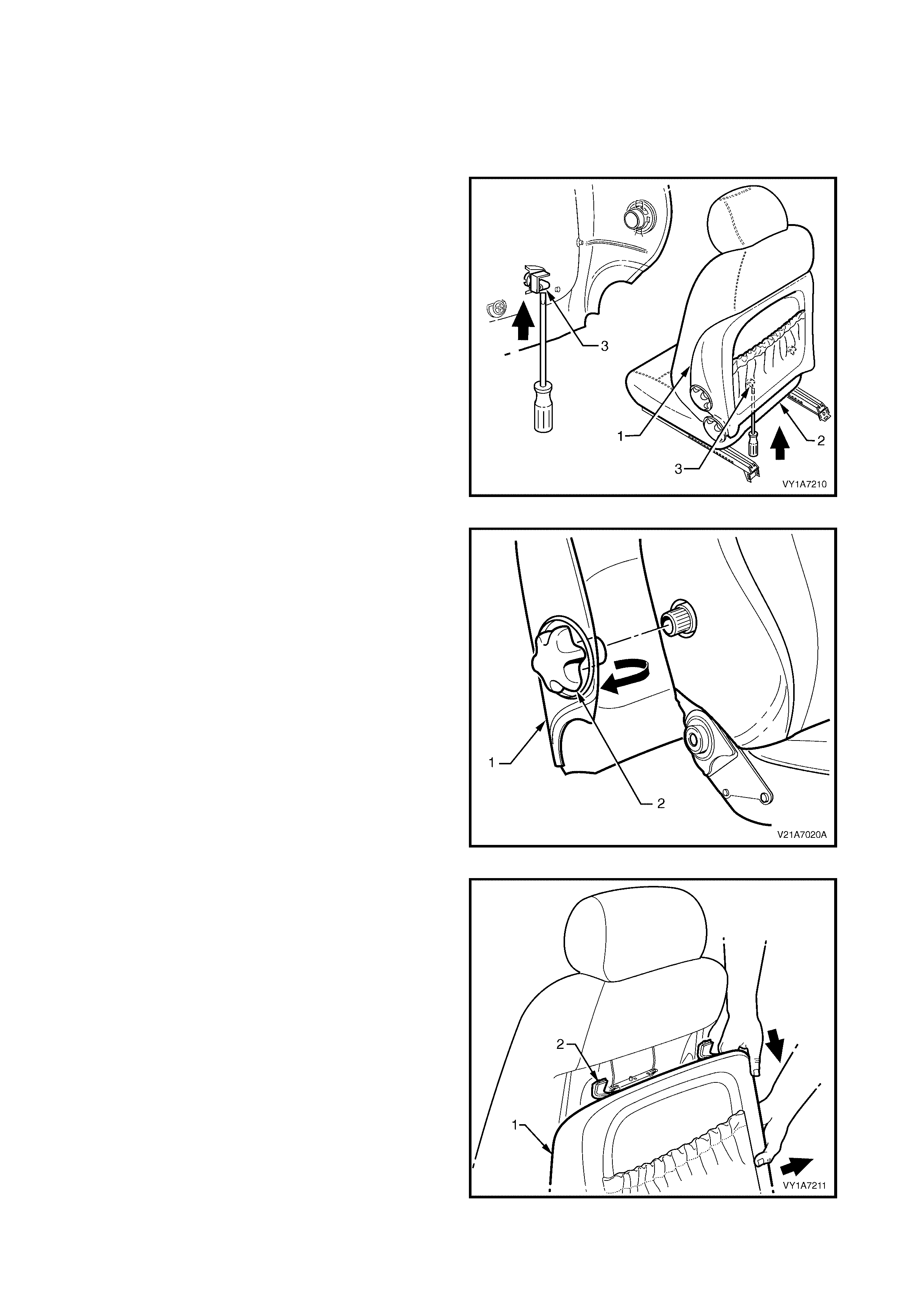
3. Using a small scr ewdriver, pus h in the c entre of the
join to separate the front cover and the front seat
outer lower rear cover (3).
4. Unclip the covers from the seat track and
disengage from the side sill trim.
5. Pull the covers apart and remove the rear cover.
6. For the driver’s side on right-hand drive vehicles,
except utility, slide the front c over over the fuel filler
door release lever (4) and remove.
Figure 1A7-21
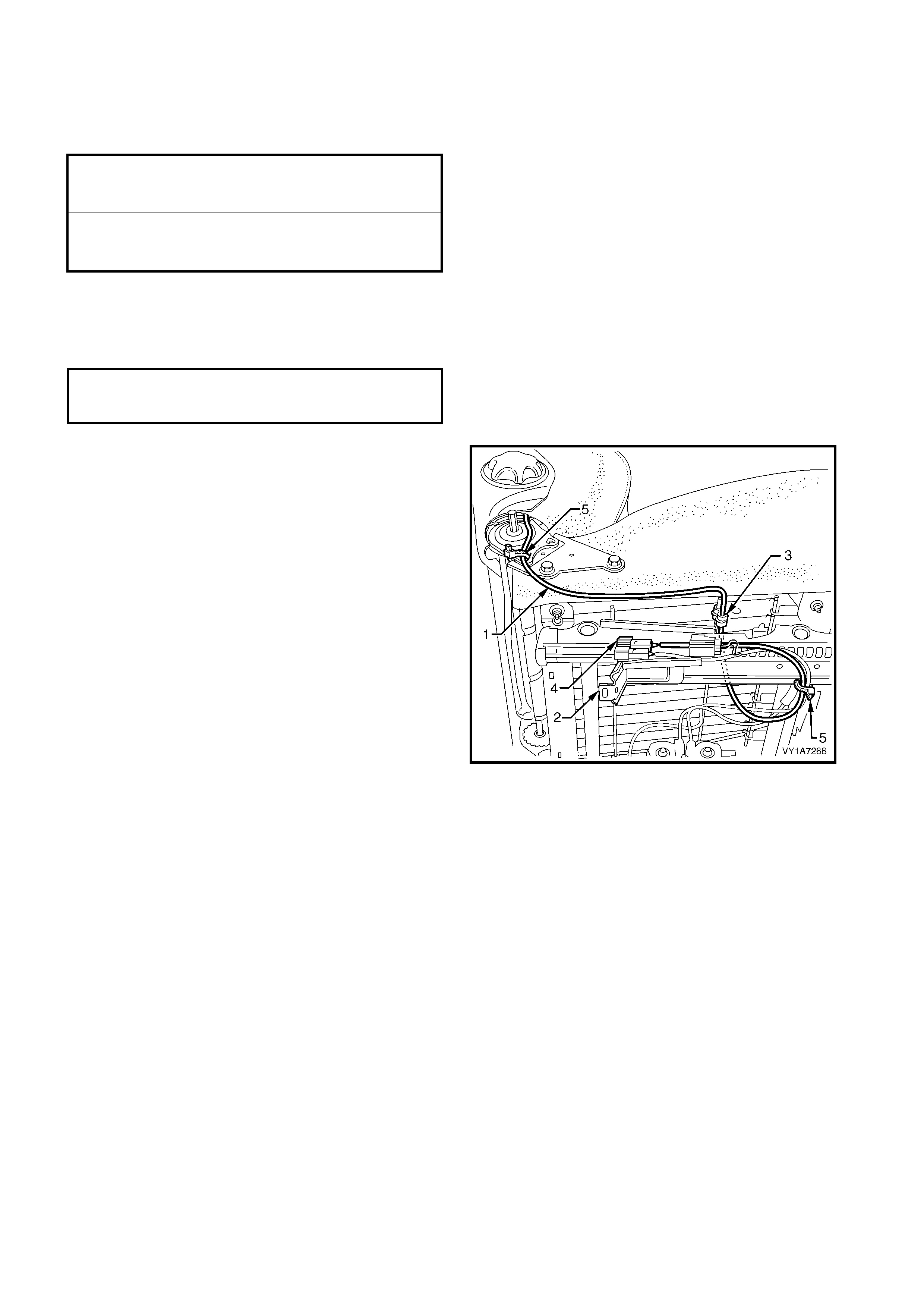
7. If fitted, disconnect the seat assembly wiring
harness (1), the seatbelt pretensioner harness (2)
and the side airbag module harness (3).
Figure 1A7-22
Techline
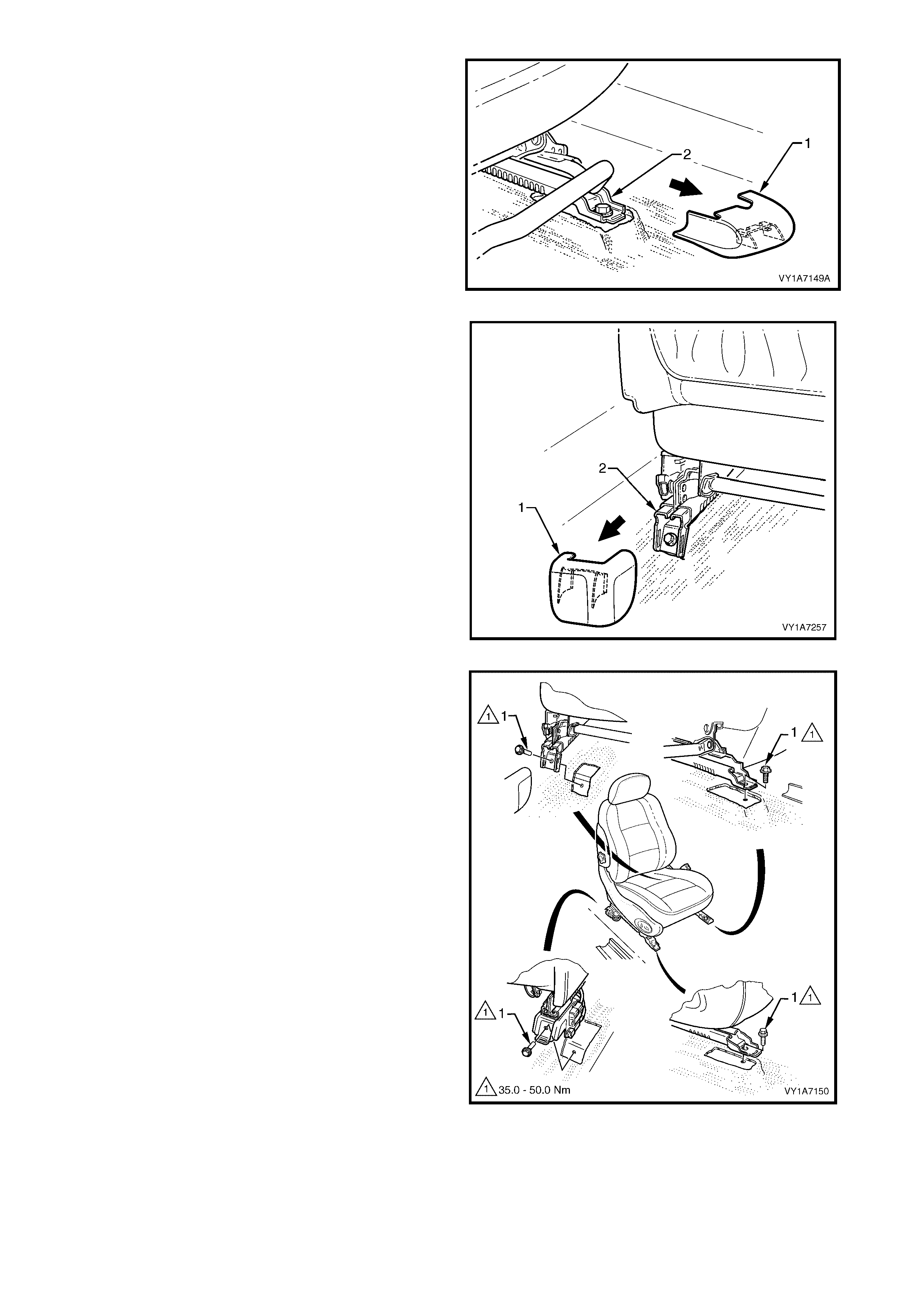
8. Unclip the front inner guide rail cover (1) from the
seat track (2).
Figure 1A7-23
9. Unclip the rear inner guide rail cover (1) from the
seat track (2).
Figure 1A7-24
10. Remove the f our scr ews (1) securing the f ront seat
to the floor.
11. Remove the seat from the vehicle.
Figure 1A7-25

REINSTALL
Reinstallation of the front seat assembly is the reverse of the removal, noting the following:
1. Position the front seat assembly into the vehicle.
2. Install the four screws securing the front seat to the floor.
3. Connect the seat pretensioner harness and if fitted, the side airbag module and seat wiring harness
connectors.
4. Tighten all retaining screws to the correct torque specification.
5. Align the front outer seat guide rail cover’s two retaining clips and push firmly to engage.
6. Push the front of the outer seat guide rail cover down to engage the cover with the front of the seat rail.
If the seat is fitted with a side impact airbag, switch the ignition ON and observe the SRS warning indicator in the
instrument cluster.
• If no fault is detected, the SRS warning indicator should illuminate for approximately five seconds while the
system performs a self-test, and then go off.
• If a fault is present, the SRS warning indicator will remain illuminated and a warning chime may sound after
approximately three seconds. The warning message ‘SRS Airbag Fault’ is also displayed in the instrument
cluster multi-function display. To diagnose the fault, refer to Section 12M, 4. DIAGNOSTICS.
SEAT ADJUSTER OUTER FRONT
COVER ATTACHING SCREW
TORQUE SPECIFICATION 1.0 – 3.0 Nm
FRONT SEAT ASSEMBLY
ATTACHING SCREW
TORQUE SPECIFICATION 35.0 – 50.0 Nm
2.3 FRONT SEAT OUTER SIDE COVER
LT Section No. – 14-322
IMPORTANT: If the s eat assem bly is to be dissem bled and it has an electric seat height adjuster , adjust the seat
assembly to its highest position before disconnecting the power to the seat.
REMOVE
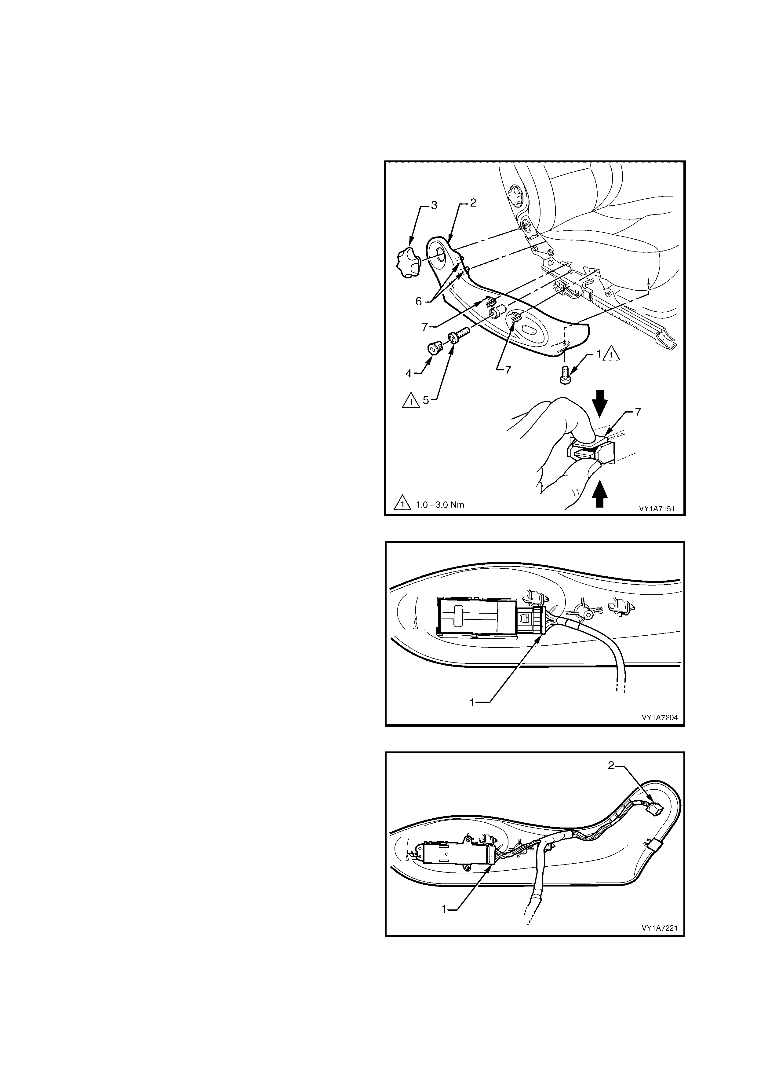
1. Remove the screw (1) from the front of the outer
side cover (2).
2. If fitted remove the recliner knob (3).
3. Remove the front seat outer side cover plug (4) by
rotating the plug anti-clockwise, one quarter of a
turn.
TIP: A fine screwdriver, would be useful to aid the
removal of the side cover plug without damage.
4. Remove the screw (5) located behind the plug.
5. Gently pull the outer cover away from the seat-
back recliner to disengage the two clips (6)
attached to the recliner frame.
6. Reach up under the seat assembly and squeeze
together the two retaining tangs (7), on the inner
side of the outer cover while gently pulling the outer
cover.
NOTE: Only remove the outer cover far enough away
from the seat cushion assembly to gain access to the
seat wiring harness connectors.
Figure 1A7-26
7. For vehic les fitted with the four-way seat as sem bly,
disconnect the four-way adjustment switch
connector (1) and remove the cover.
Figure 1A7-27
8. For vehicles fitted with the eight-way, non-memory
seat assembly:
• Disconnect the eight-way adjustment switch
connector (1).
• Disconnect the recliner motor connector (2).
• Remove the outer side cover.
Figure 1A7-28

REINSTALL
Reinstallation of the front seat outer side cover is the reverse of the removal operation, noting the following:
1. Ensure all screws are tightened to the correct torque specification.
FRONT OUTER SIDE COVER
ATTACHING SCREW
TORQUE SPECIFICATION 1.0 – 3.0 Nm
2.4 FRONT SEAT ADJUSTMENT SWITCH
LT Section No. – 14-275
1. Remove the front seat outer side cover, refer to 2.3 FRONT SEAT OUTER SIDE COVER.
REMOVE
Four-way Adjustment Switch (up and down only)
1. Remove the adjusting knob (1) from the seat
adjustment switch (2) by carefully prising it free with
a sm all flat tip s crewdriver wrapped in a clean shop
rag (3).
Figure 1A7-29
2. Gently prise the seat adjustment switch (1) from
the outer side cover (2) with the aid of a
screwdriver.
Figure 1A7-30
Eight-way Adjustment Switch - Non-memory (up, down, fore, aft and recline)
1. Remove the two adjustment knobs (1) from the
seat adjus tm ent switch (2) by ca refully prising them
free with a small flat tip screwdriver wrapped in a
clean shop rag (3).
Figure 1A7-31
2. Remove the three screws (1) attaching the seat
adjustment switch (2) to the outer side cover (3).
3. Remove the seat adjustment switch.
Figure 1A7-32
REINSTALL
Reinstallation of the four-way and the eight-way seat
adjustment switch is the reverse of the removal
operation, noting the following:
1. Ensure all screws are tightened to the correct torque
specification.
EIGHT-WAY SEAT ADJUSTMENT
SWITCH ATTACHING SCREW
TORQUE SPECIFICATION 1.0 – 3.0 Nm
2.5 FRONT SEAT INNER SIDE COVER
LT Section No. – 14-322
1. Remove the front seat assembly, refer to 2.2 FRONT SEAT ASSEMBLY.
REMOVE
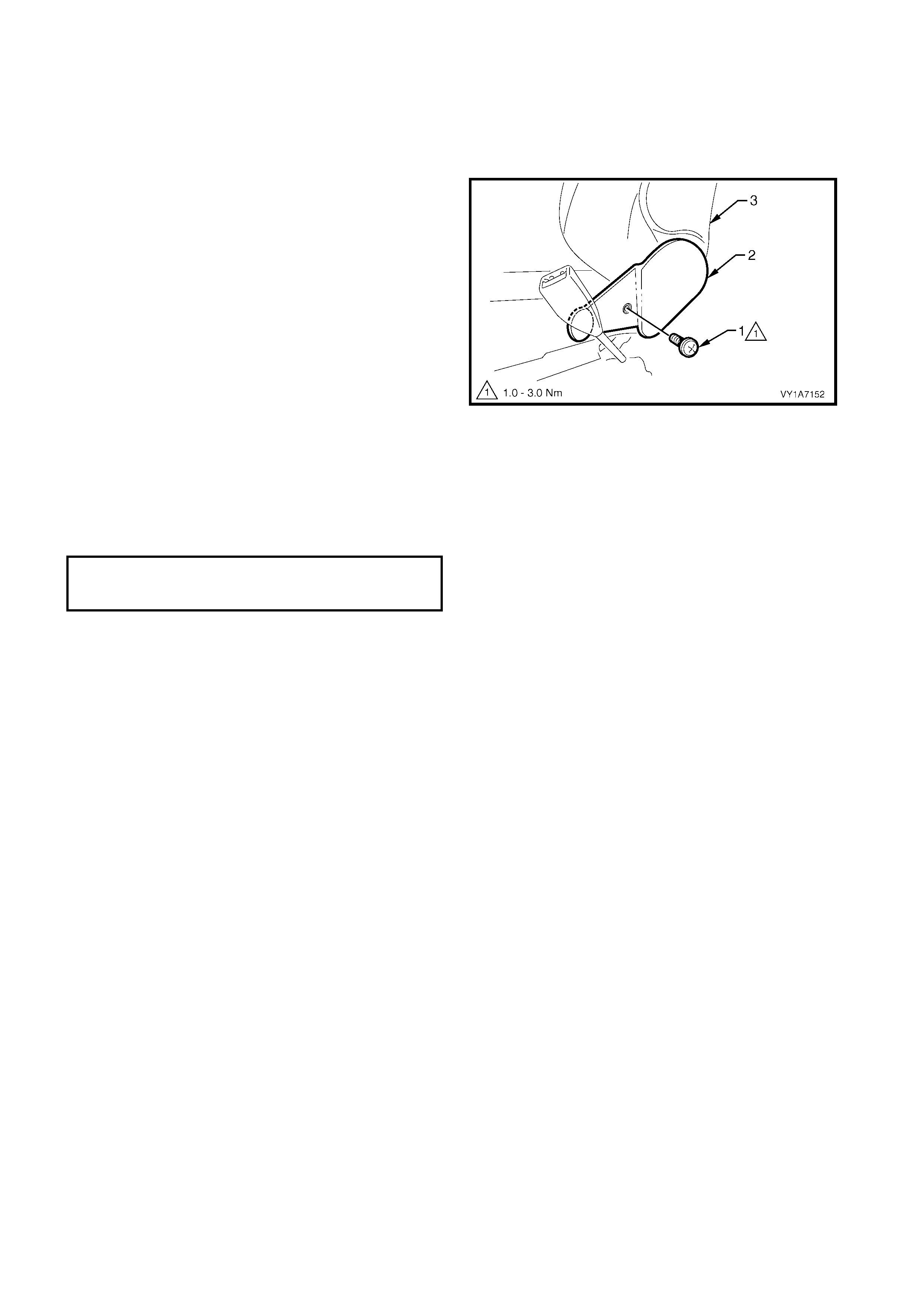
1. Remove the screw (1) securing the inner side
cover (2) to the seat assembly (3) and remove the
inner side cover.
Figure 1A7-33
REINSTALL
Reinstallation of the inner side cover is the reverse of
the removal operation, noting the following:
1. Ensure the screws are tightened to the correct
torque specification.
FRONT SEAT INNER SIDE
COVER ATTACHING SCREW
TORQUE SPECIFICATION 1.0 – 3.0 Nm
2.6 FRONT SEAT-BACK LOWER COVER ASSEMBLY AND LUMBAR
SUPPORT ADJUSTER KNOB
LT Section No. – 14-322
REMOVE
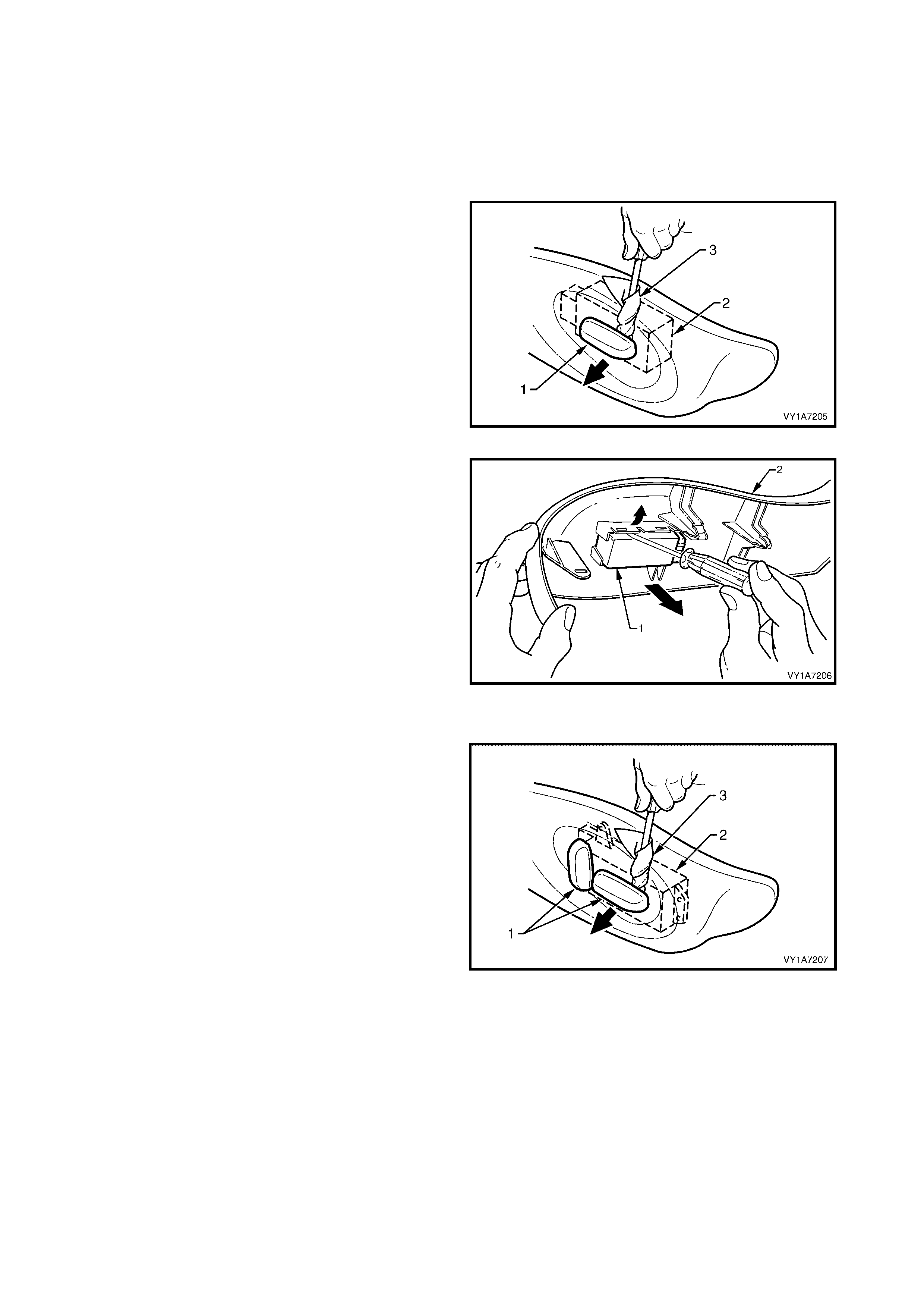
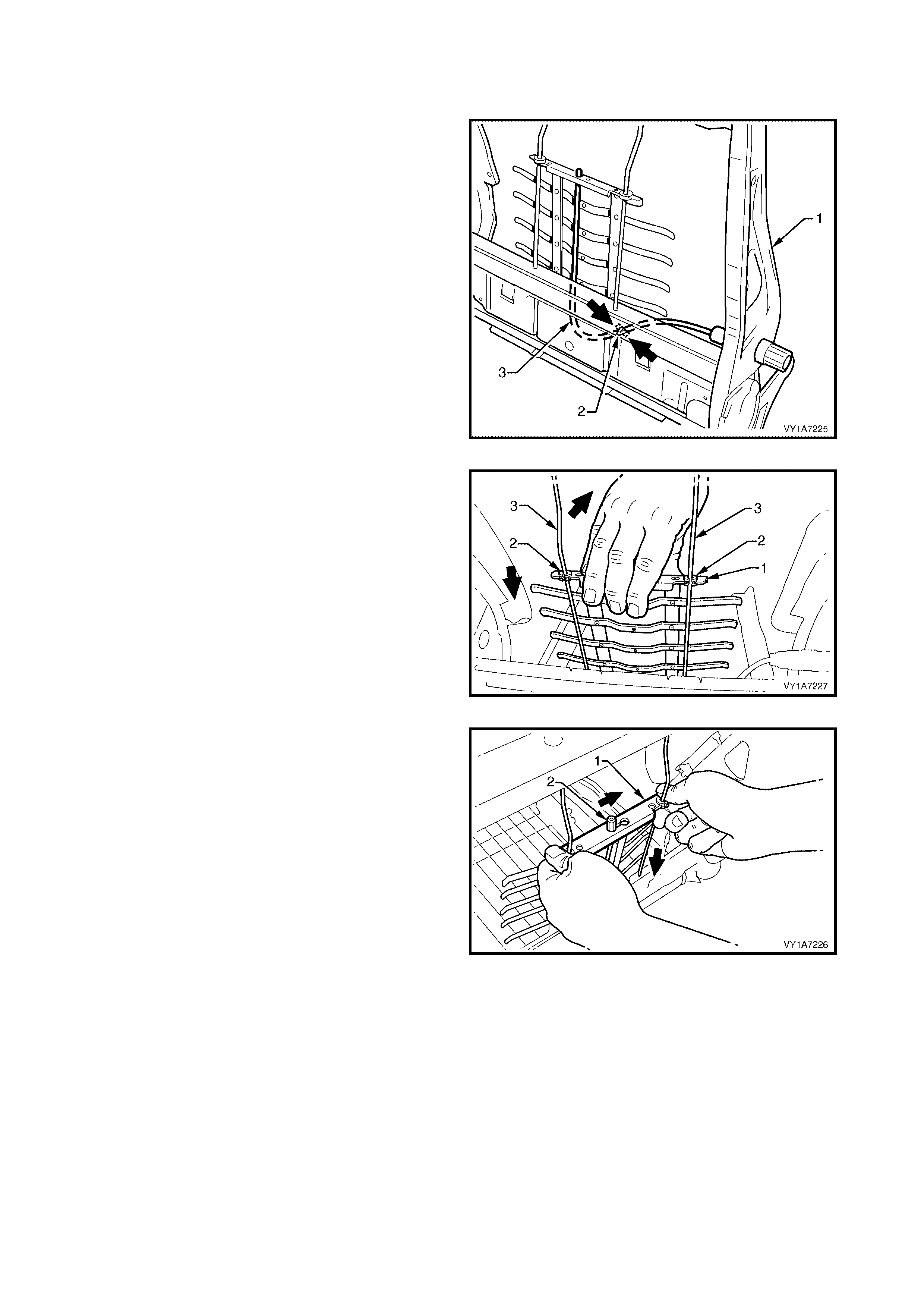
1. Insert a flat-tip screwdriver between the front seat-
back lower cover (1) and the seat-back (2).
2. Push up on each lower retaining clip (3) (two
places) while pulling the bottom of the back cover
out, away from seat, to release the lower retaining
clips.
Figure 1A7-34
3. Where fitted, pull the front edge of the front seat-
back lower cover ( 1), forward of the lumbar s upport
adjuster k nob ( 2), outward to disengage the lum ber
support adjuster knob.
Figure 1A7-35
4. W hile holding the side of the front seat-back lower
cover out (1), pull the cover down to release the
upper retainers (2), two places.
5. Remove the cover.
Figure 1A7-36

DISASSEMBLE
Remove - Lumbar Support Adjuster Knob and Adapter
1. Remove the lum bar support adj uster knob (1) from
the front seat-back cover (2) by spreading the
retaining clip (3) and withdrawing the lumbar
support adjuster knob.
Figure 1A7-37
2. Remove the retaining clip (1) by pulling it from the
lumber support adjuster knob adapter (2).
Figure 1A7-38
3. Rotate the lumber support adjuster knob adapter
(1) approximately 90° clockwise.
4. Remove the lumber support adjuster knob adapter.
Figure 1A7-39
Reinstall - Lumbar Support Adjuster Knob and Adapter
Reinstallation of the lumbar support adjuster knob and
adapter is the rever se of the rem oval procedure, noting
the following:
1. Align the narrow tab (1) on the lumber support
adjuster knob adapter (2) with the narrow key-way
(3) in the front seat-back low er cover (4).
2. Insert the adapter into the cover and rotate
approximately 90° anti-clockwise until locked.
Figure 1A7-40
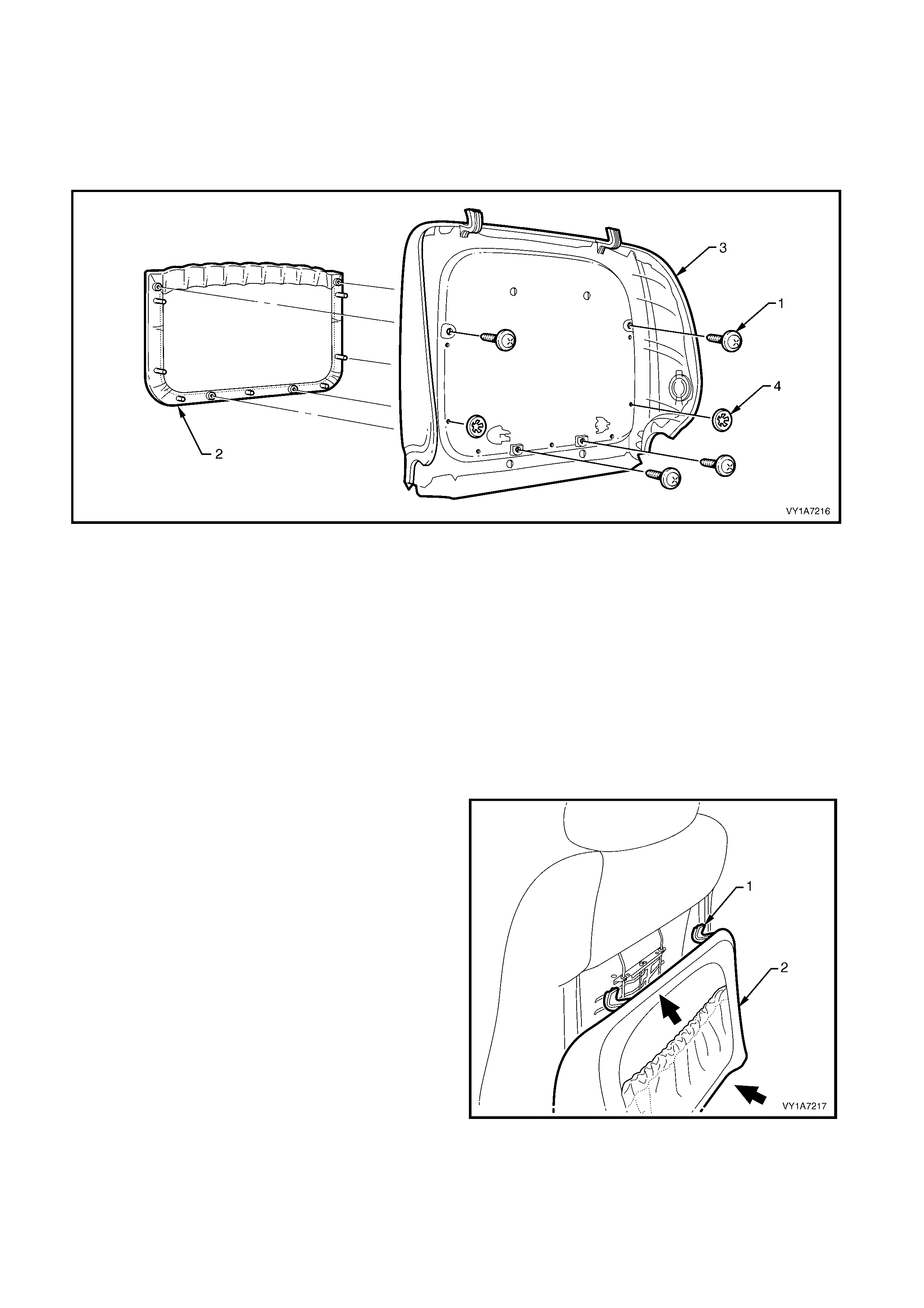
Remove - Front Seat-back Lower Cover Pocket
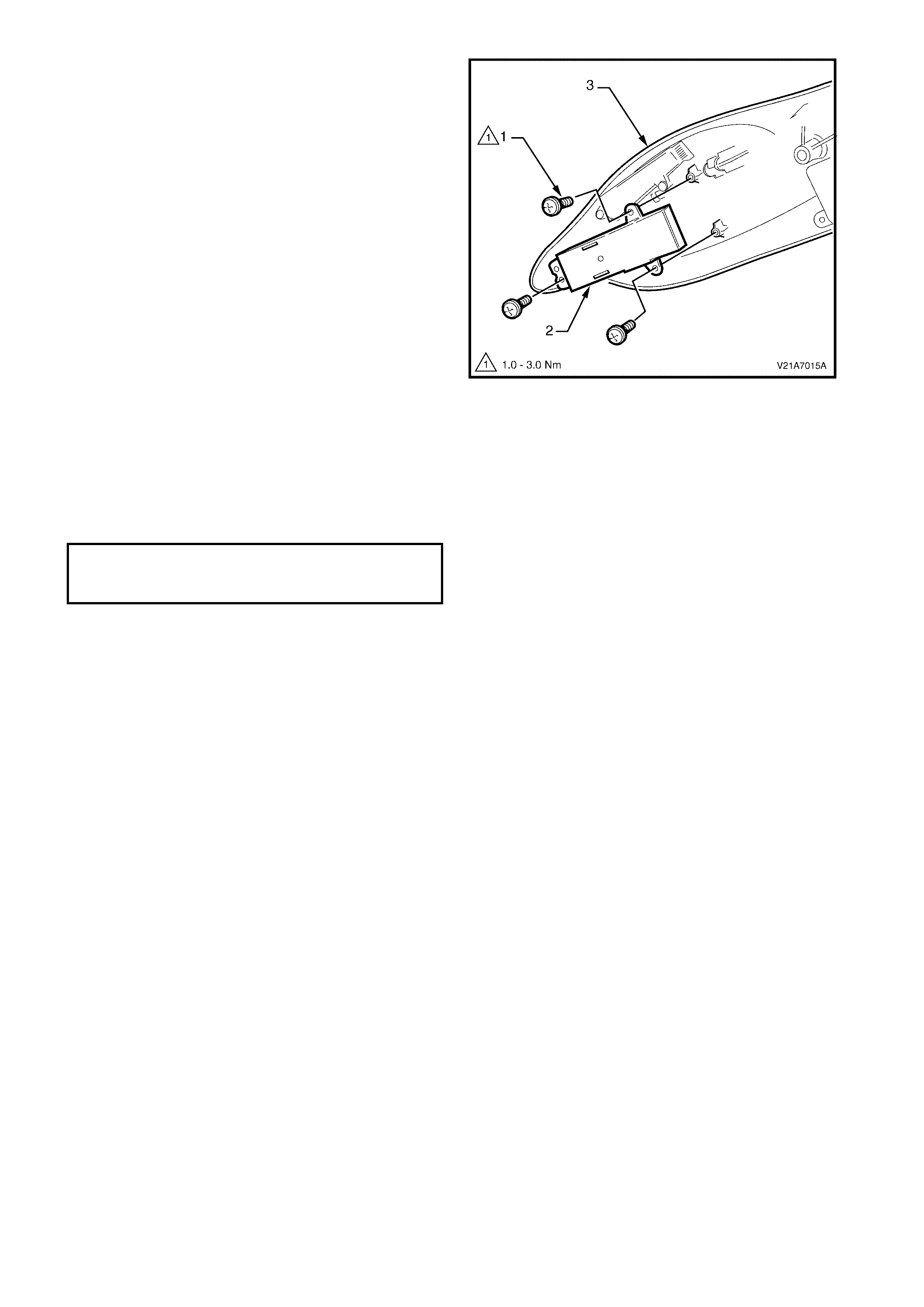
1. Remove the four screws (1) attaching the front seat-back lower cover pock et (2) to the front seat- back lower
cover (3), refer Figure 1A7-41.
2. Remove the two clips (4) securing the rear cover pocket to the front seat-back lower cover.
NOTE: Take care when removing the clips not to break the rear cover pocket shafts on which the clips are
attached.
Figure 1A7-41
Legend
1. Front Seat-back Pocket Screw - 4 Places
2. Front Seat-back Lower Cover Pocket 3. Front Seat-back Lower Cover
4. Front Seat-back Pocket Attach Clip - 2 Places
Reinstall - Front Seat-back Lower Cover Pocket
Reinstallation of the f ront seat-bac k lower cover pocket
is the reverse of the removal procedure, noting the
following:
1. Ensure all fasteners are tightened securely.
REINSTALL
1. Locate the two upper retaining clips (1) on the
seat-back cover (2) with the seat-back.
Figure 1A7-42
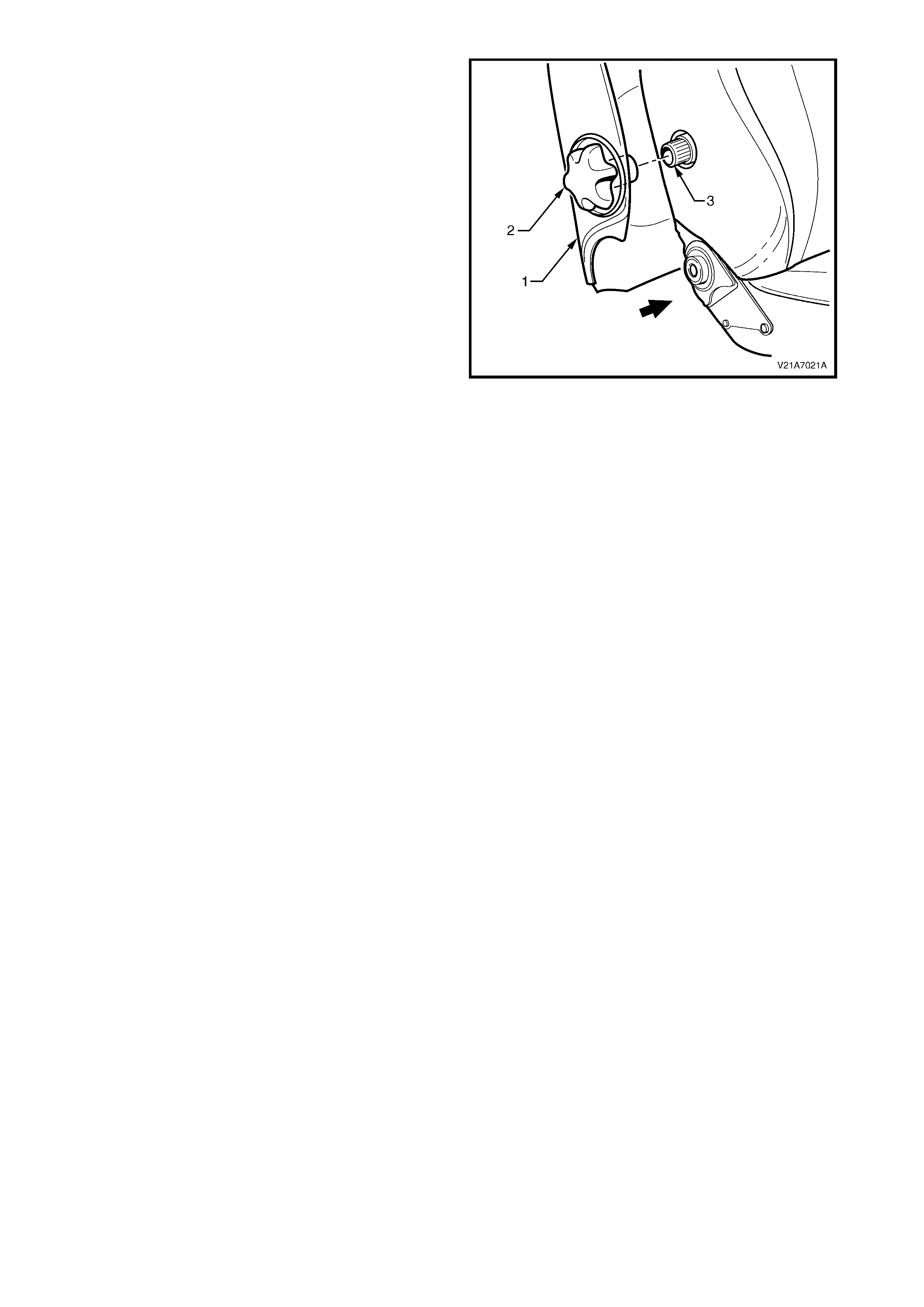
2. Where fitted, pull the side of the front seat-back
lower cover (1) out and align the splines on the
lumber support adjuster knob (2) with the splines
on the lumbar support adjuster (3).
3. Push the lumber support adjuster knob onto the
lumbar support shaft.
4. Push the seat-back cover into the seat-back to
engage the two lower retaining clips.
Figure 1A7-43
2.7 FRONT SEAT HEAD RESTRAINT ASSEMBLY
LT Section No. – 14-295
REMOVE
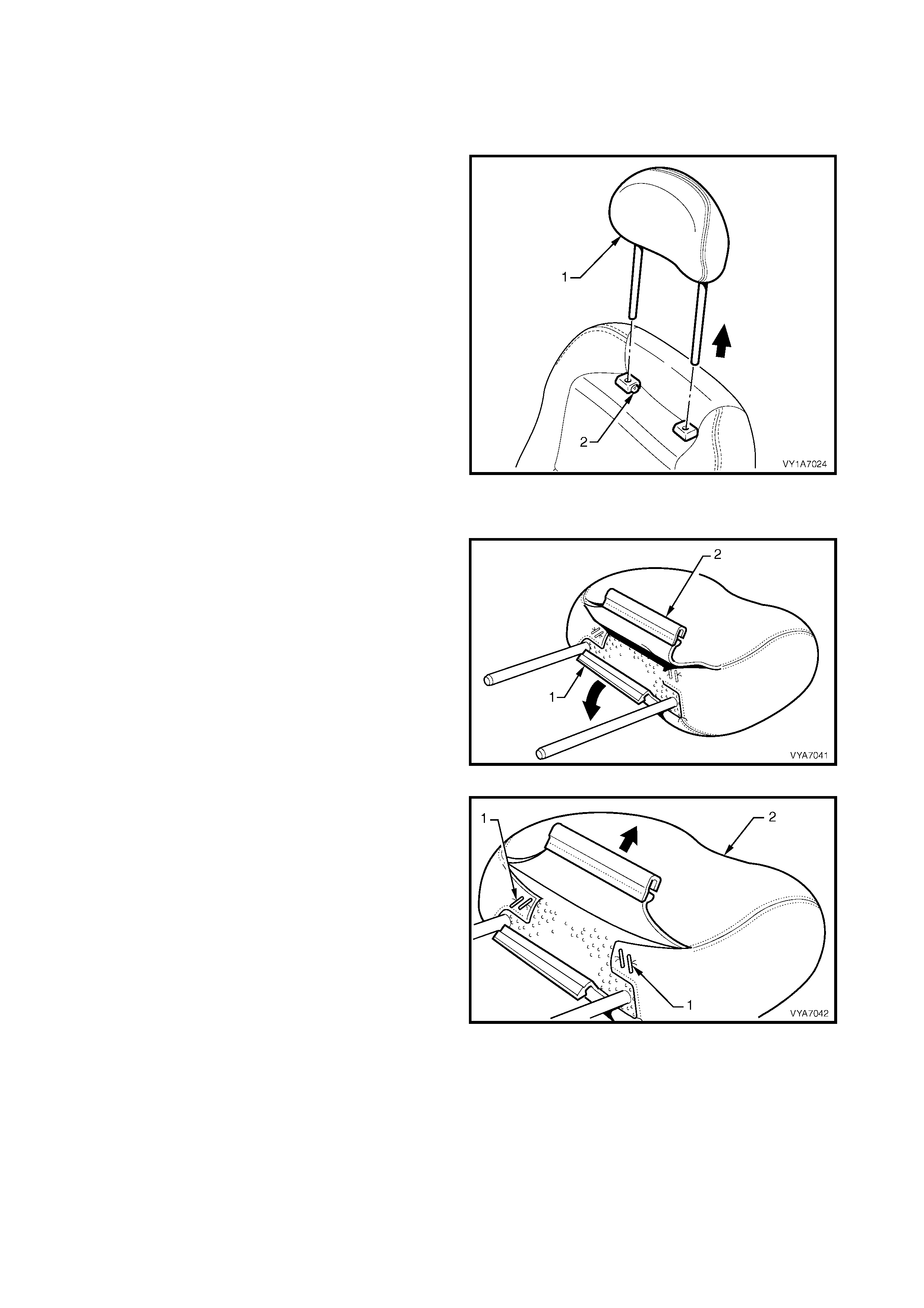
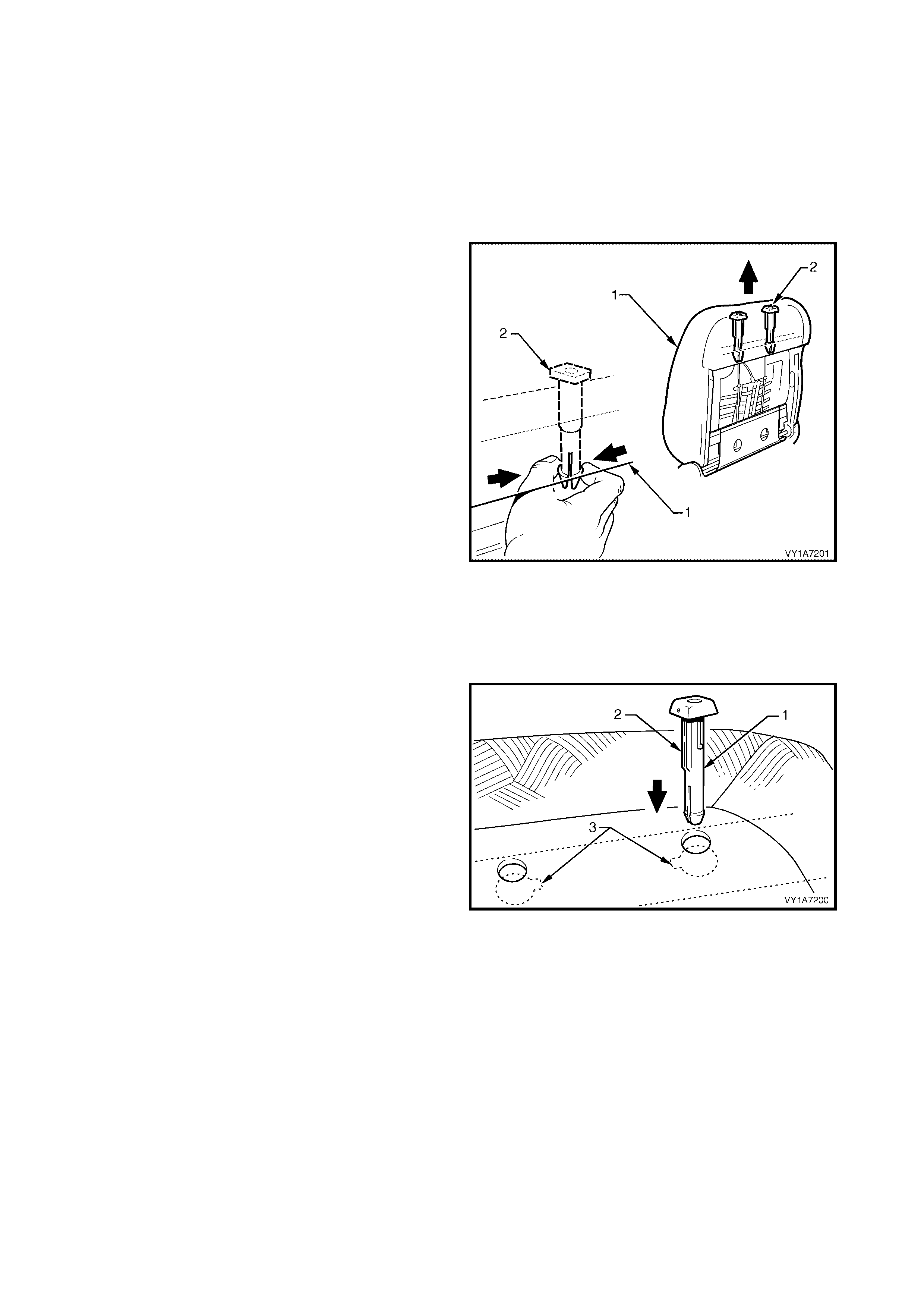
1. Rem ove the front seat head restraint assembly (1)
by depressing the head restraint guide height
adjuster lock button (2), and lifting the head
restraint completely out of the guide.
Figure 1A7-44
DISASSEMBLE
1. Disengage the front head restraint cover J-strip (1)
by pulling the flap (2) up.
Figure 1A7-45
2. Remove the four staples (1) retaining the cover (2)
to the head restraint pad assembly.
3. Remove the cover from the pad assembly.
Figure 1A7-46
REASSEMBLE
Reassembly of the front seat-back head restraint assembly is the reverse of the removal procedure, noting the
following:
1. Ensure the head restraint cover J-clip is fully engaged.
REINSTALL
Reinstallation of the front seat head restraint assembly is the reverse of the removal procedure.
2.8 FRONT SEAT HEAD RESTRAINT GUIDE
LT Section No. – 14-275
1. Remove the front seat outer side cover, refer to 2.3 FRONT SEAT OUTER SIDE COVER.
2. Remove the front seat-back lower cover assembly and lumber support adjuster knob, refer to
2.6 FRONT SEAT-BA CK LOWER COVER ASSEMBLY AND LUMBER SUPPORT ADJUSTER KNOB.
3. Remove the front seat head restraint assembly, refer to 2.7 FRONT SEAT HEAD RESTRAINT ASSEMBLY.
REMOVE
1. From the rear of the front seat-back (1), squeeze
the locking prongs of the head restraint guide (2)
together while pulling the top of the guide out of
seat-back assembly.
Figure 1A7-47
REINSTALL
Reinstallation of the front seat head restraint guide is
the reverse of the removal procedure, noting the
following:
1. When installing the head restraint guide (1), align
the locating ribs (2) with the key-way (3) in the
seat-back frame.
NOTE: Ensure the guide with the height adjuster lock is
installed on the s ide that corresponds to the notches in
the head restraint shaft.
Figure 1A7-48
2.9 FRONT SEAT-BACK PAD AND COVER ASSEMBLY
LT Section No. – 14-295
1. Remove the front seat assembly, refer to 2.2 FRONT SEAT ASSEMBLY.
2. Remove the front seat outer side cover, refer to 2.3 FRONT SEAT OUTER SIDE COVER.
3. Remove the front seat-back lower cover assembly and lumber support adjuster knob, refer to
2.6 FRONT SEAT-BA CK LOWER COVER ASSEMBLY AND LUMBER SUPPORT ADJUSTER KNOB.
4. Remove the front seat head restraint assembly, refer to 2.7 FRONT SEAT HEAD RESTRAINT ASSEMBLY.
5. Remove the front seat head restraint guide, refer to 2.8 FRONT SEAT HEAD RESTRAINT GUIDE.
REMOVE
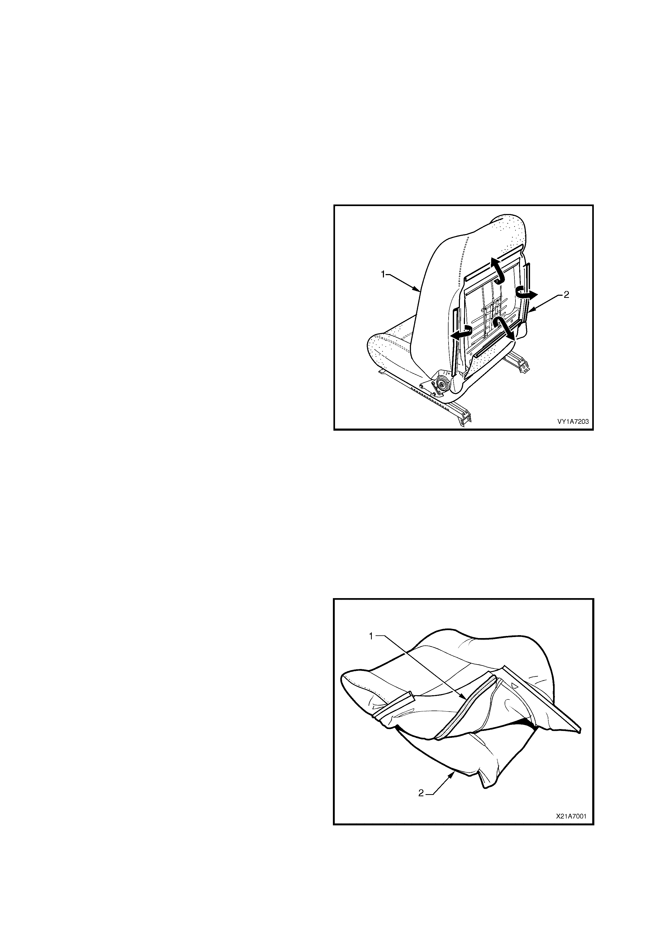
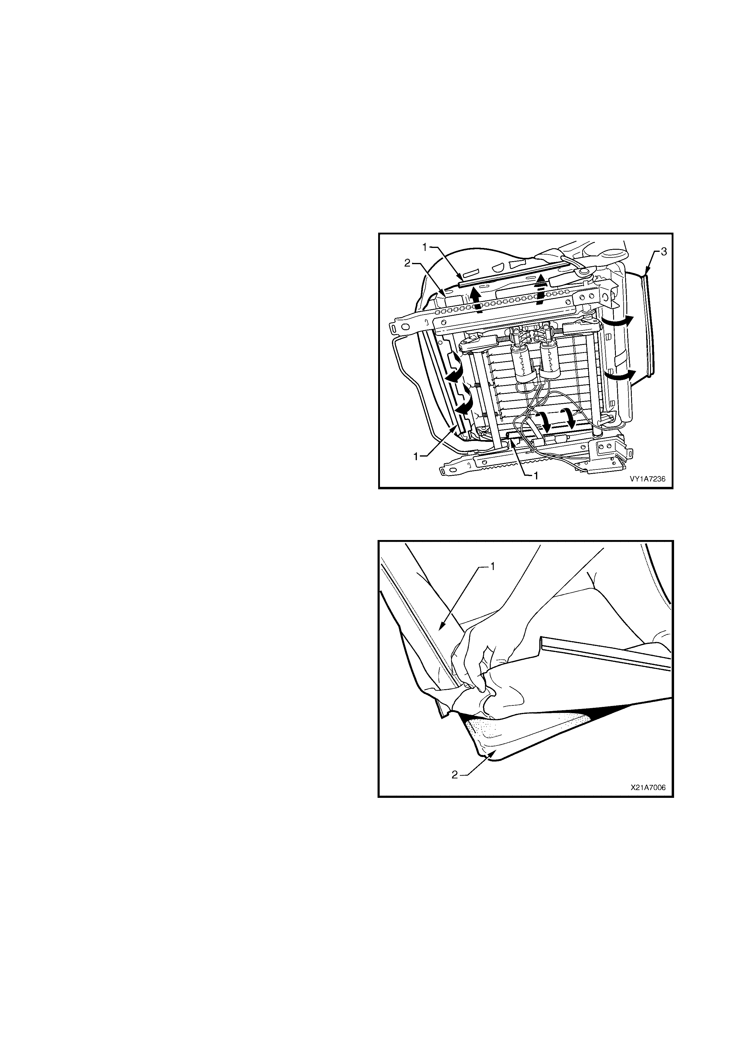
1. Remove the front seat-back pad and cover
assembly (1) by pulling the four J-strips (2) away
from the seat frame.
2. Lift the cover and pad assem bly up and away f rom
the seat-back frame.
Figure 1A7-49
DISASSEMBLE
NOTE 1: The following procedure only applies to
vehicles fitted with seat covers attached to the seat-
back pad with the fully serviced Hook and Loop. For
model reference chart, refer to 2.1 FRONT SEAT
USAGE CHART - EXCEPT COUPE.
NOTE 2: Surebond cover assemblies are not serviced
as they are glued to the seat-back pad, for model
reference chart, refer to 2.1 FRONT SEAT USAGE
CHART - EXCEPT COUPE.
1. Fold the lower corners of the seat-back cover (1)
over the seat-back pad (2).
Figure 1A7-50
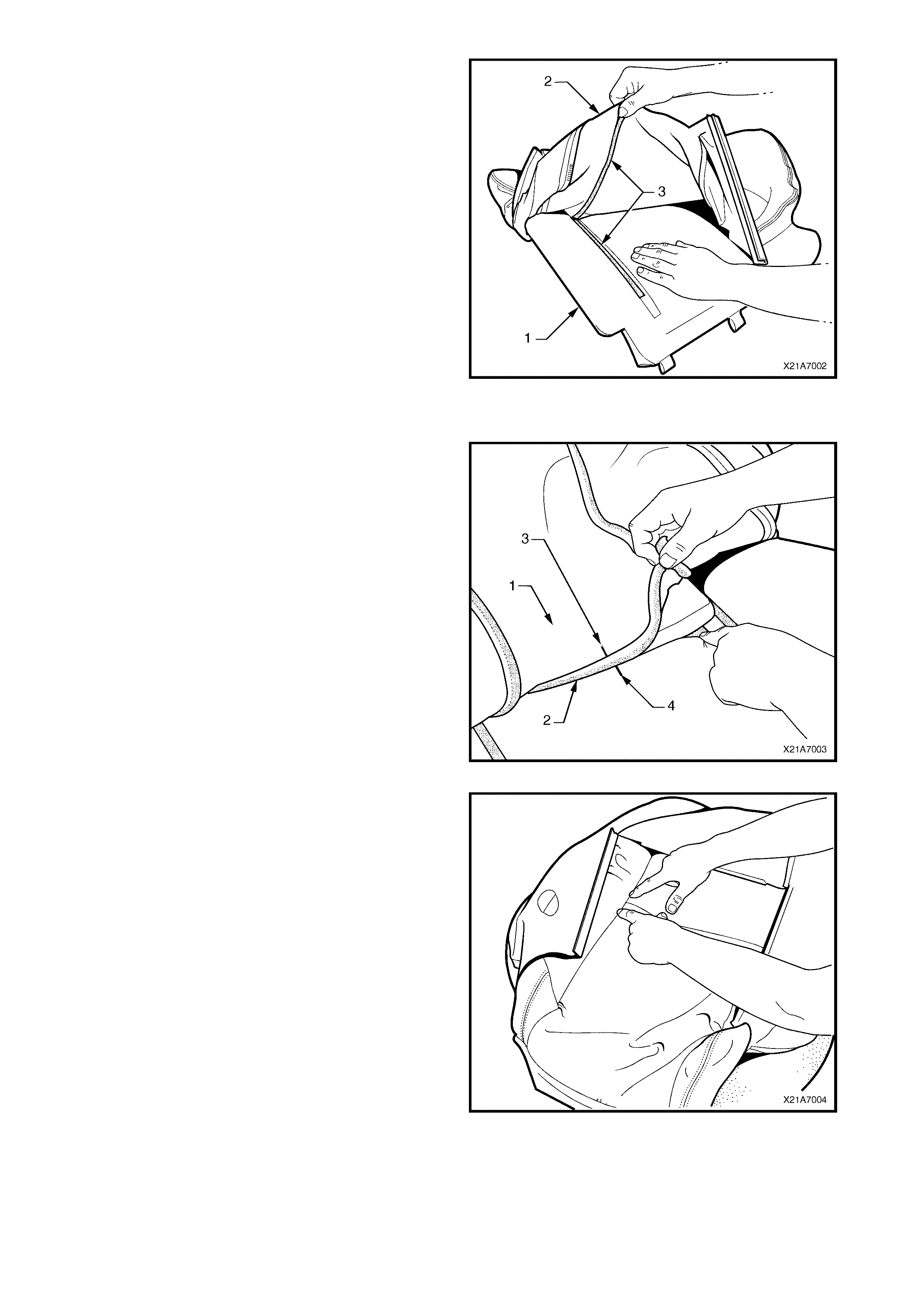
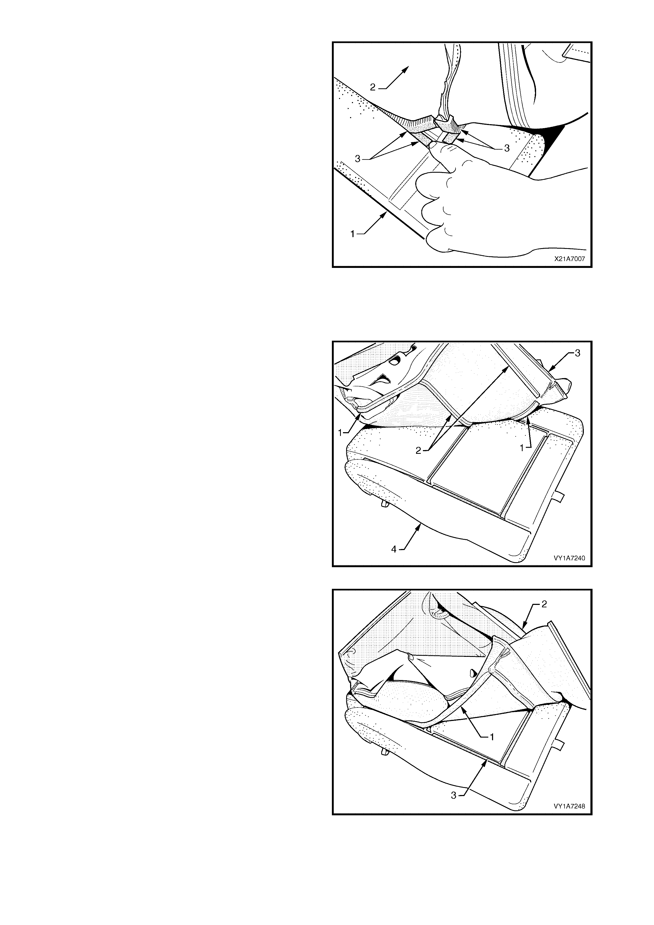
2. While holding the front seat-back pad (1), pull the
lower corners of the seat-back cover (2), upwards
and away from the front seat pad to disengage the
hook and loop strips (3).
3. Pull the front seat-back cover up and over the
upper edge of the front seat-back pad.
Figure 1A7-51
REASSEMBLE
1. With the seat-back cover (1) folded at the central
horizontal strip of hook and loop (2), align the
centre mark (3) on the front seat-back cover with
the centre mark (4) on the seat-back pad.
2. Press the seat-back cover firmly into the
corresponding groove in the seat-back pad to
engage the hook and loop.
Figure 1A7-52
3. W ith the seat cover folded at the two vertical strips
of the hook and loop, press the seat-back cover
firmly into the corresponding grooves in the seat-
back pad.
Figure 1A7-53
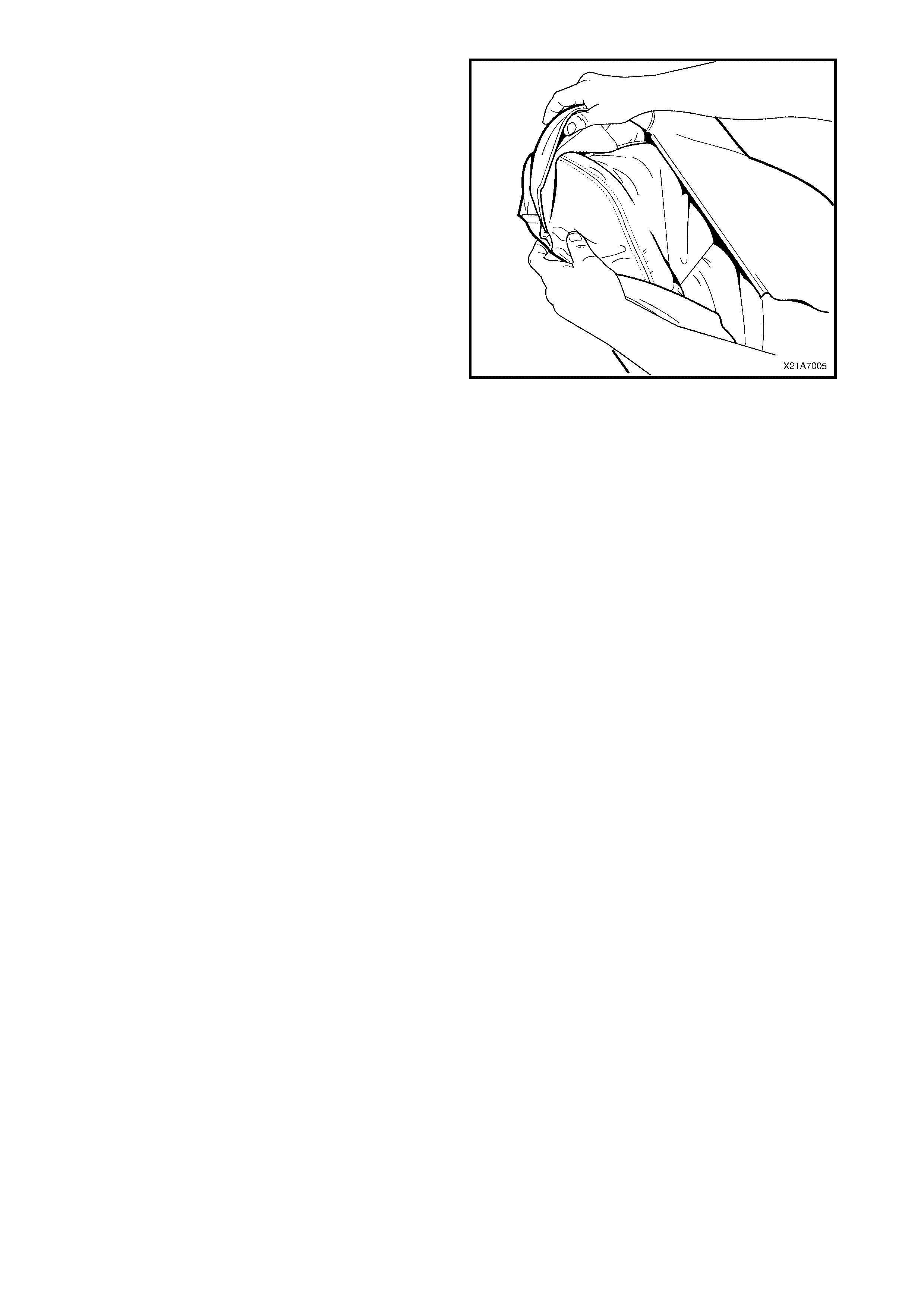
4. Roll the upper corners of the front seat-back cover
over the seat-back pad.
5. Roll the s ides of the seat-bac k c over over the s eat-
back pad.
6. Roll the lower corners of the seat-back cover over
the seat-back pad.
NOTE: Make sure the cover is fitted neatly by hand into
all corners and contours of the seat pad.
Figure 1A7-54
REINSTALL
Reinstallation of the rear seat-back assembly is the
reverse of the removal operation.
2.10 FRONT SEAT-BACK FRAME ASSEMBLY
LT Section No. – 14-275
CAUTION: When carrying a live (undeployed) side airbag assembly, make sure the airbag opening is
pointed away from you. Never carry the side airbag assembly by the wiring harness or connectors. In
case of an accidental deployment, the airbag will then deploy with minimal chance of injury.
When p lacing a liv e side airb ag assemb ly on a ben ch or o th er surf ace, alw ays face th e airbag openin g up,
away from t he surface. Never rest th e airbag assembly with th e opening face do wn. Th is is necessary so
that a free sp ace is provid ed to allo w t he airbag t o expand in the un likely event of accid ental dep loyment.
Otherwise, personal injury may result.
1. Remove the front seat assembly, refer to 2.2 FRONT SEAT ASSEMBLY.
2. Remove the front seat outer side cover, refer to 2.3 FRONT SEAT OUTER SIDE COVER.
3. Remove the front seat inner side cover, refer to 2.5 FRONT SEAT INNER SIDE COVER.
4. Remove the front seat-back lower cover assembly, refer to 2.6 FRONT SEAT-BACK LOWER COVER
ASSEMBLY AND LUMBER SUPPORT ADJUSTER KNOB.
5. Remove the front seat head restraint assembly, refer to 2.7 FRONT SEAT HEAD RESTRAINT ASSEMBLY.
6. Remove the front seat head restraint guide, refer to 2.8 FRONT SEAT HEAD RESTRAINT GUIDE.
7. Remove the front seat-back pad and cover assembly, refer to 2.9 FRONT SEAT-BACK PAD AND COVER
ASSEMBLY.
REMOVE
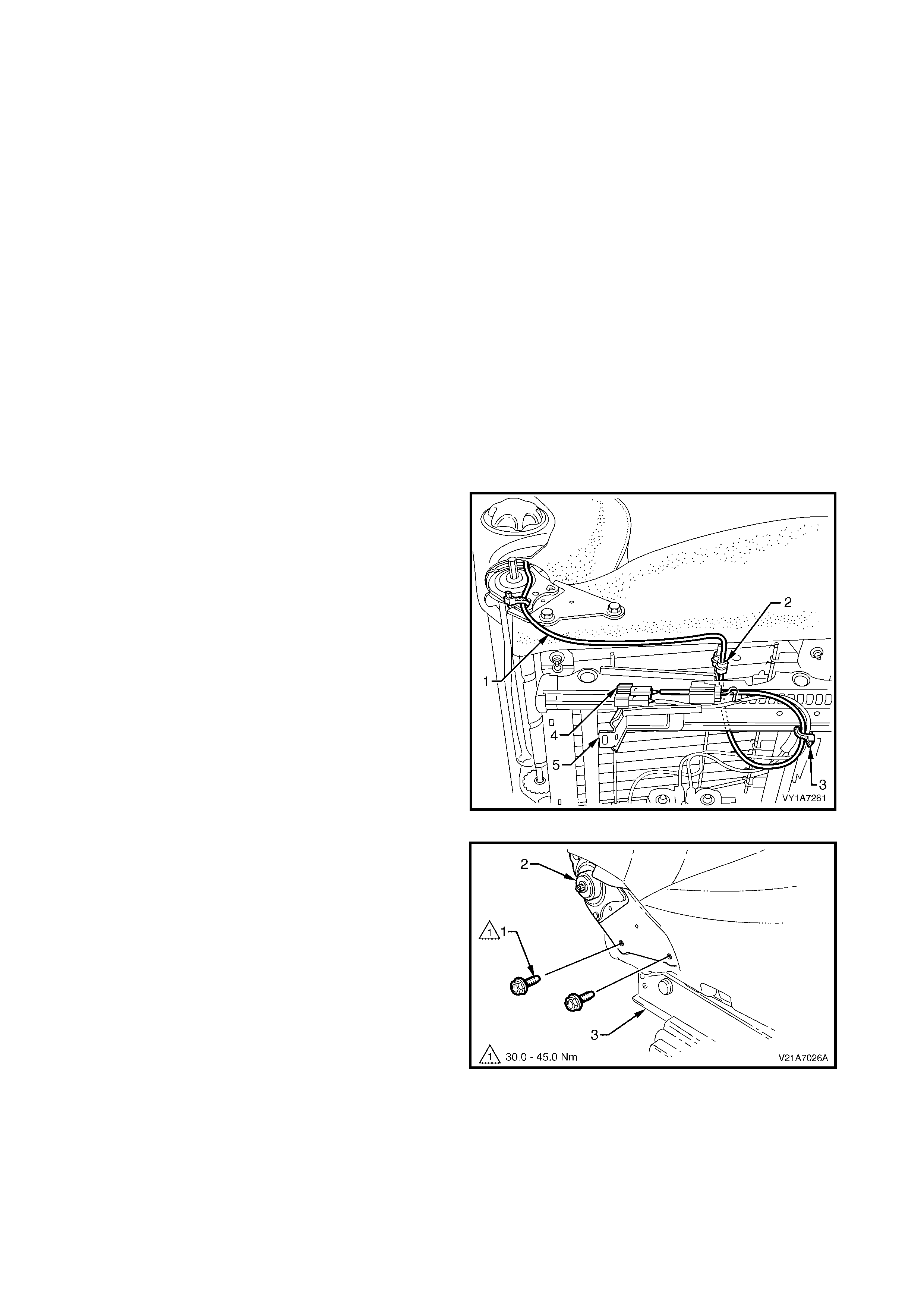
1. Where fitted, unclip the side impact airbag pigtail
wiring harness (1) from the retaining clip (2) and
cut the cable tie (3) securing the side airbag
harness to the front seat cushion frame assembly,
taking care not to damage the wiring harness.
2. Unclip the wiring harness connector (4) from the
adjuster and guide rail assembly (5).
Figure 1A7-55
3. Remove the two screws (1), each side, attaching
the seat-back assembly (2) to the seat height
adjuster and cushion frame assembly (3).
4. Remove the seat-back assembly.
Figure 1A7-56
DISASSEMBLE
Remove - Lumbar Support and Adjuster Assembly – Where Fitted
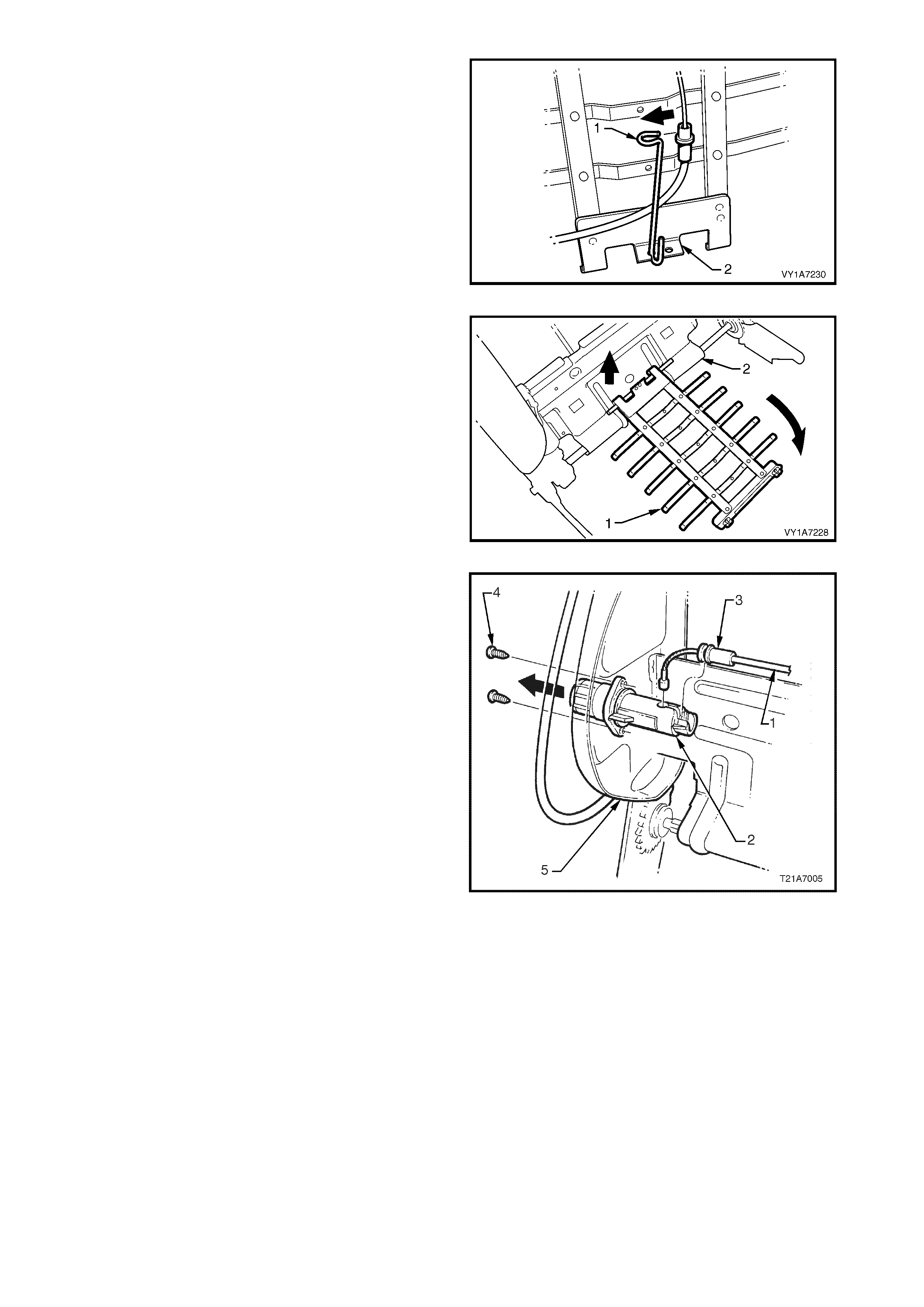
1. From the rear of the front seat-back frame (1),
disengage the clip (2) securing the lumbar support
adjuster cable (3). Squeeze the tangs on the tie clip
together and push the clip through the seat-back
frame.
Figure 1A7-57
2. Push down the top of the lum bar s upport assem bly
(1) to disengage the two retainers (2) from the
guide rails (3) on the seat-back f rame, allowing the
lumbar support to swing freely.
Figure 1A7-58
3. Slightly com press the lum bar support assembly (1)
by hand to release the cable (2) tension,
disengaging the cable from the top of the lumbar
support.
Figure 1A7-59
4. Unclip the lower cable retainer (1) from the lower
lumbar bracket (2).
Figure 1A7-60
5. Lower the lumbar support assembly (1) until it
becomes disengaged from the seat back frame
assembly (2).
6. Remove the lumbar support assembly.
Figure 1A7-61
7. Remove the adjusting cable (1) from the adjuster
(2) by unclipping the outer casing (3) of the cable
from the adjuster and removing the cable
assembly.
NOTE: The right-hand seat back is shown. The left-
hand seat back is opposite, with the cable fitting the
adjuster from the under-side.
8. Remove the two screws (4) securing the lumbar
support adjuster to the seat-back frame (5) and
remove the adjuster.
Figure 1A7-62
Reinstall - Lumbar Support and Adjuster Assembly
Reinstallation of the lumbar support and adjuster
assembly is the reverse of the removal procedure,
noting the following:
1. Align the hole in the adj us ter f or the adj us ting c able
ball by turning the adjuster , insert the c able into the
adjuster and pus h the outer cas ing of the c able into
the locking seat of the adjuster until it clicks.
NOTE: On the right-hand seat, the cable fits into the
adjuster from the top. On the left-hand seat, the cable
fits into the adjuster from the under-side.
2. Ensure all screws are tightened securely.
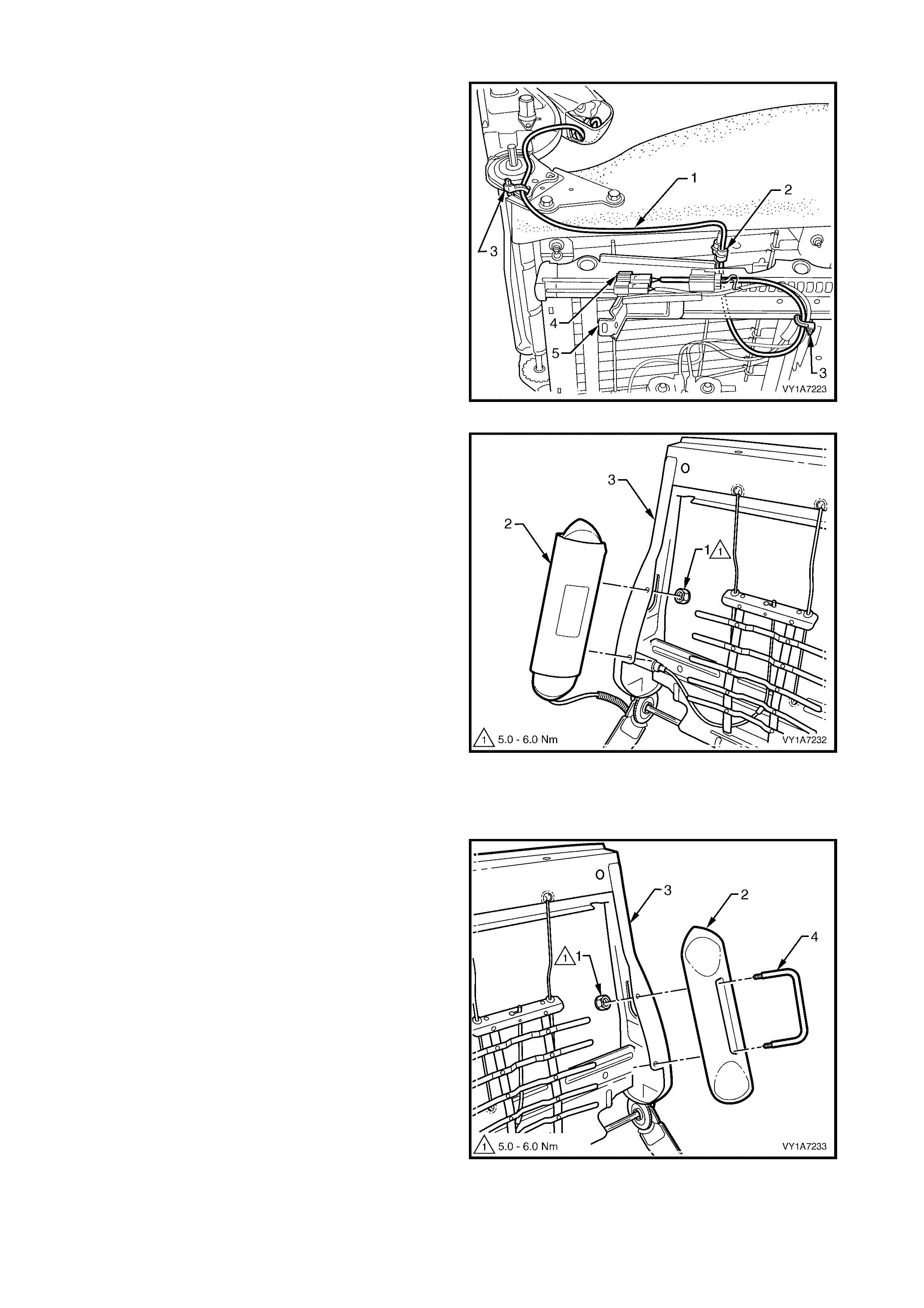
Remove – Side Impact Airbag Assembly – Where fitted
1. Unclip the pigtail wiring harness (1) from the
retaining clip (2) and cut the two cable ties (3),
securing the harness to the front seat cushion
frame assembly, taking care not to damage the
wiring harness.
2. Unclip the wiring harness connector (4) from the
adjuster and guide rail assembly (5).
Figure 1A7-63
3. Remove the two lock nuts (1), securing the side
impact airbag assembly (2) to the front seat-back
frame (3).
4. Remove side airbag assembly and pigtail wiring
harness assembly from front seat-back frame.
CAUTION: When carrying a live (undeployed) side
airbag assembly, make sure the bag opening is
point ed aw ay from you. Never carry the sid e airbag
assembly by the wiring harness or connectors. In
case of an accidental deployment, the bag will th en
deploy with minimal chance of injury.
When placing a live side airbag assembly on a
bench or other surface, always face the airbag
opening up, away from the surface. Never rest the
airbag inflator module assembly with the opening
face dow n . This is necessary so that a free space is
provided to allow the airbag to expand in the
unlikely event of accidental deployment. Otherwise,
personal injury may result.
Figure 1A7-64
5. If required, remove the two lock nuts (1) retaining
the front s eat foam block ins ert assem bly ( 2) to the
seat-back frame (3) and remove the foam block
inse rt assembly.
6. If required, remove the foam block insert retaining
bracket (4) from the foam block insert assembly.
Figure 1A7-65
Reinstall – Side Impact Airbag Assembly
Reinstallation of the side impact airbag assembly and the foam block insert assembly, is the reverse of the removal
procedure, noting the following:
1. Ensure all fasteners are tightened to the correct torque specification.
REINSTALL
Reinstallation of the front seat-back frame assembly is the reverse of the removal procedure, noting the following:
1. Ensure all fasteners are tightened to the correct torque specification.
2. If the side impact airbag is fitted, route the wiring
harness (1) through to the side of the adjuster and
guide rail assembly (2) and secure in the retaining
clip (3). Fit the connector (4) to the adjuster and
guide rail assem bly, and attach with two new cable
ties (5).
NOTE 1: If the wiring harness is not routed correctly,
damage to the har ness m ay occur, resulting in the side
impact airbag becoming inoperative and setting a
Diagnostic Trouble Code (DTC) (SRS warning lamp
on).
NOTE 2: The wiring harness that connects to the side
impact airbag module assembly, is not serviced
separately from the side airbag inflator module due to
the design of the anti-back-out connector on the
module assembly.
NOTE 3: If this wiring harness, as with any other SRS
pigtail type wiring harness becom es damaged, no wire,
connector or terminal repairs are to be attempted.
REPLACE THE SIDE AIRBAG MODULE AND
PIGTAIL WIRING HARNESS ASSEMBLY.
Figure 1A7-66
3. Reconnect the battery earth and the positive leads, if the seat is fitted with a side impact airbag, switch the
ignition ON and observe the SRS warning indicator in the instrument cluster.
• If no fault is detected, the SRS warning indicator should illuminate for approximately five seconds while
the system performs a self-test, and then go off.
• If a fault is present, the SRS warning indicator will remain illuminated and a warning chime may sound
after approximately three seconds. The warning message ‘SRS Airbag Fault’ is also displayed in the
instrument cluster multi-function display. To diagnose the fault, refer to Section 12M, 4. DIAGNOSTICS.
4. Check operation of front seat mechanical and electrical adjustments / operation. While checking the seat
adjustm ent / operation, also check to ensure that the side airbag harness does not foul with any of the seats
moveable components (ie. seat motor drive shafts, etc.).
SIDE IMPACT AIRBAG
ASSEMBLY ATTACHING NUT
TORQUE SPECIFICATION 5.0 – 6.0 Nm
FRONT SEAT FOAM BLOCK
INSERT ATTACHING NUT
TORQUE SPECIFICATION 5.0 – 6.0 Nm
FRONT SEAT-BACK FRAME
ASSEMBLY ATTACHING SCREW
TORQUE SPECIFICATION 30.0 – 45.0 Nm

2.12 FRONT SEAT CUSHION PAD AND COVER ASSEMBLY
LT Section No. – 14-295
1. Remove the front seat assembly, refer to 2.2 FRONT SEAT ASSEMBLY.
2. Remove the front seat outer side cover, refer to 2.3 FRONT SEAT OUTER SIDE COVER.
3. Remove the front seat inner side cover, refer to 2.5 FRONT SEAT INNER SIDE COVER.
4. Remove the front seat-back lower cover assembly, refer to 2.6 FRONT SEAT-BACK LOWER COVER
ASSEMBLY AND LUMBER SUPPORT ADJUSTER KNOB.
5. Remove the front seat-back frame assembly, refer to 2.10 FRONT SEAT-BACK FRAME ASSEMBLY.
REMOVE
1. From under the front seat cushion, pull the front
and side J-strips (1) away from the seat frame (2).
2. Lift cover and pad assembly away from seat frame
and then release the rear J-strip (3).
Figure 1A7-67
DISASSEMBLE
1. Fold the rear corners of the front seat cushion
cover (1) over the seat cushion pad (2).
Figure 1A7-68
2. While holding the front seat cushion pad (1), pull
the rear corners of the seat cushion cover (2)
forward and away from the front seat cushion pad
to disengage the hook and loop strips (3).
3. Pull the front seat cover up and over the forward
edge of the front seat cushion pad.
Figure 1A7-69
REASSEMBLE
Reassembly of the front seat cushion is the reverse of
the removal procedure noting the following:
1. Align either of the outer hook and loop strips (1)
and the one or two cross hook and loop strips (2),
on the seat cushion cover (3), with the seat cushion
pad (4).
2. Press the folded edge of the rear seat cushion
cover firmly into the corresponding groove in the
seat cushion pad to engage the hook and loop
strip.
Figure 1A7-70
3. Continue aligning and pressing the outer hook and
loop strips (1) on the seat cushion cover (2), with
the corresponding groove in the seat cushion pad
(3).
Figure 1A7-71
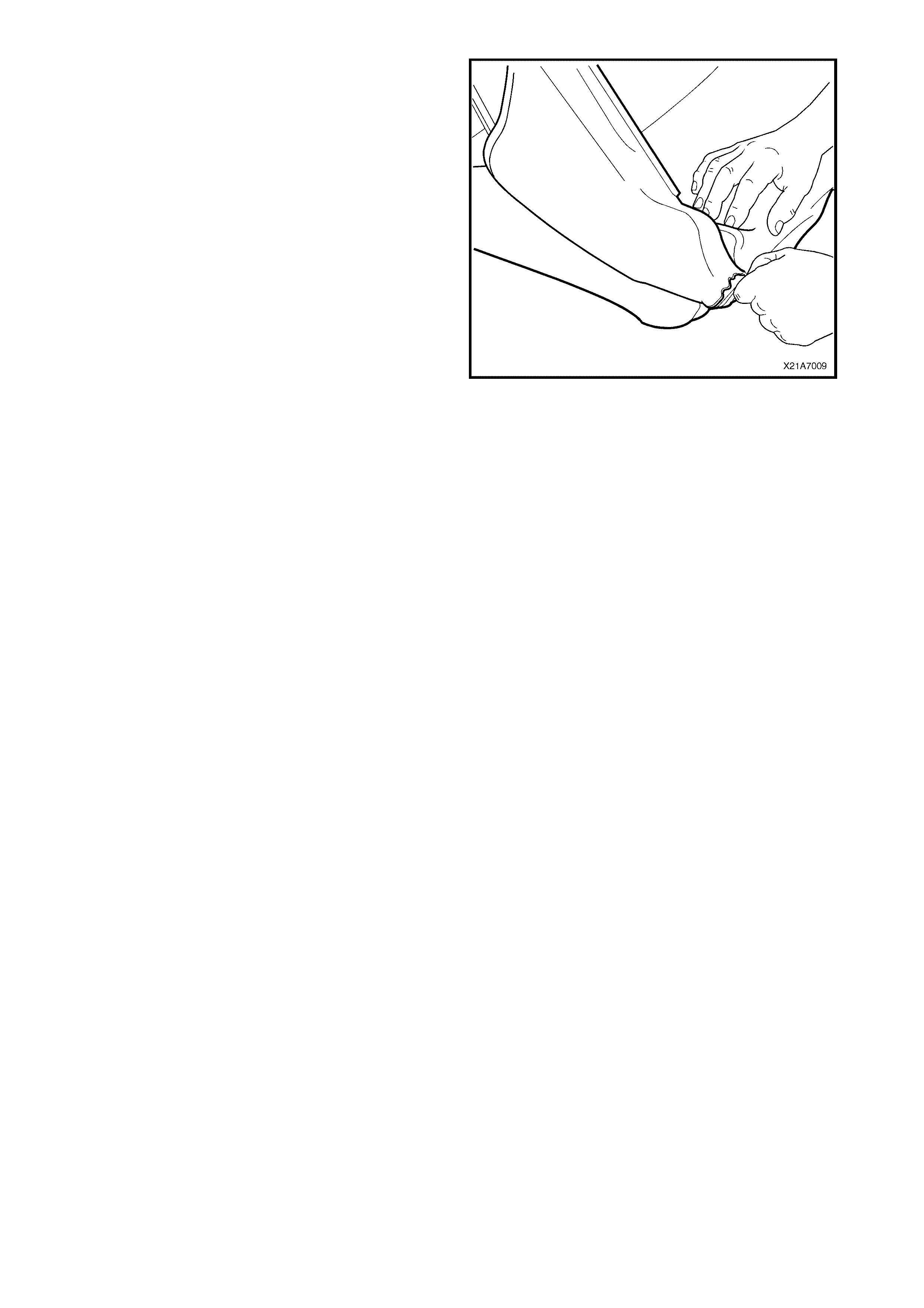
4. Roll the front corners of the front seat cushion
cover over the seat cushion pad.
5. Roll the sides of the seat cushion cover over the
seat cushion pad.
6. Roll the rear cor ners of the s eat c us hion cover over
the seat cushion pad.
NOTE: Make sure the pad is fitted neatly by hand into
all corners and contours of the seat cover.
IMPORTANT: Do not pull the cover onto the pad from
underneath using the J- strip to m ake it f it neatly, as the
fabric may be damaged.
Figure 1A7-72
REINSTALL
Reinstallation of the front seat cushion pad and cover
assembly is the reverse of the removal operation.
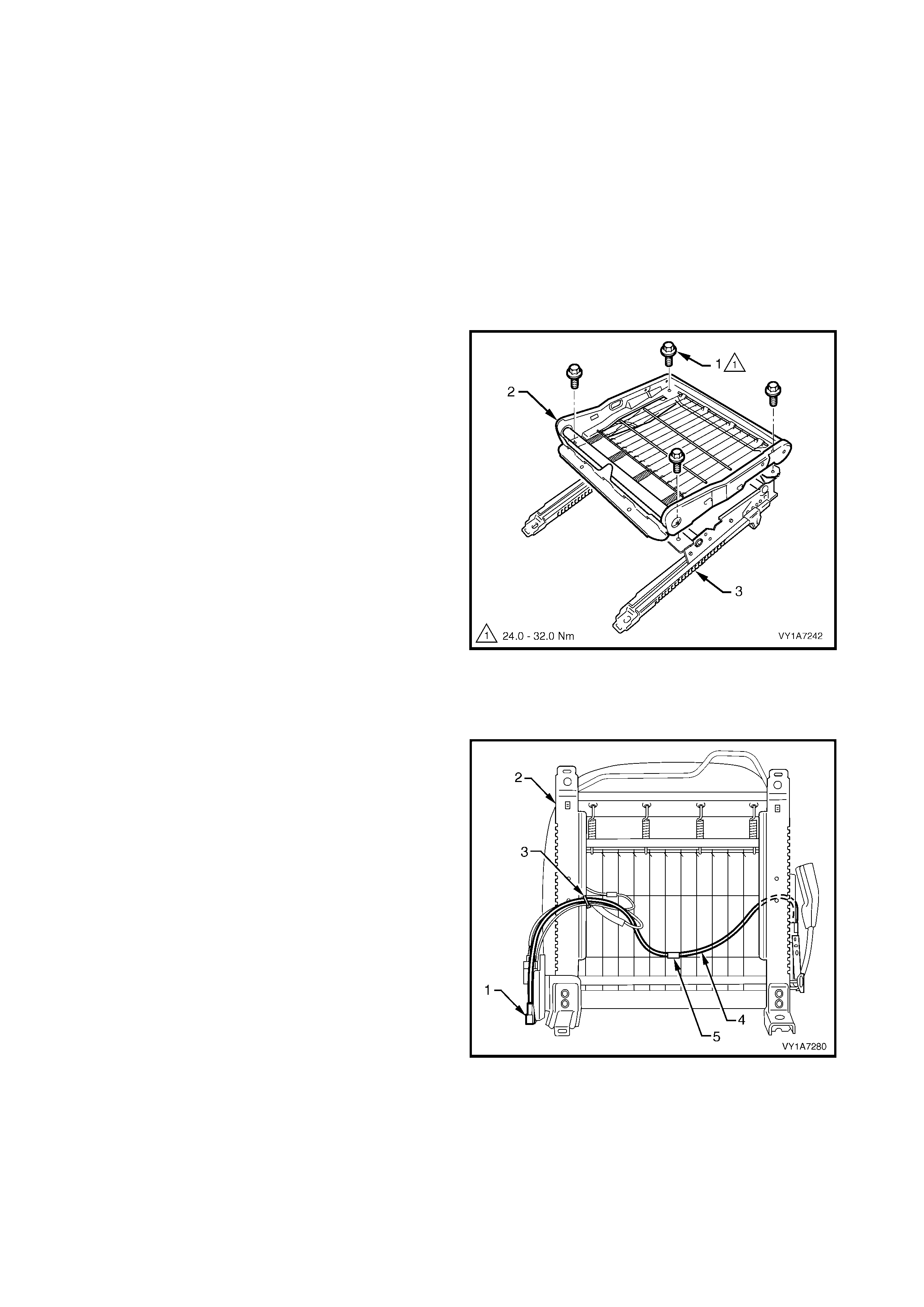
2.13 FRONT SEAT CUSHION FRAME ASSEMBLY
REMOVE – EARLY TYPE
LT Section No. – 14-275
1. Remove the front seat assembly, refer to 2.2 FRONT SEAT ASSEMBLY.
2. Remove the front seat outer side cover, refer to 2.3 FRONT SEAT OUTER SIDE COVER.
3. Remove the front seat inner side cover, refer to 2.5 FRONT SEAT INNER SIDE COVER.
4. Remove the front seat-back lower cover assembly, refer to 2.6 FRONT SEAT-BACK LOWER COVER
ASSEMBLY AND LUMBER SUPPORT ADJUSTER KNOB.
5. Remove the front seat-back frame assembly, refer to 2.10 FRONT SEAT-BACK FRAME ASSEMBLY.
6. Remove the front seat cushion pad and cover assembly, refer to 2.12 FRONT SEAT CUSHION PAD AND
COVER ASSEMBLY.
7. Remove the four screws (1) attaching the front seat
cushion frame (2) to the adjuster and guide rail
assembly (3).
Figure 1A7-73
NOTE: Before disconnecting the pretensioner wiring
harness connector, take note of the wiring harness
routing.
8. On non electric seats, unclip the pretensioner
wiring harness connector (1) from the front seat
guide rail assembly (2).
9. Cut the cable tie (3), securing the wiring harness
(4) to the guide rail assembly, taking care not to
damage the wiring harness.
10. Remove the wiring harness from the clip (5)
attached to the suspension mat.
Figure 1A7-74
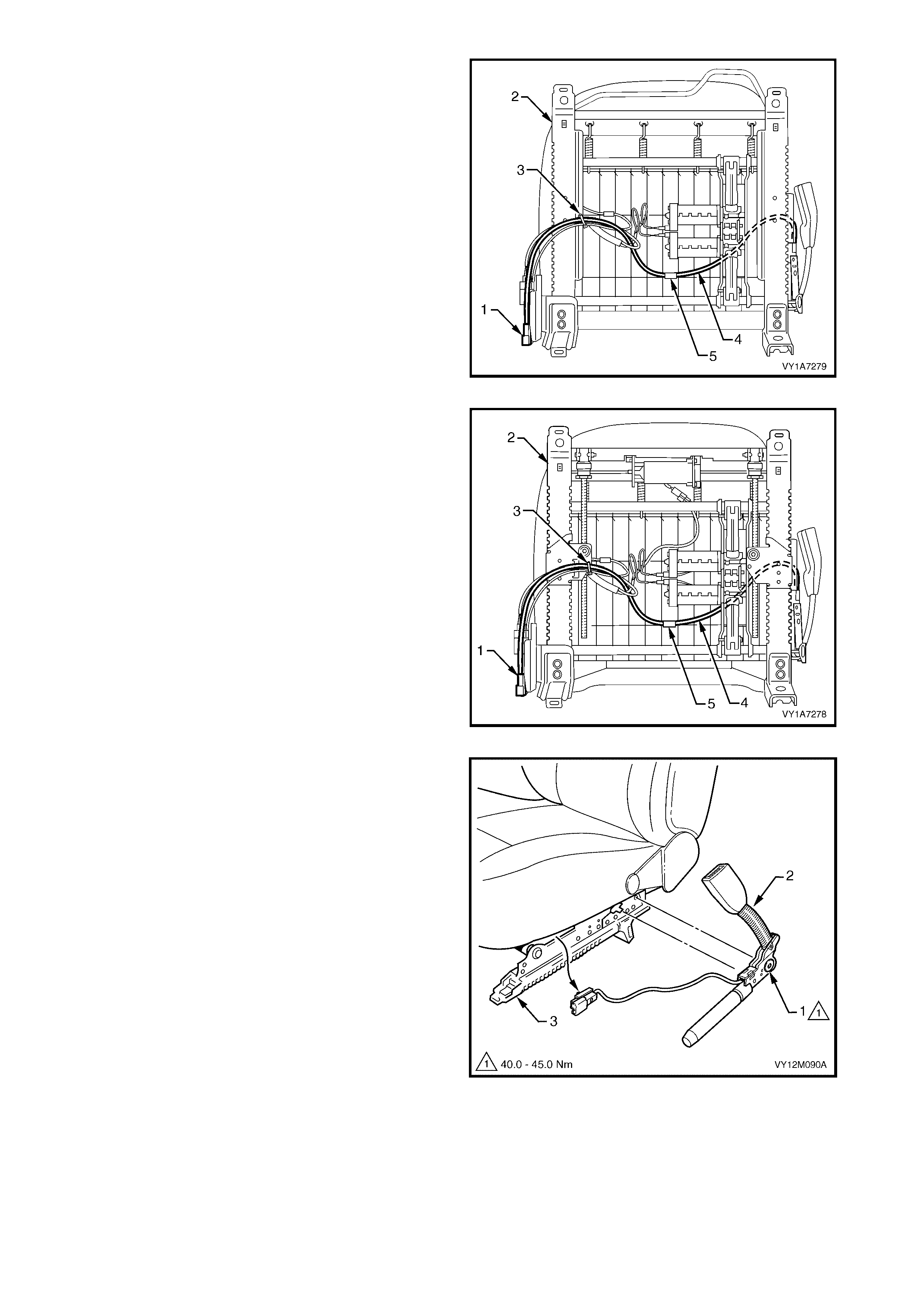
11. On four-way electric seats, unclip the pretensioner
wiring harness connector (1) from the front seat
guide rail assembly (2).
12. Cut the cable tie (3), securing the wiring harness
(4) to the guide rail assembly, taking care not to
damage the wiring harness.
13. Remove the wiring harness from the clip (5)
attached to the suspension mat.
14. If required, remove any tape attaching the
pretensioner wiring harness to the guide rail wiring
harness.
Figure 1A7-75
15. O n eight- way non-memory electric s eats, unc lip the
pretensioner wiring harness connector (1) from the
front seat guide rail assembly (2).
16. Cut the cable tie (3), securing the wiring harness
(4) to the guide rail assembly, taking care not to
damage the wiring harness.
17. Remove the wiring harness from the clip (5)
attached to the suspension mat.
18. If required, remove any tape attaching the
pretensioner wiring harness to the guide rail wiring
harness.
Figure 1A7-76
19. Remove the bolt (1) securing the seatbelt buckle
and pretensioner assembly (2) to the frame (3).
20. Remove the seatbelt buckle and pretensioner
assembly.
Figure 1A7-77
REMOVE – LATE TYPE
1 Front seat assembly, refer to 2.2 FRONT SEAT ASSEMBLY.
2 Front seat outer side cover assembly, refer to 2.3 FRONT SEAT OUTER SIDE COVER ASSEMBLY.
3 Disconnect the wiring harness as required.
4 Track and height adjust assembly, refer to 2.14 FRONT SEAT ADJUSTER ASSEMBLY.
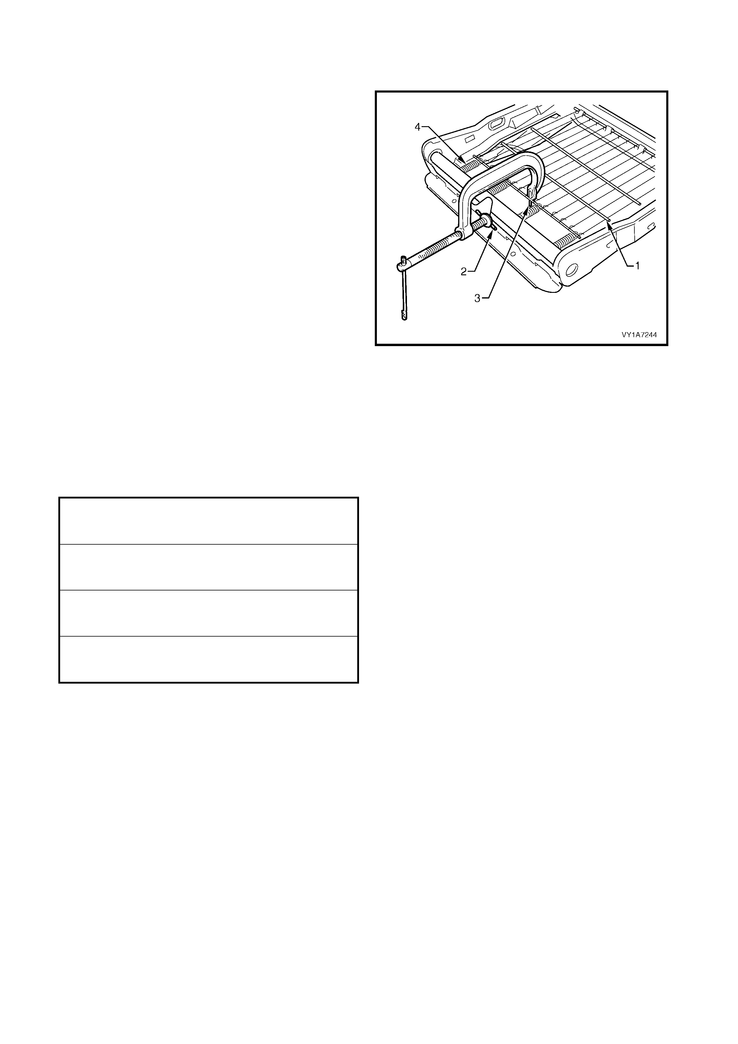
DISASSEMBLE
1. If requir ed to remove the sus pension mat (1), use a
pre-fabricated tool:
G-clamp with a 5mm diameter metal dowel (2)
welded to one end, approximately 40mm long and
with a 2mm diameter pin (3) approximately 20mm
long welded to the other end.
2. Using the pre-fabricated tool, stretch the
suspension mat far enough to allow for the
retaining springs (4) to be removed from the seat
cushion frame.
3. Back the G-clamp load off and remove the
suspension mat.
NOTE: When using the pre-fabricated tool, use existing
holes in the suspension mat to ensure that the mat
deformation does not occur.
Figure 1A7-78
REASSEMBLE
Reassembly of the rear seat cushion is the reverse of the removal procedure.
REINSTALL
Reinstallation of the front seat cushion frame assembly is the reverse of the removal operation, noting the
following:
1. For early type seats, ensure all fasteners are tightened to the correct torque specification.
2. Ensure the pretensioner, the seat adjuster motor, and (if fitted) the side impact airbag wiring harnesses are
routed correctly and retained by cable ties, refer Figure 1A7-74, Figure 1A7-75 or Figure 1A7-76.
3. When installing the seatbelt buckle and pretensioner assembly, ensure that the front locating pin on the
pretensioner assembly aligns with the seat frame.
NOTE 1: Route the side impact airbag module and the seatbelt pretensioner wiring harnesses correctly, otherwise
damage to the harness may occur, resulting in the side impact airbag or the seatbelt pretensioner becoming
inoperative and setting a Diagnostic Trouble Code (DTC) (SRS warning indicator).
NOTE 2: The wiring harness that connects to the side impact airbag module is not serviced separately from the
side airbag inflator module due to the design of the anti-back-out connector on the module assembly.
If this wiring harnes s, as with any other SRS pigtail type wiring harness becom es damaged, no wire, connector or
term inal r epairs ar e to be attempted. REPLACE THE SIDE AIRBAG MODULE AND PIG TAIL WIRING HARNESS
ASSEMBLY.
FRONT SEAT CUSHION FRAME
ASSEMBLY ATTACHING SCREW
TORQUE SPECIFICATION 24.0 – 32.0 Nm
FRONT SEAT BACK ASSEMBLY
ATTACHING SCREW
TORQUE SPECIFICATION 30.0 – 45.0 Nm
SEATBELT BUCKLE AND
PRETENSIONER ASSEMBLY BOLT
TORQUE SPECIFICATION 40.0 – 45.0 Nm
FRONT SEAT ASSEMBLY
RETAINING SCREW
TORQUE SPECIFICATION 35.0 – 50.0 Nm

4. If the seat is f itted with a side impact air bag, switch the ignition ON and obser ve the SRS warning indicator in
the instrument cluster.
• If no fault is detected, the SRS warning indicator should illuminate for approximately five seconds while
the system performs a self-test, and then go off.
• If a fault is present, the SRS warning indicator will remain illuminated and a warning chime may sound
after approximately three seconds. The warning message ‘SRS Airbag Fault’ is also displayed in the
instrument cluster multi-function display. To diagnose the fault, refer to Section 12M, 4. DIAGNOSTICS.
5. Check the operation of the front seat mechanical and electrical adjustments / operation. W hile checking the
seat adjustment / operation, also check to ensure that the side airbag harness does not foul with any of the
seats moveable components (ie. seat motor drive shafts, etc.).
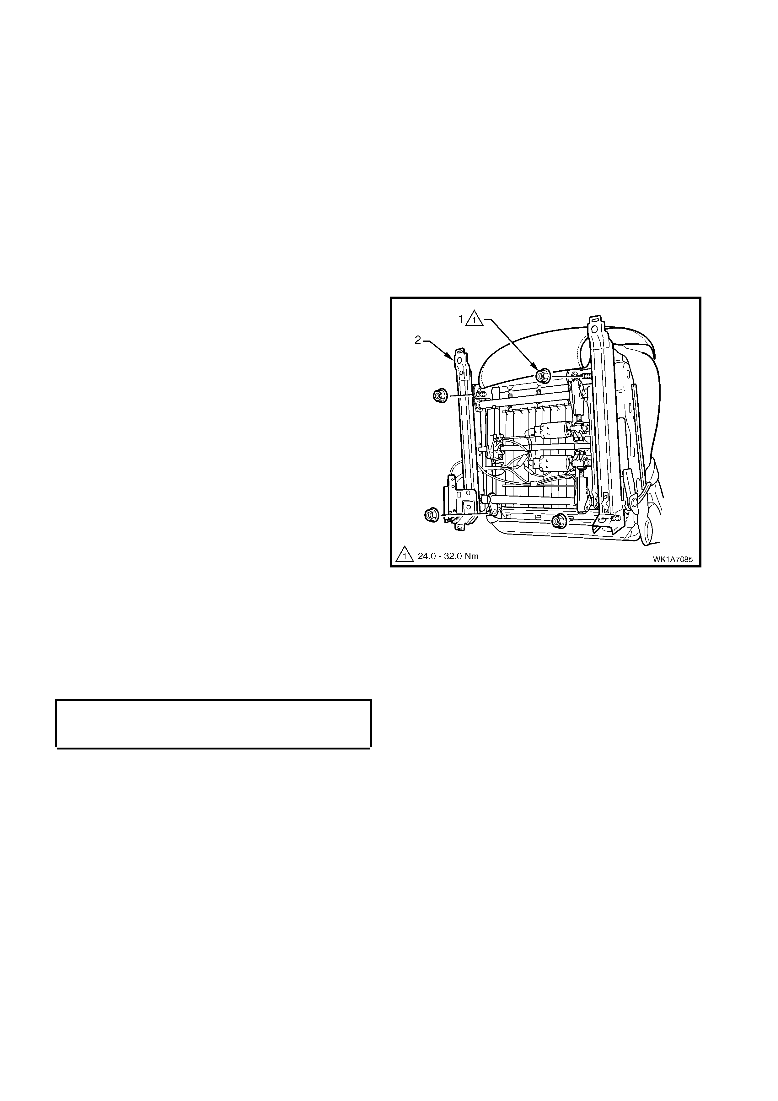
2.14 FRONT SEAT ADJUSTER ASSEMBLY
REMOVE
Early Type
1. The adjuster assembly on the front seats is a non-serviceable item.
2. If the adjuster assembly, drive motor s or drive shaf ts require replacem ent, the entire adjuster and guide r ail
assembly must be replaced, refer to 2.13 FRONT SEAT CUSHION FRAME ASSEMBLY.
Late Type
IMPORTANT: The track and height adjust assembly components are non-serviceable. If the track and height
adjust assembly, drive motors or drive shafts require replacement, the entire track and height adjust assembly
must be replaced.
1. Front seat assembly, refer to 2.2 FRONT SEAT ASSEMBLY.
2. Front seat outer side cover assembly, refer to 2.3 FRONT OUTER SIDE COVER ASSEMBLY.
3. Remove the four nuts (1) attaching the track and
height adjust assembly (2) to the seat.
4. Remove the track and height adjust assembly.
5. If required, remove the seatbelt buckle
and pretensioner assembly, refer to
2.13 FRONT SEAT CUSHION FRAME
ASSEMBLY, early type.
Figure 1A7-79
REINSTALL
Reinstallation of the track and height adjust assembly is the reverse of the removal procedure, noting the
following:
1 Ensure the connectors are correctly routed and attached securely.
2 Tighten the nuts to the correct torque specification.
FRONT SEAT CUSHION FRAME
ASSEMBLY ATTACHING SCREW
TORQUE SPECIFICATION 24.0 – 32.0 Nm


2.16 FRONT SEAT FORE / AFT MOVEMENT MOTOR
1. The front seat fore/aft movement motor on the front seats is a non-serviceable item.
2. If the f ront s eat f or e/af t movem ent motor or drive s haf ts r equire r eplacement, the entire adj us ter and guide rail
assembly must be replaced, refer to 2.13 FRONT SEAT CUSHION FRAME ASSEMBLY.
Techline

2.17 FRONT SEAT RECLINING MOTOR, GEARBOX AND POTENTIOMETER ASSEMBLY
1. The front seat recliner motor, gearbox and potentiometer assembly on the front seats is a non-serviceable
item.
2. If the front seat recliner motor, gearbox and potentiometer assembly requires replacement, the front seat-back
frame assembly must be replaced, refer to 2.10 FRONT SEAT-BACK FRAME ASSEMBLY.

2.18 DRIVE MOTOR POTENTIOMETERS
1. The front seat drive motor potentiometers on the front seats are non-serviceable items.
2. If any of the front seat drive m otor potentiometer assemblies require replacem ent, the front seat-back frame
assembly, or the adjuster and guide rail assembly must be replaced. For information relating to the
replacement procedure for the front seat-back frame assembly or the front seat adjuster and guide rail
assembly, refer to either 2.10 FRONT SEAT-BACK FRAME ASSEMBLY or 2.13 FRONT SEAT CUSHION
FRAME ASSEMBLY.

3. DIAGNOSTICS – FRONT SEAT, EXCEPT COUPE
This Section provides charts to assis t in the diagnosis and r epair of f ront s eats. Ref er to 2.1 FRO NT SEAT USAGE
CHART – EXCEPT COUPE f or a full listing of the diff erent types of seats fitted to vehicles. Included in that Section
are illustrated parts breakdowns of the various seats.
PREREQUISITES
Safety Requirements
When operating the s eat as part of any of the Steps in the diagnosis c harts, ens ure that finger s and lim bs ar e clear
of moving parts.
Equipment
The following equipment is required to diagnose the seats:
1. An unpowered test lamp with a current draw of less than 3 A.
2. A digital multimeter with a minimum impedance of 10 MΩ.
Testing Procedures
The following points must be adhered to when performing diagnostic testing on components:
1. Care must be taken when using testing equipment to diagnose wiring harness connectors. It is preferred that
the technician back probe the connector to avoid terminal damage.
2. When tests are required on connector terminals, utilise the adapters in the connector adaptor kit KM–609 to
prevent damage to the terminals.
3. Unless the multimeter being used has an auto-ranging function, ensure that the correct range is selected.
4. When back-probing connectors, ensure the test lamp earth lead is connected to a suitable earth point on the
vehicle. Ensure that this earth point is not part of the circuit being tested.
Important:
When following the Steps in the diagnosis charts, the exact order of Steps should be observed. If the required
nominal value or result is not achieved at any stage, the problem must be rectified before proceeding any further.

3.1 MECHANICAL DIAGNOSIS – TWO-WAY/FOUR-W AY SEAT
LUMBAR SUPPORT INOPERATIVE
Introduction
This test is used by the technician to aid in the diagnosis of the lumbar support assembly.
Test Description
The numbers following refer to the Step numbers in the diagnostic chart.
1. Checks that the lumbar support knob is properly engaging the lumbar support adjuster. Check the knob for
cracks and worn splines.
2. Checks that the lumbar support adjuster is not damaged or worn and that there is correct operation of the
adjuster when the splined shaft is turned throughout its range.
3. Checks that the lumbar support adjuster cable is not brok en or binding and is not inhibiting the movement and
travel of the lumbar support assembly.
4. Check s that the lum bar support assem bly is not c rack ed or bent. If this is the c ase, it ma y caus e the assem bly
to deform and bind on the guide rails.
4. Checks that the guide rails are not cracked or bent. If this is the case, they may cause the lumbar support
assembly to bind.
STEP ACTION YES NO
1. 1. Remove the lumbar support knob, refer to
2.6 FRONT SEAT-BACK LOWER COVER
ASSEMBLY AND LUMBAR SUPPORT
ADJUSTER KNOB.
Is the lumbar support adjuster knob
serviceable?
Go to Step 2.
Replace the knob.
Refer to 2.6 FRONT
SEAT-BACK LOWER
COVER ASSEMBLY AND
LUMBAR SUPPORT
ADJUSTER KNOB.
2. 1. Remove the front seat-back rear cover
assembly, refer to 2.6 FRONT SEAT-
BACK LOW ER COVER ASSEMBLY AND
LUMBAR SUPPORT ADJUSTER KNOB.
2. Disconnect the lumbar support adjuster
cable from the adjuster, refer to
2.10 FRONT SEAT-BACK FRAME
ASSEMBLY.
3. Turn the adjuster and check for correct
operation.
Is the lumbar support adjuster serviceable?
Go to Step 3.
Replace the lumbar support
adjuster.
Refer to 2.10 FRONT
SEAT-BACK FRAME
ASSEMBLY.
3. 1. Visually inspect the lumbar support
adjuster cable.
Is the lumbar support adjuster cable
serviceable?
Go to Step 4.
Replace the lumbar support
adjuster cable.
Refer to 2.10 FRONT
SEAT-BACK FRAME
ASSEMBLY.
4. 1. Visually inspect the lumbar support
assembly.
Is the lumbar support assembly serviceable?
Go to Step 5.
Replace the lumbar support
assembly.
Refer to 2.10 FRONT
SEAT-BACK FRAME
ASSEMBLY.
5. 1. Visually inspect the lumbar support
assembly guide rails.
Are the lumbar support assembly guide rails
serviceable?
System serviceable.
Replace the front seat-back
frame assembly.
Refer to 2.10 FRONT
SEAT-BACK FRAME
ASSEMBLY.
When all diagnosis and repairs are completed, check the system for correct operation.

SEAT RECLINE FORWARD AND/OR BACK FUNCTION IS INOPERATIVE
Introduction
This test is used by the technician to aid in the diagnosis of the manual recline function of the seat assembly.
Test Description
The numbers following refer to the Step numbers in the diagnostic chart.
1. Checks that the recliner knob is properly engaging the recliner shaft. Check the knob for cracks and worn
splines.
STEP ACTION YES NO
1. 1. Remove the recliner knob, refer to
2.3 FRONT SEAT OUTER SIDE COVER.
Is the recliner knob serviceable?
Replace the front seat-back
frame assembly.
Refer to 2.10 FRONT
SEAT-BACK FRAME
ASSEMBLY.
Replace the recliner knob.
Refer to 2.3 FRONT SEAT
OUTER SIDE COVER.
When all diagnosis and repairs are completed, check the system for correct operation.
SEAT FORE/AFT FUNCTION IS INOPERATIVE OR IS NOT SMOOTH
Introduction
This test is used by the technician to aid in the diagnosis of the fore/af t function of the seat being inoper ative or the
action of the seat through the range of movement is not smooth.
Test Description
The numbers following refer to the Step numbers in the diagnostic chart.
1. Checks that there are no items obstructing the guide rails which may stop or hinder the seat movement.
2. Checks that the guide rails have adequate lubricant applied to provide a smooth operation for the seat.
3. Chec ks that the linkage assembly between the adjustment lever and locking tangs is not worn or damaged. T he
locking tangs must disengage from the guide rails before the seat will move.
4. Checks that the guide rails have not been damaged. Any binding between the inner and outer guide rails will
result in poor operation of the fore and aft movement.
STEP ACTION YES NO
1. Are the guide rails free from obstructions? Go to Step 2. Remove the obstructing
item.
2. Are the guide rails adequately lubricated? Go to Step 3. Apply a small amount of
grease type NLGI No. 1
Lithium Grease (with 9%
Zinc Oxide) to the rails.
3. Do the locking tangs disengage the guide rails
when the seat fore and aft adjustment lever is
raised to its full movement? Go to Step 4.
Replace the front seat
adjuster assembly.
Refer to 2.14 FRONT
SEAT ADJUSTER
ASSEMBLY.
4. Do the guide rails bind at any point of travel
during the fore and aft movements of the
seat?
Replace the front seat
adjuster assembly.
Refer to 2.14 FRONT
SEAT ADJUSTER
ASSEMBLY.
When all diagnosis and repairs are completed, check the system for correct operation.
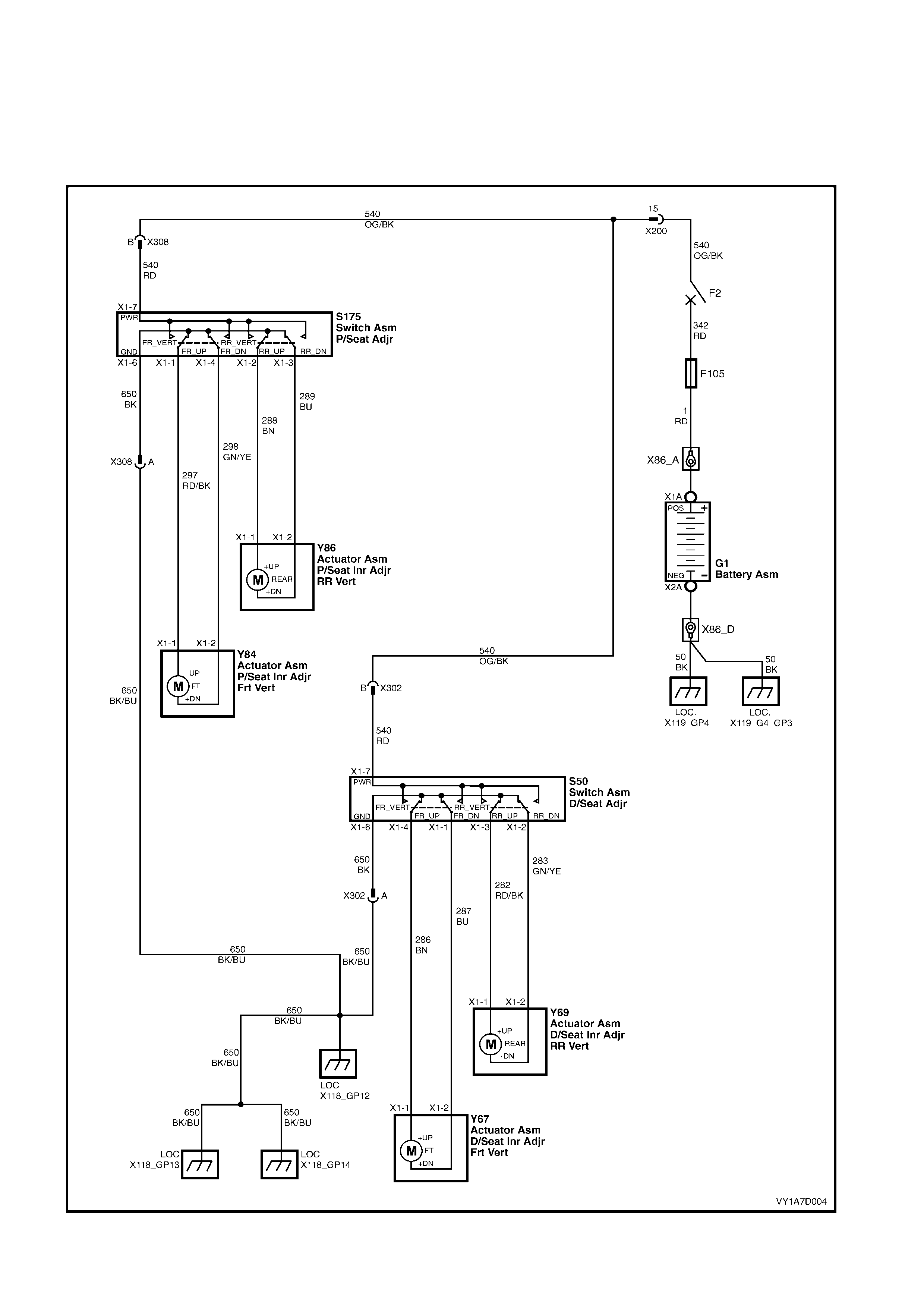
3.2 ELECTRICAL DIAGNOSIS – FOUR-WAY SE AT, NON-MEMORY
The c harts in this Sect ion are us ed by the technician in the aid of diagnos ing f aults on four-way seat assem blies . T o
aid in the use of the diagnosis charts, refer to WIRING DIAGRAM – FOUR-WAY SEAT, NON-MEMORY and
CONNECTOR CHART – FOUR-WAY SEAT, NON-MEMORY in this Section.
WIRING DIAGRAM – FOUR-WAY SEAT, NON-MEMORY
Figure 1A7-80
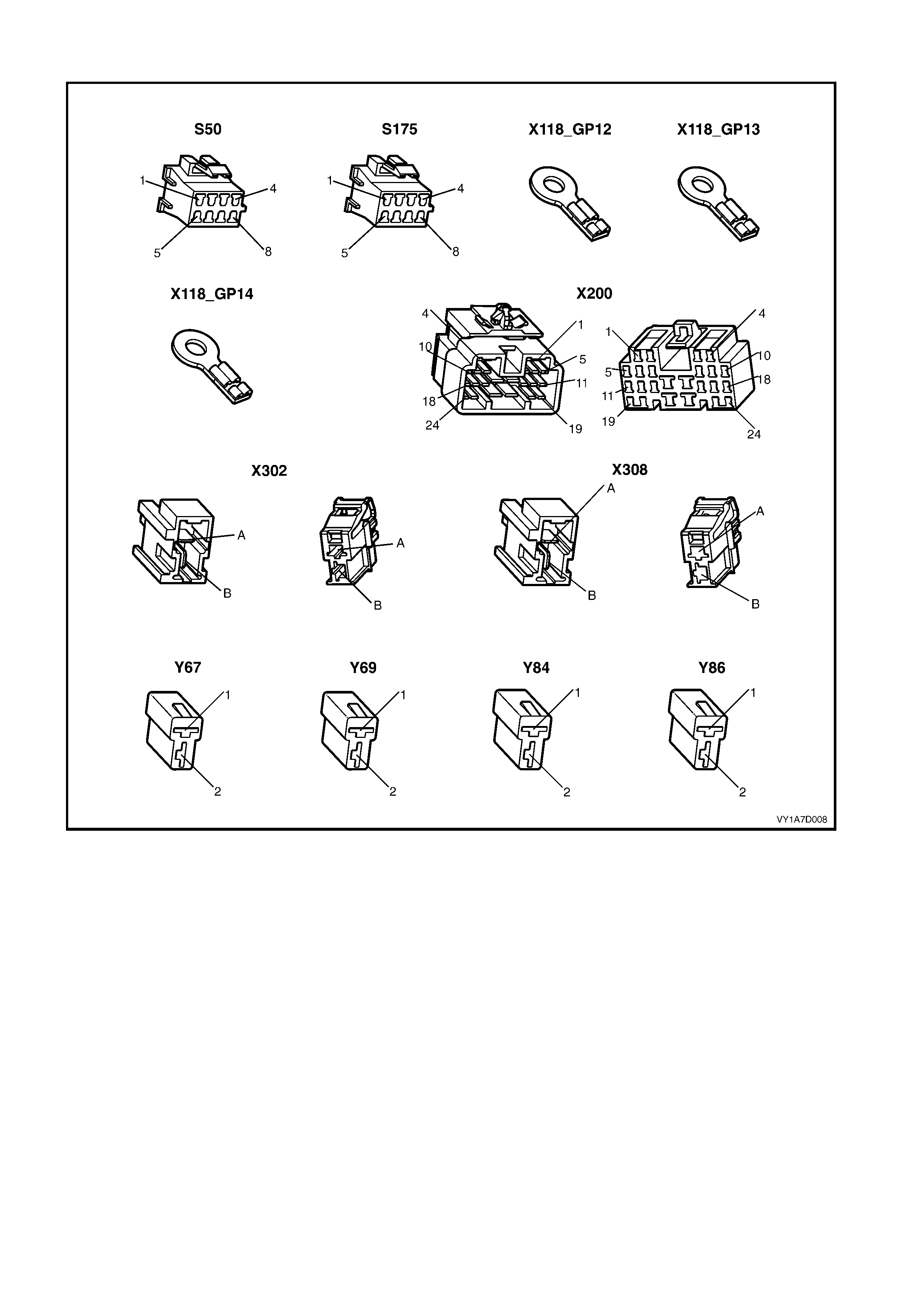
CONNECTOR CHART – FOUR-WAY SEAT, NON-MEMORY
Figure 1A7-81

NEITHER SEAT ADJUSTMENT SWITCH FUNCTIONS OPERATE
Introduction
This test is used by the technician to aid in the diagnosis of the seat power and earth circuits, if neither seat
operates when either four-way seat adjustment switch is operated.
Test Description
The numbers following refer to the Step numbers in the diagnostic chart.
1. Checks that battery voltage is more than 11.5 volts. The seat motors require more than 11.5 volts to operate
correctly.
2. Checks that circuit breaker F2 located on the passenger compartment fuse and relay panel assembly is not
tripped. Isolates whether circuit breaker F2 is the fault affecting the circuit between the battery and connector
X200 pin 15.
3. Check s that fusible link F 105 located on the engine com par tm ent fus e and relay panel assem bly is serviceable.
Isolates whether the fusible link is the fault affecting the circuit between the battery and connector X200 pin 15.
4. Ensures that connector X200 is secure.
5. Checks whether there is battery voltage at connector X200 pin 15. Isolates whether the fault is between the
battery and connector X200 pin 15. If the fault in the circuit is between connectors X200 pin 15 and either
X308 pin B or X302 pin B, only one seat will not operate.
6. Checks whether there is battery voltage at circuit breaker F2. Isolates whether the fault is between the battery
and circuit breaker F2 or between circuit breaker F2 and connector X200 pin 15.
7. Checks whether there is battery voltage at fusible link F105. Isolates whether the fault is between the battery
and fusible link F105 or between fusible link F105 and circuit breaker F2.
8. Checks that all the earth points associated with the system are serviceable and a good earth is provided at each
point.
STEP ACTION YES NO
1. 1. Check the battery voltage, refer to Section
12A, 2.9 BATTERY.
Is the battery voltage more than 11.5 V? Go to Step 2. Refer to Section 12A,
2.9 BATTERY for further
diagnosis.
2. 1. Inspect circuit breaker F2, refer to Section
12O, 2.2 CIRCUIT BREAKERS.
Is circuit breaker F2 tripped?
Allow the circuit breaker to
reset, refer to Section 12O,
2.2 CIRCUIT BREAKERS. Go to Step 3.
3. 1. Inspect fusible link F105, refer to Section
12O, 2.3 FUSIBLE LINKS.
Is fuse F105 serviceable? Go to Step 4. Replace the fusible link.
4. Is connector X200 secure? Go to Step 5. Ensure that the connector
is secure.
5. 1. Back probe connector X200 pin 15 with a
test lamp.
Does the test lamp illuminate? Go to Step 8. Go to Step 6.
6. 1. Remove circuit breaker F2 from the
passenger compartment fuse and relay
panel assembly.
2. Using a test lamp, probe connector
X129 – X45 – 2. Refer to Section 12P
WIRING DIAGRAMS.
Does the test lamp illuminate?
There is a fault in circuit
540 between circuit breaker
F2 and connector
X200 pin 15.
Repair or replace circuit
540.
Go to Step 7.
7. 1. Remove fusible link F105.
2. Using a test lamp, probe connector
X18-105. Refer to Section 12P WIRING
DIAGRAMS.
Does the test lamp illuminate?
There is a fault in circuit
342 between fusible link
F105 and circuit breaker
F2.
Repair or replace circuit
342.
There is a fault in circuit 1
between the battery and
fusible link F105.
Repair or replace circuit 1.

STEP ACTION YES NO
8. 1. Ensure that the following earth points are
secure and have good contact with the
vehicle structure:
• X118–GP12 located in the middle of the
transmission tunnel.
• X118–GP13 located in the rear
compartment on the right-hand side tail
lamp stud.
• X118–GP14 located in the rear
compartment on the decklid.
Refer to Section 12P W IRING DIAGRAMS for
further details of earthing points.
Are all the earth points secure to the vehicle
with a good contact?
There is a fault in circuit
650.
Repair or replace circuit
650.
Ensure that the connectors
are secured to the vehicle
and that there is a good
contact between the
connector and the vehicle.
When all diagnosis and repairs are completed, check the system for correct operation.

NONE OF THE DRIVER’S FOUR-WAY SEAT ADJUSTMENT SWITCH FUNCTIONS OPERATE
Introduction
This test is us ed by the technician to aid in the diagnosis of the dr iver’s f our-way seat adjustm ent switch when none
of the switch functions operate. The test diagnoses the driver’s four-way seat adjustment switch and associated
power and earth circuits.
Test Description
The numbers following refer to the Step numbers in the diagnostic chart.
1. Checks whether all of the passenger's seat four-way functions work. If none of them work, the fault is not
isolated to the driver’s seat only.
2. Checks whether there is battery power at connector X302 pin B. Isolates whether there is a fault in circuit 540
between connectors X200 pin 15 and X302 pin B.
3. Checks that all the connectors required for the seat to operate effectively are in place and positively connected.
4. Checks whether there is battery power at connector S50 – X1 pin 7. Isolates whether there is a fault in circuit
540 between connectors S50 – X1 pin 7 and X302 pin B.
5. Checks whether the driver’s four-way seat adjustment switch is serviceable.
6. Chec ks whether there is c ontinuity between connectors S50 – X1 pin 6 and X 302 pin A which supplies the earth
circuit for the driver’s four-way seat adjustment switch. Isolates whether there is a fault in circuit 650 between
the switch and connector X302 pin A or between connector X302 pin A and the earthing points.
STEP ACTION YES NO
1. Are all of the passenger’s four-way seat
adjustment switch functions inoperative? Refer to NEITHER SEAT
ADJUSTMENT SWITCH
FUNCTIONS OPERATE in
this Section.
Go to Step 2.
2. 1. Back probe connector X302 pin B with a
test lamp.
Does the test lamp illuminate? Go to Step 3.
There is a fault in circuit
540 between connectors
X200 pin 15 and
X302 pin B.
Repair or replace circuit
540.
3. Are the following connectors secure?
• S50
• X302
• Y67
• Y69
Go to Step 4. Ensure that the connectors
are secure.
4. 1. Back probe connector S50 – X1 pin 7 with
a test lamp.
Does the test lamp illuminate? Go to Step 5.
There is a fault in circuit
540 between connectors
S50 – X1 pin 7 and
X302 pin B.
Repair or replace circuit
540.
5. 1. Remove the driver’s four-way seat
adjustment switch from the seat, refer to
2.4 FRONT SEAT ADJUSTMENT
SWITCH.
2. Test the driver’s four-way seat adjustment
switch, refer to 3.3 FOUR-WAY SEAT
ADJUSTMENT SWITCH TEST.
Is the driver’s four-way seat adjustment switch
serviceable?
Go to Step 6.
Replace the driver’s four-
way seat adjustment
switch.
Refer to 2.4 FRONT SEAT
ADJUSTMENT SWITCH.
6. 1. Back probe connector X302 pin A with a
test lamp.
2. Operate the driver’s four-way seat
adjustment switch in any of the available
directions.
Does the test lamp illuminate?
There is a fault in circuit
650 between connector
X302 pin A and earth
points X118–GP12, X118–
GP13 and X118–GP14.
Repair or replace circuit
650.
There is a fault in circuit
650 between connectors
S50 – X1 pin 6 and
X302 pin A.
Repair or replace circuit
650.
When all diagnosis and repairs are completed, check the system for correct operation.

FRONT/REAR OF THE DRIVER'S SEAT DOES NOT RAISE AND/OR LOWER
Introduction
This test is used by the tec hnician to aid in the diagnosis of the f ront and/or the rear of the dr iver's seat not raising
and/or lowering. The test diagnoses the four-way seat adjustment switch and the motor circuits.
Test Description
The numbers following refer to the Step numbers in the diagnostic chart.
1. Checks whether the driver's four-way seat adjustment switch assembly operates in any of the directions.
Isolates whether there is a battery or earth fault affecting the seat operation.
2. Checks that all the connectors required for the seat to operate effectively are in place and positively connected.
3. Checks whether the driver's four-way seat adjustment switch is serviceable.
4. Conf irm s whether the rear of the seat r aises or lowers. Isolates whether the rear m otor and c ircuit of the seat is
the fault.
5. Confirms whether the front of the seat raises or lowers. Isolates whether the front motor and circuit of the seat is
the fault.
6. Checks whether there is battery power to the seat rear motor at connector Y69 – X1 pin 1. Isolates whether
there is a fault in circuit 282 that supplies battery power to the motor to raise the rear of the seat.
7. Check s whether there is battery power to the seat rear motor at connector Y69 – X1 pin 2. Isolates whether the
fault is in circuit 283 that s upplies battery power to the motor to lower the r ear of the seat or the motor is faulty.
As reversing the polarity changes the direction of the motor, this Step also confirms that the earth circuit from
Step 6 is serviceable.
8. Checks whether there is battery power to the seat front motor at connector Y67 – X1 pin 1. Isolates whether
there is a fault in circuit 286 that supplies battery power to the motor to raise the front of the seat.
9. Chec ks whether ther e is battery power to the seat front m otor at c onnector Y67 – X1 pin 2. Is olates whether the
fault is in circ uit 287 that supplies batter y power to the m otor to lower the fr ont of the s eat or the m otor is f aulty.
As reversing the polarity changes the direction of the motor, this Step also confirms that the earth circuit from
Step 8 is serviceable.
STEP ACTION YES NO
1. Does the driver's four-way seat adjustment
switch operate correctly in any of the four
directions? Go to Step 2.
Refer to NONE OF THE
DRIVER’S FOUR-WAY
SEAT ADJUSTMENT
SWITCH FUNCTIONS
OPERATE in this Section.
2. Are the following connectors secure?
• S50
• Y69
• Y67
Go to Step 3. Ensure that the connectors
are secure.
3. 1. Remove the driver's four-way seat
adjustment switch from the seat, refer to
2.4 FRONT SEAT ADJUSTMENT
SWITCH.
2. Test the driver's four-way adjustment
switch, refer to 3.3 FOUR-WAY SEAT
ADJUSTMENT SWITCH TEST.
Is the driver's four-way seat adjustment switch
serviceable?
Go to Step 4.
Replace the driver's four-
way seat adjustment
switch.
Refer to 2.4 FRONT SEAT
ADJUSTMENT SWITCH.
4. 1. Operate the driver's four-way seat
adjustment switch so that the rear of the
seat is raised or lowered.
Does the rear of the seat raise and lower?
Go to Step 5. Go to Step 6.
5. 1. Operate the driver's four-way seat
adjustment switch so that the front of the
seat is raised or lowered.
Does the front of the seat raise and lower?
System serviceable. Go to Step 8.
6. 1. Back probe connector Y69 – X1 pin 1 with
a test lamp.
2. Operate the driver's four-way seat
adjustment switch so that it will raise the
rear of the seat.
Does the test lamp illuminate?
Go to Step 7.
There is a fault in circuit
282 between connectors
S50 – X1 pin 3 and
Y69 – X1 pin 1.
Repair or replace circuit
282.
STEP ACTION YES NO
7. 1. Back probe connector Y69 – X1 pin 2 with
a test lamp.
2. Operate the driver's four-way seat
adjustment switch so that it will lower the
rear of the seat.
Does the test lamp illuminate?
The seat rear motor is
faulty.
Replace the seat rear
motor, refer to 2.15 FRONT
SEAT LIFT MOTORS.
Go to Step 5.
There is a fault in circuit
283 between connectors
S50 – X1 pin 2 and
Y69 – X1 pin 2.
Repair or replace circuit
283.
Go to Step 5.
8. 1. Back probe connector Y67 – X1 pin 1 with
a test lamp.
2. Operate the driver's four-way seat
adjustment switch so that it will raise the
front of the seat.
Does the test lamp illuminate?
Go to Step 9.
There is a fault in circuit
286 between connectors
S50 – X1 pin 4 and
Y67 – X1 pin 1.
Repair or replace circuit
286.
9. 1. Back probe connector Y67 – X1 pin 2 with
a test lamp.
2. Operate the driver's four-way seat
adjustment switch so that it lower the front
of the seat.
Does the test lamp illuminate?
The seat front motor is
faulty.
Replace the seat rear
motor, refer to 2.15 FRONT
SEAT LIFT MOTORS.
There is a fault in circuit
287 between connectors
S50 – X1 pin 1 and
Y67 – X1 pin 2.
Repair or replace circuit
287.
When all diagnosis and repairs are completed, check the system for correct operation.

NONE OF THE PASSENGER'S FOUR-WA Y SEAT ADJUSTMENT SWITCH FUNCTIONS OPERATE
Introduction
This test is used by the technician to aid in the diagnosis of the passenger's f our-way seat adjustm ent switch when
none of the switch functions operate. The test diagnoses the passenger's four-way seat adjustment switch and
associated power and earth circuits.
Test Description
The numbers following refer to the Step numbers in the diagnostic chart.
1. Check s whether all of the driver's seat four -way functions work. If none of them work, the f ault is not is olated to
the passenger's seat only .
2. Checks whether there is battery power at connector X308 pin B. Isolates whether there is a fault in circuit 540
between connectors X200 pin 15 and X308 pin B.
3. Checks that all the connectors required for the seat to operate effectively are in place and positively connected.
4. Checks whether there is battery power at connector S175 – X1 pin 7. Isolates whether there is a fault in circuit
540 between connectors S175 – X1 pin 7 and X308 pin B.
5. Checks whether the passenger's four-way seat adjustment switch is serviceable.
6. Checks whether there is continuity between connectors S175 – X1 pin 6 and X308 pin A which supplies the
earth circuit f or the passenger's four-way s eat adjustment s witc h. Isolates whether there is a fault in circuit 650
between the switch and connector X308 pin A or between connector X308 pin A and the earthing points.
STEP ACTION YES NO
1. Are all of the driver's four-way seat adjustment
switch functions inoperative? Refer to NEITHER SEAT
ADJUSTMENT SWITCH
FUNCTIONS OPERATE in
this Section.
Go to Step 2.
2. 1. Back probe connector X308 pin B with a
test lamp.
Does the test lamp illuminate? Go to Step 3.
There is a fault in circuit
540 between connectors
X200 pin 15 and
X308 pin B.
Repair or replace circuit
540.
3. Are the following connectors secure?
• S175
• X308
• Y84
• Y86
Go to Step 4. Ensure that the connectors
are secure.
4. 1. Back probe connector S175 – X1 pin 7
with a test lamp.
Does the test lamp illuminate? Go to Step 5.
There is a fault in circuit
540 between connectors
S175 – X1 pin 7 and
X308 pin B.
Repair or replace circuit
540.
5. 1. Remove the passenger's four-way seat
adjustment switch from the seat, refer to
2.4 FRONT SEAT ADJUSTMENT
SWITCH.
2. Test the passenger's four-way seat
adjustment switch, refer to 3.3 FOUR-
WAY SEAT ADJUSTMENT SWITCH
TEST.
Is the passenger's four-way seat adjustment
switch serviceable?
Go to Step 6.
Replace the passenger's
four-way seat adjustment
switch.
Refer to 2.4 FRONT SEAT
ADJUSTMENT SWITCH.
6. 1. Back probe connector X308 pin A with a
test lamp.
2. Operate the passenger's four-way seat
adjustment switch in any of the available
directions.
Does the test lamp illuminate?
There is a fault in circuit
650 between connector
X308 pin A and earth
points X118–GP12, X118–
GP13 and X118–GP14.
Repair or replace circuit
650.
There is a fault in circuit
650 between connectors
S175 – X1 pin 6 and
X308 pin A.
Repair or replace circuit
650.
When all diagnosis and repairs are completed, check the system for correct operation.

FRONT/REAR OF THE PASSENGER'S SEAT DOES NOT RAISE AND/OR LOWER
Introduction
This test is used by the technician to aid in the diagnosis of the front and/or the rear of the passenger's seat not
raising and/or lowering. The test diagnoses the four-way seat adjustment switch and the motor circuits.
Test Description
The numbers following refer to the Step numbers in the diagnostic chart.
1. Checks whether the passenger's four-way seat adjustment switch assembly operates in any of the directions.
Isolates whether there is a battery or earth fault affecting the seat operation.
2. Checks that all the connectors required for the seat to operate effectively are in place and positively connected.
3. Checks whether the passenger's four-way seat adjustment switch is serviceable.
4. Conf irm s whether the rear of the seat r aises or lowers. Isolates whether the rear m otor and c ircuit of the seat is
the fault.
5. Confirms whether the front of the seat raises or lowers. Isolates whether the front motor and circuit of the seat is
the fault.
6. Checks whether there is battery power to the seat rear motor at connector Y86 – X1 pin 1. Isolates whether
there is a fault in circuit 288 that supplies battery power to the motor to raise the rear of the seat.
7. Check s whether there is battery power to the seat rear motor at connector Y86 – X1 pin 2. Isolates whether the
fault is in circuit 289 that supplies battery power to the motor to lower the rear of the seat or the m otor is faulty.
As reversing the polarity changes the direction of the motor, this Step also confirms that the earth circuit from
Step 6 is serviceable.
8. Checks whether there is battery power to the seat front motor at connector Y84 – X1 pin 1. Isolates whether
there is a fault in circuit 297 that supplies battery power to the motor to raise the front of the seat.
9. Chec ks whether ther e is battery power to the seat front m otor at c onnector Y84 – X1 pin 2. Is olates whether the
fault is in circ uit 298 that supplies batter y power to the m otor to lower the fr ont of the s eat or the m otor is f aulty.
As reversing the polarity changes the direction of the motor, this Step also confirms that the earth circuit from
Step 8 is serviceable.
STEP ACTION YES NO
1. Does the passenger's four-way seat
adjustment switch operate correctly in any of
the four directions? Go to Step 2.
Refer to NONE OF THE
PASSENGER'S FOUR-
WAY SEAT ADJUSTMENT
SWITCH FUNCTIONS
OPERATE in this Section.
2. Are the following connectors secure?
• S175
• Y84
• Y86
Go to Step 3. Ensure that the connectors
are secure.
3. 1. Remove the passenger's four-way seat
adjustment switch from the seat, refer to
2.4 FRONT SEAT ADJUSTMENT
SWITCH.
2. Test the passenger's four-way adjustment
switch, refer to 3.3 FOUR-WAY SEAT
ADJUSTMENT SWITCH TEST.
Is the passenger's four-way seat adjustment
switch serviceable?
Go to Step 4.
Replace the passenger's
four-way seat adjustment
switch.
Refer to 2.4 FRONT SEAT
ADJUSTMENT SWITCH.
4. 1. Operate the passenger's four-way seat
adjustment switch so that the rear of the
seat is raised or lowered.
Does the rear of the seat raise and lower?
Go to Step 5. Go to Step 6.
5. 1. Operate the passenger's four-way seat
adjustment switch so that the front of the
seat is raised or lowered.
Does the front of the seat raise and lower?
System serviceable. Go to Step 8.

STEP ACTION YES NO
6. 1. Back probe connector Y86 – X1 pin 1 with
a test lamp.
2. Operate the passenger's four-way seat
adjustment switch so that it will raise the
rear of the seat.
Does the test lamp illuminate?
Go to Step 7.
There is a fault in circuit
288 between connectors
S175 – X1 pin 2 and
Y86 – X1 pin 1.
Repair or replace circuit
288.
7. 1. Back probe connector Y86 – X1 pin 2 with
a test lamp.
2. Operate the passenger's four-way seat
adjustment switch so that it will lower the
rear of the seat.
Does the test lamp illuminate?
The seat rear motor is
faulty.
Replace the seat rear
motor, refer to 2.15 FRONT
SEAT LIFT MOTORS.
Go to Step 5.
There is a fault in circuit
289 between connectors
S175 – X1 pin 3 and
Y86 – X1 pin 2.
Repair or replace circuit
289.
Go to Step 5.
8. 1. Back probe connector Y84 – X1 pin 1 with
a test lamp.
2. Operate the passenger's four-way seat
adjustment switch so that it will raise the
front of the seat.
Does the test lamp illuminate?
Go to Step 9.
There is a fault in circuit
297 between connectors
S175 – X1 pin 1 and
Y84 – X1 pin 1.
Repair or replace circuit
297.
9. 1. Back probe connector Y84 – X1 pin 2 with
a test lamp.
2. Operate the passenger's four-way seat
adjustment switch so that it lower the front
of the seat.
Does the test lamp illuminate?
The seat front motor is
faulty.
Replace the seat rear
motor, refer to 2.15 FRONT
SEAT LIFT MOTORS.
There is a fault in circuit
298 between connectors
S175 – X1 pin 4 and
Y84 – X1 pin 2.
Repair or replace circuit
298.
When all diagnosis and repairs are completed, check the system for correct operation.

3.3 FOUR-WAY SEAT ADJUSTMENT SWITCH TEST
The switch is located on the outer side of the seat, attached to the inner side of the front seat outer side cover.
TEST
1. Remove the four-way seat adjustment switch, refer to 2.4 FRONT SEAT ADJUSTMENT SWITCH.
2. Place the switch in the positions as detailed in
the chart in this Section. Place the probes of
the ohmmeter onto the terminals listed and
take the reading. Compare the reading to the
chart.
3. If the switch fails any part of the test, replace
the switch assembly with a serviceable item.
4. Install the four-way seat adjustment switch,
refer to 2.4 FRONT SEAT ADJUSTMENT
SWITCH.
Figure 1A7-82
FOUR-WAY SEAT ADJUSTMENT SWITCH
SWITCH POSITION SWITCH TERMINALS INDICATION IF SWITCH IS SERVICEABLE
Posit i on A 3 and 7 Continuity
Posit i on B 2 and 7 Continuity
Posit ion C 4 and 7 Continuit y
Posit ion D 1 and 7 Continuit y
Switch in t he neutral positi on 6 and either 1, 2, 3 or 4 Continuity

3.4 MECHANICAL DIAGNOSIS – EIGHT-W AY SEAT, NON-MEMORY
LUMBAR SUPPORT INOPERATIVE
Introduction
This test is used by the technician to aid in the diagnosis of the lumbar support assembly.
Test Description
The numbers following refer to the Step numbers in the diagnostic chart.
1. Checks that the lumbar support knob is properly engaging the lumbar support adjuster. Check the knob for
cracks and worn splines.
2. Checks that the lumbar support adjuster is not damaged or worn and that there is correct operation of the
adjuster when the splined shaft is turned throughout its range.
3. Checks that the lumbar support adjuster cable is not brok en or binding and is not inhibiting the movement and
travel of the lumbar support assembly.
4. Checks that the lum bar support as sembly is not crack ed or bent. If this is the c ase, it m ay caus e the assem bly
to deform and bind on the guide rails.
5. Checks that the guide rails are not cracked or bent. If this is the case, they may cause the lumbar support
assembly to bind.
STEP ACTION YES NO
1. 1. Remove the lumbar support knob, refer to
2.6 FRONT SEAT-BACK LOWER COVER
ASSEMBLY AND LUMBAR SUPPORT
ADJUSTER KNOB.
Is the lumbar support adjuster knob
serviceable?
Go to Step 2.
Replace the knob.
Refer to 2.6 FRONT
SEAT-BACK LOWER
COVER ASSEMBLY AND
LUMBAR SUPPORT
ADJUSTER KNOB.
2. 1. Remove the front seat-back rear cover
assembly, refer to 2.6 FRONT SEAT-
BACK LOW ER COVER ASSEMBLY AND
LUMBAR SUPPORT ADJUSTER KNOB.
2. Disconnect the lumbar support adjuster
cable from the adjuster, refer to
2.10 FRONT SEAT-BACK FRAME
ASSEMBLY.
3. Turn the adjuster and check for correct
operation.
Is the lumbar support adjuster serviceable?
Go to Step 3.
Replace the lumbar support
adjuster.
Refer to 2.10 FRONT
SEAT-BACK FRAME
ASSEMBLY.
3. 1. Visually inspect the lumbar support
adjuster cable.
Is the lumbar support adjuster cable
serviceable?
Go to Step 4.
Replace the lumbar support
adjuster cable.
Refer to 2.10 FRONT
SEAT-BACK FRAME
ASSEMBLY.
4. 1. Visually inspect the lumbar support
assembly.
Is the lumbar support assembly serviceable?
Go to Step 5.
Replace the lumbar support
assembly.
Refer to 2.10 FRONT
SEAT-BACK FRAME
ASSEMBLY.
5. 1. Visually inspect the lumbar support
assembly guide rails.
Are lumbar support assembly guide rails
serviceable?
System serviceable.
Replace the front seat-back
frame assembly.
Refer to 2.10 FRONT
SEAT-BACK FRAME
ASSEMBLY.
When all diagnosis and repairs are completed, check the system for correct operation.
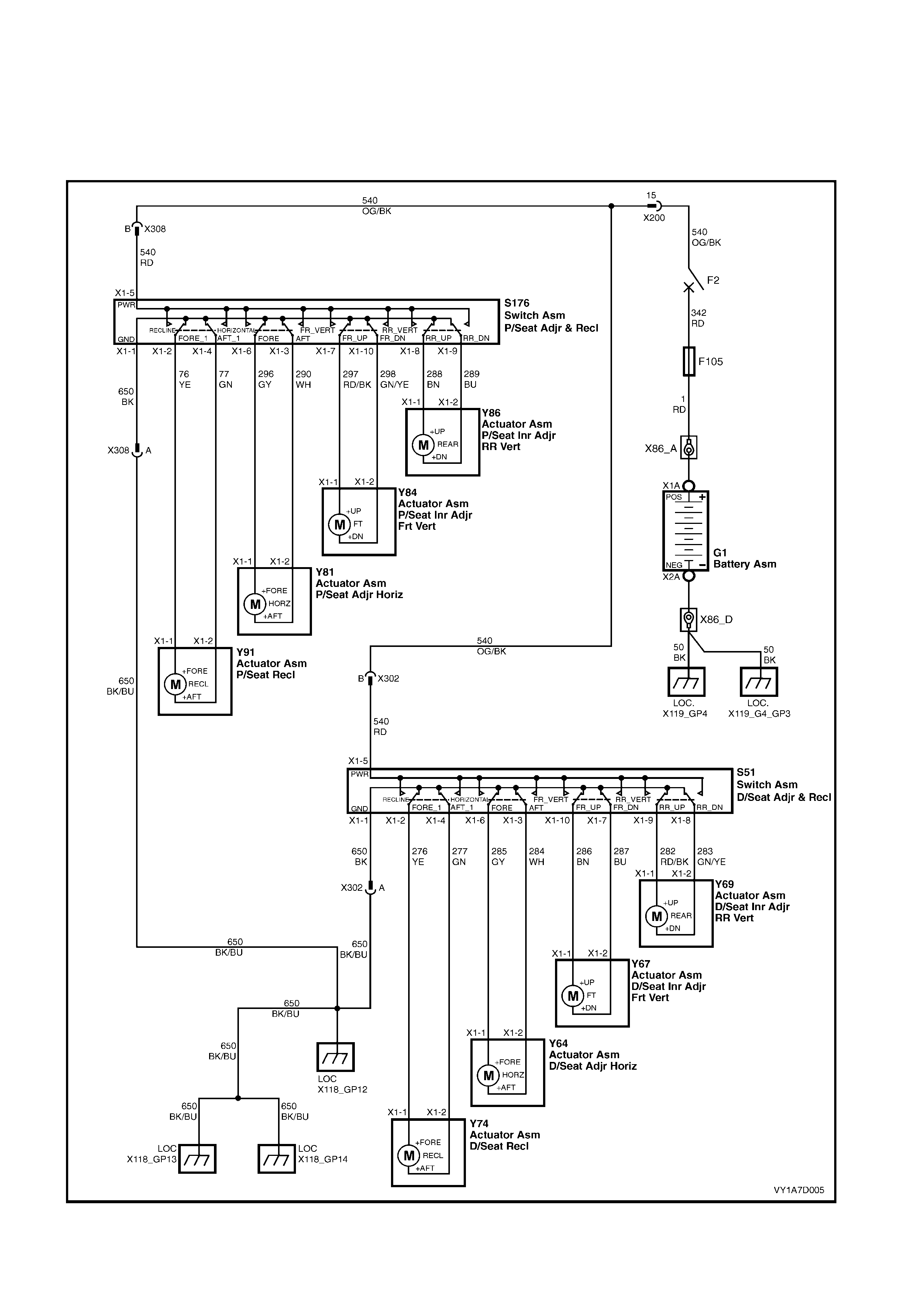
3.5 ELECTRICAL DIAGNOSIS – EIGHT-WAY SEAT, NON-MEMORY
The charts in this Section are used by the technician in the aid of diagnosing faults on eight-way non-mem ory s eat
assemblies. To aid in the use of the diagnosis charts, refer to WIRING DIAGRAM – EIGHT-WAY SEAT,
NON-MEMORY and CONNECTOR CHART – EIGHT-WAY SEAT, NON-MEMORY in this Section.
WIRING DIAGRAM – EIGHT-WAY SEAT, NON-MEMORY
Figure 1A7-83
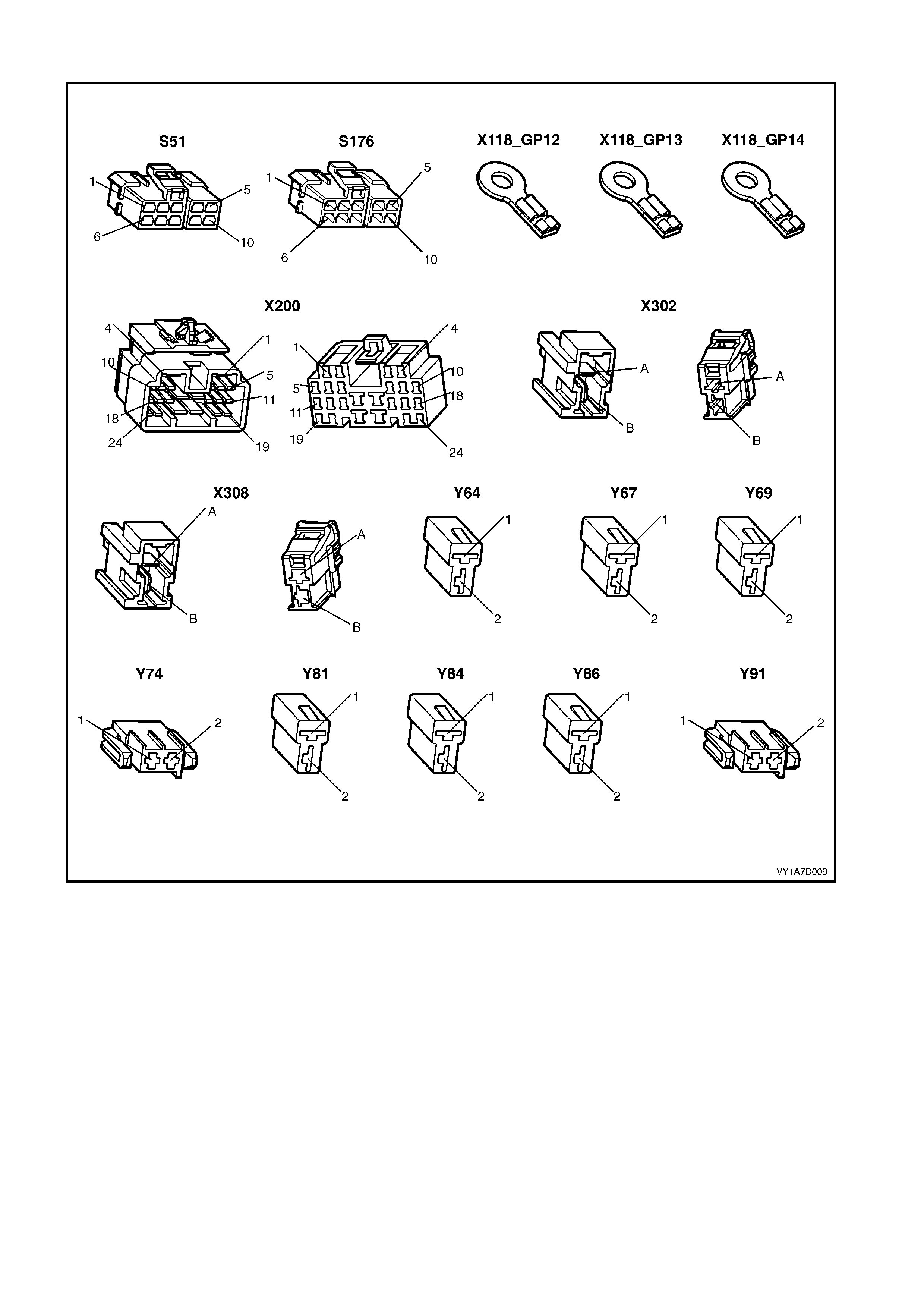
CONNECTOR CHART – EIGHT-WAY SEAT, NON-MEMORY
Figure 1A7-84

NEITHER SEAT ADJUSTMENT SWITCH FUNCTIONS OPERATE
Introduction
This test is used by the technician to aid in the diagnosis of the seat power and earth circuits, if neither seat
operates when either eight-way seat adjustment switch is operated.
Test Description
The numbers following refer to the Step numbers in the diagnostic chart.
1. Checks that battery voltage is more than 11.5 volts. The seat motors require more than 11.5 volts to operate
correctly.
2. Checks that circuit breaker F2 located on the passenger compartment fuse and relay panel assembly is not
tripped. Isolates whether circuit breaker F2 is the fault affecting the circuit between the battery and connector
X200 pin 15.
3. Check s that fusible link F 105 located on the engine com par tm ent fus e and relay panel assem bly is serviceable.
Isolates whether the fusible link is the fault affecting the circuit between the battery and connector X200 pin 15.
4. Ensures that connector X200 is secure.
5. Checks whether there is battery voltage at connector X200 pin 15. Isolates whether the fault is between the
battery and connector X200 pin 15. If the fault in the circuit is between connectors X200 pin 15 and either
X308 pin B or X302 pin B, only one seat will not operate.
6. Checks whether there is battery voltage at circuit breaker F2. Isolates whether the fault is between the battery
and circuit breaker F2 or circuit breaker F2 and connector X200 pin 15.
7. Checks whether there is battery voltage at fusible link F105. Isolates whether the fault is between the battery
and fusible link F105 or fusible link F105 and circuit breaker F2.
8. Checks that all the earth points associated with the system are serviceable and a good earth is provided at each
point.
STEP ACTION YES NO
1. 1. Check the battery voltage, refer to Section
12A, 2.9 BATTERY.
Is the battery voltage more than 11.5 V? Go to Step 2. Refer to Section 12A,
2.9 BATTERY for further
diagnosis.
2. 1. Inspect circuit breaker F2, refer to Section
12O, 2.2 CIRCUIT BREAKERS.
Is circuit breaker F2 tripped?
Allow the circuit breaker to
reset, refer to Section 12O,
2.2 CIRCUIT BREAKERS. Go to Step 3.
3. 1. Inspect fusible link F105, refer to Section
12O, 2.3 FUSIBLE LINKS.
Is fuse F105 serviceable? Go to Step 4. Replace the fusible link.
4. Is connector X200 secure? Go to Step 5. Ensure that the connector
is secure.
5. 1. Back probe connector X200 pin 15 with a
test lamp.
Does the test lamp illuminate? Go to Step 8. Go to Step 6.
6. 1. Remove circuit breaker F2 from the
passenger compartment fuse and relay
panel assembly.
2. Using a test lamp, probe connector
X129 – X45 pin 2.
Does the test lamp illuminate?
There is a fault in circuit
540 between circuit breaker
F2 and connector
X200 pin 15.
Repair or replace circuit
540.
Go to Step 7.
7. 1. Remove fusible link F105.
2. Using a test lamp, probe connector
X18-105.
Does the test lamp illuminate?
There is a fault in circuit
342 between fusible link
F105 and circuit breaker
F2.
Repair or replace circuit
342.
There is a fault in circuit 1
between the battery and
fusible link F105.
Repair or replace circuit 1.

STEP ACTION YES NO
8. 1. Ensure that the following earth points are
secure and have good contact with the
vehicle structure:
• X118–GP12 located in the middle of the
transmission tunnel.
• X118–GP13 located in the rear
compartment on the right-hand side tail
lamp stud.
• X118–GP14 located in the rear
compartment on the decklid.
Refer to Section 12P W IRING DIAGRAMS for
further details of earthing points.
Are all the earth points secure to the vehicle
with a good contact?
There is a fault in circuit
650.
Repair or replace circuit
650.
Ensure that the connectors
are secured to the vehicle
and that there is a good
contact between the
connector and the vehicle.

NONE OF THE DRIVER’S EIGHT-WAY SEAT ADJUSTMENT SWITCH FUNCTIONS OPERATE
Introduction
This test is used by the technician to aid in the diagnosis of the driver’s eight-way seat adjustment switch when none
of the switch functions operate. The test diagnoses the driver’s eight-way seat adjustment switch and associated
power and earth circuits.
Test Description
The numbers following refer to the Step numbers in the diagnostic chart.
1. Checks whether all of the passenger seat eight-way functions work. If none of them work, the fault is not
isolated to the driver’s seat only.
2. Checks whether there is battery power at connector X302 pin B. Isolates whether there is a fault in circuit 540
between connectors X200 pin 15 and X302 pin B.
3. Checks that all the connectors required for the seat to operate effectively are in place and positively connected.
4. Checks whether there is battery power at connector S51 – X1 pin 5. Isolates whether there is a fault in circuit
540 between connectors S51 – X1 pin 5 and X302 pin B.
5. Checks whether the driver’s eight-way seat adjustment switch is serviceable.
6. Chec ks whether there is c ontinuity between connectors S51 – X1 pin 1 and X 302 pin A which supplies the earth
circuit for the driver’s eight-way seat adjustment switch. Isolates whether there is a fault in circuit 650 between
the switch and connector X302 pin A or between connector X302 pin A and the earthing points.
STEP ACTION YES NO
1. Are all of the passenger’s eight-way seat
adjustment switch functions inoperative? Refer to NEITHER SEAT
ADJUSTMENT SWITCH
FUNCTIONS OPERATE in
this Section.
Go to Step 2.
2. 1. Back probe connector X302 pin B with a
test lamp.
Does the test lamp illuminate? Go to Step 3.
There is a fault in circuit
540 between connectors
X200 pin 15 and
X302 pin B.
Repair or replace circuit
540.
3. Are the following connectors secure?
• S51
• X302
• Y64
• Y67
• Y69
• Y74
Go to Step 4. Ensure that the connectors
are secure.
4. 1. Back probe connector S51 – X1 pin 5 with
a test lamp.
Does the test lamp illuminate? Go to Step 5.
There is a fault in circuit
540 between connectors
S51 – X1 pin 5 and
X302 pin B.
Repair or replace circuit
540.
5. 1. Remove the driver’s eight-way seat
adjustment switch from the seat, refer to
2.4 FRONT SEAT ADJUSTMENT
SWITCH.
2. Test the driver’s eight-way seat
adjustment switch, refer to 3.6 EIGHT-
WAY SEAT ADJUSTMENT SWITCH
TEST.
Is the driver’s eight-way seat adjustment
switch serviceable?
Go to Step 6.
Replace the driver’s
eight-way seat adjustment
switch.
Refer to 2.4 FRONT SEAT
ADJUSTMENT SWITCH.
6. 1. Back probe connector X302 pin A with a
test lamp.
2. Operate the driver’s eight-way seat
adjustment switch in any of the available
directions.
Does the test lamp illuminate?
There is a fault in circuit
650 between connector
X302 pin A and earth
points X118–GP12, X118–
GP13 and X118–GP14.
Repair or replace the circuit
650.
There is a fault in circuit
650 between connectors
S51 – X1 pin 1 and
X302 pin A.
Repair or replace circuit
650.
When all diagnosis and repairs are completed, check the system for correct operation.

FRONT/REAR OF THE DRIVER’S SEAT DOES NOT RAISE AND/OR LOWER
Introduction
This test is used by the technician to aid in the diagnosis of the front and/or the rear of the driver’s seat not r aising
and/or lowering. The test diagnoses the eight-way seat adjustment switch and the motor circuits.
Test Description
The numbers following refer to the Step numbers in the diagnostic chart.
1. Checks whether the driver’s eight-way seat adjustment switch operates in any of the directions. Isolates
whether the power and earth circuits are at fault.
2. Checks that all the connectors required for the seat to operate effectively are in place and positively connected.
3. Checks whether the driver’s eight-way seat adjustment switch is serviceable.
4. Conf irm s whether the rear of the seat r aises or lowers. Isolates whether the rear m otor and c ircuit of the seat is
the fault.
5. Confirms whether the front of the seat raises or lowers. Isolates whether the front motor and circuit of the seat is
the fault.
6. Checks whether there is battery power to the seat rear motor at connector Y69 – X1 pin 1. Isolates whether
there is a fault in circuit 282 that supplies battery power to the motor to raise the rear of the seat.
7. Check s whether there is battery power to the seat rear motor at connector Y69 – X1 pin 2. Isolates whether the
fault is in circuit 283 that supplies battery power to the motor to lower the rear of the seat or the m otor is faulty.
As the direction of the motor is changed by reversing the polarity, this Step also confirms that the earth circuit
from Step 6 is serviceable.
8. Checks whether there is battery power to the seat front motor at connector Y67 – X1 pin 1. Isolates whether
there is a fault in circuit 286 that supplies battery power to the motor to raise the front of the seat.
9. Chec ks whether ther e is battery power to the seat front m otor at c onnector Y67 – X1 pin 2. Is olates whether the
fault is in circ uit 287 that supplies batter y power to the m otor to lower the fr ont of the s eat or the m otor is faulty.
As the direction of the motor is changed by reversing the polarity, this Step also confirms that the earth circuit
from Step 8 is serviceable.
STEP ACTION YES NO
1. Does the driver’s eight-way seat adjustment
switch operate correctly in any of the eight
directions? Go to Step 2.
Refer to NONE OF THE
DRIVER’S EIGHT-WAY
SEAT ADJUSTMENT
SWITCH FUNCTIONS
OPERATE in this Section.
2. Are the following connectors secure?
• S51
• Y67
• Y69
Go to Step 3. Ensure that the connectors
are secure.
3. 1. Remove the driver’s eight-way seat
adjustment switch from the seat, refer to
2.4 FRONT SEAT ADJUSTMENT
SWITCH.
2. Test the driver’s eight-way seat
adjustment switch, refer to 3.6 EIGHT-
WAY SEAT ADJUSTMENT SWITCH
TEST.
Is the driver’s eight-way seat adjustment
switch serviceable?
Go to Step 4.
Replace the driver’s
eight-way seat adjustment
switch.
Refer to 2.4 FRONT SEAT
ADJUSTMENT SWITCH.
4. 1. Operate the driver’s eight-way seat
adjustment switch so that the rear of the
seat is raised or lowered.
Does the rear of the seat raise and lower?
Go to Step 5. Go to Step 6.
5. 1. Operate the driver’s eight-way seat
adjustment switch so that the front of the
seat is raised or lowered.
Does the front of the seat raise and lower?
System serviceable. Go to Step 8.

STEP ACTION YES NO
6. 1. Back probe connector Y69 – X1 pin 1 with
a test lamp.
2. Operate the driver’s eight-way seat
adjustment switch so that it will raise the
rear of the seat.
Does the test lamp illuminate?
Go to Step 7.
There is a fault in circuit
282 between connectors
S51 – X1 pin 9 and
Y69 – X1 pin 1.
Repair or replace circuit
282.
7. 1. Back probe connector Y69 – X1 pin 2 with
a test lamp.
2. Operate the driver’s eight-way seat
adjustment switch so that it will lower the
rear of the seat.
Does the test lamp illuminate?
The seat rear motor is
faulty.
Replace the seat rear
motor, refer to 2.15 FRONT
SEAT LIFT MOTORS.
Go to Step 5.
There is a fault in circuit
283 between connectors
S51 – X1 pin 8 and
Y69 – X1 pin 2.
Repair or replace circuit
283.
Go to Step 5.
8. 1. Back probe connector Y67 – X1 pin 1 with
a test lamp.
2. Operate the driver’s eight-way seat
adjustment switch so that it will raise the
front of the seat.
Does the test lamp illuminate?
Go to Step 9.
There is a fault in circuit
286 between connectors
S51 – X1 pin 10 and
Y67 – X1 pin 1.
Repair or replace circuit
286.
9. 1. Back probe connector Y67 – X1 pin 2 with
a test lamp.
2. Operate the driver’s eight-way seat
adjustment switch so that it will lower the
front of the seat.
Does the test lamp illuminate?
The seat front motor is
faulty.
Replace the seat front
motor, refer to 2.15 FRONT
SEAT LIFT MOTORS.
There is a fault in circuit
287 between connectors
S51 – X1 pin 7 and
Y67 – X1 pin 2.
Repair or replace circuit
287.
When all diagnosis and repairs are completed, check the system for correct operation.

DRIVER’S SEAT FORE/AFT FUNCTION IS INOPERATIVE OR NOT SMOOTH
Introduction
This test is used by the technician to aid in the diagnosis of the fore/aft function of the driver’s seat being inoperative
or the action of the seat through the range of movement is not smooth. The test diagnoses the eight-way seat
adjustment switch and the motor circuits.
Test Description
The numbers following refer to the Step numbers in the diagnostic chart.
1. Checks whether the driver’s eight-way seat adjustment switch operates in any of the directions. Isolates
whether there is battery power to the switch assembly.
2. Checks that there are no items obstructing the guide rails, which may stop or hinder the seat movement.
3. Checks that the guide rails and drive shafts have adequate lubricant applied to provide a smooth operation of
the seat.
4. Checks that the guide rails or drive shafts have not been damaged. Any binding between the moving parts will
result in poor operation of the fore and aft movement.
5. Checks that all the connectors required for the seat to operate effectively are in place and positively connected.
6. Checks whether the driver’s eight-way seat adjustment switch is serviceable.
7. Checks whether there is battery power to the seat fore/aft m otor at connector Y64 – X1 pin 1. Isolates whether
there is a fault in circuit 285 that supplies battery power to the motor to move the seat forward.
8. Checks whether there is battery power to the seat fore/aft m otor at connector Y64 – X1 pin 2. Isolates whether
the fault is in c ircuit 284 that supplies battery power to the motor to m ove the seat aft or the m otor is f aulty. As
reversing the polar ity changes the dire ction of the m otor, this Step als o conf irm s that the ear th circuit f rom Step
7 is serviceable.
STEP ACTION YES NO
1. Does the driver’s eight-way seat adjustment
switch operate correctly in any of the eight
directions? Go to Step 2.
Refer to NONE OF THE
DRIVER’S EIGHT-WAY
SEAT ADJUSTMENT
SWITCH FUNCTIONS
OPERATE in this Section.
2. Are the guide rails free from obstructions? Go to Step 3. Remove the obstructing
item.
3. Are the guide rails and drive shafts adequately
lubricated? Go to Step 4. Apply a small amount of
grease type NLGI No. 1
Lithium Grease (with 9%
Zinc Oxide).
4. Do the guide rails or drive shafts bind at any
point of travel during the fore and aft
movement of the seat?
Replace the front seat
adjuster assembly.
Refer to 2.14 FRONT
SEAT ADJUSTER
ASSEMBLY.
Go to Step 5.
5. Are the following connectors secure?
• S51
• Y64 Go to Step 6. Ensure that the connectors
are secure.
6. 1. Remove the driver’s eight-way seat
adjustment switch from the seat, refer to
2.4 FRONT SEAT ADJUSTMENT
SWITCH.
2. Test the driver’s eight-way seat
adjustment switch, refer to 3.6 EIGHT-
WAY SEAT ADJUSTMENT SWITCH
TEST.
Is the driver’s eight-way seat adjustment
switch serviceable?
Go to Step 7.
Replace the driver’s
eight-way seat adjustment
switch.
Refer to 2.4 FRONT SEAT
ADJUSTMENT SWITCH.
7. 1. Back probe connector Y64 – X1 pin 1 with
a test lamp.
2. Operate the driver’s eight-way seat
adjustment switch so that it will move the
seat forward.
Does the test lamp illuminate?
Go to Step 8.
There is a fault in circuit
285 between connectors
S51 – X1 pin 6 and
Y64 – X1 pin 1.
Repair or replace circuit
285.

STEP ACTION YES NO
8. 1. Back probe connector Y64 – X1 pin 2 with
a test lamp.
2. Operate the driver’s eight-way seat
adjustment switch so that it will move the
seat aft.
Does the test lamp illuminate?
The seat fore/aft movement
motor is faulty.
Replace the seat fore/aft
movement motor, refer to
2.16 FRONT SEAT
FORE/AFT MOVEMENT
MOTOR.
There is a fault in circuit
284 between connectors
S51 – X1 pin 3 and
Y64 – X1 pin 2.
Repair or replace circuit
284.
When all diagnosis and repairs are completed, check the system for correct operation.

DRIVER’S SEAT RECLINE FORWA RD AND/OR AFT FUNCTION IS INOPERATIVE
Introduction
This test is used by the technician to aid in the diagnosis of the reclining function of the driver’s seat being
inoperative. The test diagnoses the eight-way seat adjustment switch and the motor circuits.
Test Description
The numbers following refer to the Step numbers in the diagnostic chart.
1. Checks whether the driver’s eight-way seat adjustment switch operates in any of the directions. Isolates
whether there is battery power to the switch assembly.
2. Checks that all the connectors required for the seat to operate effectively are in place and positively connected.
3. Checks whether the driver’s eight-way seat adjustment switch is serviceable.
4. Chec ks whether there is battery power to the seat reclining motor at connec tor Y74 – X1 pin 1. Is olates whether
there is a fault in circuit 276 that supplies battery power to the reclining motor to move the seat-back forward.
5. Chec ks whether there is battery power to the seat reclining motor at connec tor Y74 – X1 pin 2. Is olates whether
the fault is in circuit 277 that supplies battery power to the reclining motor to move the seat-back aft or the
reclining motor is faulty. As reversing the polarity changes the direction of the motor, this Step also confirms that
the earth circuit from Step 4 is serviceable.
STEP ACTION YES NO
1. Does the driver’s eight-way seat adjustment
switch operate correctly in any of the eight
directions? Go to Step 2.
Refer to NONE OF THE
DRIVER’S EIGHT-WAY
SEAT ADJUSTMENT
SWITCH FUNCTIONS
OPERATE in this Section.
2. Are the following connectors secure?
• S51
• Y74 Go to Step 3. Ensure that the connectors
are secure.
3. 1. Remove the driver’s eight-way seat
adjustment switch from the seat, refer to
2.4 FRONT SEAT ADJUSTMENT
SWITCH.
2. Test the driver’s eight-way seat
adjustment switch, refer to 3.6 EIGHT-
WAY SEAT ADJUSTMENT SWITCH
TEST.
Is the driver’s eight-way seat adjustment
switch serviceable?
Go to Step 4.
Replace the driver’s
eight-way seat adjustment
switch.
Refer to 2.4 FRONT SEAT
ADJUSTMENT SWITCH.
4. 1. Back probe connector Y74 – X1 pin 1 with
a test lamp.
2. Operate the driver’s eight-way seat
adjustment switch so that it will move the
seat-back forward.
Does the test lamp illuminate?
Go to Step 5.
There is a fault in circuit
276 between connectors
S51 – X1 pin 2 and
Y74 – X1 pin 1.
Repair or replace circuit
276.
5. 1. Back probe connector Y74 – X1 pin 2 with
a test lamp.
2. Operate the driver’s eight-way seat
adjustment switch so that it will move the
seat-back aft.
Does the test lamp illuminate?
The front seat reclining
motor is faulty.
Replace the front seat
reclining motor, refer to
2.17 FRONT SEAT
RECLINING MOTOR,
GEARBOX AND
POTENTIOMETER
ASSEMBLY.
There is a fault in circuit
277 between connectors
S51 – X1 pin 4 and
Y74 - X1 pi n 2.
Repair or replace circuit
277.
When all diagnosis and repairs are completed, check the system for correct operation.

NONE OF THE PASSENGER’S EIGHT-WAY SEAT A DJUSTMENT SWITCH FUNCTIONS OPERATE
Introduction
This test is us ed by the tec hnician to aid in the diagnos is of the pas senger ’s eight-way seat adjustment switch when
none of the switch functions operate. The test diagnoses the passenger’s eight-way seat adjustment switch and
associated power and earth circuits.
Test Description
The numbers following refer to the Step numbers in the diagnostic chart.
1. Chec ks whether all of the driver ’s seat eight- way functions work . If none of them work , the fault is not isolated to
the passenger’s seat only.
2. Checks whether there is battery power at connector X308 pin B. Isolates whether there is a fault in circuit 540
between connectors X200 pin 15 and X308 pin B.
3. Checks that all the connectors required for the seat to operate effectively are in place and positively connected.
4. Checks whether there is battery power at connector S176 – X1 pin 5. Isolates whether there is a fault in circuit
540 between connectors S176 – X1 pin 5 and X308 pin B.
5. Checks whether the passenger’s eight-way seat adjustment switch is serviceable.
6. Checks whether there is continuity between connectors S176 – X1 pin 1 and X308 pin A which supplies the
earth circ uit for the pas senger’s eight-way seat adjus tm ent switch. Isolates whether there is a fault in circuit 650
between the switch and connector X308 pin A or between connector X308 pin A and the earthing points.
STEP ACTION YES NO
1. Are all of the driver’s eight-way seat
adjustment switch functions inoperative? Refer to NEITHER SEAT
ADJUSTMENT SWITCH
FUNCTIONS OPERATE in
this Section.
Go to Step 2.
2. 1. Back probe connector X308 pin B with a
test lamp.
Does the test lamp illuminate? Go to Step 3.
There is a fault in circuit
540 between connectors
X200 pin 15 and
X308 pin B.
Repair or replace circuit
540.
3. Are the following connectors secure?
• S176
• X308
• Y81
• Y84
• Y86
• Y91
Go to Step 4. Ensure that the connectors
are secure.
4. 1. Back probe connector S176 – X1 pin 5
with a test lamp.
Does the test lamp illuminate? Go to Step 5.
There is a fault in circuit
540 between connectors
S176 – X1 pin 5 and
X308 pin B.
Repair or replace circuit
540.
5. 1. Remove the passenger’s eight-way seat
adjustment switch from the seat, refer to
2.4 FRONT SEAT ADJUSTMENT
SWITCH.
2. Test the passenger’s eight-way seat
adjustment switch, refer to 3.6 EIGHT-
WAY SEAT ADJUSTMENT SWITCH
TEST.
Is the passenger’s eight-way seat adjustment
switch serviceable?
Go to Step 6.
Replace the passenger’s
eight-way seat adjustment
switch.
Refer to 2.4 FRONT SEAT
ADJUSTMENT SWITCH.
6. 1. Back probe connector X308 pin A with a
test lamp.
2. Operate the passenger’s eight-way seat
adjustment switch in any of the available
directions.
Does the test lamp illuminate?
There is a fault in circuit
650 between connector
X308 pin A and earth
points X118–GP12, X118–
GP13 and X118–GP14.
Repair or replace circuit
650.
There is a fault in circuit
650 between connectors
S176 – X1 pin 1 and
X308 pin A.
Repair or replace circuit
650.
When all diagnosis and repairs are completed, check the system for correct operation.

FRONT/REAR OF THE PASSENGER’S SEAT DOES NOT RAISE AND/OR LOWER
Introduction
This test is used by the technician to aid in the diagnosis of the front and/or the rear of the passenger’s seat not
raising and/or lowering. The test diagnoses the eight-way seat adjustment switch and the motor circuits.
Test Description
The numbers following refer to the Step numbers in the diagnostic chart.
1. Checks whether the passenger’s eight-way seat adjustment switch operates in any of the directions. Isolates
whether the power and earth circuits are at fault.
2. Checks that all the connectors required for the seat to operate effectively are in place and positively connected.
3. Checks whether the passenger’s eight-way seat adjustment switch is serviceable.
4. Conf irm s whether the rear of the seat r aises or lowers. Isolates whether the rear m otor and c ircuit of the seat is
the fault.
5. Confirms whether the front of the seat raises or lowers. Isolates whether the front motor and circuit of the seat is
the fault.
6. Checks whether there is battery power to the seat rear motor at connector Y86 – X1 pin 1. Isolates whether
there is a fault in circuit 288 that supplies battery power to the motor to raise the rear of the seat.
7. Check s whether there is battery power to the seat rear motor at connector Y86 – X1 pin 2. Isolates whether the
fault is in circuit 289 that supplies battery power to the motor to lower the rear of the seat or the m otor is faulty.
As the direction of the motor is changed by reversing the polarity, this Step also confirms that the earth circuit
from Step 6 is serviceable.
8. Checks whether there is battery power to the seat front motor at connector Y84 – X1 pin 1. Isolates whether
there is a fault in circuit 297 that supplies battery power to the motor to raise the front of the seat.
9. Chec ks whether ther e is battery power to the seat front m otor at c onnector Y84 – X1 pin 2. Is olates whether the
fault is in circ uit 298 that supplies batter y power to the m otor to lower the fr ont of the s eat or the m otor is faulty.
As the direction of the motor is changed by reversing the polarity, this Step also confirms that the earth circuit
from Step 8 is serviceable.
STEP ACTION YES NO
1. Does the passenger’s eight-way seat
adjustment switch operate correctly in any of
the eight directions? Go to Step 2.
Refer to NONE OF THE
PASSENGER’S EIGHT-
WAY SEAT ADJUSTMENT
SWITCH FUNCTIONS
OPERATE in this Section.
2. Are the following connectors secure?
• S176
• Y84
• Y86
Go to Step 3. Ensure that the connectors
are secure.
3. 1. Remove the passenger’s eight-way seat
adjustment switch from the seat, refer to
2.4 FRONT SEAT ADJUSTMENT
SWITCH.
2. Test the passenger’s eight-way seat
adjustment switch, refer to 3.6 EIGHT-
WAY SEAT ADJUSTMENT SWITCH
TEST.
Is the passenger’s eight-way seat adjustment
switch serviceable?
Go to Step 4.
Replace the passenger’s
eight-way seat adjustment
switch.
Refer to 2.4 FRONT SEAT
ADJUSTMENT SWITCH.
4. 1. Operate the passenger’s eight-way seat
adjustment switch so that the rear of the
seat is raised or lowered.
Does the rear of the seat raise and lower?
Go to Step 5. Go to Step 6.
5. 1. Operate the passenger’s eight-way seat
adjustment switch so that the front of the
seat is raised or lowered
Does the front of the seat raise and lower?
System serviceable. Go to Step 8.

STEP ACTION YES NO
6. 1. Back probe connector Y86 – X1 pin 1 with
a test lamp.
2. Operate the passenger’s eight-way seat
adjustment switch so that it will raise the
rear of the seat.
Does the test lamp illuminate?
Go to Step 7.
There is a fault in circuit
288 between connectors
S176 – X1 pin 8 and
Y86 – X1 pin 1.
Repair or replace circuit
288.
7. 1. Back probe connector Y86 – X1 pin 2 with
a test lamp.
2. Operate the passenger’s eight-way seat
adjustment switch so that it will lower the
rear of the seat.
Does the test lamp illuminate?
The seat rear motor is
faulty.
Replace the seat rear
motor, refer to 2.15 FRONT
SEAT LIFT MOTORS.
Go to Step 5.
There is a fault in circuit
289 between connectors
S176 – X1 pin 9 and
Y86 – X1 pin 2.
Repair or replace circuit
289.
Go to Step 5.
8. 1. Back probe connector Y84 – X1 pin 1 with
a test lamp.
2. Operate the passenger’s eight-way seat
adjustment switch so that it will raise the
front of the seat.
Does the test lamp illuminate?
Go to Step 9.
There is a fault in circuit
297 between connectors
S176 – X1 pin 7 and
Y84 – X1 pin 1.
Repair or replace circuit
297.
9. 1. Back probe connector Y84 – X1 pin 2 with
a test lamp.
2. Operate the passenger’s eight-way seat
adjustment switch so that it lower the front
of the seat.
Does the test lamp illuminate?
The seat front motor is
faulty.
Replace the seat front
motor, refer to 2.15 FRONT
SEAT LIFT MOTORS.
There is a fault in circuit
298 between connectors
S176 – X1 pin 10 and
Y84 – X1 pin 2.
Repair or replace circuit
298.
When all diagnosis and repairs are completed, check the system for correct operation.

PASSENGER’S SEAT FORE/AFT FUNCTION IS INOPERATIVE OR NOT SMOOTH
Introduction
This test is used by the technician to aid in the diagnosis of the fore/aft function of the passenger’s seat being
inoperative or the action of the seat through the range of movement is not smooth. The test diagnoses the eight-
way seat adjustment switch and the motor circuits.
Test Description
The numbers following refer to the Step numbers in the diagnostic chart.
1. Checks whether the passenger’s eight-way seat adjustment switch operates in any of the directions. Isolates
whether there is battery power to the switch assembly.
2. Checks that there are no items obstructing the guide rails, which may stop or hinder the seat movement.
3. Checks that the guide rails and drive shafts have adequate lubricant applied to provide a smooth operation of
the seat.
4. Checks that the guide rails or drive shafts have not been damaged. Any binding between the moving parts will
result in poor operation of the fore and aft movement.
5. Checks that all the connectors required for the seat to operate effectively are in place and positively connected.
6. Checks whether the passenger’s eight-way seat adjustment switch is serviceable.
7. Checks whether there is battery power to the seat fore/aft m otor at connector Y81 – X1 pin 1. Isolates whether
there is a fault in circuit 296 that supplies battery power to the motor to move the seat forward.
8. Checks whether there is battery power to the seat fore/aft m otor at connector Y81 – X1 pin 2. Isolates whether
the fault is in c ircuit 290 that supplies battery power to the motor to m ove the seat aft or the m otor is f aulty. As
reversing the polar ity changes the dire ction of the m otor, this Step als o conf irm s that the ear th circuit f rom Step
7 is serviceable.
STEP ACTION YES NO
1. Does the passenger’s eight-way seat
adjustment switch operate correctly in any of
the eight directions? Go to Step 2.
Refer to NONE OF THE
PASSENGER’S EIGHT-
WAY SEAT ADJUSTMENT
SWITCH FUNCTIONS
OPERATE in this Section.
2. Are the guide rails free from obstructions? Go to Step 3. Remove the obstructing
item.
3. Are the guide rails and drive shafts adequately
lubricated? Go to Step 4. Apply a small amount of
grease type NLGI No. 1
Lithium Grease (with 9%
Zinc Oxide).
4. Do the guide rails or drive shafts bind at any
point of travel during the fore and aft
movement of the seat?
Replace the front seat
adjuster assembly.
Refer to 2.14 FRONT
SEAT ADJUSTER
ASSEMBLY.
Go to Step 5
5. Are the following connectors secure?
• S176
• Y81 Go to Step 6. Ensure that the connectors
are secure.
6. 1. Remove the passenger’s eight-way seat
adjustment switch from the seat, refer to
2.4 FRONT SEAT ADJUSTMENT
SWITCH.
2. Test the passenger’s eight-way seat
adjustment switch, refer to 3.6 EIGHT-
WAY SEAT ADJUSTMENT SWITCH
TEST.
Is the passenger’s eight-way seat adjustment
switch serviceable?
Go to Step 7.
Replace the passenger’s
eight-way seat adjustment
switch.
Refer to 2.4 FRONT SEAT
ADJUSTMENT SWITCH.
7. 1. Back probe connector Y81 – X1 pin 1 with
a test lamp.
2. Operate the passenger’s eight-way seat
adjustment switch so that it will move the
seat forward.
Does the test lamp illuminate?
Go to Step 8.
There is a fault in circuit
296 between connectors
S176 – X1 pin 6 and
Y81 – X1 pin 1.
Repair or replace circuit
296.

STEP ACTION YES NO
8. 1. Back probe connector Y81 – X1 pin 2 with
a test lamp.
2. Operate the passenger’s eight-way seat
adjustment switch so that it will move the
seat aft.
Does the test lamp illuminate?
The seat fore/aft movement
motor is faulty.
Replace the seat fore/aft
movement motor, refer to
2.16 FRONT SEAT
FORE/AFT MOVEMENT
MOTOR.
There is a fault in circuit
290 between connectors
S176 – X1 pin 3 and
Y81 – X1 pin 2.
Repair or replace circuit
290.
When all diagnosis and repairs are completed, check the system for correct operation.

PASSENGER’S SEAT RECLINE FORWARD AND/OR AFT FUNCTION IS INOPERATIVE
Introduction
This test is used by the technician to aid in the diagnosis of the reclining function of the passenger’s seat being
inoperative. The test diagnoses the eight-way seat adjustment switch and the motor circuits.
Test Description
The numbers following refer to the Step numbers in the diagnostic chart.
1. Checks whether the passenger’s eight-way seat adjustment switch operates in any of the directions. Isolates
whether there is battery power to the switch assembly.
2. Checks that all the connectors required for the seat to operate effectively are in place and positively connected.
3. Checks whether the passenger’s eight-way seat adjustment switch is serviceable.
4. Chec ks whether there is battery power to the seat reclining motor at connec tor Y91 – X1 pin 1. Is olates whether
there is a fault in circuit 76 that supplies battery power to the reclining motor to move the seat-back forward.
5. Check s whether there is battery power to the seat reclining motor at connec tor Y91 – X1 pin 2. Is olates whether
the fault is in circuit 77 that supplies battery power to the reclining motor to move the seat-back aft or the
reclining motor is faulty. As reversing the polarity changes the direction of the motor, this Step also confirms that
the earth circuit from Step 4 is serviceable.
STEP ACTION YES NO
1. Does the passenger’s eight-way seat
adjustment switch operate correctly in any of
the eight directions? Go to Step 2.
Refer to NONE OF THE
PASSENGER’S EIGHT-
WAY SEAT ADJUSTMENT
SWITCH FUNCTIONS
OPERATE in this Section.
2. Are the following connectors secure?
• S176
• Y91 Go to Step 3. Ensure that the connectors
are secure.
3. 1. Remove the passenger’s eight-way seat
adjustment switch from the seat, refer to
2.4 FRONT SEAT ADJUSTMENT
SWITCH.
2. Test the passenger’s eight-way seat
adjustment switch, refer to 3.6 EIGHT-
WAY SEAT ADJUSTMENT SWITCH
TEST.
Is the passenger’s eight-way seat adjustment
switch serviceable?
Go to Step 4.
Replace the passenger’s
eight-way seat adjustment
switch.
Refer to 2.4 FRONT SEAT
ADJUSTMENT SWITCH.
4. 1. Back probe connector Y91 – X1 pin 1 with
a test lamp.
2. Operate the passenger’s eight-way seat
adjustment switch so that it will move the
seat-back forward.
Does the test lamp illuminate?
Go to Step 5.
There is a fault in circuit 76
between connectors
S176 – X1 pin 2 and
Y91 – X1 pin 1.
Repair or replace circuit 76.
5. 1. Back probe connector Y91 – X1 pin 2 with
a test lamp.
2. Operate the passenger’s eight-way seat
adjustment switch so that it will move the
seat-back aft.
Does the test lamp illuminate?
The front seat reclining
motor is faulty.
Replace the front seat
reclining motor, refer to
2.17 FRONT SEAT
RECLINING MOTOR,
GEARBOX AND
POTENTIOMETER
ASSEMBLY.
There is a fault in circuit 77
between connectors
S176 – X1 pin 4 and
Y91 – X1 pin 2.
Repair or replace circuit 77.
When all diagnosis and repairs are completed, check the system for correct operation.
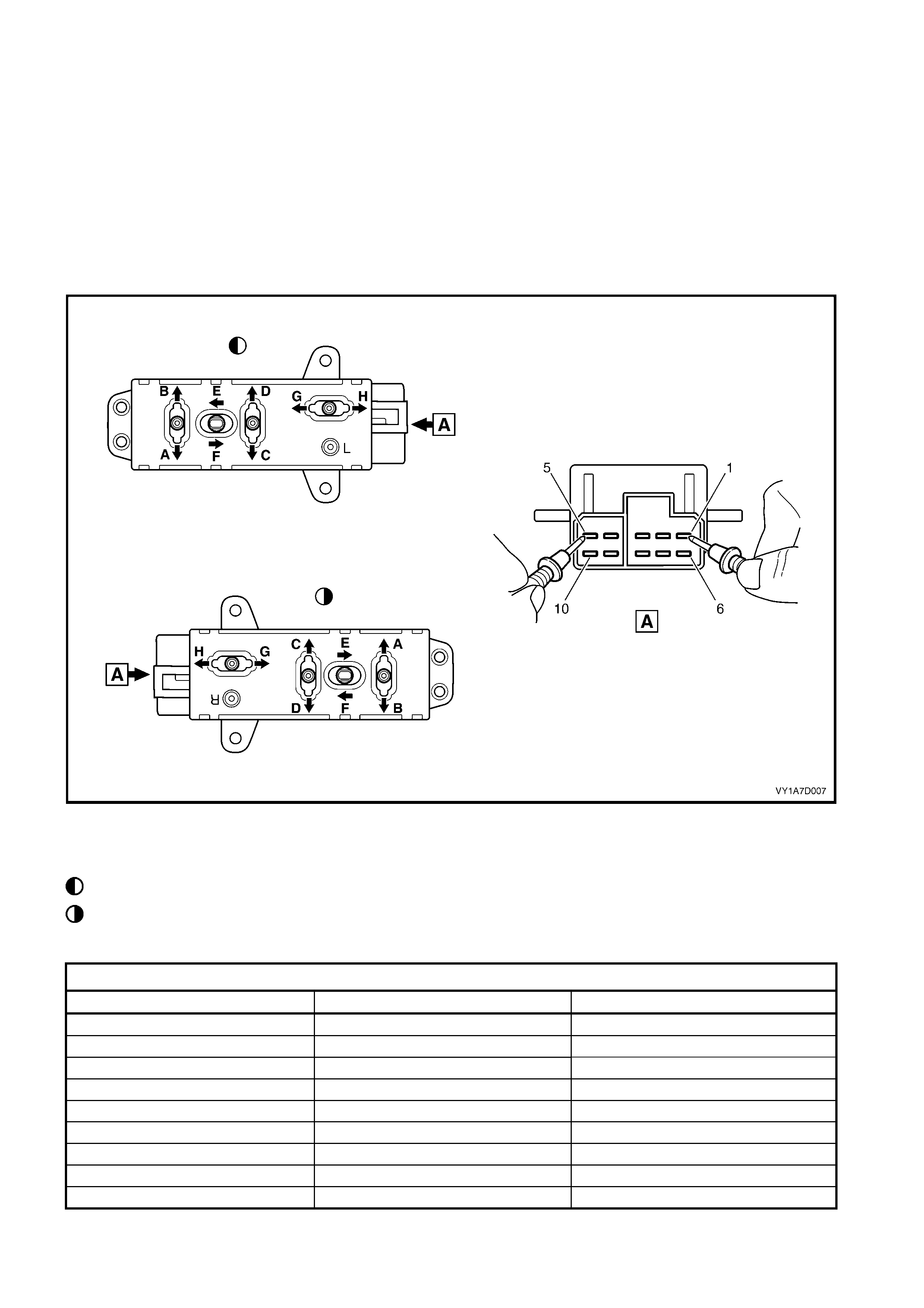
3.6 EIGHT-WAY SEAT ADJUSTMENT SWITCH TEST
The switch is located on the outer side of the seat, attached to the inner side of the front seat outer side cover.
TEST
1. Remove the eight-way seat adjustment switch, refer to 2.4 FRONT SEAT ADJUSTMENT SWITCH.
2. Place the switch in the positions as detailed in the chart in this Section. Place the probes of the ohmm eter onto
the terminals listed and take the reading. Compare the reading to the chart.
3. If the switch fails any part of the test, replace the switch assembly with a serviceable item.
4. Install the eight-way seat adjustment switch, refer to 2.4 FRONT SEAT ADJUSTMENT SWITCH.
Figure 1A7-85
Legend
Left-hand Switch
Right-hand Switch
EIGHT-WAY SEAT ADJUSTMENT SWITCH
SWITCH POSITION SWITCH TERMINALS INDICATION IF SWITCH IS SERVICEABLE
Posit i on A 10 and 5 Continuity
Posit i on B 7 and 5 Continuity
Posit ion C 9 and 5 Continuit y
Posit ion D 8 and 5 Continuit y
Posit i on E 6 and 5 Continuity
Posit i on F 3 and 5 Continuity
Posit i on G 2 and 5 Continuity
Posit ion H 4 and 5 Continuit y
Switch in t he neutral positi on 1 and either 2, 3, 4, 6, 7, 8, 9 or 10 Continuity

4. SERVICE OPERATIONS - FRONT SEAT, COUPE
4.1 FRONT SE AT USAGE CHART - COUPE
HOW TO USE THIS CHART
Two front seat configurations are used in MY2003 V2 Series ll coupe vehicle. The following usage chart is
provided to help determine the seat type fitted to the vehicle. This is important prior to repairs being performed
as the failed / damaged part may not be serviceable.
To determine the seat fitted to the vehicle, obtain the vehicle model, which seat requires attention and the seat
cover fabric. Then establish if the vehicle has a side impact airbag and/or memory track function. Using the chart
will lead to the elimination of all other seat combinations, allowing the identification of the type and the
construc tion of the seat. Finally, refer to the Figure shown in T YPE for a com ponent br eak down of the fr ont seat
assembly.
1. VEHICLE – Vehicle model identification.
2. SEATING – Driver front seat or passenger front seat.
3. FABRIC – Leather seat covers.
4. TRACK – Indicates the number of directions the electric seat track can be moved.
5. MEMORY - Indicates if the seat has a memory control module fitted.
6. SIAB – If the front seat is fitted with a side impact airbag.
7. CONST RUCTION – Hook and Loop ref ers to the seat cover being able to be attached or rem oved from the
seat pad and being serviced as separate parts.
8. TYPE – Identif ies the seat type and provides ref er enc e to the f ollowing illustrations which s how a break down
of the serviced component for each rear seat assembly.
DOMESTIC
VEHICLE SEATING FABRIC TRACK MEMORY SIAB CONSTRUCTION TYPE
(Refer to)
Driver Leather 8 way No Yes Hook & Loop 1 (Figure 1A7-86)
CV6
Passenger Leather 8 way No Yes Hook & Loop 1 (Figure 1A7-86)
CV8 Driver Leather 8 way Yes Yes Hook & Loop 2 (Figure 1A7-87)
Passenger Leather 8 way No Yes Hook & Loop 1 (Figure 1A7-86)
GULF STATES
VEHICLE SEATING FABRIC TRACK MEMORY SIAB CONSTRUCTION TYPE
(Refer to)
Driver Leather 8 way No Yes Hook & Loop 1 (Figure 1A7-86)
Coupe S
Passenger Leather 8 way No Yes Hook & Loop 1 (Figure 1A7-86)
Coupe SS Driver Leather 8 way No Yes Hook & Loop 1 (Figure 1A7-86)
Passenger Leather 8 way No Yes Hook & Loop 1 (Figure 1A7-86)
Techline
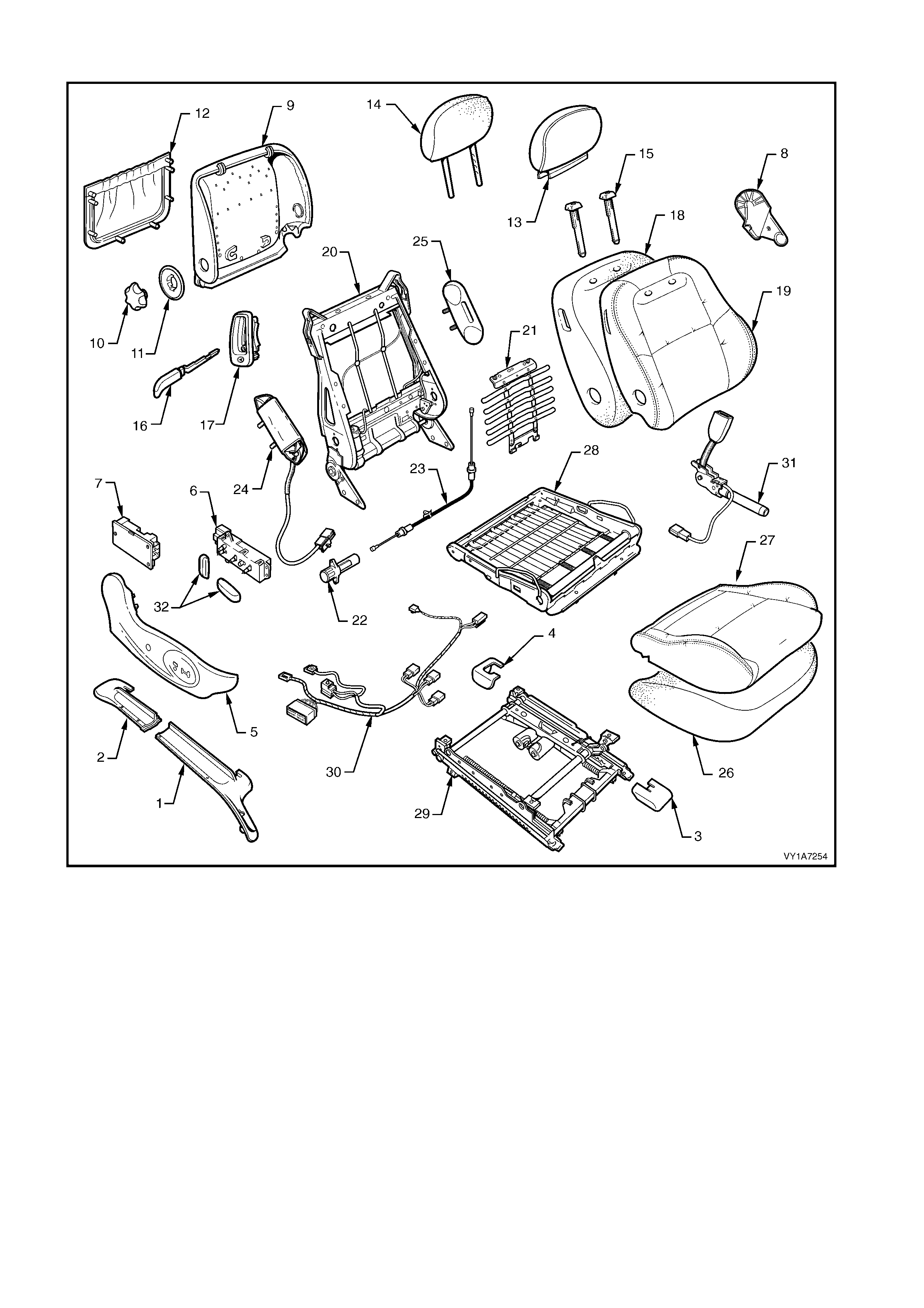
Type 1: Front Seat Assembly - Passenger And Non-memory Type Driver’s Seat
Figure 1A7-86
Legend
1. Seat Adjuster Outer Front Cover
2. Front Seat Outer Lower Rear Cover
3. Front Inner Guide Rail Cover
4. Rear Inner Guide Rail Cover
5. Front Seat Outer Side Cover
6. Front Seat Adjustment Switch - Eight-way
7. EZ-entry Module
8. Front Seat Inner Side Cover
9. Front Seat-back Lower Cover
10. Lumbar Support Adjuster Knob
11. Lumber Support Adjuster Knob Adapter
12. Front Seat-back Lower Cover Pocket
13. Front Seat Head Restraint Cover
14. Front Seat Head Restraint Pad Assembly
15. Front Seat Head Restraint Guide
16. EZ-entry Lever Arm
17. Escutcheon and Seat Return Switch Assembly
18. Front Seat-back Pad
19. Front Seat-back Cover
20. Front Seat-back Frame Assembly
21. Lumbar Support Assembly
22. Lumbar Support Assembly Adjuster
23. Lumbar Support Adjuster Cable
24. Side Impact Airbag
25. Front Seat Foam Block Insert Assembly
26. Front Seat Cushion Pad
27. Front Seat Cushion Cover
28. Front Seat Cushion Frame Assembly
29. Adjuster and Guide Rail Assembly- Eight-way
30. Guide Rail Assembly Wiring Harness
31. Seatbelt Buckle And Pretensioner Assembly
32. Adjustment Knobs
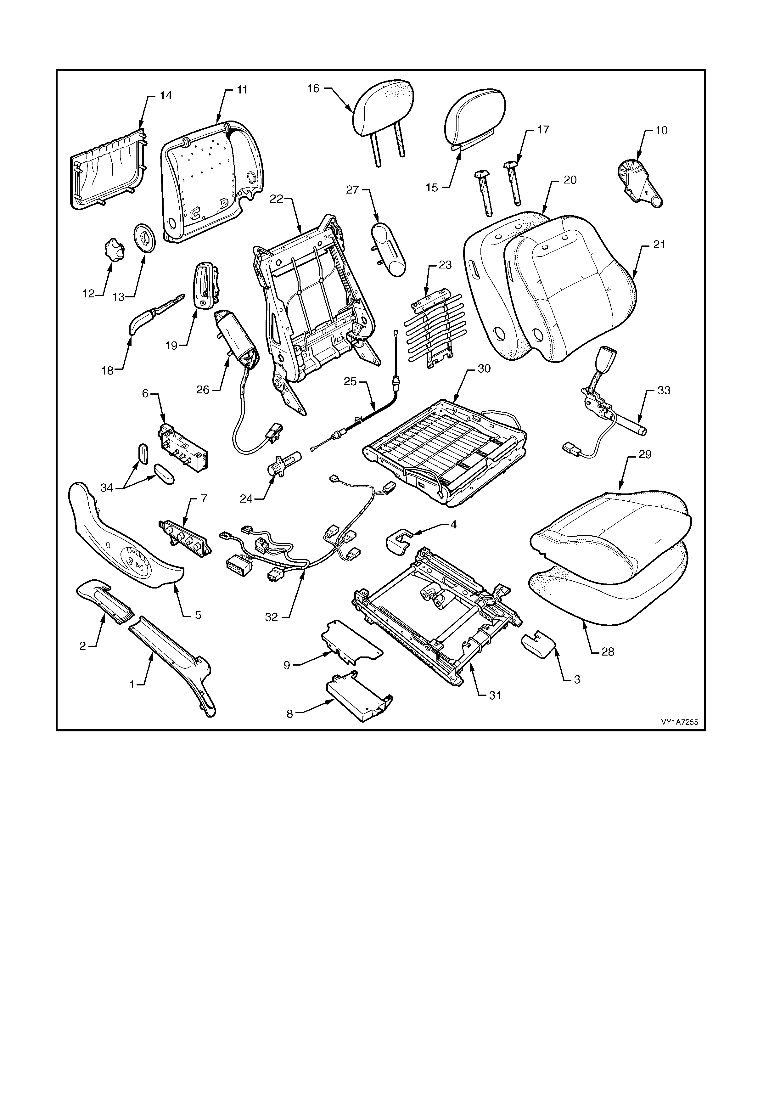
Type 2: Front Seat Assembly - Memory Type Driver’s Seat
Figure 1A7-87
Legend
1. Seat Adjuster Outer Front Cover
2. Front Seat Outer Lower Rear Cover
3. Front Inner Guide Rail Cover
4. Rear Inner Guide Rail Cover
5. Front Seat Outer Side Cover
6. Front Seat Adjustment Switch - Eight-way
7. Memory Position Switch
8. Front Seat Control Module
9. Front Seat Control Module Mounting Bracket
10. Front Seat Inner Side Cover
11. Front Seat-back Lower Cover
12. Lumbar Support Adjuster Knob
13. Lumber Support Adjuster Knob Adapter
14. Front Seat-back Lower Cover Pocket
15. Front Seat Head Restraint Cover
16. Front Seat Head Restraint Pad Assembly
17. Front Seat Head Restraint Guide
18. EZ-entry Lever Assembly
19. Escutcheon And Seat Return Switch Assembly
20. Front Seat-back Pad
21. Front Seat-back Cover
22. Front Seat-back Frame Assembly
23. Lumbar Support Assembly
24. Lumbar Support Assembly Adjuster
25. Lumbar Support Adjuster Cable
26. Side Impact Airbag
27. Front Seat Foam Block Insert Assembly
28. Front Seat Cushion Pad
29. Front Seat Cushion Cover
30. Front Seat Cushion Frame Assembly
31. Adjuster and Guide Rail Assembly- Eight-way
32. Guide Rail Assembly Wiring Harness
33. Seatbelt Buckle And Pretensioner Assembly
34. Adjustment Knobs
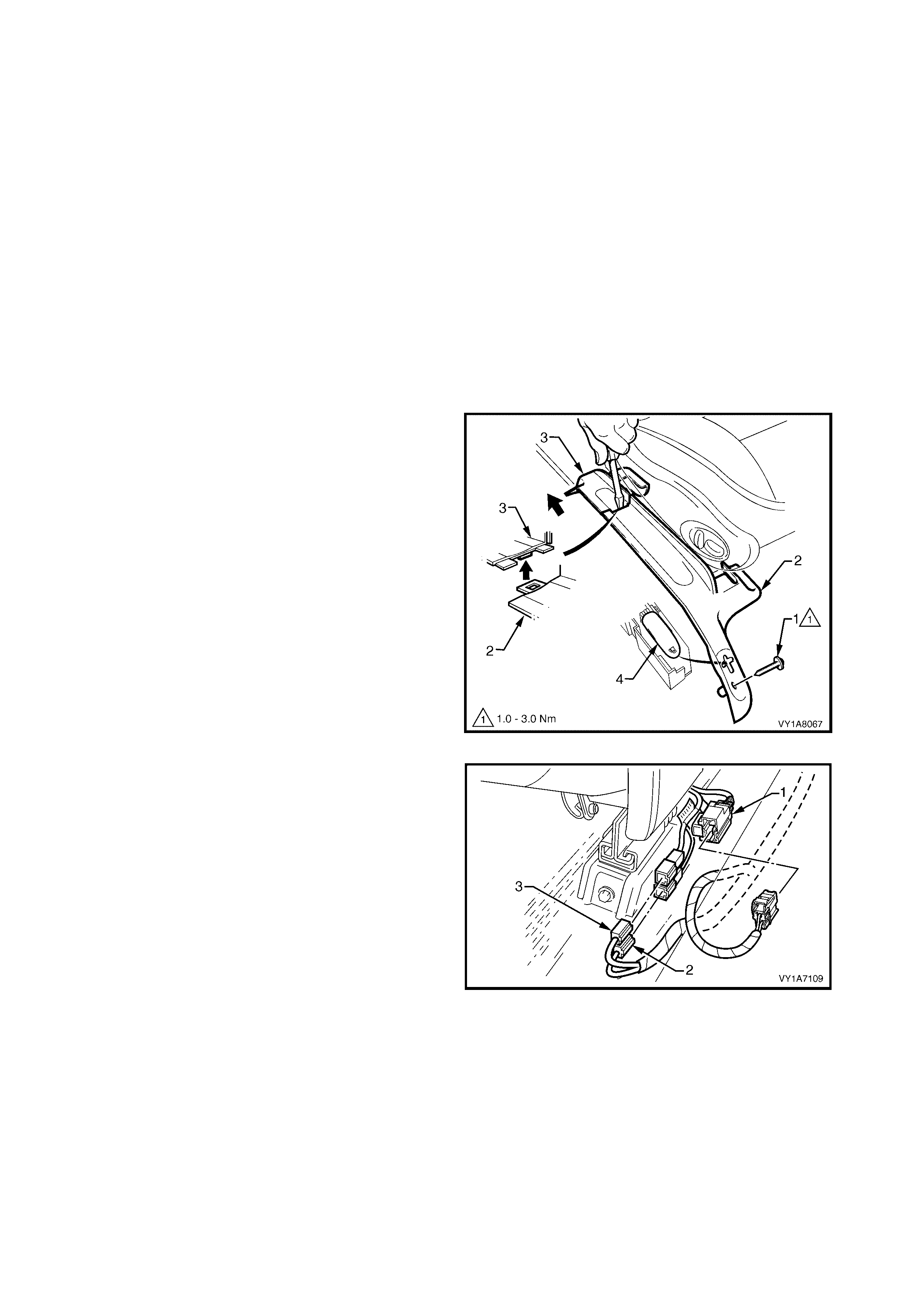
4.2 FRONT SEAT ASSEMBLY
LT Section No. – 14-295
CAUTION 1: Before performing any service operation on a Coupe front seat assembly fitted
with side impact airbags, ensure the occupant protection system is disabled, refer to
Section 12M OCCUPANT PROTECTION SYSTEM.
CAUTION 2: Accessory and after market seat covers MUST NOT be fitted to a vehicle with side impact
airbags, unless ap prov ed by the v ehicle manuf acturer. Seat cov ers that are not approv ed by the vehicle
manufacturer could greatly inhibit the performance of the side impact airbag and the occupant’s safety
in the event of side impact airbag deployment.
IMPORTANT 1: If the s eat assem bly is to be dissem bled, adj ust the seat as sem bly to its highest position before
disconnecting the power to the seat.
IMPORTANT 2: Disconnection of the battery affects certain vehicle electronic systems. Refer to
Section 00, 5. BATTERY DISCONNECTION PROCEDURES before disconnecting the battery.
NOTE: Clean hands are essential when working on the interior trim fabrics.
REMOVE
1. Disconnect the battery.
2. For the driver’s side on right-hand vehicles,
remove the screw (1) attaching the seat adjuster
outer front cover (2).
3. Using a small screwdriver, push in the centre of
the join to separate the front cover and the front
seat outer lower rear cover (3).
4. Unclip the covers from the seat track and
disengage from the side sill trim.
5. Pull the covers apart and remove the rear cover.
6. For the driver’s side on right-hand drive vehicles,
slide the f r ont c over over the f uel f iller door releas e
lever (4) and remove.
7. Adjust the seat assembly to its highest position, to
obtain the easiest access to the seats four
retaining bolts before disconnecting the power to
the seat.
Figure 1A7-88
8. Disconnect the seat assembly wiring harness (1),
the seatbelt pretensioner harness (2) and the side
airbag module harness (3).
Figure 1A7-89

9. Unclip the front inner guide rail cover (1) from the
seat track (2).
Figure 1A7-90
10. Unclip the rear inner guide rail cover (1) from the
seat track (2).
Figure 1A7-91
11. Remove the f our s c rews ( 1) s ecur ing the front seat
to the floor.
12. Remove the seat from the vehicle.
Figure 1A7-92

REINSTALL
Reinstallation of the front seat assembly is the reverse of the removal, noting the following:
1. Position the front seat assembly into the vehicle.
2. Install the four screws securing the front seat to the floor.
3. Connect the seat pretensioner harness, the side airbag module and seat wiring harness.
4. Tighten all retaining screws to the correct torque specification.
5. Align the front outer seat guide rail cover’s two retaining clips and push firmly to engage.
6. Push the front of the outer seat guide rail cover down to engage the cover with the front of the seat rail.
7. If the seat is f itted with a side impact airbag, s witch the ignition ON and obser ve the SRS warning indic ator in
the instrument cluster.
• If no fault is detected, the SRS warning indicator should illuminate for approximately five seconds while
the system performs a self-test, and then go off.
• If a fault is present, the SRS warning indicator will remain illuminated and a warning chime may sound
after approximately three seconds. The warning message ‘SRS Airbag Fault’ is also displayed in the
instrument cluster multi-function display. To diagnose the fault, refer to Section 12M, 4. DIAGNOSTICS.
8. Check the operation of the front seat electrical adjustments/operation. While checking the seat
adjustment/operation, also check to ensure that the seat wiring harnesses do not foul with any of the seats
moveable components (ie. seat motor drive shafts, etc.).
SEAT ADJUSTER OUTER FRONT
COVER ATTACHING SCREW
TORQUE SPECIFICATION 1.0 – 3.0 Nm
FRONT SEAT ASSEMBLY
ATTACHING SCREW
TORQUE SPECIFICATION 35.0 – 50.0 Nm
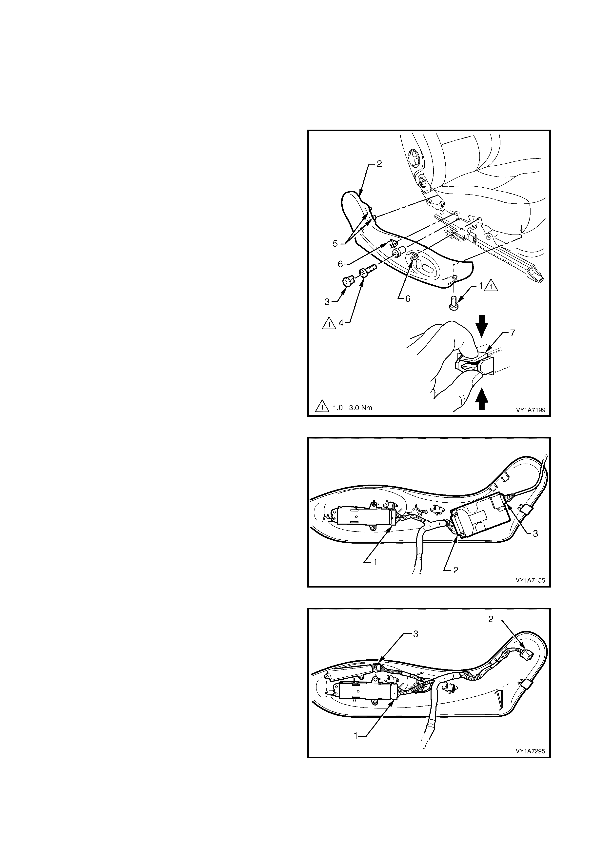
4.3 FRONT SEAT OUTER SIDE COVER
LT Section No. – 14-322
IMPORTANT: If the seat assembly is to be dissembled, adjust the seat assembly to its highest position before
disconnecting the power to the seat.
REMOVE
1. Remove the screw (1) from the front of the outer
side cover (2).
2. Rem ove the front seat outer s ide cover plug (3) by
rotating the plug anti-clockwise, one quarter of a
turn.
TIP: A fine screwdriver, would be useful to aid the
removal of the side cover plug without damage.
3. Remove the screw (4) located behind the plug.
4. Gently pull the outer cover away from the seat-
back recliner to disengage the two clips (5)
attached to the recliner frame.
5. Reach up under the seat assembly and squeeze
together the two retaining tangs (6), on the inner
side of the outer cover while gently pulling the
outer cover.
NOTE: Only remove the outer cover far enough away
from the seat cushion assembly to gain access to the
seat wiring harness connectors.
Figure 1A7-93
6. For vehicles fitted with the eight-way non-memory
seat assembly:
• Disconnect the eight-way adjustment switch
connector (1).
• Disconnect the EZ-entry module connector (2).
• Disconnect the recliner motor connector (3)
from the EZ-entry module.
• Remove the outer side cover.
Figure 1A7-94
7. For vehicles fitted with the eight-way mem ory seat
assembly:
• Disconnect the eight-way adjustment switch
connector (1).
• Disconnect the recliner motor connector (2).
• Disconnect the memory position switch
connector (3).
• Remove the outer side cover.
Figure 1A7-95

REINSTALL
Reinstallation of the front seat outer side cover is the reverse of the removal procedure, noting the following:
1. Ensure all fasteners are tightened to the correct torque specification.
FRONT OUTER SIDE COVER
ATTACHING SCREW
TORQUE SPECIFICATION 1.0 – 3.0 Nm
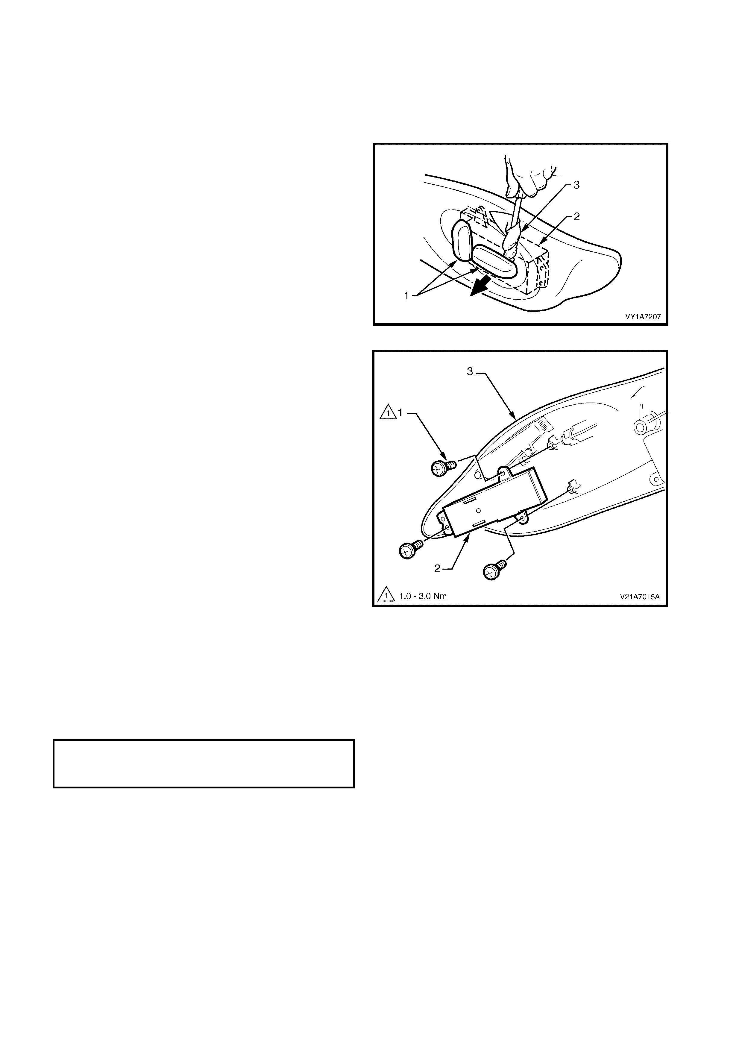
4.4 EIGHT-WAY SEAT ADJUSTMENT SWITCH
LT Section No. – 14-275
1. Remove the front seat outer side cover, refer to 4.3 FRONT SEAT OUTER SIDE COVER.
REMOVE
1. Remove the two adjustment knobs (1) from the
seat adjustment switch (2) by carefully prising
them f ree with a small f lat tip screwdriver wrapped
in a clean shop rag (3).
Figure 1A7-96
2. Remove the three screws (1) securing the seat
adjustment switch (2) to the outer side cover (3).
3. Remove the seat adjustment switch.
Figure 1A7-97
REINSTALL
Reinstallation of the eight-way seat adjustment switch
is the reverse of the removal operation, noting the
following:
1. Ensure all screws are tightened to the correct
torque specification.
EIGHT-WAY SEAT ADJUSTMENT
SWITCH ATTACHING SCREW
TORQUE SPECIFICATION 1.0 – 3.0 Nm
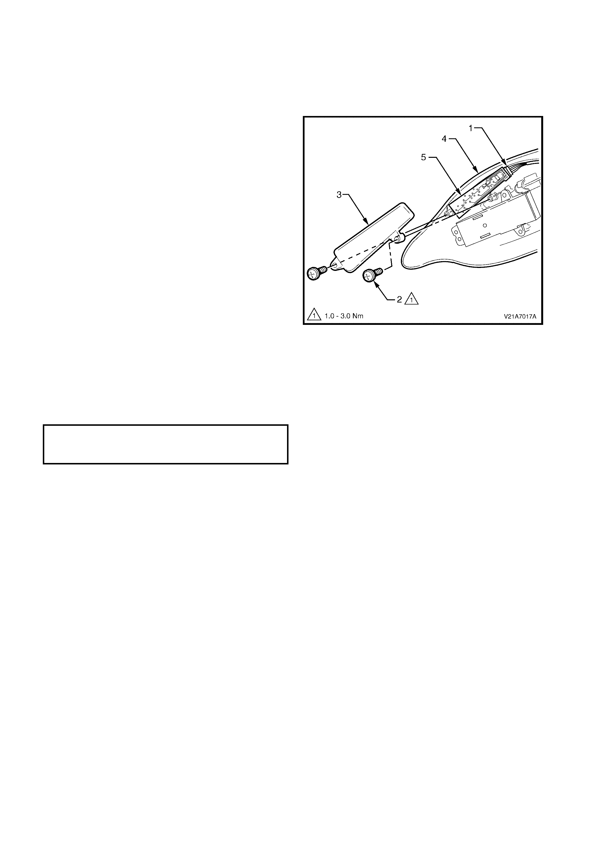
4.5 MEMORY POSITION SWITCH
LT Section No. – 14-275
1. Remove the front seat outer side cover, refer to 4.3 FRONT SEAT OUTER SIDE COVER.
REMOVE
1. Disconnect the wiring harness connector (1).
2. Remove the two screws (2) securing the memory
position switch cover (3) to the seat lower side
cover (4).
3. Remove the memory position switch (5).
Figure 1A7-98
REINSTALL
Reinstallation of the memory position switch is the
reverse of the removal procedure noting the following:
1. Ensure all fasteners are tightened to the correct
torque specification:
MEMORY POSITION SWITCH
ATTACHING SCREW
TORQUE SPECIFICATION 1.0 – 3.0 Nm
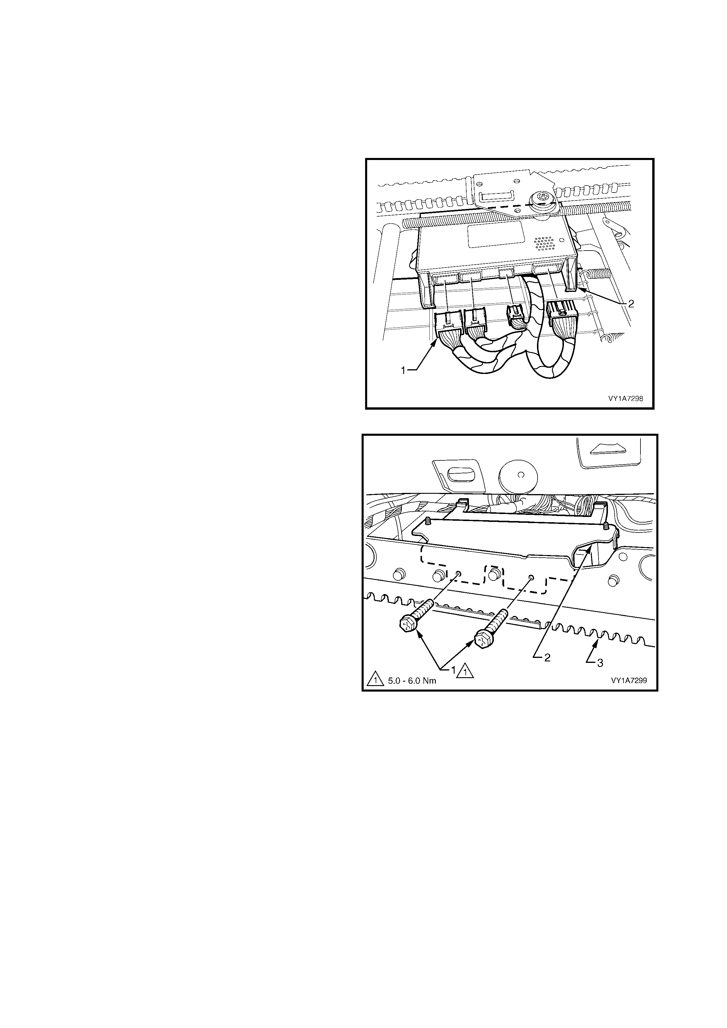
4.6 FRONT SE AT CONTROL MODULE, EIGHT-WAY MEMORY SEAT
LT Section No. – 14-275
1. Remove front seat assembly, refer to 4.2 FRONT SEA T ASSEMBLY.
2. Remove the front seat outer side cover, refer to 4.3 FRONT SEAT OUTER SIDE COVER.
REMOVE
For vehicles fitted with the eight-way memory seat
assembly:
• Disconnect the four, seat adjuster memory
module connectors (1) from the memory
module (2).
Figure 1A7-99
1. Remove the two screws (1) securing the memory
module and mounting bracket assembly (2) to the
seat track assembly (3).
2. Remove the memory module and mounting
bracket assembly.
Figure 1A7-100
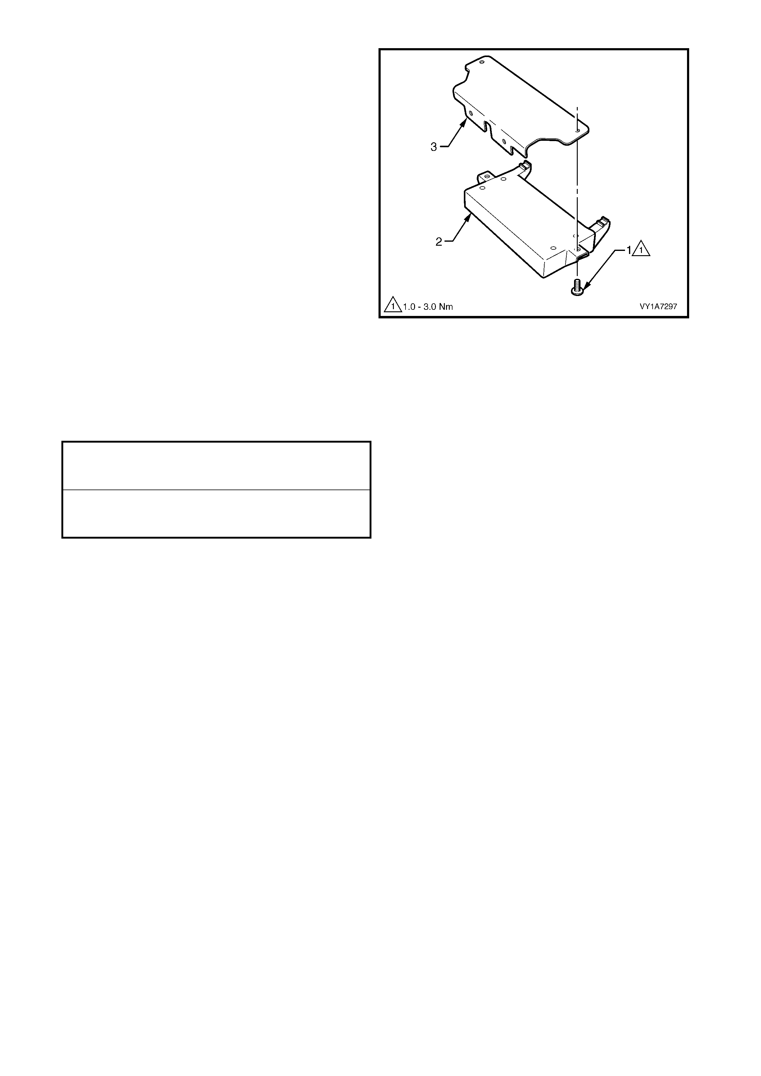
3. Remove the two screws (1) securing the memory
module (2) to the memory module mounting
bracket (3).
4. Remove the front seat memory module from the
bracket.
Figure 1A7-101
REINSTALL
Reinstallation for the seat memory module is the
reverse of the removal procedure, noting the following:
1. Ensure all fasteners are tightened to the correct
torque specification:
1. After installation, perform the drive
motor potentiometer calibration, refer to
5.8 ELECTRICAL DIAGNOSIS – DRIVER’S
EIGHT-WAY SEAT, MEMORY
MEMORY MODULE BRACKET
ATTACHING SCREW
TORQUE SPECIFICATION 5.0 – 6.0 Nm
MEMORY MODULE
ATTACHING SCREW
TORQUE SPECIFICATION 1.0 – 3.0 Nm
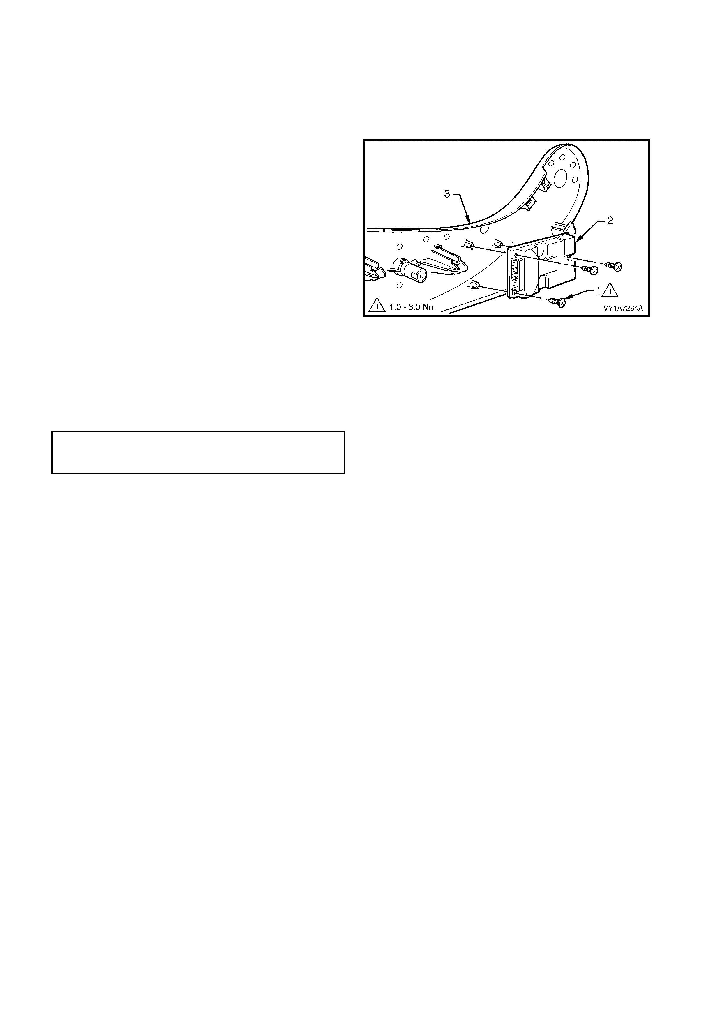
4.7 EZ-ENTRY MODULE, EIGHT-WAY NON-MEMORY SEAT
LT Section No. – 14-322
1. Remove the front seat outer side cover, refer to 4.3 FRONT SEAT OUTER SIDE COVER.
REMOVE
1. Remove the three screws (1) retaining the EZ-
entry module (2) to the outer side cover (3).
Figure 1A7-102
REINSTALL
Reinstallation of the EZ-entry module is the reverse of
the removal operation, noting the following:
1. Ensure all fasteners are tightened to the correct
torque specification.
EZ-ENTRY MODULE
ATTACHING SCREW
TORQUE SPECIFICATION 1.0 – 3.0 Nm
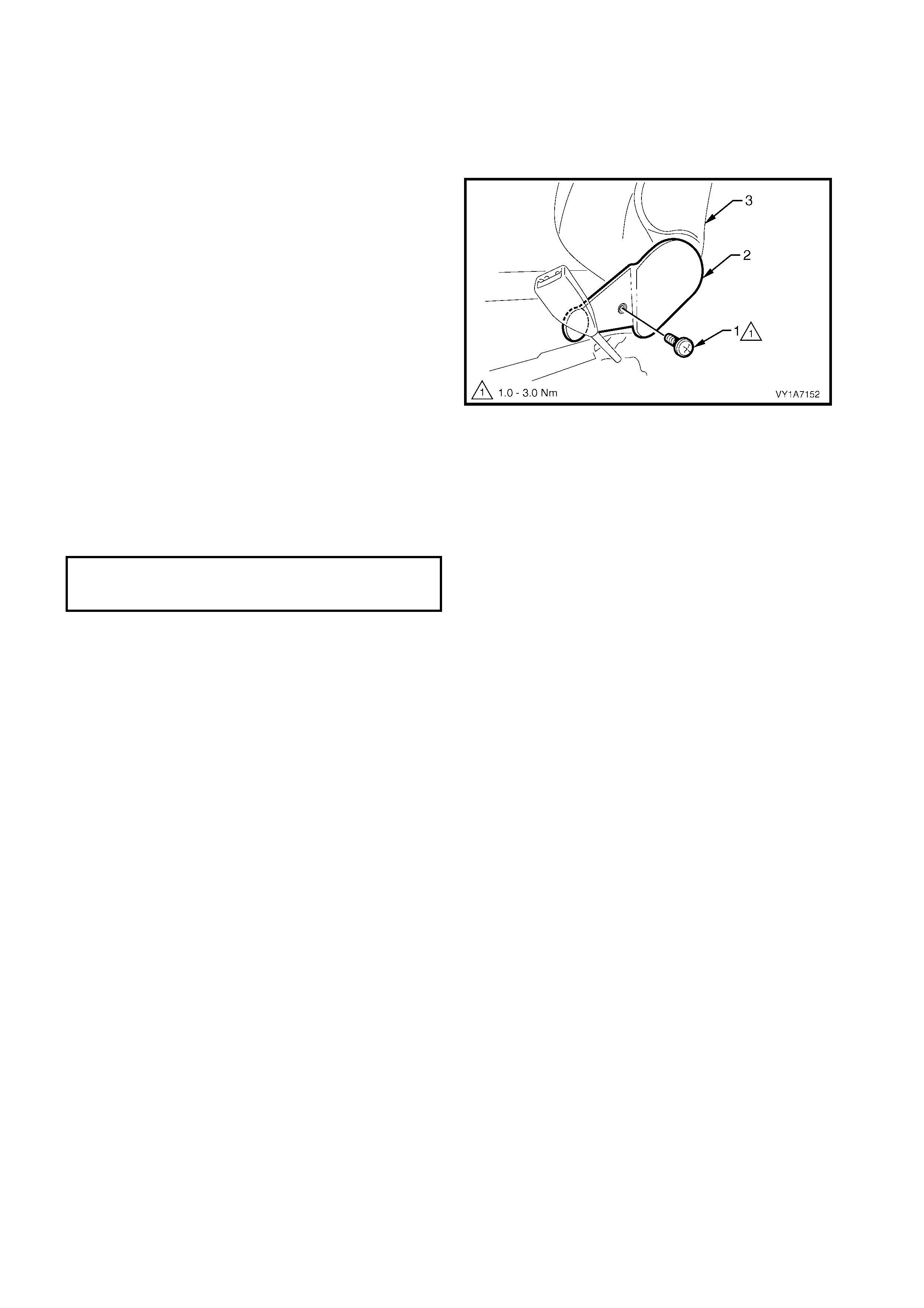
4.8 FRONT SEAT INNER SIDE COVER
LT Section No. – 14-322
1. Remove the front seat assembly, refer to 4.2 FRONT SEAT ASSEMBLY.
REMOVE
1. Remove the screw (1) securing the inner side
cover (2) to the seat assem bly (3) and r emove the
inner side cover.
Figure 1A7-103
REINSTALL
Reinstallation of the inner side cover is the reverse of
the removal operation, noting the following:
1. Ensure all fasteners are tightened to the correct
torque specification.
FRONT SEAT INNER SIDE
COVER ATTACHING SCREW
TORQUE SPECIFICATION 1.0 – 3.0 Nm
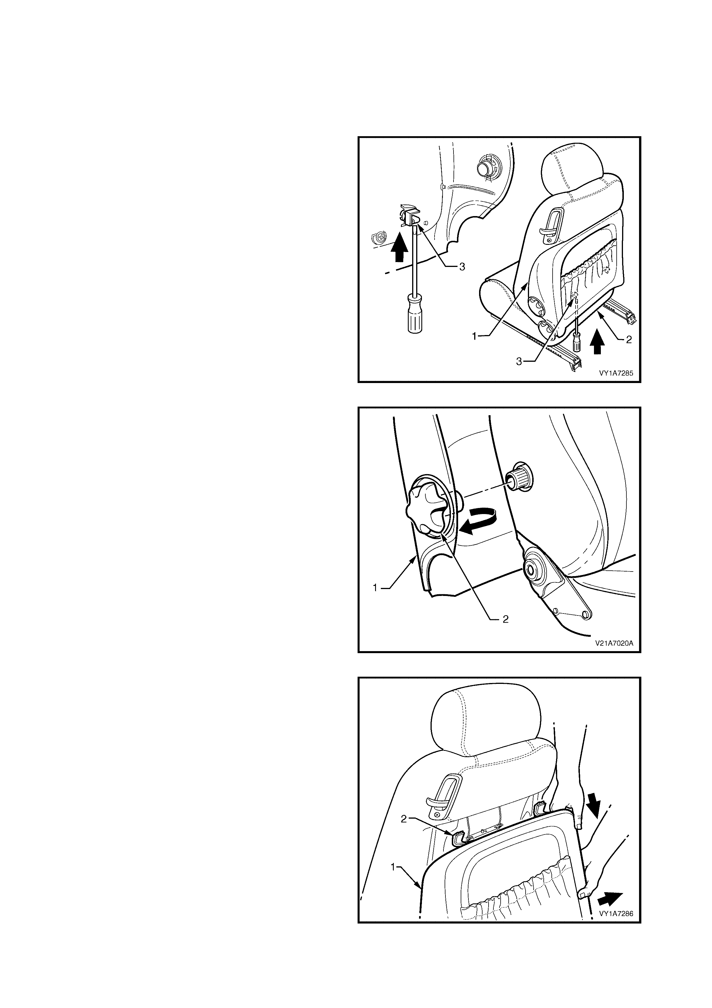
4.9 FRONT SEAT-BACK LOWER COVER ASSEMBLY AND LUMBAR
SUPPORT ADJUSTER KNOB
LT Section No. – 14-322
REMOVE
1. Insert a flat-tip screwdriver between the seat-back
cover (1) and the seat-back (2).
2. Push up on each lower retaining clip (3) (two
places) while pulling the bottom of the back cover
out, away from seat, to release the lower retaining
clips.
Figure 1A7-104
3. Pull the front edge of the front seat-back lower
cover (1), forward of the lumbar support adjuster
knob ( 2), outward to disengage the lum ber support
adjuster knob.
Figure 1A7-105
4. W hile holding the s ide of the front seat- back lower
cover out (1), pull the cover down to release the
upper retainers (2), two places.
5. Remove the cover.
Figure 1A7-106
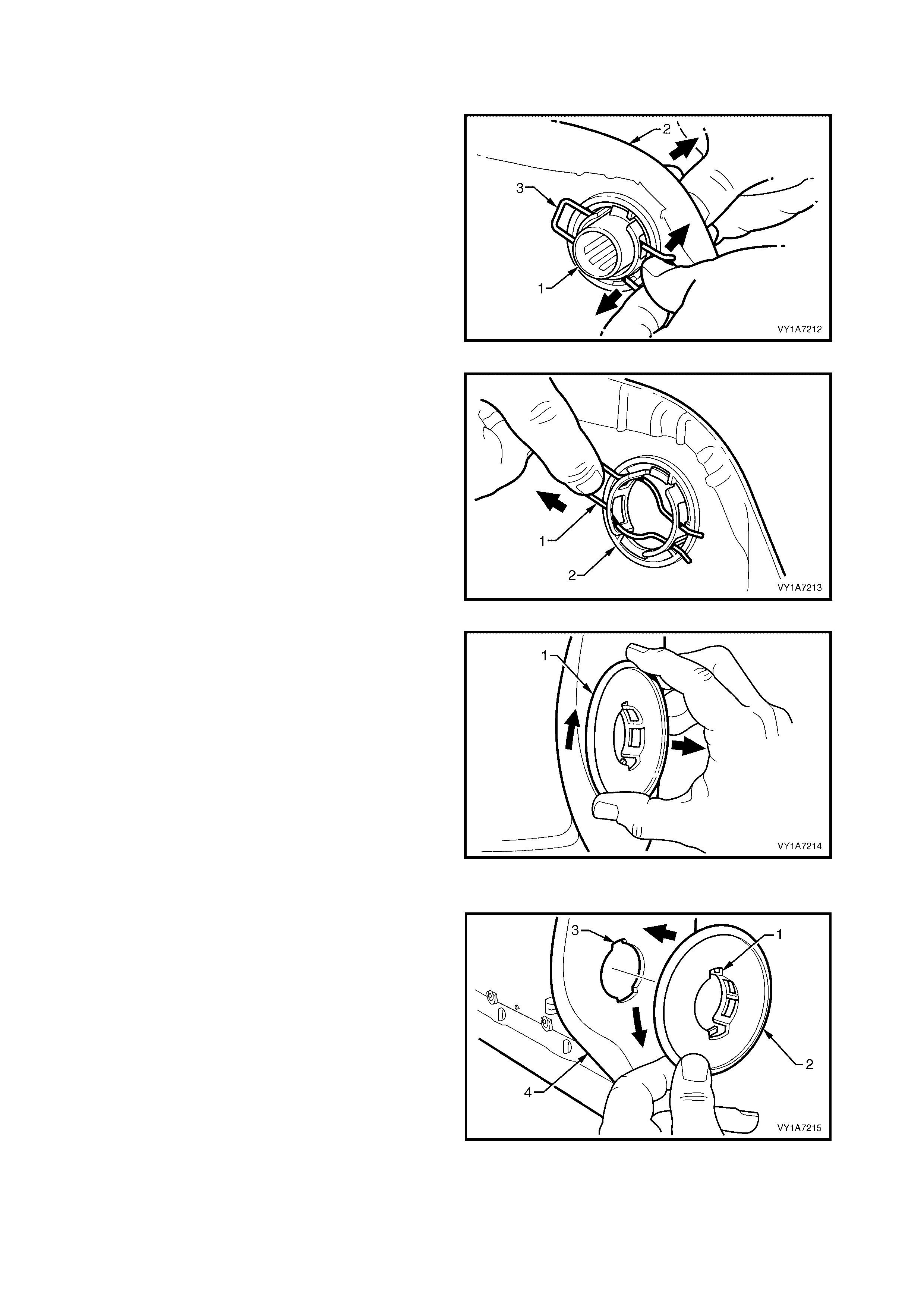
DISASSEMBLE
Remove - Lumbar Support Adjuster Knob and Adapter
1. Remove the lumbar s upport adj us ter k nob ( 1) fr om
the front seat-back cover (2) by spreading the
retaining clip (3) and withdrawing the lumbar
support adjuster knob.
Figure 1A7-107
2. Remove the retaining clip (1) by pulling it from the
lumber support adjuster knob adapter (2).
Figure 1A7-108
3. Rotate the lumber support adjuster knob adapter
(1) approximately 90° clockwise.
4. Remove the lumber support adjuster knob
adapter.
Figure 1A7-109
Reinstall - Lumbar Support Adjuster Knob and Adapter
Reinstallation of the lum bar support adjuster knob and
adapter is the rever se of the rem oval operation, noting
the following:
1. Align the narrow tab (1) on the lumber support
adjuster knob adapter (2) with the narrow key-way
(3) in the front seat-back low er cover (4).
2. Insert the adapter into the cover and rotate
approximately 90° anti-clockwise until locked.
Figure 1A7-110
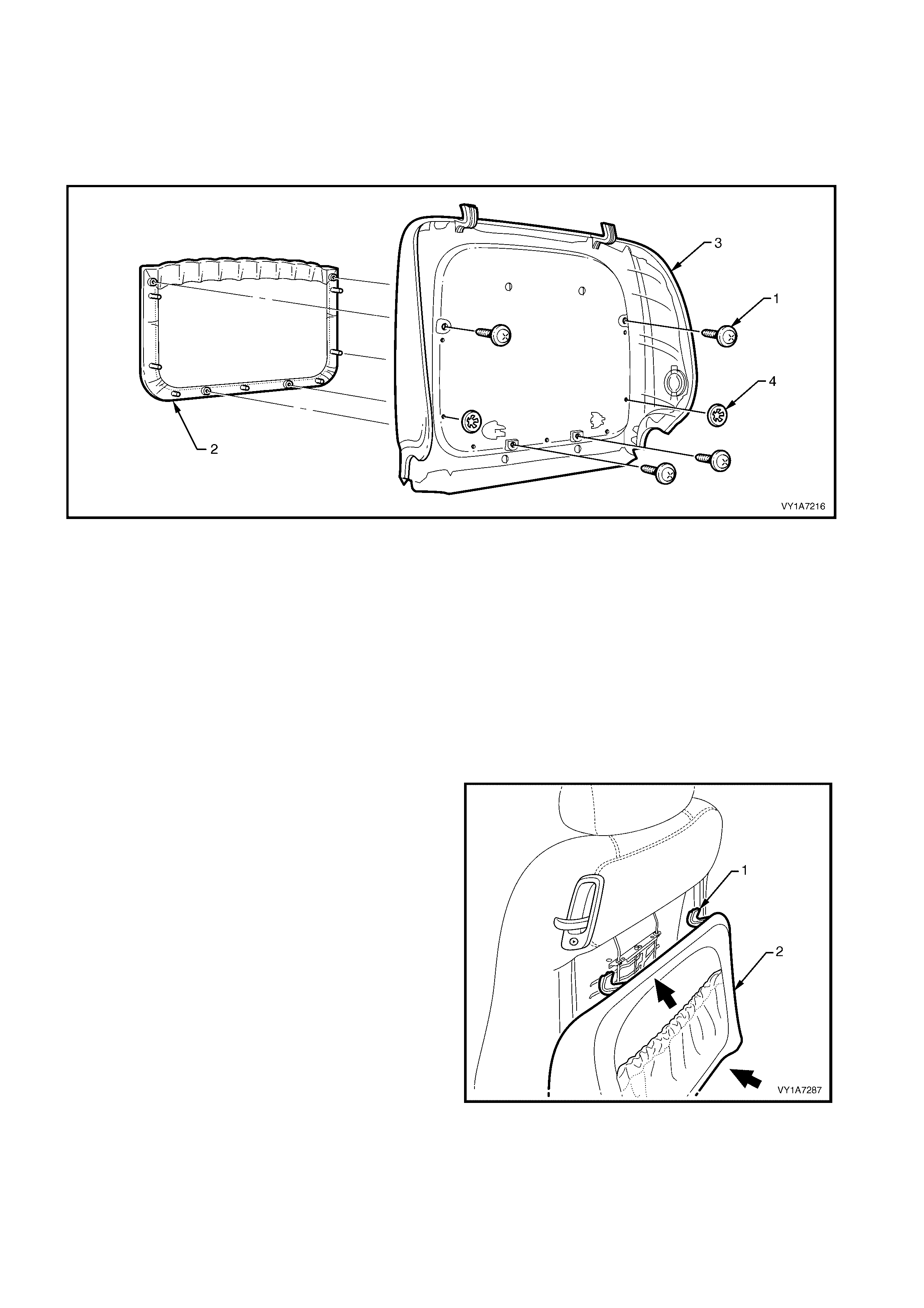
Remove - Front Seat-back Lower Cover Pocket
1. Remove the f our sc rews (1) attac hing the fr ont seat-back lower cover pocket (2) to the front seat-bac k lower
cover (3), refer Figure 1A7-111.
2. Remove the two clips (4) securing the rear cover pocket to the front seat-back lower cover.
NOTE: Take care when removing the clips not to break the rear cover pocket shafts on which the clips are
attached.
Figure 1A7-111
Legend
1. Front Seat-back Pocket Screw - 4 Places
2. Front Seat-back Lower Cover Pocket 3. Front Seat-back Lower Cover
4. Front Seat-back Pocket Attach Clip - 2 Places
Reinstall - Front Seat-back Lower Cover Pocket
Reinstallation of the front seat- back lower cover pock et
is the reverse of the removal operation, noting the
following:
1. Ensure all fasteners are tightened securely.
REINSTALL
1. Locate the two upper retaining clips (1) on the
seat-back cover (2) with the seat-back.
Figure 1A7-112
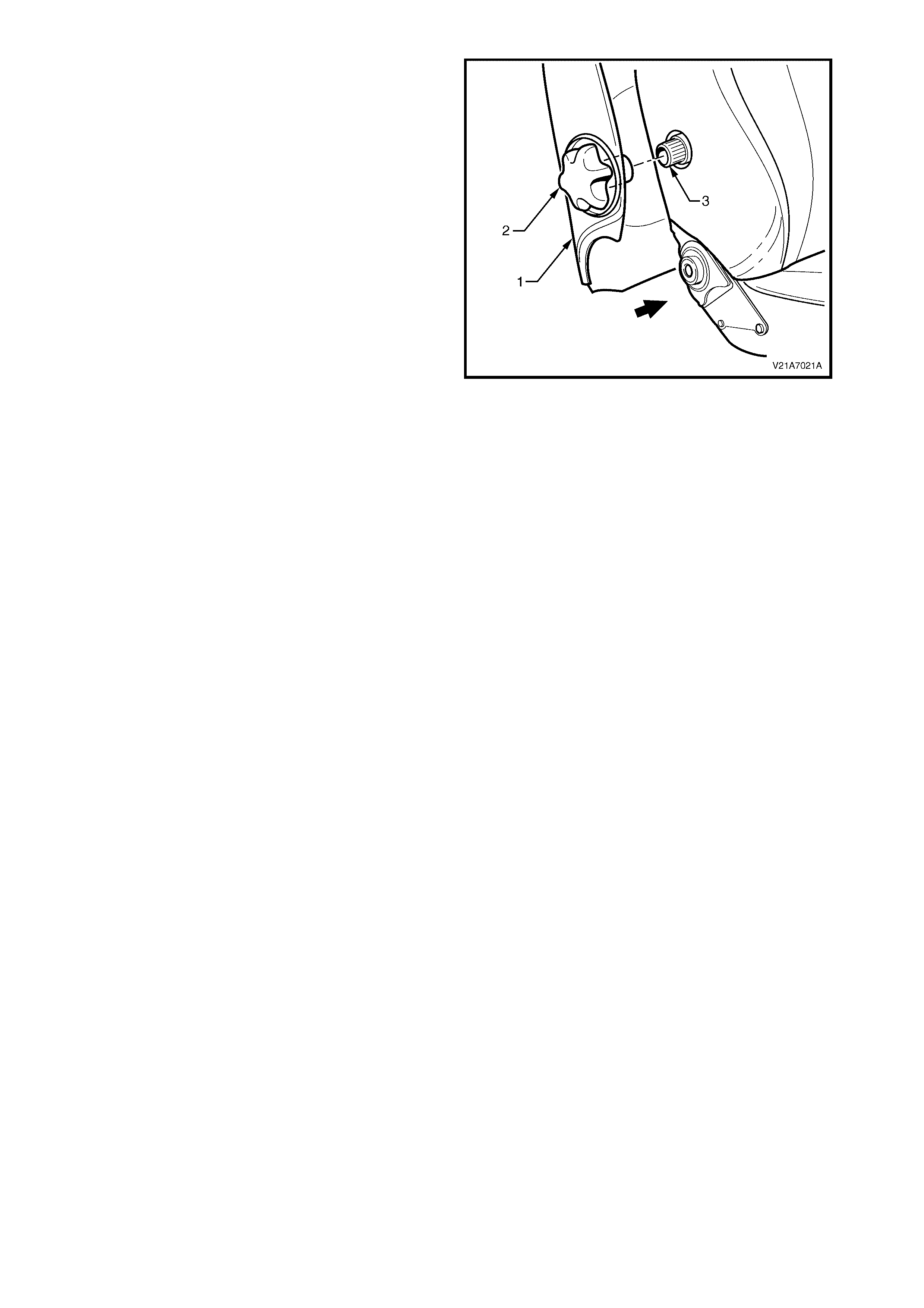
2. Pull the side of the front seat-back lower cover (1)
out and align the splines on the lumber support
adjuster knob (2) with the splines on the lumbar
support adjuster (3).
3. Push the lumbar support adjuster knob onto
lumbar support shaft.
4. Push the seat-back cover into the seat-back to
engage the two lower retaining clips.
Figure 1A7-113
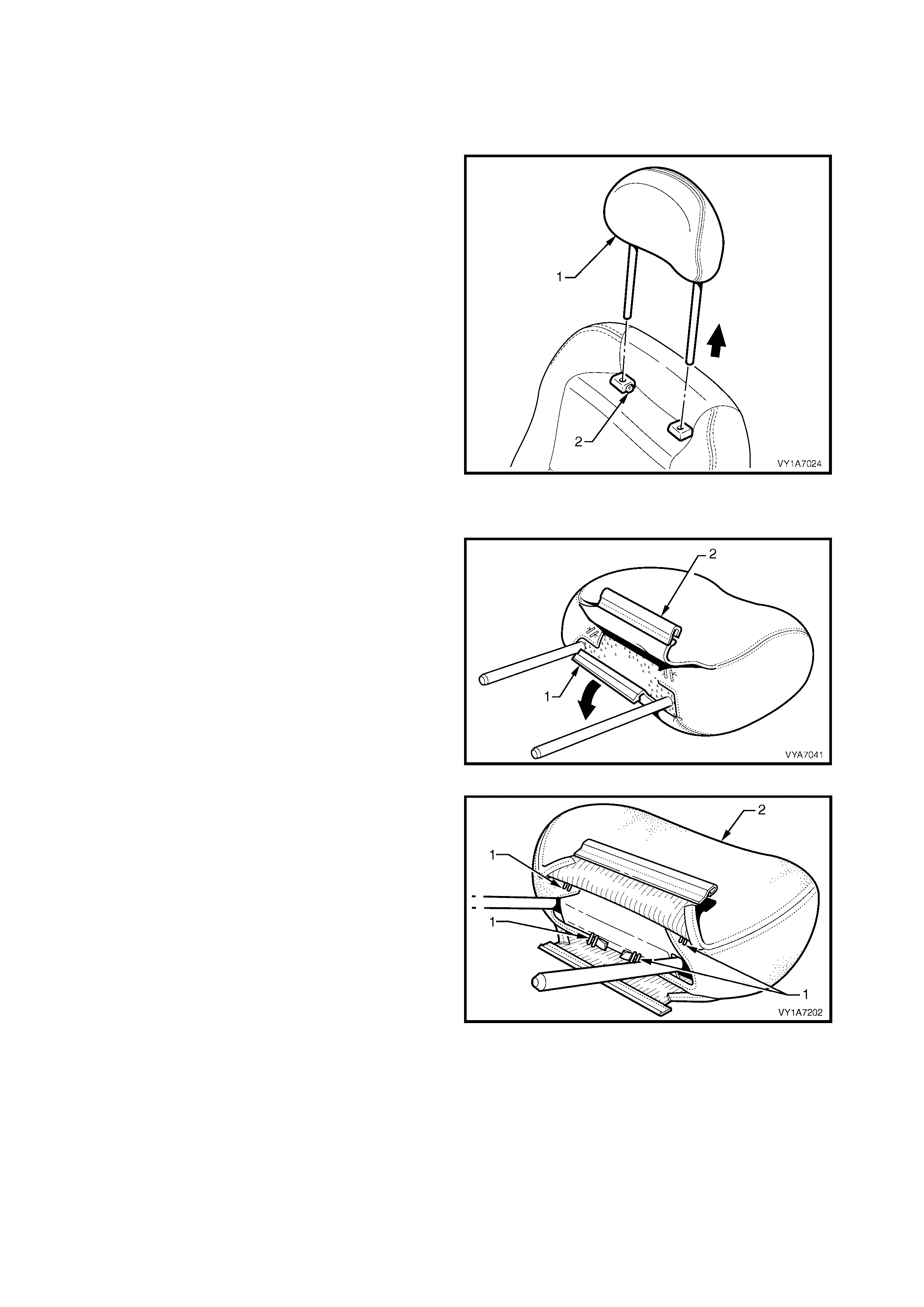
4.10 FRONT SEAT HEAD RESTRAINT ASSEMBLY
LT Section No. – 14-295
REMOVE
1. Remove the f ront seat head restr aint as sembly (1)
by depressing the head restraint guide height
adjuster lock button (2), and lifting the head
restraint completely out of the guide.
Figure 1A7-114
DISASSEMBLE
1. Dis engage the fr ont head res traint cover J-s trip (1)
by pulling the flap (2) up.
Figure 1A7-115
2. Remove the eight staples (1) retaining the cover
(2) to the head restraint pad assembly.
3. Remove the cover from the pad assembly.
Figure 1A7-116
REASSEMBLE
Reassembly of the front seat head restraint assembly is the reverse of the removal procedure, noting the
following:
1. Ensure the head restraint cover retaining clip is fully engaged.
REINSTALL
Reinstallation of the front seat-back head restraint is the reverse of the removal procedure.
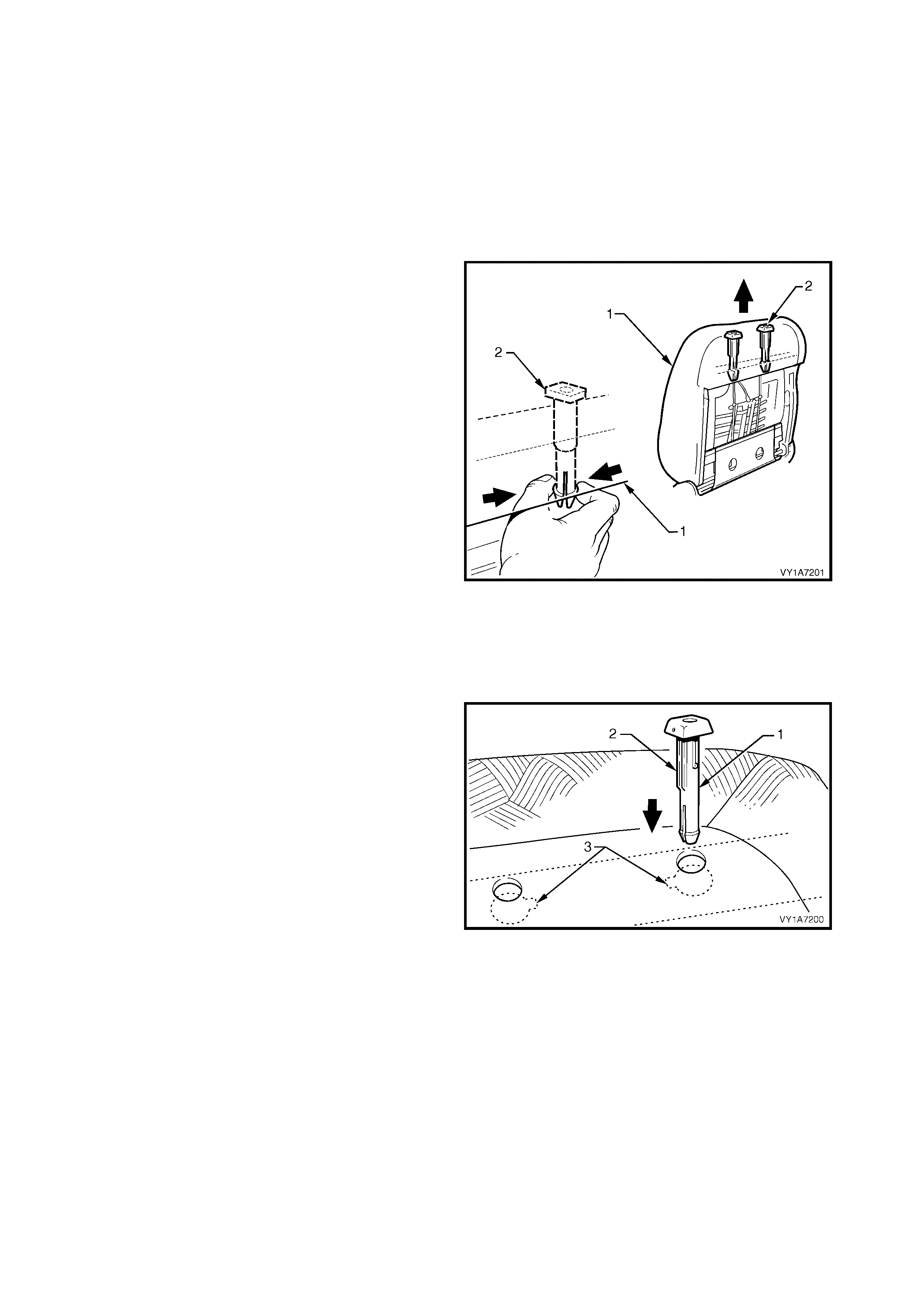
4.11 FRONT SEAT HEAD RESTRAINT GUIDE
LT Section No. – 14-275
1. Remove the front seat outer side cover, refer to 4.3 FRONT SEAT OUTER SIDE COVER.
2. Remove the front seat-back lower cover assembly, refer to 4.9 FRONT SEAT-BACK LOWER COVER
ASSEMBLY AND LUMBER SUPPORT ADJUSTER KNOB.
3. Remove the front seat head restraint assembly, refer to 4.10 FRONT SEAT HEAD RESTRAINT
ASSEMBLY.
REMOVE
1. From the rear of the front seat-back (1), squeeze
the locking prongs of the head restraint guide (2)
together while pulling the top of the guide out of
seat-back assembly.
Figure 1A7-117
REINSTALL
Reinstallation of the front seat head restraint guide is
the reverse of the removal procedure, noting the
following:
1. When installing the head restraint guide (1), align
the locating ribs (2) with the key-way (3) in the
seat-back frame.
NOTE: Ensure the guide with the height adjuster lock
is ins talled on the s ide that corres ponds to the notches
in the head restraint shaft.
Figure 1A7-118
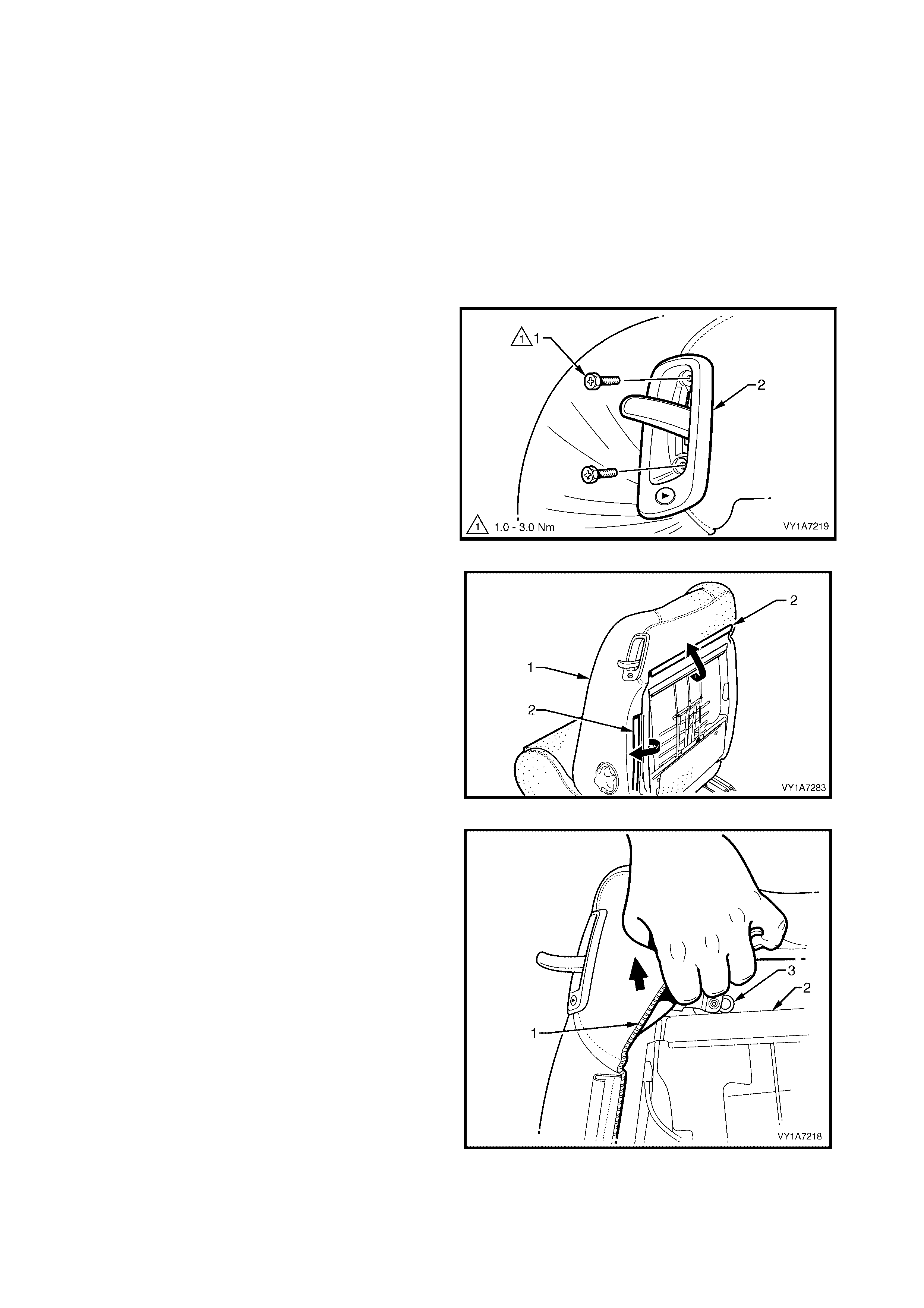
4.12 EZ-ENTRY LEVER ARM, ESCUTCHEON AND SEAT RETURN SWITCH ASSEMBLY
LT Section No. – 14-275
1. Remove front seat assembly, refer to 4.2 FRONT SEA T ASSEMBLY.
2. Remove the front seat outer side cover, refer to 4.3 FRONT SEAT OUTER SIDE COVER.
3. Remove the front seat-back lower cover assembly, refer to 4.9 FRONT SEAT-BACK LOWER COVER
ASSEMBLY AND LUMBER SUPPORT ADJUSTER KNOB.
4. Remove the front seat head restraint assembly, refer to 4.10 FRONT SEAT HEAD RESTRAINT
ASSEMBLY.
5. Remove the front seat head restraint guide, refer to 4.11 FRONT SEAT HEAD RESTRAINT GUIDE.
REMOVE
1. Remove the two screws (1) retaining the EZ-entry
escutcheon and seat r eturn switch assem bly (2) to
the seat back frame.
Figure 1A7-119
2. Partly remove the front seat-back cover (1) by
disengaging the two J-strips (2) away from the
seat frame.
Figure 1A7-120
3. Lift the rear of the seat-back cover (1) away from
the back fram e (2) to allow access to the EZ- entry
lever assembly (3).
Figure 1A7-121

4. Compress the spring clip (1) retaining the lever
arm (2) to the fram e assem bly (3) and remove the
clip.
Figure 1A7-122
5. Grasp the lever arm (1) and pull firmly away from
seat-back (2) to remove.
NOTE: It m ay be necessar y to wr iggle the lever arm to
loosen it in the escutcheon and switch assembly.
Figure 1A7-123
6. Partially remove the escutcheon and switch
assembly (1) from the front seat-back cover (2).
7. Disconnect the wiring harness (3) from the seat
return switch.
8. Remove the escutcheon and switch assembly
Figure 1A7-124

REINSTALL
Reinstallation of the EZ-entry lever arm, escutcheon and switch assembly is the reverse of the removal
procedure, noting the following:
1. Ensure all fasteners are tightened to the correct torque specification.
2. Ensur e that the lever retaining clip is corr ectly engaged by pulling the lever handle fir mly away fr om the seat
and operating the latch several times.
EZ-ENTRY LEVER ARM
ESCUTCHEON ATTACHING SCREW
TORQUE SPECIFICATION 1.0 – 3.0 Nm

4.13 EZ-ENTRY CABLE AND SWITCH ASSEMBLY
Due to safety regulation constraints, certain components of the recliner mechanism can not be removed or
replaced. If any part of the recliner mechanism requires replacement (including the EZ-entry cable assembly),
the entire front seat-back frame assembly must be replaced, refer to 4.15 FRONT SEAT-BACK FRAME
ASSEMBLY.
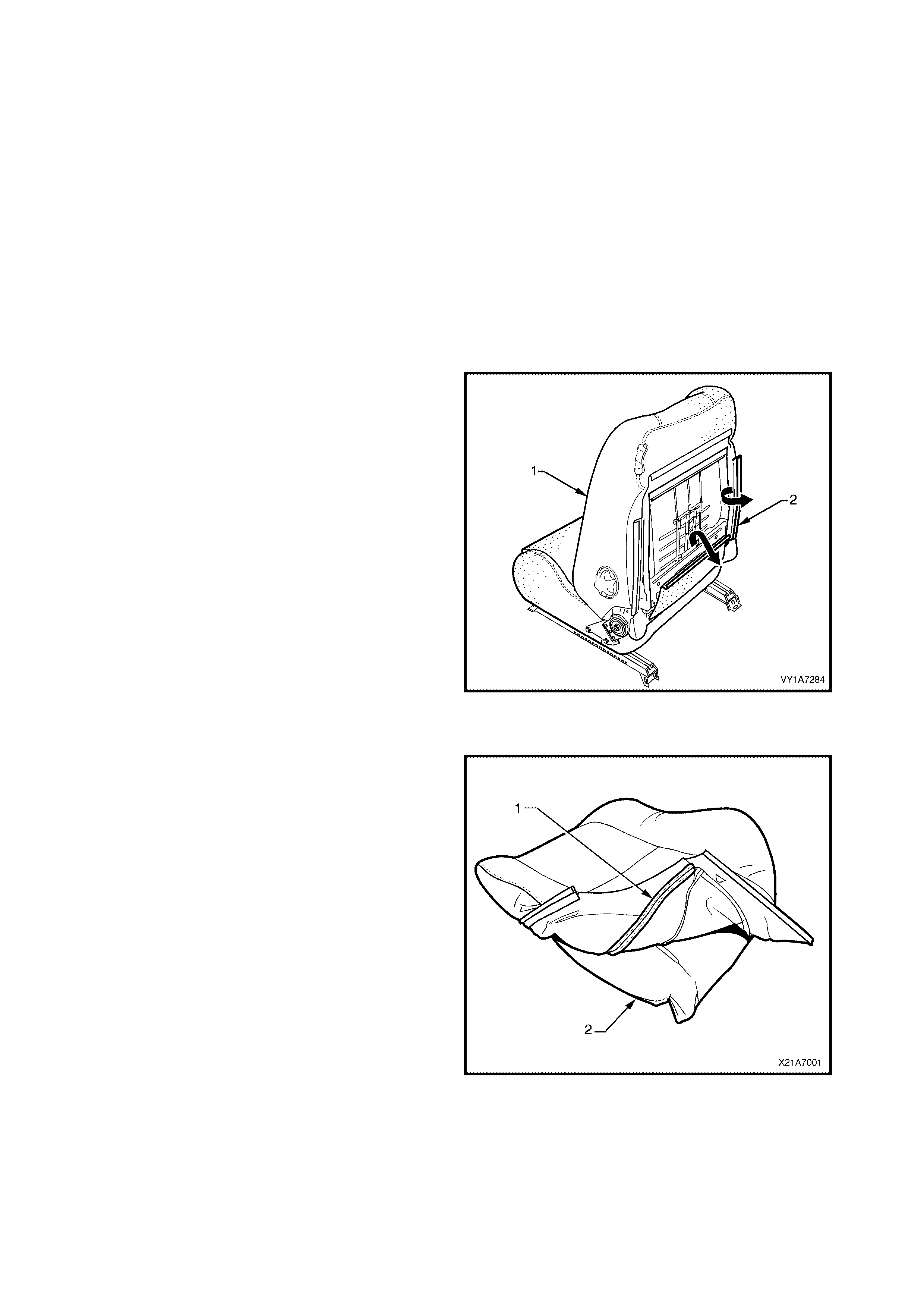
4.14 FRONT SEAT-BACK PAD AND COVER ASSEMBLY
LT Section No. – 14-295
1. Remove the front seat assembly, refer to 4.2 FRONT SEAT ASSEMBLY.
2. Remove the front seat outer side cover, refer to 4.3 FRONT SEAT OUTER SIDE COVER.
3. Remove the front seat inner side cover, refer to 4.8 FRONT SEAT INNER SIDE COVER.
4. Remove the front seat-back lower cover assembly, refer to 4.9 FRONT SEAT-BACK LOWER COVER
ASSEMBLY AND LUMBER SUPPORT ADJUSTER KNOB.
5. Remove the front seat head restraint assembly, refer to 4.10 FRONT SEAT HEAD RESTRAINT
ASSEMBLY.
6. Remove the front seat head restraint guide, refer to 4.11 FRONT SEAT HEAD RESTRAINT GUIDE.
7. Remove the EZ-entry lever and escutcheon, refer to 4.12 EZ-ENTRY LEVER ARM, ESCUTCHEON AND
SEAT RETURN SWITCH ASSEMBLY.
REMOVE
1. Remove the front seat-back pad and cover
assembly (1) by disengaging the remaining two J-
strips (2) away from the seat frame.
2. Lif t the co ver and pad as sem bly up and away from
the seat-back frame.
Figure 1A7-125
DISASSEMBLE
1. Fold the lower corners of the seat-back cover (1)
over the seat-back pad (2).
Figure 1A7-126
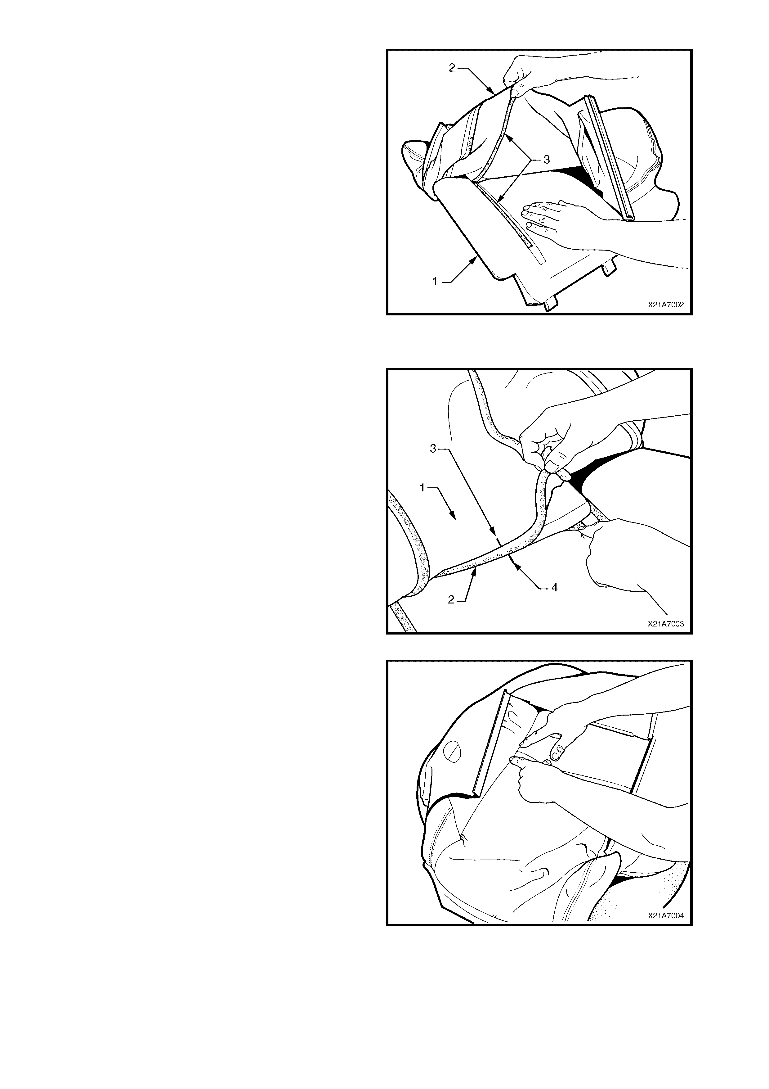
2. While holding the front seat-back pad (1), pull the
lower corners of the seat-back cover (2), upwards
and away f rom the f ront seat pad to disengage the
hook and loop strips (3).
3. Pull the front seat-back cover up and over the
upper edge of the front seat-back pad.
Figure 1A7-127
REASSEMBLE
1. With the seat-back cover (1) folded at the central
horizontal strip of hook and loop (2), align the
centre mark (3) on the front seat-back cover with
the centre mark (4) on the seat-back pad.
2. Press the seat-back cover firmly into the
corresponding groove in the seat-back pad to
engage the hook and loop.
Figure 1A7-128
3. With the s eat c over fo lded at the two vertical str ips
of the hook and loop, press the seat-back cover
firmly into the corresponding grooves in the seat-
back pad.
Figure 1A7-129

4. Roll the upper c orners of the front seat-bac k c over
over the seat-back pad.
5. Roll the sides of the seat-back cover over the seat-
back pad.
6. Roll the lower corners of the seat-back cover over
the seat-back pad.
NOTE: Make sure the cover is fitted neatly by hand
into all corners and contours of the seat pad.
Figure 1A7-130
REINSTALL
Reinstallation of the rear seat-back assembly is the
reverse of the removal operation.
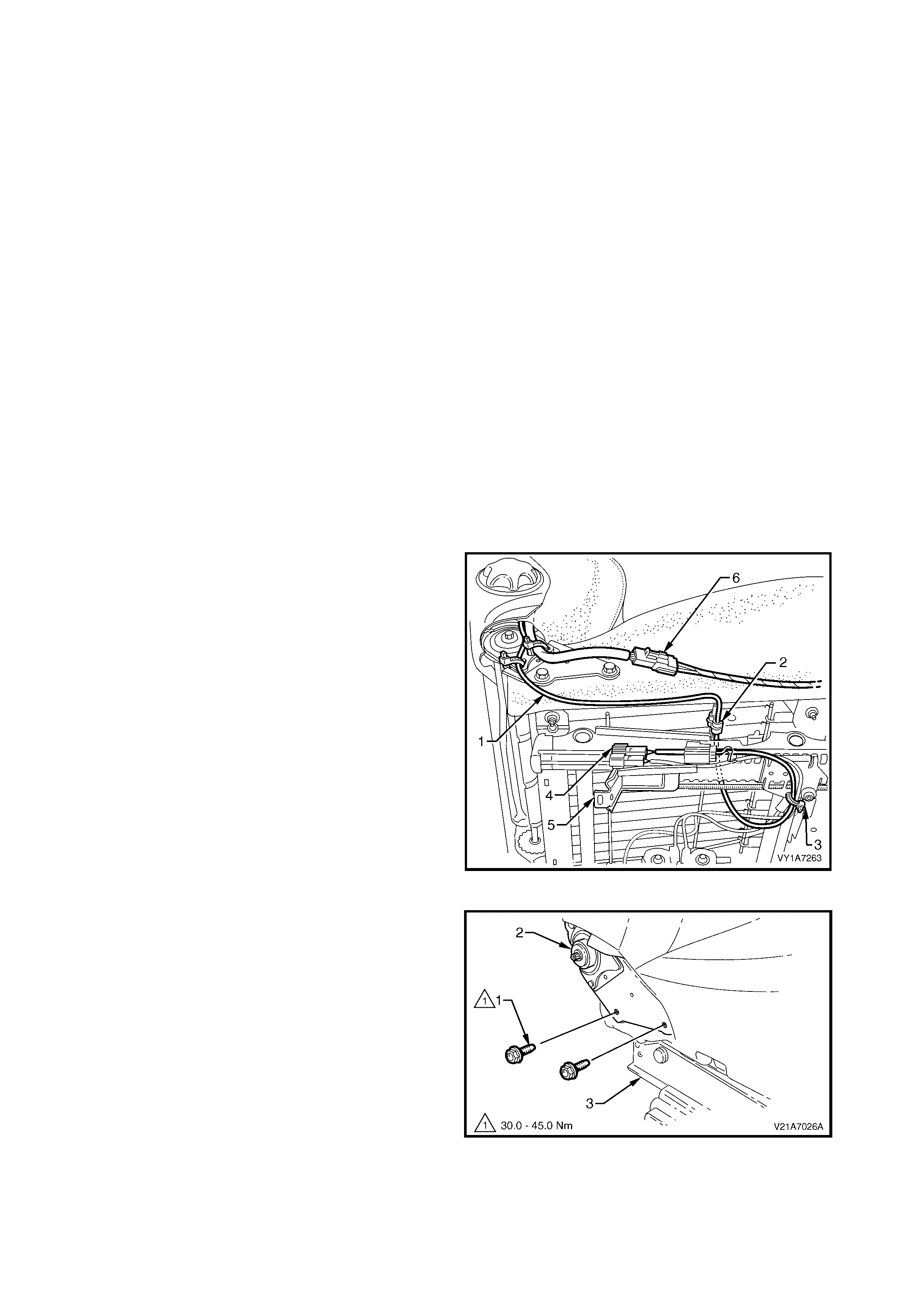
4.15 FRONT SEAT-BACK FRAME ASSEMBLY
LT Section No. – 14-275
CAUTION: When carrying a live (undeployed) side airbag assembly, make sure the airbag opening is
pointed away from you. Never carry the side airbag assembly by the wiring harness or connectors. In
case of an accidental deployment, the airbag will then deploy with minimal chance of injury.
When placing a live side airbag assembly on a bench or other surface, always face the airbag opening
up, away from the surface. Never rest the airbag assembly with the opening face down. This is
necessary so that a free space is provided to allow the airbag to expand in the unlikely event of
accidental deployment. Otherwise, personal injury may result.
1. Remove the front seat assembly, refer to 4.2 FRONT SEAT ASSEMBLY.
2. Remove the front seat outer side cover, refer to 4.3 FRONT SEAT OUTER SIDE COVER.
3. Remove the front seat inner side cover, refer to 4.8 FRONT SEAT INNER SIDE COVER.
4. Remove the front seat-back lower cover assembly, refer to 4.9 FRONT SEAT-BACK LOWER COVER
ASSEMBLY AND LUMBER SUPPORT ADJUSTER KNOB.
5. Remove the front seat head restraint assembly, refer to 4.10 FRONT SEAT HEAD RESTRAINT
ASSEMBLY.
6. Remove the front seat head restraint guide, refer to 4.11 FRONT SEAT HEAD RESTRAINT GUIDE.
7. Remove the EZ-entry lever and escutcheon, refer to 4.12 EZ-ENTRY LEVER ARM, ESCUTCHEON AND
SEAT RETURN SWITCH ASSEMBLY.
8. Remove the front seat- back pad and cover as s embly, refer to 4.14 FRONT SEAT-BACK PAD AND COVER
ASSEMBLY.
REMOVE
1. Unc lip the side im pact air bag pigtail wiring harness
(1) from the retaining clip (2) and cut the cable tie
(3) securing the side airbag harness to the front
seat cushion frame assembly, taking care not to
damage the wiring harness.
2. Unclip the wiring harness connector (4) from the
adjuster and guide rail assembly (5).
3. Disconnect the wiring harness connector for the
recliner motor (6).
Figure 1A7-131
4. Remove the two screws (1), each side, attaching
the seat-back assembly (2) to the seat height
adjuster and cushion frame assembly (3).
5. Remove the seat-back assembly.
Figure 1A7-132
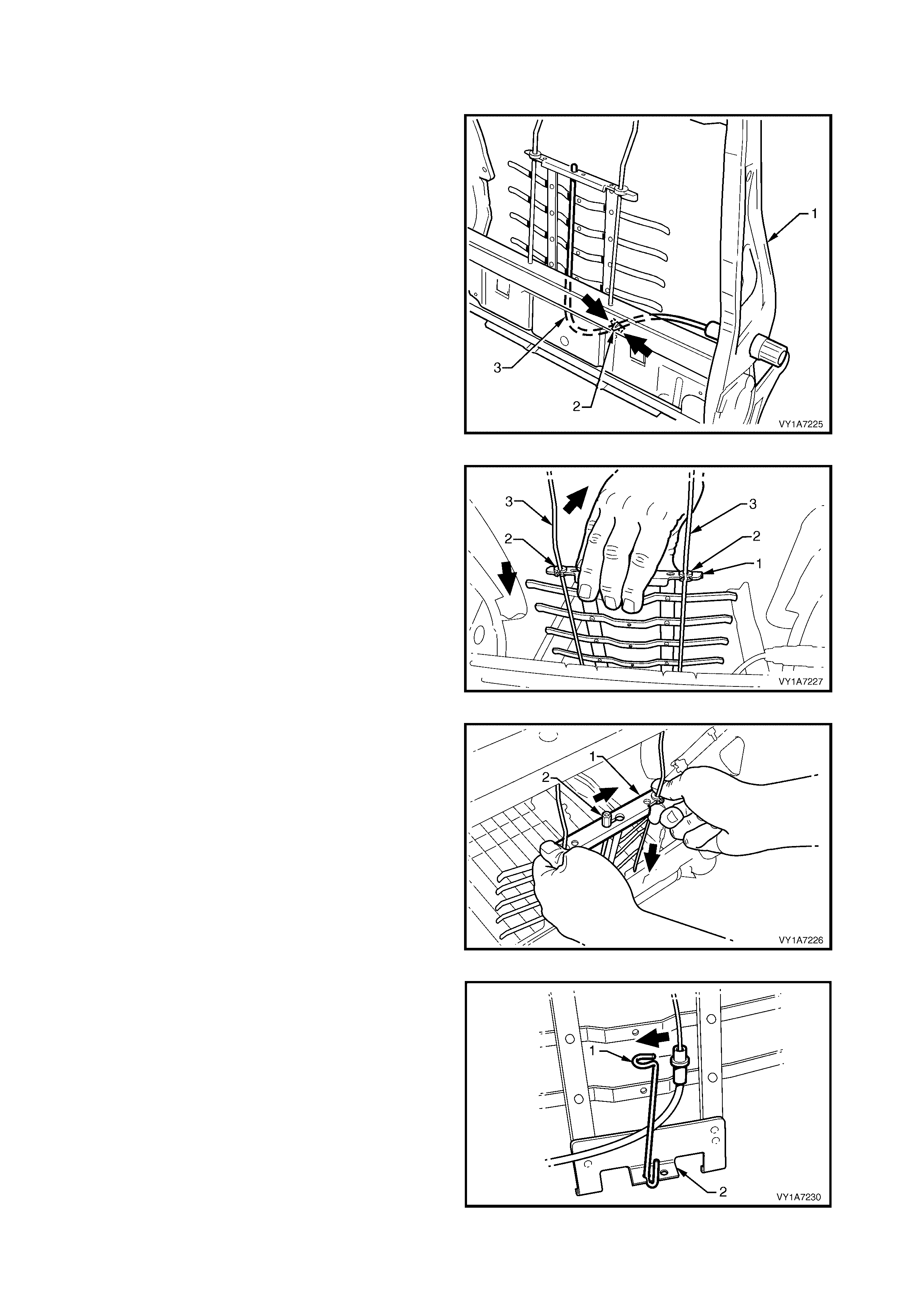
DISASSEMBLE
Remove - Lumbar Support and Adjuster Assembly
1. From the rear of the front seat-back frame (1),
disengage the clip (2) securing the lum bar support
adjuster cable (3). Squeeze the tangs on the tie
clip together and push the clip through the seat-
back frame.
Figure 1A7-133
2. Push down the top of the lumbar support ass embly
(1) to disengage the two retainers (2) from the
guide rails (3) on the seat-bac k fram e, allowing the
lumbar support to swing freely.
Figure 1A7-134
3. Slightly com press the lum bar support ass em bly ( 1)
by hand to release the cable (2) tension,
disengaging the cable from the top of the lumbar
support.
Figure 1A7-135
4. Unclip the lower cable retainer (1) from the lower
lumbar bracket (2).
Figure 1A7-136
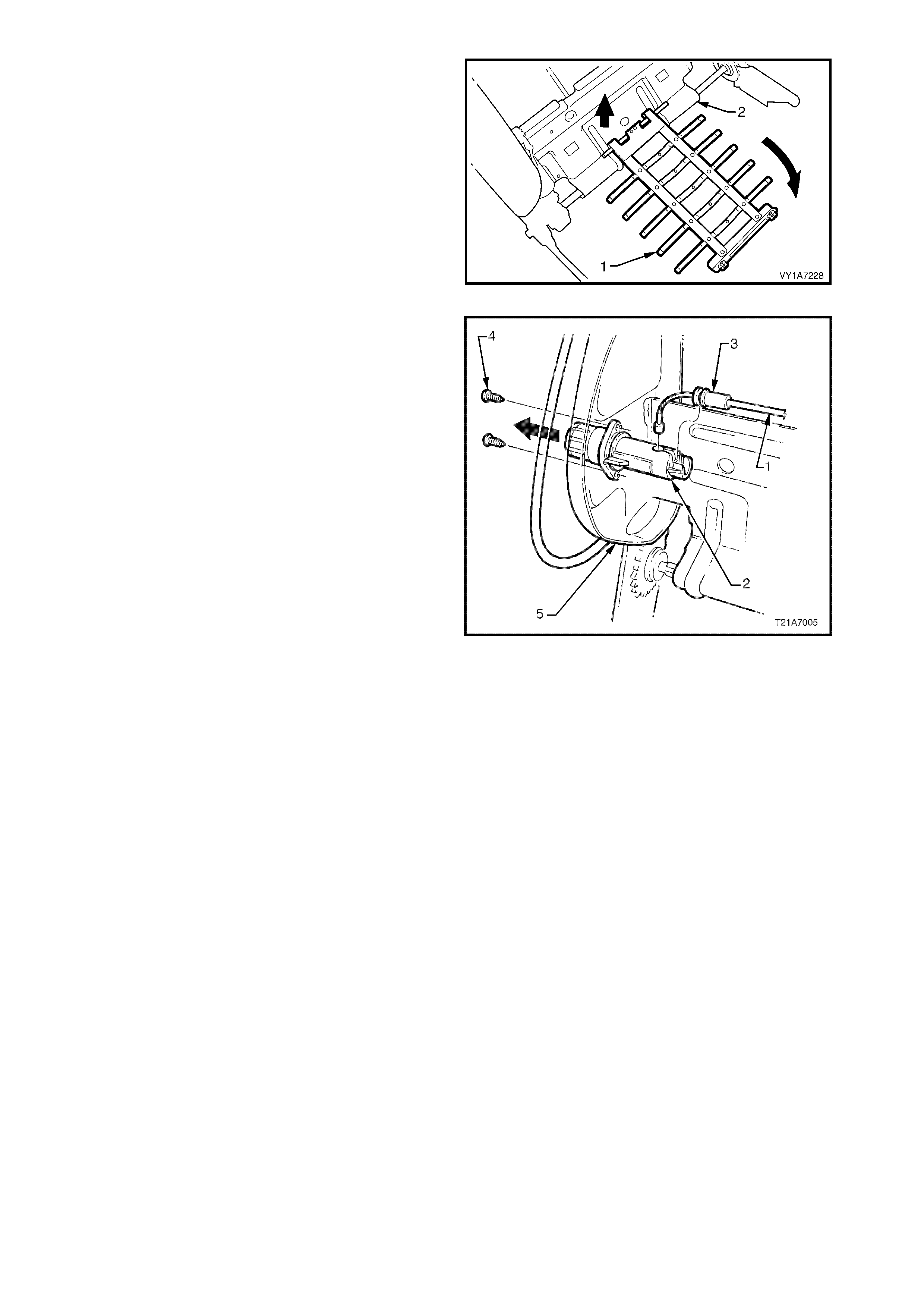
5. Lower the lumbar support assembly (1) until it
becomes disengaged from the seat back frame
assembly (2).
6. Remove the lumbar support assembly
Figure 1A7-137
7. Remove the adjusting cable (1) from the adjuster
(2) by unclipping the outer casing (3) of the cable
from the adjuster and removing the cable
assembly.
NOTE: The right-hand seat back is shown. The left-
hand seat back is opposite, with the cable fitting the
adjuster from the under-side.
8. Remove the two screws (4) securing the lumbar
support adjuster to the seat-back frame (5) and
remove the adjuster.
Figure 1A7-138
Reinstall - Lumbar Support and Adjuster Assembly
Reinstallation of the lumbar support and adjuster
assembly is the reverse of the removal procedure,
noting the following:
1. Align the hole in the adjuster for the adjusting
cable ball by turning the adjuster, insert the cable
into the adjuster and push the outer casing of the
cable into the locking seat of the adjuster until it
clicks.
NOTE: On the right-hand seat, the cable fits into the
adjuster from the top. On the left-hand seat, the cable
fits into the adjuster from the under-side.
1. Ensure all screws are tightened securely.

Remove – Side Impact Airbag Assembly
1. Unclip the pigtail wiring harness (1) from the
retaining clip (2) and cut the two cable ties (3),
securing the harness to the front seat cushion
frame assembly, taking care not to damage the
wiring harness.
2. Unclip the wiring harness connector (4) from the
adjuster and guide rail assembly (5).
3. Disconnect the wiring harness connector for the
recliner motor (6).
Figure 1A7-139
4. Rem ove the two nuts (1), securing the s ide impact
airbag assembly (2) to the front seat-back frame
(3).
5. Remove side airbag module and pigtail wiring
harness assembly from front seat-back frame.
CAUTION: When carrying a live (undeployed) side
airbag assembly, make sure the bag opening is
pointed away from you. Never carry the sid e airbag
assembly by the wiring harness or connectors. In
case of an accidental deployment, the bag will
then deploy with minimal chance of injury.
When placing a live side airbag assembly on a
bench or other surface, always face the airbag
opening up, away from the surface. Never rest the
airbag inflator module assembly with the opening
face down. This is necessary so that a free space
is provided to allow the airbag to expand in the
unlikely event of accidental deployment.
Otherwise, personal injury may result.
Figure 1A7-140
6. If required, remove the two lock nuts (1) retaining
the front s eat f oam block insert ass embly ( 2) to the
seat-back frame (3) and remove the foam block
inse rt assembly.
7. If required, rem ove the foam block insert retaining
bracket (4) from the foam block insert assembly
Figure 1A7-141
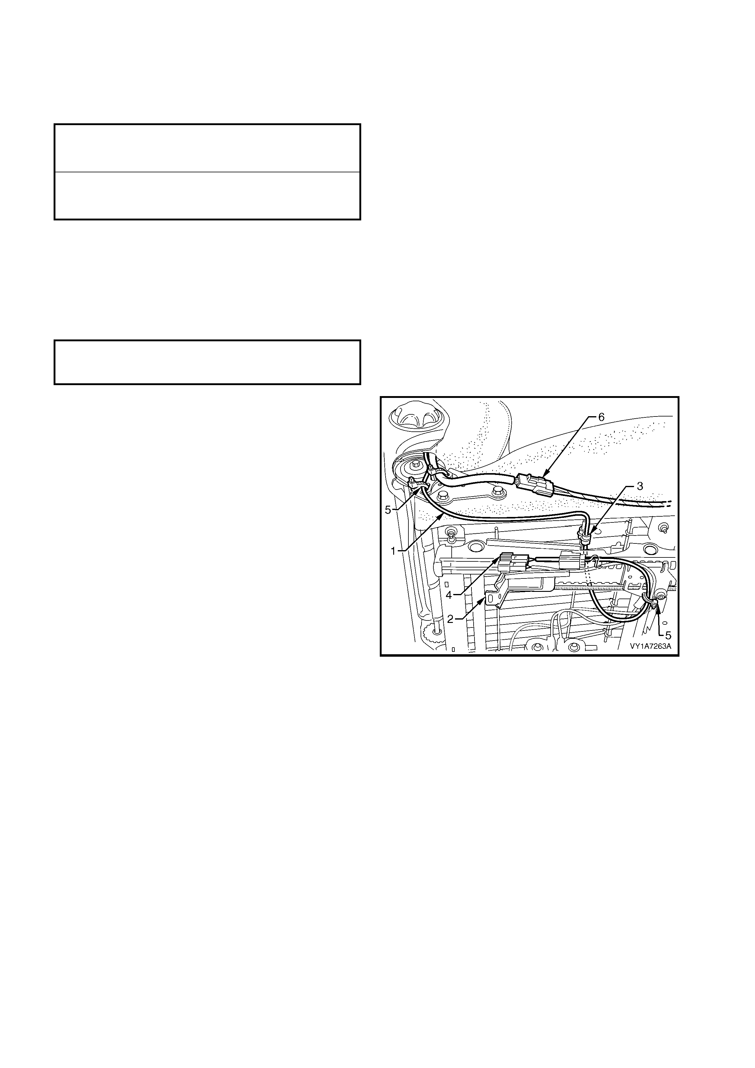
Reinstall – Side Impact Airbag Assembly
Reinstallation of the side impact airbag assembly and the foam block insert assembly is the reverse of the
removal procedure, noting the following:
1. Ensure all screws are tightened to the correct torque specification.
REINSTALL
Reinstallation of the front seat-back frame assembly is the reverse of the removal procedure, noting the
following:
1. Ensure all fasteners are tightened to the correct torque specification.
2. Route the side impact airbag wiring harness (1)
through to the side of the adjuster and guide rail
assembly (2) and secure in the retaining clip (3).
Fit the connector (4) to the adjuster and guide rail
assembly and attach wi th two new cable ties (5).
NOTE 1: If the wiring harness is not routed correctly,
damage to the har nes s may occur, res ulting in the side
impact airbag becoming inoperative and setting a
Diagnostic Trouble Code (DTC) (SRS warning lamp
on).
NOTE 2: The wiring harness that connects to the side
impact airbag module, is not serviced separately from
the side airbag inf lator m odule due to the design of the
anti-back-out connector on the module assembly.
If this wiring harness, as with any other SRS pigtail
type wiring harness becomes damaged, no wire,
connector or terminal repairs are to be attempted.
REPLACE THE SIDE AIRBAG MODULE AND
PIGTAIL WIRING HARNESS ASSEMBLY.
Figure 1A7-142
3. Connect the wiring harness connector for the recliner motor (6).
4. Reconnect the battery earth and the positive leads, if the seat is fitted with a side impact airbag, switch the
ignition ON and observe the SRS warning indicator in the instrument cluster.
• If no fault is detected, the SRS warning indicator should illuminate for approximately five seconds while
the system performs a self-test, and then go off.
• If a fault is present, the SRS warning indicator will remain illuminated and a warning chime may sound
after approximately three seconds. The warning message ‘SRS Airbag Fault’ is also displayed in the
instrument cluster multi-function display. To diagnose the fault, refer to Section 12M, 4. DIAGNOSTICS
5. Check operation of front seat mechanical and electrical adjustments / operation. While checking the seat
adjustm ent / operation, also c heck to ens ure that the side airbag harness does not foul with any of the s eats
moveable components (ie. seat motor drive shafts, etc.).
SIDE IMPACT AIRBAG
ASSEMBLY ATTACHING NUT
TORQUE SPECIFICATION 5.0 – 6.0 Nm
FRONT SEAT FOAM BLOCK
INSERT ATTACHING NUT
TORQUE SPECIFICATION 5.0 – 6.0 Nm
FRONT SEAT-BACK FRAME
ASSEMBLY ATTACHING SCREW
TORQUE SPECIFICATION 30.0 – 45.0 Nm

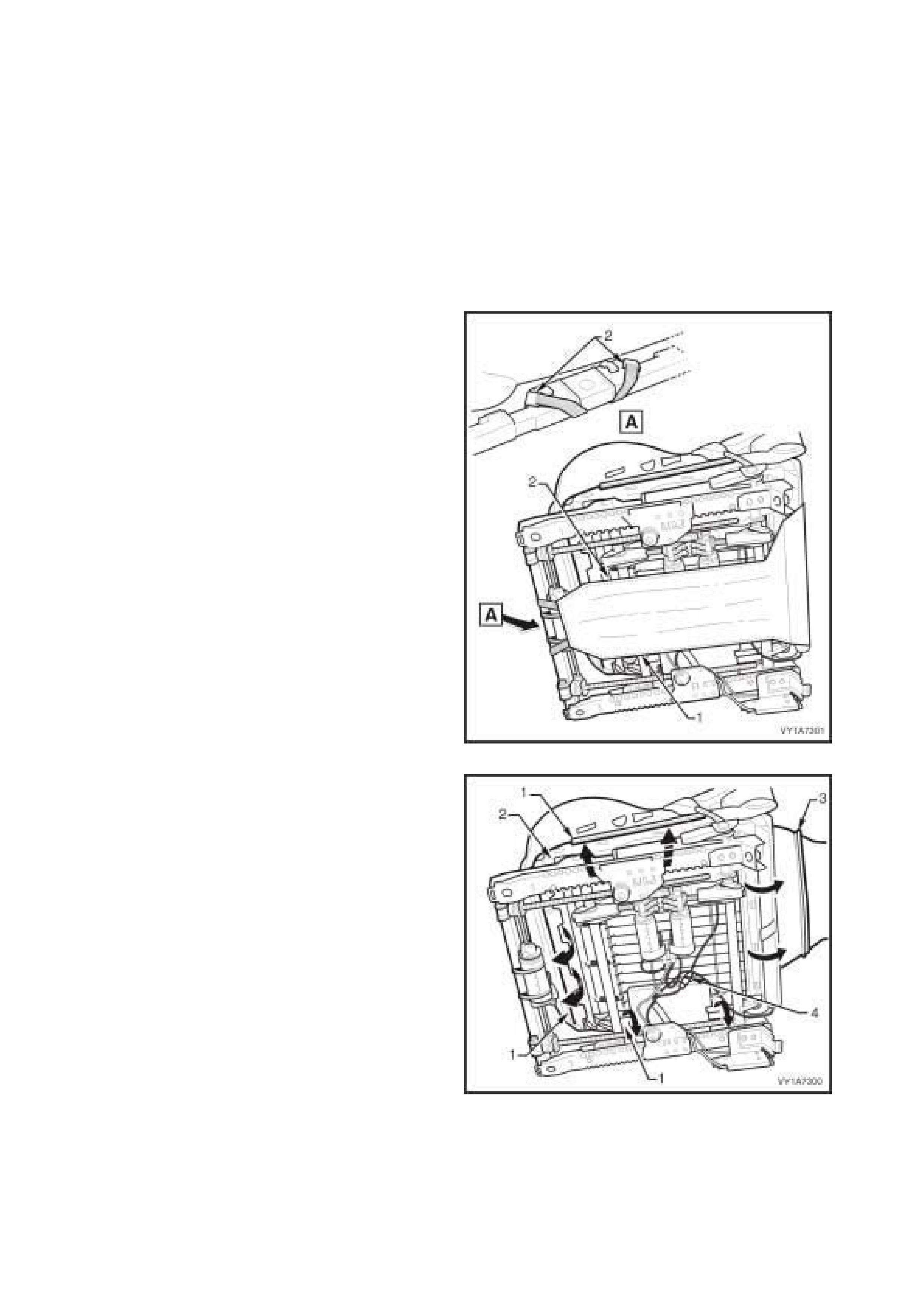
4.17 FRONT S EAT CUSHION PAD AND COVER ASSEMBLY
LT Section No. – 14-295
1. Disconnect the battery earth and positive leads.
2. Remove the front seat assembly, refer to 4.2 FRONT SEAT ASSEMBLY.
3. Remove the front seat outer side cover, refer to 4.3 FRONT SEAT OUTER SIDE COVER.
4. Remove the front seat inner side cover, refer to 4.8 FRONT SEAT INNER SIDE COVER.
5. Remove the front seat-back lower cover assembly, refer to 4.9 FRONT SEAT-BACK LOWER COVER
ASSEMBLY AND LUMBER SUPPORT ADJUSTER KNOB.
6. Remove the front seat-back frame assembly, refer to 4.15 FRONT SEAT-BACK FRAME ASSEMBLY.
REMOVE
1. From under the front seat cushion, disconnect the
front seat cushion cover flap (1), by disengaging
two small J-strips (2) located on the front of the
frame.
Figure 1A7-143
2. From under the front seat cushion, pull the front
and side J-strips (1) away from the seat frame (2).
3. Lift the cover and pad assembly away from the
seat frame and then release the rear J-strip (3).
4. Disconnect the occupant sensing mat harness
connector (4).
5. Remove the cover and pad assembly.
Figure 1A7-144
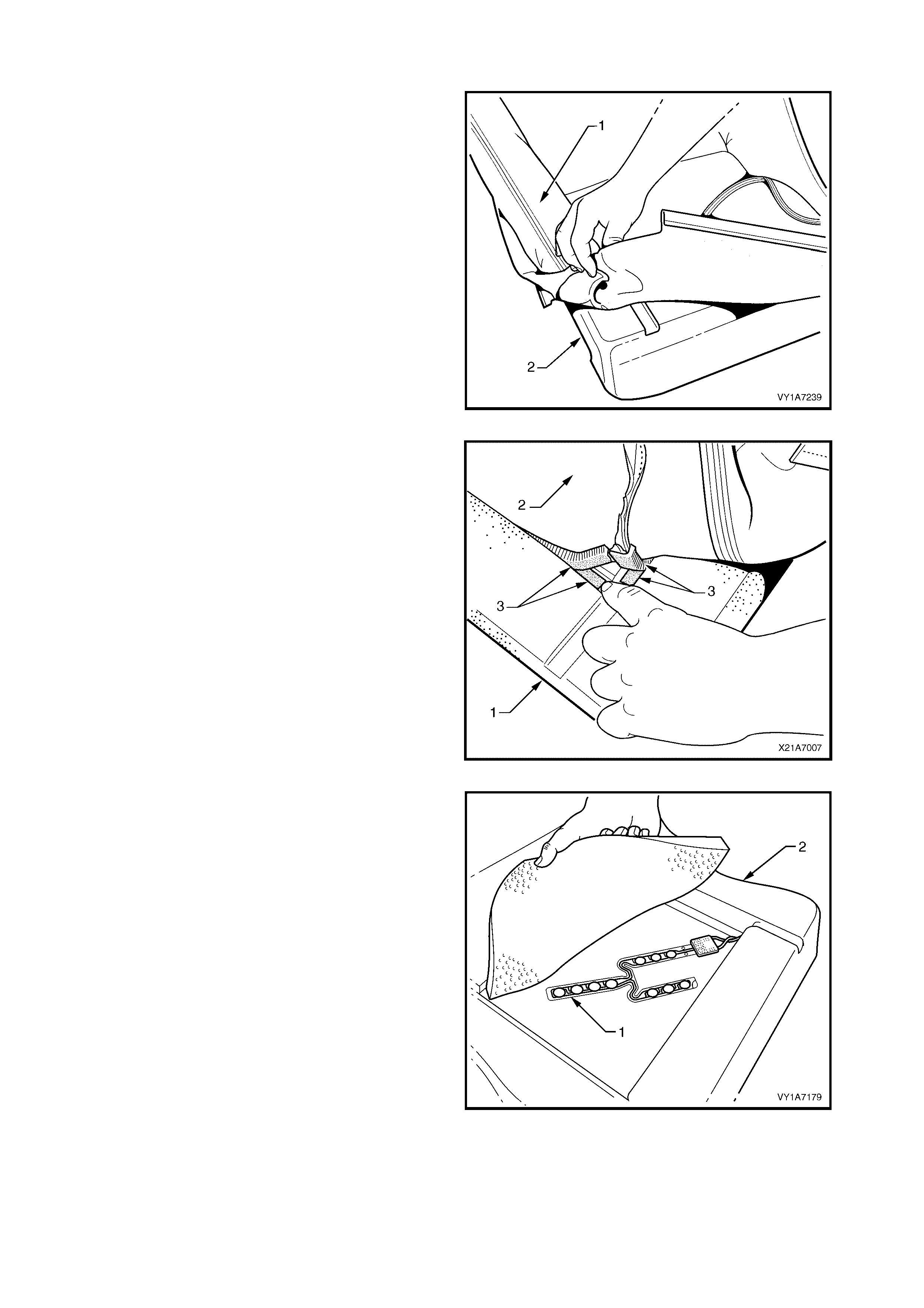
DISASSEMBLE
1. Fold the rear corners of the seat cus hion cover (1)
over the seat cushion pad (2).
Figure 1A7-145
2. While holding the front seat cushion pad (1), pull
the rear corners of the seat cushion cover (2)
forward and away from the front seat cushion pad
to disengage the hook and loop strips (3).
3. Pull the front seat cover up and over the forward
edge of the front seat cushion pad.
Figure 1A7-146
TIP: If the seat cover needs to be replaced, check to
see if the damaged area is above the occupant
sensing mat. If so, check that the damage does not
extend through the pad and into the occupant sensing
mat.
Figure 1A7-147
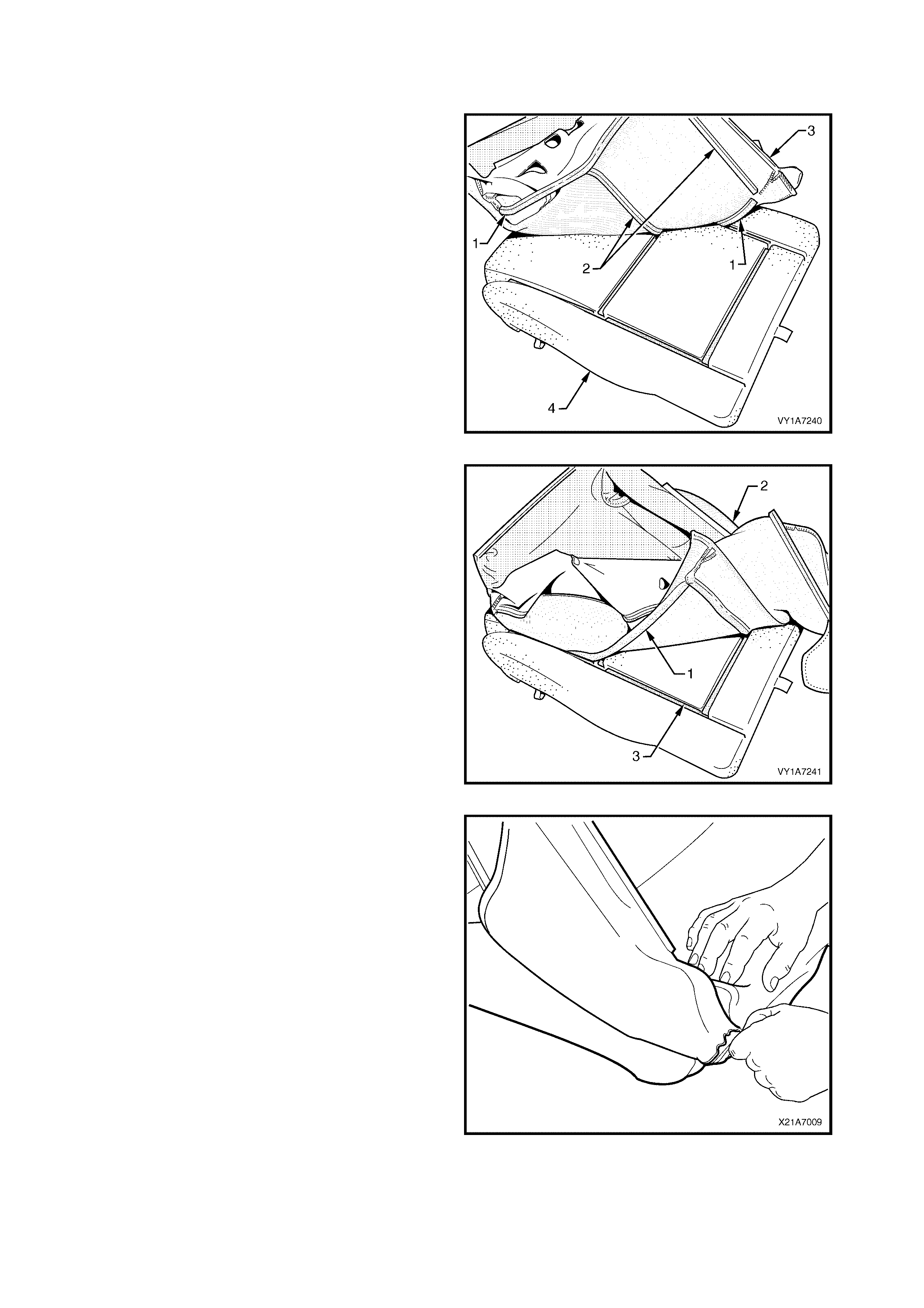
REASSEMBLE
Reassembly of the rear seat cushion is the reverse of the removal procedure noting the following:
1. Align either of the outer hook and loop strips (1)
and the one or two cross hook and loop strips (2),
on the seat cushion cover (3), with the seat
cushion pad (4).
2. Press the folded edge of the rear seat cushion
cover firmly into the corresponding groove in the
seat cushion pad to engage the hook and loop
strip.
Figure 1A7-148
3. Align and press the outer hook and loop strip (1),
on the seat cushion cover (2), with the
corresponding groove in the seat cushion pad (3).
Figure 1A7-149
4. Roll the front corners of the front seat cushion
cover over the seat cushion pad.
5. Roll the sides of the seat cushion cover over the
seat cushion pad.
6. Roll the rear corners of the seat cushion cover
over the seat cushion pad.
NOTE: Make sure the pad is fitted neatly by hand into
all corners and contours of the seat cover.
IMPORTANT: Do not pull the cover onto the pad from
underneath using the J- st rip to mak e it f it neatly, as the
fabric may be damaged.
Figure 1A7-150
REINSTALL
Reinstallation of the front seat cushion pad and cover assembly is the reverse of the removal operation.
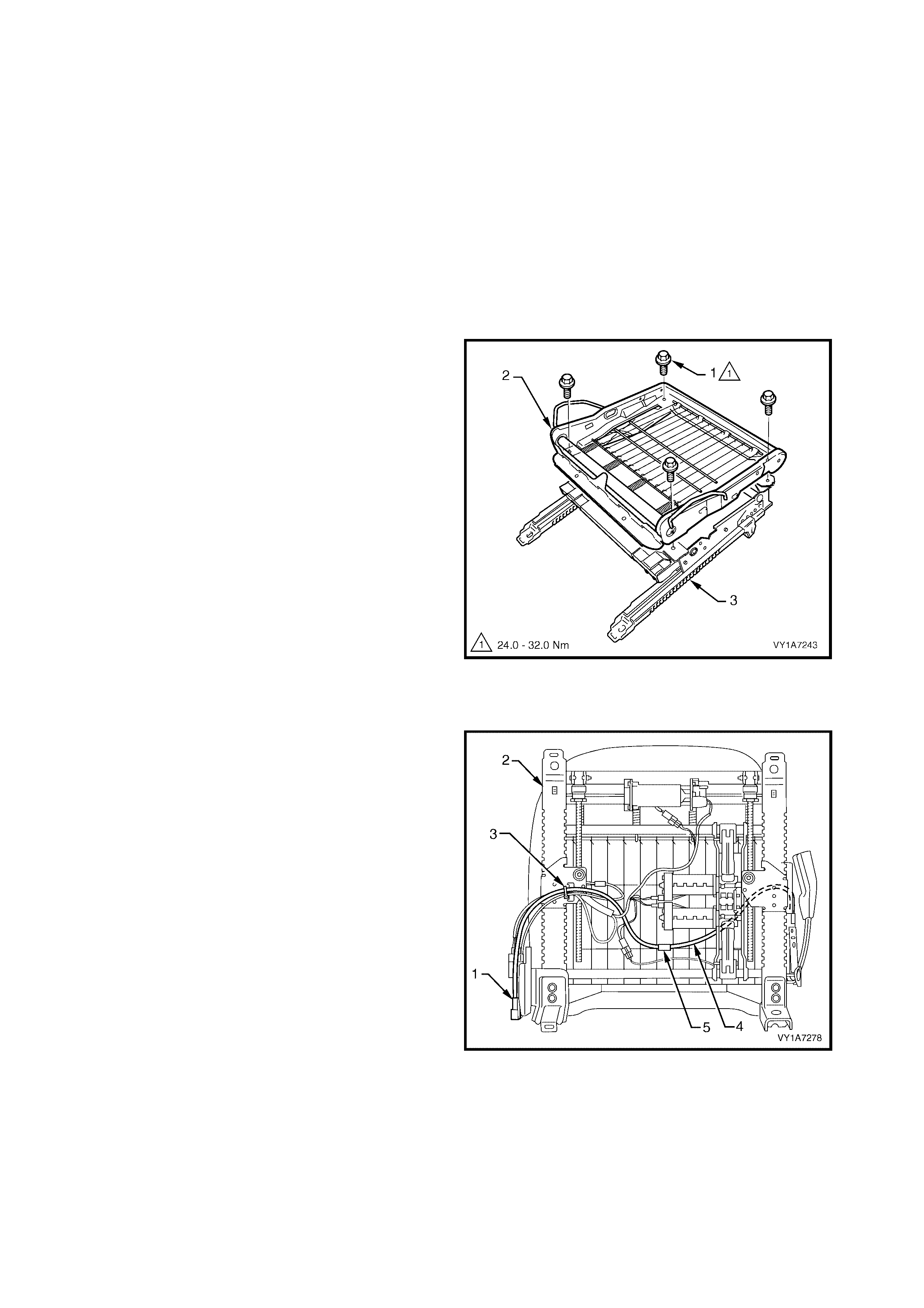
4.18 FRONT SEAT CUSHION FRAME ASSEMBLY
LT Section No. – 14-275
1. Disconnect the battery earth and positive leads.
2. Remove the front seat assembly, refer to 4.2 FRONT SEAT ASSEMBLY.
3. Remove the front seat outer side cover, refer to 4.3 FRONT SEAT OUTER SIDE COVER.
4. Remove the front seat inner side cover, refer to 4.8 FRONT SEAT INNER SIDE COVER.
5. Remove the front seat-back lower cover assembly, refer to 4.9 FRONT SEAT-BACK LOWER COVER
ASSEMBLY AND LUMBER SUPPORT ADJUSTER KNOB.
6. Remove the front seat-back frame assembly, refer to 4.15 FRONT SEAT-BACK FRAME ASSEMBLY.
7. Rem ove the front seat cushion pad and cover assembly, refer to 4.17 FRONT SEAT CUSHION PAD AND
COVER ASSEMBLY.
REMOVE
1. Remove the four sc rews (1) s ecur ing the front seat
cushion frame (2) to the adjuster and guide rail
assembly (3).
Figure 1A7-151
NOTE: Before disconnecting the pretensioner wiring
harness connector, take note of wiring harness routing.
2. On eight-way non-memory electric seats, unclip
the pretensioner wiring harness connector (1) fr om
the front seat guide rail assembly (2).
3. Cut the cable tie (3), securing the wiring harness
(4) to the guide rail assembly, taking care not to
damage the wiring harness.
4. Remove the wiring harness from the clip (5)
attached to the suspension mat.
5. If required, remove any tape attaching the
pretensioner wiring harnes s to the guide rail wiring
harness.
Figure 1A7-152
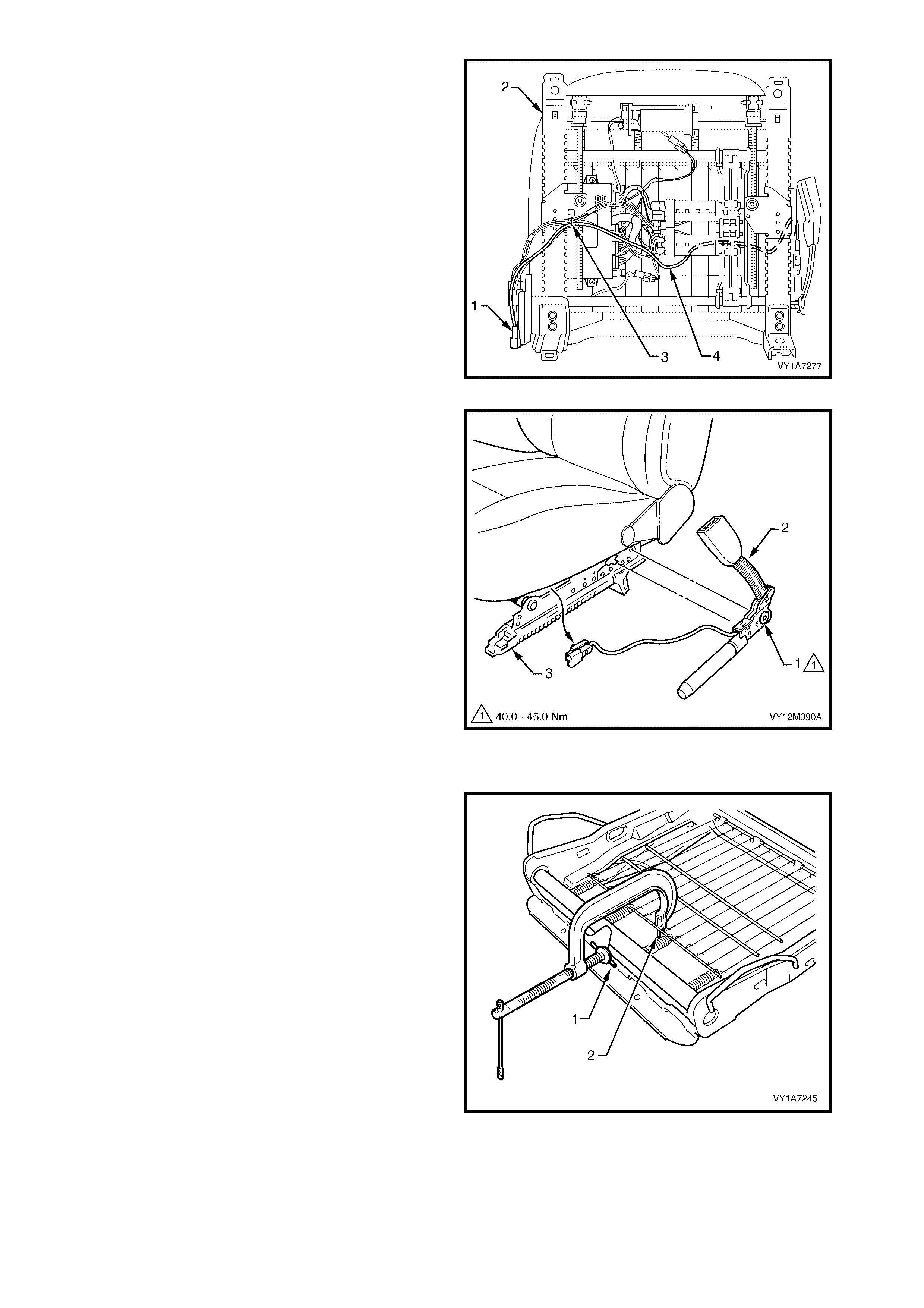
6. On the eight-way memory electric seat, unclip the
pretensioner wiring harness connector (1) f rom the
front seat guide rail assembly (2).
7. Cut the cable tie (3), securing the pretensioner
wiring harness (4) to the guide rail assem bly wiring
harness, taking care not to damage the wiring
harness.
8. If required, remove any tape attaching the
pretensioner wiring harnes s to the guide rail wiring
harness.
Figure 1A7-153
9. Remove the bolt (1) securing the seatbelt buckle
and pretensioner assembly (2) to the frame (3).
10. Remove the seatbelt buckle and pretensioner
assembly.
Figure 1A7-154
DISASSEMBLE
1. If required to remove the suspension mat (1), use
a pre-fabricated tool:
G-clamp with a 5mm diameter metal dowel (2)
welded to one end, approximately 40m m long and
with a 2mm diameter pin (3) approximately 20mm
long welded to the other end.
2. Using the pre-fabricated tool, stretch the
suspension mat far enough to allow for the
retaining springs (4) to be removed from the seat
cushion frame.
3. Back the G-clamp load off and remove the
suspension mat.
NOTE: When using the pre-fabricated tool, use
existing holes in the sus pension m at to ensur e that the
mat deformation does not occur.
Figure 1A7-155
REASSEMBLE
Reassembly of the rear seat cushion is the reverse of the removal procedure.

REINSTALL
Reinstallation of the front seat cushion frame assembly is the reverse of the removal operation, noting the
following:
1. Ensure all fasteners are tightened to the correct torque specification.
2. Ensure the pretensioner, the seat adjuster motor, and (if fitted) the s ide impact airbag wiring harness es are
routed correctly and retained by cable ties, refer Figure 1A7-152 or Figure 1A7-153.
3. When installing the seatbelt buckle and pretensioner assembly, ensure that the front locating pin on the
pretensioner assembly aligns with the seat frame.
NOTE 1: Route the side impact airbag module and the seatbelt pretensioner wiring harnesses correctly,
otherwise damage to the harness may occur, resulting in the side impact airbag or the seatbelt pretensioner
becoming inoperative and setting a Diagnostic Trouble Code (DTC) (SRS warning indicator).
NOTE 2: The wiring harness that connects to the side im pact airbag m odule is not s erviced separately from the
side airbag inflator module due to the design of the anti-back-out connector on the module assembly.
If this wiring harness, as with any other SRS pigtail type wiring harness becomes damaged, no wire, connector
or terminal repairs are to be attempted. REPLACE THE SIDE AIRBAG MODULE AND PIGTAIL WIRING
HARNESS ASSEMBLY.
4. Rec onnect the battery earth and the positive leads, s witch ignition on, and observe the SRS warning lamp in
the instrument cluster. The warning lamp should be illuminated for approximately five seconds. During this
period the SDM performs a wiring and system self check.
If no system faults are detected, the SRS warning lamp will be switched off. If the warning lamp remains
illuminated and an audible alar m chim es, or the warning lam p illuminates two sec onds after it was originally
switched off, an SRS fault is present. To rectify the fault refer to Section 12M OCCUPANT PROTECTION
SYSTEM.
5. Check the operation of the front seat m echanical and elec trical adjus tments / operation. W hile c hecking the
seat adjustm ent / operation, also chec k to ensure that the side air bag harness does not foul with any of the
seats moveable components (ie. seat motor drive shafts, etc.).
FRONT SEAT CUSHION FRAME
ASSEMBLY ATTACHING SCREW
TORQUE SPECIFICATION 24.0 – 32.0 Nm
FRONT SEAT BACK ASSEMBLY
ATTACHING SCREW
TORQUE SPECIFICATION 30.0 – 45.0 Nm
SEATBELT BUCKLE AND
PRETENSIONER ASSEMBLY BOLT
TORQUE SPECIFICATION 40.0 – 45.0 Nm
FRONT SEAT ASSEMBLY
RETAINING SCREW
TORQUE SPECIFICATION 35.0 – 50.0 Nm


4.21 FRONT SEAT FORE / AFT MOVEMENT MOTOR
1. The front seat fore/aft movement motor on the front seats is a non-serviceable item.
2. If the front seat fore/aft movement motor or drive shafts require replacement, the entire adjuster and guide
rail assembly must be replaced, refer to 4.18 FRONT SEAT CUSHION FRAME ASSEMBLY.

4.22 FRONT SEAT RECLINING MOTOR, GEARBOX AND POTENTIOMETER ASSEMBLY
1. The front seat recliner motor, gearbox and potentiometer assembly on the front seats is a non-serviceable
item.
2. If the front seat recliner motor, gearbox and potentiometer assembly requires replacement, the front seat-
back frame assembly must be replaced, refer to 4.15 FRONT SEAT-BACK FRAME ASSEMBLY.

4.23 DRIVE MOTOR POTENTIOMETERS
1. The front seat drive motor potentiometers on the front seats are non-serviceable items.
2. If any of the front seat drive motor potentiometer assemblies requires replacement, the front seat-back
frame assembly, or the adjuster and guide rail assembly must be replaced. For information relating to the
replacement procedure for the front seat-back frame assembly or the front seat adjuster and guide rail
assem bly, r efer to either 4.15 FRON T SEAT -BACK FRAME ASSEMBLY or 4.18 FRONT SEAT CUSHIO N
FRAME ASSEMBLY.

5. DIAGNOSTICS – FRONT SEAT, COUPE
This Section provides charts to assis t in the diagnosis and r epair of f ront s eats. Ref er to 4.1 FRO NT SEAT USAGE
CHART – COUPE for a full listing of the different types of seats fitted to Coupe vehicles. Included in that Section are
illustrated parts breakdowns of the various seats.
PREREQUISITES
Safety Requirements
When operating the s eat as part of any of the Steps in the diagnosis c harts, ens ure that finger s and lim bs ar e clear
of moving parts.
Equipment
The following equipment is required to diagnose the seats:
1. An unpowered test lamp with a current draw of less than 3 A.
2. A digital multimeter with a minimum impedance of 10 MΩ.
Testing Procedures
The following points must be adhered to when performing diagnostic testing on components:
1. Care must be taken when using testing equipment to diagnose wiring harness connectors. It is preferred that
the technician back probe the connector to avoid terminal damage.
2. When tests are required on connector terminals, utilise the adapters in the connector adaptor kit KM–609 to
prevent damage to the terminals.
3. Unless the multimeter being used has an auto-ranging function, ensure that the correct range is selected.
4. When back-probing connectors, ensure the test lamp earth lead is connected to a suitable earth point on the
vehicle. Ensure that this earth point is not part of the circuit being tested.
Important:
When following the Steps in the diagnosis charts, the exact order of Steps should be observed. If the required
nominal value or result is not achieved at any stage, the problem must be rectified before proceeding any further.

5.1 MECHANICAL DIAGNOSIS – FRONT SEAT
LUMBAR SUPPORT INOPERATIVE
Introduction
This test is used by the technician to aid in the diagnosis of the lumbar support assembly.
Test Description
The following numbers refer to the Step numbers in the diagnostic chart.
1. Checks that the lumbar support knob is properly engaging the lumbar support adjuster. Check the knob for
cracks and worn splines.
2. Checks that the lumbar support adjuster is not damaged or worn and that there is correct operation of the
adjuster when the splined shaft is turned throughout its range.
3. Checks that the lumbar support adjuster cable is not brok en or binding and is not inhibiting the movement and
travel of the lumbar support assembly.
4. Checks that the lum bar support as sembly is not crack ed or bent. If this is the c ase, it m ay caus e the assem bly
to deform and bind on the guide rails.
5. Checks that the guide rails are not cracked or bent. If this is the case, they may cause the lumbar support
assembly to bind.
STEP ACTION YES NO
1. 1. Remove the lumbar support knob, refer to
4.9 FRONT SEAT-BACK LOWER COVER
ASSEMBLY AND LUMBAR SUPPORT
ADJUSTER KNOB.
Is the lumbar support adjuster knob
serviceable?
Go to Step 2.
Replace the knob.
Refer to 4.9 FRONT SEAT-
BACK LOWER COVER
ASSEMBLY AND LUMBAR
SUPPORT ADJUSTER
KNOB.
2. 1. Remove the front seat-back rear cover
assembly, refer to 4.9 FRONT SEAT-
BACK LOW ER COVER ASSEMBLY AND
LUMBAR SUPPORT ADJUSTER KNOB.
2. Disconnect the lumbar support adjuster
cable from the adjuster, refer to
4.15 FRONT SEAT-BACK FRAME
ASSEMBLY.
3. Turn the adjuster and check for correct
operation.
Is the lumbar support adjuster serviceable?
Go to Step 3.
Replace the lumbar support
adjuster.
Refer to 4.15 FRONT
SEAT-BACK FRAME
ASSEMBLY.
3. 1. Visually inspect the lumbar support
adjuster cable.
Is the lumbar support adjuster cable
serviceable? Go to Step 4.
Replace the lumbar support
adjuster cable.
Refer to 4.15 FRONT
SEAT-BACK FRAME
ASSEMBLY.
4. 1. Visually inspect the lumbar support
assembly.
Is the lumbar support assembly serviceable? Go to Step 5.
Replace the lumbar support
assembly.
Refer to 4.15 FRONT
SEAT-BACK FRAME
ASSEMBLY.
5. 1. Visually inspect the lumbar support
assembly guide rails.
Are the lumbar support assembly guide rails
serviceable? System Serviceable.
Replace the front seat-back
frame assembly.
Refer to 4.15 FRONT
SEAT-BACK FRAME
ASSEMBLY.
When all diagnosis and repairs are completed, check the system for correct operation.

EZ-ENTRY LEVER FUNCTION INOPERATIVE
Introduction
The EZ-entry lever arm uses a cable to release the seat-back. There is also an electrical component to the
operation that will drive the seat f orward using f ront seat fore/af t movem ent motor . This diagnosis c hart covers the
mechanical aspect of the lever arm and cable being inoperative.
Test Description
The following numbers refer to the Step numbers in the diagnostic chart.
1. Checks that the EZ-entry lever arm is serviceable. The lever arm engages a frame assembly which is
connected to EZ-entry cable assembly.
2. The EZ- entry lever arm and its s pring clip are the only serviceable item s as f ar as the mec hanical action of this
system is c oncerned. Due to saf ety r equirem ents, if the EZ- entry lever function does not oper ate after the lever
arm has been checked for serviceability and correct installation, the seat-back frame assembly must be
replaced.
STEP ACTION YES NO
1. 1. Remove the EZ-entry lever arm, refer to
4.12 EZ-ENTRY LEVER ARM,
ESCUTCHEON AND SEAT RETURN
SWITCH ASSEMBLY.
Is the EZ-entry lever arm serviceable?
Go to Step 2.
Replace the lever arm.
Refer to 4.12 EZ-ENTRY
LEVER ARM,
ESCUTCHEON AND SEAT
RETURN SWITCH
ASSEMBLY.
2. 1. Install the EZ-entry lever arm ensuring
that the spring clip and lever arm engage
properly, refer to 4.12 EZ-ENTRY LEVER
ARM, ESCUTCHEON AND SEAT
RETURN SWITCH ASSEMBLY.
Does the EZ-entry lever function operate?
System Serviceable.
Replace the front seat-back
frame assembly.
Refer to 4.15 FRONT
SEAT-BACK FRAME
ASSEMBLY.
When all diagnosis and repairs are completed, check the system for correct operation.
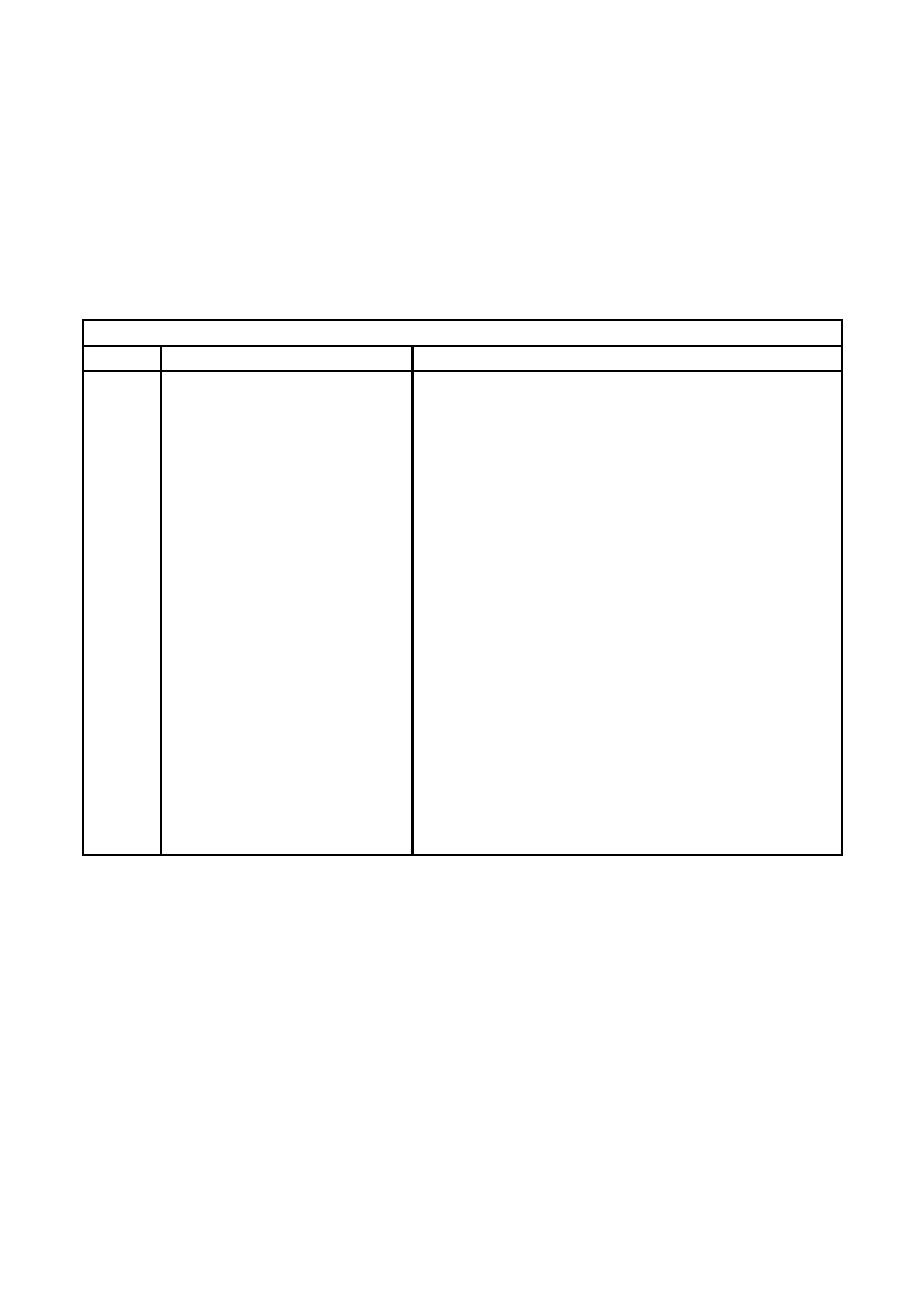
5.2 ELECTRICAL SELF TEST DIAGNOSIS – EIGHT-WAY SEAT, NON-MEMORY
EZ-ENTRY DIAGNOSTICS
Introduction
The non-memory type seat provides the technician with in-built diagnostics. The diagnostics indicator is a green
LED located on the s eat c ontrol module. T he LED c an be viewed through the small hole in the outer s ide lower seat
side cover. T o gain ac cess , it is neces sary to partially remove the seat outer s ide cover. Ref er to 4.3 FRO NT SEAT
OUTER SIDE COVER.
• The chart in this Section displays the error codes and fault description.
• If the error c ode is above ten, the indication will cons ist of a single flas h, a short delay and then the num ber of
flashes corresponding to the error. A longer delay will occur between error code indications.
EZ-ENTRY DIAGNOSTICS
Flashes Description of ERROR Reference
2 No Passenger Presence Detector
(PPD) detected Driver's or Passenger's Seat Occupant Sensing Mat Test in this
Section
3 PPD weight detected > 15kg Driver's or Passenger's Seat Occupant Sensing Mat Test in this
Section
4 No track motor sensor Driver's or Passenger's Seat Track Motor Position Sensor
Potentiometer Test in this Section
5 Track motor sensor faulty > 3V on
ADC potentiometer value Driver's or Passenger's Seat Track Motor Position Sensor
Potentiometer Test in this Section
6 Battery voltage low Section 12A, 2.9 BATTERY
7 Button stuck detected 5.4 ELECTRICAL DIAGNOSIS – DRIVER'S EIGHT-WAY SEAT,
NON-MEMORY or 5.5 ELECTRICAL DIAGNOSIS –
PASSENGER'S EIGHT-WAY SEAT, NON-MEMORY
8 Dump latch active Driver's or Passenger's Seat EZ-entry Switch Function Is
Inoperative in this Section
9 Return button active Driver's or Passenger's Seat return Switch Function Is Inoperative
in this Section
11 Forward track switch active 3.6 EIGHT-WAY SEAT ADJUSTMENT SWITCH TEST
12 Reve rse track switch active 3.6 EIGHT-WAY SEAT ADJUSTMENT SWITCH TEST
13 Recliner forward switch active 3.6 EIGHT-WAY SEAT ADJUSTMENT SWITCH TEST
14 Recliner backward switch active 3.6 EIGHT-WAY SEAT ADJUSTMENT SWITCH TEST
15 At full forward position Driver's or Passenger's Seat Fore/Aft Function is Inoperative
16 At full rearward position Driver's or Passenger's Seat Fore/Aft Function is Inoperative

5.3 ELECTRICAL DIAGNOSIS – EIGHT-WAY SEAT, NON-MEMORY
Both front seats have common power and earth circuits. If either of these circuits become unserviceable, the
electrical operation of both seats will be affected.
NEITHER SEAT ADJUSTMENT SWITCH FUNCTIONS OPERATE
Introduction
This test is used by the technician to aid in the diagnosis of the seat power and earth circuits if neither seat operates
when either eight-way seat adjustment switch is operated. Refer to Figure 1A7-156 or Figure 1A7-158.
Test Description
The following numbers refer to the Step numbers in the diagnostic chart.
1. Checks that battery voltage is more than 11.5 volts. The seat motors require more than 11.5 volts to operate
correctly.
2. Checks that circuit breaker F2 located on the passenger compartment fuse and relay panel assembly is not
tripped. Isolates whether circuit breaker F2 is the fault affecting the circuit between the battery and connector
X200 pin 15.
3. Check s that fus ible link F 105 located on the engine com par tm ent fus e and relay panel assem bly is serviceable.
Isolates whether the fusible link is the fault affecting the circuit between the battery and connector X200 pin 15.
4. Ensures that connector X200 is secure.
5. Checks whether there is battery voltage at connector X200 pin 15. Isolates whether the fault is between the
battery and connector X200 pin 15. If the fault in the circuit is between connectors X200 pin 15 and either
X308 pin B or X302 pin B, only one seat will not operate.
6. Checks whether there is battery voltage at circuit breaker F2. Isolates whether the fault is between the battery
and circuit breaker F2 or between circuit breaker F2 and connector X200 pin 15.
7. Checks whether there is battery voltage at fusible link F105. Isolates whether the fault is between the battery
and fusible link F105 or between fusible link F105 and circuit breaker F2.
8. Checks that all the earth points associated with the system are serviceable and a good earth is provided at each
point.
STEP ACTION YES NO
1. 1. Check the battery voltage, refer to Section
12A, 2.9 BATTERY.
Is the battery voltage more than 11.5 V? Go to Step 2. Refer to Section 12A,
2.9 BATTERY for further
diagnosis.
2. 1. Inspect circuit breaker F2, refer to Section
12O, 2.2 CIRCUIT BREAKERS.
Is circuit breaker F2 tripped?
Allow the circuit breaker to
reset, refer to Section 12O,
2.2 CIRCUIT BREAKERS. Go to Step 3.
3. 1. Inspect fusible link F105, refer to Section
12O, 2.3 FUSIBLE LINKS.
Is fuse F105 serviceable? Go to Step 4. Replace the fusible link.
4. Is connector X200 secure? Go to Step 5. Ensure that the connector
is secure.
5. 1. Back probe connector X200 pin 15 with a
test lamp.
Does the test lamp illuminate? Go to Step 8. Go to Step 6.
6. 1. Remove circuit breaker F2 from the
passenger compartment fuse and relay
panel assembly.
2. Using a test lamp, probe connector
X129 – X45 pin 2. Refer to Section 12P
WIRING DIAGRAMS.
Does the test lamp illuminate?
There is a fault in circuit
540 between circuit breaker
F2 and connector
X200 pin 15.
Repair or replace circuit
540.
Go to Step 7.
7. 1. Remove the fusible link F105.
2. Using a test lamp, probe connector
X18-105. Refer to Section 12P WIRING
DIAGRAMS.
Does the test lamp illuminate?
There is a fault in circuit
342 between fusible link
F105 and circuit breaker
F2.
Repair or replace circuit
342.
There is a fault in circuit 1
between the battery and
fusible link F105.
Repair or replace circuit 1.

STEP ACTION YES NO
8. 1. Ensure that the following earth points are
secure and have good contact with the
vehicle structure:
• X118–GP12 located in the middle of the
transmission tunnel.
• X118–GP13 located in the rear
compartment on the right-hand side tail
lamp stud.
• X118–GP14 located in the rear
compartment on the rear compartment lid.
Refer to Section 12P W IRING DIAGRAMS for
further details of earthing points.
Are all the earth points secure to the vehicle
with a good contact?
There is a fault in circuit
650.
Repair or replace circuit
650.
Ensure that the connectors
are secured to the vehicle
and that there is a good
contact between the
connector and the vehicle.
When all diagnosis and repairs are completed, check the system for correct operation.

5.4 ELECTRICAL DIAGNOSIS – DRIVER'S EIGHT-WAY SEAT, NON-MEMORY
The charts in this Section are used by the technician in the aid of diagnosing faults on the driver's eight-way seat,
non-memory. To aid in the use of the diagnosis charts, refer to WIRING DIAGRAM – DRIVER'S EIGHT-WAY
SEAT, NON-MEMORY and CONNECTOR CHART – DRIVER'S EIGHT-WAY SEAT, NON-MEMORY in this
Section.
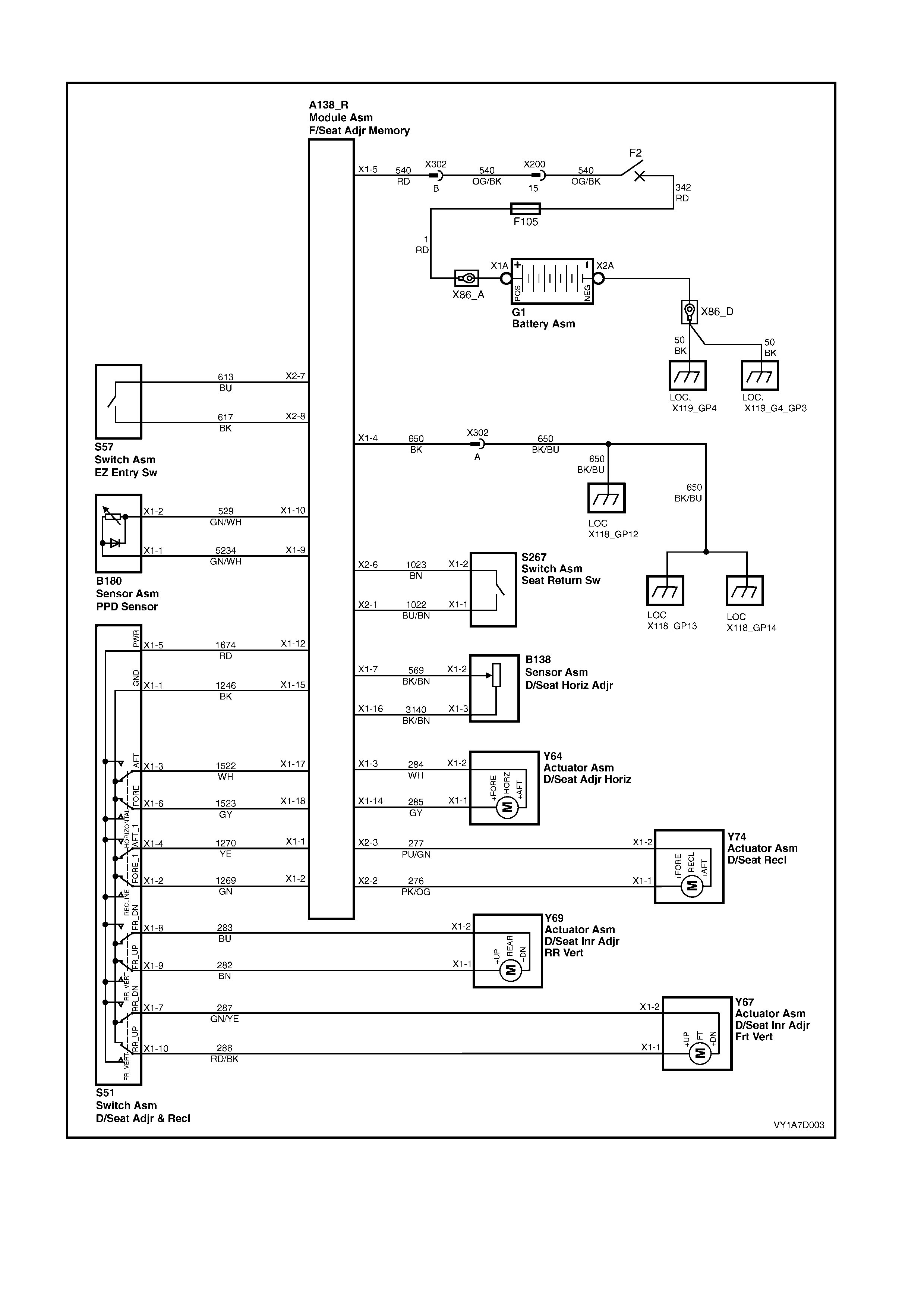
WIRING DIAGRAM – DRIVER'S EIGHT-WA Y SEAT, NON-MEMORY
Figure 1A7-156
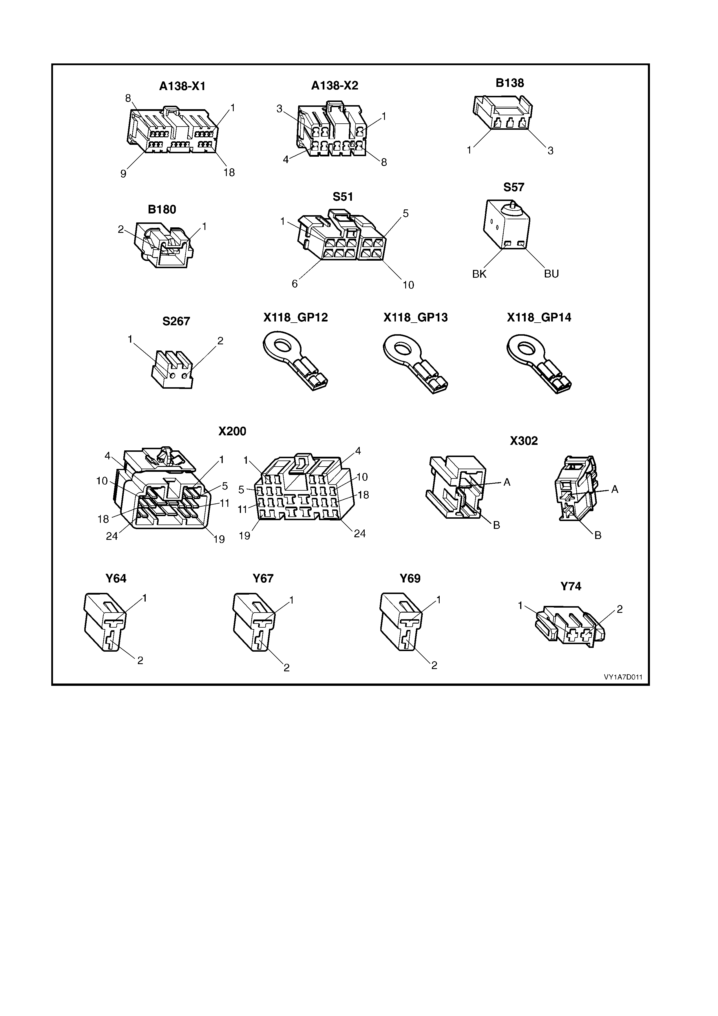
CONNECTOR CHART – DRIVER'S EIGHT-WAY SEAT, NON-MEMORY
Figure 1A7-157

NONE OF THE DRIVER’S EIGHT-WAY SEAT ADJUSTMENT SWITCH FUNCTIONS OPERATE
Introduction
This test is used by the technician to aid in the diagnosis of the driver’s eight-way seat adjustment switch when none
of the switch functions operate. The test diagnoses the driver’s eight-way seat adjustment switch and associated
power and earth circuits.
Test Description
The following numbers refer to the Step numbers in the diagnostic chart.
1. Checks whether all of the passenger seat eight-way functions work. If none of them work, the fault is not
isolated to the driver’s seat only.
2. Checks whether there is battery power at connector X302 pin B. Isolates whether there is a fault in circuit 540
between connectors X200 pin 15 and X302 pin B.
3. Checks that all the connectors required for the seat to operate effectively are in place and positively connected.
4. Checks whether there is battery power at connector A138_R – X1 pin 5. Isolates whether there is a fault in
circuit 540 between connectors A138_R – X1 pin 5 and X302 pin B.
5. Checks whether there is battery power at connector A138_R – X1 pin 12. Isolates whether there is a fault with
the EZ-entry module.
6. Checks whether there is battery power at connector S51 – X1 pin 5. Isolates whether there is a fault in circuit
1674 between connectors S51 – X1 pin 5 and A138_R – X1 pin 12.
7. Checks whether the driver’s eight-way seat adjustment switch is serviceable.
8. Chec ks whether there is c ontinuity between connectors S51 – X1 pin 1 and X 302 pin A which supplies the earth
circuit f or the dr iver’s eight-way seat adjustm ent s witch. Is olates whether there is a f ault between the switch and
connector X302 pin A or between connector X302 pin A and the earthing points.
9. Checks whether there is continuity between connectors A138_R – X1 pin 4 and X302 pin A. Isolates whether
there is a f ault between the switch and connec tor A138_R – X1 pin 4 or between connec tors A138_R – X1 pin 4
and X302 pin A.
10. Checks whether there is continuity between connectors A138_R – X1 pin 15 and A138_R – X1 pin 4. Isolates
whether there is a fault between the switch and connector A138_R – X1 pin 15 or the EZ-entry module is at
fault.
STEP ACTION YES NO
1. Are all of the passenger’s eight-way seat
adjustment switch functions inoperative? Refer to NEITHER SEAT
ADJUSTMENT SWITCH
FUNCTIONS OPERATE in
this Section.
Go to Step 2.
2. 1. Back probe connector X302 pin B with a
test lamp.
Does the test lamp illuminate? Go to Step 3.
There is a fault in circuit
540 between connectors
X200 pin 15 and
X302 pin B.
Repair or replace circuit
540.
3. Are the following connectors secure?
• A138_R
• S51
• X302
• Y64
• Y67
• Y69
• Y74
Go to Step 4. Ensure that the connectors
are secure.
4. 1. Back probe connector A138_R – X1 pin 5
with a test lamp.
Does the test lamp illuminate? Go to Step 5.
There is a fault in circuit
540 between connectors
A138_R – X1 pin 5 and
X302 pin B.
Repair or replace circuit
540.

STEP ACTION YES NO
5. 1. Back probe connector A138_R – X1 pin
12 with a test lamp.
Does the test lamp illuminate? Go to Step 6.
Replace the driver’s
EZ-entry module, refer to
4.7 EZ-ENTRY MODULE,
EIGHT-WAY
NON-MEMORY SEAT.
6. 1. Back probe connector S51 – X1 pin 5 with
a test lamp.
Does the test lamp illuminate? Go to Step 7.
There is a fault in circuit
1674 between connectors
S51 – X1 pin 5 and
A138_R – X1 pin 12.
Repair or replace circuit
1674.
7. 1. Remove the driver’s eight-way seat
adjustment switch from the seat, refer to
4.4 EIGHT-WAY SEAT ADJUSTMENT
SWITCH.
2. Test the driver’s eight-way seat
adjustment switch, refer to 3.6 EIGHT-
WAY SEAT ADJUSTMENT SWITCH
TEST.
Is the driver’s eight-way seat adjustment
switch serviceable?
Go to Step 8.
Replace the driver’s
eight-way seat adjustment
switch.
Refer to 4.4 EIGHT-W AY
SEAT ADJUSTMENT
SWITCH.
8. 1. Back probe connector X302 pin A with a
test lamp.
2. Operate the driver’s eight-way seat
adjustment switch in any of the available
directions.
Does the test lamp illuminate?
There is a fault in circuit
650 between connector
X302 pin A and earth
points X118–GP12, X118–
GP13 and X118–GP14.
Repair or replace circuit
650.
Go to Step 9.
9. 1. Back probe connector A138_R – X1 pin 4
with a test lamp.
2. Operate the driver’s eight-way seat
adjustment switch in any of the available
directions.
Does the test lamp illuminate?
There is a fault in circuit
650 between connectors
A138_R – X1 pin 4 and
X302 pin A.
Repair or replace circuit
650.
Go to Step 10.
10. 1. Back probe connector A138_R – X1 pin
15 with a test lamp.
2. Operate the driver’s eight-way seat
adjustment switch in any of the available
directions.
Does the test lamp illuminate?
Replace the driver’s
EZ-entry module
Refer to 4.7 EZ-ENTRY
MODULE, EIGHT-WAY
NON-MEMORY SEAT.
There is a fault in circuit
1246 between connectors
S51 – X1 pin 1 and
A138_R – X1 pin 15.
Repair or replace circuit
1246.
When all diagnosis and repairs are completed, check the system for correct operation.

FRONT/REAR OF THE DRIVER’S SEAT DOES NOT RAISE AND/OR LOWER
Introduction
This test is used by the technician to aid in the diagnosis of the front and/or the rear of the driver’s seat not r aising
and/or lowering. The test diagnoses the eight-way seat adjustment switch and the motor circuits.
Test Description
The following numbers refer to the Step numbers in the diagnostic chart.
1. Checks whether the driver’s eight-way seat adjustment switch operates in any of the directions. Isolates
whether the power and earth circuits are at fault.
2. Checks that all the connectors required for the seat to operate effectively are in place and positively connected.
3. Checks whether the driver’s eight-way seat adjustment switch is serviceable.
4. Conf irm s whether the rear of the seat r aises or lowers. Isolates whether the rear m otor and c ircuit of the seat is
the fault.
5. Confirms whether the front of the seat raises or lowers. Isolates whether the front motor and circuit of the seat is
the fault.
6. Checks whether there is battery power to the seat rear motor at connector Y69 – X1 pin 1. Isolates whether
there is a fault in circuit 282 that supplies battery power to the motor to raise the rear of the seat.
7. Check s whether there is battery power to the seat rear motor at connector Y69 – X1 pin 2. Isolates whether the
fault is in circuit 283 that supplies battery power to the motor to lower the rear of the seat or the m otor is faulty.
As the direction of the motor is changed by reversing the polarity, this Step also confirms that the earth circuit
from Step 6 is serviceable.
8. Checks whether there is battery power to the seat front motor at connector Y67 – X1 pin 1. Isolates whether
there is a fault in circuit 286 that supplies battery power to the motor to raise the front of the seat.
9. Chec ks whether ther e is battery power to the seat front m otor at c onnector Y67 – X1 pin 2. Is olates whether the
fault is in circ uit 287 that supplies batter y power to the m otor to lower the fr ont of the s eat or the m otor is f aulty.
As the direction of the motor is changed by reversing the polarity, this Step also confirms that the earth circuit
from Step 8 is serviceable.
STEP ACTION YES NO
1. Does the driver’s eight-way seat adjustment
switch operate correctly in any of the eight
directions? Go to Step 2.
Refer to NONE OF THE
DRIVER’S EIGHT-WAY
SEAT ADJUSTMENT
SWITCH FUNCTIONS
OPERATE in this Section.
2. Are the following connectors secure?
• A138_R
• S51
• Y67
• Y69
Go to Step 3. Ensure that the connectors
are secure.
3. 1. Remove the driver’s eight-way seat
adjustment switch from the seat, refer to
4.4 EIGHT-WAY SEAT ADJUSTMENT
SWITCH.
2. Test the driver’s eight-way seat
adjustment switch, refer to 3.6 EIGHT-
WAY SEAT ADJUSTMENT SWITCH
TEST.
Is the driver’s eight-way seat adjustment
switch serviceable?
Go to Step 4.
Replace the driver’s
eight-way seat adjustment
switch.
Refer to 4.4 EIGHT-W AY
SEAT ADJUSTMENT
SWITCH.
4. 1. Operate the driver’s eight-way seat
adjustment switch so that the rear of the
seat is raised or lowered.
Does the rear of the seat raise and lower?
Go to Step 5. Go to Step 6.
5. 1. Operate the driver’s eight-way seat
adjustment switch so that the front of the
seat is raised or lowered.
Does the front of the seat raise and lower?
System serviceable. Go to Step 8.

STEP ACTION YES NO
6. 1. Back probe connector Y69 – X1 pin 1 with
a test lamp.
2. Operate the driver’s eight-way seat
adjustment switch so that it will raise the
rear of the seat.
Does the test lamp illuminate?
Go to Step 7.
There is a fault in circuit
282 between connectors
S51 – X1 pin 9 and
Y69 – X1 pin 1.
Repair or replace circuit
282.
7. 1. Back probe connector Y69 – X1 pin 2 with
a test lamp.
2. Operate the driver’s eight-way seat
adjustment switch so that it will lower the
rear of the seat.
Does the test lamp illuminate?
The seat rear motor is
faulty. Replace the seat
rear motor.
Refer to 4.20 FRONT
SEAT LIFT MOTORS.
Go to Step 5.
There is a fault in circuit
283 between connectors
S51 – X1 pin 8 and
Y69 – X1 pin 2.
Repair or replace circuit
283.
Go to Step 5.
8. 1. Back probe connector Y67 – X1 pin 1 with
a test lamp.
2. Operate the driver’s eight-way seat
adjustment switch so that it will raise the
front of the seat.
Does the test lamp illuminate?
Go to Step 9.
There is a fault in circuit
286 between connectors
S51 – X1 pin 10 and
Y67 – X1 pin 1.
Repair or replace circuit
286.
9. 1. Back probe connector Y67 – X1 pin 2 with
a test lamp.
2. Operate the driver’s eight-way seat
adjustment switch so that it will lower the
front of the seat.
Does the test lamp illuminate?
The seat front motor is
faulty. Replace the seat
front motor.
Refer to 4.20 FRONT
SEAT LIFT MOTORS.
There is a fault in circuit
287 between connectors
S51 – X1 pin 7 and
Y67 – X1 pin 2.
Repair or replace circuit
287.
When all diagnosis and repairs are completed, check the system for correct operation.

DRIVER’S SEAT FORE/AFT FUNCTION IS INOPERATIVE OR NOT SMOOTH
Introduction
This test is used by the technician to aid in the diagnosis of the fore/aft function of the driver’s seat being inoperative
or the action of the seat through the range of movement is not smooth. The test diagnoses the eight-way seat
adjustment switch and the motor circuits.
Test Description
The following numbers refer to the Step numbers in the diagnostic chart.
1. Checks whether the driver’s eight-way seat adjustment switch operates in any of the directions. Isolates
whether there is battery power to the switch assembly.
2. Checks that there are no items obstructing the guide rails, which may stop or hinder the seat movement.
3. Checks that the guide rails and drive shafts have adequate lubricant applied to provide a smooth operation of
the seat.
4. Checks that the guide rails or drive shafts have not been damaged. Any binding between the moving parts will
result in poor operation of the fore and aft movement.
5. Checks that all the connectors required for the seat to operate effectively are in place and positively connected.
6. Checks whether the driver’s eight-way seat adjustment switch is serviceable.
7. Checks whether there is battery power to the seat fore/aft m otor at connector Y64 – X1 pin 1. Isolates whether
there is a fault between the switch and connector Y64 – X1 pin 1.
8. Checks whether there is continuity between connectors S51 – X1 pin 6 and A138_R – X1 pin 14. Isolates
whether there is a fault between the switch and connector A138_R – X1 pin 14 or in circuit 285.
9. Checks whether there is continuity between connectors S51 – X1 pin 6 and A138_R – X1 pin 18. Isolates
whether there is a fault in circuit 1523 or the driver's EZ-entry module is at fault.
10. Check s whether there is battery power to the seat f ore/aft m otor at connector Y64 – X1 pin 2. Isolates whether
there is a fault between the switch and connec tor Y64 – X1 pin 2 or the m otor is f aulty. As reversing the polarity
changes the direction of the motor, this Step also confirms that the earth circuit from Step 7 is serviceable.
11. Checks whether there is continuity between connectors S51 – X1 pin 3 and A138_R – X1 pin 3. Isolates
whether there is a fault between the switch and connector A138_R – X1 pin 3 or in circuit 284.
12. Checks whether there is continuity between connectors S51 – X1 pin 3 and A138_R – X1 pin 17. Isolates
whether there is a fault in circuit 1522 or the driver's EZ-entry module is at fault.
STEP ACTION YES NO
1. Does the driver’s eight-way seat adjustment
switch operate correctly in any of the eight
directions? Go to Step 2.
Refer to NONE OF THE
DRIVER’S EIGHT-WAY
SEAT ADJUSTMENT
SWITCH FUNCTIONS
OPERATE in this Section.
2. Are the guide rails free from obstructions? Go to Step 3. Remove the obstructing
item.
3. Are the guide rails and drive shafts adequately
lubricated? Go to Step 4. Apply a small amount of
grease type NLGI No. 1
Lithium Grease (with 9%
Zinc Oxide).
4. Do the guide rails or drive shafts bind at any
point of travel during the fore and aft
movement of the seat?
Replace the front seat
adjuster assembly, refer to
4.19 FRONT SEAT
ADJUSTER ASSEMBLY.
Go to Step 5.
5. Are the following connectors secure?
• A138_R
• S51
• Y64
Go to Step 6. Ensure that the connectors
are secure.

STEP ACTION YES NO
6. 1. Remove the driver’s eight-way seat
adjustment switch from the seat, refer to
4.4 EIGHT-WAY SEAT ADJUSTMENT
SWITCH.
2. Test the driver’s eight-way seat
adjustment switch, refer to 3.6 EIGHT-
WAY SEAT ADJUSTMENT SWITCH
TEST.
Is the driver’s eight-way seat adjustment
switch serviceable?
Go to Step 7.
Replace the driver’s
eight-way seat adjustment
switch.
Refer to 4.4 EIGHT-W AY
SEAT ADJUSTMENT
SWITCH.
7. 1. Back probe connector Y64 – X1 pin 1 with
a test lamp.
2. Operate the driver’s eight-way seat
adjustment switch so that it will move the
seat forward.
Does the test lamp illuminate?
Go to Step 10. Go to Step 8.
8. 1. Back probe connector A138_R - X1 pin 14
with a test lamp.
2. Operate the driver’s eight-way seat
adjustment switch so that it will move the
seat forward.
Does the test lamp illuminate?
There is a fault in circuit
285 between connectors
A138_R – X1 pin 14 and
Y64 – X1 pin 1.
Repair or replace circuit
285.
Go to Step 9.
9. 1. Back probe connector A138_R - X1 pin 18
with a test lamp.
2. Operate the driver’s eight-way seat
adjustment switch so that it will move the
seat forward.
Does the test lamp illuminate?
Replace the driver’s
EZ-entry module.
Refer to 4.7 EZ-ENTRY
MODULE, EIGHT-WAY
NON-MEMORY SEAT.
There is a fault in circuit
1523 between connectors
S51 – X1 pin 6 and
A138_R – X1 pin 18.
Repair or replace circuit
1523.
10. 1. Back probe connector Y64 – X1 pin 2 with
a test lamp.
2. Operate the driver’s eight-way seat
adjustment switch so that it will move the
seat aft.
Does the test lamp illuminate?
The seat fore/aft motor is
faulty. Replace the seat
fore/aft motor.
Refer to 4.21 FRONT
SEAT FORE/AFT
MOVEMENT MOTOR.
Go to Step 11.
11. 1. Back probe connector A138_R - X1 pin 3
with a test lamp.
2. Operate the driver’s eight-way seat
adjustment switch so that it will move the
seat aft.
Does the test lamp illuminate?
There is a fault in circuit
284 between connectors
A138_R – X1 pin 3 and
Y64 – X1 pin 2.
Repair or replace circuit
284.
Go to Step 12.
12. 1. Back probe connector A138_R - X1 pin 17
with a test lamp.
2. Operate the driver’s eight-way seat
adjustment switch so that it will move the
seat aft.
Does the test lamp illuminate?
Replace the driver’s EZ-
entry module.
Refer to 4.7 EZ-ENTRY
MODULE, EIGHT-WAY
NON-MEMORY SEAT.
There is a fault in circuit
1522 between connectors
S51 – X1 pin 3 and
A138_R – X1 pin 17.
Repair or replace circuit
1522.
When all diagnosis and repairs are completed, check the system for correct operation.

DRIVER’S SEAT RECLINE FORWA RD AND/OR AFT FUNCTION IS INOPERATIVE
Introduction
This test is used by the technician to aid in the diagnosis of the reclining function of the driver’s seat being
inoperative. The test diagnoses the eight-way seat adjustment switch and the motor circuits.
Test Description
The following numbers refer to the Step numbers in the diagnostic chart.
1. Checks whether the driver’s eight-way seat adjustment switch operates in any of the directions. Isolates
whether there is battery power to the switch assembly.
2. Checks that all the connectors required for the seat to operate effectively are in place and positively connected.
3. Checks whether the driver’s eight-way seat adjustment switch is serviceable.
4. Chec ks whether there is battery power to the seat reclining motor at connec tor Y74 – X1 pin 1. Is olates whether
there is a fault between the switch and connector Y74 – X1 pin 1.
5. Checks whether there is continuity between connectors S51 – X1 pin 2 and A138_R – X2 pin 2. Isolates
whether there is a fault between the switch and connector A138_R – X2 pin 2 or in circuit 276.
6. Checks whether there is continuity between connectors S51 – X1 pin 2 and A138_R – X1 pin 2. Isolates
whether there is a fault in circuit 1269 or the driver's EZ-entry module is at fault.
7. Chec ks whether there is battery power to the seat reclining motor at connec tor Y74 – X1 pin 2. Is olates whether
there is a fault between the switch and connec tor Y74 – X1 pin 2 or the m otor is f aulty. As reversing the polarity
changes the direction of the motor, this Step also confirms that the earth circuit from Step 4 is serviceable.
8. Checks whether there is continuity between connectors S51 – X1 pin 4 and A138_R – X2 pin 3. Isolates
whether there is a fault between the switch and connector A138_R – X2 pin 3 or in circuit 277.
9. Checks whether there is continuity between connectors S51 – X1 pin 4 and A138_R – X1 pin 1. Isolates
whether there is a fault in circuit 1270 or the driver's EZ-entry module is at fault.
STEP ACTION YES NO
1. Does the driver’s eight-way seat adjustment
switch operate correctly in any of the eight
directions? Go to Step 2.
Refer to NONE OF THE
DRIVER’S EIGHT-WAY
SEAT ADJUSTMENT
SWITCH FUNCTIONS
OPERATE in this Section.
2. Are the following connectors secure?
• A138_R
• S51
• Y74
Go to Step 3. Ensure that the connectors
are secure.
3. 1. Remove the driver’s eight-way seat
adjustment switch from the seat, refer to
4.4 EIGHT-WAY SEAT ADJUSTMENT
SWITCH.
2. Test the driver’s eight-way seat
adjustment switch, refer to 3.6 EIGHT-
WAY SEAT ADJUSTMENT SWITCH
TEST.
Is the driver’s eight-way seat adjustment
switch serviceable?
Go to Step 4.
Replace the driver’s
eight-way seat adjustment
switch.
Refer to 4.4 EIGHT-W AY
SEAT ADJUSTMENT
SWITCH.
4. 1. Back probe connector Y74 – X1 pin 1 with
a test lamp.
2. Operate the driver’s eight-way seat
adjustment switch so that it will move the
seat-back forward.
Does the test lamp illuminate?
Go to Step 7. Go to Step 5.
5. 1. Back probe connector A138_R - X2 pin 2
with a test lamp.
2. Operate the driver’s eight-way seat
adjustment switch so that it will move the
seat-back forward.
Does the test lamp illuminate?
There is a fault in circuit
276 between connectors
A138_R – X2 pin 2 and
Y74 – X1 pin 1.
Repair or replace circuit
276.
Go to Step 6.

STEP ACTION YES NO
6. 1. Back probe connector A138_R - X1 pin 2
with a test lamp.
2. Operate the driver’s eight-way seat
adjustment switch so that it will move the
seat-back forward.
Does the test lamp illuminate?
Replace the driver’s
EZ-entry module.
Refer to 4.7 EZ-ENTRY
MODULE, EIGHT-WAY
NON-MEMORY SEAT.
There is a fault in circuit
1269 between connectors
S51 – X1 pin 2 and
A138_R – X1 pin 2.
Repair or replace circuit
1269.
7. 1. Back probe connector Y74 – X1 pin 2 with
a test lamp.
2. Operate the driver’s eight-way seat
adjustment switch so that it will move the
seat-back aft.
Does the test lamp illuminate?
The seat reclining motor is
faulty.
Replace the seat reclining
motor, refer to 4.22 FRONT
SEAT RECLINING
MOTOR, GEARBOX AND
POTENTIOMETER
ASSEMBLY.
Go to Step 8.
8. 1. Back probe connector A138_R - X2 pin 3
with a test lamp.
2. Operate the driver’s eight-way seat
adjustment switch so that it will move the
seat-back aft.
Does the test lamp illuminate?
There is a fault in circuit
277 between connectors
A138_R – X2 pin 3 and
Y74 – X1 pin 2.
Repair or replace circuit
277.
Go to Step 9.
9. 1. Back probe connector A138_R - X1 pin 1
with a test lamp.
2. Operate the driver’s eight-way seat
adjustment switch so that it will move the
seat-back aft.
Does the test lamp illuminate?
Replace the driver’s
EZ-entry module.
Refer to 4.7 EZ-ENTRY
MODULE, EIGHT-WAY
NON-MEMORY SEAT.
There is a fault in circuit
1270 between connectors
S51 – X1 pin 4 and
A138_R – X1 pin 1.
Repair or replace circuit
1270.
When all diagnosis and repairs are completed, check the system for correct operation.

DRIVER'S SEAT EZ-ENTRY SWITCH FUNCTION IS INOPERATIVE
Introduction
The EZ- entr y function is des igned s o that when the seat-bac k is releas ed with the EZ-entr y lever, the seat will move
to its fully forward position using the seat fore/aft motor. Once the seat has moved to its fully forward position, power
to the seat fore/aft motor will cease. A switch attached to the seat-back activates the seat fore/aft motor when the
recline of the seat-back is moved forward after being released using the EZ-entry lever. This test is used by the
technician to aid in the diagnosis of the EZ -entry f unction of the driver's seat being inoperative. The test diagnos es
the EZ-entry switch and associated circuits.
Test Description
The following numbers refer to the Step numbers in the diagnostic chart.
1. Checks whether the seat fore/aft motor is serviceable.
2. Checks whether there is battery power to the EZ-entry switch. Isolates whether there is a fault with the driver's
EZ-entry module.
3. Checks whether there is continuity between connectors A138_R – X2 pin 7 and A138_R – X2 pin 8. Isolates
whether the driver's EZ-entry module is at fault.
STEP ACTION YES NO
1. Does the seat move in the fore/aft direction
when operated by the driver's eight-way seat
adjustment switch? Go to Step 2. Refer to DRIVER'S SEAT
FORE/AFT FUNCTION IS
INOPERATIVE OR NOT
SMOOTH in this Section.
2. 1. Back probe connector A138_R – X2 pin 7
with a test lamp.
Does the test lamp illuminate? Go to Step 3.
Replace the driver’s
EZ-entry module.
Refer to 4.7 EZ-ENTRY
MODULE, EIGHT-WAY
NON-MEMORY SEAT.
3. 1. Release the seat-back using the EZ-entry
lever.
2. Back probe connector A138_R – X2 pin 8
with a test lamp.
Does the test lamp illuminate?
Replace the driver’s
EZ-entry module.
Refer to 4.7 EZ-ENTRY
MODULE, EIGHT-WAY
NON-MEMORY SEAT.
Replace the driver's
EZ-entry switch, refer to
4.13 EZ-ENTRY CABLE
AND SWITCH ASSEMBLY.
When all diagnosis and repairs are completed, check the system for correct operation.

DRIVER'S SEAT RETURN SWITCH FUNCTION IS INOPERATIVE
Introduction
The s eat return switch is located on the esc utcheon at the top of the seat-bac k. The s witc h function is to move the
seat in an aft direction after the EZ-entry function has been used and the recline of the seat has been placed
upright. W ith the seat return switch continuously pressed, the seat will move to its fully aft position, pausing for 2
seconds at the s eat position where the EZ- entry lever was operated. The test diagnoses the seat retur n switch and
associated circuits.
Test Description
The following numbers refer to the Step numbers in the diagnostic chart.
1. Checks whether the seat fore/aft motor is serviceable.
2. Checks whether the seat will move to its fully forward position when the seat-back is released using the EZ-
entry lever. Isolates whether the EZ-entry switch function is serviceable.
3. Chec ks whether the seat will move aft when the seat- back is in the upright pos ition and the s eat retur n s witch is
pressed. Isolates whether the seat return switch is serviceable.
4. Checks whether there is battery power at connector A138_R – X2 pin 6. Isolates whether there is a fault with
the driver's EZ-entry module.
5. Checks whether there is continuity between connectors A138_R – X2 pin 1 and A138_R – X2 pin 6. Isolates
whether there is a fault with the seat return switch and associated circuits.
6. Checks whether there is continuity between connectors A138_R – X2 pin 6 and S267 – X1 pin 2. Isolates
whether there is a fault in circuit 1023.
7. Checks whether there is continuity between connectors S267 – X1 pin 1 and A138_R – X2 pin 6. Isolates
whether there is a fault with the driver's seat return switch or in circuit 1022.
STEP ACTION YES NO
1. Does the seat move in the fore/aft direction
when operated by the driver's eight-way seat
adjustment switch? Go to Step 2. Refer to DRIVER'S SEAT
FORE/AFT FUNCTION IS
INOPERATIVE OR NOT
SMOOTH in this Section.
2. 1. Release the seat-back using the EZ-entry
lever.
Does the seat move forward? Go to Step 3.
Refer to DRIVER'S SEAT
EZ-ENTRY SWITCH
FUNCTION IS
INOPERATIVE in this
Section.
3. 1. Move the seat-back to the upright
position.
2. Press the seat return switch.
Does the seat move aft?
System Serviceable. Go to Step 4.
4. 1. Back probe connector A138_R – X2 pin 6
with a test lamp.
Does the test lamp illuminate? Go to Step 5.
Replace the driver’s
EZ-entry module.
Refer to 4.7 EZ-ENTRY
MODULE, EIGHT-WAY
NON-MEMORY SEAT.
5. 1. Back probe connector A138_R – X2 pin 1
with a test lamp.
2. Press the seat return switch.
Does the test lamp illuminate?
Replace the driver’s
EZ-entry module.
Refer to 4.7 EZ-ENTRY
MODULE, EIGHT-WAY
NON-MEMORY SEAT.
Go to Step 6.
6. 1. Back probe connector S267 – X1 pin 2
with a test lamp.
Does the test lamp illuminate? Go to Step 7.
There is a fault in circuit
1023 between connectors
S267 – X1 pin 2 and
A138_R – X2 pin 6.
Repair or replace circuit
1023.
7. 1. Back probe connector S267 – X1 pin 1
with a test lamp.
2. Press the seat return switch.
Does the test lamp illuminate?
There is a fault in circuit
1022 between connectors
S267 – X1 pin 1 and
A138_R – X2 pin 1.
Repair or replace circuit
1022.
Replace the driver's seat
return switch, refer to 4.12
EZ-ENTRY LEVER ARM,
ESCUTCHEON AND SEAT
RETURN SWITCH
ASSEMBLY.
When all diagnosis and repairs are completed, check the system for correct operation.

DRIVER'S SEAT TRACK MOTOR POSITION SENSOR POTENTIOMETER TEST
Introduction
This test is us ed by the tec hnician to aid in the diagnosis of the seat track motor position sensor potentiometer and
associated circuits.
Test Description
The following numbers refer to the Step numbers in the diagnostic chart.
1. Checks whether the seat position sensor potentiometer is serviceable.
2. Checks whether there is continuity between connectors B138 – X1 pin 2 and A138_R – X1 pin 7. Isolates
whether there is a fault in circuit 569.
3. Checks whether there is continuity between connectors B138 – X1 pin 3 and A138_R – X1 pin 16. Isolates
whether there is a fault in circuit 3140.
STEP ACTION YES NO
1. 1. Disconnect connector B138 – X1 from the
position sensor potentiometer.
2. Using a digital multimeter set to measure
resistance, probe across the
potentiometer terminals.
3. Operate the driver’s eight-way seat
adjustment switch so that it will move the
seat forward and aft.
Multimeter should indicate between 0 and
10 kΩ (depending on seat position). Is the
resistance reading as specified?
Go to Step 2.
Replace the position
sensor potentiometer, refer
to 4.23 DRIVE MOTOR
POTENTIOMETERS.
2. 1. Disconnect connector A138_R – X1 from
the driver’s EZ-entry module.
2. Using a digital multimeter set to measure
resistance, probe across connectors
B138 – X1 pin 2 and A138_R – X1 pin 7.
Multimeter should indicate continuity. Is the
resistance reading as specified?
Go to Step 3. Repair or replace circuit
569.
3. 1. Using a digital multimeter set to measure
resistance, probe across connectors
B138 – X1 pin 3 and A138_R – X1 pin 16.
Multimeter should indicate continuity. Is the
resistance reading as specified?
Potentiometer and
associated wiring
serviceable.
Repair or replace circuit
3140.
When all diagnosis and repairs are completed, check the system for correct operation.

DRIVER'S SEAT OCCUPANT SENSING MAT TEST
Introduction
This test is used by the technician to aid in the diagnosis of the occupant sensing mat and associated circuits.
Test Description
The following numbers refer to the Step numbers in the diagnostic chart.
1. Checks diode forward resistance of the Passenger Presence Detector (PPD).
2. Checks diode reverse resistance of the PPD.
3. Checks diode reverse resistance of the PPD with w eight on seat.
4. Checks whether there is continuity between connectors B180 – X1 pin 1 and A138_R – X1 pin 9. Isolates
whether there is a fault in circuit 5234.
5. Checks whether there is continuity between connectors B180 – X1 pin 2 and A138_R – X1 pin 10. Isolates
whether there is a fault in circuit 529.
STEP ACTION YES NO
1. 1. Disconnect connector B180 – X1 from the
occupant sensing mat.
2. Using a digital multimeter set to measure
resistance, connect red (+) probe to
terminal 1 and black (–) probe to terminal
2 of the occupant sensing mat.
Multimeter should indicate continuity. Is the
resistance reading as specified?
Go to Step 2.
Replace the occupant
sensing mat, refer to 4.17
FRONT SEAT CUSHION
PAD AND COVER
ASSEMBLY.
2. 1. Using a digital multimeter set to measure
resistance, connect red (+) probe to
terminal 2 and black (–) probe to terminal
1 of the occupant sensing mat.
Multimeter should indicate greater than 50 kΩ.
Is the resistance reading as specified?
Go to Step 3.
Replace the occupant
sensing mat, refer to 4.17
FRONT SEAT CUSHION
PAD AND COVER
ASSEMBLY.
3. 1. Place a weight greater than 15 kg on the
seat.
2. Using a digital multimeter set to measure
resistance, connect red (+) probe to
terminal 2 and black (–) probe to terminal
1 of the occupant sensing mat.
Multimeter should indicate less than 50 kΩ.
(Resistance decreases as the weight
increases). Is the resistance reading as
specified?
Go to Step 4.
Replace the occupant
sensing mat, refer to 4.17
FRONT SEAT CUSHION
PAD AND COVER
ASSEMBLY.
4. 1. Disconnect connector A138_R – X1 from
the driver’s EZ-entry module.
2. Using a digital multimeter set to measure
resistance, probe across connectors
B180 – X1 pin 1 and A138_R – X1 pin 9.
Multimeter should indicate continuity. Is the
resistance reading as specified?
Go to Step 5. Repair or replace circuit
5234.
5. 1. Using a digital multimeter set to measure
resistance, probe across connectors
B180 – X1 pin 2 and A138_R – X1 pin 10.
Multimeter should indicate continuity. Is the
resistance reading as specified?
Occupant sensing mat and
associated wiring
serviceable.
Repair or replace circuit
529.
When all diagnosis and repairs are completed, check the system for correct operation.

5.5 ELECTRICAL DIAGNOSIS – PASSENGER'S EIGHT-WAY SEAT, NON-MEMORY
The charts in this Section are used by the technician in the aid of diagnosing faults on the passenger's eight-way
seat, non-m em ory. To aid in the use of the diagnosis charts , refer to WIRING DIAGRAM – PASSENGER'S EIG HT -
WAY SEAT , NON-MEMORY and CO NNECTO R CHART – PASSENG ER'S EIGHT -WAY SEAT, NO N-MEMORY in
this Section.

WIRING DIAGRAM – PASSENGER'S EIGHT-WAY SEAT, NON-MEMORY
Figure 1A7-158
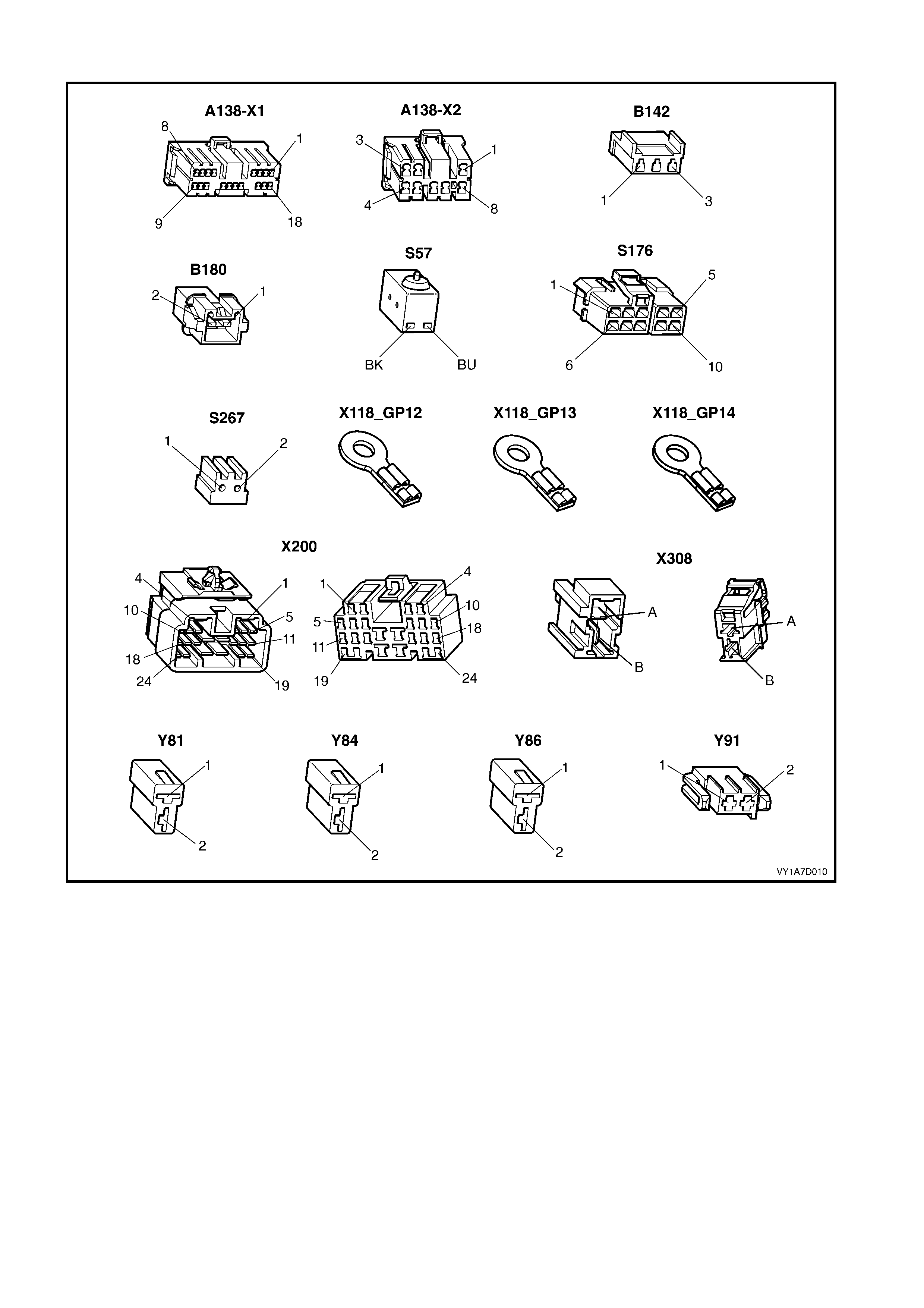
CONNECTOR CHART – PASSENGER'S EIGHT-WAY SEAT, NON-MEMORY
Figure 1A7-159

NONE OF THE PASSENGER’S EIGHT-WAY SEAT A DJUSTMENT SWITCH FUNCTIONS OPERATE
Introduction
This test is us ed by the tec hnician to aid in the diagnos is of the pas senger ’s eight-way seat adjustment switch when
none of the switch functions operate. The test diagnoses the passenger’s eight-way seat adjustment switch and
associated power and earth circuits.
Test Description
The following numbers refer to the Step numbers in the diagnostic chart for none of the passenger’s eight-way
adjustment switch functions operating.
1. Chec ks whether all of the driver ’s seat eight- way functions work . If none of them work , the fault is not isolated to
the passenger’s seat only.
2. Checks whether there is battery power at connector X308 pin B. Isolates whether there is a fault in circuit 540
between connectors X200 pin 15 and X308 pin B.
3. Checks that all the connectors required for the seat to operate effectively are in place and positively connected.
4. Checks whether there is battery power at connector A138_L – X1 pin 5. Isolates whether there is a fault in
circuit 540 between connectors A138_L – X1 pin 5 and X308 pin B.
5. Checks whether there is battery power at connector A138_L – X1 pin 12. Isolates whether there is a fault with
the EZ-entry module.
6. Checks whether there is battery power at connector S176 – X1 pin 5. Isolates whether there is a fault in the
circuit 1674 between connectors S176 – X1 pin 5 and A138_L – X1 pin 12.
7. Checks whether the passenger’s eight-way seat adjustment switch is serviceable.
8. Checks whether there is continuity between connectors S176 – X1 pin 1 and X308 pin A which supplies the
earth circ uit for the pass enger’s eight-way seat adjus tment switch. Is olates whether there is a fault between the
switch and connector X308 pin A or between connector X308 pin A and the earthing points.
9. Checks whether there is continuity between connectors A138_L – X1 pin 4 and X308 pin A. Isolates whether
there is a f ault between the switch and connector A138_L – X 1 pin 4 or between connectors A138_L – X1 pin 4
and X308 pin A.
10. Checks whether there is continuity between connectors A138_L – X1 pin 15 and A138_L – X1 pin 4. Isolates
whether there is a fault between the switch and connector A138_L – X1 pin 15 or the EZ-entry module is at
fault.
STEP ACTION YES NO
1. Are all of the driver's eight-way seat
adjustment switch functions inoperative? Refer to NEITHER SEAT
ADJUSTMENT SWITCH
FUNCTIONS OPERATE in
this Section.
Go to Step 2.
2. 1. Back probe connector X308 pin B with a
test lamp.
Does the test lamp illuminate? Go to Step 3.
There is a fault in circuit
540 between connectors
X200 pin 15 and
X308 pin B.
Repair or replace circuit
540.
3. Are the following connectors secure?
• A138_L
• S176
• X308
• Y81
• Y84
• Y86
• Y91
Go to Step 4. Ensure that the connectors
are secure.
4. 1. Back probe connector A138_L – X1 pin 5
with a test lamp.
Does the test lamp illuminate? Go to Step 5.
There is a fault in circuit
540 between connectors
A138_L – X1 pin 5 and
X308 pin B.
Repair or replace circuit
540.

STEP ACTION YES NO
5. 1. Back probe connector A138_L – X1
pin 12 with a test lamp.
Does the test lamp illuminate? Go to Step 6.
Replace the passenger’s
EZ-entry module.
Refer to 4.7 EZ-ENTRY
MODULE, EIGHT-WAY
NON-MEMORY SEAT.
6. 1. Back probe connector S176 – X1 pin 5
with a test lamp.
Does the test lamp illuminate? Go to Step 7.
There is a fault in circuit
1674 between connectors
S176 – X1 pin 5 and
A138_L – X1 pin 12.
Repair or replace circuit
1674.
7. 1. Remove the passenger’s eight-way seat
adjustment switch from the seat, refer to
4.4 EIGHT-WAY SEAT ADJUSTMENT
SWITCH.
2. Test the passenger’s eight-way seat
adjustment switch, refer to 3.6 EIGHT-
WAY SEAT ADJUSTMENT SWITCH
TEST.
Is the passenger’s eight-way seat adjustment
switch serviceable?
Go to Step 8.
Replace the passenger’s
eight-way seat adjustment
switch.
Refer to 4.4 EIGHT-W AY
SEAT ADJUSTMENT
SWITCH.
8. 1. Back probe connector X308 pin A with a
test lamp.
2. Operate the passenger’s eight-way seat
adjustment switch in any of the available
directions.
Does the test lamp illuminate?
There is a fault in circuit
650 between connector
X308 pin A and earth
points X118–GP12, X118–
GP13 and X118–GP14.
Repair or replace circuit
650.
Go to Step 9.
9. 1. Back probe connector A138_L – X1 pin 4
with a test lamp.
2. Operate the passenger’s eight-way seat
adjustment switch in any of the available
directions.
Does the test lamp illuminate?
There is a fault in circuit
650 between connectors
A138_L – X1 pin 4 and
X308 pin A.
Repair or replace circuit
650.
Go to Step 10.
10. 1. Back probe connector A138_L – X1
pin 15 with a test lamp.
2. Operate the passenger’s eight-way seat
adjustment switch in any of the available
directions.
Does the test lamp illuminate?
Replace the passenger’s
EZ-entry module.
Refer to 4.7 EZ-ENTRY
MODULE, EIGHT-WAY
NON-MEMORY SEAT.
There is a fault in circuit
1246 between connectors
S176 – X1 pin 1 and
A138_L – X1 pin 15.
Repair or replace circuit
1246.
When all diagnosis and repairs are completed, check the system for correct operation.

FRONT/REAR OF THE PASSENGER’S SEAT DOES NOT RAISE AND/OR LOWER
Introduction
This test is used by the technician to aid in the diagnosis of the front and/or the rear of the passenger’s seat not
raising and/or lowering. The test diagnoses the eight-way seat adjustment switch and the motor circuits.
Test Description
The following numbers refer to the Step numbers in the diagnostic chart.
1. Checks whether the passenger’s eight-way seat adjustment switch operates in any of the directions. Isolates
whether the power and earth circuits are at fault.
2. Checks that all the connectors required for the seat to operate effectively are in place and positively connected.
3. Checks whether the passenger’s eight-way seat adjustment switch is serviceable.
4. Conf irm s whether the rear of the seat r aises or lowers. Isolates whether the rear m otor and c ircuit of the seat is
the fault.
5. Confirms whether the front of the seat raises or lowers. Isolates whether the front motor and circuit of the seat is
the fault.
6. Checks whether there is battery power to the seat rear motor at connector Y86 – X1 pin 1. Isolates whether
there is a fault in circuit 288 that supplies battery power to the motor to raise the rear of the seat.
7. Check s whether there is battery power to the seat rear motor at connector Y86 – X1 pin 2. Isolates whether the
fault is in circuit 289 that supplies battery power to the motor to lower the rear of the seat or the m otor is faulty.
As the direction of the motor is changed by reversing the polarity, this Step also confirms that the earth circuit
from Step 6 is serviceable.
8. Checks whether there is battery power to the seat front motor at connector Y84 – X1 pin 1. Isolates whether
there is a fault in circuit 297 that supplies battery power to the motor to raise the front of the seat.
9. Chec ks whether ther e is battery power to the seat front m otor at c onnector Y84 – X1 pin 2. Is olates whether the
fault is in circ uit 298 that supplies batter y power to the m otor to lower the fr ont of the s eat or the m otor is f aulty.
As the direction of the motor is changed by reversing the polarity, this Step also confirms that the earth circuit
from Step 8 is serviceable.
STEP ACTION YES NO
1. Does the passenger’s eight-way seat
adjustment switch operate correctly in any of
the eight directions? Go to Step 2.
Refer to NONE OF THE
PASSENGER'S EIGHT-
WAY SEAT ADJUSTMENT
SWITCH FUNCTIONS
OPERATE in this Section.
2. Are the following connectors secure?
• A138_L
• S176
• Y84
• Y86
Go to Step 3. Ensure that the connectors
are secure.
3. 1. Remove the passenger’s eight-way seat
adjustment switch from the seat, refer to
4.4 EIGHT-WAY SEAT ADJUSTMENT
SWITCH.
2. Test the passenger’s eight-way seat
adjustment switch, refer to 3.6 EIGHT-
WAY SEAT ADJUSTMENT SWITCH
TEST.
Is the passenger’s eight-way seat adjustment
switch serviceable?
Go to Step 4.
Replace the passenger’s
eight-way seat adjustment
switch.
Refer to 4.4 EIGHT-W AY
SEAT ADJUSTMENT
SWITCH.
4. 1. Operate the passenger’s eight-way seat
adjustment switch so that the rear of the
seat is raised or lowered.
Does the rear of the seat raise and lower?
Go to Step 5. Go to Step 6.
5. 1. Operate the passenger’s eight-way seat
adjustment switch so that the front of the
seat is raised or lowered.
Does the front of the seat raise and lower?
System serviceable. Go to Step 8.

STEP ACTION YES NO
6. 1. Back probe connector Y86 – X1 pin 1 with
a test lamp.
2. Operate the passenger’s eight-way seat
adjustment switch so that it will raise the
rear of the seat.
Does the test lamp illuminate?
Go to Step 7.
There is a fault in circuit
288 between connectors
S176 – X1 pin 8 and
Y86 – X1 pin 1.
Repair or replace circuit
288.
7. 1. Back probe connector Y86 – X1 pin 2 with
a test lamp.
2. Operate the passenger’s eight-way seat
adjustment switch so that it will lower the
rear of the seat.
Does the test lamp illuminate?
The seat rear motor is
faulty.
Replace the seat rear
motor, refer to 4.20 FRONT
SEAT LIFT MOTORS.
Go to Step 5.
There is a fault in circuit
289 between connectors
S176 – X1 pin 9 and
Y86 – X1 pin 2.
Repair or replace circuit
289.
Go to Step 5.
8. 1. Back probe connector Y84 – X1 pin 1 with
a test lamp.
2. Operate the passenger’s eight-way seat
adjustment switch so that it will raise the
front of the seat.
Does the test lamp illuminate?
Go to Step 9.
There is a fault in circuit
297 between connectors
S176 – X1 pin 7 and
Y84 – X1 pin 1.
Repair or replace circuit
297.
9. 1. Back probe connector Y84 – X1 pin 2 with
a test lamp.
2. Operate the passenger’s eight-way seat
adjustment switch so that it will lower the
front of the seat.
Does the test lamp illuminate?
The seat front motor is
faulty.
Replace the seat front
motor, refer to 4.20 FRONT
SEAT LIFT MOTORS.
There is a fault in circuit
298 between connectors
S176 – X1 pin 10 and
Y84 – X1 pin 2.
Repair or replace circuit
298.
When all diagnosis and repairs are completed, check the system for correct operation.

PASSENGER’S SEAT FORE/AFT FUNCTION IS INOPERATIVE OR NOT SMOOTH
Introduction
This test is used by the technician to aid in the diagnosis of the fore/aft function of the passenger's seat being
inoperative or the action of the seat through the range of movement is not smooth. The test diagnoses the eight-
way seat adjustment switch and the motor circuits.
Test Description
The following numbers refer to the Step numbers in the diagnostic chart.
1. Checks whether the passenger's eight-way seat adjustment switch operates in any of the directions. Isolates
whether there is battery power to the switch assembly.
2. Checks that there are no items obstructing the guide rails, which may stop or hinder the seat movement.
3. Checks that the guide rails and drive shafts have adequate lubricant applied to provide a smooth operation of
the seat.
4. Checks that the guide rails or drive shafts have not been damaged. Any binding between the moving parts will
result in poor operation of the fore and aft movement.
5. Checks that all the connectors required for the seat to operate effectively are in place and positively connected.
6. Checks whether the passenger's eight-way seat adjustment switch is serviceable.
7. Checks whether there is battery power to the seat fore/aft m otor at connector Y81 – X1 pin 1. Isolates whether
there is a fault between the switch and connector Y81 – X1 pin 1.
8. Checks whether there is continuity between connectors S176 – X1 pin 6 and A138_L – X1 pin 14. Isolates
whether there is a fault between the switch and connector A138_L – X1 pin 14 or in circuit 296.
9. Checks whether there is continuity between connectors S176 – X1 pin 6 and A138_L – X1 pin 18. Isolates
whether there is a fault in circuit 1523 or the passenger's EZ-entry module is at fault.
10. Check s whether there is battery power to the seat f ore/aft m otor at connector Y81 – X1 pin 2. Isolates whether
there is a fault between the switch and connec tor Y81 – X1 pin 2 or the m otor is f aulty. As reversing the polarity
changes the direction of the motor, this Step also confirms that the earth circuit from Step 7 is serviceable.
11. Checks whether there is continuity between connectors S176 – X1 pin 3 and A138_L – X1 pin 3. Isolates
whether there is a fault between the switch and connector A138_L – X1 pin 3 or in circuit 290.
12. Checks whether there is continuity between connectors S176 – X1 pin 3 and A138_L – X1 pin 17. Isolates
whether there is a fault in circuit 1522 or the passenger's EZ-entry module is at fault.
STEP ACTION YES NO
1. Does the passenger's eight-way seat
adjustment switch operate correctly in any of
the eight directions? Go to Step 2.
Refer to NONE OF THE
PASSENGER'S EIGHT-
WAY SEAT ADJUSTMENT
SWITCH FUNCTIONS
OPERATE in this Section.
2. Are the guide rails free from obstructions? Go to Step 3. Remove the obstructing
item.
3. Are the guide rails and drive shafts adequately
lubricated? Go to Step 4. Apply a small amount of
grease type NLGI No. 1
Lithium Grease (with 9%
Zinc Oxide).
4. Do the guide rails or drive shafts bind at any
point of travel during the fore and aft
movement of the seat?
Replace the front seat
adjuster assembly.
Refer to 4.19 FRONT
SEAT ADJUSTER
ASSEMBLY.
Go to Step 5.
5. Are the following connectors secure?
• A138_L
• S176
• Y81
Go to Step 6. Ensure that the connectors
are secure.

STEP ACTION YES NO
6. 1. Remove the passenger's eight-way seat
adjustment switch from the seat, refer to
4.4 EIGHT-WAY SEAT ADJUSTMENT
SWITCH.
2. Test the passenger's eight-way seat
adjustment switch, refer to 3.6 EIGHT-
WAY SEAT ADJUSTMENT SWITCH
TEST.
Is the passenger's eight-way seat adjustment
switch serviceable?
Go to Step 7.
Replace the passenger's
eight-way seat adjustment
switch.
Refer to 4.4 EIGHT-W AY
SEAT ADJUSTMENT
SWITCH.
7. 1. Back probe connector Y81 – X1 pin 1 with
a test lamp.
2. Operate the passenger's eight-way seat
adjustment switch so that it will move the
seat forward.
Does the test lamp illuminate?
Go to Step 10. Go to Step 8.
8. 1. Back probe connector A138_L - X1 pin 14
with a test lamp.
2. Operate the passenger's eight-way seat
adjustment switch so that it will move the
seat forward.
Does the test lamp illuminate?
There is a fault in circuit
296 between connectors
A138_L – X1 pin 14 and
Y81 – X1 pin 1.
Repair or replace circuit
296.
Go to Step 9.
9. 1. Back probe connector A138_L - X1 pin 18
with a test lamp.
2. Operate the passenger's eight-way seat
adjustment switch so that it will move the
seat forward.
Does the test lamp illuminate?
Replace the passenger's
EZ-entry module.
Refer to 4.7 EZ-ENTRY
MODULE, EIGHT-WAY
NON-MEMORY SEAT.
There is a fault in circuit
1523 between connectors
S176 – X1 pin 6 and
A138_L – X1 pin 18.
Repair or replace circuit
1523.
10. 1. Back probe connector Y81 – X1 pin 2 with
a test lamp.
2. Operate the passenger's eight-way seat
adjustment switch so that it will move the
seat aft.
Does the test lamp illuminate?
The seat fore/aft motor is
faulty.
Replace the seat fore/aft
motor, refer to 4.21 FRONT
SEAT FORE/AFT
MOVEMENT MOTOR.
Go to Step 11.
11. 1. Back probe connector A138_L - X1 pin 3
with a test lamp.
2. Operate the passenger's eight-way seat
adjustment switch so that it will move the
seat aft.
Does the test lamp illuminate?
There is a fault in circuit
290 between connectors
A138_L – X1 pin 3 and
Y81 – X1 pin 2.
Repair or replace circuit
290.
Go to Step 12.
12. 1. Back probe connector A138_L - X1 pin 17
with a test lamp.
2. Operate the passenger's eight-way seat
adjustment switch so that it will move the
seat aft.
Does the test lamp illuminate?
Replace the passenger's
EZ-entry module.
Refer to 4.7 EZ-ENTRY
MODULE, EIGHT-WAY
NON-MEMORY SEAT.
There is a fault in circuit
1522 between connectors
S176 – X1 pin 3 and
A138_L – X1 pin 17.
Repair or replace circuit
1522.
When all diagnosis and repairs are completed, check the system for correct operation.

PASSENGER'S SEAT RECLINE FORWARD AND/OR AFT FUNCTION IS INOPERATIVE
Introduction
This test is used by the technician to aid in the diagnosis of the reclining function of the passenger's seat being
inoperative. The test diagnoses the eight-way seat adjustment switch and the motor circuits.
Test Description
The following numbers refer to the Step numbers in the diagnostic chart.
1. Checks whether the passenger's eight-way seat adjustment switch operates in any of the directions. Isolates
whether there is battery power to the switch assembly.
2. Checks that all the connectors required for the seat to operate effectively are in place and positively connected.
3. Checks whether the passenger's eight-way seat adjustment switch is serviceable.
4. Chec ks whether there is battery power to the seat reclining motor at connec tor Y91 – X1 pin 1. Is olates whether
there is a fault between the switch and connector Y91 – X1 pin 1.
5. Checks whether there is continuity between connectors S176 – X1 pin 2 and A138_L – X2 pin 2. Isolates
whether there is a fault between the switch and connector A138_L – X2 pin 2 or in circuit 76.
6. Checks whether there is continuity between connectors S176 – X1 pin 2 and A138_L – X1 pin 2. Isolates
whether there is a fault in circuit 1269 or the passenger's EZ-entry module is at fault.
7. Chec ks whether there is battery power to the seat reclining motor at connec tor Y91 – X1 pin 2. Is olates whether
there is a fault between the switch and connec tor Y91 – X1 pin 2 or the m otor is f aulty. As reversing the polarity
changes the direction of the motor, this Step also confirms that the earth circuit from Step 4 is serviceable.
8. Checks whether there is continuity between connectors S176 – X1 pin 4 and A138_L – X2 pin 3. Isolates
whether there is a fault between the switch and connector A138_L – X2 pin 3 or in circuit 77.
9. Checks whether there is continuity between connectors S176 – X1 pin 4 and A138_L – X1 pin 1. Isolates
whether there is a fault in circuit 1270 or the passenger's EZ-entry module is at fault.
STEP ACTION YES NO
1. Does the passenger's eight-way seat
adjustment switch operate correctly in any of
the eight directions? Go to Step 2.
Refer to NONE OF THE
PASSENGER'S EIGHT-
WAY SEAT ADJUSTMENT
SWITCH FUNCTIONS
OPERATE in this Section.
2. Are the following connectors secure?
• A138_L
• S176
• Y91
Go to Step 3. Ensure that the connectors
are secure.
3. 1. Remove the passenger's eight-way seat
adjustment switch from the seat, refer to
4.4 EIGHT-WAY SEAT ADJUSTMENT
SWITCH.
2. Test the passenger's eight-way seat
adjustment switch, refer to 3.6 EIGHT-
WAY SEAT ADJUSTMENT SWITCH
TEST.
Is the passenger's eight-way seat adjustment
switch serviceable?
Go to Step 4.
Replace the passenger's
eight-way seat adjustment
switch.
Refer to 4.4 EIGHT-W AY
SEAT ADJUSTMENT
SWITCH.
4. 1. Back probe connector Y91 – X1 pin 1 with
a test lamp.
2. Operate the passenger's eight-way seat
adjustment switch so that it will move the
seat-back forward.
Does the test lamp illuminate?
Go to Step 7. Go to Step 5.
5. 1. Back probe connector A138_L - X2 pin 2
with a test lamp.
2. Operate the passenger's eight-way seat
adjustment switch so that it will move the
seat-back forward.
Does the test lamp illuminate?
There is a fault in circuit 76
between connectors
A138_L – X2 pin 2 and
Y91 – X1 pin 1.
Repair or replace circuit 76.
Go to Step 6.

STEP ACTION YES NO
6. 1. Back probe connector A138_L - X1 pin 2
with a test lamp.
2. Operate the passenger's eight-way seat
adjustment switch so that it will move the
seat-back forward.
Does the test lamp illuminate?
Replace the passenger's
EZ-entry module.
Refer to 4.7 EZ-ENTRY
MODULE, EIGHT-WAY
NON-MEMORY SEAT.
There is a fault in circuit
1269 between connectors
S176 – X1 pin 2 and
A138_L – X1 pin 2.
Repair or replace circuit
1269.
7. 1. Back probe connector Y91 – X1 pin 2 with
a test lamp.
2. Operate the passenger's eight-way seat
adjustment switch so that it will move the
seat-back aft.
Does the test lamp illuminate?
The seat reclining motor is
faulty.
Replace the seat reclining
motor, refer to 4.22 FRONT
SEAT RECLINING
MOTOR, GEARBOX AND
POTENTIOMETER
ASSEMBLY.
Go to Step 8.
8. 1. Back probe connector A138_L - X2 pin 3
with a test lamp.
2. Operate the passenger's eight-way seat
adjustment switch so that it will move the
seat-back aft.
Does the test lamp illuminate?
There is a fault in circuit 77
between connectors
A138_L – X2 pin 3 and
Y91 – X1 pin 2.
Repair or replace circuit 77.
Go to Step 9.
9. 1. Back probe connector A138_L - X1 pin 1
with a test lamp.
2. Operate the passenger's eight-way seat
adjustment switch so that it will move the
seat-back aft.
Does the test lamp illuminate?
Replace the passenger's
EZ-entry module.
Refer to 4.7 EZ-ENTRY
MODULE, EIGHT-WAY
NON-MEMORY SEAT.
There is a fault in circuit
1270 between connectors
S176 – X1 pin 4 and
A138_L – X1 pin 1.
Repair or replace circuit
1270.
When all diagnosis and repairs are completed, check the system for correct operation.

PASSENGER'S SEAT EZ-ENTRY SWITCH FUNCTION IS INOPERATIVE
Introduction
The EZ- entr y function is des igned s o that when the seat-bac k is releas ed with the EZ-entr y lever, the seat will move
to its fully forward position using the seat fore/aft motor. Once the seat has moved to its fully forward position, power
to the seat fore/aft motor will cease. A switch attached to the seat-back activates the seat fore/aft motor when the
recline of the seat-back is moved forward after being released using the EZ-entry lever. This test is used by the
technician to aid in the diagnosis of the EZ-entry function of the passenger's seat being inoperative. The test
diagnoses the EZ-entry switch and associated circuits.
Test Description
The following numbers refer to the Step numbers in the diagnostic chart.
1. Checks whether the seat fore/aft motor is serviceable.
2. Checks whether there is battery power to the EZ-entry switch. Isolates whether there is a fault with the
passenger's EZ-entry module.
3. Checks whether there is continuity between connectors A138_L – X2 pin 7 and A138_L – X2 pin 8. Isolates
whether the passenger's EZ-entry module is at fault.
STEP ACTION YES NO
1. Does the seat move in the fore/aft direction
when operated by the passenger's eight-way
seat adjustment switch? Go to Step 2.
Refer to PASSENGER'S
SEAT FORE/AFT
FUNCTION IS
INOPERATIVE OR NOT
SMOOTH in this Section.
2. 1. Back probe connector A138_L – X2 pin 7
with a test lamp.
Does the test lamp illuminate? Go to Step 3.
Replace the passenger's
EZ-entry module.
Refer to 4.7 EZ-ENTRY
MODULE, EIGHT-WAY
NON-MEMORY SEAT.
3. 1. Release the seat-back using the EZ-entry
lever.
2. Back probe connector A138_L – X2 pin 8
with a test lamp.
Does the test lamp illuminate?
Replace the passenger's
EZ-entry module.
Refer to 4.7 EZ-ENTRY
MODULE, EIGHT-WAY
NON-MEMORY SEAT.
Replace the passenger's
EZ-entry switch, refer to
4.13 EZ-ENTRY CABLE
AND SWITCH ASSEMBLY.
When all diagnosis and repairs are completed, check the system for correct operation.

PASSENGER'S SEAT RETURN SWITCH FUNCTION IS INOPERATIVE
Introduction
The s eat return switch is located on the esc utcheon at the top of the seat-bac k. The s witc h function is to move the
seat in an aft direction after the EZ-entry function has been used and the recline of the seat has been placed
upright. W ith the seat return switch continuously pressed, the seat will move to its fully aft position, pausing for 2
seconds at the s eat position where the EZ- entry lever was operated. The test diagnoses the seat retur n switch and
associated circuits.
Test Description
The following numbers refer to the Step numbers in the diagnostic chart.
1. Checks whether the seat fore/aft motor is serviceable.
2. Checks whether the seat will move to its fully forward position when the seat-back is released using the EZ-
entry lever. Isolates whether the EZ-entry switch function is serviceable.
3. Chec ks whether the seat will move aft when the seat- back is in the upright pos ition and the s eat retur n s witch is
pressed. Isolates whether the return switch is serviceable.
4. Checks whether there is battery power at connector A138_L – X2 pin 6. Isolates whether there is a fault with the
passenger's EZ-entry module.
5. Checks whether there is continuity between connectors A138_L – X2 pin 1 and A138_L – X2 pin 6. Isolates
whether there is a fault with the seat return switch and associated circuits.
6. Checks whether there is continuity between connectors A138_L – X2 pin 6 and S267 – X1 pin 2. Isolates
whether there is a fault in circuit 1023.
7. Checks whether there is continuity between connectors S267 – X1 pin 1 and A138_L – X2 pin 6. Isolates
whether there is a fault with the passenger's seat return switch or in circuit 1022.
STEP ACTION YES NO
1. Does the seat move in the fore/aft direction
when operated by the passenger's eight-way
seat adjustment switch? Go to Step 2.
Refer to PASSENGER'S
SEAT FORE/AFT
FUNCTION IS
INOPERATIVE OR NOT
SMOOTH in this Section.
2. 1. Release the seat-back using the EZ-entry
lever.
Does the seat move forward? Go to Step 3.
Refer to PASSENGER'S
SEAT EZ-ENTRY SWITCH
FUNCTION IS
INOPERATIVE in this
Section.
3. 1. Move the seat-back to the upright
position.
2. Press the seat return switch.
Does the seat move aft?
System Serviceable. Go to Step 4.
4. 1. Back probe connector A138_L – X2 pin 6
with a test lamp.
Does the test lamp illuminate? Go to Step 5.
Replace the passenger's
EZ-entry module.
Refer to 4.7 EZ-ENTRY
MODULE, EIGHT-WAY
NON-MEMORY SEAT.
5. 1. Back probe connector A138_L – X2 pin 1
with a test lamp.
2. Press the seat return switch.
Does the test lamp illuminate?
Replace the passenger's
EZ-entry module.
Refer to 4.7 EZ-ENTRY
MODULE, EIGHT-WAY
NON-MEMORY SEAT.
Go to Step 6.
6. 1. Back probe connector S267 – X1 pin 2
with a test lamp.
Does the test lamp illuminate? Go to Step 7.
There is a fault in circuit
1023 between connectors
S267 – X1 pin 2 and
A138_L – X2 pin 6.
Repair or replace circuit
1023.
7. 1. Back probe connector S267 – X1 pin 1
with a test lamp.
2. Press the seat return switch.
Does the test lamp illuminate?
There is a fault in circuit
1022 between connectors
S267 – X1 pin 1 and
A138_L – X2 pin 1.
Repair or replace circuit
1022.
Replace the passenger's
seat return switch, refer to
4.12 EZ-ENTRY LEVER
ARM, ESCUTCHEON AND
SEAT RETURN SWITCH
ASSEMBLY.
When all diagnosis and repairs are completed, check the system for correct operation.

PASSENGER'S SEAT TRACK MOTOR POSITION SENSOR POTENTIOMETER TEST
Introduction
This test is us ed by the tec hnician to aid in the diagnosis of the seat track motor position sensor potentiometer and
associated circuits.
Test Description
The following numbers refer to the Step numbers in the diagnostic chart.
1. Checks whether the seat position sensor potentiometer is serviceable.
2. Checks whether there is continuity between connectors B142 – X1 pin 2 and A138_L – X1 pin 7. Isolates
whether there is a fault in circuit 569.
3. Checks whether there is continuity between connectors B142 – X1 pin 3 and A138_L – X1 pin 16. Isolates
whether there is a fault in circuit 3140.
STEP ACTION YES NO
1. 1. Disconnect connector B142 – X1 from the
position sensor potentiometer.
2. Using a digital multimeter set to measure
resistance, probe across the
potentiometer terminals.
3. Operate the passenger's eight-way seat
adjustment switch so that it will move the
seat forward and aft.
Multimeter should indicate between 0 and
10 kΩ (depending on seat position). Is the
resistance reading as specified?
Go to Step 2.
Replace the position
sensor potentiometer, refer
to 4.23 DRIVE MOTOR
POTENTIOMETERS.
2. 1. Disconnect connector A138_L – X1 from
the driver’s EZ-entry module.
2. Using a digital multimeter set to measure
resistance, probe across connectors
B142 – X1 pin 2 and A138_L – X1 pin 7.
Multimeter should indicate continuity. Is the
resistance reading as specified?
Go to Step 3. Repair or replace circuit
569.
3. 1. Using a digital multimeter set to measure
resistance, probe across connectors
B142 – X1 pin 3 and A138_L – X1 pin 16.
Multimeter should indicate continuity. Is the
resistance reading as specified?
Potentiometer and
associated wiring
serviceable.
Repair or replace circuit
3140.
When all diagnosis and repairs are completed, check the system for correct operation.

PASSENGER'S SEAT OCCUPANT SENSING MAT TEST
Introduction
This test is used by the technician to aid in the diagnosis of the occupant sensing mat and associated circuits.
Test Description
The following numbers refer to the Step numbers in the diagnostic chart.
1. Checks diode forward resistance of the Passenger Presence Detector (PPD).
2. Checks diode reverse resistance of the PPD.
3. Checks diode reverse resistance of the PPD with w eight on seat.
4. Checks whether there is continuity between connectors B180 – X1 pin 1 and A138_L – X1 pin 9. Isolates
whether there is a fault in circuit 5234.
5. Checks whether there is continuity between connectors B180 – X1 pin 2 and A138_L – X1 pin 10. Isolates
whether there is a fault in circuit 529.
STEP ACTION YES NO
1. 1. Disconnect connector B180 – X1 from the
occupant sensing mat.
2. Using a digital multimeter set to measure
resistance, connect red (+) probe to
terminal 1 and black (–) probe to terminal
2 of the occupant sensing mat.
Multimeter should indicate continuity. Is the
resistance reading as specified?
Go to Step 2.
Replace the occupant
sensing mat, refer to 4.17
FRONT SEAT CUSHION
PAD AND COVER
ASSEMBLY.
2. 1. Using a digital multimeter set to measure
resistance, connect red (+) probe to
terminal 2 and black (–) probe to terminal
1 of the occupant sensing mat.
Multimeter should indicate greater than 50 kΩ.
Is the resistance reading as specified?
Go to Step 3.
Replace the occupant
sensing mat, refer to 4.17
FRONT SEAT CUSHION
PAD AND COVER
ASSEMBLY.
3. 1. Place a weight greater than 15 kg on the
seat.
2. Using a digital multimeter set to measure
resistance, connect red (+) probe to
terminal 2 and black (–) probe to terminal
1 of the occupant sensing mat.
Multimeter should indicate less than 50 kΩ.
(Resistance decreases as the weight
increases). Is the resistance reading as
specified?
Go to Step 4.
Replace the occupant
sensing mat, refer to 4.17
FRONT SEAT CUSHION
PAD AND COVER
ASSEMBLY.
4. 1. Disconnect connector A138_L – X1 from
the driver’s EZ-entry module.
2. Using a digital multimeter set to measure
resistance, probe across connectors
B180 – X1 pin 1 and A138_L – X1 pin 9.
Multimeter should indicate continuity. Is the
resistance reading as specified?
Go to Step 5. Repair or replace circuit
5234.
5. 1. Using a digital multimeter set to measure
resistance, probe across connectors
B180 – X1 pin 2 and A138_L – X1 pin 10.
Multimeter should indicate continuity. Is the
resistance reading as specified?
Occupant sensing mat and
associated wiring
serviceable.
Repair or replace circuit
529.
When all diagnosis and repairs are completed, check the system for correct operation.
5.6 ELECTRICAL SELF TEST DIAGNOSIS – EIGHT-WAY SEAT, MEMORY
EZ-ENTRY AND MEMORY DIAGNOSTICS
Introduction
The memory type seat provides the technician with in-built diagnostics. The diagnostics indicator is a green LED
located on the memory position switch. To enter the diagnostic mode, cycle the ignition while holding memory
buttons 1 and 3 at the same time.
• The chart in this Section displays the error codes and fault description.
• If the error c ode is above ten, the indication will cons ist of a single flas h, a short delay and then the num ber of
flashes corresponding to the error. A longer delay will occur between error code indications.
EZ-ENTRY AND MEMORY DIAGNOSTICS
Flashes Description of ERROR Reference
2 No Passenger Presence Detector
(PPD) detected Driver's Seat Occupant Sensing Mat Test in this Section
3 PPD weight detected > 15kg Driver's Seat Occupant Sensing Mat Test in this Section
4 Track motor sensor faulty Driver's Seat Track Motor Position Sensor Potentiometer Test in
this Section
5 Aft lift motor sensor faulty Front/Rear of Driver's Seat Does Not Raise and/or Lower in this
Section
6 Forward lift motor sensor faulty Front/Rear of Driver's Seat Does Not Raise and/or Lower in this
Section
7 Recliner motor sensor faulty Driver's Seat Recline Forward and/or Aft Function is Inoperative
in this Section
8 Button stuck detected 5.8 ELECTRICAL DIAGNOSIS – DRIVER'S EIGHT-WAY SEAT,
MEMORY
9 Dump latch active Driver's EZ-entry Switch Function Is Inoperative in this Section
11 Return button active Driver's EZ-entry Switch Function Is Inoperative in this Section
12 Forward track switch active 3.6 EIGHT-WAY SEAT ADJUSTMENT SWITCH TEST
13 Reverse track switch active 3.6 EIGHT-WAY SEAT ADJUSTMENT SWITCH TEST
14 Recliner forward switch active 3.6 EIGHT-WAY SEAT ADJUSTMENT SW ITCH TEST
15 Recliner back ward switch active 3.6 EIGHT-WAY SEAT ADJUSTMENT SWITCH TEST
16 Memory 1 button active 5.9 MEMORY POSITION SWITCH TEST
17 Memory 2 button active 5.9 MEMORY POSITION SWITCH TEST
18 Memory 3 button active 5.9 MEMORY POSITION SWITCH TEST
19 Memory store M button active 5.9 MEMORY POSITION SWITCH TEST

5.7 ELECTRICAL DIAGNOSIS – EIGHT-WAY SEAT, MEMORY
Both front seats have common power and earth circuits. If either of these circuits become unserviceable, the
operation of both seats electrically, will be affected.
NEITHER SEAT ADJUSTMENT SWITCH FUNCTIONS OPERATE
Introduction
This test is used by the technician to aid in the diagnosis of the seat power and earth circuits if neither seat operates
when either eight-way seat adjustment switch is operated. Refer to Figure 1A7-160.
Test Description
The following numbers refer to the Step numbers in the diagnostic chart.
1. Checks that battery voltage is more than 11.5 volts. The seat motors require more than 11.5 volts to operate
correctly.
2. Checks that circuit breaker F2 located on the passenger compartment fuse and relay panel assembly is not
tripped. Isolates whether circuit breaker F2 is the fault affecting the circuit between the battery and connector
X200 pin 15.
3. Check s that fusible link F 105 located on the engine com par tm ent fus e and relay panel assem bly is serviceable.
Isolates whether the fusible link is the fault affecting the circuit between the battery and connector X200 pin 15.
4. Ensures that connector X200 is secure.
5. Checks whether there is battery voltage at connector X200 pin 15. Isolates whether the fault is between the
battery and connector X200 pin 15. If the fault in the circ uit is between c onnectors X200 pin 15 and either X315
pin 1 or X308 pin B, only one seat will not operate.
6. Checks whether there is battery voltage at circuit breaker F2. Isolates whether the fault is between the battery
and circuit breaker F2 or between circuit breaker F2 and connector X200 pin 15.
7. Chec ks whether there is batter y voltage at fusible link F10. Isolates whether the f ault is between the battery and
fusible link F105 or between fusible link F105 and circuit breaker F2.
8. Checks that all the earth points associated with the system are serviceable and a good earth is provided at each
point.
STEP ACTION YES NO
1. 1. Check the battery voltage, refer to Section
12A, 2.9 BATTERY.
Is the battery voltage more than 11.5 V? Go to Step 2. Refer to Section 12A,
2.9 BATTERY for further
diagnosis.
2. 1. Inspect circuit breaker F2, refer to Section
12O, 2.2 CIRCUIT BREAKERS.
Is circuit breaker F2 tripped?
Allow the circuit breaker to
reset, refer to Section 12O,
2.2 CIRCUIT BREAKERS. Go to Step 3.
3. 1. Inspect fusible link F105, refer to Section
12O, 2.3 FUSIBLE LINKS.
Is fusible link F105 serviceable? Go to Step 4. Replace the fusible link.
4. Is connector X200 secure? Go to Step 5. Ensure that the connector
is secure.
5. 1. Back probe connector X200 pin 15 with a
test lamp.
Does the test lamp illuminate? Go to Step 8. Go to Step 6.
6. 1. Remove circuit breaker F2 from the
passenger compartment fuse and relay
panel assembly.
2. Using a test lamp, probe connector
X129 – X45 pin 2. Refer to Section 12P
WIRING DIAGRAMS.
Does the test lamp illuminate?
There is a fault in circuit
540 between circuit breaker
F2 and connector
X200 pin 15.
Repair or replace circuit
540.
Go to Step 7.
7. 1. Remove the fusible link F105.
2. Using a test lamp, probe connector
X18-105. Refer to Section 12P WIRING
DIAGRAMS.
Does the test lamp illuminate?
There is a fault in circuit
342 between fusible link
F105 and circuit breaker
F2.
Repair or replace circuit
342.
There is a fault in circuit 1
between the battery and
fusible link F105.
Repair or replace circuit 1.

STEP ACTION YES NO
8. 1. Ensure that the following earth points are
secure and have good contact with the
vehicle structure:
• X118–GP12 located in the middle of the
transmission tunnel.
• X118–GP13 located in the rear
compartment on the right-hand side tail
lamp stud.
• X118–GP14 located in the rear
compartment on the rear compartment lid.
Refer to Section 12P W IRING DIAGRAMS for
further details of earthing points.
Are all the earth points secure to the vehicle
with a good contact?
There is a fault in circuit
650.
Repair or replace circuit
650.
Ensure that the connectors
are secured to the vehicle
and that there is a good
contact between the
connector and the vehicle.

5.8 ELECTRICAL DIAGNOSIS – DRIVER'S EIGHT-WAY SEAT, MEMORY
The charts in this Section are used by the technician in the aid of diagnosing faults on the driver's eight-way seat,
memory. To aid in the use of the diagnosis charts, refer to WIRING DIAGRAM – DRIVER'S EIGHT-WAY SEAT,
MEMORY and CONNECTOR CHART – DRIVER'S EIGHT-WAY SEAT, MEMORY in this Section.
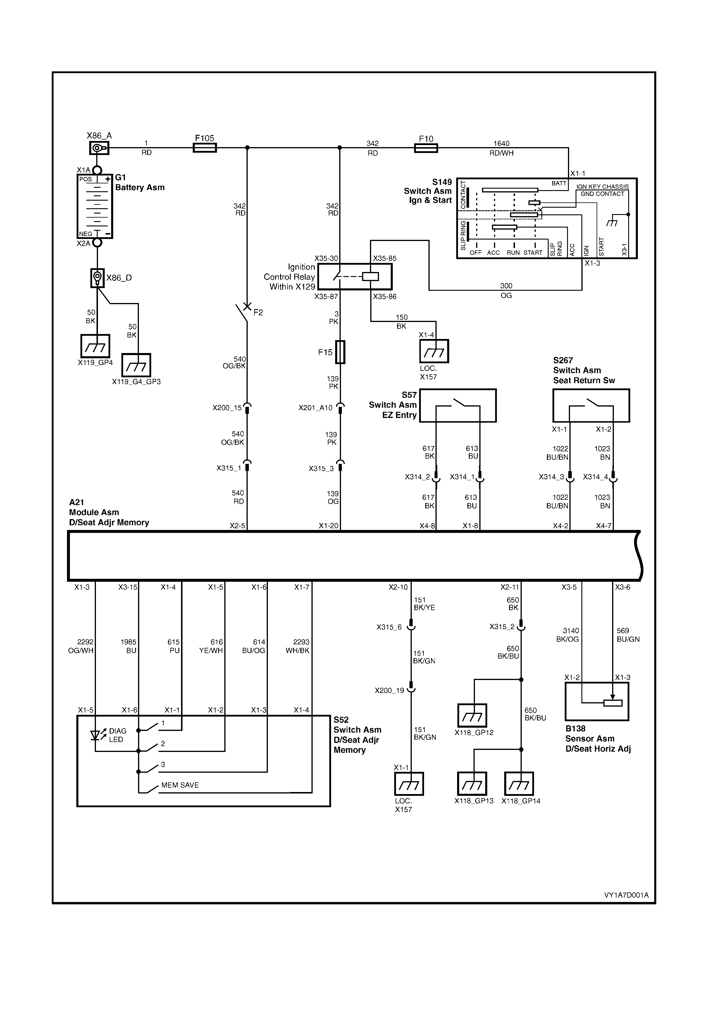
WIRING DIAGRAM – DRIVER'S EIGHT-WAY SEAT, MEMORY
Figure 1A7-160
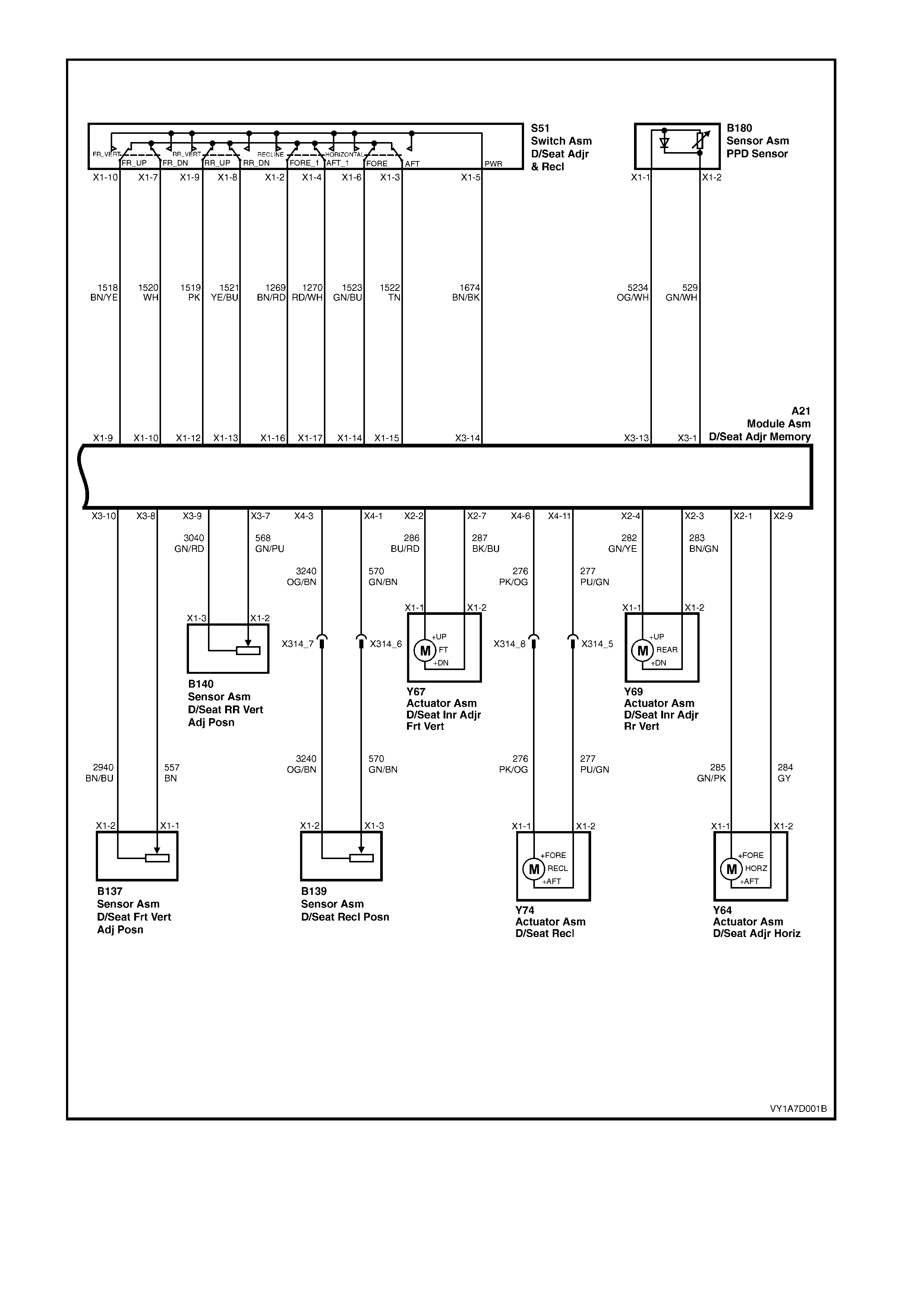
Figure 1A7-161
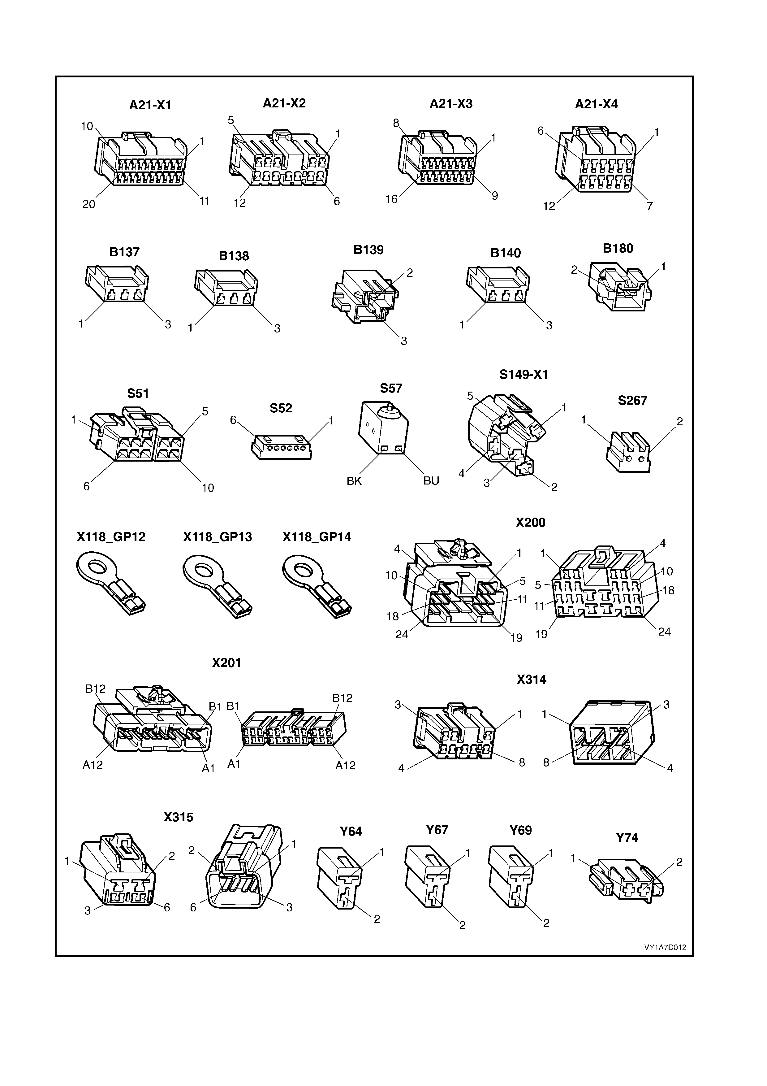
CONNECTOR CHART – DRIVER'S EIGHT-WAY SEAT, MEMORY
Figure 1A7-162

NONE OF THE DRIVER’S EIGHT-WAY SEAT ADJUSTMENT SWITCH FUNCTIONS OPERATE
Introduction
This test is used by the technician to aid in the diagnosis of the driver’s eight-way seat adjustment switch when none
of the switch functions operate. The test diagnoses the driver’s eight-way seat adjustment switch and associated
power and earth circuits.
Test Description
The following numbers refer to the Step numbers in the diagnostic chart.
1. Checks whether all of the passenger seat eight-way functions work. If none of them work, the fault is not
isolated to the driver’s seat only.
2. Checks whether there is battery power at connector X315 pin 1. Isolates whether there is a fault in circuit 540
between connectors X200 pin 15 and X315 pin 1.
3. Checks that all the connectors required for the seat to operate effectively are in place and positively connected.
4. Checks whether there is battery power at connector A21 – X2 pin 5. Isolates whether there is a fault in circuit
540 between connectors A21 – X2 pin 5 and X315 pin 1.
5. Checks whether there is battery power at connector A21 – X3 pin 14. Isolates whether there is a f ault with the
seat control module.
6. Checks whether there is battery power at connector S51 – X1 pin 5. Isolates whether there is a fault in circuit
1674 between connectors S51 – X1 pin 5 and A21 – X3 pin 14.
7. Checks whether the driver’s eight-way seat adjustment switch is serviceable.
8. Checks whether there is continuity between connector X315 pin 2 and earthing point X118_GP12. Isolates
whether there is a fault in circuit 650.
9. Chec ks whether there is c ontinuity between connector s A21 – X 2 pin 11 and X 315 pin 2. Is olates whether there
is a fault in circuit 650.
10. Checks whether there is continuity between connector X200 pin 19 and earthing point X1-1 LOC. X157. Isolates
whether there is a fault in circuit 151.
11. Checks whether there is c ontinuity between connectors X315 pin 6 and X 200 pin 19. Isolates whether there is a
fault in circuit 151.
12. Checks whether there is c ontinuity between connector s A21 – X 2 pin 10 and X 315 pin 6. Is olates whether there
is a fault in circuit 151.
STEP ACTION YES NO
1. Are all of the passenger’s eight-way seat
adjustment switch functions inoperative? Refer to NEITHER SEAT
ADJUSTMENT SWITCH
FUNCTIONS OPERATE in
this Section.
Go to Step 2.
2. 1. Back probe connector X315 pin 1 with a
test lamp.
Does the test lamp illuminate? Go to Step 3.
There is a fault in circuit
540 between connectors
X200 pin 15 and
X315 pin 1.
Repair or replace circuit
540.
3. Are the following connectors secure?
• A21
• S51
• X314
• X315
• Y64
• Y67
• Y69
• Y74
Go to Step 4. Ensure that the connectors
are secure.
4. 1. Back probe connector A21 – X2 pin 5 with
a test lamp.
Does the test lamp illuminate? Go to Step 5.
There is a fault in circuit
540 between connectors
A21 – X2 pin 5 and
X315 pin 1.
Repair or replace circuit
540.

STEP ACTION YES NO
5. 1. Back probe connector A21 – X3 pin 14
with a test lamp.
Does the test lamp illuminate? Go to Step 6.
Replace the driver’s seat
control module, refer to 4.6
FRONT SEAT CONTROL
MODULE, EIGHT-WAY
MEMORY SEAT.
6. 1. Back probe connector S51 – X1 pin 5 with
a test lamp.
Does the test lamp illuminate? Go to Step 7.
There is a fault in circuit
1674 between connectors
S51 – X1 pin 5 and
A21 – X3 pin 14.
Repair or replace circuit
1674.
7. 1. Remove the driver’s eight-way seat
adjustment switch from the seat, refer to
4.4 EIGHT-WAY SEAT ADJUSTMENT
SWITCH.
2. Test the driver’s eight-way seat
adjustment switch, refer to 3.6 EIGHT-
WAY SEAT ADJUSTMENT SWITCH
TEST.
Is the driver’s eight-way seat adjustment
switch serviceable?
Go to Step 8.
Replace the driver’s
eight-way seat adjustment
switch.
Refer to 4.4 EIGHT-W AY
SEAT ADJUSTMENT
SWITCH.
8. 1. Remove connector A21 – X2 from the
seat control module.
2. Using a digital multimeter set to measure
resistance, probe across connector X315
pin 2 and earthing point X118_GP12.
Multimeter should indicate continuity. Is the
resistance reading as specified?
Go to Step 9.
There is a fault in circuit
650 between connector
X315 pin 2 and earthing
point X118_GP12.
Repair or replace circuit
650.
9. 1. Using a digital multimeter set to measure
resistance, probe across connectors
A21 – X2 pin 11 and X315 pin 2.
Multimeter should indicate continuity. Is the
resistance reading as specified?
Go to Step 10.
There is a fault in circuit
650 between connectors
A21 – X2 pin 11 and
X315 pin 2.
Repair or replace circuit
650.
10. 1. Using a digital multimeter set to measure
resistance, probe across connector X200
pin 19 and earthing point X1-1
LOC. X157.
Multimeter should indicate continuity. Is the
resistance reading as specified?
Go to Step 11.
There is a fault in circuit
151 between connector
X200 pin 19 and earthing
point X1-1 LOC. X157.
Repair or replace circuit
151.
11. 1. Using a digital multimeter set to measure
resistance, probe across connectors
X315 pin 6 and X200 pin 19.
Multimeter should indicate continuity. Is the
resistance reading as specified?
Go to Step 12.
There is a fault in circuit
151 between connectors
X315 pin 6 and
X200 pin 19.
Repair or replace circuit
151.
12. 1. Using a digital multimeter set to measure
resistance, probe across connectors
A21 – X2 pin 10 and X315 pin 6.
Multimeter should indicate continuity. Is the
resistance reading as specified?
Replace the driver's seat
control module, refer to 4.6
FRONT SEAT CONTROL
MODULE, EIGHT-WAY
MEMORY SEAT.
There is a fault in circuit
151 between connectors
A21 – X2 pin 10 and
X315 pin 6.
Repair or replace circuit
151.
When all diagnosis and repairs are completed, check the system for correct operation.

FRONT/REAR OF THE DRIVER’S SEAT DOES NOT RAISE AND/OR LOWER
Introduction
This test is used by the technician to aid in the diagnosis of the front and/or the rear of the driver’s seat not r aising
and/or lowering. The test diagnoses the eight-way seat adjustment switch and the motor circuits.
Test Description
The following numbers refer to the Step numbers in the diagnostic chart.
1. Checks whether the driver’s eight-way seat adjustment switch operates in any of the directions. Isolates
whether the power and earth circuits are at fault.
2. Checks that all the connectors required for the seat to operate effectively are in place and positively connected.
3. Checks whether the driver’s eight-way seat adjustment switch is serviceable.
4. Conf irm s whether the rear of the seat r aises or lowers. Isolates whether the rear m otor and c ircuit of the seat is
the fault.
5. Confirms whether the front of the seat raises or lowers. Isolates whether the front motor and circuit of the seat is
the fault.
6. Checks whether there is battery power to the seat rear motor at connector Y69 – X1 pin 1. Isolates whether
there is a fault between the switch and connector Y69 – X1 pin 1 .
7. Checks whether there is continuity between connectors S51 – X1 pin 9 and A21 – X2 pin 4. Isolates whether
there is a fault between the switch and connector A21 – X2 pin 4 or in circuit 282.
8. Checks whether there is continuity between connectors S51 – X1 pin 9 and A21 – X1 pin 12. Isolates whether
there is a fault between the switch and connector A21 – X1 pin 12 or the seat control module is at fault.
9. Checks whether there is battery power to the seat rear motor at connector Y69 – X1 pin 2. Isolates whether
there is a fault between the switch and connector Y69 – X1 pin 2 or the motor is at fault.
10. Checks whether there is continuity between connectors S51 – X1 pin 8 and A21 – X2 pin 3. Isolates whether
there is a fault between the switch and connector A21 – X2 pin 3 or in circuit 283.
11. Check s whether there is continuity between connectors S51 – X1 pin 8 and A21 – X1 pin 13. Isolates whether
there is a fault between the switch and connector A21 – X1 pin 13 or the seat control module is at fault.
12. Checks whether there is battery power to the seat front motor at connector Y67 – X1 pin 1. Isolates whether
there is a fault between the switch and connector Y67 – X1 pin 1.
13. Check s whether there is continuity between connectors S51 – X1 pin 10 and A21 – X2 pin 2. Isolates whether
there is a fault between the switch and connector A21 – X2 pin 2 or in circuit 286.
14. Check s whether there is continuity between connectors S51 – X1 pin 10 and A21 – X1 pin 9. Isolates whether
there is a fault between the switch and connector A21 – X1 pin 10 or the seat control module is at fault.
15. Checks whether there is battery power to the seat front motor at connector Y67 – X1 pin 2. Isolates whether
there is a fault between the switch and connector Y67 – X1 pin 2 or the motor is at fault.
16. Checks whether there is continuity between connectors S51 – X1 pin 7 and A21 – X2 pin 7. Isolates whether
there is a fault between the switch and connector A21 – X2 pin 7 or in circuit 287.
17. Check s whether there is continuity between connectors S51 – X1 pin 7 and A21 – X1 pin 10. Isolates whether
there is a fault between the switch and connector A21 – X1 pin 10 or the seat control module is at fault.

STEP ACTION YES NO
1. Does the driver’s eight-way seat adjustment
switch operate correctly in any of the eight
directions? Go to Step 2.
Refer to NONE OF THE
DRIVER’S EIGHT-WAY
SEAT ADJUSTMENT
SWITCH FUNCTIONS
OPERATE in this Section.
2. Are the following connectors secure?
• A21
• S51
• Y67
• Y69
Go to Step 3. Ensure that the connectors
are secure.
3. 1. Remove the driver’s eight-way seat
adjustment switch from the seat, refer to
4.4 EIGHT-WAY SEAT ADJUSTMENT
SWITCH.
2. Test the driver’s eight-way seat
adjustment switch, refer to 3.6 EIGHT-
WAY SEAT ADJUSTMENT SWITCH
TEST.
Is the driver’s eight-way seat adjustment
switch serviceable?
Go to Step 4.
Replace the driver’s
eight-way seat adjustment
switch.
Refer to 4.4 EIGHT-W AY
SEAT ADJUSTMENT
SWITCH.
4. 1. Operate the driver’s eight-way seat
adjustment switch so that the rear of the
seat is raised or lowered.
Does the rear of the seat raise and lower?
Go to Step 5. Go to Step 6.
5. 1. Operate the driver’s eight-way seat
adjustment switch so that the front of the
seat is raised or lowered.
Does the front of the seat raise and lower?
System serviceable. Go to Step 12.
6. 1. Back probe connector Y69 – X1 pin 1 with
a test lamp.
2. Operate the driver’s eight-way seat
adjustment switch so that it will raise the
rear of the seat.
Does the test lamp illuminate?
Go to Step 9. Go to Step 7.
7. 1. Back probe connector A21 – X2 pin 4 with
a test lamp.
2. Operate the driver’s eight-way seat
adjustment switch so that it will raise the
rear of the seat.
Does the test lamp illuminate?
There is a fault in circuit
282 between connectors
A21 – X2 pin 4 and
Y69 – X1 pin 1.
Repair or replace circuit
282.
Go to Step 8.
8. 1. Back probe connector A21 – X1 pin 12
with a test lamp.
2. Operate the driver’s eight-way seat
adjustment switch so that it will raise the
rear of the seat.
Does the test lamp illuminate?
Replace the driver's seat
control module, refer to 4.6
FRONT SEAT CONTROL
MODULE, EIGHT-WAY
MEMORY SEAT.
Go to Step 4.
There is a fault in circuit
1519 between connectors
S51 – X1 pin 9 and
A21 – X1 pin 12.
Repair or replace circuit
1519.
Go to Step 4.
9. 1. Back probe connector Y69 – X1 pin 2 with
a test lamp.
2. Operate the driver’s eight-way seat
adjustment switch so that it will lower the
rear of the seat.
Does the test lamp illuminate?
The seat rear motor is
faulty. Replace the seat
rear motor.
Refer to 4.20 FRONT
SEAT LIFT MOTORS.
Go to Step 10.
10. 1. Back probe connector A21 – X2 pin 3 with
a test lamp.
2. Operate the driver’s eight-way seat
adjustment switch so that it will lower the
rear of the seat.
Does the test lamp illuminate?
There is a fault in circuit
283 between connectors
A21 – X2 pin 3 and
Y69 – X1 pin 2.
Repair or replace circuit
283.
Go to Step 11.

STEP ACTION YES NO
11. 1. Back probe connector A21 – X1 pin 13
with a test lamp.
2. Operate the driver’s eight-way seat
adjustment switch so that it will lower the
rear of the seat.
Does the test lamp illuminate?
Replace the driver's seat
control module, refer to 4.6
FRONT SEAT CONTROL
MODULE, EIGHT-WAY
MEMORY SEAT.
Go to Step 4.
There is a fault in circuit
1521 between connectors
S51 – X1 pin 8 and
A21 – X1 pin 13.
Repair or replace circuit
1521.
Go to Step 4.
12. 1. Back probe connector Y67 – X1 pin 1 with
a test lamp.
2. Operate the driver’s eight-way seat
adjustment switch so that it will raise the
front of the seat.
Does the test lamp illuminate?
Go to Step 15. Go to Step 13.
13. 1. Back probe connector A21 – X2 pin 2 with
a test lamp.
2. Operate the driver’s eight-way seat
adjustment switch so that it will raise the
front of the seat.
Does the test lamp illuminate?
There is a fault in circuit
286 between connectors
A21 – X2 pin 2 and
Y67 – X1 pin 1.
Repair or replace circuit
286.
Go to Step 14.
14. 1. Back probe connector A21 – X1 pin 9 with
a test lamp.
2. Operate the driver’s eight-way seat
adjustment switch so that it will raise the
front of the seat.
Does the test lamp illuminate?
Replace the driver's seat
control module, refer to 4.6
FRONT SEAT CONTROL
MODULE, EIGHT-WAY
MEMORY SEAT.
There is a fault in circuit
1518 between connectors
S51 – X1 pin 10 and
A21 – X1 pin 9.
Repair or replace circuit
1518.
15. 1. Back probe connector Y67 – X1 pin 2 with
a test lamp.
2. Operate the driver’s eight-way seat
adjustment switch so that it will lower the
front of the seat.
Does the test lamp illuminate?
The seat rear motor is
faulty. Replace the seat
rear motor.
Refer to 4.20 FRONT
SEAT LIFT MOTORS.
Go to Step 16.
16. 1. Back probe connector A21 – X2 pin 7 with
a test lamp.
2. Operate the driver’s eight-way seat
adjustment switch so that it will lower the
front of the seat.
Does the test lamp illuminate?
There is a fault in circuit
287 between connectors
A21 – X2 pin 7 and
Y67 – X1 pin 2.
Repair or replace circuit
287.
Go to Step 17.
17. 1. Back probe connector A21 – X1 pin 10
with a test lamp.
2. Operate the driver’s eight-way seat
adjustment switch so that it will lower the
front of the seat.
Does the test lamp illuminate?
Replace the driver's seat
control module, refer to 4.6
FRONT SEAT CONTROL
MODULE, EIGHT-WAY
MEMORY SEAT.
There is a fault in circuit
1520 between connectors
S51 – X1 pin 7 and
A21 – X1 pin 10.
Repair or replace circuit
1520.
When all diagnosis and repairs are completed, check the system for correct operation.

DRIVER’S SEAT FORE/AFT FUNCTION IS INOPERATIVE OR NOT SMOOTH
Introduction
This test is used by the technician to aid in the diagnosis of the fore/aft function of the driver’s seat being inoperative
or the action of the seat through the range of movement is not smooth. The test diagnoses the eight-way seat
adjustment switch and the motor circuits.
Test Description
The following numbers refer to the Step numbers in the diagnostic chart.
1. Checks whether the driver’s eight-way seat adjustment switch operates in any of the directions. Isolates
whether there is battery power to the switch assembly.
2. Checks that there are no items obstructing the guide rails, which may stop or hinder the seat movement.
3. Checks that the guide rails and drive shafts have adequate lubricant applied to provide a smooth operation of
the seat.
4. Checks that the guide rails or drive shafts have not been damaged. Any binding between the moving parts will
result in poor operation of the fore and aft movement.
5. Checks that all the connectors required for the seat to operate effectively are in place and positively connected.
6. Checks whether the driver’s eight-way seat adjustment switch is serviceable.
7. Checks whether there is battery power to the seat fore/aft m otor at connector Y64 – X1 pin 1. Isolates whether
there is a fault between the switch and connector Y64 – X1 pin 1.
8. Checks whether there is continuity between connectors S51 – X1 pin 6 and A21 – X2 pin 1. Isolates whether
there is a fault between the switch and connector A21 – X2 pin 1 or in circuit 285.
9. Checks whether there is continuity between connectors S51 – X1 pin 6 and A21 – X1 pin 14. Isolates whether
there is a fault between the switch and connector A21 – X1 pin 14 or the seat control module is at fault.
10. Check s whether there is battery power to the seat f ore/aft m otor at connector Y64 – X1 pin 2. Isolates whether
there is a fault between the switch and connector Y64 – X1 pin 2 or the motor is at fault.
11. Checks whether there is continuity between connectors S51 – X1 pin 3 and A21 – X2 pin 9. Isolates whether
there is a fault between the switch and connector A21 – X2 pin 9 or in circuit 284.
12. Check s whether there is continuity between connectors S51 – X1 pin 3 and A21 – X1 pin 15. Isolates whether
there is a fault between the switch and connector A21 – X1 pin 15 or the seat control module is at fault.
STEP ACTION YES NO
1. Does the driver’s eight-way seat adjustment
switch operate correctly in any of the eight
directions? Go to Step 2.
Refer to NONE OF THE
DRIVER’S EIGHT-WAY
SEAT ADJUSTMENT
SWITCH FUNCTIONS
OPERATE in this Section.
2. Are the guide rails free from obstructions? Go to Step 3. Remove the obstructing
item.
3. Are the guide rails and drive shafts adequately
lubricated? Go to Step 4. Apply a small amount of
grease type NLGI No. 1
Lithium Grease (with 9%
Zinc Oxide).
4. Do the guide rails or drive shafts bind at any
point of travel during the fore and aft
movement of the seat?
Replace the front seat
adjuster assembly, refer to
4.19 FRONT SEAT
ADJUSTER ASSEMBLY.
Go to Step 5.
5. Are the following connectors secure?
• A21
• S51
• Y64
Go to Step 6. Ensure that the connectors
are secure.
6. 1. Remove the driver’s eight-way seat
adjustment switch from the seat, refer to
4.4 EIGHT-WAY SEAT ADJUSTMENT
SWITCH.
2. Test the driver’s eight-way seat
adjustment switch, refer to 3.6 EIGHT-
WAY SEAT ADJUSTMENT SWITCH
TEST.
Is the driver’s eight-way seat adjustment
switch serviceable?
Go to Step 7.
Replace the driver’s
eight-way seat adjustment
switch.
Refer to 4.4 EIGHT-W AY
SEAT ADJUSTMENT
SWITCH.

STEP ACTION YES NO
7. 1. Back probe connector Y64 – X1 pin 1 with
a test lamp.
2. Operate the driver’s eight-way seat
adjustment switch so that it will move the
seat forward.
Does the test lamp illuminate?
Go to Step 10. Go to Step 8.
8. 1. Back probe connector A21 - X2 pin 1 with
a test lamp.
2. Operate the driver’s eight-way seat
adjustment switch so that it will move the
seat forward.
Does the test lamp illuminate?
There is a fault in circuit
285 between connectors
A21 - X2 pin 1 and
Y64 – X1 pin 1.
Repair or replace circuit
285.
Go to Step 9.
9. 1. Back probe connector A21 - X1 pin 14
with a test lamp.
2. Operate the driver’s eight-way seat
adjustment switch so that it will move the
seat forward.
Does the test lamp illuminate?
Replace the driver's seat
control module, refer to 4.6
FRONT SEAT CONTROL
MODULE, EIGHT-WAY
MEMORY SEAT.
There is a fault in circuit
1523 between connectors
S51 – X1 pin 6 and
A21 - X1 pin 14.
Repair or replace circuit
1523.
10. 1. Back probe connector Y64 – X1 pin 2 with
a test lamp.
2. Operate the driver’s eight-way seat
adjustment switch so that it will move the
seat aft.
Does the test lamp illuminate?
The seat fore/aft motor is
faulty. Replace the seat
fore/aft motor.
Refer to 4.21 FRONT
SEAT FORE/AFT
MOVEMENT MOTOR.
Go to Step 11.
11. 1. Back probe connector A21 – X2 pin 9 with
a test lamp.
2. Operate the driver’s eight-way seat
adjustment switch so that it will move the
seat aft.
Does the test lamp illuminate?
There is a fault in circuit
284 between connectors
A21 – X2 pin 9 and
Y64 – X1 pin 2.
Repair or replace circuit
284.
Go to Step 12.
12. 1. Back probe connector A21 – X1 pin 15
with a test lamp.
2. Operate the driver’s eight-way seat
adjustment switch so that it will move the
seat aft.
Does the test lamp illuminate?
Replace the driver's seat
control module, refer to 4.6
FRONT SEAT CONTROL
MODULE, EIGHT-WAY
MEMORY SEAT.
There is a fault in circuit
1522 between connectors
S51 – X1 pin 3 and
A21 - X1 pin 15.
Repair or replace circuit
1522.
When all diagnosis and repairs are completed, check the system for correct operation.

DRIVER’S SEAT RECLINE FORWA RD AND/OR AFT FUNCTION IS INOPERATIVE
Introduction
This test is used by the technician to aid in the diagnosis of the reclining function of the driver’s seat being
inoperative. The test diagnoses the eight-way seat adjustment switch and the motor circuits.
Test Description
The following numbers refer to the Step numbers in the diagnostic chart.
1. Checks whether the driver’s eight-way seat adjustment switch operates in any of the directions. Isolates
whether there is battery power to the switch assembly.
2. Checks that all the connectors required for the seat to operate effectively are in place and positively connected.
3. Checks whether the driver’s eight-way seat adjustment switch is serviceable.
4. Chec ks whether there is battery power to the seat reclining motor at connec tor Y74 – X1 pin 1. Is olates whether
there is a fault between the switch and connector Y74 – X1 pin 1.
5. Checks whether there is c ontinuity between connectors S51 – X1 pin 2 and X314 pin 8. Isolates whether ther e
is a fault between the switch and connector X314 pin 8 or in circuit 276.
6. Checks whether there is continuity between connectors S51 – X1 pin 2 and A21 – X4 pin 6. Isolates whether
there is a fault between the switch and connector A21 – X4 pin 6 or in circuit 276.
7. Checks whether there is continuity between connectors S51 – X1 pin 2 and A21 – X1 pin 16. Isolates whether
there is a fault between the switch and connector A21 – X1 pin 16 or the seat control module is at fault.
8. Chec ks whether there is battery power to the seat reclining motor at connec tor Y74 – X1 pin 2. Is olates whether
there is a fault between the switch and connector Y74 – X1 pin 2 or the motor is at fault.
9. Checks whether there is c ontinuity between connectors S51 – X1 pin 4 and X314 pin 5. Isolates whether ther e
is a fault between the switch and connector X314 pin 5 or in circuit 277.
10. Check s whether there is continuity between connectors S51 – X1 pin 4 and A21 – X4 pin 11. Isolates whether
there is a fault between the switch and connector A21 – X4 pin 11 or in circuit 277.
11. Check s whether there is continuity between connectors S51 – X1 pin 4 and A21 – X1 pin 17. Isolates whether
there is a fault between the switch and connector A21 – X1 pin 17 or the seat control module is at fault.
STEP ACTION YES NO
1. Does the driver’s eight-way seat adjustment
switch operate correctly in any of the eight
directions? Go to Step 2.
Refer to NONE OF THE
DRIVER’S EIGHT-WAY
SEAT ADJUSTMENT
SWITCH FUNCTIONS
OPERATE in this Section.
2. Are the following connectors secure?
• A21
• S51
• Y74
Go to Step 3. Ensure that the connectors
are secure.
3. 1. Remove the driver’s eight-way seat
adjustment switch from the seat, refer to
4.4 EIGHT-WAY SEAT ADJUSTMENT
SWITCH.
2. Test the driver’s eight-way seat
adjustment switch, refer to 3.6 EIGHT-
WAY SEAT ADJUSTMENT SWITCH
TEST.
Is the driver’s eight-way seat adjustment
switch serviceable?
Go to Step 4.
Replace the driver’s
eight-way seat adjustment
switch.
Refer to 4.4 EIGHT-W AY
SEAT ADJUSTMENT
SWITCH.
4. 1. Back probe connector Y74 – X1 pin 1 with
a test lamp.
2. Operate the driver’s eight-way seat
adjustment switch so that it will move the
seat-back forward.
Does the test lamp illuminate?
Go to Step 8. Go to Step 5.

STEP ACTION YES NO
5. 1. Back probe connector X314 pin 8 with a
test lamp.
2. Operate the driver’s eight-way seat
adjustment switch so that it will move the
seat-back forward.
Does the test lamp illuminate?
There is a fault in circuit
276 between connectors
X314 pin 8 and
Y74 – X1 pin 1.
Repair or replace circuit
276.
Go to Step 6.
6. 1. Back probe connector A21 – X4 pin 6 with
a test lamp.
2. Operate the driver’s eight-way seat
adjustment switch so that it will move the
seat-back forward.
Does the test lamp illuminate?
There is a fault in circuit
276 between connectors
A21 – X4 pin 6 and
X314 pin 8.
Repair or replace circuit
276.
Go to Step 7.
7. 1. Back probe connector A21 – X1 pin 16
with a test lamp.
2. Operate the driver’s eight-way seat
adjustment switch so that it will move the
seat-back forward.
Does the test lamp illuminate?
Replace the driver's seat
control module, refer to 4.6
FRONT SEAT CONTROL
MODULE, EIGHT-WAY
MEMORY SEAT.
There is a fault in circuit
1269 between connectors
S51 – X1 pin 2 and
A21 - X1 pin 16.
Repair or replace circuit
1269.
8. 1. Back probe connector Y74 – X1 pin 2 with
a test lamp.
2. Operate the driver’s eight-way seat
adjustment switch so that it will move the
seat-back aft.
Does the test lamp illuminate?
The seat reclining motor is
faulty.
Replace the seat reclining
motor, refer to 4.22 FRONT
SEAT RECLINING
MOTOR, GEARBOX AND
POTENTIOMETER
ASSEMBLY.
Go to Step 9.
9. 1. Back probe connector X314 pin 5 with a
test lamp.
2. Operate the driver’s eight-way seat
adjustment switch so that it will move the
seat-back aft.
Does the test lamp illuminate?
There is a fault in circuit
277 between connectors
X314 pin 5 and
Y74 - X1 pin 2.
Repair or replace circuit
277.
Go to Step 10.
10. 1. Back probe connector A21 – X4 pin 11
with a test lamp.
2. Operate the driver’s eight-way seat
adjustment switch so that it will move the
seat-back aft.
Does the test lamp illuminate?
There is a fault in circuit
277 between connectors
A21 – X4 pin 11 and
X314 pin 5.
Repair or replace circuit
277.
Go to Step 11.
11. 1. Back probe connector A21 – X1 pin 17
with a test lamp.
2. Operate the driver’s eight-way seat
adjustment switch so that it will move the
seat-back aft.
Does the test lamp illuminate?
Replace the driver's seat
control module, refer to 4.6
FRONT SEAT CONTROL
MODULE, EIGHT-WAY
MEMORY SEAT.
There is a fault in circuit
1270 between connectors
S51 – X1 pin 4 and
A21 - X1 pin 17.
Repair or replace circuit
1270.
When all diagnosis and repairs are completed, check the system for correct operation.

DRIVER'S SEAT EZ-ENTRY SWITCH FUNCTION IS INOPERATIVE
Introduction
The EZ- entr y function is des igned s o that when the seat-bac k is releas ed with the EZ-entr y lever, the seat will move
to its fully forward position using the seat fore/aft motor. Once the seat has moved to its fully forward position, power
to the seat fore/aft motor will cease. A switch attached to the seat-back activates the seat fore/aft motor when the
recline of the seat-back is moved forward after being released using the EZ-entry lever. This test is used by the
technician to aid in the diagnosis of the EZ -entry f unction of the driver's seat being inoperative. The test diagnos es
the EZ-entry switch and associated circuits.
Test Description
The following numbers refer to the Step numbers in the diagnostic chart.
1. Checks whether the seat fore/aft motor is serviceable.
2. Checks whether there is battery power to connector A21 – X1 pin 8. Isolates whether the driver's seat control
module is at fault.
3. Checks whether there is continuity between connectors A21 – X1 pin 8 and A21 – X4 pin 8. Isolates whether
there is a fault with the EZ-entry switch and associated circuits.
4. Checks whether ther e is continuity between connec tors A21 – X1 pin 8 and X314 pin 1. Isolates whether there
is a fault in circuit 613.
5. Checks whether there is continuity between connectors A21 – X4 pin 8 and X314 pin 2. Isolates whether the
EZ-entry switch or circuit 617 is at fault.
STEP ACTION YES NO
1. Does the seat move in the fore/aft direction
when operated by the driver's eight-way seat
adjustment switch? Go to Step 2. Refer to DRIVER'S SEAT
FORE/AFT FUNCTION IS
INOPERATIVE OR NOT
SMOOTH in this Section.
2. 1. Back probe connector A21 – X1 pin 8 with
a test lamp.
Does the test lamp illuminate? Go to Step 3.
Replace the driver's seat
control module, refer to 4.6
FRONT SEAT CONTROL
MODULE, EIGHT-WAY
MEMORY SEAT.
3. 1. Release the seat-back using the EZ-entry
lever.
2. Back probe connector A21 – X4 pin 8 with
a test lamp.
Does the test lamp illuminate?
Replace the driver's seat
control module, refer to 4.6
FRONT SEAT CONTROL
MODULE, EIGHT-WAY
MEMORY SEAT.
Go to Step 4.
4. 1. Back probe connector X314 pin 1 with a
test lamp.
Does the test lamp illuminate? Go to Step 5.
There is a fault in circuit
613 between connectors
A21 – X1 pin 8 and
X314 pin 1.
Repair or replace circuit
613.
5. 1. Back probe connector X314 pin 2 with a
test lamp.
Does the test lamp illuminate?
There is a fault in circuit
617 between connectors
A21 – X4 pin 8 and
X314 pin 2.
Repair or replace circuit
617.
Replace the driver's
EZ-entry switch, refer to
4.13 EZ-ENTRY CABLE
AND SWITCH ASSEMBLY.
When all diagnosis and repairs are completed, check the system for correct operation.

DRIVER'S SEAT RETURN SWITCH FUNCTION IS INOPERATIVE
Introduction
The s eat return switch is located on the esc utcheon at the top of the seat-bac k. The s witc h function is to move the
seat in an aft direction after the EZ-entry function has been used and the recline of the seat has been placed
upright. W ith the seat return switch continuously pressed, the seat will move to its fully aft position, pausing for 2
seconds at the s eat position where the EZ- entry lever was operated. The test diagnoses the seat retur n switch and
associated circuits.
Test Description
The following numbers refer to the Step numbers in the diagnostic chart.
1. Checks whether the seat fore/aft motor is serviceable.
2. Checks whether the seat will move to its fully forward position when the seat-back is released using the EZ-
entry lever. Isolates whether the EZ-entry switch function is serviceable.
3. Chec ks whether the seat will move aft when the seat- back is in the upright pos ition and the s eat retur n s witch is
pressed. Isolates whether the seat return switch is serviceable.
4. Checks whether there is battery power at connector A21 – X4 pin 7. Isolates whether there is a fault with the
driver's seat control module.
5. Checks whether there is continuity between connectors A21 – X4 pin 2 and A21 – X4 pin 7. Isolates whether
there is a fault with the seat return switch and associated circuits.
6. Checks whether ther e is continuity between connec tors A21 – X4 pin 7 and X314 pin 4. Isolates whether there
is a fault in circuit 1023.
7. Checks whether there is continuity between connectors A21 – X4 pin 7 and S267 – X1 pin 2. Isolates whether
there is a fault in circuit 1023.
8. Checks whether there is continuity between connectors A21 – X4 pin 7 and S267 – X1 pin 1. Isolates whether
there is a fault with the driver's seat return switch.
9. Checks whether ther e is continuity between connec tors A21 – X4 pin 7 and X314 pin 3. Isolates whether there
is a fault in circuit 1022.
STEP ACTION YES NO
1. Does the seat move in the fore/aft direction
when operated by the driver's eight-way seat
adjustment switch? Go to Step 2. Refer to DRIVER'S SEAT
FORE/AFT FUNCTION IS
INOPERATIVE OR NOT
SMOOTH in this Section.
2. 1. Release the seat-back using the EZ-entry
lever.
Does the seat move forward? Go to Step 3.
Refer to DRIVER'S SEAT
EZ-ENTRY SWITCH
FUNCTION IS
INOPERATIVE in this
Section.
3. 1. Move the seat-back to the upright
position.
2. Press the seat return switch.
Does the seat move aft?
System Serviceable. Go to Step 4.
4. 1. Back probe connector A21 – X4 pin 7 with
a test lamp.
Does the test lamp illuminate? Go to Step 5.
Replace the driver's seat
control module, refer to 4.6
FRONT SEAT CONTROL
MODULE, EIGHT-WAY
MEMORY SEAT.
5. 1. Back probe connector A21 – X4 pin 2 with
a test lamp.
2. Press the seat return switch.
Does the test lamp illuminate?
Replace the driver's seat
control module, refer to 4.6
FRONT SEAT CONTROL
MODULE, EIGHT-WAY
MEMORY SEAT.
Go to Step 6.
6. 1. Back probe connector X314 pin 4 with a
test lamp.
Does the test lamp illuminate? Go to Step 7.
There is a fault in circuit
1023 between connectors
A21 – X4 pin 7 and
X314 pin 4.
Repair or replace circuit
1023.
STEP ACTION YES NO
7. 1. Back probe connector S267 – X1 pin 2
with a test lamp.
Does the test lamp illuminate? Go to Step 8.
There is a fault in circuit
1023 between connectors
S267 – X1 pin 2 and
X314 pin 4.
Repair or replace circuit
1023.
8. 1. Back probe connector S267 – X1 pin 1
with a test lamp.
2. Press the seat return switch.
Does the test lamp illuminate? Go to Step 9.
Replace the driver's seat
return switch, refer to 4.12
EZ-ENTRY LEVER ARM,
ESCUTCHEON AND SEAT
RETURN SWITCH
ASSEMBLY.
9. 1. Back probe connector X314 pin 3 with a
test lamp.
2. Press the seat return switch.
Does the test lamp illuminate?
There is a fault in circuit
1022 between connectors
A21 – X4 pin 2 and
X314 pin 3.
Repair or replace circuit
1022.
There is a fault in circuit
1022 between connectors
S267 – X1 pin 1 and
X314 pin 3.
Repair or replace circuit
1022.
When all diagnosis and repairs are completed, check the system for correct operation.

DRIVER'S SEAT TRACK MOTOR POSITION SENSOR POTENTIOMETER TEST
Introduction
This test is us ed by the tec hnician to aid in the diagnosis of the seat track motor position sensor potentiometer and
associated circuits.
Test Description
The following numbers refer to the Step numbers in the diagnostic chart.
1. Checks whether the seat position sensor potentiometer is serviceable.
2. Checks whether there is continuity between connectors B138 – X1 pin 2 and A21 – X3 pin 5. Isolates whether
there is a fault in circuit 3140.
3. Checks whether there is continuity between connectors B138 – X1 pin 3 and A21 – X3 pin 6. Isolates whether
there is a fault in circuit 569.
STEP ACTION YES NO
1. 1. Disconnect connector B138 – X1 from the
position sensor potentiometer.
2. Using a digital multimeter set to measure
resistance, probe across the
potentiometer terminals.
3. Operate the driver’s eight-way seat
adjustment switch so that it will move the
seat forward and aft.
Multimeter should indicate between 0 and
10 kΩ (depending on seat position). Is the
resistance reading as specified?
Go to Step 2.
Replace the position
sensor potentiometer, refer
to 4.23 DRIVE MOTOR
POTENTIOMETERS.
2. 1. Disconnect connector A21 – X3 from the
driver’s seat memory module.
2. Using a digital multimeter set to measure
resistance, probe across connectors
B138 – X1 pin 2 and A21 – X3 pin 5.
Multimeter should indicate continuity. Is the
resistance reading as specified?
Go to Step 3. Repair or replace circuit
3140.
3. 1. Using a digital multimeter set to measure
resistance, probe across connectors
B138 – X1 pin 3 and A21 – X3 pin 6.
Multimeter should indicate continuity. Is the
resistance reading as specified?
Potentiometer and
associated wiring
serviceable.
Repair or replace circuit
569.
When all diagnosis and repairs are completed, check the system for correct operation.

DRIVER'S SEAT RECLINE MOTOR POSITION SENSOR POTENTIOMETER TEST
Introduction
This test is used by the technician to aid in the diagnosis of the seat recline motor position sensor potentiometer
and associated circuits.
Test Description
The following numbers refer to the Step numbers in the diagnostic chart.
1. Checks whether the seat position sensor potentiometer is serviceable.
2. Check s whether ther e is continuity between connectors B139 – X 1 pin 2 and X314 pin 7. Isolates whether there
is a fault in circuit 3240.
3. Checks whether ther e is continuity between connec tors X314 pin 7 and A21 – X4 pin 3. Isolates whether there
is a fault in circuit 3240.
4. Check s whether ther e is continuity between connectors B139 – X 1 pin 3 and X314 pin 6. Isolates whether there
is a fault in circuit 570.
5. Checks whether ther e is continuity between connec tors X314 pin 6 and A21 – X4 pin 1. Isolates whether there
is a fault in circuit 570.
STEP ACTION YES NO
1. 1. Disconnect connector B139 – X1 from the
position sensor potentiometer.
2. Using a digital multimeter set to measure
resistance, probe across the
potentiometer terminals.
3. Operate the driver’s eight-way seat
adjustment switch so that it will move the
seat-back forward and aft.
Multimeter should indicate between 0 and
10 kΩ (depending on seat-back position). Is
the resistance reading as specified?
Go to Step 2.
Replace the position
sensor potentiometer, refer
to 4.22 FRONT SEAT
RECLINING MOTOR,
GEARBOX AND
POTENTIOMETER
ASSEMBLY.
2. 1. Disconnect connector A21 – X4 from the
driver’s seat memory module.
2. Using a digital multimeter set to measure
resistance, probe across connectors
B139 – X1 pin 2 and X314 pin 7.
Multimeter should indicate continuity. Is the
resistance reading as specified?
Go to Step 3.
There is a fault in circuit
3240 between connectors
B139 – X1 pin 3 and
X314 pin 7.
Repair or replace circuit
3240.
3. 1. Using a digital multimeter set to measure
resistance, probe across connectors
A21 – X4 pin 3 and X314 pin 7.
Multimeter should indicate continuity. Is the
resistance reading as specified?
Go to Step 4.
There is a fault in circuit
3240 between connectors
A21 – X4 pin 3 and
X314 pin 7.
Repair or replace circuit
3240.
4. 1. Using a digital multimeter set to measure
resistance, probe across connectors
B139 – X1 pin 3 and X314 pin 6.
Multimeter should indicate continuity. Is the
resistance reading as specified?
Go to Step 5.
There is a fault in circuit
570 between connectors
B139 – X1 pin 2 and
X314 pin 6.
Repair or replace circuit
570.
5. 1. Using a digital multimeter set to measure
resistance, probe across connectors
A21 – X4 pin 1 and X314 pin 6.
Multimeter should indicate continuity. Is the
resistance reading as specified?
Potentiometer and
associated wiring
serviceable.
There is a fault in circuit
570 between connectors
A21 – X4 pin 1 and
X314 pin 6.
Repair or replace circuit
570.
When all diagnosis and repairs are completed, check the system for correct operation.

DRIVER'S SEAT FRONT LIFT MOTOR POSITION SENSOR POTENTIOMETER TEST
Introduction
This test is used by the technician to aid in the diagnosis of the seat front lift motor position sensor potentiometer
and associated circuits.
Test Description
The following numbers refer to the Step numbers in the diagnostic chart.
1. Checks whether the seat position sensor potentiometer is serviceable.
2. Check s whether there is continuity between connectors B137 – X1 pin 2 and A21 – X 3 pin 10. Isolates whether
there is a fault in circuit 2940.
3. Checks whether there is continuity between connectors B137 – X1 pin 1 and A21 – X3 pin 8. Isolates whether
there is a fault in circuit 557.
STEP ACTION YES NO
1. 1. Disconnect connector B137 – X1 from the
position sensor potentiometer.
2. Using a digital multimeter set to measure
resistance, probe across the
potentiometer terminals.
3. Operate the driver’s eight-way seat
adjustment switch so that the front of the
seat is raised or lowered.
Multimeter should indicate between 0 and
10 kΩ (depending on seat position). Is the
resistance reading as specified?
Go to Step 2.
Replace the position
sensor potentiometer, refer
to 4.23 DRIVE MOTOR
POTENTIOMETERS.
2. 1. Disconnect connector A21 – X3 from the
driver’s seat memory module.
2. Using a digital multimeter set to measure
resistance, probe across connectors
B137 – X1 pin 2 and A21 – X3 pin 10.
Multimeter should indicate continuity. Is the
resistance reading as specified?
Go to Step 3. Repair or replace circuit
2940.
3. 1. Using a digital multimeter set to measure
resistance, probe across connectors
B137 – X1 pin 1 and A21 – X3 pin 8.
Multimeter should indicate continuity. Is the
resistance reading as specified?
Potentiometer and
associated wiring
serviceable.
Repair or replace circuit
557.
When all diagnosis and repairs are completed, check the system for correct operation.

DRIVER'S SEAT REAR LIFT MOTOR POSITION SENSOR POTENTIOMETER TEST
Introduction
This test is used by the technician to aid in the diagnosis of the seat rear lift motor position sensor potentiometer
and associated circuits.
Test Description
The following numbers refer to the Step numbers in the diagnostic chart.
1. Checks whether the seat position sensor potentiometer is serviceable.
2. Checks whether there is continuity between connectors B140 – X1 pin 3 and A21 – X3 pin 9. Isolates whether
there is a fault in circuit 3040.
3. Checks whether there is continuity between connectors B140 – X1 pin 2 and A21 – X3 pin 7. Isolates whether
there is a fault in circuit 568.
STEP ACTION YES NO
1. 1. Disconnect connector B140 – X1 from the
position sensor potentiometer.
2. Using a digital multimeter set to measure
resistance, probe across the
potentiometer terminals.
3. Operate the driver’s eight-way seat
adjustment switch so that the rear of the
seat is raised or lowered.
Multimeter should indicate between 0 and
10 kΩ (depending on seat position). Is the
resistance reading as specified?
Go to Step 2.
Replace the position
sensor potentiometer, refer
to 4.23 DRIVE MOTOR
POTENTIOMETERS.
2. 1. Disconnect connector A21 – X3 from the
driver’s seat memory module.
2. Using a digital multimeter set to measure
resistance, probe across connectors
B140 – X1 pin 3 and A21 – X3 pin 9.
Multimeter should indicate continuity. Is the
resistance reading as specified?
Go to Step 3. Repair or replace circuit
3040.
3. 1. Using a digital multimeter set to measure
resistance, probe across connectors
B140 – X1 pin 2 and A21 – X3 pin 7.
Multimeter should indicate continuity. Is the
resistance reading as specified?
Potentiometer and
associated wiring
serviceable.
Repair or replace circuit
568.
When all diagnosis and repairs are completed, check the system for correct operation.

DRIVER'S SEAT OCCUPANT SENSING MAT TEST
Introduction
This test is used by the technician to aid in the diagnosis of the occupant sensing mat and associated circuits.
Test Description
The following numbers refer to the Step numbers in the diagnostic chart.
1. Checks diode forward resistance of the Passenger Presence Detector (PPD).
2. Checks diode reverse resistance of the PPD.
3. Checks diode reverse resistance of the PPD with w eight on seat.
4. Check s whether ther e is continuity between connec tors B180 – X 1 pin 1 and A21 – X3 pin 13. Isolates whether
there is a fault in circuit 5234.
5. Checks whether there is continuity between connectors B180 – X1 pin 2 and A21 – X3 pin 1. Isolates whether
there is a fault in circuit 529.
STEP ACTION YES NO
1. 1. Disconnect connector B180 – X1 from the
occupant sensing mat.
2. Using a digital multimeter set to measure
resistance, connect red (+) probe to
terminal 1 and black (–) probe to terminal
2 of the occupant sensing mat.
Multimeter should indicate continuity. Is the
resistance reading as specified?
Go to Step 2.
Replace the occupant
sensing mat, refer to 4.17
FRONT SEAT CUSHION
PAD AND COVER
ASSEMBLY.
2. 1. Using a digital multimeter set to measure
resistance, connect red (+) probe to
terminal 2 and black (–) probe to terminal
1 of the occupant sensing mat.
Multimeter should indicate greater than 50 kΩ.
Is the resistance reading as specified?
Go to Step 3.
Replace the occupant
sensing mat, refer to 4.17
FRONT SEAT CUSHION
PAD AND COVER
ASSEMBLY.
3. 1. Place a weight greater than 15 kg on the
seat.
2. Using a digital multimeter set to measure
resistance, connect red (+) probe to
terminal 2 and black (–) probe to terminal
1 of the occupant sensing mat.
Multimeter should indicate less than 50 kΩ.
(Resistance decreases as the weight
increases). Is the resistance reading as
specified?
Go to Step 4.
Replace the occupant
sensing mat, refer to 4.17
FRONT SEAT CUSHION
PAD AND COVER
ASSEMBLY.
4. 1. Disconnect connector A21 – X3 from the
driver’s seat memory module.
2. Using a digital multimeter set to measure
resistance, probe across connectors
B180 – X1 pin 1 and A21 – X3 pin 13.
Multimeter should indicate continuity. Is the
resistance reading as specified?
Go to Step 5. Repair or replace circuit
5234.
5. 1. Using a digital multimeter set to measure
resistance, probe across connectors
B180 – X1 pin 2 and A21 – X3 pin 1.
Multimeter should indicate continuity. Is the
resistance reading as specified?
Occupant sensing mat and
associated wiring
serviceable.
Repair or replace circuit
529.
When all diagnosis and repairs are completed, check the system for correct operation.

DRIVER'S SEAT MEMORY POSITION SWITCH TEST
Introduction
This test is used by the technician to aid in the diagnosis of the memory position switch and associated circuits.
Prior to commencing diagnosis, refer to 1.6 FRONT SEAT ASSEMBLY, EIGHT-WAY, COUPE – MEMORY for
correct operation of the memory functions of the seat.
Test Description
The following numbers refer to the Step numbers in the diagnostic chart.
1. Checks whether the driver’s seat memory position switch is serviceable.
2. Checks whether there is continuity between connectors S52 – X1 pin 5 and A21 – X1 pin 3. Isolates whether
there is a fault in circuit 2292.
3. Checks whether there is continuity between connectors S52 – X1 pin 6 and A21 – X3 pin 15. Isolates whether
there is a fault in circuit 1985.
4. Checks whether there is continuity between connectors S52 – X1 pin 1 and A21 – X1 pin 4. Isolates whether
there is a fault in circuit 615.
5. Checks whether there is continuity between connectors S52 – X1 pin 2 and A21 – X1 pin 5. Isolates whether
there is a fault in circuit 616.
6. Checks whether there is continuity between connectors S52 – X1 pin 3 and A21 – X1 pin 6. Isolates whether
there is a fault in circuit 614.
7. Checks whether there is continuity between connectors S52 – X1 pin 4 and A21 – X1 pin 7. Isolates whether
there is a fault in circuit 2293.
STEP ACTION YES NO
1. 1. Remove the driver’s seat memory position
switch from the seat, refer to
4.5 MEMORY POSITION SWITCH.
2. Test the driver’s memory position switch,
refer to 5.9 MEMORY POSITION
SWITCH TEST.
Is the driver’s memory position switch
serviceable?
Go to Step 2.
Replace the driver’s
memory position switch.
Refer to 4.5 MEMORY
POSITION SWITCH.
2. 1. Using a digital multimeter set to measure
resistance, probe across connectors
S52 – X1 pin 5 and A21 – X1 pin 3.
Multimeter should indicate continuity. Is the
resistance reading as specified?
Go to Step 3. Repair or replace circuit
2292.
3. 1. Using a digital multimeter set to measure
resistance, probe across connectors
S52 – X1 pin 6 and A21 – X3 pin 15.
Multimeter should indicate continuity. Is the
resistance reading as specified?
Go to Step 4. Repair or replace circuit
1985.
4. 1. Using a digital multimeter set to measure
resistance, probe across connectors
S52 – X1 pin 1 and A21 – X1 pin 4.
Multimeter should indicate continuity. Is the
resistance reading as specified?
Go to Step 5. Repair or replace circuit
615.
5. 1. Using a digital multimeter set to measure
resistance, probe across connectors
S52 – X1 pin 2 and A21 – X1 pin 5.
Multimeter should indicate continuity. Is the
resistance reading as specified?
Go to Step 6. Repair or replace circuit
616.
6. 1. Using a digital multimeter set to measure
resistance, probe across connectors
S52 – X1 pin 3 and A21 – X1 pin 6.
Multimeter should indicate continuity. Is the
resistance reading as specified?
Go to Step 7. Repair or replace circuit
614.
7. 1. Using a digital multimeter set to measure
resistance, probe across connectors
S52 – X1 pin 4 and A21 – X1 pin 7.
Multimeter should indicate continuity. Is the
resistance reading as specified?
Memory position switch
and associated wiring
serviceable.
Repair or replace circuit
2293.
When all diagnosis and repairs are completed, check the system for correct operation.
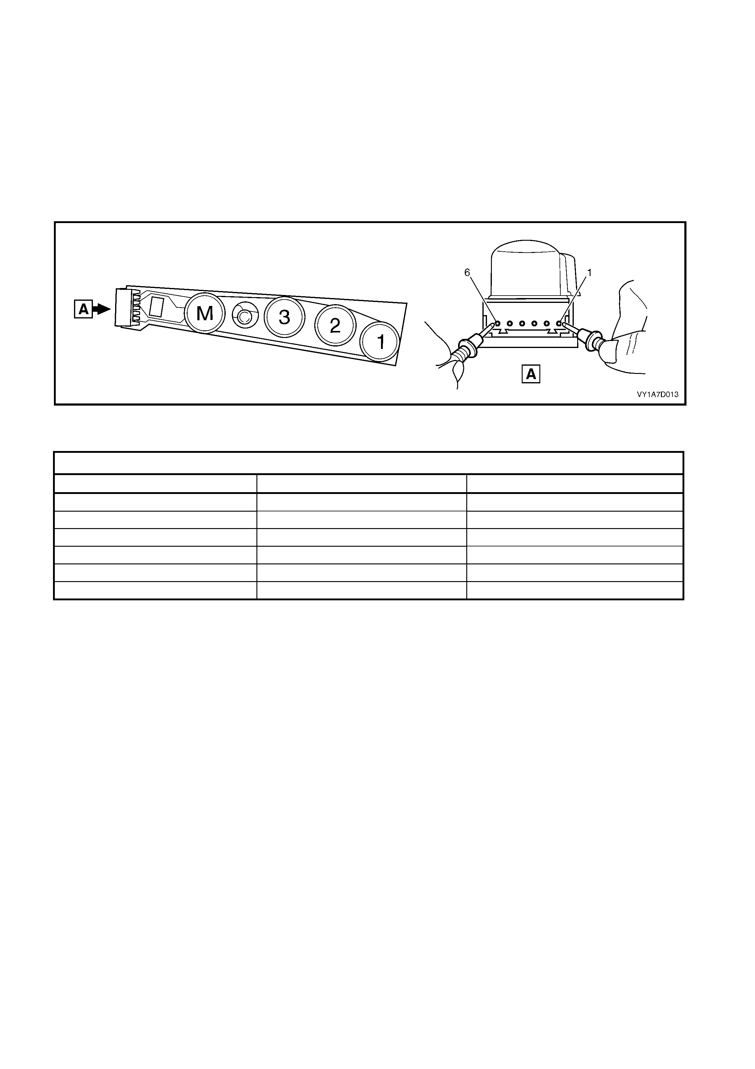
5.9 MEMORY POSITION SWITCH TEST
The switch is located on the outer side of the seat, attached to the inner side of the front seat outer side cover.
TEST
1. Place the switch in the positions as detailed in the chart in this Section. Place the probes of the digital
multimeter onto the terminals listed and take the reading. Compare the reading to the chart.
2. When testing the LED, ensure multimeter is set to diode range and note polarity of probes.
3. If the switch fails any part of the test, replace the switch assembly with a serviceable item.
Figure 1A7-163
MEMORY POSITION SWITCH
SWITCH DEPRESSED SWITCH TERMINALS INDICATION IF SWITCH IS SERVICEABLE
------------ 6 and 1, 2, 3 and 4 Open circui t
Button 1 6 and 1 Continuity
Button 2 6 and 2 Continuity
Button 3 6 and 3 Continuity
Button M 6 and 4 Continuity
------------ 5 (+) probe and 6 (–) probe LED illumi nated
6. SERVICE OPERATIONS - REAR SEAT, SEDAN
6.1 REAR SEAT USAGE CHART - SEDAN
HOW TO USE THIS CHART
Four rear seat configurations are used in MY2003 VY Series Sedan vehicles. The following usage chart is
provided to help determine the seat type fitted to the vehicle. This is important prior to repairs being performed
as the failed / damaged part may not be serviceable.
To determine the seat fitted to the vehicle, obtain the vehicle model, which seat requires attention and the seat
cover fabric. Then establish if the vehicle has an armrest and/or headrest. Using the chart will lead to the
elimination of all other seat com binations, allowing the identification of the type and the c onstruction of the seat.
Finally , refer to the Figure shown in TYPE for a component breakdown of the rear seat assembly.
1. VEHICLE – Vehicle model identification.
2. FABRIC – Cloth or leather seat covers.
3. ARMREST – If the rear seat-back is fitted with an armrest.
4. HEADREST – If the rear seat-back is fitted with a headrest.
5. CONSTRUCTION – Surebond refers to the seat cover being glued to the seat pad and only serviced as a
cover and pad ass embly. Hook and Loop refer s to the seat c over being able to be attached or removed from
the seat pad and both being serviced as separate parts.
6. TYPE – Identif ies the s eat type and provides refer enc e to the f ollowing illustrations which s how a break down
of the serviced component for each rear seat assembly.
DOMESTIC
VEHICLE FABRIC ARMREST HEADREST CONSTRUCTION TYPE
(Refer to)
Calais Leather / Cloth Yes Yes Hook & Loop 4 (Figure 1A7-167)
Berlina Leather / Cloth Yes No Hook & Loop 3 (Figure 1A7-166)
Executive Cloth No No Surebond 1 (Figure 1A7-164)
Acclaim Cloth No No Surebond 1 (Figure 1A7-164)
Cloth No No Surebond 1 (Figure 1A7-164)
S Sedan
Leather Yes No Hook & Loop 3 (Figure 1A7-166)
Cloth Yes No Surebond 2 (Figure 1A7-165)
SS Sedan
Leather Yes No Hook & Loop 3 (Figure 1A7-166)
SV8 Cloth No No Surebond 1 (Figure 1A7-164)
BRAZIL
VEHICLE FABRIC ARMREST HEADREST CONSTRUCTION TYPE
Omega CD Leather Yes Yes Hook & Loop 4 (Figure 1A7-167)
GULF STATES
VEHICLE FABRIC ARMREST HEADREST CONSTRUCTION TYPE
(Refer to)
Lumina LTZ Leather / Cloth Yes No Hook & Loop 3 (Figure 1A7-166)
Lumina LS Cloth No No Surebond 1 (Figure 1A7-164)
Lumina S Cloth No No Surebond 1 (Figure 1A7-164)
Cloth Yes No Surebond 2 (Figure 1A7-165)
Lumina SS
Leather Yes No Hook & Loop 3 (Figure 1A7-166)

SOUTH AFRICA
VEHICLE FABRIC ARMREST HEADREST CONSTRUCTION TYPE
(Refer to)
Lumina LTZ Leather / Cloth Yes No Hook & Loop 3 (Figure 1A7-166)
Lumina LS Cloth No No Surebond 1 (Figure 1A7-164)
Lumina S Cloth No No Surebond 1 (Figure 1A7-164)
Cloth Yes No Surebond 2 (Figure 1A7-165)
Lumina SS
Leather Yes No Hook & Loop 3 (Figure 1A7-166)
INDONESIA
VEHICLE FABRIC ARMREST HEADREST CONSTRUCTION TYPE
(Refer to)
Lumina LTZ Leather / Cloth Yes No Hook & Loop 3 (Figure 1A7-166)
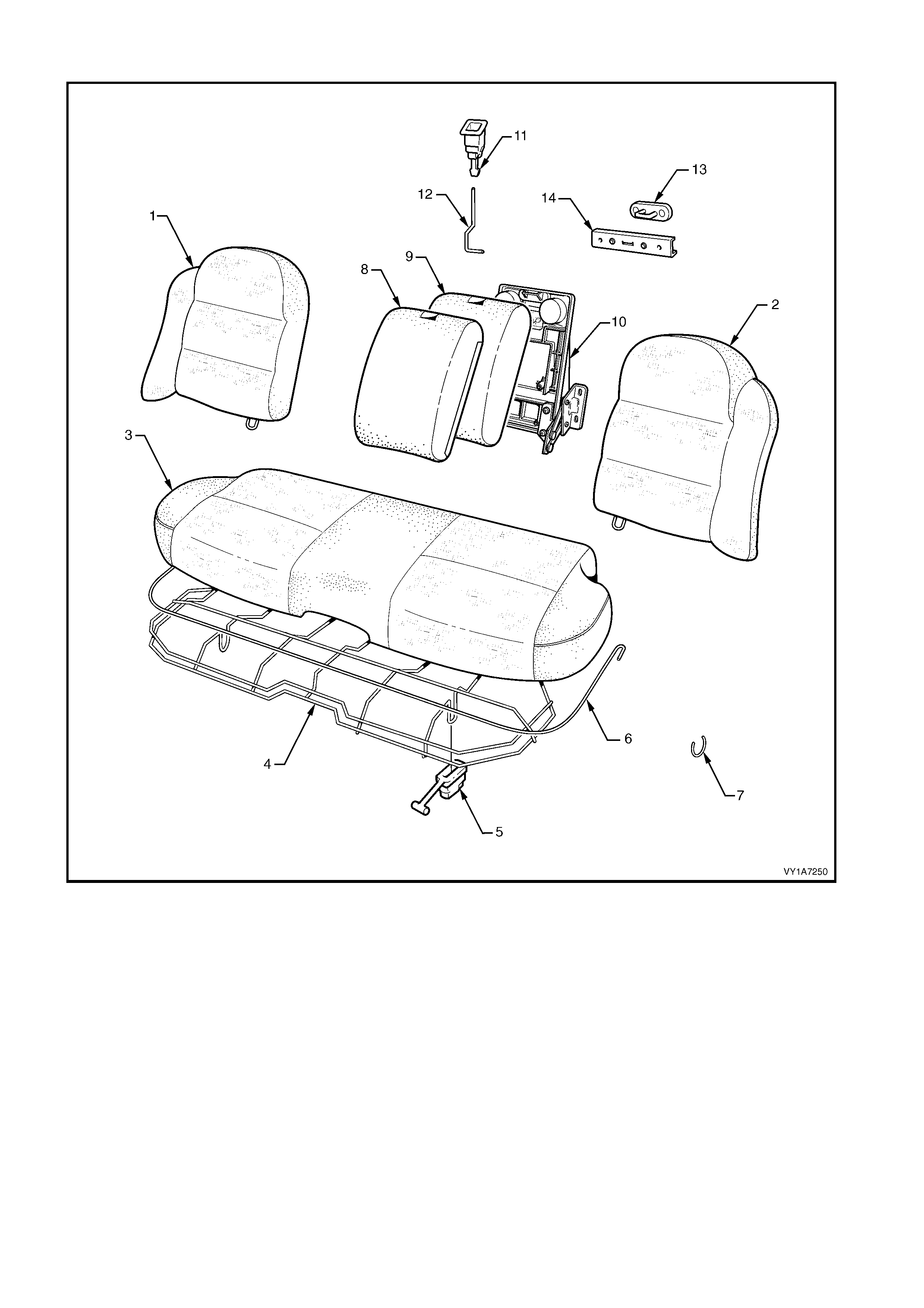
Type 1: Rear Seat Assembly
Figure 1A7-164
Legend
1. Rear Seat-back Assembly - Right-hand Side
2. Rear Seat-back Assembly - Left-hand Side
3. Rear Seat Cushion Cover and Pad Assembly
4. Rear Seat Cushion Frame Assembly
5. Rear Seat Cushion Release Handle - 2 Places
6. Rear Seat Cushion Cover Wire Retainer
7. Hog Ring
8. Rear Seat-back Centre Cover
9. Rear Seat-back Centre Pad
10. Rear Seat-back Centre Tray Assembly ∗
∗∗
∗
11. Rear Seat-back Centre Release Button
12. Release Button Rod
13. Rear Seat-back Centre Lock Striker
14. Rear Seat-back Centre Striker Cover
∗
∗∗
∗ Refer to Figure 1A7-168 for a breakdown of the rear seat-back centre tray assembly.
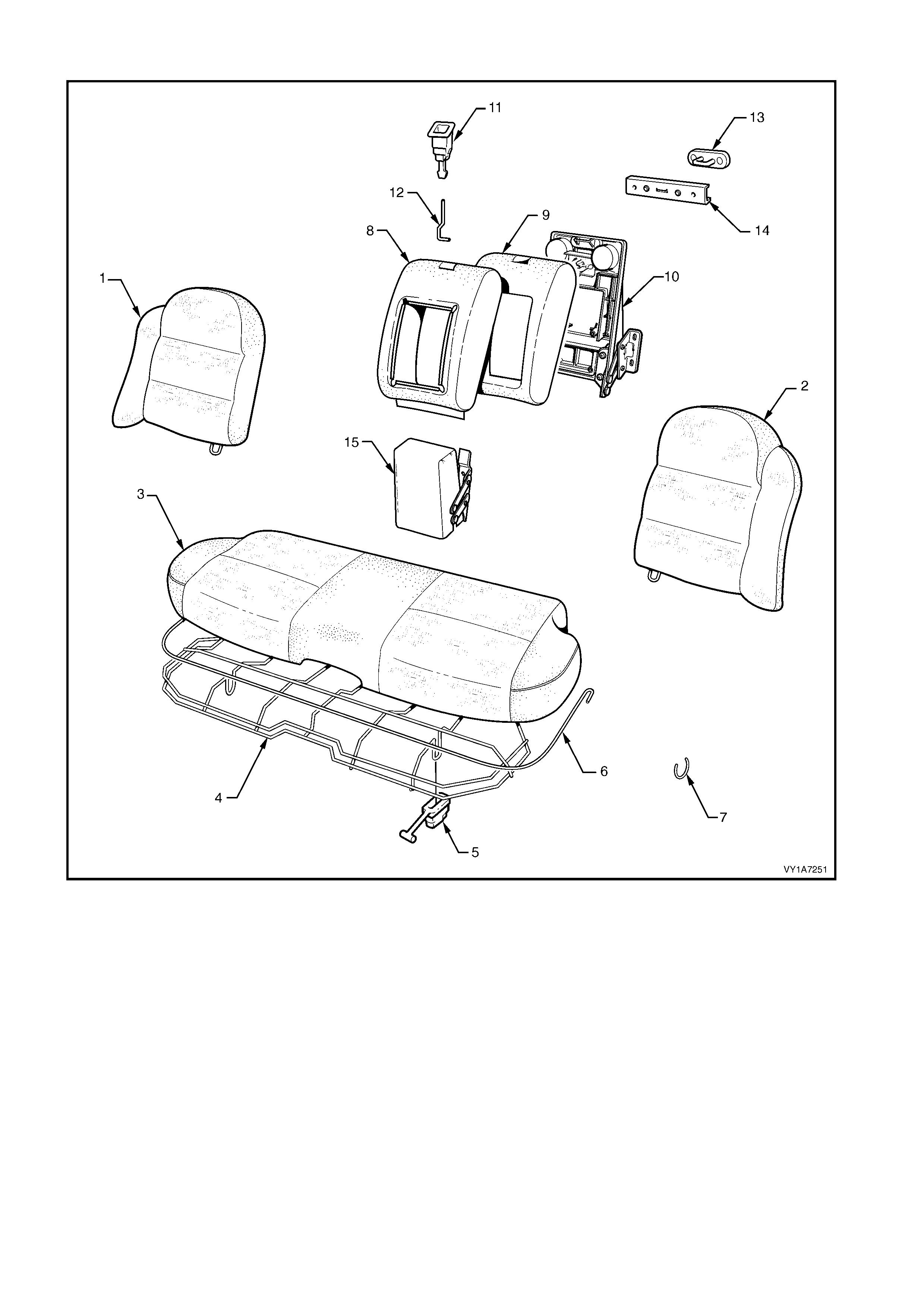
Type 2: Rear Seat Assembly
Figure 1A7-165
Legend
1. Rear Seat-back Assembly - Right-hand Side
2. Rear Seat-back Assembly - Left-hand Side
3. Rear Seat Cushion Cover and Pad Assembly
4. Rear Seat Cushion Frame Assembly
5. Rear Seat Cushion Release Handle - 2 Places
6. Rear Seat Cushion Cover Wire Retainer
7. Hog Ring
8. Rear Seat-back Centre Cover
9. Rear Seat-back Centre Pad
10. Rear Seat-back Centre Tray Assembly ∗
∗∗
∗
11. Rear Seat-back Centre Release Button
12. Release Button Rod
13. Rear Seat-back Centre Lock Striker
14. Rear Seat-back Centre Striker Cover
15. Rear Seat-back Centre Armrest Assembly ∗
∗∗
∗
∗ Refer to Figure 1A7-168 for a breakdown of the rear seat-back centre tray and armrest assemblies.

Type 3: Rear Seat Assembly
Figure 1A7-166
Legend
1. Rear Seat-back Pad and Frame Assembly -
Right-hand Side
2. Rear Seat-back Cover Assembly - Ri ght-hand Side
3. Rear Seat-back Pad and Frame Assembly -
Left-hand Side
4. Rear Seat-back Cover Assembly - Left-hand Side
5. Rear Seat Cushion Pad
6. Rear Seat Cushion Cover Assembly
7. Rear Seat Cushion Frame Assembly
8. Rear Seat Cushion Release Handle - 2 Places
9. Rear Seat Cushion Cover Retainer Wire
10. Hog Ring
11. Rear Seat-back Centre Cover
12. Rear Seat-back Centre Pad
13. Rear Seat-back Centre Tray Assembly ∗
∗∗
∗
14. Rear Seat-back Centre Release Button
15. Release Button Rod
16. Rear Seat-back Centre Lock Striker
17. Rear Seat-back Centre Striker Cover
18. Rear Seat-back Centre Armrest Assembly ∗
∗∗
∗
∗ Refer to Figure 1A7-168 for a breakdown of the rear seat-back centre tray and armrest assembly.
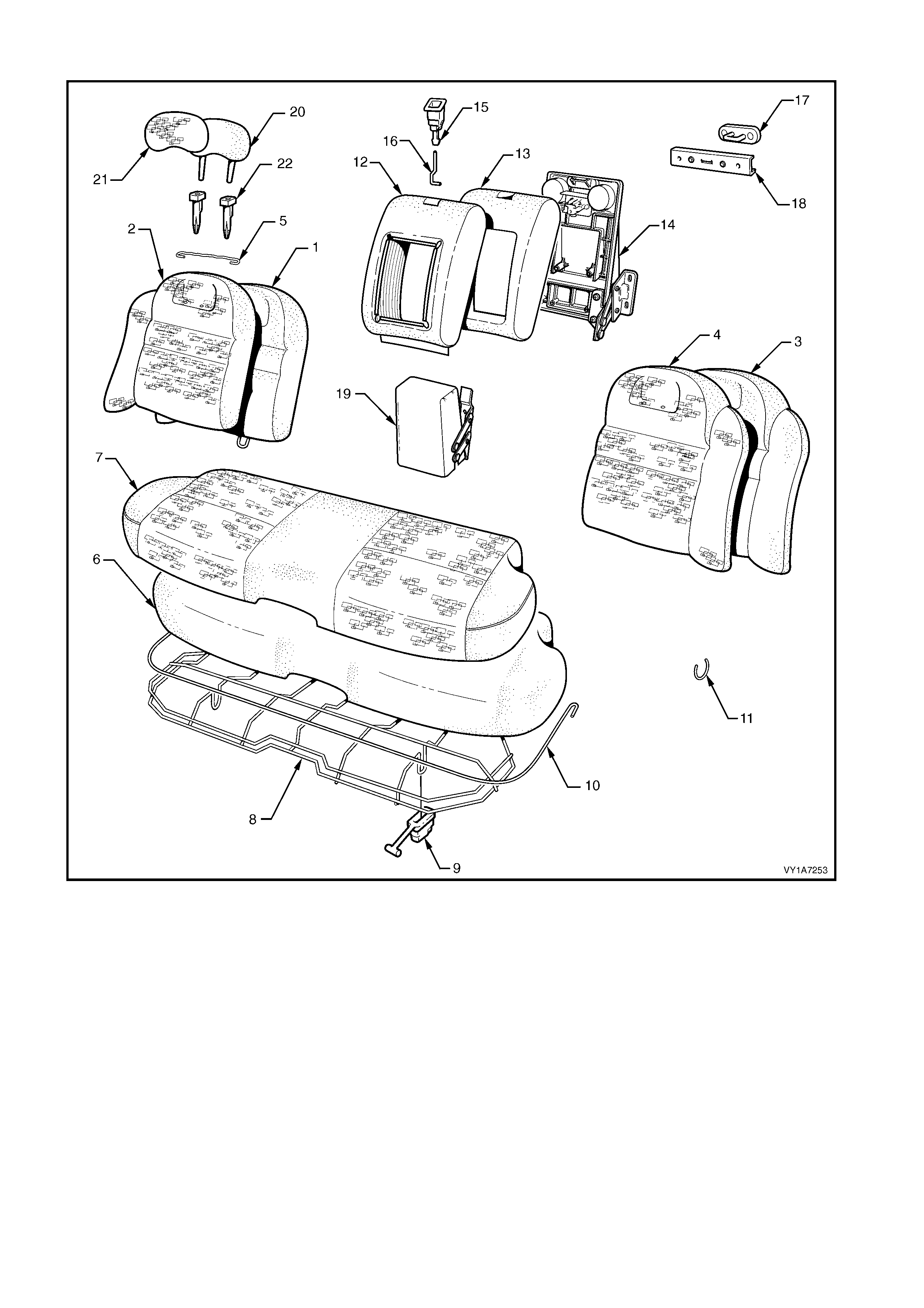
Type 4: Rear Seat Assembly
Figure 1A7-167
Legend
1. Rear Seat-back Pad & Frame Assembly -
Right-hand Side
2. Rear Seat-back Cover Assembly- Ri ght-hand Side
3. Rear Seat-back Pad & Frame Assembly -
Left-hand Side
4. Rear Seat-back Cover Assembly- Left-hand Side
5. Rear Seat-back Cover Retaining Wire - 2 Places
6. Rear Seat Cushion Pad
7. Rear Seat Cushion Cover Assembly
8. Rear Seat Cushion Frame Assembly
9. Rear Seat Cushion Release Handle - 2 Places
10. Rear Seat Cushion Cover Retainer Wi re
11. Hog Ring
12. Rear Seat-back Centre Cover
13. Rear Seat-back Centre Pad
14. Rear Seat-back Centre Tray Assembly ∗
∗∗
∗
15. Rear Seat-back Centre Release Button
16. Release Button Rod
17. Rear Seat-back Centre Lock Striker
18. Rear Seat-back Centre Striker Cover
19. Rear Seat-back Centre Armrest Assembly ∗
∗∗
∗
20. Head Restraint Pad - 1 Place each side
21. Head Restraint Cover - 1 Place each side
22. Head Restraint Guides - 2 Place each side
∗ Refer to Figure 1A7-168 for a breakdown of the rear seat-back centre tray and armrest assembly.
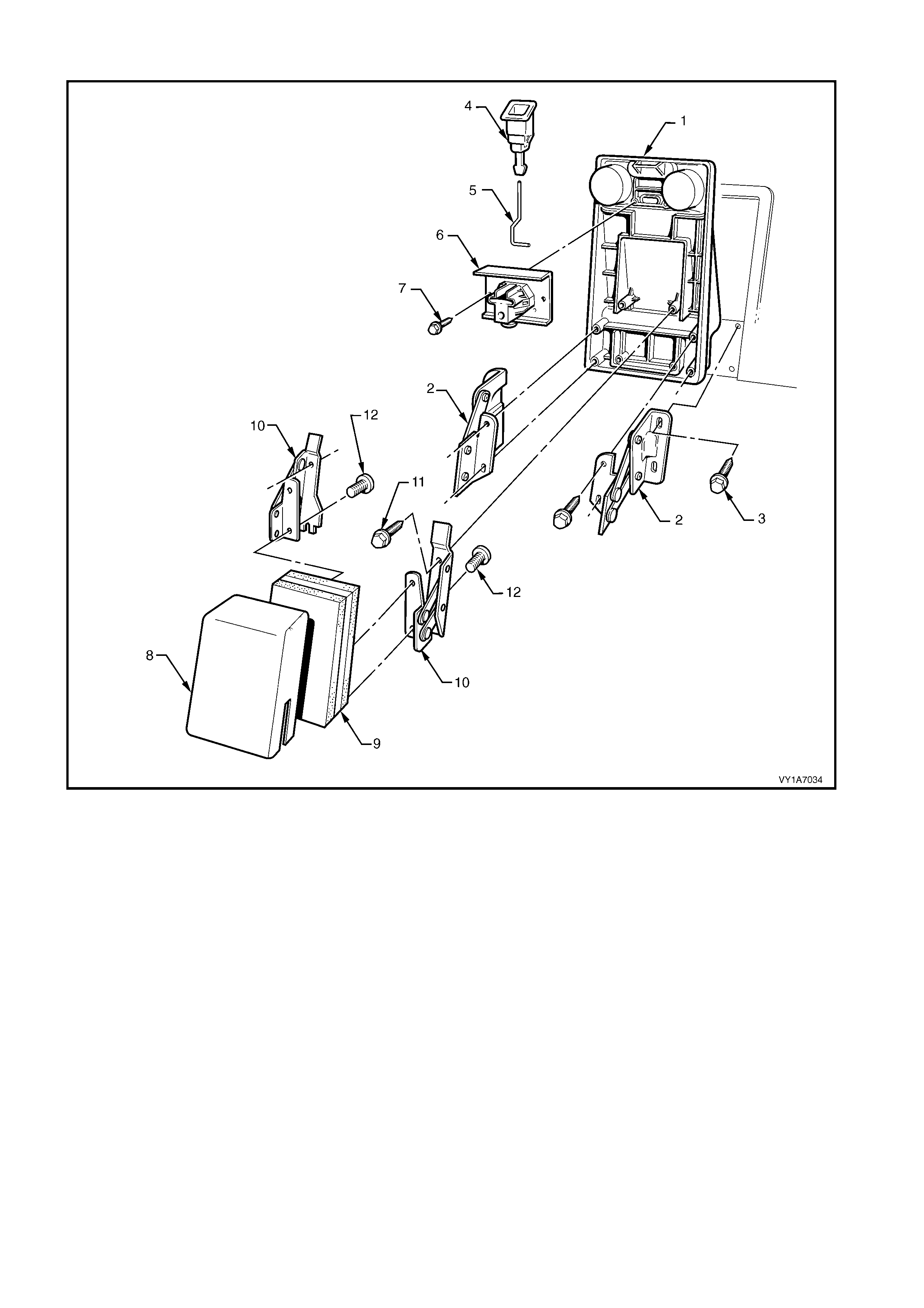
Rear Seat-back Centre Tray And Armrest Assembly
Figure 1A7-168
Legend
1. Rear Seat-back Centre Tray
2. Rear Seat-back Centre Tray Hinge - 2 Places
3. Hinge Rear Seat-back Centre Bolt - 4 Places
4. Rear Seat-back Centre Release Button
5. Release Button Rod
6. Rear Seat-back Centre Lock Actuator
7. Lock Actuator Bolt - 2 Places
8. Rear Seat-back Centre Armrest Cover (if fitted)
9. Rear Seat-back Centre Armrest Pad (if fitted)
10. Armrest Assembly Hinge - 2 Places (if fitted)
11. Armrest Hinge Bolt - 4 Places (if fitted)
12. Armrest Hinge Screw - 4 Places (if fitted)
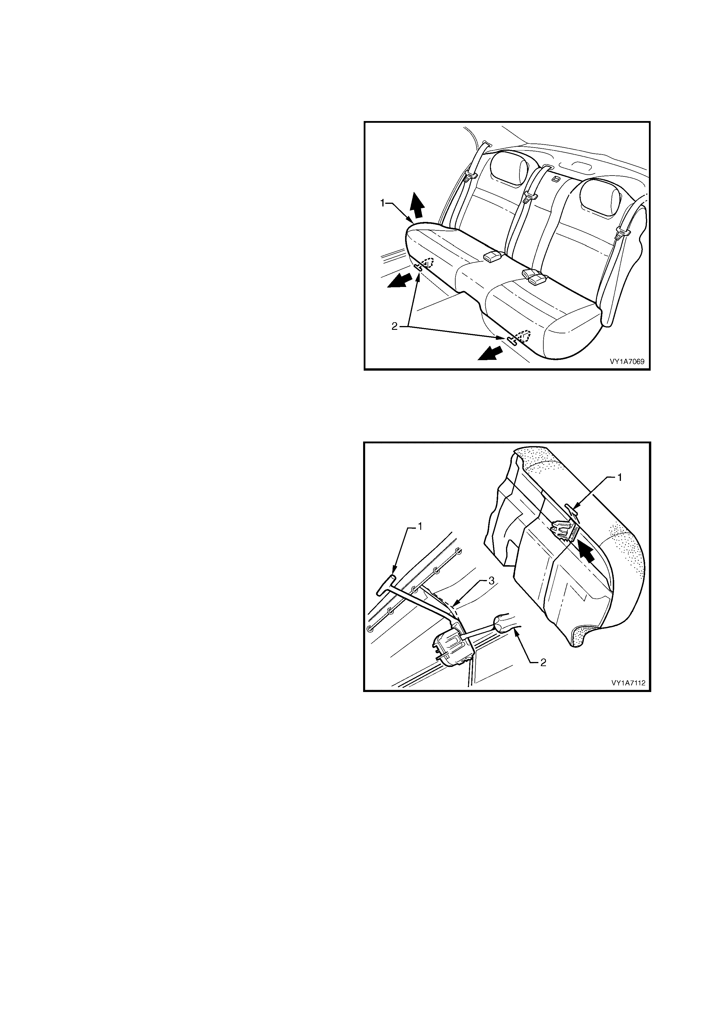
6.2 REAR SEAT CUSHION ASSEMBLY
LT Section No. – 14-330
REMOVE
1. Lift the front of the rear seat cushion assembly (1)
slightly, to gain access to the rear seat cushion
release handles (2).
2. From either the left or the right side of the seat,
pull the release handle T-peice horizontally
outwards, while at the s ame tim e lif ting the front of
the rear seat cushion until the lock mechanism is
released.
3. Repeat step 2 for the opposite side of the seat.
4. Remove the rear seat cushion assembly.
Figure 1A7-169
DISASSEMBLE
Remove – Rear Seat Cushion Release Handle
1. Remove the rear seat cushion release handle (1)
by inserting a screwdriver (2) to disengage the
retaining lugs.
2. Slide the release handle off the rear seat cushion
wire frame (3).
Figure 1A7-170
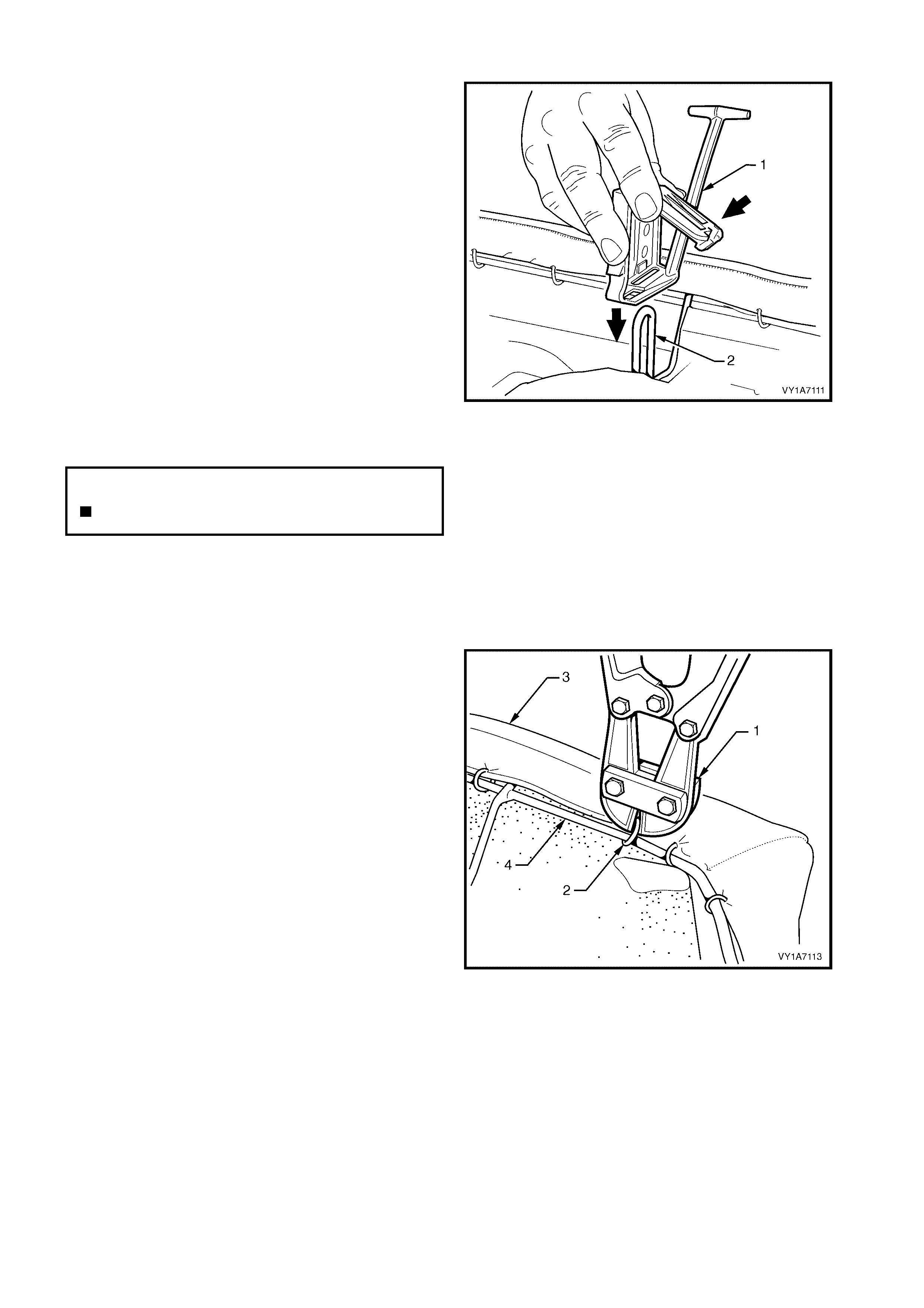
Reinstall – Rear Seat Cushion Release Handle
1. Slide the rear seat cus hion release handle ( 1) onto
the rear seat cushion wire fram e (2) and close the
cover so that it will lock into position on the frame.
Figure 1A7-171
Remove – Rear Seat Cushion Frame
CAUTION: Safety glasses and work gloves must be
worn at all times when removing the hog rings.
1. Place the rear seat cushion assembly up side
down.
2. Use bolt cutters (1) to remove the hog rings (2)
attaching the cover and pad assembly (3) to the
frame (4):
• Fifty one places for the Surebond rear seat
cushions.
• Fifty four places for the Hook and Loop rear
seat cushions.
NOTE: 1 Care must be taken when removing the hog
rings not to damage the cushion cover.
NOTE: 2 All hog rings will be destroyed during this
operation and must be replaced.
3. Remove the frame from the rear seat cushion
assembly.
Figure 1A7-172
N
O
TE: The
f
ollowing component WILL RE
Q
UIRE
REPLACEMENT when performing this operation.
Rear seat cushion hog rings.

4. If required, remove the retaining wire (1) from the
casing (2) on the front of the cushion cover
assembly (3).
Figure 1A7-173
Remove – Rear Seat Cushion Cover , Hook and Loop
The following procedure applies to vehicles fitted with
seat covers attached to the seat pad with the fully
serviced Hook and Loop. For model reference chart,
refer to 6.1 REAR SEAT USAGE CHART - SEDAN.
1. Fold the rear corner of the rear seat cus hion cover
(1) over the seat cushion pad (2).
Figure 1A7-174
2. While holding the rear seat cushion pad (1), pull
the rear corner of the seat cushion cover (2) away
from the rear seat cushion pad to disengage the
hook and loop strip (3).
Figure 1A7-175
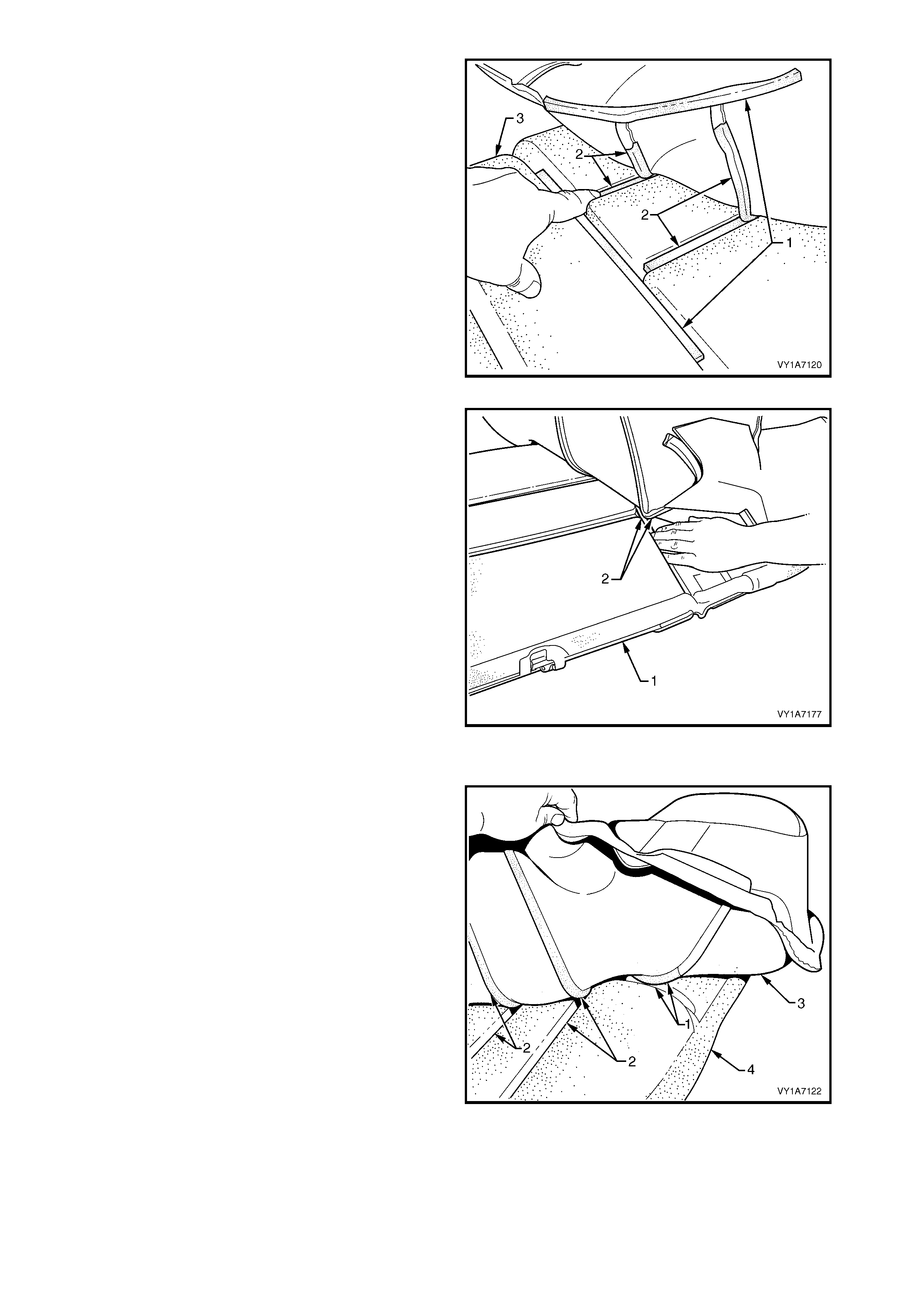
3. After dis engaging the outer hook and loop strip (1)
remove the one or two cross hook and loop strips
(2) while holding the seat cushion pad (3).
Figure 1A7-176
4. While holding the rear seat cushion pad (1),
remove the inner hook and loop strip (2).
5. Repeat this process for the opposite half of the
rear seat cushion assembly.
6. Remove the rear seat cushion cover.
Figure 1A7-177
Reinstall – Rear Seat Cushion Cover, Hook and Loop
1. Align the inner hook and loop strip (1) and the one
or two cross hook and loop strips (2), on the seat
cushion cover (3), with the seat cushion pad (4).
2. Press the folded edge of the rear seat cushion
cover firmly into the corresponding groove in the
seat cushion pad to engage the hook and loop
strip.
Figure 1A7-178
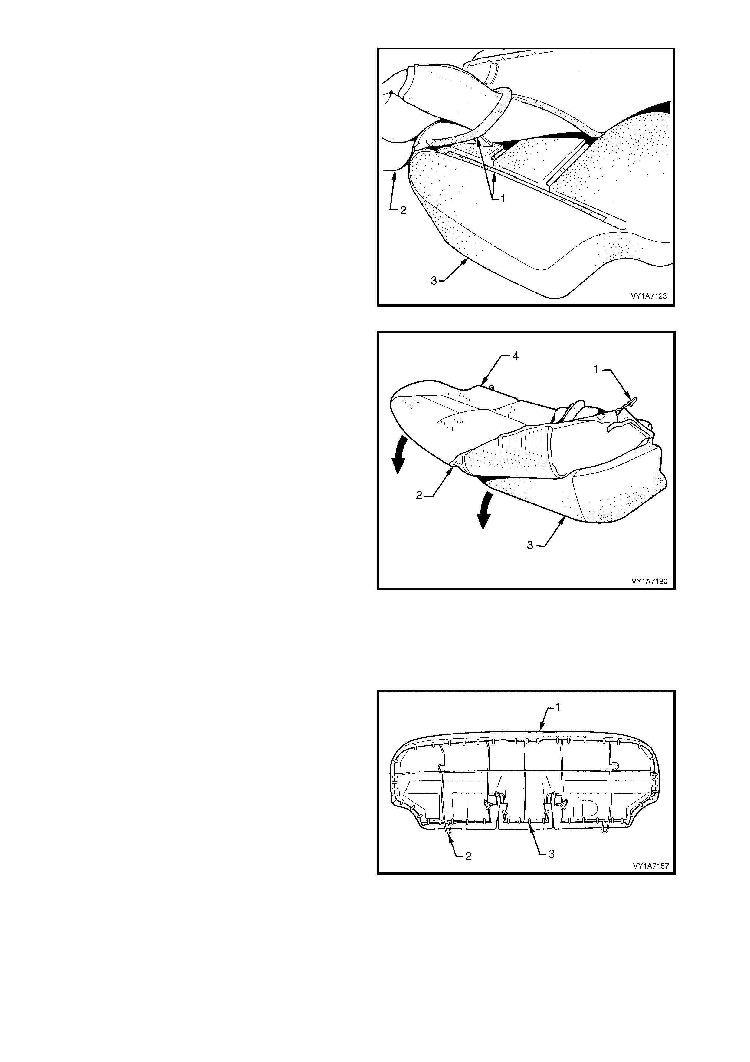
3. Align and press the outer hook and loop strip (1),
on the seat cushion cover (2), with the
corresponding groove in the seat cushion pad (3).
4. Repeat this process for the opposite half of the
rear seat cover and pad, starting with the inner
strip.
Figure 1A7-179
5. With the retaining wire (1) fitted to the rear seat
cushion c over (2), roll the f ront corner of the c over
over the seat cushion pad (3).
6. Roll the sides of the seat cushion cover over the
seat cushion pad.
7. Roll the rear corners (4) of the seat cushion cover
over the seat cushion pad.
NOTE: Make sure the pad is fitted neatly by hand into
all corners and contours of the seat cover.
Figure 1A7-180
Reinstall – Rear Seat Cushion Frame, Surebond
NOTE: All hog rings must be replaced.
CAUTION: Safety glasses and work gloves must be
worn at all times when working with hog rings.
1. Using the following sequence operations, align the
rear seat cushion cover and pad assembly (1) to
the rear seat cushion frame (2) and attach with
approximately fifty one hog rings (3) in the
positions shown.
Figure 1A7-181
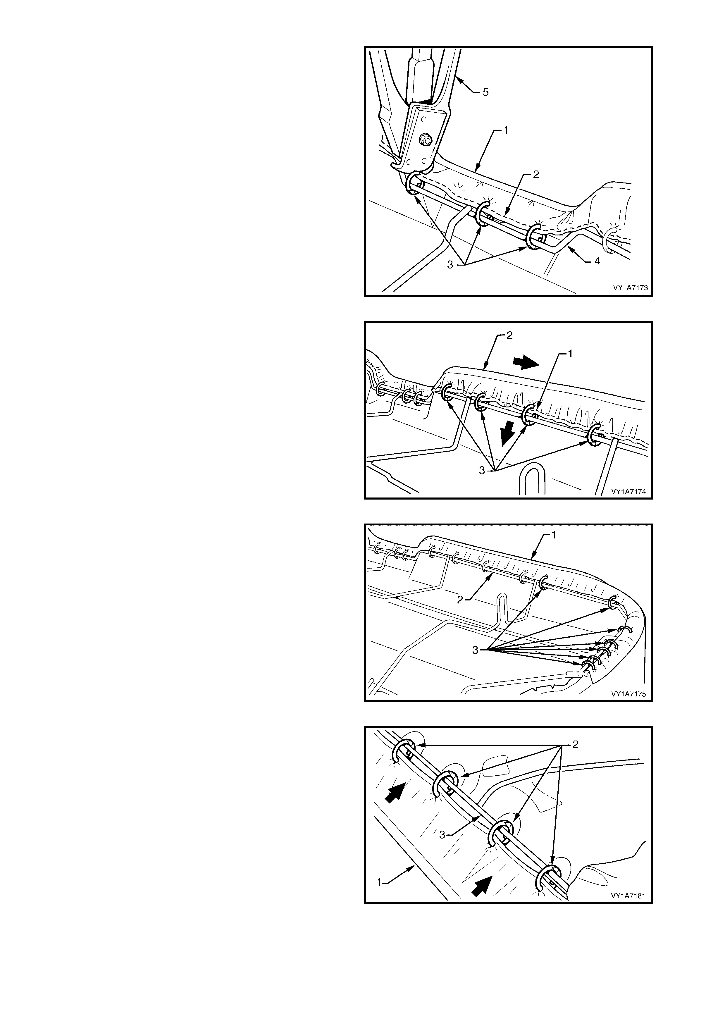
2. Starting at the front, in the centre of the rear seat
cushion cover assembly (1), attach the wire
retainer (2) with three hog rings (3) to the centr e of
the wire frame (4) using hog ring pliers (5).
Figure 1A7-182
3. Working from the centre outward, attach the wire
retainer (1), pulling the cover assembly (2) tight
and fixing with four hog rings (3).
4. Repeat this process in the opposite direction
working from the centre outward.
Figure 1A7-183
5. Continue attaching the cover assembly (1) to the
frame (2), by pulling the cover tight and fixing with
seven hog rings (3).
6. Repeat this process in the opposite direction.
NOTE: The cover should be smooth and without
creases, if this is not the case, extra hog rings should
be used to pull the cover into place.
Figure 1A7-184
7. Pull the rear of the cover assembly (1) tight and
attach the centre with four hog rings (2) to the
centre of the wire frame (3).
Figure 1A7-185
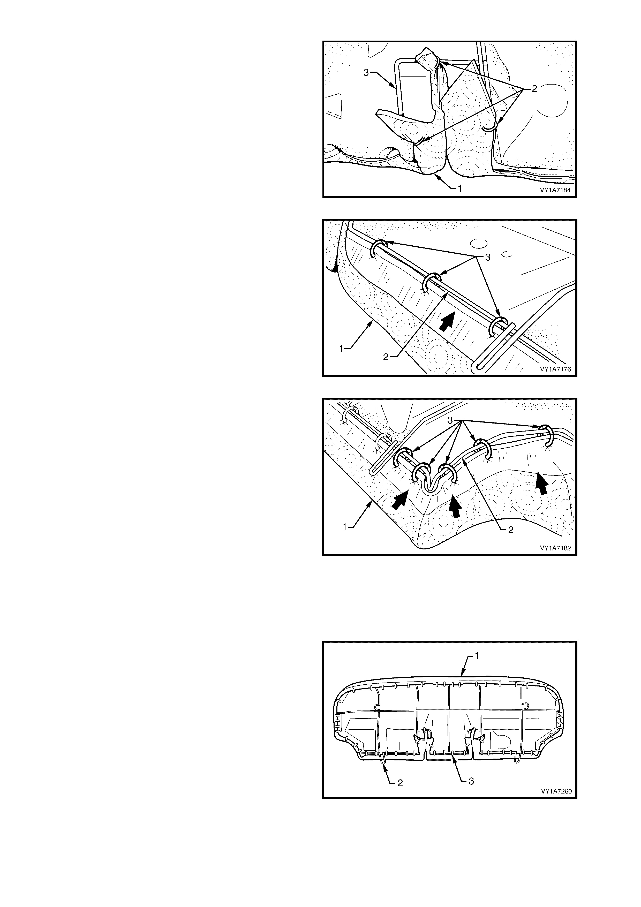
8. Pull the cover assembly (1) tight into the seatbelt
slot at the rear of the seat pad and attach with
three hog rings (2) to the wire frame (3).
9. Repeat this process for the opposite seatbelt slot.
Figure 1A7-186
10. Continue attaching the cover assembly (1) to the
frame (2), by pulling the cover tight and fixing with
three hog rings (3).
11. Repeat this process in the opposite direction.
NOTE: The cover should be smooth and without
creases, if this is not the case, extra hog rings should
be used to pull the cover into place.
Figure 1A7-187
12. Continue attaching the cover assembly (1) to the
fram e ( 2), by pulling the cover tight, up and around
the corner and fixing with five hog rings (3).
13. Repeat this process in the opposite direction.
NOTE: The cover should be smooth and without
creases, if this is not the case, extra hog rings should
be used to pull the cover into place.
Figure 1A7-188
Reinstall – Rear Seat Cushion Frame, Hook and Loop
NOTE: All hog rings must be replaced.
CAUTION: Safety glasses and work gloves must be
worn at all times when working with hog rings.
1. Using the following sequence operations, align the
rear seat cushion cover and pad assembly (1) to
the rear seat cushion frame (2) and attach with
approximately fifty four hog rings (3) in the
positions shown.
Figure 1A7-189
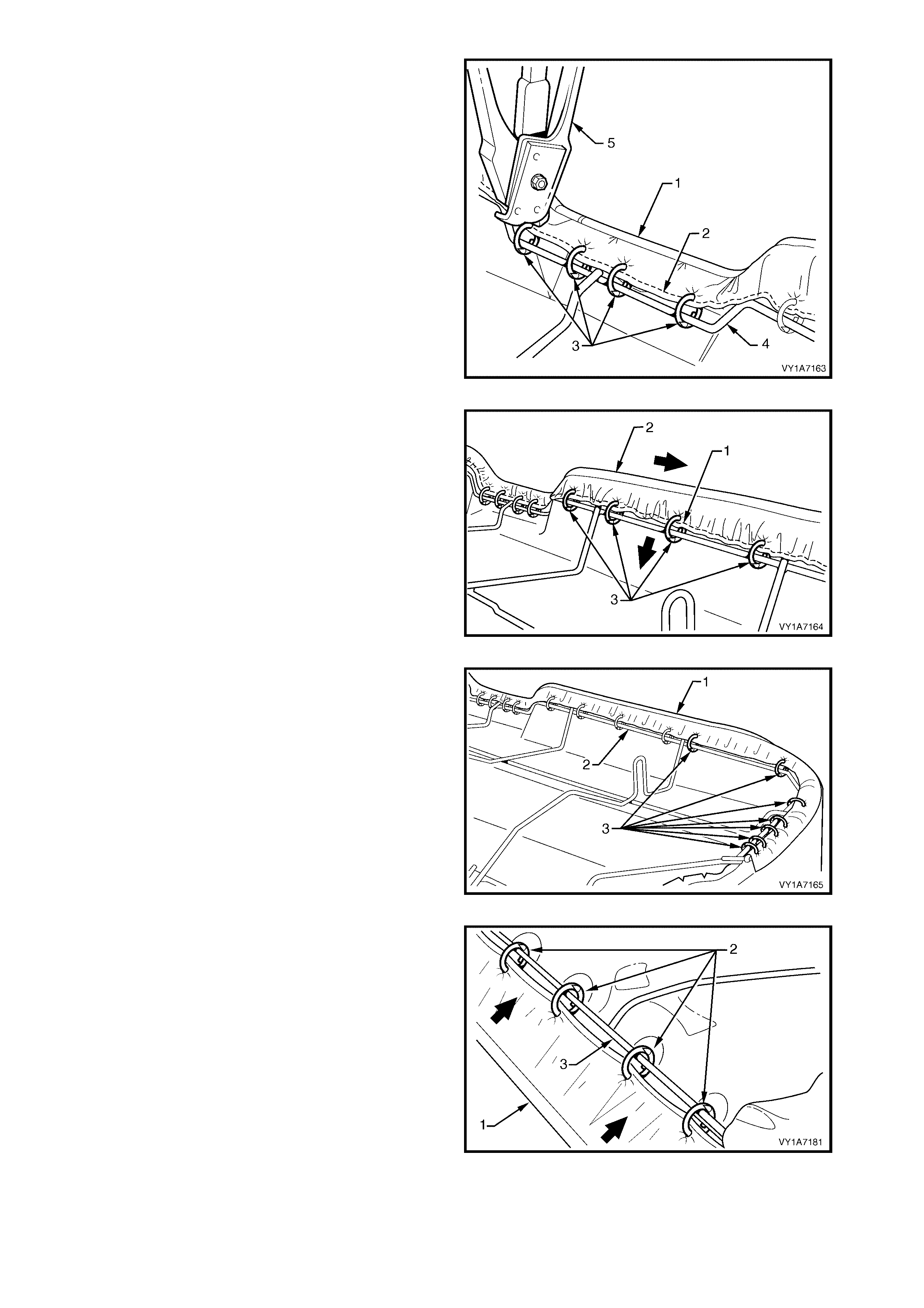
2. Starting at the front, in the centre of the rear seat
cushion cover assembly (1), attach the wire
retainer (2) with four hog rings (3) to the centre of
the wire frame (4) using hog ring pliers (5).
Figure 1A7-190
3. Working from the centre outward, attach the wire
retainer (1), while pulling the cover assembly (2)
tight and fixing with four hog rings (3).
4. Repeat this process in the opposite direction
working from the centre outward.
Figure 1A7-191
5. Continue attaching the cover assembly (1) to the
frame (2), by pulling the cover tight and fixing with
seven hog rings (3).
6. Repeat this process in the opposite direction.
NOTE: The cover should be smooth and without
creases, if this is not the case, extra hog rings should
be used to pull the cover into place.
Figure 1A7-192
7. Pull the rear of the cover assembly (1) tight and
attach the centre with four hog rings (2) to the
centre of the wire frame (3).
Figure 1A7-193
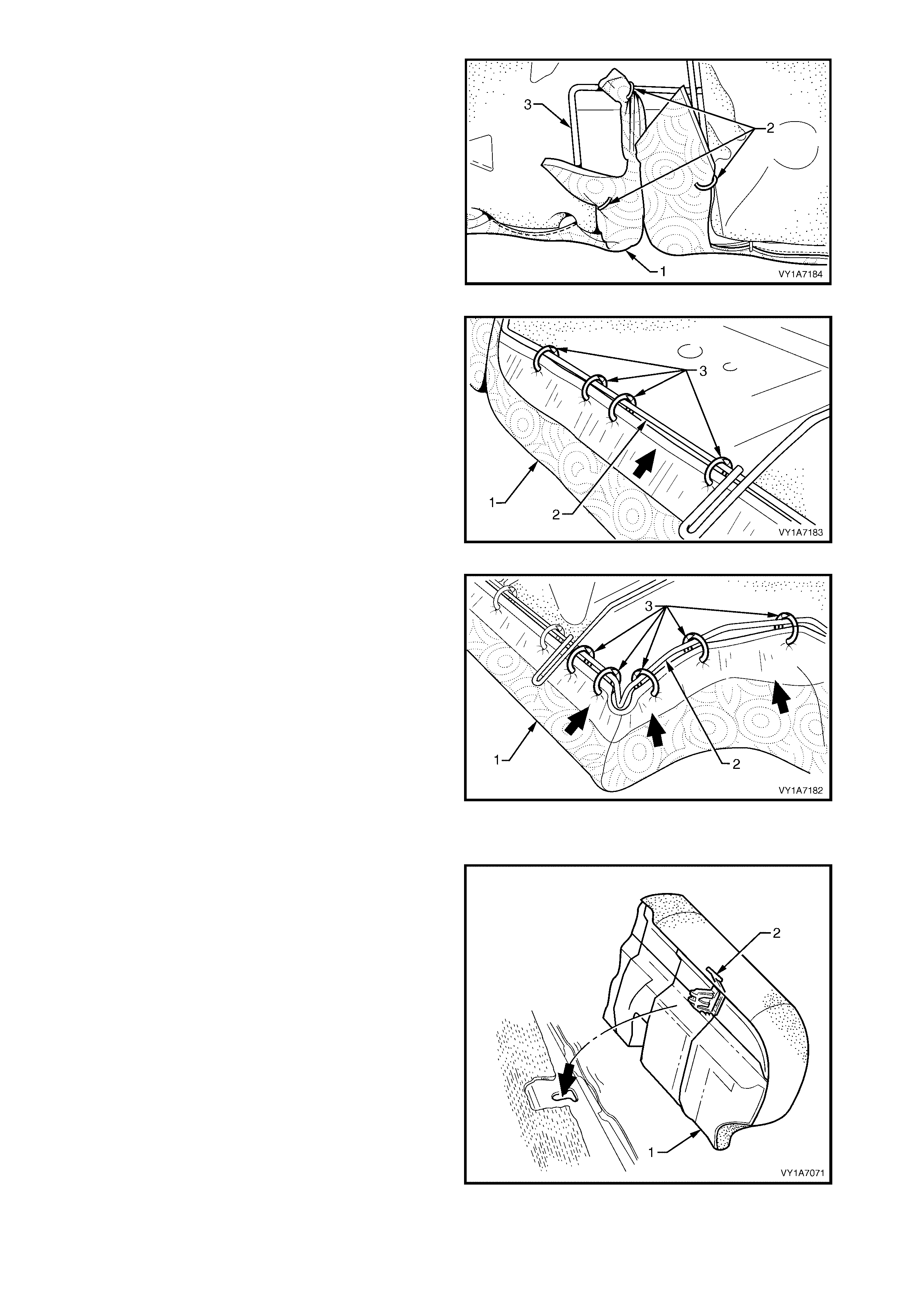
8. Pull the cushion cover assembly (1) tight into the
seatbelt slot at the rear and attach with three hog
rings (2) to the wire frame (3).
9. Repeat this process for the opposite the seatbelt
slot.
Figure 1A7-194
10. Continue attaching the cover assembly (1) to the
frame (2), by pulling the cover tight and fixing with
four hog rings (3).
11. Repeat this process in the opposite direction.
Figure 1A7-195
12. Continue attaching the cover assembly (1) to the
fram e ( 2), by pulling the cover tight, up and around
the corner and fixing with five hog rings (3).
13. Repeat this process in the opposite direction.
NOTE: The cover should be smooth and without
creases, if this is not the case, extra hog rings should
be used to pull the cover into place.
Figure 1A7-196
REINSTALL
1. Sit the rear seat cushion into position.
2. Push the rear seat cushion (1) into the seat back
and push down the front of the cushion until the
locking mechanisms (2) lock into position.
Figure 1A7-197

6.3 REAR SEAT-BACK ASSEMBLY
LT Section No. – 14-325
1. Remove the rear seat cushion assembly, refer to 6.2 REAR SEAT CUSHION ASSEMBLY.
REMOVE
1. Press the release and lower the rear seat centre
back assembly (1).
Figure 1A7-198
2. Remove the screw (1) retaining the rear seat-back
assembly (2) to the rear compartment front panel.
3. Lift the rear seat-back assembly up and out of the
retaining brackets (3) in the floor panel.
4. Remove the rear seat-back assembly and repeat
for the opposite side if required.
Figure 1A7-199
DISASSEMBLE
Remove – Rear Seat-back Head Restraint, If Fitted
1. Remove the head restraint (1) by depressing the
head restraint guide height adjuster lock (2).
2. Pull the head restraint completely out of the guide.
Reinstall – Rear Seat-back Head Restraint
Reinstallation of the head restraint into the rear seat-
back assembly is the reverse of the removal
procedure.
Figure 1A7-200
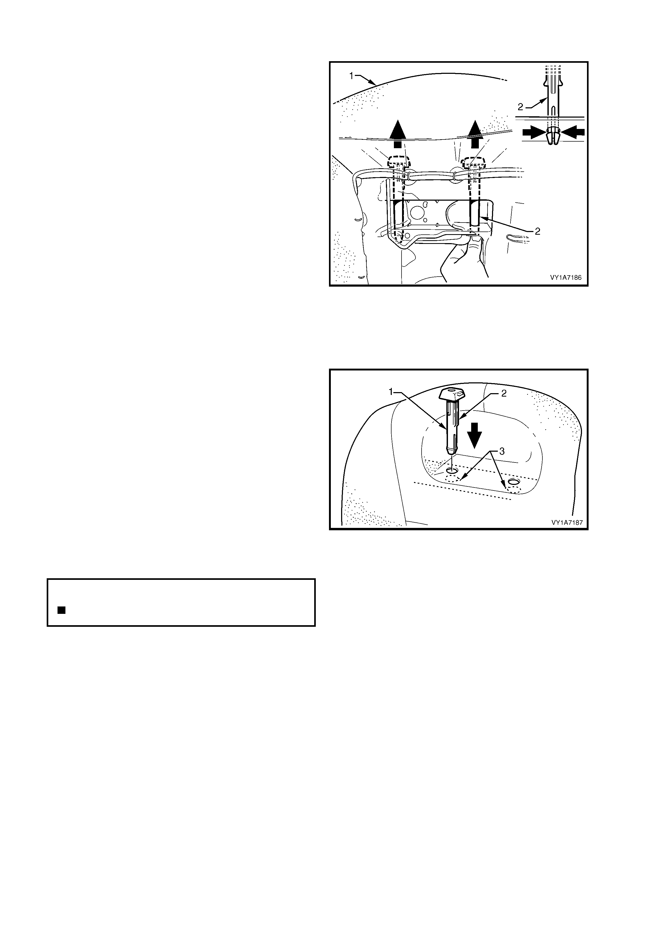
Remove – Rear Seat-back Head Restraint Guide, If Fitted
1. From the back of rear seat-back (1) (foam side)
squeeze the head restraint guide locating prongs
(2) together and remove the guide up and out of
the seat-back assembly.
2. Repeat this process for the remaining head
restraint guide.
Figure 1A7-201
Reinstall – Rear Seat-back Head Restraint Guide
Reinstallation of the rear seat head restraint guide is
the reverse of the removal procedure, noting the
following:
1. When installing the head restraint guide (1), align
the locating ribs (2) with the key-way (3) in the
seat-back frame.
NOTE: Ensure the guide with the height adjuster lock
is installed on the s ide that corresponds to the notches
in the head restraint shaft.
Figure 1A7-202
Remove – Rear Seat-back Cover, Hook and Loop
NOTE 1: Surebond cover assemblies are not serviced
as they are glued to the seat-back pad and frame
assembly, refer to 6.1 REAR SEAT USAGE CHART -
SEDAN.
NOTE 2: The following procedures are applicable to
both left and right-hand rear seat-back assemblies.
CAUTION: Safety glasses and work gloves must be
worn at all times when removing the hog rings.
1. Place the rear seat-back assembly face down.
N
O
TE: The
f
ollowing component WILL RE
Q
UIRE
REPLACEMENT when performing this operation.
Rear seat back hog rings.

2. Use bolt cutters (1) to remove approximately thirty
one hog rings (2) attaching the cover (3) to the
rear seat-back pad and frame assembly (4).
NOTE: 1 Care must be taken when removing the hog
rings, not to damage the rear seat-back cover.
NOTE: 2 All hog rings will be damaged during this
operation and must be replaced.
Figure 1A7-203
3. Fold the upper portion of the rear seat-back cover
(1) over the rear seat-back pad assembly (2).
4. If the rear seat-back has the provision for a head
restraint, cut the two hog rings (3) attaching the
retaining wire (4) to the frame assembly (5).
Figure 1A7-204
5. While holding the rear seat-back pad assembly
(1), pull the upper corner of the cover (2) away
from the r ear s eat- back pad to disengage the hook
and loop strip (3).
Figure 1A7-205
6. Rem ove the one or two cross hook and loop str ips
(1) while holding the rear seat-back pad (2).
Figure 1A7-206
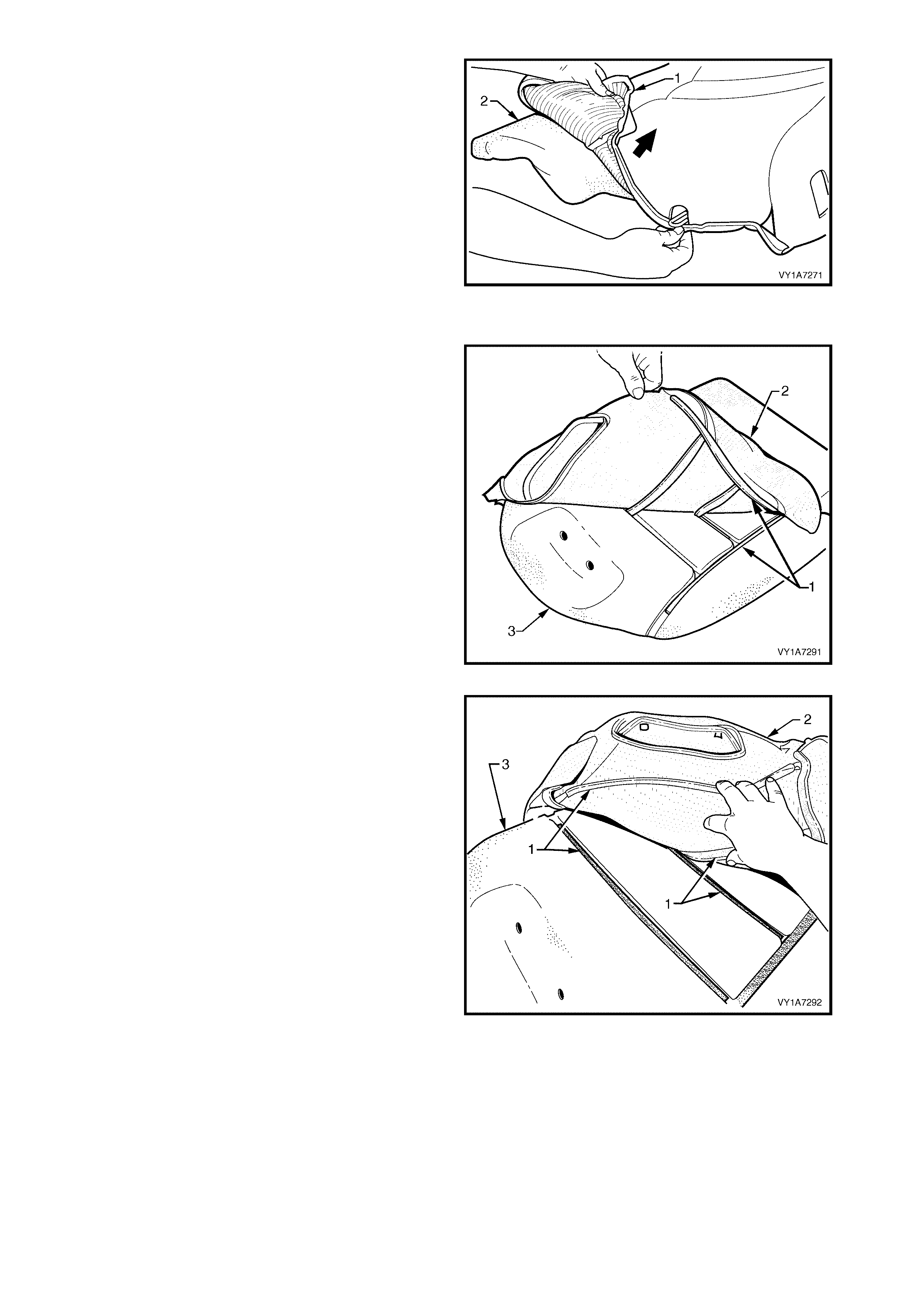
7. Fold the lower corner of the cover (1) over the
seat-back pad (2).
8. Remove the rear seat-back cover.
Figure 1A7-207
Reinstall – Rear Seat-back Cover, Hook and Loop
1. Align the outer hook and loop strip (1) on the seat-
back cover (2), with the seat -back pad (3).
Figure 1A7-208
2. Align the one or two cross hook and loop strips (1),
on the seat-back cover ( 2), with the seat - back pad
(3).
Figure 1A7-209
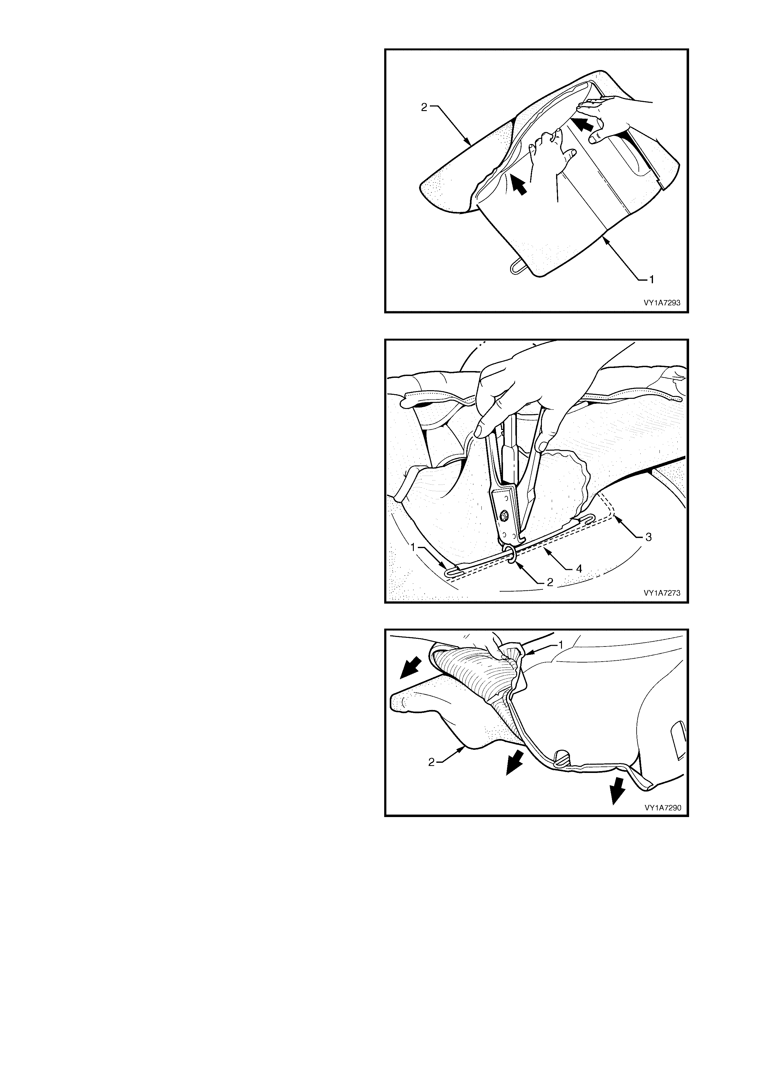
3. Press the folded edge of the rear seat-back cover
(1) firmly into the corresponding groove in the
seat-back pad (2) to engage the hook and loop
strip.
Figure 1A7-210
4. If the rear seat-back cover has the provision for a
head restraint, the retaining wire (1) must be
attached with two hog rings (2) to the frame (3)
using hog ring pliers.
Figure 1A7-211
5. Roll the lower corner of the cover (1) over the seat-
back pad (2).
6. Roll the sides of the cover over the seat-back pad.
7. Roll the upper corners of the cover over the seat-
back pad.
NOTE: Make sure the cover is fitted neatly by hand
into all corners and contours of the seat back-pad.
Figure 1A7-212
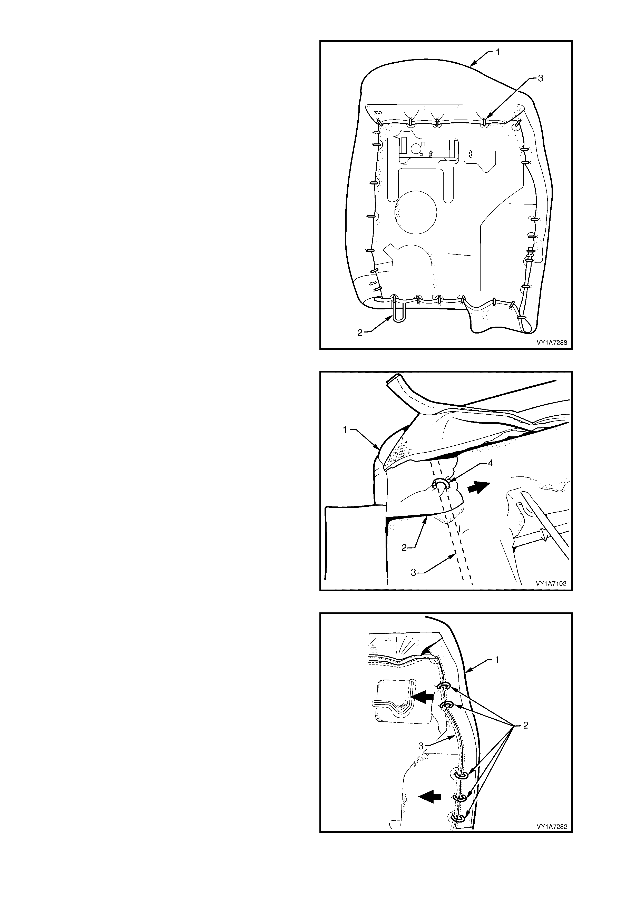
8. Using the following sequence operations attach
the rear seat-back cover (1) to the rear seat-back
pad and frame assembly (2), with approximately
thirty one hog rings (3), in the positions shown.
Figure 1A7-213
9. Starting at the upper inboard corner of the rear
seat-back cover (1), pull the cover flap (2) towards
the centre and attach to the wire frame (3) with
one hog ring (4).
Figure 1A7-214
10. While pulling the cover (1) tight, fix with five hog
rings (2) to the wire frame (3) on the outboard side.
Figure 1A7-215
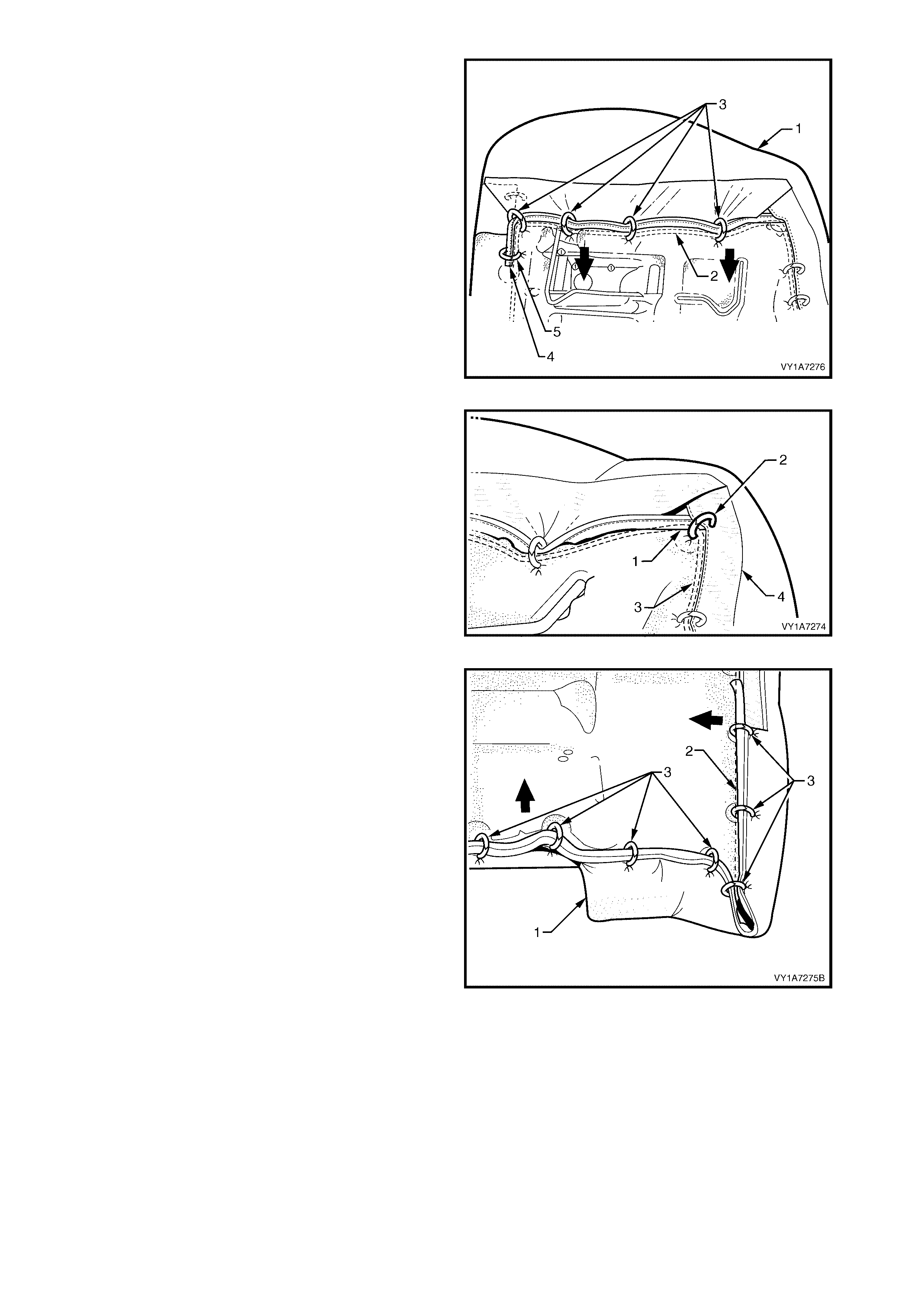
11. Continue attaching the cover (1) to the frame (2),
by pulling the cover tight and fixing with four hog
rings (3).
12. Attach the cover upper piping overhang (4), with
one hog ring (5) to the wire frame, in the top
inboard corner.
Figure 1A7-216
13. Attach the cover upper piping overhang (1), with
one hog ring (2) to the wire frame (3) and to the
hessian (4) on the side of the cover, in the top
outboard corner.
Figure 1A7-217
14. Continue attaching the cover (1) to the frame (2),
by pulling the cover tight and fixing with seven hog
rings (3).
Figure 1A7-218
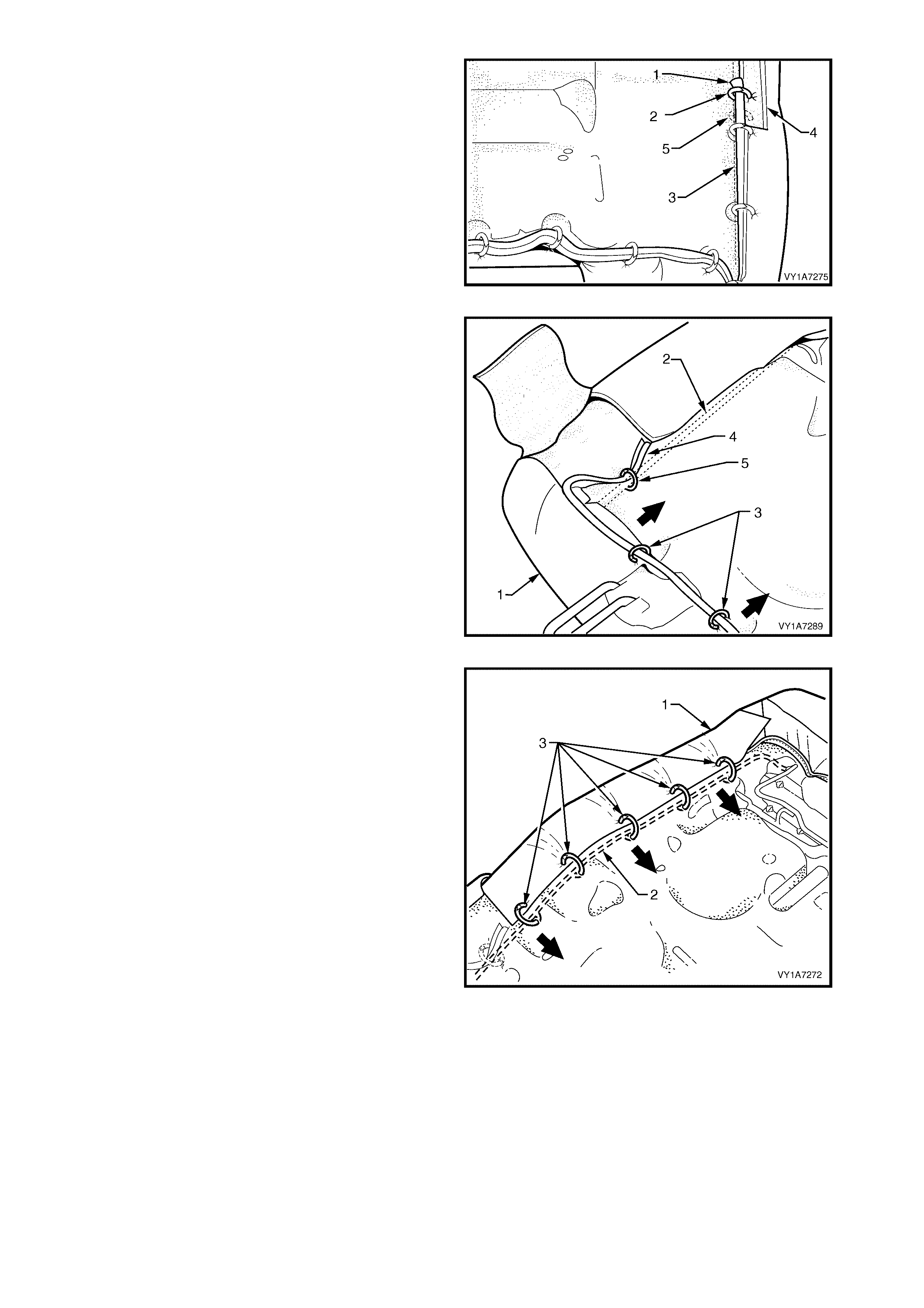
15. Attach the cover lower piping overhang (1), with
one hog ring (2) to the wire frame (3) and to the
hessian (4) on the side of the cover overlapping a
previously attach hog ring (5).
Figure 1A7-219
16. Continue attaching the cover (1) to the frame (2),
by pulling the cover tight and fixing with two hog
rings (3).
17. Attach the seat-back cover lower piping overhang
(4), with one hog ring (5) to the wire frame, in the
lower inboard corner.
Figure 1A7-220
18. Continue attaching the cover (1) to the frame (2),
by pulling the cover tight and fixing with five hog
rings (3).
Figure 1A7-221
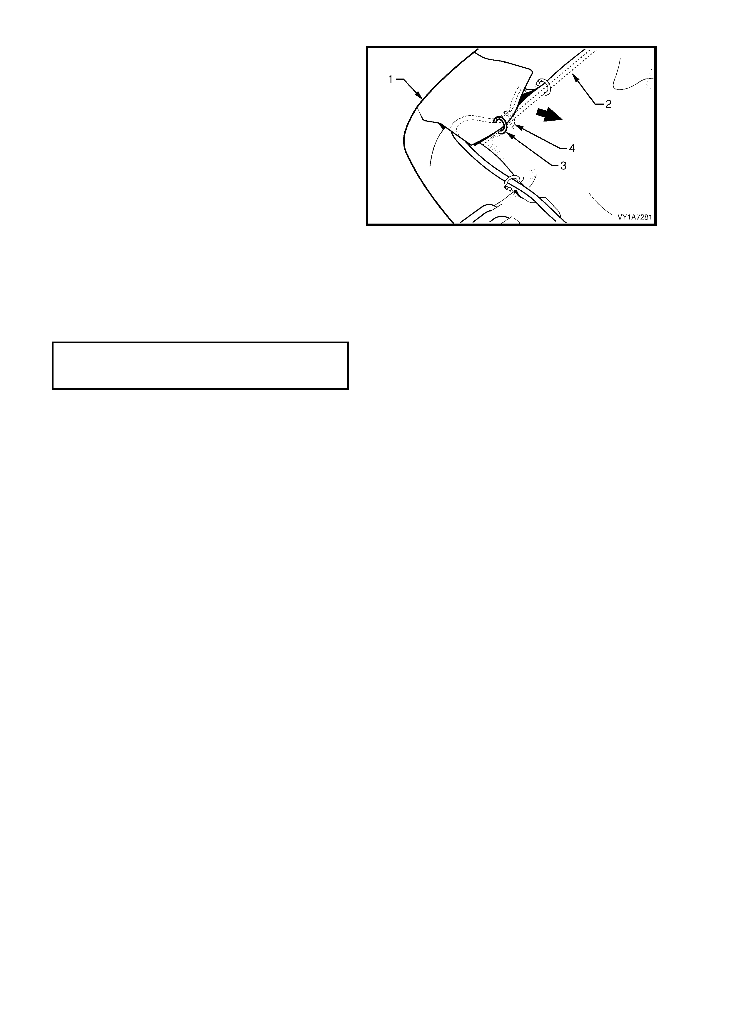
19. On the lower inboard side, pull the cover flap (1)
towards the centre and attach to the wire frame (2)
with one hog ring (3), overlapping a previously
attach hog ring (4).
Figure 1A7-222
REINSTALL
Reinstallation of the rear seat-back assembly is the
reverse of the removal procedure, noting the following:
1. Tighten all retaining screws to the correct torque
specification.
REAR SEAT BACK ASSEMBLY
ATTACHING SCREW
TORQUE SPECIFICATION 25.0 – 35.0 Nm

6.4 REAR SEAT-BACK HEAD RESTRAINT ASSEMBLY
LT Section No. – 14-350
REMOVE
1. Remove the head restraint (1) by depressing the
head restraint guide height adjuster lock (2).
2. Pull the head restraint completely out of the guide.
Figure 1A7-223
DISASSEMBLE
1. Disengaging the r ear head r es traint c over retaining
J-strip (1) by pulling the flap (2) up.
Figure 1A7-224
2. Remove the f our staples (1) r etaining the cover ( 2)
to the head restraint pad assembly.
3. Remove the cover from the pad assembly.
Figure 1A7-225
REASSEMBLE
Reassembly of the rear seat-back head restraint assembly is the reverse of the removal procedure, noting the
following:
1. Ensure the head restraint cover J-strip is fully engaged.
REINSTALL
Reinstallation of the rear seat-back head restraint is the reverse of the removal procedure.
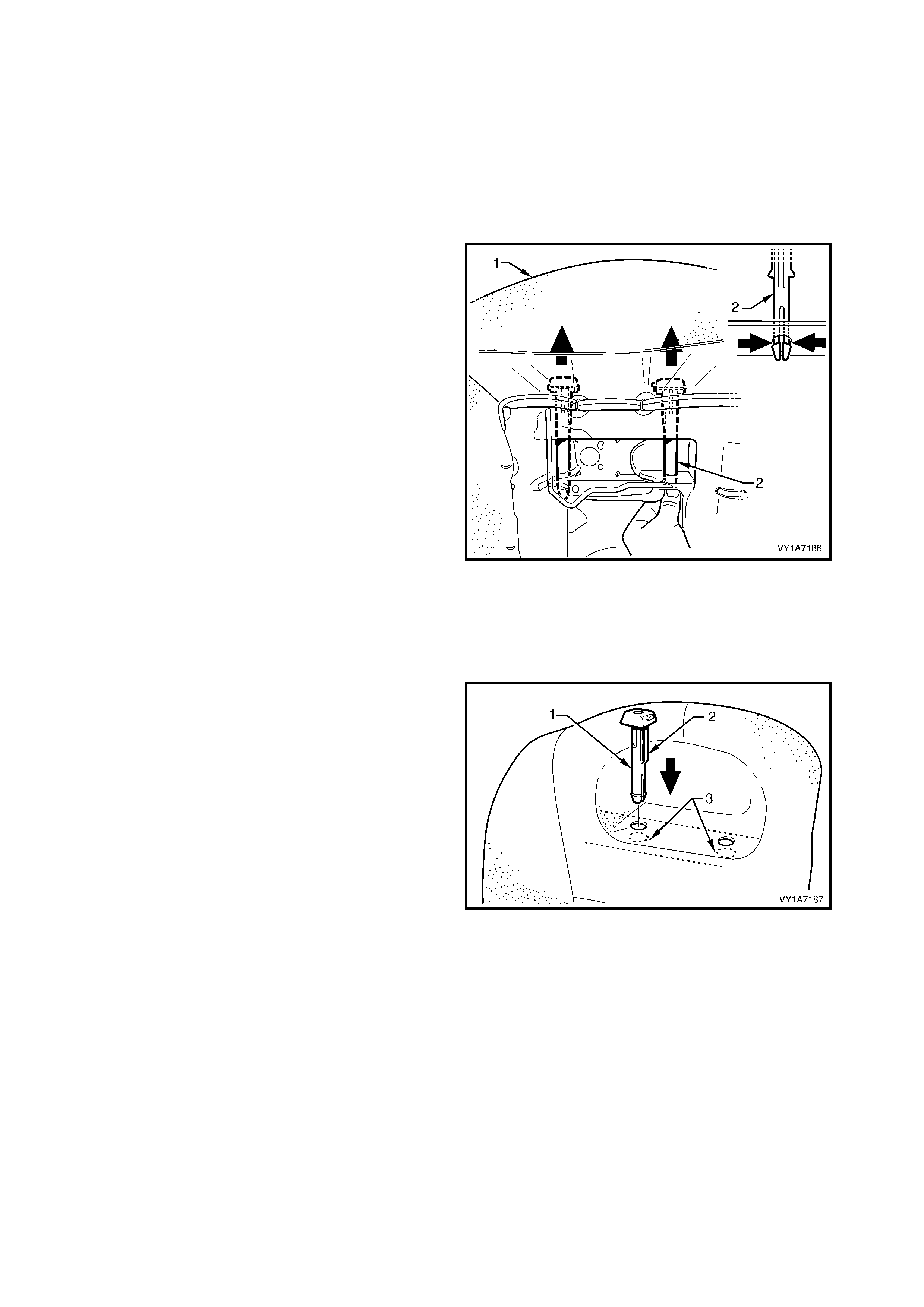
6.5 REAR SEAT-BACK HEAD RESTRAINT GUIDE
LT Section No. – 14-350
1. Remove the rear seat cushion assembly, refer to 6.2 REAR SEAT CUSHION ASSEMBLY.
2. Remove the rear seat-back assembly, refer to 6.3 REAR SEAT-BACK ASSEMBLY.
3. Remove the rear seat-back head restraint assembly, refer to 6.4 REAR SEAT-BACK HEAD RESTRAINT
ASSEMBLY.
REMOVE
1. From the back of rear seat-back (1) (foam side)
squeeze the head restraint guide locating prongs
(2) together and remove the guide up and out of
the seat-back assembly.
2. Repeat this process for the remaining head
restraint guide as required.
Figure 1A7-226
REINSTALL
Reinstallation of the rear seat head restraint guide is
the reverse of the removal procedure, noting the
following:
1. When installing the head restraint guide (1), align
the locating ribs (2) with the key-way (3) in the
seat-back frame.
NOTE: Ensure the guide with the height adjuster lock
is installed on the s ide that corresponds to the notches
in the head restraint shaft.
Figure 1A7-227
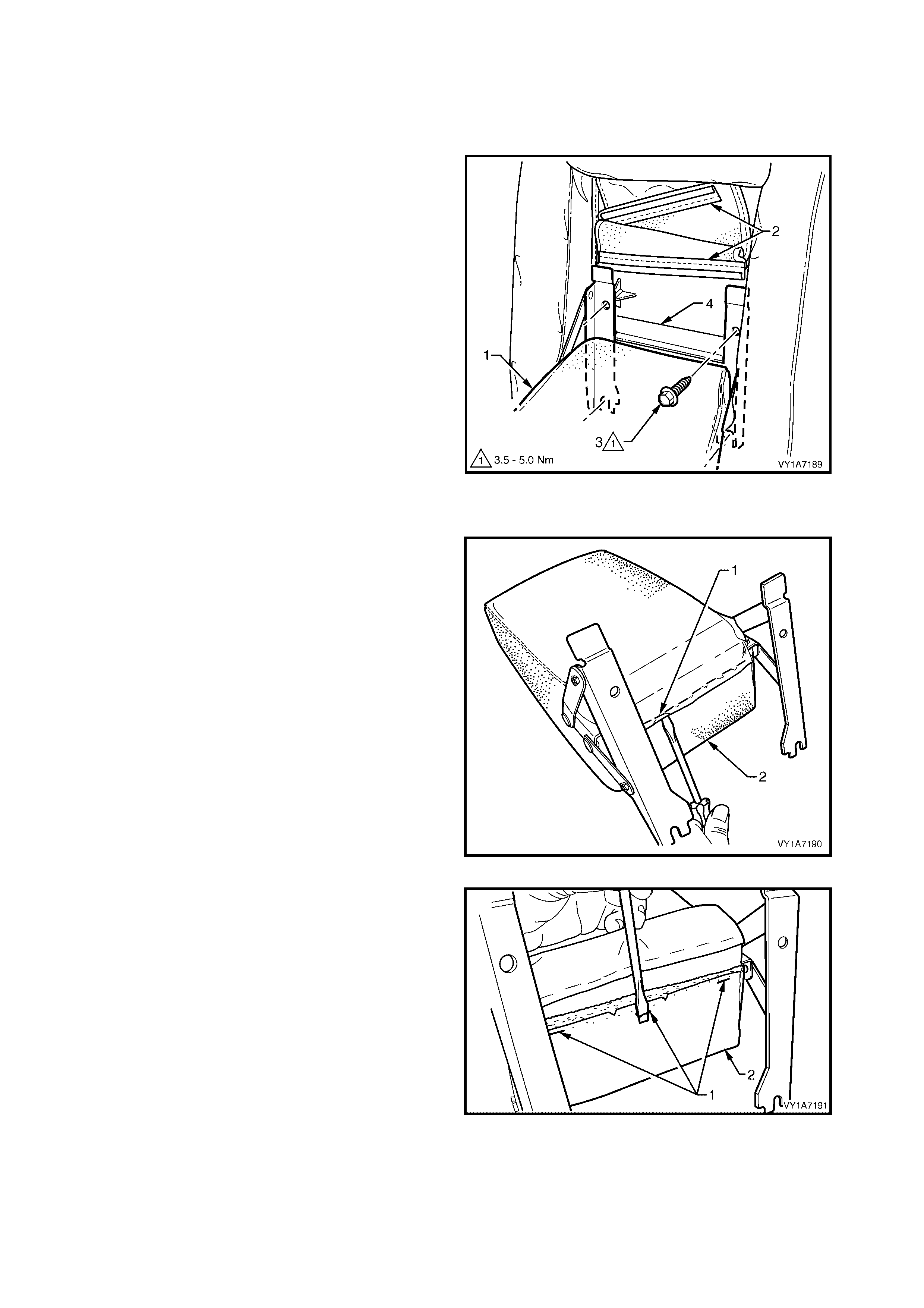
6.6 REAR SEAT-BACK CENTRE, ARMREST ASSEMBLY
LT Section No. – 14-350
REMOVE
1. Lower the armrest assembly (1) and disengage the
trim flap J-strips (2) from the armrest hinge, to gain
access to the four retaining screws (3).
2. Remove the four retaining screws from the rear
seat-back centre tray (4), two from above the
armrest and two from below.
3. Remove the armrest assembly.
Figure 1A7-228
DISASSEMBLE
1. Remove the nine staples (1) securing the upper
flap armrest cover (2) to the armrest pad
assembly.
Figure 1A7-229
2. Remove the three staples (1) securing the lower
flap of the armrest cover (2) to the armrest pad
assembly.
Figure 1A7-230
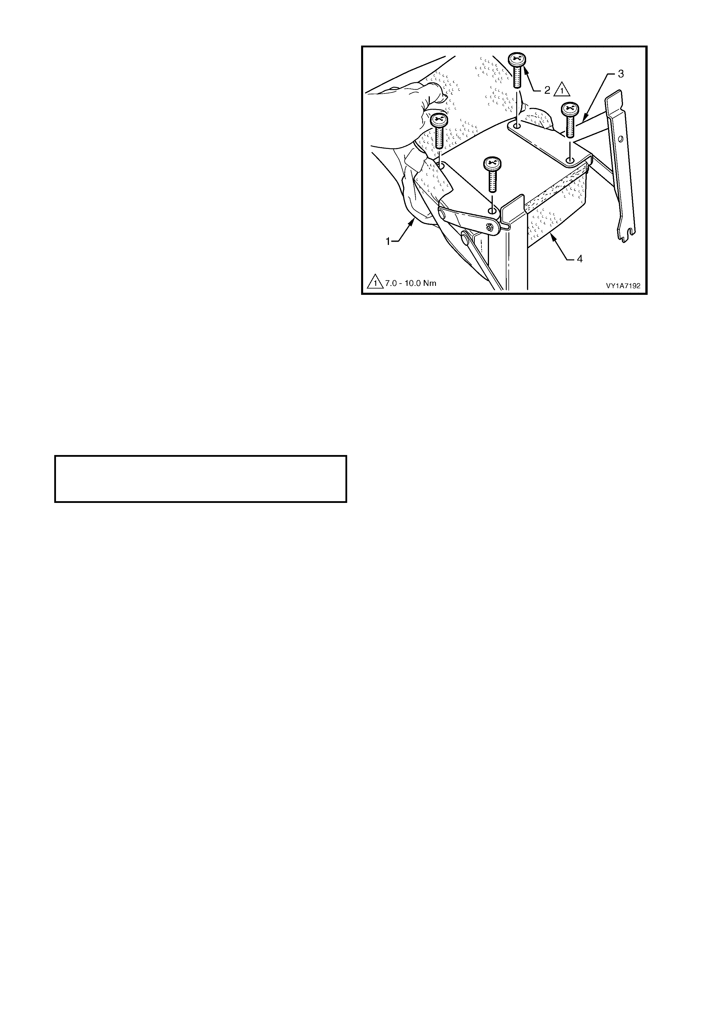
3. Pull the cover (1) along the armrest to allow
access to the hinge retaining screws (2).
4. Remove the four screws securing the armrest
hinge (3) to the armrest assembly (4) and remove
the hinges.
5. Remove the armrest cover from the armrest pad
assembly.
Figure 1A7-231
REASSEMBLE
Reassembly of the rear seat-back centre armrest
assembly is the reverse of the removal procedure,
noting the following:
1. Ensure the armrest assembly hinge is installed
before the cover is fitted.
2. Ensure all screws are tightened to the correct
torque specification.
3. The cover is to be smooth and without creases
before the staples are installed.
ARMREST HINGE
ATTACHING SCREW
TORQUE SPECIFICATION 7.0 – 10.0 Nm
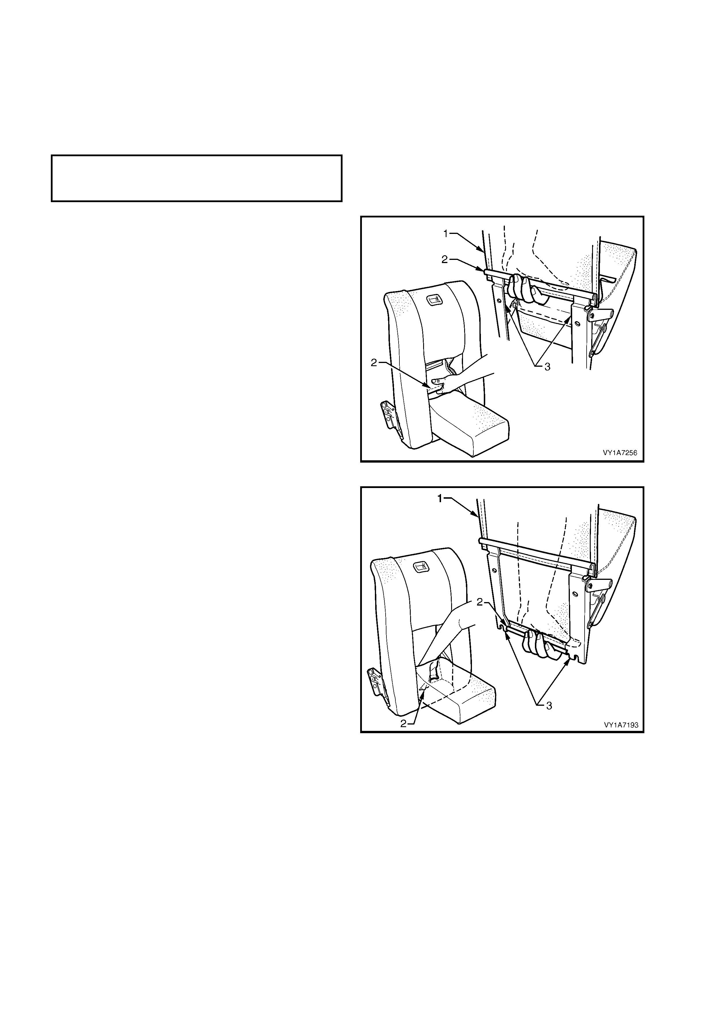
REINSTALL
Reinstallation of the rear seat-back centre armrest
assembly is the reverse of the removal operation,
noting the following:
1. Ensure all screws are tightened to the correct
torque specification.
2. Refit the armrest trim flap (1) upper J-strip (2) to
the upper part of the hinge bracket (3).
Figure 1A7-232
3. Refit the armrest trim flap (1) lower J-strip (2) to
the lower part of the hinge bracket (3).
Figure 1A7-233
ARMREST HINGE ASSEMBLY
ATTACHING SCREW
TORQUE SPECIFICATION 3.5 – 5.0 Nm
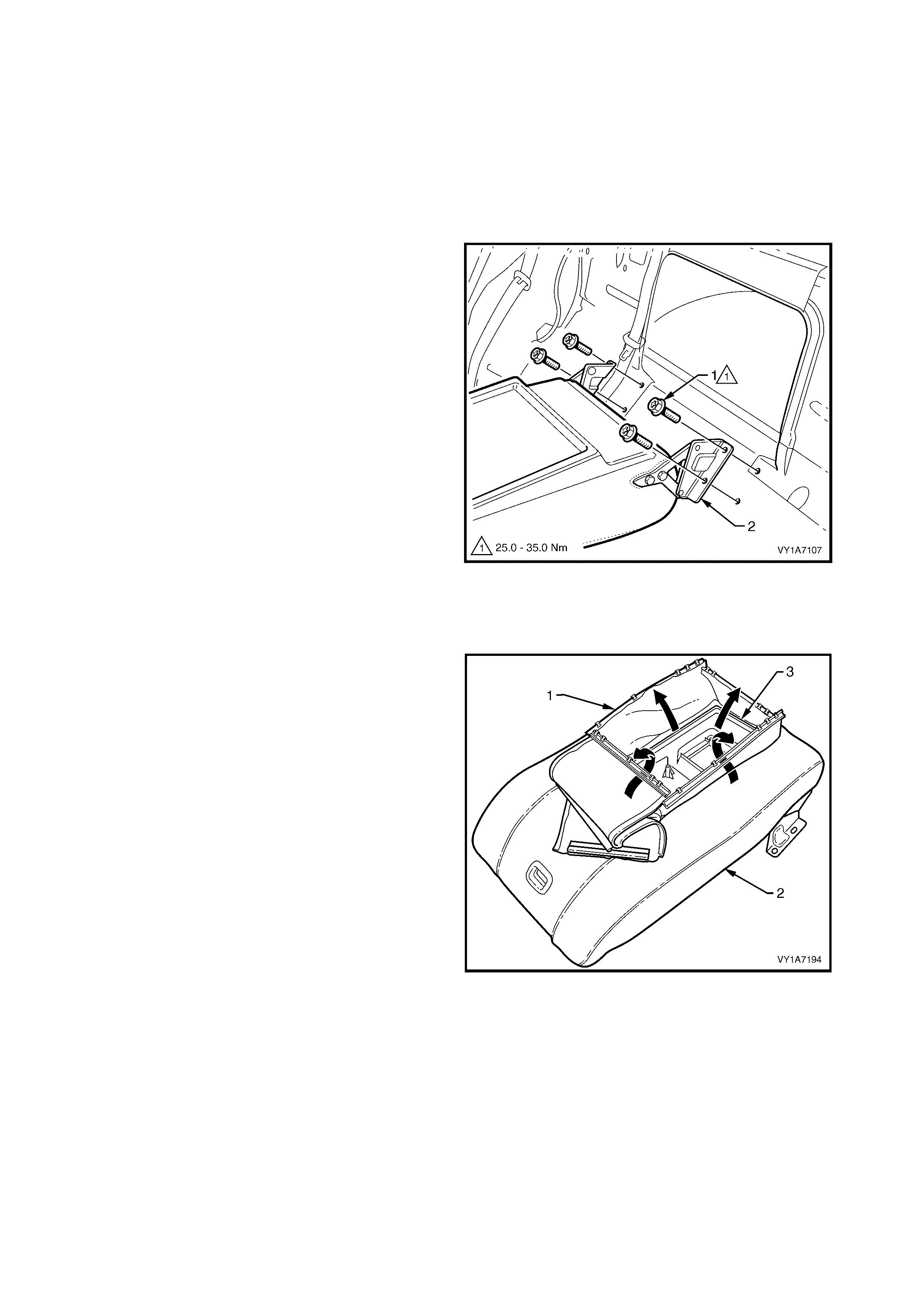
6.7 REAR SEAT CENTRE BACK ASSEMBLY
LT Section No. – 14-350
1. Remove the rear seat cushion assembly, refer to 6.2 REAR SEAT CUSHION ASSEMBLY.
2. Remove the rear seat-back assembly, refer to 6.3 REAR SEAT-BACK ASSEMBLY.
3. Remove the rear seat-back centre, armrest assembly where fitted, refer to 6.6 REAR SEAT-BACK
CENTRE, ARMREST ASSEMBLY.
REMOVE
1. Rem ove the four s crews (1) s ecuring the rear seat
centre back hinge assembly (2) to the rear
compartment floor.
2. Remove rear seat centre back assembly.
Figure 1A7-234
DISASSEMBLE
Remove – Rear Seat Centre Back Cover and Pad Assembly
1. If fitted with an armrest, pull the four retaining
strips (1) in the centre of the seat centre back
assembly (2), up and away from the inside of the
seat-back tray (3).
Figure 1A7-235
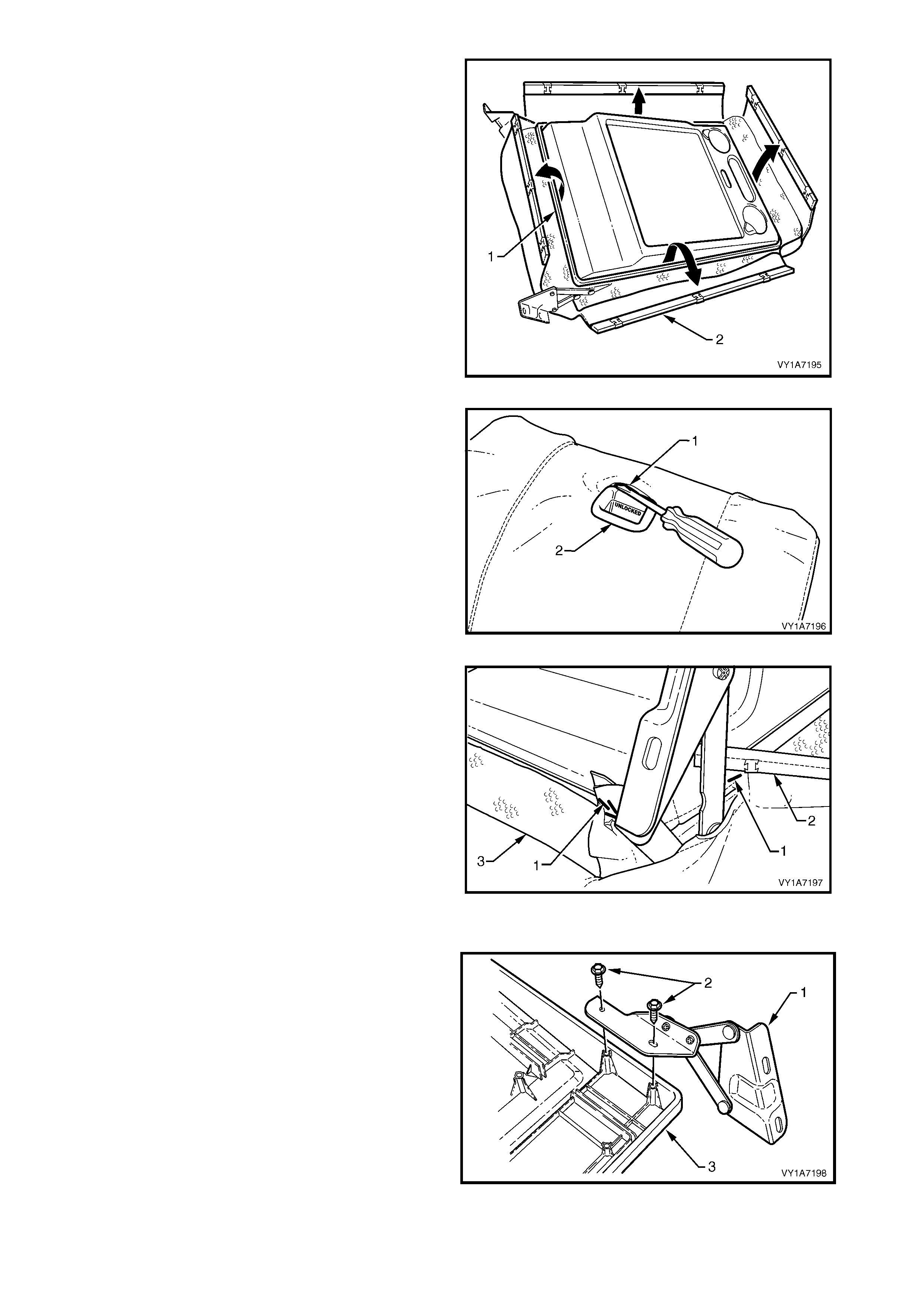
2. On the outer edge of the seat-bac k centre tr ay (1) ,
lever up the four retaining strips (2).
Figure 1A7-236
3. Lever the seat cover material (1) over the release
button and escutcheon assembly (2).
Figure 1A7-237
4. Remove the four staples (1) each side, attaching
the cover (2) to the seat-back tray (3).
5. Peel the cover away from the seat-back tray and
remove the cover and pad.
Reinstall – Rear Seat Centre Back Cover and Pad
Assembly
Reinstallation of the rear seat centre back cover and
pad assem bly is the reverse of the r emoval procedur e,
noting the following:
1. The cover is to be smooth and without creases
before the staples are installed.
Figure 1A7-238
Remove – Rear Seat-back Centre Hinge
1. Remove the two screws (1) securing the hinge (2)
to the rear seat-back centre tray assembly (3) and
remove the hinge.
2. Repeat fore the opposite hinge.
Reinstall – Rear Seat-back Centre Hinge
Reinstallation of the rear seat-back centre hinge is the
reverse of the removal procedure noting the following:
1. Ensure all screws are tightened securely.
Figure 1A7-239
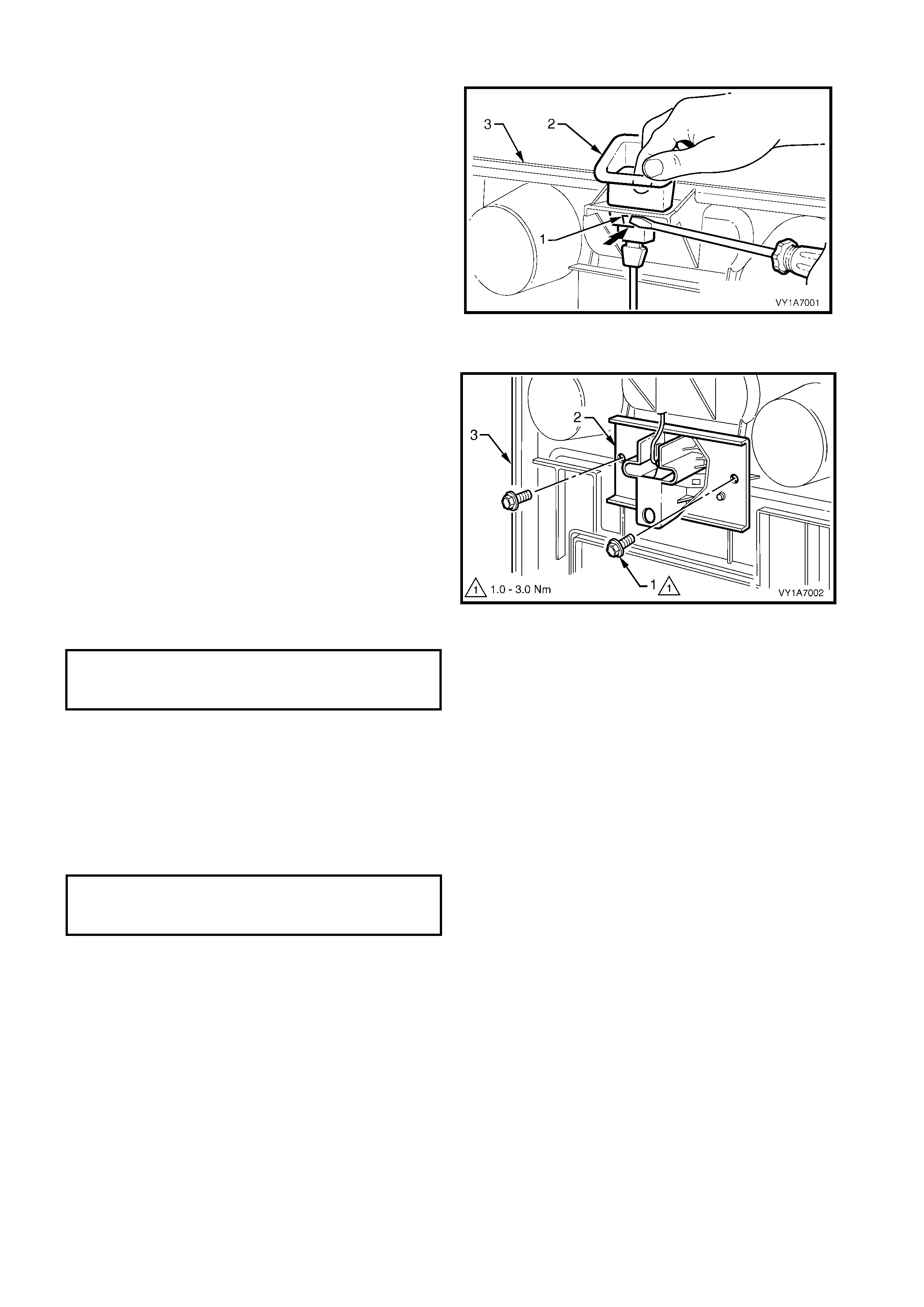
Remove – Rear Seat-back Centre Release Button
1. Using a screwdriver, depress the two tangs (1) on
the front and rear of the release button (2).
2. Pull the release button from the rear seat-back
centre (3).
Reinstall – Rear Seat-back Centre Release Button
1. Push the release button into the rear seat-back
centre assembly, until the button clicks home.
Figure 1A7-240
Remove – Rear Seat-back Centre Lock Actuator
1. Remove the two screws (1) securing the lock
actuator (2) to the back tray (3) and remove lock
actuator.
2. Disengage the release button rod from the lock
actuator.
Reinstall – Rear Seat-back Centre, Lock Actuator
Reinstallation of the rear seat-back centre, lock
actuator is the r ever se of the r emoval proc edure noting
the following:
1. Ensure the button assembly and lock actuator rod
are correctly engaged.
2. Ensure all screws are tightened to the correct
torque specification.
Figure 1A7-241
REINSTALL
Reinstallation of the rear seat-back centre is the
reverse of the removal operation, noting the following:
1. Ensure all screws are tightened to the correct
torque specification.
REAR SEAT-BACK CENTRE
ATTACHING BOLT
TORQUE SPECIFICATION 25.0 – 35.0 Nm
REAR SEAT-BACK CENTRE
LOCK ACTUATOR RETAINING
SCREW TORQUE SPECIFICATION 1.0 – 3.0 Nm
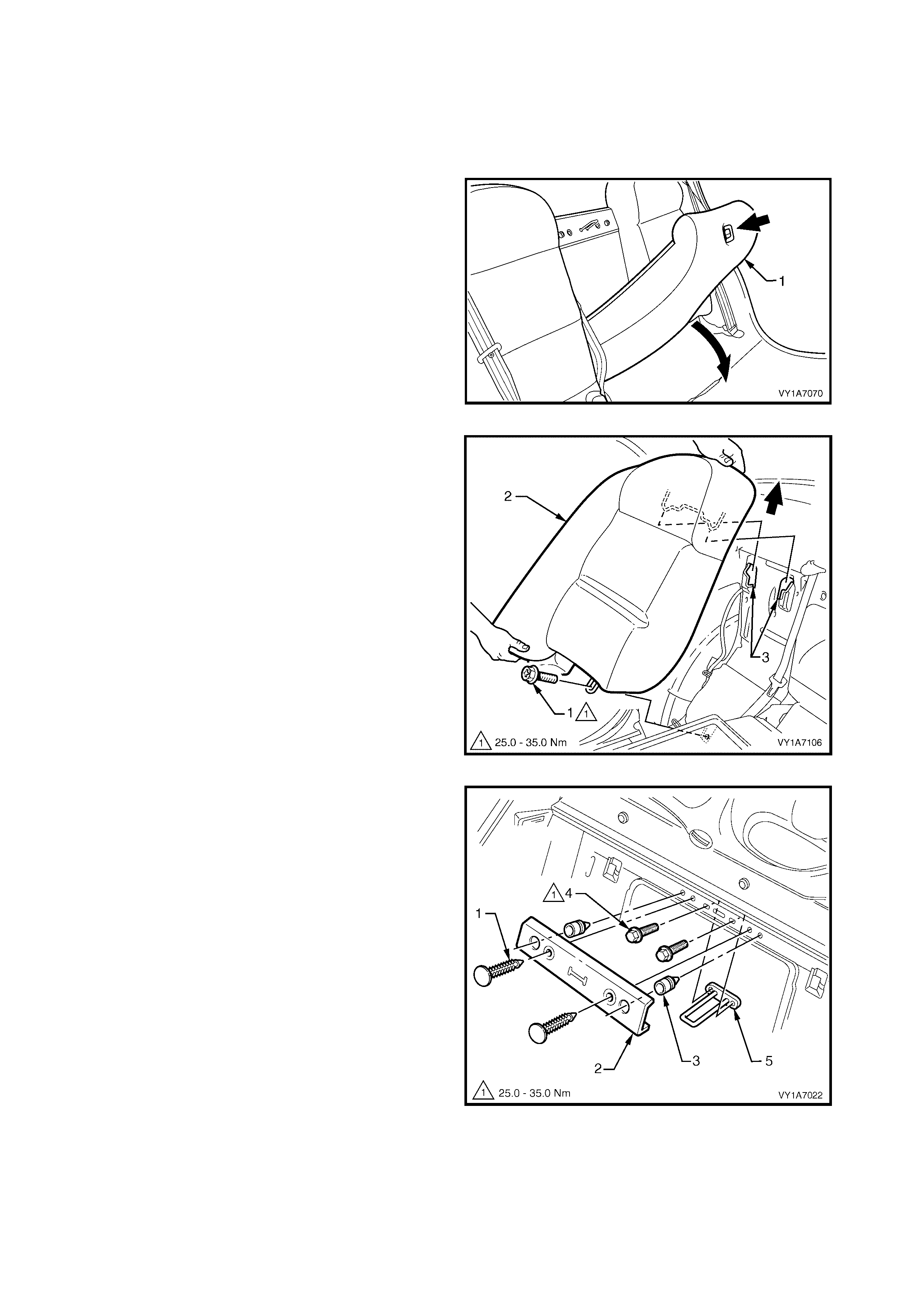
6.8 REAR SEAT CENTRE BACK, LOCK STRIKER
LT Section No. – 14-350
1. Remove the rear seat cushion assembly, refer to 6.2 REAR SEAT CUSHION ASSEMBLY.
REMOVE
1. Press the release button and lower the rear seat
centre back assembly (1).
Figure 1A7-242
2. Remove the screw (1) retaining the rear seat-back
assembly (2) to the rear compartment front panel.
3. Lift the rear seat-back assembly up and out of the
retaining brackets (3) in the floor panel.
4. Remove the rear seat-back assembly and repeat
for the opposite side if required.
Figure 1A7-243
5. Prise the two retaining clips (1) securing the rear
seat-back cover (2) to the rear compartment front
panel and remove the cover.
6. If required, remove the two bump stops (3) from
the rear compartment front panel.
7. Rem ove the two sc rews (4) s ecuring the st riker (5)
to the rear panel and remove the striker.
Figure 1A7-244

REINSTALL
Reinstallation of the rear seat lock striker is the reverse of the removal procedure ensuring that the retaining
screws are tightened to the correct torque specification.
REAR SEAT LOCK STRIKER
ATTACHING SCREW
TORQUE SPECIFICATION 25.0 – 35.0 Nm
7. SERVICE OPERATIONS - REAR SEAT, WAGON
7.1 REAR SEAT USAGE CHART - WAGON
HOW TO USE THIS CHART
Three rear seat configurations are used in MY2003 VY Series Wagon vehicles. The following usage chart is
provided to help determine the seat type fitted to the vehicle. This is important prior to repairs being performed
as the failed / damaged part may not be serviceable.
To determine the seat fitted to the vehicle, obtain the vehicle model, which seat requires attention and the seat
cover fabric. Then establish if the vehicle has an armrest and/or headrest. Using the chart will lead to the
elimination of all other seat com binations, allowing the identification of the type and the c onstruction of the seat.
Finally , refer to the Figure shown in TYPE for a component breakdown of the rear seat assembly.
1. VEHICLE – Vehicle model identification.
2. FABRIC – Cloth or leather seat covers.
3. ARMREST – If the rear seat-back is fitted with an armrest.
4. HEADREST – If the rear seat-back is fitted with a headrest.
5. CONSTRUCTION – Surebond refers to the seat cover being glued to the seat pad and only serviced as a
cover and pad ass embly. Hook and Loop refer s to the seat c over being able to be attached or removed from
the seat pad and both being serviced as separate parts.
6. TYPE – Identif ies the s eat type and provides refer enc e to the f ollowing illustrations which s how a breakdown
of the serviced component for each rear seat assembly.
DOMESTIC
Vehicle Fabric Armrest Headrest Construction Type
Berlina Leather / Cloth Yes Yes Hook & loop 3 (Figure 1A7-247)
Acclaim Cloth No Yes Surebond 2 (Figure 1A7-246)
Executive Cloth No No Surebond 1 (Figure 1A7-245)
GULF STATES
Vehicle Fabric Armrest Headrest Construction Type
Lumina Cloth No No Surebond 1 (Figure 1A7-245)
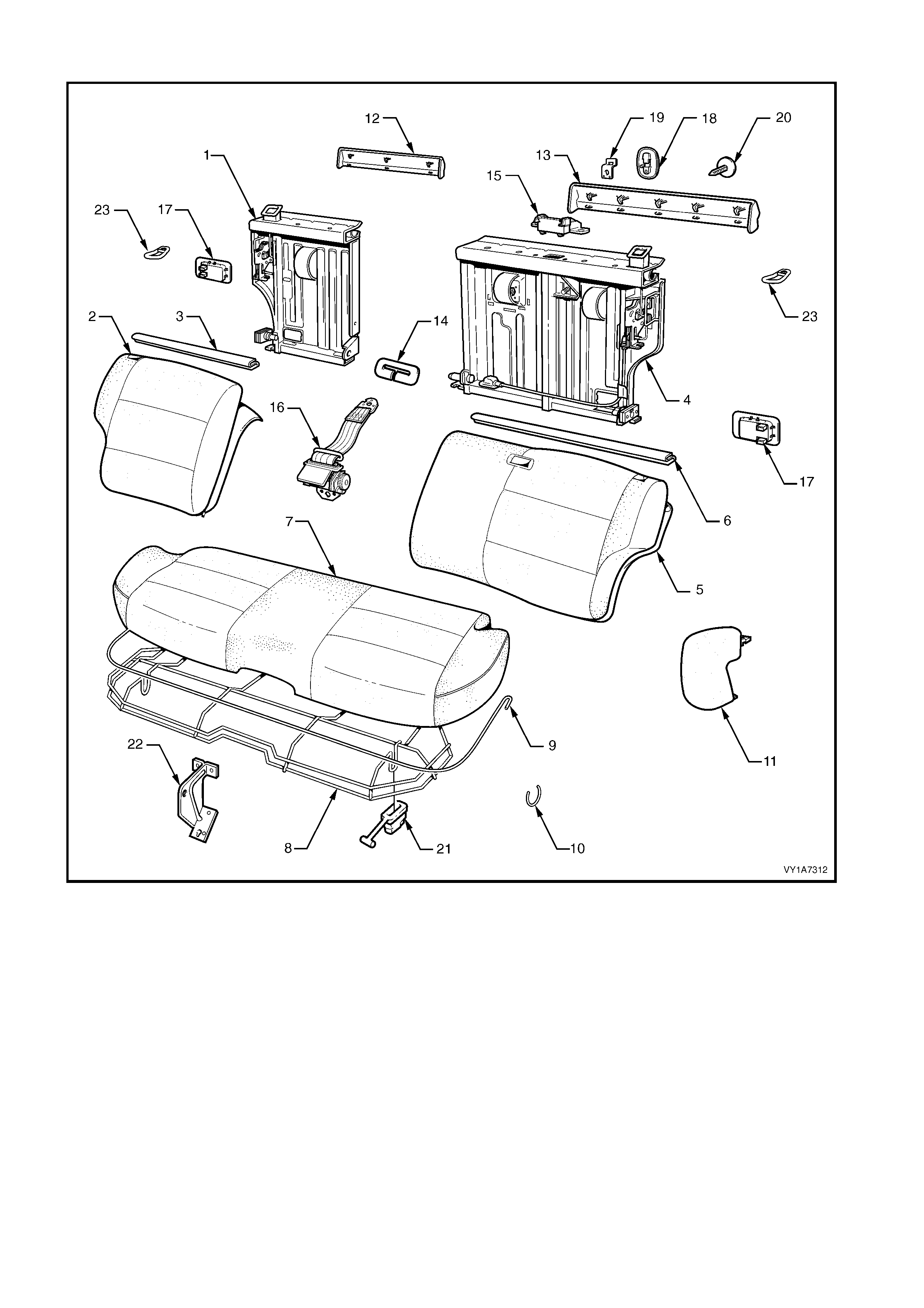
Type 1: Rear Seat Assembly
Figure 1A7-245
Legend
1. Rear Seat-back Frame Assembly - Right-hand ∗
∗∗
∗
2. Rear Seat-back Cover, Carpet & Pad Assembly -
Right-hand
3. Top Finisher Strip - Right-hand
4. Rear Seat-back Frame Assembly - Left-hand ∗
∗∗
∗
5. Rear Seat-back Cover, Carpet & Pad Assembly -
Left-hand
6. Top Finisher Strip - Left-hand
7. Rear Seat Cushion Cover & Pad Assembly
8. Rear Seat Cushion Frame Assembly
9. Rear Seat Cushion Cover Retainer (wire)
10. Hog Ring
11. Rear Seat Bolster Assembly - 2 Places
12. Rear Seat-back Trim Cover Right-hand
13. Rear Seat-back Trim Cover Left-hand
14. Centre Seatbelt Escutcheon
15. Seatbelt Guide Bracket assembly
16. Centre Seatbelt Retractor
17. Rear Seat-back Release Handle - 2 Places
18. Child Seat Escutcheon
19. Child Seat Anchor
20. Child Seat Anchor Blanking Plug
21. Rear Seat Cushion Release Handle - 2 Places
22. Rear Seat Centre Support
23. Rear Seat-back Lock Striker - 2 Places
∗
∗∗
∗ Refer to Figure 1A7-248 for a breakdown of the rear seat-back frame assembly.
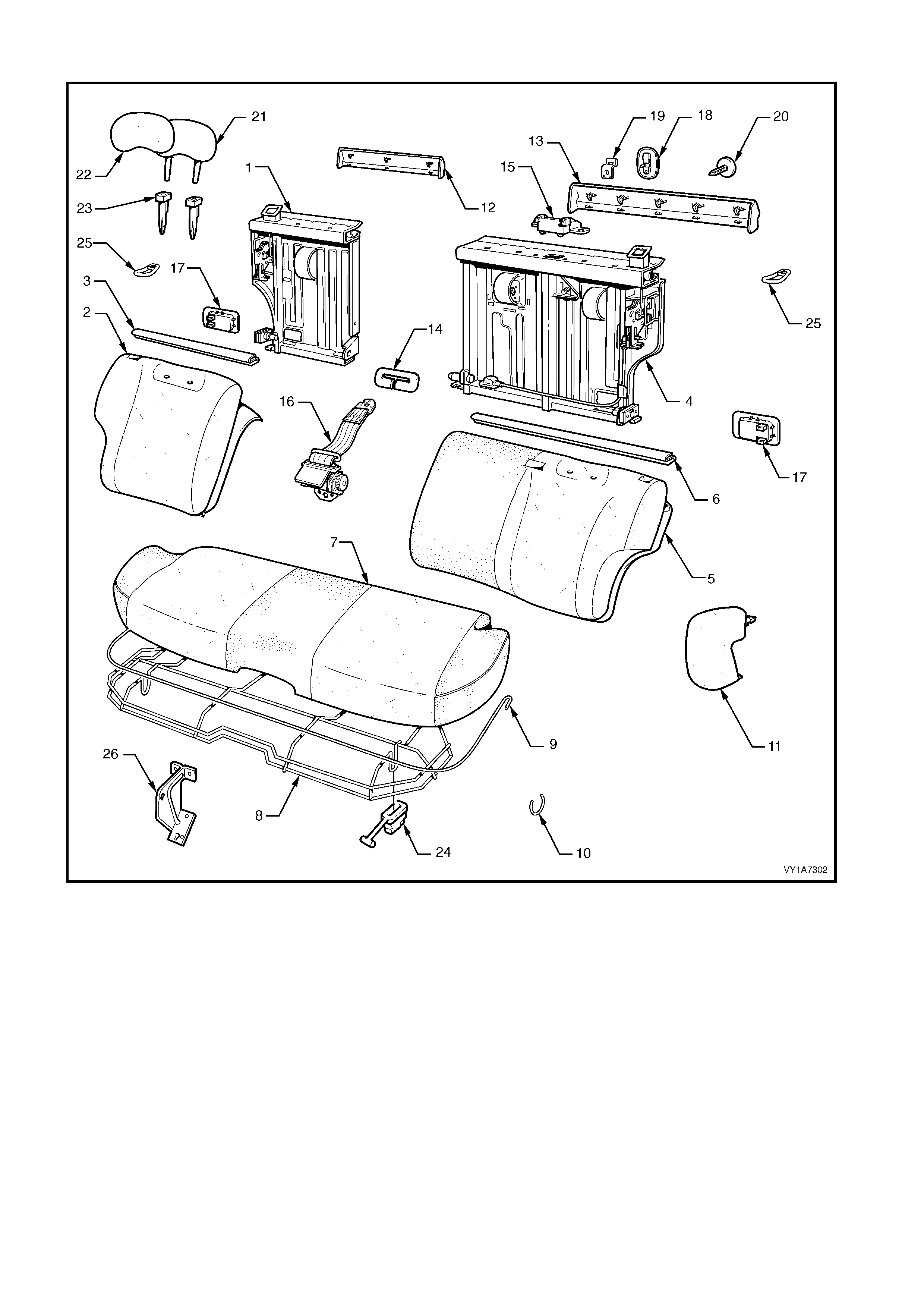
Type 2: Rear Seat Assembly
Figure 1A7-246
Legend
1. Rear Seat-back Frame Assembly - Right-hand ∗
∗∗
∗
2. Rear Seat-back Cover, Carpet & Pad Assembly -
Right-hand
3. Top Finisher Strip - Right-hand
4. Rear Seat-back Frame Assembly - Left-hand ∗
∗∗
∗
5. Rear Seat-back Cover, Carpet & Pad Assembly -
Left-hand
6. Top Finisher Strip - Left-hand
7. Rear Seat Cushion Cover & Pad Assembly
8. Rear Seat Cushion Frame
9. Rear Seat Cushion Cover Retainer (wire)
10. Hog Ring
11. Rear Seat Bolster Assembly - 2 Places
12. Rear Seat-back Trim Cover - Right-hand
13. Rear Seat-back Trim Cover - Left-hand
14. Centre Seatbelt Escutcheon
15. Seatbelt Guide Bracket assembly
16. Centre Seatbelt Retractor
17. Rear Seat-back Release Handle - 2 Places
18. Child Seat Escutcheon
19. Child Seat Anchor
20. Child Seat Anchor Blanking Plug
21. Head Restraint Pad - 2 Places
22. Head Restraint Cover - 2 Places
23. Head Restraint Guide - 4 Places
24. Rear Seat Cushion Release Handle - 2 Places
25. Rear Seat-back Lock Striker - 2 Places
26. Rear Seat Centre Support
∗
∗∗
∗ Refer to Figure 1A7-248 for a breakdown of the rear seat-back frame assembly.
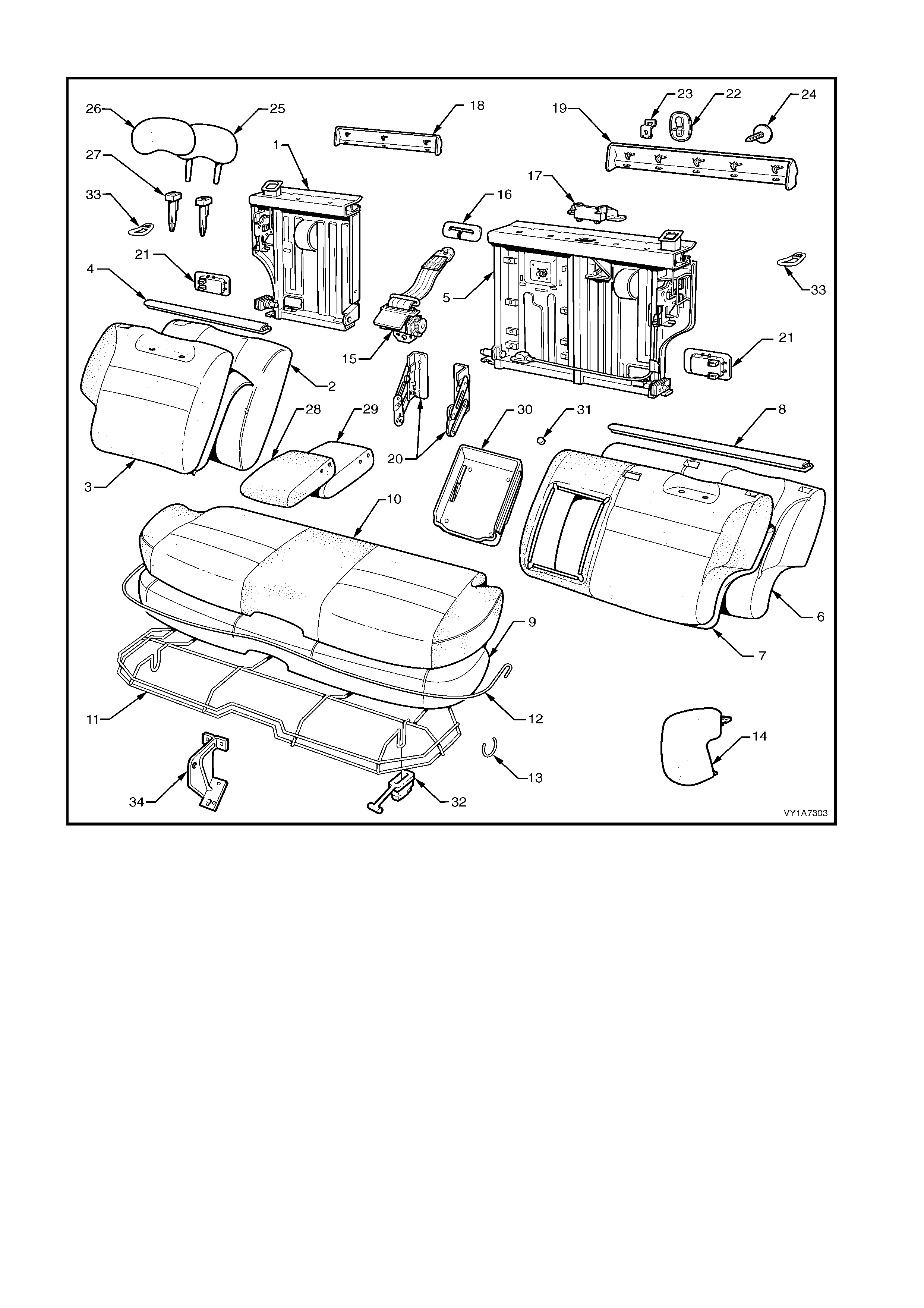
Type 3: Rear Seat Assembly
Figure 1A7-247
Legend
1. Rear Seat-back Frame Assembly - Right-hand ∗
∗∗
∗
2. Rear Seat-back Pad - Right-hand
3. Rear Seat-back Cover &Carpet Assembly - Right-
hand
4. Top Finisher Strip - Right-hand
5. Rear Seat-back Frame Assembly - Left-hand ∗
∗∗
∗
6. Rear Seat-back Pad - Left-hand
7. Rear Seat-back Cover &Carpet Assembly - Left-hand
8. Top Finisher Strip - Left-hand
9. Rear Seat Cushion Pad
10. Rear Seat Cushion Cover Assembly
11. Rear Seat Cushion Frame Assembly
12. Retainer - Rear Seat Cushion Cover (wire)
13. Hog Ring
14. Bolster Assembly - Rear Seat - 2 Places
15. Centre Rear Seatbelt Retractor
16. Centre Seatbelt Escutcheon
17. Seatbelt Guide Bracket Assembly
18. Rear Seat-back Trim Cover - Right-hand
19. Rear Seat-back Trim Cover - Left-hand
20. Armrest Hinge Assembly - 2 Places
21. Rear Seat-back Release Handle - 2 Places
22. Child Seat Escutcheon
23. Child Seat Anchor
24. Child Seat Anchor Blanking Plug
25. Head Restraint Pad - 2 Places
26. Head Restraint Cover - 2 Places
27. Head Restraint Guide - 4 Places
28. Rear Seat-back Armrest Cover Assembly
29. Rear Seat-back Armrest Pad Assembly
30. Rear Seat-back Armrest Centre Cover
31. Armrest Centre Cover Blanking Plugs
32. Rear Seat Cushion Release Handle - 2 Places
33. Rear Seat-back Lock Striker - 2 Places
34. Rear Seat Centre Support
∗
∗∗
∗ Refer to Figure 1A7-248 for a breakdown of the rear seat-back frame assembly.
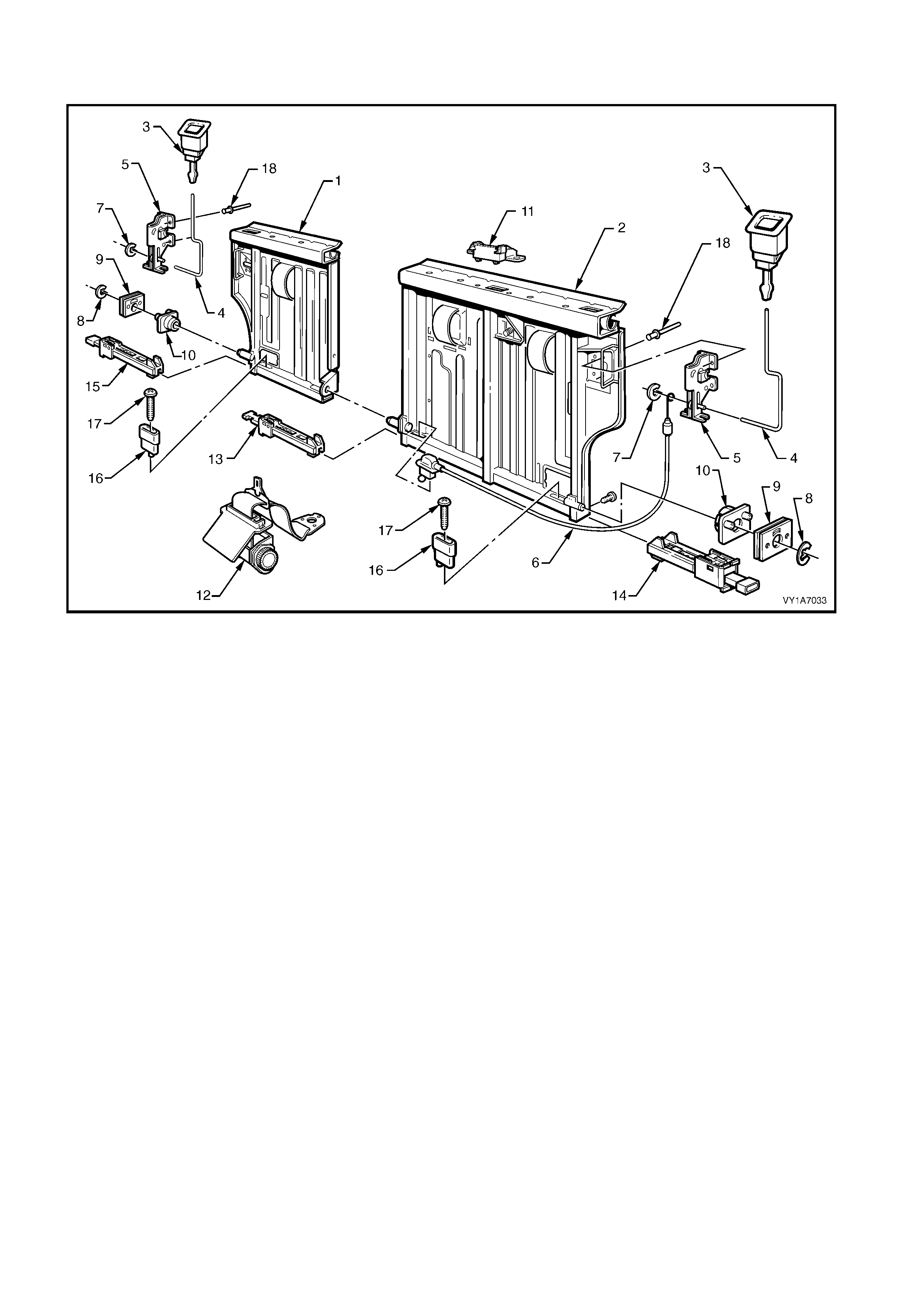
Rear Seat-back Frame Assembly
Figure 1A7-248
Legend
1. Rear Seat-back Frame Assembly - Right-hand
2. Rear Seat-back Frame Assembly - Left-hand
3. Release Button - 2 Places
4. Actuator Rod - 2 Places
5. Actuator Lock - 2 Places
6. Actuator Cable Assembly
7. Retaining Clip
8. Circlip - 2 Places
9. Retainer Plate (2 Places)
10. Locking Plate & Pin (2 Places)
11. Seatbelt Guide Bracket
12. Seatbelt Retractor Assembly
13. Inner Latch Assembly - Left-hand
14. Outer Latch Assembly - Left-hand
15. Outer Latch Assembly - Right-hand
16. Release Handle Lever - 2 Places
17. Release Handle Lever Screw - 2 Places
18. Rivets (8 Places)
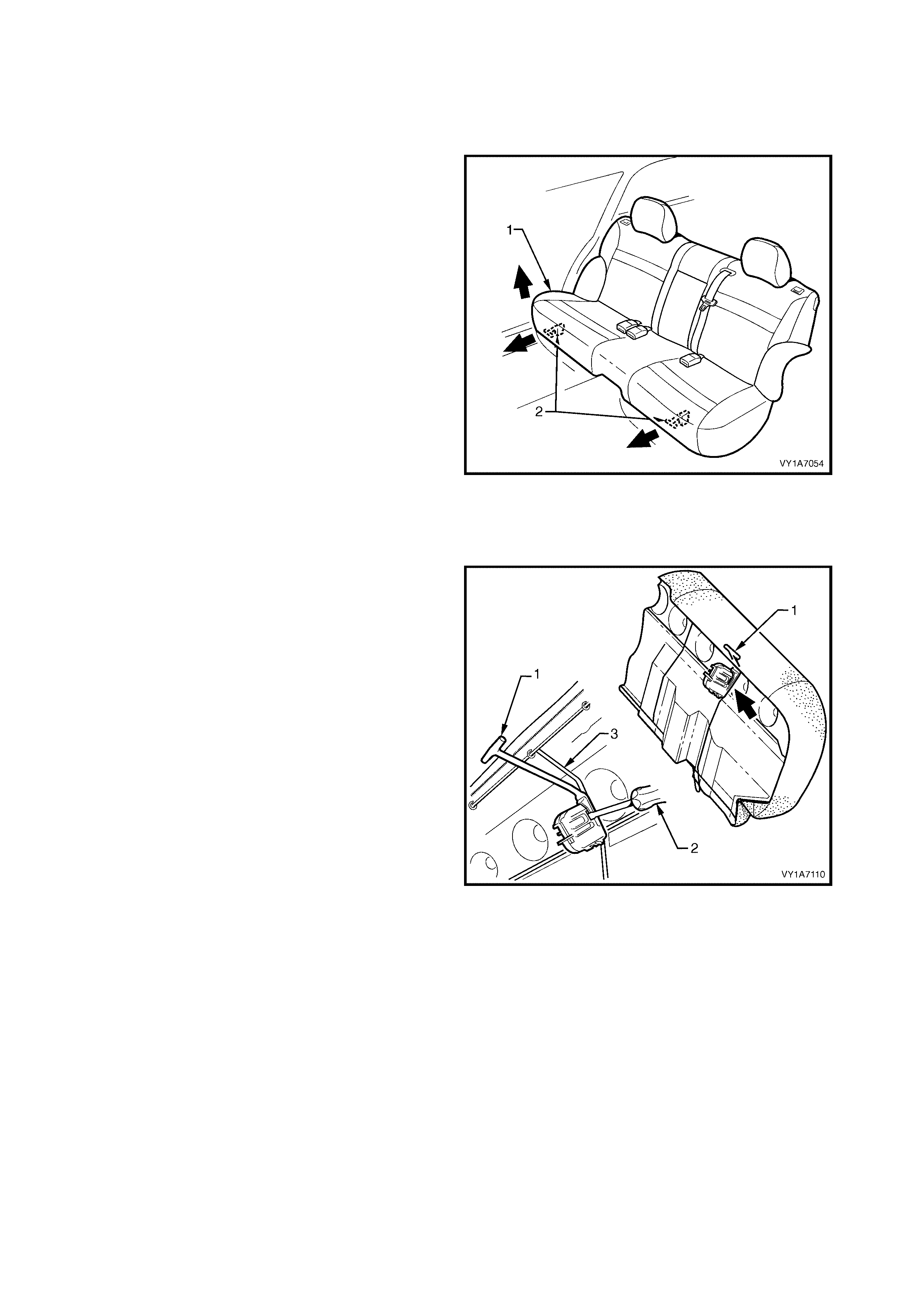
7.2 REAR SEAT CUSHION ASSEMBLY
LT Section No. – 14-330
REMOVE
1. Lift the front of the rear seat cushion assembly (1)
slightly, to gain access to the rear seat cushion
release handles (2).
2. From either the left or the right side of the seat,
pull the release handle T-piece horizontally
outwards, while at the sam e tim e lifting the f ront of
the rear seat cushion until the lock mechanism is
released.
3. Repeat step 2 for the opposite side of the seat.
4. Remove the rear seat cushion assembly.
Figure 1A7-249
DISASSEMBLE
Remove – Rear Seat Cushion Release Handle
1. Remove the rear seat cushion release handle (1)
by inserting a screwdriver (2) to disengage the
retaining lugs.
2. Slide the release handle off the rear seat cushion
wire frame (3).
Figure 1A7-250
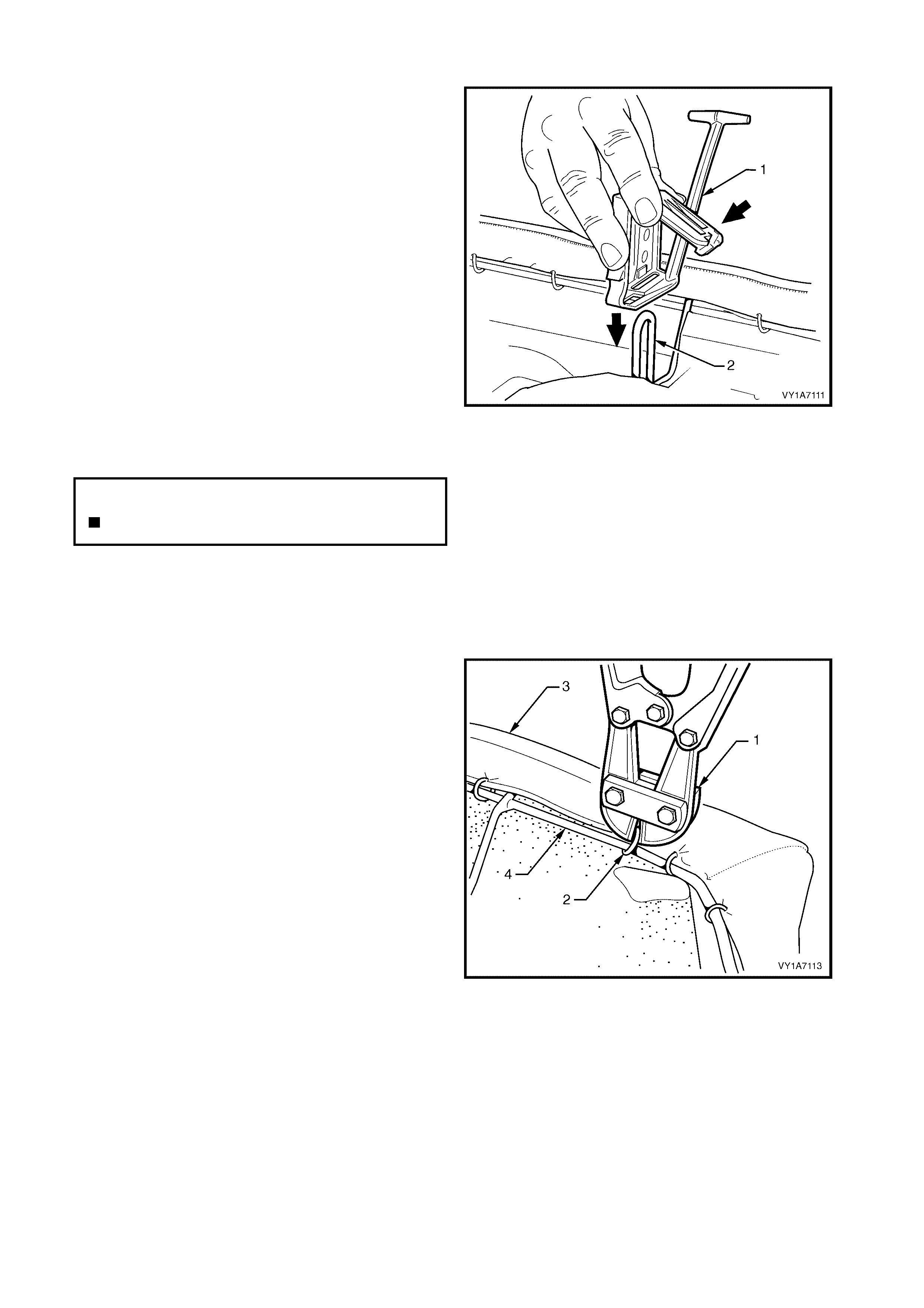
Reinstall – Rear Seat Cushion Release Handle
1. Slide the rear seat cus hion release handle ( 1) onto
the rear seat cushion wire fram e (2) and close the
cover so that it will lock into position on the frame.
Figure 1A7-251
Remove – Rear Seat Cushion Frame
CAUTION: Safety glasses and work gloves must be
worn at all times when removing the hog rings.
1. Place the rear seat cushion assembly up side
down.
2. Use bolt cutters (1) to remove the hog rings (2)
attaching the cover and pad assembly (3) to the
frame (4):
• Forty eight places for the Surebond rear seat
cushions.
• Thirty four places for the Hook and Loop rear
seat cushions.
NOTE: 1 Care must be taken when removing the hog
rings not to damage the rear seat cushion cover.
NOTE: 2 All hog rings will be destroyed during this
operation and must be replaced.
3. Remove the frame from the rear seat cushion
cover and pad assembly.
Figure 1A7-252
N
O
TE: The
f
ollowing component WILL RE
Q
UIRE
REPLACEMENT when performing this operation.
Rear seat cushion hog rings.
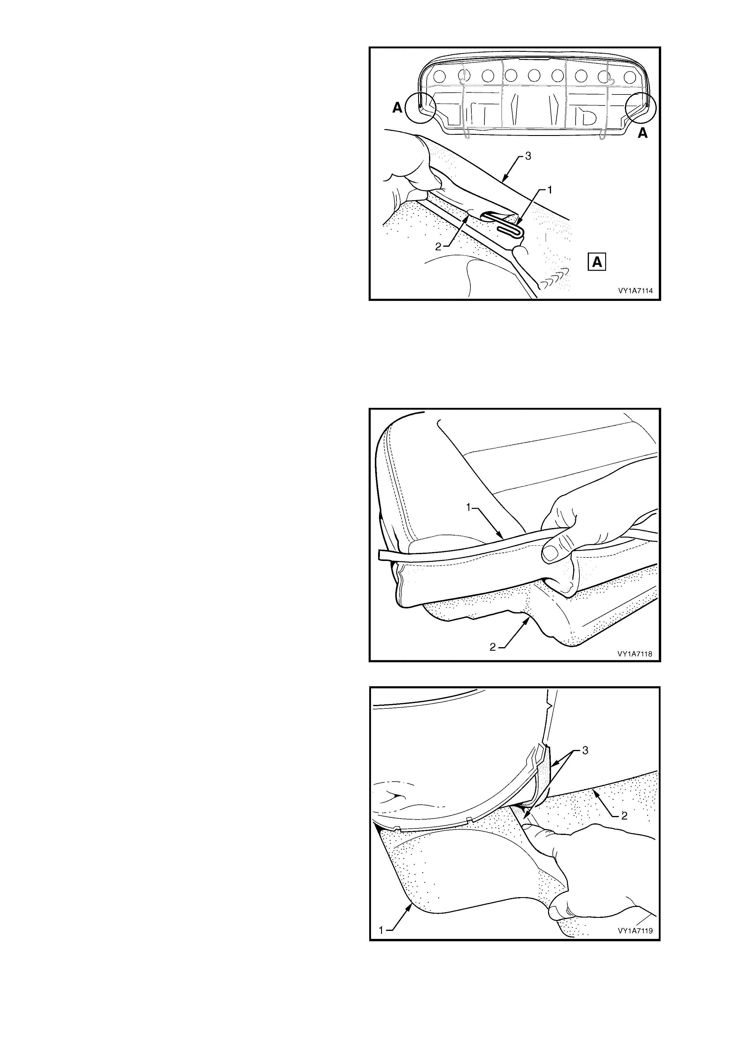
4. If required, remove the retaining wire (1) from the
casing (2) on the front of the cushion cover
assembly (3).
Figure 1A7-253
Remove – Rear Seat Cushion Cover, Hook and Loop
The following procedure only applies to vehicles fitted
with seat c overs attached to the seat pad with the fully
serviced Hook and Loop. For model reference chart,
refer to 7.1 REAR SEAT USAGE CHART - WAGON.
1. Fold the rear corner of the rear seat cus hion cover
(1) over the seat cushion pad (2).
Figure 1A7-254
2. While holding the rear seat cushion pad (1), pull
the rear corner of the seat cushion cover (2) away
from the rear seat cushion pad to disengage the
hook and loop strip (3).
Figure 1A7-255
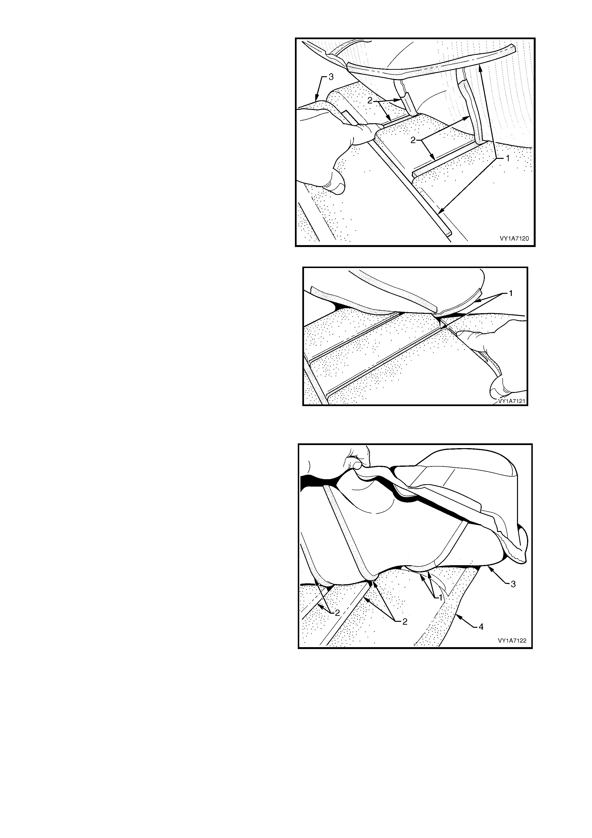
3. After dis engaging the outer hook and loop strip (1)
remove the one or two cross hook and loop strips
(2) while holding the seat cushion pad (3).
Figure 1A7-256
4. Remove the inner hook and loop strip (1) while
holding the seat cushion pad.
5. Repeat this process for the opposite half of the
rear seat cushion assembly.
6. Remove the rear seat cushion cover.
Figure 1A7-257
Reinstall – Rear Seat Cushion Cover, Hook and Loop
1. Align the inner hook and loop strip (1) and the one
or two cross hook and loop strips (2), on the seat
cushion cover (3), with the seat cushion pad (4).
2. Press the folded edge of the rear seat cushion
cover firmly into the corresponding groove in the
seat cushion pad to engage the hook and loop
strip.
Figure 1A7-258
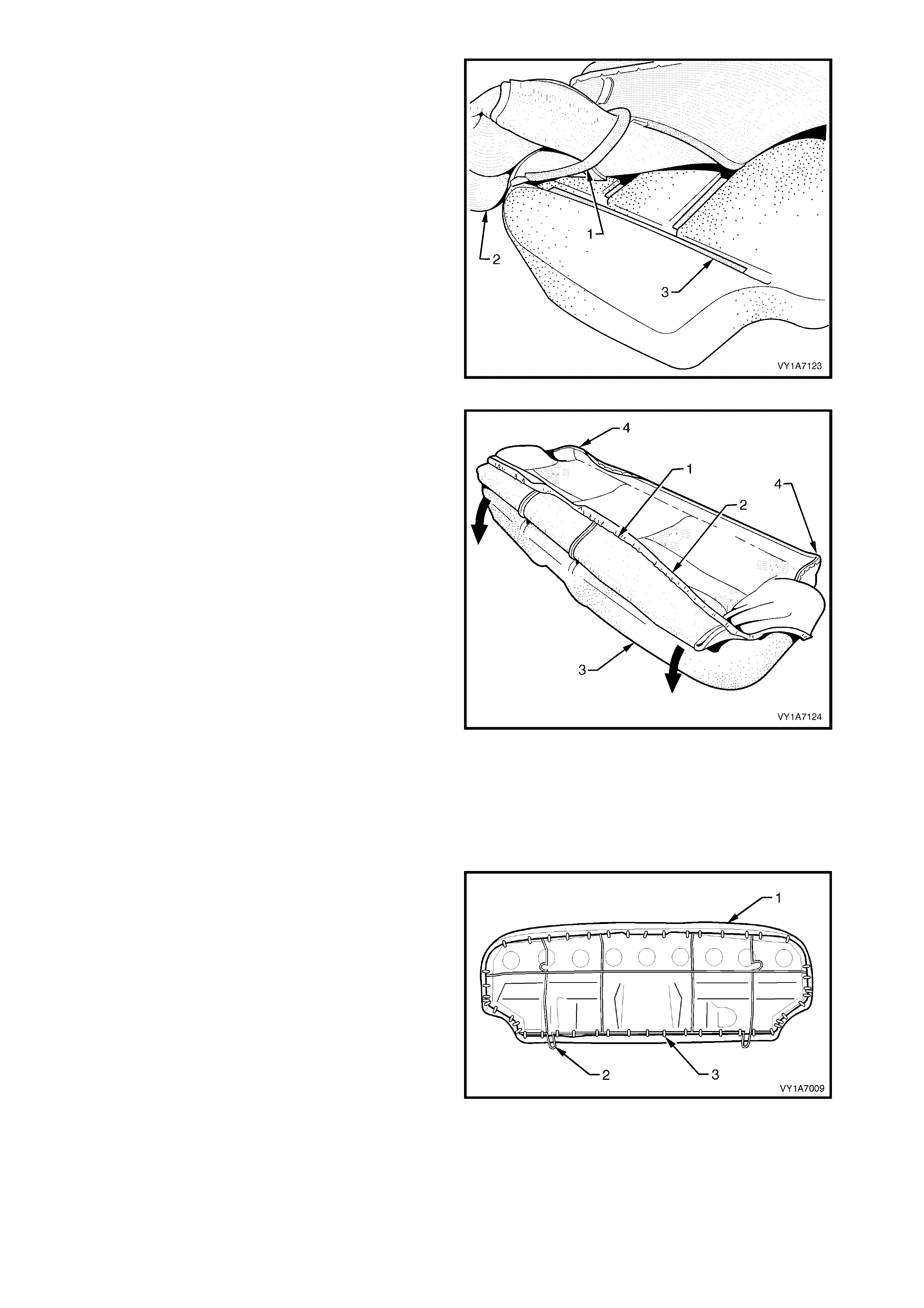
3. Align and press the outer hook and loop strip (1),
on the seat cushion cover (2), with the
corresponding groove in the seat cushion pad (3).
4. Repeat this process for the opposite half of the
rear seat cover and pad, starting with the inner
strip.
Figure 1A7-259
5. W ith the retaining wire (1) fitted to the front of the
rear seat cushion cover (2), roll the front corner of
the cover over the seat cushion pad (3).
6. Roll the sides of the seat cushion cover over the
seat cushion pad.
7. Roll the rear corners (4) of the seat cushion cover
over the seat cushion pad.
NOTE: Make sure the pad is fitted neatly by hand into
all corners and contours of the seat cover.
Figure 1A7-260
Reinstall – Rear Seat Cushion Frame, Surebond
NOTE: All hog rings must be replaced.
CAUTION: Safety glasses and work gloves must be
worn at all times when working with hog rings.
1. Using the following sequence operations, align the
rear seat cushion cover and pad assembly (1) to
the rear seat cushion frame (2) and attach with
approximately forty eight hog rings (3) in the
positions shown.
Figure 1A7-261
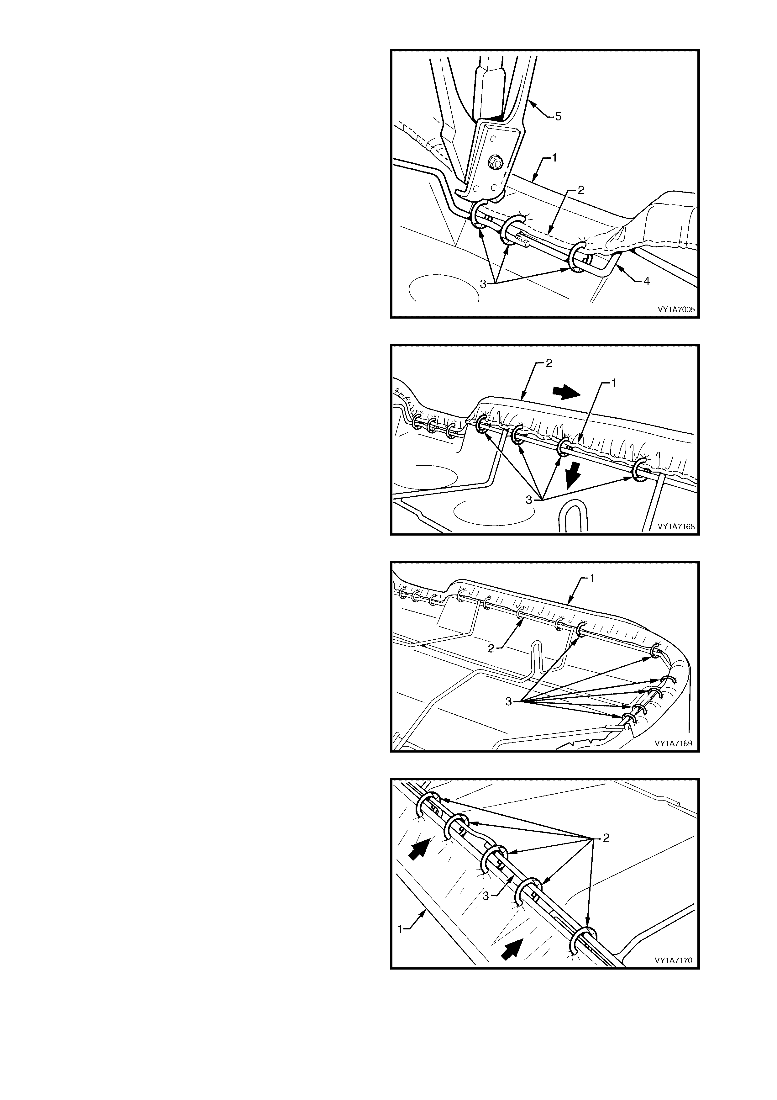
2. Starting at the front, in the centre of the rear seat
cushion cover assembly (1), attach the wire
retainer (2) with three hog rings (3) to the centr e of
the wire frame (4) using hog ring pliers (5).
Figure 1A7-262
3. Working from the centre outward, attach the wire
retainer (1), pulling the cover assembly (2) tight
and fixing with four hog rings (3).
4. Repeat this process in the opposite direction
working from the centre outward.
Figure 1A7-263
5. Continue attaching the cover assembly (1) to the
frame (2), by pulling the cover tight and fixing with
six hog rings (3).
6. Repeat this process in the opposite direction.
NOTE: The cover should be smooth and without
creases, if this is not the case, extra hog rings should
be used to pull the cover into place.
Figure 1A7-264
7. Pull the rear of the cushion cover assembly (1)
tight and attach in the centre with five hog rings (2)
to the centre of the wire frame (3).
Figure 1A7-265
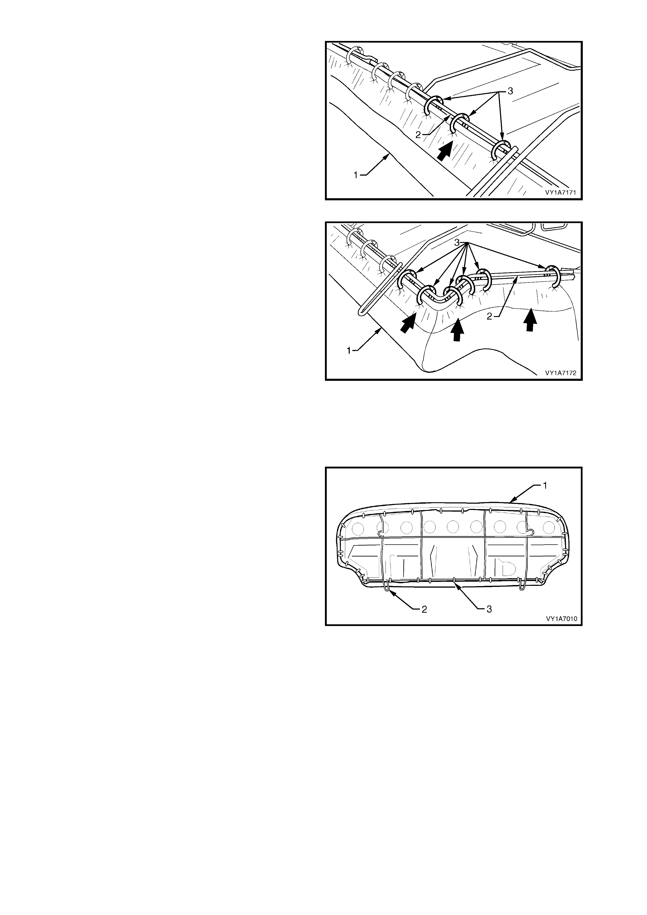
8. Continue attaching the cover assembly (1) to the
frame (2), by pulling the cover tight and fixing with
three hog rings (3).
9. Repeat this process in the opposite direction.
NOTE: The cover should be smooth and without
creases, if this is not the case, extra hog rings should
be used to pull the cover into place.
Figure 1A7-266
10. Continue attaching the cover assembly (1) to the
fram e ( 2), by pulling the cover tight, up and around
the corner and fixing with six hog rings (3).
11. Repeat this process in the opposite direction.
NOTE: The cover should be smooth and without
creases, if this is not the case, extra hog rings should
be used to pull the cover into place.
Figure 1A7-267
Remove – Rear Seat Cushion Frame, Hook and Loop
NOTE: All hog rings must be replaced.
CAUTION: Safety glasses and work gloves must be
worn at all times when working with hog rings.
1. Using the following sequence operations, align the
rear seat cushion cover and pad assembly (1) to
the rear seat cushion frame (2) and attach with
approximately thirty four hog rings (3) in the
positions shown.
Figure 1A7-268

2. Starting at the front, in the centre of the rear seat
cushion cover assembly (1), attach the wire
retainer (2) with two hog rings (3) to the centre of
the wire frame (4) using hog ring pliers (5).
Figure 1A7-269
3. Working from the centre outward, attach the wire
retainer (1), while pulling the cover assembly (2)
tight and fixing with two hog rings (3).
4. Repeat this process in the opposite direction
working from the centre outward.
Figure 1A7-270
5. Continue attaching the cover assembly (1) to the
frame (2), by pulling the cover tight and fixing with
five hog rings (3).
6. Repeat this process in the opposite direction.
NOTE: The cover should be smooth and without
creases, if this is not the case, extra hog rings should
be used to pull the cover into place.
Figure 1A7-271
7. Pull the rear of the cushion cover assembly (1)
tight, attach the centre with three hog rings (2) to
the centre of the wire frame (3).
Figure 1A7-272
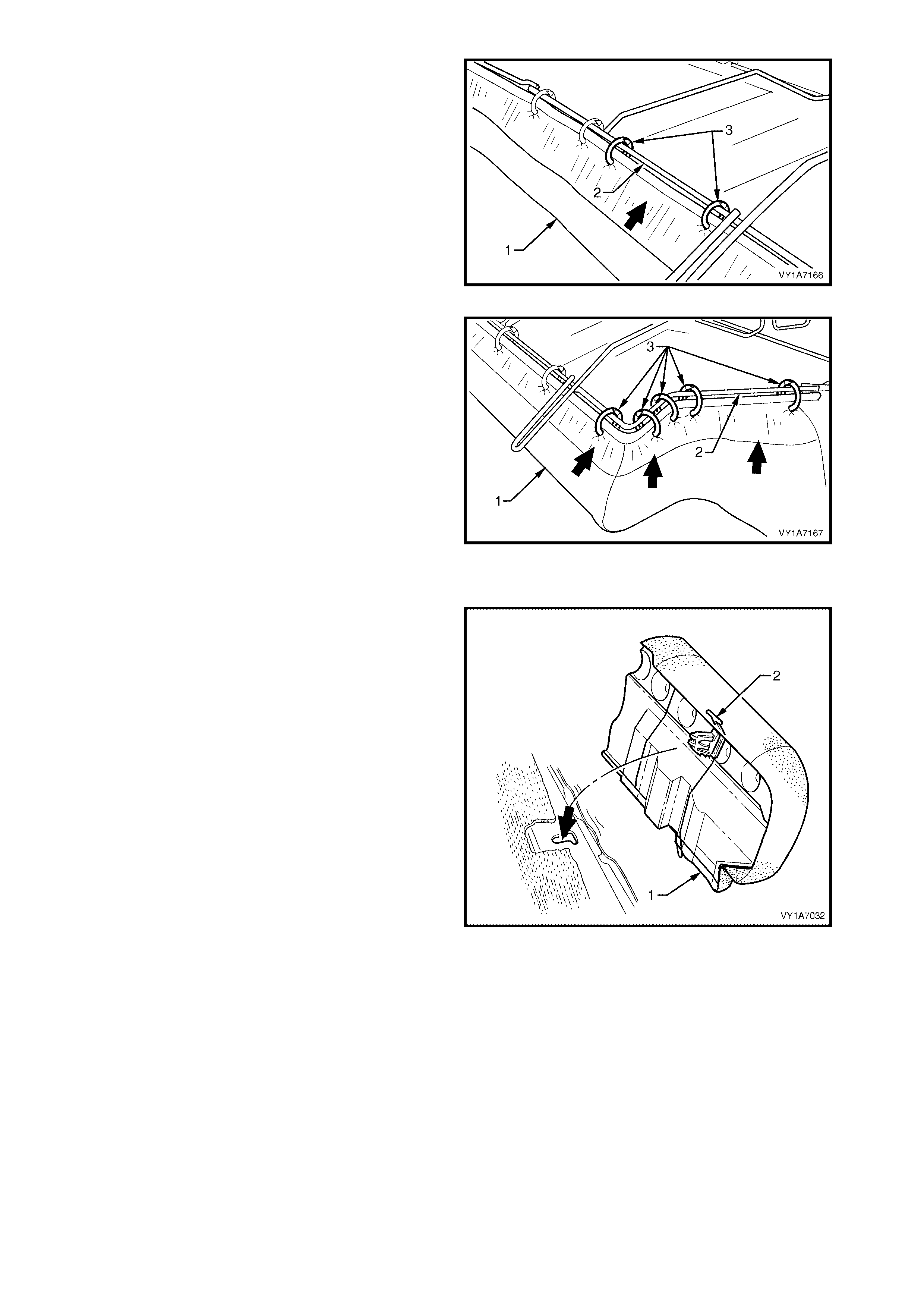
8. Continue attaching the cover assembly (1) to the
frame (2), by pulling the cover tight and fixing with
two hog rings (3).
9. Repeat this process in the opposite direction.
NOTE: The cover should be smooth and without
creases, if this is not the case, extra hog rings should
be used to pull the cover into place.
Figure 1A7-273
10. Continue attaching the cover assembly (1) to the
fram e ( 2), by pulling the cover tight, up and around
the corner and fixing with five hog rings (3).
11. Repeat this process in the opposite direction.
NOTE: The cover should be smooth and without
creases, if this is not the case, extra hog rings should
be used to pull the cover into place.
Figure 1A7-274
REINSTALL
1. Sit the rear seat cushion into position.
2. Push the rear seat cushion (1) into the seat back
and push down the front of seat cushion until the
locking mechanisms (2) lock into position.
Figure 1A7-275
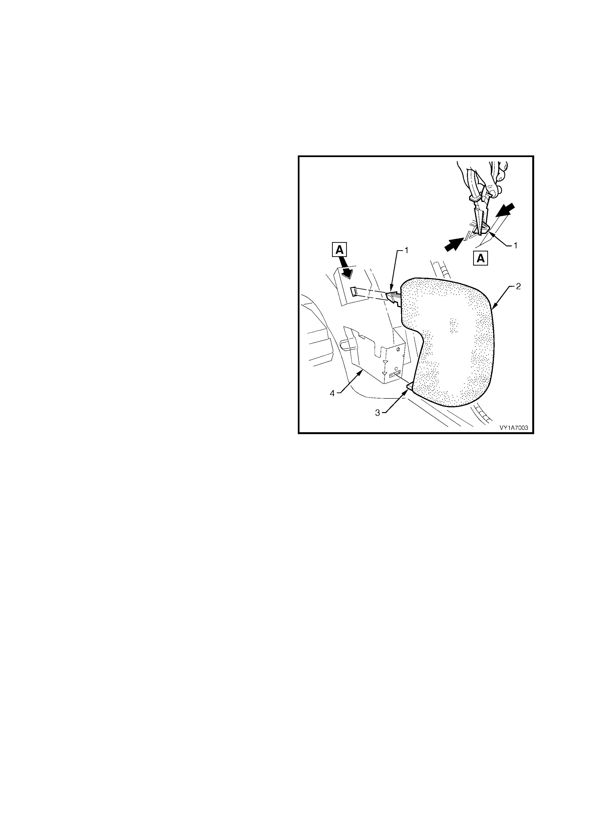
7.3 REAR SEAT BOLSTER ASSEMBLY
LT Section No. – 14-330
1. Remove the rear seat cushion, refer to 7.2 REAR SEAT CUSHION ASSEMBLY.
2. Unlatch and lower the rear seat-back assembly.
3. Remove the quarter inner trim panel as sem bly, refer to Sectio n 1A8, 3.11 QUARTER INNER TRIM PANEL
ASSEMBLY.
REMOVE
1. Using pliers, squeeze the tangs of the upper
bolster retaining clip (1) together and pull the rear
seat bolster assembly (2) towards the front of the
vehicle.
2. To disengage, lift the lower retaining tang (3) up
and pull the bolster forward, out of the seat-back
retaining bracket (4) towards the front of the
vehicle.
Figure 1A7-276
REINSTALL
Reinstallation of the rear seat bolster assembly is the
reverse of the removal, noting the following:
1. Insert the lower retaining tang of the bolster into
seat-back retaining bracket and push the upper
retaining tab into the upper retaining bracket.
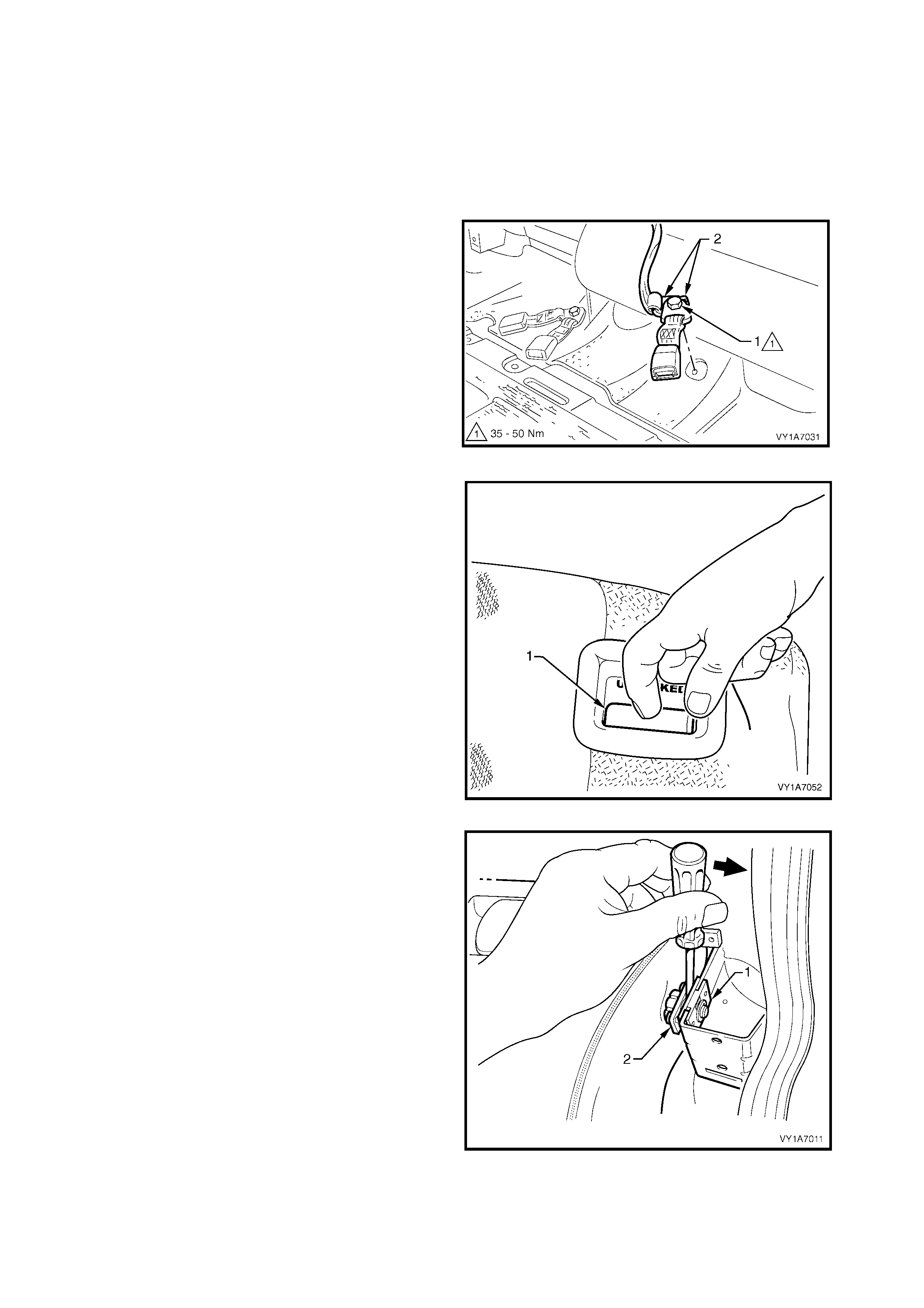
7.4 REAR SEAT-BACK ASSEMBLY
LT Section No. – 14-325
1. Remove the rear seat cushion assembly, refer to 7.2 REAR SEAT CUSHION ASSEMBLY.
2. Remove the rear seat bolster assembly on the appropriate side of the vehicle, refer to 7.3 REAR SEAT
BOLSTER ASSEMBLY.
REMOVE
1. For the left-hand side only, remove the bolt (1)
securing the centre rear seatbelt and the left-hand
buckle anchors (2) to the floor pan.
`
Figure 1A7-277
2. Unlatch and lower the rear seat-back assembly
(1).
IMPORTANT: If the seat-back assembly is not
lowered, the seat-back locking plate and pin assem bly
will be damaged if Step 3 is attempted.
Figure 1A7-278
3. Insert a screwdriver between the seat (1) and the
locking plate and pin assembly (2). Gently prise
apart to withdraw the pins from the retaining plate.
4. Lift the outer end of the seat up and out of the
seat-back retainer. Pull the seat-back assembly
towards the door, withdrawing it from the seat-
back centre hinge assembly.
5. Repeat for the opposite side if required.
Figure 1A7-279
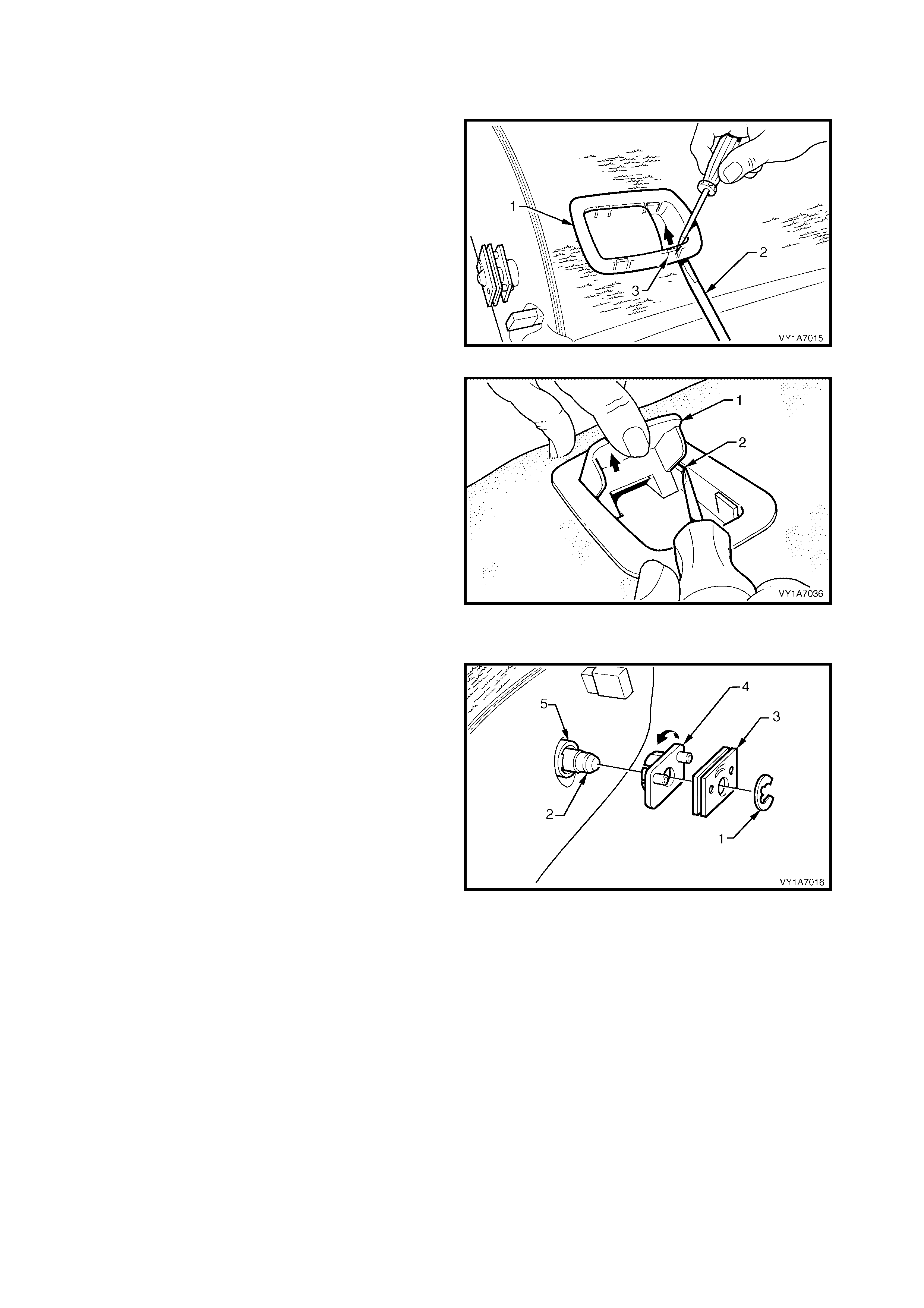
DISASSEMBLE
Remove – Rear Seat-back Release Handle
1. Disengage the release handle assembly (1) by
inserting a screwdriver (2) under one of the
corners of the release handle, while at the same
time prising the retaining tang (3) towards the
centre of the release handle.
Figure 1A7-280
2. With one corner of the release handle (1)
disengaged, hold the handle in the release position
(up) and disengage the remaining three tangs (2).
Prise them inwards using a screwdriver towards
the centre of the handle.
3. Remove the release handle assembly.
Reinstall – Rear Seat-back Release Handle
Reinstallation of the rear seat-back assembly is the
reverse of the removal procedure.
Figure 1A7-281
Remove – Rear Seat-back Retainer Locking Plate
1. Remove the circlip (1) from the seat-back pivot
shaft ( 2) and r emove the retainer plate (3) fr om the
shaft.
2. Remove the retainer locking plate and pin (4) by
twisting it off the locking bush (5).
NOTE: The loc k ing bush does not have to be rem oved
unless it is being replaced. This can be achieved by
simply levering it off the shaft.
Reinstall – Rear Seat-back Retainer Locking Plate
Reinstallation of the rear seat-back assembly is the
reverse of the removal procedure.
Figure 1A7-282
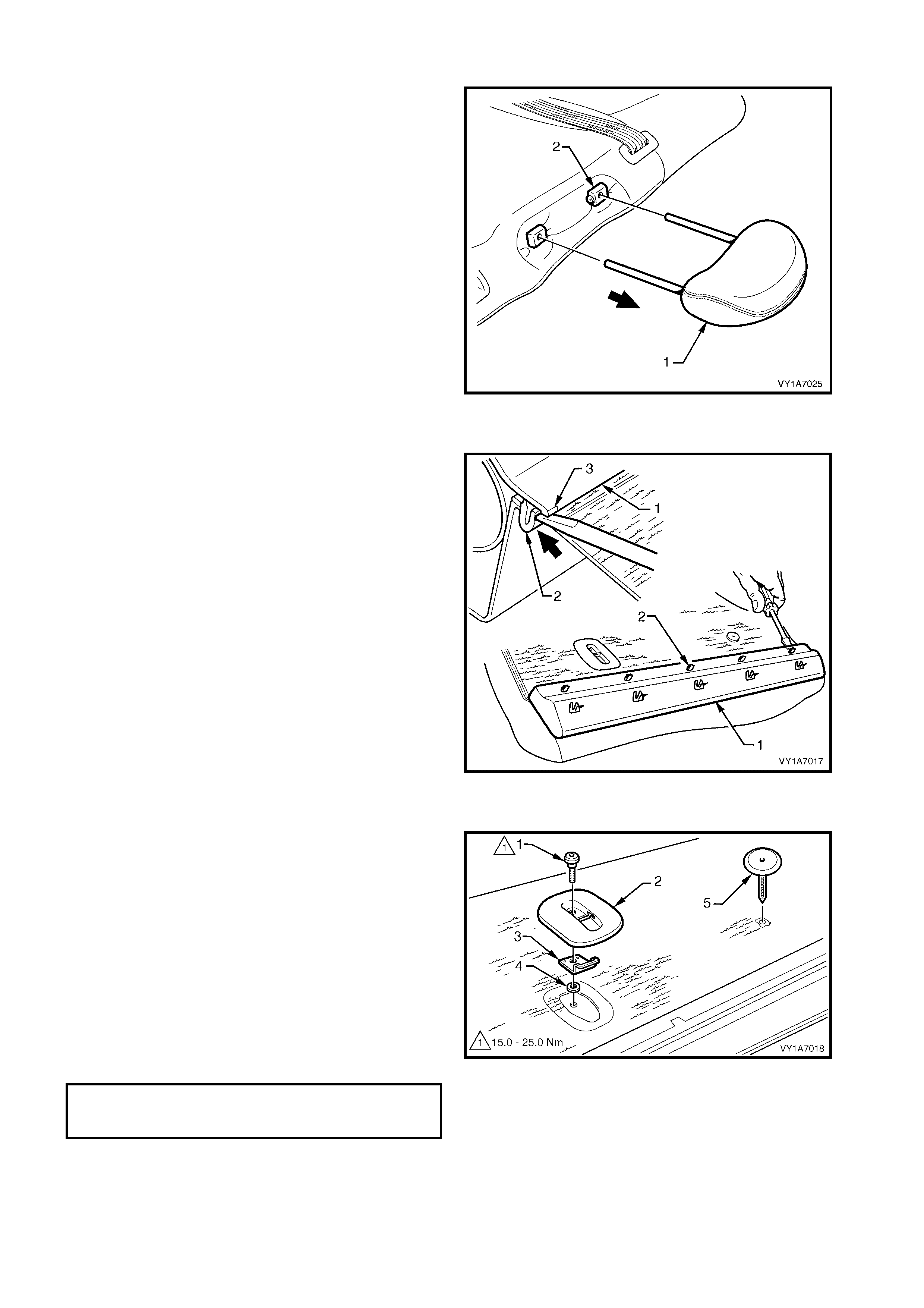
Remove – Rear Seat-back Head Restraint, If Fitted
1. Remove the head restraint (1) by depressing the
head restraint guide height adjuster lock (2).
2. Pull the head restraint completely out of the guide.
Reinstall – Rear Seat-back Head Restraint
Reinstallation of the head restraint into the rear seat-
back assembly is the reverse of the removal
procedure.
Figure 1A7-283
Remove – Rear Seat-back Trim Cover
1. Car efully rem ove the rear s eat-back trim c over (1) ,
by inserting a small screwdriver at the tab (2)
position, highlighted by small polished areas (3).
Push in to disengage the retaining tabs (3) five
places on the left-hand seat and three places on
the right-hand seat.
2. Star t at one end to disengage the cover away f rom
the seat-back and work your way along until all
retaining tabs have been disengaged.
NOTE: Care must be taken not to break the lower
retaining tabs from the rear seat-back trim cover,
otherwise a replacement part will be required.
Reinstall – Rear Seat-back Trim Cover
Reinstallation of the rear seat-back trim cover is the
reverse of the removal procedure.
Figure 1A7-284
Remove – Child Seat Anchor
1. Remove the child seat anchor bolt (1) from the left-
hand rear seat-back.
2. Remove the child seat escutcheon (2), anchor (3)
and the washer (4).
3. Prise the child seat anchor blanking plug (5) from
the rear seat-back.
Reinstall – Child Seat Anchor
Reinstallation of the c hild seat anchor is the reverse of
the removal procedure, noting the following:
1. Tighten the anchor bolt to the correct torque
specification.
Figure 1A7-285
CHILD SEAT ANCHOR
ATTACHING BOLT
TORQUE SPECIFICATION 15.0 – 25.0 Nm
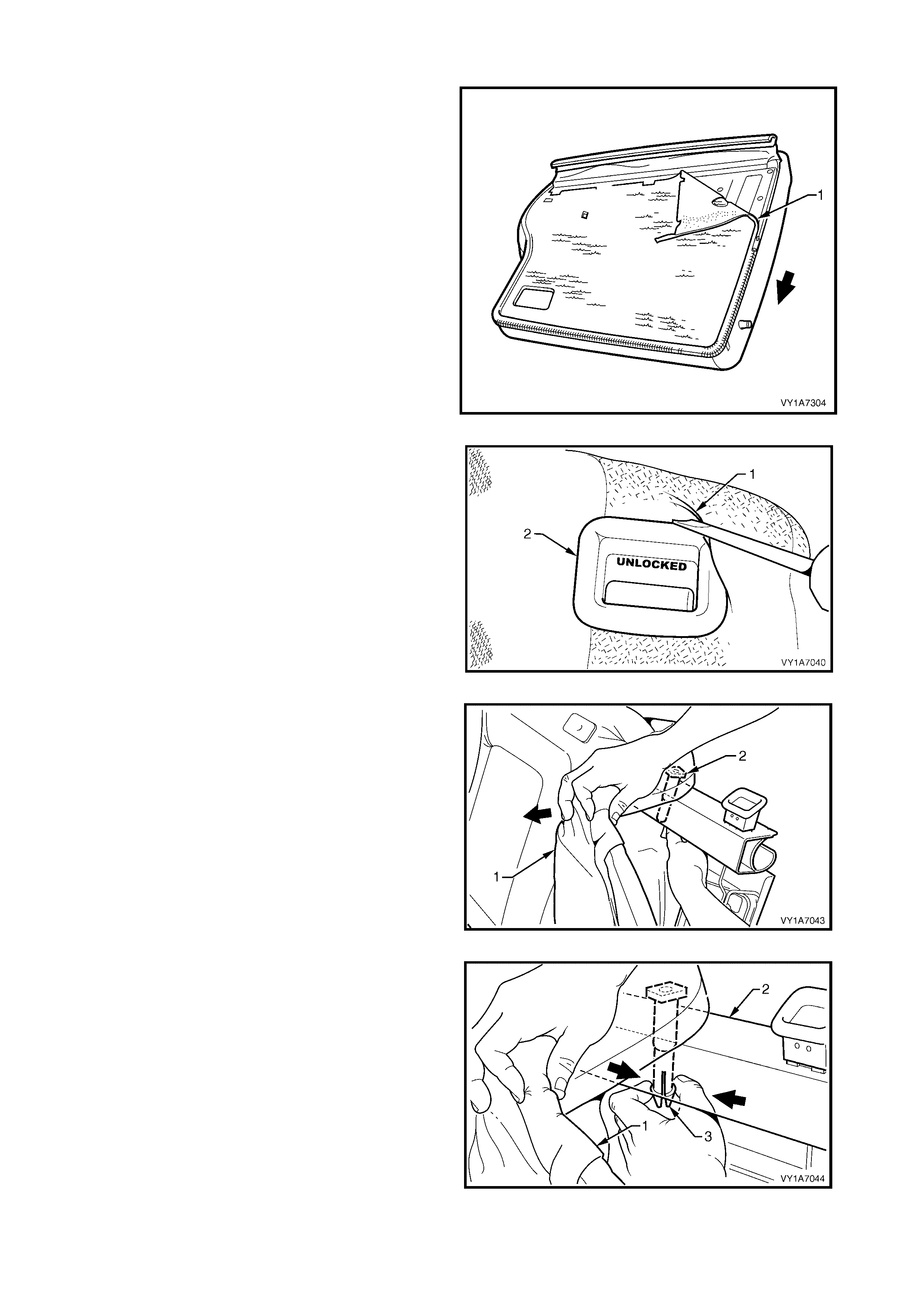
Remove – Rear Seat-back Head Restraint Guide, If Fitted
1. Unzip the rear carpet (1) attached to the rear seat-
back cover (2) around the two sides.
2. Fold the cover back revealing the rear seat-back
frame.
Figure 1A7-286
3. Lever the cover and pad assembly (1) over the
release button (2).
Figure 1A7-287
4. Pull the top cor ner of the pad as sem bly forward, to
allow for the removal of the two head restraint
guide (2).
Figure 1A7-288
5. While holding the cover and pad assembly (1),
reach in between the seat-back frame (2) and the
pad assembly.
6. Squeeze the head restraint guide locating prongs
(3) together and remove the guide up and out of
the seat-back assembly.
7. Repeat this process for the remaining head
restraint guide.
Figure 1A7-289
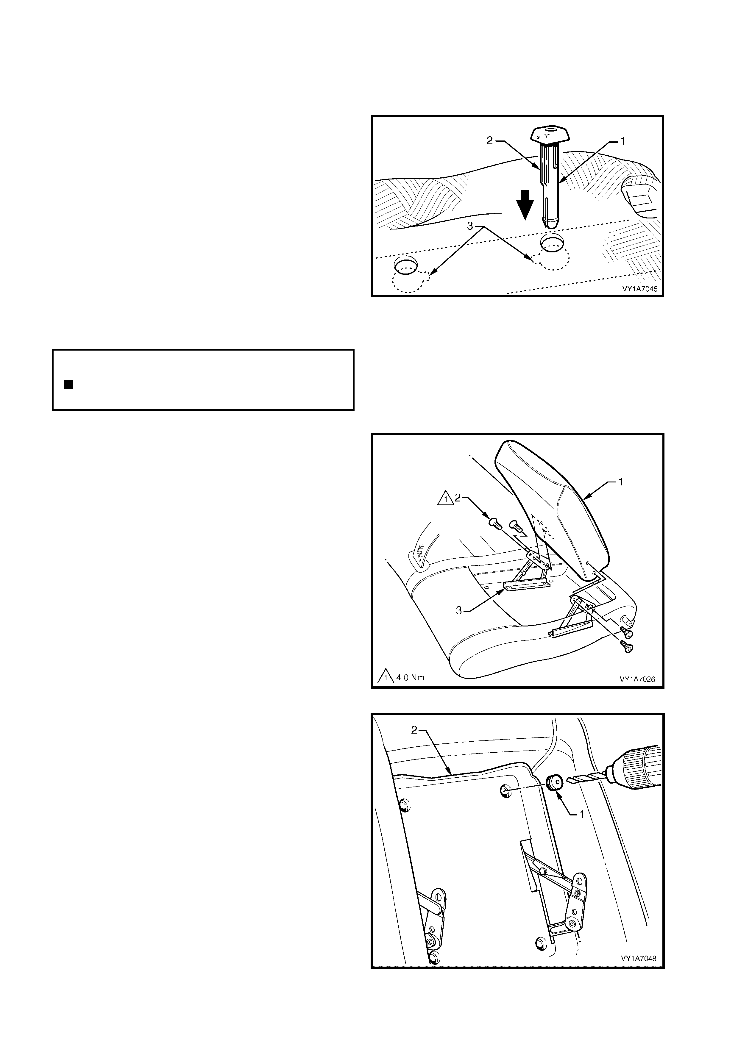
Reinstall – Rear Seat-back Head Restraint Guide
Reinstallation of the rear seat-back head restraint
guide is the reverse of the removal procedure, noting
the following:
1. When installing the head restraint guide (1),
ensure the locating slots (2) in the seat-back align
with key-way (3) on the head restraint guide.
NOTE: Ensure the guide with the height adjuster lock
is installed on the s ide that corresponds to the notches
in the head restraint shaft.
Figure 1A7-290
Remove – Rear Seat-back Armrest Assembly, If Fitted
1. Partially open the rear seat-back armrest assembly
(1) and remove the four screws (2) securing the
armrest assembly to the armrest hinge assembly
(3).
2. Remove the rear seat-back armrest assembly.
Figure 1A7-291
3. To remove the four blanking plugs (1) from the
rear seat-back armrest centre cover (2), drill a
small hole into the centre of each plug.
4. Inser t a s cribe or sm all sc rewdriver into the hole in
the plug and pull them free. Take care not to
damage the seat-back cover.
Figure 1A7-292
N
O
TE: The
f
ollowing component WILL RE
Q
UIRE
REPLACEMENT when performing this operation.
Rear seat-back armrest centre cover blanking
plugs.
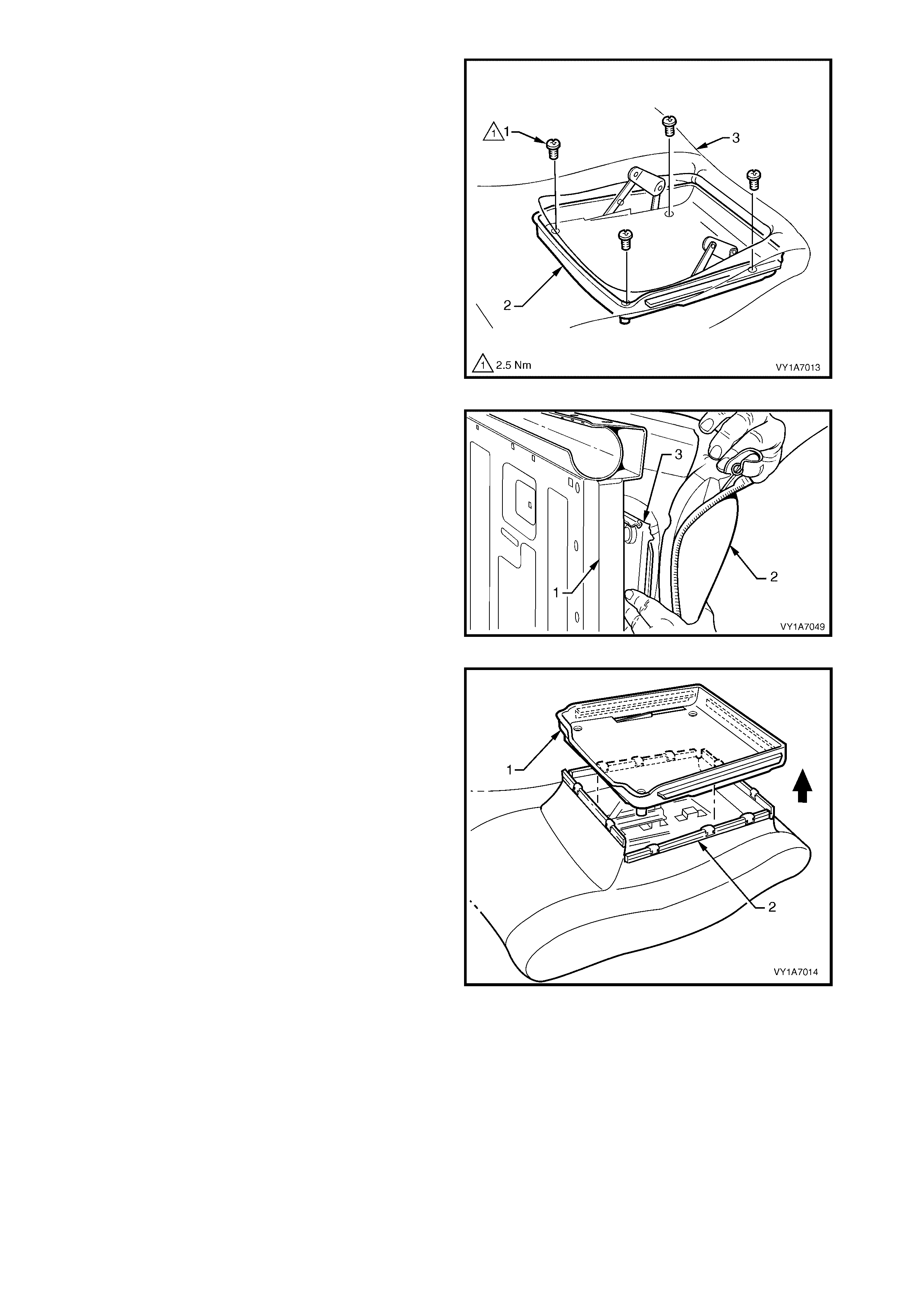
5. Remove the four screws (1) securing the armrest
centre cover (2) to the seat-back pad and frame
assembly (3).
Figure 1A7-293
6. Reach in between the seat-back fram e (1) and the
seat-back cover and pad assembly (2).
7. Push the armrest centre cover (3) out through the
front of the seat-back pad.
Figure 1A7-294
8. Lift the armrest centre cover (1) up and pull the
four seat-back cover retainers (2) away from the
four sides of the centre cover.
9. Remove the armrest centre cover.
Figure 1A7-295
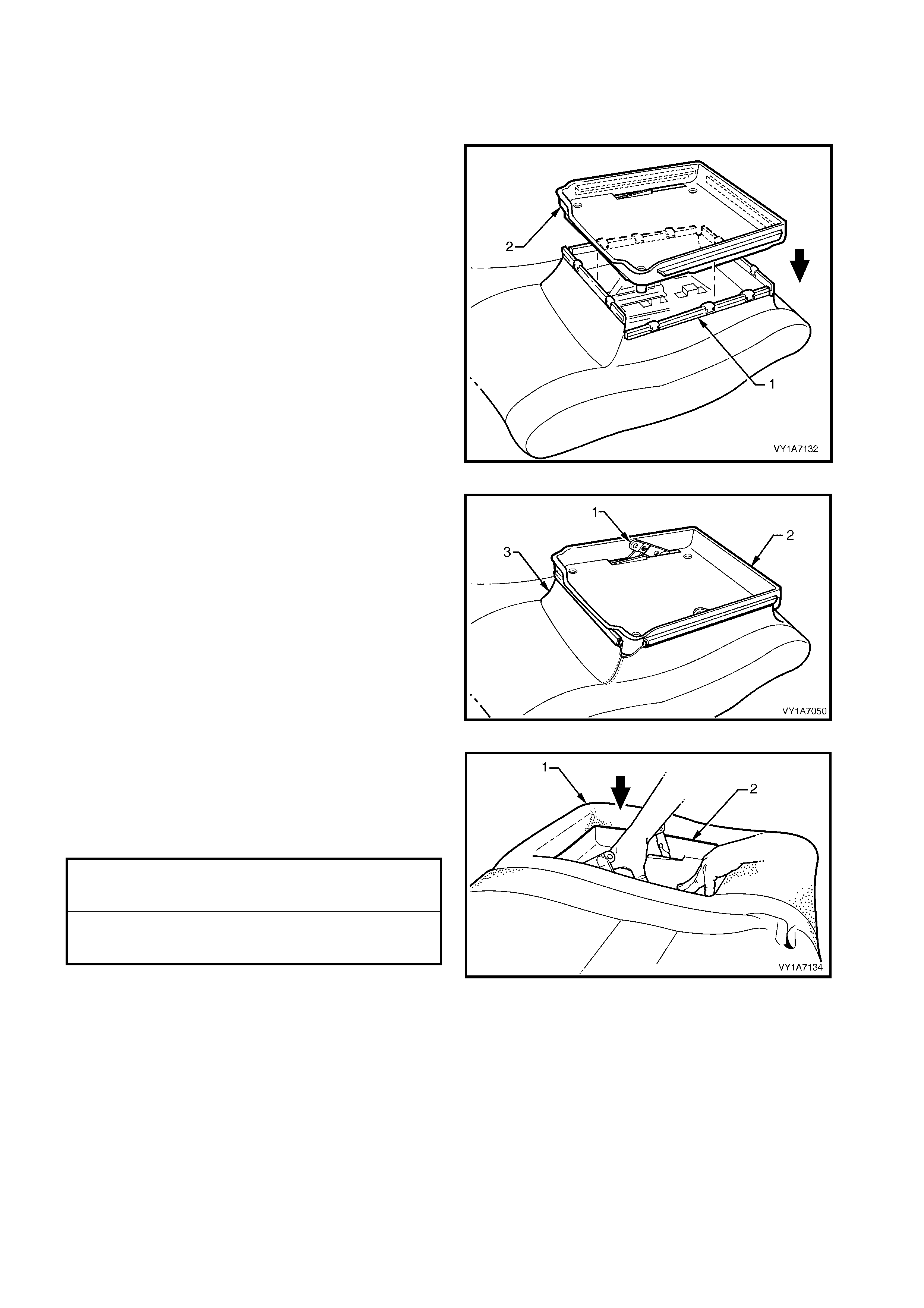
Reinstall – Rear Seat-back Armrest Assembly
Reinstallation of the rear seat-back armrest assembly
is the reverse of the removal procedure, noting the
following:
1. Ins ert the f our rear seat-bac k c over retaining s trips
(1) into the armrest centre cover (2).
Figure 1A7-296
2. Have the armrest hinges (1) in the partly open
position before installing the armrest centre cover
(2).
Figure 1A7-297
3. Ensure no puckering occurs around the rear seat-
back cover (3) while installing the armrest centre
cover.
4. Tighten all retaining screws to the correct torque
specification.
5. Install four new centre cover blanking plugs.
Figure 1A7-298
ARMREST CENTRE COVER
RETAINING SCREW
TORQUE SPECIFICATION 2.5 Nm
REAR SEAT BACK ARMREST
ASSEMBLY RETAINING SCREW
TORQUE SPECIFICATION 4.0 Nm
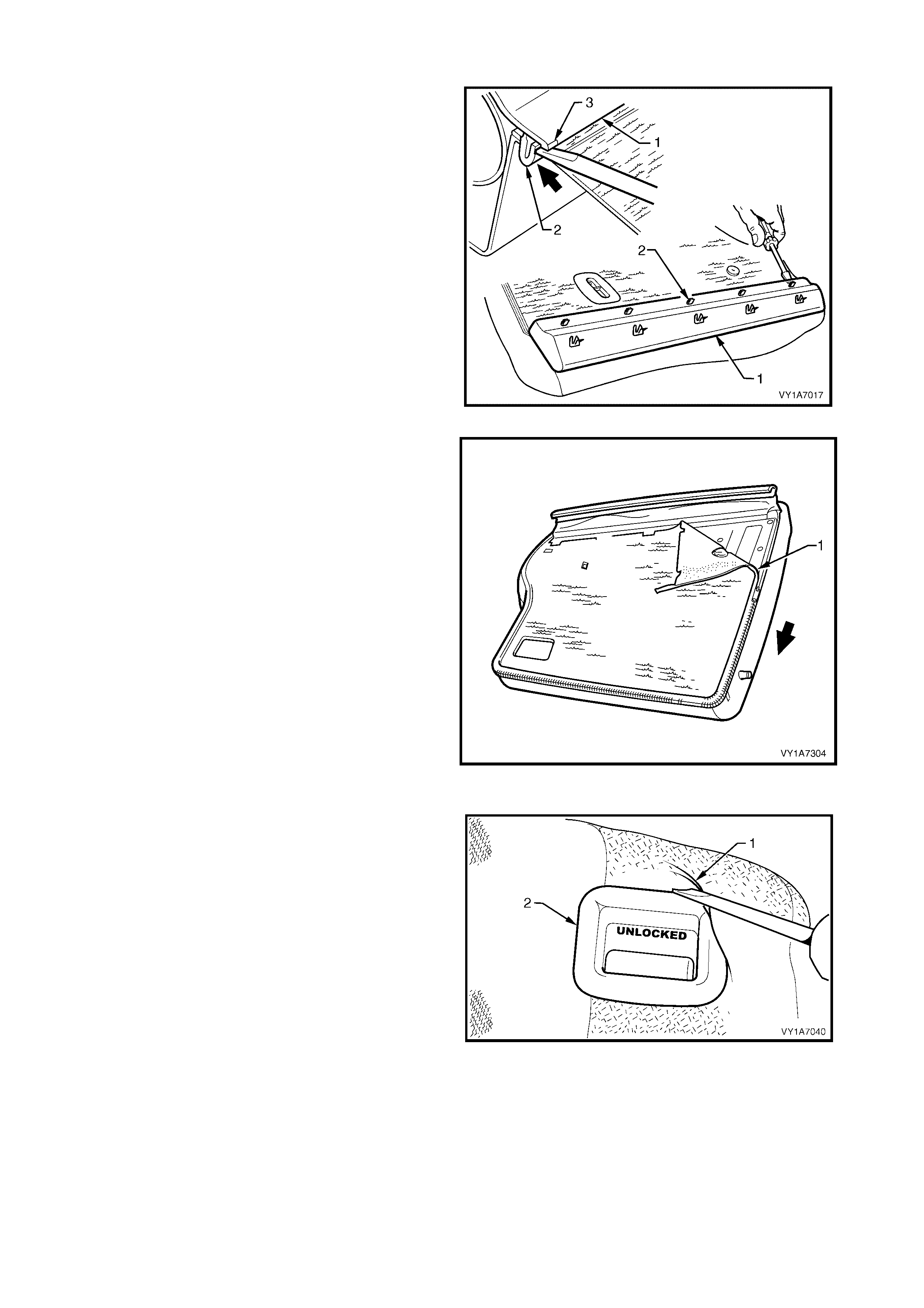
Remove – Rear Seat-back Cover and Pad Assembly
1. Car efully rem ove the rear s eat-back trim c over (1) ,
by inserting a small screwdriver at the tab (2)
position, highlighted by small polished areas (3).
Push in to disengage the retaining tabs (3) five
places on the left-hand seat and three places on
the right-hand seat.
2. Star t at one end to disengage the cover away f rom
the seat-back and work your way along until all
retaining tabs have been disengaged.
NOTE: Care must be taken not to break the lower
retaining tabs from the rear seat-back trim cover,
otherwise a replacement part will be required.
Figure 1A7-299
3. Unzip the rear seat-back cover and pad assembly
(1) around two sides and fold the cover and pad
assembly back.
Figure 1A7-300
4. Lever the cover and pad assembly (1) over the
release button (2).
5. For the r ight-hand side, rem ove the rear seat-bac k
cover and pad assembly.
Figure 1A7-301
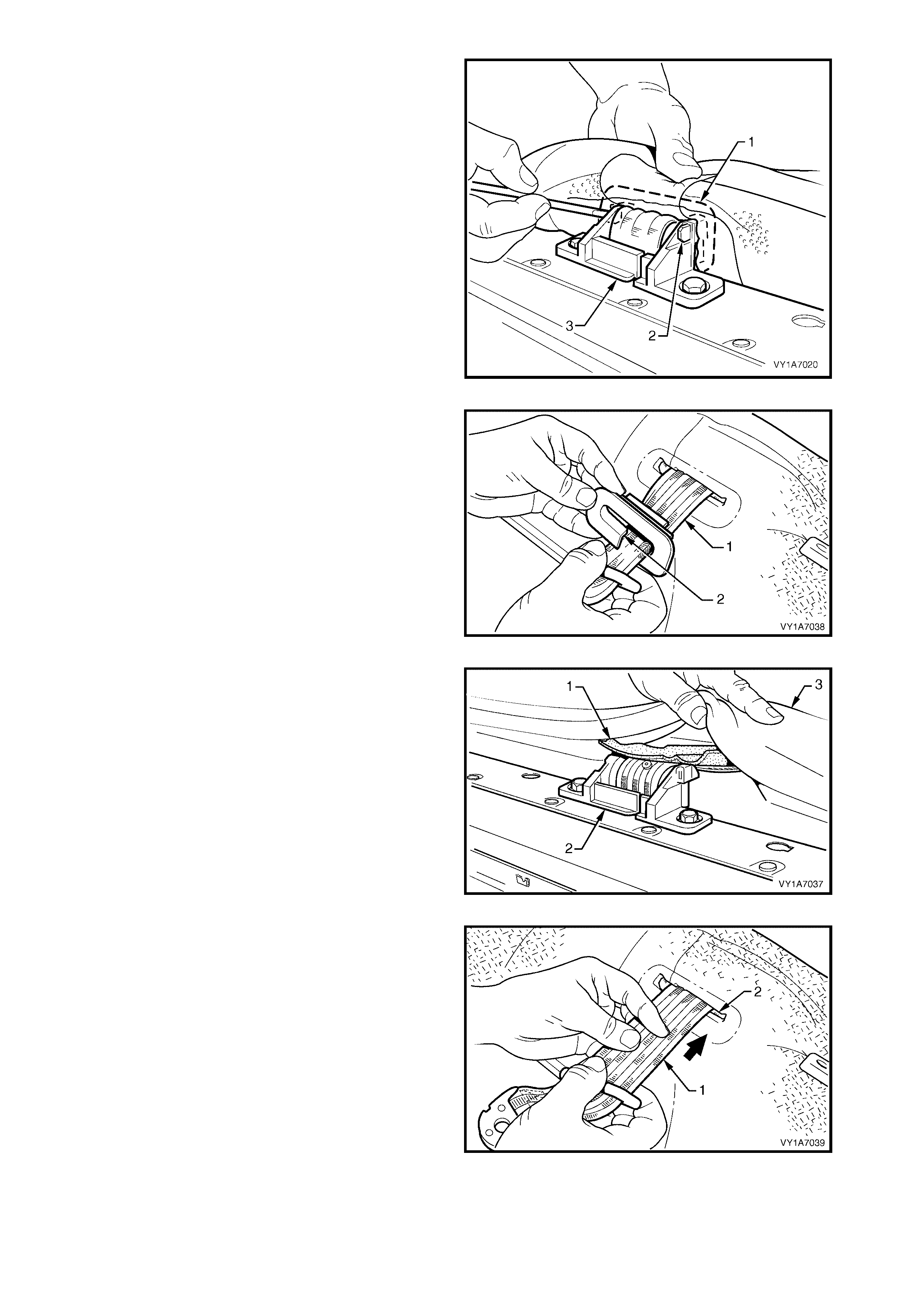
6. F or the lef t-hand side, using a screwdriver , release
the centre seatbelt escutcheon (1) from inside the
left-hand rear seat-back by pushing the tangs (2)
of the escutcheon through the seatbelt guide
bracket assembly (3).
NOTE: Care must be taken not to break the attaching
tangs from the escutcheon.
Figure 1A7-302
7. Remove the escutcheon (1) from the seatbelt (2).
Figure 1A7-303
8. Feed the seat-back cover flap (1), over the
seatbelt guide bracket assembly (2) and through
the pad assembly (3).
Figure 1A7-304
9. Feed the seatbelt (1) through the slot (2) in the
cover and pad assembly.
10. Remove the cover and pad assembly away from
the seat-back frame.
Reinstall – Rear Seat-back Cover and Pad
Assembly
Reinstallation of the rear seat-back cover and pad
assembly is the reverse of the removal procedure.
Figure 1A7-305
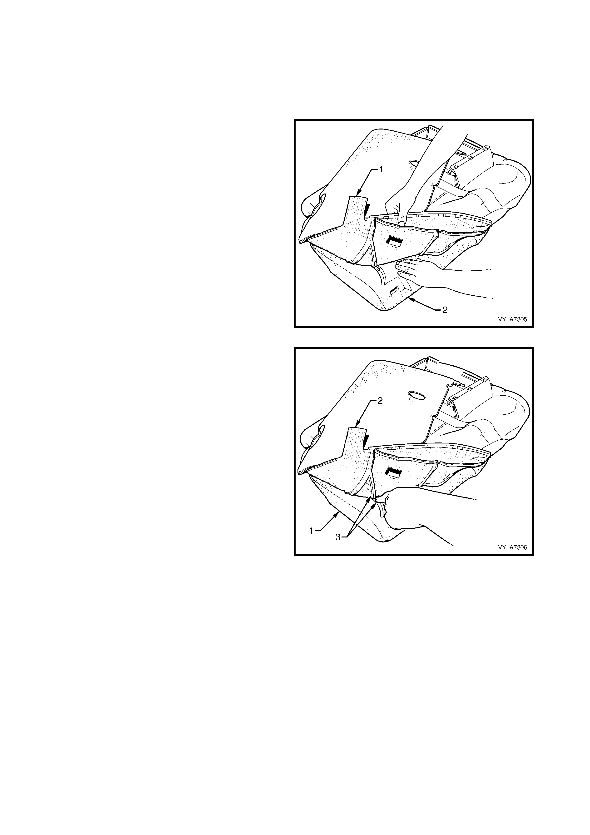
Remove – Rear Seat-back Cover, Hook and Loop
NOTE 1: Surebond cover assemblies are not serviced
as they are glued to the seat-back pad, refer to
7.1 REAR SEAT USAGE CHART - WAGON.
NOTE 2: The following procedures are applicable to
both left and right-hand rear seat-back assemblies.
1. Fold the outer upper corner of the rear seat-back
cover (1) over the rear seat-back pad (2).
Figure 1A7-306
2. While holding the rear seat-back pad (1), pull the
upper corner of the seat cushion cover (2) away
from the r ear s eat- back pad to disengage the hook
and loop strip (3).
Figure 1A7-307
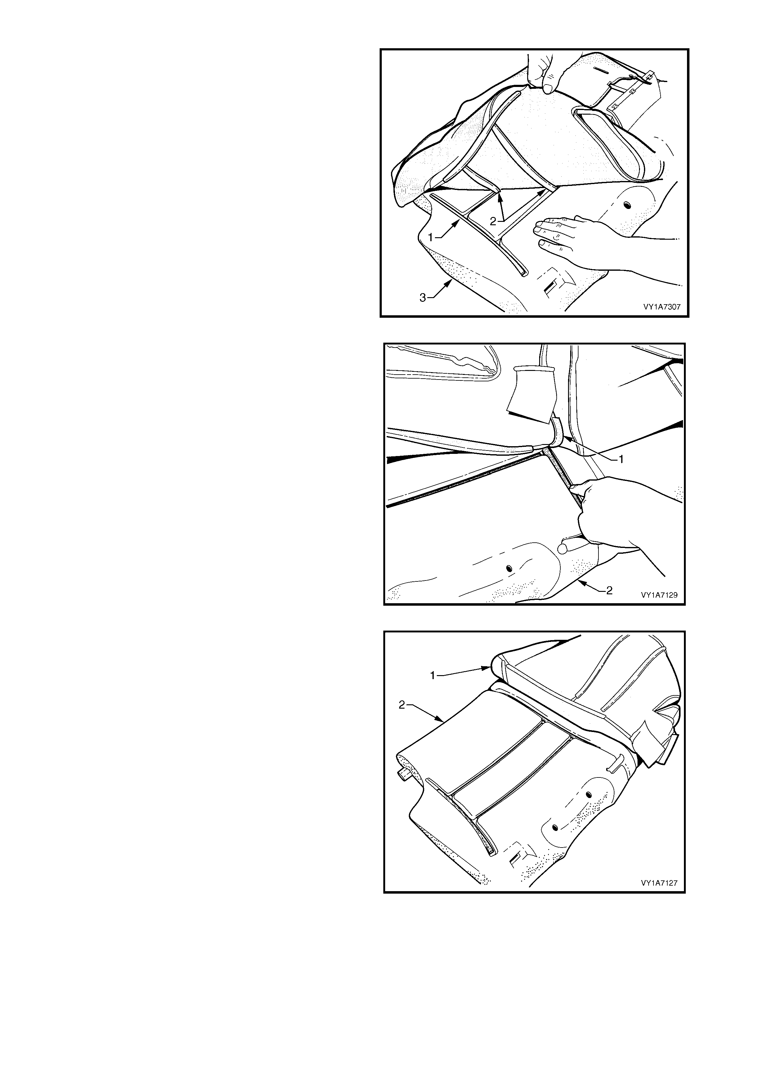
3. After dis engaging the outer hook and loop strip (1)
remove the one or two cross hook and loop strips
(2) while holding the seat cushion pad (3).
Figure 1A7-308
4. Remove the inner hook and loop strip (1) while
holding the seat cushion pad (2).
Figure 1A7-309
5. Pull the rear seat-back cover (1) up and over the
lower edge of the rear seat-back pad (2).
6. Remove the rear seat-back cover from the rear
seat-back pad.
Figure 1A7-310
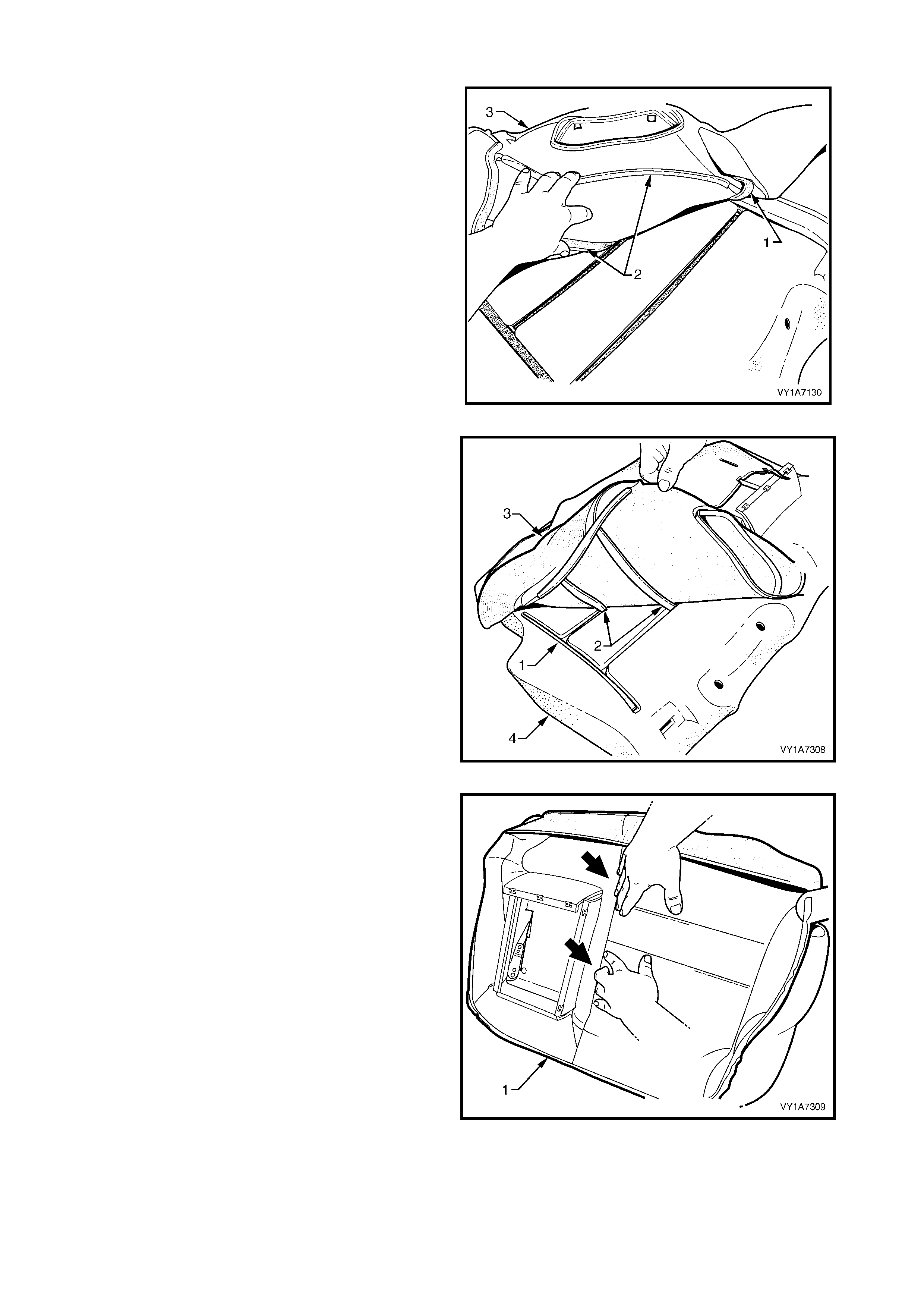
Reinstall – Rear Seat-back Cover, Hook and Loop
1. Align the inner hook and loop strip (1) and the one
or two cross hook and loop strips (2) on the seat-
back cover (3), with the seat-back pad.
2. Press the seat-back cover firmly into the
corresponding groove in the seat-back pad to
engage the hook and loop.
Figure 1A7-311
3. Align the outer hook and loop str ip (1) and the one
or two cross hook and loop strips (2) on the seat
cushion cover (3), with the seat cushion pad (4).
4. Press the seat-back cover firmly into the
corresponding groove in the seat-back pad to
engage the hook and loop.
Figure 1A7-312
5. With the seat cover (1) folded at the two vertical
strips of the hook and loop, press the seat-back
cover firmly into the corresponding grooves in the
seat-back pad.
Figure 1A7-313
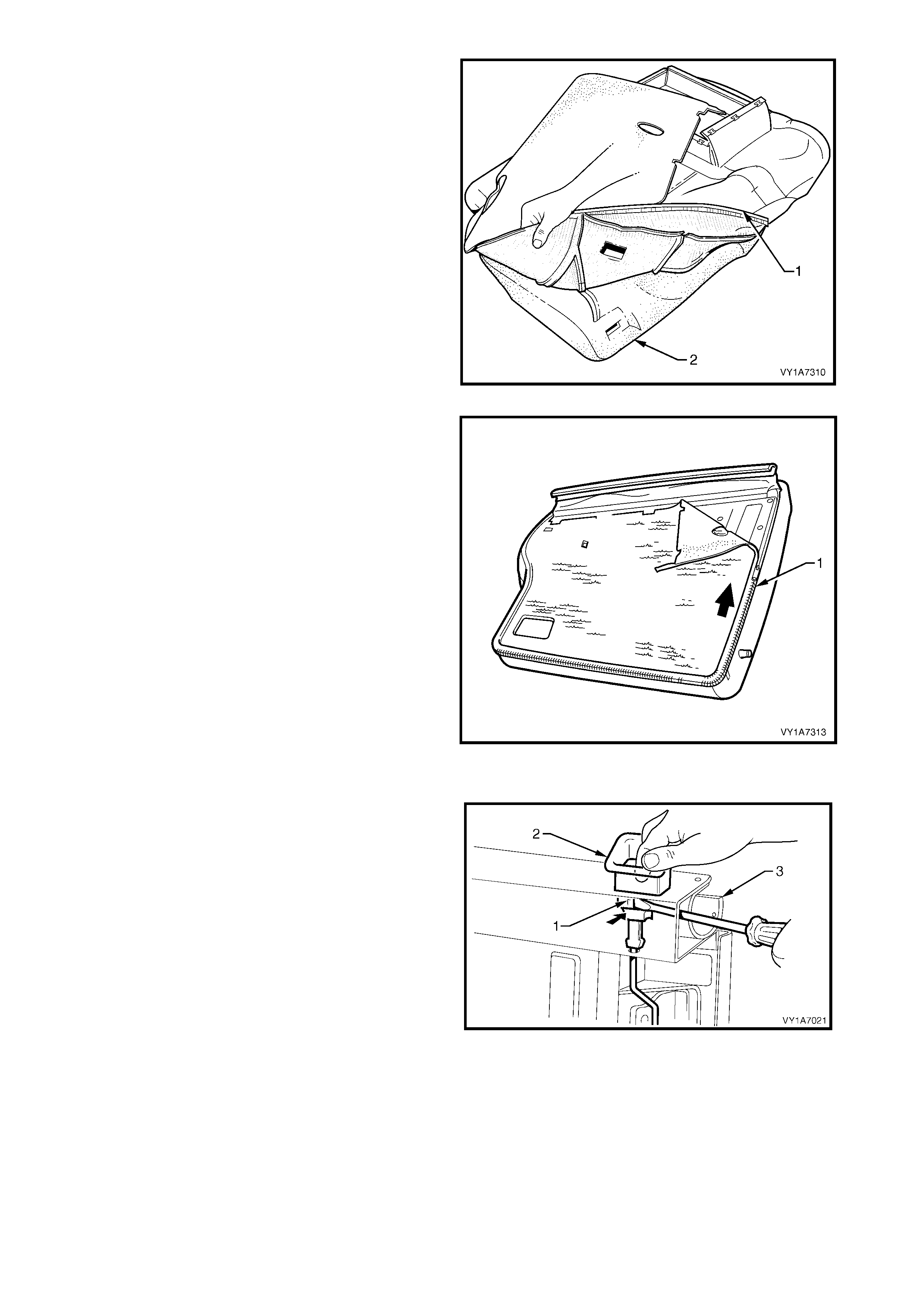
6. Roll the lower corners of the rear seat-back cover
(1) over the seat-back pad (2).
7. Roll the sides of the seat-back cover over the seat-
back pad.
8. Roll the upper corner s of the seat-back cover over
the seat-back pad.
NOTE: Make sure the pad is fitted neatly by hand into
all corners and contours of the seat cover.
Figure 1A7-314
9. Reattach the zip (1) and fasten along two sides.
Figure 1A7-315
Remove – Rear Seat-back Frame Release Button
1. Using a screwdriver, depress the two tangs (1) on
the front and rear of the release button (2).
2. Pull the release button from the seat frame (3).
Reinstall – Rear Seat-back Frame Release Button
1. Push the release button into the rear seat-back
frame assembly, until the button clicks home.
Figure 1A7-316
Remove – Left-hand Rear Seat-back Frame Actuator Cable Assembly
NOTE: The following procedure is applicable to the
left-hand rear seat-back assembly only.
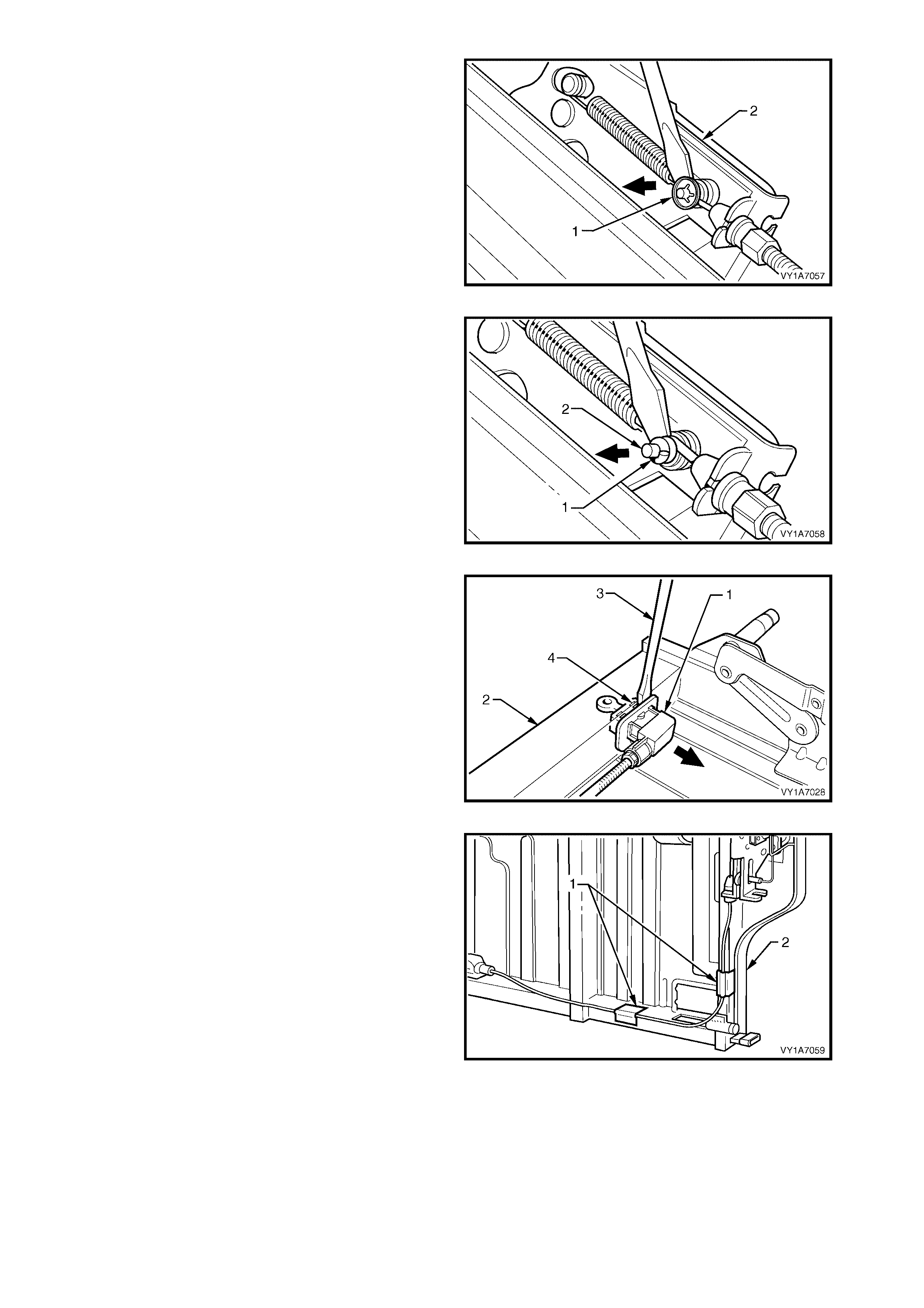
1. Lever the retaining clip (1) off the actuator
assembly (2) using a screwdriver.
Figure 1A7-317
2. Lever the actuator cable (1) from the actuator
retaining bracket (2) using a small screwdriver.
3. Remove the cable from the actuator.
Figure 1A7-318
4. Lever the ac tuator cable retainer (1) f rom the seat-
back frame (2) with the aid of a screwdriver (3).
NOTE: Care needs to be taken, when levering the
actuator cable retainer from the seat-back frame. The
retaining tangs (4) could be damaged during removal
and would require the actuator cable assembly to be
replaced.
Figure 1A7-319
5. Remove the tape ( 1) s ec uring the actuator cable to
the seat-back frame (2) and remove the cable.
NOTE: Take note of the location of the tape for
reinstallation.
Figure 1A7-320
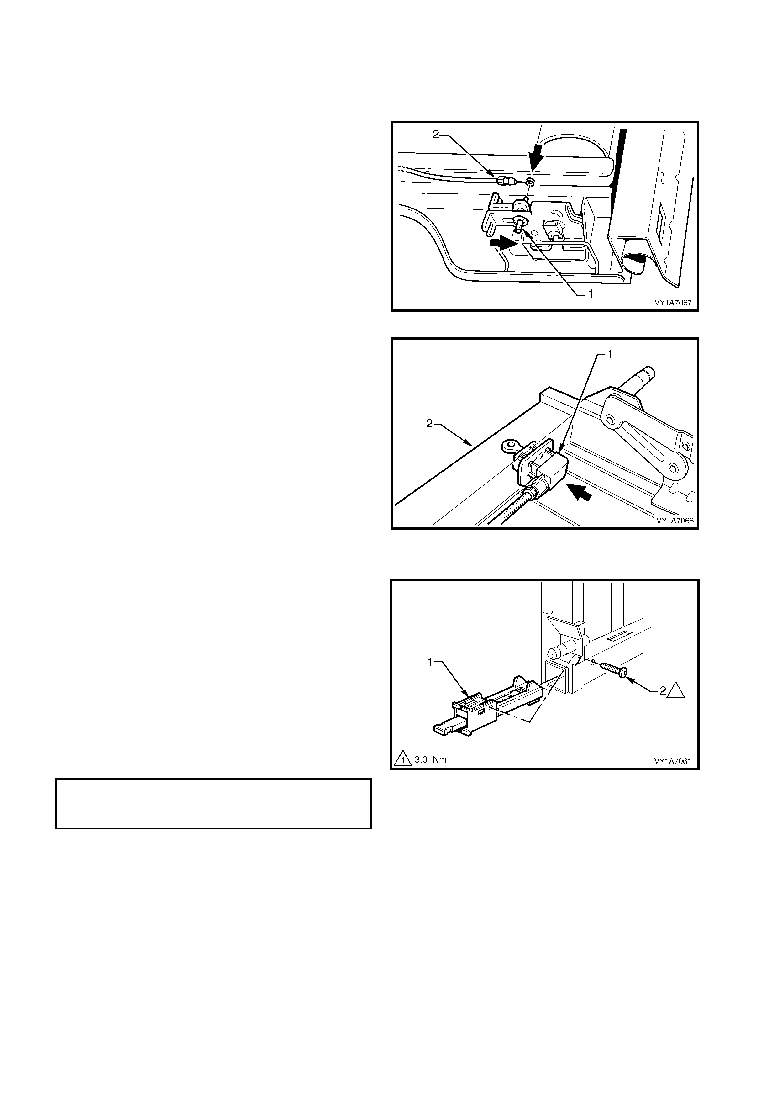
Reinstall – Left-hand Rear Seat-back Frame Actuator Cable Assembly
Reinstallation of the rear seat-back frame actuator
cable is the reverse of the removal procedure noting
the following:
1. Place the actuator lock (1) in the up position before
connecting the actuator cable (2).
Figure 1A7-321
2. Install the actuator cable retainer (1) into the rear
seat-back (2), after the cable is connected to the
actuator assembly
Figure 1A7-322
Remove – Left-hand Rear Seat-back Frame Inner Latch
1. Remove the inner latch assembly (1) by removing
the screw (2) retaining the inner latch assembly.
2. Slide the inner latc h assem bly out of the seat-back
frame.
Reinstall – Left-hand Rear Seat-back Frame Inner
Latch
Reinstallation of the left-hand rear seat-back frame
inner latch is the reverse of the removal procedure
noting the following:
1. Ensure the screws are tightened to the correct
torque specification:
Figure 1A7-323
RELEASE HANDLE LEVER
ATTACHING SCREW
TORQUE SPECIFICATION 3.0 Nm
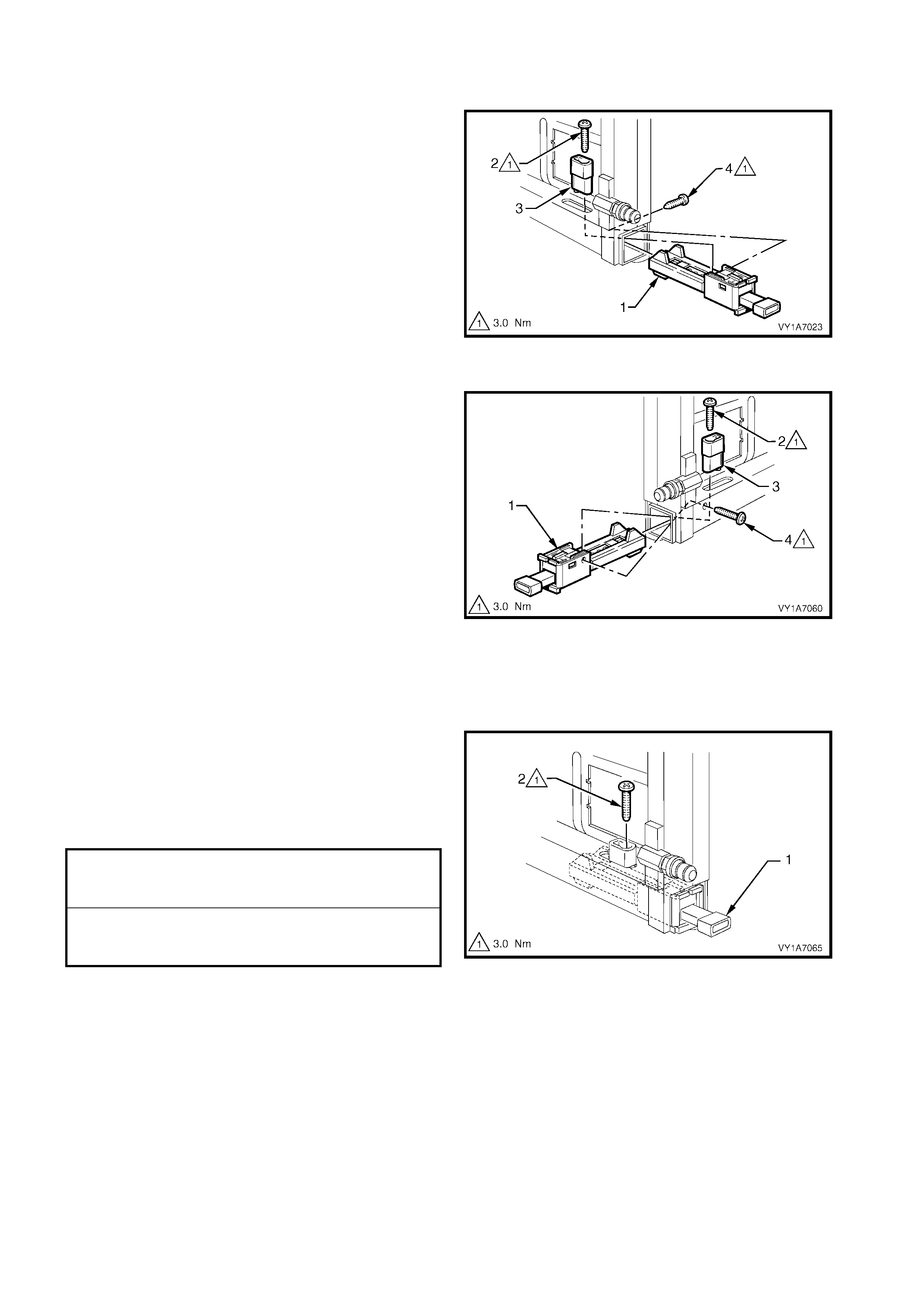
Remove – Rear Seat-back Frame Outer Latch
Left-hand Se at
1. O n the left- hand rear s eat fram e, r em ove the outer
latch ass embly (1) by rem oving the scr ew ( 2) from
the release handle lever (3) and remove the lever.
2. From the rear of the seat-back remove the screw
(4) retaining the outer latch assembly.
3. Slide the outer latch ass em bly out of the seat-back
frame.
Figure 1A7-324
Right-hand Seat
1. On the right-hand rear seat frame, remove the
outer latch ass em bly (1) by rem oving the screw (2)
from the release handle lever (3) and remove the
lever.
2. Remove the screw (4) retaining the outer latch
assembly.
3. Slide the outer latch ass em bly out of the seat-back
frame.
Figure 1A7-325
Reinstall – Rear Seat-back Frame Outer Latch
Reinstallation of the r ear seat- bac k fram e outer latc h is
the reverse of the removal procedure noting the
following:
1. When installing the release handle lever (1) on
both the r ight and lef t- hand rear seat fram es , apply
Loctite 262 or equivalent, to the threads of the
retaining screw (2).
2. Ensure all fasteners are tightened to the correct
torque specification:
Figure 1A7-326
RELEASE HANDLE LEVER
ATTACHING SCREW
TORQUE SPECIFICATION 3.0 Nm
OUTER LATCH ASSEMBLY
ATTACHING SCREW
TORQUE SPECIFICATION 3.0 Nm
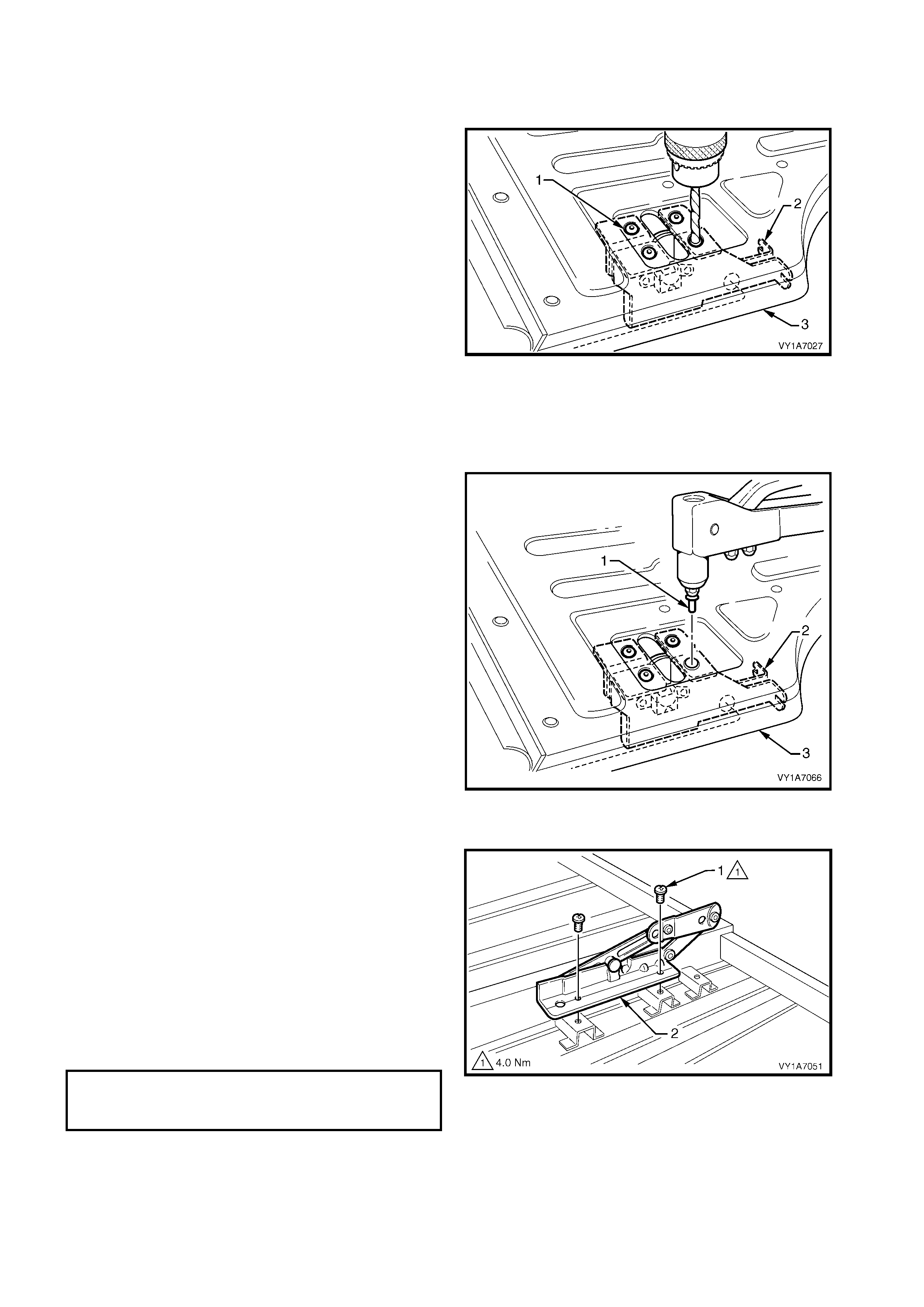
Remove – Rear Seat-back Frame Actuator
CAUTION: Safety glasses and work gloves must be
worn at all times when drilling.
1. From the rear of the seat-back, drill out the four
rivets (1) r etaining the actuator ass embly (2) to the
seat-back frame (3), using a 5mm drill bit.
2. Remove the actuator from the seat-back frame.
Figure 1A7-327
Reinstall – Rear Seat-back Frame Actuator
Reinstallation of the rear seat-back frame actuator is
the reverse of the removal procedure noting the
following:
1. Use four 4.5 mm (3/16) steel rivets (1), (not
aluminium) to retain the actuator assembly (2) to
the seat-back (3).
2. Ensure the actuator rod is aligned correctly.
Figure 1A7-328
Remove – Rear Seat-back Armrest Hinge, If Fitted
1. Remove the two screws (1) securing the hinge
assembly (2) to the seat-back frame assembly (3)
and remove the hinge assemblies.
2. Repeat for the opposite side.
Reinstall – Rear Seat-back Armrest Hinge
Reinstallation of the rear seat-back frame actuator is
the reverse of the removal procedure noting the
following:
1. Ensure the screws are tightened to the correct
torque specification:
Figure 1A7-329
ARMREST HINGES ASSEMBLY
RETAINING SCREW
TORQUE SPECIFICATION 4.0 Nm
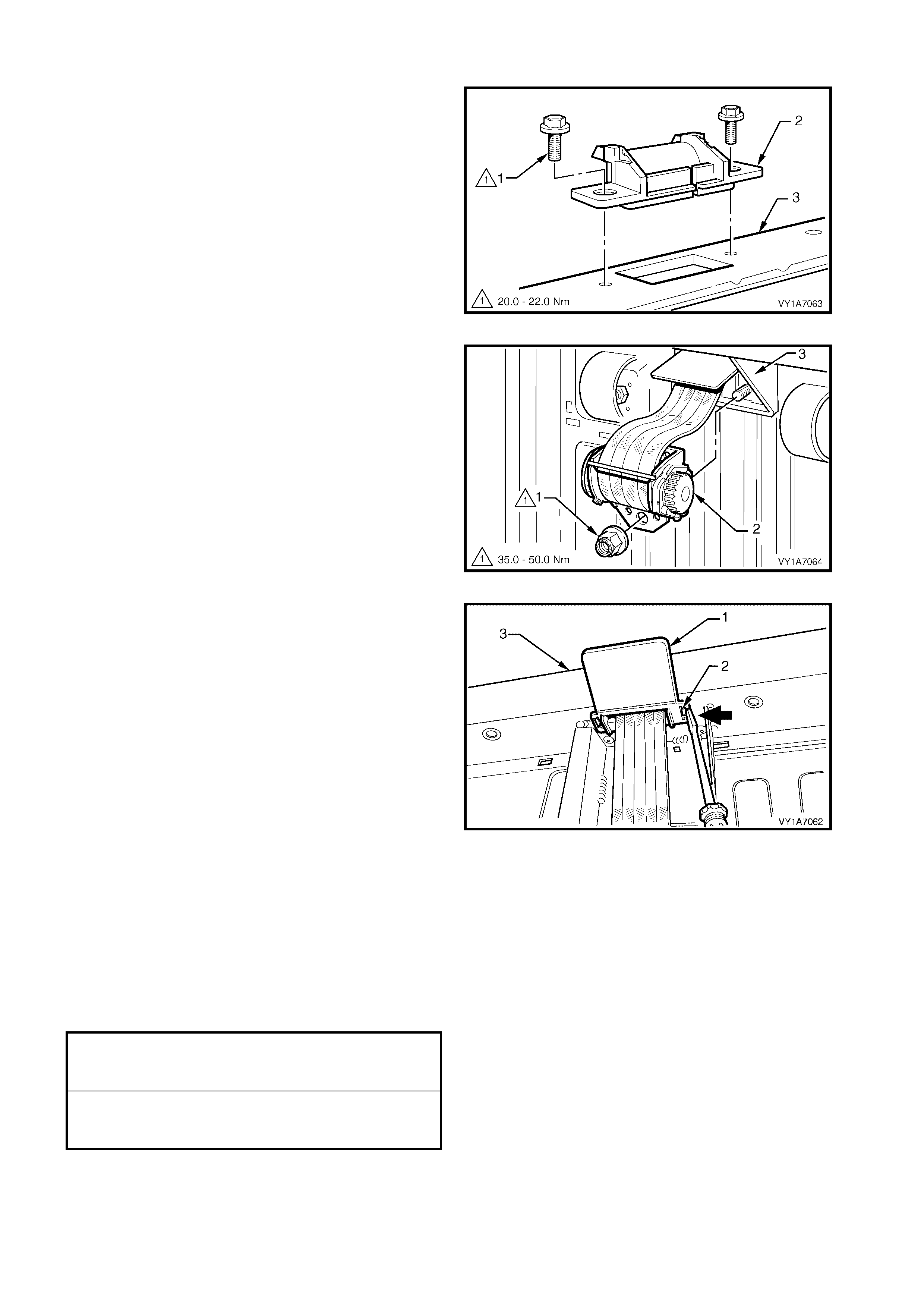
Remove – Rear Seat-back Seatbelt Retractor
1. Remove the two screws (1) securing the seatbelt
guide brack et (2) to the top of the s eat-back fram e
(3).
2. Remove seatbelt guide bracket by feeding the
seatbelt webbing through the slot in the seatbelt
guide bracket.
Figure 1A7-330
3. Remove the nut (1) retaining the s eat- belt retr actor
(2) to the rear seat-back frame (3).
4. Remove the seatbelt retractor from the seat-back
frame stud.
Figure 1A7-331
5. Remove the seatbelt retractor escutcheon (1) by
pushing in the tangs (2) and releasing it from the
seat-back frame (3).
6. Feed the seatbelt webbing through seat-back
frame and remove the retractor assembly.
NOTE: The seatbelt retractor will not function unless
the seat-back is in an upright position.
Figure 1A7-332
Reinstall – Rear Seat-back Seatbelt Retractor
Reinstallation of the rear seat-back seatbelt retainer is
the reverse of the removal procedure noting the
following:
1. Place the rear seat-back in an upright position
before installing the seatbelt retractor.
2. Ensure all fasteners are tightened to the correct
torque specification:
SEATBELT GUIDE BRACKET
RETAINING SCREW
TORQUE SPECIFICATION 20.0 – 22.0 Nm
SEATBELT RETRACTOR
RETAINING NUT
TORQUE SPECIFICATION 35.0 – 50.0 Nm

REINSTALL
Reinstallation of the rear seat-back assembly is the
reverse of the removal procedure, noting the following:
1. Install the rear seat-back in its lowered position.
2. Fold the rear seat into the upright position and the
locking plate and pin assembly will automatically
lock.
3. Check the function of the seat-back lock by
operating the seat-back lock at least three times
while observing the following:
• Ensure the locking pin on the centre lock
assembly engages fully with the rear seat-back
centre support assembly when it is in the lock
position.
• Ensure the release button, when in the lock
position, sits flush with the escutcheon.
4. Tighten all retaining screws to the correct torque
specification.
CENTRE REAR SEATBELT
ATTACHING BOLT
TORQUE SPECIFICATION 35.0 – 50.0 Nm
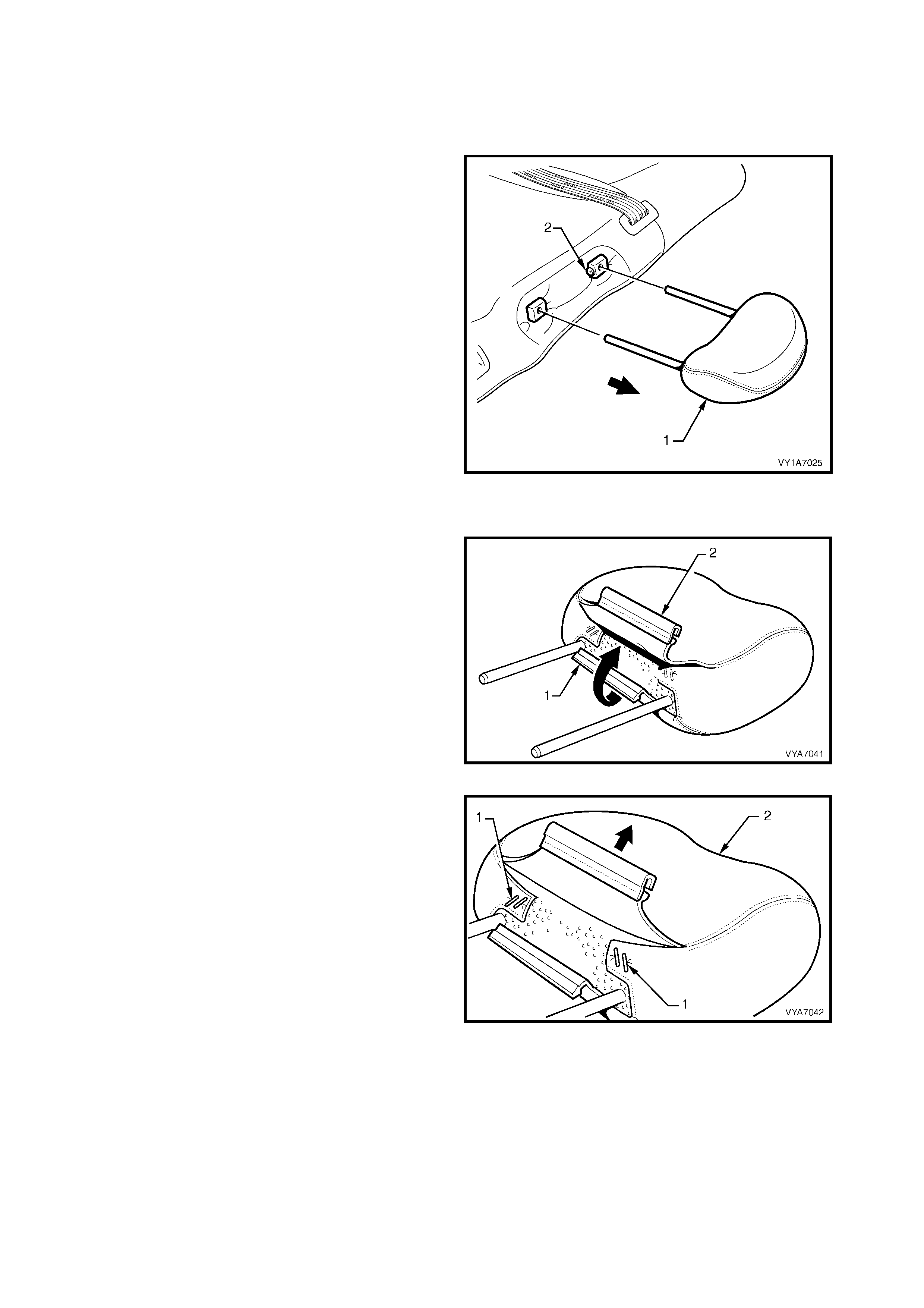
7.5 REAR SEAT-BACK HEAD RESTRAINT ASSEMBLY
LT Section No. – 14-350
REMOVE
1. Remove the head restraint (1) by depressing the
head restraint guide height adjuster lock (2), pull
the head restraint completely out of the guide.
Figure 1A7-333
DISASSEMBLE
1. Disengage the rear head restraint cover J-strip (1)
by pulling the flap (2) up.
Figure 1A7-334
2. Remove the f our staples (1) r etaining the cover ( 2)
to the head restraint pad assembly (3).
3. Remove the cover from the pad assembly.
Figure 1A7-335
REASSEMBLE
Reassembly of the rear seat-back head restraint assembly is the reverse of the removal procedure, noting the
following:
1. Ensure the head restraint cover retaining clip is fully engaged.
REINSTALL
Reinstallation of the rear seat-back head restraint is the reverse of the removal procedure.
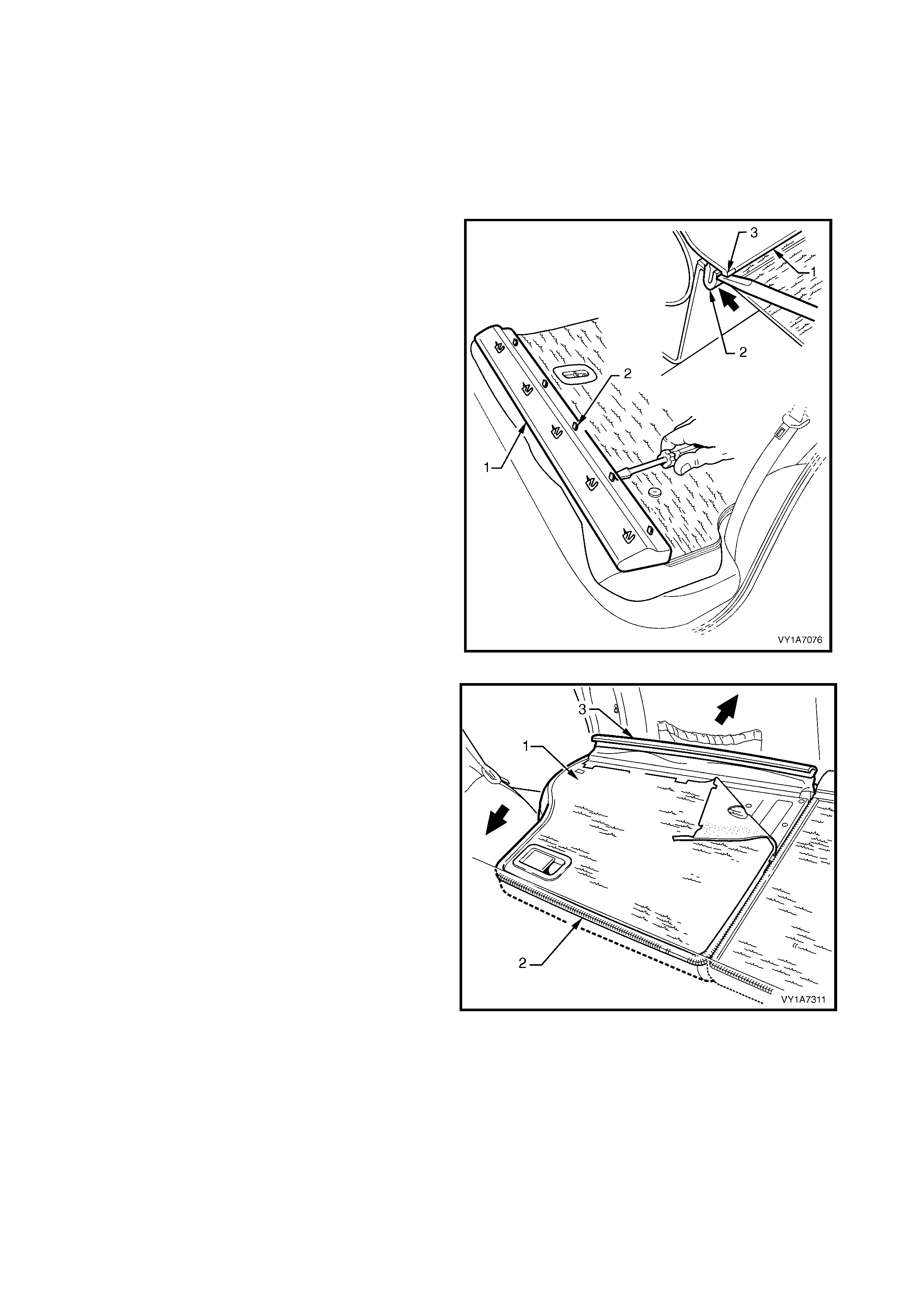
7.6 REAR SEAT-BACK HEAD RESTRAINT GUIDE
LT Section No. – 14-350
1. Remove the rear seat-back head restraint assembly, refer to 7.5 REAR SEAT-BACK HEAD RESTRAINT
ASSEMBLY.
2. Unlatch and lower the rear seat-back assembly.
REMOVE
1. Carefully rem ove the rear s eat-back tr im cover ( 1),
by inserting a small screwdriver at the tab (2)
position, highlighted by small polished areas (3).
Push in to disengage the retaining tabs (3) five
places on the left-hand seat and three places on
the right-hand seat.
2. Start at one end to disengage the cover away f rom
the seat-back and work your way along until all
retaining tabs have been disengaged.
NOTE: Care must be taken not to break the lower
retaining tabs from the rear seat-back trim cover,
otherwise a replacement part will be required.
Figure 1A7-336
3. Partly remove the rear seat-back cover (1), unzip
(2) the cover down one side of the rear seat-back.
4. Pull the outer top finisher strip (3) from the rear
seat-back frame.
NOTE: T o ease in the r emoval of the top finisher s trip,
gently lever the strip away from the frame using a
screwdriver.
Figure 1A7-337
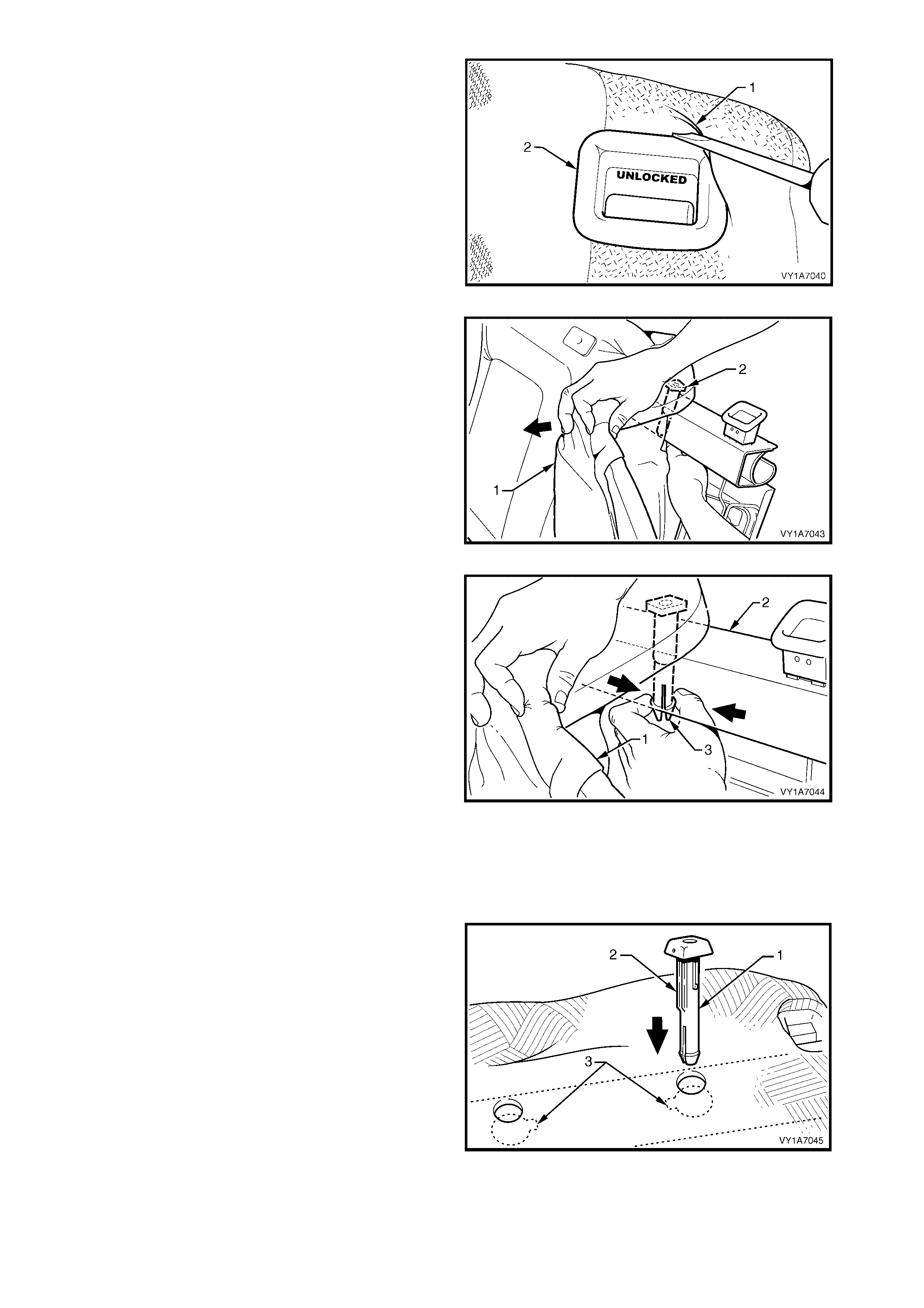
5. Lever the cover and pad assembly (1) over the
release button (2).
Figure 1A7-338
6. Pull the top corner of the cover and pad assem bly
(1) down to allow for the removal of the two head
restraint guides (2).
Figure 1A7-339
7. While holding the cover and pad assembly (1),
reach in between the seat-back frame (2) and the
pad assembly.
8. Squeeze the head restraint guide locating prongs
(3) together and remove the guide up and out of
the seat-back assembly.
9. Repeat this process for the remaining head
restraint guide.
Figure 1A7-340
REINSTALL
Reinstallation of the rear seat head restraint guide is
the reverse of the removal procedure, noting the
following:
1. When installing the head restraint guide (1), align
the locating ribs (2) with the key-way (3) in the
seat-back frame.
NOTE: Ensure the guide with the height adjuster lock
is installed on the s ide that corresponds to the notches
in the head restraint shaft.
Figure 1A7-341
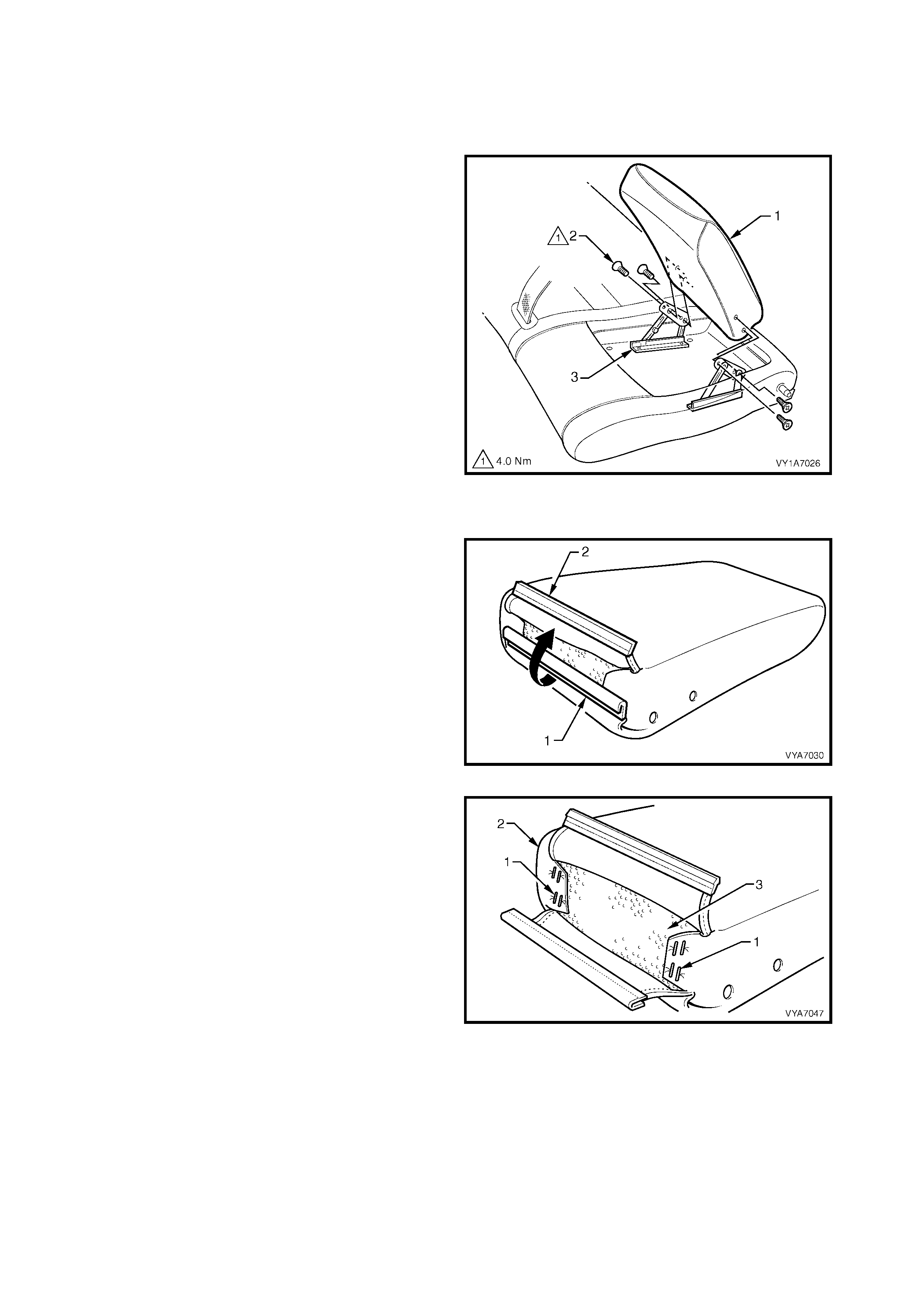
7.7 REAR SEAT-BACK ARMREST ASSEMBLY
LT Section No. – 14-350
REMOVE
1. Partially open the rear seat-back armrest assembly
(1).
2. Remove the four screws (2) securing the armrest
assembly to the armrest hinge assembly (3).
3. Remove the rear seat-back armrest assembly.
Figure 1A7-342
DISASSEMBLE
1. Disengaging the rear seat-back armrest cover
retaining strip (1) by pulling the flap (2) up.
Figure 1A7-343
2. Remove the eight s taples (1) retaining the arm rest
cover (2) to the armrest pad (3).
3. Slide the armrest cover off the armrest pad.
Figure 1A7-344
REASSEMBLE
Reassembly of the rear seat-back armrest assembly is the reverse of the removal procedure, noting the
following:
1. Ensure the rear seat-back armrest retaining clip is fully engaged.

REINSTALL
Reinstallation of the rear seat-back armrest assembly is the reverse of the removal procedure noting the
following:
1. Tighten all retaining screws to the correct torque specification.
REAR SEAT BACK ARMREST
ASSEMBLY RETAINING SCREW
TORQUE SPECIFICATION 4.0 Nm
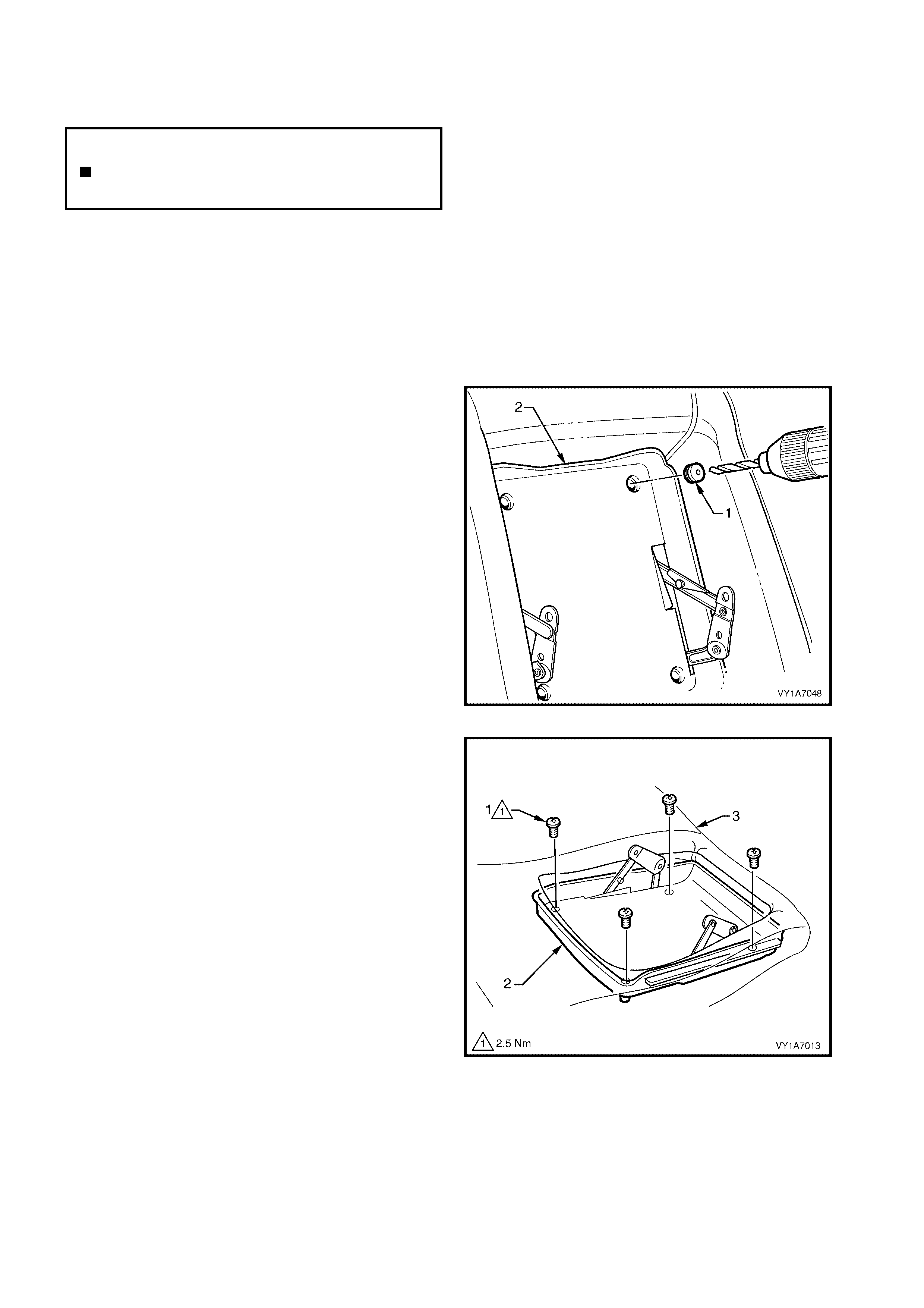
7.8 REAR SEAT-BACK ARMREST HINGE ASSEMBLY AND CENTRE COVER
LT Section No. – 14-350
1. Remove the rear seat cushion assembly, refer to 7.2 REAR SEAT CUSHION ASSEMBLY.
2. Remove the left-hand rear seat bolster assembly, refer to 7.3 REAR SEAT BOLSTER ASSEMBLY.
3. Remove the left-hand rear seat-back assembly, refer to 7.4 REAR SEAT-BACK ASSEMBLY
4. Remove the left-hand rear seat-back head restraint assembly, refer to 7.5 REAR SEAT-BACK HEAD
RESTRAINT ASSEMBLY.
5. Remove the rear seat-back armrest assembly, refer to 7.7 REAR SEAT-BACK ARMREST ASSEMBLY.
REMOVE
1. To remove the four blanking plugs (1) from the
rear seat-back armrest centre cover (2), drill a
small hole into the centre of each plug.
2. Inser t a s cribe or sm all sc rewdriver into the hole in
the plug and pull them free. Take care not to
damage the seat-back cover.
NOTE: The four blanking plugs will be damaged during
this operation and must be replaced.
Figure 1A7-345
3. Remove the four screws (1) securing the armrest
centre cover (2) to the seat-back pad and frame
assembly (3).
Figure 1A7-346
N
O
TE: The
f
ollowing component WILL RE
Q
UIRE
REPLACEMENT when performing this operation.
Rear seat-back armrest centre cover blanking
plugs.
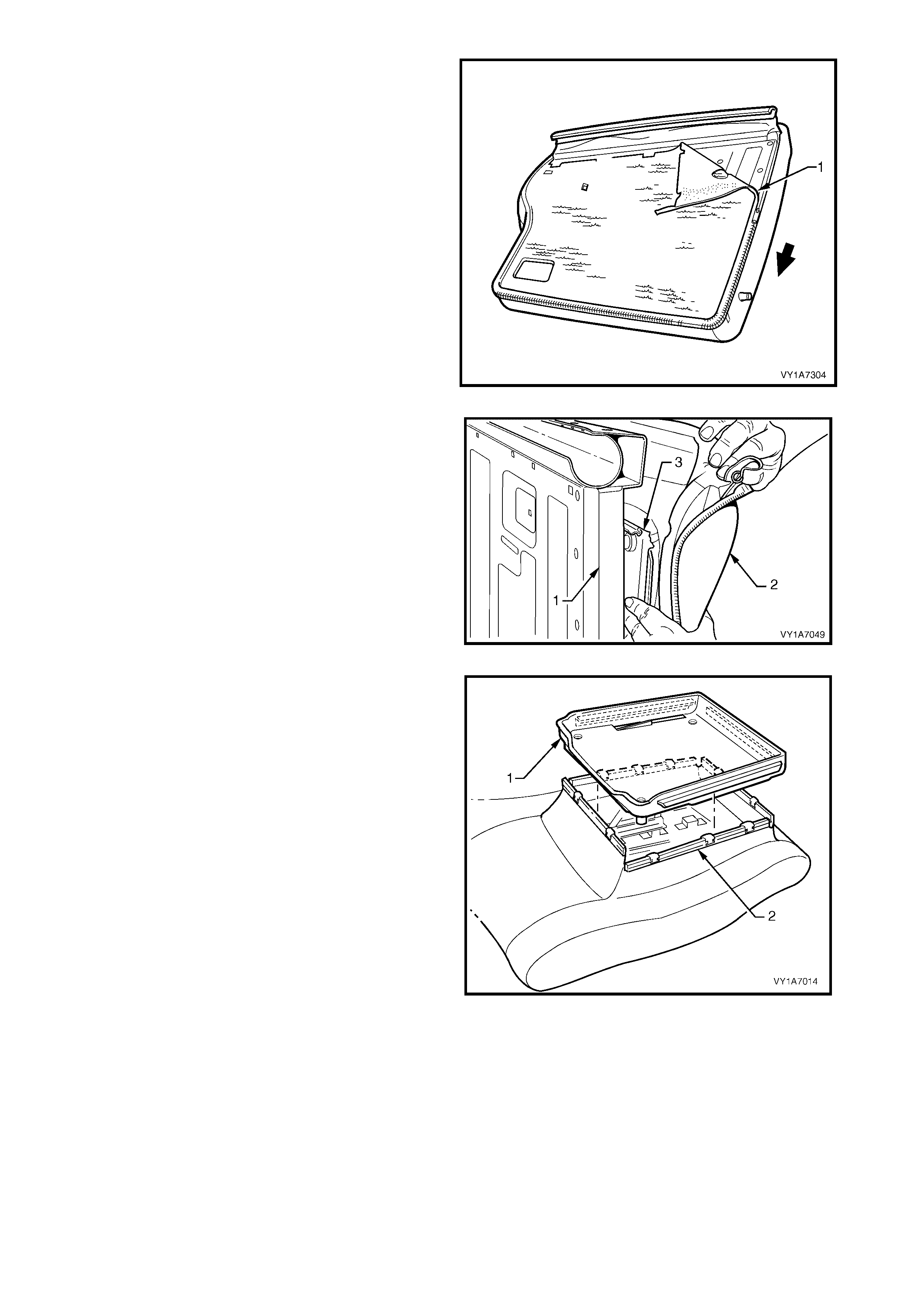
4. Remove the rear seat-back cover (1) from the
rear, by un-zipping the cover around two sides of
the rear seat-back assembly.
5. Pull the outer top finisher strip (3) from the rear
seat-back frame.
NOTE: To ease in the r emoval of the top J- s trip, gently
lever the strip away from the frame using a
screwdriver.
Figure 1A7-347
6. Reach in between the seat-back fram e (1) and the
pad assembly (2) and push the armrest centre
cover (3) out of the pad.
Figure 1A7-348
7. Lift the armrest centre cover (1) up and pull the
four seat-back cover retainers (2) away from the
four sides of the centre cover.
8. Remove the armrest centre cover.
Figure 1A7-349
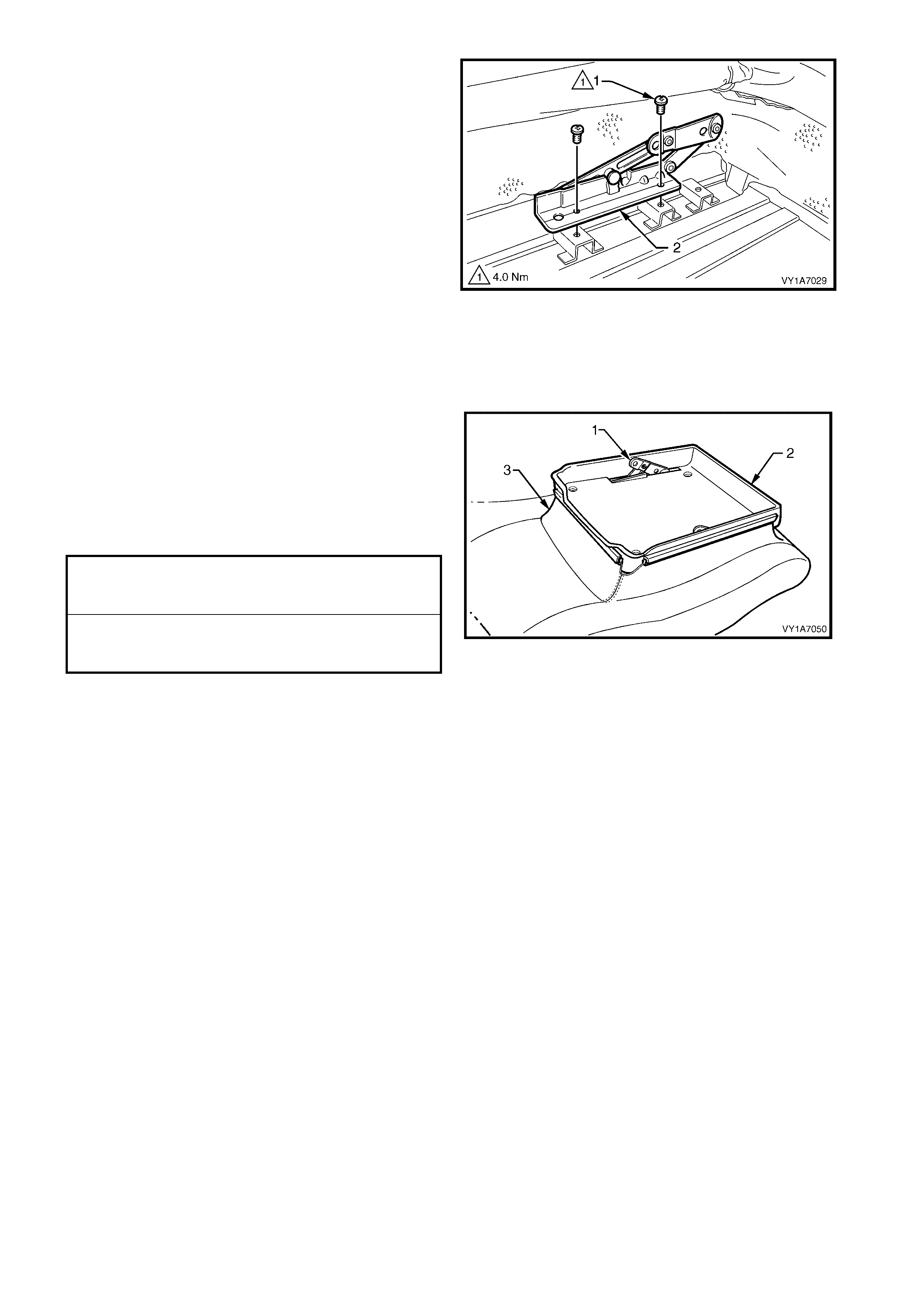
9. Remove the two screws (1) securing the hinge
assembly, to the seat-back frame assembly (2)
and remove the hinge assembly.
10. Repeat for the opposite side.
Figure 1A7-350
REINSTALL
Reinstallation of the rear seat-back armrest hinge
assembly and centre cover is the reverse of the
removal procedure noting the following:
1. Have the hinges (1) in the partly open position
before installing the centre cover (2).
2. Ensure no puckering occurs around the rear seat-
back armrest cover (3) while installing the centre
cover.
3. Tighten all retaining screws to the correct torque
specification.
4. Use four new centre cover blanking plugs, refer
Figure 1A7-345.
Figure 1A7-351
ARMREST CENTRE COVER
RETAINING SCREW
TORQUE SPECIFICATION 2.5 Nm
ARMREST HINGES ASSEMBLY
RETAINING SCREW
TORQUE SPECIFICATION 4.0 Nm
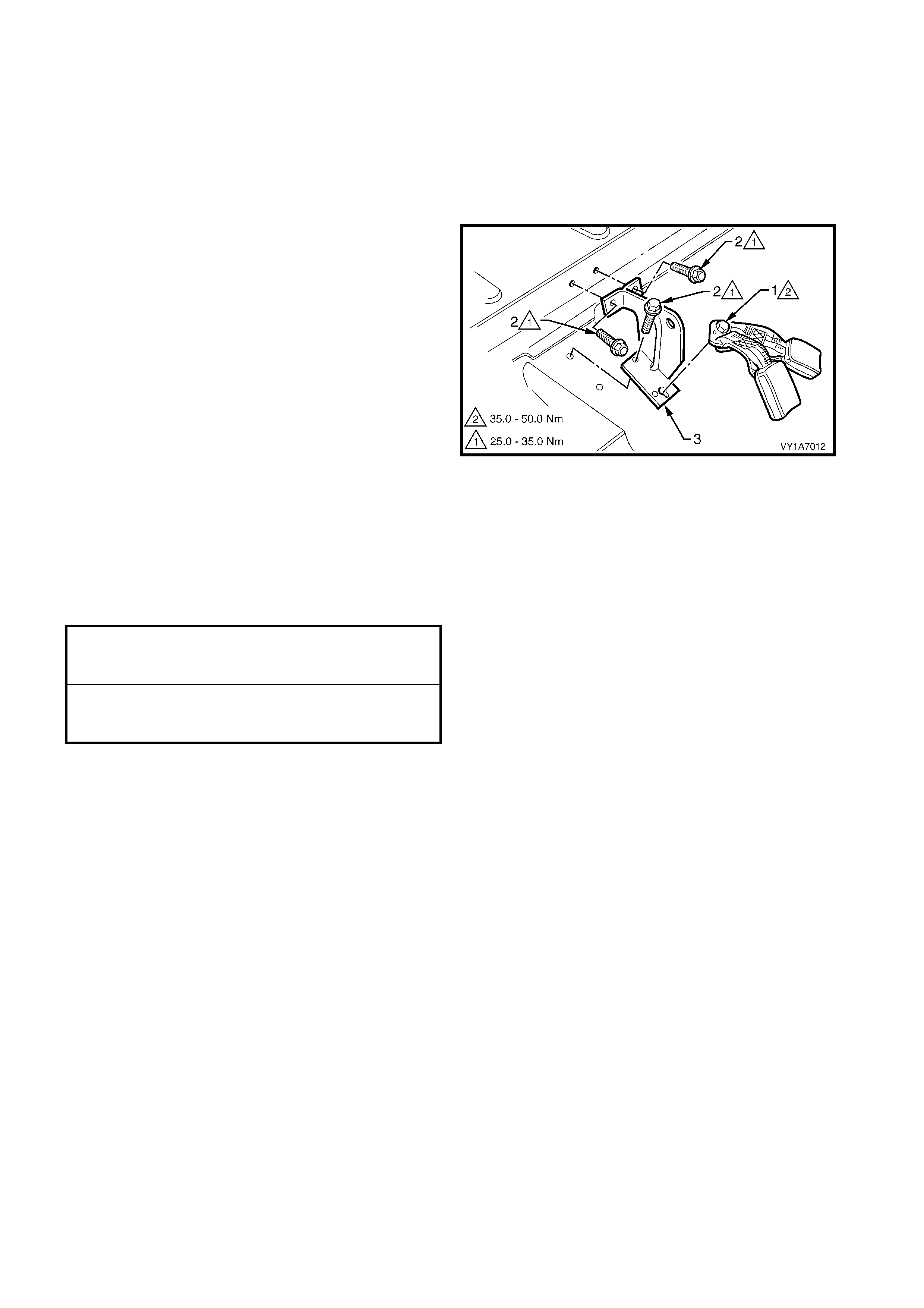
7.9 REAR SEAT CENTRE SUPPORT
LT Section No. – 14-350
1. Remove the rear seat cushion assembly, refer to 7.2 REAR SEAT CUSHION ASSEMBLY.
2. Remove the rear seat bolsters assembly, refer to 7.3 REAR SEAT BOLSTER ASSEMBLY.
3. Remove the rear seat-back assembly, refer to 7.4 REAR SEAT-BACK ASSEMBLY.
REMOVE
1. Rem ove the right-hand and centre seatbelt buckle
assembly anchor bolt (1).
2. Remove the three screws (2) securing the rear
seat centre support (3) to the floor pan.
3. Remove rear seat centre support.
Figure 1A7-352
REINSTALL
Reinstallation of the rear seat-back centre support is
the reverse of the removal operation, noting the
following:
Ensure all bolts are fastened to the correct torque
specifications
REAR SEAT CENTRE SUPPORT
RETAINING SCREW
TORQUE SPECIFICATION 25.0 – 35.0 Nm
SEATBELT ANCHOR
RETAINING BOLT
TORQUE SPECIFICATION 35.0 – 50.0 Nm
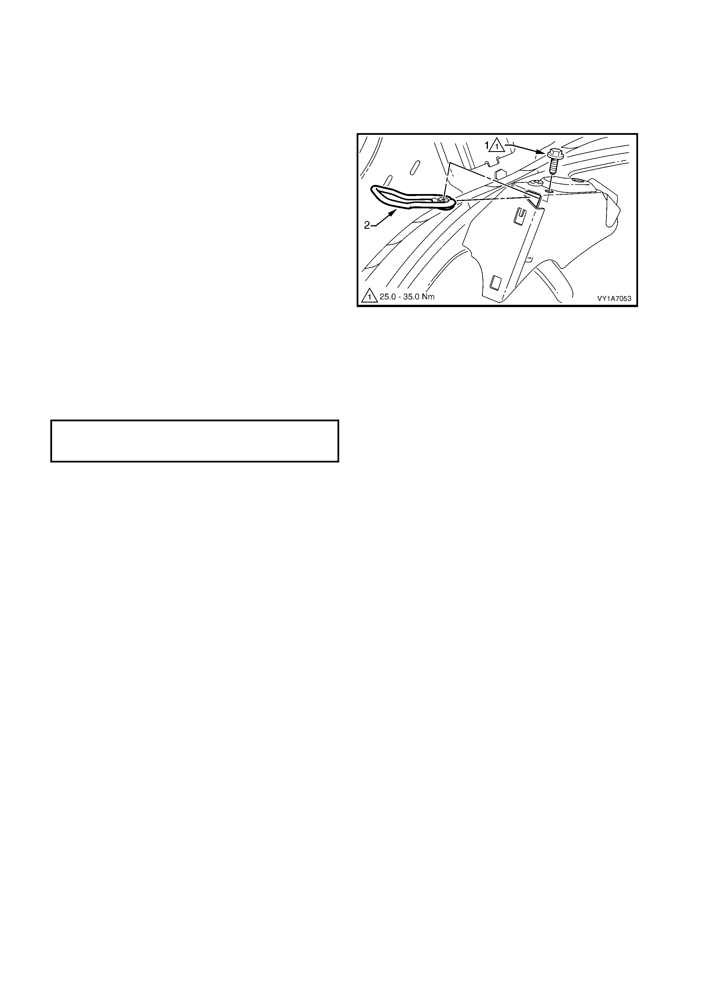
7.10 REAR SEAT-BACK LOCK STRIKER
1. Remove quarter inner trim panel assembly, refer to Section 1A8, 3.11 QUARTER INNER TRIM PANEL
ASSEMBLY.
REMOVE
1. Remove the screw (1) sec uring the rear seat-back
lock striker (2) to the rear quarter inner panel.
2. Remove the striker.
Figure 1A7-353
REINSTALL
Reinstallation of the rear seat-back lock striker is the
reverse of the removal procedure noting the following:
Ensure all fas teners ar e tightened to the correc t torque
specifications.
SEAT BACK LOCK STRIKER
RETAINING SCREW
TORQUE SPECIFICATION 25.0 – 35.0 Nm
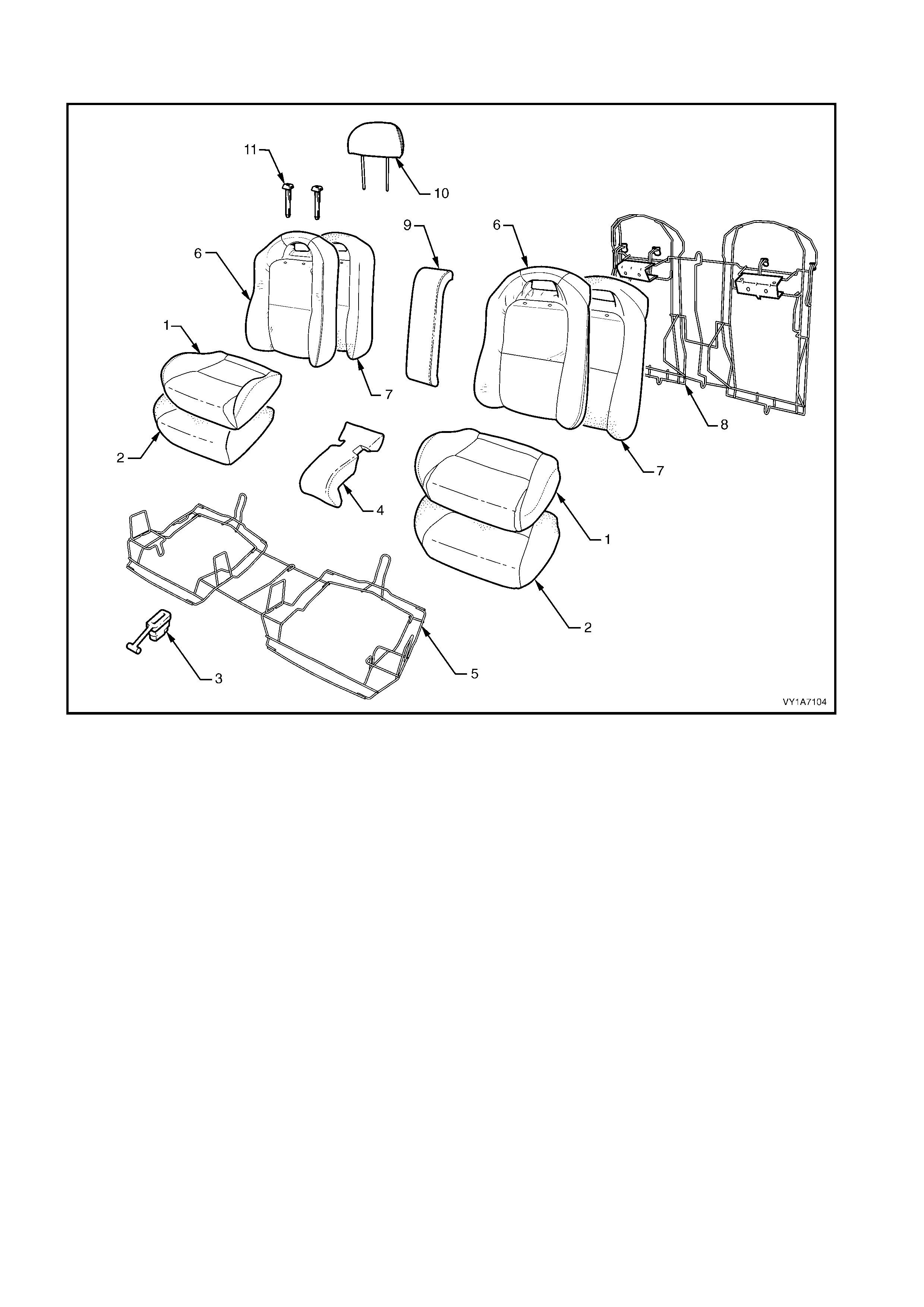
8. SERVICE OPERATIONS - REAR SEAT, COUPE
Figure 1A7-354
Legend
1. Rear Seat Cushion Cover- 2 Places
2. Rear Seat Cushion Pad - 2 Places
3. Rear Seat Cushion Release Handle - 2 Places
4. Rear Seat Cushion Centre Escutcheon
5. Rear Seat Cushion Frame
6. Rear Seat-back Cover - 2 Places
7. Rear Seat-back Pad - 2 Places
8. Rear Seat-back Frame
9. Rear Seat-back Centre Escutcheon
10. Head Restraint - 1 Place each side
11. Head Restraint Guide - 2 Places each side
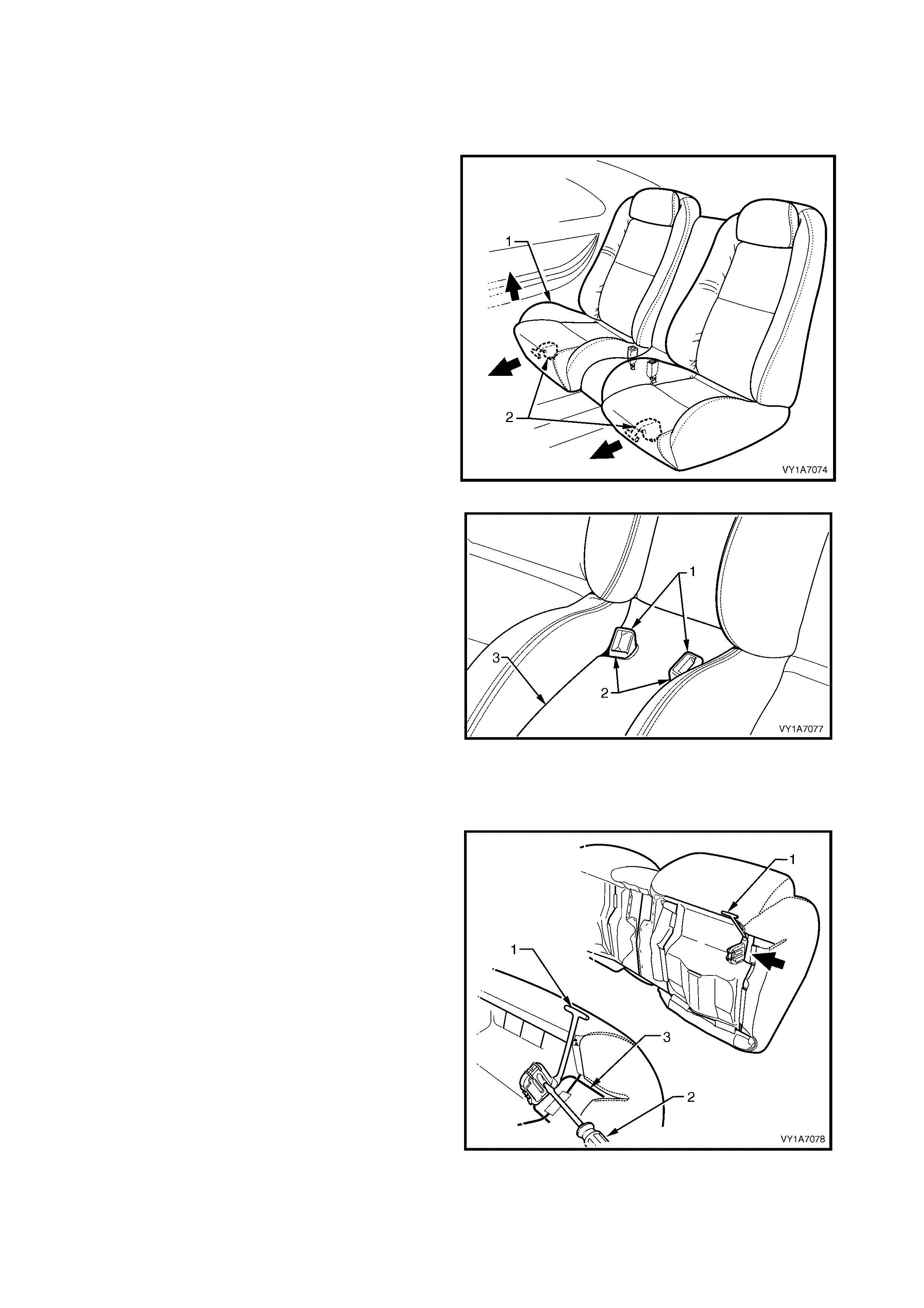
8.1 REAR SEAT CUSHION ASSEMBLY
LT Section No. – 14-325
REMOVE
1. Lift the front of the rear seat cushion assembly (1)
slightly to gain access to the rear seat cushion
release handles (2).
2. From either the left or the right side of the seat,
pull the release handle T-piece horizontally
outwards, while at the sam e tim e lifting the f ront of
the rear seat cushion until the lock mechanism is
released.
3. Repeat step 2 for the opposite side of the seat.
Figure 1A7-355
4. Manoeuvre the two seatbelt buckles (1) through
the two slots (2) in the rear seat c entr e esc utc heon
(3).
5. By lifting the front of the rear seat cushion
assembly, the rear of the frame will disengage
from the rear seat-back frame.
6. Remove the rear seat cushion assembly.
Figure 1A7-356
DISASSEMBLE
Remove – Rear Seat Cushion Release Handle
1. Remove the rear seat cushion release handle (1)
by inserting a screwdriver to disengage the
retaining lugs.
2. Slide the release handle off the rear seat cushion
wire frame (2).
Figure 1A7-357
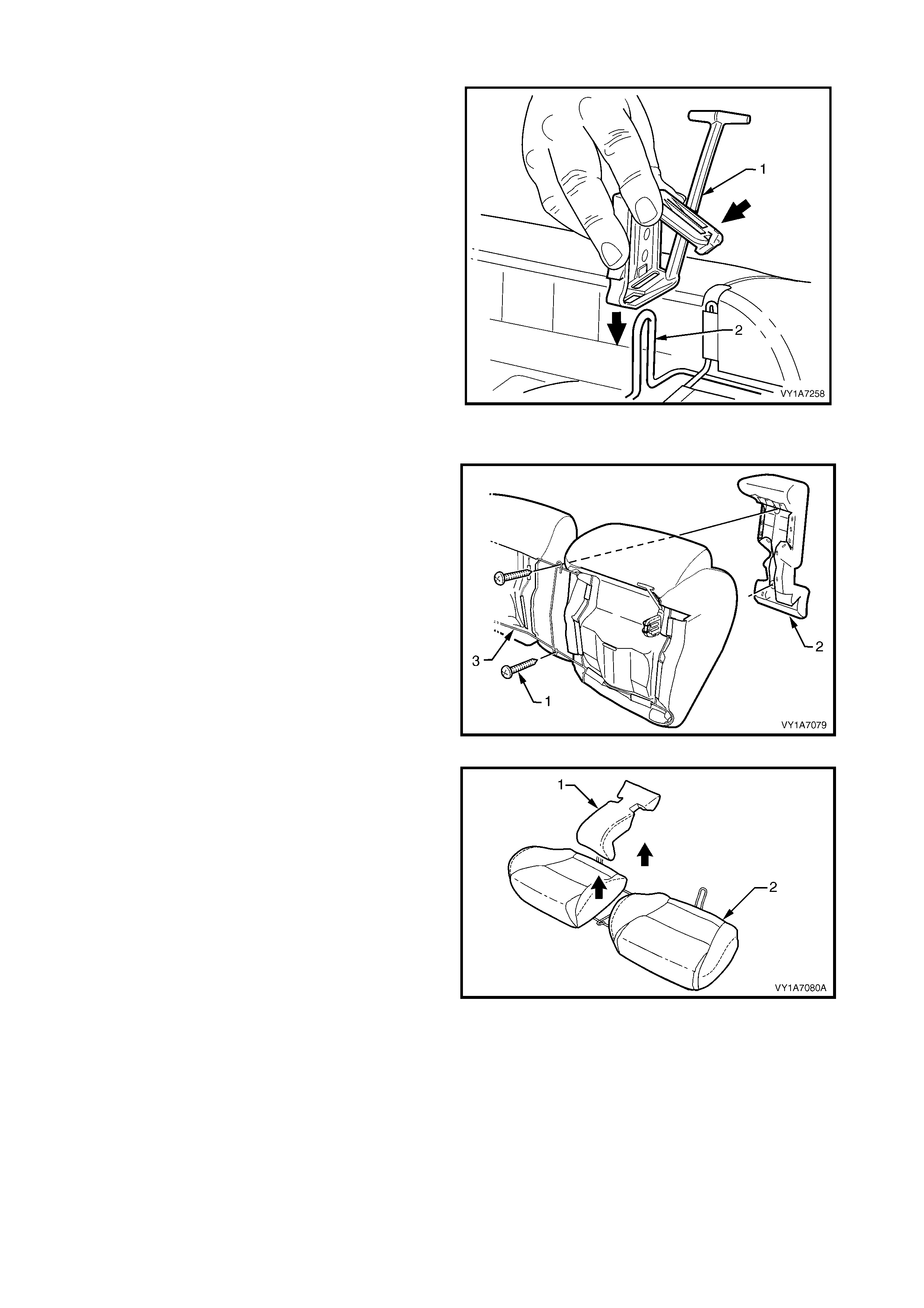
Reinstall – Rear Seat Cushion Release Handle
1. Slide the rear seat cus hion release handle ( 1) onto
the rear seat cushion wire fram e (2) and close the
cover so that it will lock into position on the frame.
Figure 1A7-358
Remove – Rear Seat Cushion Centre Escutcheon
1. Rem ove the two scr ews (1) attaching the r ear seat
cushion centre escutcheon (2) to the rear seat
cushion frame (3).
Figure 1A7-359
2. Remove the rear seat cushion centre escutcheon
(1) from the rear seat cushion assembly (2).
Reinstall – Rear Seat Cushion Centre Escutcheon
Reinstallation of the rear seat cushion centre
escutcheon is the reverse of the removal procedure
noting the following:
1. Ensure all screws are tightened securely.
Figure 1A7-360
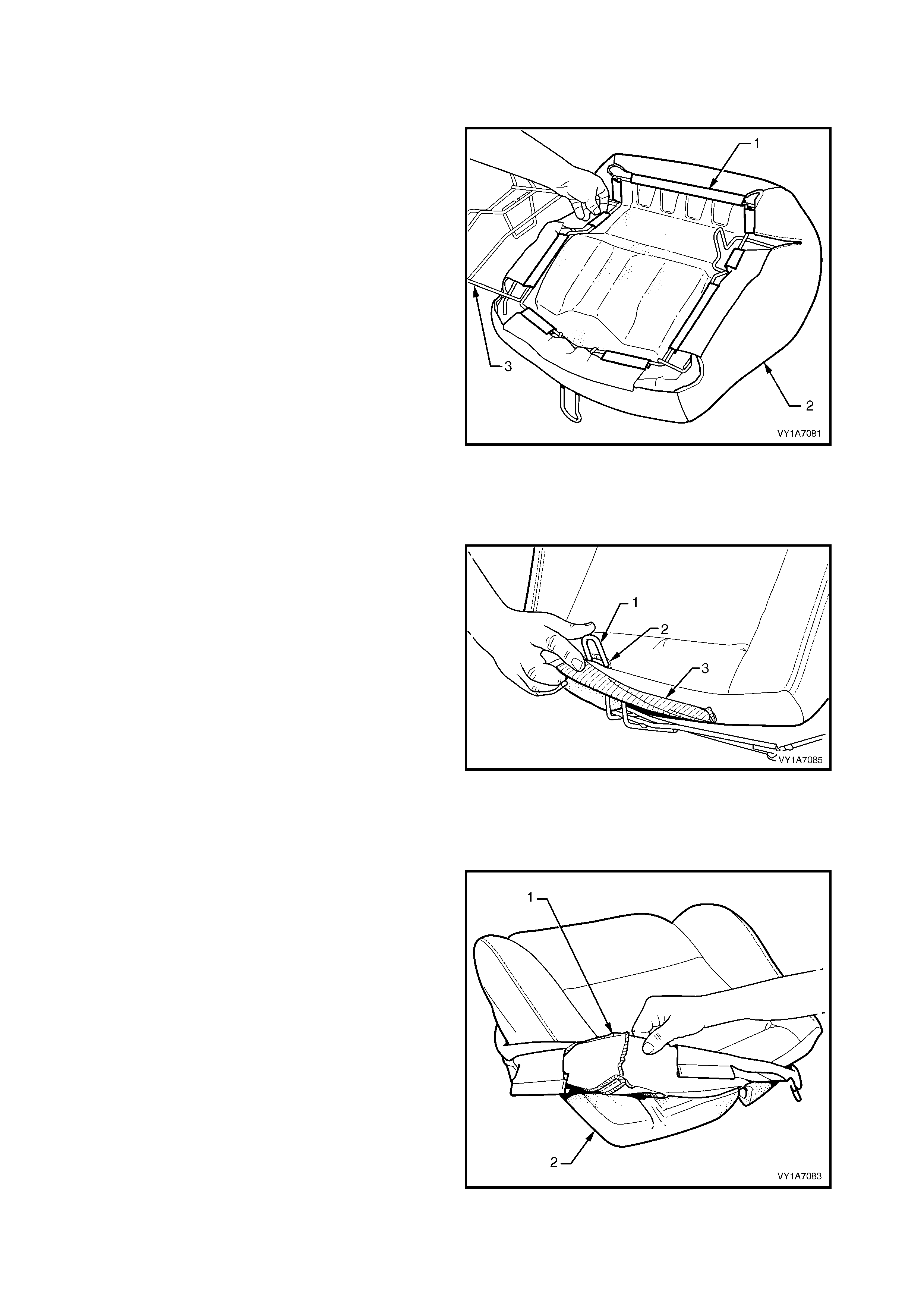
Remove – Rear Seat Cushion Cover and Pad Assembly
NOTE: The following procedures are applicable to
both left and right-hand rear seat cushion assemblies.
1. With the rear seat cushion assembly up side
down, unclip the nine retainers (1) attaching the
rear seat cushion cover (2) to the frame (3).
2. Remove the cover and pad assembly from the
frame.
3. Repeat for the opposite side as required.
Figure 1A7-361
Reinstall – Rear Seat Cushion Cover and Pad Assembly
Reinstallation is the reverse of the removal procedure
noting the following:
1. Before attaching the cushion assembly to the
frame, fit the leg of the seat frame (1) through the
slot (2) provided in the rear of the seat cushion
cover (3).
Figure 1A7-362
Remove – Rear Seat Cushion Cover
NOTE: The following procedures are applicable to
both left and right-hand rear seat cushion assemblies.
1. Fold the rear corners of the rear seat cushion
cover (1) over the seat cushion pad (2).
Figure 1A7-363
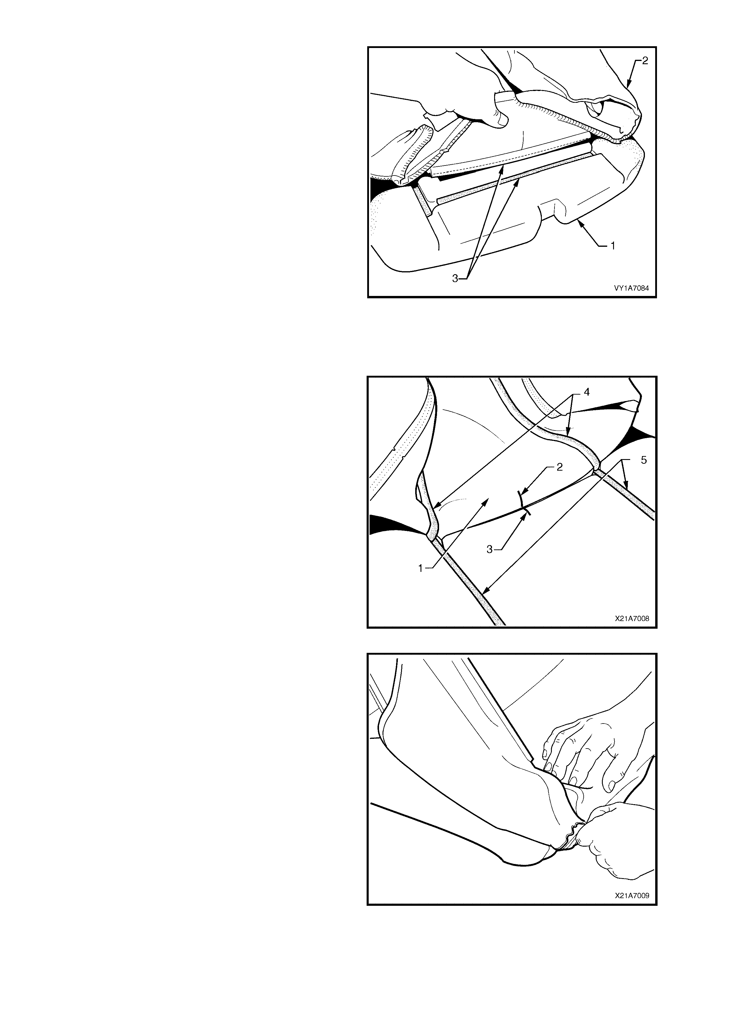
2. While holding the rear seat cushion pad (1), pull
the rear corners of the seat cushion cover (2)
forwards and away from the rear seat cushion pad
to disengage the hook and loop strips (3).
3. Pull the rear seat cover up and over the forward
edge of the rear seat cushion pad and remove.
Figure 1A7-364
Reinstall – Rear Seat Cushion Cover
Reinstallation of the rear seat c ushion is the reverse of
the removal procedure noting the following:
1. With the seat cushion cover (1) folded at the
central horizontal strip of hook and loop, align the
centre mark (2) on the rear seat cushion cover
with the centre mark (3) on the seat cushion pad.
2. Press the folded edge of the rear seat cushion
cover firmly into the corresponding groove in the
seat cushion pad to engage the hook and loop.
3. With the s eat c over f olded at the two vertical s trips
of hook and loop (4), press the seat-back cover
firmly into the corresponding grooves (5) in the
seat cushion pad.
Figure 1A7-365
4. Roll the front corners of the rear seat cushion
cover over the seat cushion pad.
5. Roll the sides of the seat cushion cover over the
seat cushion pad.
6. Roll the rear corners of the seat cushion cover
over the seat cushion pad.
NOTE : Make sure the pad is f itted neatly by hand into
all corners and contours of the seat cover.
TIP: Do not pull the cover onto the pad from
underneath using the J- st rip to mak e it f it neatly, as the
fabric may be damaged.
Figure 1A7-366
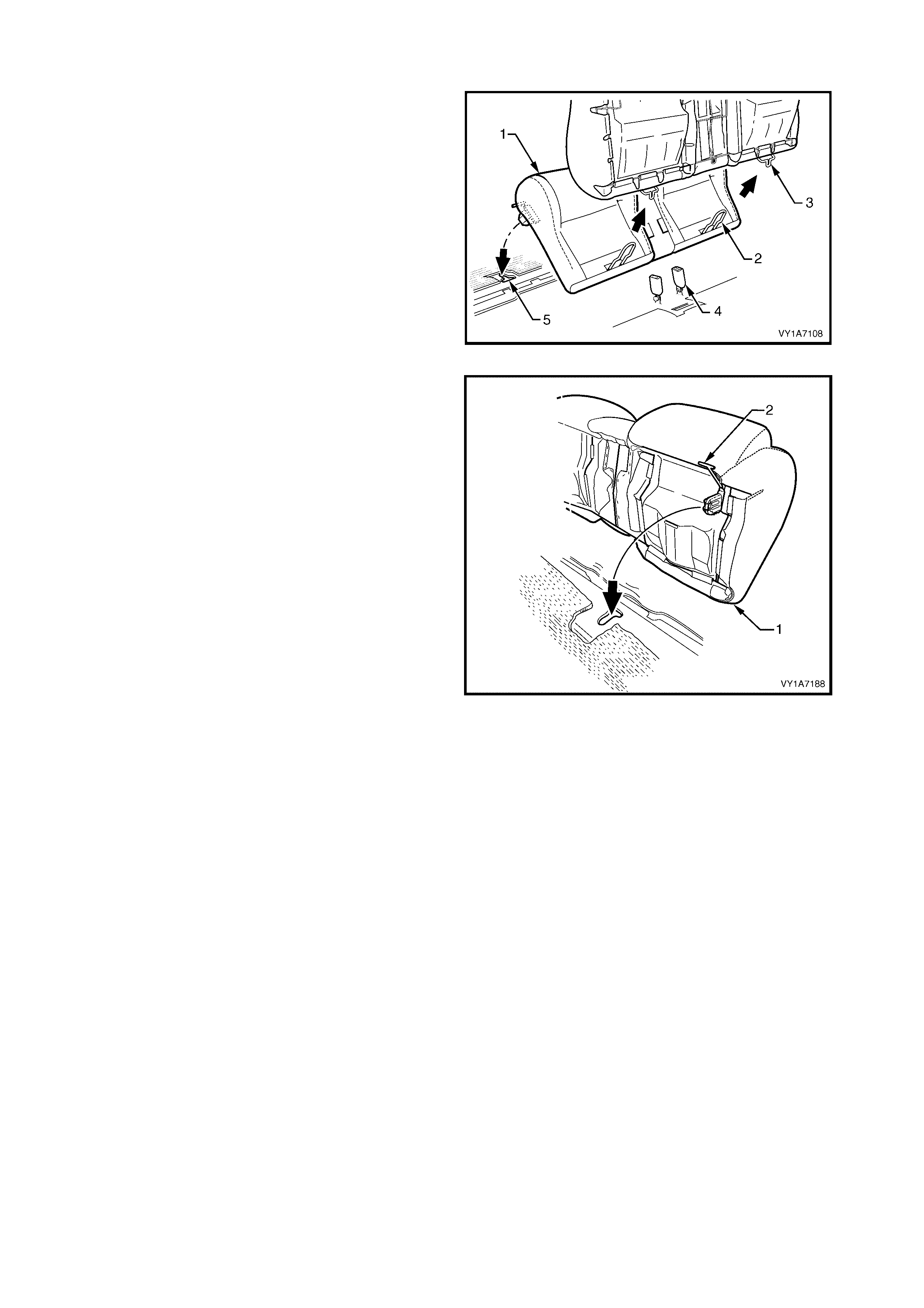
REINSTALL
1. Sit the rear seat cushion (1) into position allowing
the frame legs (2) to slide up under the rear seat-
back (3).
2. F eed the seatbelt buck les ( 4) through the two slots
in the centre escutcheon.
Figure 1A7-367
3. Push the rear s eat cushion (1) into the back of the
seat and push down the front of the seat until the
locking mechanisms (2) lock the seat cushion into
position.
Figure 1A7-368
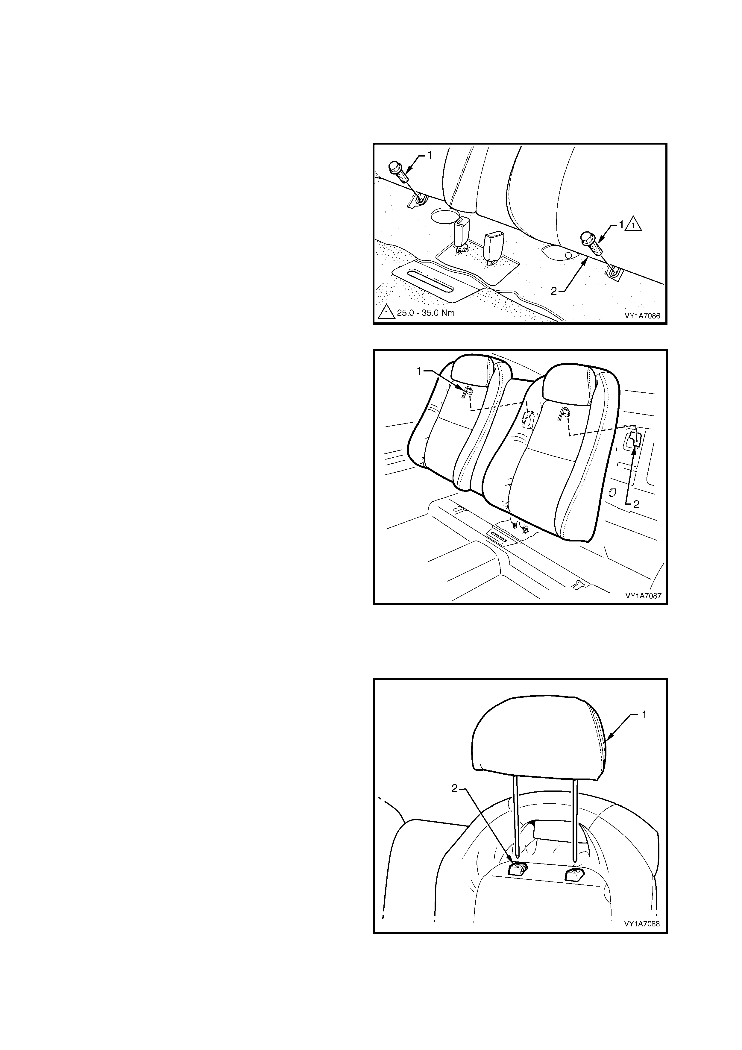
8.2 REAR SEAT-BACK ASSEMBLY
LT Section No. – 14-350
1. Remove the rear seat cushion assembly, refer to 8.1 REAR SEAT CUSHION ASSEMBLY.
REMOVE
1. Rem ove the two sc rews (1) s ecuring the rear seat-
back assembly (2) to the rear floor pan.
Figure 1A7-369
2. Lift the rear seat-back assembly up until the seat-
back retaining hooks (1) release from the retaining
slots (2) in the rear compartment front panel.
3. Remove the rear seat-back assemblies.
Figure 1A7-370
DISASSEMBLE
Remove – Rear Seat-back Head Restraint
1. Remove the head restraint (1), by depressing the
head restraint guide height adjuster lock (2), pull
the head restraint completely out of the guide.
Reinstall – Rear Seat-back Head Restraint
Reinstallation of the head restraints into the rear seat-
back assembly is the reverse of the removal
procedure.
Figure 1A7-371
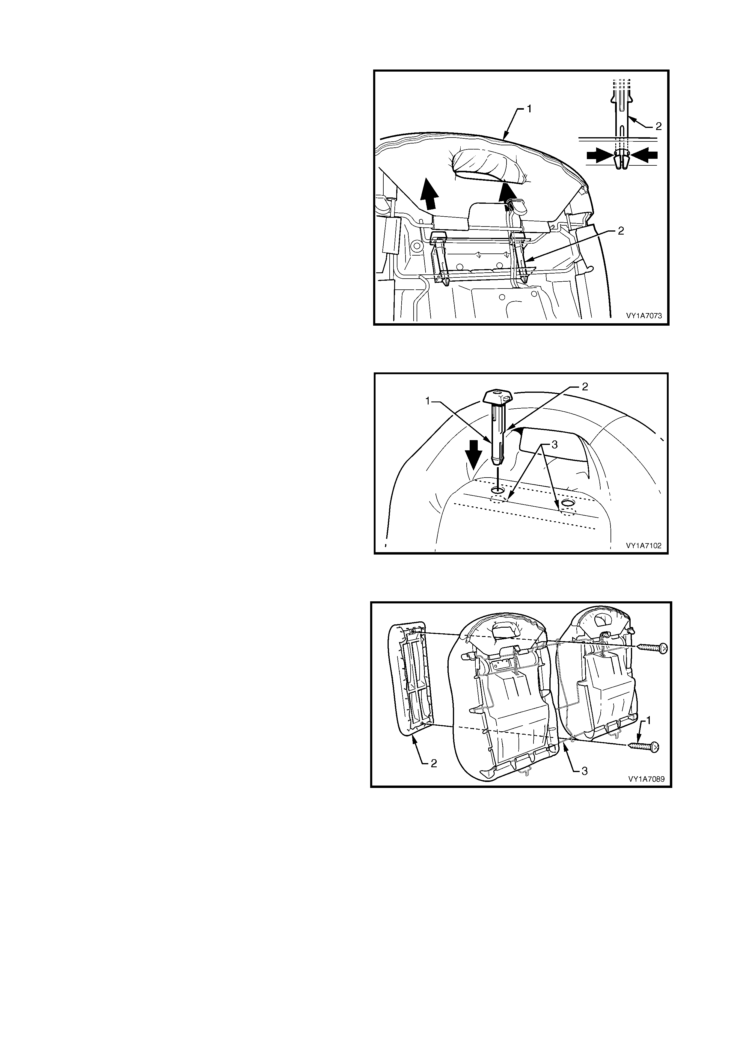
Remove – Rear Seat-back Head Restraint Guide
1. From the rear side of the rear seat-back (1),
squeeze the locking prongs of the head restraint
guide (2) together while pulling the top of the guide
out of the seat-back assembly.
Figure 1A7-372
Reinstall – Rear Seat-back Head Restraint Guide
1. When installing the head restraint guide (1),
ensure the locating slots (2) in the seat-back align
with key-way (3) on the head restraint guide.
Figure 1A7-373
Remove – Rear Seat-back Centre Escutcheon
1. Remove the two screws (1) attaching the rear
seat-back centre escutcheon (2) to the rear seat-
back frame (3).
Figure 1A7-374
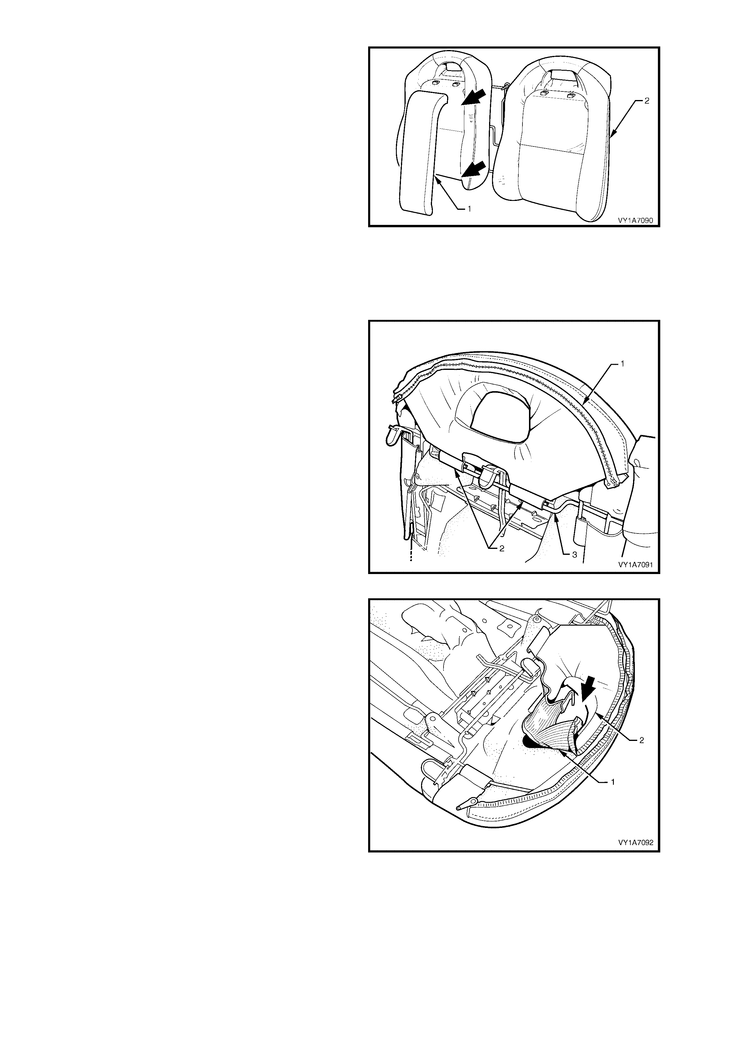
2. Remove the rear seat-back centre escutcheon (1)
from the rear seat-back assembly (2).
Reinstall – Rear Seat-back Centre Escutcheon
Reinstallation of the rear seat-back centre escutcheon
is the reverse of the removal procedure noting the
following:
1. Ensure all retaining screws are tightened securely.
Figure 1A7-375
Remove – Rear Seat-back Cover and Pad Assembly
NOTE: The following procedures are applicable to
both left-hand and right-hand rear seat-back
assemblies.
1. Completely unzip the rear seat-bac k cover f lap (1),
located behind the head restraint.
2. Unclip the two retainers (2) attac hing the rear seat-
back cover (2) to the frame (3).
Figure 1A7-376
3. T uck the r ear seat-back cover f lap (1), through the
opening in the rear seat-back pad (2).
Figure 1A7-377
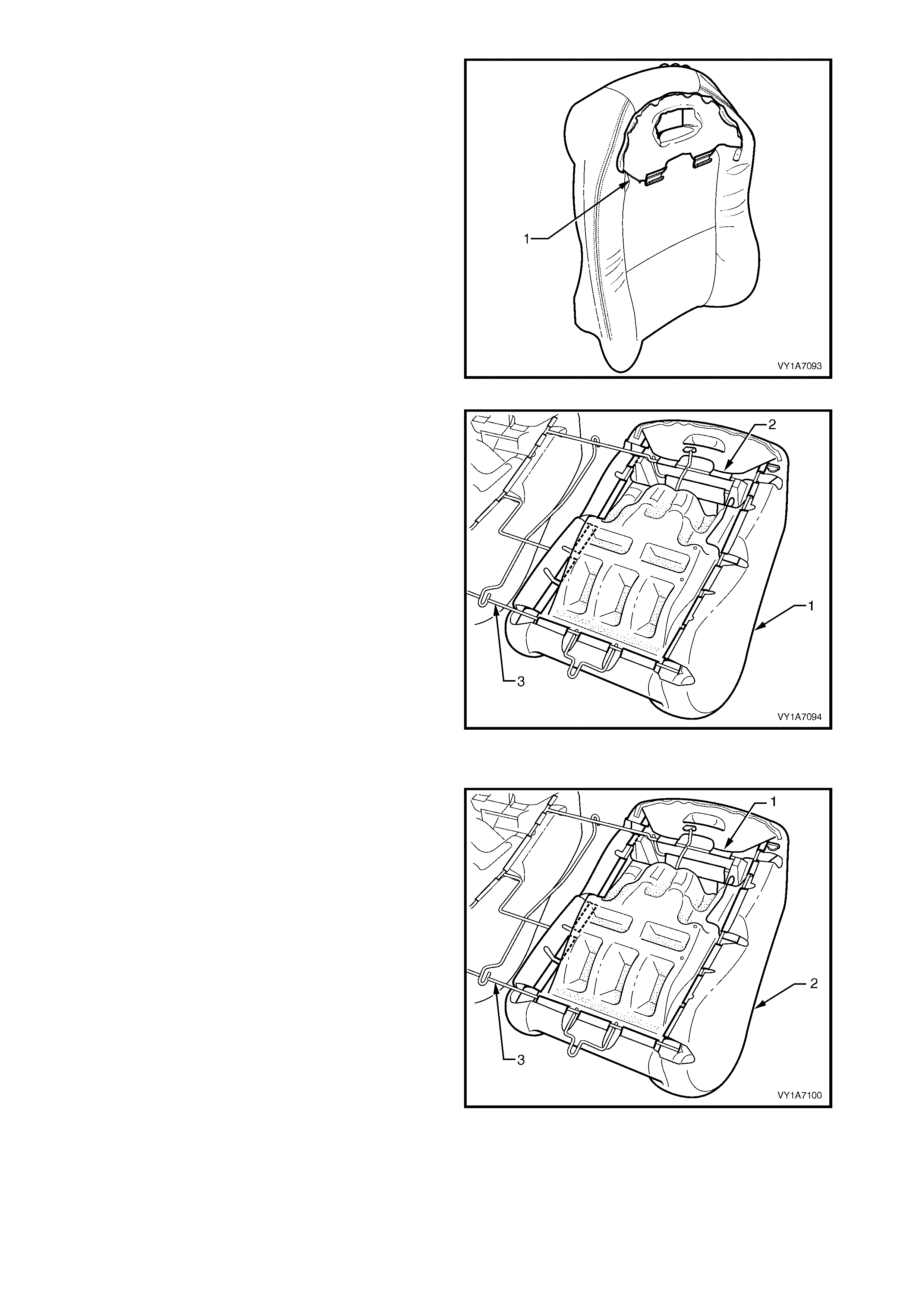
4. Pull the flap (1) completely through the opening in
the rear seat-back pad.
Figure 1A7-378
5. With the rear seat-back assembly (1) face down,
unclip the remaining fifteen retainers (2) attaching
the rear seat-back cover to the rear seat-back
frame (3).
6. Remove the rear seat-back cover and pad
assembly.
7. Repeat for the opposite side as required.
Figure 1A7-379
Reinstall – Rear Seat-back Cover and Pad Assembly
1. Attach the fifteen retainers (1) securing the rear
seat-back cover and pad assembly (2) to the rear
seat-back frame (3).
2. Feed the rear seat-back cover flap through the
opening in the rear seat-back pad.
Figure 1A7-380
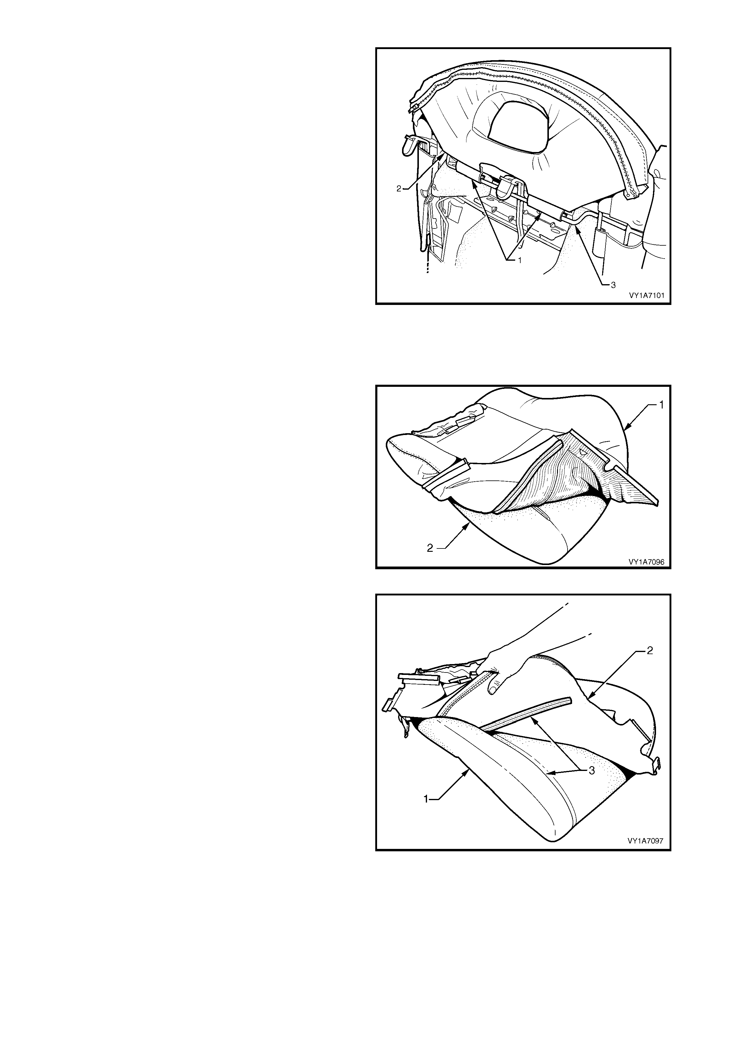
3. Attach the two retainers (1) secur ing the rear seat-
back cover flap (2) to the rear seat-back frame (3).
4. Zip the rear seat-back cover flap.
Figure 1A7-381
Remove – Rear Seat-back Cover
NOTE: The following procedures are applicable to
both left and right-hand rear seat-back assemblies.
1. Fold the lower corners of the seat-back cover (1)
over the seat-back pad (2).
Figure 1A7-382
2. While holding the front seat-back pad (1), pull the
lower corners of the seat-back cover (2), upwards
and away f rom the f ront seat pad to disengage the
hook and loop strips (3).
3. Pull the front seat-back cover up and over the
upper edge of the front seat-back pad.
Figure 1A7-383

Reinstall – Rear Seat-back Cover
Reinstallation of the rear seat-back is the reverse of
the removal procedure noting the following:
1. With the seat-back cover (1) folded at the central
horizontal strip of hook and loop (2), align the
centre mark (3) on the front seat-back cover with
the centre mark (4) on the seat-back pad.
2. Press the seat-back cover firmly into the
corresponding groove in the seat-back pad to
engage the hook and loop.
Figure 1A7-384
3. With the s eat c over f olded at the two vertical s trips
(1) of the hook and loop, press the seat-back
cover (2) firmly into the corresponding grooves in
the seat-back pad.
Figure 1A7-385
4. Continue to press firmly behind the head restraint
guide holes, under the flap (1), of the rear seat-
back cover (2), engaging the hook and loop into
the corresponding groove in the seat-back pad.
Figure 1A7-386
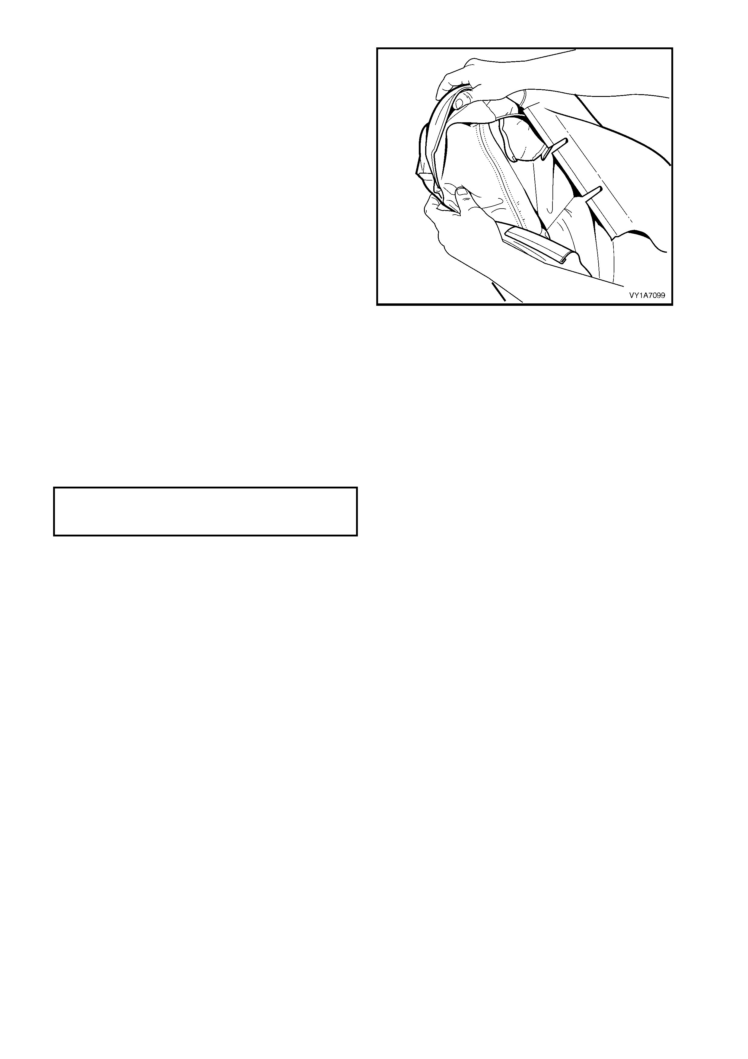
5. Roll the lower corners of the seat-back cover over
the seat-back pad.
6. Roll the sides of the seat-back cover over the seat-
back pad.
7. Roll the upper corners of the rear seat-back cover
over the seat-back pad.
NOTE 1: Make sure the pad is fitted neatly by hand
into all corners and contours of the seat cover.
TIP: Do not pull the cover onto the pad from
underneath using the J- st rip to mak e it f it neatly, as the
fabric may be damaged.
NOTE 2: Do not feed the flap through the opening in
the rear seat-back pad until the c over is s ecured to the
frame.
8. Fit the cover and pad assembly to the rear seat-
back frame.
Figure 1A7-387
REINSTALL
Reinstallation of the rear seat-back assembly is the
reverse of the removal procedure, noting the following:
1. The head restraints must be installed into the rear
seat-back assembly, before the rear seat-back
assembly is reinstalled.
2. Tighten all retaining screws to the correct torque
specification.
REAR SEAT-BACK ASSEMBLY
ATTACHING SCREW
TORQUE SPECIFICATION 25.0 – 35.0 Nm
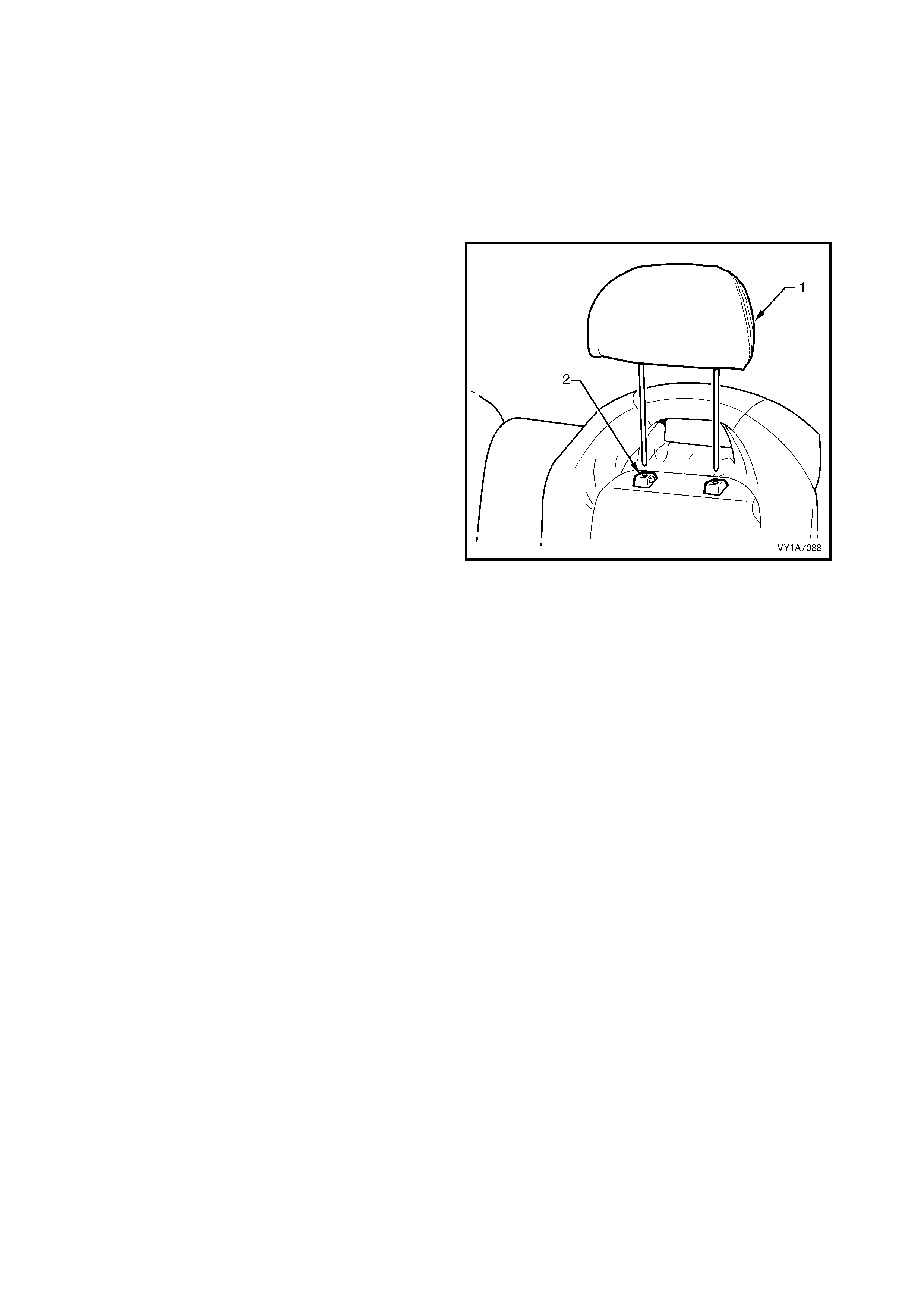
8.3 REAR SEAT HEAD RESTRAINT ASSEMBLY
LT Section No. – 14-350
NOTE: As a safety design feature, the rear seat head restraint can only be removed from the vehicle with the
rear seat-back assembly.
1. Remove the rear seat cushion assembly, refer to 8.1 REAR SEAT CUSHION ASSEMBLY.
2. Remove the rear seat-back assembly, refer to 8.2 REAR SEAT-BACK ASSEMBLY.
REMOVE
1. While holding the head restraint height adjuster
lock in, pull the head restr aint (1) c om pletely out of
the guide (2).
Figure 1A7-388
REINSTALL
Reinstallation of the rear seat head restraint is the
reverse of the removal procedure.
NOTE: Head restraints must be installed into the rear
seat-back assembly, before the rear seat-back
assembly is reinstalled.
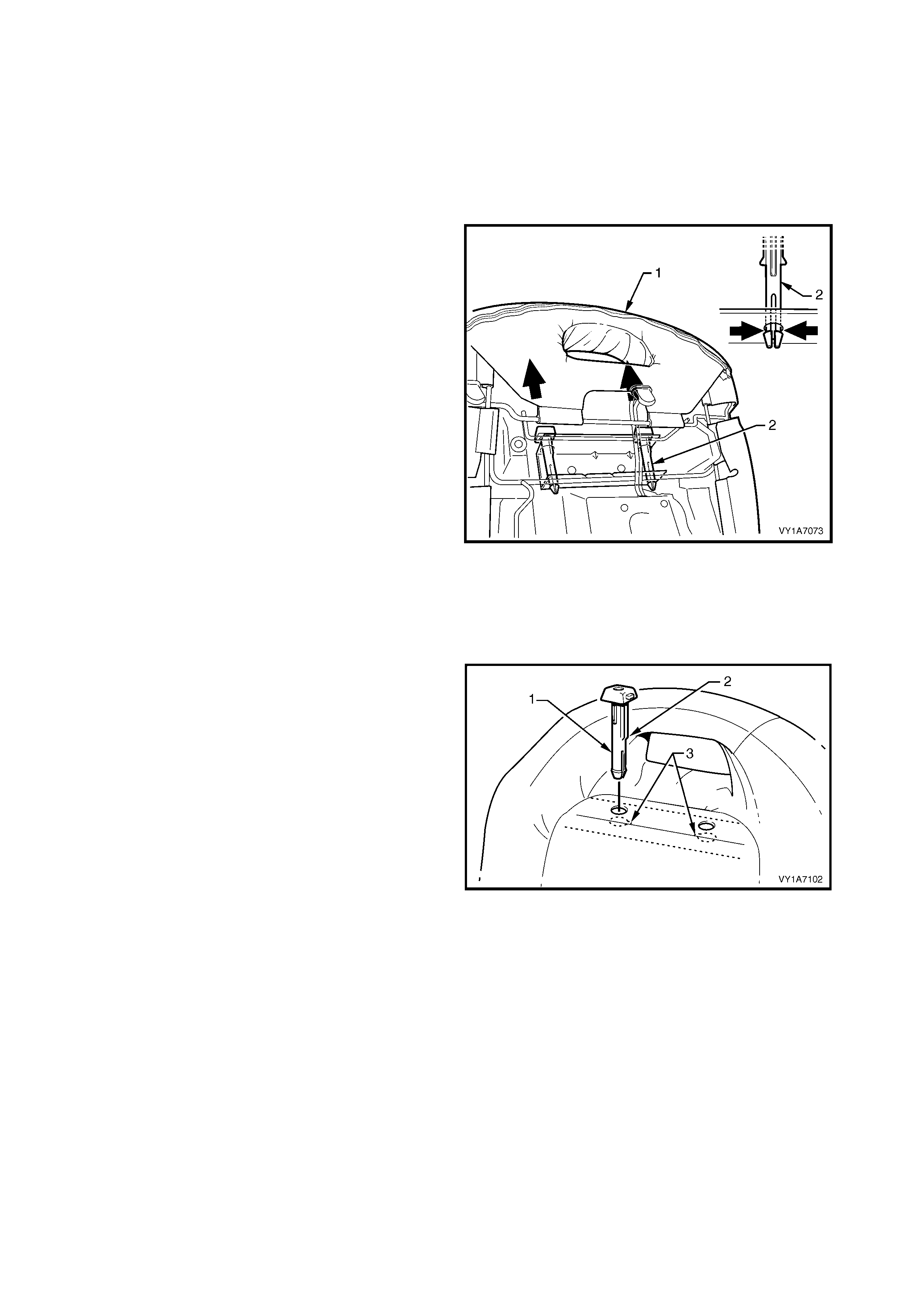
8.4 REAR SEAT HEAD RESTRAINT GUIDE
LT Section No. – 14-350
1. Remove the rear seat cushion assembly, refer to 8.1 REAR SEAT CUSHION ASSEMBLY.
2. Remove the rear seat-back assembly, refer to 8.2 REAR SEAT-BACK ASSEMBLY.
3. Remove the rear seat head restraint assembly, refer to 8.3 REAR SEAT HEAD RESTRAINT ASSEMBLY.
REMOVE
1. From the rear side of the rear seat-back (1),
squeeze the locking prongs of the head restraint
guide (2) together while pulling the top of the guide
out of the seat-back assembly.
Figure 1A7-389
REINSTALL
Reinstallation of the rear seat head restraint guide is
the reverse of the removal procedure, noting the
following:
1. When installing the head restraint guide (1),
ensure the locating slots (2) in the seat-back align
with key-way (3) on the head restraint guide.
NOTE: Head restraints must be installed into the rear
seat-back assembly, before the rear seat-back
assembly is reinstalled.
Figure 1A7-390

9. TORQUE WRENCH SPECIFI CATIONS
Seat adjuster outer front cover attaching screw .......................................................1.0 – 3.0 Nm
Front seat assembly attaching screw........................................................................35.0 – 50.0 Nm
Front outer side cover attaching screw.....................................................................1.0 – 3.0 Nm
Eight-way seat adjustment switch attaching screw...................................................1.0 – 3.0 Nm
Front seat inner side cover attaching screw .............................................................1.0 – 3.0 Nm
Side impact airbag assembly attaching nut ..............................................................5.0 – 6.0 Nm
Front seat foam block insert attaching nut................................................................5.0 – 6.0 Nm
Front seat-back frame assembly attaching screw....................................................30.0 – 45.0 Nm
Front seat cushion frame assembly attaching screw................................................24.0 – 32.0 Nm
Front seat back assembly attaching screw...............................................................30.0 – 45.0 Nm
Seatbelt buckle and pretensioner assembly bolt ......................................................40.0 – 45.0 Nm
Front seat assembly retaining screw ........................................................................35.0 – 50.0 Nm
Memory position switch attaching screw...................................................................1.0 – 3.0 Nm
Memory module attaching screw..............................................................................1.0 – 3.0 Nm
Memory module attaching bracket screw.................................................................5.0 – 6.0 Nm
EZ-entry module attaching screw .............................................................................1.0 – 3.0 Nm
EZ-entry lever arm escutcheon attaching screw.......................................................1.0 – 3.0 Nm
Rear seat back assembly attaching screw ...............................................................25.0 – 35.0 Nm
Armrest hinge attaching screw .................................................................................7.0 – 10.0 Nm
Armrest hinge assembly attaching screw.................................................................3.5 – 5.0 Nm
Rear seat-back centre lock actuator retaining screw................................................1.0 – 3.0 Nm
Rear seat-back centre attaching bolt........................................................................25.0 – 35.0 Nm
Rear seat lock striker attaching screw......................................................................25.0 – 35.0 Nm
Child seat anchor attaching bolt................................................................................15.0 – 25.0 Nm
Armrest centre cover retaining screw.......................................................................2.5 Nm
Armrest hinges assembly retaining screw................................................................4.0 Nm
Rear seat back armrest assembly retaining screw...................................................4.0 Nm
Release handle lever attaching screw......................................................................3.0 Nm
Outer latch assembly attaching screw......................................................................3.0 Nm
Seatbelt guide bracket retaining screw.....................................................................20.0 – 22.0 Nm
Seatbelt retractor retaining nut..................................................................................35.0 – 50.0 Nm
Centre rear seatbelt attaching bolt............................................................................35.0 – 50.0 Nm
Rear seat centre support retaining screw.................................................................25.0 – 35.0 Nm