
SECTION 1A8 - HEADLINING & INTERIOR TRIM
IMPORTANT
Before performing any Service Operation or other procedure described in this Section, refer to Section
00 CAUTIONS AND NOTES for correct workshop practices with regard to safety and/or property damage.
CONTENTS
1. GENERAL DESCRIPTION
2. SERVICE OPERATIONS - SEDAN
2.1 ASSIST HANDLE
REMOVE
REINSTALL
2.2 CENTRE PILLAR LOWER TRIM
REMOVE
REINSTALL
2.3 CENTRE PILLAR UPPER TRIM
ASSEMBLY
REMOVE
REINSTALL
2.4 SIDE SILL TRIM AND PLATE
REMOVE
REINSTALL
2.5 WINDSHIELD SIDE GARNISH
REMOVE
REINSTALL
2.6 BODY LOCK PILLAR GARNISH
REMOVE
REINSTALL
2.7 REAR WINDOW UPPER GARNISH
REMOVE
REINSTALL
2.8 HINGE PILLAR TRIM ASSEMBLY
REMOVE
REINSTALL
2.9 REAR WINDOW TRIM PANEL ASSEMBLY
REMOVE
DISASSEMBLE
ASSEMBLE
REINSTALL
2.10 SUNSHADE ASSEMBLY
REMOVE
REINSTALL
2.11 ROOF CONSOLE
REMOVE
REINSTALL
2.12 HEADLINING ASSEMBLY
REMOVE
REINSTALL
2.13 DRIVER FOOTREST
REMOVE
REINSTALL
2.14 FRONT FLOOR CARPET ASSEMBLY
REMOVE
REINSTALL
2.15 REAR END TRIM PANEL
REMOVE
REINSTALL
2.16 REAR COMPARTMENT FLOOR
CARPET ASSEMBLY
REMOVE
DISASSEMBLE
ASSEMBLE
REINSTALL
2.17 QUARTER INNER REAR SIDE CARPET
REMOVE
REINSTALL
2.18 REAR SEAT BACK PANEL CARPET
REMOVE
REINSTALL
2.19 CONVENIENCE NET
REMOVE
REINSTALL
3. SERVICE OPERATIONS - WAGON
3.1 ASSIST HANDLE
REMOVE
REINSTALL
3.2 CENTRE PILLAR LOWER TRIM
REMOVE
REINSTALL
3.3 CENTRE PILLAR UPPER TRIM ASSEMBLY
REMOVE
REINSTALL
3.4 SIDE SILL TRIM AND PLATE
REMOVE
REINSTALL
3.5 WINDSHIELD SIDE GARNISH
REMOVE
REINSTALL
3.6 BODY LOCK PILLAR LOWER TRIM
REMOVE
REINSTALL
3.7 BODY LOCK PILLAR GARNISH
REMOVE
REINSTALL
3.8 QUARTER INNER TRIM UPPER
REMOVE
REINSTALL
3.9 BODY REAR CORNER GARNISH
REMOVE
REINSTALL
3.10 REAR WINDOW UPPER GARNISH
REMOVE
REINSTALL
3.11 QUARTER INNER TRIM PANEL ASSEMBLY
REMOVE
DISASSEMBLE
REINSTALL

3.12 HINGE PILLAR TRIM ASSEMBLY
REMOVE
REINSTALL
3.13 SUNSHADE ASSEMBLY
REMOVE
REINSTALL
3.14 ROOF CONSOLE
REMOVE
REINSTALL
3.15 HEADLINING ASSEMBLY
REMOVE
REINSTALL
3.16 DRIVER FOOTREST
REMOVE
REINSTALL
3.17 FRONT FLOOR CARPET ASSEMBLY
REMOVE
REINSTALL
3.18 REAR FLOOR FILLER PANEL
REMOVE
REINSTALL
3.19 REAR END TRIM PANEL
REMOVE
REINSTALL
3.20 REAR COMPARTMENT FLOOR
CARPET ASSEMBLY, EXCEPT LPG
REMOVE
DISASSEMBLE
ASSEMBLE
REINSTALL
3.21 REAR COMPARTMENT FLOOR CARPET
ASSEMBLY AND SPARE WHEEL COVER,
WITH LPG.
REMOVE
REINSTALL
3.22 LUGGAGE SHADE ASSEMBLY
REMOVE
REINSTALL
4. SERVICE OPERATIONS - COUPE
4.1 SIDE SILL TRIM AND PLATE
REMOVE
REINSTALL
4.2 QUARTER TRIM PANEL ASSEMBLY
REMOVE
DISASSEMBLE
REINSTALL
4.3 CENTRE PILLAR UPPER TRIM ASSEMBLY
REMOVE
REINSTALL
4.4 WINDSHIELD SIDE GARNISH
REMOVE
REINSTALL
4.5 BODY REAR CORNER GARNISH
REMOVE
REINSTALL
4.6 HINGE PILLAR TRIM ASSEMBLY
REMOVE
REINSTALL
4.7 REAR WINDOW TRIM PANEL ASSEMBLY
REMOVE
DISASSEMBLE
ASSEMBLE
REINSTALL
4.8 SUNSHADE ASSEMBLY
REMOVE
REINSTALL
4.9 HEADLINING ASSEMBLY
REMOVE
REINSTALL
4.10 DRIVER FOOTREST
REMOVE
REINSTALL
4.11 FRONT FLOOR CARPET ASSEMBLY
REMOVE
REINSTALL
4.12 REAR END TRIM PANEL
REMOVE
REINSTALL
4.13 REAR COMPARTMENT FLOOR
CARPET ASSEMBLY
REMOVE
DISASSEMBLE
ASSEMBLE
REINSTALL
4.14 QUARTER INNER REAR SIDE CARPET
REMOVE
REINSTALL
4.15 REAR SEAT BACK PANEL CARPET
REMOVE
REINSTALL
5. SERVICE OPERATIONS - UTILITY
5.1 ASSIST HANDLE
REMOVE
REINSTALL
5.2 CENTRE PILLAR LOWER TRIM
REMOVE
REINSTALL
5.3 BODY LOCK PILLAR UPPER TRIM
REMOVE
REINSTALL
5.4 SIDE SILL TRIM AND PLATE
REMOVE
REINSTALL
5.5 WINDSHIELD SIDE GARNISH
REMOVE
REINSTALL
5.6 HINGE PILLAR TRIM ASSEMBLY
REMOVE
REINSTALL
5.7 SUNSHADE ASSEMBLY
REMOVE
REINSTALL
5.8 HEADLINING ASSEMBLY
REMOVE
REINSTALL
5.9 DRIVER FOOTREST
REMOVE
REINSTALL
5.10 FRONT FLOOR CARPET ASSEMBLY
REMOVE
REINSTALL
5.11 SEAT BACK BODY PANEL TRIM
REMOVE
REINSTALL
6. SPECIFICATIONS
6.1 TRIM CLEARANCES, SEDAN
6.2 TRIM CLEARANCES, WAGON
6.3 TRIM CLEARANCES, COUPE
6.4 TRIM CLEARANCES, UTILITY
7. TORQUE WRENCH SPECIFICATIONS

1. GENERAL DESCRIPTION
This headlining and interior trim s ection of the MY2003 VY Series & MY2003 V2 Series II service m anual, has been
divided into Sedan, Wagon, Coupe and Utility.
A com plete overview of all tr im c omponents covered by this trim s ection, are illustr ated and identified at the star t of
each body style section; for Sedan refer Figure 1A8-1, for Wagon refer Figure 1A8-27, for Coupe refer Figure
1A8-61 and for Utility refer Figure 1A8-87.
There is a common design of components between all body styles, but most components are unique to the
individual models.
The centre pillar upper trim features a front seat belt sash height adjuster cover, if fitted.
The headlining is of the one-piece moulded type, varying due to body style and the fitment of the roof console on
high level equipment models.
The roof console, on high level equipment models except Coupe, features an interior dome lamp, reading lamps
and concealed sunglasses holder.
The sunshade features a vanity mirror and on high level equipment models, an illuminated vanity mirror with cover.
The front floor carpet is unique for each body style.
The rear compartment floor carpet and quarter side carpets varies between all models.
In the rear seat back panel carpet on Sedan there is an opening for a ski hatch.
The rear window trim panel, feature radio speaker grilles on high level equipment models.
The quarter inner trim panel on Wagon, incorporates a stowage compartment on each side.
The quarter trim panel on Coupe, features a radio speaker grille and a leather armrest insert.
Body pillar and roof garnish, have guide pins, for accurate installation and mating of adjacent components. Care
must be taken not to damage these pins when removing and installing parts.
Trim clearance illustrations are provided for all body styles, refer to 6. SPECIFICATIONS.
The interior trim is the s am e for left and r ight hand drive m odels, ex cept f or the f uel filler door release and the hood
release lever.
NOTE: WHEN WORKING ON THE BODY INTERIOR TRIM, CLEAN HANDS ARE ESSENTIAL AND
PROTECTIVE COVERING MUST BE PLACED OVER THE INTERIOR TRIM.
2. SERVICE OPERATIONS - SEDAN
NOTE: The following chart is included to assist with the identification of the components.
For the service procedures of the rear compartment lid carpet, refer to Section 1A4, 3.1 REAR COM PARTM ENT
LID CARPET.
For the service procedures of the front and rear door trim panel assemblies, refer to Section 1A5,
2.6 FRONT DOOR TRIM PANEL ASSEMBLY and 3.6 REAR DOOR TRIM PANEL ASSEMBLY.
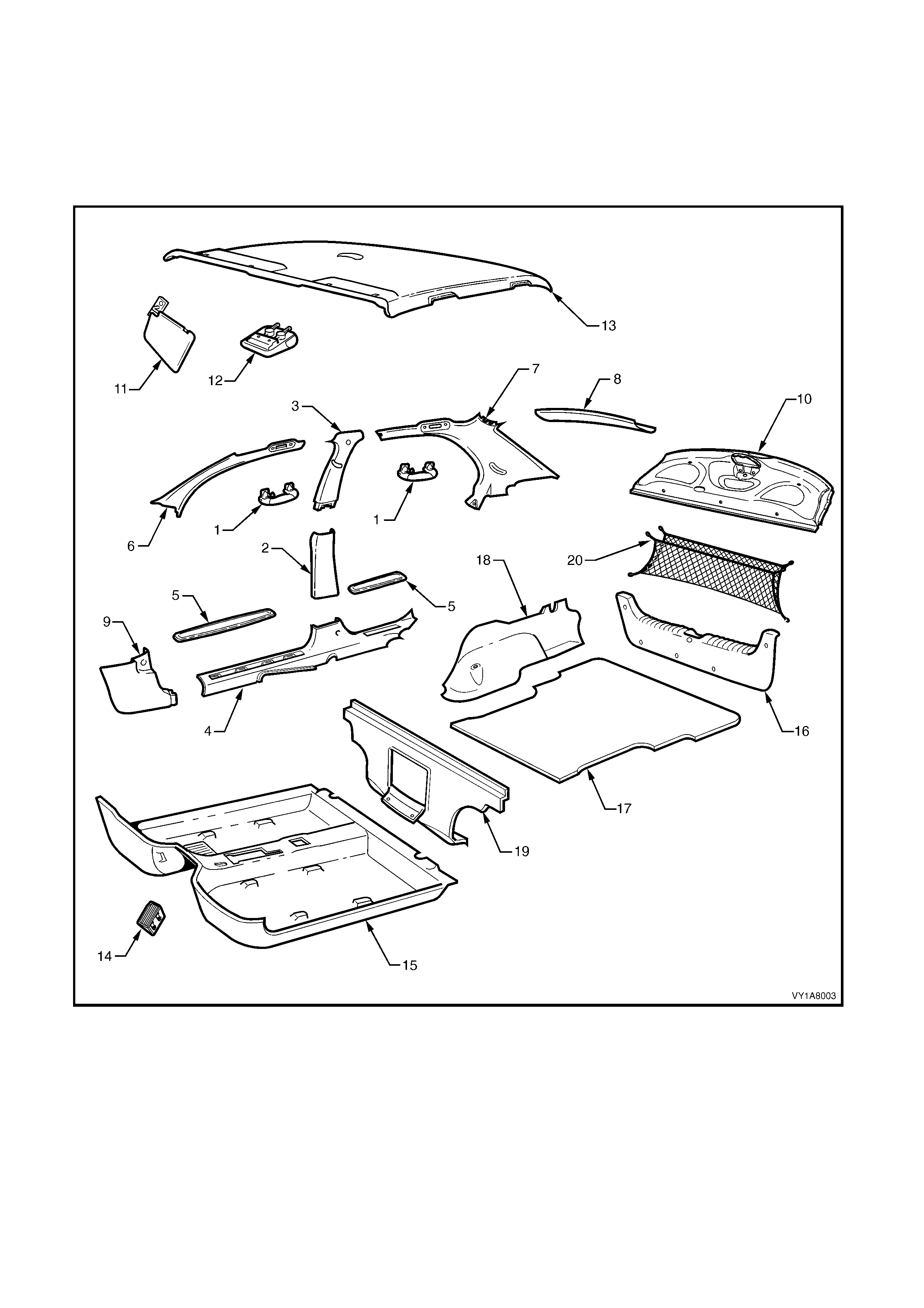
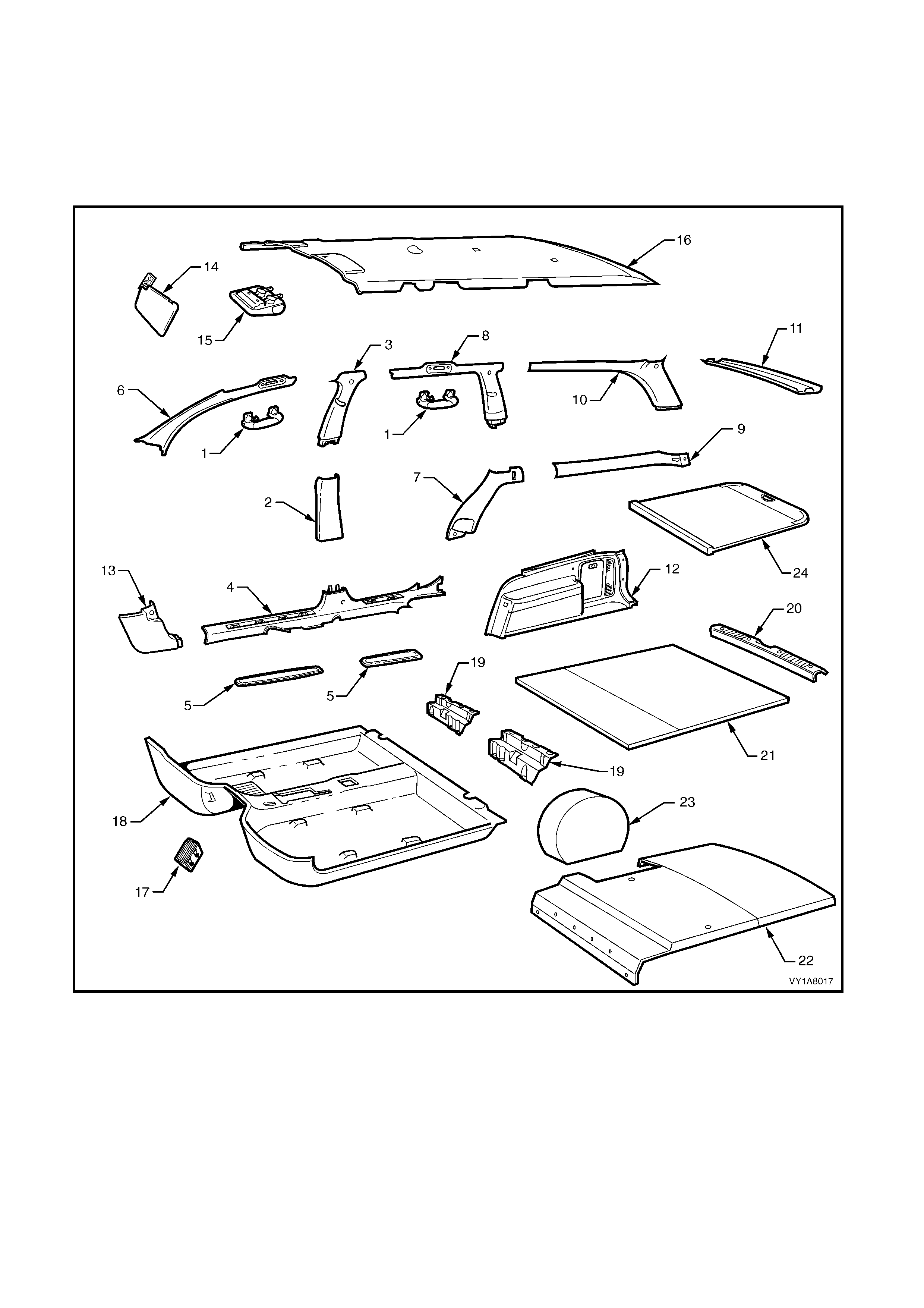
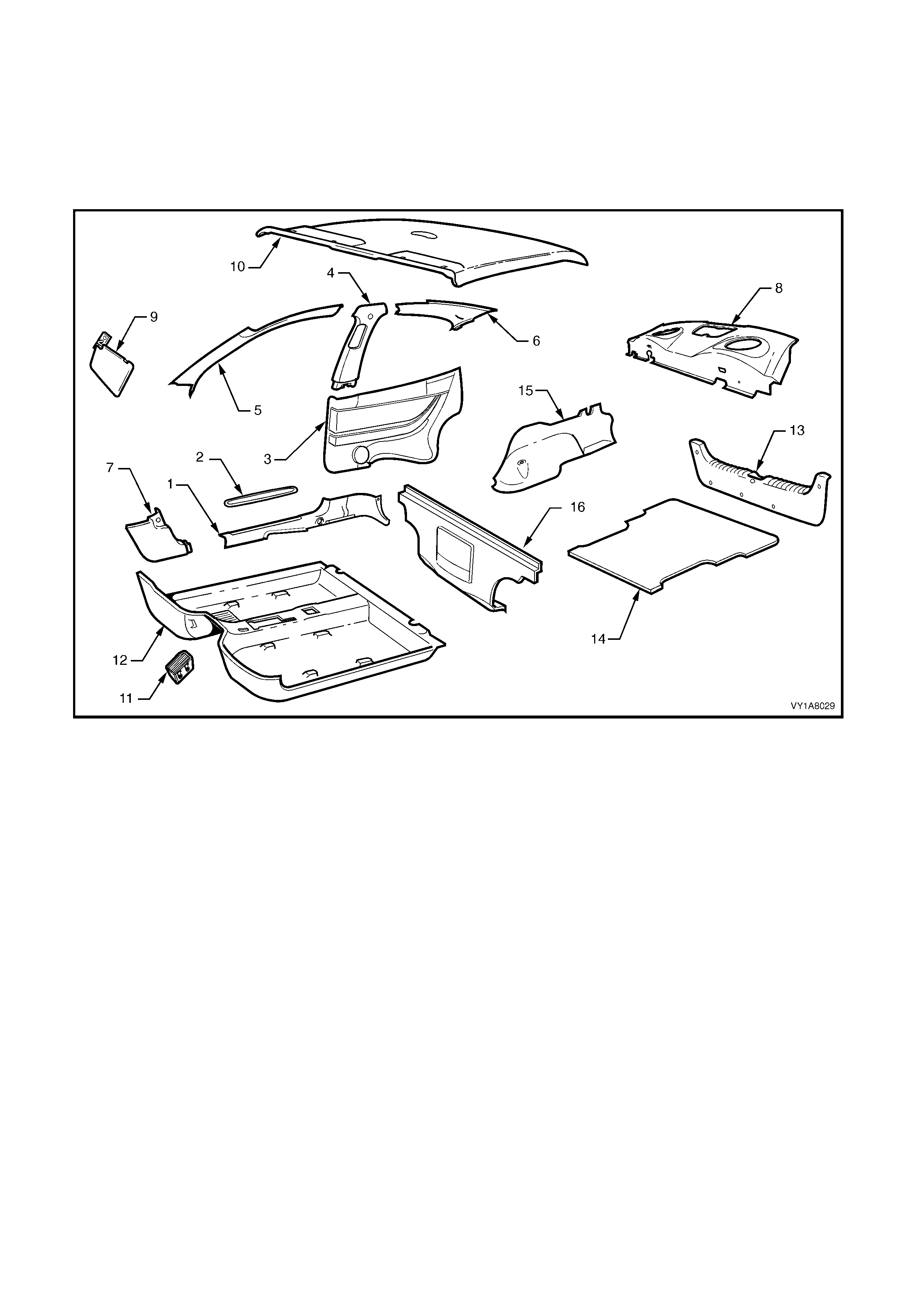
Figure 1A8-1
Legend
1. Assist Handle
2. Centre Pillar Lower Trim
3. Centre Pillar Upper Trim
4. Side Sill Trim
5. Side Sill Trim Plate
6. Windshield Side Garni sh
7. Body Lock Pillar Garnish
8. Rear Window Upper Garnish
9. Hinge Pillar Trim Assem bly
10. Rear Window Trim P anel
11. Sunshade Assembly
12. Roof Console
13. Headlining Assembly
14. Driver Footrest
15. Front Floor Carpet Assem bl y
16. Rear End Trim Panel
17. Rear Compart ment Floor Carpet Assembly
18. Quarter Inner Rear Si de Carpet
19. Rear Seat Back Panel Carpet
20. Convenience Net
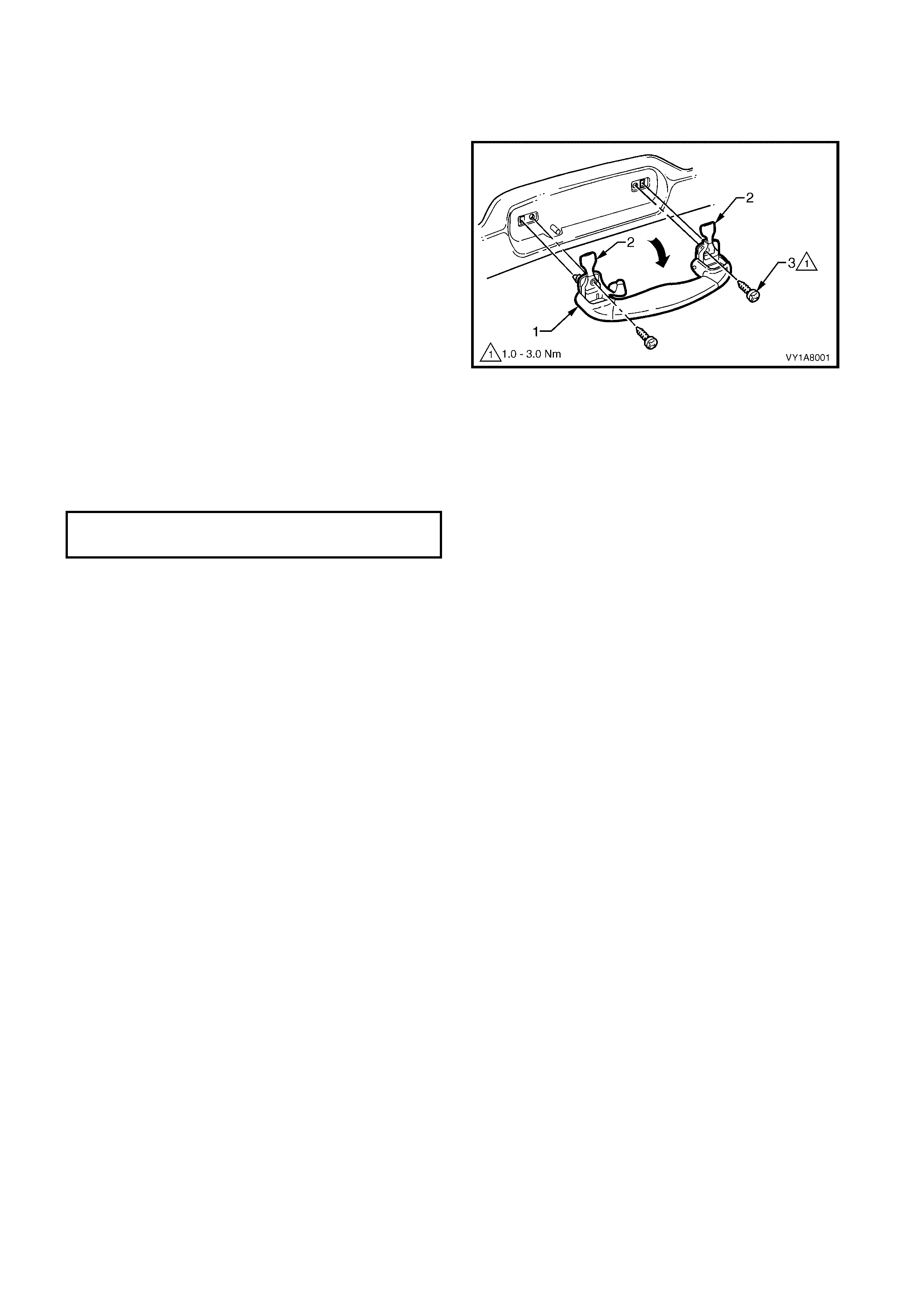
2.1 ASSIST HANDLE
LT Section No. – 14-100
REMOVE
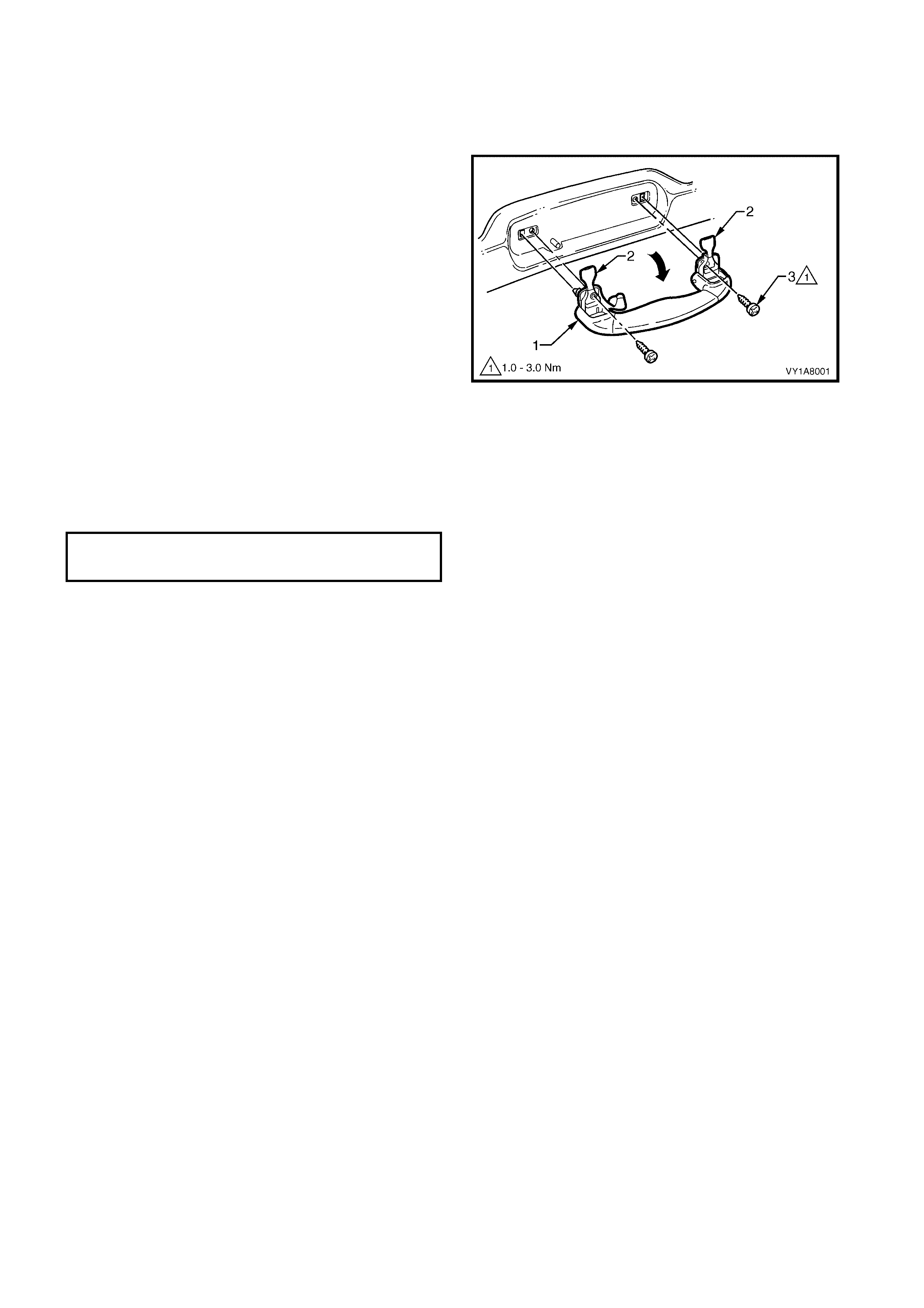
1. Pull the assist handle (1) into the down position.
2. Prise open the assist handle screw cover (2) and
remove the attaching screw (3) two places.
3. Remove the assist handle ensuring care is taken
not to damage the locating pins.
Figure 1A8-2
REINSTALL
1. Ensure the locating pins are correctly aligned with
the locating holes.
2. Tighten all retaining screws to the correct torque
specification.
ASSIST HANDLE ATTACHING
SCREW TORQUE SPECIFICATION 1.0 – 3.0 Nm

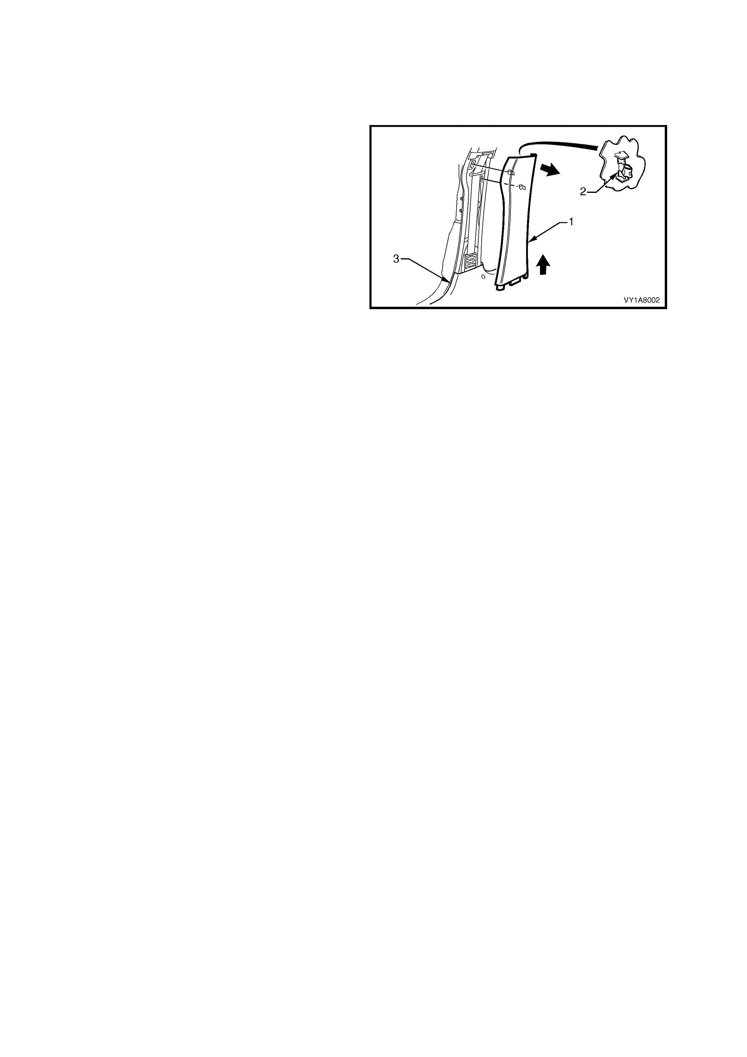
2.2 CENTRE PILLAR LOWER TRIM
LT Section No. – 14-100
REMOVE
1. Lever the centre pillar lower trim ( 1) away f rom the
front door opening weatherstrip with your fingers,
pulling the trim towards the centre of car,
disengaging the two retaining clips (2).
2. Remove the trim upward, out of the side sill
trim (3).
Figure 1A8-3
REINSTALL
1. Locate the centre pillar lower trim into the side sill
trim and push the retaining clips in firmly.
2. Ensure the front and rear door opening
weatherstrip fits neatly over the outer edge of
centre pillar lower trim.

2.3 CENTRE PILLAR UPPER TRIM ASSEMBLY
LT Section No. – 14-100
1. Remove the centre pillar lower trim, refer to 2.2 CENTRE PILLAR LOWER TRIM.
2. Remove the front lower seat belt bolt, refer to Section12M, OCCUPANT PROTECTION SYSTEM.
REMOVE
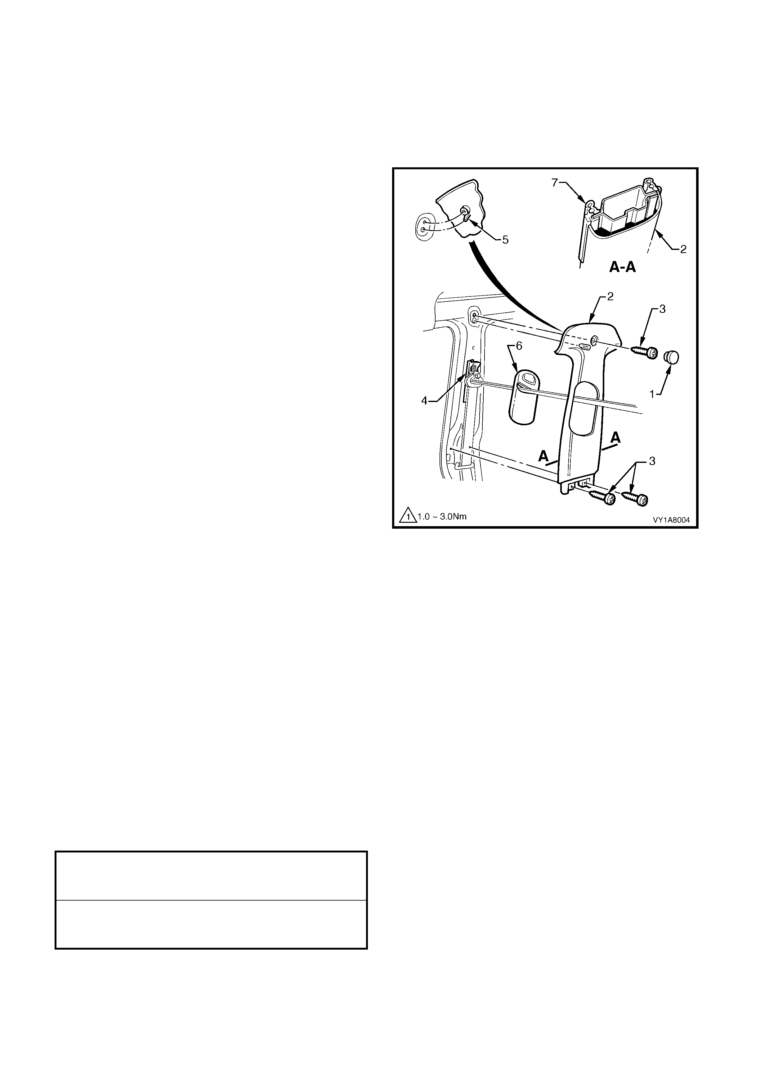
1. Remove the centre pillar cap (1) from the upper
attachment of the centre pillar upper trim (2).
2. Remove the three screws (3) securing the centre
pillar upper trim.
3. Pull the upper edge of the centre pillar upper trim,
away from the headlining to disengage the seat
belt guide adjuster assembly (4) if fitted.
4. Feed the seat belt and anchor plate through the
centre pillar upper trim and remove the trim.
NOTE: When removing the centre pillar upper trim,
ensure car e is tak en not to dam age the locating pin (5)
below the upper attaching screw.
5. If required to remove, lift out the seat belt adjuster
trim (6) by gently spreading the outer edges of the
centre pillar upper trim.
Figure 1A8-4
REINSTALL
Reinstallation of the centre pillar upper trim is the
reverse of the removal, noting the following:
1. If fitted, ensure the seat belt adjuster trim and the
seat belt guide adjus ter ass embly are in the full up
position and are correctly aligned prior to
installation of the centre pillar upper trim.
2. Ensure the locating pin below the upper attaching
screw in the centre pillar upper trim, is correctly
aligned with the locating hole in the centre pillar.
3. Ensure the leading edge of the centre pillar upper
trim engages the door opening weatherstrip (7),
refer Figure 1A8-4.
4. Check seat belt operation prior to tightening the
centre pillar upper trim attaching screws.
5. Tighten all fasteners to the correct torque
specification.
CENTRE PILLAR UPPER TRIM
ATTACHING SCREW
TORQUE SPECIFICATION 1.0 – 3.0 Nm
FRONT SEAT BELT LOWER
ATTACHING BOLT
TORQUE SPECIFICATION 35.0 – 50.0 Nm

2.4 SIDE SILL TRIM AND PLATE
LT Section No. – 14-100
1. Remove the centre pillar lower trim, refer to 2.2 CENTRE PILLAR LOWER TRIM.
REMOVE
1. Remove the front attaching screw (1) from the seat
adjuster outer front cover (2), driver side, right
hand drive only.
2. Using a small screwdriver, push in the centre of
the join to separate the front cover and the front
seat outer lower rear cover (3).
3. Unclip the covers from the seat track, and
disengage from the side sill trim.
4. Pull the covers apart and remove the rear cover.
5. For the driver’s side on right hand drive vehicles,
slide the f r ont c over over the f uel filler door r eleas e
lever (4) and remove.
Figure 1A8-5
6. Carefully lever the front and rear side sill trim
plates (1) from the side sill trim (2), starting at the
front of each plate and moving rearwards,
revealing the attaching screws.
IMPORTANT: Care must be taken not to snap the sill
trim plates.
7. Remove the six Torx head screws (3) from the
side sill trim , f our in the f ront door opening and two
in the rear door opening.
8. Remove the Torx head s crew (4) from the side sill
trim to the centre pillar.
9. Remove the side sill trim through the front door
opening, by lifting the f ront and sliding the rear out
from under the rear seat cushion.
Figure 1A8-6
REINSTALL
Reinstallation of the side sill trim and the seat adjuster
outer front cover is the reverse of the removal, noting
the following:
1. Ensure the outer edge of the side sill trim engages
the door opening weatherstrip (5), refer Figure
1A8-6.
2. Tighten all fasteners to the correct torque
specification.
SEAT ADJUSTER OUTER FRONT
COVER ATTACHING SCREW
TORQUE SPECIFICATION 1.0 – 3.0 Nm
SIDE SILL TRIM
ATTACHING SCREW
TORQUE SPECIFICATION 1.0 – 3.0 Nm
2.5 WI NDSHIELD SIDE GARNISH
LT Section No. – 14-100
1. Remove the assist handle, refer to 2.1 ASSIST HANDLE.
2. Partially remove the centre pillar upper trim by removing the upper attaching screw, refer to
2.3 CENTRE PILLAR UPPER TRIM ASSEMBLY.
REMOVE
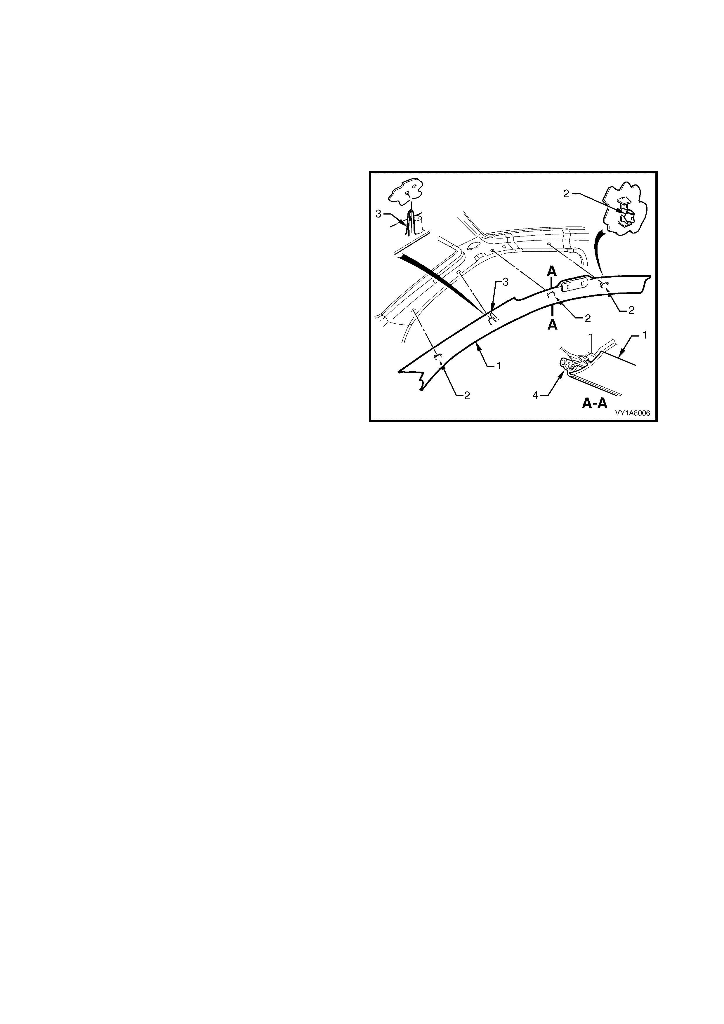
1. Starting at the upper rear edge of the windshield
side garnish (1), disengage the three attaching
clip s (2).
2. Remove the windshield side garnish.
NOTE: When removing the windshield side garnish,
ensure care is taken not to damage the locating
pin (3).
Figure 1A8-7
REINSTALL
Reinstallation of the windshield side garnish is the
reverse of the removal, noting the following:
1. Ensure the windshield side garnish locating pin is
aligned with the hole in the inner panel.
2. Ensure the outer edge of the windshield side
garnish engages the door opening weatherstrip
(4), refer Figure 1A8-7.
2.6 BODY LOCK PILLAR GARNISH
LT Section No. – 14-120
1. Remove the rear assist handle, refer to 2.1 ASSIST HANDLE.
2. If fitted, remove the roof rail courtesy lamp, refer to Section 12B, 3.15 ROOF RAIL COURTESY AND
READING LAMP ASSEMBLY.
3. Partially remove the centre pillar upper trim by removing the upper attaching screw, refer to
2.3 CENTRE PILLAR UPPER TRIM ASSEMBLY.
4. Remove the rear seat cushion, refer to Section 1A7, SEAT ASSEMBLIES.
5. Remove the rear seat back, refer to Section 1A7, SEAT ASSEMBLIES.
6. Remove the rear lower seat belt bolt, refer to Section12M, OCCUPANT PROTECTION SYSTEM.
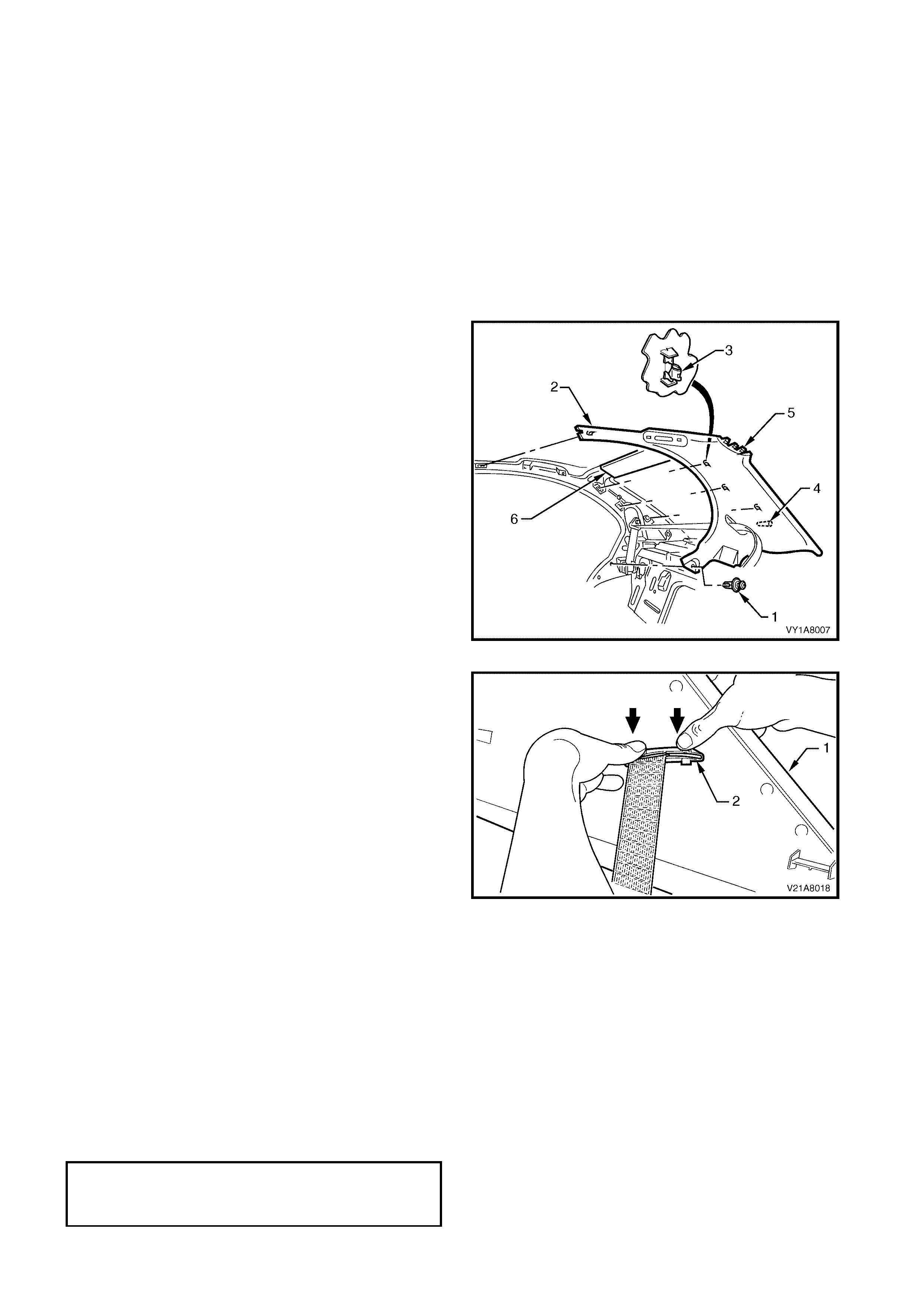
REMOVE
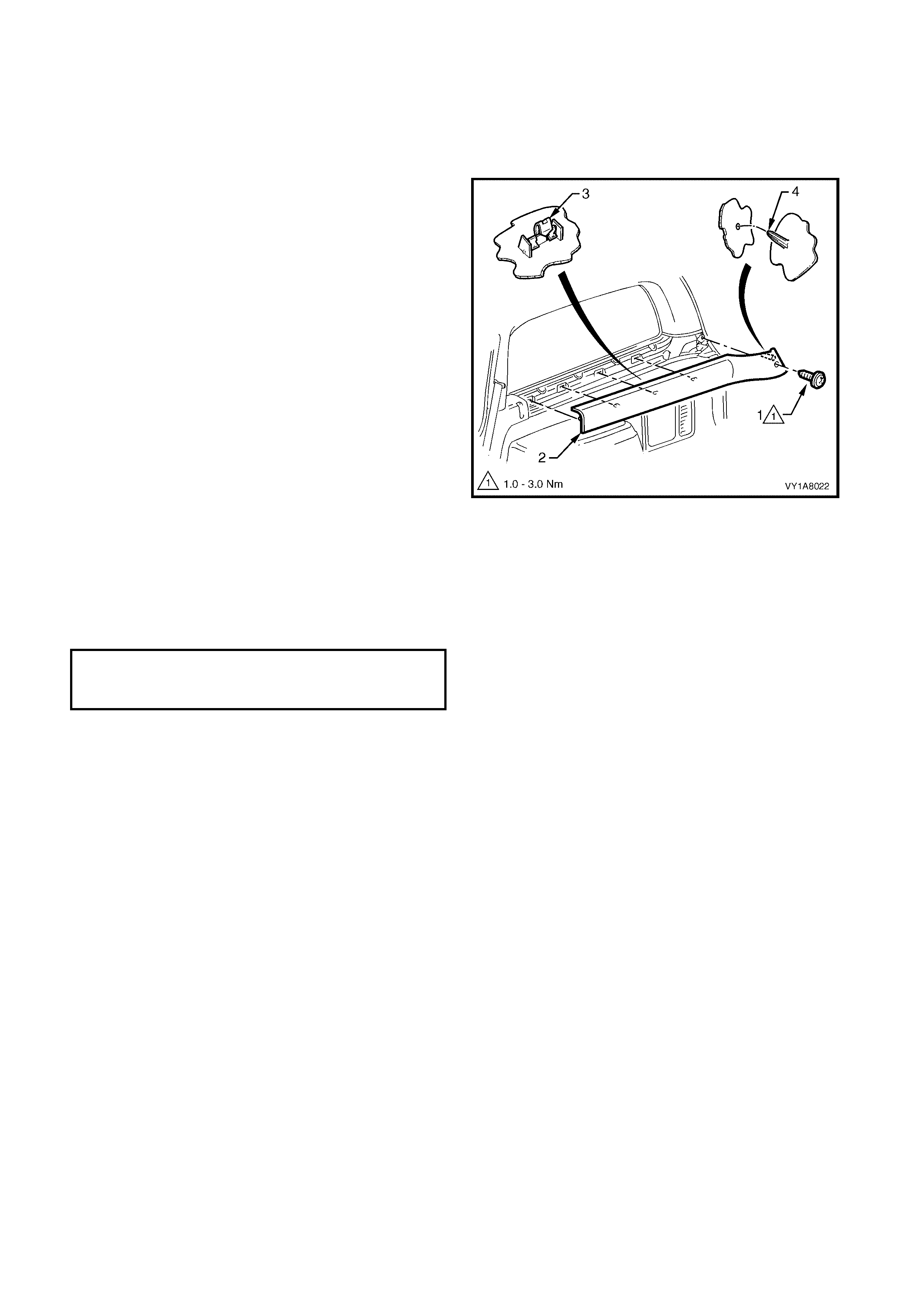
1. Remove the garnish retainer (1) from the lower
edge of the body lock pillar garnish (2).
2. Pull the front edge of the body lock pillar garnish
away from the body lock pillar and working
rearwards, disengage the three garnish clips (3).
NOTE: When removing the body lock pillar garnish,
ensure care is taken not to damage the locating
pin (4), or the loc ating lugs (5) f itting under the rear
window upper garnish (6).
3. Slide the three locating lugs on the body lock pillar
garnish, out from underneath the rear window
upper garnish.
Figure 1A8-8
4. With the body lock pillar garnish (1) partially
removed, disengage the seat belt guide (2) from
the garnish and feed the seat belt and anchor plate
through the opening.
5. Remove the body lock pillar garnish.
Figure 1A8-9
REINSTALL
Reinstallation of the body lock pillar garnish is the
reverse of the removal, noting the following:
1. Ensur e the body lock pillar garnish is fully engaged
into the rear window upper garnish.
2. Ensure the body lock pillar garnish locating pin is
aligned with the hole in the inner panel.
3. Ensure the outer edge of the body lock pillar
garnish engages the door opening weatherstrip.
4. Tighten all fasteners to the correct torque
specification.
REAR SEAT BELT LOWER
ATTACHING BOLT
TORQUE SPECIFICATION 35.0 – 50.0 Nm

2.7 REAR WINDOW UPPER GARNISH
LT Section No. – 14-120
1. Remove the rear assist handle, refer to 2.1 ASSIST HANDLE.
2. If fitted, remove the roof rail courtesy lamp, refer to Section 12B, 3.15 ROOF RAIL COURTESY AND
READING LAMP ASSEMBLY.
3. Partially remove the centre pillar upper trim by removing the upper attaching screw, refer to
2.3 CENTRE PILLAR UPPER TRIM ASSEMBLY.
4. Remove the rear seat cushion, refer to Section 1A7, SEAT ASSEMBLIES.
5. Remove the rear seat back, refer to Section 1A7, SEAT ASSEMBLIES.
6. Remove the body lock pillar garnish, refer to 2.6 BODY LOCK PILLAR GARNISH.
REMOVE
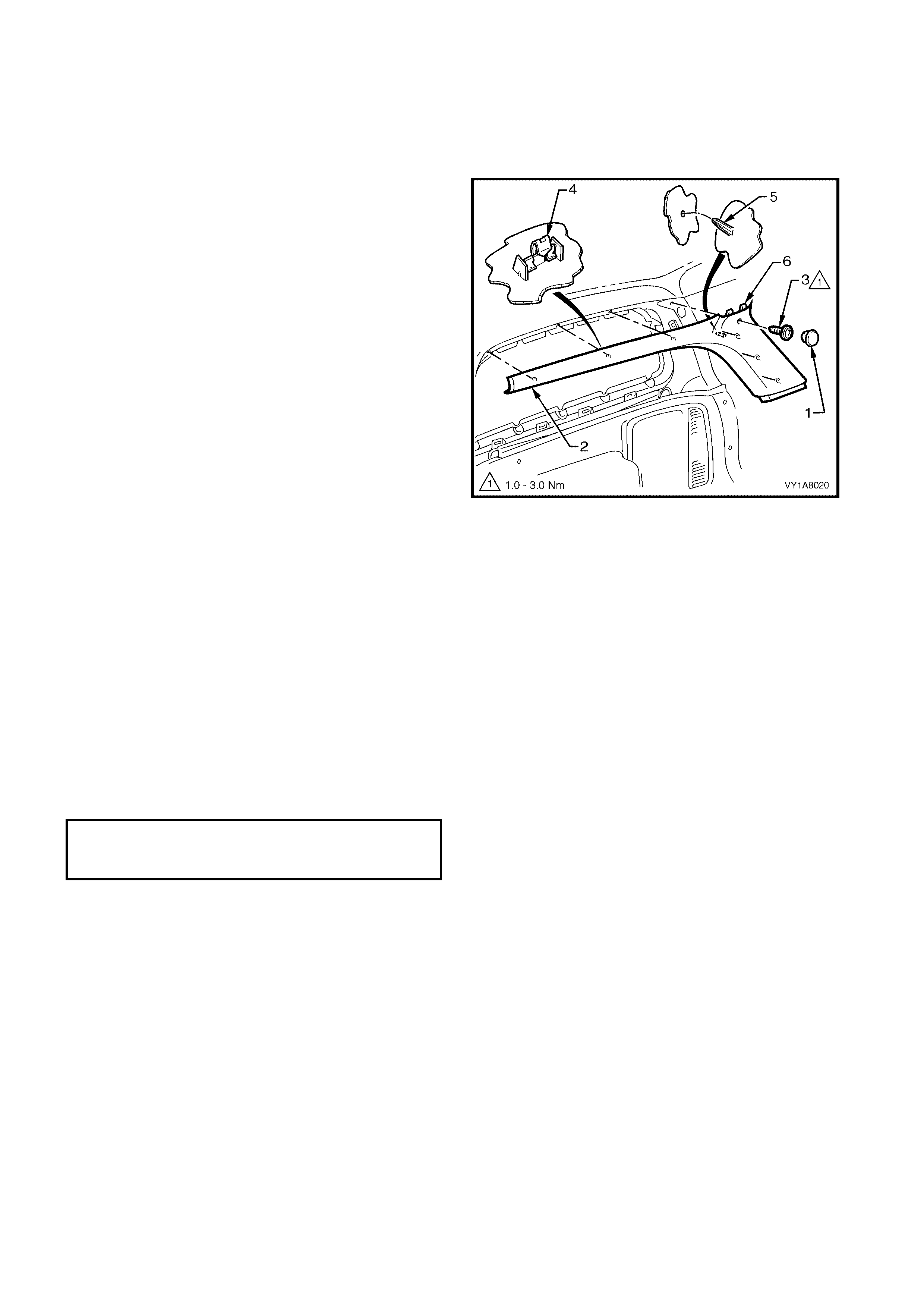
1. Lever the rear window upper garnish (1) away from
the headlining with your fingers, disengaging the
four retaining clips (2) from the roof rear frame.
2. Remove the rear window upper garnish away from
the remaining body lock pillar garnish (3).
NOTE: When removing the rear window upper
garnish, ensure care is taken not to damage the
locating pin (4).
Figure 1A8-10
REINSTALL
Reinstallation of the rear window upper garnish is the
reverse of the removal, noting the following:
1. Ensure a neat fit over the outer edge of the body
lock pillar garnish.

2.8 HINGE PILLAR TRIM ASSEMBLY
LT Section No. – 14-100
1. Remove the seat adjuster outer front cover, refer to Section 1A7, SEAT ASSEMBLIES.
2. Remove the centre pillar lower trim, refer to 2.2 CENTRE PILLAR LOWER TRIM.
3. Remove the rear seat cushion, refer to Section 1A7, SEAT ASSEMBLIES.
4. Partially remove the side sill trim, refer to 2.4 SIDE SILL TRIM AND PLATE.
REMOVE
1. Remove the two attaching screws (1) from the
hinge pillar trim assembly (2).
2. Disengage the hinge pillar trim clip (3) by pulling
the lower edge of the hinge pillar tr im ass embly up
and away from the sheetmetal.
3. Remove the hinge pillar trim assembly.
Figure 1A8-11
REINSTALL
Reinstallation of the hinge pillar trim assembly is the
reverse of the removal, noting the following:
1. Ensure the hinge pillar trim clip is correctly
engaged.
2. Ensur e the nut inserts (4) are correc tly loc ated and
in good condition, refer Figure 1A8-11.
3. Ensure the outer edge of the hinge pillar trim
assembly engages the door opening weatherstrip
(5), refer Figure 1A8-11.
4. Tighten all fasteners to the correct torque
specification.
HINGE PILLAR TRIM ASSEMBLY
ATTACHING SCREW
TORQUE SPECIFICATION 0.7 – 1.0 Nm
2.9 REAR WINDOW TRIM PANEL ASSEMBLY
LT Section No. – 14-460
1. Remove the rear assist handle, refer to 2.1 ASSIST HANDLE.
2. If fitted, remove the roof rail courtesy lamp, refer to Section 12B, 3.15 ROOF RAIL COURTESY AND
READING LAMP ASSEMBLY.
3. Partially remove the centre pillar upper trim by removing the upper attaching screw, refer to
2.3 CENTRE PILLAR UPPER TRIM ASSEMBLY.
4. Remove the rear seat cushion, refer to Section 1A7, SEAT ASSEMBLIES.
5. Remove the rear seat back, refer to Section 1A7, SEAT ASSEMBLIES.
6. Partially remove the body lock pillar garnish, refer to 2.6 BODY LOCK PILLAR GARNISH.
7. Remove the lower centre seat belt bolt, refer to Section12M, OCCUPANT PROTECTION SYSTEM.
REMOVE
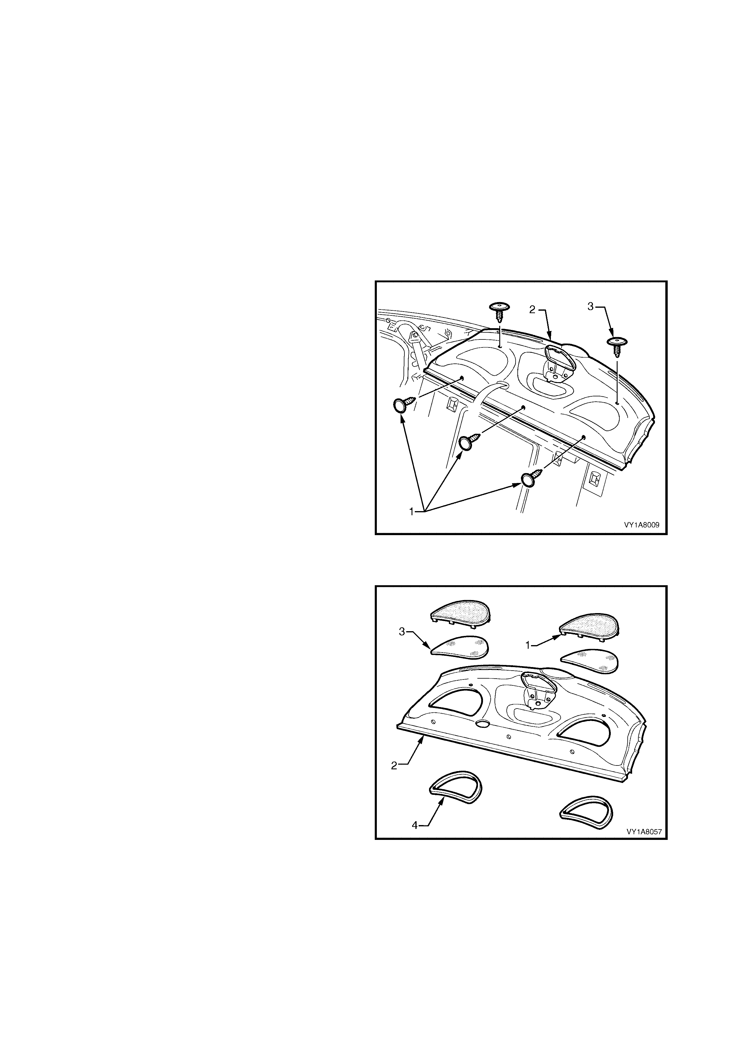
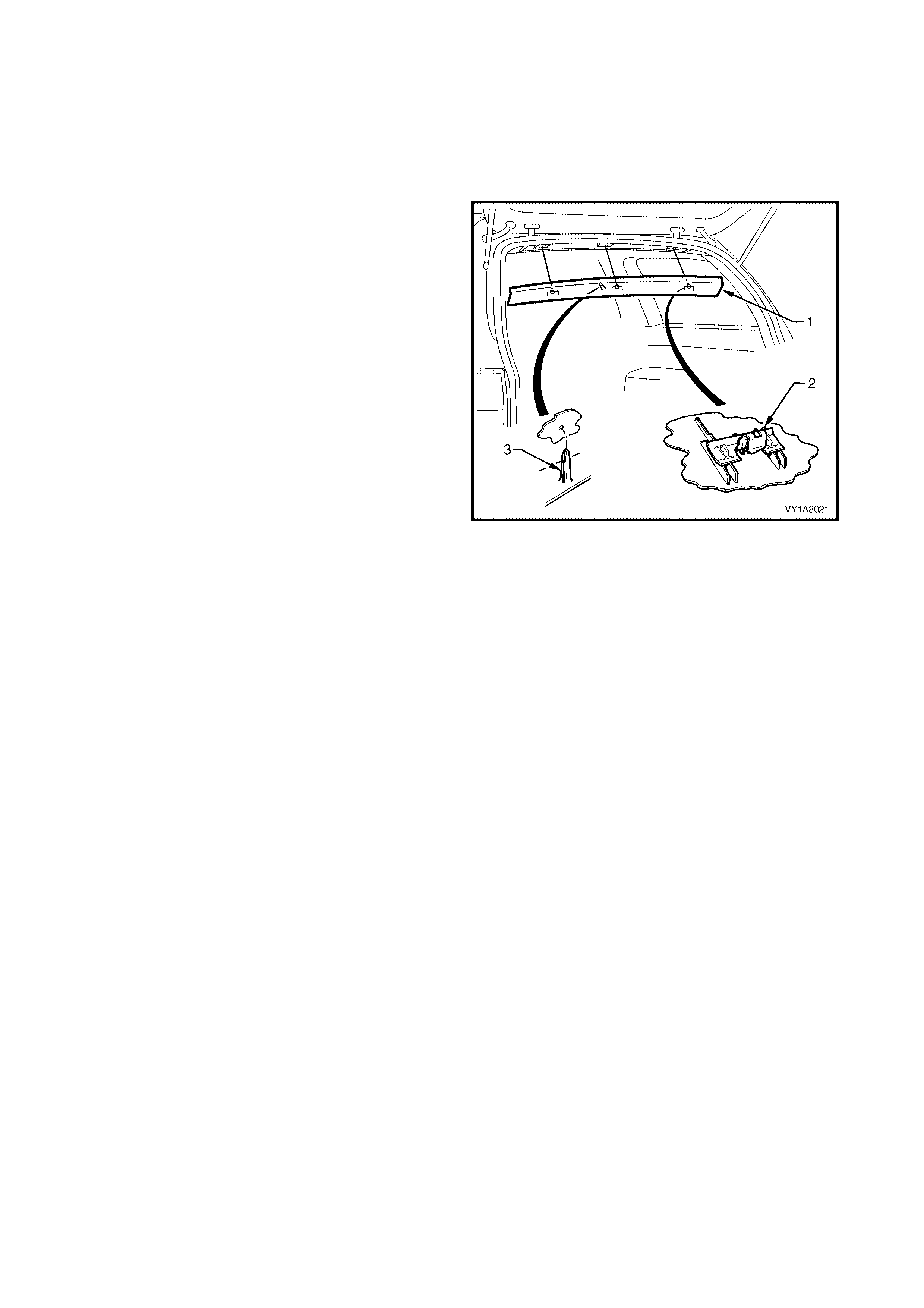
1. Remove the three retainers (1) attaching the
forward edge of the rear window trim panel
assembly (2).
2. Remove the two retainers (3) attaching the upper
surface of the rear window trim panel assembly.
3. Lift the front edge of the rear window trim panel
assembly and feed the seat belt and anchor plate
through the seat belt opening.
4. Remove the rear window trim panel assembly.
Figure 1A8-12
DISASSEMBLE
1. Bend the nine speaker grille tabs (1) to a vertical
position and remove from the rear window trim
panel assembly (2).
2. Remove the dust seal (3) from the speaker grille.
3. Remove the s peak er s eal (4) f rom the r ear window
trim panel assembly.
ASSEMBLE
Reinstallation of the rear window trim panel speaker
grille is the reverse of the removal, noting the
following:
1. Bend the nine speaker grille tabs to a horizontal
position to retain the speaker grille.
Figure 1A8-13

REINSTALL
Reinstallation of the rear window trim panel assembly
is the reverse of the removal, noting the following:
1. W here fitted, ensure the speaker seals do not foul
on the speaker assemblies.
LOWER CENTRE SEAT BELT
ATTACHING BOLT
TORQUE SPECIFICATION 35.0 – 50.0 Nm

2.10 SUNSHADE ASSEMBLY
LT Section No. – 14-050
1. Remove the fuse F6 from the passenger compartment fuse and relay assembly, refer Section 12O,
1.1 FUSES and 1.2 CIRCUIT BRAKERS.
REMOVE
1. Disconnect the sunshade assembly (1) from the
sunshade support (2) and rotate to gain access.
2. Remove the sunshade assembly attaching Torx
screws (3) two places.
3. Pull the sunshade away from the headlining
assembly and if fitted, disconnect the wiring
harness (4) to the illuminated vanity mirrors (5).
4. Remove the sunshade.
5. Remove the Torx screw (6) from the sunshade
support and pull the support from the headlining
assembly.
NOTE: W hen removing the sunshade support, ensure
that care is taken not to damage the locating pin (7).
Figure 1A8-14
REINSTALL
Reinstallation of the s unshade assem bly is the r everse
of the removal, noting the following:
1. Ensure the sunshade support is correctly located.
2. If fitted, reconnect the wiring harness to the
sunshade assembly.
3. Tighten all fasteners to the correct torque
specification.
SUNSHADE ASSEMBLY ATTACHING
SCREWS TORQUE SPECIFICATION 0.5 – 2.0 Nm
SUNSHADE SUPPORT ATTACHING
SCREWS TORQUE SPECIFICATION 0.5 – 2.0 Nm
2.11 ROOF CONSOLE
LT Section No. –
1. Remove the fuse F6 from the passenger compartment fuse and relay assembly, refer Section 12O,
1.1 FUSES and 1.2 CIRCUIT BRAKERS.
NOTE: The following procedure is only applicable to
vehicles fitted with a roof console.
REMOVE
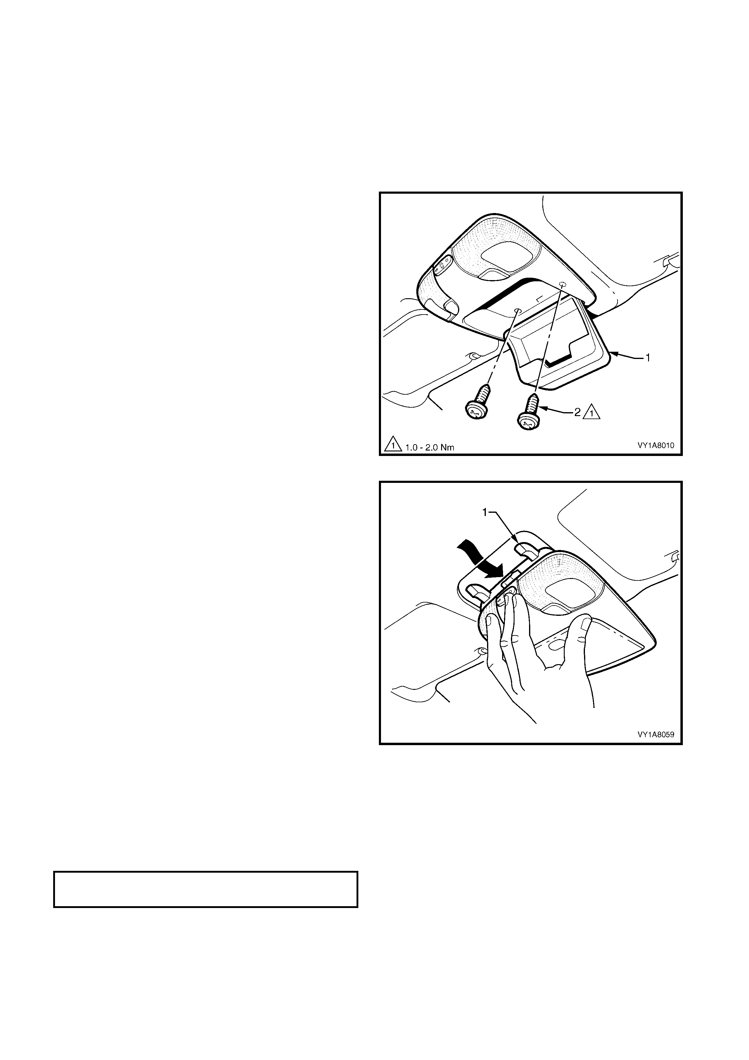
1. Open the roof console (1) compartment door.
2. Rem ove the two roof console attaching screws (2)
from inside the console.
3. Close the compartment door.
4. Using your hand to pull down, disengage the front
of the roof console from the roof header panel.
Figure 1A8-15
5. Remove in a forward motion to allow the locator
arms (1) to clear the headlining.
6. Disconnect the wiring harness and remove.
NOTE: For replacement of the reading lamp
bulbs, refer to Section 12B, 3. SERVICE
OPERATIONS INTERIOR ILLUMINATION.
Figure 1A8-16
REINSTALL
The installation procedure for the roof console is the
reverse of the removal procedure, noting the following:
1. Tighten all fasteners to the correct torque
specification.
ROOF CONSOLE ATTACHING
SCREW TORQUE SPECIFICATION 1.0 – 2.0 Nm
2.12 HEADLINING ASSEMBLY
LT Section No. – 14-150
1. Remove the fuse F6 from the passenger compartment fuse and relay assembly, refer Section 12O,
1.1 FUSES and 1.2 CIRCUIT BRAKERS.
NOTE: If a sunroof is fitted, refer to Section 1F1, SUNROOF for the headlining assembly removal.
2. Place protective covering over both front seats and the interior trim.
3. Remove the rear seat cushion, refer to Section 1A7, SEAT ASSEMBLIES.
4. Remove the rear seat back, refer to Section 1A7, SEAT ASSEMBLIES.
5. Remove assist handles, refer to 2.1 ASSIST HANDLE.
6. If fitted, remove the roof rail courtesy lamp, refer to Section 12B, 3.15 ROOF RAIL COURTESY AND
READING LAMP ASSEMBLY.
7. Partially remove the centre pillar upper trim by removing the upper attaching screw, refer to
2.3 CENTRE PILLAR UPPER TRIM ASSEMBLY.
8. Remove the windshield side garnish, refer to 2.5 WINDSHIELD SIDE GARNISH .
9. Remove the body lock pillar garnish, refer to 2.6 BODY LOCK PILLAR GARNISH.
10. Remove the rear window upper garnish, refer to 2.7 REAR WINDOW UPPER GARNISH.
11. Remove the sunshade assembly, refer to 2.10 SUNSHADE ASSEMBLY.
12. Remove the roof console, if fitted, refer to 2.11 ROOF CONSOLE.
13. Remove the dome lamp, if fitted, refer to Section 12B, 3.8 DOME LAMP ASSEMBLY.
REMOVE
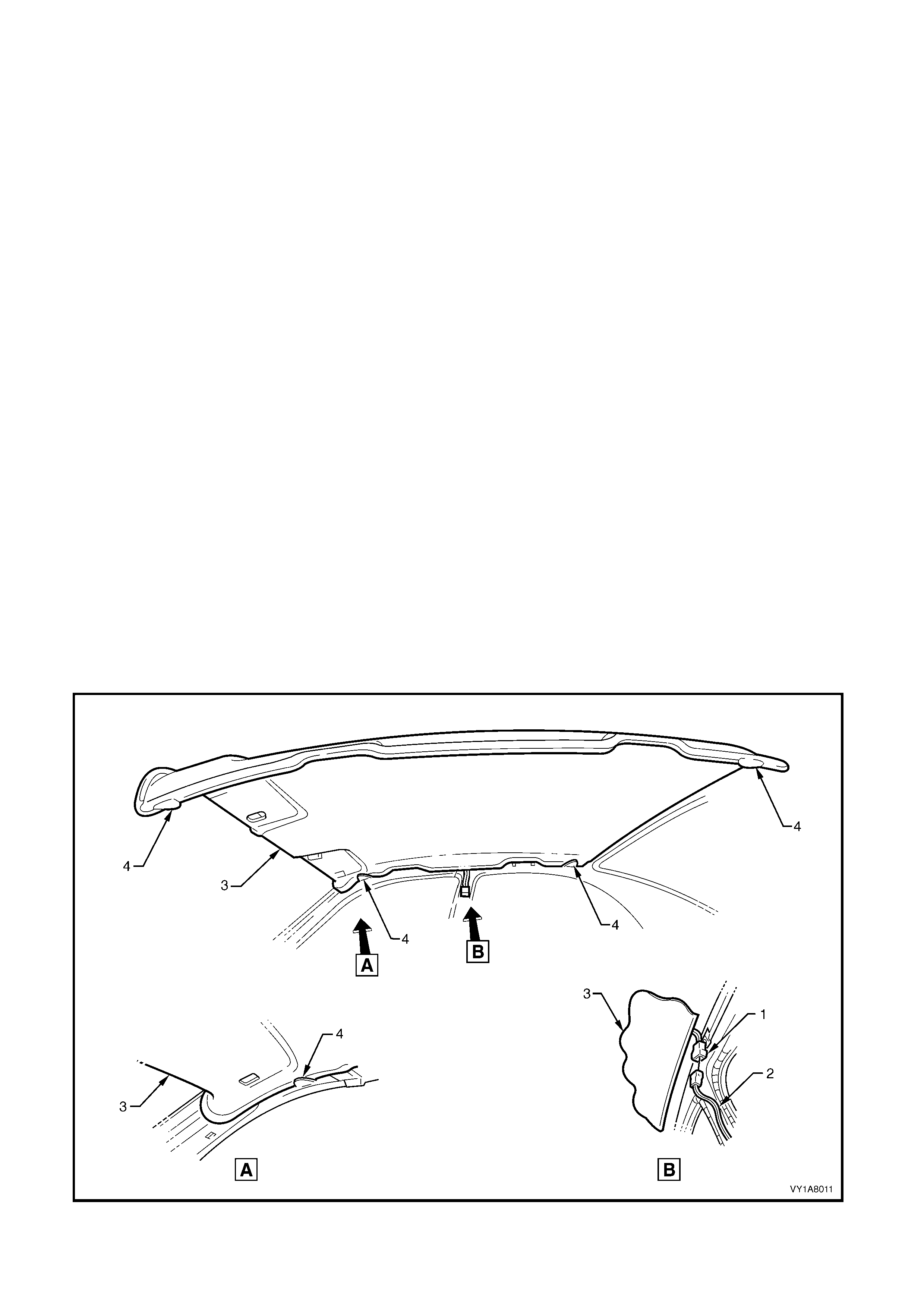
1. Disconnect the headlining assembly harness (1) from the body harness connector (2), located above and
slightly forward of the right-hand centre pillar, refer to Figure1A8-17.
NOTE: It may be necessary to flex the headlining assembly (3) down slightly to gain access to the harness
connector.
2. With the aid of an assistant, flex the headlining assembly to disengage the corners from the four ‘D’ tabs (4) on
the sides of the roof panel.
3. Ease the headlining assembly from its position in the roof and turn the assembly so that it can be passed
through the passenger side front door, removing the assembly from the vehicle, refer to Figure1A8-17.
Figure 1A8-17

REINSTALL
Reinstallation of the headlining assembly is the reverse of the removal, noting the following:
1. Temporaraly support the headlining assembly on the ‘D’ tabs before the trim components are reinstalled.

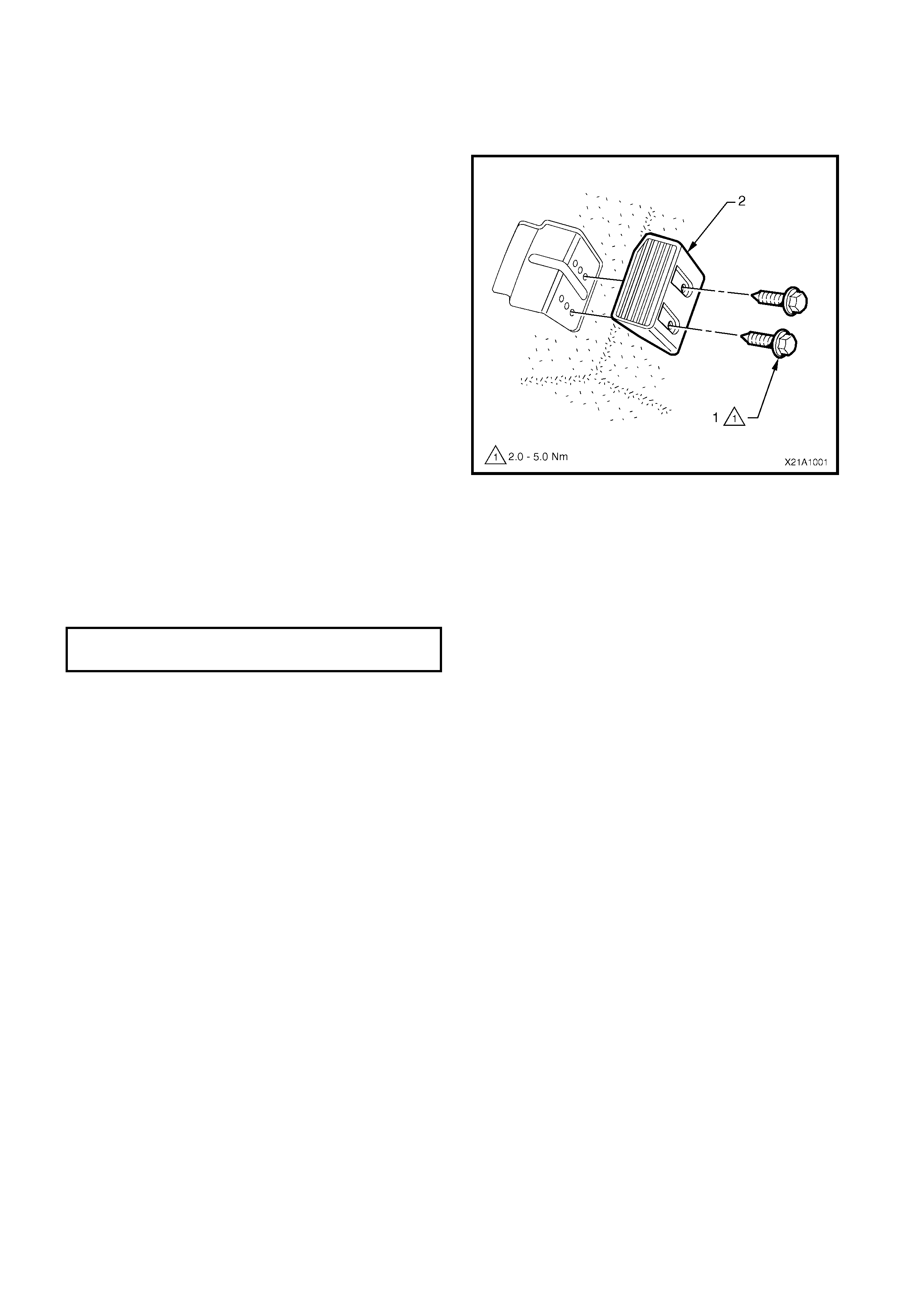
2.13 DRIVER FOOTREST
LT Section No. – 14-475
REMOVE
1. Remove the two screws (1) securing the driver
footrest (2) to the footrest mounting bracket.
2. Remove the footrest pad.
Figure 1A8-18
REINSTALL
Reinstallation of the dr iver f ootr es t is the rever s e of the
removal procedure, noting the following:
1. Ensure all fasteners are tightened to the correct
torque specifications.
DRIVER FOOTREST ATTACHING
SCREW TORQUE SPECIFICATION 2.0 – 5.0 Nm
2.14 FRONT FLOOR CARPET ASSEMBLY
LT Section No. – 14-475
CAUTION: It will be necessary to disable the SRS (Air Bag) prior to this operation. Refer to DISABLING
THE SRS, Section12M, OCCUPANT PROTECTION SYSTEM.
If required, first remove the following components,
1. Remove the right and left-hand centre pillar lower trims, refer to 2.2 CENTRE PILLAR LOWER TRIM.
2. Remove the rear seat cushion, refer to Section 1A7, SEAT ASSEMBLIES.
3. Remove the right and left-hand side sill trims, refer to 2.4 SIDE SILL TRIM AND PLATE.
4. Remove the right and left-hand hinge pillar trim assemblies, refer to 2.8 HINGE PILLAR TRIM ASSEMBLY.
5. Remove both front seats, refer to Section 1A 7,SEAT ASSEMBLIES.
6. Remove the driver footrest, refer to 2.13 DRIVER FOOTREST.
7. Remove the park brake lever cover by grasping the cover firmly by hand and sliding the cover over the park
brake lever, refer to Section 5A, 2.9 PARK BRAKE LEVER.
8. Remove the instrument panel compartment, refer to Section 1A3, 3.2 INSTRUMENT PANEL
COMPARTMENT ASSEMBLY.
9. Remove the instrument panel lower trim panel, refer to Section 1A3, 3.4 INSTRUMENT PANEL LOWER
TRIM PANEL ASSEMBLY.
10. Remove the right and left-hand instrument panel lower trim plate assembly, refer to Section 1A3,
3.1 INSTRUMENT PANEL LOWER TRIM PLATE ASSEMBLY.
11. Remove instrument panel lower extension side trim panel, refer to Section 1A3, 2.2 INSTRUMENT PANEL
LOWER EXTENSION SIDE TRIM PANEL.
12. Remove floor console assembly, refer to Section 1A3, 2.3 FLOOR CONSOLE ASSEMBLY.
13. Disconnect the inflatable restraint control module (SDM) wiring harness, refer to Section 12M,
2.8 INFLATABLE RESTRAINT CONTROL MODULE (SDM).
14. For vehicles fitted with an automatic transmission, remove the selector control lever assembly, refer
Section 7C4, AUTOMATIC TRANSMISSION ON VEHICLE SERVICING.
15. For vehicles fitted with manual transmission, remove the gearshift lever, refer to Section 7B1, MANUAL
TRANSMISSION – V6 ENGINE or Section 7B2, MANUAL TRANSMISSION - GEN III V8 ENGINE.
REMOVE
1. Remove the two retaining clips (1) from the front
floor carpet assembly (2) by rotating the clips
counter- clockwise and lift clear of the attaching
studs.
NOTE: To assist in the removal and installation of the
front floor carpet assembly, it has been perforated
(3) from the front edge through the centre of the
evaporator dr ain cut out to the forward edge of the
lower radio bracket cut out, refer Figure 1A8-20.
Figure 1A8-19
2. From ins ide the left-hand foot well, grasp the edge
of the hole in the front floor carpet assembly
around the evaporator drain hose (4) and tear
open the perforated line (3) by pulling the carpet
away from the transmission tunnel.
3. Slide the remaining flap of carpet out from under
the heating, ventilation and air conditioning
(HVAC) unit (5) and into the right-hand foot well.
4. Carefully manoeuvre the floor carpet and insulator
assembly from the vehicle.
Figure 1A8-20

REINSTALL
The installation procedure for the front floor carpet
assembly is the reverse of the removal procedure,
noting the following:
1. If a new carpet is being fitted, cut along the
perforated line in the floor carpet that runs from the
forward edge of the carpet, through the evaporator
drain cut-out, to the forward edge of the lower
radio bracket cut-out, prior to installation, refer
Figure 1A8-19.
2. Ensure all the cut-outs in the carpet are correctly
aligned and install the two retaining clips and the
front seat belt lower attaching bolts to secure the
carpet, prior to installing the seats and console.
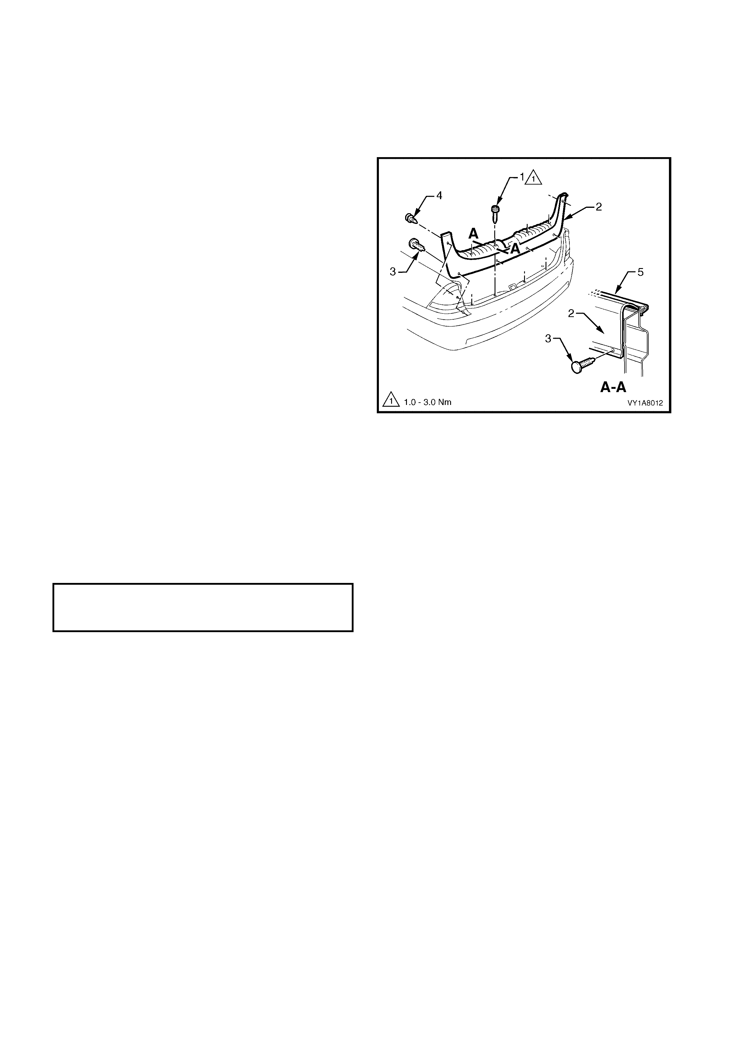
2.15 RE AR END TRIM PANEL
LT Section No. – 14-120
1. Partially remove the rear compartment weatherstrip, refer to Section 1A4, 3.12 REAR COMPARTMENT
WEATHERSTRIP.
REMOVE
1. Remove the four attaching screws (1) along the
ribbed upper surface of the rear end trim panel (2).
2. Remove the four retainers (3) along the lower
inner edge of the rear end trim panel.
3. Remove the two retainers (4) attaching the upper
sides of the rear end trim panel.
4. Carefully lift the rear end trim panel over the rear
compartment lid latch and clear of the rear
compartment.
Figure 1A8-21
REINSTALL
Reinstallation of the rear end trim panel is the reverse
of the removal, noting the following:
1. Ensure that the outer edge of rear end trim panel
engages the rear compartment seal (5), refer
Figure 1A8-21.
2. Tighten all retaining screws to the correct torque
specification.
REAR END TRIM PANEL
ATTACHING SCREW
TORQUE SPECIFICATION 1.0 – 3.0 Nm
2.16 REAR COMPARTMENT FLOOR CARPET ASSEMBLY
LT Section No. – 14-480
REMOVE
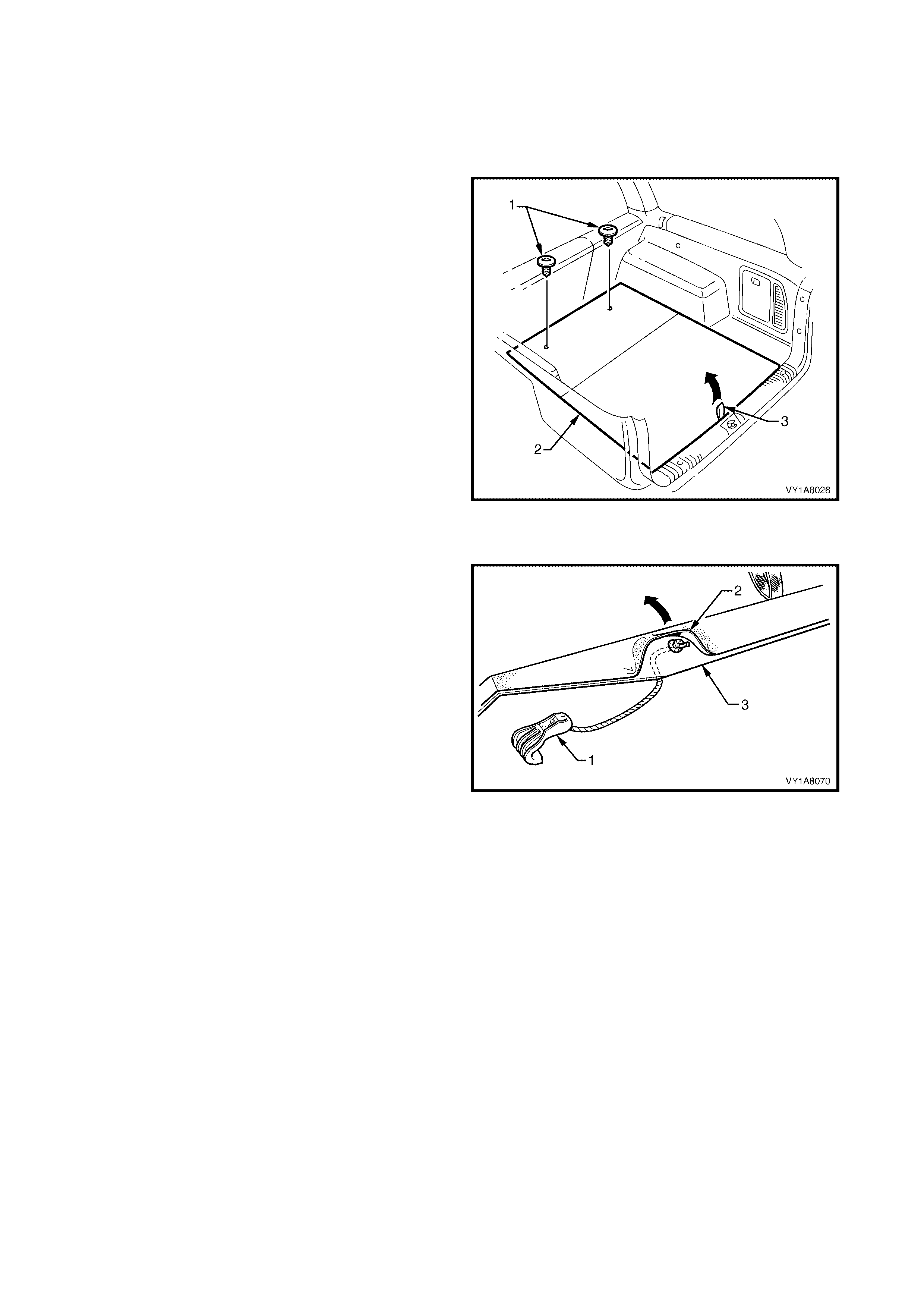
1. Open the rear compartment lid.
2. Grasp the handle (1) on the rear compartment
floor carpet assembly (2) and lift the rear edge
upward.
3. Lift the rear compartment floor carpet assembly
from the rear compartment.
Figure 1A8-22
DISASSEMBLE
1. Lever the rear compartment strap (1) out of the
slot in the rear compartment floor (2), and remove.
2. Feed the strap through the hole in the rear
compartment floor carpet and remove.
ASSEMBLE
Assem bly of the rear com partm ent strap is the reverse
of the removal.
Figure 1A8-23
REINSTALL
Reinstallation of the rear compartment floor carpet
assembly is the reverse of the removal.
2.17 QUARTER INNER REAR SIDE CARPET
LT Section No. – 14-480
1. Remove the rear end trim panel, refer to 2.15 REAR END TRIM PANEL.
2. Remove the rear c ompartment floor car pet as sembly, refer to 2.16 REAR COMPARTMENT FLOOR CARPET
ASSEMBLY.
REMOVE
1. Carefully prise off the rear shock absorber access hole cover (1).
2. Carefully remove the retainer (2) away from the quarter inner rear side carpet (3).
3. Unhook the carpet flap from the rear compartment lid hinge bracket.
4. Carefully remove the quarter inner rear side carpet, refer Figure 1A8-24.
Figure 1A8-24
REINSTALL
The installation procedure for the quarter inner rear side carpet is the reverse of the removal procedure.
2.18 REAR SE AT BACK PANEL CARP ET
LT Section No. – 14-480
1. Remove the rear end trim panel, refer to 2.15 REAR END TRIM PANEL.
2. Remove the rear c ompartment floor car pet as sembly, refer to 2.16 REAR COMPARTMENT FLOOR CARPET
ASSEMBLY.
3. Partially remove the front of the quarter inner rear side carpet, refer to 2.17 QUARTER INNER REAR SIDE
CARPET.
4. Lower the rear seat-back centre armrest assembly, refer to Section 1A7, SEAT ASSEMBLIES.
REMOVE
1. Carefully remove the six retainers (1) out of the
rear seat back panel carpet (2).
2. Remove the rear seat back panel carpet.
Figure 1A8-25
REINSTALL
The installation procedur e for the rear seat bac k panel
carpet is the reverse of the removal operations.
1. Ensure the rear seat back panel carpet is fitted
behind the quarter inner rear side carpet.
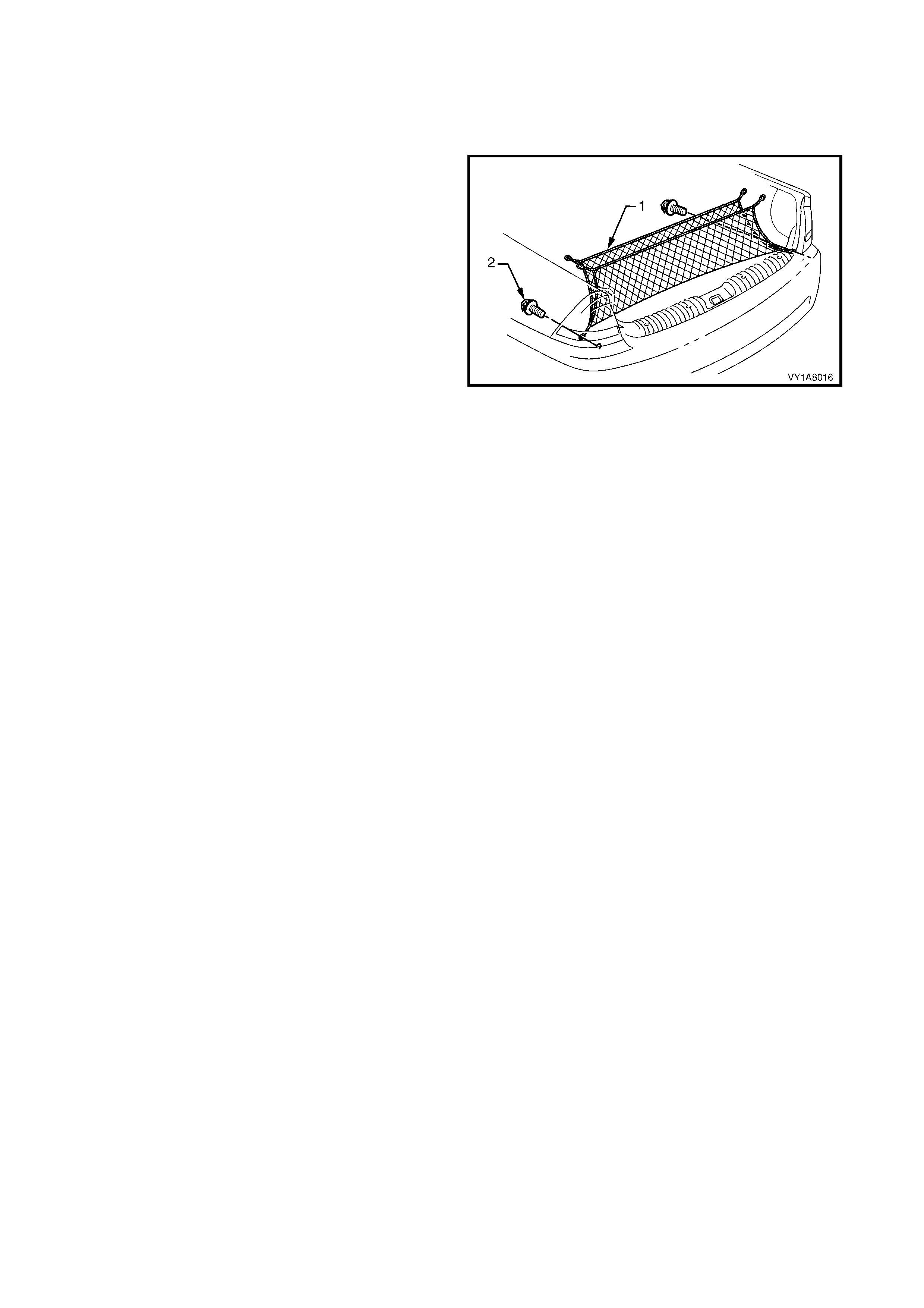
2.19 CONVENIENCE NET
LT Section No. –
REMOVE
1. Carefully unhook the convenience net (1) from the
four retainers (2) and remove.
Figure 1A8-26
REINSTALL
The installation procedure for the convenience net is
the reverse of the removal operations.
3. SERVICE OPERATIONS - WAGON
NOTE: The following chart is included to assist with the identification of the components.
For the removal and reinstall procedures of the liftgate trim, refer to Section 1A4, 4. SERVICE OPERATIONS -
LIFTGATE, WAGON.
For the service procedures of the front and rear door trim panel assemblies, refer to Section 1A5,
2.6 FRONT DOOR TRIM PANEL ASSEMBLY and 3.6 REAR DOOR TRIM PANEL ASSEMBLY.
Figure 1A8-27
Legend
1. Assist Handle
2. Centre Pillar Lower Trim
3. Centre Pillar Upper Trim
4. Side Sill Trim
5. Side Sill Trim Plate
6. Windshield Side Garni sh
7. Body Lock Pillar Lower Trim
8. Body Lock Pillar Garnish
9. Quarter I nner Tri m Upper
10. Body Rear Corner Garnish
11. Rear Window Upper Garnish
12. Quarter Inner Trim Panel Assembly
13. Hinge Pillar Trim Assembly
14. Sunshade assembly
15. Roof Console
16. Headlining Assembly
17. Driver Footrest
18. Front Floor Carpet Assem bl y
19. Rear Floor Filler Panel
20. Rear End Trim Panel
21. Rear Compartment Floor Carpet Ass embly, E xcept LP G
22. Rear Compartment Floor Carpet Ass embly, Wi th LPG
23. Spare Wheel Cover, With LPG
24. Luggage Shade Assembly
3.1 ASSIST HANDLE
LT Section No. – 14-100
REMOVE
1. Pull the assist handle (1) into the down position.
2. Prise open the assist handle screw cover (2) and
remove the attaching screw (3) two places.
3. Remove the assist handle ensuring care is taken
not to damage the locating pins.
Figure 1A8-28
REINSTALL
1. Ensure the locating pins are correctly aligned with
the locating holes.
2. Tighten all retaining screws to the correct torque
specification.
ASSIST HANDLE ATTACHING
SCREW TORQUE SPECIFICATION 1.0 – 3.0 Nm
3.2 CENTRE PILLAR LOWER TRIM
LT Section No. – 14-100
REMOVE
1. Lever the centre pillar lower trim ( 1) away f rom the
front door opening weatherstrip with your fingers,
pulling the trim towards the centre of car,
disengaging the two retaining clips (2).
2. Remove the trim upward, out of the side sill trim
(3).
Figure 1A8-29
REINSTALL
1. Locate the centre pillar lower trim into the side sill
trim and push the retaining clips in firmly.
2. Ensure front and rear door opening weatherstrip
fits neatly over the outer edge of c entre pillar lower
trim.
3.3 CENTRE PILLAR UPPER TRIM ASSEMBLY
LT Section No. – 14-100
1. Remove the centre pillar lower trim, refer to 3.2 CENTRE PILLAR LOWER TRIM.
2. Remove the front lower seat belt bolt, refer to Section12M, OCCUPANT PROTECTION SYSTEM.
REMOVE
1. Remove the centre pillar cap (1) from the upper
attachment of the centre pillar upper trim (2).
2. Remove the three screws (3) securing the centre
pillar upper trim.
3. Pull the upper edge of the centre pillar upper trim,
away from the headlining to disengage the seat
belt guide adjuster (4) assembly if fitted.
4. Feed the seat belt and anchor plate through the
centre pillar upper trim and remove the trim.
NOTE: When removing the centre pillar upper trim,
ensure car e is tak en not to dam age the locating pin (5)
below the upper attaching screw.
5. If required to remove, lift out the seat belt adjuster
trim (6) by gently spreading the outer edges of the
centre pillar upper trim.
Figure 1A8-30
REINSTALL
Reinstallation of the centre pillar upper trim is the
reverse of the removal, noting the following:
1. If fitted, ensure that the seat belt adjuster trim and
the seat belt guide adjus ter as s embly are in the full
up position and are correctly aligned prior to
installation of the centre pillar upper trim.
2. Ensure the locating pin below the upper attaching
screw in the centre pillar upper trim, is correctly
aligned with the locating hole in the centre pillar.
3. Ensure the leading edge of the centre pillar upper
trim engages the door opening weatherstrip (7),
refer Figure 1A8-30.
4. Check seat belt operation prior to tightening the
centre pillar upper trim attaching screws.
5. Tighten all fasteners to the correct torque
specification.
CENTRE PILLAR UPPER TRIM
ATTACHING SCREW
TORQUE SPECIFICATION 1.0 – 3.0 Nm
FRONT SEAT BELT LOWER
ATTACHING BOLT
TORQUE SPECIFICATION 35.0 – 50.0 Nm
3.4 SIDE SILL TRIM AND PLATE
LT Section No. – 14-100
1. Remove the centre pillar lower trim, refer to 3.2 CENTRE PILLAR LOWER TRIM.
REMOVE
1. Remove the front attaching screw (1) from the seat
adjuster outer front cover (2), driver side, right
hand drive only.
2. Using a small screwdriver, push in the centre of
the join to separate the front cover and the front
seat outer lower rear cover (3).
3. Unclip the covers from the seat track, and
disengage from the side sill trim.
4. Pull the covers apart and remove the rear cover.
5. For the driver’s side on right hand drive vehicles,
slide the f r ont c over over the f uel filler door r eleas e
lever (4) and remove.
Figure 1A8-31
1. Carefully lever the front and rear side sill trim
plates (1) from the side sill trim (2), starting at the
front of each plate and moving rearwards,
revealing the attaching screws.
IMPORTANT: Care must be taken not to snap the sill
trim plates.
2. Remove the six Torx head screws (3) from the
side sill trim , f our in the f ront door opening and two
in the rear door opening.
3. Remove the Torx head s crew (4) from the side sill
trim to the centre pillar.
4. Remove the side sill trim through the front door
opening, by lifting the f ront and sliding the rear out
from under the rear seat cushion.
Figure 1A8-32
REINSTALL
Reinstallation of the side sill trim and the seat adjuster
outer front cover is the reverse of the removal, noting
the following:
1. Ensure the outer edge of the side sill trim engages
the door opening weatherstrip (5), refer Figure
1A8-32.
2. Tighten all fasteners to the correct torque
specification.
SEAT ADJUSTER OUTER FRONT
COVER ATTACHING SCREW
TORQUE SPECIFICATION 1.0 – 3.0 Nm
SIDE SILL TRIM
ATTACHING SCREW
TORQUE SPECIFICATION 1.0 – 3.0 Nm

3.5 WI NDSHIELD SIDE GARNISH
LT Section No. – 14-100
1. Remove the assist handle, refer to 3.1 ASSIST HANDLE.
2. Partially remove the centre pillar upper trim by removing the upper attaching screw, refer to
3.3 CENTRE PILLAR UPPER TRIM ASSEMBLY.
REMOVE
1. Starting at the upper rear edge of the windshield
side garnish (1), disengage the three attaching
clip s (2).
2. Remove the windshield side garnish.
NOTE: When removing the windshield side garnish,
ensure care is taken not to damage the locating pin
(3).
Figure 1A8-33
REINSTALL
Reinstallation of the windshield side garnish is the
reverse of the removal, noting the following:
1. Ensure the windshield side garnish locating pins
are aligned with the holes in the inner panel.
2. Ensure the outer edge of the windshield side
garnish engages the door opening weatherstrip
(4), refer Figure 1A8-33.
3.6 BODY LOCK PILLAR LOWER TRIM
LT Section No. – 14-130
1. Remove the rear seat bolster assembly, refer to Section 1A7, 7.3 REAR SEAT BOLSTER ASSEMBLY.
REMOVE
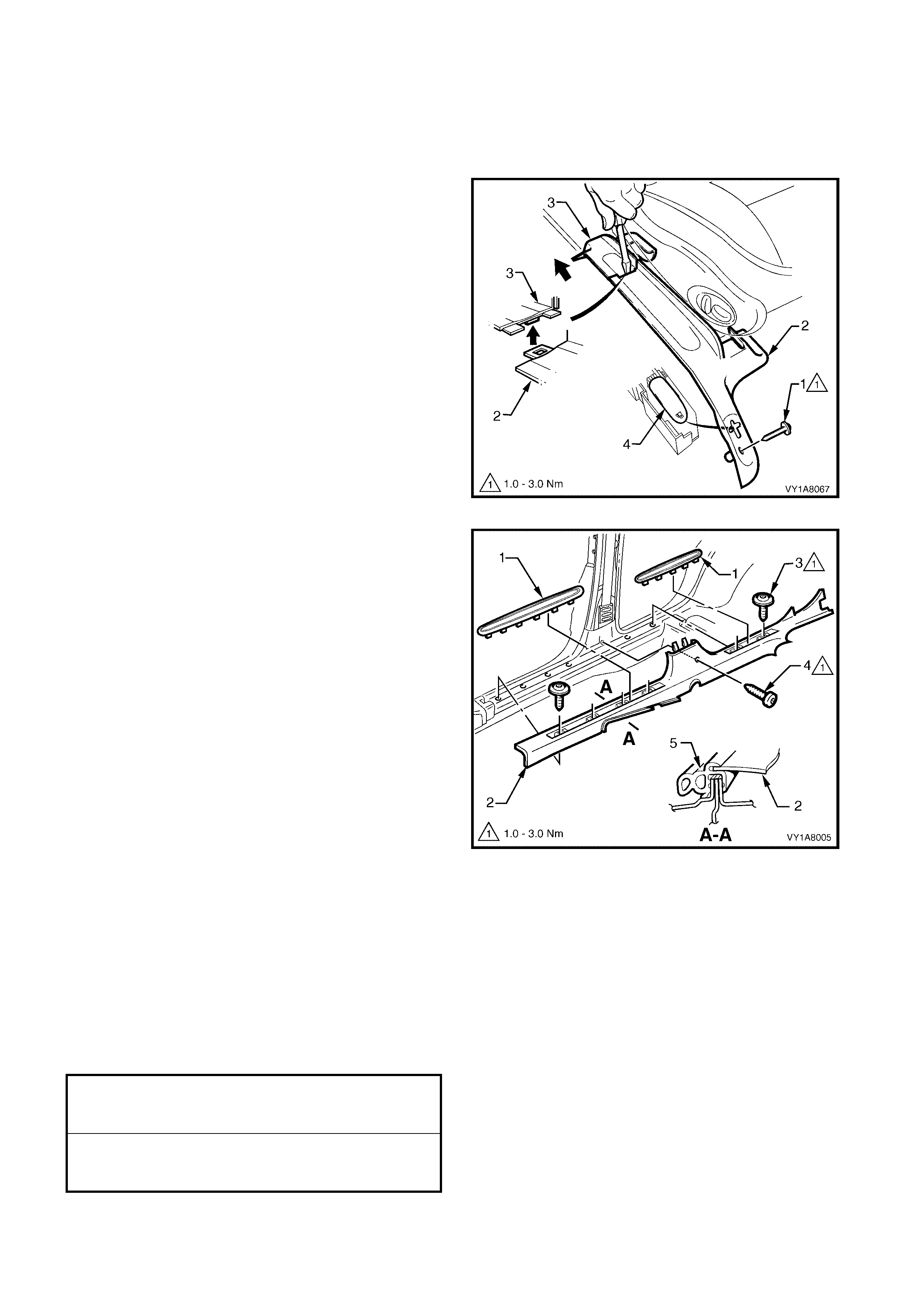
1. Remove the upper screw (1) securing the body
lock pillar lower trim (2).
2. Remove the lower retainer (3) securing the body
lock pillar lower trim.
3. Pull the lower edge of the body lock pillar lower
trim, away from the lock pillar to disengage the
retainer (4) one place.
4. Remove the body lock pillar lower trim.
Figure 1A8-34
5. If required, remove the luggage shade attaching
spring clip (1) from the body lock pillar lower trim
(2).
6. Spread the spring clip open through the holes in
the lower trim and lever out with a screwdriver.
Figure 1A8-35
REINSTALL
Reinstallation of the body lock pillar lower trim is the
reverse of the removal, noting the following:
1. If removed, replace the spring clip into the body
lock pillar lower trim, refer figure 1A8-35.
2. Ensure the outer edge of the body lock pillar lower
trim engages the door opening weatherstrip.
3. Tighten all fasteners to the correct torque
specification.
BODY LOCK PILLAR LOWER TRIM
ATTACHING SCREW
TORQUE SPECIFICATION 1.0 – 3.0 Nm
3.7 BODY LOCK PILLAR GARNISH
LT Section No. – 14-130
1. Remove the rear assist handle, refer to 3.1 ASSIST HANDLE.
2. If fitted, remove the roof rail courtesy lamp, refer to Section 12B, 3.15 ROOF RAIL COURTESY AND
READING LAMP ASSEMBLY.
3. Partially remove the centre pillar upper trim by removing the upper attaching screw, refer to
3.3 CENTRE PILLAR UPPER TRIM ASSEMBLY.
4. Remove the body lock pillar lower trim, refer to 3.6 BODY LOCK PILLAR LOWER TRIM.
5. Fold forward the rear seat back.
6. Remove the rear seat bolster assembly, refer to Section 1A7, 7.3 REAR SEAT BOLSTER ASSEMBLY.
7. Remove the rear lower seat belt bolt, refer to Section12M, OCCUPANT PROTECTION SYSTEM.
REMOVE
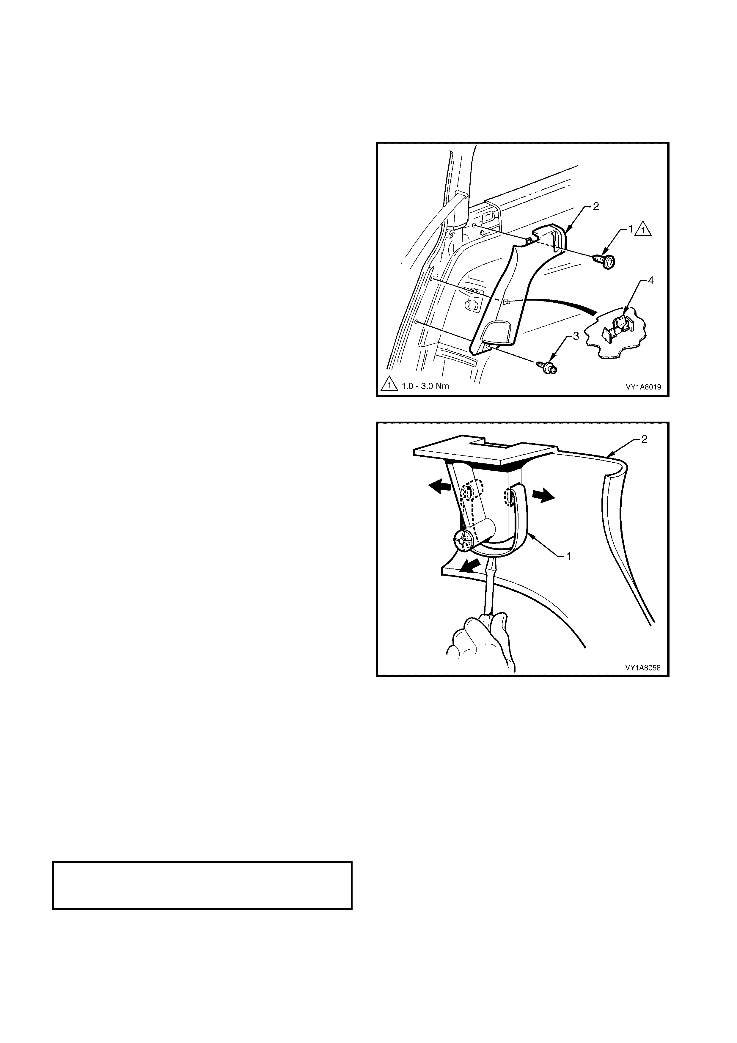
1. Remove the body lock pillar garnish cap (1) from
the body lock pillar garnish (2).
2. Remove the upper screw (3) securing the body
lock pillar garnish.
3. Remove the lower screw (4) from the body lock
pillar garnish (4).
4. Pull the front edge of the body lock pillar garnish
away from the body lock pillar and working
rearwards, disengage the three garnish clip (5).
NOTE: When removing the body lock pillar garnish,
ensure care is taken not to damage the locating
pin (6).
Figure 1A8-36
5. With the body lock pillar garnish (1) partially
removed, disengage the seat belt guide (2) from
the garnish and feed the seat belt and anchor plate
through the opening.
6. Remove the body lock pillar garnish.
Figure 1A8-37
REINSTALL
Reinstallation of the body lock pillar garnish is the reverse of the removal, noting the following:
1. Ensure the body lock pillar garnish locating pin is aligned with the hole in the inner panel.
2. Ensure the outer edge of the body lock pillar garnish engages the door opening weatherstrip.
3. Tighten all fasteners to the correct torque specification.
BODY LOCK PILLAR GARNISH
ATTACHING RETAINER
TORQUE SPECIFICATION 1.0 – 3.0 Nm
REAR SEAT BELT LOWER
ATTACHING BOLT
TORQUE SPECIFICATION 35.0 – 50.0 Nm
3.8 QUARTER INNER TRIM UPPER
LT Section No. – 14-130
1. Remove the body lock pillar lower trim, refer to 3.6 BODY LOCK PILLAR LOWER TRIM.
REMOVE
1. Remove the screw (1) retaining the quarter inner
trim upper (2).
2. Pull the rear edge of the quarter inner trim upper
away from the body side panel and working
forwards, disengage the four garnish clips (3).
NOTE: When removing the quarter inner trim upper,
ensure care is taken not to damage the locating
pin (4).
Figure 1A8-38
REINSTALL
Reinstallation of the quarter inner trim upper is the
reverse of the removal, noting the following:
1. Tighten all fasteners to the correct torque
specification.
QUARTER INNER TRIM UPPER
ATTACHING SCREW
TORQUE SPECIFICATION 1.0 – 3.0 Nm
3.9 BODY REAR CORNER GARNISH
LT Section No. – 14-130
1. Remove the quarter inner trim upper, refer to 3.8 QUARTER INNER TRIM UPPER.
REMOVE
1. Remove the body rear corner garnis h cap (1) f rom
the body rear corner garnish (2).
2. Remove the screw (3) securing the body rear
corner garnish.
3. Starting at the lower rear edge of the rear corner
garnish, disengage the six attaching clips (4).
4. Slide out the rear corner garnish to disengage it
from the rear window upper garnish and remove.
NOTE: When removing the rear corner garnish,
ensure care is taken not to damage the locating
pin (5) or the loc ating lugs ( 6) , f itting under the rear
window upper garnish.
Figure 1A8-39
REINSTALL
Reinstallation of the rear corner garnish is the reverse
of the removal, noting the following:
CAUTION: Extreme care is required not to snap off the
locating pin or the locating lugs, when refitting.
1. Ensure the rear corner garnish locating pin is
aligned with the hole in the inner panel.
2. Ensure the rear corner garnish locating lugs are
fitted under the rear window upper garnish.
3. Ensure the outer edge of the rear corner garnish
engages the door opening weatherstrip.
4. Tighten all fasteners to the correct torque
specification.
BODY REAR CORNER GARNISH
ATTACHING SCREW
TORQUE SPECIFICATION 1.0 – 3.0 Nm
3.10 REAR WINDOW UPPER GARNISH
LT Section No. – 14-130
1. Remove the quarter inner trim upper, refer to 3.8 QUARTER INNER TRIM UPPER.
2. Remove the right or left-hand, body rear corner garnish, refer to 3.9 BODY REAR CORNER GARNISH.
REMOVE
1. Starting from the end that has the rear corner
garnish removed, disengage the rear window
upper garnish (1) three attaching clips (2).
NOTE: When removing the rear window upper
garnish, ensure care is taken not to damage the
locating pin (3).
2. Slide out the rear window upper garnish from the
remaining rear corner garnish and remove.
Figure 1A8-40
REINSTALL
Reinstallation of the rear window upper garnish is the
reverse of the removal, noting the following:
1. Ensure the rear window upper garnish locating pin
is aligned with the hole in the inner panel.
2. Ensure the outer edge of the rear window upper
garnish engages the liftgate opening weatherstrip.
3.11 QUARTER INNER TRIM PANEL ASSEMBLY
LT Section No. – 14-480
1. Fold forward the rear seat back, refer to Section 1A7, SEAT ASSEMBLIES.
2. Remove the quarter inner trim upper, refer to 3.8 QUARTER INNER TRIM UPPER.
3. Loosen the rear end trim panel, refer to 3.19 REAR END TRIM PANEL.
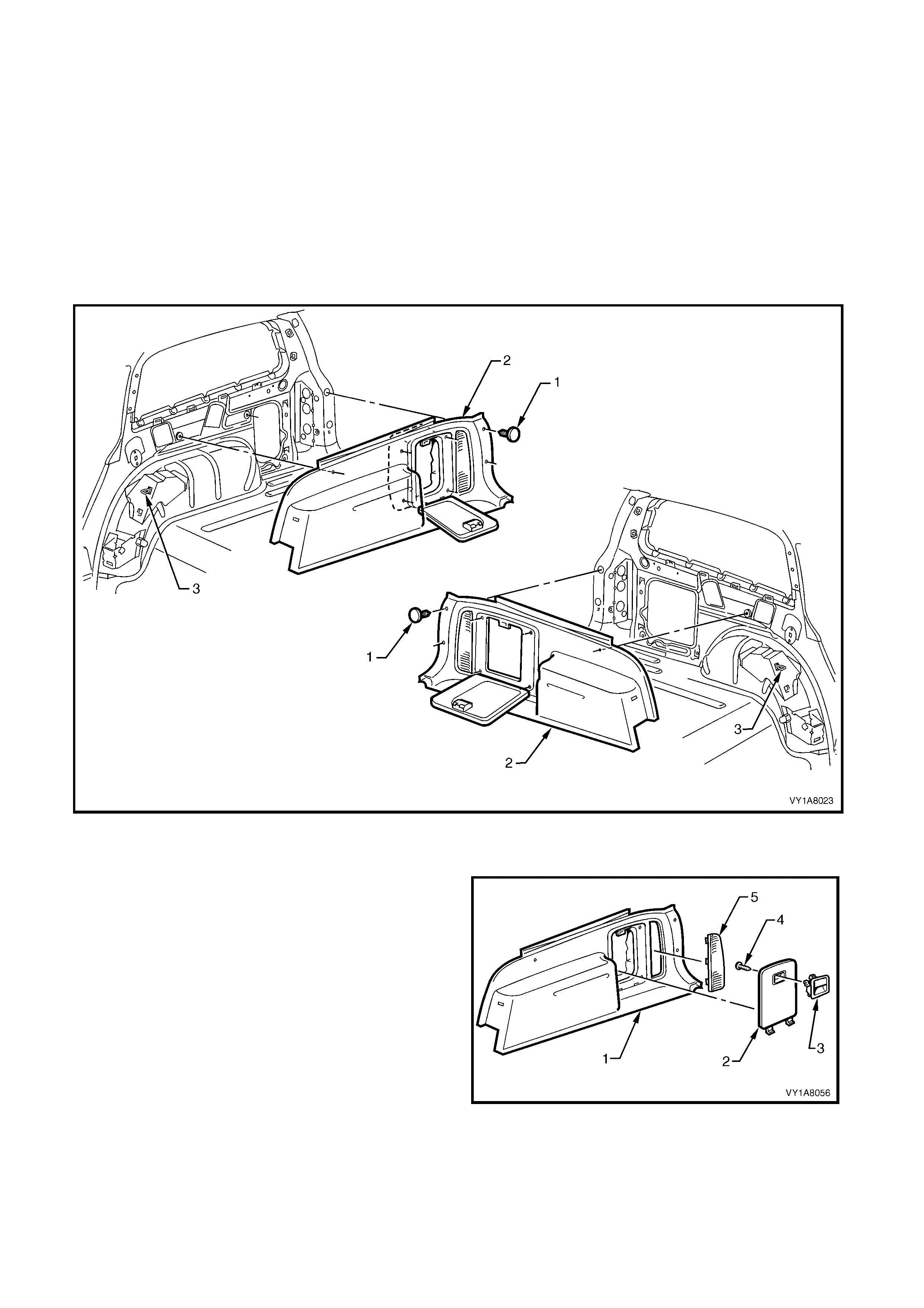
REMOVE
1. Remove the seven retainers (1) on the quarter inner trim panel assembly (2), right or left-hand sides, refer
Figure 1A8-41.
2. Remove the quarter inner trim panel assembly, by raising the edge of the rear compartment floor carpet and
lifting it forward over the rear seat back striker (3), refer Figure 1A8-41.
Figure 1A8-41
DISASSEMBLE
The following components are disassembled in the
following procedures:
1. Quarter inner trim panel assembly.
2. Quarter trim stowage door.
3. Stowage door latch assembly.
4. Latch assembl y screw.
5. Quarter trim panel vent.
Figure 1A8-42
Remove – Quarter Trim Stowage Door
1. Open the quarter trim stowage door (1) in the
quarter inner trim panel assembly (2) to a position
lower than horizontal.
2. Remove the door vertically.
Reinstall – Quarter Trim Stowage Door
Reinstallation of the quarter trim stowage door is the
reverse of the removal.
Figure 1A8-43
Remove – Stowage Door Latch A ssembly
1. Remove the two screws (1) retaining the latch
assembly (2) into the quarter trim stowage door
(3).
2. Push down on the two retaining lugs (4) and eject
the handle.
Reinstall – Stowage Door Latch Assembly
Reinstallation of the latch assembly, is the reverse of
the removal, noting the following:
1. Ensure the latch assembly is pressed firmly into
the quarter trim stowage door.
2. Tighten all retaining screws to the correct torque
specification.
Figure 1A8-44
Remove – Quarter Trim Panel Vent
1. Remove the quarter trim panel vent (1) from the
quarter inner trim panel assembly (2), by
depressing the rear tabs.
2. Remove the vent to the rear.
Reinstall – Quarter Trim Panel Vent
Reinstallation of the quarter trim panel vent.
Figure 1A8-45
STOWAGE DOOR LATCH
ASSEMBLY ATTACHING SCREW
TORQUE SPECIFICATION 1.0 – 3.0 Nm

REINSTALL
Reinstallation of the quarter inner trim panel assembly
is the reverse of the removal, noting the following:
1. Feed the quarter inner trim panel stowage bag into
the quarter panel, so that it does not interfere with
the final fitment of the assembly.
2. Ensure the outer edge of the quarter inner trim
panel assembly engages the door opening
weatherstrip.
3. Tighten all fasteners to the correct torque
specification.
STOWAGE DOOR LATCH
ASSEMBLY ATTACHING SCREW
TORQUE SPECIFICATION 1.0 – 3.0 Nm
3.12 HINGE PILLAR TRIM ASSEMBLY
LT Section No. – 14-100
1. Remove the seat adjuster outer front cover, refer to Section 1A7, SEAT ASSEMBLIES.
2. Remove the centre pillar lower trim, refer to 3.2 CENTRE PILLAR LOWER TRIM.
3. Remove the rear seat cushion, refer to Section 1A7, SEAT ASSEMBLIES.
4. Remove the side sill trim, refer to 3.4 SIDE SILL TRIM AND PLATE.
REMOVE
1. Remove the two attaching screws (1) from the
hinge pillar trim assembly (2).
2. Disengage the hinge pillar trim clip (3) by pulling
the lower edge of the hinge pillar tr im ass embly up
and away from the sheetmetal.
3. Remove the hinge pillar trim assembly.
Figure 1A8-46
REINSTALL
Reinstallation of the hinge pillar trim assembly is the
reverse of the removal, noting the following:
1. Ensure the hinge pillar trim clip is correctly
engaged.
2. Ensur e the nut inserts (4) are correc tly loc ated and
in good condition, refer Figure 1A8-46.
3. Ensure the outer edge of the hinge pillar trim
assembly engages the door opening weatherstrip
(5), refer Figure 1A8-46.
4. Tighten all fasteners to the correct torque
specification.
HINGE PILLAR TRIM ASSEMBLY
ATTACHING SCREW
TORQUE SPECIFICATION 0.7 – 1.0 Nm

3.13 SUNSHADE ASSEMBLY
LT Section No. – 14-050
1. Remove the fuse F6 from the passenger compartment fuse and relay assembly, refer Section 12O,
1.1 FUSES and 1.2 CIRCUIT BRAKERS.
REMOVE
1. Disconnect the sunshade assembly (1) from the
sunshade support (2) and rotate to gain access.
2. Remove the sunshade assembly attaching Torx
screws (3) two places.
3. Pull the sunshade away from the headlining
assembly and if fitted, disconnect the wiring
harness (4) to the illuminated vanity mirrors (5).
4. Remove the sunshade.
5. Remove the Torx screw (6) from the sunshade
support and pull the support from the headlining
assembly.
NOTE: W hen removing the sunshade support, ensure
that care is taken not to damage the locating pin (7).
Figure 1A8-47
REINSTALL
Reinstallation of the s unshade assem bly is the r everse
of the removal, noting the following:
1. Ensure the sunshade support is correctly located.
2. If fitted, reconnect the wiring harness to the
sunshade assembly.
3. Tighten all fasteners to the correct torque
specification.
SUNSHADE ASSEMBLY ATTACHING
SCREWS TORQUE SPECIFICATION 0.5 – 2.0 Nm
SUNSHADE SUPPORT ATTACHING
SCREWS TORQUE SPECIFICATION 0.5 – 2.0 Nm
3.14 ROOF CONSOLE
LT Section No. –
1. Remove the fuse F6 from the passenger compartment fuse and relay assembly, refer Section 12O,
1.1 FUSES and 1.2 CIRCUIT BRAKERS.
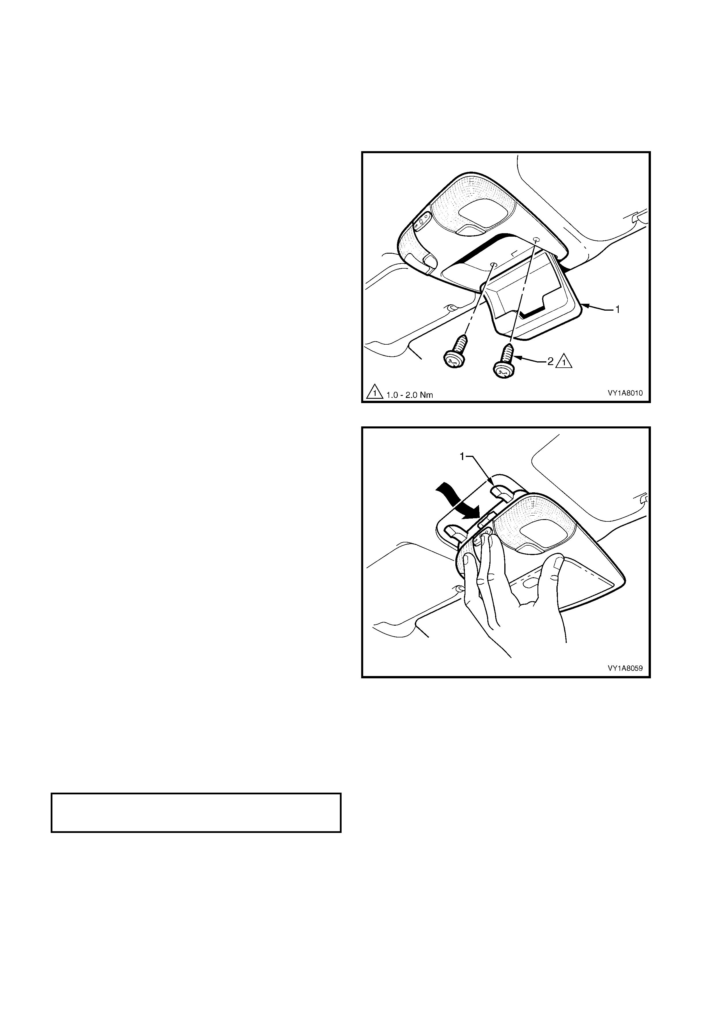
REMOVE
1. Open the roof console (1) compartment door.
2. Rem ove the two roof console attaching screws (2)
from inside the console.
3. Close the compartment door.
4. Using your hand to pull down, disengage the front
of the roof console from the roof header panel.
Figure 1A8-48
5. Remove in a forward motion to allow the rear
locator arms to clear the headlining.
6. Disconnect the wiring harness and remove.
NOTE: For replacement of the reading lamp bulbs,
refer to Section 12B, 3. SERVICE OPERATIONS
INTERIOR ILLUMINATION.
Figure 1A8-49
REINSTALL
The installation procedure for the roof console is the
reverse of the removal procedure, noting the following:
1. Tighten all fasteners to the correct torque
specification.
ROOF CONSOLE ATTACHING
SCREW TORQUE SPECIFICATION 1.0 – 2.0 Nm

3.15 HEADLINING ASSEMBLY
LT Section No. – 14-150
1. Remove the fuse F6 from the passenger compartment fuse and relay assembly, refer Section 12O,
1.1 FUSES and 1.2 CIRCUIT BRAKERS.
2. Place protective covering over both front seats and the interior trim.
3. Remove the rear seat bolster assembly, refer to Section 1A7, 7.3 REAR SEAT BOLSTER ASSEMBLY.
4. Remove the assist handles, refer to 3.1 ASSIST HANDLE.
5. If fitted, remove the roof rail courtesy lamp, refer to Section 12B, 3.15 ROOF RAIL COURTESY AND
READING LAMP ASSEMBLY.
6. Partially remove the centre pillar upper trim by removing the upper attaching screw, refer to
3.3 CENTRE PILLAR UPPER TRIM ASSEMBLY.
7. Remove the windshield side garnish, refer to 3.5 WINDSHIELD SIDE GARNISH .
8. Remove the body lock pillar lower trim, refer to 3.6 BODY LOCK PILLAR LOWER TRIM.
9. Remove the body lock pillar garnish, refer to 3.7 BODY LOCK PILLAR GARNISH.
10. Remove the quarter inner trim upper, refer to 3.8 QUARTER INNER TRIM UPPER.
11. Remove the body rear corner garnish, refer to 3.9 BODY REAR CORNER GARNISH.
12. Remove the rear window upper garnish, refer to 3.10 REAR WINDOW UPPER GARNISH.
13. Remove the sunshade assembly, refer to 3.13 SUNSHADE ASSEMBLY.
14. If fitted, remove the roof console, refer to 3.14 ROOF CONSOLE.
15. If fitted, remove the dome lamp, refer to Section 12B, 3.8 DOME LAMP ASSEMBLY.
16. Remove the rear compartment courtesy lamp from the headlining, refer to Section 12B,
3.5 REAR COMPARTMENT COURTESY LAMP ASSEMBLY.
REMOVE
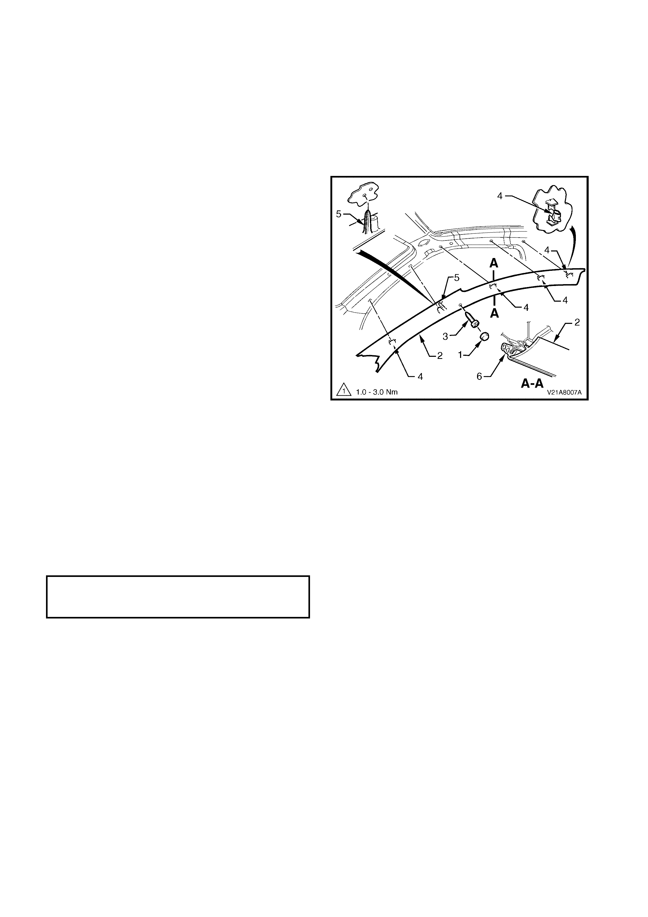
1. Disconnect the headlining assembly harness (1) from the body harness connector (2), located above and
slightly forward of the right-hand centre pillar, refer to Figure 1A8-50.
NOTE: It may be necessary to flex the headlining assembly (3) down slightly to gain access to the harness
connector.
2. Using a suitable trim clip removal tool, carefully prise out the three retainers (4) attaching the headlining
assembly to the roof reinforcement.
3. With the aid of an ass istant, f lex the headlining assem bly to disengage the corner s and centr e from the s ix ‘D’
tabs (5) on the sides of the roof panel.
4. With the liftgate open, ease the headlining assembly from its position, removing the assembly through the
liftgate opening, refer to Figure 1A8-50.
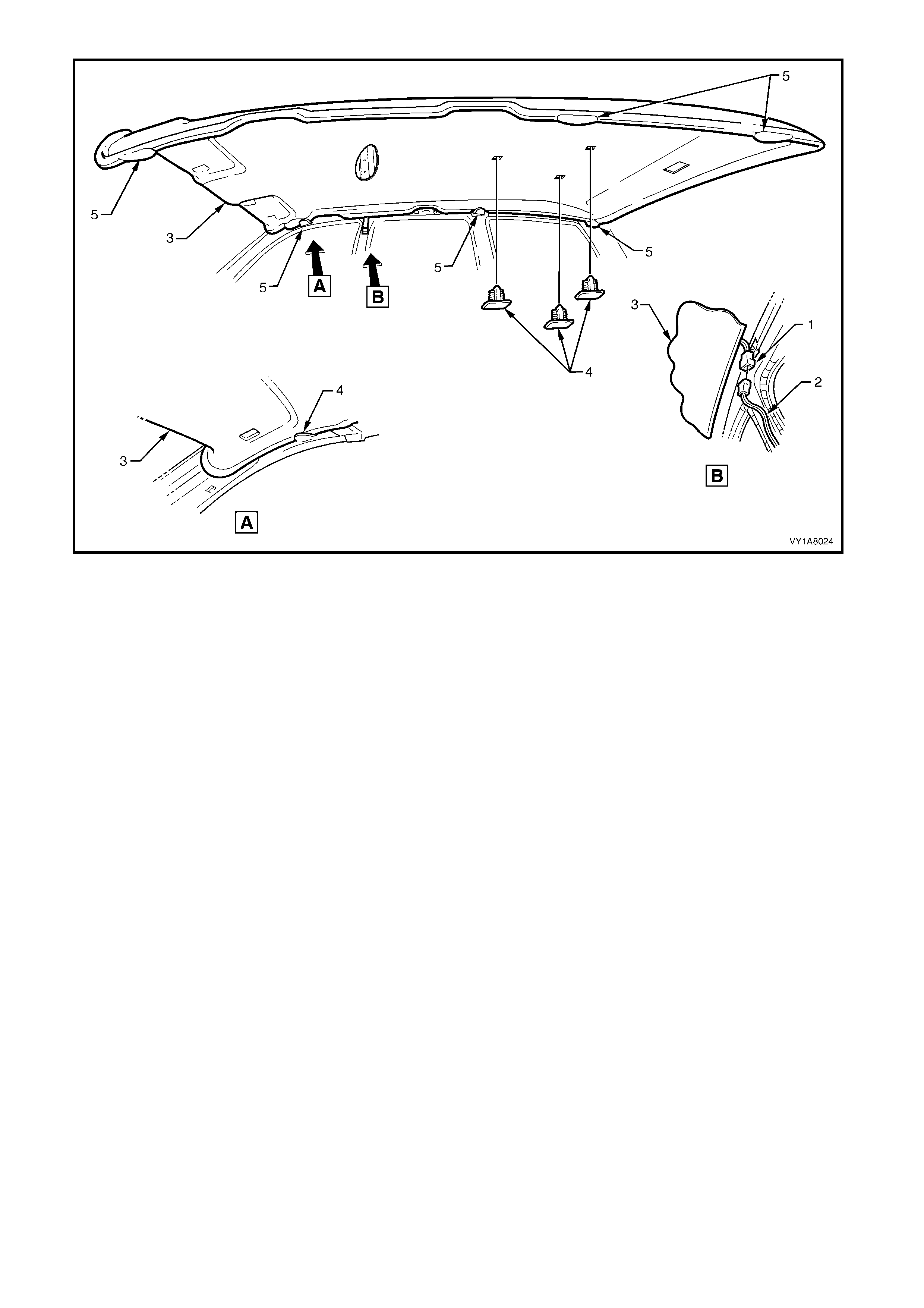
Figure 1A8-50
REINSTALL
Reinstallation of the headlining assembly is the reverse of the removal, noting the following:
1. Temporaraly support the headlining assembly on the ‘D’ tabs before the trim components are reinstalled.
3.16 DRIVER FOOTREST
LT Section No. – 14-475
REMOVE
1. Remove the two screws (1) securing the driver
footrest (2) to the footrest mounting bracket.
2. Remove the footrest pad.
Figure 1A8-51
REINSTALL
Reinstallation of the dr iver f ootr es t is the rever s e of the
removal procedure, noting the following:
1. Ensure all fasteners are tightened to the correct
torque specifications.
DRIVER FOOTREST ATTACHING
SCREW TORQUE SPECIFICATION 2.0 – 5.0 Nm
3.17 FRONT FLOOR CARPET ASSEMBLY
LT Section No. – 14-475
CAUTION: Before performing any Service Operation on a front seat assembly fitted with side impact
airbags, ensure t he SRS ( Air Bag) is disabled, refer to DISABLING THE SRS, Section 12M SUPPLEMENTAL
RESTRAINT SYSTEM.
If required, first remove the following components,
1. Remove the right and left-hand centre pillar lower trims, refer to 3.2 CENTRE PILLAR LOWER TRIM.
2. Remove the rear seat cushion, refer to Section 1A7, SEAT ASSEMBLIES.
3. Remove the right and left-hand side sill trims, refer to 3.4 SIDE SILL TRIM AND PLATE.
4. Remove the right and left-hand hinge pillar trim assemblies, refer to 3.12 HINGE PILLAR TRIM ASSEMBLY.
5. Remove both front seats, refer to Section 1A 7, SEAT ASSEMBLIES.
6. Remove the driver footrest, refer to 2.13 DRIVER FOOTREST.
7. Remove the park brake lever cover by grasping the cover firmly by hand and sliding the cover over the park
brake lever, refer to Section 5A, 2.9 PARK BRAKE LEVER.
8. Remove the instrument panel compartment, refer to Section 1A3, 3.2 INSTRUMENT PANEL
COMPARTMENT ASSEMBLY.
9. Remove the instrument panel lower trim panel, refer to Section 1A3, 3.4 INSTRUMENT PANEL LOWER
TRIM PANEL ASSEMBLY.
10. Remove the right and left-hand instrument panel lower trim plate assembly, refer to Section 1A3,
3.1 INSTRUMENT PANEL LOWER TRIM PLATE ASSEMBLY.
11. Remove instrument panel lower extension side trim panel, refer to Section 1A3, 2.2 INSTRUMENT PANEL
LOWER EXTENSION SIDE TRIM PANEL.
12. Remove floor console assembly, refer to Section 1A3, 2.3 FLOOR CONSOLE ASSEMBLY.
13. Disconnect the inflatable restraint control module (SDM) wiring harness, refer to Section 12M,
2.8 INFLATABLE RESTRAINT CONTROL MODULE (SDM).
14. For vehicles fitted with an automatic transmission, remove the selector control lever assembly, refer
Section 7C4, AUTOMATIC TRANSMISSION ON VEHICLE SERVICING.
15. For vehicles fitted with manual transmission, remove the gearshift lever, refer to Section 7B1, MANUAL
TRANSMISSION – V6 ENGINE or Section 7B2, MANUAL TRANSMISSION – GEN III V8 ENGINE.
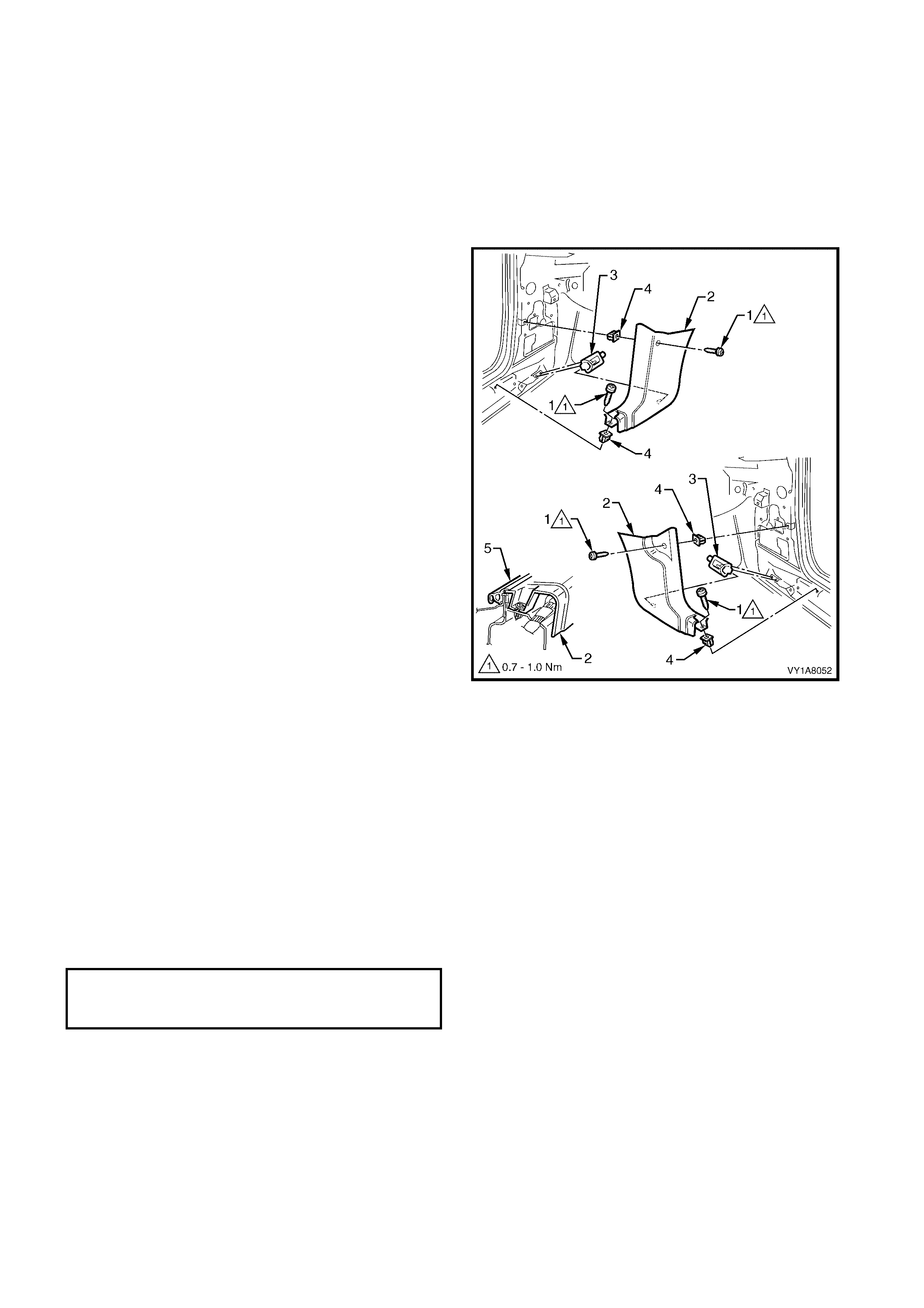
REMOVE
1. Remove the two retaining clips (1) from the front
floor carpet assembly (2) by rotating the clips
counter- clockwise and lift clear of the attaching
studs.
NOTE: To assist in the removal and installation of the
front floor carpet assembly, it has been perforated
(3) from the front edge through the centre of the
evaporator dr ain cut out to the forward edge of the
lower radio bracket cut out, refer Figure 1A8-53.
Figure 1A8-52
2. From ins ide the left-hand foot well, grasp the edge
of the hole in the front floor carpet assembly
around the evaporator drain hose (4) and tear
open the perforated line (3) by pulling the carpet
away from the transmission tunnel.
3. Slide the remaining flap of carpet out from under
the heating, ventilation and air conditioning
(HVAC) unit (5) and into the right-hand foot well.
4. Carefully manoeuvre the floor carpet and insulator
assembly from the vehicle.
Figure 1A8-53

REINSTALL
The installation procedure for the front floor carpet
assembly is the reverse of the removal procedure,
noting the following:
1. If a new carpet is being fitted, cut along the
perforated line in the floor carpet that runs from the
forward edge of the carpet, through the evaporator
drain cut-out, to the forward edge of the lower
radio bracket cut-out, prior to installation, refer
Figure 1A8-52.
2. Ensure all the cut-outs in the carpet are correctly
aligned and install the two retaining clips and the
front seat belt lower attaching bolts to secure the
carpet, prior to installing the seats and console.
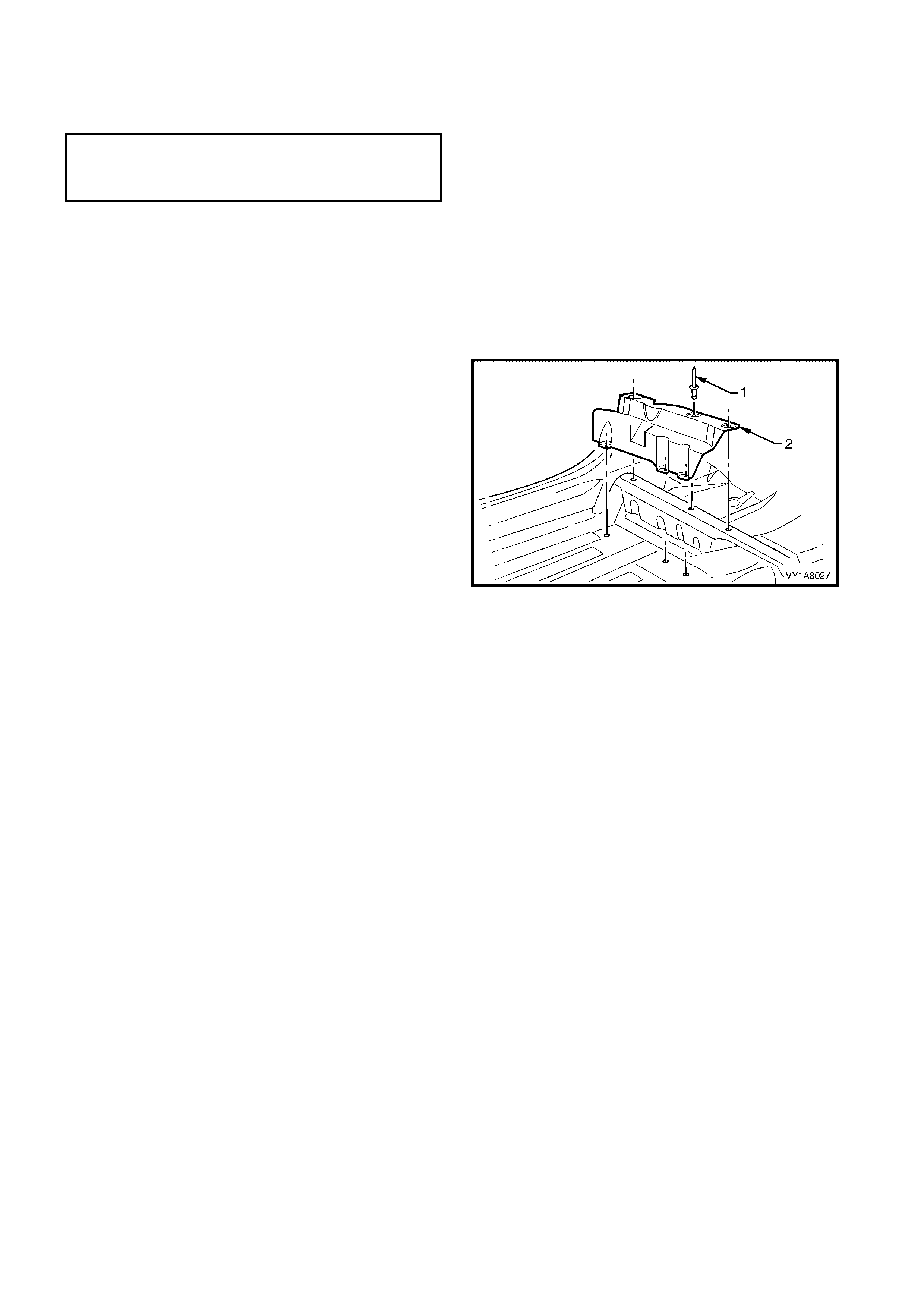
3.18 REAR FLOOR FILLER PANEL
LT Section No. –
If required, first remove the following components:
1. Remove the centre pillar lower trim, refer to 3.2 CENTRE PILLAR LOWER TRIM.
2. Remove the side sill trim, refer to 3.4 SIDE SILL TRIM AND PLATE.
3. Remove the rear seat cushion, refer to Section 1A7, SEAT ASSEMBLIES.
4. Peel back the rear corner section of the front floor carpet, refer 3.17 FRONT FLOOR CARPET.
REMOVE
1. Using a 4.5 mm drill, carefully drill out the pop-
rivets (1) attaching the rear floor filler panel (2) to
the floor panel and rear seat ramp.
2. Remove the rear floor filler panel from the vehicle.
Figure 1A8-54
REINSTALL
Reinstallation of the rear floor f iller panel is the revers e
of the removal procedure, noting the following:
1. Use new 4.8 mm dome-head pop-rivets.
N
O
TE: The
f
ollowing components WILL RE
Q
UIRE
REPLACEMENT when performing this operation.
§ Rivet - Filler Panel to Floor (6 per side).
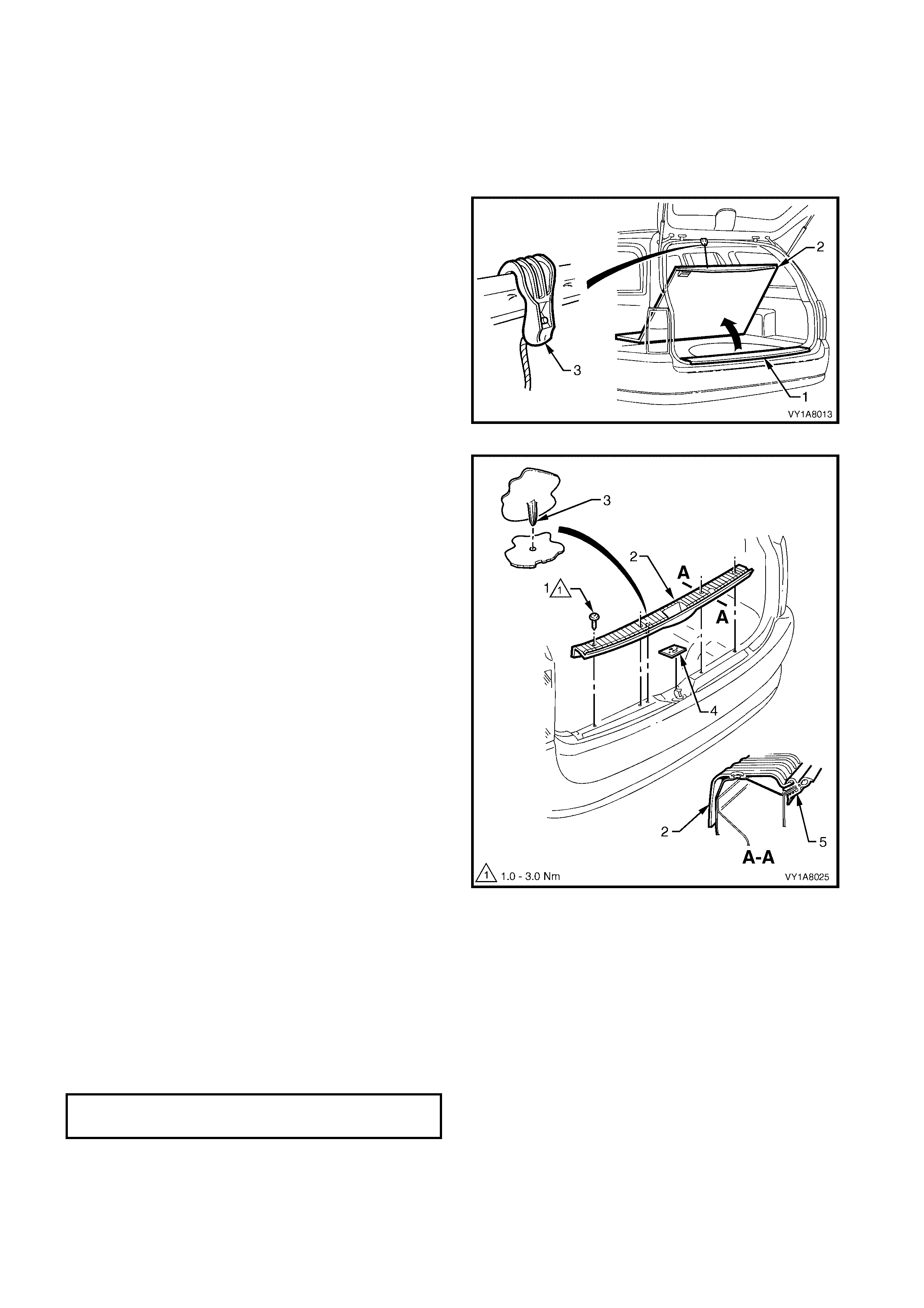
3.19 RE AR END TRIM PANEL
LT Section No. – 14-130
1. Partially remove the rear compartment weatherstrip, refer to Section 1A4, 3.12 REAR COMPARTMENT
WEATHERSTRIP.
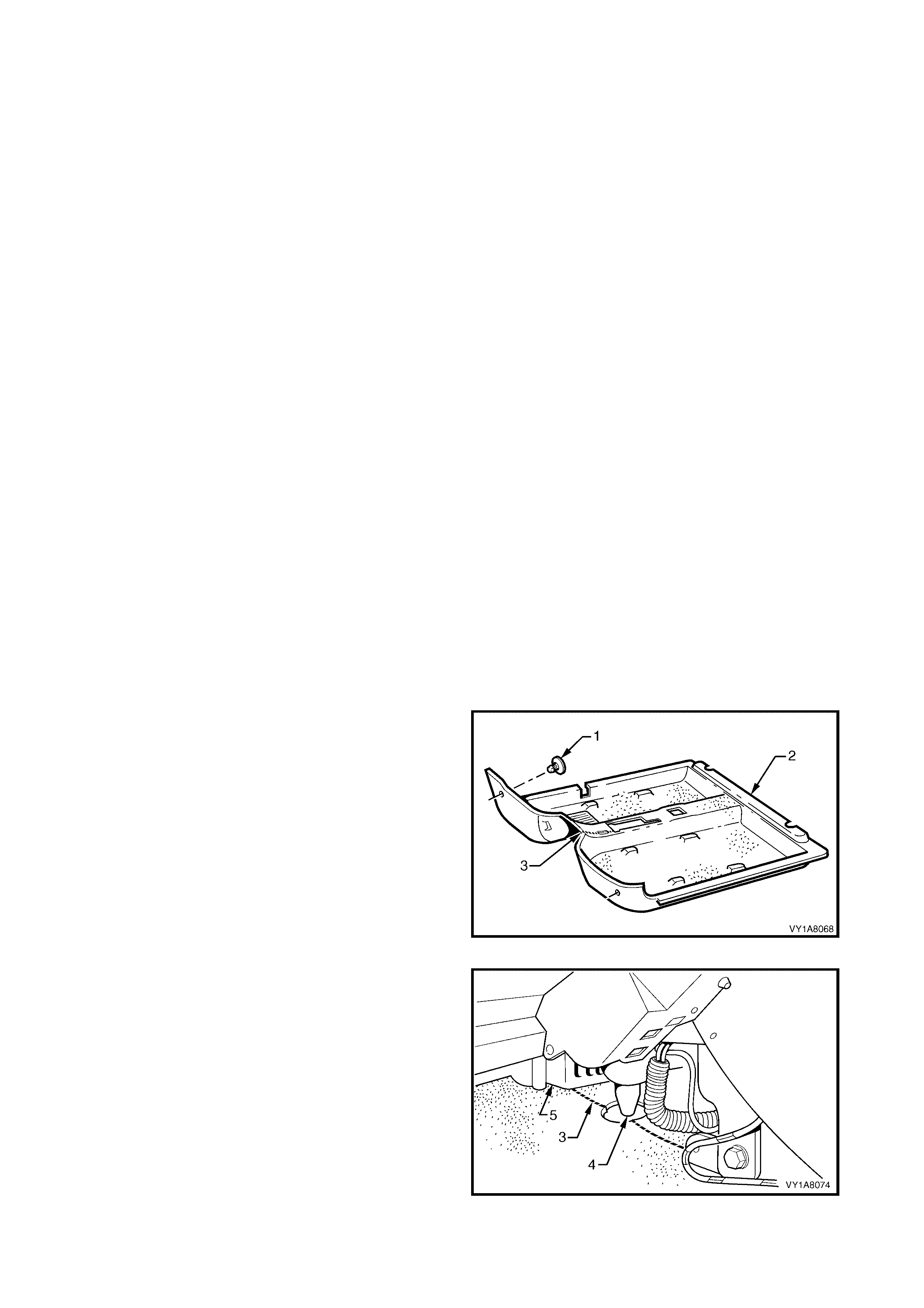
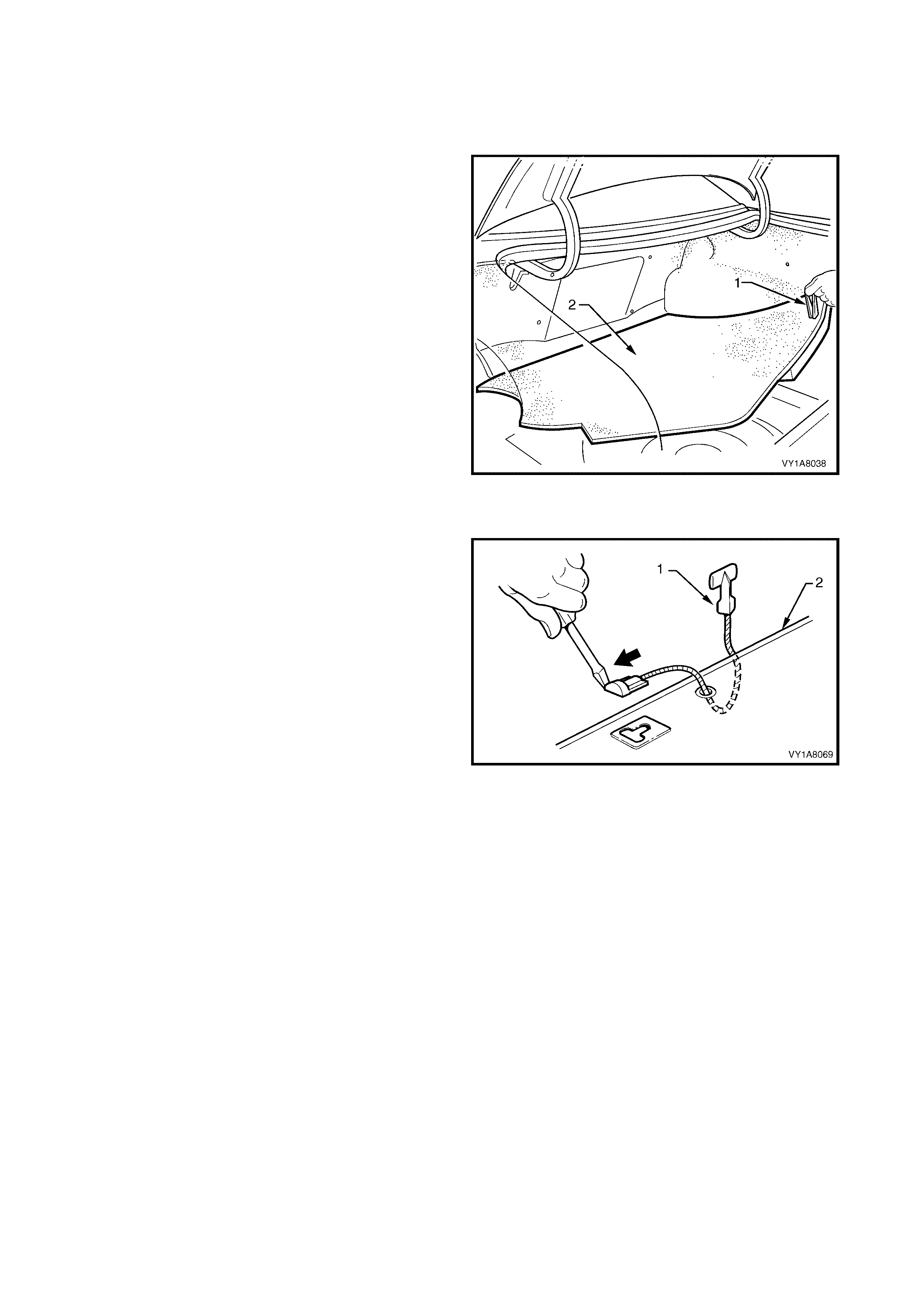
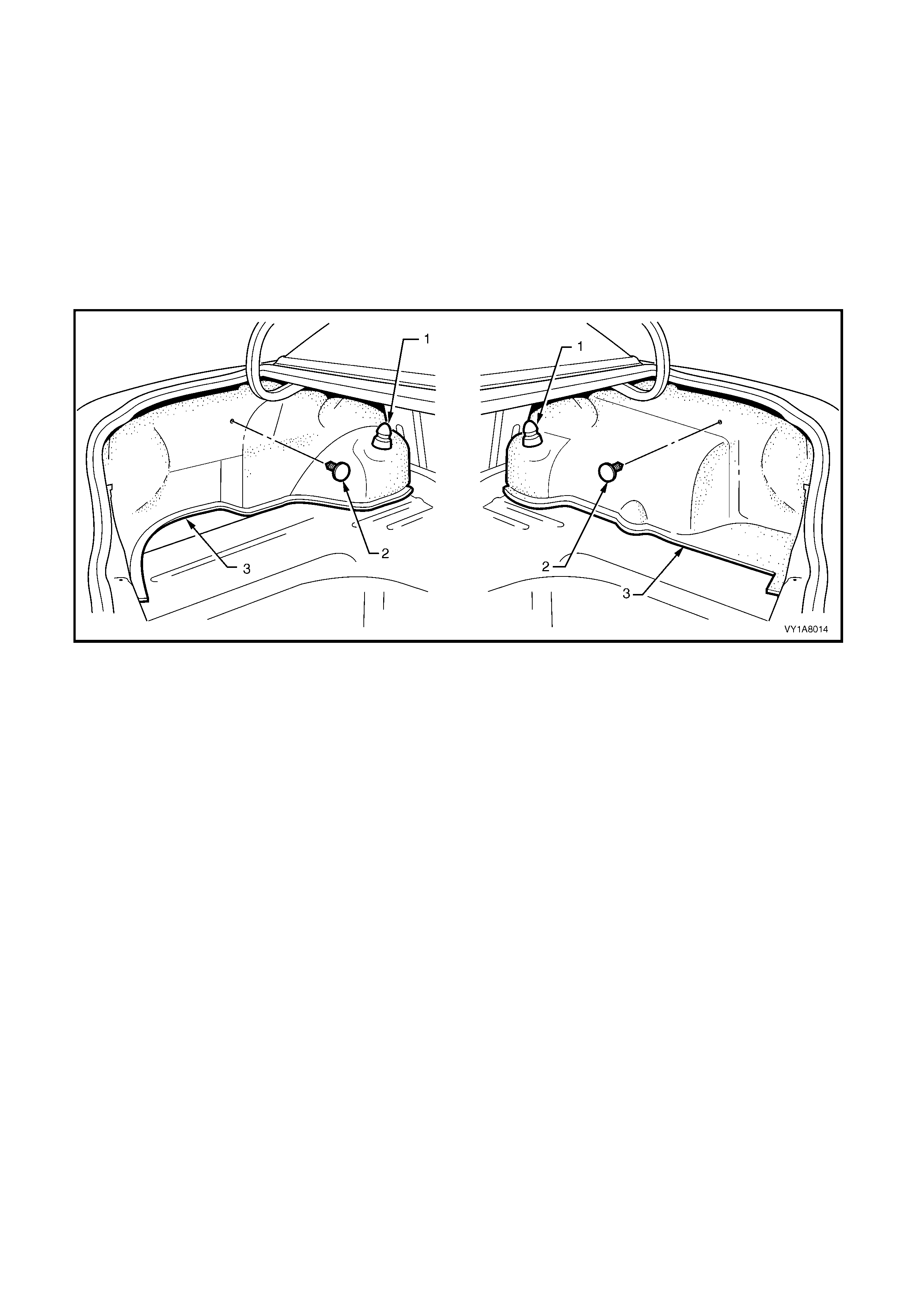
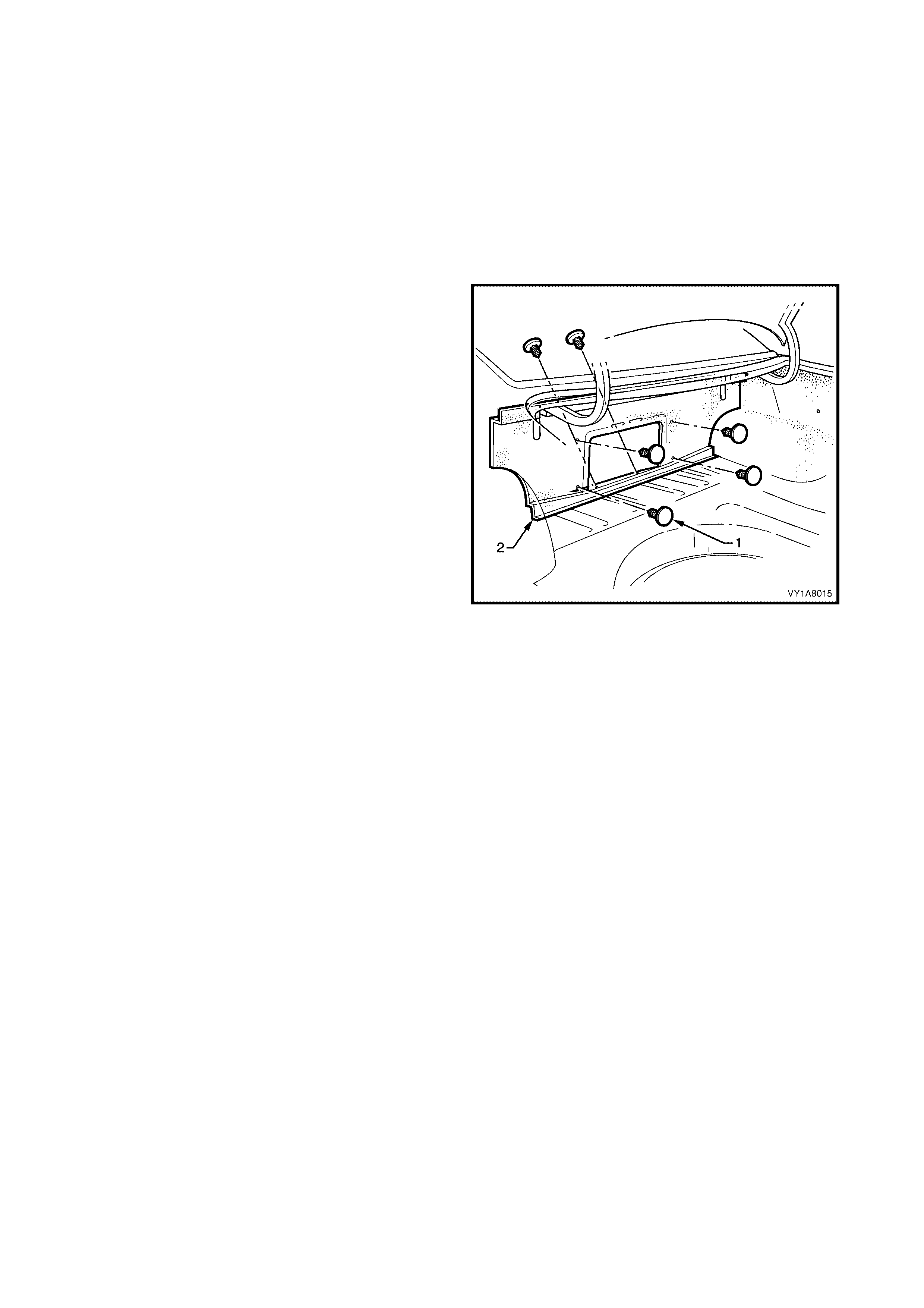
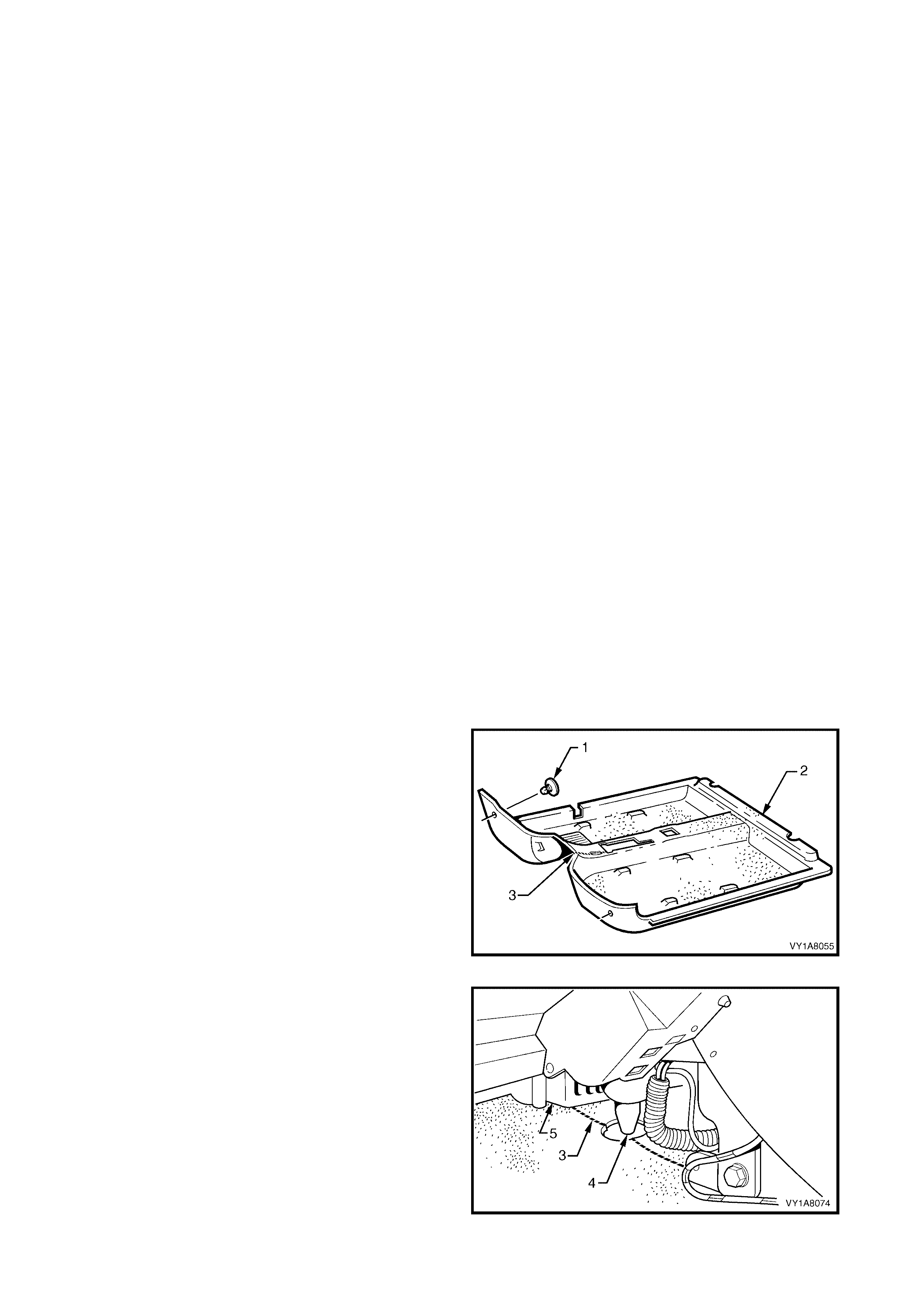
REMOVE
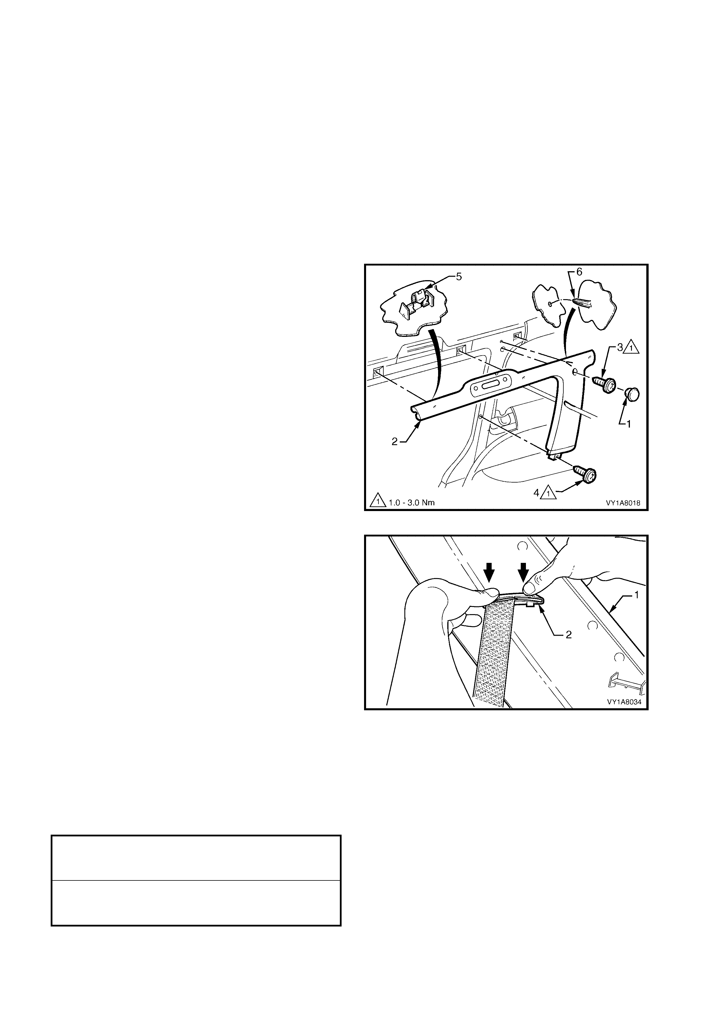
1. To gain excess to the rear end trim panel (1) open
the rear compartment floor carpet assembly (2),
using the hook (3) to retain in the open position.
Figure 1A8-55
2. Remove the four rear end trim panel attaching
screws (1), along the ribbed upper surface of the
rear end trim panel (2).
3. Remove the rear end trim panel.
NOTE: When removing the rear end trim panel,
ensure care is taken not to damage the locating
pin (3).
4. If required remove the rear end trim panel seal (4).
Figure 1A8-56
REINSTALL
The ins tallation proc edur e f or rear end trim panel is the
reverse of the removal procedure, noting the following:
1. Ensure the outer edge of rear end trim panel
engages the rear compartment seal (5), refer
Figure 1A8-56.
2. Ensure all fasteners are tightened to the correct
torque specifications.
REAR END TRIM PANEL ATTACHING
SCREW TORQUE SPECIFICATION 1.0 – 3.0 Nm
3.20 REAR COMPARTMENT FLOOR CARPET ASSEMBLY, EXCEPT LPG
LT Section No. – 14-480
1. Fold forward the rear seat back.
REMOVE
1. Remove the two rear compartment floor carpet
retainers (1) from the front of the rear
compartment floor carpet assembly (2).
2. Grasp the handle (3) on the rear compartment
floor carpet assembly and lift the rear edge
upward.
3. Lift the rear compartment floor carpet assembly
from the rear, out through the liftgate opening.
Figure 1A8-57
DISASSEMBLE
1. W ith the aid of a heat gun to r eplace the hook and
cord assembly (1), prise the carpet (2) away from
the rear compartment floor baseboard (3) to
expose the knot.
2. Undo or cut the knot and remove the hook and
cord assembly from the rear compartment floor
baseboard.
ASSEMBLE
1. Fit the cord through the hole in the baseboard and
tie a knot to retain.
2. Apply contact adhesive to the area on the
baseboard, exposed by the lifting of the carpet for
removal of the hook and cord assembly.
3. Press the carpet down firmly on the baseboard.
Figure 1A8-58
REINSTALL
Reinstallation of the rear compartment floor carpet
assembly is the reverse of the removal.
3.21 REAR COMPARTMENT FLOOR CARPET ASSEMBLY AND
SPARE WHEEL COVER, WITH LPG
LT Section No. –
1. Fold forward the rear seat back.
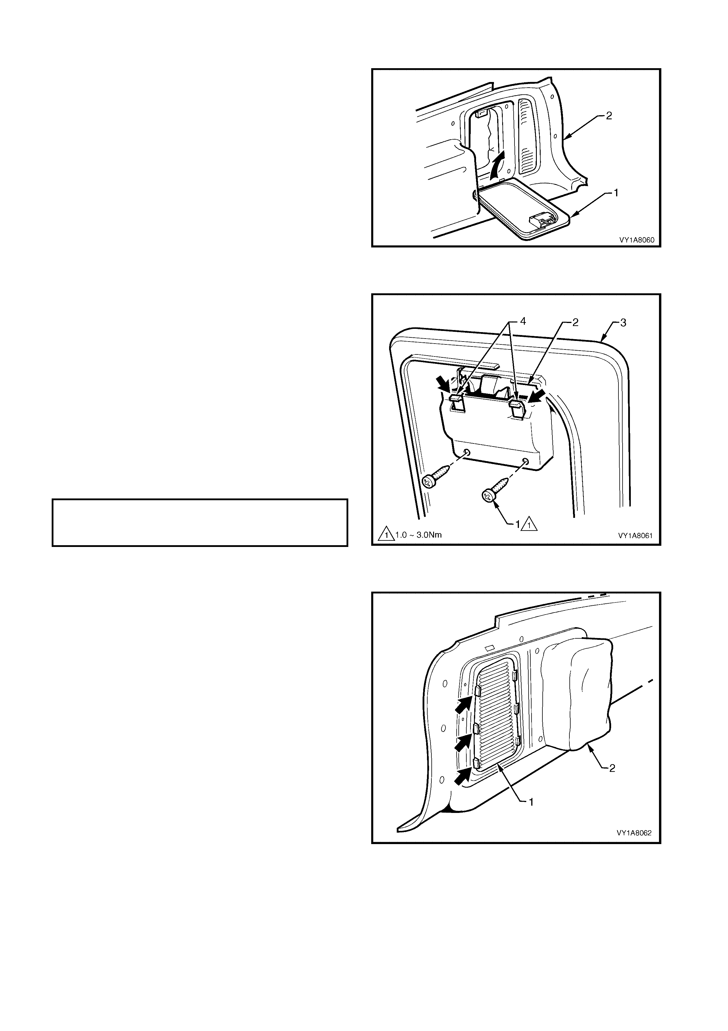
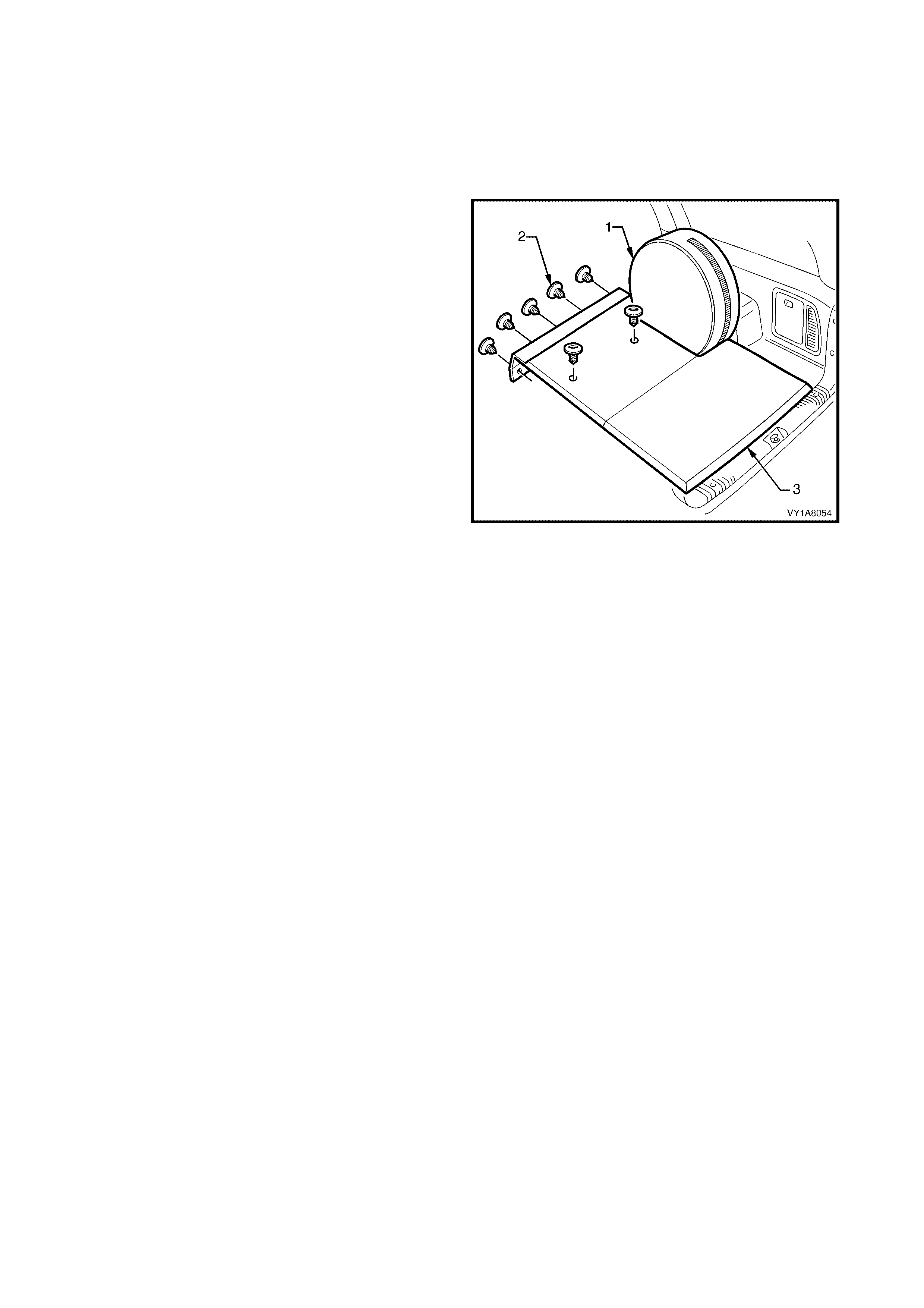
REMOVE
1. Remove the spare wheel and cover (1).
2. Remove the seven retainers (2) from the rear
compartment floor carpet assembly (3).
3. Lift the rear compartment floor carpet assembly
from the rear, out through the liftgate opening.
Figure 1A8-59
REINSTALL
Reinstallation of the rear compartment floor carpet
assembly is the reverse of the removal.

3.22 LUGGAGE SHADE ASSEMBLY
LT Section No. – AA-000
REMOVE
1. Retract the luggage shade assembly (1).
2. Unclip the luggage shade assem bly from the body
lock pillar lower trim (2), by lifting vertically and
remove from the vehicle.
Figure 1A8-60
REINSTALL
Reinstallation of the luggage shade assembly is the
reverse of the removal.
4. SERVICE OPERATIONS - COUPE
NOTE: The following chart is included to assist with the identification of the components.
For the service procedures of the rear compartment lid carpet, refer to Section 1A4, 3.1 REAR COM PARTM ENT
LID CARPET.
For the service procedures of the front door trim panel assem bly, refer to Section 1A5, 2.6 FRONT DOOR TRIM
PANEL ASSEMBLY.
Figure 1A8-61
g
end
1. Side Sill Trim
2. Side Sill Trim Plate
3. Quarter Trim Panel
4. Centre Pillar Upper Trim A ssem bly
5. Windshiel d Side Garnish
6. Body Rear Corner Garnish
7. Hinge Pillar Trim A s sembly
8. Rear Window Trim P anel
9. Sunshade Assem bl y
10. Headlining Assem bl y
11. Driver Footrest
12. Front Floor Carpet Assem bl y
13. Rear End Trim Panel
14. Rear Compartment Floor Carpet Ass embly
15. Quarter Inner Rear Si de Carpet
16. Rear Seat Back Panel Carpet
4.1 SIDE SILL TRIM AND PLATE
LT Section No. – 14-100
1. Remove the rear seat cushion, refer to Section 1A7, 8.1 REAR SEAT CUSHION ASSEMBLY.
REMOVE
1. Remove the front attaching screw (1) from the seat
adjuster outer front cover (2), driver side, right
hand drive only.
2. Using a small screwdriver, push in the centre of
the join to separate the front cover and the front
seat outer lower rear cover (3).
3. Unclip the covers from the seat track, and
disengage from the side sill trim.
4. Pull the covers apart and remove the rear cover.
5. For the driver side, right hand drive only, slide the
front c over over the f uel f iller door release lever (4)
and remove.
Figure 1A8-62
6. Prise the cap (1) of f the seat belt bolt (2) and then
remove the seat belt bolt. For further information
refer to Section12M, OCCUPANT PROTECTION
SYSTEM.
7. Carefully lever the side sill trim plate (3) from the
side sill trim (4), starting at the front and moving
rearwards, revealing the attaching screws.
IMPORTANT: Care must be taken not to snap the sill
trim plates.
8. Remove the retainer (5) attaching side sill trim to
the rear quarter trim panel (6).
9. Remove the four attaching screws (7) from the
side sill trim.
10. Carefully disengage the two clips (8) attaching the
rear of the side sill trim to the lower edge of the
rear quarter trim panel by pulling the rear edge of
the rocker panel cover towards the centre of the
vehicle.
11. Remove the side sill trim.
Figure 1A8-63
REINSTALL
Reinstallation of the side sill trim and the seat adjuster outer front cover is the reverse of the removal, noting the
following:
1. Ensure the outer edge of the side sill trim engages the door opening weatherstrip (9), refer Figure 1A8-63.
2. Tighten all fasteners to the correct torque specification.
SEAT ADJUSTER OUTER FRONT
COVER ATTACHING SCREW
TORQUE SPECIFICATION 1.0 – 3.0 Nm
SIDE SILL TRIM
ATTACHING SCREW
TORQUE SPECIFICATION 1.0 – 3.0 Nm
FRONT SEAT BELT LOWER
ATTACHING BOLT
TORQUE SPECIFICATION 35.0 – 50.0 Nm
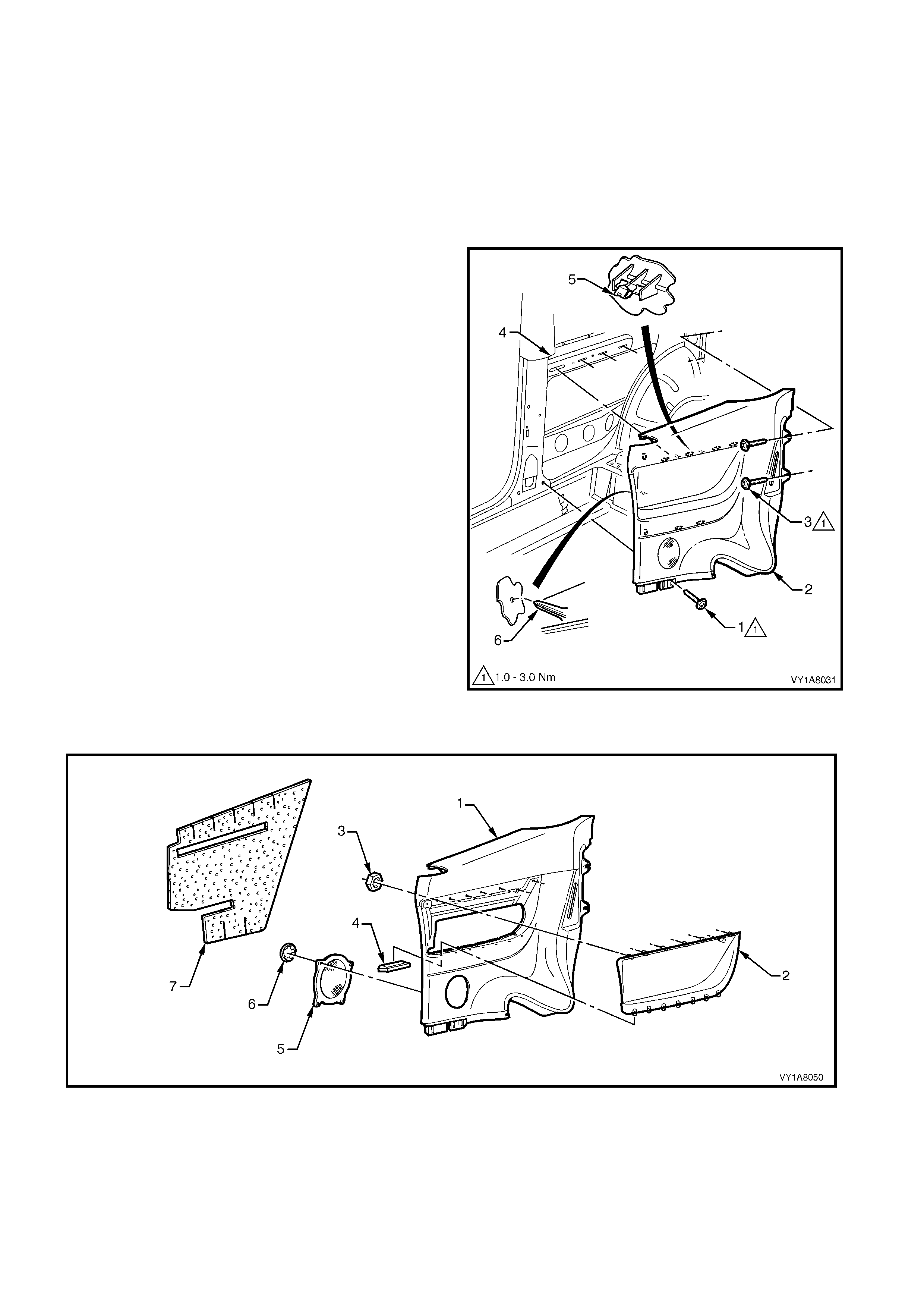
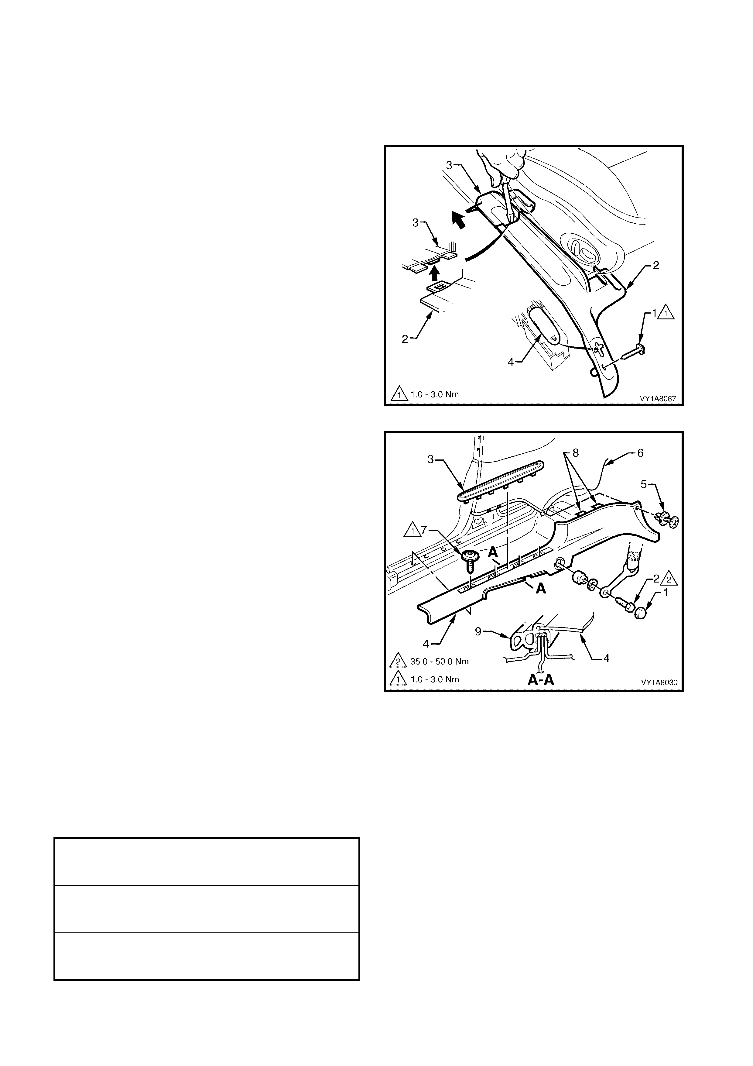
4.2 QUARTER TRIM PANEL ASSEMBLY
LT Section No. –
1. Remove the rear seat cushion, refer to Section 1A7, 8.1 REAR SEAT CUSHION ASSEMBLY.
2. Remove the rear seat back, refer to Section 1A7, 8.2 REAR SEAT BACK ASSEMBLY.
3. Remove the seat adjuster outer front cover, refer to Section 1A7, SEAT ASSEMBLIES.
4. Remove the side sill trim, refer to 4.1 SIDE SILL TRIM AND PLATE.
REMOVE
1. Remove the screw (1) from the lower edge of the
quarter trim panel (2).
2. Remove the two screws (3) from the rear edge of
the quarter trim panel.
3. Starting at the lower edge of the centre pillar upper
trim (4) and moving alternately clockwise and
counter clockwise, disengage the eight rear
quarter trim attaching clips (5) by carefully
manoeuvring the trim away from the rear
sheetmetal.
4. Remove the quarter trim panel.
NOTE: W hen removing the quarter trim panel, ensure
care is taken not to damage the two locating pins (6).
Figure 1A8-64
DISASSEMBLE
Figure 1A8-65
Legend
1. Quarter Trim Panel Foundation Assem bl y
2. Quarter Trim Armrest Insert Assembly
3. Armrest Insert A ssem b l y Nut (7 P l aces)
4. Armrest Insert A ssem b l y Cli p (7 Places)
5. Quarter Trim Radio Speaker Grille
6. Radio Speaker Grille Retainer (4 P l aces)
7. Quarter Trim Insulator Assembly
NOTE: For specific procedures refer below.
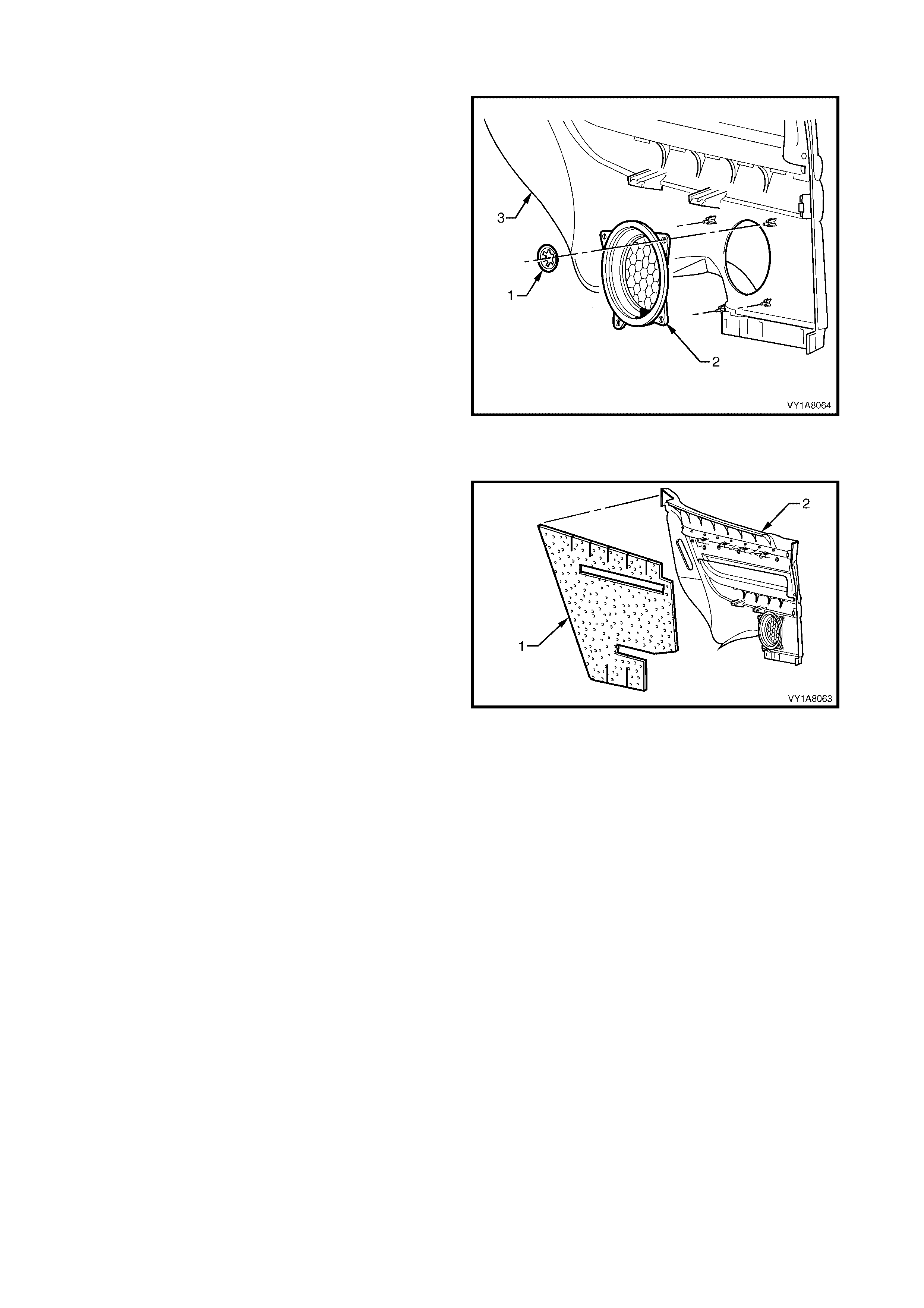
Remove – Quarter Trim Radio Speaker Grille
1. Remove four clips (1) securing the radio speaker
grille (2) to the quarter trim panel (3).
NOTE: Take care when removing clips, not to break
the speak er grille loc ating shaf ts on which the clips are
attached.
2. Remove the radio speaker grille.
Reinstall – Quarter Trim Radio Speaker Grille
Reinstallation of the radio speaker grille is the reverse
of the removal.
Figure 1A8-66
Remove – Quarter Trim Insulator
1. Remove the quarter trim insulator (1), from the
back of the quarter trim assembly (2), by peeling
the insulator slowly across the panel.
NOTE: Take care not to tear the insulator. Retain as
much adhesive as possible on the insulator. Do not
fold the insulator, and store in a flat location with the
adhesive facing away from objects.
Reinstall – Quarter Trim Insulator
1. Locate the insulator centrally within the quarter trim
assembly and press firmly into position.
NOTE: If required, apply additional hot melt adhesive
with a high softening point (eg. 90°c).
Figure 1A8-67
Remove – Quarter Trim Armrest Insert Assembly
1. Peel back the insulator assembly, refer this
Section, from the upper portion of quarter trim
panel assembly, allowing access to the insert
assembly attaching parts.
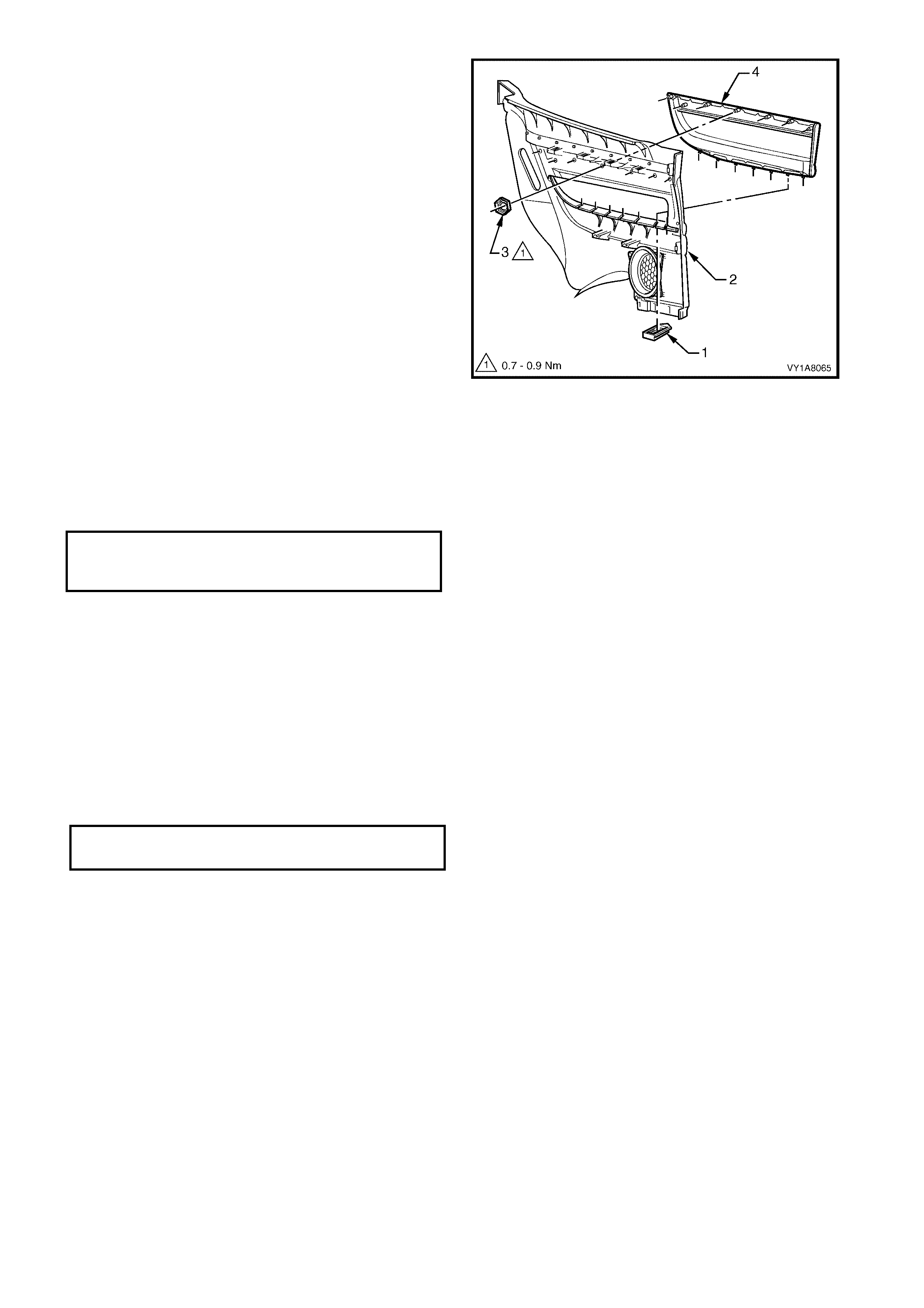
2. Remove the clips (1), seven places, by sliding
them away from the quarter trim panel assembly
(2).
3. Remove the nuts (3) seven places, attaching the
armrest armrest insert assembly (4) to the quarter
trim panel.
IMPORTANT: Take care when removing the nuts, as
the rotating action will cut-off the quarter trim armrest
insert shafts, to which the nuts are attached, requiring
a replacement insert assembly to be fitted.
4. Before removal, prise the quarter trim armrest
insert assembly away from quarter trim panel
assembly. Slide the insert assembly to the rear of
the quarter trim panel assembly and remove.
Reinstall – Quarter Trim Armrest Insert Assembly
Reinstallation of the quarter trim armrest insert
assem bly is the reverse of the removal procedure,
noting the following.
1. The insert assembly, must be sitting flush against
the panel assembly, along the entire top c ontacting
surface.
2. Tighten all retaining nuts to the correct torque
specification.
Figure 1A8-68
REINSTALL
The installation procedure for the rear quarter trim is
the reverse of the removal procedure, noting the
following:
1. Ensure the locating pins are aligned with the
locating holes before engaging the attaching clips.
Also ensure that the leading edge of the rear
quarter trim engages the door seal.
2. Tighten all fasteners to the correct torque
specification.
REAR QUARTER TRIM ATTACHING
SCREW TORQUE SPECIFICATION 1.0 – 3.0 Nm
ARMREST INSERT ASSEMBLY
RETAINING NUT
TORQUE SPECIFICATION 0.7 – 0.9 Nm

4.3 CENTRE PILLAR UPPER TRIM ASSEMBLY
LT Section No. – 14-100
1. Remove the rear seat cushion, refer to Section 1A7, 8.1 REAR SEAT CUSHION ASSEMBLY.
2. Remove the rear seat back, refer to Section 1A7, 8.2 REAR SEAT BACK ASSEMBLY.
3. Remove the seat adjuster outer front cover, refer to Section 1A7, SEAT ASSEMBLIES.
4. Remove the side sill trim, refer to 4.1 SIDE SILL TRIM AND PLATE.
5. Remove the quarter trim panel, refer to 4.2 QUARTER TRIM PANEL.
REMOVE
1. Remove the centre pillar cap (1) from the upper
attachment of the centre pillar upper trim (2).
2. Remove the three screws (3) securing the centre
pillar upper trim.
3. Pull the upper edge of the centre pillar upper trim,
away from the headlining to disengage the centre
pillar attaching clip (4) and the seat belt guide
adjuster (5).
4. Feed the seat belt and anchor plate through the
centre pillar upper trim and remove the trim.
NOTE: When removing the centre pillar upper trim,
ensure car e is tak en not to dam age the locating pin (6)
below the upper attaching screw.
5. If required to remove, lift out the seat belt adjuster
trim (7) by gently spreading the outer edges of the
centre pillar upper trim.
Figure 1A8-69
REINSTALL
Reinstallation of the centre pillar upper trim is the
reverse of the removal, noting the following:
1. Ensur e the seat belt adj uster tr im and the seat belt
guide adjuster assembly are in the full up position
and are correctly aligned prior to installation of the
centre pillar upper trim.
2. Ensure the locating pin below the upper attaching
screw in the centre pillar upper trim, is correctly
aligned with the locating hole in the centre pillar.
3. Ensure the leading edge of the centre pillar upper
trim engages the door opening weatherstrip (8),
refer Figure 1A8-69.
4. Check seat belt operation prior to tightening the
centre pillar upper trim attaching screws.
5. Tighten all fasteners to the correct torque
specification.
CENTRE PILLAR UPPER TRIM
ATTACHING SCREW
TORQUE SPECIFICATION 1.0 – 3.0 Nm
FRONT SEAT BELT LOWER
ATTACHING BOLT
TORQUE SPECIFICATION 35.0 – 50.0 Nm
4.4 WI NDSHIELD SIDE GARNISH
LT Section No. – 14 -100
1. Remove the rear seat cushion, refer to Section 1A7, 8.1 REAR SEAT CUSHION ASSEMBLY.
2. Remove the rear seat back, refer to Section 1A7, 8.2 REAR SEAT BACK ASSEMBLY.
3. Partially remove the rear portion of the side sill trim, to enable the removal of the quarter trim panel, refer to
4.1 SIDE SILL TRIM AND PLATE, and 4.2 QUARTER TRIM PANEL.
4. Remove the centre pillar upper trim, refer to 4.3 CENTRE PILLAR UPPER TRIM ASSEMBLY.
REMOVE
1. Remove the windshield side garnish cap (1) from
the windshield side garnish (2).
2. Remove the screw (3) securing the windshield side
garnish.
3. Starting at the upper rear edge of the windshield
side garnish, disengage the four attaching clips
(4).
4. Remove the windshield side garnish.
NOTE: When removing the windshield side garnish,
ensure care is taken not to damage the two locating
pins (5).
Figure 1A8-70
REINSTALL
Reinstallation of the windshield side garnish is the
reverse of the removal, noting the following:
1. Ensure the windshield side garnish locating pins
are aligned with the holes in the inner panel.
2. Ensure the outer edge of the windshield side
garnish engages the door opening weatherstrip
(6), refer Figure 1A8-70.
3. Tighten all fasteners to the correct torque
specification.
WINDSHIELD SIDE GARNISH
ATTACHING SCREW
TORQUE SPECIFICATION 1.0 – 3.0 Nm
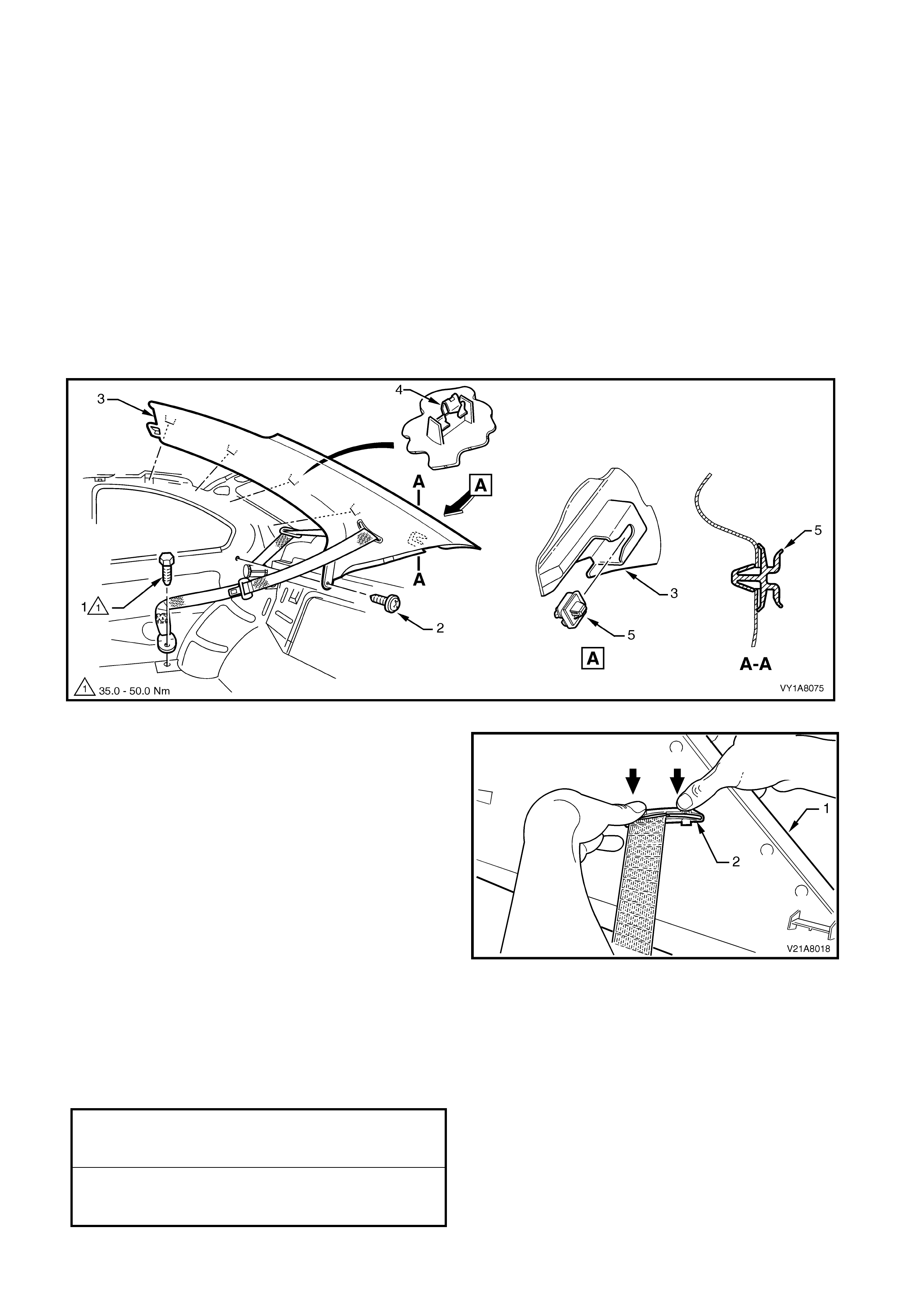
4.5 BODY REAR CORNER GARNISH
LT Section No. –
1. Remove the rear seat cushion, refer to Section 1A7, 8.1 REAR SEAT CUSHION ASSEMBLY.
2. Remove the rear seat back, refer to Section 1A7, 8.2 REAR SEAT BACK ASSEMBLY.
3. Partially remove the rear portion of the side sill trim, to enable the removal of the quarter trim panel, refer to
4.1 SIDE SILL TRIM AND PLATE, and 4.2 QUARTER TRIM PANEL.
4. Remove the centre pillar upper trim, refer to 4.3 CENTRE PILLAR UPPER TRIM ASSEMBLY.
REMOVE
1. Remove the rear lower seat belt bolt (1), refer to Figure 1A8-71.
2. Remove the screw (2) from the lower edge of the body rear corner garnish (3).
3. Pull the front edge of the garnish away from the body lock pillar and working rearwards, disengage the garnish
clip (4), four places.
4. Carefully slide the garnish forward to disengage it from the retainer (5), which is attached to the body lock
pillar, and move the garnish away from the body.
Figure 1A8-71
5. From the rear of the garnish (1), disengage the
seat belt guide (2) and feed the seat belt and
anchor plate through the opening.
6. Remove the body rear corner garnish.
7. If required, prise the retainer (5) from the body lock
pillar with a fine, flat-blade screwdriver, refer to
Figure 1A8-71.
Figure 1A8-71
REINSTALL
Reinstallation of the body rear corner garnish is the reverse of the removal, noting the following:
1. Ensure the body rear corner garnish locating pins are aligned with the holes in the inner panel.
2. Ensure the outer edge of the body rear corner garnish engages the door opening weatherstrip.
3. Tighten all fasteners to the correct torque specification.
BODY REAR CORNER
GARNISH RETAINING SCREW
TORQUE SPECIFICATION 1.0 – 3.0 Nm
REAR SEAT BELT LOWER
ATTACHING BOLT
TORQUE SPECIFICATION 35.0 – 50.0 Nm

4.6 HINGE PILLAR TRIM ASSEMBLY
LT Section No. – 14-100
1. Remove the rear seat cushion, refer to Section 1A7, 8.1 REAR SEAT CUSHION ASSEMBLY.
2. Remove the seat adjuster outer front cover, refer to Section 1A7, SEAT ASSEMBLIES.
3. Remove the side sill trim, refer to 4.1 SIDE SILL TRIM AND PLATE.
REMOVE
1. Remove the two attaching screws (1) from the
hinge pillar trim assembly (2).
2. Disengage the hinge pillar trim clip (3) by pulling
the lower edge of the hinge pillar tr im ass embly up
and away from the sheetmetal.
3. Remove the hinge pillar trim assembly.
Figure 1A8-73
REINSTALL
Reinstallation of the hinge pillar trim assembly is the
reverse of the removal, noting the following:
1. Ensure the hinge pillar trim clip is correctly
engaged.
2. Ensur e the nut inserts (4) are correc tly loc ated and
in good condition, refer Figure 1A8-73.
3. Ensure the outer edge of the hinge pillar trim
assembly engages the door opening weatherstrip
(5), refer Figure 1A8-73.
4. Tighten all fasteners to the correct torque
specification.
HINGE PILLAR TRIM ASSEMBLY
ATTACHING SCREW
TORQUE SPECIFICATION 0.7 – 1.0 Nm
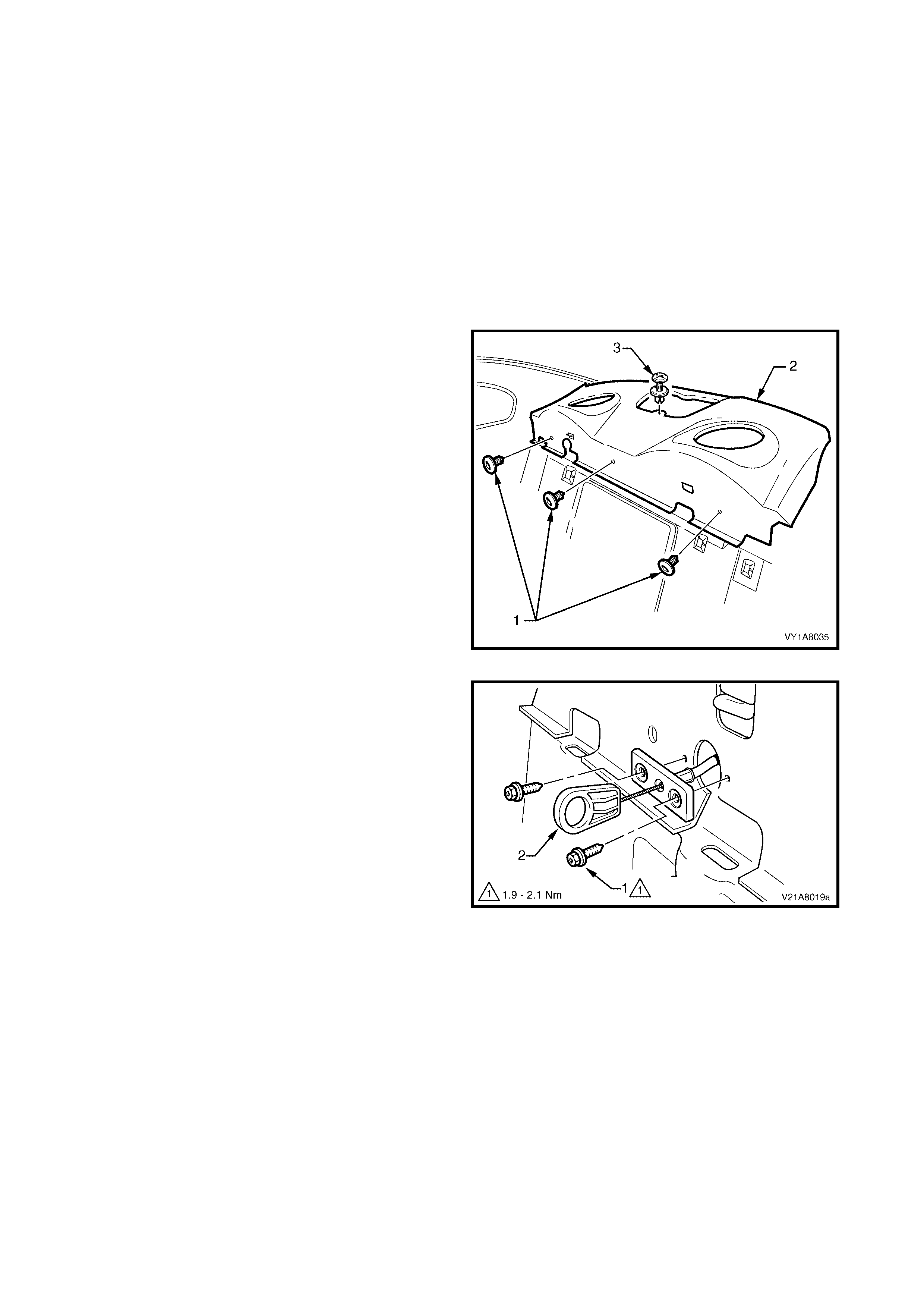
4.7 REAR WINDOW TRIM PANEL ASSEMBLY
LT Section No. – 14-460
1. Remove the rear seat cushion, refer to Section 1A7, 8.1 REAR SEAT CUSHION ASSEMBLY.
2. Remove the rear seat back, refer Section 1A7, SEATS ASSEMBLIES.
3. Partially remove the rear portion of the side sill trim, to enable the removal of the quarter trim panel, refer to
4.1 SIDE SILL TRIM AND PLATE, and 4.2 QUARTER TRIM PANEL.
4. Remove the centre pillar upper trim, refer to 4.3 CENTRE PILLAR UPPER TRIM ASSEMBLY.
5. Partially remove the body rear corner garnish, refer to 4.5 BODY REAR CORNER GARNISH.
6. Remove the high mount stop lamp assembly, refer to Section 12B, 2.10 HIGH MOUNT STOP LAMP
ASSEMBLY.
REMOVE
1. Remove the three retainers (1) attaching the
forward edge of the rear window trim panel
assembly (2).
2. Remove the retainer (3) attaching the rear window
trim panel assembly to the rear sheetmetal.
Figure 1A8-74
3. Remove the two screws (1) securing the rear
compartment lid release cable assembly (2).
4. Pull the rear compartment lid release cable
assembly away from the rear window trim panel
assembly.
5. Lift the front edge of the rear window trim panel
assembly and feed the rear compartment lid
emergency release cable through the slot in the
parcel shelf.
6. Remove the rear window trim panel assembly.
Figure 1A8-75

DISASSEMBLE
1. Bend the nine speaker grille tabs (1) to a vertical
position and remove from the rear window trim
panel assembly (2).
2. Remove the dust seal (3) from the speaker grille.
3. Remove the s peak er s eal (4) f rom the r ear window
trim panel assembly.
ASSEMBLE
Reinstallation of the rear window trim panel speaker
grille is the reverse of the removal, noting the
following:
1. Bend the nine speaker grille tabs to a horizontal
position to retain the speaker grille.
Figure 1A8-76
REINSTALL
Reinstallation of the body lock pillar garnish is the
reverse of the removal, noting the following:
1. W here fitted, ensur e that the speaker seals do not
foul on the speaker assemblies.
2. Tighten all fasteners to the correct torque
specification.
REAR COMPARTMENT LID RELEASE
CABLE ASSEMBLY ATTACHING
SCREW TORQUE SPECIFICATION 1.9 – 2.1 Nm
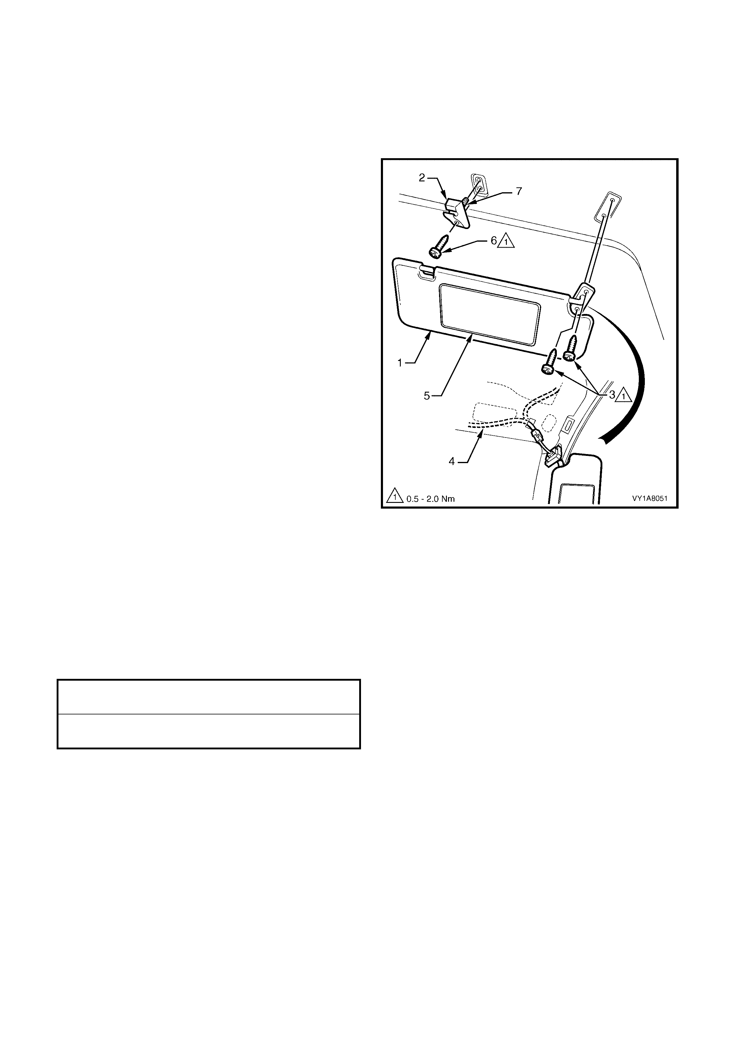
4.8 SUNSHADE ASSEMBLY
LT Section No. – 14-050
1. Remove the fuse F6 from the passenger compartment fuse and relay assembly, refer Section 12O,
1.1 FUSES and 1.2 CIRCUIT BRAKERS.
REMOVE
1. Disconnect the sunshade assembly (1) from the
sunshade support (2) and rotate to gain access.
2. Remove the sunshade assembly attaching Torx
screws (3) two places.
3. Pull the sunshade away from the headlining
assembly and if fitted, disconnect the wiring
harness (4) to the illuminated vanity mirrors (5).
4. Remove the sunshade.
5. Remove the Torx screw (6) from the sunshade
support and pull the support from the headlining
assembly.
NOTE: W hen removing the sunshade support, ensure
that care is taken not to damage the locating pin (7).
Figure 1A8-77
REINSTALL
Reinstallation of the s unshade assem bly is the r everse
of the removal, noting the following:
1. Ensure the sunshade support is correctly located.
2. If fitted, reconnect the wiring harness to the
sunshade assembly.
3. Tighten all fasteners to the correct torque
specification.
SUNSHADE ASSEMBLY ATTACHING
SCREWS TORQUE SPECIFICATION 0.5 – 2.0 Nm
SUNSHADE SUPPORT ATTACHING
SCREWS TORQUE SPECIFICATION 0.5 – 2.0 Nm
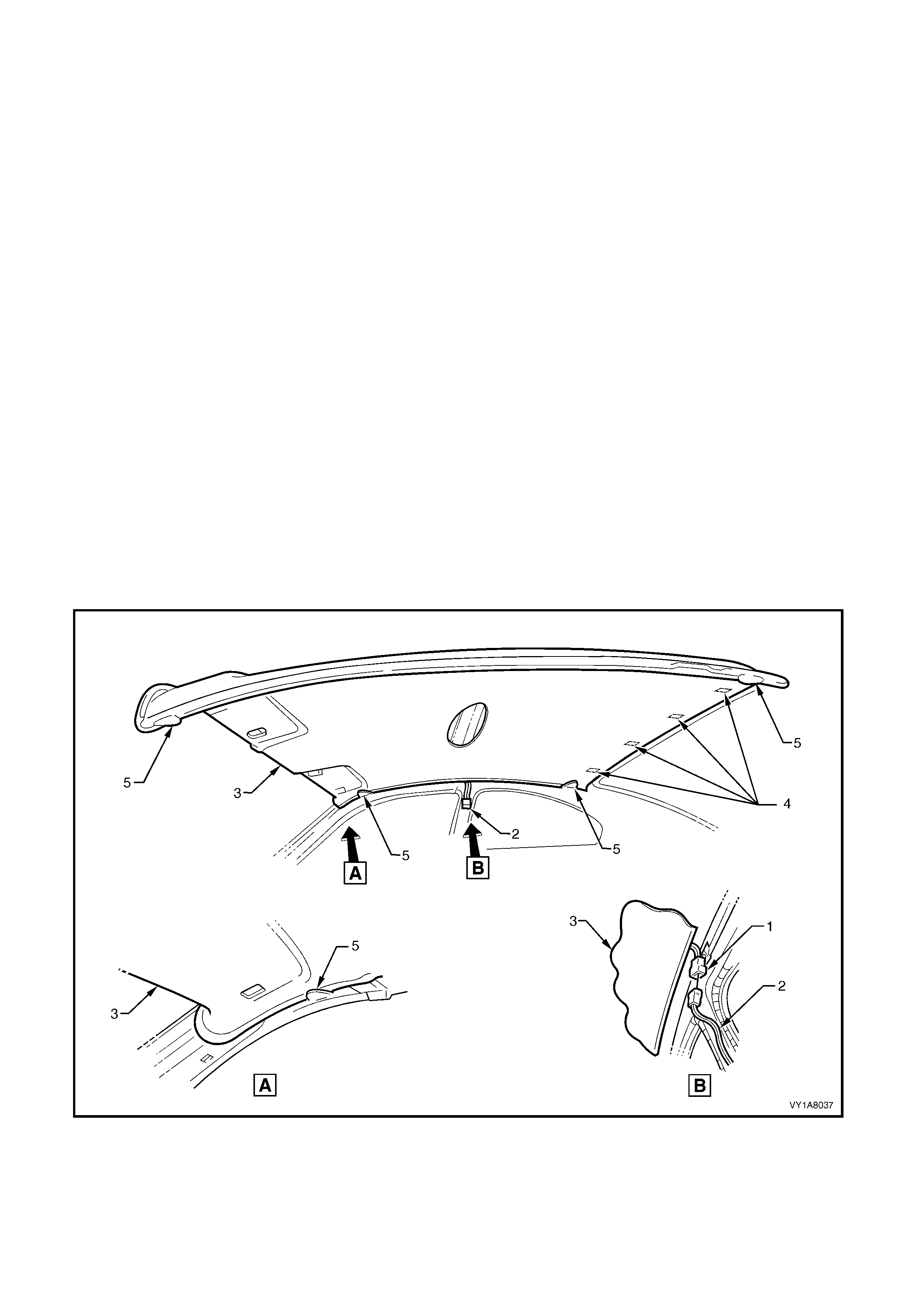
4.9 HEADLINING ASSEMBLY
LT Section No. – 14-150
1. Remove the fuse F6 from the passenger compartment fuse and relay assembly, refer Section 12O,
1.1 FUSES and 1.2 CIRCUIT BRAKERS.
2. Move both front seats to the rear access position and place protective covering over the interior trim.
3. Remove the rear seat cushion, refer to Section 1A7, 8.1 REAR SEAT CUSHION ASSEMBLY.
4. Remove the rear seat back, refer to Section 1A7, 8.2 REAR SEAT BACK ASSEMBLY.
5. Remove the side sill trim, refer to 4.1 SIDE SILL TRIM AND PLATE.
6. Remove the quarter trim panel, refer to 4.2 QUARTER TRIM PANEL ASSEMBLY.
7. Remove the centre pillar upper trim, refer to 4.3 CENTRE PILLAR UPPER TRIM ASSEMBLY.
8. Remove the windshield side garnish, refer to 4.4 WINDSHIELD SIDE GARNISH .
9. Remove the body rear corner garnish, refer to 4.5 BODY REAR CORNER GARNISH.
10. Remove the sunshade assembly, refer to 4.8 SUNSHADE ASSEMBLY.
11. Remove the dome lamp, refer to Section 12B, 3.8 DOME LAMP ASSEMBLY.
REMOVE
1. Disconnect the headlining assembly harness (1) from the body harness connector (2), located above and
slightly forward of the right-hand centre pillar, refer to Figure1A8-78.
NOTE: It may be necessary to flex the headlining assembly (3) down slightly to gain access to the harness
connector.
2. Disengage the f our Velcro™ fas teners (4) attaching the rear edge of the headlining ass em bly by gently pulling
down the headlining assembly in one corner and working across the rear edge.
3. With the aid of an as sistant, f lex the roof lining to disengage the c orners f rom the four ‘D’ tabs (5) on the sides
of the roof panel.
4. Carefully manoeuvre the headlining assembly from the vehicle, refer to Figure1A8-78.
Figure 1A8-78
REINSTALL
Reinstallation of the headlining assembly is the reverse of the removal, noting the following:
1. Temporaraly support the headlining assembly on the ‘D’ tabs before the trim components are reinstalled.
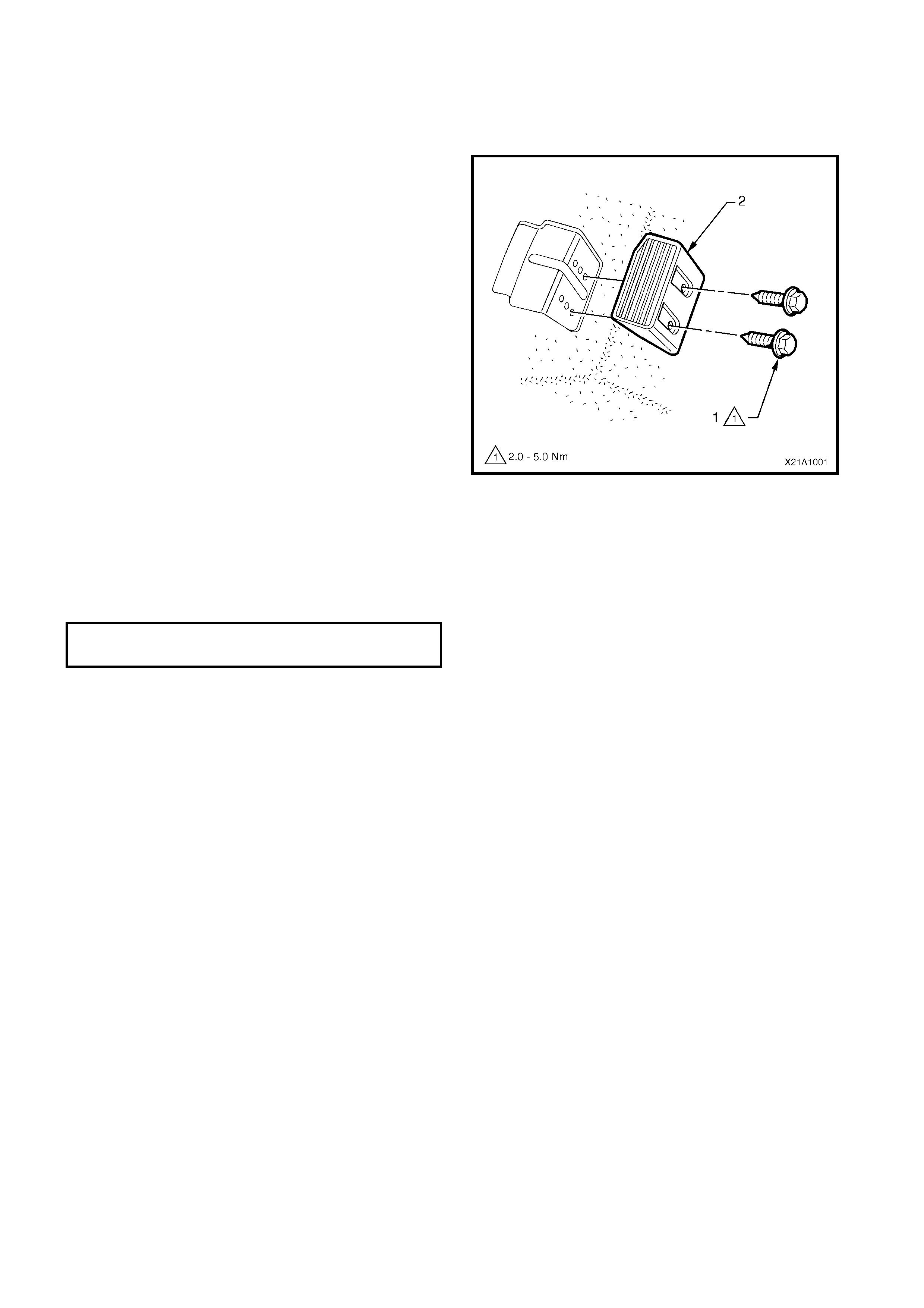
4.10 DRIVER FOOTREST
LT Section No. – 14-475
REMOVE
1. Remove the two screws (1) securing the driver
footrest (2) to the footrest mounting bracket.
2. Remove the footrest pad.
Figure 1A8-79
REINSTALL
Reinstallation of the dr iver f ootr es t is the rever s e of the
removal procedure, noting the following:
1. Ensure all fasteners are tightened to the correct
torque specifications.
DRIVER FOOTREST ATTACHING
SCREW TORQUE SPECIFICATION 2.0 – 5.0 Nm
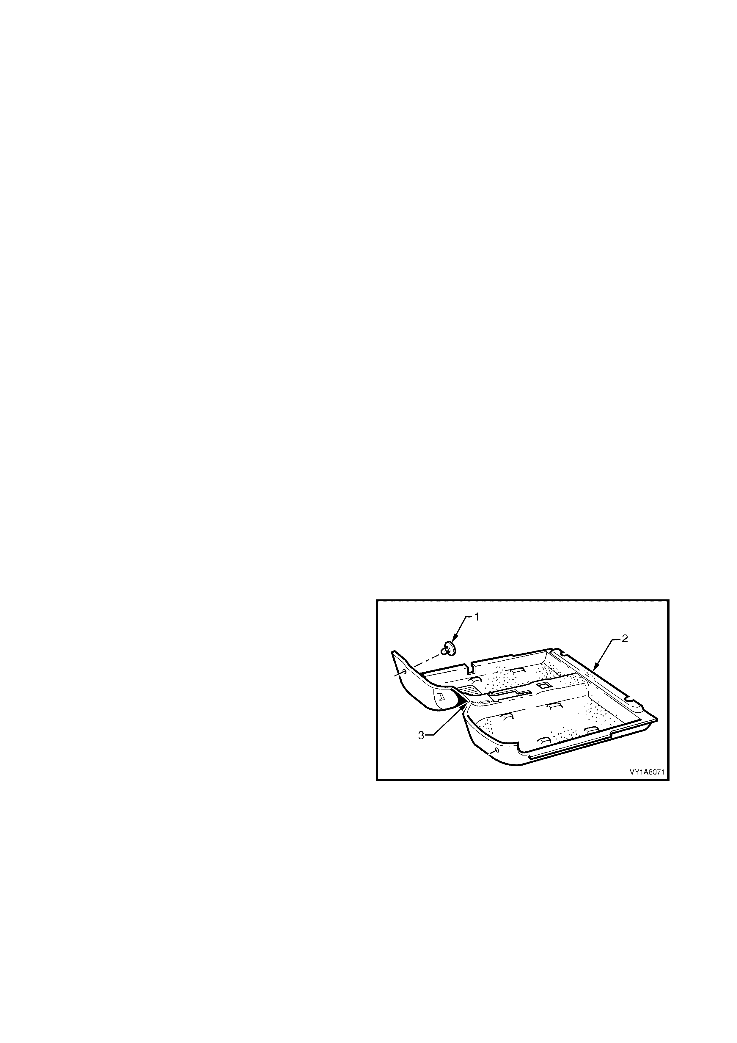
4.11 FRONT FLOOR CARPET ASSEMBLY
LT Section No. – 14-475
CAUTION: Before performing any Service Operation on a front seat assembly fitted with side impact
airbags, ensure t he SRS ( Air Bag) is disabled, refer to DISABLING THE SRS, Section 12M SUPPLEMENTAL
RESTRAINT SYSTEM.
If required, first remove the following components,
1. Remove the rear seat cushion, refer to Section 1A7, 8.1 REAR SEAT CUSHION ASSEMBLY.
2. Remove the seat adjuster outer front cover, refer to Section 1A7, SEAT ASSEMBLIES.
3. Remove the right and left-hand side sill trims, refer to 4.1 SIDE SILL TRIM AND PLATE.
4. Remove the right and left-hand hinge pillar trim assemblies, refer to 4.6 HINGE PILLAR TRIM ASSEMBLY.
5. Remove the quarter trim panel, refer to 4.2 QUARTER TRIM PANEL.
6. Remove both front seats, refer to Section 1A 7, SEAT ASSEMBLIES.
7. Remove the driver footrest, refer to 4.10 DRIVER FOOTREST.
8. Remove the park brake lever cover by grasping the cover firmly by hand and sliding the cover over the park
brake lever, refer to Section 5A, 2.9 PARK BRAKE LEVER.
9. Remove the instrument panel compartment, refer to Section 1A3, 3.2 INSTRUMENT PANEL
COMPARTMENT ASSEMBLY.
10. Remove the instrument panel lower trim panel, refer to Section 1A3, 3.4 INSTRUMENT PANEL LOWER
TRIM PANEL ASSEMBLY.
11. Remove the right and left-hand instrument panel lower trim plate assembly, refer to Section 1A3,
3.1 INSTRUMENT PANEL LOWER TRIM PLATE ASSEMBLY.
12. Remove instrument panel lower extension side trim panel, refer to Section 1A3, 2.2 INSTRUMENT PANEL
LOWER EXTENSION SIDE TRIM PANEL.
13. Remove floor console assembly, refer to Section 1A3, 2.3 FLOOR CONSOLE ASSEMBLY.
14. Disconnect the inflatable restraint control module (SDM) wiring harness, refer to Section 12M,
2.8 INFLATABLE RESTRAINT CONTROL MODULE (SDM).
15. For vehicles fitted with an automatic transmission, remove the selector control lever assembly, refer
Section 7C4, AUTOMATIC TRANSMISSION ON VEHICLE SERVICING.
16. For vehicles fitted with manual transmission, remove the gearshift lever, refer to Section 7B2, MANUAL
TRANSMISSION – GEN III V8 ENGINE.
REMOVE
1. Remove the two retaining clips (1) from the front
floor carpet assembly (2) by rotating the clips
counter- clockwise and lift clear of the attaching
studs.
NOTE: To assist in the removal and installation of the
front floor carpet assembly, it has been perforated (3)
from the front edge through the centre of the
evaporator drain cut out to the forward edge of the
lower radio bracket cut out, refer Figure 1A8-81.
Figure 1A8-80

2. From ins ide the left-hand foot well, grasp the edge
of the hole in the front floor carpet assembly
around the evaporator drain hose (4) and tear
open the perforated line (3) by pulling the carpet
away from the transmission tunnel.
3. Slide the remaining flap of carpet out from under
the heating, ventilation and air conditioning
(HVAC) unit (5) and into the right-hand foot well.
4. Carefully manoeuvre the floor carpet and insulator
assembly from the vehicle.
Figure 1A8-81
REINSTALL
The installation procedure for the front floor carpet
assembly is the reverse of the removal procedure,
noting the following:
1. If a new carpet is being fitted, cut along the
perforated line in the floor carpet that runs from the
forward edge of the carpet, through the evaporator
drain cut-out, to the forward edge of the lower
radio bracket cut-out, prior to installation, refer
Figure 1A8-80.
2. Ensure that all the cut-outs in the carpet are
correctly aligned and install the two retaining clips
and the front seat belt lower attaching bolts to
secure the carpet, prior to installing the seats and
console.
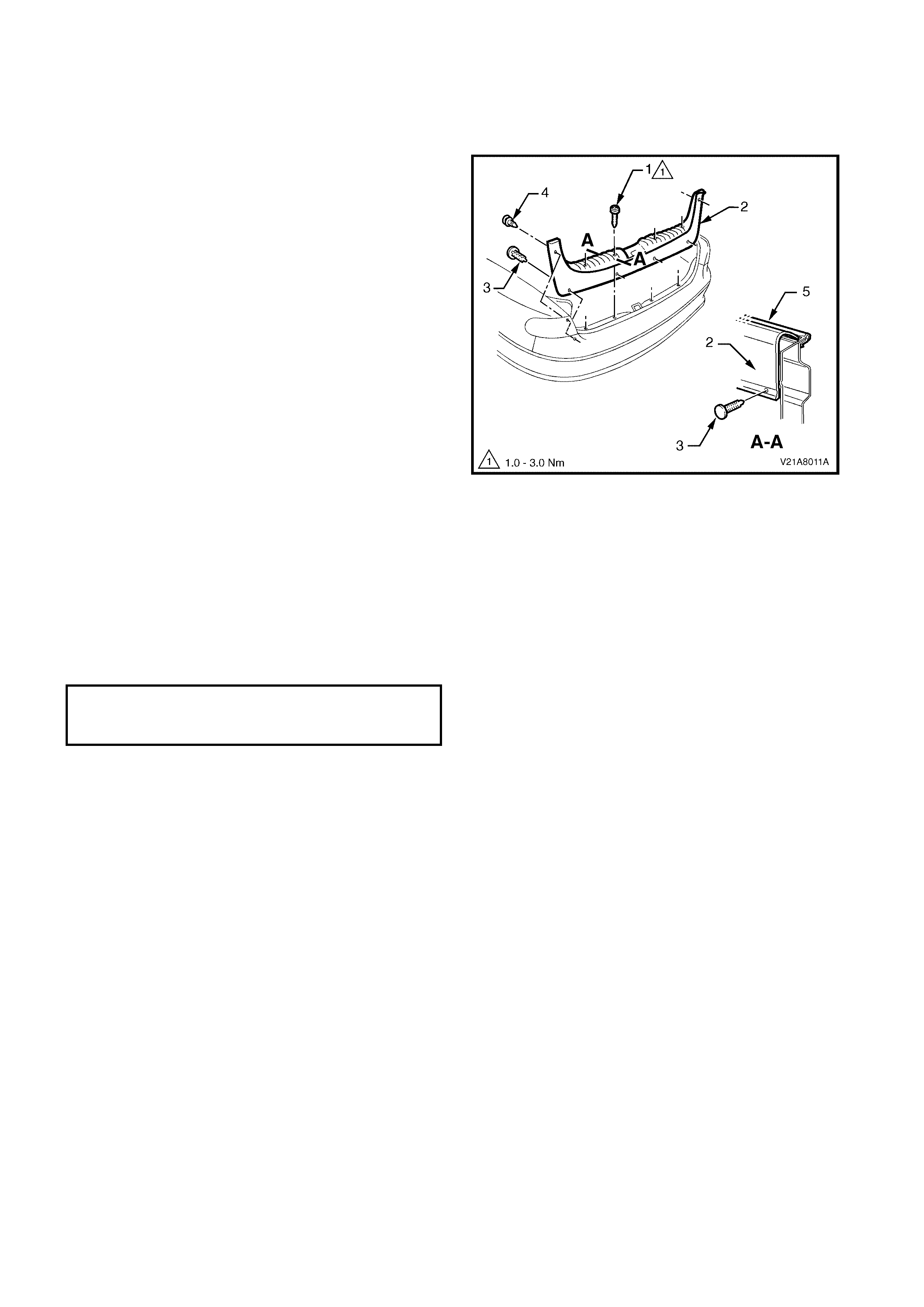
4.12 RE AR END TRIM PANEL
LT Section No. – 14-120
REMOVE
1. With the rear compartment lid open, remove the
four attaching screws (1) along the ribbed upper
surface of the rear end trim panel (2).
2. Remove the four retainers (3) along the lower
inner edge of the rear end trim panel.
3. Remove the two retainers (4) attaching the upper
sides of the rear end trim panel.
4. Carefully lift the rear end trim panel over the rear
compartment lid latch and clear of the rear
compartment.
Figure 1A8-82
REINSTALL
Reinstallation of the rear end trim panel is the reverse
of the removal, noting the following:
1. Ensure that the outer edge of rear end trim panel
engages the rear compartment seal (5), refer
Figure 1A8-82.
2. Tighten all retaining screws to the correct torque
specification.
REAR END TRIM PANEL
ATTACHING SCREW
TORQUE SPECIFICATION 1.0 – 3.0 Nm
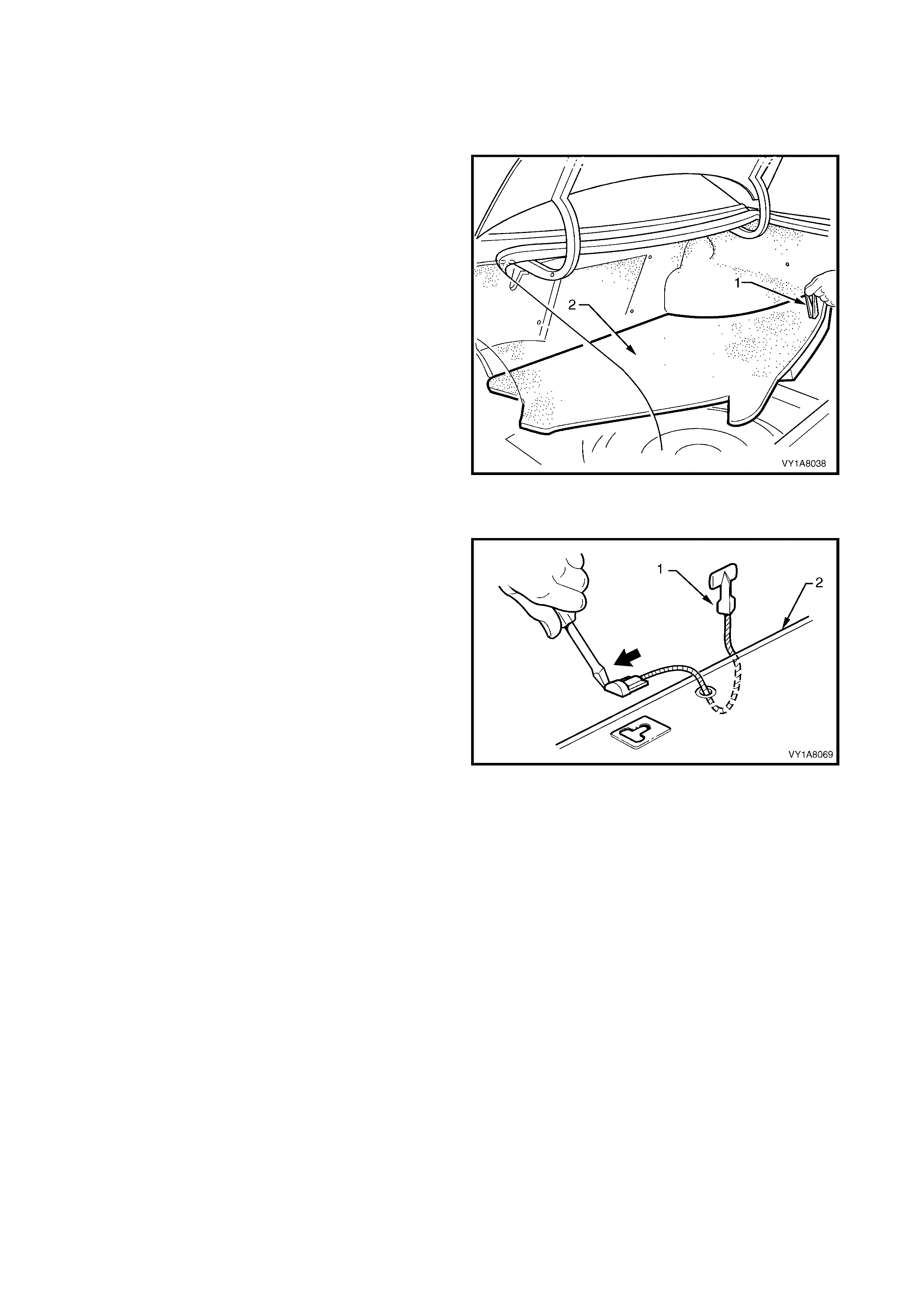
4.13 REAR COMPARTMENT FLOOR CARPET ASSEMBLY
LT Section No. – 14-480
REMOVE
1. Open the rear compartment lid.
2. Grasp the handle (1) on the rear compartment
floor carpet assembly (2) and lift the rear edge
upward.
3. Lift the rear compartment floor carpet assembly
from the rear compartment.
Figure 1A8-83
DISASSEMBLE
1. Lever the rear compartment strap (1) out of the
slot in the rear compartment floor (2), and remove.
2. Feed the strap through the hole in the rear
compartment floor carpet and remove.
ASSEMBLE
Assem bly of the rear com partm ent strap is the reverse
of the removal.
Figure 1A8-84
REINSTALL
Reinstallation of the rear compartment floor carpet
assembly is the reverse of the removal.
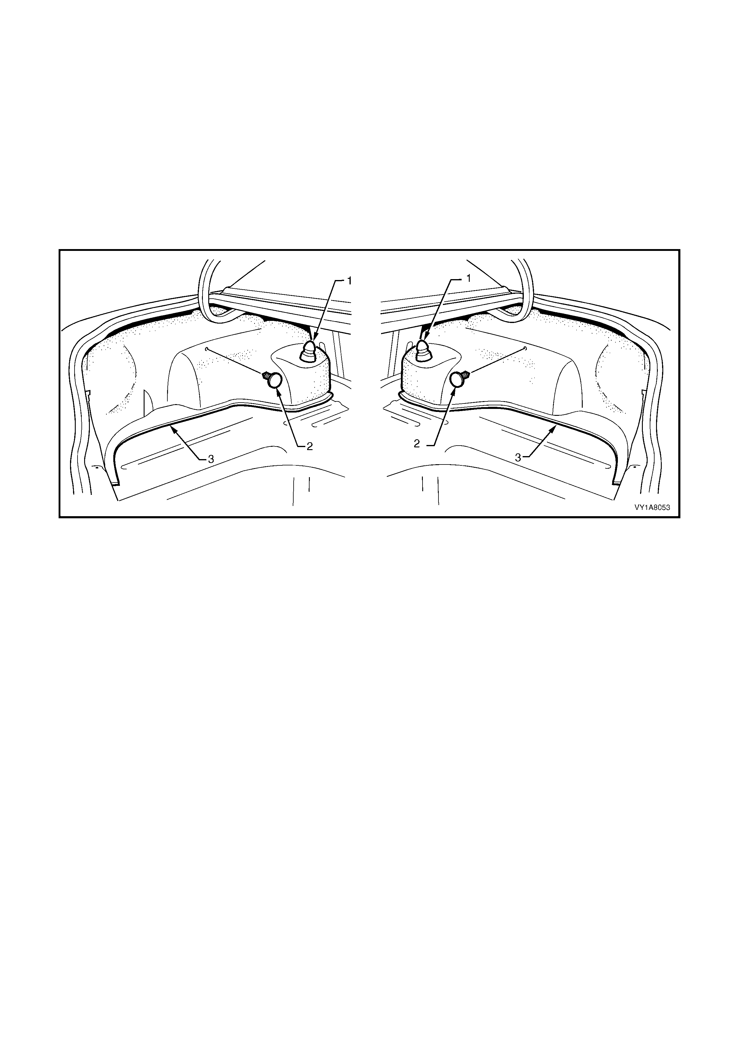
4.14 QUARTER INNER REAR SIDE CARPET
LT Section No. – 14-480
1. Remove the rear end trim panel, refer to 4.12 REAR END TRIM PANEL.
2. Remove the rear c ompartment floor car pet as sembly, refer to 4.13 REAR COMPARTMENT FLOOR CARPET
ASSEMBLY.
REMOVE
1. Carefully prise off the rear shock absorber access hole cover (1).
2. Carefully remove the retainer (2) away from the quarter inner rear side carpet (3).
3. Unhook the carpet flap from the rear compartment lid hinge bracket.
4. Carefully remove the quarter inner rear side carpet, refer Figure 1A8-85.
Figure 1A8-85
REINSTALL
The installation procedure for the quarter inner rear side carpet is the reverse of the removal procedure.
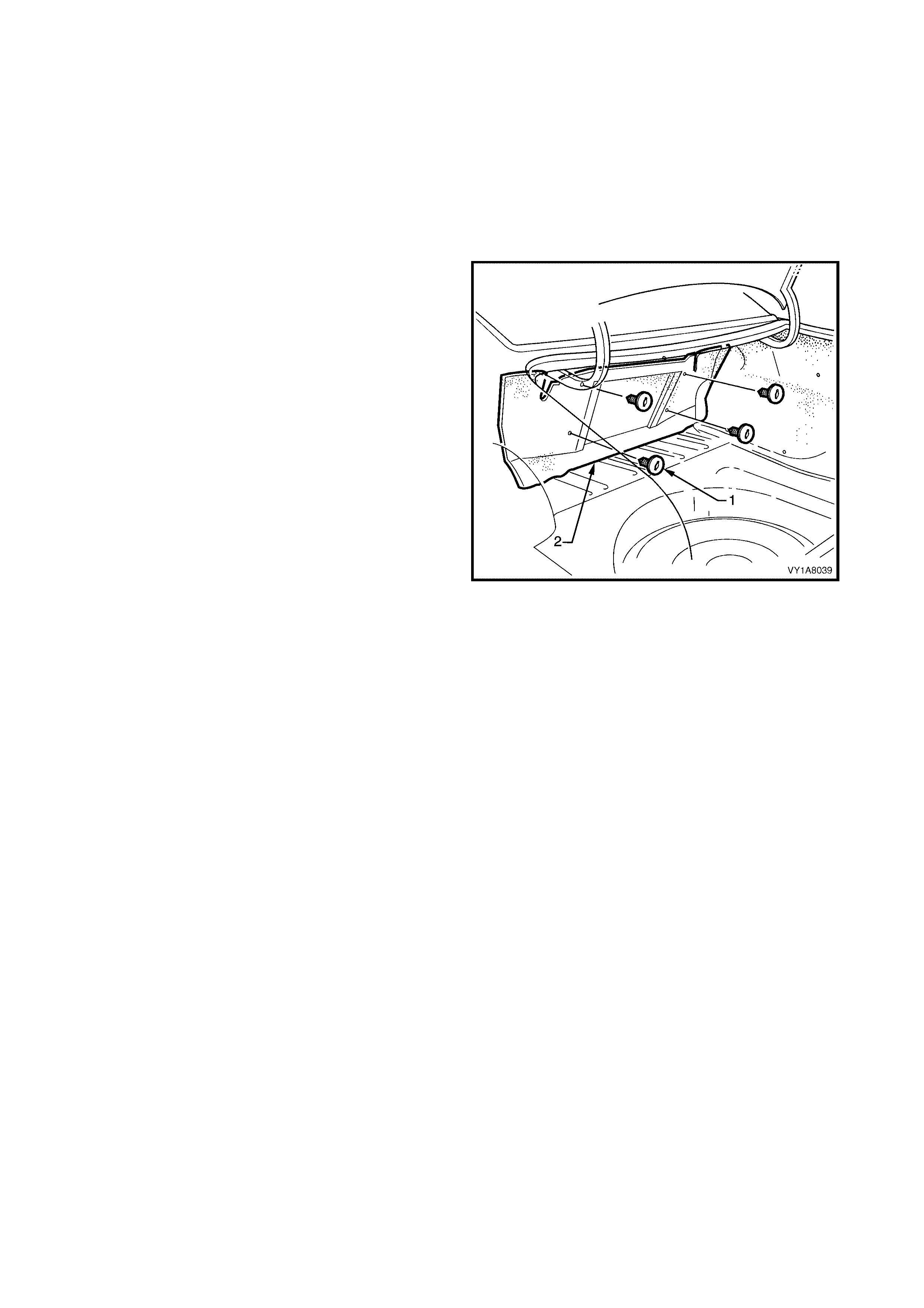
4.15 REAR SE AT BACK PANEL CARP ET
LT Section No. – 14-480
1. Remove the rear end trim panel, refer to 4.12 REAR END TRIM PANEL.
2. Remove the rear c ompartment floor car pet as sembly, refer to 4.13 REAR COMPARTMENT FLOOR CARPET
ASSEMBLY.
3. Partially remove the front of the quarter inner rear side carpet, refer to 4.14 QUARTER INNER REAR SIDE
CARPET.
REMOVE
1. Carefully remove the four retainers (1) out of the
rear seat back panel carpet (2).
2. Remove the rear seat back panel carpet.
Figure 1A8-86
REINSTALL
The installation procedur e for the rear seat bac k panel
carpet is the reverse of the removal operations.
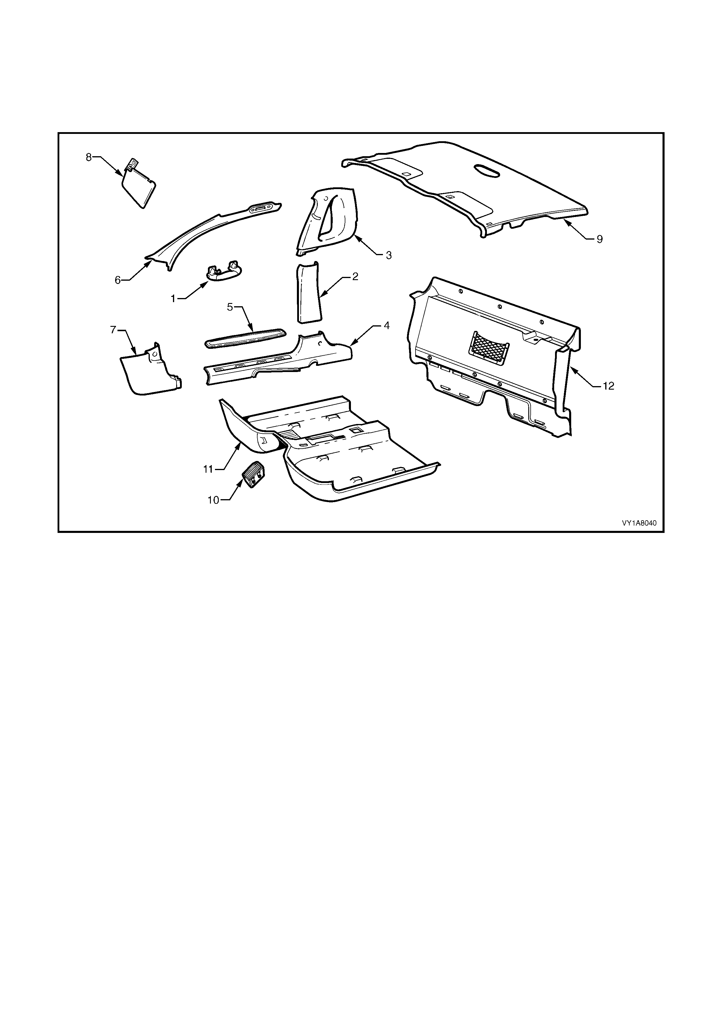
5. SERVICE OPERATIONS - UTILITY
NOTE: The following chart is included to assist with the identification of the components.
For the service procedures of the front door trim panel assem bly, refer to Section 1A5, 2.6 FRONT DOOR TRIM
PANEL ASSEMBLY.
Figure 1A8-87
Legend
1. Assist Handle
2. Centre Pillar Lower Trim
3. Body Lock P illar Upper Trim
4. Side Sill Trim
5. Side Sill Trim Plate
6. Windshield Side Garni sh
7. Hinge Pillar Trim Assem bly
8. Sunshade Assembly
9. Headlining Assembly
10. Driver Footrest
11. Front Floor Carpet Assem bl y
12. Seat Back Body Panel Tri m

5.1 ASSIST HANDLE
LT Section No. – 14-100
REMOVE
1. Pull the assist handle (1) into the down position.
2. Prise open the assist handle screw cover (2) and
remove the attaching screw (3) two places.
3. Remove the assist handle ensuring care is taken
not to damage the locating pins.
Figure 1A8-88
REINSTALL
1. Ensure the locating pins are correctly aligned with
the locating holes.
2. Tighten all retaining screws to the correct torque
specification.
ASSIST HANDLE ATTACHING
SCREW TORQUE SPECIFICATION 1.0 – 3.0 Nm
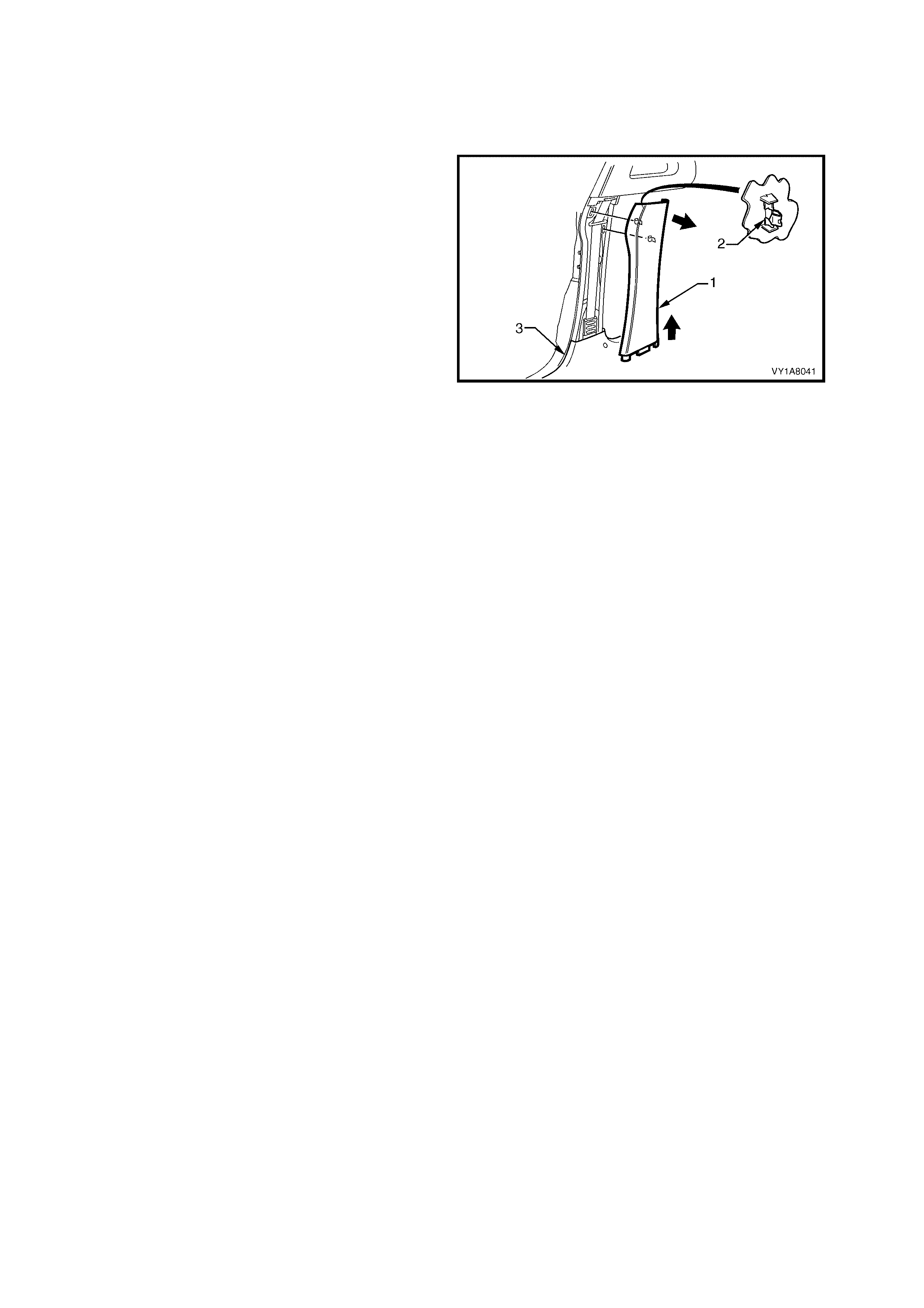
5.2 CENTRE PILLAR LOWER TRIM
LT Section No. – 14-100
REMOVE
1. Lever the centre pillar lower trim ( 1) away f rom the
front door opening weatherstrip with your fingers,
pulling the trim in towards the centre of car,
disengaging the two retaining clips (2).
2. Remove the trim upward, out of the side sill
trim (3).
Figure 1A8-89
REINSTALL
1. Locate the centre pillar lower trim into the side sill
trim and push the retaining clips in firmly.
2. Ensure the front and rear door opening
weatherstrip fits neatly over the outer edge of the
centre pillar lower trim.
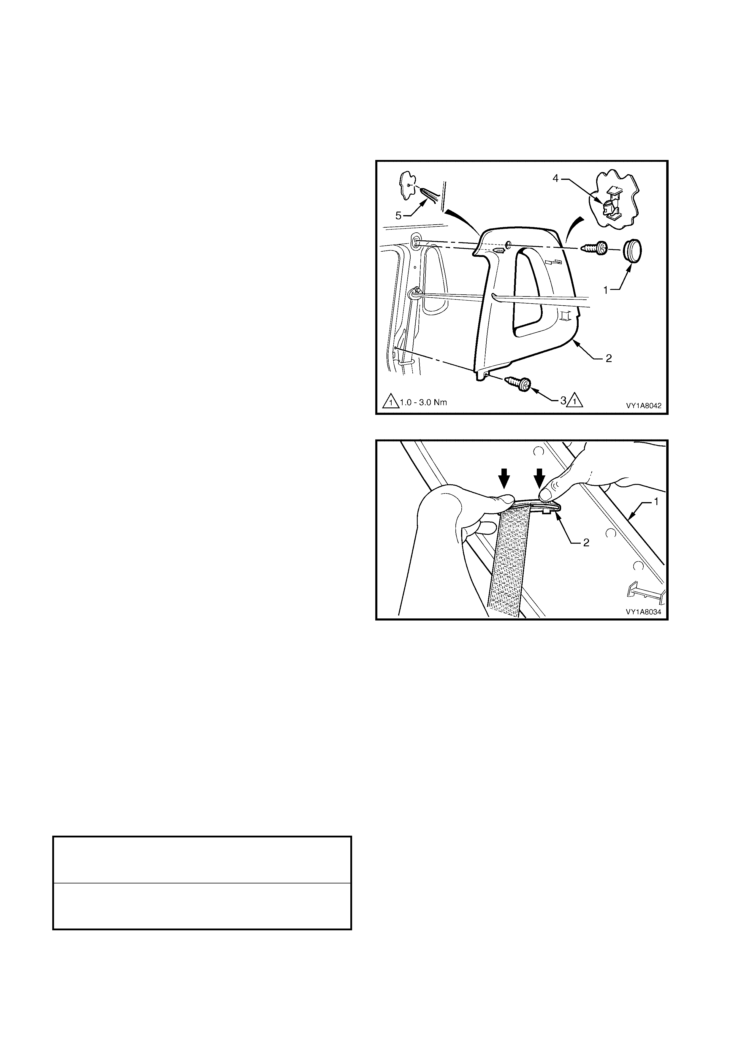
5.3 BODY LOCK PILLAR UPPER TRIM
LT Section No. – 14-100
1. Remove the centre pillar lower trim, refer to 5.2 CENTRE PILLAR LOWER TRIM.
2. Remove the lower seat belt bolt, refer to Section12M, OCCUPANT PROTECTION SYSTEM.
REMOVE
1. Remove the centre pillar cap (1) from the upper
attachment of the body lock pillar upper trim (2).
2. Remove the two screws (3) securing body lock
pillar upper trim.
3. Pull the upper edge of the body lock pillar upper
trim away from the headlining, while disengage the
two retaining clips (4) at the rear of the trim.
NOTE: When rem oving the body loc k pillar upper tr im,
ensure car e is tak en not to dam age the locating pin (5)
below the upper attaching screw.
Figure 1A8-90
4. With the body lock pillar upper trim (1) partially
removed, disengage the seat belt guide (2) from
the trim and feed the seat belt and anchor plate
through the opening.
5. Remove the body lock pillar upper trim.
Figure 1A8-91
REINSTALL
Reinstallation of the body lock pillar upper trim is the
reverse of the removal, noting the following:
1. Ensure the locating pin, below the upper attaching
screw is correctly aligned with the locating hole.
2. Ensure the leading edge of the body lock pillar
upper trim engages the door opening weatherstrip.
3. Check seat belt operation prior to tightening the
body lock pillar upper trim attaching screws.
4. Tighten all fasteners to the correct torque
specification.
BODY LOCK PILLAR UPPER TRIM
ATTACHING SCREW
TORQUE SPECIFICATION 1.0 – 3.0 Nm
FRONT SEAT BELT LOWER
ATTACHING BOLT
TORQUE SPECIFICATION 35.0 – 50.0 Nm
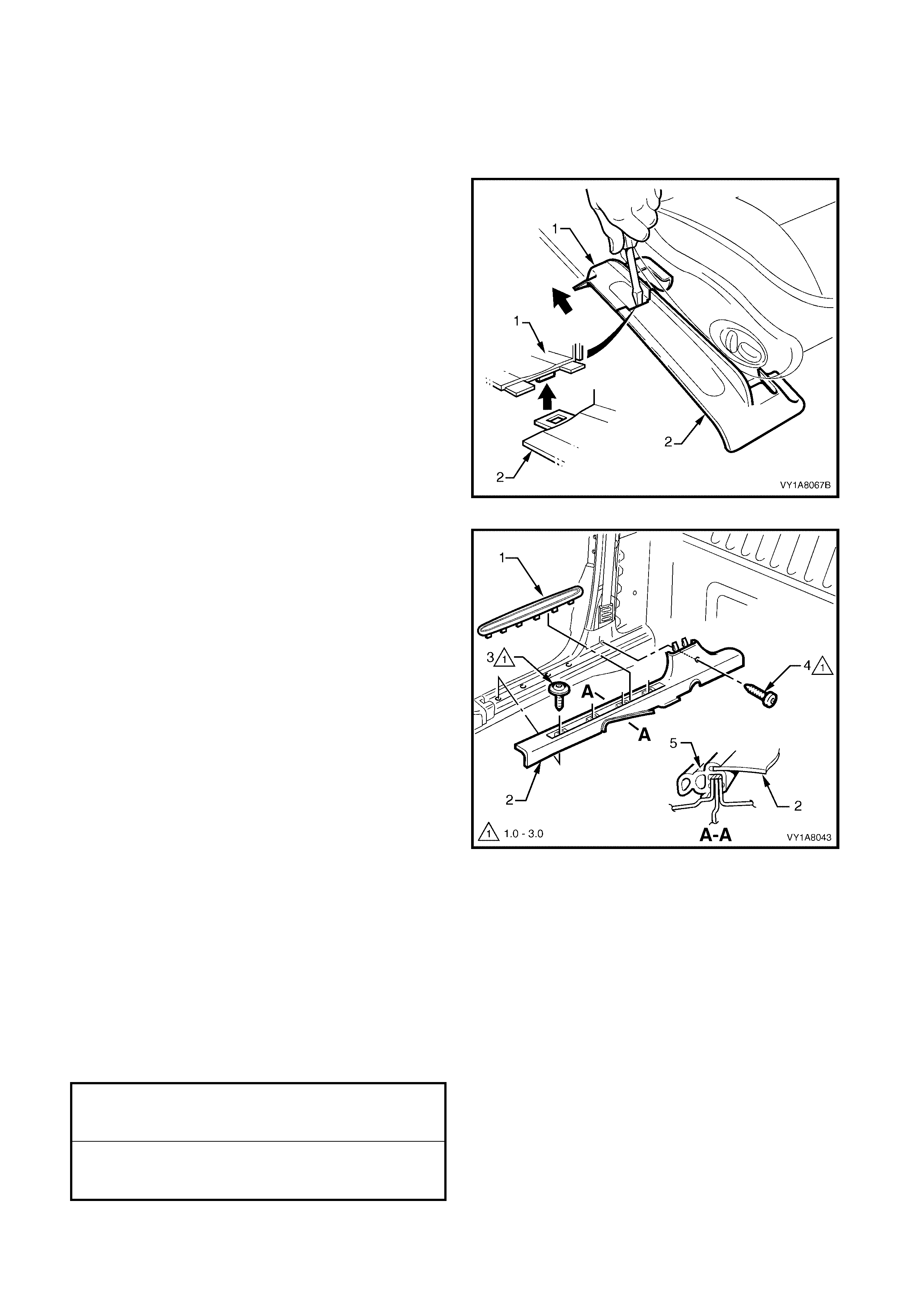
5.4 SIDE SILL TRIM AND PLATE
LT Section No. – 14-100
1. Remove the centre pillar lower trim, refer to 5.2 CENTRE PILLAR LOWER TRIM.
REMOVE
1. Remove the front attaching screw (1) from the seat
adjuster outer front cover (2), driver side only.
2. Using a small screwdriver, push in the centre of
the join to separate the front cover and the front
seat outer lower rear cover (3).
3. Unclip the covers from the seat track, and
disengage from the side sill trim.
4. Pull the covers apart and remove the rear cover.
Figure 1A8-92
5. Carefully lever the side sill trim plate (1) from the
side sill trim (2), starting at the front of the plate
and move rearward, revealing the attaching
screws.
IMPORTANT: Care must be taken not to snap the sill
trim plates.
6. Remove the four Torx head screws (3) from the
side sill trim, in the door opening.
7. Remove the Torx head s crew (4) from the side sill
trim to the centre pillar.
8. Remove the side sill trim.
Figure 1A8-93
REINSTALL
Reinstallation of the side sill trim and the seat adjuster
outer front cover is the reverse of the removal, noting
the following:
1. Ensure the outer edge of the side sill trim engages
the door opening weatherstrip (5), refer Figure
1A8-93.
2. Tighten all fasteners to the correct torque
specification.
SEAT ADJUSTER OUTER FRONT
COVER ATTACHING SCREW
TORQUE SPECIFICATION 1.0 – 3.0 Nm
SIDE SILL TRIM
ATTACHING SCREW
TORQUE SPECIFICATION 1.0 – 3.0 Nm

5.5 WI NDSHIELD SIDE GARNISH
LT Section No. – 14-100
1. Remove the assist handle, refer to 5.1 ASSIST HANDLE.
2. Remove the centre pillar lower trim, refer to 5.2 CENTRE PILLAR LOWER TRIM.
3. Remove the centre pillar upper trim, refer to 5.3 BODY LOCK PILLAR UPPER TRIM.
REMOVE
1. Starting at the upper rear edge of the windshield
side garnish (1), disengage the three attaching
clip s (2).
2. Remove the windshield side garnish.
NOTE: When removing the windshield side garnish,
ensure care is taken not to damage the locating pin
(3).
Figure 1A8-94
REINSTALL
Reinstallation of the windshield side garnish is the
reverse of the removal, noting the following:
1. Ensure the windshield side garnish locating pins
are aligned with the holes in the inner panel.
2. Ensure the outer edge of the windshield side
garnish engages the door opening weatherstrip
(4), refer Figure 1A8-94.
3. Tighten all fasteners to the correct torque
specification.
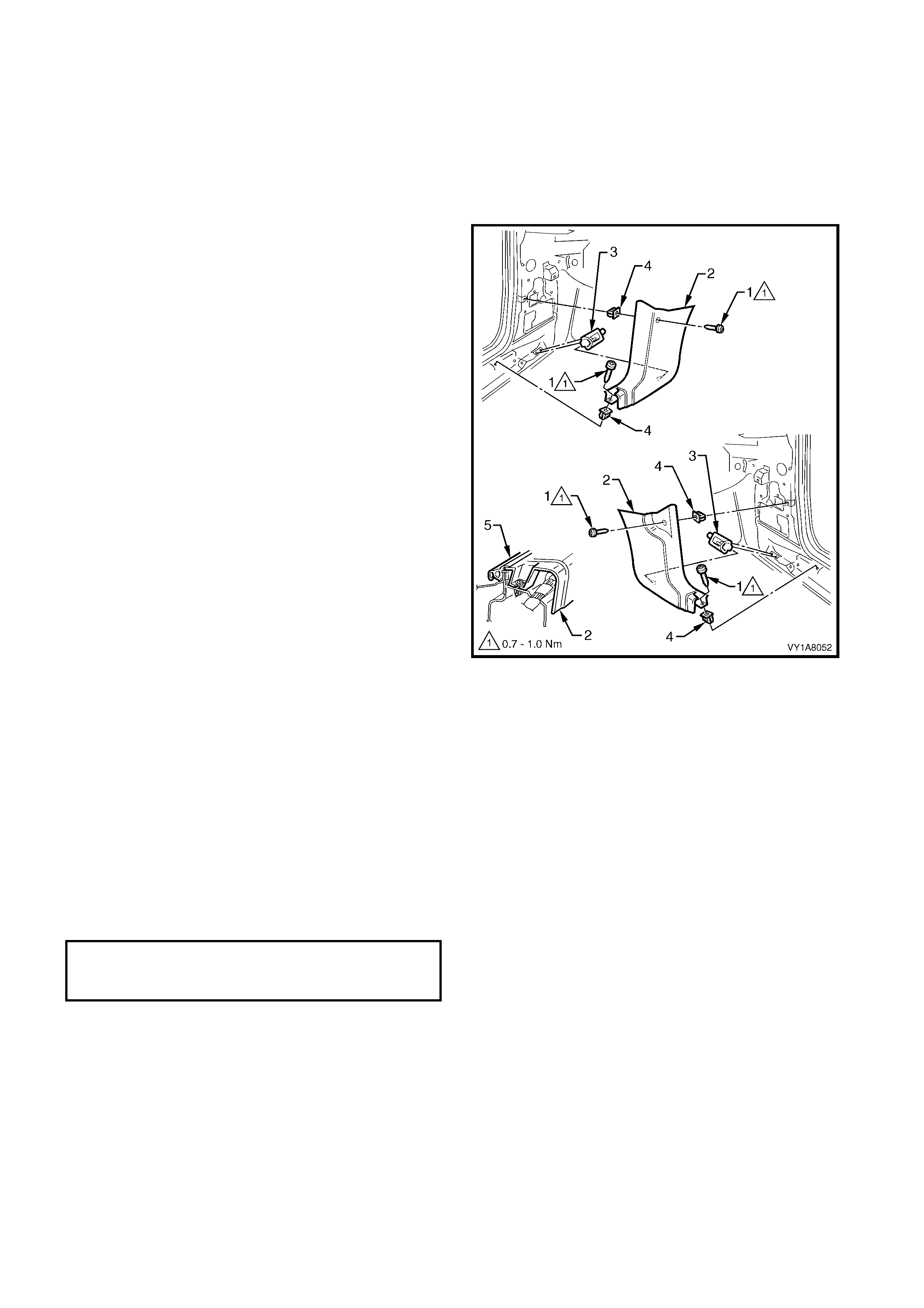
5.6 HINGE PILLAR TRIM ASSEMBLY
LT Section No. – 14-100
1. Remove the centre pillar lower trim, refer to 5.2 CENTRE PILLAR LOWER TRIM.
2. Remove the seat adjuster outer front cover, refer to Section 1A7, SEAT ASSEMBLIES.
3. Remove the side sill trim, refer to 5.4 SIDE SILL TRIM AND PLATE.
REMOVE
1. Remove the two attaching screws (1) from the
hinge pillar trim assembly (2).
2. Disengage the hinge pillar trim clip (3) by pulling
the lower edge of the hinge pillar tr im ass embly up
and away from the sheetmetal.
3. Remove the hinge pillar trim assembly.
Figure 1A8-95
REINSTALL
Reinstallation of the hinge pillar trim assembly is the
reverse of the removal, noting the following:
1. Ensure the hinge pillar trim clip is correctly
engaged.
2. Ensur e the nut inserts (4) are correc tly loc ated and
in good condition, refer Figure 1A8-95.
3. Ensure the outer edge of the hinge pillar trim
assembly engages the door opening weatherstrip
(5), refer Figure 1A8-95.
4. Tighten all fasteners to the correct torque
specification.
HINGE PILLAR TRIM ASSEMBLY
ATTACHING SCREW
TORQUE SPECIFICATION 0.7 – 1.0 Nm
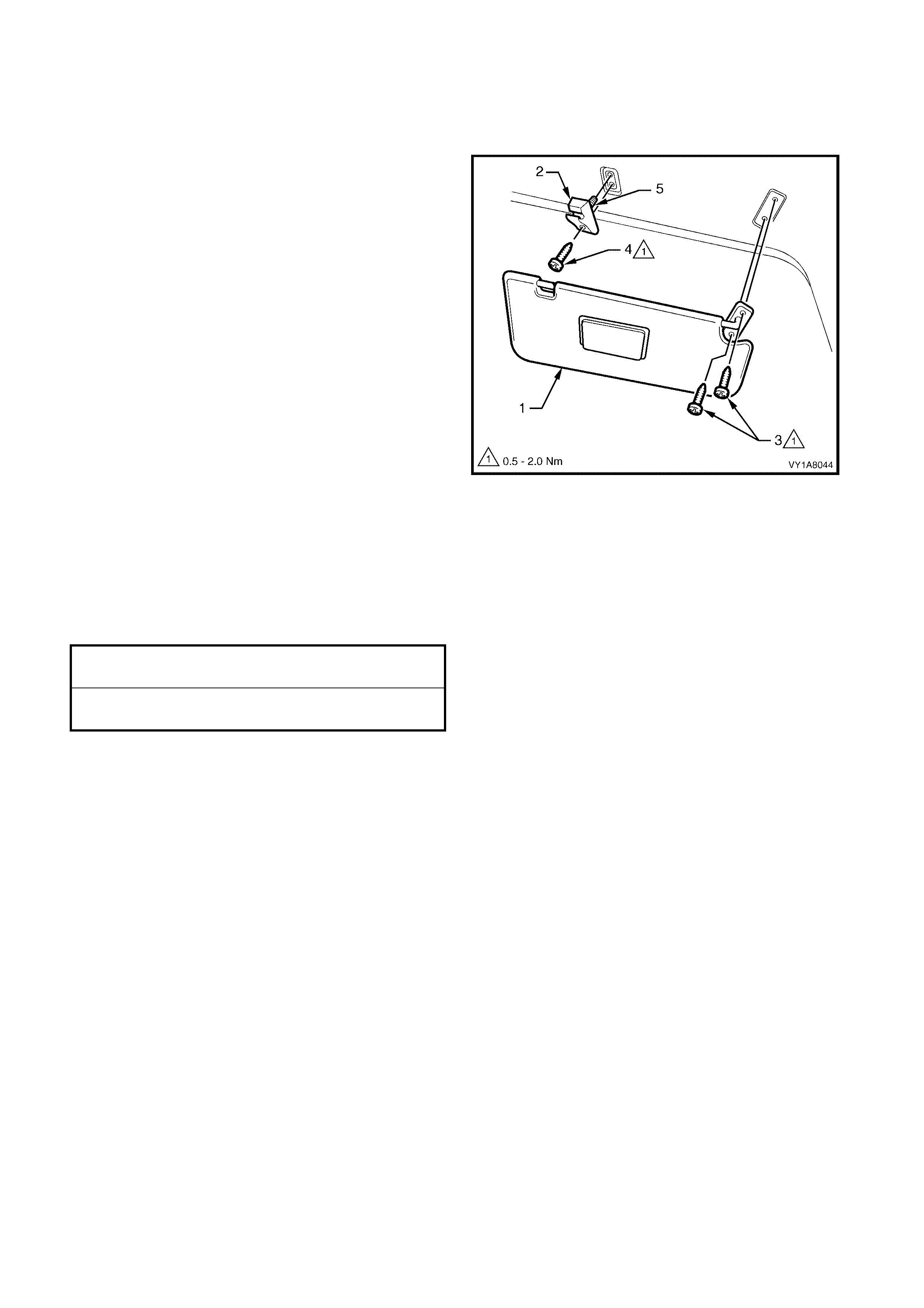
5.7 SUNSHADE ASSEMBLY
LT Section No. – 14-050
REMOVE
1. Disconnect the sunshade assembly (1) from the
sunshade support (2) and rotate to gain access.
2. Remove the sunshade assembly attaching Torx
screws (3) two places.
3. Pull the sunshade away from the headlining
assembly and remove.
4. Remove the Torx screw (4) from the sunshade
support and pull the support from the headlining
assembly.
NOTE: W hen removing the sunshade support, ensure
that care is taken not to damage the locating pin (5).
Figure 1A8-96
REINSTALL
Reinstallation of the s unshade assem bly is the r everse
of the removal, noting the following:
1. Ensure the sunshade support is correctly located.
2. Tighten all fasteners to the correct torque
specification.
SUNSHADE ASSEMBLY ATTACHING
SCREWS TORQUE SPECIFICATION 0.5 – 2.0 Nm
SUNSHADE SUPPORT ATTACHING
SCREWS TORQUE SPECIFICATION 0.5 – 2.0 Nm
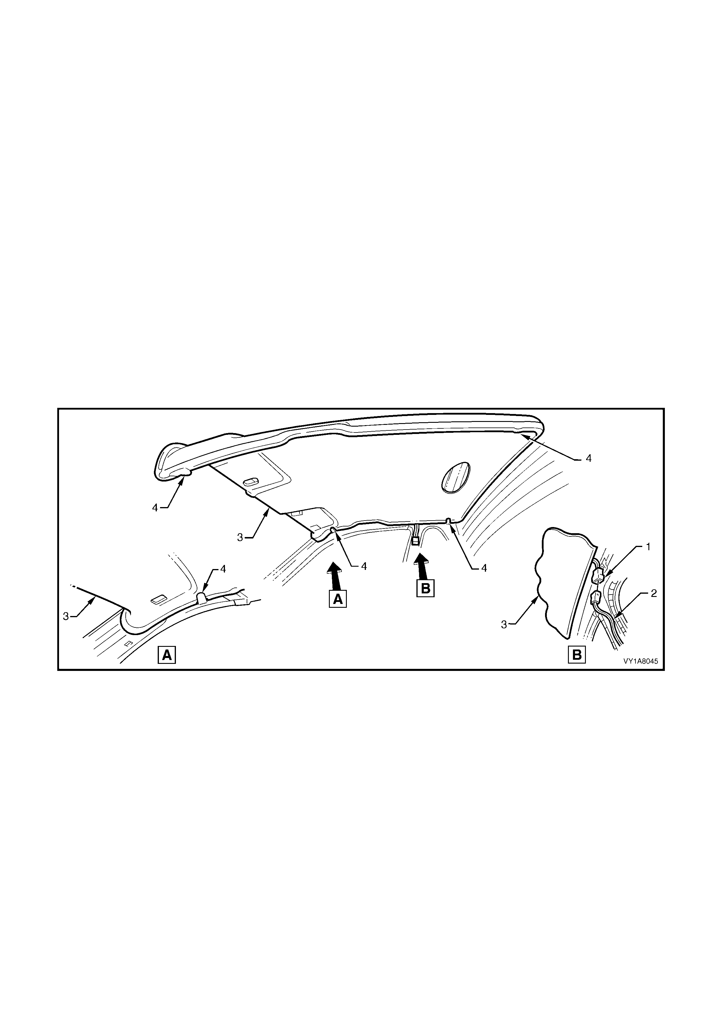
5.8 HEADLINING ASSEMBLY
LT Section No. – 14-150
1. Remove the fuse F6 from the passenger compartment fuse and relay assembly, refer Section 12O,
1.1 FUSES and 1.2 CIRCUIT BRAKERS.
2. Place protective covering over both front seats and the interior trim.
3. Remove the assist handles, refer to 5.1 ASSIST HANDLE.
4. Remove the centre pillar lower trim, refer to 5.2 CENTRE PILLAR LOWER TRIM.
5. Remove the body lock pillar upper trim, refer to 5.3 BODY LOCK PILLAR UPPER TRIM.
6. Remove the windshield side garnish, refer to 5.5 WINDSHIELD SIDE GARNISH .
7. Remove the sunshade assembly, refer to 5.7 SUNSHADE ASSEMBLY.
8. Remove the dome lamp, refer to Section 12B, 3.8 DOME LAMP ASSEMBLY.
REMOVE
1. Disconnect the headlining assembly harness (1) from the body harness connector (2), located above and
slightly forward of the right-hand centre pillar, refer to Figure1A8-97.
NOTE: It may be necessary to flex the headlining assembly (3) down slightly to gain access to the harness
connector.
2. With the aid of an assistant, flex the headlining assembly to disengage the corners from the four ‘D’ tabs (4) on
the sides of the roof panel.
3. Ease the headlining assembly from its position in the roof and turn the assembly so that it can be passed
through the passenger side front door, removing the assembly from the vehicle, refer to Figure1A8-97.
Figure 1A8-97
REINSTALL
Reinstallation of the headlining assembly is the reverse of the removal, noting the following:
1. Temporaraly support the headlining assembly on the ‘D’ tabs before the trim components are reinstalled.

5.9 DRIVER FOOTREST
LT Section No. – 14-475
REMOVE
1. Remove the two screws (1) securing the driver
footrest (2) to the footrest mounting bracket.
2. Remove the footrest pad.
Figure 1A8-98
REINSTALL
Reinstallation of the dr iver f ootr es t is the rever s e of the
removal procedure, noting the following:
1. Ensure all fasteners are tightened to the correct
torque specifications.
DRIVER FOOTREST ATTACHING
SCREW TORQUE SPECIFICATION 2.0 – 5.0 Nm
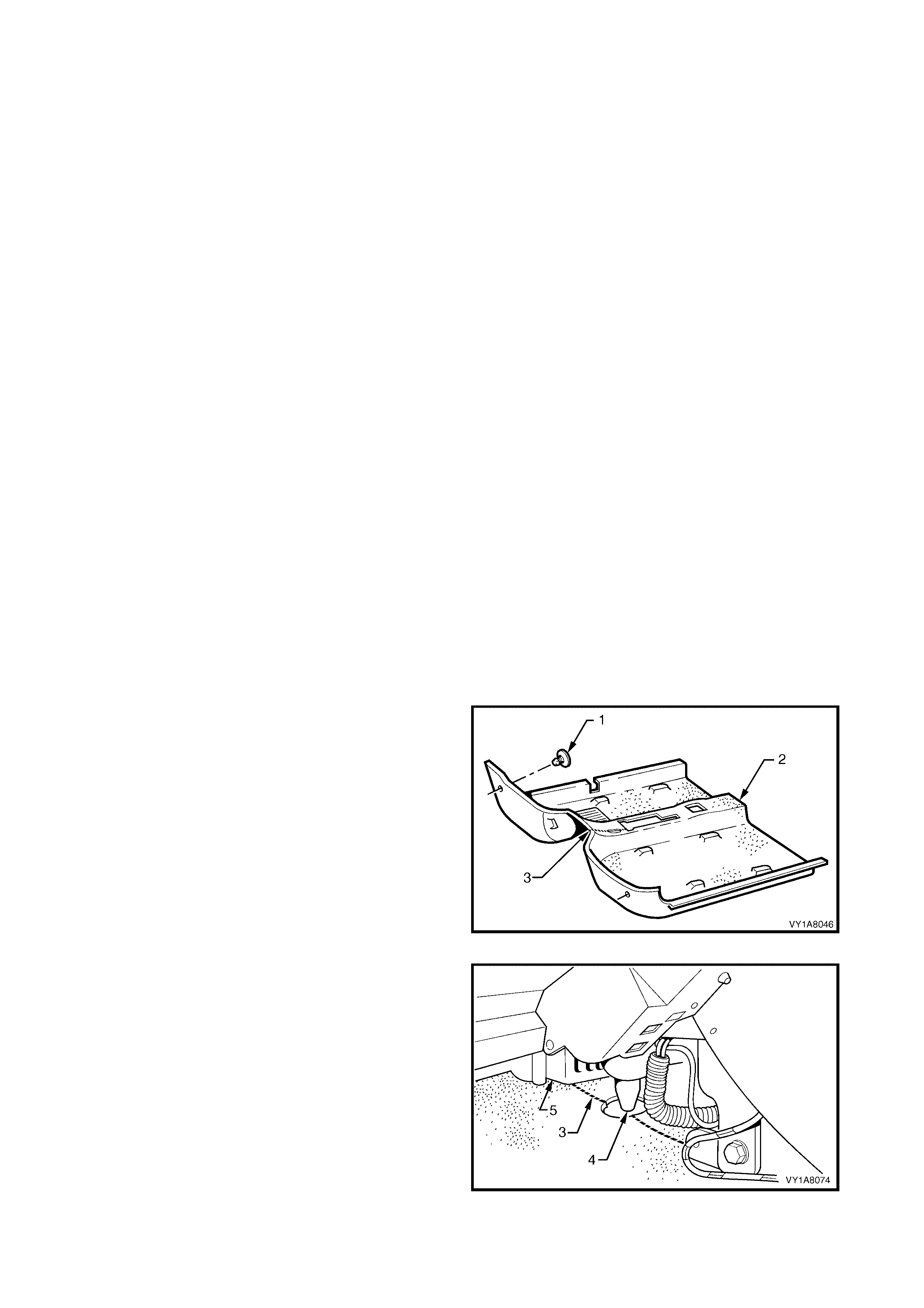
5.10 FRONT FLOOR CARPET ASSEMBLY
LT Section No. – 14-475
CAUTION: Before performing any Service Operation on a front seat assembly fitted with side impact
airbags, ensure t he SRS ( Air Bag) is disabled, refer to DISABLING THE SRS, Section 12M SUPPLEMENTAL
RESTRAINT SYSTEM.
If required, first remove the following components,
1. Remove the right and left-hand centre pillar lower trims, refer to 5.2 CENTRE PILLAR LOWER TRIM.
2. Remove the right and left-hand side sill trims, refer to 5.4 SIDE SILL TRIM AND PLATE.
3. Remove the right and left-hand hinge pillar trim assemblies, refer to 5.6 HINGE PILLAR TRIM ASSEMBLY.
4. Remove both front seats, refer to Section 1A 7, SEAT ASSEMBLIES.
5. Remove the driver footrest, refer to 5.9 DRIVER FOOTREST.
6. Remove the park brake lever cover by grasping the cover firmly by hand and sliding the cover over the park
brake lever, refer to Section 5A, 2.9 PARK BRAKE LEVER.
7. Remove the instrument panel compartment, refer to Section 1A3, 3.2 INSTRUMENT PANEL
COMPARTMENT ASSEMBLY.
8. Remove the instrument panel lower trim panel, refer to Section 1A3, 3.4 INSTRUMENT PANEL LOWER
TRIM PANEL ASSEMBLY.
9. Remove the right and left-hand instrument panel lower trim plate assembly, refer to Section 1A3,
3.1 INSTRUMENT PANEL LOWER TRIM PLATE ASSEMBLY.
10. Remove instrument panel lower extension side trim panel, refer to Section 1A3, 2.2 INSTRUMENT PANEL
LOWER EXTENSION SIDE TRIM PANEL.
11. Remove floor console assembly, refer to Section 1A3, 2.3 FLOOR CONSOLE ASSEMBLY.
12. Disconnect the inflatable restraint control module (SDM) wiring harness, refer to Section 12M,
2.8 INFLATABLE RESTRAINT CONTROL MODULE (SDM).
13. For vehicles fitted with an automatic transmission, remove the selector control lever assembly, refer
Section 7C4, AUTOMATIC TRANSMISSION ON VEHICLE SERVICING.
14. For vehicles fitted with manual transmission, remove the gearshift lever, refer to Section 7B1, MANUAL
TRANSMISSION – V6 ENGINE or refer to Section 7B2, MANUAL TRANSMISSION – GEN III V8 ENGINE.
REMOVE
1. Remove the two retaining clips (1) from the front
floor carpet assembly (2) by rotating the clips
counter- clockwise and lift clear of the attaching
studs.
NOTE: To assist in the removal and installation of the
front floor carpet assembly, it has been perforated (3)
from the front edge through the centre of the
evaporator drain cut out to the forward edge of the
lower radio bracket cut out, refer Figure 1A8-100.
Figure 1A8-99
2. From ins ide the left-hand foot well, grasp the edge
of the hole in the front floor carpet assembly
around the evaporator drain hose (4) and tear
open the perforated line (3) by pulling the carpet
away from the transmission tunnel.
3. Slide the remaining flap of carpet out from under
the heating, ventilation and air conditioning
(HVAC) unit (5) and into the right-hand foot well.
4. Carefully manoeuvre the floor carpet and insulator
assembly from the vehicle.
Figure 1A8-100

REINSTALL
The installation procedure for the front floor carpet assembly is the reverse of the removal procedure, noting the
following:
1. If a new carpet is being f itted, cut along the perforated line in the floor carpet that runs fr om the forward edge
of the carpet, thr ough the evaporator dr ain cut- out, to the f orward edge of the lower radio br ac ket cut-out, prior
to installation, refer Figure 1A8-99.
2. Ensure that all the cut-outs in the carpet are correctly aligned and install the two retaining clips and the front
seat belt lower attaching bolts to secure the carpet, prior to installing the seats and console.
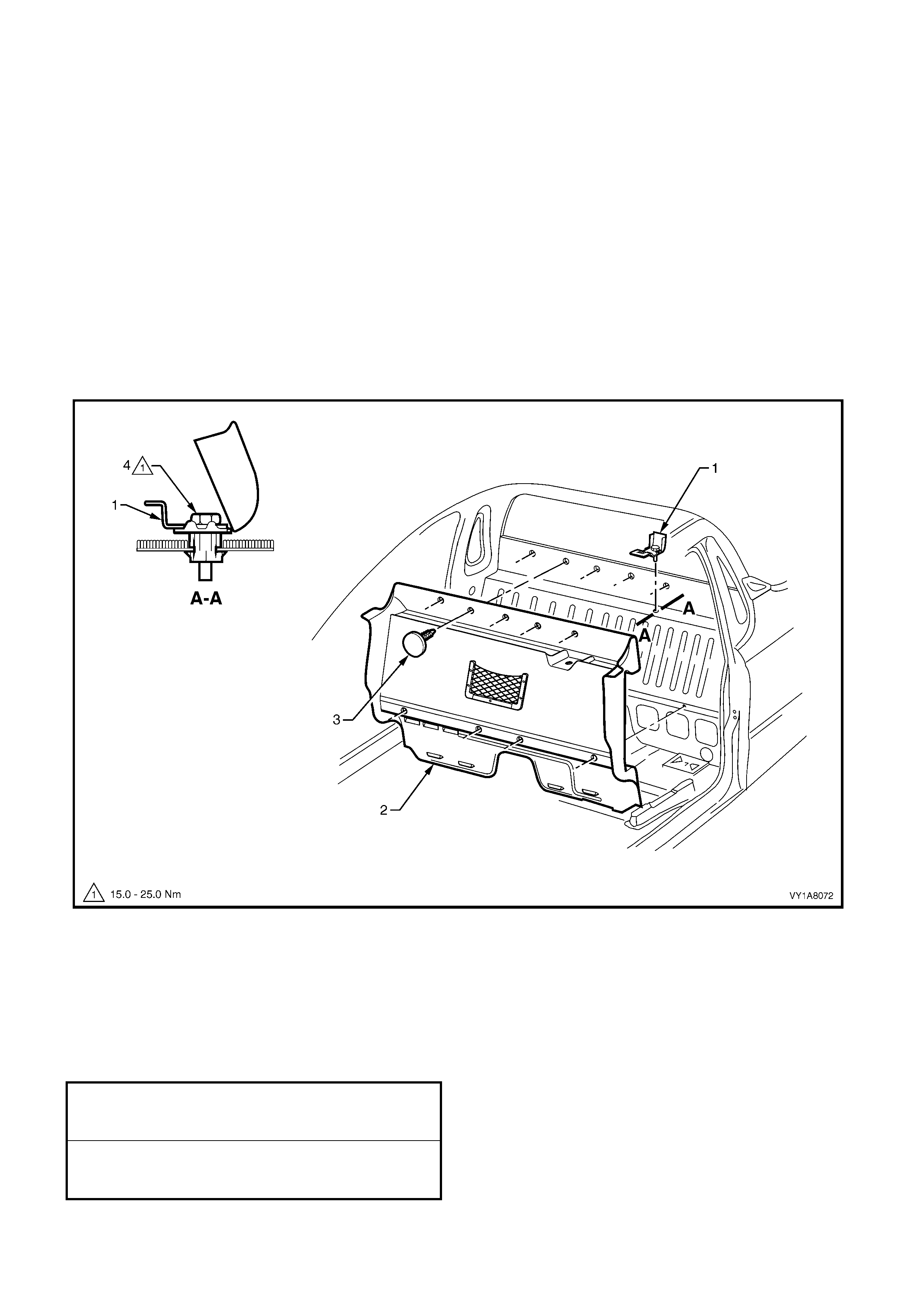
5.11 SEAT BACK BODY PANEL TRIM
LT Section No. –
If required, first remove the following components,
1. Remove the right and left-hand centre pillar lower trims, refer to 5.2 CENTRE PILLAR LOWER TRIM.
2. Remove the right and left-hand side sill trims, refer to 5.4 SIDE SILL TRIM AND PLATE.
3. Remove floor console assembly, refer to Section 1A3, 2.3 FLOOR CONSOLE ASSEMBLY.
4. Move the passenger and driver seat to the forward position.
5. Remove the jack handle from its location behind the passenger seat.
REMOVE
1. Remove the child seat restraint fitting (1) refer to Section 12M, SUPPLEMENTAL RESTRAINT SYSTEM
from the seat back body panel trim (2).
2. Remove the nine retainers (3) attaching the seat back body panel trim to the back panel.
3. Remove the two screws (4) attaching the stowage net reinforcement bracket.
4. Remove the seat back body panel trim, refer Figure 1A8-101.
Figure 1A8-101
REINSTALL
The installation procedure for seat back body panel trim is the reverse of the removal procedure, noting the
following:
1. T he child seat r estraint f itting bolt (5) s hould be hand star ted for minim um of five full threads before tightening,
refer Figure 1A8-101.
2. Ensure all fasteners are tightened to the correct torque specifications.
STOWAGE NET REINFORCEMENT
BRACKET ATTACHING SCREW
TORQUE SPECIFICATION 1.0 – 2.0 Nm
CHILD SEAT RESTRAINT FITTING
ATTACHING BOLT
TORQUE SPECIFICATION 15.0 – 25.0 Nm

6. SPECIFICATIONS
6.1 TRIM CLEARANCES, SEDAN
Figure 1A8-102 provides the trim clearances for the Sedan.
NOTE: All measurements are in millimeters.
Figure 1A8-102
Legend
1. Hinge Pillar Trim Assembly
2. Side Sill Trim
3. Side Sill Trim Plate
4. Centre Pillar Lower Trim
5. Centre Pillar Upper Trim Assembly
6. Windshield Side Garnish
7. Body Lock Pillar Garnish
8. Rear Window Upper Garnish
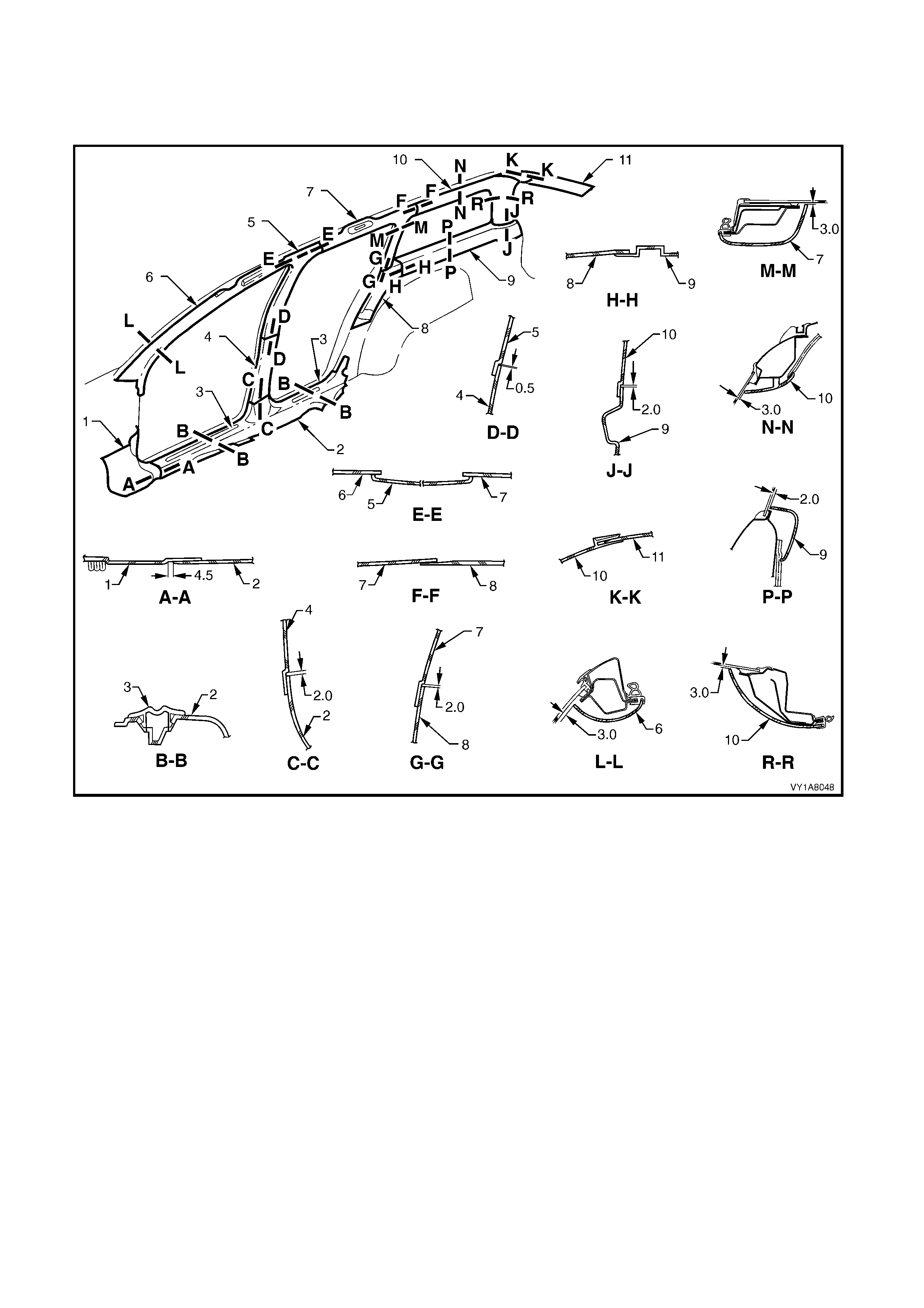
6.2 TRIM CLEARANCES, WAGON
Figure 1A8-103 provides the trim clearances for Wagon.
NOTE: All measurements are in millimeters.
Figure 1A8-103
Legend
1. Hinge Pillar Trim Assembly
2. Side Sill Trim
3. Side Sill Trim Plate
4. Centre Pillar Lower Trim
5. Centre Pillar Upper Trim
6. Windshield Side Garnish
7. Body Lock Pillar Garnish
8. Body Lock Pillar Lower Trim
9. Quarter Inner Trim Upper
10. Body Rear Corner Garnish
11. Rear Window Upper Garnish
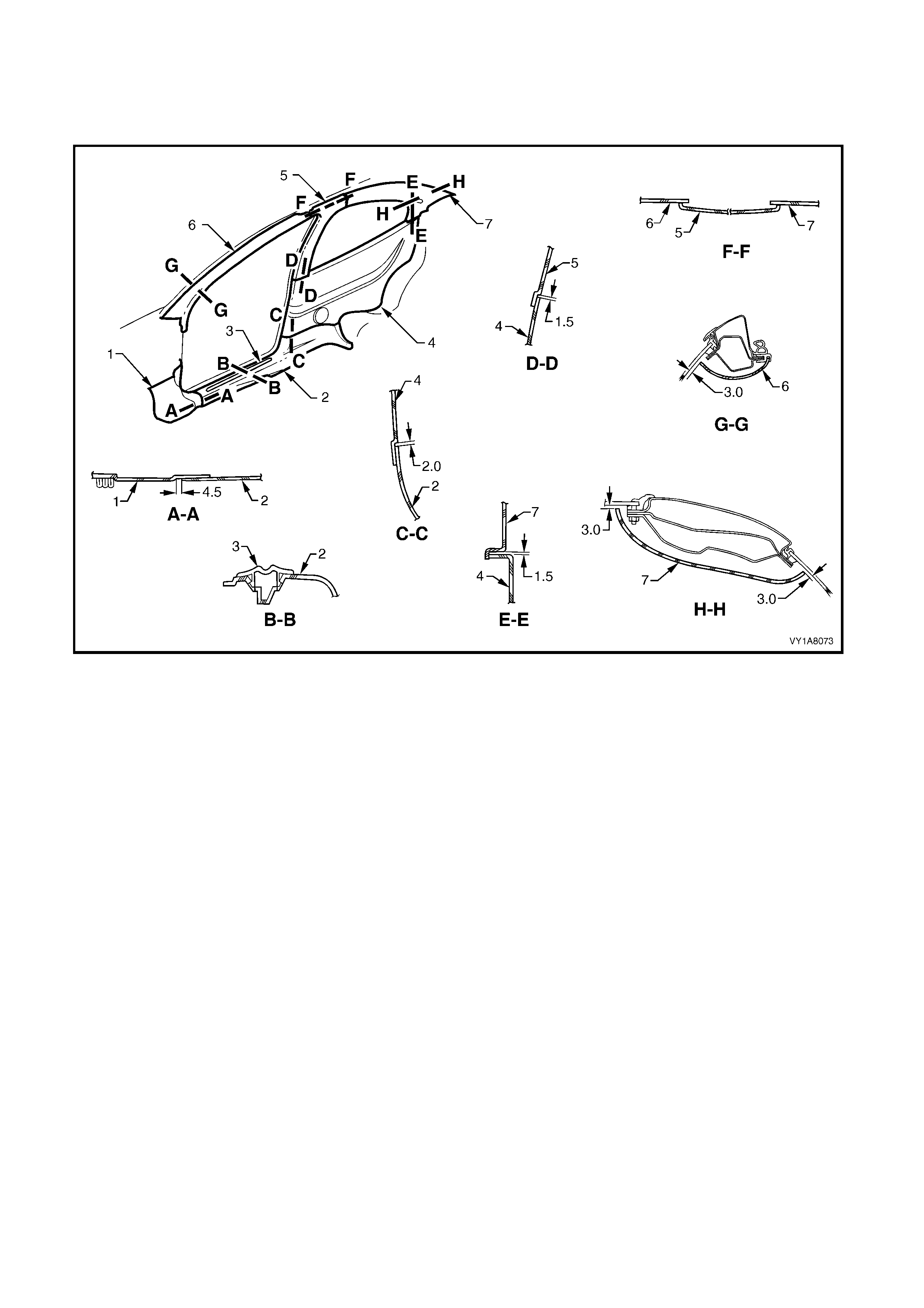
6.3 TRIM CLEARANCES, COUPE
Figure 1A8-104 provides the trim clearances for the Coupe.
NOTE: All measurements are in millimeters.
Figure 1A8-104
Legend
1. Hinge Pillar Trim Assembly
2. Side Sill Trim
3. Side Sill Trim Plate
4. Quarter Trim Panel
5. Centre Pillar Upper Trim Assembly
6. Windshield Side Garnish
6. Body Rear Corner Garnish
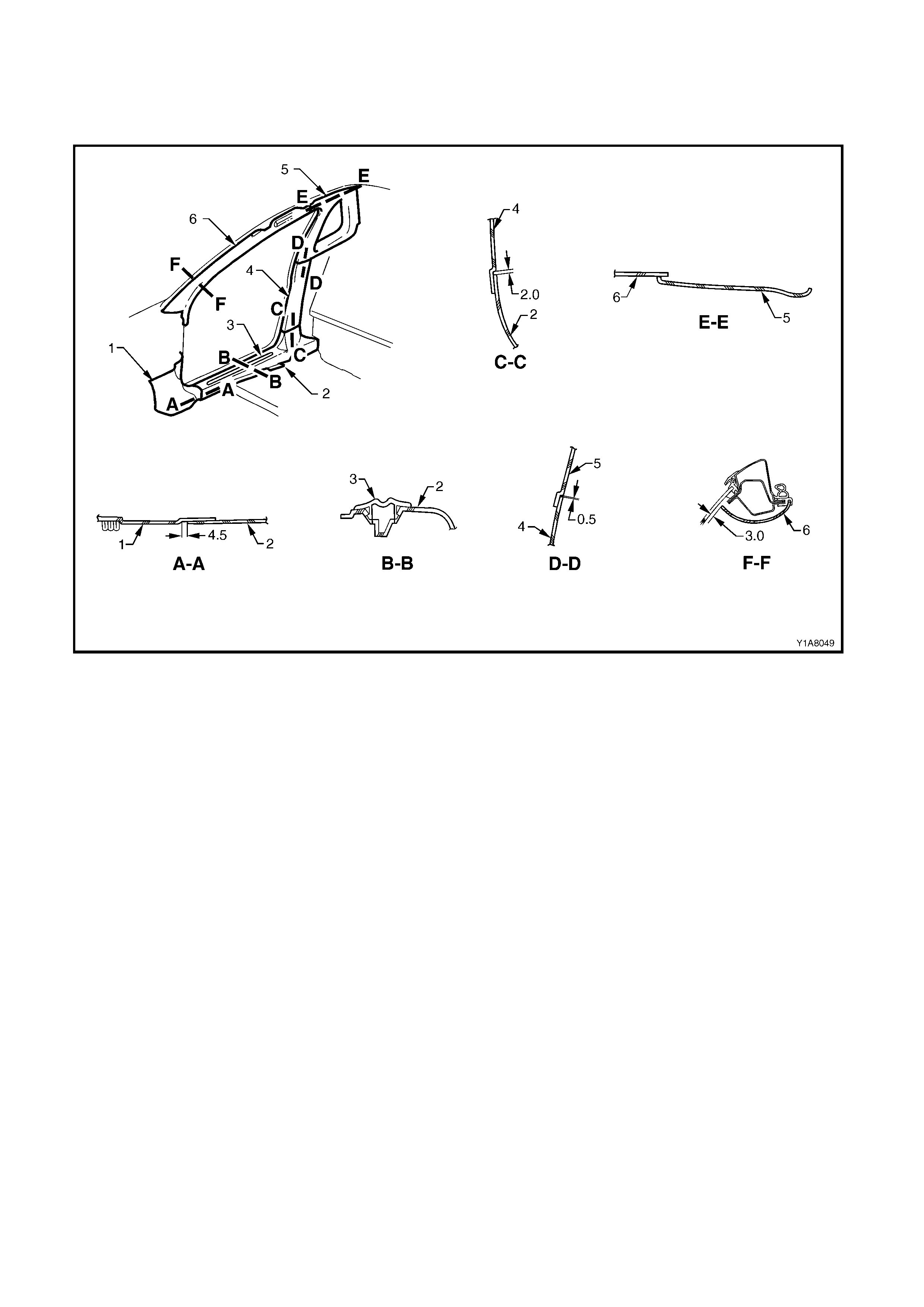
6.4 TRIM CLEARANCES, UTILITY
Figure 1A8-105 provides the trim clearances for the Utility.
NOTE: All measurements are in millimeters.
Figure 1A8-105
Legend
1. Hinge Pillar Trim Assembly
2. Side Sill Trim 3. Side Sill Trim Plate
4. Centre Pillar Lower Trim 5. Body Lock Pillar Upper Trim
6. Windshield Side Garnish

7. TORQUE WRENCH SPECIFICATIONS
Assist handle attaching screw...................................................................................1.0 – 3.0 Nm
Centre pillar upper trim attaching screw ...................................................................1.0 – 3.0 Nm
Front seat belt lower attaching bolt...........................................................................35.0 – 50.0 Nm
Seat adjuster outer front cover attaching screw .......................................................1.0 – 3.0 Nm
Side sill trim attaching screw.....................................................................................1.0 – 3.0 Nm
Windshield side garnish attaching screw..................................................................1.0 – 3.0 Nm
Rear seat belt lower attaching bolt............................................................................35.0 – 50.0 Nm
Hinge pillar trim assembly attaching screw...............................................................0.7 – 1.0 Nm
Sunshade assembly attaching screws......................................................................0.5 – 2.0 Nm
Sunshade support attaching screws.........................................................................0.5 – 2.0 Nm
Roof console attaching screw...................................................................................1.0 – 2.0 Nm
Driver footrest attaching screw .................................................................................2.0 – 5.0 Nm
Rear end trim panel attaching screw........................................................................1.0 – 3.0 Nm
Body lock pillar lower trim attaching screw...............................................................1.0 – 3.0 Nm
Body lock pillar garnish attaching retainer ................................................................1.0 – 3.0 Nm
Quarter inner trim upper attaching screw .................................................................1.0 – 3.0 Nm
Body rear corner garnish attaching screw ................................................................1.0 – 3.0 Nm
Stowage door latch assembly attaching ...................................................................1.0 – 3.0 Nm
Rear end trim panel attaching screw........................................................................0.7 – 1.0 Nm
Armrest insert assembly retaining nut ......................................................................0.7 – 0.9 Nm
Rear quarter trim attaching screw.............................................................................1.0 – 3.0 Nm
Windshield side garnish attaching screw..................................................................1.0 – 3.0 Nm
Rear compartment lid release cable assembly.........................................................1.9 – 2.1 Nm
Body lock pillar upper trim attaching screw...............................................................1.0 – 3.0 Nm
Child restraint anchor attaching screws....................................................................15.0 – 25.0 Nm
Stowage net reinforcement bracket attaching screw................................................1.0 – 2.0 Nm