
SECTION 1A9 - EXTERIOR ORNAMENTATION
IMPORTANT
Before perfo rming any Service O peration or oth er procedu re described in t his Sectio n, refer to Section 00
CAUTIONS AND NOTES for correct workshop practices with regard to safety and/or property damage.
CONTENTS
1. GENERAL DESCRIPTION
1.1 PICTORIAL INDEX – DOMESTIC
SEDAN: EXECUTIVE & ACCLAIM
SEDAN: SV8
SEDAN: S
SEDAN: SS
SEDAN: BERLINA
SEDAN: CALAIS
WAGON: EXECUTIVE & ACCLAIM
WAGON: BERLINA
UTILITY
UTILITY: S
UTILITY: SS
COUPE: MONARO CV6 & CV8
1.2 PICTORIAL INDEX – EXPORT
COUPE: MONARO CV6 & CV8
SEDAN: LUMINA LS
SEDAN: S
SEDAN: SS
SEDAN: LUMINA LTZ
SEDAN: OMEGA CD
WAGON: LUMINA LS
UTILITY: SS
COUPE: LUMINA S & SS
2. SERVICE OPERATIONS, SEDAN
2.1 RADIATOR GRILLE EMBLEM
REMOVE
REINSTALL
2.2 FENDER NAME PLATE
REMOVE
REINSTALL
2.3 REAR DOOR NAME PLATE
SS
CALAIS
2.4 REAR COMPARTMENT LID EMBLEM
HOLDEN, CHEVROLET
2.5 REAR COMPARTMENT LID NAME
PLATE, LH
COMMODORE, LUMINA, OMEGA CD
2.6 REAR COMPARTMENT LID NAME
PLATE, RH
EXECUTIVE, ACCLAI M, S, SV8, SS,
BERLINA, CALAIS, LUMINA LS,
LUMINA LTZ, 3.8 V6
2.7 ROOF JOINT MOULDING
REMOVE
REINSTALL
2.8 DOOR OPENING MOULDING
REMOVE
REINSTALL
2.9 CENTRE PILLAR UPPER FINISHER
ASSEMBLY
REMOVE
REINSTALL
2.10 QUARTER PANEL BELT MOULDING
REMOVE
REINSTALL
2.11 BODY SIDE MOULDINGS
REMOVE
REINSTALL
2.12 ROCKER PANEL MOULDING
ASSEMBLY
REMOVE
REINSTALL
3. SERVICE OPERATIONS, WAGON
3.1 RADIATOR GRILLE EMBLEM
REMOVE
REINSTALL
3.2 FENDER NAME PLATE
REMOVE
REINSTALL
3.3 LIFTGATE EMBLEM
HOLDEN, CHEVROLET
3.4 LIFTGATE NAME PLATE, LH
COMMODORE, CHEVROLET
3.5 LIFTGATE EMBLEM, RH
EXECUTIVE, ACCLAIM, BERLINA,
LUMINA LS
3.6 ROOF JOINT MOULDING
REMOVE
REINSTALL
3.7 ROOF BARS
REMOVE
REINSTALL
3.8 ROOF SIDE RAILS
REMOVE
REINSTALL
3.9 DOOR OPENING MOULDING
REMOVE
REINSTALL
3.10 CENTRE PILLAR UPPER FINISHER
ASSEMBLY
REMOVE
REINSTALL
3.11 ROOF JOINT FINISHER
REMOVE
REINSTALL
3.12 BODY SIDE MOULDINGS
REMOVE
REINSTALL
3.13 ROCKER PANEL MOULDING
ASSEMBLY
REMOVE
REINSTALL
4. SERVICE OPERATIONS, UTILITY
4.1 RADIATOR GRILLE EMBLEM
REMOVE
REINSTALL
4.2 FENDER NAME PLATE
REMOVE
REINSTALL
4.3 QUARTER PANEL NAME PLATE
SS

4.4 ENDGATE EMBLEM
HOLDEN, CHEVROLET
4.5 ENDGATE NAME PLATE, RH
S, SS
4.6 ROOF JOINT MOULDING
REMOVE
REINSTALL
4.7 DOOR OPENING MOULDING
REMOVE
REINSTALL
4.8 CENTRE PILLAR UPPER FINISHER
ASSEMBLY
REMOVE
REINSTALL
4.9 ROCKER PANEL MOULDING
ASSEMBLY
REMOVE
REINSTALL
4.10 REAR WINDOW UPPER MOULDING
REMOVE
REINSTALL
4.11 REAR WINDOW SIDE MOULDING
REMOVE
REINSTALL
4.12 QUARTER WINDOW MOULDING
REMOVE
REINSTALL
4.13 QUARTER PANEL RAILS
REMOVE
REINSTALL
4.14 TONNEAU COVER BOW RETAINER
REMOVE
REINSTALL
5. SERVICE OPERATIONS, COUPE
5.1 RADIATOR GRILLE EMBLEM
REMOVE
REINSTALL
5.2 QUARTER PANEL NAME PLATE
MONARO, SS
5.3 REAR COMPARTMENT LID EMBLEM
HOLDEN, CHEVROLET
5.4 REAR COMPARTMENT LID NAME
PLATE, LH
LUMINA
5.5 REAR COMPARTMENT LID NAME
PLATE, RH
CV6, CV8, S, SS
5.6 ROOF JOINT MOULDING
REMOVE
REINSTALL
5.7 DOOR OPENING MOULDING
REMOVE
REINSTALL
5.8 CENTRE PILLAR UPPER FINISHER
ASSEMBLY
REMOVE
REINSTALL
5.9 ROCKER PANEL MOULDING
ASSEMBLY
REMOVE
REINSTALL
6. TORQUE WRENCH SPECIFICATIONS

1. GENERAL DESCRIPTION
This Section describes the service procedures for the ornamentation components such as emblems, name plates,
mouldings and finishers. Also included are the Wagon roof bars, and the Utility quarter panel rails and tonneau
cover bow retainer.
Several components previously in this Section have been moved to other Sections, these are:
• Rear spoiler, refer to Section 1A4, 3.4 REAR SPOILER ASSEMBLY,
• Liftgate air deflector, refer to Section 1A4, 4.9 LIFTGATE AIR DEFLECTOR ASSEMBLY.
Domestic Calais vehicles feature a hood front moulding assembly which is not included in this Section, refer to
Section 1A4. 2.1 HOOD FRONT MOULDING ASSEMBLY.
Many of the components in this Section are affixed to the vehicle with double-sided tape or urethane adhesive. It is
imperative that the correct materials are used when reinstalling these parts, as specified in this Section. Use of
materials other than those specified may lead to premature failure.
To aid in identification and service procedure location, refer to the pictorial index diagrams on the following pages.
NOTE: For information regarding the exterior ornamentation for domestic merchandising packs such as the Berlina
International Wagon and right-hand drive (Holden) Lumina, refer to the MERCHANDISING PACK Section in this
Service Information.
1.1 PICTORIAL INDEX – DOMESTIC
The following diagrams provide a quick reference to the correct service procedures for the exterior ornamentation
components relevant to each vehicle model.
Simply refer to the vehicle model by using the table below, locate the component on the Figure, cross-reference it in
the accompanying table below the Figure and go to the appropriate service procedure.
BODY MODEL REFER TO BODY MODEL REFER TO
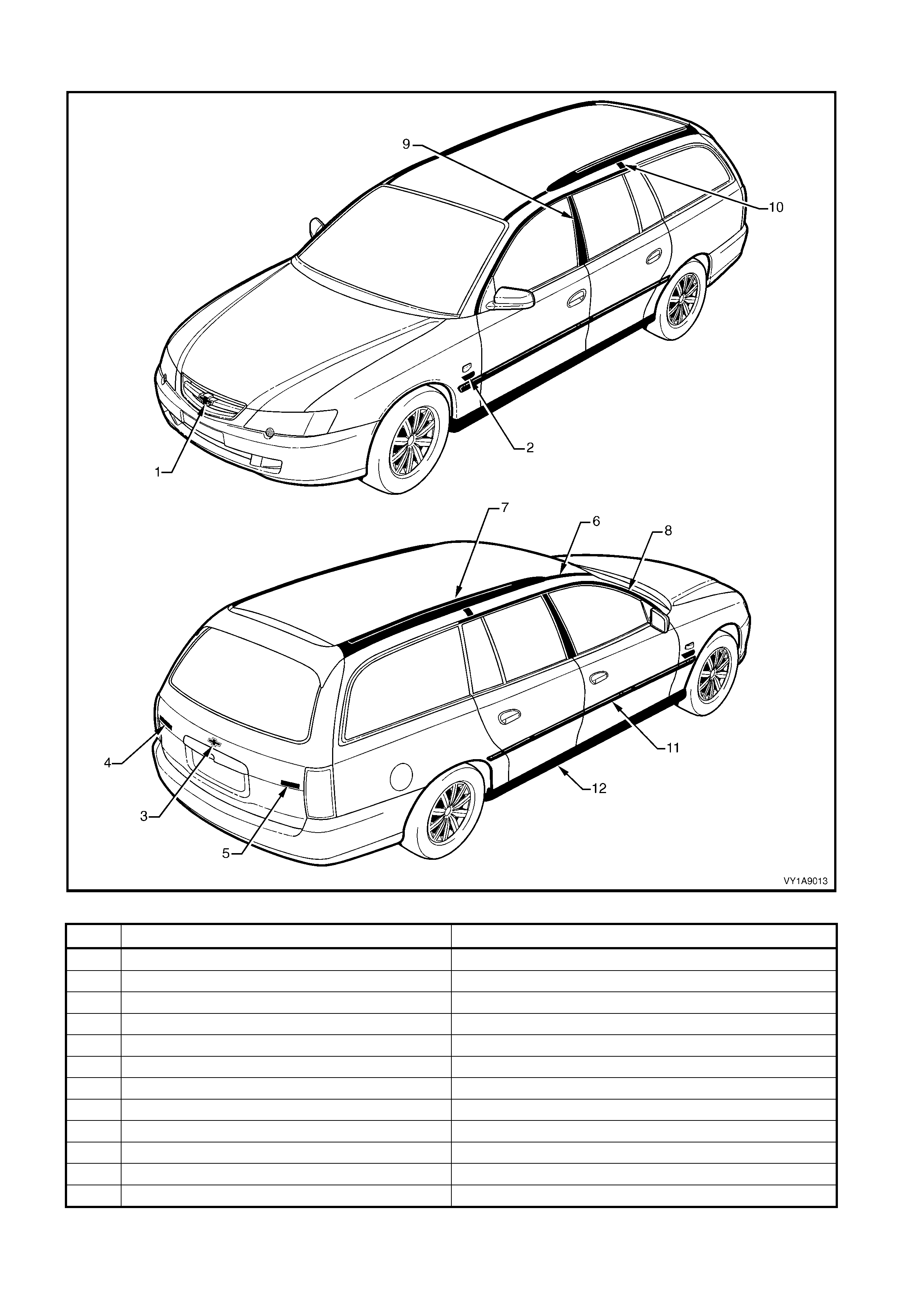
Sedan Executive & Acclaim Figure 1A9-1 Wagon Executive & Acclaim Figure 1A9-7
SV8 Figure 1A9-2 Berlina Figure 1A9-8
S Figure 1A9-3 Utility Figure 1A9-9
SS Figure 1A9-4 S Figure 1A9-10
Berlina Figure 1A9-5 SS Figure 1A9-11
Calais Figure 1A9-6 Coupe Monaro CV6 & CV8 Figure 1A9-14
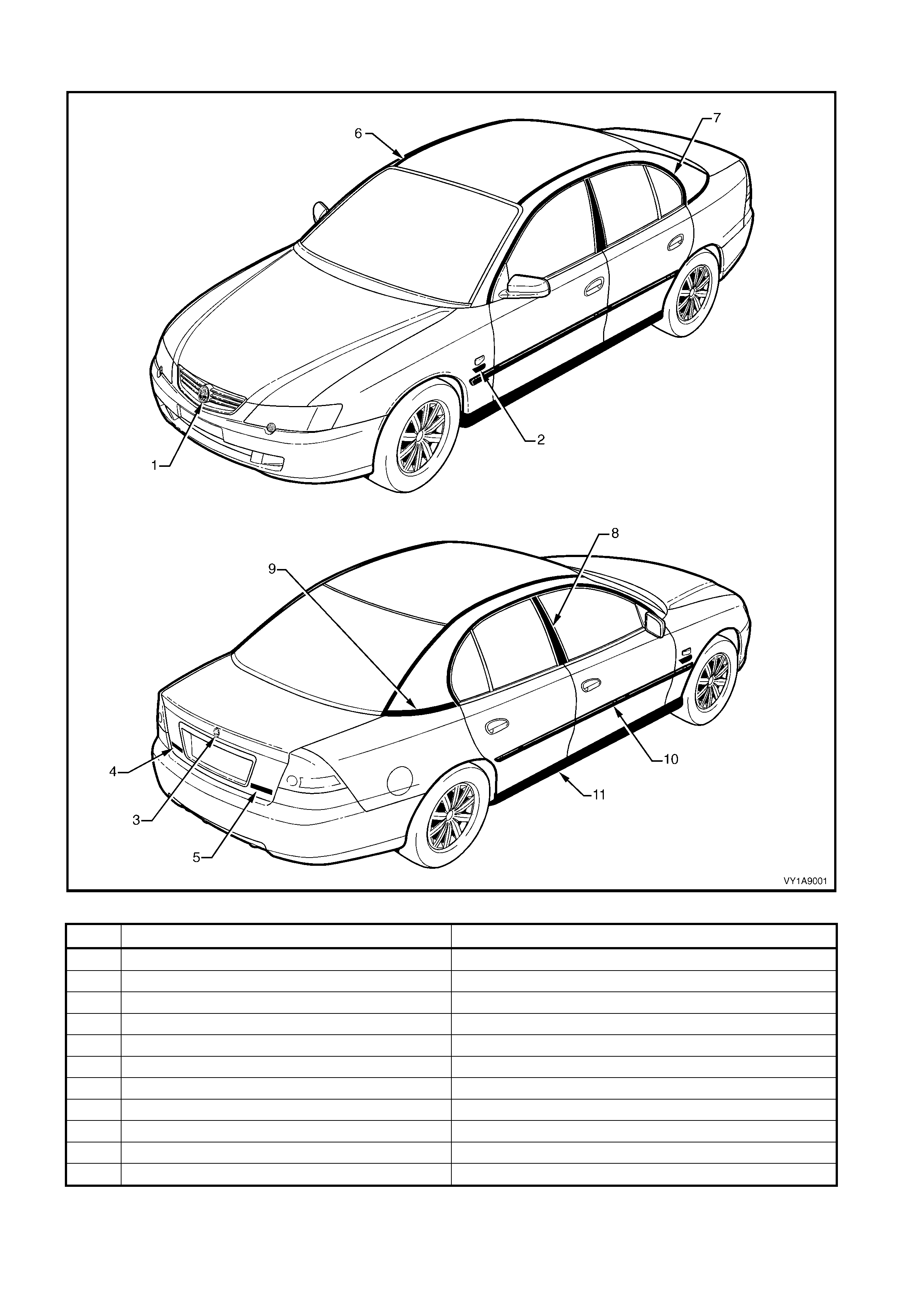
SEDAN: EXECUTIVE & ACCLAIM
Figure 1A9-1
ITEM DESCRIPTION REFER TO
1 Radiator Grille Emblem: Holden 2.1 RADIA T OR GRI LLE EMBLEM
2 Fender Name Pl ate: V6, S upercharged, V8 2.2 FENDER NA ME PLATE
3 Rear Compart ment Lid E mblem : Holden 2.4 REAR COMPARTMENT LID EMBLEM
4 Rear Compart ment Lid: Commodore 2.5 REAR COMPA RTMENT LI D NAME PLATE, LH
5 Rear Compart ment Lid Name Plate: Executive, Acclaim 2.6 REAR COMPA RTMENT LI D NAME PLATE, RH
6 Roof Joint Moulding 2.7 ROOF JOI NT MOULDING
7 Door Opening Moulding 2.8 DOOR OPENI NG MOULDING
8 Centre Pillar upper Finisher A ssembly 2.9 CENTRE P I LLAR UPPER FINI SHER ASSE MBLY
9 Quarter Panel Bel t Moulding 2.10 QUARTER P A NE L BELT MOULDING
10 Body Side Moulding 2.11 BODY SIDE MOULDINGS
11 Rocker Panel Moulding A ssem bl y 2.12 ROCKER P ANEL MOULDING ASS EMBLY

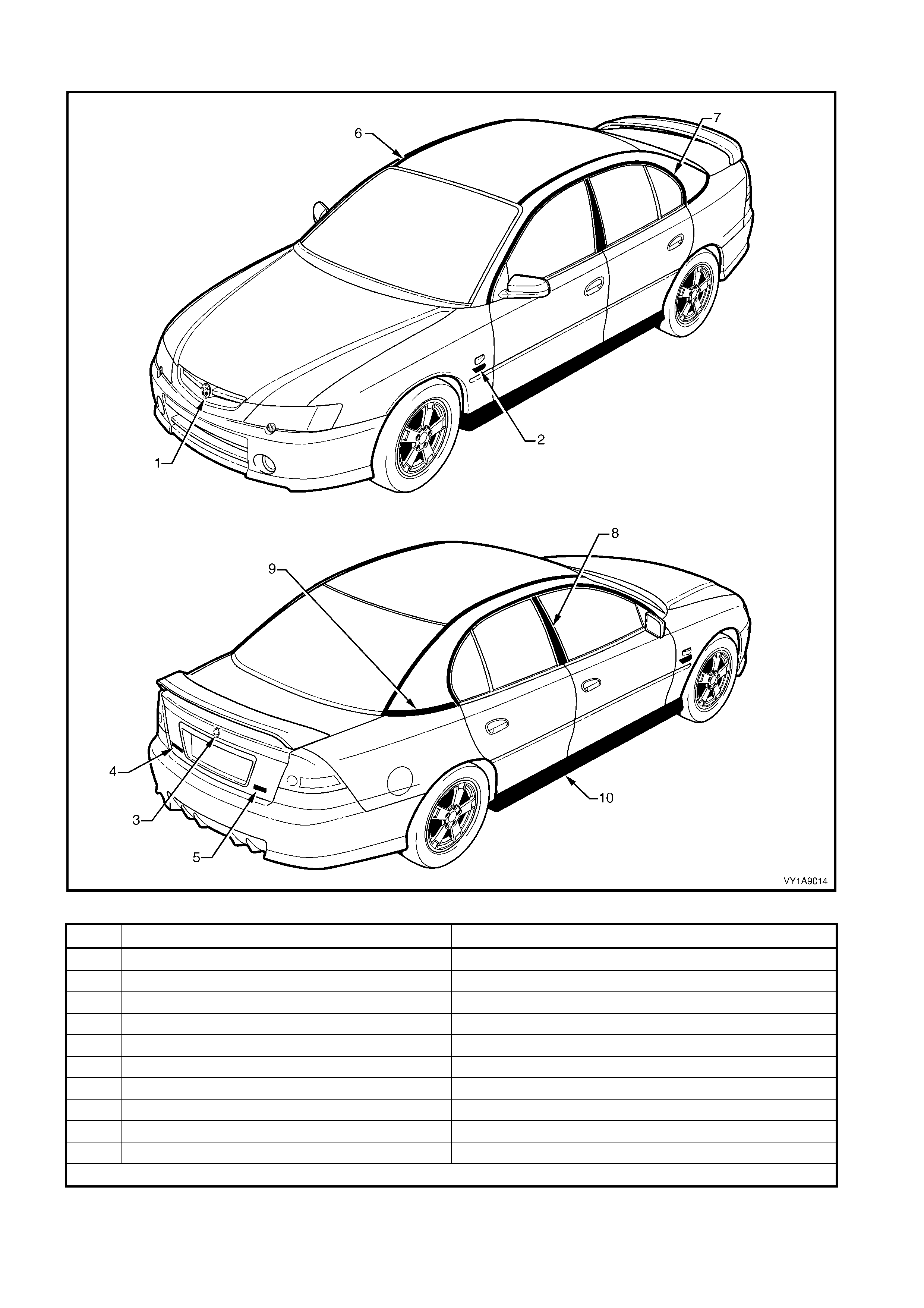
SEDAN: SV8
Figure 1A9-2
ITEM DESCRIPTION REFER TO
1 Radiator Grille Emblem: Holden 2.1 RADIA T OR GRI LLE EMBLEM
2 Fender Name Pl ate: V8 2.2 FENDER NA ME PLATE
3 Rear Compart ment Lid E mblem : Holden 2.4 REAR COMPARTMENT LID EMBLEM
4 Rear Compart ment Lid Name Plate: Comm odore 2.5 REAR COMPA RTMENT LI D NAME PLATE, LH
5 Rear Compart ment Lid Name Plate: SV8 2.6 REAR COMPA RTMENT LI D NAME PLATE, RH
6 Roof Joint Moulding 2.7 ROOF JOI NT MOULDING
7 Door Opening Moulding 2.8 DOOR OPENI NG MOULDING
8 Centre Pillar upper Finisher A ssembly 2.9 CENTRE P I LLAR UPPER FINI SHER ASSE MBLY
9 Quarter Panel Bel t Moulding 2.10 QUARTER P A NE L BELT MOULDING
10 Rocker Panel Moulding A ssem bl y 2.12 ROCKER P ANEL MOULDING ASS EMBLY
NOTE: For service procedures of the rear spoiler refe r t o Section 1A 4, 3.4 REAR S P OILER ASS EMBLY
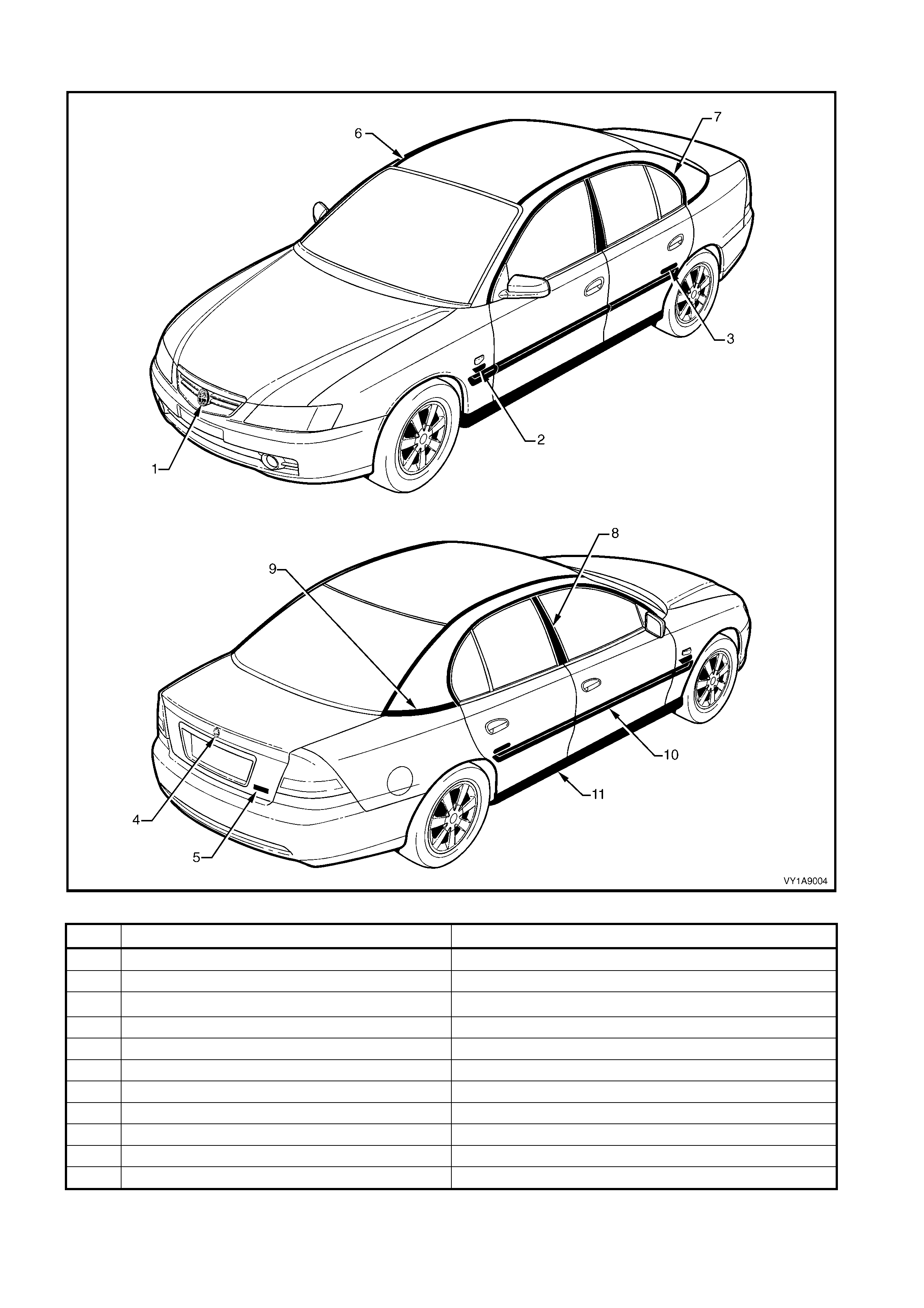
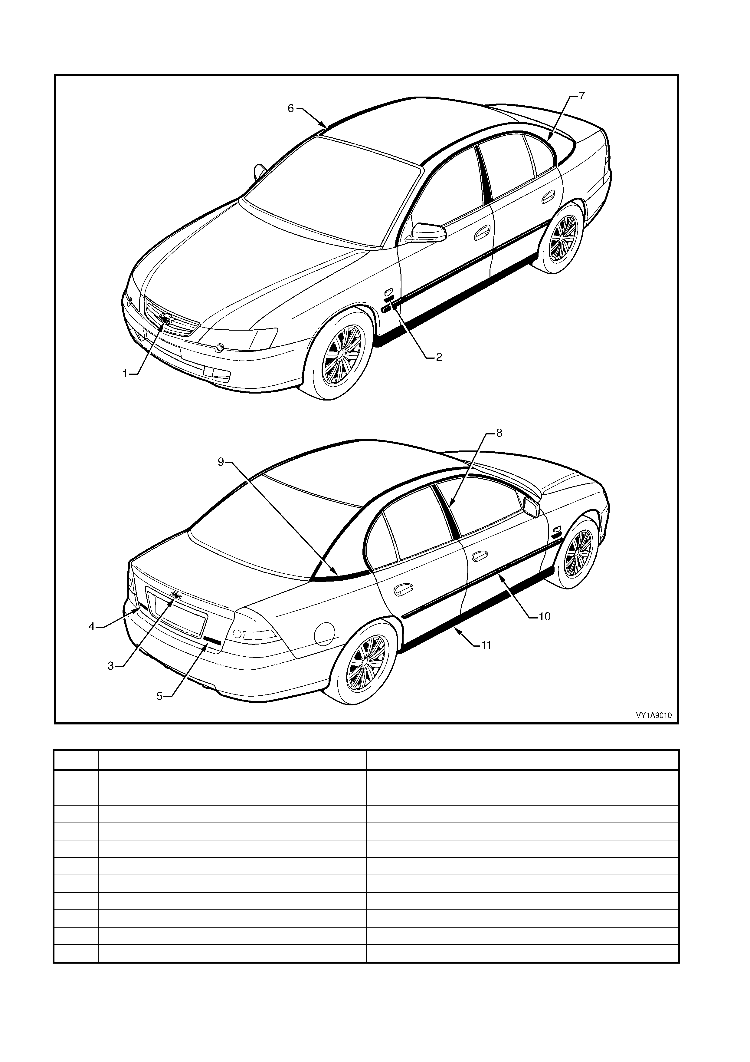
SEDAN: S
Figure 1A9-3
ITEM DESCRIPTION REFER TO
1 Radiator Grille Emblem: Holden 2.1 RADIA T OR GRI LLE EMBLEM
2 Fender Name Pl ate: V6, S upercharged 2.2 FENDER NA ME PLATE
3 Rear Compart ment Lid E mblem : Holden 2.4 REAR COMPARTMENT LI D EMBLEM
4 Rear Compart ment Lid Name Plate: Comm odore 2.5 REAR COMPA RTMENT LI D NAME PLATE, LH
5 Rear Compart ment Lid Name Plate: S 2.6 REAR COMPA RTMENT LI D NAME PLATE, RH
6 Roof Joint Moulding 2.7 ROOF JOI NT MOULDING
7 Door Opening Moulding 2.8 DOOR OPENI NG MOULDING
8 Centre Pillar upper Finisher A ssembly 2.9 CENTRE P I LLAR UPPER FINI SHER ASSE MBLY
9 Quarter Panel Bel t Moulding 2.10 QUARTER P A NE L BELT MOULDING
10 Rocker Panel Moulding A ssem bl y 2.12 ROCKER P ANEL MOULDING ASS EMBLY
NOTE: For service procedures of the rear spoiler refe r t o Section 1A 4, 3.4 REAR S P OILER ASS EMBLY.
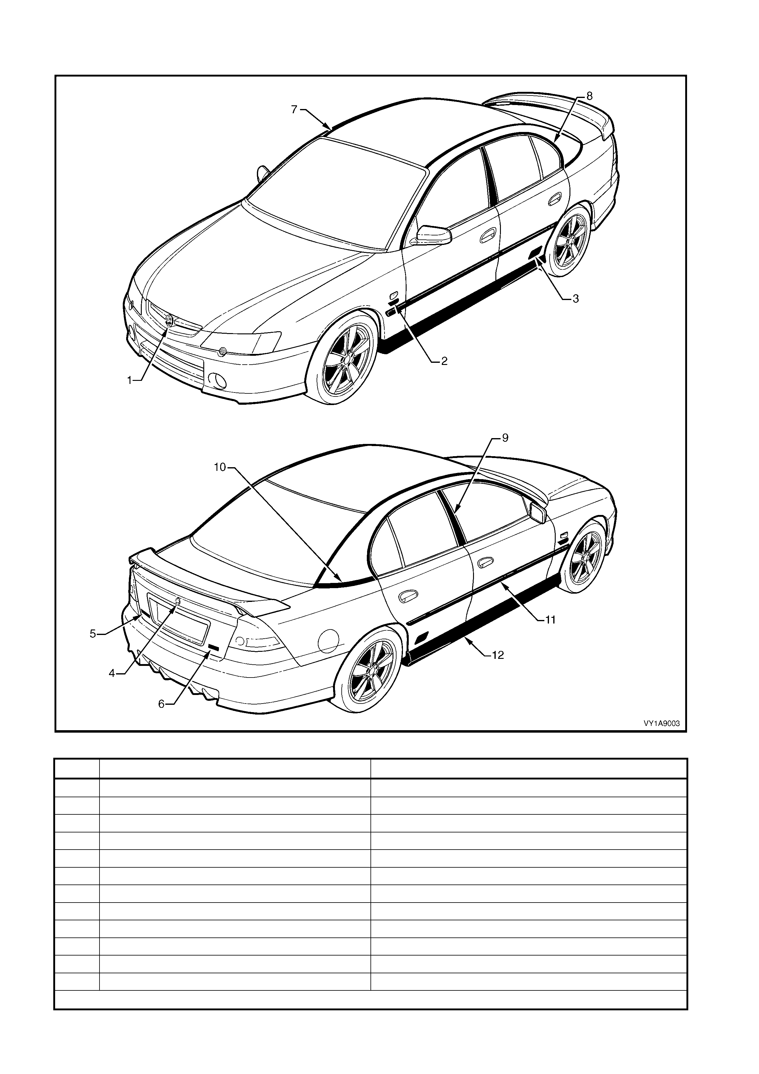
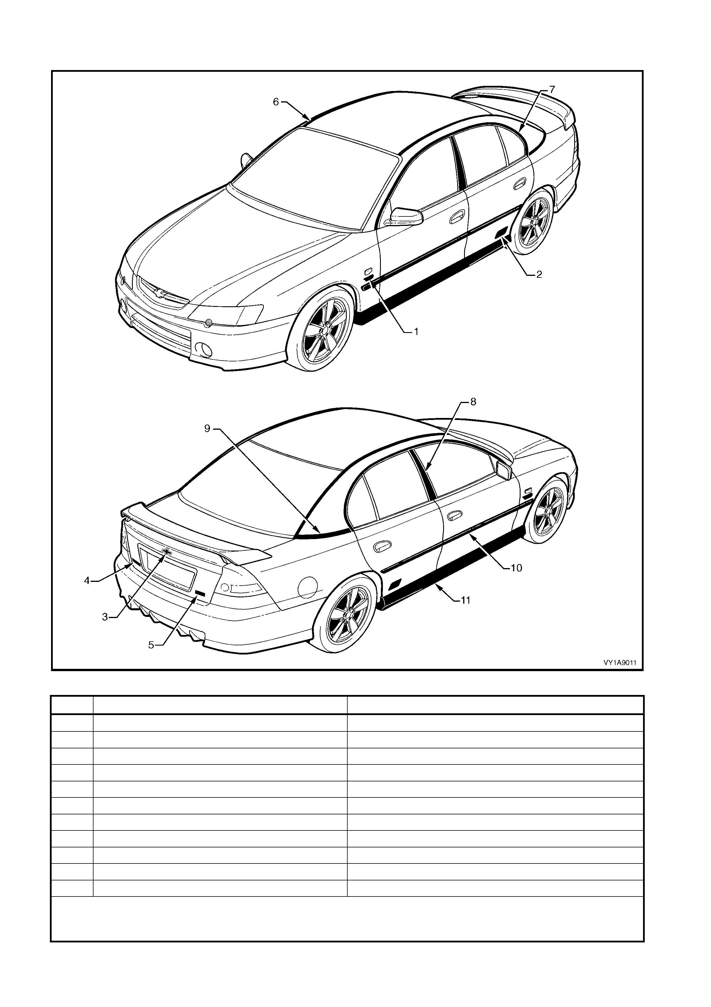
SEDAN: SS
Figure 1A9-4
ITEM DESCRIPTION REFER TO
1 Radiator Grille Emblem: Holden 2.1 RADIA T OR GRI LLE EMBLEM
2 Fender Name Pl ate: V8 2.2 FENDER NA ME PLATE
3 Rear Door Name P l at e: SS 2.3 REAR DOOR NA ME P LATE
4 Rear Compart ment Lid E mblem : Holden 2.4 REAR COMPARTMENT LI D EMBLEM
5 Rear Compart ment Lid Name Plate: Comm odore 2.5 REAR COMPA RTMENT LI D NAME PLATE, LH
6 Rear Compart ment Lid Name Plate: SS 2.6 REAR COMPA RTMENT LI D NAME PLATE, RH
7 Roof Joint Moulding 2.7 ROOF JOI NT MOULDING
8 Door Opening Moulding 2.8 DOOR OPENI NG MOULDING
9 Centre Pillar upper Finisher A ssembly 2.9 CENTRE P I LLAR UPPER FINI SHER ASSE MBLY
10 Quarter Panel Belt Mouldi ng 2. 10 QUARTER PANEL B E LT MOULDI NG
11 Body Side Moulding 2.11 BODY SIDE MOULDINGS
12 Rocker Panel Moulding A ssem bl y 2.12 ROCKER P ANEL MOULDING ASS EMBLY
NOTE: For service procedures of the rear spoiler refe r t o Section 1A 4, 3.4 REAR S P OILER ASS EMBLY

SEDAN: BERLINA
Figure 1A9-5
ITEM DESCRIPTION REFER TO
1 Radiator Grille Emblem: Holden 2.1 RADIA T OR GRI LLE EMBLEM
2 Fender Name Pl ate: V6, S upercharged, V8 2.2 FENDER NA ME PLATE
3 Rear Compart ment Lid E mblem : Holden 2.4 REAR COMPARTMENT LID EMBLEM
4 Rear Compart ment Lid Name Plate: Berlina 2.6 REAR COMPA RTMENT LI D NAME PLATE, RH
5 Roof Joint Moulding 2.7 ROOF JOI NT MOULDING
6 Door Opening Moulding 2.8 DOOR OPENI NG MOULDING
7 Centre Pillar upper Finisher A ssembly 2.9 CENTRE P I LLAR UPPER FINI SHER ASSE MBLY
8 Quarter Panel Bel t Moulding 2.10 QUARTER P A NE L BELT MOULDING
9 Body Side Moulding 2.11 B ODY SIDE MOULDI NGS
10 Rocker Panel Moulding A ssem bl y 2.12 ROCKER P ANEL MOULDING ASS EMBLY
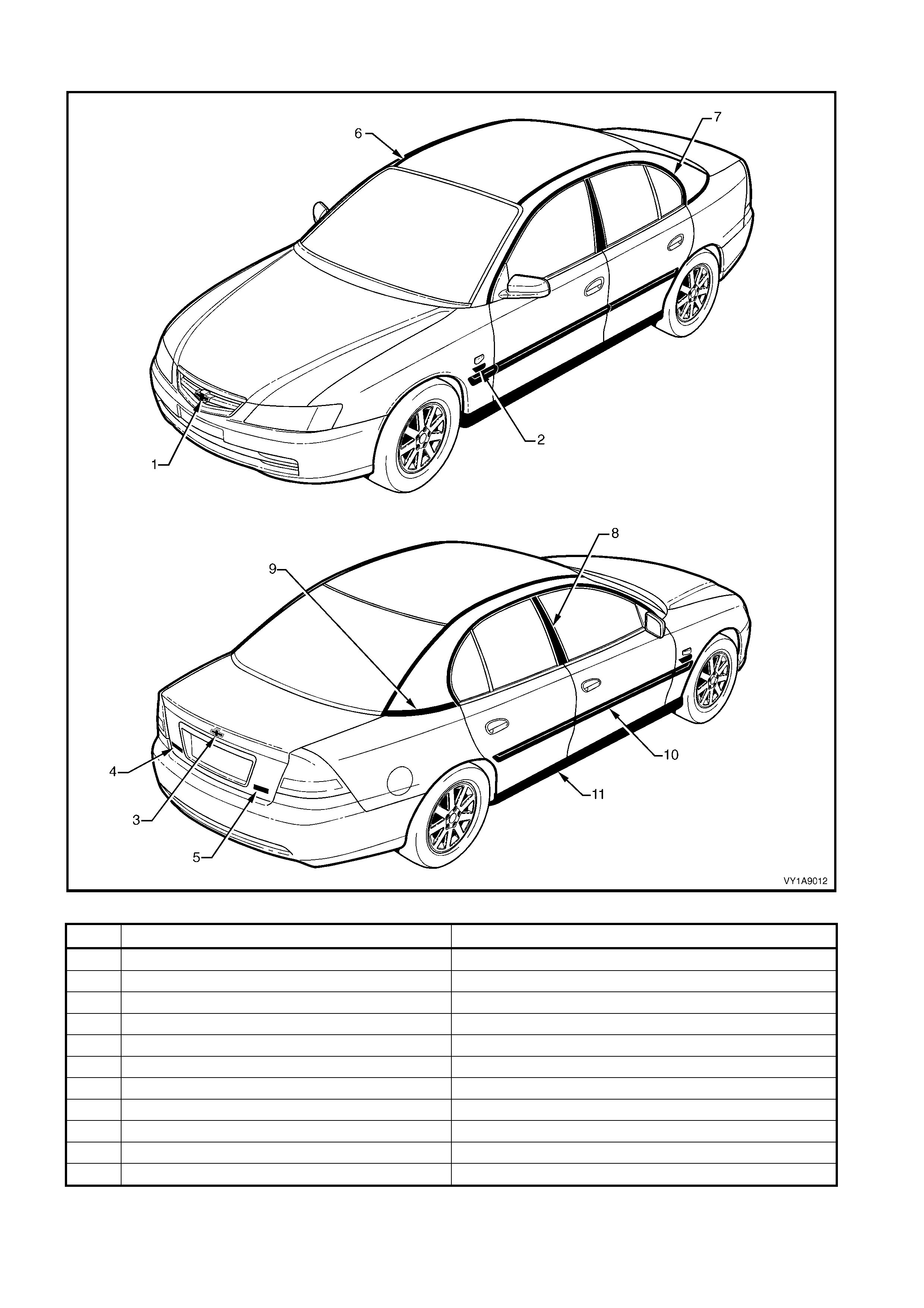
SEDAN: CALAIS
Figure 1A9-6
ITEM DESCRIPTION REFER TO
1 Radiator Grille Emblem: Holden 2.1 RADIA T OR GRI LLE EMBLEM
2 Fender Name Pl ate: V6, S upercharged, V8 2.2 FENDER NA ME PLATE
3 Rear Door Name Plate: Calais 2.3 REAR DOOR NAME PLATE
4 Rear Compart ment Lid E mblem : Holden 2.4 REAR COMPARTMENT LID EMBLEM
5 Rear Compart ment Lid Name Plate: Calais 2.6 REAR COMPA RTMENT LI D NAME PLATE, RH
6 Roof Joint Moulding 2.7 ROOF JOI NT MOULDING
7 Door Opening Moulding 2.8 DOOR OPENI NG MOULDING
8 Centre Pillar upper Finisher A ssembly 2.9 CENTRE P I LLAR UPPER FINI SHER ASSE MBLY
9 Quarter Panel Bel t Moulding 2.10 QUARTER P A NE L BELT MOULDING
10 Body Side Moulding 2.11 BODY SIDE MOULDINGS
11 Rocker Panel Moulding A ssem bl y 2.12 ROCKER P ANEL MOULDING ASS EMBLY

WAGON: EXECUTIVE & ACCLAIM
Figure 1A9-7
ITEM DESCRIPTION REFER TO
1 Radiator Grille Emblem: Holden 3.1 RADIA T OR GRI LLE EMBLEM
2 Fender Name Pl ate: V6, V 8 3.2 FENDER NA ME PLATE
3 Liftgate Emblem: Holden 3.3 LIFTGATE EMBLEM
4 Liftgat e Name Plat e: Comm odore 3.4 LIFTGAT E NAME PLATE, LH
5 Liftgat e Name Plat e: Executive, Ac claim 3.5 LIFTGAT E NAME PLATE, RH
6 Roof Joint Moulding 3.6 ROOF JOI NT MOULDING
7 Roof Side Rail s 3.8 ROOF SIDE RAILS
8 Door Opening Moulding 3.9 DOOR OPENI NG MOULDING
9 Centre Pillar upper Finisher Assembly 3.10 CENTRE PILLAR UPPER FINISHER ASSEMBLY
10 Roof Joint Finis her 3.11 ROOF JOINT FI NISHER
11 Body Side Moulding 3.12 BODY SIDE MOULDINGS
12 Rocker Panel Moulding A ssem bl y 3.13 ROCKER P ANEL MOULDING ASS EMBLY
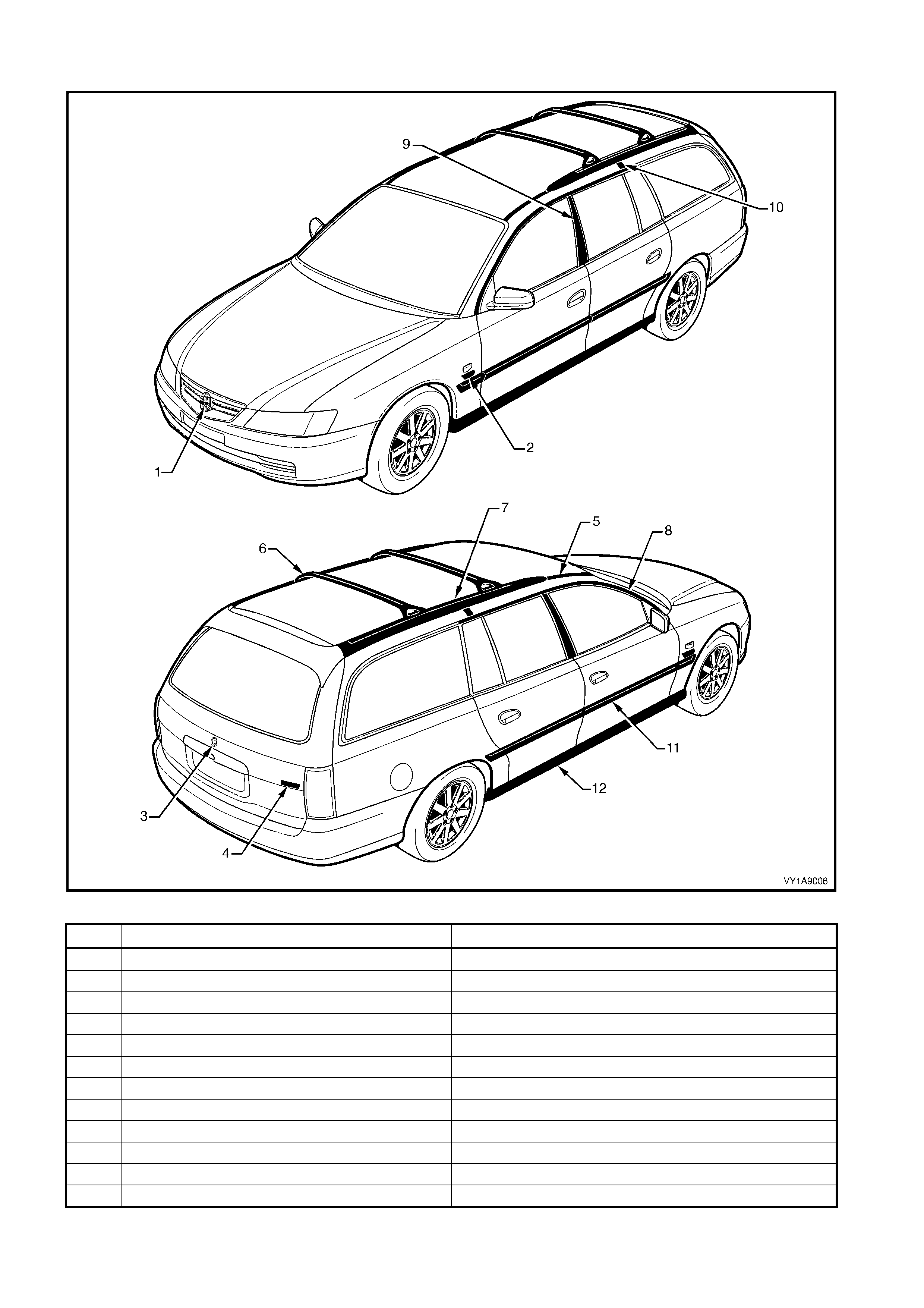
WAGON: BERLINA
Figure 1A9-8
ITEM DESCRIPTION REFER TO
1 Radiator Grille Emblem: Holden 3.1 RADIA T OR GRI LLE EMBLEM
2 Fender Name Pl ate: V6, V 8 3.2 FENDER NA ME PLATE
3 Liftgate Emblem: Holden 3.3 LIFTGATE EMBLEM
4 Liftgat e Name Plat e: Berlina 3.5 LIFTGAT E NAME PLATE, RH
5 Roof Joint Moulding 3.6 ROOF JOI NT MOULDING
6 Roof Bars 3.7 ROOF BARS
7 Roof Side Rail s 3.8 ROOF SIDE RAILS
8 Door Opening Moulding 3.9 DOOR OPENI NG MOULDING
9 Centre Pillar upper Finisher Assembly 3.10CENTRE PILLAR UPPER FINISHER ASSEMBLY
10 Roof Joint Finis her 3.11 ROOF JOINT FI NISHER
11 Body Side Moulding 3.12 BODY SIDE MOULDINGS
12 Rocker Panel Moulding A ssem bl y 3.13 ROCKER P ANEL MOULDING ASS EMBLY
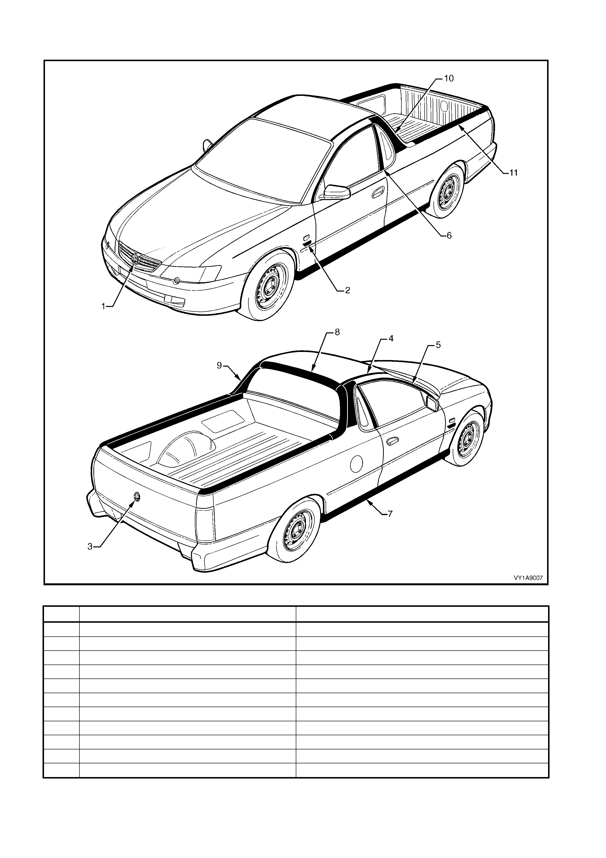
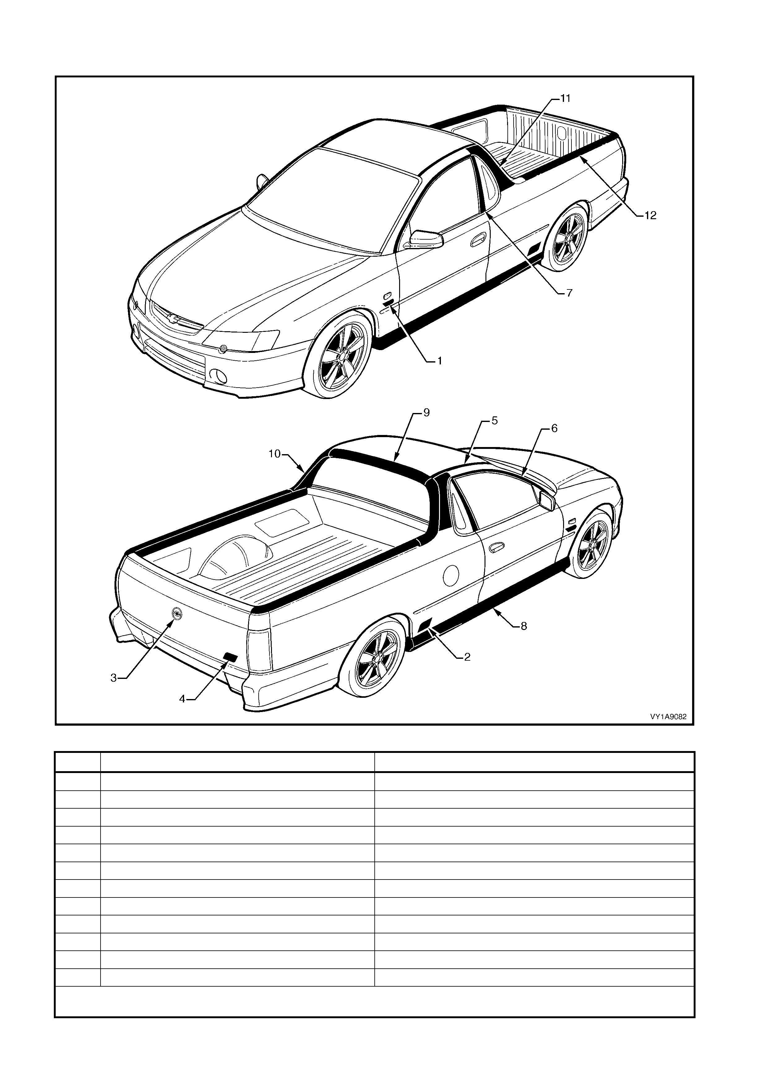
UTILITY
Figure 1A9-9
ITEM DESCRIPTION REFER TO
1 Radiator Grille Emblem: Holden 4.1 RADIA T OR GRI LLE EMBLEM
2 Fender Name Pl ate: V6, V 8 4.2 FENDER NA ME PLATE
3 Endgate Emblem: Holden 4.4 ENDGATE EMBLEM & NAME PLATES
4 Roof Joint Moulding 4.6 ROOF JOI NT MOULDING
5 Door Opening Moulding 4.7 DOOR OPENI NG MOULDING
6 Centre Pillar upper Finisher A ssembly 4.8 CENTRE P I LLAR UPPER FINI SHER ASSE MBLY
7 Rocker P anel Moulding Assembly 4.9 ROCKER PANE L MOULDING ASSEMBLY
8 Rear Window Upper Moulding 4.10 REAR WINDOW UPPER MOULDING
9 Rear Window Side Moulding 4.11 REAR WINDOW SIDE MOULDI NG
10 Quarter Window Moulding 4.12 QUARTER WINDOW MOULDING
11 Quarter Panel Rails 4.13 QUARTER P A NEL RAILS
UTILITY: S
Figure 1A9-10
ITEM DESCRIPTION REFER TO
1 Radiator Grille Emblem: Holden 4.1 RADIA T OR GRI LLE EMBLEM
2 Fender Name Pl ate: V6, V 8 4.2 FENDER NA ME PLATE
3 Endgate Emblem: Holden 4.4 ENDGATE EMBLEM
4 Endgate Name Plate: S 4.5 ENDGATE NAME PLATE, RH
5 Roof Joint Moulding 4.6 ROOF JOI NT MOULDING
6 Door Opening Moulding 4.7 DOOR OPENI NG MOULDING
7 Centre Pillar upper Finisher A ssembly 4.8 CENTRE P I LLAR UPPER FINI SHER ASSE MBLY
8 Rocker P anel Moulding Assembly 4.9 ROCKER PANE L MOULDING ASSEMBLY
9 Rear Window Upper Moulding 4.10 REAR WINDOW UPPER MOULDING
10 Rear Wi ndow Side Mouldi ng 4.11 RE A R WINDOW SIDE MOULDING
11 Quarter Window Moulding 4.12 QUARTER WINDOW MOULDING
12 Quarter Panel Rails 4.13 QUARTER P A NEL RAILS
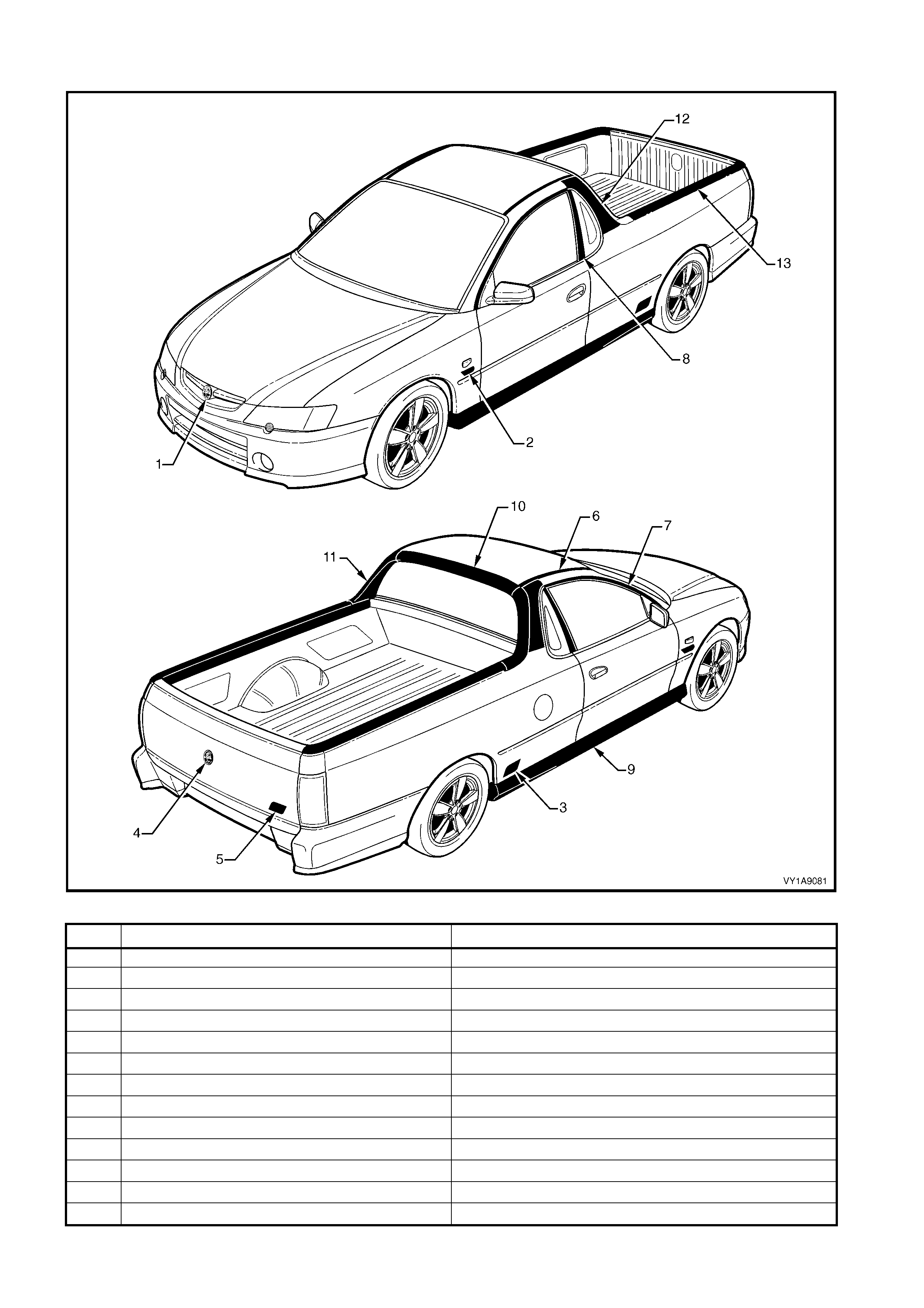
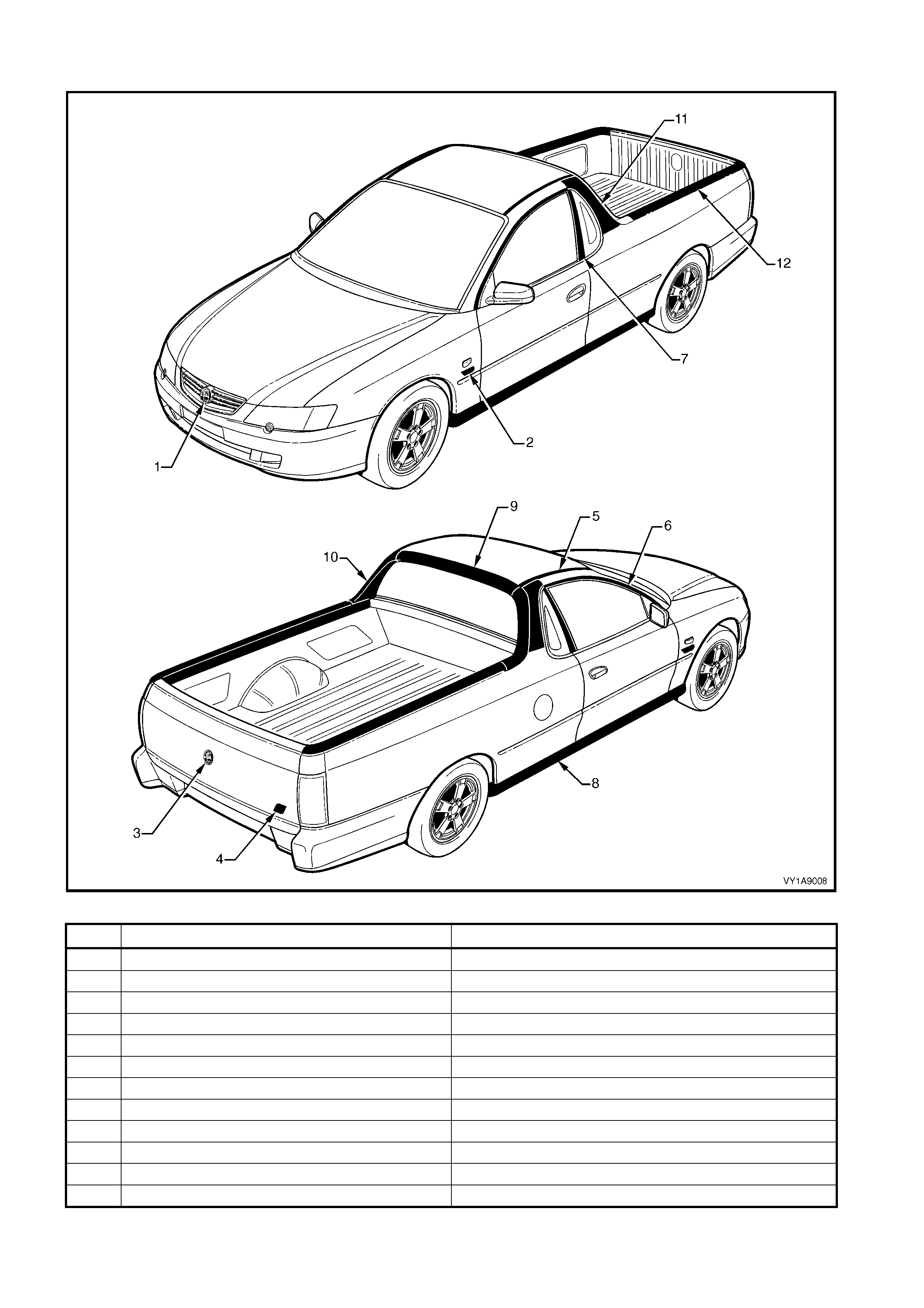
UTILITY: SS
Figure 1A9-11
ITEM DESCRIPTION REFER TO
1 Radiator Grille Emblem: Holden 4.1 RADIA T OR GRI LLE EMBLEM
2 Fender Name Pl ate: V8 4.2 FENDER NA ME PLATE
3 Quarter Panel Name Plate: SS 4.3 QUARTER P A NEL NAME PLATE
4 Endgate Emblem: Holden 4.4 ENDGATE EMBLEM
5 Endgate Name Plate: SS 4.5 ENDGAT E NAME PLATE , RH
6 Roof Joint Moulding 4.6 ROOF JOI NT MOULDING
7 Door Opening Moulding 4.7 DOOR OPENI NG MOULDING
8 Centre Pillar upper Finisher A ssembly 4.8 CENTRE P I LLAR UPPER FINI SHER ASSE MBLY
9 Rocker P anel Moulding Assembly 4.9 ROCKER PANE L MOULDING ASSEMBLY
10 Rear Wi ndow Upper Moulding 4.10 REAR WINDOW UP PER MOULDING
11 Rear Wi ndow Side Mouldi ng 4.11 RE A R WINDOW SIDE MOULDING
12 Quarter Window Moulding 4.12 QUARTER WINDOW MOULDING
13 Quarter Panel Rails 4.13 QUARTER P A NEL RAILS
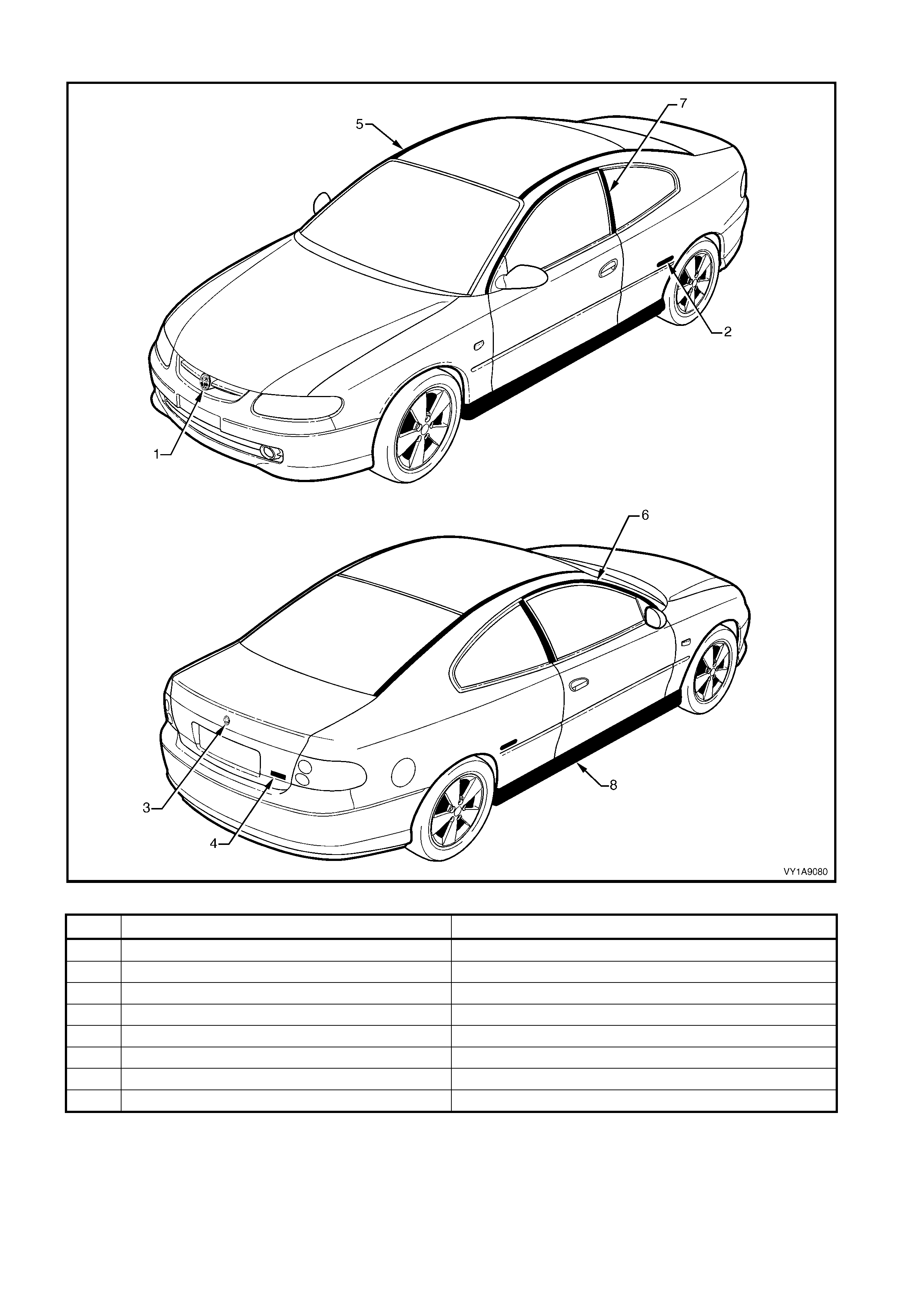
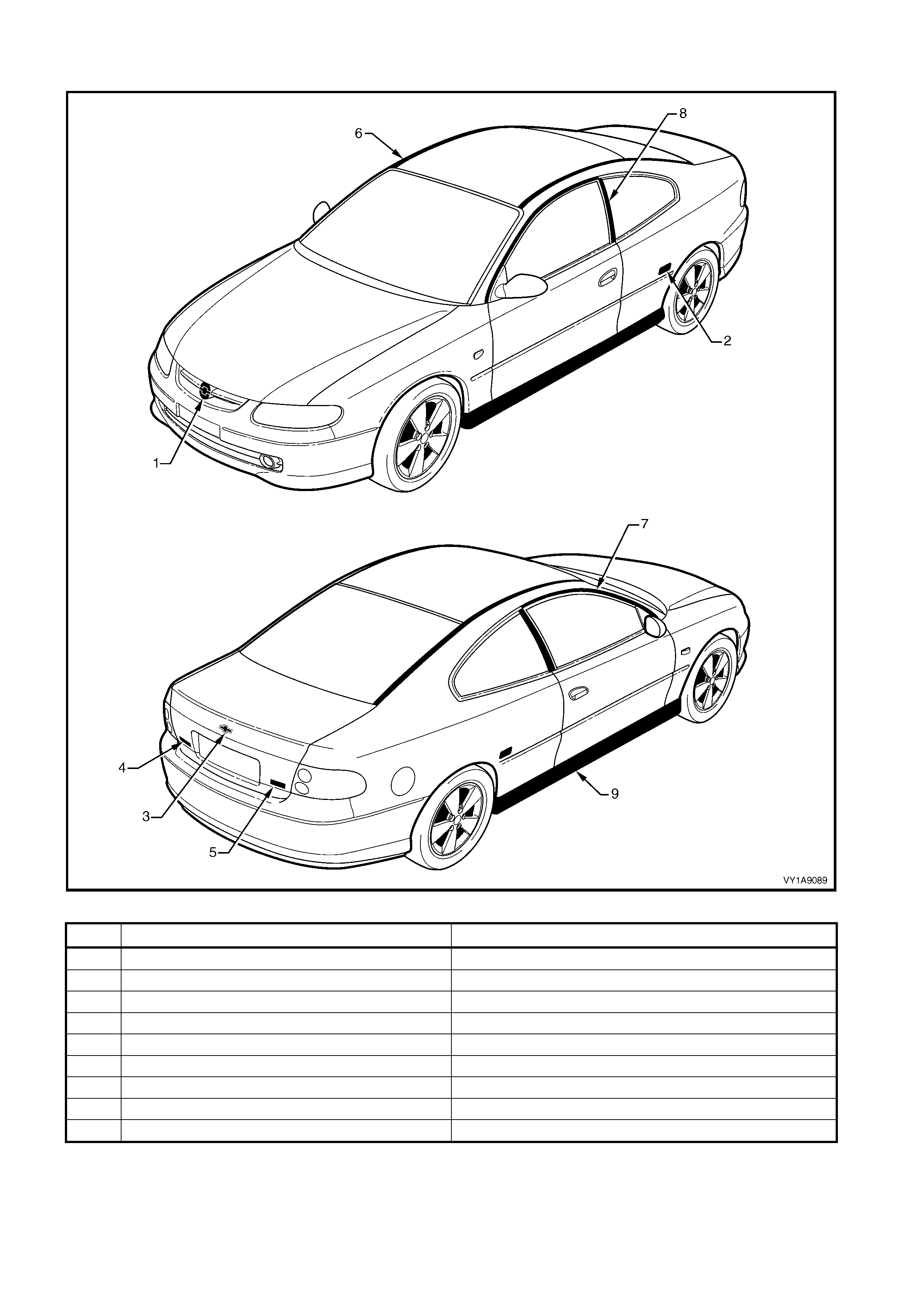
COUPE: MONARO CV6 & CV8
Figure 1A9-12
ITEM DESCRIPTION REFER TO
1 Radiator Grille Emblem: Holden 5.1 RADIA T OR GRI LLE EMBLEM
2 Quarter Panel Name Plate: Monaro 5.2 QUARTER P A NEL NAME PLATE
3 Rear Compart ment Lid E mblem : Holden 5.3 REAR COMPARTMENT LID EMBLEM
4 Rear Compart ment Lid Name Plate: CV6, CV8 5.5 REAR COMPA RTMENT LI D NAME PLATE , RH
5 Roof Joint Moulding 5.6 ROOF JOI NT MOULDING
6 Door Opening Moulding 5.7 DOOR OPENI NG MOULDING
7 Centre Pillar upper Finisher A ssembly 5.8 CENTRE P I LLAR UPPER FINI SHER ASSE MBLY
8 Rocker P anel Moulding Assembly 5.9 ROCKER PANE L MOULDING ASSEMBLY

1.2 PICTORIAL INDEX – EXPORT
The following diagrams provide a quick reference to the correct service procedures for the exterior ornamentation
components relevant to each vehicle model.
Simply refer to the vehic le m odel by using the table below, locate the component on the Figure and c ross -ref erenc e
it in the table below the Figure and go to the appropriate service procedure.
BODY MODEL REFER TO BODY MODEL REFER TO
Sedan Lumina LS Figure 1A9-13 Omega CD Figure 1A9-17
Lumina S Figure 1A9-14 Wagon Lumina LS Figure 1A9-18
Lumina SS Figure 1A9-15 Utility SS Figure 1A9-19
Lumina LTZ Figure 1A9-16 Coupe Lumina S & SS Figure 1A9-20
SEDAN: LUMINA LS
Figure 1A9-13
ITEM DESCRIPTION REFER TO
1 Radiator Grille Emblem: Chevrolet 2.1 RADIATOR GRILLE EMBLEM
2 Fender Name Pl ate: V6 2.2 FENDER NA ME PLATE
3 Rear Compart ment Lid E mblem : Chevrolet 2.4 REAR COMPARTMENT LID EMBLEM
4 Rear Compart ment Lid Name Plate: Chevrolet 2.5 REAR COMPA RTMENT LI D NAME PLATE, LH
5 Rear Compart ment Lid Name Plate: Lumina LS 2.6 REA R COMPA RTMENT LI D NAME PLATE, RH
6 Roof Joint Moulding 2.7 ROOF JOI NT MOULDING
7 Door Opening Moulding 2.8 DOOR OPENI NG MOULDING
8 Centre Pillar upper Finisher A ssembly 2.9 CENTRE P I LLAR UPPER FINI SHER ASSE MBLY
9 Quarter Panel Bel t Moulding 2.10 QUARTER P A NE L BELT MOULDING
10 Body Side Moulding 2.11 BODY SIDE MOULDINGS
11 Rocker Panel Moulding A ssem bl y 2.12 ROCKER P ANEL MOULDING ASS EMBLY

SEDAN: LUMINA S
Figure 1A9-14
ITEM DESCRIPTION REFER TO
1 Fender Name Pl ate: V6 2.2 FENDER NA ME PLATE
2 Rear Compart ment Lid E mblem : Chevrolet 2.4 REAR COMPARTMENT LID EMBLEM
3 Rear Compart ment Lid Name Plate: Lumina 2.5 RE AR COMPARTMENT LID NAME PLATE, LH
4 Rear Compart ment Lid Name Plate: S 2.6 REAR COMPA RTMENT LI D NAME PLATE, RH
5 Roof Joint Moulding 2.7 ROOF JOI NT MOULDING
6 Door Opening Moulding 2.8 DOOR OPENI NG MOULDING
7 Centre Pillar upper Finisher A ssembly 2.9 CENTRE P I LLAR UPPER FINI SHER ASSE MBLY
8 Quarter Panel Bel t Moulding 2.10 QUARTER P A NE L BELT MOULDING
9 Rocker P anel Moulding Assembly 2.12 ROCKER PANE L MOULDING ASSEMBLY
NOTE 1: S vehicles are not fitted with a radiator grille emblem. For servicing of the radiator grille escutcheon refer to Section 1C, 2.2
RADIATOR GRILLE ASSEMBLY, S SEDAN & SS.
NOTE 2: For service procedures of the rear spoiler refer to Secti on 1A4, 3.4 REA R SPOILER A SSEMBLY.
SEDAN: LUMINA SS
Figure 1A9-15
ITEM DESCRIPTION REFER TO
1 Fender Name Pl ate: V8 or High Out put V8 2.2 FENDER NA ME PLATE
2 Rear Door Name P l at e: SS 2.3 REAR DOOR NA ME P LATE
3 Rear Compart ment Lid E mblem : Chevrolet 2.4 REAR COMPARTMENT LID EMBLEM
4 Rear Compart ment Lid Name Plate: Lumina 2.5 RE AR COMPARTMENT LID NAME PLATE, LH
5 Rear Compart ment Lid Name Plate: SS 2.6 REAR COMPA RTMENT LI D NAME PLATE, RH
6 Roof Joint Moulding 2.7 ROOF JOI NT MOULDING
7 Door Opening Moulding 2.8 DOOR OPENI NG MOULDING
8 Centre Pillar upper Finisher A ssembly 2.9 CENTRE P I LLAR UPPER FINI SHER ASSE MBLY
9 Quarter Panel Bel t Moulding 2.10 QUARTER P A NE L BELT MOULDING
10 Body Side Moulding 2.11 BODY SIDE MOULDINGS
11 Rocker Panel Moulding A ssem bl y 2.12 ROCKER P ANEL MOULDING ASS EMBLY
NOTE 1: SS vehicles are not f itted with a radiator grille emblem . For servicing of the radiator grille esc utcheon refer to Section 1C, 2.2
RADIATOR GRILLE ASSEMBLY, S SEDAN & SS.
NOTE 2: For service procedures of the rear spoiler refer to Secti on 1A4, 3.4 REA R SPOILER A SSEMBLY.
SEDAN: LUMINA LTZ
Figure 1A9-16
ITEM DESCRIPTION REFER TO
1 Radiator Grille Emblem: Chevrolet 2.1 RADIATOR GRILLE EMBLEM
2 Fender Name Pl ate: V6 2.2 FENDER NA ME PLATE
3 Rear Compart ment Lid E mblem : Chevrolet 2.4 REAR COMPARTMENT LID EMBLEM
4 Rear Compart ment Lid Name Plate: Chevrolet 2.5 REAR COMPA RTMENT LI D NAME PLATE, LH
5 Rear Compartment Lid Name Plate: Lumina LTZ 2.6 REAR COMPA RTMENT LI D NA ME PLATE, RH
6 Roof Joint Moulding 2.7 ROOF JOI NT MOULDING
7 Door Opening Moulding 2.8 DOOR OPENI NG MOULDING
8 Centre Pillar upper Finisher A ssembly 2.9 CENTRE P I LLAR UPPER FINI SHER ASSE MBLY
9 Quarter Panel Bel t Moulding 2.10 QUARTER P A NE L BELT MOULDING
10 Body Side Moulding 2.11 BODY SIDE MOULDINGS
11 Rocker Panel Moulding A ssem bl y 2.12 ROCKER P ANEL MOULDING ASS EMBLY

SEDAN: OMEGA CD
Figure 1A9-17
ITEM DESCRIPTION REFER TO
1 Radiator Grille Emblem: Chevrolet 2.1 RADIATOR GRILLE EMBLEM
2 Fender Name Pl ate: V6 2.2 FENDER NA ME PLATE
3 Rear Compart ment Lid E mblem : Chevrolet 2.4 REAR COMPARTMENT LID EMBLEM
4 Rear Compart ment Lid Name Plate: Omega CD 2.5 RE AR COMPARTMENT LID NAME PLAT E, LH
5 Rear Compart ment Lid Name Plate: 3.8 V6 2.6 REAR COMPA RTMENT LI D NAME PLATE, RH
6 Roof Joint Moulding 2.7 ROOF JOI NT MOULDING
7 Door Opening Moulding 2.8 DOOR OPENI NG MOULDING
8 Centre Pillar upper Finisher A ssembly 2.9 CENTRE P I LLAR UPPER FINI SHER ASSE MBLY
9 Quarter Panel Bel t Moulding 2.10 QUARTER P A NE L BELT MOULDING
10 Body Side Moulding 2.11 BODY SIDE MOULDINGS
11 Rocker Panel Moulding A ssem bl y 2.12 ROCKER P ANEL MOULDING ASS EMBLY
WAGON: LUMINA LS
Figure 1A9-18
ITEM DESCRIPTION REFER TO
1 Radiator Grille Emblem: Chevrolet 3.1 RADIATOR GRILLE EMBLEM
2 Fender Name Pl ate: V6 3.2 FENDER NA ME PLATE
3 Liftgate Emblem: Chevrolet 3.3 LIFTGAT E E MBLE M
4 Liftgat e Name Plat e: Chevrolet 3.4 LI FTGA T E NAME PLATE , LH
5 Liftgat e Name Plat e: Lumina LS 3.5 LIFTGAT E NAME PLATE, RH
6 Roof Joint Moulding 3.6 ROOF JOI NT MOULDING
7 Roof Side Rail s 3.8 ROOF SIDE RAILS
8 Door Opening Moulding 3.9 DOOR OPENI NG MOULDING
9 Centre Pillar upper Finisher Assembly 3.10 CENTRE PILLAR UPPER FINISHER ASSEMBLY
10 Roof Joint Finis her 3.11 ROOF JOINT FI NISHER
11 Body Side Moulding 3.12 BODY SIDE MOULDINGS
12 Rocker Panel Moulding A ssem bl y 3.13 ROCKER P ANEL MOULDING ASS EMBLY
UTILITY: SS
Figure 1A9-19
ITEM DESCRIPTION REFER TO
1 Fender Name Pl ate: V8 4.2 FENDER NA ME PLATE
2 Quarter Panel Name Plate: SS 4.3 QUARTER P A NEL NAME PLATE
3 Endgate Emblem: Chevrolet 4.4 ENDGATE EMBLEM
4 Endgate Name Plate: SS 4.5 ENDGAT E NAME PLATE , RH
5 Roof Joint Moulding 4.6 ROOF JOI NT MOULDING
6 Door Opening Moulding 4.7 DOOR OPENI NG MOULDING
7 Centre Pillar upper Finisher A ssembly 4.8 CENTRE P I LLAR UPPER FINI SHER ASSE MBLY
8 Rocker P anel Moulding Assembly 4.9 ROCKER PANE L MOULDING ASSEMBLY
9 Rear Window Upper Moulding 4.10 REAR WINDOW UPPER MOULDING
10 Rear Wi ndow Side Mouldi ng 4.11 RE A R WINDOW SIDE MOULDING
11 Quarter Window Moulding 4.12 QUARTER WINDOW MOULDING
12 Quarter Panel Rails 4.13 QUARTER P A NEL RAILS
NOTE: S S Utility vehicles are not fitted with a radiator grille em blem. For servicing of the radiator grille escut cheon refer to Section 1C,
2.2 RADIATOR GRILLE ASSEMBLY, S SEDAN & SS.
COUPE: LUMINA S & SS
Figure 1A9-20
ITEM DESCRIPTION REFER TO
1 Radiator Grille Emblem: Chevrolet 5.1 RADIATOR GRILLE EMBLEM
2 Quarter Panel Name Plate: SS 5.2 QUARTER P A NEL NAME PLATE
3 Rear Compart ment Lid E mblem : Chevrolet 5.3 REAR COMPARTMENT LID EMBLEM
4 Rear Compart ment Lid Name Plate: Lumina 5.4 RE AR COMPARTMENT LID NAME PLATE, LH
5 Rear Compart ment Lid Name Plate: S or SS 5.5 REAR COMPA RTMENT LI D NAME PLATE, RH
6 Roof Joint Moulding 5.6 ROOF JOI NT MOULDING
7 Door Opening Moulding 5.7 DOOR OPENI NG MOULDING
8 Centre Pillar upper Finisher A ssembly 5.8 CENTRE P I LLAR UPPER FINI SHER ASSE MBLY
9 Rocker P anel Moulding Assembly 5.9 ROCKER PANE L MOULDING ASSEMBLY
2. SERVICE OPERATIONS, SEDAN
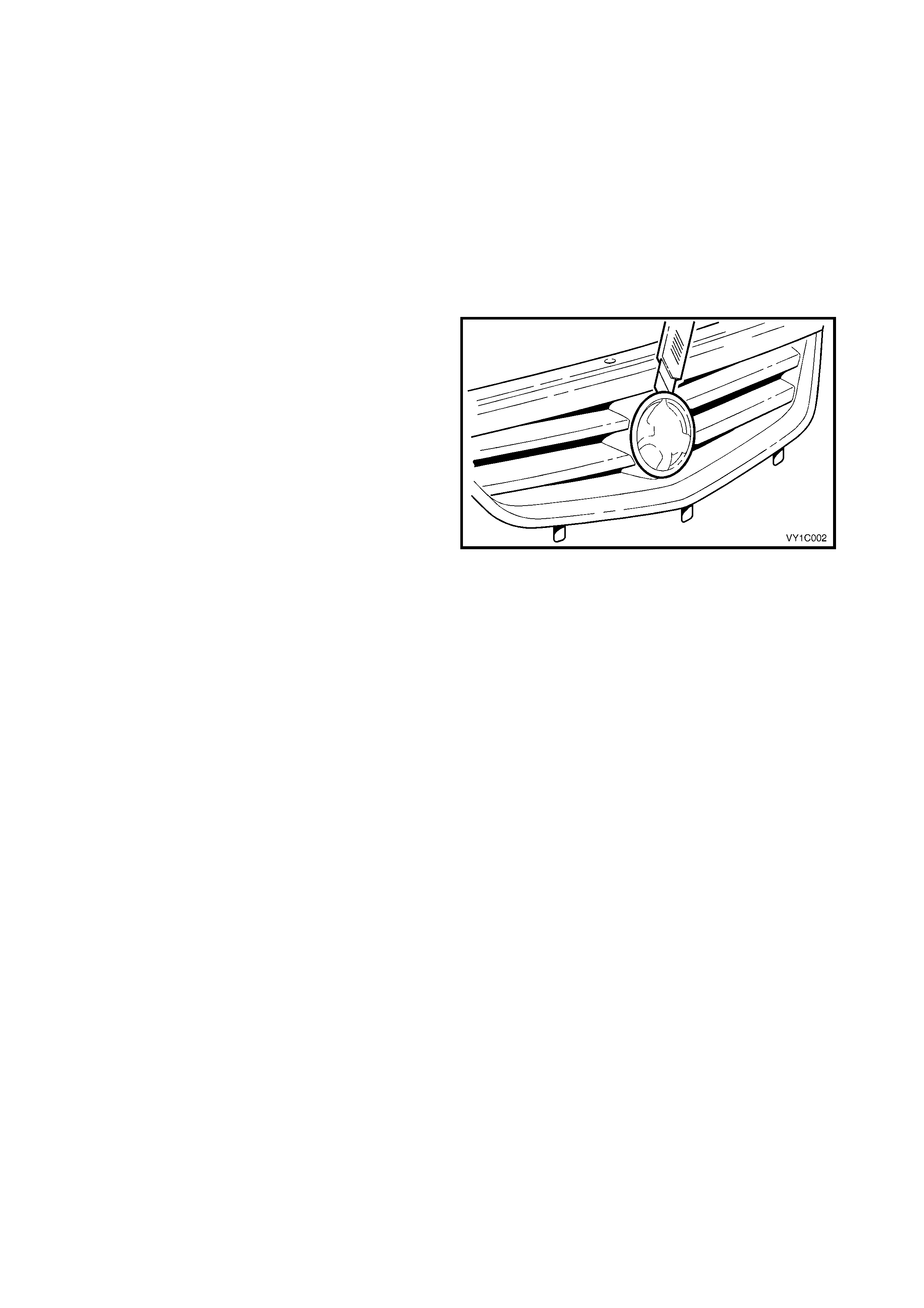
2.1 RADIATOR GRILLE EMBLEM
LT Section No. – 10-150
NOTE: Export S and SS vehicles are not fitted with a radiator grille emblem. For servicing of the radiator grille
escutcheon refer to Section 1C, 2.2 RADIATOR GRILLE ASSEMBLY, S SEDAN & SS.
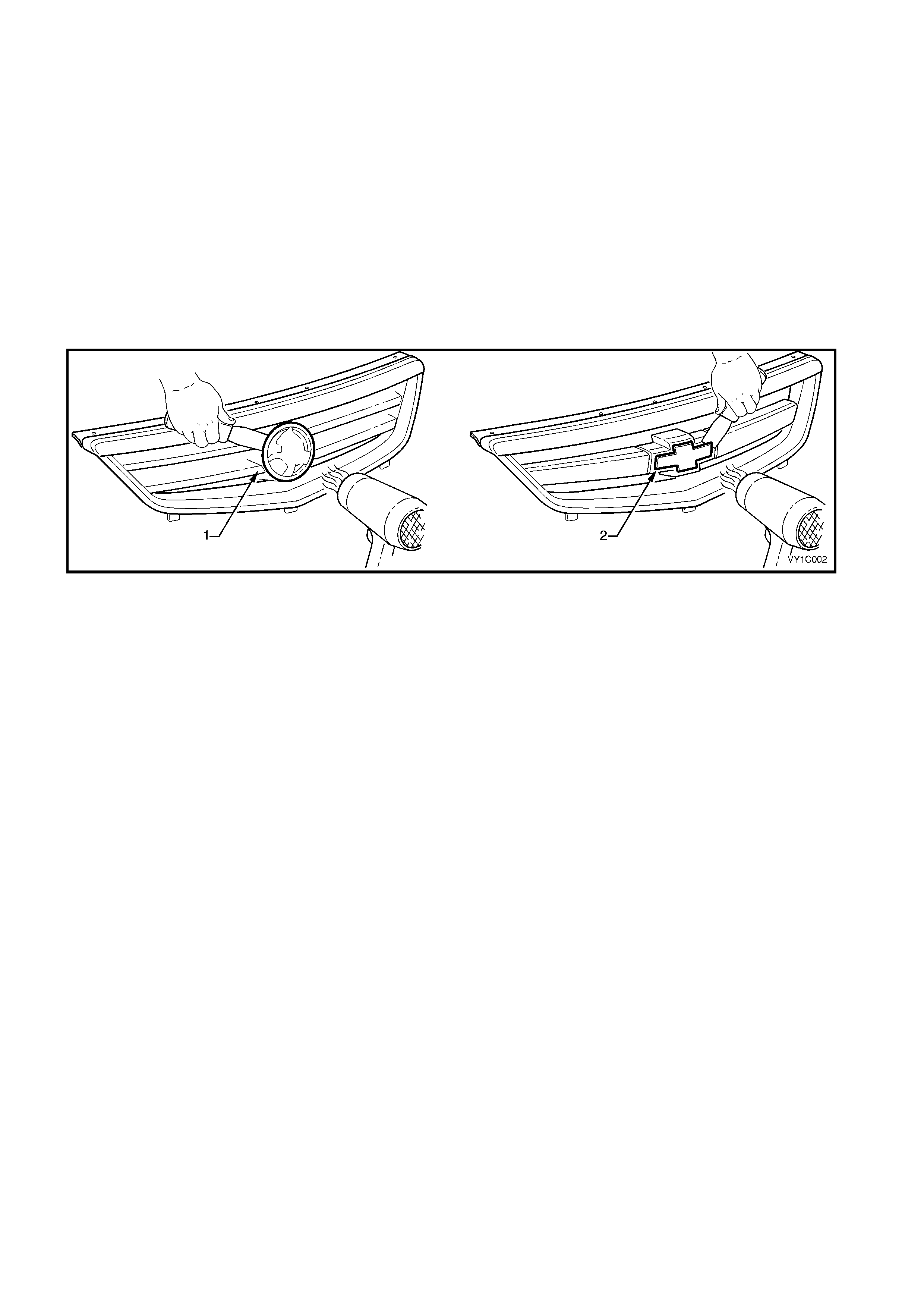
REMOVE
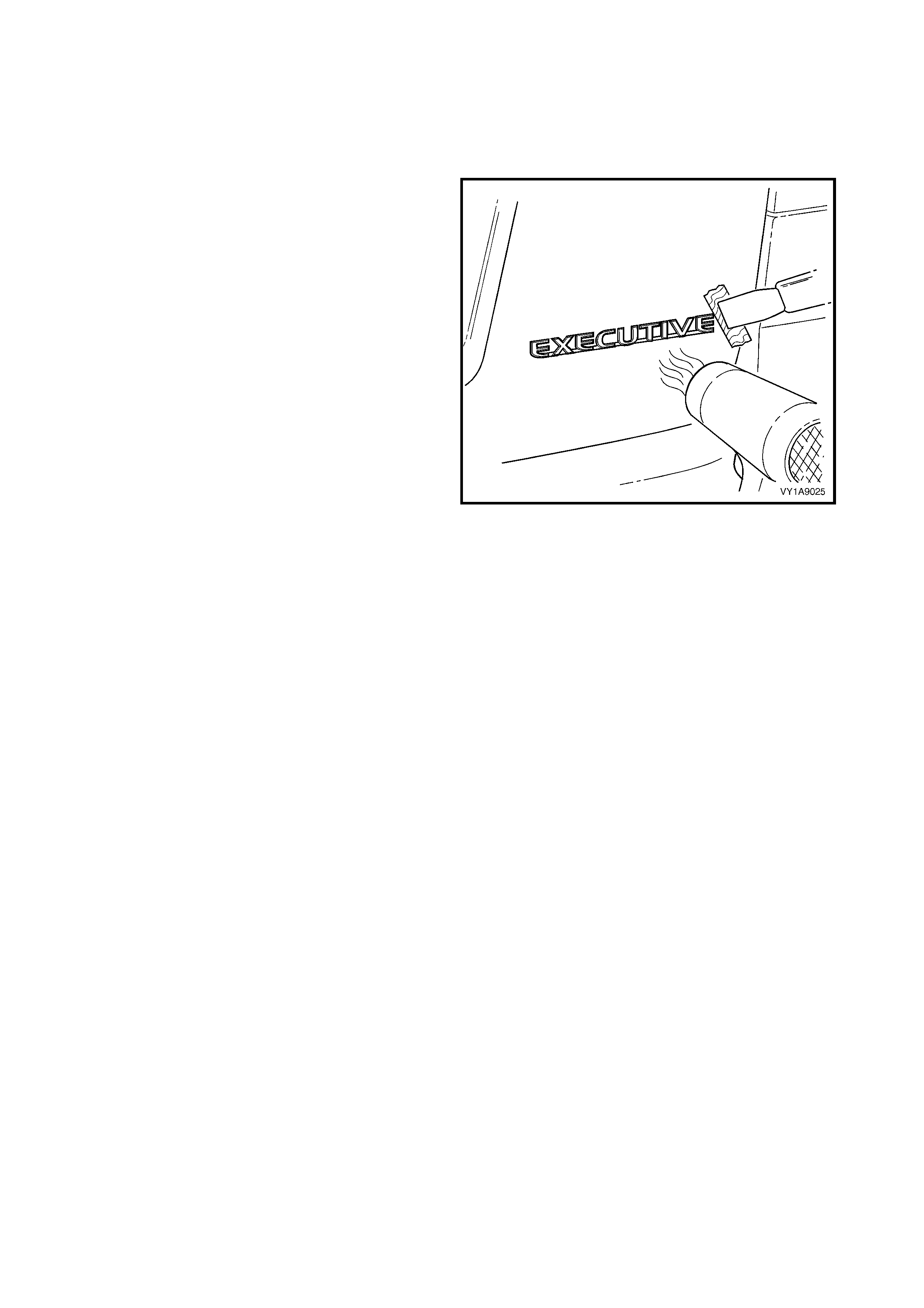
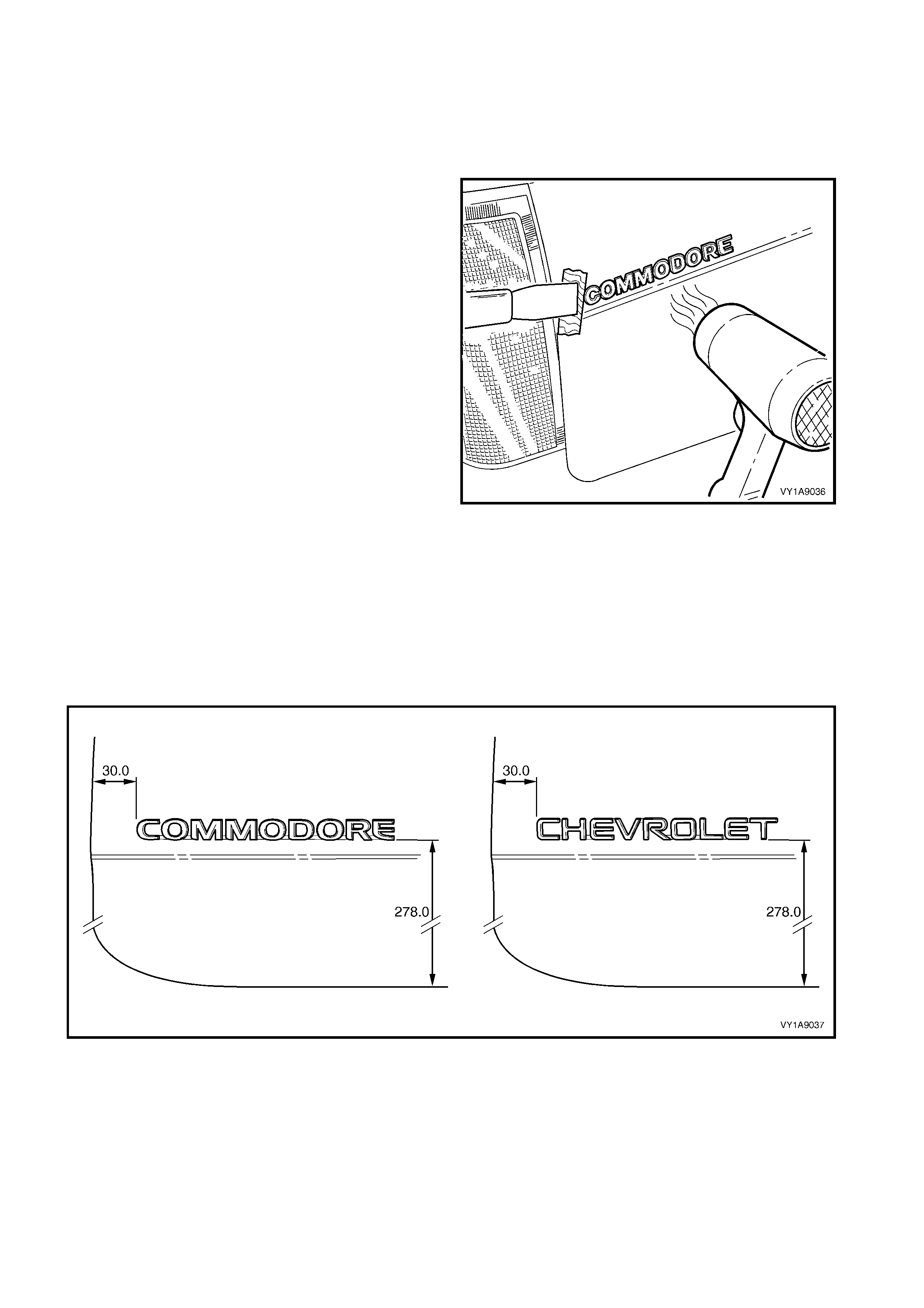
1. To assist removal, warm the emblem with a heat-lamp or heat-gun to soften the adhesive.
2. Using a knife or paint scraper, carefully remove the emblem assembly (1–domestic or 2–export) from the
grille assembly, cutting the double-sided tape, refer to Figure 1A9-21.
NOTE: The domestic emblem has two locating lugs which must not be cut if the emblem is to be reused.
3. Remove any remaining double-sided tape as required.
Figure 1A9-21
REINSTALL
1. If reinstalling the existing emblem, remove the existing double-sided tape and clean the surface with wax
and grease remover such as Prepsol or equivalent. Apply new polyethylene double-sided tape such as 3M
4428 or equivalent.
2. Clean the surface of the grille assembly with wax and grease remover such as Prepsol or equivalent.
3. Remove the backing paper from the double-sided tape.
4. Align the emblem. For domestic vehicles, locate the lugs with their corresponding holes in the grille
assembly. For export vehicles, align the emblem within its recess in the grille assembly.
5. Affix the emblem and press firmly over the entire emblem for at least 10 seconds to ensure sound adhesion.
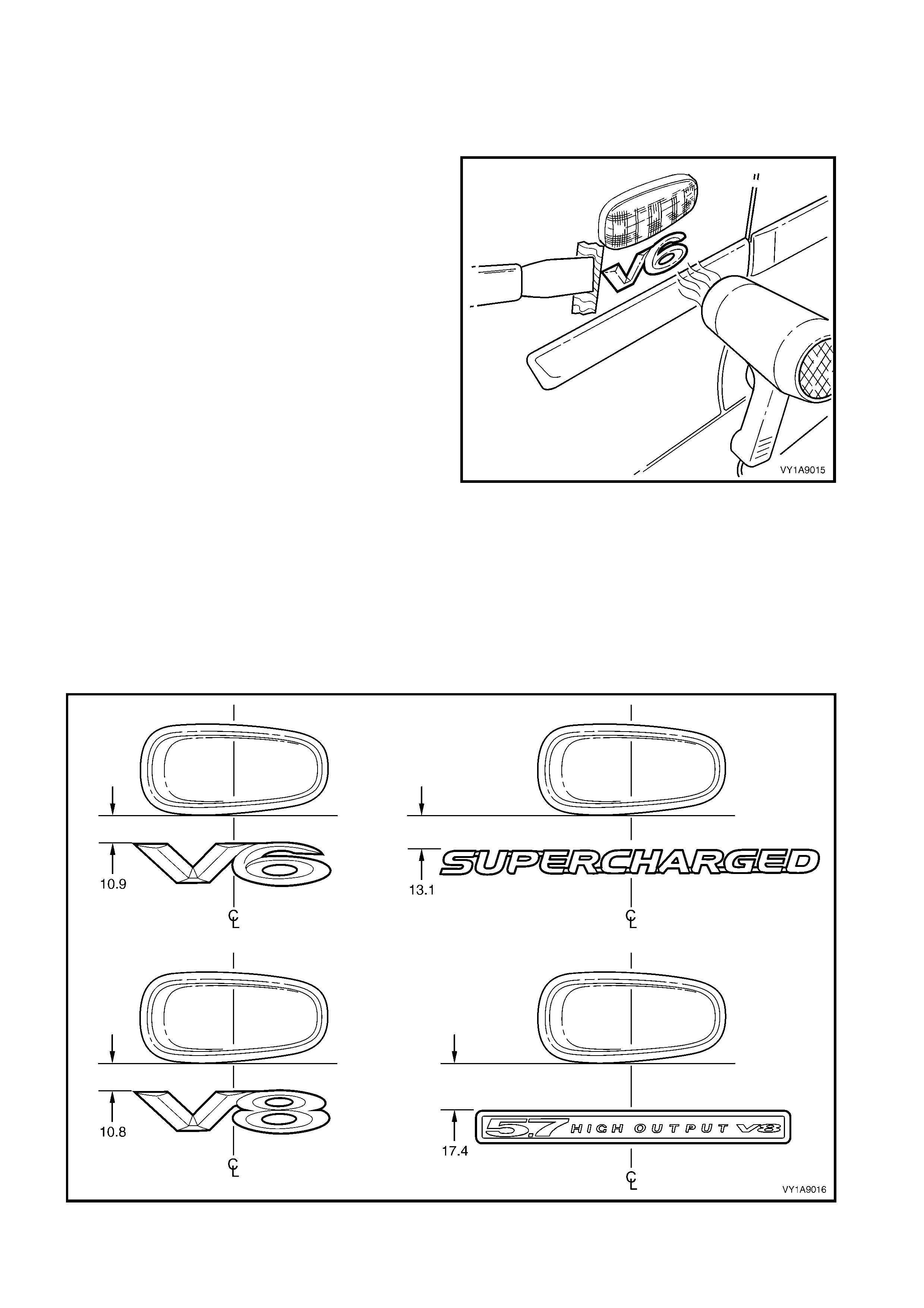
2.2 FENDER NAME PL ATE
LT Section No. – 10-150
REMOVE
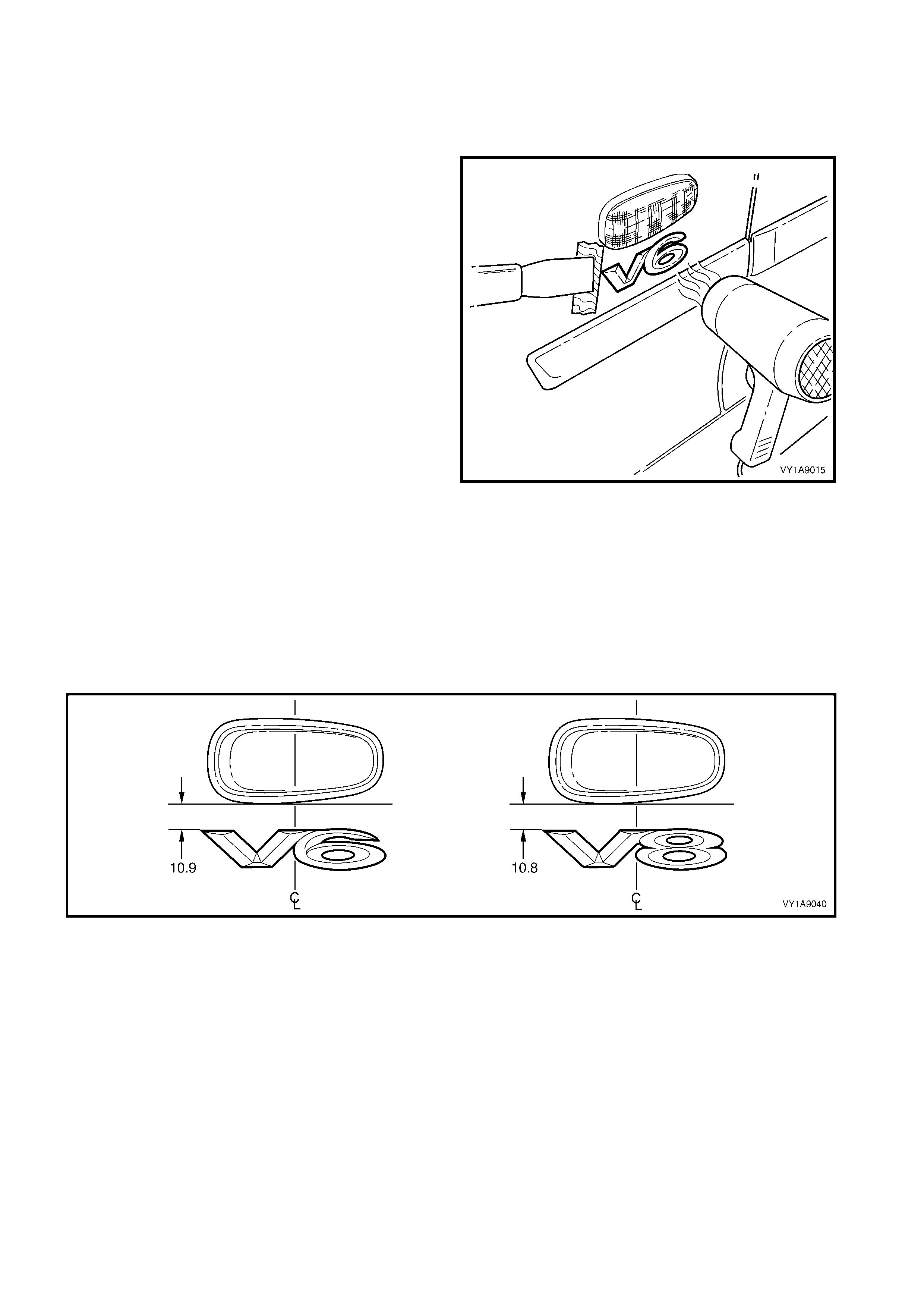
1. Protect the paint and bodywork with tape or a rag.
2. To assist removal, warm the plate with a heat-
lamp or heat-gun to soften the adhesive.
3. Using a paint s craper or sim ilar, caref ully pris e the
plate from the fender.
4. Remove any remaining double- sided tape from the
plate and/or fender and clean the surfaces with
Prepsol or equivalent.
Figure 1A9-22
REINSTALL
1. If reusing the plate, apply new polyethylene double-sided tape such as 3M 4428 or equivalent to the back
and trim the edges of the tape slightly in from the edge of plate.
2. Clean the fender surface with Prepsol or equivalent.
3. Remove the backing paper from the double-sided tape.
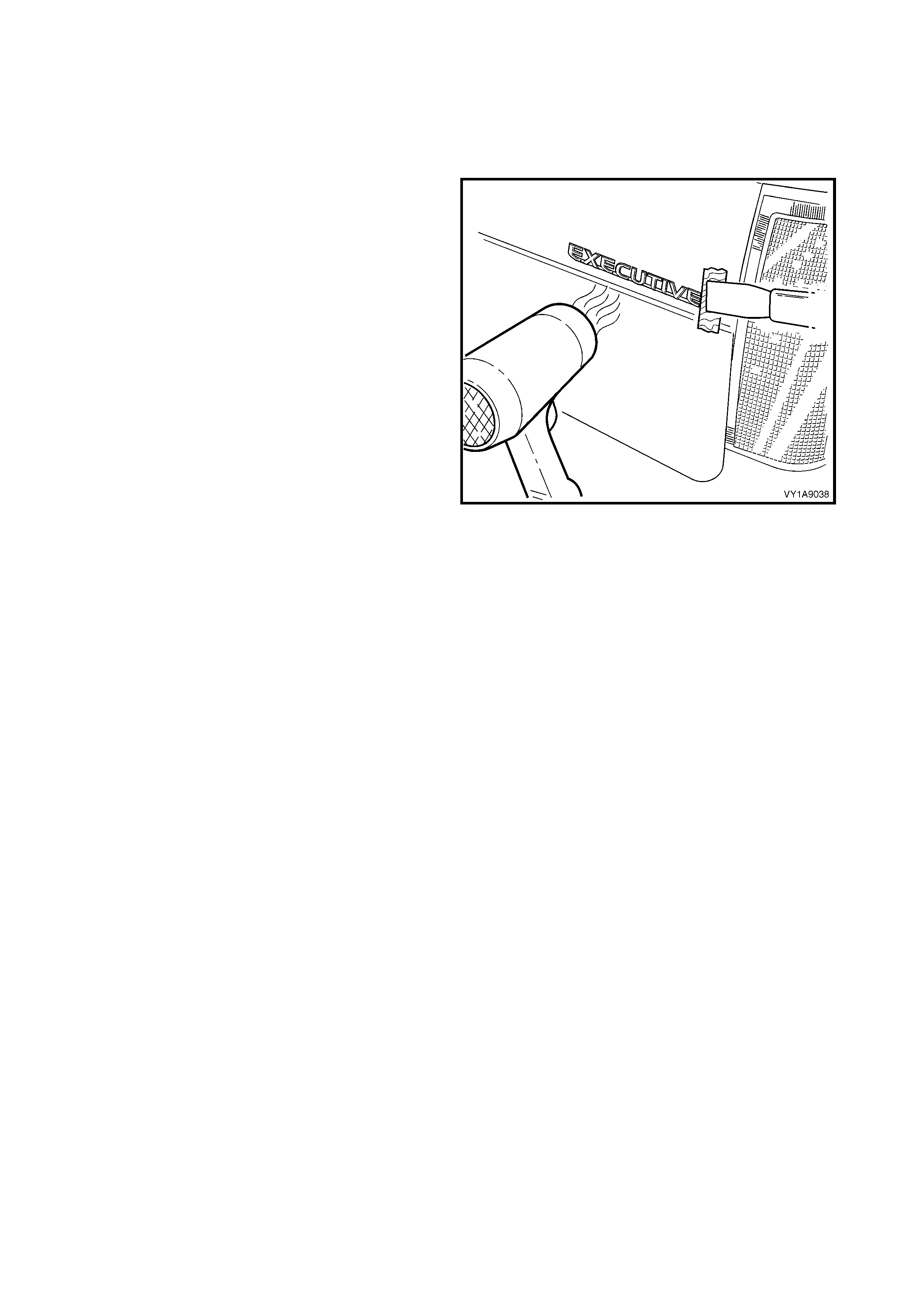
4. Apply the plate in the position shown, measuring from the front side turn signal lamp hole, refer to Figure
1A9-23. Ensure it is positioned parallel to the body side moulding or style line.
5. Press firmly over the entire plate for at least 10 seconds to ensure maximum adhesion.
Figure 1A9-23

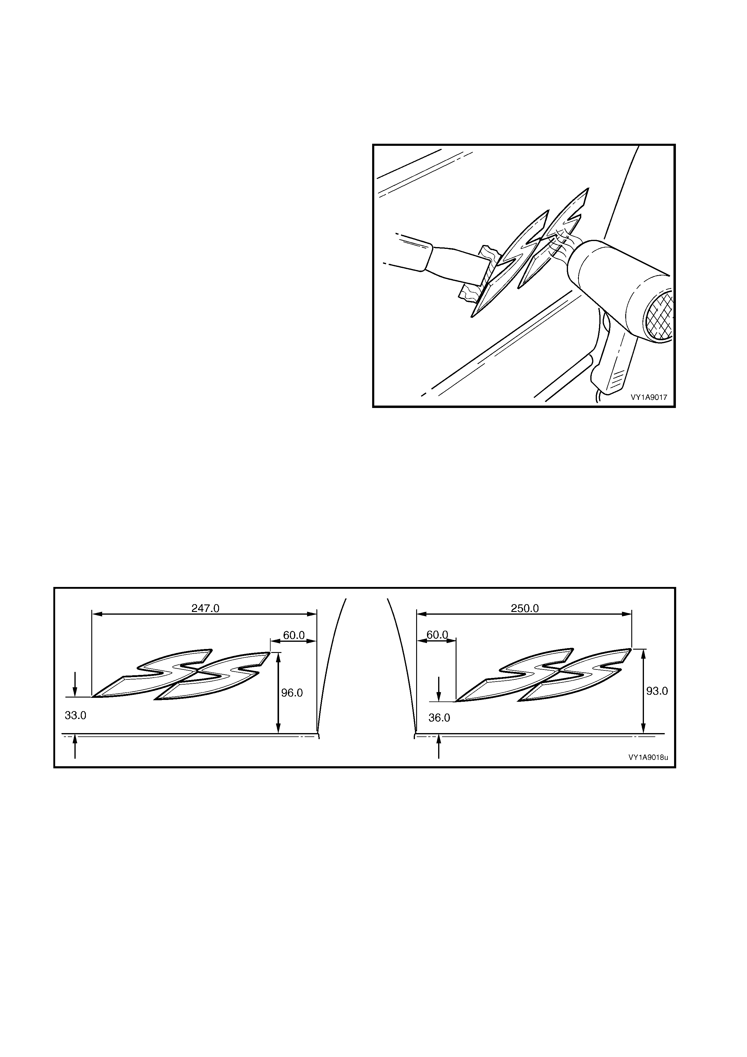
2.3 REAR DOOR NAME PLATE
LT Section No. – 10-150
SS
REMOVE
1. Protect the paint and bodywork with tape or a rag.
2. To assist removal, warm the name plate with a
heat-lamp or heat-gun to soften the adhesive.
3. Using a paint s craper or sim ilar, caref ully pris e the
name plate from the door panel.
4. As required, remove any remaining double-sided
tape from the name plate and/or door panel and
clean the surfaces with Prepsol or equivalent.
Figure 1A9-24
REINSTALL
1. If reusing the name plate, apply new polyethylene double-sided tape such as 3M 4428 or equivalent to the
back and the trim edges of the tape slightly in from the edge of the name plate.
2. Clean the door surface with Prepsol or equivalent.
3. Remove the backing paper from the double-sided tape.
4. Apply the nam e plate on to the lower section of the rear door in the position shown, m easuring up from the
lower edge of the door and in from the rear edge of the door, refer to Figure 1A9-25.
5. Press firmly over the entire plate for at least 10 seconds to ensure maximum adhesion.
Figure 1A9-25
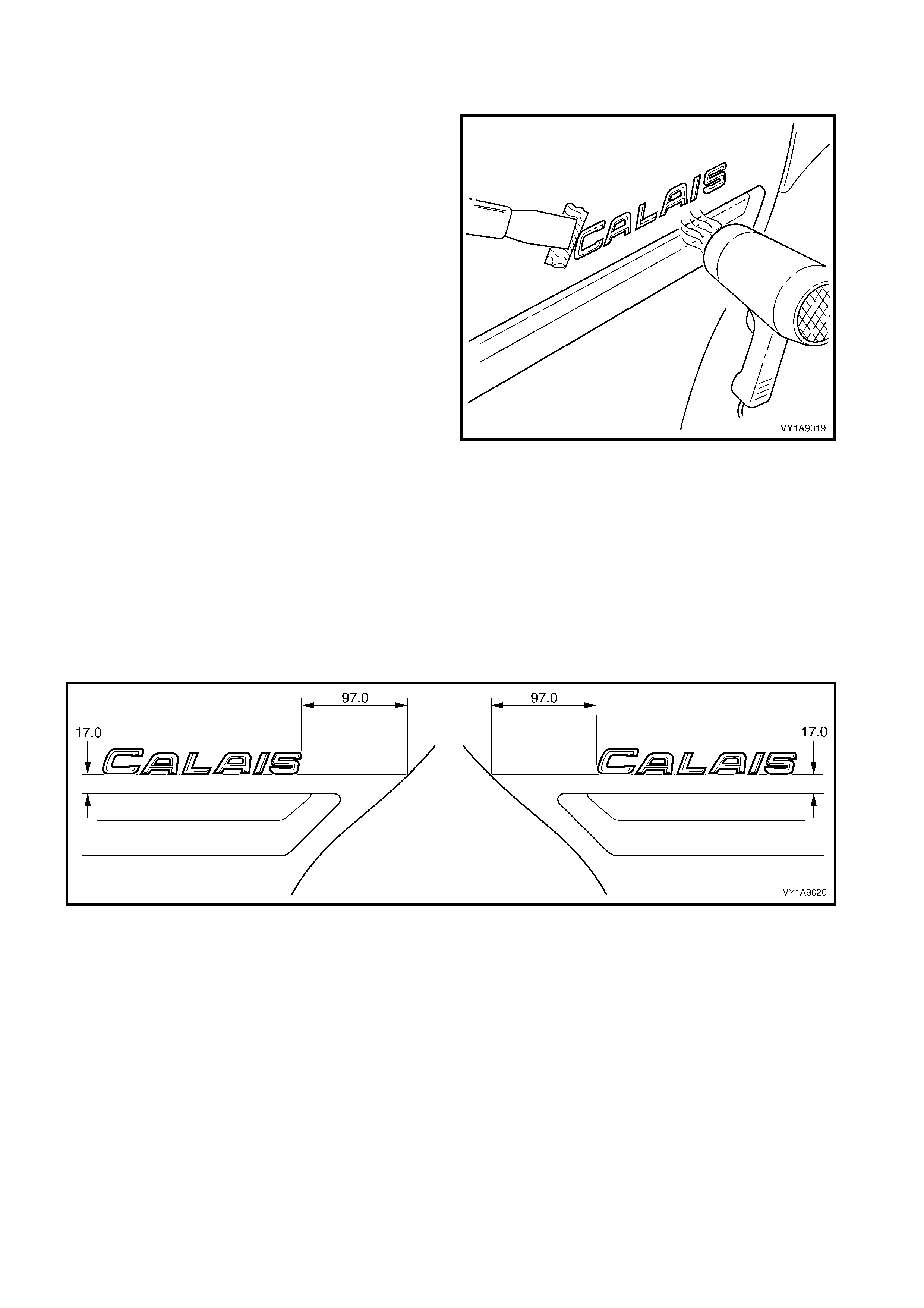
CALAIS
REMOVE
1. Protect the paint and bodywork with tape or a rag.
2. To assist removal, warm the name plate with a
heat-lamp or heat-gun to soften the adhesive.
3. Using a paint s craper or sim ilar, caref ully pris e the
name plate from the door panel.
4. As required, remove any remaining double-sided
tape from the name plate and/or door panel and
clean the surfaces with Prepsol or equivalent.
Figure 1A9-26
REINSTALL
1. If reusing the name plate, apply new polyethylene double-sided tape such as 3M 4428 or equivalent to the
back and the trim edges of the tape slightly in from the edge of the name plate.
2. Clean the door surface with Prepsol or equivalent.
3. Remove the backing paper from the double-sided tape.
4. Apply the nam e plate on to the rear door in the position shown, measuring up from the body side moulding
and in from the rear edge of the door. Ensure it is positioned parallel to the body side moulding, refer to
Figure 1A9-27.
5. Press firmly over the entire plate for at least 10 seconds to ensure maximum adhesion.
6. Remove the plastic carrier.
Figure 1A9-27
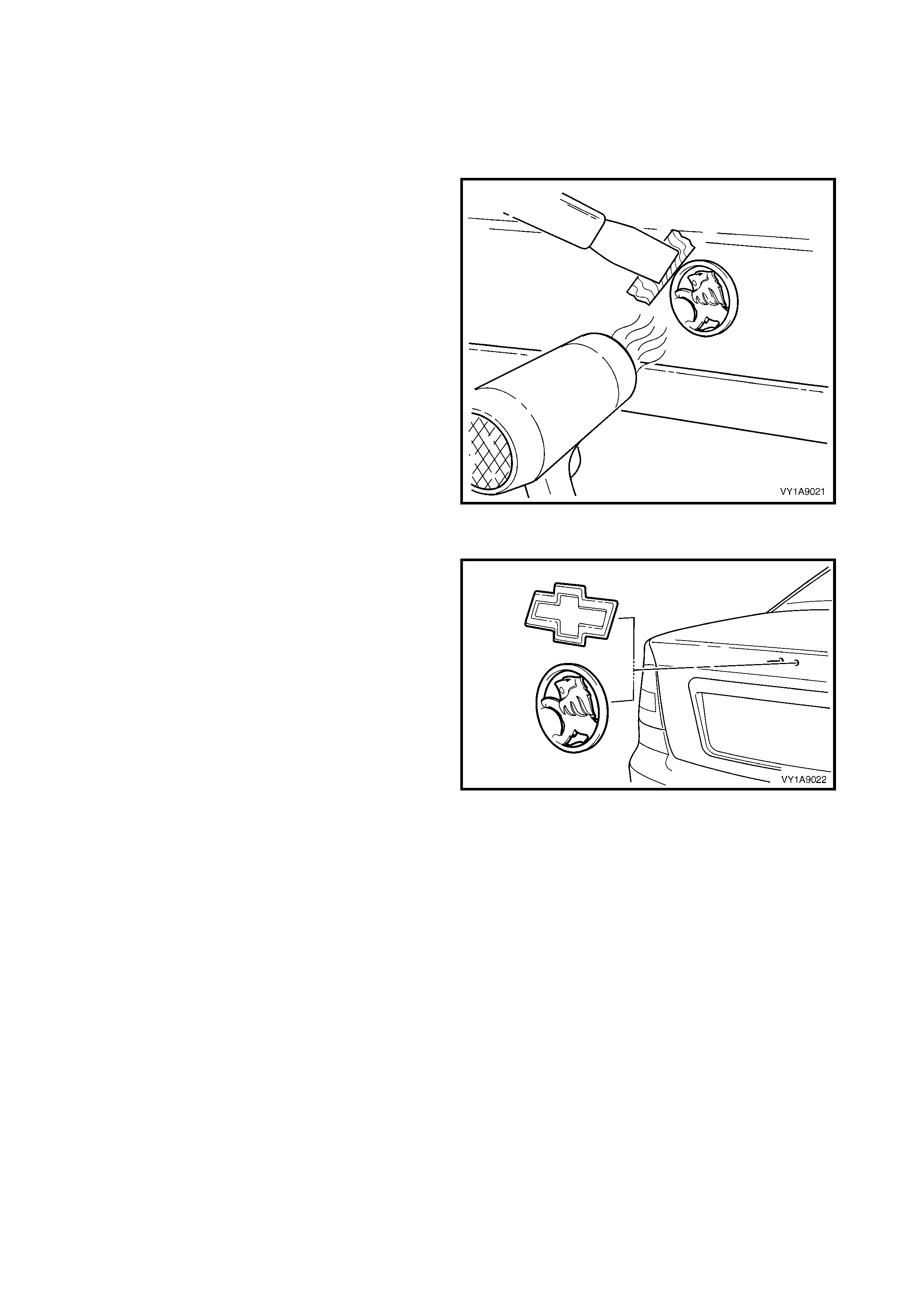
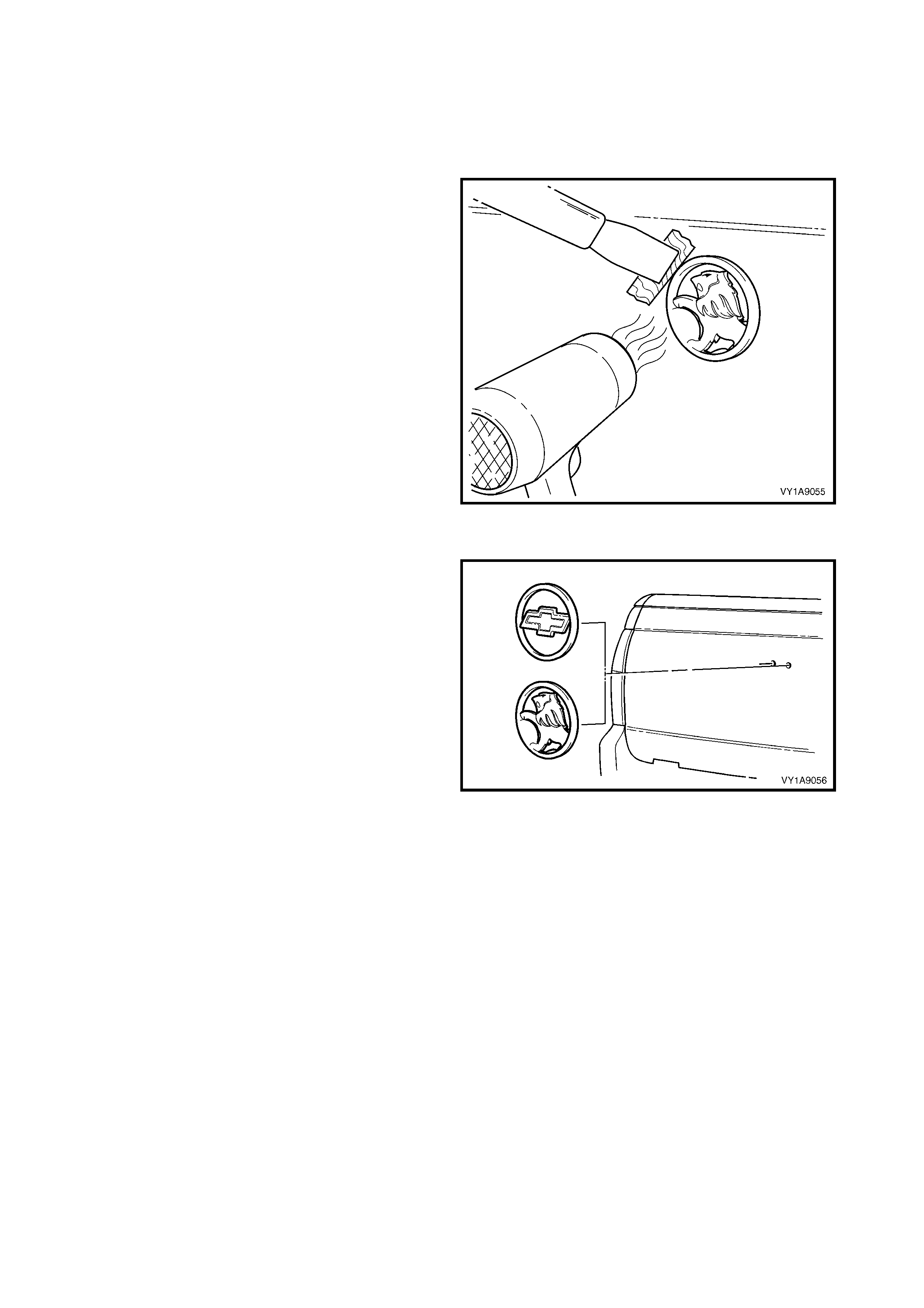
2.4 REAR COMPARTMENT LID EMBLEM
LT Section No. – 10-150
HOLDEN, CHEVROLET
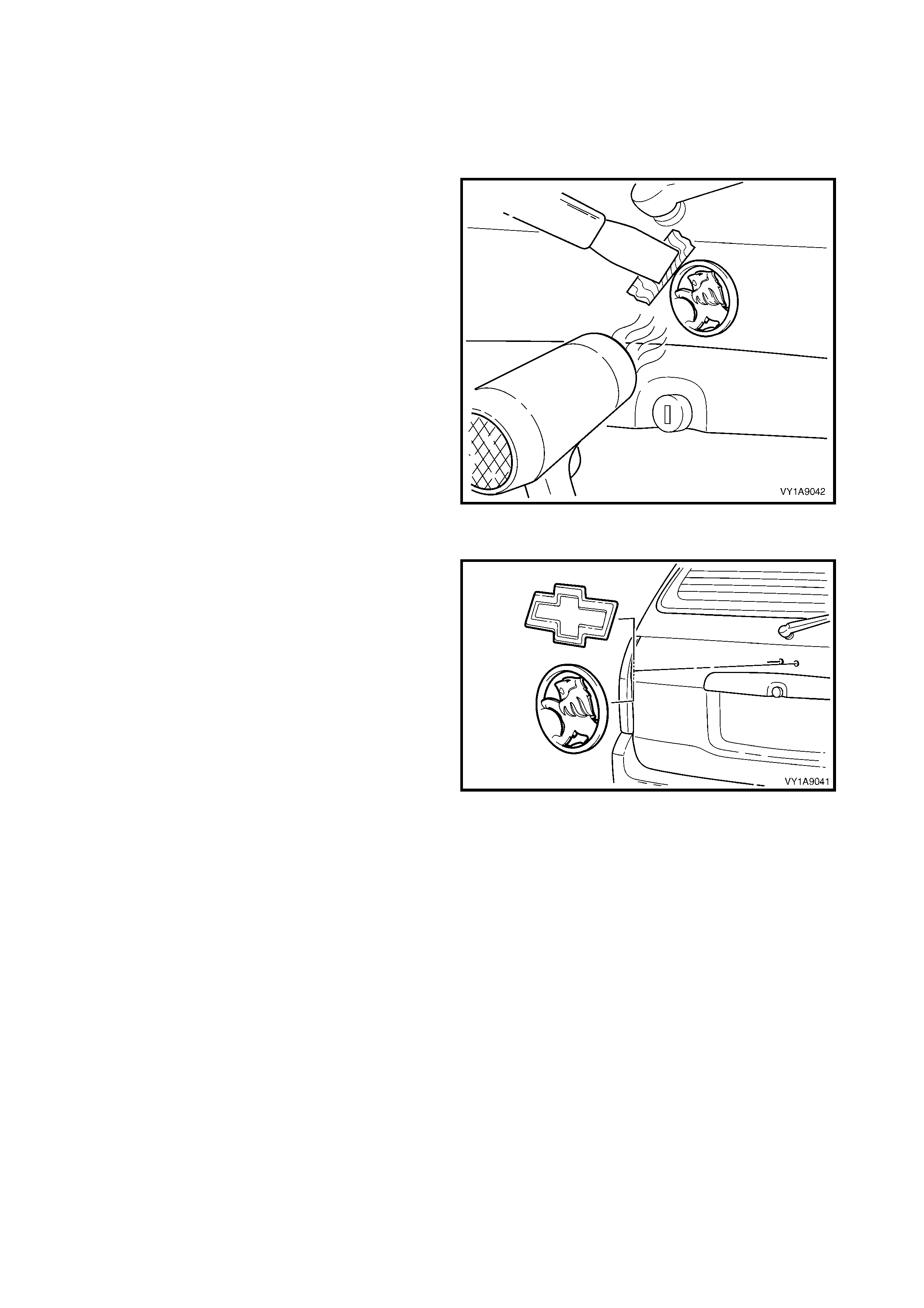
REMOVE
1. Protect the paint and bodywork with tape or a rag.
2. To assist removal, warm the emblem with a heat-
lamp or heat-gun to soften the adhesive.
3. Using a paint s craper or sim ilar, caref ully pris e the
emblem from the rear compartment lid.
NOTE: The emblem has two locating pins, take care
not to break them if the emblem is to be reused.
4. As required, remove any remaining double-sided
tape f rom the em blem and/or rear com partm ent lid
and clean the surfaces with Prepsol or equivalent.
Figure 1A9-28
REINSTALL
1. If reusing the emblem, apply new polyethylene
double-sided tape such as 3M 4428 or equivalent
to the back and the trim edges of the tape slightly
in from the edge of the emblem.
2. Clean the panel surface with Prepsol or equivalent.
3. Remove the backing paper from the double-sided
tape.
4. Apply the emblem in the position shown, ensuring
the locating pins are correctly orientated with the
locating holes in the panel surface.
5. Press firm ly over the entire emblem for at leas t 10
seconds to ensure maximum adhesion.
Figure 1A9-29
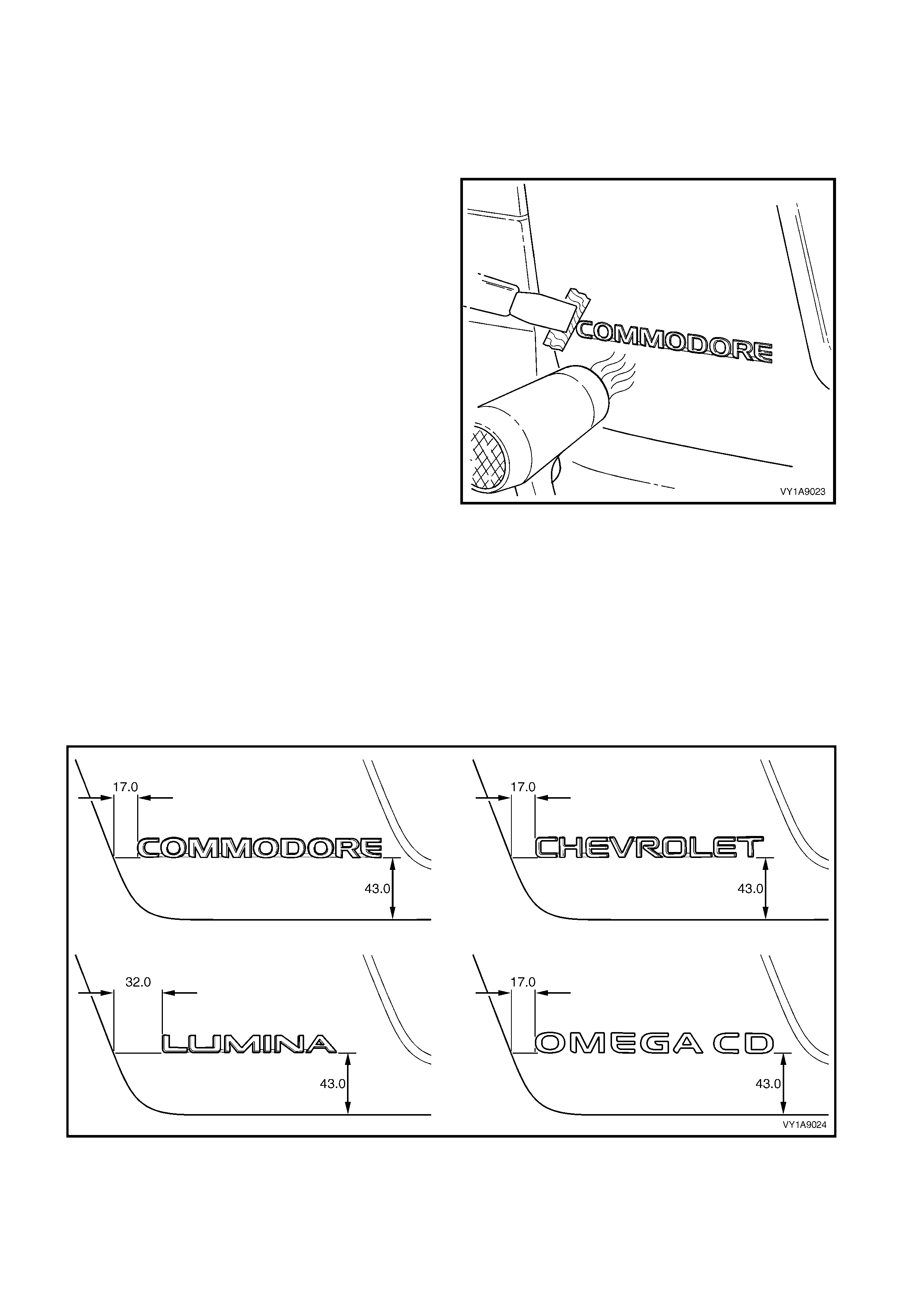
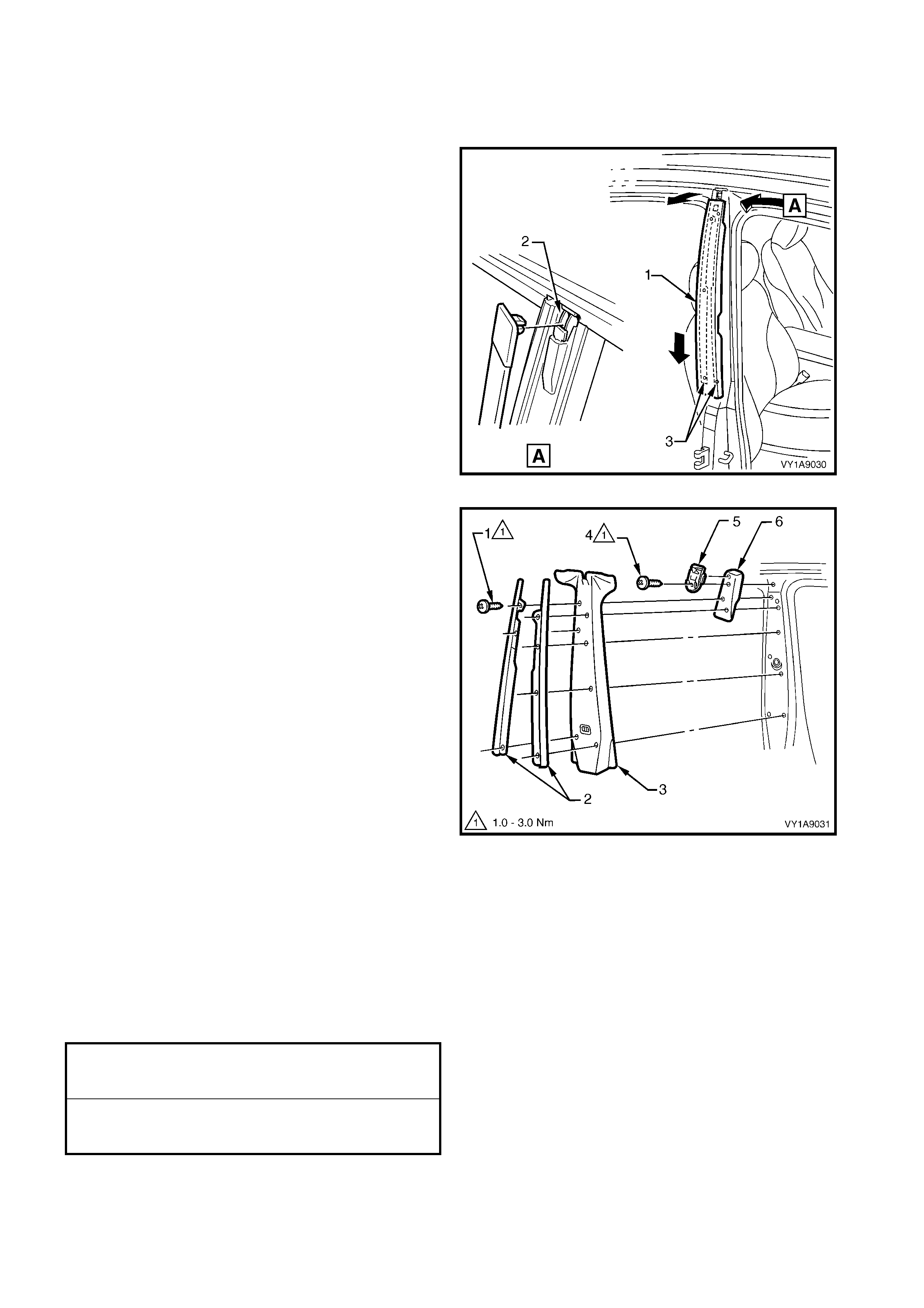
2.5 REAR COMPARTMENT LID NAME PLATE, LH
LT Section No. – 10-150
COMMODORE, CHEVROLET, LUMINA, OMEGA CD
REMOVE
1. Protect the paint and bodywork with tape or a rag.
2. To assist removal, warm the name plate with a
heat-lamp or heat-gun to soften the adhesive.
3. Using a paint s craper or sim ilar, caref ully pris e the
name plate from the rear compartment lid.
4. As required, remove any remaining double-sided
tape from the nam e plate and/or rear c ompartment
lid and clean the surfaces with Prepsol or
equivalent.
Figure 1A9-30
REINSTALL
1. If reusing the name plate, apply new polyethylene double-sided tape such as 3M 4428 or equivalent to the
back and the trim edges of the tape slightly in from the edge of the name plate.
2. Clean the panel surface with Prepsol or equivalent.
3. Remove the backing paper from the double-sided tape.
4. Apply the name plate onto the left-hand side of the rear compartment lid in the position shown, measuring
from the edge of the r ear com partment lid. Ens ure it is positioned parallel to the lower edge, ref er to Figure
1A9-31.
5. Press firmly over the entire plate for at least 10 seconds to ensure maximum adhesion.
6. If required, remove the plastic carrier.
Figure 1A9-31
2.6 REAR COMPARTMENT LID NAME PLATE, RH
LT Section No. – 10-150
EXECUTIVE, ACCLAIM, S, SV8, SS, BERLINA, CALAIS, LUMINA LS, LUMINA LTZ, 3.8 V6
REMOVE
1. Protect the paint and bodywork with tape or a rag.
2. To assist removal, warm the name plate with a
heat-lamp or heat-gun to soften the adhesive.
3. Using a paint s craper or sim ilar, caref ully pris e the
name plate from the rear compartment lid.
4. As required, remove any remaining double-sided
tape from the nam e plate and/or rear c ompartment
lid and clean the surfaces with Prepsol or
equivalent.
Figure 1A9-32
REINSTALL
1. If reusing the name plate, apply new polyethylene double-sided tape such as 3M 4428 or equivalent to the
back and the trim edges of the tape slightly in from the edge of the name plate.
2. Clean the panel surface with Prepsol or equivalent.
3. Remove the backing paper from the double-sided tape.
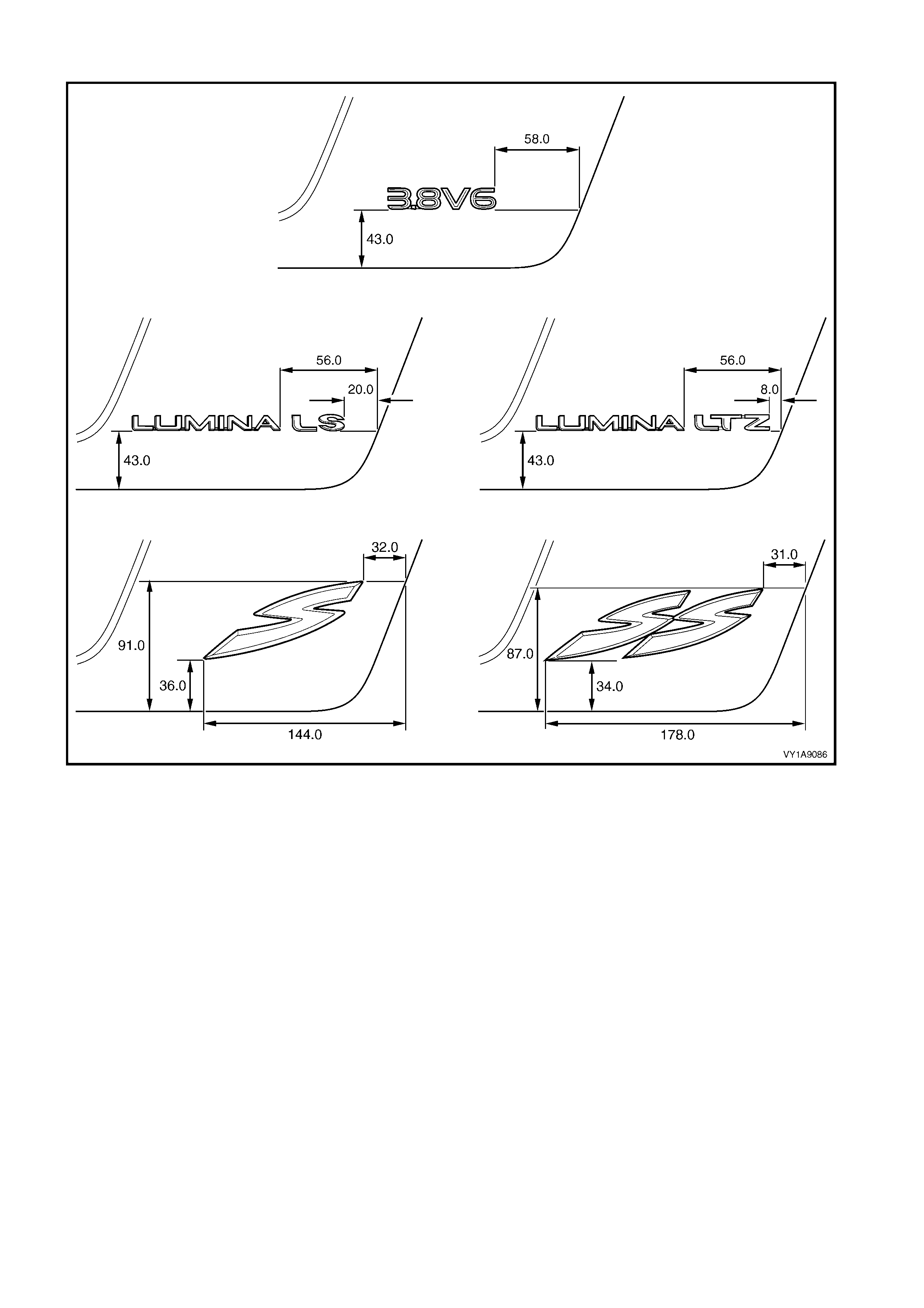
4. Apply the name plate onto the r ight-hand side of the rear com partm ent lid in the position shown, measuring
from the edge of the r ear com partment lid. Ens ure it is positioned parallel to the lower edge, ref er to Figure
1A9-33 for domestic vehicles or Figure 1A9-34 for export vehicles.
5. Press firmly over the entire plate for at least 10 seconds to ensure maximum adhesion.
6. Where required remove the plastic carrier.

DOMESTIC VEHICLES
Figure 1A9-33
EXPORT VEHICLES
Figure 1A9-34
2.7 ROOF JOINT MOULDING
LT Section No. – 10-250
REMOVE
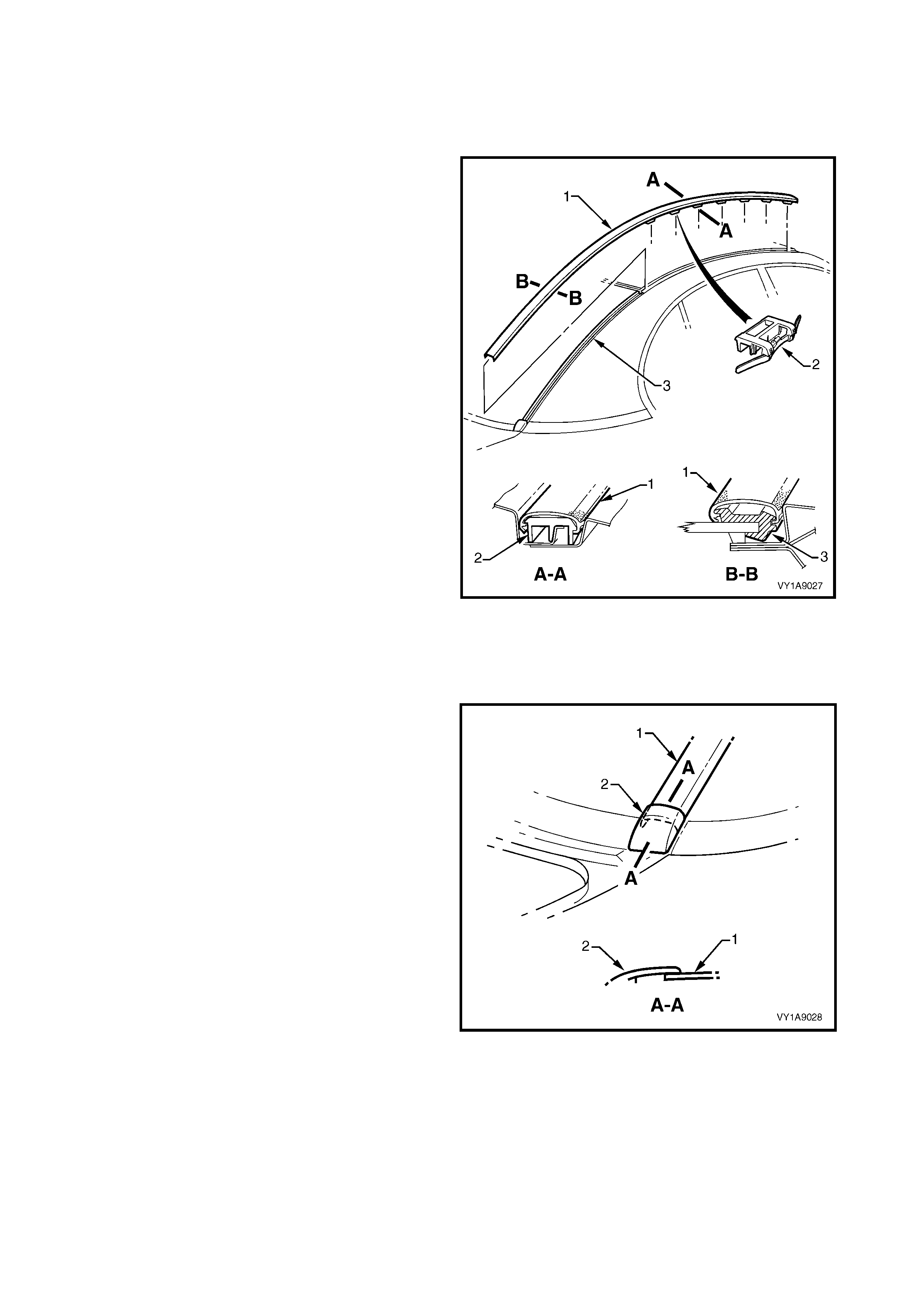
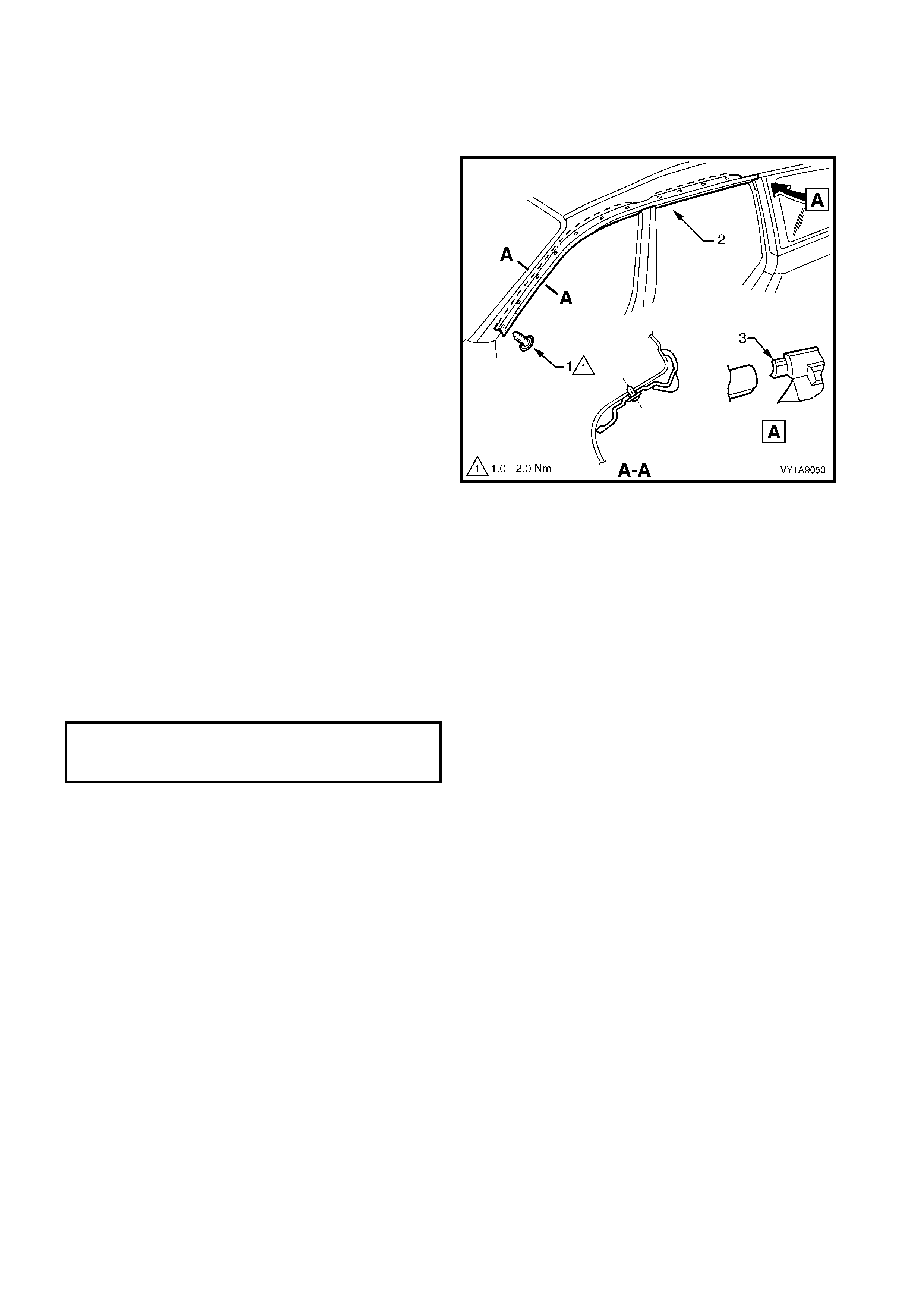
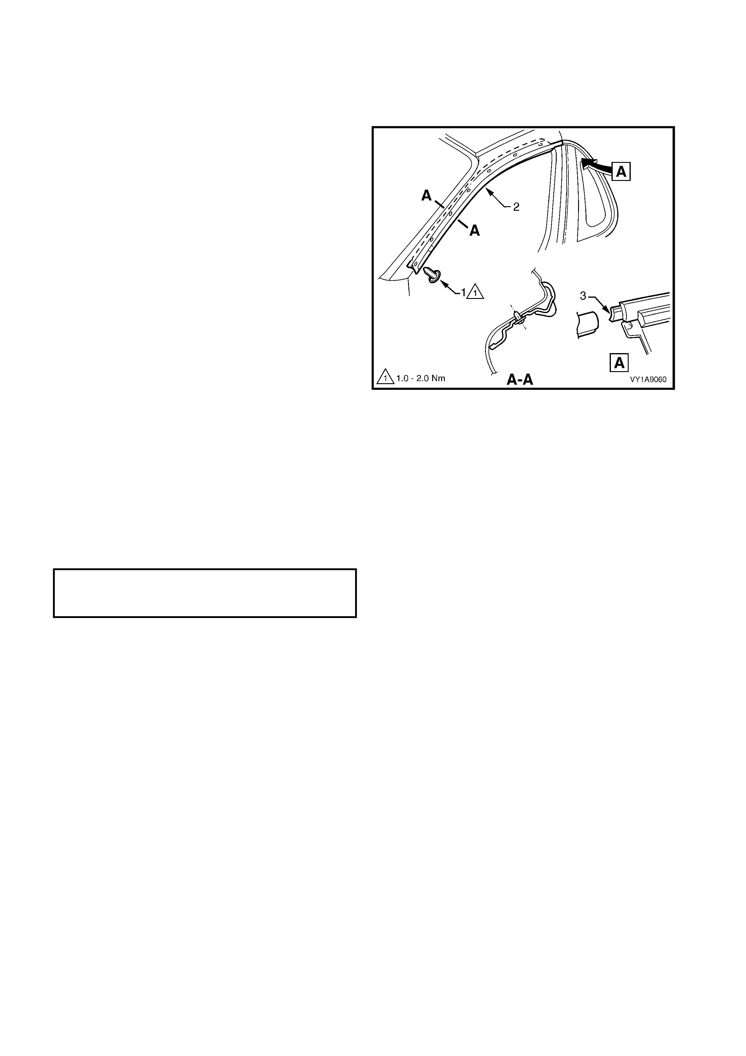
1. Beginning at the front of the vehicle, use a
screwdriver to carefully prise the roof joint
moulding (1) from the roof channel, disengaging
the retaining clips (2) at seven places.
IMPORTANT: Take care as the retaining clips can
easily break. Protect the paintwork with a shop rag.
2. Slide the joint moulding from the rear window side
moulding retainer (3) and remove.
NOTE: For removal of the rear window side moulding
retainer, refer to Section 1A6, 5.1 REAR WINDOW
ASSEMBLY, SEDAN & COUPE.
Figure 1A9-35
REINSTALL
1. As required, s eat the seven retainers onto the roof
joint moulding, evenly spaced.
2. Engage the roof joint moulding (1) onto the rear
window side moulding retainer, refer to Figure
1A9-35, and slide along until the roof joint
moulding sits under the endcap (2).
3. Seat the roof joint moulding in the roof channel
and beginning at the rear, clip it in place.
4. At the f ront, ensure the m oulding is installed under
the windshield moulding cover.
Figure 1A9-36
2.8 DOOR OPENING MOULDING
LT Section No. – 10-250
REMOVE
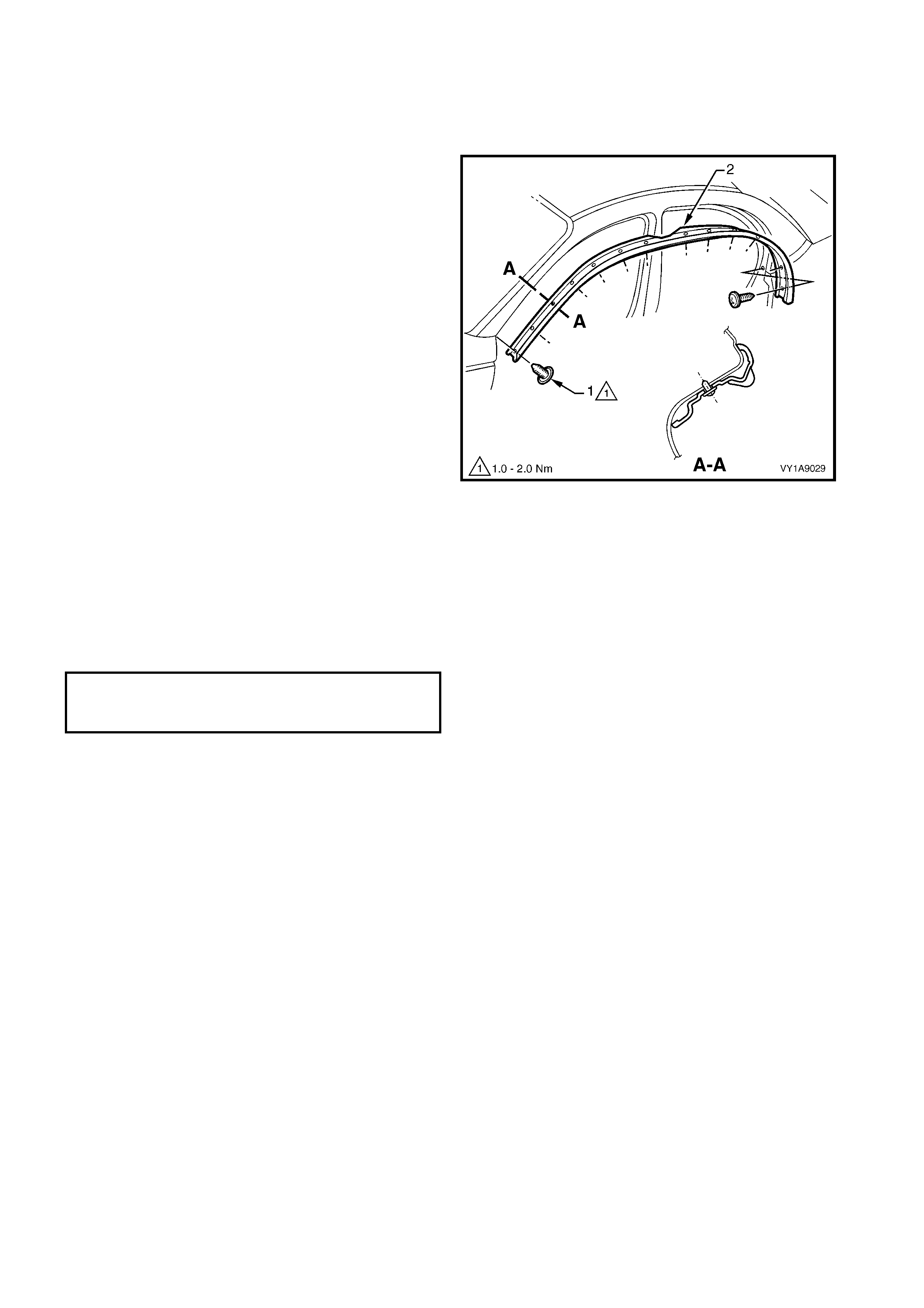
1. Open the fr ont and rear doors on the relevant side
of the vehicle.
2. Beginning at each end and working towards the
middle, rem ove the s crew (1), 13 plac es, attaching
the door opening moulding (2) to the vehicle.
3. Carefully remove the moulding.
Figure 1A9-37
REINSTALL
Reinstallation is the reverse of the removal.
NOTE: The screws are encapsulated with a wax
sealer. It is r ecom mended that the sc rews be replaced
once removed, however if this is impractical, apply a
small amount of sealer to the end of the thread.
Tighten the screws to the specified torque.
DOOR OPENING MOULDING
ATTACHING SCREW
TORQUE SPECIFICATION 1.0 – 2.0 Nm
2.9 CENTRE PILLAR UPPER FINISHER ASSEMBLY
LT Section No. – 10-250
REMOVE
1. Open the fr ont and rear doors on the relevant side
of the vehicle.
2. Gently prise the top of the centre pillar upper
finisher (1) out to disengage it from the centre
pillar upper finisher retainer (2).
3. Holding the top of finisher out, slide it down the
centre pillar outer sealing strips (3) until it rests on
rear door hinge.
4. Manoeuvre the finisher f rom the s ealing strips and
remove.
Figure 1A9-38
5. Remove the screw (1) seven places, securing the
centre pillar sealing strips (2) to the pillar and
remove the strips.
6. Partially rem ove the door fram e opening moulding,
refer to 2.8 DOOR OPENING MOULDING in this
Section.
7. Remove centre pillar upper trim panel (3) by
pulling away from the pillar.
8. Remove the screw (4) securing the centre pillar
upper finisher retainer (5) and centre pillar upper
trim mount plate (6) to the pillar and remove.
Figure 1A9-39
REINSTALL
Reinstallation of the centre pillar upper finisher
assembly is the reverse of the removal procedure,
noting the following:
1. Ensure the centre pillar upper trim panel is seated
correctly under the door opening weatherstrips.
2. Ensure all fasteners are tightened to the correct
torque specification.
3. Slide the centre pillar upper f inisher up and press it
in at the top to engage into the retaining clip.
CENTRE PILLAR UPPER FINISHER
RETAINER ATTACHING SCREW
TORQUE SPECIFICATION 1.0 – 3.0 Nm
CENTRE PILLAR SEALING STRIP
ATTACHING SCREW
TORQUE SPECIFICATION 1.0 – 3.0 Nm
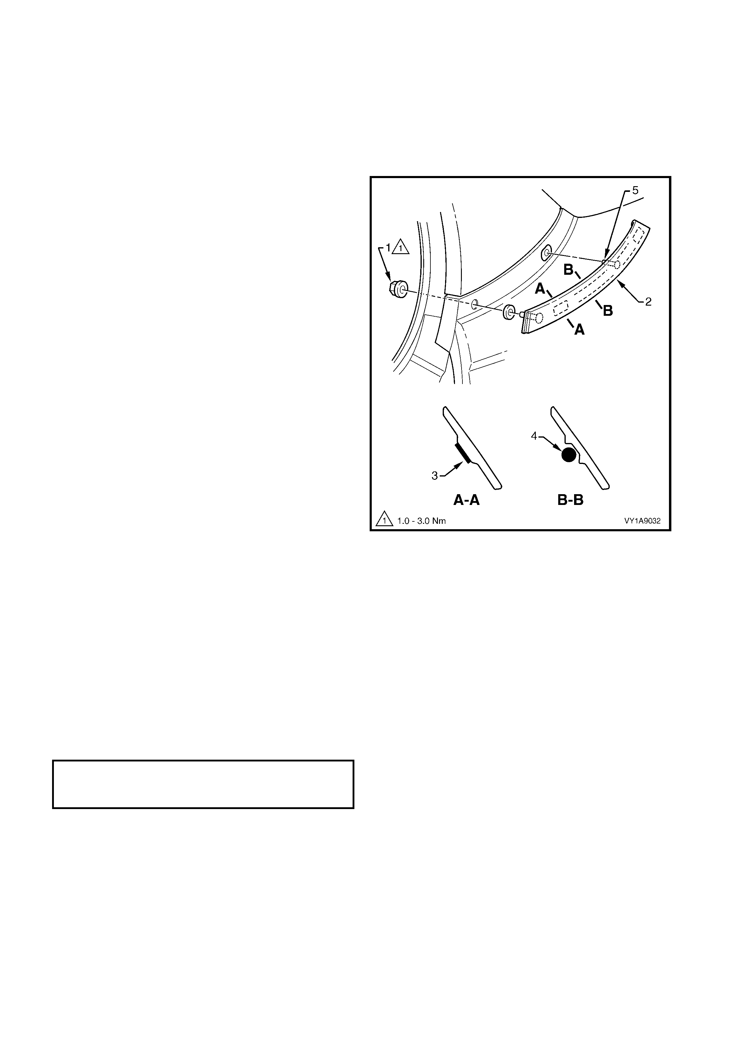
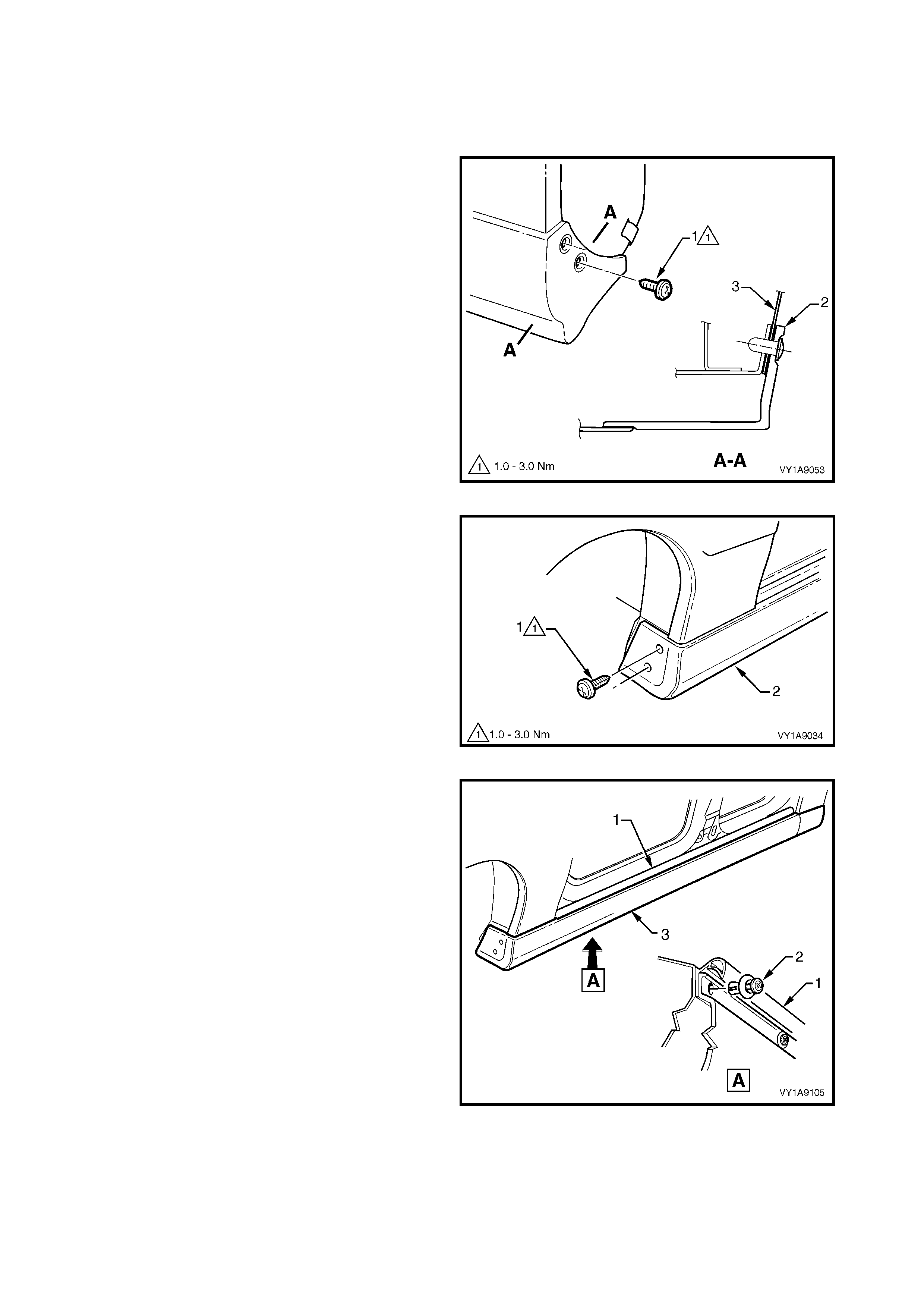
2.10 QUARTER PANEL BELT MOULDING
LT Section No. – 10-250
REMOVE
1. Partially remove the body lock pillar garnish far
enough to access the quarter panel belt moulding
retaining nut, refer to Section 1A8, 2.6 BODY
LOCK PILLAR GARNISH.
2. Remove the retaining nut (1) securing the quarter
panel belt moulding (2) to the vehicle.
3. Using a length of piano wire, carefully cut the
double sided tape (3) and bead of polyurethane
adhesive (4) from the back of the moulding, two
places, noting to rem o ve and reinsert piano wire to
get around the attaching stud (5).
IMPORTANT: Take care not to damage the adjacent
paintwork.
4. Carefully prise the moulding from the vehicle and
remove.
Figure 1A9-40
REINSTALL
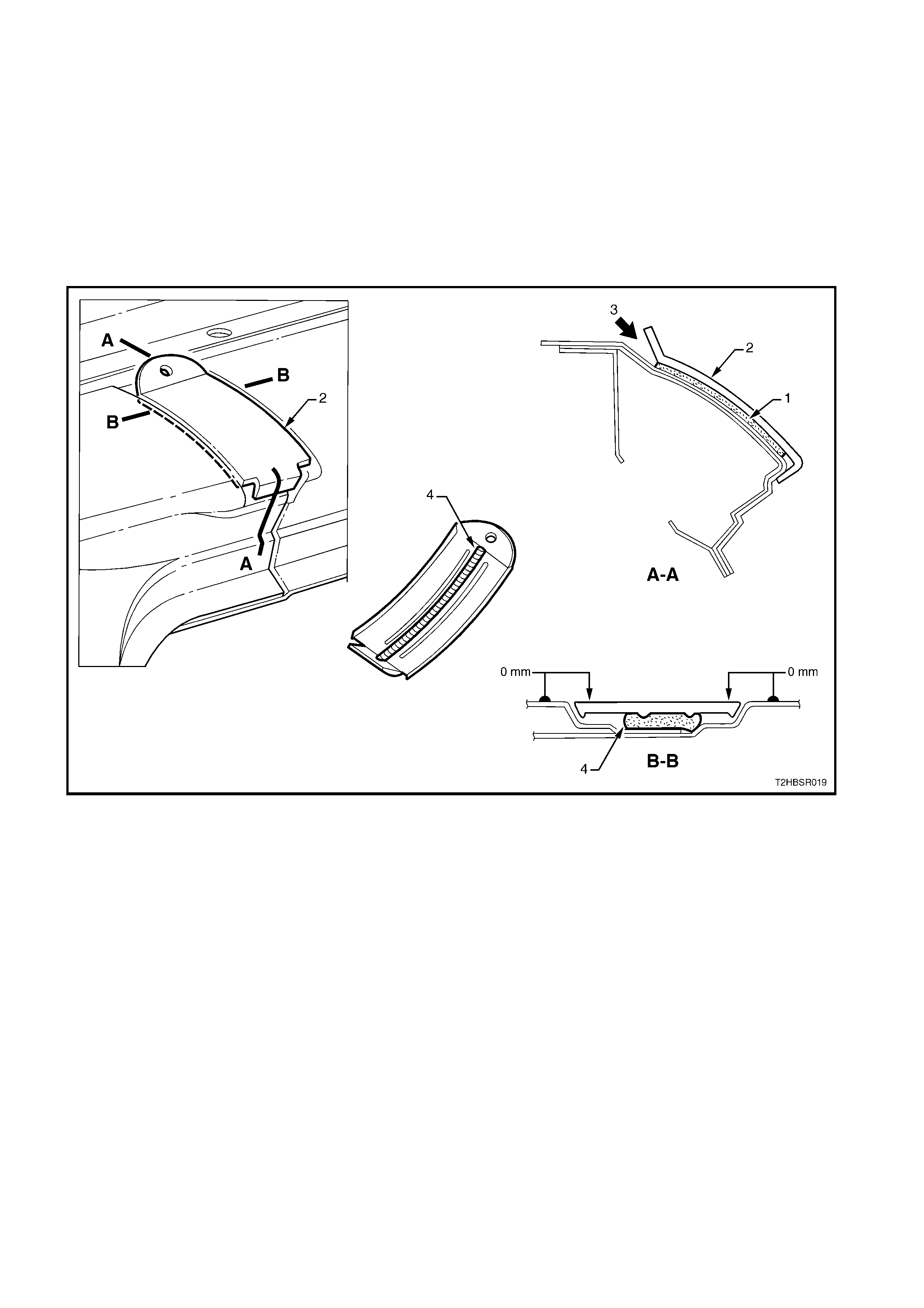
Reinstallation of the quarter panel belt moulding is the
reverse of the removal noting the following:
1. Apply two lengths of new acr ylic double-sided tape
such as 3M 5344 or equivalent to the back of the
moulding, refer to Section A-A in Figure 1A9-40.
2. Apply an 8.0 mm bead of urethane adhesive such
as Expandite Betaseal 554.02, Sikaflex Drive or
equivalent to the back of the moulding, between
and for the length of, the ribs in two places, refer to
Section B-B in Figure 1A9-40.
3. Tighten the retaining nut to the specified torque.
QUARTER PANEL BELT
MOULDING RETAINING NUT
TORQUE SPECIFICATION 1.0 – 3.0 Nm
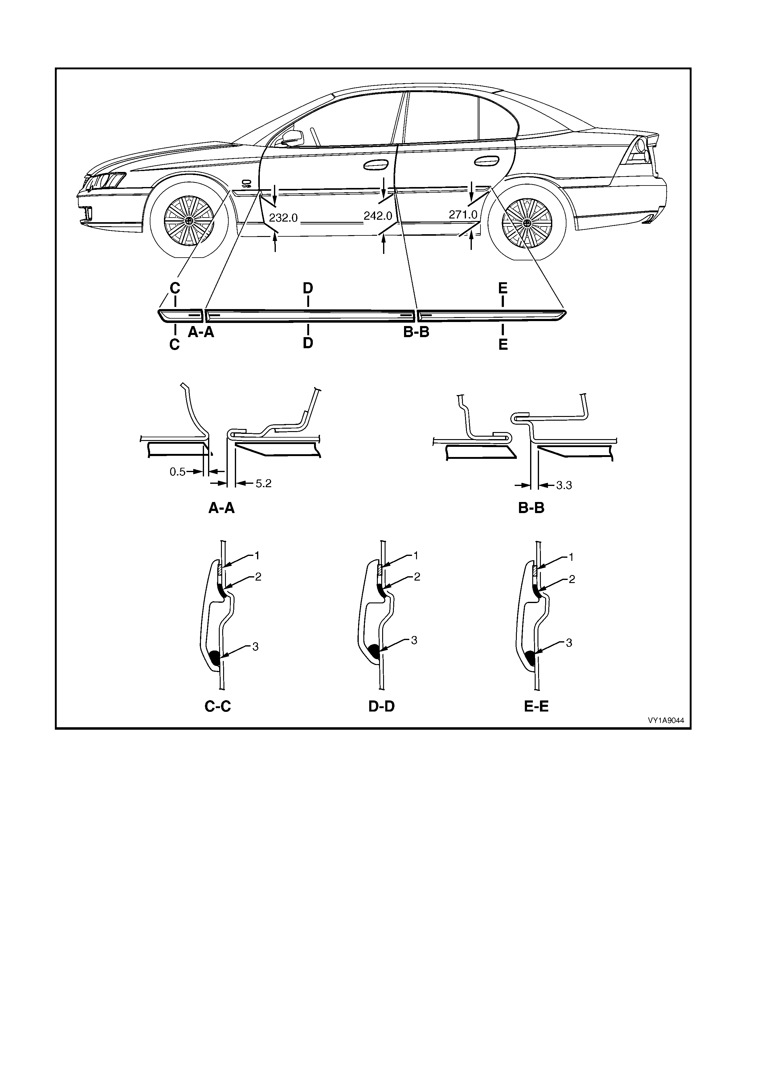
2.11 BODY SIDE MOULDINGS
LT Section No. – 10-250
REMOVE
1. Protect the paint and bodywork with tape or a rag.
2. Using a paint scraper or similar, begin at one end
and carefully prise the moulding from the panel,
cutting through the double sided tape and
adhesive.
NOTE: As an alternative, carefully use a length of
piano wire to cut the adhesive in a similar way to
removing a windshield.
3. As required, remove any remaining double-sided
tape and adhesive from the moulding and/or panel.
Clean the surfaces with Prepsol or equivalent.
Figure 1A9-41
REINSTALL
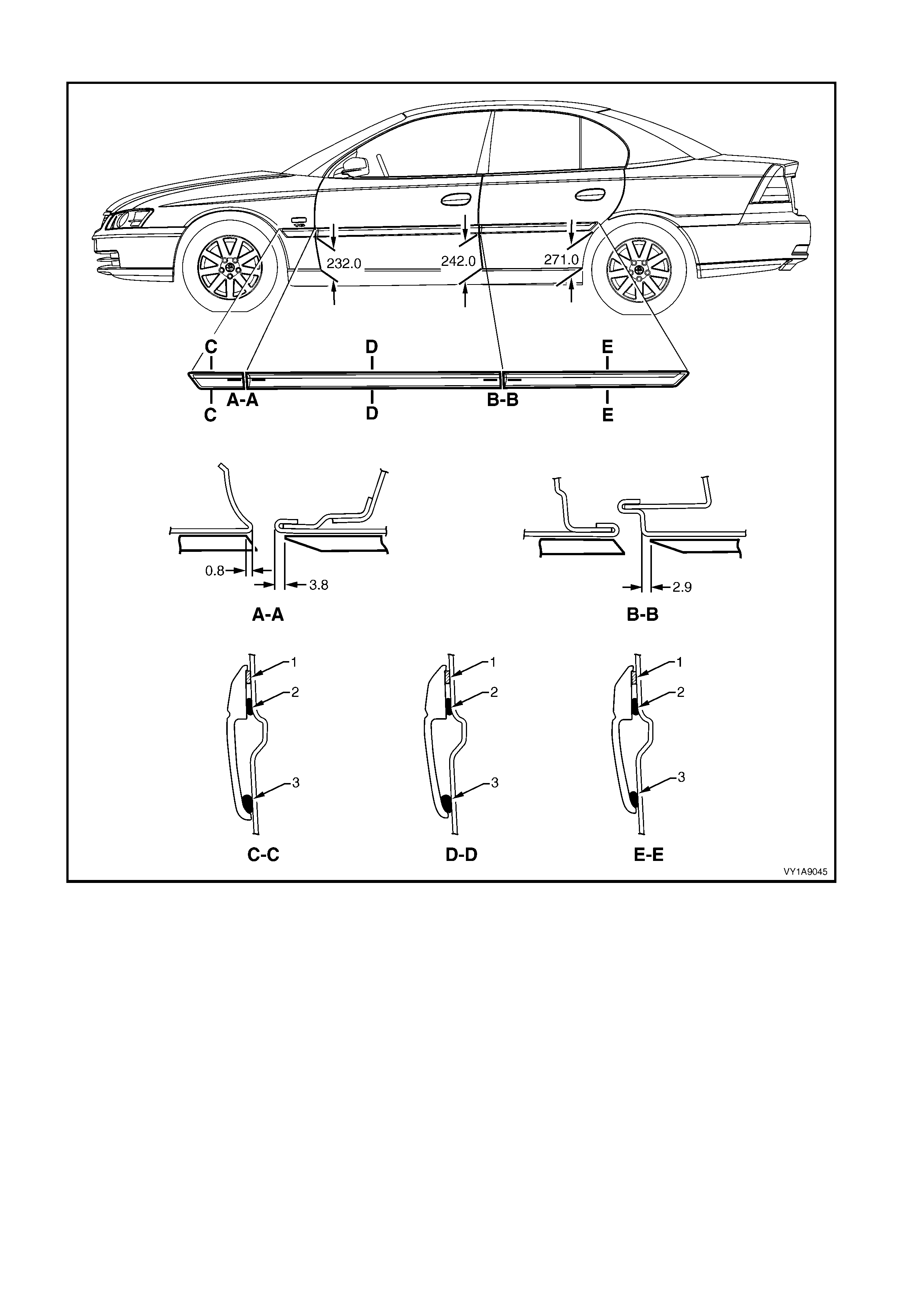
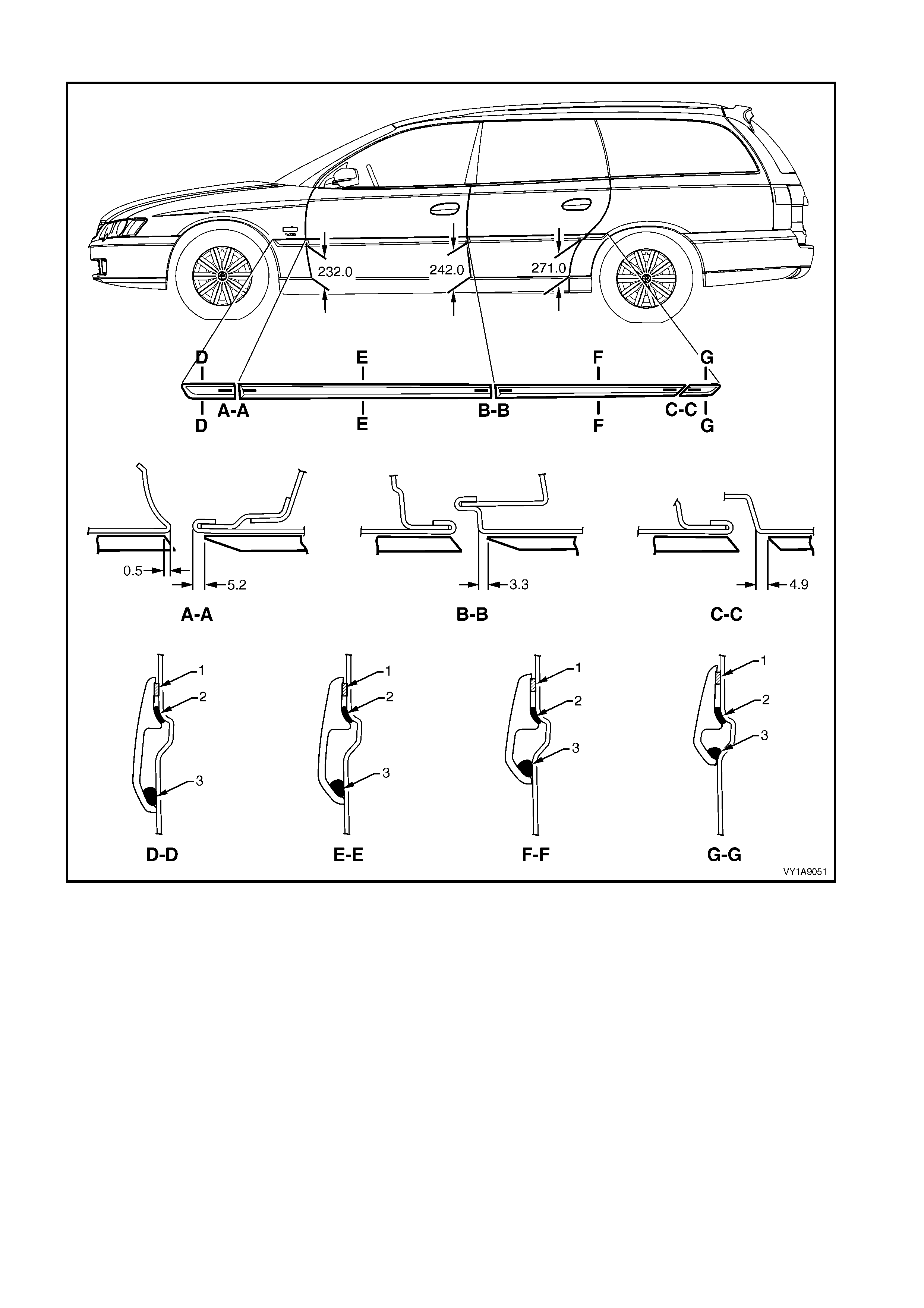
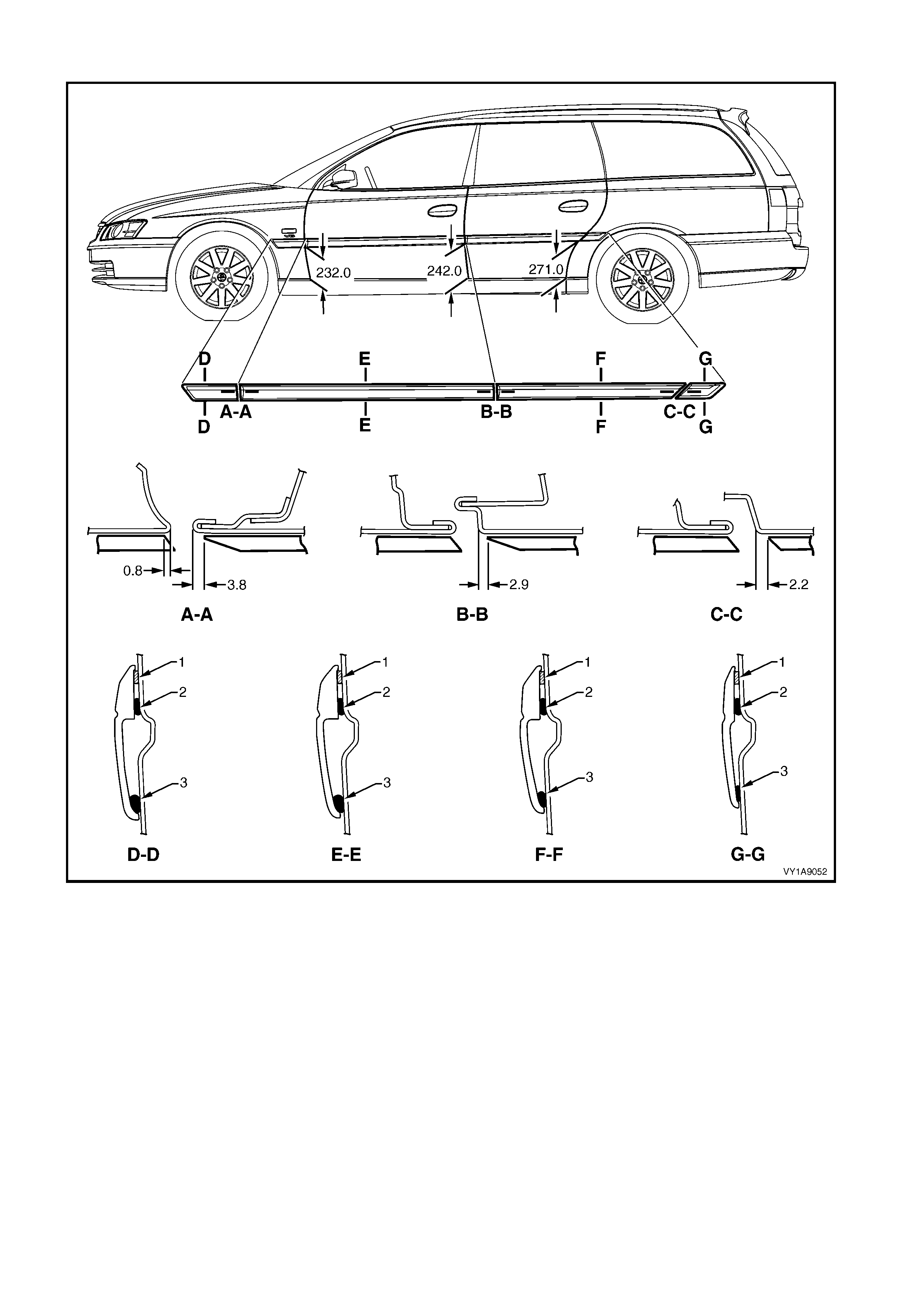
Refer to Figure 1A9-42 for Executive, Acclaim , SS or Lumina LS vehicles, Figure 1A9-43 for Berlina or Lum ina
LTZ vehicles or to Figure 1A9-44 for Calais or Omega CD vehicles.
1. Place a mark on the rear edge of the fender and/or door panels at the three points shown in the relevant
Figure as required. Measure in a straight line from the lower edge of each panel:
2. If a complete moulding set is to be f itted, or as r equir ed, apply a length of mas king tape along the side of the
vehicle, level with the marks. Begin by affixing the tape at the rear of the rear door, hold it taut and away
from the vehicle, and affix it to each panel. Ensure it is straight and then smooth it down along its length.
3. If reusing the moulding, apply new acrylic double-sided tape (1) such as 3M 5344 or equivalent along the
back of the moulding.
4. Apply a 3.0 m m diam eter bead of urethane adhesive such as Expandite Betaseal 554.02, Sikaflex Drive or
equivalent over the entire length of moulding (2) and for 50mm in several places (3).
NOTE: Refer to any further directions supplied with the urethane adhesive.
5. Affix the moulding to the vehicle in the correct positions, aligning the lower edge with the masking tape (if
fitted) and:
• For the fender moulding begin at the rear edge of the fender, aligning to the dimension at Section A-A.
• For the f ront door moulding begin at the fr ont edge of the f r ont door, aligning to the dimension at Section
A-A.
• For the rear door moulding begin at the f ront edge of the rear door, aligning to the dim ension at Section
B-B.
6. Press firmly over the length of the moulding(s) at the double-sided tape to ensure maximum adhesion.
EXECUTIVE, ACCLAIM, SS, LUMINA LS
Figure 1A9-42
BERLINA, LUMINA LTZ
Figure 1A9-43
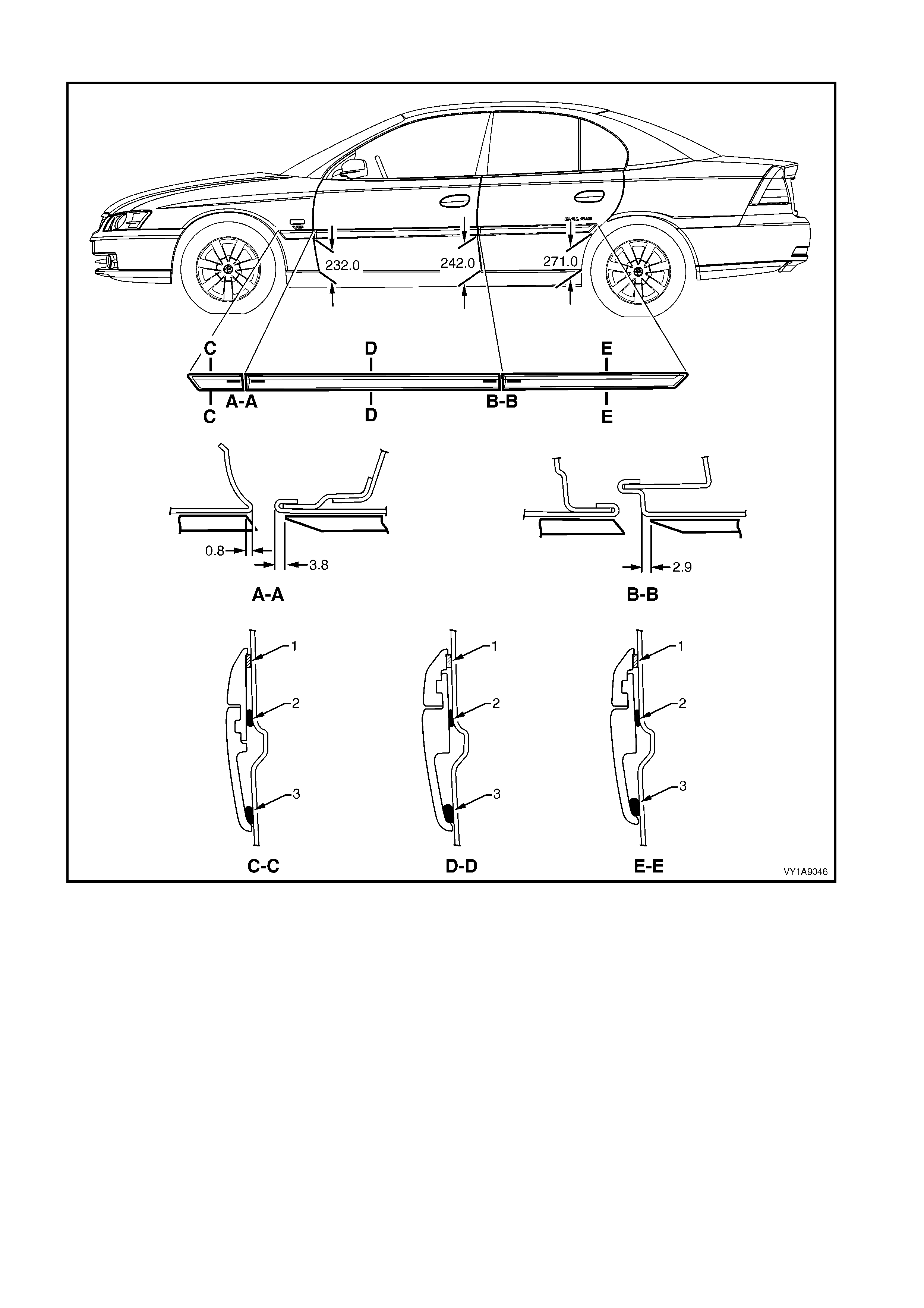
CALAIS, OMEGA CD
Figure 1A9-44
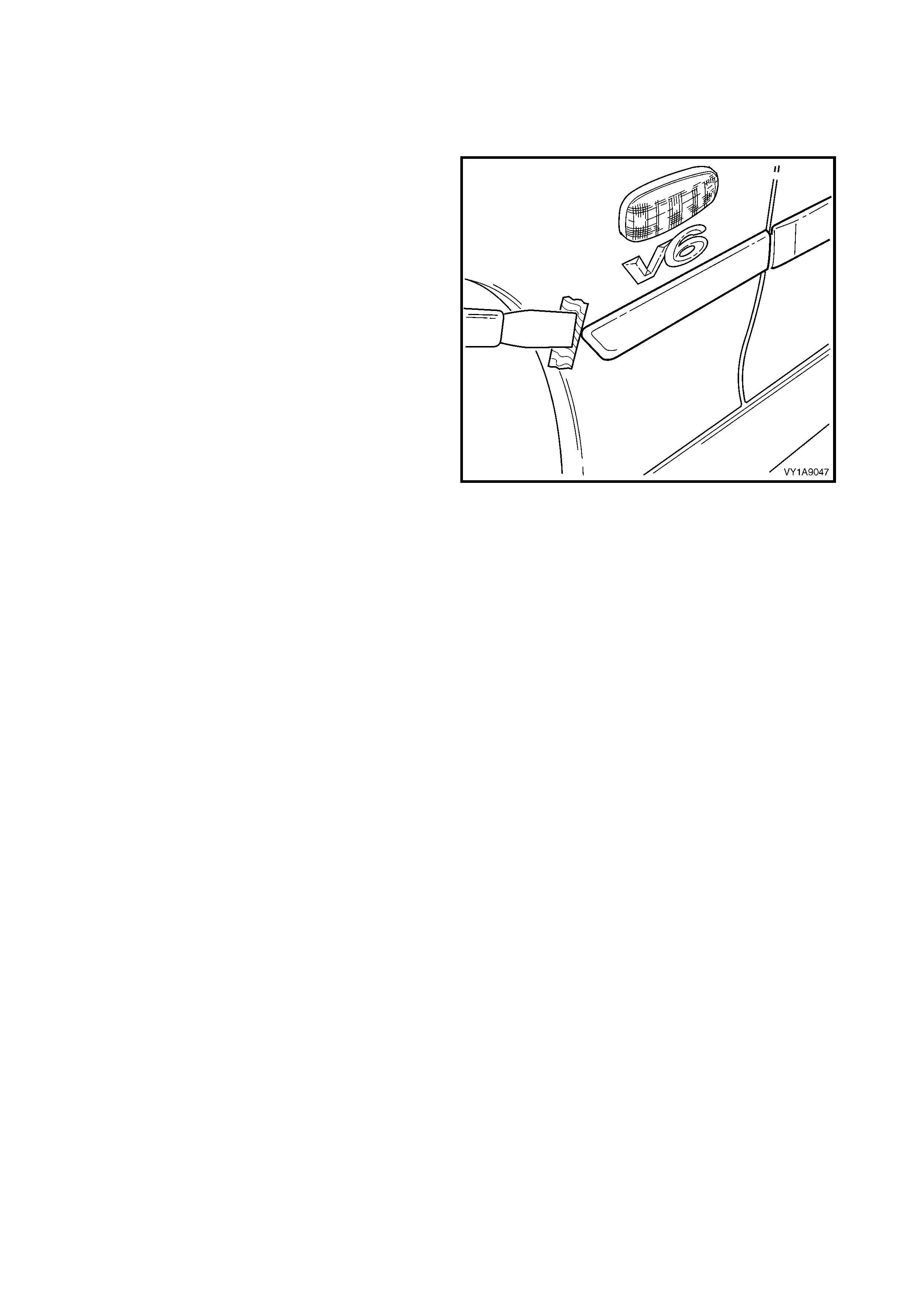
2.12 ROCKER PANEL MOULDING ASSEMBLY
LT Section No. – 10-300
REMOVE
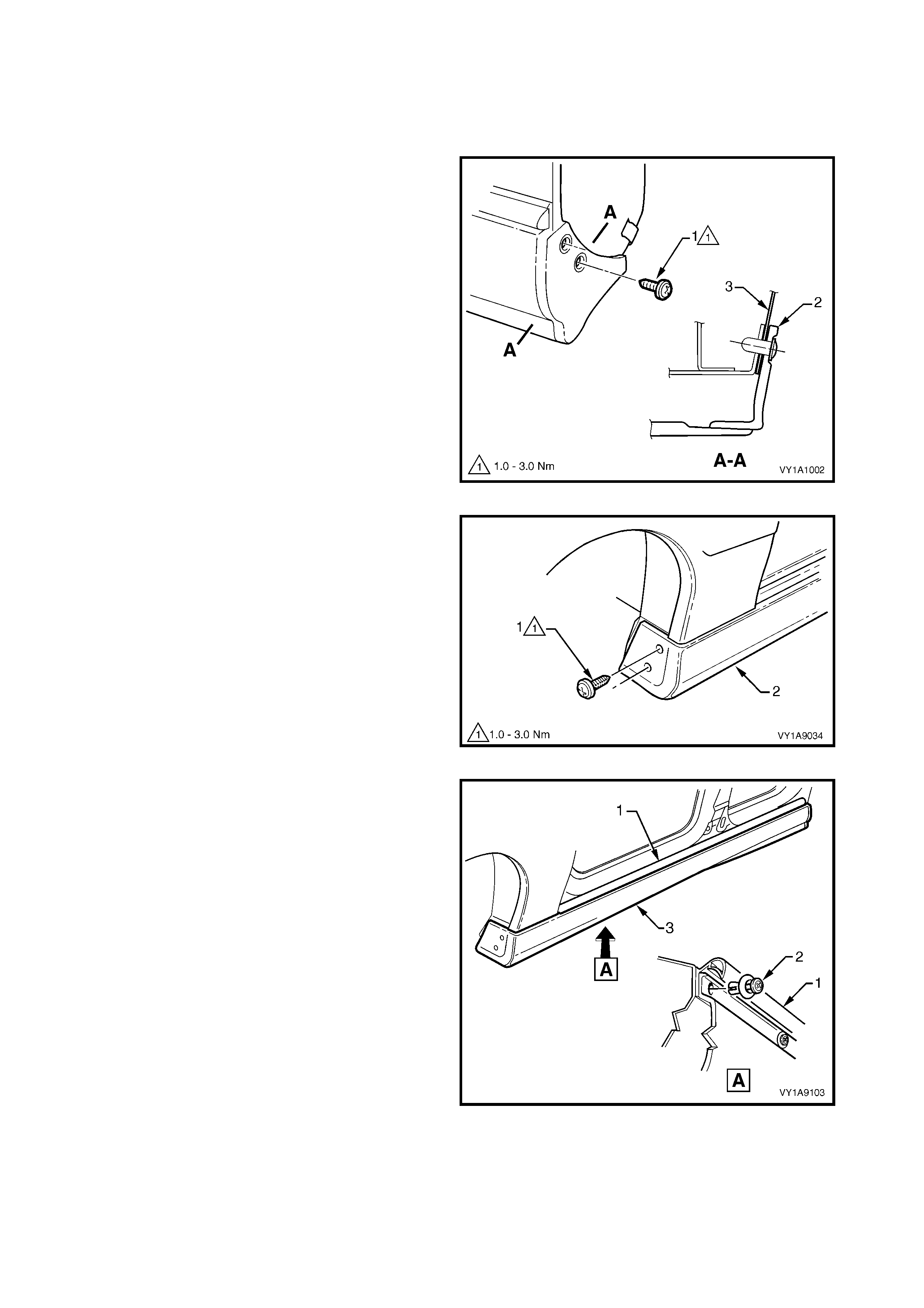
1. Remove the screw (1), two places, attaching the
rear rocker panel moulding (2) and wheelhouse
liner (3 ).
NOTE: If required, the r ear rocker panel moulding can
be removed at this stage by sliding it rearward from the
front rocker panel moulding.
Figure 1A9-45
2. Remove the screw (1), two places, attaching the
front rocker panel moulding (2) to the fender and
liner.
Figure 1A9-46
3. Lift up the rocker panel weatherstrip (1) to gain
access and remove the retainer (2), nine places,
attaching the rocker panel moulding (3).
4. From underneath the vehicle, refer to Figure 1A9-
48:
• For earlier build vehicles f itted with the retainer
(1), beginning at one end of the moulding (2),
use a flat blade screwdriver to spread the
retainer apart slightly while holding outward
pressure on the moulding, disengaging it from
the retainer.
• For later build vehicles fitted with the screw
arrangement, remove the screw (3), six
places, from the retainer under the moulding
(4).
5. Remove the moulding.
6. If required, prise the nut (5), two places, from the
fender.
Figure 1A9-47
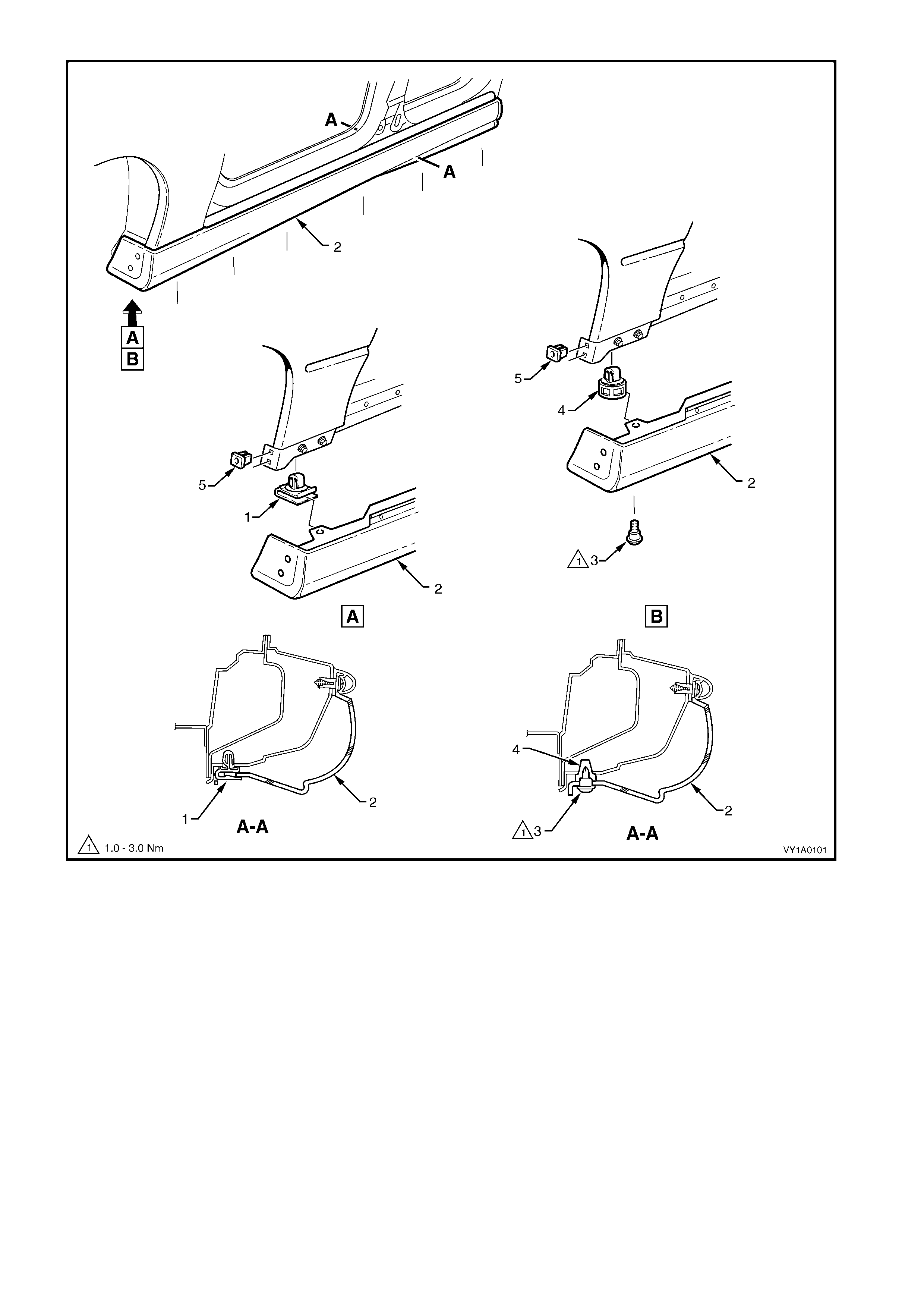
Figure 1A9-48
7. If required:
• For earlier build vehicles , remove the retainer ( 1), s ix plac es , by gently levering out f r om the body, tak ing
care not to damage paint work, refer to View A, Figure 1A9-49.
• For later build vehicles, remove the retainer (2), six places, by gently levering out from the body, taking
care not to damage paint work, refer to View B, Figure 1A9-49.
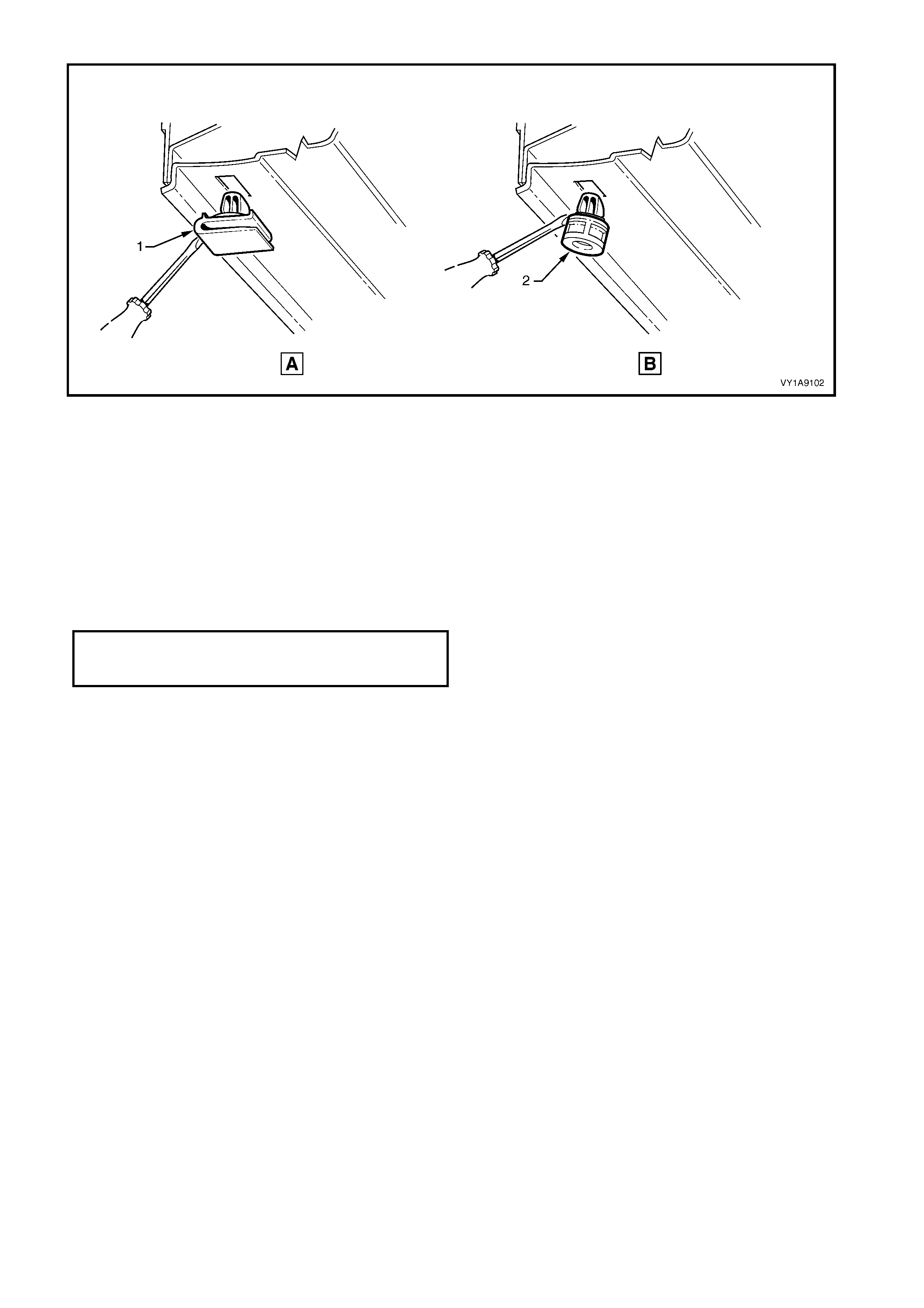
Figure 1A9-49
REINSTALL
Reinstallation of the rocker panel front and rear
mouldings is the reverse of the removal operation
noting the following.
1. Ensure the front moulding is c or re ctly seated in the
retaining clips.
2. Tighten all fasteners to the correct torque
specification.
3. Ensure the weatherstrip is seated correctly.
ROCKER PANEL MOULDING
ATTACHING SCREW
TORQUE SPE CIFICATI ON 1.0 – 3.0 Nm
3. SERVICE OPERATIONS, WAGON
3.1 RADIATOR GRILLE EMBLEM
LT Section No. – 10-150
REMOVE
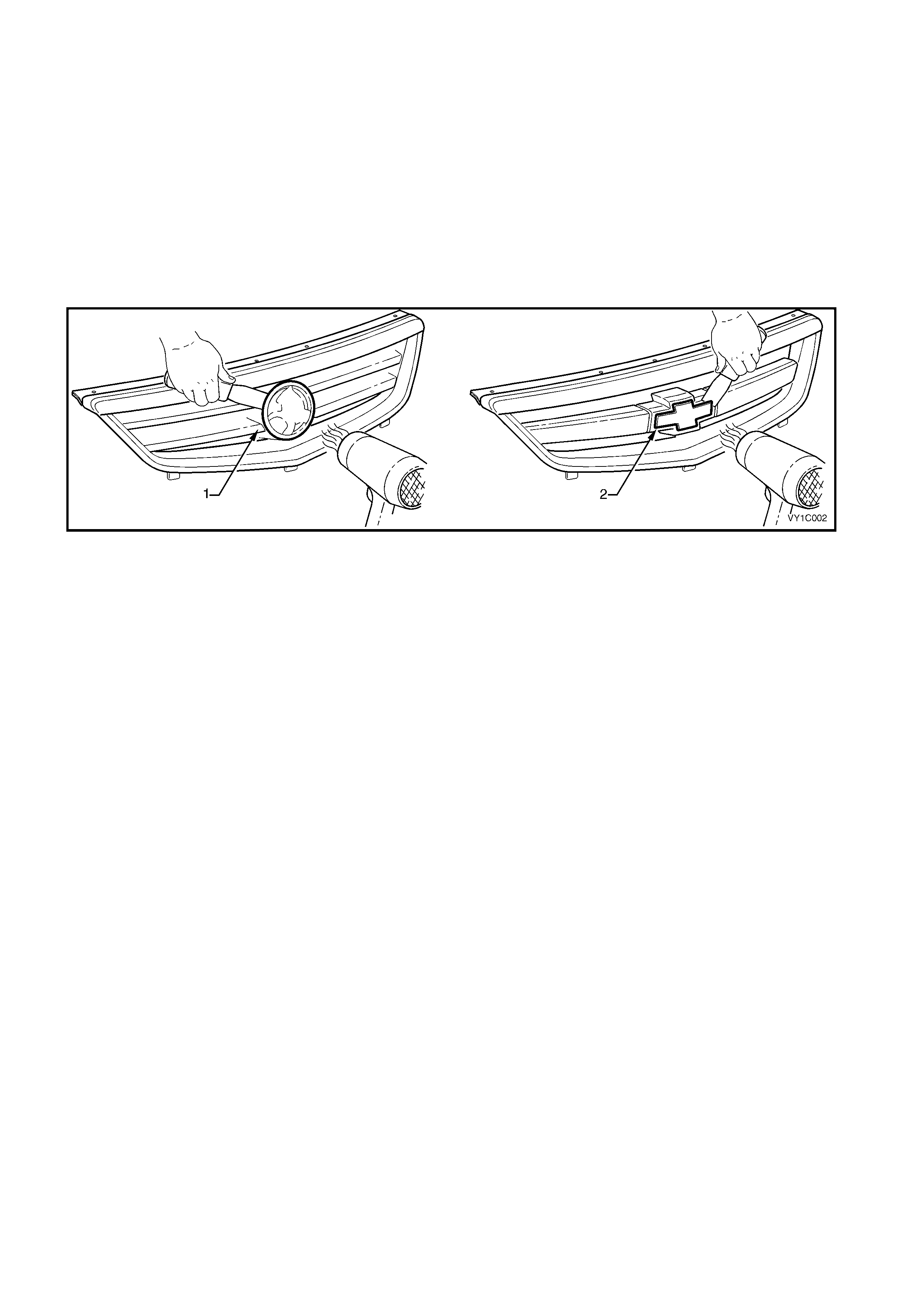
1. To assist removal, warm the emblem with a heat-lamp or heat-gun to soften the adhesive.
2. Using a knife or paint scraper, carefully remove the emblem assembly (1–domestic or 2–export) from the
grille assembly, cutting the double-sided tape, refer to Figure 1A9-49.
NOTE: The domestic emblem has two locating lugs which must not be cut if the emblem is to be reused.
3. Remove any remaining double-sided tape as required.
Figure 1A9-49
REINSTALL
1. If reinstalling the existing emblem, remove the existing double-sided tape and clean the surface with wax
and grease remover such as Prepsol or equivalent. Apply new polyethylene double-sided tape such as 3M
4428 or equivalent.
2. Clean the surface of the grille assembly with wax and grease remover such as Prepsol or equivalent.
3. Remove the backing paper from the double-sided tape.
4. Align the emblem. For domestic vehicles, locate the lugs with their corresponding holes in the grille
assembly. For export vehicles, align the emblem within its recess in the grille assembly.
5. Affix the emblem and press firmly over the entire emblem for at least 10 seconds to ensure sound adhesion.
3.2 FENDER NAME PL ATE
LT Section No. – 10-150
REMOVE
1. Protect the paint and bodywork with tape or a rag.
2. To assist removal, warm the plate with a heat-
lamp or heat-gun to soften the adhesive.
3. Using a paint s craper or sim ilar, caref ully pris e the
plate from the fender.
4. Remove any remaining double- sided tape from the
plate and/or fender and clean the surfaces with
Prepsol or equivalent.
Figure 1A9-50
REINSTALL
1. If reusing the plate, apply new polyethylene double-sided tape such as 3M 4428 or equivalent to the back
and trim the edges of the tape slightly in from the edge of plate.
2. Clean the fender surface with Prepsol or equivalent.
3. Remove the backing paper from the double-sided tape.
4. Apply the plate in the position shown, measuring from the front side turn signal lamp hole, refer to Figure
1A9-51. Ensure it is positioned parallel to the body side moulding.
5. Press firmly over the entire plate for at least 10 seconds to ensure maximum adhesion.
Figure 1A9-51
3.3 LIFTGATE EMBLEM
LT Section No. – 10-150
HOLDEN, CHEVROLET
REMOVE
1. Protect the paint and bodywork with tape or a rag.
2. To assist removal, warm the emblem with a heat-
lamp or heat-gun to soften the adhesive.
3. Using a paint s craper or sim ilar, caref ully pris e the
emblem from the liftgate.
NOTE: The emblem has two locating pins, take care
not to break them if the emblem is to be reused.
4. As required, remove any remaining double-sided
tape from the em blem and/or liftgate and c lean the
surfaces with Prepsol or equivalent.
Figure 1A9-52
REINSTALL
1. If reusing the emblem, apply new polyethylene
double-sided tape such as 3M 4428 or equivalent
to the back and the trim edges of the tape slightly
in from the edge of the emblem.
2. Clean the panel surface with Prepsol or equivalent.
3. Remove the backing paper from the double-sided
tape.
4. Apply the emblem in the position shown ensuring
the locating pins are correctly orientated with the
locating holes in the panel surface.
5. Press firm ly over the entire emblem for at leas t 10
seconds to ensure maximum adhesion.
Figure 1A9-53
3.4 LIFTGATE NAME PLATE, LH
LT Section No. – 10-150
COMMODORE, CHEVROLET
REMOVE
1. Protect the paint and bodywork with tape or a rag.
2. To assist removal, warm the emblem with a heat-
lamp or heat-gun to soften the adhesive.
3. Using a paint s craper or sim ilar, caref ully pris e the
emblem from the liftgate.
4. As required, remove any remaining double-sided
tape from the name plate and/or liftgate and clean
the surfaces with Prepsol or equivalent.
Figure 1A9-54
REINSTALL
1. If reusing the name plate, apply new polyethylene double-sided tape such as 3M 4428 or equivalent to the
back and the trim edges of the tape slightly in from the edge of the name plate.
2. Clean the panel surface with Prepsol or equivalent.
3. Remove the backing paper from the double-sided tape.
4. Apply the name plate onto the left- hand s ide of the lif tgate in the position s hown, ensur ing it is s tr aight and is
correctly aligned to the measurements, refer to Figure 1A9-55.
5. Press firmly over the entire plate for at least 10 seconds to ensure maximum adhesion.
Figure 1A9-55
3.5 LIFTGATE NAME PLATE, RH
LT Section No. – 10-150
EXECUTIVE, ACCLAIM, BERLINA, LUMINA LS
REMOVE
1. Protect the paint and bodywork with tape or a rag.
2. To assist removal, warm the name plate with a
heat-lamp or heat-gun to soften the adhesive.
3. Using a paint s craper or sim ilar, caref ully pris e the
name plate from the liftgate.
4. As required, remove any remaining double-sided
tape from the name plate and/or liftgate and clean
the surfaces with Prepsol or equivalent.
Figure 1A9-56
REINSTALL
1. If reusing the name plate, apply new polyethylene double-sided tape such as 3M 4428 or equivalent to the
back and the trim edges of the tape slightly in from the edge of the name plate.
2. Clean the panel surface with Prepsol or equivalent.
3. Remove the backing paper from the double-sided tape.
4. Apply the name plate onto the right-hand s ide of the liftgate in the position s hown, ensuring it is straight and
is correctly aligned to the measurements, refer to Figure 1A9-57.
5. Press firmly over the entire plate for at least 10 seconds to ensure maximum adhesion.
6. Where required remove the plastic carrier.
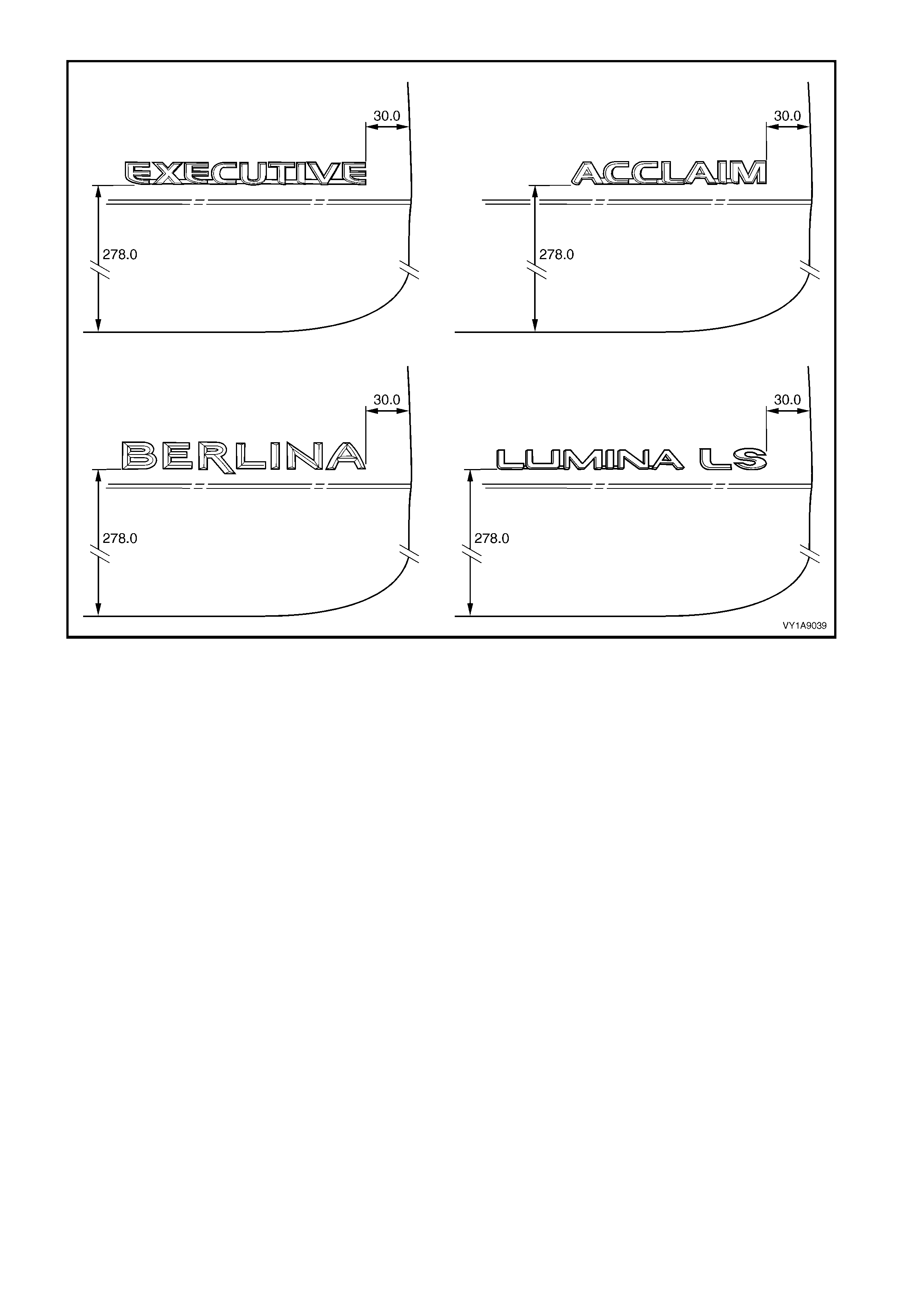
Figure 1A9-57

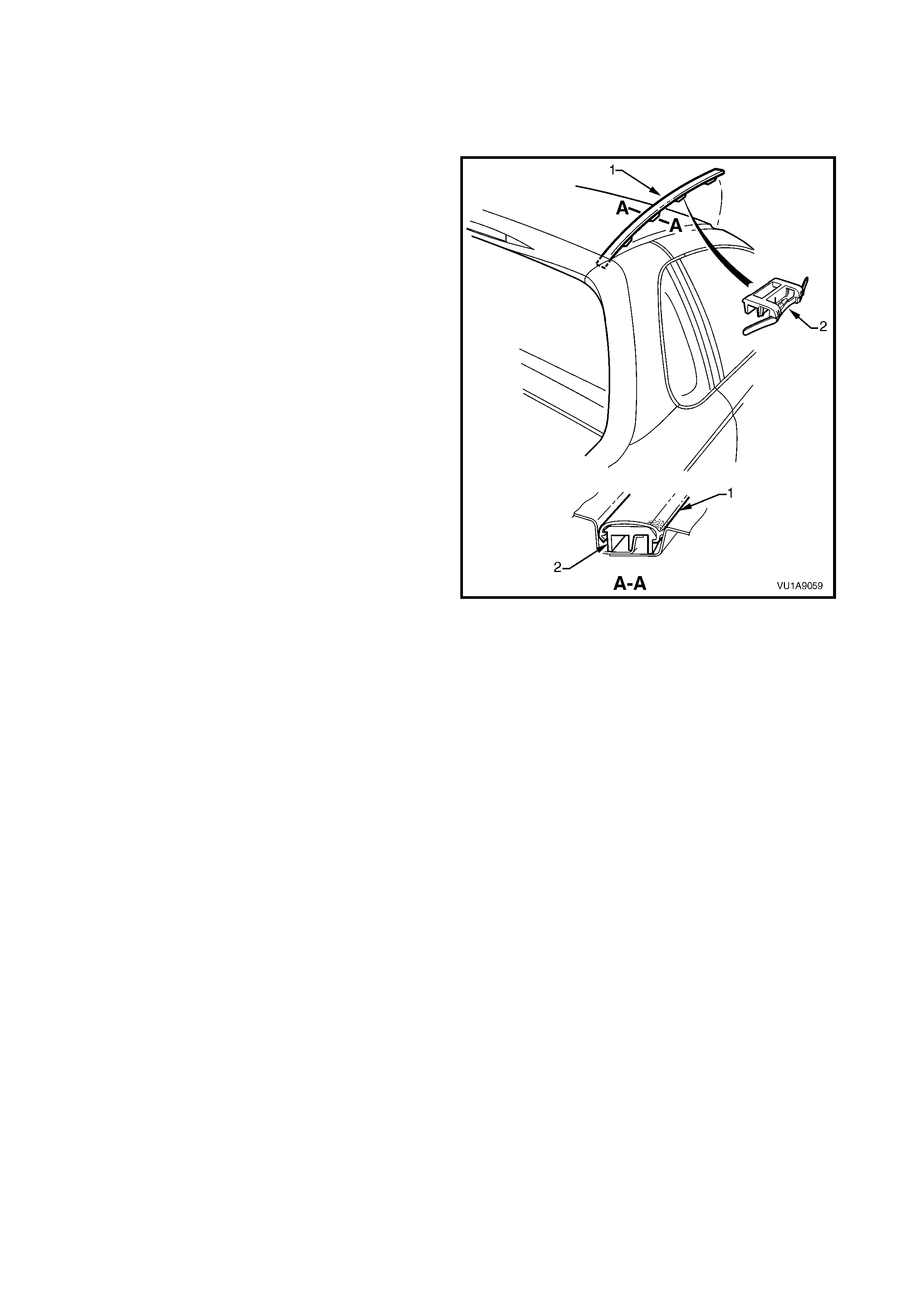
3.6 ROOF JOINT MOULDING
LT Section No. – 10-250
REMOVE
1. Beginning at the front of the vehicle, use a
screwdriver to carefully prise the roof joint
moulding (1) from the roof channel, disengaging
the retaining clips (2), three places.
IMPORTANT: Take care as the retaining clips can
easily break. Protect the paintwork with a shop rag.
2. Slide the joint moulding from under the roof side
rail and remove.
Figure 1A9-58
REINSTALL
1. As required, seat the three retainers onto the roof
joint moulding, evenly spaced.
2. Slide the moulding under the roof side rail.
3. Seat the moulding in the roof channel and
beginning at the rear, clip it in place.
4. At the f ront, ensure the m oulding is installed under
the windshield moulding cover.
3.7 ROOF BARS
LT Section No. – AA-005
REMOVE
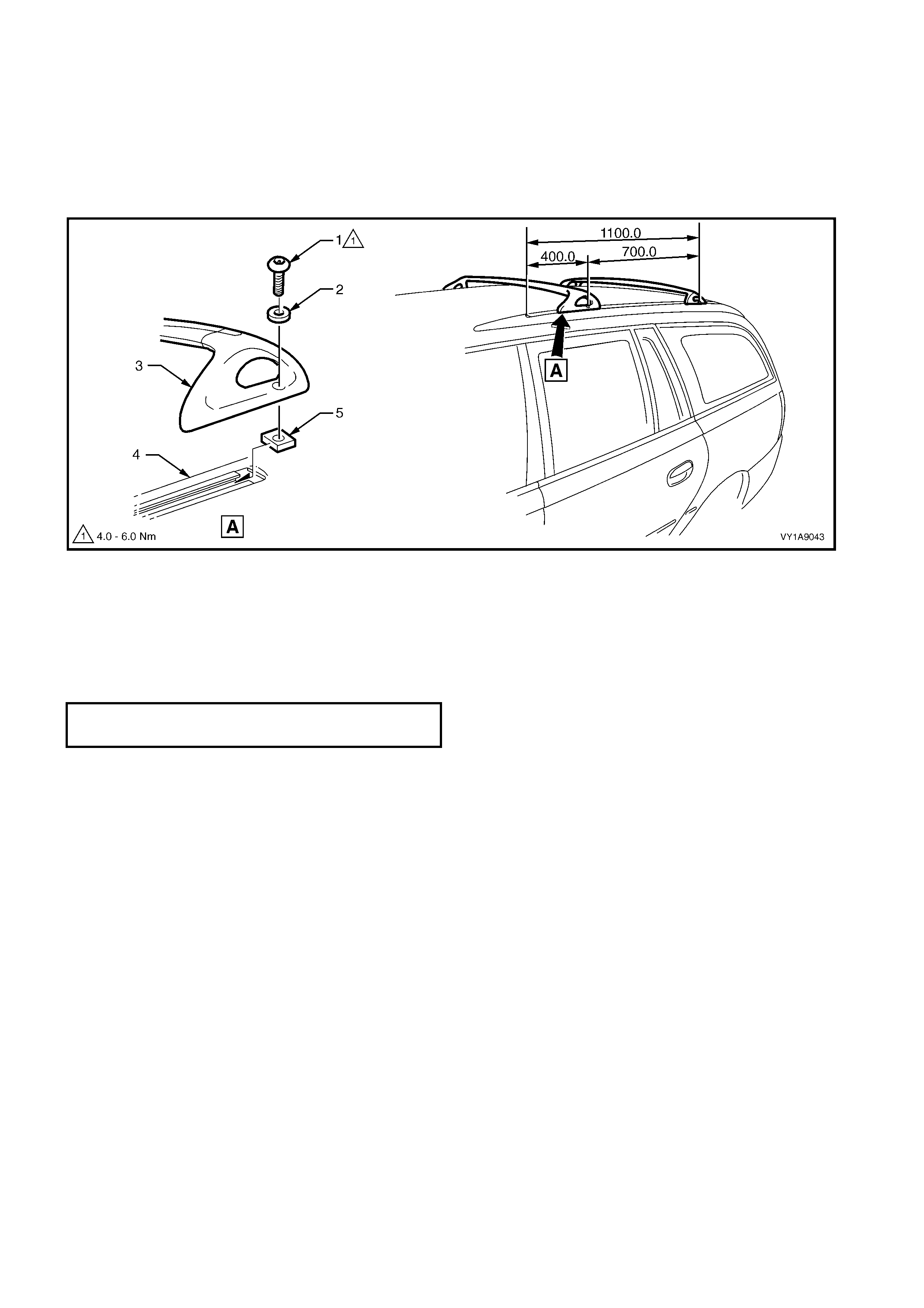
1. Using the key tool (supplied with vehicle) or an appropriate Allen key, loosen and remove the two locking
screws (1) and washers (2) securing each roof bar (3) to the roof side rail (4), refer to Figure 1A9-59.
2. If required, slide the roof bar securing nuts (5) out of the rear of the roof side rail.
Figure 1A9-59
REINSTALL
Reinstallation of the roof bars is the reverse of the removal procedure, noting the following:
1. Position the roof bars in the production standard position as shown, refer to Figure 1A9-59.
2. Tighten the fasteners to the correct torque specification.
ROOF BAR ATTACHING SCREW
TORQUE SPECIFICATION 4.0 – 6.0 Nm

3.8 ROOF SIDE RAILS
LT Section No. – 10-250
REMOVE
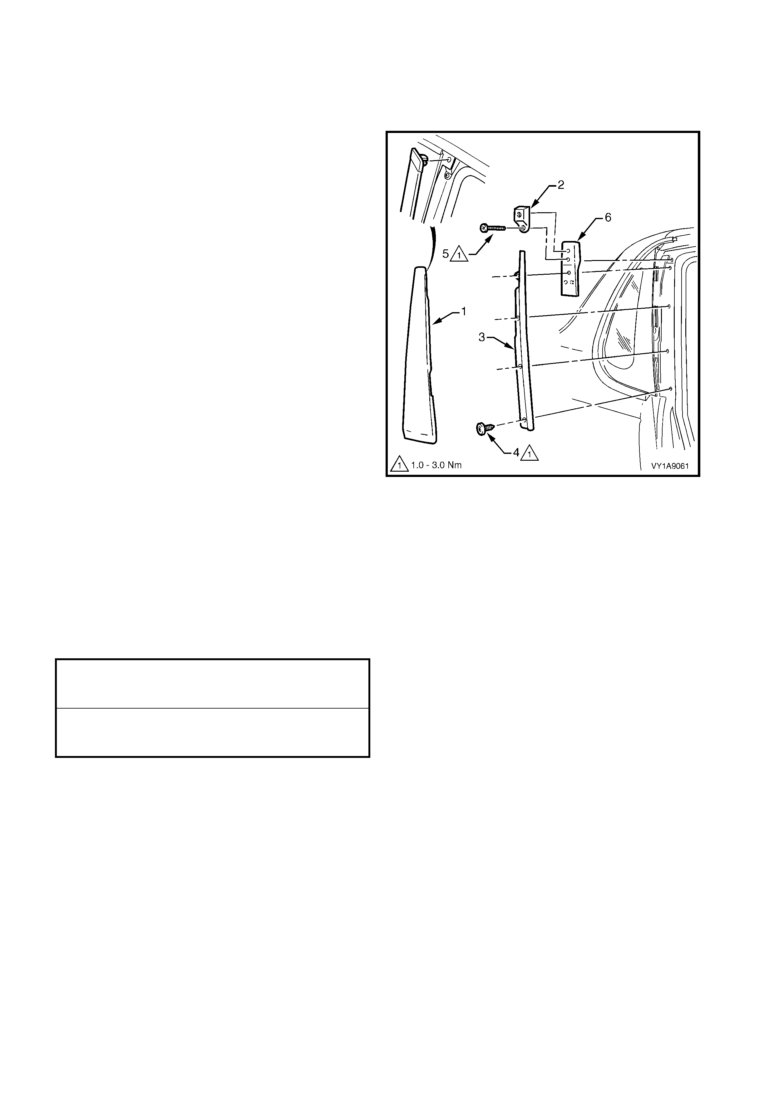
1. Remove the headlining from the vehicle, refer to
Section 1A8, HEADLINING.
2. Rem ove the nut (1), f our places, attaching the roof
side rail (2) to the roof panel.
3. Remove the roof side rail up until the studs are
free and then slide the rail rearward.
Figure 1A9-60
REINSTALL
Reinstallation of the roof side rail is the reverse of the
removal procedure, noting the following:
1. Ensure the foam seal (3) is not damaged and is
correctly seated and that the O-ring seals (4) are
fitted to each of the studs, refer to Figure 1A9-60.
2. Tighten the nuts to the specified torque.
ROOF SIDE RAIL ATTACHING
NUT TORQUE SPECIFICATION 10.0 – 12.0 Nm
3.9 DOOR OPENING MOULDING
LT Section No. – 10-250
REMOVE
1. Open the fr ont and rear doors on the relevant side
of the vehicle.
2. Beginning at each end and working towards the
middle, rem ove the s crew (1), 11 plac es, attaching
the door opening moulding (2) to the body.
3. Carefully remove the moulding, disengaging the
quarter window assembly tab (3).
Figure 1A9-61
REINSTALL
Reinstallation is the reverse of the removal. When
installing the screws, begin at the rear and work
forward.
NOTE: The screws are encapsulated with a wax
sealer. It is r ecom mended that the sc rews be replaced
once removed, however if this is impractical, apply a
small amount of sealer to the end of the thread.
Tighten the screws to the specified torque.
DOOR OPENING MOULDING
ATTACHING SCREW
TORQUE SPECIFICATION 1.0 – 2.0 Nm

3.10 CENTRE PILLAR UPPER FINISHER ASSEMBLY
LT Section No. – 10-250
REMOVE
1. Open front and rear doors on relevant side of the
vehicle.
2. Gently prise top of centre pillar upper finisher (1)
out to disengage it from the centre pillar upper
finisher retainer (2).
3. Holding the top of finisher out, slide it down the
centre pillar outer sealing strips (3) until it rests on
rear door hinge.
4. Manoeuvre the finisher f rom the s ealing strips and
remove.
Figure 1A9-62
5. Remove the screw (1), seven places, sec uring the
centre pillar sealing strips (2) to the pillar and
remove the strips.
6. Partially rem ove the door fram e opening moulding,
refer to 3.9 DOOR OPENING MOULDING in this
Section.
7. Remove centre pillar upper trim panel (3) by
pulling away from the pillar.
8. Remove the screw (4) securing the centre pillar
upper finisher retainer (5) and centre pillar upper
trim mount plate (6) to the pillar and remove.
Figure 1A9-63
REINSTALL
Reinstallation of the centre pillar upper finisher
assembly is the reverse of the removal procedure,
noting the following:
1. Ensure the centre pillar upper trim panel is seated
correctly under door opening weatherstrips.
2. Ensure all fasteners are tightened to the correct
torque specification.
3. Slide the centre pillar upper f inisher up and press it
in at the top to engage into the retaining clip.
CENTRE PILLAR UPPER FINISHER
RETAINER ATTACHING SCREW
TORQUE SPECIFICATION 1.0 – 3.0 Nm
CENTRE PILLAR SEALING STRIP
ATTACHING SCREW
TORQUE SPECIFICATION 1.0 – 3.0 Nm
3.11 ROOF JOINT FINISHER
LT Section No. –
As required, first remove the following components:
1. Roof side rails, refer to 3.8 ROOF SIDE RAILS.
2. Door opening moulding, refer to 3.9 DOOR OPENING MOULDING.
REMOVE
1. Car efully cut the adhesive (1) attac hing the roof joint f inisher (2) , while prising the top of the finis her (3) f rom
the vehicle, refer to Figure 1A9-64.
2. Clean off any residual adhesive as required.
Figure 1A9-64
REINSTALL
1. The surface is to be clean and painted.
2. Apply an 8 m m bead of urethane adhesive such as Expandite Betaseal 554.02, Sik aflex Drive or equivalent
(4) along the back of the moulding, between the ribs.
3. Fit the finisher, ensuring the outer surface is flush with the panel surfaces and the side gaps are even.
4. If required, temporarily secure finisher with tape.
5. Allow adhesive to cure overnight.

3.12 BODY SIDE MOULDINGS
LT Section No. – 10-250
REMOVE
1. Protect the paint and bodywork with tape or a rag.
2. Using a paint scraper or similar, begin at one end
and carefully prise the moulding from the panel,
cutting through the double sided tape and
adhesive.
NOTE: As an alternative, carefully use a length of
piano wire to cut the adhesive in a similar way to
removing a windshield.
3. As required, remove any remaining double-sided
tape and adhesive from the moulding and/or panel.
Clean the surfaces with Prepsol or equivalent.
Figure 1A9-65
REINSTALL
Refer to Figure 1A9-66 for Executive, Acclaim or Lumina LS vehicles or to Figure 1A9-67 for Berlina vehicles.
1. Place a mark on the rear edge of the fender and/or door panels at the three points shown in the relevant
Figure as required. Measure in a straight line from the lower edge of each panel:
2. If a complete moulding set is to be f itted, or as r equir ed, apply a length of mas king tape along the side of the
vehicle, level with the marks. Begin by affixing the tape at the rear of the rear door, hold it taut and away
from the vehicle, and affix it to each panel. Ensure it is straight and then smooth it down along its length.
3. If reusing the moulding, apply new acrylic double-sided tape (1) such as 3M 5344 along the back of the
moulding.
4. Apply a 3.0 m m diam eter bead of urethane adhesive such as Expandite Betaseal 554.02, Sikaflex Drive or
equivalent over the entire length of moulding (2) and for 50mm in several places (3).
NOTE: Refer to any further directions supplied with the urethane adhesive.
5. Affix the moulding to the vehicle in the correct positions, aligning the lower edge with the masking tape (if
fitted) and:
• For the fender moulding begin at the rear edge aligning to the dimension at Section A-A.
• For the f ront door moulding begin at the fr ont edge of the f r ont door, aligning to the dimension at Section
A-A.
• For the rear door moulding begin at the f ront edge of the rear door, aligning to the dim ension at Section
B-B.
• For the quarter panel m oulding begin at the f ront edge of the quarter panel, aligning to the dim ension at
Section C-C.
6. Press firmly over the length of the moulding(s) at the double-sided tape to ensure maximum adhesion.
EXECUTIVE, ACCLAIM, LUMINA LS
Figure 1A9-66
BERLINA
Figure 1A9-67
3.13 ROCKER PANEL MOULDING ASSEMBLY
LT Section No. – 10-300
REMOVE
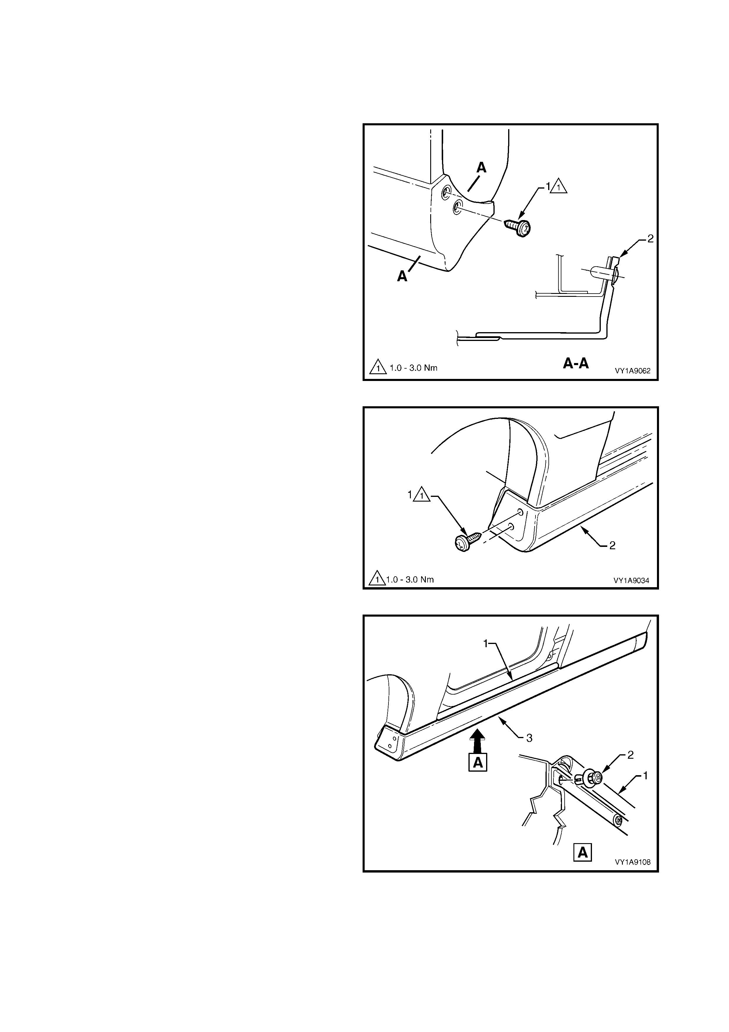
1. Remove the screw (1), two places, attaching the
rear rocker panel moulding (2) and wheelhouse
liner (3 ).
NOTE: If required, the r ear rocker panel moulding can
be removed at this stage by sliding it rearward from the
front rocker panel moulding.
Figure 1A9-69
2. Remove the two screw (1), two places, attaching
the front rocker panel moulding (2) to the fender
and liner.
Figure 1A9-70
3. Lift up the rocker panel weatherstrip (1) to gain
access and remove the retainer (2), nine places,
attaching the rocker panel moulding (3).
4. From underneath the vehicle, refer to Figure 1A9-
72:
• For earlier build vehicles f itted with the retainer
(1), beginning at one end of the moulding (2),
use a flat blade screwdriver to spread the
retainer apart slightly while holding outward
pressure on the moulding, disengaging it from
the retainer.
• For later build vehicles fitted with the screw
arrangement, remove the screw (3), seven
places, from the retainer under the moulding
(4).
5. Remove the moulding.
6. If required, prise the nut (5), two places, from the
fender.
Figure 1A9-71
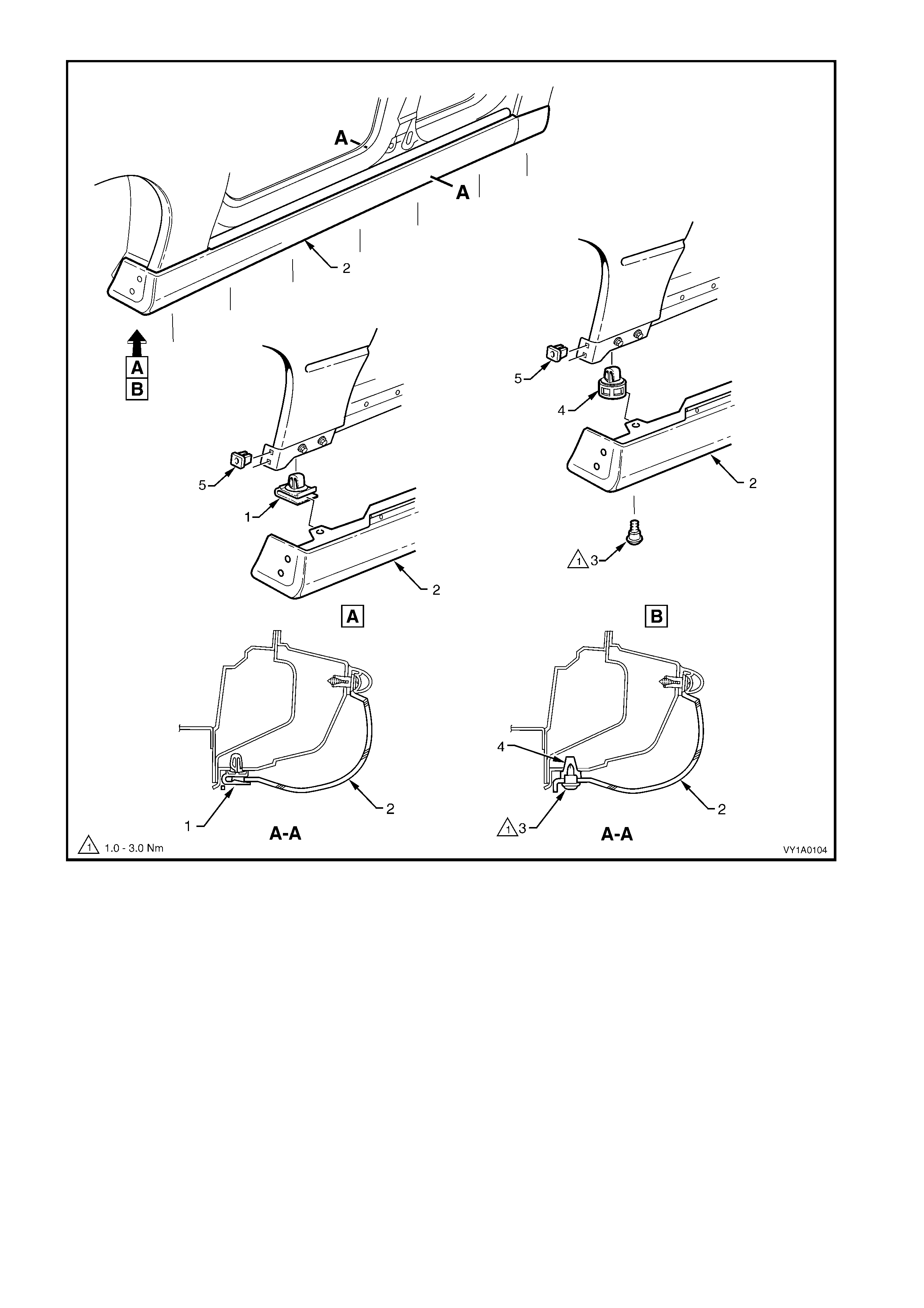
Figure 1A9-72
7. If required:
• For earlier build vehicles, remove the retainer (1), seven places, by gently levering out from the body,
taking care not to damage paint work, refer to View A, Figure 1A9-73.
• For later build vehicles, remove the retainer (2), seven places, by gently levering out from the body,
taking care not to damage paint work, refer to View B, Figure 1A9-73.
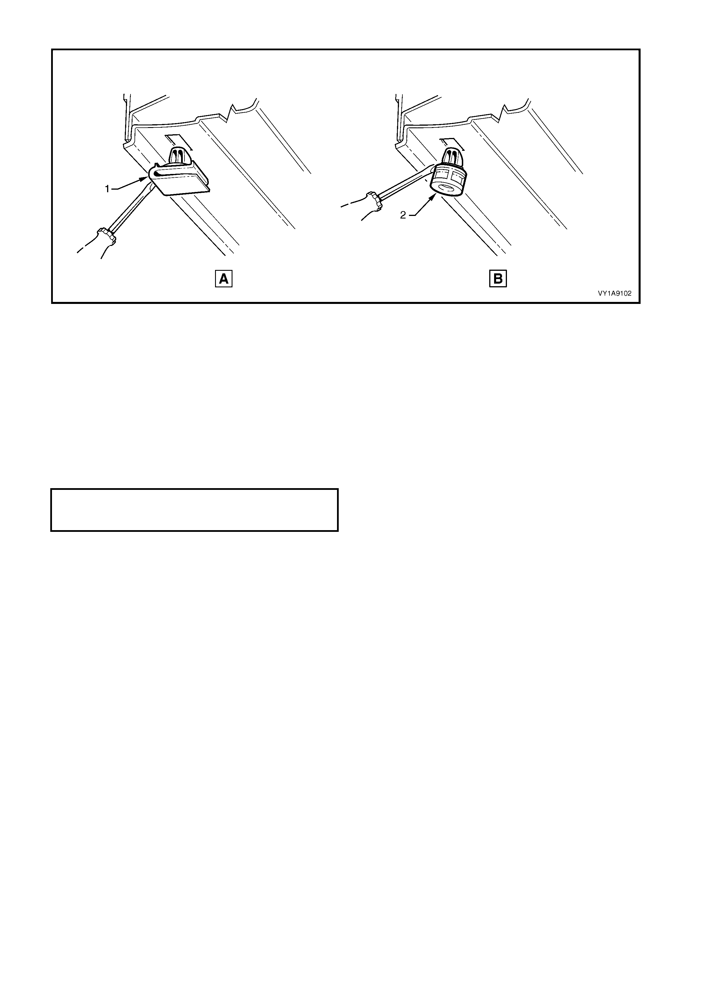
Figure 1A9-73
REINSTALL
Reinstallation of the rocker panel front and rear
mouldings is the reverse of the removal operation
noting the following.
1. Ensure the front moulding is c or re ctly seated in the
retaining clips.
2. Tighten all fasteners to the correct torque
specification.
3. Ensure the weatherstrip is seated correctly.
ROCKER PA NEL MOULDING
ATTACHING SCREW
TORQUE SPE CI FICATION 1.0 – 3.0 Nm
4. SERVICE OPERATIONS, UTILITY
4.1 RADIATOR GRILLE EMBLEM
LT Section No. – 10-150
NOTE: Export SS Utilities are not fitted with a radiator
grille emblem. For servicing of the radiator grille
escutcheon refer to Section 1C, 2.2 RADIATOR
GRILLE ASSEMBLY, S SEDAN & SS.
REMOVE
1. To assist removal, warm the emblem with a heat-
lamp or heat-gun to soften the adhesive.
2. Using a knife or paint scraper, carefully remove
the emblem as sem bly from grille as sem bly, cutting
the double-sided tape.
NOTE: The em blem has two locating lugs which must
not be cut if the emblem is to be reused.
3. Remove any remaining double-sided tape as
required.
Figure 1A9-72
REINSTALL
1. If reinstalling the existing emblem, remove the
existing double-sided tape and clean the surface
with wax and grease remover such as Prepsol or
equivalent. Apply new polyethylene double-sided
tape such as 3M 4428 or equivalent.
2. Clean the surface of the grille assembly with
Prepsol or equivalent.
3. Remove the backing paper from the double-sided
tape.
4. Align the emblem locating lugs with their
corresponding holes in the grille assembly and
affix the emblem.
5. Press firm ly over the entire emblem for at leas t 10
seconds to ensure maximum adhesion.

4.2 FENDER NAME PL ATE
LT Section No. – 10-150
REMOVE
1. Protect the paint and bodywork with tape or a rag.
2. To assist removal, warm the plate with a heat-
lamp or heat-gun to soften the adhesive.
3. Using a paint s craper or sim ilar, caref ully pris e the
plate required, remove any rem aining double-sided
tape from the plate and/or fender and clean the
surfaces with Prepsol or equivalent.
Figure 1A9-73
REINSTALL
1. If reusing the plate, apply new polyethylene double-sided tape such as 3M 4428 or equivalent to the back
and trim the edges of the tape slightly in from the edge of plate.
2. Clean the fender surface with Prepsol or equivalent.
3. Remove the backing paper from the double-sided tape.
4. Apply the plate in the position shown, measuring from the front side turn signal lamp hole, refer to Figure
1A9-74. Ensure it is positioned parallel to the style line.
5. Press firmly over the entire plate for at least 10 seconds to ensure maximum adhesion.
Figure 1A9-74
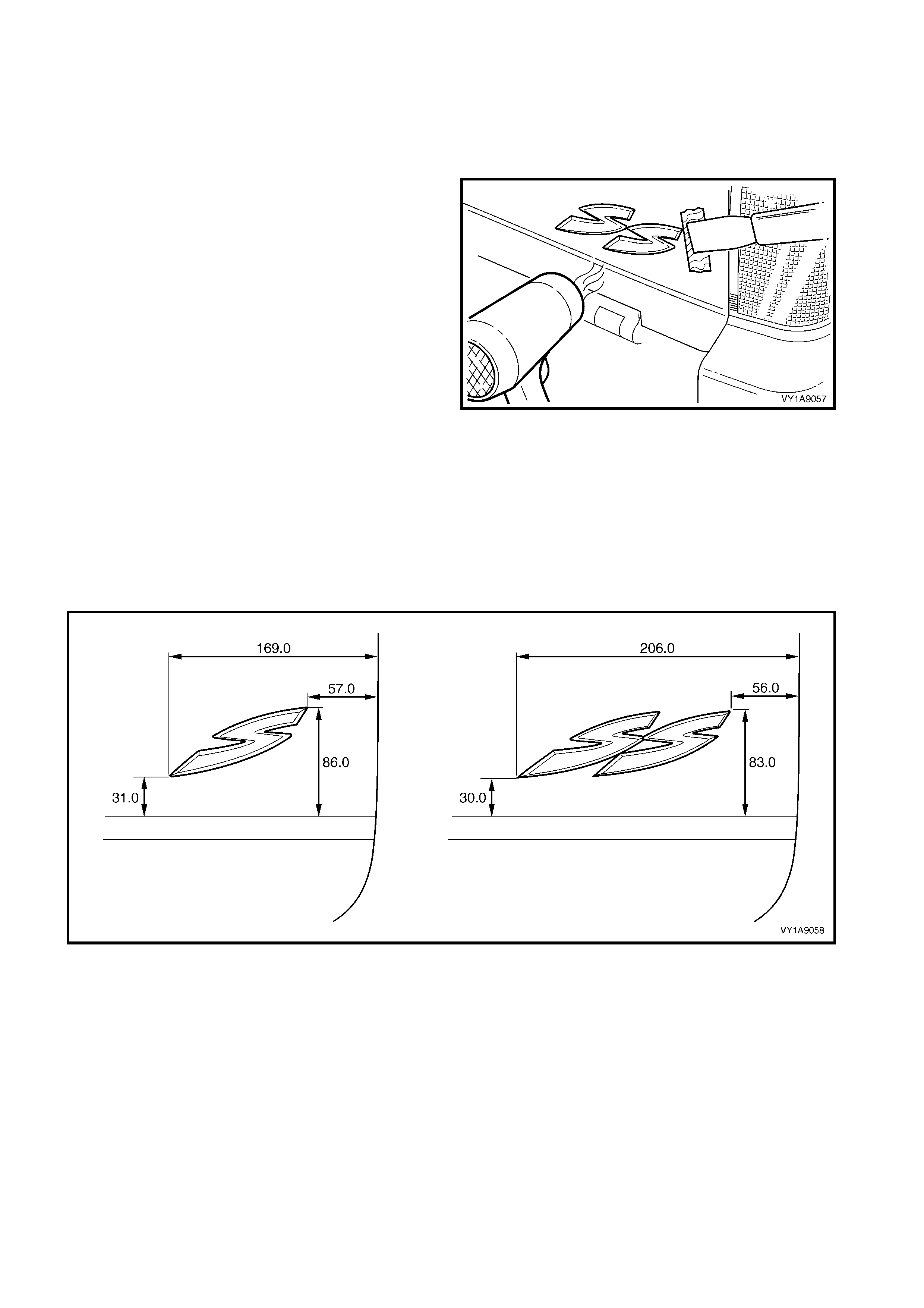
4.3 QUARTER PANEL NAME PLATE
LT Section No. – 10-150
SS
REMOVE
1. Protect the paint and bodywork with tape or a rag.
2. To assist removal, warm the name plate with a
heat-lamp or heat-gun to soften the adhesive.
3. Using a paint s craper or sim ilar, caref ully pris e the
name plate from the quarter panel.
4. As required, remove any remaining double-sided
tape f rom the nam e plate and/or quarter panel and
clean the surfaces with Prepsol or equivalent.
Figure 1A9-75
REINSTALL
1. If reusing the name plate, apply new polyethylene double-sided tape such as 3M 4428 or equivalent to the
back and the trim edges of the tape slightly in from the edge of the name plate.
2. Clean the quarter panel surface with Prepsol or equivalent.
3. Remove the backing paper from the double-sided tape.
4. Apply the nam e plate on to the lower section of the quarter panel in the position shown, meas uring up from
the lower edge of the quarter panel and in from the wheel arch, level with the lower edge of the plate, refer to
Figure 1A9-76.
5. Press firmly over the entire plate for at least 10 seconds to ensure maximum adhesion.
Figure 1A9-76
4.4 ENDGATE EMBLEM
LT Section No. – 10-150
HOLDEN, CHEVROLET
REMOVE
1. Protect the paint and bodywork with tape or a rag.
2. To assist removal, warm the emblem with a heat-
lamp or heat-gun to soften the adhesive.
3. Using a paint s craper or sim ilar, caref ully pris e the
emblem from the endgate.
NOTE: The emblem has two locating pins, take care
not to break them if the emblem is to be reused.
4. As required, remove any remaining double-sided
tape from the emblem and/or endgate and clean
the surfaces with Prepsol or equivalent.
Figure 1A9-77
REINSTALL
1. If reusing the emblem, apply new polyethylene
double-sided tape such as 3M 4428 or equivalent
to the back and the trim edges of the tape slightly
in from the edge of the emblem.
2. Clean the panel surface with Prepsol or equivalent.
3. Remove the backing paper from the double-sided
tape.
4. Apply the emblem in the position shown ensuring
the locating pins are correctly orientated with the
locating holes in the panel surface.
5. Press firm ly over the entire emblem for at leas t 10
seconds to ensure maximum adhesion.
Figure 1A9-78
4.5 ENDGATE NAME PLATE, RH
LT Section No. – 10-150
S & SS
REMOVE
1. Protect the paint and bodywork with tape or a rag.
2. To assist removal, warm the name plate with a
heat-lamp or heat-gun to soften the adhesive.
3. Using a paint s craper or sim ilar, caref ully pris e the
name plate from the endgate.
4. As required, remove any remaining double-sided
tape from the name plate and/or endgate and
clean the surfaces with Prepsol or equivalent.
Figure 1A9-79
REINSTALL
1. If reusing the name plate, apply new polyethylene double-sided tape such as 3M 4428 or equivalent to the
back and the trim edges of the tape slightly in from the edge of the name plate.
2. Clean the panel surface with Prepsol or equivalent.
3. Remove the backing paper from the double-sided tape.
4. Apply the name plate onto the right-hand side of the endgate in the position shown, ensuring it is straight and
is correctly aligned to the measurements, refer to Figure 1A9-80.
5. Press firmly over the entire plate for at least 10 seconds to ensure maximum adhesion.
Figure 1A9-80
4.6 ROOF JOINT MOULDING
LT Section No. – 10-265
REMOVE
1. Beginning at the front of the vehicle, use a
screwdriver to carefully prise the roof joint
moulding (1) from the roof channel, disengaging
the retaining clips (2) at four places.
IMPORTANT: Take care as the retaining clips can
easily break. Protect the paintwork with a shop rag.
2. Disengage the roof joint m oulding rear loc ating lug
from the rear window upper moulding by lifting the
moulding at the front until it slides freely from its
location in the rear window upper moulding.
Figure 1A9-81
REINSTALL
1. As required, seat the four retainers onto the roof
joint moulding, evenly spaced.
2. Position the roof joint moulding locating lug in
position in the rear window upper moulding.
3. Seat the roof joint moulding in the roof channel
and beginning at the rear, clip it in place.
4. At the f ront, ensure the m oulding is installed under
the windshield moulding cover.
4.7 DOOR OPENING MOULDING
LT Section No. – 10-265
REMOVE
1. Open the door on the relevant side of the vehicle.
2. Remove the scr ew (1), s even places , attac hing the
door opening moulding (2) to the body.
3. Carefully remove the moulding, disengaging the
quarter window assembly tab (3).
Figure 1A9-82
REINSTALL
Reinstallation is the reverse of the removal. When
installing the screws, begin at the rear and work
forward.
NOTE: The screws are encapsulated with a wax
sealer. It is r ecom mended that the sc rews be replaced
once removed, however if this is impractical, apply a
small amount of sealer to the end of the thread.
Tighten the screws to the specified torque.
DOOR OPENING MOULDING
ATTACHING SCREW
TORQUE SPECIFICATION 1.0 – 2.0 Nm
4.8 CENTRE PILLAR UPPER FINISHER ASSEMBLY
LT Section No. – 10-265
REMOVE
1. Open the door on the relevant side of the vehicle.
2. Gently prise the top of the centre pillar upper
finisher (1) out to disengage it from the centre
pillar upper finisher retainer (2).
3. Holding the top of the finisher out, slide it up the
centre pillar outer sealing strip (3).
4. Manoeuvre the rear edge and then the front edge
of the finisher from the sealing strip and remove.
5. Remove the screw (4), four places, securing the
centre pillar sealing strip to the pillar and remove
the strip.
6. Remove the screw (5) securing the centre pillar
upper finisher retainer and centre pillar upper trim
mount plate (6) to the pillar and remove.
Figure 1A9-83
REINSTALL
Reinstallation of the centre pillar upper finisher
assembly is the reverse of the removal procedure,
noting the following:
1. Ensure the centre pillar upper trim panel is seated
correctly under the door opening weatherstrip
2. Ensure all fasteners are tightened to the correct
torque specification.
3. Engage the front edge of the finisher into the
sealing strip and then the rear edge into the
window assembly
4. Slide the centre pillar upper finisher down and
press it in at the top to engage it into the retaining
clip.
CENTRE PILLAR UPPER FINISHER
RETAINER ATTACHING SCREW
TORQUE SPECIFICATION 1.0 – 3.0 Nm
CENTRE PILLAR SEALING STRIP
ATTACHING SCREW
TORQUE SPECIFICATION 1.0 – 3.0 Nm
4.9 ROCKER PANEL MOULDING ASSEMBLY
LT Section No. – 10-300
REMOVE
1. Remove the screw (1), two places, attaching the
rear rocker panel moulding (2).
NOTE: If required, the r ear rocker panel moulding can
be removed at this stage by sliding it rearward from the
front rocker panel moulding.
Figure 1A9-86
2. Remove the screw (1), two places, attaching the
front rocker panel moulding (2) to the fender and
liner.
Figure 1A9-87
1. Lift up the rocker panel weatherstrip (1) to gain
access and remove the retainer (2), five places,
attaching the rocker panel moulding (3).
2. From underneath the vehicle, refer to Figure 1A9-
89:
• For earlier build vehicles f itted with the retainer
(1), beginning at one end of the moulding (2),
use a flat blade screwdriver to spread the
retainer apart slightly while holding outward
pressure on the moulding, disengaging it from
the retainer.
• For later build vehicles fitted with the screw
arrangement, remove the screw (3), seven
places, from the retainer (4) under the
moulding.
3. Carefully remove the moulding from the vehicle,
unclipping the three retainers (5).
4. If required, prise the nut (6), two places, from the
fender.
Figure 1A9-88
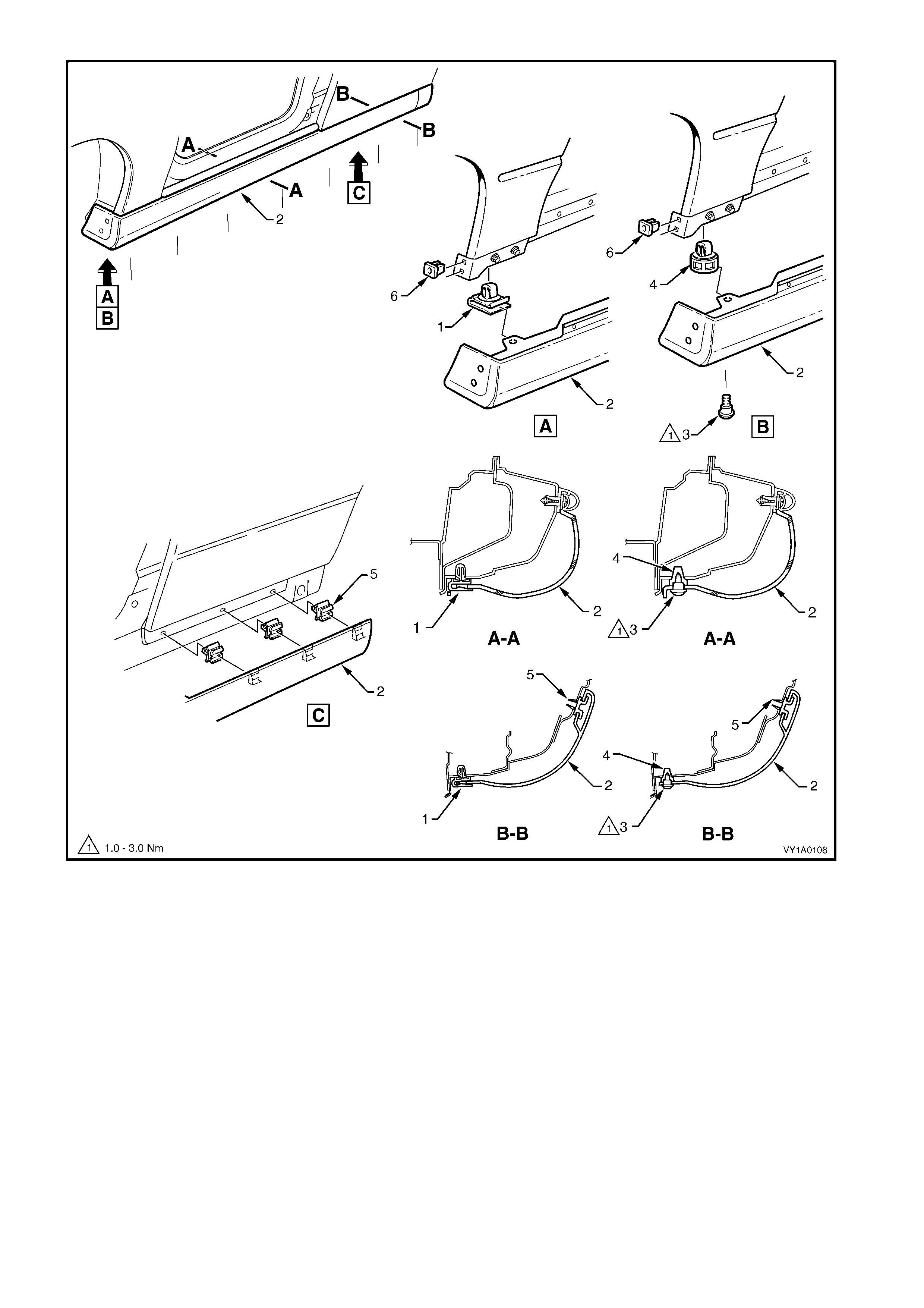
Figure 1A9-89
5. If required:
• For earlier build vehicles, remove the retainer (1), seven places, by gently levering out from the body,
taking care not to damage paint work, refer to View A, Figure 1A9-90.
• For later build vehicles, remove the retainer (2), seven places, by gently levering out from the body,
taking care not to damage paint work, refer to View B, Figure 1A9-90.

Figure 1A9-90
REINSTALL
Reinstallation of the rocker panel front and rear
mouldings is the reverse of the removal operation
noting the following.
1. Ensure the front moulding is c or re ctly seated in the
retaining clips.
2. Tighten all fasteners to the correct torque
specification.
3. Ensure the weatherstrip is seated correctly.
ROCKER PANEL MOULDING
ATTACHING SCREW
TORQUE SPE CIFICATI ON 1.0 – 3.0 Nm
4.10 REAR WINDOW UPPER MOULDING
LT Section No. – 10-265
REMOVE
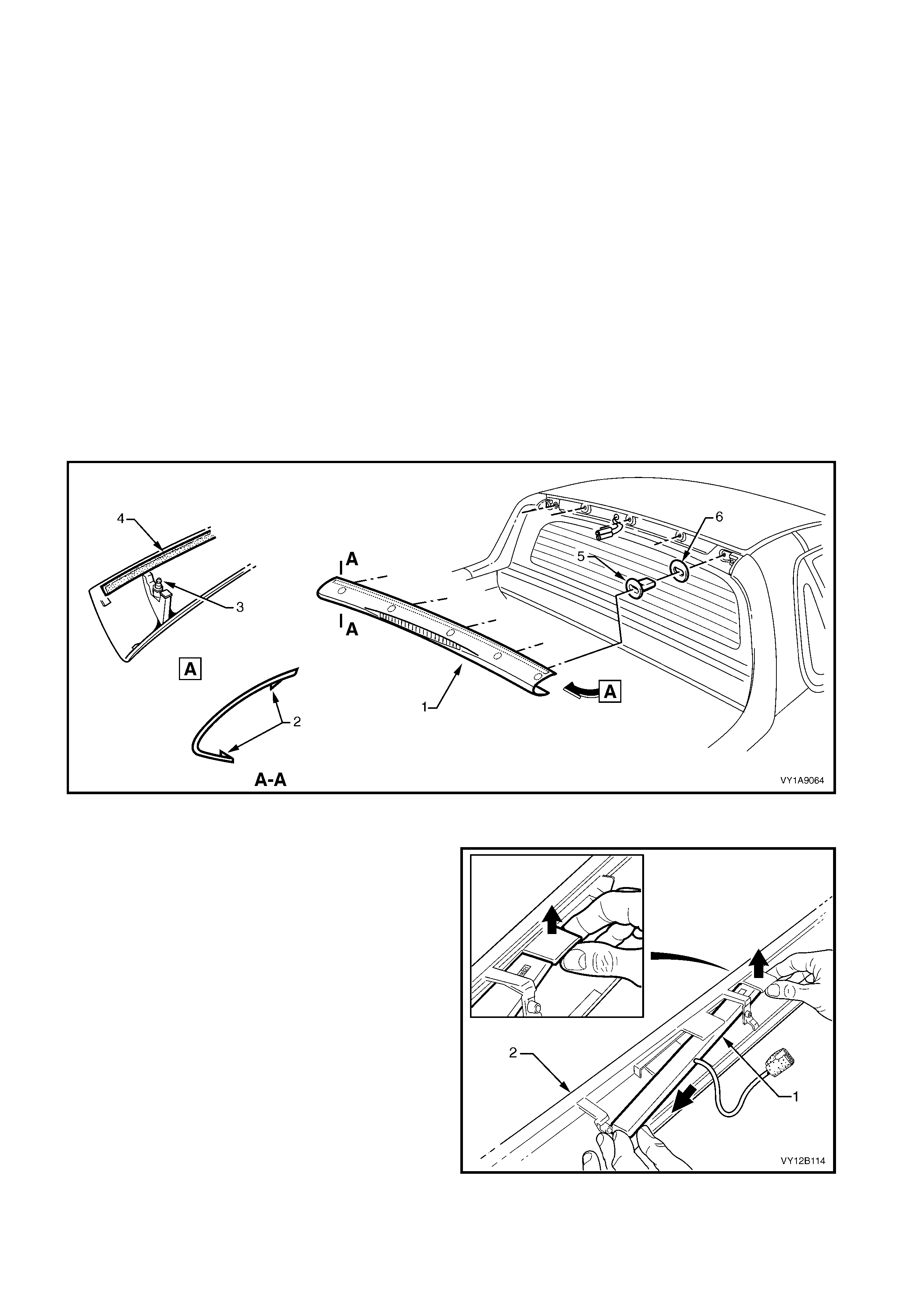
1. Carefully spread each end of the rear window upper m oulding (1) to disengage the locking tabs (2), ref er to
Figure 1A9-88.
2. Insert a flat-blade screwdriver and clean shop rag between the lower edge of the moulding and the rear
window.
3. Ensur ing the lock ing tabs are disengaged, pr ise the moulding of f in a rear ward and slightly upward direction
to disengage the retaining studs (3), five places.
NOTE: The upper edge of the moulding is attached with double-sided tape (4), remove the moulding carefully.
4. Where f itted, disconnec t the high mount stop lam p connec tor from the rear of the moulding and r emove the
moulding.
5. Remove any remaining double-sided tape from the moulding and/or panel as required and clean the
surfaces with Prepsol or equivalent.
6. If required, remove the five retainers (5) and seals (6) by inserting a flat-blade screwdriver between the
upper edge of the retainer and the panel. W hile pressing down on the screwdriver, ease the retainer out of
its location.
NOTE: Take care not to damage the paintwork.
Figure 1A9-88
DISASSEMBLE
1. Where fitted, carefully disengage the retaining
tangs fr om the high m ount stop lam p assem bly (1)
and manoeuvre the lamp assembly free from the
moulding (2).
Figure 1A9-89

REINSTALL
1. If fitted, install the high mount stop lamp assembly using the reverse of the removal procedure.
2. Check the retainers and seals are in sound condition. Replace as required.
3. If removed, fit the retainers and seals.
4. If reusing the moulding, apply new polyethylene double-sided tape such as 3M 4428 or equivalent to the
upper surface.
5. Clean the panel surface with Prepsol or equivalent.
6. Connect the high mount stop lamp connector, if fitted, and check its operation prior to installing the cap. Fit
the connector into its recess in the rear of the moulding.
7. Remove the backing paper from the double-sided tape.
8. Align the r etaining studs with their respec tive retainers on the vehicle and pus h home, ensuring the double-
sided tape does not contact until the moulding is fully seated.
9. Push-in each end to engage the locking tabs.
10. Press down along the upper surface of the moulding to ensure the tape is correctly adhered to the panel.
4.11 REAR WINDOW SIDE MOULDING
LT Section No. – 10-265
REMOVE
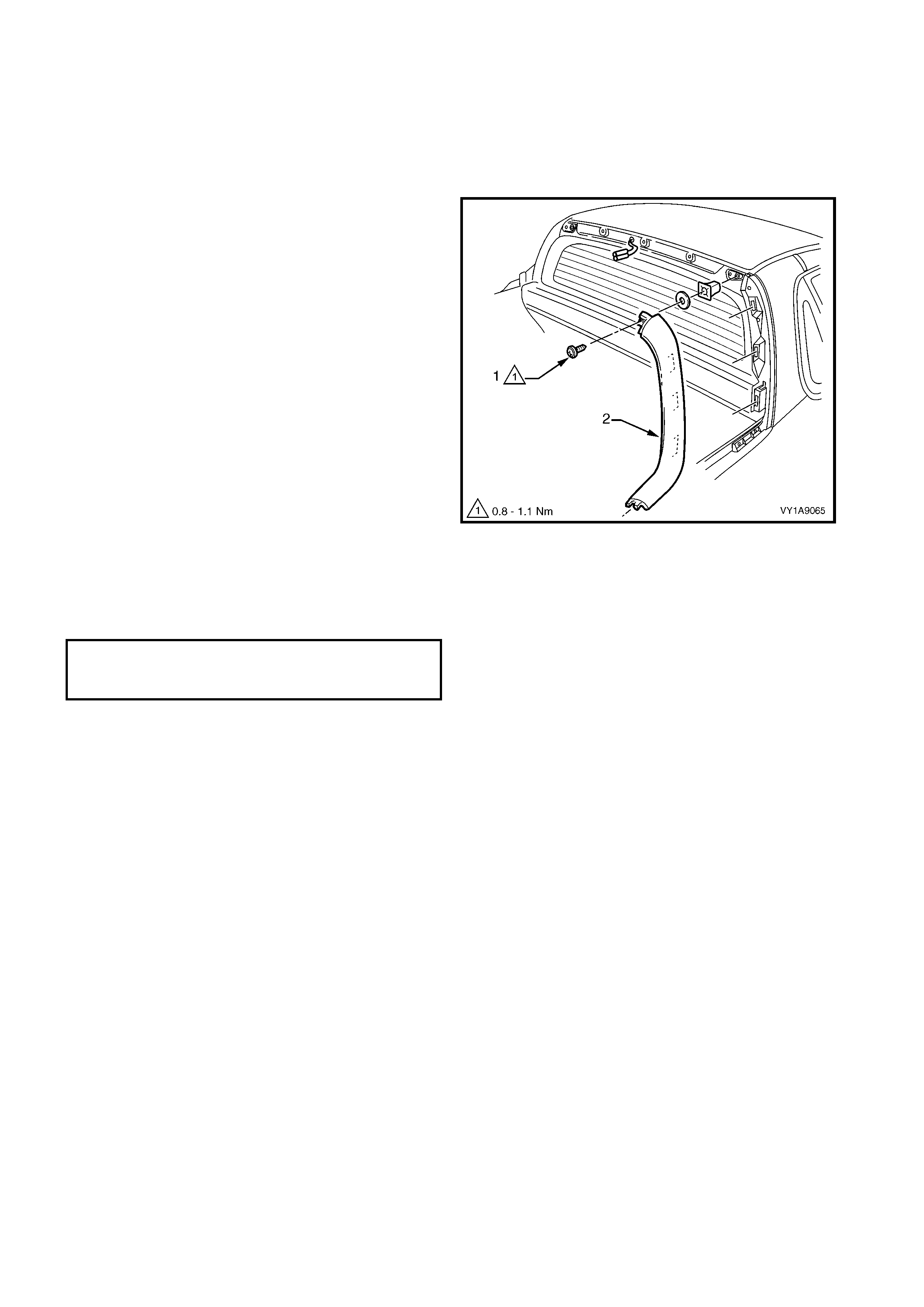
1. Remove the rear window upper moulding, refer to
4.10 REAR WINDOW UPPER MOULDING.
2. Remove the screw (1) attaching the rear window
side moulding (2).
3. Rotate the upper end of the moulding rearward to
disengage the three retainers.
4. Ease the lower end of the moulding forward to
disengage it from the quarter panel outer rail.
5. As required, remove the seal and retainer.
Figure 1A9-90
REINSTALL
Reinstallation is the reverse of removal. Tighten the
screw to the specified torque.
TORQUE SPEC
REAR WINDOW SIDE MOULDING
ATTACHING SCREW
TORQUE SPECIFICATION 0.8 – 1.1 Nm
4.12 QUARTER WINDOW MOULDING
LT Section No. – 10-265
As required, first remove the following components:
1. Body lock pillar upper trim, refer to Section 1A8, 5.3 BODY LOCK PILLAR UPPER TRIM.
2. Quarter window assembly, refer to Section 1A6, 4.2 QUARTER WINDOW ASSEMBLY, UTILITY.
3. Rear window upper moulding, refer to 4.10 REAR WINDOW UPPER MOULDING.
4. Rear window side moulding, refer to 4.11 REAR WINDOW SIDE MOULDING.
REMOVE
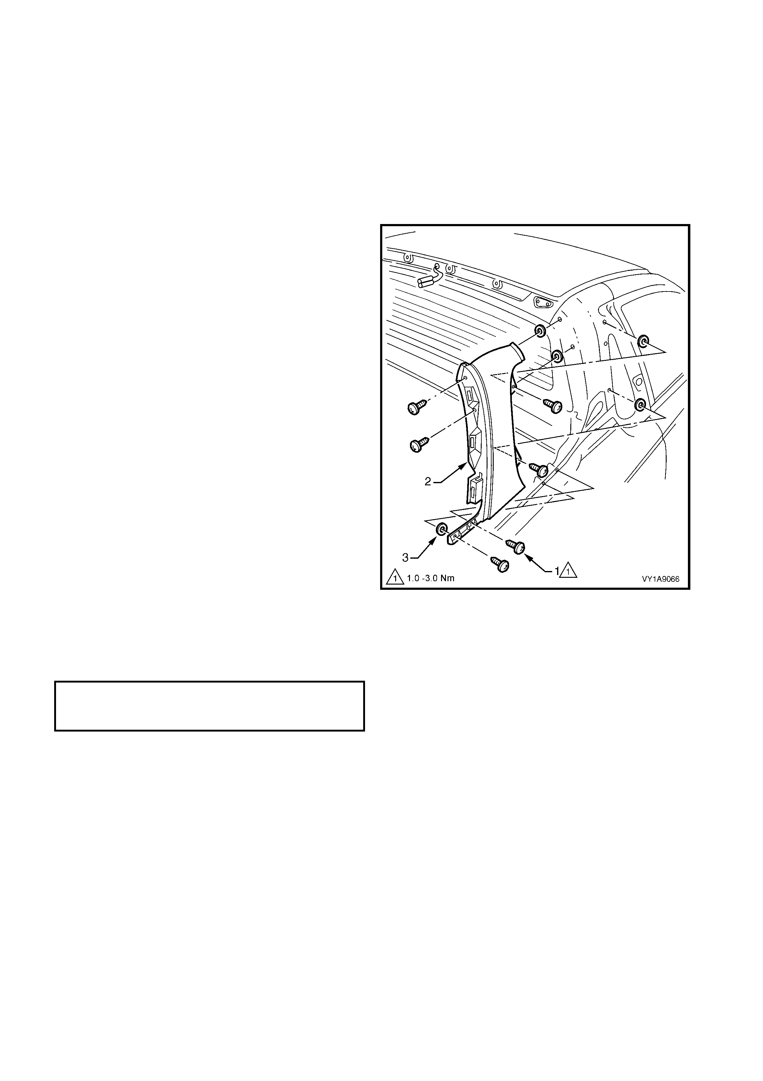
1. Remove the screw (1), six places, attaching the
quarter window moulding (2) to the vehicle.
2. Remove the moulding rearwards, disengaging the
front upper edge.
3. If required, carefully peel the seals (3) from the
vehicle.
Figure 1A9-91
REINSTALL
Reinstallation is the reverse of removal. Tighten the
screws to the specified torque.
QUARTER WINDOW MOULDING
ATTACHING SCREW
TORQUE SPECIFICATION 1.0 – 3.0 Nm
4.13 QUARTER PANEL RAILS
LT Section No. – 12-480
REMOVE
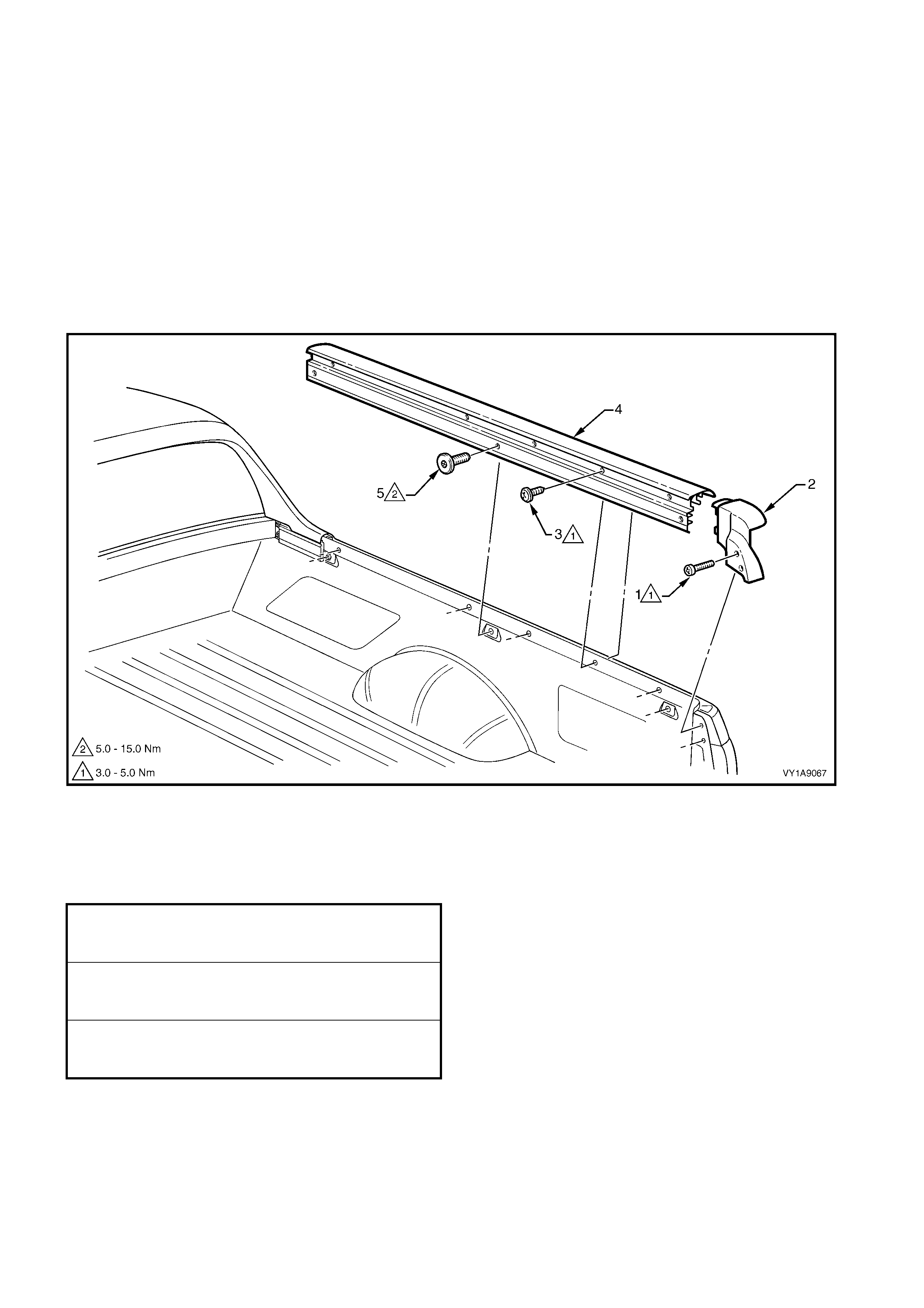
1. Remove the screw (1), two places, attaching the
quarter panel rear moulding (2) to the vehicle, refer
to Figure 1A9-92.
2. Remove the screw (3), five places, attaching the
quarter panel outer rail (4) to the vehicle.
3. Remove the torx-head screw (5), three places
attaching the quarter panel outer rail.
4. Carefully lift the moulding and rail from the vehicle
and remove.
Figure 1A9-92
REINSTALL
Reinstallation is the reverse of removal. Tighten the
screws to the specified torque.
QUARTER PANEL REAR MOULDING
ATTACHING SCREW
TORQUE SPECIFICATION 3.0 – 8.0 Nm
QUARTER PANEL OUTER RAIL
ATTACHING SCREW
TORQUE SPECIFICATION 3.0 – 8.0 Nm
QUARTER PANEL OUTER RAIL
ATTACHING TORX SCREW
TORQUE SPECIFICATION 5.0 – 15.0 Nm

4.14 TONNEAU COVER BOW RETAINER
LT Section No. – 12-480
REMOVE
1. Remove the rear window side moulding, refer to
4.11 REAR WINDOW SIDE MOULDING.
2. Remove the quarter panel rails, refer to
4.13 QUARTER PANEL RAILS.
3. Remove the screw (1) attaching the quarter
window moulding to the tonneau cover bow
retainer (2 ).
4. Remove the torx-head screw (3), two places,
attaching the tonneau cover bow retainer.
5. Remove the retainer from the vehicle.
NOTE: The torx-head screw (4) should not be
removed unless body panel replacement is being
perfor m ed. If it is rem oved, ens ure it is ins talled befor e
the retainer and tightened to the same torque as the
retainer torx-head screws
Figure 1A9-93
REINSTALL
Reinstallation is the reverse of removal. Tighten the
screws to the specified torque.
TONNEAU COVER BOW RETAINER
ATTACHING TORX SCREW
TORQUE SPECIFICATION 17.0 – 23.0 Nm
QUARTER WINDOW MOULDING
ATTACHING SCREW
TORQUE SPECIFICIATION 1.0 – 3.0 Nm
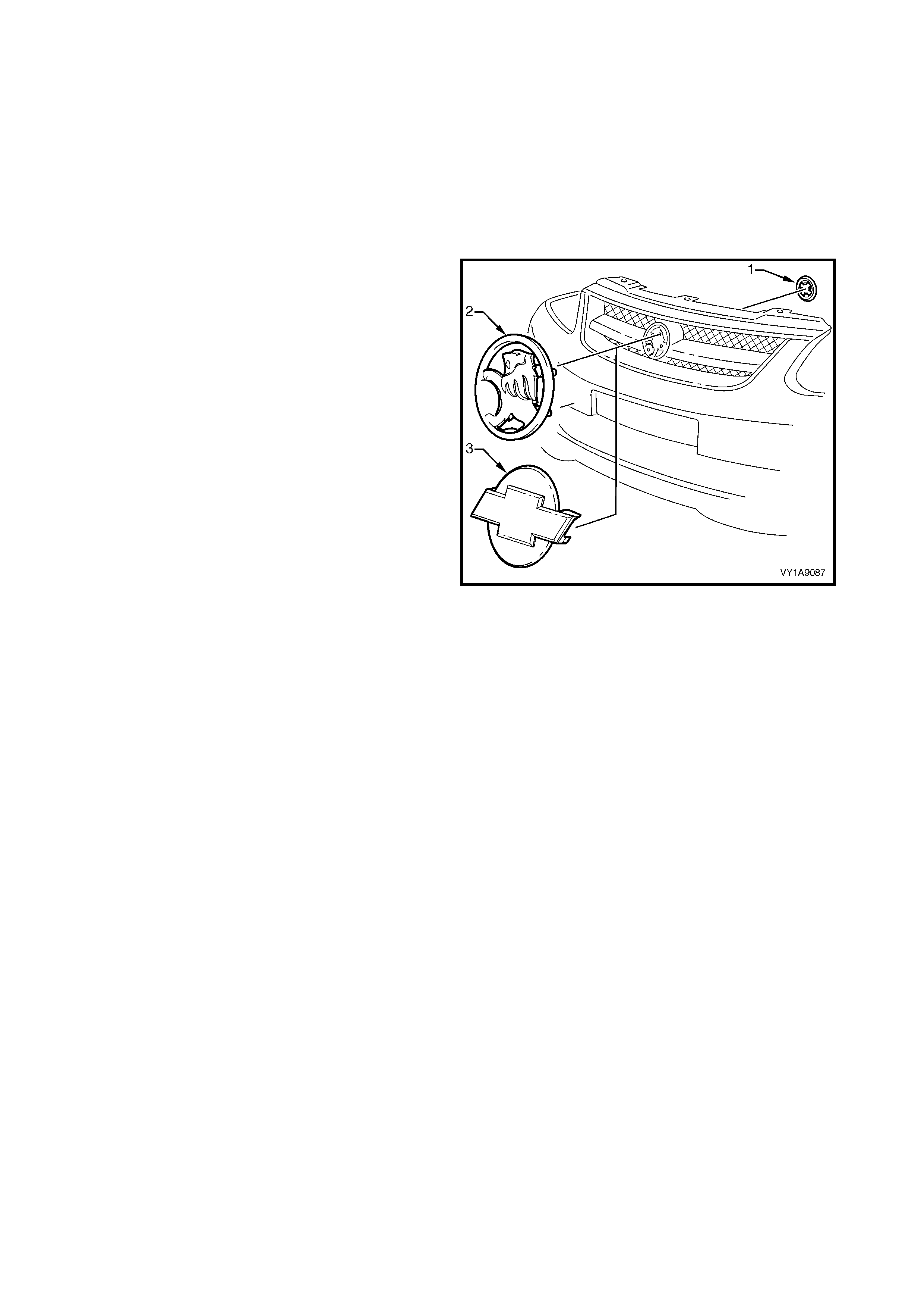
5. SERVICE OPERATIONS, COUPE
5.1 RADIATOR GRILLE EMBLEM
LT Section No. – 10-150
REMOVE
1. Remove the front bumper fascia, refer to
Section 1D, 2.2 FRONT BUMPER FASCIA
ASSEMBLY.
2. From the rear of the front bumper fascia, remove
the speed nut (1), attaching the emblem to the
bumper fascia:
• three places (2 – Domestic), or
• two places (3 – Export).
NOTE: If the em blem is to be reused, take care as the
speed nuts can cut into and break the lugs during
removal.
3. Remove the emblem.
Figure 1A9-94
REINSTALL
1. Fit the emblem onto the bumper fascia, locating
the lugs in their respective holes.
2. Fit a speed nut to the rear of each lug securely.
3. Reinstall the bumper fascia, refer to Section 1D,
2.2 FRONT BUMPER FASCIA ASSEMBLY.
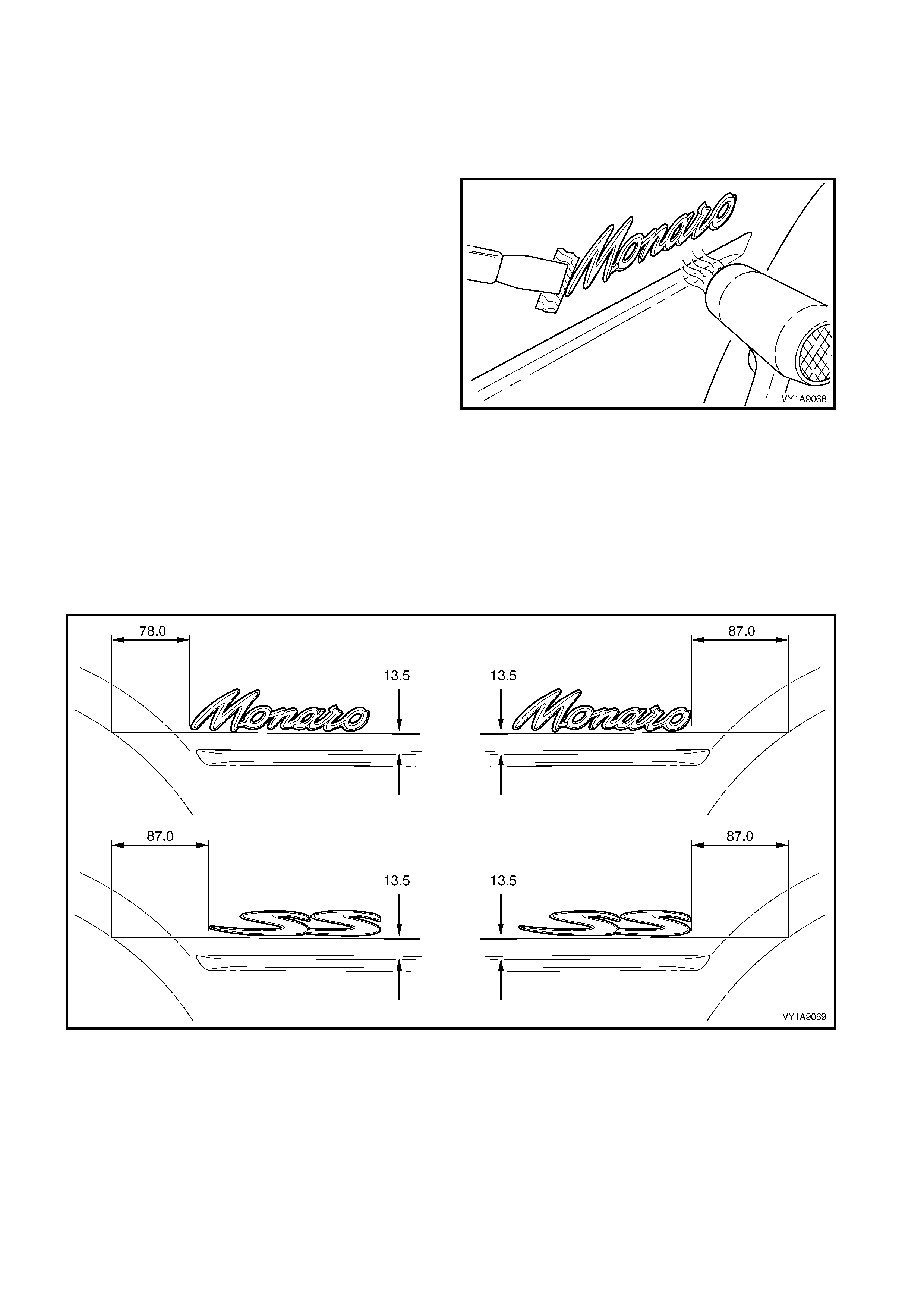
5.2 QUARTER PANEL NAME PLATE
LT Section No. – 10-150
MONARO, SS
REMOVE
1. Protect the paint and bodywork with tape or a rag.
2. To assist removal, warm the name plate with a
heat-lamp or heat-gun to soften the adhesive.
3. Using a paint s craper or sim ilar, caref ully pris e the
name plate from the quarter panel.
4. As required, remove any remaining double-sided
tape f rom the nam e plate and/or quarter panel and
clean the surfaces with Prepsol or equivalent.
Figure 1A9-95
REINSTALL
1. If reusing the name plate, apply new polyethylene double-sided tape such as 3M 4428 or equivalent to the
back and the trim edges of the tape slightly in from the edge of the name plate.
2. Clean the quarter panel surface with Prepsol or equivalent.
3. Remove the backing paper from the double-sided tape.
4. Apply the name plate in the position shown ensuring it is straight and is aligned correctly, measuring from
the body styling line and wheelarch, refer to Figure 1A9-96.
5. Press firmly over the entire plate for at least 10 seconds to ensure maximum adhesion.
Figure 1A9-96
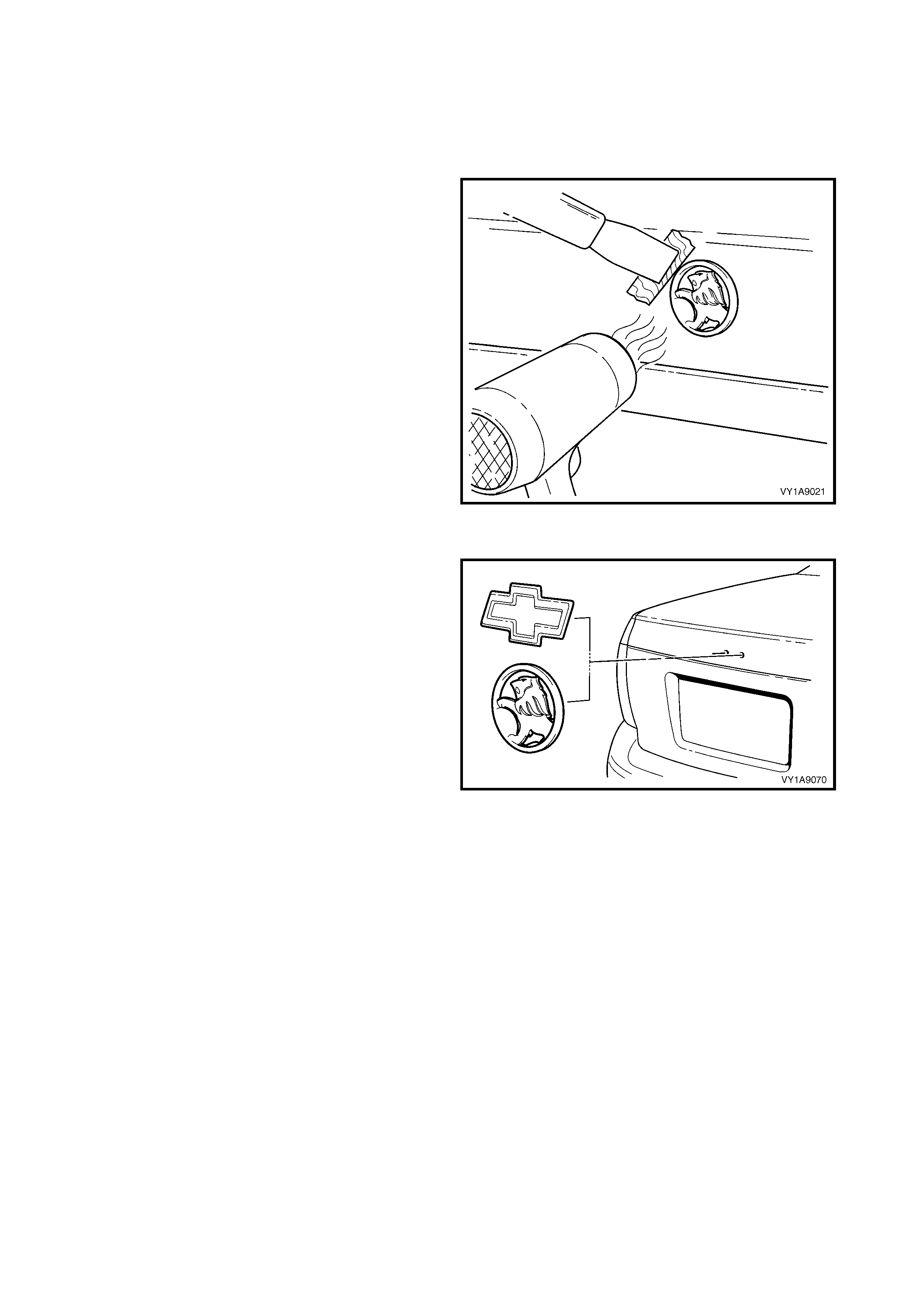
5.3 REAR COMPARTMENT LID EMBLEM
LT Section No. – 10-150
HOLDEN, CHEVROLET
REMOVE
1. Protect the paint and bodywork with tape or a rag.
2. To assist removal, warm the emblem with a heat-
lamp or heat-gun to soften the adhesive.
3. Using a paint s craper or sim ilar, caref ully pris e the
emblem from the rear compartment lid.
NOTE: The emblem has two locating pins, take care
not to break them if the emblem is to be reused.
4. As required, remove any remaining double-sided
tape f rom the em blem and/or rear com partm ent lid
and clean the surfaces with Prepsol or equivalent.
Figure 1A9-97
REINSTALL
1. If reusing the emblem, apply new polyethylene
double-sided tape such as 3M 4428 or equivalent
to the back and the trim edges of the tape slightly
in from the edge of the emblem.
2. Clean the panel surface with Prepsol or equivalent.
3. Remove the backing paper from the double-sided
tape.
4. Apply the emblem in the position shown ensuring
the locating pins are correctly orientated with the
locating holes in the panel surface.
5. Press firm ly over the entire emblem for at leas t 10
seconds to ensure maximum adhesion.
Figure 1A9-98
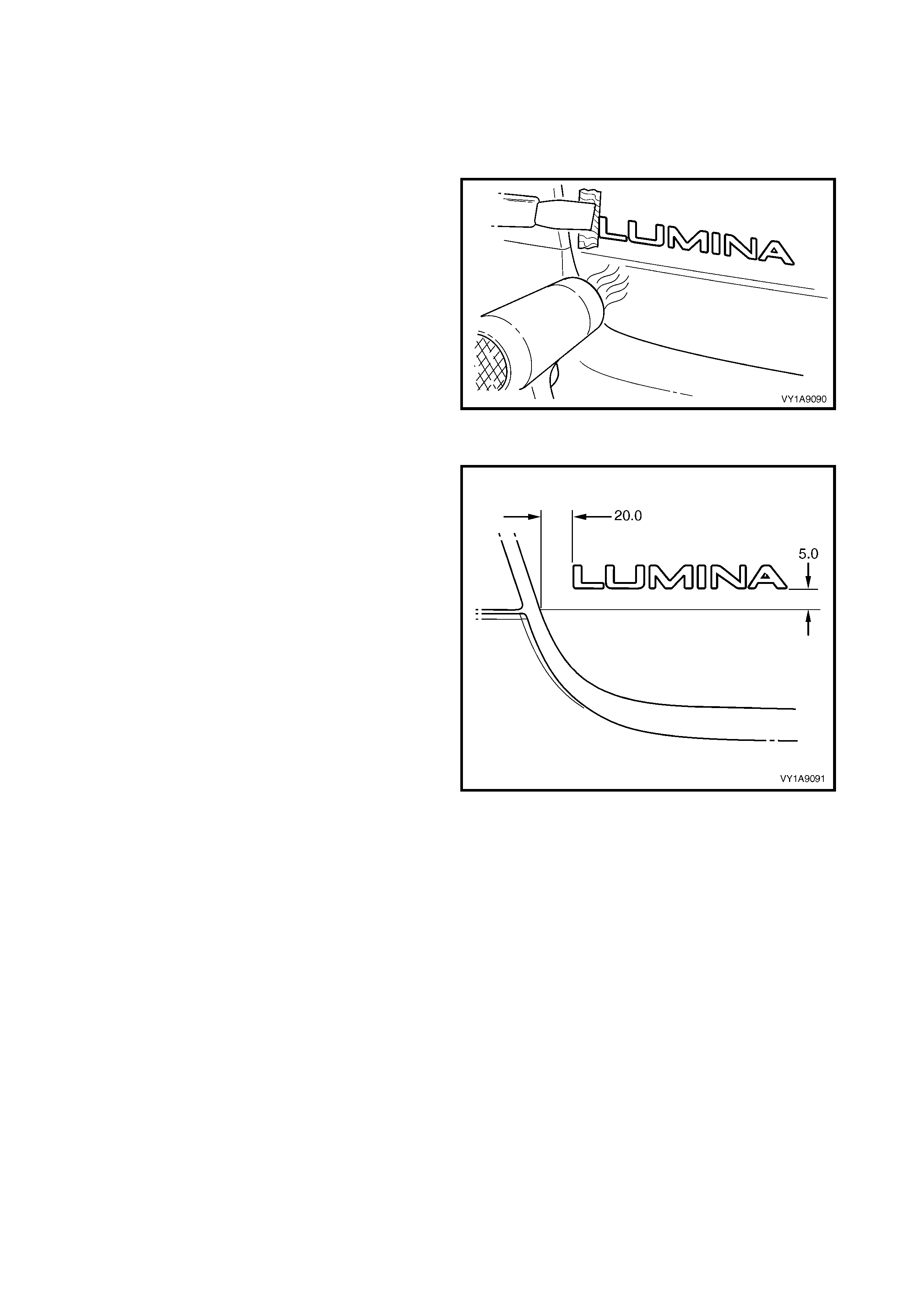
5.4 REAR COMPARTMENT LID NAME PLATE, LH
LT Section No. – 10-150
LUMINA
REMOVE
1. Protect the paint and bodywork with tape or a rag.
2. To assist removal, warm the emblem with a heat-
lamp or heat-gun to soften the adhesive.
3. Using a paint s craper or sim ilar, caref ully pris e the
emblem from the rear compartment lid.
4. As required, remove any remaining double-sided
tape f rom the em blem and/or rear com partm ent lid
and clean the surfaces with Prepsol or equivalent.
Figure 1A9-99
REINSTALL
1. If reusing the name plate, apply new polyethylene
double-sided tape such as 3M 4428 or equivalent
to the back and the trim edges of the tape slightly
in from the edge of the name plate.
2. Clean the panel surface with Prepsol or equivalent.
3. Remove the backing paper from the double-sided
tape.
4. Apply the name plate onto the right-hand side of
the rear compartment lid in the position shown,
ensuring it is s traight and is correc tly aligned to the
measurements.
5. Press firmly over the entire plate for at least 10
seconds to ensure maximum adhesion.
Figure 1A9-100
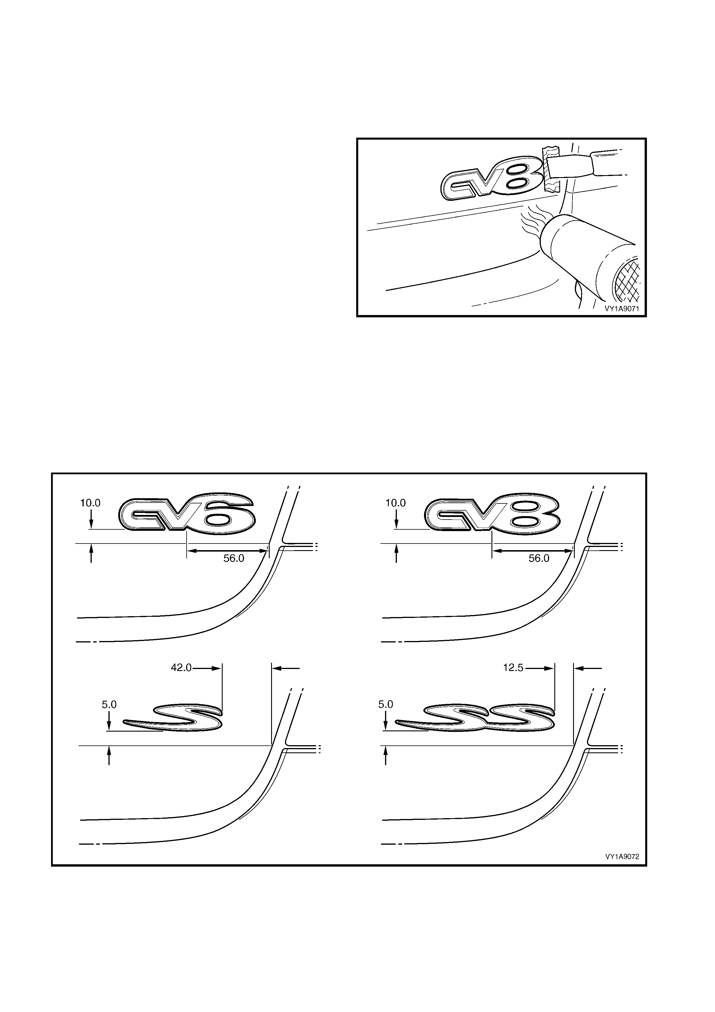
5.5 REAR COMPARTMENT LID NAME PLATE, RH
LT Section No. – 10-150
CV6, CV8, S, SS
REMOVE
1. Protect the paint and bodywork with tape or a rag.
2. To assist removal, warm the emblem with a heat-
lamp or heat-gun to soften the adhesive.
3. Using a paint s craper or sim ilar, caref ully pris e the
emblem from the rear compartment lid.
4. As required, remove any remaining double-sided
tape f rom the em blem and/or rear com partm ent lid
and clean the surfaces with Prepsol or equivalent.
Figure 1A9-101
REINSTALL
1. If reusing the name plate, apply new polyethylene double-sided tape such as 3M 4428 or equivalent to the
back and the trim edges of the tape slightly in from the edge of the name plate.
2. Clean the panel surface with Prepsol or equivalent.
3. Remove the backing paper from the double-sided tape.
4. Apply the nam e plate onto the right-hand side of the rear com partment lid in the position shown, ensur ing it
is straight and is correctly aligned to the measurements, refer to Figure 1A9-102.
5. Press firmly over the entire plate for at least 10 seconds to ensure maximum adhesion.
Figure 1A9-102

5.6 ROOF JOINT MOULDING
LT Section No. – 10-250
REMOVE
1. Beginning at the front of the vehicle, use a
screwdriver to carefully prise the roof joint
moulding (1) from the roof channel, disengaging
the retaining clips (2) at six places.
IMPORTANT: Take care as the retaining clips can
easily break. Protect the paintwork with a shop rag.
2. Slide the joint moulding from the rear window side
moulding retainer (3) and remove.
Figure 1A9-103
REINSTALL
1. As required, seat the six retainers onto the roof
joint moulding, evenly spaced.
2. Engage the roof joint moulding (1) onto the rear
window side moulding retainer, refer to Figure
1A9-103, and slide along until the roof joint
moulding sits under the endcap (2).
3. Seat the roof joint moulding in the roof channel
and beginning at the rear, clip it in place.
4. At the f ront, ensure the m oulding is installed under
the windshield moulding cover.
Figure 1A9-104
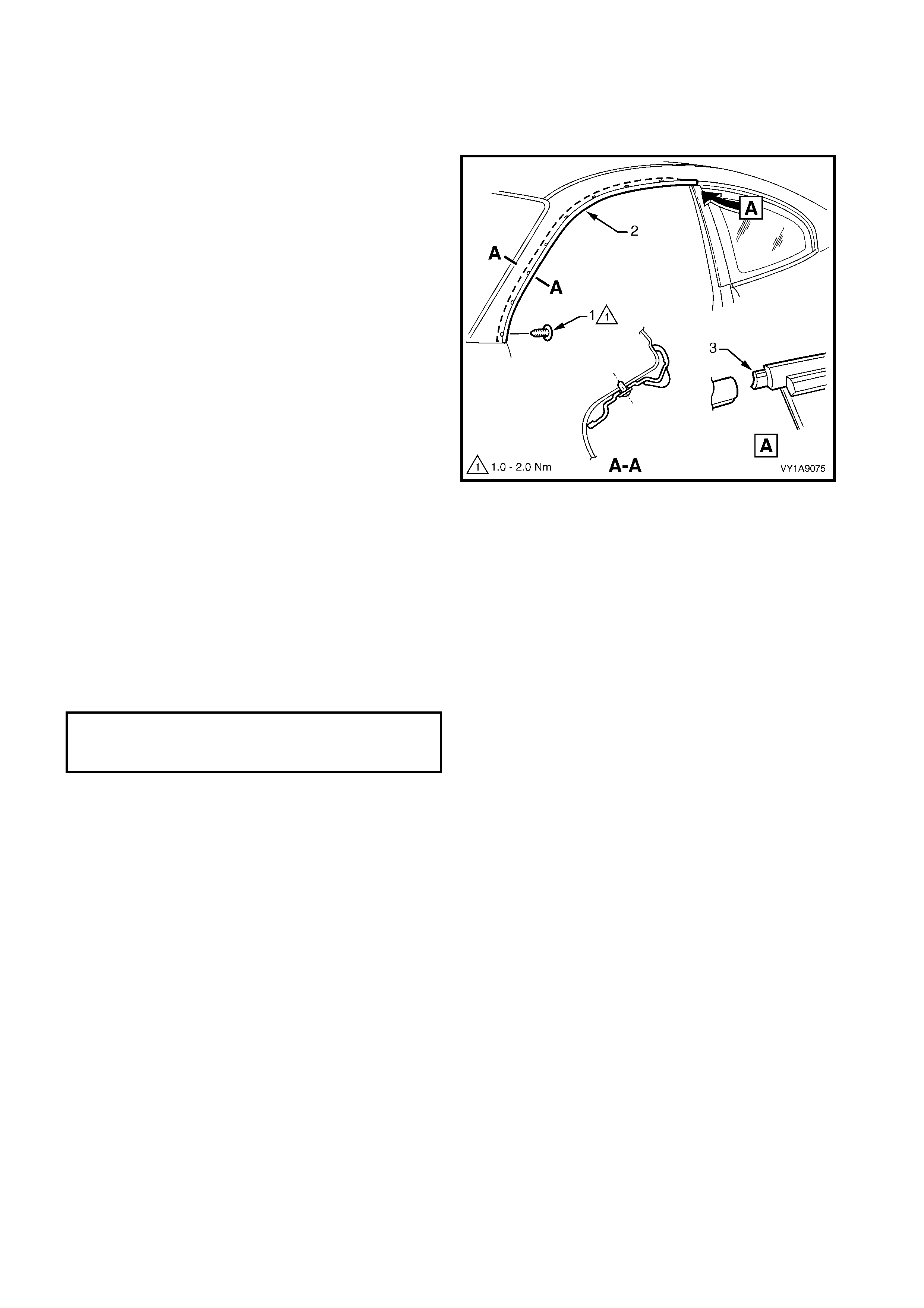
5.7 DOOR OPENING MOULDING
LT Section No. – 10-250
REMOVE
1. Open the door on the relevant side of the vehicle.
2. Beginning at each end and working towards the
middle, remove the screw (1), eight places,
attaching the door opening moulding (2) to the
vehicle.
3. Carefully remove the moulding, disengaging the
quarter window assembly tab (3).
Figure 1A9-105
REINSTALL
Reinstallation is the reverse of the removal. When
installing the screws, begin at the rear and work
forward.
NOTE: The screws are encapsulated with a wax
sealer. It is r ecom mended that the sc rews be replaced
once removed, however if this is impractical, apply a
small amount of sealer to the end of the thread.
Tighten the screws to the specified torque.
DOOR OPENING MOULDING
ATTACHING SCREW
TORQUE SPECIFICATION 1.0 – 2.0 Nm
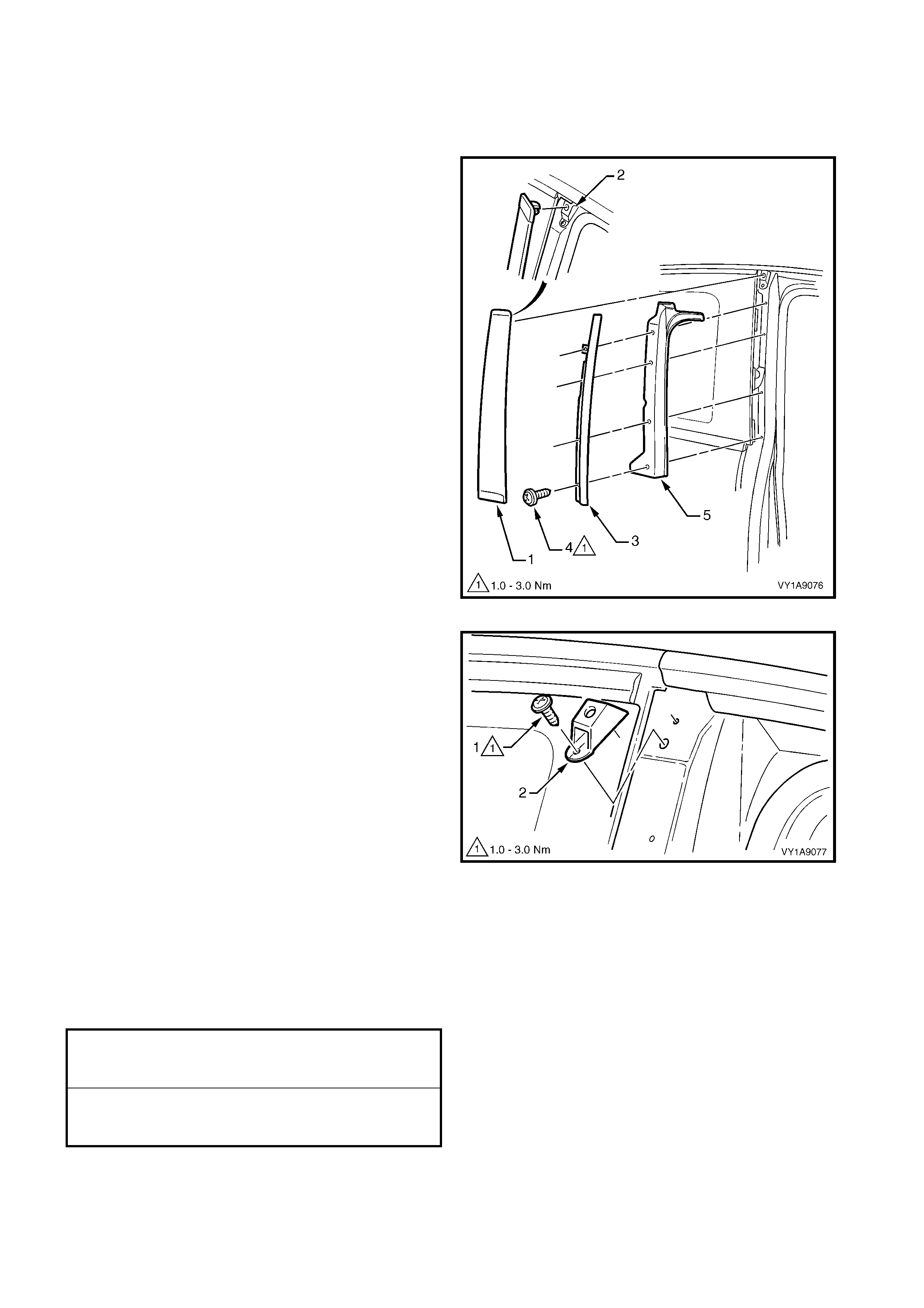
5.8 CENTRE PILLAR UPPER FINISHER ASSEMBLY
LT Section No. – 10-250
REMOVE
1. Open the door on the relevant side of the vehicle.
2. Gently prise the top of the centre pillar upper
finisher (1) out to disengage it from the centre
pillar upper finisher retainer (2).
3. Holding the top of finisher out, slide it up the centre
pillar outer sealing strip (3).
4. Manoeuvre the rear edge and then the front edge
of the finisher from the sealing strip and remove.
5. Remove the screw (4), four places, securing the
centre pillar sealing strip to the pillar and remove
the strip.
6. Remove the centre pillar upper trim panel (5) by
pulling away from the pillar.
Figure 1A9-106
7. Remove the screw (1), securing the centre pillar
upper finisher retainer (2).
8. Carefully prise the retainer from under the quarter
window, noting to disengage the locating lug.
Figure 1A9-107
REINSTALL
Reinstallation of the centre pillar upper finisher assembly is the reverse of the removal procedure, noting the
following:
1. Ensure the centre pillar upper trim panel is seated correctly under the door opening weatherstrip.
2. Ensure all fasteners are tightened to the correct torque specification.
3. Engage the front edge of the finisher into sealing strip and then the rear edge into the window assembly.
4. Slide the centre pillar upper finisher down and press it in at the top to engage it into the retaining clip.
CENTRE PILLAR UPPER FINISHER
RETAINER ATTACHING SCREW
TORQUE SPECIFICATION 1.0 – 3.0 Nm
CENTRE PILLAR SEALING STRIP
ATTACHING SCREW
TORQUE SPECIFICATION 1.0 – 3.0 Nm
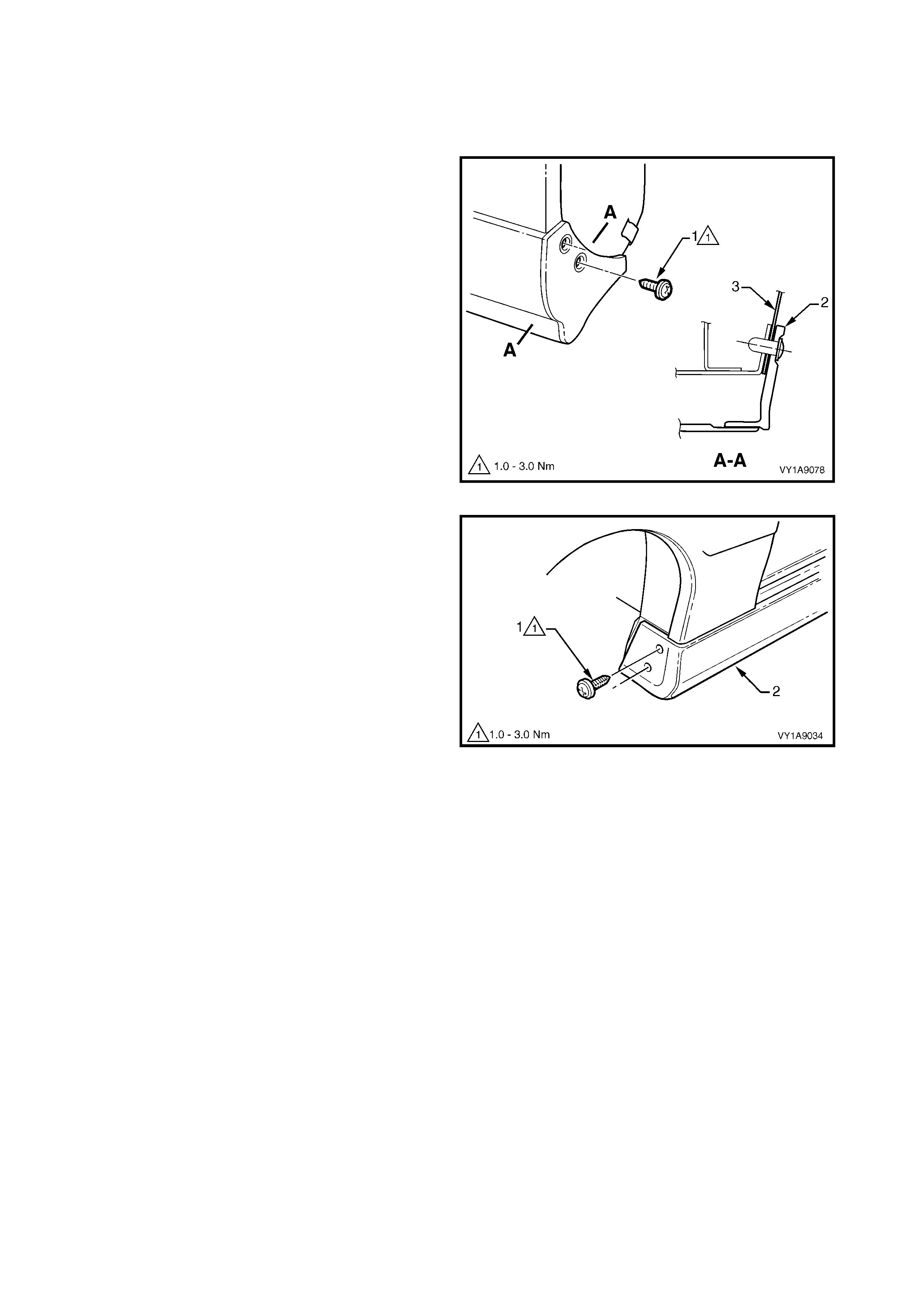
5.9 ROCKER PANEL MOULDING ASSEMBLY
LT Section No. – 10-300
REMOVE
1. Remove the screw (1), two places, attaching the
rear rocker panel moulding (2).
NOTE: If required, the r ear rocker panel moulding can
be removed at this stage by sliding it rearward from the
front rocker panel moulding.
Figure 1A9-111
2. Remove the screw (1), two places, attaching the
front rocker panel moulding (2) to the fender and
liner.
3. Lift up the rocker panel weatherstrip (1) to gain
access and remove the retainer (2), five places,
attaching the rocker panel moulding (3), refer to
Figure 1A9-113.
4. Remove the screw (4), six places, from the
retainer under the moulding (5).
5. Carefully remove the moulding from the vehicle,
unclipping the three retainers (6).
6. If required, prise the nut (7), two places, from the
fender.
Figure 1A9-112
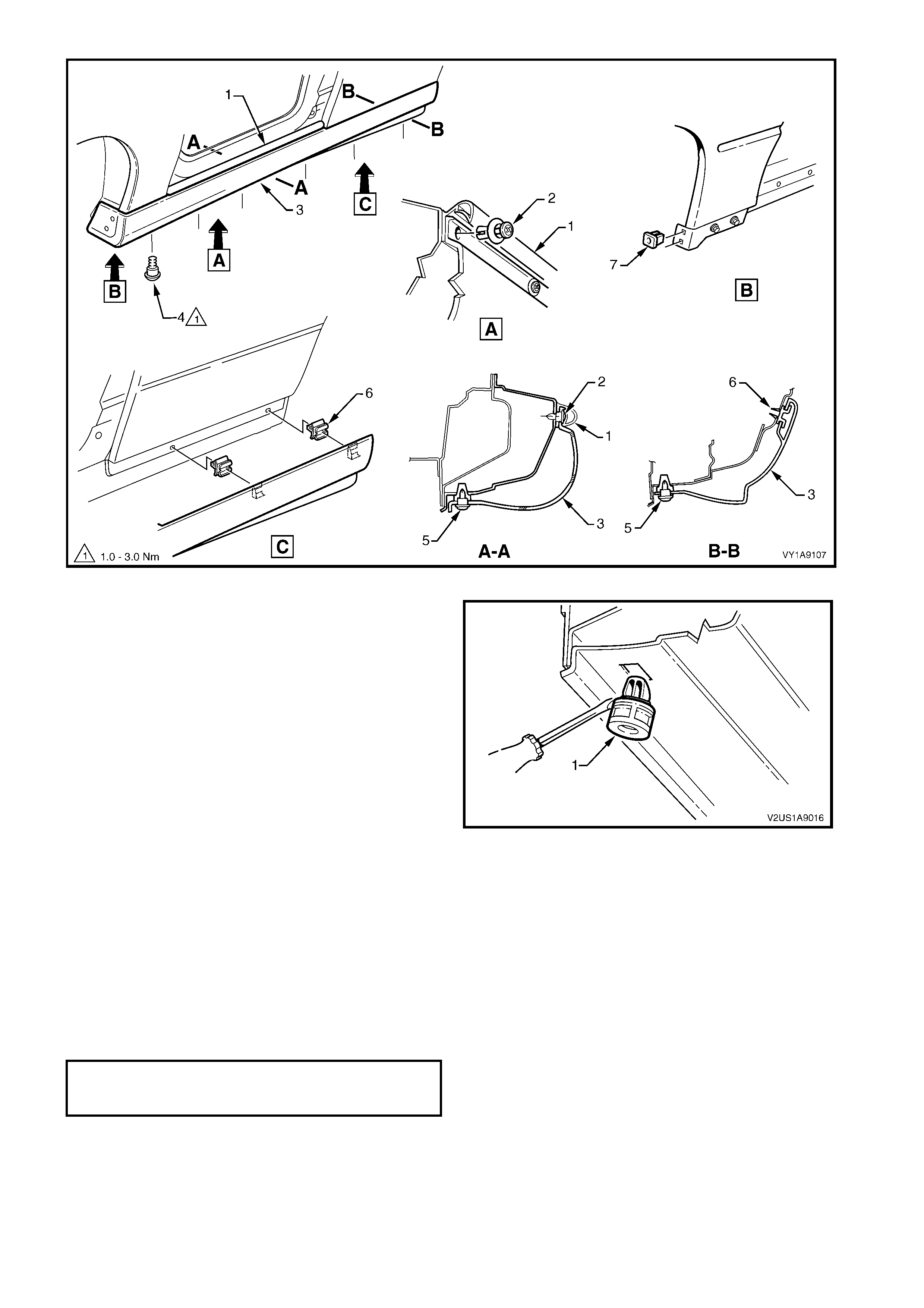
Figure 1A9-113
7. If required, remove the retainer (1), six places, by
gently levering out from the body, taking care not
to damage the paint work.
Figure 1A9-114
REINSTALL
Reinstallation of the rocker panel front and rear
mouldings is the reverse of the removal operation
noting the following.
1. Ensure the front moulding is c or re ctly seated in the
retaining clips.
2. Tighten all fasteners to the correct torque
specification.
3. Ensure the weatherstrip is seated correctly.
ROCKER PA NEL MOULDING
ATTACHING SCREW
TORQUE SPE CI FICATION 1.0 – 3.0 Nm

6. TORQUE WRENCH SPECIFICATIONS
Door opening moulding attaching screw..............................1.0 – 2.0 Nm
Centre pillar upper finisher retainer attaching screw.............1.0 – 3.0 Nm
Centre pillar sealing strip attaching screw ............................1.0 – 3.0 Nm
Rocker panel moulding attaching screw...............................1.0 – 3.0 Nm
Roof bar attaching screw......................................................4.0 – 6.0 Nm
Roof side rail attaching nut ...................................................10.0 – 12.0 Nm
Rear window side moulding attaching screw........................0.8 – 1.1 Nm
Quarter window moulding attaching screw...........................1.0 – 3.0 Nm
Quarter panel rear moulding attaching screw.......................3.0 – 8.0 Nm
Quarter panel outer rail attaching screw...............................3.0 – 8.0 Nm
Quarter panel outer rail attaching Torx screw.......................5.0 – 15.0 Nm
Tonneau cover bow retainer attaching Torx screw...............17.0 – 23.0 Nm