
SECTION 1B - SHEETMETAL
IMPORTANT
Before perfo rming any Service O perat ion or o th er pro cedu re describ ed in th is Section, refer to Section
00 CAUTIONS AND NOTES for correct workshop practices with regard to safety and/or property
damage.
CONTENTS
1. GENERAL DESCRIPTION
2. SERVICE OPERATIONS
2.1 BODY STRUTURE PART REFINISHING
2.2 ANTI-CORROSIVE TREATMENT
2.3 BODY STRUCTURE REPLACEMENT PARTS
UNDERBODY - SEDAN
UPPERBODY, EXCLUDING ROOF
STRUCTURE - SEDAN
ROOF STRUCTURE - SEDAN
BODY ASSEMBLY - SEDAN
UNDERBODY - WAGON
UPPERBODY - WAGON
BODY ASSEMBLY - WAGON
UNDERBODY - UTILITY
UPPERBODY - UTILITY
BODY ASSEMBLY - UTILITY
UNDERBODY - COUPE
UPPERBODY - COUPE
BODY ASSEMBLY - COUPE
2.4 FRONT FENDER
REMOVE
REINSTALL
2.5 BATTERY TRAY ASSEMBLY
REMOVE
REINSTALL
2.6 FRONT SIDE RAIL BRACE
REMOVE
REINSTALL
2.7 LOAD FLOOR FRONT PANEL ASSEMBLY,
UTILITY
REMOVE
REINSTALL
2.8 FRONT INNER SIDE PANEL COVER,
UTILITY
REMOVE
REINSTALL
2.9 REAR INNER SIDE PANEL COVER,
UTILITY
REMOVE
REINSTALL
3. TORQUE WRENCH SPECIFICATIONS
Techline

1. GENERAL DESCRIPTION
The MY2003 VY series is a major upgrade of the MY 2001 VX Series. New sheetmetal components include the
hood, front fender and for Sedan models, the quarter panel outer and rear compartment lid. Many minor revisions
have also been made to accommodate new trim and wiring harness mounting points. The MY2003 V2 Series
Coupe carries over from the previous model with minor revisions also made.
This Section contains an illustrated listing of the serviced sheetmetal components that form the vehicle’s body
struc ture. This lis ting is provided for inf or mation only and is to be used as a guide. For the latest configur ations ref er
to the current spare parts catalogue.

2. SERVICE OPERATIONS
2.1 BODY STRUCTURE P ART REFINISHING
The vehicle body structure is designed to meet or exceed many regulations, including crash performance and
occupant protection, etc. When replacing or repairing a part or sub-assembly, care must be taken to ensure that
correct alignment and strength of unit as a whole is maintained.
In some instances, major damage to the body structure can be more effectively and economically repaired by
replacing a part or sub-assembly with a new one, rather than repairing the damaged part.
Spot welding is used extensively for joining panels or assemblies, however special adhesives are playing an ever
increasing role in the joining of body structure components, either on their own or together with spot welds. W here
repairs are performed, it is imperative that effective rust proofing techniques, as outlined in the following
paragraphs, be observed.
It is for these reasons that qualified persons with suitable training and qualifications only perform the repair or
replacement of body structure components. Further information can be found in the MY2003 VY & V2 Series
Service Manual Supplement, Body Structure Repair.

2.2 ANTI-CORROSIVE TREATMENT
Precoated and galvanised steel is used extensively for various body structure components for increased corrosion
protection. Body panels such as the engine hood, door and deck lid outer panels ar e precoated on the inner surf ace
of the metal to improve corrosion protection. Other body structure members have complete double-sided galvanised
protection.
In addition, a rust preventative material is sprayed after paint application to areas such as the interior surfaces of
doors, etc.
Any repair or replacement of panels, assemblies, etc. that disturb this anti-corrosive treatment must be resealed
and should be included as part of the repair or replacement operation.
Anti-corrosive compounds used for repairs should be light bodied materials designed to penetrate between metal-
to-metal surfaces such as pinch weld flanges and integral panel attaching points.
All bare metal sur f ac es must be tr eated with metal conditioner and pr imed. T hes e operations need to be c arr ied out
prior to the application of sealer s, waxes and s ound deadeners. Attac hing points of new replacem ent panels s hould
be resealed. The hemming flanges of replacement doors, tailgates and rear compartment lids will require resealing.
Open joins that require bridging of the sealer to close a gap should be sealed with a heavy-bodied caulking material.
When colour application is required to restore repaired areas to original appearance, conventional refinishing
preparation, undercoat build-up and colour application techniques should be employed.
When deadeners are disturbed during damage repair, or a panel has been replaced, the deadener material must be
replaced with an equivalent material. The location and pattern for replacement material can be determined by
observing the original deadener application outlines.
Further information can be found in the MY2003 VY & V2 Series Service Manual Supplement, Body Structure
Repair.

2.3 BODY STRUCTURE REPLACEMENT PARTS
The following illustrations and tables describe the body structure assemblies and panels that are available for
service replacement.
The purpose of this information is to provide the repairer with a better understanding of available replacement
sections . For further inform ation r egarding the body structur e, refer to the MY2003 VY & V2 Series Service Manual
Supplement, Body Structure Repair.
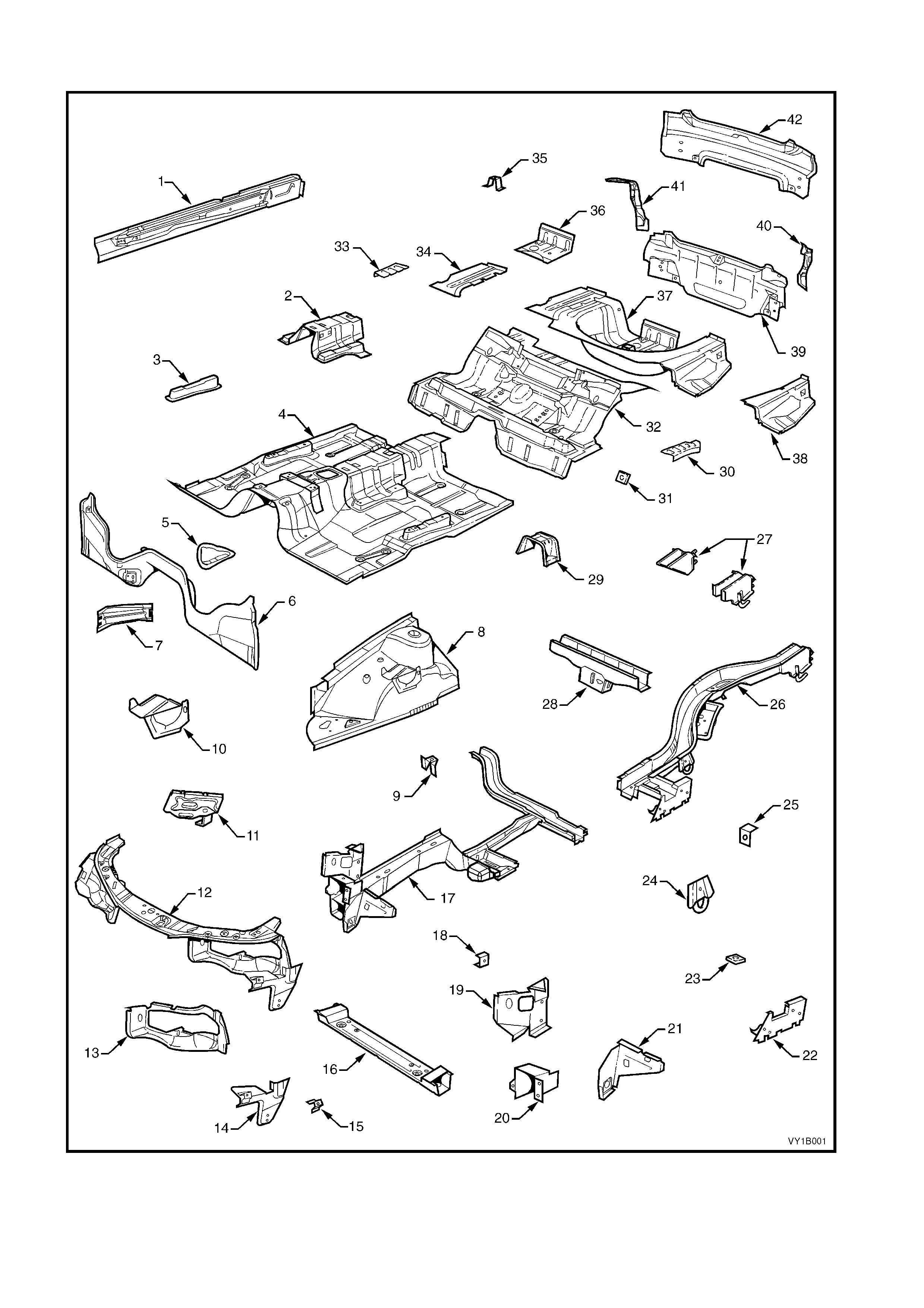
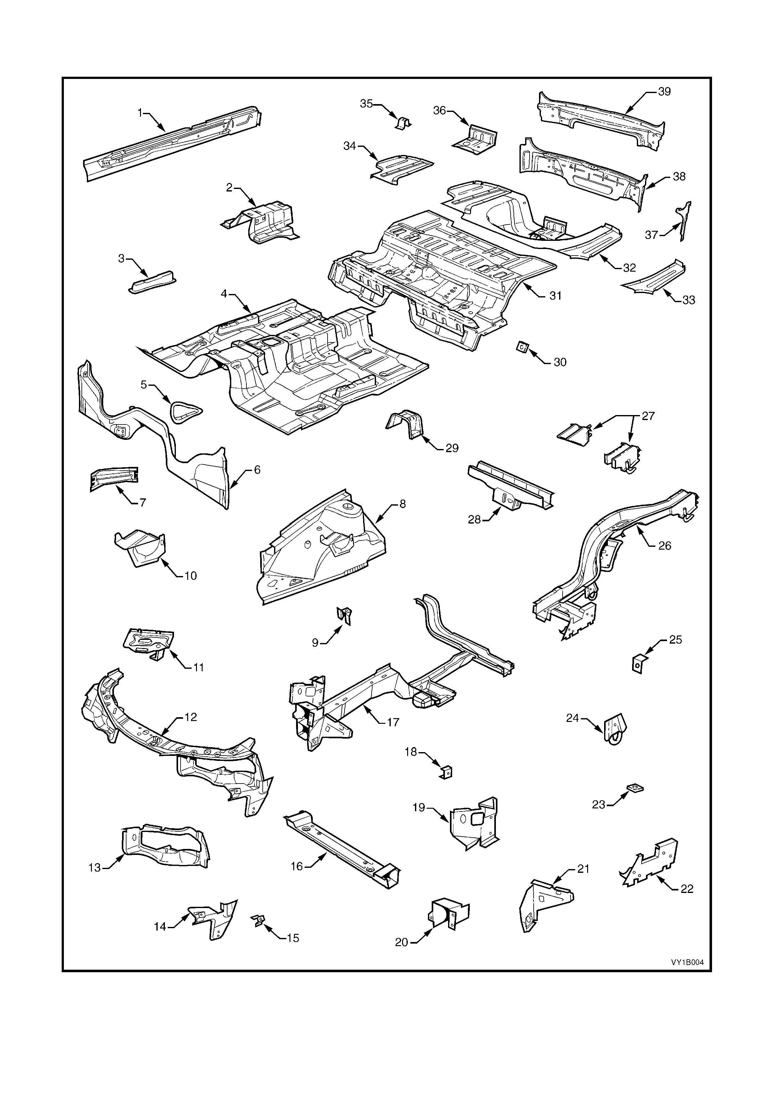
UNDERBODY – SEDAN
Figure 1B-1

Legend
1. Inner Rocker Panel Assembly 22. Rear Floor Panel Outer Extension
2. Seat Inner Bracket Assembly 23. Rear Suspension Support Mount Plate
3. Seat Outer Bracket Assembly 24. Rear Tie Down Assembly
4. Front Floor Panel Assembly 25. Rear Brake Hose Bracket
5. Transmission Support Bracket 26. Rear Side Rail Assembly
6. Front Floor Panel Extension 27. Rear Bumper Impact Bar Brace Assembly, LH / RH
7. Front Side Rail Brace 28. Crossmember Assembly No. 2
8. Front Wheelhouse Panel Assembly 29. Propeller Shaft Hanger Assembly
9. Horn Bracket Assembly 30. Rear Floor Panel Reinforcement, LH
10. ABS Modulator Bracket Assembly 31. Rear Seat Belt Anchor Plate Assembly
11. Battery Tray Assembly 32. Rear Floor Panel Assembly
12. Front End Panel Assembly 33. Rear Floor Panel Reinforcement, RH
13. Headlamp Panel 34. Rear Compartment Floor Panel Outer Extension, RH
14. Headlamp & Front Fascia Mount Bracket 35. Spare Wheel Anchor Plate Assembly
15. Fender Front Lower Bracket 36. Fuel Tank Support Reinforcement Assembly
16. Radiator Lower Support Assembly 37. Rear Compartment Floor Panel Assembly
17. Front Side Rail Assembly 38. Rear Compartment Floor Panel Outer Extension, LH
18. Radiator Side Mounting Bracket 39. Rear End Panel Assembly
19. Front Wheelhouse Bracket Assembly 40. Rear End Panel Extension, LH
20. Front Bumper Impact Bar Bracket 41. Rear End Panel Extension, RH
21. Front Wheelhouse Panel Bracket 42. Rear End Lower Panel
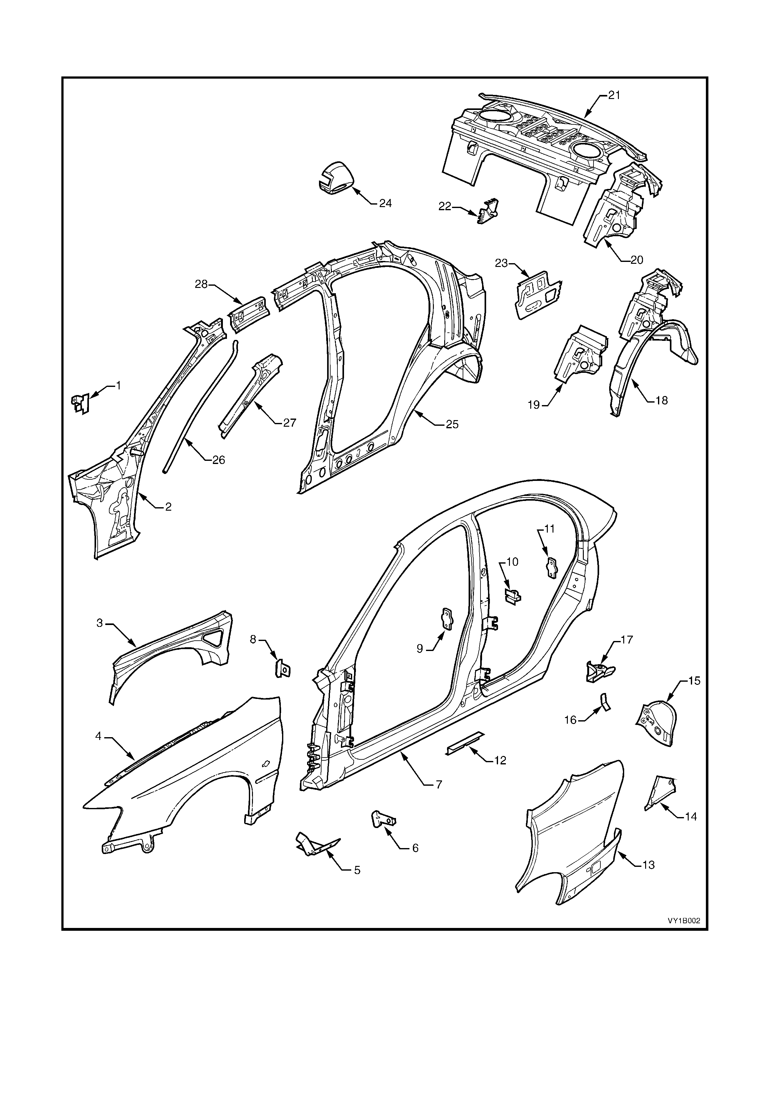
UPPERBODY, EXCLUDING ROOF STRUCTURE – SEDAN
Figure 1B-2

Legend
1. Hinge Pillar Trim Panel Bracket 15. Tail Lamp Housing
2. Hinge Pillar Inner Panel Assembly 16. Wiring Harness Bracket
3. Front Wheelhouse Panel Upper Side Rail 17. Quarter Panel Upper Extension
4. Front Fender 18. Rear Wheelhouse Inner Panel Assembly
5. Fender Lower Rear Bracket 19. Rear Seat Back Panel Extension
6. Fender Rear Bracket 20. Rear Seat Back Panel Extension Assembly
7. Door Opening Frame Assembly 21. Rear Window Panel Assembly
8. Fender Upper Rear Bracket 22. Rear Compartment Lid Strut Bracket Assembly
9. Front Door Striker Anchor Plate 23. Tail Lamp Housing Brace
10. Rear Door Check Link Bracket 24. Fuel Filler Pipe Housing, RH
11. Rear Door Striker Anchor Plate 25. Quarter Panel Inner Assembly
12. Underbody Jacking Locator 26. Sunroof front drain tube
13. Rear Quarter Panel 27. Hinge Pillar Upper Reinforcement
14. Quarter Panel Lower Extension 28. Quarter Panel Inner Extension
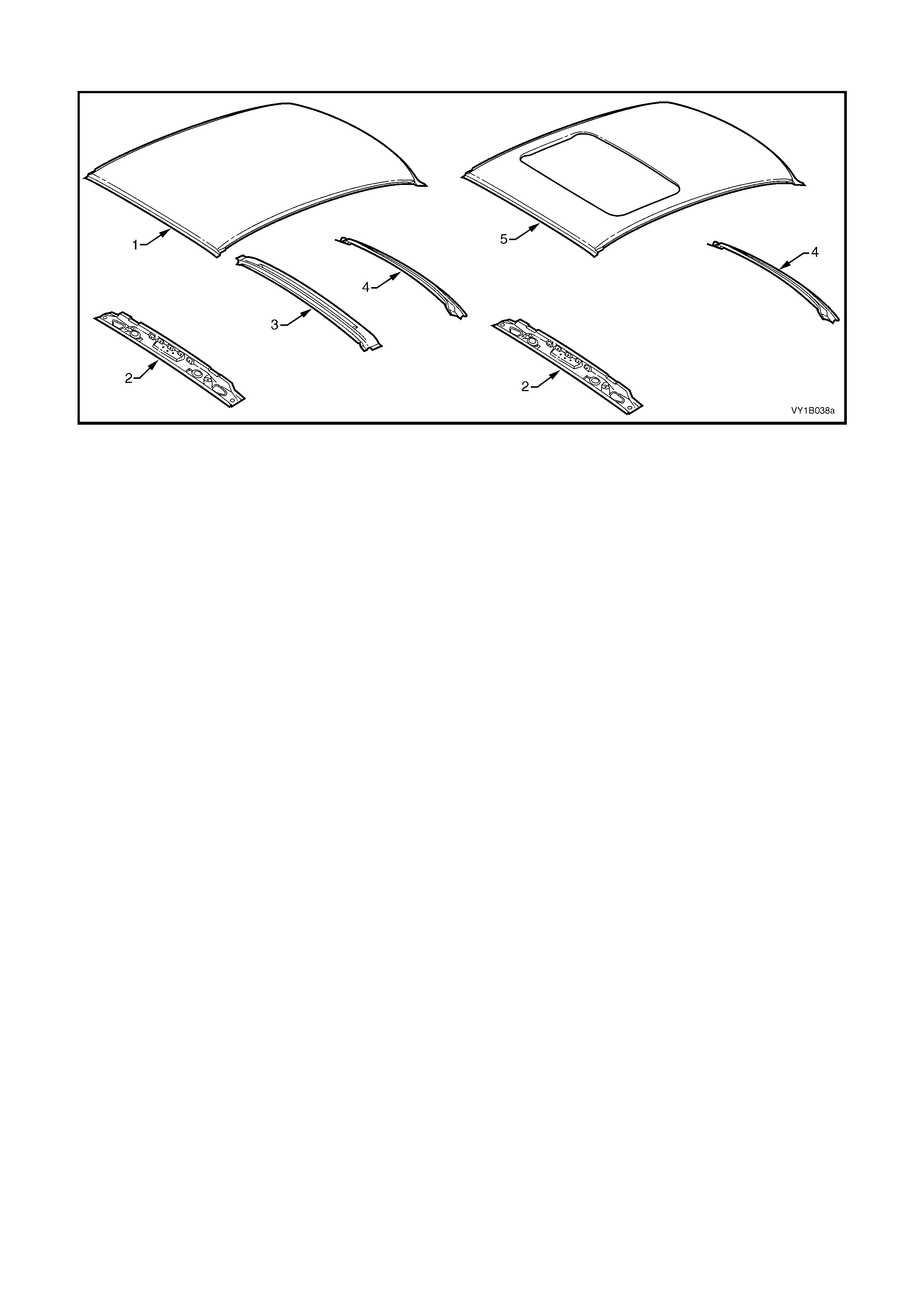
ROOF STRUCTURE – SEDAN
Figure 1B-3
Legend
1. Roof Panel 4. Roof Rear Panel
2. Roof Front Header Panel 5. Roof Panel Assembly (with Sunroof)
3. Roof Bow Panel
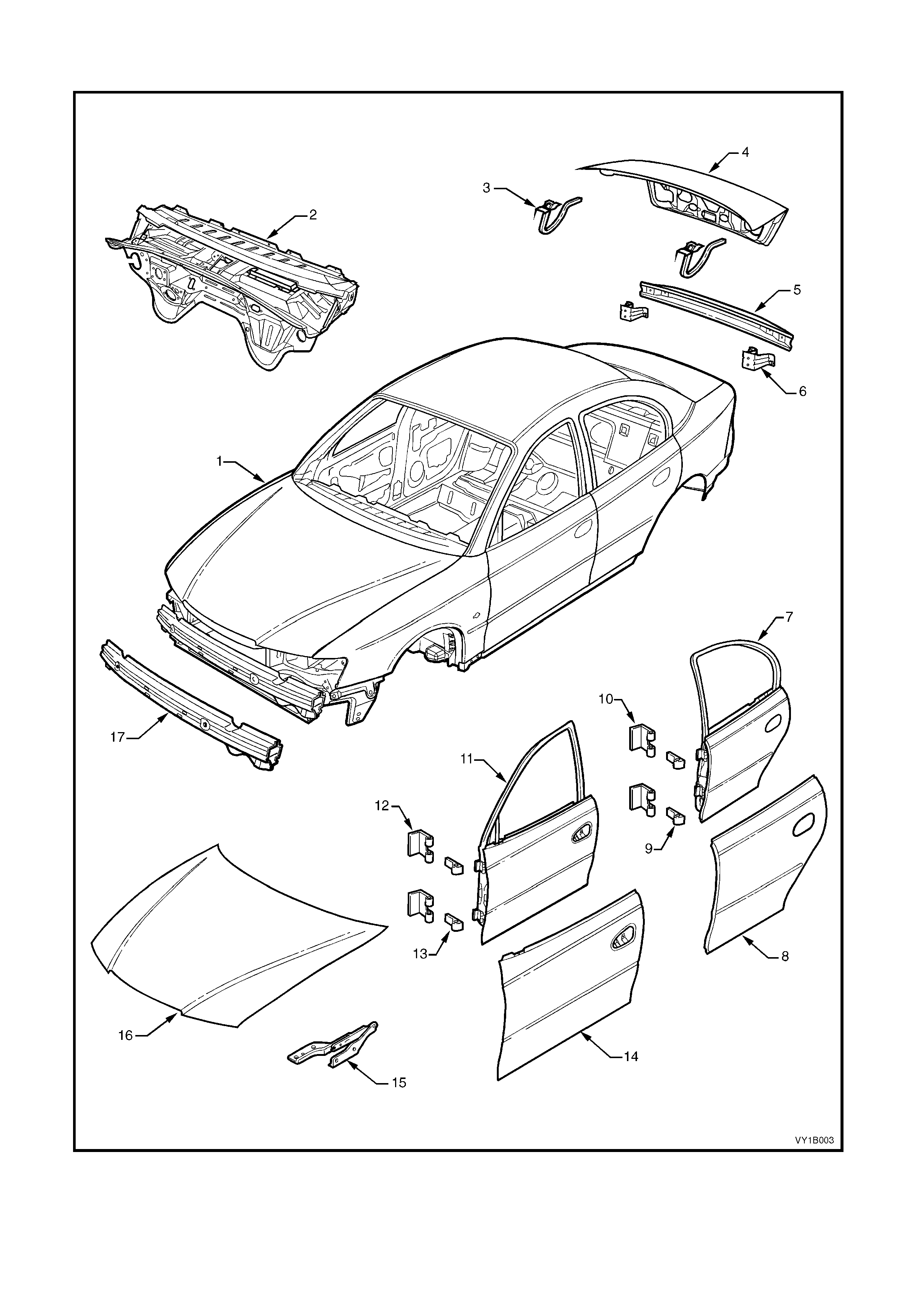
BODY ASSEMBLY – SEDAN
Figure 1B-4

Legend
1. Body assembly 10. Rear Door Hinge (body side)
2. Dash Panel Assembly 11. Front Door Assembly
3. Rear Compartment Lid Hinge Assembly 12. Front Door Hinge (body side)
4. Rear Compartment Lid Assembly 13. Front Door Hinge (door side)
5. Rear Bumper Impact Bar 14. Front Door Outer Panel
6. Rear Bumper Impact Bar Bracket Assembly 15. Hood Hinge Assembly
7. Rear Door Assembly 16. Hood assembly
8. Rear Door Outer Panel 17. Front Bumper Impact Bar Assembly
9. Rear Door Hinge (Door Side)
UNDERBODY – WAGON
Figure 1B-5

Legend
1. Inner Rocker Panel Assembly 21. Front Wheelhouse Panel Bracket
2. Seat Inner Bracket Assembly 22. Rear Floor Panel Outer Extension
3. Seat Outer Bracket Assembly 23. Rear Suspension Support Mount Plate
4. Front Floor Panel Assembly 24. Rear Tie Down Assembly
5. Transmission Support Bracket 25. Rear Brake Hose Bracket
6. Front Floor Panel Extension 26. Rear Side Rail Assembly
7. Front Side Rail Brace 27. Rear Bumper Impact Bar Brace Assembly, LH / RH
8. Front Wheelhouse Panel Assembly 28. Crossmember Assembly No. 2
9. Horn Bracket Assembly 29. Propeller Shaft Hanger Assembly
10. ABS Modulator Bracket Assembly 30. Rear Seat Belt Anchor Plate Assembly
11. Battery Tray Assembly 31. Rear Floor Panel Assembly
12. Front End Panel Assembly 32. Rear Compartment Floor Panel Assembly
13. Headlamp Panel 33. Rear Compartment Floor Panel Outer Extension, LH
14. Headlamp & Front Fascia Mount Bracket 34. Rear Compartment Floor Panel Outer Extension, RH
15. Fender Front Lower Bracket 35. Spare Wheel Anchor Plate Assembly
16. Radiator Lower Support Assembly 36. Fuel Tank Support Reinforcement Assembly
17. Front Side Rail Assembly 37. Rear End Panel Extension
18. Radiator Side Mounting Bracket 38. Rear End Panel Assembly
19. Front Wheelhouse Bracket Assembly 39. Rear End Lower Panel
20. Front Bumper Impact Bar Bracket
UPPERBODY – WAGON
Figure 1B-6

Legend
1. Hinge Pillar Trim Panel Bracket 16. Quarter Outer Lower Rear Panel
2. Hinge Pillar Inner Panel Assembly 17. Fuel Filler Pipe Housing, RH
3. Front Wheelhouse Panel Upper Side Rail 18. Quarter Inner Lower Rear Extension
4. Front Fender 19. Quarter Panel Inner Assembly
5. Fender Lower Rear Bracket 20. Cargo Screen Reinforcement Assembly
6. Fender Rear Bracket 21. Quarter Panel Inner Extension
7. Door Opening Frame Assembly 22. Rear Wheelhouse Inner Panel Assembly
8. Fender Upper Rear Bracket 23. Hinge Pillar Upper Reinforcement
9. Front Door Striker Anchor Plate 24. Roof Front Header Panel
10. Rear Door Check Link Bracket 25. Roof Bow Panel No. 1
11. Rear Door Striker Anchor Plate 26. Roof Bow Panel No. 2
12. Underbody Jacking Locator 27. Roof Panel
13. Rear Quarter Panel 28. Roof Bow Panel No. 3
14. Rear Bumper Fascia Side Bracket 29. Roof Bow Panel No. 2
15. Quarter Panel Extension 30. Roof Rear Panel
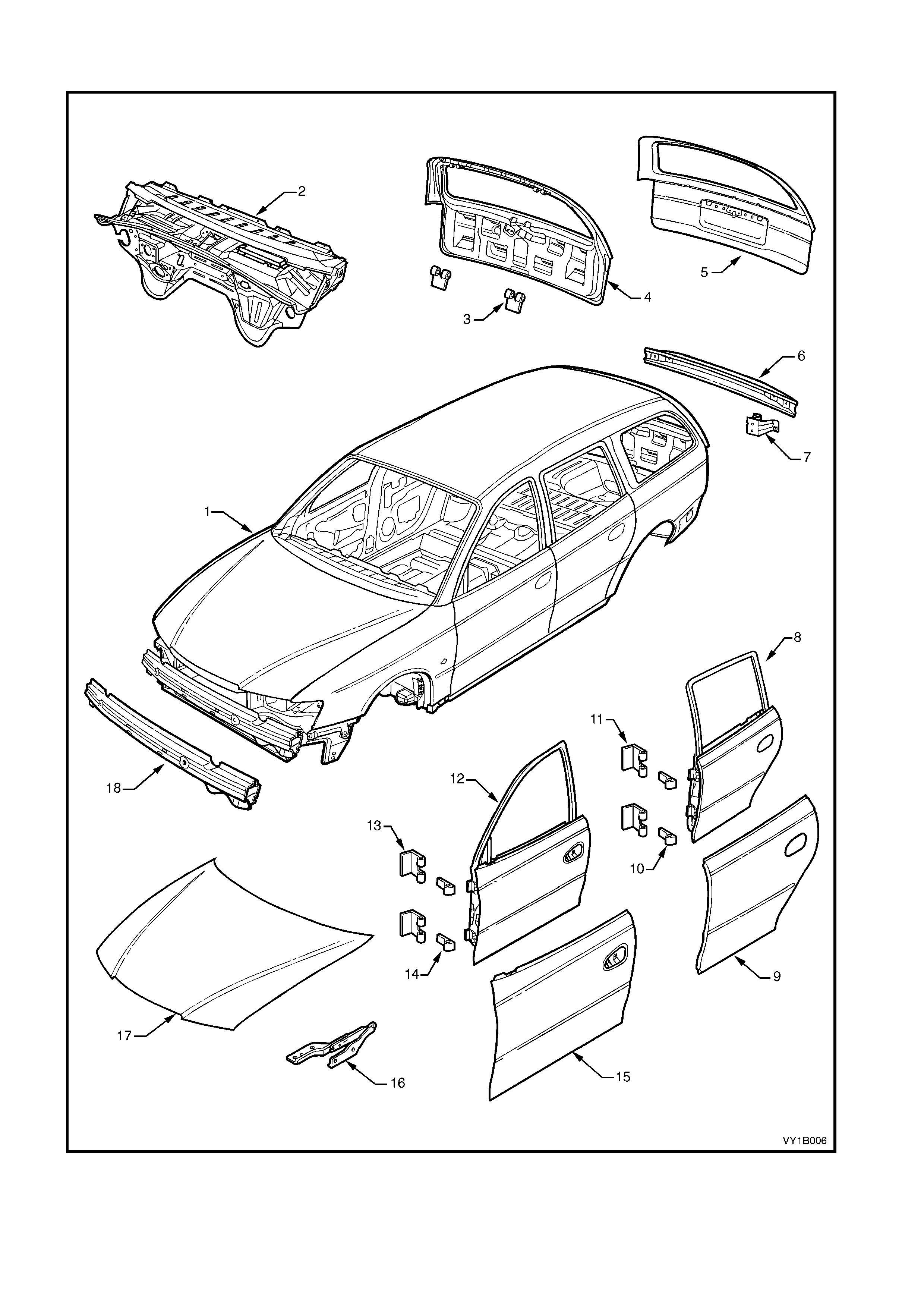
BODY ASSEMBLY – WAGON
Figure 1B-7

Legend
1. Body Assembly 10. Rear Door Hinge (Door Side)
2. Dash Panel Assembly 11. Rear Door Hinge (Body Side)
3. Liftgate Hinge (Liftgate Side) 12. Front Door Assembly
4. Liftgate Assembly 13. Front Door Hinge (Body Side)
5. Liftgate Outer Panel 14. Front Door Hinge (Door Side)
6. 5. Rear Bumper Impact Bar 15. Front Door Outer Panel
7. 6. Rear Bumper Impact Bar Bracket Assembly 16. Hood Hinge Assembly
8. Rear Door Assembly 17. Hood assembly
9. Rear Door Outer Panel 18. Front Bumper Impact Bar Assembly
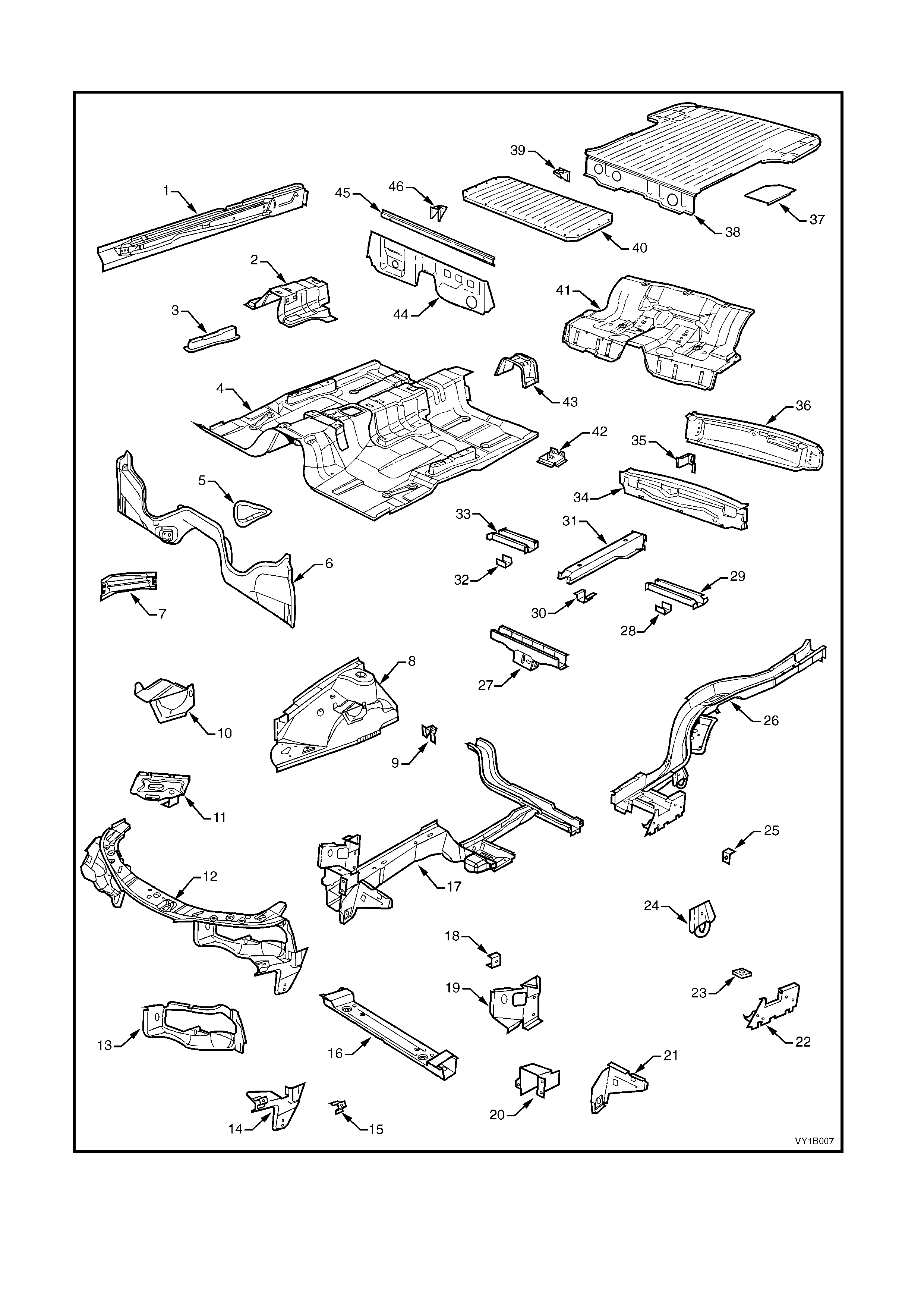
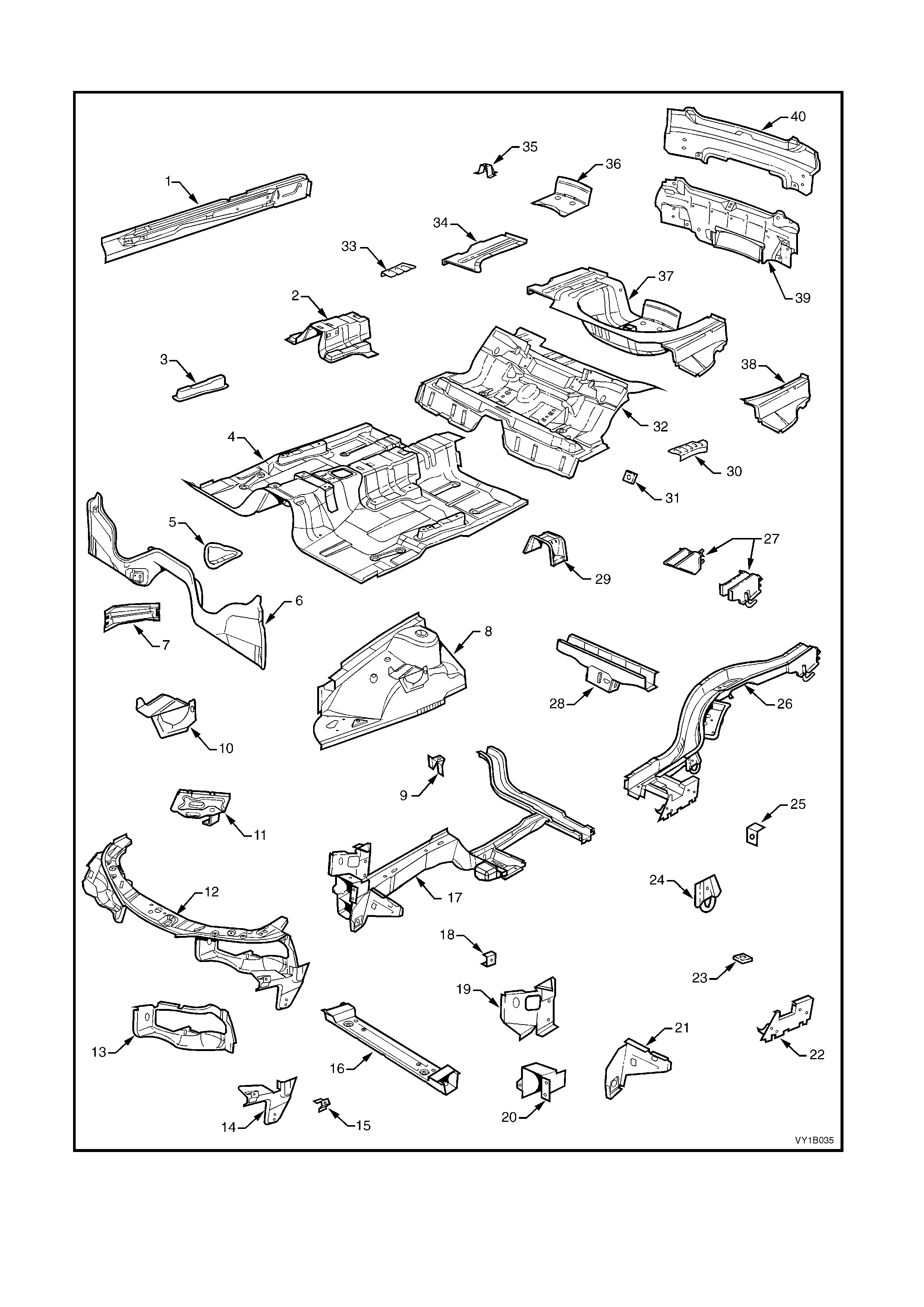
UNDERBODY – UTILITY
Figure 1B-8

Legend
1. Inner Rocker Panel Assembly 24. Rear Tie Down Assembly
2. Seat Inner Bracket Assembly 25. Rear Brake Hose Bracket
3. Seat Outer Bracket Assembly 26. Rear Side Rail Assembly
4. Front Floor Panel Assembly 27. Crossmember Assembly No. 2
5. Transmission Support Bracket 28. Spare Wheel Support, LH
6. Front Floor Panel Extension 29. Load Floor Reinforcement Rail, LH
7. Front Side Rail Brace 30. Spare Wheel Support
8. Front Wheelhouse Panel Assembly 31. Load Floor Centre Rail Assembly
9. Horn Bracket Assembly 32. Spare Wheel Support, RH
10. ABS Modulator Bracket Assembly 33. Load Floor Reinforcement Rail, RH
11. Battery Tray Assembly 34. Rear End Panel
12. Front End Panel Assembly 35. Endgate Hinge Bracket Assembly (body side)
13. Headlamp Panel 36. Rear End Lower Panel
14. Headlamp & Front Fascia Mount Bracket 37. Load Floor Panel Reinforcement
15. Fender Front Lower Bracket 38. Load Floor Panel
16. Radiator Lower Support Assembly 39. Fuel Tank Bracket Assembly
17. Front Side Rail Assembly 40. Load Floor Front Panel Assembly
18. Radiator Side Mounting Bracket 41. Rear Floor Panel Assembly
19. Front Wheelhouse Bracket Assembly 42. Jack Stowage Bracket Assembly
20. Front Bumper Impact Bar Bracket 43. Propeller Shaft Hanger Assembly
21. Front Wheelhouse Panel Bracket 44. Front Floor Rear Extension Assembly
22. Rear Floor Panel Outer Extension 45. Front Floor Rear Extension Reinforcement
23. Rear Suspension Support Mount Plate 46. Fuel Tank Bracket Assembly
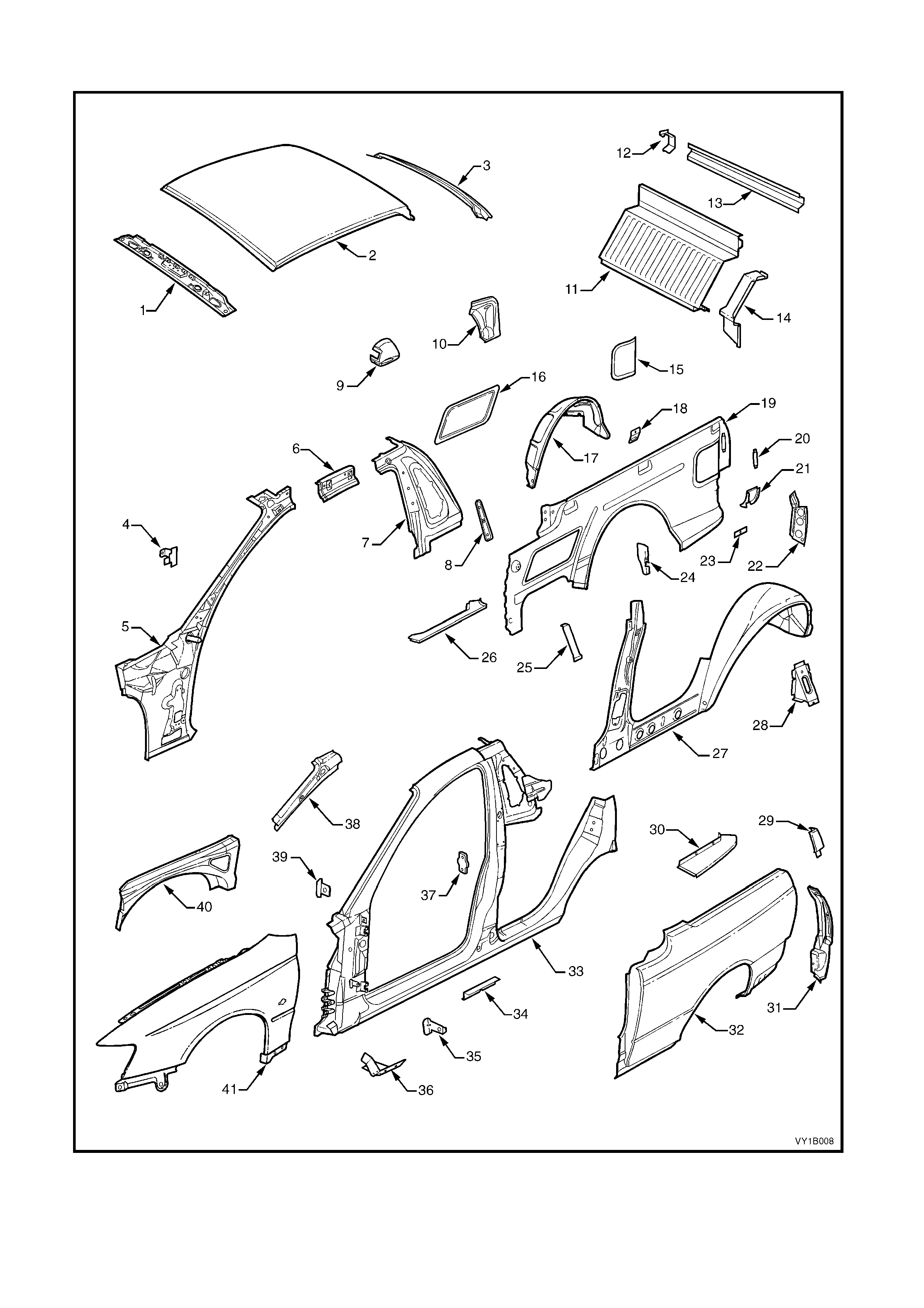
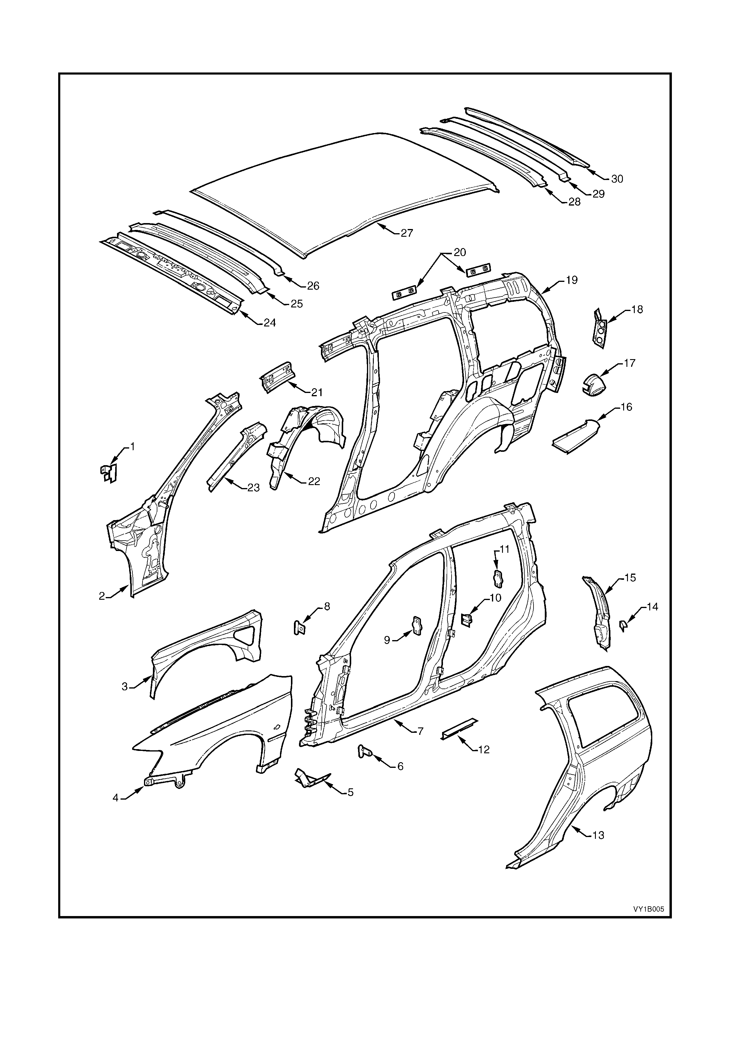
UPPERBODY – UTILITY
Figure 1B-9

Legend
1. Roof Front Header Panel 22. Quarter Inner Lower Rear Extension
2. Roof Panel 23. Cargo Tie-Down Bracket Anchor Plate Assembly
3. Roof Rear Panel 24. Rear Wheelhouse Bracket
4. Hinge Pillar Trim Panel Bracket 25. Load Floor Panel Outer Reinforcement
5. Hinge Pillar Inner Panel Assembly 26. Load Floor Panel Outer Extension
6. Quarter Panel Inner Extension 27. Quarter Panel Inner Assembly
7. Side Inner Upper Panel 28. Quarter Inner & Rear Wheelhouse Brace
8. Seat Belt Guide Anchor Plate Assembly 29. Quarter Panel Upper Extension
9. Fuel Filler Pipe Housing, RH 30. Quarter Outer Lower Rear Panel
10. Rear Wheelhouse Outer Extension 31. Quarter Panel Extension
11. Front Seat Back Panel 32. Rear Quarter Panel
12. Load Compartment Extension Panel Bracket 33. Door Opening Frame Assembly
13. Load Compartment Extension Outer Panel 34. Underbody Jacking Locator
14. Front Seat Back Panel Outer 35. Fender Rear Bracket
15. Rear Inner Side Panel Cover 36. Fender Lower Rear Bracket
16. Front Inner Side Panel Cover 37. Front Door Striker Anchor Plate
17. Rear Wheelhouse Inner Panel 38. Hinge Pillar Upper Reinforcement
18. Cargo Tie-Down Bracket 39. Fender Upper Rear Bracket
19. Side Inner Upper Panel 40. Front Wheelhouse Panel Upper Side Rail
20. Endgate Striker Anchor Plate Retainer 41. Front Fender
21. Quarter Lower Rear Panel
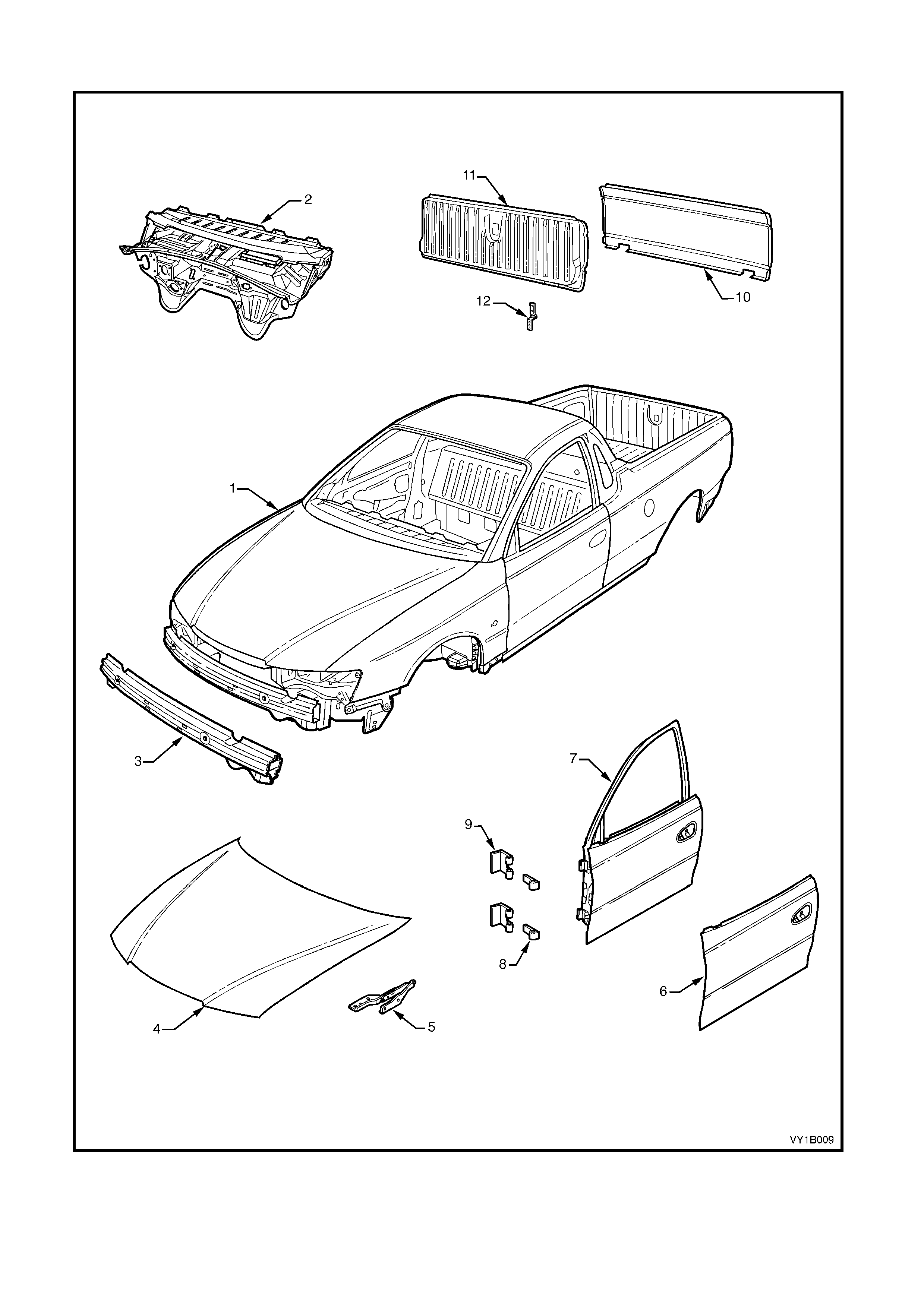
BODY ASSEMBLY – UTILITY
Figure 1B-10

Legend
1. Body assembly 7. Front Door Assembly
2. Dash Panel Assembly 8. Front Door Hinge (Door Side)
3. Front Bumper Impact Bar Assembly 9. Front Door Hinge (Body Side)
4. Hood assembly 10. Endgate Outer Panel
5. Hood Hinge Assembly 11. Endgate Assembly
6. Front Door Outer Panel 12. Endgate Hinge Assembly
UNDERBODY – COUPE
Figure 1B-11

Legend
1. Inner Rocker Panel Assembly 21. Front Wheelhouse Panel Bracket
2. Seat Inner Bracket Assembly 22. Rear Floor Panel Outer Extension
3. Seat Outer Bracket Assembly 23. Rear Suspension Support Mount Plate
4. Front Floor Panel Assembly 24. Rear Tie Down Assembly
5. Transmission Support Bracket 25. Rear Brake Hose Bracket
6. Front Floor Panel Extension 26. Rear Side Rail Assembly
7. Front Side Rail Brace 27. Rear Bumper Impact Bar Brace Assembly, LH / RH
8. Front Wheelhouse Panel Assembly 28. Crossmember Assembly No. 2
9. Horn Bracket Assembly 29. Propeller Shaft Hanger Assembly
10. ABS Modulator Bracket Assembly 30. Rear Floor Panel Reinforcement, LH
11. Battery Tray Assembly 31. Rear Seat Belt Anchor Plate Assembly
12. Front End Panel Assembly 32. Rear Floor Panel Assembly
13. Headlamp Panel 33. Rear Floor Panel Reinforcement, RH
14. Headlamp & Front Fascia Mount Bracket 34. Rear Compartment Floor Panel Outer Extension, RH
15. Fender Front Lower Bracket 35. Spare Wheel Anchor Plate Assembly
16. Radiator Lower Support Assembly 36. Fuel Tank Support Reinforcement Assembly
17. Front Side Rail Assembly 37. Rear Compartment Floor Panel Assembly
18. Radiator Side Mounting Bracket 38. Rear Compartment Floor Panel Outer Extension, LH
19. Front Wheelhouse Bracket Assembly 39. Rear End Panel Assembly
20. Front Bumper Impact Bar Bracket 40. Rear End Lower Panel
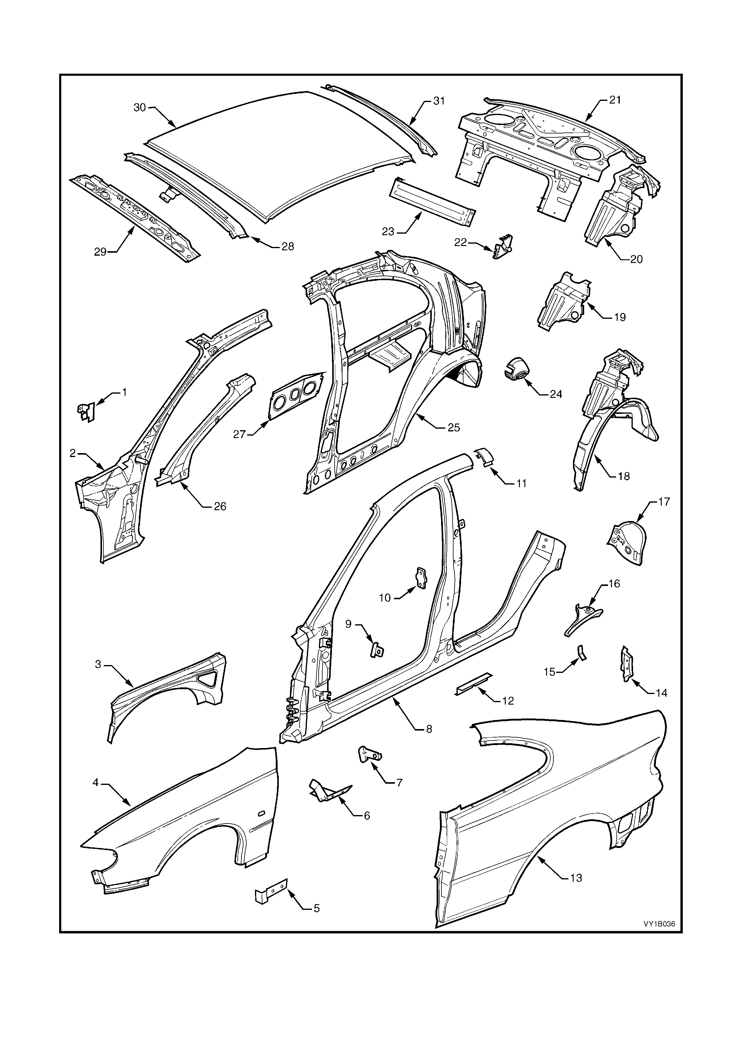
UPPERBODY – COUPE
Figure 1B-12

Legend
1. Hinge Pillar Trim Panel Bracket 17. Tail Lamp Housing
2. Hinge Pillar Inner Panel Assembly 18. Rear Wheelhouse Inner Panel Assembly
3. Front Wheelhouse Panel Upper Side Rail 19. Rear Seat Back Panel Extension
4. Front Fender 20. Rear Seat Back Panel Extension Assembly
5. Rocker Panel Moulding Bracket 21. Rear Window Panel Assembly
6. Fender Lower Rear Bracket 22. Rear Compartment Lid Strut Bracket Assembly
7. Fender Rear Bracket 23. Rear Seat Back Panel Centre Extension
8. Door Opening Frame Assembly 24. Fuel Filler Pipe Housing, RH
9. Fender Upper Rear Bracket 25. Quarter Panel Inner Assembly
10. Front Door Striker Anchor Plate 26. Hinge Pillar Upper Reinforcement
11. Body Pillar Inner Panel Reinforcement 27. Radio Quarter Speaker Bracket
12. Underbody Jacking Locator 28. Roof Bow Panel
13. Rear Quarter Panel 29. Roof Front Header Panel
14. Extension - quarter outer panel 30. Roof Panel
15. Bracket - rear lamp wiring harness extension 31. Roof Rear Panel
16. Quarter Panel Lower Extension
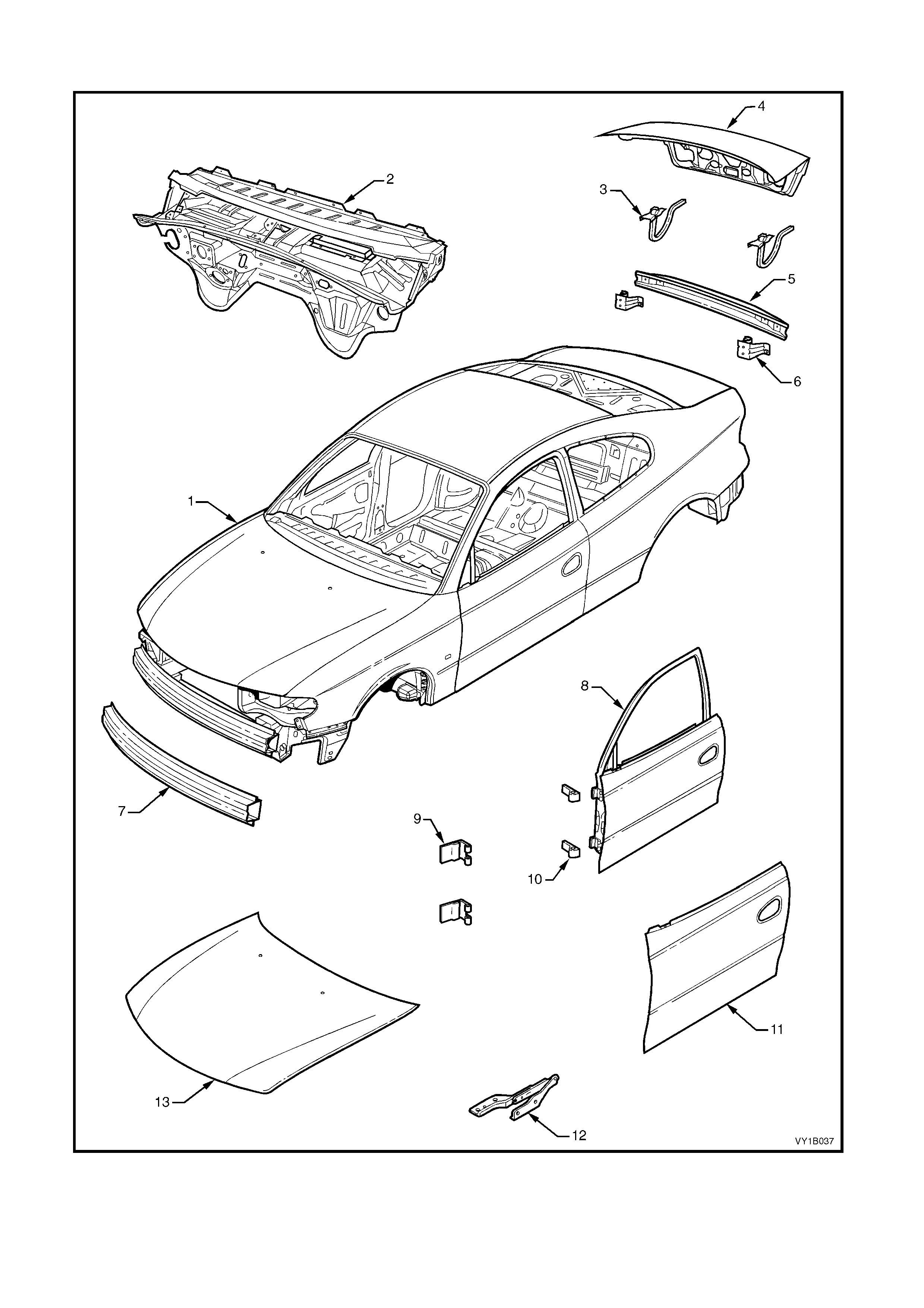
BODY ASSEMBLY – COUPE
Figure 1B-13

Legend
1. Body Assembly 8. Front Door Assembly
2. Dash Panel Assembly 9. Front Door Hinge (Body Side)
3. Rear Compartment Lid Hinge Assembly 10. Front Door Hinge (Door Side)
4. Rear Compartment Lid Assembly 11. Front Door Outer Panel
5. Rear Bumper Impact Bar 12. Hood Hinge Assembly
6. Rear Bumper Impact Bar Bracket Assembly 13. Hood assembly
7. Front Bumper Impact Bar Assembly
2.4 FRONT FENDER
LT Section – 12-425
If required, first remove the following components:
1. Front bumper fascia assembly, refer to Section 1D, BUMPER BARS.
2. Front wheelhouse liner, refer to Section 1A1, 3.1 FRONT WHEELHOUSE LINER.
3. Radio antenna assembly, refer to Section 12D, ENTERTAINMENT SYSTEM.
4. Hood strut assembly to fender screws, refer to Section 1A4, 2.6 HOOD STRUT ASSEMBLY.
5. Fender name plate and where fitted, the fender section of the body side moulding, refer to
Section 1A9 ,EXTERIOR ORNAMENTATION.
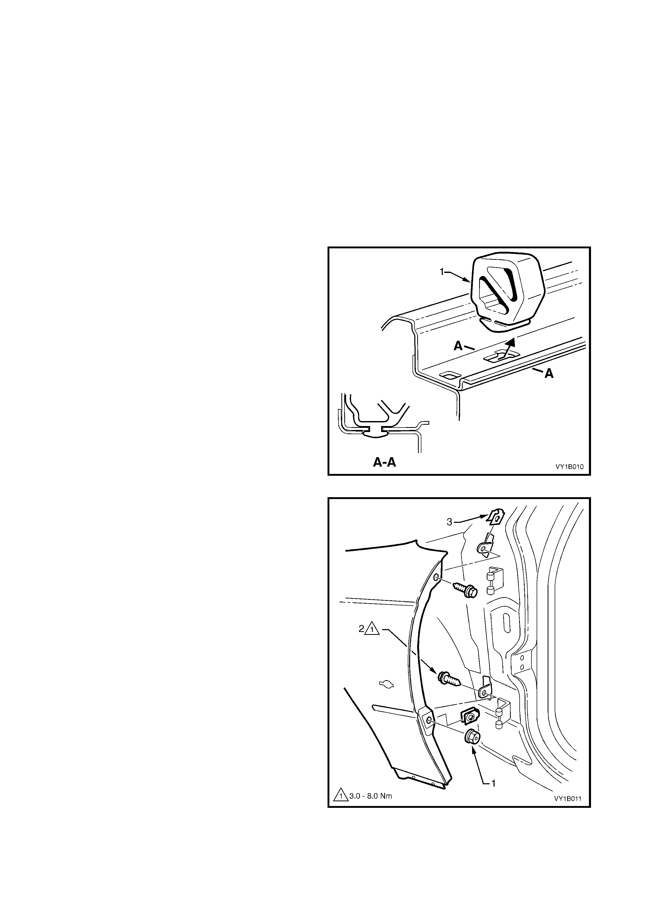
REMOVE
NOTE: Sedan, Wagon & Utility shown, Coupe is
similar.
1. While tilting the hood side bumper (1) forward
slightly, carefully slide it rearward to disengage it
from the inner edge of the fender.
Figure 1B-14
2. From the rear of the fender, remove the nut (1).
3. From behind the fender, remove the screw (2)
attaching the rear of the fender.
4. Remove the screw (3) attaching the rear of the
fender to the vehicle.
5. Remove the s even screws ( 1) attaching the f ender
to the vehicle, refer to Fig 1B-16.
Figure 1B-15

Figure 1B-16
6. Remove the fender.
NOTE: For Coupe, if required remove the Rocker
Panel Moulding Bracket, refer to (5) in Figure 1B-12.
7. If required, using a flat-blade screwdriver remove
the J-nuts from the vehicle and rear of the fender,
refer to (3) Figure 1B-15 & (2) Figure 1B-16.
REINSTALL
1. Install the J-nuts as required, refer to (3) Figure
1B-15 & (2) Figure 1B-16.
NOTE: Replace any nuts that are worn or damaged.
2. Install the fender in position and start all screws.
3. Carefully close the door and align the rear of the
fender to the door panel surface and body lines at
points A, B & C, refer to Figure 1B-17.
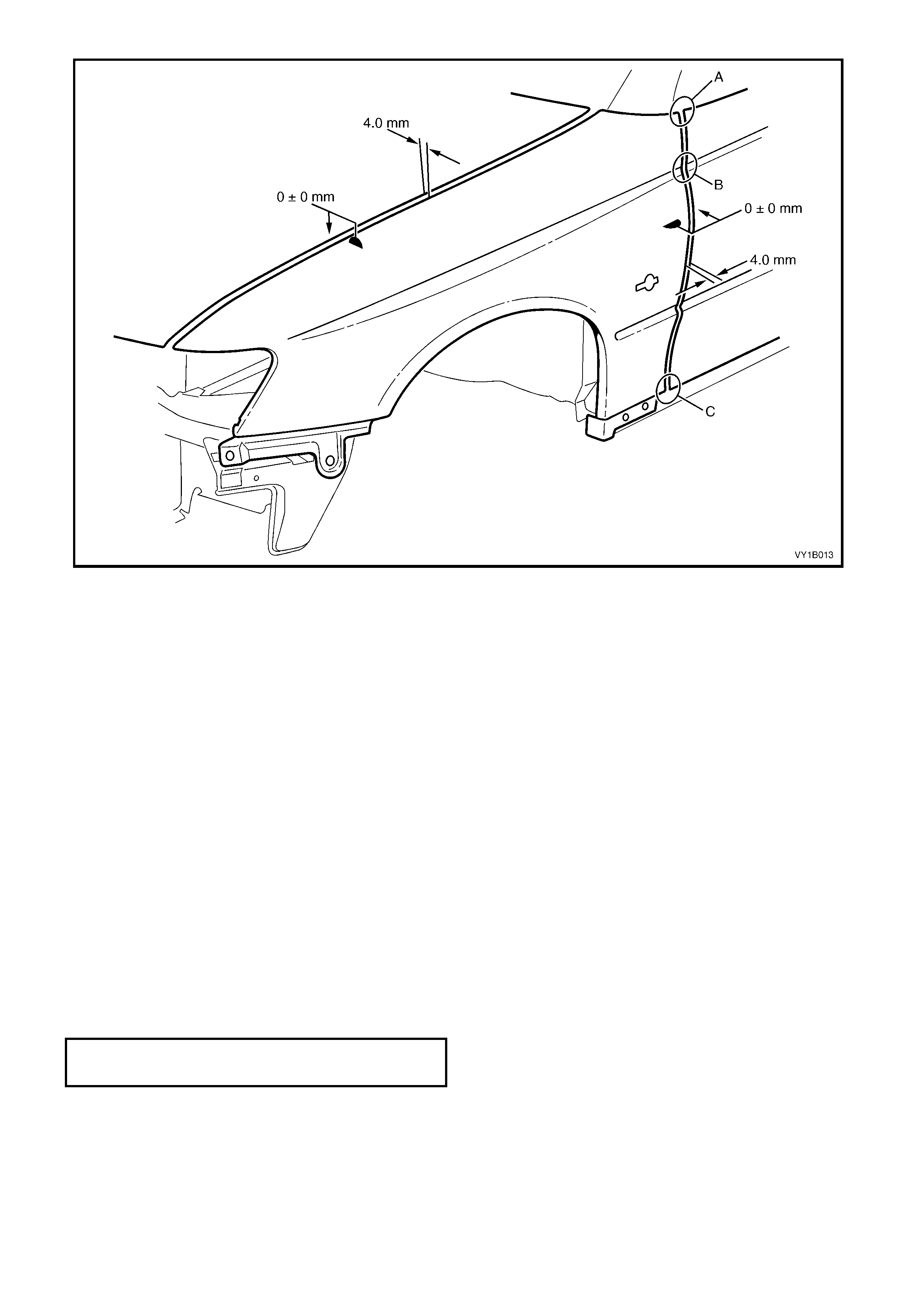
Figure 1B-17
4. Tighten the lower rear screw from behind the
fender to the specified torque, refer to Figure
1B-15.
5. Open the door and tighten the upper rear scr ew to
the specified torque.
6. Recheck alignment and also check for an even
gap of 4.0 mm to the f r ont door, r ef er to Figure 1B-
17.
7. If the gap is not to spec ification, caref ully bend the
rear fender brackets.
8. Carefully close the hood and adjust the position of
the fender to provide an even gap of 4.0 mm.
9. Open the hood and tighten the three upper fender
screws to the specified torque, refer to Figure
1B-16.
10. Recheck alignment and readjust as required.
NOTE: Also chec k that the upper f ender sur f ac e aligns
to the engine hood surface. If not adjust the hood, refer
to Section 1A4, 2.7 HOOD & HINGE ASSEMBLIES,
ADJUST.
11. Tighten all the remaining screws to the specified
torque.
12. Following painting, install the nut onto the rear
lower fender screw and other removed
components as required.
FRONT FENDER ATTACHING SCREW
TORQUE SPECIFICATION 3.0 – 8.0 Nm
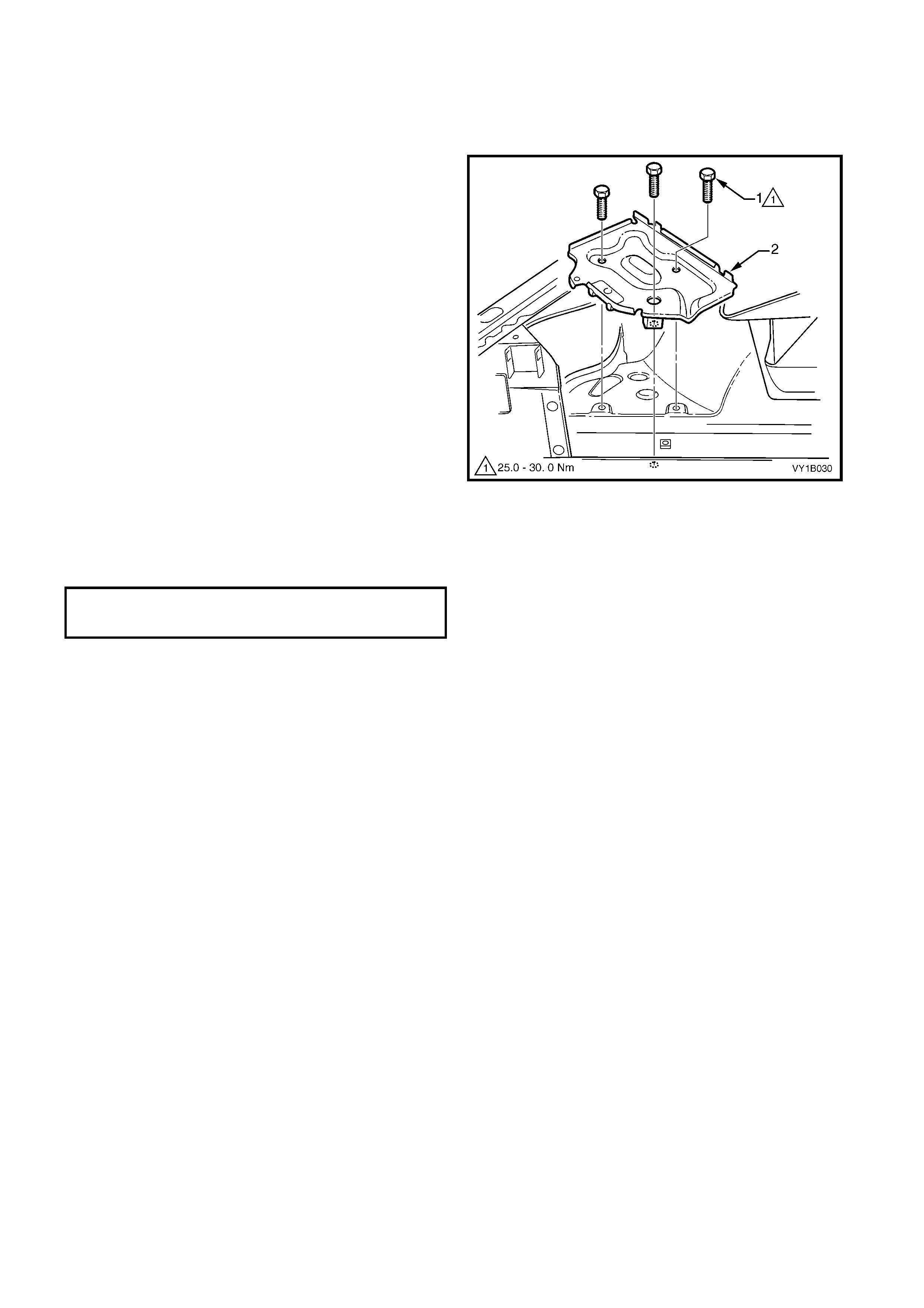
2.5 BATTERY TRAY ASSEMBLY
LT Section – 02-200
REMOVE
1. Remove the battery as described in
Section 12A BATTERY & CABLES.
2. Rem ove the three screws (1) attaching the battery
tray assembly (2) to the front wheelhouse and rail.
Figure 1B-18
REINSTALL
1. Installation is the reverse of removal. Tighten the
screws to the specified torque.
BATTERY TRAY ASSEMBLY ATTACHING
SCREW TORQUE SPECIFICATION 25.0 – 30.0 Nm
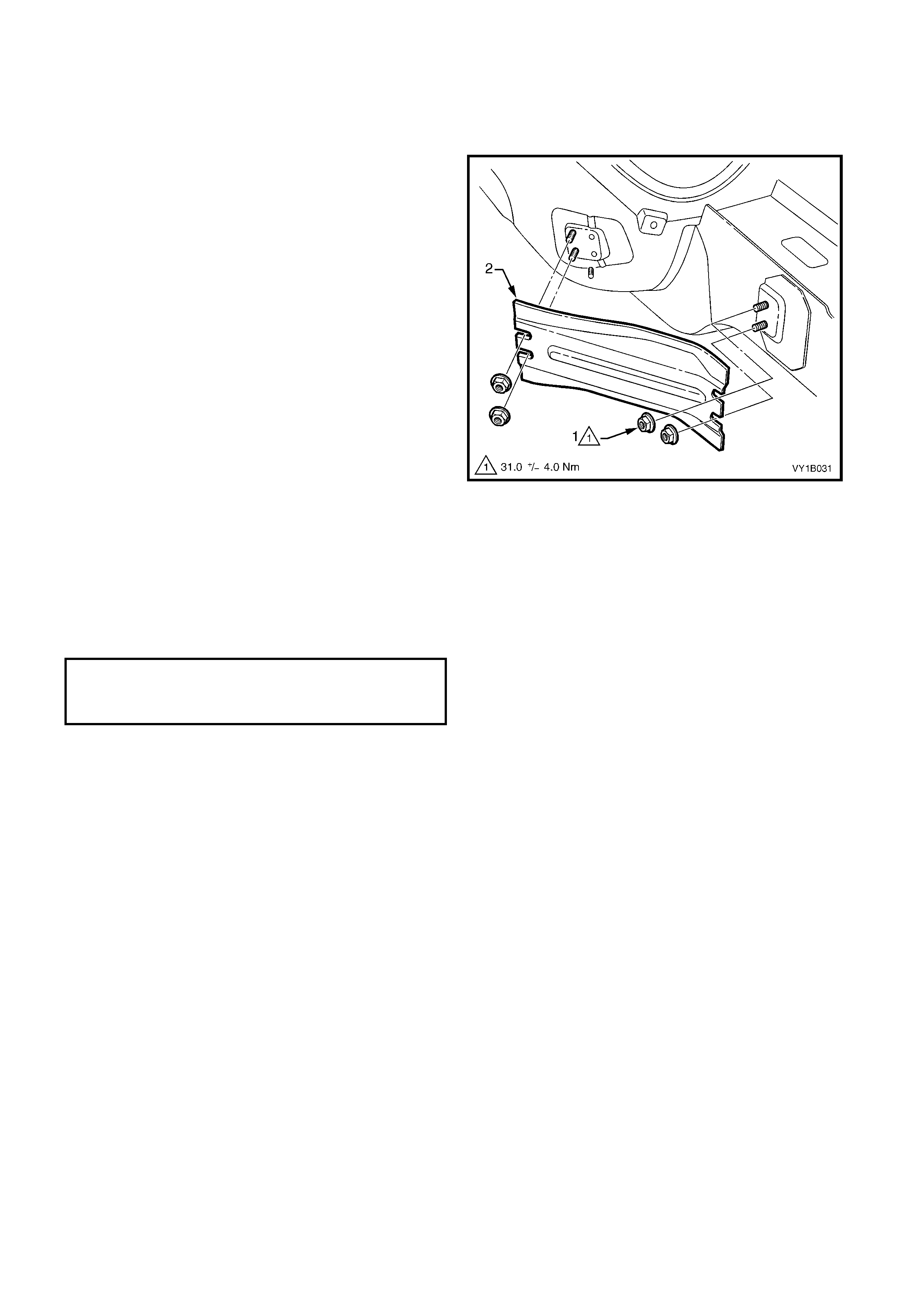
2.6 FRONT SIDE RAIL BRACE
LT Section – 12-425
REMOVE
1. Loosen the two rear nuts and rem ove the two f ront
nuts (1) attaching the front side rail brace (2)
between the front side rail and brace
reinforcement assembly - underbody.
2. Remove the brace from the vehicle.
Figure 1B-19
REINSTALL
1. Install the brace ensuring it is correctly orientated.
2. Tighten the nuts to the specified torque.
IMPORTANT: As the braces serve as a critical
structural component of the body structure, correct
fitment and torque are crucial.
FRONT SIDE RAIL BRACE
UPPER ATTACHING NUT
TORQUE SPECIFICATION 31.0 ± 4.0 Nm

2.7 LOAD FLOOR FRONT PANEL ASSEMBLY, UTILITY
LT Section – 12-480
REMOVE
1. If fitted, remove the LPG cylinder and mounting
hardware, refer to Section 8A2, LPG.
2. Rem ove the 22 screws (1) attaching the load floor
front panel assembly (2) to the vehicle, refer to
Figure 1B-20.
3. Using a f lat-blade sc rewdriver or suitable lever and
a piece a scrap wood as a fulcrum, prise each
corner of the panel assembly from the vehicle to
break the sealer (3).
4. With the aid of an as s istant, lift the panel assem bly
from the vehicle.
Figure 1B-20
REINSTALL
1. If required apply a continuous bead of sealer such
as a non-hardening butyl sealer around the
perimeter of the lower flange of the panel
assembly.
2. With the aid of an assistant, install the panel
assembly ensuring it is correctly orientated. The
arrows (4) must be pointing forward, refer to
Figure 1B-20.
3. Start all screws and then tighten to the specified
torque.
4. Remove any residual sealer as required.
LOAD FLOOR FRONT PANEL
ASSEMBLY ATTACHING SCREW
TORQUE SPECIFICATION 1.0 – 3.0 Nm
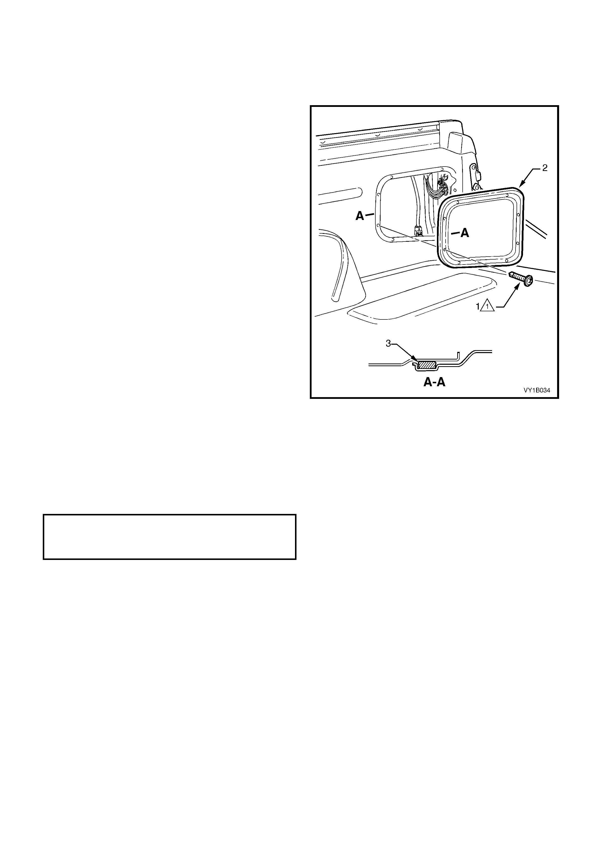
2.8 FRONT INNER SIDE PANEL COVER, UTILITY
LT Section – 12-480
REMOVE
1. If fitted, rem ove the LPG cylinder and hardware as
required, refer to Section 8A2, LPG.
2. Remove the 10 s cr ews (1) attac hing the f ront inner
side panel cover (2) to the vehicle.
3. Using a flat-blade screwdriver or suitable lever
carefully prise the corner of the cover from the
vehicle to break the sealer (3).
NOTE: Protect the paintwork with a rag.
4. Remove the cover from the vehicle.
Figure 1B-21
REINSTALL
1. Apply a continuous bead of sealer such non-
hardening butyl sealer around the perimeter of the
cover.
2. Install the cover ensuring it is correctly orientated.
3. Start all screws and then tighten to the specified
torque.
4. Remove any residual sealer as required.
FRONT INNER SIDE PANEL
COVER ATTACHING SCREW
TORQUE SPECIFICATION 1.0 – 3.0 Nm
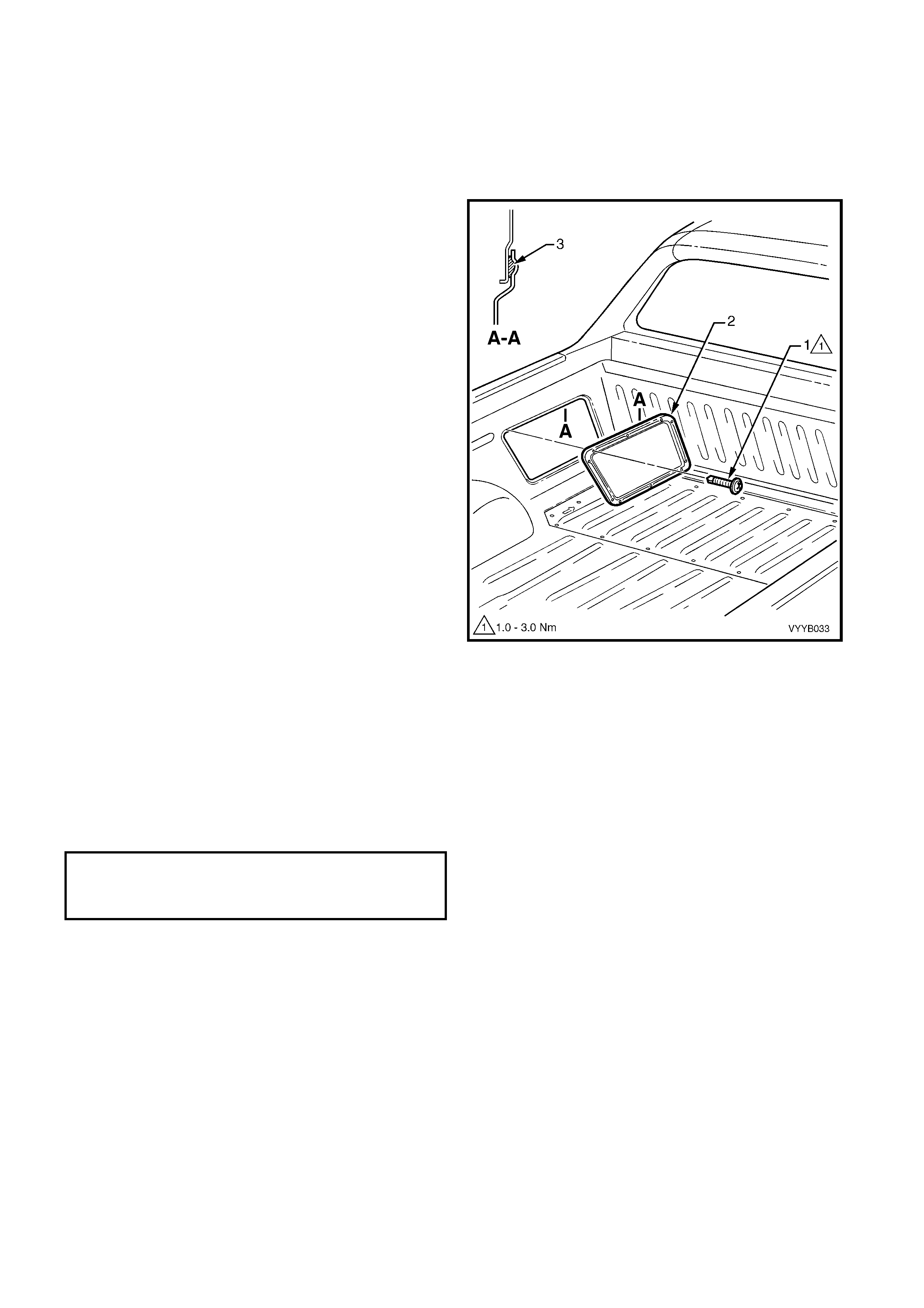
2.9 REAR INNER SIDE PANEL COVER, UTILITY
LT Section – 12-480
REMOVE
1. Remove the 8 screws (1) attaching the rear inner
side panel cover (2) to the vehicle.
2. If required, use a flat-blade screwdriver or suitable
lever carefully prise the corner of the cover from
the vehicle. Do not break the seal (3).
NOTE: Protect the paintwork with a rag.
3. Remove the cover from the vehicle.
Figure 1B-22
REINSTALL
1. Install the cover ensuring it is correctly orientated
and the seal is correctly positioned.
2. Start all screws and then tighten to the specified
torque.
3. Remove any residual sealer as required.
REAR INNER SIDE PANEL
COVER ATTACHING SCREW
TORQUE SPECIFICATION 1.0 – 3.0 Nm

3. TORQUE WRENCH SPECIFICATIONS
Front fender attaching screw..........................................................................3.0 – 8.0 Nm
Battery tray assembly attaching screw ...........................................................25.0 – 30.0 Nm
Front side rail brace attaching nut ..................................................................31.0 ± 4.0 Nm
Load floor front panel assembly, Utility attaching screw.................................1.0 – 3.0 Nm
Inner side panel cover, Utility attaching screw................................................1.0 – 3.0 Nm