
SECTION 1D - BUMPER BARS
IMPORTANT
Before performing any Service Operation or other procedure described in this Section, refer to Section 00
CAUTIONS AND NOTES for correct workshop practices with regard to safety and/or property damage.
CONTENTS
1. GENERAL DESCRIPTION
2. SERVICE OPERATIONS
2.1 PAINT SYSTEMS
GENERAL
REVERSE PARKING AID (RPA)
RECOMMENDED MATERIALS
REFINISHING OF REPLACEMENT
PARTS
REPAIRING COLOUR COAT
HARDENER PRECAUTIONS
PAINT MASKING
2.2 FRONT BUMPER FASCIA ASSEMBLY
REMOVE
DISASSEMBLE
REINSTALL
2.3 FRONT BUMPER FASCIA GUIDE
ASSEMBLY
SEDAN, WAGON & UTILITY
COUPE
2.4 FRONT BUMPER IMPACT BAR
ASSEMBLY
REMOVE
REINSTALL
2.5 REAR BUMPER FASCIA ASSEMBLY,
SEDAN & COUPE
REMOVE
DISASSEMBLE
REVERSE PARKING AID
COMPONENTS
REINSTALL
2.6 REAR BUMPER FASCIA ASSEMBLY,
WAGON
REMOVE
DISASSEMBLE
REINSTALL
2.7 REAR BUMPER FASCIA, UTILITY
REMOVE
REINSTALL
2.8 REAR BUMPER FASCIA GUIDE ASSEMBLY
REMOVE
REINSTALL
2.9 REAR BUMPER FASCIA CENTRE
SUPPORT, SEDAN & COUPE
REMOVE
REINSTALL
2.10 REAR BUMPER SUPPORT FASCIA
UPPER, WAGON
REMOVE
REINSTALL
2.11 REAR BUMPER IMPACT BAR, EXCEPT
UTILITY
REMOVE
REINSTALL
3. TORQUE WRENCH SPECIFICATIONS

1. GENERAL DESCRIPTION
The bumper fascia assemblies fitted to MY2003 VY and V2 series vehicles are constructed from polypropylene
resin. Four styles of fr ont bumper f ascia are available depending on the m odel level: Level 1, Level 2 & 3, S Sedan
& SS, and Coupe.
NOTE: For model level designations, refer to Section 0A GENERAL INFORMATION.
All of the front bumper fascias, with the exception of Coupe, feature a separate radiator grille assembly which is
described in Section 1C RADIATOR GRILLE. The Coupe the radiator grille is moulded as part of the bumper
fascia.
With the exception of S Sedan and SS models, all front bumper fascias feature a separate lower radiator grille,
which is also described in Section 1C RADIATOR GRILLE.
Seven rear bumper fascias are available depending on model level and body type:
• Sedan: one each for Level 1, Level 2 & 3 and S & SS, all with or without Reverse Parking Aid (RPA) sensor
assemblies,
• Wagon: one for all Levels,
• Coupe: one for all Levels, with or without RPA sensor assemblies, and
• Utility: separate bumper fascias each side of the vehicle, one for Level 1 & S and one for SS.
The Level 1, S & SS Sedan rear bumper fascias feature a separate lower insert which has a black finish to match
the paint masking area.
Removable towbar opening covers ar e fitted to Sedan and Wagon rear bum per fas cias. Coupe f asc ias do not have
a cover and if a towbar is fitted, the fascia must be modified by cutting an opening and fitting a surround. This
procedure is included in this Section.
A steel front bumper impact bar assembly is installed behind the front bumper fascia assembly and is attached
directly to the front side rails . T he bar ass em bly is designed to assist in the dis persion of crash energy and plays an
integral role with the vehicle’s safety systems.
A steel rear bumper impact bar is also installed behind the rear bumper fascia on all models except utility.
As mentioned, the Sedan and Coupe rear fascia assemblies may include four rear sensor assemblies for Reverse
Parking Aid (RPA).
W hen reverse gear is selected, the sensors emit an ultra-sonic signal which is monitored by a control module. As
the sensors detect an object within their field of range, the system warns the driver by emitting an audible sound,
which increases in frequency, as the object becomes closer.
NOTE: If the vehicle is fitted with RPA, a new rear bumper fascia service part will require modification prior to
painting and installation, ref er to 2.5 REAR BUM PER FASCIA ASSEMBLY , SEDAN & COUPE – Reverse Park ing
Aid Components.
IMPORTANT: The sensors are supplied pre-painted in the vehicle’s body colour and must not be painted, refer to
2.1 PAINT SYSTEM S and Revers e Par k ing Aid Components in 2.5 REAR BUMPER FASCIA ASSEMBLY, SEDAN
& COUPE.
Further information on RPA can be found in Section 12F REVERSE PARKING AID.

2. SERVICE OPERATIONS
2.1 PAINT SYSTEMS
GENERAL
The paint s ystem f o r the bumper fascias and other painted plastic c omponents is relatively straightf or ward providing
the correct materials are used. Normal refinish lacquers will not adhere to plastic components unless the correct
primers and/or additives are used.
NOTE: Thorough cleaning and the use of approved paint and additives or their equivalent is required. Incorrect
materials and methods may damage the plastic or lead to premature paint failure.
The f ollowing s er vice r ecommendations ar e c ompiled to guide repair ers on the c orr ec t materials and methods to be
employed when refinishing bum per f asc ias and preparing new parts for service ins tallation. If another paint brand is
chosen, refer to the manufacturer’s latest technical data for the appropriate materials and procedures required.
REVERSE PARKING AID (RPA)
Where fitted, the rear bumper fascia assembly contains four sensor assemblies for Reverse Parking Aid (RPA).
The exposed end of the sensor assembly is painted the vehicle’s body colour. New service sensor assemblies are
supplied pre-painted in the vehicle’s body colour and must not have any further paint applied.
IMPORTANT: If r epainting a fascia as sem bly, the s ensors and rings MUST be rem oved. Paint m ust not be applied
to any part of a sensor, including the exposed coloured surface. Paint film applied to the exposed surface will render
the sensor inoperable as the paint film restricts the sensor’s ultra-sonic signal. If a sensor is damaged, it must be
replaced.
Replacement housings are supplied unpainted. As they are partially exposed when installed, they will require
painting using the same procedures for painting the bumper fascia, described below.
NOTE: It is preferable to paint the housings and bumper fascia separately to avoid adhesion problems. Assemble
the housings onto the bum per fasc ia once the paint has cured, ref er to 2.5 REAR BUM PER FASCIA ASSEM BLY,
SEDAN & COUPE – Reverse Parking Aid Components.
For further information on reverse parking aid, refer to Section 12F REVERSE PARKING AID.
RECOMMENDED MATERIALS
Front and rear bumper fascias are made from high impact strength Polypropylene (PP).
It is essential that only approved materials, paints, etc. or their equivalent are employed when paint repair
operations are performed and when preparing new parts for installation to the vehicles.
The approved materials are:
- PPG Bodykleen 920-30509
- PPG Plastpak Universal Anti Static Cleaner 920-39237
- PPG Plastpak Universal Primer 499-38571
- PPG Plastpak Flexible Additive for Two Component Products 499-35484
- PPG Cobra Basecoat - Colour 534 Line
- PPG Basecoat Thinner 920-34926
- PPG 2K Clearcoat 455-30900
- PPG 2K Acrylic Enamel Solid Colour 426 Line
- PPG 2K MS Hardener Normal 980-35239
- PPG 2K Reducer Fast 920-9148
REFINISHING OF REPLACEMENT PARTS
Replacement parts will require priming and coating with approved topcoat colour before installation to the vehicle.
1. Order part and paint materials.
2. Read all safety data material relative to the paint system chosen from the paint manufacturer and the
HARDENER PRECAUTIONS further in this Section.
3. Obtain the required respiration and safety equipment recommended by the paint manufacturer, in this
publication or required by regulations.
4. Wash the unpainted bumper fascia all over with a made-up solution of 9 parts fresh water to 1 part PPG
Bodykleen 920-39237. Apply with a clean, non-metallic pad (recommended Scotchbrite** 448) to scuff the
surface.

5. Rinse with fresh cold water.
6. Use a clean cloth saturated with PPG Plastpak Universal Anti-static Cleaner 920-39237. W ash the entire part
allowing contact for a minimum 15 seconds.
7. Dry thoroughly using a separate, clean, dry cloth.
8. Repeat steps five and six another three times. Use a separate, clean dry cloth each time.
NOTE: If a static charge has built up on the bum per surface ( after com pleting all cleaning operations) dam pen the
surface with Plastpak Universal Anti Static Cleaner and allow to evaporate dry. This will impart full anti-static
properties to the bumper fascia.
Priming
1. Fit an air-supplied respirator.
2. Apply one light double coat (approx imately 3-8 m D.F. B. uniformly wet) of PPG Plastpak Univers al Pr imer 499-
38571 to the bumper surface intended for topcoat. Recommended air pressure range is 320-420 kPa.
3. Allow to air dry 15-20 minutes at 20°C. DO NOT SAND.
** Scotchbrite is a trademark of 3M Co.
PAINT – 2K SYSTEM
1. To the matched colour, add Flexible Additive then Hardener and Reducer in the following ratios:
- 246 line colour - 5 parts by volume
- Flexible Additive 499-35484 - 1 part by volume
- 2K MS Hardener 980-35239 - 3 parts by volume
- 2K Reducer 920-19148 - 10-20% by volume
2. Stir thoroughly and strain.
3. Fit an air-supplied respirator.
4. Using a 1.4 – 1.8 mm fluid nozz le on a standard spray gun, apply one medium wet coat.
5. Apply a further one or two coats to achieve coverage (correct film thickness is 40-50 microns) allowing a 3-5
minute flash-off time between coats.
6. If low baking, this can be done im mediately after the last coat, but do not allow more than 5 minutes flash-off.
Bake at 60°C for 40 minutes.
7. If air drying, allow 16 hours.
PAINT – COBRA BASECOAT, METALLIC, PEARL OR SOLID COLOUR SYSTEM
1. Thin the matched basecoat colour with Cobra Basebuilder, 920 line at a 1:1 mix ratio and stir thoroughly.
2. Strain material.
3. Fit an air supplied respirator.
4. Using a 1.4 - 1.6 mm gravity feed spray gun, apply one medium, wet even coat. Allow to flash-off for five
minutes before applying the next coat.
5. Apply one or two further coats to achieve a uniform and even coverage with 5 minutes flash-off between coats.
6. Allow 10-20 minutes drying
7. Mix the 2K Clearcoat with flexible additive, then hardener and reducer in the following ratios:
- 2K Clearcoat 455-30900 - 5 parts by volume
- Flexible Additive 499-35484 - 1 part by volume
- 2K MS Hardener 980-35239 - 3 parts by volume
- 2K Reducer 920-19148 - 20% by volume
Stir thoroughly and strain.
8. Using a 1.4-1.8 fluid nozzle spray gun set up, apply one medium wet coat.
9. Apply a further one or two wet coats after a 3-5 minutes flash-off between coats.
10. If low baking, this can be done immediately after the last coat, but do not allow more than 5 minutes flash-off.
Bake at 60°C for 40 minutes.
11. If air drying, allow 16 hours.

REPAIRING COLOUR COAT
Sanding and repainting may rectify superficial damage to the paint film and/or plastic surfaces. Parts having deep
gouges in the plastic s urface should be r eplaced as repair m ethods using filling m aterials and thinning down of the
plastic section may reduce overall impact strength.
For shallow paint damage, follow the procedure listed under “Colour Finishing of Replacement Parts” in this Section,
using P800 paper to sand down imperfections and using a Scotchbrite 448 pad or P1200 paper, scuff and key
existing paintwork.
Basecoat and Clearcoat can be spot repaired by blending away the basecoat colour and spraying the complete
bumper with Clearcoat. Solid colours are best sprayed as complete panels. If the damage extends through the
paintwork to the plastic surface, this must be primed with Plastpak Universal Primer after the correct cleaning
procedure.
NOTE: Drying of all products m ay be accelerated by heat. But to avoid distortion, uns upported bumper s should not
be heated in an oven or by lamp above 60°C.
HARDENER PRECAUTIONS
The following instructions relate to the safe handling of all paints containing PPG 2K MS Hardener, which contains
not more than 0.3% isocyanate monomer.
CAUTION: This product is for automotive and industrial use only. It requires professional equipment and
experience for safe handling. It is not for use by the general public.
Read and understand the instr uc tions and warnings c ontained in Material Saf ety Data s heets and on the label of the
can containing the base product before opening. Follow all directions and warnings carefully, otherwise do not use
this product. Warnings and precautions on the label also apply to the mixture of hardener and base.
Inhalation of vapour, spray mist and dust from sanding is harmful and may cause lung irritation and allergic
respiratory reaction. The vapour also irritates the skin and eyes.
W hen m ixed with the appropriate base, apply in a spray booth fitted with an effective exhaust system. Com ply with
local legislation applicable to spray painting of motor vehicles. Wear a positive pressure air supplied full face
respirator (complying with any relevant Standards) and gloves while spraying and during all subsequent use. The
spray booth area should be isolated from other people while spraying is in progress and until all spray mist has been
effectively evacuated.
If affected by inhalation of vapour or spray mist, move to a location with plenty of fresh air.
If breathing difficulty persists or occurs later, consult a doctor and have the label information available. In the case
of eye contact, flush immediately with plenty of water for 15 minutes and call a doctor.
In case of skin contact, remove contaminated clothing and wash skin thoroughly with soap and water. Immerse
contaminated clothing in water for 24 hours and do not re-use until it has been laundered.
In case of spillage, absor b the liquid onto dry sand or earth. Rem ove the spillage from the work area and cover with
water for 24 hours before disposal. Treat the empty hardener cans in the same manner.
PAINT MASKING
The following illustrations show the front and rear bumper fascia paint masking areas for each vehicle model and
are provided to assist when painting a bumper fascia to match the factory finish.
For further information on the specific model levels, refer to Section 0A.
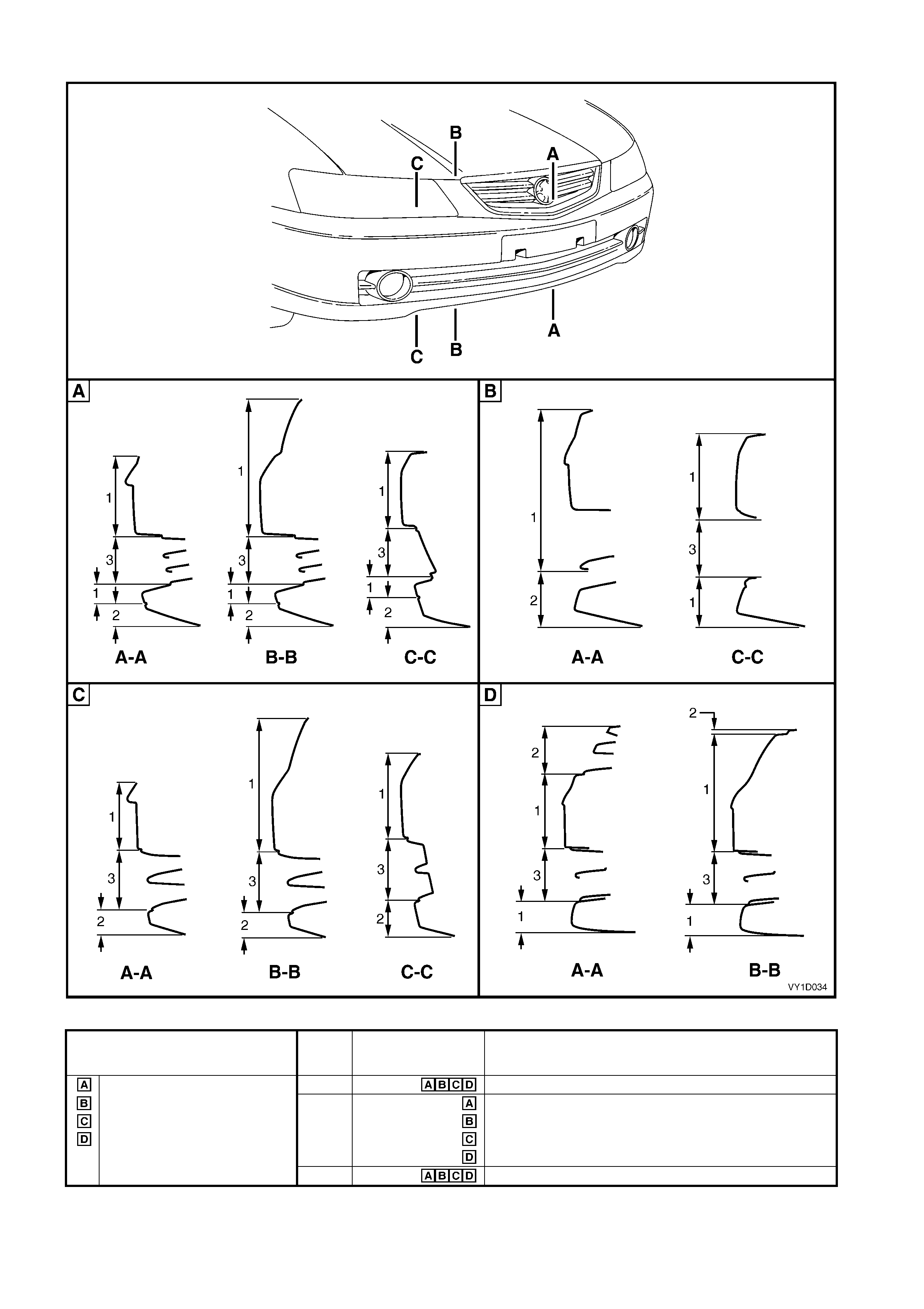
Front Bumper
Figure 1D-1
Model Area Applicable
Model Finish
Level 1, except S sedan and SS 1 Body Colour
S sedan and SS 2 Unpainted, except Ac claim, SV8 and S ut ility – body colour
Level 2 and 3 Unpainted
Coupe Body colour
Unpainted
3 Fog lamp / Lower grille / Ins ert – finish of supplied part
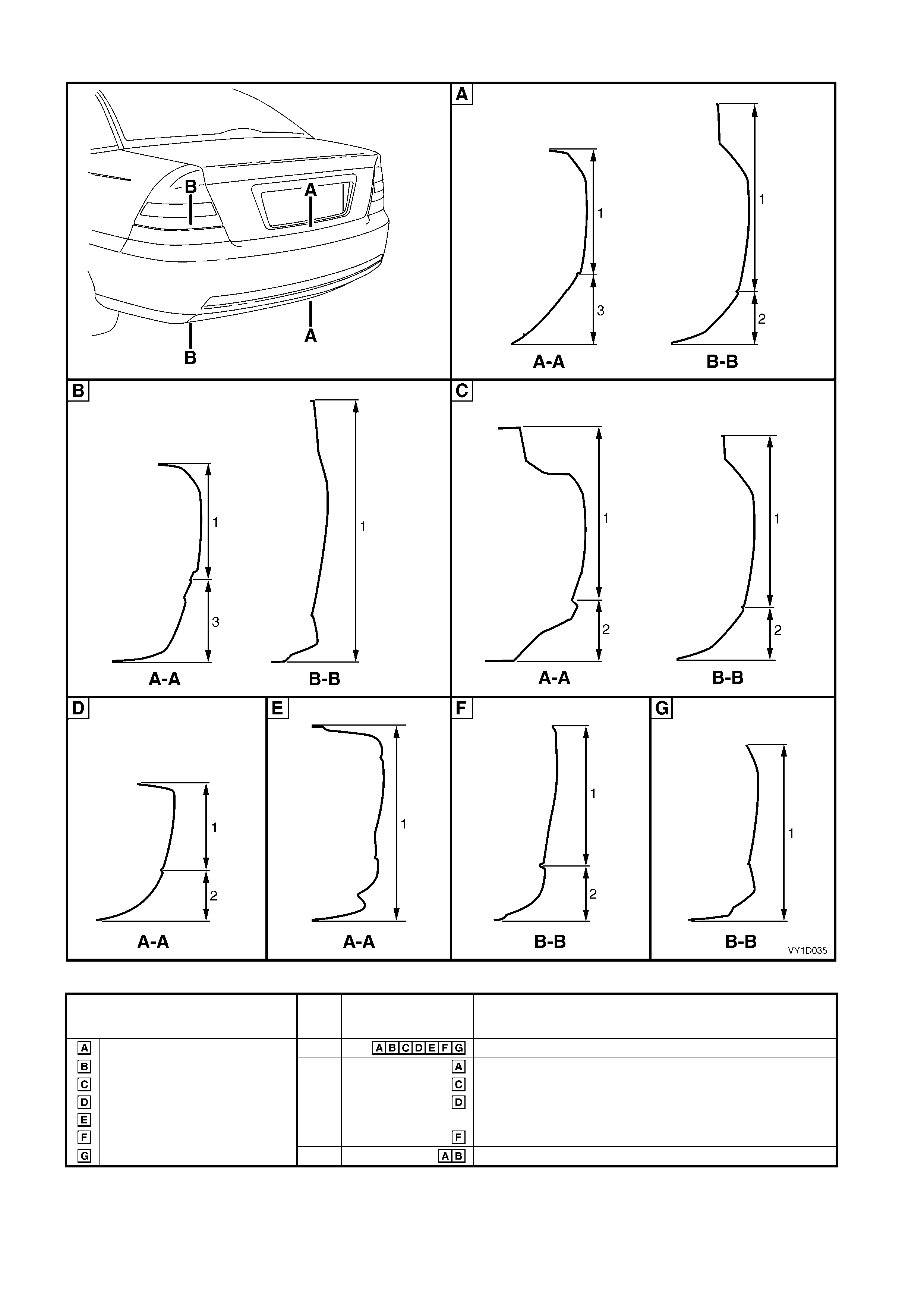
Rear Bumper
Figure 1D-2
Model
A
rea Applicable
Model Finish
Level 1 sedan, except S and SS 1 Body Colour
S sedan and SS 2 Unpainted, except Acclai m and SV 8 – body colour
Level 2 and 3 sedan Body colour
Wagon
Coupe Level 1 – unpainted, except A cclaim
Level 2 and Acclaim – body colour
Utility, except SS Unpainted, except S – body colour
Utility SS 3 Insert – f i ni sh of suppl i ed part

2.2 FRONT BUMPER FASCIA ASSEMBLY
LT Section – 07-500
NOTE: Although different in appearance and minor detail, the procedure for removal of the front bumper fascia
assembly is the same for all models.
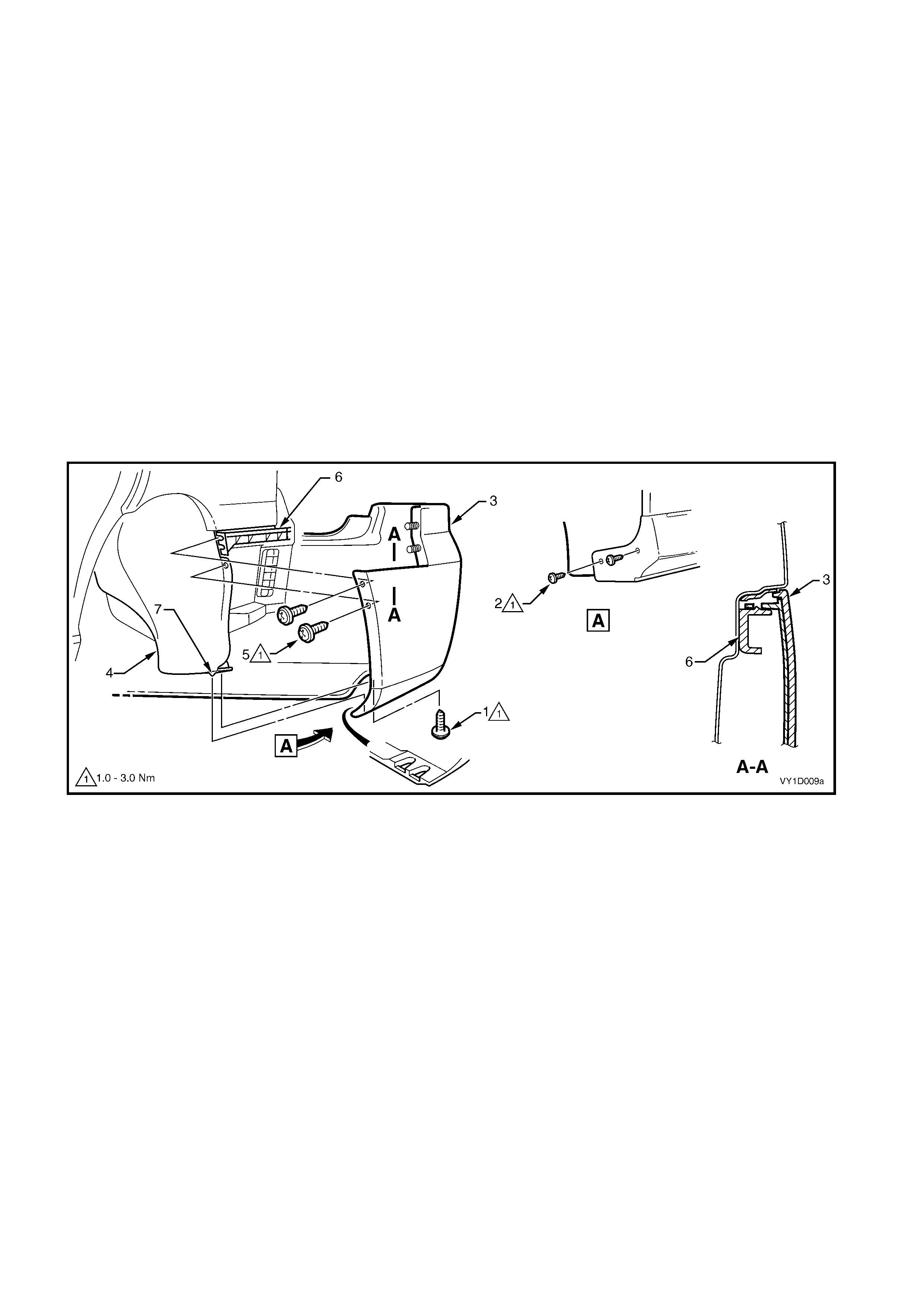
REMOVE
1. From each side of the vehicle:
a. Remove the screw (1), or for S and SS vehicles (2), attaching the front bumper fascia assembly (3) to
the front wheelhouse liner (4), refer to Figure 1D-3.
b. Remove the screw (5) attaching the front bumper assembly to the fascia guide assembly (6).
c. Carefully unclip the fascia assembly from the guide assembly by grasping the upper end of the fascia
and pulling away from the vehicle.
Figure 1D-3
2. If fitted, disconnect the front fog lamp wiring connector (1), one place each side of the vehicle, refer to Figure
1D-4.
3. Remove the two retainers ( 2) f r om the rec es ses ( behind the licenc e plate) , attaching the fascia as s embly (3)
to the front bumper impact bar assembly (4).
4. Remove the three screws (5) attaching the fascia assembly to the front upper panel.
NOTE: For S Sedan and SS, these screws also attach the radiator grille.
5. With the aid of an assistant remove the fascia assembly and store in a safe place.
Figure 1D-4
DISASSEMBLE
For all vehicles exc ept Coupe, as required rem ove the
radiator grille assembly and lower radiator grille, refer
to Section 1C, RADIATOR GRILLE.
For Coupe, as required remove the grille emblem,
refer to Section 1A9, 5.1 RADIATOR GRILLE
EMBLEM and the lower radiator grille, refer to
Section 1C RADIATOR GRILLE.
FRONT BUMPER ACCESS HOLE COVER, LEVEL 1
Remove
1. Unclip the six retainers (1) securing the cover (2)
to the bumper fascia.
2. Remove the cover.
Reinstall
1. F it the cover into pos ition and clip onto the bumper
fascia.
2. Ensure the retainers are seated correctly.
Figure 1D-5
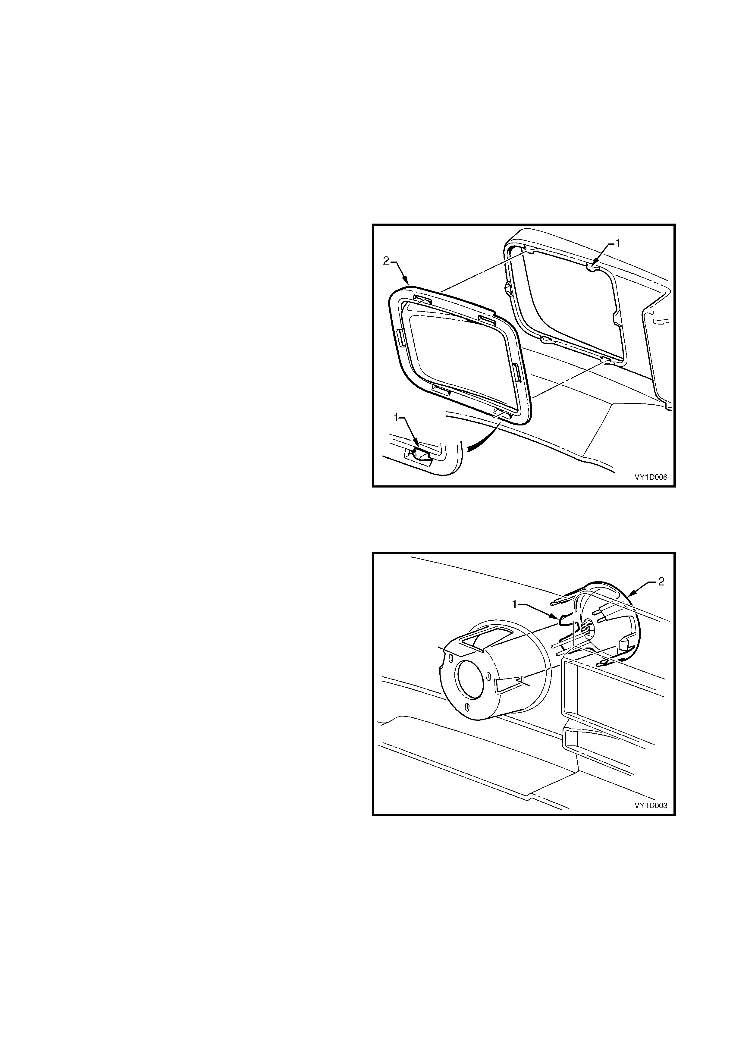
FRONT FOG LAMP OPENING COVER, S SEDAN
Remove
1. Depress the two retaining tabs (1) securing the
cover (2) to the bumper fascia.
2. W ithdraw the cover f rom the recess to the front of
the bumper fascia.
Reinstall
1. Fit the cover into position and ensure that the
retaining tabs are seated correctly.
Figure 1D-6

FRONT FOG LAMP ASSEMBLY, SS & COUPE
Remove
1. For Coupe, remove the lower radiator grille, refer
to Section 1C, 2.5 LOWER RADIATOR GRILLE.
2. Remove the three nuts (1) attaching the lamp
assembly (2) to the bumper fascia.
NOTE: SS model shown, Coupe similar.
3. W ithdraw the lam p assembly and wiring connector
from the recess the front of the bumper fascia.
NOTE: For further service of the front fog lamp
assembly refer to Section 12B, 2.7 FRONT FOG
LAMP ASSEMBLY.
Reinstall
Installation is the reverse of removal. Tighten the nuts
to the specified torque.
NOTE: Following installation of the bumper fascia
assembly, aim the fog lamps, refer to Section 12B,
2.1 HEADLAMP AND FOG LAMP AIMING.
Figure 1D-7
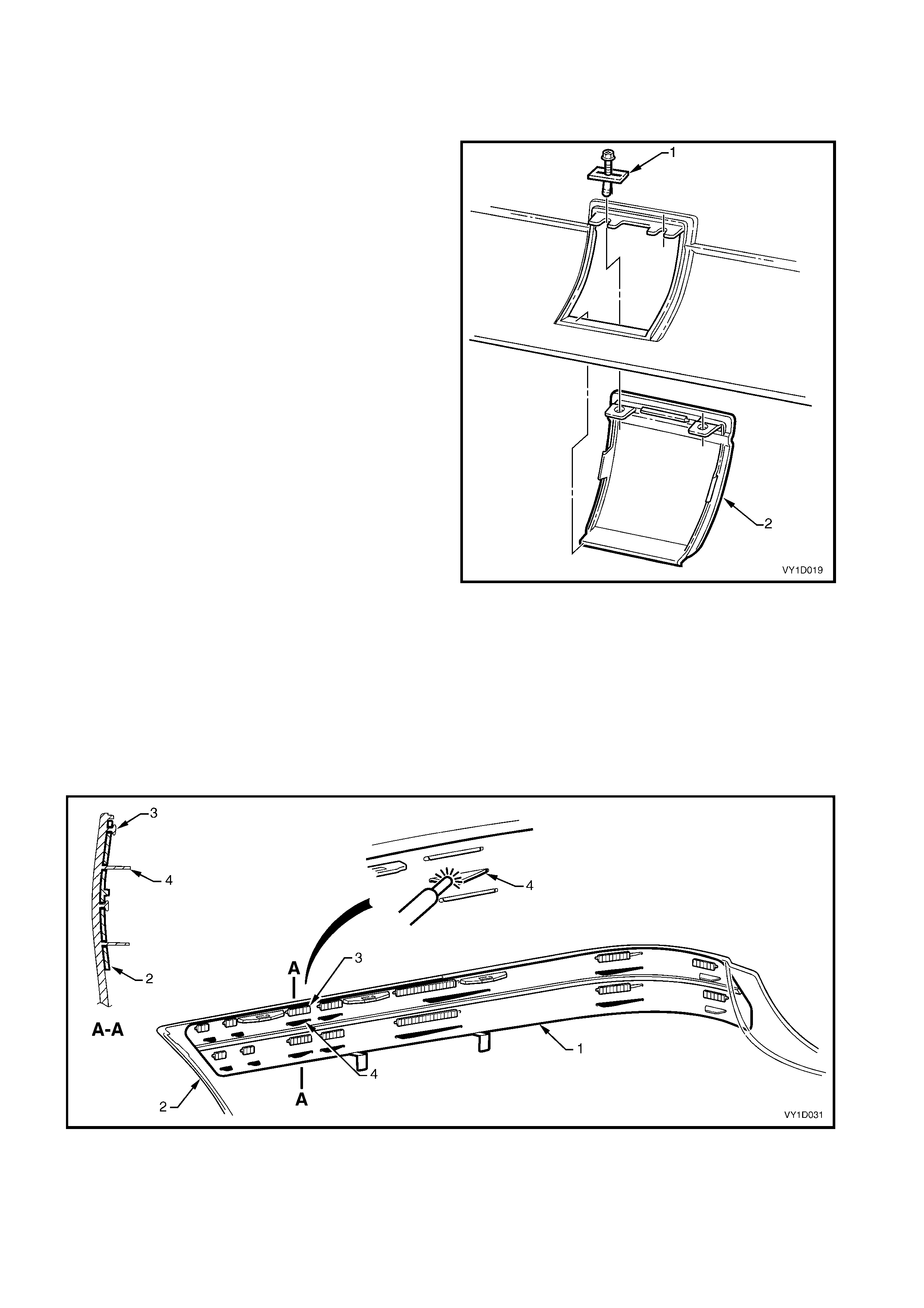
FRONT BUMPER FASCIA REINFORCEMENT
Two reinforcements are attached to the inner side of the front bumper fascia.
Referr ing to Figure 1D-8 – typical front bum per f asc ia assem bly, the r einforc em ent (1) is attached to the bum per
fasc ia (2) with the heat stakes (3). If the bum per fasc ia assembly is damaged, a replacement reinf orcem ent can
be fitted, or if the heat stakes are broken, a repair can be made.
If the heat stakes are broken, melt over the adjacent heat stakes (4) with a soldering iron.
If the reinf orcem ent is being replaced, c ut the heat stak es (3) with a knif e and rem ove the old reinforc ement. Fit
the new reinforcement in position and using a soldering iron, melt over the adjacent heat stakes (4).
Figure 1D-8

REINSTALL
1. Refinish the bumper fascia assembly in accordance with the procedures in 2.1 PAINT SYSTEMS.
2. With the aid of an assistant, fit the front bumper fascia assembly onto the vehicle.
3. Start the three screws (5) attaching the fascia assembly to the front upper panel, refer to Figure 1D-4.
4. Install the two retainers (2) in the recesses (behind the licence plate).
5. Align the side of the fasc ia assem bly to the f ender, clip the f ascia assem bly into the guide assem bly ( 6) and
install the screw (5), refer to Figure 1D-3. Repeat for the opposite side.
6. Install the screw (1), or for S and SS vehicles (2), attaching each side of the fascia assembly to the front
wheelhouse liner, refer to Figure 1D-3.
7. Tighten the screws to the specified torque.
8. Reconnect the fog lamp wiring connectors if fitted, refer to (1) Figure 1D-4.
FRONT BUMPER FASCIA ASSEMBLY TO
FRONT WHEELHOUSE LI NER SCREW
TORQUE SPECIFICATION 1.0 – 3.0 Nm
FRONT BUMPER FASCIA ASSEMBLY
TO FRONT BUMPER FASCIA
GUIDE ASSEMBLY SCREW
TORQUE SPECIFICATION 1.0 – 3.0 Nm
FRONT BUMPER FASCIA ASSEMBLY TO
FRONT UPPER PANEL SCREW
TORQUE SPECIFICATION 2.5 – 4.0 Nm

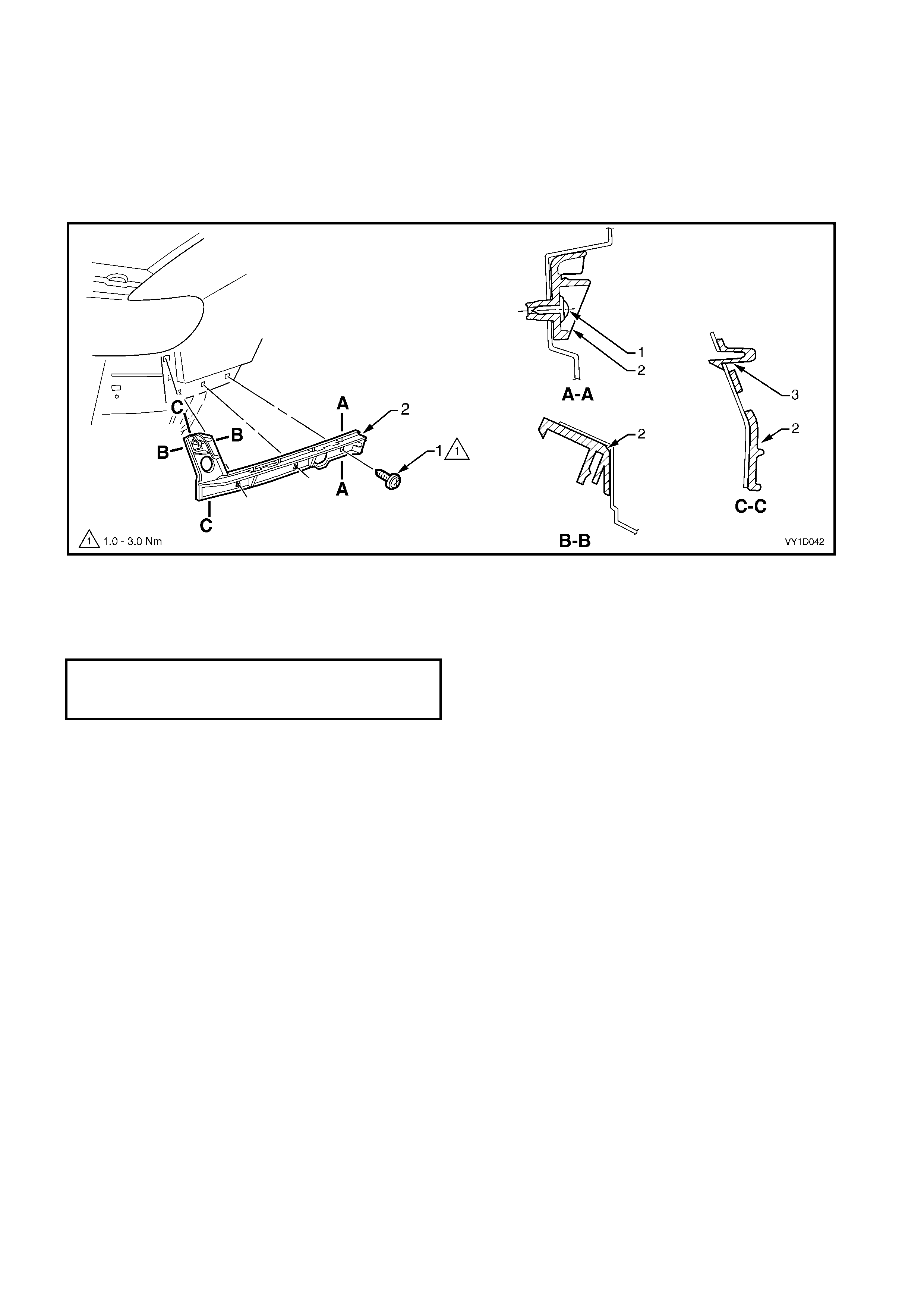
2.3 FRONT BUMPER FASCIA GUIDE ASSEMBLY
SEDAN, WAGON & UTILITY
Remove
1. Remove the f ront bumper f as c ia assembly, refer to
2.2 FRONT BUMPER FASCIA ASSEMBLY.
NOTE: It is poss ible to rem ove one side of the bumper
fascia and carefully move it out to gain access to the
guide assembly.
2. Using a fine flat-blade screwdriver, lever and hold
the tab (1) outwards.
3. Slide the guide assembly (2) forward and out to
detach it from the fender.
Figure 1D-9
Reinstall
1. Align the guide assembly with the slots in the
fender and while pushing in s lightly, s lide the guide
rearwards until it ‘clicks’ into place.
2. Reinstall the bumper fascia as required, refer to
2.2 FRONT BUMPER FASCIA ASSEMBLY.
COUPE
Remove
1. Remove the front bumper fascia assembly, refer to 2.2 FRONT BUMPER FASCIA ASSEMBLY.
2. Remove the screw (1), three places, attaching the front bumper fascia guide assembly (2) to the vehicle,
refer to Figure 1D-10.
3. Using a fine flat-blade screwdriver, lever and hold the retaining tab (3).
4. Remove the guide outwards to detach it from the fender.
Figure 1D-10
Reinstall
1. Align the guide assembly with the holes in the fender push in to locate it in place.
2. Install the screws and tighten to the specified torque.
3. Reinstall the bumper fascia as required, refer to 2.2 FRONT BUMPER FASCIA ASSEMBLY.
FRONT BUMPER FASCIA GUIDE
ASSEMBLY ATTACHING SCREW
TORQUE SPECIFICATION 1.0 – 3.0 Nm
2.4 FRONT BUMPER IMPACT BAR ASSEMBLY
The front bumper impact bar assembly not only acts as a m ount and support for the bum per fascia, but is also
critical in the dispersion of crash energy. Hence, it plays an integral role in the operation of the vehicle’s safety
systems.
Repair of the bar assembly should be limited to replacement, as straightening and/or heating can weaken the
bar assembly, resulting in incorrect airbag and seatbelt pretensioner operation.
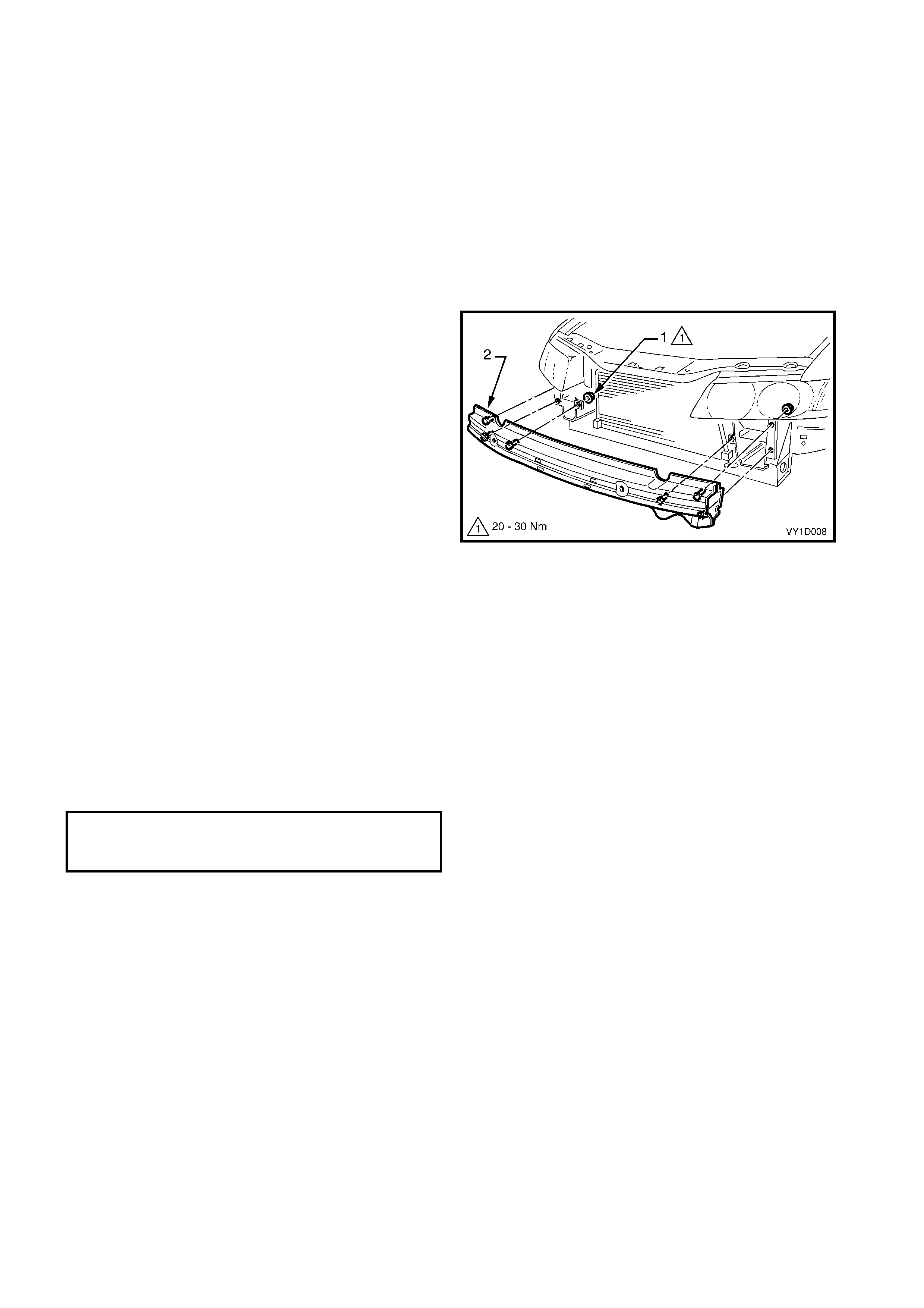
REMOVE
1. Remove the f ront bumper f as c ia assembly, refer to
2.2 FRONT BUMPER FASCIA ASSEMBLY.
2. If fitted, remove the radiator air lower baffle, refer
to Section 6B1.
3. Remove the nuts (1), three places each side,
attaching the bar assembly (2) to the vehicle.
4. Remove the bar assembly.
Figure 1D-11
REINSTALL
NOTE: Check the vehicle’s front body dimensions as
required to ensure correct alignment, refer to
Section 1A2 BODY DIMENSIONS.
1. Fit the bar assembly in position and attach each
nut. Do not tighten.
2. Ensure the bar assembly is correctly positioned
centrally and tighten the nuts to the specified
torque.
3. Refit the front bumper fascia assembly, refer to
2.2 FRONT BUMPER FASCIA ASSEMBLY.
FRONT BUMPER IMPACT BAR
ASSEMBLY ATTACHING NUT
TORQUE SPECIFICATION 20.0 – 30.0 Nm
2.5 REAR BUMPER FASCIA ASSEMBLY, SEDAN & COUPE
LT Section No. – 07-525
NOTE: Although different in appearance, the procedure for removal of the rear bumper fascia assembly is the
same for both Sedan and Coupe.
If required, first remove the following components:
1. Rear end trim panel, refer to Section 1A8, 2.15 REAR END PANEL, SEDAN or 4.12 REAR END TRIM
PANEL, COUPE.
2. Quarter inner rear s ide c arpet, ref er to Section 1A8, 2.17 QUARTER INNER REAR SIDE CARPET, SEDAN
or 4.14 QUARTER INNER REAR SIDE CARPET, COUPE.
REMOVE
1. From each side of the vehicle:
a. Rem ove the screw (1) one place Sedan or two places Coupe, or f or S and SS vehicles (2) two places,
attaching the rear bumper fascia assembly (3) to the rear wheelhouse liner (4), refer to Figure 1D-12.
b. Remove the screw (5) two places, attaching the rear bumper fascia assembly to the liner and rear
bumper fascia guide assembly (6).
c. Carefully unclip the fascia assembly from the guide assembly by grasping the upper end of the fascia
and pulling away f rom the vehicle, als o disconnecting the liner lug (7) from the bum per fascia assem bly
for Sedan except S & SS.
Figure 1D-12
2. Remove the two nuts (1) each side, attaching the fascia assembly (2) to the vehicle, refer to Figure 1D-13.
3. Remove the two retainers (3) from below the fascia assembly.
4. Remove the centre section of the rear compartment lid weatherstrip to allow access to the four upper
retainers (4).
5. Remove the four upper retainers attaching the fascia assembly to the rear bumper fascia centre support
assembly.
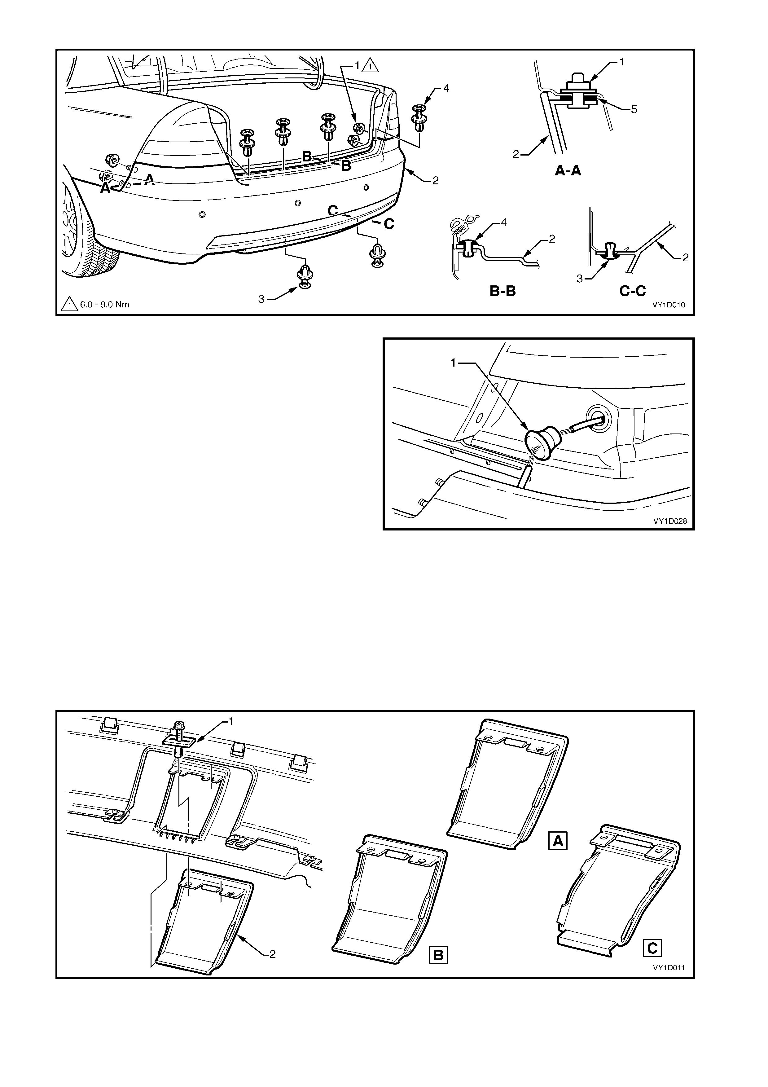
Figure 1D-13
6. If f itted, disconnec t the Reverse Park ing Aid (RPA)
wiring connector from within the rear compartment.
7. With the aid of an assistant, withdraw the fascia
assembly, push the RPA wiring harness grommet
(1) through the side panel for Sedan or rear panel
for Coupe, and withdraw the RPA harness thr ough
the panel.
NOTE: Sedan shown, Coupe is similar except located
below the tail lamp housing on the rear of the vehicle.
8. Remove the fascia assembly ensuring the seals
(5, Figure 1D-13) remain with the fascia assembly.
Figure 1D-14
DISASSEMBLE
NOTE: For the disassembly of Reverse Parking Aid (RPA) components, refer to REVERSE PARKING AID
COMPONENTS, following this procedure.
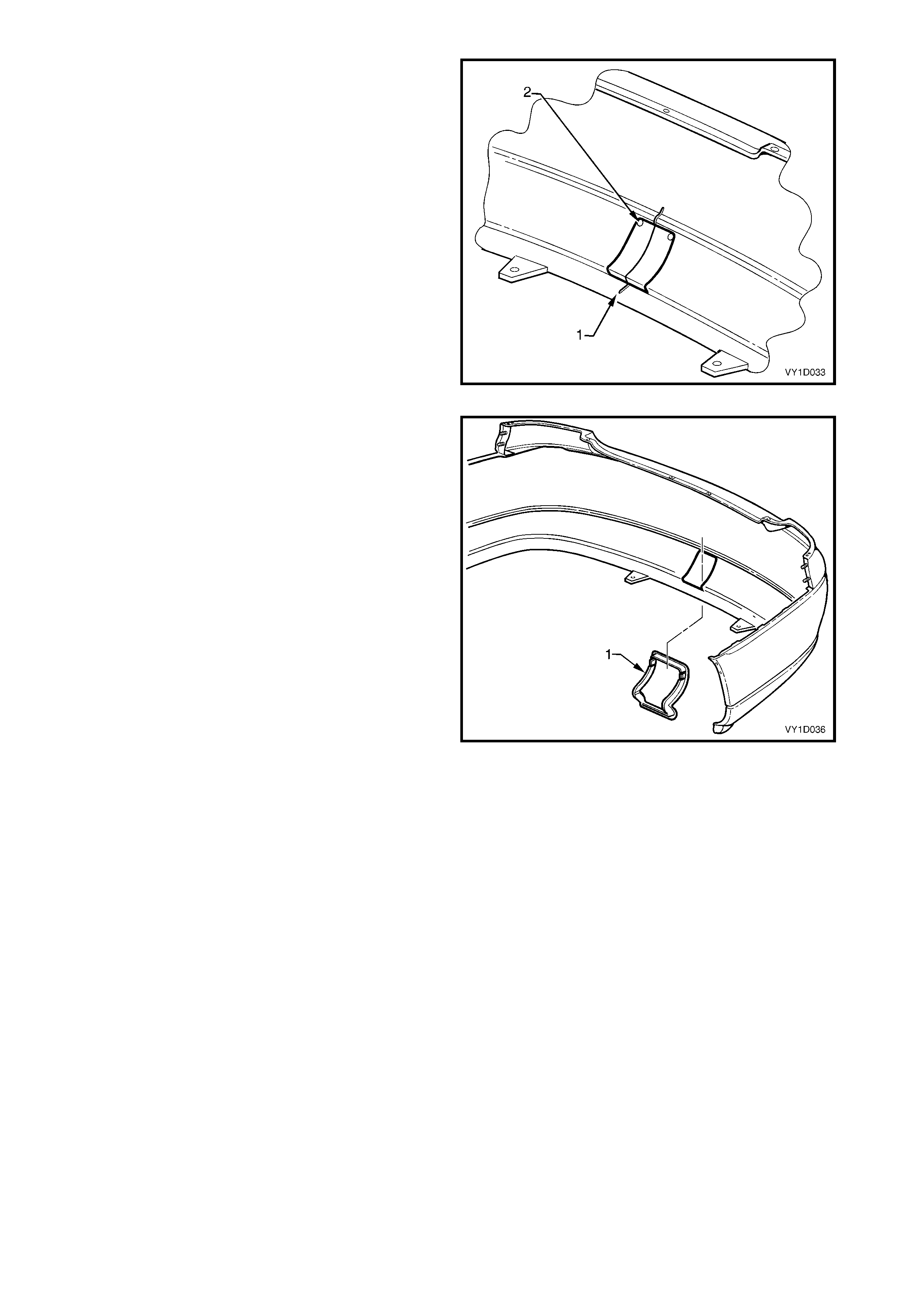
TOWBA R OPENING COVER, EXCEPT COUPE
Remove
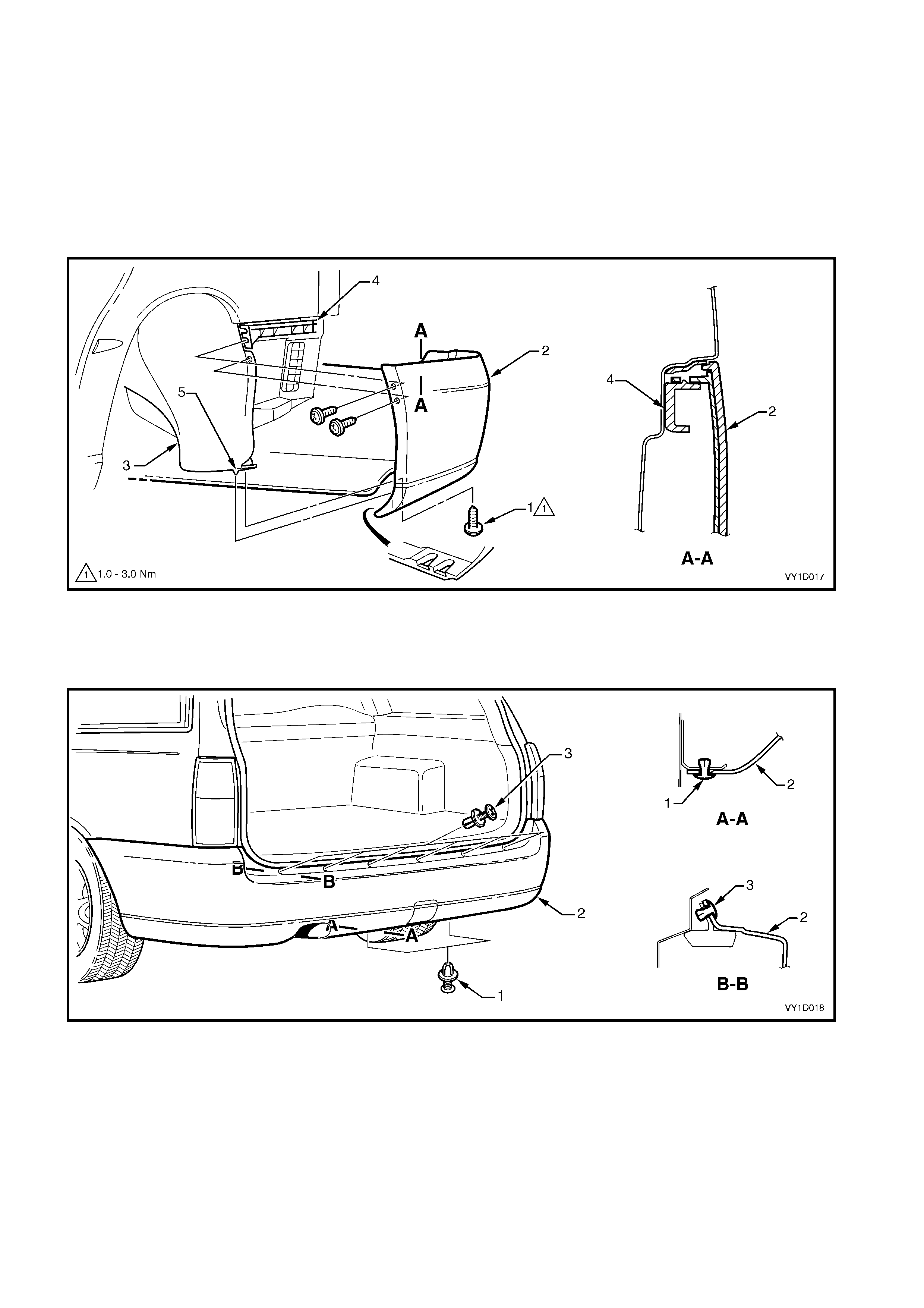
1. Remove the r etainer (1), two places, sec uring the towbar opening cover ( 2) to the bumper fas cia assem bly,
refer to Figure 1D-15.
2. Depress the retaining tabs and remove the cover from the bumper fascia. Note the different styles:
A – Level 1, B – S & SS, C – Levels 2 & 3.
Figure 1D-15
Reinstall
1. Clip the cover in place ensuring the retaining tabs are seated correctly and install the two retainers.
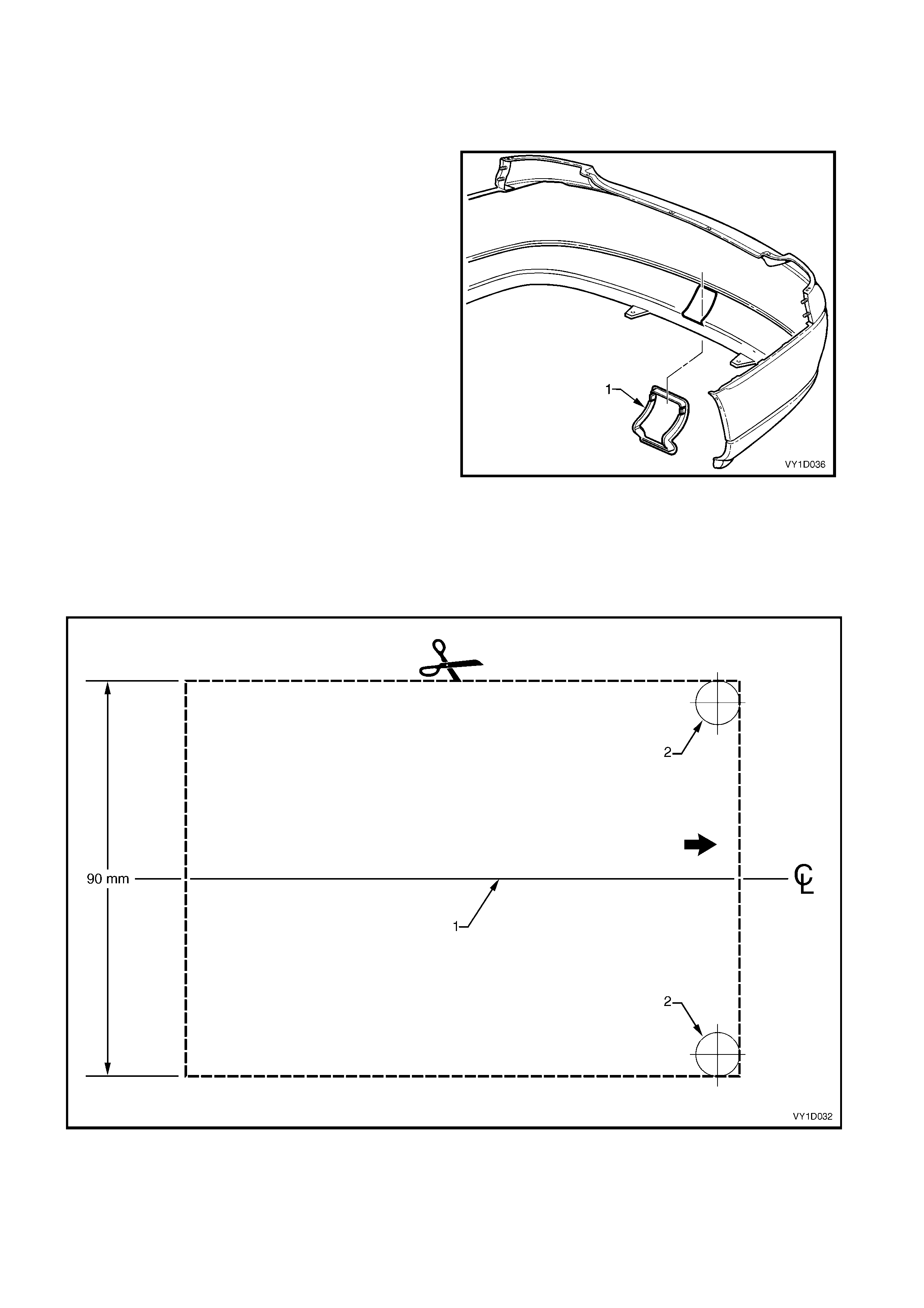
TOWBAR OPENING SURROUND, COUPE
Remove
1. Carefully prise the surround (1) from the bumper
fascia.
Figure 1D-16
Reinstall
1. If the bumper fascia has not been replaced, proceed to Step 9.
2. Print and accurately cut out the towbar opening template in Figure 1D-17.
IMPORTANT: W hen pr inting, in the PRINT DIALOG BOX ensure the ‘SHRINK OVERSIZE PAGES TO PAPER
SIZE’ box is NOT ticked. Always check the scale on the template to ensure it has printed the correct size.
Figure 1D-17
3. Place the template on the rear side of the bum per
fascia and align the template centreline (1) with the
centreline embossed in the fascia.
4. Mark the perimeter of the template on the fascia
and scribe the pilot hole (2) centre points.
5. Rem ove the template and drill a 3.0 m m pilot hole
at each scribed centre point on the inside surface
of the bumper fascia.
6. Enlarge the holes to 10.0 mm.
IMPORTANT: Do not drill outs ide the perim eter line as
the surround will not cover this area.
7. Cut between the drilled holes with a sm all sharp or
serrated knife, taking care not to deviate from the
guidelines.
NOTE: The width of the opening m ust not exceed 90.0
mm.
8. Remove the section of bumper fascia.
Figure 1D-18
9. Clean up the opening and install the towbar
surround (1) to the fascia once the fascia has been
painted.
Figure 1D-19
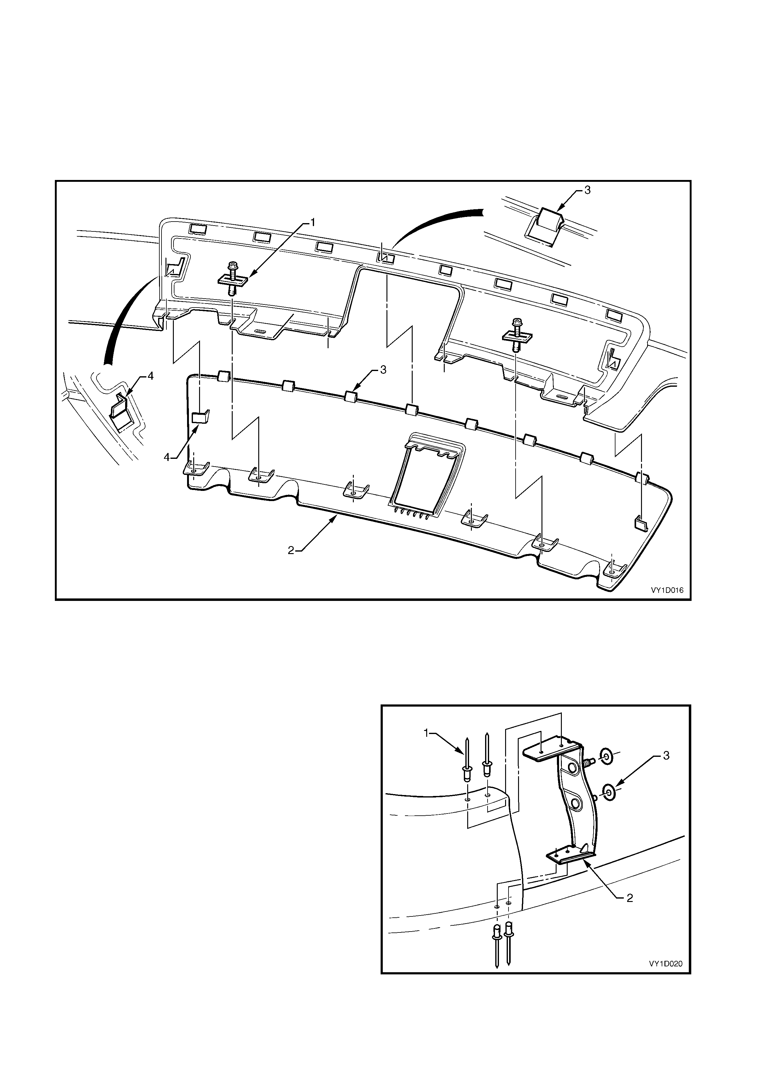
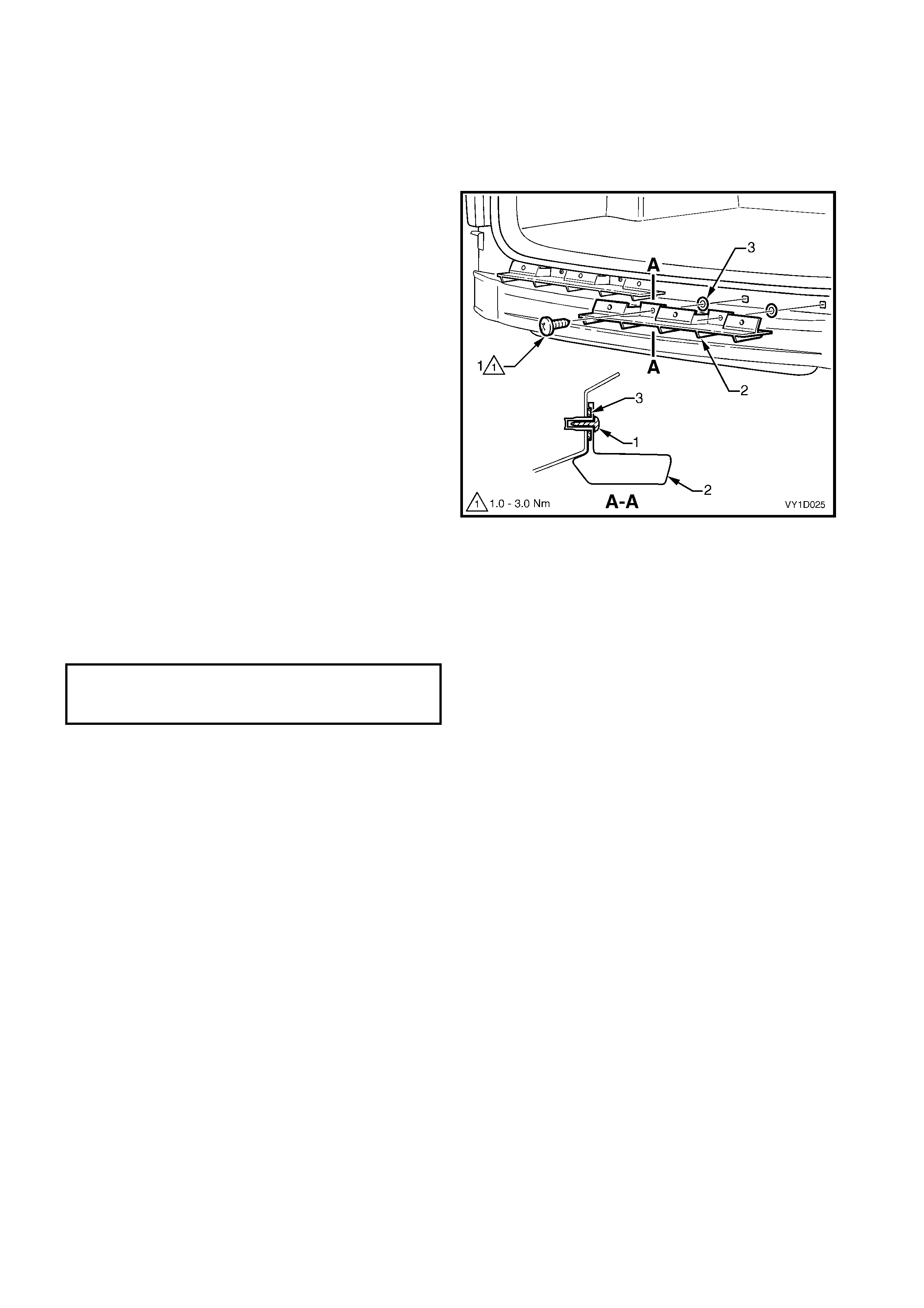
REAR BUMPER FASCIA INSERT, LEVEL 1, S & SS
Remove
1. Remove the retainer s (1) , s ix plac es f or Level 1 or f ive plac es for S and SS, sec ur ing the rear bumper f as c ia
insert (2) to the bumper fascia.
2. Apply downward pressure on the insert while unclipping the eight tabs (3), for Level 1 or seven tabs for S
and SS.
3. Manoeuvr e the insert downward and out of the bum per fas cia, disengaging the loc ating tabs (4) each end of
the insert.
Figure 1D-20
Reinstall
Installation is the reverse of removal. Ensure the retainers and tabs are seated correctly.
REAR BUMPER FASCIA ANCHOR PLATE ASSEMBLY, COUPE
Remove
1. Using a 3mm drill-bit, remove the four rivets (1)
attaching the plate assembly (2) to the fascia
assembly.
NOTE: If r eusing the fasc ia assem bly, tak e care not to
enlarge the rivet holes.
2. Remove the plate ass embly and if required the two
seals (3).
Reinstall
Installation is the reverse of removal.
Figure 1D-21
REAR BUMPER FASCIA BRACKET ASSEMBLY, SEDAN
A brack et as s embly, which also acts as a reinforcement, is attached to eac h inner side of the rear bumper fas cia
for Sedan models.
Referring to Figure 1D-22 – typical rear bumper fascia assembly, the bracket assembly (1) is attached to the
bumper fascia (2) with the heat stakes (3). If the bumper fascia assembly is damaged a replacement bracket
assembly can be fitted, or if the heat stakes are broken, a repair can be made.
If the heat stakes are broken, melt over the adjacent heat stakes (4) with a soldering iron.
If the bracket assembly is being replaced, cut the heat stakes (3) with a knife and remove the old bracket
assembly. Fit the new bracket assembly in position and using a soldering iron, melt over the adjacent heat
stakes (4).
Figure 1D-22
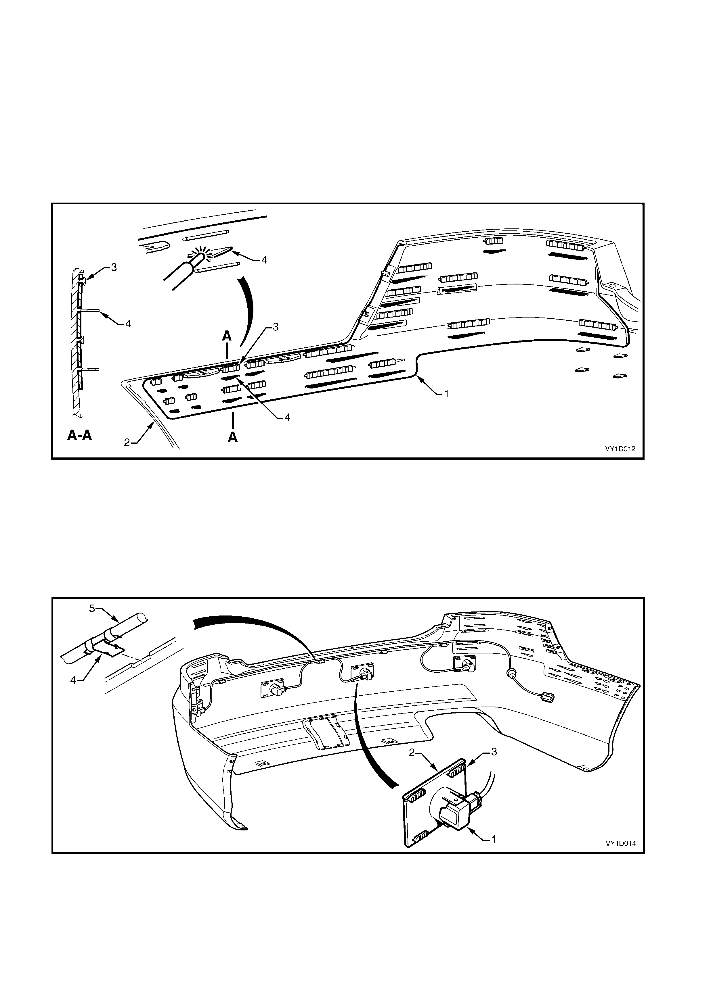
REVERSE PARKING AID COMPONENTS
Where fitted, four sensor assemblies and their associated wiring are fitted to the rear bumper fascia assembly
as part of the Reverse Parking Aid (RPA), refer to Figure 1D-23. Sedan shown, Coupe is similar.
Each rear object sensor assembly (1) is fitted into a rear object sensor housing (2) which is attached to the
fascia assembly with four heat-stakes (3). Holes in the fascia expose the sensor and housing faces. Four
retaining clips (4) secure the rear object sensor wiring harness assembly (5) to the fascia assembly which is
routed across to the left-hand side.
Figure 1D-23
IMPORTANT: The fascia assem bly and sensors m ust be correctly aligned if the system is to operate correctly.
Sensors may be damaged if dropped or subjected to temperatures above 80° C.
If repainting a f ascia as sem bly, the sensor s and rings MUST be rem oved. Paint m ust not be applied to any part
of a sensor, including the exposed coloured surface. Paint film applied to the exposed surface will render the
sensor inoperable as the paint film restricts the sensor’s ultra-sonic signal. If a sensor is damaged, it must be
replaced.
Replacement housings are supplied unpainted. As they are partially exposed when installed, they will require
painting using the same procedures for painting the bumper fascia, refer to 2.1 PAINT SYSTEMS.
NOTE: It is preferable to paint the housings and bumper fascia separately to avoid adhesion problems.
Assemble the housings onto the bumper fascia once the paint has cured.
Replacement bumper fascias are supplied without holes and must be modified by following the procedures in
New Facia Modification.
For further information on reverse parking aid, refer to Section 12F REVERSE PARKING AID.
Disassemble
1. Remove the wiring connector (1) from the rear
object sensor assembly (2).
2. Using a fine blade screwdriver, lever the upper and
lower tabs (3) of the rear object sensor housing
and slide the sensor from the housing.
3. If required, remove the rear object sensor ring (4)
from the sensor.
4. Remove the housing from the bumper fascia by
cutting the heat-stakes (5).
NOTE: If the housing is to be reinstalled on the same
bumper fascia, only cut the minimum amount of
material to enable removal, ensuring enough remains
to reattach the housing.
5. Remove the wiring harness from the bumper
fascia by prising the four retaining clips from the
bumper fascia with a fine flat blade screwdriver.
Figure 1D-24
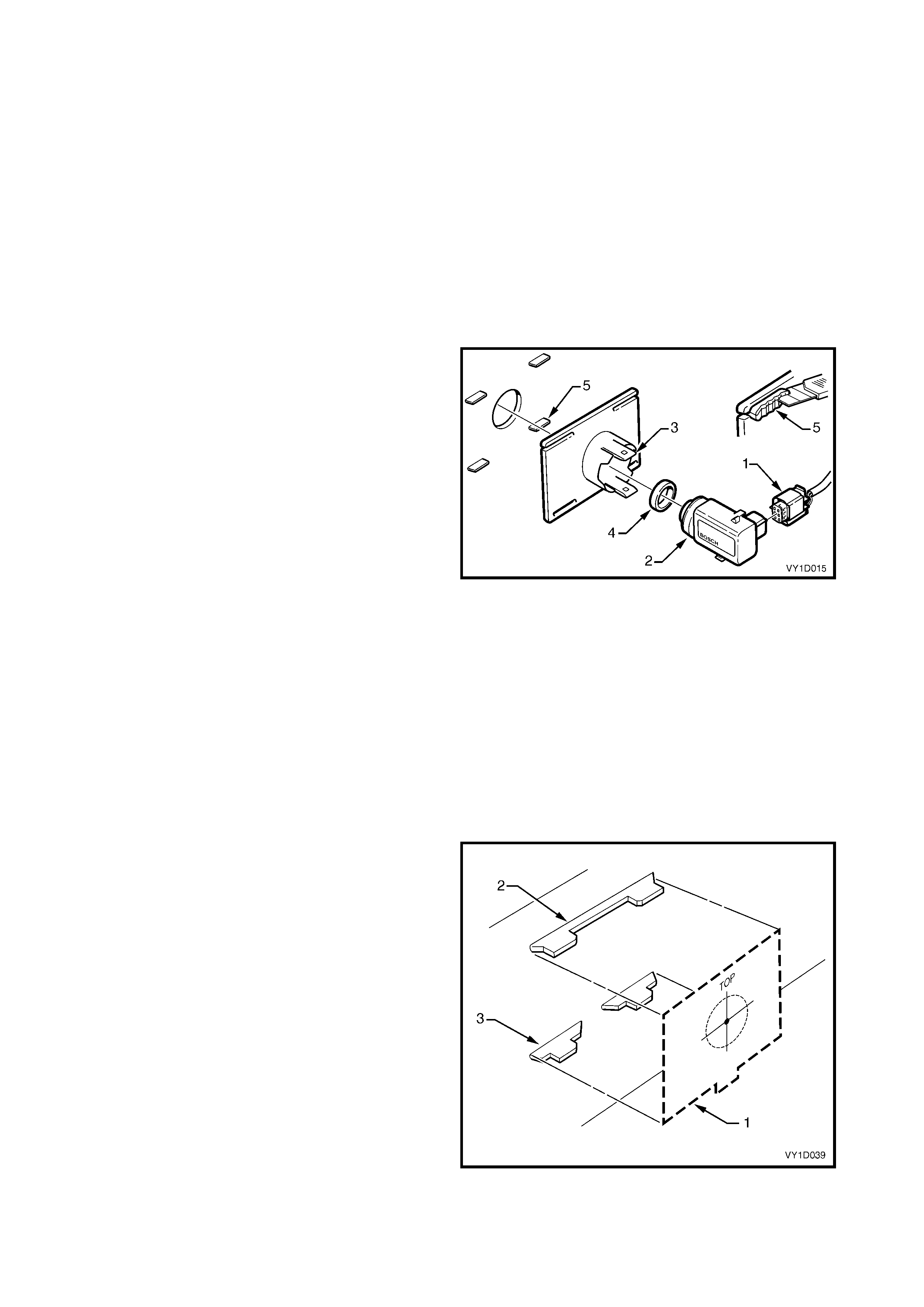
New Fascia Modification
1. Print and cut-out the templates in Figure 1D-28.
IMPORTANT: When printing, in the PRINT DIALOG
BOX ensure the ‘SHRINK OVERSIZE PAGES TO
PAPER SIZE’ box is NOT ticked. Always check the
scale on the template to ensure it has printed the
correct size.
2. Perform the following instructions at the four
reverse parking aid module mounting locations.
3. Tape the template (1) to the inside of the rear
fascia, aligning the edges between the upper (2)
and lower (3) reverse parking aid heat stakes.
Figure 1D-25
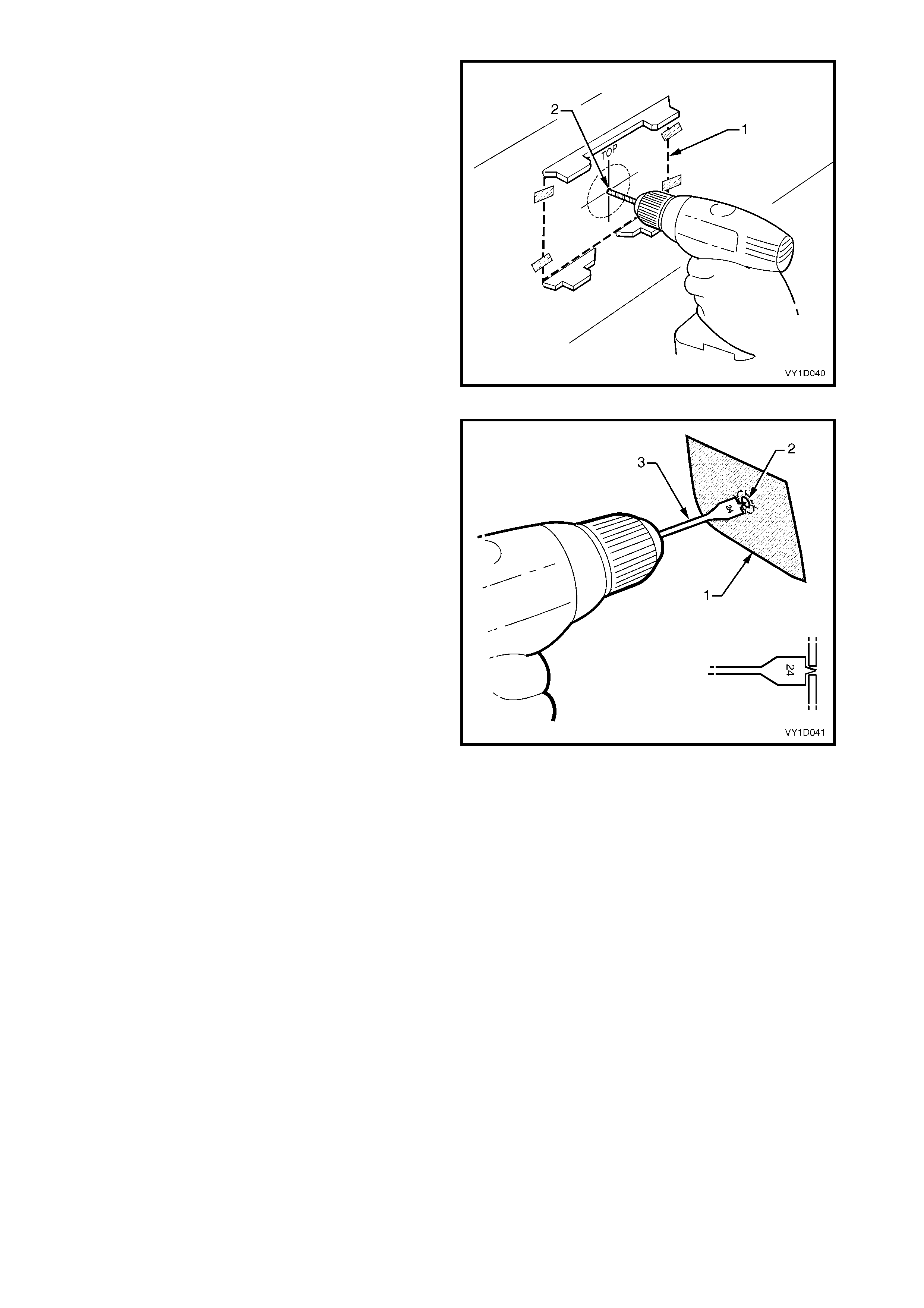
4. From the inside of the fascia, drill a 2 mm diameter
pilot hole at the template (1) centre point (2).
Figure 1D-26
5. Place masking tape (1) on the outside surface of
the fascia in the area to be drilled.
6. From the outside of the fascia, enlarge the pilot
hole (2) to 24 mm using a wood spade drill bit (3).
IMPORTANT:
• Only use a wood spade drill bit as a normal drill bit
or hole saw may damage the rear fascia.
• Ensure the spade drill bit remains square with the
rear fascia.
• Use a slow drill speed to avoid damaging the rear
fascia.
7. Debur the edges of the hole if necessary.
8. As required, paint the bumper fascia and
sensor housings prior to reassembly, refer to
2.1 PAINT SYSTEMS.
Figure 1D-27
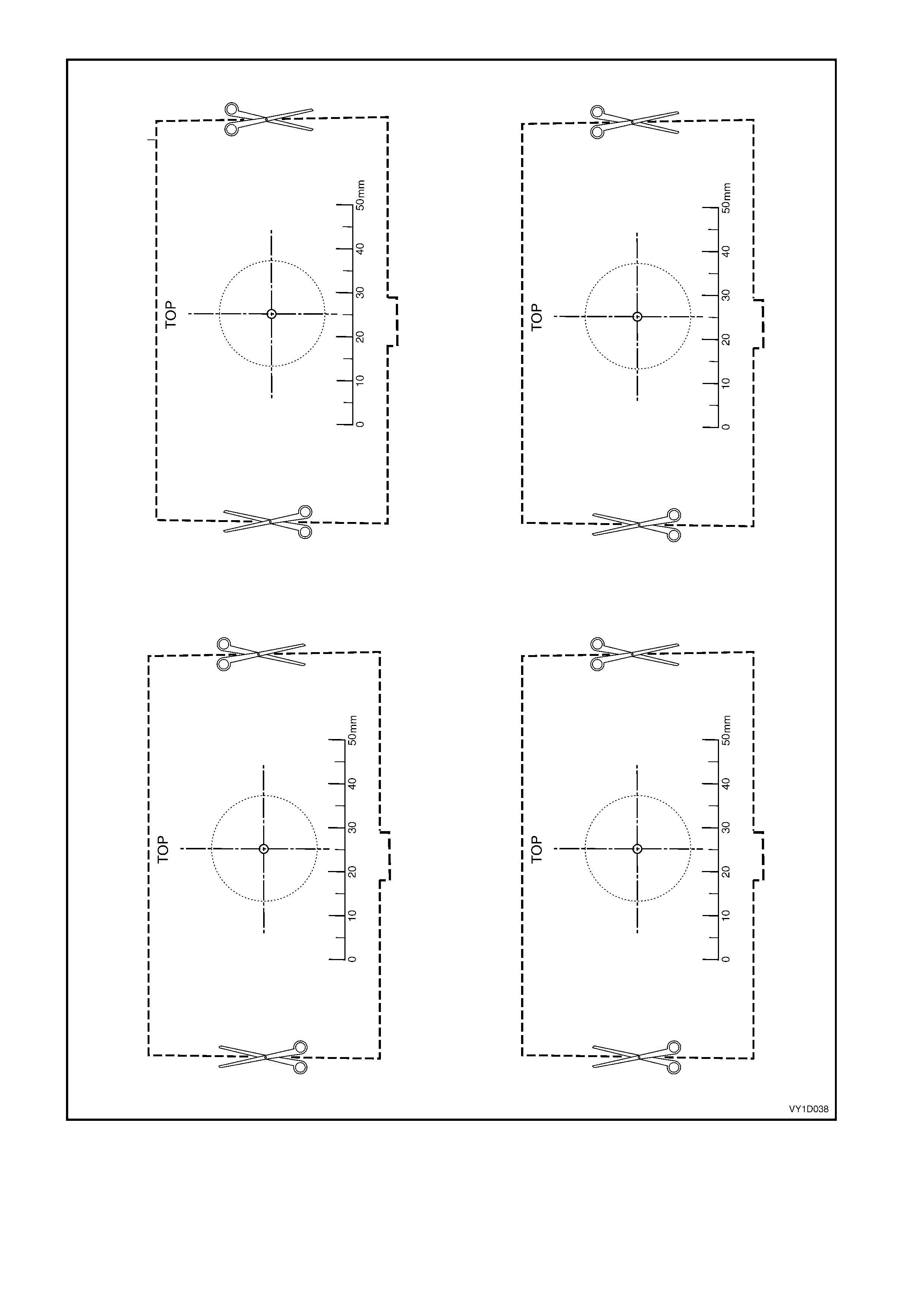
Figure 1D-28
Reassemble
NOTE: It is advisable to paint the bumper fascia and
housings prior to attachment to the bumper fascia,
refer to 2.1 PAINT SYSTEMS.
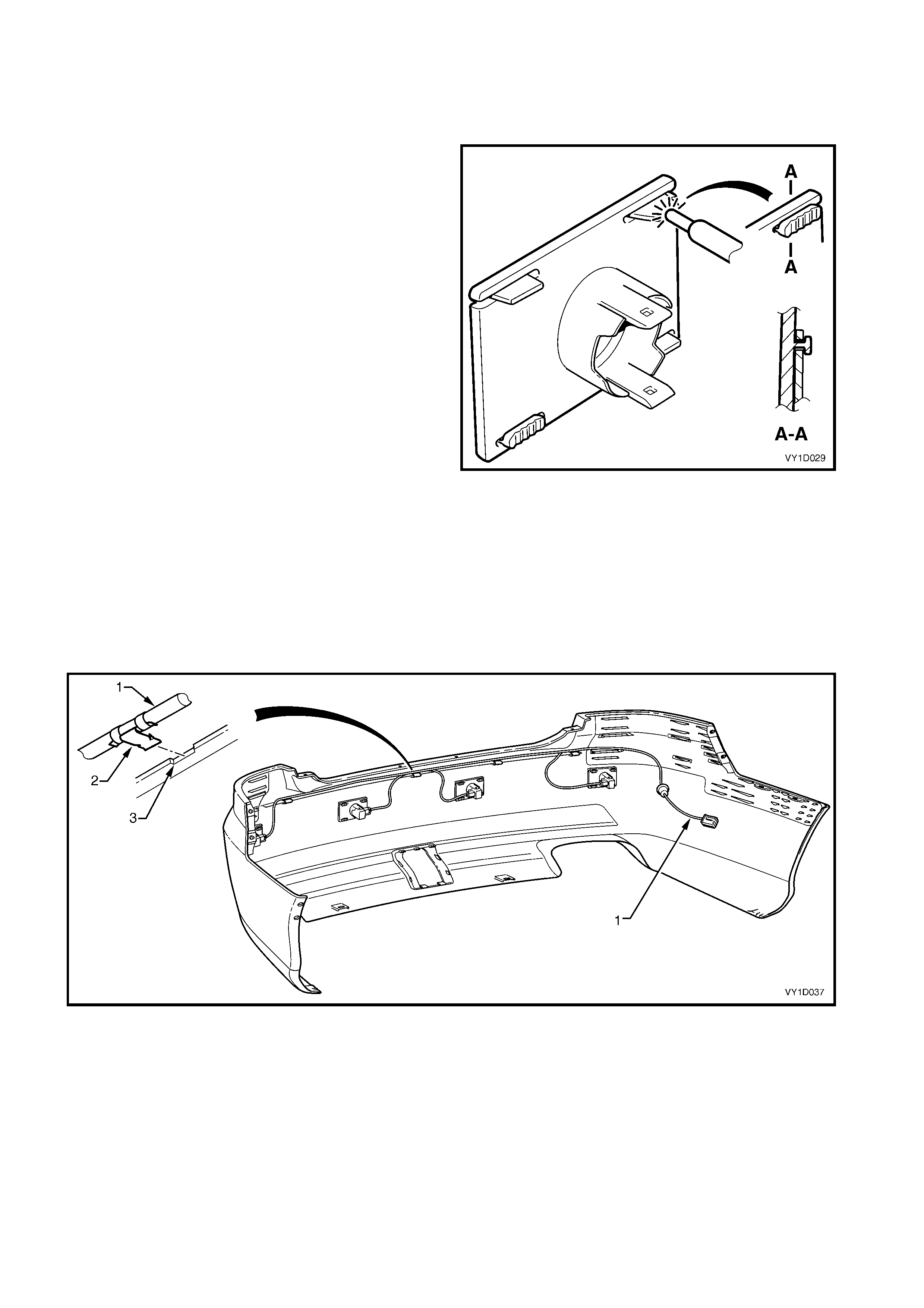
1. Position the housing onto the four stakes, ens ur ing
it is seated against the f asc ia surf ace and correc tly
protrudes through the hole.
2. Using a soldering iron, melt the end of the heat-
stakes. Hold the housing in position until the
plastic has cooled.
NOTE 1: Do not over- melt the m aterial and ensure the
housing is fixed securely.
NOTE 2: If the housing is being reinstalled onto the
same bumper fascia, ensure there is enough material
to provide secure attachment. If required, cut a thin
piece of bumper m aterial from an inconspicuous place
and use as a filler, melting it into the heat-stake.
3. Fit the ring onto the end of the sensor, refer to
Figure 1D-24.
4. Insert the sensor into the housing firmly, ensuring
that the tabs are locked into the sensor.
5. Repeat as required.
6. Route the wiring harness (1) to the LH side of the
vehicle and connect the wiring harness connectors
to each sensor, refer to Figure 1D-30.
7. Attach the harness to the upper side of the bumper
fascia rib, aligning each clip (2) at the notch (3).
8. Following installation of the bumper fascia
assembly, test the reverse parking aid for correct
operation, refer to Section 12F REVERSE
PARKING AID.
Figure 1D-29
Figure 1D-30

REINSTALL
1. For Sedan, if the vehicle is fitted with a towbar remove the towbar opening cover.
2. Refinish the bumper fascia assembly in accordance with the procedures in 2.1 PAINT SYSTEMS.
3. For Coupe, if the vehicle is fitted with a towbar install the towbar opening surround.
4. With the aid of an assistant, install the rear bumper fascia assembly onto the vehicle, inserting the RPA
wiring connector, if fitted, through its hole in the side panel.
5. Securely fit the RPA wiring harness grommet (1) into the side panel hole, refer to Figure 1D-14.
6. Install the two nuts (1) attac hing the fascia assem bly to the vehicle each side, refer to Figure 1D-13. Do not
tighten.
7. Insert the four retainers (4) across the rear compartment lid opening.
8. Insert the two retainers (3) below the fascia assembly.
9. Align the side of the f ascia assem bly to the quarter panel and clip the fascia assem bly into the rear bum per
fascia guide assem bly (6), also ensuring the wheelhouse liner lug (7) for Sedan except S & SS is engaged
into the fascia, refer to Figure 1D-13. Repeat for the opposite side.
10. Install the two screws each s ide (5), attaching the f a sc ia ass embly to the rear bum per fas c ia guide assem bly
and rear wheelhouse liner, refer to Figure 1D-12.
11. Install the screw (1) one place Sedan or two places Coupe, or for S and SS Vehicles (2) two places,
attaching the fascia assembly to the rear wheelhouse liner.
12. Tighten the two nuts each side and then the screws to the specified torque.
13. If fitted, test the reverse parking aid for correct operation, refer to Section 12F REVERSE PARKING AID.
REAR BUMPER FASCIA ASSEMBLY
TO REAR WHEELHOUSE
LINER ATTACHING SCREW
TORQUE SPECIFICATION 1.0 – 3.0 Nm
REAR BUMPER FASCIA ASSEMBLY
TO REAR BUMPER FASCIA GUIDE
ASSEMBLY ATTACHING SCREW
TORQUE SPECIFICATION 1.0 – 3.0 Nm
REAR BUMPER FASCIA
ASSEMBLY ATTACHING NUT
TORQUE SPECIFICATION 6.0 – 9.0 Nm
2.6 REAR BUMPER FASCIA ASSEMBLY, WAGON
LT Section No. – 07-525
REMOVE
1. Remove the screws (1), three places on each side, attaching the rear bumper fascia assembly (2) to the rear
wheelhouse liner (3) and rear bumper fascia guide assembly (4), refer to Figure 1D-31.
2. Disconnect the lug (5) from the liner.
3. Carefully unclip the fascia assembly from the guide assembly by grasping the upper end of the fascia
assembly and pulling away from the vehicle.
Figure 1D-31
4. Remove the two retainers (1) from below the fascia assembly (2), refer to 1D-32.
5. Remove the six retainers (3) from across the liftgate opening.
6. With the aid of an assistant remove the fascia assembly, sliding it rearward.
Figure 1D-32
DISASSEMBLE
TOWBAR OPENING COVER
Remove
1. Remove the retainer (1), two places, securing the
towbar opening cover (2) to the bumper fascia
assembly.
2. Depress the retaining tabs and remove the cover
from the bumper fascia.
Reinstall
1. Clip the cover in place ensuring the retaining tabs
are seated correctly and install the two retainers.
Figure 1D-33
REAR BUMPER FASCIA BRACKET
A bracket assembly, which also acts as a reinforcement, is attached to each inner side of the rear bumper
fasc ia. Ref erring to Figure 1D-34, the brac ket ( 1) is attac hed to the bum per fas cia (2) with the heat stak es ( 3). If
the bum per f asc ia assem bly is damaged a r eplacem ent brac ket c an be fitted, or if the heat stak es are brok en, a
repair can be made.
If the heat stakes are broken, melt over the adjacent heat stakes (4) with a soldering iron.
If the bracket assembly is being replaced, cut the heat stakes (3) with a knife and remove the old bracket
assembly. Fit the new bracket assembly in position and using a soldering iron, melt over the adjacent heat
stakes (4).
Figure 1D-34

REINSTALL
1. Refinish the bumper fascia assembly in accordance with the procedures in 2.1 PAINT SYSTEMS.
2. If the vehicle is fitted with a towbar, remove the towbar opening cover.
3. With the aid of an assistant, install the rear bumper fascia assembly, ensuring that it is seated correctly.
4. Install the six retainers (3) around the liftgate opening, refer to Figure 1D-32.
5. Insert the two retainers (1) from below the fascia assembly.
6. Align the side of the fascia assembly to the quarter panel and clip the fascia assembly into the guide
assembly (6), refer to Figure 1D-31. Repeat for the opposite side.
7. Install the three screws on each side, attaching the fascia assembly to the guide assembly and rear
wheelhouse liner and tighten to the specified torque.
REAR BUMPER FASCIA ASSEMBLY
TO REAR WHEELHOUSE LINER
ATTACHING SCREW
TORQUE SPECIFICATION 1.0 – 3.0 Nm
REAR BUMPER FASCIA ASSEMBLY
TO REAR BUMPER FASCIA GUIDE
ASSEMBLY ATTACHING SCREW
TORQUE SPECIFICATION 1.0 – 3.0 Nm
2.7 REAR BUMPER FASCIA, UTILITY
LT Section No. – 07-525
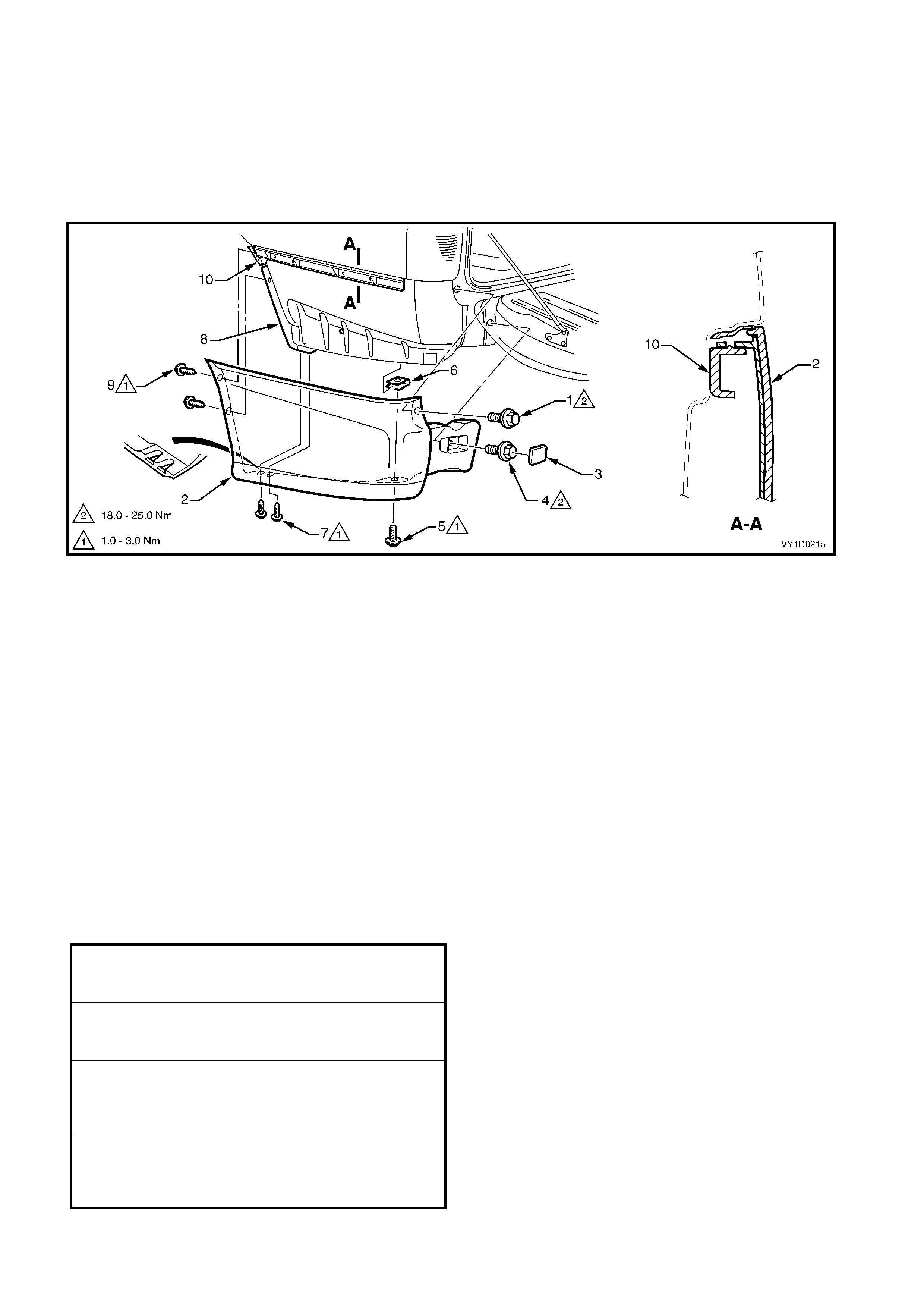
REMOVE
Referring to Figure 1D-35:
1. Open the endgate and remove the screw (1) attaching the bumper fascia (2).
2. Close the endgate.
Figure 1D-35
3. Insert a fine flat-blade screwdriver and clean shop-rag between the outer edge of the rear bumper fascia cap
(3) and fascia and prise off the cap.
4. Remove the screw (4) attaching the fascia.
5. Remove the screw (5) attaching the underside of the fascia to the J-nut (6).
6. Remove the screw (7) attaching the lower forward edge of the fascia to the rear wheelhouse liner (8).
7. Remove the two screws (9) attaching the forward edge of the fascia to the rear bumper fascia guide
assembly (10) and liner.
8. Carefully unclip the f as cia f r om the guide ass embly by gras ping the upper end of the fas c ia and pulling away
from the vehicle.
9. Remove the fascia from the vehicle.
10. If required, remove the J-nut (6) from the outer side panel.
REINSTALL
1. Refinish the bumper fascia assembly in accordance with the procedures in 2.1 PAINT SYSTEMS.
2. Align the side of the fascia to the outer side panel and clip into the guide assembly (10), refer to
Figure 1D-35.
3. Install the screws attaching the fascia and tighten to the specified torque.
REAR BUMPER FASCIA TO REAR END
PANEL ATTACHING SCREW
TORQUE SPECIFICATION 18.0 – 25.0 Nm
REAR BUMPER FASCIA TO J-NUT
ATTACHING SCREW
TORQUE SPECIFICATION 1.0 – 3.0 Nm
REAR BUMPER FASCIA TO
REAR WHEELHOUSE
LINER ATTACHING SCREW
TORQUE SPECIFICATION 1.0 – 3.0 Nm
REAR BUMPER FASCIA TO REAR
BUMPER FASCIA GUIDE ASSEMBLY
ATTACHING SCREW
TORQUE SPECIFICATION 1.0 – 3.0 Nm
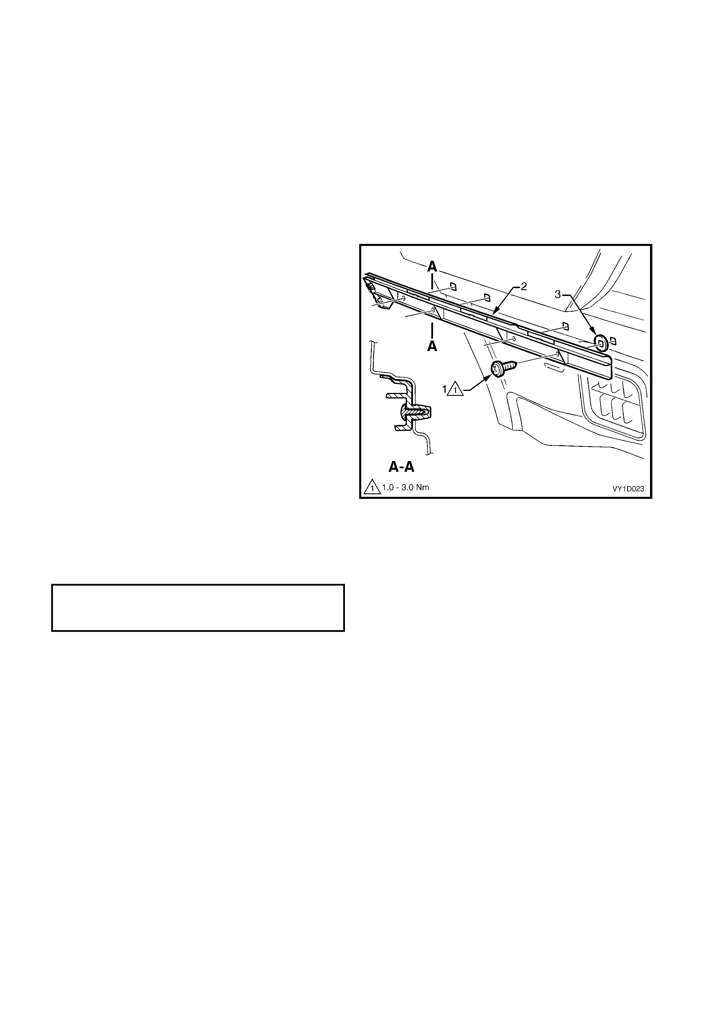
2.8 REAR BUMPER FASCIA GUIDE ASSEMBLY
REMOVE
1. Remove the rear bumper fascia, refer to:
2.5 REAR BUMPER FASCIA ASSEMBLY, SEDAN &
COUPE,
or
2.6 REAR BUMPER FASCIA ASSEMBLY, WAGON,
or
2.7 REAR BUMPER FASCIA, UTILITY.
NOTE: It may be possible to remove one side of the
bumper fascia and carefully move it out far enough to
gain access to the guide assembly.
2. Remove the four screws (1) attaching the guide
assembly (2).
3. Prise the guide assembly out to detach it from the
vehicle.
NOTE: Ensure the seal (3), four places, is removed
with the guide assembly.
Figure 1D-36
REINSTALL
Installation is the reverse of removal. Tighten the
screws to the specified torque.
REAR BUMPER FASCIA GUIDE
ASSEMBLY ATTACHING SCREW
TORQUE SPECIFICATION 1.0 – 3.0 Nm
2.9 REAR BUMPER FASCIA CENTRE S UP PORT, SEDAN & COUP E
REMOVE
1. Rem ove the rear bum per fasc ia assem bly, r efer to
2.5 REAR BUMPER FASCIA ASSEMBLY,
SEDAN & COUPE.
2. Remove the six screws (1), attaching the support
(2) to the vehicle.
3. Prise the support from the vehicle, ensuring the
seals (3) remain with the support.
Figure 1D-37
REINSTALL
1. Installation is the reverse of removal.
NOTE: Ensure the seals are correctly fitted to the
support prior to installation. Tighten the screws to the
specified torque.
REAR BUMPER FASCIA CENTRE
SUPPORT ATTACHING SCREW
TORQUE SPECIFICATION 1.0 – 3.0 Nm
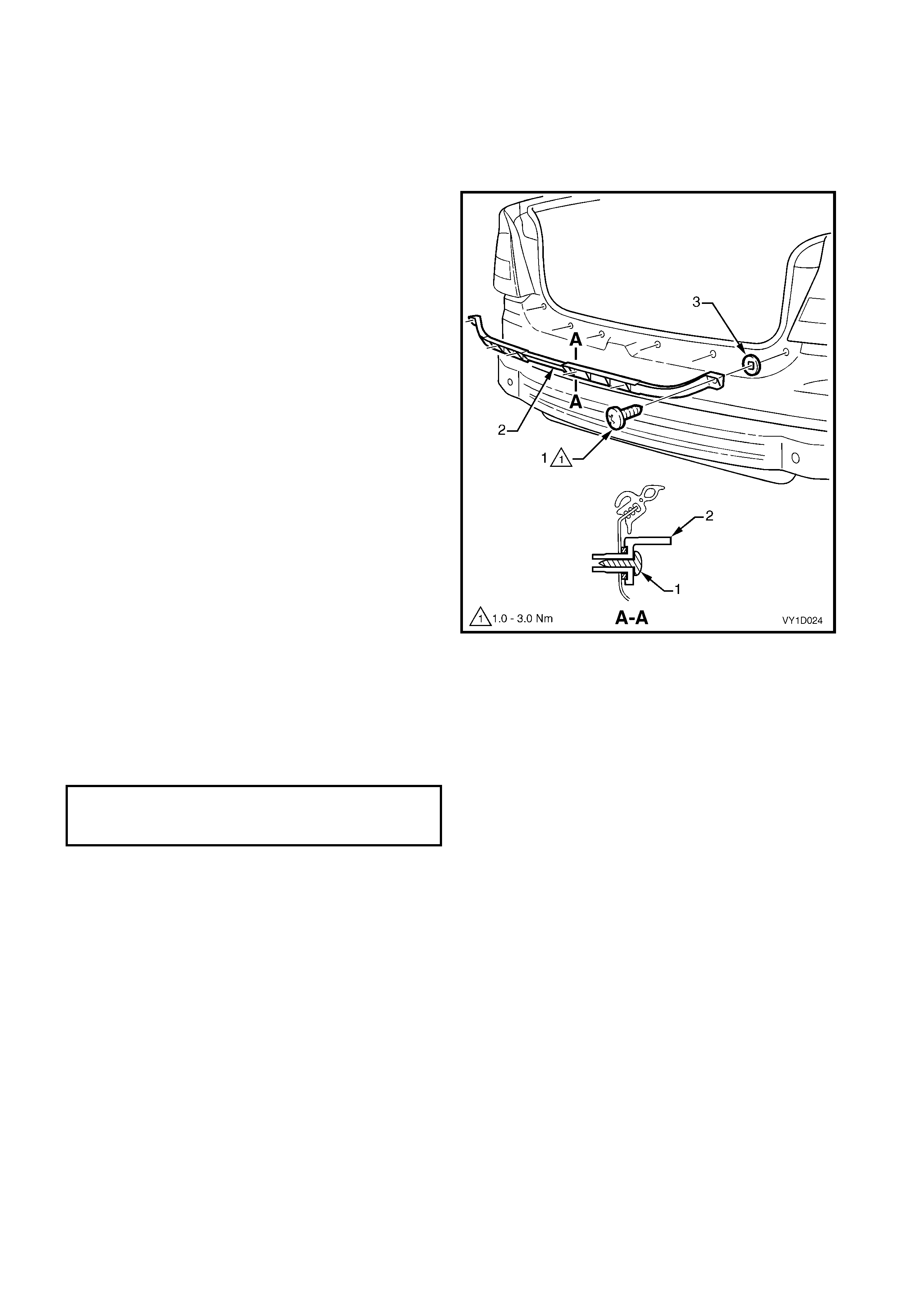
2.10 REAR BUMPER FASCIA UPPER SUPPORT, WAGON
REMOVE
1. Remove the rear bumper fascia, refer to
2.6 REAR BUMPER FASCIA ASSEMBLY,
WAGON.
2. Remove the screw (1), two places, attaching the
support (2) to the vehicle.
3. Prise the support from the vehicle ensuring the
seals (3) remain with the support.
4. Repeat for the opposite support as required.
Figure 1D-38
REINSTALL
1. Installation is the reverse of removal.
NOTE: Ensure the seals are correctly fitted to the
support prior to installation. Tighten the screws to the
specified torque.
REAR BUMPER FASCIA UPPER
SUPPORT ATTACHING SCREW
TORQUE SPECIFICATION 1.0 – 3.0 Nm

2.11 RE AR BUMPER IMPACT BAR, EXCEPT UTILITY
REMOVE
1. Remove the rear bumper fascia assembly, refer to:
2.5 REAR BUMPER FASCIA ASSEMBLY, SEDAN &
COUPE
or
2.6 REAR BUMPER FASCIA ASSEMBLY, WAGON.
2. Remove the screws (1), two places each side,
attaching the rear bumper impact bar (2) to the
rear bumper impact bar bracket assembly (3).
3. Remove the bar.
4. If required, remove the two nuts (4), attaching the
bracket assembly to the vehicle and remove the
bracket.
Figure 1D-39
REINSTALL
1. Fit the bracket assemblies in position and attach
the nuts. Tighten to the specified torque.
2. Fit the bar to the bracket assemblies and fit each
screw. Do not tighten.
3. When all screws are installed, check the bar is
centralised. Tighten the bolts to the specified
torque.
4. Refit the rear bumper fascia, refer to:
2.5 REAR BUMPER FASCIA ASSEMBLY, SEDAN &
COUPE
or
2.6 REAR BUMPER FASCIA ASSEMBLY, WAGON.
REAR BUMPER IMPACT BAR BRACKET
ASSEMBLY ATTACHING NUT
TORQUE SPECIFICATION 49.0 – 65.0 Nm
REAR BUMPER IMPACT BAR
ATTACHING SCREW
TORQUE SPECIFICATION 35.0 – 52.0 Nm

3. TORQUE WRENCH SPECIFICATIONS
Front fog lamp assembly nut..................................................................................................2.0 – 5.0 Nm
Front bumper fascia assembly to front wheelhouse liner screw ............................................1.0 – 3.0 Nm
Front bumper fascia assembly to front bumper fascia guide assembly screw ......................1.0 – 3.0 Nm
Front bumper fascia assembly to front upper panel screw....................................................2.5 – 4.0 Nm
Front bumper fascia guide assembly screw...........................................................................1.0 – 3.0 Nm
Front bumper impact bar assembly nut .................................................................................20.0 – 30.0 Nm
Rear bumper fascia assembly to rear wheelhouse liner screw..............................................1.0 – 3.0 Nm
Rear bumper fascia assembly to rear bumper fascia guide assembly screw........................1.0 – 3.0 Nm
Rear bumper fascia assembly nut, Sedan & Coupe..............................................................6.0 – 9.0 Nm
Rear bumper fascia to rear end panel screw, Utility ..............................................................18.0 – 25.0 Nm
Rear bumper fascia to J-nut screw, Utility..............................................................................1.0 – 3.0 Nm
Rear bumper fascia to rear wheelhouse liner screw, Utility...................................................1.0 – 3.0 Nm
Rear bumper fascia to rear bumper fascia guide assembly screw, Utility .............................1.0 – 3.0 Nm
Rear bumper fascia guide assembly screw ...........................................................................1.0 – 3.0 Nm
Rear bumper fascia centre support screw, Sedan & Coupe..................................................1.0 – 3.0 Nm
Rear bumper fascia upper support screw, Wagon ................................................................1.0 – 3.0 Nm
Rear bumper impact bar bracket assembly nut.....................................................................49.0 – 65.0 Nm
Rear bumper impact bar screw..............................................................................................35.0 – 52.0 Nm