
SECTION 1E - COCKPIT MODULE
IMPORTANT
Before perfo rming any Service Operation or other procedu re described in this Section , refer to Section 00
CAUTIONS AND NOTES for correct workshop practices with regard to safety and/or property damage.
CONTENTS
1. GENERAL DESCRIPTION
1.1 PRECAUTIONS
GENERAL PRECAUTIONS
INSTALLATION PRECAUTIONS
SAFETY PRECAUTIONS
2. SERVICE OPERATIONS
2.1 DASH PANEL ASSEMBLY
REMOVE
2.2 INSTALLATION PREPARATION
SURFACE PREPARATION
CHECKLIST
MIXING ADHESIVE & CATALYST
2.3 REINSTALL
DASH PANEL ASSEMBLY
COMPONENTS
2.4 DASH PANEL ASSEMBLY REPAIR
PANEL REPAIR
ADHESIVE REPAIR
3. TORQUE WRENCH SPECIFICATIONS
4. SPECIAL TOOLS

1. GENERAL DESCRIPTION
This Section describes the replacement of the dash panel assembly which is part of the cockpit module: a
production line sub-assembly consisting of the instrum ent panel, heater & A/C module assembly, steering colum n,
pedal assembly, wiring, etc. mounted to the dash panel assembly.
During production, the cockpit module is fitted to the vehicle in one operation. It is lowered through the windshield
opening and the dash panel as s embly is fitted into a channel k nown as the glue-tr ack, which is par t of the f r ont f loor
panel extension and hinge pillar inner panel assembly.
The glue track is filled with a special silicone adhesive prior to the cockpit module being installed. The dash panel
assem bly aligns with several dimples and four bolts sec ure it to the vehicle; two through the hinge pillar and two in
the plenum area. Once the adhesive cures, the dash panel assembly becomes an integral part of the body
structure.
The dash panel assembly is clearly visible from within the engine compartment. It is the gloss-black body panel
forming the plenum chamber below the windshield and continuing to the floor panel. The glue-track can be seen
where the dash panel assembly joins the hinge pillars and floor.
The s ilicone adhesive is a specif ic type f or this application and is s uited for the high temperatures generated within
the engine c om partm ent. It has exc ellent bonding, sealing and longevity characterist ics. T his tec hnique has been in
use for many years.
The components of the cockpit module, e.g. instrument panel, steering column, heater & A/C module assembly,
etc. c an be s ervic ed in the nor mal manner. The dash panel as s embly can also be serviced, however due to the f ac t
it is ‘glued-in’, the procedures in this Section must be followed.
Also included in this Sec tion are repair pr ocedures f or a damaged dash panel assem bly and adhesive. As the dash
panel is ‘glued’ to the vehicle, consideration is needed for the adhesive when repair procedures are performed.

1.1 PRECAUTIONS
GENERAL PRECAUTIONS
1. Only the correct two-part silicone adhesive should be used when refitting or repairing the dash panel assembly.
NOTE: Remove as much of the old adhesive as possible from the glue track before installation.
2. As the das h panel as sembly forms par t of the vehicle s tr uctur e, where it has any damage or cr ac ks in the sheet
metal, or if fire damage has occurred, the dash panel assembly must be removed and replaced.
3. Tears, separation or splitting of the adhesive exceeding 300 mm in length requires removal and complete re-
gluing of the dash panel. T he adhesive m ay be repaired where dam age is less than 300 m m in length, ref er to
2.4 DASH PANEL REPAIR.
4. The silicone adhesive used in the glue track must not be replaced with any other type of adhesive or sealant
other than that which is recommended and available from your authorised dealer as the Sealant Kit - Dash
Panel. Urethanes, epoxies, acrylic or ‘normal’ silicones, etc. are not suitable for use in this application. Failure to
correctly seal the cockpit module panel to the vehicle may allow exhaust, fuel or other fumes to enter the
passenger compartment and compromise the structural integrity of the vehicle.
5. The adhesive is best applied with the SAE 677 barrel gun & follower plate. Refer to your authorised dealer for
availability .
INSTALLATION PRECAUTIONS
IMPORTANT: To obtain a satisfactory bond between the two parts, the following procedures must be observed.
1. Prior to installation of the dash panel ass em bly, remove as m uc h of the r em aining adhesive f rom the glue trac k
as possible.
2. After repairing any damaged sheet metal, completely remove the rem aining adhesive in the repaired area and
apply primer and refinish the area according to the paint manufacturer’s specifications.
3. Do not apply paint over any remaining adhesive or allow overs pray to get in the glue-track . Apply mask ing tape
to the track before painting, and install the dash panel assembly after oven baking the paint (where
appropriate).
4. Do not use an adhesive other than which is recommended.
5. Body shell assemblies are available with the cockpit module installed, refer to your authorised dealer for
availability .
6. Before commencing installation of the dash panel assembly, thoroughly read 2.2 INSTALLATION
PREPARATION in this Section.
7. Although the cock pit module is installed as an assem bly on the production line, this method is not practical for
repairing the vehicle.
SAFETY PRECAUTIONS
The silicone adhesive used in the glue track, once cured, requires no special precautions. However, when mixing
the adhesive compound with the catalyst and applying the adhesive, the following precautions should be observed.
1. Do not swallow: the catalyst is a toxic substance, keep away from children.
2. Safety glasses should be worn to avoid contact with eyes. If eye contact occurs, wash the area in clean water
only, and seek immediate medical advice.
3. Wear protective gloves when handing the adhesive and catalyst, as they may cause skin irritation. If irritation
occurs, wipe the adhesive/catalyst off with a clean cloth and wash the affected area thoroughly in clean water.
4. Vapour produced by the adhesive and catalyst may cause breathing difficulties, use only in a well ventilated
area.
5. The catalyst is combustible, keep away from sparks and flame.

2. SERVICE OPERATIONS
2.1 DASH PANEL ASSEMBLY
LT Section No. – 12-425
IMPORTANT: Prior to commencing any of the following procedures, disconnect the battery to disable the SIR
system. Following reconnection of the battery the security PIN code will be required to reinstate the entertainment
system, refer to Section 12D ENTERTAINMENT SYSTEM.
As required, first remove the following components:
1. Hood and hinge assemblies, refer to Section 1A4, 2.5 HOOD & HINGE ASSEMBLIES.
2. Drain the engine coolant, refer to Section 6B1 ENGINE CO OLING – V6 or Section 6B2 ENGINE COO LING –
V6 S/C or Section 6B3 ENGINE COOLING – V8.
3. Discharge the air-conditioning s ystem (Manual or Auto A/C), refer to Section 2C HVAC OCCUPANT CLIMATE
CONTROL (MANUAL A/C) – SERVICE & DIAGNOSIS.
4. Engine, refer to Section 6A1 ENGINE MECHANICAL – V6 or Section 6A2 ENGINE M ECHANICAL – V6 S/C
or Section 6A3 ENGINE MECHANICAL – V8.
5. Plenum Cover assembly and windshield wiper assembly, refer to Section 12N WIPERS/WASHERS & HORN.
6. Windscreen side garnish, refer to Section 1A8 HEADLING & INTERIOR TRIM.
7. Hinge pillar trim, refer to Section 1A8 HEADLING & INTERIOR TRIM.
8. Windshield assembly, refer to Section 1A6 STATIONARY GLASS.
9. Floor console and instrument panel assembly, refer to Section 1A3 INSTRUMENT PANEL & CONSOLE.
10. Passenger airbag assembly, refer to Section 12M OCCUPANT PROTECTION SYSTEM.
11. Fuse panel, refer to Section 12O FUSES & WIRING HARNESS.
12. BCM, refer to Section 12J BODY CONTROL MODULE.
13. Instrument panel brackets and braces, refer to Section 1A3 INSTRUMENT PANEL & CONSOLE.
14. PCM, refer to Section 6C1 POWERTRAIN MANAGEMENT SYSTEM – V6 or Section 6C2 POWERTRAIN
MANAGEMENT SYSTEM – V6 S/C or Section 6C3 POWERTRAIN MANAGEMENT SYSTEM – V8.
15. Heater & A/C module ass embly, refer to Section 2B HVAC OCCUPANT CLIMATE CONTROL (MANUAL A/C)
– REMOVAL & INSTALLATION or Section 2E HVAC OCCUPANT CLIMATE CONTROL (AUTO A/C) –
REMOVAL & INSTALLATION.
16. Steering Column assembly, refer to Section 9A POWER STEERING.
17. Brake master cylinder assembly, brake and accelerator pedal assemblies, refer to Section 5A SERVICE &
PARK BRAKE SYSTEMS.
18. Clutch master cylinder assembly and clutch pedal assembly, if fitted, refer to Section 7A1 CLUTCH – V6
ENGINE.
19. Telematics module and antenna, if fitted, refer to Section 12K TELEMATICS.
20. As required, remove the wiring harnesses from the dash panel and lay out of the way, refer to
Section 12O FUSES & WIRING HARNESS.
NOTE 1: For the RH side, the dash panel assem bly will be cut f rom around the har ness. This saves disconnec tion
of the complete main wiring harness.
NOTE 2: As required, mark and identify the connectors to aid reinstallation.
NOTE: The following fasteners MUST be replaced
when performing this operation:
+
++
+
Dash panel screw (plenum side)
+
++
+
Dash panel bolt (hinge pillar side)
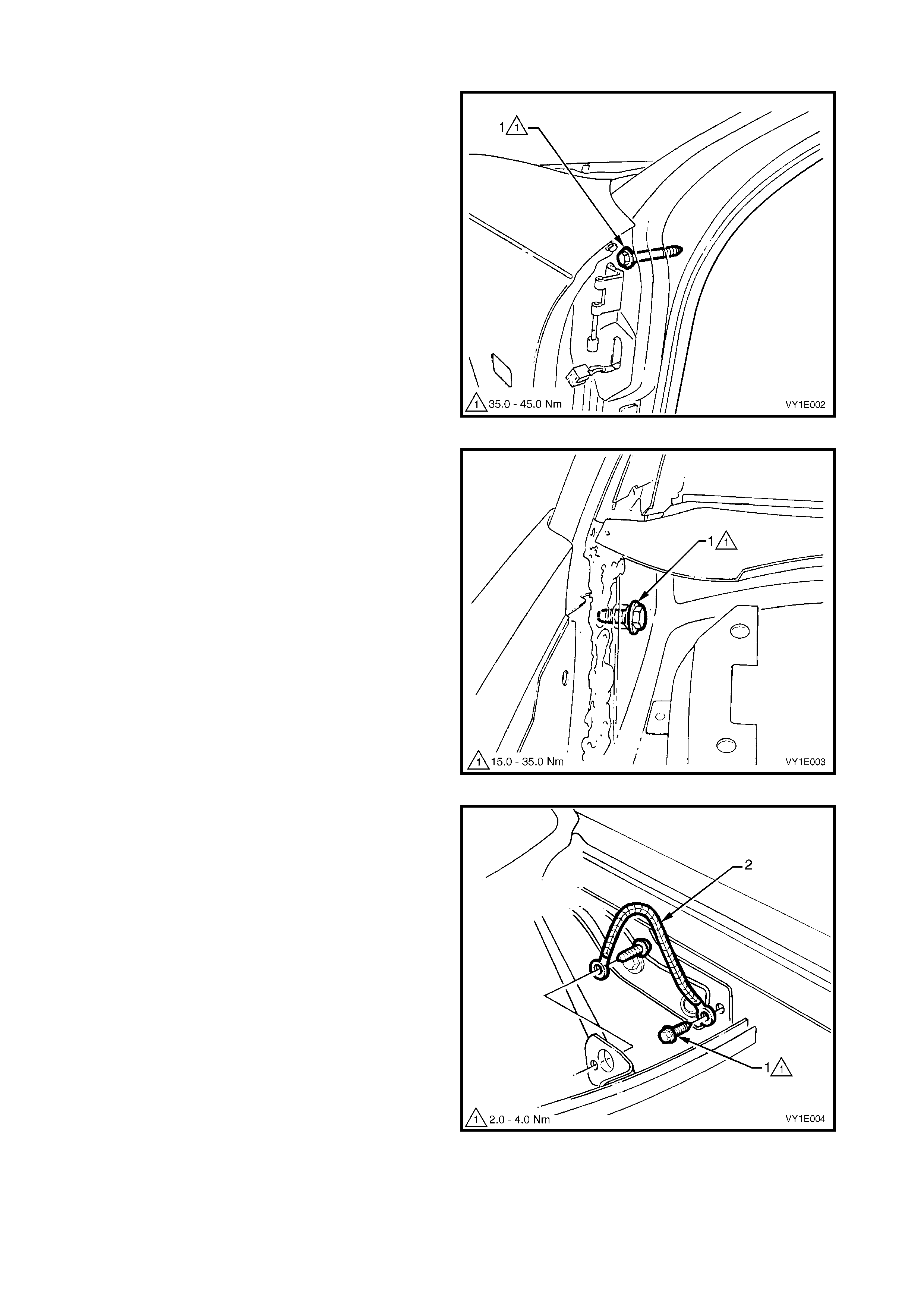
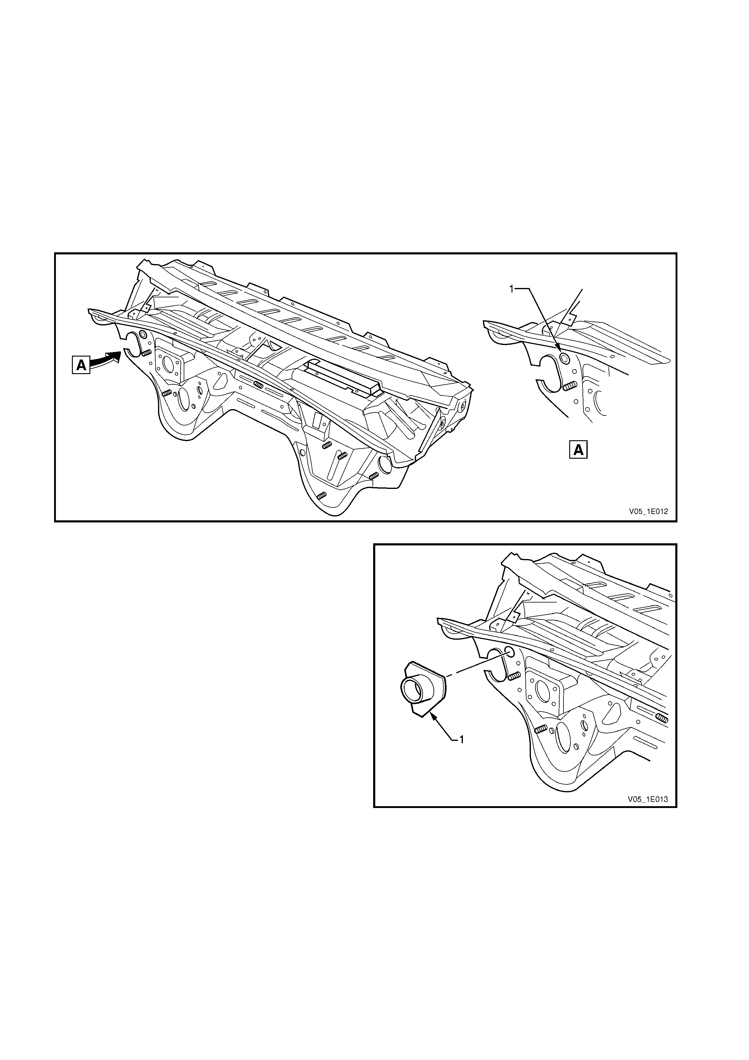
REMOVE
1. Remove the dash panel bolt (1) from each hinge
pillar.
Figure 1E-1
2. From within the plenum chamber, remove the
dash panel screw (1) each side.
Figure 1E-2
3. Remove the two screws (1) attaching the body
earth strap (2) and remove.
Figure 1E-3
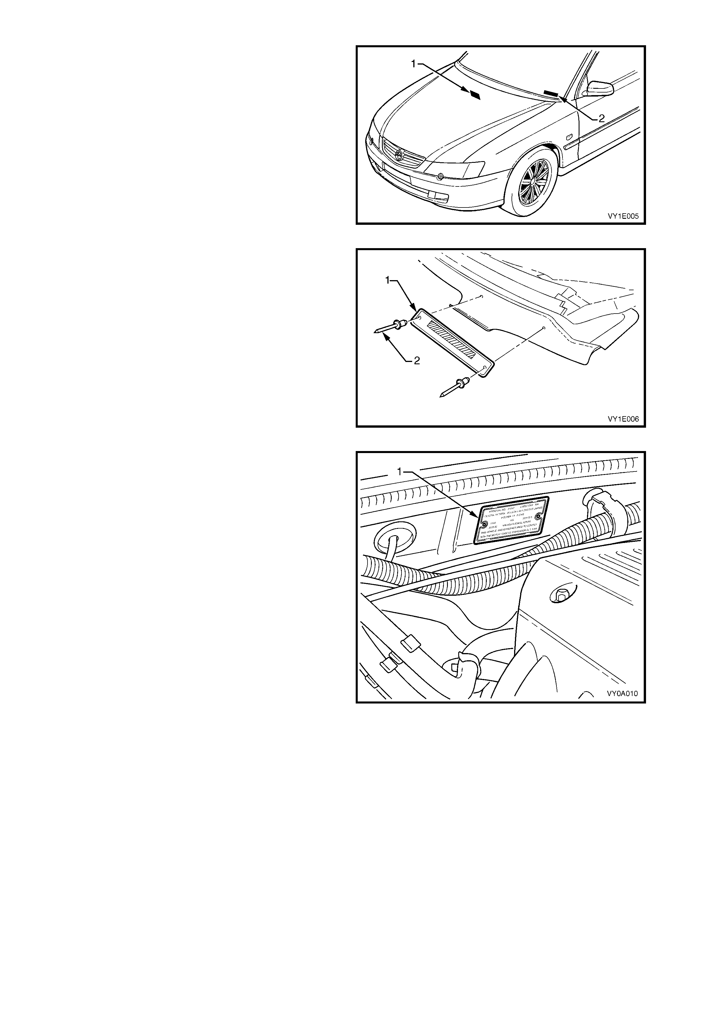
4. Locate the safety compliance plate (1) near the
centre of the dash panel and VIN plate (2) on the
LH side of the dash pane.
5. Using a drill and suitable size drill bit, drill out the
retaining rivets.
Figure 1E-4
6. Transf er the VIN plate (1) onto the new dash panel
assembly.
7. Using a com mercially available hand rivet tool and
two new rosette headed rivets (2), secure the VIN
plate to the new dash panel assembly.
Figure 1E-5
8. Transfer the safety compliance plate (1) onto new
dash panel assembly.
9. Using a com mercially available hand rivet tool and
two new rosette headed rivets (2), secure the
safety compliance plate to the new dash panel
assembly.
10. Remove the retainer (1) attaching the dash panel
lower insulator outer to the engine compartment
side of the dash panel, refer to Figure 1E-7.
Figure 1E-6
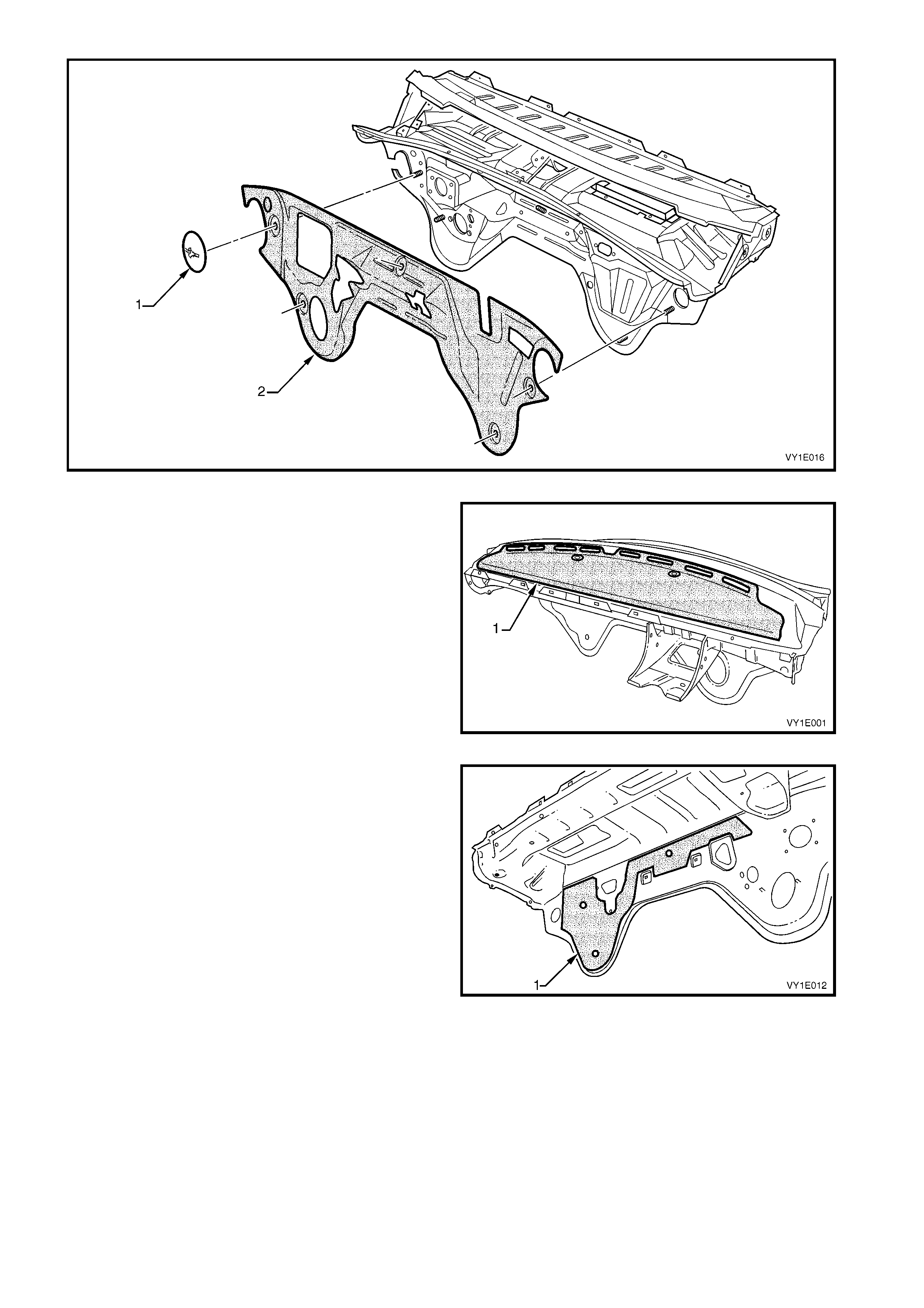
Figure 1E-7
11. Transfer the dash panel upper insulator (1) from
the existing dash panel to the new dash panel.
The insulator is adhered to the dash panel and
care is required during removal. If required, apply
contact adhesive to the insulator prior to affixing it
to the new dash panel and ensure it follows the
form of the dash panel.
If a new insulator is being fitted, remove the
backing paper prior to fitting and apply.
Figure 1E-8
12. The dash panel lower deadener (1) cannot be
transferred to the new dash panel; a new
deadener will be required. Affix the deadener to
the new dash panel now to allow the dash panel
lower insulator to be transferred.
The deadener is a heat-fusible type. Install it in
position with the diamond embossed side to the
panel. Use a heat gun, heat lamps or suc h, to c ure
the deadener. Smooth the deadener with a roller
or such to expel any air bubbles and to maximise
adhesion.
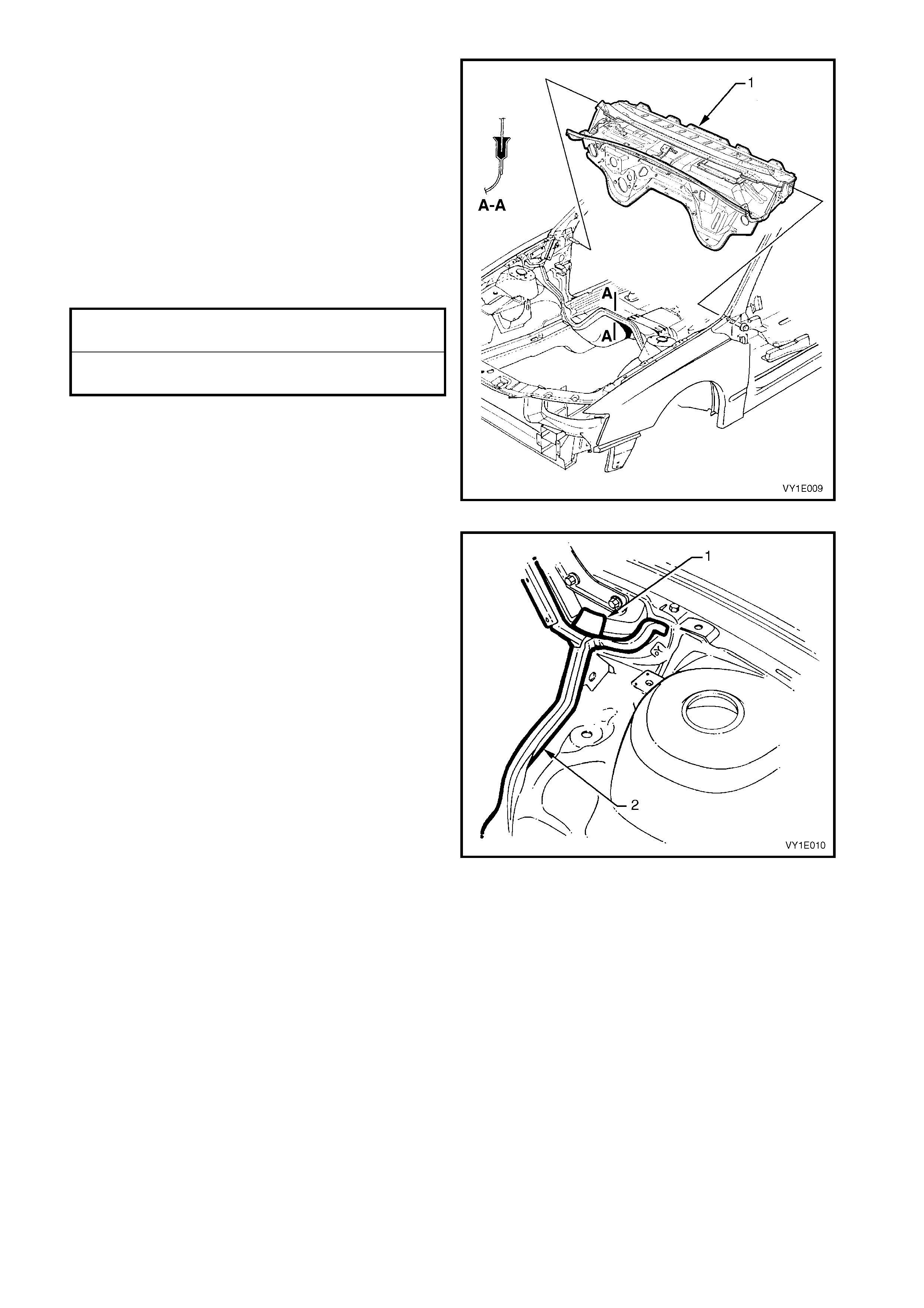
Figure 1E-9
13. Transfer the dash panel lower insulator inner (1)
from the existing dash panel. The insulator is
attached with two retainers (2).
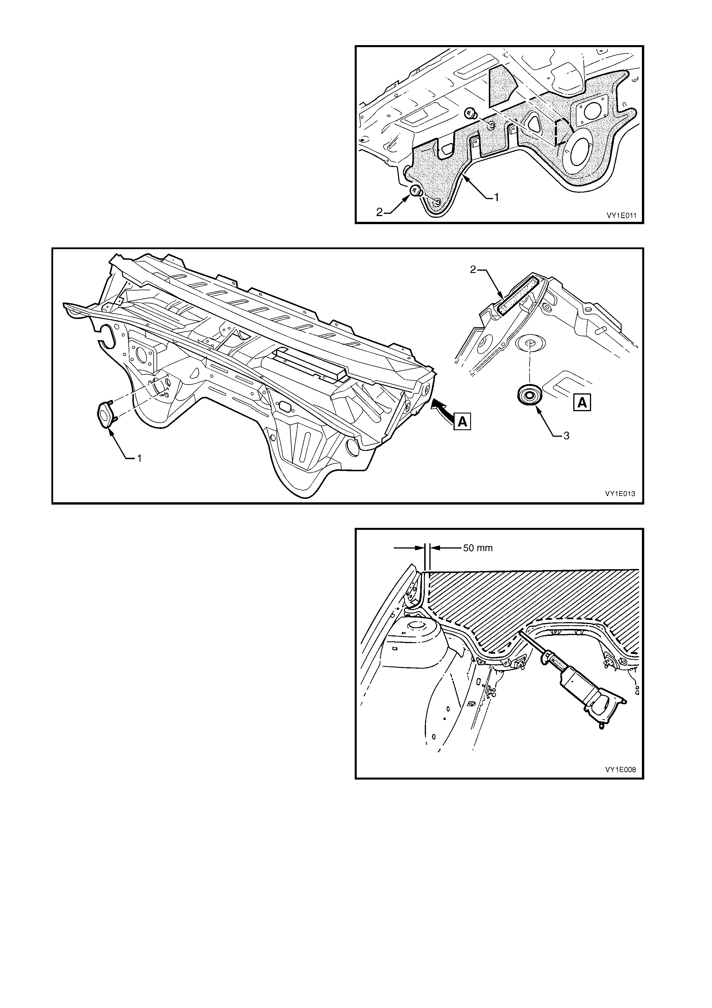
14. Transfer the plug (1), if fitted, spacer (2) and plug
(3), refer to Figure 1E-11.
Figure 1E-10
Figure 1E-11
15. Using a power saw, cut the dash panel assembly
approximately 50 mm above the glue track.
CAUTION: Sparks may ignite petrol in the fuel or
emission control lines if due precautions are not
taken.
NOTE: Take care cutting around the main wiring
harness.
16. Remove the dash panel assembly section.
17. Cut the section of remaining panel to enable
removal of the main wiring harness.
Figure 1E-12
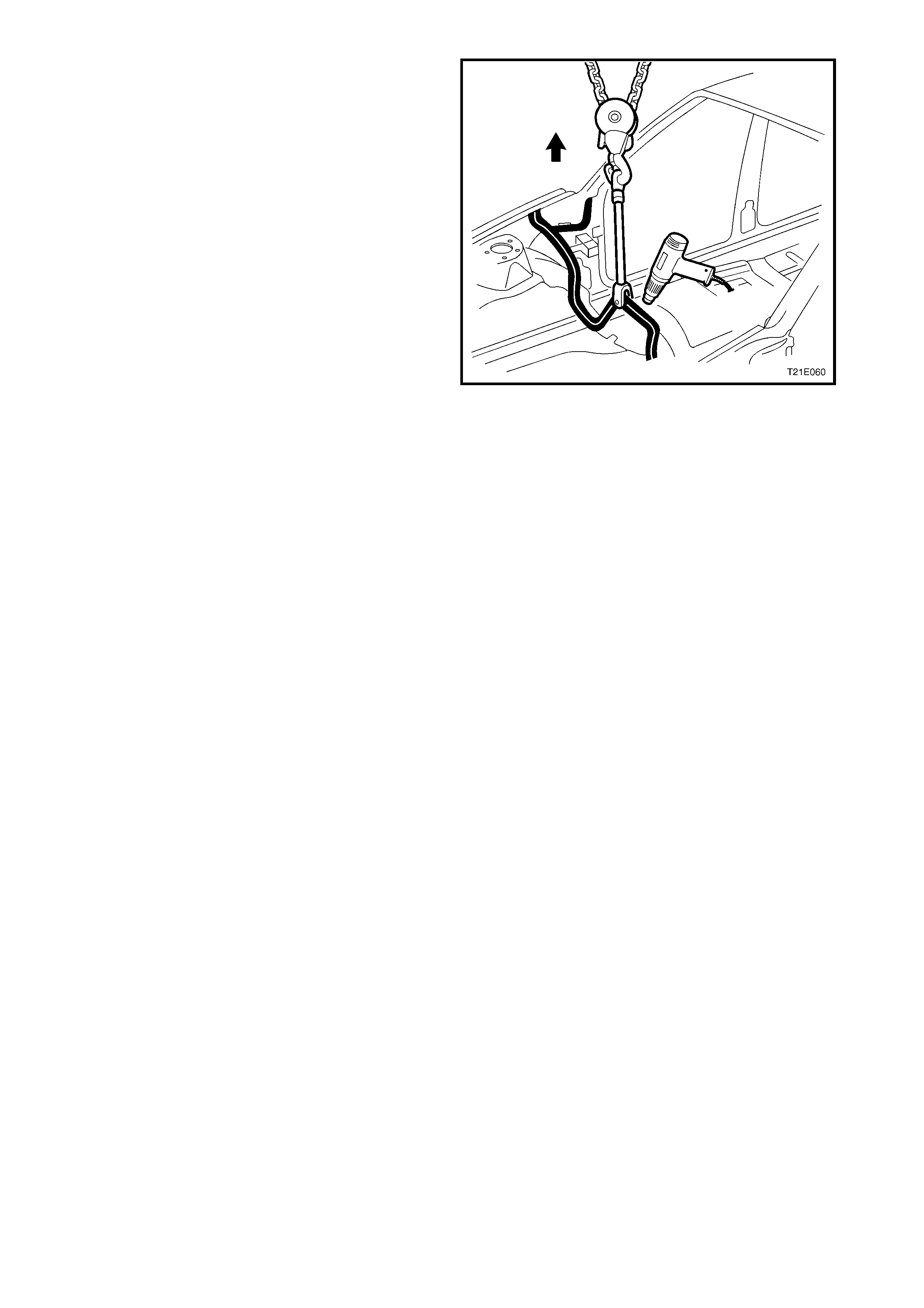
18. Drill a hole in the flange above the transmission
tunnel, and attach a chain block and a clevis.
19. Apply and maintain a light tension to the rem aining
part of the dash panel assembly .
20. Either cut the adhesive with a hot knife or heat the
adhesive us ing a heat gun and pull the panel fr om
the glue track.
NOTE: This may be required in several places.
21. Clean the excess adhesive from the glue track
using a hot knife or a heat gun and tool.
CAUTION: To avoid fire, do not attempt to burn
the remaining adhesive from the glue track using
an oxy / acetylene torch.
Figure 1E-13

2.2 INSTALLATION PREPARATION
NOTE: Do not attempt to install a fully built-up cockpit module assembly.
SURFACE PREPARATION
Clean any remaining adhesive from the glue track using a hot knife or heat gun.
The vehicle should be painted before installation of the dash panel assembly. Before painting the vehicle, apply
masking tape to prevent paint entering the glue track.
The adhesive will not adhere to paint, overspray, oil, grease, etc. The glue track must be free of dirt, dust, grease,
oil and paint or overspray.
W ipe the glue track with a suitable cleaning agent such as Prepsol or equivalent, then clean any residue from the
area with a clean, dry, lint free cloth.
Temporarily install the new dash panel assembly prior to mixing the adhesive to check for correct fit. Rectify any
faults found then remove the panel from the vehicle.
NOTE: Before mixing the adhesive, it is advisable to have the SAE 677 barrel gun & follower plate. Refer to the
latest Spare Parts Information for details.
CHECKLIST
Before mixing the adhesive and installing the dash panel assembly, the following items should be checked:
• Familiarise yourself with the precautions in 1.1 GENERAL PRECAUTIONS.
• Ensure the adhesive being used is the recommended material.
• The vehicle surface should be finished and the paint fully dry before installation.
• Clean any overspray, grease, oil, dir t, etc. f rom the glue trac k using an agent suc h as Pr epsol or equivalent and
a clean, dry, lint-free cloth.
• Test fit the module panel in the glue track BEFORE MIXING THE ADHESIVE.
• Is the adhesive applicator gun clean and ready for use?
• Are the cockpit module bolts readily accessible?
MIXING ADHESIVE & CATALYST
IMPORTANT: This is a two-part, fast cur e adhes ive. Ensur e that the panel is ready for ins tallation bef or e m ixing the
adhesive. The working time is less than 20 minutes.
Part A : Adhesive compound, yellow in colour and supplied in a 1.4 kilogram container.
Part B: Catalyst, used to accelerate the cure time of the adhesive compound and is supplied in a 120 gram tube.
The contents of the Sealant Kit - Dash Panel is sufficient to install the dash panel assembly in a vehicle.
CAUTION: The vapour from the adhesive may cause breathing difficulties, use only in a well ventilated
area. In case of eye contact, flush immediately with clean water. Refer to Safety Precautions in
1.1 GENERAL PRECAUTIONS.
COMBUSTIBLE – keep away from spark and flame.
1. Remove the lid from the adhesive compound container.
2. Rem ove the cap from the catalyst and pierce the end of the tube, then squeeze the entire contents of the tube
into the adhesive compound container.
3. Hold the container securely, and m ix the catalyst into the adhesive using a paint mixer or a flat clean wooden
utensil.
4. Continue to mix until the adhesive is a consistent grey colour without any streaks.
5. Place the follower plate supplied with the applicator gun into the adhesive container.
6. Remove the front end cap and disposable nozzle from the applicator gun.
7. Cut the tip from the nozzle.
8. Place the applicator gun front end over the hole in the follower plate.
NOTE: The eas iest m ethod of drawing the adhesive into the gun is to proceed slowly, allow the downward pressure
on the plate and the suction of the gun to draw the compound.
9. Sim ultaneously push down on the gun and plate with max imum pressure, pres s the gun’s release plate inward
and slowly pull the T-bar (piston) outward. This procedure will slowly suck the mixed adhesive into the
applicator gun.
10. Wipe any excess adhesive f r om the applicator gun, sc r ew the end cap onto the applicator gun and then reinstall
the nozzle.
11. Proceed immediately with installing the panel.
IMPORTANT: After mixing the silicone adhesive, installation of the cockpit module panel should be completed
within 15 – 20 minutes. Under normal conditions, the adhesive will begin to cure in about 25 – 30 minutes. After
installation, the dash panel assembly or vehicle should not be moved or disturbed until the adhesive is fully cured
(about 3 hours).
2.3 REINSTALL
DASH PANEL ASSEMBLY
NOTE: A replacement dash panel assembly may
require a hole to be drilled and a throttle cable bush
and plate assembly to be welded in place to allow
throttle cable installation.
1. If fitting a replacement dash panel:
a. Carefully drill a 3 mm pilot hole through the
centre of the dimple (1). Drill out the hole to
23 mm, refer to Figure 1E-14
b. Remove any burrs and refinish as required.
Figure 1E-14
c. Ensure the throttle cable bush and plate
assembly (1) is centred over the hole and
carefully MIG weld the bush and plate
assembly along the three edges onto the dash
panel.
Figure 1E-15
NOTE: Do not attempt to install a fully built-up cockpit
module assembly.
2. Ensure any remaining adhesive is cleaned off the
glue track using a hot knife or heat gun.
3. Check each item in 2.2 INSTALLATION
PREPARATION – CHECKLIST.
4. Mix the silicone adhesive and fill the applicator
gun as described in 2.2 INSTALLATION
PREPARATION – MIXING ADHESIVE &
CATALYST.
NOTE: Installation is best performed with the aid of
two people.
5. Begin filling the glue track from the lowest points
to prevent air bubbles forming in the adhesive.
Completely fill the channel in a continuous bead.
6. Apply a patch of adhesive approximately 50mm
diameter to the base or the windshield pillar.
7. Hold the dash panel assembly in position slightly
above the glue track.
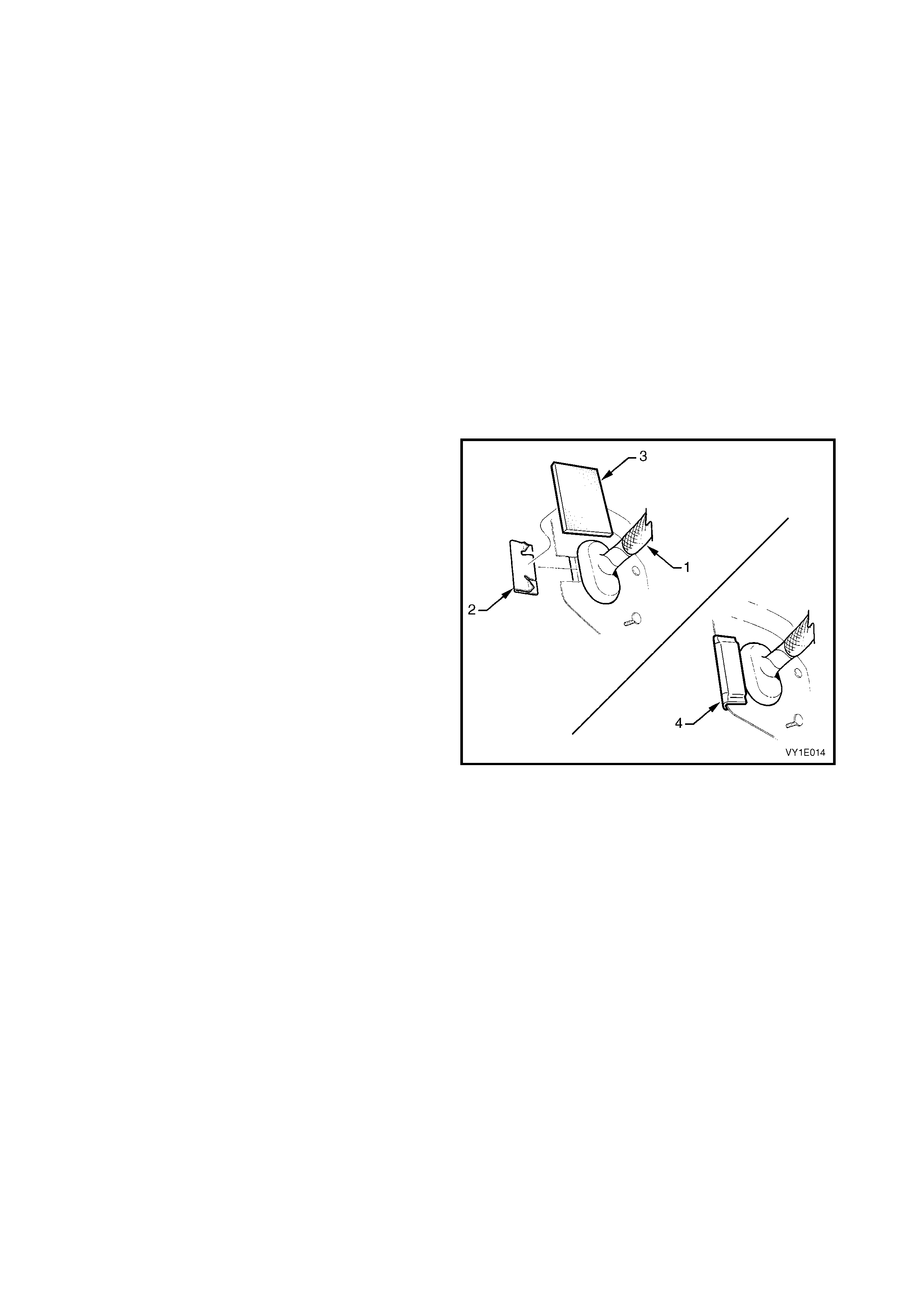
8. Have an assistant pass the main wiring harness
(1) through the opening in the dash panel.
9. Install the dash panel outer opening cover (2) onto
the dash panel assembly.
10. Affix the dash panel side insulator (3) over the
cover and fold over the back of the panel as
shown (4).
Figure 1E-16
11. Lower the dash panel assembly (1), ensuring the
flange seats correctly in the glue track.
12. Push the panel firmly into the glue track channel
until mounting bolt holes align. Check to ensure
that the section around the main wiring harness
hole is correctly installed.
13. Install two new dash panel bolts through the hinge
pillar and two new screws within the plenum
chamber and hand tighten.
14. Recheck the flanges are correctly seated.
15. Tighten the bolts and screws to the specified
torque.
Figure 1E-17
16. Wipe any excess adhesive from the plenum drain
hole (1) each side and the glue track areas (2).
17. Immediately following dash panel assembly
installation, clean any adhesive from the applicator
gun and follower plate.
18. Leave adhesive to cure for a minimum of three
hours.
Figure 1E-18
COMPONENTS
Installation of the cockpit module components is the reverse of the removal, noting the following.
1. Ensure all the rubber grommets and insulation materials are installed onto the dash panel assembly.
2. Ensure all fasteners are tightened to the correct torque specification.
3. Ensure the heater & A/C module assembly drain tube is correctly installed.
4. Ensure that all wiring harnesses are correctly routed and retained correctly, refer to Section 12O FUSES &
WIRING HARNESS.
5. Ensure the stop lamp switch and cruise control release switches are adjusted correctly, refer to Sections 12B
LIGHTING SYSTEM and 12E CRUISE CONTROL.
6. Ensure the throttle and cruise control cables are correctly routed and adjusted.
7. On battery reconnection, check the SIR warning icon for correct operation, refer to Section 12M, OCCUPANT
PROTECTION SYSTEM and reprogram the audio system security PIN, refer to Section 12D
ENTERTAINMENT SYSTEM.
DASH PANEL SCREW (PLENUM SIDE)
TORQUE SPECIFICATION 15.0 – 35.0 Nm
DASH PANEL BOLT (HINGE PILLAR SIDE)
TORQUE SPECIFICATION 35.0 – 45.0 Nm
2.4 DASH PANEL ASSEMBLY REPAIR
PANEL REPAIR
NOTE: The dash panel assembly can only be levered against itself. Levering or pulling from other panels or
external objects may cause the dash panel assembly to separate from the adhesive and glue track.
If the dash panel as s embly is separated from the glue track for les s than 300 mm , due to damage of either the dash
panel assembly or surrounding panels and the dash panel assembly is serviceable, it is permissible to repair the
panel without removal.
1. Disassemble the required components to allow access, refer to 2.1 DASH PANEL ASSEMBLY.
2. Cut the required section of adhesive from the glue track using a hot knife.
3. Repair the damage to the surrounding panels as required.
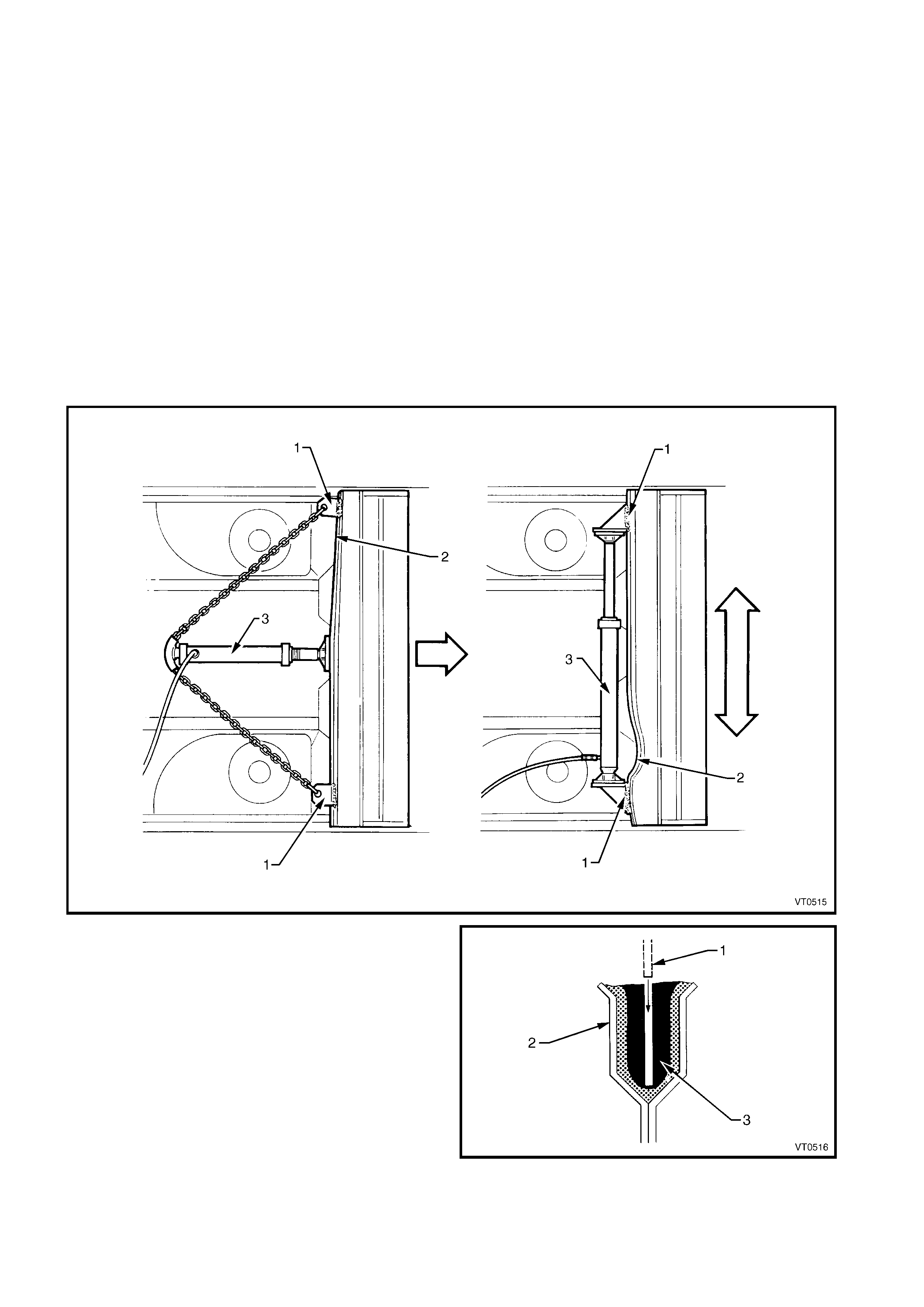
4. Secure two clamps or brackets (1) to the dash panel assembly to act as levering points to straighten the
damaged area (2), refer to Figure 1E-17.
NOTE: Depending on the damage, it may be more appropriate to pull the area instead of pushing it.
5. Install a suitable hydraulic ram (3) between the clamps.
6. Make the necessary repairs and adjustments to the module panel to ensure an accurate fit in the glue track.
7. W ith the dash panel assem bly (1) correctly seated
in the glue track (2), fill the glue track with the
approved adhesive (3). Follow the procedures as
required in 2.2 INSTALLATION PREPARATION
and 2.3 INSTALL - DASH PANEL ASSEMBLY.
8. Allow the adhesive at least three hours to cure
before performing any further work or painting the
vehicle.
Figure 1E-18
ADHESIVE REPAIR
Adhesive tears or splits of less than 300 mm in length
may be repaired using single pack silicone adhesive.
Repairing a tear or split longer than 300 mm in length
necessitates removal of the dash panel assembly, as
described pr evious ly, with complete replacement of the
silicone adhesive.
1. Wipe the surrounding area with a cleaning agent
such as Prepsol, then remove any residue from
the area with a dry, lint free cloth.
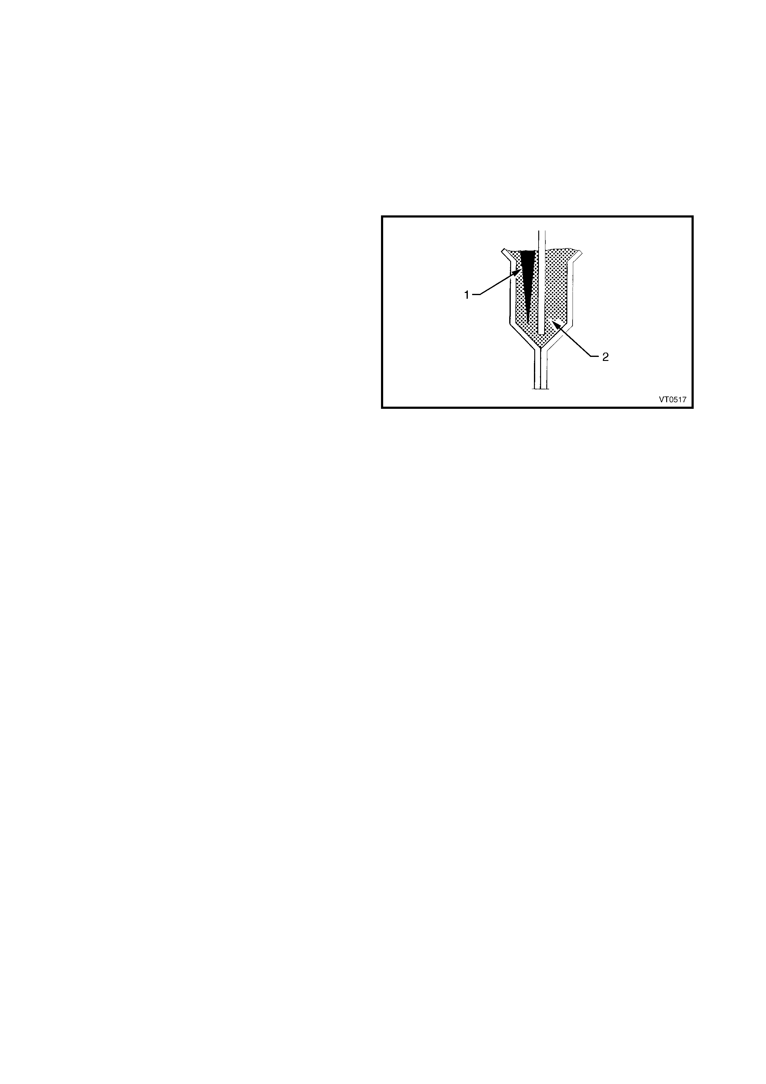
2. Cut a deep “V” (1) into the adhesive (2),
completely cutting out the torn or split section.
NOTE: The area must be completely clean; free of dirt,
oil, grease, etc. to obtain satisfactory adhesion of the
silicone adhesive.
3. If necessary, wipe the metal area of the glue track
with mineral spir its, then wipe the r esidue from the
surface using clean, dry, lint free cloth.
4. Fill the void with silicone adhesive, ensuring no air
bubbles remain trapped in the adhesive.
5. Smooth out the adhesive flush with adjacent area.
6. Clean up any excess before the adhesive cures,
using mineral spirits.
7. Allow the adhes ive to cure ( up to 24 hours), befor e
performing any further work on the area.
Figure 1E-19

3. TORQUE WRENCH SPECIFICATIONS
Dash panel screw (plenum side) ....................................................................15.0 – 35.0 Nm
Dash panel bolt (hinge pillar side)...................................................................35.0 – 65.0 Nm
Body earth strap screws .................................................................................2.0 – 4.0 Nm

4. SPECIAL TOOLS
TOOL NUMBER ILLUSTRATION DESCRIPTION TOOL
CLASIFICATION
SAE 677
BARREL GUN &
FOLLOWER
PLATE
Used to apply dash panel assembly
two-part silicone adhesive.
Previously available, refer parts
catalogue
Desirable