
SECTION 1F1 - SUNROOF
IMPORTANT
Before performing any Service Operation or other procedure described in this Section, refer to Section
00 CAUTIONS AND NOTES for correct workshop practices with regard to safety and/or property damage.
CONTENTS
1. GENERAL DESCRIPTION
PRE-PROGRAMMED FUNCTIONS
OPTIONAL PROGRAMMABLE FUNCTION
INTERIOR TRIM
POWER HARNESS
SUNROOF CONTROL UNIT (SCU)
SUNROOF COMPONENTS
2. SERVICE OPERATIONS
2.1 DRIVE MOTOR
REMOVE
REINSTALL
2.2 DRIVE GEAR
REMOVE
REINSTALL
2.3 SUNROOF CONTROL UNIT (SCU)
REMOVE
REINSTALL
2.4 CALIBRATING THE SUNROOF
CONTROL UNIT
2.5 GLASS PANEL
REMOVE
REINSTALL AND ADJUST
2.6 ADJUSTMENT BRACKETS
REMOVE
REINSTALL
2.7 EXTERIOR COVERS
REMOVE
REINSTALL
2.8 RUBBER SEAL
REMOVE
REINSTALL
ADJUSTMENT
2.9 WIND DEFLECTOR
REMOVE
REINSTALL
2.10 DRAIN CHANNEL
REMOVE
REINSTALL
2.11 SUNSHADE
REMOVE
REINSTALL
2.12 DRIVE CABLES
REMOVE
REINSTALL
2.13 TIMING OF DRIVE CABLES
2.14 RETRACTION MECHANISM
REMOVE
REINSTALL
2.15 GUIDE RAIL MECHANISM
REMOVE
REINSTALL
2.16 BLOCKING CATCH
REMOVE
REINSTALL
2.17 SUNROOF POWER HARNESS
REMOVE
REINSTALL
2.18 SUNROOF HARNESS
REMOVE
REINSTALL
2.19 SUNROOF CONTROL HARNESS
REMOVE
REINSTALL
2.20 SUNROOF SWITCH
REMOVE
REINSTALL
2.21 REAR DRAIN TUBE – SEDAN
REMOVE
REINSTALL
2.22 REAR DRAIN TUBE – WAGON
REMOVE
REINSTALL
2.23 FRONT DRAIN TUBE
REMOVE
REINSTALL
3. DIAGNOSIS
3.1 FAULT DIAGNOSIS CHARTS
INTRODUCTION
PREREQUISITES
FUNCTIONAL TEST
ELECTRICAL TEST
SUNROOF SWITCH AND SUNROOF
CONTROL HARNESS TEST
REPAIR ADVICE FOR MECHANICAL
FAILURES
REPAIR ADVICE FOR ELECTRICAL
FAILURES
REPAIR ADVICE FOR RATTLING NOISES
REPAIR ADVICE FOR WIND NOISES
REPAIR ADVICE FOR WATER LEAKS
3.2 WIRING DIAGRAM – SUNROOF
3.3 CONNECTOR DIAGRAMS – SUNROOF
4. TORQUE WRENCH SPECIFICATIONS
5. SPECIAL TOOLS
6.
1. GENERAL DESCRIPTION
This section describes the service procedures required for the Holden By Design (HBD) sunroof installed in MY
2003 VY Series Sedans and Wagons.
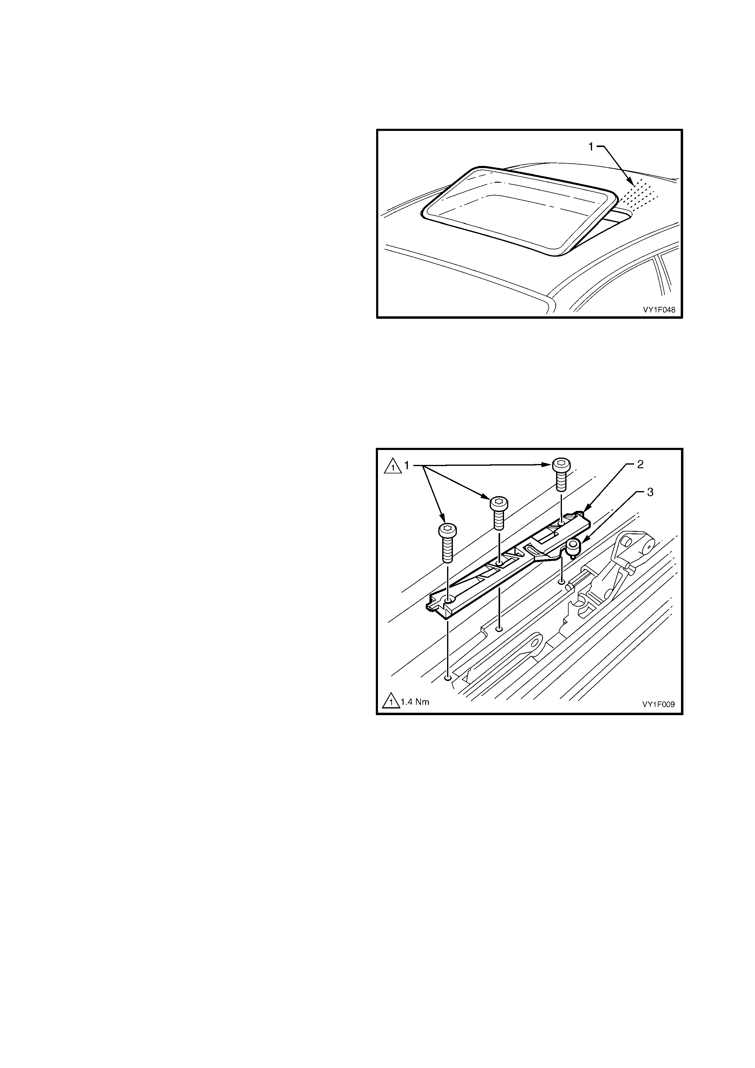
The HBD s unroof c an be identif ied by the presence of a rubber tr im ring located ar ound the sunr oof and attac hed to
the roof panel.
The HBD sunroof is an electronically operated, two-way design allowing either tilting or sliding actions. It features
tinted glass with a separate internal s unshade and a f ront edge wind deflector . T he sunroof is operated via a s witch
panel located in the roof console, for ward of the sunroof opening. The Sunroof Control Unit (SCU) provides several
pre-programmed functions and the option to program an additional function.
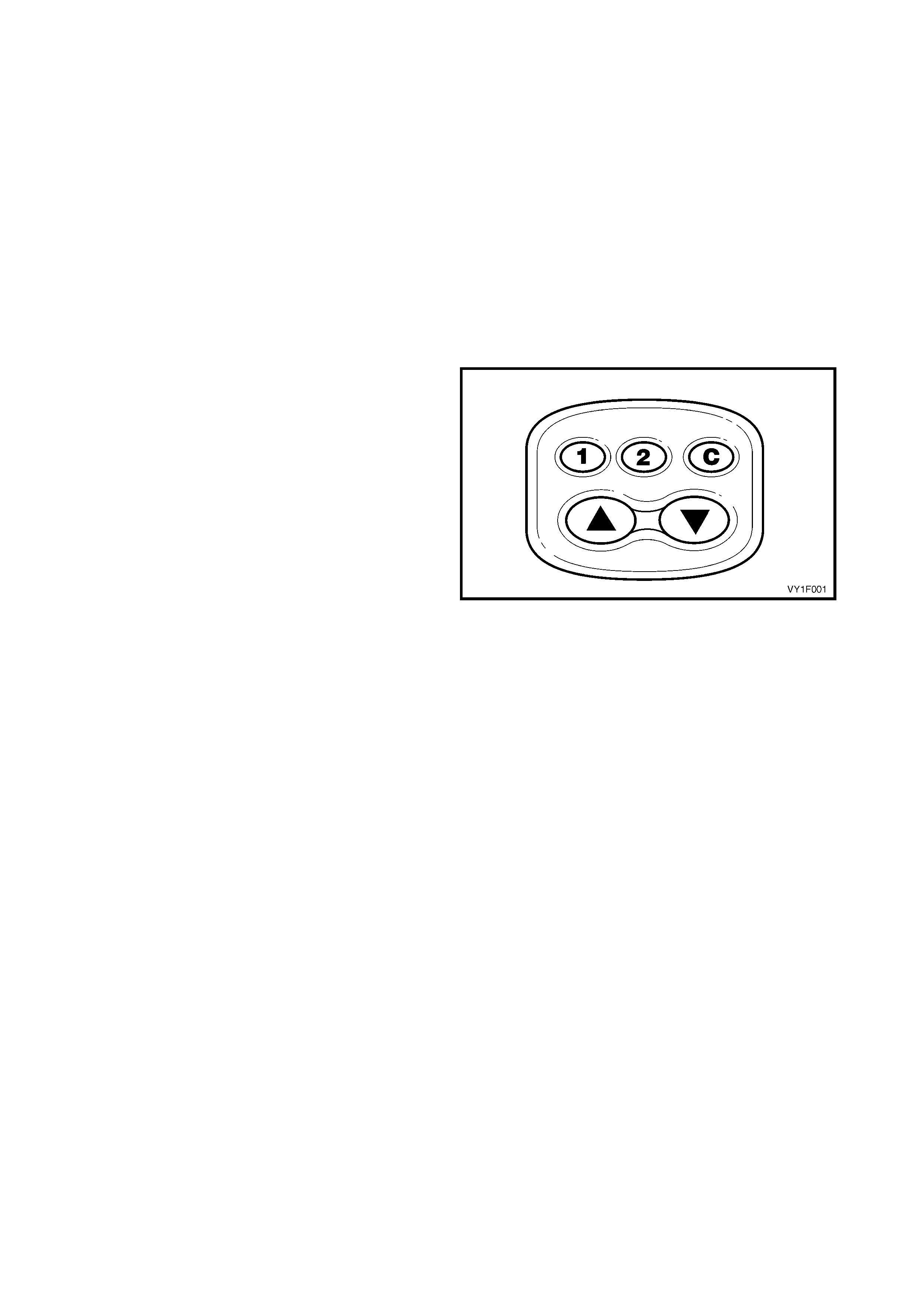
PRE-PROGRAMMED FUNCTIONS
NOTE: If only the sunroof switch button ! and button
" are operating, the sunroof switch has to be reset,
refer to 2.20 SUNROOF SWITCH.
SOFT TOUCH
With the ignition switch ON, briefly pressing the
sunroof button ! will open the sunroof to the
maximum slide position. Briefly pressing the sunroof
button " will open the sunroof to the maximum tilt
position. Movement of the sunroof can be stopped at
any time by briefly pressing the button ! or " again.
CLOSING THE SUNROOF
Briefly pressing the button C will cause the sunroof to
close from any open position.
VARIABLE TILT POSITION
NOTE: Sunroofs installed until June 2003 can be
opened to four tilt positions, sunroofs installed after
June 2003 open to three tilt positions only.
The sunroof can be lowered from maximum tilt
opening in three/four intermediate tilt positions. Press
and hold the sunroof button ! until the glass panel
reaches the next tilt position. Alternatively hold the
button pressed and then r elease it at the desired glass
panel tilt position.
Figure 1F-1
JAMMING PROTECTION (SAFETY FEATURE)
W hen c losing the sunroof using Soft T ouch or Auto-C lose, the sunroof will automatically re-open if it enc ounters
an obstacle and then try to close again. This cycle will continue until the obstacle is removed.
AUTO-CLOSE FUNCTION
Three seconds after the ignition has been turned OFF, the sunroof will close automatically. To override this
action, br iefly pres s the sunroof button ! or " when the sunroof has reached the desir ed position or during the
three second interval to maintain the sunroof position, refer to Figure 1F-1.
The sunroof can be closed when the ignition is OFF but it cannot be opened.
ONE-WAY CLOSING
This automatic f eatur e always closes the sunroof fr om above lowering the glass panel in the clos e position, even
when closed from a slide position, assuring correct positioning of the glass panel.

OPTIONAL PROGRAMMABLE FUNCTION
COMFORT POSITION
This feature allows the sunroof to be opened to two preset positions in the sliding range.
PROGRAMMING THE COMFORT POSITION
To program the two preset positions:
1. Position the sunroof in the desired location.
2. Press and hold button 1 until a beep is heard (approx. 3 seconds).
3. Position the sunroof in the second desired location.
4. Press and hold button 2 until a beep is heard (approx. 3 seconds).
Refer to Figure 1F-1.
To select either preset position, press button 1 or 2. (Pressing either button again will open the sunroof fully).
INTERIOR TRIM
SUNSHADE
The sunshade c an be opened and closed manually when the sunroof is closed but is c ontrolled autom atically in
the following conditions:
• Opening the sunroof in a tilt position, automatically opens the sunshade to a vent position. The sunshade
can then be fully opened manually.
• When the sunroof is opened in slide m ode, the s unshade opens along with it. The s unshade can be opened
further manually.
The sunshade can only be closed fully when the sunroof is closed, and can only be closed manually.
WIND DEFLECTOR
The wind deflector is designed to reduce high frequency noise. The wind deflector is automatically raised when
the sunroof is opened in slide mode. It retracts when the sunroof is closed.
GLASS PANEL
The sunroof glass panel is heat and UV resistant. Clean the glass panel using mild, non-scratching detergent
and a chamois.
RUBBER SEAL
Two types of rubber seal can be fitted to the glass panel assembly. They both have the same function despite
the physical and cross-section differences.
The first r ubber seal type can be identified by its outer surfac e of velvet-like appear ance. The outer edge of the
seal body is open- ended to allow adjus tm ents, with foam st rips, that m ay be necessary to ensure proper s ealing
when the glass panel is in the closed position.
The second rubber seal type is an optional design to the first type and can be identified by its outer surface of
smooth appearance. The outer section of the seal body is hollow with the external surface covered by an anti-
friction coating. No adjustment is necessary for this rubber seal type.
POWER HARNESS
CONFIGURATION ONE
The configuration one power harness is connected to sunroofs installed on all wagon vehicles, and until March
2003 on sedan vehicles.
The configuration one power harness is routed around the sunroof frame, along the hinge pillar, and is
connected to the passenger compartment fuse and relay panel assembly.
CONFIGURATION TWO
The configuration two power harness is connected to sunroofs installed after March 2003, on sedan vehicles.
The configuration two power harness is routed along the C pillar and is connected to the body harness, behind
the quarter inner rear side carpet in the rear compartment.
SUNROOF CONTROL UNIT (SCU)
The SCU is located at the rear of the sunr oof fram e and controls a drive m otor to activate the m ovement of the
glass panel.
The SCU detec ts the position of the glass panel by using an internal position counter. This counter is inc reased
and decreased every time the SCU controls the drive motor.
The c ounter mus t first be s et (calibrated) to detec t the end position of the glas s panel, in full tilt and full slide, by
running to a mechanical block.
If the SCU determines that the glas s panel is in the inc orr ec t pos ition, as def ined by the internal position counter,
it responds by entering the non-calibrated state.
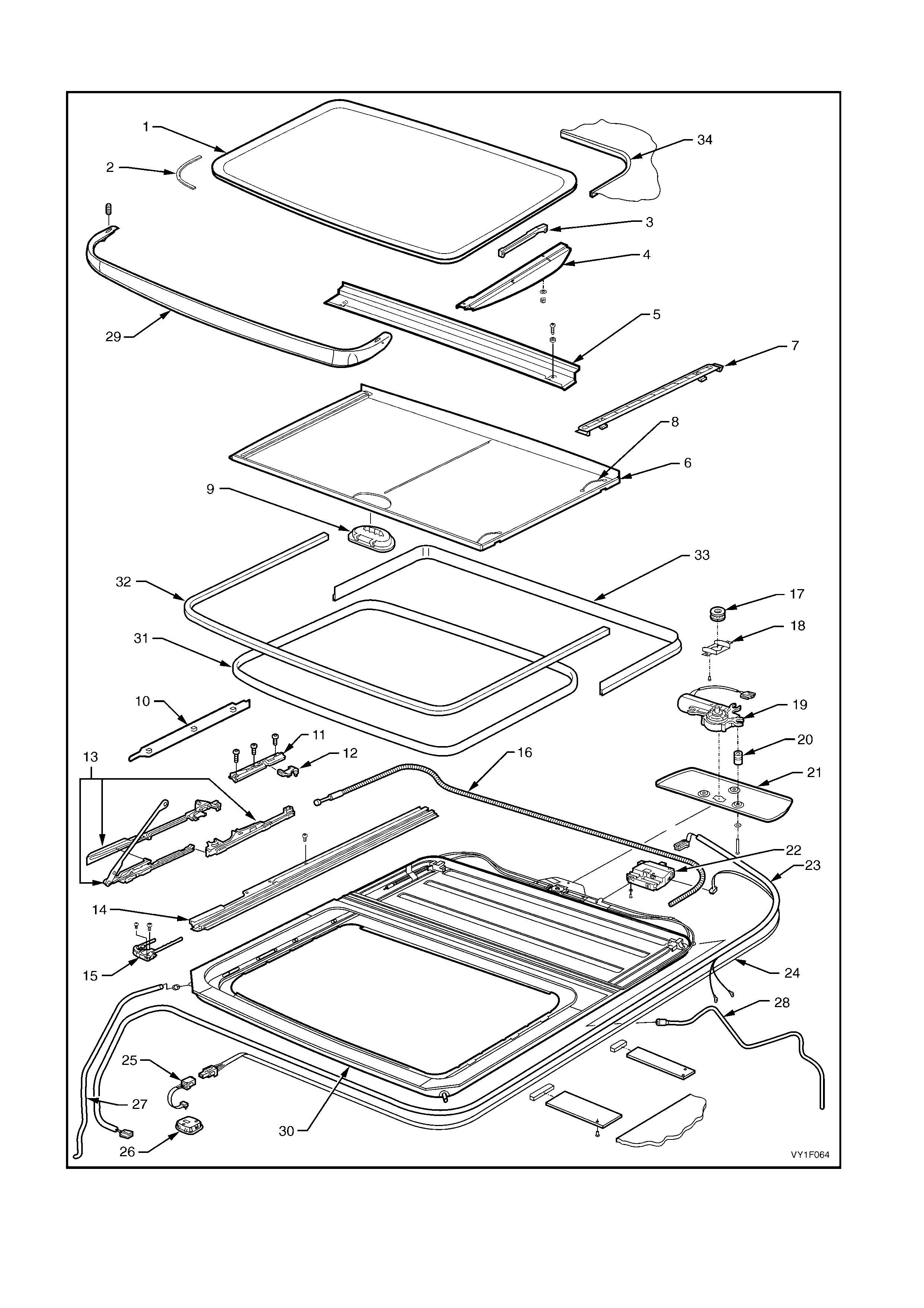
SUNROOF COMPONENTS
Figure 1F-2

Legend
1. Glass Panel 13. Guide Rail Mechanism 25. Sunroof Control Harness
2. Rubber Seal 14. Guide Rail 26. Sunroof Switch
3. Adjustment Bracket 15. Retraction Mechanism 27. Front Drain Tube
4. Exterior Cover 16. Drive Cable 28. Rear Drain Tube
5. Drain Channel 17. Drive Gear 29. Wind Deflector
6. Sunshade 18. Drive Gear Box Retainer 30. Sunroof Assembly
7. Sunshade Guide 19. Drive Motor 31. Opening Seal
8. Sunshade Spring 20. Spacer 32. Front Roof Seal
9. Sunshade Handle 21. Drive Cover 33. Rear Roof Seal
10. Mechanism Cover 22. Sunroof Control Unit (SCU) 34. Trim Ring
11. Locator 23. Sunroof Power Harness
12. Blocking Catch 24. Sunroof Harness
2. SERVICE OPERATIONS
The following service operations detail the service procedures that can be performed by the general service
technician with the sunroof fitted to the vehicle.
The proc edure for the r emoval and ins tallation of the sunroof assembly has been deliber ately om itted due to the
sk ills and special tools required, which would be beyond the s cope of the general r epair technician. The sunr oof
assem bly is chemically bonded to the vehicle’s roof panel and any attem pt to remove it m ay c ause damage the
sunroof and / or the roof panel.
NOTE: W hen a sunroof is fitted, a new headlining is created using pieces of the original headlining and a new
piece of cloth.
The headlining is then installed with adhesive. Removal may damage the headlining and extreme care is
required.
2.1 DRIVE MOTOR
LT Section No. -
REMOVE
IMPORTANT: Take extreme care when removing the
headlining which has been modified and installed using
adhesive.
1. Remove the sunroof circuit breaker F3 from the
passenger compartment fuse and relay panel
assembly, refer to Section 12O, 2.2 CIRCUIT
BREAKERS.
2. Remove the headlining to gain access to the drive
motor cover. Refer to Section 1A8,
• 2.12 HEADLINING ASSEMBLY – SEDA N
• 3.15 HEADLINING ASSEMBLY – WAGON
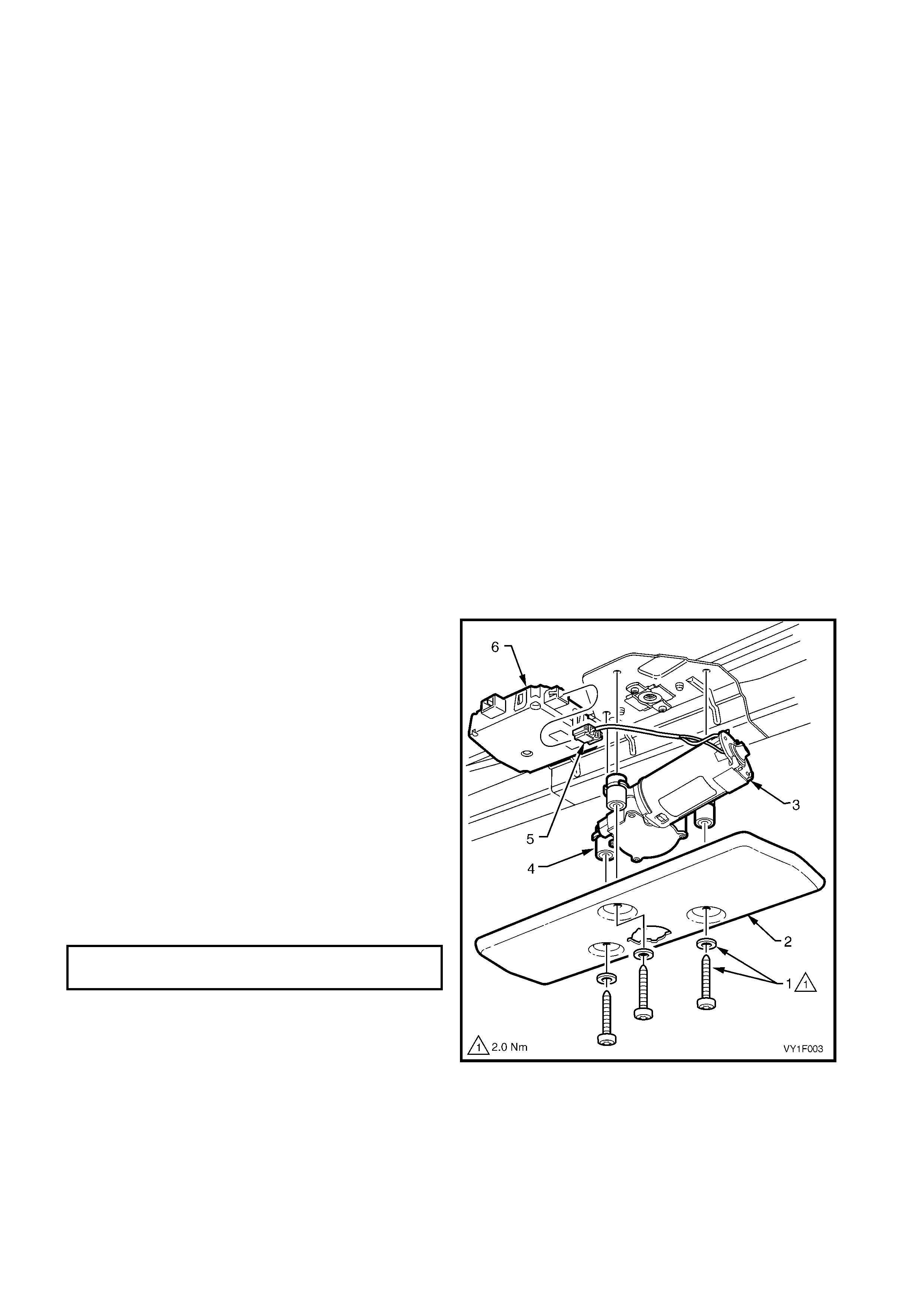
3. Remove the three Torx screws and washers (1)
securing the drive motor cover (2). Carefully lower
the drive motor cover with the drive motor (3) and
spacers (4).
4. Disconnect the drive motor connector (5) from the
sunroof control unit (6).
REINSTALL
Installation of the drive motor is the reverse of the
removal procedure noting the following:
1. Chec k the drive m otor f or correc t operation in both
directions, refer to 3.1 FAULT DIAGNOSIS
CHARTS.
2. Ensure that the three spacer s are f itted to the drive
motor before installing it.
3. Tighten all fasteners to the specified torque.
Figure 1F-3
DRIVE MOTOR COVER TORX SCREWS
TORQUE SPECIFICATION 2.0 Nm
2.2 DRIVE GEAR
LT Section No. -
REMOVE
1. Remove the drive motor cover and the drive
motor, refer to 2.1 DRIVE MOTOR.
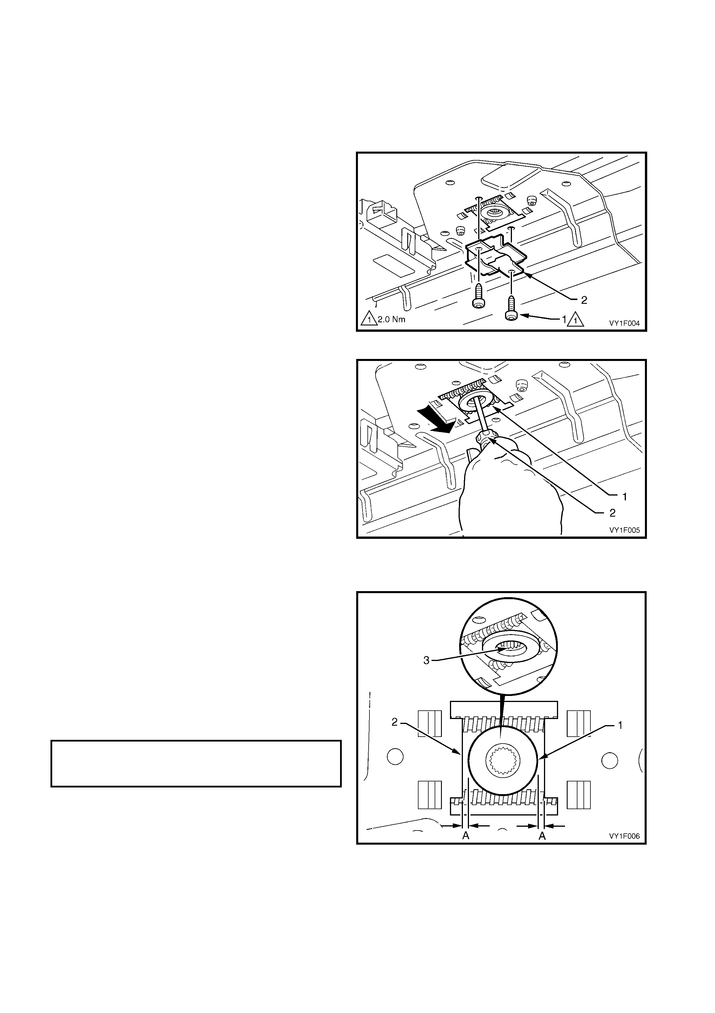
2. Remove the two Torx screws (1) retaining the
drive gear box retainer (2).
3. Remove the drive gear box retainer.
Figure 1F-4
4. Remove the gear wheel (1) by inserting a
screwdriver (2) and pushing forward to allow the
drive gear to drop down.
Figure 1F-5
REINSTALL
Installation of the drive gear is the reverse of the
removal procedure noting the following:
1. Install the drive gear (1), ensur ing that it is centred
(A) in the opening in the drive motor bracket (2).
Note that the core of the centre of the gear has
splines (3). The splines do not extend completely
to one side of the drive gear inner core. This side
faces downward when fitted.
2. Tighten all fasteners to the specified torque.
Figure 1F-6
DRIVE GEAR BOX
RETAINER TORX SCREWS
TORQUE SPECIFICATION 2.0 Nm
2.3 SUNROOF CONTROL UNIT (SCU)
LT Section No. -
REMOVE
1. Remove the drive motor cover and drive motor,
refer to 2.1 DRIVE MOTOR.
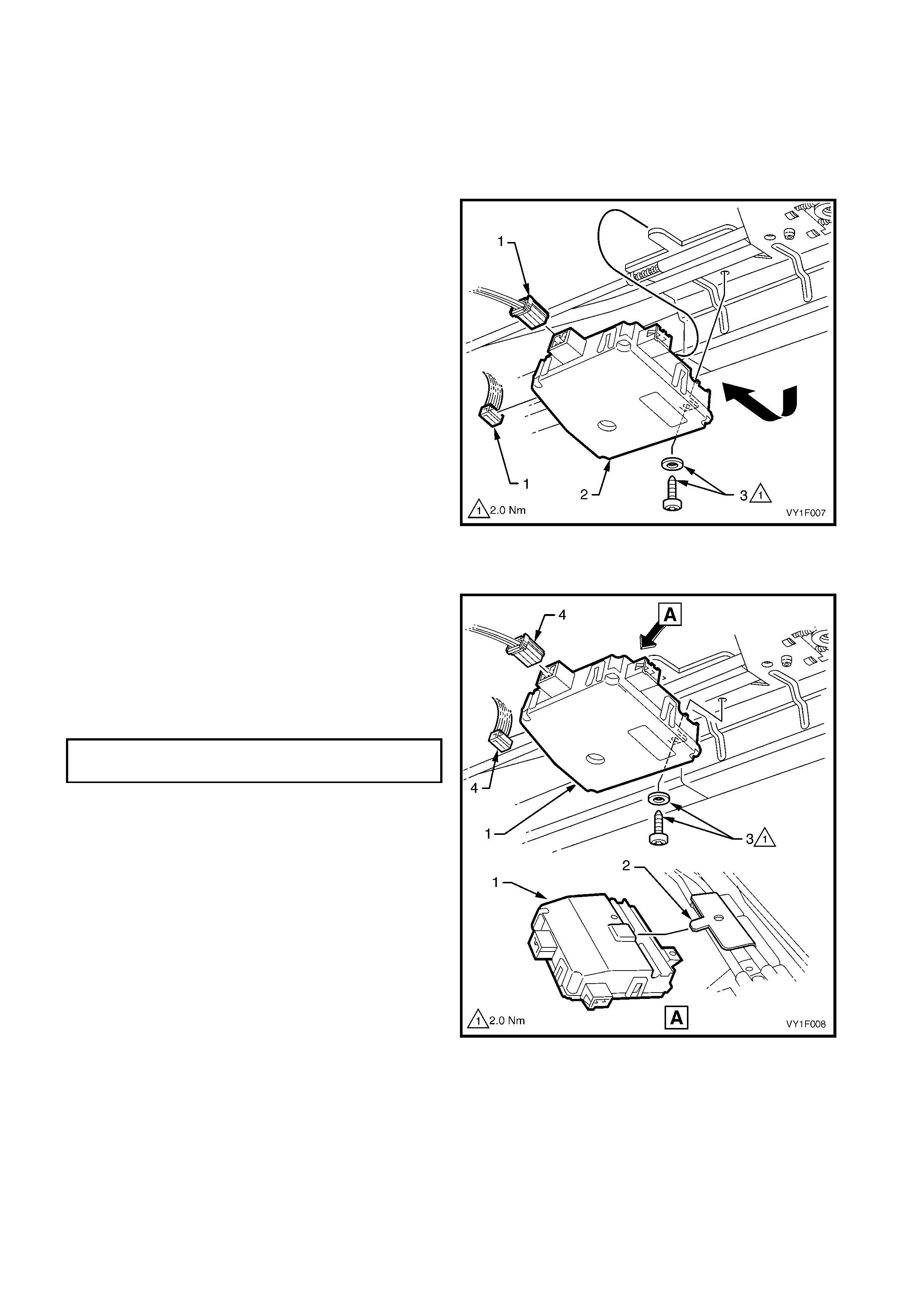
2. Disc onnect the wiring harness connectors (1) f rom
the SCU (2).
3. Remove the SCU retaining Torx screw and
washer (3), lower the front of the SCU and slide
the unit back to remove.
Figure 1F-7
REINSTALL
Installation of the SCU is the reverse of the removal
procedure noting the following:
1. Install the SCU (1) by lowering the unit at the front,
engaging the tang (2) on the cable plate with the
slot on the top of the SCU then slide forward into
position. Secure with Torx screw and washer (3).
2. Tighten the Torx screw to the specified torque.
3. Connect the wiring harness connectors (4).
4. Install the drive motor, refer to
2.1 DRIVE MOTOR.
NOTE: If the SCU installed is a new unit, it must be
calibrated. Refer to 2.4 CALIBRATING THE
SUNROOF CONTROL UNIT.
Figure 1F-8
SCU RETAINING TORX SCREW
TORQUE SPECIFICATION 2.0 Nm

2.4 CALIBRATING THE SUNROOF CONTROL UNIT
LT Section No. -
The SCU is calibrated when the sunroof is installed onto the vehicle, however it needs to be calibrated again if
the glass panel stops at an unexpected position related to the sunroof switch function, the end position cannot
be reached, or one or more buttons of the sunroof switch do not operate properly any more.
If the SCU fails and is replaced with a new unit, the first tim e the new SCU is connected to the power supply it
must be calibrated.
NOTE: The calibration sequence of the sunroof control unit (SCU) m ust be fully completed before the power is
removed from the SCU. Failing to do so causes the SCU to enter the non-calibrated state.
The SCU must be calibrated as follows:
1. Turn the ignition ON.
2. Open the sunroof to the m axim um tilt pos ition (until it reaches the m echanic al block) by pr essing the tilt soft
touch switch continuously, refer to 1. GENERAL DESCRIPTION.
3. The maximum tilt position is now stored in the SCU memory and all electrical functions are now available.
4. To com plete the calibration the sunroof m ust be fully opened in slide mode (until it reaches the mechanical
block) by pressing the slide soft touch switch, refer to 1. GENERAL DESCRIPTION.
5. Check that the sunroof operates correctly.
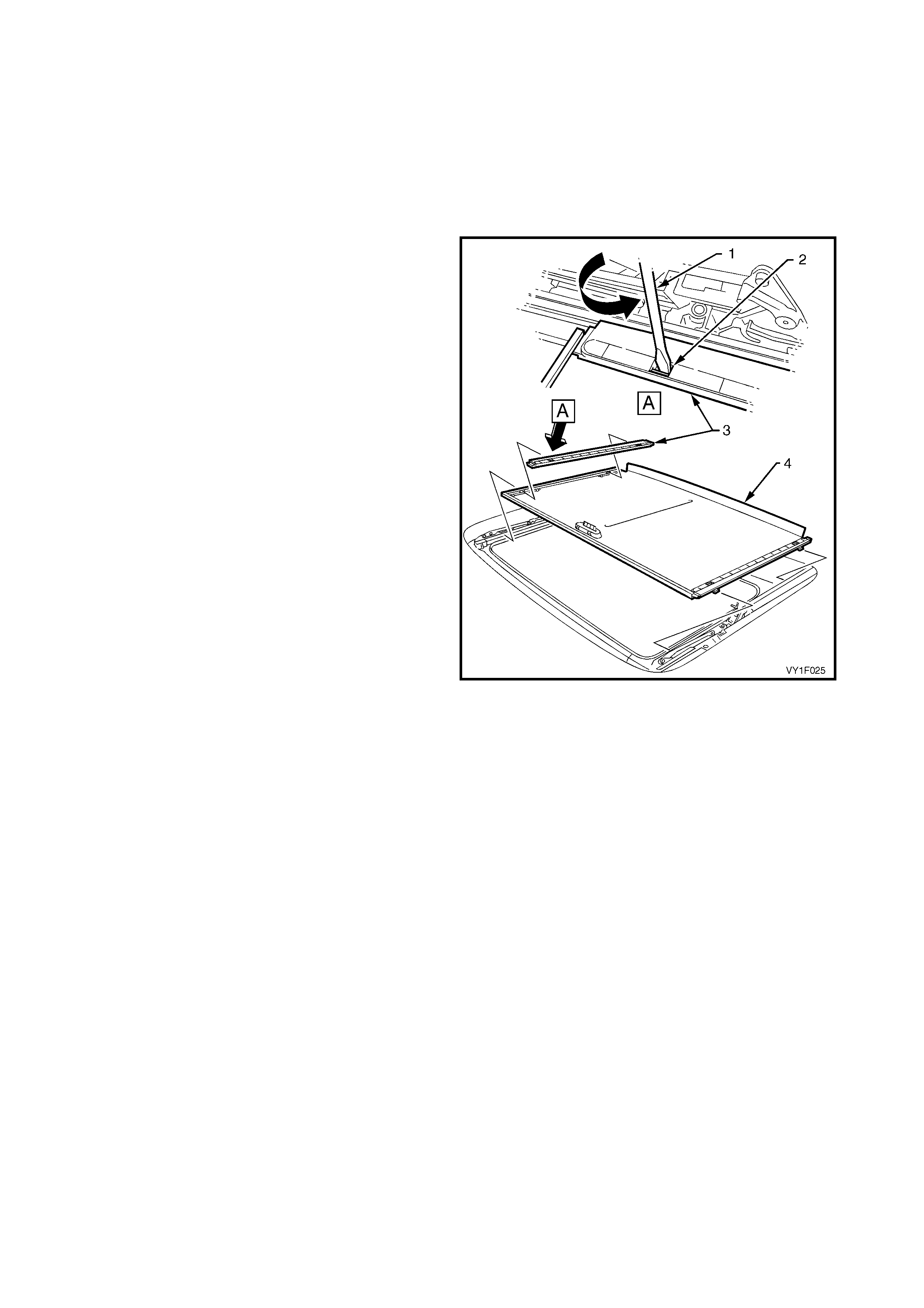
2.5 GLASS PANEL
LT Section No. -
REMOVE
1. Position the sunroof in the full tilt position, refer to
Figure 1F-21.
2. Remove the left-hand and right-hand mechanism
covers (1) by grasping them by hand and sliding
towards the rear of the sunroof assembly.
Figure 1F-9
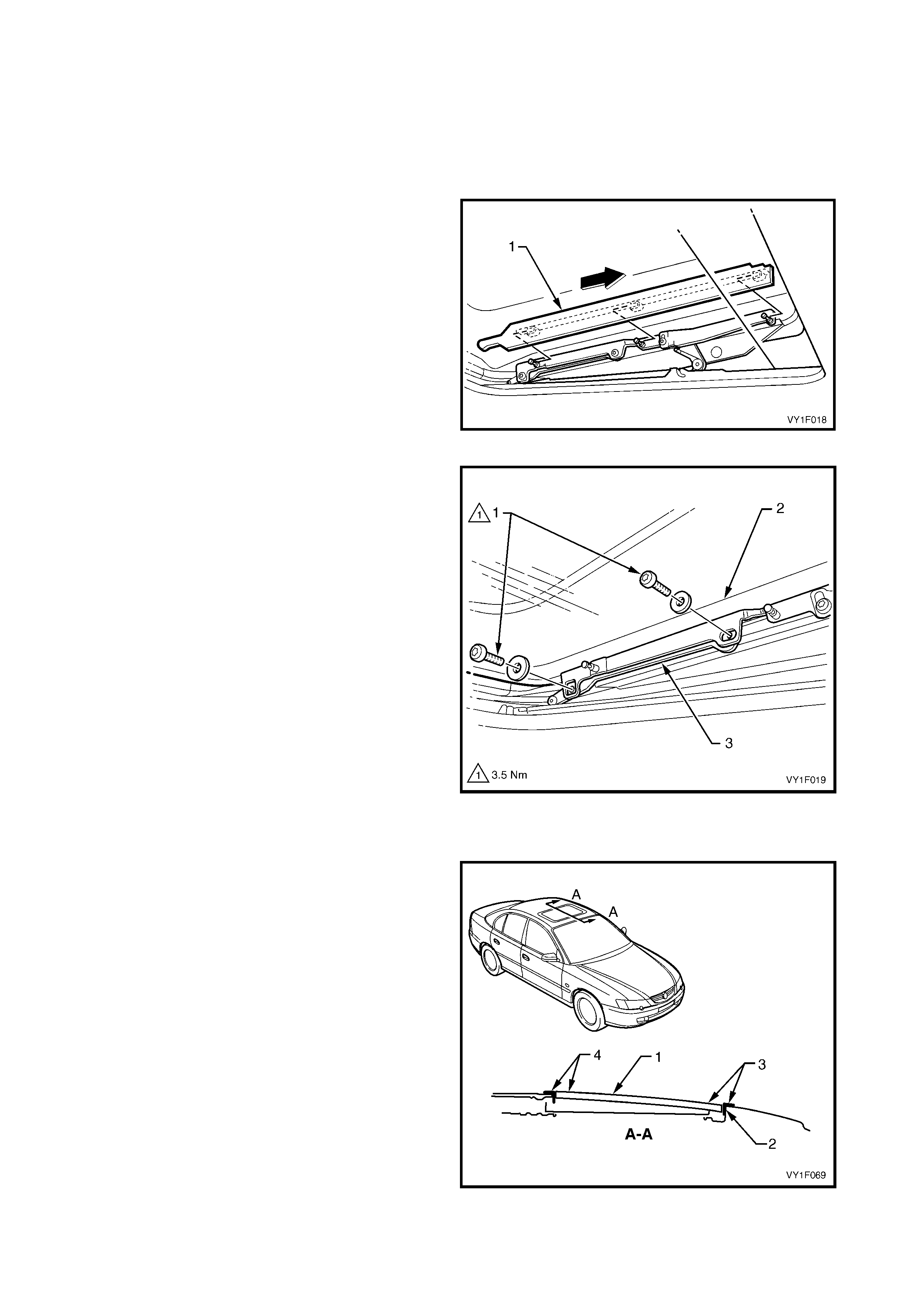
3. Remove the two Torx screws and washers (1) on
each side of the glass panel (2) securing it to the
guide rail mechanism (3), noting the size and
position of the washers.
4. Carefully lift out the glass panel, releasing the
locating tabs from the sliding mechanism and
place in a safe place.
Figure 1F-10
REINSTALL AND ADJUST
NOTE: To avoid wind noise (whistling), the glass
panel (1) must be installed level with the trim ring (2)
within the following limits:
• Front, location (3) flushness 0 to –1 mm
• Rear, location (4) flushness +1 to 0 mm
Figure 1F-11
1. Position the mechanism in the full tilt position, refer to Figure 1F-21.
2. Place the glass panel locating tabs (1) in the sliding mechanism guides (2) then align the glass panel
mounting bracket holes with the threaded holes of the sliding mechanisms, refer to Figure 1F-12.
3. Secure the glass panel with four Torx screws and washers (3, 4 and 5), with the large washers (5) at the
front locations. Do not tighten the Torx screws at this point.
4. Position the sunroof in the closed position.
5. Adj ust the glas s panel against the front of the roof panel opening trim ring, checking the tens ion of the seal
using a business card or s imilar. T he card s hould not fit easily between the roof panel opening trim ring and
the glass panel.
6. Tighten the centre mounting Torx screws (3) to the specified torque.
7. Adj ust the height of the glass panel at the fr ont, flush with the roof trim ring, then tighten the front m ounting
Torx screws (4) to the specified torque.
8. Loos en the left- hand and right-hand adjustment br acket T orx screws (6) . Adjust the glass panel s o that it is
level with the r oof trim ring, ref er to NOTE, and tighten the adj ustment brac ket Torx screws to the specif ied
torque, refer to 2.6 ADJUSTMENT BRACKETS.
9. Check the operation of the m echanis m and the adj ustment of the glass panel. Repeat Steps 4 to 8 if further
adjustments are required.
10. Install the left-hand and right-hand mechanism covers, by sliding them towards the front of the sunroof
assembly.
Figure 1F-12
GLASS PANEL RETAINING TORX
SCREWS TORQUE SPECIFICATION 3.5 Nm
2.6 ADJUSTMENT BRACKETS
LT Section No. -
REMOVE
1. Remove the left-hand and right-hand
mechanism covers and glass panel, refer to
2.5 GLASS PANEL.
2. Remove the circlip (1) and Torx screw and
washer (2) securing each adjustment bracket (3)
to the glass panel mounting bracket (4). Slide the
bracket off the locating pin.
Figure 1F-13
REINSTALL
Installation of the adjustment bracket is the reverse of
the removal procedure. Tighten the screw to the
specified torque.
ADJUSTMENT BRACKET
RETAINING TORX SCREWS
TORQUE SPECIFICATION 2.0 Nm
2.7 EXTERIOR COVERS
LT Section No. -
REMOVE
1. Remove the left-hand and right-hand
mechanism covers and glass panel, refer to
2.5 GLASS PANEL.
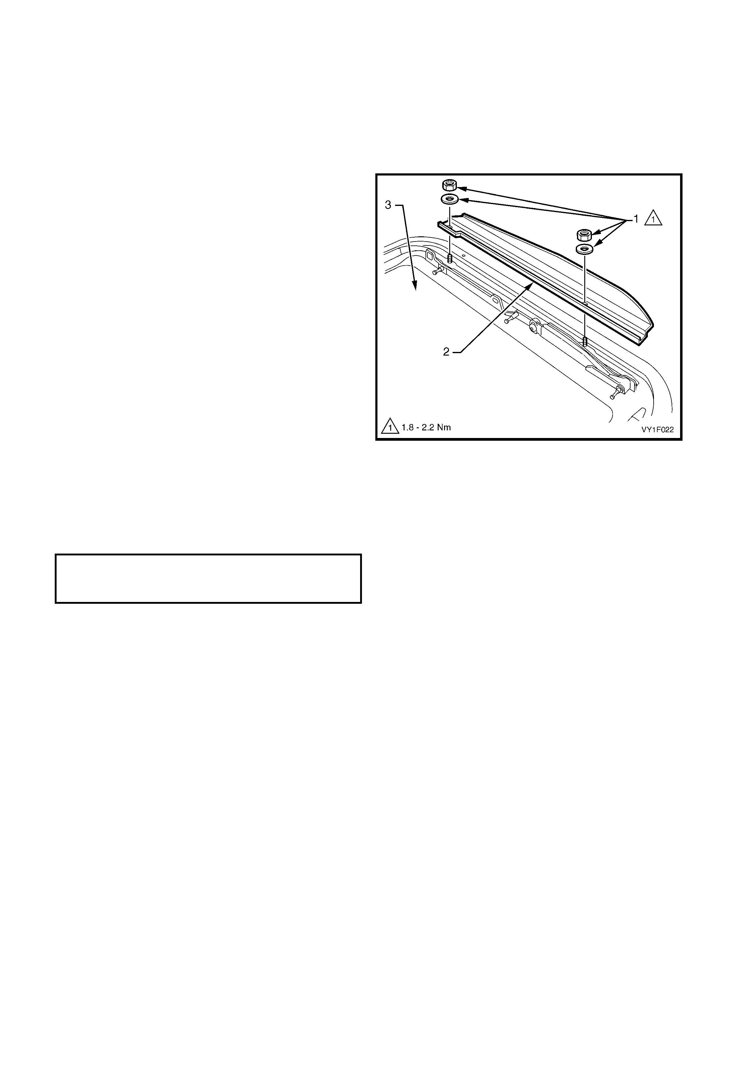
2. Remove the two nuts and washers (1) securing
each exterior cover (2) to the glass panel (3).
Figure 1F-14
REINSTALL
Installation of the exterior covers is the reverse of the
removal procedure. Tighten the nuts to the specified
torque.
EXTERIOR COVER
MOUNTING NUTS
TORQUE SPECIFICATION 1.8 – 2.2 Nm
2.8 RUBBER SEAL
LT Section No. -
REMOVE
1. Remove the left-hand and right-hand
mechanism covers and glass panel, refer to
2.5 GLASS PANEL.
2. Remove the exterior covers, refer to
2.7 EXTERIOR COVERS.
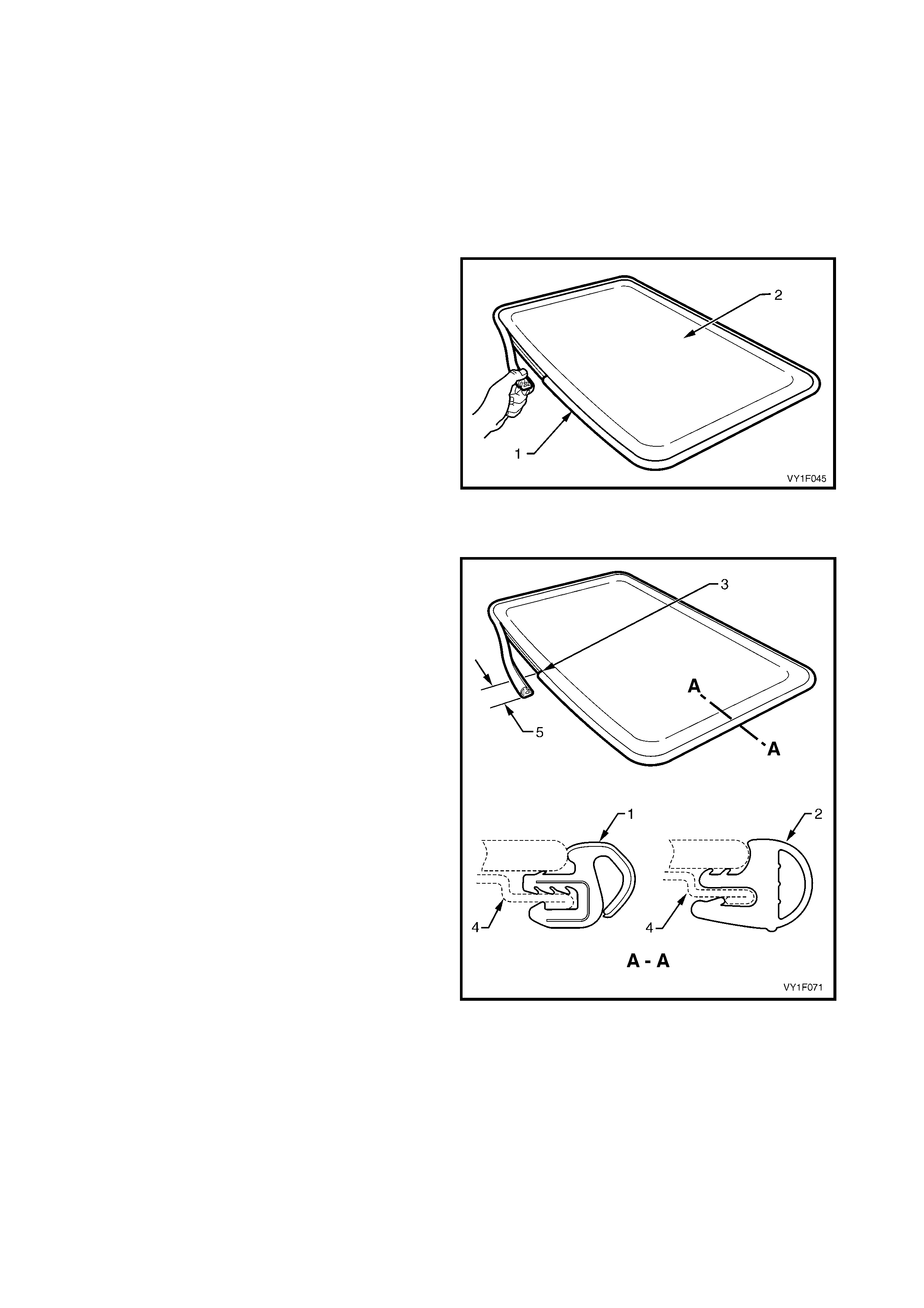
3. Remove the rubber seal (1) from the glass panel
(2).
4. Remove any dirt or debris and clean the glass
panel, refer to 1. GENERAL INFORMATION.
Figure 1F-15
REINSTALL
IMPORTANT: Ensure that the glass and frame are
clean and free of debris before fitting the new rubber
seal.
NOTE: There are two rubber seal configurations that
can be fitted to the glass panel. The installation
procedure is the same for both configurations.
1. Install the new rubber seal configuration one (1) or
alternatively configuration two (2), beginning at the
centre front of the glass frame retaining channel
(3).
2. Insert the new rubber seal in the glass frame
retaining channel (4) with enough pressure to have
a flush fit with the glass.
3. Trim the new rubber seal with approxim ately 6 m m
overlap (5), then work into the retaining channel.
4. Install the glass panel and the mechanism covers,
refer to 2.5 GLASS PANEL.
5. Check that the new rubber seal f irmly contacts the
trim ring attached to the roof panel opening, with
the sunroof in the closed position.
6. Check the sunroof for correct operation.
Figure 1F-16
ADJUSTMENT
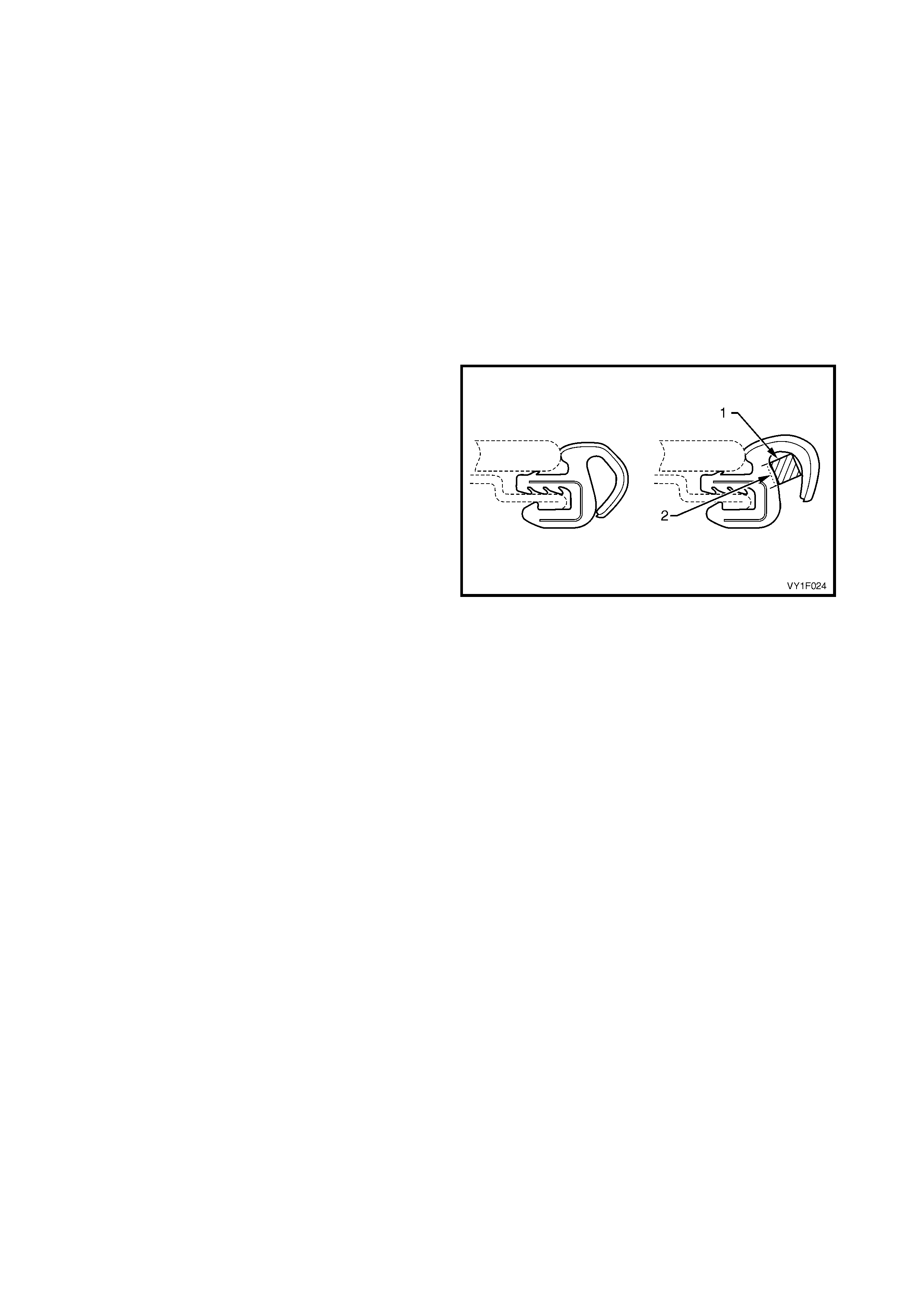
NOTE: T he adjustm ent is applicable to the rubber seal
configuration one (1) only, refer to Figure 1F-16.
With the glass panel positioned correctly, the rubber
seal should firmly contact the EPDM trim ring on the
sunroof opening. If the glass panel fits correctly but
gaps r emain between the seal and the EPDM trim ring
on the sunroof opening, adjust as follows:
1. Adjus t the glass panel correctly against the rear of
the EPDM trim ring, refer to 2.5 GLASS PANEL.
2. With a grease pencil or similar, mark the areas
where the rubber seal does not make sufficient
contact with the front of the EPDM trim ring.
3. Remove the glass panel, refer to
2.5 GLASS PANEL.
4. In the areas m arked, ins ert a spacer (1) ins ide the
rubber seal as shown (use a 3mm square section
foam strip with adhesive backing).
5. Peel the backing off the foam spacer and stick to
the inner surface of the seal (2).
6. Install the glass panel and adjust, refer to
2.5 GLASS PANEL.
Figure 1F-17
2.9 W IND DEFLECTOR
LT Section No. -
REMOVE
1. Remove the exterior covers and glass panel, refer
to 2.5 GLASS PANEL.
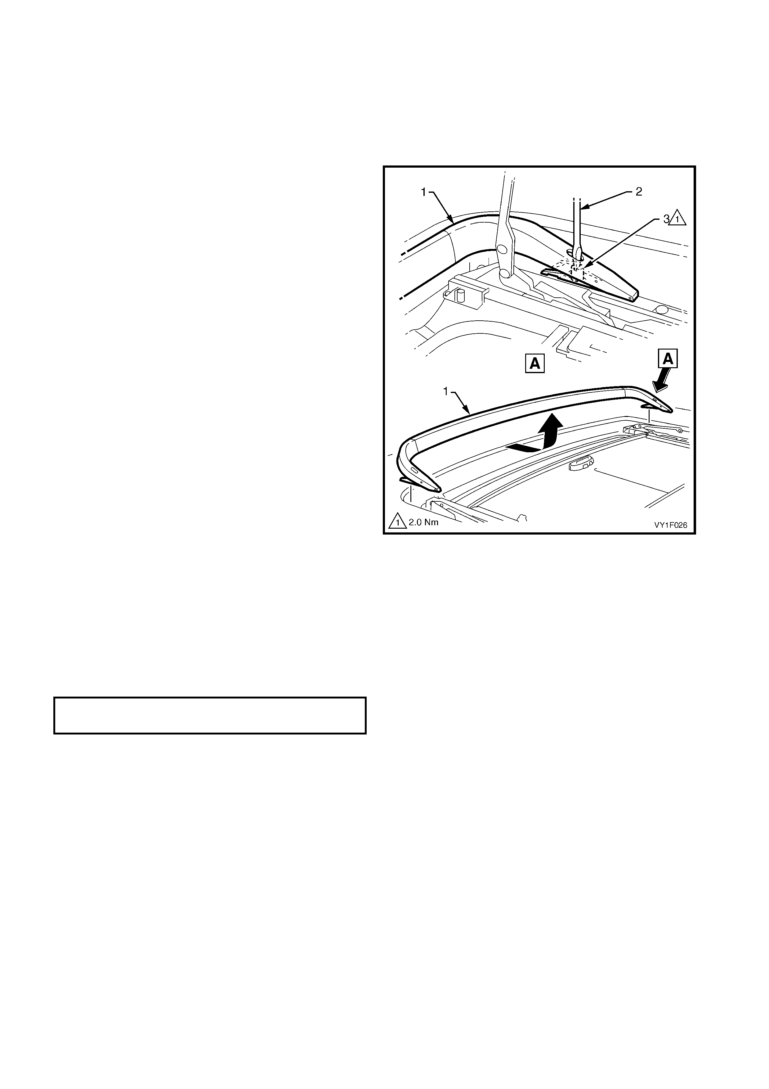
2. Insert a flat blade screwdriver (2) in the wind
deflector mounting hole and loosen the left-hand
and right-hand securing nuts (3).
3. Slide the wind deflector (1) towards the rear and lift
it out.
Figure 1F-18
REINSTALL
Installation of the wind deflector is the reverse of the
removal procedure, noting the following:
1. Always fit the wind deflector to the maximum
forward position.
2. Secure the wind deflector with the two attaching
nuts. Tighten the nuts to the specified torque.
3. Check the glass panel and wind deflector for
correct operation, adjust if necessary.
WIND DEFLECTOR ATTACHING NUTS
TORQUE SPECIFICATION 2.0 Nm
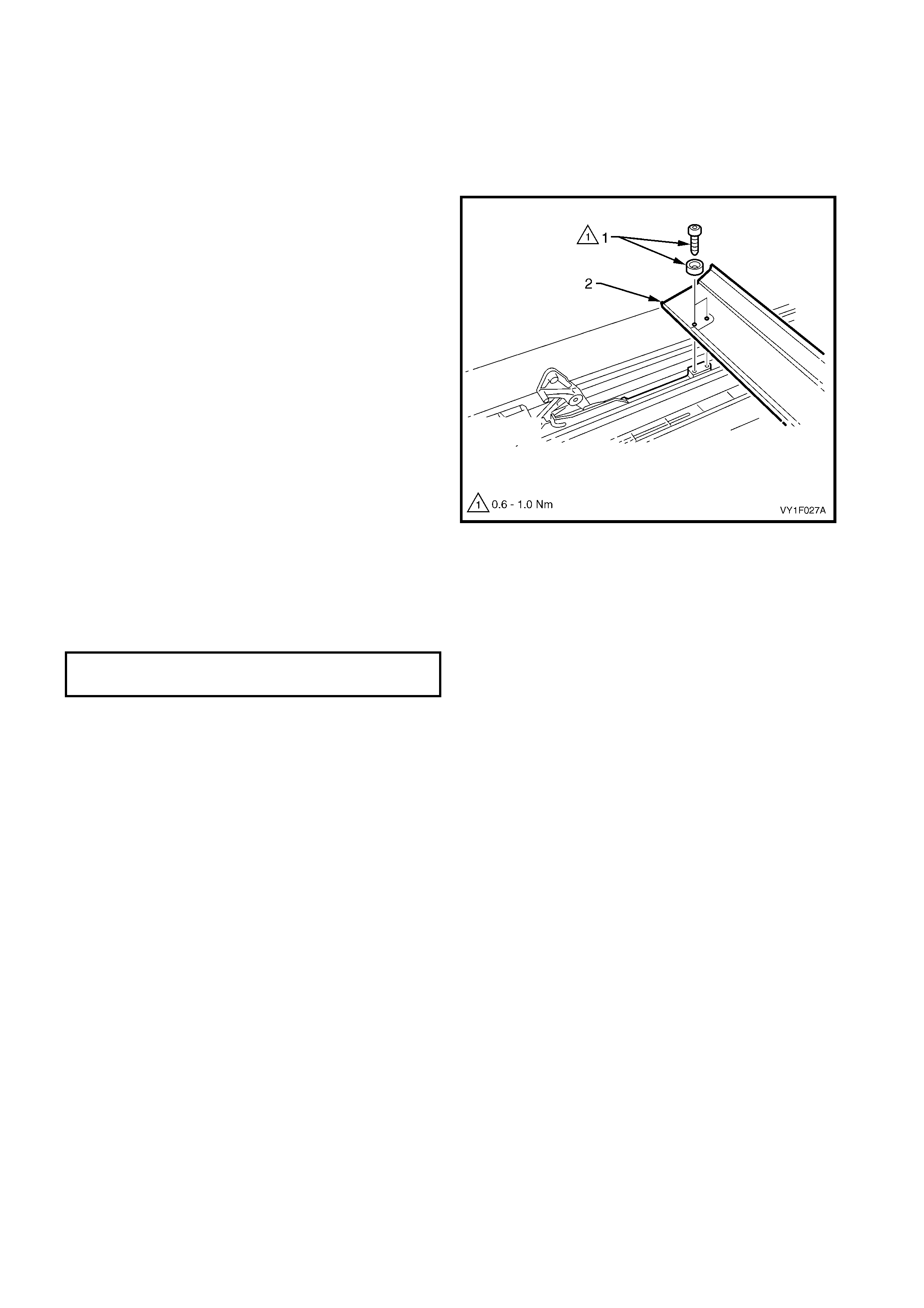
2.10 DRAIN CHANNEL
LT Section No. -
REMOVE
1. Rem ove the exterior covers and glass panel, refer
to 2.5 GLASS PANEL.
2. Rem ove the two lef t-hand and right-hand retaining
Torx screws and washers (1) and lift out the drain
channel (2).
Figure 1F-19
REINSTALL
Installation of the drain channel is the reverse of the
rem oval pr ocedur e. Tighten the scr ews to the specified
torque.
DRAIN CHANNEL TORX SCREWS
TORQUE SPECIFICATION 0.6 – 1.0 Nm
2.11 SUNSHADE
LT Section No. -
REMOVE
1. Rem ove the exterior covers and glass panel, refer
to 2.5 GLASS PANEL.
2. Remove the drain channel, refer to
2.10 DRAIN CHANNEL.
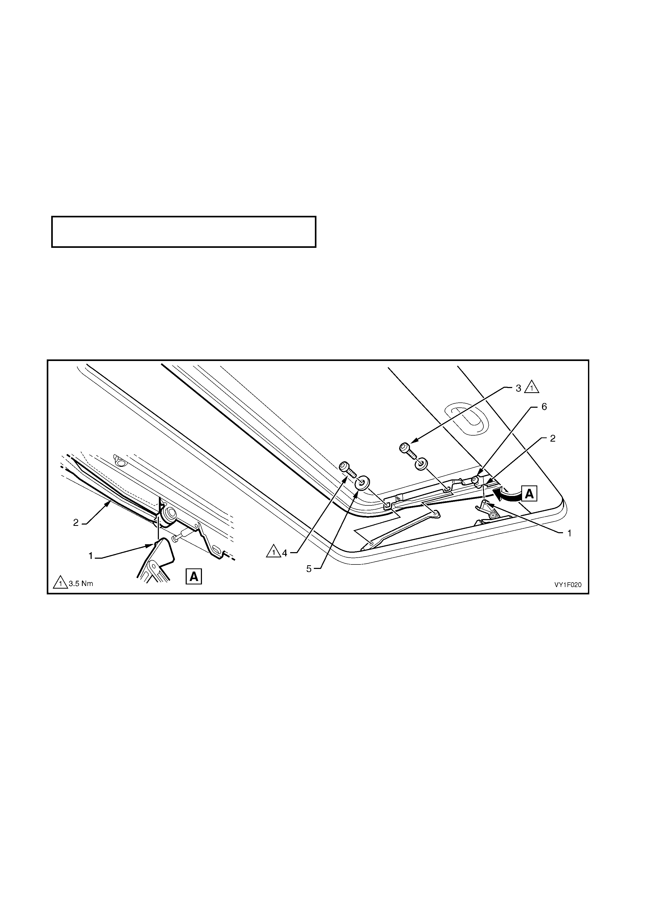
3. Using a flat blade screwdriver (1) or similar,
release the front and rear spring clips (2) from the
sunshade guide (3) by inserting the screwdriver
blade in the slot and twisting as shown in the
figure.
4. Slide the sunshade guide towards the c entre of the
vehicle and lift out.
NOTE: It is only necessary to remove the sunshade
guide on one side of the sunshade to allow
sunshade (4) removal.
5. Lift the sunshade clear of the guide rails.
Figure 1F-20
REINSTALL
Installation of the sunshade is the reverse of the
removal procedure, noting the following:
1. If the suns hade guide was rem oved from one side
only, ensure the tabs on the sunshade guide still
fitted locate correctly in the guide rail when the
sunshade is placed in position.
2. When fitted, check for smooth operation before
continuing with installation.
2.12 DRIVE CABLE S
LT Section No. -
REMOVE
1. Position the sunroof in the maximum tilt position
(1).
2. Remove the mechanism covers and glass panel,
refer to 2.5 GLASS PANEL.
3. Remove the wind deflector, refer to
2.9 WIND DEFLECTOR.
4. Remove the drain channel, refer to 2.10 DRAIN
CHANNEL.
5. Remove the sunshade, refer to 2.11 SUNSHADE.
6. Close the sunroof mechanism.
IMPORTANT: Take extreme care when removing the
headlining which has been modified and installed using
adhesive.
7. Remove the drive motor cover and drive motor,
refer to 2.1 DRIVE MOTOR.
8. Remove the SCU, refer to 2.3 SUNROOF
CONTROL UNIT (SCU)
9. Remove the drive gear retainer and drive gear,
refer to 2.2 DRIVE GEAR.
Figure 1F-21
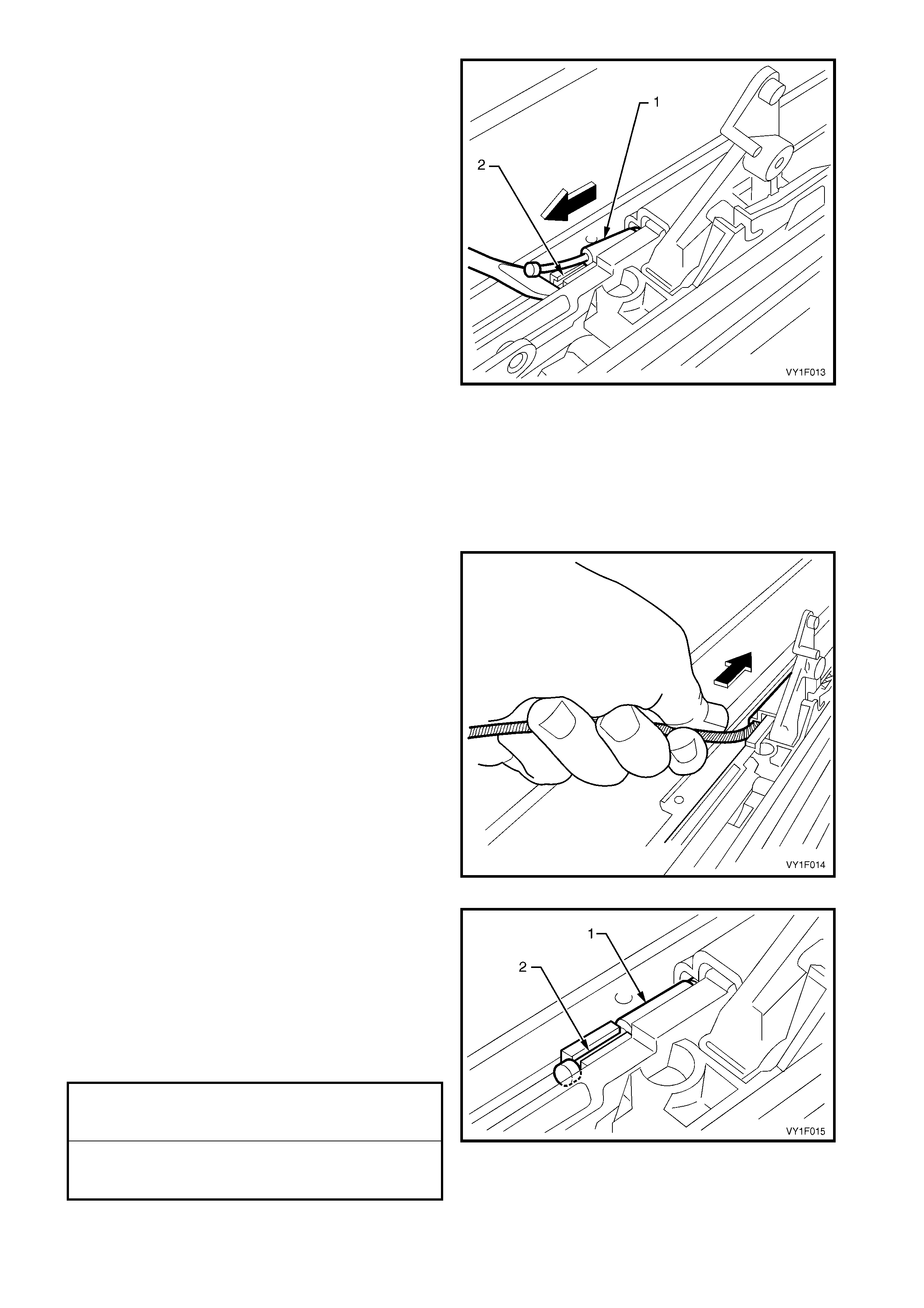
10. Remove the three Torx screws (1) securing the
locator (2) noting the length and position of the
screws. Lift off the locator and the blocking
catch (3) noting the orientation of the blocking
catch.
Figure 1F-22
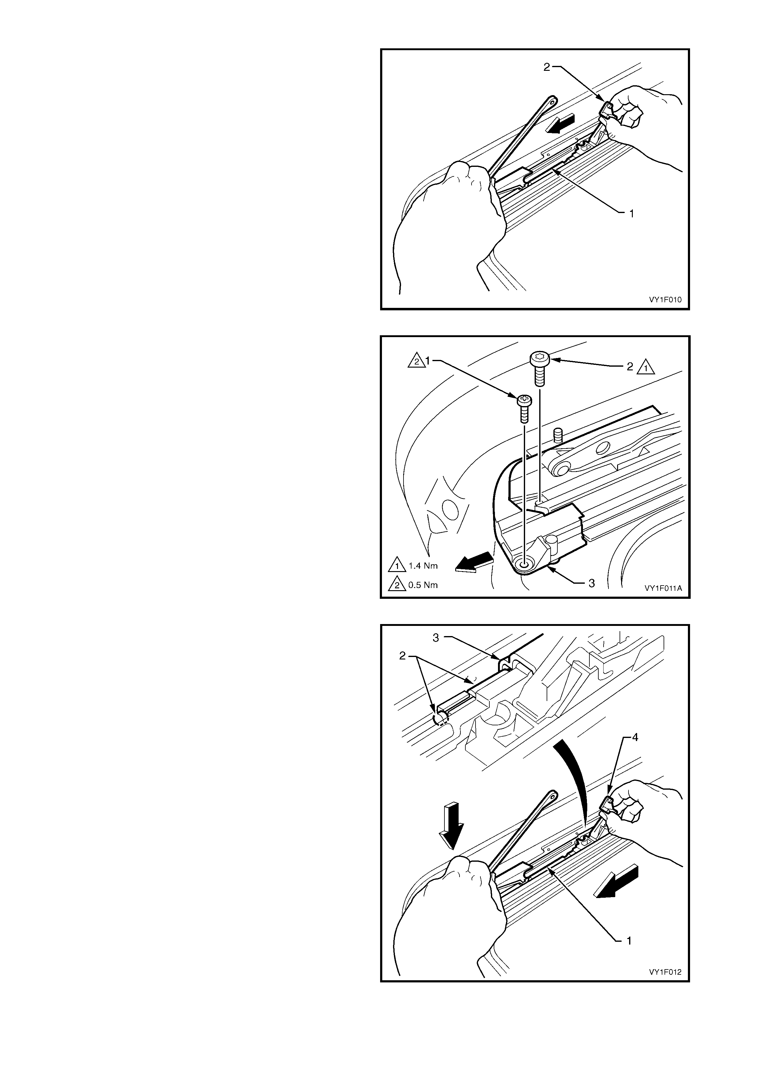
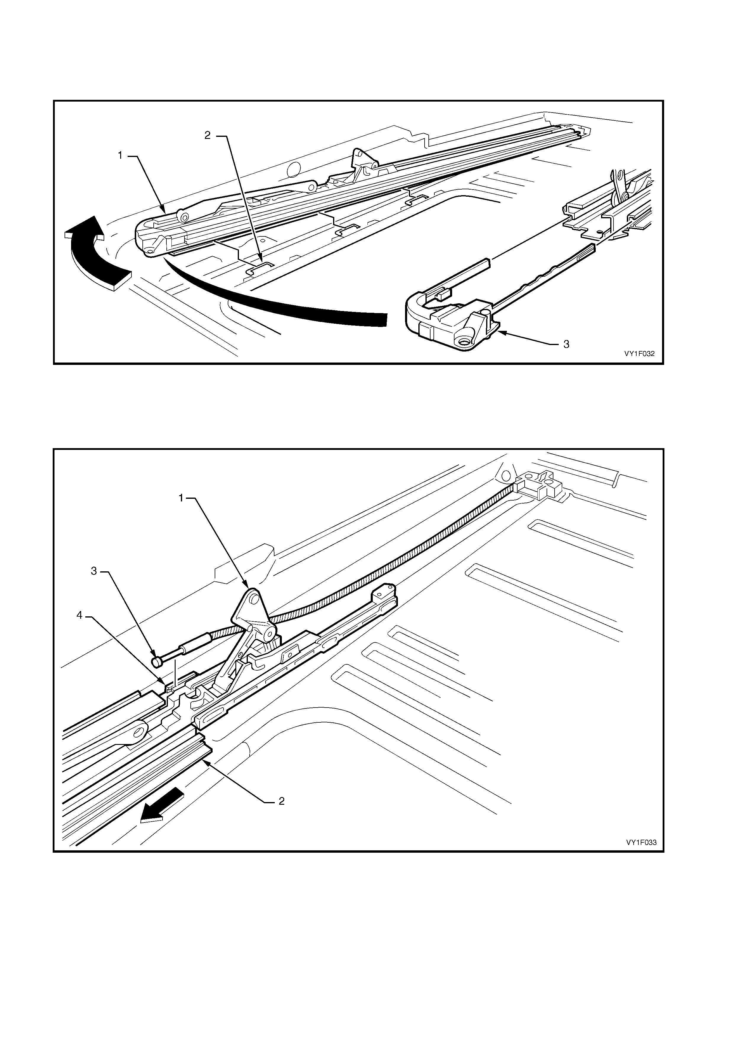
11. Pull the guide r ail m echanis m (1) as far for ward as
possible.
12. Push the guide rail mechanism into the full tilt
position (2).
Figure 1F-23
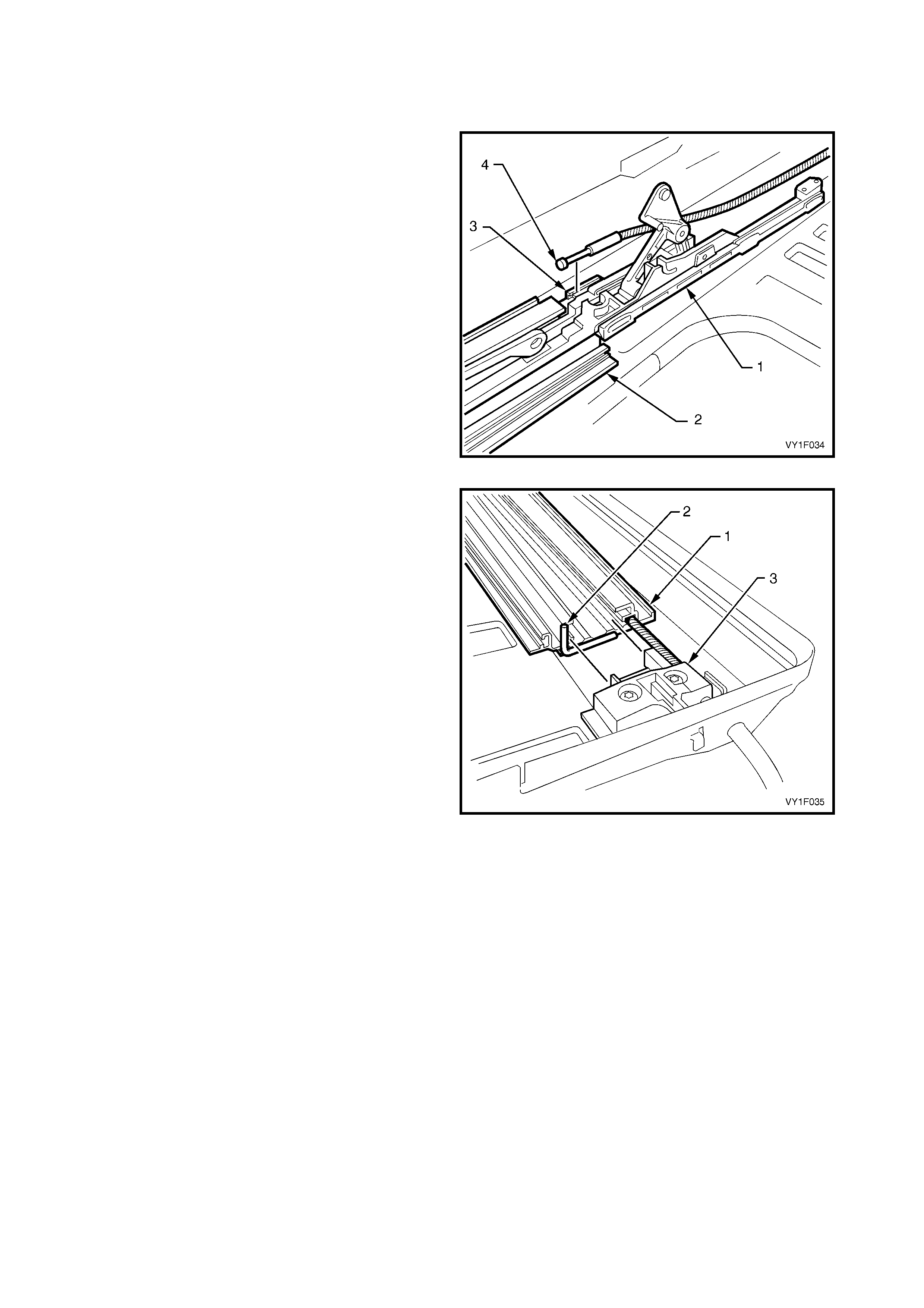
13. Remove the Phillips head screw (1) and the Torx
screw (2) from the retraction m echanism (3). Slide
the retraction mechanism forward but do not
remove.
Figure 1F-24
14. Push the guide rail mechanism (1) further forward
until the drive cable brass end fitting (2) is fully
forward of the drive cable channel (3). While
pushing forward, apply downward pressure on the
front of the guide rail mec hanism and m aintain the
tilt mechanism in the raised position (4).
Figure 1F-25
15. Lift the drive cable (1) out of the retaining slot (2) in
the guide rail track and carefully withdraw the
cable.
Figure 1F-26
REINSTALL
Installation of the drive cable is the reverse of the
removal procedure, noting the following:
1. Check that the new cable is the correct length. Oil
the cable using Applied Chemicals Tefoil +PTFE,
Part No. 8-830.
2. Carefully feed the drive cable into the guide rail
opening until the copper head aligns with the
retaining slot in the guide rail track. Do not force
the cable and avoid kinking or bending the cable
excessively.
Figure 1F-27
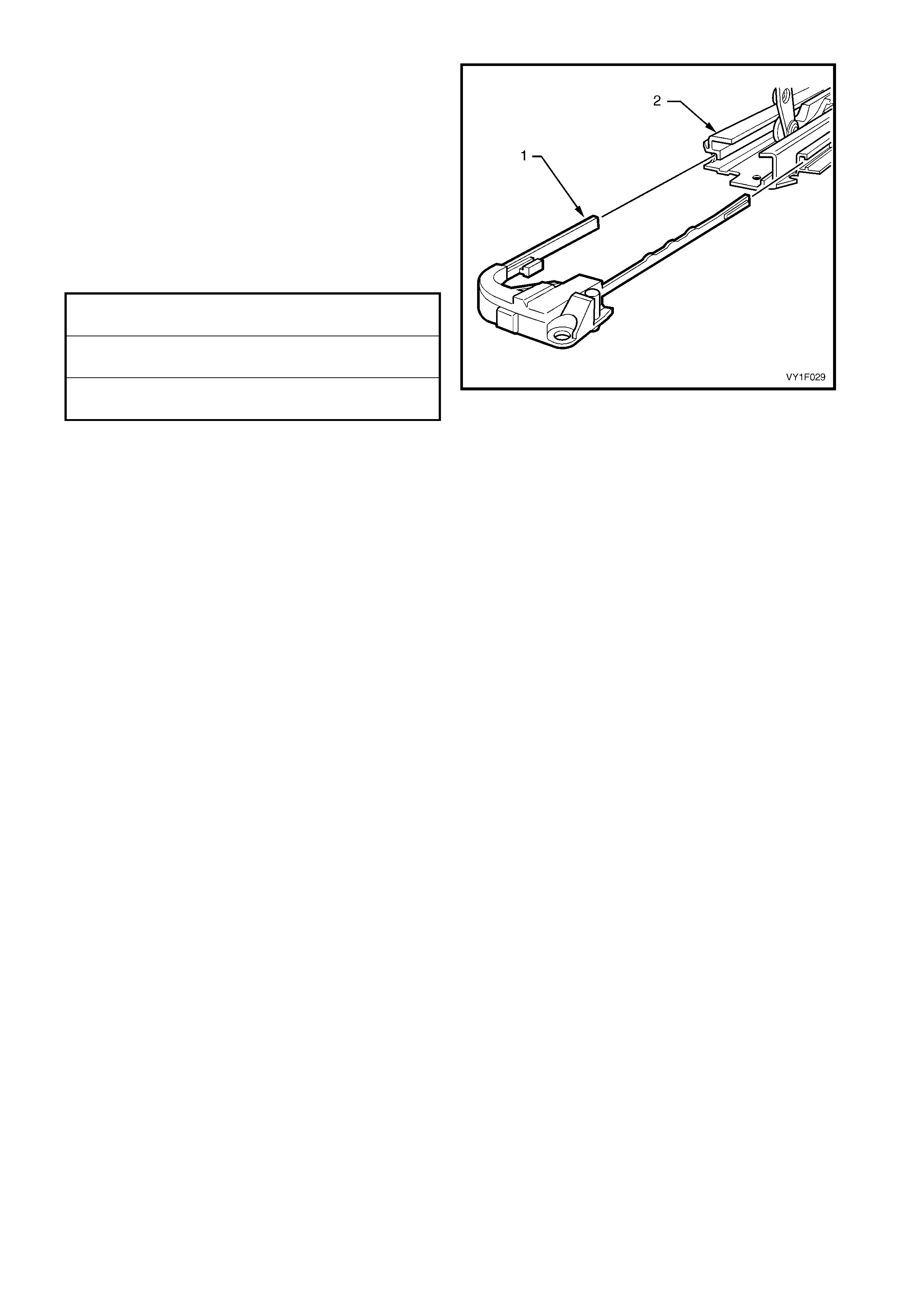
3. Ensure the copper head (1) of the cable seats
securely in the retaining slot (2) in the guide rail
track.
4. To install the retraction mechanism, push the
guide rail mechanism towards the rear slightly,
refer to Figure 1F-24. Position the retraction
mechanism with the locating Phillips head screw
and secure with the Torx screw. Tighten the
screws to the specified torque.
Figure 1F-28
RETRACTION MECHANISM
TORX SCREW
TORQUE SPECIFICATION 1.4 Nm
RETRACTION MECHANISM
LOCATING SCREW
TORQUE SPECIFICATION 0.5 Nm
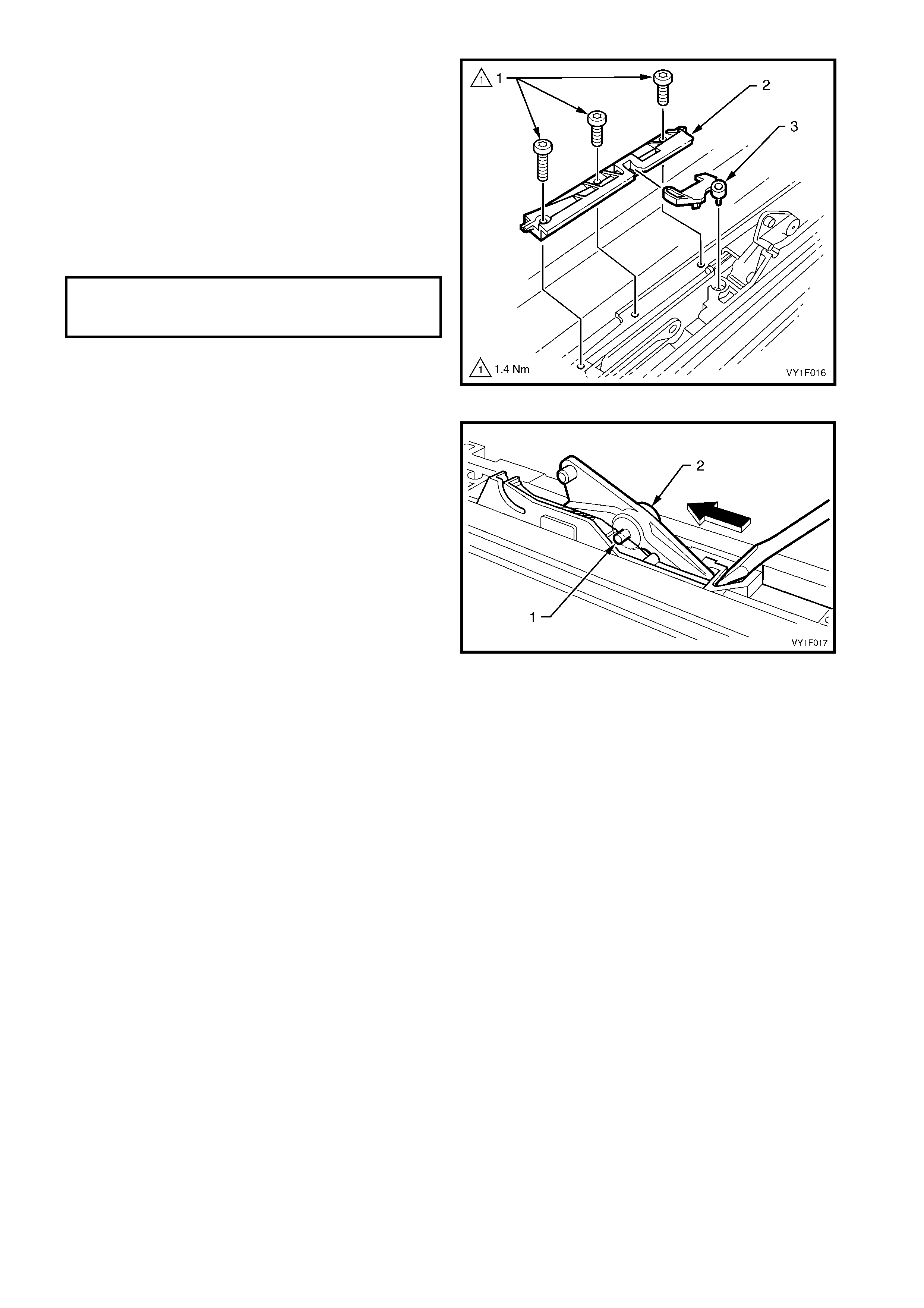
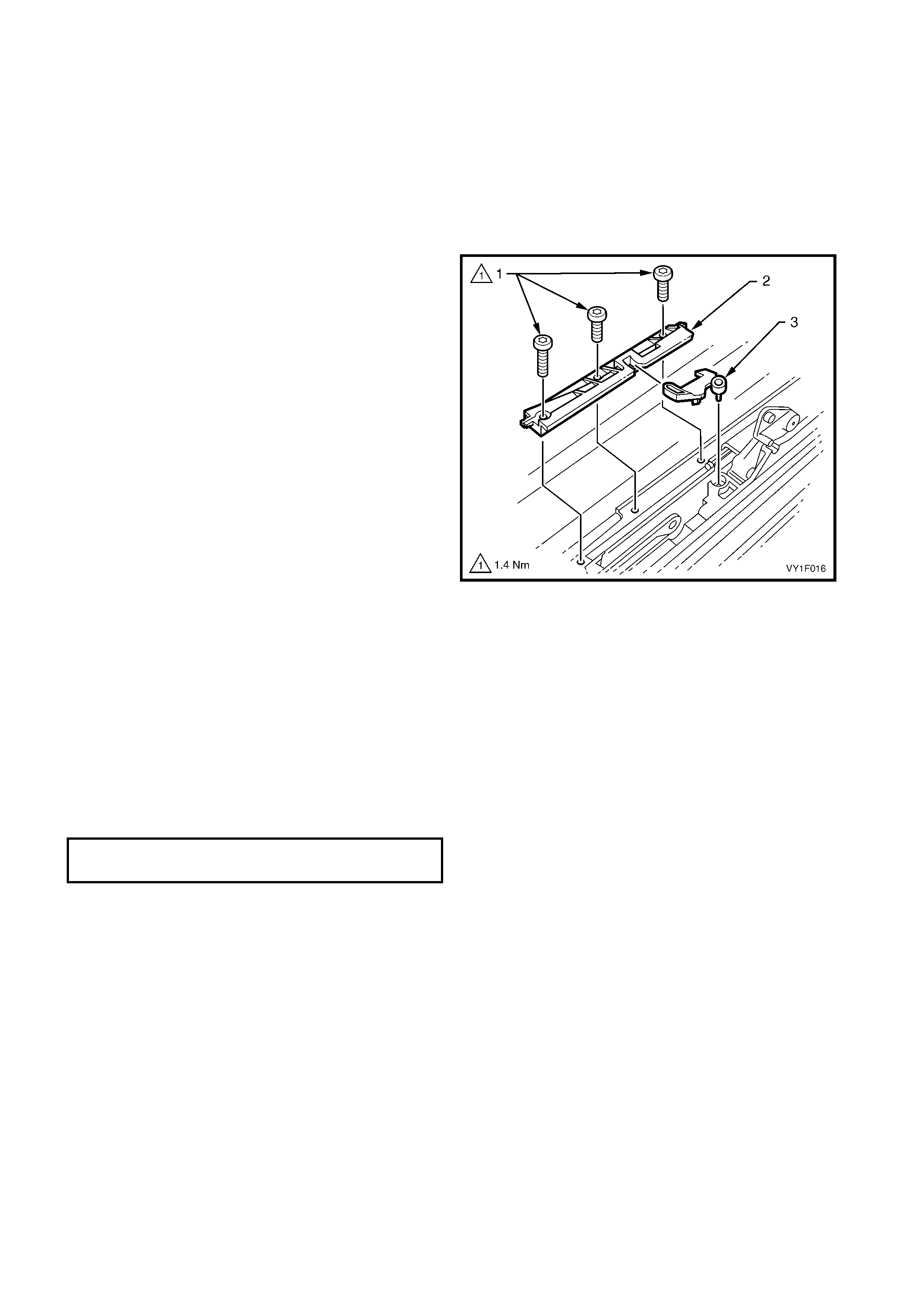
5. Ensure the blocking catch (3) is correctly fitted to
the locator (2). Position the guide rail mechanism
(by pushing back wards or forwards) so the locator
and blocking catch can be fitted with the blocking
catch mating correctly with the guide rail
mechanism. Secure with three Torx screws (1).
Push the guide rail mechanism to the fully closed
position. Tighten all fasteners to the specified
torque.
6. To replace the opposite cable, repeat the
procedure from Step 10 – REMOVE.
Figure 1F-29
7. Push the left-hand and right-hand mechanisms to
the closed position. Insert a pin (1) in the 2.5 mm
hole in the left-hand and right-hand tilt levers (2).
Slide the mechanisms forward until the pins stop
the mechanisms movement.
8. Install the gearwheel and gearwheel retainer, refer
to 2.2 DRIVE GEAR in this Section.
9. Install the SCU, refer to 2.3 SUNROOF
CONTROL UNIT (SCU).
10. Install the drive m otor and drive motor cover, refer
to 2.1 DRIVE MOTOR.
11. Remove the pins installed in Step 7.
12. Check the sunroof for correct electrical and
mechanical operation before installing the
adjustment bracket, drain c hannel, sunshade, wind
deflector, glass panel and mechanism covers.
13. Check the sunroof for correct operation before
fitting the headlining.
Figure 1F-30
LOCATOR RETAINING
TORX SCREWS
TORQUE SPECIFICATION 1.4 Nm

2.13 TIMING OF DRIVE CABLES
LT Section No. -
1. Open the sunroof in the full tilt position, refer to Figure 1F-21.
2. Remove the left-hand and right-hand mechanism covers and the glass panel, refer to 2.5 GLASS PANEL.
3. Fully close the sunroof.
4. Remove the drive motor cover and drive motor, refer to 2.1 DRIVE MOTOR.
5. Remove the SCU, refer to 2.3 SUNROOF CONTROL UNIT (SCU).
6. Remove the drive gear retainer and the drive gear, refer to 2.2 DRIVE GEAR.
7. Push the left-hand/right-hand mechanisms to the closed position. Insert a pin in the 2.5 mm hole in the
left-hand/right-hand tilt levers. Slide the m echanism forward until the pins stop the mechanism s movement,
refer to Figure 1F-18.
8. Install the drive gear and drive gear retainer, refer to 2.2 DRIVE GEAR.
9. Install the SCU, refer to 2.3 SUNROOF CONTROL UNIT (SCU).
10. Install the drive motor and drive motor cover, refer to 2.1 DRIVE MOTOR.
11. Remove the pins installed in Step 7.
12. Check the sunroof for correct electrical and mechanical function.
13. Install the left-hand and right-hand mechanism covers.
14. Check the sunroof for correct operation before fitting the headlining.
2.14 RE TRACTION MECHANISM
LT Section No. -
REMOVE
1. Retract the sunroof fully.
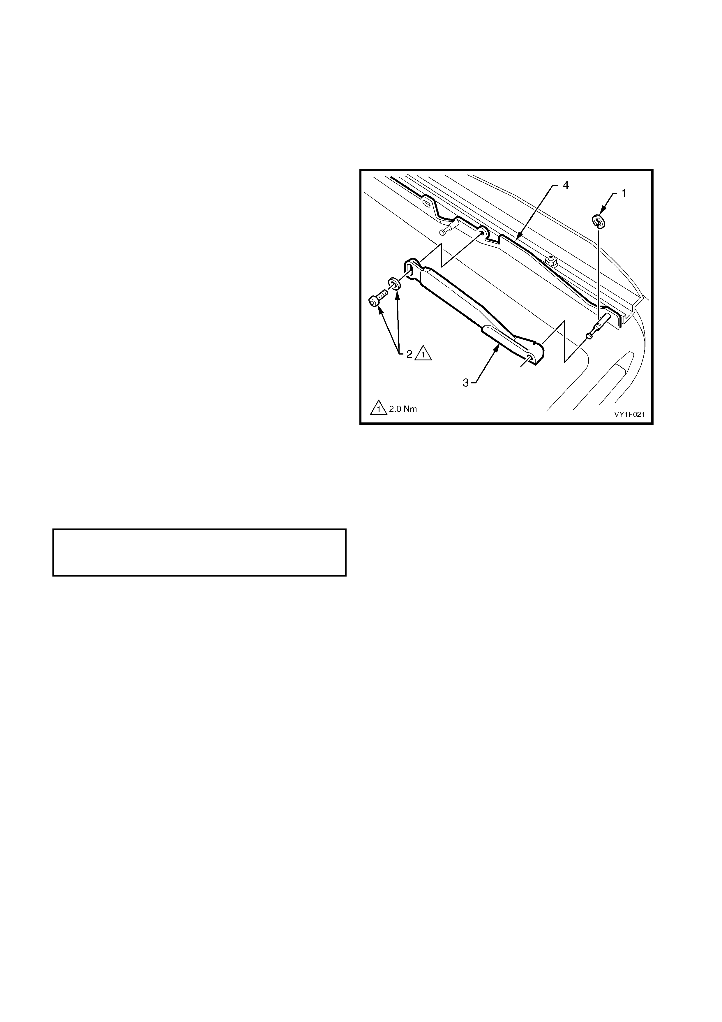
2. Remove the wind deflector, refer to
2.9 WIND DEFLECTOR.
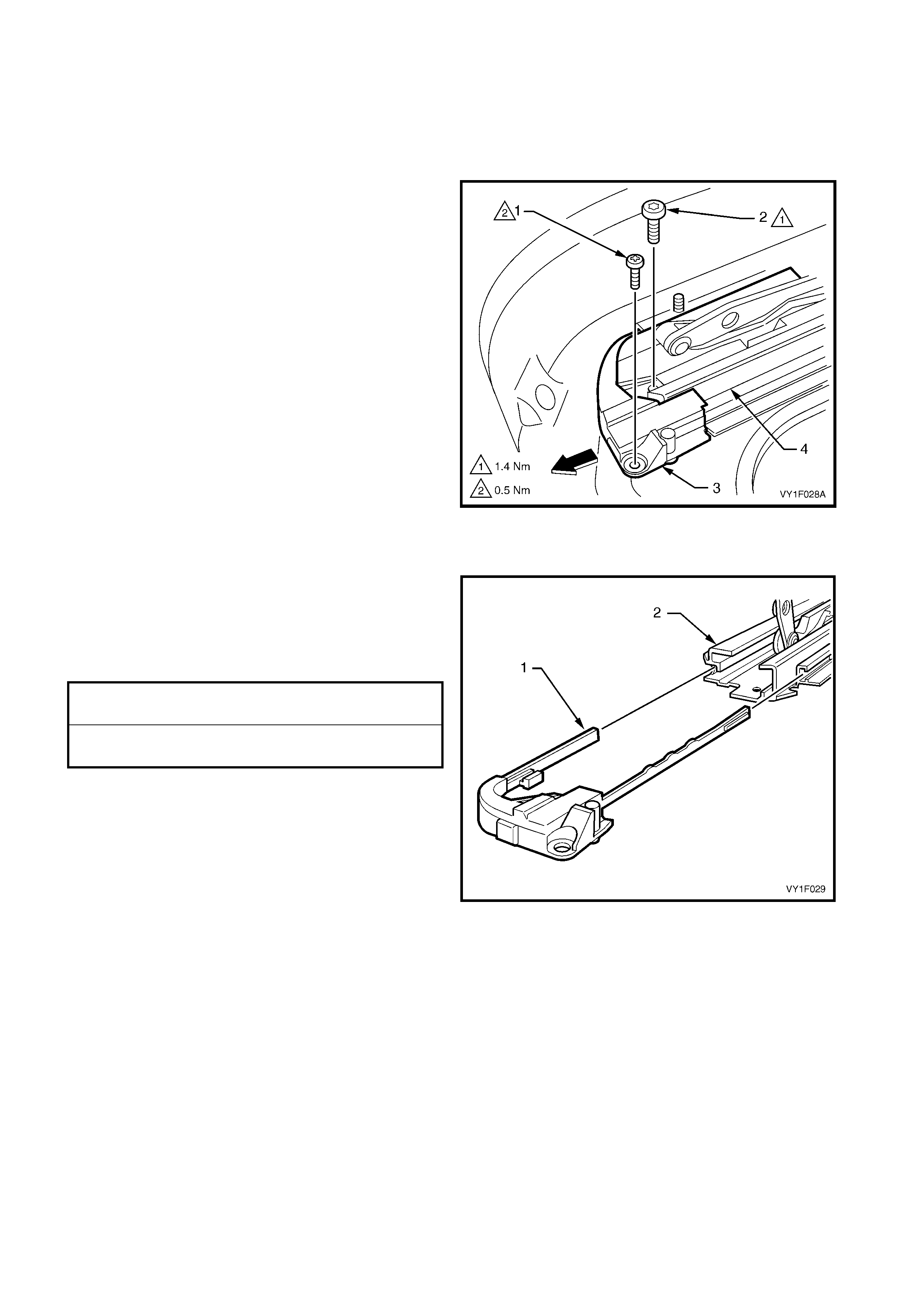
3. Remove the Phillips head screw (1) and the Torx
screw (2) from the retraction mechanism (3).
4. Withdraw the retraction mechanism forwards out
of the guide rail (4).
Figure 1F-31
REINSTALL
1. Install the new retraction mechanism (1) in the
guide rail (2).
2. Position the retrac tion mechanis m with the locating
Phillips head screw and secure with the Torx
screw. Tighten the screws to the specified torque.
3. Install the wind deflector, refer to
2.9 WIND DEFLECTOR.
4. Check the sunroof for correct operation.
Figure 1F-32
RETRACTION MECHANISM SCREW
TORQUE SPECIFICATION 1.4 Nm
RETRACTION MECHANISM LOCATING
SCREW TORQUE SPECIFICATION 0.5 Nm
2.15 GUIDE RAIL MECHANISM
LT Section No. -
REMOVE
1. Remove the left-hand and right-hand mechanism
covers and glass panel, refer to
2.5 GLASS PANEL.
2. Remove the wind deflector, refer to
2.9 WIND DEFLECTOR.
3. Remove the drain channel, refer to
2.10 DRAIN CHANNEL.
4. Remove the sunshade, refer to 2.11 SUNSHADE .
5. Remove the locator and blocking catch, refer to
2.16 BLOCKING CATCH.
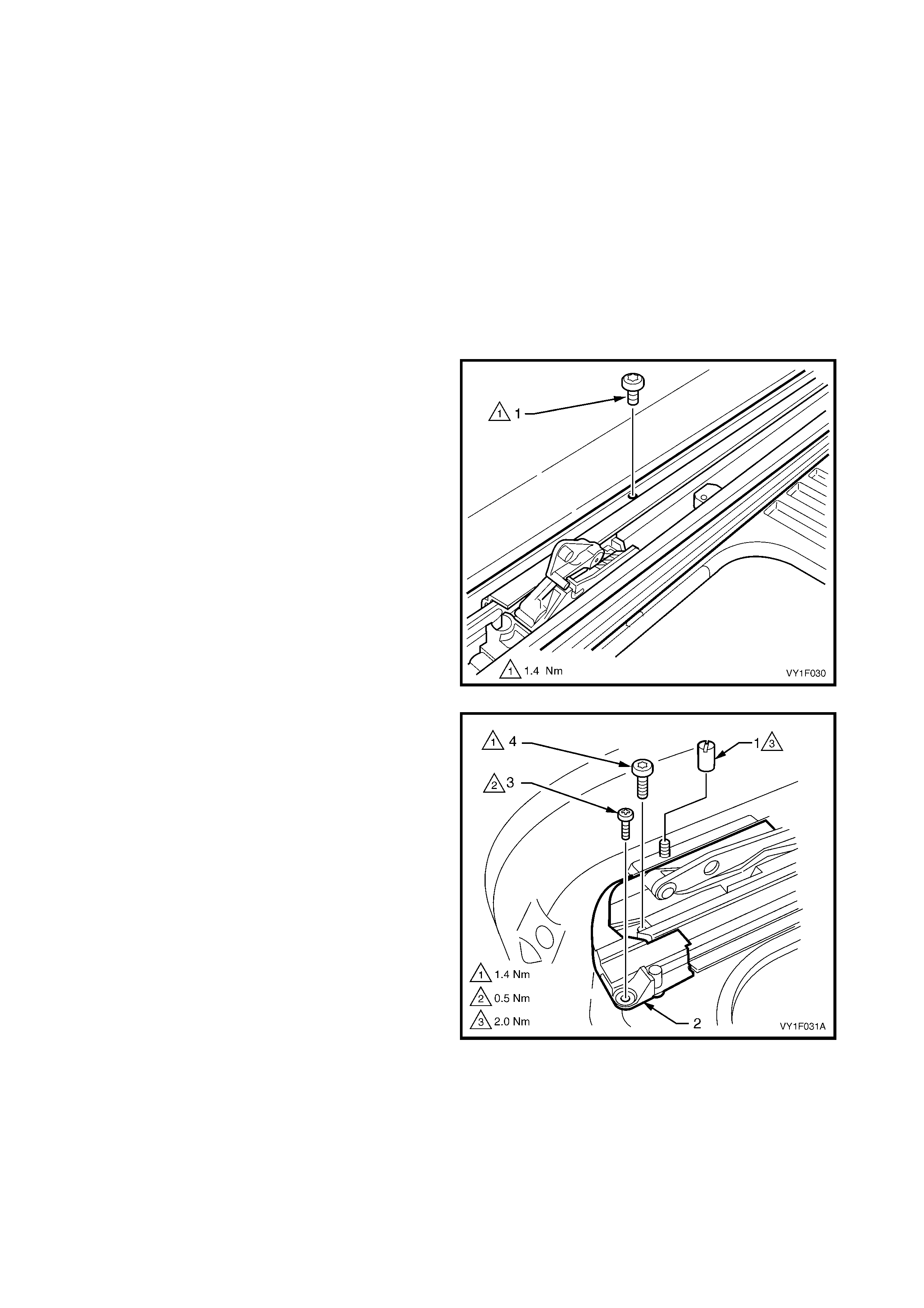
6. Remove the guide rail retaining screw (1) noting
the length and position of the screw.
Figure 1F-33
7. Remove the wind deflector mounting nuts (1).
8. Remove the retraction mechanism (2) locating
Phillips head screw (3) and retaining Torx
screw (4 ).
Figure 1F-34
9. Slide the mechanism guide rail (1) sideways to unlock from the locating tabs (2), refer to Figure 1F-35.
10. Lift the front of the mechanism guide rail and withdraw the retraction mechanism (3).
11. Fully close the mechanism.
Figure 1F-35
12. While holding the guide rail mechanism (1), gently pull the guide rail (2) forward over the guide rail
mechanism until the front of the drive cable (3) becomes visible, refer to Figure 1F-36.
13. Lift the drive cable out of the locating slot (4) then carefully lift out the guide rail and guide rail mechanism.
Figure 1F-36
REINSTALL
1. Check that the guide ra il mechanis m and guide rail
are clean and complete.
2. Slide the guide r ail mec hanism (1) out of the guide
rail (2) until the drive cable locating slot (3) is
visible.
3. Fit the drive c able (4) into the locating slot. Ensur e
the copper head of the drive cable seats securely
in the retaining slot, refer to Figure 1F-28. While
holding the guide rail mechanism (1) in position,
push the guide rail towards the rear locating
position gently to avoid damaging the drive cable.
Figure 1F-37
4. Apply a bead of butyl mastic sealer (2) to the end
of the guide rail (1).
5. While holding the guide r ail mechanis m in position,
push the guide rail towards the rear locating
position gently to avoid damaging the drive cable.
Then push into the rear locating bracket (3).
Figure 1F-38
6. Lift the front of the guide rail (2) and replace the
retraction mechanism (1).
7. Ensure the guide rail is pos itioned c orr ec tly against
the rear locating bracket then slide sideways to
lock into position.
8. Install the retraction mechanism and guide rail
retaining scr ews ensur ing the c orr ec t sc r ews noted
during removal are used. Tighten the guide rail
screw to the specified torque. Position the
retraction mechanism with the locating Phillips
head screw and secure with the Torx screw.
Tighten the screws to the specified torque.
9. Install the locator and blocking catch, refer to
2.16 BLOCKING CATCH.
10. Fully tilt the mechanism.
11. Ensure the mechanism functions correctly.
12. Install the sunshade, refer to 2.11 SUNSHADE .
13. Install the drain channel, refer to
2.10 DRAIN CHANNEL.
14. Install the wind deflector, refer to
2.9 WIND DEFLECTOR.
15. Install the glass panel and mechanism covers,
refer to 2.5 GLASS PANEL.
16. Check the sunroof for correct operation.
Figure 1F-39
GUIDE RAIL TORX SCREW
TORQUE SPECIFICATION 1.4 Nm
RETRACTION MECHANISM TORX SCREW
TORQUE SPECIFICATION 1.4 Nm
RETRACTION MECHANISM LOCATING
SCREW TORQUE SPECIFICATION 0.5 Nm
2.16 BLOCKING CATCH
LT Section No. -
REMOVE
1. Open the sunroof in the full tilt position, refer to
Figure 1F-21. Remove the left-hand and
right-hand m echanism covers and the glass panel,
refer to 2.5 GLASS PANEL.
2. Fully retract the mechanism.
3. Rem ove the three locator retaining screws (1) and
the locator (2) noting the length and position of the
screws.
4. Fully tilt the mechanism.
5. Lift out the blocking catch (3).
6. If replacing a broken blocking catch, make sure
that any debris is removed.
Figure 1F-40
REINSTALL
1. Ensure the blocking catch is correctly fitted to the
locator (2), refer to Figure 1F-40. Position the
guide rail mechanism (by pushing backwards or
forwards) so the locator and bloc king catch can be
fitted with the blocking catch mating correctly with
the guide rail mechanism. Secure the locator and
blocking catch with three Torx screws in the
positions noted during removal. Push the
mec hanism to the fully closed position. T ighten the
locator retaining screws to the specified torque.
2. Check for correct mechanical operation.
3. Install the glass panel and the left-hand and
right-hand mechanism covers, refer to
2.5 GLASS PANEL in this Section.
LOCATOR RETAINING TORX SCREWS
TORQUE SPECIFICATION 1.4 Nm
2.17 SUNROOF POWER HARNESS
LT Section No. -
REMOVE
IMPORTANT: Take extreme care when removing the
headlining which has been modified and installed using
adhesive.
1. Remove the sunroof circuit breaker F3 from the
passenger compartment fuse and relay panel
assembly, refer to Section 12O, 2.2 CIRCUIT
BREAKERS.
2. Remove the headlining. Refer to Section 1A8,
• 2.12 HEADLINING ASSEMBLY – SEDAN
• 3.15 HEADLINING ASSEMBLY – WAGON
3. Remove the front windshield side garnish, refer to
Section 1A8,
• 2.5 WINDSHIELD SIDE GARNISH – SEDAN
• 3.5 WINDSHIELD SIDE GARNISH – WAGON
Configuration One
NOTE: This power harness configuration applies to
sunroofs installed on all wagon vehicles, and until
March 2003 on sedan vehicles.
1. Remove the right-hand hinge pillar trim assembly,
refer to Section 1A8,
• 2.8 HINGE PILLAR TRIM ASSEMBLY –
SEDAN
• 3.12 HINGE PILLAR TRIM ASSEMBLY –
WAGON
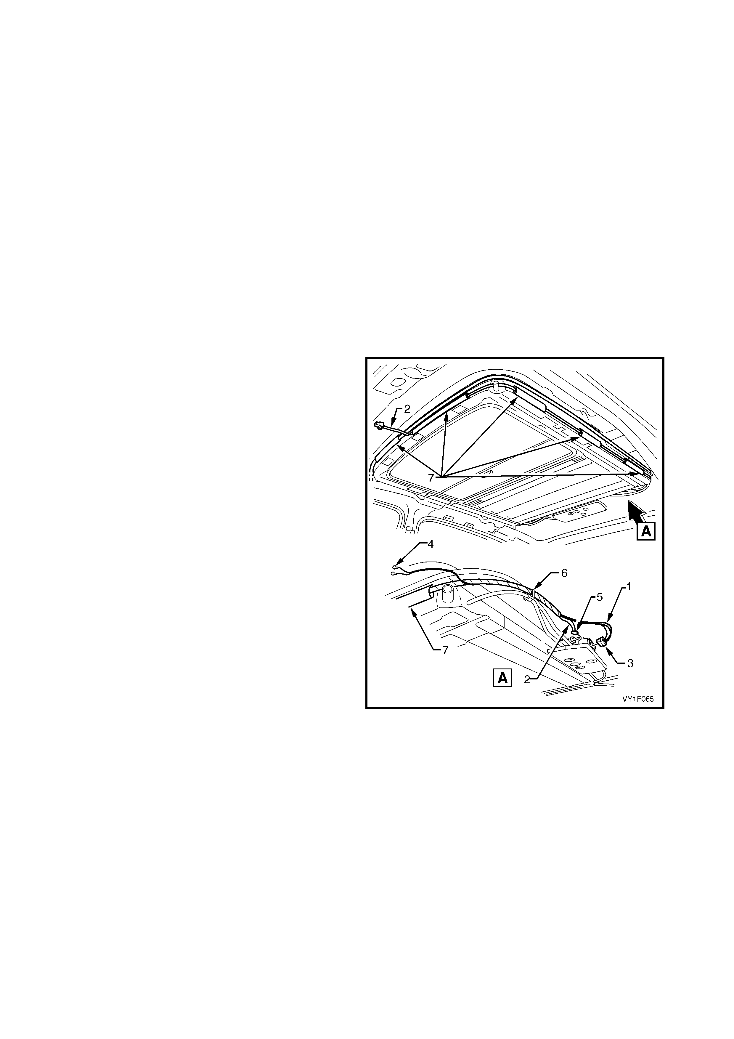
NOTE: The sunroof power harness (1) and the sunroof
harness (2) ar e taped together and should be r eplaced
as an assembly.
2. Disconnect the sunroof power harness
connector (3) from the SCU.
3. Remove the sunroof power harness ground
connections (4) from the left-hand inner side
panel.
4. Disconnect the sunroof harness connector (5)
from the SCU.
5. Unclip the wiring harnes ses from the sunroof drive
cable guides plastic support clip (6).
6. Open the guide tubes (7) attached to the side of
the sunroof to release the wiring harnesses.
Figure 1F-41
7. Gain access to the passenger compartment
fuse and relay panel assembly, refer to
Section 1A3, 3.4 INSTRUMENT PANEL LOWER
TRIM PANEL.
8. Disconnect the sunroof power harness
connectors (1 and 2) from the passenger
compartment fuse and relay panel assembly.
9. Remove the tape holding the sunroof power
harness (3) to the hinge pillar and remove the
harnesses.
Figure 1F-42
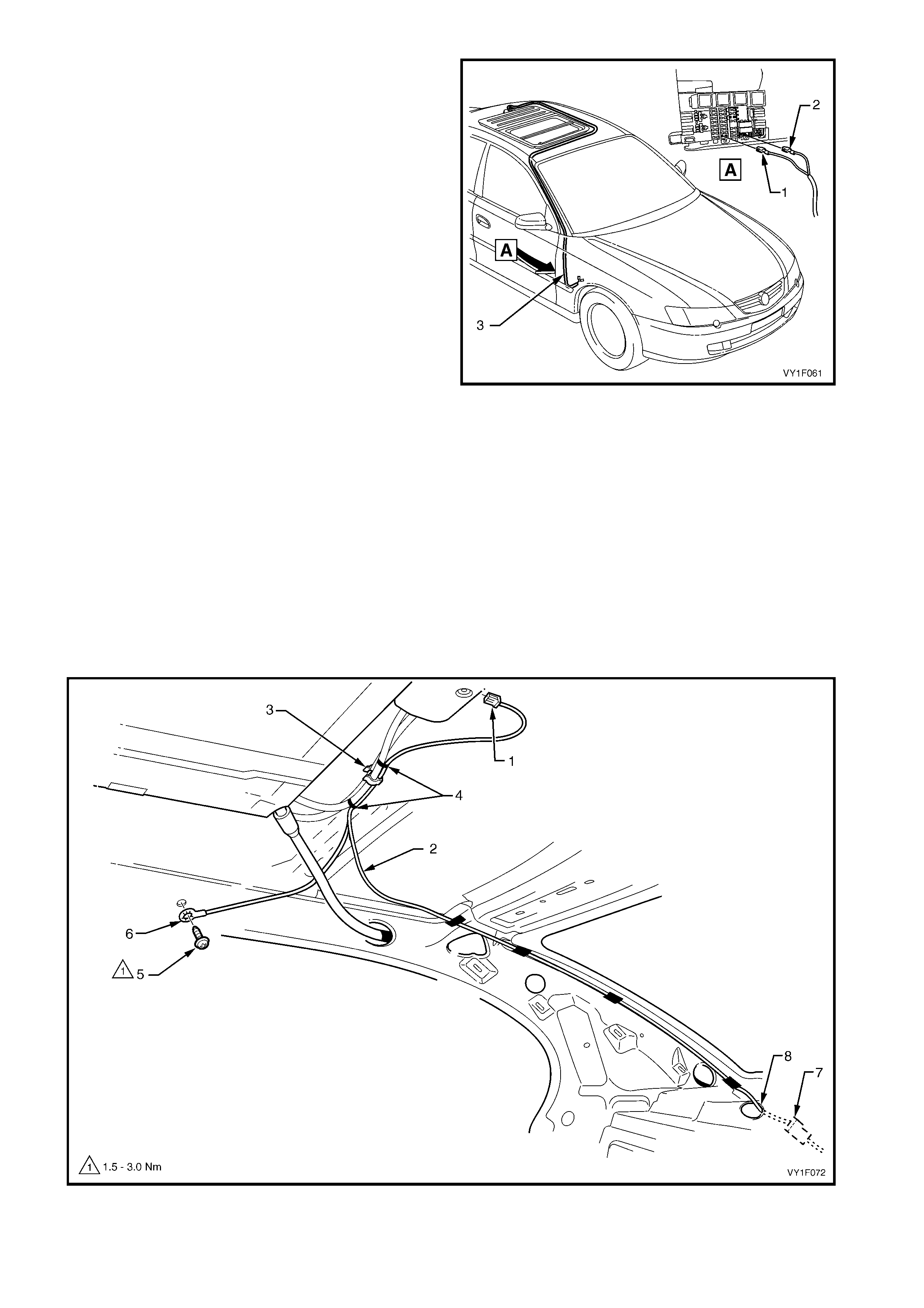
Configuration Two
NOTE: This power harness configuration applies to HBD sunroofs installed after March 2003 on sedan vehicles
only .
1. Disconnect the SCU connector (1) from the SCU, refer to Figure 1F-43.
2. Unclip the sunroof power harness (2) from the sunroof drive cable guides plastic support clip (3) and remove
the cable ties (4).
3. Remove the self-tapping screw (5) securing the ground wire (6) to the inner side panel.
4. Untape the sunroof power harness from the C pillar, noting the position of the tape.
5. Partially remove the quarter inner rear side carpet from the rear compartment to expose the sunroof power
harness connector, refer to Section 1A 8, 2.17 QUARTER INNER REAR SIDE CARPET.
6. Disconnect the sunroof power harness connector (7) from the body harness connector.
7. Feed the sunroof power harness through the hole (8) in the parcel tray and remove.
Figure 1F-43
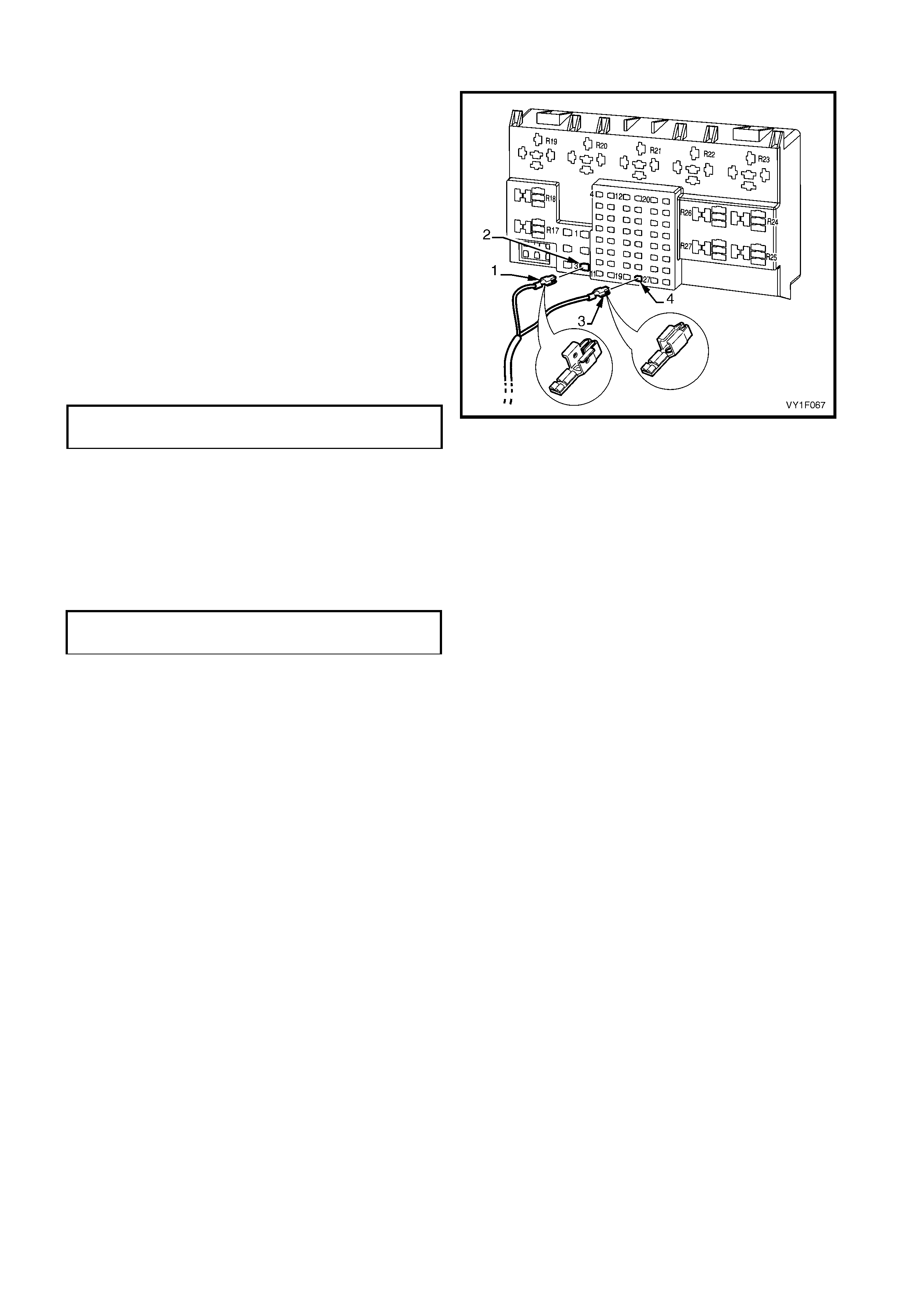
REINSTALL
Configuration One
Installation of the s unr oof power harnes s is the rever se
of the removal, noting the following:
1. Connect the harness to the passenger
compartment fuse and relay panel assembly with:
a. Winged terminal (1) (red wire) to circuit
breaker #3, port (2) X45 3_1
b. Non-winged terminal (3) (white wire) to spare
fuse #19, port (4) X43_19_1
Refer to 3.2 WIRING DIAGRAM – SUNROOF.
3. T ape the s unroof power harness to the hinge pillar
in the same way noted during removal.
4. Ensure that the ground connections are securely
attached to the left-hand inner side panel. Tighten
the screw to the specified torque.
Figure 1F-44
Configuration Two
Installation of the sunroof power harness is the reverse of the removal, noting the following:
1. Tape the sunroof power harness to the C pillar as noted during removal.
2. Sec ure the sunroof power harness to the sunroof drive cable guides plas tic support c lip (3) and c able tie to the
drive cable guides, refer to Figure 1F-43.
3. Ensure the ground connection is securely attached to the right-hand inner side panel. Tighten the screw to the
specified torque.
SUNROOF POWER HARNESS GROUND
SCREW TORQUE SPECIFICATION 1.5 – 3.0 Nm
SUNROOF POWER HARNESS GROUND
SCREW TORQUE SPECIFICATION 1.5 – 3.0 Nm

2.18 S UNROOF HARNESS
LT Section No. -
REMOVE
NOTE: The sunroof harness and the sunroof power harness are taped together and should be replaced as an
assembly.
1. Remove the sunroof harness with the sunroof power harness, refer to 2.17 SUNROOF POWER HARNESS.
REINSTALL
NOTE: The sunroof harness and the sunroof power harness are taped together and should be installed as an
assembly.
1. Install the sunroof harness with the sunroof power harness, refer to 2.17 SUNROOF POWER HARNESS.
2.19 SUNROOF CONTROL HARNESS
LT Section No. -
REMOVE
1. Remove the sunroof circuit breaker F3 from the
passenger compartment fuse and relay panel
assembly, refer to Section 12O, 2.2 CIRCUIT
BREAKERS.
2. Remove the roof console. Refer to:
• Section 1A8, 2.11 ROOF CONSOLE –
SEDAN
• Section 1A8, 3.14 ROOF CONSOLE –
WAGON
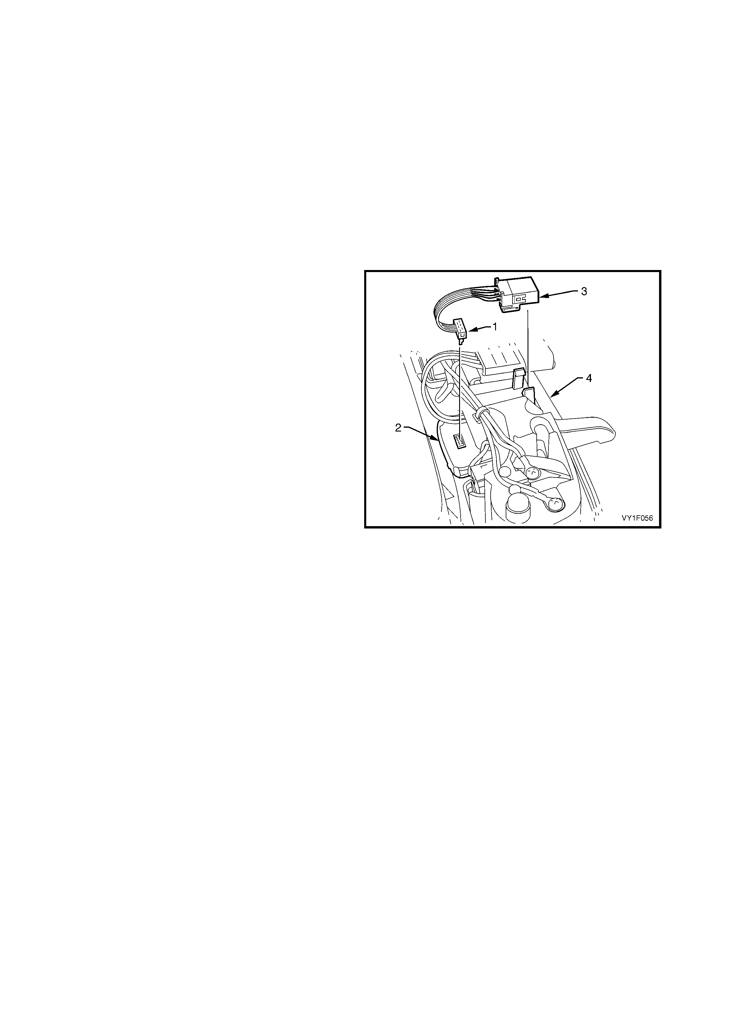
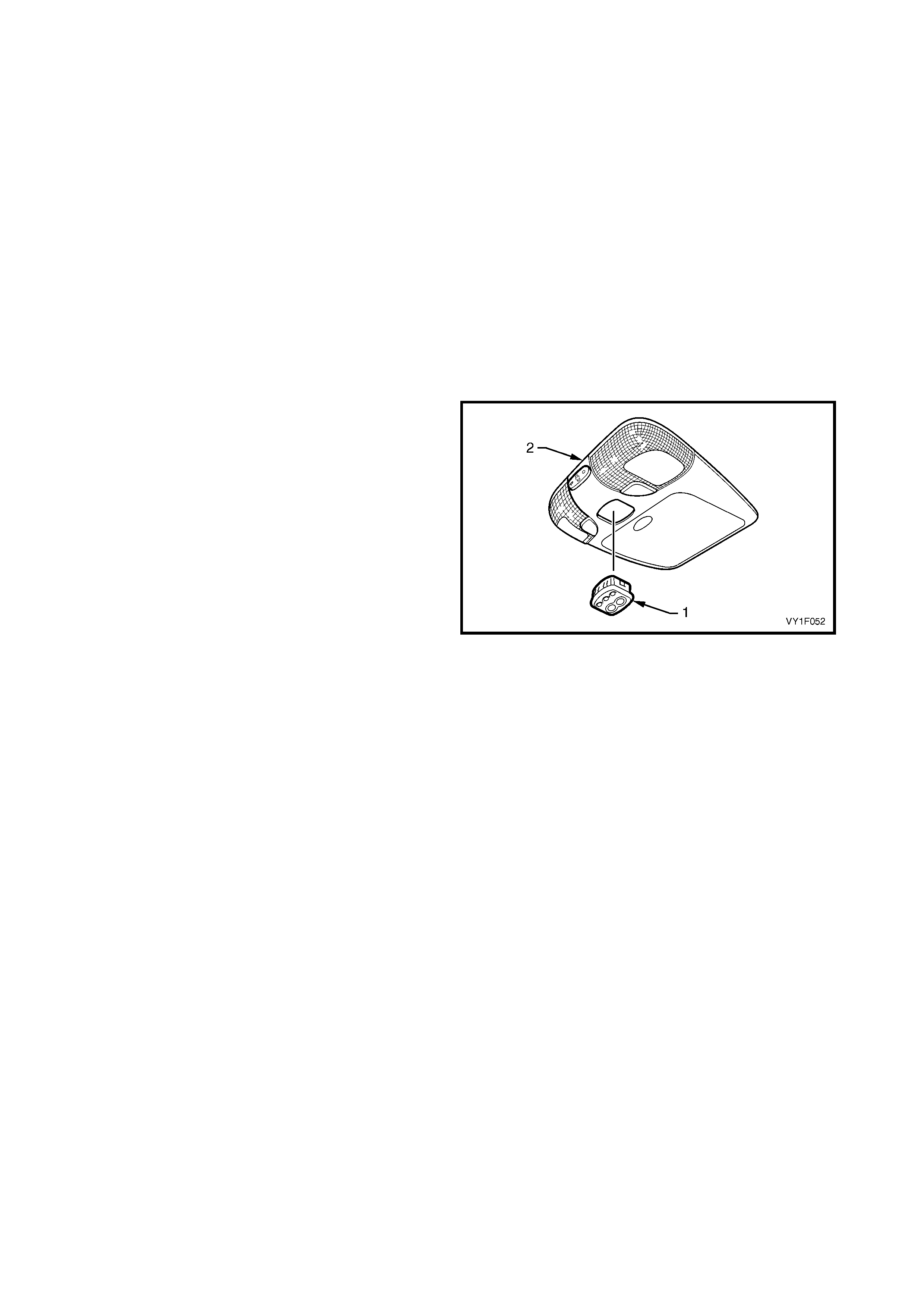
3. Disconnect the sunroof control harness connector
(1) from the sunroof switch (2) and unclip the
connector (3) from the roof console (4).
Figure 1F-45
REINSTALL
Installation of the sunroof control harness is the
reverse of the removal procedure.
2.20 SUNROOF SWITCH
LT Section No. -
REMOVE
1. Remove the sunroof circuit breaker F3 from the
passenger compartment fuse and relay panel
assembly, refer to Section 12O, 2.2 CIRCUIT
BREAKERS.
2. Remove the roof console. Refer to:
• Section 1A8, 2.11 ROOF CONSOLE –
SEDAN
• Section 1A8, 3.14 ROOF CONSOLE –
WAGON
3. Remove the sunroof control harness from the roof
console, refer to 2.19 SUNROOF CONTROL
HARNESS.
4. Carefully unclip the sunroof switch (1) from the
roof console (2).
Figure 1F-46
REINSTALL
Installation of the sunroof switch is the reverse of the
removal procedure.
NOTE : Should the situation arise where the battery
power is supplied to the sunroof before the sunroof
switch is connected to the SCU, only the sunroof
switch button ! and button " will operate. With the
ignition switch in the OFF position, the sunroof switch
has to be reset by removing and inserting the sunroof
circuit breaker F3 on the passenger com partment f use
and relay panel assembly, refer to Section 12O,
2.2 CIRCUIT BREAKERS.
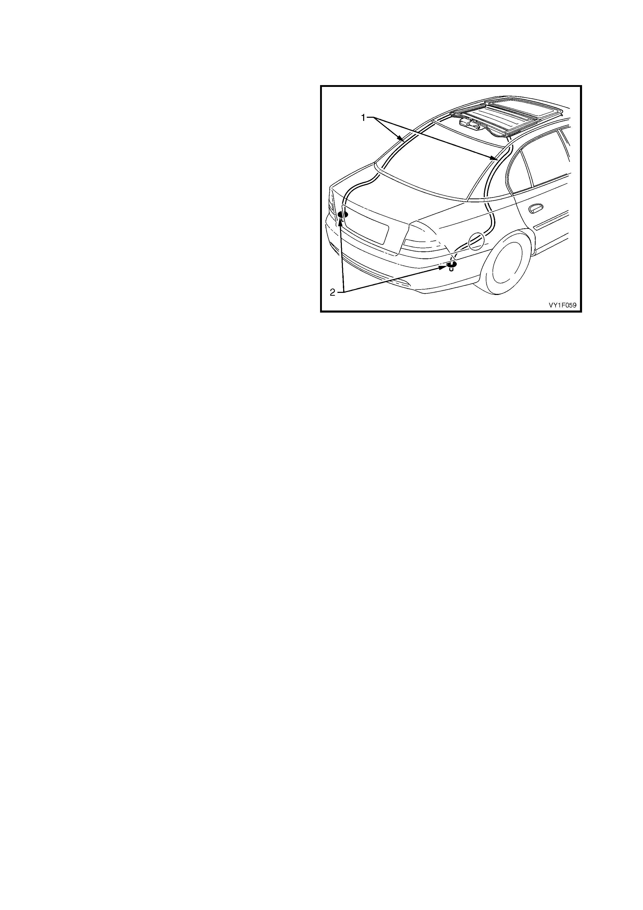
2.21 REAR DRAIN TUBE – SEDAN
LT Section No. -
REMOVE
IMPORTANT: Take extreme care when removing the
headlining which has been modified and installed using
adhesive.
1. Remove the sunroof circuit breaker F3 from the
passenger compartment fuse and relay panel
assembly, refer to Section 12O, 2.2 CIRCUIT
BREAKERS.
2. Remove the headlining, the body lock pillar garnish
and the rear window trim panel assembly, refer to
Section 1A8 HEADLINING AND INTERIOR
TRIM.
3. Partially remove the relevant rear compartment
side trim, refer to Section 1A8, 2.17 QUARTER
INNER REAR SIDE CARPET.
4. Remove the silicone from the rear drain tube exit
hole (2) in the quarter panel and pull the rear drain
tube (1) from the hole.
5. From within the passenger compartment,
disconnect the rear drain tube from the sunroof
assembly.
6. Pull the rear drain tube through the pillar and
remove.
Figure 1F-47
REINSTALL
Installation of the r ear drain tubes is the rever se of the
removal procedure, noting the following:
1. Ensure the rear drain tubes are clear from dirt and
debris and that they are free of kinks.
2. Apply non-acidic silicone to seal the rear drain tube
exit hole.
NOTE: Chlorinated rubber paint is applied to the panel
at the entry holes of the rear drain tubes, touch-up if
needed.
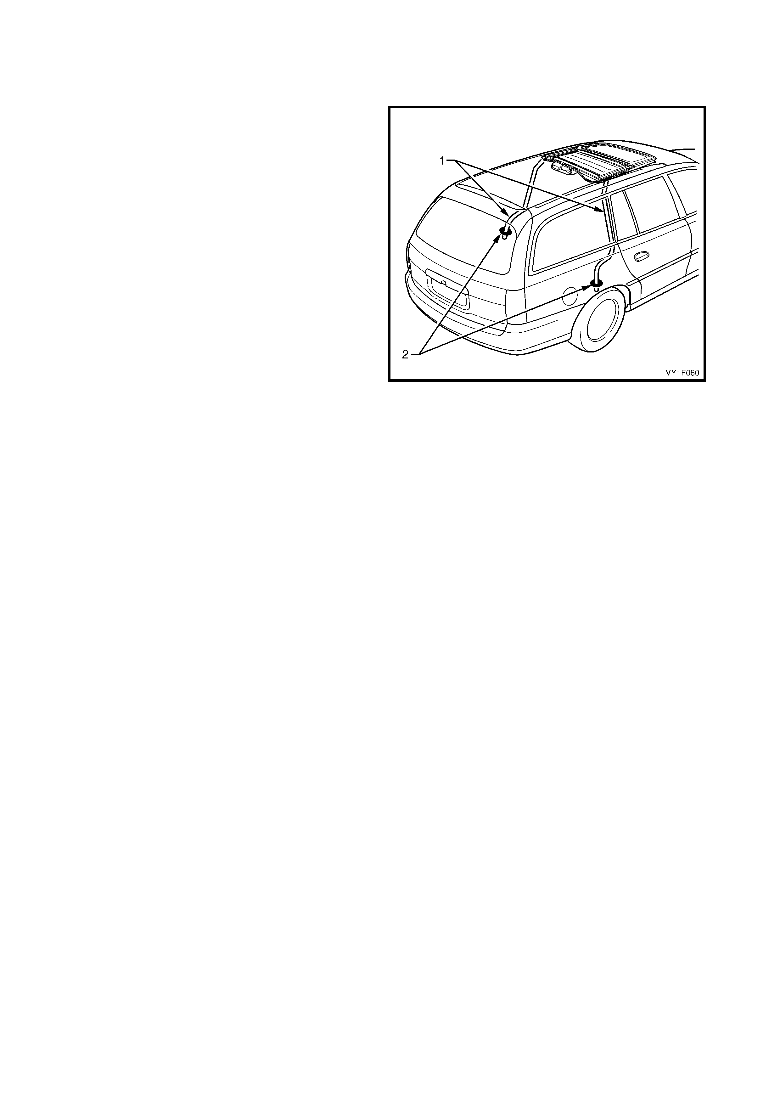
2.22 REAR DRAIN TUBE – WAGON
LT Section No. -
REMOVE
IMPORTANT: Take extreme care when removing the
headlining which has been modified and installed using
adhesive.
1. Remove the sunroof circuit breaker F3 from the
passenger compartment fuse and relay panel
assembly, refer to Section 12O, 2.2 CIRCUIT
BREAKERS.
2. Remove the headlining and the body lock pillar
garnish, refer to Section 1A8 HEADLINING AND
INTERIOR TRIM.
3. Remove the relevant quarter inner tr im panel, ref er
to Section 1A8, 3.11 QUARTER INNER TRIM
PANEL ASSEMBLY.
4. Remove the silicone from the rear drain tube exit
hole (2) in the wheel house liner and pull the rear
drain tube (1) from the hole.
5. From within the passenger compartment,
disconnect the rear drain tube from the sunroof
assembly.
6. Pull the rear drain tube through the pillar and
remove.
Figure 1F-48
REINSTALL
Installation of the r ear drain tubes is the rever se of the
removal procedure, noting the following:
1. Ensure the rear drain tubes are clear from dirt and
debris and that they are free of kinks.
2. Apply non-acidic silicone to seal the rear drain tube
exit hole.
NOTE: Chlorinated rubber paint is applied to the panel
at the entry hole of the rear drain tube in the pillar,
touch-up if needed.
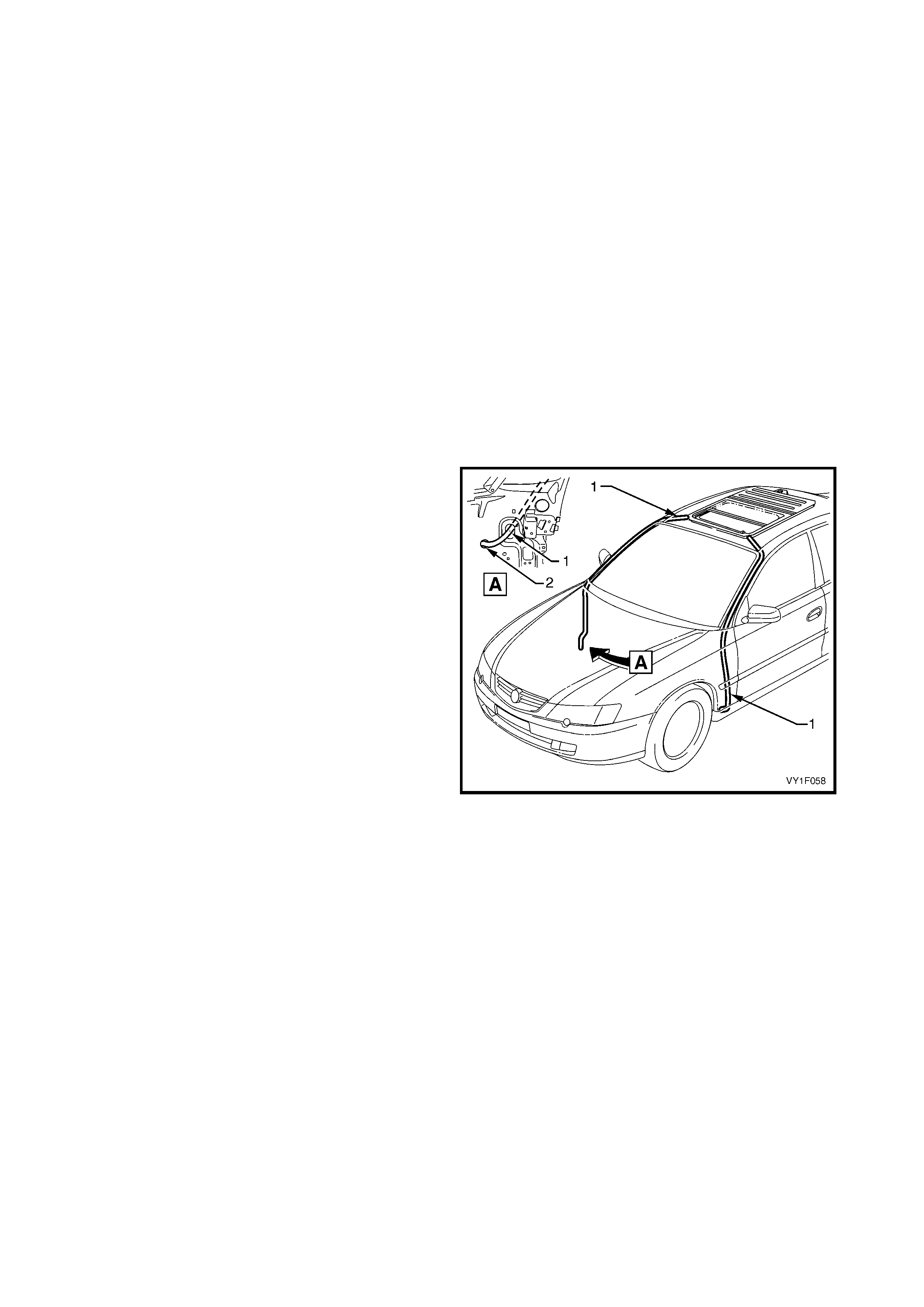
2.23 FRONT DRAIN TUBE
LT Section No. -
REMOVE
IMPORTANT: Take extreme care when removing the
headlining which has been modified and installed using
adhesive.
1. Remove the sunroof circuit breaker F3 from the
passenger compartment fuse and relay panel
assembly, refer to Section 12O, 2.2 CIRCUIT
BREAKERS.
2. Remove the headlining, the front windshield side
garnish, and the hinge pillar tr im ass embly, refer to
Section 1A8 HEADLINING AND INTERIOR
TRIM.
NOTE: If required remove the PCM on V6 vehicles,
refer to Section 6C1-3, 2.1 POWERTRAIN CONTROL
MODULE, or remove the PIM on V8 vehicles, refer to
Section 6C3-3, 2.1 POWERTRAIN INTERFACE
MODULE (PIM).
3. Remove the silicone from the front drain tube exit
hole in the hinge inner pillar assembly (2) and pull
the front drain tube (1) from the hole.
4. From within the passenger compartment,
disconnect the front drain tube from the sunroof
assembly.
5. Pull the front drain tube through the upper side
panel and remove.
Figure 1F-49
REINSTALL
Installation of the front drain tube is the reverse of the
removal procedure, noting the following:
1. Ensure the f ront dr ain tubes are c lear f r om dirt and
debris and that they are free of kinks.
2. Apply non-acidic silicone to seal the front drain
tube exit hole in the hinge inner pillar assembly.
NOTE: Chlorinated rubber paint is applied to the panel
at the entry hole of the front drain tube in the upper
side panel, touch-up if needed.

3. DIAGNOSIS
IMPORTANT: The following diagnosis is applicable to HBD sunroofs equipped with a configuration one power
harness, r efer to 1. GENERAL INFORMAT ION. The diagnosis f or HBD sunroof s equipped with a configuration two
power harness and Online sunroofs are identical, refer to Section 1F2, 3. DIAGNOSIS.
3.1 FAULT DIAGNOSIS CHARTS
LT Section No.
INTRODUCTION
The s unroof is operated via a contr ol unit and a switch. T he control unit and the s witch are connec ted to each other
by two harnes ses that each have s ix wires. The glas s panel is activated by a drive motor which is connected to the
control unit. Battery voltage is supplied to the control unit through the ignition switch in the ON position or a circuit
breaker when the ignition switch is in the OFF position. These tests confirms the correct operation of the sunroof
and the serviceability of the switch, the control unit, the drive motor and associated circuits. For a complete wiring
diagram of the sunroof circuits , refer to 3.2 WIRING DIASGRAM - SUNROOF. For connec tor pin locations , ref er to
3.3 CONNECTOR DIAGRAM _ SUNROOF.
NOTE 1: The drive motor has an inbuilt thermal cut-out device that automatically switches the motor off during
period of overload. After a cool down period, the motor will function normally again.
NOTE 2: If the SCU fails and is replaced with a new unit, the first time the new SCU is connected to the power
supply it must be calibrated, refer to 2.4 CALIBRATING THE SUNROOF CONTROL UNIT.
NOTE 3: On completion of the electrical test and/or if the situation arise where only the sunroof switch button ! and
button " are operating, the sunroof switch has to be reset, refer to 2.20 SUNROOF SWITCH.
PREREQUISITES
SAFETY REQUIREMENTS
When operating the sunroof as part of any of the Steps in the diagnosis charts, ensure that fingers are clear of
moving parts.
EQUIPMENT
The following equipment is required to diagnose the sunroof:
1. An unpowered test lamp with a current draw of less than 3 A.
2. A digital multimeter with a minimum impedance of 10 MΩ.
TESTING PROCEDURES
The following points must be adhered to when performing diagnostic testing on components:
1. Care must be taken when using testing equipment to diagnose wiring harness connectors. It is preferred that
the technician back probe the connector to avoid terminal damage.
2. When tests are required on connector terminals, utilise the adapters in the connector adaptor kit KM–609 to
prevent damage to the terminals.
3. Unless the multimeter being used has an auto-ranging function, ensure that the correct range is selected.
4. When back-probing connectors, ensure the test lamp earth lead is connected to a suitable earth point on the
vehicle. Ensure that this earth point is not part of the circuit being tested.
IMPORTANT: When following the Steps in the diagnosis c harts , the exac t or der of Steps s hould be obs erved. If the
required nominal value or result is not achieved at any stage, the pr oblem m ust be rectified bef ore proceeding any
further.

FUNCTIONAL TEST
NOTE: If the glass panel stops at an unexpected position related to the sunroof switch function, the end position
cannot be reached, or one or more buttons of the sunroof s witc h do not operate properly any m ore, it is necessary
to recalibrate the SCU, refer to 2.4 CALIBRATING THE SUNROOF CONTROL UNIT.
TEST DESCRIPTION
The following numbers refer to the Steps in the diagnostic chart.
For functions description and a view of the sunroof switch buttons refer to 1. GENERAL DESCRIPTION and
Figure 1F-1.
1. Checks whether the sunroof operates correctly in the slide open and close mode.
2. Checks whether the sunroof operates correctly in the maximum tilt open and close mode.
3. Checks whether the sunroof operates correctly in the variable tilt mode.
4. Checks whether the sunroof operates correctly in the soft touch mode.
5. Checks whether the sunroof operates correctly in the auto-close mode.
6. Checks whether the sunroof operates correctly in the auto-close override mode.
7. Checks whether the sunroof operates correctly in the jamming protection mode.
8. Checks whether the sunroof operates correctly in the comfort position mode.
STEP ACTION YES NO
1. 1. Turn the ignition switch to the ON position.
2. Briefly press the ! button to open the glass panel.
3. Briefly press the C button to close the glass panel.
Does the glass panel slide fully open and then close?
Go to Step 2. Go to ELECTRICAL
TEST DESCRIPTION.
2. 1. Briefly press the " button to open the glass panel to
maximum tilt position.
2. Briefly press the C button to close the glass panel.
Does the glass panel open to maximum tilt position and
then close?
Go to Step 3. Go to ELECTRICAL
TEST DESCRIPTION.
3. 1. Briefly press the " button to open the glass panel to
maximum tilt position.
2. Press and hold the ! button, release it at the next
tilt position, repeat for all three/four tilt steps.
Does the variable tilt operation function correctly?
Go to Step 4. Go to ELECTRICAL
TEST DESCRIPTION.
4. 1. Perform the soft touch operation, refer to
1. GENERAL DESCRIPTION.
Does the soft touch operation function correctly ? Go to Step 5. Go to ELECTRICAL
TEST DESCRIPTION.
5. 1. Briefly press the ! button to open the glass panel.
2. Turn the ignition switch to the OFF position.
Does the sunroof close after three seconds? Go to Step 6. Go to ELECTRICAL
TEST DESCRIPTION.
6. 1. Briefly press the ! button to open the glass panel.
2. Turn the ignition switch to the OFF position.
3. Perform the auto-close override operation, refer to
1. GENERAL DESCRIPTION.
Does the auto-close override operation function
correctly?
Go to Step 7. Go to ELECTRICAL
TEST DESCRIPTION.
7. 1. Turn the ignition switch to the ON position.
2. Briefly press the ! button to open the glass panel.
3. Place an obstacle in the glass panel travel path.
4. Briefly press the C button to close the glass panel.
Does the glass panel automatically open when
encountering the obstacle and then try to close again?
Go to Step 8. Go to ELECTRICAL
TEST DESCRIPTION.
8. 1. Perform the comfort position operation, refer to
1. GENERAL DESCRIPTION.
Does the comfort position operation function correctly?
System serviceable.
Go to ELECTRICAL
TEST DESCRIPTION.
ELECTRICAL TEST
TEST DESCRIPTION
The following numbers refer to the Steps in the diagnostic chart.
1. Checks whether the sunroof operates correctly in any mode.
2. Checks that battery voltage is more than 11.5 V. The sunroof requires more than 11.5 V to operate correctly.
3. Checks that circuit breaker F3 within the passenger compartment fuse and relay panel assembly is not tripped.
4. Checks that fusible link F105 within the engine compartment fuse and relay panel assembly is serviceable.
5. Checks that fuses F10 and F19 within the passenger compartment fuse and relay panel assembly are
serviceable.
6. Checks whether there is battery voltage at connector A108 – X1 pin 1. Isolates whether the power supply
electrical circuits are at fault.
7. Checks whether there is battery voltage at connector A108 – X1 pin 3. Isolates whether the power supply
electrical circuits are at fault, with the ignition switch in the ON position.
8. Checks whether there is battery voltage at connector A108 – X1 pin 2. Isolates whether the ground circuit is at
fault.
9. Chec ks whether ther e is battery voltage at circuit breaker F3. Isolates whether sunroof power harness between
circuit breaker F3 and connector A108 – X1 pin 1 is at fault.
10. Chec ks whether there is battery voltage at fuse F19. Isolates whether sunr oof power harnes s between fuse F19
and connector A108 – X1 pin 3 is at fault.
11. Checks that the sunroof switch and sunroof control harness are serviceable.
12. Checks that the sunroof control harness is serviceable. Isolates whether the sunroof control harness or the
sunroof switch is at fault.
13. Checks whether there is correct voltage values at connector X321, with the ignition switch in the ON position.
14. Checks whether there is correct voltage values at connector X321, with the ignition switch in the OFF position.
15. Checks that the sunroof harness is serviceable. Isolates whether the sunroof harness or the SCU is at fault.
16. Checks whether there is battery voltage at connector A108 – X2 pin 2. Isolates whether the SCU is at fault.
17. Checks whether there is battery voltage at connector A108 – X2 pin 1. Isolates whether the drive motor or the
SCU is at fault.
STEP ACTION YES NO
1. 1. Turn the ignition switch to the ON position.
2. Perform the sunroof functional test, refer to
FUNCTIONAL TEST DESCRIPTION.
Does the sunroof operate correctly in any mode?
Go to Step 11. Go to Step 2.
2. 1. Check the battery voltage, refer to Section 12A,
2.9 BATTERY.
Is the battery voltage more than 11.5 V? Go to Step 3. Refer to Section 12A,
2.9 BATTERY for
further diagnosis.
3. 1. Check the circuit breaker F3, refer to Section 12O,
2.2 CIRCUIT BREAKERS.
Is the circuit breaker F3 tripped?
Allow circuit breaker to
reset, refer to
Section 12O,
2.2 CIRCUIT
BREAKERS.
Go to Step 4.
4. 1. Check the fusible link F105, refer to Section 12O,
2.3 FUSIBLE LINKS.
Is the fusible link F105 serviceable? Go to Step 5. Replace the fusible link.
5. 1. Check fuses F10 and F19, refer to Section 12O,
2.1 FUSES.
Are the fuses F10 and F19 serviceable? Go to Step 6. Replace the fuse.
6. 1. Remove the headlining, refer to Section 1A8,
! 2.12 HEADLINING ASSEMBLY (sedan)
! 3.15 HEADLINING ASSEMBLY (wagon)
2. Back probe SCU connector A108 – X1 pin 1 with a
test lamp.
Does the test lamp illuminate?
Go to Step 7. Go to Step 9.
7. 1. Back probe SCU connector A108 – X1 pin 3 with a
test lamp.
Does the test lamp illuminate? Go to Step 8. Go to Step 10.

STEP ACTION YES NO
8. 1. Back probe SCU connector A108 – X1 pin 2 with a
test lamp.
Does the test lamp illuminate?
There is a fault in
sunroof power harness
ground circuit.
Repair or replace
sunroof power harness
ground circuit.
Go to Step 11.
9. 1. Probe connector X129 – X45 pin 2 with a test lamp.
Does the test lamp illuminate? There is a fault in
sunroof power harness
circuit between circuit
breaker F3 and
connector A108 – X1
pin 1.
Repair or replace
sunroof power harness
circuit.
There is a fault in
circuits 342 or 1.
Repair or replace
circuits 342 or 1.
10. 1. Probe connector X129 – X43 pin 2 with a test lamp.
Does the test lamp illuminate? There is a fault in
sunroof power harness
circuit between
fuse F19 and connector
A108 – X1 pin 3.
Repair or replace
sunroof power harness
circuit.
There is a fault in
circuits 4, 1640, 342, 1
or switch S149.
Repair or replace
circuits 4, 1640, 342, 1
or switch S149.
11. 1. If not previously carried out, remove the roof
console, refer to Section 1A8,
• 2.11 ROOF CONSOLE – SEDAN
• 3.14 ROOF CONSOLE – WAGON
2. Check the sunroof switch and sunroof control
harness for continuity, refer to ERROR! NOT A
VALID BOOKMARK SELF-REFERENCE..
Are the sunroof switch and sunroof control harness
serviceable?
Go to Step 13. Go to Step 12.
12. 1. Remove the sunroof control harness, refer to 2.19
SUNROOF CONTROL HARNESS.
2. W ith a multimeter, check for continuity of the sunroof
control harness, between connectors X321 and
S228 – X1.
Is the sunroof control harness serviceable?
Replace the sunroof
switch.
Refer to 2.20
SUNROOF SWITCH.
Replace the sunroof
control harness.
Refer to 2.19
SUNROOF CONTROL
HARNESS.
13. 1. Turn the ignition switch to the ON position.
2. With a multimeter, attach the negative lead to a
suitable earth point.
3. Probe the multimeter positive lead successively to
each pin of sunroof harness connector X321 and
take a reading.
Do the readings indicate:
• battery voltage on pin 1,
• 6.5 V on pin 2,
• 0 V on pins 3 and 4, and
• 6 V on pins 5 and 6?
Tolerances are +/- 0.1 V.
Go to Step 14. Go to Step 15.
14. 1. Turn the ignition switch to the OFF position.
2. With a multimeter, attach the negative lead to a
suitable earth point.
3. Ten seconds after the ignition switch has been
turned to the OFF position, probe the multimeter
positive lead successively to each pin of sunroof
harness connector X321 and take a reading.
Do the readings indicate:
• 1.7 V on pin 1,
• 0.3 V on pin 2, and
• 0 V on pins 3, 4, 5 and 6?
Tolerances are +/- 0.1 V.
Go to Step 16. Go to Step 15.

STEP ACTION YES NO
15. 1. Disconnect sunroof harness connector A108 – X3
from the SCU.
2. W ith a multimeter, check for continuity of the sunroof
harness, between connectors A108 – X3 and X321.
Is the sunroof harness serviceable?
Replace the SCU.
Refer to
2.3 SUNROOF
CONTROL UNIT (SCU).
Replace the harness.
Refer to
2.18 SUNROOF
HARNESS.
16. 1. With a test lamp, back probe connector M16 – X2
pin 2.
2. Briefly press the ! button on the sunroof switch.
Does the test lamp illuminate?
Go to Step 17.
Replace the SCU.
Refer to
2.3 SUNROOF
CONTROL UNIT (SCU).
17. 1. With a test lamp, back probe connector M16 – X2
pin 1.
2. Briefly press the " button on the sunroof switch.
Does the test lamp illuminate?
Replace the motor.
Refer to
2.1 DRIVE MOTOR.
Replace the SCU.
Refer to
2.3 SUNROOF
CONTROL UNIT (SCU).
When all diagnosis and repairs are completed, check the system for correct operation.
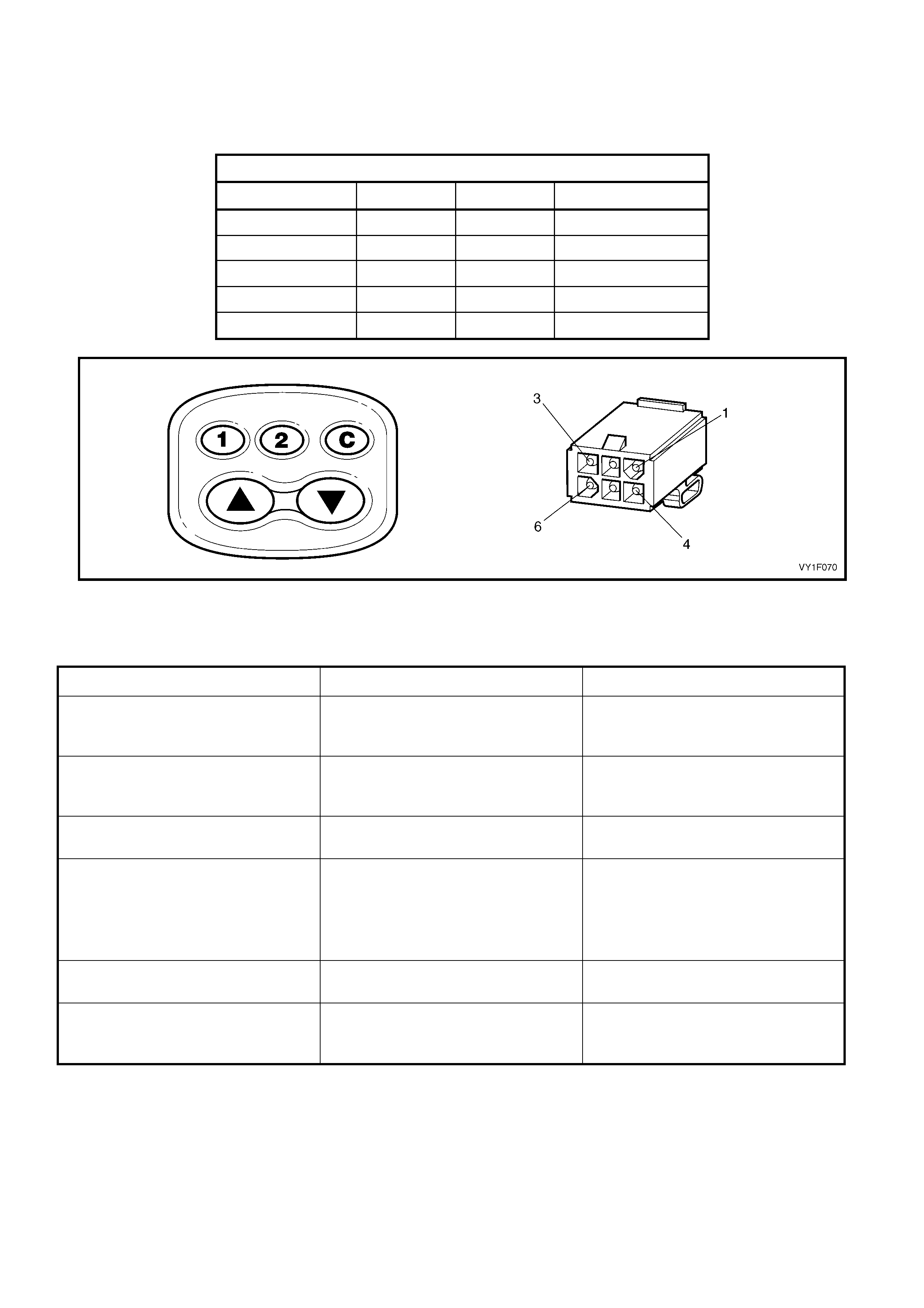
SUNROOF SWITCH AND SUNROOF CONTROL HARNESS TEST
Depress the switch buttons and place the multimeter probe tips onto the pins of sunroof control harness
connector X321. Ensure reading is as indicated in the chart below. Refer to Figure 1F-50.
Dimension
Sunroof Switch and Sunr oof Control Harness
Depress Switch + Lead – Lead Indication
! button Pin 3 Pin 5 Continuity
" button Pin 3 Pin 2 Continuity
C button Pin 6 Pin 4 Continuity
1 button Pin 6 Pin 5 Continuity
2 button Pin 6 Pin 2 Continuity
Figure 1F-50
REPAIR ADVICE FOR MECHANICAL FAILURES
Problem Possible Cause Solution
While closing the panel from the tilt
position, the panel begins to slide
rearward.
Blocking catch is broken. Replace blocking catch, refer to
2.16 BLOCKING CATCH.
While closing the panel from the
fully opened position, the panel
begins to tilt under the roof skin.
Blocking catch is broken. Replace blocking catch, refer to
2.16 BLOCKING CATCH.
Panel is misaligned side to side. Timing of drive cables is incorrect. Re-time drive cables, refer to
2.13 TIMING OF DRIVE CABLES.
Panel is sliding too slowly. With a
13.5 V power supply, the panel
should not take more than 7
seconds to close from the fully
opened position.
1. Misaligned panel creating drag
or friction.
2. Dirty mechanism.
1. Re-time drive cables, refer to
2.13 TIMING OF DRIVE
CABLES.
2. Clean and grease mechanism
or replace if necessary.
Glass panel stops prematurely. Obstacle in mechanism or guide
rail. Remove obstacle.
Sunshade fails to open when the
glass panel is opened to tilt
position.
Retraction mechanism is broken. Replace retraction mechanism,
refer to 2.14 RETRACTION
MECHANISM.
REPAIR ADVICE FOR ELECTRICAL FAILURES
Problem Possible Cause Solution
The sunroof operates but the
auto-close and soft touch functions
do not operate.
Voltage-drop in power supply
(battery changed or bad battery ). Check power supply/battery, refer
to Section 12A, 2.9 BATTERY.
Clicking noises from the SCU and
the panel does not slide. Voltage too low. Check power supply /battery, refer
to Section 12A, 2.9 BATTERY.
SCU clicking in open position, but
the sunroof does not close with
continuous pressing of the button.
Voltage drop in power supply. Cut off power supply briefly
(remove fuse F105), reset
programmable positions.
Panel is sliding too slowly. With a
13.5 V power supply, the panel
should not take more than 7
seconds to close from the fully
opened position.
1. Weak battery.
2. Weak motor. Test as detailed
in this Section.
1. Charge or replace the battery.
2. Replace the drive motor, refer
to 2.1 DRIVE MOTOR.
REPAIR ADVICE FOR RATTLING NOISES
Problem Possible Cause Solution
Drain channel rattles. Check if insulator tape is applied
between drain channel and
mechanism.
Add insulator tape.
Rattling in motor area. Drive motor cover screws loose. Tighten drive motor cover screws.
REPAIR ADVICE FOR WIND NOISES
Problem Possible Cause Solution
Excessive wind noise when the
glass panel is in the closed
position.
1. Glass panel seal not fitting
securely against roof panel.
2. Blocking catch broken.
1. Adjust glass panel seal, refer to
2.8 RUBBER SEAL.
2. Replace the blocking catch,
refer to 2.16 BLOCKING
CATCH.
REPAIR ADVICE FOR WATER LEAKS
Problem Possible Cause Solution
Water coming through panel
opening area. 1. Blocked drain tube/s.
2. Misaligned or kinked drain
tubes.
1. Inspect drain tubes outlet. Blow
out drain tubes.
2. Correct routing of drain tubes,
refer to:
2.21 REAR DRAIN TUBE –
SEDAN,
2.22 REAR DRAIN TUBE –
WAGON,
2.23 FRONT DRAIN TUBE.
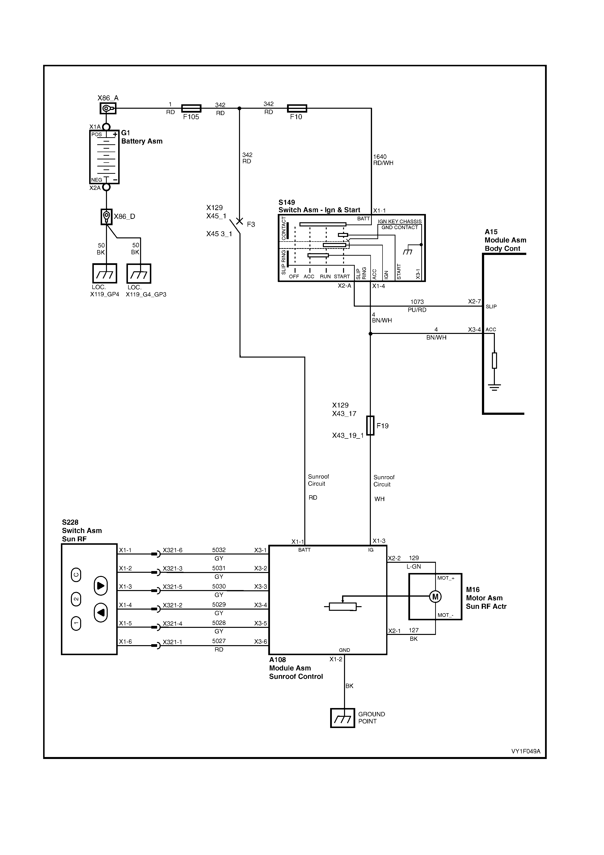
3.2 WI RING DIAGRAM – SUNROOF
Figure 1F-51
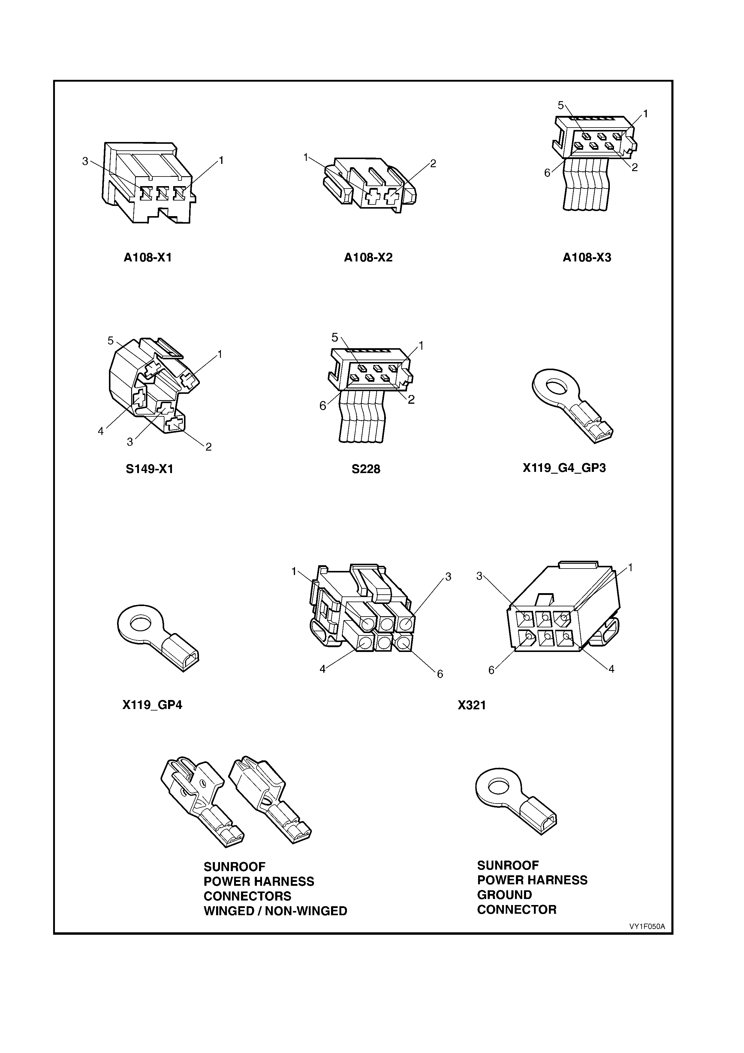
3.3 CONNECTOR DIAGRAMS – SUNROOF
Figure 1F-52

4. TORQUE WRENCH SPECIFI CATIONS
Drive motor cover Torx screw...............................................2.0 Nm
Drive gear box retainer Torx screw.......................................2.0 Nm
SCU retaining Torx screw.....................................................2.0 Nm
Glass panel retaining Torx screw..........................................3.5 Nm
Adjustment bracket retaining Torx screw..............................2.0 Nm
Exterior cover mounting nut..................................................1.8 – 2.2 Nm
Wind deflector attaching nut.................................................2.0 Nm
Drain channel Torx screw.....................................................0.6 – 1.0 Nm
Retraction mechanism Torx screw.......................................1.4 Nm
Retraction mechanism locating screw..................................0.5 Nm
Locator retaining Torx screw.................................................1.4 Nm
Sunroof power harness ground screw..................................1.5 – 3.0 Nm
Guide rail Torx screw............................................................1.4 Nm
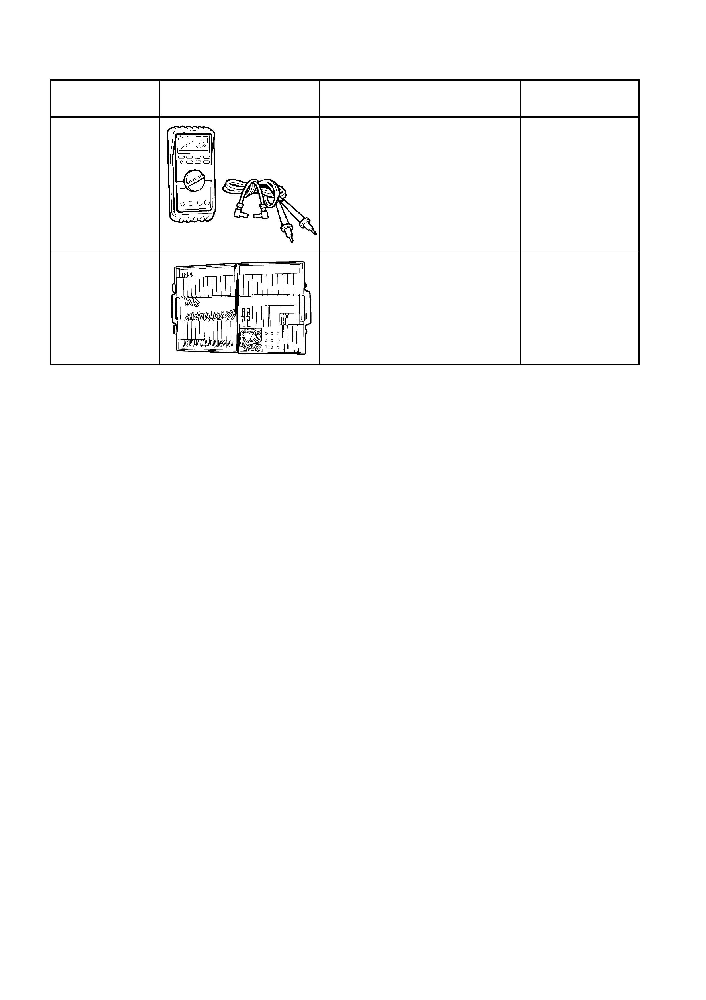
5. SPECIAL TOOLS
TOOL NUMBER ILLUSTRATION DESCRIPTION TOOL
CLASSIFICATION
J39200
(3588)
DIGITAL MULTIMETER
Tool no. J39200 previously
released, or use commercially
available equivalent. Must have 10
meg ohm input impedance.
Available
KM-609
(J35616-A)
ELECTRONIC KIT
Used in conjunction with a
multimeter for measuring voltages
and resistances without damaging
wiring harness connectors.
Desirable