
SECTION 10 - WHEELS AND TYRES
IMPORTANT
Before performing any Service Operation or other procedure described in this Section, refer to Section 00
CAUTIONS AND NOTES for correct workshop practices with regard to safety and/or property damage.
CONTENTS
1. GENERAL INFORMATION
1.1 WHEEL AND TYRE COMBINATIONS
1.2 TYRE PLACARDS
1.3 TYRE MARKINGS
1.4 SPARE WHEEL STOWAGE
SEDAN
WAGON
COUPE
UTILITY
2. SERVICE OPERATIONS
2.1 SPARE WHEEL HOIST – UTILITY
REMOVE
REINSTALL
2.2 TYRE INFLATION AND INSPECTION
PRESSURE ADJUSTMENTS TO SUIT
OPERATING CONDITIONS
2.3 WHEEL REMOVAL AND INSTALLATION
2.4 TYRE REMOVAL AND INSTALLATION
TYRE REPAIRS
2.5 REPLACEM ENT OF WHEELS AND TYRES
2.6 TYRE ROTATION
2.7 CHECKING WHEEL AND TYRE ASSEMBLY
RUNOUT
PROCEDURE
MATCH MOUNTING
2.8 CHECKING WHEEL RUNOUT
PROCEDURE
2.9 WHEEL AND TYRE ASSEMBLY BALANCING
OFF-VEHICLE BALANCING
ON-VEHICLE BALANCING
BALANCE LIMITS
2.10 WHEEL ATTACHING NUTS AND STUDS
3. DIAGNOSIS
3.1 WEAR
3.2 ROAD TESTING
TYRE AND WHEEL INSPECTION
SLOW ACCELERATION TEST
NEUTRAL COAST-DOWN TEST
DOWNSHIFT TEST
STEERING INPUT TEST
STANDING START ACCELERATION
3.3 VIBRATION
RADIAL FORCE VARIATION
LATERAL FORCE VARIATION
3.4 VEHICLE LEAD
4. SPECIFICATIONS
STEEL WHEEL
ALLOY WHEELS
INFLATION PRESSURES
5. TORQUE WRENCH SPECIFICATIONS
6. SPECIAL TOOLS
Techline

1. GENERAL INFORMATION
New wheels and wheel covers have been introduced for the MY2003 VY and V2 Series vehicles. This section
includes the details of all models in the right-hand drive and left-hand drive range of vehicles, which includes:
Right-hand Drive Vehicles — Domestic
Holden Holden Commodore
Level 1 Level 2 Level 3
Executive
Sedan,
Wagon and
Utility
Acclaim
Sedan and
Wagon
S Sedan,
Utility and
Monaro
Coupe
SS
Sedan and
Utility
Berlina
Sedan and Wagon
Calais Sedan and
SS Monaro Coupe
Right-hand Drive Vehicles — Export
Chevrolet Lumina
Level 1
LS
Sedan,
Wagon and
Utility
S
Sedan
SS
Sedan and
Utility
Left-hand Drive Vehicles — Export
Chevrolet Lumina Chevrolet
Omega
Level 1 Level 2
LS
Sedan and
Wagon
SS
Sedan
LTZ
Sedan
CD
Sedan
NOTE: For information regarding the wheels and tyres for domestic merchandising packs such as the Berlina
International Wagon and right-hand drive (Holden) Lumina, refer to the MERCHANDISING PACK Section in this
Service Information.
1.1 WHE EL AND TYRE COMBINATIONS
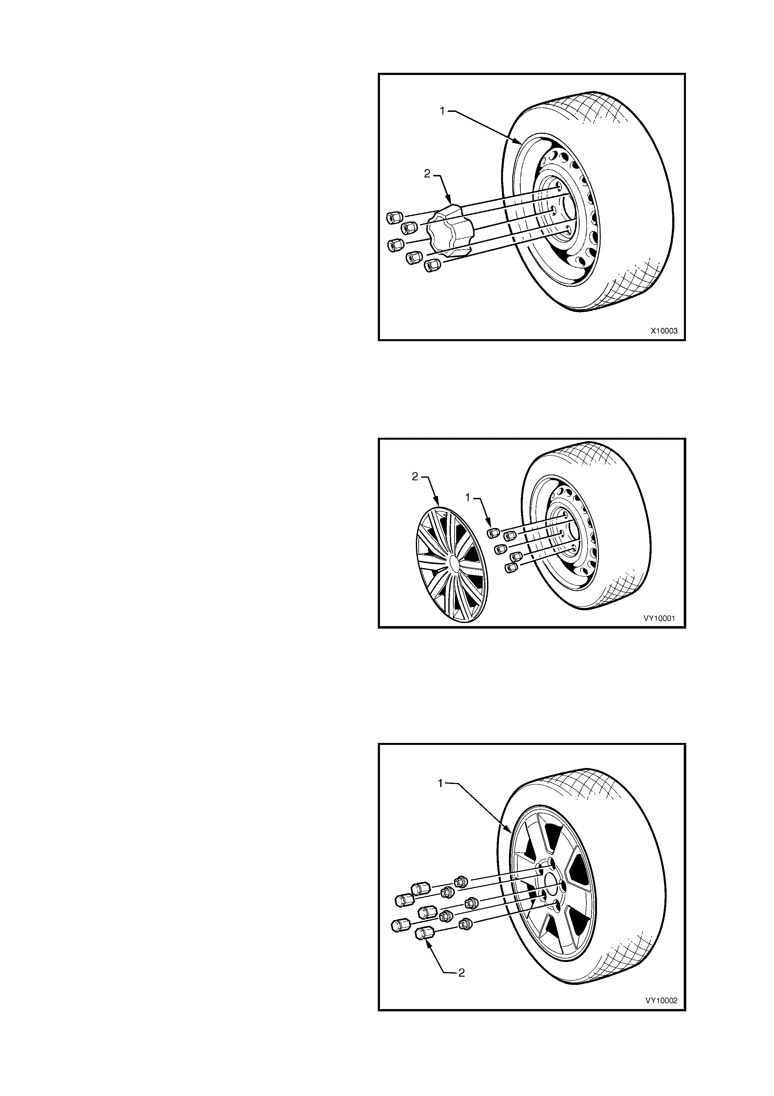
Figure 10- 1 illustrates the silver s teel wheel (1) and
centre cap (2) fitted to the following vehicles:
National Police Pack (Option 9C1)
Executive Sedans, Wagons and Utilities equipped
with the National Police Pack (Option 9C1).
Road wheels......................... 7J x 15
Tyres (Sedan and Wagon)... 225/60R15 96V
Tyres (Utility) ........................ 205/65R15 99H
Taxi Pack (Option A9T) and Utility
Road wheels......................... 7J x 15
Tyres .................................... 205/65R15 99H
Left-hand Drive Police Pack (Option 9C3)
Left-hand drive Lumina Sedans equipped with the
Police Pack (Option 9C3).
Road wheels......................... 7J x 15
Tyres .................................... 225/60R15 96V
Figure 10-1
Level 1
Figure 10- 2 illustrates the blac k steel wheel (1) and
cover (2) fitted to Executive and left-hand drive
Lumina Sedans:
Right-hand Drive vehicles
Road Wheels........................ 6J x 15
Tyres:
V6 Engine .................... P205/65R15 95H
V6 LPG (Wagon).......... P205/65R15 95H
GEN III V8 Engine ........ 225/60R15 96V
Left-hand Drive vehicles
Road Wheels........................ 7J x 15
Tyres:
V6 Engine .................... 225/60R15 96W
Figure 10-2
Level 1
Figure 10-3 illustrates the alloy wheel fitted to the
Acclaim Sedans and Wagons.
Road Wheels........................ 7JJ x 15 alloy
Tyres .................................... P205/65R15 95H
Figure 10-3
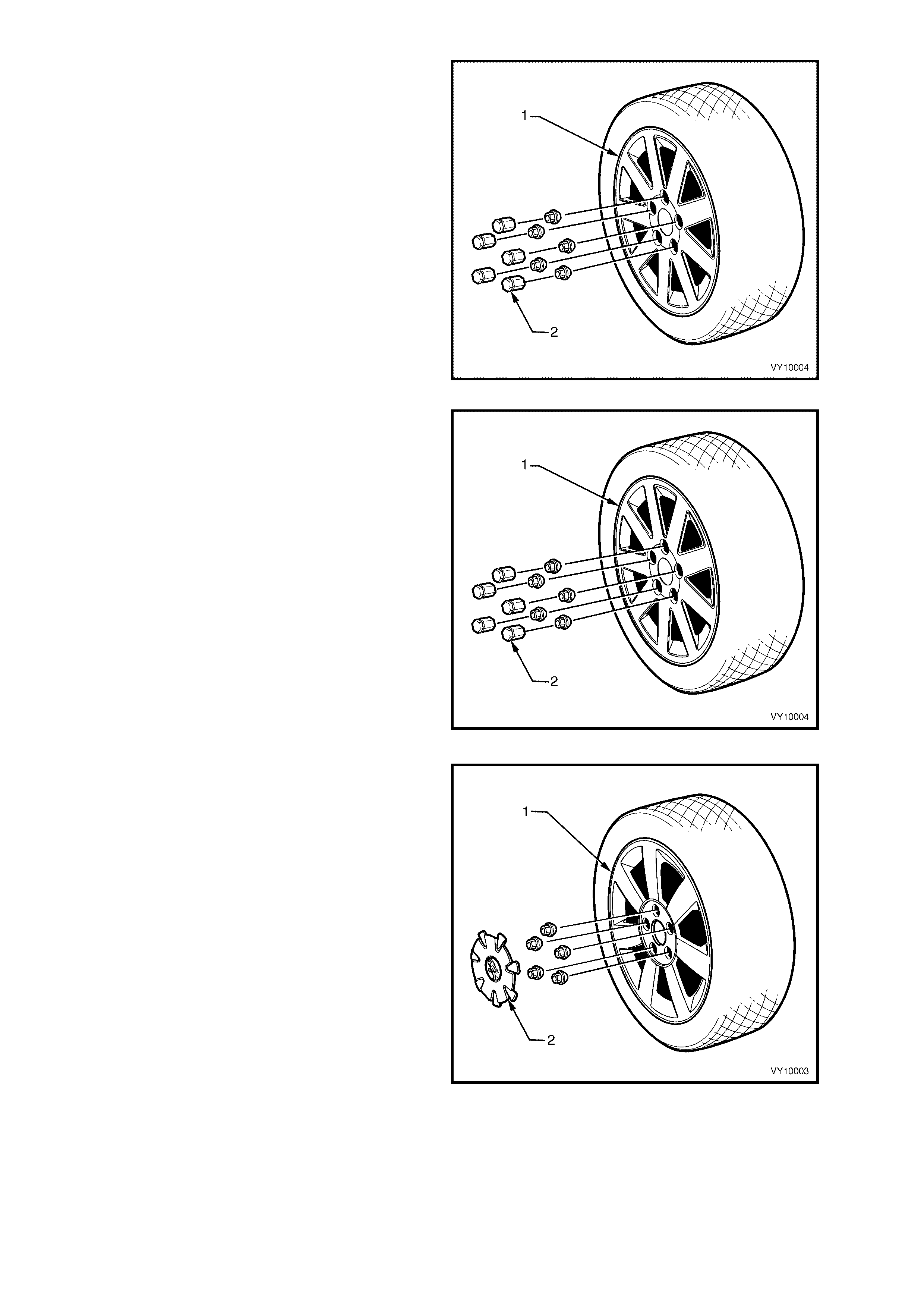
Left-hand Drive Police Pack (Option 9C3)
Figure 10-4 illustrates the alloy wheel available as
an option for the left-hand drive Lumina Sedans
equipped with the Police Pack:
Road Wheels........................ 7JJ x 16 alloy
Tyres .................................... 225/55R16 94V
Figure 10-4
Level 2
Figure 10-5 illustrates the alloy wheel fitted to the
Level 2 Model vehicles.
Road Wheels........................ 7JJ x 16 alloy
Tyres:
V6 Engine..................... 215/60R16 95V
V6 Option...................... 215/60R16 95V
GEN III V8 Engine ........ 215/60R16 95V
Figure 10-5
Level 3
Figure 10-6 illustrates the alloy wheel fitted to the
Level 3 Model vehicles.
Australia
Road Wheels........................ 7JJ x 16 alloy
Tyres .................................... 225/55R16 95V
Brazil
Road Wheels........................ 7JJ x 16 alloy
Tyres .................................... 215/60R16 95V
Figure 10-6
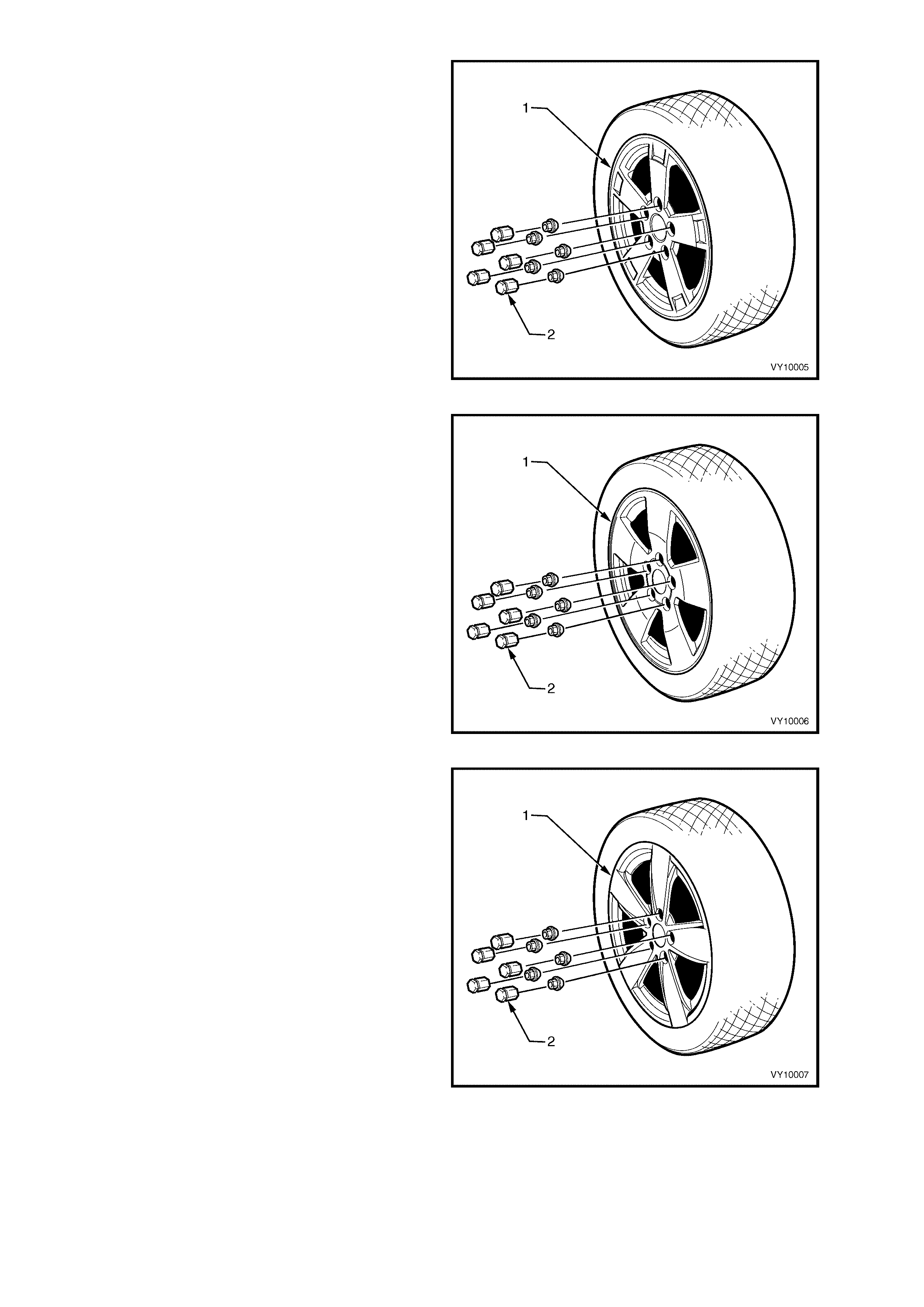
‘S’ Pack Sedan and ‘S’ Pack Utility
Figure 10-7 illustrates the alloy wheel fitted to the
‘S’ Pack Sedan and ‘S’ Pack Utility.
Road Wheels........................ 7JJ x 16 alloy
Tyres .................................... 225/50R16 92V
Utility
Road Wheels........................ 7JJ x 16 alloy
Tyres .................................... 225/55R16 95V
Figure 10-7
‘SV8’ Pack Sedan
Figure 10-8 illustrates the alloy wheel fitted to the
‘SV8’ Pack Sedan.
Australia
Road Wheels........................ 8JJ x 17 alloy
Tyres .................................... 235/45R17 93V
Figure 10-8
‘SS’ Pack Sedan and ‘SS’ Pack Utility ‘S’ Pack
Coupe
Figure 10-9 illustrates the alloy wheel fitted to the
‘SS’ Pack Sedan and ‘SS’ Pack Utility and the ‘S’
Pack Coupe.
Sedan – Gulf States
Road Wheels........................ 8JJ x 17 alloy
Tyres .................................... 235/45R17 93V
Utility – Australia and South Africa
Road Wheels........................ 8JJ x 17 alloy
Tyres .................................... 235/45R17 93V
‘S’ Pack Coupe
Road Wheels........................ 8JJ x 17 alloy
Tyres .................................... 235/45R17 93V
Figure 10-9
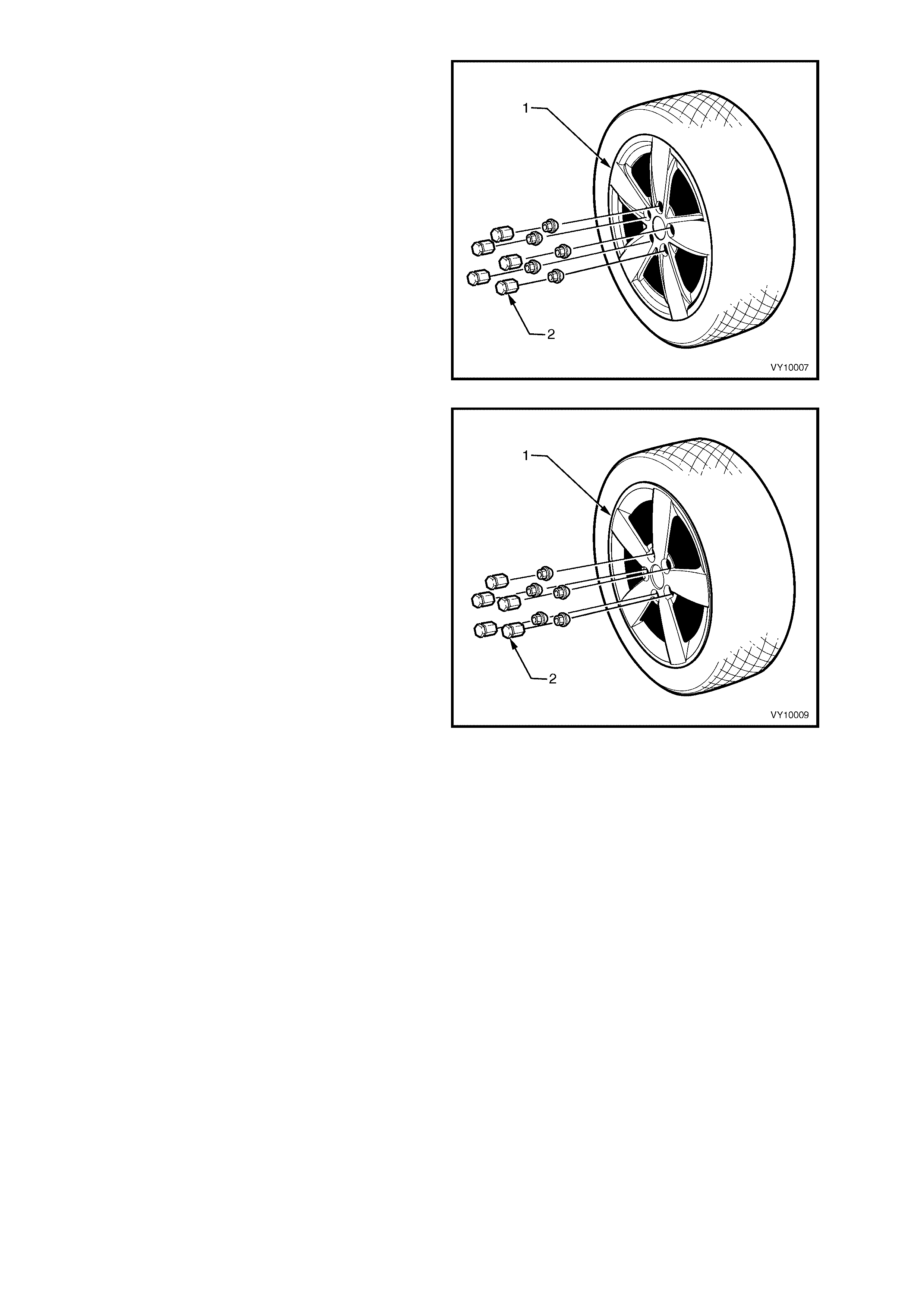
‘SS’ Pack Sedan
Figure 10-10 illustrates the alloy wheel fitted to the
‘SS’ Pack Sedan.
South Africa
Road Wheels........................ 8JJ x 18 alloy
Tyres .................................... 235/40R18 91W
Australia
Road Wheels........................ 8JJ x 18 alloy
Tyres .................................... 235/40R18 91W
Figure 10-10
‘SS’ Pack Coupe
Figure 10-11 illustrates the alloy wheel fitted to the
‘SS’ Pack Coupe.
Australia
Road Wheels........................ 8J x 18 alloy
Tyres .................................... 235/40R18 91W
Figure 10-11
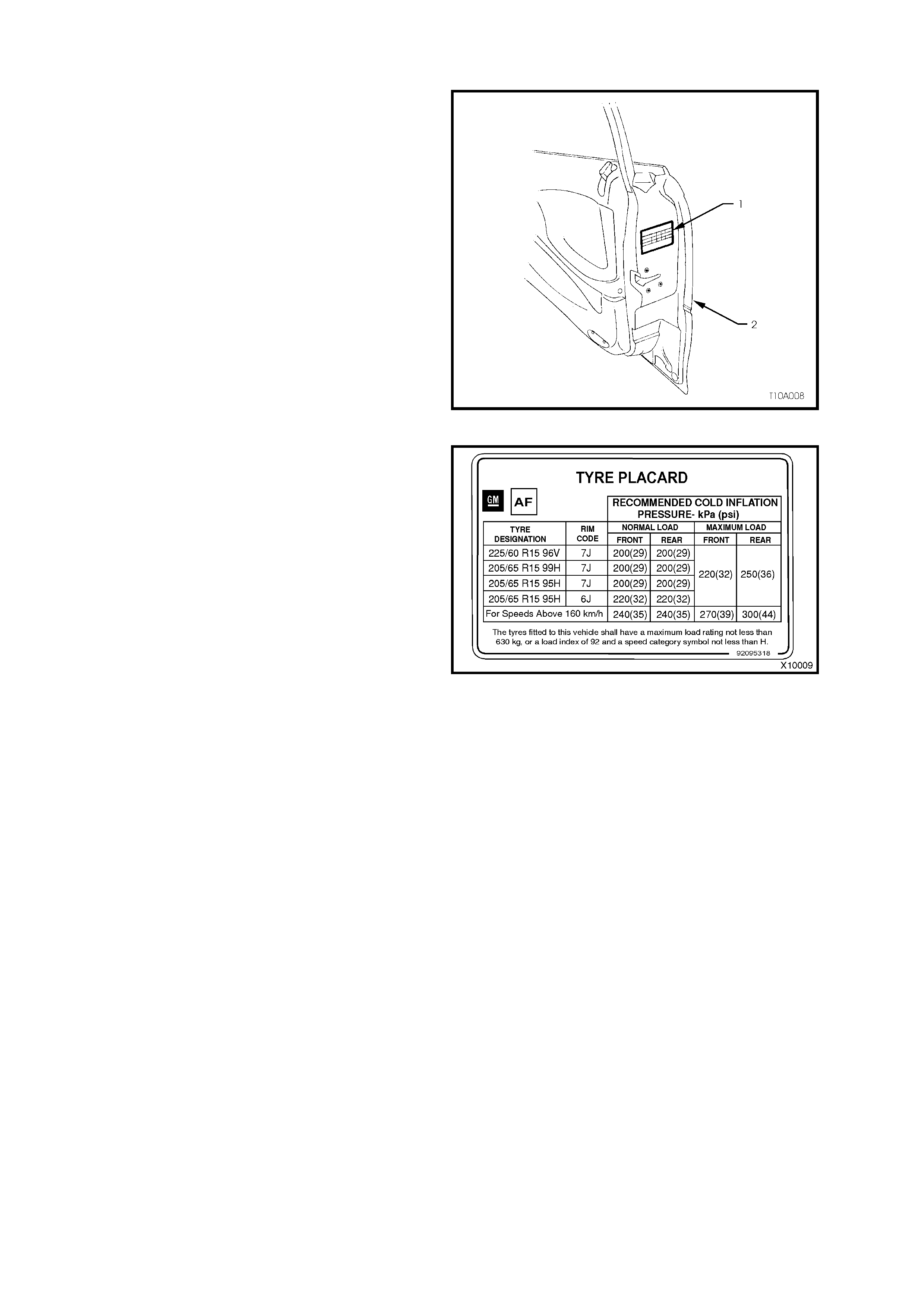
1.2 TYRE PLACARDS
Wheel and tyre sizes, inflation pressures and load
capacity are specified on a tyre placard (1) located
on the end surface of the driver door (2) refer to
Figure 10-12 (Right-hand Drive shown).
Always check tyre pressures, with COLD tyres
(after vehicle has stood for three hours or more, or
driven less than 2 km) and should be checked
weekly or before any extended trip.
W hen c hecking tyre pressur e, visually inspect tyres
for ex cessive wear, sharp objec ts embedded in the
tyre or damage to the sidewalls.
NOTE 1: Clean valve exterior, prior to applying air
pressure nozzle when inflating tyre.
NOTE 2: Always install valve caps to k eep out dust
and water.
Figure 10-12
The tyre placard shown in Figure 10- 13 is typic al of
those fitted on the vehicle.
Refer to 4. SPECIFICATIONS in this Section or the
Tyre Placard on the driver’s door for the correct
wheel and tyre size and tyre pressures.
Figure 10-13
When a Temporary Use Spare Wheel is fitted on the vehicle, drive with caution. Do not exceed the speed of
80 km/h when driving with the spare wheel fitted. Install the standard wheel and tyre as soon as possible.
All MY2003 V2 Series Coupe Models use T135/90D 15 temporary spare tyres on 4T x 15 wheels. The tyres must
have a load rating of not less than 800 kg, or a load index of 100, and a speed category symbol of not less than M.
The spare wheel and tyre supplied with all MY2003 VY Series Utility Models is a 7.0J x 15 steel wheel f itted with a
205/65 R15 99H tyre.
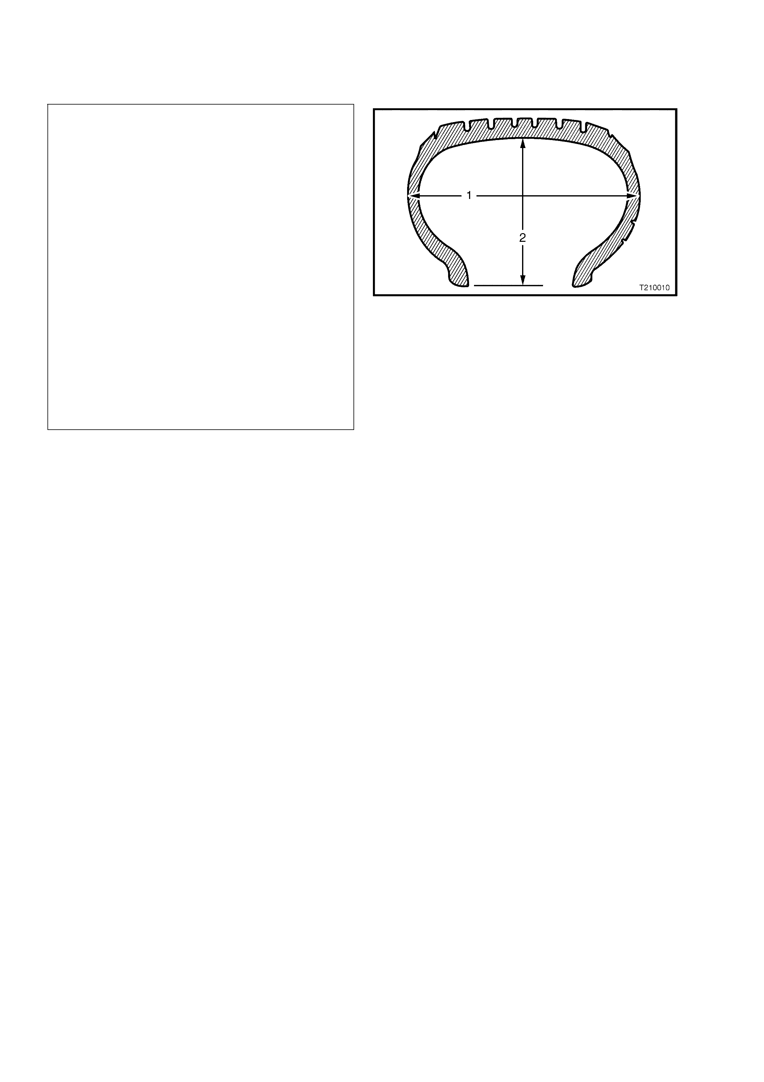
1.3 TYRE MARKINGS
The tyre sidewall has a coded marking system,
which provides information about the tyre.
Tyre Marking Example:
225 55 R 16 95 V
225 = Secti on Width (1) – mm (225 mm )
55 = Aspec t Ratio % (Section Height (2) to
Section Width (1):
(55 = 55%)
R = Tyre Construction:
(R = Radial)
16 = Rim Di ameter – inches:
(16 = 16”)
95 = Max. Load Index – kg @ 250 kPa (36 psi):
(91 = 615 kg)
(92 = 630 kg)
(93 = 650 kg)
(94 = 670 kg)
(95 = 690 kg)
(96 = 710 kg)
(99 = 775 kg)
V = Speed Rating:
(H = 210 km/ h)
(V = 240 km /h)
(W = 270 km /h)
Figure 10-14
1.4 SPARE WHEEL STOWAGE
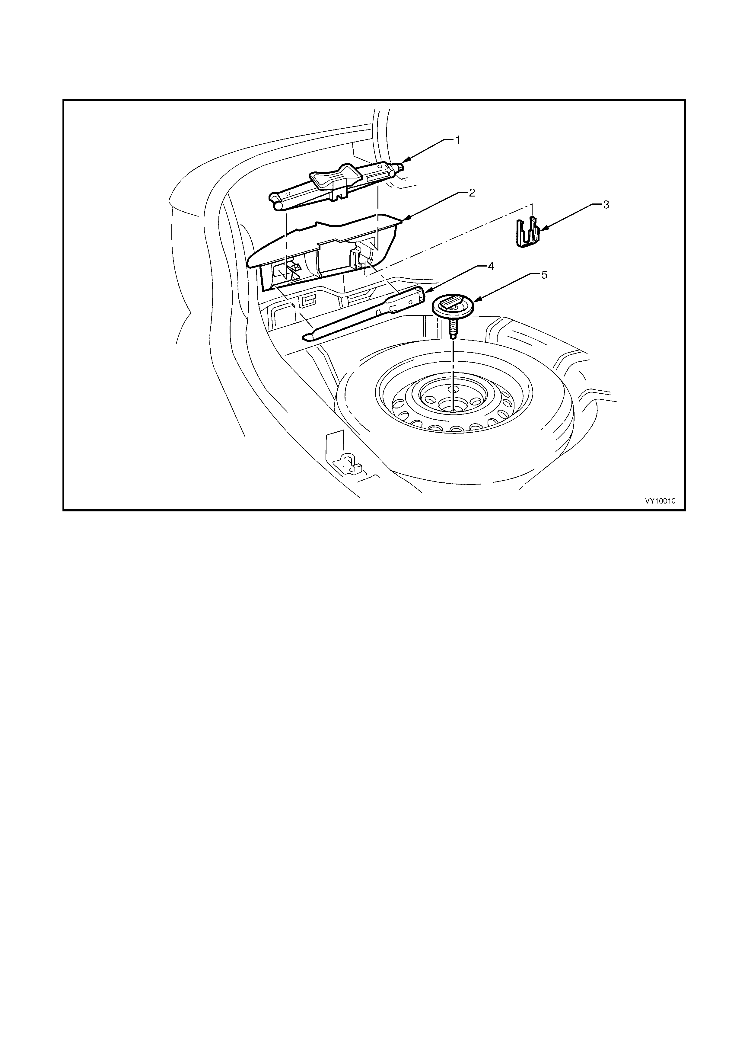
SEDAN
Figure 10-15 Sedan Spare Wheel and Jack Stowage
Legend
1. Jack 4. Jack / Wheel Nut Wrench
2. Stowage Compartment 5. Spare Wheel Retaining Bolt and Plate
3. Nut Cap Tool
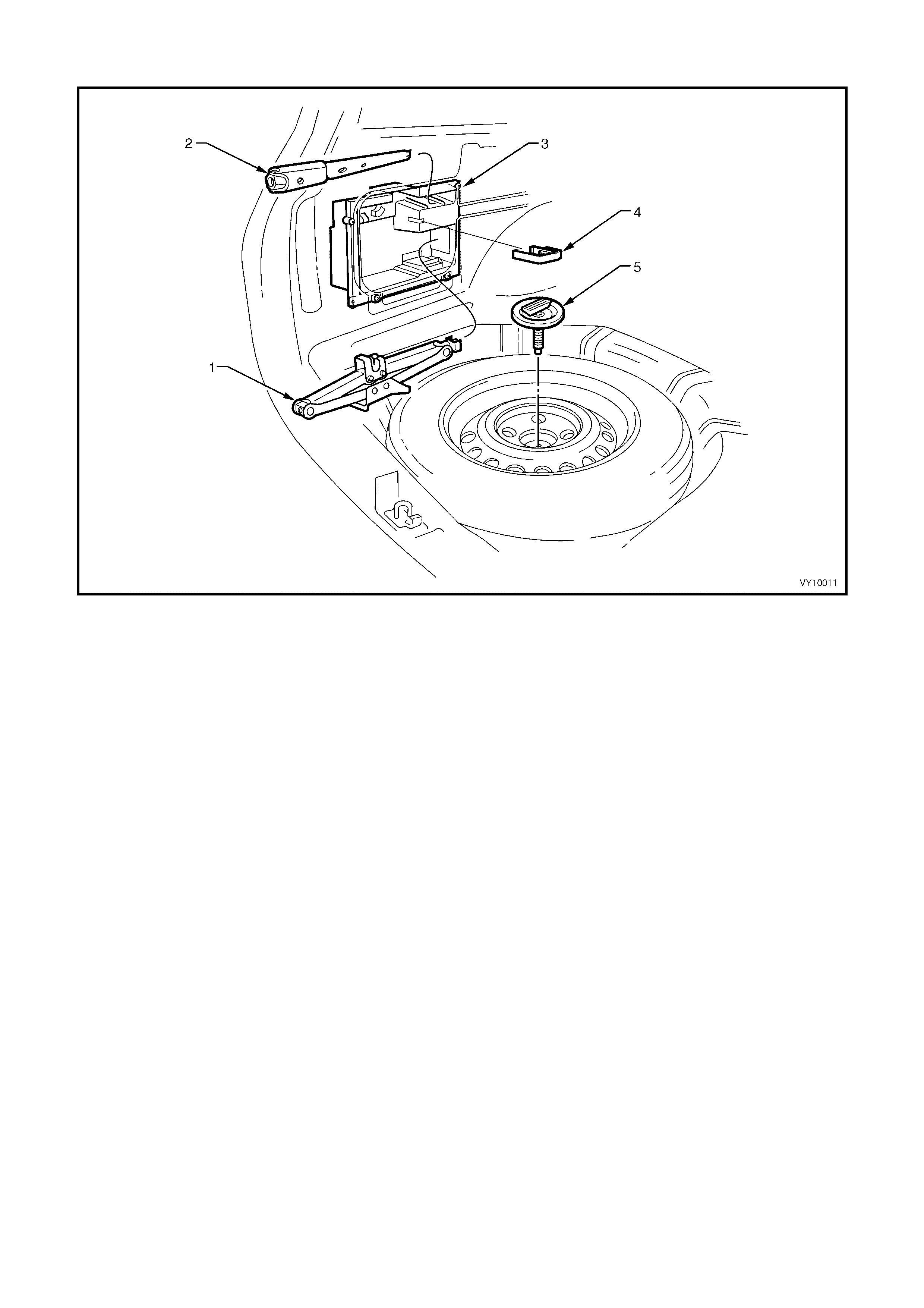
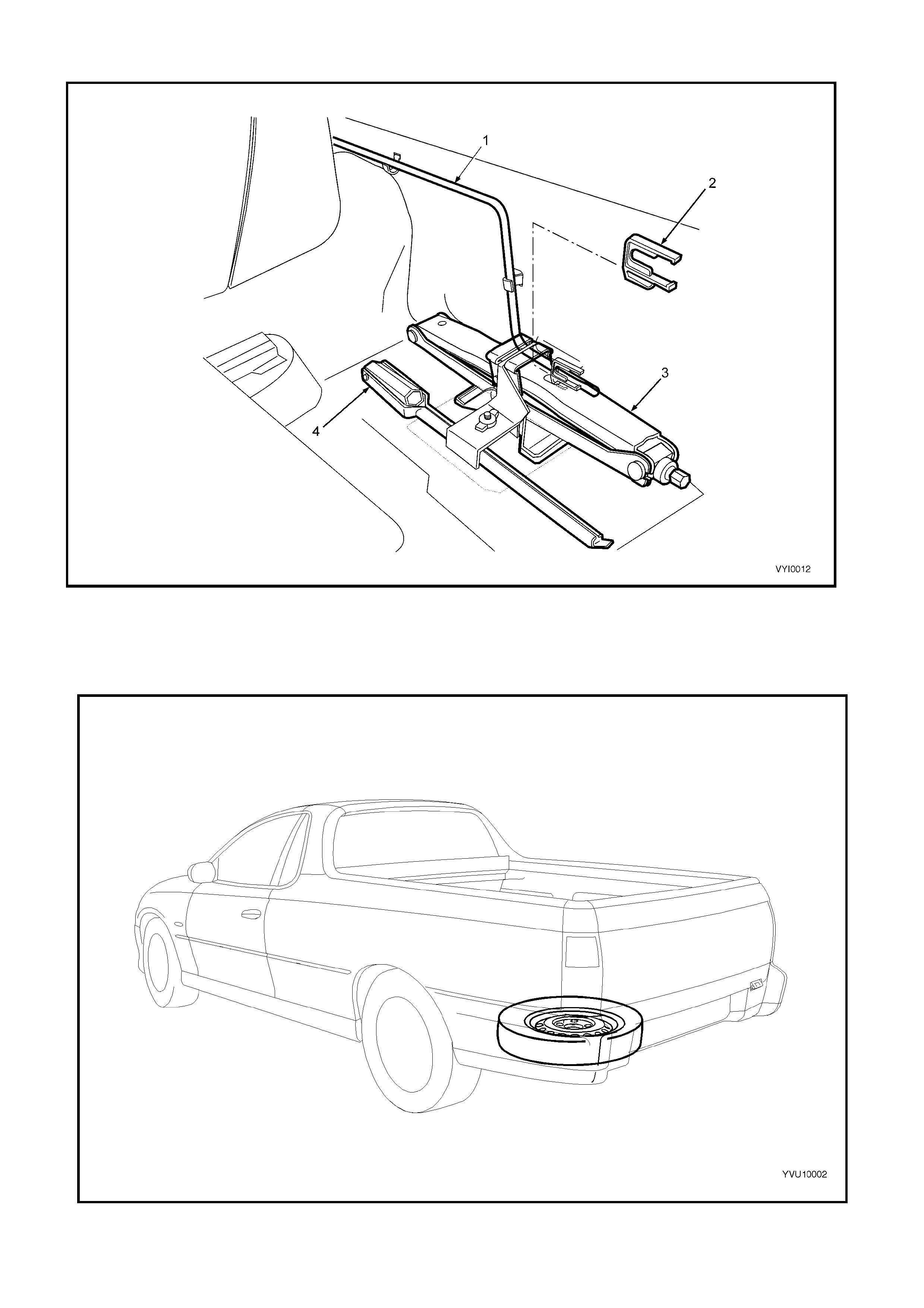
WAGON
Figure 10-16 Wagon Spare Wheel and Jack Stowage
Legend
1. Jack 4. Nut Cap Tool
2. Jack / Wheel Nut Wrench 5. Spare Wheel Retaining Bolt and Plate
3. Stowage Compartment
COUPE
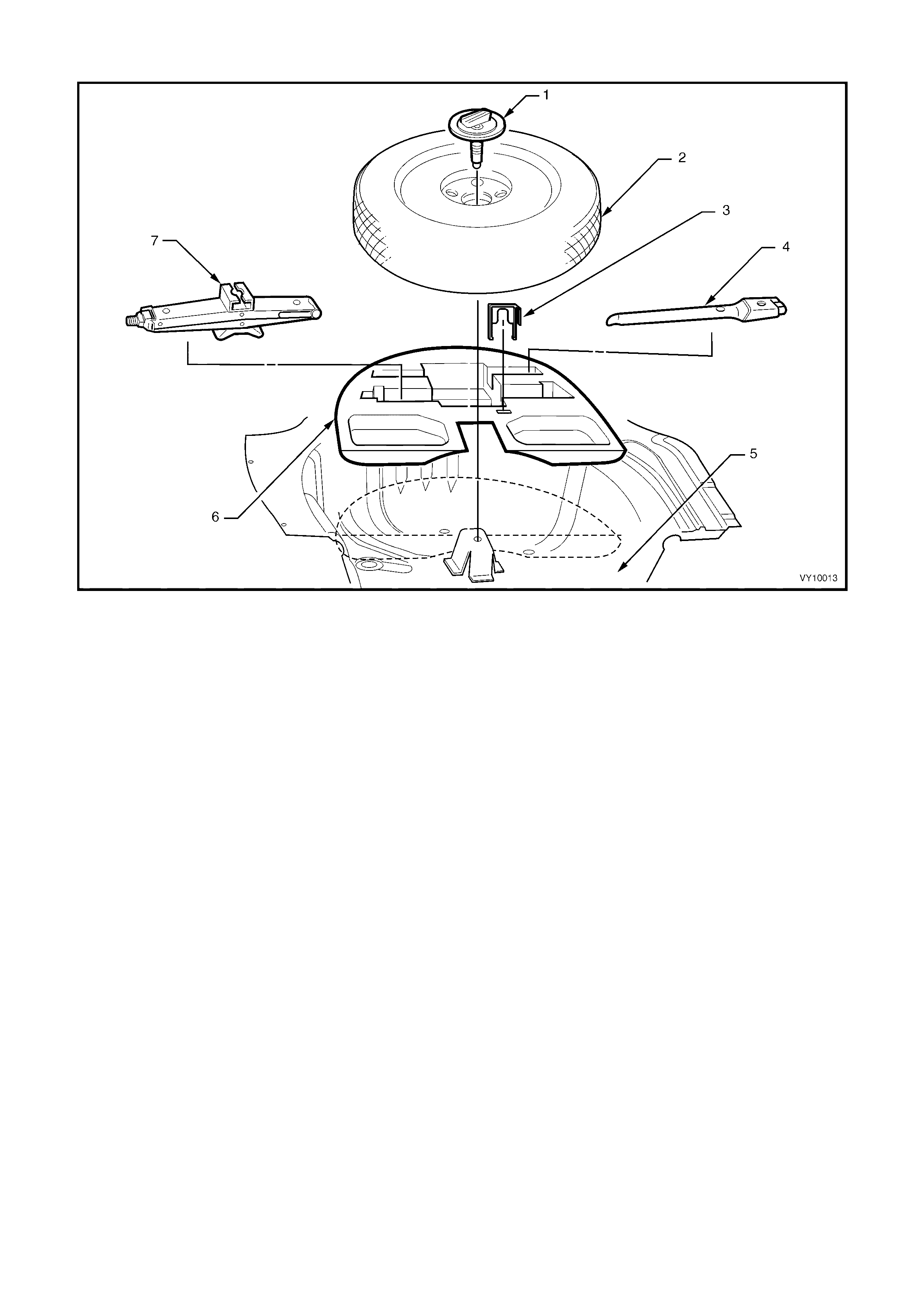
Figure 10-17 Coupe Spare Wheel and Jack Stowage
Legend
1. Spare Wheel Retaining Bolt and Plate Assembly 5. Spare Wheel Well
2. Temporary Use Spare Wheel 6. Jack Container
3. Nut Cap Tool 7. Jack Assembly
4. Jack / Wheel Nut Wrench
UTILITY
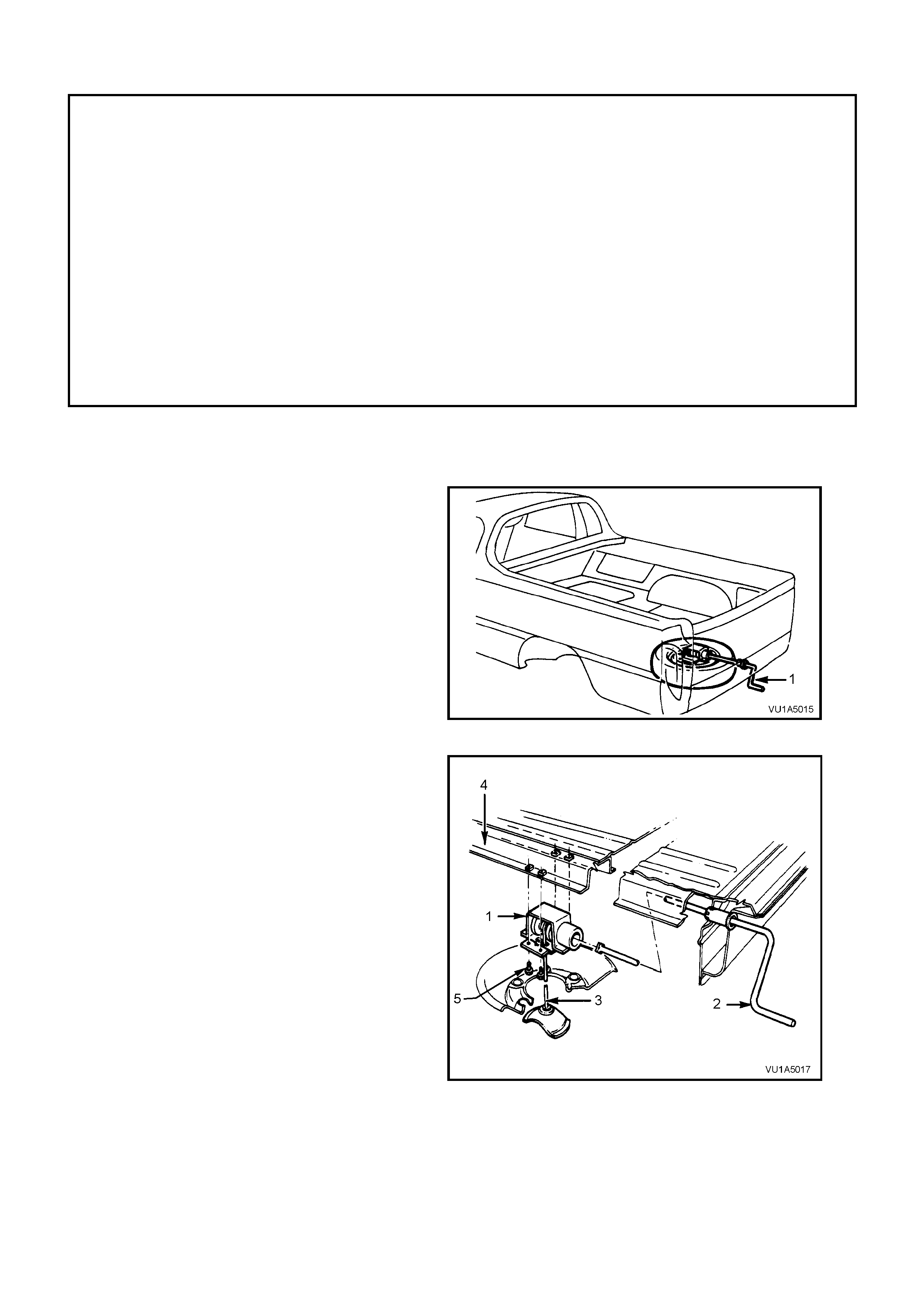
Figure 10-18 Utility Jack Stowage
Legend
1. Spare Wheel Hoist Crank Handle 3. Jack Assembly
2. Nut Cap Tool 4. Jack / Wheel Nut Wrench
Figure 10-19 Utility Spare Wheel Location
2. SERVICE OPERATIONS
IMPORTANT
All fasteners are important attaching parts as they affect the performance of vital components and/or
could result in major repair expense. Where specified in this section, fasteners MUST be replaced with
parts of the same part number or a GM approved equivalent. Do not use fasteners of an inferior quality
or substitute design.
Torque values must be used as specified during reassembly to ensure proper retention of all
components.
Through out this section, fastener torque w rench specifications may be accompanied with the following
identification marks:
+
++
+ Fasteners must be replaced after loosening.
&
&&
& Vehicle must be at curb height before final tightening.
6
66
6 Fasteners either have micro encapsulated sealant applied or incorporate a mechanical thread lock
and should only be re-used once. If in doubt, replacement is recommended.
If one of these identification marks is present alongside a fastener torque wrench specification, the
recommendation regarding that fastener must be adhered to.
2.1 SPARE WHEEL HOIST – UTILITY
REMOVE
1. Insert the handle (1) into the aperture located
beside the licence plate.
2. Rotate the handle in a counter-clockwise
direction until the spare wheel is completely
lowered and some slack exists in the cable.
3. Support the wheel with one hand. Tilt the wheel
retainer upward, allowing the retainer to pass
through the wheel centre.
4. Remove the wheel from below the vehicle.
Figure 10-20
5. Remove the four sc r ews (5) and lower the hoist
(1).
Legend
Hoist
Handle
Cable
Frame
Screw (4 places)
Figure 10-21

REINSTALL
Installation of the spare wheel hoist is the reverse of the removal procedure.
NOTE: Ensure that the hoist is installed with the square coupling towards the rear of the vehicle.
Tighten the hoist-attaching screws to the correct torque specification.
SPARE WHEEL HOIST
ATTACHING SCREW
TORQUE SPECIFICATION 15 – 35 Nm

2.2 TYRE INFLATION AND INSPECTION
The pressure recommended for any model is carefully calculated to give satisfactory ride, stability, steering, tread
wear, tyre lif e and resistance to wheel / tyre dam age. All specified pressures are for COLD tyres (after vehicle has
stood for 3 hours or more, or driven less than 2 km).
Tyre pressures should be checked weekly or before any extended trip, and set to the specifications on the tyre
placard located on the end surface of the driver’s front door, as shown in Figure 10-12.
When checking tyre pressure, visually inspect tyres for excessive wear, sharp objects embedded in the tyre or
damage to sidewalls.
NOTE 1: Clean the exterior of the valve, prior to apply ing the air pressure nozzle when inflating a tyre.
NOTE 2: Always install valve caps to keep out dust and water.
PRESSURE ADJUSTMENTS TO SUIT OPERATING CONDITIONS
Tyre pressure can increase as much as 40 kPa when hot. DO NOT REDUCE PRESSURES TO OFFSET THIS
BUILD-UP.
For continuous high-speed operation, increase pressures as recommended on the tyre placard.
For operation on unsealed rough roads, increase COLD tyre pressures 28 kPa above that shown on the tyre
placard.
NOTE: Tyre pressures are not to be increased for unsealed rough road conditions if the tyre pressures have already
been increased for high-speed operation.
2.3 WHEEL REMOVAL AND INSTALLATION
IMPORTANT: Before removing any wheel, mark the relationship of the wheel to the mounting flange or brake
disc/hub.
Either corrosion or a tight fit between the wheel centre and the mounting or brake disc / hub flange can cause
difficulty in wheel removal.
NOTE: If tightness is caused by corrosion, do not use heat or heavy impact.
If a wheel is tight, proceed as follows:
1. Tighten and loosen each road wheel-attaching nut a maximum of two turns.
2. Lower vehicle to ground and allow weight of the vehicle to rest on the wheel.
3. Drive the vehicle approx imately 2 metres in a f or ward and rever se dir ec tion. Apply quick, har d jabs on the brake
pedal to loosen the wheel.
4. Raise the vehicle, remove road wheel attaching nuts and remove wheel.
An alloy wheel showing signs of corrosion should have all deposits of the corrosion removed from the hub spigot
and mating bore of the wheel, using fine emery paper!
W ash down with mineral spirit, dry and apply a light c oating of a lubricant such as Omega 929 or equivalent to the
hub spigot, using a s mall brush. Remove any excess with m ineral s pirit and allow the product to dry before installing
the road wheel.
CAUTION: Wheel nuts for alloy wheels have a different mounting taper to those for steel wheels. DO NOT
interchange or mix wheel nuts from both types of wheel, as incorrect wheel nuts will not allow the w heels
to be tightened securely.
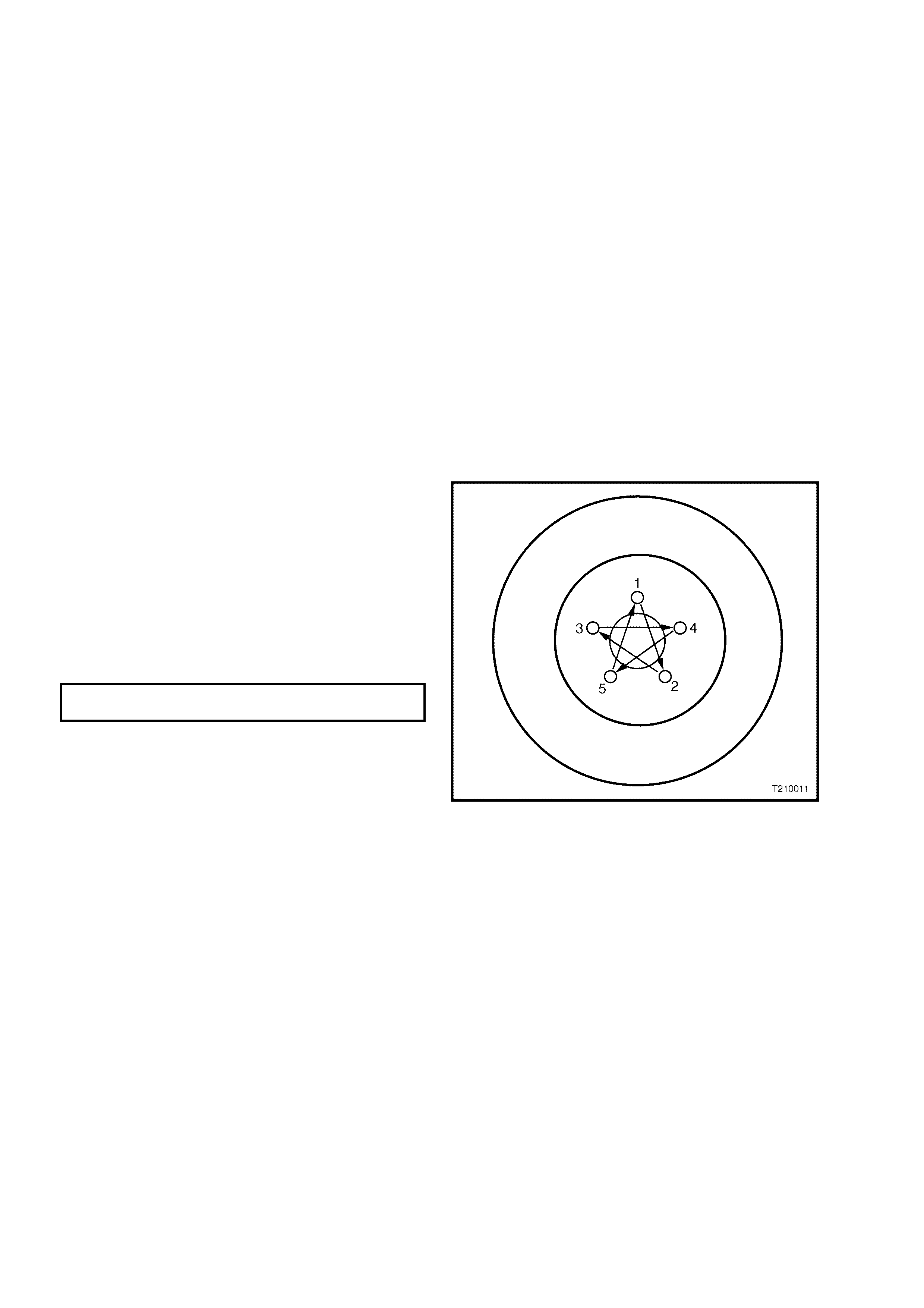
NOTE 1: Installing wheels without good metal-to-
metal contact at the mounting surfaces can result
in wheel nuts coming loose. Tighten road wheel
attaching nuts to the specified torque and in the
order shown.
NOTE 2: Do not use an impact gun to tighten
wheel nuts unless it is fitted with a torque limiter bar
(com m er cially available). Failure to c orr ectly tighten
wheel nuts to the correct torque specification may
result in a warped brake disc, which may lead to
development of brake shudder.
ROAD WHEEL ATTACHING NUT
TORQUE SPECIFICATION 110 – 140 Nm
Figure 10-22

2.4 TYRE REMOVAL AND INSTALLATION
Whenever possible, tyre rem oval and installation s hould be carr ied out on a tyre-c hanging mac hine. The use of tyre
levers and mallets is likely to damage tyre carcasses and wheel rims.
On steel rims, filing can repair most minor dents and burrs, but alloy rims must always be replaced if significantly
damaged.
CAUTION: Wheels must not be welded, brazed, peened or treated in any manner, which could weaken
them.
The bead seat of the rim must be clean and smooth; rust, rubber etc. may be removed with a wire brush or steel
wool.
Before removing or installing a tyre, or a valve stem, apply tyre lubricant (Holden's Specification HN1162 or
equivalent) to the tyre bead and rim flanges.
Install the valve stem and tyre before the lubricant dries.
Initially, inflate the tyre to 280 kPa to ensure that the tyre beads seat correctly in the rim flanges.
If the tyre beads f ail to seal at this pres sure, def late the tyre, lubric ate the tyre beads and wheel rim again and then
inflate.
CAUTION: Exercise care to avoid personal injury when the tyre bead snaps over the wheel rim safety
humps.
NOTE: When fitting a tyre to a rim, ensure that the tyre is correctly indexed to the rim, ie. the first harmonic high
point of the tyre should be matched to the first harmonic low point of the rim. This matching minimises force
variations inherent with tyre and rim manufacture. For more information on harmonics, refer to 3. DIAGNOSIS in
this Section.
As different origins of tyres have different standards regarding the first harmonic point, refer to the following as a
guide to the correct tyre fitting position.
♦ Australian manufactured tyres have a red dot indicating the first harmonic high point.
♦ European manufactured tyres have a white dot indicating the first harmonic low point.
♦ Some Japanese manufactured tyres have a red dot indicating the first harmonic high point and a yellow dot
(that should be ignored), which indicates a static balance point.
As independent rear suspension is more sensitive to a wheel / tyre imbalance condition than other suspension
designs, particular care should be given to correct fitment of tyres to all MY2003 VY vehicles.
AUSTRALIAN MFD. TYRES
(Red dot on sidewall)
Align RED dot on tyre to mark on outer flange of wheel, or if there is no mark on the wheel, align RED dot to low
spot of wheel as measured with dial indicator.
EUROPEAN MFD. TYRES
(White dot on sidewall)
Align WHITE dot on tyre 180° from the mark on outer flange of wheel, or if there is no mark on the wheel, align
WHITE dot 180° from the low spot of wheel as measured with dial indicator.
JAPANESE MFD. TYRES
If there is a YELLOW dot but not a red dot use the rule for Australian tyres. If there is a YELLOW and a RED dot,
ignore the yellow dot and use the red dot as per rule for Australian tyres.
TYRE REPAIRS
There ar e many different m aterials and techniques available to r epair tyres. It is s uggested that details of m aterials
and procedures for the repair of tyres should be obtained from the tyre manufacturer.

2.5 REPLACEMENT OF WHEELS AND TYRES
W heels must be replaced if they are bent, dented or have excessive lateral or radial run-out. Wheels with run-out
greater than specified may cause objectionable vibration through the vehicle.
Replacement wheels must be equivalent to the original equipment wheels in load capacity, diameter, rim width,
profile, of fset and m ounting conf iguration. A wheel of incorr ect size or type may affect wheel and bear ing life, brake
cooling, speedometer / odometer calibration, vehicle to ground clearance or tyre to body or chassis clearance.
The selection of replacement tyres requires careful consideration if vehicle handling, braking, steering response and
ride comfort are to be preserved.
In the course of vehicle development, all of the factors influencing handling and ride comfort are considered and
particular emphasis is placed on the role of tyres in order to achieve optimum standards in vehicle performance.
W hen selecting replacement tyres, consult the tyre placard to determine appropriate tyre sizes. It is advisable that
replacem ent tyres be of the sam e size, type and speed / load rating in or der to maintain the intended ride, handling
and brak ing. This also ensur es com patibility of new tyres with existing tyres and the spare tyre. If such tyres are not
available, choose tyres that meet the requirements specified in the lower section of the tyre placard.
NOTE: The mixing of different tyre types / profiles may adversely affect vehicle handling and control.
Do not mix different types of tyres on the same vehicle except in emergencies.
It is recom mended that new tyres be installed in pairs on the s am e axle. If it is necessary to replac e only one tyre, it
should be paired with the tyre having the most tread, to equalise braking traction.
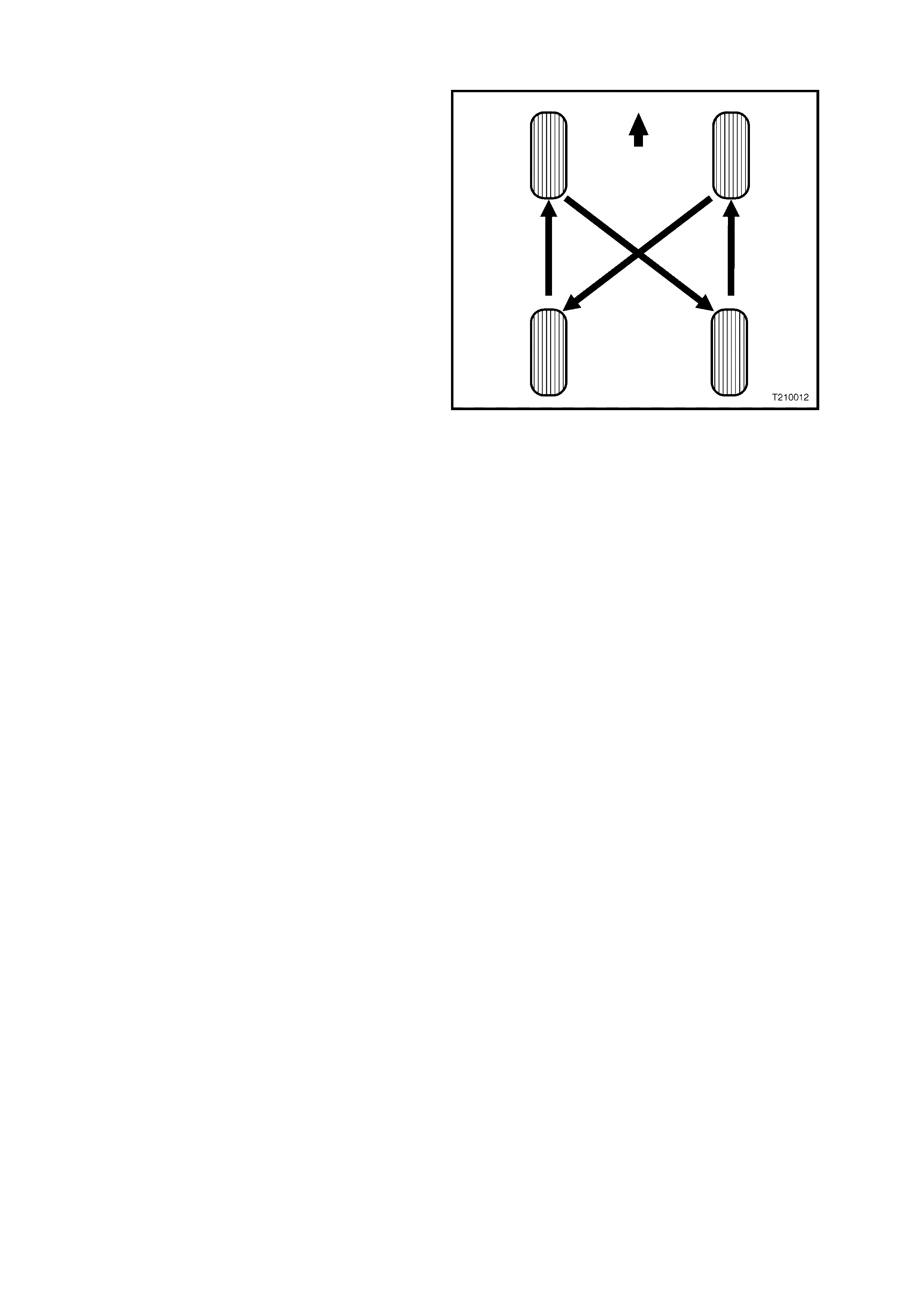
2.6 TYRE ROTATION
It is recommended that tyre rotation be carried out
when brake inspections are performed, as per the
service schedule outlined in the Owner's
Handbook, or when:
1. Difference in tread depth between front and
rear tyres is 1.5 mm.
2. When any unusual tyre wear pattern develops.
If uneven tyre wear is evident, the reason for the
wear should be corrected if possible.
If the tyres are rotated, it is recommended that the
tyre and wheel assembly balance be checked at
the same time, refer to 2.9 WHEEL AND TYRE
BALANCING in this Section.
Tyre rotation in accordance with Figure 10-23 will
assist in obtaining optimum performance, except
where a ‘Directional’ tyre is fitted. Directional tyres
should not be diagonally swapped
Figure 10-23
2.7 CHECKING WHEEL AND TYRE ASSEMBLY RUN-OUT
Because the run-out of a tyre / wheel assembly will directly affect the amount of imbalance and radial force
variation, it should be corrected first. The smaller the amount of run-out, the less imbalance and force variation.
Radial and later al r un-out c an be c orr ec ted at the same time. T her e are two m ethods to measur e r un-out of the tyre
/ wheel assemblies:
• On the vehicle (mounted to the hub), the wheel bearing must be in good condition.
• Off the vehicle (mounted on a spin-type w heel balancer).
NOTE: Initial on-car inspection should be made prior to off-car run-out checks.
Measuring the tyre / wheel run-out off the vehicle is easiest. It is usually easier to mount a dial indicator in the
correct location, and the chances of water, dirt, or slush getting on the dial indicator are decreased. Once the run-
out has been m easured and corrected off the vehicle, a quick visual check of run-out on the vehicle will indicate if
any further problems exist.
If there is a large diff erenc e in the run-out m eas urem ents f rom on- vehicle to off -vehic le, then the run-out problem is
due to stud pattern run-out, or hub flange run-out, or a mounting problem between the wheel and the vehicle.
Before m easuring or attempting to c orrect exc essive run-out, c arefully check the tyre for an uneven bead seat. The
distance from the edge of the ring to the concentric rim locating-ring should be equal around the entire
circumference. If the beads are not seated properly, the tyre should be remounted. Otherwise, excessive run-out
and imbalance will result.
IMPORTANT: If the vehicle has been sitting in one plac e for a long tim e, f lat spots m ay exist at the point where the
tyres are resting on the ground. As the flat spots affect run-out readings, they should be removed by driving the
vehicle far enough to warm-up the tyres before conducting any run-out measurements.
PROCEDURE
1. Raise the vehicle on a hoist or jack and support with safety stands.
2. To obtain an initial indication of how much run-out exists, spin each wheel on the vehicle by hand (or use the
engine to run the drive wheels at a slow speed). Visually check the amount of run-out from the front or rear.
3. Mark the location of each tyre / wheel assembly
in relation to the wheel studs and to their
position on the vehicle (eg. right front, lef t rear)
for future reference.
4. Remove tyre / wheel assemblies one at a time
and mount on a spin-type wheel balancer.
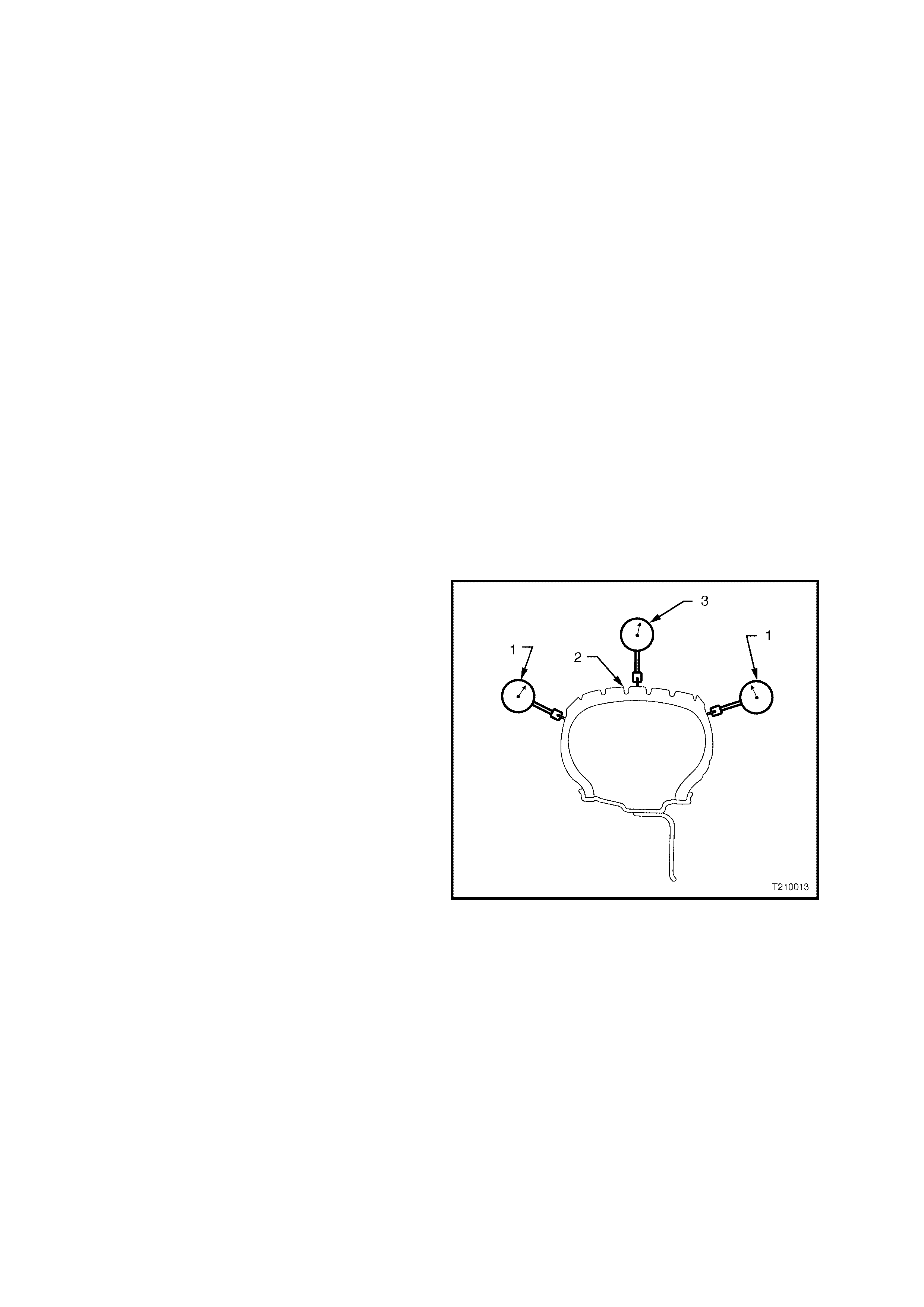
5. Using a dial indicator fitted with a roller,
measure the radial (3) and lateral run-outs (1)
of the tyre / wheel assembly.
NOTE 1: With tyres that use an aggressive tread
pattern, it will be necessary to wrap the outer
circumference with tape (2) when measuring radial
run-out, to provide a smooth surface for a more
accurate measurement.
NOTE 2: Lateral run-out should be measured on a
smooth area of the sidewall, as close to the tread
as possible. Any jumps or dips due to sidewall
splices should be ignored and an average amount
of run-out attained.
6. Slowly rotate the assembly one complete
revolution and zero the dial indicator on the low
spot.
7. Rotate the assembly one more complete
revolution and note the total amount of run-out
indicated.
As a guide: T he radial and later al run-out of the tyre
/ wheel assembly should be no more than 1.5 mm
when measured off the vehicle.
Figure 10-24
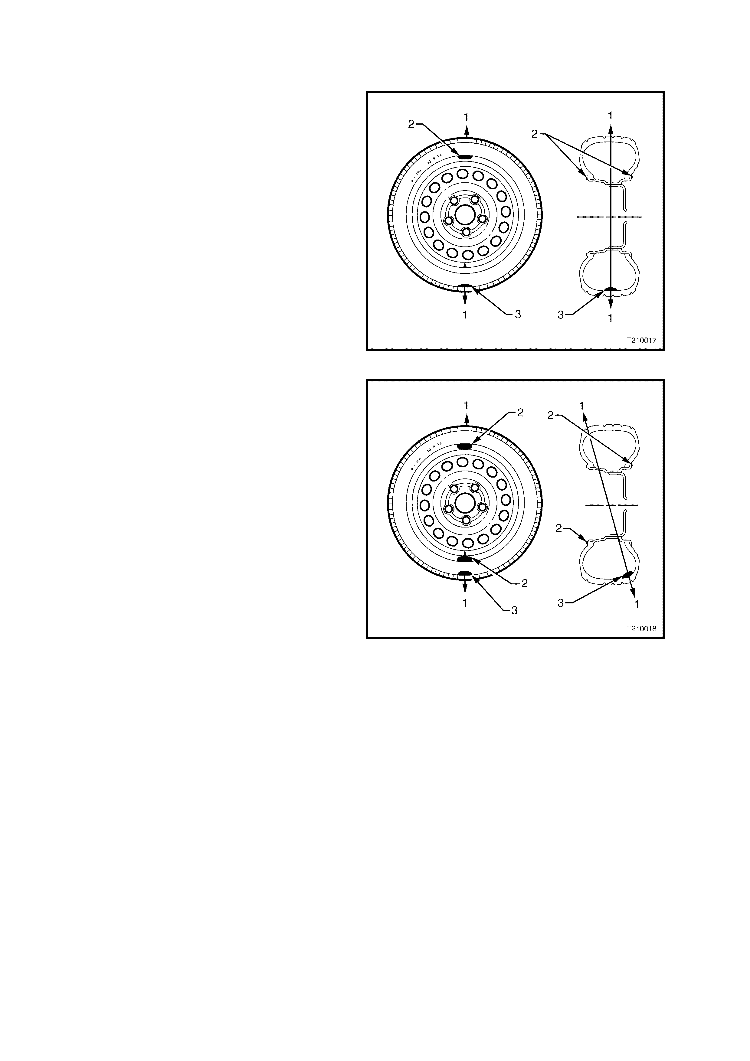
MATCH MOUNTING
NOTE: While this operation is not normally necessary with original equipment tyres, when replaced, match
mounting is recommended to obtain optimum performance with minimal or no vibration.
If tyre / wheel assembly run-out is exc ess ive, mar k the location of the high and low spots on the tyre and the wheel.
The nex t step will be to determine if the r un-out problem exis ts in the tyre, wheel, or a com bination of both, then to
correct it. The procedure used to accomplish this is called match mounting or system matching.
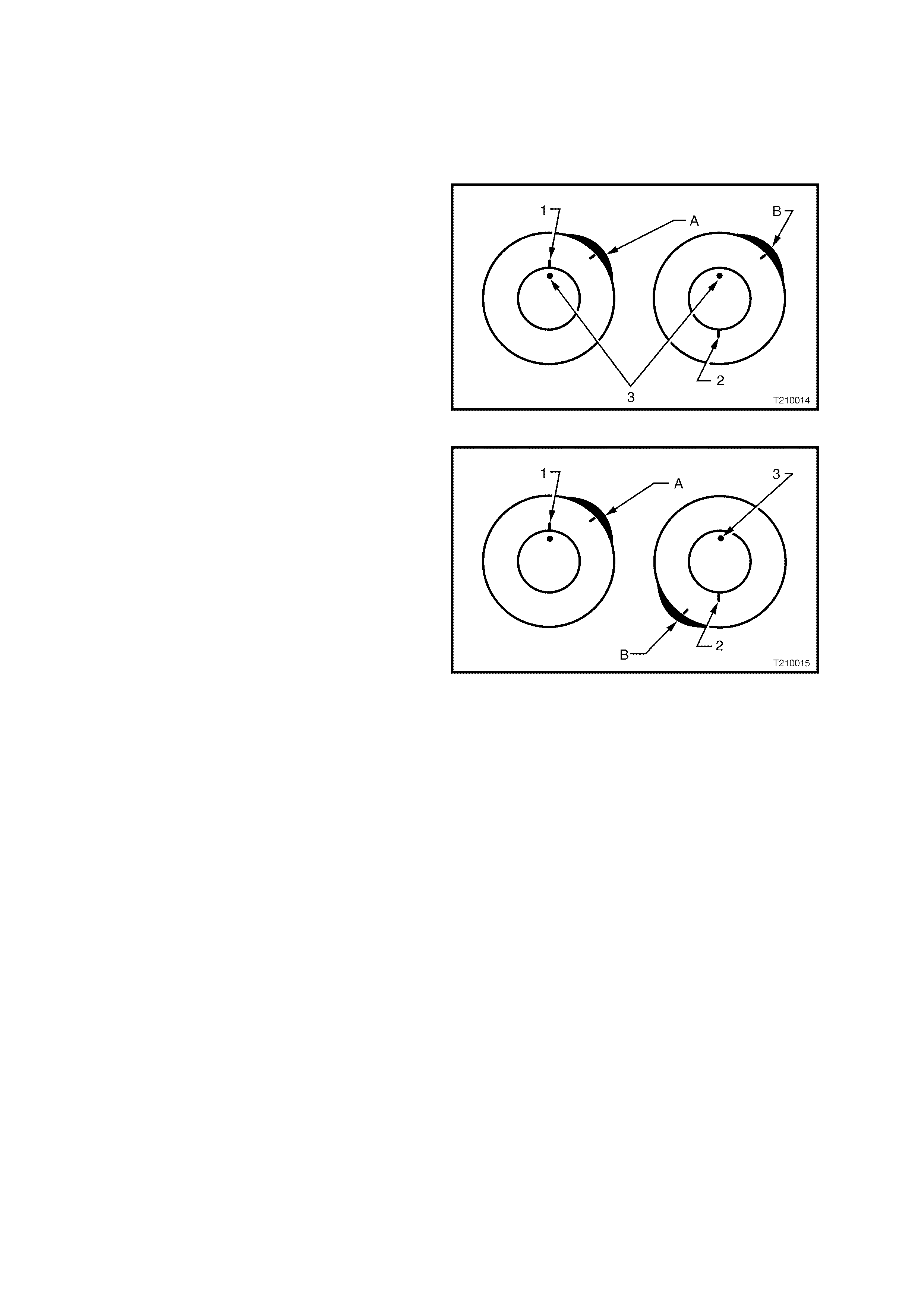
1. Place a mark on the tyre sidewall (1) at the
location of the valve stem (3). This will be
referred to as the 12 o’clock position. The
location of the high spot A will always be
refer red to in r elation to its cloc k position on the
wheel.
2. Mount the tyre and wheel assembly on a tyre
machine and break down the bead. Do not
dismount the ty re from the wheel at this time.
3. Rotate the tyre 180° on the rim so the valve
stem reference mark (2) is now at 6 o’clock in
relation to the valve stem itself. Inflate the tyre
and make sure the bead is seated properly.
You may have to lube the bead to enable easy
rotation of the tyre on the wheel.
4. Install the assembly on the tyre balancer and
again measure the run-out. Mark the new
location of the run-out high spot B on the tyre.
If the run-out is now within tolerance, no further
steps are necessary. The tyre may be balanced
and installed on the vehicle.
Alternatively, if the c lock location of the high spot B
remained at or near the clock location of the
original high spot A (as in Figure 10-25), the wheel
is the major contributor to the run-out problem. It
should be measured for excessive run-out, as
detailed in 2.8 CHECKING WHEEL RUN-OUT in
this Section and replaced if found to exceed
specification.
If the high spot is now at or near a position 180°
(6 o’clock) from the original high spot, the tyre is
the major contributor (as in Figure 10-26) and
should be replaced.
Always measure the tyre / wheel assembly run-out
after replacing the tyre and make sure the run-out
is within tolerance bef ore c ontinuing. In the m ajority
of cas es, the f irst 180° ro tation of the tyre will either
correct the run-out problem or indicate which
component to replace.
If the high spot is between the two extremes, then
both the tyre and wheel are contributing to the run-
out. Try rotating the tyre an additional 90° in both
the clockwise (9 o’clock) and counter-clockwise
(3 o’clock) directions, measuring the run-out after
each rotation.
If run-out cannot be corrected by match mounting,
then the tyre must be removed and the wheel run-
out measured, as detailed in the next Operation.
Once run-out has been brought within the
tolerance, the tyre / wheel assembly should be
balanced.
Figure 10-25
Figure 10-26
2.8 CHECKING WHEEL RUN-OUT
W heel run-out should be m easured on the ins ide bead area of the wheel. Measure the run- out in the sam e fashion
as tyre run-out. Ignore any jumps or dips due to paint drips, chips, or welds, measure both inboard and outboard.
If the run-out of the wheel is within tolerance, and the tyre / wheel assembly run-out cannot be reduced to an
acceptable level by using the match-mounting technique, the tyre must be replaced. Always measure the
assembly run-out after replacing the tyre.
If there is a large diff erenc e in the run-out m eas urem ents f rom on- vehicle to off -vehic le, then the run-out problem is
due to stud pattern run-out, or hub flange run-out, or a mounting problem between the wheel and the vehicle.
The tolerances listed are to serve as guidelines. If run-out measurements are within tolerance but are marginal,
som e sens itive vehicles m ay still be aff ected. It is always advisable to reduc e run-out to as little as possible in order
to attain optimum results under all conditions.
PROCEDURE
NOTE: The following measuring procedure can be performed on either steel or alloy road wheels.
1. Raise the vehicle on a hoist or jack and support with safety stands.
2. Remove the wheel cover (steel wheel) or the centre cap (alloy wheel).
3. Mark the relationship of the wheel to the mounting flange or the brak e disc / hub. Remove the wheel attaching
nuts and remove the wheel.
4. Mark the relationship of the tyre to the w heel rim and then remove the ty re from the rim.
5. Check that the wheel and mounting flange or brake disc / hub mating surfaces are clean and free from burrs.
6. Install the wheel onto the mounting flange or brak e disc / hub and install the wheel attaching nuts. T ighten the
nuts to the correct torque specification.
ROAD WHEEL ATTACHING NUT
TORQUE SPECIFICATION 110 – 140 Nm
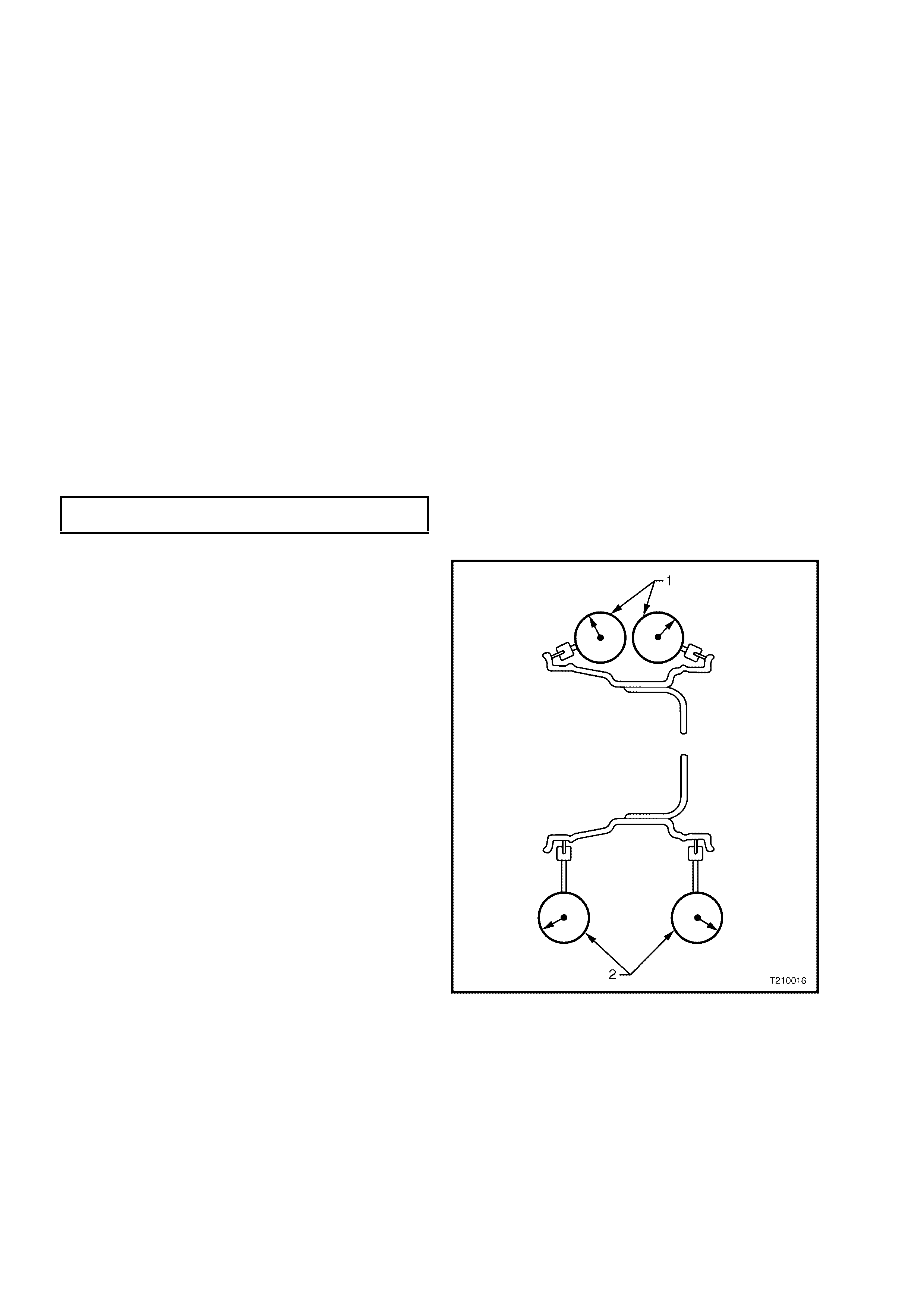
7. Using a dial indicator with a roller fitted to the
probe, secure the body of the indicator to a
fixed point, and butt the roller and probe
against the wheel rim at the points shown.
Then, slowly rotate the road wheel and
measure the wheel run-out.
1 = Lateral Run-out
2 = Radial Run-out
Wheel run-out should be within the specified
values listed in 4. SPECIFICATIONS in this
Section.
If not within specification, replace the wheel.
Figure 10-27
2.9 WHEEL AND TYRE BALANCING
There are two types of wheel and tyre balance, Static and Dynamic.
STATIC balance is the equal distribution of weight
around the wheel.
Vibrations caused by static imbalance will cause a
vertical or bouncing motion of the tyre.
Legend
1 = Directi on of Mot i on of Wheel
2 = Posit i on for Balance Weight
3 = Heavy Point
Figure 10-28
DYNAMIC balance af fec ts the dist ribution of weight
on each side of the tyre / wheel centreline.
Dynam ic im balance results in a side- to-side motion
of the tyre sometimes referred to as shimmy.
Legend
1 = Direction of Motion of Wheel
2 = Position for Balance Weight
3 = Heavy Point
Figure 10-29
OFF-VEHICLE BALANCING
When wheel and tyre assemblies require balancing, they should be removed from the vehicle and balanced on a
machine capable of ensuring correct static and dynamic balance. Balancing should be carried out in accordance
with the machine manufacturer's instructions.
Before balancing, remove all accumulated mud from the wheel and any embedded stones from the tyre treads. If
using on-vehicle balancing equipment, observe the LIMITED SLIP DIFFERENTIAL PRECAUTIONS as outlined in
Section 4B, FINAL DRIVE AND DRIVE SHAFTS.
ON-VEHICLE BALANCING
NOTE: W hen using on-vehicle balancing equipm ent, observe the LIMITED SLIP DIFFERENTIAL PRECAUTIONS
as outlined in Section 4B, FINAL DRIVE AND DRIVE SHAFTS.
If chec king and / or cor rec ting a tyre / wheel imbalance c ondition of f the vehicle and it does not c orr ec t the vibration,
it may be necessar y to balance the tyre and wheel assem bly with the ass em bly m ounted on the vehicle. Use an on-
vehicle, high-speed spin balancer, as this will balance the hubs, rotors, and wheel trims simultaneously. Additionally,
it can compensate for any amount of residual run-out encountered due to mounting the tyre / wheel assembly on the
vehicle, as opposed to the balance that was achieved on the off-vehicle balance.
IMPORTANT: Although hub / brake discs do not contribute significantly to an out of balance condition, if wheels are
rem oved fr om the vehicle after balanc ing it is desirable to f it the wheels to the sam e position when installing on the
vehicle. Accordingly, it is good practice to m ark the relationship of the wheel to the axle flange or hub / brake disc
prior to wheel removal.
Always follow the on-vehicle balancer manufacturer’s Operator Manual for specific instructions.
IMPORTANT 1: Do not rem ove the off-vehicle balance weights. The purpose of on-vehicle balance is to fine tune
the assembly balance already achieved, not to begin again.
IMPORTANT 2: Leave all wheel trims installed where possible. Some wire wheel covers have been known to
induce s tatic imbalance. If you suspect a wheel trim of caus ing the vibr ation, it can be eliminated by road testing the
vehicle with the wheel trim removed.
IMPORTANT 3: If the on-vehicle balance calls for more than 10 grams of additional weight, split the weight between
the inboard and outboard flanges of the wheel. This will avoid disturbing the dynamic balance of the assembly,
achieved in the off-vehicle balance procedure.
IMPORTANT 4: Evaluate the condition following the on-vehicle balance to determine if the vibration has been
eliminated.
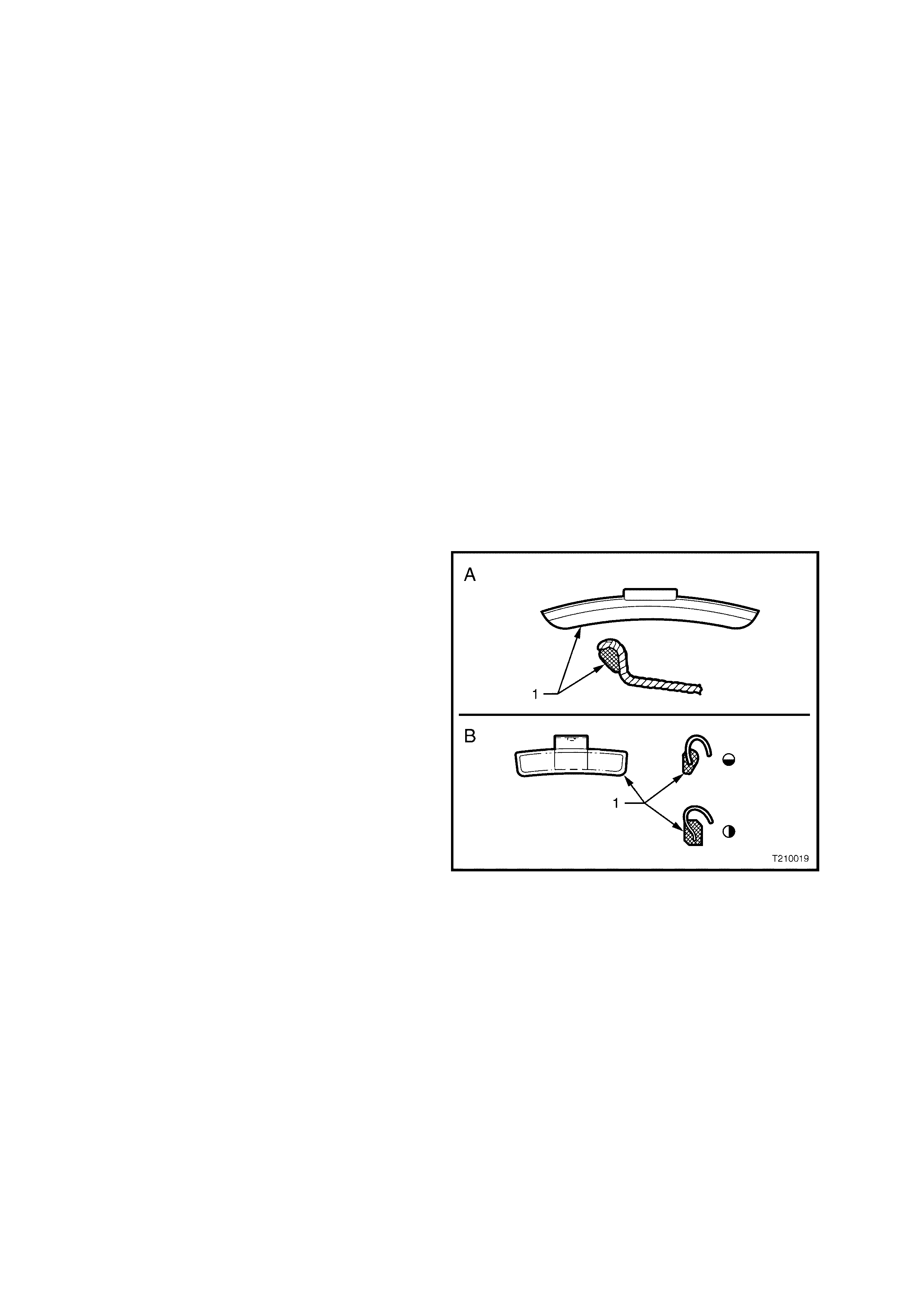
BALANCE LIMITS
NOTE: Specific wheel weights for each design of
wheel are used. This is due to the differences in
wheel rim profile.
The shape of wheel weights is shown in Figure
10-30 sections A and B. Section A shows wheel
weight and profile for steel wheels. W eights of this
design are available in 10 grams and 15 grams.
Section B shows wheel weights and profiles for
alloy wheels. We ights of this des ign are available in
20, 30, 40 and 50 grams.
A third style of wheel weight is the ribbon weight
(not illustrated) which has a self-adhesive backing
enabling weights to be adhered to clean flat
surfaces on the inside diameter of the wheel.
These ribbon weights are used primarily on alloy
wheels and are available marked in increments of
5 grams or 10 grams.
Figure 10-30
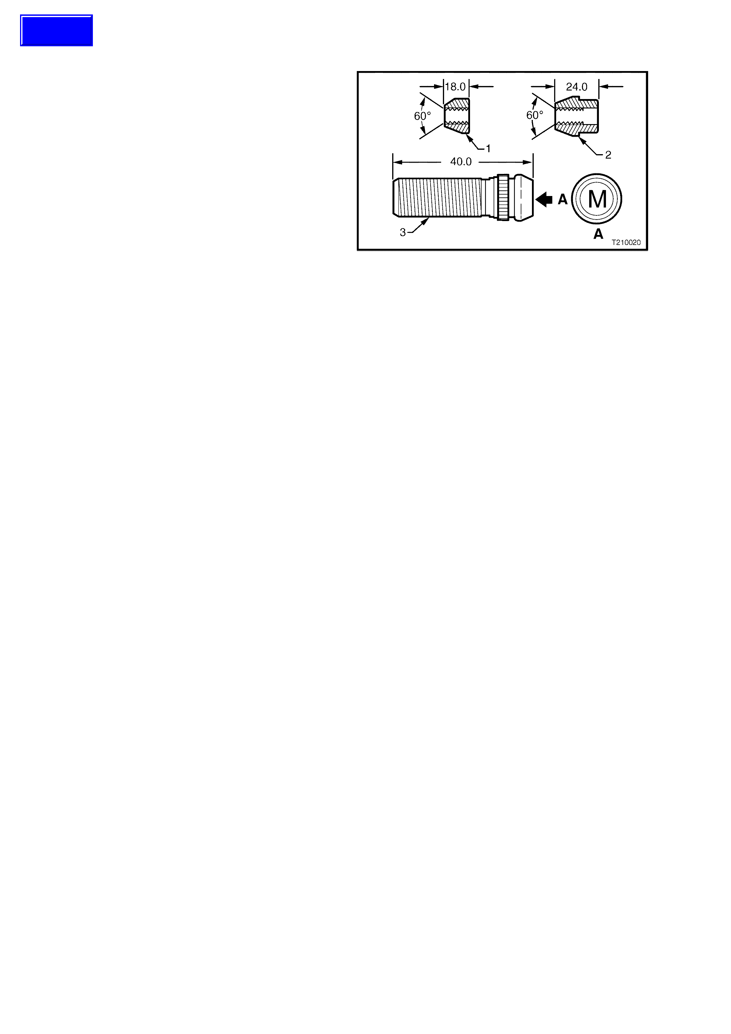
2.10 WHEEL ATTACHING NUTS AND STUDS
IMPORTANT: When alloy wheels are fitted to
MY2003 VY and V2 Series vehicles, special
attaching wheel nuts (2) are also used. If alloy
wheels are to be fitted to a vehicle normally
equipped with steel wheels, then the original nuts
(1) MUST be discarded and revised design
attaching nuts used on the replacement wheels.
CAUTION: Wheel nuts for alloy wheels have a
different mounting taper to those for steel
wheels. DO NOT interchang e or mix wheel nuts
from both types of wheel, as incorrect wheel
nuts will not allow the wheels to be tightened
securely.
For removal and installation instructions for
the wheel attaching studs (3), either refer to
Section 3, FRONT SUSPENSION or
Section 4B, FINAL DRIVE AND DRIVE SHAFTS.
All models use metric (M12 x 1.5) wheel attaching
studs and nuts (refer to A, in Figure 10-31).
Figure 10-31
Techline

3. DIAGNOSIS
3.1 WEAR
Analysis of tyre wear conditions is adequately covered in tyre company literature.

3.2 ROAD TESTING
Because there are many reasons for a vibration condition to be present in a vehicle, it is vital that a thorough road
test be conducted, to eliminate other possible causes for a vibration condition being present.
TYRE AND WHEEL INSPECTION
This visual inspection should be conducted for all vibration complaints unless the disturbance only occurs with the
vehicle at a standstill.
• The tyres should be inspected for unusual wear, including cupping, flat spots and heel-and-toe wear. These
conditions can cause tyre growl, howl, slapping noises, and vibrations throughout the vehicle.
• Establish that all tyres are inflated to the correct pressures prior to any road test.
• Check for bulging in the sidewalls.
• Check all wheels for bent rim f langes. Many times, hubcaps or trim rings that appear dented can indicate a bent
wheel underneath.
SLOW ACCELERATION TEST
This test is to identify engine or vehicle speed related conditions. It will be necessary to perform additional tests in
order to determine in which category the vibration belongs.
1. On a smooth, level road, slowly accelerate up to highway speed.
2. Look for disturbances that match the customer's description.
3. Note the vehicle speed (km/h) and engine speed (rpm) where the disturbance occurs.
Follow this test with the neutral coast-down test, and the downshift test.
NEUTRAL COAST-DOWN TEST
1. On a smooth, level road, accelerate to a speed slightly higher than the speed at which the vibration occurs.
2. Shift the vehicle into NEUTRAL and coast down through the vibration range. Note if the vibration is present in
NEUTRAL.
If the vibration still occurs in NEUTRAL, it is definitely vehicle-speed sensitive. At this point, the engine and torque
converter have been eliminated as a cause. Depending on the symptoms or frequency, the repair will concentrate
on either the tyres and wheels, or the propshaft and rear axle.
DOWNSHIFT TEST
1. On a smooth, level road, accelerate to the speed at which the complaint vibration occurs. Note the engine rpm.
2. Next, decelerate and safely downshift to the next lower gear (from overdrive to drive, or from drive to second
gear).
3. Operate the vehicle at the previous engine rpm.
If the vibration returns at the same rpm, the engine or torque converter is the most probable cause. To confirm
these results, repeat this test in still lower gears, and in NEUTRAL.
STEERING INPUT TEST
This test is intended to determine how much wheel bearings and other suspension components contribute to a
vibration, especially those relating to noises, howl or growl, grinding and roaring.
• With the vehicle at the vibration s peed (km/h), drive thr ough s low sweeping turns – f irs t in one dir ection, then the
other.
• If the vibration either gets worse or goes away, the wheel bearings, hubs and tyre tread wear are all possible
causes.
STANDING START ACCELERATION
The purpose of this test is to duplicate a vibration called Take-off-Shudder. In some cases, a powertrain mount or
the exhaust contacting the body may also be suspect, depending on the symptoms.
1. With the vehicle at a complete stop and in gear, remove your foot from the brake.
2. Accelerate to 60 or 70 km/h while checking for vibrations that match the customer's description.
Shudder in the seat or steering wheel under these c onditions usually res ults from improper driveline angles. W orn,
tight or failed universal joints may also be a cause, and should be inspected first.
Grunting or groaning noises along with a buzzing or roughness in the floor usually points to the vibration being
conducted through the engine or transmission mounts, or through exhaust mounts and hangers that have
GROUNDED OUT. Refer to the respective Sections for rectification procedures.
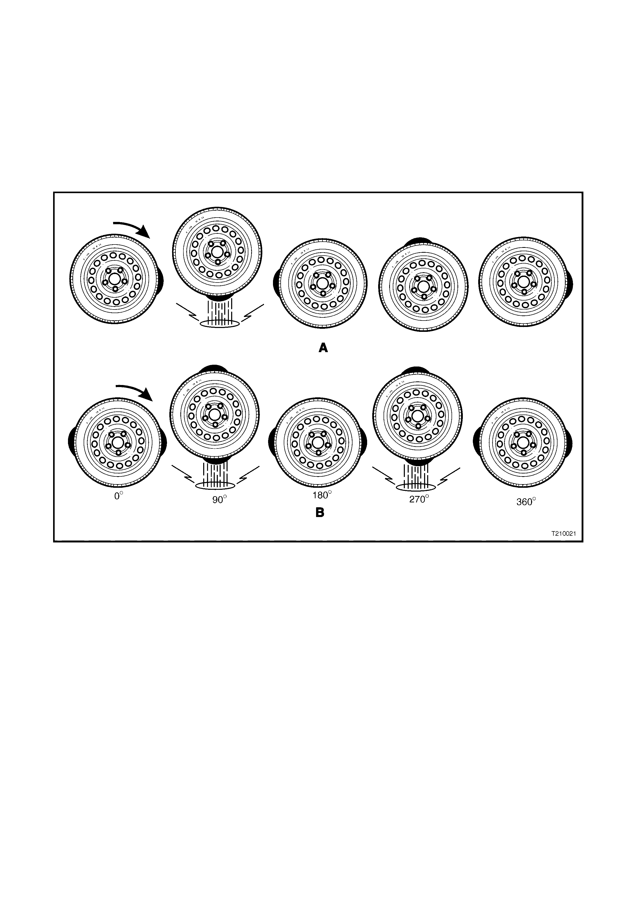
3.3 VIBRATION
To determine the cause of a vibration condition that is suspected of being tyre / w heel related, an essential aspect is
to understand the nature of first and second order vibrations (or harmonics).
As shown in Figure 10-32 Section A, a tyre with one high spot would create a disturbance once every complete
revolution. This is called first-order vibrations.
An oval shaped tyre with two high spots (as shown in Section B) would create a disturbance twice per revolution.
This is called second-order vibrations.
Three high spots would be third order, and so on.
Two first-order vibrations may add to or subtract from the overall amplitude of the disturbance, but that is all. Two
first- order vibrations do not equal a sec ond-order. Due to centr ifugal for ce, an out-of -balanc e com ponent (eg. tyres,
drive shafts or engine) will always create a first-order vibration.
Figure 10-32
If wheel and tyre assemblies are balanced to the degree required and vibration is still evident, then tyre run-out or
Force Variation could be responsible.
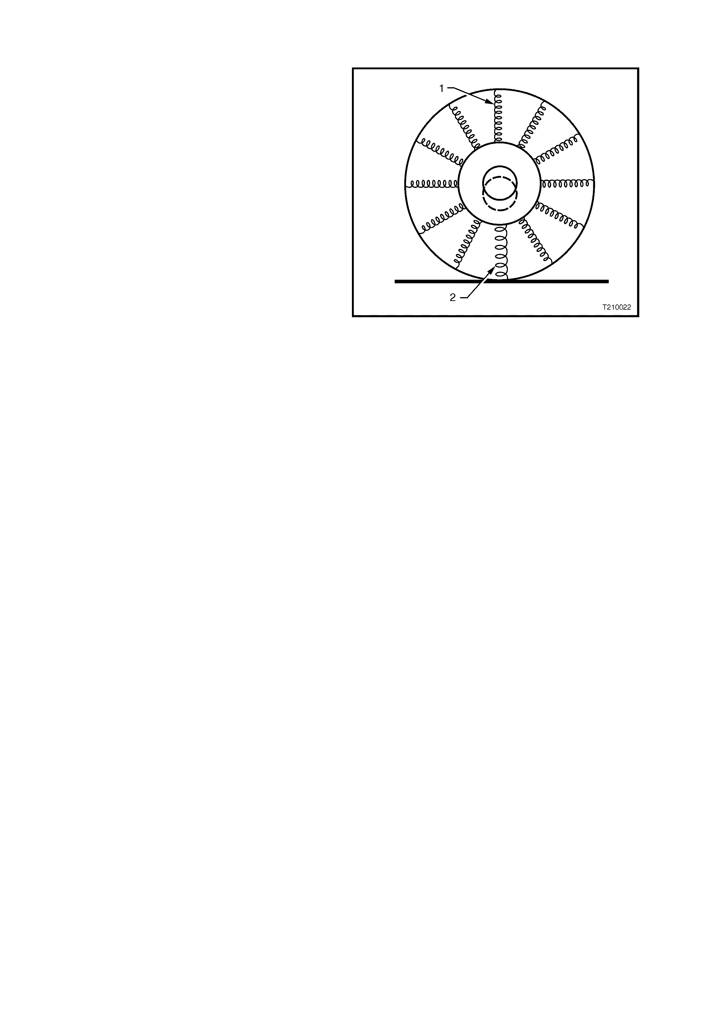
RADIAL FORCE VARIATION
Radial force variation refers to a difference in the
stiff nes s of a tyre sidewall as it rotates and contacts
the road. Figure 10-33 uses springs to illustr ate the
point. The lighter springs (1) represent a normal
sidewall while the heavier spring (2) represents a
stiffer section of the sidewall. Tyre / wheel
assemblies have some of this due to splices in the
different plies of the tyre, but they do not cause a
problem unless the force variation is excessive.
Thes e stiff spots in the sidewall can def lect the tyre
/ wheel assembly upward as they contact the road.
If there is only one stiff spot in the sidewall, it will
deflect the spindle once per each revolution of the
tyre / wheel assembly, causing a first order tyre /
wheel vibration.
If there are two stiff s pots, they c an cause a second
order vibration.
First and second order tyre / wheel vibrations are
the most common to occur as a result of radial
force variation. Higher orders (eg. third, fourth) are
possible, but quite rare. The most effective way to
minimise the possibility of force variation as a factor
in tyre / wheel vibration is to ensure that the tyre /
wheel assembly run-out is at an absolute minimum.
Some tyre / wheel assemblies may exhibit
vibration-causing amounts of force variation
although they are within run-out and balance
tolerances. Due to tighter tolerances and higher
standards in manufacturing, these instances are
becoming rare. If force variation is suspected as
being a factor, substitute one or more known good
tyr e / wheel assemblies f or the sus pect ass emblies.
If this rectifies the problem, replace the offending
tyre.
Figure 10-33
LATERAL FORCE VARIATION
This is based on the sam e concept as radial force variation, except that lateral force variation tends to deflect the
vehicle sideways or later ally, as the nam e implies. A s naky belt inside the tyre can cause lateral for c e variation. Tyre
replacement using the substitution method may be necessary.
This condition is very rare and again, the best way to eliminate it as a factor is to ensure that the lateral run-out of
the tyre / wheel assemblies is at an absolute minimum.
In most cases where excessive lateral force variation exists, the vehicle will display a wobble or waddle at low
speeds (8-to-40 km/h) on a smooth road surface. The condition will usually be related to a first order vibration of
tyre / wheel rotation.
Some degree of tyre run-out will always be present, due to dimensional tolerances in both the tyre and wheel and
can of ten be r educ ed by rotating the tyre on the wheel to cancel out the overall eff ect. F or ce Var iation (a var iation in
stiffness around the tyre) can also cause the same problem, resulting in a varying loaded radius as the tyre rotates.
All of these factors have so far been considered to act radially. However, lateral run-out and lateral force variation
can also be translated into vehicle vibration ranging from low speed waddle to relatively high-speed shake or
vibrations similar to those obtained with tyre imbalance.

3.4 VEHICLE LEAD
Vehicle lead is the deviation of the vehicle fr om a stra ight path, on a level road (no camber ) and with no load on the
steering wheel. Lead is usually caused by alignment and / or brake drag, but can sometimes be caused by tyres.
The way in which a tyre is built can produc e lead in a vehicle. An exam ple of this is placem ent of the belt in a radial
tyre. An off-centre belt can cause the tyre to develop a side force while rolling straight down the road.
If one side of the tyre is a little larger in diameter than the other, the tyre will tend to roll up to one side. This will
develop a side force, which can produce vehicle lead.
The following diagnostic chart can be used to confirm vehicle lead.
DIAGNOSING VEHICLE LEAD
STEP ACTION YES NO
1 1. Inflate tyres to the correct pressures.
2. Road test vehicle in opposite directions, on a
level, uncrowned road with little or no crosswind.
Does vehicle lead to the same side in both
directions?
Go to Step 2. Go to Step 8.
2 1. Swap front tyres from one side to the other and
road test, again in opposite directions.
Does vehicle lead to the same side as in Step 1?
Put tyres back in original
positions.
Go to Step 8.
Go to Step 3.
3 Does the vehicle now lead to the opposite side to that
in Step 1? Go to Step 5. Go to Step 4.
4 Has the lead condition been corrected? Leave tyres as is. If roughness
develops, replace front tyres. Go to Step 5.
5 1. Install a known good tyre to replace one front
tyre and road test again.
Is the lead condition corrected?
Lead condition has been
isolated. Replace tyre. Go to Step 6.
6 1. Check the test tyre on a known good vehicle.
Has the lead condition been corrected? Test tyre is faulty.
Go to Step 5. Go to Step 7.
7 1. Install a known good tyre to replace remaining
front tyre.
Has the lead condition been corrected?
Lead condition has been
isolated. Replace tyre. Go to Step 8.
8 1. Check / correct vehicle wheel alignment and
maladjusted or binding steering.
2. Road test again.
Has the lead condition been corrected?
Vehicle is now operating to
specification. Swap tyres, front to
rear.

4. SPECIFICATIONS
STEEL WHEELS
Rim Width Code........................................................... 6J 7J
Diameter Code............................................................. 15 15
Maximum Permissible Radial Run-out
All Steel Wheels...................................................... 0.6 mm
Maximum Permissible Lateral Run-out
All Steel Wheels...................................................... 0.8 mm
Offset............................................................................ 43 mm (positive)
ALLOY WHEELS
Rim Width Code........................................................... 7JJ 7JJ 8JJ 8JJ
Diameter Code............................................................. 15 16 17 18
Maximum Permissible Radial Run-out
All models................................................................ 0.35 mm
Maximum Permissible Lateral Run-out
All models................................................................ 0.35 mm
Offset
All models................................................................ 48 mm (positive)
Acclaim.................................................................... 41 mm (positive)

INFLATION PRESSURES
Australia and South Africa
RECOMMENDED COLD INFLATION – kPa
MODEL ENGINE WHEEL TYRE DESIGNATION Up to 3 Passengers Up to Max. Load
Front Rear Front Rear
Sedan V6
6J - 7JJ x 15
Steel - Alloy P205/65 R15 95H 220 220 240 270
V6 7J X 15 Steel 205/65 R15 99H 200 200 220 250
V6 7J X 15 Steel 225/60 R15 96V 200 200 220 250
V6 7JJ X 16 Alloy 215/60 R16 95V 200 200 220 250
V6 7JJ X 16 Alloy 225/50 R16 92V 200 200 220 250
Sedan V6 S/C 7JJ x 16 Alloy 225/55 R16 95V 200 200 220 250
V6 8JJ x 17 Alloy 235/45 R17 93V 200 200 220 250
Wagon V6 (LPG) 6J - 7JJ x 15
Steel - Alloy P205/65 R15 95H 220 220 240 270
Sedan/Wagon V8 7J - 7JJ x 15
Steel - Alloy 225/60 R15 96V 200 200 220 250
Sedan V8 7JJ x 15 Alloy 225/60 R15 96V 200 200 220 250
Sedan V8 7JJ x 16 Alloy 225/55 R16 95V 200 200 220 250
V8 8JJ x 17 Alloy 235/45 R17 93V 200 200 220 250
SS Sedan V8 8JJ x 18 Alloy 235/40 R18 91W 230 230 230 270
SS Coupe V8 8J x 18 Alloy 235/40 R18 91W 230 230 230 270
Temporary use spare 4T T135/90D15 420
S Utility V6 7JJ x 16 Alloy 225/55 R16 95V 200 200 200 300
SS Utility V8 8JJ x 17 Alloy 235/45 R17 93V 200 200 220 250
Temporary use spare 7J 205/65 R15 99H 300
For speeds above 140 km/h (V6 with 15” wheels) 240 240 270 300
For speeds above 160 km/h (Sedan and Wagon) 240 240 270 300
For speeds above 160 km/h (Utility) 220 220 220 300
For speeds above 160 km/h (Coupe) 250 250 270 300
For speeds above 140 km/h (LPG Wagon) 240 240 270 310

Gulf States
RECOMMENDED COLD INFLATION – kPa
MODEL ENGINE WHEEL TYRE DESIGNATION Up to 3 Passengers Up to Max. Load
Front Rear Front Rear
V6 7J X 15 Steel 225/60 R15 96W 230 230 270 310
V6 S/C 7JJ x 16 Alloy 225/55 R16 94V 230 230 270 310
V6 8JJ x 17 Alloy 235/45 R17 93Y 230 230 270 310
V8 7JJ x 15 Alloy 225/60 R15 96W 230 230 270 310
V8 7JJ x 16 Alloy 225/55 R16 94V 230 230 270 310
V8 8JJ x 17 Alloy 235/45 R17 93Y 230 230 270 310
Brazil
RECOMMENDED COLD INFLATION – kPa
MODEL ENGINE WHEEL TYRE DESIGNATION Up to 3 Passengers Up to Max. Load
Front Rear Front Rear
V6 7JJ X 16 Alloy 215/60 R16 95V 210 210 240 280
Berlina International
RECOMMENDED COLD INFLATION – kPa
MODEL ENGINE WHEEL TYRE DESIGNATION Up to 3 Passengers Up to Max. Load
Front Rear Front Rear
Wagon 8J x 17 235/45 R17 93V 200 200 220 250
Temporary use spare 6J P205/65 R 15 95H 280
For speeds above 160 km/h (Wagon) 240 240 270 300

5. TORQUE WRENCH SPECIFICATIONS
Nm
Road Wheel Attaching Nuts (All Wheels).....................................110 – 140

6. SPECIAL TOOLS
TOOL NUMBER ILLUSTRATION DESCRIPTION CLASSIFICATION
AU534
TORQUE LIMITING SOCKET
Released to allow the use of impact
gun to tighten road wheel nuts
Mandatory