
SECTION 12A - BATTERY AND CABLES
IMPORTANT
Before p erforming any Serv ice Operation or other procedure d escribed in this Section , refer to Section 00,
CAUTIONS AND NOTES for correct workshop practices with regard to safety and / or property damage.
CONTENTS
1. GENERAL INFORMATION
CIRCUIT OVERVIEW
1.1 BATTERY RATINGS
RESERVE CAPACITY (RC)
COLD CRANKING AMPS (CCA)
RATINGS
1.2 BATTERY HARNESS
1.3 BATTERY HARNESS ROUTING
2. SERVICE OPERATIONS
2.1 SAFETY PRECAUTIONS
2.2 BATTERY INSPECTION
REGULAR CHECKS
2.3 HYDROMETER TEST
TEST THE STATE OF CHARGE
2.4 LOAD TEST
HIGH RATE DISCHARGE (HRD) LOAD TEST
ALTERNATE LOAD TEST
2.5 BATTERY CURRENT DRAW TEST
2.6 BATTERY CHARGE
CAUTIONS
2.7 VEHICLE WIRING
REGULAR CHECKS
2.8 DRY CHARGED BATTERIES
STORAGE
ACTIVATION
POST-ACTIVATION TESTS
2.9 BATTERY
REMOVE
REINSTALL
2.10 EMERGENCY JUMP STARTING PROCEDURE
PRECAUTIONS
JUMP STARTING PROCEDURE
3. DIAGNOSIS
4. SPECIFICATIONS
5. TORQUE WRENCH SPECIFICATIONS
6. SPECIAL TOOLS
Techline
1. GENERAL INFORMATION
The MY2003 VY and V2 Series vehicles are fitted with a 12 volt battery located towards the front of the engine
compartment. Battery cables attached to the battery posts provide power and ground connections for the vehicle
electrical system . T hese battery cables attac h to the batter y posts via nut-tightened term inals. T he battery is held in
position by a hold-down bracket and a hold-down bolt. Refer to Figure 12A-1.
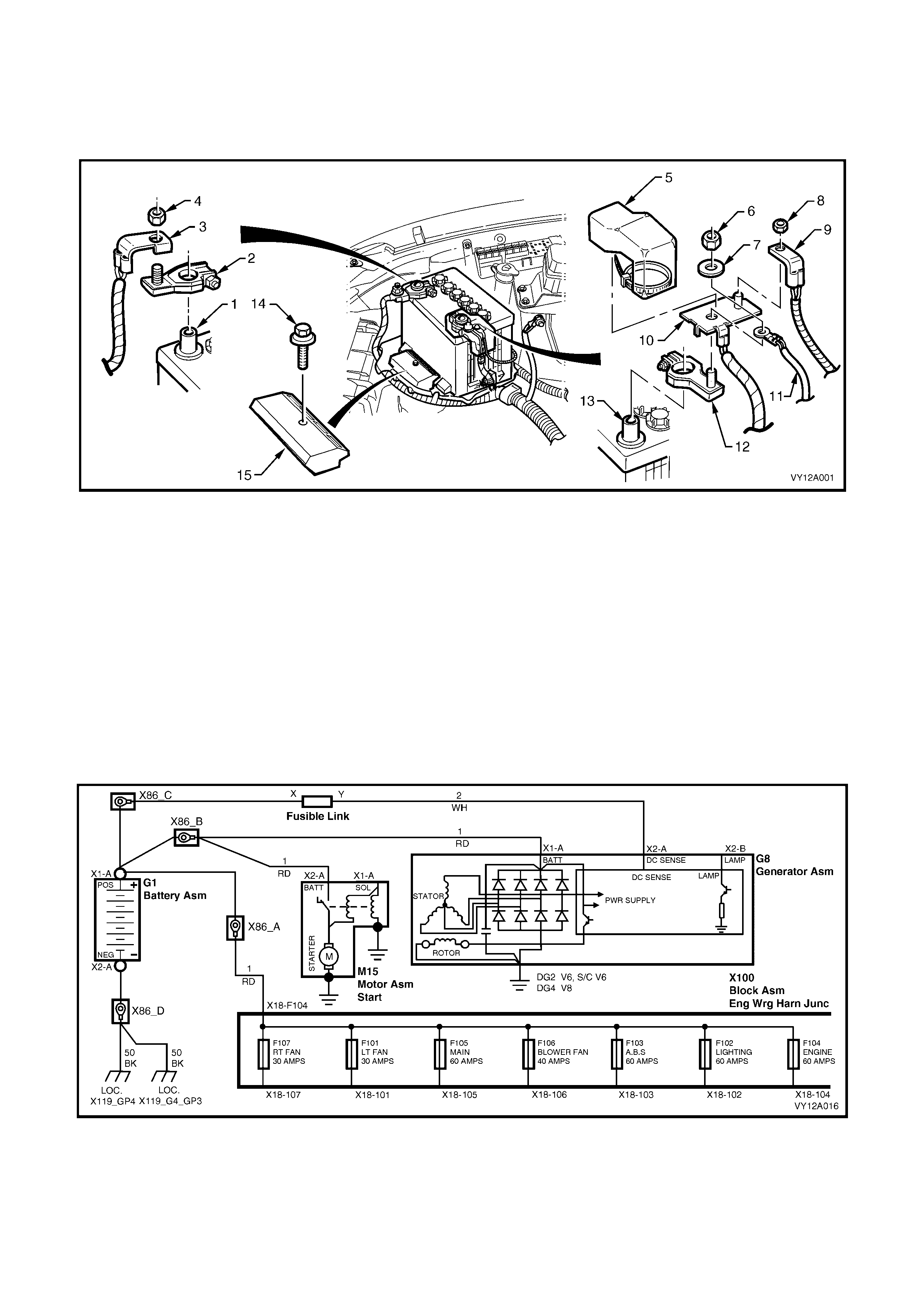
Figure 12A-1
Legend
1. Battery Negative Post 6. Battery Terminal Nut 11. Generator Voltage-Sensing Wire
2. Battery Negative Terminal 7. Battery Terminal Washer 12. Positive Battery Terminal
3. Battery Ground Cable Connection 8. Main Fuse Box Supply Terminal Nut 13. Positive Battery Post
4. Battery Terminal Nut 9. Main Fuse Box Supply 14. Battery Hold-down Bolt
5. Positive-Connection Cover And Tie 10. Battery Positive Cable Assembly 15. Battery Hold-down Bracket
CIRCUIT OVERVIEW
The battery provides:
• power for cranking the engine
• power (for a limited time) when the electrical load exceeds the generator output
• power for accessories (for a limited time) when the engine is not running
• a voltage stabilising load in the electrical system.
Figure 12A-2

1.1. BATTERY RATINGS
There are two battery ratings to consider when replacing a battery; Reserve Capacity (RC) and Cold Cranking Amps
(CCA). Ensure that the replacement battery meets or exceeds these rating specifications.
RESERVE CAPACITY (RC)
The RC of a battery is the maxim um amount of m inutes that the vehicle will travel at night with minimum electrical
load and no generator output.
This is calculated under the following conditions:
• a fully charged battery
• discharged at a constant current of 25 amps
• at 25°C
• until 10.5 volts remains.
COLD CRANKING AMPS (CCA)
The CCA rating indicates the ability of the battery to maintain enough voltage for ignition requirements while
supplying engine cranking current for long enough to start the engine under severely cold conditions.
The rating is the minimum amperage maintained under the following conditions:
• cranking for 30 seconds
• at –18°C
• maintaining at least 7.2 volts.
RATINGS
A specification label on the top of the battery displays important information about the battery. This includes the
battery ratings and the original equipment part number.
The MY2003 VY and V2 Series vehicles are f itted with a low m aintenance, 85 minute RC and 430 CCA batter y ( or,
for export vehicles, a maintenance free 115 minute RC and 450 CCA battery).
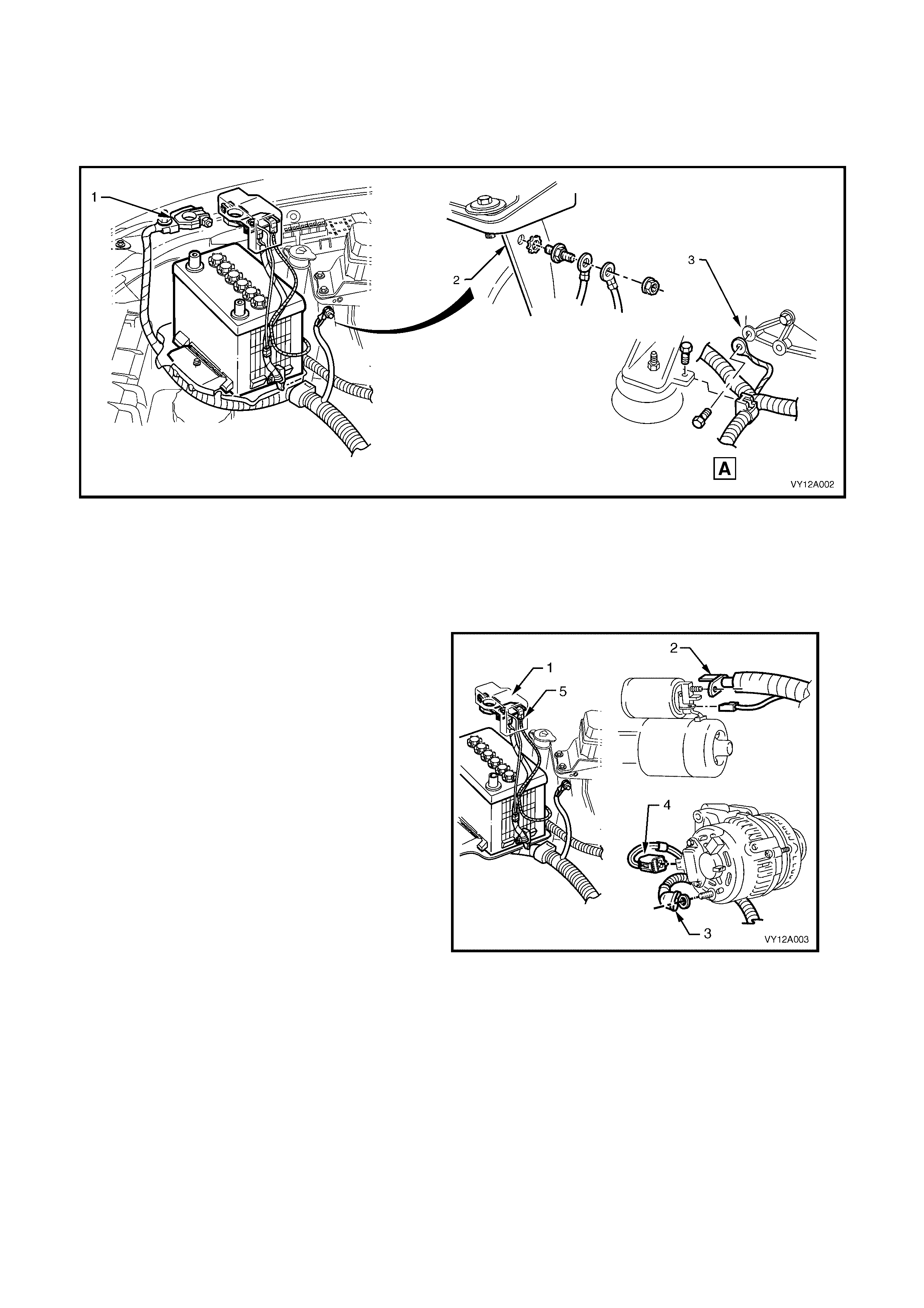
1.2 BATTERY HARNESS
The battery harness connects the vehicle electrical system components to the battery.
The battery ground cables and terminal (1) provide a ground connection to the vehicle body (2) and to the
engine (3).
Figure 12A-3
Legend
A. Front, right-hand side of the engine.
1. Ground Cables and Terminal 3. Engine Ground Connection.
2. Body Ground Connection
The battery positive terminal and cable assembly
(1) provide a power supply to:
• the starter motor main terminal (M) connection
(2)
• the generator main terminal connection (3)
• the generator voltage sensing wire (4).
The main fuse box supply (5) is connected to the
battery harness at the battery positive terminal.
Figure 12A-4
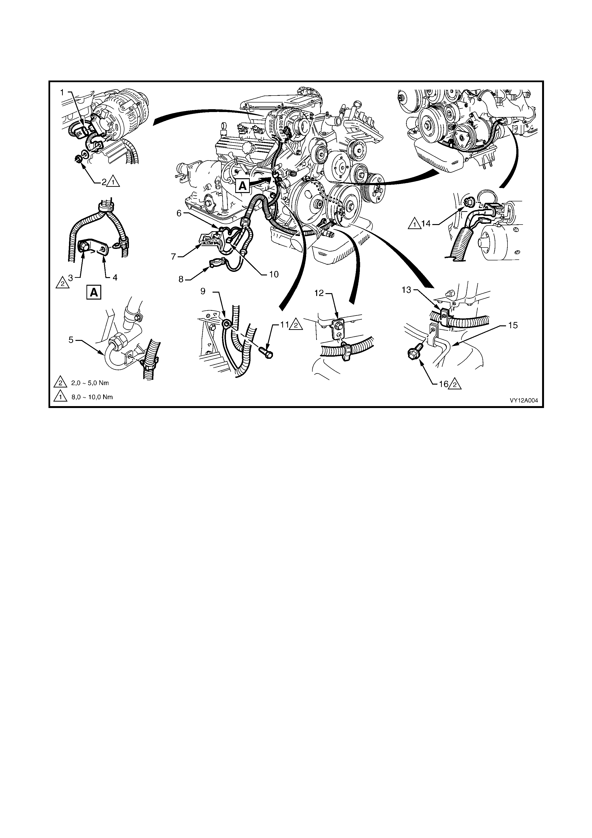
1.3 BATTERY HARNESS ROUTING
The battery harness is fitted as outlined in the following illustrations.
Figure 12A-5
Legend, V6 engine
1. Battery Harness Generator Connector 7. Battery Positive Terminal Assembly 12. Harness Securing Bracket
2. Generator B+ Terminal Nut 8. Battery Negative Terminal 13. Harness Securing Bracket
3. Lift-hook and Bracket Bolt 9. Engine Ground Terminal 14. Starter Motor Power Supply Cable Nut
4. Harness Securing Bracket 10. Main Wiring Harness Connector 15. Oil Cooler Pipes
5. Power Steering Pipe Assembly 11. Engine Mount Bolt 16. Oil Cooler Pipe Attaching Bolt
6. Body Ground Terminal
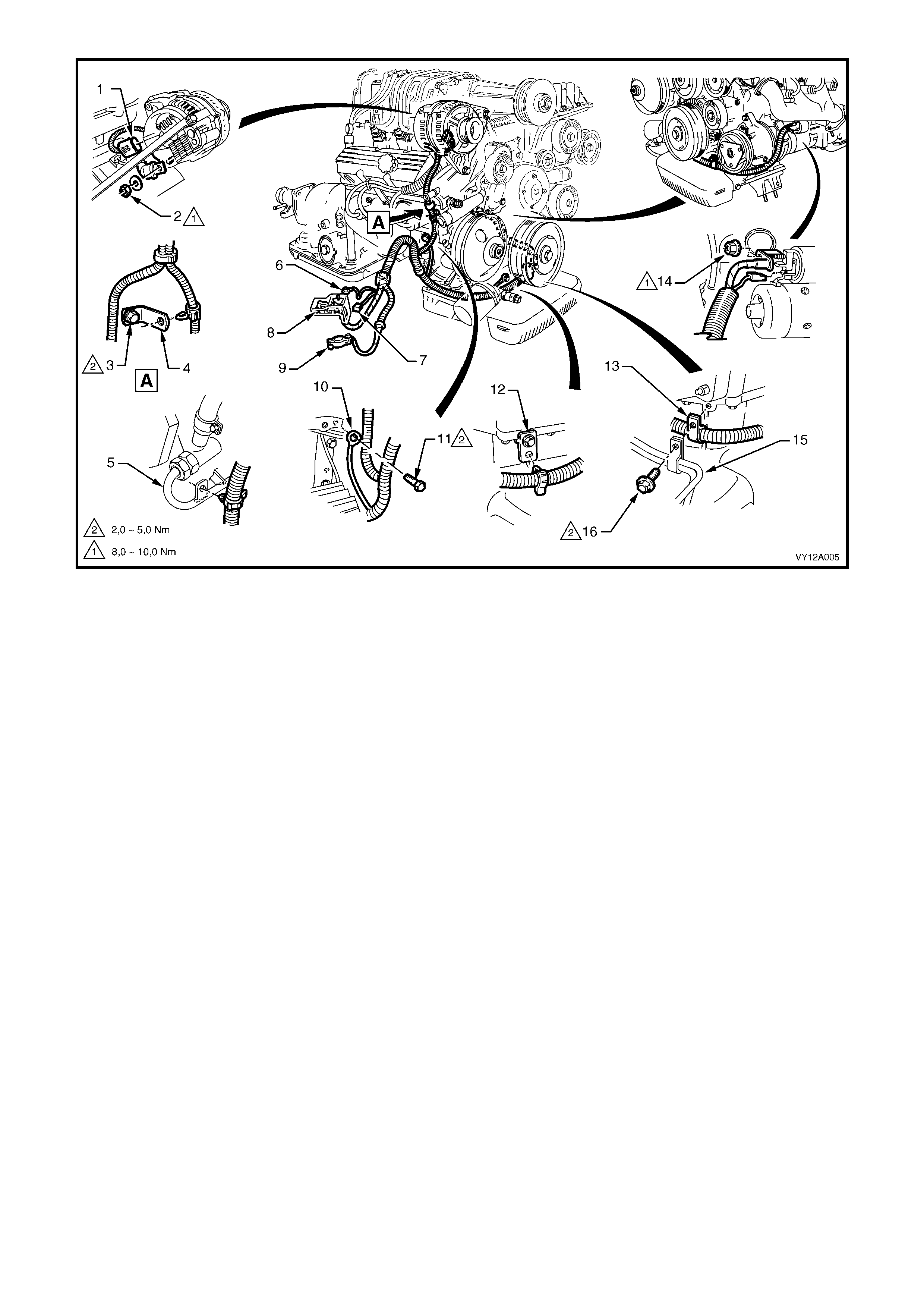
Figure 12A-6
Legend, V6 supercharged engine
1. Battery Harness Generator Connector 7. Main W iring Harness Connector 12. Harness Securing Bracket
2. Generator B+ Terminal Nut 8. Battery Positive Terminal Assembly 13. Harness Securing Bracket
3. Lift-hook and Bracket Bolt 9. Battery Negative Terminal 14. Starter Motor Power Supply Cable Nut
4. Harness Securing Bracket 10. Engine Ground Terminal 15. Oil Cooler Pipes
5. Power Steering Pipe Assembly 11. Engine Mount Bolt 16. Oil Cooler Pipe Attaching Bolt
6. Body Ground Terminal
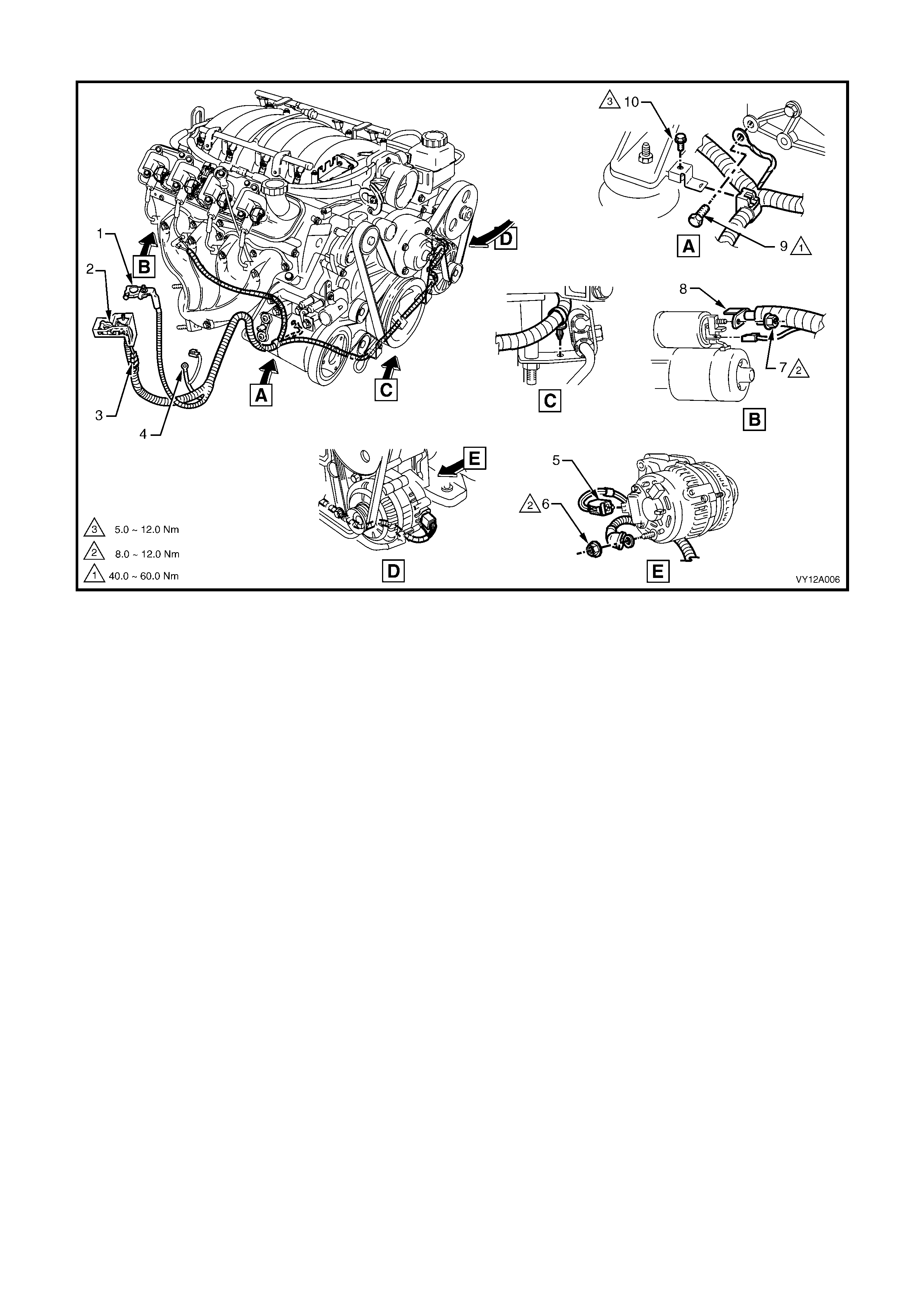
Figure 12A-7
Legend, GEN III V8 engine
1. Battery Negative Terminal 5. Battery Harness Generator Connector 8. Starter Motor Power Supply Cable
2. Battery Positive Terminal Assembly 6. Generator B+ Te rminal Nut 9. Engine Ground Terminal Bolt
3. Main Harness Connector 7. Starter Motor Power Supply Cable Nut 10. Harness Securing Bracket Bolt
4. Body Ground Terminal

2. SERVICE OPERATIONS
2.1 SAFETY PRECAUTIONS
Battery fluid contains sulphuric acid, which can cause personal injury and component damage. Do not allow liquid
from the battery to contact ey es, skin, clothing or painted surfaces. If contact occurs, flush the area immediately with
running water and contact a physician.
Lead acid batteries produce explosive gases. Keep sparks, flames and lighted cigarettes away from the battery,
especially when the battery is being charged, when working around the battery area and if the battery is in an
enclosed area. Failure to follow this warning could result in a battery explosion.
Metal objects that touc h a battery terminal can caus e spark s and serious burns . W hen working near a battery, take
extra care with metal objects including tools and items of jewellery (especially rings and metal watchbands).
Ensure that the ignition is switched off when connecting or disconnecting battery cables, battery charging equipment
or battery jumper cables. Failing to do so can damage the vehicle electronic components.
For vehicles fitted with Telematics, refer to Section 12K, TELEMATICS before performing any service work.
Disconnect the battery negative cable from the battery before disconnecting the positive cable. Similarly, connect
the battery negative cable to the battery af ter the positive c able is c onnected. T his reduces the possibility of shorting
the battery to ground while working near the positive connections.
2.2 BATTERY INSPECTION
LT Section – 02-200
REGULAR CHECKS
1. Check the battery terminals and around the battery area for corrosion deposits.
2. Remove deposits as follows:
Scrub the area with a stiff brush.
Treat the area with a solution of warm water and baking soda or ammonia.
Rinse with clean water.
Smear the battery posts and terminals with petroleum jelly to resist corrosion.
3. Replace the battery if the battery posts are severely damaged (ie. loose, burned, pitted or broken). Refer to
2.9 BATTERY in this Section.
4. Check the battery case.
5. Replace the battery if the case is cracked. Refer to 2.9 BATTERY in this Section.
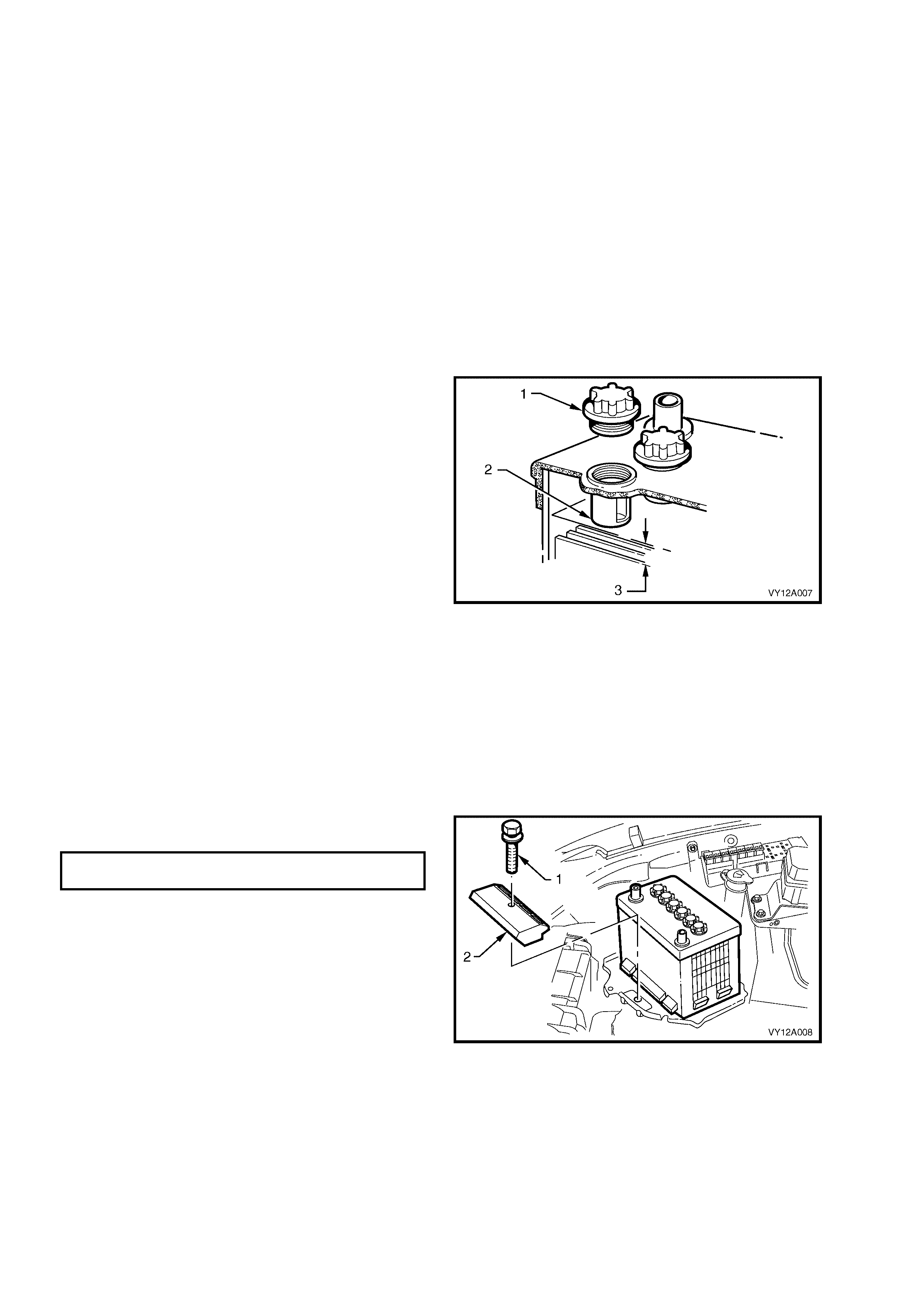
6. Remove each vent cap (1) and check that the
electrolyte level is at the bottom of the filler-
neck tube (2).
7. If the level is low, c are f ully add distilled water to
the cell until the level reaches the bottom of the
filler-neck tube.
NOTE: DO NOT OVERFILL THE CELLS, but
maintain the level at least 20 mm above the
separator plates (3).
8. If the electrolyte usage seems excessive,
check that the battery case is not faulty.
NOTE: Norm al electrolyte usage is less than 30 m l
per 10,000 kilometres (slightly more for long,
continuous running or in high temperatures).
9. If the battery case is okay, check that the
generator is not overcharging. Refer to:
• Section 6D1-1A, CHARGING SYSTEM – V6
ENGINE (100 AMPS)
• Section 6D1-1B, CHARGING SYSTEM – V6
ENGINE (120 AMPS), or
• Section 6D3-1, CHARGING SYSTEM – GEN
III V8 ENGINE.
Figure 12A-8
10. Ensure that the battery hold-down bolt (1) and
bracket (2) firmly secure the battery.
BATTERY HOLD-DOWN BOLT
TORQUE SPECIFICATION ......................8 – 10 Nm
11. Check the cable insulation for dam age or wear
along the cable. Replace the cable as
necessary.
12. Check that the cables do not have broken or
frayed strands and are secure in the term inals.
Repair as necessary.
Figure 12A-9
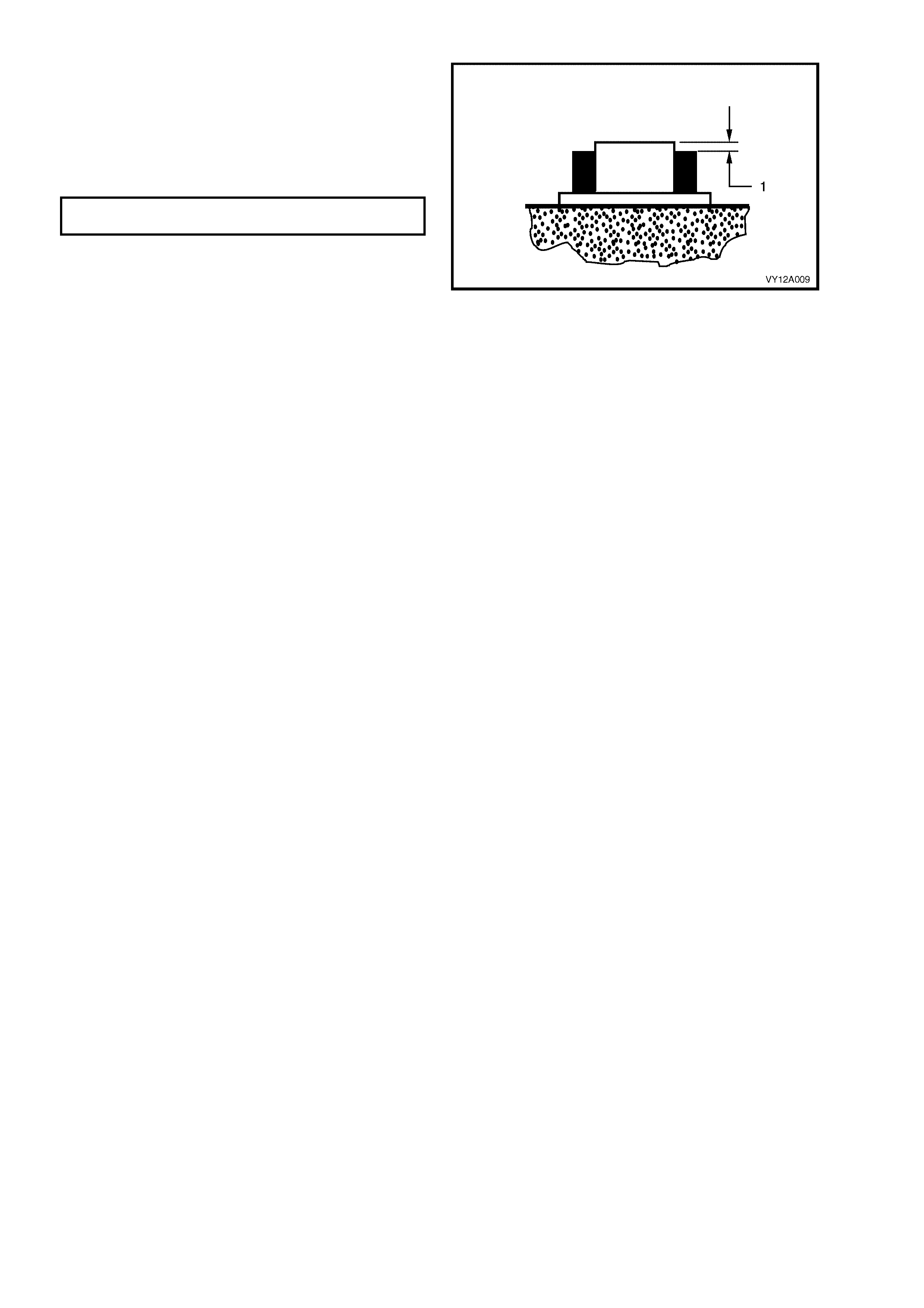
13. Fit the terminal clamps so that they sit below
the top of the battery post (1).
14. Check that the terminal clamps attach to the
battery posts securely. Replace the terminals
as necessary.
15. Tighten the terminal clamp nuts to the correct
torque specification.
BATTERY TERMINAL NUT
TORQUE SPECIFICATION ......................2 – 5 Nm
Figure 12A-10
2.3 HYDROMETER TEST
As a lead-acid battery discharges, the sulphuric acid in the electrolyte leaves the solution and enters the battery
plates. This removes the acid from the electrolyte and changes it to near-pure water.
This relationship between the state of charge and the concentration of sulphuric acid in the electrolyte can be
measured using a hydrometer. The state of charge is measured in term s of specific gravity; the lower the specific
gravity reading, the lower the state of charge.
NOTE: If dis tilled water has been added to the battery, do not use the hydrom eter until the battery (electrolyte) has
been charged for at least 30 minutes.
TEST THE STATE OF CHARGE
1. Remove the battery vent caps.
2. Force the air out of the hydrometer bulb.
3. Hold the hydrometer vertically in the cell w ith the pick-up tube submerged.
4. Draw in sufficient liquid to lift the hydrometer float freely w hen the bulb is fully released.
5. Still holding the hydrometer vertically, record the reading.
6. Put the electrolyte back into the cell.
7. Repeat this for each cell.
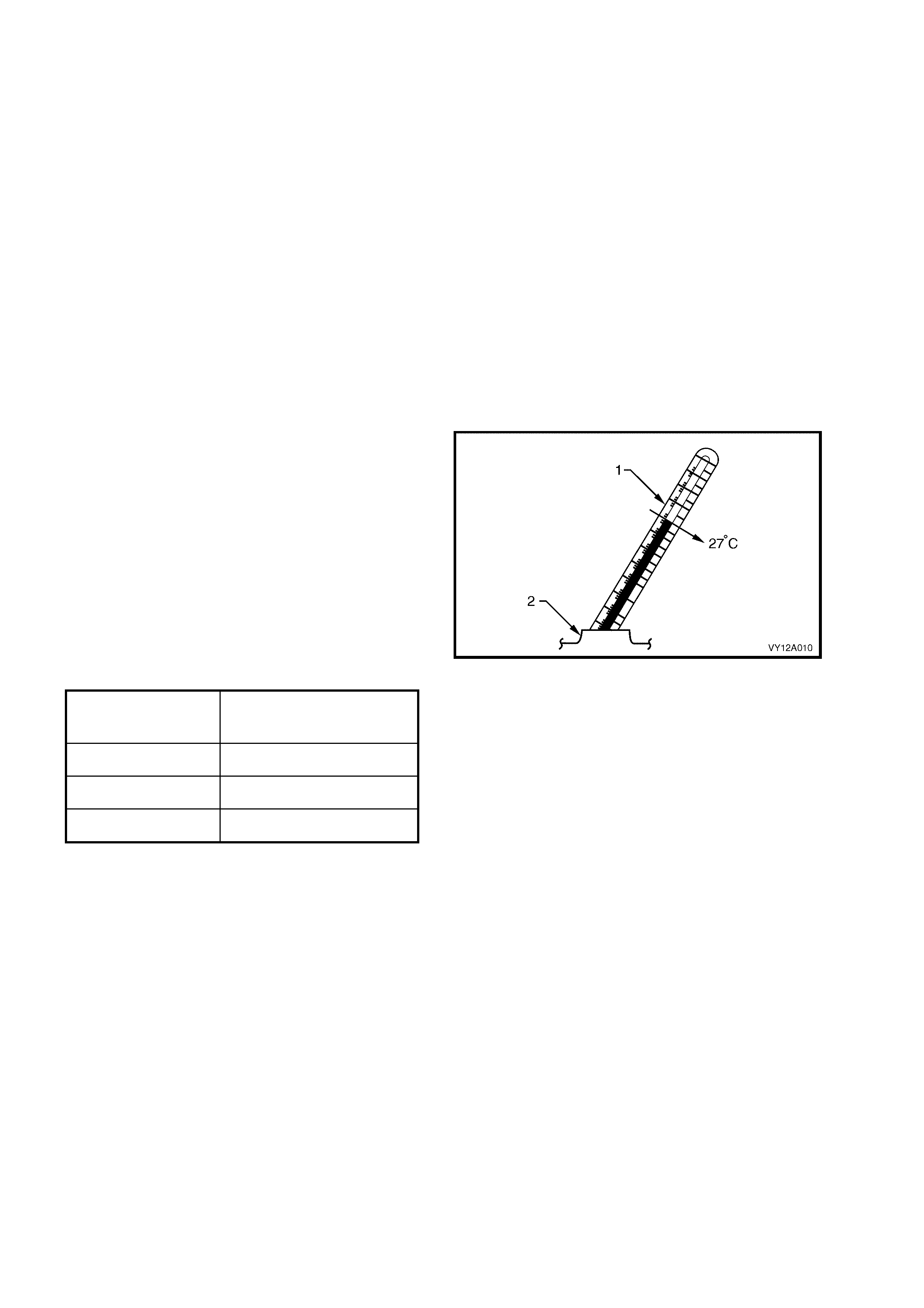
8. Determine the temperature of the battery by
temporarily placing a thermometer (1) into one
of the cells (2).
9. Install the battery vent caps.
10. Calculate the temperature-compensated
readings: add 0.004 for every 5°C above 27°C
or subtract 0.004 for every 5°C below 27°C.
11. Determine the state of charge of the battery
using the temperature-compensated readings
and the table below.
NOTE: The specific gravity of a charged battery
should not vary more than 0.025 between cells.
Larger variations indicate defective cells.
Figure 12A-11
BATTERY
CONDITION SPECIFIC GRAVITY
READING
Fully charged 1.240 to 1.260
Requires charging less than 1.190
Fully discharged 1.110 to 1.130
2.4 LOAD TEST
Load testing the battery with a High Rate Discharge (HRD) tester simulates using the starter motor and checks if
the battery is in serviceable condition. The battery must be at least 65% charged for this test.
NOTE: HRD tes ters are available with either f ixed or variable loads. The operating procedures may vary from brand
to brand, therefore follow the manufacturer’s instructions.
HIGH RATE DISCHARGE (HRD) LOAD TEST
1. Ensure that the state of the battery is at least 65% charged. Refer to TEST THE STATE OF CHARGE in this
Section.
2. Perform the TECH 2 Learn BCM Settings procedur e. Ref er to Sectio n 12J, 3.9 PROGRAM, F3: LEARN BCM
SETTINGS.
3. Refer to Section 00, 5. BATTERY DISCONNECTION PROCEDURES before disconnecting the battery.
4. For vehicles fitted with Telematics, refer to Section 12K, TELEMATICS before performing any service work.
5. Disconnect the battery negative terminal.
6. Disconnect the battery positive terminal.
7. Connect the HRD tester to the battery terminals ensuring correct polarity.
8. Set the tester switches to suit the battery size.
Fixed load tester:
a. Apply the load for approximately 10 seconds to remove any surface charge.
b. Wait 15 seconds for the battery to recover.
Variable load tester:
a. Apply a 300 amp load for approximately 15 seconds to remove any surface charge.
b. Wait 15 seconds for the battery to recover.
9. If possible, set the selector to 50% of rapid discharge current (or three times the 20 hour discharge rate).
10. Apply the load test for 10 seconds and record the battery voltage. If one cell is faulty it will gas excessively or
overheat. This indicates a faulty battery.
11. Recharge the battery if the voltage is at or below the minimum voltage specified by the HRD manufacturer (or
9.6 volts).
12. Replace the battery if the voltage is below the minimum voltage specified by the HRD manufacturer (or below
9.6 volts after the battery is charged and the test is repeated). Refer to 2.9 BATTERY in this Section.
13. Perform the Program Learnt BCM Settings procedure. Refer to Section 12J, 3.9 PROGRAM, F4: PROGRAM
LEARNT BCM SETTINGS.
ALTERNATE LOAD TE ST
If HRD test equipment is not available, test the battery as follows:
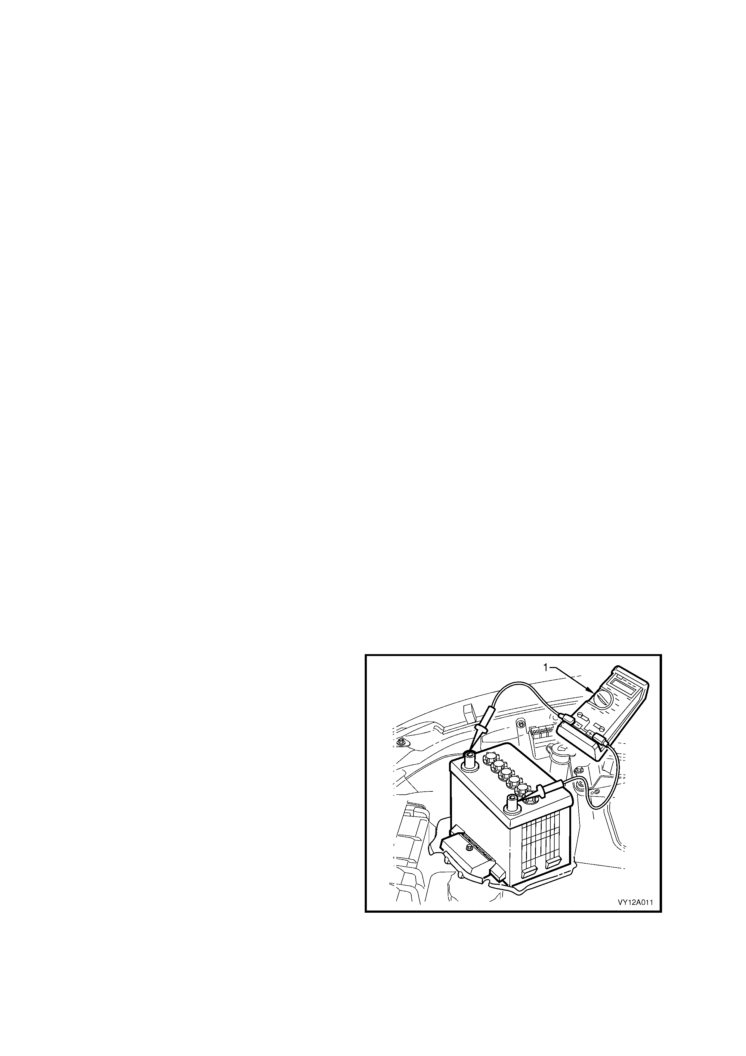
1. Ensure that the state of the battery is at least
65% charged.
2. Connect a voltmeter (1) between the battery
terminals.
3. Turn the headlights on to high-beam for
10 seconds to rem ove any surface char ge from
the battery.
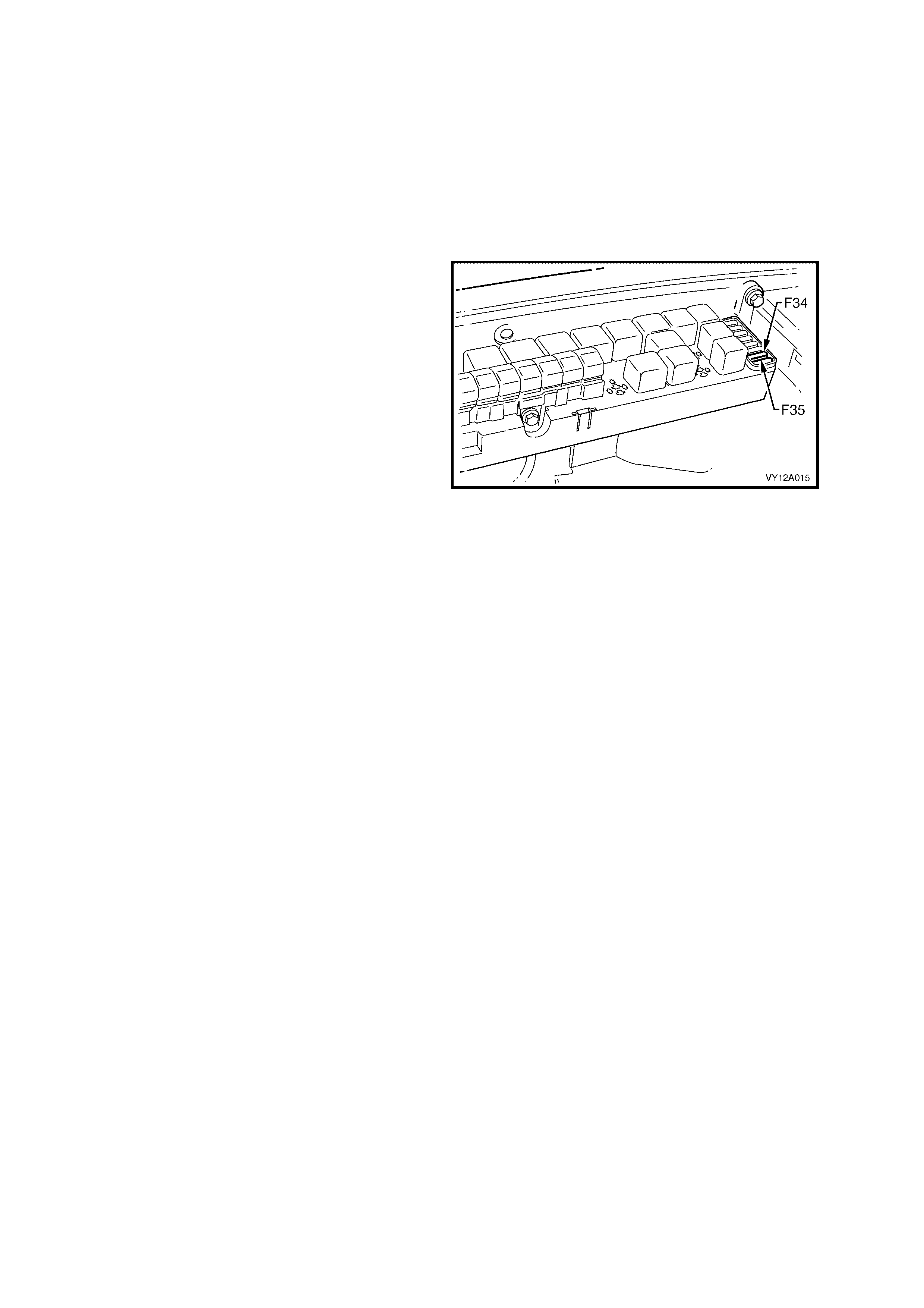
4. Remove fuses F34 and F35 from the engine
compartment fuse and relay housing. This
prevents vehicle ignition and f uel injec tion while
cranking the engine. Refer to Figure 12A-17.
5. Crank the engine and read the voltmeter. At
temperatures above 5°C, the voltage of a fully
charged battery should not fall below 9.6 volts.
NOTE: If the battery and engine temperatures are
below 5°C, the voltage may fall to 9 volts.
6. Replace the batter y if a cell gasses exc essively
or overheats or if the voltage falls away quickly.
Figure 12A-12

2.5 BATTERY CURRENT DRAW TEST
W ith the ignition turned of f, there is still a s tanding current draw from the battery. The standing curr ent is that used
when the vehicle has all electric al items turned off. The BCM featur es a Batter y Saver Mode, which provides vehicle
battery protection through reduced current consumption.
The battery saver mode will be activated after a preset delay period. This delay period has a default value of 65
minutes, however it can be set from 3 – 180 minutes using TECH 2. The delay period starts when the ignition is
switched off.
W hen s witching to Battery Saver Mode, the BCM de-energises the interior illum ination relay (which supplies power
to the interior dome lamps, ignition lock lamp, instrum ent panel compartment lamp and rear compartment lamps),
de-energises the power window r elay, and dis ables the BCM inputs that are norm ally not required when the ignition
is off.
1. Perform the TECH 2 Learn BCM Settings procedur e. Ref er to Sect ion 12J, 3.9 PROGRAM, F3: LEARN BCM
SETTINGS.
2. Before disconnecting the battery, refer to Section 00, 5. BATTERY DISCONNECTION PROCEDURES.
3. If the battery is flat, temporarily install a good battery for the duration of this test.
4. Ensure that the vehicle starts and the accessories operate normally.
5. Ensure that the theft deterrent system operates normally. Refer to Section 12J, 4.7 THEFT DETERRENT
SYSTEM.
6. Use TECH 2 to set the BCM Battery Saver Shut Down Time to 3 minutes. Refer to
Section 12J, 3.9 PROGRAM, F1: OPTIONS. This sets the BCM to switch to Battery Saver mode (Stand-by)
after 3 minutes.
7. For vehicles fitted with Telematics, enable the Service mode. Refer to Section 12K, TELEMATICS. The
Telematics will switch to Stand-by mode (Stand-by) 2 minutes after the ignition is switched off.
8. Fully open the driver’s window (for access purposes).
9. Turn the windscreen wiper intermittent setting to maximum dwell (minimum resistance).
10. Switch the ignition off.
11. Cover the sun sensor (mounted in the top centre of the instrument panel) to simulate dark conditions.
12. Check that all interior illumination is off (including any compartment lighting).
13. Ensure that both the rear compartment lid and the bonnet are closed.
14. Open the instrument panel compartment (glove-box ) to illuminate the lam p. (When the BCM switches to Battery
Saver mode, the glove-box lamp will extinguish.)
15. Close all of the doors.
16. Lock the doors and activate the theft deterrent system (if fitted) to arm the vehicle.
17. Wait for the BCM to switch to Battery Saver mode (when the glove-box lamp extinguishes).
18. Set an ammeter to its highest scale (at least 20 amps).
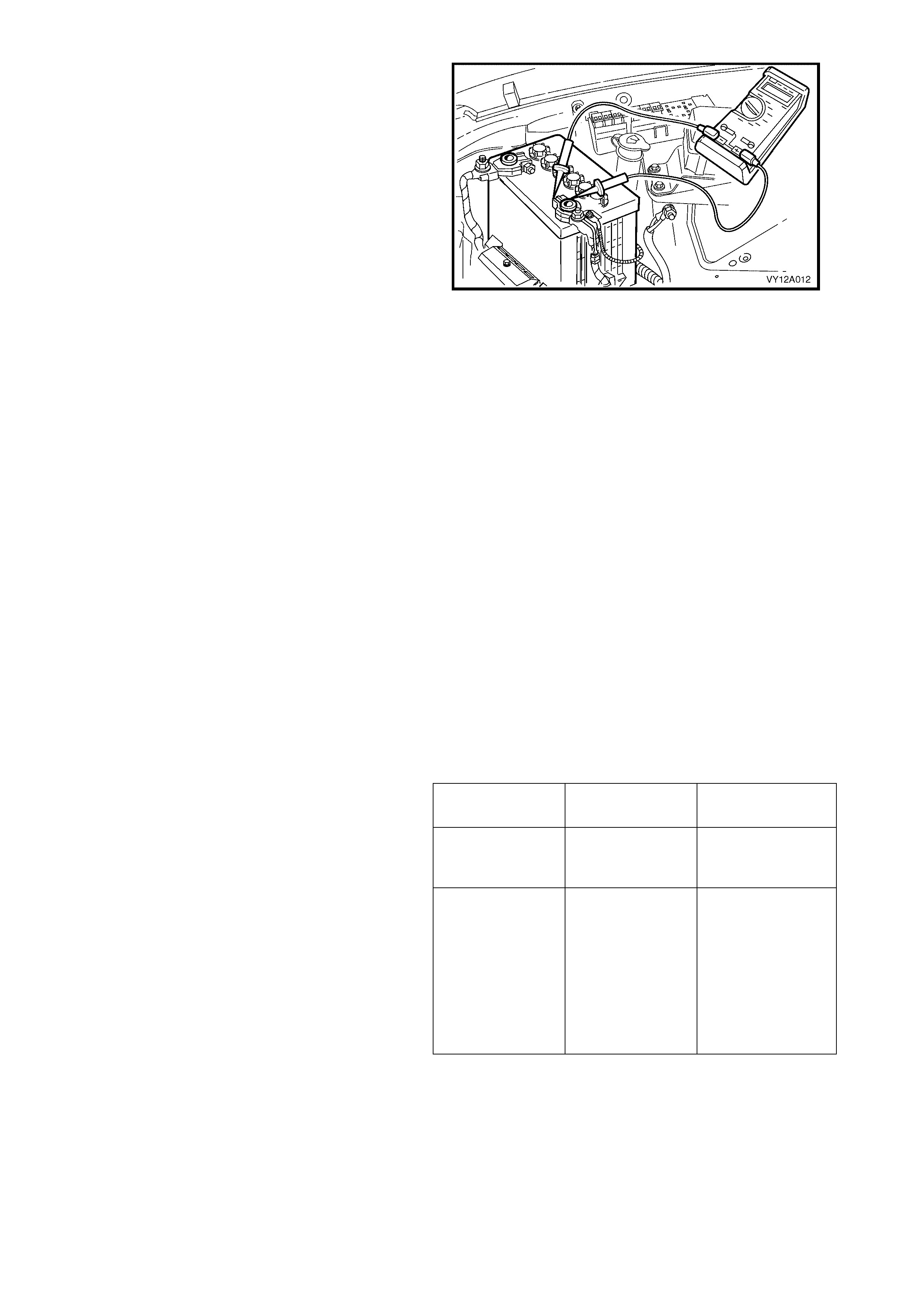
19. Loosen (but do not disconnect) the battery
positive terminal.
20. Connect the positive lead of the ammeter to the
base of the battery positive post.
21. Connect the negative lead of the ammeter to
the top of the positive ter m inal clam p. Refer to
Figure 12A-13.
NOTE: Do not connect an ammeter directly
between the battery positive and negative
connections. This can severely damage the meter.
CAUTION: Do not allow any metallic object (ie.
a spanner or screwdriver) to connect the
positive battery post to ground.
22. Carefully lift the positive cable from the battery
post while maintaining the ammeter
connections.
23. Record the current draw. The ammeter should
read:
• 16 mA – 49 mA fluctuating, on a vehicle
without Telematics
• 66 mA – 99 mA fluctuating, on a vehicle
with Telematics.
Figure 12A-13
24. If the ammeter reading is higher than specified, visually inspect the vehicle for illuminated lamps and
components activated by energised relays.
25. On sedans, lower the rear seat fold-down tray to check that the rear compartment lamp is not illuminated.
26. If the cause of the excessive current draw is not apparent, remove one fuse (or circuit breaker) at a time to
determine the circuit group that is drawing current. Refer to Section 12O, FUSES AND WIRING HARNESSES.
27. W hen the circ uit group is determ ined, install the fuse / cir cuit breaker and identif y the spec ific circuit within this
group that is drawing the extra current. ( Disconnect the wiring harnes s connectors in this circuit gr oup one at a
time.)
28. When the cause is disconnected, the ammeter reading should drop to the correct reading as outlined in Step
23.
29. If necessary, remove the components in this circuit (one at a time) to determine the cause of the excessive
standing current.
30. Fix the cause.
31. Fit all fuses, circuit breakers and connectors.
32. Ensure that the standing current draw is now
within specifications.
33. Use TECH 2 to set the BCM Battery Saver
Shut Down Time to 65 minutes. Refer to
Section 12J, 3.9 PROGRAM, F1: OPTIONS.
34. For vehicles fitted with Telematics, disable the
Service mode. Refer to
Section 12K, TELEMATICS.
35. Perform the Program Learnt BCM
Settings procedure. Refer to
Section 12J, 3.9 PROGRAM, F4: PROGRAM
LEARNT BCM SETTINGS.
Without
Telematics With Telematics
After 3 minutes Fluctuating
16 – 49 mA Fluctuating
66 – 99 mA
(Stand-by mode).
After 2 days Fluctuating
16 – 49 mA Cycling:
Fluctuating
66 – 99 mA for
2 minutes
(Stand-by mode).
Fluctuating
18.5 – 51.5 mA
for 15 minutes
(Sleep mode).

2.6 BATTERY CHARGE
LT Section – 02-200
CAUTIONS
The battery releases an explosive hydrogen and oxygen gas mixture during charging. Ensure that there are no
naked flames or sparks near the battery.
Flat batteries can be safely boost-charged, however, avoid excessive charging current if the battery is more than
half charged. Slow charging is best.
Fast charging can substantially boost a battery, but slow charging is necessary to fully charge the battery.
Do not use a fast charger:
• for starting the vehicle
• if the specific gravity readings are not uniform between battery cells
• if the specific gravity readings are above 1.20
• if the electrolyte is discoloured with brown sediment
• if any of the above three conditions develop after beginning a fast charge.
1. If a ‘constant voltage’ charger is used, charge the battery at 14.5 to 15.0 volts. The battery automatically
regulates the current to a safe level.
2. Check the battery charger specifications to determine the type of charger.
3. Follow the manufacturer’s recommendations for battery charging.
4. Perform the TECH 2 Learn BCM Settings procedur e. Ref er to Sect ion 12J, 3.9 PROGRAM, F3: LEARN BCM
SETTINGS.
5. For vehicles fitted with Telematics, refer to Section 12K, TELEMATICS before performing any service work.
6. Refer to Section 00, 5, BATTERY DISCONNECTION PROCEDURES before disconnecting the battery.
NOTE: Switch the ignition off when connecting or disconnecting battery cable terminals. Failing to do so can
damage electronic components.
7. Remove the battery from the vehicle. Refer to 2.9 BATTERY in this Section.
8. Rem ove the vent caps and c heck the elec trolyte level in each cell. Refer to 2.2 BAT TERY INSPECTIO N in this
Section.
9. Add distilled water as necessary to correct the level. Refer to 2.2 BATTERY INSPECTION in this Section.
10. Rest the caps loosely in the filler tubes.
11. Connect the battery to the battery charger.
CAUTION: Ensure that the connections are to the correct polarity.
12. Set the charging current using the following table as a guide.
CHARGE RATE INITIAL
CURRENT MAXIMUM TIME
REQUIRED
Slow charge 4 amps 24 hrs
Fast charge 35 amps 2 hrs
13. Af ter a f ew minutes, c heck the c olour and specif ic gravity of the electrolyte. Refer to 2.3 HYDROMETER TEST
in this Section.
14. Monitor the electrolyte temperature while the battery is charging.
15. If the temperature reaches 55°C:
a. sw itch the charging current off,
b. allow the battery to cool,
c. reduce the charging current, and
d. restart charging the battery.
16. For the best results, charge the battery with the electrolyte and plates at room temperature. An extrem ely cold
battery may not appear to accept current for several hours after starting the battery charger.
17. Connect a fast-charged battery to a slow-charger for a few hours to bring the battery to the fully charged
condition. Ensure the last few hours of charge do not exceed 1 amp.
18. Check the voltage and specific gravity each hour.
19. Stop the slow charging when there is no change in voltage or electrolyte specific gravity over three checks.
20. Install the battery in the vehicle. Refer to 2.9 BATTERY in this Section.
21. Perform the Program Learnt BCM Settings procedure. Refer to Section 12J, 3.9 PROGRAM, F4: PROGRAM
LEARNT BCM SETTINGS.
NOTE: Charging a battery many times or at higher current rates can significantly reduce the life of the battery.

2.7 VEHICLE WIRING
REGULAR CHECKS
Perform the following checks / repairs regularly to ensure the correct operation of the electrical system and to
safeguard against damage.
1. Check that all harnesses and wires are held securely in their retainer clips.
2. Check the harness and wires for chafing or damaged insulation.
3. Repair or replace parts as necessary.
4. Attach the harness and wire terminals securely.
5. Ensure that the battery tray, clamp and cable terminals are clean and free from corrosion.

2.8 DRY CHARGED BATTERIES
STORA GE
Dry charged batteries are fully charged when manufactured and contain no electrolyte until activated for service.
The dry charged battery is completely sealed and can be stored indefinitely with no servicing until activated.
ACTIVATION
1. Remove the vent caps.
2. Add 1.265 specific gravity electrolyte to each cell to the correct level.
3. Wait several minutes.
4. Check the electrolyte level and add more electrolyte (not water) as necessary. After a dry charged battery is
activated, it becomes a ‘wet’ battery.
IMPORTANT: Add only distilled water when servicing a wet battery.
POST-ACTIVATION TESTS
Although a dry charged battery can be put into service immediately after activation, the following tests are
recommended:
1. Check the voltage of the battery after adding the electrolyte.
2. If the reading is less than 10 volts, replace the battery.
3. Check the specific gravity of the electrolyte in each cell. (Make temperature-compensations as necessary.
Refer to 2.3 HYDROMETER TEST in this Section.)
4. If any reading shows m ore than a 0.030 drop f rom the initial electrolyte reading, slow-charge the battery before
use. Refer to 2.6 BATTERY CHARGE in this Section.
5. Chec k the cells f or violent gas sing. If violent gassing is detected evenly across all ce lls, slow-char ge the battery
before use. If violent gassing is not even across all cells, replace the battery.
2.9 BATTERY
LT Section – 02-200
REMOVE
NOTE: Ensure that the ignition is s witched of f bef or e disc onnec ting or r ec onnec ting the battery cables. Failure to do
so can damage electronic components on the vehicle.
1. Refer to Section 00, 5. BATTERY DISCONNECTION PROCEDURES before disconnecting the battery.
2. For vehicles fitted with Telematics, refer to Section 12K, TELEMATICS before performing any service work.
3. Using TECH 2, per f orm the Learn BCM Settings proc edur e. Ref er to Sect ion 12J, 3.9 PRO G RAM, F3: LEARN
BCM SETTINGS.
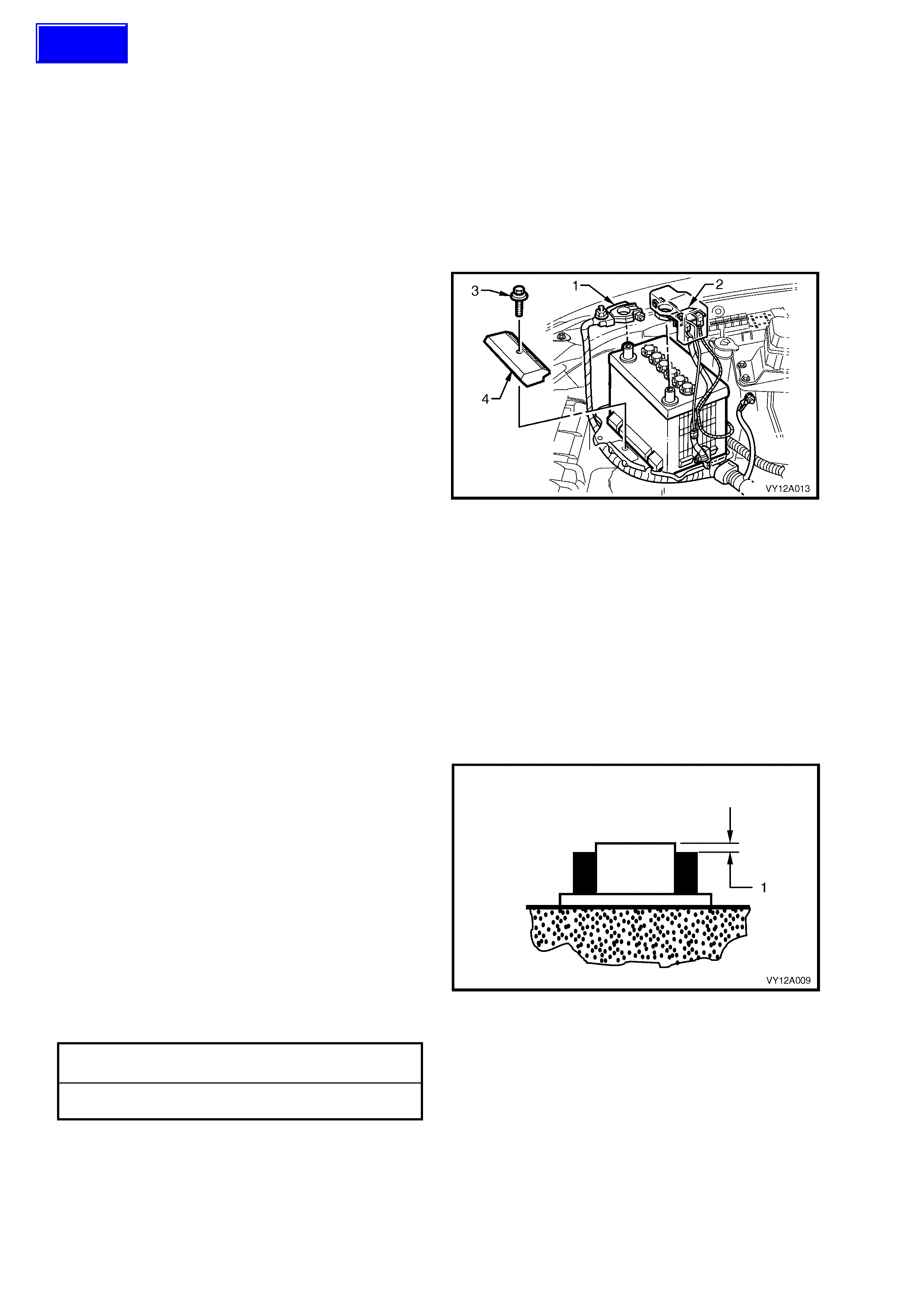
6. Disconnect the battery negative terminal (1).
7. Disconnect the battery positive terminal (2).
8. Unscrew the battery hold-down bolt (3) and
remove the battery hold-down bracket (4).
9. Lift the battery out of the engine compartment.
Figure 12A-14
REINSTALL
Install the battery in the reverse order to the removal procedure, noting the following:
1. Ensure that the battery tray, cables and terminals are clean and free from corrosion and moisture.
2. Replace the battery harness if the terminal clamps are corroded.
3. Remove corrosion deposits as follows:
a. Scrub the area with a stiff brush.
b. Treat the area with a solution of warm water and baking soda or ammonia.
c. Rinse the area with clean water.
4. Install the battery and check that it sits level in the tray.
5. Ensure that no foreign objects (i.e. loose nuts or stones) are in the battery tray.
6. Fit each cable terminal so that it sits below the
top of the battery post (1):
a. Ins tall the battery pos itive terminal onto the
battery positive post.
Install the battery negative terminal onto the battery
negative post.
7. Tighten the battery hold-down bolt and cable
terminal nuts to the specified torques.
8. Smear the battery posts and cable terminals
with petroleum jelly to inhibit corrosion.
9. Perform the Program Learnt BCM Settings
procedure. Refer to Section 12J, 3.9
PROGRAM, F4: PROGRAM LEARNT BCM
SETTINGS.
BATTERY HOLD-DOWN BOLT
TORQUE SPECIFICATION 8 – 10 Nm
BATTERY TERMINAL NUT
TORQUE SPECIFICATION 2 – 5 Nm
Figure 12A-15
Techline
2.10 EME RGE NCY JUMP STARTING PROCEDURE
PRECAUTIONS
• Observe these precautions and conditions to avoid serious personal injury (particularly to the eyes), property
damage and damage to the electronic components of either vehicle.
• Do not attempt to pus h or tow the vehicle to start it. Dam age can result when unburnt fuel reaches the catalytic
converter and ignites.
• Do not attempt to start the vehicle using a fast charger.
• When using jumper leads, treat both the booster battery (auxiliary) and the discharged battery with care.
• Do not cause or allow sparks, flame or smoking near a battery.
• Remove rings, watches and any other conductive jewellery when working around batteries.
• Wear approved ey e protection.
• Do not allow battery fluid to contact eyes, skin, fabrics, or painted surfaces, as the fluid is a corrosive acid. If
skin or eye contact occurs, thoroughly flush the area with water immediately and seek medical attention.
• Take care to ensure that metal tools or jumper cables do not simultaneously contact the battery positive
terminal and any other metal on the vehicle.
• For vehicles fitted with Telematics, refer to Section 12K, TELEMATICS before performing any service work.
JUMP STARTING PROCEDURE
1. Position the assisting vehicle so that the
batteries of both vehicles are close together.
NOTE: Ensure that the vehicles are not touching.
2. Apply the park brake on both vehicles.
3. Ensure that P (park) is selected for automatic
transmission and N (neutral) is selected for
manual transmissions.
4. Turn off the ignition, lights and all other
electrical loads.
NOTE: Ensure that the assisting vehicle battery
has the sam e voltage rating and connects negative
to ground.
If this is not the case, serious injury and / or
damage to electrical equipment can result.
5. Check that the vent caps on both batteries are
tight.
6. Place a wet cloth (if available) over the vent
caps of each battery.
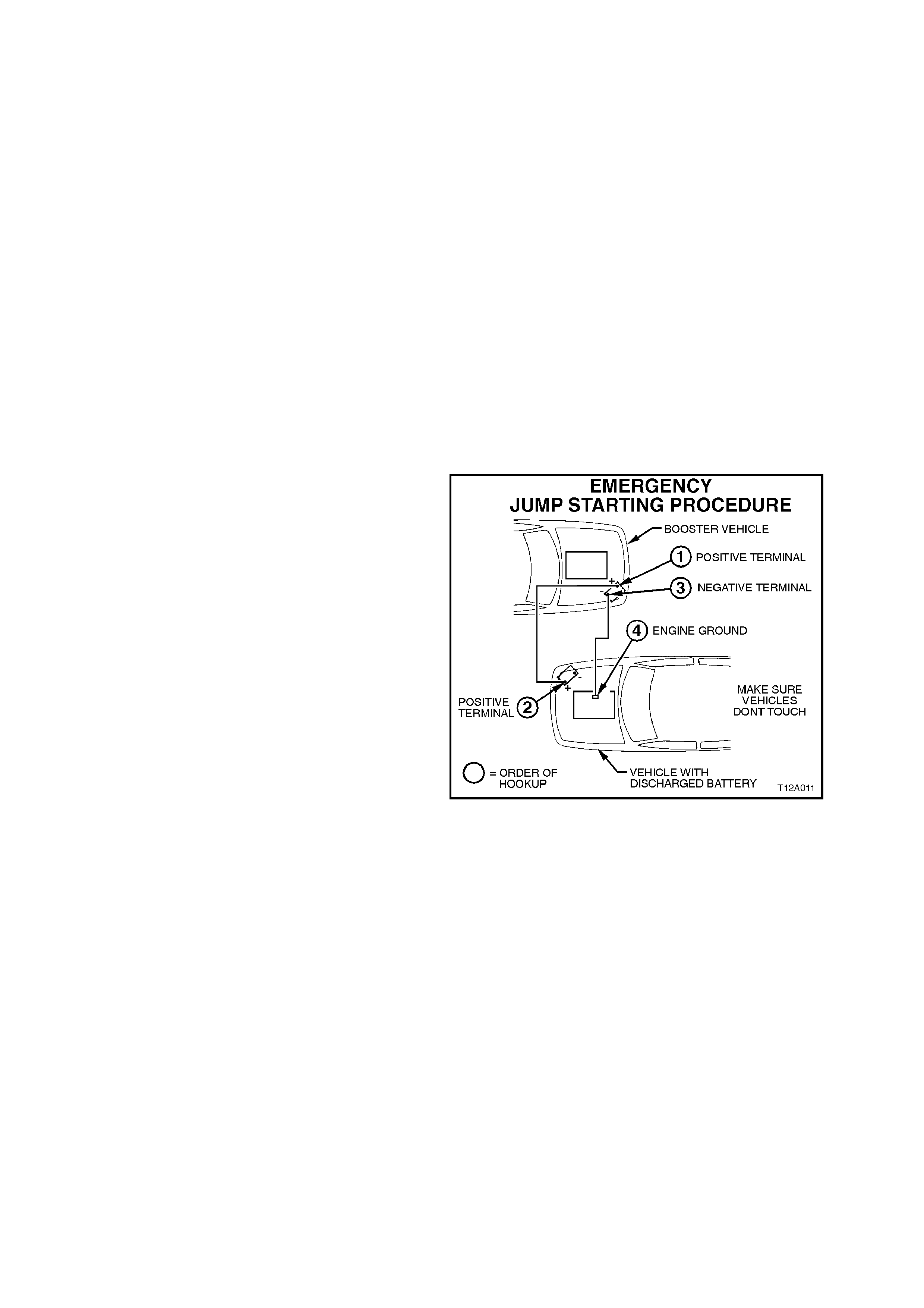
7. Attach one end of a jumper cable (red) to the
positive terminal of the assisting battery.
Figure 12A-16
8. Attach the other end of the same cable to the positive terminal of the discharged battery.
9. Attach one end of the second jumper cable (black) to the negative terminal of the assisting battery.
10. Attach the other end to a solid stationary, metallic point on the engine of the disabled vehicle.
11. NOTE: Do not connect this end directly to the negative post of the discharged battery.
12. Ensur e that the jum per cables are not on or near drive pulleys, cooling fans or other points that will move when
the engine is started.
13. Start the engine in the assisting vehicle and run the engine at a moderate speed for a few minutes.
14. Start the engine in the disabled vehicle.
15. When the engine star ts, allow both engines to idle f or approxim ately 7 m inutes. This allows the voltage levels in
both vehicles to balance.
16. Leave the vehicles running and remove the jumper cables in the reverse sequence to attaching them. When
removing each clamp, take care that it does not touch any other metal.
NOTE: If the engine in the disabled vehicle does not start within 30 seconds, stop cranking the engine and fix the
cause.
17. Discard the wet cloths covering the vent caps of both batteries.

3. DIAGNOSIS
With the increased use of elec tronic s ensor s and c omputer c ontrol, the batter y is muc h more than just a component
used to start a car. Low battery voltage can:
• affect the operation of the vehicle control modules and cause annoying driveability problems
• cause the control modules to set diagnostic trouble codes.
If a contr ol module sens es low battery voltage, it may increase f uel inje ctor timing to increase engine rpm in order to
increase the generator output.
Consider the state of charge of the battery any tim e a custom er com plains of a driveability-related problem . Always
check the condition of the battery before beginning a full diagnostic procedure.
For vehicles fitted with Telematics, refer to Section 12K, TELEMATICS before performing any service work.
BATTERY CHARGE DIAGNOSTIC CHART
STEP ACTION VALUE YES NO
1 1. Check that the battery is the size recommended for
the vehicle. Refer to 4 SPECIFICATIONS in this
Section.
Is the battery the correct size?
Go to Step 2. Fit the correct
sized battery.
2 1. Check for obvious damage. (i.e. A cracked or
broken case, terminal damage, loose cables.)
Is the battery damaged?
Replace the
battery. Go to Step 3.
3 1. Check the electrolyte level.
Is the level OK? Go to Step 4. Correct the
electrolyte levels.
Refer to
2.2 BATTERY
INSPECTION in
this Section.
Charge the
battery. Refer to
2.6 BATTERY
CHARGE in this
Section.
Go to Step 4.
4 1. Check the generator voltage output at the battery.
Is the value as specified? 14.5 ± 0.2
volts
@ 20ºC
Go to Step 5. Go to Step 5.
5 1. Check for a voltage drop between the generator
main output terminal and the battery positive post.
Is the voltage drop more than 0.5 volt?
Repair faulty
generator to
battery circuit.
Repair faulty
charging system.
Refer to:
Section 6D1-1
(V6 engine,
100 amp
generator)
Section 6D2-1
(V6 engine,
120 amp
generator)
Section 6D3-1
(GENIII V8
engine).
6 1. Check the battery cable and terminal connections
to the battery posts.
Are all connections OK?
Go to Step 7. Repair poor
connections.
7 1. Fully charge the battery. Refer to 2.6 BATTERY
CHARGE in this Se ction.
Did the battery accept a charge and is the nominal
voltage 12.4 volts or more after charging?
Go to Step 8. Replace the
battery.
8 1. Load test the battery. Refer to 2.4 LOAD TEST in
this Section.
Read the tester just before releasing the load.
Is the value as specified?
More than
9.6 volts Go to Step 9. Replace the
battery.
9 1. Attempt to start the engine.
Does the engine start without hesitation? System OK. Check the
vehicle for faults
other than the
battery.
PROBLEM STILL EXISTS
If the battery has proven to be in good condition, determine the cause of a no-start or slow cranking condition to
avoid further customer complaint. If no obvious cause is evident, diagnose the vehicle electrical system, as follows:
Step 1: Starting System
1. Test the battery under load. Refer to 2.4 LOAD TEST in this Section.
2. If the battery passes the battery load tes t but the engine will not crank over or is still dif ficult to start, c heck the
starting system.
3. If there are no problems with the starting system, go to Step 2: Battery Current Draw.
4. Check the starting system to verify proper operation using a simple cranking test, as follows:
a. Remove fuses F34 and F35 from the
engine compartment fuse and relay
housing. This prevents vehicle ignition and
fuel injection while cranking the engine.
Refer to Section 12O, FUSES AND
WIRING HARNESSES.
Figure 12A-17
b. Connect a voltmeter between the main battery positive terminal of the starter motor and a good ground
connection.
c. Turn the ignition switch to start the engine and read the voltmeter while cranking.
d. Turn the ignition off.
NOTE: Try to avoid activating the starter motor continuously for more than 30 seconds. If activating the starter
motor for 30 seconds, allow the starter motor to cool for 3 minutes.
5. If the cranking voltage is less than 9.6 volts (and the battery is good), check for:
• poor starter motor ground connection
• excessive current draw from the starter motor
• major voltage drop in the battery cables / terminals.
If the cranking voltage is greater than 9.6 volts, proceed to number 8 in this step.
6. Check the starter m otor operation. Refer to Section 6D1-2, START ING SY STEM – V6 AND V6 S/C ENGINES
or Section 6D3-2, STARTING SYSTEM – GEN III V8 ENGINE.
7. Install fuses F34 and F35.
8. Crank the engine.
If the starting system is okay but long cranking is required to start the vehicle, excessive demands are placed on the
battery. Diagnose and repair the cause of this. Possible causes for excessive cranking requirements include
problems with the fuel system or the ignition system. Refer to:
• Section 6C1, POWERTRAIN MANAGEMENT – V6 ENGINE
• Section 6C2, POWERTRAIN MANAGEMENT – V6 SUPERCHARGED ENGINE
• Section 6C3, POWERTRAIN MANAGEMENT – GEN III V8 ENGINE.
Step 2: Battery Current Draw
Perform the battery current draw test. Refer to 2.5 BATTERY CURRENT DRAW TEST in this Section.
Step 3: Charging System
A charging system problem may keep the battery sufficiently charged during normal operation, but not during
prolonged periods of driving with a number of accessories operating. Check the charging system to diagnose this.
Refer to Section 6D1-1, CHARGING SYSTEM – V6 AND V6 S/C ENGINES or 6D3-1 CHARGING SYSTEM –
GEN III V8 ENGINE.
Step 4: Driver Related Condition
If the cause of the battery discharge is still not determined (and the battery tests okay), possible causes include:
• a lamp left on but turned off before diagnosis
• the user driving habits. For exam ple, many short trips and repeated starts which prevent sufficient tim e for the
generator to fully recharge the battery between starts.
If either of these situations is suspected, make the vehicle owner aware of ways to reduce the demand on the
battery.
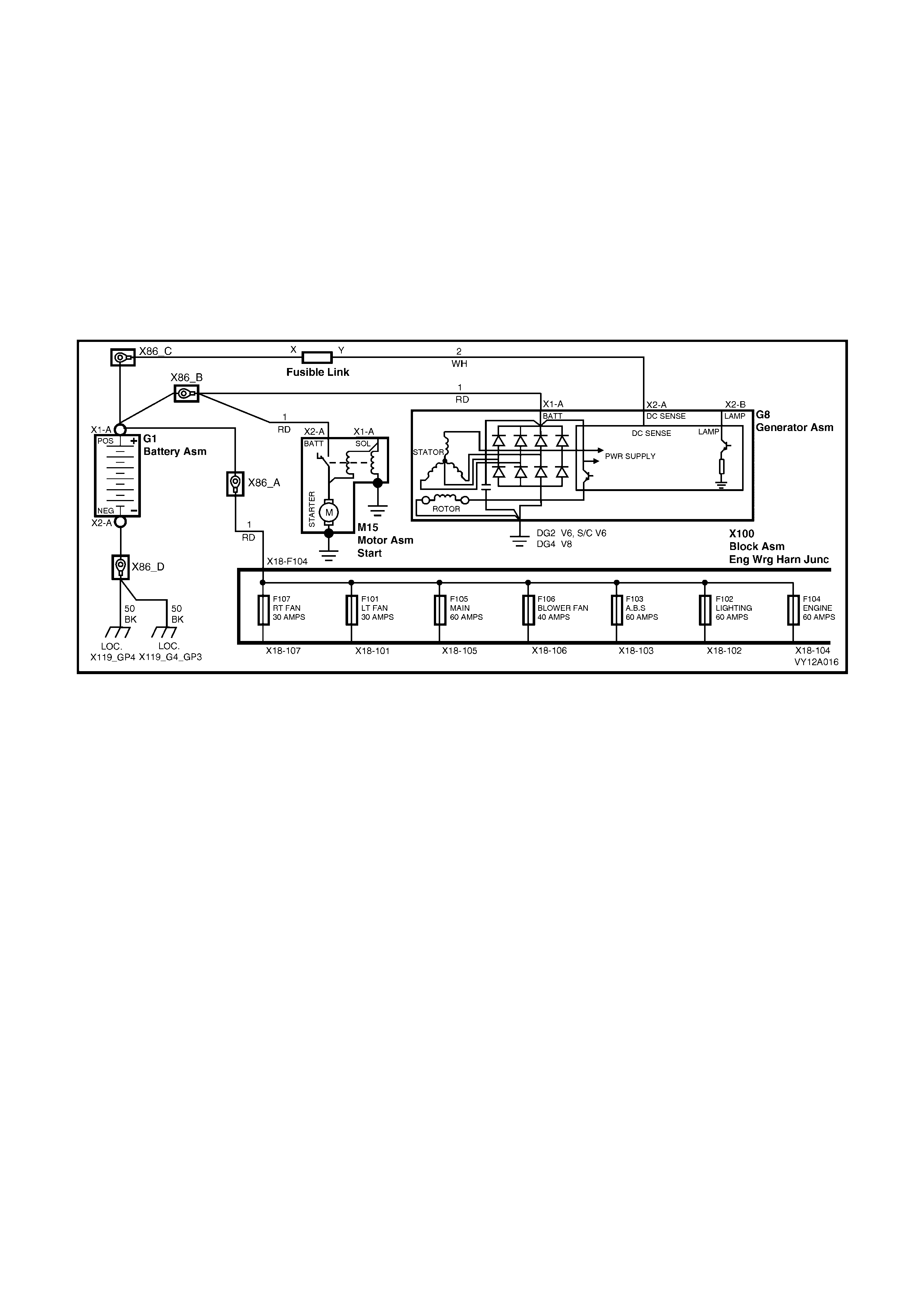
CIRCUIT DIAGRAM
Figure 12A-18

4. SPECIFICATIONS
AUSTRALIAN AND NEW ZEALAND MODELS
Rated Voltage.............................................................12 volts
Cold Cranking Amps ..................................................430 amps minimum
Reserve Capacity.......................................................85 minutes minimum
20 Hour Discharge .....................................................54 amp / hour minimum
5 Second Voltage @ 25° C ........................................150 amps 10.4 + / – 0.2 volts
.........................................................................400 amps 8.4 + / – 0.2 volts
Number of Plates (per cell) ........................................11
EXPORT MODELS
Rated Voltage.............................................................12 volts
Cold Cranking Amps ..................................................450 amps minimum
Reserve Capacity.......................................................115 minutes minimum
20 Hour Discharge .....................................................54 amp / hour minimum
5 Second Voltage @ 25° C ........................................150 amps 10.6 + / – 0.2 volts
.........................................................................400 amps 8.4 + / – 0.2 volts
Number of Plates (per cell) ........................................11
NOTE: Specified ratings when tested in accordance with Australian Standard AS 2149-1990

5. TORQUE WRENCH SPECIFICATIONS
Nm
Battery hold-down bolt .......................................................... .......8 – 10
Battery terminal nut............................................................... .......2 – 5
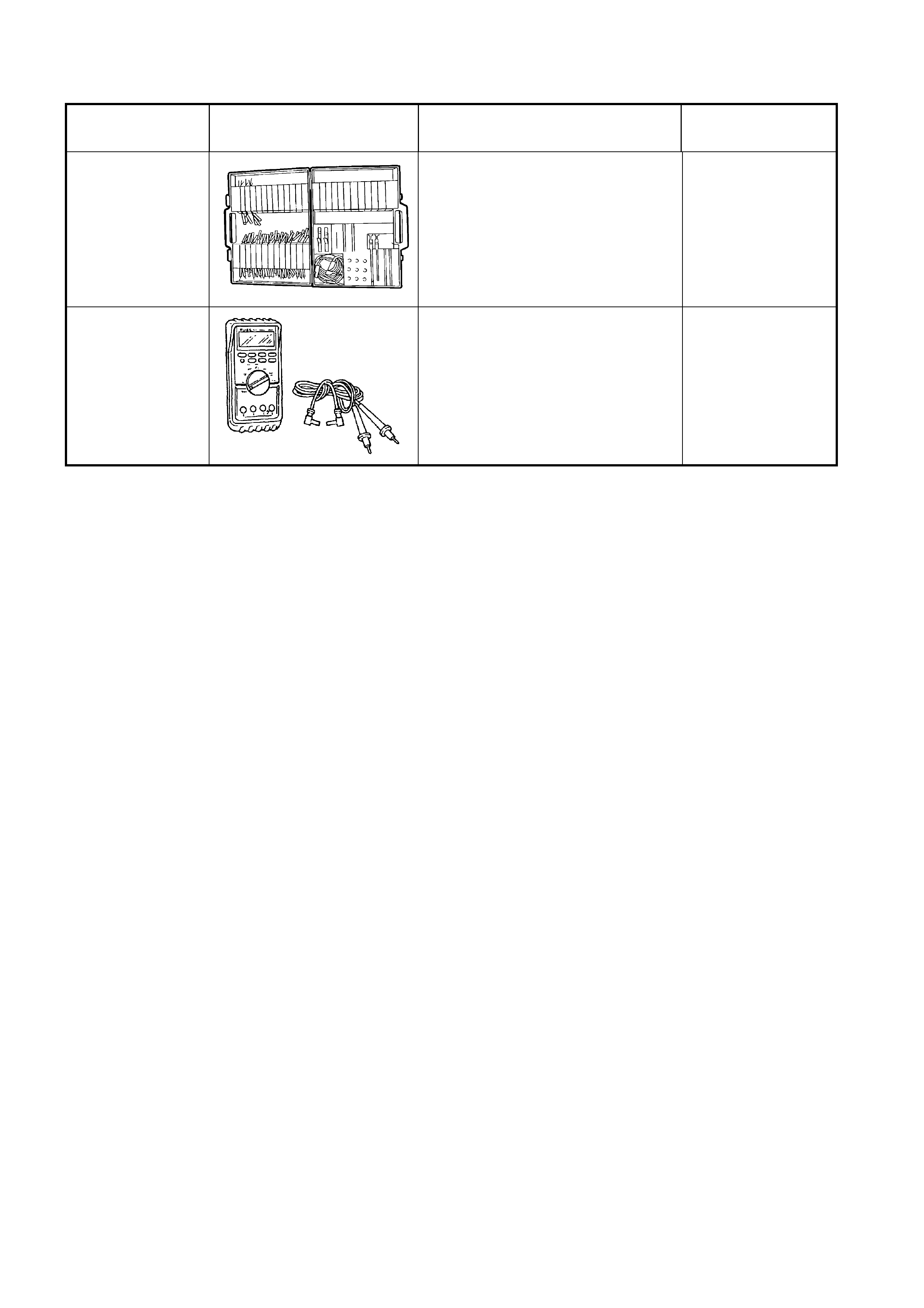
6. SPECIAL TOOLS
TOOL NUMBER ILLUSTRATION DESCRIPTION TOOL
CLASSIFICATION
J35616-A
(KM609)
CONNECTOR TEST ADAPTOR
KIT
Used when carrying out electrical
diagnostic circuit checks.
Previously released.
Desirable
3588
(J39200)
DIGITAL MULTIMETER
Must have at least 10 MΩ input
impedance and be capable of
reading frequencies.
Previously released.
Available