
SECTION 12B - LIGHTING SYSTEM
IMPORTANT
Before performing any Service Operation or other procedure described in this Section, refer to Section 00
CAUTIONS AND NOTES for correct workshop practices with regard to safety and/or property damage.
CONTENTS
1. GENERAL DESCRIPTION
1.1 HEADLAMP ASSEMBLY
LEVEL 1 VEHICLES
LEVEL 2 AND LEVEL 3 VEHICLES
COUPE
1.2 TAIL LAMP ASSEMBLY
1.3 HIGH MOUNT STOP LAMPS
1.4 INTERIOR ILLUMINATION
LEVEL 1
LEVEL 2 AND 3
COUPE
1.5 INSTRUMENT AND SWITCH ILLUMINATION
HEADLAMP SWITCH
POLICE LIGHTS-OUT SWITCH
2. SERVICE OPERATIONS – EXTERIOR
ILLUMINATION
2.1 HEADLAMP AND FOG LAMP AIMING
HEADLAMP ASSEMBLY AIM
FRONT FOG LAMP ASSEMBLY AIM
2.2 HEADLAMP AND PARK LAMP
ASSEMBLY BULBS
LEVEL 1
LEVEL 2 AND LEVEL 3
COUPE
2.3 FRONT TURN SIGNAL LAMP BULB
REPLACE
2.4 FRONT FOG LAMP BULB ASSEMBLIES
LEVEL 3
SS
COUPE
2.5 TAIL LAMP ASSEMBLY BULBS
SEDAN
WAGON
COUPE
UTILITY
2.6 HEADLAMP ASSEMBLY
REMOVE
REINSTALL
2.7 FRONT FOG LAMP ASSEMBLY
LEVEL 3
SS
COUPE
2.8 TAIL LAMP ASSEMBLY
SEDAN
WAGON
COUPE
UTILITY
2.9 FRONT SIDE TURN SIGNAL LAMP
ASSEMBLY
REMOVE
REINSTALL
2.10 HIGH MOUNT STOP LAMP ASSEMBLY
SEDAN WITHOUT REAR END SPOILER
SEDAN WITH REAR END SPOILER
WAGON
COUPE
UTILITY
2.11 REAR LICENCE PLATE LAMP ASSEMBLY
REMOVE
REINSTALL
WIRING HARNESS, SEDAN
WIRING HARNESS, WAGON
WIRING HARNESS, COUPE
3. SERVICE OPERATIONS – INTERIOR
ILLUMINATION AND SWITCHING
3.1 SIDE DOOR COURTESY LAMP ASSEMBLY
REMOVE
REINSTALL
3.2 INSTRUMENT PANEL COMPARTMENT
LAMP ASSEMBLY
REMOVE
REINSTALL
3.3 INSTRUMENT PANEL COMPARTMENT
LAMP SWITCH ASSEMBLY
REMOVE
REINSTALL
3.4 REAR COMPARTMENT COURTESY
LAMP ASSEMBLY
REMOVE
REINSTALL
3.5 REAR COMPARTMENT COURTESY
LAMP SWITCH ASSEMBLY
REMOVE
REINSTALL
3.6 UNDER-HOOD LAMP ASSEMBLY
REMOVE
REINSTALL
3.7 UNDER-HOOD LAMP ASSEMBLY
WIRING HARNESS
REMOVE
REINSTALL
3.8 DOME LAMP ASSEMBLY
BULB REPLACE
REMOVE
REINSTALL
3.9 DOME AND READING LAMP ASSEMBLY
BULB REPLACE
REMOVE
REINSTALL
3.10 ROOF CONSOLE
BULB REPLACE
REMOVE
REINSTALL
Techline
Techline
Techline
Techline
Techline
Techline

3.11 DOOR JAMB SWITCHES
REMOVE
REINSTALL
3.12 STEPWELL LAMPS
REPLACE
3.13 FLOOR CONSOLE COMPARTMENT
LAMP ASSEMBLY
REMOVE
REINSTALL
3.14 FLOOR CONSOLE COMPARTMENT
LAMP SWITCH ASSEMBLY
REMOVE
REINSTALL
3.15 ROOF RAIL COURTESY AND READING
LAMP ASSEMBLY
REMOVE
REINSTALL
3.16 AUTOMATIC TRANSMISSION
CONTROL POSITION LAMP
REPLACE
3.17 IGNITION LOCK CYLINDER BULB
REPLACE
3.18 STOP LAMP SWITCH ASSEMBLY
REPLACE
TEST
3.19 SWITCH ILLUMINATION
AUXILIARY SWITCH BULBS
POWER AND TRACTION
CONTROL SWITCH BULBS
HAZARD WARNING SWITCH BULB
FUEL TANK FILLER DOOR
LOCK RELEASE SWITCH BULB, LHD
3.20 BACK-UP LAMP SWITCH
3.21 NEUTRAL SAFETY BACK-UP SWITCH
3.22 TURN SIGNAL SWITCH ASSEMBLY
REMOVE
REINSTALL
TESTING
3.23 HEADLAM P SWITCH ASSEMBLY
REMOVE
REINSTALL
TESTING
3.24 DAYLIGHT RUNNING LAMP
ASSEMBLY (OPTION T82)
REMOVE
REINSTALL
TESTING
3.25 HAZARD WARNING SWITCH ASSEMBLY
REMOVE
REINSTALL
TESTING
3.26 PASSENGER COMPARTMENT FUSE
AND RELAY ASSEMBLY
ACCESS
COMPONENT LOCATION
3.27 ENGINE COMPARTMENT FUSE AND
RELAY PANEL ASSEMBLY
ACCESS
COMPONENT LOCATION
4. SPECIFICATIONS
5. TORQUE WRENCH SPECIFICATIONS

1. GENERAL DESCRIPTION
IMPORTANT: All illustrations in this Section represent a right-hand drive vehicle. For left-hand drive vehicles, any
procedure or item that is not a direct mirror of a right-hand drive vehicle in left-hand drive configuration, will be
highlighted and a procedure or illustration produced to accommodate the difference.
1.1 HEADLAMP ASSEMBLY
The headlamp ass emblies fitted to the MY 2003 VY Series vehic les and V2 Ser ies II Coupe inc orpor ate the lates t in
headlamp reflector technology. There are three basic headlamp geometries and each type is applicable to the
following groups of vehicles:
• Level 1
• Level 2 and Level 3 vehicles
• Coupe
Although the headlamp assemblies are visually different, they share the following common features:
• All are equipped with low beam, high beam, park and turn signal lamps.
• Beam movement in the vertical and horizontal axes is controlled by the same type of adjustment device.
• Turn signal bulb holders and main wiring connector are identical.
• Turn signal lamps are located on the outside extremities of the assembly.
• The high beam is located in the inboard side of the assembly.
• The low beam lamp is located outboard of the high beam lamp.
• The headlamp assemblies have common mounting holes, that is, they all require three screws in the same
locations to secure the assemblies to the sheetmetal.
LEVEL 1 VEHICLES
Level 1 vehicle headlamp assemblies (refer to Figure 12B-1) have the following features, depending on particular
model specifications:
• The headlamps use complex reflector technology for low and high beam.
• Distinctive styling to suit the Level 1 vehicle bumper fascia.
• Chrome or black headlamp bezels.
• Single filament H1 and dual filament H4 specification globes are fitted to the inner and outer beam reflector
pockets respectively.
• T he park lamp is located on the lower edge of the assem bly, between the inner and outer reflector pockets, in
its own reflector housing.
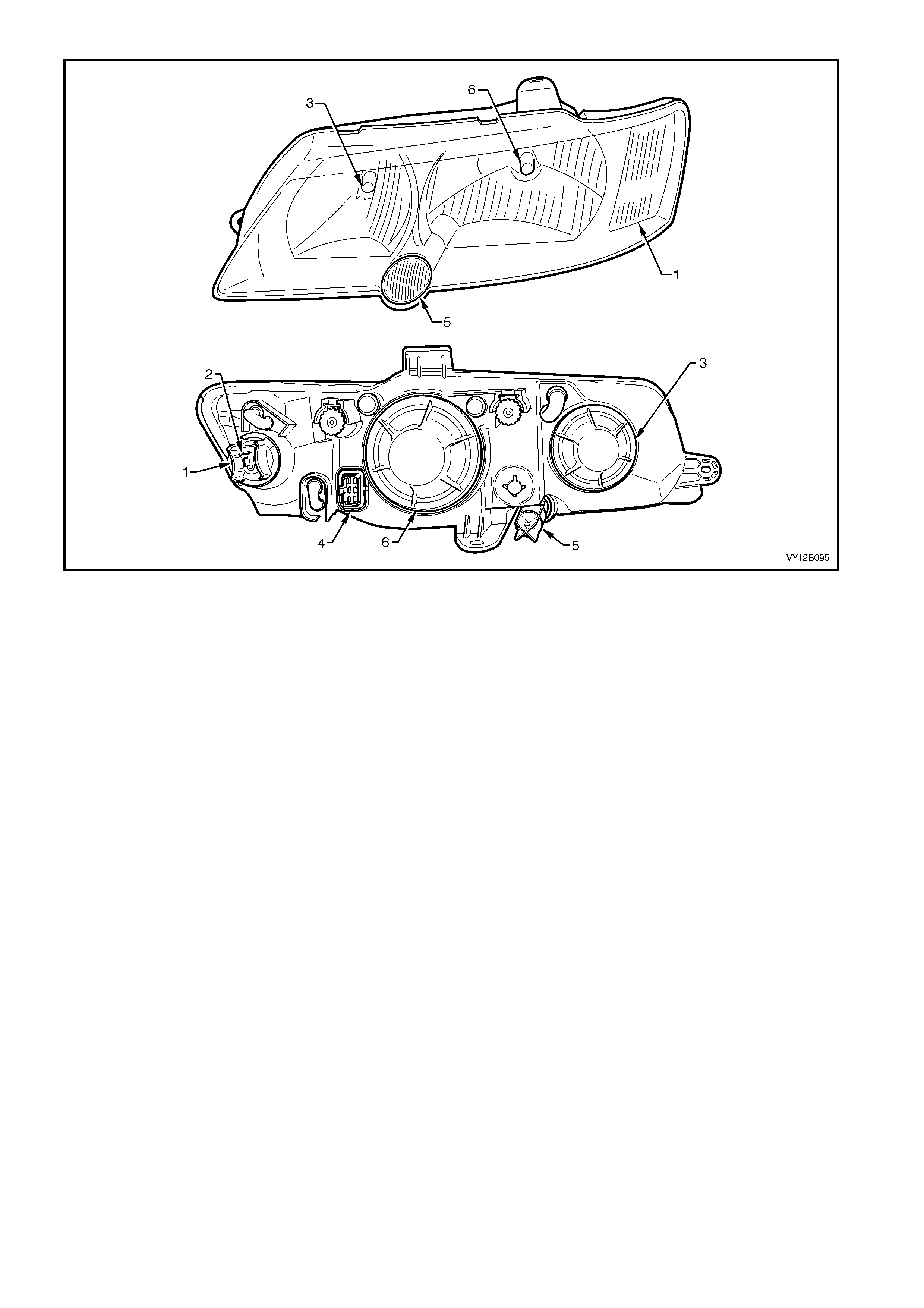
Figure 12B-1
Legend
1. Turn Signal Lamp
2. Turn Signal Wiring Connector 3. Headlamp High Beam Bulb (H1)
4. Headlamp Main Wiring Connector 5. Park Lamp
6. Headlamp Low Beam Bulb (H4)
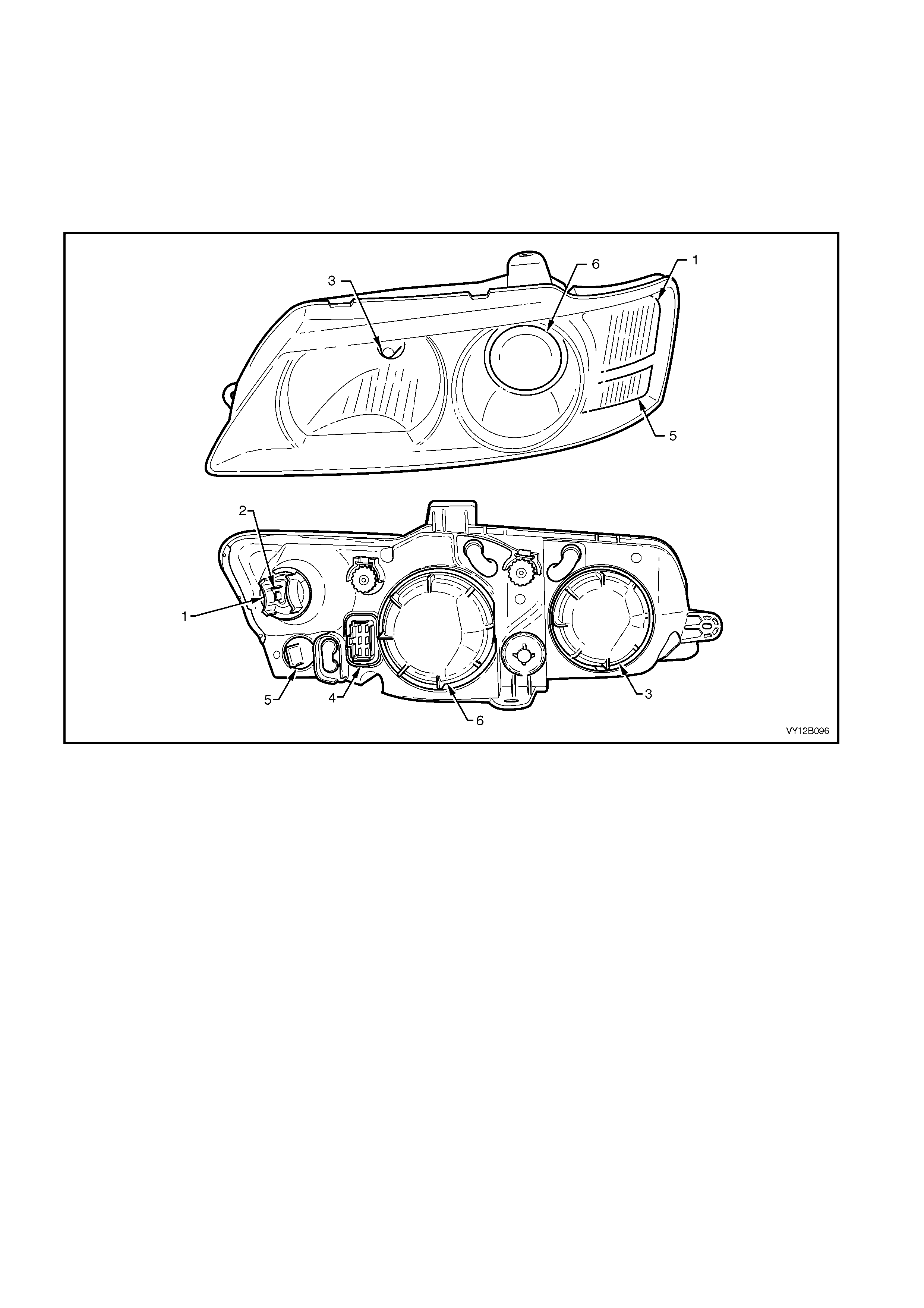
LEVEL 2 AND LEVEL 3 VEHICLES
The Level 2 and 3 vehicle headlamp assemblies (refer to Figure 12B-2) have the following features:
• Distinctive styling to suit the Level 2 and Level 3 vehicle bumper fascia.
• Chrome or black headlamp bezels.
• Single filament H9 and H11 specification globes for high and low beam reflector pockets respectively.
• The low beam uses projector lamp technology to increase illumination and give distinctive styling, whilst high
beam uses complex reflector technology.
• The park lamp is located below the turn signal lamp in its own reflector housing.
Figure 12B-2
Legend
1. Turn Signal Lamp
2. Turn Signal Wiring Connector 3. Headlamp High Beam Bulb (H9)
4. Headlamp Main Wiring Connector 5. Park Lamp
6. Headlamp Low Beam Bulb (H11)
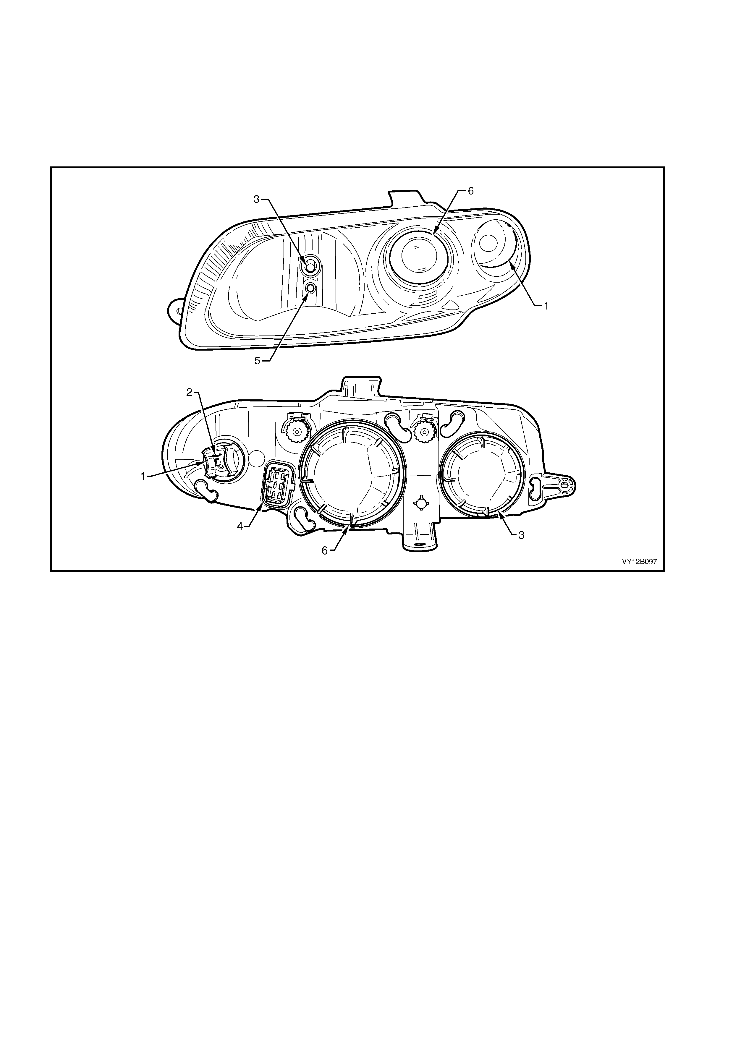
COUPE
The Coupe headlamp assembly (refer to Figure 12B-3) has the following features:
• Distinctive styling to suite the Coupe bumper fascia.
• Single filament H9 and H11 specification globes high and low beam reflector pockets respectively.
• The low beam uses projector lamp technology to increase illumination and give distinctive styling, whilst high
beam uses complex reflector technology.
• The park lamp is located in the high beam reflector and is accessed through the high beam lamp dust cap.
Figure 12B-3
Legend
1. Turn Signal Lamp
2. Turn Signal Wiring Connector 3. Headlamp High Beam Bulb (H9)
4. Headlamp Main Wiring Connector 5. Park Lamp
6. Headlamp Low Beam Bulb (H11)

1.2 TAIL LAMP ASSEMBLY
The tail lam ps fitted to the MY 2003 VY Series vehicles and V2 Ser ies II Coupe are designed to be f unctional whilst
providing aesthetically pleasing looks. T here are four basic tail lamp geometries and each type is applicable to the
following groups of vehicles:
• Level 1
• Level 2 and Level 3 Sedan vehicles
• All Utility and Wagon vehicles
• Coupe
For views of the front and rear of the tail lamp assemblies, refer to Figure 12B-4 where:
• VIEW A – Coupe front and rear views
• VIEW B – Level 2 and Level 3 Sedan vehicle front and rear views
• VIEW C – Level 1 Sedan vehicle front and rear views
• VIEW D – Utility and Wagon front and rear views
All provide the following functions:
• Stop/tail lamps (1)
• Turn signal lamps (2)
• Back-up lamps (3)
• Reflex reflectors (4)
Beside the physical differences between the tail lamp assemblies across the various model levels, Level 1 Sedan
vehicles tail lamp assemblies have chrome or black housings, depending on particular model specifications.
Techline
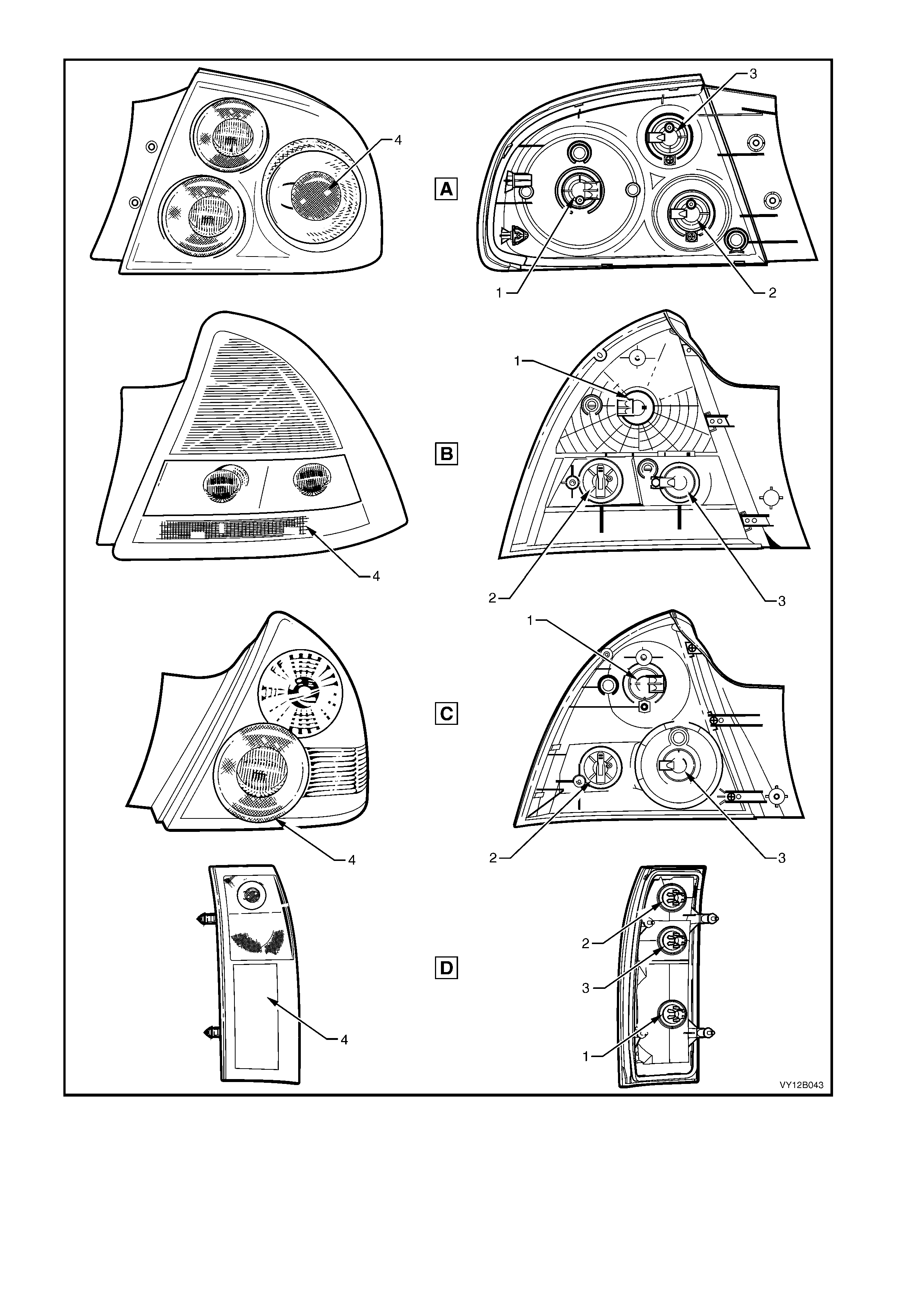
Figure 12B-4
Legend
A Tail Lamp Assembly – Coupe
B Tail Lamp Assembly – Level 2 and Level 3
C Tail Lamp Assembly – Level 1
D Tail Lamp Assembly – Wagon and Utility
1. Stop/Tail Lamp
2. Turn Signal Lamp
3. Back-up Lamp
4. Reflex Reflector

1.3 HIGH MOUNT STOP LAMPS
Five different high mount stop lamp variants are fitted to MY 2003 VY Series vehicles and V2 Series II Coupe. All
high mount stop lamps that are fitted to the inside of the vehicle use bulbs for illumination, except for the Coupe
which uses a strip of Light Em itting Diodes (LED’s) . High mounted stop lam ps that are fitted to s edan rear spoilers
use LED’s.

1.4 INTERIOR ILLUMINATION
The type and amount of interior illumination depends on the model level of the vehicle. All vehicles are fitted with
lamp s adequate to illum inate the c abin ar ea during low light conditions . In addition, all m odels are equipped with an
instrument panel compartment lam p and a rear compartment lam p. Many of the lamps are controlled by the Body
Control Module (BCM). Refer to Section 12J BODY CONTROL MODULE for further information.
Refer to Figure 12B-5 for interior lighting component locations.
LEVEL 1
• Dome lamp assembly or, dome and reading lamp assembly depending on particular model specification.
LEVEL 2 AND LEVEL 3
• Roof console lamps
• Roof rail courtesy and reading lamp assembly
• Side door courtesy lamps (left-hand drive model only)
• Side door courtesy lamps (right-hand drive Level 3 vehicle only)
• Sunshade vanity mirror lamps (Level 3 only)
• Stepwell lamps
• Floor console compartment lamp (Level 3 only)
COUPE
• Dome lamp assembly (right-hand drive CV6 and left-hand drive Lumina S only)
• Dome and reading lamp assembly (right-hand drive CV8 and left-hand drive Lumina SS only)
• Side door courtesy lamps
• Stepwell lamps
• Sunshade vanity mirror lamps
• Floor console compartment lamp (right-hand drive CV8 and left-hand drive Lumina SS only)
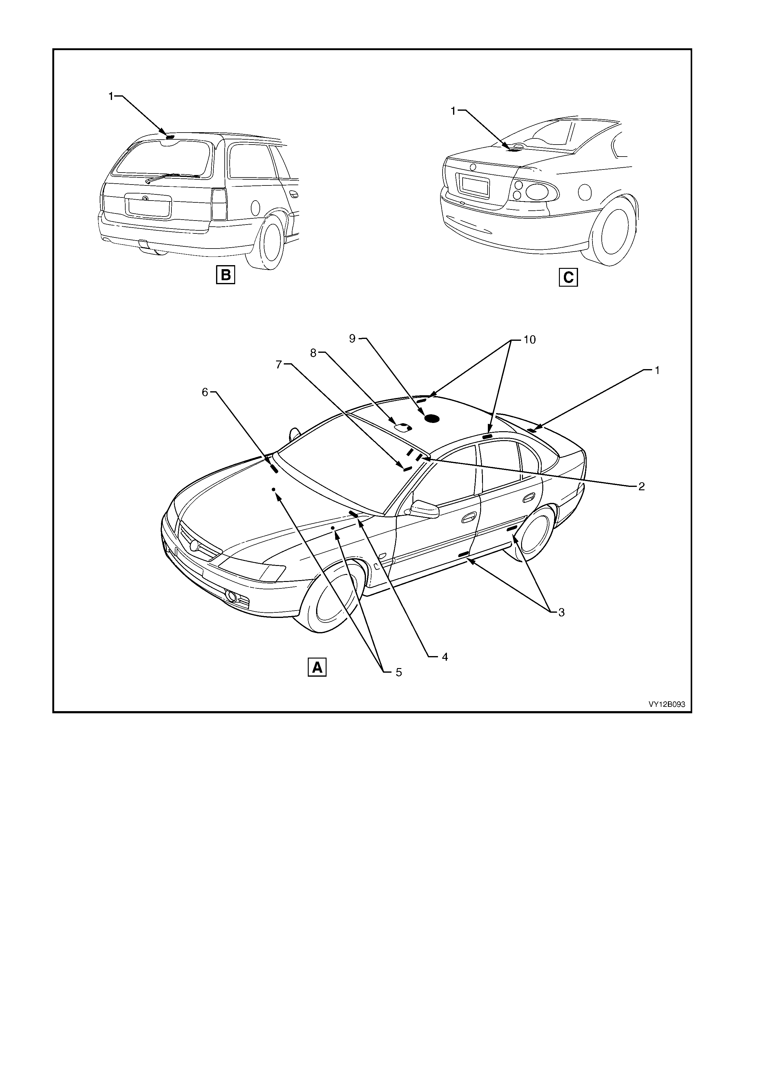
Figure 12B-5
Legend
A Sedan – Interior illumination
B Wagon – Interior Illumination
C Coupe – Interior Illumination
1. Rear Compartment Courtesy Lamp
2. Sunshade Vanity Mi rror Lamps
3. Side Door Courtesy Lamps
4. Instrument Panel Compartment
Courtesy Lamp
5. Stepwell Lamps
6. Under-Hood Lamp (Where Fitted)
7. Floor Console Compartment Lamp
8. Roof Console
9. Dome Lamp
10. Roof Rail Courtesy And Reading
Lamps
1.5 INSTRUME NT AND SWITCH ILLUMINATION
All instrument and switch illumination is provided by Light Emitting Diodes (LED’s) with the exception of the
following, which are illuminated with conventional bulbs:
• Hazard warning switch
• Left-hand drive fuel filler door lock release switch
• Traction control switch (automatic transmission)
• Traction control switch (manual transmission)
• Power switch selector
• LPG (Liquefied Petroleum Gas) switch
• Headlamp switch
• Trip computer switch
• Side window switch assembly
• Ignition lock cylinder
The LPG and traction control (manual transmission) are located in the auxiliary switches location.
The headlamp, trip computer and side window switches are sealed units and the conventional bulbs cannot be
serviced on these items.
LED’s are used instead of conventional bulbs due to their longevity in operation. If the illumination of any LED
equipped item no longer operates correctly, and the LED is isolated as the fault, replace the assembly in question.
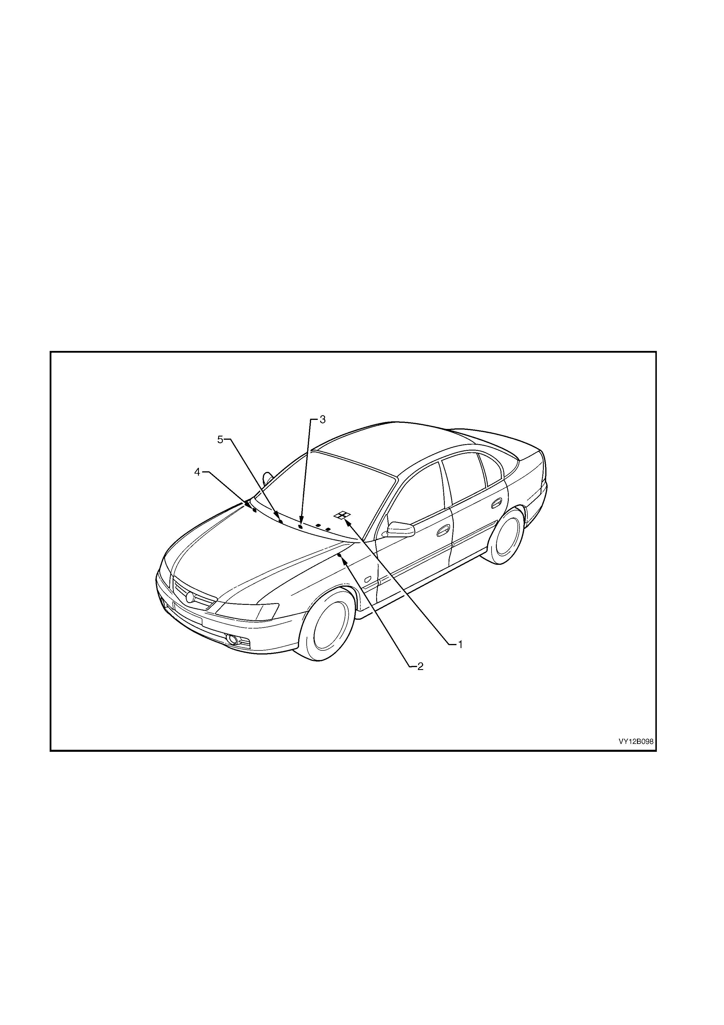
Figure 12B-6
Legend
1. Auxiliary switches
2. Fuel tank filler door lock release switch, LHD
3. Hazard warning switch
4. Headlamp switch
5. Trip computer switch

HEADLAMP SWITCH
A feature of the MY 2003 VY Series vehicles and V2 Series II Coupe, is they are equipped with the automatic
headlamp control feature. With the headlamp switch in the AUTO position (refer to Figure 12B-105), the BCM
controls the function of the park and low beam of the headlamps. For further information on this feature, refer to
Section 12J, 1.13 AUTOMATIC LA MP CONTROL.
POLICE LIGHTS-OUT SWITCH
The lights -out switch is f itted to police vehicles when required. T he switch, when on, will inactivate all interior lamps
from operating except reading lamps, which can be operated individually.
NOTE: This switch does not illuminate with the park lamps operating.
2. SERVICE OPERATIONS – EXTERIOR ILLUM I NATION
2.1 HEADLAMP AND FRONT FOG LAMP AIMING
CAUTION: During headlamp assembly aiming procedures, do not use a cloth or similar material to cover
the lens of the headlamp assembly not being adjusted. Damage to the headlamp assembly will result if the
headlamp beam is obstructed in this manner.
The headlamp assemblies and front fog lamp assemblies (if fitted) must be correctly aimed in order to obtain the
max im um road illum ination and saf ety. The headlam ps and f og lam ps m ust be c heck ed f or corr ect aim whenever a
bulb or lamp assembly is replaced, and after any adjustments or repairs to the front-end sheetmetal.
Headlamp aim ing devices are in general use. W hen using one of these devices, ensure that it is in good condition
and carefully follow the instructions of the manufacturer.
Regardless of the method used for check ing headlamp and f og lamp aim, the vehicle must be at kerb weight, that
is, with full fuel level, oil, water and spare tyre but no passengers. The tyres must be uniformly inflated to their
specified pressure.
IMPORTANT: If the vehic le will regularly carry an unusual load in the rear compar tm ent or tow a trailer, these loads
should be on the vehicle when the headlamps/fog lamps are checked.
HEADLAMP ASSEMBLY AIM
LT Section –
This procedure is to be used only when suitable test equipment is not available.
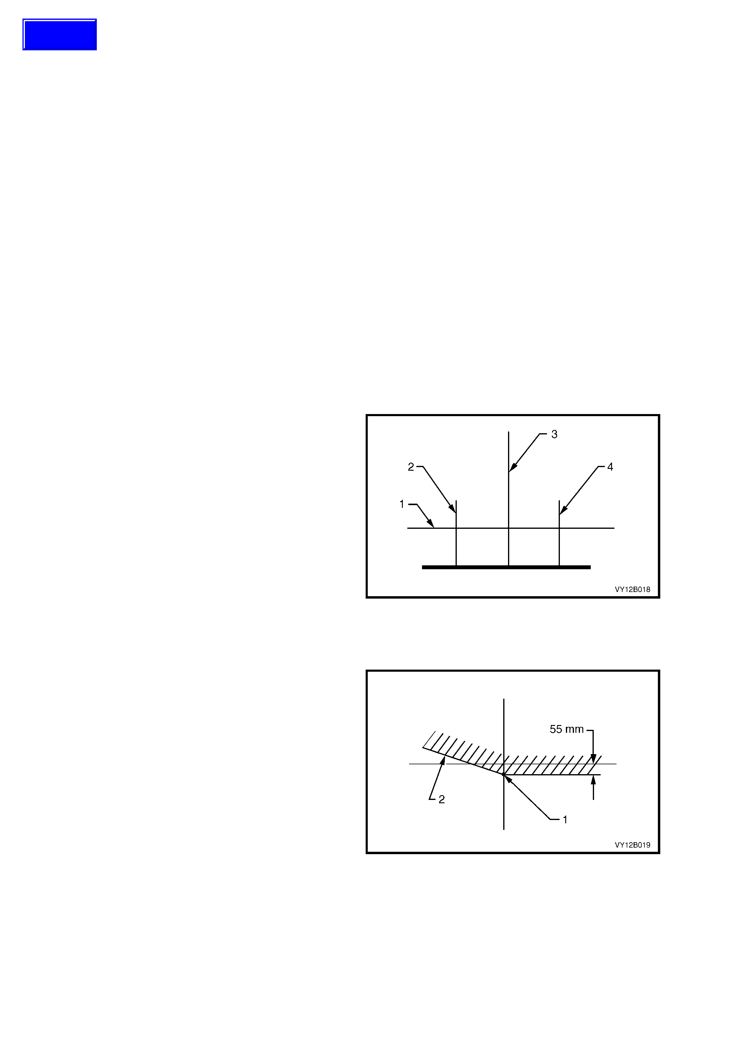
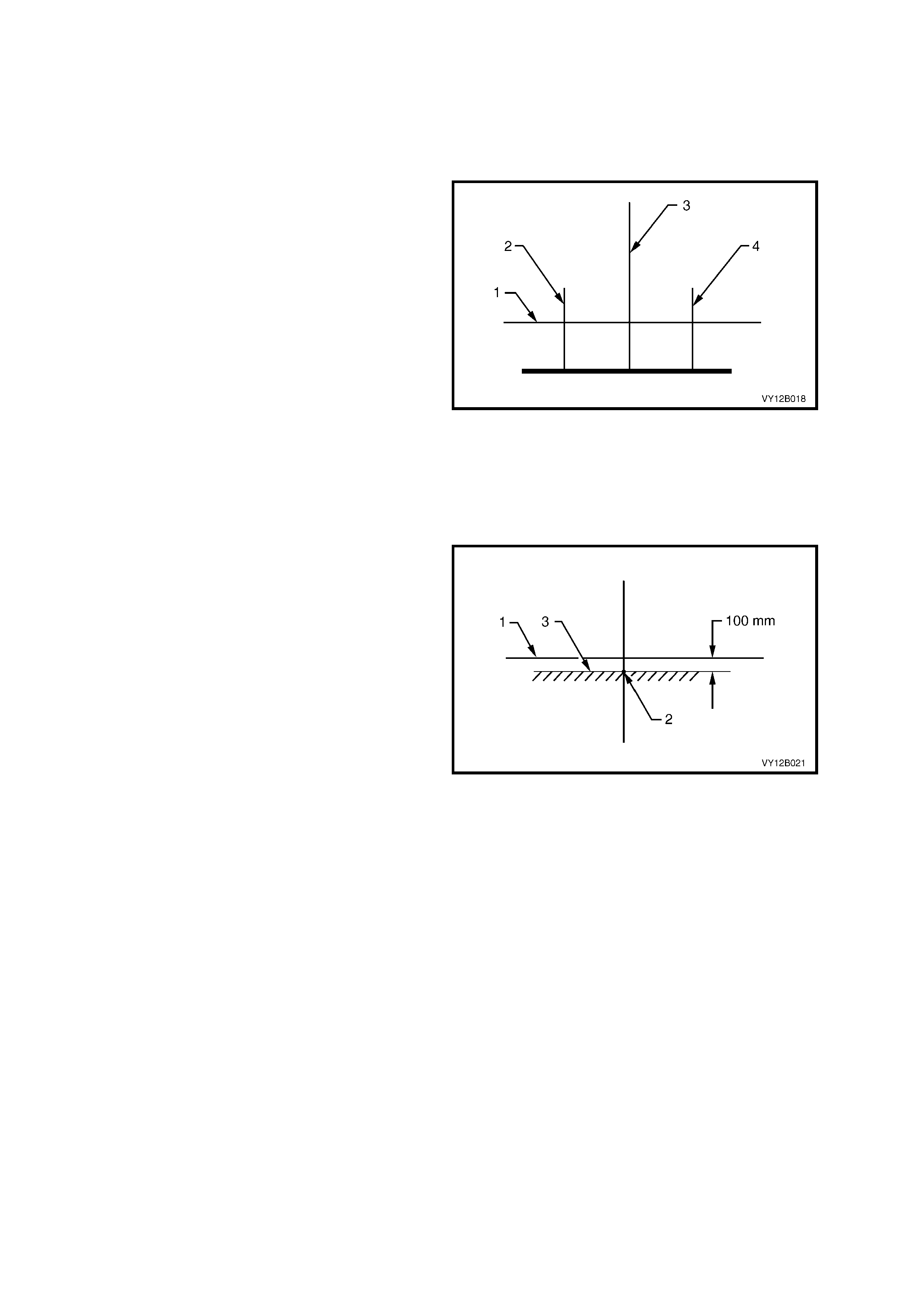
1. Set up a screen or use a vertical wall, in
conjunction with a flat horizontal floor. Park the
vehicle im m ediately in front of scr een / wall and
mark the following lines:
a. A vertical c entre line (3) which corres ponds
to the centre of the vehicle.
b. Two vertical lines (2 and 4). These lines
are to correspond to the respective centre
of the low beam bulb on each side of the
vehicle.
c. A horizontal line (1) that corr esponds to the
centre of the low beam bulb.
2. To check whether the marks are correctly
positioned, turn on the headlights.
3. Reverse the vehicle straight back so that the
front is 5 metres in front of the screen or wall,
ensuring that the centre of the vehicle is
aligned with the vehicle centre line m ark (3) on
the screen.
Figure 12B-7
4. Individually aim each headlamp to a point (1)
on its vertical centre line, 55 mm below the
headlamp horizontal centre line. Item 2 is the
cut-off line. To adjust the headlamp assembly
(refer to Figure 12B-9):
a. Rotate the inboard adjuster (1) to move the
beam vertically.
b. Rotate the outboard adjuster (2) to move the
beam horizontally.
Aiming directions for each adjuster are visible on
the headlamp assembly.
Figure 12B-8
Techline
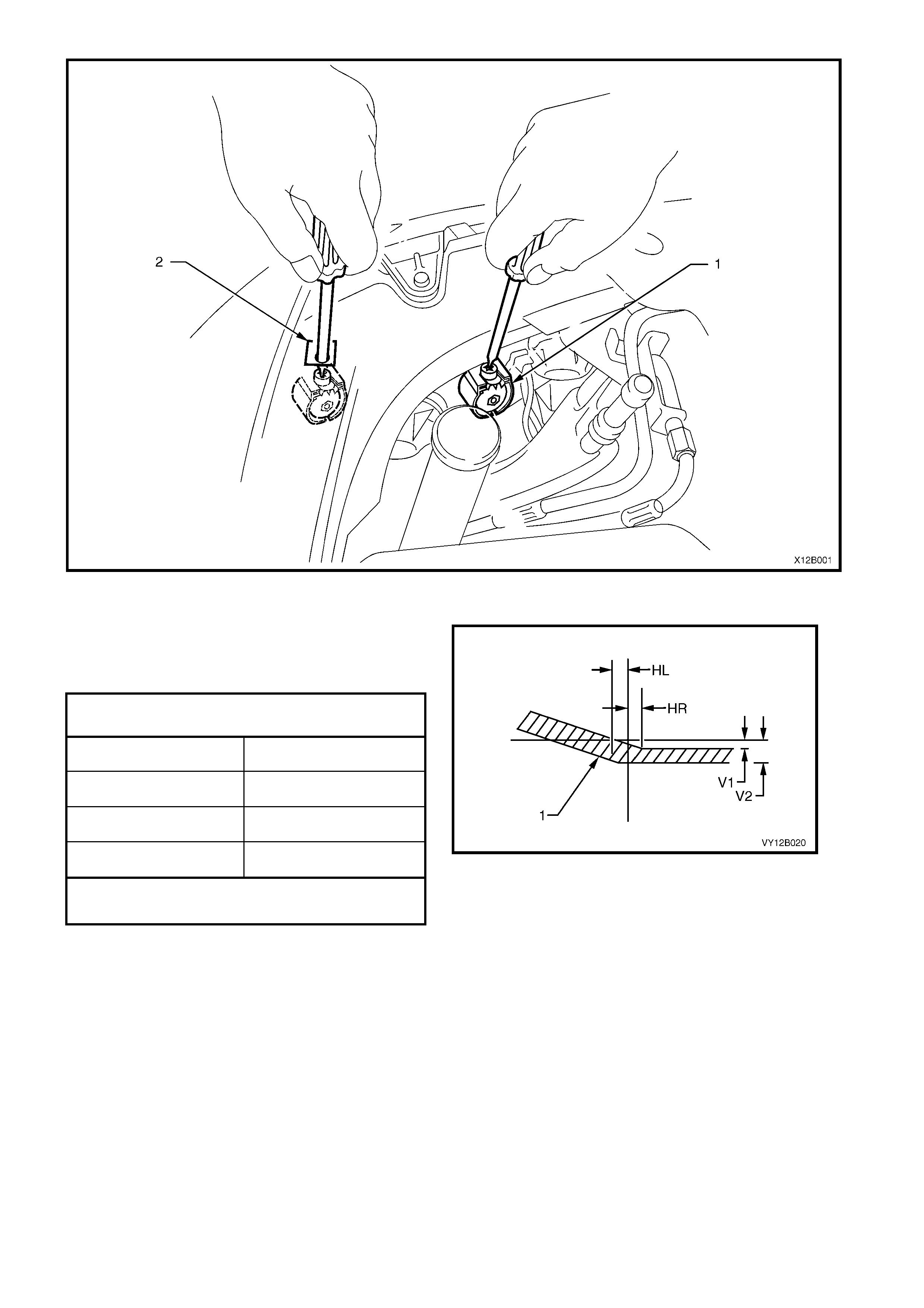
Figure 12B-9
5. The allowable variations on headlamp aiming
point settings shown in Figure 12B-10 are
specified as follows:
NOTE: The cut-off line must be within the shaded
zone (1).
Figure 12B-10
HE ADLAMP AIMING
Acceptable Variations In Headlamp Aiming Points
HL 50 mm
HR 0 mm
V1 50 mm
V2 60 mm
Maximum allowable vertical variation between any
pair of headlamps is not to exceed 10 mm
FRONT FOG LAMP ASSEMBLY AIM
LT Section –
The process for aiming the front fog lamps is the
same for all vehicles fitted with fog lamps. This
procedure is to be used only when suitable test
equipment is not available.
1. Set up a screen or use a vertical wall, in
conjunction with a flat horizontal floor. Park the
vehicle immediately in front of a screen / wall
and mark the following lines on it:
a. A vertical centre line (3), which
corresponds to the centre of the vehicle.
b. Two vertical lines (2 and 4). These lines
are to correspond to the respective centre
of the fog lamp bulb on each side of the
vehicle.
c. A horizontal line (1), that corresponds to
the centre of the fog lamp bulb.
2. To check whether the marks are correctly
positioned, turn on the fog lamps.
3. Reverse the vehicle straight back so the that
front is 5 metres in front of the screen or wall,
ensuring that the centre of the vehicle is
aligned with the vehicle centre line m ark (3) on
the screen.
Figure 12B-11
4. Turn the front fog lamps on. Individually aim
each fog lamp to a point on its vertical centre
line (2), with the cut-off line (3) 100 mm below
fog lamp horizontal centre line (1).
NOTE: There is no provision for horizontal
adjustm ent. Fog lamps are fix ed to a ver tical centre
line.
Figure 12B-12
4. For Level 3 vehicles, the front fog lamp bezel
assembly must be removed to access the
adjusting screw. To remove the bezel
assembly:
a. Depress the inboard side of the bezel
assembly and rotate the inboard side
forward.
b. When the inboard side of the bezel
assem bly is clear of the lam p lens, pull the
bezel assembly forward to unclip it from the
outboard side of the bumper fascia.
5. For Coupe, the lower grille m us t be rem oved to
access the adjusting screw. Refer to
Section 1C, 2.5 LOWER RADIATOR GRILLE
– COUPE.
7. Using a No. 2 Philips head screwdriver adjust
the beam of the front fog lamp (2) by rotating
the adjusting screw (1) clockwise to raise the
beam and anti-clockwise to lower the beam.
Refer to Figure 12B-14 where:
A. Level 3.
B. SS and Coupe fog lamp assembly (SS
shown, Coupe is similar.
8. For Level 3 front fog lamp assemblies, install
the bezel assembly.
Figure 12B-13
Figure 12B-14
2.2 HEADLAMP AND PARK LAMP ASSEMBLY BULBS
LT Section – 02-300
LEVEL 1
Replace – Low Beam Bulb
1. Remove the fusible link F102. Refer to Figure 12B-118, item 6.
2. Open the hood and disconnect the wiring harness connector from the rear of the relevant headlamp assembly.
3. If required, for GEN III V8 engine models, remove the four retainers securing the upper radiator shroud and
remove the shroud. Refer to Section 6B3, 2.16 RADIATOR.
4. For the right-hand headlamp assembly, it may be necessary to remove the battery to gain the required access.
a. If required, remove the battery hold-down bracket and move the battery to gain access. Refer to
Section 12A, 2.9 BATTERY.
b. If further access is required, remove the battery terminals from the battery and remove the battery from the
engine compartment. Refer to Section 12A, 2.9 BATTERY.
Important: Disconnection of the battery affects certain vehicle electronic systems. Refer to
Section 00, 5. BATTERY DISCONNECTION PROCEDURES before disconnecting the battery.
NOTE: On GEN III V8 engine models, left-hand bulb access can be gained via a hole in the top of the air intake
duct.
5. For lef t- hand headlamp as s embly’s on V6 engine models, remove the c oolant f iller bottle nec k and place to one
side.
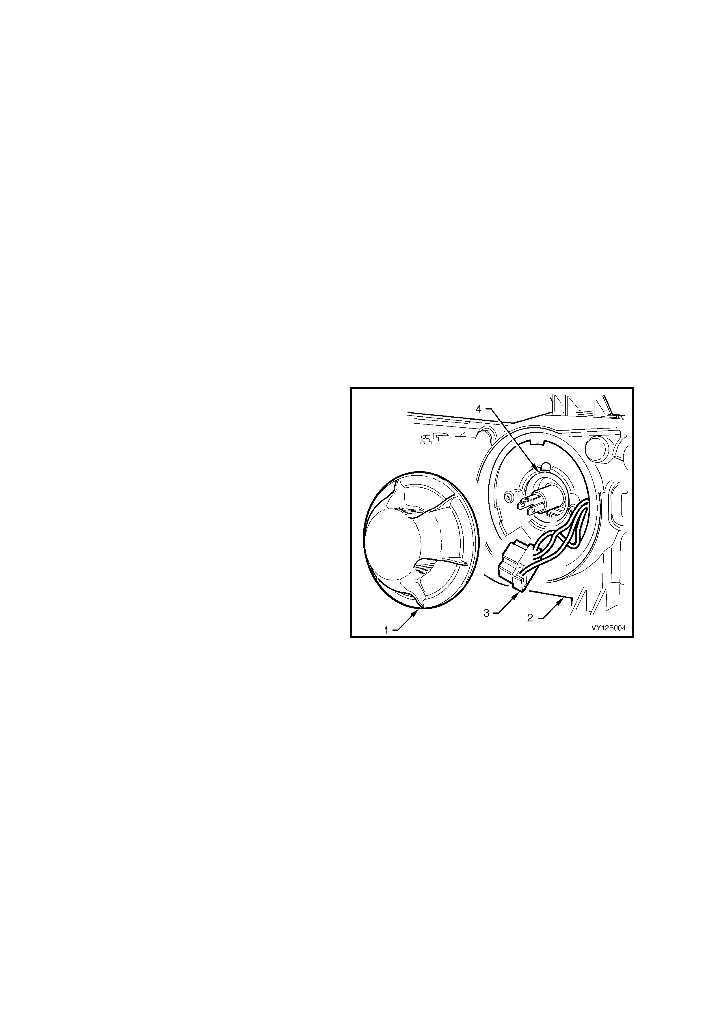
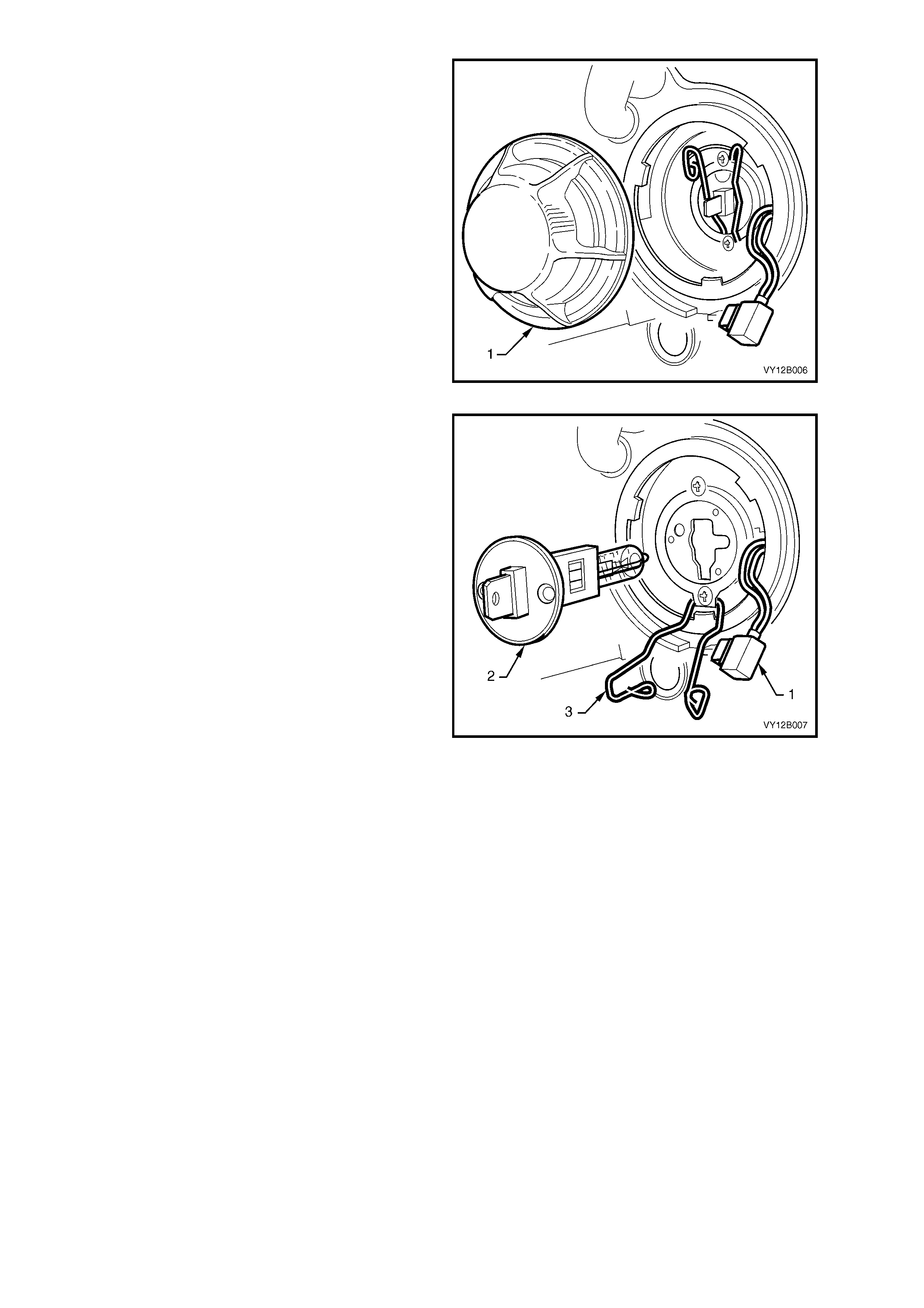
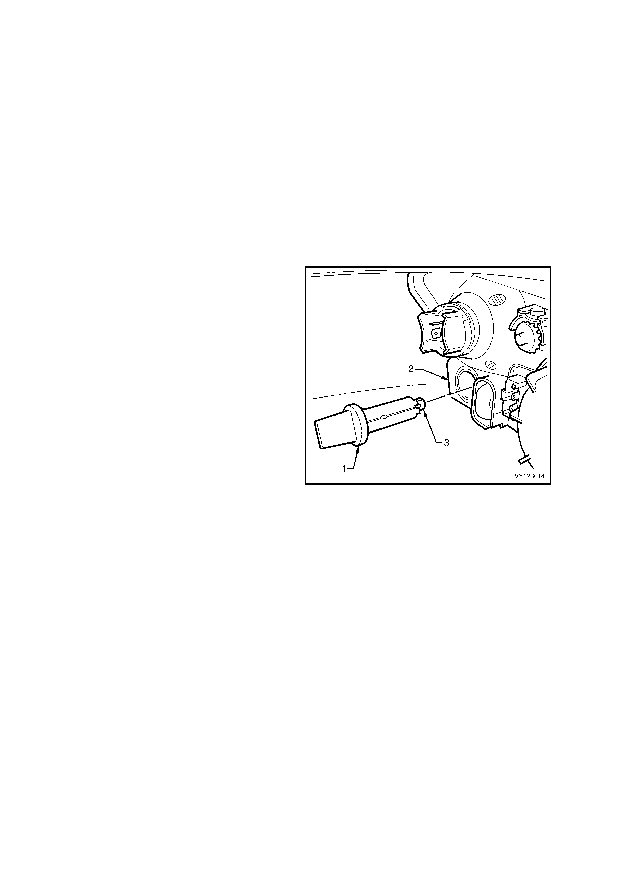
6. From within the engine compartment, remove
the outboard dust cap (1) from the rear of the
headlamp assembly (2) by turning dust cap
anti-clockwise, and pulling it away from
assembly. If the dust cap seal stays on the
headlamp assembly, remove the seal and
install it onto the cap.
7. Carefully pull the wiring harness connector (3)
from the rear of the bulb (4).
Figure 12B-15
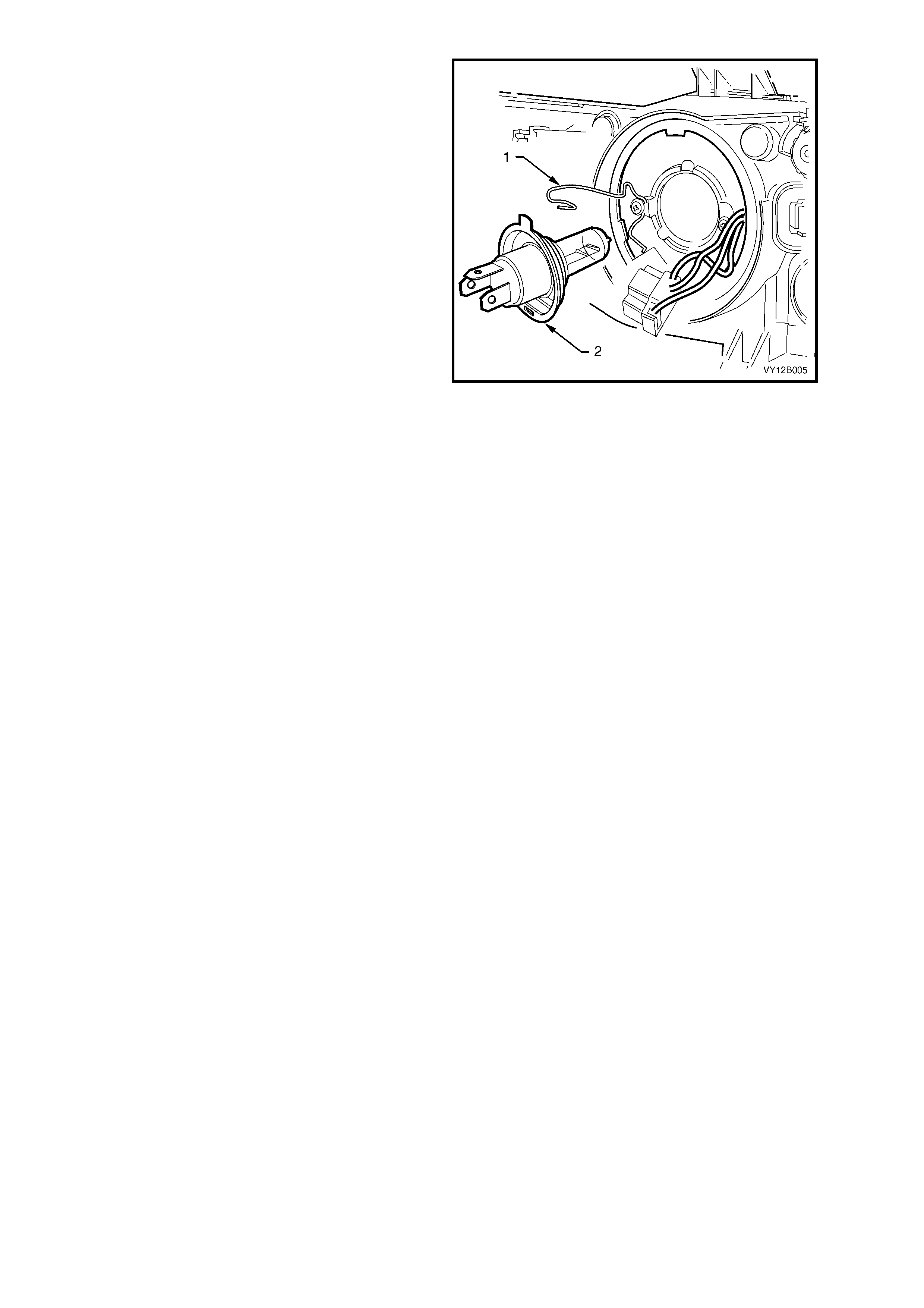
8. Depress and unclip the bulb spring retainer (1)
and pivot clear of the bulb. Remove the bulb (2)
from the reflector.
NOTE: Do not handle the quartz envelope of the
headlamp bulb. If the envelope is touched
accidentally, wipe it immediately with methylated
spirits or the bulb’s performance will be
deteriorated.
9. Install a new bulb into the reflector, ensuring
that the locating tangs mate correctly with the
cutouts in the reflector.
NOTE: The different sized locating tangs on the
bulb and the mating cut-outs in the reflector, allow
the bulb to seat correctly into the reflector in one
orientation only. This ensures correct relationship
of the bulb to the reflector.
10. Install the spring retainer and the wiring
harness connector.
11. Inspect the seal in the dus t c ap to ensur e that it
is not dam aged and that it is s eated corr ectly in
the cap. Replace the seal if it is damaged.
12. Install the cap onto the rear of the headlamp
assembly. Lock the cap into place by turning it
clockwise. Connect the wiring harness
connector to the rear of the headlamp
assembly.
Figure 12B-16
13. As required, install the coolant filler bottle neck, upper radiator shroud and battery.
14. Fit the fusible link F102.
15. Check the headlamp operation and the aim of the headlamps as the bulb filam ent with respect to the reflector
may have changed. Refer to 2.1 AIMING OF HEADLAMPS AND FOG LAMPS in this Section.
Replace – High Beam Bulb
1. Remove the fusible link F102. Refer to Figure 12B-118, item 6.
2. Open the hood and disconnect the wiring harness connector from the rear of the relevant headlamp assembly.
3. If required, for GEN III V8 engine models, remove the four retainers securing the upper radiator shroud and
remove the shroud. Refer to Section 6B3, 2.16 RADIATOR.
4. For the right-hand headlamp assembly, it may be necessary to remove the battery to gain the required access.
a. If required, remove the battery hold-down bracket and move the battery to gain access. Refer to
Section 12A, 2.9 BATTERY.
b. If further access is required, remove the battery terminals from the battery and remove the battery from the
engine compartment. Refer to Section 12A, 2.9 BATTERY.
Important: Disconnection of the battery affects certain vehicle electronic systems. Refer to
Section 00, 5. BATTERY DISCONNECTION PROCEDURES before disconnecting the battery.
NOTE: On GEN III V8 engine models, left-hand bulb access can be gained via a hole in the top of the air intake
duct.
5. For lef t- hand headlamp as s embly’s on V6 engine models, remove the c oolant f iller bottle nec k and place to one
side.
6. From within the engine compartment, remove
the inboard high beam dust cap (1) from the
rear of the headlamp assembly by turning the
dust cap anti-clockwise, and pulling it away
from the assembly. If the dust cap seal stays
on the headlamp assembly, remove the seal
and install it onto the cap.
Figure 12B-17
7. Carefully pull the wiring harness connector (1)
from the bulb (2). Depress and unclip the bulb
retaining clip (3), and allow to it fall clear of
bulb. Remove the bulb
NOTE: Do not handle the quartz envelope of the
inboard high beam bulb. If touched accidentally,
wipe immediately with methylated spirits or bulb
performance will deteriorate.
8. Install a new bulb into the reflector, ensuring
that the locating lug on the bulb assembly
aligns with the square edge on the reflector.
9. Fit the bulb retaining clip. Connect the wiring
harness connector to the bulb.
10. Inspect the seal in the dus t c ap to ensur e that it
is not damaged and that it is seated correctly.
Replace the seal if it is damaged.
11. Install the dust cap onto the rear of headlamp
assembly and lock it into place by turning the
cap clockwise. Connect the wiring harness
connector to the rear of the headlamp
assembly.
Figure 12B-18
12. As required, install the coolant filler bottle neck, upper radiator shroud and battery.
13. Fit the fusible link F102.
Replace – Park Lamp Bulb
1. Remove the fusible link F102. Refer to Figure 12B-118, item 6.
2. Open the hood and disconnect the wiring harness connector from the rear of the relevant headlamp assembly.
3. If required, for GEN III V8 engine models, remove the four retainers securing the upper radiator shroud and
remove the shroud. Refer to Section 6B3, 2.16 RADIATOR.
4. For the right-hand headlamp assembly, it may be necessary to remove the battery to gain the required access.
a. If required, remove the battery hold-down bracket and move the battery to gain access. Refer to
Section 12A, 2.9 BATTERY.
b. If further access is required, remove the battery terminals from the battery and remove the battery from the
engine compartment. Refer to Section 12A, 2.9 BATTERY.
Important: Disconnection of the battery affects certain vehicle electronic systems. Refer to
Section 00, 5. BATTERY DISCONNECTION PROCEDURES before disconnecting the battery.
NOTE: On GEN III V8 engine models, left-hand bulb access can be gained via a hole in the top of the air intake
duct.
5. For lef t- hand headlamp as s embly’s on V6 engine models, remove the c oolant f iller bottle nec k and place to one
side.
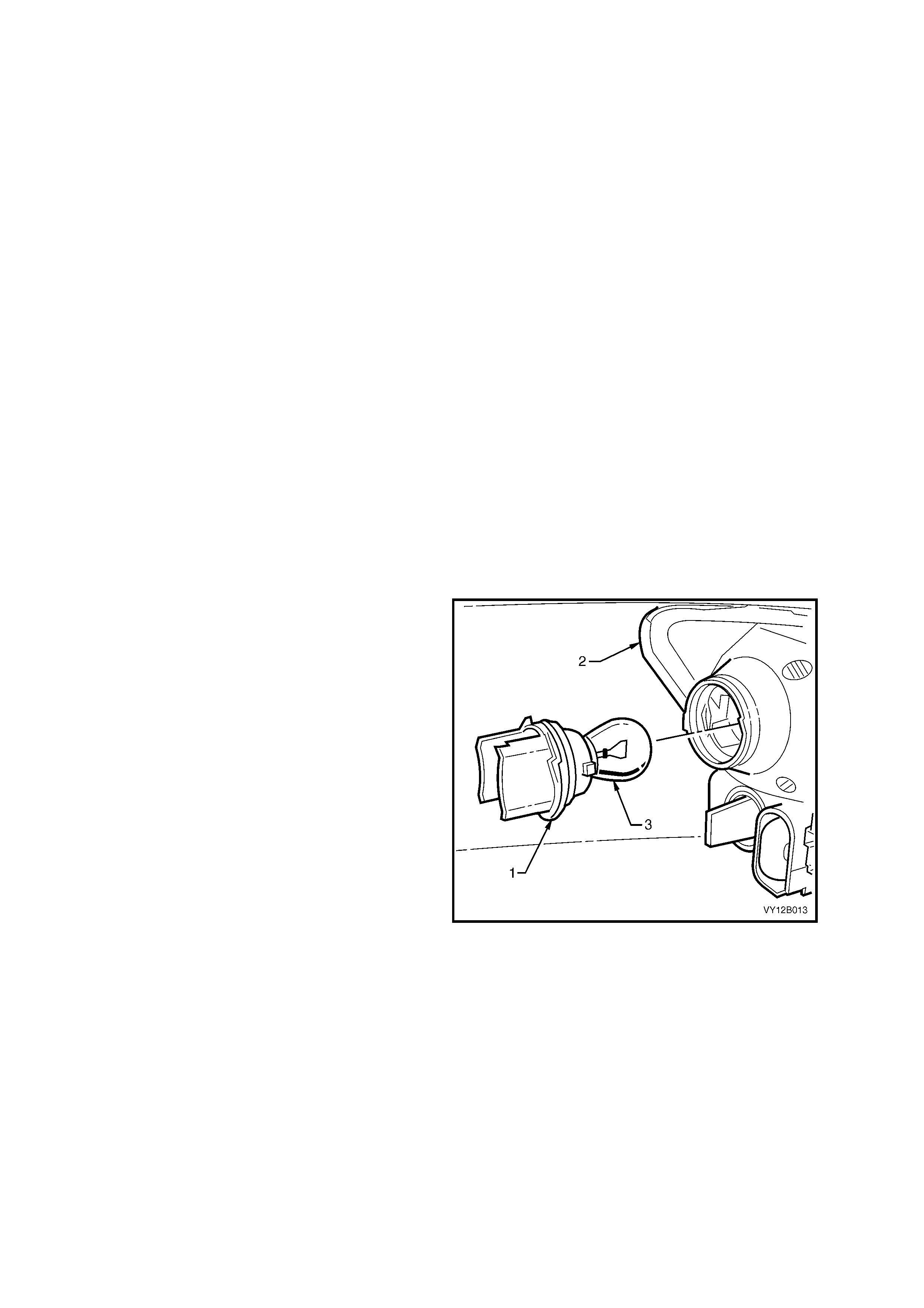
6. From within the engine compartment, remove
the park lamp socket (1) from the headlamp
assembly (2) by rotating it anti-clockwise and
then pulling it away from the headlamp
assembly.
7. Pull the bulb ( 3) away fr om the sock et. Insert a
new bulb into the socket.
8. Inspect the seal on the socket to ensure that it
is not damaged and that it is seated correctly.
Replace the seal if necessary.
9. Install the park lamp socket into the rear of the
headlamp assembly and lock it into place by
turning it clockwise. Ensure that the ‘TOP’ mark
is facing upwards. The socket has a two stage
locking feature. Ensure that the socket is
engaged in the secondary lock (4) and there is
no excess movement.
10. Connect the wiring harness connector to the
rear of the headlamp assembly.
Figure 12B-19
11. As required, install the coolant filler bottle neck, upper radiator shroud and battery.
12. Fit the fusible link F102.
13. Check the park lamp operation.
LEVEL 2 AND LEVEL 3
Replace – Low Beam Bulb
1. Remove the fusible link F102. Refer to Figure 12B-118, item 6.
2. Open the hood and disconnect the wiring harness connector from the rear of the relevant headlamp assembly.
3. If required, for GEN III V8 engine models, remove the four retainers securing the upper radiator shroud and
remove the shroud. Refer to Section 6B3, 2.16 RADIATOR.
4. For the right-hand headlamp assembly, it may be necessary to remove the battery to gain the required access.
a. If required, remove the battery hold-down bracket and move the battery to gain access. Refer to
Section 12A, 2.9 BATTERY.
b. If further access is required, remove the battery terminals from the battery and remove the battery from the
engine compartment. Refer to Section 12A, 2.9 BATTERY.
Important: Disconnection of the battery affects certain vehicle electronic systems. Refer to
Section 00, 5. BATTERY DISCONNECTION PROCEDURES before disconnecting the battery.
NOTE: On GEN III V8 engine models, left-hand bulb access can be gained via a hole in the top of the air intake
duct.
5. For lef t- hand headlamp as s embly’s on V6 engine models, remove the c oolant f iller bottle nec k and place to one
side.
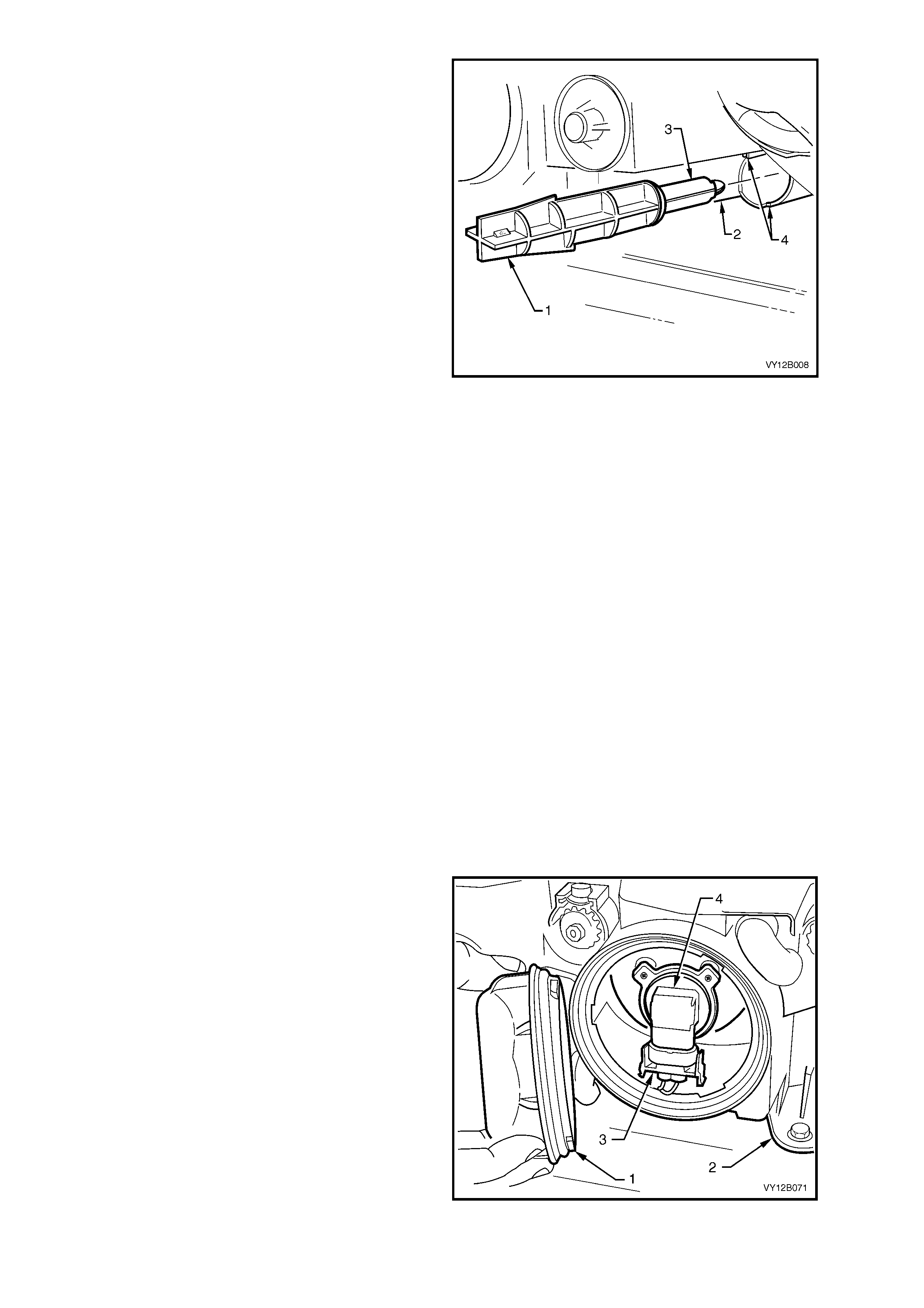
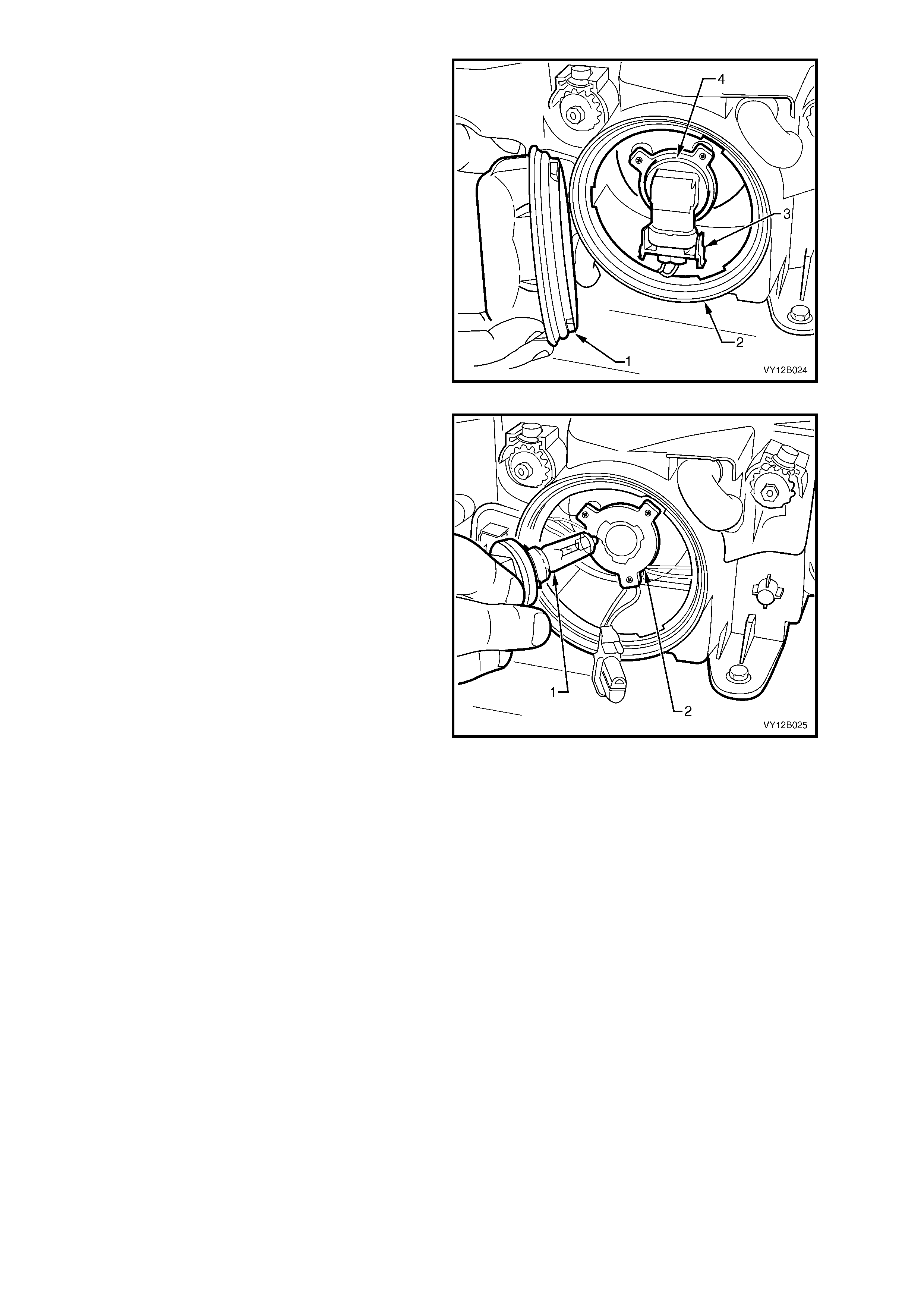
6. From within the engine compartment, remove
the outboard dust cap (1) from the rear of the
headlamp assembly (2) by turning dust cap
anti-clockwise, and pulling it away from
assembly. If the dust cap seal stays on the
headlamp assembly, remove the seal and
install it onto the cap.
7. Disconnect the wiring connector (3) from the
bulb (4) by squeezing the two tangs together
and pulling the connector down from the bulb.
Figure 12B-20
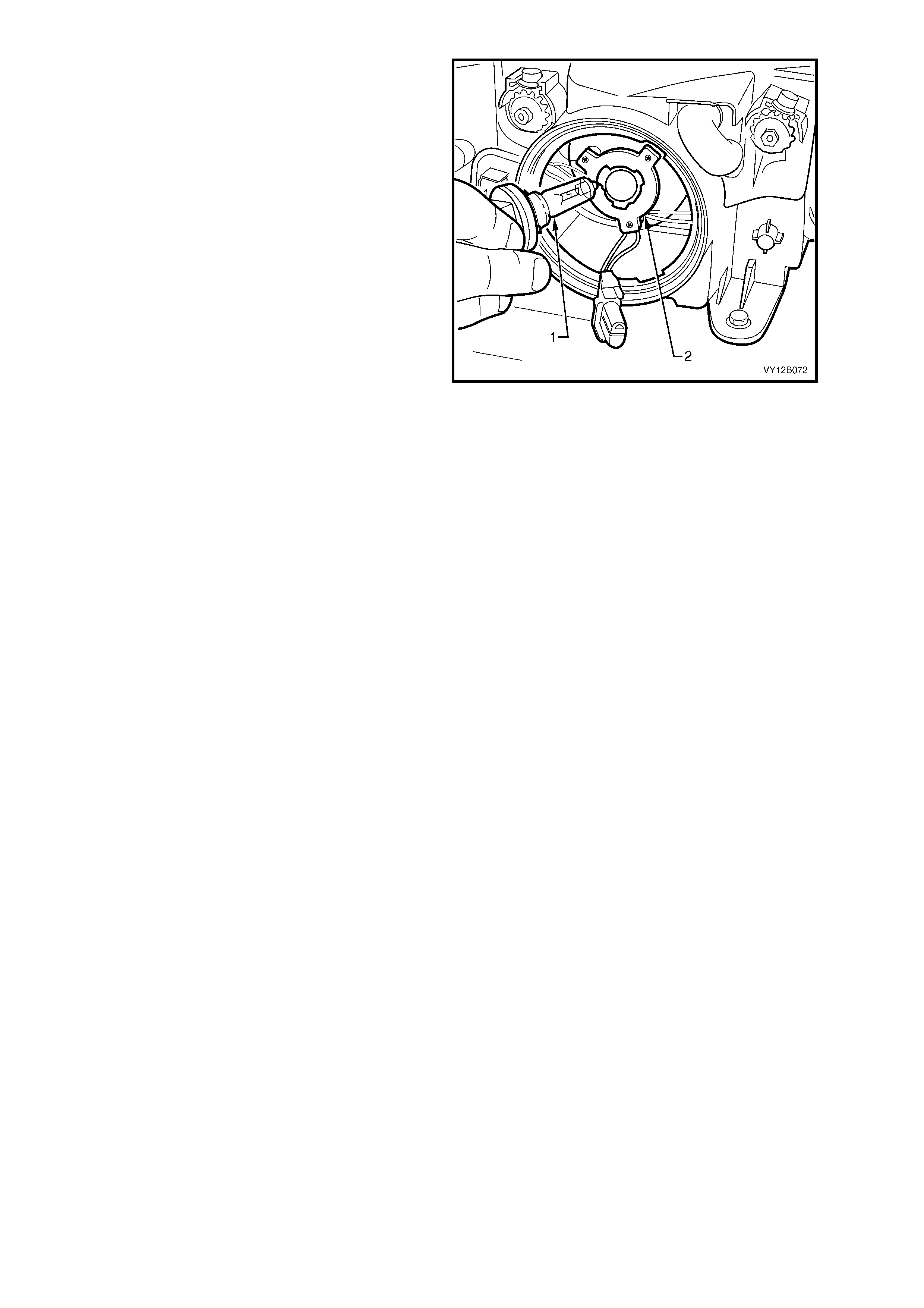
8. Rotate the bulb (1) anti-clockwise and remove
the bulb from the bulb holder (2).
NOTE: Do not handle the quartz envelope of the
headlamp bulb. If the envelope is touched
accidentally, wipe it immediately with methylated
spirits or the bulb’s performance will be
deteriorated.
9. Install a new bulb into the bulb holder. Lock the
bulb in place by turning it clockwise. Fit the bulb
connector by pushing it into the base of the
bulb until the tangs engage.
NOTE: The dif f erent sized locating lugs on the bulb
base and mating cut-outs in the bulb holder allow
the bulb to seat correctly in one orientation only.
This ensures correct relationship of the bulb to the
reflector.
10. Inspect the seal on the dust cap to ensure that
it is not damaged and that it is seated corr ectly
on the cap. Replace the seal if it is damaged.
11. Install the cap onto the rear of the headlamp
assembly. The different size lugs on the dust
cap and the mating cut-outs on the headlamp
assem bly ensure that the dust cap can only be
installed in one orientation. T he chamf ered f lats
of the cap need to be f ac ing inboard f or the cap
to install. Lock the cap into place by turning it
clockwise.
12. Connect the wiring harness connector to the
rear of the headlamp assembly.
Figure 12B-21
13. As required, install the coolant filler bottle neck, upper radiator shroud and battery.
14. Fit the fusible link F102.
15. Check the headlamp operation and the aim of the headlamps as the bulb filam ent with respect to the reflector
may have changed. Refer to 2.1 AIMING OF HEADLAMPS AND FOG LAMPS in this Section.
Replace – High Beam Bulb
1. Remove the fusible link F102. Refer to Figure 12B-118, item 6.
2. Open the hood and disconnect the wiring harness connector from the rear of the relevant headlamp assembly.
3. If required, for GEN III V8 engine models, remove the four retainers securing the upper radiator shroud and
remove the shroud. Refer to Section 6B3, 2.16 RADIATOR.
4. For the right-hand headlamp assembly, it may be necessary to remove the battery to gain the required access.
a. If required, remove the battery hold-down bracket and move the battery to gain access. Refer to
Section 12A, 2.9 BATTERY.
b. If further access is required, remove the battery terminals from the battery and remove the battery from the
engine compartment. Refer to Section 12A, 2.9 BATTERY.
Important: Disconnection of the battery affects certain vehicle electronic systems. Refer to
Section 00, 5. BATTERY DISCONNECTION PROCEDURES before disconnecting the battery.
NOTE: On GEN III V8 engine models, left-hand bulb access can be gained via a hole in the top of the air intake
duct.
5. For lef t- hand headlamp as s embly’s on V6 engine models, remove the c oolant f iller bottle nec k and place to one
side.
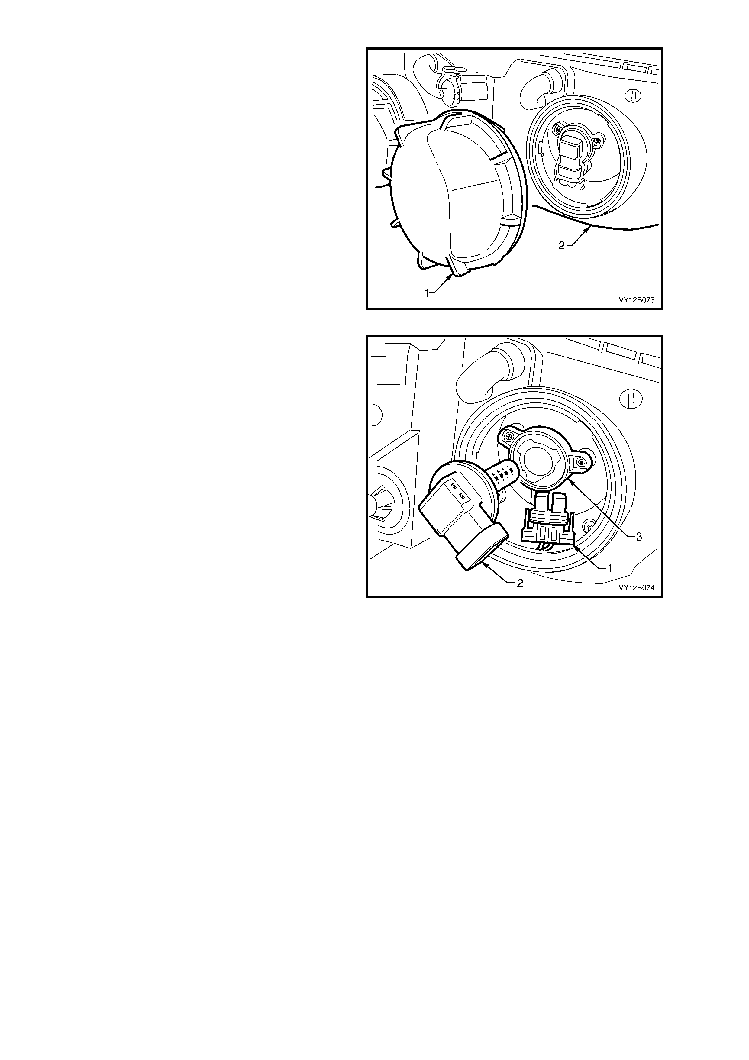
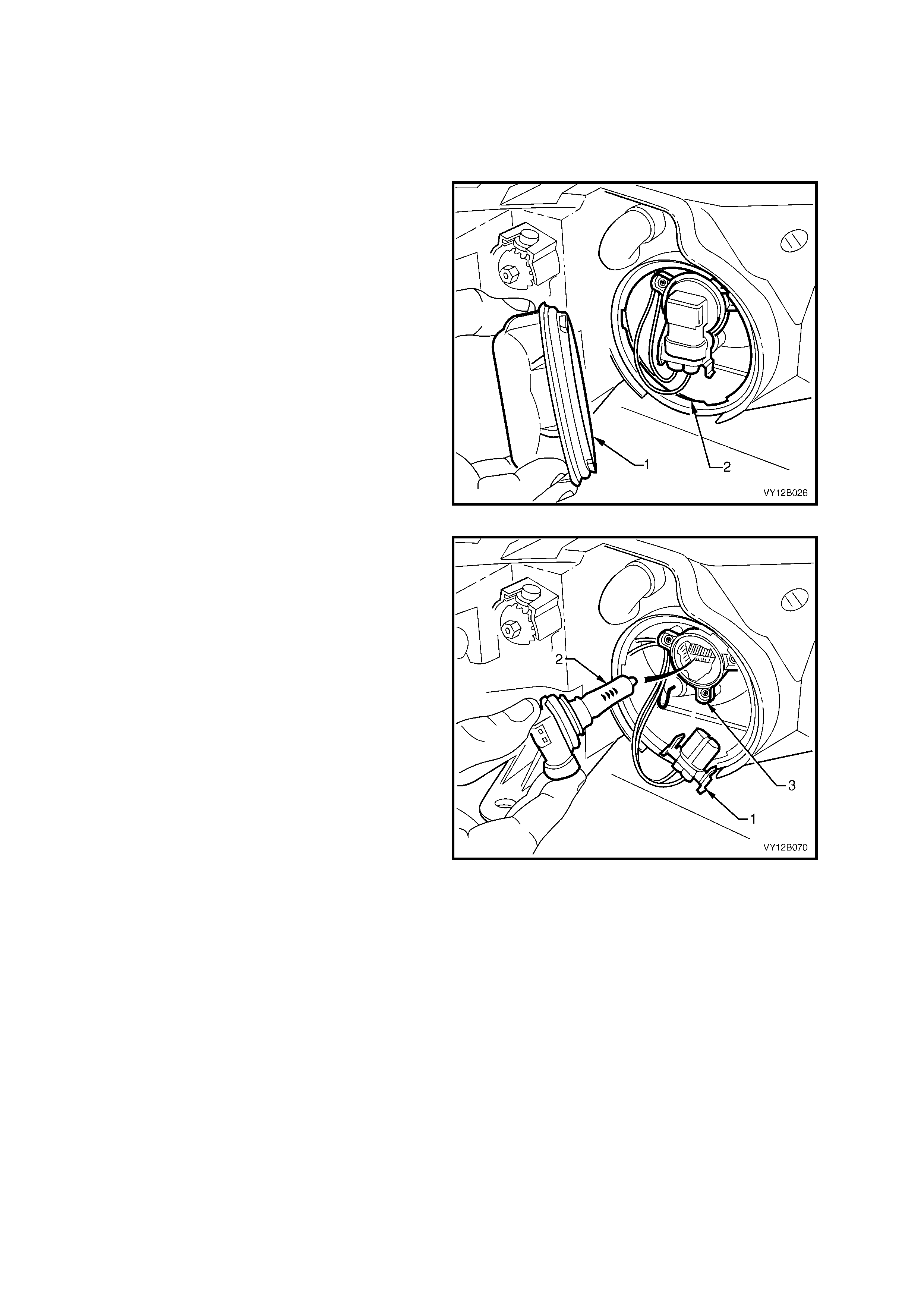
6. From within the engine compartment, remove
the inboard high beam dust cap (1) from the
rear of the headlamp assembly (2) by turning
dust cap anti-clockwise, and pulling it away
from assembly. If the dust cap seal stays on
the headlamp assembly, remove the seal and
install it onto the cap.
Figure 12B-22
7. Disconnect the wiring connector (1) from the
bulb by squeezing the two tangs together and
pulling the connector down from the bulb.
8. Rotate the bulb (2) anti-clockwise and remove
the bulb from the bulb holder (3).
NOTE: Do not handle the quartz envelope of
inboard high beam bulb. If touched accidentally,
wipe immediately with methylated spirits or bulb
performance will deteriorate.
9. Install a new bulb into the bulb holder. Lock the
bulb in place by turning it clockwise. Fit the bulb
connector by pushing it into the base of the
bulb until the tangs engage.
NOTE: The dif f erent sized locating lugs on the bulb
base and mating cut-outs in the bulb holder allow
the bulb to seat correctly in one orientation only.
This ensures correct relationship of the bulb to the
reflector.
10. Inspect the seal on the dust cap to ensure that
it is not damaged and that it is seated corr ectly
on the cap. Replace the seal if it is damaged.
11. Install the dust cap onto the rear of headlamp
assembly. The different size lugs on the dust
cap and the mating cut-outs in the headlamp
assem bly ensure that the dust cap can only be
installed in one orientation. T he chamf ered f lats
of the cap need to be f ac ing inboard f or the cap
to install. Lock it into place by turning the cap
clockwise.
12. Connect the wiring harness connector to the
rear of the headlamp assembly.
Figure 12B-23
13. As r equired, ins tall the c oolant f iller bottle nec k,
upper radiator shroud and battery.
14. Fit the fusible link F102.
Replace – Park Lamp Bulb
1. Remove the fusible link F102. Refer to Figure 12B-118, item 6.
2. Open the hood and disconnect the wiring harness connector from the rear of the relevant headlamp assembly.
3. If required, for GEN III V8 engine models, remove the four retainers securing the upper radiator shroud and
remove the shroud. Refer to Section 6B3, 2.16 RADIATOR.
4. For the right-hand headlamp assembly, it may be necessary to remove the battery to gain the required access.
a. If required, remove the battery hold-down bracket and move the battery to gain access. Refer to
Section 12A, 2.9 BATTERY.
b. If further access is required, remove the battery terminals from the battery and remove the battery from the
engine compartment. Refer to Section 12A, 2.9 BATTERY.
Important: Disconnection of the battery affects certain vehicle electronic systems. Refer to
Section 00, 5. BATTERY DISCONNECTION PROCEDURES before disconnecting the battery.
NOTE: On GEN III V8 engine models, left-hand bulb access can be gained via a hole in the top of the air intake
duct.
5. For lef t- hand headlamp as s embly’s on V6 engine models, remove the c oolant f iller bottle nec k and place to one
side.
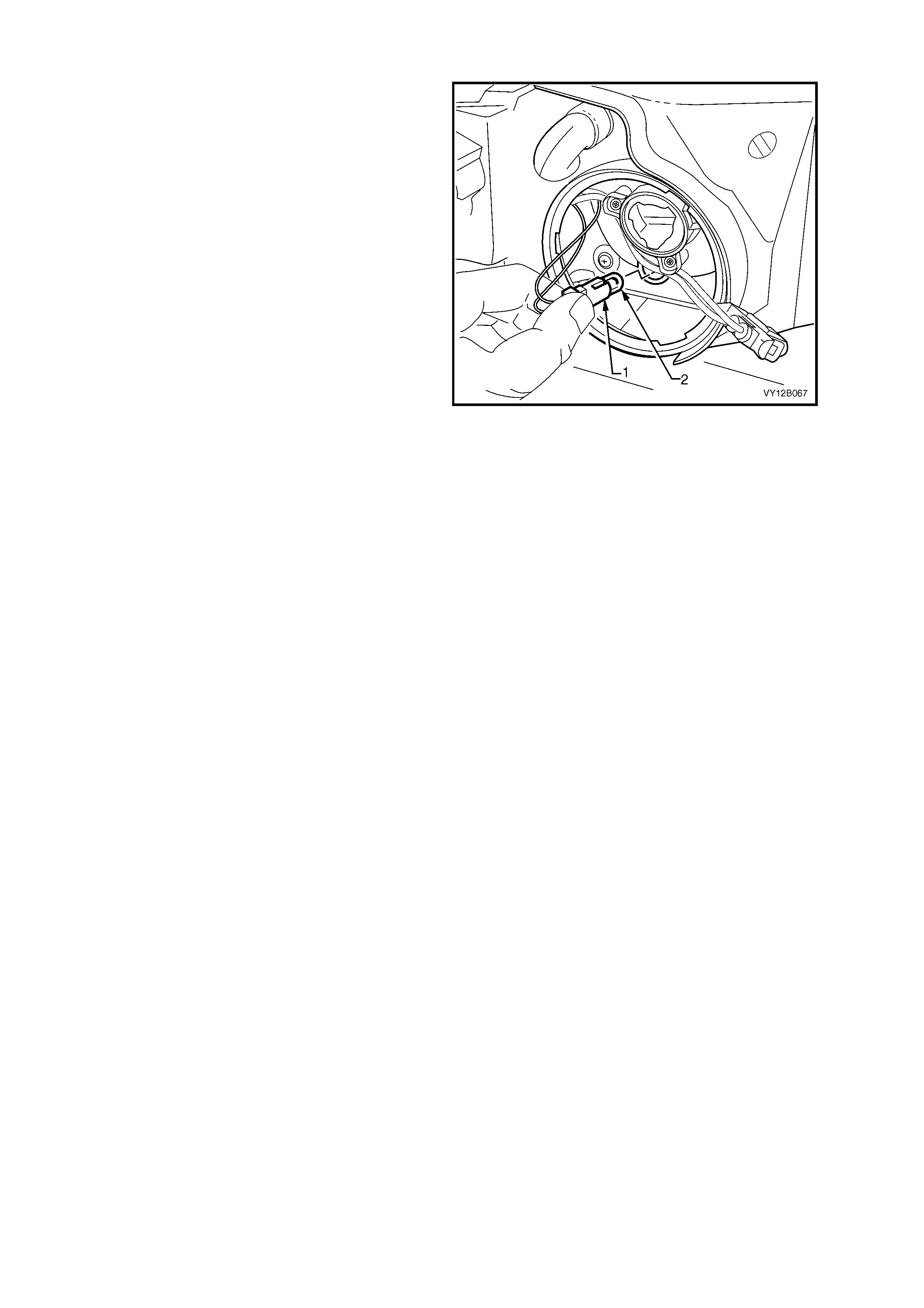
6. From within the engine compartment, remove
the park lamp socket (1) from the headlamp
assembly (2) by rotating it anti-clockwise and
then pulling it away from the headlamp
assembly.
7. Pull the bulb ( 3) away fr om the sock et. Insert a
new bulb into the socket.
8. Inspect the seal on the socket to ensure that it
is not damaged and that it is seated correctly.
Replace the seal if it is damaged.
9. Install the park lamp socket into the rear of the
headlamp assembly and lock into place by
turning it clockwise. Connect the wiring harness
connector to the rear of the headlamp
assembly.
Figure 12B-24
10. As required, install the coolant filler bottle neck, upper radiator shroud and battery.
11. Fit the fusible link F102.
12. Check the park lamp operation.
COUPE
Replace – Low Beam Bulb
1. Remove the fusible link F102. Refer to Figure 12B-118, item 6.
2. Open the hood and disconnect the wiring harness connector from the rear of the relevant headlamp assembly.
3. If required, for GEN III V8 engine models, remove the four retainers securing the upper radiator shroud and
remove the shroud. Refer to Section 6B3, 2.16 RADIATOR.
4. For the right-hand headlamp assembly, it may be necessary to remove the battery to gain the required access.
a. If required, remove the battery hold-down bracket and move the battery to gain access. Refer to
Section 12A, 2.9 BATTERY.
b. If further access is required, remove the battery terminals from the battery and remove the battery from the
engine compartment. Refer to Section 12A, 2.9 BATTERY.
Important: Disconnection of the battery affects certain vehicle electronic systems. Refer to
Section 00, 5. BATTERY DISCONNECTION PROCEDURES before disconnecting the battery.
NOTE: On GEN III V8 engine models, left-hand bulb access can be gained via a hole in the top of the air intake
duct.
5. For lef t- hand headlamp as s embly’s on V6 engine models, remove the c oolant f iller bottle nec k and place to one
side.
6. From within the engine compartment, remove
the outboard dust cap (1) from the rear of the
headlamp as sembly (2) by turning the dus t cap
anti-clockwise, and pulling it away from the
assembly. If the dust cap seal stays on the
headlamp assembly, remove the seal and
install it onto the cap.
7. Disconnect the wiring connector (3) from the
bulb (4) by squeezing the two tangs together
and pulling the connector down from the bulb.
Figure 12B-25
8. Rotate the bulb (1) anti-clockwise and remove
the bulb from the bulb holder (2).
NOTE: Do not handle the quartz envelope of the
inboard high beam bulb. If touched accidentally,
wipe immediately with methylated spirits or bulb
performance will deteriorate.
9. Install a new bulb into the bulb holder. Lock the
bulb in place by turning it clockwise. Fit the bulb
connector by pushing it into the base of the
bulb until the tangs engage.
NOTE: The dif f erent sized locating lugs on the bulb
base and mating cut-outs in the bulb holder allow
the bulb to seat correctly in one orientation only.
This ensures correct relationship of the bulb to the
reflector.
10. Inspect the seal in the dus t c ap to ensur e that it
is not damaged and that it is seated correctly.
Replace the seal if it is damaged.
11. Install the dust cap onto the rear of headlamp
assembly. The different size lugs on the dust
cap and the mating cut-outs in the headlamp
assem bly ensure that the dust cap can only be
installed in one orientation. T he chamf ered f lats
of the cap need to be f ac ing inboard f or the cap
to install. Lock the cap into place by turning it
clockwise.
12. Connect the wiring harness connector to the
rear of the headlamp assembly.
Figure 12B-26
13. As required, install the coolant filler bottle neck, upper radiator shroud and battery.
14. Fit the fusible link F102.
15. Check the headlamp operation and the aim of the headlamps as the bulb filam ent with respect to the reflector
may have changed. Refer to 2.1 AIMING OF HEADLAMPS AND FOG LAMPS in this Section.
Replace – High Beam Bulb
1. Remove the fusible link F102. Refer to Figure 12B-118, item 6.
2. Open the hood and disconnect the wiring harness connector from the rear of the relevant headlamp assembly.
3. If required, for GEN III V8 engine models, remove the four retainers securing the upper radiator shroud and
remove the shroud. Refer to Section 6B3, 2.16 RADIATOR.
4. For the right-hand headlamp assembly, it may be necessary to remove the battery to gain the required access.
a. If required, remove the battery hold-down bracket and move the battery to gain access. Refer to
Section 12A, 2.9 BATTERY.
b. If further access is required, remove the battery terminals from the battery and remove the battery from the
engine compartment. Refer to Section 12A, 2.9 BATTERY.
Important: Disconnection of the battery affects certain vehicle electronic systems. Refer to
Section 00, 5. BATTERY DISCONNECTION PROCEDURES before disconnecting the battery.
NOTE: On GEN III V8 engine models, left-hand bulb access can be gained via a hole in the top of the air intake
duct.
5. For lef t- hand headlamp as s embly’s on V6 engine models, remove the c oolant f iller bottle nec k and place to one
side.
6. From within the engine compartment, remove
the inboard dust cap (1) from the rear of the
headlamp assembly (2) by turning dust cap
anti-clockwise, and pulling it away from the
assembly. If the dust cap seal stays on the
headlamp assembly, remove the seal and
install it onto the cap.
Figure 12B-27
7. Disconnect the wiring connector (1) from the
bulb (2) by squeezing the two tangs together
and pulling the connector down from the bulb.
8. Rotate the bulb anti-clockwise and remove the
bulb from the bulb holder (3).
NOTE: Do not handle the quartz envelope of the
inboard high beam bulb. If touched accidentally,
wipe immediately with methylated spirits or bulb
performance will deteriorate.
9. Install a new bulb into the bulb holder. Lock the
bulb in place by turning it clockwise. Fit the bulb
connector by pushing it into the base of the
bulb until the tangs engage.
NOTE: The dif f erent sized locating lugs on the bulb
base and the mating cut-outs in the bulb holder
allow the bulb to seat correctly in one orientation
only. This ensures correct relationship of the bulb
to the reflector.
10. Inspect the rubber seal in the dust cap to
ensure that it is not damaged and that it is
seated correctly. Replace the seal if it is
damaged.
11. Install the dust cap onto the rear of headlamp
assembly. The different size lugs on the dust
cap and the mating cut-outs in the headlamp
assem bly ensure that the dust cap can only be
installed in one orientation. T he chamf ered f lats
of the cap need to be f ac ing inboard f or the cap
to install. Lock it into place by turning the cap
clockwise.
12. Connect the wiring harness connector to the
rear of the headlamp assembly.
Figure 12B-28
13. As r equired, ins tall the c oolant f iller bottle nec k,
upper radiator shroud and battery.
14. Fit the fusible link F102.
Replace – Park Lamp Bulb
1. Remove the fusible link F102. Refer to
Figure 12B-118, item 6.
2. Open the hood and disconnect the wiring
harness connec tor fr om the rear of the relevant
headlamp assembly.
3. Remove the high beam bulb from the
headlamp assembly, refer REPLACE – HIGH
BEAM BULB, in this Section.
CAUTION: Do not place fingers through the
high beam bulb opening to assist park lamp
socket from assembly.
4. Remove the park lamp socket (1) from the
headlamp assembly high beam reflector by
pulling it firmly rearwards.
5. Pull the bulb (2) from the socket.
6. Inser t a new bulb into the socket and ins tall the
socket into the reflector.
7. Install the high beam bulb into the headlamp
assembly, refer REPLACE – HIGH BEAM
BULB, in this Section.
8. Check the park lamp operation.
Figure 12B-29
2.3 FRONT TURN SIGNAL LAMP BULB
REPLACE
LT Section – 02-300
This Section details the replacement of the turn signal bulb for all models. Although there are dif ferences between
the headlamp assemblies, the turn signal bulb and socket is identical on each. It is situated on the outboard
extremity of each headlamp assembly. The turn signal lamp socket is orange in colour and has a separate wiring
connector to that of the headlamp assembly. To view the rear of the different headlamp assemblies, refer to:
Figure 12B-1 item 1 for Level 1.
Figure 12B-2 item 1 for Level 2 and Level 3 vehicles.
Figure 12B-3 item 1 for Coupe.
1. Open the hood.
2. Remove the turn signal lamp fuse, refer to Figure 12B-116, item 4.
3. If required, for GEN III V8 engine models, remove the four retainers securing the upper radiator shroud and
remove the shroud. Refer to Section 6B3, 2.16 RADIATOR.
4. For the right-hand headlamp assembly, it may be necessary to remove the battery to gain the required access.
a. If required, remove the battery hold-down bracket and move the battery to gain access. Refer to
Section 12A, 2.9 BATTERY.
b. If further access is required, remove the battery terminals from the battery and remove the battery from the
engine compartment. Refer to Section 12A, 2.9 BATTERY.
Important: Disconnection of the battery affects certain vehicle electronic systems. Refer to
Section 00, 5. BATTERY DISCONNECTION PROCEDURES before disconnecting the battery.
NOTE: On GEN III V8 engine models, left-hand bulb access can be gained via a hole in the top of the air intake
duct.
5. For lef t- hand headlamp as s embly’s on V6 engine models, remove the c oolant f iller bottle nec k and place to one
side.
6. Disconnect the turn signal wiring harness
connector from the turn signal socket (1).
7. From within the engine compartment, remove
the turn signal socket from the headlamp
assembly (2) by rotating it anti-clockwise and
then pulling it away from the headlamp
assembly.
8. Depress the bulb (3) into the socket and rotate
anti-clockwise to remove.
9. Inspec t the seal on the bulb soc ket f or damage
and correct seating. Replace the seal if
necessary.
10. Install the new bulb into the socket. Install the
socket into the headlamp assembly and lock
into place by turning it clockwise.
11. Connect the wiring harness connector to the
socket.
Figure 12B-30
12. As required, install the coolant filler bottle neck,
upper radiator shroud and battery.
13. Fit the turn signal lamp fuse.
14. Check the turn signal operation.
2.4 FRONT FOG LAMP BULB ASSEMBLIES
LT Section – 02-325
LEVEL 3
Replace
1. Remove the fusible link F102. Refer to
Figure 12B-118, item 6.
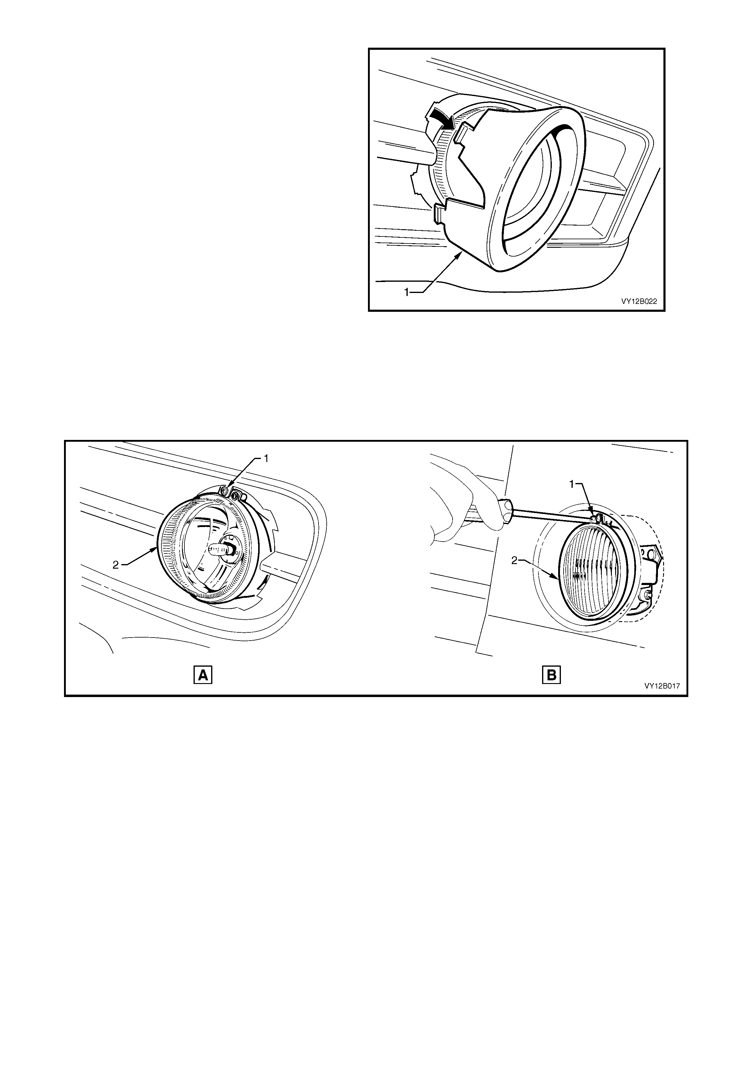
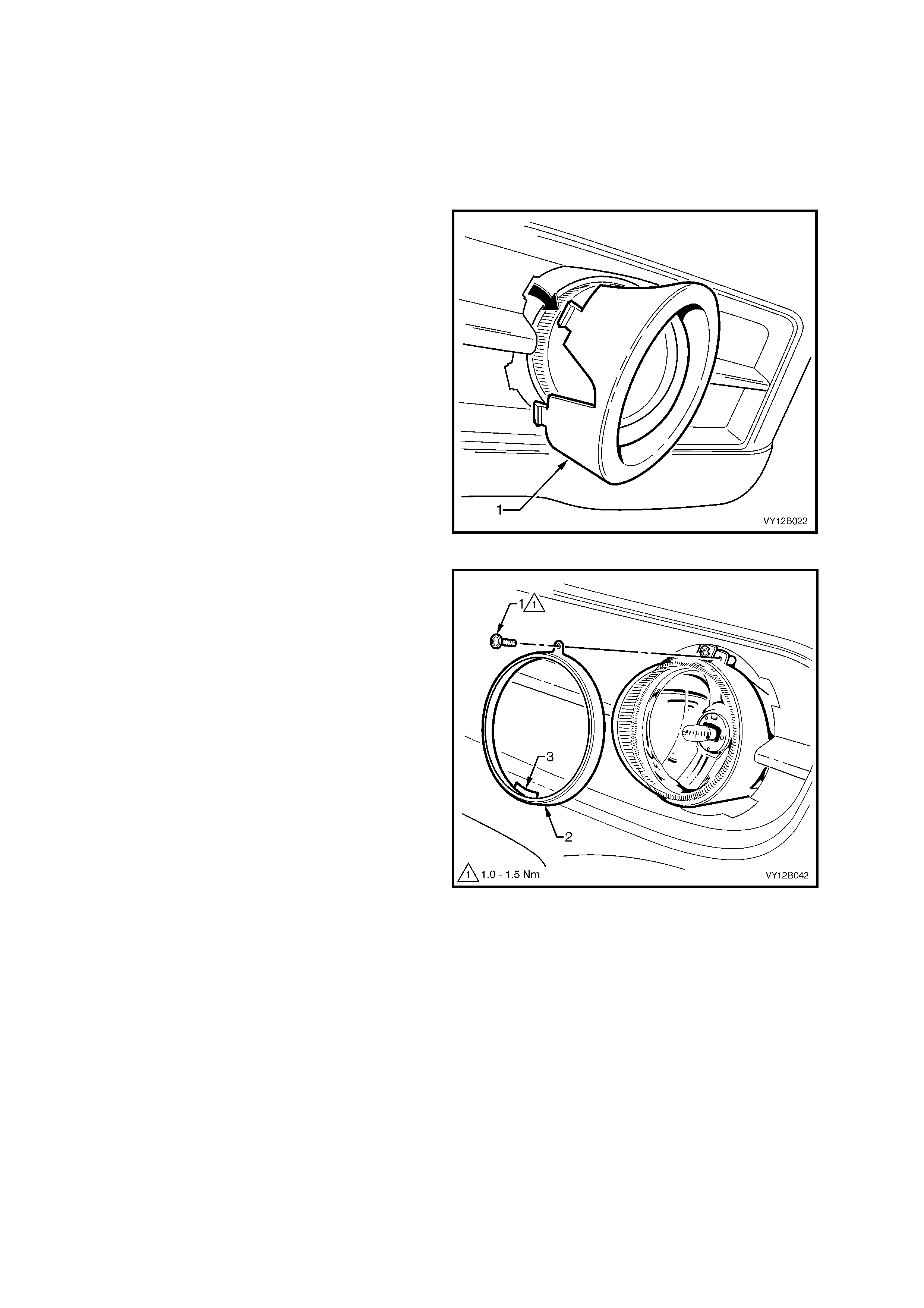
2. Depress the inner side of the front fog lamp
bezel assembly (1). Rotate the inner side of the
bezel assembly outwards until the tabs are
clear of the bumper fascia. Pull the bezel
assembly away from the bumper fascia.
Figure 12B-31
3. Remove the screw (1) to release the clamp
ring (2).
4. Rotate the ring clockwise until the retaining
hook (3) is at the 9 o’clock position. Ease the
ring out of the aperture and away from the fog
lamp.
Figure 12B-32
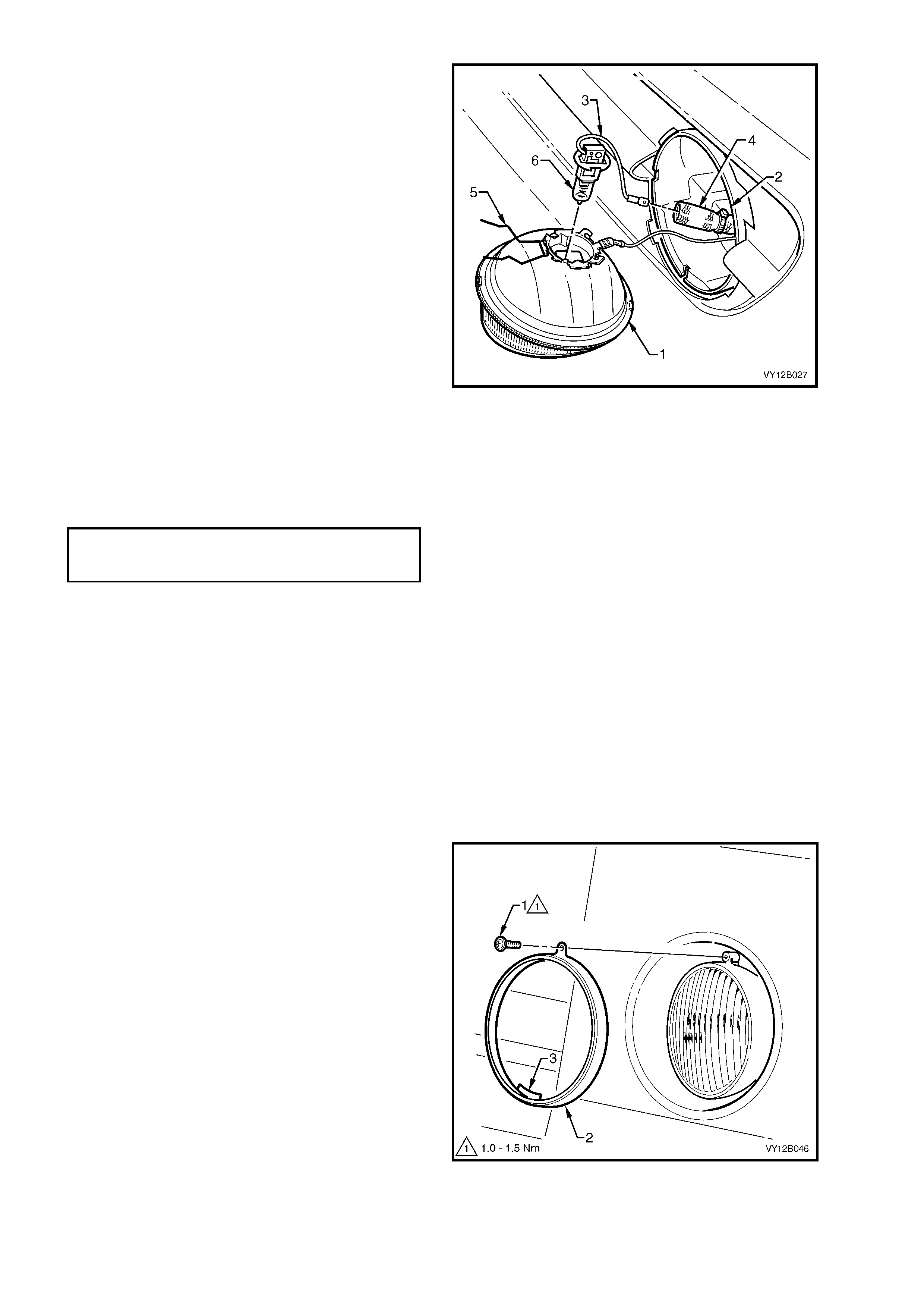
5. Pull the lens and reflector assembly (1) out
from the lamp housing (2).
6. Disconnect the bulb lead (3) from the wiring
harness connector located inside the insulation
sheath (4).
7. Squeeze the two halves of the spring retainer
(5) together and pivot the spring backward
clear of the bulb. Lif t the bulb (6) out of the lens
and reflector assembly.
NOTE: Do not handle the quartz envelope of the
bulb. If touched, wipe it immediately with
methylated spirits or the bulbs performance will
deteriorate.
8. Install the new bulb into the correct locating
notches in the reflector and insert the spring
retainer. Connect the bulb lead to the wiring
harness connector.
9. Install the lens and reflector assembly into the
housing ensuring that the tabs on the rim of the
lens and reflector assembly correspond with
the cut-outs in the rim of the housing.
10. Secure the lens and r ef lec tor as s embly with the
clamp ring and tighten the screw to the correct
torque specification.
11. Install the fusible link F102.
12. Check fog lamp operation and aim, refer to
2.1 AIMING OF HEADLAMPS AND FOG
LAMPS.
13. Install the fog lamp bezel assembly, ensuring
that the tabs lock securely into the bumper
fascia assembly.
Figure 12B-33
SS
Replace
1. Remove the fusible link F102. Refer to
Figure 12B-118, item 6.
2. Remove the screw (1) to release the clamp
ring (2).
3. Rotate the ring clockwise until the retaining
hook (3) is at the 9 o’clock position. Ease the
ring out of the aperture and away from the fog
lamp.
Figure 12B-34
FRONT FOG LAMP ASSEMBLY
CLAMP RING SECURING SCREW
TORQUE SPECIFICATION 1.0 – 1.5 Nm
4. Pull the lens and reflector assembly (1) out
from the lamp assembly (2).
5. Disconnect the bulb lead (3) from the wiring
harness connector (4) located inside the
insulating sheath.
6. Squeeze the spring retainer (5) together and
pivot the spring backward clear of the bulb.
Remove the bulb ( 6) f rom the lens and reflector
assembly.
NOTE: Do not handle the quartz envelope of the
bulb. If touched, wipe immediately with methylated
spirits or the bulbs performance will deteriorate.
7. Align the bulb to the notches in the reflector
and install the bulb. Install the spring retainer.
8. Connect the new bulb lead to the wiring
harness connector.
9. Install the lens and reflector assembly into the
housing ensuring that the tabs on the rim of the
lens and reflector assembly correspond with
the cut-outs in the rim of the housing.
10. Install the clamp ring and tighten screw to the
specified torque
11. Install the fusible link F102.
12. Check fog lamp operation and aim, refer to
2.1 AIMING OF HEADLAMPS AND FOG
LAMPS.
Figure 12B-35
COUPE
Replace
1. Remove the fusible link F102. Refer to
Figure 12B-118, item 6.
2. Remove the lower grille, refer to Section 1C,
2.5 LOWER RADIATOR GRILLE, COUPE.
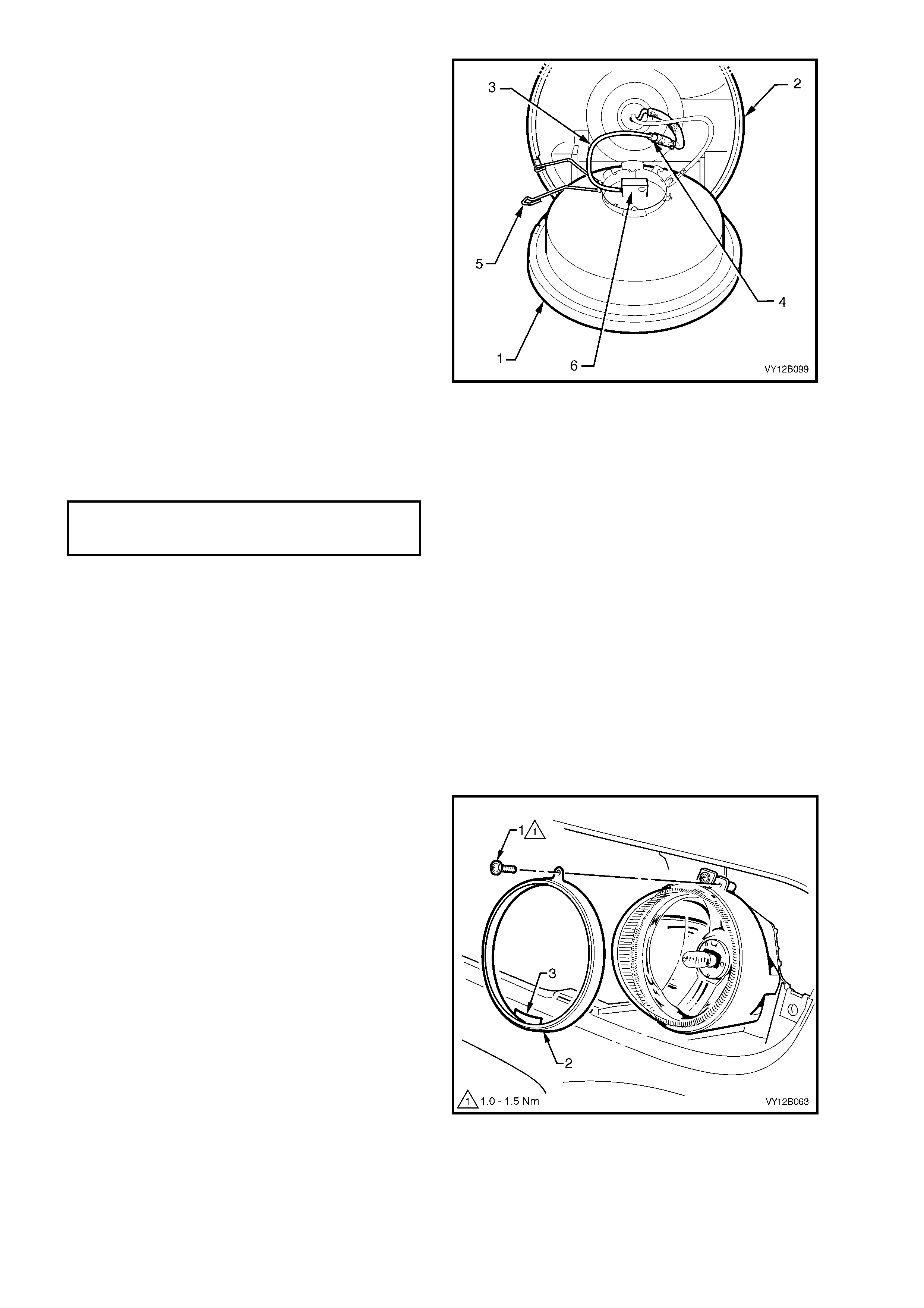
3. Remove the screw (1) to release the clamp
ring (2).
4. Rotate the ring clockwise until the retaining
hook (3) is at the 9 o’clock position. Ease the
ring out of the aperture and away from the fog
lamp.
Figure 12B-36
FRONT FOG LAMP ASSEMBLY
CLAMP RING SECURING SCREW
TORQUE SPECIFICATION 1.0 – 1.5 Nm

5. Pull the lens and reflector assembly (1) out
from the lamp housing (2).
6. Disconnect the bulb lead (3) from the wiring
harness connector located inside the insulation
sheath (4).
7. Squeeze the two halves of the spring retainer
(5) together and pivot the spring backward
clear of the bulb. Lif t the bulb (6) out of the lens
and reflector assembly.
NOTE: Do not handle the quartz envelope of the
bulb. If touched, wipe it immediately with
methylated spirits or the bulbs performance will
deteriorate.
8. Install the new bulb into the correct locating
notches in the reflector and insert the spring
retainer. Connect the bulb lead to the wiring
harness connector.
9. Install the lens and reflector assembly into the
housing ensuring that the tabs on the rim of the
lens and reflector assembly correspond with
the cut-outs in the rim of the housing.
10. Secure the lens and r ef lec tor as s embly with the
clamp ring and tighten the screw to the correct
torque specification.
11. Install the fusible link F102.
12. Check fog lamp operation and aim, refer to
2.1 AIMING OF HEADLAMPS AND FOG
LAMPS.
Figure 12B-37
FRONT FOG LAMP ASSEMBLY
CLAMP RING SECURING SCREW
TORQUE SPECIFICATION 1.0 – 1.5 Nm
2.5 TAIL LAMP ASSEMBLY BULBS
LT Section – 02-350
SEDAN
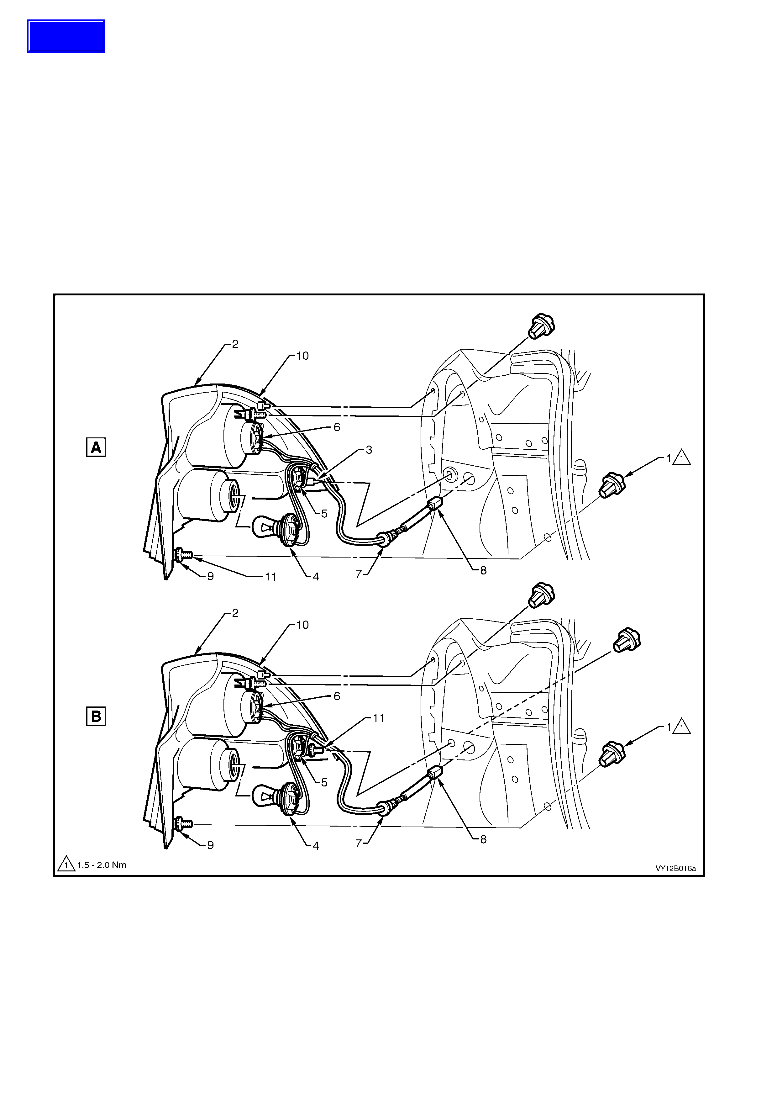
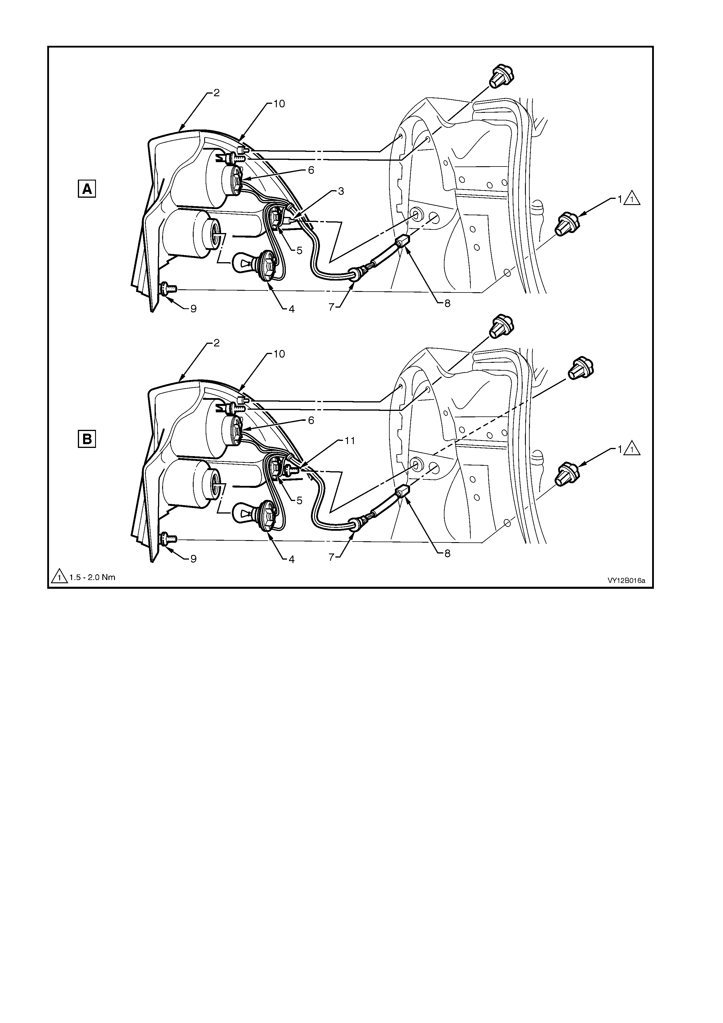
NOTE: During the production of the Sedan, the tail lamp assembly has been modified. The metal locating peg (3,
refer to Figure 12B-38, View A) has been replaced with a threaded stud (11) and attaching nut (1) so to provide a
further securing point for tail lamp assembly to sheetmetal. Therefore some tail lamp assemblies will have three
attaching nuts (View B), and some will have two attaching nuts and a metal locating peg (View A).
Replace
1. Remove the fusible link F102. Refer to Figure 12B-118, item 6.
2. Open the rear compartment lid.
3. Pull the quar ter inner r ear s ide car pet f r om the cor ner of the r ear compartment to ex pose the tail lamp attac hing
nuts (1), refer to Figure 12B-38.
NOTE: The tail lamp attaching nuts can be removed by hand or using a 6.0 mm Allen key.
Figure 12B-38
Legend
A Early Type Tail Lamp Assembly
with Two Attachment Studs
B Later Type Tail Lamp Assembly
with Three Attachment Studs
1. Attaching Nut
(two places View A)
(three places View B)
2. Tail lamp assembly
3. Metal locating peg
(one place View A)
4. Back-up Lamp Socket
5. Turn Signal Lamp Socket
6. Stop/Tail Lamp Socket
7. Grommet
8. Electrical Connector
9. Stud Seals
10. Main Seal
11. Attachment Stud
(two places View A)
(three places View B)
Techline
4. Remove the attaching nuts (1), in two places for the early type or three places for the later type tail lamps.
5. Pull the tail lamp away from the vehicle, releasing the metal lock peg (3) from its retainer for early type tail
lamps. Support the tail lamp assembly.
6. Remove the appr opriate bulb soc ket ( 4, 5 or 6) by turning the sock et anti-clock wise and pulling it away f rom the
lamp assembly.
7. Remove the bulb from the socket by depressing the bulb and then rotating it anti-clockwise.
8. Inspect the bulb socket seal for damage and replace if necessary.
9. Insert a new bulb into the socket and install the socket into the lam p assembly, ensuring that the sock et locks
securely into place.
NOTE: Lamp sockets have differing numbers of lugs to prevent installation into the incorrect rear lamp receptacle.
10. Ensure that the main seal (10), stud seals (9) and seal mating areas are clean to prevent any paint damage.
11. Install the lamp assembly onto the vehicle. Apply a firm pressure to the outboard lower corner of the tail lamp so
that the metal locating peg locks into the retainer (early type tail lamps).
12. Install and tighten the tail lamp assembly attaching nuts to the correct torque specification.
TAIL LAMP ASSEMBLY
ATTACHING NUT
TORQUE SPECIFICATION 1.5 – 2.0 Nm
13. Fit the fusible link F102 and check the tail lamp operation.
14. Fit the quarter inner rear side carpet in the rear compartment.
WAGON
Replace
1. Remove the fusible link F102. Refer to
Figure 12B-118, item 6.
2. Open the liftgate.
3. Remove the quarter trim panel vent with
a flat blade screwdriver, taking care not
to damage the surrounding quarter
inner trim panel assembly. Refer to
Section 1A8, 3.11 QUARTER INNER TRIM
PANEL ASSEMBLY – DISASSEMBLE.
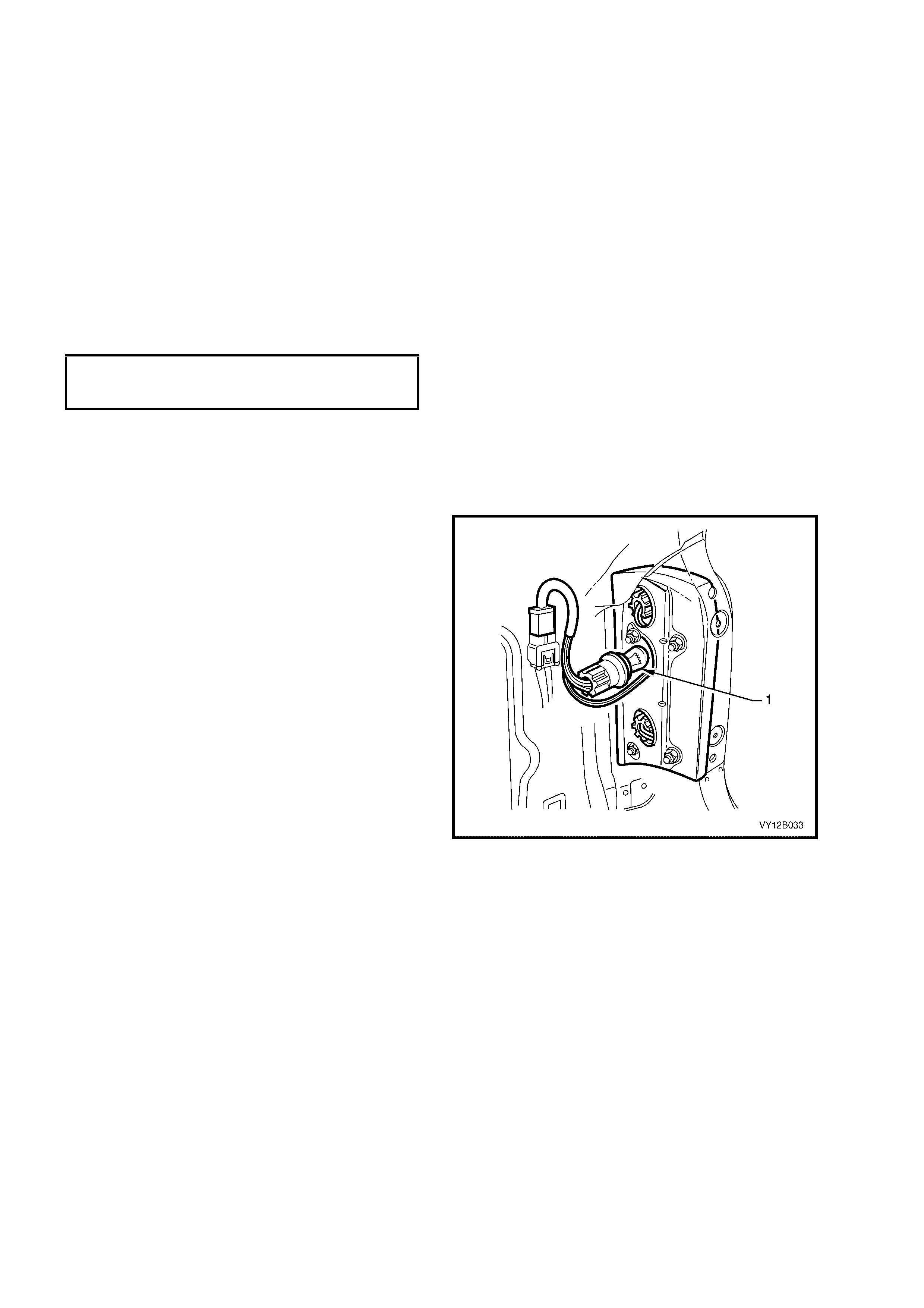
4. Remove the appropriate bulb socket (1) by
turning it anti-clockwise and pulling it away from
the lamp assembly.
IMPORTANT: The various sockets are colour
coded to aid in identification:
• Black socket – stop/tail lamp
• Grey socket – back-up lamp
• Orange socket – turn signal
5. Remove the bulb from the socket by
depressing the bulb and then rotating it anti-
clockwise.
6. Inspect the socket to lamp assembly seals for
damage and replace if necessary.
7. Insert a new bulb into the socket and fit the
socket into the lamp assembly, ensuring that
the socket locks securely into place.
8. F it the fus ible link F 102 and check the tail lam p
operation.
9. Fit the quarter trim panel vent.
Figure 12B-39
COUPE
Replace
1. Remove the fusible link F102. Refer to Figure 12B-118, item 6.
2. Open the rear compartment.
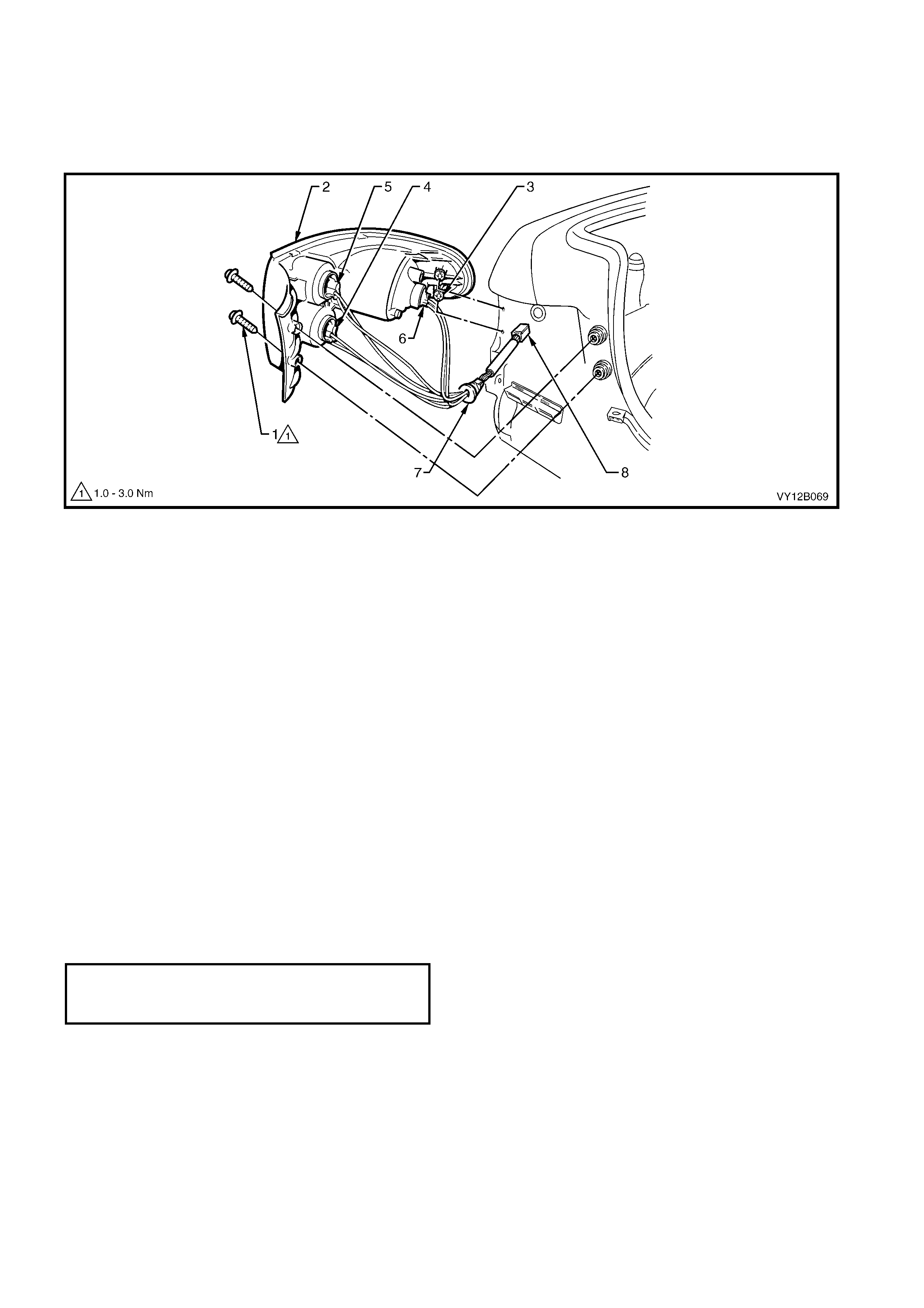
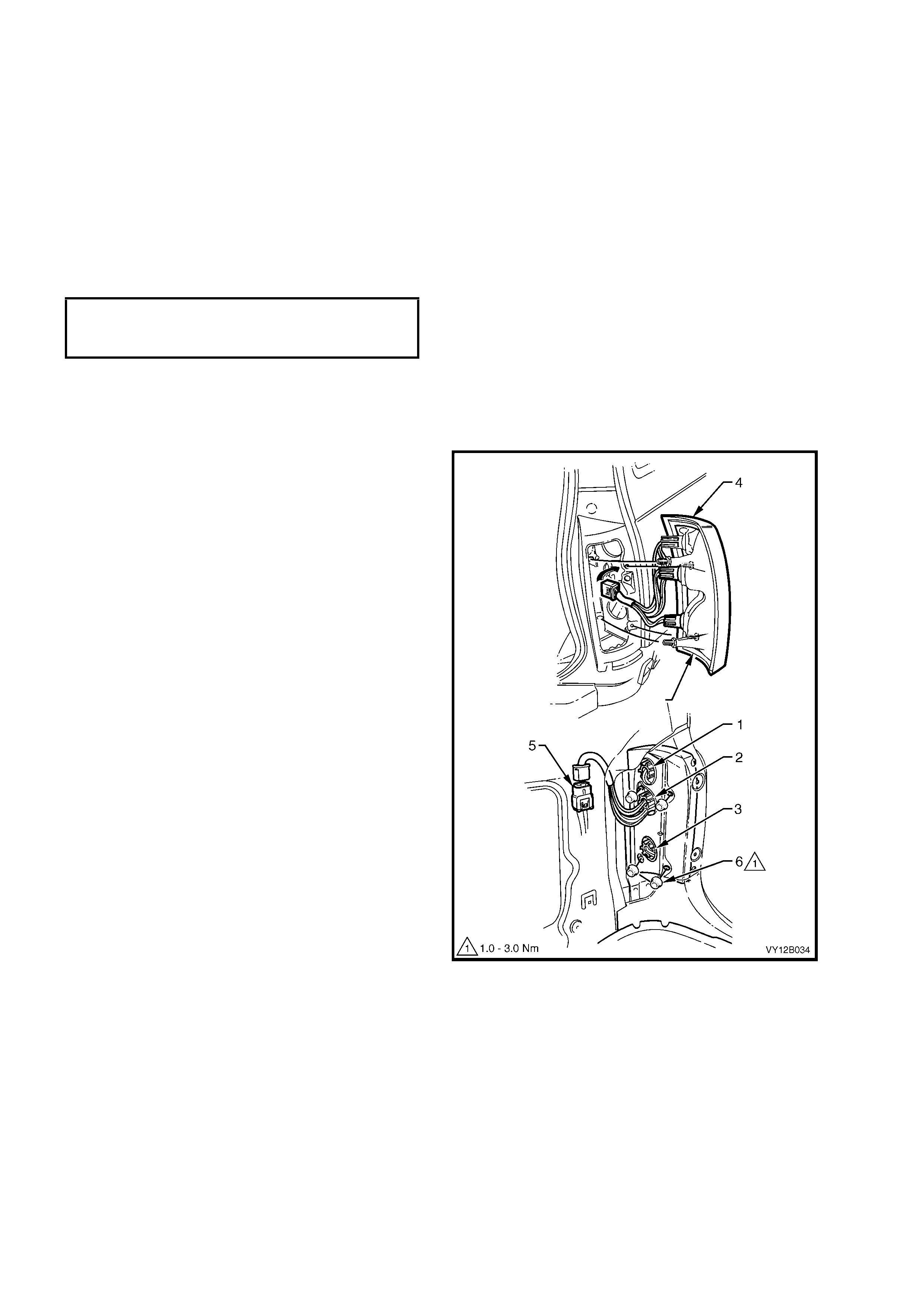
3. Remove the tail lamp assembly attaching screws (1), refer to Figure 12B-40.
Figure 12B-40
Legend
1. Attaching screw (2 places)
2. Tail lamp assembly
3. Locating pegs
4. Back-up lamp socket
5. Turn signal lamp socket
6. Stop/tail lamp socket
7. Grommet
8. Electrical connector
4. Pull the tail lamp assembly (2) sideways and out from the panel so that locating pegs (3) on the side of lamp
assembly snap free from the retainers. Support the assembly.
NOTE: When removing the tail lamp assembly from the panel, take care not to damage the locating pegs.
5. Remove the appr opriate bulb soc ket ( 4, 5 or 6) by turning the sock et anti-clock wise and pulling it away f rom the
lamp assembly.
6. Remove the bulb from the socket by depressing the bulb and then rotating it anti-clockwise.
7. Inspect the socket seal for damage and replace if necessary.
8. Insert a new bulb into the socket and install the socket into the lam p assembly, ensuring that the sock et locks
securely into place.
NOTE 1: Lamp sockets have differing numbers of lugs to prevent installation into the incorrect rear lamp receptacle.
NOTE 2: Harness length will allow the back -up light sock et and the turn signal bulb socket to be fitted into correct
locations only.
9. Ensure that the lamp harness grommet (7) is seated correctly. Fit the tail lamp assembly to the body ensuring
that the locating pegs snap into the retainers.
10. Install and tighten the attaching screws to the correct torque specification.
TAIL LAMP ASSEMBLY
ATTACHING SCREW
TORQUE SPECIFICATION 1.0 – 3.0 Nm
11. Install the fusible link F102 and check the tail lamp operation.
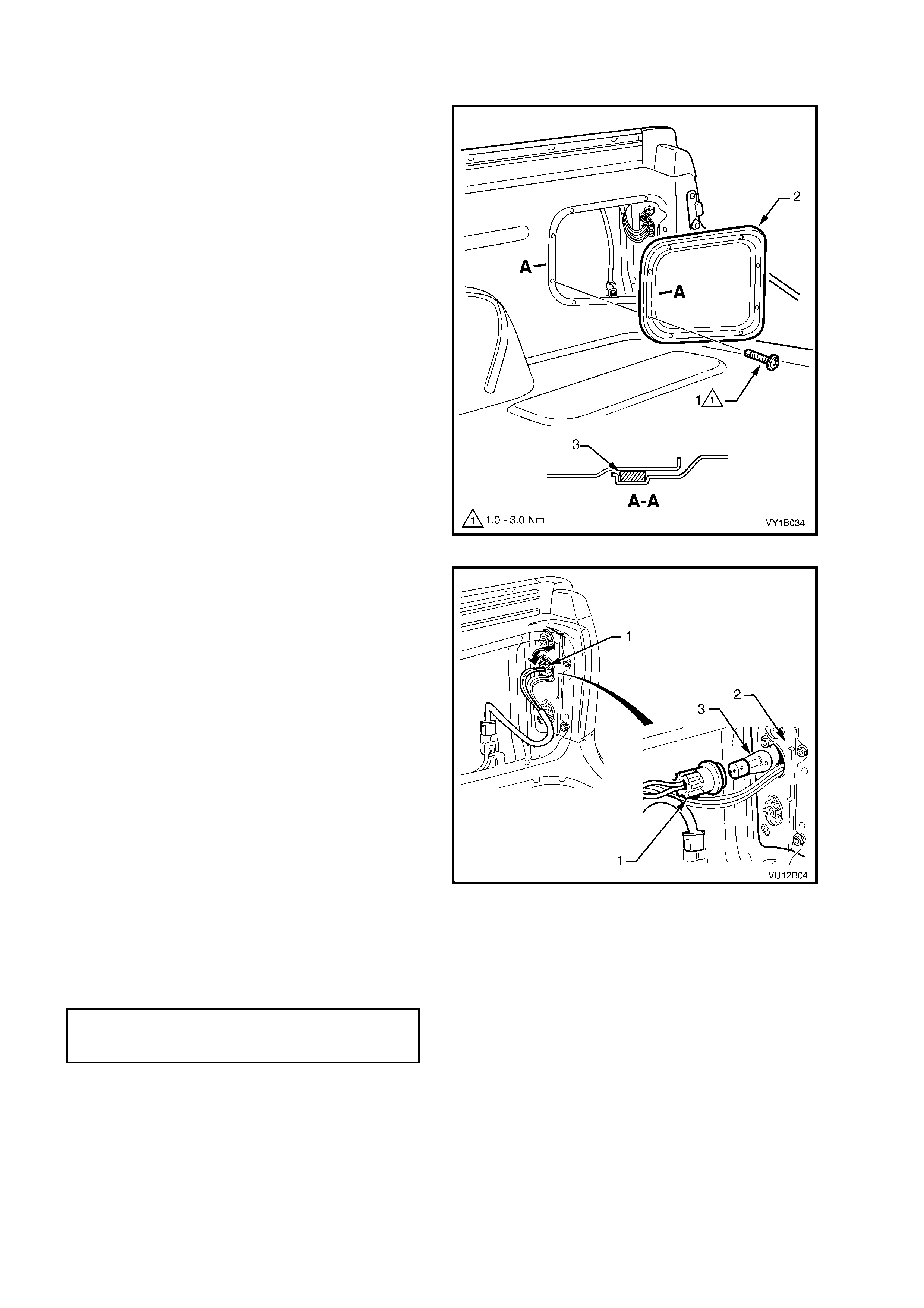
UTILITY
Replace
1. Remove the fusible link F102. Refer to
Figure 12B-118, item 6.
2. Remove the eight screws (1) securing the rear
inner side panel cover (2) and remove the
cover.
NOTE: The cover may require careful prising to
break the seal (3) from the inner side panel.
Figure 12B-41
3. Rem ove the appropriate soc ket (1) by turning it
anti-clockwise and removing the socket from
the tail lamp assembly (2).
IMPORTANT: The various sockets are colour
coded to aid in identification:
• Black socket – stop/tail lamp
• Grey socket – back-up lamp
• Orange socket – turn signal
4. Remove the bulb (3) from the socket by
depressing the bulb and then rotating it anti-
clockwise.
5. Inspect the socket to the lamp assembly seals
for damage and replace if necessary.
6. Insert a new bulb into the socket and fit the
socket into the lamp assembly, ensuring that it
locks securely into place.
7. F it the fus ible link F 102 and check the tail lam p
assembly operation.
8. Check the seal (3) on the rear inner side panel
cover, refer to Figure 12B-41. Fit and tighten
the rear inner side panel cover screws to the
specified torque.
Figure 12B-42
REAR INNER SIDE
PANEL COVER SCREW
TORQUE SPECIFICATION 1.0 – 3.0 Nm
2.6 HEADLAMP ASSEMBLY
The headlamp assemblies all have the same retainer attaching pattern, that is, they all require three screws in the
same locations to secure the assemblies to the sheetmetal.
LT Section – 02-300
REMOVE
1. Remove the fusible link F102. Refer to Figure 12B-118, item 6.
2. Remove the front bumper fascia assembly . Refer to Section 1D, 2.2 FRONT BUMPER FASCIA ASSEMBLY.
3. If required, for GEN III V8 engine models, remove the four retainers securing the upper radiator shroud and
remove the shroud. Refer to Section 6B3, 2.16 RADIATOR.
4. For the right-hand headlamp assembly, it may be necessary to remove the battery to gain the required access.
a. If required, remove the battery hold-down bracket and move the battery to gain access. Refer to
Section 12A, 2.9 BATTERY.
b. If further access is required, remove the battery terminals from the battery and remove the battery from the
engine compartment. Refer to Section 12A, 2.9 BATTERY.
Important: Disconnection of the battery affects certain vehicle electronic systems. Refer to
Section 00, 5. BATTERY DISCONNECTION PROCEDURES before disconnecting the battery.
4. For lef t- hand headlamp as s embly’s on V6 engine models, remove the c oolant f iller bottle nec k and place to one
side.
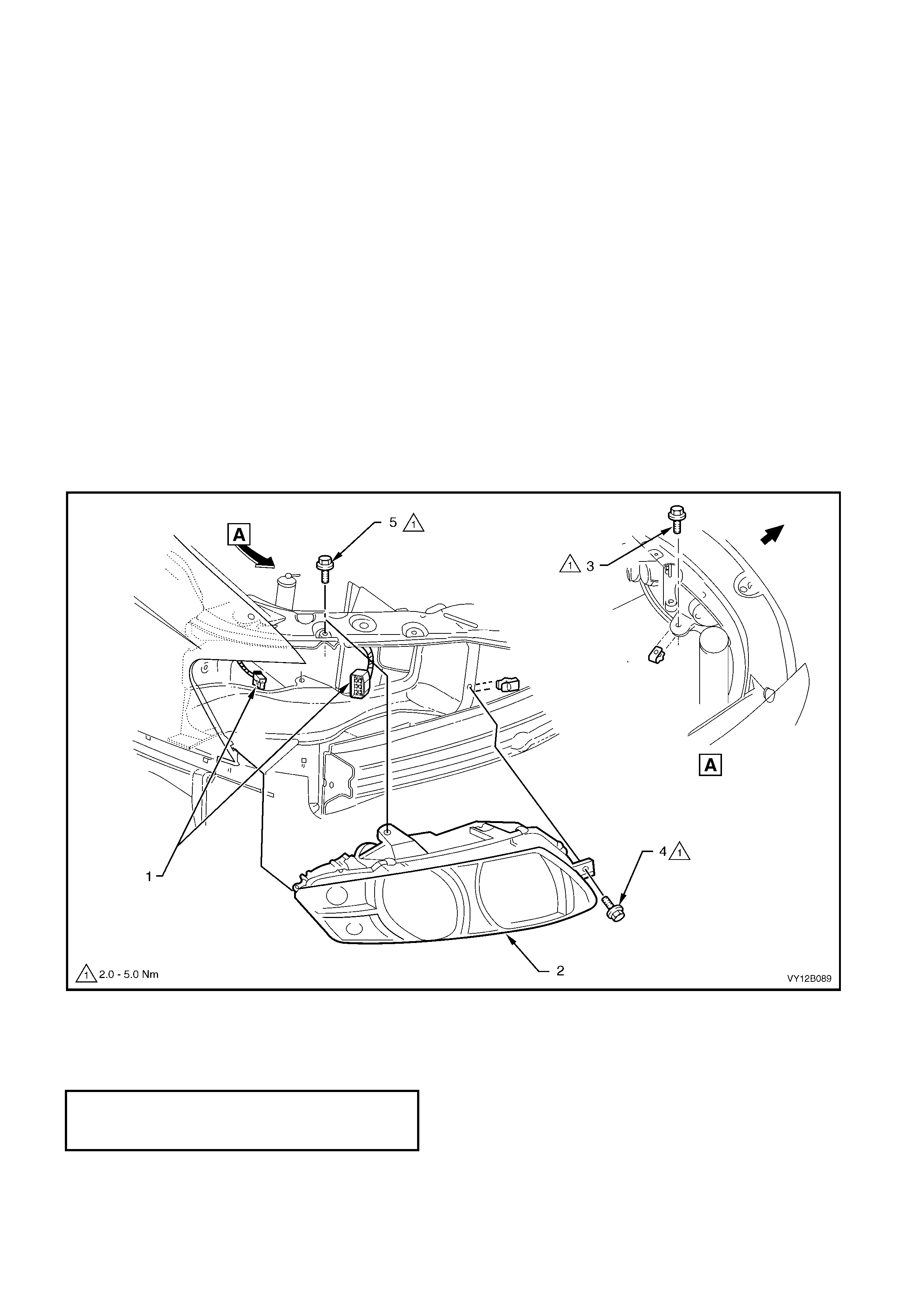
5. Disconnect the turn signal and headlamp wiring harness connectors (1) from the rear of the headlamp
assembly (2).
6. Remove the three headlamp retaining screws (3, 4 and 5) and remove the headlamp assembly.
Figure 12B-43
REINSTALL
Installation of the headlamp assembly is the reverse of the removal procedure, noting the following points:
1. Install the headlamp assembly and tighten the retaining screws to the correct torque specification.
HEADLAMP ASSEMBLY
RETAINING SCREW
TORQUE SPECIFICATION 2.0 – 5.0 Nm
2. Connect all the wiring harness connectors and check the operation of the headlamps and turn signal/parking
lamps.
3. Install the front bumper fascia assembly. Refer to Section 1D, 2.2 FRONT BUMPER FASCIA ASSEMBLY.
4. Check the headlamp (and fog lamps) aim, refer to 2.1 AIMING OF HEADLAMPS AND FOG LAMPS.
2.7 FRONT FOG LAMP ASSEMBLY
LT Section – 02-325
LEVEL 3
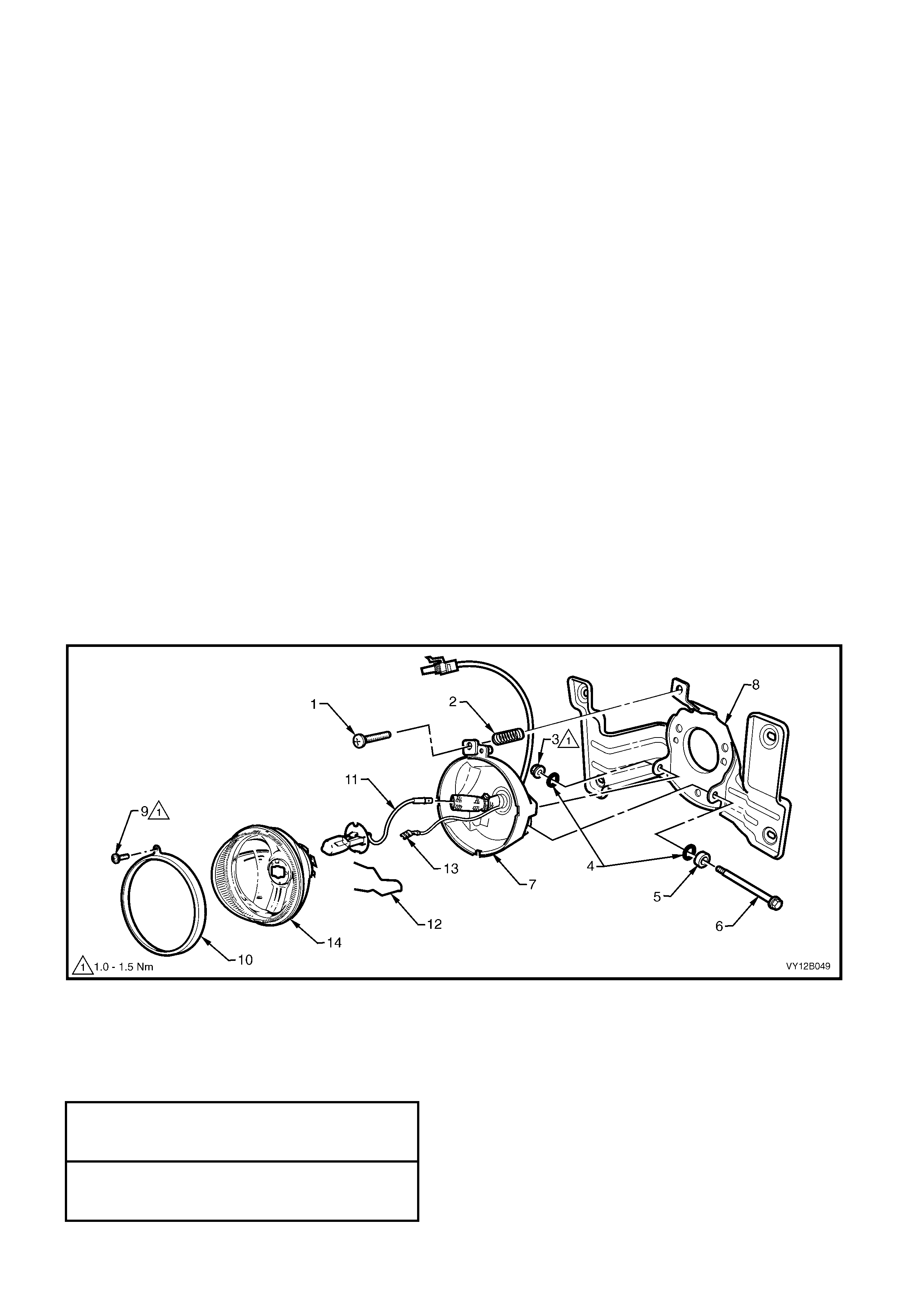
The following parts (refer to Figure 12B-44) may be disassembled from the front fog lamp assembly without
removing the complete unit from behind the lower radiator grille:
• Adjusting screw (1)
• Spring (2 )
• Clamp ring (10)
• Lens and reflector assembly (14)
• Bulb (11)
• Retaining spring (12)
To remove any of these items, refer to 2.4 FRONT FOG LAMP BULB ASSEMBLY – LEVEL 3.
Remove
1. Remove the fusible link F102. Refer to Figure 12B-118, item 6.
2. Remove the front fog lamp assembly, refer to Section 1C, 2.4 LOWER RADIATOR GRILLE, LEVEL
2 & 3 –DISASSEMBLY.
Disassemble
1. Remove the adjusting screw (1) and the spring (2).
NOTE: Ensure that the spring is contained when the adjusting screw is removed.
2. Remove the nut (3), seals (4), spacer (5) and bolt (6) securing the lens and reflector housing (7) to the
mounting bracket (8). Separate the two items.
3. Remove the screw (9) and clamp ring (10).
4. Disconnect the bulb lead (11) from the wiring harness connector inside the insulation sheath.
5. Remove the earth lead connector (13) from the lens and reflector assembly (14).
6. Squeeze the ends of the retaining spring (12) together and remove the spring. Remove the bulb.
7. Remove the grommet and remove the wiring harness from the lens and reflector housing.
Figure 12B-44
Reassemble
Assembly of the front fog lamp is the reverse of the disassembly procedure, noting the following:
1. Tighten the clamp ring securing screw to the correct torque specification.
2. Tighten the lens and reflector housing hinge bolt nut to the correct torque specification.
FRONT FOG LAMP ASSEMBLY
CLAMP RING SECURING SCREW
TORQUE SPECIFICATION 1.0 – 1.5 Nm
FRONT FOG LAMP ASSEMBLY LENS
AND REFLECTOR HOUSING HINGE
BOLT NUT TORQUE SPECIFICATION 1.0 – 1.5 Nm
Reinstall
Installation of the fog lamp assembly is the reverse of the removal procedure.
SS
The following parts (refer to Figure 12B-44) may be disassembled from the front fog lamp assembly without
removing the complete unit from behind the lower radiator grille:
• Adjusting screw (1)
• Spring (2 )
• Clamp ring (10)
• Lens and reflector assembly (14)
• Bulb (11)
• Retaining spring (12)
To remove any of these items, refer to 2.4 FRONT FOG LAMP BULB ASSEMBLY – SS.
Remove
1. Remove the fusible link F102. Refer to
Figure 12B-118, item 6.
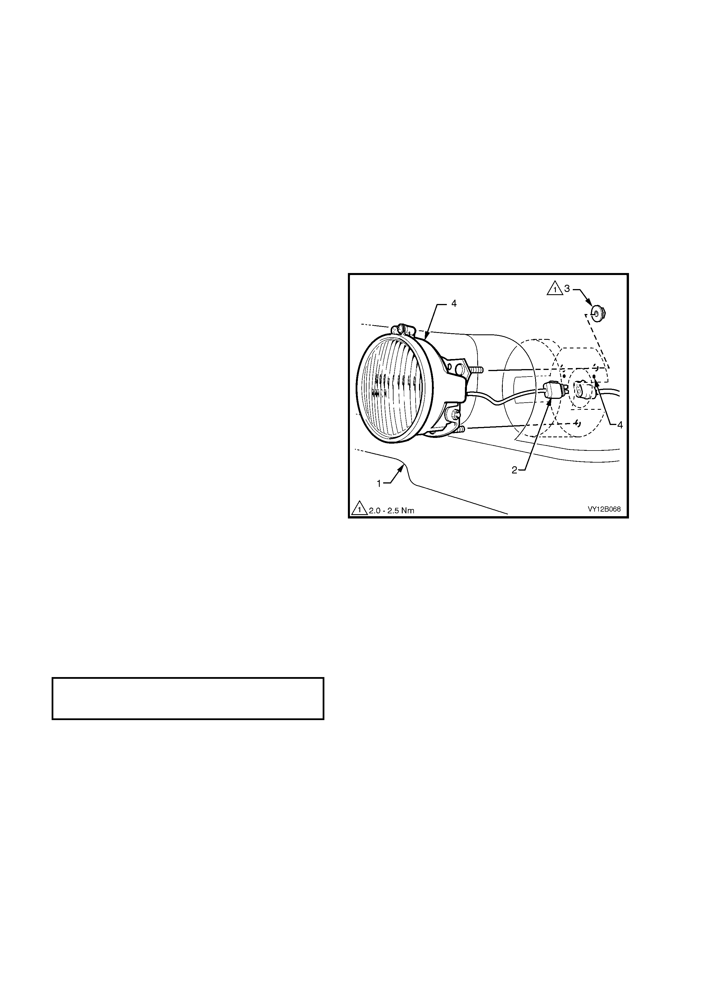
2. From behind the bumper fascia assembly (1),
disconnect the fog lamp harness connector (2).
3. Remove the three nuts (3) securing the front
fog lamp assembly (4) to bumper fascia and
remove the lamp assembly.
Disassemble
Disassembly of the SS front fog lamp is the same
as Level 3, refer to 2.7 FRONT FOG LAMP
ASSEMBLY, LEVEL 3 - DISASSEMBLY.
Reassembly
Assembly of the SS front fog lamp is the same as
Level 3, refer to 2.7 FRONT FOG LAMP
ASSEMBLY, LEVEL 3 – REASSEMBLY.
Reinstall
Installation of the front fog lamp assembly is the
reverse of the removal procedures, noting the
following points:
1. Ensure that the front fog lamp assembly is
correctly orientated with the beam adjustment
screw located to the top.
2. Ensure that the lamp is located on the fascia
datum pins (4). Tighten the nuts securing the
lamp assembly to the bumper fascia assembly
to the correct torque specification.
3. Check the operation and adjust the aim of the
front fog lamps. Refer to 2.1 AIMING OF
HEADLAMPS AND FOG LAMPS in this
Section.
Figure 12B-45
FRONT FOG LAMP
ASSEMBLY ATTACHING NUT
TORQUE SPECIFICATION 2.0 – 2.5 Nm
COUPE
Remove
1. Remove the fusible link F102. Refer to
Figure 12B-118, item 6.
2. Remove the lower grille, refer to Section 1C,
2.5 LOWER RADIATOR GRILLE – COUPE.
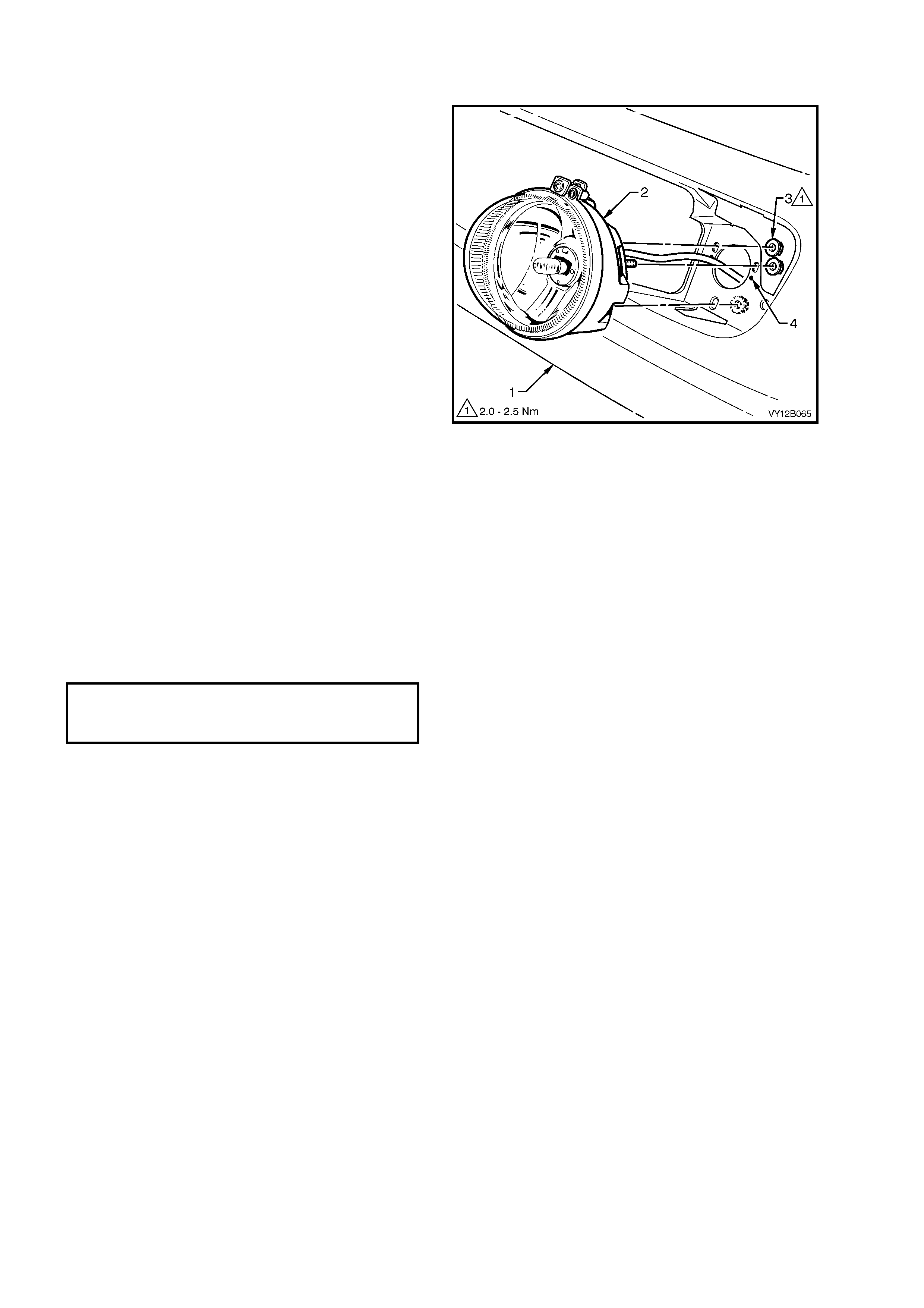
3. F rom behind the f ront bum per fas cia assem bly,
disconnect the f og lam p harness from the main
wiring harness connector.
4. Remove the three nuts (3) securing the front
fog lamp as s embly (2) to the bumper bar fascia
(1) and remove the lamp assembly.
Disassemble
Disassembly of the Coupe front fog lamp is the
same as Level 3, refer to 2.7 FRONT FOG LAMP
ASSEMBLY, LEVEL 3 - DISASSEMBLY.
Reassembly
Assembly of the Coupe front fog lam p is the same
as Level 3, refer to 2.7 FRONT FOG LAMP
ASSEMBLY, LEVEL 3 – REASSEMBLY.
Reinstall
Installation of the front fog lamp assembly is the
reverse of the removal procedures, noting the
following points:
1. Ensure that the front fog lamp assembly is
correctly orientated with the beam adjustment
screw located to the top.
2. Ensure that the lamp is located on the fascia
datum pins (4). Tighten the nuts securing the
lamp assembly to the bumper fascia assembly
to the correct torque specification.
FRONT FOG LAMP
ASSEMBLY ATTACHING NUT
TORQUE SPECIFICATION 2.0 – 2.5 Nm
3. Check the operation and adjust the aim of the
front fog lamps. Refer to 2.1 AIMING OF
HEADLAMPS AND FOG LAMPS in this
Section.
4. Install the lower grille, refer to Section 1C, 2.5
LOWER RADIATOR GRILLE – COUPE.
Figure 12B-46

2.8 TAIL LAMP ASSEMBLY
LT Section – 02-350
SEDAN
NOTE: During the production of the Sedan, the tail lamp assembly has been modified. The metal locating peg (3,
refer to Figure 12B-38, View A) has been replaced with a threaded stud (11) and attaching nut (1) so to provide a
further securing point for tail lamp assembly to sheetmetal. Therefore some tail lamp assemblies will have three
attaching nuts (View B), and some will have two attaching nuts and a metal locating peg (View A).
Remove
1. Remove the fusible link F102. Refer to Figure 12B-118, item 6.
2. Open the rear compartment lid.
3. Pull the quar ter inner r ear s ide car pet f r om the cor ner of the r ear compartment to ex pose the tail lamp attac hing
nuts (1), refer to Figure 12B-47.
NOTE: The tail lamp attaching nuts can be removed by hand or using a 6.0 mm Allen key.
4. If leaving the wiring harness installed:
a. Remove the attaching nuts (1), in two places for the early type or three places for the later type tail lamps.
b. Pull the tail lamp away from the vehicle, releasing the metal lock peg (3) from its retainer for early type tail
lamps. Support the tail lamp assembly.
c. Rem ove all the bulb sock ets (4, 5 and 6) by turning the sock ets anti-clock wise and pulling them away from the
reflector.
5. If removing the wiring harness:
a. Remove the attaching nuts (1), in two places for the early type or three places for the later type tail lamps.
b. Pull the tail lamp away from the vehicle, releasing the metal lock peg (3) from its retainer for early type tail
lamps. Support the tail lamp assembly.
c. Disconnect the tail lamp wiring harness (8) from the body wiring harness.
d. Pull the grommet (7) out from the sheetmetal and remove the tail lamp assembly and the harness.
Techline
A Early Type Tail Lamp Assembly
with Two Attachment Studs
B Later Type Tail Lamp Assembly
with Three Attachment Studs
1. Attaching Nut
(two places View A)
(three places View B)
2. Tail lamp assembly
3. Metal locating peg
(one place View A)
4. Back-up Lamp Socket
5. Turn Signal Lamp Socket
6. Stop/Tail Lamp Socket
7. Grommet
8. Electrical Connector
9. Stud Seals
10. Main Seal
11. Attachment Stud
(two places View A)
(three places View B)
Replace – Main Seal
The main seal is adhered to the lens cover of the lamp assembly with contact adhesive and double-sided tape.
1. T o r eplace the seal, c arefu lly rem ove the old seal and clean the surf ace lam p assem bly with soapy water . Wipe
any residue of the cleaner from the plastic before applying fresh adhesive and tape.
NOTE: Do not use solvents on the plastic surfaces of the lamp assembly.
2. Apply a small amount of adhesive to the seal and double-sided tape to the lamp assembly.
3. Place the seal on the lamp assembly.
4. Allow time for the adhesive to cure before installing the lamp assembly to the vehicle.
Figure 12B-47
Legend
Reinstall
Installation of the lamp assembly is the reverse on the removal procedure, noting the following points:
1. If required, inspect the socket to lamp assembly seals for damage and replace where necessary.
2. If required, replace the wiring harness.
3. Ensure that the lamp sockets are installed into the lamp assembly correctly and locked into place.
NOTE: Lamp sockets have differing numbers of lugs to prevent installation into the incorrect tail lamp assembly
receptacle.
4. Ensure that the main seal (10), stud seals (9) and seal mating areas are clean to prevent any paint damage.
5. Install the lamp assembly onto the vehicle. Apply a firm pressure to the outboard lower corner of the tail lamp so
that the metal locating peg locks into the retainer (early type tail lamps).
6. Install and tighten the tail lamp assembly attaching nuts to the correct torque specification.
TAIL LAMP ASSEMBLY
ATTACHING NUT
TORQUE SPECIFICATION 1.5 – 2.0 Nm
7. Check the tail lamp operation.
WAGON
Remove
1. Remove the fusible link F102, refer to
Figure 12B-118, item 6.
2. Open the liftgate.
3. If leaving the wiring harness installed:
a. Remove the quarter trim panel vent with
a flat blade screwdriver, taking care not
to damage the surrounding quarter
inner trim panel assembly. Refer to
Section 1A8, 3.11 QUARTER INNER TRIM
PANEL ASSEMBLY – DISASSEMBLE.
b. Remove all three bulb sockets (1, 2 and 3)
from the lamp assembly (4) by turning them
anti-clockwise and pulling them away from the
assembly.
4. If removing the wiring harness:
a. Remove the quarter inner trim
panel assembly, refer to Section 1A8,
3.11 QUARTER INNER TRIM PANEL
ASSEMBLY.
b. Disconnect the tail lamp wiring harness (5)
from the body wiring harness connector.
5. Remove the four nuts (6) retaining the lamp
assembly to the vehicle.
6. Remove the lamp assembly.
Reinstall
Installation of the lamp assembly is the reverse of
the removal procedures, noting the following points:
1. If necessary, install new bulbs into the sockets
and fit the sockets to the lamp assembly.
2. Ensure that the main seal and seal mating
surface is clean to avoid damage to the
paintwork.
Figure 12B-48
IMPORTANT: The various sockets are colour coded to aid in identification:
• Black socket – stop/tail lamp.
• Grey socket – back-up lamp.
• Orange socket – turn signal.
3. Tighten the lamp assembly attaching nuts to the correct torque specification.
4. Check the tail lamp operation.
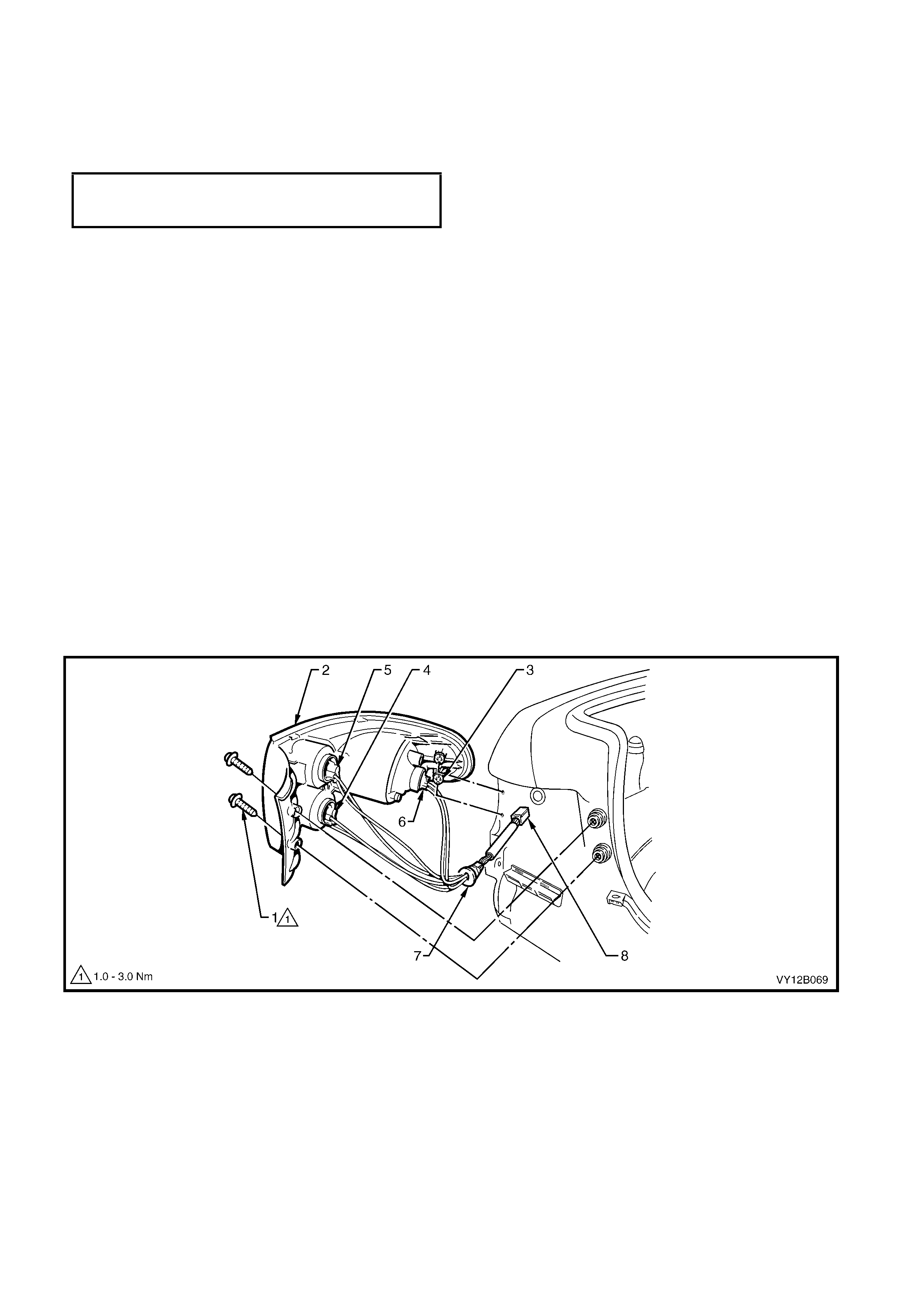
COUPE
Remove
1. Remove the fusible link F102, refer to Figure 12B-118, item 6.
2. Open the rear compartment lid.
3. Remove the two lamp assembly to body attaching screws (1).
4. If leaving the wiring harness installed:
a. Pull the tail lam p assem bly (2) sideways and out f rom the panel so that the locating peg (3) on the side of lamp
assembly snaps free from the retainer.
NOTE: When removing the tail lamp assembly from panel, take care not to damage the locating pegs (3).
b. Remove all the sockets (4, 5 and 6) by turning the sockets anti-clockwise and pulling them away from the
reflector.
5. If removing the wiring harness:
a. Pull the quarter inner rear side carpet away from the vehicle to expose the tail lamp wiring harness connector
(8).
b. Disconnect the tail lamp wiring harness from the body wiring harness.
c. Pull the tail lamp assembly (2) sideways out from the panel so that the locating peg (3) on side of the lamp
assembly snaps free from the retainer.
d. Pull the grommet (7) out from the sheetmetal and remove and tail lamp assembly and the harness.
Figure 12B-49
Legend
1. Attaching screw (2 places)
2. Tail lamp assembly
3. Locating pegs
4. Back-up lamp socket
5. Turn signal lamp socket
6. Stop/tail lamp socket
7. Grommet
8. Electrical connector
TAIL LAMP ASSEMBLY
ATTACHING NUT
TORQUE SPECIFICATION 1.0 – 3.0 Nm

Replace – Main Seal
The seal is adhered to the lens cover of the lamp assembly with contact adhesive and double-sided tape.
1. T o r eplace the seal, c arefu lly rem ove the old seal and clean the surf ace lam p assem bly with soapy water . Wipe
any residue of the cleaner from the plastic before applying fresh adhesive and tape.
NOTE: Do not use solvents on the plastic surfaces of the lamp assembly.
2. Apply a small amount of adhesive to the seal and double-sided tape to the lamp assembly.
3. Place the seal on the lamp assembly.
4. Allow time for the adhesive to cure before installing the lamp assembly to the vehicle.
Reinstall
Installation of the lamp assembly is the reverse on the removal procedure, noting the following points:
1. If required, inspect the socket to lamp assembly seals for damage and replace where necessary.
2. If required, replace the wiring harness.
3. Ensure that the lamp sockets are installed into the lamp assembly correctly and locked into place.
NOTE: Harness length will allow the back-up light socket and turn signal bulb socket to be fitted to the correct
locations only.
4. Install and tighten the attaching screws to the correct torque specification.
TAIL LAMP ASSEMBLY
ATTACHING SCREW
TORQUE SPECIFICATION 1.0 – 3.0 Nm
5. Check the tail lamp operation.
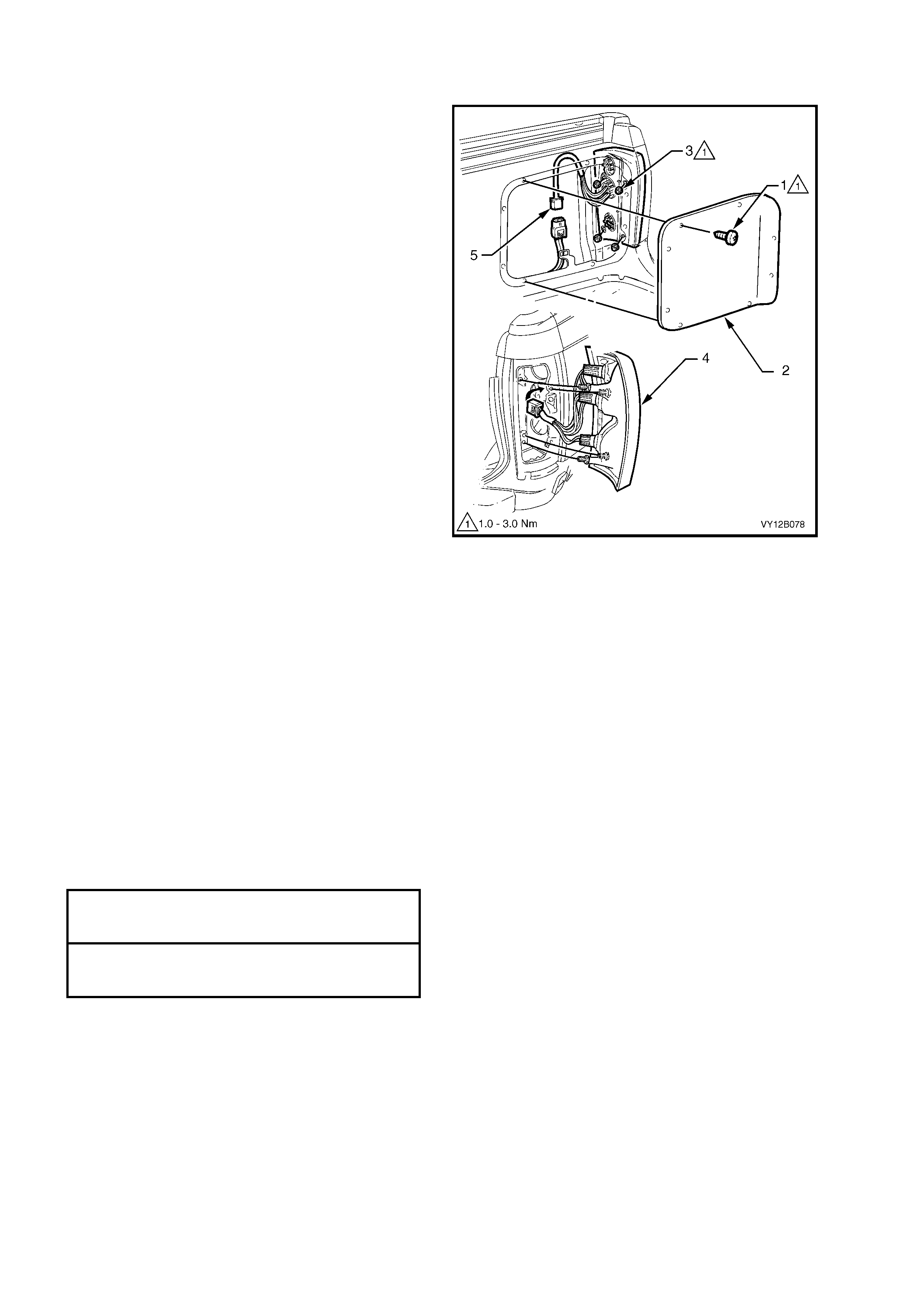
UTILITY
Remove
1. Remove the fusible link F102, refer to
Figure 12B-118, item 6.
2. Remove the eight screws (1) securing the rear
inner side panel cover (2) and remove the
cover.
3. Remove the four nuts (3) retaining the lamp
assembly (4) to the vehicle.
4. Disconnect the tail lamp wiring harness (5)
from the body harness and carefully remove
the lamp assembly.
5. If necess ary, rem ove the bulb sock ets from the
lamp assembly. To remove the sockets, rotate
them anti-clockwise and pull them away from
the reflector.
Reinstall
Installation of the lamp assembly is the reverse of
the removal procedure, noting the following points:
1. If necessary, install new bulbs into the sockets
and fit the sockets to the lamp assembly.
IMPORTANT: The various sockets are colour
coded to aid in identification:
• Black socket – stop/tail lamp
• Grey socket – back-up lamp
• Orange socket – turn signal
2. If necessary, replace the lamp harness.
3. Ensure that the main seal and seal mating
surface is clean to avoid damage to the
paintwork.
4. Tighten the lamp ass embly retaining nuts to the
correct torque specification.
5. Clean the mating surfaces of the load
compartment side panel inner rear cover and
the load compartment. Apply sealant (Holden
specification HN1005) to the mating surfaces of
the cover and the load com partm ent and fit the
cove r.
6. Tighten the load compartment side panel inner
rear cover screws to the correct torque
specification.
7. Install the fusible link F102 and check the tail
lamp operation.
Figure 12B-50
TAIL LAMP ASSEMBLY
ATTACHING NUT
TORQUE SPECIFICATION 1.0 – 3.0 Nm
REAR INNER SIDE
PANEL COVER SCREW
TORQUE SPECIFICATION 1.0 – 3.0 Nm
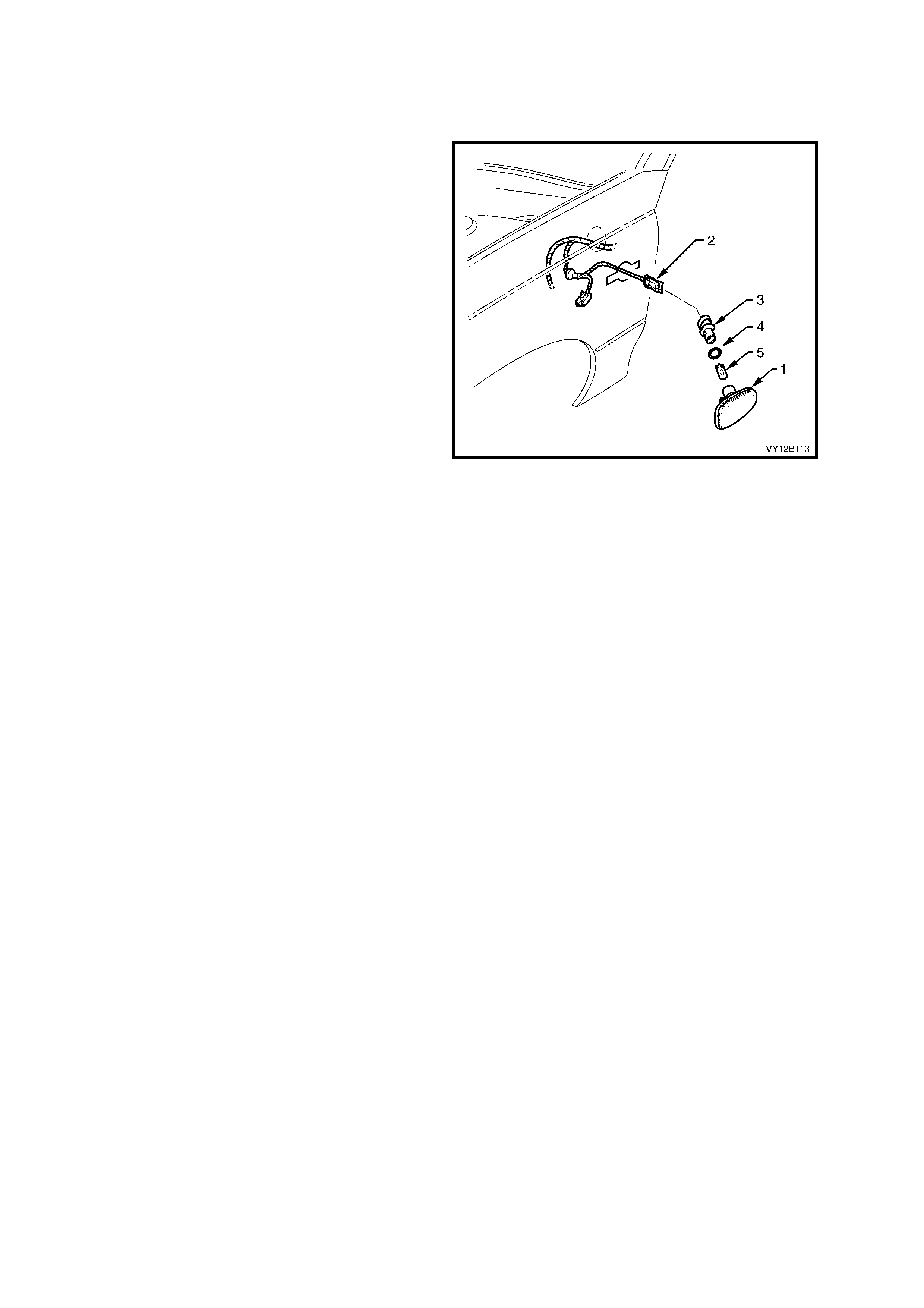
2.9 FRONT SIDE TURN SIGNAL LAMP ASSEMBLY
LT Section – 02-300
REMOVE
1. Remove the turn signal lamp fuse, refer to
Figure 12B-116, item 4.
2. Grip the rear edge of the front side turn signal
lamp assembly (1) with finger tips and pull the
lamp assembly forward, outwards and clear of
the front fender.
NOTE: The Sedan is shown, Coupe is similar.
3. Disconnect the harness connector (2) from the
lamp assembly.
NOTE: Tape the harness to the fender so that the
harness and the connector will not fall into the
fender.
4. Twist and remove the bulb socket (3), O-ring
(4) and bulb (5) from the lamp assembly.
5. If required, pull the bulb from the socket.
REINSTALL
1. If necessary, install a new bulb into the socket.
2. Inspect the lamp assembly and the socket
O-ring for damage and replace if necessary.
3. Insert the socket in to the lamp assembly and
twist to lock into position. Connect the harness
connector to the lamp assembly.
4. Install the turn signal lamp fuse and check the
operation of the lamp assembly.
5. Place the rear of the lamp assembly into the
fender and place the locking tab into the
forward end of the fender aperture. Push the
front of the lamp assembly towards the fender
to engage the locking tab.
Figure 12B-51
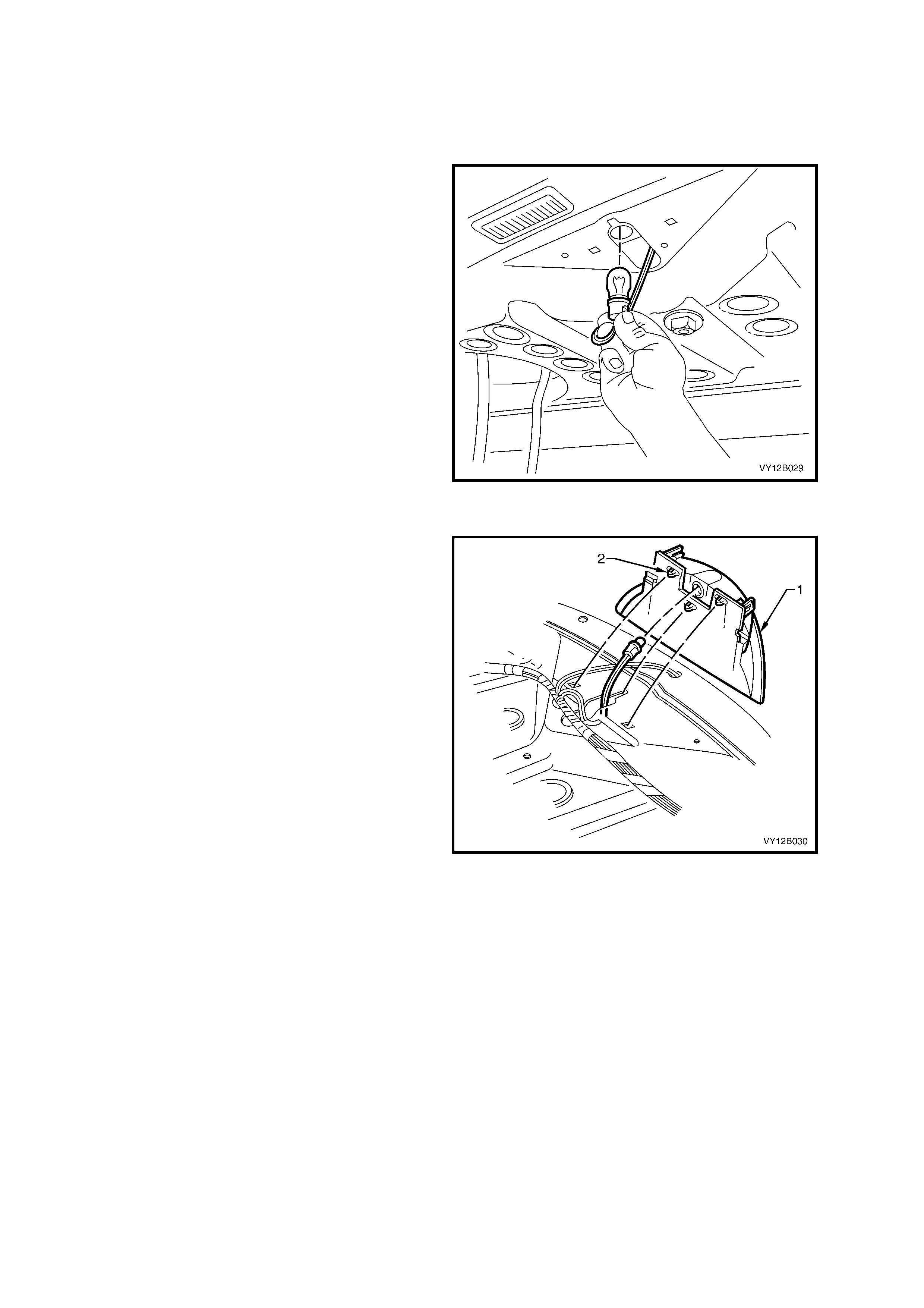
2.10 HIGH MOUNT STOP LAMP ASSEMBLY
LT Section – 02-350
SEDAN WITHOUT REAR END SPOILER
Bulb Replacement
1. Remove the fusible link F102, refer to
Figure 12B-118, item 6.
2. Open the rear compartment lid.
3. From under the rear window panel assembly,
twist the bulb sock et to releas e it from the lamp
assembly. Pull the socket down, into the rear
compartment.
NOTE: It m ay be necessary to use a pair of pointed
nose pliers to hold the socket and release the bulb.
4. Pull the bulb out from the socket.
5. Ins tall a new bulb into the sock et and ins tall the
socket into the high mount stop lamp
assembly. Twist the socket and lock it into
place.
6. Install the fusible link F102 and check the
operation of the lamp assembly.
Figure 12B-52
Remove
1. Remove the fusible link F102, refer to
Figure 12B-118, item 6.
2. Remo ve the rear parc el s helf tr im as detailed in
Section 1A8, 2.9 REAR WINDOW TRIM
PANEL ASSEMBLY - SEDAN.
3. Remove the socket from the lamp assembly
(1). Refer to Bulb Replacement in this Section.
4. From under the rear window panel assembly
disengage the retaining clips (2) securing the
high mount stop lamp assembly to the rear
window panel assembly. Remove the lamp
assembly.
Reinstall
Installation of the high mount stop lamp assembly
is the reverse of the removal procedure, noting the
following points:
1. Ensure that the lamp assembly is pushed fully
rearward before engaging the retaining clips.
Figure 12B-53
SEDAN WITH REAR END SPOILER
The high m ount stop lamp assembly fitted to the air spoilers is a Light Emitting Diode (LED) type. For the removal
and installation of the high mounted stop lamp assembly, refer to Section 1A4, 3.4 REAR SPOILER ASSEMBLY
END.
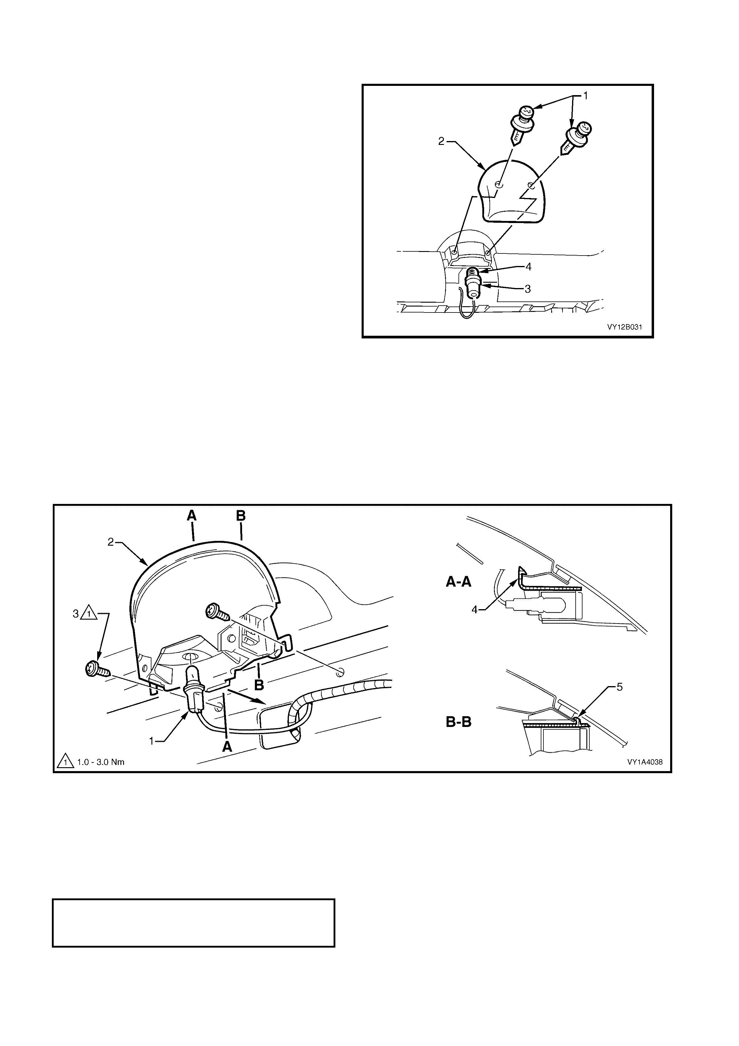
WAGON
Bulb Replacement
1. Remove the fusible link F102, refer to
Figure 12B-118, item 6.
2. Open the liftgate and remove the two
retainers (1) s ec uring the high mount stop lamp
cover (2). Remove the cover.
3. Twist and pull the socket (3) out of the lamp
assembly.
4. Pull the bulb (4) from the socket.
5. Install a new bulb into the socket and fit the
socket to the lamp assembly.
6. Install the fusible link F102 and check the high
mount stop lamp assembly.
7. Install the high mount stop lamp cover.
Figure 12B-54
Remove
1. Remove the fusible link F102, refer to Figure 12B-118, item 6.
2. Remove the high mount stop lamp cover, refer to Bulb Replacement in this Section.
3. Remove the liftgate window upper garnish, refer to Section 1A4, 4.4 LIFTGATE WINDOW UPPER GARNISH.
4. Twist and unlock the bulb socket (1) from the lamp assembly (2), refer to Figure 12B-55.
5. Remove the two lamp assembly attaching screws (3).
6. Prise the locking tab (4) back slightly, release the locking tabs (5) from each side and remove the lamp
assembly from the liftgate assembly.
Figure 12B-55
Reinstall
Installation of the high mount stop lamp assembly is the reverse of the removal procedure, noting the following
points:
1. Ensure that the lamp assembly is correctly located by inserting the locking tab (4) and pushing the lamp
assembly toward the window to engage the locking tabs (5), refer to Figure 12B-55.
2. Tighten the screws to the correct torque specification.
HIGH MOUNT STOP LAMP
ASSEMBLY ATTACHING SCREWS
TORQUE SPECIFICATION 1.0 – 3.0 Nm
3. Test the operation of the high mount stop lamp before installing the cover and garnish.
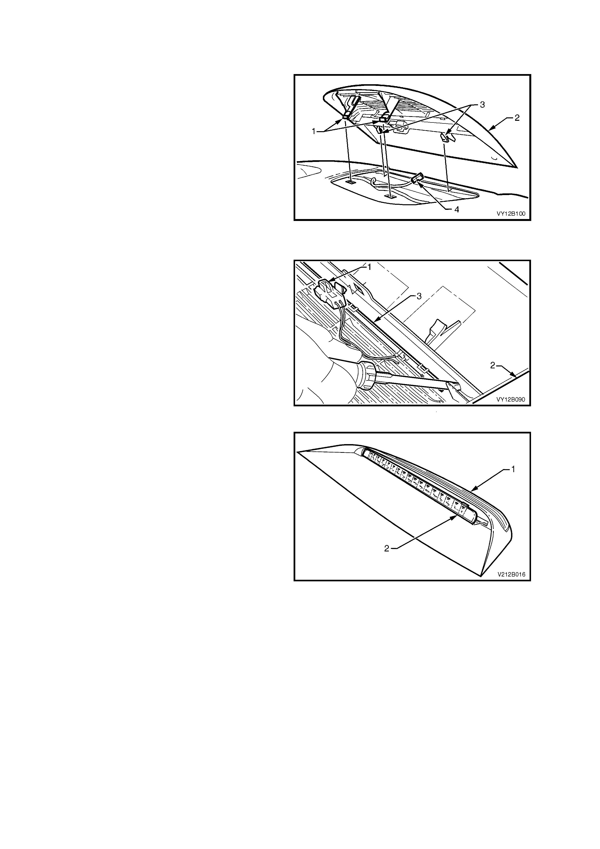
COUPE
Remove
1. Remove the fusible link F102, refer to
Figure 12B-118, item 6.
2. Open the rear compartment lid.
3. From inside the rear compartment, disengage
the two retaining tangs (1) from the rear
window panel assembly.
4. From inside the vehicle, grasp the edge of the
high mount s top lamp as s embly (2) and pull the
assembly up and away from the rear
windscreen until the locating tabs (3) are free of
the slots.
5. Disconnect the harness connector (4) from the
lam p assem bly and remove the lam p assem bly
from the vehicle.
Figure 12B-56
Disassemble
1. Unc lip the harness connector (1) f rom the lam p
assembly (2).
2. Starting at one end of the light emitting diode
(LED) assembly (3), carefully disengage the
retaining tabs with a small screwdriver.
Figure 12B-57
3. Carefully spread the lamp assembly (1) by
hand and work the LED assem bly ( 2) sideways
and rearwards until it is free of the lamp
assembly.
Reassemble
The assembly procedure for the high mount stop
assembly is the reverse of the disassemble
procedure.
Reinstall
Installation of the high mount stop lamp assembly
is the reverse of the removal procedure, noting the
following:
1 Ensure that the locating tabs are correctly
engaged into the slots in the rear of the parcel
shelf prior to engaging the retaining tabs.
2. Check the high mount stop lamp assembly
operation.
Figure 12B-58
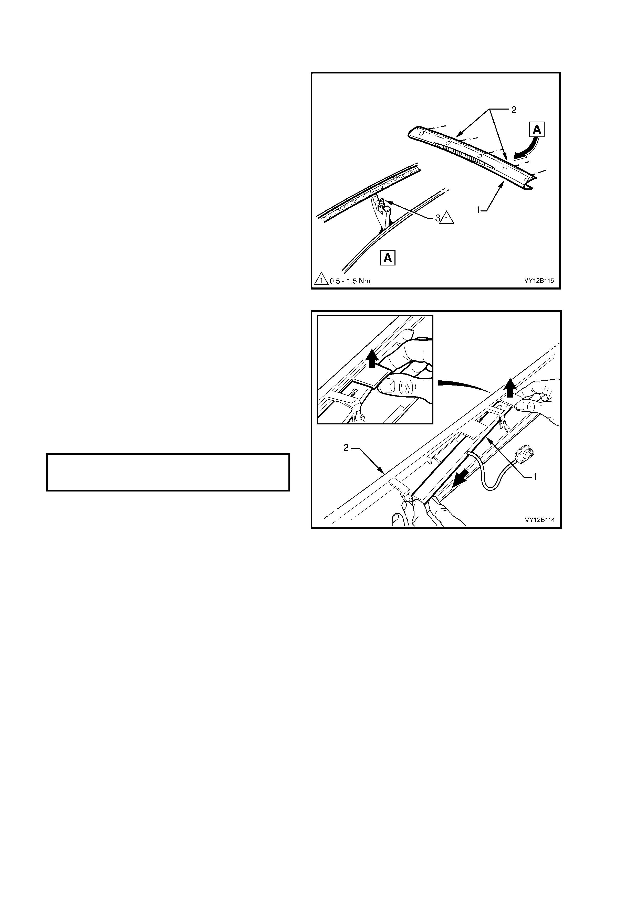
UTILITY (WHERE FITTED)
Remove
1. Remove the fusible link F102, refer to
Figure 12B-118, item 6.
2. Remove the rear window upper moulding.
Section 1A9, 4.10 REAR WINDOW UPPER
MOULDING.
3. Remove one of the studs (3) located either
right or left (2) of the high mount stop lamp
assembly.
NOTE: One of the studs m us t be removed so there
is clearance to remove the high mount stop lamp
assembly.
Figure 12B-59
4. Carefully disengage the retaining tangs from
the high mount stop lamp assembly (1) and
manoeuvre the lamp assembly free from the
cap (2).
Reinstall
Installation of the high mount stop lamp assembly
is the reverse of the removal procedure, noting the
following:
1. Tighten the stud to the correct torque
specification.
Figure 12B-60
REAR WI NDOW MOULDING
ATTACHING STUD
TORQUE SPECIFICATION 0.5 – 1.5 Nm
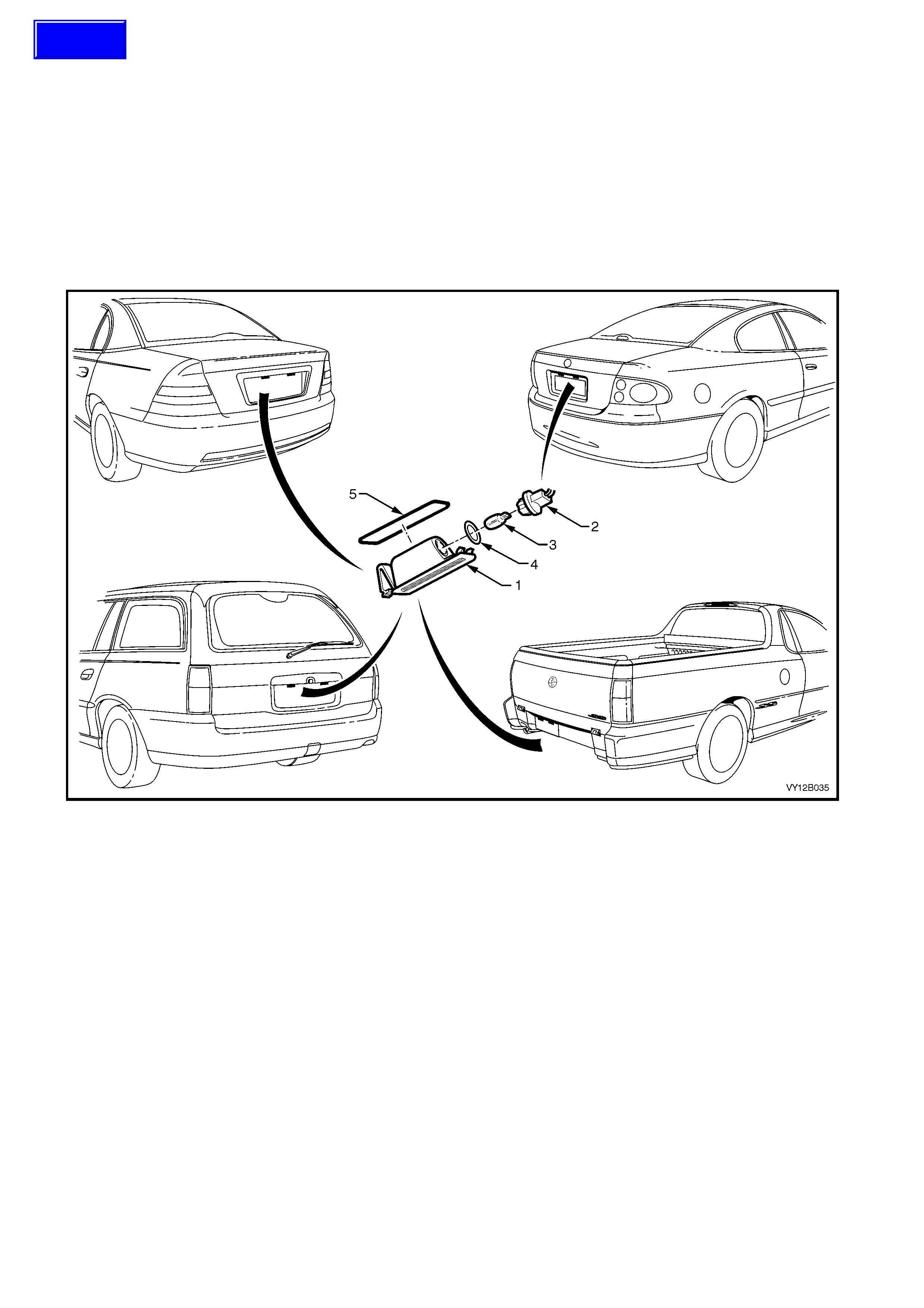
2.11 REAR LICENSE PLATE LAMP ASSEMBLY
LT Section – 02-375 (Sedan, Coupe and Utility)
LT Section – 02-385 (Wagon)
REMOVE
1. Remove the fusible link F102, refer to Figure 12B-118, item 6.
2. Push the lock ing tang located at the end of the lam p housing (1) towards the lens. Pivot the housing down and
remove it from the aperture, refer to Figure 12B-61.
3. Remove the bulb socket (2) from the lamp housing.
4. If required, replace the bulb (3) by pulling it from the socket.
5. Inspect the bulb socket seal (4) for damage and replace if required.
Figure 12B-61
REINSTALL
1. Push a new bulb into the bulb socket if required.
2. Install the socket and bulb assembly into the lamp housing assembly.
3. On Utility, ensure that the seal and seal mating surface is clean to avoid paint damage.
NOTE: The lamp housing will install into the aperture in one direction only.
4. Install the lamp housing into the aperture.
5. Install the fusible link F102.
6. Check the rear licence plate lamp operation.
WIRING HARNESS, SEDAN
To remove and install the rear licence plate lamp harness, the rear compartment lid appliqué assembly must be
removed, refer to Section 1A4, 3.2 REAR COMPARTMENT LID APPLIQUÉ ASSEMBLY, SEDAN.
WIRING HARNESS, WAGON
To rem ove and install the rear licence plate lamp harness, the liftgate handle assembly m ust be removed, refer to
Section 1A4, 4.5 LIFTGATE HANDLE ASSEMBLY, WAGON.
WIRING HARNESS, COUPE
To remove and install the rear licence plate lamp harness, the rear compartment lid appliqué assembly must be
removed, refer to Section 1A4, 3.3 REAR COMPARTMENT LID APPLIQUÉ ASSEMBLY, COUPE.
Techline
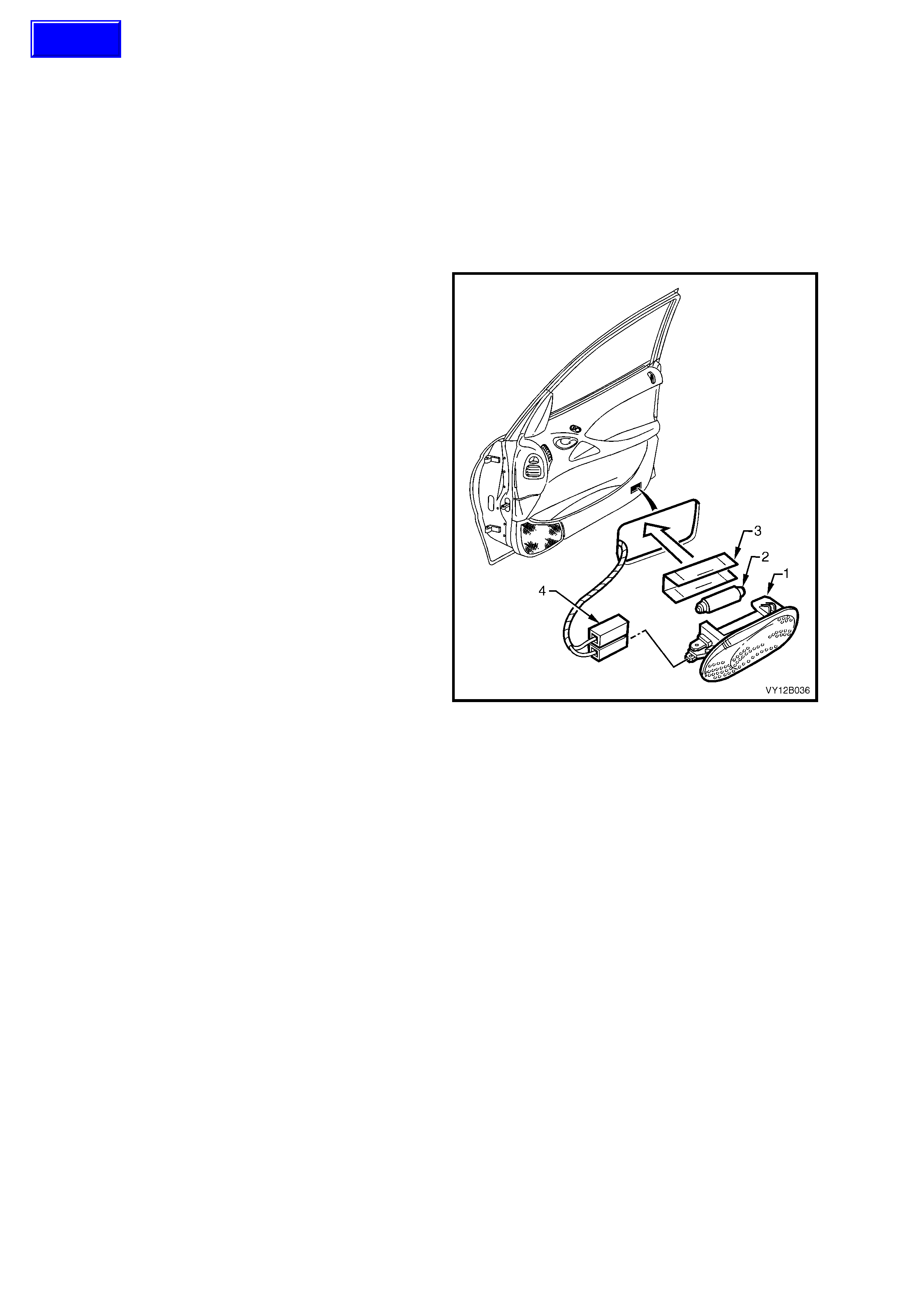
3. SERVICE OPERATIONS – INTERIOR ILLUMINATION AND SWITCHING
The interior lighting configuration is dependant on the vehicle model and trim level. Refer to 1.4 INTERIOR
ILLUMINATION for further information.
3.1 SIDE DOOR COURTESY LAMP ASSEMBLY
LT Section – 02-780
IMPORTANT: Figure 12B-62 shows a front door assembly of a Sedan. The rear door assembly of the Sedan and
the front door assembly of the Coupe are similar.
REMOVE
1. Remove the fusible link F102, refer to
Figure 12B-118, item 6.
2. Insert a f ine blade screwdriver into the notch at
the bottom edge of the lamp and depress the
locking tang.
1. Prise the side door courtesy lamp (1) from the
door trim assembly.
2. Disconnect the lamp harness connector (4)
from the lamp assembly.
3. If removing the bulb from the lamp:
a. Pull the protective m etal cover (3) from the
rear of the lamp to gain access to the bulb
(2).
b. Bend back the lever contact retaining the
bulb and remove the bulb.
4. Check the lamp assembly for damage and
replace where necessary.
NOTE: Ensure that the wiring harness connector
does not fall into the door cavity.
REINSTALL
Installation of the side door courtesy lamp
assembly is the reverse of the removal procedure
noting the following points:
1. Insert a new bulb into the lamp assembly if
required.
2. Ensure that the lens is flush with the side of the
door trim assembly.
3. Check the operation of the lamp assembly.
Figure 12B-62
Techline
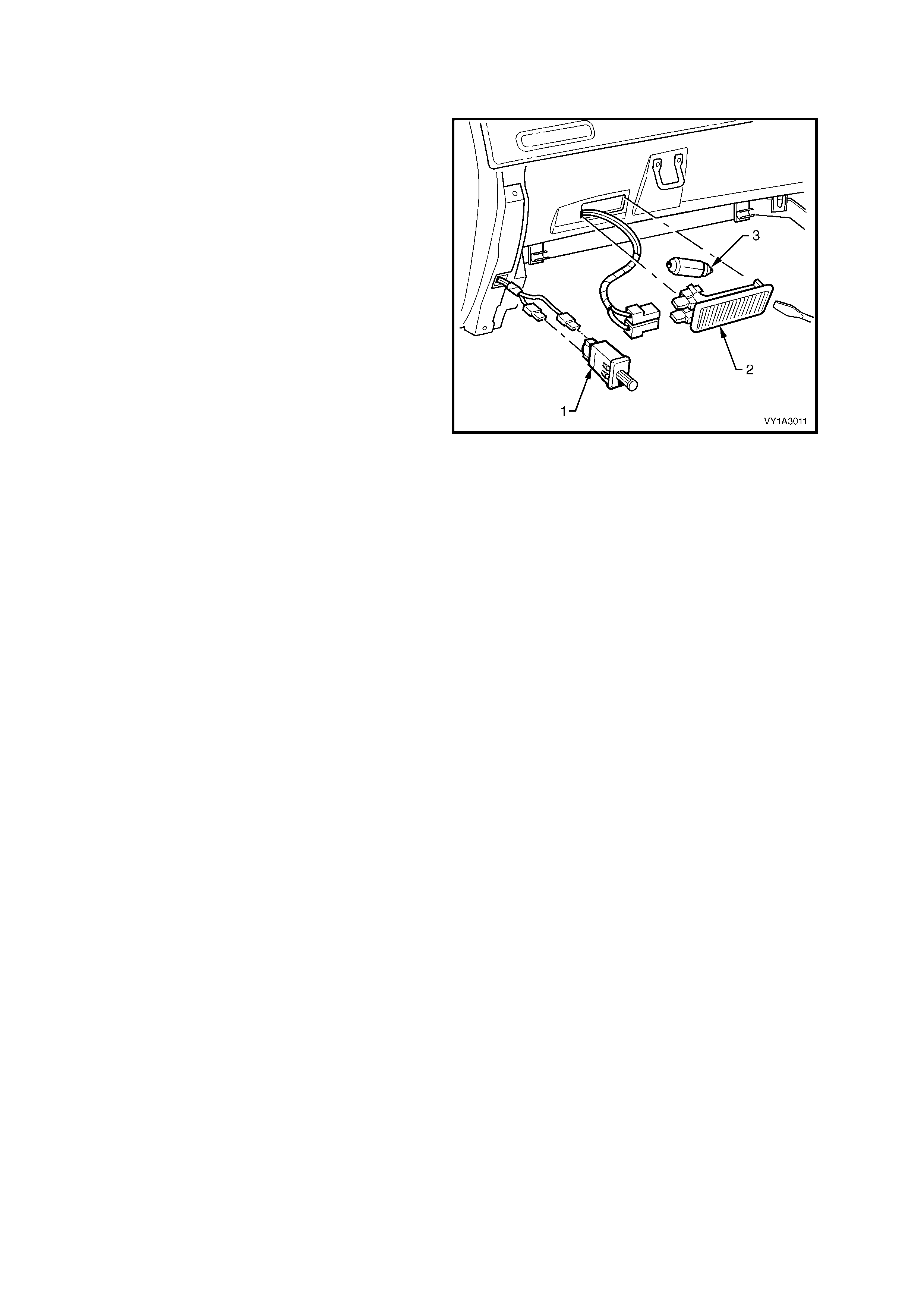
3.2 INSTRUMENT PANEL COMPARTMENT LAMP ASSEMBLY
LT Section – 02-780
REMOVE
1. Remove the fusible link F102, refer to
Figure 12B-118, item 6.
2. Prise the instrument panel compartment lamp
assembly (2) from the compartment using a
fine blade screwdriver.
3. Disconnect the lamp harness connector from
the lamp assembly. Check the lamp assembly
for damage and replace where necessary.
NOTE: Ensure that the wiring harness connector
does not fall into the cavity behind the
compartment.
4. If necessary, remove the bulb (3) from the
assembly by depressing the metal contact.
REINSTALL
Installation of the instrument panel compartment
lamp assembly is the reverse of the removal
procedure noting the following points:
1. Insert a new bulb in the lamp assembly if
required.
2. Ensure that the lens is flush with the
compartment.
3. Check the operation of the lamp assembly.
Figure 12B-63

3.3 INSTRUMENT PANEL COMPARTMENT LAMP SWITCH ASSEMBLY
LT Section – 02-780
Refer to Figure 12B-6 3 for the instrument panel compartment lamp switch assembly.
REMOVE
1. Remove the fusible link F102, refer to Figure 12B-118, item 6.
2. Prise the switch assembly (1) from the instrument panel assembly using a fine blade screwdriver.
3. Disconnect the wiring harness connectors from the assembly. Check the switch assembly for damage and
replace where necessary.
NOTE: Ensure that the wiring connector does not fall inside the instrument panel assembly cavity.
REINSTALL
Installation of the instrument panel compartment lamp switch assembly is the reverse if the removal procedure.
Check the operation of the switch assembly.
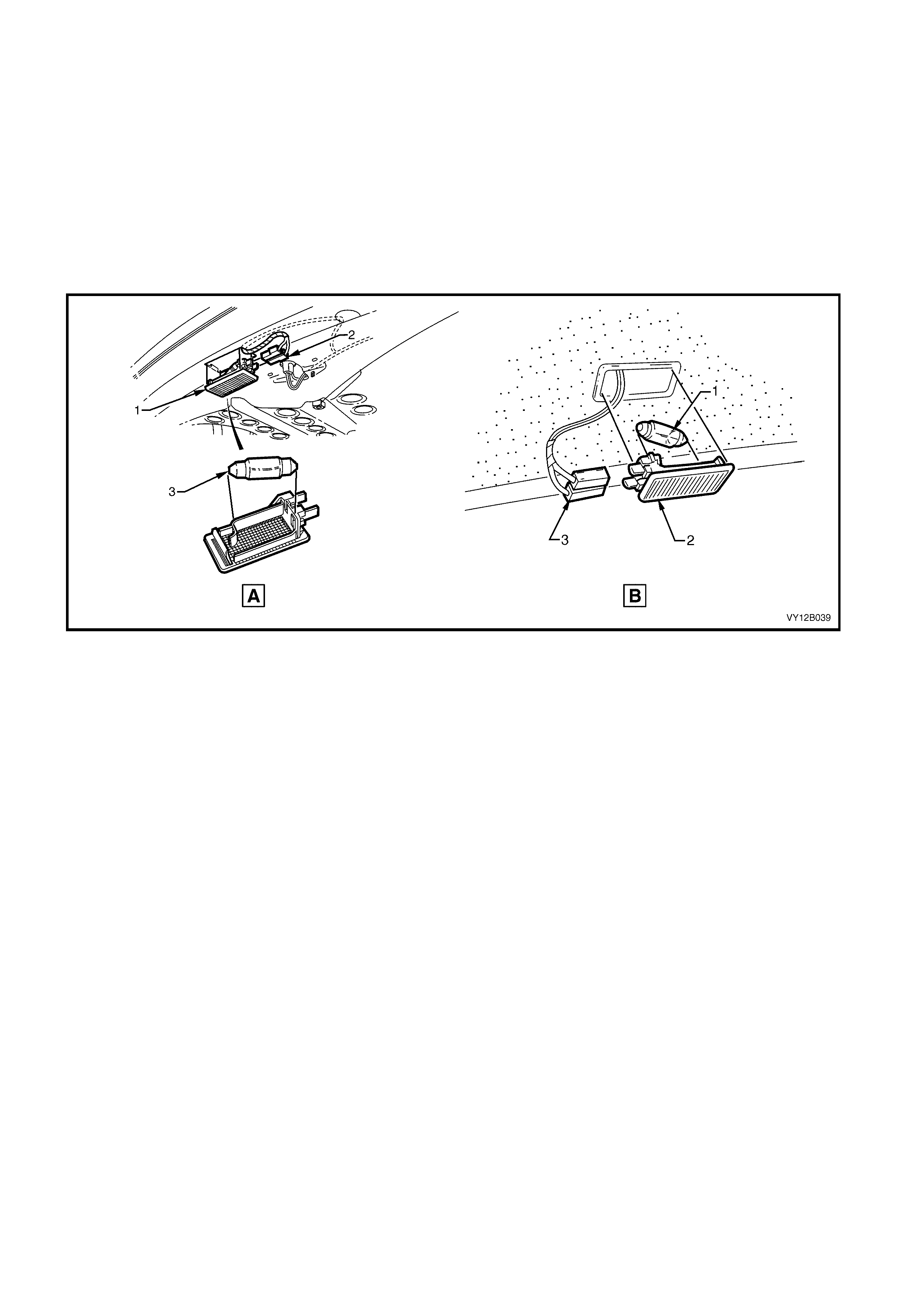
3.4 REAR COMPARTMENT COURTESY LAMP ASSEMBLY
LT Section – 02-780
Refer to Figure 12B-64 view A for the Sedan and Coupe lamp assembly installations.
Refer to Figure 12B-64 view B for the Wagon lamp assembly installations.
REMOVE
1. Remove the fusible link F102, refer to Figure 12B-118, item 6.
2. Prise the rear compartment courtesy lamp assembly (1) from the mating surface using a fine blade screwdriver.
3. Disconnect the wiring harness connector (2) from the assembly. Check the lamp assembly for damage and
replace where necessary.
4. If necessary, remove the bulb (3) from the assembly by depressing the metal contact.
REINSTALL
Installation of the rear compartment courtesy lamp assembly is the reverse of the removal procedure noting the
following points:
1. Insert a new bulb in the lamp assembly if required.
2. Ensure that the lens is flush with the rear compartment roof.
3. Check the operation of the lamp assembly.
Figure 12B-64
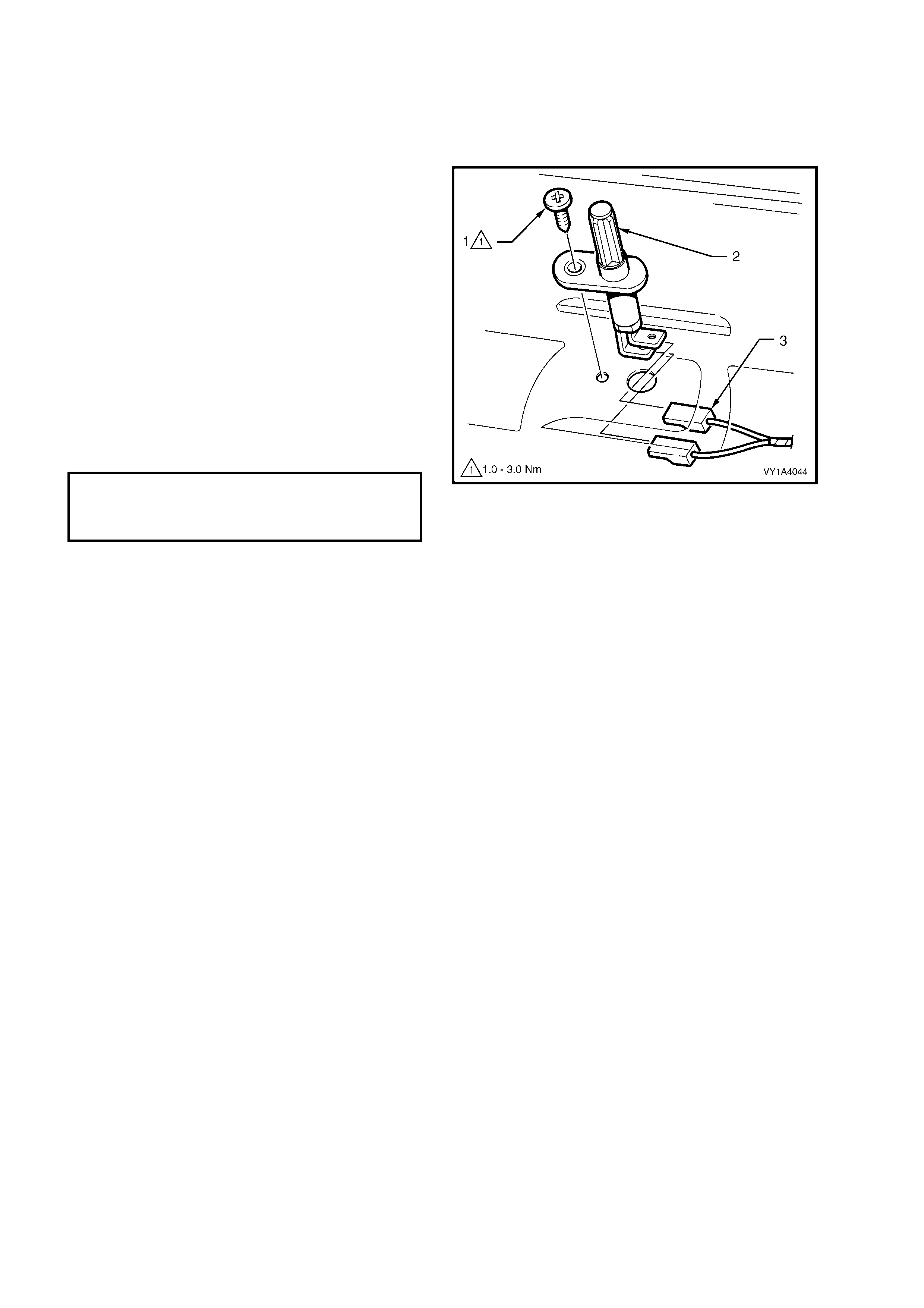
3.5 REAR COMPARTMENT COURTESY LAMP SWITCH ASSEMBLY
LT Section – 02-780
The rear compartm ent courtesy lamp as sembly is operated by a switch attached to the rear compartm ent lid of the
Sedan and Coupe, and the lif tgate of the Wagon. The switch is actuated when either the com par tm ent lid or lif tgate
is opened.
REMOVE
1. Remove the fusible link F102, refer to
Figure 12B-118, item 6.
2. Remove the screw (1) and the pull the switch
assembly (2) out far enough to gain access to
the wiring harness connectors (3).
3. Disconnect the wiring harness connectors and
remove the switch.
REINSTALL
Installation of the rear compartment courtesy lamp
switch assembly is the reverse of the removal
procedure noting of the following points:
1. Tighten the screw to the correct torque
specification.
Figure 12B-65
REAR COMPARTMENT COURTESY
LAMP SWITCH ASSEMBLY
ATTACHING SCREW
TORQUE SPECIFICATION 1.0 – 3.0 Nm
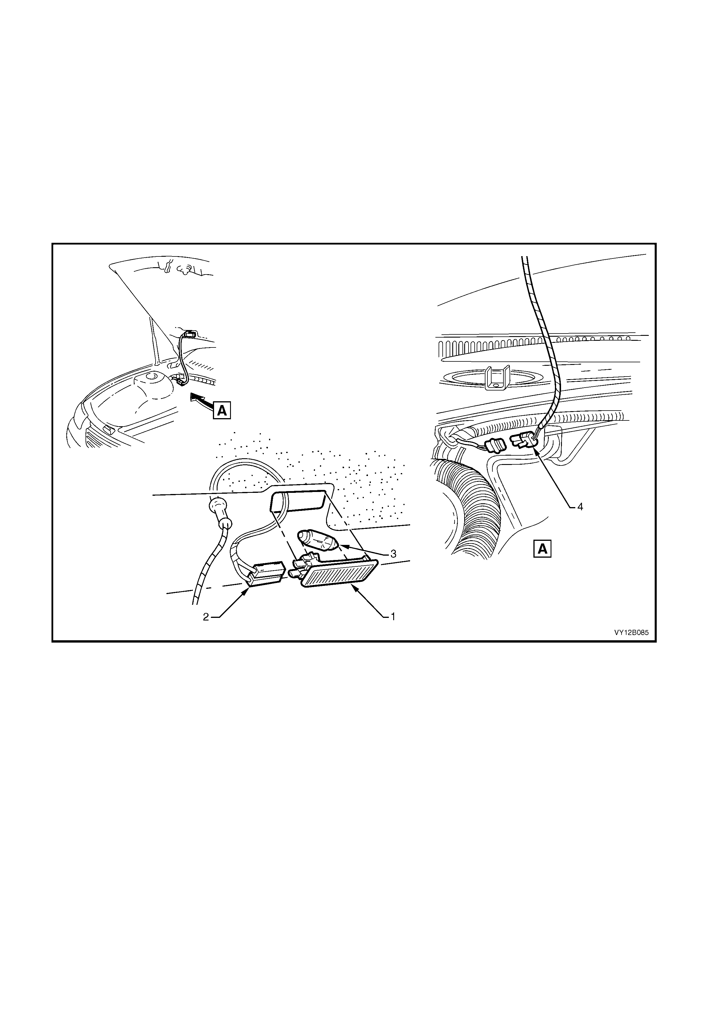
3.6 UNDER-HOOD LAMP ASSEMBLY
LT Section –
The under-hood lamp assembly is only fitted to select vehicles. It is operated by turning on the park lamps of the
vehicle. Refer to Figure 12B-66 for the following procedures.
REMOVE
1. Remove the fusible link F102, refer to Figure 12B-118, item 6.
2. Pr ise the under- hood lam p assembly (1) fr om the underside of the hood using a f ine blade screwdriver , refe r to
Figure 12B-66.
3. Disconnect the wiring harness connectors (2) from the assembly.
4. Check the lamp assembly for damage and replace where necessary.
5. If necessary, remove the bulb (3) from the assembly by depressing the metal contact.
Figure 12B-66
REINSTALL
Installation of the under-hood lamp assembly is the reverse of the removal procedure noting the following points:
1. Insert a new bulb into the lamp assembly if required.
2. Ensure that the lens is flush with the hood.
3. Check the operation of the lamp assembly.

3.7 UNDER-HOOD LAMP ASSEMBLY W I RING HARNESS
LT Section –
Refer to Figure 12B-6 6 for the following procedures.
REMOVE
1. Remove the under-hood lamp assembly, refer to 3.6 UNDER-HOOD LAMP ASSEMBLY.
2. Disconnect the under-hood wiring harness connector from the body harness (4).
3. Remove the grommet from the hood.
4. Remove the wiring harness from the hood.
REINSTALL
Installation of the under-hood lamp assembly wiring harness is the reverse of the removal procedure noting the
following:
1. W hen the wiring harness has been installed, check that it will not be damaged with the opening and closing of
the hood.
2. Check the operation of the under-hood lamp assembly.
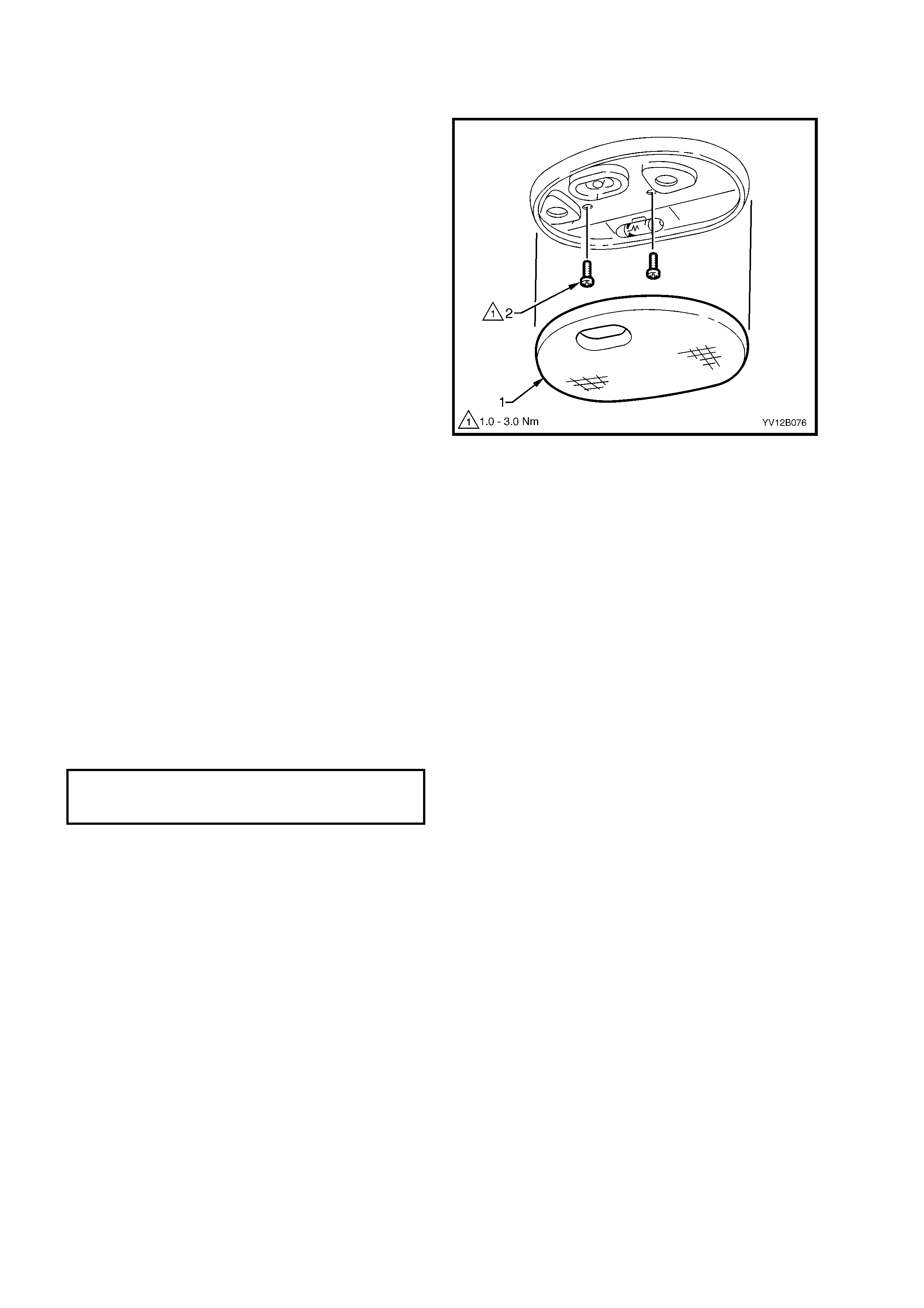
3.8 DOME LAMP ASSEMBLY
LT Section – 02-780
BULB REPLACE
1. Remove the fusible link F102, refer to
Figure 12B-118, item 6.
2. Using a fine blade screwdriver, start at the
centre notch in the lens (1) and prise the lens
from the lamp assembly. Use the screwdriver
in the other two notches to remove the lens.
3. Replace the bulb.
4. Carefully install the lens to the assembly,
ensuring that it snaps into place. Check that the
lens is flush with the lamp assembly.
5. Install the fusible link F102 and check the
operation of the dome lamp assembly.
REMOVE
1. Remove the fusible link F102, refer to
Figure 12B-118, item 6.
2. Using a fine blade screwdriver, start at the
centre notch in the lens (1) and prise the lens
from the lamp assembly. Use the screwdriver
in the other two notches to remove the lens.
3. Remove the two screws (2) securing the lamp
assembly.
4. Pull the lamp assembly down and disconnect
the wiring harness connector from the lamp
assembly.
REINSTALL
Installation of the dome lamp assembly is the
reverse of the removal procedure noting the
following points:
1. Tighten the attaching screws to the correct
torque specification
2. Ensure that the lens is installed flush to the
lamp assembly.
Figure 12B-67
DOME LAMP ASSEMBLY
ATTACHING SCREW
TORQUE SPECIFICATION 1.0 – 3.0 Nm
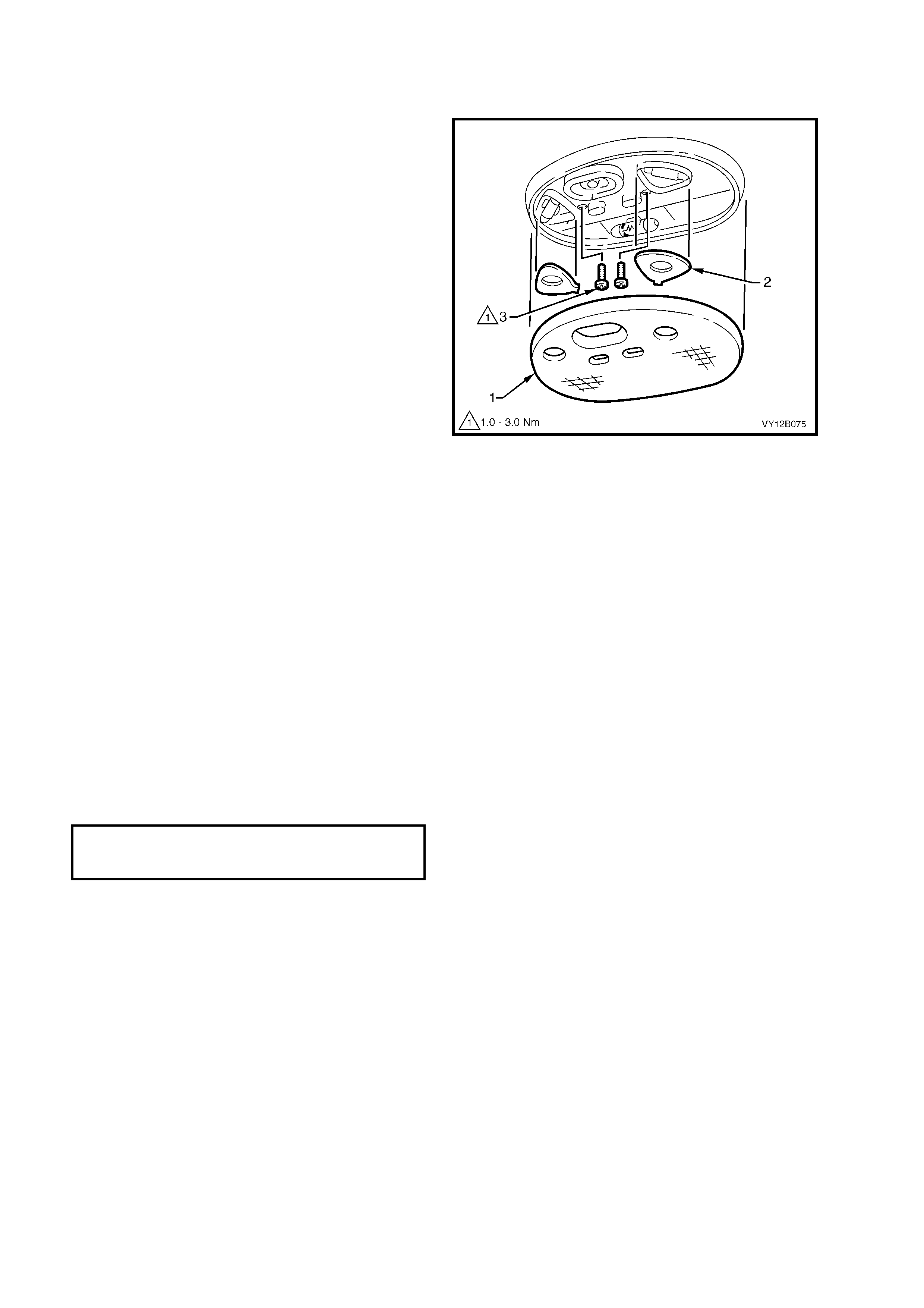
3.9 DOME AND READING LAMP ASSEMBLY
LT Section – 02-780
BULB REPLACE
1. Remove the fusible link F102, refer to
Figure 12B-118, item 6.
2. Using a fine blade screwdriver, start at the
centre notch in the lens (1) and prise the lens
from the lamp assembly. Use the screwdriver
in the other two notches to remove the lens.
3. If required, remove the bulb cover plates (2).
4. Replace the affected bulb.
5. If required, install the bulb cover plates.
6. Carefully install the lens to the assembly,
ensuring that it snaps into place. Check that the
lens is flush with the lamp assembly.
7. Install the fusible link F102 and check the
operation of the dome and reading lamp
assembly.
REMOVAL
1. Remove the fusible link F102, refer to
Figure 12B-118, item 6.
2. Using a fine blade screwdriver, start at the
centre notch in the lens (1) and prise the lens
from the lamp assembly. Use the screwdriver
in the other two notches to remove the lens.
3. Remove the two screws (3) securing the lamp
assembly.
4. Pull the lamp assembly down. Disconnect the
wiring harness connector from the lamp
assembly.
REINSTALL
Installation of the dome and reading lamp assembly
is the reverse of the removal procedure noting the
following:
1. Tighten the attaching screws to the correct
torque specification.
2. Ensure that the lens is installed flush to the
lamp assembly.
Figure 12B-68
DOME AND READING LAMP
ASSEMBLY ATTACHING SCREW
TORQUE SPECIFICATION 1.0 – 3.0 Nm
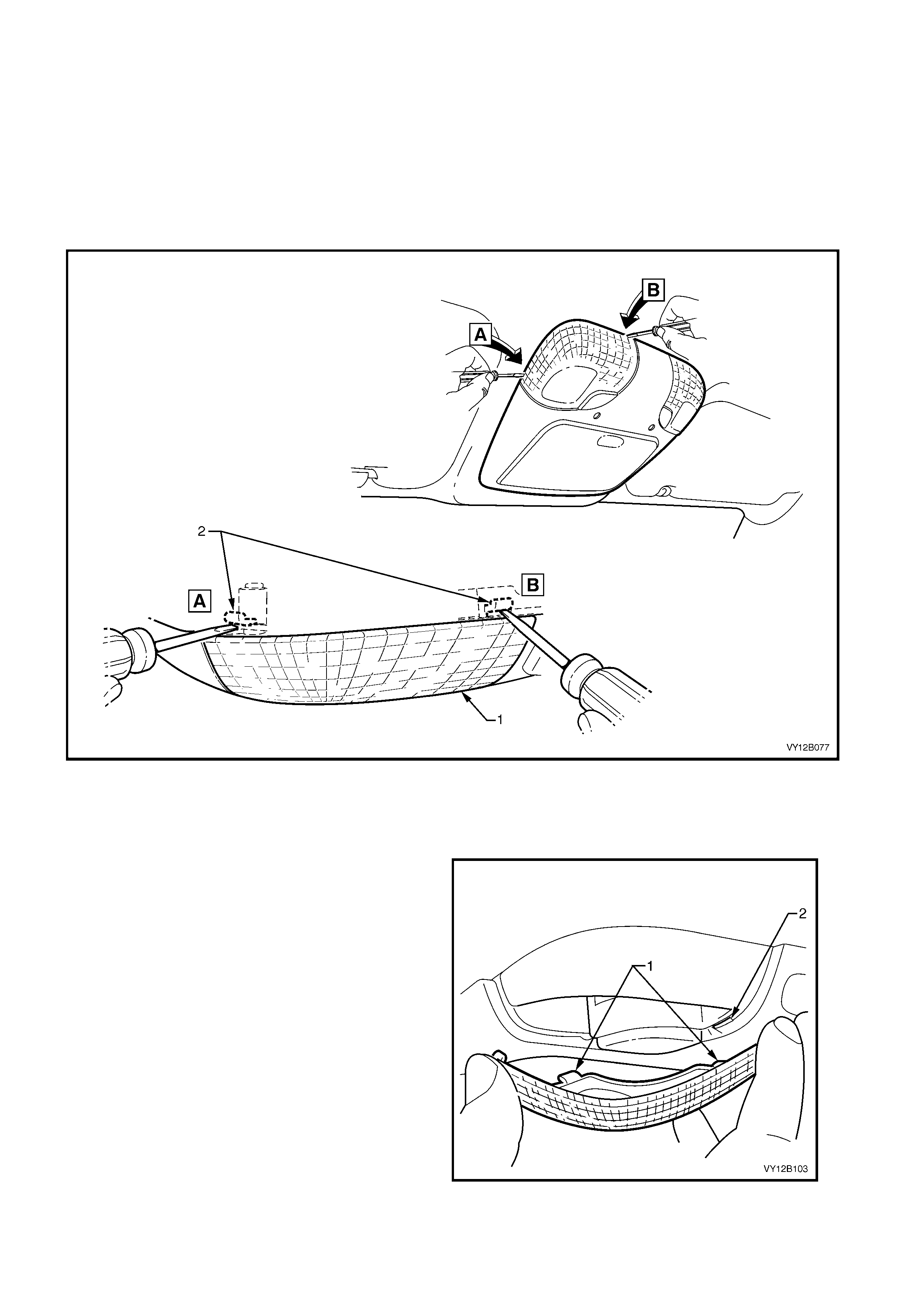
3.10 ROOF CONSOLE
LT Section –
BULB REPLACE
1. Remove the fusible link F102, refer to Figure 12B-118, item 6.
IMPORTANT: T he fine blade screwdriver m ust only be inserted at the points shown so to engage the tabs (2) that
act as a leverage point. These tabs are hidden from view under the headlining assembly.
2. Place a fine blade screwdriver between the lens (1) and the headlining assembly as shown.
3. Gently prise the lens away from the roof console assembly.
Figure 12B-69
4. Remove the bulb by depressing and turning it a quarter of a turn.
5. Insert a new bulb into the socket.
6. Install the fusible link F102. Check the bulbs operation.
7. Fit the lens by inserting the tabs (1) on the lens
into the slots (2) in the roof console assembly.
8. Swing the lens up and lock into place ensuring
that it is flush with the headlining assembly.
Figure 12B-70

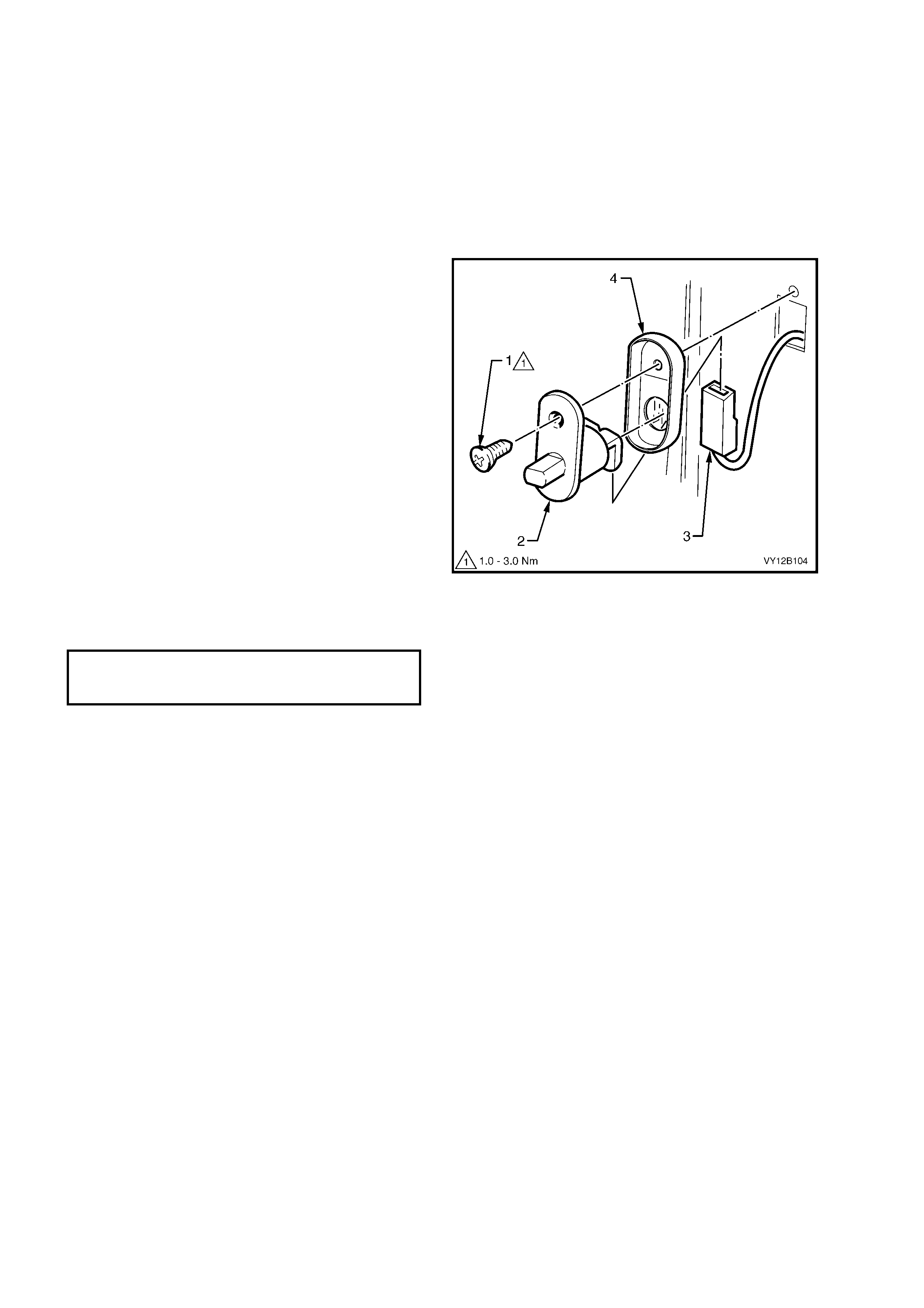
3.11 DOOR JAMB SWITCHES
The door jamb switches are installed in the hinge and centre pillars. The switches inform the BCM of the status of
the doors; either open or closed. When the plunger is depress ed, an open c ircuit is created inform ing the BCM that
the door is closed. When a door is open, the plunger is released and the switch closes to complete a circuit to earth.
To diagnose the door jamb switch circuit, refer to Section 12J, 4.5 PART B – LOCKING DOORS USING
DRIVER’S DOOR LOCK MICROSWITCH.
This information is utilised by the BCM for numerous systems in the vehicle, one being interior illumination.
LT Section No. – 02-780
REMOVE
1. Using a Philips head screwdriver, remove the
screw (1) securing the door jamb switch (2) to
the sheetmetal.
2. Pull the switch out from the aperture and
remove the connector (3).
NOTE 1: Ensure that the c onnectors do not fall into
the cavity.
NOTE 2: The door jamb switch seal (4) is only
fitted to the door jamb switches installed in the
centre pillar.
REINSTALL
1. If required, fit the door jamb switch seal to the
switch.
2. Push the wiring connector onto the door jamb
switch terminal.
3. Position the door jamb switch in the door jamb
and secure in place with the Philips head
screw. Tighten the screw to the correct torque
specification.
Figure 12B-71
DOOR JAMB SWITCH
ATTACHING SCREW
TORQUE SPECIFICATION 1.0 – 3.0 Nm
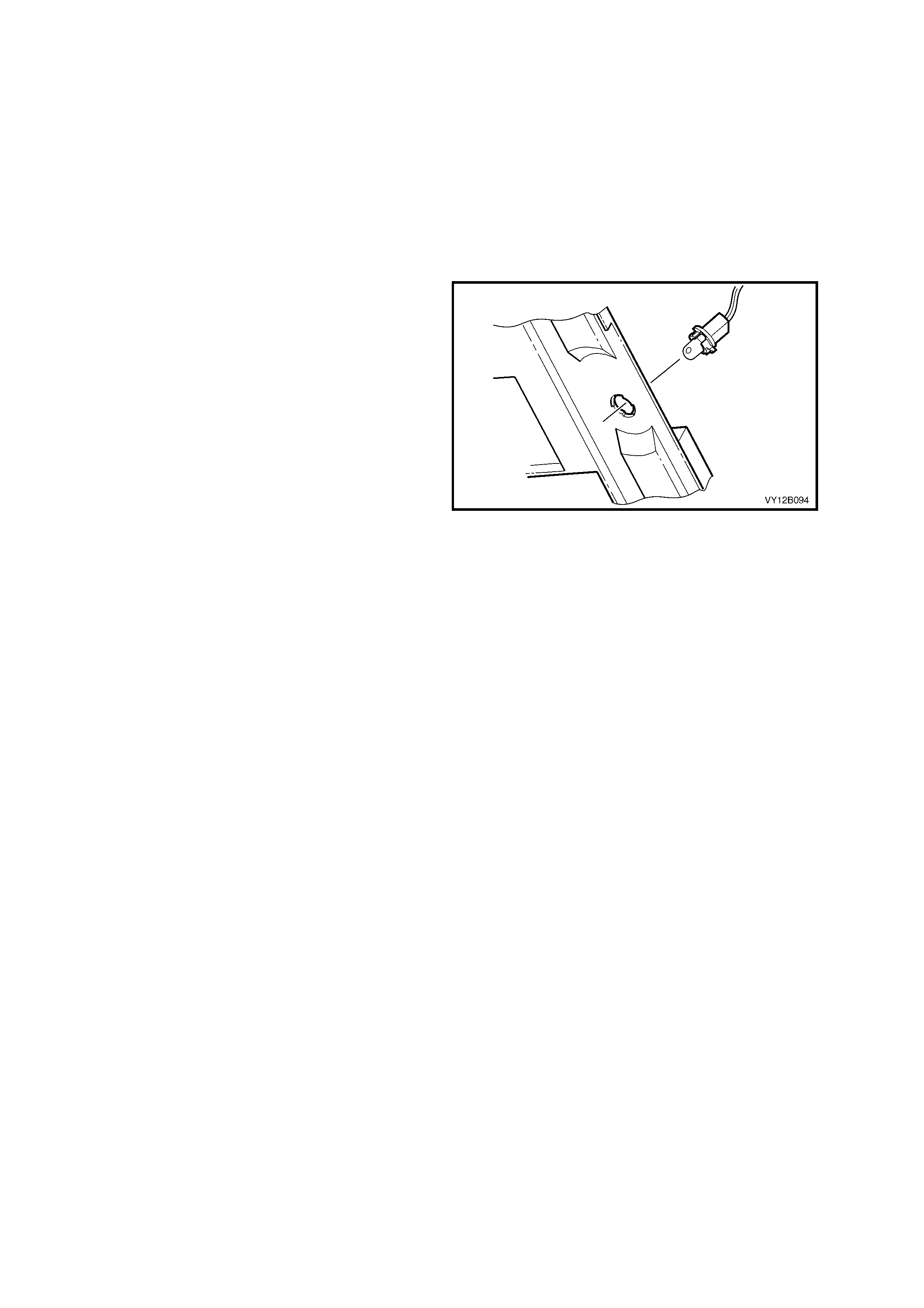
3.12 STEPWELL LAMPS
LT Section – 02-780
The stepwell lamps are located on either side of the vehicle and are attached to the instrument panel lower trim
plate assemblies. The stepwell lamps socket are part of the body wiring harness.
REPLACE
1. Remove the fusible link F102, refer to
Figure 12B-118, item 6.
2. Remove the relevant instrument panel lower
trim plate, refer to Section 1A3, 3.1
INSTRUMENT PANEL LOWER TRIM PLATE.
3. Pull the sheath off the bulb and pull the bulb
from the socket.
4. Insert a new bulb into the socket and fit the
sheath to the bulb.
5. Check the operation of the bulb by turning the
headlamp switch to ON.
6. Install the instrument panel lower trim plate,
refer to Section 1A3, 3.1 INSTRUMENT
PANEL LOWER TRIM PLATE.
Figure 12B-72
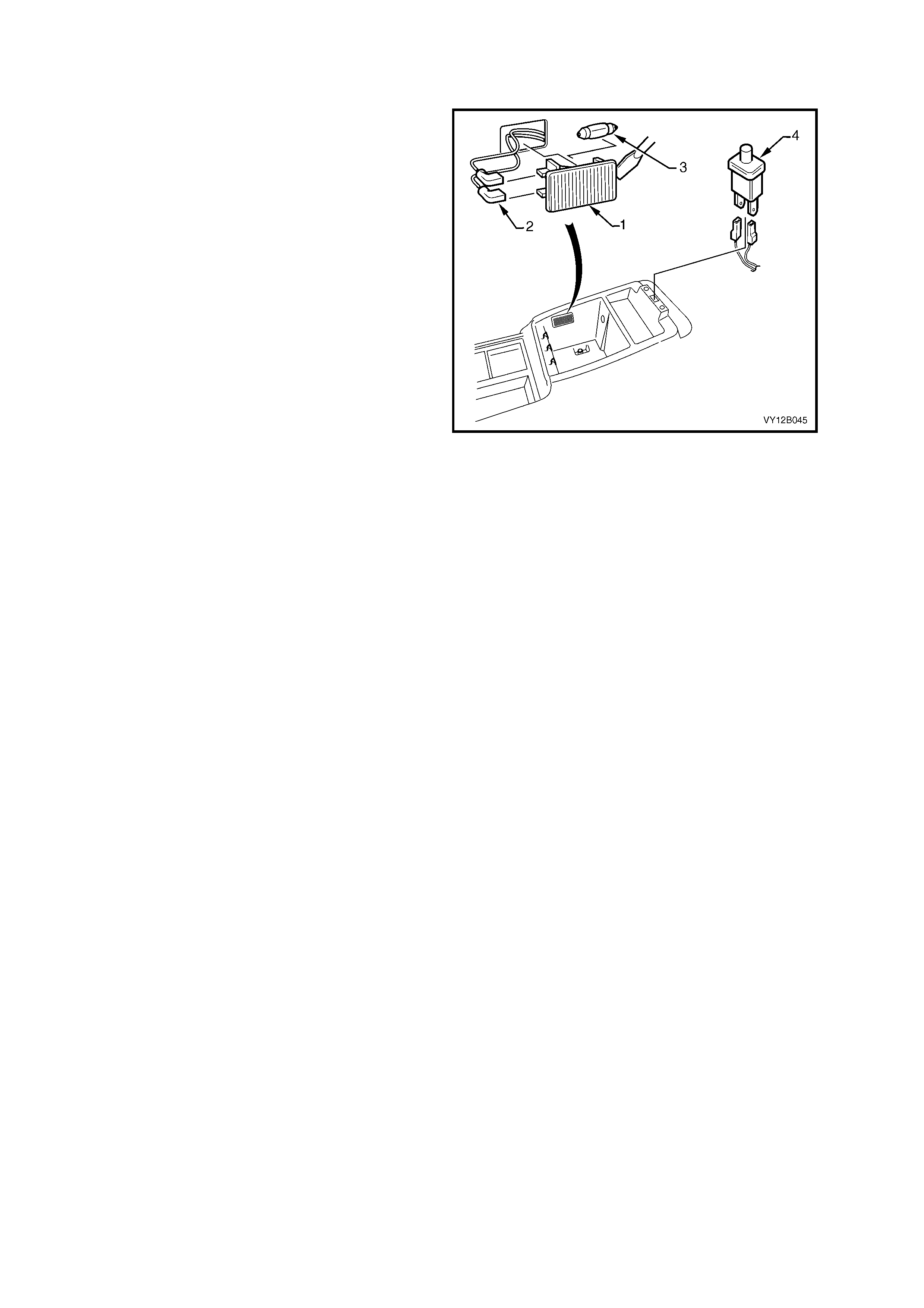
3.13 FLOOR CONSOLE COMPARTMENT LAMP ASSEMBLY
LT Section –
REMOVE
1. Remove the fusible link F102, refer to
Figure 12B-118, item 6.
2. Prise the floor console compartment lamp
assem bly ( 1) from the side of the compartm ent
using a fine blade screwdriver.
3. Disconnect the wiring harness connectors (2)
from the assembly. Check the lamp assembly
for damage and replace where necessary.
NOTE: Ensure that the wiring connector does not
fall inside the floor console cavity.
4. If necessary, remove the bulb (3) from the
assembly by depressing the metal contact.
REINSTALL
Installation of the floor console compartment lamp
assembly is the reverse of the removal procedure
noting the following points:
1. Insert a new bulb in the lamp assembly if
required.
2. Ensure that the lens is flush with the console
compartment side.
3. Check the operation of the lamp assembly.
Figure 12B-73

3.14 FLOOR CONSOLE COMPARTMENT LAMP SWITCH ASSEMBLY
LT Section –
Refer to Figure 12B-7 3 for the floor console compartment lamp switch assembly.
REMOVE
1. Remove the fusible link F102, refer to Figure 12B-118, item 6.
2. Prise the switch assembly (4) from the top of the compartment using a fine blade screwdriver.
3. Disconnect the wiring harness from the assembly. Check the switch assembly for damage and replace where
necessary.
NOTE: Ensure that the wiring connector does not fall inside the floor console cavity.
REINSTALL
Installation of the f loor console c ompartm ent lamp s witc h assem bly is the rever se if the rem oval procedure. Check
the operation of the switch assembly.
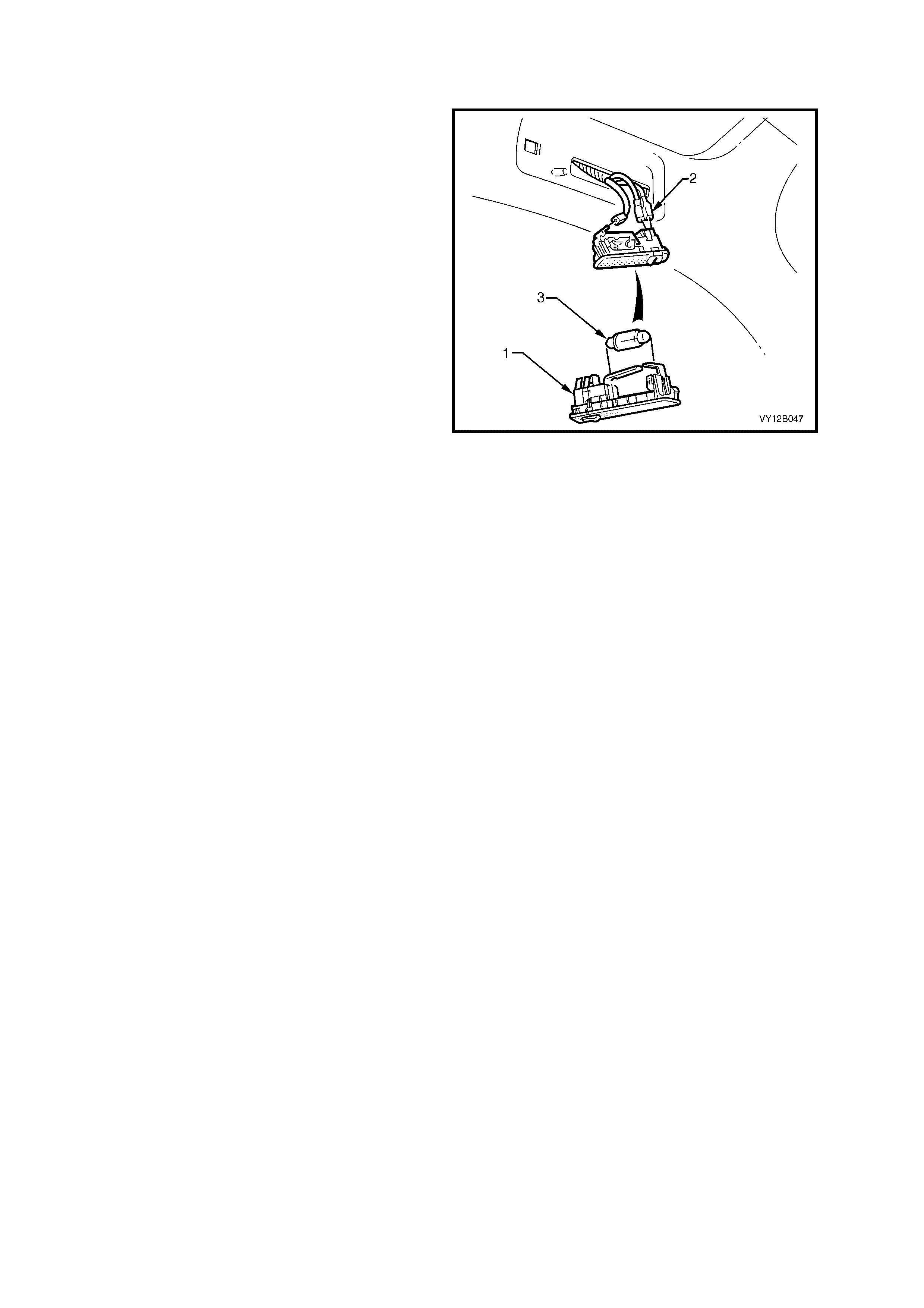
3.15 ROOF RAIL COURTESY AND READING LAMP ASSEMBLY
LT Section – 02-780
REMOVE
1. Remove the fusible link F102, refer to
Figure 12B-118, item 6.
2. Prise the roof rail courtesy and reading lamp
assembly (1) from the lens surround using a
fine blade screwdriver.
3. Disconnect the wiring harness connectors (2)
from the assembly. Check the lamp assembly
for damage and replace where necessary.
4. If necessary, remove the bulb (3) from the
assembly by depressing the metal contact.
REINSTALL
Installation of the roof rail courtesy and reading
lamp assembly is the reverse if the removal
procedure noting the following points:
1. Insert a new bulb into the lamp assembly if
required.
2. Ensure that the lens is flush with the lens
surround.
3. Check the operation of the lamp assembly.
Figure 12B-74
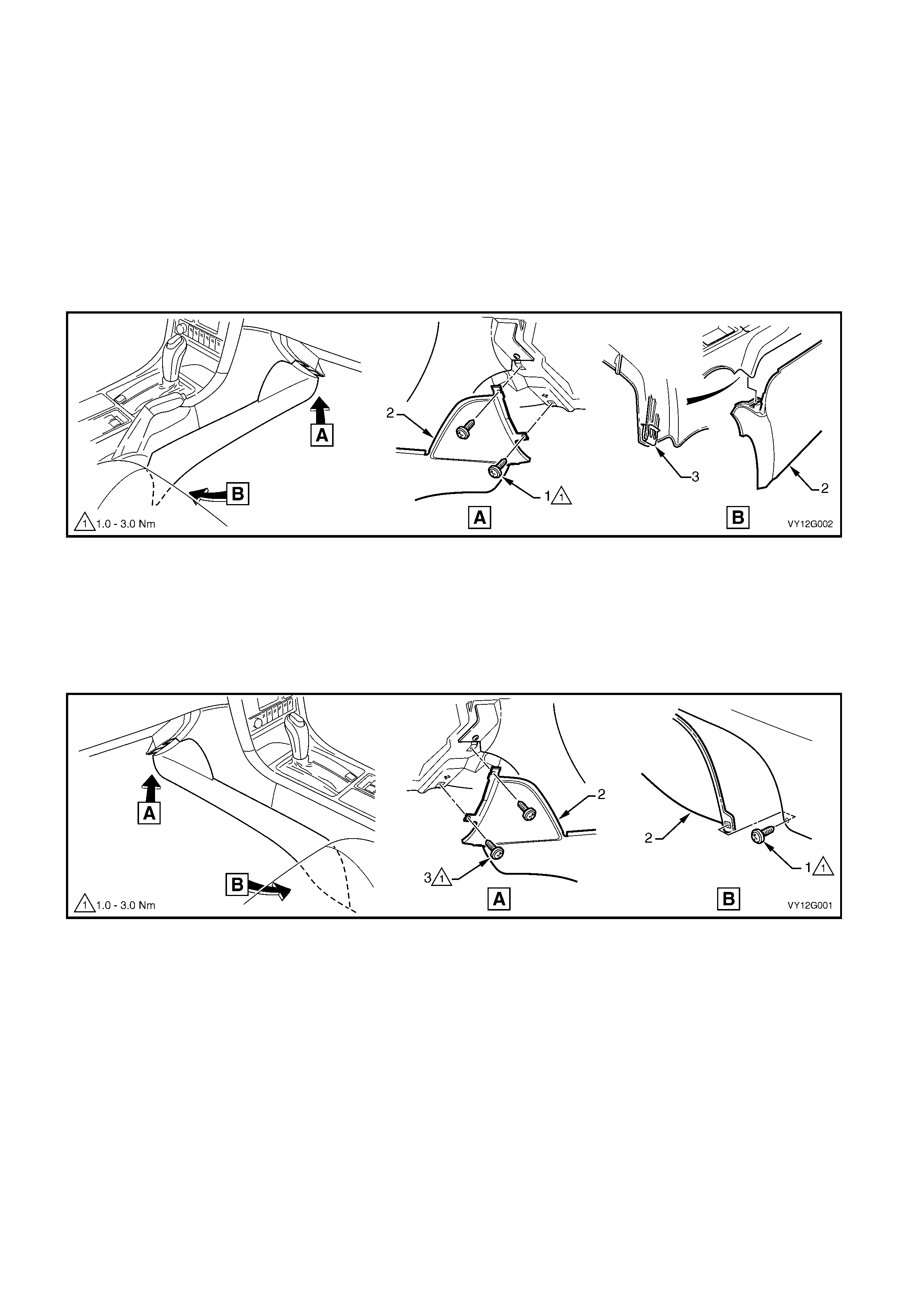
3.16 AUTOMATIC TRANSMISSION CONTROL POSITION LAMP
LT Section – 04-190
REPLACE
1. Remove the fusible link F102, refer to Figure 12B-118, item 6.
2. Move the front seats to the rearmost position. For the left-hand side, move the front to the uppermost position.
3. For right-hand dr ive vehicles, rem ove the right-hand instrum ent panel lower extension side trim panel (2), refer
to Figure 12B-75.
a. Open the instrument panel lower trim panel and remove the two screws (1) attaching the instrument panel lower
extension side trim (2) to the instrument panel.
b. Prise the rear of the trim panel downward to disengage it from the floor console retaining clip (3).
c. Remove the side trim.
Figure 12B-75
4. For left-hand drive vehicles, rem ove the left-hand inst rument panel lower extens ion side trim panel (2) , refer to
Figure 12B-76.
a. Remove the screw (1) attaching the instrument panel lower extension side trim (2) to the floor console.
b. Open the instrument panel lower trim panel and remove the two screws (3) attaching the side trim to the
instrument panel.
c. Remove the side trim.
Figure 12B-76
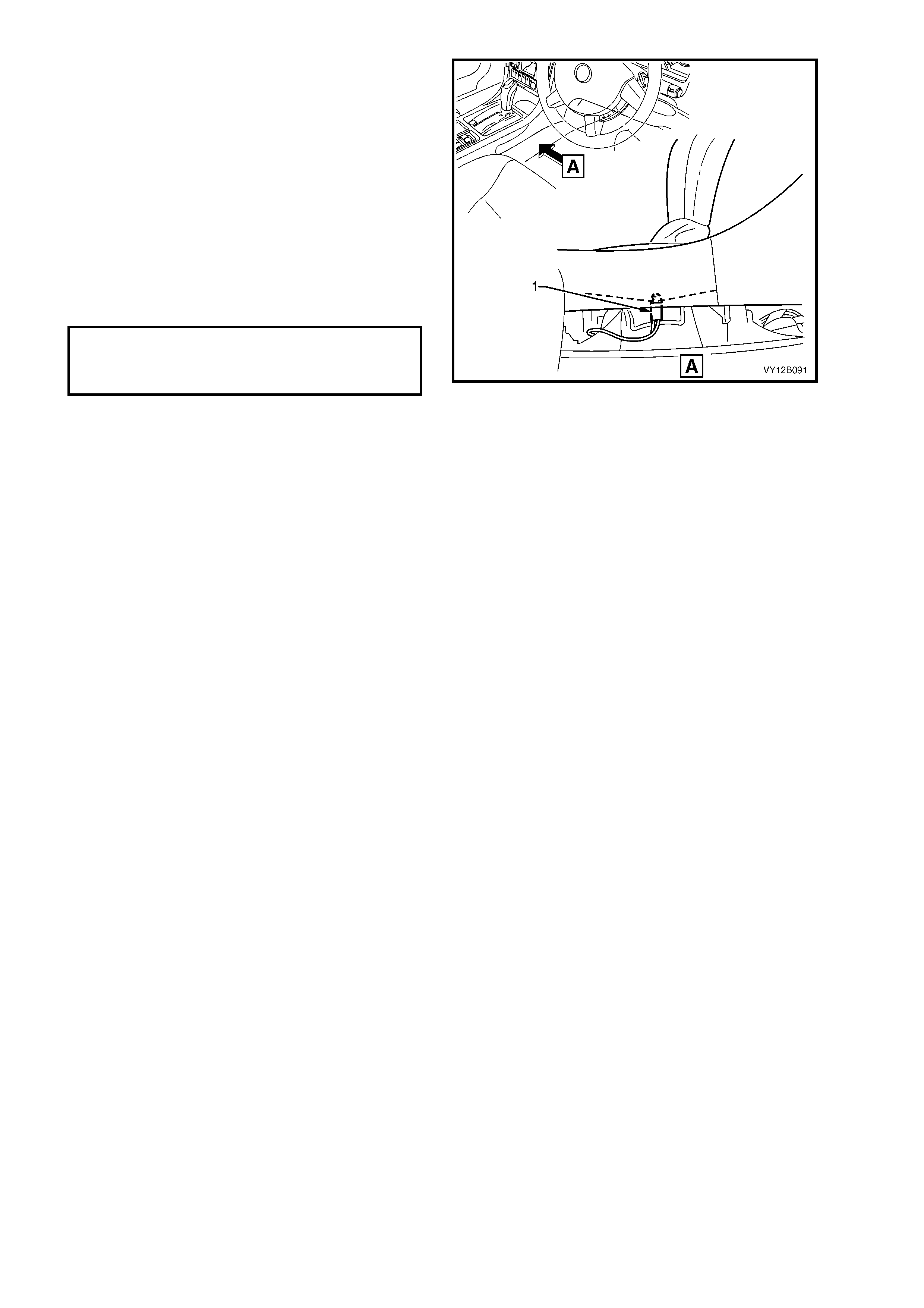
5. Remove the socket (1) from the automatic
transmission control assembly by twisting
anti-clockwise and pulling it down.
6. Replace the bulb in the socket.
7. Install the fusible link F102.
8. Check the operation of the bulb by turning the
park lamps on.
9. Insert the socket into the automatic
transm ission control as sembly and twist to lock
into position.
10. Install the instrument panel lower extension
side trim panel. Tighten all the screws to the
correct torque specification.
Figure 12B-77
INSTRUMENT PANEL LOWER
EXTENSION SIDE TRIM PANEL
ATTACHING SCREW
TORQUE SPECIFICATION 1.0 – 3.0 Nm
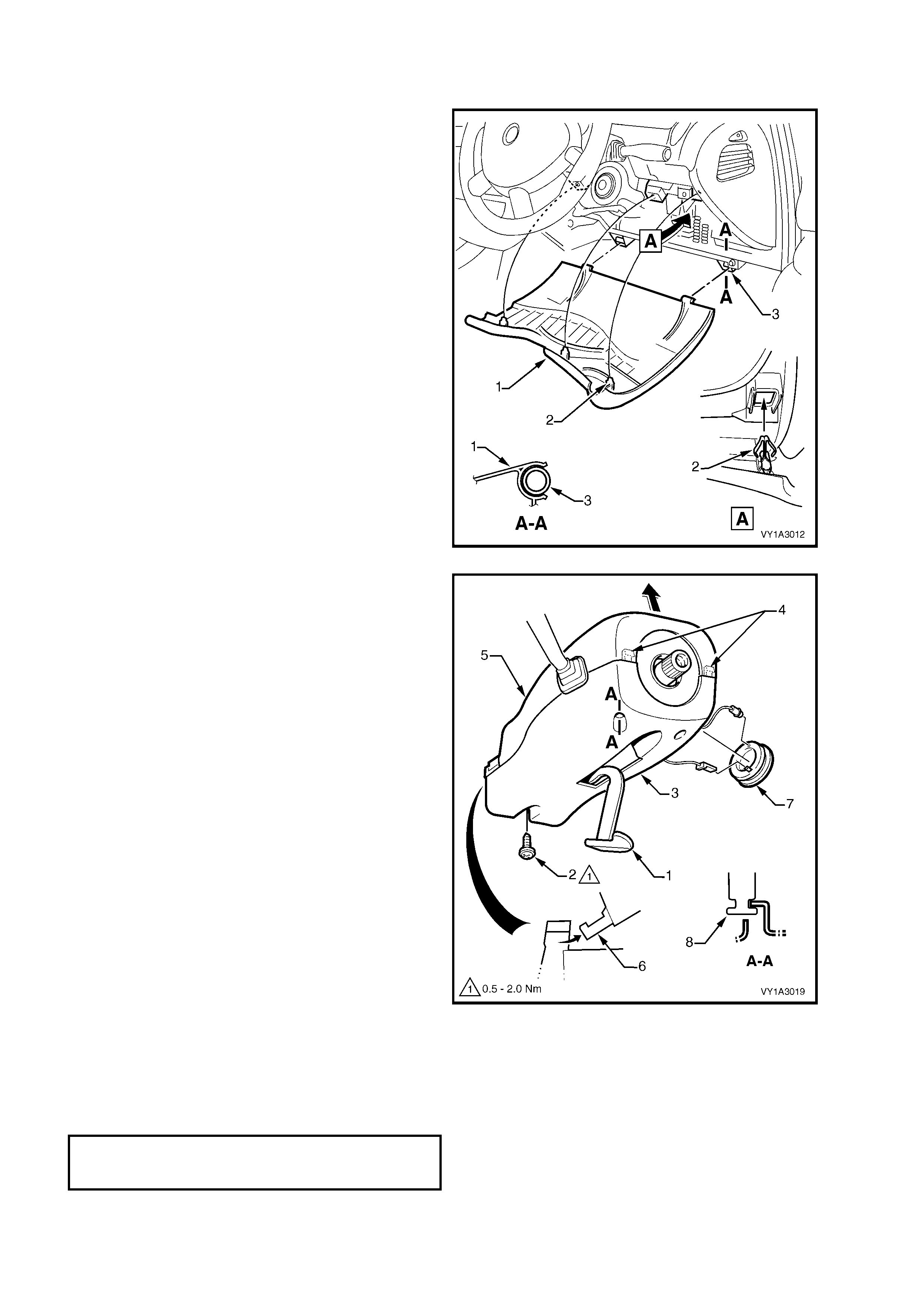
3.17 IGNITION LOCK CYLINDE R BULB
LT Section – 02-780
REPLACE
1. Remove the fusible link F102, refer to
Figure 12B-118, item 6.
2. Grasp the upper edge of the instrument panel
lower trim panel assembly (1) and pull
outwards to disengage the three clips (2).
Swing the panel assembly open.
Figure 12B-78
NOTE: The steering wheel assembly has been
removed from the illustration for clarity. The
steering column upper and lower cover can be
removed while the steering wheel assembly is
installed.
3. Remove the key from the ignition assembly.
4. Release the steering column adjustment
lever (1) and move the column to its lowest
position.
5. From below the steering column, remove the
screw (2) attaching the steering column lower
cover (3).
6. Depress the lower cover inwards to disengage
the tabs (4) while lifting the steering column
upper cover (5).
7. Raise the upper cover as high as possible to
disengage the lugs (6) and remove the cover.
8. Remove the theft deterrent receiver assembly
from the lower cover.
9. Remove the bulb socket from the receiver
assembly (7).
10. Replace the bulb.
11. Insert the bulb socket into the theft deterrent
receiver assembly and install the receiver
assembly into the lower cover.
Figure 12B-79
12. Install the fusible link F102 and check the operation of the ignition lock cylinder bulb.
13. Install the upper cover so that the lugs (6) are engaged. Ensure that the upper and lower covers are mated
together correctly and the tabs (4) are snapped into place.
14. Install the screw (2) and tighten to the specified torque.
15. Position the steering column and secure the lever (1).
16. Push the instrument panel lower trim panel assembly upwards and engage the three clips.
STEERING COLUMN
COVER TRIM COVER SCREW
TORQUE SPECIFICATION 0.5 – 2.0 Nm
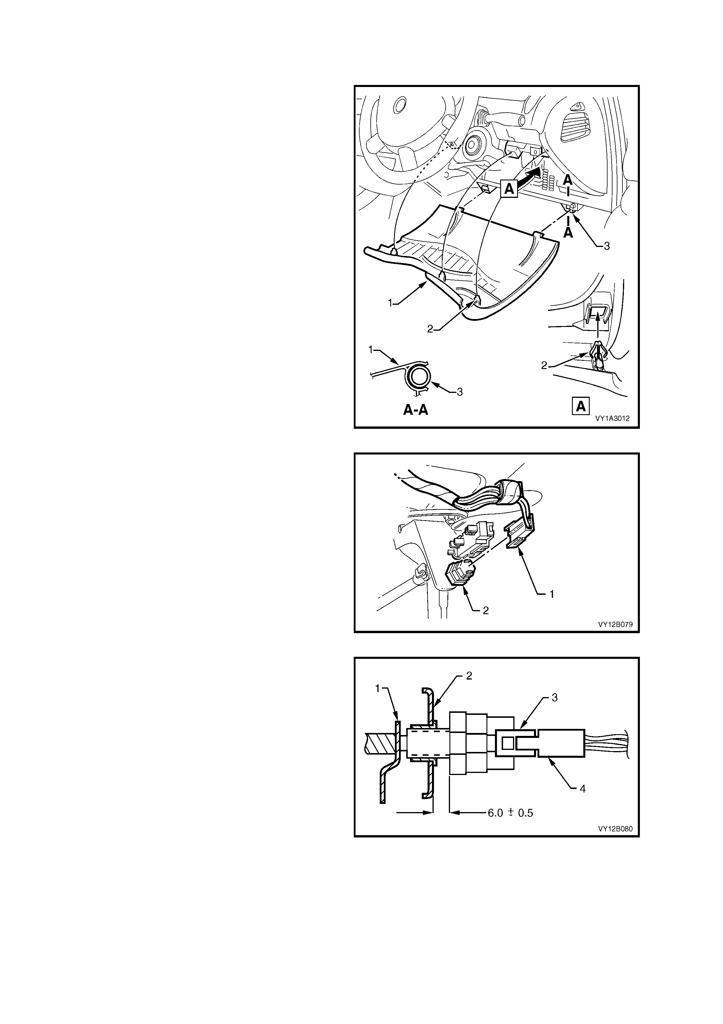
3.18 STOP LAMP SWITCH ASSEMBLY
LT Section – 04-600
REPLACE
1. Remove the fusible link F102, refer to
Figure 12B-118, item 6.
2. Grasp the upper edge of the instrument panel
lower trim panel assembly (1) and pull
outwards to disengage the three clips (2).
Swing the panel assembly open.
3. Holding each s ide of the panel assem bly, pull it
rearwards to disengage the two clips (3)
attaching the lower edge of the panel assem bly
to the instrument panel.
Figure 12B-80
4. Remove the wiring harness connector (1) from
the rear of the stop lamp switch assembly (2).
5. Pull the switch assembly out from the pedal
support tubular clip.
6. Push a new switch ass embly through the pedal
support tubular clip.
Figure 12B-81
7. Ensure that the brake pedal (1) is in the REST
position.
8. The gap between the switch assembly and the
support bracket (2) is to be 5.5 ± 0.5 mm. To
adjust the gap, rotate the switch assembly
clockwise or anti-clockwise to decrease or
increase the gap distance accordingly.
9. Connect the wiring harness connector (4) to the
switch assembly (3).
10. Install the fusible link F102.
11. Check the tail lamp assembly operation.
Figure 12B-82
12. Holding each side of the instrument panel lower trim panel assembly (1), push it forwards to engage the two
clips (3) that attach the lower edge of the panel assembly to the instrument panel. Refer to Figure 12B-80.
13. Close the panel, pushing it upwards to engage the three clips, item 2, Figure 12B-80.
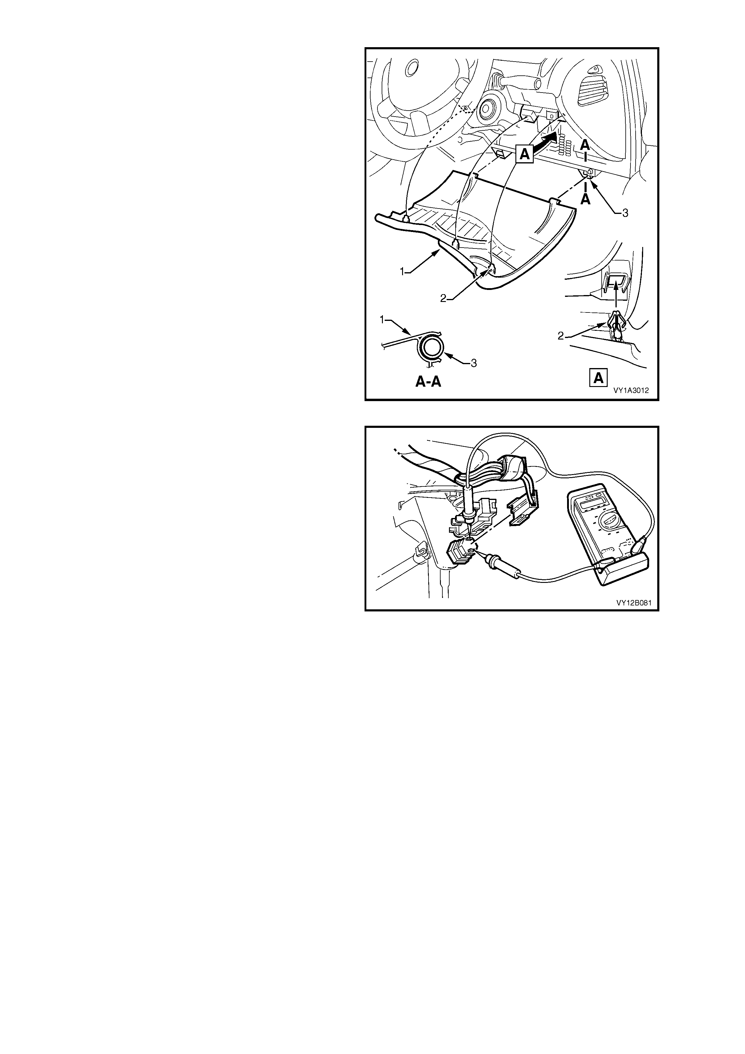
TEST
1. Remove the fusible link F102, refer to
Figure 12B-118, item 6.
2. Grasp the upper edge of the instrument panel
lower trim panel assembly (1) and pull
outwards to disengage the three clips (2).
Swing the panel assembly open.
3. Holding each s ide of the panel assem bly, pull it
rearwards to disengage the two clips (3)
attaching the lower edge of the panel assem bly
to the instrument panel.
Figure 12B-83
4. Remove wiring harness connectors from the
switch assembly.
5. Using an ohmmeter, measure the resistance
across the terminals of the switch assembly.
The following readings should be taken:
a. W ith the brake pedal in the REST position, the
ohmmeter should indicate an open circuit.
b. With the brak e pedal depress ed, the ohmm eter
should indicate continuity.
6. If the ohmmeter does not indicate the readings
as specified, check the switch assembly
calibration as detailed in steps 7 and 8 of
REPLACE. Retest the switch after any
adjustment.
7. If the switch assembly calibration is within the
specified tolerance, and the ohmmeter does
not indicate the readings as specified, replace
the switch assembly as detailed in REPLACE.
8. Connect the wiring harness connector to the
switch assembly.
9. Install the fusible link F102.
10. Holding each side of the lower trim panel
assembly, push it forwards to engage the two
clips that attach the lower edge of the panel
assembly to the instrument panel.
11. Close the panel, pushing it upwards to engage
the three clips.
12. Check the operation of the tail lamps.
Figure 12B-84
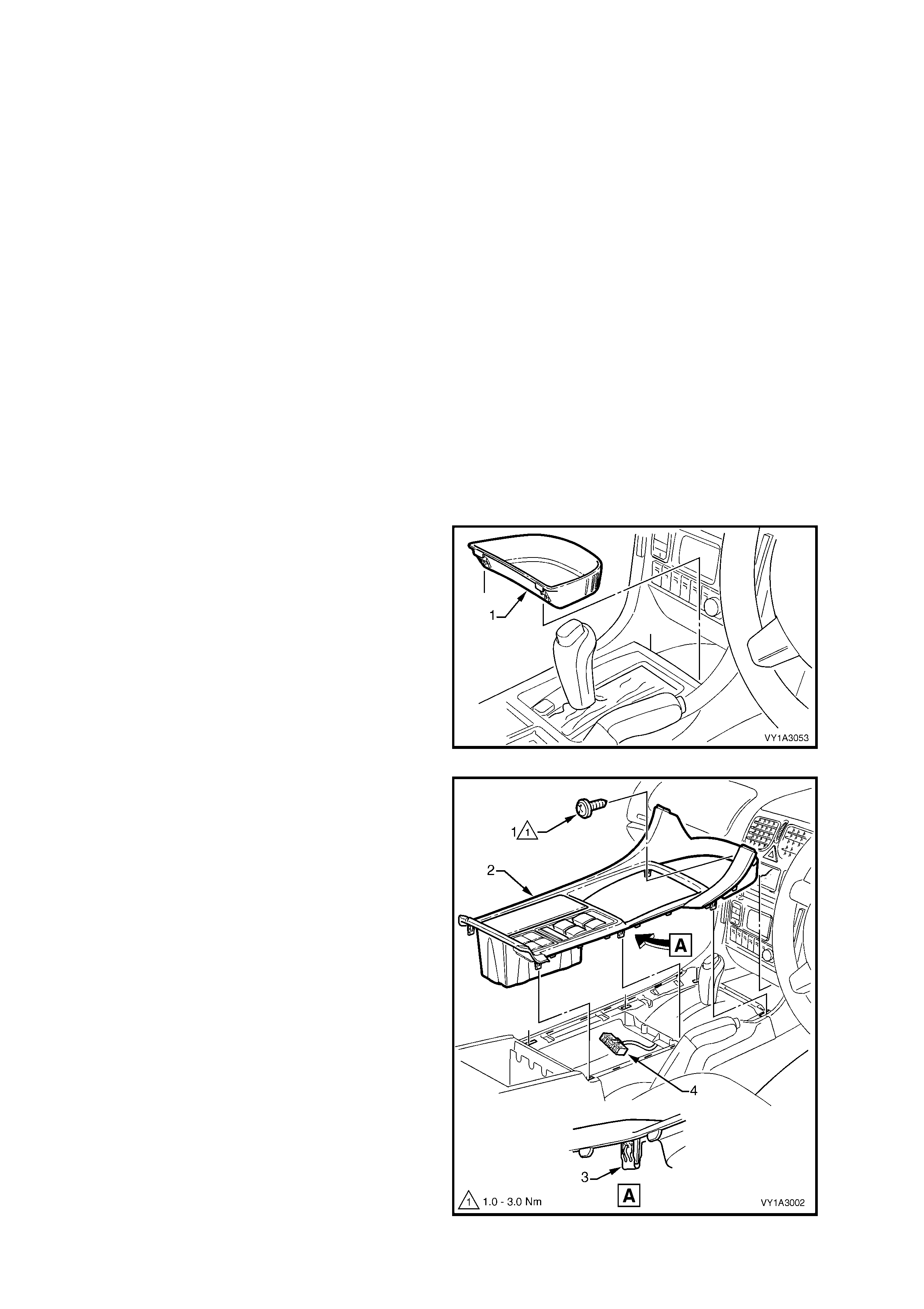
3.19 SWITCH ILLUMINATION
LT Section –
There are a number of switches within the cabin that are illuminated with conventional bulbs. The bulbs used in
these switches are physically identical. Refer to Figure 12B-6 for the locations of the switches.
This Section will provide service procedures for replacing the bulb of the particular switches, depending on their
location within the vehicle.
Even though the headlamp, trip computer and side window switches are illuminated with conventional bulbs, the
switches are sealed units and the bulbs are not serviceable.
AUXILIARY SWITCH BULBS
Replace
There ar e four spaces available for switches in the f loor cons ole cover assem bly. All the switches installed her e are
of the same type however, the functionality is different.
Switches that can be installed in this location are:
• Traction control (manual transmission vehicles)
• LPG (Liquefied Petroleum Gas)
• Police lights-out (not illuminated)
1. Ensure that the ignition switch is in the OFF position.
2. Remove the fusible link F102, refer to Figure 12B-118, item 6.
3. If required, remove the following navigation system equipment:
a. Remote control cradle
b. Navigation monitor escutcheon
Refer to Section 12L, 3.2 REMOTE CONTROL ASSEMBLY.
4. Remove the floor console front compartment
liner (1) by lifting it upwards to disengage the
retaining lugs.
Figure 12B-85
5. Remove the screw (1) attaching the floor
console cover assembly (2).
6. Prise the cover from the floor console
assembly in six places (3).
7. Lift the cover assembly up from the rear and
disconnect the wiring connector (4) from the
side window switch assem bly and all the wiring
connectors from the auxiliary switches fitted.
NOTE: Note which wiring connectors are
connected to their relevant switch assembly.
8. Remove the cover assembly.
Figure 12B-86
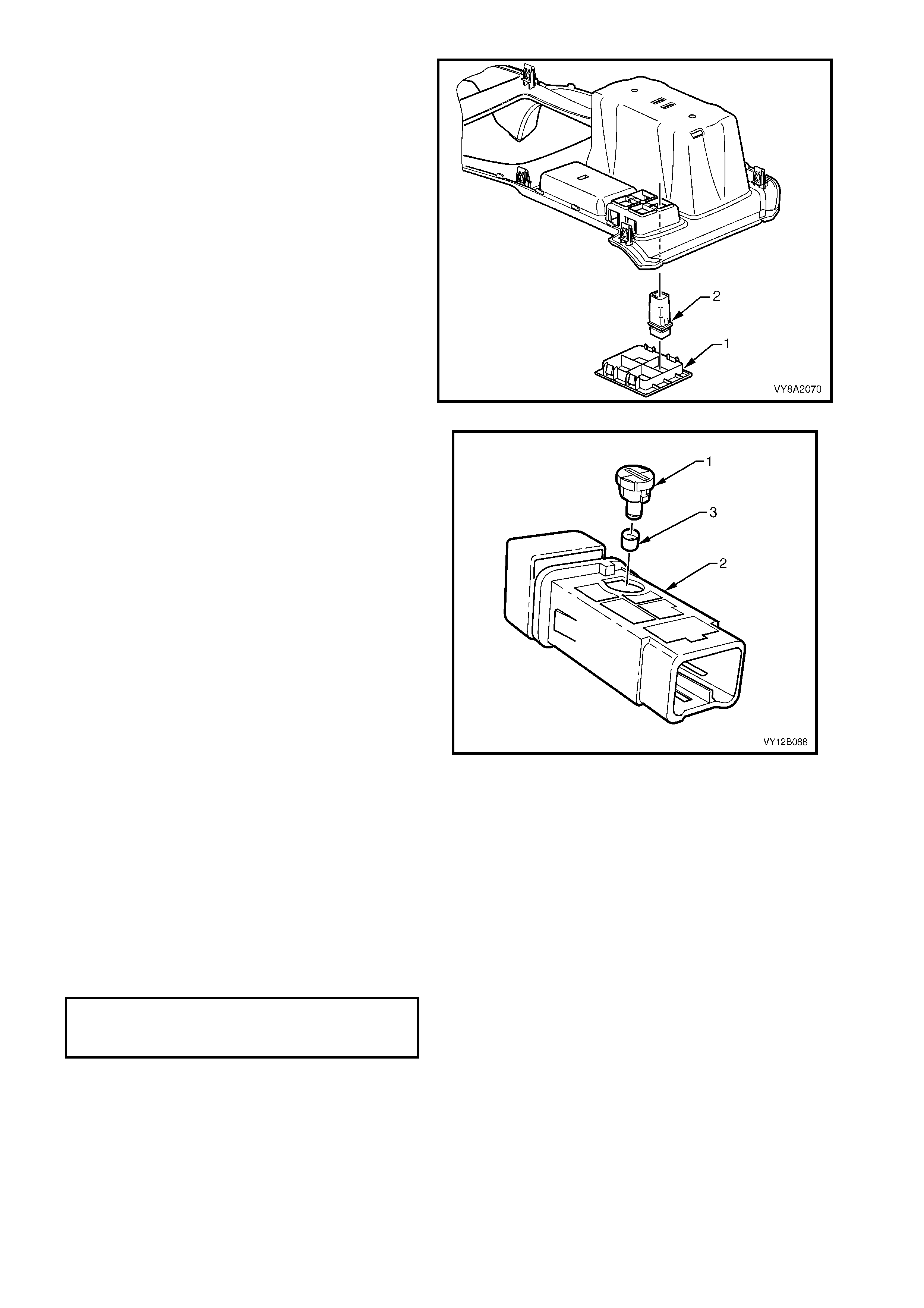
9. From the underside of the cover assembly,
depress the four tabs securing the auxiliary
switch bezel assembly (1). Remove the bezel
assembly.
10. As required, depress the two tabs securing the
switch assembly (2) to the console cover
assembly and remove the switch.
NOTE: Record the orientation and position of the
switch assembly being removed.
Figure 12B-87
11. Using a fine blade screwdriver, inserted into the
groove on the bulb sock et, twist the sock et and
bulb assembly (1) anti-clockwise and remove
from the switch assembly (2).
12. Remove the green bulb sleeve (3) from the
socket and bulb assembly.
13. Check the bulb sleeve for splits and replace
where necessary.
14. Fit the bulb sleeve to the new socket and bulb
assembly.
15. Insert the socket and bulb assembly into the
switch assembly.
Figure 12B-88
16. Connect the switch to the correct wiring connector in the floor console. Install the fusible link 102. Turn on the
park lamps and check for the correct operation of the bulb.
17. Remove the fusible link F102. Disconnect the wiring connector from the switch assembly.
18. Insert the switch assembly into the switch bezel assembly ensuring the position and orientation are correct.
19. Insert the bezel into the cover assembly and ensure that it locks into place securely.
20. Lift the cover assembly onto the front floor console inserting the front of the cover first.
21. Connect all the wiring connectors to the switch assemblies ensuring that each switch is mated to the correct
connector.
22. Press the cover onto the console.
23. Insert the screw attaching the floor console cover assembly and tighten to the correct torque specification.
FLOOR CONSOLE COVER ASSEMBLY
ATTACHING SCREW
TORQUE SPECIFICATION 1.0 – 3.0 Nm
24. If required, install the following navigation system equipment:
a. Remote control cradle
b. Navigation monitor escutcheon
Refer to Section 12L, 3.2 REMOTE CONTROL ASSEMBLY.
25. Install the fusible link F102.
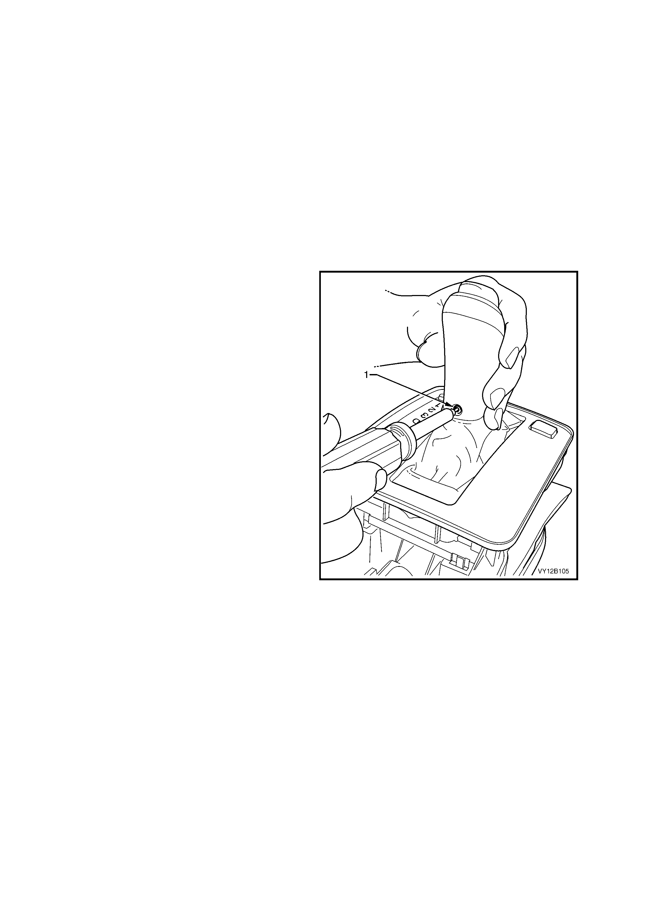
POWER AND TRACTION CONTROL SWITCH BULBS
Replace
Two switch assemblies can be installed into the automatic control selector indicator assembly. The switches are:
• Power
• Traction control (automatic transmissions)
The power switch assembly is always fitted where an automatic transmission is fitted to the vehicle. The traction
control is an option, depending on the level of the vehicle.
The traction control switch is always fitted to the rear of the PRNDL lens.
1. Ensure that the ignition switch and the headlamp switch assembly are in the OFF position.
2. Ensure that the park brake is applied.
3. Remove the floor console cover assembly as detailed in this Section, refer to REPLACE – AUXILIARY
SWITCH BULBS.
4. Shift the transmission selector into the DRIVE position.
NOTE: If the vehicle is fitted with a brake transmission shift interlock (BTSI), the brake pedal must be pressed to
shift the transmission selector from the PARK position to the DRIVE position.
5. Remove the Torx head screw (1) using a
number 25 Torx tip.
Figure 12B-89
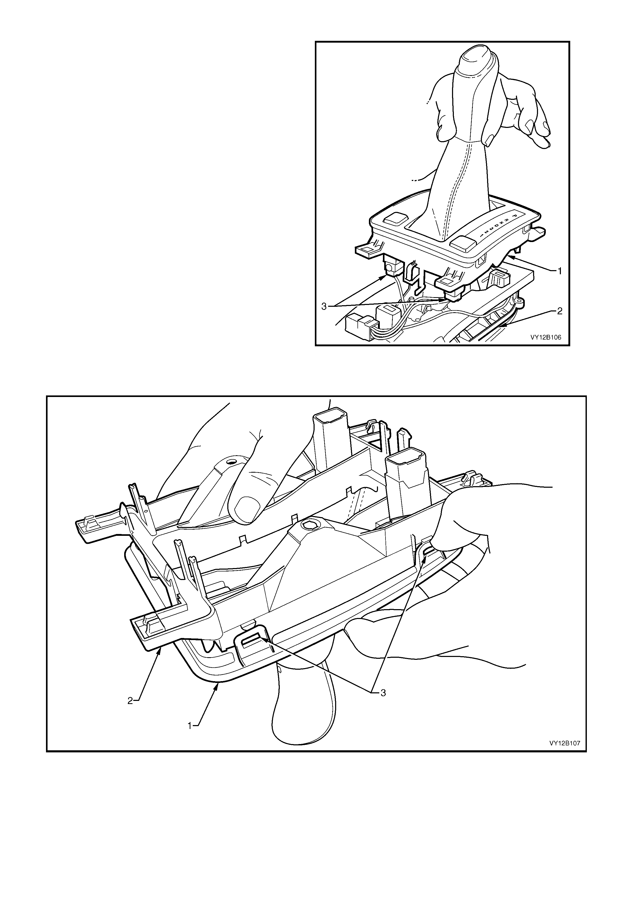
6. Unclip the upper and lower housing assembly
(1) from the base assembly (2) at three points.
7. Disconnect the wiring harness from the power
switch (3) and traction switch (if fitted).
8. Twist the automatic transmission control
position lamp anti-clockwise and pull down to
remove it from the lower housing.
Figure 12B-90
9. With the shift lever knob hanging down, unclip the upper housing (1) from the lower housing (2) at four
points (3), refer to Figure 12B-91.
Figure 12B-91

10. Lift the lower housing from the upper housing.
NOTE: Leave the upper housing upside down, that
is, with the shifter lever knob keeping the boot (1)
taught. This is to reduce the chance of the boot
coming away from the tabs (2) on the upper
housing.
Figure 12B-92
11. Us ing a thin f lat-blade screwdriver, depr ess the
tabs (1) on either side of the switch and remove
it from the lower housing.
Figure 12B-93
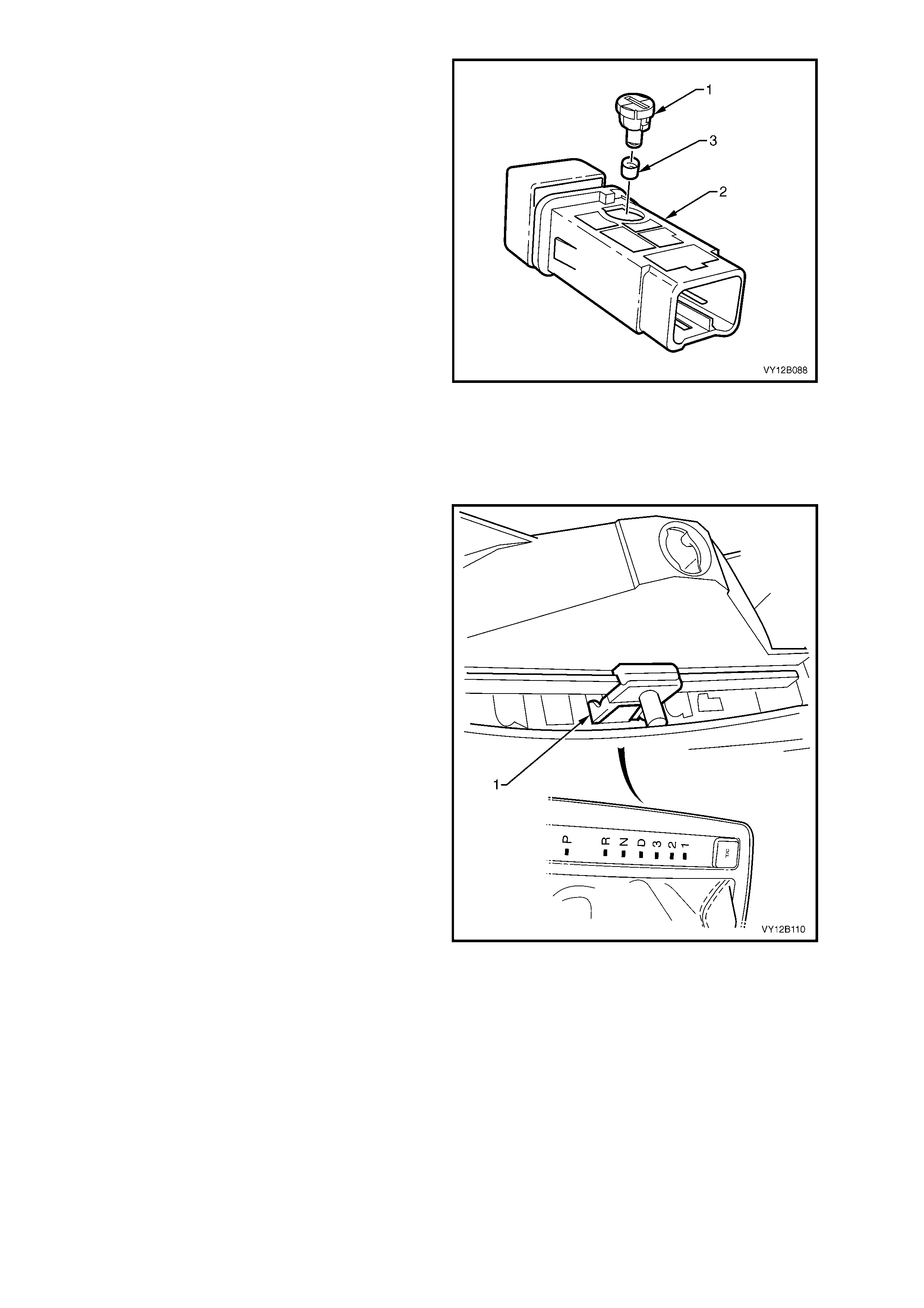
12. Using a fine blade screwdriver, inserted into the
groove on the bulb sock et, twist the sock et and
bulb assembly (1) anti-clockwise and remove
from the switch assembly (2).
13. Remove the green bulb sleeve (3) from the
socket and bulb assembly.
14. Check the bulb sleeve for splits and replace
where necessary.
15. Fit the bulb sleeve to the new socket and bulb
assembly.
16. Insert the socket and bulb assembly into the
switch assembly.
17. Connect the switch to the correct wiring
connector. Turn on the park lamps and check
for the correct operation of the bulb.
Disconnect the wiring connector from the
switch assembly.
18. Fit the switch back into the lower assembly,
ensuring that it locks correctly in place.
19. Turn the lower assem bly upside down. Clip the
upper assembly back into place, ensuring that
the skirt is still placed over the tabs, refer to
Figure 12B-92.
Figure 12B-94
20. Place the carrier indicator (1) so that the ‘D’ is
selected.
21. Place the lower and upper housing assembly
over the shift lever and ensure that the k nob is
correctly seated on the shift lever.
22. Connect the harness to the power switch and
traction control switch (if fitted).
23. Insert the automatic transmission control
position lamp and turn clockwise to lock it into
place.
24. Clip the upper and lower housing assembly to
the base and ensure that the carrier indicator
correctly engages in the slot.
25. Install the floor console cover assembly as
detailed in this Section, refer to REPLACE –
AUXILIARY SWITCH BULBS.
Figure 12B-95
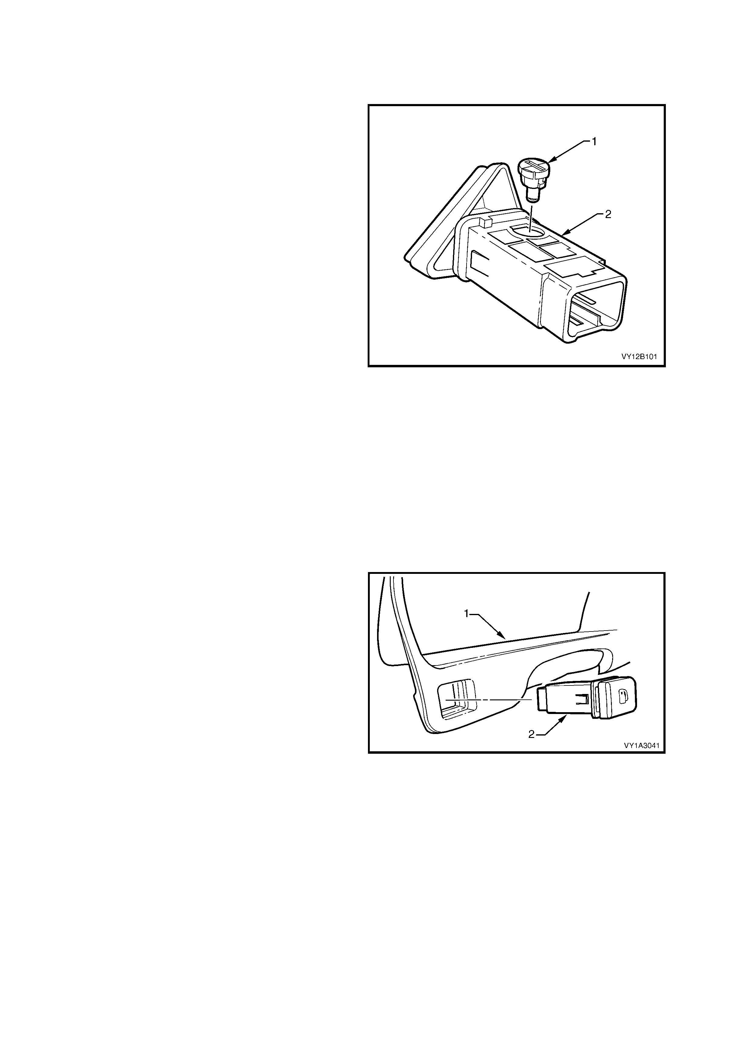
HAZARD WARNING SWITCH BULB
Replace
1 Remove the hazard warning switch assembly, refer to 3.25 HAZARD WARNING SWITCH ASSEMBLY.
2. Using a fine blade screwdriver, inserted into the
groove on the bulb sock et, twist the sock et and
bulb assembly (1) anti-clockwise and remove
from the switch assembly (2).
3. Pull the sock et and bulb ass embly out from the
switch assembly.
4. Insert the new socket and bulb assembly into
the switch assembly.
Figure 12B-96
5. Fit the fusible link F102.
6. Connect the switch assembly to the wiring connector and check the operation of the bulb by turning the park
lamps on.
7. Remove the fusible link F102. Disconnect the wiring connector from the switch assembly.
8. Install the hazard warning switch assembly, refer to 3.25 HAZARD WARNING SWITCH ASSEMBLY.
FUEL TANK FILLER DOOR LOCK RELEASE SWITCH BULB, LHD
Replace
This switch is only fitted to left-hand drive vehicles.
It is located in the instrument panel trim plate
assembly.
1. Remove the fusible link F102, refer to
Figure 12B-118, item 6.
2. Remove the power door lock fuse F20, ref er to
Section 12O, 1.0 GENERAL INFORMATION.
3. Remove the instrument panel trim plate
assembly, refer to 3.23 HEADLAMP SWITCH
ASSEMBLY.
4. From the rear of the instrument cluster trim
assembly (1), depress the tab on each side of
the switch as sembly (2) and rem ove the switch
assembly.
Figure 12B-97
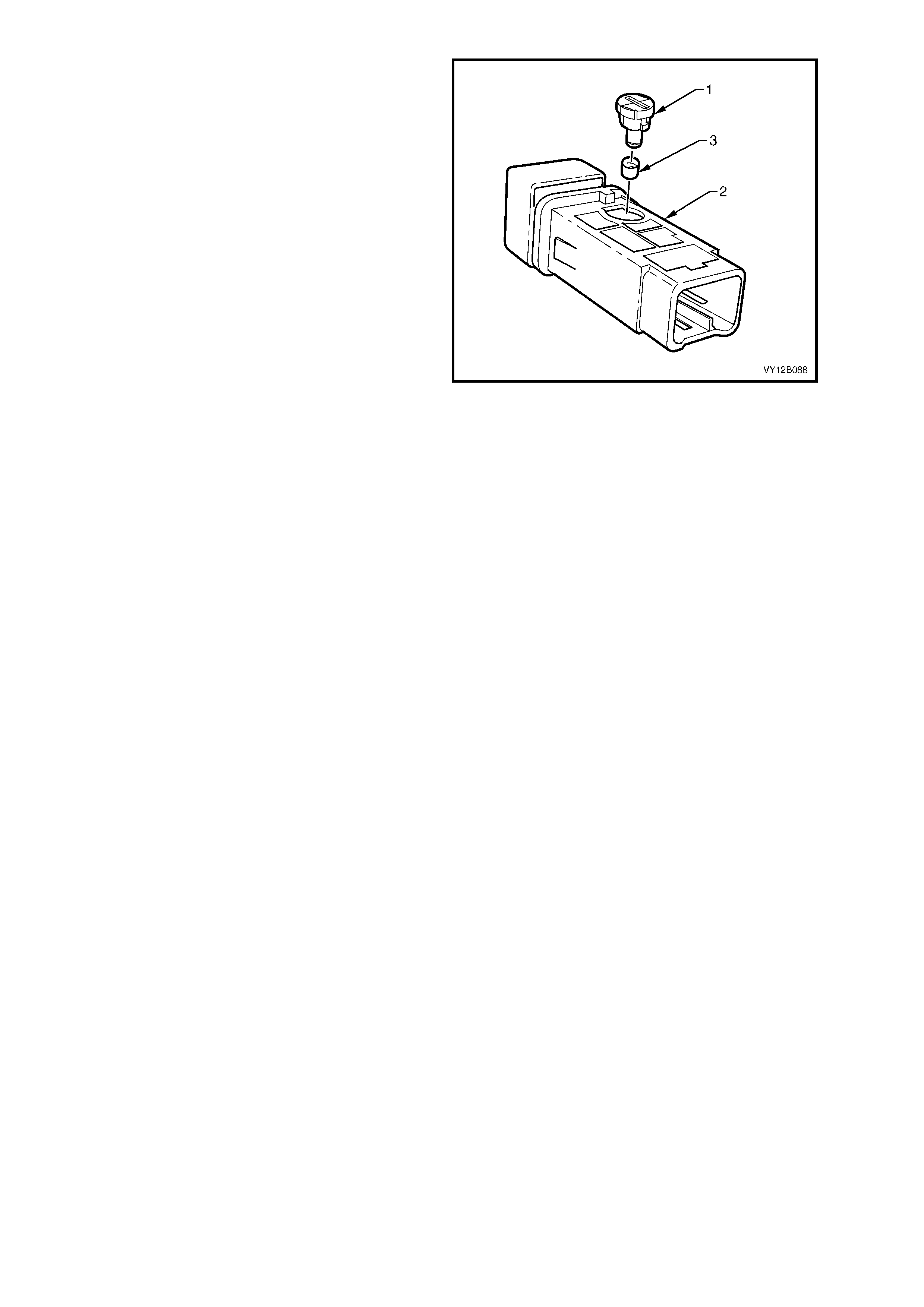
5. Using a fine blade screwdriver, inserted into the
groove on the bulb sock et, twist the sock et and
bulb assembly (1) anti-clockwise and remove
from the switch assembly (2).
6. Remove the green bulb sleeve (3) from the
socket and bulb assembly.
7. Check the bulb sleeve for splits and replace
where necessary.
8. Fit the bulb sleeve to the new socket and bulb
assembly.
9. Insert the socket and bulb assembly into the
switch assembly.
Figure 12B-98
10. Connect the switch assembly to the wiring
connector. Install the fuse F20 and the fusible
link F102, and check the operation of the bulb
by turning the park lamps on.
11. Remove the fuse and the fusible link.
Disconnect the wiring connector from the
switch assembly.
12. Insert the switch assembly into the plate
assembly ensuring that it locks into place.
13. Connect the wiring connector to the switch
assembly. Install the fuse F20 and the fusible
link F102.
14. Install the instrument panel trim plate
assembly, refer to 3.23 HEADLAMP SWITCH
ASSEMBLY.

3.20 BACK-UP LAMP SW ITCH
The back-up lamp switch assembly is fitted to both manual transmission assembly configurations. The switch
assembly is fitted to the right-hand side of the transmission case and is not adjustable.
If, during the c ourse of diagnosis the switch ass em bly requires changing, refer to Section 7B, 3.1 BACK-UP LAMP
SWITCH.

3.21 NEUTRAL SAFETY BACK-UP SW ITCH
The neutral safety back-up switch is fitted to vehicles with automatic transmission. This switch has numerous
functions, one being to activate the back-up lamps when the transmission selector is in the REVERSE position. If,
during the cours e of diagnos is the switch as s embly requires changing, re f er to Section 7C4, 3.4 NEUTRAL START
AND BACK-UP LAMP SWITCH.
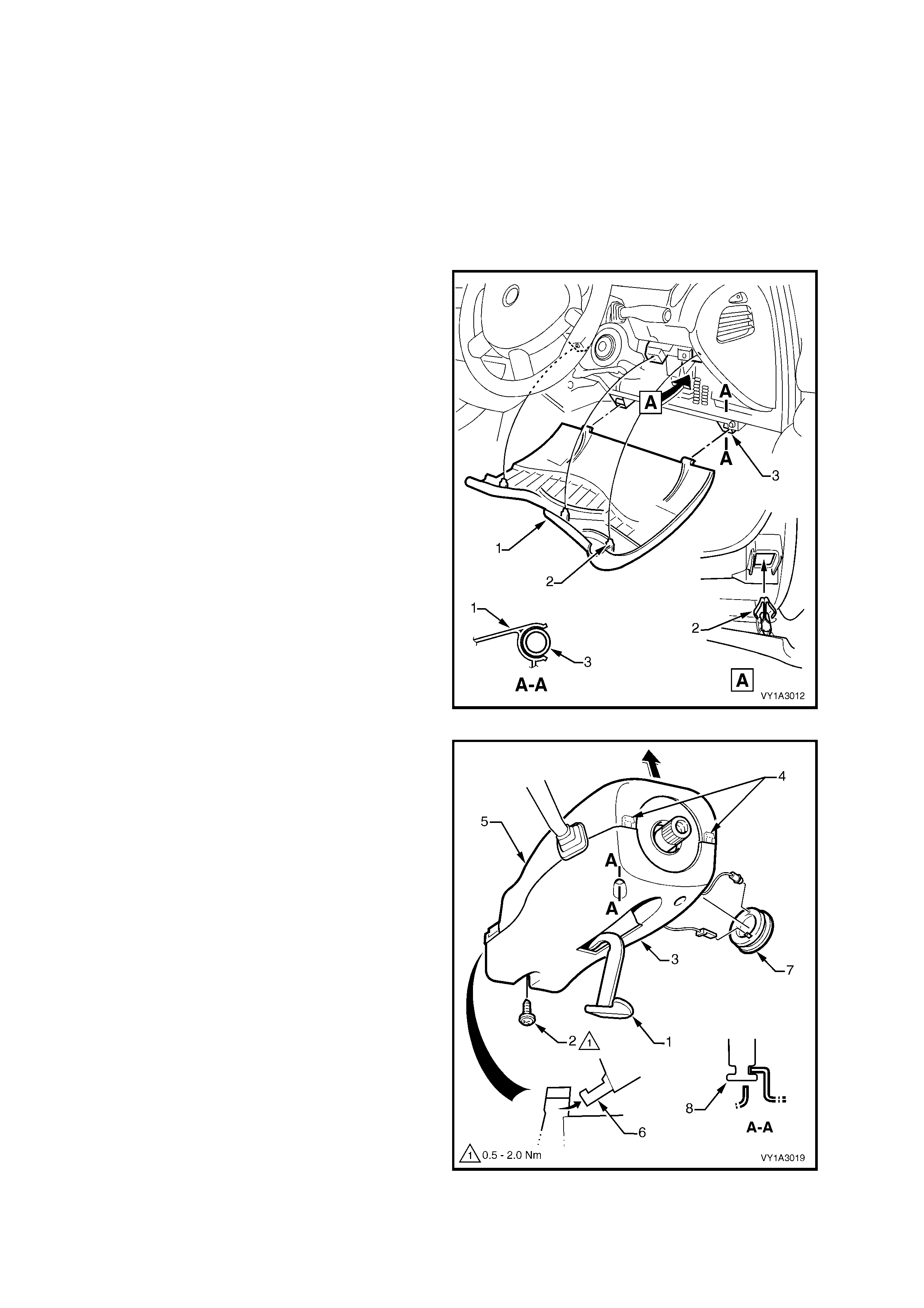
3.22 TURN SIGNAL SWITCH ASSEMBLY (& CRUISE CONTROL IF FITTED)
LT Section – 06-250
There are two turn signal switch assemblies available. Both assemblies provide the following functions:
• Turn signal
• Pass
• High beam
In addition, where fitted, cruise control switching functions are included. For m ore information on the cruise control
system, refer to Section 12E CRUISE CONTROL.
REMOVE
1. Remove the fusible link F102, refer to
Figure 12B-118, item 6.
2. Grasp the upper edge of the instrument panel
lower trim panel assembly (1) and pull
outwards to disengage the three clips (2).
Swing the panel assembly open.
Figure 12B-99
3. From below the steering column, remove the
screw (2) attaching the steering column lower
cover (3).
4. Depress the lower cover inwards to disengage
the tabs (4) while lifting the steering column
upper cover (5).
5. Raise the upper cover as high as possible to
disengage the lugs (6) and remove the cover.
6. Prise the theft deterrent receiver assembly (7)
from the lower cover.
7. Disconnect the wiring connector and bulb
socket from the receiver.
8. Slide the lower cover rear wards to disengage it
from the lugs (8) and remove the lower cover.
Figure 12B-100
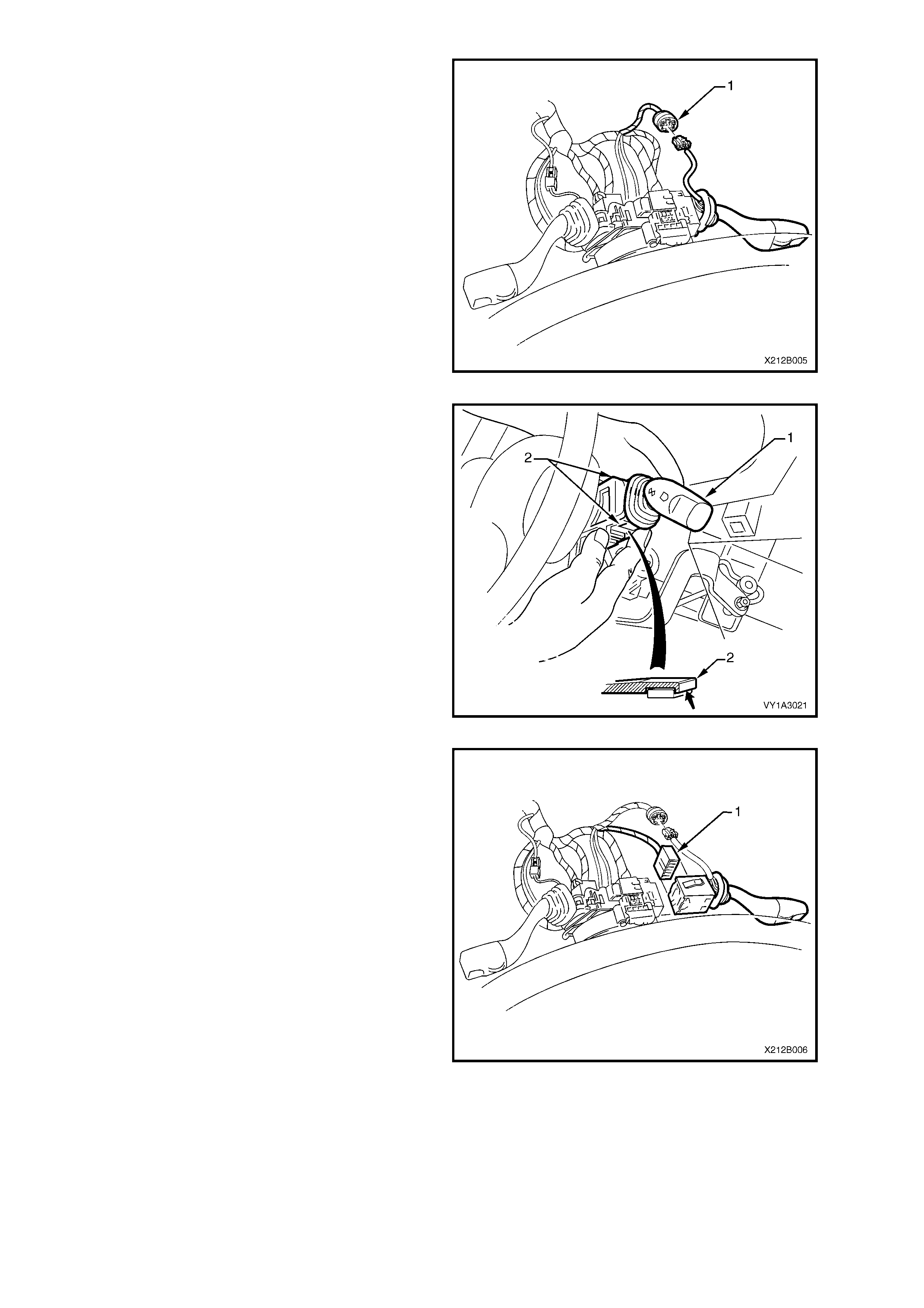
9. For turn signal switch assemblies fitted with
cruise control, disconnect the wiring harness
connector (1).
Figure 12B-101
10. Depress the retaining tangs (2) on the switch
assembly (1) and pull the assembly away from
the steering column.
Figure 12B-102
11. Depress the wiring harness connector tangs
and pull the connector (1) from the switch
assembly.
Figure 12B-103
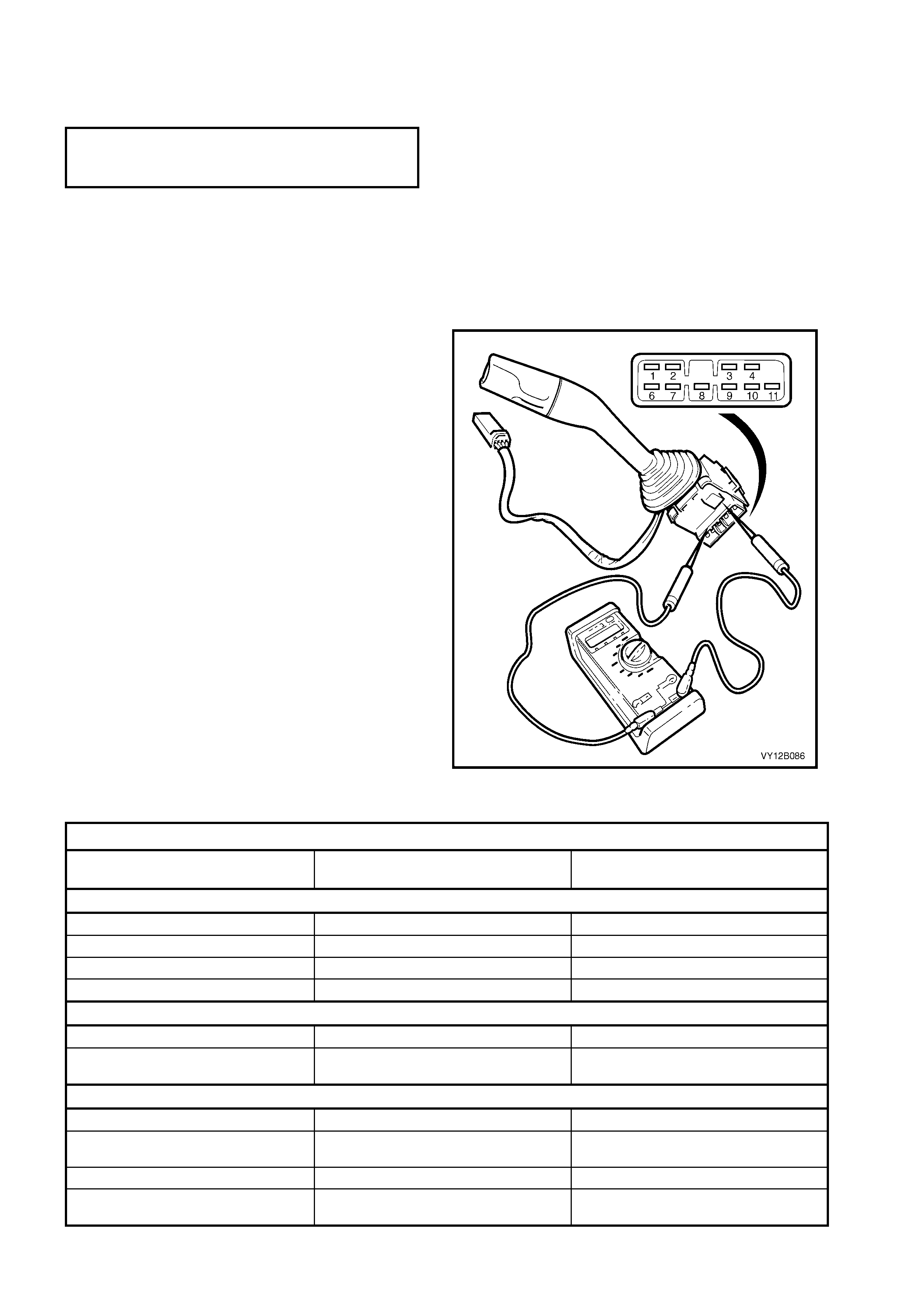
REINSTALL
Installation of the turn signal switch assembly is the reverse of the removal procedure noting the following points:
1. Ensure the steering column trim cover screw is tightened to the correct torque specification.
STEERING COLUMN
TRIM COVER
TORQUE SPECIFICATION 0.5 – 2.0 Nm
2. Check the operation of the turn signal switch assembly.
TESTING
To test the turn signal switch assembly, an ohmmeter is used to check the continuity when the switch is placed in
certain positions.
IMPORTANT: To test the cruise control features where fitted, refer to Section 12E, 2.3 CRUISE CONTROL
ASSEMBLY.
1. Perform the removal procedure for the turn
signal switch assembly as detailed in this
Section, but do not unclip and remove the
switch assembly from the steering column.
With the switch assembly attached to the
steering c olumn provides a stable platfor m with
which to carry out the testing.
2. Place the switch into the positions as detailed
in the chart following. Position the contacts of
the ohmmeter onto the terminals and take the
reading. Compare the reading with the chart.
3. If there is continuity between any other
terminals other than those listed, the switch
assem bly is faulty. If the switch fails any par t of
the test, replace the switch assembly with a
serviceable item. To replace the switch,
depress the two retaining tangs and pull the
switch assembly away from the steering
column. Refer to Figure 12B-102. Insert a new
switch.
4. Perform the reinstall procedure in this Section.
Figure 12B-104
TURN SIGNAL SWITCH ASSEMBLY
SWITCH TERMINALS SWITCH POSITION INDICATION IF SWITCH IS
SERVICEABLE
Turn Signal Sw i tch Terminals
9 and 6 Switch in neut ral position Open circui t
9 and 6 Switch in left-hand turn pos i tion Continuity
9 and 10 Switch in neut ral position Open circui t
9 and 10 Switch in right-hand turn position Continuity
Headlamp Pass Terminals
1 and 4 Switch in t he neutral posit i on Open circui t
1 and 4 Switch pulled to the rear in the pass
position. Continuity
Headlamp High Beam Terminals
1 and 3 Switch in neut ral position Open circui t
1 and 3 Switch pushed forward in the high beam
position Continuity
2 and 3 Switch in neut ral position Continuit y
2 and 3 Switch pushed forward in the high beam
position. Open circui t
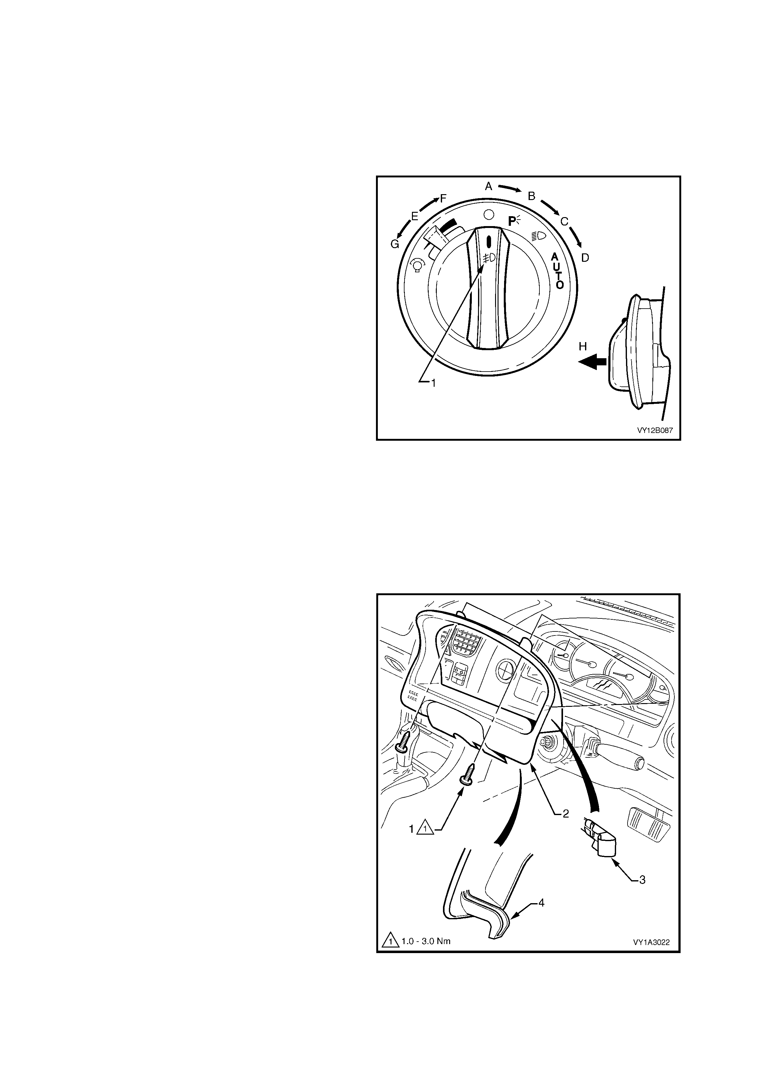
3.23 HEADLAMP SWITCH ASSEMBLY (& FRONT FOG IF FITTED)
LT Section – 02-800
Two specific headlamp switch assemblies are used dependant on the level of vehicle to which the switch is
installed. T he difference between the two switches is that one switch assem bly has the ability to turn the f og lamps
on and off.
Switches with fog lamp capability will have a fog lamp icon (1).
If replacing a headlamp switch, ensure the correct type is used.
The headlamp switch assembly shown is
representative of a switch equipped with the fog
lamp function and has the fog lamp icon (1).
The operation of the switch assembly is as follows:
• The switch assembly is off in position A.
• Park lamps are turned on when the switch is
rotated clockwise to position B.
• Low beam headlamps are turned on when the
switch is rotated clockwise to position C.
• Headlamp operation is controlled automatically
by the BCM when the switch is rotated
clockwise to position D.
• Instrumentation lighting is brightened when the
dimm er switch is moved from the position E to
F.
• Instrumentation lighting is dimmed when the
dimm er switch is moved from the position E to
G.
• Fog lamps are turned on when the switch is
pulled out to position H, while the switch is in
position B, C or D.
NOTE: Fog lamps will not be turned on of the
switch is pulled out in position H while the switch is
also in position A.
Figure 12B-105
REMOVE
NOTE: The steering wheel has been removed for
clarity. The instrument cluster trim assembly (2)
can be removed with the steering column trim
covers and the steering wheel assembly installed.
1. Remove the fusible link F102, refer to
Figure 12B-118, item 6.
2. Release the steering column adjustment lever
and move the column to its lowest position.
3. Remove the two screws (1) attaching the
instrument cluster trim assembly to the
instrument panel.
4. Depress the top of the trim assembly slightly
and tilt the top of the trim assembly out of the
instrument panel pad, disengaging the retaining
clips (3) from either side.
5. Unhook each lug (4) from the instrument panel
pad.
6. For left-hand drive configured vehicles,
disconnect the fuel filler door lock release
switch assembly wiring connector.
7. Remove the trim assembly.
Figure 12B-106
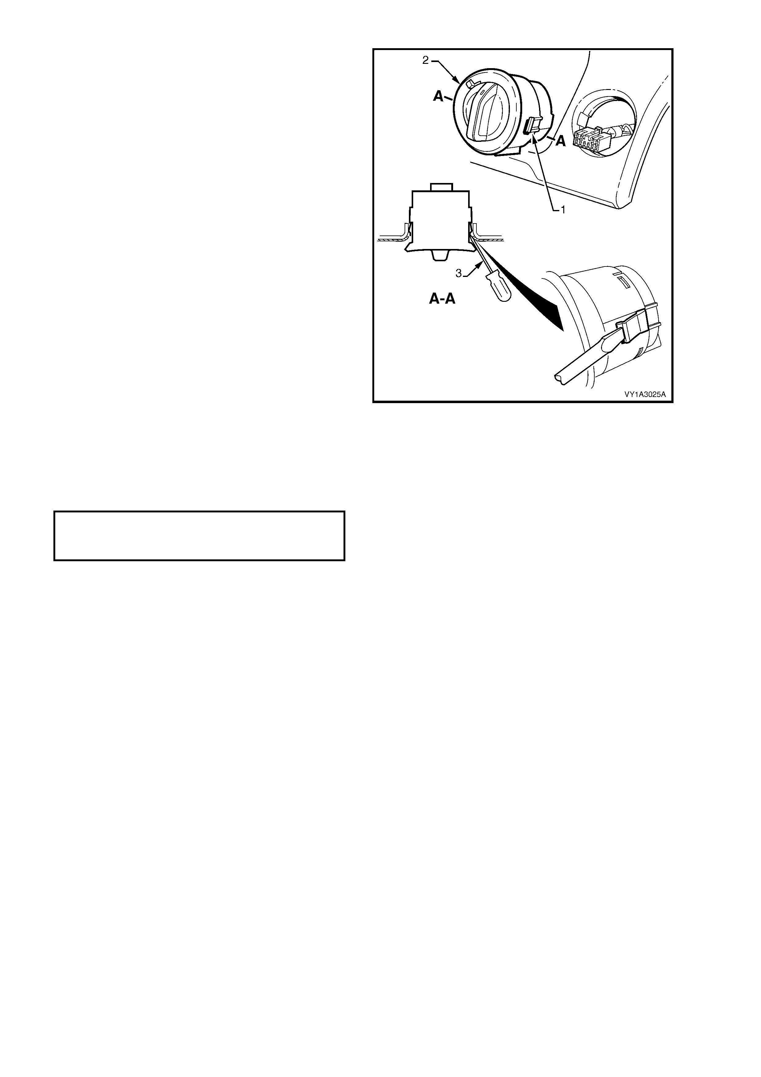
8. If required remove the following components:
a. Remove the right-hand instrument panel
outer cover, refer to Section 1A3, 3.17
INSTRUMENT PANEL OUTER COVER.
b. Remove the driver’s side outer duct, refer to
Section 2B, 18.2 HVAC SYSTEM DUCTS.
IMPORTANT: Care must be exercised when
removing the headlamp switch as the retaining clip
and locating guide will catch and damage the
instrument panel outer material.
9. Squeeze the retaining clips (2) on either side of
the headlamp switch assembly and carefully
push the assembly part way from the cavity.
10. Insert a fine blade screwdriver (3) as shown
and hold the retaining clip depress while slowly
manipulating the switch from its cavity. Repeat
for the opposite side and for the locating guide
as required.
11. Disconnect the wiring connector and remove
the switch assembly.
Figure 12B-107
REINSTALL
Installation of the headlamp switch assembly is the reverse of the removal procedure noting the following points:
1. Ensure the switch assembly’s retaining tangs are correctly seated.
2. Tighten the instrument cluster trim plate assembly screw to the specified torque.
INSTRUMENT CLUSTER
TRIM PLATE ASSEMBLY SCREW
TORQUE SPECIFICATION 1.0 – 3.0 Nm
3. Ensure the steering column dash trim cover is hooked in place to the instrument panel.
4. Check the operation of the headlamp switch assembly.
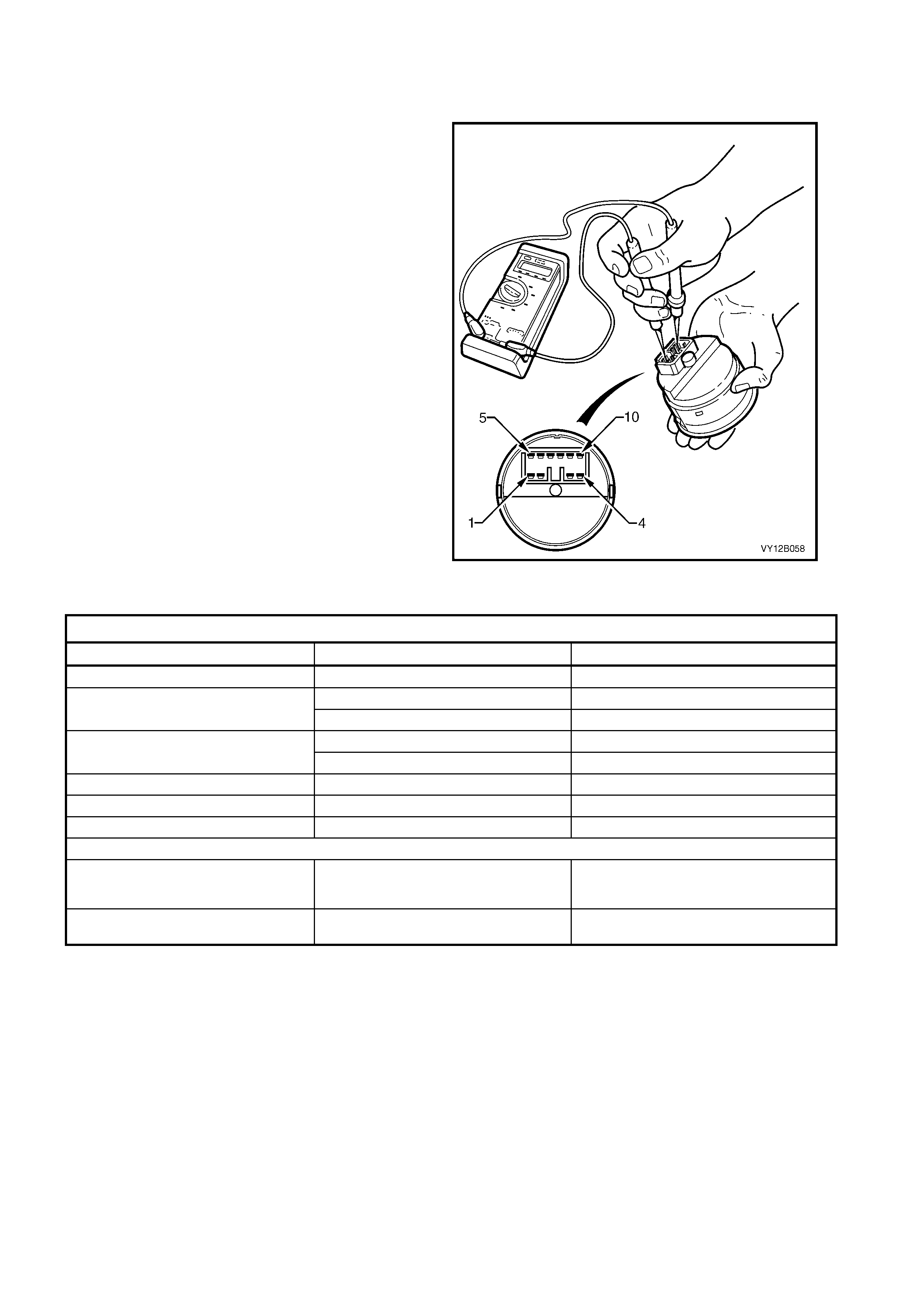
TESTING
To test the headlamp switch assembly, an ohmmeter is used to check the continuity or resistance when the
functions of the switch are actuated.
NOTE: Refer to Figure 12B-105 in conjunction with
the chart in this Section for details of the switch
positions.
1. Perform the removal procedure for the
headlamp switch assembly as detailed in this
Section.
2. Place the switch in the positions as detailed in
the chart in this Section. Position the contacts
of the ohmmeter onto the terminals and take
the reading. Compare the reading with the
chart.
3. If there is continuity between any other
terminals other than those listed, the switch
assem bly is faulty. If the switch f ails any par t of
the test, replace the switch assembly with a
serviceable item.
4. Perform the reinstall procedure in this Section
Figure 12B-108
HEADLAMP SWITCH ASSEMBLY (& FOG LAMP IF FITTED)
SWITCH POS I TI ON SWITCH TERMINALS INDICATION IF S WI TCH I S SERVI CEABLE
Switch in park l amp posi t i on; positi on B 5 and 8 Continuity
5 and 8 Continui t y Switch in low beam position; position C
5 and 4 Continui t y
2 and 4 Continui t y Switch in AUTO position; position D
2 and 8 Continui t y
Dimmer in neutral ; positi on E 7 and 8 2.68 k Ω
Dimmer in high, pos i tion F 7 and 8 5.36 k Ω
Dimmer in low, posi t i on G 7 and 8 0 kΩ
IMPORTANT: The switch must be in park, low beam or AUTO position f or t he fog lamps to be act i vat ed.
Switch with fog lamps activated; position
H and switch in either park or low beam
position
5 and 6 Continui t y
Switch with fog lamps activated; position
H and switch in A UTO pos i t i on 2 and 6 Continui t y
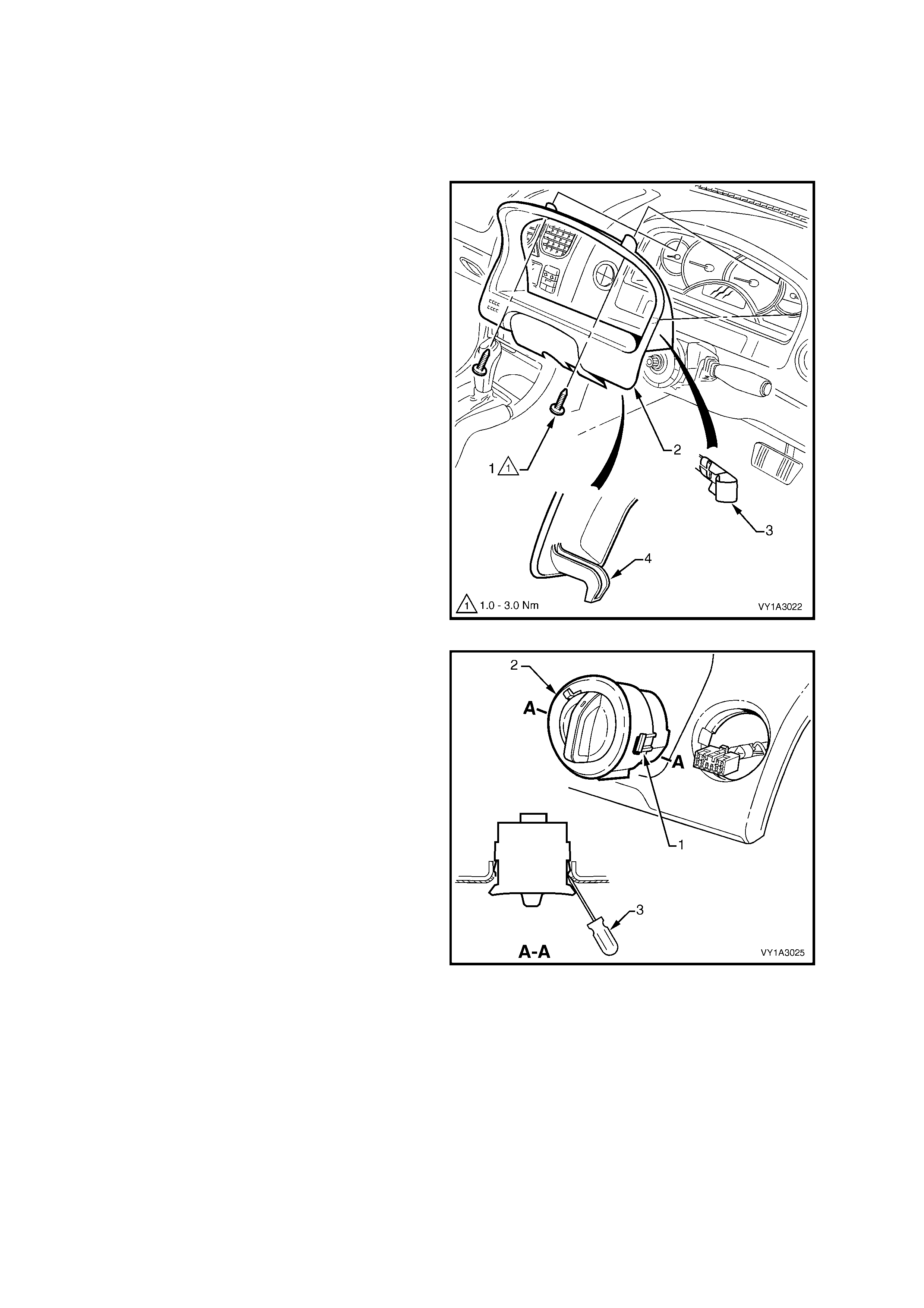
3.24 DAYLIGHT RUNNING LAMP ASSEMBLY (OPTION T82)
LT Section –
For vehicles with the daylight running lamp feature (option T82), operation of the front headlamps will occur at all
times while the ignition switch is on.
REMOVE
NOTE: The steering wheel has been removed for
clarity. The instrument cluster trim plate assembly
(2) can be removed with the steering column trim
covers and the steering wheel assembly installed.
1. Remove the fusible link F102, refer to
Figure 12B-118, item 6.
2. Release the steering column adjustment lever
and move the column to its lowest position.
3. Remove the two screws (1) attaching the
instrument cluster trim assembly to the
instrument panel.
4. Depress the top of the trim assembly slightly
and tilt the top of the trim assembly out of the
instrument panel pad, disengaging the retaining
clips (3) from either side.
5. Unhook each lug (4) from the instrument panel
pad.
6. Remove the trim assembly.
Figure 12B-109
7. From behind the instrument panel pad,
depress the retaining clips (1), with a fine flat
blade screwdriver.
8. Push the switch assembly (2) part way from its
cavity.
9. Insert a fine blade screwdriver (3) as shown
and hold the retaining clip depressed, and
slowly manipulate the switch from its cavity.
Repeat for the opposite side as required.
10. Disconnect the light switch connector from the
day light running lamps wiring harness
connector by depressing the wiring harness
connector tang and pulling the connectors
apart.
Figure 12B-110
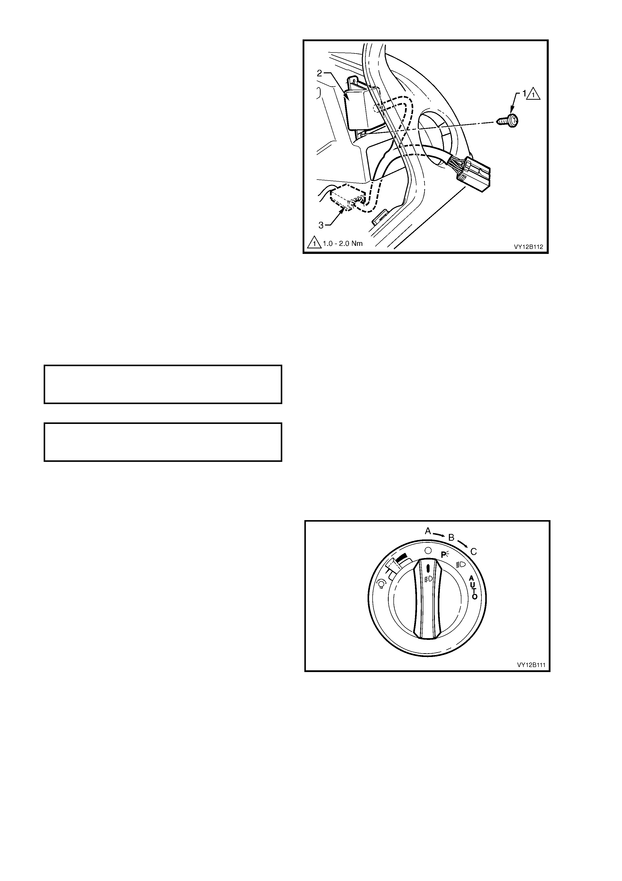
11. To separate the day light running lamps
module from the instrument panel:
a. Remove the screw that aligns the module
to the instrument panel (1) using a
magnetic tipped Phillips head screwdriver.
The screw can be accessed through the
headlamp switch cavity.
b. Prise the module (2) away from the
instrument panel.
NOTE: The module is fastened to the instrument
panel with double sided tape. lf necessary, use a
bladed screwdriver to assist removal.
12. To disconnec t the headlam p switch main wiring
harness connector (3), carefully draw the day
light running lamp modules wiring harness up
from behind the instrument panel.
13. Depress the wiring harness c onnector tang and
pull the connectors apart.
14. Remove the day light running lamps assembly .
Figure 12B-111
REINSTALL
Reinstallation of the day light running lam ps module and harnes s as s embly is the reverse of the rem oval procedur e,
noting the following points:
1. Ensure the day light running lamps module to instrument panel fastening screw is tightened to the correct
torque specification.
DAY LIGHT RUNNING LAMPS MODULE
TO INSTRUMENT PANEL FASTENING
SCREW TORQUE SPECIFICATION 1.0 – 2.0 Nm
2. Tighten the instrument panel cluster trim plate screw to the specified torque.
INSTRUMENT PANEL
CLUSTER TRIM PLATE SCREW
TORQUE SPECIFICATION 1.0 – 3.0 NM
3. Ensure the steering column dash trim cover is hooked in place to the instrument panel.
4. Check the operation of the day light running lamps feature.
TESTING
1. W ith the headlamp switch in the off position A,
turn the ignition on.
2. If the front headlamps illuminate, the day light
running lamps system is operating correctly.
3. If the front headlamps do not illuminate, turn
the headlam p switch to position C and check if
the front low beam headlamps illuminate.
4. If the front low beam headlamps do not
illuminate, replace fusible link F102, refer to
Figure 12B-118, item 6.
5. Repeat step 1 and check whether the front
headlamps illuminate.
6. If the front headlamps illuminate, the day light
running lamps system is operating correctly.
7. If the front headlamps do not illuminate, the day
light running lamps module and harness
assembly is faulty. Remove and replace the
daylight running lamp module and harness
assembly wi th a serviceable item.
Figure 12B-112
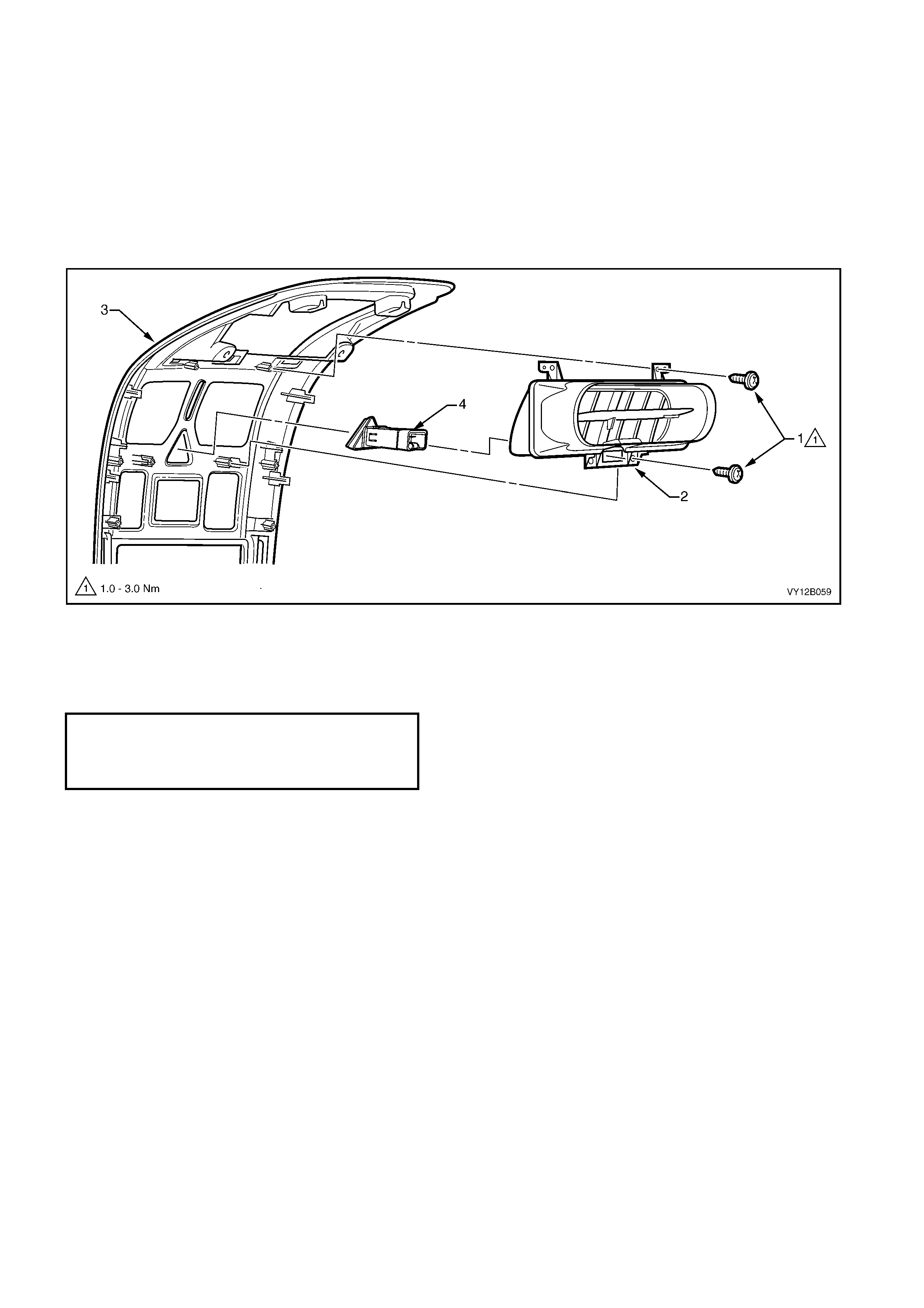
3.25 HAZARD WARNING SWITCH ASSEMBLY
LT Section – 02-800
REMOVE
1. Remove the fusible link F102, refer to Figure 12B-118, item 6.
2. Remove the ins trum ent panel centr e trim ass em bly, refer to Section 1A3, 3.7 INSTRUM ENT PANEL CENTRE
TRIM ASSEMBLY.
3. Remove the f our screws (1) attaching the instrum ent panel centre air outlet housing assem bly (2) to the centre
trim (3) and remove the housing assembly.
4. Depress the two tabs securing the hazard warning switch (4) to the air outlet housing and remove the switch.
Figure 12B-113
REINSTALL
Installation of the hazard warning switch assembly is the reverse of the removal process noting the following points:
1. Tighten the instrument panel centre air outlet housing assembly attaching screws to the specified torque.
INSTRUMENT PANEL CENTRE
AIR OUTLET HOUSING ASSEMBLY
ATTACHING SCREW
TORQUE SPECIFICATION 1.0 – 3.0 Nm
2. Check the operation of the hazard warning switch assembly.
TESTING
To test the hazard warning switch assembly, an ohmmeter is used to check the continuity or resistance when the
functions of the switch are actuated.
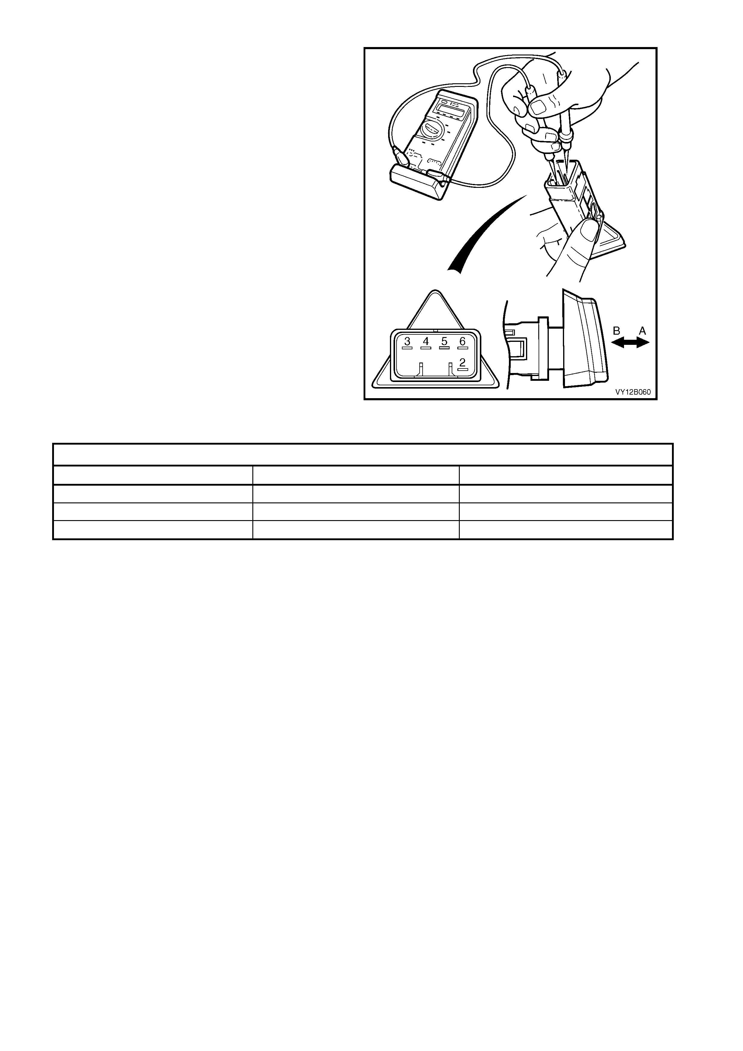
NOTE: Refer to Figure 12B-114 in c onjunction with
the chart in this Section for the switch positions.
1. Perform the removal procedure for the hazard
warning switch assembly as detailed in this
Section.
2. Place the switch in the positions as detailed in
the chart following. Position the contacts of the
ohmmeter onto the terminals and take the
reading. Compare the reading with the chart.
3. If there is continuity between any other
terminals other than those listed, the switch
assem bly is faulty. If the switch fails any par t of
the test, replace the switch assembly with a
serviceable item.
4. Perform the reinstall procedure in this Section.
Figure 12B-114
HAZARD WARNING SWITCH ASSEMBLY
SWITCH POSITION SWITCH TERMINALS INDICATION IF SWITCH IS SERVICEABLE
Switch in the OFF position; position A 3 and 4 Continuity
Switch in t he ON position; position B 3 and 5 Continuity
Switch in eit her position, ON or OFF 2 and 6 Approximatel y 30 Ω
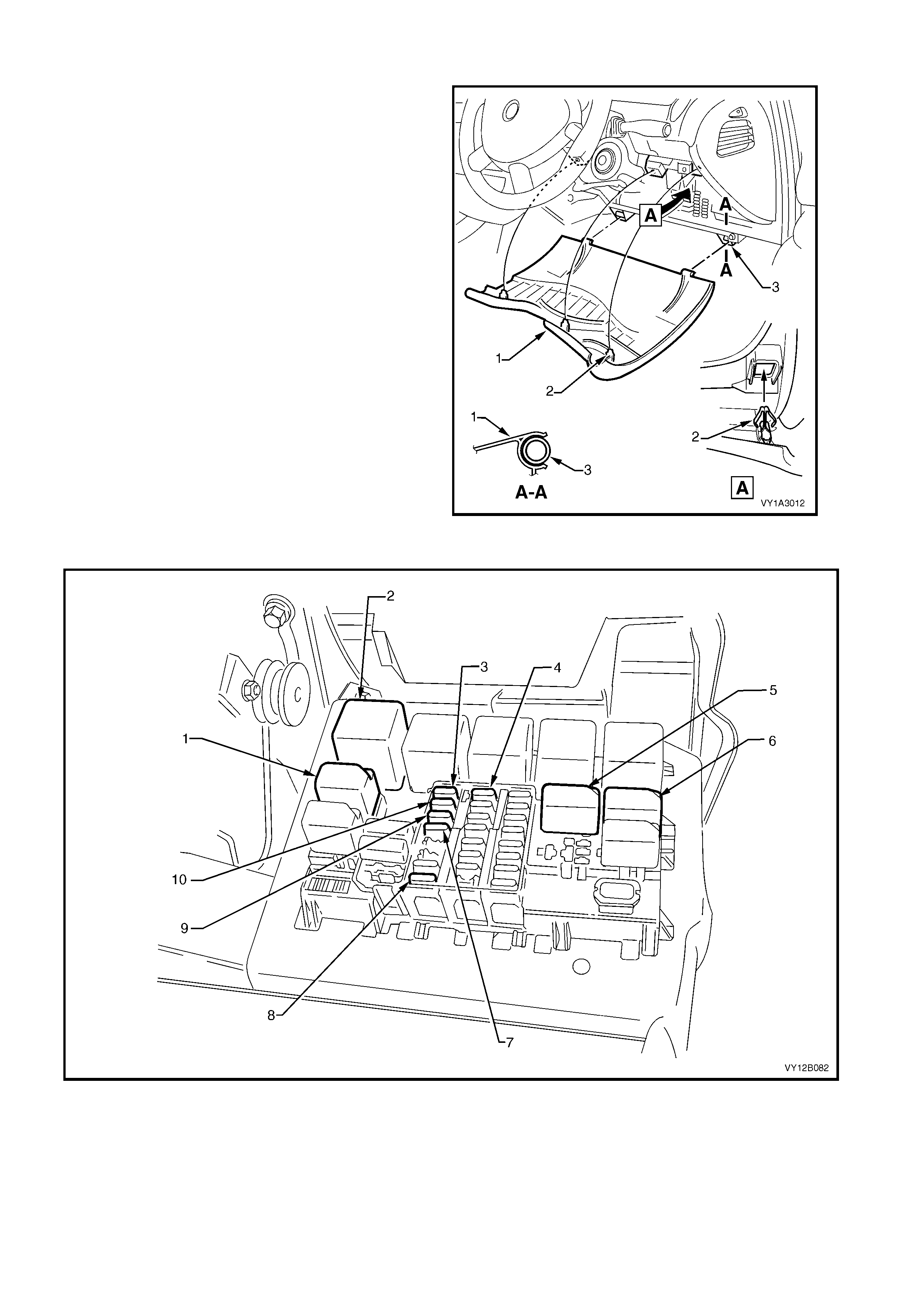
3.26 PASSENGER COMPARTMENT FUSE AND RELAY ASSEMBLY
The passenger compartment fuse and relay
assembly is located behind the instrument panel
lower trim panel assembly.
ACCESS
1. To gain access to the passenger compartment
fuse and relay assembly, grasp the upper edge
of the instrument panel lower trim panel
assem bly (1) and disengage the three clips (2).
Swing the panel assembly open.
2. Once work is completed, check the operation
of the system that has been worked on.
3. Close the panel assembly, ensuring that the
three clips engage.
Figure 12B-115
Figure 12B-116
Legend
1. Park Lamp Relay Assembly
2. Turn Signal Lamp Flasher
Assembly
3. Park Lamp Fuse
4. Turn Signal Lamp Fuse
5. Hazard Warning Lamp Relay Assembly
6. Interior Lamp Relay Assembly
7. Hazard Warning Lamp Fuse
8. Instrument Illumination Fuse
9. Interior Lamp Fuse
10. Stop Lamp Fuse

COMPONENT LOCATION
Refer to Figure 12B-116 for the location of the components in this Section. For further information on the
components and serviceability of the items covered in this Section, refer to Section 12O.
Park Lamp Relay Assembly
Pull the park lamp relay assembly (1) from the passenger compartment fuse and relay assembly. W hen required,
replace the relay assembly with a serviceable item.
Turn Signal Lamp Flasher Assembly
Pull the turn signal lamp flasher assembly (2) from the passenger compartment fuse and relay assembly. When
required, replace the flasher assembly with a serviceable item.
Park La mp Fuse
Pull the park lamp fuse (3) from the passenger compartment fuse and relay assembly. Visually check the fuse for
serviceability. When required, replace with a 10 A fuse.
Turn Signal Lamp Fuse
Pull the turn signal lamp fuse (4) from the passenger compartment fuse and relay assembly. Visually check the fuse
for serviceability. When required, replace with a 15 A fuse.
Hazard Warning Lamp Relay Assembly
Pull the hazard warning lam p relay assem bly (5) from the pass enger com partm ent fuse and relay assem bly. W hen
required, replace the relay assembly with a serviceable item.
Interior Lamp Relay Assembly
Pull the interior lam p r elay assem bly (6) fr om the pass enger compar tment fu se and r elay assem bly. When r equir ed,
replace the relay assembly with a serviceable item.
Hazard Warning Lamp Fuse
Pull the hazard warning lamp fuse (7) from the passenger compartment fuse and relay assembly. Visually check the
fuse for serviceability. When required, replace with a 15 A fuse.
Instrument Illumination Fuse
Pull the instrument illumination fuse (8) from the passenger compartment fuse and relay assembly. Visually check
the fuse for serviceability. When required, replace with a 7.5 A fuse.
Interior La mp Fuse
Pull the interior lam p fuse (9 ) f r om the pass enger compar tment fus e and r elay assem bly. Visually check the fuse for
serviceability. When required, replace with a 10 A fuse.
Stop Lamp Fuse
Pull the stop lam p fuse (10) f rom the pas senger com partment f use and relay assem bly. Visually check the fuse for
serviceability. When required, replace with a 10 A fuse.
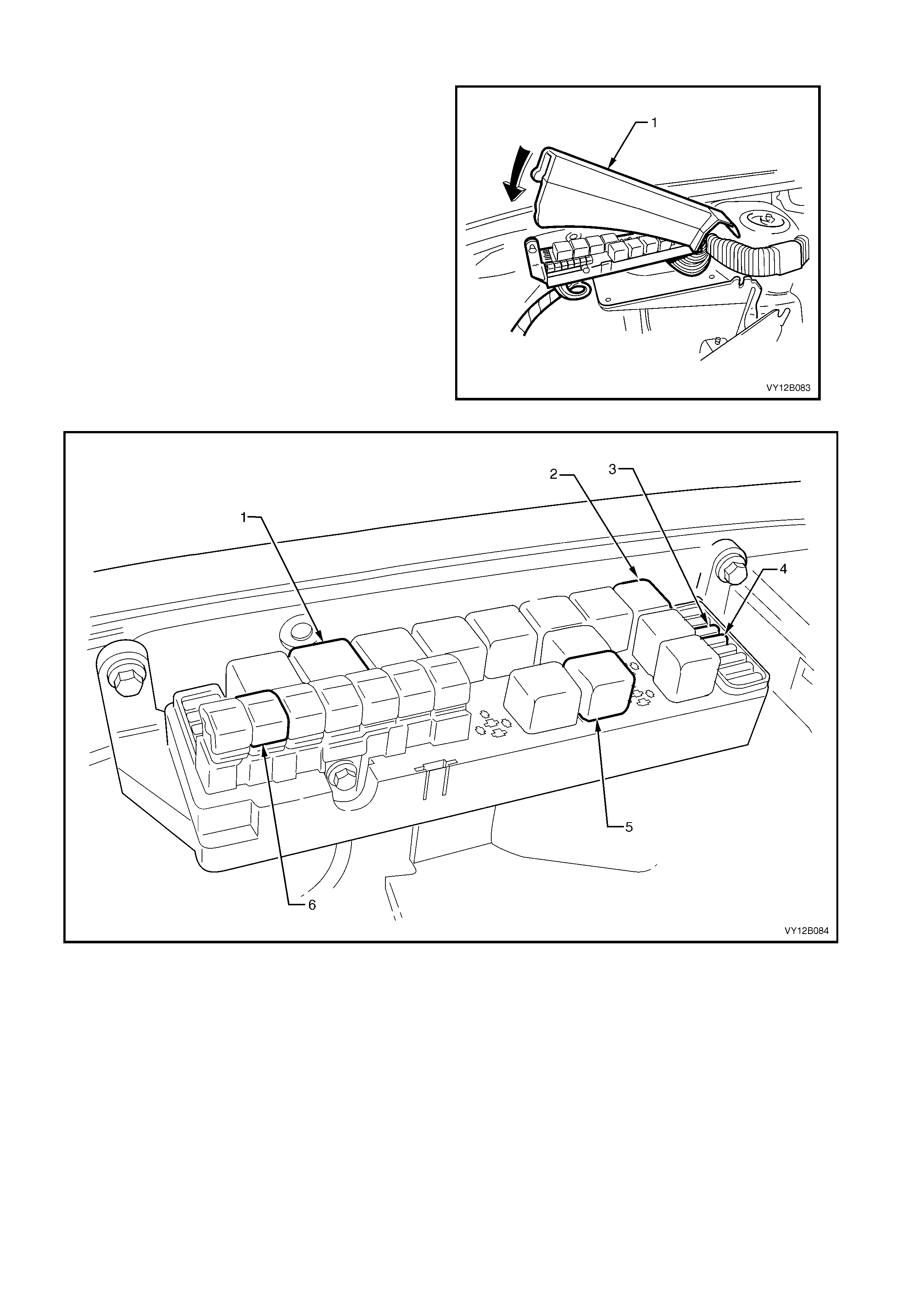
3.27 ENGINE COMPARTMENT FUSE AND RELAY PANEL ASSEMBLY
ACCESS
1. Open the hood.
2. Lift the cover (1) of the engine compartment
fuse and relay panel assembly.
Figure 12B-117
Figure 12B-118
Legend
1. Headlamp High Beam Relay
Assembly
2. Fog Lamp Relay Assembly (if fitted)
3. Right-hand Headlamp Fuse
4. Left-hand Headlamp Fuse 5. Headlamp Low Beam Relay
Assembly
6. Lighting Fusible Link

COMPONENT LOCATION
Refer to Figure 12B-118 for the location of the components described in the following procedures. For further
information on the components and serviceability of the items covered in this Section, refer to Section 12O.
Headlamp High Beam Relay Assembly
Pull the headlamp high beam relay assembly (1) from the engine compartment fuse and relay panel assembly.
When required, replace the relay assembly with a serviceable item.
Fog Lamp Relay Assembly (if fitted)
Pull the fog lam p relay as sembly (2) fr om the engine com partment f use and relay panel assembly. W hen required,
replace the relay assembly with a serviceable item.
Right-hand Headlamp Fuse
Pull the r ight-hand headlamp f use (3) from the engine com partment f use and relay panel assem bly. Vis ually check
the fuse for serviceability. When required, replace with a 20 A fuse.
Left-hand Headlamp Fuse
Pull the left-hand headlamp fuse (4) from the engine compartment fuse and relay panel assembly. Visually check
the fuse for serviceability. When required, replace with a 20 A fuse.
Headlamp Low Beam Relay Assembly
Pull the headlamp low beam relay assembly (5) from the engine compartment fuse and relay panel assembly.
When required, replace the relay assembly with a serviceable item.
Lighting Fusible Link
Visually inspect the lighting fusible link (6) for serviceability. When required, replace with a 60 A fusible link.

4. SPECIFICATIONS
BULB POWER RATING —
WA TTS TYPE
HEADLAMPS Level 1
Hi/Lo Beam (Outboard)
Inboard High Beam
60/55
55
H4
H1
HEADLAMPS Level 2 and 3, Coupe
Lo Beam (Outboard)
Inboard High Beam
55
65
H11
H9
TAIL LAMPS
Stop/Tail 21/5 P21/5W
TAIL LAMPS
Backup 21 P21W
FOG LAMPS 55 H3
PARKI NG LA MPS (Front) 5 Wedge
TURN SIGNAL LA MPS (Front) 21 Offset Pin (Orange gl ass)
SIDE REPEATER LAMPS
Sedan, Wagon and Ut ilit y
Coupe
5
5
Clear Wedge
Orange Wedge
TURN SIGNAL LAMPS
(Sedan — Rear) 21 Of f set Pin (Orange gl ass)
TURN SIGNAL LAMPS
(Wagon — Rear) 21 Offset Pin (Orange glas s)
TURN SIGNAL LAMPS
(Coupe — Rear) 21 Offset Pin (Si l ver Vi sion)
TURN SIGNAL LAMPS
(Utility — Rear) 21 Offset Pin (Orange glas s)
LICENCE P L A T E LAMPS – all models 5 Wedge
HAZARD WA RNING LAMP SWITCH 1 Bayonet
LHD FUEL FILLER DOOR LOCK
RELEASE 1 Bayonet
POWE R S WITCH 1 Bayonet
TRACTION CONTROL SWITCH 1 Bayonet
POLICE LIGHTS SWITCH 1 Bayonet
LPG SWITCH 1 Bayonet
REAR COMPARTMENT LAMP 10 Fes t oon
DOME (Courtesy) LAMP 10 Fes toon
FRONT SEAT READING LAMP
In Dome 8 Festoon
ROOF CONSOLE LAMPS 10 Bayonet
REAR SE A T READING LAMP 6 Festoon (Minixen)
INSTRUMENT PANEL
COMPARTMENT LAMP 5 Festoon
FRONT STEPWELL LAMPS 2.7 Wedge
FRONT VANITY MIRROR LA MP 1.4 Wedge
DOOR COURTESY LA MPS 5 Festoon
FLOOR CONSOLE COMPART MENT
LAMP 5 Festoon
HIGH MOUNTED STOP LA MP 18 Wedge
HIGH MOUNTED ST OP LAMP — (S
and SS Spoi l er mounted) 5 LED assembly
HIGH MOUNTED ST OP LAMP —
Coupe 5 LED assembly
FRONT AND REAR CIGAR LIGHT ER
LAMPS 1.2 Wedge
IGNITION LOCK LAMP 1.4 Wedge
UNDER-HOOD LAMP 10 Festoon

5. TORQUE WRENCH SPECIFICATIONS
Front fog lamp assembly clamp ring securing screw............1.0 – 1.5 Nm
Tail lamp assembly attaching nut..........................................1.0 – 1.5 Nm
Tail lamp assembly attaching screw.....................................1.0 – 3.0 Nm
Rear inner side panel cover screw........................................1.0 – 3.0 Nm
Headlamp assembly retaining screw....................................2.0 – 5.0 Nm
Front fog lamp assembly lens and reflector housing
hinge nut ...............................................................................1.0 – 1.5 Nm
Front fog lamp assembly attaching nut.................................2.0 – 2.5 Nm
Tail lamp assembly attaching screw.....................................1.0 – 3.0 Nm
High mount stop lamp assembly attaching screws...............1.0 – 3.0 Nm
Rear window moulding attaching stud ..................................0.5 – 1.5 Nm
Rear compartment courtesy lamp switch assembly
attaching screw.....................................................................1.0 – 3.0 Nm
Dome lamp assembly attaching screw .................................1.0 – 3.0 Nm
Instrument panel lower extension side trim panel
attaching screw.....................................................................1.0 – 3.0 Nm
Steering column cover trim screw.........................................0.5 – 2.0 Nm
Floor console cover assembly attaching screw ....................1.0 – 3.0 Nm
Instrument panel cluster trim plate screw.............................1.0 – 3.0 Nm
Instrument panel centre air outlet housing assembly
attaching screw.....................................................................1.0 – 3.0 Nm
Door jamb switch attaching screw........................................1.0 – 3.0 Nm
Day light running lamps module attaching screw..................1.0 – 2.0 Nm