
SECTION 12C - INSTRUMENTS
IMPORTANT
Before performing any Service Operation or other procedure described in this Section, refer to Section
00 CAUTIONS AND NOTES for correct workshop practices with regard to safety and/or property damage.
CONTENTS
1. GENERAL INFORMATION
1.1 GENERAL DESCRIPTION
1.2 INSTRUMENT FACIA SWITCHES
1.3 INSTRUMENT ILLUMINATION
1.4 TRIP COMPUTOR – SINGLE
WINDOW CLUSTER
OPERATION
ODOMETER/ TRIP METER
DISTANCE TO GO
DISTANCE TO EMPTY
AVERAGE SPEED/ FUEL
OVERSPEED FUNCTION
OVERSPEED
PRESET OVERSPEED
POLICE MODE
STOP WATCH
1.5 TRIP COMPUTOR – TRIPPLE
WINDOW CLUSTER
OPERATION
AVERAGE SPEED/ ODOMETER/
AVERAGE FUEL
TRIP TIME/ TRIP DISTANCE/ FUEL USED
TIME TO ARRIVAL/ DISTANCE TO ARRIVAL/
REMAINING FUEL
TRIP TIME A/B/ TRIP DISTANCE A/B/
FUEL USED A/B
OVERSPEED/ DISTANCE TO EMPTY/
INSTANTANEOUS FUEL
POLICE MODE
STOP WATCH
1.6 INSTRUMENT OPERATION – ALL MODELS
IGNITION ON – WELCOME SEQUENCE
IGNITION OFF
ALARMS
1.7 MULTI-FUNCTION DISPLAY – ALL MODELS
CONSTANT ICONS
ANIMATED WARNINGS
SERVICE ITEMS
1.8 CUSTOMISATION MODE
ENTERING CUSTOMISATION MODE
(OPTIONS MENU)
1.9 POLICE MODE
DIGITAL SPEEDO
TRAP SPEED
TRAP SPEED RESET
1.10 HOLDEN SPECIAL VEHICLES
TACHOMETER LIGHT
300 KW ENGINE IDLE SPEED
HSV MODEL NAMES AND BUILD NUMBERS
2. SERVICE OPERATIONS
2.1 INSTRUMENT CLUSTER TRIM ASSEMBLY
REMOVE
REINSTALL
2.2 IN_CAR AIR TEMPERATURE SENSOR
REMOVE
REINSTALL
2.3 INSTRUMENT CLUSTER ASSEMBLY
REMOVE
REINSTALL
CLUSTER PROGRAMMING
DISASSEMBLE
REASSEMBLE
2.4 INSTRUMENT CLUSTER INPUTS
CHECK
2.5 SENDER UNITS
VEHICLE SPEED SENDER
FUEL GAUGE SENDER UNIT
2.6 TRIP COMPUTER SWITCH ASSEMBLY
REMOVE
TESTING SWITCH
REINSTALL
3. DIAGNOSTICS
3.1 BASIC KNOWLEDGE REQUIRED
3.2 PRELIMINARY SYSTEM DIAGNOSIS
3.3 INSTRUMENT CLUSTER DIAGNOSTICS
DIAGNOSTIC TROUBLE CODES
DIAGNOSTIC MODE OPERATION
USE OF TECH 2 DIAGNOSTIC TOOL
WITH INTERMITTENT FAULTS
3.4 DIAGNOSING FAULTS NOT COVERED BY
DIAGNOSTIC TROUBLE CODES
DIAGNOSIS FOR HARD-WIRED
INPUT SIGNALS
DIAGNOSIS FOR INTERNALLY
GENERATED SIGNALS
DIAGNOSIS FOR SERIAL DATA
INPUT SIGNALS
FRONT FOG LAMP ON
TURN SIGNAL INDICATOR LAMPS
HIGH BEAM INDICATOR LAMP
SECURITY STATUS INDICATOR
ABS OFF WARNING INDICATOR
CRUISE CONTROL DISPLAY
LOW TRACTION CONTROL DISPLAY
GENERATOR WARNING
TRIP COMPUTER SWITCH
INSTRUMENT ILLUMINATION
BRAKE FAIL / PARK BRAKE WARNING
SPEEDOMETER DIAGNOSIS
TACHOMETER DIAGNOSIS
COOLANT TEMPERATURE GAUGE
DIAGNOSIS
FUEL LEVEL GAUGE DIAGNOSIS
3.5 SERIAL DATA COMMUNICATION
GENERAL INFORMATION
3.6 CONNECTING TECH 2 FOR SYSTEM
DIAGNOSIS
3.7 TECH 2 TEST MODES AND DISPLAYS
FOR INSTRUMENT DIAGNOSIS
MAIN MENU
SYSTEM SELECTION MENU
SYSTEM IDENTIFICATION SCREEN
BODY MENU
Techline
Techline
Techline
Techline
Techline
Techline
Techline
Techline
Techline
Techline

3.8 INSTRUMENT DIAGNOSTIC PROCEDURES
INTRODUCTION
DIAGNOSTIC CIRCUIT CHECK
DTC 1 — PETROL LEVEL SENDER
SIGNAL VOLTAGE TOO LOW
DTC 2 — PETROL LEVEL SENDER
SIGNAL VOLTAGE INTERMITTENT
DTC 3 — PETROL LEVEL SENDER
SIGNAL VOLTAGE TOO HIGH
DTC 4 — LPG LEVEL SENDER
SIGNAL VOLTAGE TOO HIGH
DTC 5 — LPG LEVEL SENDER
SIGNAL VOLTAGE TOO LOW
DTC 6 — LPG LEVEL SENDER
SIGNAL VOLTAGE INTERMITTENT
DTC 8 — NO SERIAL DATA FROM ABS/TCS
DTC 9 — NO SERIAL DATA FROM BCM
DTC 10 — NO SERIAL DATA FROM OCC
DTC 11 — NO SERIAL DATA FROM PCM
DTC 12 — NO SERIAL DATA FROM SDM
DTC 13 — NO INSTRUMENT POLL FROM BCM
DTC 14 — NO SERIAL DATA
DTC 15 — NO SERIAL DATA FROM
AUDIO SYSTEM
DTC 16 — PETROL LEVEL SENDER STUCK
DTC 17 — LPG LEVEL SENDER STUCK
DTC 19 — INCORRECT SDM DETECTED
DTC 21 — TRIP SWITCH SHORT CIRCUIT
DTC 22 — TRIP SWITCH BUTTON STUCK
DTC 24 — EE CHECKSUM = FAILURE
3.9 USING TECH 2 TO DIAGNOSE THE
INSTRUMENT CLUSTER
SYSTEM SELECTION MENU
INSTRUMENT CLUSTER SELECTION
INSTRUMENT CLUSTER IDENTIFICATION
BODY MENU
3.10 NORMAL MODE
3.11 DIAGNOSTIC TROUBLE CODES
DIAGNOSTIC TROUBLE CODES MENU
READ DTC INFORMATION
3.12 DATA DISPLAY
F0: INSTRUMENT
F1: TRIP COMPUTER SWITCH
F2: CONFIGURATION
F3: SYSTEM IDENTIFICATION
3.13 SNAPSHOT
3.14 MISCELLANEOUS TESTS
WARNINGS
STATUS INDICATORS
CHIME
PRNDL
TRIP COMPUTER BUTTONS
GAUGE CONTROL TESTS
INPUT OVERRIDES
ILLUMINATION
SELF TEST
MFD TESTS
LCD TESTS
3.15 PROGRAM
F0: FUEL GAUGE CALIBRATION
F1: CONFIGURATION
F2: ODOMETER
F3: SPEEDOMETER CALIBRATION
F4: RESET SERVICE INTERVAL
F5: RESET TRIP COMPUTER SETTINGS
F6: RESET TO VEHICLE BUILD
SETTINGS
4. TORQUE WRENCH SETTINGS
5. SPECIAL TOOLS
1. GENERAL INFORMATION
This section provides a description of the instrument clusters fitted to the MY 2003 VY and V2 Series vehicles.
1.1 GENERAL DESCRIPTION
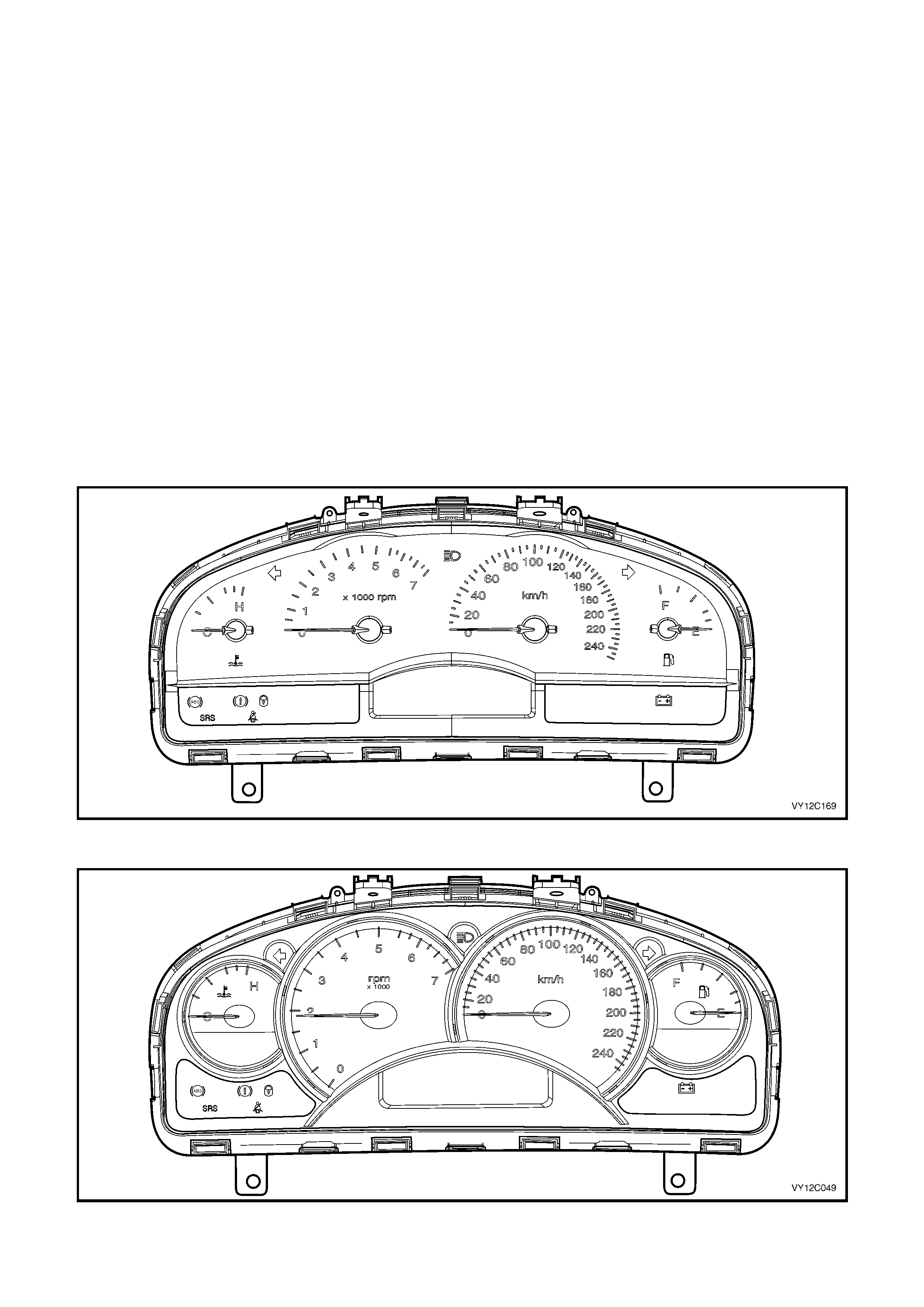
Two versions of instrument cluster assemblies are used on VY Series Models, one with a single window
Multi-function Display (MFD) and the other with a triple window display, the centre window being the MFD. A trip
computer is standard equipment on all VY Series Models. Refer to 1.4 TRIP COMPUTER — SINGLE WINDOW
TYPE or 1.5 TRIP COMPUTER — TRIPLE WINDOW TYPE in this Section for an explanation of trip computer
functions.
The instrum ent cluster assem bly on VY Series Models consists of specific style analogue type instrument gauges.
An electr onic s peedometer is situated to the r ight of centr e, with the odom eter and tr ip/odometer r eadings s tor ed on
the trip computer and displayed on the MFD. A tachometer is located to the left of centre, a tem perature gauge to
the left of the tachometer and a fuel gauge to the right of the speedometer. The speedometer indicates up to
250 km/h on all models except the SS, which indicates up to 260 km/h.
Instrument cluster illumination is by Light Emitting Diodes (LEDs) within the instrument cluster. The LEDs are not
serviceable.
A switch assembly located in the instrument facia operates the trip computer on both instrument cluster assemblies.
NOTE: If installing a new instrument cluster, the original odometer reading, together with other important
parameters, must be transferred into the replacement instrument cluster. This can be done by an authorised Holden
Retailer using TECH 2.
Figure 12C-1 illustrates the instrument cluster fitted to Level 1 vehicles.
Figure 12C-1
Figure 12C-2 illustrates the instrument cluster fitted to Level 2 vehicles.
Figure 12C-2
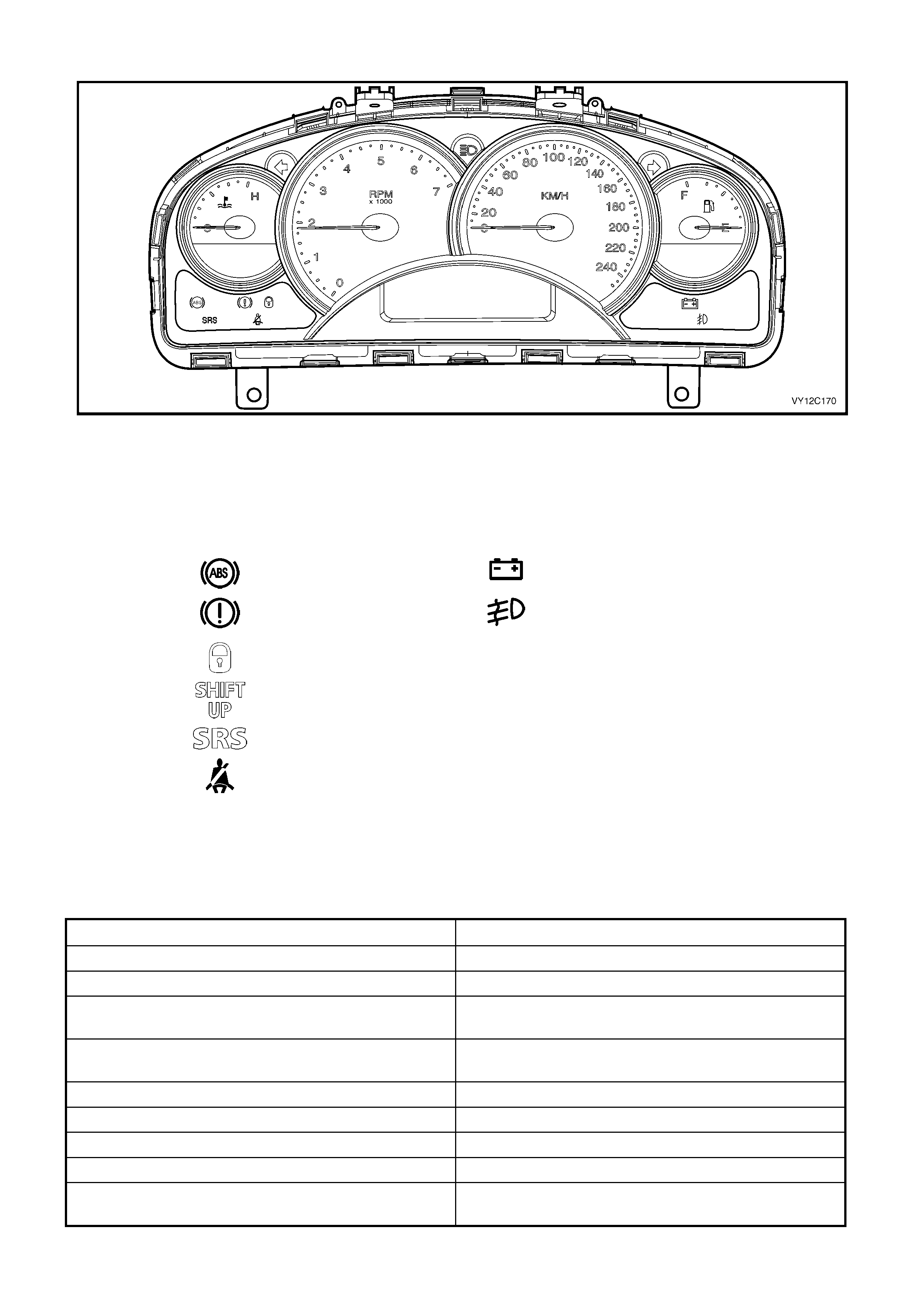
Figure 12C-3 illustrates the instrument cluster fitted to Level 3 vehicles.
Figure 12C-3
The following warning telltales are located beneath the temperature gauge on the left-hand side of the instrument
cluster and beneath the f uel gauge on the r ight-hand side of the instrum ent cluster. T he telltales are illum inated by
LEDs.
LEFT-HAND SIDE RIGHT-HAND SIDE
ABS Off (Amber) Generator Fail (Red)
Brake (Red) – (Park
Brake On or Brake Fail) Front Fog Lamps On
(Green)
Security System On (Red)
Shift Up (Red) – (HSV
only )
SRS Fault (Red)
Seat Belt (Red)
An audible warning chime is incorporated in the instrument cluster. T his feature is used to em phasise the warning
conditions in the following table, with the tone and repetition rate of the chime varied to allow different warnings to
be identified by sound.
In addition to the warning conditions displayed on the MFD, the audible warning chime will sound when buttons on
the trip computer switch assembly are pressed or certain functions are entered.
DESCRIPTION SEQUENCE OF TONES
Overspeed C, F
Underspeed F, C
Low Fuel (petrol or LPG) B1, B
Repeated five times
Fuel Sender Error (petrol or LPG) B1, B
Repeated five times
Park Brake C, D, E, E, E, E, E
Over Temperature C, D, E, E, E, E, E
Low Oil Pressure C, D, E, E, E, E, E
Low Coolant C, D, E, E, E, E, E
Rear Brake Bulb Failure (monitors the rear brake
lamps and the high-mount brake lamp) C, D, E, E, E, E, E

DESCRIPTION SEQUENCE OF TONES
Rear Lam p Bulb Failure ( m onitors the rear park lam ps
and the licence plate lamps) C, D, E, E, E, E, E
Rear Lamp Fuse Failure (monitors the stop lamps
fuse and the park lamps fuse) C, D, E, E, E, E, E
Check Engine C, D, E, E, E, E, E
Check Alternator (Generator) C, D, E, E, E, E, E
SRS Warning D, E, F
Repeated three times
Trip Computer Switch SET button C1, F1
Trip Computer Switch MODE button C
Trip Computer Switch UP or DOWN buttons F
Entering the Auxiliary Function (not applicable to
Omega) C1, E1
Entering the Customisation Mode C1, E1, F
Using the Reset Function C1, E1, F
Setting a function ON or OFF C1, E1
Shift Up (HSV Only) F
Repeated until warning condition removed
The frequency of each tone is listed in the following table.
TONE FREQUENCY (Hz) TONE FREQUENCY (Hz)
B 494 B1 988
C 523 C1 1047
D 587 — —
E 659 E1 1319
F 698 F1 1397
NOTE: Should it be necessary to electric weld on any vehicle at any time, removal of the instrument cluster is
mandatory. Failure to do so will result in damage to the instrument gauge circuitry.
If the battery is disconnected for any reason, the following accumulative values are reset:
• Trip Time
• Trip Distance
• Fuel Used
• Average Fuel
• Average Speed
• Stop Watch (if enabled and display ing a non-zero figure).
On all VY Series Models the clock is incorporated into the audio system LCD window.

1.2 INSTRUMENT FACIA SWITCHES
Details on the trip com puter switch are pr ovided in this Section. For inform ation on other instrum ent f acia switches,
refer to Section 12B, LIGHTING SYSTEM.
For vehicles with an adjustable height power antenna, the antenna up and down control switches are loc ated in the
radio control panel.

1.3 INSTRUMENT ILLUMINATION
The headlamp switch incorporates a variable intensity instrument cluster illumination control (slider), and a four-
position switch for off, parking, headlamps on and an auto headlamps on switch mode. In auto headlamps on mode,
cluster illumination is dependant upon whether the lights are on or off.
With the headlamp switch in the OFF position, the MFD illumination (or the side LCD on triple-window instrument
cluster) is set to maximum backlighting. In any of the other positions, the MFD illumination (or side LCD) is
controlled by the position of the slider.
The dial, pointer and MFD illumination is controlled by the slider on the headlamp switch. Moving the slider varies an
input voltage to the Body Control Module (BCM), which in turn sends an illumination level signal to the Instrument
Cluster via the serial data communications bus. The Instrument Cluster interprets the illumination level signal and
controls the illumination level accordingly. For further details, refer to Section 12J, BODY CONTROL MODULE.
1.4 TRIP COMPUTE R — S I NGLE WINDOW CLUSTE R
OPERATION
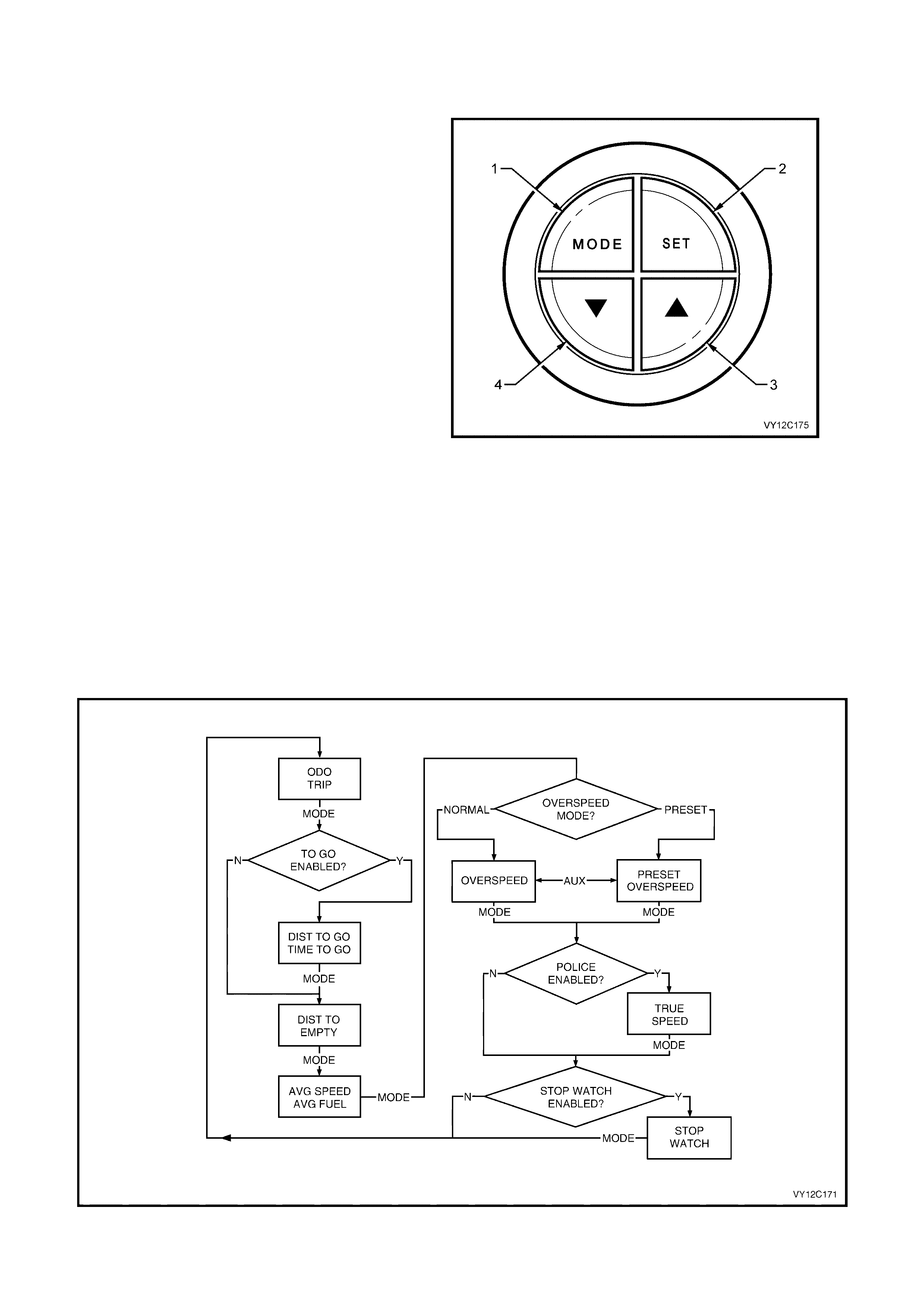
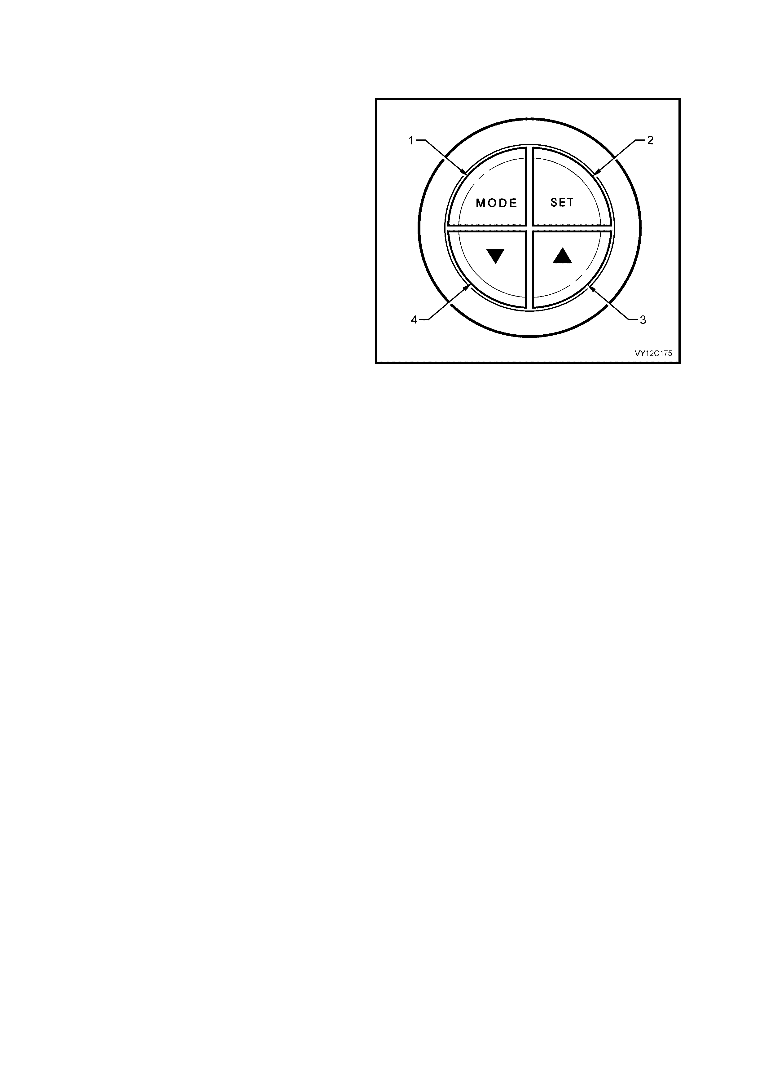
The buttons for the trip com puter are loc ated to the
left of the instrument cluster. The four buttons in
the switch assembly are MODE (1), SET (2), UP
(3) and DOWN (4).
All the trip computer screens are displayed on the
MFD, which is located in the centre of the
instrument cluster below the gauges.
When the ignition is turned on, the MFD initially
displays the start up sequence, then displays the
same trip computer functions as when the ignition
was last turned off.
To res et the trip com puter func tions, pres s the SET
button. This will reset all functions, with the
exception of Distance to Empty, Overspeed
Warning, Odometer, Time to Go and Distance to
Go.
To scroll between the trip computer functions,
press the MODE button for less than 2 seconds.
NOTE: If the wrong buttons have been accidentally
pressed, c aus ing the dis play to show other than the
normal readings, turn the ignition off, then on again.
Personal customisation of the trip computer is also
possible. Refer to 1.8 CUSTOMISATION MODE in
this Section.
Figure 12C-4
The trip c omputer f unctional sequence for the single-window clus ter is shown in Figure 12C-5. Pressing the MODE
button steps through the screens as shown in the flowchart. The Distance to Go function must be enabled in
Customisation Mode before this screen can be accessed using the MODE button.
NOTE: If the instrument cluster is set as a Police cluster, the MFD will always default to True Speed Mode at
ignition on. The digital speedometer is the default display for Police instrument clusters.
Figure 12C-5
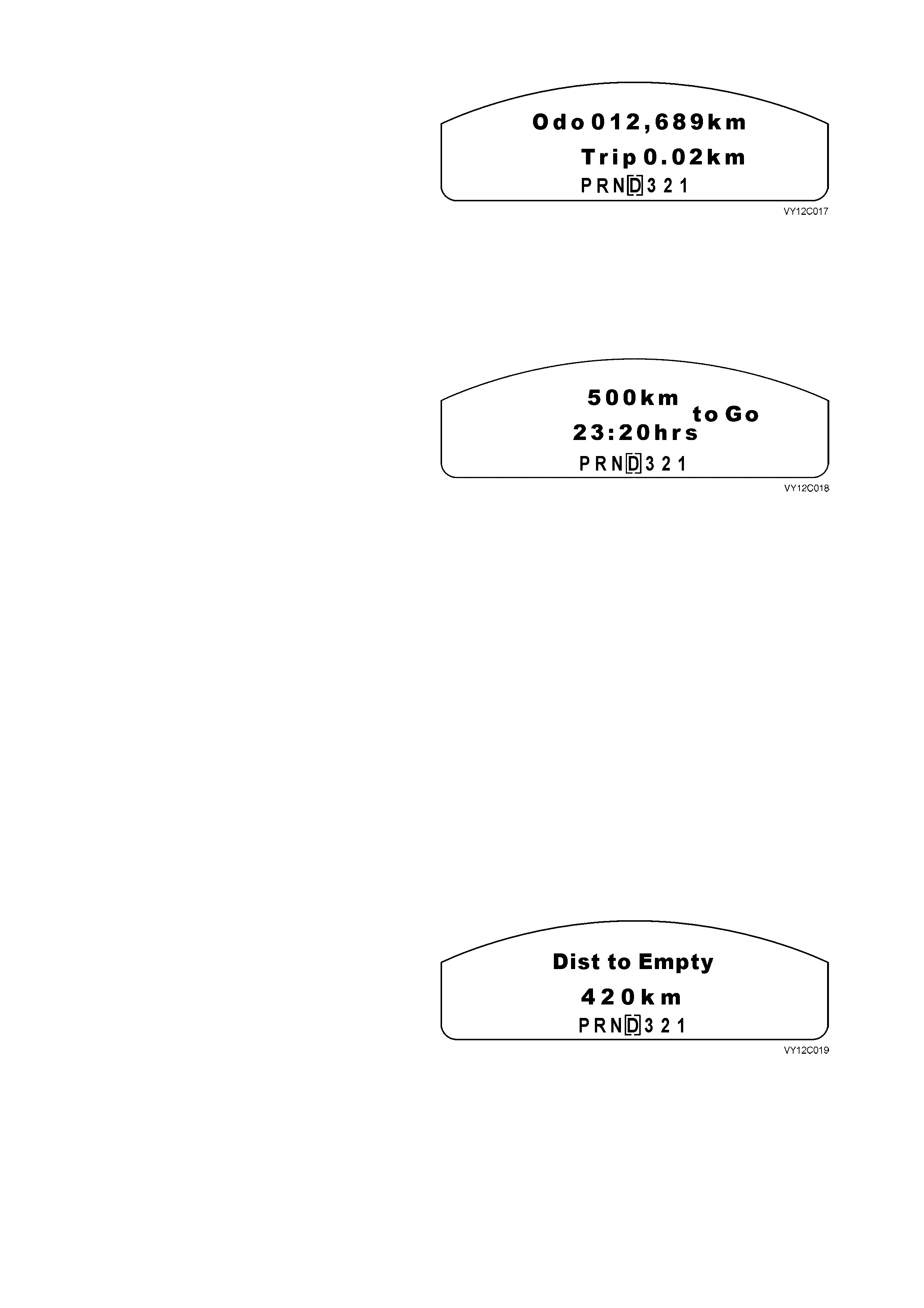
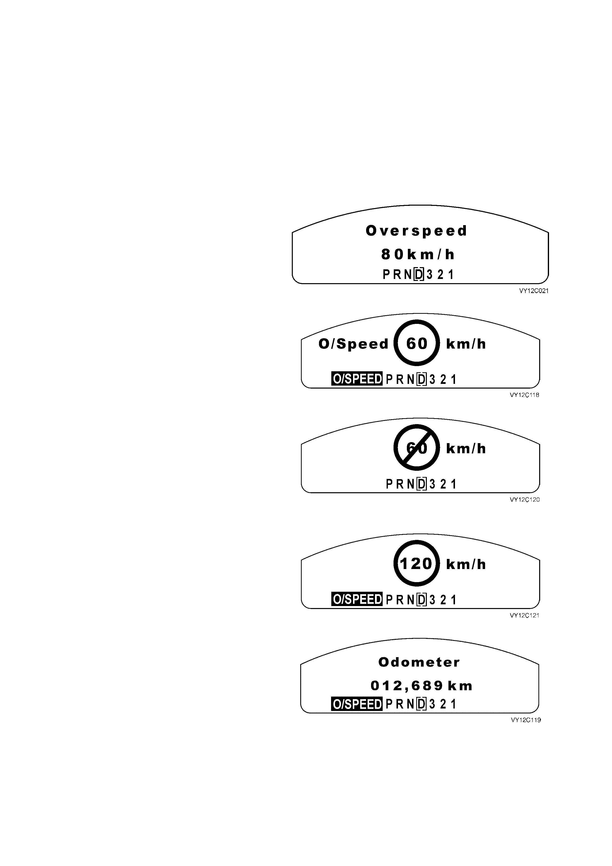
ODOMETER / TRIP METER
The odometer records the kilometres travelled
since the vehicle was built.
The trip meter displays the kilometres travelled
from the start of a particular trip. The trip meter
reading is res et to zero by pressing the SET button
for less than 2 seconds while the Odometer / Trip
Meter screen is displayed.
Press the MODE button to advance to the next
screen. If the Distance to Go function is enabled in
Customisation Mode then the Distance / Time to
Go screen will be the next to be displayed.
Otherwise the next screen will be the Distance to
Empty screen.
Figure 12C-6
DISTANCE / TIME TO GO
This function is enabled in Customisation Mode.
At the start of a trip, an estimate of distance to
arrival should be made. Tap the UP or DOWN
buttons on the trip com puter switch until the display
shows the estimated trip distance.
W hile the vehicle is being driven, the trip computer
constantly updates the Time to Go based on
changing driving speeds. The Time to Go value is
displayed as follows:
• In 1 minute increments if the Time to Go is
less than 10 minutes.
• In 5 minute increments if the Time to Go is
more than 10 minutes, but less than 2 hours.
• In 10 minute increments if the Time to Go is
mor e than 2 hours , but less than 99 hours and
59 minutes.
• In 1 hour inc rements if the T ime to Go is more
than 99 hours and 59 minutes.
The UP and DOW N buttons can be used to adjust
the distance (kilometres) at any time the display is
showing.
To reset the distance to a value set in
Customisation Mode or the default of 500 km,
press the SET button for less than 2 seconds while
the Distance / Time to Go screen is displayed.
Press the MODE button to advanc e to the Distance
to Empty screen.
Figure 12C-7
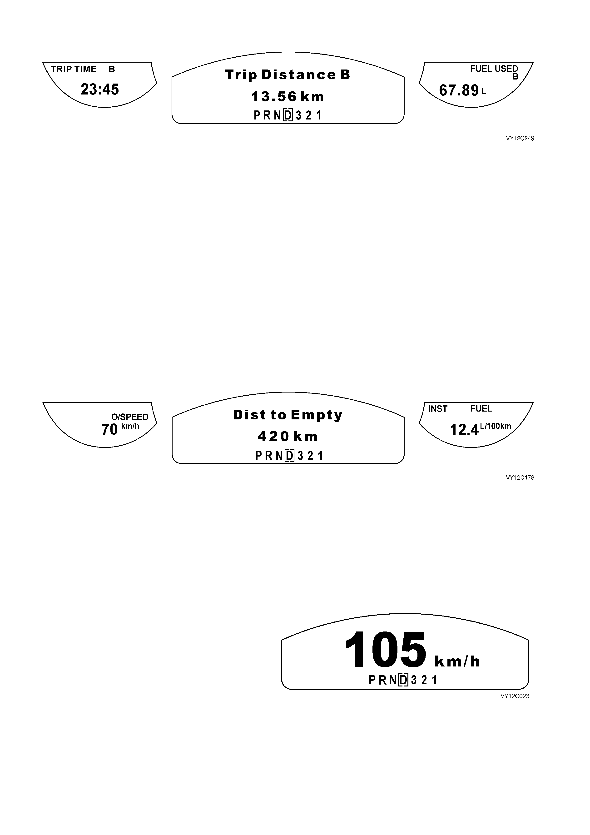
DISTANCE TO EMPTY
Distance to Empty is an estimate of how far the
current fuel will last. It is based on previous fuel
usage and is frequently updated. Therefore, as
conditions become suited to more economical
driving the Distance to Empty may actually
increase, for example when changing from city to
highway driving.
Press the MO DE button to advance to the Average
Speed / Fuel screen.
Figure 12C-8
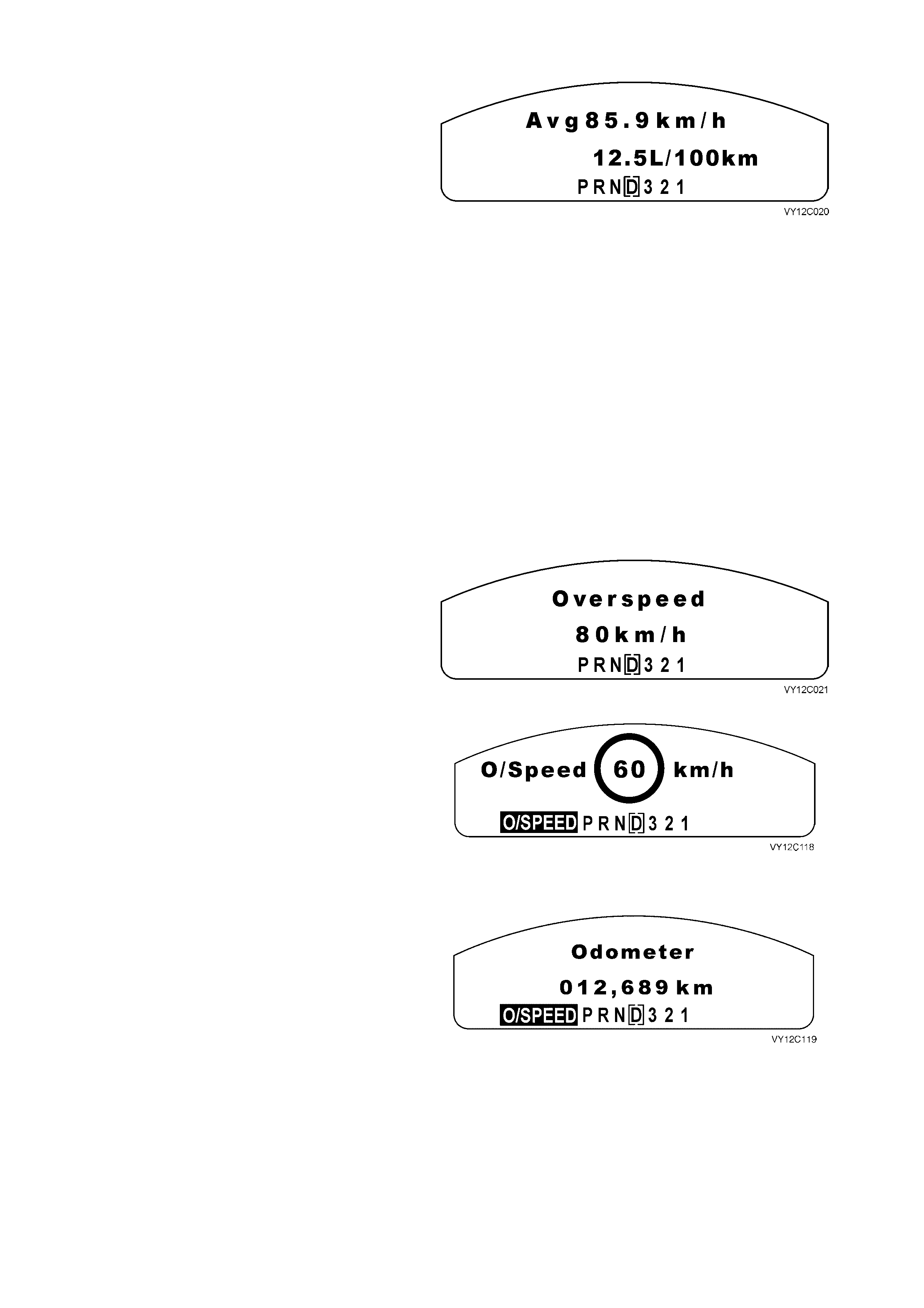
AVERAGE SPEED / FUEL
The Average Speed / Fuel screen shows the
average speed while the engine is running and the
average fuel consumed since the trip computer
was last reset.
To reset the f unction, pr ess the SET button f or less
than 2 seconds while the Average Speed / Fuel
screen is displayed.
After resetting, some large figures may initially be
shown due to the short distance travelled and the
large amount of fuel used when accelerating.
Press the MODE button to advance to the next
screen. The screen displayed will be either the
norm al O verspeed sc reen or the Pr eset Overs peed
screen depending on the previous overspeed
selection.
Figure 12C-9
OVERSPEED FUNCTION
The Overspeed function is provided to alert the
driver that a predetermined speed has been
reached. There are two Overspeed functions — the
factory default setting of normal Overspeed, and
the Preset Overs peed setting. The MFD shows the
overspeed function and its speed value at the last
ignition cycle or priority key setting.
OVERSPEED
Overspeed On / Off
To turn the Overspeed function on, press and hold
the trip computer switch SET button for at least
2 seconds, and the Overspeed screen appears.
To turn the Overspeed function off, press and hold
the SET button for at least 2 seconds while the
Overspeed screen is displayed.
Figure 12C-10
Overspeed Trigger
The Overspeed screen alerts the driver that a
predetermined speed has been reached. If the
overspeed warning is triggered, the overspeed
figure in a circle f lashes for 10 seconds, or until the
speed is dropped if overspeed is maintained for
less than 10 seconds.
If the vehicle speed is more than 15 km/h above
the set over speed value, the dis play, the overspeed
wording and the overspeed value all flash.
Figure 12C-11
If the overspeed is maintained for longer than
10 seconds but it is not more than 15 k m/h over the
set overspeed value, the overspeed warning drops
back to the O/SPEED constant icon. The display
reverts back to the previously displayed trip
computer screen.
If the overspeed is maintained for longer than
10 seconds and is more than 15 km/h over the set
overspeed value, the overspeed warning drops
back to the O/SPEED constant icon and continues
to flash.
Figure 12C-12
Overspeed Adjustment
The overspeed value can be adjusted while the
vehicle is stationary or while the vehicle is being
driven.
To adjust the overspeed value, tap the UP or
DOWN buttons on the trip computer switch until the
screen displays the desired speed. The new
overspeed value is now locked in. The overspeed
value is variable between 20 km/h and 200 km/h,
and increments or decrements by 5 km/h for each
press of the corresponding button.
NOTE: T o scr oll to a speed rapidly, press and hold
the UP or DOWN button.
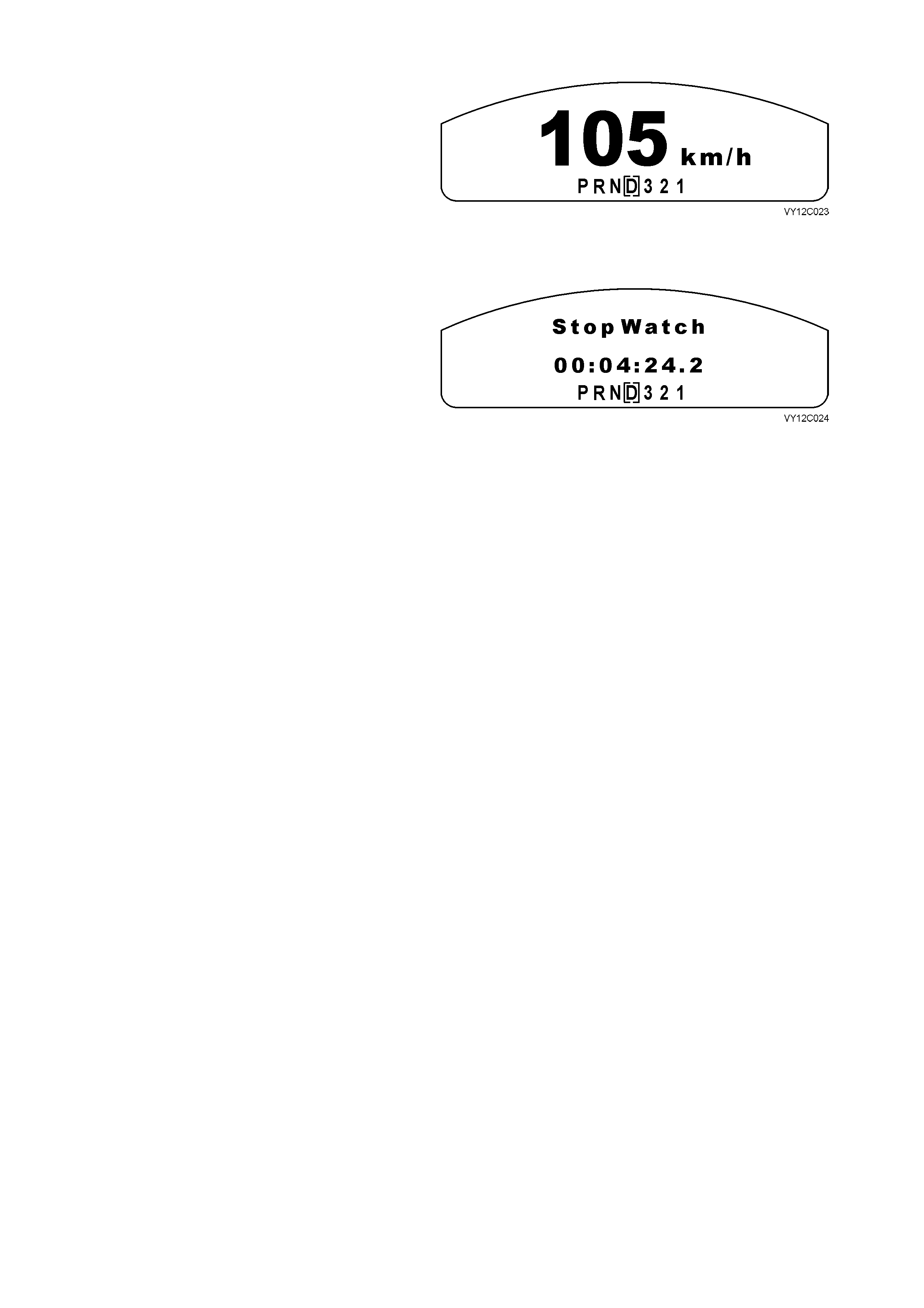
Overspeed Adjustment — Overspeed Warning
Not Displayed
The Overspeed adjustment screen displayed when
the vehicle is stationary is shown as:
Figure 12C-13
Overspeed Adjustment — Overspeed Warning
Displayed
The Overspeed adjustment screen displayed when
the vehicle is moving is shown as:
To set the overspeed value to the speed at which
the vehicle is currently travelling, briefly press the
trip computer switch SET button.
Figure 12C-14
Underspeed
When the vehicle drops below the overspeed
setting, the Underspeed screen is displayed and a
chime sounds if the driver has enabled the
underspeed chime in Custom isation Mode (refer to
1.8 CUSTOMISATION MODE in this Section).
If no underspeed chime has been set, the screen
turns off with no chime or visual underspeed
indication.
Figure 12C-15
Mandatory Overspeed
The Mandatory Overspeed value is set by T ECH 2.
If the vehicle travels above this speed, the
Mandatory Overspeed screen is displayed for
10 seconds, or until the speed is dropped if
overspeed is maintained for less than 10 seconds.
The overspeed value in the circle flashes.
Figure 12C-16
If the overspeed is maintained for more than
10 seconds but not by more than 15 km/h over the
mandatory overspeed value, the overspeed
warning drops back to the constant O /SPEED icon.
The dis play reverts back to the previously displayed
trip computer screen.
If the overspeed is maintained, and is more than
15 km/h over the mandatory overspeed value, the
constant O/SPEED icon flashes.
Figure 12C-17
NOTE: If a mandatory overspeed is set, there is no underspeed chime or display. The underspeed function is
turned off when a mandatory overspeed is set.
Press the MODE button to advance to the next screen:
• If Police Mode is enabled by TECH 2, then the true speed digital speedometer will be displayed, or
• If Police Mode is not enabled and the Stop Watch function is enabled in Customisation Mode, then the Stop
Watch screen will be displayed, or
• If neither the Polic e Mode nor the Stop W atch func tion are enabled, then the next scr een displayed will be the
Odometer / Trip Meter screen.
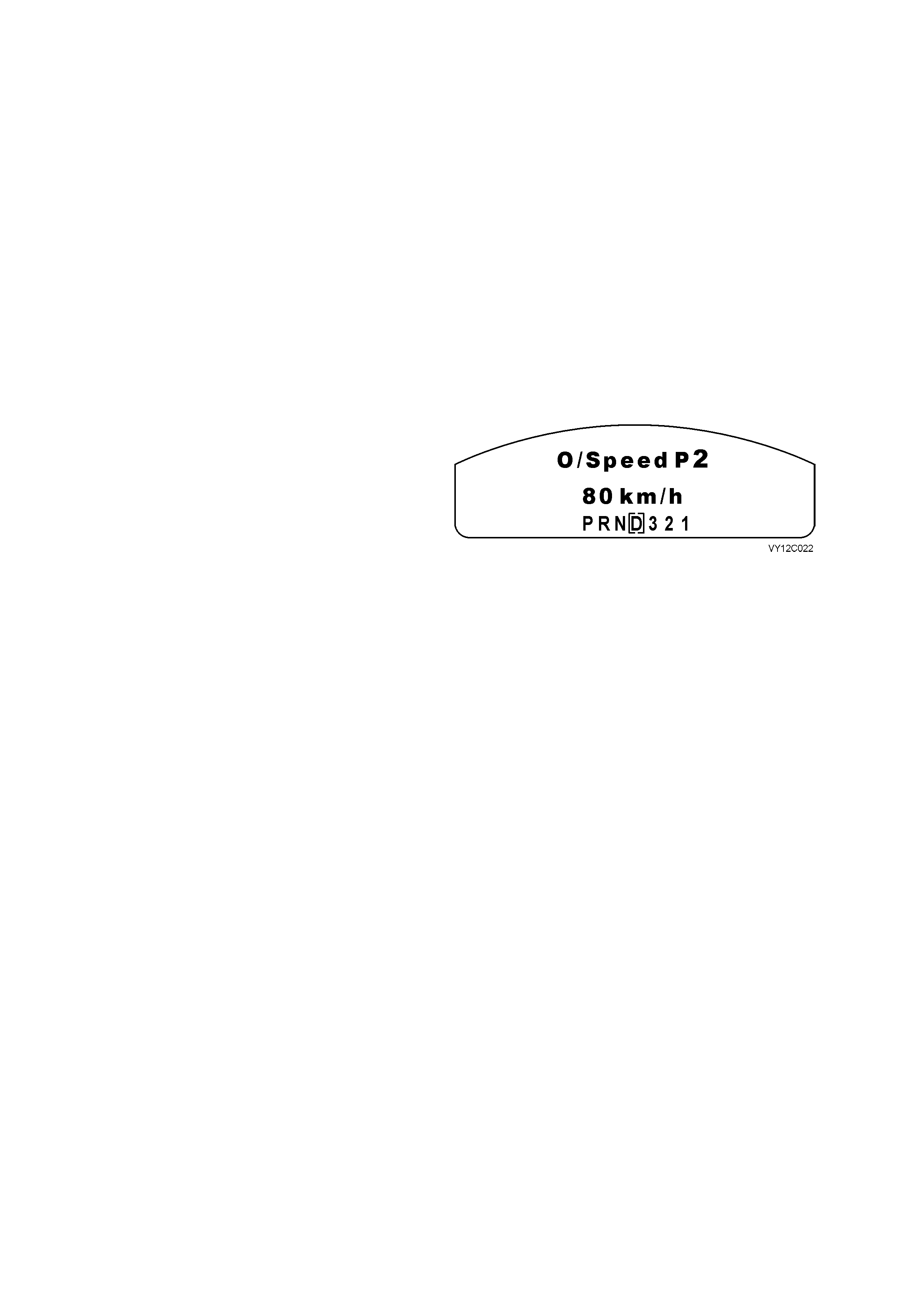
PRESET OVERSPEED
There are four preset overspeed values, which are
60, 80, 100 and 110 km/h. These are called
PRESET 1 to PRESET 4 r espectively. T o enter the
Preset Overs peed func tion, press the trip computer
switch MODE button f or more than 2 seconds while
the Overspeed screen is displayed. PRESET 1
screen will be displayed. Press the trip computer
switch UP or DOW N buttons to move between the
Preset Overspeed screens.
Preset Overspeed Adjustment
NOTE: To change the overspeed presets, the car
must be stationary.
To alter the preset, ensure the speed to be
changed is showing, eg, PRESET 2 80 km/h, then
briefly press the trip computer switch SET button.
When the screen display starts flashing, use the
UP or DOWN button to adjust the setting. When
the preset overspeed value is correct, briefly press
the SET button.
Each preset can be changed in this way and the
presets are automatically arranged in ascending
order.
One or more presets can be assigned to ‘OFF’ by
reducing the reset to 0 (OFF). This reduces the
number of presets available. To reset an ‘OFF’
preset, use the UP button to inc rease the s peed for
this preset when the car is stationary.
Figure 12C-18
Press the MODE button to advance to the next
screen:
• If Police Mode is enabled by TECH 2, then the
true speed digital speedometer will be
displayed, or
• If Police Mode is not enabled and the Stop
Watch function is enabled in Customisation
Mode, then the Stop Watch screen will be
displayed, or
• If neither the Police Mode nor the Stop W atch
function are enabled, then the next screen
displayed will be the Odometer / Trip Meter
screen.
POLICE MODE
The Police Mode is enabled by TECH 2. If the
Police Mode is enabled, the digital speedometer is
the MFD default display at ignition on.
Refer to 1.9 POLICE MODE in this Section.
Press the MODE button to advance to the next
screen. If the Stop Watch function is enabled in
Customisation Mode then this will be the next
screen to be displayed. Otherwise the next screen
will be the Odometer / Trip Meter screen.
Figure 12C-19
STOP WATCH
The Stop Watch screen is activated and
deactivated in Customisation Mode (refer to
1.8 CUSTOMISATION MODE in this Section).
Pressing the SET button on the trip computer
switch starts and stops the stop watch. Pressing
and holding the MODE button for more than
3 seconds resets the stop watch with a confirming
beep.
Press the MODE button to advance to the
Odometer / Trip Meter screen.
Figure 12C-20
1.5 TRIP COMPUTE R — TRIP LE WINDOW CLUSTER
OPERATION
The buttons for the trip com puter are loc ated to the
left of the instrument cluster. The four buttons in
the switch assembly are MODE (1), SET (2), UP
(3) and DOWN (4).
The trip computer screens are displayed on the
MFD, and the two side Liquid Crystal Displays
(LCD). The MFD is located in the centre of the
instrument cluster below the gauges, and the two
side LCDs are located beneath the temperature
gauge on the left, and the fuel gauge on the right.
To scroll between the functions (three sets of
displays), press the MODE button for less than
2 seconds. The speed related details are provided
in the left window, the distance related details are
provided in the MFD, and the fuel related details
are provided in the window on the right.
When the ignition is turned on, the MFD initially
displays the start up sequence, then displays the
same trip computer functions as when the ignition
was last turned of f as long as the same priority key
is used.
The trip computer functions can be reset when the
Average Speed or Trip Time details are displayed
in the left window. To reset the trip computer
functions, press the SET button. This will reset all
functions, with the exception of Distance to Empty,
Overspeed Warning, Odometer, Time to Arrival,
Distance to Arrival, Remaining Fuel and
Instantaneous Fuel.
NOTE: If the wrong buttons have been accidentally
pressed, c aus ing the dis play to show other than the
normal readings, turn the ignition off, then on again.
Personal customisation of the trip computer is also
possible. Refer to 1.8 CUSTOMISATION MODE in
this Section.
Figure 12C-21
The trip computer functional sequence for the
triple-window cluster is shown in Figure 12C-22.
Pressing the MODE button steps through the
screens as shown in the flowchart. There are two
flow paths depending upon the selection of the
Trip A and B function in Customisation Mode:
• If Trip A and B is enabled, the screens in the
right-hand path will be displayed, or
• If Trip A and B is not enabled, the screens in
the left-hand path will be displayed.
The Dis tance to Arr ival function m u st be enabled in
Customisation Mode before the Time to Arrival /
Distance to Arrival / Remaining Fuel screens can
be accessed using the MODE button. These
screens are not available if T rip A and B function is
enabled. However they can be accessed from the
Trip B screens by pressing and holding the MODE
button for more than 2 seconds.
NOTE: If the instrument cluster is set as a Police
cluster, the MFD will always default to True Speed
Mode at ignition on. T he digital speedom eter is the
default display for Police instrument clusters.
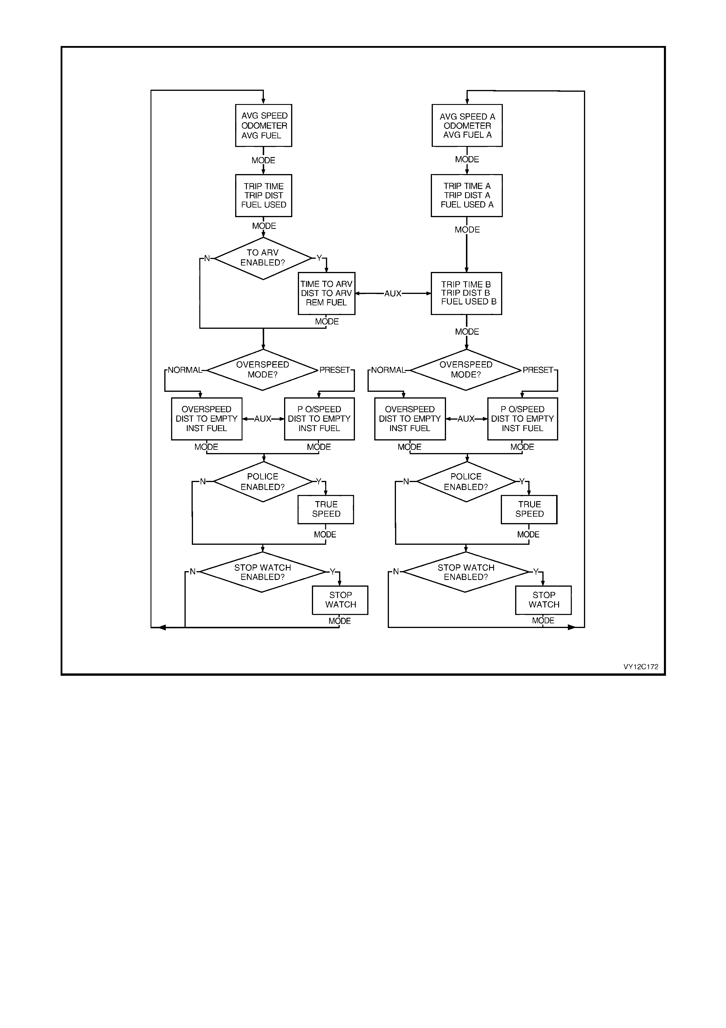
Figure 12C-22
AVERAGE SPEED / ODOMETER / AVERAGE FUEL
To r eset the Aver age Speed and Aver age Fuel dis plays, press the SET button for les s than 2 sec onds while this set
of functions is displayed. Note that this also resets the Trip Time / Trip Distance / Fuel Used set of displays.
However, to reset the Average Speed and Average Fuel functions only, hold the SET button down for 8 seconds
while this set of functions is displayed.
Average Speed
Shows the average speed (while the engine is running) since the trip computer was reset.
Odometer
The odometer records kilometres travelled since the vehicle was built.
Average Fuel
Shows average fuel used since the trip computer was reset. After resetting, some large numbers may initially be
shown, due to the short distance travelled and the high fuel used when accelerating.
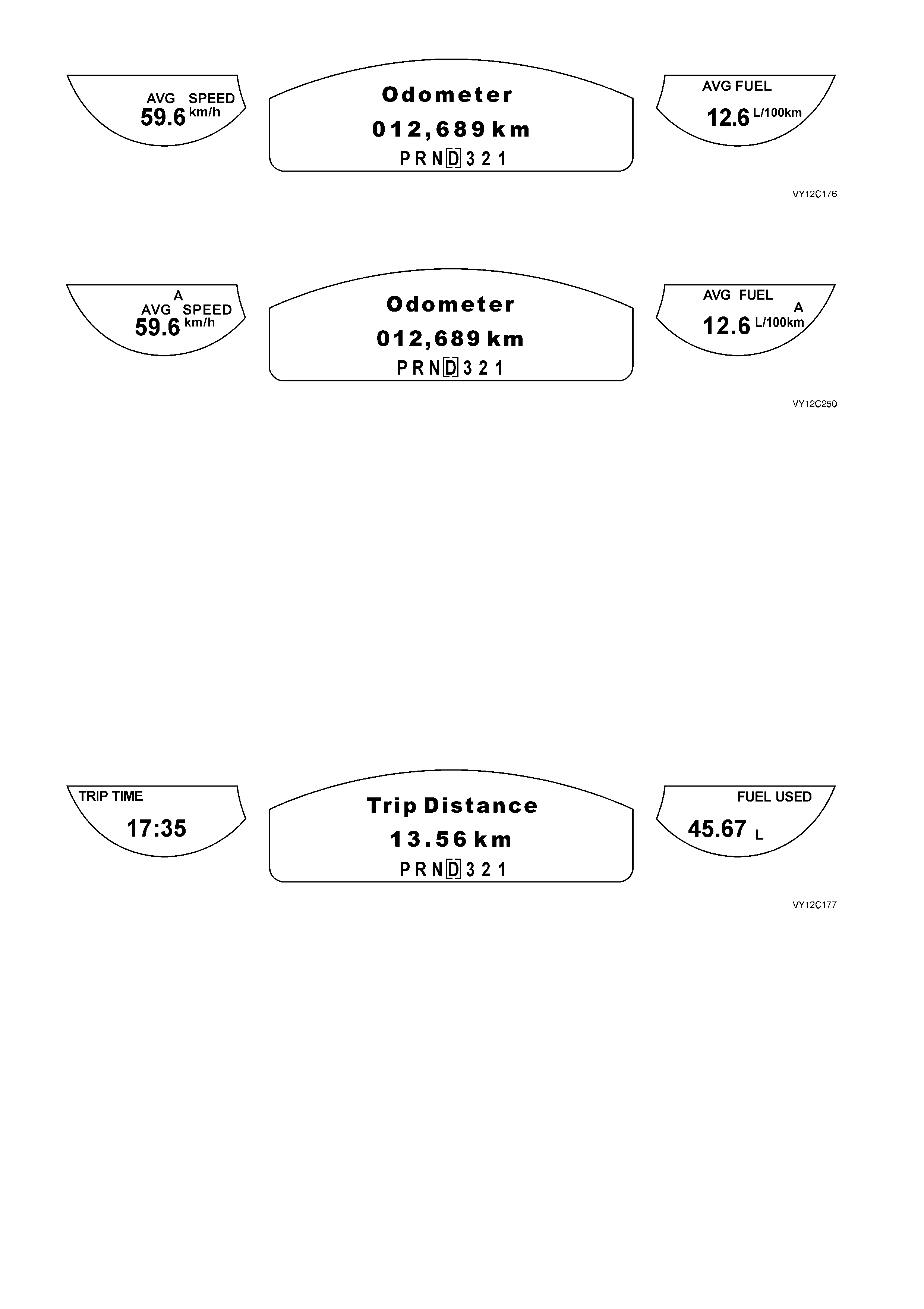
Figure 12C-23
If the Trip A and B function has been selected in Customisation Mode, the Average Speed and Average Fuel
displays indicate Trip A.
Figure 12C-24
Press the trip computer MODE button to advance to the next set of screens:
• If Trip A and B is enabled, the Trip Time A / Trip Distance A / Fuel Used A screens will be displayed, or
• If Trip A and B is not enabled, the Trip Time / Trip Distance / Fuel Used screens will be displayed.
TRIP TIME / TRIP DISTANCE / FUEL USED
To reset the Trip Distance to zero, press the SET button for less than 2 seconds while this set of functions is
displayed. Note that this also resets the Average Speed and Average Fuel set of displays. However, to reset the
Trip Time / Trip Distance / Fuel Used functions only, hold the SET button down for 8 seconds while this set of
functions is displayed.
Trip Time
Shows the engine running time in hours and minutes since the trip computer was reset. If this exceeds 99 hours
and 59 minutes, the trip time is displayed in hours only.
Trip Distance
Shows the kilometres travelled from the start of a particular trip.
Fuel Used
Shows the total litres of fuel used since the trip computer was reset.
Figure 12C-25
Press the trip computer MODE button to advance to the next set of screens:
• If Trip A and B is enabled, the Trip Time B / Trip Distance B / Fuel Used B screens will be displayed, or
• If Trip A and B is not enabled and the Distance to Arrival function is enabled in Customisation Mode, then the
Time to Arrival / Distance to Arrival / Remaining Fuel screens will be displayed, or
• If neither the T rip A and B f unction nor the Distance to Ar rival function is enabled, then the norm al Overspeed
or Preset Overspeed screens will be displayed, depending on the previous overspeed selection.
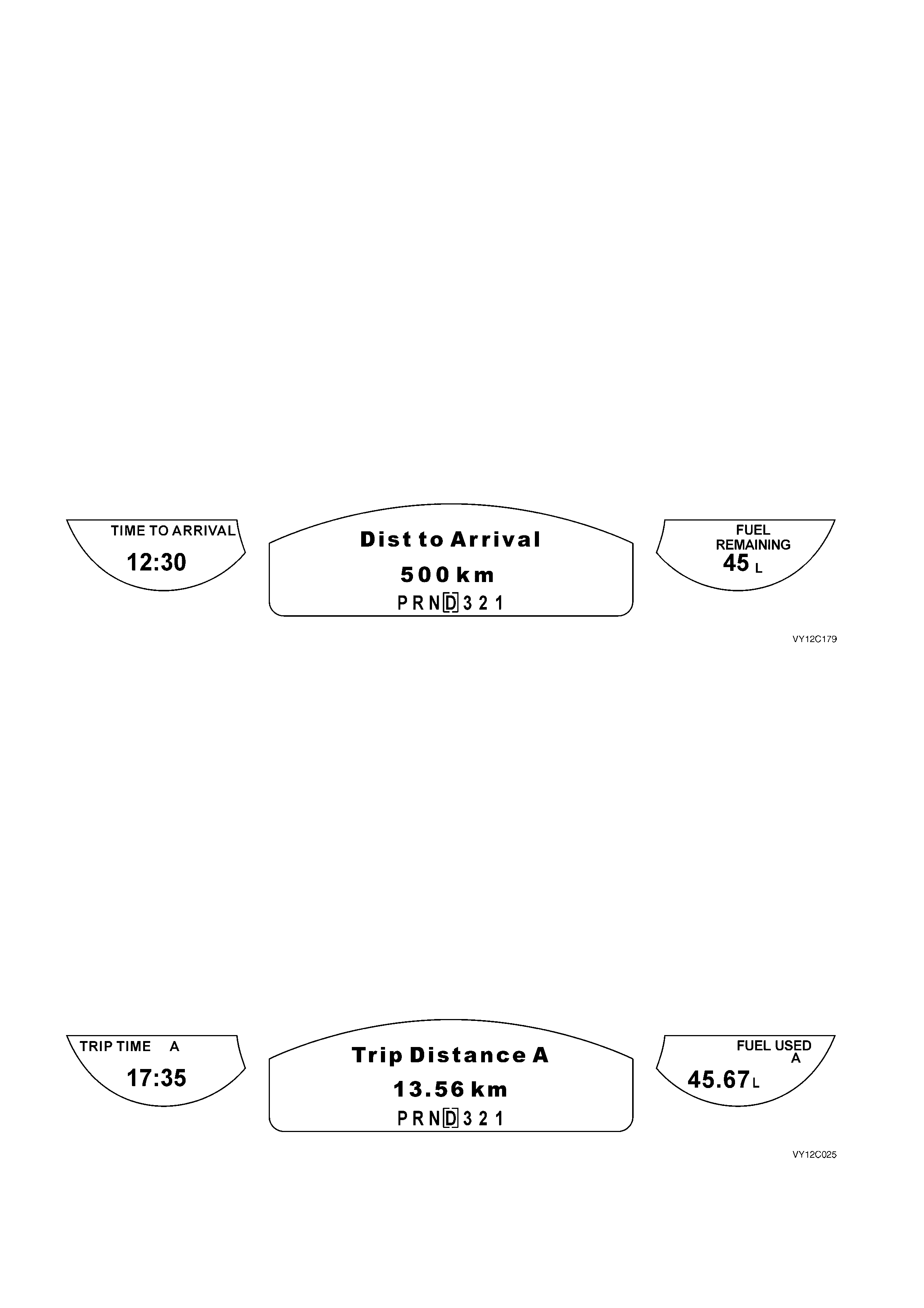
TIME TO ARRIVAL / DISTANCE TO ARRIVAL / REMAINING FUEL
The T ime to Ar rival / Distance to Arr ival / Remaining Fuel s creens can be enabled in Custom isation Mode as a set.
They cannot be individually activated. Additionally, the Trip A and B function can be enabled from this set of screens
by pressing and holding the MODE button for more than 2 seconds.
To r eset the Dis tanc e to Ar rival to a value s et in Cus tomisation Mode, pr ess the SET button for les s than 2 sec onds
while this set of screens is displayed.
Time to Arrival
Shows trip tim e to arrival in hour s and m inutes, bas ed on Distanc e to Arrival. T he T im e to Arrival value is dis played
as follows:
• In 1 minute increments if the Time to Arrival is less than 10 minutes.
• In 5 minute increments if the Time to Arrival is more than 10 minutes, but less than 2 hours.
• In 10 minute increments if the Time to Arrival is more than 2 hours, but less than 99 hours and 59 minutes.
• In 1 hour increments if the Time to Arrival is more than 99 hours and 59 minutes.
Distance to Arrival
At the start of a trip, estimate the distance to arrival from m aps or road signs. Tap the UP or DOW N buttons until
the display shows the estimated trip distance. When the vehicle is driven the trip computer will constantly update the
time to arrival, based on changing driving speeds.
The UP or DOWN buttons can be used to adjust the distance (kilometres) any time this screen is displayed.
Remaining Fuel
Displays the amount of f uel lef t in the f uel tank in litres , r ounded to the nearest 5 litres. In a low fuel situation, LO will
be displayed in the Fuel Remaining LCD when the fuel level is down to approximately 8 litres left in the tank.
Figure 12C-26
Press the trip computer MODE button to advance to the next set of screens:
• Press the MODE button for less than 2 seconds and either the normal Overspeed or Preset Overspeed
screens will be displayed, depending on the previous overspeed selection.
• Press the MODE button for more than 2 seconds, the Trip A and B function will be enabled and the Trip
Time B / Trip Distance B / Fuel Used B screens will be displayed.
TRIP TIME A/B / TRIP DISTANCE A/B / FUEL USED A/B
The Trip A and B function is enabled in Customisation Mode. Normally if this function is enabled, the Distance to
Arrival function is disabled. However, the Distance to Arrival function can be accessed from the T rip B windows by
pressing and holding the MODE button for more than 2 seconds.
When the Trip A and B function has been enabled, the Trip A windows are normally displayed on the instrument
cluster.
Two diff erent sets of trip screens are now counting, the or iginal set of trip sc reens (labelled A while B is turned on)
and a new set of trip s creens , labelled B. This is usef ul on a long trip, as Tr ip B can be reset at the beginning of the
journey and then locked away (by pressing the MO DE button for mor e than 2 seconds when Trip B is shown). T im e
to Arrival / Distance to Arrival / Remaining Fuel will again be shown on the screen, but Trip B will still be counting
away in the back ground and the original trip screen can be used for short distances during the journey. Trip B can
be viewed at any time by pressing the MODE button for more than 2 seconds when Distance to Arrival is shown.
Figure 12C-27
To advance to the Trip B windows, press the MODE button for less than 2 seconds.
Figure 12C-28/VY12C249
Press the trip computer MODE button to advance to the next set of screens:
• If the MODE button is pressed for less than 2 seconds, either the normal Overspeed or Preset Overspeed
screens will be displayed, depending on the previous overspeed selection, or
• If the MODE button is pressed for more than 2 seconds, the Time to Arrival / Distance to Arrival / Remaining
Fuel screens will be displayed.
OVERSPEED / DISTANCE TO EMPTY / INSTANTANEOUS FUEL
Overspeed
The Overspeed function on a triple-window instrument cluster is the same as that already described for the
single-window instrument cluster. However, the overspeed value is also displayed on the left-hand side LCD. For
further details, refer to 1.4 TRIP COMPUTER — SINGLE-WINDOW CLUSTER in this Section.
Distance to Empty
Distance to Empty is an estim ate of how fa r c ur rent f uel will last. It is bas ed on previous f uel us age and is fr equently
updated. Therefore, as conditions become suited to more economical driving the Distance to Empty may actually
increase, for example changing from city to highway driving.
Instantaneous Fuel
Shows instantaneous fuel us age in litres per 100 k m when driving. W hen s peed drops below 10 k m/h the us age is
shown in litres per hour.
Figure 12C-29
Press the MODE button to advance to the next screen:
• If Police Mode is enabled by TECH 2, then the true speed digital speedometer will be displayed, or
• If Police Mode is not enabled and the Stop Watch function is enabled in Customisation Mode, then the Stop
Watch screen will be displayed, or
• If neither the Polic e Mode nor the Stop W atch func tion are enabled, then the next scr een displayed will be the
Average Speed / Odometer / Average Fuel screen, or the Average Speed A / Odometer / Average Fuel A
screen.
POLICE MODE
The Police Mode is enabled by TECH 2. If the
Police Mode is enabled, the digital speedometer is
the MFD default display at ignition on, and the side
LCDs display no information.
Refer to 1.9 POLICE MODE in this Section.
NOTE: The Police Mode is not applicable to
Omega.
Figure 12C-30
Press the MODE button to advance to the next screen:
• If the Stop Watch function is enabled in Customisation Mode, then the Stop Watch screen will be displayed, or
• If the Stop Watch function is not enabled, then the next screen displayed will be the Average Speed /
Odometer / Average Fuel screen, or the Average Speed A / Odometer / Average Fuel A screen.

STOP WATCH
The Stop Watch screen is enabled
in Customisation Mode (refer to
1.8 CUSTOMISATION MODE in this Section).
Pressing the SET button on the trip computer
switch starts and stops the stop watch. Pressing
and holding the MODE button for more than
3 seconds resets the stop watch with a confirming
beep.
Figure 12C-31
Press the MO DE button to advance to either the Aver age Speed / Odom eter / Aver age Fuel screen, or the Average
Speed A / Odometer / Average Fuel A screen.
1.6 INSTRUMENT OPERATION — ALL MODELS
IGNITION ON — WELCOME SEQUENCE
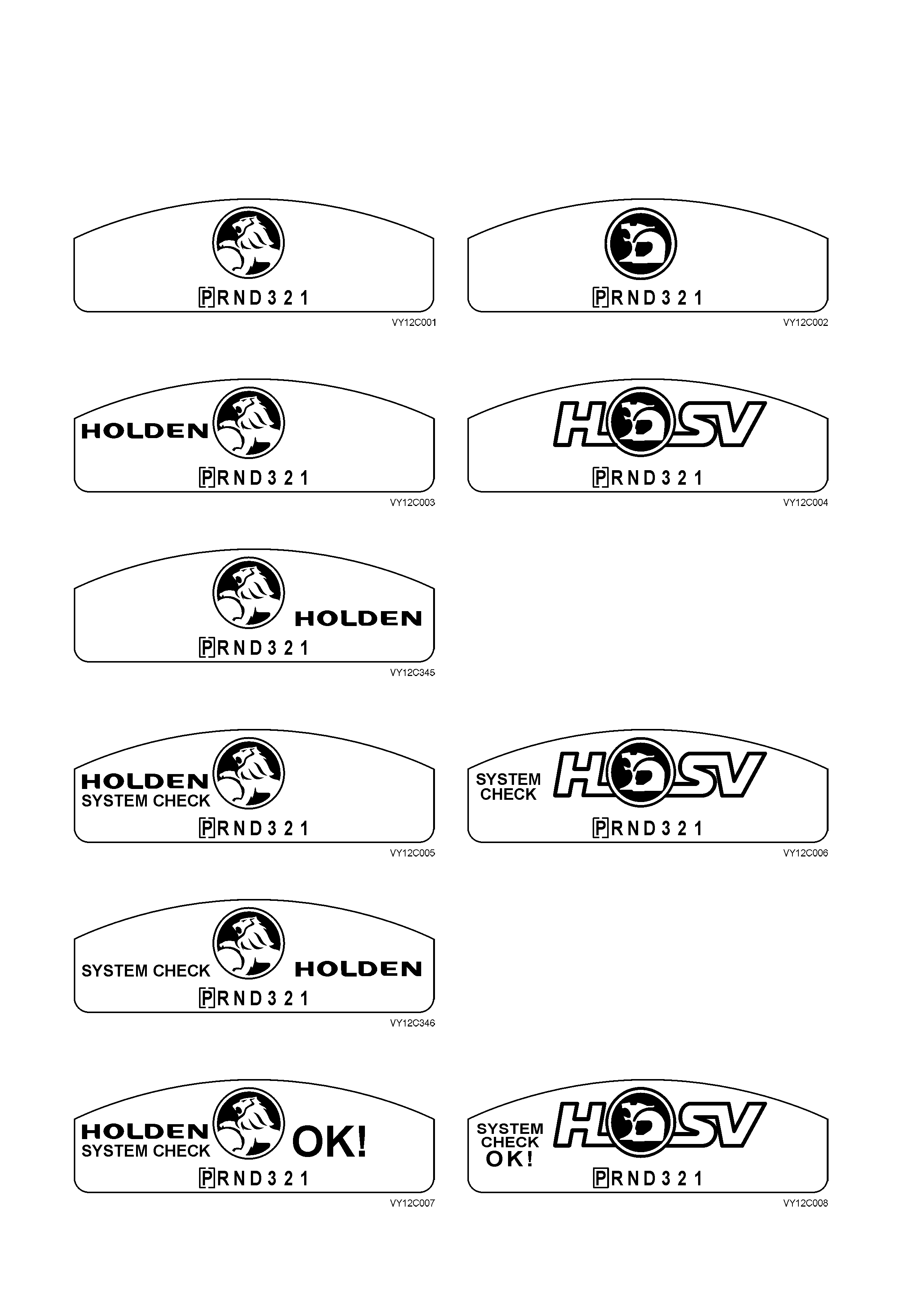
When the ignition switch is turned to the ON position, a vehicle System Check is performed and the status is
displayed on the MFD. The System Check displays the following if there are no warnings or service reminders
active: Holden/Chevrolet HSV/CSV
Figure 12C-32
Figure 12C-33
After 0.5 second.
Figure 12C-34 Initial
Production
Figure 12C-35 Running Change
Figure 12C-36
After 1.0 second.
Figure 12C-37 Initial Production
Figure 12C-38 Running Change
Figure 12C-39
After 2.0 seconds.
Figure 12C-40 Initial Production
Figure 12C-42
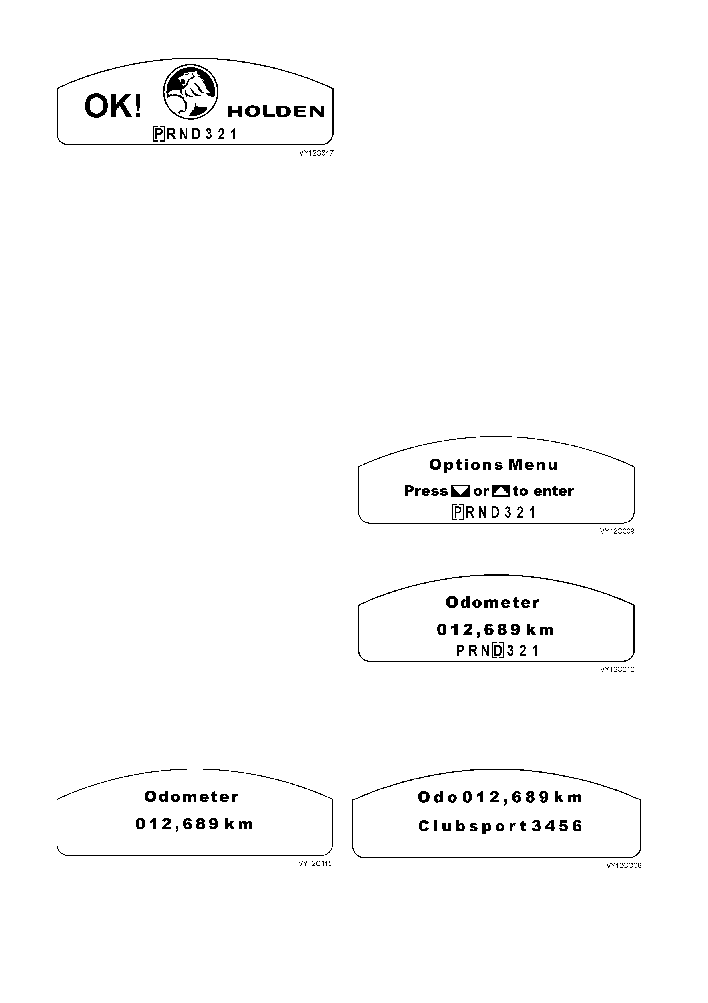
Figure 12C-41 Running Change
NOTE 1: For Chevrolet vehicles, the Chevrolet ‘Bow Tie’ logo replaces the Holden logo and the wording ‘Holden’
becomes ‘Chevrolet’. For CSV, the CSV logo replaces the HSV logo.
NOTE 2: If the Options Menu is invoked by the driver, eg, MODE is held while ignition is keyed on, the System
Check display will be carried out in the background and not displayed.
During the System Check the PRNDL icon or any other icon that can be turned on or off, or is on by default from the
last ignition cycle, will be displayed at the System Check start up.
If the System Chec k detects a warning or alar m , the MFD displays it im m ediately. If a warning or alarm is displayed
and then acknowledged by the driver (depending on the fault message) by pressing the MODE button, the
Welcom e Sequenc e is bypassed and the MFD defaults to the las t s cr een that was dis played prior to the last ignition
key off.
If a service reminder is active, it will be displayed for 10 seconds before the Welcome Sequence. If no service
reminder is active, the Welcome Sequence continues. If more than one service reminder is active they will be
displayed for a total of 10 seconds. When the service reminders are displayed, pressing the trip computer switch
MODE button allows scrolling through the service reminders.
Pressing the trip computer switch MODE button at any stage throughout the System Check will display the trip
computer screen. The System Check will continue operating in the background.
When the System Check is completed, the Options
Menu is displayed for 3 seconds if the vehicle speed is
below 10 k m /h. Refer to 1.8 CUSTO M ISAT ION MO DE
in this Section for further details on the Options Menu.
If the MODE button is pressed or the scr een times-out
(3 s econds), the Options Menu dis appears and reverts
back to the las t sc reen displayed on the last k ey off for
that priority key.
Figure 12C-43
To display the odom eter screen, tap the MODE button
until the screen is displayed
Figure 12C-44
IGNITION OFF
When the ignition switch is turned to the OFF position, the odometer is displayed in the MFD unless any service
reminders are active. Active service reminders are shown for 10 seconds before displaying the odometer screen.
Holden/Chevrolet HSV/CSV
Figure 12C-45 Figure 12C-46
With HSV/CSV, the vehicle ty pe and build ID number can be displayed while the ignition is off.
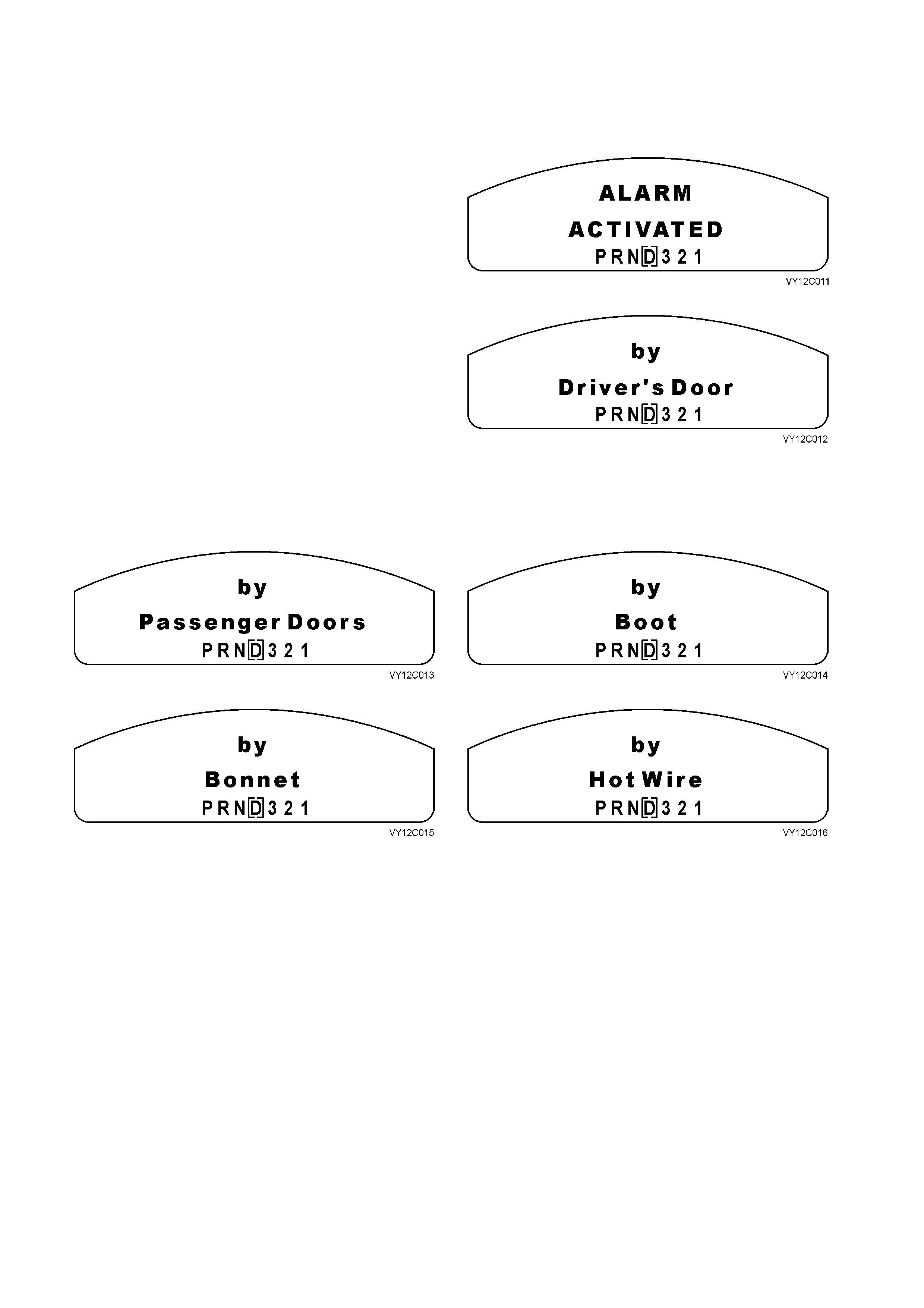
ALARMS
The following screens are displayed if an alarm has
been activated and are displayed as soon as the
cluster has received the alarm , even prior to or during
a System Check.
The Alarm Activated screen is displayed first for
1 second, followed by the trigger point screens.
Figure 12C-47
The trigger point screens are also displayed for
1 second. If more than one trigger point has been
activated the MFD will display each trigger point screen
in sequence for 1 second, returning to the Alarm
Activated screen.
The alarm screens are displayed in a continuous cycle
until the trip computer switch MODE or SET button is
pressed. The MFD then reverts to the last screen
displayed prior to ignition off.
Figure 12C-48
Figure 12C-49
Figure 12C-50
Figure 12C-51
Figure 12C-52
1.7 MULTI-FUNCTION DISPLAY — ALL MODE LS
The following details the functions available in the MFD on both single-window and triple-window instrument
clusters.
CONSTANT ICONS
The display of Warnings has priority over the display of animated icons.
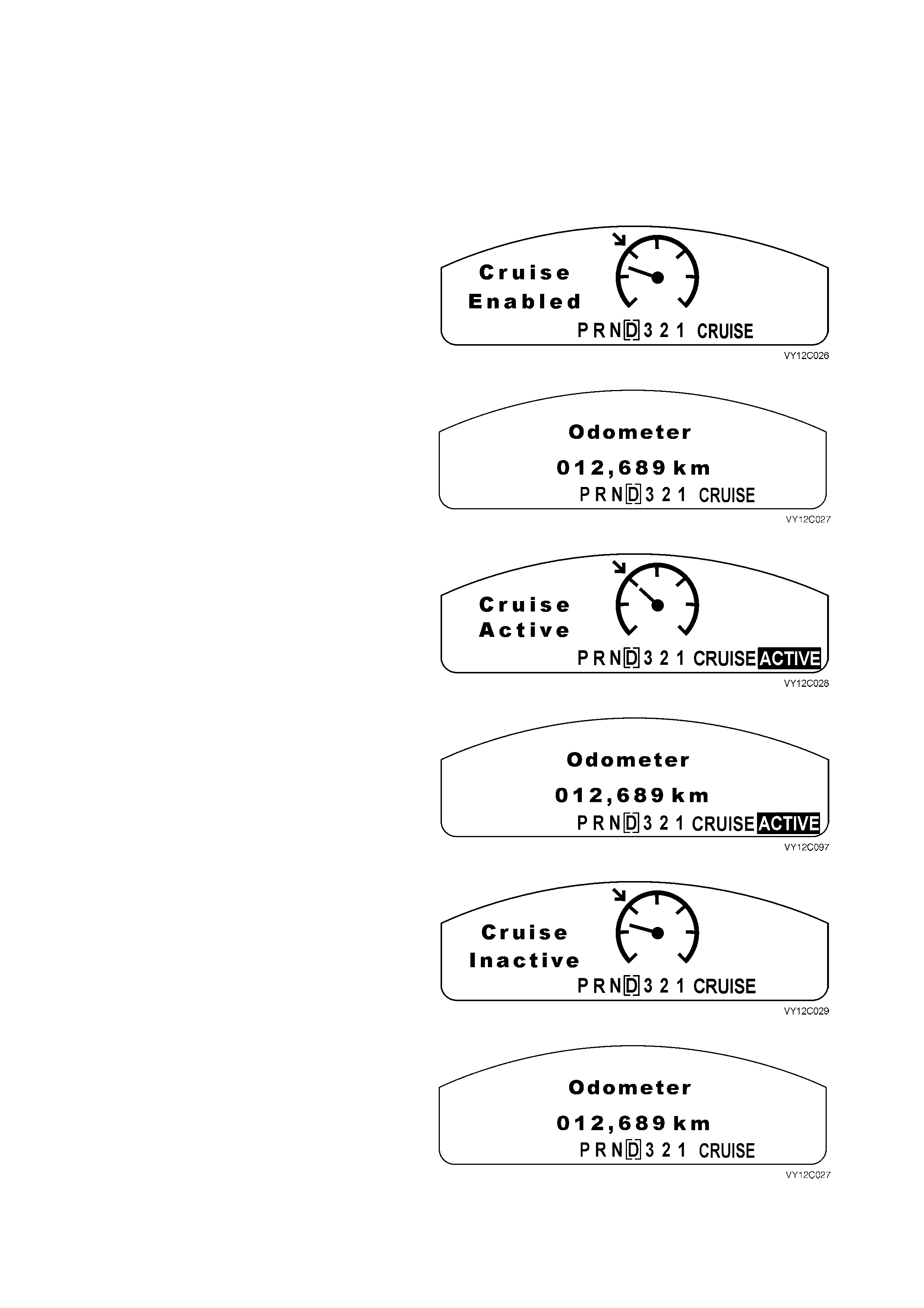
Cruise Control
1. Cruise Enabled
When the instrument cluster receives the Cruise
ON signal from the Cruise Control Module, the
CRUISE icon illuminates and the Cruise Enabled
animation is displayed for 2 seconds.
The animation is shown initially with the set arrow
flashing.
Figure 12C-53
After 2 seconds the animated display extinguishes
and the CRUISE icon remains. The display reverts
back to the previously displayed trip computer
screen.
Figure 12C-54
2. Cruise Active
When the cruise control is activated via the cruise
control switch assembly, the highlighted ACTIVE
icon illuminates and the Cruise Active animation is
displayed for 2 seconds.
The animation is shown initially with speedometer
needle moving toward the set arrow.
Figure 12C-55
After 2 seconds the animated display extinguishes
and the CRUISE icon and the highlighted ACTIVE
icon remain. The display reverts back to the
previously displayed trip computer screen.
Figure 12C-56
3. Cruise Inactive
When the cruise control is deactivated via the
cruise control switch assembly, the highlighted
ACTIVE icon extinguishes immediately and the
Cruise Inactive animation is displayed for
2 seconds.
Figure 12C-57
After 2 seconds the animated display extinguishes
and the CRUISE icon remains. The display reverts
back to the previously displayed trip computer
screen.
Figure 12C-58
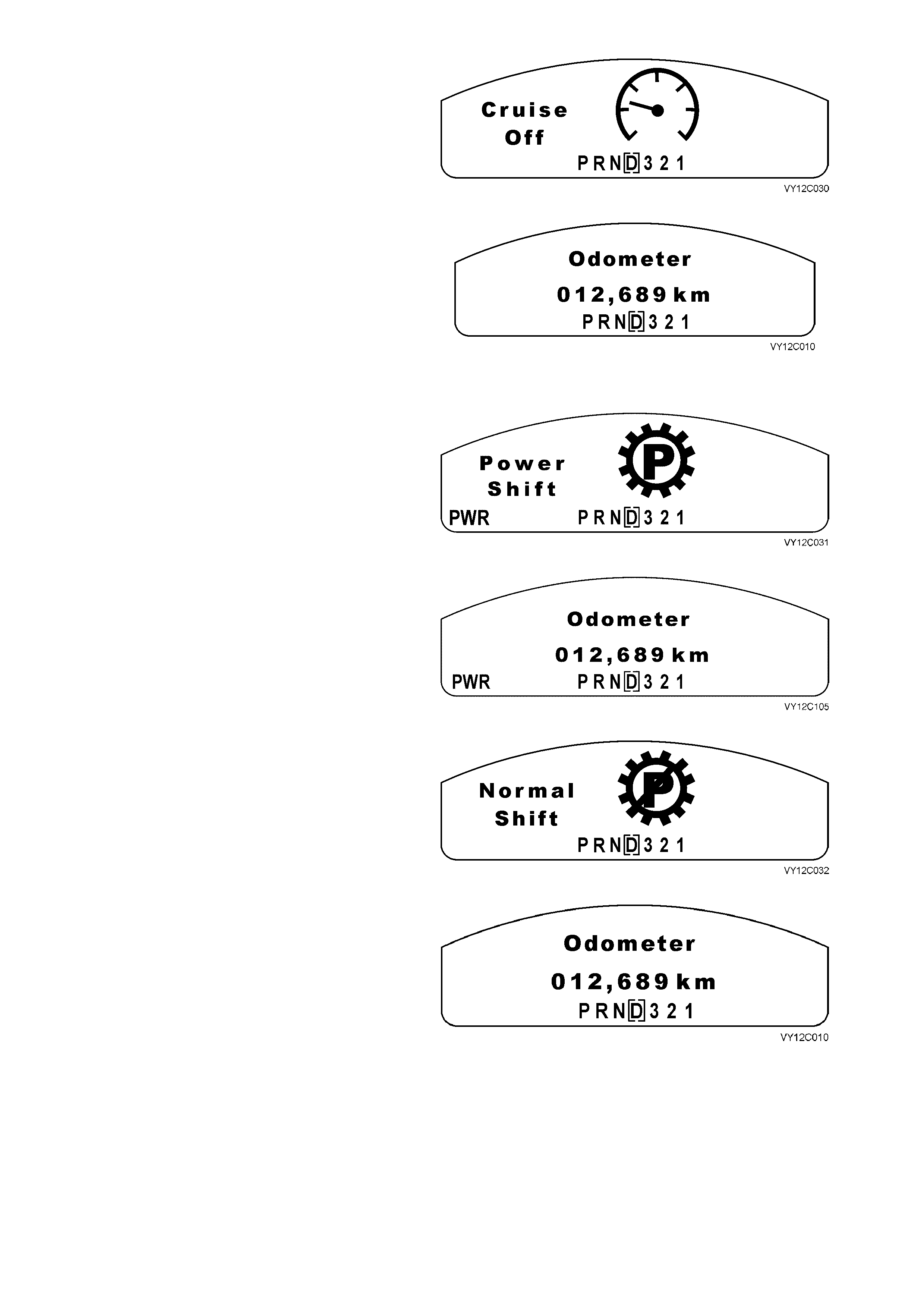
4. Cruise Off
When Cruise Power is disabled, the CRUISE icon
extinguishes immediately and the Cruise Off
animation is displayed for 2 seconds.
Figure 12C-59
After 2 seconds the animated display extinguishes,
and the display reverts back to the previously
displayed trip computer screen.
Figure 12C-60
Power Mode
1. Power Mode On
When the transmission is placed in Power Mode,
the PWR icon illuminates and the Power Shift
animation is displayed for 2 seconds.
Figure 12C-61
After 2 seconds, the animated display extinguishes
and the PWR icon remains. The display reverts
back to the previously displayed trip computer
screen.
Figure 12C-62
2. Normal Mode On (Power Mode Off)
When the transmission is changed from Power
Mode to Normal Mode, the PW R icon extinguishes
immediately and the Normal Shift animation is
displayed for 2 seconds.
Figure 12C-63
After 2 seconds the animated display extinguishes
and the display reverts back to the previously
displayed trip computer screen.
Figure 12C-64
NOTE: If Power Mode is on and the cruis e control has been activated, the Power Mode is turned off by the PCM as
there is no Power Mode while the cruis e control is active. W hen this occurs, the dis play does not show the Normal
Shift display but instead turns off the PWR icon. When cruise control is deselected, the PWR icon illuminates
3 seconds after the cruise control has been deselected. This prevents the PW R icon cycling if the cruise control is
deselected momentarily.
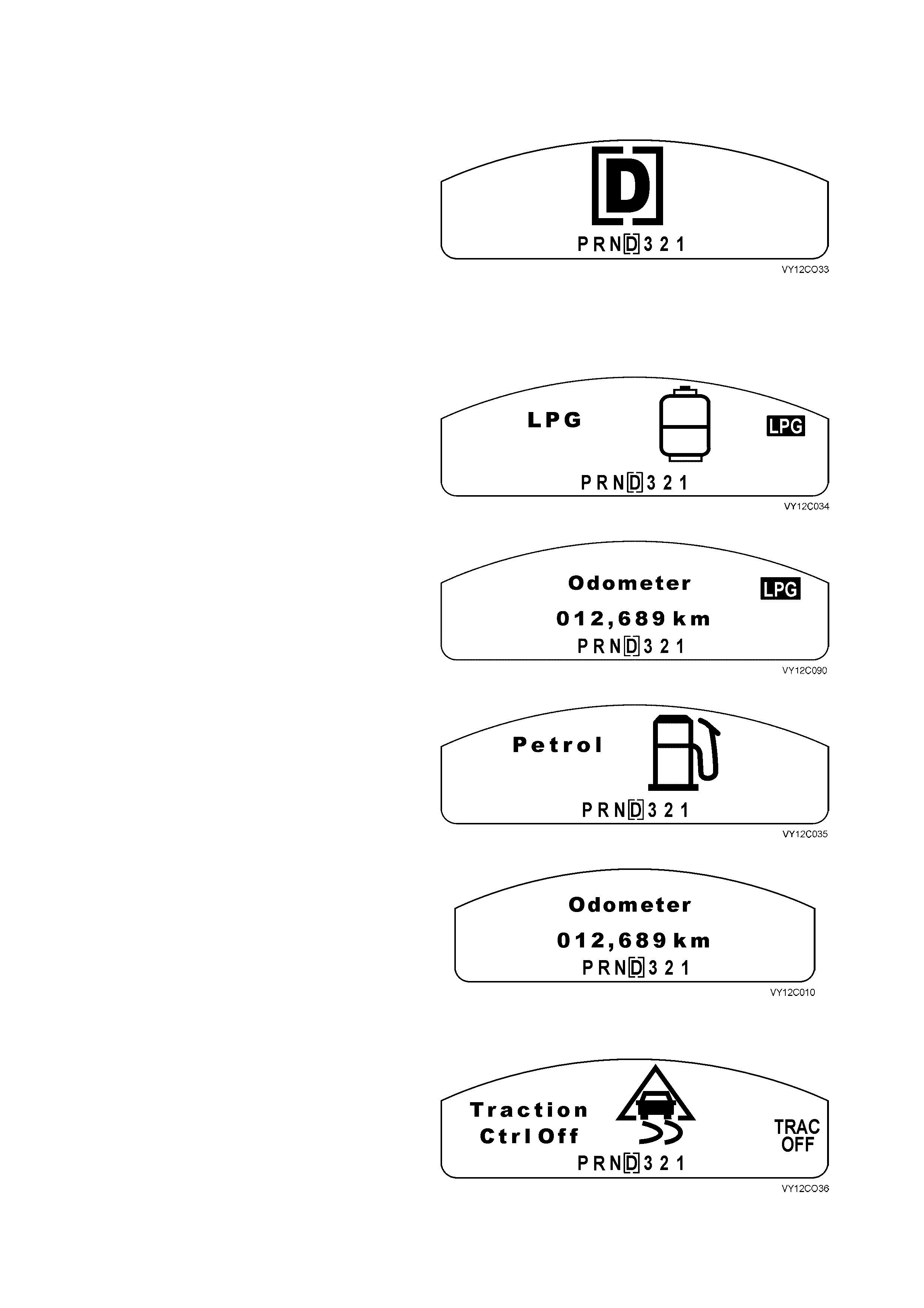
PRND321
When the pos ition of the trans m ission selector is changed, a lar ge icon is dis played on the MFD in conjunction with
the PRND321 constant icon at the bottom of the MFD. The square box around the designated gear letter moves
according to what gear is selected on the gear selector.
The gear icon remains for 2 seconds after it is
selected. While the transmission selector is
moving, the constant icons reflect the selector
movement through the gears.
Figure 12C-65
NOTE: If any warning is active, the large display symbol is not shown and only the bracketed constant icon at the
bottom changes when the automatic transmission selector is moved.
LPG
1. LPG On
When the LPG Mode is selected, the highlighted
LPG icon is illuminated immediately and the LPG
symbol is displayed for 2 seconds.
Figure 12C-66
After 2 seconds, the LPG symbol extinguishes and
the highlighted LPG icon remains. The display
reverts back to the previously displayed trip
computer screen.
Figure 12C-67
2. LPG Off
When the Petrol Mode is selected, the highlighted
LPG icon extinguishes immediately and the Petrol
symbol is displayed for 2 seconds.
Figure 12C-68
After 2 seconds, the Petrol symbol extinguishes,
and the display reverts back to the previously
displayed trip computer screen.
Figure 12C-69
Traction Control
1. Traction Control Off
When the traction control is turned off or a fault
occurs, the TRAC OFF icon illuminates
imm ediately and the T raction Control Of f animation
is displayed for 2 seconds.
Figure 12C-70
After 2 seconds, the animated display extinguishes
and the TRAC OFF icon remains. The display
reverts back to the previously displayed trip
computer screen.
Figure 12C-71
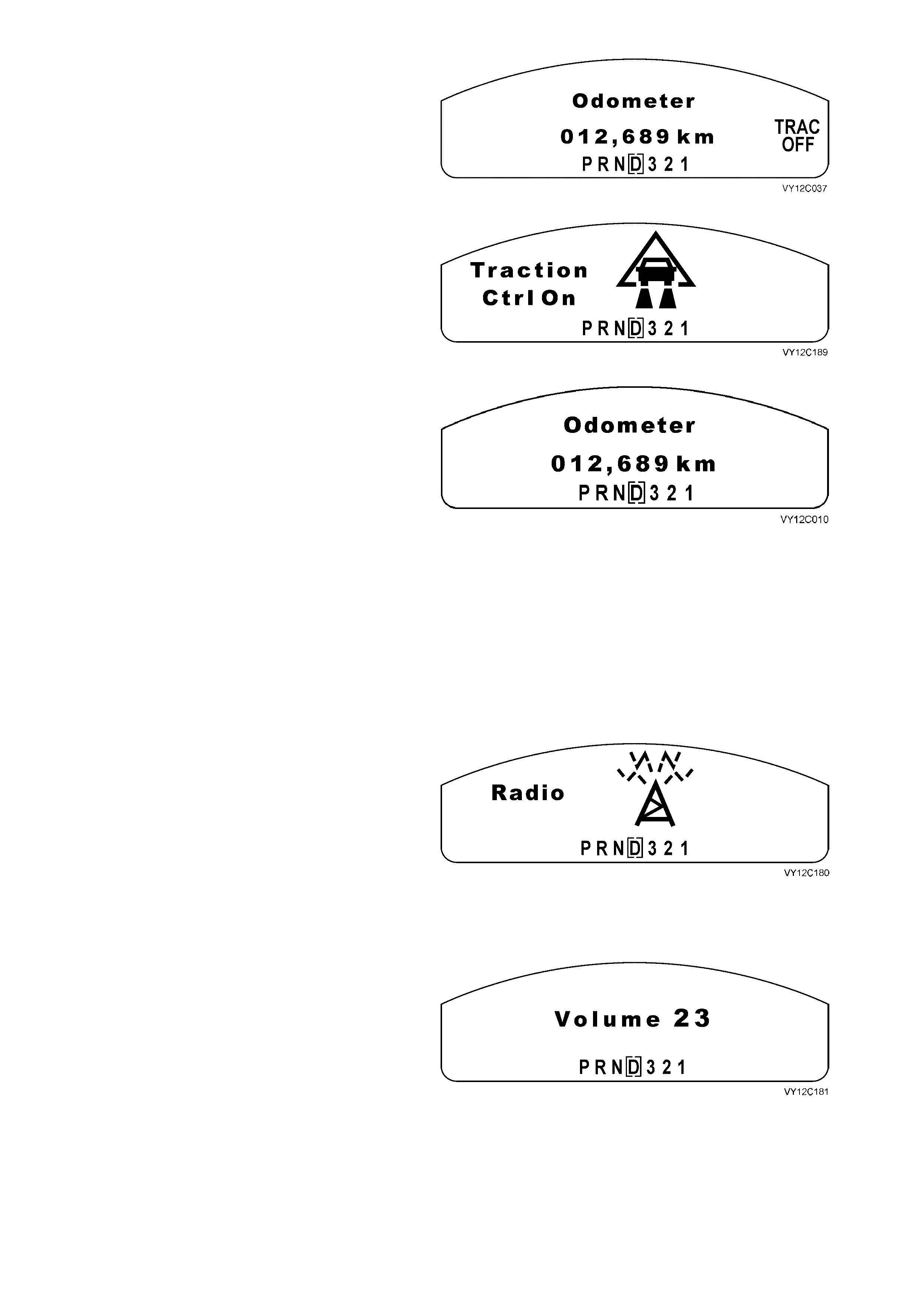
2. Traction Control On
When the traction control is turned on, the TRAC
OFF icon extinguishes immediately and the
Traction Control On animation is displayed for
2 seconds.
Figure 12C-72
After 2 seconds, the anim ated display extinguishes,
and the display reverts back to the previously
displayed trip computer screen.
Figure 12C-73
Radio Data
The radio information is displayed in the warning icon location on the left-hand side of the MFD. If a warning is
active, the radio information will be overridden, as all warning messages have priority.
NOTE 1: At ignition key on, the instrument cluster detects the presence of the original equipment radio by a
message response from the radio via the serial data communication bus. If the vehicle has no radio fitted or the
driver has fitted a different radio, the radio information on the display is not shown. Additionally the Diagnostic
Trouble Code (DTC) associated with the radio may be permanently set.
NOTE 2: If the trip computer MODE button is pressed, the main MFD radio message is cancelled and the trip
computer function is returned. The radio information display on the left-hand side of the MFD remains.
Radio On
If the radio is on when the ignition is turned on, the
MFD displays trip computer information and the
only radio information is shown on the left-hand
side of the MFD in the small constant icon location.
If the radio is turned on while the ignition is on, the
MFD displays the radio screen on the MFD for
2 seconds, then displays the trip computer screen.
If the radio is turned off no radio data or messages
will be shown on the MFD.
Figure 12C-74
Volume
This display is shown if the radio volume is
adjusted up or down.
The volume indication shown is a number
corresponding to a value transmitted by the radio.
Figure 12C-75
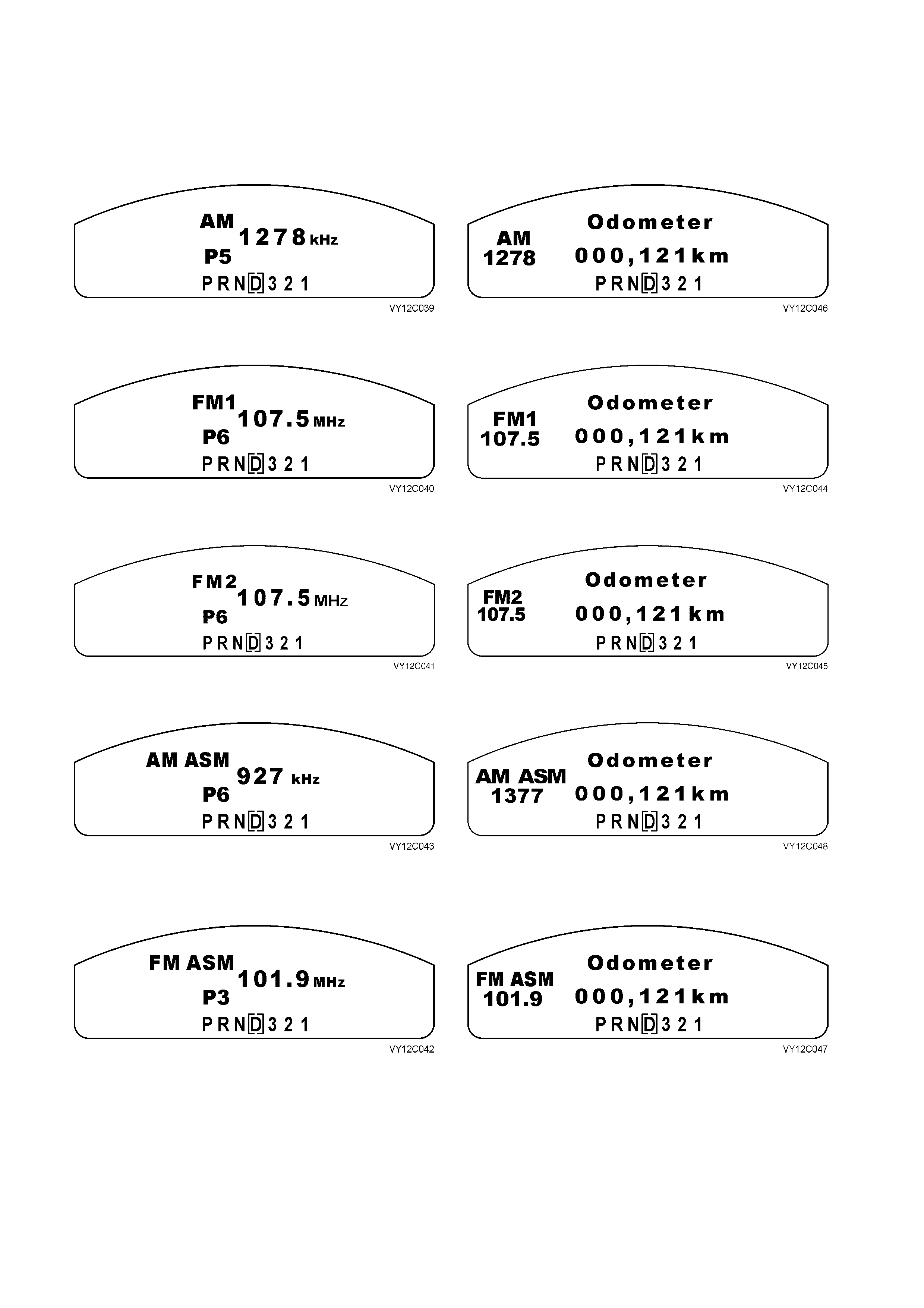
Radio
When the radio source is selected and the bands are being selected, the following main displays are shown in
sequence for 2 seconds.
Once a band has been selected, the display reverts to the secondary small icon of the station band and frequency
with the odometer display.
For the AM band:
Figure 12C-76
Figure 12C-77
For the FM 1 band:
Figure 12C-78
Figure 12C-79
For the FM 2 band:
Figure 12C-80
Figure 12C-81
For the AM ASM band:
Figure 12C-82
Figure 12C-83
For the FM ASM band:
Figure 12C-84
Figure 12C-85
If a preset station is being selected or scrolled through, the MFD will display the station frequency and preset
number it is stored in. The display will be shown for 2 seconds once it has been selected and then revert back to the
small icon on the left of the MFD.
W hen the r adio is tuning or seek ing a frequenc y, the MFD will display the radio band and the frequenc y sc rolling. If
the radio comes across a preset station while scrolling through the frequency during a tune or seek, this preset
number will be displayed in the preset location on the display.
Once the f requency has stopped s crolling and the driver has stor ed or star ted listening to the station, the f requenc y
of the radio station will be displayed for 2 seconds and then revert back to the small icon on the left of the MFD.
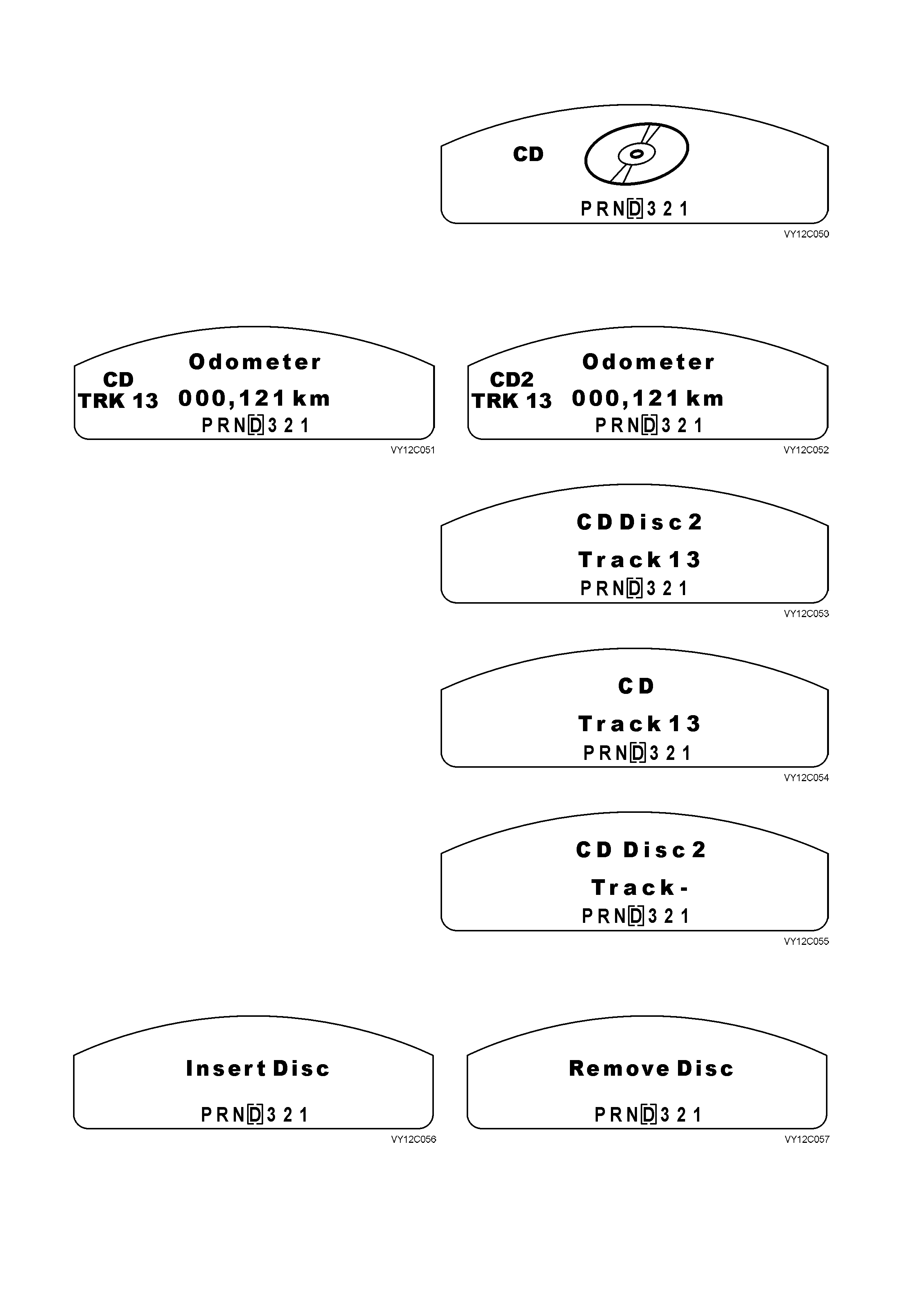
Compact Disc (CD)
When the CD source is selected, this display is
shown for 2 seconds.
Figure 12C-86
Once the CD source has been selected the display reverts to a small icon. The small icon displays the current CD
number and the track number if a CD changer is fitted or just CD and the track number if a single disc CD unit is
fitted.
Figure 12C-87
Figure 12C-88
When the driver or the radio head unit changes
tracks or discs, the MFD displays the track and disc
information. Once the change is completed, the
display remains for 2 seconds.
For a CD changer, the display is:
Figure 12C-89
For a single CD player, the display is:
Figure 12C-90
If the CD changer is changing discs, it shows this
display for the disc and track numbers and then
drops back with the same information in the small
icon location.
Figure 12C-91
If the radio has a CD changer that requires the driver to be informed on when to remove or insert a CD, the
following is displayed on the MFD when necessary.
Figure 12C-92
Figure 12C-93
This display rem ains until a disc is ins erted or r em oved, or the driver pr ess es the MODE button to go to the las t trip
computer function. When this occurs there are no small message icons. This is also implemented for Load Disc,
Eject Disc and Please Wait.
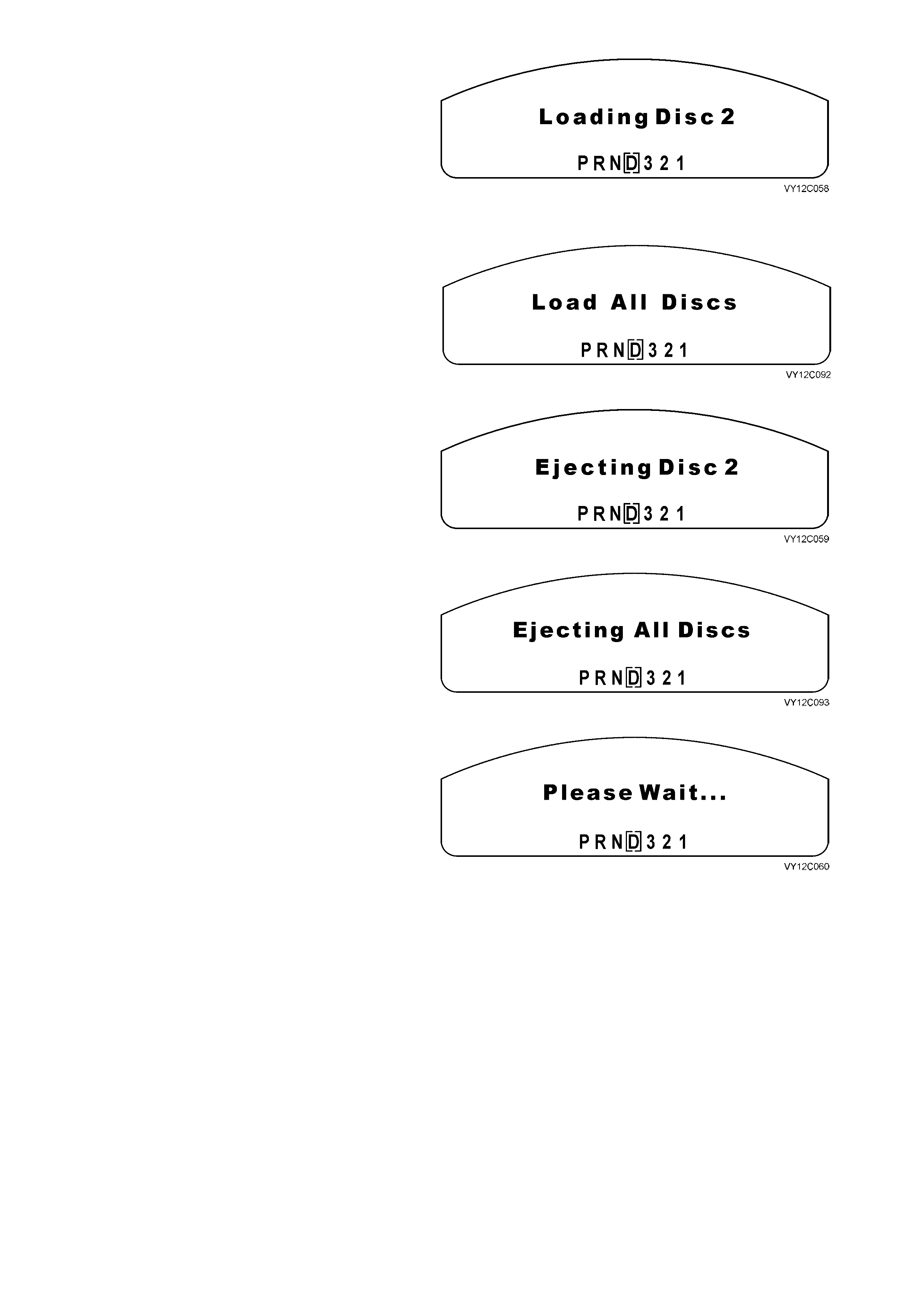
The MFD presents this message when the single
slot CD changer is loading a disc number when
inserting a disc, or when the CD changer is
changing a disc. This message is displayed while
the CD is loading. The message remains until the
next insert or remove disc message or the track
disc m essage is displayed. If the driver presses the
MODE button, the message is cancelled and the
MFD goes to the last trip computer function.
Figure 12C-94
If the driver has selected Load All Discs, the
following display is presented for 2 seconds unless
the driver presses the MODE button and the
display reverts to the last trip computer function.
Figure 12C-95
If the driver has elected to eject a single CD, the
display shows the num ber of the CD being ejected.
The display remains until the CD is ejected or the
driver presses the MODE button to revert to the last
trip computer function.
Figure 12C-96
If the driver has elected to eject all the discs in the
CD changer, the display shows this message. The
display remains until the CDs are ejected or the
driver presses the MODE button to revert to the last
trip computer function.
Figure 12C-97
If the CD changer is performing a function and the
driver should wait before selecting the next
operation, a Please Wait display appears.
Figure 12C-98
Auxiliary (Not Applicable to Omega)
The auxiliary mode is used to inform the driver that an external source separate from the radio head unit is being
used. The external sources can be:
• Unidentified
• TV
• Video
• DVD
• Navigation
• Mini Disc
• Game.
The mess age dis played on the MF D is dependent on the data sent with the m es s age that decodes it into one of the
MFD displays.

Auxiliary Function
If an ‘unidentif ied’ mess age is s ent, the MFD shows
this as an ‘auxiliary’ function. This is displayed for
2 seconds.
Figure 12C-99
After 2 seconds, the display reverts to:
Figure 12C-100
All other functions are represented by the message data sent through and are displayed as shown in the following
MFD displays.
TV Function
When the TV auxiliary function is selected, the
MFD shows TV for 2 seconds.
Figure 12C-101
After 2 seconds, the display reverts to:
Figure 12C-102
Video Function
When the Video auxiliary function is selected, the
MFD shows Video for 2 seconds.
Figure 12C-103
After 2 seconds, the display reverts to:
Figure 12C-104
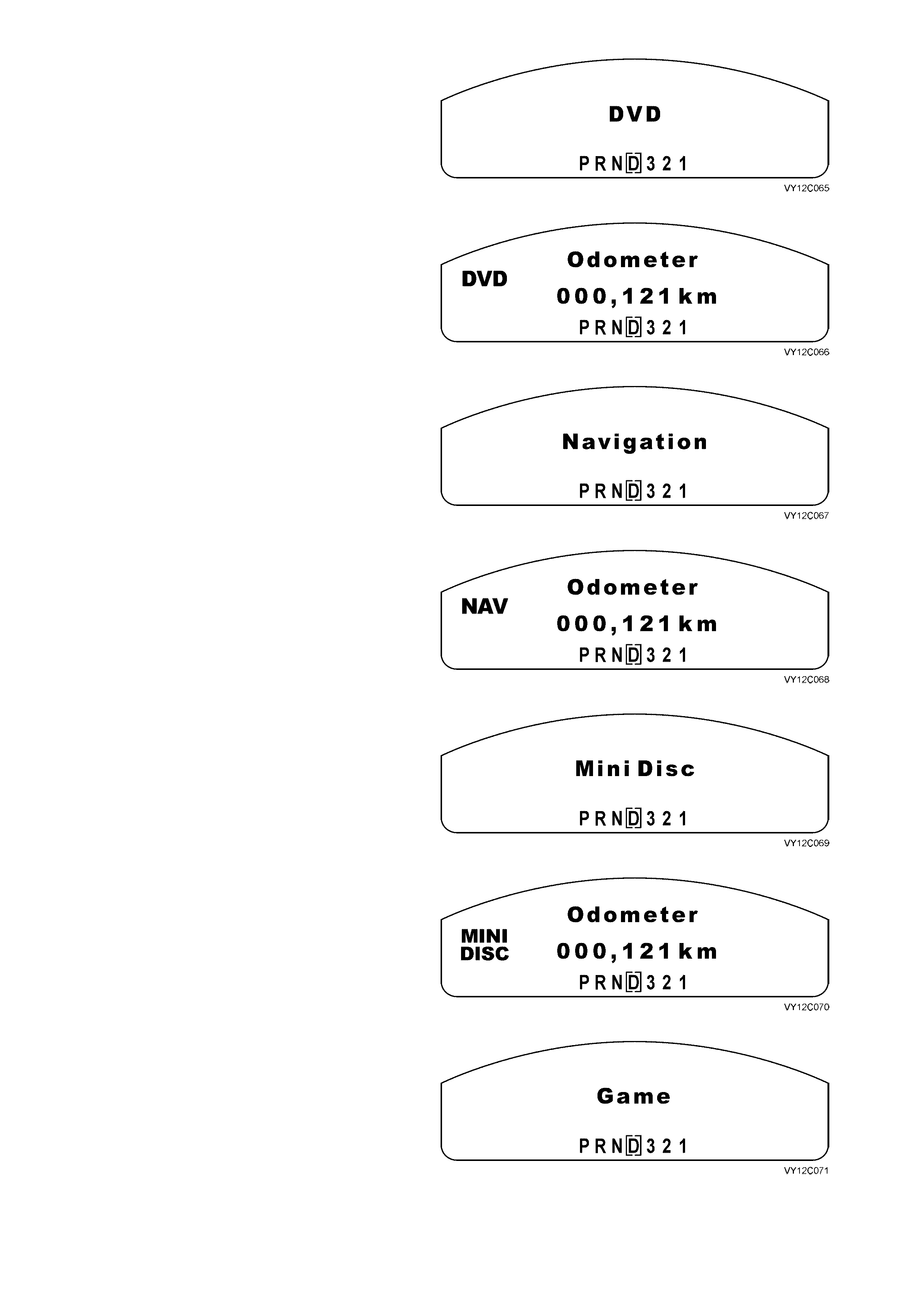
DVD Function
When the DVD auxiliary function is selected, the
MFD shows DVD for 2 seconds.
Figure 12C-105
After 2 seconds, the display reverts to:
Figure 12C-106
Navigation Function
When the Navigation auxiliary function is selected,
the MFD shows Navigation for 2 seconds.
Figure 12C-107
After 2 seconds, the display reverts to:
Figure 12C-108
Mini Disc Function
When the Mini Disc auxiliary function is selected,
the MFD shows Mini Disc for 2 seconds.
Figure 12C-109
After 2 seconds, the display reverts to:
Figure 12C-110
Game Function
When the Game auxiliary function is selected, the
MFD shows Game for 2 seconds.
Figure 12C-111
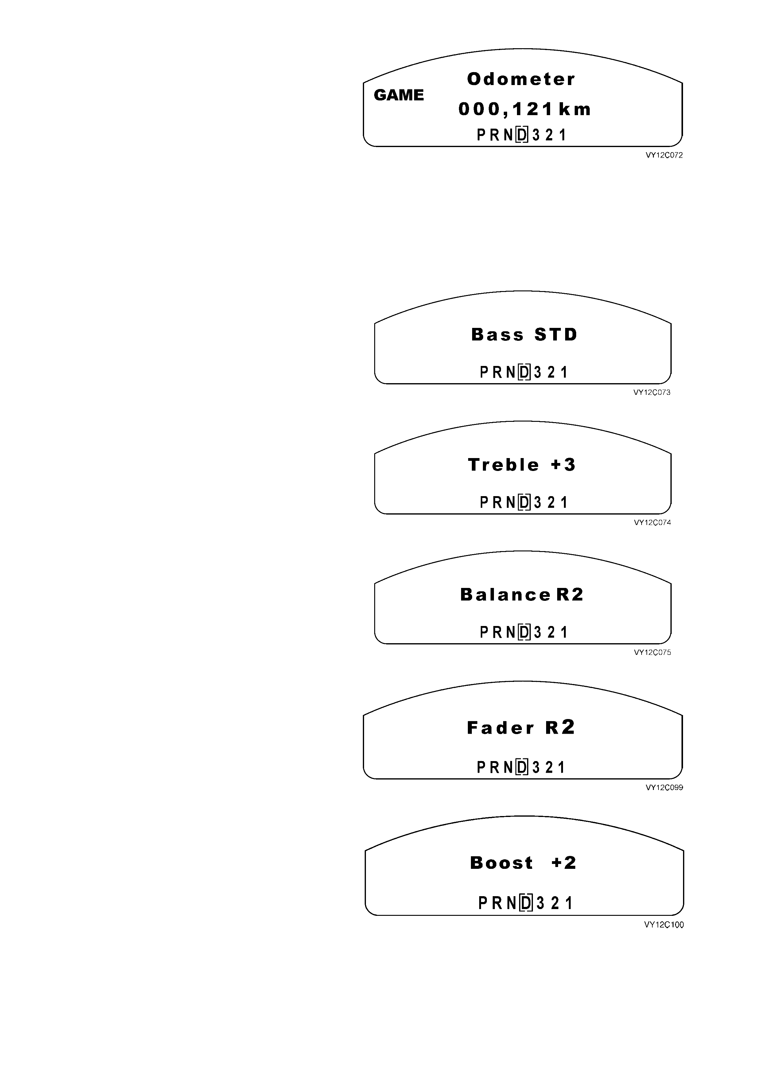
After 2 seconds, the display reverts to:
Figure 12C-112
Audio
When the audio settings are selected, the MFD shows the current entertainment system settings. The driver can
scroll through these parameters from the entertainment system. Once the final adjustment has been made, the
display is shown for 2 seconds before reverting to the original trip computer function.
If the entertainment system fitted does not include a particular function, the screen for that function will not be
displayed.
Bass Settings
The range of Bass adjustm ent is fr om –6 to +6 with
STD (0) being the standard setting.
NOTE: On models fitted with a pre-programmed
equalizer function, the bass function is replaced by
the boost function when the equaliser is operating.
Figure 12C-113
Treble Settings
The range of Treble adjustment is from –6 to +6
with STD (0) being the standard setting.
NOTE: On models fitted with a pre-programmed
equalizer function, the treble f unction is replaced by
the boost function when the equaliser is operating.
Figure 12C-114
Balance Se ttings
The Balance adjustment shifts the sound between
the left and right speakers.
The range of Balance adjustment is from L6 to R6
with STD (0) being the standard setting.
Figure 12C-115
Fader Settings
The Fader adj ustment shifts the sound between the
front and rear speaker.
The range of Fader adjustment is from F6 to R6
with STD (0) being the standard setting.
Figure 12C-116
Boost Settings
On models fitted with a pre-programmed equalizer
function, the sound level can be boosted or cut to
highlight the frequency responses found in various
types of music.
The range of Boost adjustment is from –2 to +2
with STD (0) being the standard setting.
Figure 12C-117
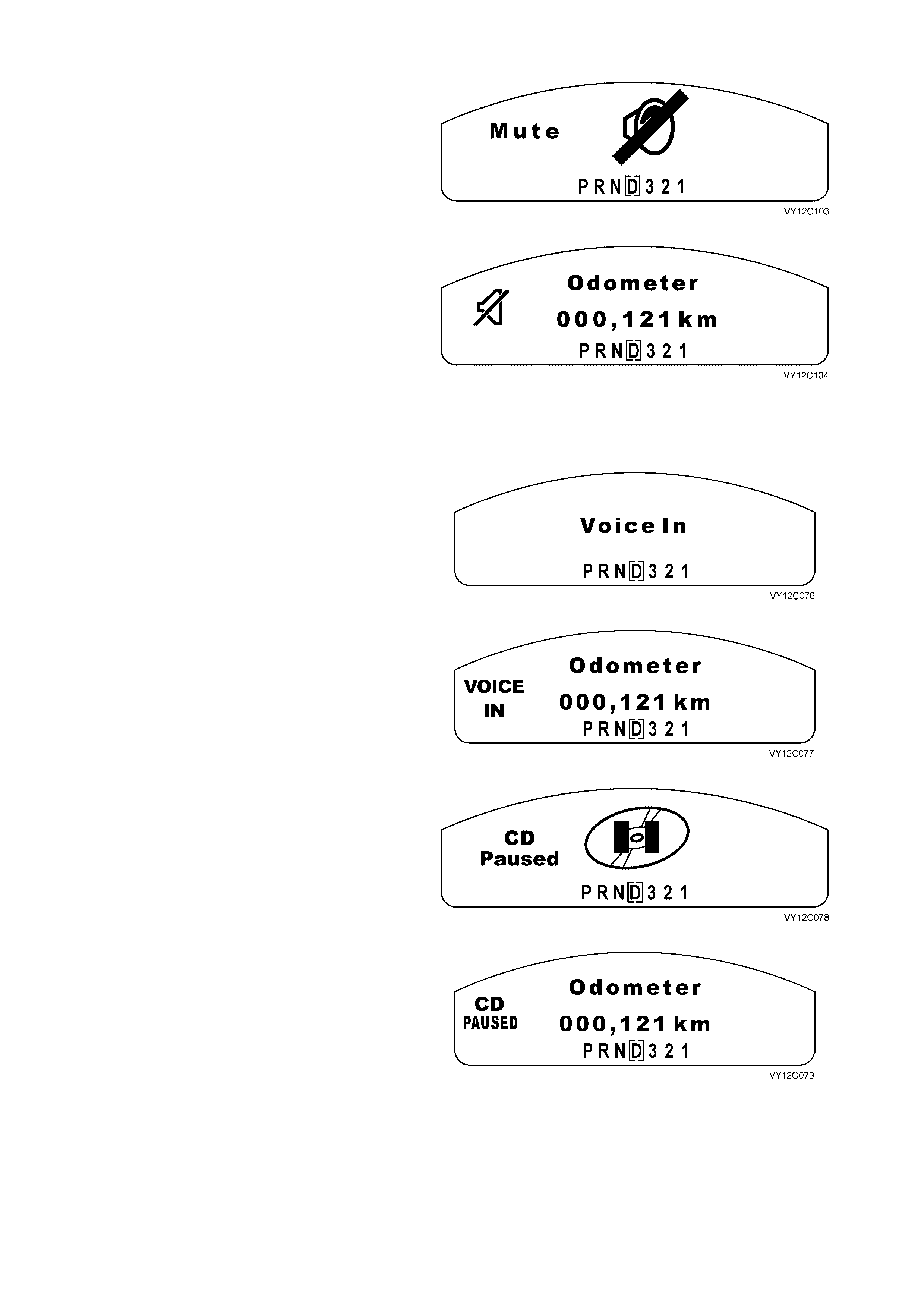
Mute
Mute Display
The Mute function reduces the audio level by a
preset amount. When the audio system head unit is
muted, the MFD displays Mute for 2 seconds.
Figure 12C-118
After 2 seconds, the display reverts to:
Figure 12C-119
If the driver changes the radio presets, CD information or the source, the MFD shows the change for 2 seconds.
The Mute icon remains in the small icon location until the mute condition is deactivated or the volume is increased.
Phone Display
When the audio system head unit has a phone
connected and the phone line is muted, the MFD
shows Voice In.
Figure 12C-120
After 2 seconds, the display reverts to:
Figure 12C-121
Pause Display
When the audio system head unit sourc e is paused
in CD mode the MFD shows CD Paused.
Figure 12C-122
After 2 seconds, the display reverts to:
Figure 12C-123
When the Pause function is switched off, the small icon on the MFD extinguishes.
ANIMATED WARNINGS
W arnings have priority over everything on the left of the MFD and replace the radio display. Most warning displays
are accompanied by a chime.
There are effectively three warning levels. The Level 0 Warning instantly overrides all displays, both warning and
otherwise. This warning can only be cleared by removing the condition, i.e. removing the redline condition.
All cur rent Level 1 War nings will be displayed after the System Chec k and befor e any current Level 2 Warnings. If a
Level 2 Warning is being displayed and there are new Level 1 and Level 2 Warnings, the new Level 1 Warning/s
are displayed before the Level 2 Warnings. All current warnings are displayed in a cycle until the driver
acknowledges each by pressing the trip computer switch MODE button.
LEVEL 0 WARNINGS LEVEL 1 WARNINGS LEVEL 2 WARNINGS
Shift Up / Redline (HSV Only) Over Temperature
Brake (See Note 1)
Low Oil Pressure (See Note 1)
Check Engine (See Note 1)
SRS (See Note 1)
Generator
Seatbelt
Low Petrol
Very Low Petrol
Low LPG
Very Low LPG
Low Traction (See Notes 1 and 2)
Low Coolant (See Note 1)
Rear Lamp Bulb Fail
Rear Brake Bulb Fail
Rear Lamp Fuse Fail
ABS (See Note 1)
Traction Control O ff (See Notes 1 and 2)
Rest Reminder
No Serial Communication (See Note 2)
Fuel Sender Error
LPG Sender Error
NOTE 1: These warnings will be ignored during the System Check (5 seconds) when the ignition is turned on, and then
once again when the engine cranks and starts (running), the same warnings will be ignored for another 5 seconds (in the
background). This is to enable the TECH 2 diagnostics to be carried out on modules with their warning messages to the
instrument cluster without having the engine started (running). This also means that the messages need to be ignored after
the engine is started (or running) as some modules recheck their warning lamps at engine crank or start (running).
NOTE 2: This warning is not accompanied by a chime.
If m ore than one warning occ urs and rever ts to a small ic on on the left of the MFD, the warnings c ycle for 1 second
each until the warning condition is cleared.
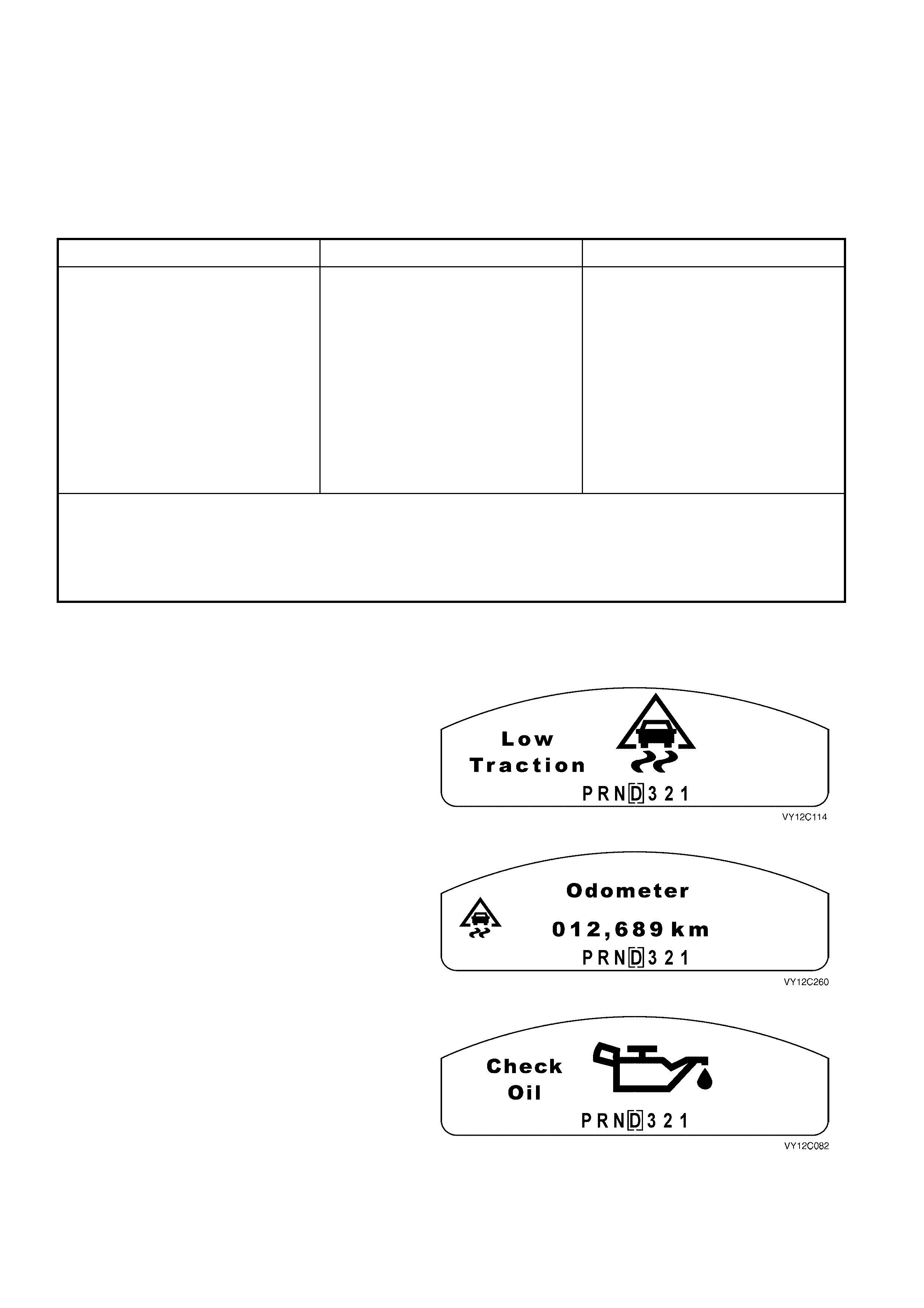
Low Traction
W hen a low traction event occurs, the MFD shows
the Low Traction animated symbol and the fixed
text warning. The Low Traction warning is not
accompanied by a chime.
Figure 12C-124
When the MODE button on the trip computer
switch is pres sed, the anim ated s ymbol reverts to a
small low traction icon on the left of the MFD.
The small icon remains illuminated as long as the
low traction situation exists.
Figure 12C-125
Low Oil Pressure
The Check Oil (low oil pressure) warning is active
when the low oil pressure bit in the PCM poll
response is active and the engine speed has
equalled or exceeded 150 rpm for at least
5 seconds.
A large oilcan with drips flowing out of the spout is
shown on the MFD.
Figure 12C-126
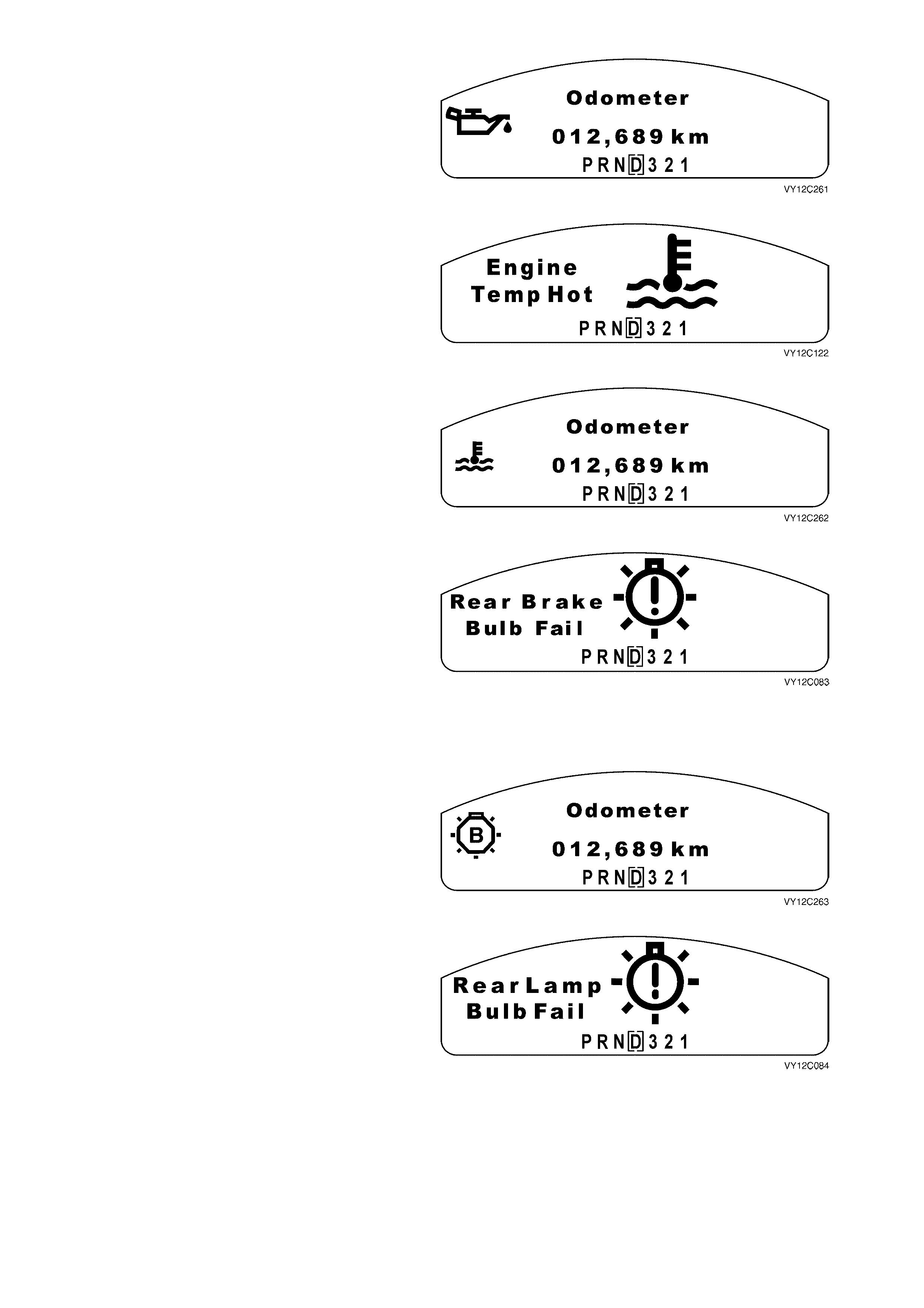
When the MODE button on the trip computer
switch is pres sed, the anim ated s ymbol reverts to a
small oilcan icon on the left of the MFD.
The small icon remains illuminated until the
problem is rectified.
Figure 12C-127
Over Temperature
The Over Temperature warning is active when the
engine temperature value in the PCM poll r es ponse
equals or exceeds the over-temperature value set
in the instrument cluster.
A large thermometer over flowing water is shown
on the MFD.
Figure 12C-128
When the MODE button on the trip computer
switch is pres sed, the anim ated s ymbol reverts to a
small over temperature icon on the left of the MFD.
The small icon remains illuminated until the
problem is rectified.
Figure 12C-129
Rear Brake Bulb Failure
The stop lamp circuits are monitored by the BCM.
The Rear Brake Bulb Fail warning is active when
the rear brak e bulb failur e bit in the BCM broadcast
message is set.
A large bulb with a flashing exclamation mark is
shown on the MFD.
This warning indicates that a fault has been
detected in the rear br ake lamps or the high-mount
brake lamp.
Figure 12C-130
When the MODE button on the trip computer
switch is pres sed, the anim ated s ymbol reverts to a
small bulb failure icon on the left of the MFD.
The small icon remains illuminated until the
problem is rectified.
Figure 12C-131
Rear Lamp Bulb Failure
The rear park lamp circuits are monitored by the
BCM. The Rear Lamp Bulb Fail warning is active
when the rear lam p f ailur e bit in the BCM broadcas t
message is set.
A large bulb with a flashing exclamation mark is
shown on the MFD.
This warning indicates that a fault has been
detected in the rear par k lamp s or the licenc e plate
lamps.
Figure 12C-132
When the MODE button on the trip computer
switch is pres sed, the anim ated s ymbol reverts to a
small bulb failure icon on the left of the MFD.
The small icon remains illuminated until the
problem is rectified.
Figure 12C-133
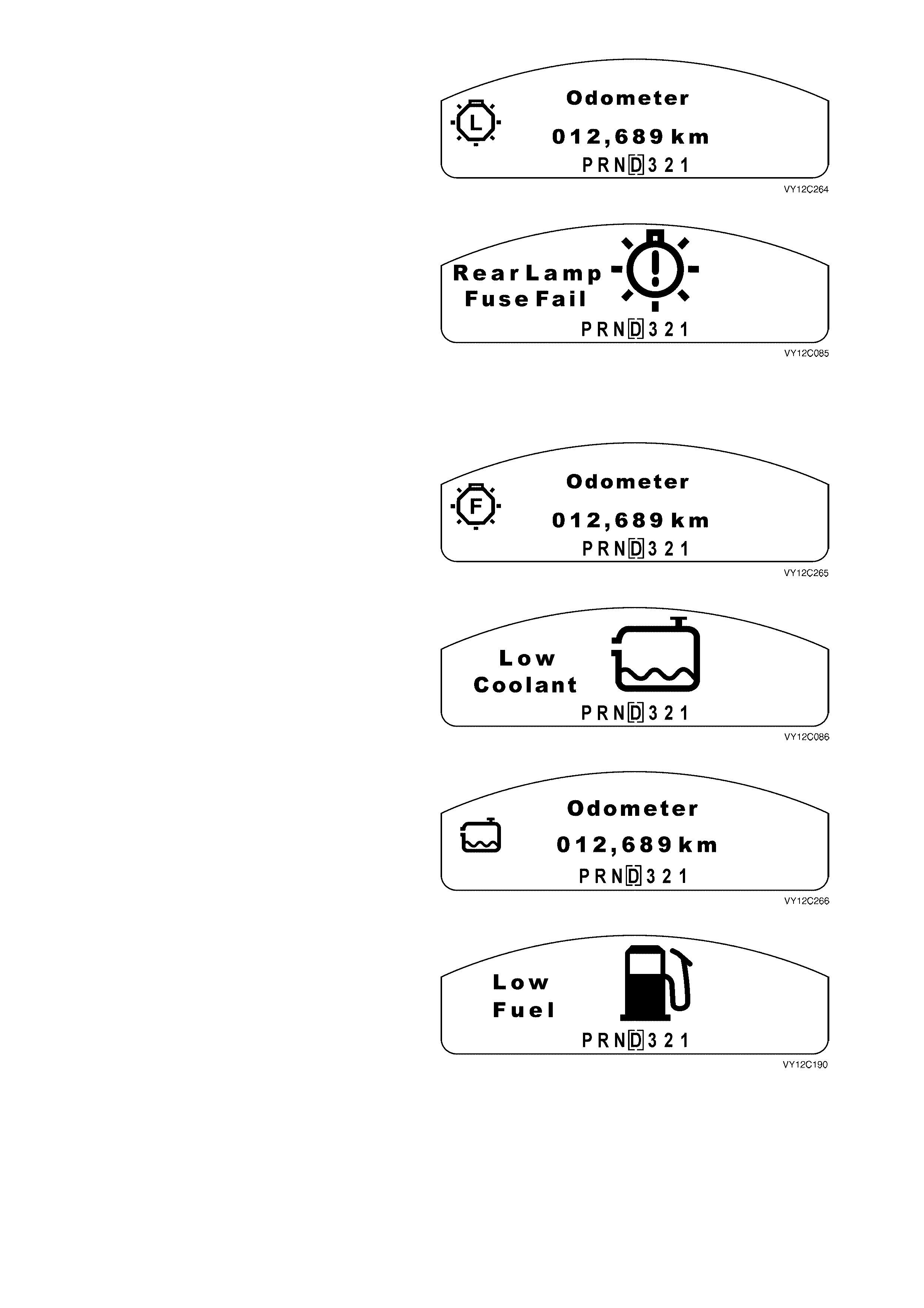
Rear Lamp Fuse Failure
The rear brake lamp fuse circuit is monitored by the
BCM. The Rear Lamp Fuse Fail warning is active
when the rear lamp fuse failure bit in the BCM
broadcast message is set.
A large bulb with a flashing exclamation mark is
shown on the MFD.
This warning indicates that a fault has been
detected in the stop lamps fuse or the park lamps
fuse.
Figure 12C-134
When the MODE button on the trip computer
switch is pres sed, the anim ated s ymbol reverts to a
small fuse failure icon on the left of the MFD.
The small icon remains illuminated until the
problem is rectified.
Figure 12C-135
Low Coolant
The large Low Coolant warning icon is ac tive when
the low coolant bit in the PCM poll response
message is set.
A large coolant bottle with flowing water is shown
on the MFD.
Figure 12C-136
When the MODE button on the trip computer
switch is pres sed, the anim ated s ymbol reverts to a
small low coolant icon on the left of the MFD.
The small icon remains illuminated until the
problem is rectified.
Figure 12C-137
Low Fuel (Petrol)
The Low Fuel (petrol) warning is active when the
estimated current fuel level is equal to or less than
the low fuel warning level but greater than the very
low fuel warning level.
The large animated low fuel icon is displayed on
the MFD.
Figure 12C-138
When the MODE button on the trip computer
switch is pressed, the distance to empty display is
shown for 10 seconds before reverting to the
original trip computer display with a small low fuel
icon on the left of the MFD.
The small icon remains until the fuel tank is filled
above the low level.
Figure 12C-139
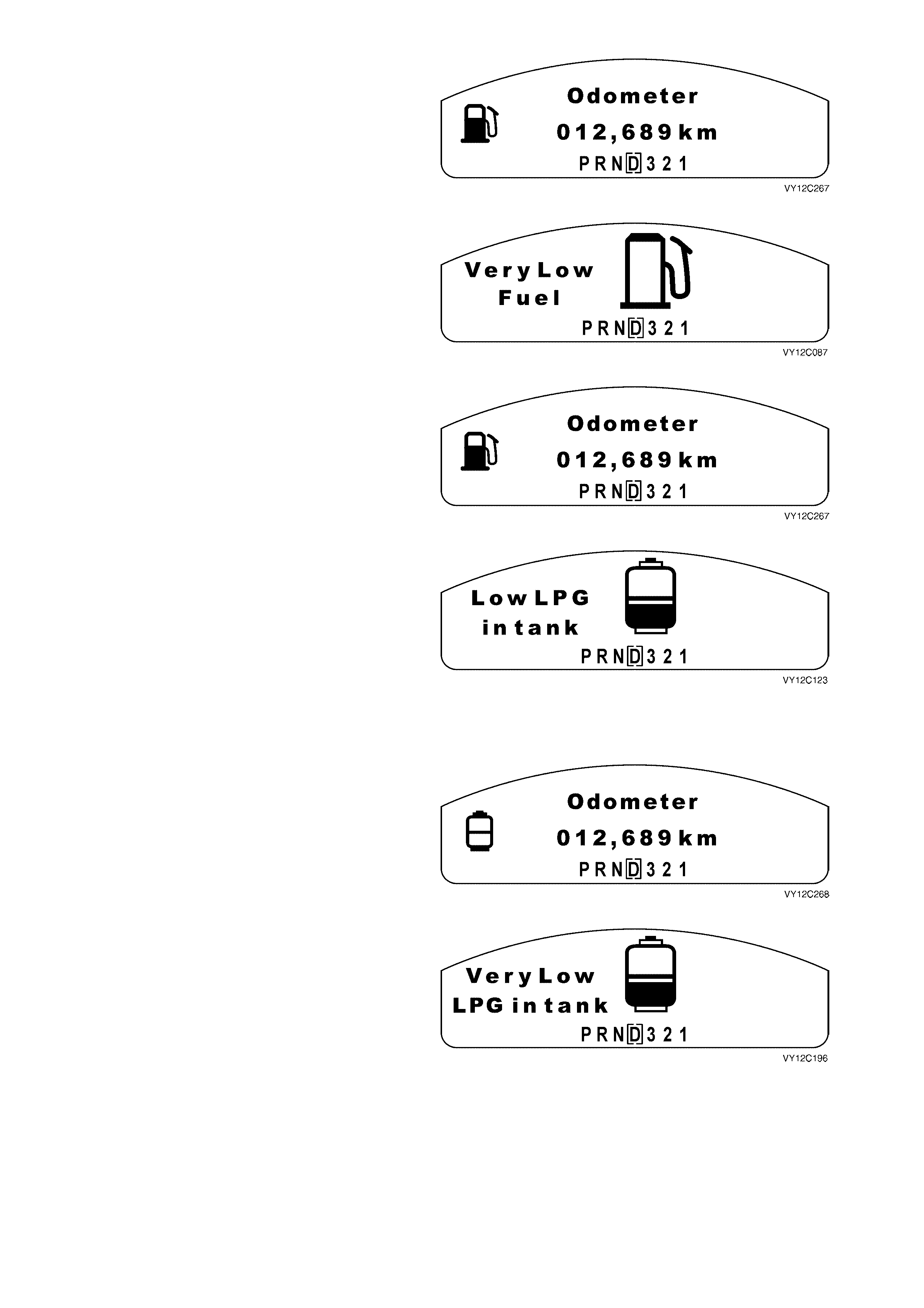
Very Low Fuel (Petrol)
The Very Low Fuel (petrol) warning is active when
the estimated current fuel level is equal to or less
than the very low fuel warning level.
The large animated very low fuel icon is displayed
on the MFD.
Figure 12C-140
When the MODE button on the trip computer
switch is pressed, the distance to empty display is
shown for 10 seconds before reverting to the
original trip computer display with a small flashing
very low fuel icon on the left of the MFD.
The small icon remains flashing until the fuel tank
is filled above the very low level.
Figure 12C-141
Low LPG in Petrol Mode
If the vehicle is fitted with LPG, there is an
additional warning for low LPG when in petrol
mode. If the low LPG warning has activated, the
LPG warning will still be shown at ignition on. W hen
the vehicle is started in petrol mode, the cluster
goes through the System Check and then displays
the warning icon.
The large animated low LPG in tank icon is
displayed on the MFD.
Figure 12C-142
When the MODE button on the trip computer
switch is pressed, the MFD reverts to the original
trip computer display with a small low LPG icon on
the left of the MFD.
When the LPG tank is f illed above the low level, the
LPG low warning is deactivated.
Figure 12C-143
Very Low LPG in Petrol Mode
If the vehicle is fitted with LPG, there is an
additional warning for very low LPG when in petrol
mode. If the very low LPG warning has activated,
the LPG warning will still be shown at ignition on.
When the vehicle is started in petrol mode, the
cluster goes through the System Check and then
displays the warning icon.
The large animated very low LPG in tank icon is
displayed on the MFD.
Figure 12C-144
When the MODE button on the trip computer
switch is pressed, the MFD reverts to the original
trip c omputer display with a small f lashing low LPG
icon on the left of the MFD.
When the LPG tank is filled above the very low
level, the LPG very low warning is deactivated.
Figure 12C-145
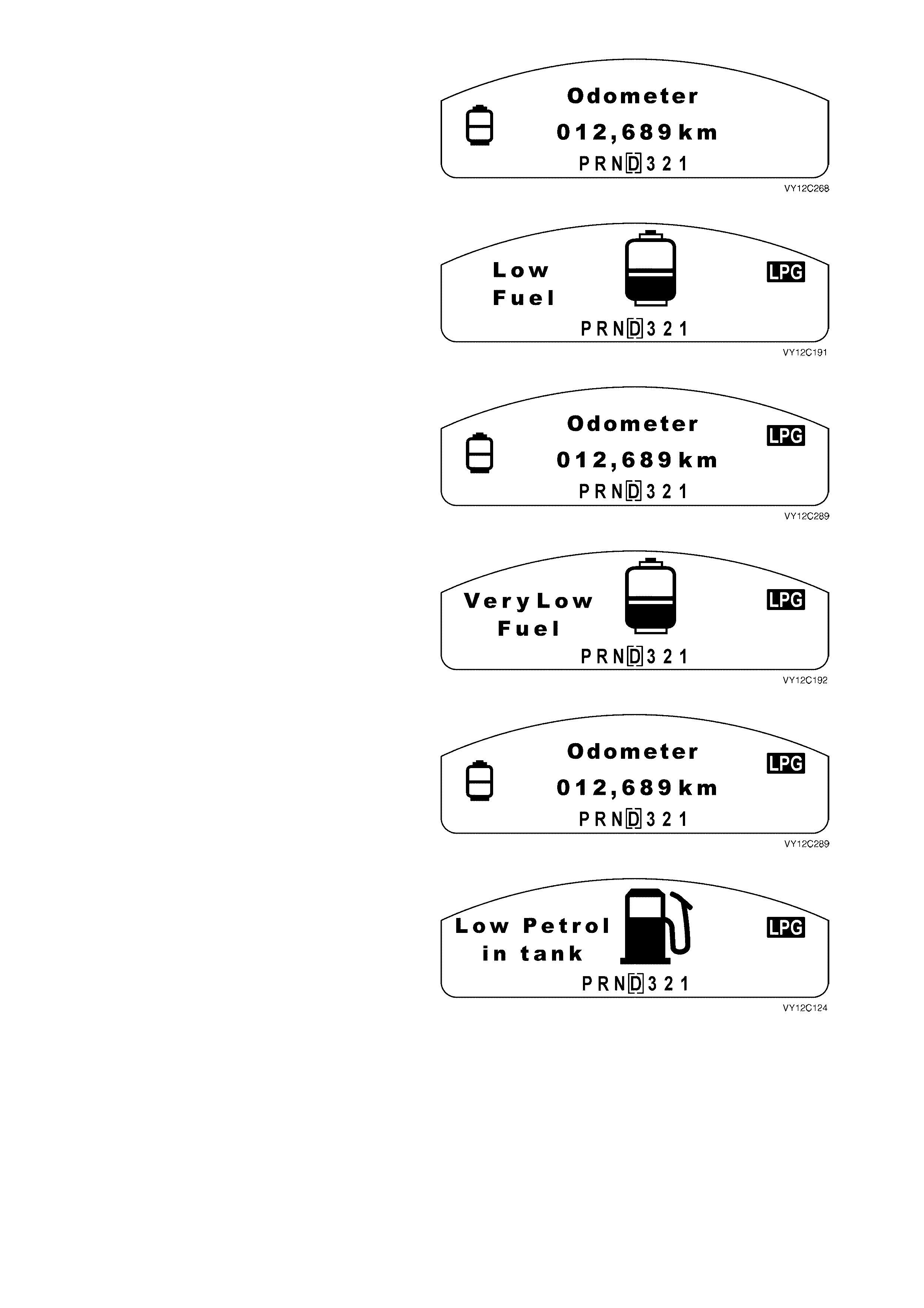
Low LPG
The Low Fuel (LPG) warning is active when the
estimated current fuel level is equal to or less than
the low fuel warning level but greater than the very
low fuel warning level.
The large animated low LPG icon is displayed on
the MFD.
Figure 12C-146
When the MODE button on the trip computer
switch is pressed, the distance to empty display is
shown for 10 seconds before reverting to the
original trip computer display with a small low LPG
icon on the left of the MFD.
The small icon remains until the LPG tank is filled
above the low level.
Figure 12C-147
Very Low LPG
The Very Low Fuel (LPG) warning is active when
the estimated current fuel level is equal to or less
than the very low fuel warning level.
The large animated very low LPG icon is displayed
on the MFD.
Figure 12C-148
When the MODE button on the trip computer
switch is pressed, the distance to empty display is
shown for 10 seconds before reverting to the
original trip computer display with a small flashing
low LPG icon on the left of the MFD.
The small icon remains flashing until the LPG tank
is filled above the very low level.
Figure 12C-149
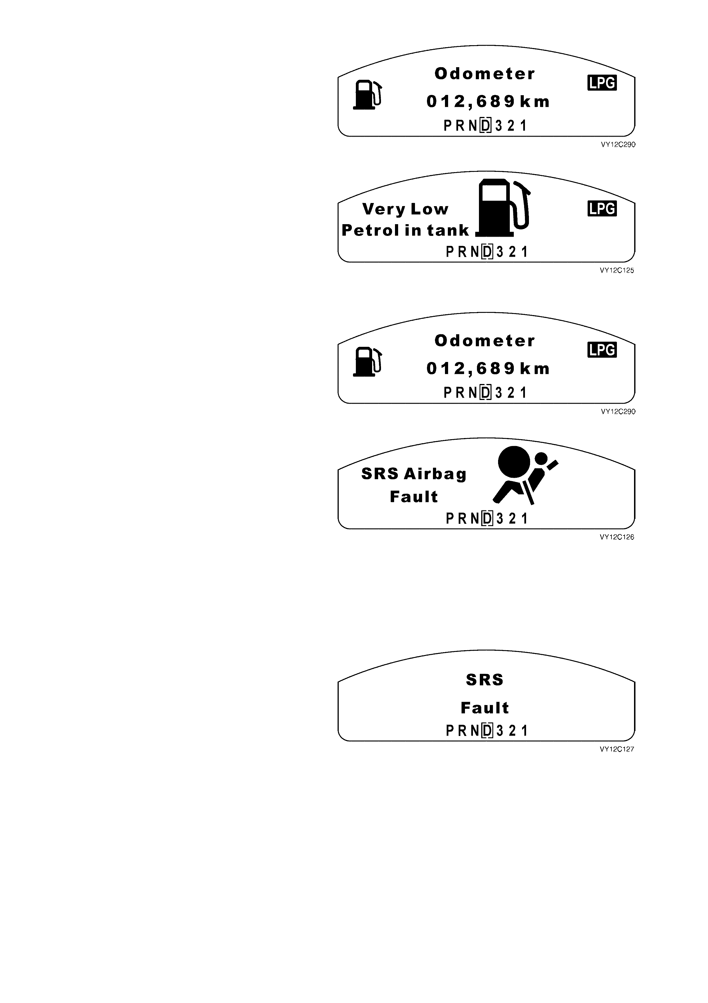
Low Petrol in LPG Mode
NOTE: The vehicle uses petrol to start when
operating on LPG.
When operating on LPG, the Low Petrol in Tank
warning is active when the estimated current fuel
(petrol) level is equal to or less than the low fuel
(petrol) warning level but greater than the very low
fuel (petrol) warning level.
The large animated icon is displayed on the MFD.
Figure 12C-150
When the MODE button on the trip computer
switch is pressed, the distance to empty display is
shown for 10 seconds before reverting to the
original trip computer display with a small low fuel
icon on the left of the MFD.
The small icon remains until the fuel tank is filled
above the low level.
Figure 12C-151
Very Low Petrol in LPG Mode
NOTE: The vehicle uses petrol to start when
operating on LPG.
When operating on LPG, the Very Low Petrol in
Tank warning is active when the estimated current
fuel (petrol) level is equal to or less than the very
low fuel (petrol) warning level.
The large animated icon is displayed on the MFD.
Figure 12C-152
When the MODE button on the trip computer
switch is pressed, the distance to empty display is
shown for 10 seconds before reverting to the
original trip computer display with a small flashing
very low fuel icon on the left of the MFD.
The small icon remains flashing until the fuel tank
is filled above the very low level.
Figure 12C-153
SRS Airbag and Pretensioners
The SRS Airbag Fault warning is active when the
SRS warning bit in the SRS poll res pons e mess age
is set.
In vehicles f itted with airbags, the SRS Airbag Fault
warning illuminates the SRS telltale LED and
displays an icon on the MFD.
The MFD ic on flas hes and the wording is stationary
until the MODE button on the trip computer switch
is pressed.
The SRS telltale LED illuminates as soon as the
warning is activated and remains illuminated until
the problem is rectified.
Figure 12C-154
SRS Fault
If the vehicle is fitted with pretensioners only, the
SRS Fault warning appears on the MFD and
illuminates the SRS telltale LED.
The SRS Fault warning flashes until the MODE
button on the trip computer switch is pressed. The
MFD then reverts back to the previously displayed
trip computer screen.
The SRS telltale LED illuminates as soon as the
warning is activated and remains illuminated until
the problem is rectified.
Figure 12C-155
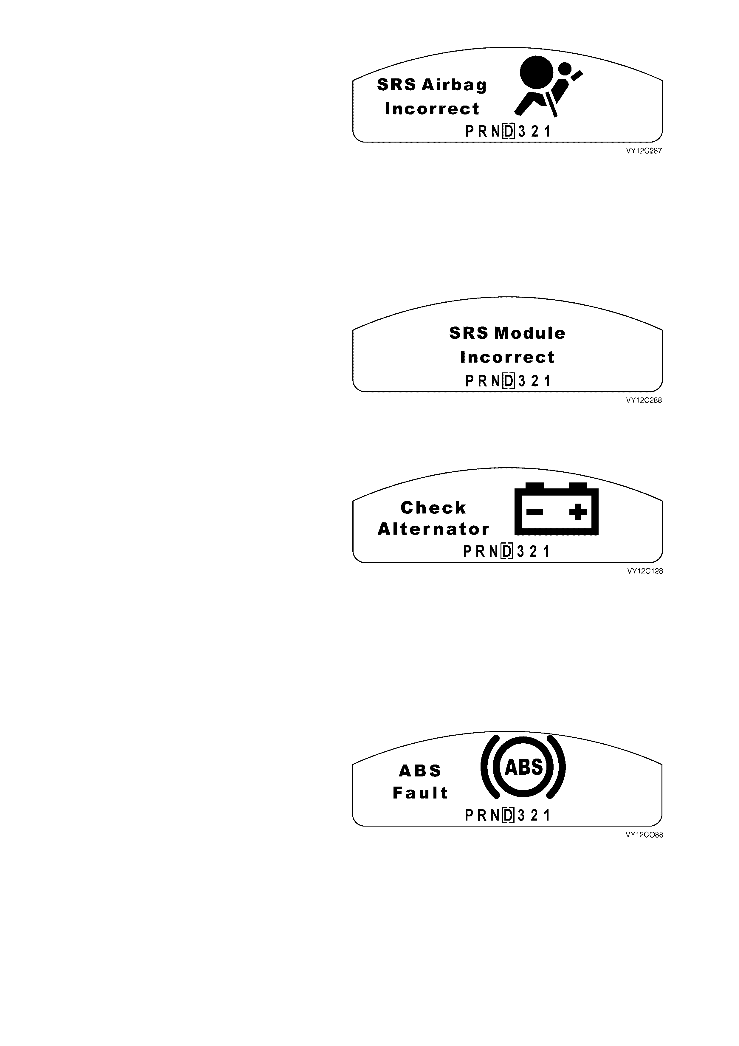
Incorrect SRS Module
The instrument cluster is programmed by TECH 2
to identify the appropriate SRS Module for the
vehicle configuration. If the instrument cluster
detects that an incorrect module has been fitted to
the vehicle, the SRS Airbag Incorrect warning is
activated.
The SRS Airbag Incorrect warning also illuminates
the SRS telltale LED.
The MFD ic on flas hes and the wording is stationary
until the MODE button on the trip computer switch
is pressed.
The SRS telltale LED illuminates as soon as the
warning is activated and remains illuminated until
the problem is rectified.
Figure 12C-156
If the vehicle is fitted with pretensioners only, the
SRS Module Incorrect warning appears on the
MFD and illuminates the SRS telltale LED.
The SRS Module Inc orr ec t warning f lashes until the
MODE button on the trip computer switch is
pressed. The MFD then reverts back to the
previously displayed trip computer screen
The SRS telltale LED illuminates as soon as the
warning is activated and remains illuminated until
the problem is rectified.
Figure 12C-157
Generator
The generator warning (Check Alternator) is active
when the generator input to the instrument cluster
is active and the engine speed has equalled or
exceeded 150 rpm for at least 5 seconds.
A generator fault warning illuminates the battery
telltale LED and displays an animated icon on the
MFD.
The MFD icon is displayed only if the engine is
running and remains displayed until the MODE
button on the trip computer switch is pressed. The
MFD then reverts back to the previously displayed
trip computer screen.
The Battery telltale LED is illuminated even if the
engine is not running and remains illuminated until
the problem is rectified.
Figure 12C-158
ABS
The ABS is active when the ABS Off input to the
instrument cluster is active.
An ABS fault warning illuminates the ABS telltale
LED and displays an animated icon on the MFD.
The ABS text in the centre of the icon flashes until
the MODE button on the trip computer switch is
pressed. The MFD then reverts back to the
previously displayed trip computer screen.
The ABS telltale LED illuminates as soon as the
warning is activated and remains illuminated until
the problem is rectified.
Figure 12C-159
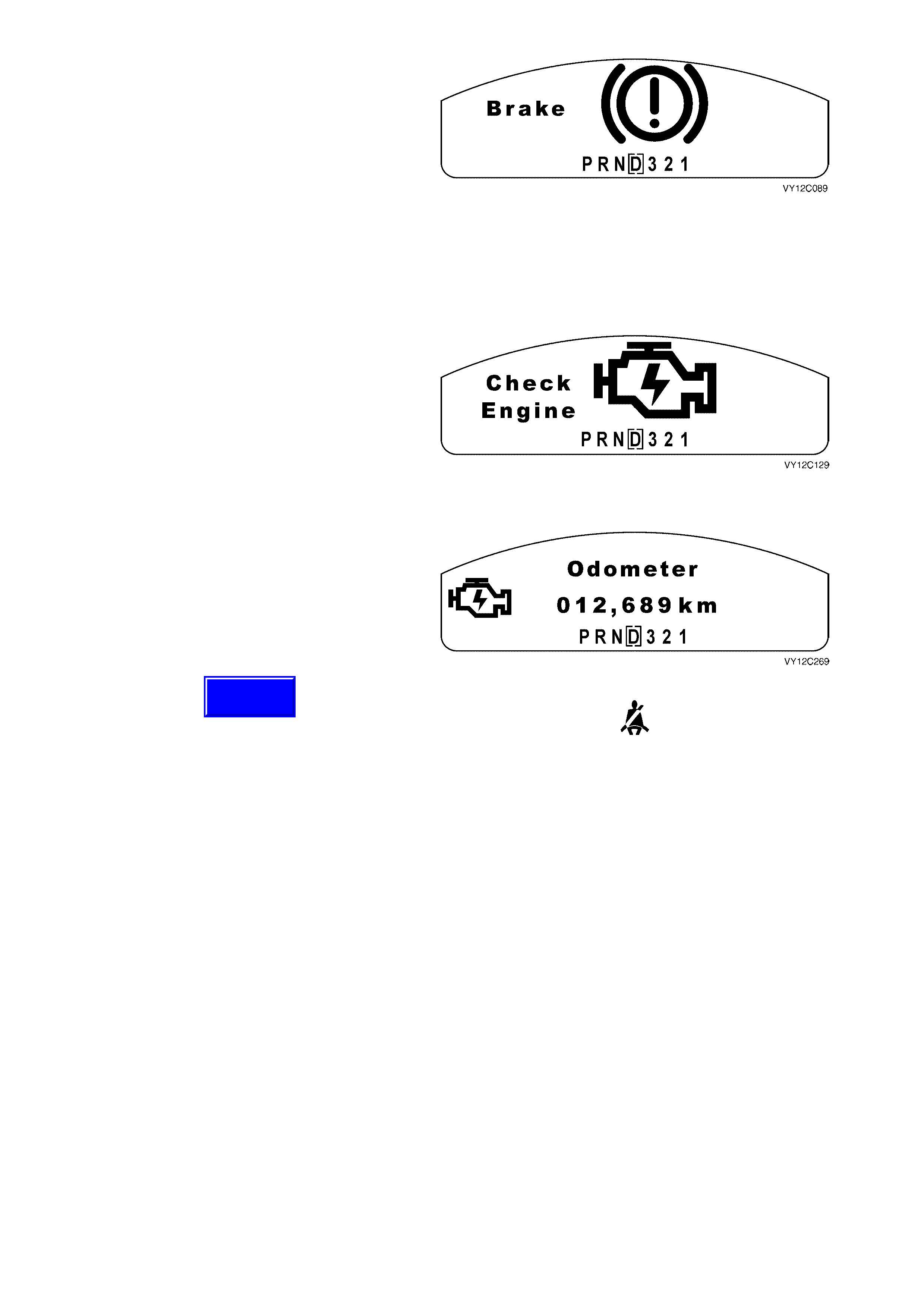
Brake Fail / Park Brake Warning
The Brake warning is active when the brake input
to the instrument cluster is active and the vehicle
speed is greater than 8 km/h.
A Brake warning illuminates the Brake telltale LED
and displays an animated icon on the MFD.
The exclamation mark in the centre of the icon
flashes until the MODE button on the trip com puter
switch is pressed. The MFD then reverts back to
the previously displayed trip computer screen.
The Brake telltale LED illuminates as soon as the
warning is activated and remains illuminated until
the problem is rectified.
Figure 12C-160
Check Engine
The Check Engine warning is active if the
Powertrain Control Module (PCM) detects a
problem in either the engine or the transmiss ion (ie.
the powertrain).
The lar ge anim ated Check Engine icon is displayed
on the MFD. The lightning bolt in the centre of the
icon flashes until the MODE button on the trip
computer switch is pressed.
Figure 12C-161
When the MODE button on the trip computer
switch is pr essed the dis play reverts to a sm all ic on
on the left of the MFD.
The icon remains until the problem is rectified.
Figure 12C-162
Seat Belt Warning
Whenever the ignition is turned on, the seat belt
warning telltale LED illuminates for 8 seconds.
Figure 12C-163
Techline

SERVICE ITEMS
A ser vice rem inder is dis played when the ignition is
switched on or off until the trip computer is reset.
The service reminder is displayed for a total of
10 seconds.
Figure 12C-164
Reset Service Display
The service reminder can be reset at ignition on. To
enter the reset func tion, press and hold the UP and
DOWN buttons on the trip computer switch and
turn the ignition on. The UP and DOWN buttons
mus t be held for 2 s econds after the ignition switch
is turned on.
The active service reset reminder is displayed.
To reset the displayed service rem inder, press and
hold the SET button for 3 seconds. A confirmation
beep sounds upon reset.
NOTE: When resetting the service reminders, the
PCM poll responses are cleared and the odometer
readings for the last changes are recorded. These
can be accessed by TECH 2.
Figure 12C-165
When the service reminder is reset, the MFD
shows the Service Reset No Items screen. After
2 seconds MFD advances to the System Check.
Figure 12C-166
Prior to Service Due
Service Due is determined from the odometer
reading. The MFD shows a reminder 1000 km
before a service is due. The service interval
becoming due is displayed on the MFD, and the
spanner in the icon flashes. This service reminder
is displayed for up to 10 seconds whenever the
ignition is switched on or off until the service
reminder is reset.
Figure 12C-167
Service Due
W hen a service is due, the whole icon flashes. This service reminder is displayed for up to 10 seconds whenever
the ignition is switched on or off until the service reminder is reset.
Service Overdue
When a service is overdue by less than 5000 km, the MFD shows a flashing icon for up to 10 seconds whenever
the ignition is switched on or off until the service reminder is reset.
Service Well Overdue
W hen a service is overdue by more than 5000 km , the MFD shows a flashing icon for up to 10 seconds whenever
the ignition is switched on or off until the service reminder is reset. This event is permanently logged in the
instrument cluster memory (EEPROM) in case of future warranty disputes.
NOTE: W hen a Servic e Due reminder is r eset, the PCM poll res ponses are cleared and the odometer readings f or
the last changes are recorded. These can be accessed by TECH 2. The next Service Due reminder will appear
1000 km before the next scheduled service period.
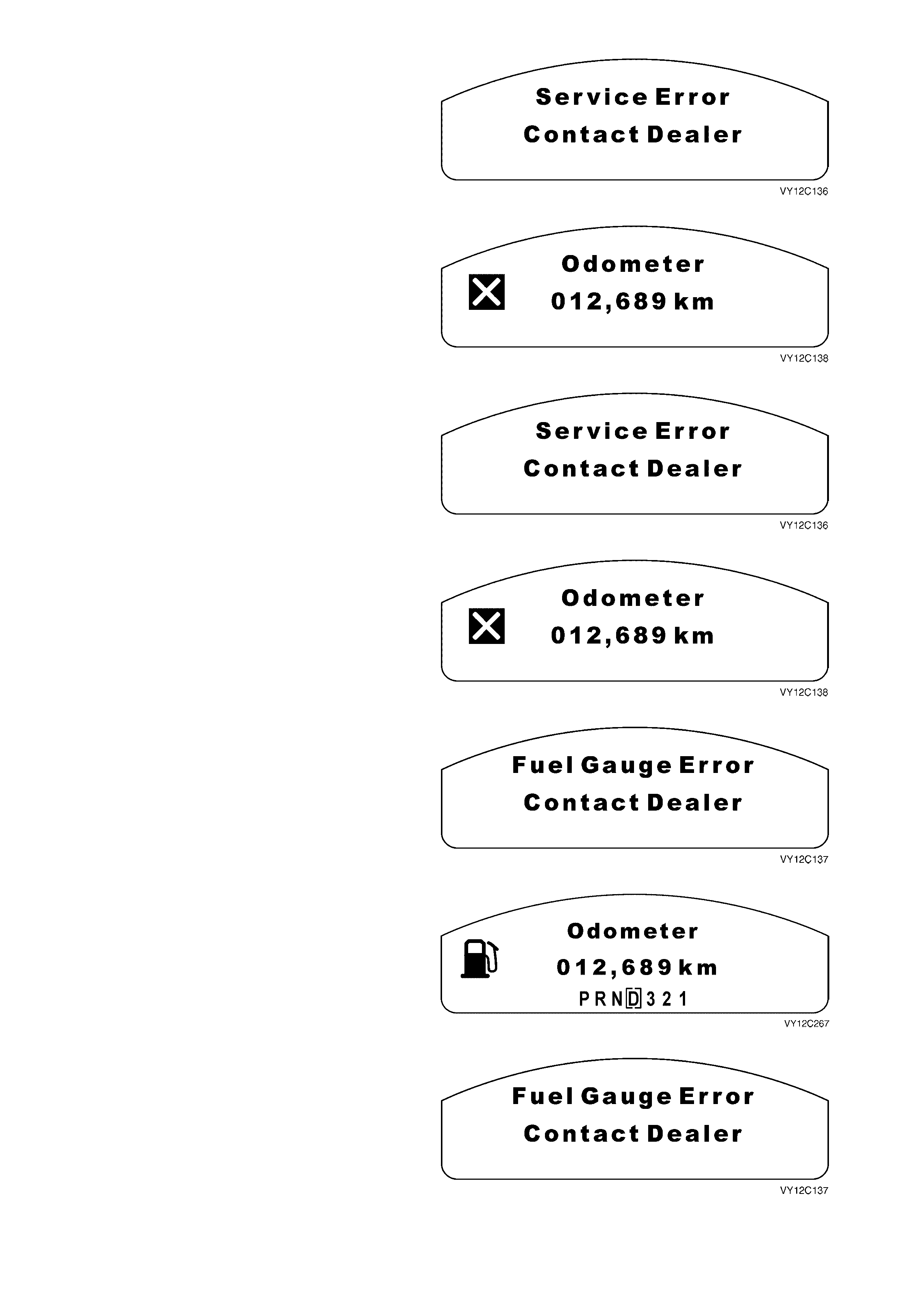
Service Error
The Service Error screen indicates that a
malfunction has occurred in the instrument cluster
and / or a cluster subsystem.
Use TECH 2 diagnostics to check the instrument
cluster. The display resets when the problem is
rectified.
Figure 12C-168
The service error message is displayed until the
MODE button on the trip computer switch is
pressed. The display then reverts to the small icon
on the left of the MFD.
Use TECH 2 diagnostics to check the instrument
cluster. The display resets when the problem is
rectified.
Figure 12C-169
Serial Communications Error
When serial bus c om m unications ar e lost, the MFD
shows the Service Error screen:
Figure 12C-170
The service error message is displayed until the
MODE button on the trip computer switch is
pressed. The display then reverts to the small icon
on the left of the MFD.
Use TECH 2 diagnostics to check the instrument
cluster. The display resets when the problem is
rectified.
Figure 12C-171
Fuel (Petrol) Sender Error
The Fuel Gauge Error screen is displayed if a fault
has been detected with the fuel sender.
Figure 12C-172
When the MODE button on the trip computer
switch is pressed, the original trip com puter screen
is displayed with a small fuel icon on the left of the
MFD.
Use TECH 2 diagnostics to check the appropriate
Diagnostic Trouble Code. The display resets when
the problem is rectified.
Figure 12C-173
Fuel (LPG) Sender Error
The Fuel Gauge Error screen is displayed if a fault
has been detected with the fuel sender.
Figure 12C-174
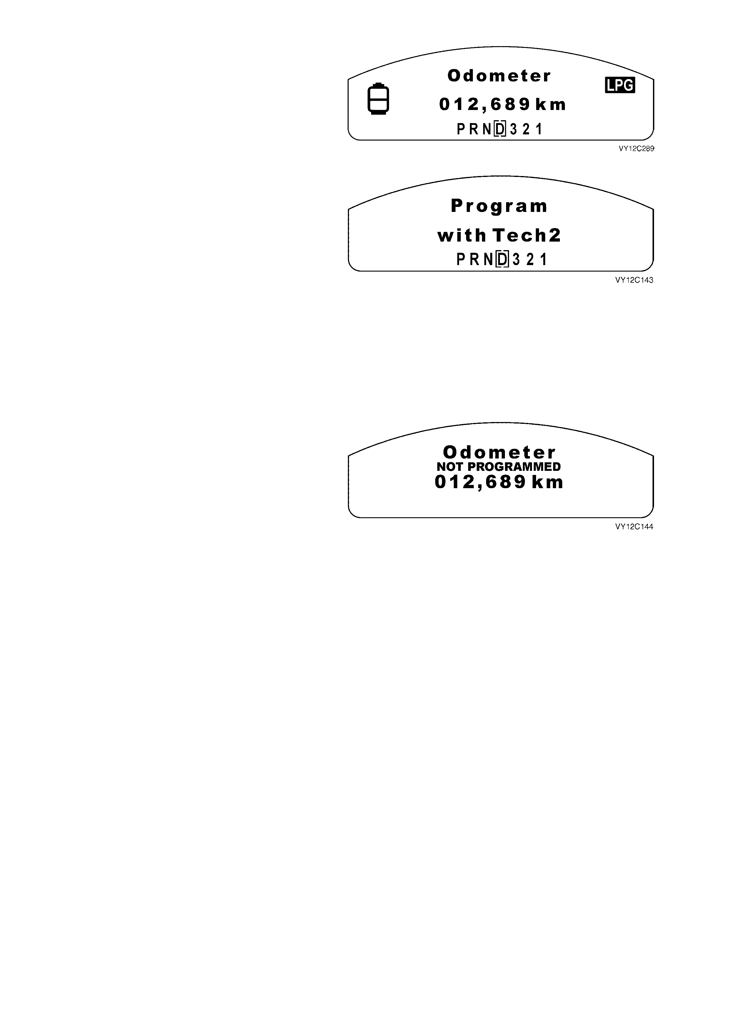
When the MODE button on the trip computer
switch is pressed, the original trip com puter screen
is displayed with a small LPG ic on on the lef t of the
MFD.
Use TECH 2 diagnostics to check the appropriate
Diagnostic Trouble Code. The display resets when
the problem is rectified.
Figure 12C-175
Program Cluster
When a new instrum ent c luster is f itted at a Holden
Retailer, the Program Cluster screen indicates that
it m ust be pr ogramm ed to suit the vehicle type and
country of destination.
When the instrument cluster is first powered up, the
MFD shows Program with TECH 2.
No trip computer functions or selections are
available when the ignition is on.
NOTE: If a warning is active on the MFD, it will be
shown until the trip computer switch MODE button
is pr essed. When the MODE button is pr essed, the
display reverts to having the small warning icon on
the left of the MFD. The Program with TECH 2
message remains displayed.
Figure 12C-176
At ignition off, the MFD shows the Odometer
screen and Not Programmed to indicate that the
instrument cluster requires programming.
Figure 12C-177
For further details on programming the instrument
cluster refer to 3.15 PROGRAM in this Section.
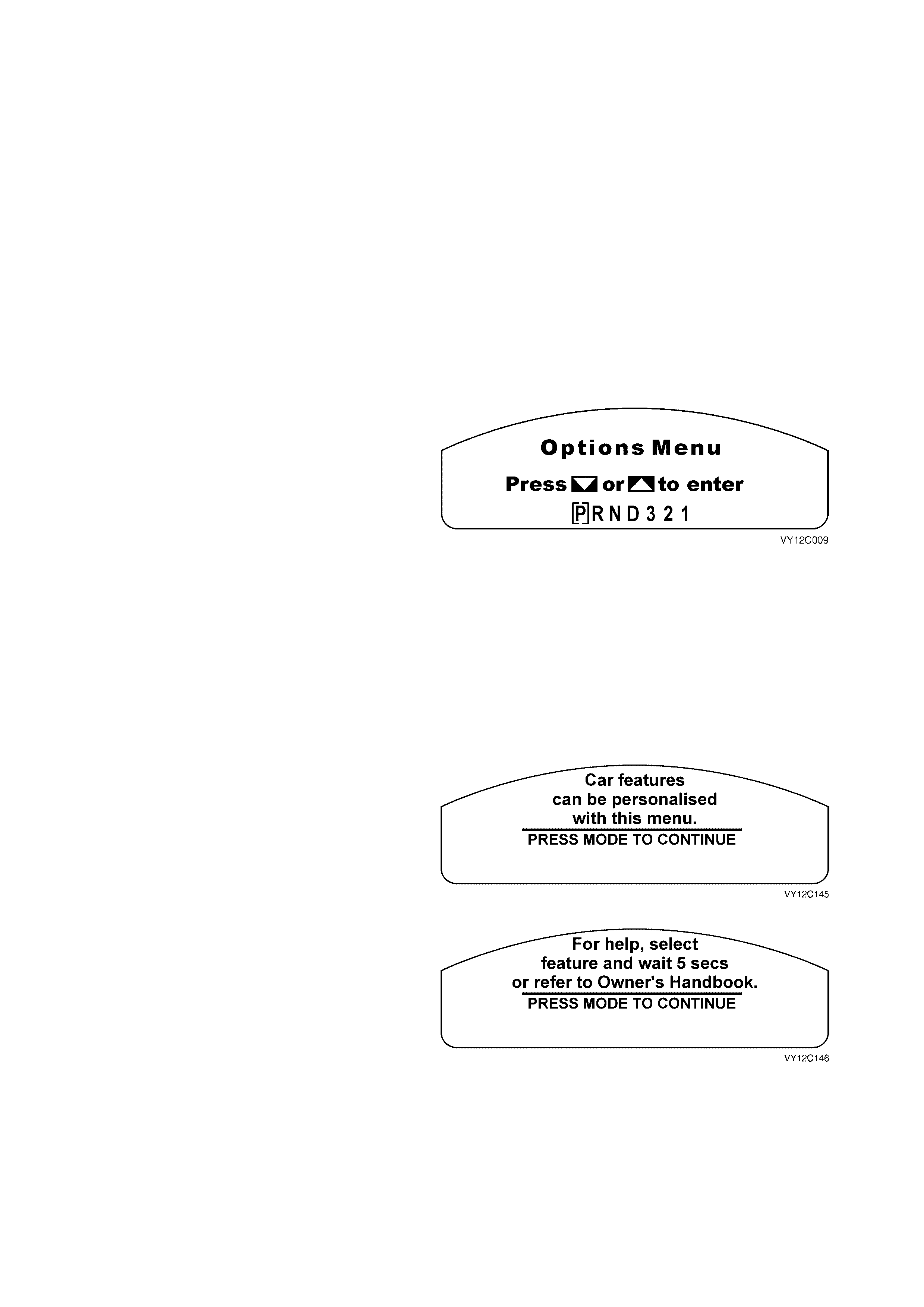
1.8 CUSTOMISATION MODE
Customisation Mode enables the driver to turn on or off functions and adjust features. Only features that are fitted to
the vehicle are displayed. If the vehicle is moving at more than 10 km/h while in Customisation Mode, the screen
reverts back to the previous trip computer function.
In Custom is ation Mode ther e are help menus to as s ist dr ivers to under stand the feature they are adjusting. When in
Custom isation Mode, if a m enu item is select ed and the screen is lef t for m ore than 5 seconds , a help scr een pops
up to inform the driver how to operate the selected feature.
To scroll through the customisation items, press the MODE button on the trip computer switch. To exit the
Customisation Mode:
• press the trip computer switch MODE button to scroll through to the exit screen, or
• drive the vehicle at more than 10 km/h, or
• switch the ignition off.
NOTE 1: Custom isation Mode is not displayed if an alarm warning has been activated or a warning sym bol on the
instrument cluster has been triggered.
NOTE 2: Not all the following customisation items are available on all models.
ENTERING CUSTOMISATION MODE (OPTIONS MENU)
Customisation Mode is accessed via the Options
Menu, which can be displayed when the vehicle is
stationary or moving slowly.
• If the vehicle is stationary, turn the ignition key
on while pres sing the MODE button on the trip
computer switch. (If the MODE button is
pressed a second time, the Options Menu
disappears and the display reverts back to the
previous trip computer function).
• If the vehicle has been started, the System
Check completed and the vehicle speed is
less than 10 km/h, then the Options Menu is
displayed for 3 seconds. (If the vehicle is
driven at more than 10 km/h, the Options
Menu disappears and the display reverts back
to the previous trip computer function).
With the Options Menu displayed, press the trip
computer UP or DOWN button to enter
Customisation Mode.
Figure 12C-178
When the Customisation Mode is entered, the
following displays show how to reach the Help
screens.
Press the MODE button to advance to the next
Help screen.
Figure 12C-179
Press the MODE button to advance to the Restore
to Factory Settings screen.
Figure 12C-180
NOTE 1: If the message is too big for one screen a second (or third) screen with more information appears once
the MODE button is pressed, until the menu item is shown.
NOTE 2: In the Options Menu there ar e no fixed icons displayed around the outside of the m ain dot matr ix area. If
an icon is activated while in the Options Menu, that ic on is displayed f or 2 seconds and then dis appears. Once the
Options Menu is ex ited or the vehicle s peed is greater than 10 k m/h when the Options Menu is locked out, the ic ons
reappear.
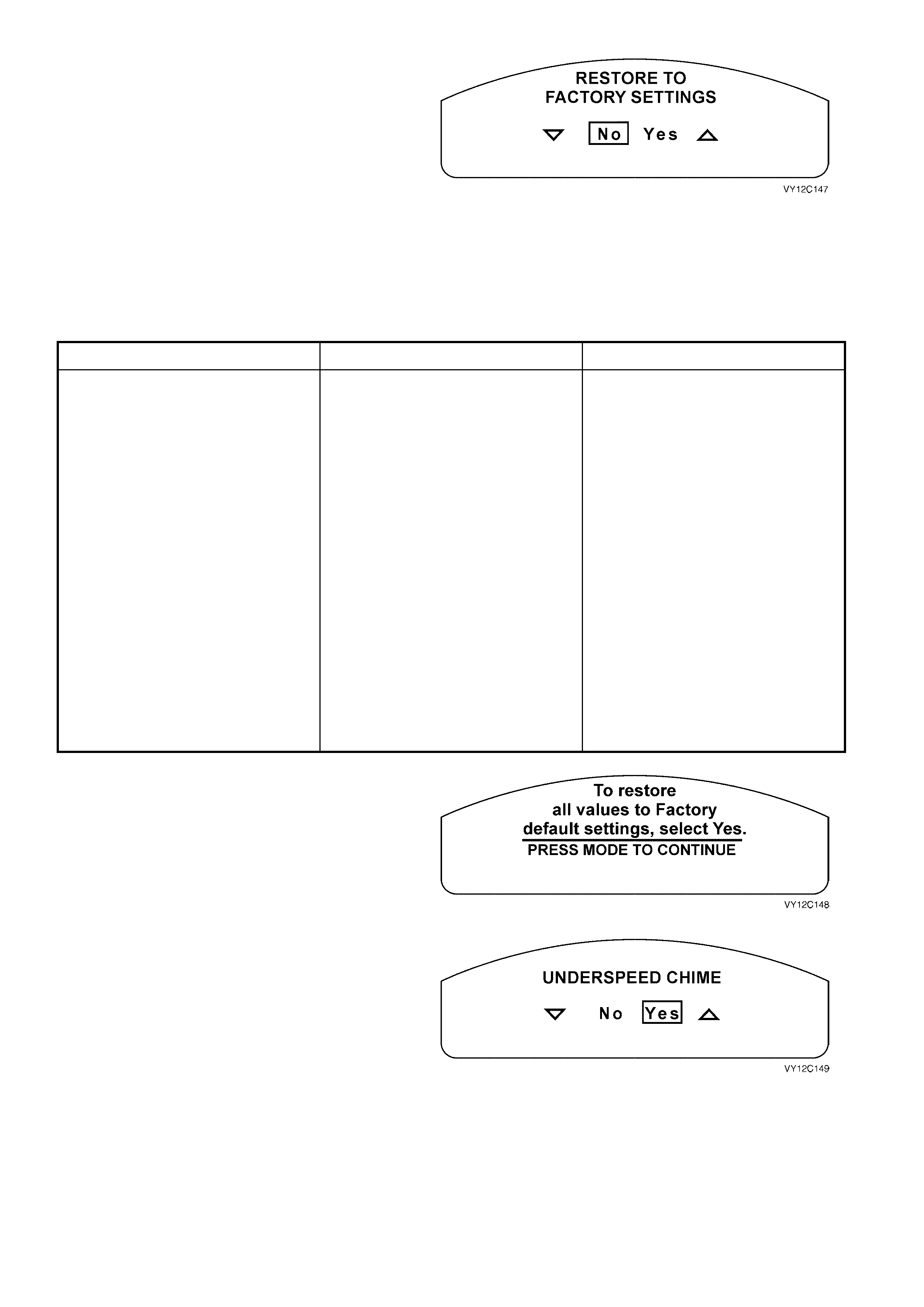
Restore to Factory Settings
The Restore to Factory Settings screen is the first
item on the Options Menu.
IMPORTANT: T his function res tor es the ins tr ument
cluster, the entertainment system and the body
control module to the factory default settings.
Use the trip computer switch UP or DOWN button
to select Yes or No.
Press the MODE button to continue. If Yes is
selected as the option, a 2 sec ond delay allows the
following param eters to be updated before the next
screen is displayed:
Figure 12C-181
CLUSTER PARAM E TERS BCM PARAMETERS AUDIO SYSTEM PARAMETERS
• Underspeed Chime set to Yes.
• Distance to Go Display set to
Yes.
• Distance to Go Default set to
500 km.
• Distance to Arrival Display set to
Yes.
• Distance to Arrival Default set to
500 km.
• Trip Computer A and B set to
Trip A.
• Stop Watch set to Yes.
• Radio Display set to On.
• Restore BCM Factory Settings set
to No.
• Headlamp Off Delay set to
1 second.
• Approach Illumination set to
30 seconds.
• Automatic Headlamp Sensitivity
set to Normal.
• Interior Courtesy Lamp Timeout
set to 30 seconds.
• Interior Courtesy Lamp Timeout
— Ignition Off set to 30 seconds.
• Intermittent Wiper Speed set to
On.
• Two Stage Unlock set to Yes.
• Auto Lock in Drive set to No.
• Door Lock Indication set to
Indicators.
• Radio and Accessories Timeout
set to Door Open.
• Bass set to STD (0).
• Treble set to STD (0).
• Balance set to STD (0).
• Fader set to STD (0).
• Loudness set to On.
• Equaliser set to On.
• CD Random set to Off.
• CD Repeat set to Off.
• Local / Distance set to Distance.
• Display Mode set to Time.
• Audio Distortion Limiter set to On.
• Confirmation Beeps set to On.
• Speed Dependent Volume set
to 2.
If no selection is made at the Restore to Factory
Settings screen within 5 seconds, this Help screen
message appears.
Press the MODE button to return to the Restore to
Factory Settings screen.
Figure 12C-182
Underspeed Chime
When an overspeed condition has occurred, the
underspeed chime alerts the driver when the
vehicle speed drops back below the set overspeed
value.
Use the trip computer switch UP or DOWN button
to select Yes or No.
Press the MODE button to continue. If Yes is
selected as the option, the underspeed chime is
activated.
NOTE: The underspeed chime is set to Yes if the
Restore to Factory Settings option has been
selected.
Figure 12C-183
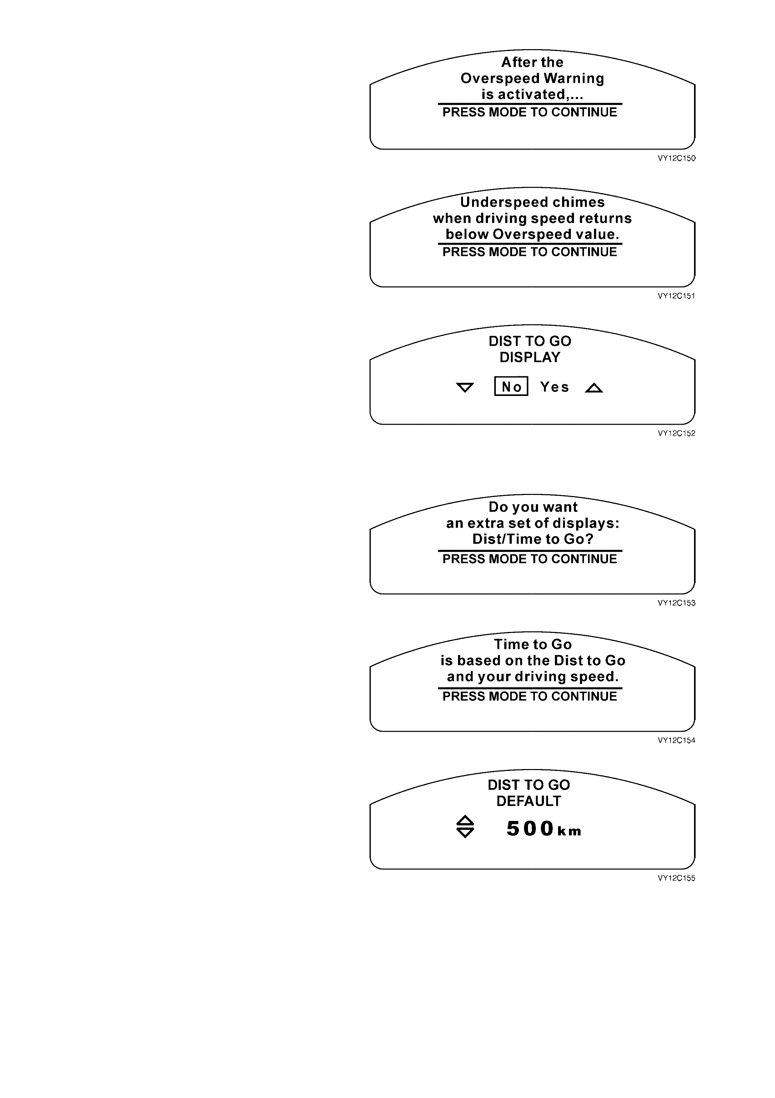
If no selection is made at the Underspeed Chime
screen within 5 seconds, this Help screen m essage
appears.
Press the MODE button to advance to the next
Help screen.
Figure 12C-184
Press the MODE button to return to the
Underspeed Chime screen.
Figure 12C-185
Distance to Go Display (Single-window Cluster)
Use the trip computer switch UP or DOWN button
to select Yes or No.
Press the MODE button to continue. If Yes is
selected as the option, the Distance to Go Default
screen is displayed.
NOTE: The Distance to Go Display is set to Yes if
the Restore to Factory Settings option has been
selected.
Figure 12C-186
If no selection is made at the Distance to Go
Display screen within 5 seconds, this Help screen
message appears.
Press the MODE button to advance to the next
Help screen.
Figure 12C-187
Press the MO DE button to retur n to the Distance to
Go Display screen.
Figure 12C-188
Distance to Go Default (Single-window Cluster)
Use the trip computer switch UP or DOWN button
to adjust the Distance to Go value. Note that
changing this value changes the displayed
Distance to Go figure.
The default value for Distance to Go is 500 km.
Press the MODE button to continue.
NOTE: The Dis tanc e to G o Def ault is set to 500 km
if the Restore to Factory Settings option has been
selected.
Figure 12C-189
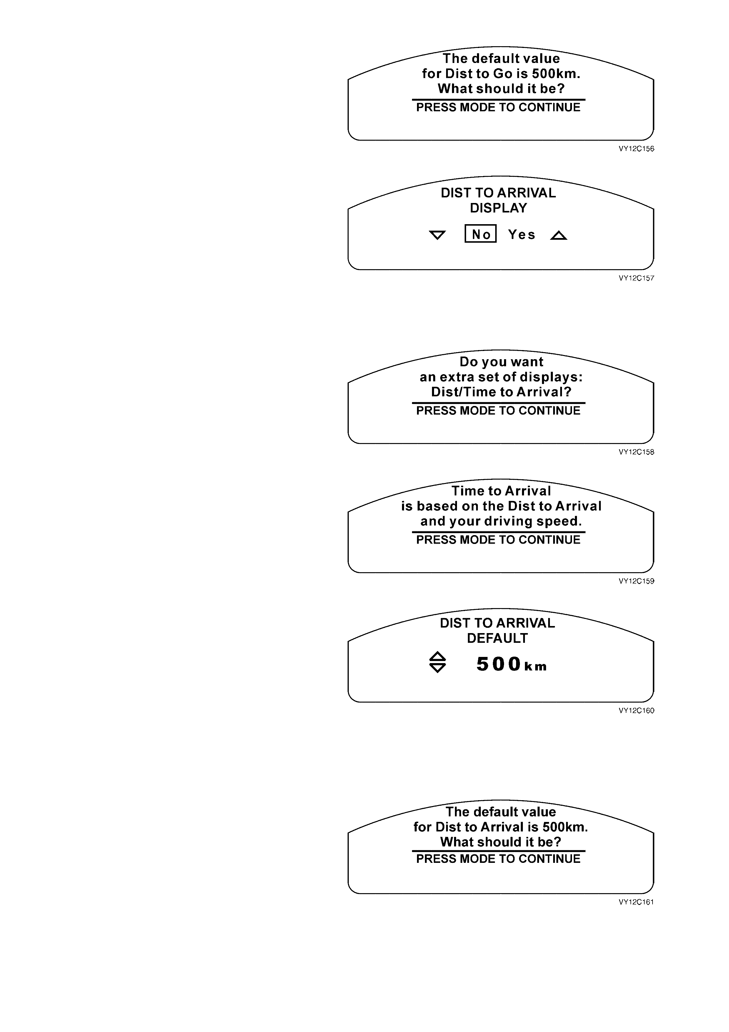
If no selection is made at the Distance to Go
Default screen within 5 seconds, this Help screen
message appears.
Press the MO DE button to retur n to the Distance to
Go Default screen.
Figure 12C-190
Distance to Arrival Display (Triple-window
Cluster)
Use the trip computer switch UP or DOWN button
to select Yes or No.
Press the MODE button to continue. If Yes is
selected as the option, the Distance to Arrival
Default screen is displayed.
NOTE: The Dis tanc e to Ar rival Dis play is set to Yes
if the Restore to Factory Settings option has been
selected.
Figure 12C-191
If no selection is made at the Distance to Arrival
Display screen within 5 seconds, this Help screen
message appears.
Press the MODE button to advance to the next
Help screen.
Figure 12C-192
Press the MO DE button to retur n to the Distance to
Arrival Display screen.
Figure 12C-193
Distance to Arrival Default (Triple-window
Cluster)
Use the trip computer switch UP or DOWN button
to adjust the Distance to Arrival value. Note that
changing this value changes the displayed
Distance to Arrival figure.
The default value for Distance to Arrival is 500 km.
Press the MODE button to continue.
NOTE: The Distance to Arrival Default is set to
500 km if the Restore to Factory Settings option
has been selected.
Figure 12C-194
If no selection is made at the Distance to Arrival
Default screen within 5 seconds, this Help screen
message appears.
Press the MO DE button to retur n to the Distance to
Arrival Default screen.
Figure 12C-195
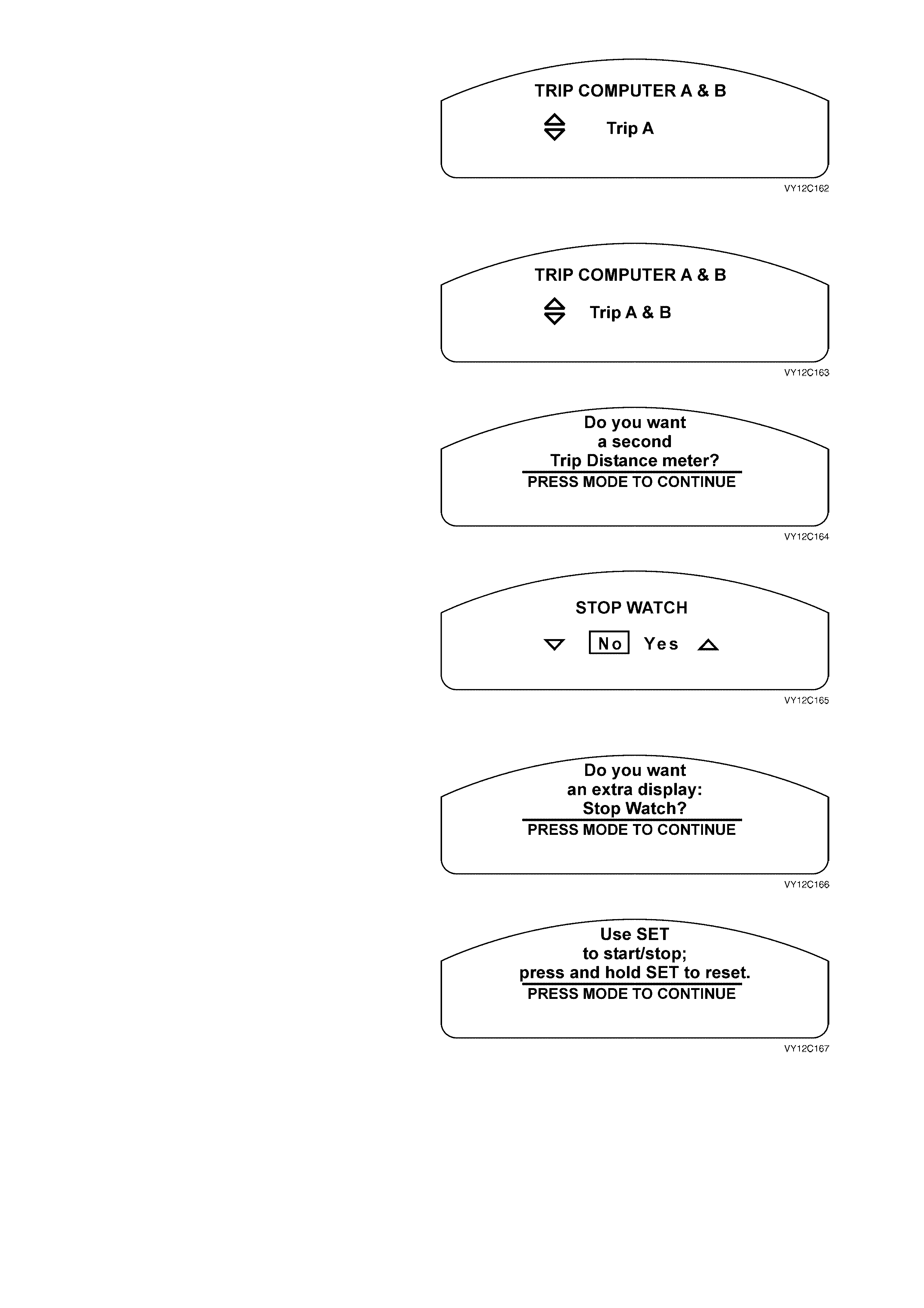
Trip Computer A and B (Triple-window Cluster)
Two trip computers can be used to record the
details of separate trips.
Use the trip computer switch DOWN button to
select Trip A only, or press the MODE button to
continue.
NOTE: Trip A is enabled if the Restore to Factory
Settings option has been selected.
Figure 12C-196
Use the trip computer switch UP button to select
Trip A and Trip B, or press the MODE button to
continue.
Figure 12C-197
If no selection is m ade at the Trip Com puter A and
B screen within 5 seconds, this Help screen
message appears.
Press the MODE button to return to the Trip
Computer A and B screen.
Figure 12C-198
Stop Watch
Use the trip computer switch UP or DOWN button
to select Yes or No.
Press the MODE button to continue. If Yes is
selected as the option, the Stop Watch screen is
enabled.
NOTE: T he Stop Watch is set to Yes if the Res tore
to Factory Settings option has been selected.
Figure 12C-199
If no selection is made at the Stop Watch screen
within 5 seconds, this Help screen message
appears.
Press the MODE button to advance to the next
Help screen.
Figure 12C-200
Press the MODE button to return to the Stop Watch
screen.
Figure 12C-201
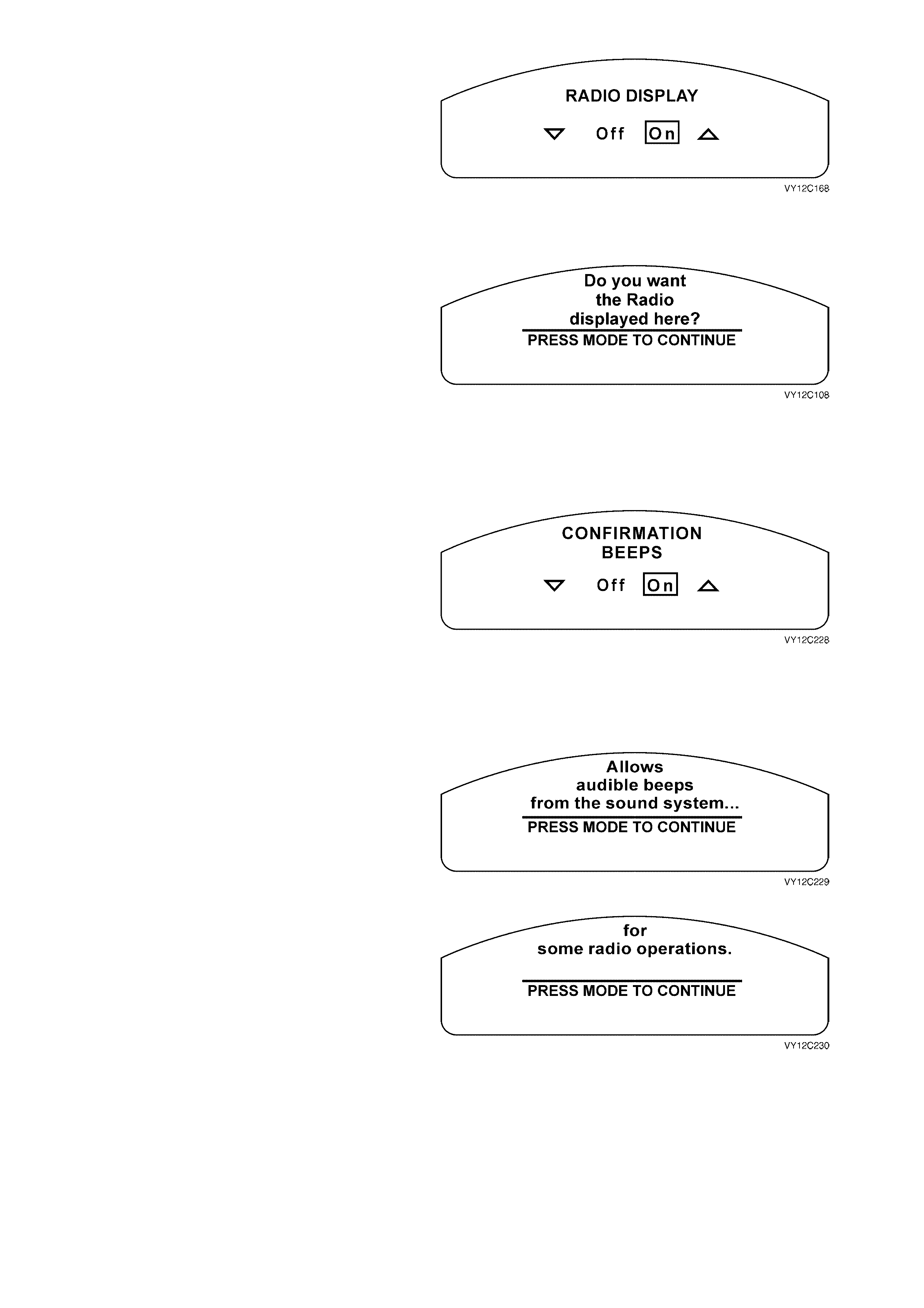
Radio Display
The entertainment system parameters can be
displayed on the instrument cluster MFD.
Use the trip computer switch UP or DOWN button
to select On or Off.
Press the MODE button to continue.
NOTE: The Radio Display is set to On if the
Restore to Factory Settings option has been
selected.
Figure 12C-202
If no selec tion is made at the Radio Dis play screen
within 5 seconds, this Help screen message
appears.
Press the MODE button to return to the Radio
Display screen.
Figure 12C-203
Confirmation Beeps
The Confirmation Beeps screen displayed will
depend on the level of the audio system fitted to
the vehicle.
Confirmation Beeps — Radio Only
Confirmation beeps can be set to confirm that
various func tions of the entertainm ent syst em have
been completed. For example storing a radio
station.
Use the trip computer switch UP or DOWN button
to set to On or Off.
Press the MODE button to continue.
NOTE: The Confirmation Beeps is set to On if the
Restore to Factory Settings option has been
selected.
Figure 12C-204
If no selection is made at the Confirmation Beeps
screen within 5 seconds, this Help screen m essage
appears.
Press the MODE button to advance to the next
Help screen.
Figure 12C-205
Press the MODE button to return to the
Confirmation Beeps screen.
Figure 12C-206
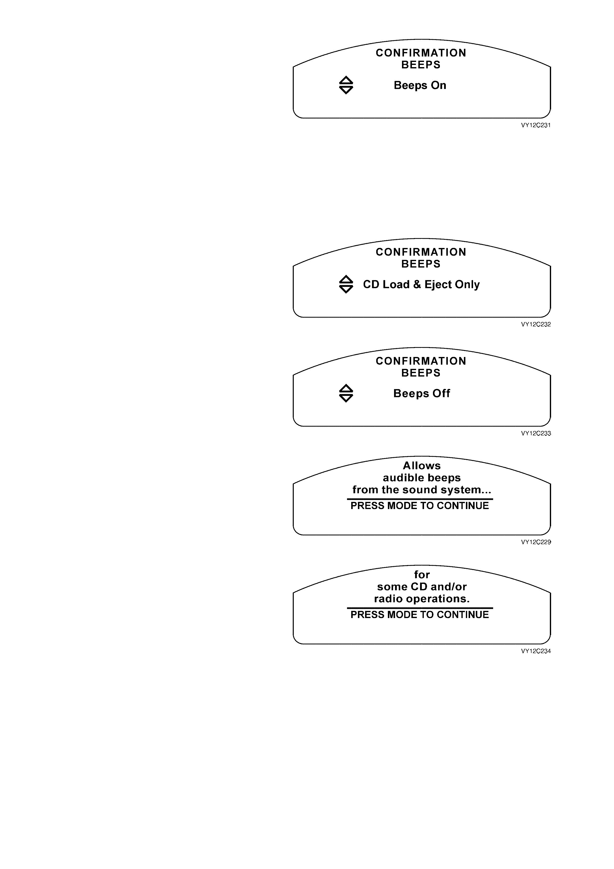
Confirmation Beeps — Radio and CD
Confirmation beeps can be set to confirm that
various func tions of the entertainm ent syst em have
been completed. For example storing a radio
station or loading a CD. The Confirmation Beeps
screen displayed indicates the current setting.
The conf irm ation beeps c an be set to O n, CD Load
and Eject Only or Off.
Use the trip computer switch UP or DOWN button
to scroll through the selection.
Press the MODE button to continue.
NOTE: The Confirmation Beeps is set to On if the
Restore to Factory Settings option has been
selected.
Figure 12C-207
Figure 12C-208
Figure 12C-209
If no selection is made at the Confirmation Beeps
screen within 5 seconds, this Help screen m essage
appears.
Press the MODE button to advance to the next
Help screen.
Figure 12C-210
Press the MODE button to return to the
Confirmation Beeps screen.
Figure 12C-211
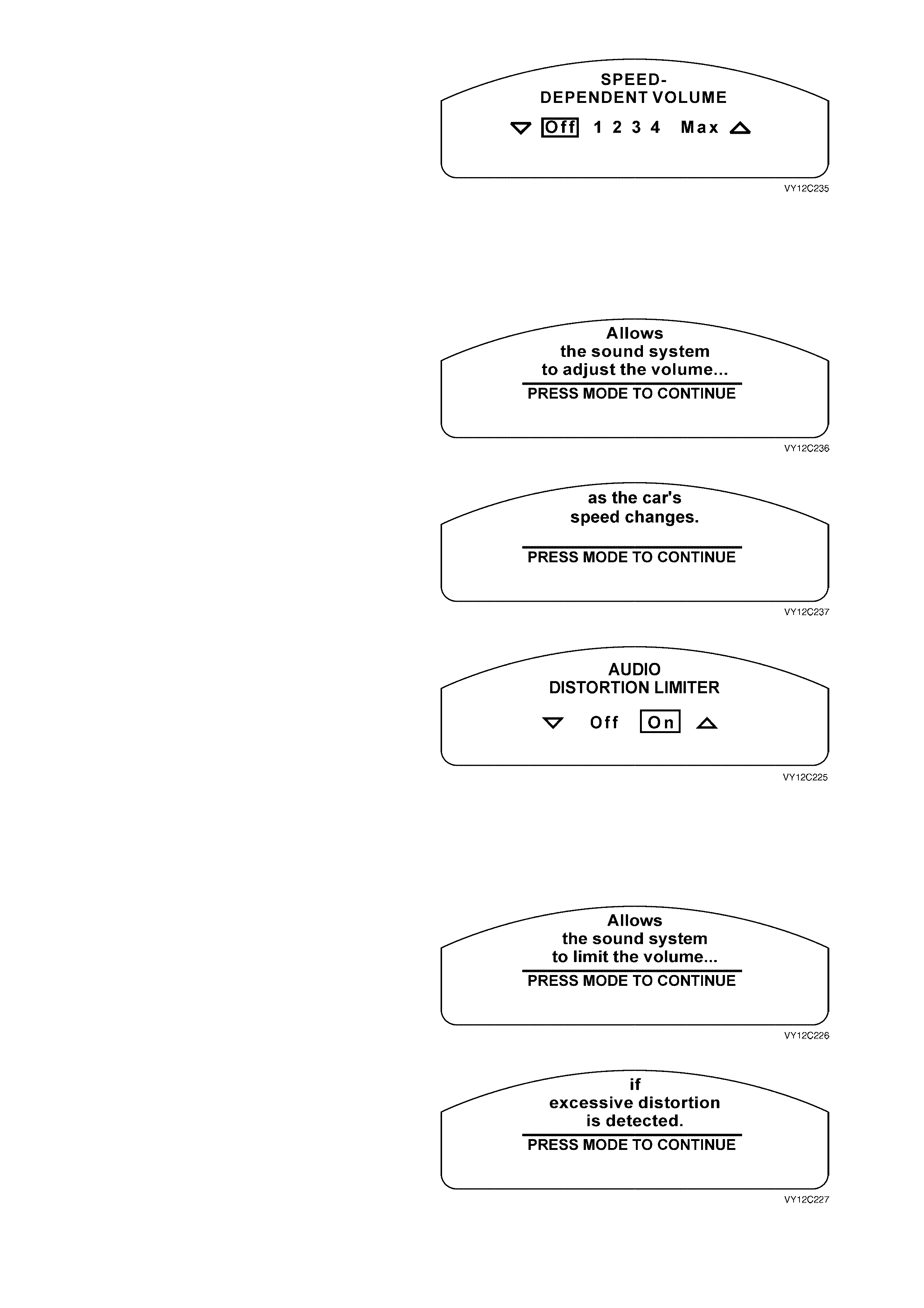
Speed Dependent Volume
The entertainment system volume can be set to
vary automatically with the speed of the vehicle to
compensate for additional background noise. The
speed dependent volume can be selected between
Off / 1 / 2 / 3 / 4 / Max.
Use the trip computer switch UP or DOWN button
to scroll through the selection.
Press the MODE button to continue.
NOTE: The Speed Dependent Volum e is set to 2 if
the Restore to Factory Settings option has been
selected.
Figure 12C-212
If no selection is made at the Speed Dependent
Volume screen within 5 seconds, this Help screen
message appears.
Press the MODE button to advance to the next
Help screen.
Figure 12C-213
Press the MODE button to return to the Speed
Dependent Volume screen.
Figure 12C-214
Audio Distortion Limiter
The entertainment system incorporates a dynamic
distortion limiting function to monitor the audio
output and reduce the audio level if distortion is
detected. The audio distortion limiter can be
enabled or disabled.
Use the trip computer switch UP or DOWN button
to select On or Off.
Press the MODE button to continue.
NOTE: The Audio Distortion Limiter is set to On if
the Restore to Factory Settings option has been
selected.
Figure 12C-215
If no selection is made at the Audio Distortion
Limiter screen within 5 seconds, this Help screen
message appears.
Press the MODE button to advance to the next
Help screen.
Figure 12C-216
Press the MODE button to return to the Audio
Distortion Limiter screen.
Figure 12C-217
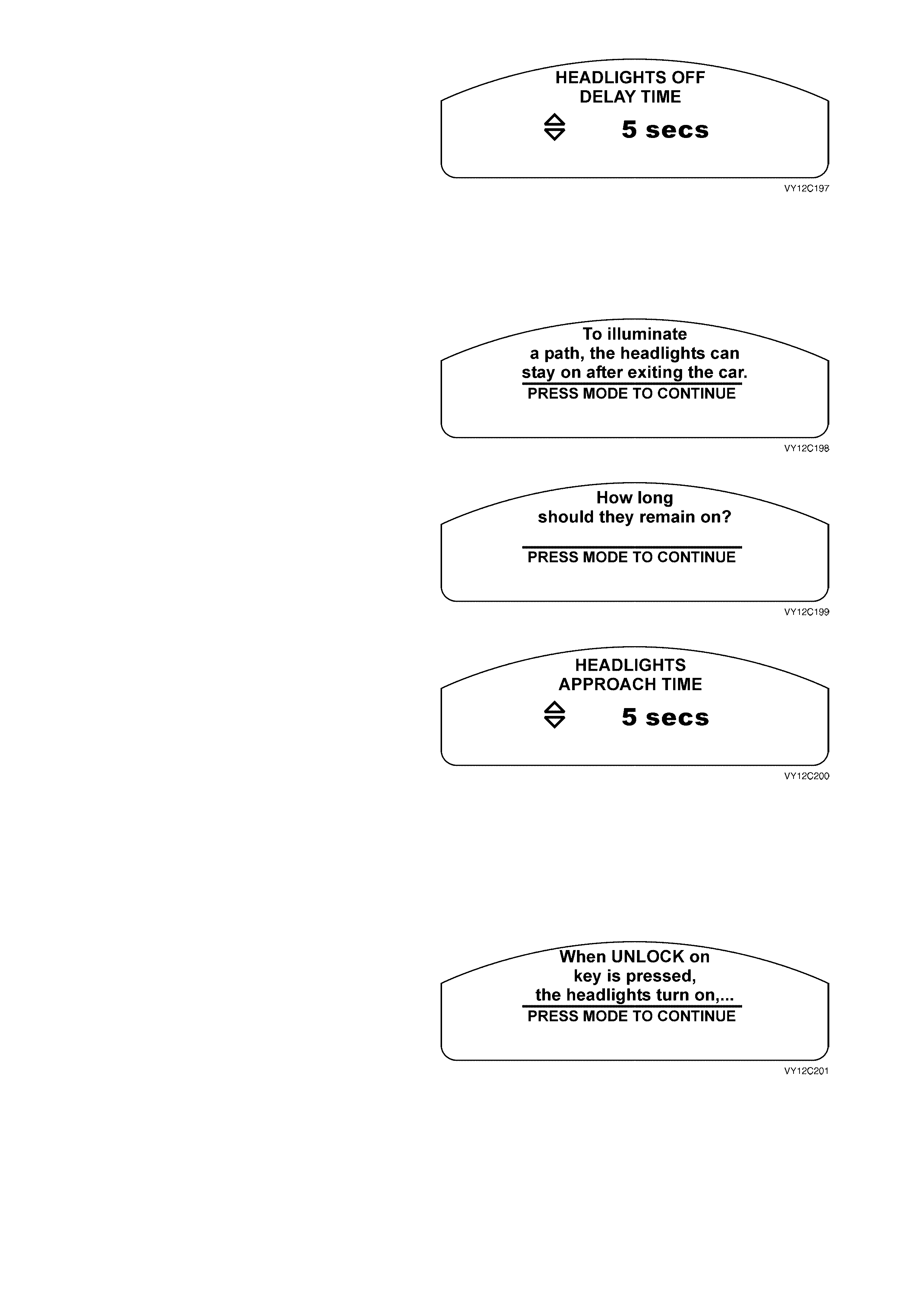
Headlamp Off Delay
The headlam p off delay is adjustable between zero
and 180 seconds.
Use the trip computer switch UP or DOWN button
to increase or decrease the set value. Pressing the
button once will change the value by 1 second.
Press and hold the button to change the value at a
faster rate.
Press the MODE button to continue.
NOTE: The Headlam p Off Delay is set to 1 sec ond
if the Restore to Factory Settings option has been
selected.
Figure 12C-218
If no selection is made at the Headlights Off Delay
Time screen within 5 seconds, this Help screen
message appears.
Press the MODE button to advance to the next
Help screen.
Figure 12C-219
Press the MODE button to return to the Headlights
Off Delay Time screen.
Figure 12C-220
Approach Illumination
The headlamps can be set to provide illumination
when approaching the vehicle at night. The
approach illumination delay is adjustable between
zero and 90 seconds.
Use the trip computer switch UP or DOWN button
to increase or decrease the set value. Pressing the
button once will change the value by 1 second.
Press and hold the button to change the value at a
faster rate.
Press the MODE button to continue.
NOTE: The Headlights Approach Time is set to
30 seconds if the Restore to Factory Settings
option has been selected.
Figure 12C-221
If no selection is made at the Headlights Approach
Time screen within 5 seconds, this Help screen
message appears.
Press the MODE button to advance to the next
Help screen.
Figure 12C-222
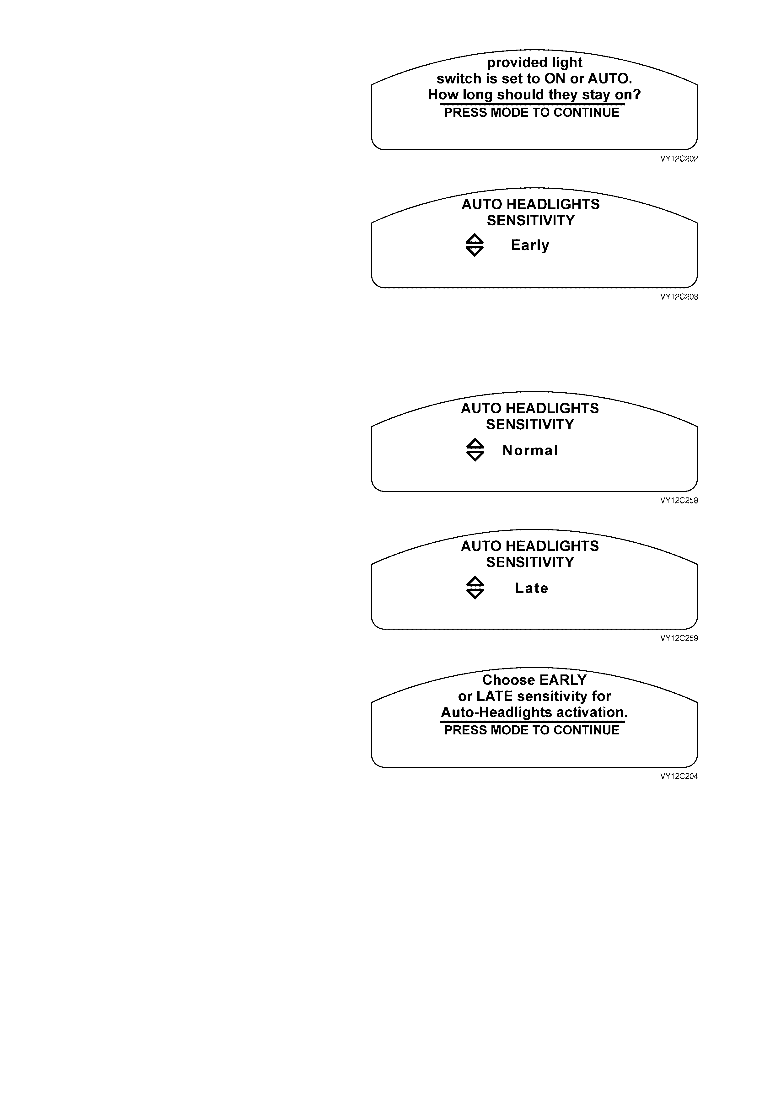
Press the MODE button to return to the Headlights
Approach Time screen.
Figure 12C-223
Automatic Headlamp Sensitivity
The headlamps can be set to come on
automatically when lighting conditions deteriorate.
The headlamp sensitivity can be set to Early,
Normal or Late.
Use the trip computer switch UP or DOWN button
to scroll through the selection.
Press the MODE button to continue.
NOTE: The Automatic Headlights Sensitivity is set
to Normal if the Restore to Factory Settings option
has been selected.
Figure 12C-224
Figure 12C-225
Figure 12C-226
If no selection is made at the Auto Headlights
Sensitivity screen within 5 seconds, this Help
screen message appears.
Press the MODE button to return to the Auto
Headlights Sensitivity screen.
Figure 12C-227

Interior Courtesy Lamp Timeout
The length of time that the interior courtesy lamp
remains illuminated after opening a door or
unlocking the vehicle is adjustable between zero
and 255 seconds.
Use the trip computer switch UP or DOWN button
to increase or decrease the set value. Pressing the
button once will change the value by 1 second.
Press and hold the button to change the value at a
faster rate.
Press the MODE button to continue.
NOTE: The Interior Courtesy Lamp Timeout is set
to 30 seconds if the Restore to Factory Settings
option has been selected.
Figure 12C-228
If no selection is made at the Courtesy Lamp
Timeout screen within 5 seconds, this Help screen
message appears.
Press the MODE button to advance to the next
Help screen.
Figure 12C-229
Press the MODE button to return to the Courtesy
Lamp Timeout screen.
Figure 12C-230
Interior Courtesy Lamp Timeout — Ignition Off
The length of time that the interior courtesy lamp
rem ains illuminated af ter the ignition is turned of f is
adjustable between zero and 255 seconds.
Use the trip computer switch UP or DOWN button
to increase or decrease the set value. Pressing the
button once will change the value by 1 second.
Press and hold the button to change the value at a
faster rate.
Press the MODE button to continue.
NOTE: The Interior Courtesy Lamp Timeout —
Ignition Off is set to 30 seconds if the Restore to
Factory Settings option has been selected.
Figure 12C-231
If no selection is made at the Ignition Off Courtesy
Lamp screen within 5 seconds, this Help screen
message appears.
Press the MO DE button to return to the Ignition Of f
Courtesy Lamp screen.
Figure 12C-232
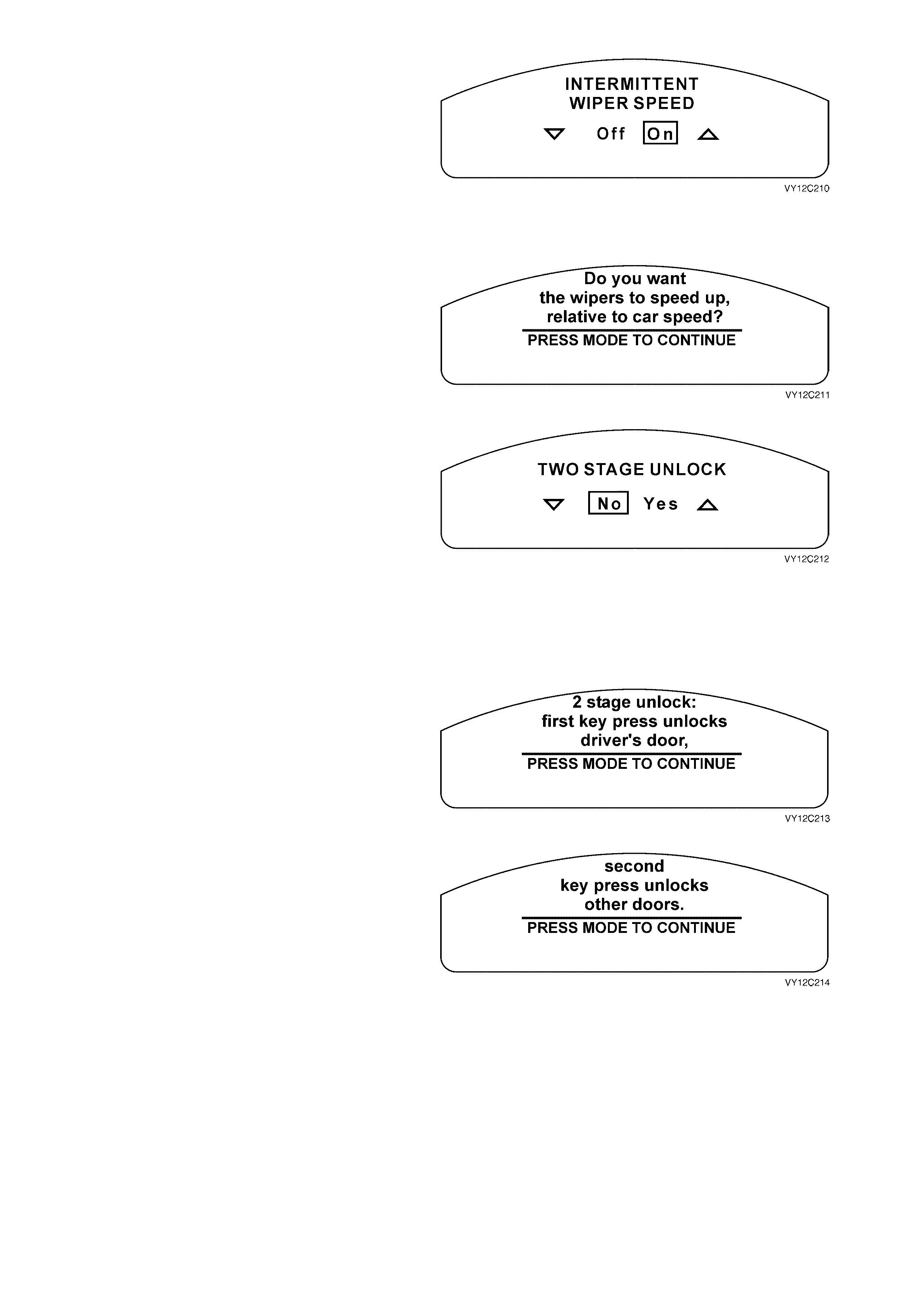
Intermittent Wiper Speed
The intermittent windscreen wiper speed can be set
to vary in conjunction with the vehicle speed.
Use the trip computer switch UP or DOWN button
to select On or Off.
Press the MODE button to continue.
NOTE: The Inter m ittent Wiper Speed is s et to On if
the Restore to Factory Settings option has been
selected.
Figure 12C-233
If no selection is made at the Intermittent Wiper
Speed screen within 5 seconds, this Help screen
message appears.
Press the MODE button to return to the Interm ittent
Wiper Speed screen.
Figure 12C-234
Two Stage Unlock
The vehicle can be set for two stage unlock, or
unlock all doors. With two stage unlock, the first
press of the unlock button on the key unlocks the
drivers door only. Pressing the unlock button a
second time unlocks the remaining doors.
Use the trip computer switch UP or DOWN button
to select Yes or No.
Press the MODE button to continue.
NOTE: The Two Stage Unlock is set to Yes if the
Restore to Factory Settings option has been
selected.
Figure 12C-235
If no selection is made at the Two Stage Unlock
screen within 5 seconds, this Help screen m essage
appears.
Press the MODE button to advance to the next
Help screen.
Figure 12C-236
Press the MODE button to return to the Two Stage
Unlock screen.
Figure 12C-237
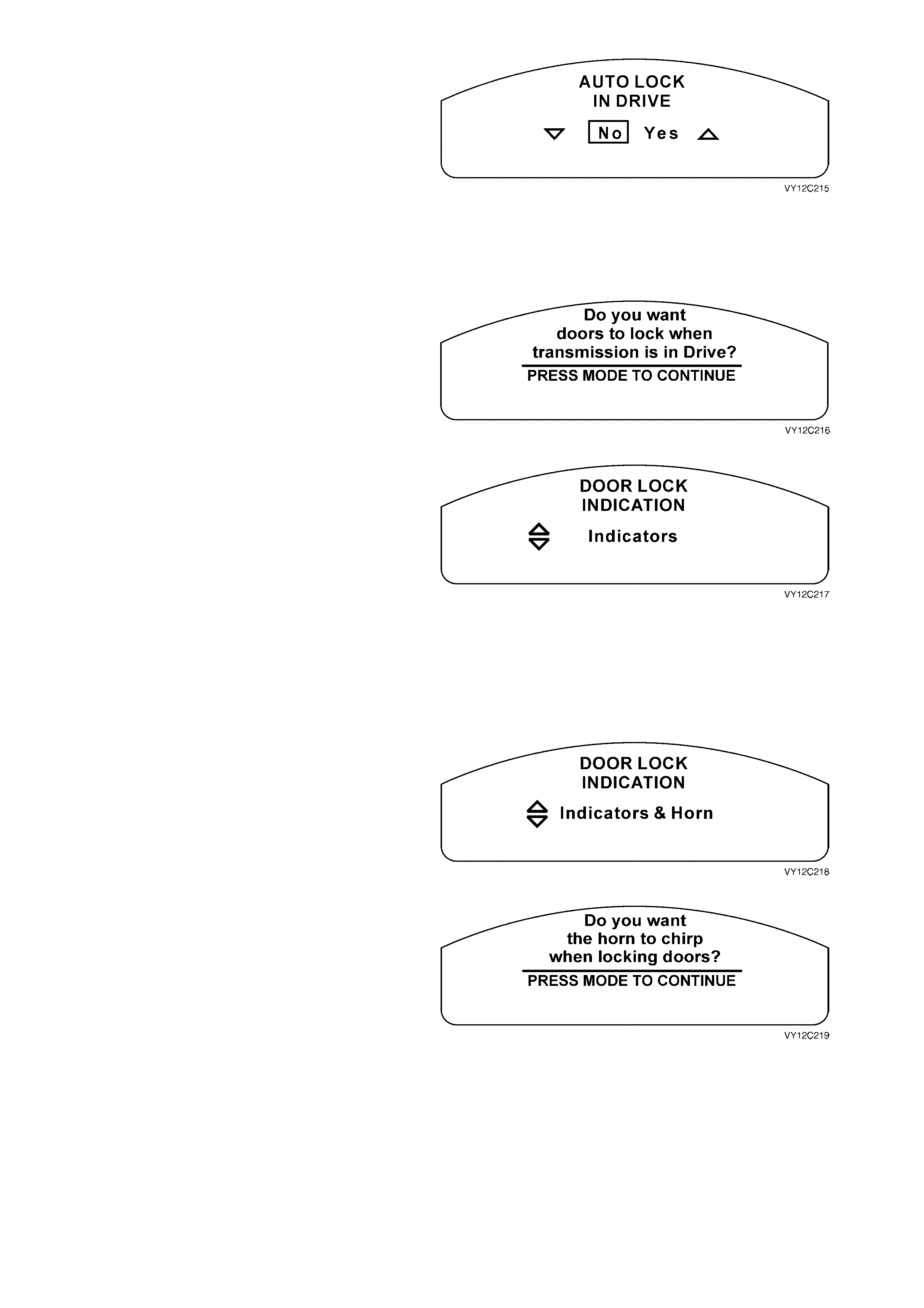
Auto Lock In Drive
The doors can be automatically locked when the
transmission is shifted from Park. This function is
only available on vehicles fitted with an automatic
transmission.
Use the trip computer switch UP or DOWN button
to select Yes or No.
Press the MODE button to continue.
NOTE: The Auto Lock In Drive is set to No if the
Restore to Factory Settings option has been
selected.
Figure 12C-238
If no selection is made at the Auto Lock In Drive
screen within 5 seconds, this Help screen m essage
appears.
Press the MODE button to return to the Auto Lock
In Drive screen.
Figure 12C-239
Door Lock Indication
The door lock indication can be selected between
the turn indicators flashing or the turn indicators
flashing accompanied by the sounding of the horn.
The selected function also operates when
unlocking the vehicle.
Use the trip computer switch UP button to enable
the turn indicators and horn, or the DOWN button
to enable the turn indicators only.
Press the MODE button to continue.
NOTE: The Door Lock Indication is set to
Indicators if the Restore to Factory Settings option
has been selected.
Figure 12C-240
Figure 12C-241
If no selection is made at the Door Lock Indication
screen within 5 seconds, this Help screen m essage
appears.
Press the MODE button to return to the Door Lock
Indication screen.
Figure 12C-242
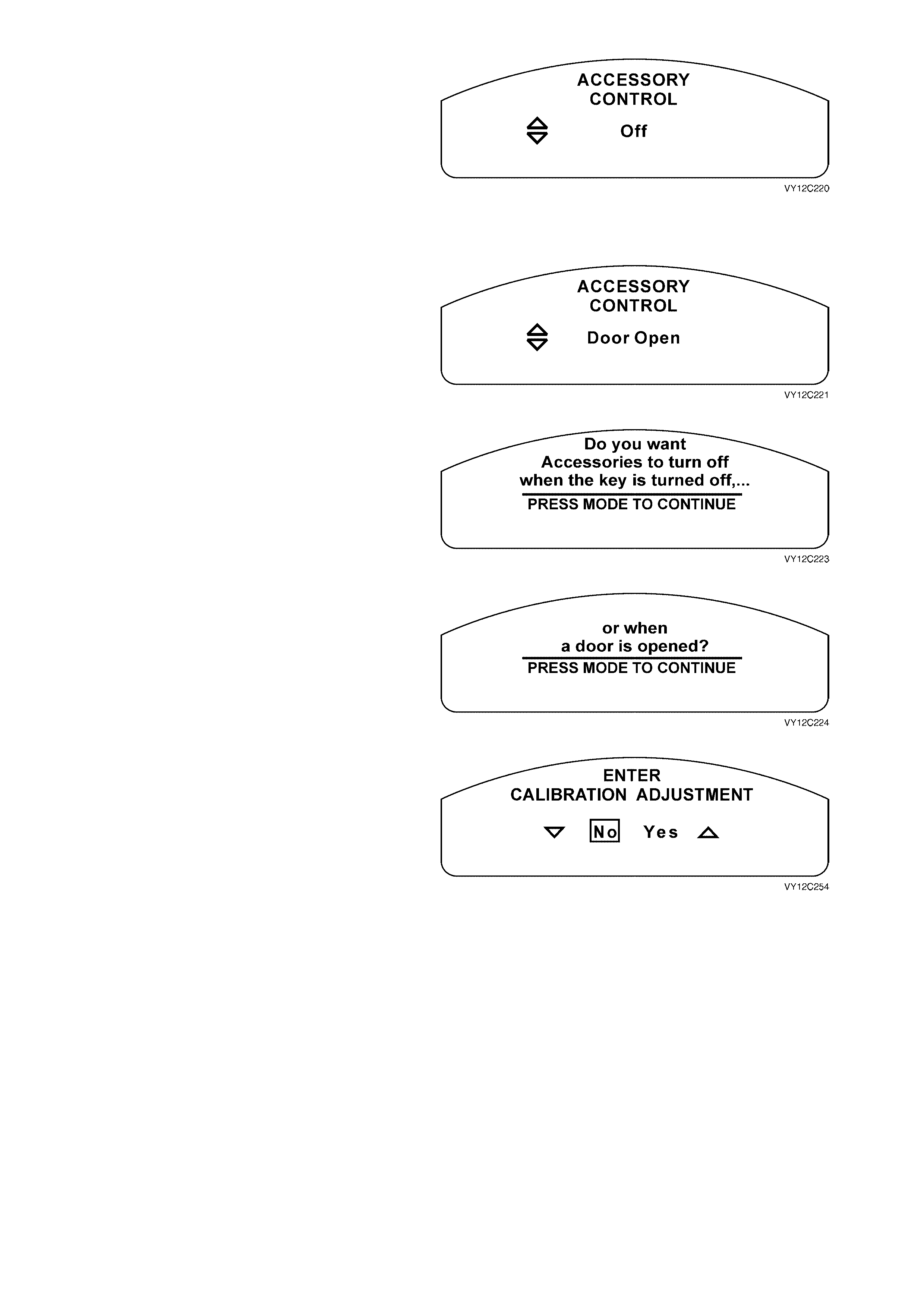
Radio and Accessories Timeout
The accessories can be turned off at either ignition
off or door opening.
Use the trip computer switch UP or DOWN button
to scroll through the selection.
Press the MODE button to continue.
NOTE: The Radio and Accessories Timeout is set
to Door Open if the Restore to Factory Settings
option has been selected.
Figure 12C-243
Figure 12C-244
If no selection is made at the Accessory Control
screen within 5 seconds, this Help screen m essage
appears.
Press the MODE button to advance to the next
Help screen.
Figure 12C-245
Press the MODE button to return to the Accessory
Control screen.
Figure 12C-246
Calibration Adjustment (Triple-window Cluster)
The trip computer can be calibrated for distance
and fuel flow.
Use the trip computer switch UP or DOWN button
to select Yes or No.
Press the MODE button to continue.
If No is selected, Custom isation Mode advances to
the Exit Options Menu.
If Yes is selected, the next screen displayed is the
Distance Calibration screen.
Figure 12C-247
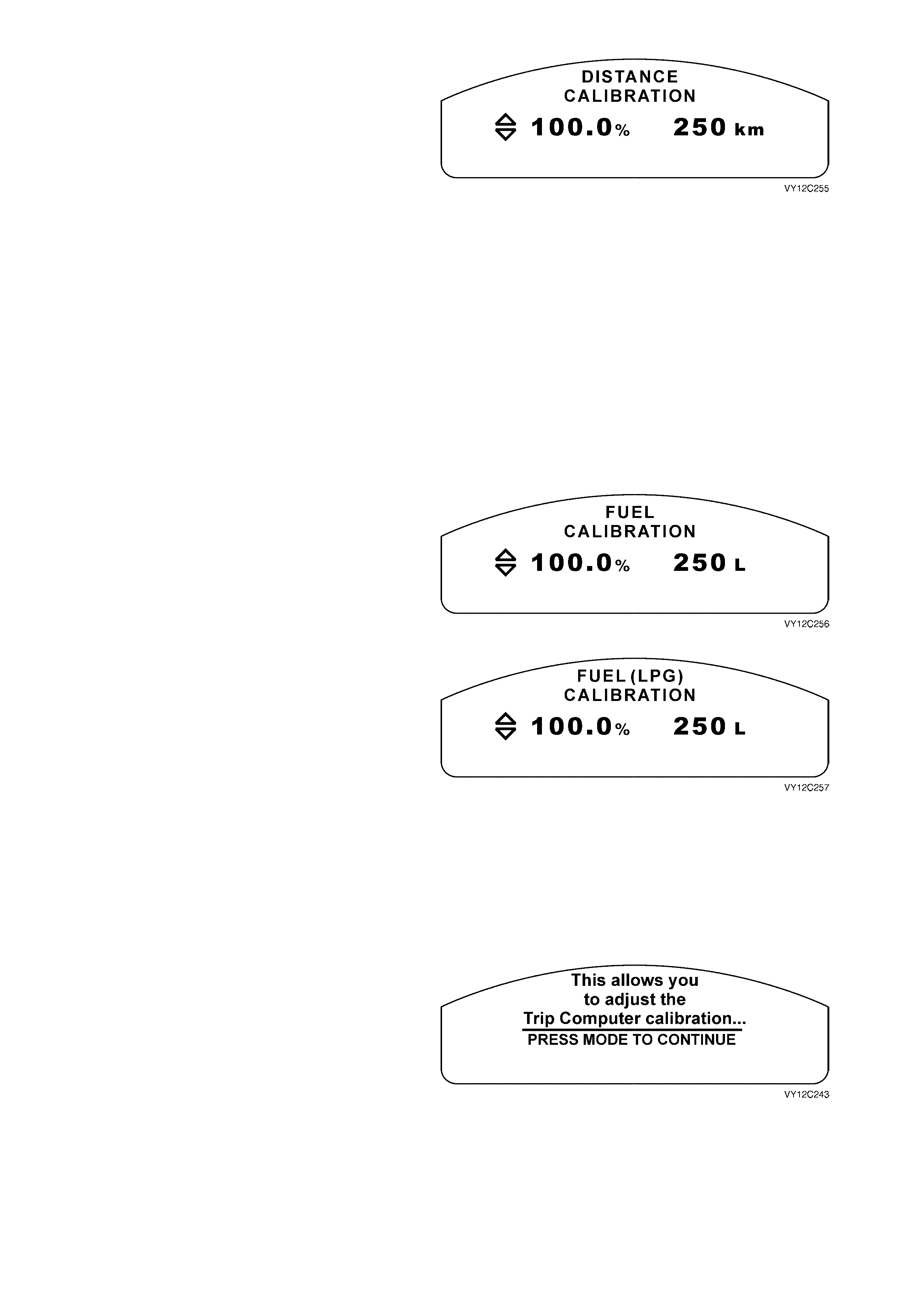
If the Distance Calibration screen is not required,
press the MODE button to advance to the Fuel
Calibration screen.
To check the distance calibration figures, align the
front wheels of the vehicle with a highway k ilom etre
shield post before entering Customisation Mode.
Press the MODE button to display the Trip Distance
screen. Reset the Trip Distance by pressing the
SET button for less than 2 seconds.
Drive to another shield post, between 10 km and
500 k m, and s top with the front wheels aligned with
the shield post. Note the real distance between the
shield posts and the distance on the Trip Distance
display. If these distances are different, enter
Customisation Mode / Calibration Adjustment /
Distance Calibration and use the UP and DOWN
buttons to adjust the distance displayed to the real
distance between the shield posts.
The def ault dis tanc e c alibration f igur e is 100%. The
max im um f igure is 120%, while the m inim um f igure
is 80%.
Press the MODE button to advance to the Fuel
Calibration screen.
Figure 12C-248
Figure 12C-249
Depending on the fuel mode of operation selected,
either the Fuel Calibration s creen or the Fuel ( LPG)
Calibration screen will be displayed.
If the Fuel Calibration or Fuel (LPG) Calibration
screen is not required, press the MODE button to
advance to the Exit Options Menu.
To check the fuel (or LPG) calibration figures,
press the MODE button to display the Fuel Used
screen bef ore entering Customisation Mode. Reset
the Fuel Used by pressing the SET button for less
than 2 seconds.
For at least five consecutive fuel fills, record the
total litres added (but no more than 500 litres)
according to the service station fuel meters. Note
the real fuel us ed and the reading on the F uel Used
display. If these are different, enter Customisation
Mode/ Calibration Adjustment/ Distance
Calibration/ Fuel Calibration and use the UP and
DOWN buttons to adjust the litres displayed to the
real figure.
The default fuel calibration figure is 100%. The
max im um f igure is 120%, while the m inim um f igure
is 80%.
Press the MODE button to advance to the Exit
Options Menu screen.
Figure 12C-250
If no selection is made at the Enter Calibration
Adjustment screen within 5 seconds, this Help
screen message appears.
Press the MODE button to advance to the next
Help screen.
Figure 12C-251
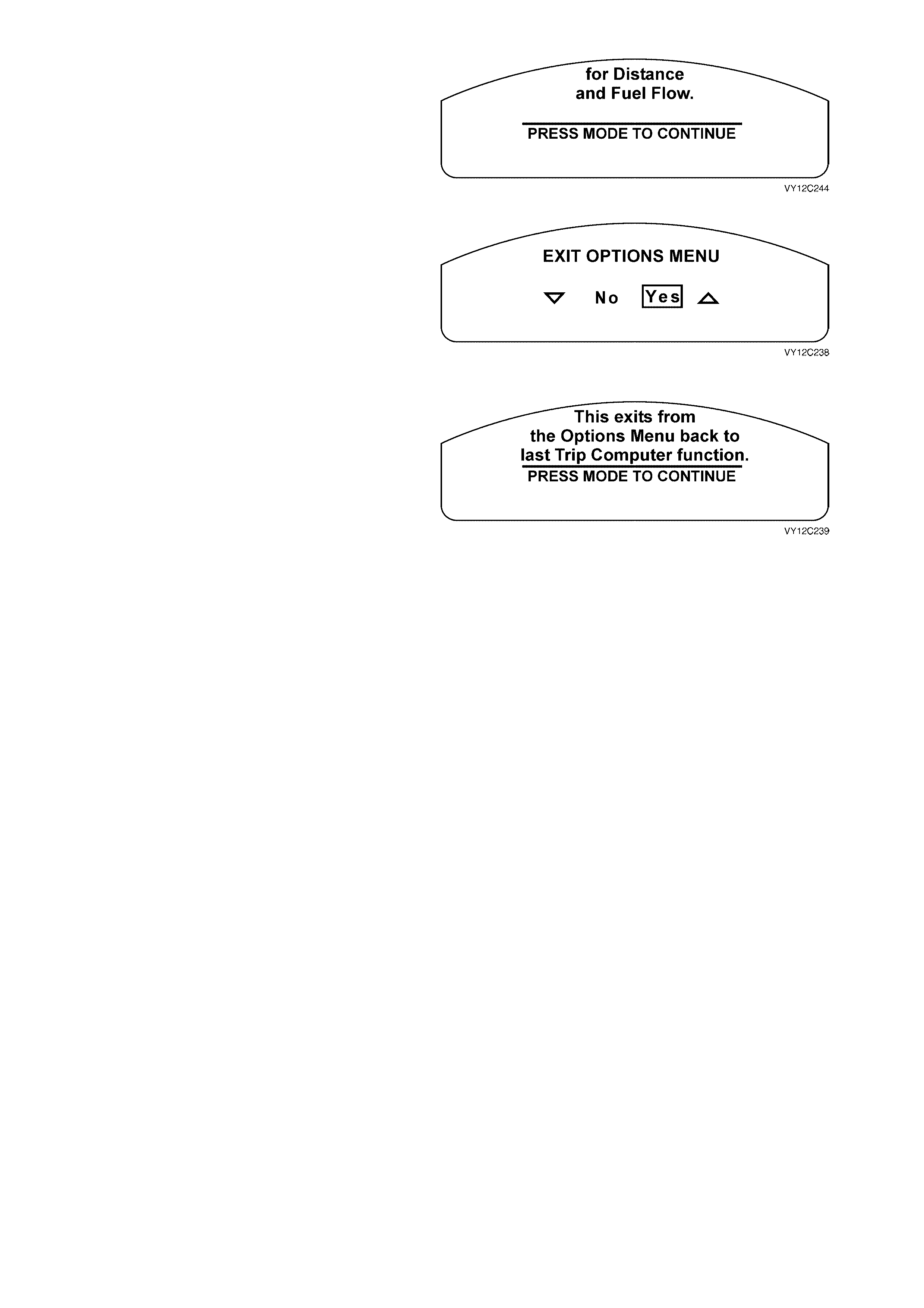
Press the MODE button to return to the Enter
Calibration Adjustment screen.
Figure 12C-252
Exit Options Menu
The default selection for the Exit Options Menu is
Yes. Use the trip computer switch MODE button to
exit the Customisation Mode. The MFD will display
the previous trip computer screen.
Use the trip computer DOWN button followed by
the MODE button to return to the Restore to
Factory Settings screen.
Figure 12C-253
If no selection is made at the Exit Options Menu
screen within 5 seconds, this Help screen m essage
appears.
Press the MODE button to return to the Exit
Options Menu screen.
Figure 12C-254
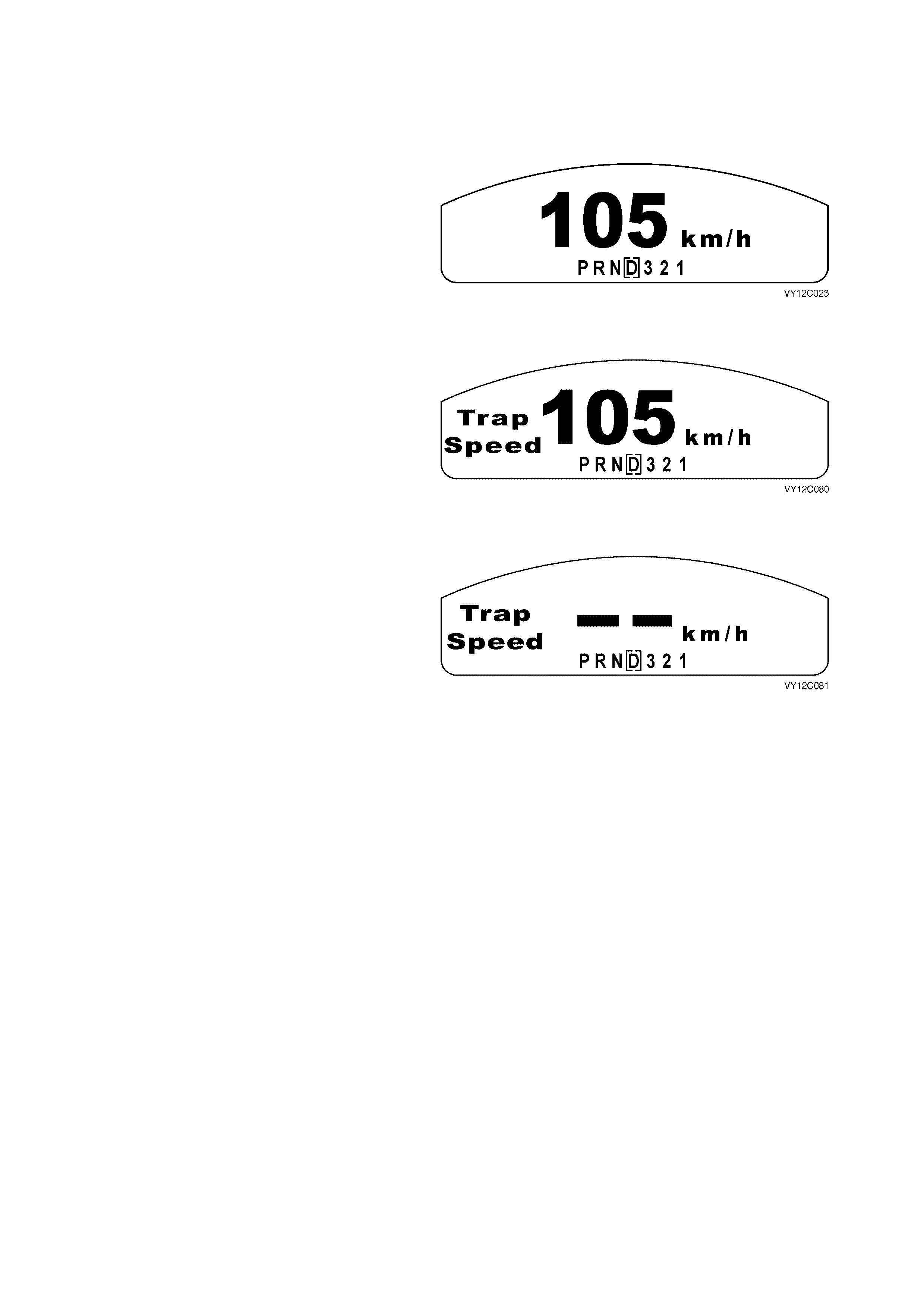
1.9 POLICE MODE
If Police Mode is enabled via the TECH 2, the digital speedo is the default display at ignition switch on.
NOTE: The police Mode is not applicable to Omega.
DIGITAL SPEEDO
The large digital s peed shown in the MFD replaces
the overspeed indication unless overspeed is
loaded in by TECH 2.
Figure 12C-255
TRAP SPEED
The Trap Speed screen enables the driver to
capture the speed at which the vehicle is travelling.
To use the Trap Speed function, press the SET
button on the trip computer switch. The current
speed is stored and displayed for 5 seconds with a
confirming beep.
Figure 12C-256
TRAP SPEED RESET
After 5 seconds, the display reverts to the current
speed on the digital speedo display. Pressing the
UP or DOW N buttons toggles between the current
speed and the stored speed. Trapping another
speed or pressing and holding the trip computer
switch SET button for more than 3 seconds resets
the trap speed. Reset is confirmed by a beep and
this screen is displayed:
Figure 12C-257
NOTE: When trap speed is reset it reverts to the current speed on the digital speedo display. The trap speed is
stored in memory even if the vehicle ignition is turned off. The trap speed remains stored unless trapping another
speed or resetting the trapped speed erases it.
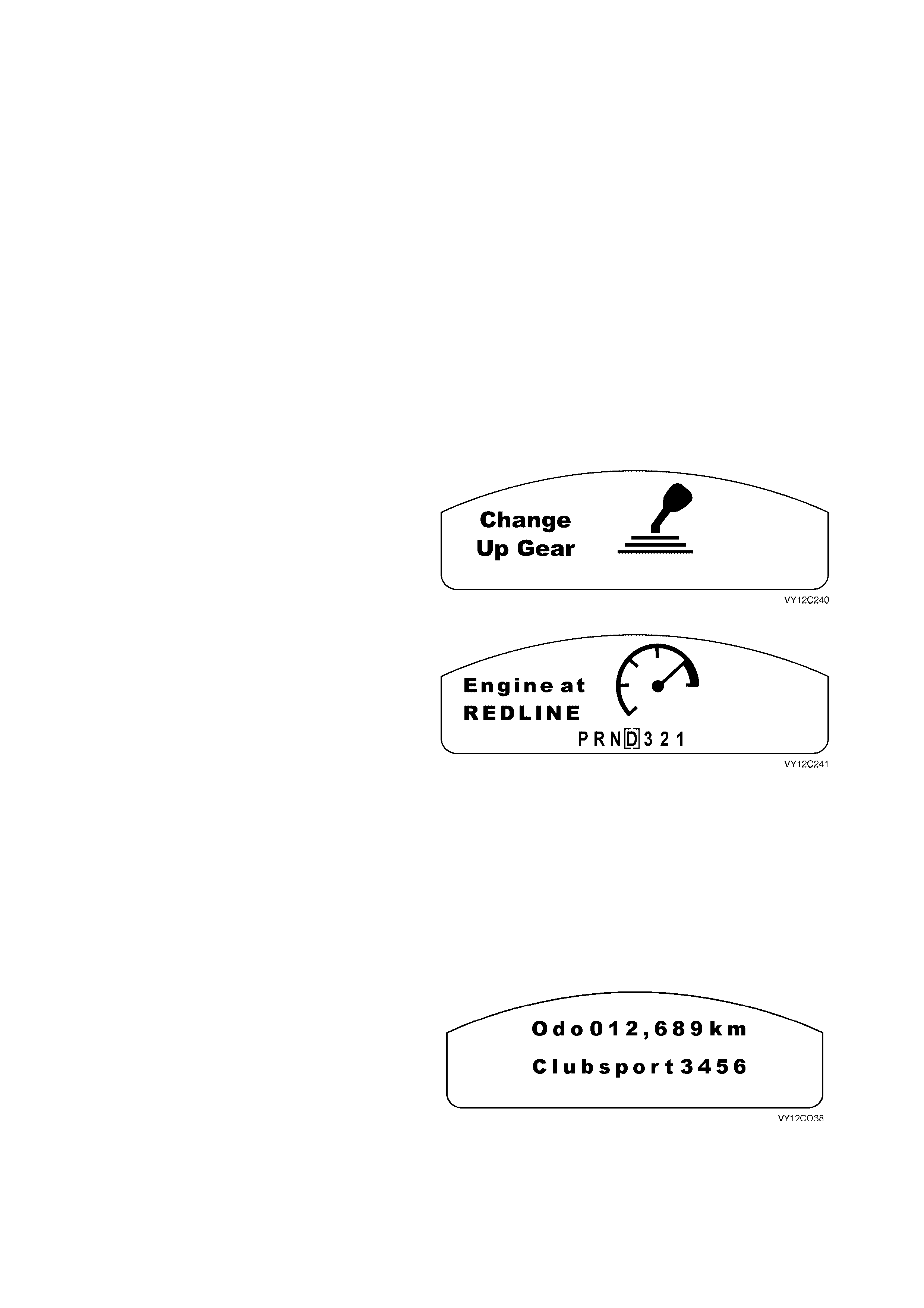
1.10 HOLDEN SPECIAL VEHICLES
TACHOMETER LIGHT
The Holden Spec ial Vehicles (HSV) instr ument clusters have a red telltale (SHIFT UP) to indicate to the driver that
they need to change gear as the engine is about to reach its red line.
The Powertrain Contr ol Module (PCM) m onitors engine speed (r pm), c oolant temper ature and transmis sion gear to
determine the optimum engine speed for upshifting gears. When the engine coolant temperature is below the
optimum running tem perature, the ins trum ent cluster telltale will warn the driver when to change gear to r educe the
risk of engine damage whilst it is cold. When the coolant is below 85°C the telltale illuminates at 4000 rpm.
When the coolant is above 85°C the telltale illuminates at:
Transmission Engine Speed
1 st 6050 rpm
2 nd 6200 rpm
3 rd 6300 rpm
4 th 6300 rpm
5 th 6300 rpm
6 th 6300 rpm
The red SHIF T UP telltale flashes and the chime is
audible when the gear change is required.
The MFD animation and the wording Change Up
Gear are displayed until the gear change occurs or
the conditions requiring the gear change have
themselves changed.
Figure 12C-258
If the vehicle is stationary, the telltale will flash and
the chime will sound, and this screen is displayed
on the MFD.
The MFD animation and the wording Engine at
REDLINE are displayed until the engine speed has
been reduced below the redline limit.
Figure 12C-259
300 KW ENGINE IDLE SPEED
The HSV instrument cluster has a Retailer option
to set the c luster f or a 300 k W engine. The 300 kW
engine has an engine idle speed of 1000 rpm. If
this option is enabled, the instrument cluster
tachometer will show an engine idle speed of
750 rpm instead of the actual engine idle speed
(1000 rpm).
HSV MODEL NAMES AND BUILD NUMBERS
HSV will have the ability to show the model names
and build ID number s of their vehicles at ignition off
on the odometer display
Also HSV has the option of a text field to allow a
new model name of up to 10 characters to be
entered.
The build ID num ber is to be input by HSV only and
is a four-digit number.
Figure 12C-260
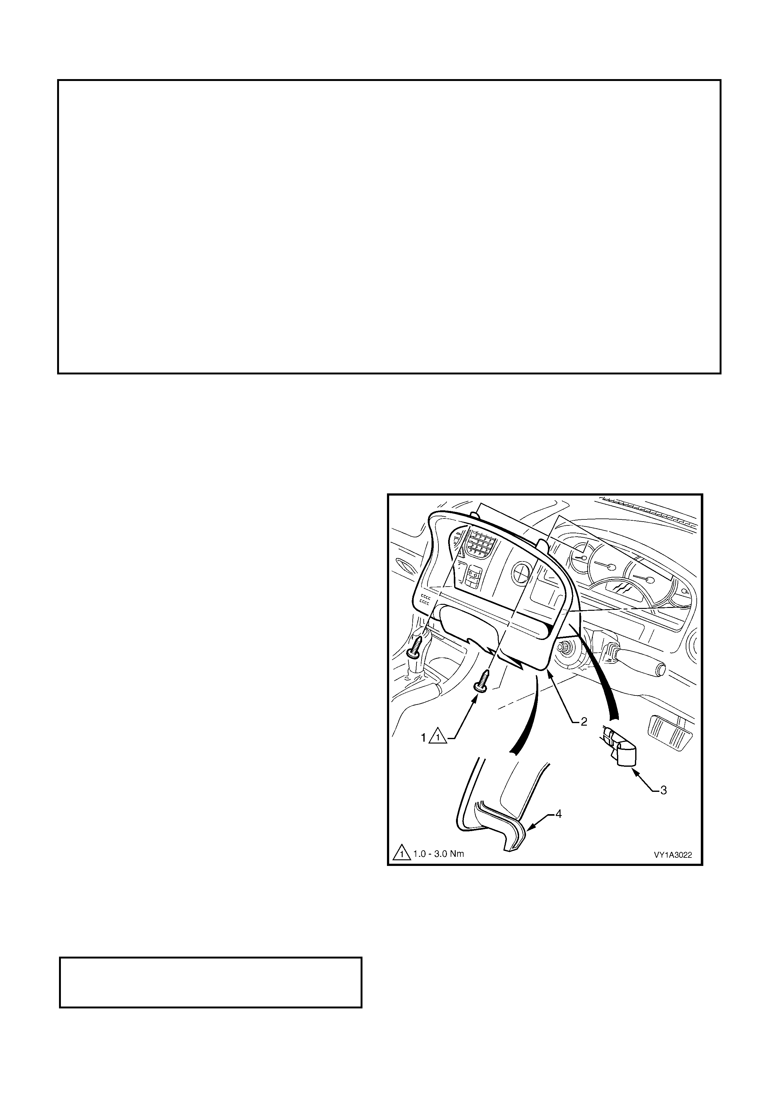
2. SERVICE OPERATIONS
IMPORTANT
All fasteners are important attaching parts as they affect the performance of vital components and/or
could result in major repair expense. Where specified in this section, fasteners MUST be replaced with
parts of the same part number or a GM approved equivalent. Do not use fasteners of an inferior quality
or substitute design.
Torque values must be used as specified during reassembly to ensure proper retention of all
components.
Through out this section, fastener torque w rench specifications may be accompanied with the following
identification marks:
+
++
+ Fasteners must be replaced after loosening.
&
&&
& Vehicle must be at curb height before final tightening.
6
66
6 Fasteners either have micro encapsulated sealant applied or incorporate a mechanical thread lock
and
should only be re-used once. If in doubt, replacement is recommended.
If one of these identification marks is present alongside a fastener torque wrench specification, the
recommendation regarding that fastener must be adhered to.
IMPORTANT: Prior to c om m encing any of the following procedures , disconnec t the battery to disable the Occupant
Protection System. Reconnect the battery on completion.
2.1 INSTRUMENT CLUSTER TRIM ASSEMBLY
LT Section No. 09–100
REMOVE
NOTE: The steering wheel has been removed for
clarity; the cluster trim can be removed with
steering column, covers and steering wheel
installed.
1. Release the steering column adjustment lever
and move the column to its lowest position.
2. Remove the two screws (1) attaching the
instrument cluster trim assembly (2) to the
instrument panel.
3. Depress the top of the trim assembly slightly
and tilt the top of the trim assembly out of the
instrument panel pad, disengaging the retaining
clips (3) each side.
4. Unhooking each lug (4) from the instrument
panel pad.
5. For lef t-hand drive vehic les, disconnec t the fuel
tank filler door lock release switch wiring
connector.
6. Remove the trim assembly
Figure 12C-261
REINSTALL
Installation is the reverse of the removal procedure.
Ensure the cluster trim and filler are seated correctly. Tighten the screws to the specified torque.
INSTRUMENT CLUSTER TRIM
ASSEMBLY ATTACHING SCREW
TORQUE SPECIFICATION 1.0 – 3.0 Nm
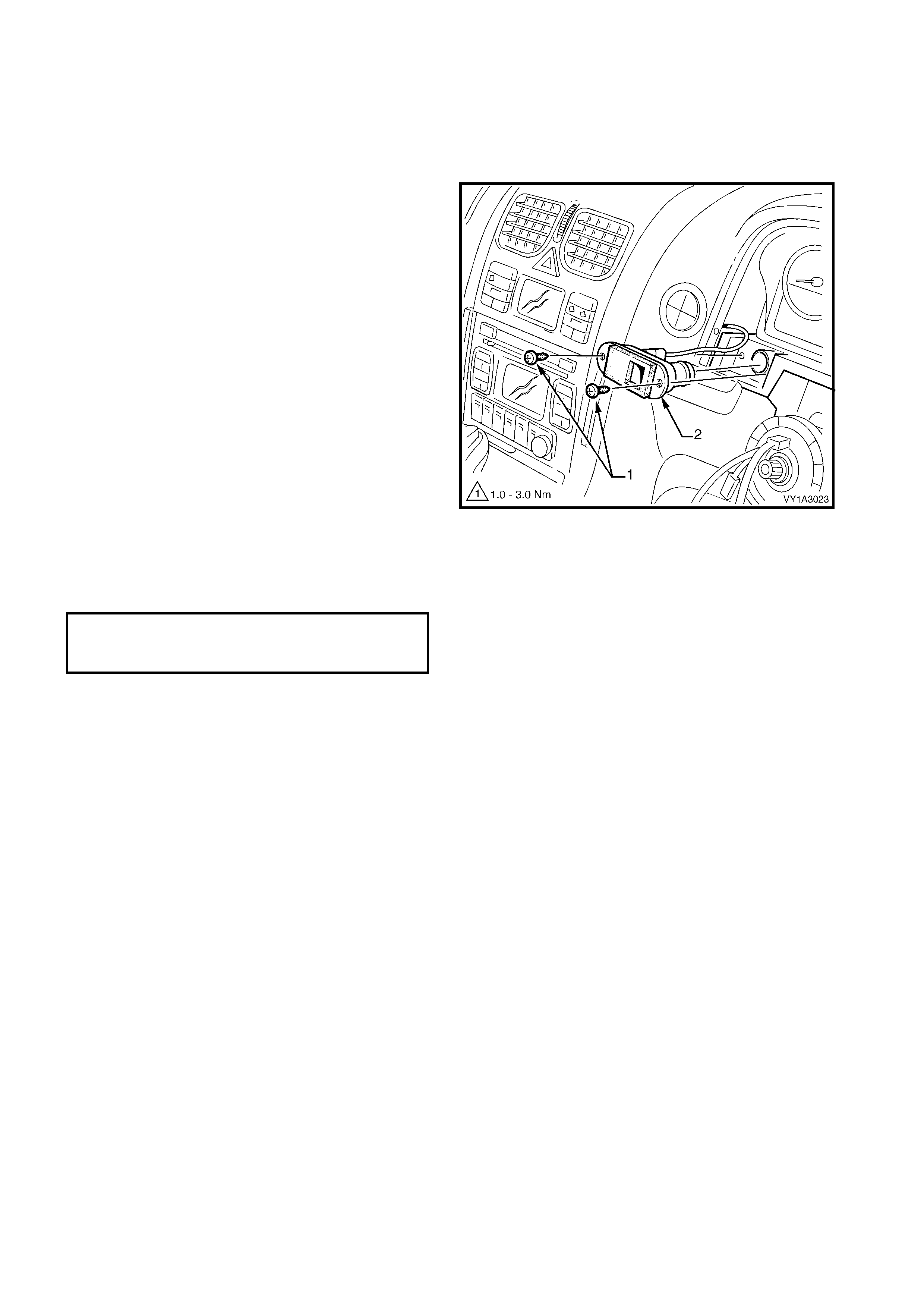
2.2 IN-CAR AIR TEMPERATURE SENSOR
If required, first remove the instrument cluster trim assembly, refer to 2.1 INSTRUMENT CLUSTER TRIM
ASSEMBLY in this Section.
LT Section No.
REMOVE
1. Remove the two screw (1) attaching the in-car
air temperature sensor (2) to the instrument
panel.
2. Extract the sensor assembly from the cavity
and disconnect the air tube and wiring
connector.
3. Remove the sensor assembly.
NOTE: For service and diagnosis of the sensor
assembly refer to Section 2F, HVAC OCCUPANT
CLIMATE CONTROL (AUTO A/C) —
DIAGNOSTICS.
Figure 12C-262
REINSTALL
Installation is the reverse of removal. Tighten the
screws to the specified torque.
IN-CAR AIR TEMPERATURE
SENSOR ATTACHING SCREW
TORQUE SPECIFICATION 1.0 – 3.0 Nm
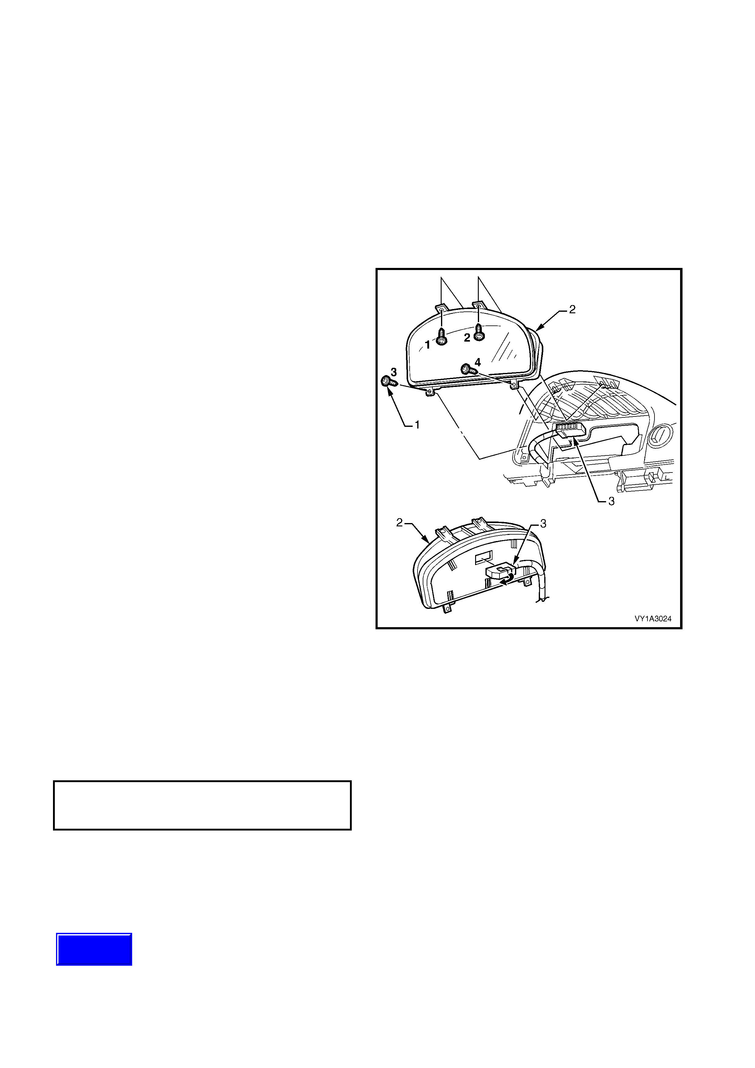
2.3 INSTRUMENT CLUSTER ASSEMBLY
NOTE: Before replac ing any instrum ent cluster ass em bly that is suspec ted of being f aulty, first carr y out instrument
cluster input checks, refer to 2.4 INSTRUMENT CLUSTER INPUTS in this Section.
If these tests prove that the inputs to the instrument cluster are OK, carry out checks of the gauge assemblies.
Refer to 3.3 INSTRUMENT CLUSTER DIAGNOSTICS or 3.4 DIAGNOSING FAULTS NOT COVERED BY
DIAGNOSTIC TROUBLE CODES in this Section for further details. Following these steps will ensure correct
diagnosis of a system fault and needless replacement of components that are not faulty.
LT Section No. 09 – 100
REMOVE
If required, first remove the following components:
Instrument cluster trim assembly, refer to 2.1 INSTRUMENT CLUSTER TRIM ASSEMBLY in this Section.
In-car air sensor (vehicles with OCC), refer to 2.2 IN-CAR AIR TEMPERATURE SENSOR in this Section.
1. Remove the four screws (1) attaching the
instrument cluster (2) to the instrument panel.
2. Roll the top of the cluster from its cavity.
3. Using a fine flat blade screwdriver, open the
wiring connector locking tab (3) on the back of
the cluster.
4. Remove the cluster assembly.
Figure 12C-263
REINSTALL
Installation is the reverse of removal.
NOTE: Ensure the locking tab on the wiring
connector is fully closed.
IMPORTANT: Tighten the screws in the correct
sequence, refer to Figure 12C-, and to the specified
torque.
INSTRUMENT CLUSTER
ATTACHING SCREW
TORQUE SPECIFICATION 1.0 – 3.0 Nm
CLUSTER PROGRAMMING
If a new instrument cluster has been installed, the
original odometer reading, together with other
important vehicle parameters, must be programmed
into the replacement instrument cluster. Refer to
3.15 PROGRAM in this Section for further details.
Techline

DISASSEMBLE
NOTE 1: Dis ass embly of the instrument c luster ass embly is limited to r eplac ement of the lens . The lens s hould only
be removed in a dust-free environment.
NOTE 2: Grip around the edges of the instrument cluster lens during removal or installation as finger marks are
difficult to remove from the lens.
1. Using a flat-bladed screwdriver, carefully push the three retaining tabs securing the lens to the top of the
instrument cluster housing to release them from the clips.
2. Using a flat-bladed s crewdriver, caref ully push and twist the retaining tab sec uring the lens at each side of the
instrument cluster housing to release them from the clips.
3. Using a flat-bladed screwdriver, carefully push the four retaining tabs securing the lens to the bottom of the
instrument cluster housing to release them from the clips.
REASSEMBLE
1. Place the lens in position on the instrument cluster housing and check that each retaining tab is located
correctly in the corresponding clip.
2. Cover the lens with a clean lint-free cloth or chamois.
3. Press down evenly on the lens to lock the retaining tabs in position.

2.4 INSTRUME NT CLUSTER INPUTS
CHECK
The following table provides details on the instrument cluster connector and signal functions. To check the input
voltage or wiring continuity between the various sensors / senders to the instrument cluster connector refer to
3. DIAGNOSTICS in this Section.
PIN NUMBER FUNCTION PIN NUMBER FUNCTION
X1-1 Battery X1-17 Ground
X1-2 Serial Data X1-18 Trip Computer Switch
Return
X1-3 Brakes X1-19 Fuel Level Return
X1-4 Park Lamps X1-20 Ignition
X1-5 Speedometer X1-21 Cruise Control Active
X1-6 Tachometer X1-22 Spare
X1-7 Spare X1-23 Seat Belt
X1-8 Spare X1-24 Low Traction
X1-9 Front Fog Lamps X1-25 Spare
X1-10 Spare X1-26 Spare
X1-11 Right Turn Indicators X1-27 Cruise Control On
X1-12 High Beam X1-28 Trip Computer Switch
X1-13 Charging X1-29 Fuel Level
X1-14 ABS Off X1-30 LPG Fuel Level
X1-15 Left Turn Indicators X1-31 Security Warning
X1-16 Spare X1-32 Spare

2.5 SENDER UNITS
VEHICLE SPEED SENDER
Manual Transmission
For all details of the manual transmission vehicle speed sender, refer to:
Section 6C1, POWERTRAIN MANAGEMENT V6 ENGINE,
Section 6C2, POWERTRAIN MANAGEMENT V6 SUPERCHARGED ENGINE or
Section 6C3, POWERTRAIN MANAGEMENT V8 ENGINE.
Automatic Transmission
For all details of the automatic transmission vehicle speed sensor, refer to:
Section 6C1, POWERTRAIN MANAGEMENT V6 ENGINE or
Section 6C3, POWERTRAIN MANAGEMENT V8 ENGINE.
FUEL GAUGE SENDER UNIT
Petrol
For all details on the (petrol) fuel gauge sender unit, refer to Section 8A1, FUEL TANK.
LPG
For all details on the (LPG) fuel gauge sender unit, refer to Section 8A2, LPG GAS.
Techline
Techline
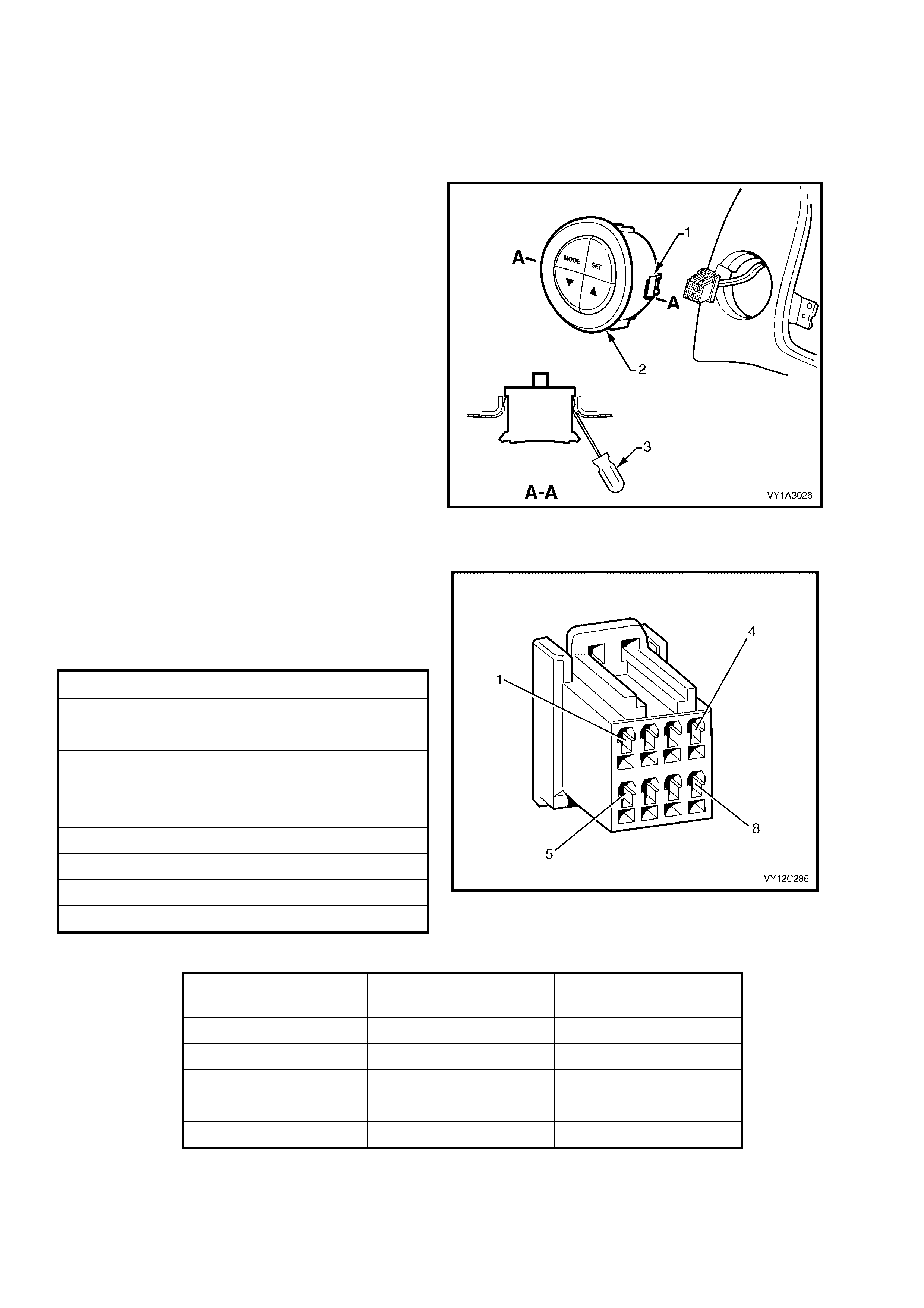
2.6 TRIP COMPUTER SWITCH ASSEMBLY
LT Section No. 02 – 800
REMOVE
IMPORTANT: Care m ust be exercis ed when r emoving the trip com puter switch as the retaining c lip can catch and
damage the instrument panel outer material.
1. From behind the instrument panel pad, depress
the retaining clips (1). Use a fine, flat blade
screwdriver if required.
2. Carefully push the trip computer switch
assembly (2) part way from its cavity.
3. Insert a fine, flat-blade screwdriver (3) as
shown and hold the retaining clip depressed,
while manipulating the switch from its cavity.
Repeat for the oppos ite side and for the locator
underneath as required.
4. Disconnect the wiring connector and remove
the switch assembly.
Figure 12C-264
TESTING SWITCH
W ith the aid of an ohmmeter, check the resistance
of the trip computer switch contacts using the
following chart.
If resistance is not as specified at any switch
position, replace the switch assembly.
CONNECTOR DETAILS
PIN NUMBER FUNCTION
X1–1 Enabled Switch
X1–2 Not Connected
X1–3 Illumination Positive
X1–4 Not Connected
X1–5 Ground
X1–6 Not Connected
X1–7 Illumination Ground
X1–8 Not Connected
Figure 12C-265
FUNCTION / BUTTON
PRESSED SWITCH CONTACTS RESISTANCE READING
MODE 1 and 5 20 kohms
SET 1 and 5 40.2 kohms
UP 1 and 5 10 kohms
DOWN 1 and 5 4.99 kohms
ILLUMINATION 3 and 7 Continuity
REINSTALL
Installation is the reverse of removal procedure.
Ensure that the retaining clips are correctly seated.

3. DIAGNOSTICS
3.1 BASIC KNOWLEDGE REQUIRED
Before attempting to diagnose the instrument cluster you must have a good understanding of electrical system
basics and the use of circuit testing tools. Without this basic knowledge it will be difficult to use the diagnostic
procedures detailed in this Section.
Some electric al basics , as well as basic troubleshooting procedures and hints on the use of circuit testing tools are
covered in Section 12P, WIRING DIAGRAMS.
Basic Electrical Circuits — You should understand the basic theory of electricity, series and parallel circuits, and
voltage drops across series resistors. You should know the meaning of voltage (volts), current (amps), and
resistanc e (ohms ). You should understand what happens in a circ uit with an open or shorted wire (shorted either to
voltage or ground). You should also be able to read and understand a wiring diagram.
Additionally, a knowledge of AC theory including inductance, capacitance and impedance would be useful.
Use of Circuit Testing Tools — You should know how to use a jumper lead to test circuits. You should be familiar
with the use of a high input impedance (10 Megohm) digital type multimeter such as Tool No. 3588 (J39200) or
equivalent and be able to measure voltage, current, and resistance. You should be familiar with the proper use of
the TECH 2 Diagnostic Scan Tool.
NOTE: The vehicle’s battery must be removed before performing any ground resistance checks with a high
impedance multimeter. Refer to Section 00, 5. BATTERY DISCONNECTION PROCEDURES.
Techline
Techline

3.2 PRELIMINARY SYSTEM DIAGNOSIS
When investigating any complaint of an instrument cluster problem or malfunction, always begin diagnosis with a
circuit check, refer to 3.8 INSTRUMENT DIAGNOSTIC PROCEDURES, DIAGNOSTIC CIRCUIT CHECK chart in
this Section.
The diagnostic circuit check is a preliminary procedure that checks to ensure the instrument cluster is
communicating on the serial data line as well as helping to identify the problem.

3.3 INSTRUME NT CLUS TER DIAGNOSTICS
Fault diagnosis for the instrument cluster is divided into two areas; faults which can be remedied by checking the
operation of components connected to the instrument cluster, and those which can be checked by using the
TECH 2 Diagnostic Tool.
The instrum ent cluster can provide a preliminary indication that there is a fault either on the serial data bus, within
the instrument cluster or the BCM. When the instrument cluster does not receive a valid or complete serial data
message for 10 seconds, the MFD shows the message 'Service Error – Contact Dealer'. This error message
indicates a short circuit on the serial data bus, an open circuit to the instrument cluster or a fault within the
instrument cluster. Pressing the MODE button on the trip computer switch clears the error message. In this
instance, the icon N is shown in the left-hand side of the MFD. If the fault is associated with the fuel sender, the
mes sage displayed is 'Fuel Sender Error – Contact Dealer ', and the appropriate Petrol/LPG symbol is displayed on
the left-hand side of the MFD.
Additionally, when a fault is detected, the instrum ent cluster sets a Diagnos tic Trouble Code (DT C) that represents
that particular problem or failure.
DIAGNOSTIC TROUBLE CODES
There are two types of DTC, current and history.
• A Current DT C is active only for the per iod that the f ault is pres ent and is indicated by the icon/me ssage on the
instrument cluster. When the fault is cleared, the Current DTC and the icon / message are also cleared.
• The History DTC is set at the same time as the Current DTC, and is stored in memory within the instrument
cluster to provide information on vehicle system operation over a period of time. History DTC are read and
cleared from memory by TECH 2.
Each DTC is allocated a number from 0 to 31. The following table provides details on each of the DTC.
DTC 0 Not Used DTC 16 Petrol Level Sender Stuck
DTC 1 Petrol Level Sender Signal Voltage Too Low DTC 17 LPG Level Sender Stuck
DTC 2 Petrol Level Sender Signal Voltage Intermittent DTC 18 Not Used
DTC 3 Petrol Level Sender Signal Voltage Too High DTC 19 Incorrect SDM Detected
DTC 4 LPG Level Sender Signal Voltage Too High DTC 20 Not Used
DTC 5 LPG Level Sender Signal Voltage Too Low DTC 21 Trip Computer Switch Voltage Too Low
DTC 6 LPG Level Sender Signal Voltage Intermittent DTC 22 Trip Computer Switch Button Stuck
DTC 7 Not Used DTC 23 Not Used
DTC 8 No Serial Data From ABS / TCS DTC 24 EEPROM Checksum Error
DTC 9 No Serial Data Fro m BCM DTC 25 Not Used
DTC 10 No Serial Da ta From OCC DTC 26 Not Used
DTC 11 No Serial Data From PCM DTC 27 Not Used
DTC 12 No Serial Data From SDM DTC 28 Not Used
DTC 13 No Instrum ent Poll From BCM DTC 29 Not Used
DTC 14 No Serial Da ta DTC 30 Not Used
DTC 15 No Serial Data From Audio System DTC 31 Not Used
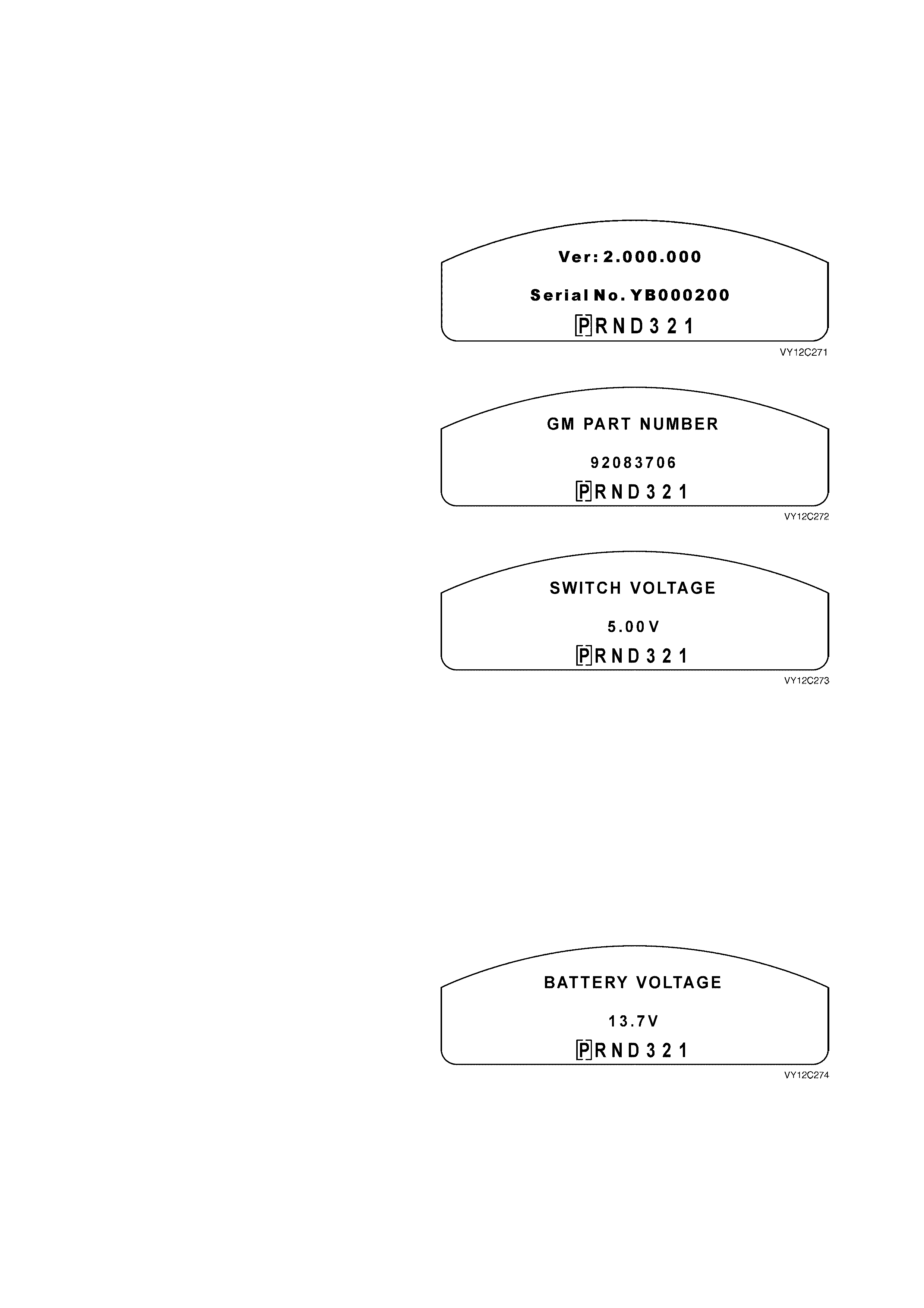
DIAGNOSTIC MODE OPERATION
To enter the instrument cluster Diagnostic Mode, press the trip computer switch MODE and SET buttons
simultaneously while turning the ignition on. Further pressing the MODE button for less than 2 seconds will step
through the various instrument cluster information displays, which appear on the MFD. The vehicle may be driven
while in Diagnostic Mode.
To exit the instrum ent cluster Diagnostic Mode press the trip com puter switch SET button for less than 2 seconds,
or switch the ignition off.
In sequence, the instrument cluster Diagnostic Mode screens are:
Software Version
This screen provides details of the instrument
cluster software versi on.
Press the MODE button to continue.
Figure 12C-266
GM Part Number
This screen provides details of the instrument
cluster part number.
Press the MODE button to continue.
Figure 12C-267
Trip Computer Switch Voltage
This screen provides an indication of the
operational status of the trip computer switch.
NOTE 1: When checking the MODE button
voltage, press and hold the button for more than
2 seconds otherwise the Diagnostic Mode will
advance to the Battery Voltage screen.
NOTE 2: When checking the SET button voltage,
press and hold the button for m ore than 2 seconds
otherwise the system will exit the Diagnostic Mode.
Press each button and the following nominal
voltages should be indicated:
MODE button — 4.09 V
SET button — 4.51 V
UP button — 3.4 V
DOWN button — 2.57 V
Press the MODE button to continue.
Figure 12C-268
Battery Voltage
This screen provides an indication of the current
battery voltage.
Press the MODE button to continue.
Figure 12C-269
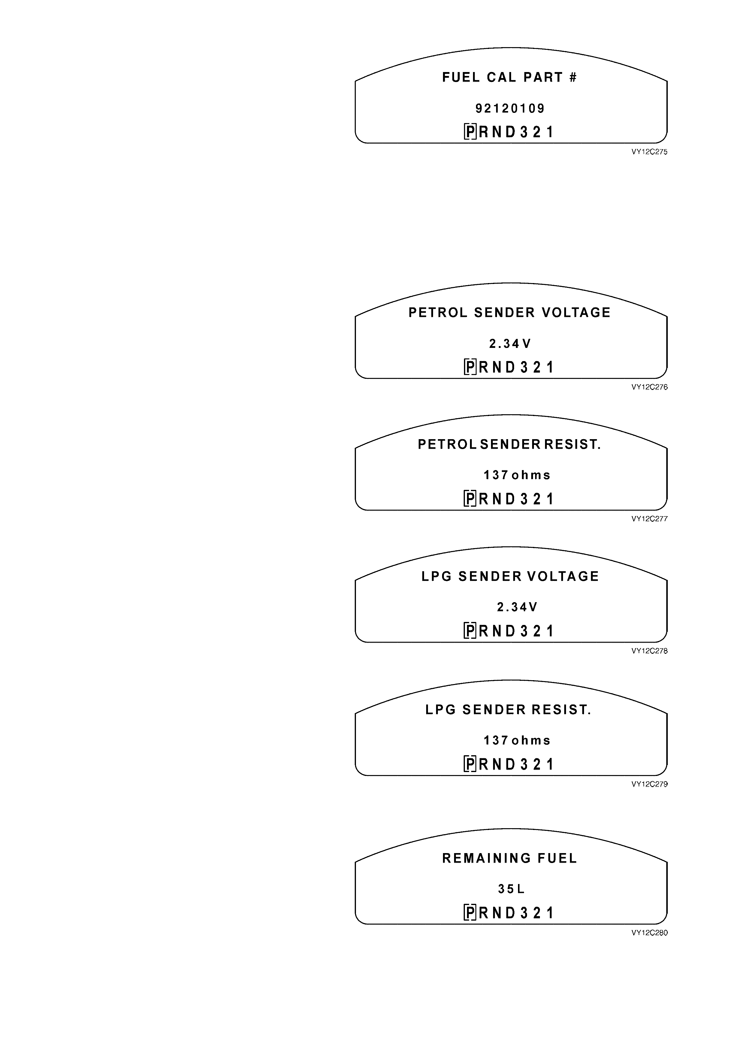
Fuel Calibration Part Number
When an instrument cluster is replaced, the fuel
calibration part number is to be entered using
TECH 2 (refer to 3.15 PROGRAM – F0: FUEL
GAUGE CALIBRATION in this Section). This
identifies the fuel tank size and fuel sender unit
resistance to the instrument cluster.
The part number details are as follows:
Sedan / Monaro (V6 and V8) 92120109
Wagon 92120110
Utility 92120111
Sedan / Monaro (V6 S/C) 92120112
Press the MODE button to continue.
Figure 12C-270
Petrol Sender Voltage
The f uel s ender voltage s hould be between 0 V and
5 V. This voltage should increase as the tank is
filled and decrease as the tank is emptied.
Press the MODE button to continue.
Figure 12C-271
Petrol Sender Resistance
The fuel sender resistance should be between
40 ± 5 ohms and 250 ± 5 ohms. This resistance
should increase as the tank is filled and decrease
as the tank is emptied.
Press the MODE button to continue.
Figure 12C-272
LPG Sender Voltage (If Fitted)
The LPG fuel sender voltage should be between
0 V and 5 V. This voltage should increase as the
tank is filled and decrease as the tank is emptied.
If the vehicle is not fitted with LPG, this screen will
not be displayed.
Press the MODE button to continue.
Figure 12C-273
LPG Sender Resistance (If Fitted)
The LPG fuel sender resis tance should be between
40 ± 5 ohms and 250 ± 5 ohms. This resistance
should increase as the tank is filled and decrease
as the tank is emptied.
If the vehicle is not fitted with LPG, this screen will
not be displayed.
Press the MODE button to continue.
Figure 12C-274
Remaining Fuel
This screen provides an estimate of the fuel
remaining in the fuel tank to the nearest 5 litres.
If petrol mode of operation is selected, the
indication will be for the petr ol tank . If LPG mode of
operation is selected, the indication will be for the
LPG tank.
Press the MODE button to continue.
Figure 12C-275
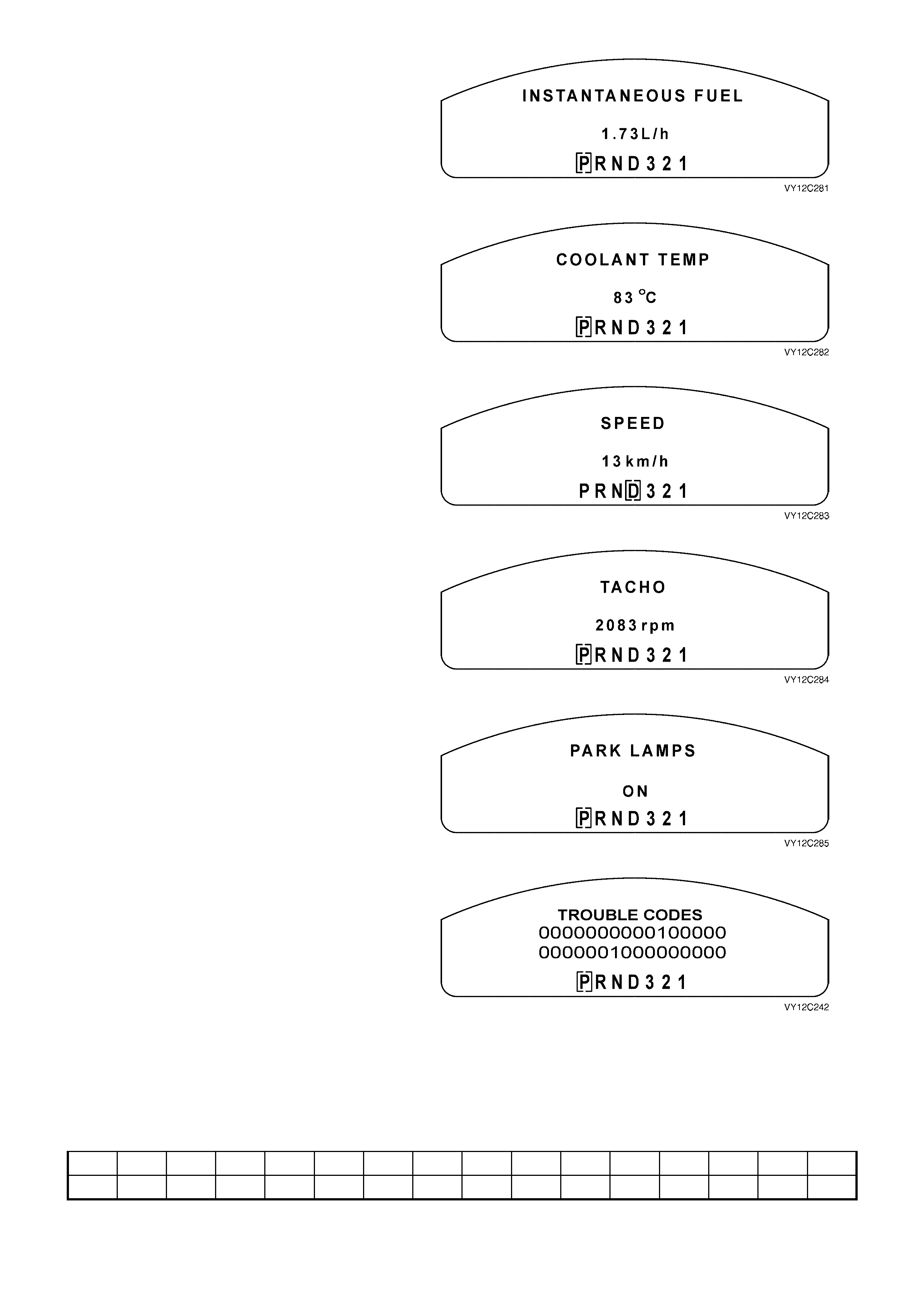
Instantaneous Fuel
This screen provides details of the instantaneous
fuel usage.
Press the MODE button to continue.
Figure 12C-276
Coolant Temperature
This screen provides an indication of the current
coolant temperature.
Press the MODE button to continue.
Figure 12C-277
Speed
This screen provides an indication of the current
vehicle speed.
Press the MODE button to continue.
Figure 12C-278
Tacho
This screen provides an indication of the current
engine speed in rpm.
Press the MODE button to continue.
Figure 12C-279
Park Lamps On / Off
The park lamps circuit provides illumination for the
instrum ent cluster. If the park s lam ps are s hown as
ON, the instrument cluster should also be
illuminated.
Press the MODE button to continue.
Figure 12C-280
Trouble Codes
The Trouble Codes screen displays two rows of
16 digits each. If no DT C is set the 32 digits are all
zeros (0).
However, if a DTC is set, this is represented by a
one (1) in the appropriate position in the rows.
The f ollowing table shows the location of each DTC
identifying digit. To determine the actual DTC
number that has been set, c ount the digits f rom the
bottom right-hand side, starting at zero. In the
example shown in Figure 12C-281, DTC 9 and
DTC 21 have been set.
Figure 12C-281
31 30 29 28 27 26 25 24 23 22 21 20 19 18 17 16
15 14 13 12 11 10 9 8 7 6 5 4 3 2 1 0
Press the MODE button to continue.
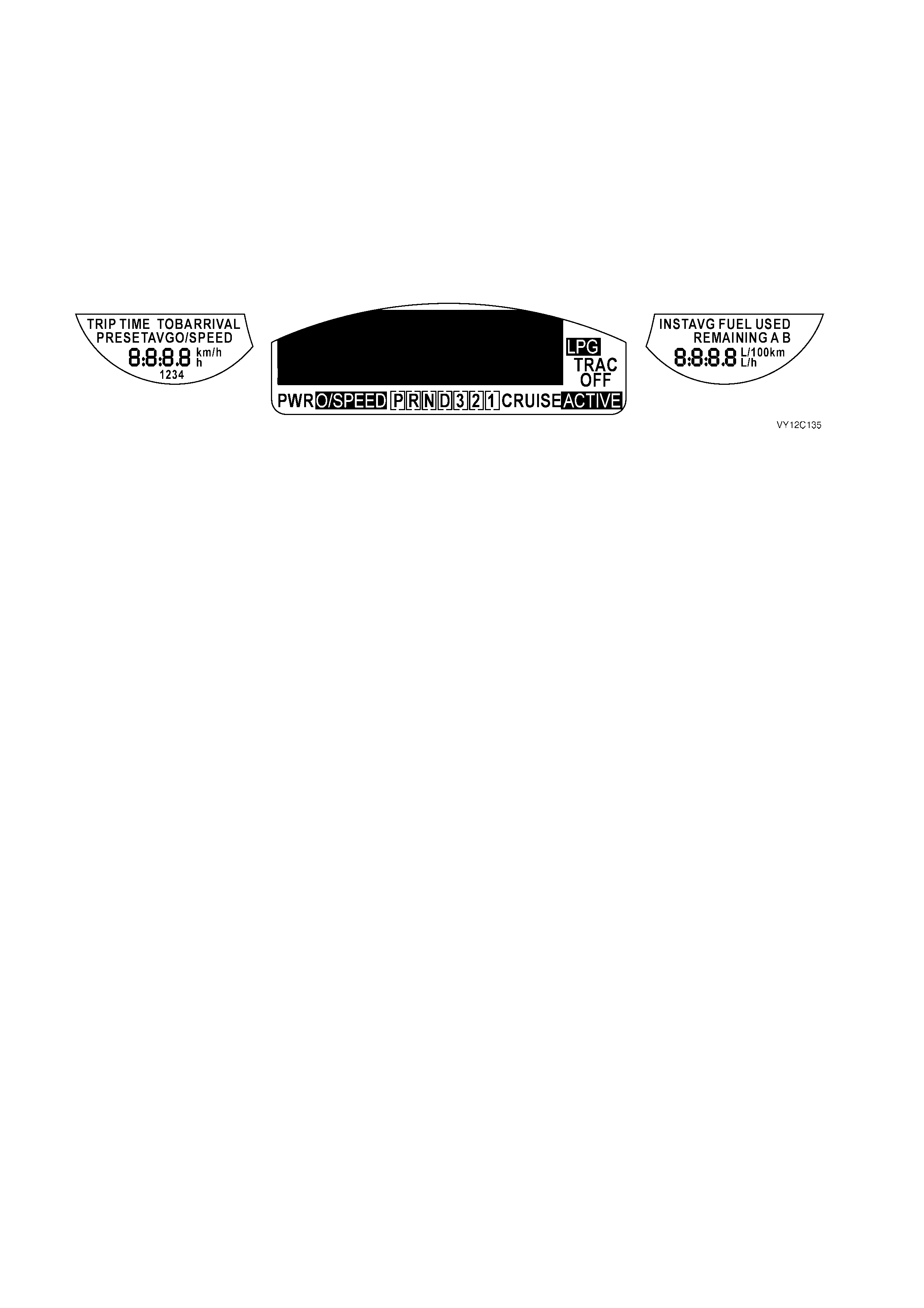
Full Test
The Diagnostic Mode also has a self-test function (Full Test) to verify correct instrument cluster operation. When
activated, the following occurs:
• The temperature gauge and the fuel gauge are set to the half-way mark (50%).
• The tachometer is set to 3000 rpm.
• The speedometer is set to 100 km/h.
• The chime is activated at 1 kHz.
• The telltale LEDs that are driven by either the internal microprocessor or from the serial data line are
illuminated. These are SRS, Brake Park/Fail, Seat Belt and Shift Up (HSV only).
• All segments of the MFD and the side LCDs (triple-window cluster only) are illuminated.
Figure 12C-282
Press the MODE button to return to the GM Part Number screen, or the SET button to exit the instrument cluster
Diagnostic Mode.
Faults can be identified by using TECH 2 to test instruments and force values and conditions into the instrument
cluster. The results of thes e test s c an be us ed to diagnose pr oblems in the instrument cluster such as faulty gauges
and switches.
Faults within other components can be identified after using TECH 2 to confirm correct operation of the instruments.
For example, if there was a reported fault with the speedometer gauge and TECH 2 diagnosed the gauge as
working c orrectly, then the fault would lie in the Powertrain Control Module (PCM) or in the har ness from the speed
sensor to the PCM, both of which would then require further testing.
USE OF TECH 2 DIA GNOSTIC TOOL WITH INTERMITTENT FAULTS
The TECH 2 Diagnostic Tool allows m anipulation of wiring harnesses , while observing the TECH 2 Diagnostic Tool
readout. If the pr oblem seem s to be related to certain param eters that can be check ed on the TECH 2 Diagnostic
Tool, they should be checked while driving the vehicle. If there does not seem to be any connection between the
problem and any specif ic circuit, the T ECH 2 Diagnostic Tool can be us ed to monitor eac h param eter, watching for
a period of time to see if there is any change in the readings that indicates intermittent operation.
The TECH 2 Diagnostic T ool saves time in diagnos is and helps to prevent the replacem ent of good parts . The key
to using the TECH 2 Diagnostic Tool successfully is the TECHnicians ability to understand the system being
diagnosed, as well as under standing the TECH 2 Diagnostic T ool oper ation and limitations. The T ECHnician s hould
read the TECH 2 User’s Guide to become familiar with the TECH 2 Diagnostic Tool operation.
With an understanding of the data which the tool displays, and knowledge of the circuits involved, the tool can be
very useful in obtaining information which would be more difficult or impossible to obtain with other equipment.
The TECH 2 Diagnostic Tool does not make the use of diagnostic charts unnecessary, nor can it indicate exactly
where a problem is in a particular circuit. Diagnostic charts incorporate diagnostic procedures that require the use of
a TECH 2 Diagnostic Tool.
Throughout the diagnostic procedures are references to various module or component connectors. These
connectors are illustrated in the following figures.
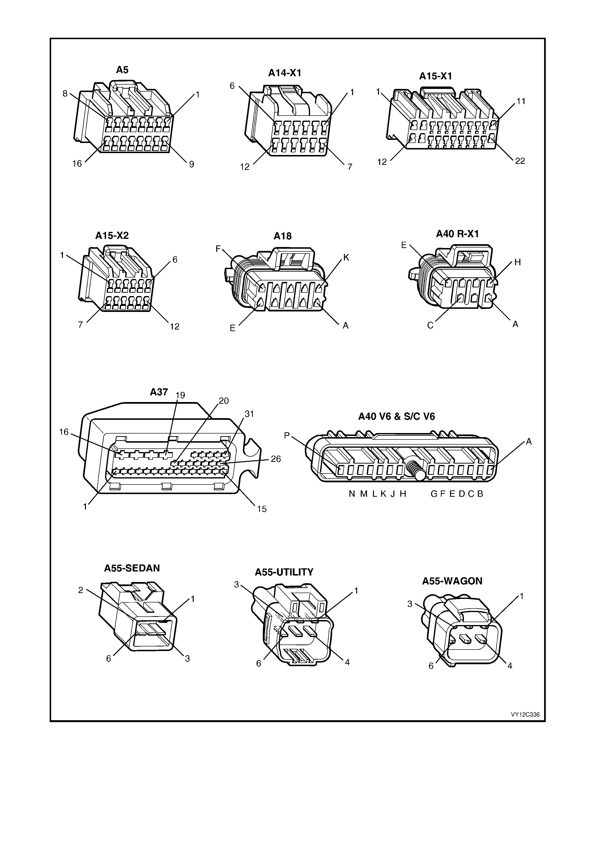
Figure 12C-283
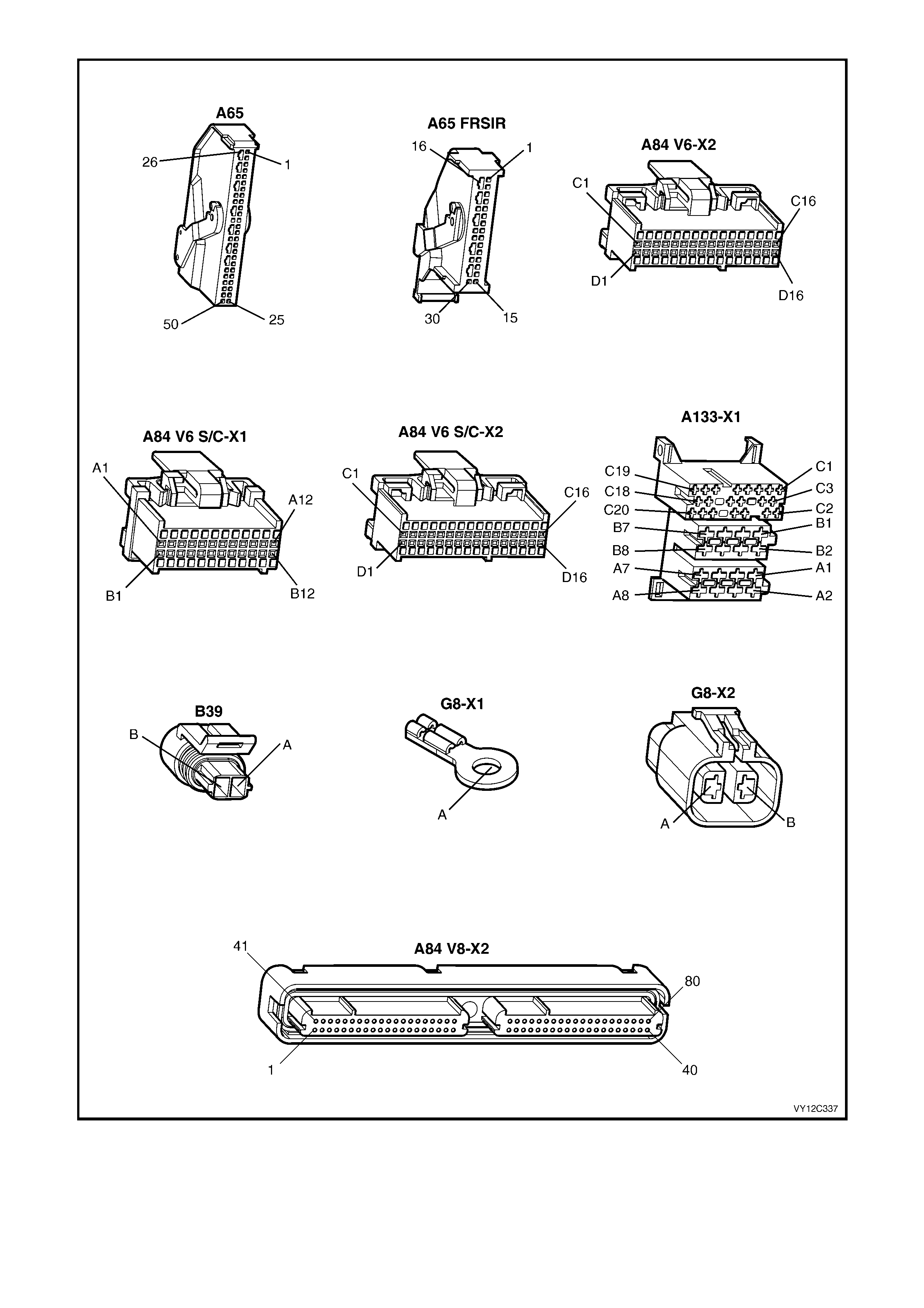
Figure 12C-284
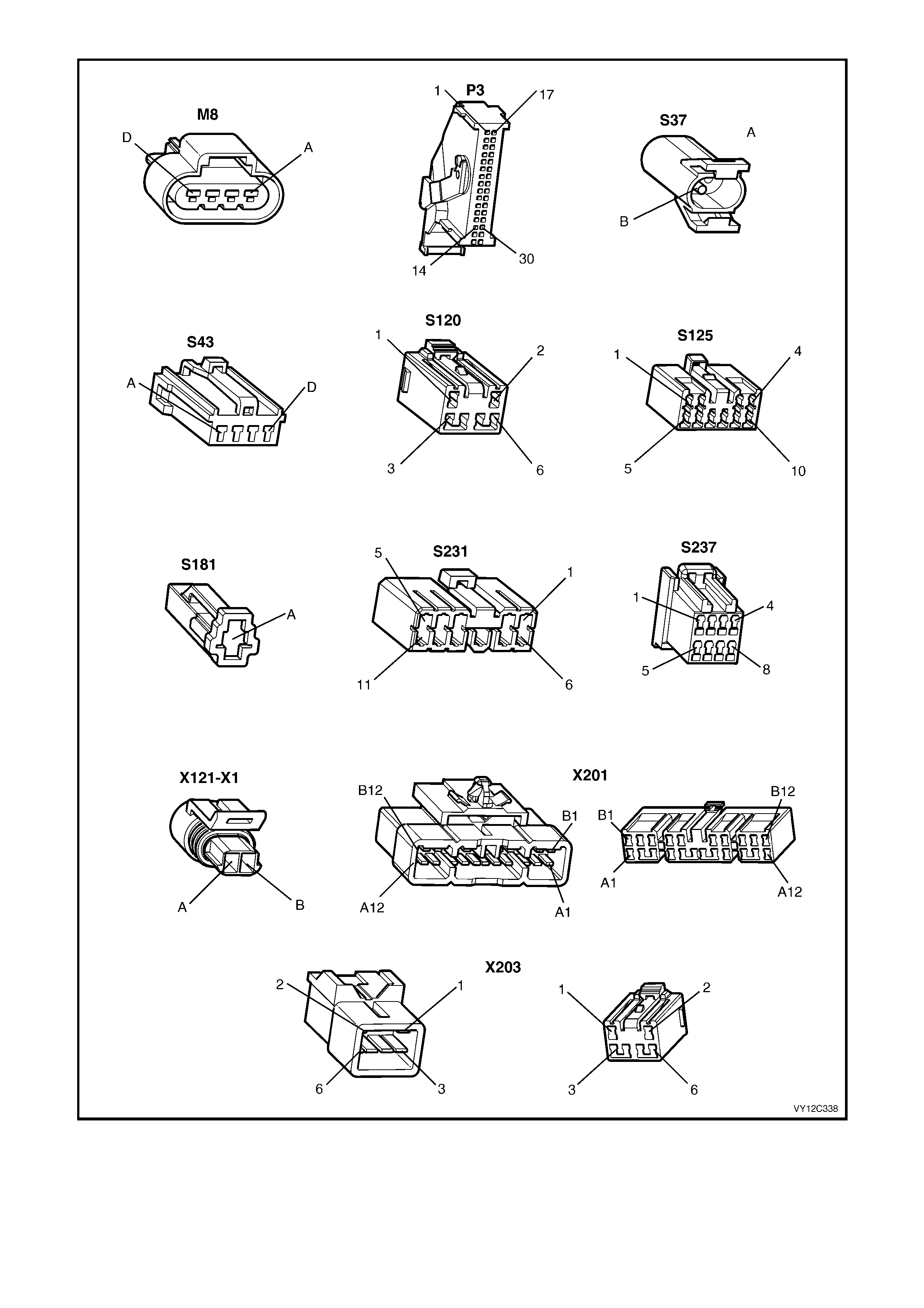
Figure 12C-285
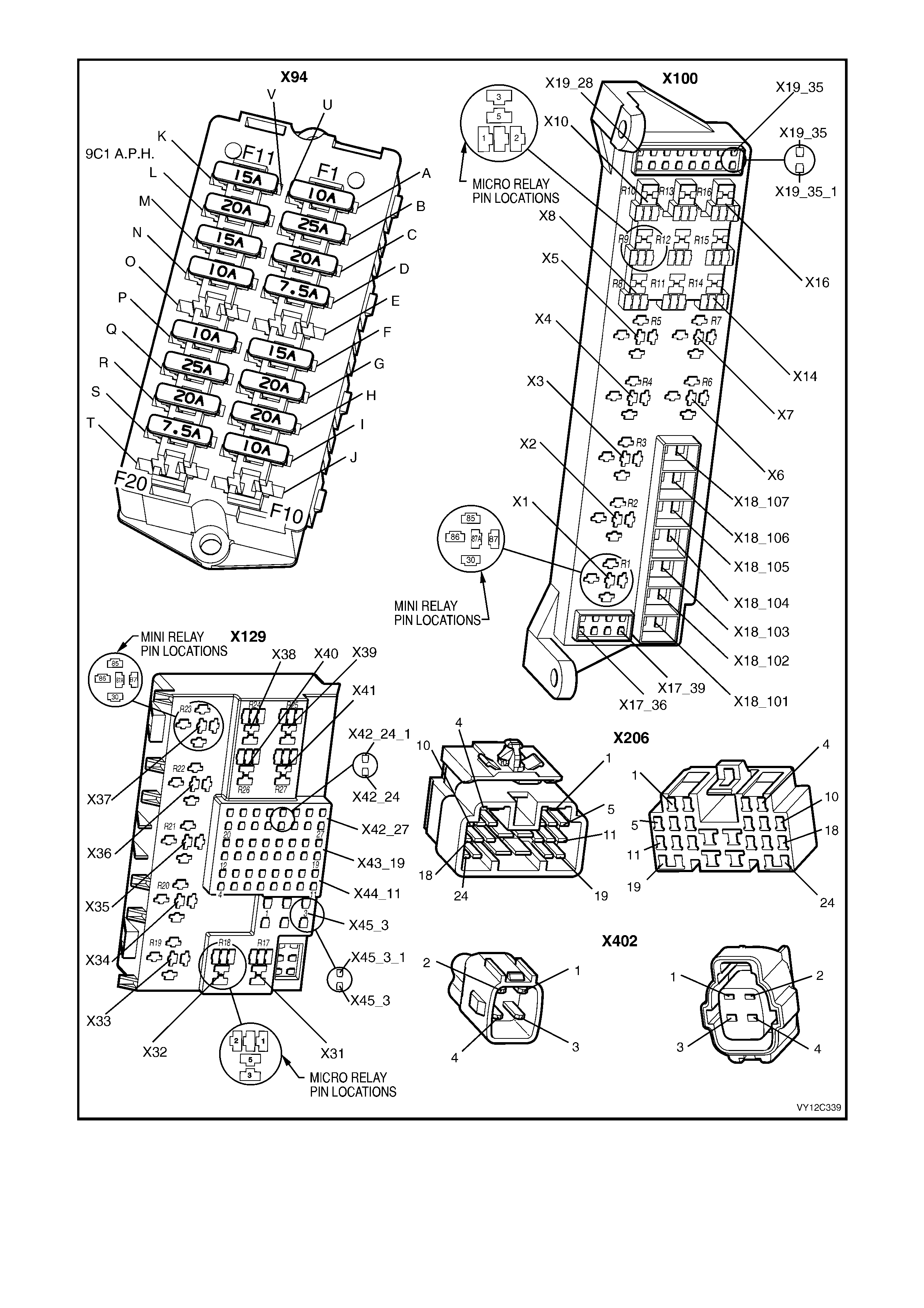
Figure 12C-286
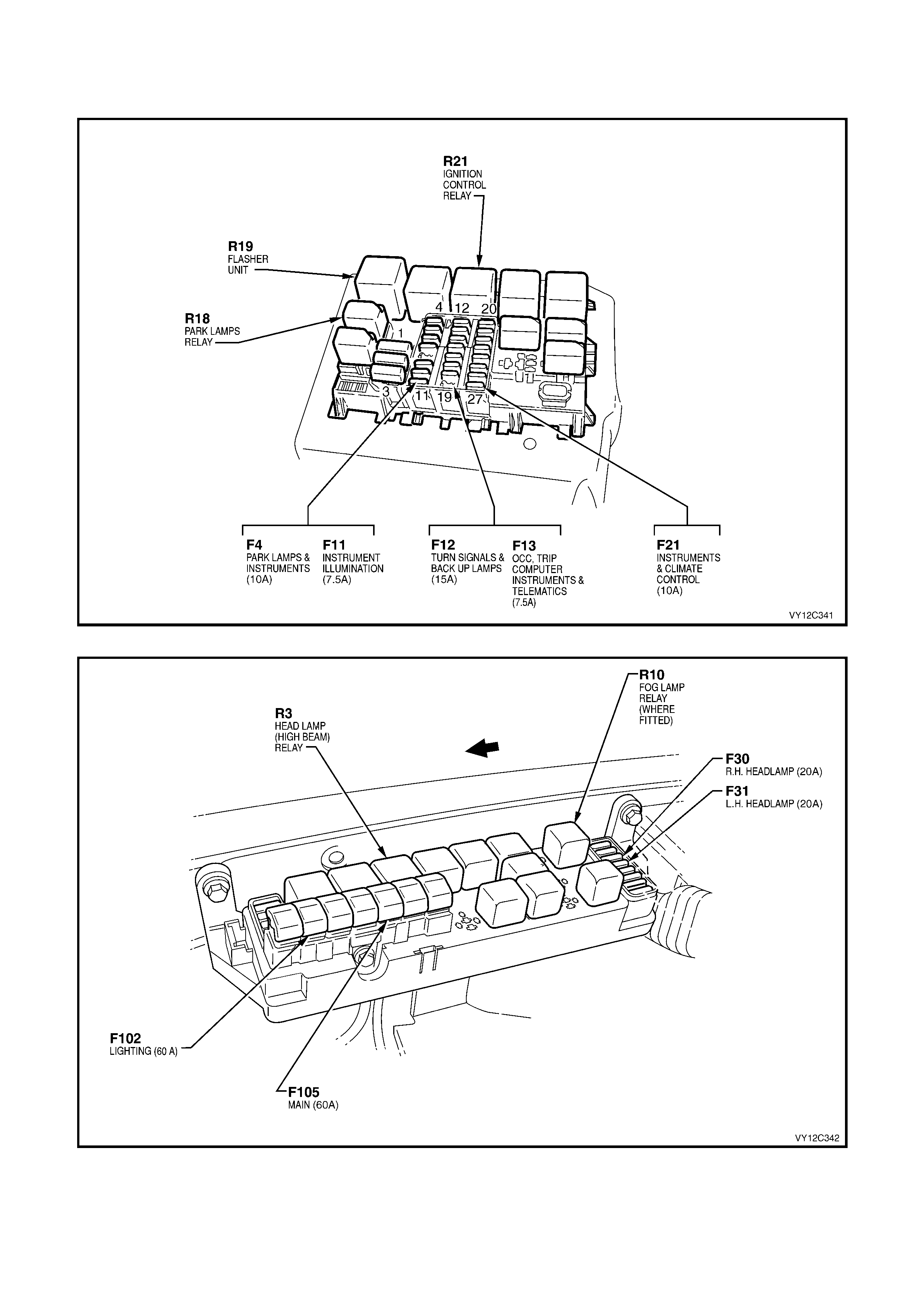
Fuses and relays associated with the instrument cluster are located in the instrument panel fuse and relay panel
(refer to Figure 12C-287.) and the engine compartment fuse and relay panel (refer to Figure 12C-288).
Figure 12C-287
Figure 12C-288

3.4 DIAGNOSING FAULTS NOT COVERED BY DIAGNOSTIC TROUBLE CODES
The instrument cluster telltales and MFD are triggered by information or signals which can be either internally
generated, or be input to the cluster via the serial data bus from an external module or component, or hard-wired
from a module or switch. Some of these components do not set a DTC in the event of a component failure. The
following diagnostic procedures are devised to assist in these cases:
• Diagnosis for Hard-wired Input Signals • Low Traction Control Display
• Diagnosis for Internally Generated Signals • Generator Warning
• Diagnosis for Serial Data Input Signals • Trip Computer Switch
• Front Fog Lamps On • Instrument Illumination
• Turn Signal Indicator Lamps • Brake Fail / Park Brake Warning
• High Beam Indicator Lamp • Speedometer Diagnosis
• Security Status Indicator • Tachometer Diagnosis
• ABS Off Warning Indicator • Coolant Temperature Gauge Diagnosis
• Cruise Control Display • Fuel Level Gauge Diagnosis
DIAGNOSIS FOR HARD-WIRED INPUT SIGNALS
The following table provides diagnostic information for the instrument cluster hard-wired inputs.
DISPLAY TELLTALE / MFD ACTION
Low Traction MFD Refer to Low Traction Control Display Diagnosis in this Section.
Cruise On MFD Refer to Cruise Control Indication Diagnosis in this Section.
Cruise Active MFD Refer to Cruise Control Indication Diagnosis in this Section.
Left Turn Telltale Refer to Turn Signal Indicator Lamps Diagnosis in this Section.
High Beam Telltale Refer to High Beam Indicator Lamp Diagnosis in this Section.
Right Turn Telltale Refer to Turn Signal Indicator Lamps Diagnosis in this Section.
ABS Off Telltale / MFD Refer to ABS Off Warning Indicator Diagnosis in this Section.
Brake (Park/Fail) Telltale / MFD Refer to Park Brake Fail Diagnosis in this Section.
Security Telltale Refer to Security Status Indicator Diagnosis in this Section.
Generator Telltale / MFD Refer to Generator (Alternator) Lamp Diagnosis in this Section.
Front Fog Lamps Telltale Refer to Front Fog Lamp On Diagnosis in this Section.
DIAGNOSIS FOR INTERNALLY GENERATED SIGNALS
The following provides diagnostic information for the internally generated instrument cluster signals.
1. Connect TECH 2 to the DLC.
2. Select Diagnostics / Model Year / Vehicle Model / Body / Instrument / Miscellaneous Tests.
3. Use the Up and Down arrow keys to scroll through the Miscellaneous Tests list and highlight the test required.
4. Press the Enter key to select the test function.
5. Once the test function has been highlighted and select ed, the TECH 2 will display the current serial data at the
top of the screen and soft keys at the bottom of the screen. Conduct the test as directed by the soft keys.
6. Does the telltale illuminate and / or the MFD display the correct information?
Yes — Refer to the following table.
No — Replace the instrument cluster. Refer to 2.3 INSTRUMENT CLUSTER ASSEMBLY in this Section.
DISPLAY TELLTALE / MFD ACTION
Overpseed MFD Refer to Speedometer Diagnosis in this Section.
High Temperature MFD Refer to Coolant Temperature Gauge Diagnosis in this Section.
Seat Belt Telltale Replace the instrument cluster. Refer to 2.3 INSTRUMENT
CLUSTER ASSEMBLY in this Section.
Shift Up (HSV Only) Telltale Refer to Tachometer Diagnosis in this Section.
Low Fuel MFD Refer to Fuel Level Gauge Diagnosis in this Section.

DIAGNOSIS FOR SERIAL DATA INPUT SIGNALS
The following provides diagnostic information for the internally generated instrument cluster signals.
1. Connect TECH 2 to the DLC.
2. Select Diagnostics / Model Year / Vehicle Model / Vehicle DTC Check.
3. Does the TECH 2 communicate with all the control modules?
NOTE: If ‘No Data’ is displayed next to a control module, then there is no communication between TECH 2 and
the that control module. If 'No DTC' or 'DTCs Set' is displayed then there is communication between the
TECH 2 and the control module.
Yes — Go to Step 4.
No — Go to DTC 14 No Serial Communication in this Section.
4. Select Diagnostics / Model Year / Vehicle Model / Body / Instrument / Miscellaneous Tests / Warnings.
5. Use the Up and Down arrow keys to scroll through the Warnings list and highlight the test required.
6. Press the Enter key to select the test function.
7. Once the test function has been highlighted and select ed, the TECH 2 will display the current serial data at the
top of the screen and soft keys at the bottom of the screen. Conduct the test as directed by the soft keys.
8. Does the telltale illuminate and / or the MFD display the correct information?
Yes — Refer to the following table.
No — Replace the instrument cluster. Refer to 2.3 INSTRUMENT CLUSTER ASSEMBLY in this Section.
DISPLAY TELLTALE / MFD ACTION
Power Shift MFD For V6 engine, refer to Section 6C1-2C, FUNCTIONAL CHECKS –
TABLE 2.6.
For V6 S/C engine, refer to Section 6C2-2C, FUNCTIONAL
CHECKS – TABLE 2.5.
For GEN III V8 engine, refer to Section 6C3-2C, FUNCTIONAL
CHECKS.
Rear Lamp Fail MFD Refer to Section 12J, 4.20 REAR LAMP FAILURE WARNING
SYSTEM for further diagnosis.
Traction Control Off MFD Refer to Section 5B, CHART A2 – TRAC OFF WARNING DISPLAY
INOPERATIVE for further diagnosis.
LPG MFD Refer to Section 6C1-2A, DIAGNOSTIC TABLES – DTC P1642 or
DTC P1643.
SRS Telltale / MFD Refer to Section 12M, 4.6 DIAGNOSTIC CHARTS, CHART C —
SRS WARNING INDICATOR
Oil Pressure MFD Refer to Section 6C3-2A, DIAGNOSTIC TABLES – DTC P0522 or
DTC P0523.
Low Coolant MFD Refer to Section 6C3-2 C, FUNCTIONAL CHECKS – ENGINE
COOLANT LEVEL SWITCH DIAGNOSIS.
Check Powertrain MFD For V6 engine, refer to Section 6C1-2A, DIAGNOSTIC TABLES –
TABLE A-1 or TABLE A-2.
For V6 S/C engine, refer to Section 6C2-2A, DIAGNOSTIC
TABLES – TABLE A-1 or TABLE A-2.
For GEN III V8 engine, refer to Section 6C3-2A, DIAGNOSTIC
TABLES – 2.2 CHECK POWERTRAIN MALFUNCTION
INDICATOR LAMP.
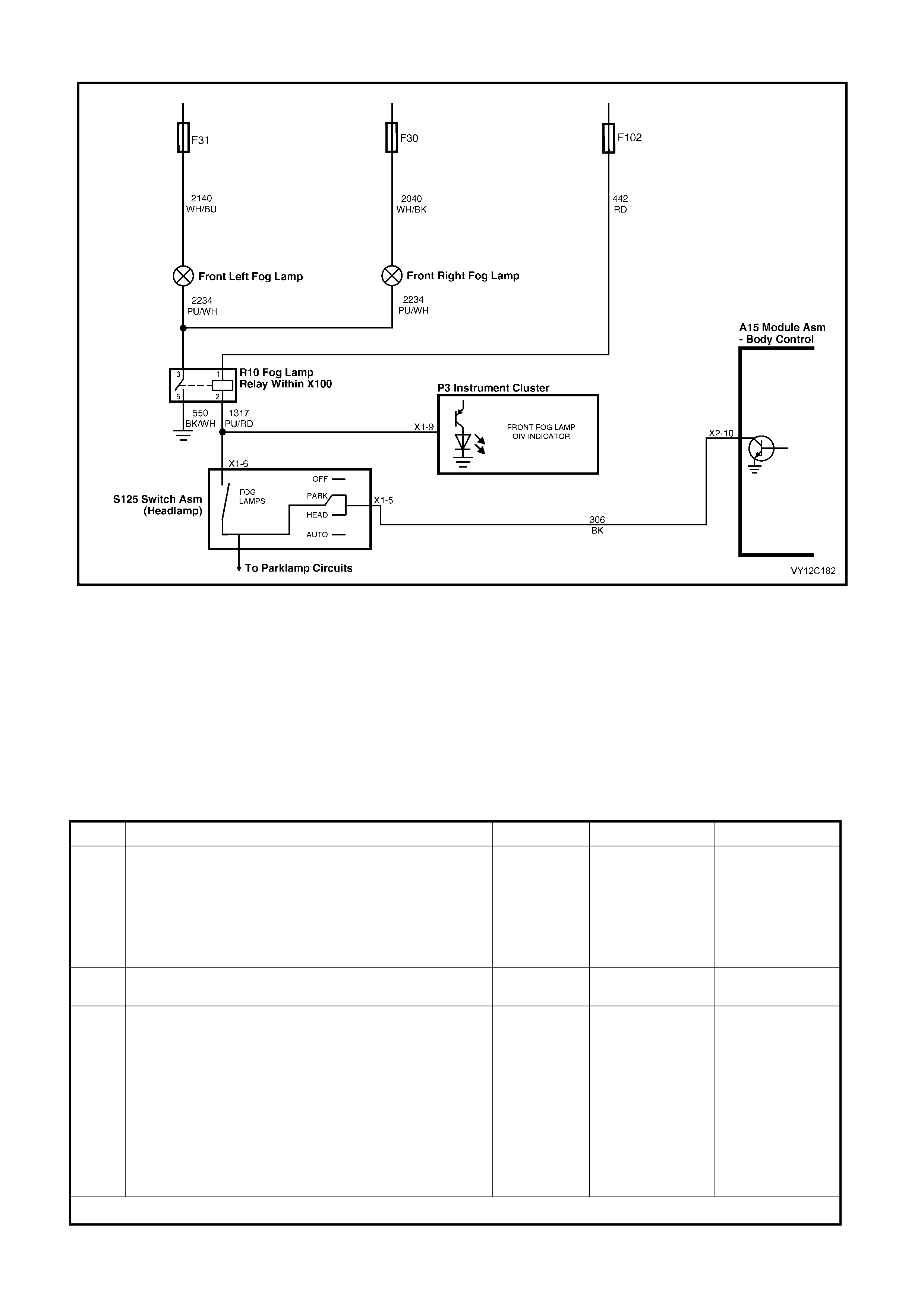
FRONT FOG LAMP ON
Figure 12C-289
CIRCUIT DESCRIPTION
When turning the front fog lamps switch on with the headlamp switch in the PARK position, the fog lamp relay is
energised via the BCM. This turns on the front fog lamps and illuminates the front fog lamp telltale LED in the
instrument cluster.
The following fuses protect the fog lamp circuit. Ensure that the fuses are serviceable before proceeding:
• F30 — Front right fog lamp
• F31 — Front left fog lamp
• F102 — Fog lamp relay
FRONT FOG LAMP ON DIAGNOSTIC CHART
STEP ACTION VALUE YES NO
1 1. Turn the ignition on and set the headlamp switch to
the PARK position.
2. Turn the front fog lamps on.
Do the front fog lamps illuminate?
Go to Step 2. Check the Park
Lamp / Fog Lamp
circuit and
electrical supply.
Refer to Section
12P, WIRING
DIAGRAMS.
2 Does the front fog lamp telltale LED in the instrument
cluster illuminate? System OK. Go to Step 3.
3 1. Turn the fog lamps off.
2. Turn the ignition off.
3. Remove the instrument cluster. Refer to
2.3 INSTRUMENT CLUSTER ASSEMBLY in this
Section.
4. Using an ohmmeter, check for continuity of circuit
1317 (Purple / Red wire) between the instrument
cluster P3 connector X1-9 and the headlamp switch
S125, connector X1-6.
Is the value as specified?
Less than
1 ohm Replace the
instrument cluster.
Refer to 2.3
INSTRUM ENT
CLUSTER
ASSEMBLY in this
Section.
Repair faulty
circuit 1317.
WHEN ALL DIAGNOSIS AND REPAIRS ARE COM PLETED, VERIFY CORRECT OPERATION
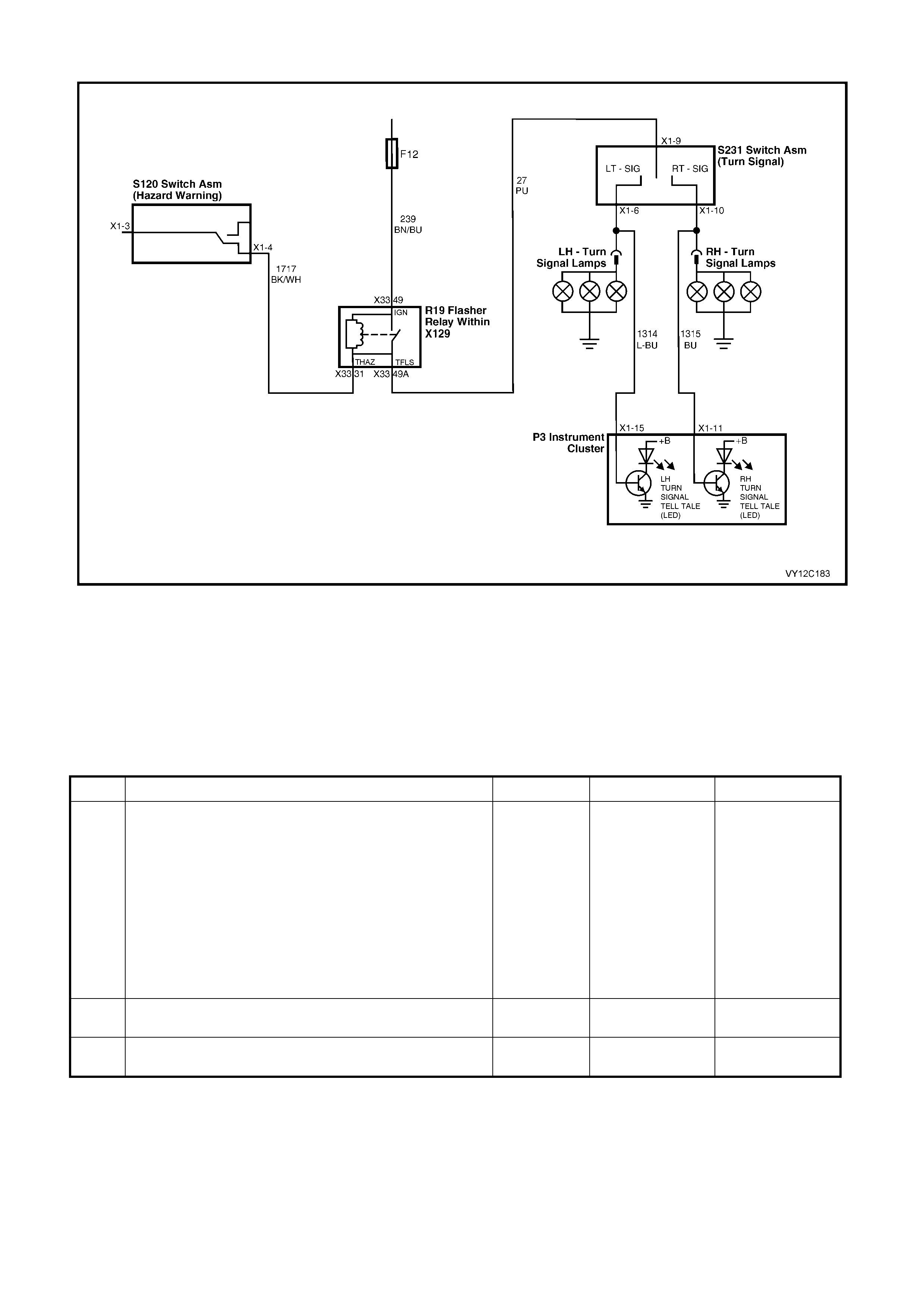
TURN SIGNAL INDICATOR LAMPS
Figure 12C-290
CIRCUIT DESCRIPTION
When the hazard warning switch or the left-hand/right-hand turn signal indicator switch is activated, 12 volts is
switched through the flasher relay to the left-hand/right-hand turn signal indicator lamps and the corresponding
instrument cluster telltale LED via circuit 1314 and circuit 1315.
The turn signal circuit is protect by fuse F12. Ensure that the fuse is serviceable before proceeding.
TURN SIGNAL INDICATOR LAMP DIAGNOSTIC CHART
STEP ACTION VALUE YES NO
1 1. Turn the ignition on and activate the hazard lamp
switch.
Do the turn signal lamps flash continuously?
Go to Step 2. Check the Turn
Signal Indicator
Lamp circuit,
including flasher
relay, hazard
switch and turn
signal switch, and
the electrical
supply. Refer to
Section 12P,
WIRING
DIAGRAMS.
2 Does the left-hand turn signal telltale LED in the
instrument cluster flash continuously? Go to Step 3. Go to Step 4.
3 Does the right-hand turn signal telltale LED in the
instrument cluster flash continuously? System OK. Go to Step 5.

STEP ACTION VALUE YES NO
4 1. Turn the hazard lamps off.
2. Turn the ignition off.
3. Remove the instrument cluster. Refer to
2.3 INSTRUMENT CLUSTER ASSEMBLY in this
Section.
4. Using an ohmmeter, check for continuity of circuit
1314 (Light-blue wire) between the instrument
cluster P3 connector X1-15 and the turn signal
switch S231, connector X1-6.
Is the value as specified?
Less than
1 ohm Replace the
instrument cluster.
Refer to 2.3
INSTRUM ENT
CLUSTER
ASSEMBLY in this
Section.
Repair faulty
circuit 1314.
5 1. Turn the hazard lamps off.
2. Turn the ignition off.
3. Remove the instrument cluster. Refer to
2.3 INSTRUMENT CLUSTER ASSEMBLY in this
Section.
4. Using an ohmmeter, check for continuity of circuit
1315 (Blue wire) between the instrument cluster P3
connector X1-11 and the turn signal switch S231,
connector X1-10.
Is the value as specified?
Less than
1 ohm Replace the
instrument cluster.
Refer to 2.3
INSTRUM ENT
CLUSTER
ASSEMBLY in this
Section.
Repair faulty
circuit 1315.
WHEN ALL DIAGNOSIS AND REPAIRS ARE COM PLETED, VERIFY CORRECT OPERATION
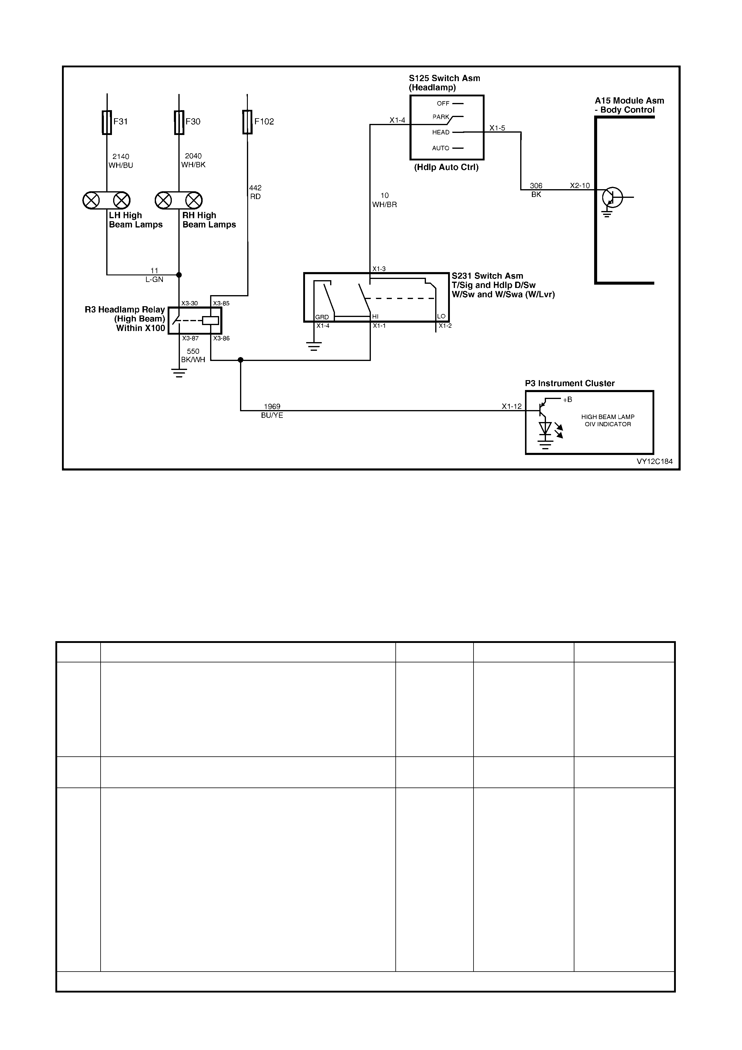
HIGH BEAM INDICATOR LAMP
Figure 12C-291
CIRCUIT DESCRIPTION
When activating the high beam switch with the headlamp switch in the HEAD position, the headlamp relay (high
beam) r elay is energised via the BCM. T his turns on the high beam in the headlamps and illuminates the high beam
telltale LED in the instrument cluster.
The following fuses protect the headlamp circuit. Ensure that the fuses are serviceable before proceeding:
• F30 — Front right headlamp
• F31 — Front left headlamp
• F102 — Headlamp relay HIGH BEAM INDICATOR LAMP DIAGNOSTIC CHART
STEP ACTION VALUE YES NO
1 1. Turn the ignition on and set the headlamp switch to
the HEAD position.
2. Activate the high beam switch.
Do the high beam lamps illuminate?
Go to Step 2. Check the
Headlamp (High
Beam) circuit and
electrical supply.
Refer to Section
12P, WIRING
DIAGRAMS.
2 Did the high beam telltale LED in the instrument cluster
illuminate? System OK. Go to Step 3.
3 1. Turn the ignition off.
2. Remove the instrument cluster. Refer to
2.3 INSTRUMENT CLUSTER ASSEMBLY in this
Section.
3. Connect a digital voltmeter between the instrument
cluster P3 connector X1-12, circuit 1969 (Blue /
Yellow wire) and a known good ground.
4. Activate the high beam switch and note the voltage
reading.
5. Release the high beam switch and note the voltage
reading.
Is the value as specified?
High beam
OFF = 12 V
High beam
ON = 0 V
Replace the
instrument cluster.
Refer to 2.3
INSTRUM ENT
CLUSTER
ASSEMBLY in this
Section.
Repair faulty
circuit 1969.
WHEN ALL DIAGNOSIS AND REPAIRS ARE COM PLETED, VERIFY CORRECT OPERATION
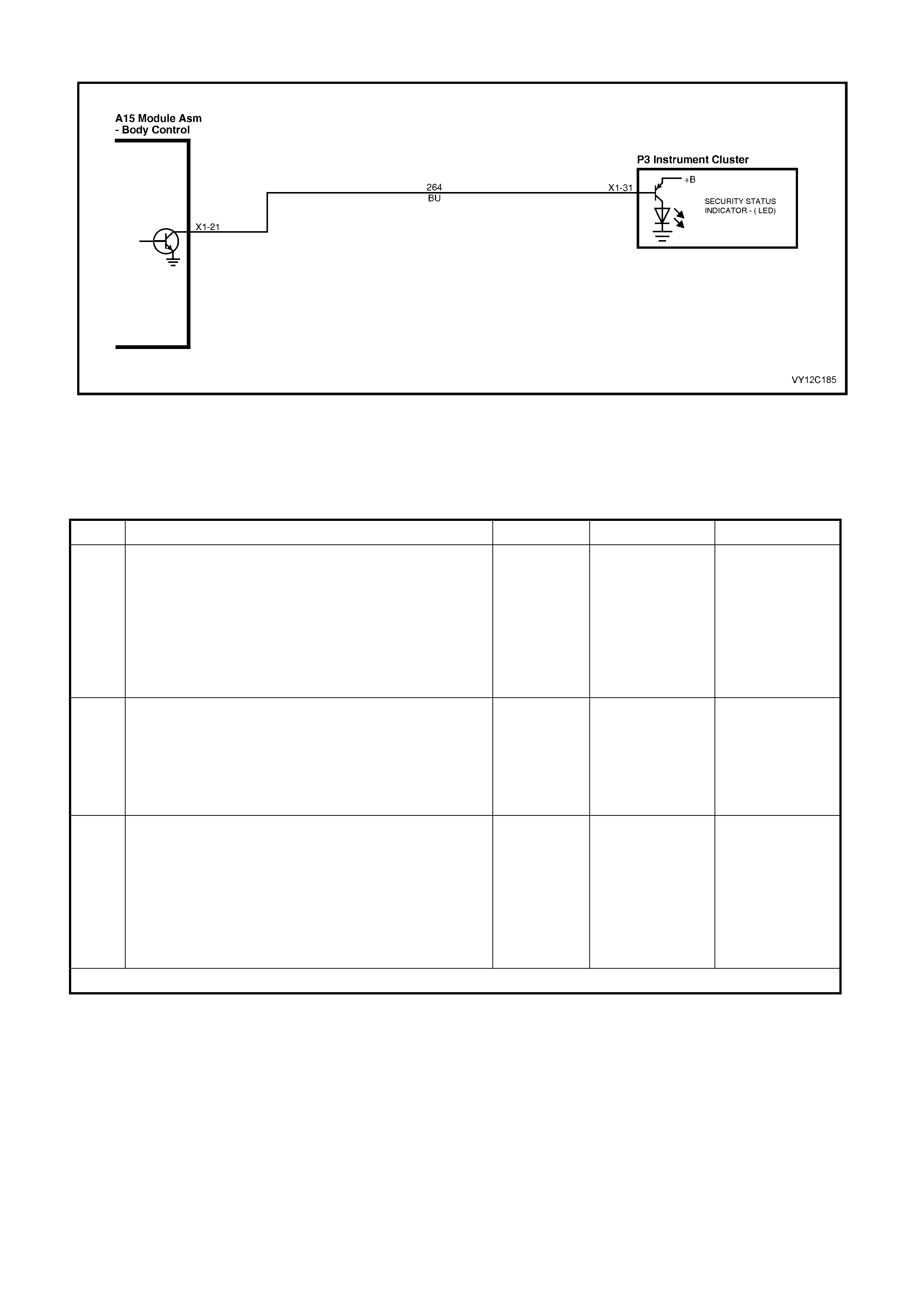
SECURITY STATUS INDICATOR
Figure 12C-292
CIRCUIT DESCRIPTION
The s ecurity s tatus indicator LED in the inst rument c luster displays the security status of the BCM. The telltale LED
flashes to indicate when the vehicle security system is armed.
SECURITY STATUS INDICATOR DIAGNOSTIC CHART
STEP ACTION VALUE YES NO
1 1. Connect TECH 2 to the DLC.
2. Turn the ignition on.
3. Select Diagnostics / Model Year / Vehicle Model /
Body / Body Control Module / Miscellaneous Tests /
Security System / Security LED, and conduct the test
as directed by soft keys at the bottom of the TECH 2
screen.
Does the security telltale LED illuminate?
System OK. Go to Step 2.
2 1. Gain access to the BCM. Refer to Section 12J,
2.1 BODY CONTROL MODULE.
2. With the ignition on, back probe the BCM A15
connector X1-21, circuit 264 (Blue wire) with a
jumper lead to ground.
Does the security telltale LED illuminate?
Replace the
instrument cluster.
Refer to 2.3
INSTRUM ENT
CLUSTER
ASSEMBLY in this
Section.
Go to Step 3.
3 1. Turn the ignition off.
2. Remove the instrument cluster. Refer to
2.3 INSTRUMENT CLUSTER ASSEMBLY in this
Section.
3. Using an ohmmeter, check for continuity of circuit
264 (Blue wire) between the instrument cluster P3
connector X1-31 and BCM A14 connector X1-21.
Is the value as specified?
Less than
1 ohm Refer to Section
12J, 3.8 THEFT
DETERRENT
SYSTEM for
further diagnosis.
Repair faulty
circuit 264.
WHEN ALL DIAGNOSIS AND REPAIRS ARE COM PLETED, VERIFY CORRECT OPERATION
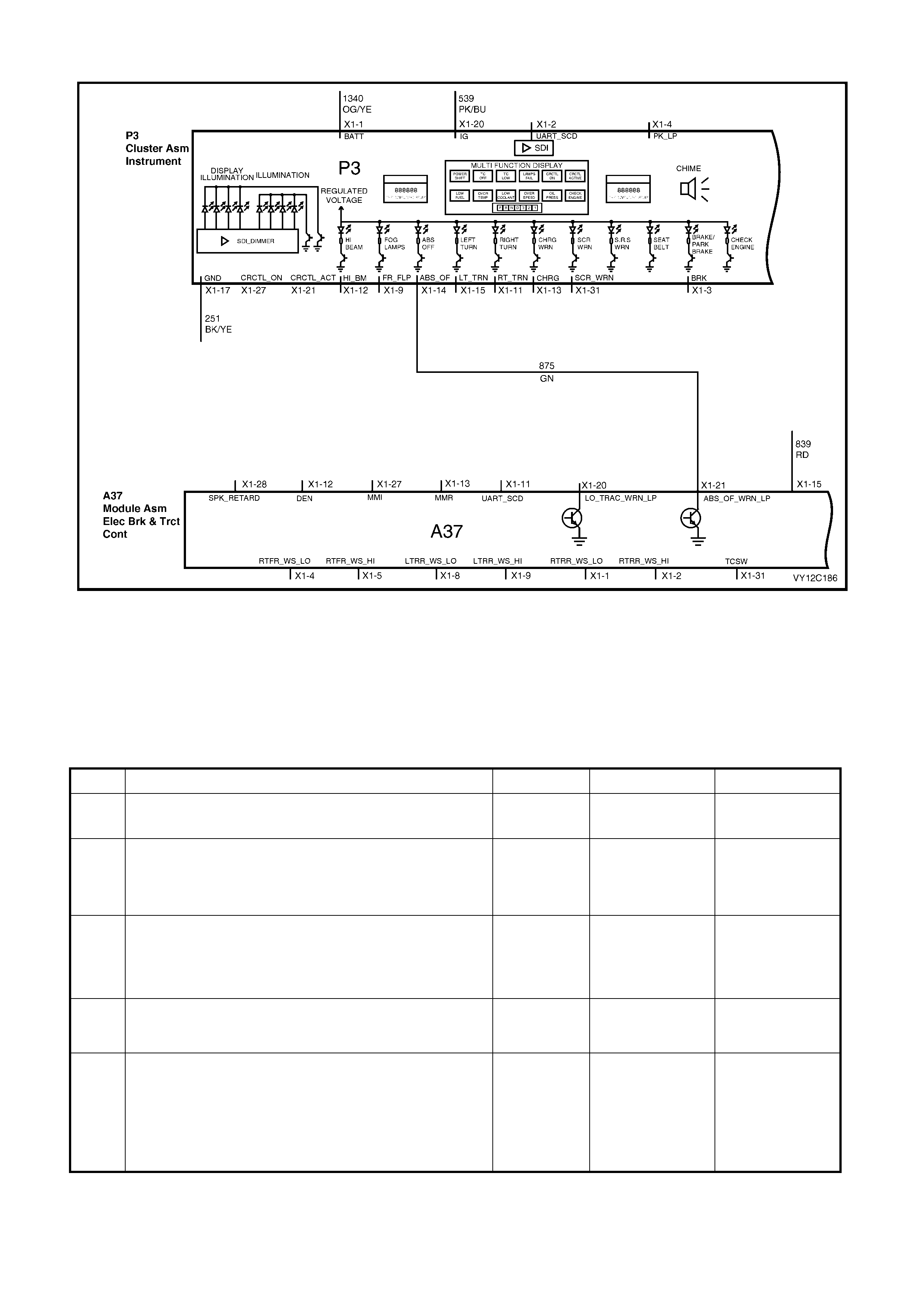
ABS OFF WARNING INDICATOR
Figure 12C-293
CIRCUIT DESCRIPTION
The ABS of f telltale LED is illuminated f or 2 sec onds when the ignition is s witched fr om Off to On by a ground signal
from the ABS / T CS m odule to the instr ument cluster. If there is a fault within the ABS / T CS module at ignition O n
or during normal operation, the module is disabled and the ABS off telltale LED remains illuminated. Additionally,
the MFD displays an animated ic on, which can be cleared by pressing the Mode button on the trip com puter switch.
The ABS off telltale LED remains illuminated until the condition is cleared.
ABS OFF WARNING INDICATOR DIAGNOSTIC CHART
STEP ACTION VALUE YES NO
1 1. Turn the ignition from Off to On.
Does the ABS off warning telltale LED illuminate? Go to Step 2. Go to Step 4.
2 1. Cycle the ignition from On to Off to On.
Does the ABS off warning telltale LED extinguish within
2 seconds and does the ABS fault animated icon not
illuminate?
Go to Step 4. Go to Step 3.
3 1. Connect TECH 2 to the DLC.
2. Select Diagnostics / Model Year / Vehicle Model /
Vehicle DTC Check.
Is there a DTC set for ABS?
Refer to the
relevant chart in
Section 5B, ABS
& ABS / TCS.
Go to Step 8.
4 In the event of an ABS module fault do the ABS off
warning telltale LED and animated icon on the MFD
illuminate?
System OK. Go to Step 5.
5 1. Select Diagnostics / Model Year / Vehicle Model /
Body / Instrument / Miscellaneous Tests / W arnings /
ABS Fault and conduct the test as directed by soft
keys at the bottom of the TECH 2 screen.
Does the animated ABS fault icon illuminate on the MFD?
Go to Step 6. Replace the
instrument cluster.
Refer to 2.3
INSTRUM ENT
CLUSTER
ASSEMBLY in this
Section.

STEP ACTION VALUE YES NO
6 1. Turn the ignition off.
2. Disconnect ABS / TCS module A37 connector X1.
3. Turn the ignition on.
Does the ABS off warning telltale LED and the animated
ABS fault icon illuminate?
NOTE: Disconnecting the ABS / TCS module A37
connector X1 will short the wiring harness connector
terminals X1-20 and X1-21 to the ground terminal X1-19.
Refer to Section
5B, CHART A1 –
ABS WARNING
DISPLAY
INOPERATIVE for
further diagnosis.
Go to Step 7.
7 1. Turn the ignition off.
2. Leave the ABS / TCS module A37 connector X1
disconnected.
3. Remove the instrument cluster. Refer to
2.3 INSTRUMENT CLUSTER ASSEMBLY in this
Section.
4. Using an ohmmeter, check for continuity of circuit
875 (Green wire) between the instrument cluster P3
connector X1-14 and ABS / TCS module A37
connector X1-21.
Is the value as specified?
NOTE: Disconnecting the ABS / TCS module A37
connector X1 will short the wiring harness connector
terminals X1-20 and X1-21 to the ground terminal X1-19.
Less than
1 ohm Replace the
instrument cluster.
Refer to 2.3
INSTRUM ENT
CLUSTER
ASSEMBLY in this
Section.
Repair faulty
circuit 875.
8 1. Turn the ignition off.
2. Remove the instrument cluster. Refer to
2.3 INSTRUMENT CLUSTER ASSEMBLY in this
Section.
3. Connect a test light between the instrument cluster
P3 connector X1-14 and battery voltage.
4. Turn the ignition on
Does the test light illuminate?
Go to Step 9. Replace the
instrument cluster.
Refer to 2.3
INSTRUM ENT
CLUSTER
ASSEMBLY in this
Section.
9 1. Turn the ignition off.
2. Using an ohmmeter, check for continuity of circuit
875 (Green wire) between the instrument cluster P3
connector X1-14 and ABS / TCS module A37
connector X1-21.
Is the value as specified?
Less than
1 ohm False signal from
ABS / TCS
module. Refer to
the diagnostic
charts in Section
5B, ABS & ABS /
TCS for further
diagnosis.
Repair faulty
circuit 875.
WHEN ALL DIAGNOSIS AND REPAIRS ARE COM PLETED, VERIFY CORRECT OPERATION
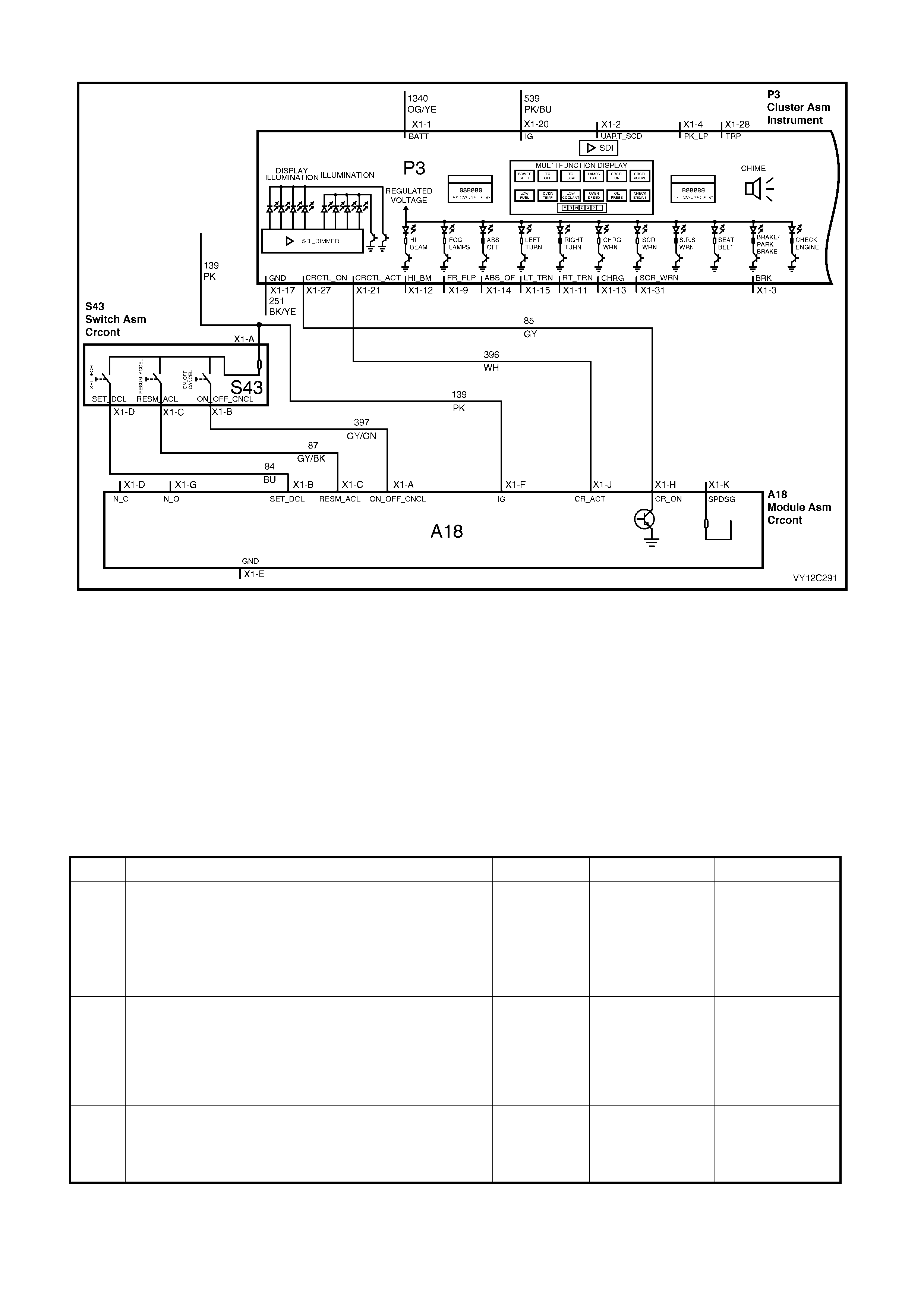
CRUISE CONTROL DISPLAY
Figure 12C-294
CIRCUIT DESCRIPTION
W ith the ignition on, when the instrum ent cluster receives the Cr uise On signal from the cruise c ontrol module, the
CRUISE icon illuminates and the Cruise Enabled animation is displayed for 2 seconds on the MFD. When the
cruise control is activated via the cruise control switch assembly, the instrument cluster receives the cruise active
signal from the cruise control module. The cruise control CRUISE ACTIVE icon illuminates until disabled and the
Cruise Ac tive animation is displayed for 2 sec onds. W hen cruis e control is deactivated via the cruis e contr ol s witc h
assembly, the cruise active signal from the cruise control module to the instrument cluster is cancelled, the cruise
control ACTIVE icon extinguishes im m ediately and the Cruise Inac tive animation is dis played for 2 s econds. W hen
the cruise c ontrol is disabled by pressing the cr uise on / off switch on the cruis e control switch assembly the Cruis e
On signal f orm the cr uise m odule to the instrument c luster is canc elled, the CRUISE icon ex tinguishes imm ediately
and the Cruise Off animation is displayed for 2 seconds.
CRUISE CONTROL DISPLAY DIAGNOSTIC CHART
STEP ACTION VALUE YES NO
1 1. Turn the ignition on.
2. Press the Cruise On switch on the cruise control
switch assembly.
Does the CRUISE icon in the instrument cluster MFD
illuminate and the Cruise Enable animation run for
2 seconds?
Go to Step 2. Go to Step 5.
2 1. With the vehicle travelling at greater than 40 km/h
press the cruise Set switch, located on the cruise
control switch assembly.
Does the CRUISE ACTIVE icon in the instrument cluster
MFD illuminate and is the Cruise Active animation
displayed for 2 seconds?
Go to Step 3. Go to Step 8.
3 1. Press the Cruise On / Off switch located on the
cruise control switch assembly
Does the cruise ACTIVE icon extinguish and is the Cruise
Inactive animation displayed for 2 seconds.
Go to Step 4. Go to Step 8.

STEP ACTION VALUE YES NO
4 1. Press the Cruise On / Off switch located on the
cruise control switch assembly.
Does the CRUISE icon extinguish and is the Cruise Off
animation displayed for 2 seconds?
System OK. Go to Step 5.
5 1. Connect TECH 2 to the DLC.
2. Turn the ignition on.
3. Select Diagnostics / Model Year / Vehicle Model /
Body / Instrument / Miscellaneous Tests / Status
Indicators / Cruise Enabled, and conduct the test as
directed by soft keys at the bottom of the TECH 2
screen.
Does the CRUISE icon illuminate and is the Cruise
Enable animation displayed for 2 seconds, and does the
CRUISE icon extinguish and is the Cruise Off animation
displayed for 2 seconds when the test is cancelled?
Go to Step 6. Replace the
instrument cluster.
Refer to 2.3
INSTRUM ENT
CLUSTER
ASSEMBLY in this
Section.
6 1. Turn the ignition off.
2. Remove the instrument cluster. Refer to 2.3
INSTRUMENT CLUSTER ASSEMBLY in this
Section.
3. Connect a digital voltmeter between the instrument
cluster P3 connector X1-27, circuit 85 (Grey wire),
and a known good ground.
4. Turn the ignition on.
5. Press the cruise on switch located on the cruise
control switch assembly.
Is the voltage as specified?
Approximately
battery
voltage
Replace the
instrument cluster.
Refer to 2.3
INSTRUM ENT
CLUSTER
ASSEMBLY in this
Section.
Go to Step 7.
7 1. Disconnect the cruise control module A18 connector
X1.
2. Using an ohmmeter, check for continuity of circuit 85
(Grey wire) between the instrument cluster P3
connector X1-27 and the cruise control module A18
connector X1-H.
3. Check circuit 85 (Grey wire) for short to ground or
battery voltage.
Is circuit 85 OK?
Refer to Section
12E, CRUISE
CONTROL
SYSTEM
DIAGNOSTIC
CHART for further
diagnosis.
Repair faulty
circuit 85.
8 1. Connect TECH 2 to the DLC.
2. Turn the ignition on.
3. Select Diagnostics / Model Year / Vehicle Model /
Body / Instrument / Miscellaneous Tests / Status
Indicators / Cruise Active, and conduct the test as
directed by soft keys at the bottom of the TECH 2
screen.
Does the CRUISE ACTIVE icon illuminate and is the
Cruise Active animation displayed for 2 seconds, and
does the cruise ACTIVE icon extinguish and is the Cruise
Inactive animation displayed for 2 seconds when the test
is cancelled?
Go to Step 9. Replace the
instrument cluster.
Refer to 2.3
INSTRUM ENT
CLUSTER
ASSEMBLY in this
Section.
9 1. With the ignition on, back probe cruise control
module A18 connector X1-J, circuit 396 (W hite wire)
with a jumper lead and connect to ground.
Does the cruise ACTIVE icon illuminate and is the Cruise
Active animation displayed for 2 seconds, and when
removing the jumper lead, does the ACTIVE icon
extinguish and is the Cruise Inactive animation displayed
for 2 seconds?
Refer to Section
12E, 3.5 CRUISE
CONTROL
SYSTEM
DIAGNOSTIC
CHART for further
diagnosis.
Go to Step 10.

STEP ACTION VALUE YES NO
10 1. If necessary, remove the instrument cluster. Refer to
2.3 INSTRUMENT CLUSTER ASSEMBLY in this
Section.
2. Disconnect the cruise control module A18 connector
X1.
3. Using an ohmmeter, check for continuity of circuit
396 (White wire) between the instrument cluster P3
connector X1-21 and the cruise control module A18
connector X1-J.
4. Check circuit 396 (W hite wire) for short to ground or
battery voltage.
Is circuit 396 OK?
Replace the
instrument cluster.
Refer to 2.3
INSTRUM ENT
CLUSTER
ASSEMBLY in this
Section.
Repair faulty
circuit 396.
WHEN ALL DIAGNOSIS AND REPAIRS ARE COM PLETED, VERIFY CORRECT OPERATION
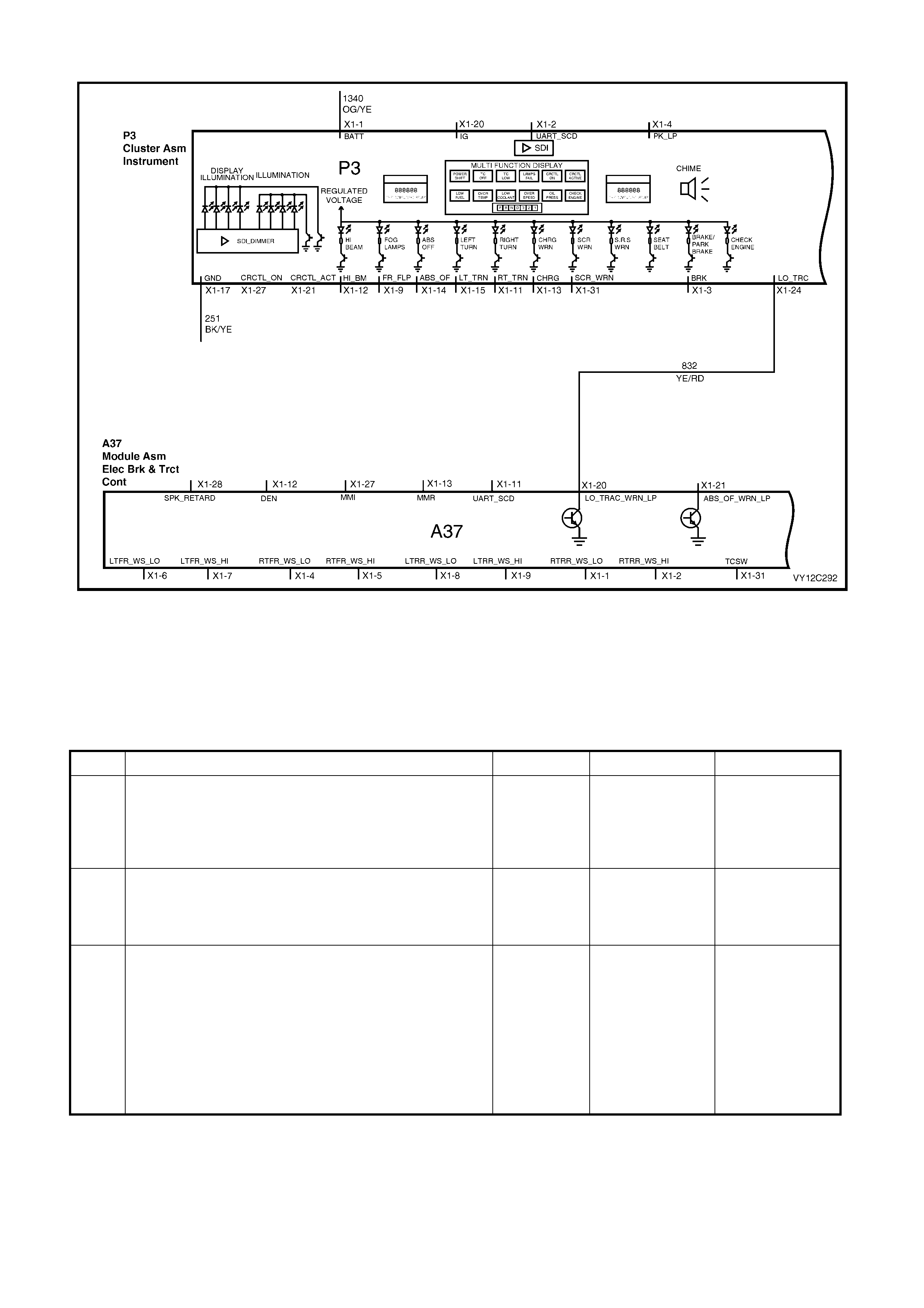
LOW TRACTION CONTROL DISPLAY
Figure 12C-295
CIRCUIT DESCRIPTION
When a low traction event oc curs the instrum ent c luster r eceives a s ignal from the ABS / T CS m odule and dis plays
the low traction animation and the fixed text ‘Low Traction’ warning. W hen the Mode button on the trip computer
switch assembly is pressed, the animated symbol reverts to a low traction control warning icon on the left of the
MFD. This warning icon remains illuminated for as long as a low traction situation exists.
LOW TRACTION CONTROL DISPLAY DIAGNOSTIC CHART
STEP ACTION VALUE YES NO
1 1. Turn the traction control on and operate the vehicle
in low traction conditions.
Does the low traction animated symbol and the fixed text
‘Low Traction’ warning in the instrument cluster illuminate
when the vehicle is in a low traction situation?
Go to Step 2. Go to Step 3.
2 1. With traction control on, operate the vehicle in
normal traction conditions.
Does the low traction animated symbol and the fixed text
‘Low Traction’ warning extinguish?
System OK. Go to Step 6.
3 1. Connect TECH 2 to the DLC.
2. Turn the ignition on.
3. Select Diagnostics / Model Year / Vehicle Model /
Body / Instrument / Miscellaneous Tests / W arnings /
Low Traction, and conduct the test as directed by
soft keys at the bottom of the TECH 2 screen.
Does the low traction animated symbol and the fixed text
‘Low Traction’ warning in the instrument cluster
illuminate?
Go to Step 4. Replace the
instrument cluster.
Refer to 2.3
INSTRUM ENT
CLUSTER
ASSEMBLY in this
Section.

STEP ACTION VALUE YES NO
4 1. Turn the ignition off.
2. Disconnect the ABS / TCS module A37 connector
X1.
3. Start the vehicle and allow the engine to idle.
Does the low traction animated symbol and the fixed text
‘Low Traction’ warning in the instrument cluster
illuminate?
NOTE: Disconnecting the ABS / TCS module A37
connector X1 will short the wiring harness connector
terminals X1-20 and X1-21 to the ground terminal X1-19.
Refer to Section
5B, CHART A3 –
LOW TRAC
WARNING
DISPLAY
INOPERATIVE for
further diagnosis.
Go to Step 5.
5 1. Turn the ignition off.
2. Remove the instrument cluster. Refer to
2.3 INSTRUMENT CLUSTER ASSEMBLY in this
Section.
3. Disconnect the ABS / TCS module A37 connector
X1.
4. Using an ohmmeter, check for continuity of circuit
832 (Yellow / Red wire) between the instrument
cluster P3 connector X1-24 and the ABS / TCS
module A37 connector X1-20.
5. Check circuit 832 (Yellow / Red wire) for no short to
battery voltage.
Is circuit 832 OK?
NOTE: Disconnecting the ABS / TCS module A37
connector X1 will short the wiring harness connector
terminals X1-20 and X1-21 to the ground terminal X1-19.
Less than
1 ohm Refer to Section
5B, CHART A3 –
LOW TRAC
WARNING
DISPLAY
INOPERATIVE for
further diagnosis.
Repair faulty
circuit 832.
6 1. Ensure that the vehicle is stationary and the ignition
is in the On position.
2. From the Body Menu, select Data Display /
Instrument on the TECH 2.
3. Scroll down to the Low Traction Input Signal.
Does TECH 2 display ON?
Go to Step 7. Replace the
instrument cluster.
Refer to 2.3
INSTRUM ENT
CLUSTER
ASSEMBLY in this
Section.
7 1. Remove the instrument cluster. Refer to
2.3 INSTRUMENT CLUSTER ASSEMBLY in this
Section.
2. Disconnect the ABS / TCS module A37 connector
X1.
3. Using an ohmmeter, check for continuity of circuit
832 (Yellow / Red wire) between the instrument
cluster P3 connector X1-24 and the ABS / TCS
module A37 connector X1-20.
4. Check circuit 832 (Yellow / Red wire) for no short to
battery voltage.
Is circuit 832 OK?
NOTE: Disconnecting the ABS / TCS module A37
connector X1 will short the wiring harness connector
terminals X1-20 and X1-21 to the ground terminal X1-19.
Less than
1 ohm Refer to Section
5B, CHART A3 –
LOW TRAC
WARNING
DISPLAY
INOPERATIVE for
further diagnosis.
Repair faulty
circuit 832.
WHEN ALL DIAGNOSIS AND REPAIRS ARE COM PLETED, VERIFY CORRECT OPERATION
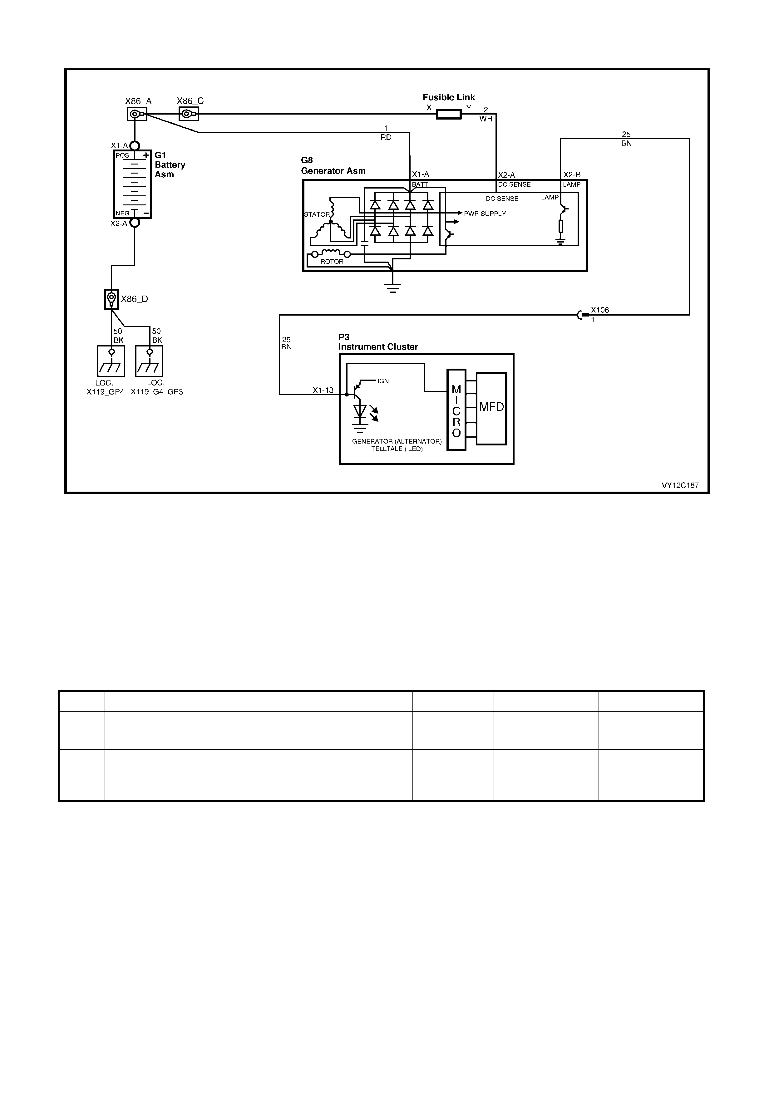
GENERATOR WARNING
Figure 12C-296
CIRCUIT DESCRIPTION
The generator warning telltale LED is illum inated continuous ly when the ignition is in the On position and the engine
is not running. In addition, if the generator input to the instrument cluster is active and the engine speed has
equalled or exceeded 150 rpm for at least 5 seconds, the LED is illum inated and / or the anim ated icon is displayed
on the MFD. The animated icon is only displayed if the engine is running and remains displayed until the trip
computer switch MODE button is pressed, at which point the MFD reverts back to the previously displayed trip
computer screen.
The generator warning telltale LED illuminates even if the engine is not running and remains illuminated until the
problem is rectified.
GENERATOR INDICATOR DIAGNOSTIC CHART
STEP ACTION VALUE YES NO
1 1. Turn the ignition from Off to On.
Does the generator warning telltale LED illuminate? Go to Step 2. Go to Step 3.
2 1. Start the engine.
With the engine speed greater than 150 rpm, does the
generator warning telltale LED extinguish?
System OK. Go to Step 6.

STEP ACTION VALUE YES NO
3 1. With the ignition on, back probe the generator
assembly G8 connector X2-B, circuit 25 (Brown wire)
with a jumper lead to a known good ground.
Does the generator warning telltale LED illuminate?
Refer to 2.2
MAINTENANCE
AND ON-VEHICLE
TESTING in the
following sections
as appropriate.
Section 6D1-1A
CHARGING
SYSTEM – V6
ENGINE (100
AMP),
Section 6D1-1B
CHARGING
SYSTEM – V6
ENGINE (120
AMP), Section
6D2-1 CHARG ING
SYSTEM – V6 S/C
ENGINE or Section
6D3-1 CHARG ING
SYSTEM –
GEN III V8
ENGINE.
Go to Step 4.
4 1. Turn the ignition off.
2. Remove the instrument cluster. Refer to
2.3 INSTRUMENT CLUSTER ASSEMBLY in this
Section.
3. Disconnect the generator assembly connector X2.
4. Using an ohmmeter, check for continuity of circuit 25
(Brown wire) between the instrument cluster P3
connector X1-13 and the generator assembly G8
connector X2-B.
Is the value as specified?
Less than
1 ohm Go t o S t e p 5 . Repair faulty
circuit 25.
5 1. Connect the TECH 2 to the DLC.
2. Turn the ignition on and start the vehicle.
3. Select Diagnostics / Model Year / Vehicle Model /
Body / Instrument / Data Display / Instrument.
4. Scroll down to the Alternator Input signal.
5. With the engine at idle speed, back probe the
generator assembly G8 connector X2-B, circuit 25
(Brown wire) with a jumper lead to a known good
ground.
Does TECH 2 display ON?
G o t o S te p 6 . Replace the
instrument cluster.
Refer to 2.3
INSTRUM ENT
CLUSTER
ASSEMBLY in this
Section.
6 1. From the Body Menu, select Miscellaneous Tests /
Warnings / Alternator, and conduct the test as
directed by soft keys at the bottom of the TECH 2
screen.
Is the animated icon displayed?
Refer to 2.2
MAINTENANCE
AND ON-VEHICLE
TESTING in the
following sections
as appropriate.
Section 6D1-1A
CHARGING
SYSTEM – V6
ENGINE (100
AMP),
Section 6D1-1B
CHARGING
SYSTEM – V6
ENGINE (120
AMP), Section
6D2-1 CHARG ING
SYSTEM – V6 S/C
ENGINE or Section
6D3-1 CHARG ING
SYSTEM –
GEN III V8
ENGINE.
Replace the
instrument cluster.
Refer to 2.3
INSTRUM ENT
CLUSTER
ASSEMBLY in this
Section.
WHEN ALL DIAGNOSIS AND REPAIRS ARE COM PLETED, VERIFY CORRECT OPERATION
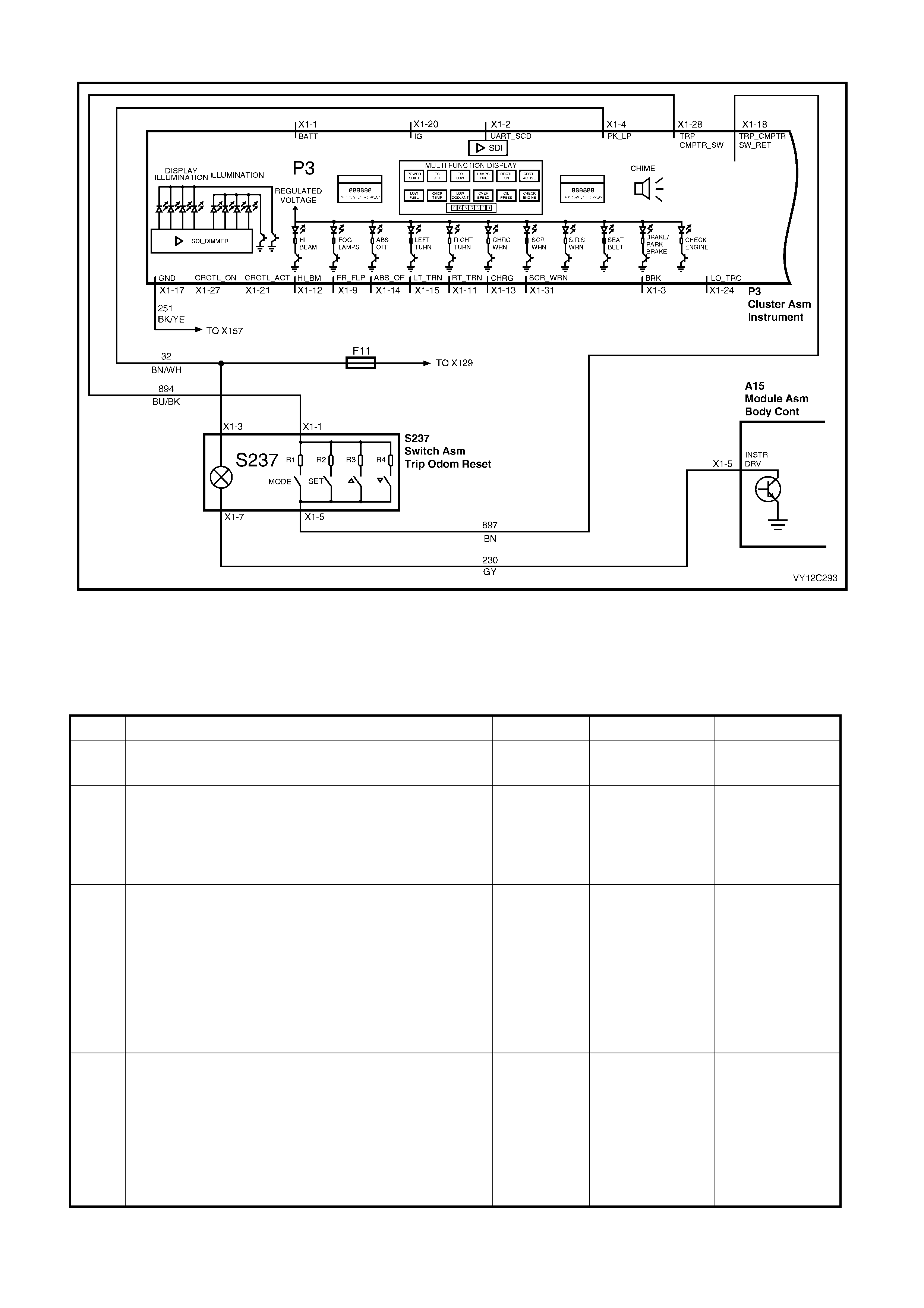
TRIP COMPUTER SWITCH
Figure 12C-297
CIRCUIT DESCRIPTION
The res istance presented to the ins trum ent cluster on term inal X1-28 is dependent upon the button select ed on the
trip computer switch. The trip computer switch ground circuit is supplied by the instrument cluster.
TRIP COMPUTER SWITCH DIAGNOSTIC CHART
STEP ACTION VALUE YES NO
1 1. Turn the ignition on.
Do all trip computer switches operate when pressed? System OK. Go to Step 2.
2 1. Connect TECH 2 to the DLC.
2. Select Diagnostics / Model Year / Vehicle Model /
Body / Instrument / Diagnostic Trouble Codes / Read
DTC Information.
Is DTC 21 or DTC 22 set?
Go to the relevant
diagnostic chart in
this Section.
Go to Step 3.
3 1. From the Body Menu, select Data Display /
Instrument.
2. Scroll to Trip Computer Switch Down Button. Press
the trip computer switch DOWN button while
watching the button status on the TECH 2 screen.
3. Repeat for the remaining trip computer switch
buttons.
Does the TECH 2 display the switch status as ON when
each button is pressed?
Replace the
instrument cluster.
Refer to 2.3
INSTRUM ENT
CLUSTER
ASSEMBLY in this
Section.
Go to Step 4.
4 1. Turn the ignition off.
2. Remove the trip computer switch. Refer to
2.6 SWITCH ASSEMBLY — TRIP COMPUTER in
this Section.
3. Using an ohmmeter, test the switch as detailed in
2.6 SWITCH ASSEMBLY — TRIP COMPUTER in
this Section.
Does the switch test OK?
G o t o S t ep 5 . R eplace the trip
computer switch.
Refer to
2.6 SWITCH
ASSEMBLY —
TRIP COMPUTER
in this Section

STEP ACTION VALUE YES NO
5 1. Remove the instrument cluster. Refer to
2.3 INSTRUMENT CLUSTER ASSEMBLY in this
Section.
2. Using an ohmmeter, check for continuity of circuit
894 (Blue / Black wire) between the instrument
cluster P3 connector X1-28 and the trip computer
switch S237 connector X1-1.
Is the value as specified?
Less than
1 ohm Go t o S t e p 6 . Repair faulty
circuit 894.
6 1. Using an ohmmeter, check for continuity of circuit
897 (Brown wire) between the instrument cluster P3
connector X1-18 and the trip computer switch S237
connector X1-5.
Is the value as specified?
Less than
1 ohm Replace the
instrument cluster.
Refer to 2.3
INSTRUM ENT
CLUSTER
ASSEMBLY in this
Section.
Repair faulty
circuit 897.
WHEN ALL DIAGNOSIS AND REPAIRS ARE COM PLETED, VERIFY CORRECT OPERATION
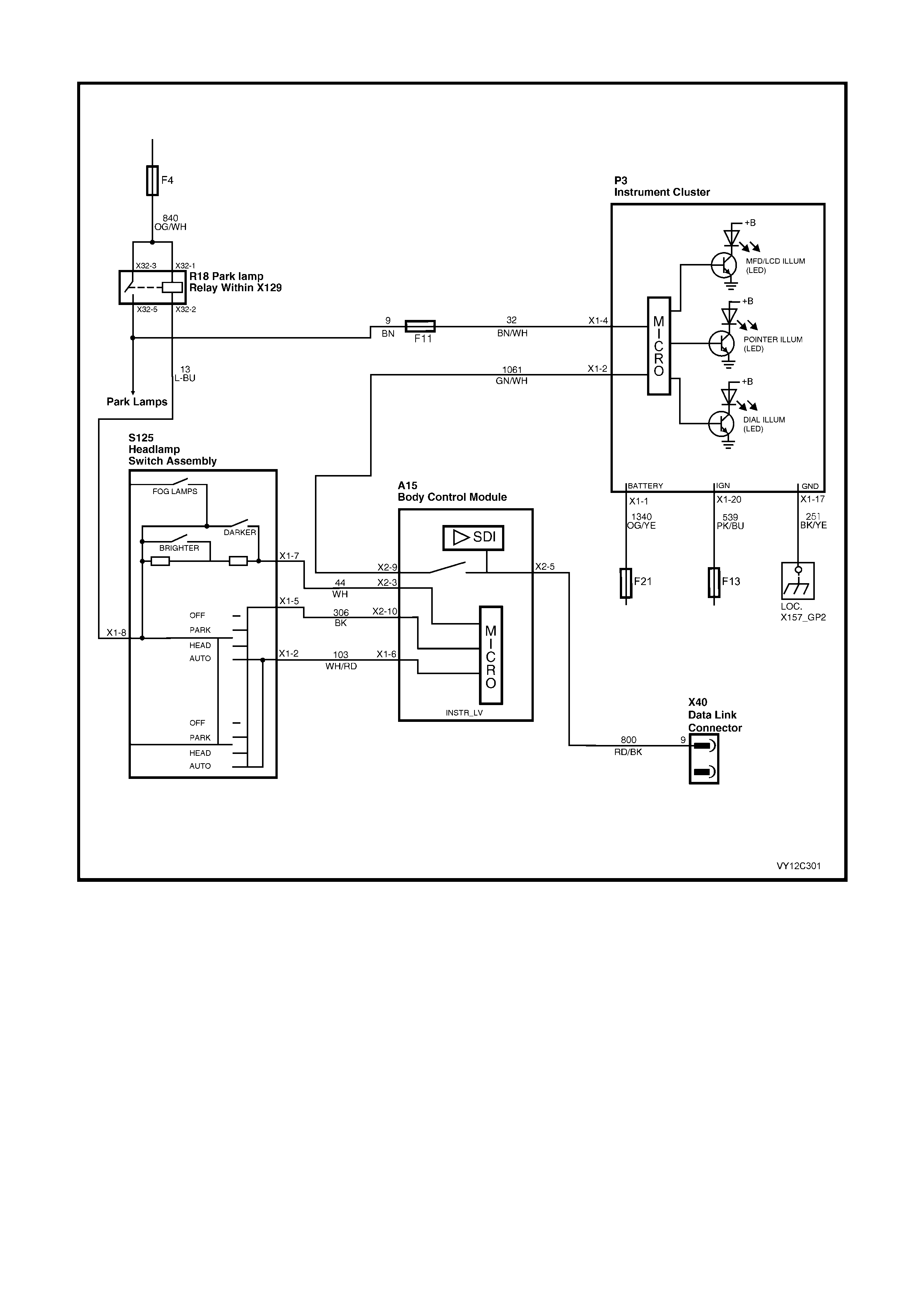
INSTRUMENT ILLUMINATION
Figure 12C-298
CIRCUIT DESCRIPTION
The headlamp switch incorporates a variable intensity instrument cluster illumination control (slider) and a four-
position switch for Off, Park, Headlamps and Auto Headlamps On switch mode.
With the switch in the Off position (open circuit), the MFD (and side LCDs for triple-window cluster) are set at
maximum backlighting. W hen the switch is in the Park , Headlamp or Auto positions, a 12 volt signal is supplied to
the instrum ent cluster f rom the park lam p relay, and the MFD (and side LCDs for triple-window cluster) are s et to a
reduced level of backlighting.
The dial and pointer illumination are controlled by the slider control on the headlamp switch. The slider varies an
input voltage to the BCM, which in turn transmits an illumination level to the instrument cluster via the Serial
Communications Bus. The instrument cluster interprets this illumination level and controls the illumination
accordingly .

INSTRUMENT ILLUMINATION DIAGNOSTIC CHART
STEP ACTION VALUE YES NO
1 1. Turn the ignition on.
Is the MFD (and side LCDs for triple-window cluster)
backlit?
Go to Step 2. Replace the
instrument cluster.
Refer to 2.3
INSTRUM ENT
CLUSTER
ASSEMBLY in this
Section.
2 1. With the ignition in the On position, set the headlamp
switch to the Park position.
Is the MFD (and side LCDs for triple-window cluster) set
to a reduced backlight?
Go to Step 3. Go to Step 4.
3 1. With the ignition in the On position and the
headlamp switch in the Park position, vary the slider
position to vary the dial and pointer illumination level.
Does the dial and pointer illumination level vary?
System OK. Go to Step 8.
4 1. Connect TECH 2 to the DLC.
2. Check that the ignition is in the On position and the
headlamp switch is in the Park position.
3. Select Diagnostics / Model Year / Vehicle Model /
Body / Instrument / Data Display / Instrument.
4. Scroll to the Park Lamp Switch Input signal.
Does the TECH 2 display ON?
Replace the
instrument cluster.
Refer to 2.3
INSTRUM ENT
CLUSTER
ASSEMBLY in this
Section.
Go to Step 5.
5 1. Check that the ignition is in the On position and the
headlamp switch is in the Park position.
Do the park lamps operate?
Go to Step 6. Refer to Section
12J, 3.14 AUTO
LAMPS OFF
CONTROL for
further diagnosis.
6 1. Check the condition of the instrument cluster
illumination Fuse F11.
Is the Fuse OK?
Go to Step 7. Replace fuse.
7 1. Remove the instrument cluster. Refer to
2.3 INSTRUMENT CLUSTER ASSEMBLY in this
Section.
2. Check that the ignition is in the On position and the
headlamp switch is in the Park position.
3. Using a digital voltmeter, check the voltage at
instrument cluster P3 connector X1-4, circuit 32
(Brown / White wire), to a known good ground.
Is the value as specified?
12 volts Replace the
instrument cluster.
Refer to 2.3
INSTRUM ENT
CLUSTER
ASSEMBLY in this
Section.
Repair faulty
circuit 32.
8 1. Connect TECH 2 to the DLC.
2. Check that the ignition is in the On position and the
headlamp switch is in the Park position.
3. From the Body Menu, select Miscellaneous Tests /
Illumination / Pointers. Use the Up and Down soft
keys to increase and decrease the illumination level
of the instrument pointers.
4. From the Body Menu, select Miscellaneous Tests /
Illumination / Dials. Use the Up and Down soft keys
to increase and decrease the illumination level of the
instrument dials.
Does the illumination vary?
Refer to Section
12J, 3.16
INSTRUM ENT
DIMMING
CONTROL for
further diagnosis.
Replace the
instrument cluster.
Refer to 2.3
INSTRUM ENT
CLUSTER
ASSEMBLY in this
Section.
WHEN ALL DIAGNOSIS AND REPAIRS ARE COM PLETED, VERIFY CORRECT OPERATION
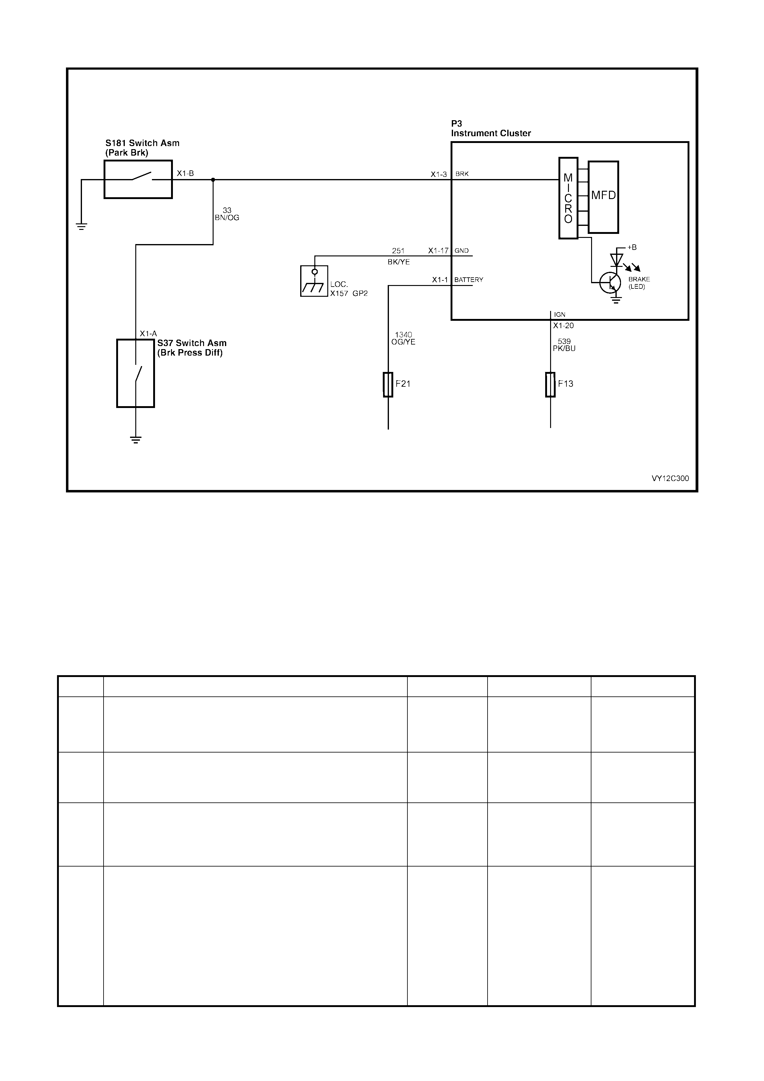
BRAKE FAIL / PARK BRAKE WARNING
Figure 12C-299
CIRCUIT DESCRIPTION
The brake warning telltale LED is illuminated when the park br ak e s witch is on, or when the vehicle speed is greater
than 8 km/h and there is a brake warning.
A brake warning illuminates the brake warning telltale LED and also displays an animated icon on the MFD. The
exclamation mark in the centre of the icon flashes until the MODE button on the trip computer switch is pressed.
The MFD then reverts back to the previously displayed trip computer screen.
The brake warning telltale LED illuminates as soon as the warning is activated and remains illuminated until the
problem is rectified.
BRAKE FAIL / PARK BRAKE WARNING DIAGNOSTIC CHART
STEP ACTION VALUE YES NO
1 1. Turn the ignition on.
2. Ensure that the park brake is engaged.
Does the brake warning telltale LED illuminate?
Go to Step 2. Go to Step 4.
2 1. W ith the ignition in the On position, release the park
brake.
Does the brake warning telltale LED extinguish?
Go to Step 3. Go to Step 7.
3 1. Drive the vehicle at a speed greater than 8 km/h.
In the event of a brake warning, does the brake warning
telltale LED illuminate and is the MFD animated icon
displayed?
System OK. Go to Step 8.
4 1. Connect TECH 2 to the DLC.
2. Check that the ignition is in the On position.
3. Select Diagnostics / Model Year / Vehicle Model /
Body / Instrument / Miscellaneous Tests / W arnings /
Park Brake and Brake Fail, and conduct the test as
directed by the soft keys at the bottom of the TECH 2
screen.
Does the brake warning telltale LED illuminate and is the
MFD animated icon displayed?
Go to Step 5. Replace the
instrument cluster.
Refer to 2.3
INSTRUM ENT
CLUSTER
ASSEMBLY in this
Section.

STEP ACTION VALUE YES NO
5 1. Check that the ignition is in the On position and the
park brake is engaged.
2. From the Body Menu, select Data Display /
Instrument.
3. Scroll to the Park Brake and Brake Fail Input signal.
Does TECH 2 display the status of the Park Brake and
Brake Fail Input signal as ON?
ON Replace the
instrument cluster.
Refer to 2.3
INSTRUM ENT
CLUSTER
ASSEMBLY in this
Section.
Go to Step 6.
6 1. Check that the ignition is in the On position.
2. Using a jumper lead, back probe the brake pressure
switch S37 connector X1-A, circuit 33 (Brown /
Orange wire) to a known good ground.
Does the brake warning telltale LED illuminate?
Replace defective
brake pressure
switch. Refer to
Section 5A,
2.9 PARK BRAKE
LEVER.
Go to Step 7.
7 1. Chock the wheels.
2. Remove the instrument cluster. Refer to
2.3 INSTRUMENT CLUSTER ASSEMBLY in this
Section.
3. Release the park brake.
4. Using a digital ohmmeter, check continuity of circuit
33 (Brown / Orange wire) between the instrument
cluster P3 connector X1-3, and a known good
ground.
Is the value as specified?
Less than
1 ohm Repair faulty
circuit 33. If no
fault found with
circuit 33, check
for a defective
park brake switch.
Refer to Section
5A, 2.9 PARK
BRAKE LEVER.
Replace the
instrument cluster.
Refer to 2.3
INSTRUM ENT
CLUSTER
ASSEMBLY in this
Section.
8 1. Remove the instrument cluster. Refer to
2.3 INSTRUMENT CLUSTER ASSEMBLY in this
Section.
2. Chock the vehicle wheels then release the park
brake.
3. Using a digital ohmmeter, check for continuity of
circuit 33 (Brown / Orange wire) between instrument
cluster P3 connector X1-3, and brake pressure
switch assembly S37 connector X1-A.
Is the value as specified?
Continuity Check for a
defective brake
pressure switch.
Refer to Section
5A, 2.9 PARK
BRAKE LEVER.
Repair faulty
circuit 33.
WHEN ALL DIAGNOSIS AND REPAIRS ARE COM PLETED, VERIFY CORRECT OPERATION
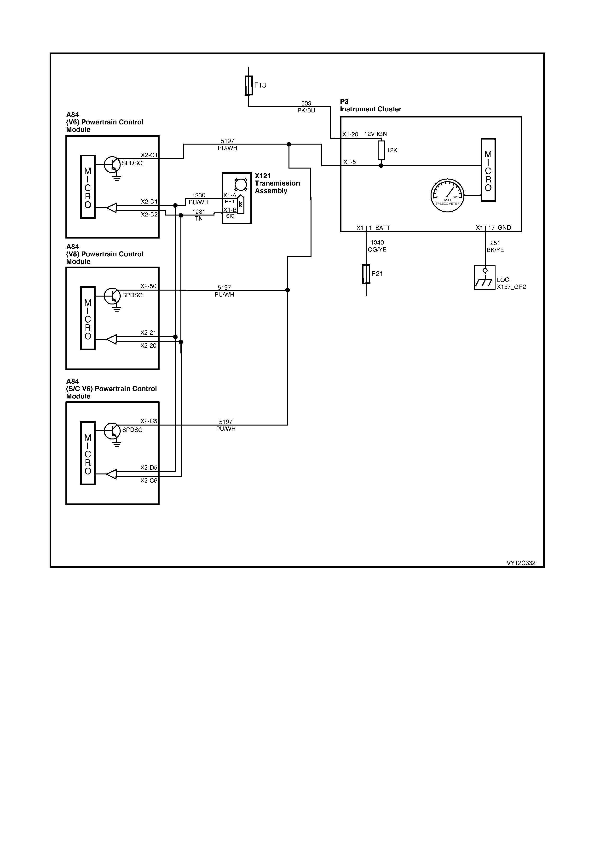
SPEEDOMETER DIAGNOSIS
Figure 12C-300
CIRCUIT DESCRIPTION
The instrument cluster receives vehicle speed information from the Powertrain Control Module (PCM) via circuit
5197. The PCM pulses this circuit to ground. The number of pulses varies with tyre size.
The PCM receives vehicle speed inform ation from the vehicle speed sensor located in the transmission assem bly.
A voltage is produced by the speed sensor and is fed to the PCM, which filters and shapes the signal. The PCM
then counts the number of pulses received in a given time to determine the vehicle speed.
Once the PCM has calculated the vehicle speed, it then pulses circuit 5197 to ground. This causes the 12 volts at
instrum ent cluster ter minal X 1-5 to be pulled down to less than 0.5 volt. The instr ument cluster then determ ines the
vehicle speed and the kilometres travelled from the number of pulses it receives.

SPEEDOMETER DIAGNOSTIC CHART
STEP ACTION VALUE YES NO
1 Does the speedometer respond when the vehicle is
travelling at more than 2 km/h? Go to Step 2. Go to Step 3.
2 Does the speedometer display the correct speed of the
vehicle? System OK. Go to Step 6.
3 1. Connect TECH 2 to the DLC.
2. Turn the ignition on.
3. Select Diagnostics / Model Year / Vehicle Model /
Body / Instrument / Miscellaneous Tests / Gauge
Control Tests / Speedometer, and conduct the test
as directed by the soft keys at the bottom of the
TECH 2 screen.
Does the speedometer pointer move?
Go to Step 4. Replace the
instrument cluster.
Refer to 2.3
INSTRUM ENT
CLUSTER
ASSEMBLY in this
Section.
4 1. Support the rear of the vehicle on stands.
2. Remove the instrument cluster. Refer to 2.3
INSTRUMENT CLUSTER ASSEMBLY in this
Section.
3. Connect a digital voltmeter between the instrument
cluster P3 connector X1-5, circuit 5197 (Purple /
White wire) to a known good ground.
4. Start the vehicle and engage the rear wheels.
Is the value as specified?
Does the
voltage
fluctuate on
the DC scale.
Replace the
instrument cluster.
Refer to 2.3
INSTRUM ENT
CLUSTER
ASSEMBLY in this
Section.
Go to Step 5.
5 1. Disconnect the PCM connector A84.
2. Using a digital multimeter, check circuit 5197 (Purple
/ White wire) between the instrument cluster P3
connector X1-5 and the PCM A84 (connector X2-C1
for V6, X2-C5 for V6 S/C or X2-50 for GEN III V8) for
continuity and for no short to ground or battery
voltage.
Is the circuit OK?
For V6 engine,
refer to Section
6C1, DTC P0502
or DTC P0503.
For V6 S/C
engine, refer to
Section 6C2,
DTC 24.
For GEN III V8
engine, refer to
Section 6C3,
DTC P0500,
DTC P0502,
DTC P0503 or
DTC P0608.
Repair faulty
circuit 5197.
6 1. Check that the ignition is in the Off position.
2. Connect TECH 2 to the DLC.
3. Select Diagnostics / Model Year / Vehicle Model /
Body / Instrument / Miscellaneous Tests / Gauge
Control Tests / Speedometer, and conduct the test
as directed by the soft keys at the bottom of the
TECH 2 screen.
Is the value as specified?
60 km/h =
–0 / +2
100 km/h =
–0 / +2
160 km/h =
–0 / +3
Go to Step 7. Replace the
instrument cluster.
Refer to 2.3
INSTRUM ENT
CLUSTER
ASSEMBLY in this
Section.
7 1. From the Body Menu, select Data Display /
Instrument.
2. Scroll to the Vehicle Speed signal.
3. Road test the vehicle.
Does the speedometer pointer reading match the
TECH 2 display within the specified value?
60 km/h =
–0 / +2
100 km/h =
–0 / +2
160 km/h =
–0 / +3
For V6 engine,
refer to Section
6C1, DTC P0502
or DTC P0503.
For V6 S/C
engine, refer to
Section 6C2,
DTC 24.
For GEN III V8
engine, refer to
Section 6C3,
DTC P0500,
DTC P0502,
DTC P0503 or
DTC P0608.
Replace the
instrument cluster.
Refer to 2.3
INSTRUM ENT
CLUSTER
ASSEMBLY in this
Section.
WHEN ALL DIAGNOSIS AND REPAIRS ARE COM PLETED, VERIFY CORRECT OPERATION
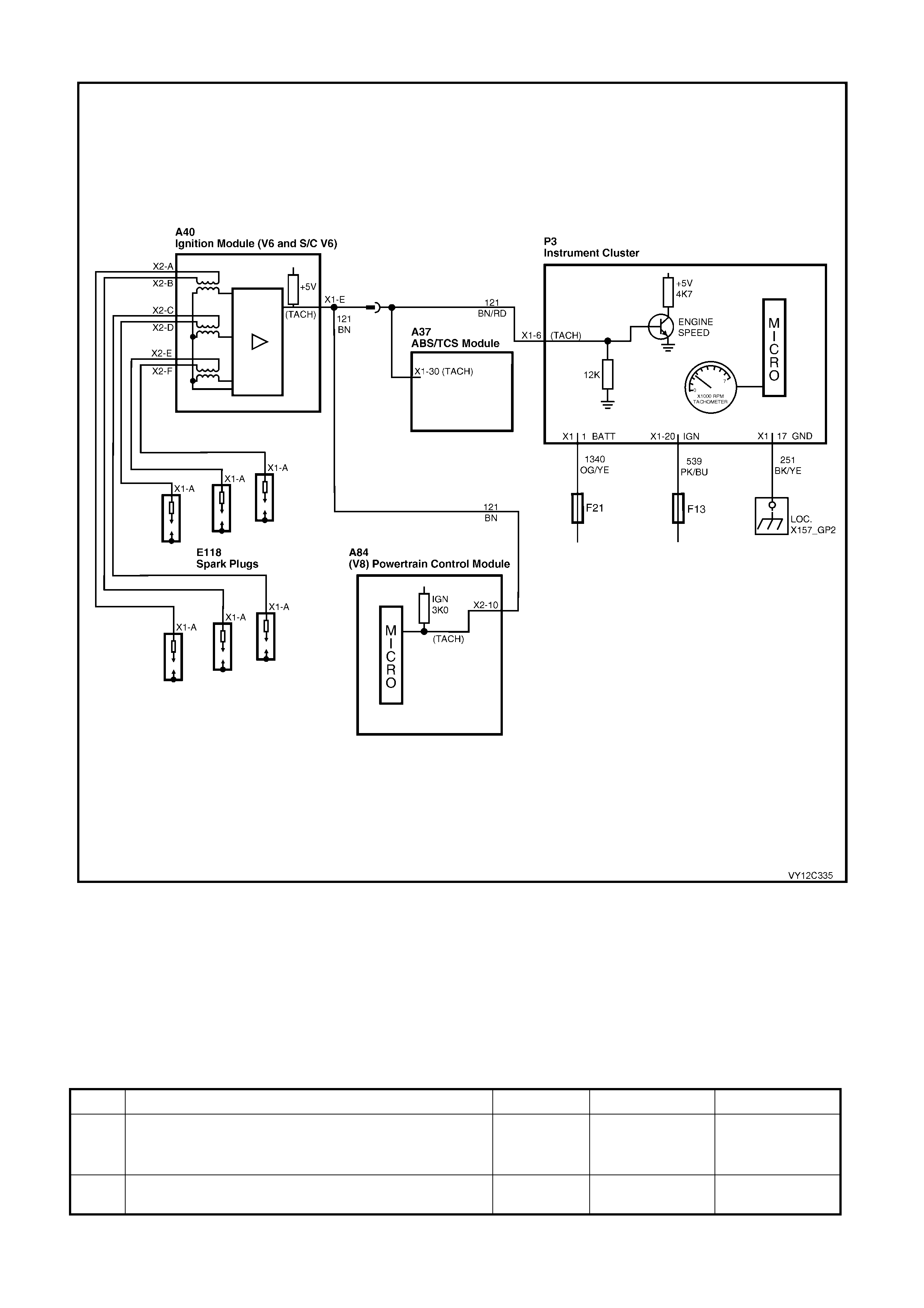
TACHOMETER DIA GNOSIS
Figure 12C-301
CIRCUIT DESCRIPTION
The instrum ent cluster receives the engine speed (rpm ) inf ormation f rom the Ignition Module (V6 and V6 S/C), and
the PCM (GEN III V8), via circuit 121. The Ignition Module / PCM pulses the circuit to ground. The instrument
cluster counts the number of pulses to determine the speed (rpm) of the engine.
NOTE: The instrument cluster can be programmed by TECH 2 to suit the vehicle’s engine and powertrain
configuration. Refer to 3.15 PROGRAM in this Section.
TACHOMETER DIAGNOSTIC CHART
STEP ACTION VALUE YES NO
1 1. Start the engine.
Does the tachometer respond when increasing the
engine rpm?
Go to Step 2. Go to Step 3.
2 Does the tachometer display the accurate rpm of the
engine? System OK. Go to Step 6.

STEP ACTION VALUE YES NO
3 1. Connect TECH 2 to the DLC.
2. Turn the ignition on.
3. Select Diagnostics / Model Year / Vehicle Model /
Body / Instrument / Miscellaneous Tests / Gauge
Control Tests / Tachometer, and conduct the test as
directed by the soft keys at the bottom of the TECH 2
screen.
Does the tachometer pointer move?
Go to Step 4. Replace the
instrument cluster.
Refer to 2.3
INSTRUM ENT
CLUSTER
ASSEMBLY in this
Section.
4 1. Turn the ignition off.
2. Remove the instrument cluster. Refer to
2.3 INSTRUMENT CLUSTER ASSEMBLY in this
Section.
3. Connect a digital voltmeter between the instrument
cluster P3 connector X1-6, circuit 121 (Brown / Red
wire) and a known good ground.
4. Start the engine.
Is the value as specified?
Between
1.5 V at
700 rpm
and
3.5 V at
6000 rpm
Replace the
instrument cluster.
Refer to 2.3
INSTRUM ENT
CLUSTER
ASSEMBLY in this
Section.
Go to Step 5.
5 1. For GEN III V8 engines disconnect the PCM A84
connector X2. For V6 and V6 S/C engines,
disconnect the ignition module A40 connector X1.
2. For GEN III V8 engines, use a digital multimeter to
check circuit 121 (Brown / Red wire) between the
instrument cluster P3 connector X1-6 and the PCM
A84 connector X2-10 for continuity and for no short
to ground or battery voltage.
3. For V6 or V6 S/C engines, use a digital multimeter to
check circuit 121 (Brown / Red wire) between the
instrument cluster P3 connector X1-6 and the ignition
module A40 connector X1-E for continuity and for no
short to ground or battery voltage.
NOTE: Circuit 121 is a Brown / Red wire at the
instrument cluster and a Brown wire at the PCM and at
the ignition module.
Is the circuit OK?
Refer to the
Diagnostic Charts
in the following
sections as
appropriate.
For V6 engine,
refer to Section
6C1.
For V6 S/C
engine, refer to
Section 6C2.
For GEN III V8
engine, refer to
Section 6C3.
Repair faulty
circuit 121.
6 1. Check that the ignition is in the Off position.
2. Connect TECH 2 to the DLC.
3. Select Diagnostics / Model Year / Vehicle Model /
Body / Instrument / Miscellaneous Tests / Gauge
Control Tests / Tachometer, and conduct the test as
directed by the soft keys at the bottom of the TECH 2
screen.
Is the value as specified?
Accurate to
±50 rpm
between
500 rpm and
6500 rpm
Go to Step 7. Replace the
instrument cluster.
Refer to 2.3
INSTRUM ENT
CLUSTER
ASSEMBLY in this
Section.
7 1. From the Body Menu, select Data Display /
Instrument.
2. Scroll to the Engine Speed signal.
3. Start the engine and vary the engine speed.
Does the tachometer pointer reading match the TECH 2
display within the specified value?
Accurate to
±50 rpm
between
500 rpm and
6500 rpm
Refer to the
Diagnostic Charts
in the following
sections as
appropriate.
For V6 engine,
refer to Section
6C1.
For V6 S/C
engine, refer to
Section 6C2.
For GEN III V8
engine, refer to
Section 6C3.
Replace the
instrument cluster.
Refer to 2.3
INSTRUM ENT
CLUSTER
ASSEMBLY in this
Section.
WHEN ALL DIAGNOSIS AND REPAIRS ARE COM PLETED, VERIFY CORRECT OPERATION
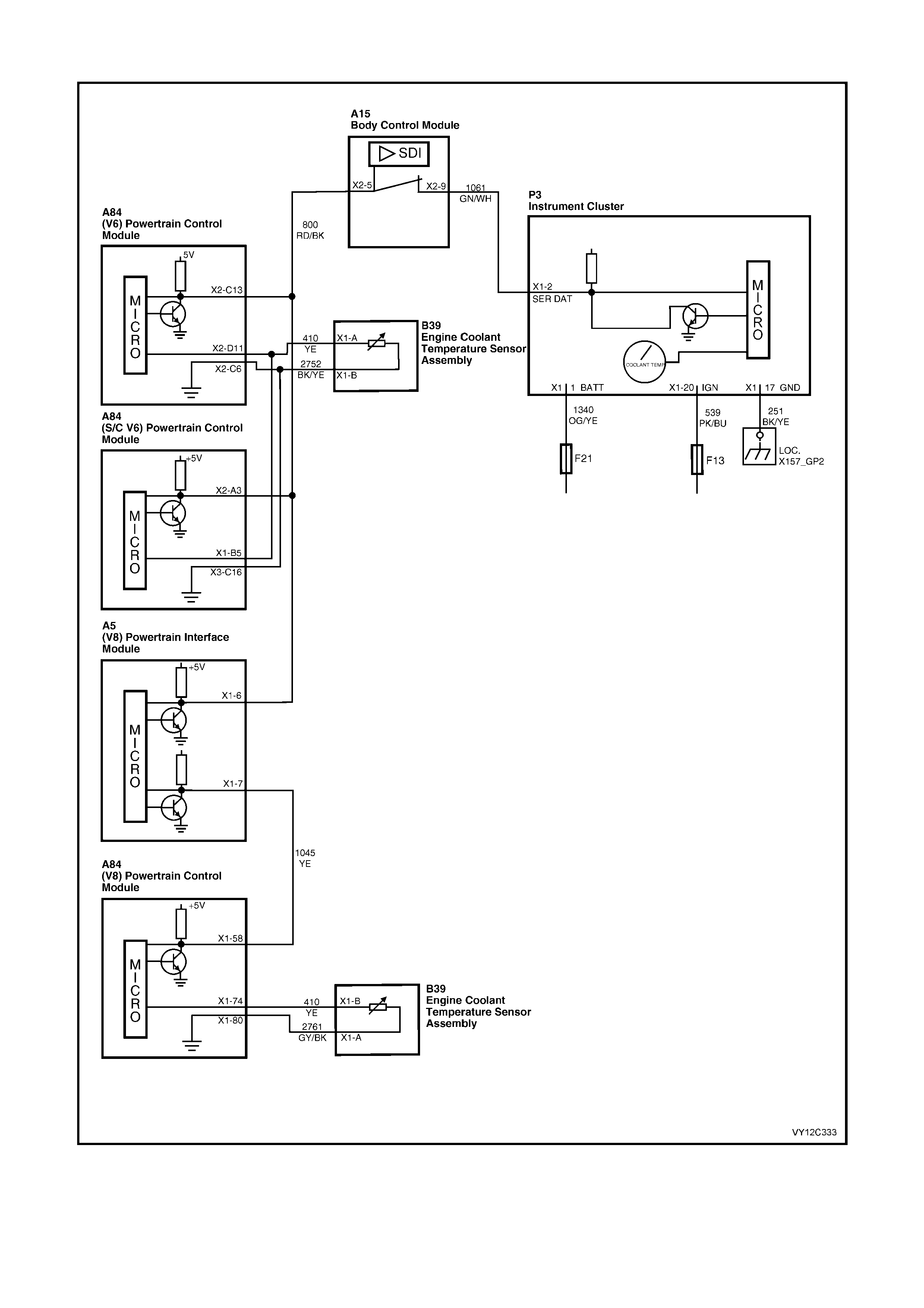
COOLANT TEMPERATURE GAUGE DIAGNOSIS
Figure 12C-302

CIRCUIT DESCRIPTION
The ins trument c luster receives engine coolant tem perature infor mation f rom the Powertrain Control Module (PCM)
via the serial data bus normal mode message.
The PCM receives engine coolant temperature information from the Engine Coolant Temperature (ECT) Sensor.
The ECT Sensor is a thermistor (a resistor that changes value based on temperature) mounted in the engine
coolant stream. Low engine coolant temperature produces a high sensor resistance, while high engine coolant
temperature causes a low sensor resistance.
COOLANT TEMPERATURE GAUGE DIAGNOSTIC CHART
STEP ACTION VALUE YES NO
1 1. Turn the ignition on.
Does the coolant temperature gauge pointer move past
the C position and display the accurate coolant
temperature?
System OK. Go to Step 2.
2 1. Turn the ignition off.
2. Connect TECH 2 to the DLC.
3. Turn the ignition on.
4. Select Diagnostics / Model Year / Vehicle Model /
Body / Instrument / Miscellaneous Tests / Gauge
Control Tests / Temperature Gauge, and conduct the
test as directed by the soft keys at the bottom of the
TECH 2 screen.
Does the coolant temperature gauge pointer move to the
correct position when commanded?
For V6 engine,
refer to Section
6C1, DTC P0117
or DTC P0118.
For V6 S/C
engine, refer to
Section 6C2,
DTC 14, DTC 15,
or DTC 16.
For GEN III V8
engine, refer to
Section 6C3,
DTC P0117,
DTC P0118,
DTC P1114 or
DTC P1115.
Replace the
instrument cluster.
Refer to 2.3
INSTRUM ENT
CLUSTER
A
SSEMBLY in this
Section.
WHEN ALL DIAGNOSIS AND REPAIRS ARE COM PLETED, VERIFY CORRECT OPERATION
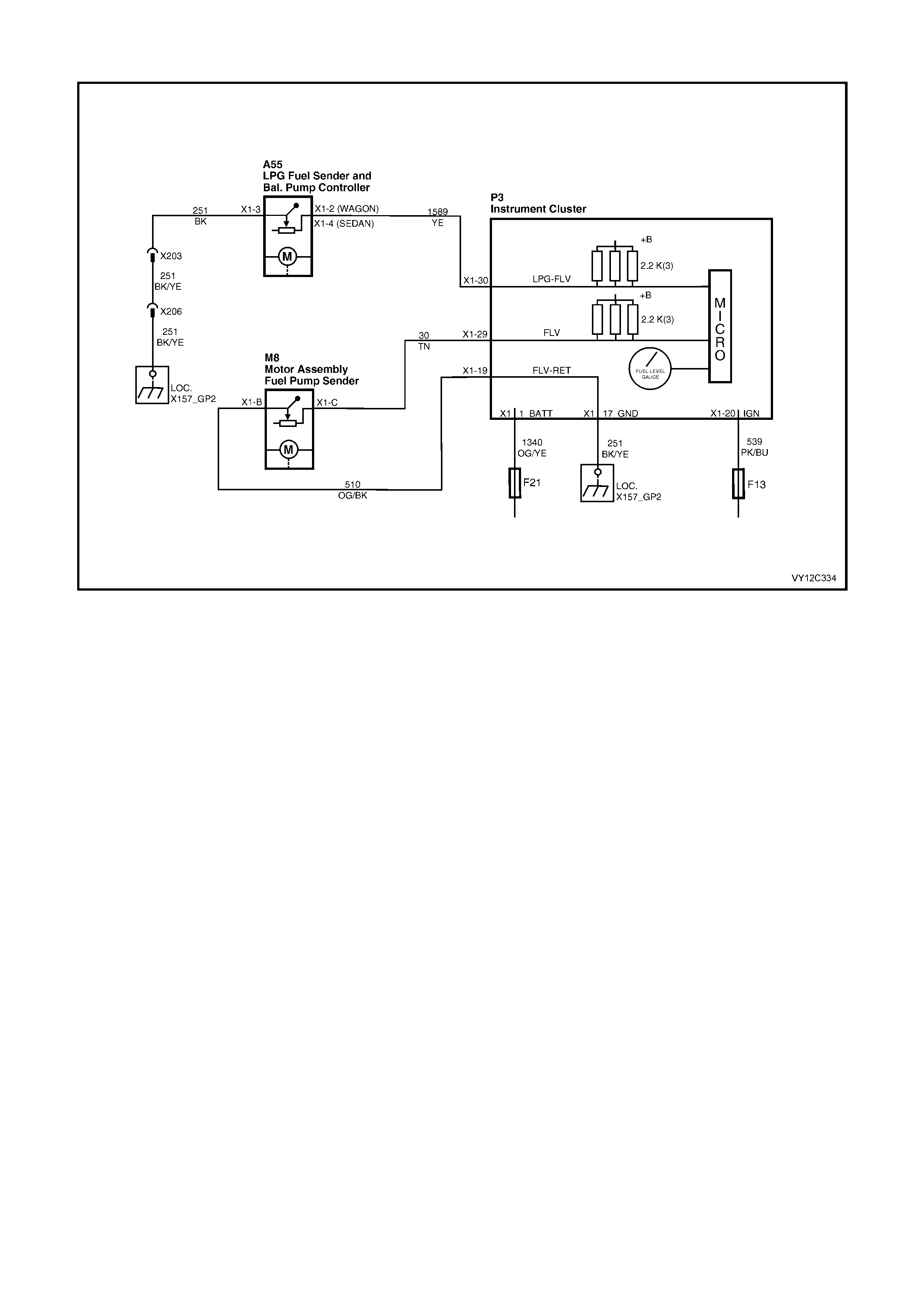
FUEL LEVEL GAUGE DIAGNOSIS
Figure 12C-303
CIRCUIT DESCRIPTION
The instrument cluster supplies a 12 volt reference voltage and a ground circuit to the fuel (petrol) gauge sender
unit. In the case of LPG, the instrument cluster only supplies the 12 volt reference signal.
The f uel / LPG sender unit pr ovides a resistanc e value to the inst rument cluster based on its position relative to the
fuel level. The resistance value will vary between 40 ±5 ohms with no fuel in the tank and 250 ±5 ohms with a full
tank. The instrument cluster drives the fuel gauge pointer to the appropriate position.

FUEL LEVEL GAUGE DIAGNOSTIC CHART
STEP ACTION VALUE YES NO
1 1. Turn the ignition on.
After a settling period, does the fuel level gauge pointer
move and display the accurate fuel level?
System OK. Go to Step 2.
2 1. Turn the ignition off.
2. Connect TECH 2 to the DLC.
3. Turn the ignition on.
4. Select Diagnostics / Model Year / Vehicle Model /
Body / Instrument / Diagnostic Trouble Codes/ Read
DTC Information.
Are either DTC 1, 2, 3, 4, 5, 6, 16 or 17 set?
Go to the relevant
diagnostic chart.
Refer to 3.8
INSTRUM ENT
DIAGNOSTIC
PROCEDURES in
this Section.
Go to Step 3.
3 1. From the Body Menu, select Miscellaneous Tests /
Gauge Control Tests / Fuel Gauge, and conduct the
test as directed by the soft keys at the bottom of the
TECH 2 screen.
Does the fuel gauge pointer move to the correct position
when commanded?
Check the fuel
sender unit. Refer
to Section 8A1,
2.6 MODULAR
FUEL SENDER
ASSEMBLY –
SEDAN, WAGON
AND COUPE, or
2.7 MODULAR
FUEL SENDER
ASSEMBLY –
UTILITY, or
Section 8A2,
3.12 TANK FUEL
GAUGE
ASSEMBLY as
appropriate.
Replace the
instrument cluster.
Refer to 2.3
INSTRUM ENT
CLUSTER
ASSEMBLY in this
Section.
WHEN ALL DIAGNOSIS AND REPAIRS ARE COM PLETED, VERIFY CORRECT OPERATION
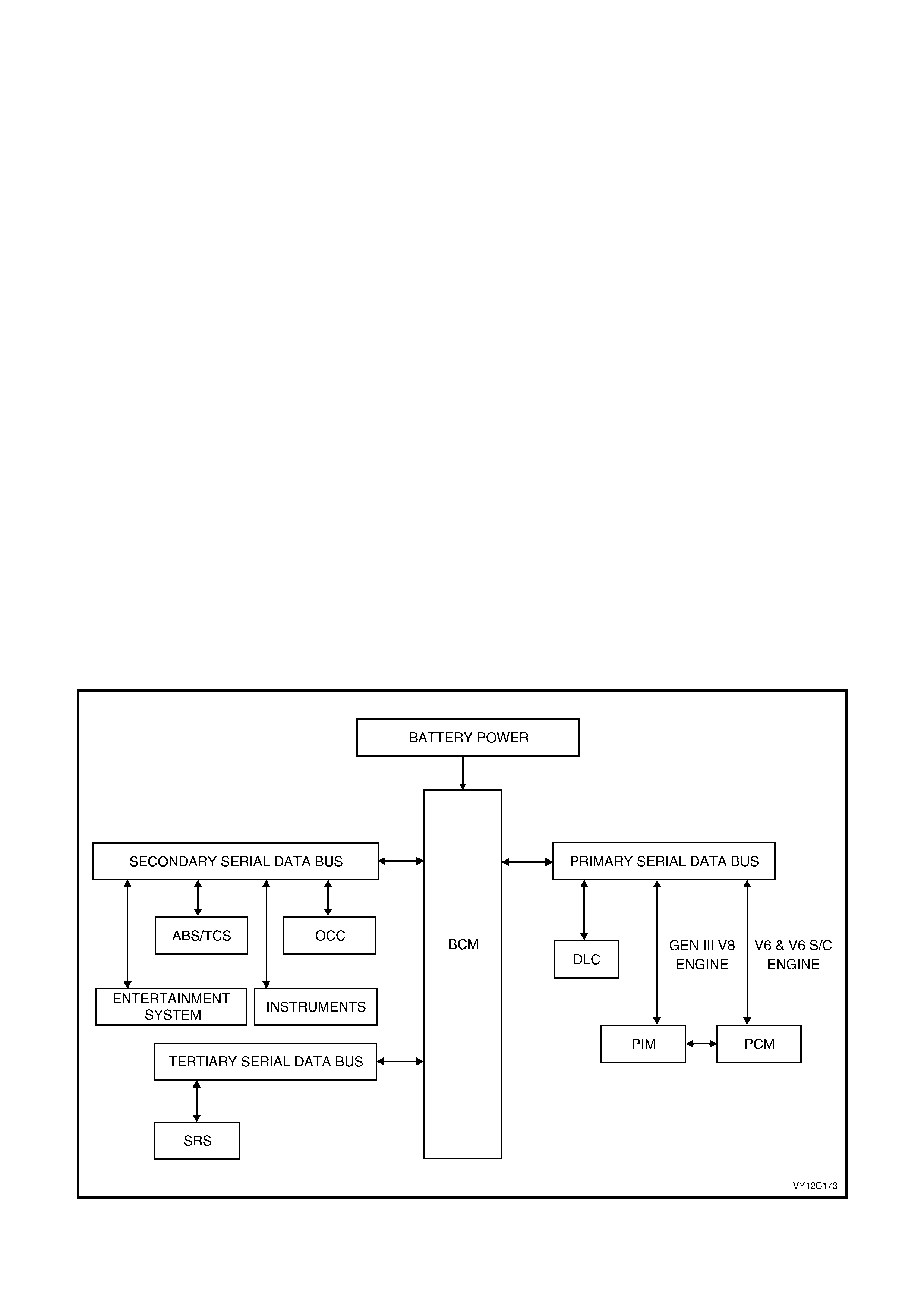
3.5 SERIAL DATA COMMUNICATION
GENERAL INFORMATION
The VY Series m odel uses a BUS MASTER com munication system, where the BCM is the bus m aster. The serial
data bus comprises:
• the primary serial data bus, circuit 800,
• the secondary serial data bus, circuit 1061, and
• the tertiary serial data bus, circuit 774.
The BCM periodically polls (surveys) each device on the bus and requests status data.
The devices connected are:
• Body Control Module (BCM).
• Powertrain Control Module (PCM) for V6 and V6 supercharged engines.
• Powertrain Interface Module (PIM) for GEN III V8 engines only.
• Occupant Climate Control (OCC).
• Instrument Cluster (INS).
• Anti-lock Brake (ABS) or Anti-lock Brake / Traction Control System (ABS / TCS).
• Supplementary Restraint System (SRS).
• Entertainment Sy stem.
• External diagnostic tool (TECH 2).
The data provided by each device may be utilised by any device connected to the bus.
Each device has a unique response Message Identifier Word (MIW) for ease of identification.
The bus mas ter (BCM) polls eac h device with a serial data m essage which includes that device’s MIW. T he device
responds by putting a serial data message onto the bus which includes its MIW and data, which is retrieved and
utilised by any device requiring it.
The BCM polls each device for a st atus update, once every 300 m illiseconds. The exception to this being the PCM
(V6), the PIM (GEN III V8) and the Entertainment System which are polled twice every 300 milliseconds.
The TECH 2 diagnostic tool can be used to read serial data on the data bus and analyse faults in the instrument
cluster and its related components.
Figure 12C-304

3.6 CONNECTING TECH 2 FOR SYSTEM DIAGNOSIS
TECH 2, with the appropriate sof tware, c ables and
adaptors, when connected to the Data Link
Connector (DLC) is capable of reading the
instrument cluster serial data. The DLC is
connected to the instrument panel lower
right-hand trim, to the right of the steering column.
1. Data Link Connector (DLC)
2. DLC Adaptor
3. DLC Cable
4. TECH 2
For additional general information on
connecting and operating TECH 2, refer to
Section 0C, TECH 2.
Figure 12C-305
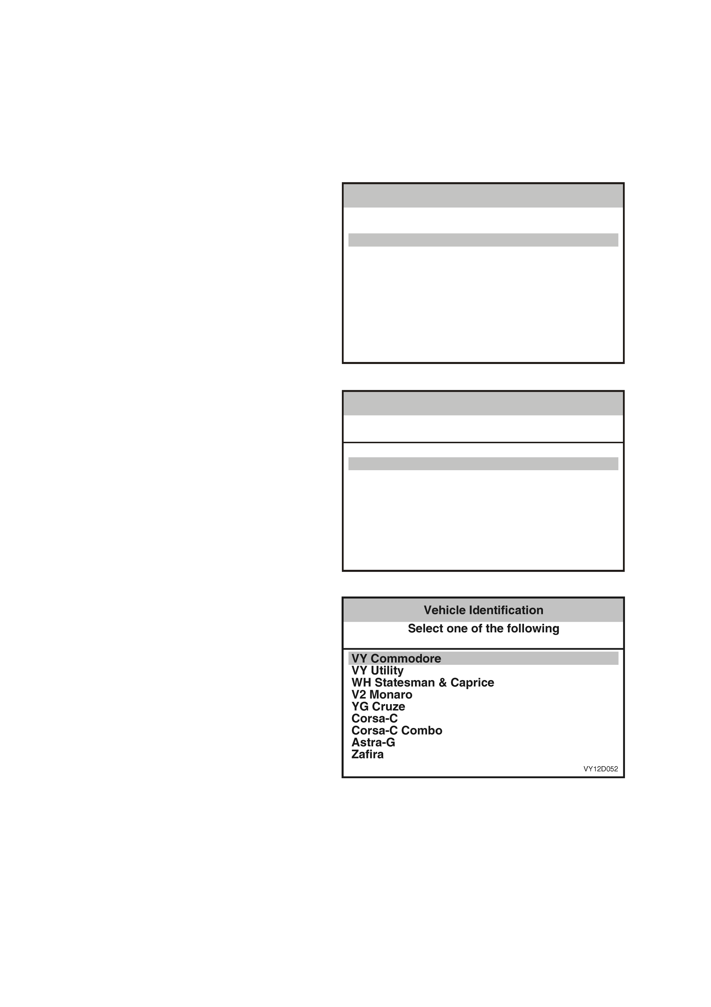
3.7 TECH 2 TEST MODES AND DISPLAYS FOR INSTRUMENT DIAGNOSIS
A prerequisite of this diagnostic section is for the user to be familiar with the proper use of TECH 2. The following
pages illustrate only the major TECH 2 screen displays and provide a brief explanation of their function for
diagnosing the Instruments. If additional information is required on the operation of TECH 2, reference should be
made to either Section 0C TECH or the TECH 2 User’s Guide.
W ith the ignition tur ned off , connect the T ECH 2 to the Data Link Connector ( DLC) using the DLC Adaptor, ref er to
3.6 CONNECTING TECH 2 FOR SYSTEM DIAGNOSIS in this Section.
MAIN MENU
Turn the ignition on and press the power button
(PWR) on the TECH 2.
The TECH 2 will perform a series of self-
diagnosing power on self-tests (POST). Once this
has been completed successfully, the TECH 2
startup screen will be displayed. Press the Enter
key to continue.
The Main Menu screen should look as follows.
Press the F0 function button or Select F0:
Diagnostics by using the arrow keys until F0:
Diagnostics is highlighted and press the Enter
key.
VY12D050
Main Menu
F0:
F1:
F2:
F3:
F4:
Diagnostics
Service Programming System (SPS)
View Capture Data
Tool Options
Download/Upload Hel p
Figure 12C-306
Model Year
Select the appropriate Model Year and press
Enter.
VY12D051
Vehicle Identificat ion
Sele c t on e of the follow in g
Model Year(s)
(3)
(2)
(1)
(Y)
(X)
(W)
(V)
2003
2002
2001
2000
1999
1998
1997
Figure 12C-307
Vehicle Identification Menu
Select the appropriate vehicle type and press
Enter.
Figure 12C-308

SYSTEM SELECTION MENU
Select F3: Body from the System Selection Menu
and press Enter.
VY12D053
System S e lection Menu
(3) 2003 VY Commodore
F0:
F1:
F2:
F3:
F4:
Engine
Transmission
Chassis
Body
Veh icle DTC Che ck
Figure 12C-309
Select Instrument and press the Enter key.
VY12C294
Vehicle Identificat ion
Sele c t on e of the follow in g
Body
Body Con trol Module
Powertrai n Interface Module
SRS
Instrument
Occupant Climate Control
Au dio System
Telemat ics S ystem
Figure 12C-310
SYSTEM IDENTIFICATION SCREEN
Turn the ignition on (as requested) and press
Confirm soft key to continue.
The System Identification screen will be displayed
detailing the following:
• Identifier
• Partnumber
• Production Date
• Software Version
• Instrument Type
• Fuel Calibration
• Code Version
• Code Index
• VAP Process Number
• TIS Hardware Key Serial Number
• TAG Number
• VIN / Hardware Key
Press the Confirm soft key to confirm these details
and the Body Menu will be displayed.
VY12C295
Body
(3) 2003 VY Commodore
Instrument
Turn on Ignition!
Figure 12C-311

BODY MENU
This menu provides the TECH 2 user with access to
the various functions used to diagnose f aults in the
instrument cluster and its related components.
F0: Normal Mode
The instrument normal mode data list is used to
view serial data being sent to and from the
instrument cluster. Refer to 3.10 NORMAL MODE
in this Section.
F1: Diagnostic Trouble Codes
In this mode Diagnos tic Tr ouble Codes can be read
and cleared. Refer to 3.11 DIAGNOSTIC
TROUBLE CODES in this Section.
F2: Data Display
In this test mode, TECH 2 displays the status of
inputs and outputs of the instrument cluster. Refer
to 3.12 DATA DISPLAY in this Section.
F3: Snapshot
In this test m ode, the TECH 2 captures data before
and after a forced manual error. This is not
applicable to instrument diagnostics. Refer to
3.13 SNAPSHOT in this Section.
F4: Miscellaneous Tests
In this test mode, the TECH 2 can test and
diagnose faults in the instrument cluster. Telltale
lamps and instrument gauges can be tested in this
mode. Refer to 3.14 MISCELLANEOUS TESTS in
this Section.
F5: Program
Instruments and options can be programmed when
this mode is selected. Refer to 3.15 PROGRA M in
this Section.
VY12D058
Body
F0:
F1:
F2:
F3:
F4:
F5:
Normal Mode
Diagnostic Trouble Codes
Data Displ ay
Snapshot
Misc ellaneous Tests
Program
Figure 12C-312
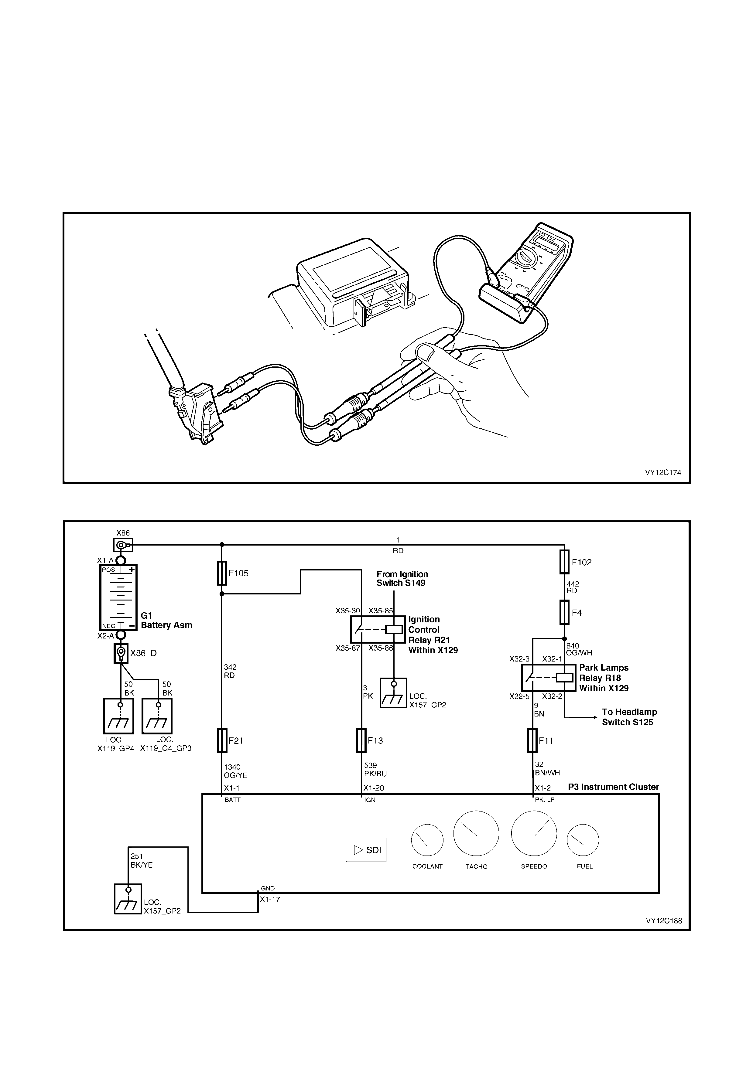
3.8 INSTRUMENT DIAGNOSTIC PROCEDURES
INTRODUCTION
The following charts are designed to provide fast and efficient fault location of the instruments. Each diagnostic
chart consists of a diagnostic chart and pertinent information including Diagnostic Trouble Code (DTC) setting
parameters and, in most charts, circuit diagrams.
W hen carrying out wiring checks as directed by the diagnostic charts, rather than probe terminals and connectors
with incorrect sized multimeter connections, use the adaptors contained in connector test adaptor kit J35616-A (KM-
609), as shown in the f ollowing illustration. T his will prevent any possibility of spreading or dam aging wiring harness
terminals, which may later cause a system intermittent failure.
Figure 12C-313
Figure 12C-314

DIAGNOSTIC CIRCUIT CHECK
W hen investigating any com plaint of an instrum ent cluster problem or malf unction, always begin diagnos is with the
following diagnostic circuit check. This check is a preliminary procedure that ensures that the instrument cluster is
powered up, communicating on the serial data line, helping to identify a problem or malfunction, and directing the
reader to the appropriate diagnostic chart in this Section.
With TECH 2 connected to the DLC and the ignition switched on, TECH 2 should display serial data
communication. If TECH 2 does not display serial data, the serial data circuit may be open or shorted.
The entertainment system and several other control modules are connected to the serial data line. The control
modules are the PCM, PIM (GEN III V8 only) BCM, ABS or ABS / T CS, OCC and SRS. The enter tainment system
or ANY one of the control m odules could caus e a fault on the serial data line. T his fault could result in T ECH 2 not
being able to display serial data.
DIAGNOSTIC CIRCUIT CHECK DIAGNOSTIC CHART
STEP ACTION VALUE YES NO
1 1. Turn the ignition on.
Do any of the instrument cluster warning telltale LEDs
illuminate?
Go to Step 5. Go to Step 2.
2 1. Check the instrument cluster fuses F13 and F21 in
instrument panel compartment.
Are the fuses OK?
Go to Step 3. Replace blown
fuses.
3 1. Remove the instrument cluster. Refer to
2.3 INSTRUMENT CLUSTER ASSEMBLY in this
Section.
2. Connect a digital ohmmeter between the instrument
cluster P3 connector X1-17, circuit 251 (Black /
Yellow wire), and a known good ground.
Is the value as specified?
Less than
1 ohm Go to Step 4. Repair faulty
circuit 251.
4 1. Connect a digital voltmeter between the instrument
cluster connector P3 terminal X1-1, circuit 1340
(Orange / Yellow wire), and a known good ground.
2. Turn the ignition on and note the voltage reading.
3. Connect a digital voltmeter between the instrument
cluster P3 connector X1-20, circuit 539 (Pink / Blue
wire), and a known good ground. Note the voltage
reading.
Is the value as specified?
Battery
voltage Replace the
instrument cluster.
Refer to 2.3
INSTRUM ENT
CLUSTER
ASSEMBLY in this
Section.
Repair faulty
circuits 539 and/or
1340 as
necessary.
5 1. Turn the ignition off.
2. Connect TECH 2 to the DLC.
3. Turn the ignition on.
4. Push the power button on TECH 2.
Does TECH 2 power up? (Screen should illuminate and
display TECH 2).
Go to Step 6. Go to TECH 2
diagnosis. Refer
to Section 0C,
TECH 2.
6 1. At the TECH 2 title screen press the Enter key.
2. Select Diagnostics / Model Year / Vehicle Model /
Body / Instrument.
Does TECH 2 display Instrument System Identification
(ie. Part Number)?
Confirm the
details and go to
Step 7.
Go to DTC 14 No
Serial
Communication In
this Section.
7 1. Select Diagnostic Trouble Codes / Read DTC
Information.
Does TECH 2 display any DTC?
Refer to
corresponding
diagnostic chart.
Refer to 3.4
DIAGNOSING
FAULTS NOT
COVERED BY
DIAGNOSTIC
TROUBLE
CODES in this
Section.
WHEN ALL DIAGNOSIS AND REPAIRS ARE COM PLETED, CLEAR ALL DTC AND VERIFY CORRECT OPERATION
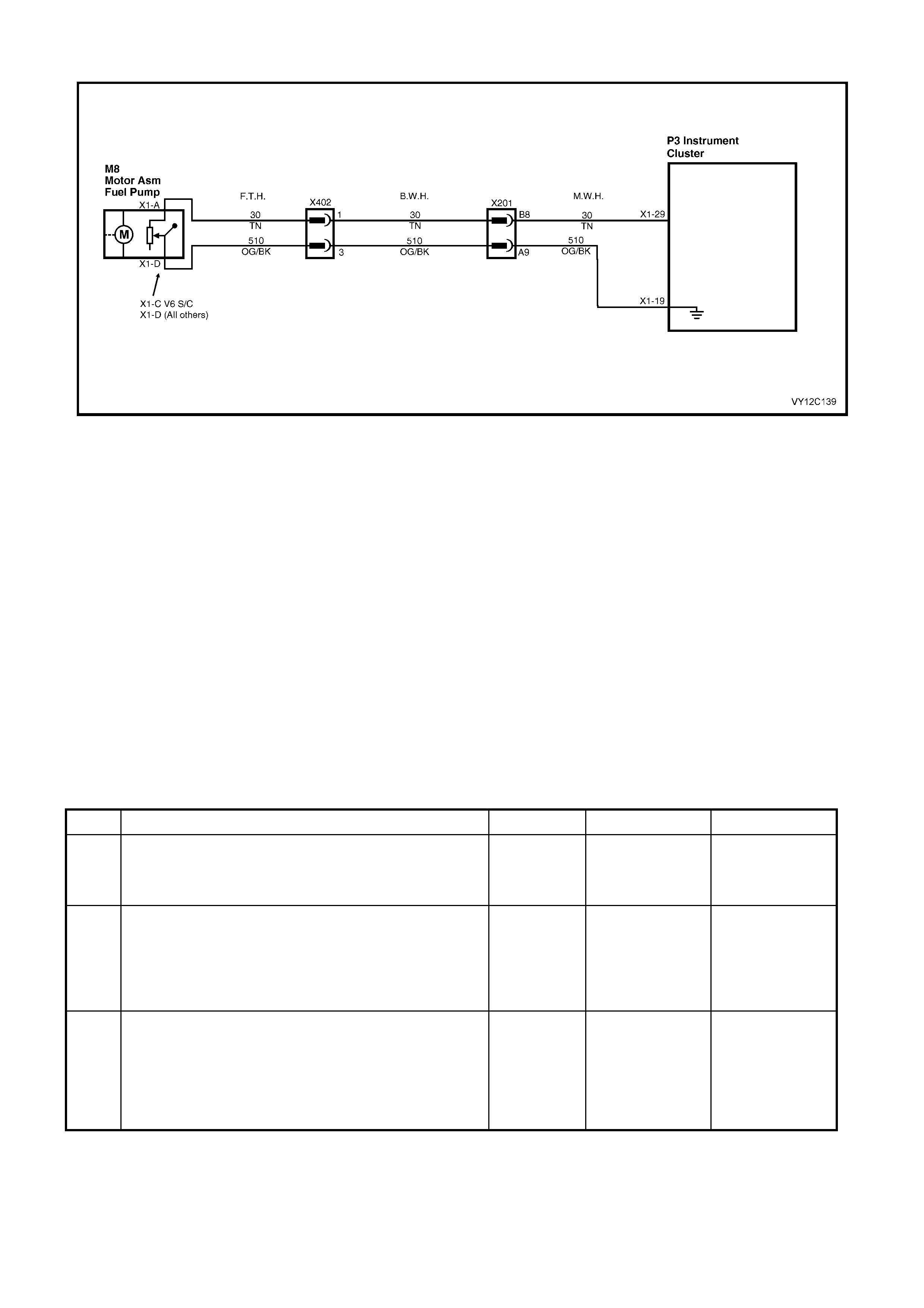
DTC 1 — PETROL LEVEL SENDER SIGNAL VOLTAGE TOO LOW
Figure 12C-315
CIRCUIT DESCRIPTION
The instrument cluster supplies a 12 volt reference voltage and a ground circuit to the fuel gauge sender unit. The
fuel sender provides a resistanc e value to the instrument c luster based on its position relative to the f uel level. The
fuel sender resistance will vary between 40 ± 5 ohms and 250 ± 5 ohms from no fuel in the tank to full tank.
DTC 1 will set if the fuel sender resistance is less than 12.9 ohms for a period of 30 seconds. The DTC is reset
when the fuel sender resistance returns to its normal operating range for a period of 60 seconds. The DTC is
logged as a History DTC.
When a DTC 1 is set the fuel gauge will display the fuel tank level as empty irrespective of actual fuel level.
DIAGNOSTIC AIDS
The TECH 2 diagnostic tool reads fuel sender position as a voltage between 0 and 5 volts. The fuel sender signal
resistanc e should be between 40 ± 5 ohm s and 250 ± 5 ohms when the fuel sender is functioning correctly. The fuel
sender voltage should increase at a steady rate as the fuel level increases.
The multimeter allows continuity of the wiring harness to be checked. Harness voltage can also be confirmed at
connector locations.
Check for any damage to the harness which could cause an intermittent open or short to ground or backed-out
terminals at the instrument cluster connectors, broken connector locks, improperly formed or damaged terminals.
PETROL LEVEL SENDER SIGNAL VOLTAGE TOO LOW DIAGNOSTIC CHART
STEP ACTION VALUE YES NO
1 Was the Diagnostic Circuit Check performed? Go to Step 2. Go to
Diagnostic Circuit
Check
in this Section.
2 1. Connect TECH 2 to the DLC.
2. Select Diagnostics / Model Year / Vehicle Model /
Body / Instrument / Data Display / Instrument.
3. Scroll to the Fuel Level Sender Resistance signal.
Is the value as specified?
Less than
12.9 ohms Go to Step 3. Go to Fuel Gauge
Sender Unit —
Intermittent in this
Section.
3 1. From the Body Menu, select Miscellaneous Tests /
Gauge Control Tests / Fuel Gauge, and conduct the
test as directed by soft keys at the bottom of the
TECH 2 screen.
Does the fuel gauge operate correctly?
Go to Step 4. Replace the
instrument cluster.
Refer to 2.3
INSTRUM ENT
CLUSTER
ASSEMBLY in this
Section.

STEP ACTION VALUE YES NO
4 1. Disconnect the battery. Refer to Section 00,
5. BATTERY DISCONNECTION PROCEDURES.
2. Disconnect the body harness connector from the
main wiring harness connector X201.
3. Using an ohmmeter, check for continuity between
X201-B8 circuit 30 (Tan wire) and X201-
A
9 circuit
510 (Orange / Black wire) on the main wiring
harness.
4. Using an ohmmeter, check for continuity between
X201-B8 circuit 30 (Tan wire) and a known good
ground.
Is there continuity?
Go to Step 5. Go to Step 6.
5 1. Remove the instrument cluster. Refer to
2.3 INSTRUMENT CLUSTER ASSEMBLY in this
Section.
2. Using an ohmmeter, check for continuity between
X201-B8 circuit 30 (Tan wire) and X201-
A
9 circuit
510 (Orange / Black wire) on the main wiring
harness.
3. Using an ohmmeter, check for continuity between
X201-B8 circuit 30 (Tan wire) and a known good
ground.
Is there continuity?
Short circuit in
main wiring
harness between
connector X201
and instrument
cluster connector
P3. Repair
harness.
Replace the
instrument cluster.
Refer to 2.3
INSTRUM ENT
CLUSTER
ASSEMBLY in this
Section.
6 1. Disconnect the fuel tank harness from the body
harness connector X402 located under the rear of
the vehicle.
2. Using an ohmmeter, check for continuity between
X402-1 circuit 30 (Tan wire) and X402-3 circuit 510
(Orange / Black wire) on the body harness
connector.
3. Using an ohmmeter, check for continuity between
X402-1 circuit 30 (Tan wire) and a known good
ground.
Is there continuity?
Short circuit in
body harness
between X402 and
X201. Repair
harness.
Go to Step 7.
7 1. Using an ohmmeter, check resistance across X402-1
circuit 30 (Tan wire) and X402-3 circuit 510 (Orange /
Black wire) on the fuel tank harness.
Is the value as specified?
Between
40 ± 5 ohms
and
250 ± 5 ohms
Go to Petrol Level
Sender Signal
Voltage
Intermittent
Diagnostic Chart
in this Section.
Go to Step 8.
8 1. Drain and remove the fuel tank. Refer to
Section 8A1, 2.1 FUEL TANK – SEDAN AND
WAGON, 2.2 FUEL TANK – COUPE or 2.3 FUEL
TANK – UTILITY as appropriate.
2. Using an ohmmeter, check for continuity between
M8 X1-A circuit 30 (Tan wire) and M8 X1-D (M8 X1-C
for V6 S/C) circuit 510 (Orange / Black wire) on the
fuel tank harness.
3. Using an ohmmeter, check for continuity between
M8 X1-
A
circuit 30 (Tan wire) and a known good
ground.
Is there continuity?
Short circuit in fuel
tank harness
between the fuel
sender unit and
connector X402.
Repair harness.
Replace faulty fuel
sender unit. Refer
to Section 8A1,
2.6 MODULAR
FUEL SENDER
ASSEMBLY –
SEDAN, WAGON
AND COUPE, or
2.7 MODULAR
FUEL SENDER
ASSEMBLY –
UTILITY as
appropriate.
9 1. From the Body Menu, select Diagnostic Trouble
Codes / Clear DTC Information on the TECH 2.
Has the DTC cleared?
End of diagnostic
checking. Refer to
corresponding
diagnostic chart.
WHEN ALL DIAGNOSIS AND REPAIRS ARE COM PLETED, CLEAR ALL DTC AND VERIFY CORRECT OPERATION
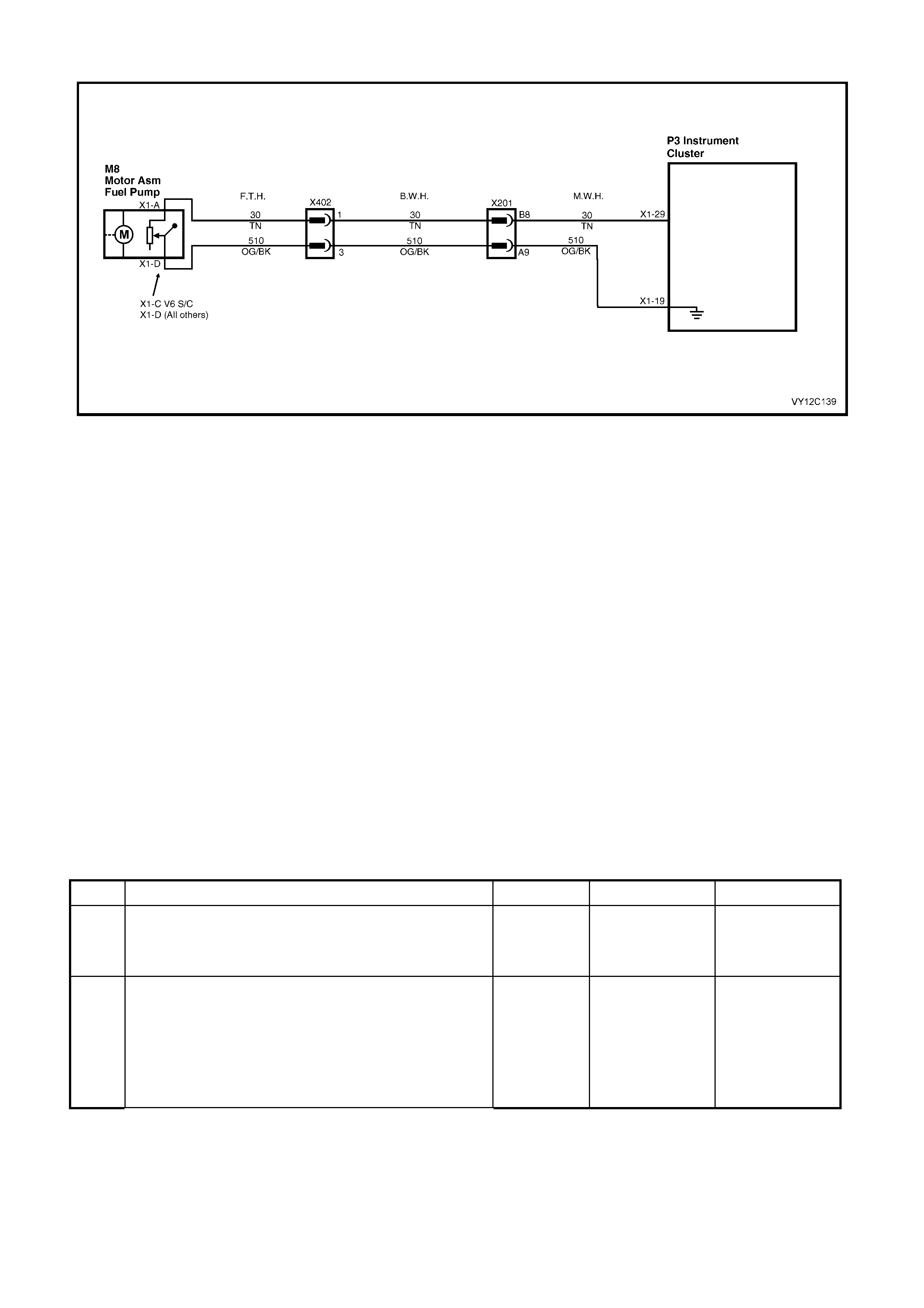
DTC 2 — PETROL LEVEL SENDER SIGNAL VOLTAGE INTERMITTENT
Figure 12C-316
CIRCUIT DESCRIPTION
The instrument cluster supplies a 12 volt reference voltage and a ground circuit to the f uel gauge sender unit. The
fuel sender provides a resistanc e value to the instrument c luster based on its position relative to the f uel level. The
fuel sender resistance will vary between 40 ± 5 ohms and 250 ± 5 ohms from no fuel in the tank to full tank.
DTC 2 will set if there is an interm ittent fault in the connection between the fuel sender and the instrument cluster.
The DTC is set when the fuel sender resistance is greater than 290 ohms for 30 seconds or if the fuel sender
resistance is less than 37.5 ohms for 30 seconds. The DTC is reset when the fuel sender is detected as being
open circuit or short circuit or the sender resis tance is within its norm al operating range f or a period of 60 s econds.
The DTC is logged as a History DTC.
DIAGNOSTIC AIDS
By manipulating the harnesses at the various connectors and points along the harness it is possible to isolate the
cause of the circuit interruption. By work ing through the chart in the specified order it is possible to work out which
harness contains the fault. This harness can then be removed and repaired.
The TECH 2 diagnostic tool reads fuel sender position as a voltage between 0 and 5 volts. The fuel sender signal
resistanc e should be between 40 ± 5 ohm s and 250 ± 5 ohms when the fuel sender is functioning correctly. The fuel
sender voltage should increase at a steady rate as the fuel level increases.
The multimeter allows continuity of the wiring harness to be checked. Harness voltage can also be confirmed at
connector locations.
Check for any damage to the harness which could cause an intermittent open or short to ground or backed out
terminals at the instrument cluster connectors, broken connector locks, improperly formed or damaged terminals.
PETROL LEVEL SENDER SIGNAL VOLTAGE INTERMITTENT DIAGNOSTIC CHART
STEP ACTION VALUE YES NO
1 Was the Diagnostic Circuit Check performed? Go to Step 2. Go to
Diagnostic Circuit
Check
in this Section.
2 1. Connect TECH 2 to the DLC.
2. Select Diagnostics / Model Year / Vehicle Model /
Body / Instrument / Miscellaneous Tests / Gauge
Control Tests / Fuel Gauge, and conduct the test as
directed by soft keys at the bottom of the TECH 2
screen.
Does the fuel gauge operate correctly?
Go to Step 3. Replace the
instrument cluster.
Refer to 2.3
INSTRUM ENT
CLUSTER
A
SSEMBLY in this
Section.

STEP ACTION VALUE YES NO
3 1. From the Body Menu, select Diagnostic Trouble
Codes / Clear DTC Information.
2. Turn the ignition off then on.
3. From the Body Menu, select Data Display /
Instrument.
4. Scroll to the Fuel Level Sender Resistance signal.
5. Have an assistant manipulate the main wiring
harness between connector X201 and the instrument
cluster connector P3 to induce an intermittent fault.
Did the fuel level sender resistance vary during the
manipulations, or
Did DTC 2 set again?
Repair faulty main
wiring harness. Go to Step 4.
4 1. Have assistant manipulate the body wiring harness
between connectors X201 and X402 to induce an
intermittent fault.
Did the fuel level sender resistance vary during the
manipulations, or
Did DTC 2 set again?
Repair faulty body
wiring harness. Go to Step 5.
5 1. Drain and remove the fuel tank. Refer to
Section 8A1, 2.1 FUEL TANK – SEDAN AND
WAGON, 2.2 FUEL TANK – COUPE or 2.3 FUEL
TANK – UTILITY as appropriate.
2. Have assistant manipulate the fuel tank wiring
harness between connector X402 and the fuel
sender connector M8 to induce an intermittent fault.
Did the fuel level sender resistance vary during the
manipulations, or
Did DTC 2 set again?
Repair faulty fuel
tank wiring
harness.
Replace faulty fuel
sender. Refer to
Section 8A1,
2.6 MODULAR
FUEL SENDER
ASSEMBLY –
SEDAN, WAGON
AND COUPE, or
2.7 MODULAR
FUEL SENDER
ASSEMBLY –
UTILITY as
appropriate.
6 1. From the Body Menu, select Diagnostic Trouble
Codes / Clear DTC Information on the TECH 2.
Has the DTC cleared?
End of diagnostic
checking. Refer to
corresponding
diagnostic chart.
WHEN ALL DIAGNOSIS AND REPAIRS ARE COM PLETED, CLEAR ALL DTC AND VERIFY CORRECT OPERATION
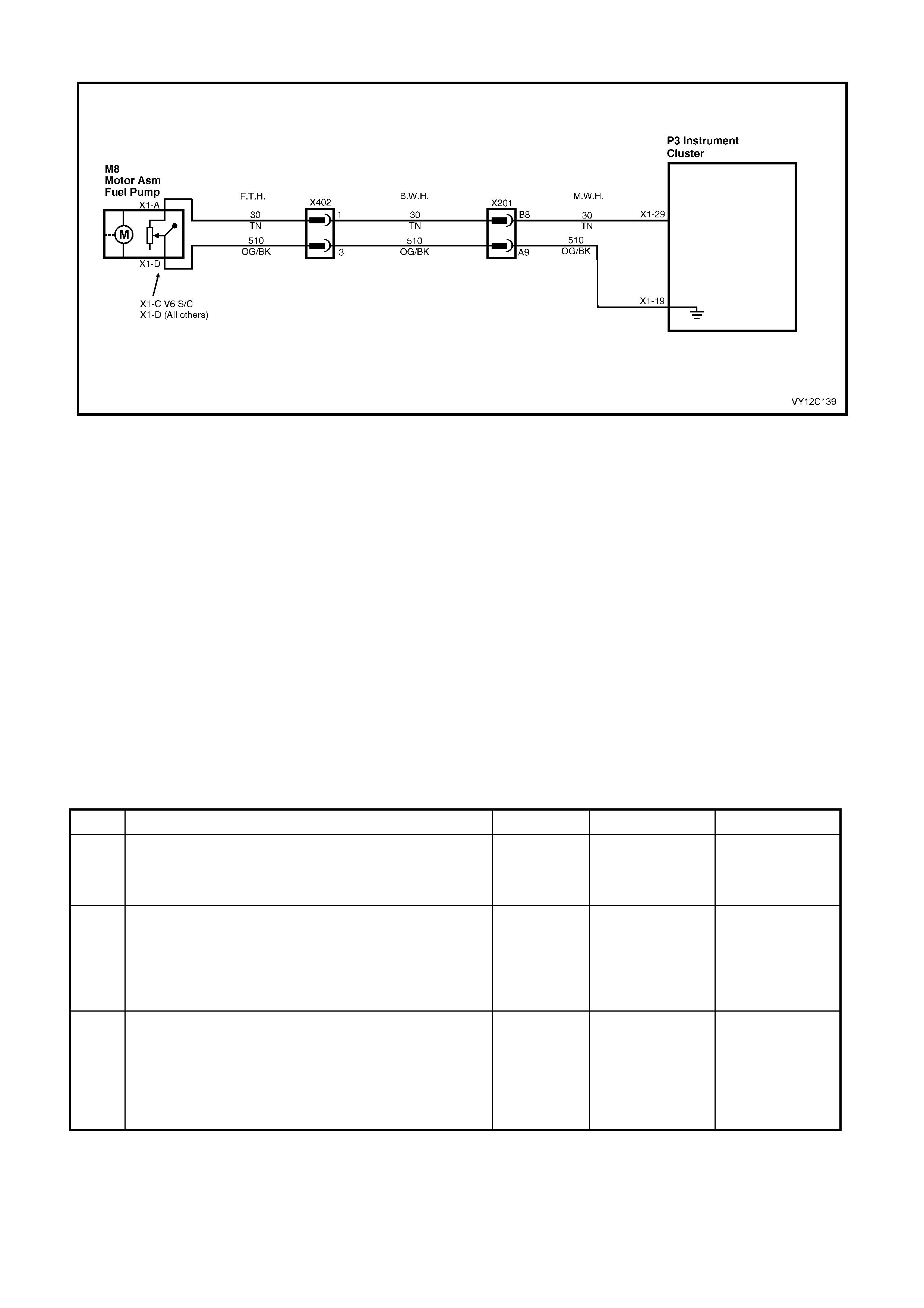
DTC 3 — PETROL LEVEL SENDER SIGNAL VOLTAGE TOO HIGH
Figure 12C-317
CIRCUIT DESCRIPTION
The instrument cluster supplies a 12 volt reference voltage and a ground circuit to the fuel gauge sender unit. The
fuel sender provides a resistanc e value to the instrument c luster based on its position relative to the f uel level. The
fuel sender resistance will vary between 40 ± 5 ohms and 250 ± 5 ohms from no fuel in the tank to full tank.
DTC 3 will set if the fuel sender circuit provides a resistance above 290 ohms for a duration longer than 30 seconds.
The DTC is reset when the fuel sender res istance returns to its norm al operating range f or a period of 60 seconds.
The DTC is logged as a History DTC.
When a DTC 3 is set the fuel gauge will display the fuel tank level as empty irrespective of actual fuel level.
DIAGNOSTIC AIDS
The TECH 2 diagnostic tool reads fuel sender position as a voltage between 0 and 5 volts. The fuel sender signal
resistanc e should be between 40 ± 5 ohm s and 250 ± 5 ohms when the fuel sender is functioning correctly. The fuel
sender voltage should increase at a steady rate as the fuel level increases.
The multimeter allows continuity of the wiring harness to be checked. Harness voltage can also be confirmed at
connector locations.
Check for any damage to the harness which could cause an intermittent open or short to ground or backed-out
terminals at the instrument cluster connectors, broken connector locks, improperly formed or damaged terminals.
PETROL LEVEL SENDER SIGNAL VOLTAGE TOO HIGH DIAGNOSTIC CHART
STEP ACTION VALUE YES NO
1 Was the Diagnostic Circuit Check performed? Go to Step 2. Go to
Diagnostic Circuit
Check
in this Section.
2 1. Connect TECH 2 to the DLC.
2. Select Diagnostics / Model Year / Vehicle Model /
Body / Instrument / Data Display / Instrument.
3. Scroll to the Fuel Level Sender Resistance signal.
Is the value as specified?
Greater than
290 ohms Go to Step 3. Go to Fuel Gauge
Sender Unit —
Intermittent in this
Section.
3 1. From the Body Menu, select Miscellaneous Tests /
Gauge Control Tests / Fuel Gauge, and conduct the
test as directed by soft keys at the bottom of the
TECH 2 screen.
Does the fuel gauge operate correctly?
Go to Step 4. Replace the
instrument cluster.
Refer to 2.3
INSTRUM ENT
CLUSTER
ASSEMBLY in this
Section.

STEP ACTION VALUE YES NO
4 1. Disconnect the battery. Refer to Section 00,
5. BATTERY DISCONNECTION PROCEDURES.
2. Remove the instrument cluster. Refer to
2.3 INSTRUMENT CLUSTER ASSEMBLY in this
Section.
3. Disconnect the main wiring harness connector X201
from the body wiring harness.
4. Using an ohmmeter, check for continuity of circuit 30
(Tan wire) between the instrument cluster P3,
connector X1-29, and main wiring harness connector
X201-B8.
Is there continuity?
Go to Step 5. Repair open
circuit in main
wiring harness,
circuit 30.
5 1. Using an ohmmeter, check for continuity of circuit
510 (Orange / Black wire) between the instrument
cluster P3, connector X1-19 and main wiring harness
connector X201-A9.
Is there continuity?
Go to Step 6. Repair open
circuit in main
wiring harness,
circuit 510.
6 1. Disconnect the body wiring harness connector X402
from the fuel tank harness.
2. Using an ohmmeter, check for continuity of circuit 30
(Tan wire) between the main wiring harness
connector X201-B8 and the body wiring harness
connector X402-1.
Is there continuity?
Go to Step 7. Repair open
circuit in body
wiring harness,
circuit 30.
7 1. Using an ohmmeter, check for continuity of circuit
510 (Orange / Black wire) between the main wiring
harness connector X201-
A
9 and the body wiring
harness connector X402-3.
Is there continuity?
Go to Step 8. Repair open
circuit in body
wiring harness,
circuit 510.
8 1. Drain and remove the fuel tank. Refer to
Section 8A1, 2.1 FUEL TANK – SEDAN AND
WAGON, 2.2 FUEL TANK – COUPE or 2.3 FUEL
TANK – UTILITY as appropriate.
2. Disconnect the fuel tank wiring harness from the fuel
sender unit.
3. Using an ohmmeter, check for continuity of circuit 30
(Tan wire) between the body wiring harness
connector X402-1 and the fuel tank wiring harness
connector M8 X1-A.
Is there continuity?
Go to Step 9. Repair open
circuit in fuel tank
wiring harness,
circuit 30.
9 1. Using an ohmmeter, check for continuity of circuit
510 (Orange / Black wire) between the body wiring
harness connector X402-3 and the fuel tank wiring
harness connector M8 X1-D (M8 X1-C for V6 S/C).
Is there continuity?
Go to Step 10. Repair open
circuit in fuel tank
wiring harness,
circuit 510.
10 1. Using an ohmmeter, check for continuity across the
fuel sender.
Is there continuity?
Replace the
instrument cluster.
Refer to 2.3
INSTRUM ENT
CLUSTER
ASSEMBLY in this
Section.
Replace faulty fuel
sender. Refer to
Section 8A1,
2.6 MODULAR
FUEL SENDER
ASSEMBLY –
SEDAN, WAGON
AND COUPE, or
2.7 MODULAR
FUEL SENDER
ASSEMBLY –
UTILITY as
appropriate.
11 1. From the Body Menu, select Diagnostic Trouble
Codes / Clear DTC Information on the TECH 2.
Has the DTC cleared?
End of diagnostic
checking. Refer to
corresponding
diagnostic chart.
WHEN ALL DIAGNOSIS AND REPAIRS ARE COM PLETED, CLEAR ALL DTC AND VERIFY CORRECT OPERATION
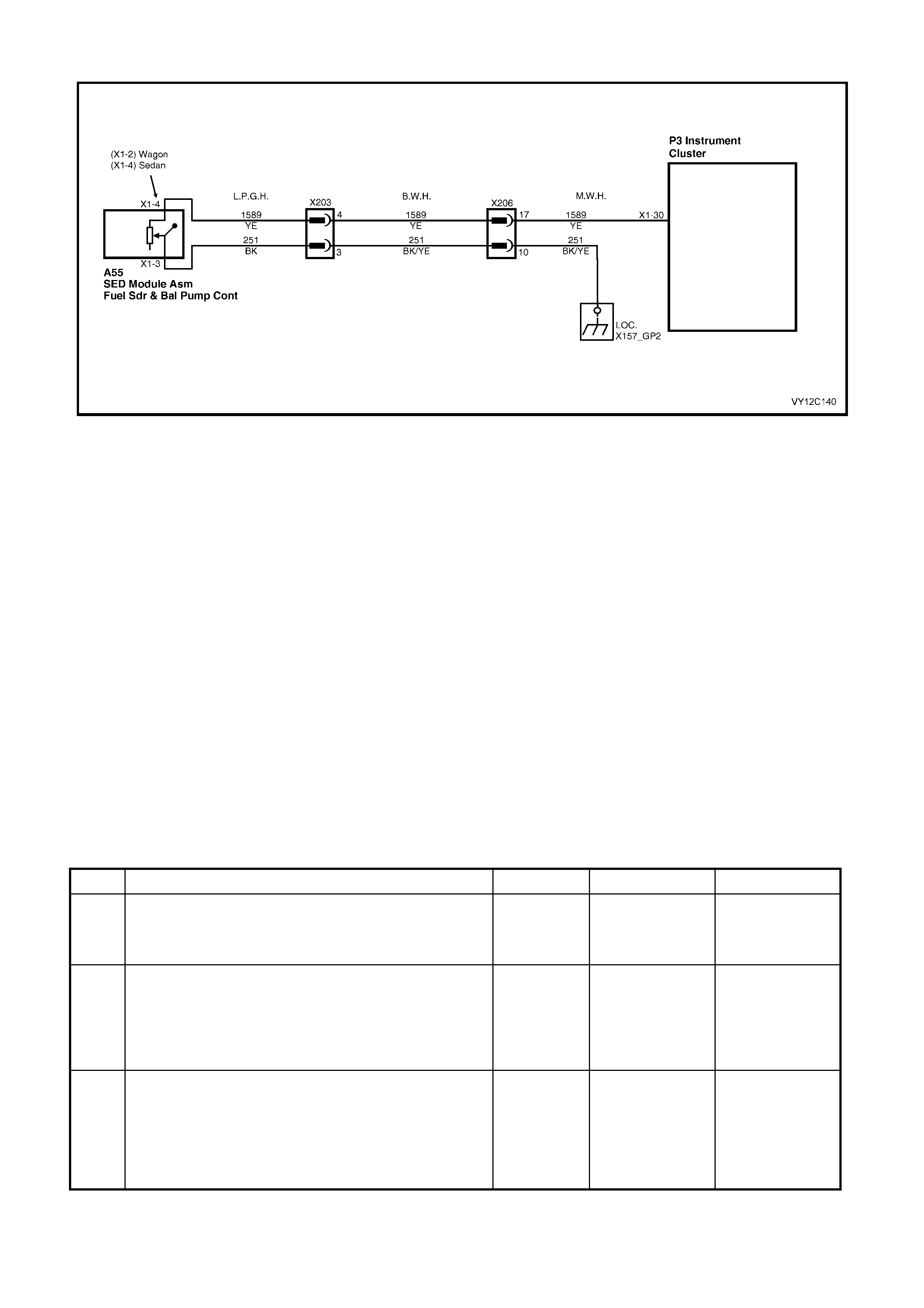
DTC 4 — LPG LEVEL SENDER SIGNAL VOLTAGE TOO HIGH
Figure 12C-318
CIRCUIT DESCRIPTION
The instrument cluster supplies a 12 volt reference voltage to the LPG gauge sender unit. The LPG sender provides
a resistance value to the instrument cluster based on its position relative to the LPG level. The LPG sender
resistance will vary between 40 ± 5 ohms and 250 ± 5 ohms from no LPG in the tank to full tank.
NOTE: If a vehicle is not fitted with LPG and DTC 4 is set, verify the instrument c luster configuration progr amm ing
with TECH 2. Refer to 3.15 PROGRAM in this Section.
DTC 4 will set if the LPG sender circuit provides a resistance above 290 ohms for a duration longer than
30 seconds. The DTC is reset when the LPG sender resistances return to its normal operating range for a period of
60 seconds. The DTC is logged as a History DTC.
When a DTC 4 is set the LPG gauge will display the LPG tank level as empty when LPG mode is selected
irrespective of actual fuel level.
DIAGNOSTIC AIDS
The TECH 2 diagnostic tool reads LPG sender pos ition as a voltage between 0 and 5 volts. The LPG sender signal
resistance should be between 40 ± 5 ohms and 250 ± 5 ohms when the LPG sender is functioning correctly. The
LPG sender voltage should increase at a steady rate as the LPG level increases.
The multimeter allows continuity of the wiring harness to be checked. Harness voltage can also be confirmed at
connector locations.
Check for any damage to the harness which could cause an intermittent open or short to ground or backed out
terminals at the instrument cluster connectors, broken connector locks, improperly formed or damaged terminals.
LPG LEVEL SENDER SIGNAL VOLTAGE TOO HIGH DIAGNOSTIC CHART
STEP ACTION VALUE YES NO
1 Was the Diagnostic Circuit Check performed? Go to Step 2. Go to
Diagnostic Circuit
Check
in this Section.
2 1. Connect TECH 2 to the DLC.
2. Select Diagnostics / Model Year / Vehicle Model /
Body / Instrument / Data Display / Instrument.
3. Scroll to the LPG Level Sender Resistance signal.
Is the value as specified?
Greater than
290 ohms Go to Step 3. Go to LPG Level
Sender Signal
Voltage
Intermittent in this
Section.
3 1. From the Body Menu, select Miscellaneous Tests /
Gauge Control Tests / Fuel Gauge, and conduct the
test as directed by soft keys at the bottom of the
TECH 2 screen.
Does the fuel gauge operate correctly?
Go to Step 4. Replace the
instrument cluster.
Refer to 2.3
INSTRUM ENT
CLUSTER
A
SSEMBLY in this
Section.

STEP ACTION VALUE YES NO
4 1. Disconnect the battery. Refer to Section 00,
5. BATTERY DISCONNECTION PROCEDURES.
2. Remove the instrument cluster. Refer to
2.3 INSTRUMENT CLUSTER ASSEMBLY in this
Section.
3. Disconnect the body harness connector from the
main wiring harness connector X206.
4. Using an ohmmeter, check for continuity of circuit
1589 (Yellow wire) between the instrument cluster
P3, connector X1-30 and main wiring harness
connector X206-17.
Is there continuity?
Go to Step 5. Repair open
circuit in main
wiring harness,
circuit 1589.
5 1. Using an ohmmeter, check for continuity of circuit
251 (Black / Yellow wire) between the main wiring
harness connector X206-10 and a known good
ground.
Is there continuity?
Go to Step 6. Repair open
circuit in main
wiring harness,
circuit 251.
6 1. Disconnect the body harness connector X203 from
the LPG harness.
2. Using an ohmmeter, check for continuity of circuit
1589 (Yellow wire) between the main wiring harness
connector X206-17 and the body wiring harness
connector X203-4.
Is there continuity?
Go to Step 7. Repair open
circuit in body
wiring harness,
circuit 1589.
7 1. Using an ohmmeter, check for continuity of circuit
251 (Black / Yellow wire) between the main wiring
harness connector X206-10 and the body wiring
harness connector X203-3.
Is there continuity?
Go to Step 8. Repair open
circuit in body
wiring harness,
circuit 251.
8 1. Disconnect the LPG harness from the fuel sender
unit.
2. Using an ohmmeter, check for continuity of circuit
1589 (Yellow wire) between the body wiring harness
connector X203-4 and the LPG harness connector
A55 X1-4 (X1-2 for Wagon).
Is there continuity?
Go to Step 9. Repair open
circuit in LPG
harness, circuit
1589.
9 1. Using an ohmmeter, check for continuity of circuit
251 (Black wire) between the body wiring harness
connector X203-3 and the LPG harness connector
A55 X1-3.
Is there continuity?
Go to Step 10. Repair open
circuit in LPG tank
wiring harness,
circuit 251.
10 1. Using an ohmmeter, check for continuity across the
LPG sender.
Is there continuity?
Replace the
instrument cluster.
Refer to 2.3
INSTRUM ENT
CLUSTER
ASSEMBLY in this
Section.
Replace faulty
LPG sender unit.
Refer to Section
8A2, 3.12 TANK
FUEL GAUGE
ASSEMBLY.
11 1. From the Body Menu, select Diagnostic Trouble
Codes / Clear DTC Information on the TECH 2.
Has the DTC cleared?
End of diagnostic
checking. Refer to
corresponding
diagnostic chart.
WHEN ALL DIAGNOSIS AND REPAIRS ARE COM PLETED, CLEAR ALL DTC AND VERIFY CORRECT OPERATION

DTC 5 — LPG LEVEL SENDER SIGNAL VOLTAGE TOO LOW
Figure 12C-319
CIRCUIT DESCRIPTION
The instrument cluster supplies a 12 volt reference voltage to the LPG gauge sender unit. The LPG sender provides
a resistance value to the instrument cluster based on its position relative to the LPG level. The LPG sender
resistance will vary between 40 ± 5 ohms and 250 ± 5 ohms from no LPG in the tank to full tank.
NOTE: If a vehicle is not fitted with LPG and DTC 5 is set, verify the instrument c lus ter configuration progr amm ing
with TECH 2. Refer to 3.15 PROGRAM in this Section.
DTC 5 will set if the LPG sender resistance is less than 12.9 ohms for a period of 30 seconds. The DTC is reset
when the LPG sender resistance returns to its normal operating range for a period of 60 seconds. The DTC is
logged as a History DTC.
When a DTC 5 is set the LPG gauge will display the LPG tank level as empty when LPG mode is selected
irrespective of actual fuel level.
DIAGNOSTIC AIDS
The TECH 2 diagnos tic tool reads LPG sender pos ition as a voltage between 0 and 5 volts. The LPG sender signal
resistance should be between 40 ± 5 ohms and 250 ± 5 ohms when the LPG sender is functioning correctly. The
LPG sender voltage should increase at a steady rate as the LPG level increases.
The multimeter allows continuity of the wiring harness to be checked. Harness voltage can also be confirmed at
connector locations.
Check for any damage to the harness which could cause an intermittent open or short to ground or backed out
terminals at the instrument cluster connectors, broken connector locks, improperly formed or damaged terminals.
LPG LEVEL SENDER SIGNAL VOLTAGE TOO LOW DIAGNOSTIC CHART
STEP ACTION VALUE YES NO
1 Was the Diagnostic Circuit Check performed? Go to Step 2. Go to
Diagnostic Circuit
Check
in this Section.
2 1. Connect TECH 2 to the DLC.
2. Select Diagnostics / Model Year / Vehicle Model /
Body / Instrument / Data Display / Instrument.
3. Scroll to the LPG Level Sender Resistance signal.
Is the value as specified?
Less than
12.9 ohms Go to Step 3. Go to LPG Level
Sender signal
Voltage
Intermittent in this
Section.
3 1. From the Body Menu, select Miscellaneous Tests /
Gauge Control Tests / Fuel Gauge, and conduct the
test as directed by soft keys at the bottom of the
TECH 2 screen.
Does the fuel gauge operate correctly?
Go to Step 4. Replace the
instrument cluster.
Refer to 2.3
INSTRUM ENT
CLUSTER
ASSEMBLY in this
Section.

STEP ACTION VALUE YES NO
4 1. Disconnect the battery. Refer to Section 00,
5. BATTERY DISCONNECTION PROCEDURES.
2. Disconnect the body harness connector from the
main wiring harness connector X206.
3. Using an ohmmeter, check for continuity between
X206-17 circuit 1589 (Yellow wire) and X206-10
circuit 251 (Black / Yellow wire) on the main wiring
harness.
4. Using an ohmmeter, check for continuity between
X206-17 circuit 1589 (Yellow wire) and a known
good ground.
Is there continuity?
Go to Step 5. Go to Step 6.
5 1. Remove the instrument cluster. Refer to
2.3 INSTRUMENT CLUSTER ASSEMBLY in this
Section.
2. Using an ohmmeter, check for continuity between
X206-17 circuit 1589 (Yellow wire) and X206-10
circuit 251 (Black / Yellow wire) on the main wiring
harness.
3. Using an ohmmeter, check for continuity between
X206-17 circuit 1589 (Yellow wire) and a known
good ground.
Is there continuity?
Short circuit in
main wiring
harness between
connector X206
and instrument
cluster connector
P3 or to ground.
Repair harness.
Replace the
instrument cluster.
Refer to 2.3
INSTRUM ENT
CLUSTER
ASSEMBLY in this
Section.
6 1. Disconnect the LPG tank harness from the body
harness connector X203.
2. Using an ohmmeter, check for continuity between
X203-4 circuit 1589 (Yellow wire) and X203-3 circuit
251 (Black / Yellow wire) on the body harness
connector.
3. Using an ohmmeter, check for continuity between
X203-4 circuit 1589 (Yellow wire) and a known good
ground.
Is there continuity?
Short circuit in
body wiring
harness between
X203 and X206.
Repair harness.
Go to Step 7.
7 1. Using an ohmmeter, check resistance across X203-4
circuit 1589 (Yellow wire) and X203-3 circuit 251
(Black wire) on the LPG harness.
Is the value as specified?
Between
40 ± 5 ohms
and
250 ± 5 ohms
Go to LPG Level
Sender Signal
Voltage
Intermittent
Diagnostic Chart
in this Section.
Go to Step 8.
8 1. Disconnect the LPG tank wiring harness from the
LPG sender unit.
2. Using an ohmmeter, check for continuity across
X203-4 circuit 1589 (Yellow wire) and X203-3 circuit
251 (Black wire) on the LPG harness.
3. Using an ohmmeter, check for continuity between
X203-4 circuit 1589 (Yellow wire) and a known good
ground.
Is there continuity?
Short circuit in
LPG harness
between the LPG
sender unit and
connector X203.
Repair harness.
Replace faulty
LPG sender unit.
Refer to Section
8A2, 3.12 TANK
FUEL GAUGE
ASSEMBLY.
9 1. From the Body Menu, select Diagnostic Trouble
Codes / Clear DTC Information on the TECH 2.
Has the DTC cleared?
End of diagnostic
checking. Refer to
corresponding
diagnostic chart.
WHEN ALL DIAGNOSIS AND REPAIRS ARE COM PLETED, CLEAR ALL DTC AND VERIFY CORRECT OPERATION
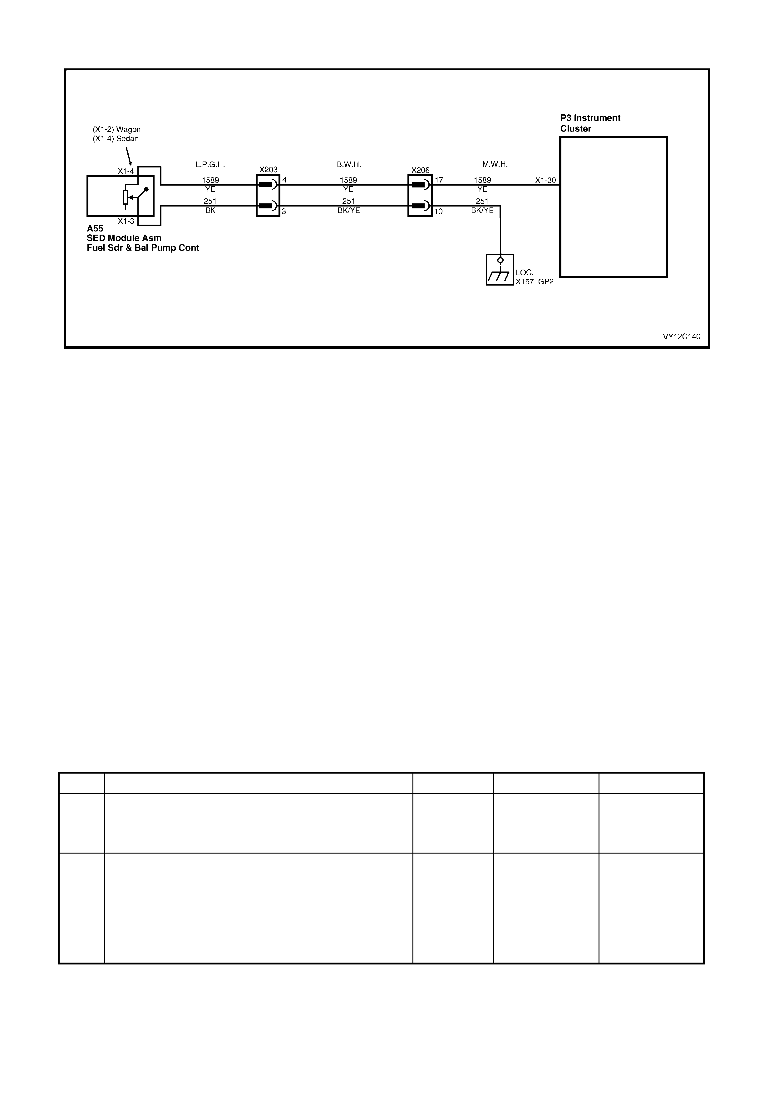
DTC 6 — LPG LEVEL SENDER SIGNAL VOLTAGE INTERMITTENT
Figure 12C-320
CIRCUIT DESCRIPTION
The instrument cluster supplies a 12 volt reference voltage to the LPG gauge sender unit. The LPG sender provides
a resistance value to the instrument cluster based on its position relative to the LPG level. The LPG sender
resistance will vary between 40 ± 5 ohms and 250 ± 5 ohms from no LPG in the tank to full tank.
NOTE: If a vehicle is not fitted with LPG and DTC 6 is set, verify the instrument c lus ter configuration progr amm ing
with TECH 2. Refer to 3.15 PROGRAM in this Section.
DTC 6 will set if there is an interm ittent fault in the c onnection between the LPG sender and the instr ument c luster.
The DTC is set when the LPG sender resistance is greater than 290 ohms for 30 seconds or if the LPG sender
resistance is less than 37.5 ohms for 30 seconds. The DTC is reset when the LPG sender is detected as being
open circuit or shor t c irc uit or the s ender is within its normal operating r ange f or a period of 60 seconds . The DT C is
logged as a History DTC.
DIAGNOSTIC AIDS
By manipulating the harnesses at the various connectors and points along the harness it is possible to isolate the
cause of the circuit interruption. By work ing through the chart in the specified order it is possible to work out which
harness contains the fault. This harness can then be removed and repaired.
The TECH 2 diagnostic tool reads fuel sender position as a voltage between 0 and 5 volts. The fuel sender signal
resistanc e should be between 40 ± 5 ohm s and 250 ± 5 ohms when the fuel sender is functioning correctly. The fuel
sender voltage should increase at a steady rate as the fuel level increases.
The multimeter allows continuity of the wiring harness to be checked. Harness voltage can also be confirmed at
connector locations.
Check for any damage to the harness which could cause an intermittent open or short to ground or backed out
terminals at the instrument cluster connectors, broken connector locks, improperly formed or damaged terminals.
LPG LEVEL SENDER SIGNAL VOLTAGE INTERMITTENT DIAGNOSTIC CHART
STEP ACTION VALUE YES NO
1 Was the Diagnostic Circuit Check performed? Go to Step 2. Go to
Diagnostic Circuit
Check
in this Section.
2 1. Connect TECH 2 to the DLC.
2. Select Diagnostics / Model Year / Vehicle Model /
Body / Instrument / Miscellaneous Tests / Gauge
Control Tests / Fuel Gauge, and conduct the test as
directed by soft keys at the bottom of the TECH 2
screen.
Does the fuel gauge operate correctly?
Go to Step 3. Replace the
instrument cluster.
Refer to 2.3
INSTRUM ENT
CLUSTER
A
SSEMBLY in this
Section.

STEP ACTION VALUE YES NO
3 1. From the Body Menu, select Diagnostic Trouble
Codes / Clear DTC Information.
2. Turn the ignition off then on.
3. From the Body Menu, select Data Display /
Instrument.
4. Scroll to the LPG Level Sender Resistance signal.
5. Have an assistant manipulate the main wiring
harness between connector X206 and the instrument
cluster connector P3 and to ground connection GP2
to induce an intermittent fault.
Did the LPG level sender resistance vary during the
manipulations, or
Did DTC 6 set again?
Repair faulty main
wiring harness. Go to Step 4.
4 1. Have assistant manipulate the body wiring harness
between connectors X203 and X206 to induce an
intermittent fault.
Did the LPG level sender resistance vary during the
manipulations, or
Did DTC 6 set again?
Repair faulty body
wiring harness. Go to Step 5.
5 1. Have assistant manipulate the LPG harness
between connector X203 and the LPG sender
connector A55 to induce an intermittent fault.
Did the LPG level sender resistance vary during the
manipulations, or
Did DTC 6 set again?
Repair faulty LPG
harness. Replace faulty
LPG sender unit.
Refer to Section
8A2, 3.12 TANK
FUEL GAUGE
ASSEMBLY.
6 1. From the Body Menu, select Diagnostic Trouble
Codes / Clear DTC Information on the TECH 2.
Has the DTC cleared?
End of diagnostic
checking. Refer to
corresponding
diagnostic chart.
WHEN ALL DIAGNOSIS AND REPAIRS ARE COM PLETED, CLEAR ALL DTC AND VERIFY CORRECT OPERATION
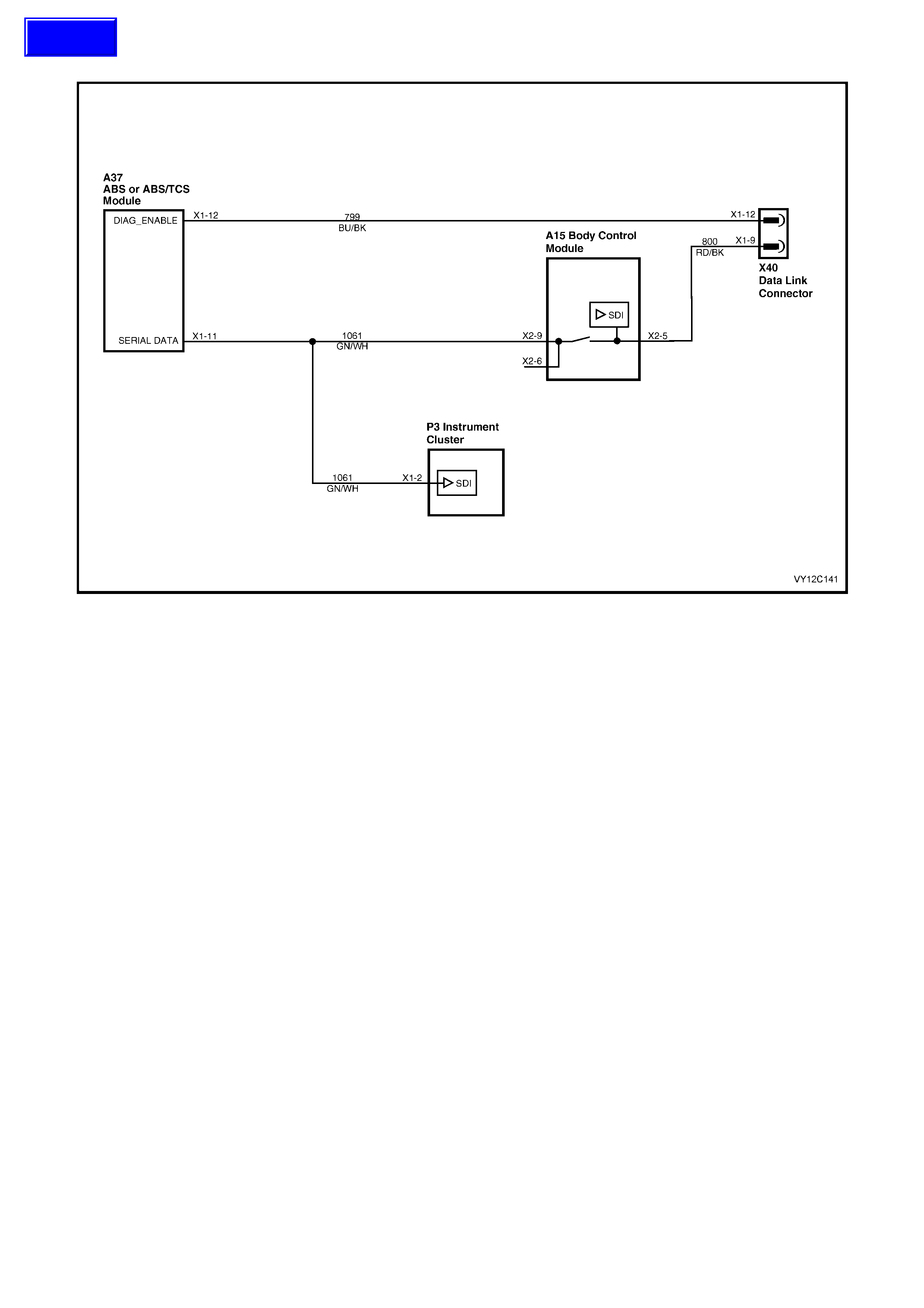
DTC 8 — NO SERIAL DATA FROM ABS / TCS
Figure 12C-321
CIRCUIT DESCRIPTION
The ABS (o r ABS / TCS) module sends s erial data along the s ec ondary serial data bus, circuit 1061. This is read by
the instr um ent c luster to indicate the s tatus of the traction c ontrol. If traction contr ol has been disabled by the ABS /
TCS module, the Traction Control Off warning will appear on the instrument cluster MFD.
DTC 8 will set if there is no ABS data message on the bus for more than 10 seconds. In practice the trouble code is
set som ewhere between 10 and 20 seconds after the last ABS data m ess age is received by the instr ument cluster .
The DTC is reset within 10 seconds of the arrival of an ABS data message on the bus. The DTC is logged as a
History DTC.
NOTE: The TECH 2 recognises the ABS / TCS Module as ABS / ETC.
DIAGNOSTIC AIDS
By manipulating the harnesses at the various connectors it is often possible to isolate the cause of the circuit
interruption. This harness can then be removed and repaired.
Check for any damage to the harness which could cause an intermittent open or short to ground or backed out
terminals at the instrument cluster connectors, broken connector locks, improperly formed or damaged terminals.
The multimeter allows continuity of the wiring harness circuit 1061 to be checked.
If the fault cannot be found in the harness then the fault may lie in the ABS module or the BCM. Refer to the
diagnostic charts in Section 5B for the ABS / TCS Module or Section 12J, 4. BCM DIAGNOSTICS for further
diagnosis.
Techline

NO SERIAL DATA FROM ABS / TCS DIAGNOSTIC CHART
STEP ACTION VALUE YES NO
1 Was the Diagnostic Circuit Check performed? Go to Step 2. Go to
Diagnostic Circuit
Check
in this Section.
2 1. Connect TECH 2 to the DLC.
2. Turn the ignition on.
3. Push power button on TECH 2.
Does TECH 2 power up? (Screen should illuminate and
display TECH 2).
Go to Step 3. Go to TECH 2
diagnosis. Refer
to Section 0C,
TECH 2.
3 1. At the TECH 2 title screen press the Enter key.
2. Select Diagnostics / Model Year / Vehicle Model /
Chassis / ABS/ETC.
3. Press the Confirm soft key.
Does TECH 2 display the Electronic System: ABS/ETC
information (ie. Part Number / System ID / System)?
Go to Step 4.
Go to Section 5B
ABS & ABS / TCS
for further
diagnosis.
For V6 and V6
S/C engines, refer
to Section 5B,
4.9 DIAGNOSTIC
CHARTS – V6
ENGINES, DTC
72 SERIAL DATA
FAULT.
For GEN III V8
engine, refer to
Section 5B,
5.9 DIAGNOSTIC
CHARTS –
GEN III V8
ENGINE, DTC 72
SERIAL DATA
FAULT.
4 1. Turn the ignition off.
2. Remove the instrument cluster. Refer to
2.3 INSTRUMENT CLUSTER ASSEMBLY in this
Section.
3. Disconnect the ABS / TCS module A37 connector
X1.
4. Using an ohmmeter, check for continuity of circuit
1061 (Green / White wire) between the ABS / TCS
module A37 connector X1-11 and the instrument
cluster P3 connector X1-2.
Is there continuity?
NOTE: Disconnecting the ABS / TCS module A37
connector X1 will short the wiring harness connector
terminals X1-20 and X1-21 to the ground terminal X1-19.
Go to Step 5. Open circuit in the
secondary serial
data bus (circuit
1061). Find
source of open
circuit and repair.
5 1. Using an ohmmeter, check circuit 1061 (Green /
White wire) for a short between the instrument
cluster P3 connector X1-2 and a known good
ground.
Is there continuity?
Short circuit in the
secondary serial
data bus (circuit
1061) to ground.
Find source of
short circuit and
repair.
Go to Step 6.
6 1. Using an ohmmeter, check circuit 1061 (Green /
White wire) for a short between the instrument
cluster P3 connector X1-2 and battery voltage.
Is there continuity?
Short circuit in the
secondary serial
data bus (circuit
1061) to battery
voltage. Find
source of short
circuit and repair.
Go to Step 7.

STEP ACTION VALUE YES NO
7 1. From the Body Menu, select Diagnostic Trouble
Codes / Clear DTC Information on the TECH 2.
Has the DTC cleared?
DTC 8 is
intermittent.
Check circuit 1061
between ABS /
TCS module and
instrument cluster
for an intermittent
fault.
Check the
instrument cluster
and ABS / TCS
module
connectors for
terminal retention.
If OK, replace the
instrument cluster.
Refer to 2.3
INSTRUM ENT
CLUSTER
ASSEMBLY in this
Section.
WHEN ALL DIAGNOSIS AND REPAIRS ARE COM PLETED, CLEAR ALL DTC AND VERIFY CORRECT OPERATION
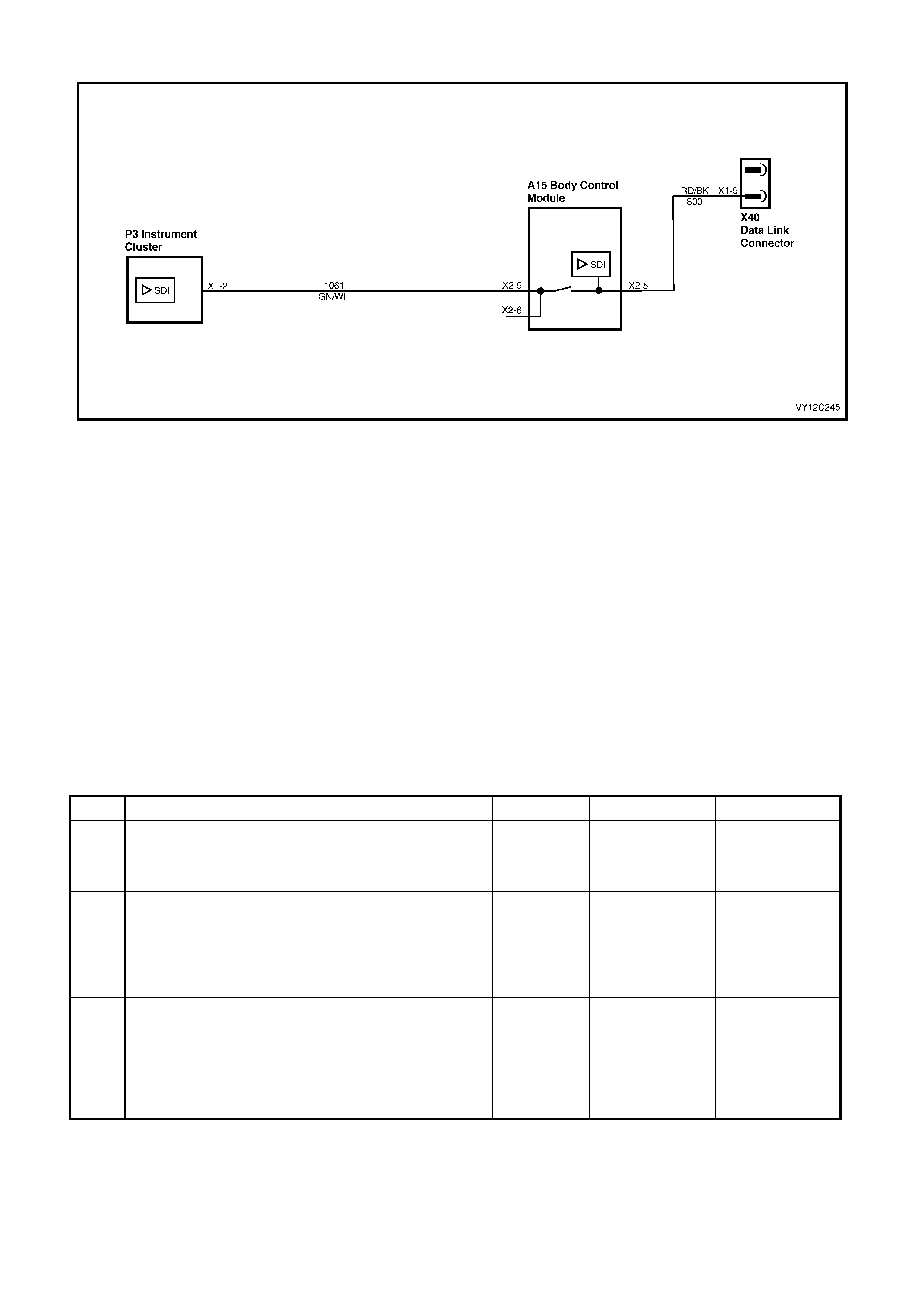
DTC 9 — NO SERIAL DATA FROM BCM
Figure 12C-322
CIRCUIT DESCRIPTION
The BCM s ends serial data along the sec ondary ser ial data bus, circuit 1061. T his is read by the instrument cluster
to indicate the status of the various components on the serial data line.
DTC 9 will set if there is no BCM data message on the bus for more than 10 seconds. In practice the trouble code is
set som ewhere between 10 and 20 seconds after the las t BCM data m ess age is received by the instrum ent cluster.
The DTC is reset within 10 seconds of the arrival of a BCM data message on the bus. The DTC is logged as a
History DTC.
DIAGNOSTIC AIDS
By manipulating the harnesses at the various connectors it is often possible to isolate the cause of the circuit
interruption. This harness can then be removed and repaired.
Check for any damage to the harness which could cause an interm ittent open circ uit or back ed out terminals at the
instrument cluster connectors, broken connector locks, improperly formed or damaged terminals.
The multimeter allows continuity of the wiring harness circuit 1061 to be checked.
If the fault cannot be found in the harness then the fault may lie in the BCM. Refer to Section 12J, 4. BCM
DIAGNOSTICS for further diagnosis.
NO SERIAL DA TA FROM BCM DIAGNOSTIC CHART
STEP ACTION VALUE YES NO
1 Was the Diagnostic Circuit Check performed? Go to Step 2. Go to
Diagnostic Circuit
Check
in this Section.
2 1. Connect TECH 2 to the DLC.
2. Turn the ignition on.
3. Push power button on TECH 2.
Does TECH 2 power up? (Screen should illuminate and
display TECH 2).
Go to Step 3. Go to TECH 2
diagnosis. Refer
to Section 0C,
TECH 2.
3 1. At the TECH 2 title screen press the Enter key.
2. Select Diagnostics / Model Year / Vehicle Model /
Body / Body Control Module.
3. Press the Confirm soft key.
Does TECH 2 display the Electronic System: BCM
information (ie. BCM Level / BCM Type)?
Go to Step 4.
Refer to Section
12J, 3.2 SERIAL
DATA
COMMUNICATIO
N for further
diagnosis.

STEP ACTION VALUE YES NO
4 1. Turn the ignition off.
2. Remove the instrument cluster. Refer to
2.3 INSTRUMENT CLUSTER ASSEMBLY in this
Section.
3. Gain access to the BCM. Refer to Section 12J,
2.1 BODY CONTROL MODULE.
4. Disconnect BCM A15 connector X2.
5. Using an ohmmeter, check for continuity of circuit
1061 (Green / W hite wire) between the BCM module
A15 connector X2-9 and the instrument cluster P3
connector X1-2.
Is there continuity?
Go to Step 5. Open circuit in the
secondary serial
data bus (circuit
1061). Repair
faulty circuit 1061.
5 1. Using an ohmmeter, check circuit 1061 (Green /
White wire) for a short between the instrument
cluster P3 connector X1-2 and a known good
ground.
Is there continuity?
Short circuit in the
secondary serial
data bus (circuit
1061) to ground.
Repair faulty
circuit 1061.
Go to Step 6.
6 1. Using an ohmmeter, check circuit 1061 (Green /
White wire) for a short between the instrument
cluster P3 connector X1-2 and battery voltage.
Is there continuity?
Short circuit in the
secondary serial
data bus (circuit
1061) to battery
voltage. Repair
faulty circuit 1061.
Go to Step 7.
7 1. From the Body Menu, select Diagnostic Trouble
Codes / Clear DTC Information on the TECH 2.
Has the DTC cleared?
DTC 9 is
intermittent.
Check circuit 1061
between BCM and
instrument cluster
for an intermittent
fault.
Check the
instrument cluster
and BCM
connectors for
terminal retention.
If OK, replace the
instrument cluster.
Refer to 2.3
INSTRUM ENT
CLUSTER
ASSEMBLY in this
Section.
WHEN ALL DIAGNOSIS AND REPAIRS ARE COM PLETED, CLEAR ALL DTC AND VERIFY CORRECT OPERATION
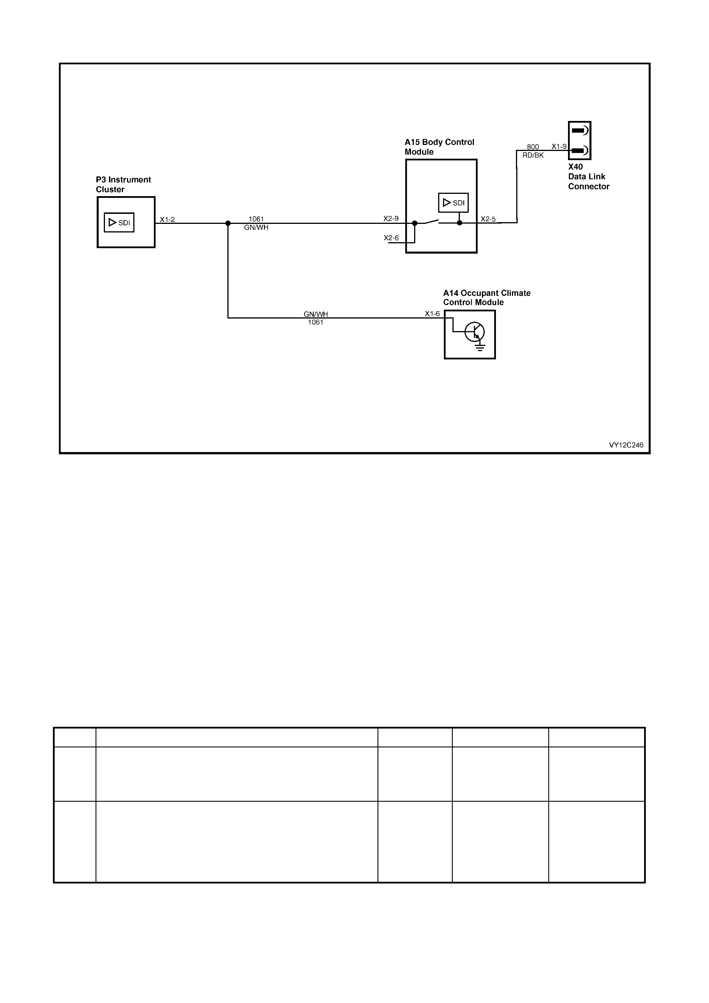
DTC 10 — NO SERIAL DATA FROM OCC
Figure 12C-323
CIRCUIT DESCRIPTION
The OCC module sends serial data to the instrument cluster along the secondary serial data bus, circuit 1061.
DTC 10 will set if there is no O CC data m essage on the bus for more than 10 seconds. In pr actice the tr ouble code
is set som ewhere between 10 and 20 sec onds after the las t OCC data message is received by the instrum ent. The
DTC is reset within 10 seconds of the arrival of a OCC data m essage on the bus. The DTC is logged as a History
DTC.
DIAGNOSTIC AIDS
By manipulating the harnesses at the various connectors it is often possible to isolate the cause of the circuit
interruption. This harness can then be removed and repaired.
Check for any damage to the harness which could cause an intermittent open or short to ground or backed out
terminals at the instrument cluster connectors, broken connector locks, improperly formed or damaged terminals.
The multimeter allows continuity of the wiring harness circuit 1061 to be checked.
If the fault cannot be found in the harness then the fault may lie in the OCC module or the BCM. Refer to
Section 2F, 1. DIAGNOSTICS or Section 12J, 4. BCM DIAGNOSTICS for further diagnosis.
NO SERIAL DA TA FROM OCC DIAGNOSTIC CHART
STEP ACTION VALUE YES NO
1 Was the Diagnostic Circuit Check performed? Go to Step 2. Go to
Diagnostic Circuit
Check
in this Section.
2 1. Connect TECH 2 to the DLC.
2. Turn the ignition on.
3. Push power button on TECH 2.
Does TECH 2 power up? (Screen should illuminate and
display TECH 2).
Go to Step 3. Go to TECH 2
diagnosis. Refer
to Section 0C,
TECH 2.

STEP ACTION VALUE YES NO
3 1. At the TECH 2 title screen press the Enter key.
2. Select Diagnostics / Model Year / Vehicle Model /
Body / Occupant Climate Control.
3. Press the Confirm soft key.
Does TECH 2 display the Electronic System: OCC
information?
Go to Step 4.
Refer to Section
2F, DIAGNOSTIC
CHARTS —
DTC 36.
4 1. Turn the ignition off.
2. Remove the instrument cluster. Refer to
2.3 INSTRUMENT CLUSTER ASSEMBLY in this
Section.
3. Disconnect the OCC module A14 connector X1.
4. Using an ohmmeter, check for continuity of circuit
1061 (Green / W hite wire) between the OCC module
A14 connector X1-6 and the instrument cluster P3
connector X1-2.
Is there continuity?
Go to Step 5. Open circuit in the
secondary serial
data bus (circuit
1061). Repair
faulty circuit 1061.
5 1. Using an ohmmeter, check circuit 1061 (Green /
White wire) for a short between the instrument
cluster P3 connector X1-2 and a known good
ground.
Is there continuity?
Short circuit in the
secondary serial
data bus (circuit
1061) to ground.
Repair faulty
circuit 1061.
Go to Step 6.
6 1. Using an ohmmeter, check circuit 1061 (Green /
White wire) for a short between the instrument
cluster P3 connector X1-2 and battery voltage.
Is there continuity?
Short circuit in the
secondary serial
data bus (circuit
1061) to battery
voltage. Repair
faulty circuit 1061.
Go to Step 7.
7 1. From the Body Menu, select Diagnostic Trouble
Codes / Clear DTC Information on the TECH 2.
Has the DTC cleared?
DTC 10 is
intermittent.
Check circuit 1061
between OCC
module and
instrument cluster
for an intermittent
fault.
Check the
instrument cluster
and OCC module
connectors for
terminal retention.
If OK, replace the
instrument cluster.
Refer to 2.3
INSTRUM ENT
CLUSTER
ASSEMBLY in this
Section.
WHEN ALL DIAGNOSIS AND REPAIRS ARE COM PLETED, CLEAR ALL DTC AND VERIFY CORRECT OPERATION
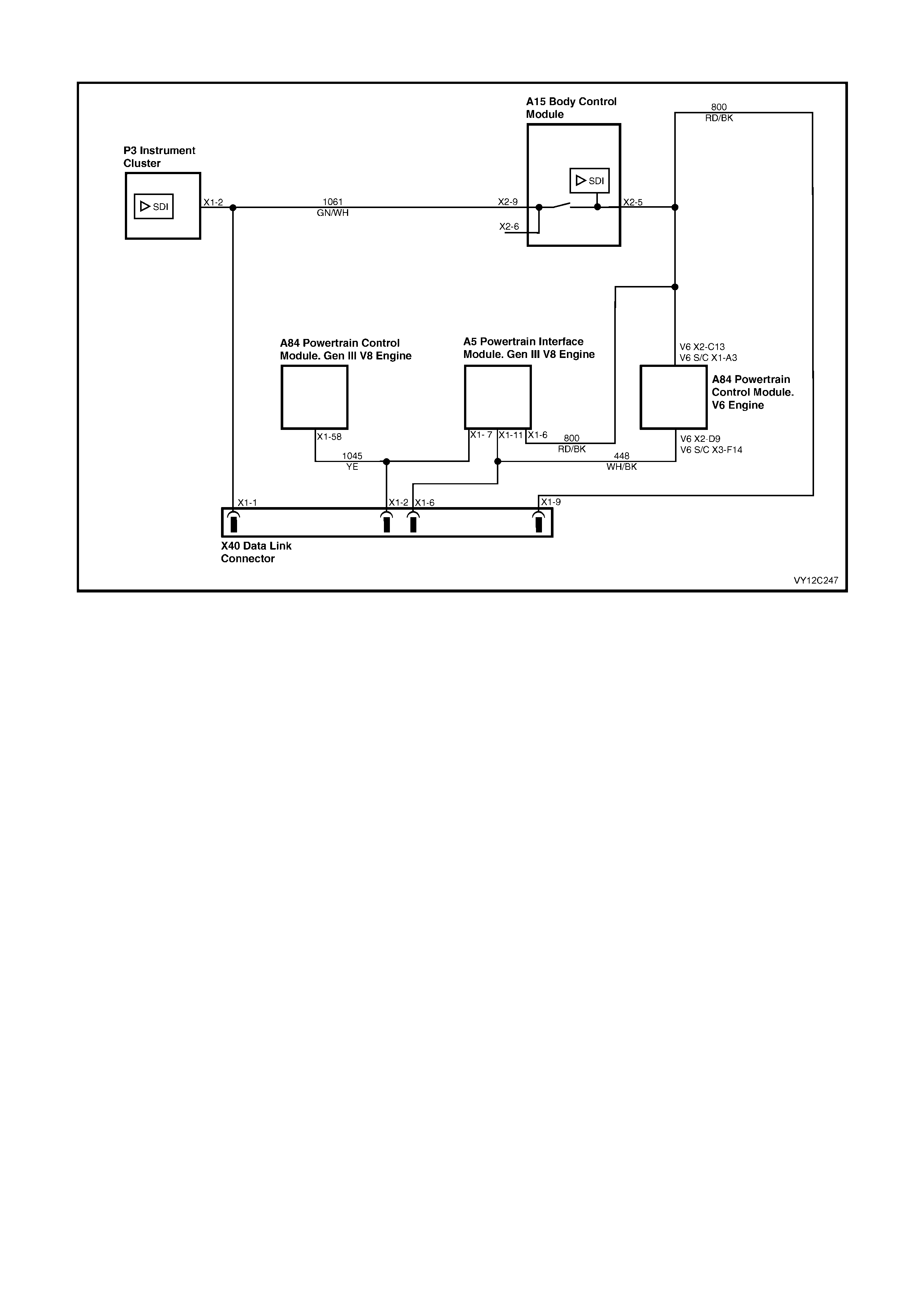
DTC 11 — NO SERIAL DATA FROM PCM
Figure 12C-324
CIRCUIT DESCRIPTION
The PCM s ends s erial data to the BCM along the prim ar y s erial data bus, c ircuit 800. Serial data is then s ent to the
instrument cluster along the secondary serial data bus, circuit 1061. The following data is read by the instrument
cluster, which then indicates the status as appropriate on the MFD and/or cluster telltales:
• Oil pressure
• High temperature
• Power Mode
• Check engine (powertrain)
• Engine oil life
• Transmission oil life
As the PCM used in conjunction with the GEN III V8 engine is different to that used with the V6 engine, a Powertrain
Interface Module (PIM) is required to convert the serial data generated by the PCM into serial data that is
compatible with the BCM.
DTC 11 will set if there is no PCM data m ess age on the bus for m ore than 10 seconds. In prac tice the trouble c ode
is set somewhere between 10 and 20 seconds after the last PCM data message is received by the instrument
cluster. The DTC is reset within 10 seconds of the arrival of a PCM data message on the bus. The DTC is logged
as a History DTC.
DIAGNOSTIC AIDS
By manipulating the harnesses at the various connectors it is often possible to isolate the cause of the circuit
interruption. This harness can then be removed and repaired.
Check for any damage to the harness which could cause an intermittent open or short to ground or backed out
terminals at the instrument cluster connectors, broken connector locks, improperly formed or damaged terminals.
The multimeter allows continuity of the wiring harness circuits to be checked.
If the f ault cannot be f ound in the harness then the f ault m ay lie in the PCM, PIM (GEN III V8 only) or the BCM. For
further diagnosis, refer to the diagnostic tables in:
Section 6C1 for V6 engine, Section 6C3 for GEN III V8 enginer
Section 6C2 for V6 S/C engine, Section 12J for BCM.

NO SERIAL DATA FROM PCM DIAGNOSTIC CHART
STEP ACTION VALUE YES NO
1 Was the Diagnostic Circuit Check performed? Go to Step 2. Go to
Diagnostic Circuit
Check
in this Section.
2 1 Connect TECH 2 to the DLC.
2 Turn the ignition on.
3 Push power button on TECH 2.
Does TECH 2 power up? (Screen should illuminate and
display TECH 2).
Go to Step 3. Go to TECH 2
diagnosis. Refer
to Section 0C,
TECH 2.
3 1 At the TECH 2 title screen press the Enter key.
2 Select Diagnostics / Model Year / Vehicle Model /
Engine / select appropriate engine.
3 Press the Confirm soft key.
Does TECH 2 display the Engine System: Identification
information (ie. PROM Identification)?
V6 engine, go to
Step 4.
GEN III V8
engine, go to
Step 5.
For V6 engine,
refer to Section
6C1,
DIAGNOSTIC
TABLE A-2.
For V6 S/C
engine, refer to
Section 6C2,
DIAGNOSTIC
TABLE A-2
For GEN III V8
engine, refer to
Section 6C3, DTC
B2006 NO
SERIAL DATA
FROM PCM.
4 1 Turn the ignition off.
2 Disconnect the BCM A15 connector X2.
3 Disconnect the PCM A84 connector X2 for V6 engine
or connector X1 for V6 S/C engine.
4 Using an ohmmeter, check for continuity of circuit
800 (Red / Black wire) between BCM A15 connector
X2-5 and PCM A84 connector X2-C13 for V6 engine,
or connector X1-A3 for V6 S/C engine.
Is there continuity?
Harness from
BCM to PCM OK.
Go to Step 7.
Open circuit in
primary serial data
bus (circuit 800).
Repair faulty
wiring harness
from BCM to
PCM.
5 1 Turn the ignition off.
2 Disconnect the BCM A15 connector X2.
3 Disconnect the PIM A5 connector X1.
4 Using an ohmmeter, check for continuity of circuit
800 (Red / Black wire) between BCM A15 connector
X2-5 and PIM A5 connector X1-6.
Is there continuity?
Harness from
BCM to PIM OK.
Go to Step 6.
Open circuit in
primary serial data
bus (circuit 800).
Repair faulty
wiring harness
from BCM to PIM.
6 1 Disconnect the PCM A84 connector X1.
2 Using an ohmmeter, check for continuity of circuit
1045 (Yellow wire) between PCM A84 connector
X1-58 and PIM A5 connector X1-7.
Is there continuity?
Harness from
PCM to PIM OK.
Go to Step 7.
Open circuit in
serial data line
(circuit 1045).
Repair faulty
wiring harness
from PCM to PIM.
7 1 Remove the instrument cluster. Refer to
2.3 INSTRUMENT CLUSTER ASSEMBLY in this
Section.
2 Using an ohmmeter, check for continuity of circuit
1061 (Green / White wire) between BCM A15
connector X2-9 and instrument cluster P3 connector
X1-2.
Is there continuity?
Harness from
BCM to instrument
cluster OK. Go to
Step 8.
Open circuit in
secondary serial
data bus (circuit
1061). Repair
faulty wiring
harness from BCM
to instrument.

STEP ACTION VALUE YES NO
8 1 From the Body Menu, select Diagnostic Trouble
Codes / Clear DTC Information on the TECH 2.
Has the DTC cleared?
DTC 11 is
intermittent.
Check circuit 800
between BCM and
PCM (V6 engine)
or BCM and PIM
(GEN III V8
engine), circuit
1045 between
PCM and PIM
(GEN III V8
engine) and circuit
1061 between
BCM and
instrument cluster
(both engines) for
an intermittent
fault.
Check the
instrument cluster,
PCM, PIM and
BCM connectors
as appropriate for
terminal retention.
If OK, replace the
instrument cluster.
Refer to 2.3
INSTRUM ENT
CLUSTER
ASSEMBLY in this
Section.
WHEN ALL DIAGNOSIS AND REPAIRS ARE COM PLETED, CLEAR ALL DTC AND VERIFY CORRECT OPERATION
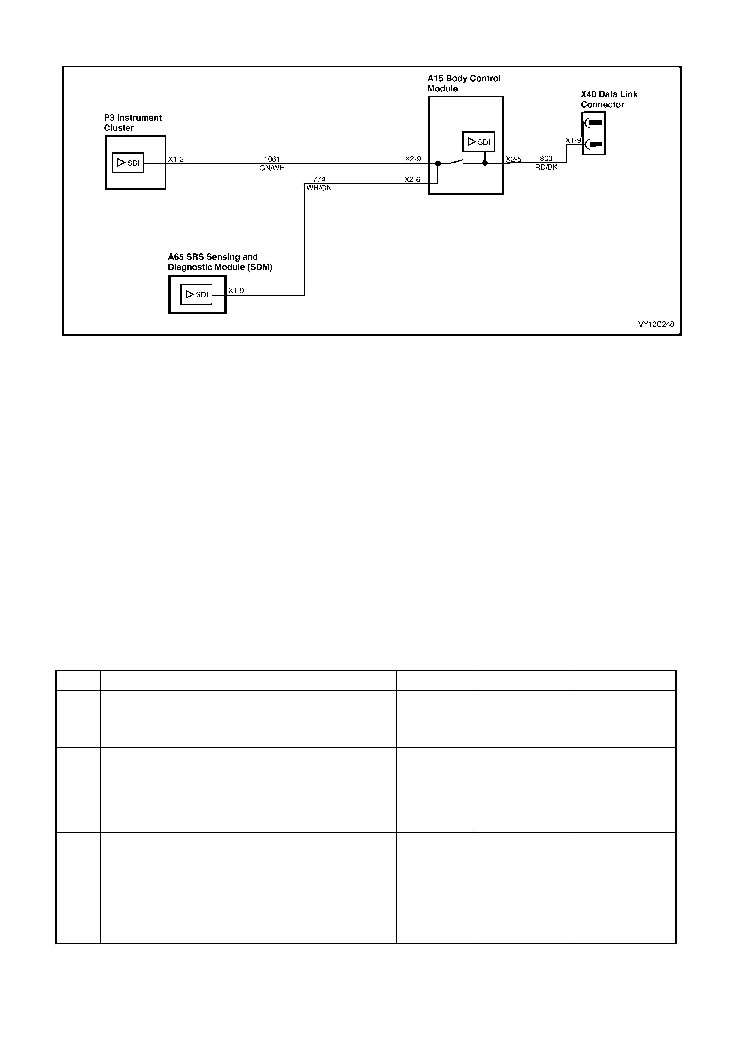
DTC 12 — NO SERIAL DATA FROM SDM
Figure 12C-325
CIRCUIT DESCRIPTION
The SRS Sensing and Diagnostic Module ( SDM) sends serial data along the tertiary serial data bus, cir cuit 774, to
the BCM and then on to the instrument cluster on the secondary serial data bus, circuit 1061. This is read by the
instrument cluster, which displays the status of the SDM on the MFD and cluster telltale.
NOTE: There are two versions of SDM used by the SRS. Version 8.0 is used on vehicles with either 2-loop (left-
hand drive only), 3-loop or 4-loop systems, while version 8.1 is used on vehicles with a 6-loop system. For more
information, refer to Section 12M, OCCUPANT PROTECTION SYSTEM.
DTC 12 will set if there is no serial data being received from the SDM. The DTC is reset within 10 seconds of the
arrival of a SDM data message on the bus. The DTC is logged as a History DTC.
DIAGNOSTIC AIDS
By manipulating the harnesses at the various connectors it is often possible to isolate the cause of the circuit
interruption. This harness can then be removed and repaired.
Check for any damage to the harness which could cause an intermittent open or short to ground or backed out
terminals at the instrument cluster connectors, broken connector locks, improperly formed or damaged terminals.
The multimeter allows continuity of the wiring harness circuit 774 to be checked.
If the fault cannot be found in the harness then the fault may lie in the SDM or the BCM. Refer to
Section 12M, 4. DIAGNOSTICS or Section 12J, 4. BCM DIAGNOSTICS for further diagnosis.
NO SERIAL DATA FROM SDM DIAGNOSTIC CHART
STEP ACTION VALUE YES NO
1 Was the Diagnostic Circuit Check performed? Go to Step 2. Go to
Diagnostic Circuit
Check
in this Section.
2 1. Connect TECH 2 to the DLC.
2. Turn the ignition on.
3. Push power button on TECH 2.
Does TECH 2 power up? (Screen should illuminate and
display TECH 2).
Go to Step 3. Go to TECH 2
diagnosis. Refer
to Section 0C,
TECH 2.
3 1. At the TECH 2 title screen press the Enter key.
2. Select Diagnostics / Model Year / Vehicle Model /
Body / SRS.
3. Press the Confirm soft key.
Does TECH 2 display the Electronic System:
Identification information (ie. Part Number / Production
Date)?
Go to Step 5.
Go to Step 4.

STEP ACTION VALUE YES NO
4 1. Disable the OPS (Airbag). Refer to Section 12M,
2.2 SYSTEM ENABLING AND DISABLING
PROCEDURE.
2. Gain access to the BCM. Refer to Section 12J,
2.1 BODY CONTROL MODULE.
3. Disconnect BCM A15 connector X2.
4. Gain access to the SDM. Refer to Section 12M,
2.8 INFLATABLE RESTRAINT CONTROL MODULE
(SDM).
5. Disconnect SDM A65 connector X1.
6. Using an ohmmeter and Tool KM-609-20, check
harness for continuity of circuit 774 (White / Green
wire) between SDM A65 connector X1-9 and BCM
A15 connector X2-6.
Is there continuity?
Harness from
SDM to BCM OK.
Go to Step 5.
Open circuit in
tertiary serial data
bus (circuit 774).
Repair faulty
wiring harness
from SDM to
BCM.
5 1. Remove the instrument cluster. Refer to
2.3 INSTRUMENT CLUSTER ASSEMBLY in this
Section.
2. Using an ohmmeter, check for continuity of circuit
1061 (Green / White wire) between BCM A15
connector X2-9 and instrument cluster P3 connector
X1-2.
Is there continuity?
Harness from
BCM to instrument
cluster OK. Go to
Step 6.
Open circuit in
secondary serial
data bus (circuit
1061). Repair
faulty wiring
harness from BCM
to instrument
cluster.
6 1. If necessary, disconnect BCM A15 connector X2.
2. Using an ohmmeter, check for continuity between
BCM A15 connector X2-6, circuit 774 (W hite / Green
wire) and BCM A15 connector X2-9, circuit 1061
(Green / White wire) at BCM connector X2.
Is there continuity?
Refer to Section
12M, 4.6
DIAGNOSTIC
CHARTS for
further diagnosis.
Check the BCM
connectors for
terminal retention. If
OK, replace the
BCM. Refer to
Section 12J,
2.1 BODY
CONTROL
MODULE.
7 1. Enable the OPS (Airbag). Refer to Section 12M,
2.2 SYSTEM ENABLING AND DISABLING
PROCEDURE.
2. From the Body Menu, select Diagnostic Trouble
Codes / Clear DTC Information on the TECH 2.
Has the DTC cleared?
DTC 12 is
intermittent.
Check circuit 774
between SDM and
BCM, and circuit
1061 between
BCM and
instrument cluster
for an intermittent
fault.
Check the
instrument cluster,
SDM and BCM
connectors for
terminal retention.
If OK, replace the
instrument cluster.
Refer to 2.3
INSTRUM ENT
CLUSTER
ASSEMBLY in this
Section.
WHEN ALL DIAGNOSIS AND REPAIRS ARE COM PLETED, CLEAR ALL DTC AND VERIFY CORRECT OPERATION
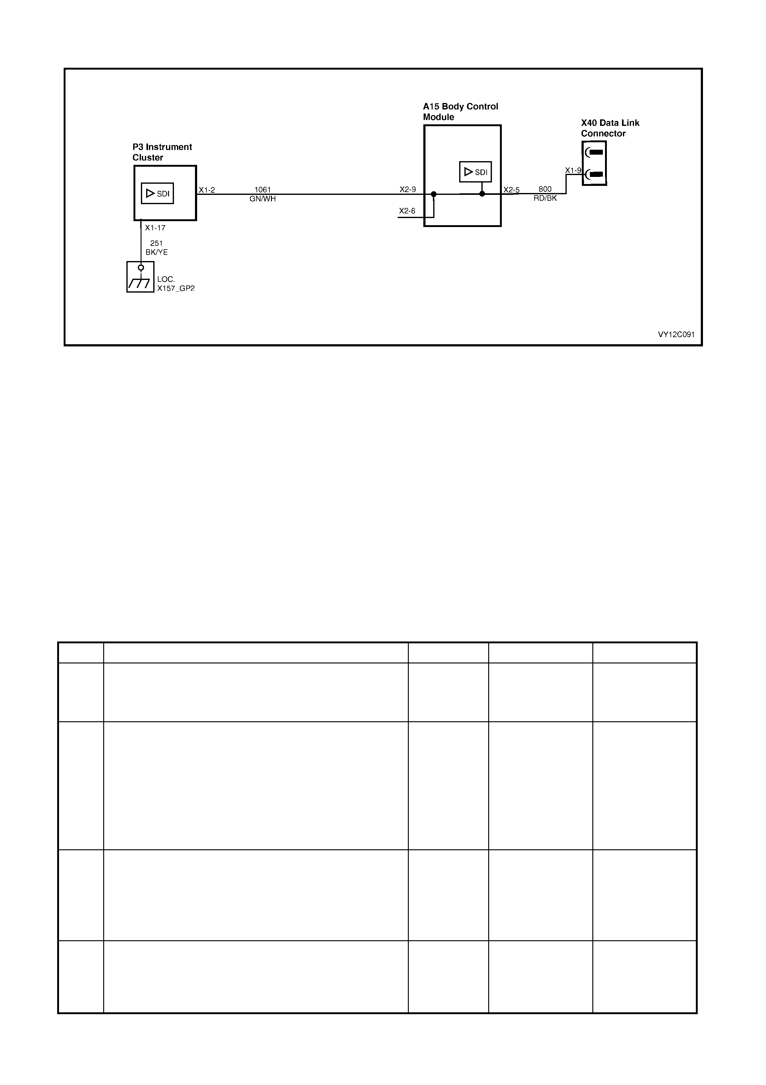
DTC 13 — NO INSTRUMENT POLL FROM BCM
Figure 12C-326
CIRCUIT DESCRIPTION
The BCM uses the secondary serial data bus (circuit 1061) to poll the instrument cluster for information.
DTC 13 will s et if ther e is no instr ument poll f rom the BCM f or more than 10 seconds . In prac tic e the trouble c ode is
set s omewhere between 10 and 20 s econds after the last instrum ent poll is rec eived by the instr ument c luster. The
DTC is reset within 10 seconds of the arrival of an instrument poll from the BCM. The DTC is logged as a History
DTC.
DIAGNOSTIC AIDS
By manipulating the harnesses at the various connectors it is often possible to isolate the cause of the circuit
interruption. This harness can then be removed and repaired.
Check for any damage to the harness which could cause an intermittent open or short to ground or backed out
terminals at the instrument cluster connectors, broken connector locks, improperly formed or damaged terminals.
The multimeter allows continuity of the wiring harness circuit 1061 to be checked.
If the fault cannot be found in the harness then the fault may lie in the BCM. Refer to
Section 12J, 4. BCM DIAGNOSTICS for further diagnosis.
NO INSTRUMENT POLL FROM BCM DIAGNOSTIC CHART
STEP ACTION VALUE YES NO
1 Was the Diagnostic Circuit Check performed? Go to Step 2. Go to
Diagnostic Circuit
Check
in this Section.
2 1. Connect TECH 2 to the DLC.
2. Select Diagnostics / Model Year / Vehicle Model /
Vehicle DTC Check.
Can TECH 2 communicate with the BCM?
NOTE: If ‘No Data’ is displayed next to the BCM, then
there is no communication between TECH 2 and the
BCM. If 'No DTC' or 'DTCs Set' is displayed then there is
communication between the TECH 2 and the BCM.
Go to Step 3. Refer to Section
12J, 3.2 SERIAL
DATA
COMM UNICATION
for further
diagnosis.
3 In Step 2, was TECH 2 able to communicate with all the
other control modules, except the Instruments, fitted to
the vehicle (ABS or ABS/ETC, OCC, SRS, RADIO)?
NOTE: If ‘No Data’ is displayed next to a control module,
then there is no communication between TECH 2 and
that control module.
Go to Step 6. Go to Step 4.
4 1. Using an ohmmeter, back probe BCM connector
terminals X2-5 circuit 800 (Red / Black wire) and
X2-9 circuit 1061 (Green / W h ite wire).
Is the value as specified?
Less than
10 ohms Go to Step 5. Replace the BCM.
Refer to Section
12J, 2.1 BODY
CONTROL
MODULE.

STEP ACTION VALUE YES NO
5 1. Check circuit 1061 for open, short to ground or short
to voltage between BCM and individual control
modules.
Is circuit 1061 okay?
NOTE: Disconnect each control module in circuit 1061
one at a time to isolate the fault in the circuit or to identify
the control module causing the fault.
Refer to the
appropriate
diagnostic
procedure for the
faulty control
module.
Repair faulty
circuit 1061.
6 1. Remove the instrument cluster. Refer to
2.3 INSTRUMENT CLUSTER ASSEMBLY in this
Section.
2. Gain access to the BCM. Refer to Section 12J,
2.1 BODY CONTROL MODULE.
3. Disconnect BCM A15 connector X2.
4. Using an ohmmeter, check for continuity between
BCM connector terminal X2-9, circuit 1061 (Green /
White wire) and instrument cluster P3 connector
X1-2, circuit 1061 (Green / White wire).
Does continuity exist?
Go to Step 7. Repair faulty
circuit 1061.
7 1. Check the integrity of the Instruments ground circuit
by performing a voltage drop on circuit 150 between
instrument connector terminal X1-17, circuit 251
(Black / Yellow wire) and ground point E3.
W ith the ignition on, is the voltage less than the specified
value?
0.15 volt Go to Step 8. Repair ground
circuit as
necessary.
8 1. From the Body Menu, select Diagnostic Trouble
Codes / Clear DTC Information on the TECH 2.
Has the DTC cleared?
DTC 13 is
intermittent.
Check circuit 1061
between BCM and
instrument cluster
for an intermittent
fault.
Check the
instrument cluster
and BCM
connectors for
terminal retention.
If OK, replace the
instrument cluster.
Refer to 2.3
INSTRUM ENT
CLUSTER
ASSEMBLY in this
Section.
WHEN ALL DIAGNOSIS AND REPAIRS ARE COM PLETED, CLEAR ALL DTC AND VERIFY CORRECT OPERATION
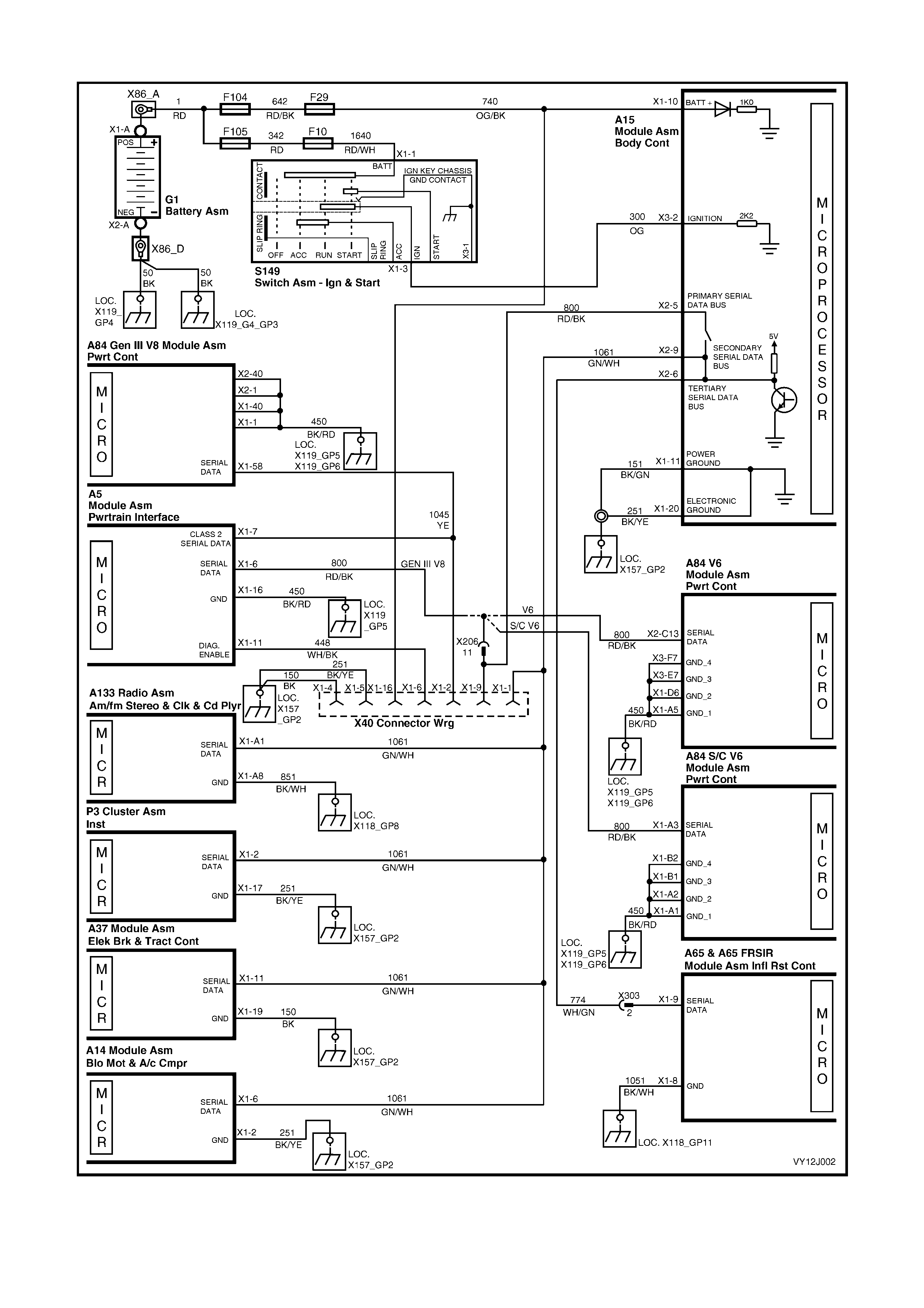
DTC 14 — NO SERIAL DATA
Figure 12C-327

CIRCUIT DESCRIPTION
W hen investigating any com plaint of an Instrum ent cluster problem or malfunction, always begin diagnosis with the
diagnostic circuit check. This check is a preliminary procedure that checks that the Instrument cluster is powered
up, communicating on the serial data line, helping to identify a problem or malfunction and directing the reader to
the appropriate diagnostic chart in this section.
W ith TECH 2 c onnected to the DLC and ignition switched on, TECH 2 should display serial data comm unication. If
TECH 2 does not display serial data, the serial data circuit maybe open or shorted.
There are several other control modules that are connected to the serial data line (PCM, PIM (GEN III V8 only),
BCM, OCC, ABS or ABS / TCS, instrum ent cluster, Radio and SDM). Any of these control m odules could cause a
fault on the serial data line. This fault could result in TECH 2 not being able to display serial data.
DTC 14 will set if there is no serial data m essage on the serial data bus for more than 10 seconds. In practice, the
trouble code is set somewhere between 10 and 20 seconds after the last serial data message is received by the
instrument cluster. The trouble code is reset within 10 seconds of the arrival of an instrument cluster poll from the
BCM. The DTC is logged as a History DTC.
DIAGNOSTIC AIDS
A fault with the serial data cir cuit could be caused by one or more of the several control modules connected to this
serial data circuit. Isolate the fault by disconnecting each control module, one at a time, until serial data
communication is restored.
NO SERIAL DATA DIAGNOSTIC CHART
STEP ACTION VALUE YES NO
1 Was the Diagnostic Circuit Check performed? Go to Step 2. Go to
Diagnostic Circuit
Check
in this Section.
2 1. Connect TECH 2 to the DLC.
2. Select Diagnostics / Model Year / Vehicle Model /
Vehicle DTC Check.
Can TECH 2 communicate with the BCM?
NOTE: If ‘No Data’ is displayed next to the BCM, then
there is no communication between TECH 2 and the
BCM. If 'No DTC' or 'DTCs Set' is displayed then there is
communication between the TECH 2 and the BCM.
Go to Step 3. Refer to Section
12J, 3.2 SERIAL
DATA
COMM UNICATION
for further
diagnosis.
3 In Step 2, was TECH 2 able to communicate with all the
other control modules, except the Instruments, fitted to
the vehicle (ABS or ABS / TCS, OCC, SRS, RADIO)?
NOTE: If ‘No Data’ is displayed next to a control module,
then there is no communication between TECH 2 and
that control module.
Go to Step 6. Go to Step 4.
4 1. Gain access to the BCM. Refer to Section 12J,
2.1 BODY CONTROL MODULE.
2. Using an ohmmeter, back probe BCM connector
terminals X2-5 circuit 800 (Red / Black wire) and
X2-9 circuit 1061 (Green / W h ite wire).
Is the value as specified?
Less than
10 ohms Go to Step 5. Replace the BCM.
Refer to Section
12J, 2.1 BODY
CONTROL
MODULE.
5 1. Check circuit 1061 (Green / White wire) for open,
short to ground or short to voltage between BCM and
individual control modules.
Is circuit 1061 okay?
NOTE: Disconnect each control module in circuit 1061
one at a time to isolate the fault in the circuit or to identify
the control module causing the fault.
Refer to the
appropriate
diagnostic
procedure for the
faulty control
module.
Repair faulty
circuit 1061.

STEP ACTION VALUE YES NO
6 1. Remove the instrument cluster. Refer to
2.3 INSTRUMENT CLUSTER ASSEMBLY in this
Section.
2. Gain access to the BCM. Refer to Section 12J,
2.1 BODY CONTROL MODULE.
3. Disconnect BCM A15 connector X2.
4. Using an ohmmeter, check for continuity between
BCM connector terminal X2-9, circuit 1061 (Green /
White wire) and instrument cluster P3 connector
X1-2, circuit 1061 (Green / White wire).
Does continuity exist?
Go to Step 7. Repair faulty
circuit 1061.
7 1. Using an ohmmeter, check for continuity of the
instrument cluster ground circuit 251 (Black / Yellow
wire), between instrument cluster P3 connector
X1-17 and ground point X157_GP2.
Is the value as specified?
Less than
1 ohm Go to Step 8. Repair ground
circuit as
necessary.
8 1. From the Body Menu, select Diagnostic Trouble
Codes / Clear DTC Information on the TECH 2.
Has the DTC cleared?
DTC 14 is
intermittent.
Check circuit 1061
between BCM and
instrument cluster
for an intermittent
fault.
Check the
instrument cluster
and BCM
connectors for
terminal retention.
If OK, replace the
instrument cluster.
Refer to 2.3
INSTRUM ENT
CLUSTER
ASSEMBLY in this
Section.
WHEN ALL DIAGNOSIS AND REPAIRS ARE COM PLETED, CLEAR ALL DTC AND VERIFY CORRECT OPERATION
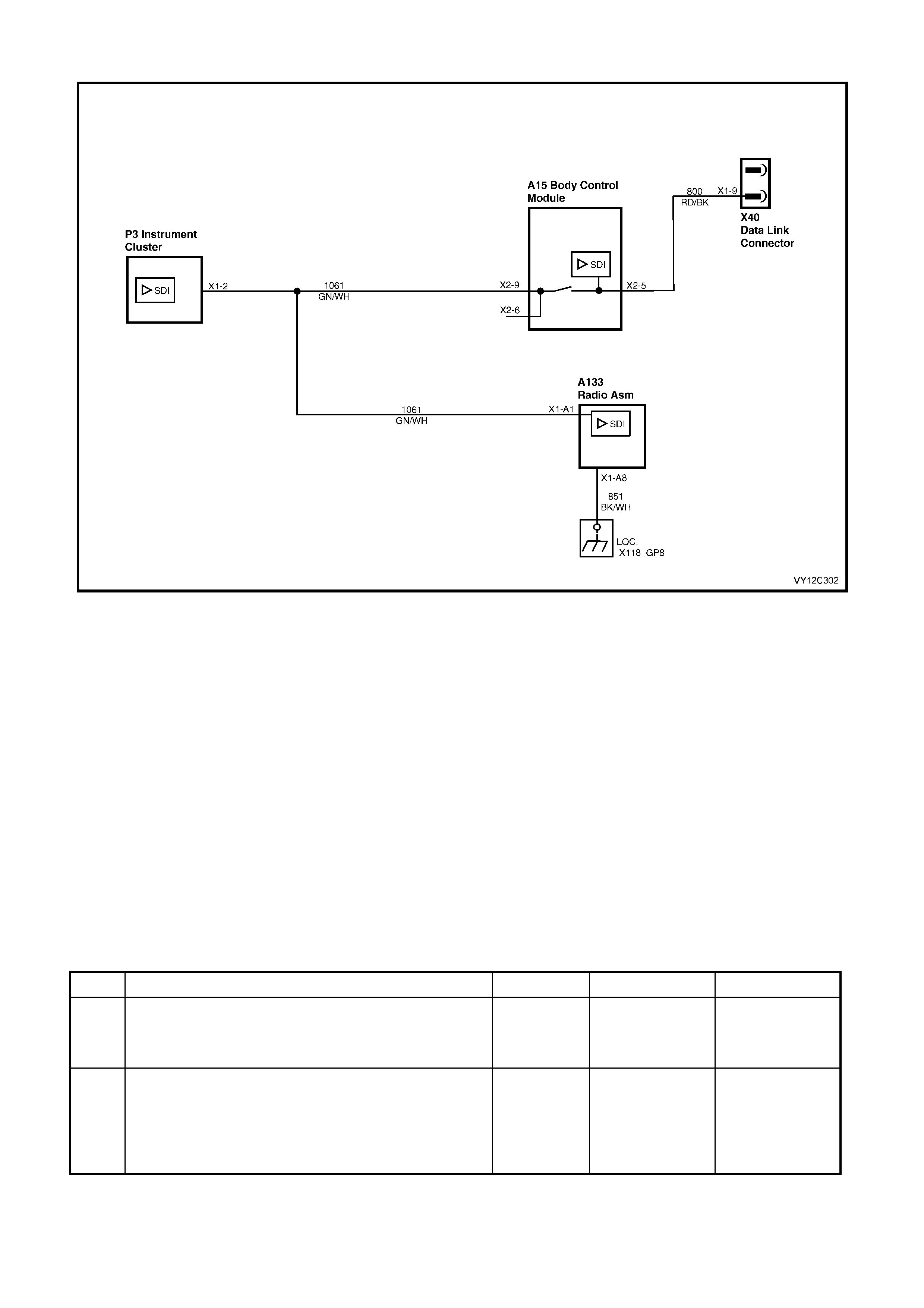
DTC 15 — NO SERIAL DATA FROM AUDIO SYSTEM
Figure 12C-328
CIRCUIT DESCRIPTION
The audio system sends serial data to the instrument cluster along the secondary serial data bus, circuit 1061.
DTC 15 will set if there is no RADIO data message on the bus for more than 10 seconds. In practice the trouble
code is set somewhere between 10 and 20 seconds after the last RADIO data message is received by the
instrument cluster. The DTC is reset within 10 seconds of the arrival of a RADIO data message on the bus. The
DTC is logged as a History DTC.
NOTE: If the vehicle is fitted with an aftermarket entertainment system, DTC 15 will always be set.
DIAGNOSTIC AIDS
By manipulating the harnesses at the various connectors it is often possible to isolate the cause of the circuit
interruption. This harness can then be removed and repaired.
Check for any damage to the harness which could cause an intermittent open or short to ground or backed out
terminals at the instrument cluster connectors, broken connector locks, improperly formed or damaged terminals.
The multimeter allows continuity of the wiring harness circuit 1061 to be checked.
If the f ault cannot be f ound in the harness then the f ault m ay lie in the audio system head unit or the BCM. Ref er to
Section 12D, 3. DIAGNOSTICS or Section 12J, 4. BCM DIAGNOSTICS for further diagnosis.
NO SERIAL DATA FROM AUDIO SYSTEM DIAGNOSTIC CHART
STEP ACTION VALUE YES NO
1 Was the Diagnostic Circuit Check performed? Go to Step 2. Go to
Diagnostic Circuit
Check
in this Section.
2 1. Connect TECH 2 to the DLC.
2. Turn the ignition on.
3. Push the power button on TECH 2.
Does TECH 2 power up? (The screen should illuminate
and display TECH 2).
Go to Step 3. Go to TECH 2
diagnosis. Refer
to Section 0C,
TECH 2.

STEP ACTION VALUE YES NO
3 1. At the TECH 2 title screen press the Enter key.
2. Select Diagnostics / Model Year / Vehicle Model /
Body / Audio System.
3. Turn the ignition on and press the Confirm soft key.
Does TECH 2 display the RADIO information?
Go to Step 4.
Refer to Section
12 D, 3.12 AUDIO
SYSTEM
DIAGNOSTIC
PROCEDURES for
further diagnosis.
4 1. Remove the instrument cluster. Refer to
2.3 INSTRUMENT CLUSTER ASSEMBLY in this
Section.
2. Remove the audio system head unit. Refer to
Section 12D, 2.1 AUDIO SYSTEM HEAD UNIT.
3. Using an ohmmeter, check for continuity between
the audio system A133 connector X1-
A
1, circuit
1061 (Green / White wire) and instrument cluster P3,
connector X1-2, circuit 1061 (Green / W h ite wire).
Is there continuity?
Go to Step 5. Repair faulty
circuit 1061.
5 1. From the Body Menu, select Diagnostic Trouble
Codes / Clear DTC Information on the TECH 2.
Has the DTC cleared?
DTC 15 is
intermittent.
Check circuit 1061
between radio and
instrument cluster
for an intermittent
fault.
Check the
instrument cluster
and radio
connectors for
terminal retention.
If OK, replace the
instrument cluster.
Refer to 2.3
INSTRUM ENT
CLUSTER
ASSEMBLY in this
Section.
WHEN ALL DIAGNOSIS AND REPAIRS ARE COM PLETED, CLEAR ALL DTC AND VERIFY CORRECT OPERATION
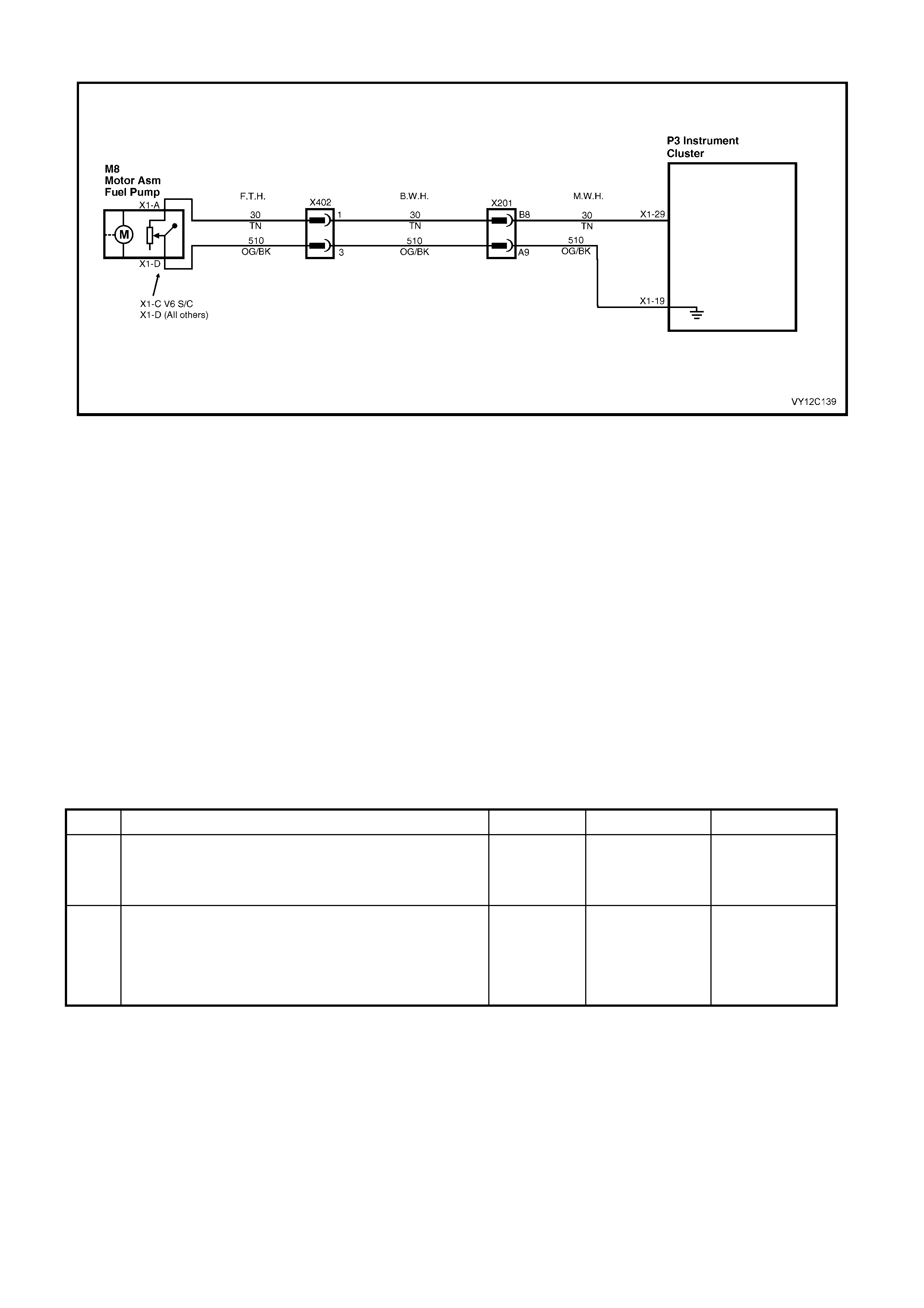
DTC 16 — PETROL LEVEL SENDER STUCK
Figure 12C-329
CIRCUIT DESCRIPTION
The instrument cluster supplies a 12 volt reference voltage and a ground circuit to the fuel gauge sender unit. The
fuel sender provides a resistanc e value to the instrument c luster based on its position relative to the f uel level. The
fuel sender resistance will vary between 40 ± 5 ohms and 250 ± 5 ohms from no fuel in the tank to full tank.
DTC 16 will set if the f uel s ender r es istanc e does not change dur ing a period that the PCM indic ates the usage of at
least 15 litres of f uel. The DTC is reset when the fuel sender resistance returns to its normal operating range for a
period of 60 seconds. The DTC is logged as a History DTC.
When a DTC 16 is set the fuel gauge will display the fuel tank level as empty irrespective of actual fuel level.
DIAGNOSTIC AIDS
The TECH 2 diagnostic tool reads fuel sender position as a voltage between 0 and 5 volts. The fuel sender signal
resistanc e should be between 40 ± 5 ohm s and 250 ± 5 ohms when the fuel sender is functioning correctly. The fuel
sender voltage should increase at a steady rate as the fuel level increases.
The multimeter allows continuity of the wiring harness to be checked. Harness voltage can also be confirmed at
connector locations.
Check for any damage to the harness which could cause an intermittent open or short to ground or backed-out
terminals at the instrument cluster connectors, broken connector locks, improperly formed or damaged terminals.
PETROL LEVEL SENDER STUCK DIAGNOSTIC CHART
STEP ACTION VALUE YES NO
1 Was the Diagnostic Circuit Check performed? Go to Step 2. Go to
Diagnostic Circuit
Check
in this Section.
2 1. Connect TECH 2 to the DLC.
2. Select Diagnostics / Model Year / Vehicle Model /
Body / Instrument / Diagnostic Trouble Codes / Read
DTC Information.
Were either DTC 1, DTC 2 or DTC 3 set?
Go to the relevant
diagnostic
procedure in this
Section.
Go to Step 3.

STEP ACTION VALUE YES NO
3 1. Ensure that the fuel tank contains at least 30 litres of
fuel.
2. From the Body Menu, select Data Display /
Instrument.
3. Scroll to the Fuel Level Sender Resistance signal.
Record the resistance value.
4. Drain approximately 15 litres of fuel from the fuel
tank. Refer to Section 8A1, 2.1 FUEL TANK –
SEDAN AND WAGON, 2.1 FUEL TANK – COUPE or
2.3 FUEL TANK – UTILITY as appropriate.
5. Note the new value of the Fuel Level Sender
Resistance signal.
Has the resistance value changed by more than
35 ohms?
Replace the
instrument cluster.
Refer to 2.3
INSTRUM ENT
CLUSTER
ASSEMBLY in this
Section.
Go to Step 4.
4 1. Disconnect the instrument cluster connector P3.
2. Using an ohmmeter, check the resistance between
X1-29 circuit 30 (Tan wire) and X1-19 circuit 510
(Orange / Black wire) on the main wiring harness.
Record the resistance reading.
3. Add petrol to the fuel tank.
4. Using an ohmmeter, check the resistance between
X1-29 circuit 30 (Tan wire) and X1-19 circuit 510
(Orange / Black wire) on the main wiring harness.
5. Note the new resistance reading.
Did the resistance reading change?
Replace the
instrument cluster.
Refer to 2.3
INSTRUM ENT
CLUSTER
ASSEMBLY in this
Section.
Replace faulty fuel
sender unit. Refer
to Section 8A1,
2.6 MODULAR
FUEL SENDER
ASSEMBLY –
SEDAN, WAGON
AND COUPE, or
2.7 MODULAR
FUEL SENDER
ASSEMBLY –
UTILITY as
appropriate
5 1. From the Body Menu, select Diagnostic Trouble
Codes / Clear DTC Information on the TECH 2.
Has the DTC cleared?
End of diagnostic
checking. Refer to
corresponding
diagnostic chart.
WHEN ALL DIAGNOSIS AND REPAIRS ARE COM PLETED, CLEAR ALL DTC AND VERIFY CORRECT OPERATION
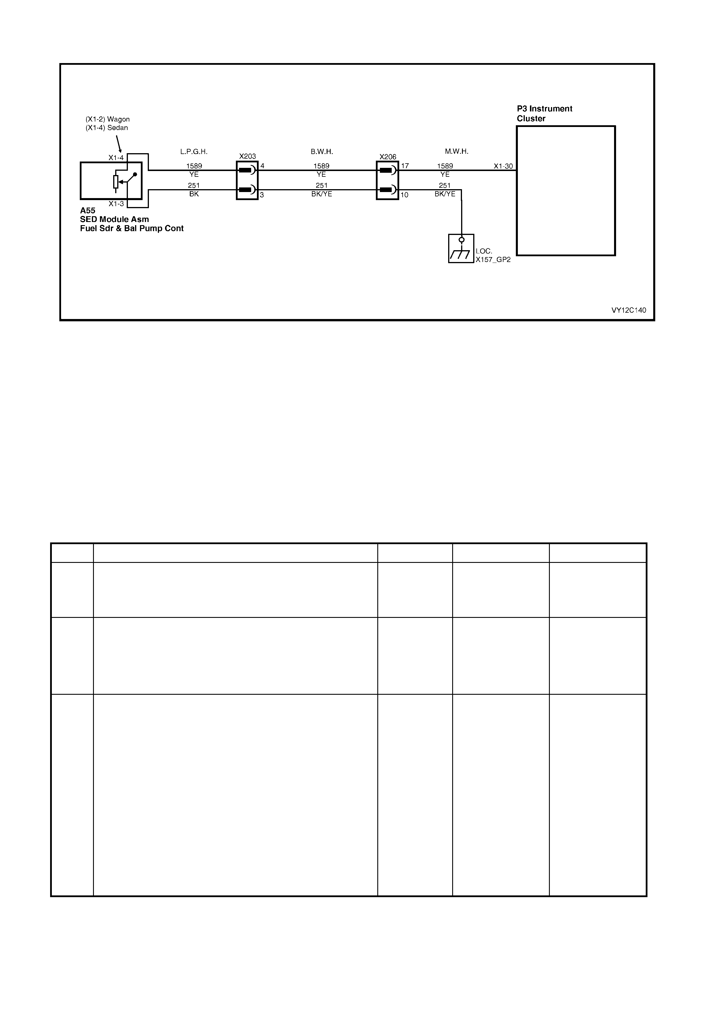
DTC 17 — LPG LEVEL SENDER STUCK
Figure 12C-330
CIRCUIT DESCRIPTION
The instrument cluster supplies a 12 volt reference voltage to the LPG gauge sender unit. The LPG sender provides
a resistance value to the instrument cluster based on its position relative to the LPG level. The LPG sender
resistance will vary between 40 ± 5 ohms and 250 ± 5 ohms from no LPG in the tank to full tank.
NOTE: If a vehic le is not fitted with LPG and DT C 17 is set, verify the instr um ent cluster configur ation program m ing
with TECH 2. Refer to 3.15 PROGRAM in this Section.
DTC 17 will set if the LPG sender resistance is less than 12.9 ohms for a period of 30 seconds. T he DTC is reset
when the LPG sender resistance returns to its normal operating range for a period of 60 seconds. The DTC is
logged as a History DTC.
When a DTC 17 is set the LPG gauge will display the LPG tank level as empty when LPG mode is selected
irrespective of actual fuel level.
LPG LEVEL SENDER STUCK DIAGNOSTIC CHART
STEP ACTION VALUE YES NO
1 Was the Diagnostic Circuit Check performed? Go to Step 2. Go to
Diagnostic Circuit
Check
in this Section.
2 1. Connect TECH 2 to the DLC.
2. Select Diagnostics / Model Year / Vehicle Model /
Body / Instrument / Diagnostic Trouble Codes / Read
DTC Information.
Were either DTC 4, DTC 5 or DTC 6 set?
Go to the relevant
diagnostic
procedure in this
Section.
Go to Step 3.
3 1. Ensure that the LPG tank contains at least 30 litres
of fuel.
2. From the Body Menu, select Data Display /
Instrument.
3. Scroll to LPG Level Sender Resistance signal.
Record the resistance value.
4. Release approximately 15 litres of LPG from the LPG
tank. Refer to Section 8A2, 2.1 FUEL TANK –
SEDAN AND WAGON, 2.2 FUEL TANK – COUPE
OR 2.3 FUEL TANK – UTILITY as appropriate.
5. Note the new value of the LPG Level Sender
Resistance signal.
Has the resistance value changed by more than
35 ohms?
Replace the
instrument cluster.
Refer to 2.3
INSTRUM ENT
CLUSTER
ASSEMBLY in this
Section.
Go to Step 4.

STEP ACTION VALUE YES NO
4 1. Disconnect the body harness connector from the
main wiring harness connector X206.
2. Using an ohmmeter, check the resistance between
X206-17 circuit 1589 (Yellow wire) and X206-10
circuit 251 (Black / Yellow wire) on the main wiring
harness.
3. Add LPG to the LPG tank.
4. Using an ohmmeter, check the resistance between
X206-17 circuit 1589 (Yellow wire) and X206-10
circuit 251 (Black / Yellow wire) on the main wiring
harness.
5. Note the new resistance reading.
Did the resistance reading change?
Replace the
instrument cluster.
Refer to 2.3
INSTRUM ENT
CLUSTER
ASSEMBLY in this
Section.
Replace faulty
LPG sender unit.
Refer to Section
8A2, 3.12 TANK
FUEL GAUGE
ASSEMBLY.
5 1. From the Body Menu, select Diagnostic Trouble
Codes / Clear DTC Information on the TECH 2.
Has the DTC cleared?
End of diagnostic
checking. Refer to
corresponding
diagnostic chart.
WHEN ALL DIAGNOSIS AND REPAIRS ARE COM PLETED, CLEAR ALL DTC AND VERIFY CORRECT OPERATION
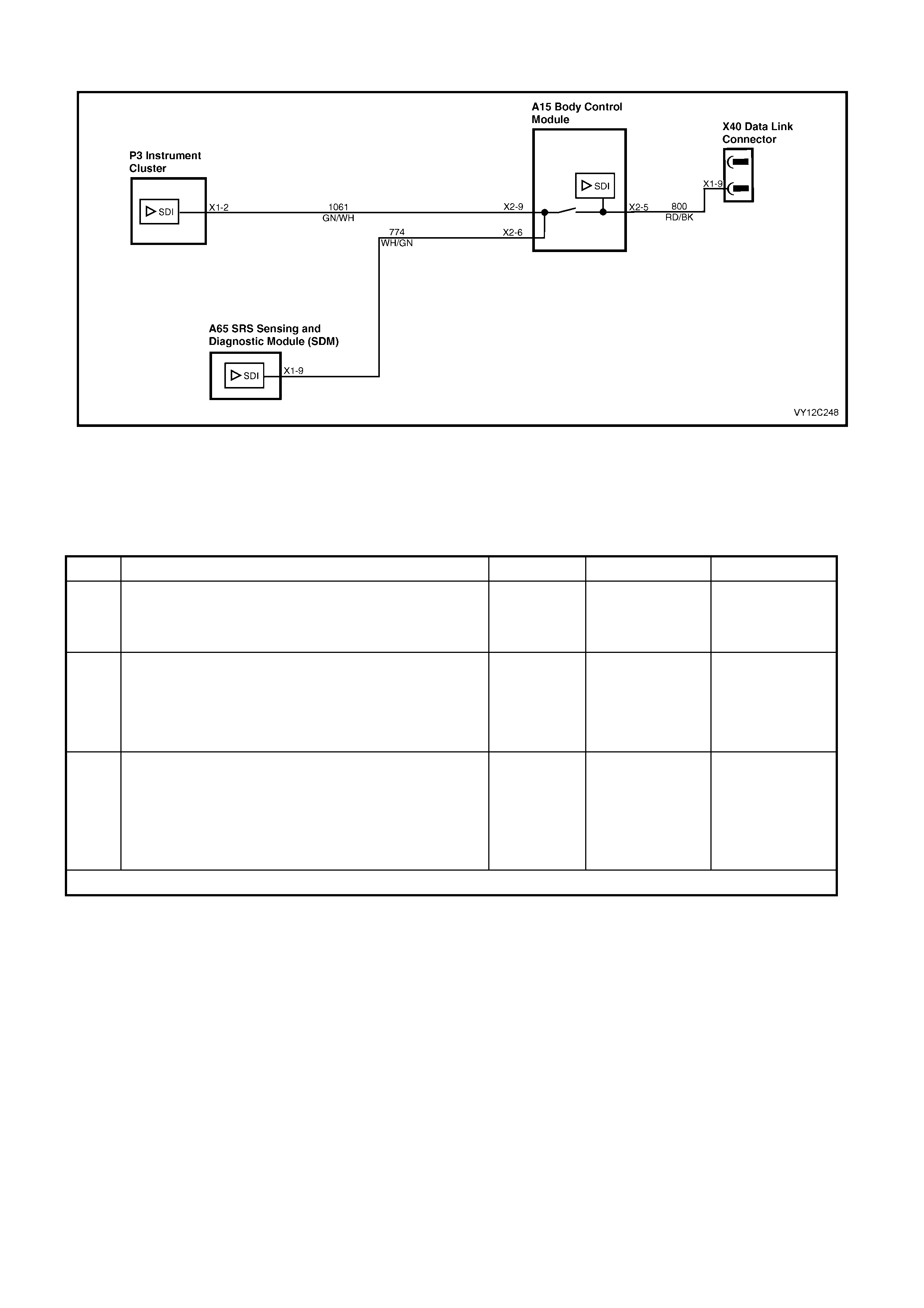
DTC 19 — INCORRECT SDM DETECTED
Figure 12C-331
CIRCUIT DESCRIPTION
The SRS Sensing and Diagnostic Module (SDM) sends serial data along the serial data line via the BCM. This is
read by the instrument cluster, which displays the status of the SDM on the MFD and the SRS telltale LED.
INCORRECT SDM DETECTED DIAGNOSTIC CHART
STEP ACTION VALUE YES NO
1 Was the Diagnostic Circuit Check performed? Go to Step 2. Go to
Diagnostic Circuit
Check
in this Section.
2 1. Connect TECH 2 to the DLC.
2. Select Diagnostics / Model Year / Vehicle Model /
Body / Instrument / Diagnostic Trouble Codes / Read
DTC Information.
Is DTC 12 set?
Go to DTC 12 NO
SERIAL DATA
FROM SDM in this
Section.
Go to Step 3.
3 1. Replace the SDM. Refer to Section 12M,
2.8 INFLATABLE RESTRAINT CONTROL MODULE
(SDM).
2. From the Body Menu, select Diagnostic Trouble
Codes / Clear DTC Information on the TECH 2.
Has the DTC cleared?
End of diagnosis. Replace the
instrument cluster.
Refer to 2.3
INSTRUM ENT
CLUSTER
ASSEMBLY in this
Section.
WHEN ALL DIAGNOSIS AND REPAIRS ARE COM PLETED, CLEAR ALL DTC AND VERIFY CORRECT OPERATION

DTC 21 — TRIP SWITCH SHORT CIRCUIT
Figure 12C-332
CIRCUIT DESCRIPTION
The res istance presented to the ins trum ent cluster on term inal X1-28 is dependent upon the button select ed on the
trip comput er switch.
DTC 21 will s et if the trip com puter switch res istance is less than 1000 ohms for 100 ms . T he DTC is reset as soon
as the switch resistance is greater than 1000 ohms. The DTC is logged as a History DTC.
DIAGNOSTIC AIDS
By manipulating the harnesses at the various connectors it is often possible to isolate the cause of the circuit
interruption. This harness can then be removed and repaired.
Check for any damage to the harness which could cause an intermittent open or short to earth or backed out
terminals at the instrument cluster connectors, broken connector locks, improperly formed or damaged terminals.
The multimeter allows continuity of the wiring harness circuit 894 to be checked.
TRIP SWITCH SHORT CIRCUIT DIAGNOSTIC CHART
STEP ACTION VALUE YES NO
1 Was the Diagnostic Circuit Check performed? Go to Step 2. Go to
Diagnostic Circuit
Check
in this Section.
2 1. Connect TECH 2 to the DLC.
2. Select Diagnostics / Model Year / Vehicle Model /
Vehicle DTC Check.
Can TECH 2 communicate with the BCM?
NOTE: If ‘No Data’ is displayed next to the BCM, then
there is no communication between TECH 2 and the
BCM. If 'No DTC' or 'DTCs Set' is displayed then there is
communication between the TECH 2 and the BCM.
Go to Step 3. Refer to Section
12J, 3.2 SERIAL
DATA
COMM UNICATION
for further
diagnosis.

STEP ACTION VALUE YES NO
3 1. Check the switch for obvious signs of damage. Replace the
switch. Refer to
2.6 SWITCH
ASSEMBLY –
TRIP COMPUTER
in this Section.
Go to Step 4.
4 1. Remove the switch, refer to 2.6 SWITCH
ASSEMBLY – TRIP COMPUTER in this Section.
2. Using an ohmmeter, test the switch as detailed in
2.6 SW ITCH ASSEMBLY – TRIP COMPUTER in this
Section.
Switch tests OK?
Go to Step 5. Replace the
switch. Refer to
2.6 SWITCH
ASSEMBLY –
TRIP COMPUTER
in this Section.
5 1. Remove the instrument cluster. Refer to
2.3 INSTRUMENT CLUSTER ASSEMBLY in this
Section.
2. Connect an ohmmeter between the instrument
cluster P3 connector X1-28, circuit 894 (Blue / Black
wire) and a known good ground.
Is the value as specified?
Less than
1 ohm Repair faulty
circuit 894. Go to Step 6.
6 1. From the Body Menu, select Diagnostic Trouble
Codes / Clear DTC Information on the TECH 2.
Has the DTC cleared?
DTC 21 is
intermittent.
Check circuit 894
between switch
and instrument
cluster for an
intermittent fault.
Check the
instrument cluster
and switch
connectors for
terminal retention.
If OK, replace the
instrument cluster.
Refer to 2.3
INSTRUM ENT
CLUSTER
ASSEMBLY in this
Section.
WHEN ALL DIAGNOSIS AND REPAIRS ARE COM PLETED, CLEAR ALL DTC AND VERIFY CORRECT OPERATION
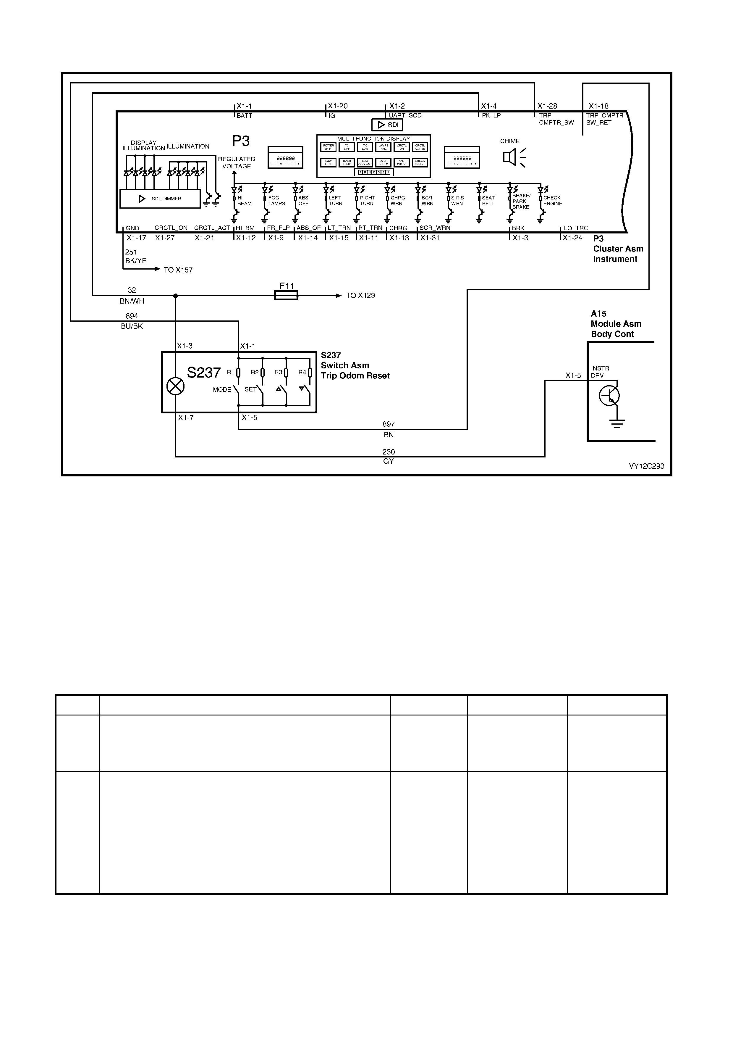
DTC 22 — TRIP SWITCH BUTTON STUCK
Figure 12C-333
CIRCUIT DESCRIPTION
The res istance presented to the ins trum ent cluster on term inal X1-28 is dependent upon the button select ed on the
trip comput er switch.
DTC 22 will set if any button on the trip c omputer is pressed f or longer than 1 minute. The DTC is reset as soon as
the button is released, and the DTC is logged as a History DTC.
DIAGNOSTIC AIDS
By manipulating the harnesses at the various connectors it is often possible to isolate the cause of the circuit
interruption. This harness can then be removed and repaired.
Check for any damage to the harness which could cause an intermittent open or short to earth or backed out
terminals at the instrument cluster connectors, broken connector locks, improperly formed or damaged terminals.
TRIP SWITCH BUTTON STUCK DIAGNOSTIC CHA RT
STEP ACTION VALUE YES NO
1 Was the Diagnostic Circuit Check performed? Go to Step 2. Go to
Diagnostic Circuit
Check
in this Section.
2 1. Connect TECH 2 to the DLC.
2. Select Diagnostics / Model Year / Vehicle Model /
Vehicle DTC Check.
Can TECH 2 communicate with the BCM?
NOTE: If ‘No Data’ is displayed next to the BCM, then
there is no communication between TECH 2 and the
BCM. If 'No DTC' or 'DTCs Set' is displayed then there is
communication between the TECH 2 and the BCM.
Go to Step 3. Refer to Section
12J, 3.2 SERIAL
DATA
COMM UNICATION
for further
diagnosis.

STEP ACTION VALUE YES NO
3 1. Check the switch for obvious signs of a stuck button. Replace the
switch. Refer to
2.6 TRIP
COMPUTER
SWITCH
ASSEMBLY in this
Section.
Go to Step 4.
4 1. Remove the switch, refer to 2.6 TRIP COMPUTER
SWITCH ASSEMBLY in this Section.
2. Using an ohmmeter, test the switch as detailed in
2.6 TRIP COMPUTER SWITCH ASSEMBLY in this
Section.
Switch tests OK?
Go to Step 5. Replace the
switch. Refer to
2.6 TRIP
COMPUTER
SWITCH
ASSEMBLY in this
Section.
5 1. From the Body Menu, select Diagnostic Trouble
Codes / Clear DTC Information on the TECH 2.
Has the DTC cleared?
DTC 22 is
intermittent.
Check circuit 894
between switch
and instrument
cluster for an
intermittent fault.
Replace the
instrument cluster.
Refer to
2.3 INSTRUMENT
CLUSTER
ASSEMBLY in this
Section.
WHEN ALL DIAGNOSIS AND REPAIRS ARE COM PLETED, CLEAR ALL DTC AND VERIFY CORRECT OPERATION

DTC 24 — EE CHECKSUM = FAILURE
CIRCUIT DESCRIPTION
The EEPROM (Electrically Erasable Programm able Read Only Mem ory) is part of the printed circuit board housed
within the instrument cluster. It stores variables required in the operation of the instrument cluster and in the
interpretation of the inc oming data and can be progr amm ed for dif f er ent instr ument levels. If a DTC 24 was set as a
result of interrupted instrument programming then the following diagnostic table will need to be followed.
DTC 24 will set if the EEPROM checksum is incorrect. The testing of the EEPROM checksum occurs every time the
ignition is turned on. T he DT C is res et when the EEPROM check sum is tested as being correct. The DTC is logged
as a History DTC.
DIAGNOSTIC AIDS
If the progr am m ed instrum ent c luster values ar e corr upted, reprogram ming can be c arried out via T ECH 2 to r ectif y
the fault as detailed in 3.15 PROGRAM in this Section.
EE CHECKSUM = FAILURE DIAGNOSTIC CHART
STEP ACTION VALUE YES NO
1 Was the Diagnostic Circuit Check performed? Go to Step 2. Go to
Diagnostic Circuit
Check
in this Section.
2 1. Connect the TECH 2 to the DLC.
2. Turn the ignition on.
3. Select Diagnostics / Model Year / Vehicle Model /
Body / Instrument / Program / Configuration and
following the instructions to verify the configuration
programming.
Is programming completed successfully?
Go to Step 3. Replace the
instrument cluster.
Refer to 2.3
INSTRUM ENT
CLUSTER
A
SSEMBLY in this
Section.
3 1. From the Body Menu, select Diagnostic Trouble
Codes / Clear DTC Information on the TECH 2.
Has the DTC cleared?
Instrument cluster
OK. End of
diagnostic testing.
EEPROM failed.
Replace the
instrument cluster.
Refer to 2.3
INSTRUM ENT
CLUSTER
A
SSEMBLY in this
Section.
WHEN ALL DIAGNOSIS AND REPAIRS ARE COM PLETED, CLEAR ALL DTC AND VERIFY CORRECT OPERATION
3.9 USING TECH 2 TO DIAGNOSE THE INSTRUMENT CLUSTER
A prerequisite to this diagnostic section is that the user is familiar with the proper use of TECH 2. The following
pages illustrate only the major TECH 2 screen displays and provide a brief explanation of their function for
diagnosing the Instruments. If additional information is required on the operation of TECH 2, refer to
Section 0C, TECH 2.
SYSTEM SELECTION MENU
This mode contains all functions to test, diagnose,
monitor and program the vehicles body systems
including the Instruments as well as providing the
opportunity to check all DTC that m ay be set in the
vehicle.
1. With TECH 2 connected to the DLC:
• select F0: Diagnostics from the Main Menu,
• select the appropriate model year at the
vehicle Identification Menu,
• select the appropriate vehicle type at the
next screen, and
• select F3: Body at the System Selection
Menu.
NOTE: If information regarding DTC set for the
vehicle is required, select Vehicle DTC Check and
press enter to continue. To return to the System
Selection Menu from the Vehicle DTC Check
screen, simply press the Exit key on TECH 2.
VY12D053
System S e lection Menu
(3) 2003 VY Commodore
F0:
F1:
F2:
F3:
F4:
Engine
Transmission
Chassis
Body
Veh icle DTC Che ck
Figure 12C-334
INSTRUMENT CLUSTER SELECTION
1. Select Instrument from the Vehicle
Identification Menu.
Once Instrument has been selected, the following
two System Identif ication screens will appear which
require action.
VY12C294
Vehicle Identificat ion
Sele c t on e of the follow in g
Body
Body Con trol Module
Powertrai n Interface Module
SRS
Instrument
Occupant Climate Control
Au dio System
Telemat ics S ystem
Figure 12C-335
INSTRUMENT CLUSTER IDENTIFICATION
1. Turn the ignition on (as requested) and press
Confirm soft key to continue.
VY12C295
Body
(3) 2003 VY Commodore
Instrument
Turn on Ignition!
Figure 12C-336
2. At the System Identification screen, press the
Confirm soft key and the Body Menu will be
displayed.

BOY MENU
1. Select the appropriate menu and press the
Enter key.
NOTE: If information regarding DTC set for the
vehicle is required, select Diagnostic Trouble
Codes and press Enter to c ontinue. To return to the
Body Menu from the Diagnostic Trouble Codes
screen, simply press the Exit key on TECH 2.
VY12D058
Body
F0:
F1:
F2:
F3:
F4:
F5:
Normal Mode
Diagnostic Trouble Codes
Data Displ ay
Snapshot
Misc ellaneous Tests
Program
Figure 12C-337

3.10 NORMAL MODE
The Normal Mode data list is used to view serial
data being sent to and from the instrument cluster.
1. From the Body Menu select Normal Mode and
press the Enter key.
VY12D058
Body
F0:
F1:
F2:
F3:
F4:
F5:
Normal Mode
Diagnostic Trouble Codes
Data Displ ay
Snapshot
Misc ellaneous Tests
Program
Figure 12C-338
Normal Mode Data List
TECH 2 DISPLAY RANGE REMARKS
Engine Oil Life Reset No / Yes
Transmission Fluid Life
Reset No / Yes
SRS Configuration No SRS / 2 Loop SRS / 3 Loop SRS /
4 Loop SRS / 6 Loop SRS Displays the SRS configuration for the vehicle.
Cruise Control Engaged No / Yes Displays the current cruise control status.
Radio Status Request No / Yes Displays the current audio system status.
Fuel Level Displays the current fuel level.
MFD Message
Requested No / Text Message / PCM / ABS/TC /
Instrument / OCC / SRS Airbag / BCM / Audio
System / Reset All
Indicates the type of message request.
MFD Message Received No / PCM / ABS/TC / Instrument / OCC / SRS
Airbag / BCM / Audio System Indicates the type of message received.
Language English / Portuguese Indicates the language option selected for the
instrument cluster.

3.11 DIAGNOSTIC TROUBLE CODES
1. From the Body Menu s elect Diagnostic T rouble
Codes and press the Enter key.
VY12D085
Body
F0:
F1:
F2:
F3:
F4:
F5:
Normal Mode
Diagnostic Trouble Codes
Data Displ ay
Snapshot
Misc ellaneous Tests
Program
Figure 12C-339
DIAGNOSTIC TROUBLE CODES MENU
F0: Read DTC Information. If this mode is
selected, a lis ting of all (if any) DTC that have been
set by the instrument cluster will be displayed.
NOTE: If any DTC are set, reference should be
made to the relevant diagnostic charts in this
Section.
F1: Clear DTC Information. DTC can be cleared
in this mode by simply selecting F1: Clear DTC
Inform ation, pr essing the Enter k ey on TECH 2 and
confirming the action as instructed by TECH 2.
NOTE: TECH 2 will display Clear DTC Information
Failed if any DTC are still current.
VY12C299
Diagnostics Tr oub le Codes
F0:
F1:
Rea d DTC In formation
Clear DTC Information
Figure 12C-340
READ DTC INFORMATION
1. Select F0: Read DTC Information and press
the Enter key.
Both Current DTC and History DTC are displayed.
Use the following table to assist in diagnosing and
rectifying DTC.

The following chart sets out the diagnostic trouble codes for the instrument cluster.
DTC 0 Not Used DTC 16 Petrol Level Sender Stuck
DTC 1 Petrol Level Sender Signal Voltage Too Low DTC 17 LPG Level Sender Stuck
DTC 2 Petrol Level Sender Signal Voltage Intermittent DTC 18 Not Used
DTC 3 Petrol Level Sender Signal Voltage Too High DTC 19 Incorrect SDM Detected
DTC 4 LPG Level Sender Signal Voltage Too High DTC 20 Not Used
DTC 5 LPG Level Sender Signal Voltage Too Low DTC 21 Trip Computer Switch Voltage Too Low
DTC 6 LPG Level Sender Signal Voltage Intermittent DTC 22 Trip Computer Switch Button Stuck
DTC 7 Not Used DTC 23 Not Used
DTC 8 No Serial Data From ABS / TCS DTC 24 EEPROM Checksum Error
DTC 9 No Serial Data From BCM DTC 25 Not Used
DTC 10 No Serial Data From OCC DTC 26 Not Used
DTC 11 No Serial Data From PCM DTC 27 Not Used
DTC 12 No Serial Data From SDM DTC 28 Not Used
DTC 13 No Instrument Poll From BCM DTC 29 Not Used
DTC 14 No Serial Data DTC 30 Not Used
DTC 15 No Serial Data From Audio System DTC 31 Not Used

3.12 DATA DISPLAY
The Data Display function allows the status of the
instrument cluster inputs and outputs to be
monitored.
1. From the Body Menu select Data Display and
press the Enter key.
VY12D086
Body
F0:
F1:
F2:
F3:
F4:
F5:
Normal Mode
Diagnostic Trouble Codes
Data Displ ay
Snapshot
Misc ellaneous Tests
Program
Figure 12C-341
The Data Display Menu provides access to the
serial data lists for:
• the instrument cluster,
• the trip computer switch functions,
• the vehicle configuration details, and
• system identification details.
The list can be scrolled through using the Up and
Down arrow keys. Make the requir ed selec tion f r om
the data display screen, and press Enter to
continue.
Details of each of the data lists are provided in the
following tables.
VY12C296
Data Displ ay
F0:
F1:
Instrument
Trip Computer
F2:
F3:
Configuration
System Iden tification
Figure 12C-342

F0: INSTRUMENT
The Instrument data list is as follows.
NOTE: Only the data relevant to the level of vehicle will be displayed.
TECH 2 DISPLAY UNIT RANGE
Battery Voltage Volts
Alternator Input Signal Off / On
Low Traction Input Signal Off / On
ABS Input Signal Off / On
Ignition Switch Off / On
Cruise Control Active Input Off / On
Cruise Control Enabled Input Signal Off / On
Park Lamp Switch Input Off / On
Park Brake and Brake Fail Input Off / On
Trip Computer Switch Down Button Off / On
Trip Computer Switch Up Button Off / On
Trip Computer Switch Set Button Off / On
Trip Computer Switch Mode Button Off / On
Trip Computer Switch Voltage Volts
Vehicle Speed km/h
Engine Speed rpm
LPG Level Sender Resistance ohms
Fuel Level Sender Resistance ohms
Low Fuel Warning Off / On
Very Low Fuel Warning Off / On
Low LPG W arning Off / On
Very Low LPG Warning Off / On
Check Powertrain Warning Off / On
High Coolant Temperature Warning Off / On
Low Oil Pressure Warning Off / On
Low Coolant Level Warning Off / On
Gear Change Warning Off / On
Seat Belt Warning Off / On
SRS Airbag Warning Off / On
Park Brake and Brake Fail Warning Off / On
Alternator Warning Off / On
Low Traction Warning Off / On
Rear Park Lamp Bulb Failure Warning Off / On
Stop Lamp Bulb Failure Warning Off / On
Stop Lamp Fuse Failure Warning Off / On
ABS Warning Off / On
Rest Reminder — For future use Off / On
Shift Mode Normal / Power
Overspeed Warning Off / On
Cruise Control Enabled Off / On
Cruise Control Active Off / On
PRNDL Position Invalid / 1 / 2 / 3 / D / N / R / P / Invalid
Traction Control Off / On
LPG in Use Off / On
Instrument Illumination Level % 0 – 100%
Pointer Illumination Level % 0 – 100%
MFD/LCD Illumination Level % 0 – 100%

F1: TRIP COMPUTER SWITCH
The Trip Computer Switch data list is as follows.
NOTE: Only the data relevant to the level of vehicle will be displayed.
TECH 2 DISPLAY UNIT RANGE
Odometer km
Average Speed km/h
Remaining Fuel L
Distance to Arrival km
Time to Arrival day(s)
Time to Arrival h:m:s
Average Fuel Consumption L/100 km
Instantaneous Fuel Consumption L/100 km
Instantaneous Fuel Consumption L/hour
Stop Watch day(s)
Stop Watch h:m:s
Distance to Empty km
Trip A Distance km
Trip A Time da y(s)
Trip A Time h:m:s
Fuel Used A L
Trip B Distance km
Trip B Time da y(s)
Trip B Time h:m:s
Fuel Used B L
Overspeed km/h
Preset 1 Overspeed km/h
Preset 2 Overspeed km/h
Preset 3 Overspeed km/h
Preset 4 Overspeed km/h
Trip Distance Mode Odometer/Trip / Odometer / Dist to Empty / Dist/Time to
Go / Avg Speed/Avg Fuel / Overspeed / Vehicle Speed /
Preset Overspeed / Stop Watch
Current Overspeed Normal / Preset 1 / Preset 2 / Preset 3 / Preset 4
Overspeed Mode Normal / Preset
Current Trip Mode
Overspeed On No / Yes

F2: CONFIGURATION
The Configuration data list is as follows.
NOTE: Only the data relevant to the level of vehicle will be displayed.
TECH 2 DISPLAY UNIT RANGE
Speedometer Pulses Pulse/km
Tachometer Ratio Pulses/Rev
Transmission Type Manual Transmission / Automatic Transmission
Police Mode No / Yes
SRS Configuration No SRS / 2 Loop SRS / 3 Loop SRS / 4 Loop SRS /
6 Loop SRS
LPG Fitted No / Yes
First / Next Service km
Service Interval km
Country
A
ust/NZ / Middle East / South Africa / Brazil / Indonesia /
Other
Speedometer Calibration % 80 to 120%
F3: SYSTEM IDENTIFICATION
The System Identification data list is as follows.
NOTE: Only the data relevant to the level of vehicle will be displayed.
TECH 2 DISPLAY UNIT RANGE
Identifier
Part Number
Production Date DD MM YY
Software Version
Instrument Type Level 1 / Level 1 SS / Level 2 / Level 3 / Level 3 Brazil /
Level 3 HSV / Level 4 / Level 5
Fuel Calibration
Code Version
Code Index
VAP Process Number
TIS Hardware Key Serial Number
TAG Number
Country Aust/NZ / Middle East / South Africa / Brazil / Indonesia /
Other

3.13 SNAPSHOT
The TECH 2 can be used to record system
information that is occurring at a particular moment
in time, and this is called a snapshot. For more
details, refer to Section 0C, TECH 2.
1. From the Body Menu select Snapshot and
press the Enter key.
VY12D087
Body
F0:
F1:
F2:
F3:
F4:
F5:
Normal Mode
Diagnostic Trouble Codes
Data Displ ay
Snapshot
Misc ellaneous Tests
Program
Figure 12C-343
The Snapshot Menu provides access to the serial
data lists for:
• the instrument cluster,
• the trip computer switch functions,
• the vehicle configuration details, and
• system identification details.
2. Scroll through the Data Display screen using
the Up and Down arrow keys. Make the
required selection and press the Enter key to
continue.
3. Scroll through the data list using the Up and
Down arrow keys. Make the required selection
and press the Enter key to continue.
4. For more details on Snapshot, refer to
Section 0C, TECH 2.
VY12C296
Data Displ ay
F0:
F1:
Instrument
Trip Computer
F2:
F3:
Configuration
System Iden tification
Figure 12C-344

3.14 MISCELLANEOUS TESTS
Miscellaneous Tests allows for the testing of various
components of the instrument cluster, such as
instrument and warning lamps, switches and
instrument gauges.
1. From the Body Menu select Miscellaneous
Tests and press the Enter key.
VY12D067
Body
F0:
F1:
F2:
F3:
F4:
F5:
Normal Mode
Diagnostic Trouble Codes
Data Displ ay
Snapshot
Misc ellaneous Tests
Program
Figure 12C-345
2. Scroll through the Miscellaneous Tests using
the TECH 2 Up and Down arrows.
VY12C297
Misc ellaneous Tests
Warnings
Status Indicators
Chime
PRNDL
Trip Computer Buttons
Gauge Control Tests
Input Overrides
Illumination
Self Test
Figure 12C-346
3. To select the required test function, press the
Enter key.
VY12C298
Misc ellaneous Tests
MFD Tests
LCD Tests
Figure 12C-347

WARNINGS
The Warnings function provides a means of testing the correct operation of the following warning displays and
status telltales in the instrument cluster:
• Check Powertrain* • Park Brake and Brake Fail* • Low Fuel*
• Check Oil* • SRS Airbag Fault* • Very Low Fuel*
• Engine Temperature* • Seatbelt • Rear Park Lamp Bulb Fail*
• Low Coolant* • ABS Fault* • Rear Brake Lamp Bulb Fail*
• Alternator (Generator)* • Low Traction • Rear Brake Lamp Fuse Fail*
* Activation of these warnings is accompanied by a chime.
1. Use the Up and Down arrow keys to scroll through the Miscellaneous Tests list and highlight a test.
2. Press the Enter key to select the test function.
3. Once a test function has been highlighted and selected, the TECH 2 will display the current serial data at the
top of the screen and the selected display or telltale and its current status at the bottom of the screen.
4. Pr es s the appr opriate s of t k eys as shown on the T ECH 2 screen to tes t the s elec ted display or telltale, and note
its status on the instrument cluster. Note that a chime also accompanies some warnings.
5. If the display or telltale does not activate as expected and the TECH 2 screen indicates that it has, there is a
fault in the instrument cluster and the instrument cluster will need to be replaced. Refer to
2.3 INSTRUMENT CLUSTER ASSEMBLY in this Section.
6. Press the Quit soft key or the Exit key to exit the test and return to the previous screen.
STATUS INDICATORS
The Status Indicators function pr ovides a m eans of testing the c orrec t operation of the following status displays and
telltales in the instrument cluster:
• Shift Mode • Cruise Active • Over Speed*
• Cruise Enabled • Traction Control • Rest Reminder
* Activation of this indicator is accompanied by a chime.
1. Use the Up and Down arrow keys to scroll through the Miscellaneous Tests list and highlight a test.
2. Press the Enter key to select the test function.
3. Once a test function has been highlighted and selected, the TECH 2 will display the current serial data at the
top of the screen and the selected display or telltale and its current status at the bottom of the screen.
4. Press the appr opriate s of t keys as shown on the TECH 2 screen to tes t the s elec ted dis play or telltale, and note
its status on the instrument cluster. Note that a chime also accompanies some status indicators.
5. If the display or telltale does not activate as expected and the TECH 2 screen indicates that it has, there is a
fault in the instrument cluster and the instrument cluster will need to be replaced. Refer to
2.3 INSTRUMENT CLUSTER ASSEMBLY in this Section.
6. Press the Quit soft key or the Exit key to exit the test and return to the previous screen.
CHIME
The Chime function provides a means of testing the correct operation of the internal instrument cluster chime.
1. Use the Up and Down arrow key s to scroll through the Miscellaneous Tests list and highlight the chime test.
2. Press the Enter key to select the test function.
3. Once the test f unction has been highlighted and selected, the T ECH 2 will display the current serial data at the
top of the screen and the current status of the chime at the bottom of the screen.
4. Pr es s the On sof t k ey on the T ECH 2 and note that a 1 kHz chim e is emitted f r om the instr ument cluster and its
status is display ed on the TECH 2 screen.
5. Press the Off soft key and note that the chime stops and its status indicated on the TECH 2 screen changes.
6. If the chime does not activate as expected and the TECH 2 screen indicates that it has, there is a fault in the
instrument cluster and the instrument cluster will need to be replaced. Refer to 2.3 INSTRUMENT CLUSTER
ASSEMBLY in this Section.
7. Press the Quit soft key or the Exit key to exit the test and return to the previous screen.

PRNDL
The PRNDL function provides a means of testing the correct operation of the automatic transmission gear shift
lever pattern displayed on the instrument by sequentially illuminating the P, R, N, D, 1, 2 and 3 segments of the
MFD.
1. Use the Up and Down arrow keys to scroll through the Miscellaneous Tests list and highlight the PRNDL test.
2. Press the Enter key to select the test function.
3. Once the test f unction has been highlighted and selected, the T ECH 2 will display the current serial data at the
top of the screen and the current status of the gearshift lever at the bottom of the screen.
4. Press the Next Lamp soft key on the TECH 2
and note that the gearshif t pattern displayed on
the MFD changes, and its status is displayed
on the TECH 2 screen.
5. Use the Next Lamp soft key to sequentially
step through the complete pattern, noting that
the status indicated on the T ECH 2 screen also
changes.
6. If the gearshift pattern does not activate as
expected and the T ECH 2 sc reen indicates that
it has, there is a fault in the instrument cluster
and the instrument cluster will need to be
replaced. Refer to 2.3 INSTRUMENT
CLUSTER ASSEMBLY in this Section.
7. Press the Quit soft key or the Exit key to exit
the test and return to the previous screen.
Figure 12C-348
TRIP COMPUTER BUTTONS
The Trip Computer Buttons function provides a means of testing the correct operation of the trip computer switch.
These tests can be used to identify if a switch button is stuck or if the instrument cluster is not functioning correctly.
Mode Button
With this test a MODE button press can be simulated.
1. Us e the Up and Down arrow keys to scr oll through the Misc ellaneous T ests lis t and highlight the Trip Com puter
Buttons test.
2. Press the Enter key to select the test function.
3. Once the test function has been highlighted and select ed, the TECH 2 will display the current serial data at the
top of the screen and four soft key s at the bottom of the screen.
4. Press the Mode soft key on the TECH 2 and note that the display on the MFD changes and the instrument
cluster emits a chime.
5. Use the Mode sof t key to s equentially step through the com plete series of MFD sc reens and note that a chime
accompanies each screen change.
6. If the MF D does not oper ate as expec ted, ther e is a fault in the instrument cluster and the instrument cluster will
need to be replaced. Refer to 2.3 INSTRUMENT CLUSTER ASSEMBLY in this Section.
7. Press the Exit key to exit the test and return to the previous screen.
Set Button
With this test a SET button press can be simulated.
1. Us e the Up and Down arrow keys to scr oll through the Misc ellaneous T ests lis t and highlight the Trip Com puter
Buttons test.
2. Press the Enter key to select the test function.
3. Once the test function has been highlighted and select ed, the TECH 2 will display the current serial data at the
top of the screen and four soft key s at the bottom of the screen.
4. Press the Mode soft key on the TECH 2 or on the trip computer switch to display the Distance / Time to Go
display (Single Window) or Distance to Arrival (Triple Window) display.
5. Press the Up or Down soft keys on the TECH 2 to vary the distance displayed.
6. Press the Set soft key on the TECH 2 and check that the distance displayed now shows the default value of
500 km. Note that the change in value is accompanied by a chime.
7. If the MF D does not oper ate as expec ted, ther e is a fault in the instrument cluster and the instrument cluster will
need to be replaced. Refer to 2.3 INSTRUMENT CLUSTER ASSEMBLY in this Section.
8. Press the Exit key to exit the test and return to the previous screen.

Up Button
With this test an UP button press can be simulated.
1. Us e the Up and Down arrow keys to scr oll through the Misc ellaneous T ests lis t and highlight the Trip Com puter
Buttons test.
2. Press the Enter key to select the test function.
3. Once the test function has been highlighted and select ed, the TECH 2 will display the current serial data at the
top of the screen and four soft key s at the bottom of the screen.
4. Press the Mode soft key on the TECH 2 or on the trip computer switch to display the Distance / Time to Go
display (Single Window) or Distance to Arrival (Triple Window) display.
5. Pr ess the Up s oft k ey and note that the distance displayed increases, and note that a chim e accom panies each
screen change.
6. If the MF D does not oper ate as expec ted, ther e is a fault in the instrument cluster and the instrument cluster will
need to be replaced. Refer to 2.3 INSTRUMENT CLUSTER ASSEMBLY in this Section.
7. Press the Exit key to exit the test and return to the previous screen.
Down Button
With this test a DOWN button press can be simulated.
1. Us e the Up and Down arrow keys to scr oll through the Misc ellaneous T ests lis t and highlight the Trip Com puter
Buttons test.
2. Press the Enter key to select the test function.
3. Once the test function has been highlighted and select ed, the TECH 2 will display the current serial data at the
top of the screen and four soft key s at the bottom of the screen.
4. Press the Mode soft key on the TECH 2 or on the trip computer switch to display the Distance / Time to Go
display (single window) or Distance to Arrival (triple window) display.
5. Press the Down soft key and note that the distance displayed decreases, and note that a chime accompanies
each screen change.
6. If the MF D does not oper ate as expec ted, ther e is a fault in the instrument cluster and the instrument cluster will
need to be replaced. Refer to 2.3 INSTRUMENT CLUSTER ASSEMBLY in this Section.
7. Press the Exit key to exit the test and return to the previous screen.
GAUGE CONTROL TESTS
The Gauge Control Tests function provides a means of testing the speedometer, tachometer, engine coolant
temperature gauge and fuel gauge by forcing known values into each gauge to verify their correct operation.
F0: Speedometer
Commanded vehicle speed can be adjusted up or down in 20 km/h steps from 0 km/h to the maximum value
displayed on the speedometer. Ensure that the speedometer is accurate according to the following table.
COMMANDE
D VEHICLE
SPEED
SPEEDO
ERROR ACCEPTABLE
READINGS ON
SPEEDOMETER
60 km / h –0 / +2 km/h 60 – 62 k m/h
100 km / h –0 / +2 km/h 100 – 102 km/h
160 km / h –0 / +3 km/h 160 – 163 km/h
NOTE: In Police Mode the allowable speedometer error is ±1 km/h at all speeds.
1. Use the Up and Down arrow keys to scroll through the Miscellaneous Tests list and highlight Gauge Control
Tests.
2. Select F0: Speedometer and press the Enter key to select the test function.
3. Once the test function has been highlighted and select ed, the TECH 2 will display the current serial data at the
top of the screen and the current status of the speedometer at the bottom of the screen.
4. Use the Up and Down soft keys on the TECH 2 to increase and decrease the displayed speed and verify that
the speedometer display changes accordingly. For each change, verify that the indication on the speedometer
and the speedometer status on the TECH 2 display agree.
5. If the speedometer does not operate as expected, there is a fault in the instrument cluster and the instrument
cluster will need to be replaced. Refer to 2.3 INSTRUMENT CLUSTER ASSEMBLY in this Section.
6. Press the Quit soft key or the Exit key to exit the test and return to the previous screen.

F1: Tachometer
Commanded engine speed can be adjusted up and down in 500 rpm steps with a maximum value of 7000 rpm.
Ensure that the tachometer is accurate to ±50 rpm between 500 rpm and 6500 rpm.
1. Use the Up and Down arrow keys to scroll through the Miscellaneous Tests list and highlight Gauge Control
Tests.
2. Select F1: Tachometer and press the Enter key to select the test function.
3. Once the test function has been highlighted and select ed, the TECH 2 will display the current serial data at the
top of the screen and the current status of the tachometer at the bottom of the screen.
4. Use the Up and Down soft keys on the TECH 2 to increase and decrease the displayed engine speed and verify
that the tachom eter display c hanges accordingly. For each change, verif y that the indication on the tac hometer
and the tachometer status on the TECH 2 display agree.
5. If the tachometer does not operate as expected, there is a fault in the instrument cluster and the instrument
cluster will need to be replaced. Refer to 2.3 INSTRUMENT CLUSTER ASSEMBLY in this Section.
6. Press the Quit soft key or the Exit key to exit the test and return to the previous screen.
F2: Temperature Gauge
Commanded engine temperature can be adjusted up and down in three steps, these being Cold, Mid and Hot.
1. Use the Up and Down arrow keys to scroll through the Miscellaneous Tests list and highlight Gauge Control
Tests.
2. Select F2: Temperature Gauge and press the Enter key to select the test function.
3. Once the test function has been highlighted and select ed, the TECH 2 will display the current serial data at the
top of the screen and the current status of the temperature gauge at the bottom of the screen.
4. Use the Up and Down soft keys on the TECH 2 to increase and decrease the displayed engine temperature and
verify that the temperature gauge display changes accordingly. For each change, verify that the indication on
the temperature gauge and the temperature gauge status on the TECH 2 display agree.
5. If the temperature gauge does not operate as expected, there is a fault in the instrument cluster and the
instrument cluster will need to be replaced. Refer to 2.3 INSTRUMENT CLUSTER ASSEMBLY in this Section.
6. Press the Quit soft key or the Exit key to exit the test and return to the previous screen.
F3: Fuel Gauge
Commanded fuel tank level can be adjusted up and down in three steps, these being Empty, Half and Full.
1. Use the Up and Down arrow keys to scroll through the Miscellaneous Tests list and highlight Gauge Control
Tests.
2. Select F3: Fuel Gauge and press the Enter key to select the test function.
3. Once the test function has been highlighted and select ed, the TECH 2 will display the current serial data at the
top of the screen and the current status of the fuel gauge at the bottom of the screen.
4. Use the Up and Down soft keys on the TECH 2 to increase and decrease the displayed fuel tank level and
verify that the fuel gauge display changes accordingly. For each change, verify that the indication on the fuel
gauge and the fuel gauge status on the TECH 2 display agree.
5. If the fuel gauge does not operate as expected, there is a fault in the instrument cluster and the instrument
cluster will need to be replaced. Refer to 2.3 INSTRUMENT CLUSTER ASSEMBLY in this Section.
6. Press the Quit soft key or the Exit key to exit the test and return to the previous screen.
INPUT OVERRIDES
The Input Overrides test function simulates input signals at the instrument cluster under normal operating
conditions. Accordingly, some tests may require the engine to be running. Follow the directions on the TECH 2
screen:
• Vehicle Speed • Alternator (Generator) • Cruise Control Active
• Engine Speed • Low Traction • Cruise Control Enabled
• LPG Mode • ABS • Park Brake and Brake Fail
1. Use the Up and Down arrow keys to scroll through the Miscellaneous Tests list and highlight Input Overrides.
2. Select the appropriate test and press the Enter key to select the test function.
3. Once the test function has been highlighted and select ed, the TECH 2 will display the current serial data at the
top of the screen and the current status of the item at the bottom of the screen.
4. Follow any screen prompts and use the soft keys on the TECH 2 as necessary to perform the test.
5. If the appr opriate tes t does not oper ate as ex pec ted, there is a f ault in the ins trument c luster and the instr ument
cluster will need to be replaced. Refer to 2.3 INSTRUMENT CLUSTER ASSEMBLY in this Section.
6. Press the Quit soft key or the Exit key to exit the test and return to the previous screen.

ILLUMINATION
The Illumination function provides a means of testing the illumination level of the MFD, LCDs, as well as the
instrument cluster pointers and dials. The illumination level can be adjusted in increments of 20%, from 0% to
100%.
F0: MFD / LCD
1. Use the Up and Down arrow keys to scroll through the Miscellaneous Tests list and highlight Illumination.
2. Select F0: MFD / LCD and press the Enter key to select the test function.
3. Once the test function has been highlighted and select ed, the TECH 2 will display the current serial data at the
top of the screen and the current status of the illumination level at the bottom of the screen.
4. Use the Up and Down soft keys on the TECH 2 to increase and decrease the illumination level and verify that
the MFD / LCD illumination level changes accordingly.
5. If the illumination level does not operate as expected, there is a fault in the instrument cluster and the
instrument cluster will need to be replaced. Refer to 2.3 INSTRUMENT CLUSTER ASSEMBLY in this Section.
6. Press the Quit soft key or the Exit key to exit the test and return to the previous screen.
F1: Pointers
1. Use the Up and Down arrow keys to scroll through the Miscellaneous Tests list and highlight Illumination.
2. Select F1: Pointers and press the Enter key to select the test function.
3. Once the test function has been highlighted and select ed, the TECH 2 will display the current serial data at the
top of the screen and the current status of the illumination level at the bottom of the screen.
4. Use the Up and Down soft keys on the TECH 2 to increase and decrease the illumination level and verify that
the illumination level of the pointers changes accordingly.
5. If the illumination level does not operate as expected, there is a fault in the instrument cluster and the
instrument cluster will need to be replaced. Refer to 2.3 INSTRUMENT CLUSTER ASSEMBLY in this Section.
6. Press the Quit soft key or the Exit key to exit the test and return to the previous screen.
F2: Dials
1. Use the Up and Down arrow keys to scroll through the Miscellaneous Tests list and highlight Illumination.
2. Select F2: Dials and press the Enter key to select the test function.
3. Once the test function has been highlighted and select ed, the TECH 2 will display the current serial data at the
top of the screen and the current status of the illumination level at the bottom of the screen.
4. Use the Up and Down soft keys on the TECH 2 to increase and decrease the illumination level and verify that
the illumination level of the dials changes accordingly.
5. If the illumination level does not operate as expected, there is a fault in the instrument cluster and the
instrument cluster will need to be replaced. Refer to 2.3 INSTRUMENT CLUSTER ASSEMBLY in this Section.
6. Press the Quit soft key or the Exit key to exit the test and return to the previous screen.
SELF TEST
The Self Test function provides a means of testing the correct operation of the instrument cluster.
1. Use the Up and Down arrow keys to scroll through the Miscellaneous Tests list and highlight Self Test.
2. Press the Enter key to select the test function.
3. Once the test function has been highlighted and select ed, the TECH 2 will display the current serial data at the
top of the screen and three soft keys at the bottom of the screen.
4. Use the On and Of f soft k eys on the T ECH 2 to enable and disable the self tes t. W hen activated, the following
occurs for approximately 5 seconds:
• The temperature gauge and the fuel gauge are set to the half-way mark (50%).
• The tachometer is set to 3000 rpm.
• The speedometer is set to 100 km/h.
• The chime is activated at 1 kHz.
• The telltale LEDs that are driven by either the internal microprocessor or from the serial data line are
illuminated. These are SRS, Brake Park/Fail, Seat Belt and Shift Up (HSV only).
• All segments of the MFD and the side LCDs (triple-window cluster only) are illuminated.
5. If the instrument cluster does not operate as expected, there is a fault in the instrument cluster and the
instrument cluster will need to be replaced. Refer to 2.3 INSTRUMENT CLUSTER ASSEMBLY in this Section.
6. Press the Quit soft key or the Exit key to exit the test and return to the previous screen.
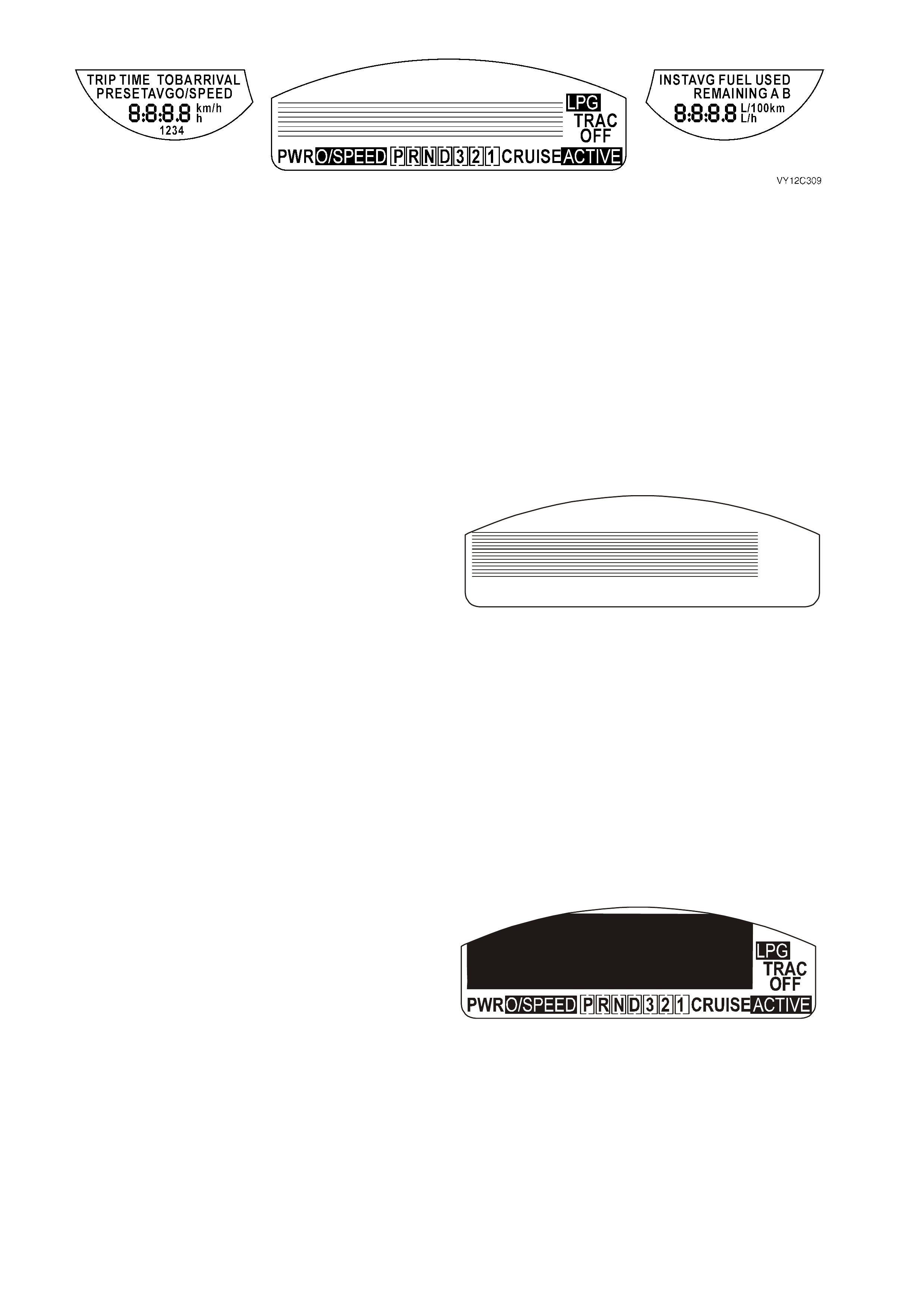
Figure 12C-349
MFD TESTS
The MFD Tests function provides a means of
testing the correct operation of the MFD by using
the TECH 2 to force known values into the MFD.
F0: Test Pattern 1
1. Use the Up and Down arrow keys to scroll
through the Miscellaneous Tests list and
highlight MFD Tests.
2. Press the Enter key to select the test function.
3. Once the test function has been highlighted
and selected, the TECH 2 will display the
current serial data at the top of the screen and
the four soft keys at the bottom of the screen.
4. Press the Pattern 1 soft key on the TECH 2 to
enable the self test. When activated, the MFD
display is as shown for approximately
5 seconds.
5. If the instrument cluster does not operate as
expected, there is a fault in the instrument
cluster and the instrument cluster will need to be
replaced. Refer to 2.3 INSTRUMENT
CLUSTER ASSEMBLY in this Section.
6. Press the Q uit s of t key or the Exit key to exit the
test and return to the previous screen.
VY12C303
Figure 12C-350
F1: Test Pattern 2
1. Use the Up and Down arrow keys to scroll
through the Miscellaneous Tests list and
highlight MFD Tests.
2. Press the Enter key to select the test function.
3. Once the test function has been highlighted
and selected, the TECH 2 will display the
current serial data at the top of the screen and
the four soft keys at the bottom of the screen.
4. Press the Pattern 2 soft key on the TECH 2 to
enable the self test. When activated, the MFD
display is as shown for approximately
5 seconds.
5. If the instrument cluster does not operate as
expected, there is a fault in the instrument
cluster and the instrument cluster will need to
be replaced. Refer to 2.3 INSTRUMENT
CLUSTER ASSEMBLY in this Section.
6. Press the Quit soft key or the Exit key to exit
the test and return to the previous screen.
VY12C304
Figure 12C-351
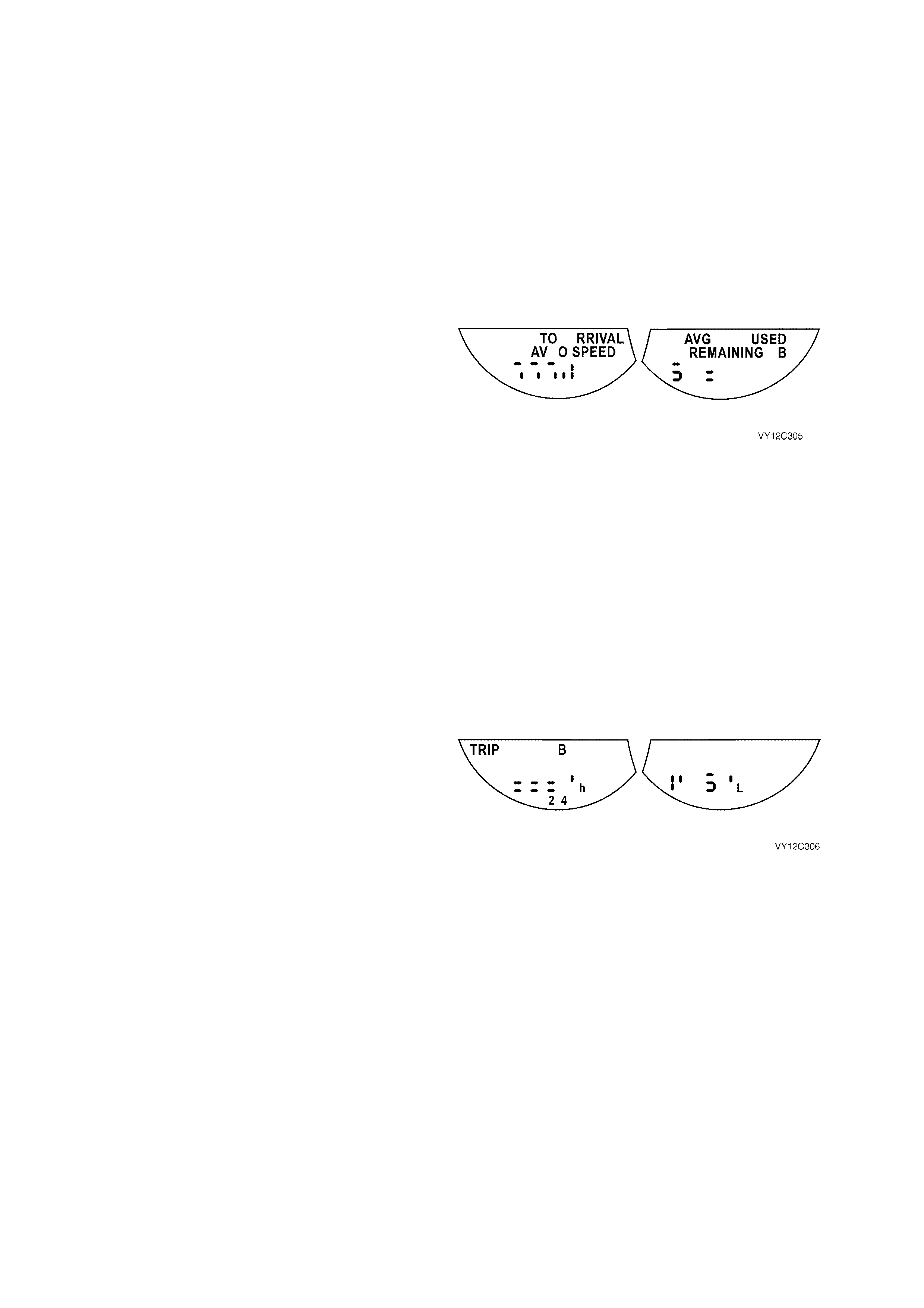
LCD TESTS
The LCD Tests function provides a means of
testing the correct operation of the LCDs by using
the TECH 2 to force known values into the LCDs.
F0: Test Pattern 1
1. Use the Up and Down arrow keys to scroll
through the Miscellaneous Tests list and
highlight LCD Tests.
2. Press the Enter key to select the test function.
3. Once the test function has been highlighted
and selected, the TECH 2 will display the
current serial data at the top of the screen and
the four soft keys at the bottom of the screen.
4. Press the Pattern 1 soft key on the TECH 2 to
enable the self test. When activated, the LCD
displays are as shown for approximately
5 seconds.
5. If the instrument cluster does not operate as
expected, there is a fault in the instrument
cluster and the instrument cluster will need to
be replaced. Refer to 2.3 INSTRUMENT
CLUSTER ASSEMBLY in this Section.
6. Press the Quit soft key or the Exit key to exit
the test and return to the previous screen.
Figure 12C-352
F1: Test Pattern 2
1. Use the Up and Down arrow keys to scroll
through the Miscellaneous Tests list and
highlight LCD Tests.
2. Press the Enter key to select the test function.
3. Once the test function has been highlighted
and selected, the TECH 2 will display the
current serial data at the top of the screen and
the four soft keys at the bottom of the screen.
4. Press the Pattern 2 soft key on the TECH 2 to
enable the self test. When activated, the LCD
displays are as shown for approximately
5 seconds.
5. If the instrument cluster does not operate as
expected, there is a fault in the instrument
cluster and the instrument cluster will need to
be replaced. Refer to 2.3 INSTRUMENT
CLUSTER ASSEMBLY in this Section.
6. Press the Quit soft key or the Exit key to exit
the test and return to the previous screen.
Figure 12C-353
3.15 PROGRAM
The Program function allows various instrument cluster parameters to be programmed.
1. From the Body Menu select Program and press
the Enter key.
VY12D088
Body
F0:
F1:
F2:
F3:
F4:
F5:
Normal Mode
Diagnostic Trouble Codes
Data Displ ay
Snapshot
Misc ellaneous Tests
Program
Figure 12C-354
F0: FUEL GAUGE CALIBRATION
When an instrument cluster is replaced, the Fuel Calibration Part Number is to be entered using TECH 2. This
identifies the fuel tank size and fuel sender unit resistance to the instrument cluster. The Fuel Calibration Part
Number is identified by the Code Index Number, which is associated with a particular vehicle configuration. The
Code Vers ion Num ber identifies the s oftware version. O nly the Code Index Num ber can be c hanged. The f ollowing
table details the Code Index and Fuel Calibration Part Numbers for the various models in the MY2003 VY and V2
Series vehicles.
VEHICLE FUEL CALIBRATION PART NUMBER CODE INDEX NUMBER
Sedan / Monaro (V6 and V8) 92120109 1
Wagon 92120110 2
Utility 92120111 3
Sedan / Monaro (V6 Supercharged) 92120112 4
1. From the Program Menu select F0: Fuel Gauge
Calibration and press the Enter key.
VY12C316
Program
F0:
F1:
F2:
F3:
F4:
F5:
F6:
Fuel Gauge Calibration
Configuration
Odometer
Speedometer Calibration
R e se t S e r vice Inte r va l
Re set Tr i p Com puter Sett in gs
Reset to Vehicle Build Settings
Figure 12C-355
Techline
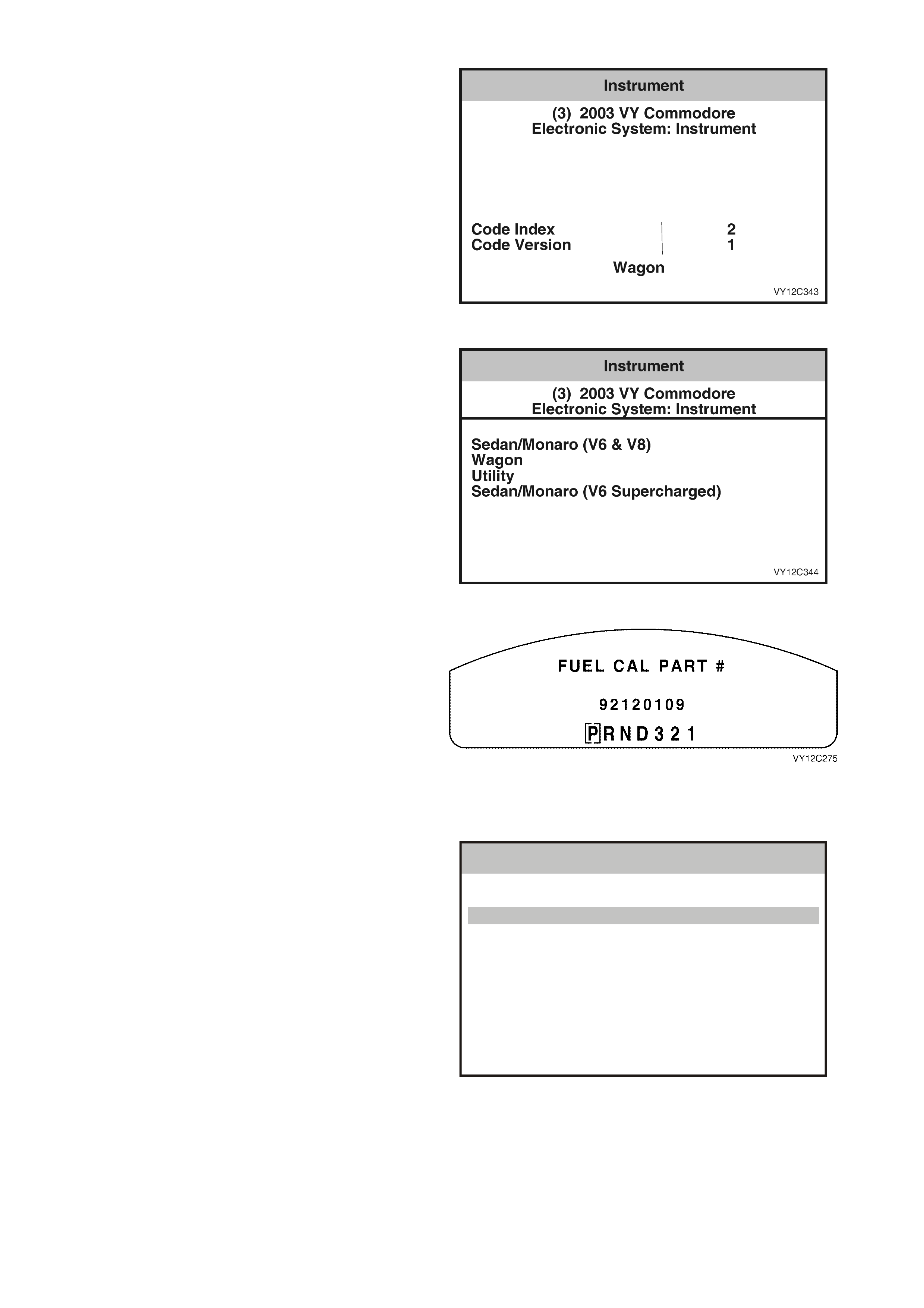
2. T he Code Index Num ber and the Code Version
Number are displayed. To change the Code
Index Number, press the Modify soft key. To
exit without making a change, press the Okay
soft key.
Figure 12C-356
3. Use the Up and Down arrow keys to highlight a
vehicle type and press the Enter key.
4. Follow the TECH 2 screen prompts to complete
the programming.
Figure 12C-357
5. Enter the instrument cluster Diagnostic Mode
(refer to DIAGNOSTIC MODE OPERATION in
this Section). Press the trip computer switch
MODE button until the Fuel Calibration Part
Number is displayed on the MFD. Verify that
the Fuel Calibration Part Number displayed is
correct.
Figure 12C-358
F1: CONFIGURATION
1. From the Program Menu select F1:
Configuration and press the Enter key.
VY12C308
Program
F0:
F1:
F2:
F3:
F4:
F5:
F6:
Fuel Gauge Calibration
Configuration
Odometer
Speedometer Calibration
R e se t S e r vice Inte r va l
Re set Tr i p Com puter Sett in gs
Reset to Vehicle Build Settings
Figure 12C-359
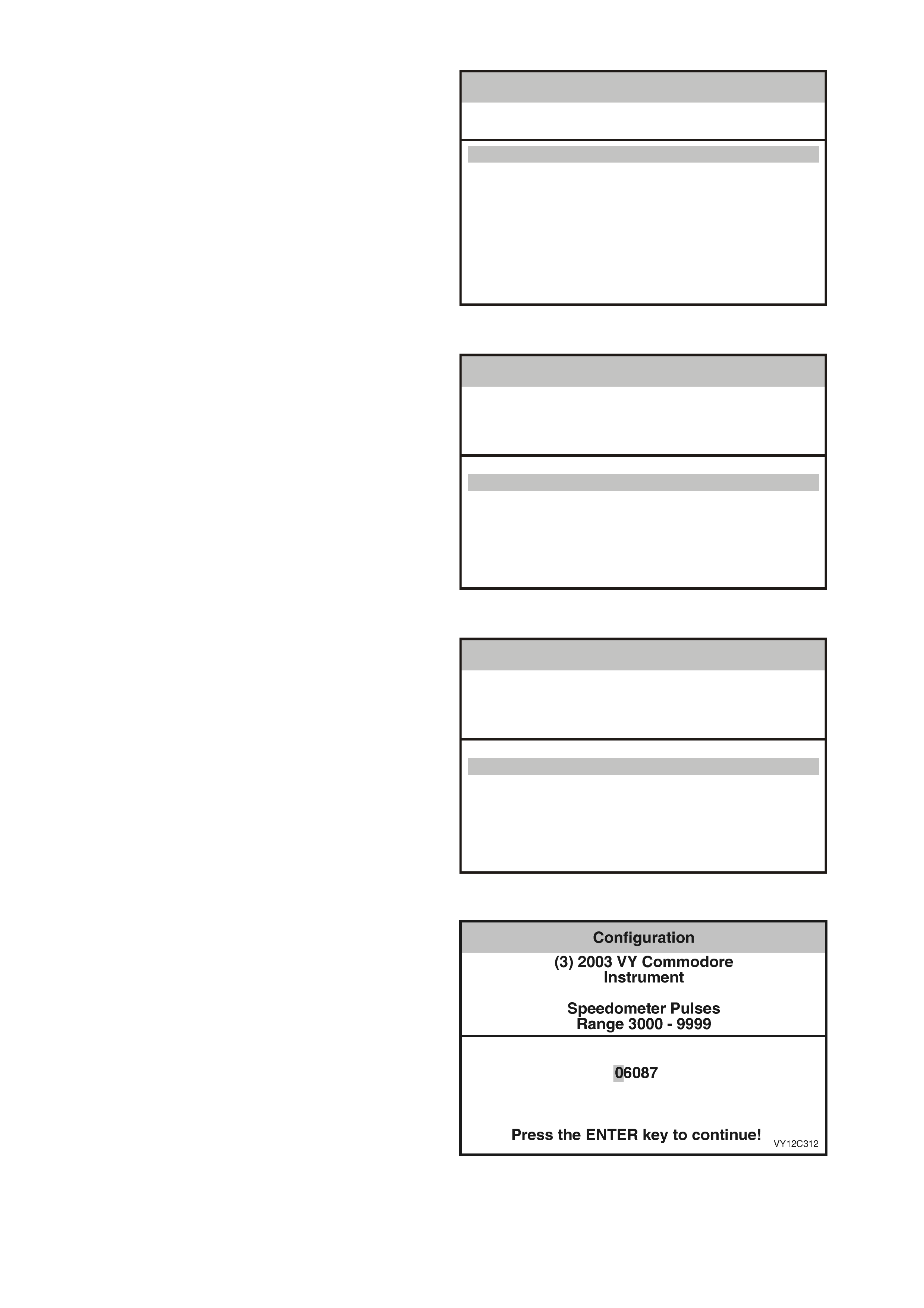
2. The Configuration Menu will be displayed
showing the current vehicle configuration.
3. To modify any item, select the item using the
Up and Down arrows and pres s the Modify soft
key or the Enter key. The appropriate screen
will be displayed.
VY12C315
Configuration
(3) 2003 VY Commodore
Instrument
Australia/NZ
V6 & V6 SC
Country
Engine Type
Speedometer Pulses
SRS Configuration
Transmission Type
Police Mode
6 Loop SRS
Automatic
No
6087
Figure 12C-360
Country
1. Use the Up and Down arrow keys to highlight a
country in the menu.
2. When selected, press the Modify soft key to
advance to the Engine Type selection screen.
Note that if either Brazil or Indonesia is
selected, pressing the Modify soft key will
return to the Configuration Menu as there is
only one engine configuration for those
countries.
3. To exit the Country screen without changing
the selection shown, press the Exit key to
advance to the Engine Type selection screen.
VY12C310
Configuration
(3) 2003 VY Commodore
Instrument
Country
Australia/New Zealand
Middle East
South Africa
Brazil
Indonesia
Other Country
Figure 12C-361
Engine Type
1. Use the Up and Down arrow keys to highlight
the engine type in the menu.
2. When s elec ted, pres s the Enter key to return to
the Configuration Menu.
3. To return to the Configuration Menu without
changing the selection shown, press the Exit
key.
VY12C311
Configuration
(3) 2003 VY Commodore
Instrument
Engine Type
V6 & V6 SC
V6 LPG
V8
Figure 12C-362
Speedometer Pulses
1. Select the speedometer pulses per kilometre
for the correct tyre size from the following table.
2. If nec essary, use the Left and Right ar row keys
to scroll across the number displayed on the
TECH 2 screen and modify using the numeral
keys.
3. When s elec ted, pres s the Enter key to return to
the Configuration Menu.
4. To return to the Configuration Menu without
changing the selection shown, press the Exit
key.
Figure 12C-363

BODY STYLE ENGINE TRANSMISSION TYRE SIZE SPEEDOMETER
PULSES
Sedan/Wagon V6 Auto/Manual 205/65 R15 6272
Sedan/Wagon V6 Auto/Manual 225/60 R15 6238
Sedan/Wagon V6 Auto/Manual 215/60 R16 6077
Sedan/Wagon V6 Auto/Manual 225/55 R16 6173
Sedan/Wagon V6 Auto/Manual 225/50 R16 6391
Sedan/Wagon V6 Auto/Manual 235/45 R17 6301
Ute V6 Auto 205/65 R15 6272
Ute V6 Auto 225/55 R16 6087
Ute V6 Manual 205/65 R15 6450
Ute V6 Manual 225/55 R16 6307
Sedan/Wagon/Ute V8 Auto/Manual 205/65 R15 6272
Sedan/Wagon/Ute V8 Auto/Manual 225/60 R15 6238
Sedan/Wagon/Ute V8 Auto/Manual 225/55 R16 6087
Sedan/Wagon/Ute V8 Auto/Manual 235/45 R17 6301
Coupe V8 Auto/Manual 235/40 R18 6230
HSV All Auto 225/50 ZR17 6355
HSV All Auto 235/45 ZR17 6210
HSV All Auto 235/40 ZR18 6210
HSV All T56 225/50 ZR17 6300
HSV All T56 235/40 ZR18 6300
HSV All GETRAG 225/50 ZR16 6355
HSV All GETRAG 235/45 ZR17 6210
HSV All GETRAG 235/40 ZR18 6210
SRS Configuration
1. Use the Up and Down arrow keys to highlight
the appropriate vehicle SRS configuration in
the menu.
NOTE: Configuration of the various SRS systems
is as follows:
• A 2-loop system is for left-hand drive
vehicles with pretensioners only.
• A 3-loop system is for vehicles with
pretensioners and driver’s airbag only.
• A 4-loop system is for vehicles with
pretensioners, driver’s airbag and front
passenger’s airbag only.
• A 6-loop system is for vehicles with
pretensioners, driver’s airbag, front
passenger’s airbag and side impact airbags.
2. When s elec ted, pres s the Enter key to return to
the Configuration Menu.
3. To return to the Configuration Menu without
changing the selection shown, press the Exit
key.
VY12C313
Configuration
(3) 2003 VY Commodore
Instrument
SRS Configuration
No SRS
2 Loop SRS
3 Loop SRS
4 Loop SRS
6 Loop SRS
Figure 12C-364

Transmission Type
1. Use the Up and Down arrow keys to highlight
the transmission type in the menu.
2. When s elec ted, pres s the Enter key to return to
the Configuration Menu.
3. To return to the Configuration Menu without
changing the selection shown, press the Exit
key.
VY12C314
Configuration
(3) 2003 VY Commodore
Instrument
Transmission Type
Manual Transmission
Automatic Transmission
Figure 12C-365
Police Mode
1. Use the Up and Down arrow keys to highlight
No / Yes in the menu as required.
2. When s elec ted, pres s the Enter key to return to
the Configuration Menu.
3. To return to the Configuration Menu without
changing the selection shown, press the Exit
key.
VY12C326
Configuration
(3) 2003 VY Commodore
Instrument
Police Mode
No
Yes
Figure 12C-366
Program Settings
1. Press the Quit soft key to abandon the
programming process, or press the Program
soft key to initiate the programming process.
2. Press the Confirm soft key when notified that
the programming has been completed
successfully.
3. Turn the ignition off and on again to acc ept the
programming changes.
VY12C315
Configuration
(3) 2003 VY Commodore
Instrument
Australia/NZ
V6 & V6 SC
Country
Engine Type
Speedometer Pulses
SRS Configuration
Transmission Type
Police Mode
6 Loop SRS
Automatic
No
6087
Figure 12C-367
F2: ODOMETER
NOTE: It is only possible to program the odometer
reading on an instrument once the TIS approval
(Enable Programming) has been obtained and on
an instrument which presently reads no more than
100 km. Refer to Section 0C, TECH 2 for further
details to enable programming.
1. From the Program Menu select F2: Odometer
and press the Enter key.
VY12C317
Program
F0:
F1:
F2:
F3:
F4:
F5:
F6:
Fuel Gauge Calibration
Configuration
Odometer
Speedometer Calibration
R e se t S e r vice Inte r va l
Re set Tr i p Com puter Sett in gs
Reset to Vehicle Build Settings
Figure 12C-368
2. Press the Abort soft key to abandon the
process, or press the Modify soft key to
continue.
VY12C318
Odometer
(3) 2003 VY Commodore
Instrument
O dom eter XX k m
Figure 12C-369
NOTE: If TIS approval (Enable Programming) has
been obtained, this screen will not appear. If TIS
approval (Enable Programming) has not been
obtained, this screen will appear and programming
is not possible. Refer to Section 0C, TECH 2 for
further details to enable programming.
VY12C319
Odometer
(3) 2003 VY Commodore
Instrument
Please get programming approval from
TIS!
Figure 12C-370
3. Use the Left and Right arrow keys to scroll
across the number displayed on the TECH 2
screen and modify using the numeral keys.
4. Press the Enter key to continue.
VY12C320
Odometer
(3) 2003 VY Commodore
Instrument
Enter Odometer Value (in km), then press
ENTER.
XXXXXX
Press ENTER key to Continue.
Figure 12C-371
IMPORTANT: This is the last chance to get the
odometer value correct. Ensure that the value is
correct before proceeding.
5. Check that the odometer value displayed on
the TECH 2 screen is correct.
• If the value is incorrect, press the Not Okay
soft k ey to return to the previous screen and
enter the correct value.
• If the value is correct, press the Okay soft
key to continue programming.
6. Press the Confirm soft key when notified that
the programming has been completed
successfully.
7. Turn the ignition off and on again to acc ept the
programming changes.
VY12C321
Odometer
(3) 2003 VY Commodore
Instrument
O dom eter V a lue Pr o g r am?
XXXXXX
Figure 12C-372
F3: SPEEDOMETER CALIBRATION
NOTE: Speedometer calibration is only possible
when Police Mode has been enabled.
1. From the Program Menu select F3:
Speedometer Calibration and press the Enter
key.
VY12C322
Program
F0:
F1:
F2:
F3:
F4:
F5:
F6:
Fuel Gauge Calibration
Configuration
Odometer
Speedometer Calibration
R e se t S e r vice Inte r va l
Re set Tr i p Com puter Sett in gs
Reset to Vehicle Build Settings
Figure 12C-373
NOTE: If Police Mode has been enabled, this
screen will not appear. If Police Mode is disabled,
this s c reen will appear and s peedometer c alibr ation
is not possible. Refer to F1: CONFIGURATION in
this Section for details on how to enable Police
Mode.
VY12C327
Speedometer Calibration
(3) 2003 VY Commodore
Instrument
Selected Programming is not possible!
Figure 12C-374
2. Use the Left and Right arrow keys to scroll
across the number displayed on the TECH 2
screen and modify using the numeral keys.
3. Press the Enter key to continue.
4. Press the Confirm soft key when notified that
the programming has been completed
successfully.
5. Turn the ignition off and on again to acc ept the
programming changes.
VY12C328
Speedometer Calibration
(3) 2003 VY Commodore
Instrument
Speedometer Calibration
Range 80 - 120 %
100.0
Press ENTER key to continue
Figure 12C-375

F4: RESET SERVICE INTERVAL
1. From the Program Menu select F4: Reset
Service Interval and press the Enter key.
VY12C323
Program
F0:
F1:
F2:
F3:
F4:
F5:
F6:
Fuel Gauge Calibration
Configuration
Odometer
Speedometer Calibration
R e se t S e r vice Inte r va l
Re set Tr i p Com puter Sett in gs
Reset to Vehicle Build Settings
Figure 12C-376
NOTE: If a Service Reset is not required or the
distance to the next service is more than 1000 km,
TECH 2 displays this screen and a Service Reset is
not possible. Pres s the Confirm sof t key to return to
the Program Menu.
VY12C340
R e se t S e r vice Inte r va l
(3) 2003 VY Commodore
Instrument
More tha n 1000 km until Next Service!
Figure 12C-377
2. Press the Abort soft key to abandon the
process, or the Reset soft key to reset the
service interval.
3. Press the Confirm soft key when notified that
the programming has been completed
successfully.
4. Turn the ignition off and on again to acc ept the
programming changes.
VY12C329
R e se t S e r vice Inte r va l
(3) 2003 VY Commodore
Instrument
R e se t S e r vice Inte r va l?
Figure 12C-378
Techline

F5: RESET TRIP COMPUTER SETTINGS
1. From the Program Menu select F5: Reset Trip
Computer Settings and press the Enter key.
VY12C324
Program
F0:
F1:
F2:
F3:
F4:
F5:
F6:
Fuel Gauge Calibration
Configuration
Odometer
Speedometer Calibration
R e se t S e r vice Inte r va l
Re set Tr i p Com puter Sett in gs
Reset to Vehicle Build Settings
Figure 12C-379
2. Press the Abort soft key to abandon the
process, or the Reset soft key to reset the
service interval.
3. Press the Confirm soft key when notified that
the programming has been completed
successfully.
4. Turn the ignition off and on again to acc ept the
programming changes.
VY12C330
Re set Tr i p Com puter Sett in gs
(3) 2003 VY Commodore
Instrument
Re set Tr i p Com puter Sett in gs
Figure 12C-380
F6: RESET TO VEHICLE BUILD SETTINGS
1. From the Program Menu select F6: Reset to
Vehicle Build Settings and press the Enter key.
VY12C325
Program
F0:
F1:
F2:
F3:
F4:
F5:
F6:
Fuel Gauge Calibration
Configuration
Odometer
Speedometer Calibration
R e se t S e r vice Inte r va l
Re set Tr i p Com puter Sett in gs
Reset to Vehicle Build Settings
Figure 12C-381
2. Press the Abort soft key to abandon the
process, or the Reset soft key to reset the
service interval.
3. Press the Confirm soft key when notified that
the programming has been completed
successfully.
4. Turn the ignition off and on again to acc ept the
programming changes.
VY12C331
Reset to Vehicle Build Settings
(3) 2003 VY Commodore
Instrument
Reset to Vehicle Build Settings
Figure 12C-382

4. TORQUE WRENCH SPECIFICATIONS
Nm
Instrument Cluster Trim Assembly Attaching Screw.................... 1 – 3
In-car Air Temperature Sensor Attaching Screw......................... 1 – 3
Instrument Cluster Attaching Screw............................................. 1 – 3
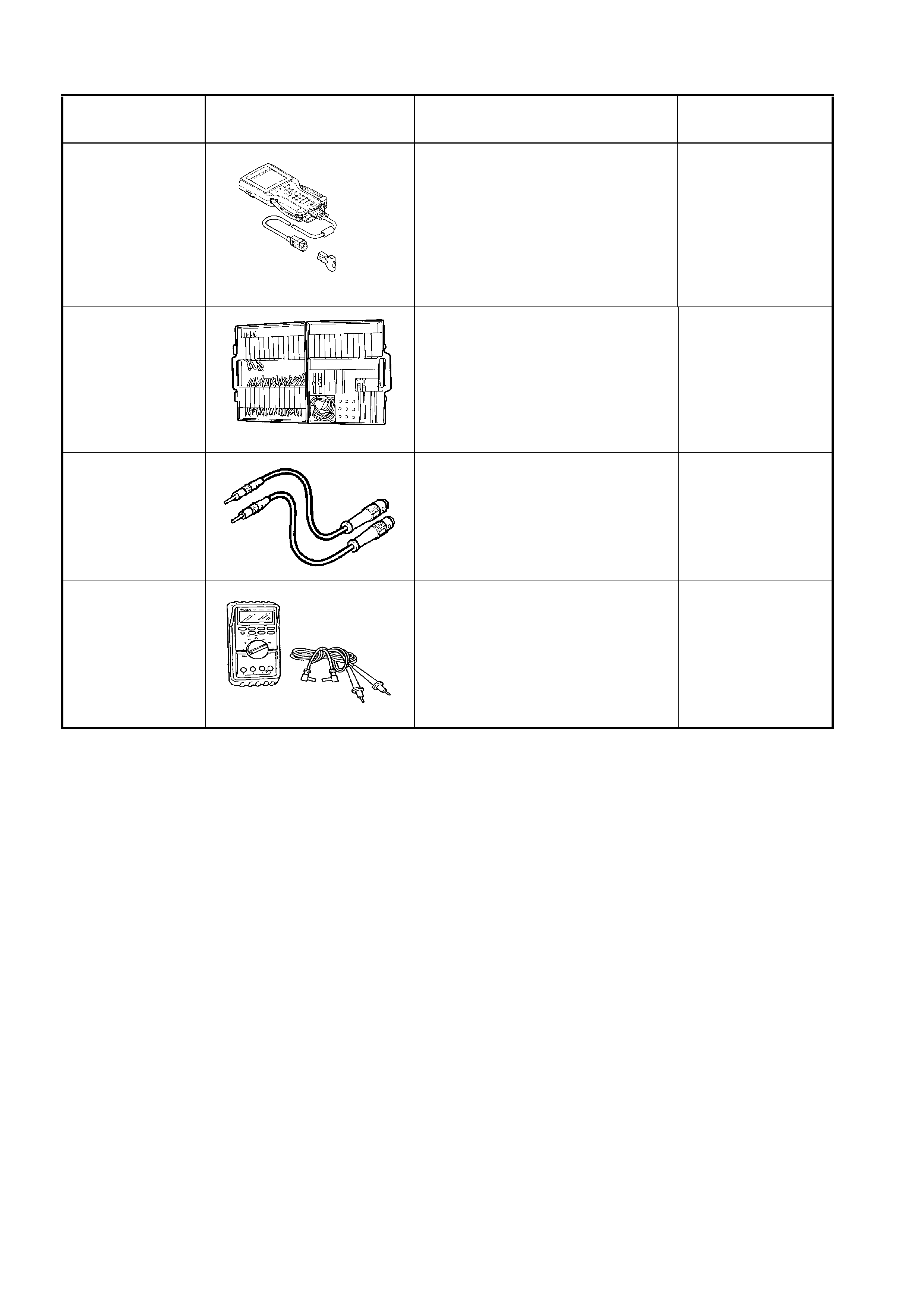
5. SPECIAL TOOLS
TOOL NUMBER ILLUSTRATION DESCRIPTION TOOL
CLASSIFICATION
7000086I
TECH 2
DIAGNOSTIC SCAN TOOL
Used for diagnosis of vehicle
electrical system.
Previously released.
Mandatory
J35616-A
(KM609)
CONNECTOR TEST ADAPTOR
KIT
Used when carrying out electrical
diagnostic circuit checks.
Previously released.
Desirable
KM609-20
TEST LEADS
Used when carrying out diagnostic circuit
check on the SIR s ys tem.
Previously released.
Mandatory
3588
(J39200)
DIGITAL MULTIMETER
Must have at least 10 MΩ input
impedance and be capable of
reading frequencies.
Previously released.
Available