
SECTION 12E - CRUISE CONTROL
IMPORTANT
Before perfo rming any Service O peration or oth er procedu re described in t his Sectio n, refer to Section 00
CAUTIONS AND NOTES for correct workshop practices with regard to safety and/or property damage.
CONTENTS
1. GENERAL INFORMATION
1.1 SYSTEM OPERATION
COMPONENTS
CRUISE CONTROL SWITCH OPERATION
2. SERVICE OPERATIONS
2.1 CRUISE CONTROL CABLE
REMOVE
REINSTALL
2.2 CRUISE CONTROL MODULE
REMOVE
REINSTALL
2.3 CRUISE CONTROL SWITCH ASSEMBLY
REMOVE AND REINSTALL
CHECKING SWITCH CONTACTS
2.4 STOP LAMP SWITCH (SWITCH A)
TESTING SWITCH CONTACTS
REMOVE
REINSTALL AND ADJUST
2.5 ELECTRICAL RELEASE SWITCH (SWITCH B)
TESTING SWITCH CONTACTS
REMOVE
REINSTALL AND ADJUST
2.6 CLUTCH PEDAL SWITCH
TESTING SWITCH CONTACTS
REMOVE
REINSTALL AND ADJUST
3. DIAGNOSIS
3.1 PRELIMINARY DIAGNOSIS AND INSPECTION
3.2 CRUISE CONTROL SYSTEM FUNCTIONAL
CHECK
ROAD TEST PROCEDURE
3.3 SELF DIAGNOSTIC TEST
3.4 CRUISE CONTROL SYSTEM CONNECTORS
AND CIRCUIT DIAGRAM
3.5 CRUISE CONTROL SYSTEM DIAGNOSTIC
CHART
TEST DESCRIPTION
4. TORQUE WRENCH SPECIFICATIONS
5. SPECIAL TOOLS
Techline

1. GENERAL I NFORMATION
Cruise control is a vehicle speed control system which maintains a desired vehicle speed without the driver having
to continually apply foot pressure to the accelerator pedal.
Depending on the model var iant, cruis e control is available as either standar d or optional equipm ent on all MY 2003
VY and V2 Series models with either automatic or manual transmission.
The cruise control system is an Electro-motor system, i.e. it uses a stepper motor to control vehicle speed.
On m odels fitted with GEN III V8 engine and traction control, a throttle relaxer servo is f itted as part of the traction
control system to pr ovide engine torque c ontrol. The thr ottle relaxer m om entarily reduces the throttle opening angle
when traction loss occurs.
There is no electronic interface between the throttle relaxer and the cruise control module.
1.1 SYSTEM OPERATION
The main components of the Electro-motor cruise control system are:
• Module Assembly – Cruise Control (cruise control module);
• Switch Assembly – Cruise Control (cruise control switch assembly, incorporated into the turn signal switch
assembly);
• Brake pedal stop lamp switch (Switch A);
• Brake pedal electrical release switch (Switch B);
• Clutch pedal switch and patch harness (manual transmission models);
• Cruise control cable; and
• Electrical wiring (incorporated into the main wiring harness).
The cruise control module also uses an output from the Powertrain Control Module (PCM) for vehicle speed, and
provides an input to the instrument cluster for cruise control status indication.
When the c r uise contr ol module is powered up via the cr uis e c ontrol O N- OF F push- button s witch, the cr uis e contr ol
module activates an input to the instrument cluster. The instrument cluster sees this line as active and sends a
message to the Multi-function Display (MFD) to turn its CRUISE icon on.
W hen the CRUISE switch is rotated to the SET -DECEL position (provided the vehicle s peed is above 40 km/h and
either the brake or clutch pedal is not pressed) the cruise control module activates an input to the instrument
cluster. The instrument cluster sees this line as active and sends a mess age to the MFD to turn its ACTIVE icon on
and in tur n, the instrument c luster inform s the PCM via the serial data interf ace to use a specif ic transm ission shift
pattern. T he transm iss ion s hift pattern is des igned primar ily for cruise m ode, having f ewer trans m ission down shif ts
and reduc ed trans miss ion gear c hange ac tivity. For f urt her inf or mation about the PCM cr uis e contr ol inter f ace, r ef er
to Section 6C, POWERTRAIN MANAGEMENT.
Figure 12E-1 illustrates the component relationship for the cruise control sy stem.
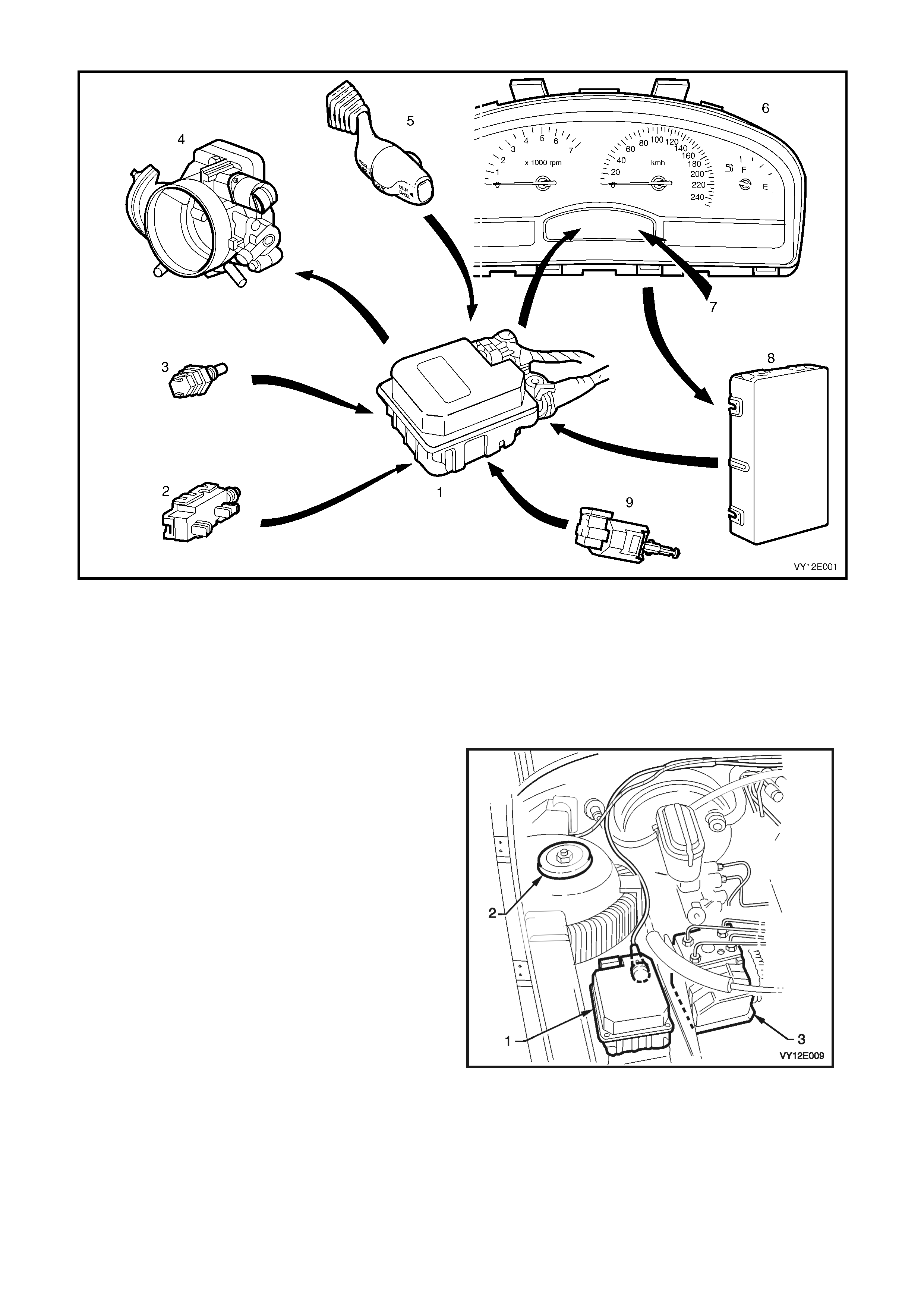
Figure 12E-1
Legend
1. Cruise Control Module 6. Instrument Cluster
2. Brake Pedal Electrical Release Switch (Switch B) 7. Multi-function Display – CRUISE and ACTIVE Icons
3. Brake Pedal Stop Lamp Switch (Switch A) 8. Powertrain Control Module
4. Throttle Body 9. Clutch Switch
5. Cruise Control Switch Assembly
COMPONENTS
The cruise control module (1) is mounted forward
of the right-hand s trut tower (2) and adjacent to the
optional ABS/TCS module (3), on both LHD and
RHD vehicles, regardless of the engine variant.
Refer to Figure 12E-2, RHD shown.
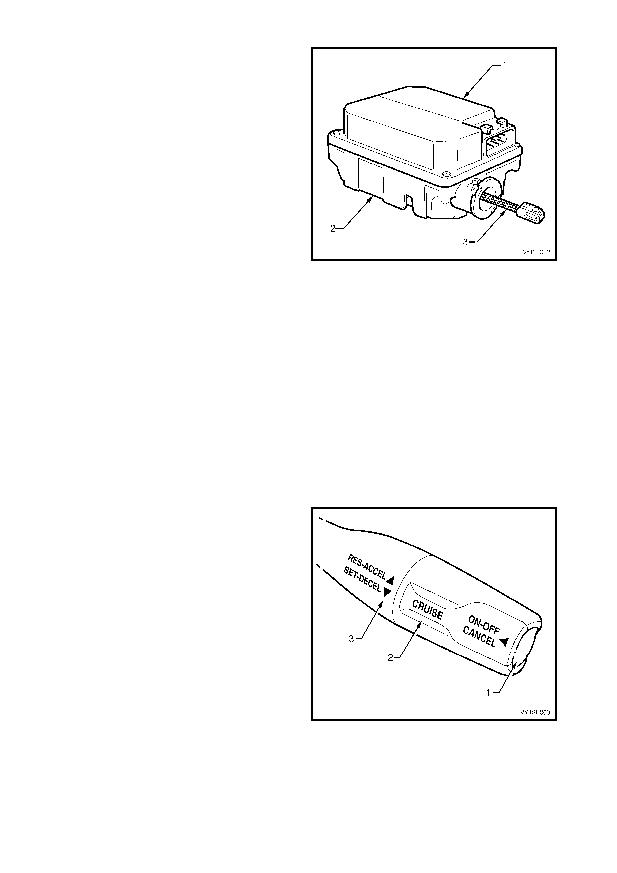
Figure 12E-2

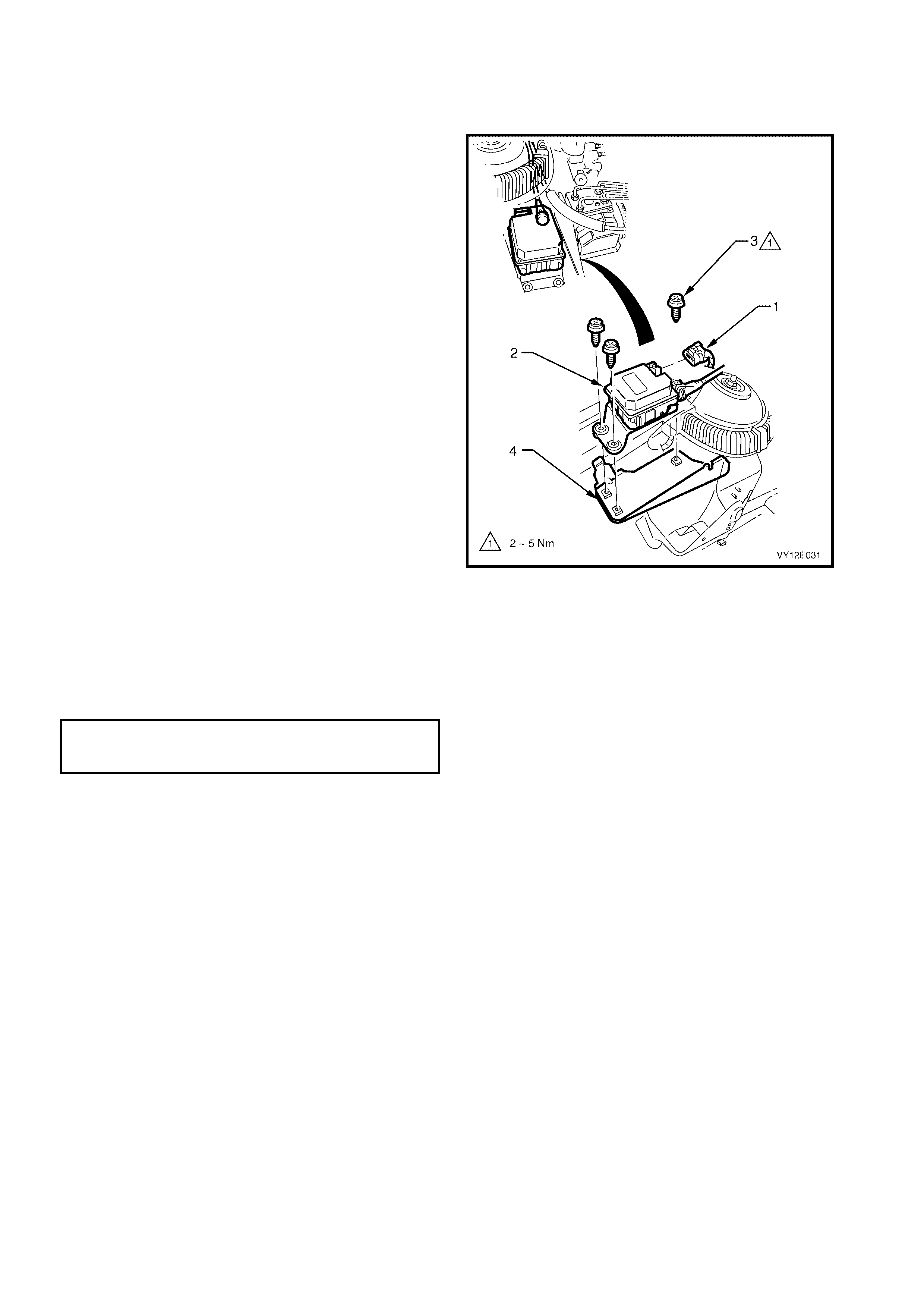
The c ruis e c ontrol module f unctionally integrates an
electronic controller (1) with an electric stepper
motor (2).
The electronic controller monitors vehicle speed
from a signal generated by the PCM which in turn,
operates the electric stepper motor.
The stepper motor, in response to the electronic
controller, adjusts the throttle position to maintain
the desired vehicle set speed. The electronic
controller is operated by the cruise control system
control switches (3), RHD model shown, located at
the tip of the headlamp and turn signal switch
assembly.
Figure 12E-3
Two switches, mounted on the brake pedal
support (1), disengage the cruise control system
electronically when the brake pedal (2) is pressed.
The upper switch (3) is the cruise control electrical
release switch (Switch B). The two rear terminals
are used for the cruise control system.
NOTE: Us ing the front set of terminals will res ult in
the cruise control not functioning.
The lower switch (4) is the brake pedal stop lamp
switch (Switch A), and is used to illum inate the stop
lamps and signal the cruise control module to
disengage.
With the brake pedal at rest, the stop lamp contacts
in the lower switch are open, and closed when the
brake pedal is pressed.
With the brake pedal at rest, the electrical release
contacts in the upper switch are closed, and open
when the brake pedal is pressed.
Both switches are used to signal the cruise control
module s o that if one should f ail, the second switch
will still generate a signal to the cruise control
module to disengage the cruise control function.
Figure 12E-4
For vehicles with a manual transmission, a clutch
pedal switch (1) mounted on the clutch pedal
support (2), has been incorporated into the cruise
control system. W hen the driver presses the clutch
pedal (3) to change gear, the cruise control is
disengaged.
When the clutch pedal is pressed, a signal is
transmitted to the cruise control module to
disengage the cruise control function.
With the clutch pedal at rest, the contacts of the
clutch switch are c losed, and open when the clutch
pedal is pressed.
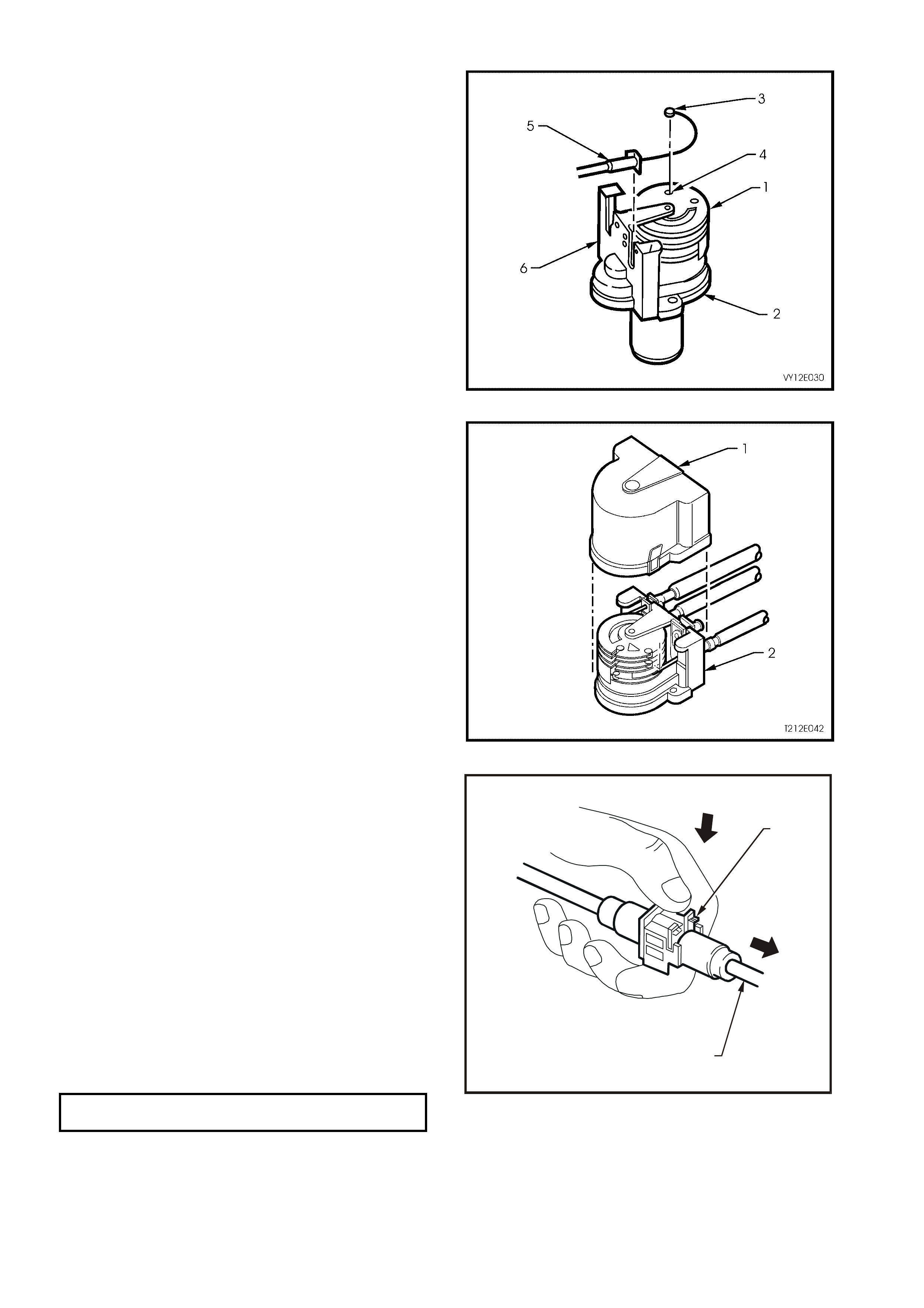
Figure 12E-5
The cruise control module comprises of an
electronic controller (1) and electric stepper motor,
solenoid operated clutch and gear train
assemblies (2), and a connecting strap (3).
The electronic controller receives signals from the
cruise control electrical release switch, stop lamp
switch, clutch pedal switch and vehicle speed
output. It then generates signals to control the
stepper m otor and solenoid operated cr uise control
module clutch.
The electric stepper motor is a brushless type
motor with a four pole perm anent magnet arm ature
and three phase stator. The motor provides torque
through a mechanical gear train to a control cable,
which actuates the throttle linkage.
When the brake pedal electrical release switch is
activated (brake pedal pressed) the stepper motor
begins to spin the motor back to the zero motor
position. If the signal at pin X1-G (refer to
Figure 12E-43) of the cruise control module is
pulled high, it will cause the stepper m otor clutch to
de-energise in about 0.75 second. In most cases,
the stepper motor will be in the zero position when
the module clutch is disengaged. This time delay
period is introduced to prevent the accelerator
pedal from slapping while the throttle is still held
open. The stepper motor relies on the throttle
return s pr ing to r eturn the s tepper motor to the zero
position as the spring on the drum gear is not
strong enough to return the throttle/cruise to zero.
The internal components of the cruise control
module are not serviceable.
CAUTION: Do not attempt to repair the cruise
control module assembly if faulty.
Unauthorised repair of the cruise control
module will affect vehicle safety.
Figure 12E-6
CRUISE CONTROL SWITCH OPERATION
Engaging the Cruise Control
With the ignition switched on, press the CRUISE
ON-OFF push-button (1), RHD model shown. This
will cause the ‘Cruise Enabled’ message to be
displayed for 2 seconds on the instrument cluster
MFD along with the cruise symbol with a flashing
set arrow and the CRUISE icon, refer to
Figure 12E-8. The instrument cluster MFD then
reverts to just the CRUISE icon, indicating that
power is on.
Accelerate the vehicle to the desired cruise speed
(above 40 km/h) and rotate the CRUISE switch (2)
to the SET-DECEL position (3) and release, then
release the accelerator pedal.
Figure 12E-7
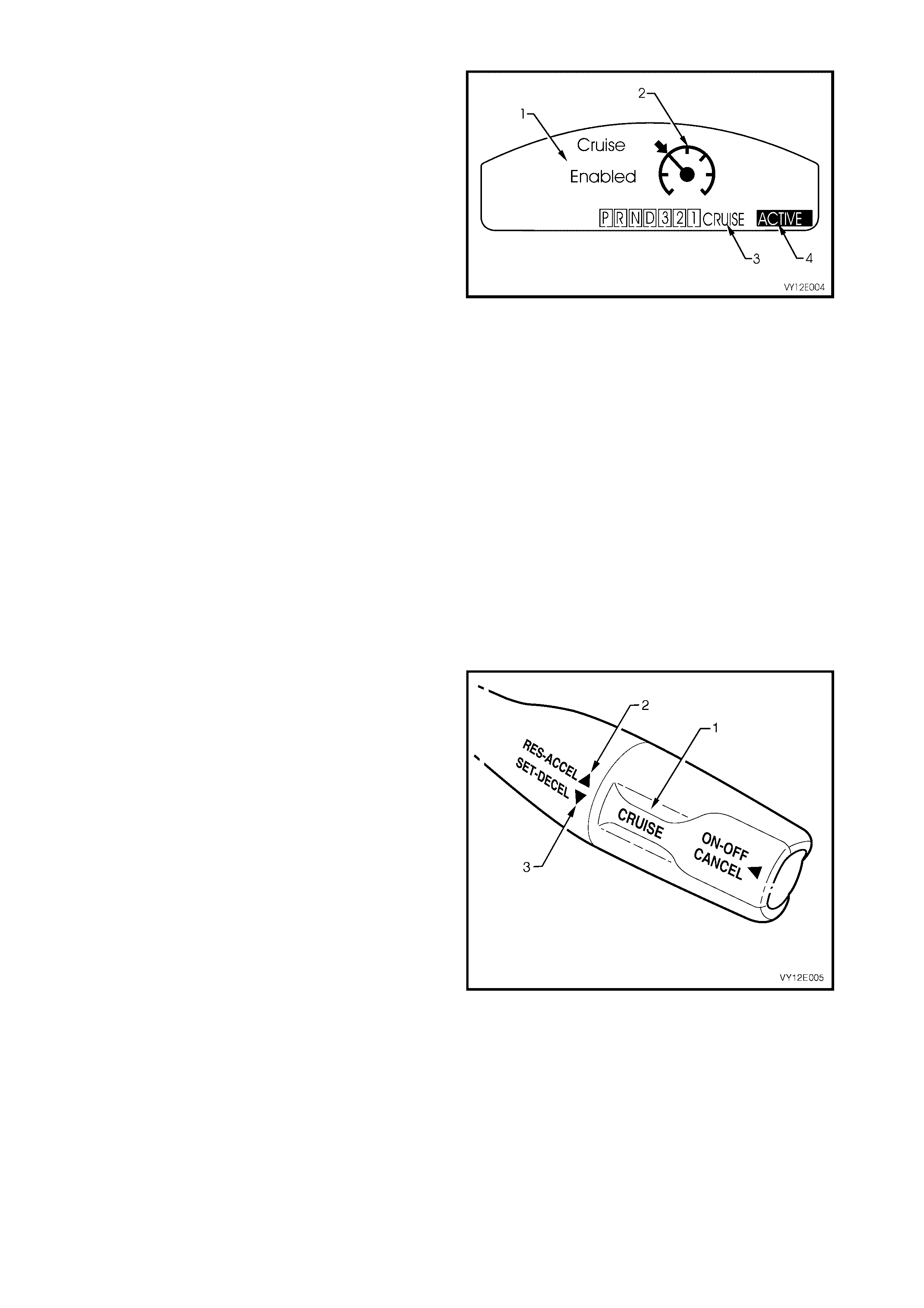
The ‘Cruise Enabled’ message (1), the cruise
symbol with a flashing set arrow (2) and the
CRUISE icon (3) will be displayed on the
instrument cluster MFD for 2 seconds when the
cruise control system is turned on at the control
switch located on the turn signal switch assembly.
The instrum ent cluster MFD then reverts to j ust the
CRUISE icon (3) indicating that power is on.
The ACTIVE icon (4) in the instrum ent cluster MFD
will be displayed when the cruise control system is
engaged. The cruise speed will be automatically
maintained, provided the vehicle speed is above
40 km/h.
Figure 12E-8
To Change Cruise Speed
To reset the cruise control to a higher speed,
accelerate the vehicle to the desired speed, rotate
the CRUISE switch (1) to the SET-DECEL
position (3) and release it. Refer to Figure 12E-9,
RHD model shown.
Rotating the CRUISE switch (1) to the RES-ACCEL
position (2) will cause an increase in cruise speed
and the vehicle will accelerate at a controlled rate
until the CRUISE switch is released. The vehicle
will now cruise at this higher set speed.
To decrease the cruise speed, rotate the CRUISE
switch to the SET-DECEL position (3). The vehicle
will decelerate, coasting to a slower speed at a
controlled rate until the CRUISE switch is released.
The vehicle will now continue to cruise at the
reduced set speed.
NOTE: While holding the CRUISE switch in the
SET-DECEL position, the ACTIVE icon (4) in the
instrument cluster MFD (refer to Figure 12E-8) will
turn OFF . The ACTIVE ic on will be displayed again
when the CRUISE switch is released.
The cruise control switches also provide the facility
for TAP UP and TAP DOWN for smaller
incremental adjustments in vehicle cruise speed.
TAP UP is ac hieved by quickly rotating the CRUISE
switch to the RES-ACCEL position and releasing.
The cruise speed will increase by 2.0 km/h for
every TAP UP. Quickly rotating the CRUISE switch
to the SET-DECEL position (TAP DOWN) will
decrease the cruise control speed by 2.0 km/h for
every TAP DOW N. T AP DOW NS are lim ited to the
minimum cruising speed of 40 km/h.
Figure 12E-9

To Override the Cruise Control System
The acceler ator pedal m ay be pressed at any time to overr ide the cruis e control s ys tem . Release of the acceler ator
pedal will return the vehicle to the cruise speed set previously.
To Disengage the Cruise Control System
The system is disengaged when:
1. The brake pedal is pressed.
2. The clutch pedal is pressed (for vehicles with manual transmission).
3. The ON-OFF push-button is pressed switching the cruise control system to the Standby mode.
IMPORTANT: When vehicles fitted with Electronic T raction Control are in a low traction situation, the c ruise control
will disengage.
When the cruise control system is disengaged, the ACTIVE icon goes out but the CRUISE icon remains.
To resume the previously set cruise control memory speed after changing gear, braking, stopping or pressing the
ON-OFF switch once; first accelerate, if required, until the vehicle speed is greater than 40 km/h, then rotate the
CRUISE switch to the RES-ACCEL position ( for less than 1 s econd). The vehicle will then autom atically acceler ate
to the previous cruise speed setting.
The cruise control module will retain the previous set speed in memory for as long as the CRUISE icon is on.
Pressing the clutch pedal or brake pedal, or pressing the ON-OFF switch once while the ACTIVE icon is, will not
erase the vehicle set speed from the cruise control module memory.
Pressing the ON-OFF switch while only the CRUISE icon is on or turning the ignition off, will erase the previous
cruise set speed from the cruise control module memory.
NOTE: Each tim e the ignition is cycled, the CRUISE and ACTIVE icons will go out. To reactivate the cruise control,
the CRUISE ON-OFF switch will have to be pressed.
2. SERVICE OPERATIONS
IMPORTANT
All fasteners are important attaching parts as they affect the performance of vital components and / or
could result in major repair expense. Where specified in this section, fasteners M UST be replaced with
parts of the same part number or a GM approved equivalent. Do not use fasteners of an inferior quality
or substitute design.
Torque values must be used as specified during reassembly to ensure proper retention of all
components.
Through out this section, fastener torque w rench specifications may be accompanied with the follow ing
identification marks:
+
++
+ Fasteners must be replaced after loosening.
&
&&
& Vehicle must be at curb height before final tightening.
6
66
6 Fasteners either have micro encapsulated sealant applied or incorporate a mechanical thread lock
and should only be re-used once. If in doubt, replacement is recommended.
If one of these identification marks is present alongside a fastener torque wrench specification, the
recommendation regarding that fastener must be adhered to.
2.1 CRUISE CONTROL CABLE
LT Section No. 03–400
REMOVE
1. On vehicles fitted with the V6 engine, push the
outer cable retaining tang (1) at the throttle
cable bracket (2) away from the throttle body
and pull the outer cable (3) out of the throttle
cable bracket.
2. On vehicles fitted with the V6 engine, remove
the inner cable retaining clip (4) from the
throttle body linkage lever stud by pushing the
retaining clip off the stud with the aid of a
screwdriver.
Figure 12E-10
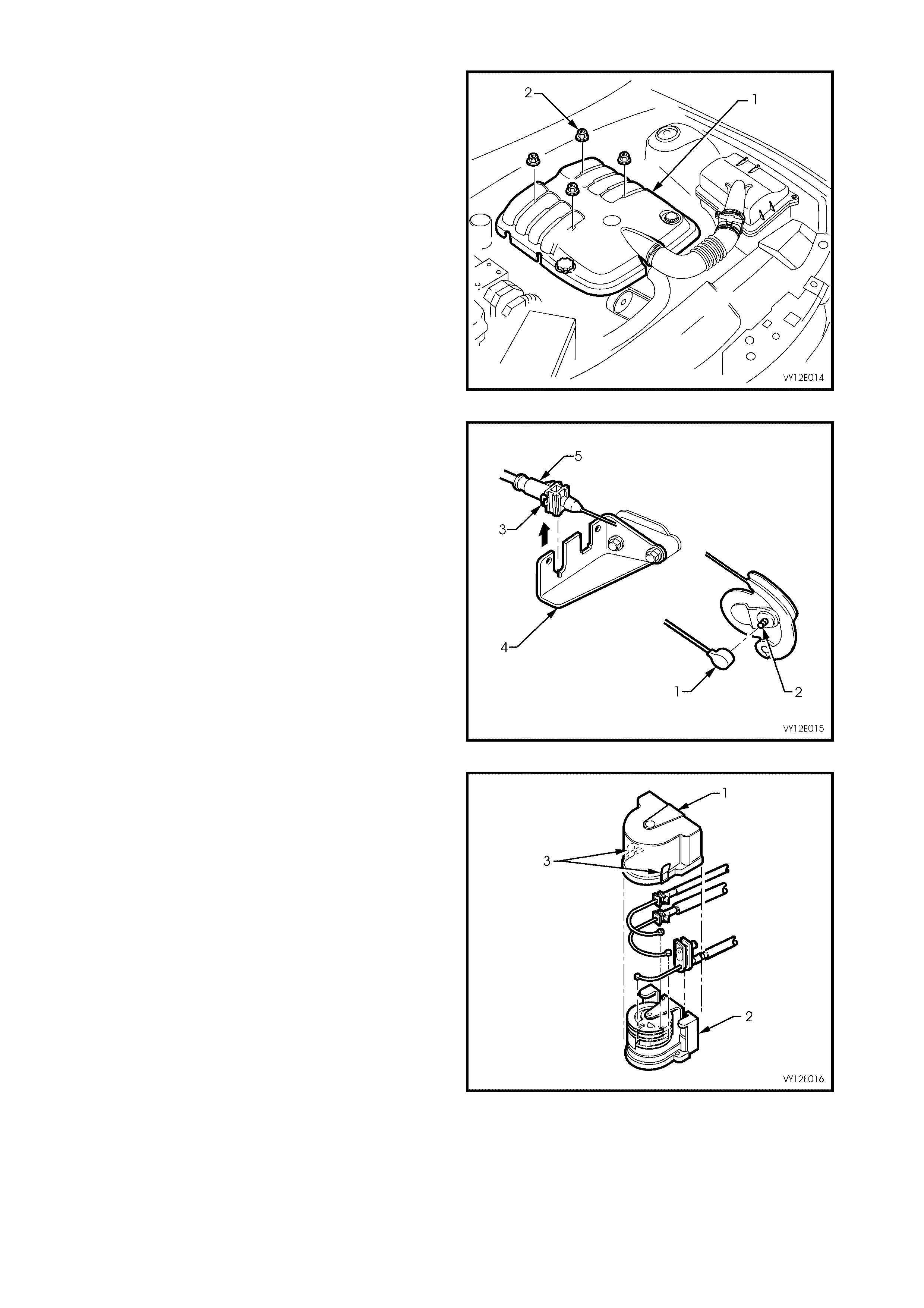
3. On vehicles fitted with the GEN III V8 engine
and without traction control, remove the four
dome nuts (2) securing the engine dress cover
assembly (1) to the intake manifold studs. Lift
and remove the dress cover assembly.
Figure 12E-11
4. On vehicles fitted with the GEN III V8 engine
and without traction control, use a screwdriver
to prise the end of the cruise control inner
cable (1) from the throttle body lever stud (2).
Lever the outer c able r etaining tang (3) at c able
the mounting bracket (4) and pull the outer
cable (5) upwards from the cable mounting
bracket.
Figure 12E-12
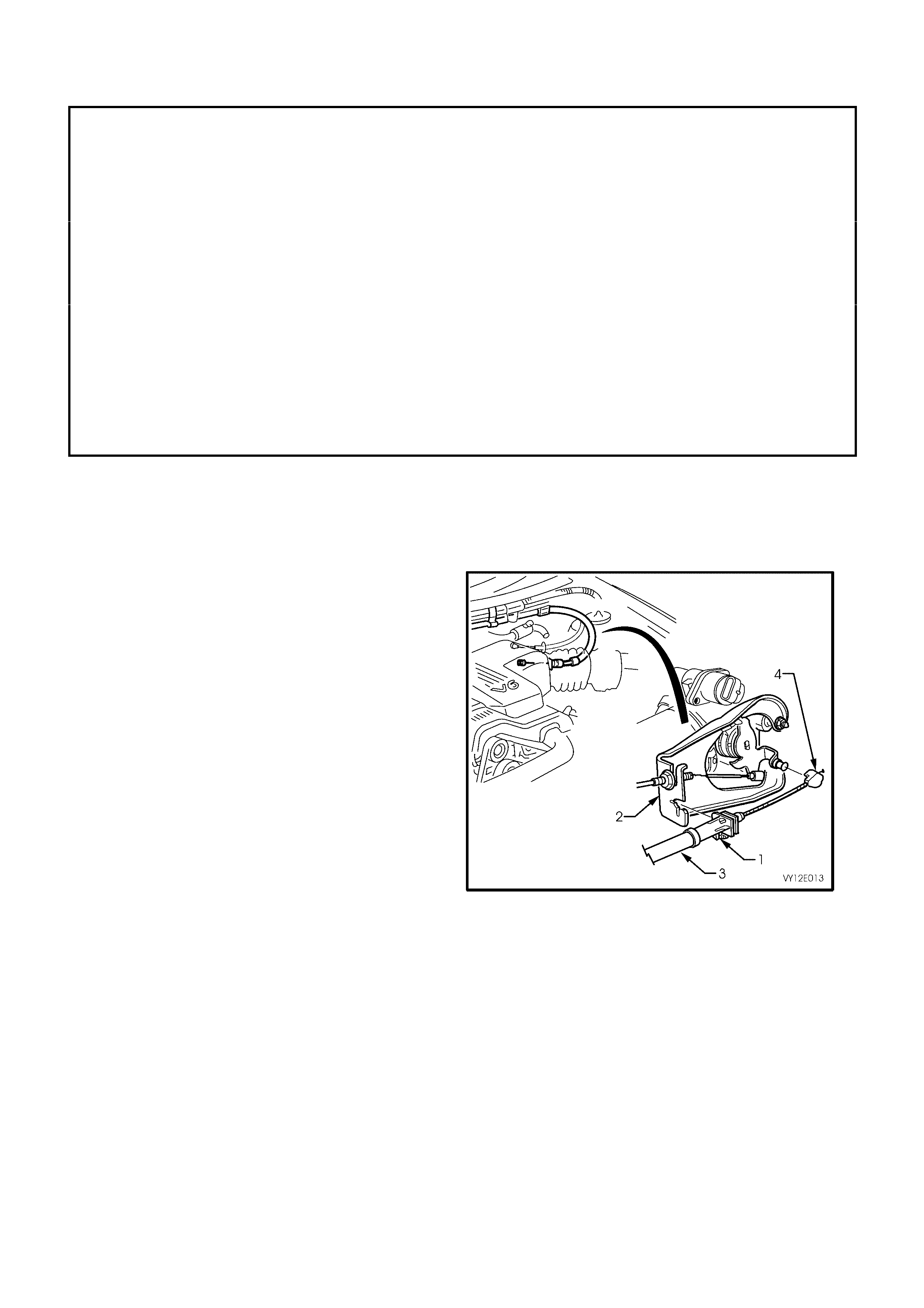
5. On vehicles fitted with the GEN III V8 engine
and traction control, remove the cover (1) from
the throttle relaxer (2) by pressing the tabs (3)
on both sides of the cover. Refer to
Figures 12E-13 and 12E-24 for RHD vehicles
and 12E-25 for LHD vehicles.
Figure 12E-13
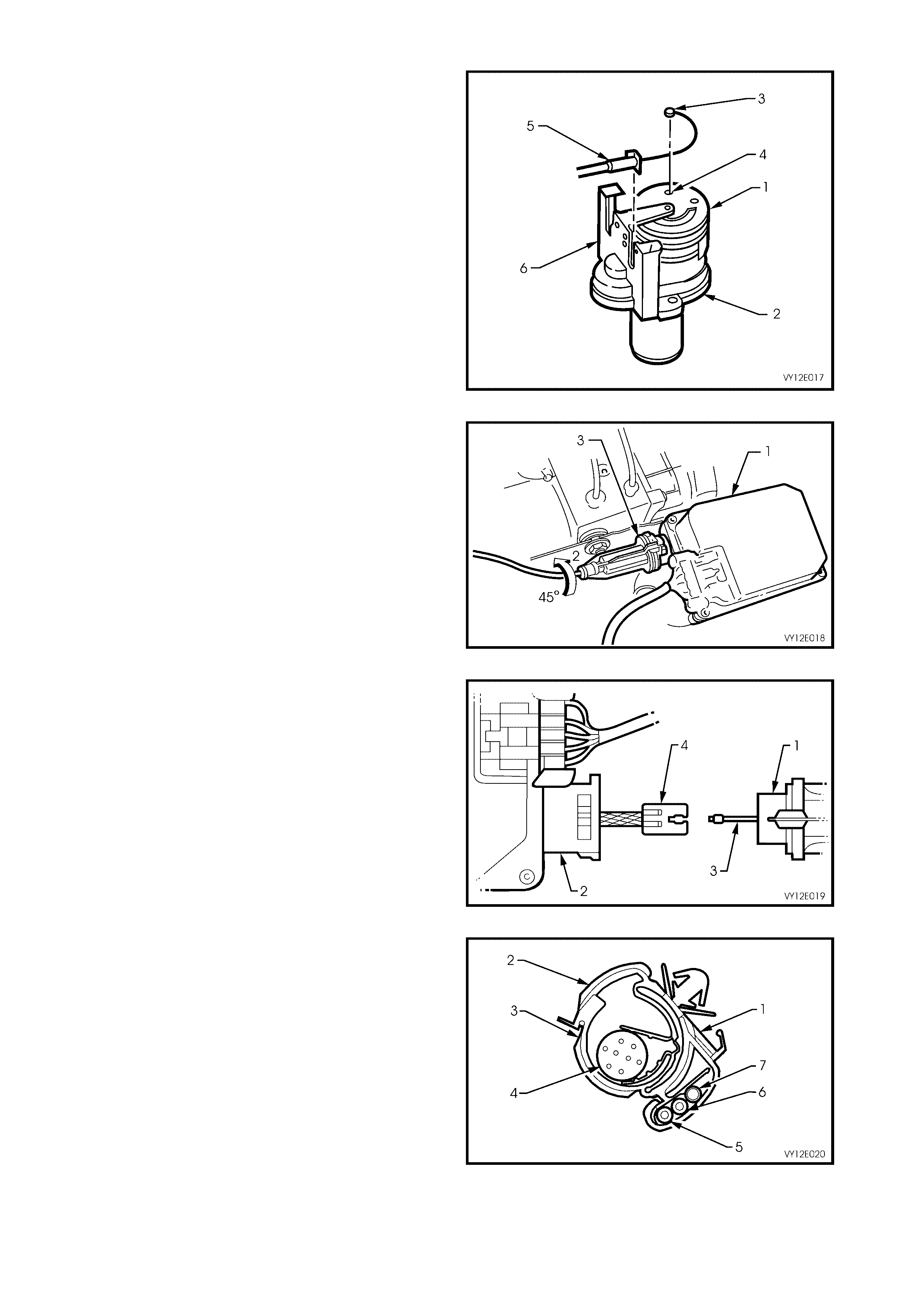
6. Rotate the top cam (1) of throttle relaxer (2)
and remove the ferrule (3) of the cruise control
inner cable from the locating slot (4) in the
throttle cam . Lever out the retaining tang of the
outer cable (5) then lift the cable away from the
throttle relaxer mounting bracket (6).
Figure 12E-14
7. At the cruise control module (1), turn the outer
control cable (2) towards the engine (approx.
45°) to release the cable lock mechanism (3)
from the cruise control module.
Figure 12E-15
8. Pull the outer cable (1) from the cruise control
module (2) and disconnect the inner cable (3)
from the electric stepper motor strap end
fitting (4) by lifting the cable upward,
approximately 45°, allowing it to be released
from the end fitting.
Figure 12E-16
9. On RHD vehicles. Release the cruise control
cable from the main wiring harness/cable
clip (1) by holding the upper retention clip (2)
and then pushing the lower retention clip (3)
inward and down to release the powertrain
wiring harness (4), throttle cable (5), cruise
control cable (6), and for wagon only, the rear
washer hose (7).
NOTE: Depending on the model and harness/c able
clip location, the clip may also retain the accelerator
pedal cable and the wiper motor harness.
Figure 12E-17
10. On LHD vehicles. Release cruise control cable
from main wiring harness/cable clip (1) by
holding the upper retention clip (2) and then
pushing the lower retention clip (3) inward and
down to release the wiper motor harness (4),
powertrain wiring harness (5), throttle cable (6 ),
cruise control cable (7) and engine hood
release cable (8).
NOTE: Depending on the model and harness/c able
clip location, the clip may also retain the accelerator
pedal cable and the wiper motor harness.
Figure 12E-18
11. Remove the cruise control cable.
REINSTALL
1. Ens uring that the motor s trap (1) is not twisted,
attach the inner cable end (2) to the motor
strap end fitting (3) at the cruise control
module (4).
Figure 12E-19
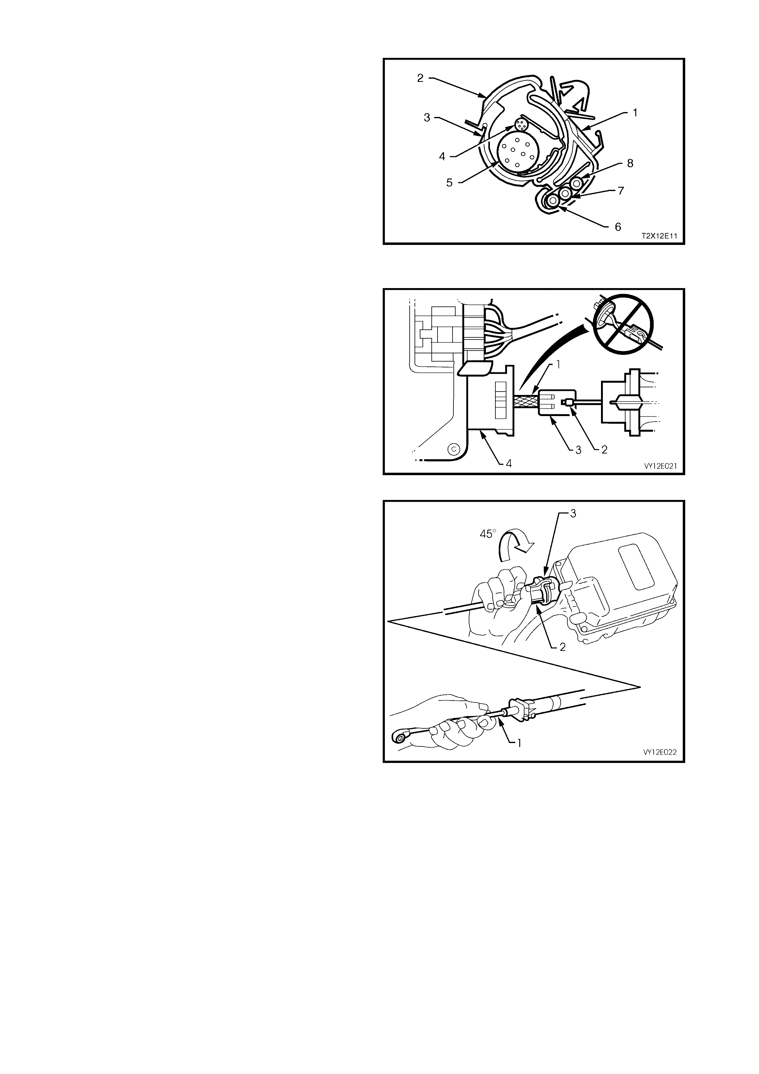
2. While holding the inner cable (1) at the throttle
body linkage lever stud connection end, slide
the outer cable (2) over the motor strap until
the outer cable sits flush with the c ruise control
module housing (3).
3. Turn the outer cable towards the right-hand
fender (approximately 45°) to lock the outer
cable locking mechanism to the cruise control
module.
4. Ensuring that the cruise control cable is routed
correctly, lock the cable into the main wiring
harness/cable clips. Refer to:
• Figure 12E-21 (V6 and V6 S/C, RHD),
• Figure 12E-22 (V6 and V6 S/C, LHD),
• Figure 12E-23 (GEN III V8 without throttle
relaxer, RHD),
• Figure 12E-24 (GEN III V8 with throttle
relaxer, RHD), and
• Figure 12E-25 (GEN III V8 with throttle
relaxer, LHD).
Figure 12E-20
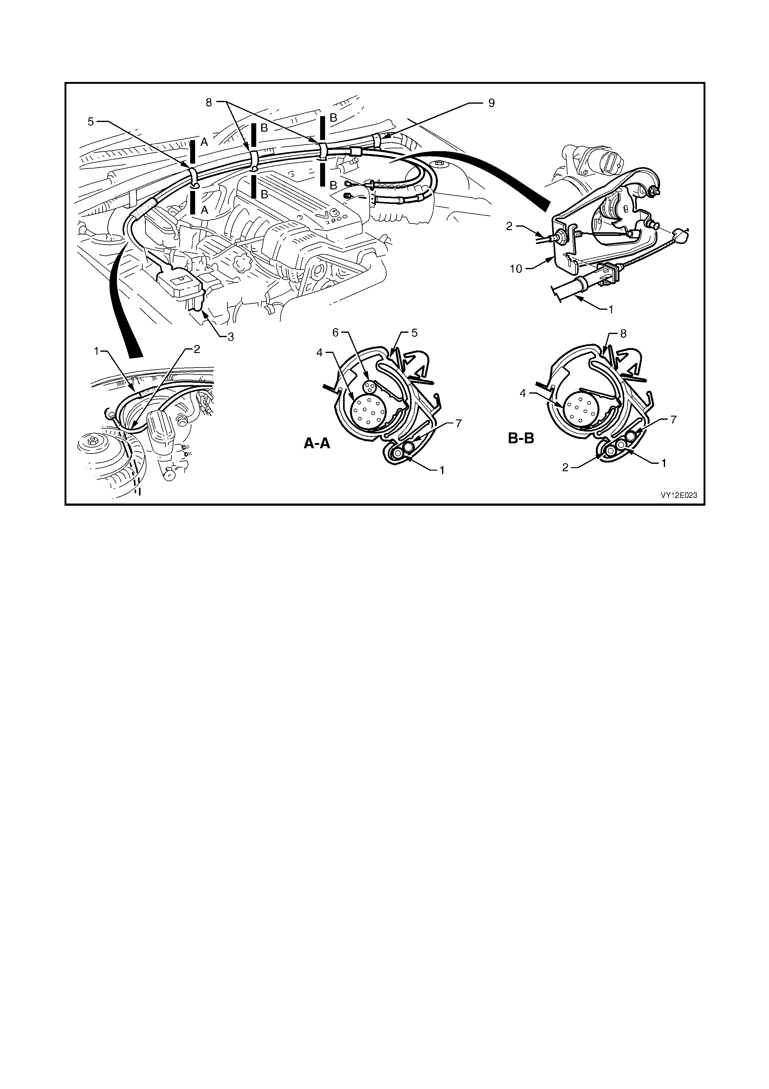
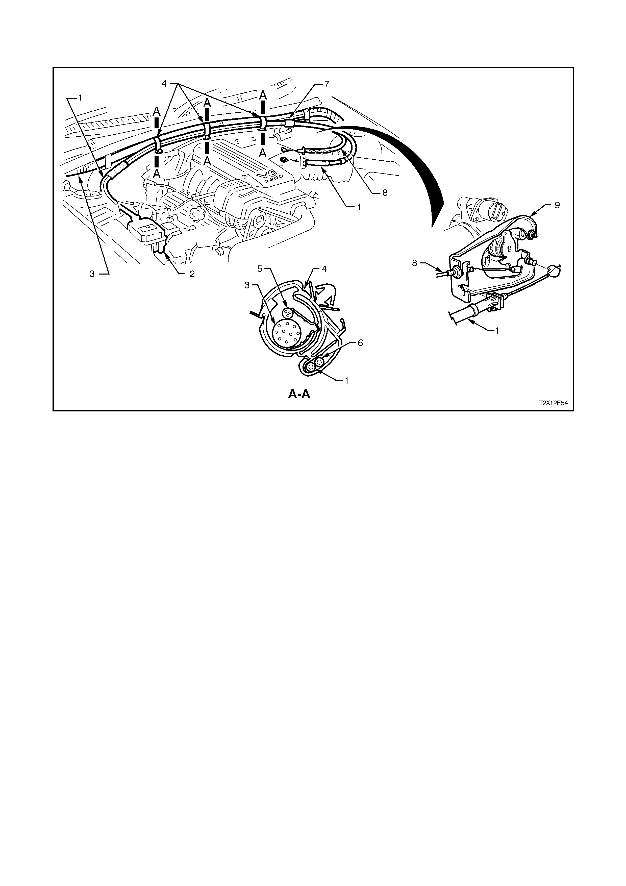
Cable Routing – V6 And V6 Supercharged Engines (RHD)
Figure 12E-21
Legend
1. Cruise Control Cable 6. Wiper Motor Harness
2. Throttle Cable 7. Rear Washer Hose (Wagon Only)
3. Cruise Control Module 8. Harness/Cable Clip (Section B-B, Three Places)
4. Powertrain Wiring Harness 9. Cruise Control Outer Cable Adjuster/Lock
5. Harness/Cable Clip (Section A-A) 10. Throttle Cable Bracket
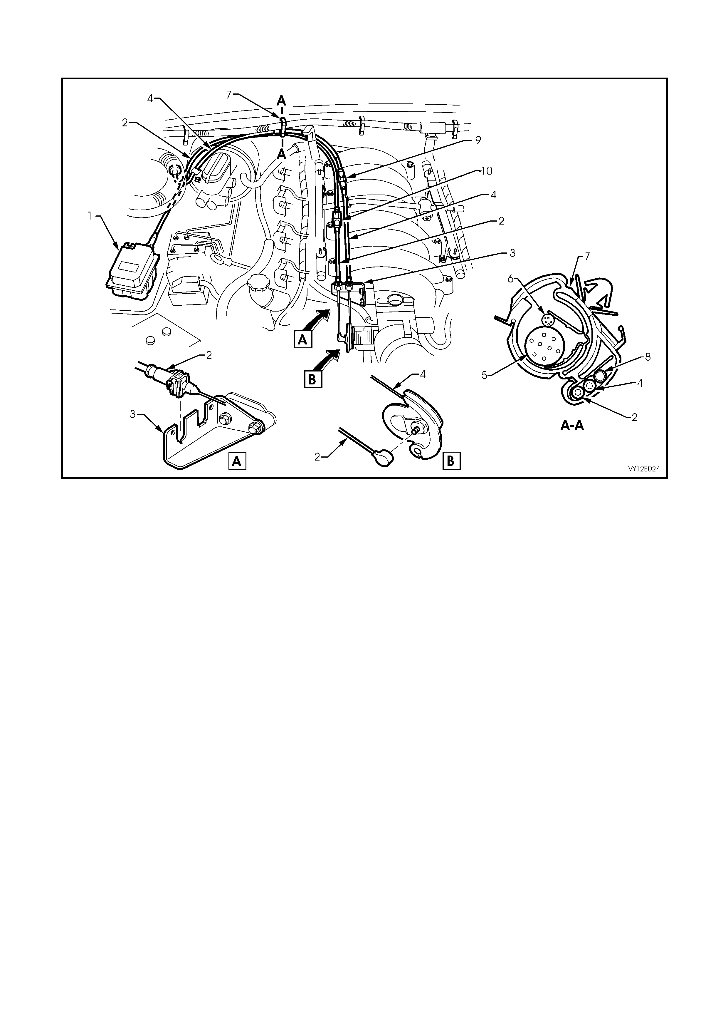
Cable Routing – V6 And V6 Supercharged Engines (LHD)
Figure 12E-22
Legend
1. Cruise Control Cable 6. Engine Hood Release Cable
2. Cruise Control Module 7. Cruise Control Outer Cable Adjuster/Lock
3. Powertrain Wiring Harness 8. Throttle Cable
4. Harness/Cable Clip (Section A-A, Three Places) 9. Throttle Cable Bracket
5. Wiper Motor Harness
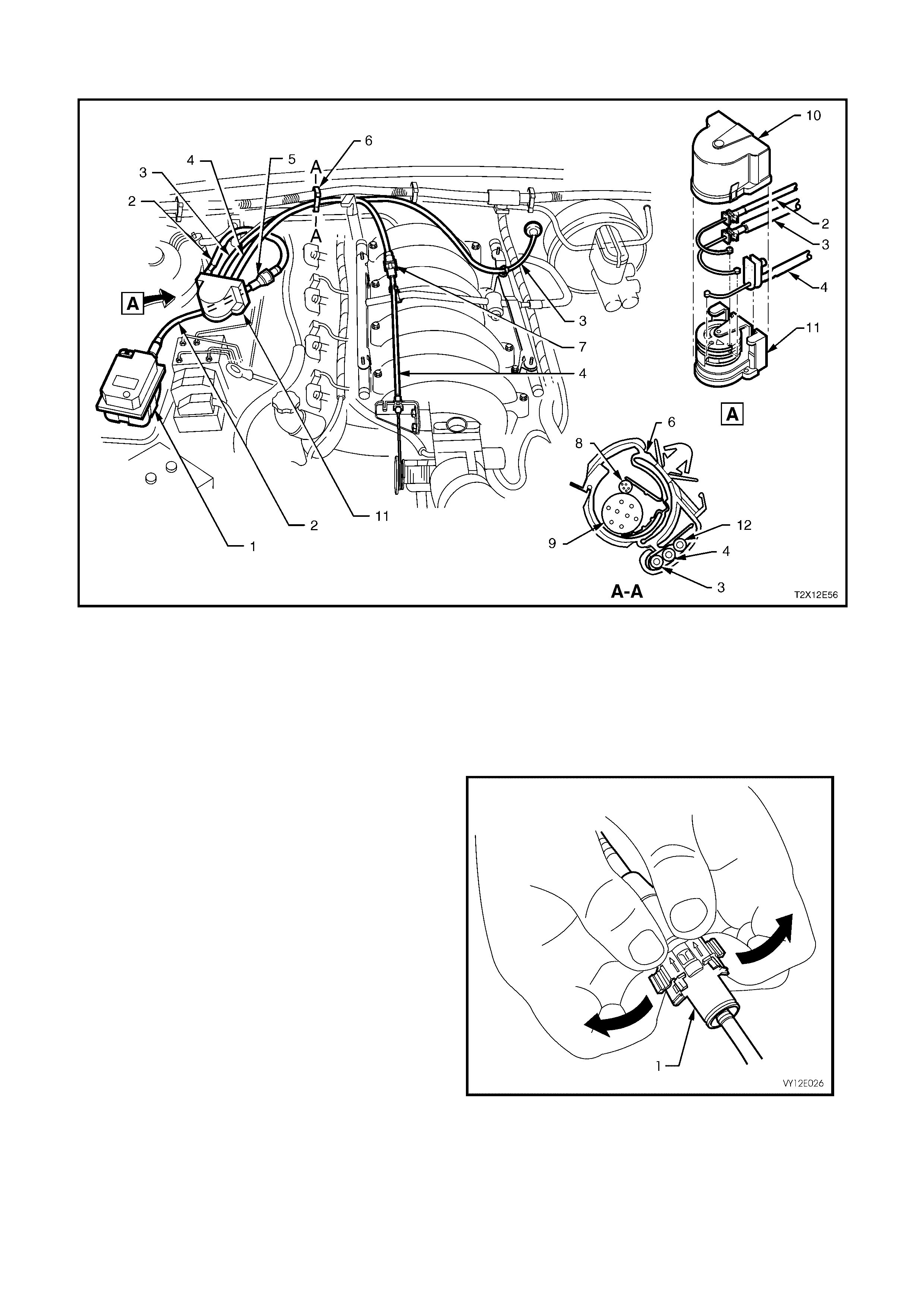
Cable Routing – Gen III V8 Engine Without Throttle Relaxer (RHD)
Figure 12E-23
Legend
1. Cruise Control Module 6. Wiper Motor Harness
2. Cruise Control Cable 7. Harness/Cable Clip (Section A-A)
3. Throttle Cable Bracket 8. Rear Washer Hose (Wagon Only)
4. Throttle Cable 9. Throttle Outer Cable Adjuster/Lock
5. Powertrain Harness 10. Cruise Control Outer Cable Adjuster/Lock

Cable Routing – GEN III V8 Engine With Throttle Relaxer (RHD)
Figure 12E-24
Legend
1. Cruise Control Module 9. Throttle Outer Cable Adjuster/Lock
2. Cruise Control Cable 10. Throttle Cable
3. Accelerator Pedal Cable 11. Harness/Cable Clip (Section B-B)
4. Powertrain Harness 12. Cruise Control Outer Cable Adjuster/Lock
5. Wiper Motor Harness 13. Harness/Cable Clip (Section C-C)
6. Harness/Cable Clip (Section A-A) 14. Throttle Relaxer
7. Rear Washer Hose (Wagon Only) 15. Throttle Relaxer Cover
8. Throttle Cable Bracket
Cable Routing – Gen Iii V8 Engine With Throttle Relaxer (LHD)
Figure 12E-25
Legend
1. Cruise Control Module 7. Throttle Outer Cable Adjuster/Lock
2. Cruise Control Cable 8. Wiper Motor Harness
3. Accelerator Pedal Cable 9. Powertrain Harness
4. Throttle Cable 10. Throttle Relaxer Cover
5. Cruise Control Outer Cable Adjuster/Lock 11. Throttle Relaxer
6. Harness/Cable Clip (Section A-A) 12. Engine Hood Release Cable
5. Unlock the cruise control outer cable by pulling
the lock tangs on the outer cable
adjuster/lock (1) in the direction indicated by
the arrows in Figure 12E-26.
Figure 12E-26
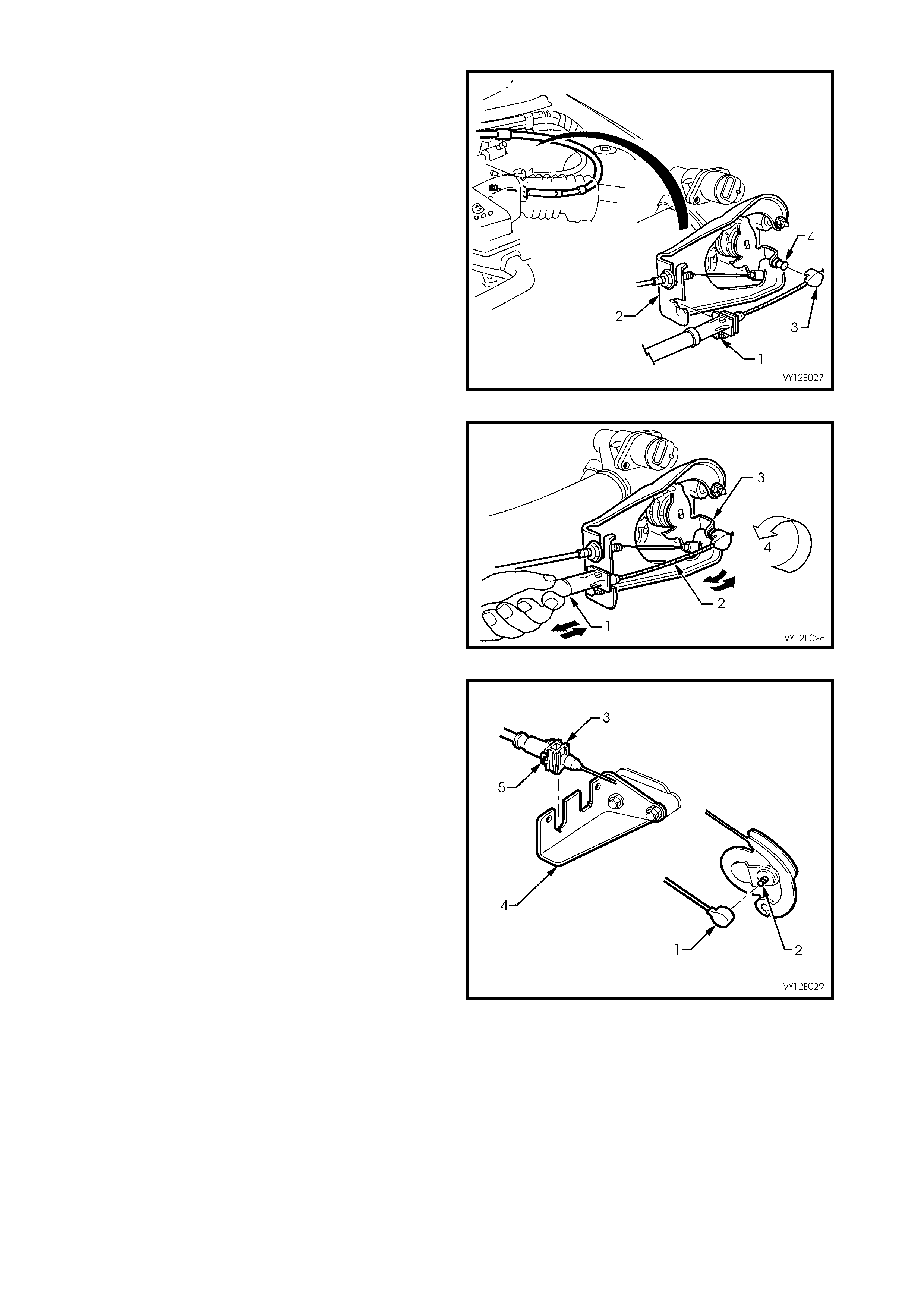
6. On vehicles fitted with the V6 engine, push the
outer cable retainer (1) into the throttle cable
bracket (2).
7. On vehicles fitted with the V6 engine, push the
inner cable retaining clip (3) onto the throttle
body linkage lever stud (4).
Figure 12E-27
8. On vehicles f itted with the V6 engine, adjus t the
cruise control outer cable (1) at the cable
adjuster/lock (refer to Figure 12E-26) to
achieve minimum slack of the inner cable (2)
while ensuring that the throttle lever (3)
remains in the fully closed position (4), refer to
Figure 12E-28.
Figure 12E-28
9. On vehicles fitted with the GEN III V8 engine
without traction control push the inner cable
retainer clip (1) onto the throttle body linkage
lever stud (2). Push the outer cable retainer (3)
into the throttle cable bracket (4) ensuring that
the cable retaining tang (5) locks into the
throttle cable bracket.
Figure 12E-29
10. On vehicles fitted with the GEN III V8 engine
and traction control, rotate the top cam (1) of
the throttle relaxer (2) and install the inner
cable ferrule (3) into the slot in the cam (4).
Ensure that the inner cable is properly in the
groove on the cam. Push the outer cable
retainer (5) onto the throttle relaxer mounting
bracket (6) ensuring that the cable retaining
tang locks into the mounting bracket.
Figure 12E-30
11. On vehicles fitted with the GEN III V8 engine
and traction control, install the cover (1) onto
the throttl e relaxer (2).
Figure 12E-31
12. Allow the internal spring of the cable
adjuster/loc k m echanism ( 1) to tak e up the f ree
play of the outer cable (2). Push down on the
outer cable locking retainer to fix the outer
cable to the correct self adjusted length. Refer
to Figure 12E-32.
NOTE: After the cable is fitted, ensure that the
throttle opens without binding and returns to the
fully closed position under throttle return spring
tension.
13. On vehicles fitted with the GEN III V8 engine
without traction control, install the engine dress
cover. Ensure that the stud grommets in the
dress cover remain in place.
14. Install the engine dress cover dome nuts.
Tighten the dome nuts to the correct torque
specification.
ENGINE DRESS COVER DOME NUT
TORQUE SPECIFICATION 4 – 6 Nm
T212E021
2
1
Figure 12E-32
2.2 CRUISE CONTROL MODULE
LT Section No. 03–400
REMOVE
1. Remove the cruise control cable, refer to
2.1 CRUISE CONTROL CABLE in this
Section.
2. Pull up the tang on the wiring harness
connector (1), and pull the connector from the
cruise control module (2).
3. Remove the three screws (3) securing the
cruise control module to the ABS/c ruise control
module mounting bracket (4) and remove the
cruise control module.
Figure 12E-33
REINSTALL
Installation of the cruise control module is the reverse of the removal operation, noting the following:
1. To install the cruise control cable, refer to 2.1 CRUISE CONTROL CABLE in this Section.
2. Tighten all fasteners to the correct torque specification.
CONTROL MODULE
SECURING SCREW
TORQUE SPECIFICATION 2 – 5 Nm
3. Connect the wiring harness connector ensuring that the connector tang is secure.
2.3 CRUISE CONTROL SWITCH ASSEMBLY
LT Section No. 06–250
REMOVE AND REINSTALL
The cruise control switches are incorporated with
the headlamp and turn signal switch assembly
located to the right of the steering column in the
RHD models and to the left of the steering column
in the LHD models.
Removal and installation instructions for the turn
signal switch assembly are described in
Section 12B, LIGHTING SYSTEM.
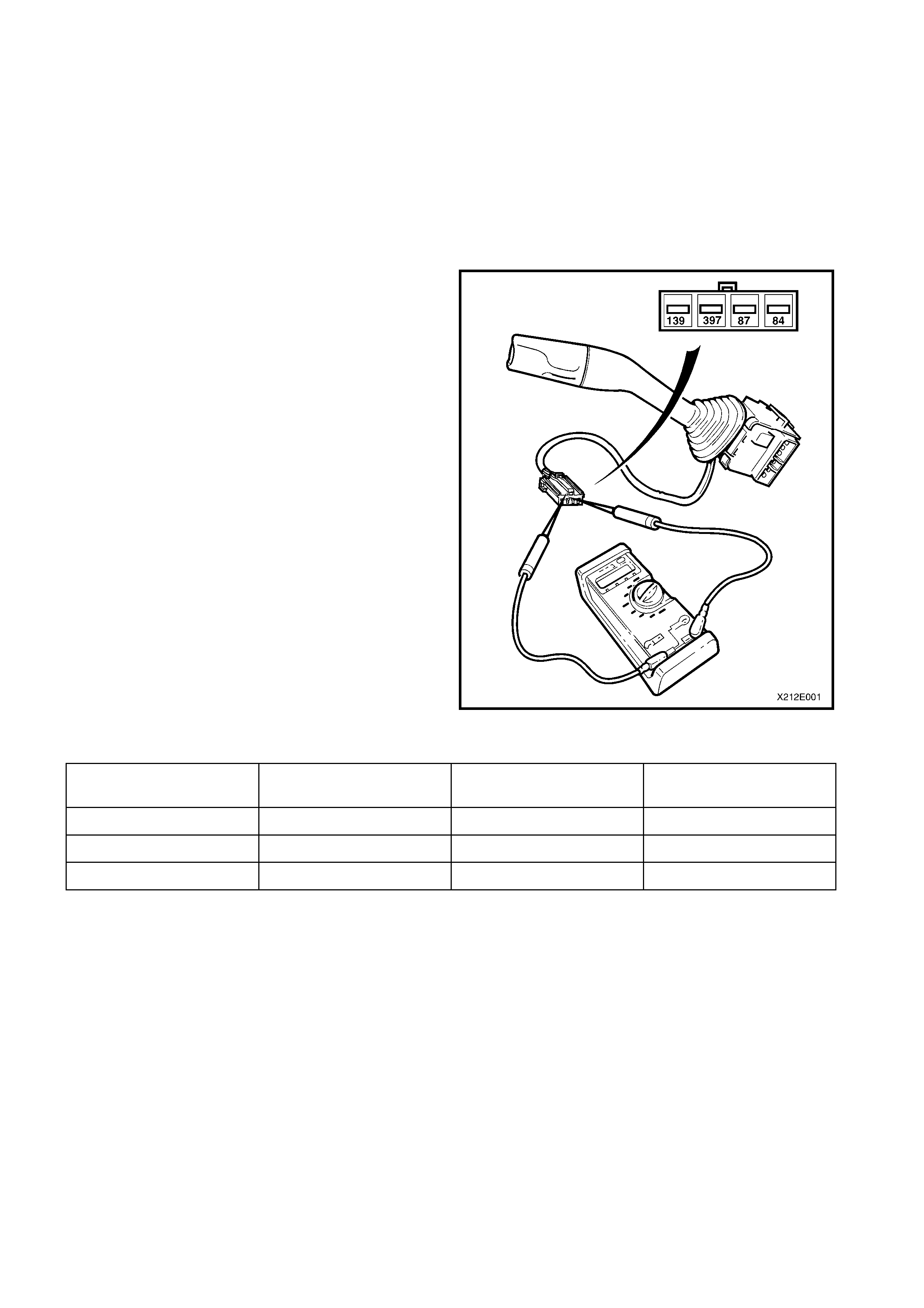
CHECKING SWITCH CONTACTS
With the cruise control switch assembly lead
disconnected from the main wiring harness, check
the cruise control switch contacts as follows:
Attach an ohmmeter to the appropriate terminals
nominated in the following chart and press and hold
button as directed. The ohmmeter will read
approximately 470 ohms resistance when the
button is pressed and show an open circuit when
released.
NOTE: If the resistance is not to specification,
replace the cruise control switch assembly.
Figure 12E-34
SWITCH OHMMETER CONNECTED
BETWEEN TERMINALS RESISTANCE –
SWITCH PRESSED RESISTANCE –
SWITCH RELEASED
ON-OFF 139 and 397 Approximately 470 Ω Open Circuit
SET-DECEL 139 and 84 Approximately 470 Ω Open Circuit
RES-ACCEL 139 and 87 Approximately 470 Ω Open Circuit
2.4 STOP LAMP SWITCH (SWITCH A)
LT Section No. 04B–600
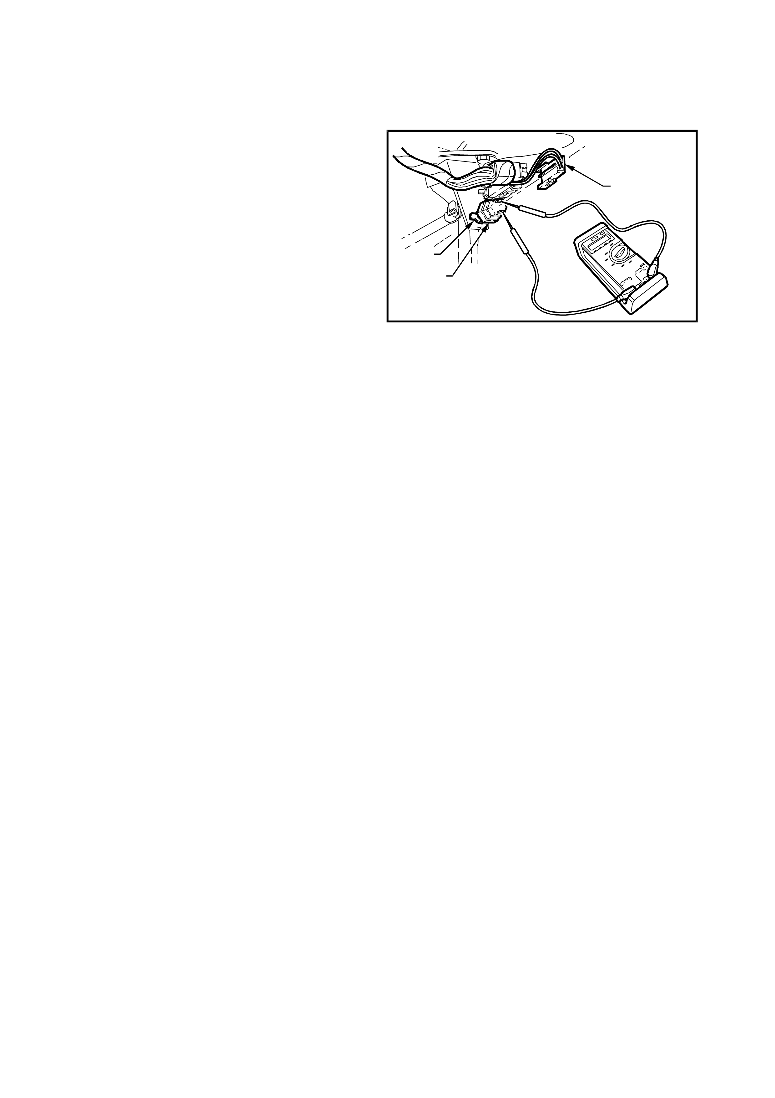
TESTING SWITCH CONTACTS
1. Check the adjustment of the stop lamp
switch (1). Refer to the following switch
installation and adjustment procedure and
adjust the switch as required.
Ensure that the stop lamps ar e operating when
the brake pedal is pressed.
If the stop lamps are not operating, repair as
necessary. Refer to Section 12B, LIGHTING
SYSTEM.
2. Remove the wiring harness connector (2) from
the terminals of the stop lamp switch (1).
3. Connect an ohmmeter across the switch
terminals and the ohmmeter should indicate
open circuit with the brake pedal at rest.
Press the brake pedal and the ohmmeter
should indicate continuity.
4. Replace the switch as per the following
removal procedure if the tests prove the switch
to be faulty.
5. If the test proves the switch to be serviceable,
connect the wiring harness connector to the
switch.
T212E045
2
3
1
Figure 12E-35
REMOVE
1. Remove the instrument panel lower trim
assembly and the instrument panel lower trim
retainer plate. Refer to Section 1A3,
INSTRUMENT PANEL & CONSOLE.
2. Disconnect the wiring harness connectors (2)
from the stop lamp switch (1), refer to
Figure 12E-35.
3. Rotate the switch anticlockwise and remove it
from the mounting nut (3).
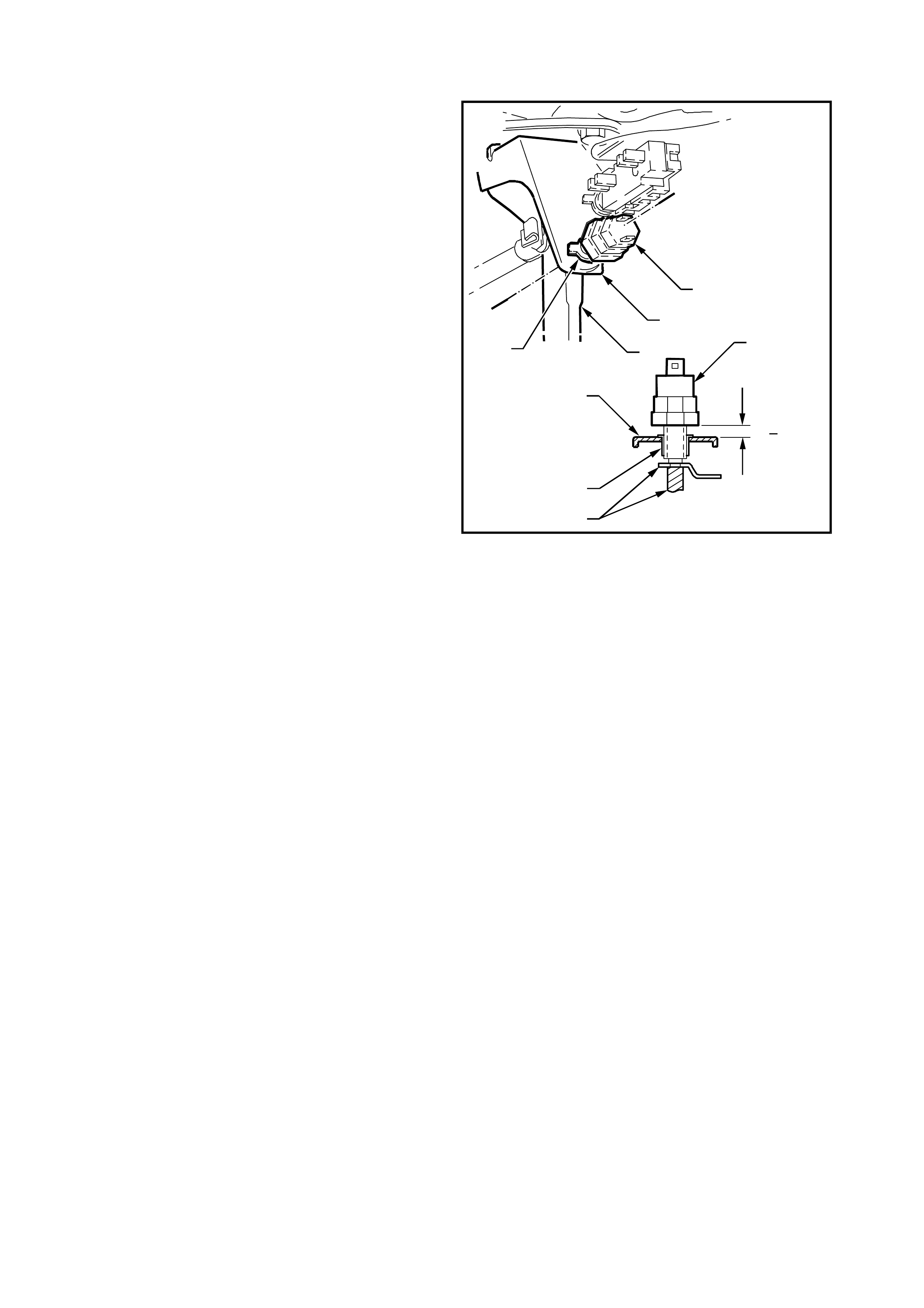
REINSTALL AND ADJUST
1. Install the stop lamp switch (1) into the
mounting nut (2) on the brake pedal
support (3).
2. With the brake pedal (4) in its rest position,
adjust the switch to the clearance dimension
shown in Figure 12E-36.
3. Connect the wiring harness connector to the
switch.
4. Install the instrument panel lower trim assembly
and the instrument panel lower trim retainer
plate. Refer to Section 1A 3, INSTRUMENT
PANEL & CONSOLE.
T212E046
1
3
2
4
6 0.5mm
A
A
1
3
4
2
A-A
+
Figure 12E-36
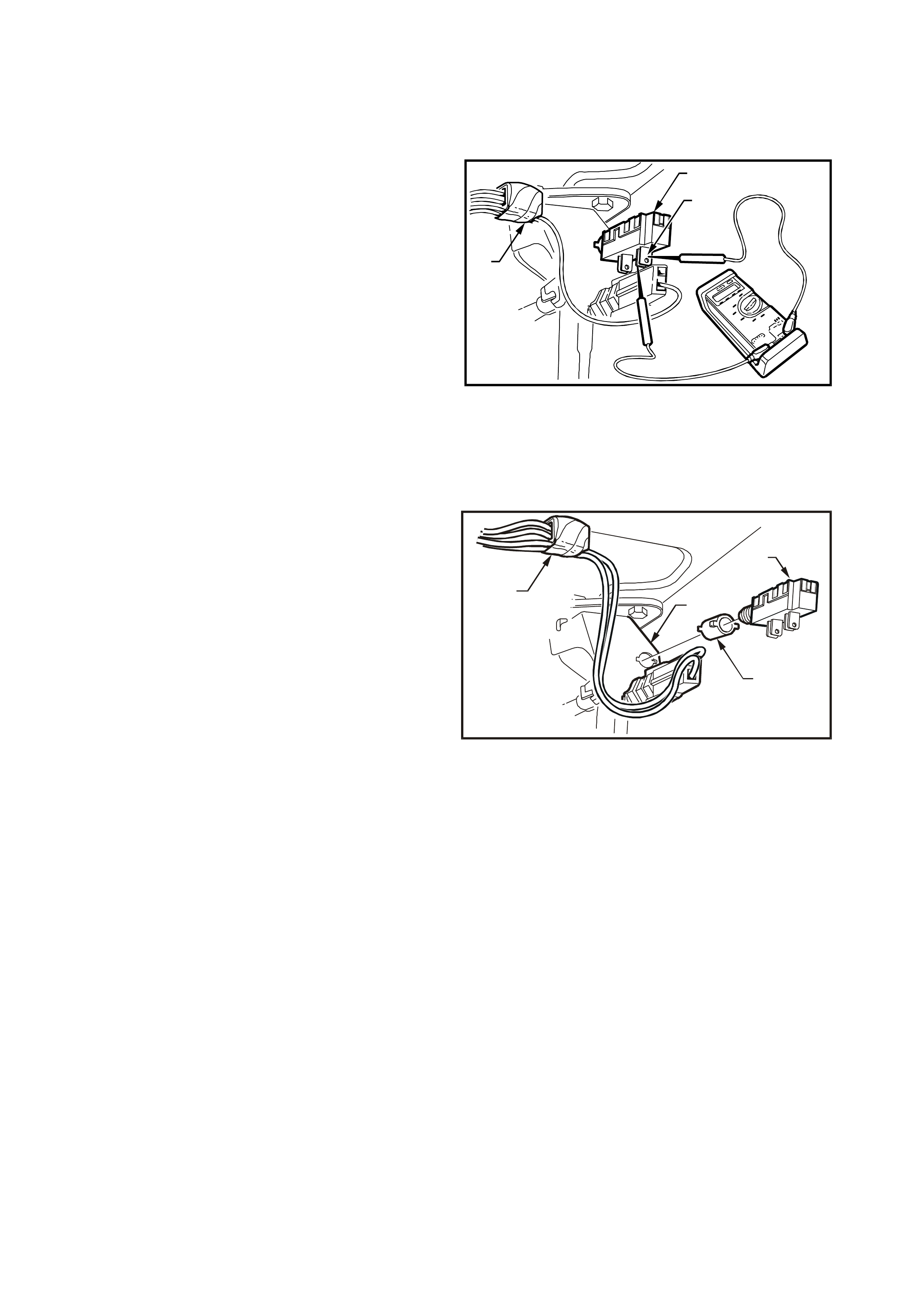
2.5 ELECTRICAL RELEASE SWITCH (SWITCH B)
LT Section No. 04B–600
TESTING SWITCH CONTACTS
1. Check the adjustment of the electrical release
switch (1), refer to the following switch
installation and adjustment procedure and
adjust the switch as required.
2. Rem ove the wiring harness c onnector from the
rear most terminals (2) of the switch.
3. Connect an ohmmeter across the switch
terminals and the ohmmeter should indicate
continuity with the brake pedal at rest.
Press the brake pedal and the ohmmeter
should indicate an open circuit.
4. Replace the switch as per the following
removal procedure if the tests prove the switch
to be faulty.
5. If the test proves the switch to be serviceable,
connect the wiring harness connector to the
switch.
T212E023
1
3
2
Figure 12E-37
REMOVE
1. Remove the instrument panel lower trim
assembly and the instrument panel lower trim
retainer plate. Refer to Section 1A3,
INSTRUMENT PANEL & CONSOLE.
2. Disconnect the wiring harness connectors (1)
from the electrical release switch (2).
3. Pull the switch from the tubular clip (3).
4. If necessary, remove the clip from the brake
pedal support (4).
T212E024
1
2
4
3
Figure 12E-38
REINSTALL AND ADJUST
1. If removed, install the tubular clip into the mounting hole of the brake pedal support.
2. Holding the brake pedal in its pressed position, install the switch into the tubular clip. Push the switch forward
until the switch body locates in the clip.
NOTE: Audible c licks will be heard as the thr eaded por tion of s witch ass embly is pushed into the tubular c lip toward
the brake pedal.
Pull the brake pedal fully against the pedal stop until audible ‘click’ sounds can no longer be heard. (The switch
assembly is pushed back out from the clip to provide the correct switch position adjustment).
Press the brake pedal again and repeat above procedure to ensure that the switch adjustment is correct (no click
sounds).
3. Connect the wiring harness connector to the switch.
4. Install the instrument panel lower trim assembly and the instrument panel lower trim retainer plate. Refer to
Section 1A3, INSTRUMENT PANEL & CONSOLE.

2.6 CLUTCH PE DAL SWITCH
LT Section No. 04B–600
TESTING SWITCH CONTACTS
1. Rem ove the wiring harnes s connector fr om the
terminals of the clutch switch.
2. Connect an ohmmeter across the switch
term inals (1) and the ohm m eter should indic ate
continuity with the clutch pedal at rest.
3. Press the clutch pedal and the ohmmeter
should indicate an open circuit.
4. Replace the switch as per the following
removal procedure if the tests prove the switch
to be faulty.
5. If the test proves the switch to be serviceable,
connect the wiring harness connector to the
switch.
T212E040
1
Figure 12E-39
REMOVE
1. Remove the instrument panel lower trim
assembly and the instrument panel lower trim
retainer plate. Refer to Section 1A3,
INSTRUMENT PANEL & CONSOLE.
2. Dis connect the wiring harness c onnectors from
the switch.
3. Turn the switch 90°, then pull the switch
assembly out from the pedal support to
remove.
REINSTALL AND ADJUST
1. Install the new switch by pushing the switch
assembly through the pedal support and
turning the switch 90°.
2. Hold the clutch pedal at its rest position.
3. Connect the wiring harness connectors to the
clutch switch.
4. Install the instrument panel lower trim assembly
and the instrument panel lower trim retainer
plate. Refer to Section 1A 3, INSTRUMENT
PANEL & CONSOLE.
5. Verify the operation of the clutch switch by
operating the cruise control and checking that
the clutch switch stops operation of the cruise
control when the clutch pedal is pressed.

3. DIAGNOSIS
3.1 PRELIMINARY DIAGNOSIS AND INSPECTION
NOTE: If a vehic le is fitted with traction contr ol, the cruise control system will disengage or fail to engage whenever
the LOW TRAC icon is displayed on the instrum ent cluster MFD, and will not engage or re-engage until the LOW
TRAC icon turns off.
When a vehicle is sus pected of having a cruis e control s ystem operation malf unction, it is im portant to carr y out the
following preliminary diagnosis. This diagnosis should be used to determine whether the cruise control system
problem is the result of an actual system defect, or the result of a problem with some other vehicle component.
Also, s om e c ruise control system c om plaints m ay be a misunders tanding by the driver about how the cruise contr ol
system f unctions . In that c as e, the operation of the s ystem should be ex plained in a manner the dr iver unders tands .
A practical demonstration is very useful to explain system operation.
If it is decided the cruise control system is at fault, perform a visual inspection of all components in the system.
Cruise control system malfunctions can be caused by mechanical, electrical, or a combination of both problems.
Things to check are:
1. Switch inputs to the cruise control module.
2. Dirty, corroded, or loose electrical connections.
3. Damaged or incor rectly adjusted stop lam p switch (Switch A). Refer to 2.4 ST OP LAMP SWITCH (SW IT CH A)
in this Section for test and adjustment procedure.
4. Damaged or incorrectly adjusted electrical release switch (Switch B). Refer to 2.5 ELECTRICAL RELEASE
SWITCH (SWITCH B) in this Section for test and adjustment procedure.
5. Damaged or inoper ative clutch pedal s witch. Refer to 2.6 CLUT CH PEDAL SWITCH in this Sec tion f or tes t and
adjustment procedure.
6. Binding or sticking throttle linkage.
7. Broken components (eg. cruise control cable).
8. Bare, broken or disconnected wires.
9. Adjustment of the control cable, refer to 2.1 CRUISE CONTROL CABLE in this Section.
10. On vehicles fitted with GEN III V8 engine and traction control, ensure that the throttle relaxer is functioning
correctly. Refer to Section 12L, ABS AND ABS/ETC.
11. If pr elim inary inspection reveals no problem , and the s ystem is m alfunc tioning, refe r to 3.3 SELF DIAGNOSTIC
TEST in this Section.
NOTE: Verify that the problem exists before attempting any repairs. Sometimes normal operating characteristics
may be misunderstood as a problem.

3.2 CRUISE CONTROL SYSTEM FUNCTIONAL CHECK
The f ollowing procedure s hould be used to chec k the oper ating m odes of the cruis e control s ystem. T his procedure
should always be used after repair work has been completed on the cruise control system.
ROAD TEST PROCEDURE
1. Check ON-OFF activation: Ignition on, press the cruise control ON-OFF push-button to turn the system on;
system CRUISE icon should illuminate.
2. Check the low speed inhibit: Drive the vehicle at 30 km/h. Rotate the CRUISE switch to the SET-DECEL
position and release. Cruise control must not engage and only the CRUISE icon should be illuminated.
3. Check set speed: Drive the vehicle at a steady speed of 60 km/h. Rotate the CRUISE switch to the
SET-DECEL position and release. The cruise control should engage at approximately 60 km/h and both the
CRUISE and ACTIVE icons must illuminate.
4. Check b rake release: With the cruis e c ontrol system engaged, pr ess the br ak e pedal. The c ruise c ontrol m ust
release the throttle, allowing vehicle speed to drop. The system must not re-engage when the brake pedal is
released. The ACTIVE icon must go out but the CRUISE icon should remain on.
5. Check clu tch release (manual t ransmission only): With the cruis e control system engaged, pr ess the clutch
pedal. The c ruise control m ust r elease the throttle, allowing the vehicle speed to drop. The system m ust not re-
engage when the clutch pedal is released. The ACTIVE icon must go out but the CRUISE icon should remain
on.
6. Check resume feature: With the vehicle speed at approximately 50 km/h, rotate the CRUISE switch to the
RES-ACCEL position and release. The vehicle should accelerate to approximately 60 km/h and the CRUISE
and ACTIVE icons should illuminate again.
7. Check coast feature: Rotate the CRUISE switch to the SET-DECEL position and hold. Only the ACTIVE icon
must go out. Allow the vehicle speed to drop to 50 km/h and release the CRUISE switch. The cruise control
should hold the vehicle speed at approximately 50 km/h and both the ACTIVE and CRUISE icons should be
illuminated.
8. Check accelerator feature: Rotate the CRUISE switch to the RES-ACCEL position and hold. The vehicle
speed should begin to increase. Allow the speed to increase to 60 km/h and release the switch. The cruise
control s hould hold the vehicle s peed at approximately 60 km /h. Both the ACT IVE and CRUISE ic ons should be
illuminated.
9. Check coast down mode:
a) Press and release the ON-OFF push-button. The vehicle should begin to slow down (this has the same effect
as holding the CRUISE switch in the SET-DECEL position). In this m ode, the cruise is deactivated and allows
the vehicle to slow down but the CRUISE icon remains illuminated. Allow the vehicle to slow to approximately
50 km/h then rotate the CRUISE switch to the RES-ACCEL position and release. The vehicle must return to
approximately 60 km/h and both the CRUISE and ACTIVE icons should be illuminated.
b) Press and release the ON-OFF push-button and allow vehicle to slow to approximately 50 km/h again then
rotate the CRUISE switch to the SET-DECEL position. The vehicle speed must hold at 50 km/h and both the
CRUISE and ACTIVE icons should be illuminated.
c) Press the ON-OFF pus h-button again and allow the vehicle to coast down. Only the CRUISE icon should be
illuminated.
d) Press the ON-OFF push-button again while in coast down mode (Step c) to fully turn the cruise control
system off. Both the CRUISE and ACTIVE icons must go out.

3.3 SELF DIAGNOSTIC TEST
To provide a means of checking the brake switch, clutch switch, cruise release switch, speed sensor inputs and
electro-motor operation, the cruise control system incorporates a self diagnostic facility.
Following the SELF DIAGNOSTIC TEST CHART is a detailed Diagnostic Chart to pin point the cause of a cruise
control system malfunction. Refer to 3.5 CRUISE CONTROL SYSTEM DIAGNOSTIC CHART in this Section.
Carry out the Self Diagnostic Test as outlined.
Jack up the vehicle and support on saf ety stands. Ref er to Section 0A GENERAL INFORMAT ION f or the location
of jacking points. Ensure that the drive shafts are horizontal.
Follow Steps 1 – 23 in the SELF DIAGNOSTIC TEST CHART and perform each function as requested. If at any
stage during this tes t the system does not func tion as nominated (CRUISE or ACTIVE icon illum ination), repair the
fault as necessary.
NOTE: If at any time during Steps 1 – 23 of the diagnos tic test the ignition is switched off , the cruise control system
will exit diagnostic mode and return to normal operating conditions.
Self Diagnostic Test Chart ICONS
(Refer to Figure 12E-40)
STEP PROCEDURE
CRUISE ACTIVE
COMMENTS
1 Turn ignition OFF OFF OFF Clears memory of any pre-set speed.
2 Press and hold in the ON-OFF push-button OFF OFF
3 Turn ignition ON ON OFF Triggers diagnostic test. ON-OFF push-
button must be held until Step 13.
4 Wait 5 seconds ON OFF Waits for LOW TRAC warning icon to
switch OFF (if fitted).
5 Rotate and hold SET-DECEL position ON ON
6 Release SET-DECEL position ON OFF Tests SET-DECEL function of cruise
control switch assembly.
7 Rotate and hold RES-ACCEL position ON ON
8 Release RES-ACCEL position ON OFF Checks RES-ACCEL function of cruise
control switch assembly.
9 Press and hold brake pedal ON ON
10 Release brake pedal ON OFF Checks cruise control electrical release
switch (switch B).
11 Press and hold clutch pedal (man. trans.)
brake pedal (auto. trans.) ON ON
12 Release clutch pedal (man. trans.) brake
pedal (auto. trans.) ON OFF
This Step is included for vehicles with
manual transmission. If the vehicle is
fitted with automatic transmission, then
the brake pedal must be pressed and
released to enable the completion of
the switch diagnostic test.
13 Release ON-OFF push-button ON ON
14 Press and hold in the ON-OFF push-button OFF OFF Enters the second stage of the
diagnostic mode to check the ON-OFF
switch and cruise control warning
icons.
15 Press and hold brake pedal OFF ON
16 Release brake pedal OFF OFF
17 Press and hold brake pedal OFF ON
18 Release brake pedal OFF OFF
Checks stop lamp switch (switch A)
and cruise control switch inputs to
cruise control module. If not
functioning, repair as necessary.
19 Release ON-OFF push-button OFF ON Enters final stage of diagnostic mode,
allowing vehicle to be road tested
without having to hold cruise control
function buttons.
20 Press and hold brake pedal after motor
stroking OFF
OFF
OFF
ON
Checks stepper motor and cable
operation.
Stepper motor will stroke and return to
rest (closed throttle) state. If not
functioning, repair as necessary.
21 Hold brake pedal and start engine OFF X ACTIVE icon can be either ON or OFF.
22 Select DRIVE, drive vehicle and monitor
ACTIVE icon OFF FLASH ACTIVE icon will flash with vehicle
speed signal.
Checks speed sender input to cruise
control module. If not functioning as
specified, replace cruise control
module.
23 Select PARK (auto. trans.), 1st gear (man.
trans.) and switch engine OFF OFF OFF Ends diagnostic mode. Returns cruise
control to normal operating conditions.

Legend
1. Cruise Text Message
2. Flashing Set Arrow
3. Cruise Symbol
4. CRUISE Icon
5. ACTIVE Icon
Figure 12E-40
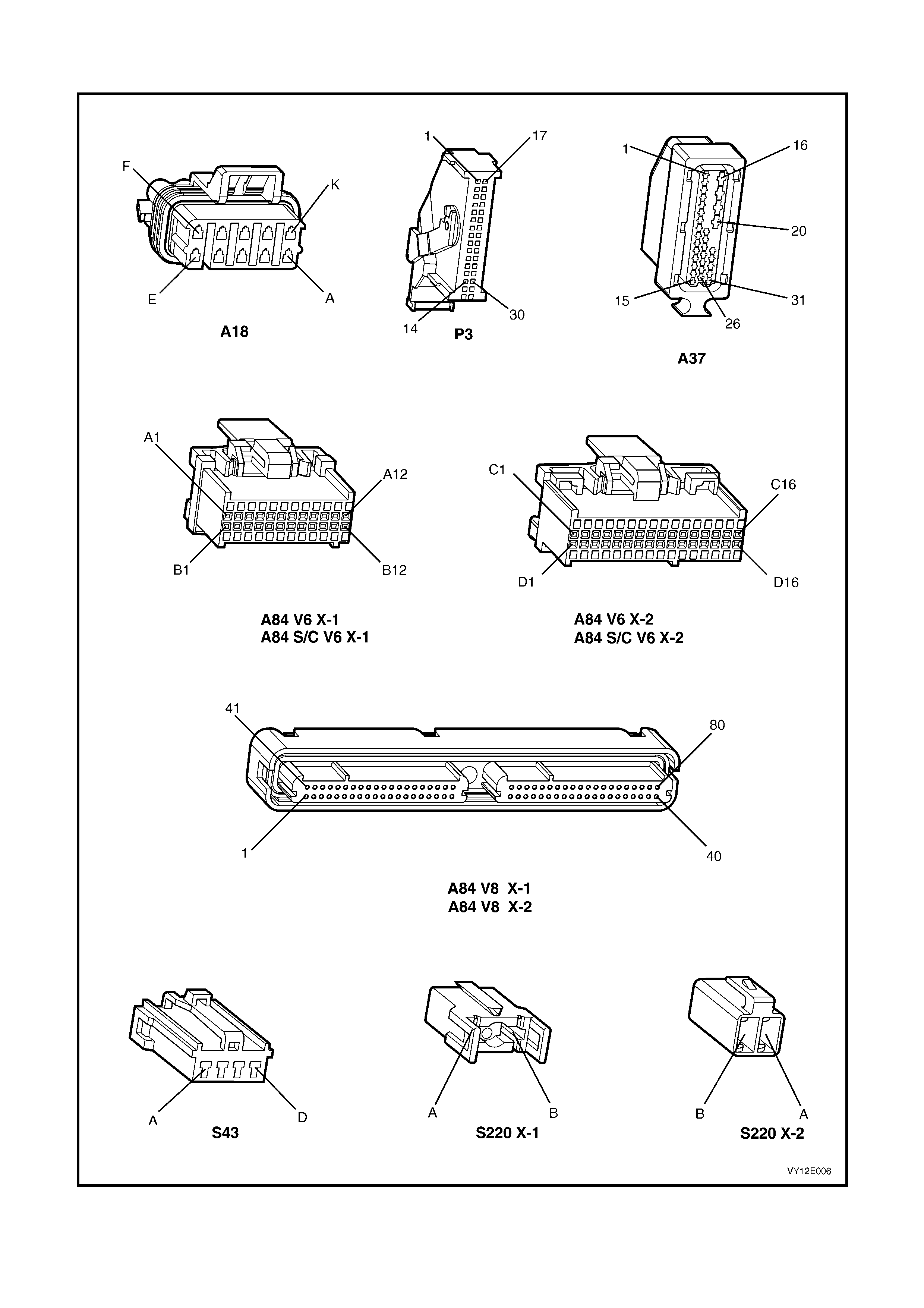
3.4 CRUISE CONTROL SYSTEM CONNECTORS AND CIRCUIT DIAGRAM
Figure 12E-41

Figure 12E-42
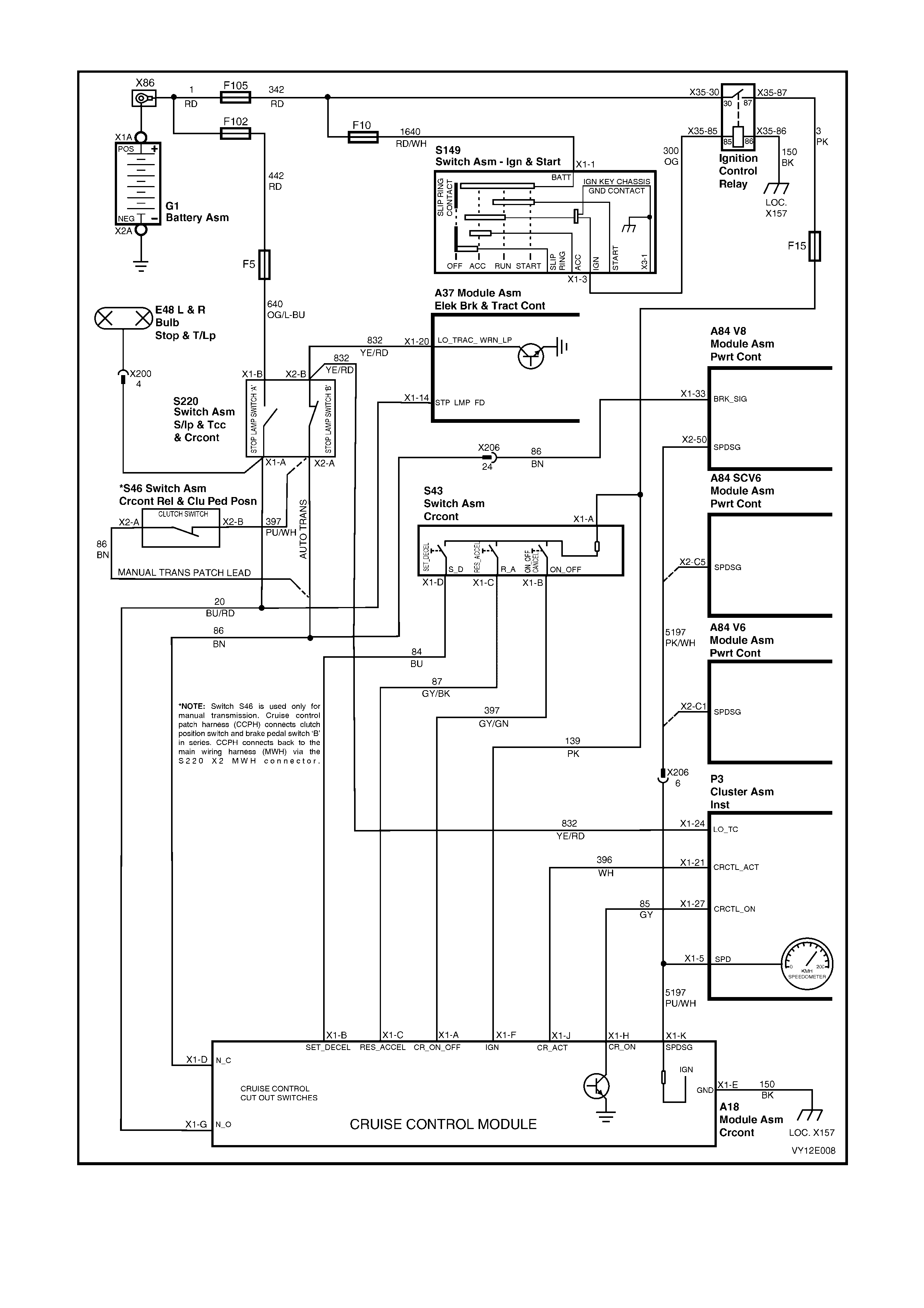
Figure 12E-43

3.5 CRUISE CONTROL S YSTEM DIAGNOSTIC CHART
When using the following diagnostic chart, refer also to the cruise control system circuit diagram and connectors
(refer to Figure s 12E-41, 12E-42 and 12E-43).
TEST DESCRIPTION
The numbers below refer to Step numbers in the diagnostic chart for the cruise control system.
1. Checks ignition supply to the cruise control module.
2. Checks for ground circuit 150 to the cruise control module.
3. Checks circuits 84 and 87.
4. Checks if the fault is in circuits 84 and 87, or with the cruise control module.
5. Checks RES-ACCEL function on the cruise control switch assembly.
6. Checks for ignition supply to the cruise control switch.
7. Checks RES-ACCEL function of the cruise control switch.
8. Checks power supply to the cruise control module at SET-DECEL input.
9. Checks SET-DECEL function of the cruise control switch.
10. Determ ines if the f ault is with the cruise c ontrol module to the ins trum ent cluster interface or with the stop lam p
switch inputs.
11. Checks the cruise control interface to the instrument cluster.
12. Checks circuit 85 for an open circuit.
13. Checks for faulty a stop lamp switch (Switch A).
14. Checks for a faulty electrical release switch (stop lamp Switch B) and the clutch switch.
15. Checks operation of the ACTIVE icon.
16. Determines if the fault is in circuit 396 or in the instrument cluster.
17. Checks for a fault in circuit 5197 and/or PCM.
18. Checks the operation of the cruise control system during road test.
19. Visual checks of the cruise control cable for damage and adjustment.
20. Further diagnostic test that can be performed to help isolate any malfunctions within the system.
Cruise Control System Diagnostic Chart
STEP ACTION VALUE(S) YES NO
1 1. Ignition OFF.
2. Disconnect connector A18 from cruise control
module.
3. Ignition ON.
4. Measure voltage between terminal X1-F, circuit 139
(Pink wire) and a good ground.
Is voltage as specified?
Approx.
12 volts Go to Step 2. Check and repair
open in circuit
139 between
(and including)
fuse F15 and
connector A18.
2 1. Ignition OFF.
2. With connector A18 still disconnected from cruise
control module, check for continuity between cruise
control module connector A18, terminal X1-E,
circuit 150 (Black wire) and ground location E3
(connector X157, terminal X1-4).
Does continuity exist?
—
Go to Step 3. Check and repair
open in
circuit 150.
3 1. Ignition ON.
2. Measure voltage at connector A18, terminal X1-B,
circuit 84 (Blue wire) and terminal X1-C, circuit 87
(Grey/Black wire) to ground.
Is voltage as specified at either terminal?
Less than
1 volt Go to Step 5. Go to Step 4.
4 1. Ignition ON.
2. Disconnect cruise control switch assembly
connector S43 and measure voltage at terminals
X1-B and X1-C to ground on connector A18 again.
Is voltage as specified at either terminal?
Less than
1 volt Replace cruise
control switch
assembly, refer
to 2.3 CRUISE
CONTROL
SWITCH
ASSEMBLY in
this Section.
Check and repair
short to voltage
in circuit 84
and/or 87.

STEP ACTION VALUE(S) YES NO
5 1. Ignition ON.
2. Rotate and hold the CRUISE switch in the
RES-ACCEL position on cruise control switch
assembly.
3. Measure voltage between connector A18, terminal
X1-C, circuit 87 (Grey/Black wire) and ground.
Is voltage as specified?
Greater than
9 volts Go to Step 8. Go to Step 6.
6 1. Ignition OFF.
2. Disconnect cruise control switch assembly
connector S43.
3. Ignition ON.
4. Measure voltage between connector S43, circuit
139 (Pink wire) and ground.
Does voltage exist?
Approx.
12 volts Go to Step 7. Check and repair
open in circuit
139 between
(and including)
fuse F15 and
connector S43.
7 1. Ignition OFF.
2. Disconnect cruise control switch assembly
connector S43.
3. Rotate and hold the CRUISE switch in the
RES-ACCEL position and check for continuity
between terminal X1-A (Black wire) and terminal
X1-C (Yellow wire) on cruise control switch
assembly.
Is resistance as specified?
Approx.
470 ohms Check and repair
open in
circuit 87.
Replace cruise
control switch
assembly, refer
to 2.3 CRUISE
CONTROL
SWITCH
ASSEMBLY in
this Section.
8 1. Ignition ON.
2. Connect cruise control switch assembly connector
S43.
3. Rotate and hold the CRUISE switch in the
SET-DECEL position on cruise control switch
assembly.
4. Measure voltage between connector A18, terminal
X1-B, circuit 84 (Blue wire) and a good ground.
Is voltage as specified?
Greater than
9 volts Go to Step 10. Go to Step 9.
9 1. Ignition OFF.
2. Disconnect cruise control switch assembly
connector S43.
3. Rotate and hold the CRUISE switch in the
SET-DECEL position and check for continuity
between terminal X1-A (Black wire) and terminal
X1-D (White wire) on cruise control switch
assembly.
Is resistance as specified?
Approx.
470 ohms Check and repair
open in
circuit 84.
Replace cruise
control switch
assembly, refer
to 2.3 CRUISE
CONTROL
SWITCH
ASSEMBLY in
this Section.
10 1. Ignition OFF.
2. Connect cruise control switch connector S43 and
cruise control module connector A18.
3. Ignition ON.
4. Repeatedly press the cruise ON-OFF push-button.
Does the CRUISE icon, text and symbol in the
instrument cluster MFD toggle between the on and off
representation with switch operating?
—
Go to Step 13. Go to Step 11.
11 1. Ignition OFF.
2. Disconnect connector P3 from the instrument
cluster and probe the instrument cluster connector
P3, terminal X1-27, circuit 85 (Grey wire) with a
voltmeter to ground.
3. Ignition ON.
4. Repeatedly press the cruise ON-OFF push-button
again.
Does the voltage vary as specified?
Switch
pressed:
approx.
12 volts
Switch
released:
approx.
7 volts
Check connector.
Replace
instrument panel
cluster, refer to
Section 12C,
INSTRUMENTS.
Go to Step 12.
12 1. Ignition OFF.
2. Disconnect connector A18 from cruise control
module.
3. Check for continuity between connector A18,
terminal X1-H and connector P3, terminal X1-27,
circuit 85 (Grey wire).
Does continuity exist?
—
Replace cruise
control module
assembly, refer
to 2.2 CRUISE
CONTROL
MODULE
in this Section.
Repair open in
circuit 85.

STEP ACTION VALUE(S) YES NO
13 1. Remove connector A18 from cruise control module.
2. Ignition ON.
3. Measure voltage at connector A18, terminal X1-G,
circuit 20 (Blue/Red wire) to ground.
Is voltage as specified?
Less than
1 volt Go to Step 14. Check operation
of stop lamp
switch (switch A).
In particular, look
for improperly
adjusted stop
lamp switch.
Repair as
necessary.
14 1. With connector A18 still disconnected from cruise
control module and ignition ON, measure voltage at
connector A18, terminal X1-D, circuit 86 (Brown
wire) to ground.
Is voltage as specified?
Approx.
12 volts Go to Step 15. Check operation
of electrical
release switch
(switch B) and
clutch switch. In
particular, look
for improperly
adjusted
switches or
check for open in
circuit 86. Repair
as necessary.
15 1. With connector A18 still disconnected from cruise
control module and ignition ON (using an
appropriate jumper lead from J35616-A) place a
short between cruise control connector A18,
terminal X1-J and ground.
Does the cruise control ACTIVE icon, text and symbol
illuminate in the instrument cluster MFD?
—
Go to Step 17. Go to Step 16.
16 1. Ignition OFF.
2. Disconnect connector P3 from instrument cluster.
3. Check for continuity between connector A18,
terminal X1-J and connector P3, terminal X1-21,
circuit 396 (White wire).
Does continuity exist?
—
Check connector.
Replace
instrument
cluster, refer to
Section 12C,
INSTRUMENTS.
Repair open in
circuit 396.
17 1. Jack up rear of vehicle and support on safety
stands.
2. Back probe cruise control module connector A18,
terminal X1-K, circuit 5197 (Purple/White wire) with
a voltmeter to ground.
3. Ignition ON.
4. Spin rear wheels by hand.
Does voltage vary as specified?
Varies from
less than
1 volt to
greater than
10 volts
Go to Step 18.
Check for open
or short to
ground in circuit
5197
(Purple/White
wire) between
PCM and cruise
control module
connector A18.
NOTE: If circuit
5197 is OK, refer
to PCM
DIAGNOSIS in
Section
6C1 (V6),
6C2 (V6 S/C), or
6C3 (GEN III V8.
18 1. Connect all electrical connectors.
2. Drive vehicle at approximately 50 km/h and rotate
the CRUISE switch to the SET-DECEL position to
set vehicle speed.
Does the cruise fail to hold speed?
Go to Step 19. System OK.
19 1. Check condition and adjustment of cruise control
cable, refer to 2.1 CRUISE CONTROL CABLE in
this Section.
Is cable OK?
Go to Step 20. Adjust or replace
the cruise control
cable as
necessary, refer
to 2.1 CRUISE
CONTROL
CABLE in this
Section.
20 1. Perform switch diagnostic test, refer to 3.3 SELF
DIAGNOSTIC TEST, SWITCH DIAGNOSTIC
TEST CHART in this Section.
Does test highlight a fault with the system?
Repair fault as
necessary. Replace cruise
control module
assembly, refer
to 2.2 CRUISE
CONTROL
MODULE in this
Section.
WHEN ALL DIAGNOSIS AND REPAIRS ARE COM PLETE, VERIFY CORRECT OPERATION

4. TORQUE WRENCH SPECIFICATIONS
Nm
Engine Dress Cover Dome Nut ............................................ 4 – 6
Cruise Control Module Securing Screw................................ 2 – 5
§
Fasteners must be replaced after loosening.
• Vehicle mus t be at curb height before final tightening.
♦ Fasteners either have micro encapsulated sealant applied or incorporate a mechanical
thread lock and should only be re-used once. If in doubt, replacement is recommended.
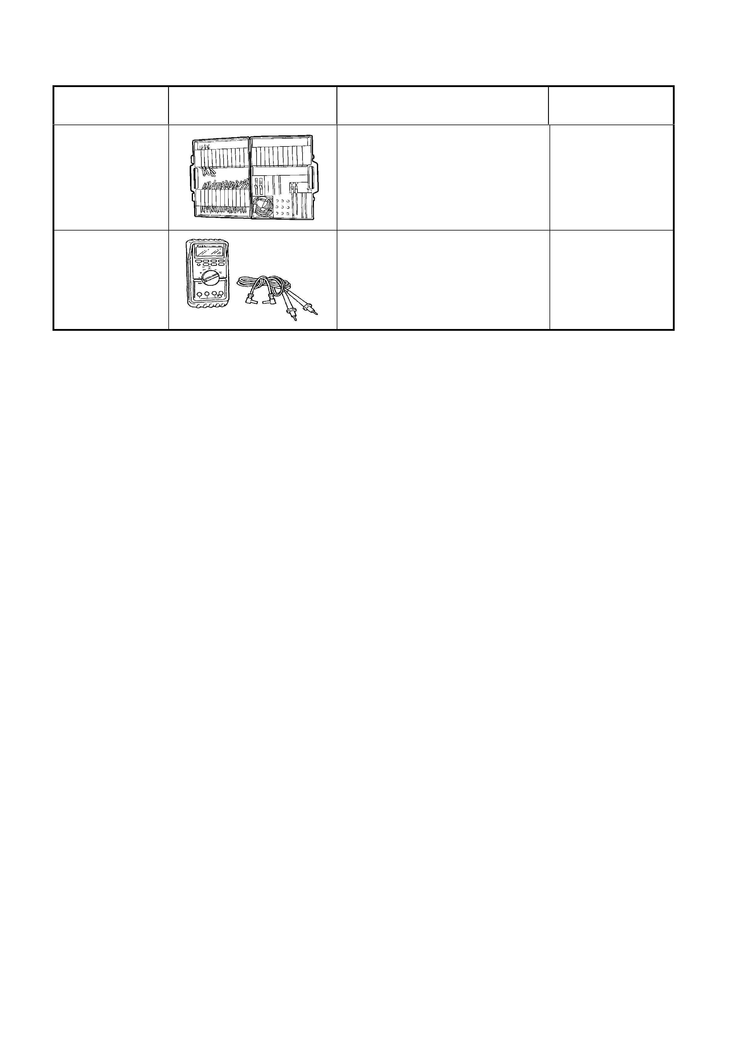
5. SPECIAL TOOLS
TOOL NUMBER ILLUSTRATION DESCRIPTION TOOL
CLASSIFICATION
J35616-A
(KM609)
CONNECTOR TEST ADAPTOR
KIT
Used when carrying out electrical
diagnostic circuit checks.
Previously released.
Desirable
3588
(J39200)
DIGITAL MULTIMETER
Must have at least 10 MΩ input
impedance and be capable of
reading frequencies.
Previously released.
Available