
SECTION 12F - REVERSE PARKING AID
IMPORTANT
Before performing any Service Operation or other procedure described in this Section, refer to Section 00
CAUTIONS AND NOTES for correct workshop practices with regard to safety and/or property damage.
CONTENTS
1. GENERAL DESCRIPTION
1.1 OPERATION
COMPONENTS
DETECTION & WARNING
TOWING
2. SERVICE OPERATIONS
2.1 REAR OBJECT SENSOR CONTROL MODULE
ASSEMBLY, SEDAN
REMOVE
DISASSEMBLE
REASSEMBLE
REINSTALL
2.2 REAR OBJECT SENSOR CONTROL MODULE
ASSEMBLY, COUPE
REMOVE
DISASSEMBLE
REASSEMBLE
REINSTALL
2.3 REAR OBJECT SENSOR ASSEMBLY
REMOVE
REINSTALL
3. DIAGNOSIS
3.1 DESCRIPTION
3.2 SELF-DIAGNOSIS
3.3 GROUND CONNECTION CIRCUIT TEST
3.4 POWER INPUT CIRCUIT TEST
3.5 DIAGNOSTIC CIRCUIT TEST
3.6 NO AUDIBLE TONE FROM ALARM
3.7 SENSOR CIRCUIT TEST
4. WIRING
4.1 REAR OBJECT SENSOR CONTROL
MODULE PIN-OUT
4.2 WIRING SCHEMATIC
4.3 CONNECTOR VIEWS
Techline
Techline
1. GENERAL DESCRI PTI O N
Reverse Parking Aid (RPA) is an electronic system designed to provide an acoustic tone informing the driver of
obstacles at or near the rear of the vehicle during reversing maneuvers. Available only on Sedan and Coupe
models, the RPA primarily consists of four ultrasonic rear object sensor assemblies mounted to the rear bumper
fascia and an electronic control module assembly which incorporates an alarm assembly.
The RPA does not relieve the driver of duty of care when reversing the vehicle. Caution must always be
exercised.
Sonar is used to detect the presence of obstacles within a defined area, by measuring the time between the
transmission and reception (echo) of sound waves.
When reverse gear is selec ted, the sens ors sequentially transm it shor t ultrasonic pulses and then listen for an ec ho
reflected from an object within range. The electronic control module uses echo data from one or more sensors to
calculate the distance to the obstacle.
An audible intermittent tone is sounded through the alarm informing the driver that an obstacle has been detected
within the range of the system. As the distance to the obstacle draws closer, the frequency of the tone increases
until it becomes constant at a distance of approximately 30 cm or, 45 cm for vehicles fitted with a towbar.
NOTE: Some sound absorbing or reflecting materials can effect the range of detection. In extreme cases,
temporary non-detection of obstacles can result.
While operational, the control module constantly monitors the system for faults. Should a fault occur, an audible
warning is indicated to the driver. A diagnosis system aids the technician locate the source of the fault.
On vehicles produced after the start of W K production, connector X907 has been changed from a male connector
to a female connector on the trailer harness to eliminate the use of a short patch harness.
1.1 OPERATION
COMPONENTS
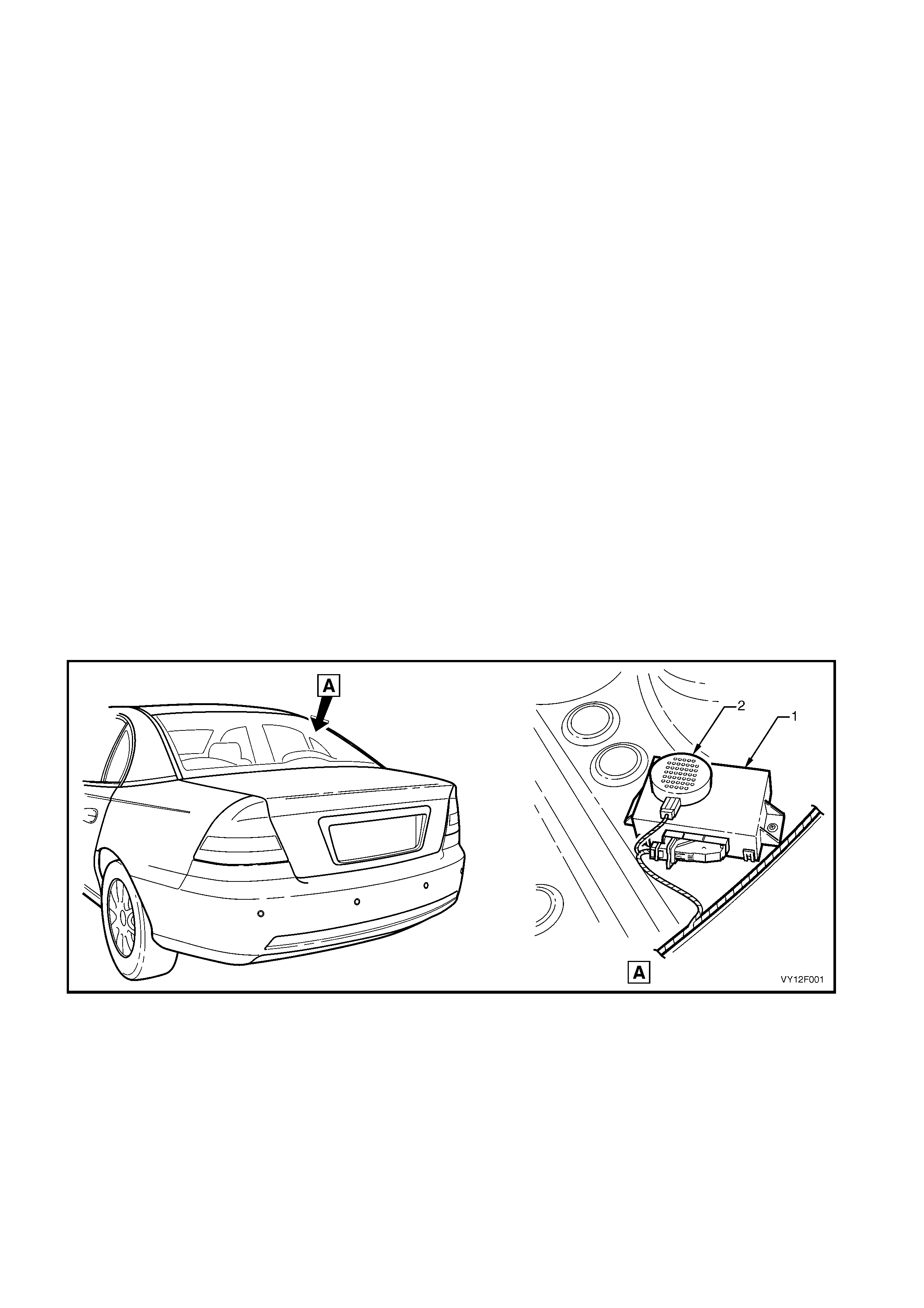
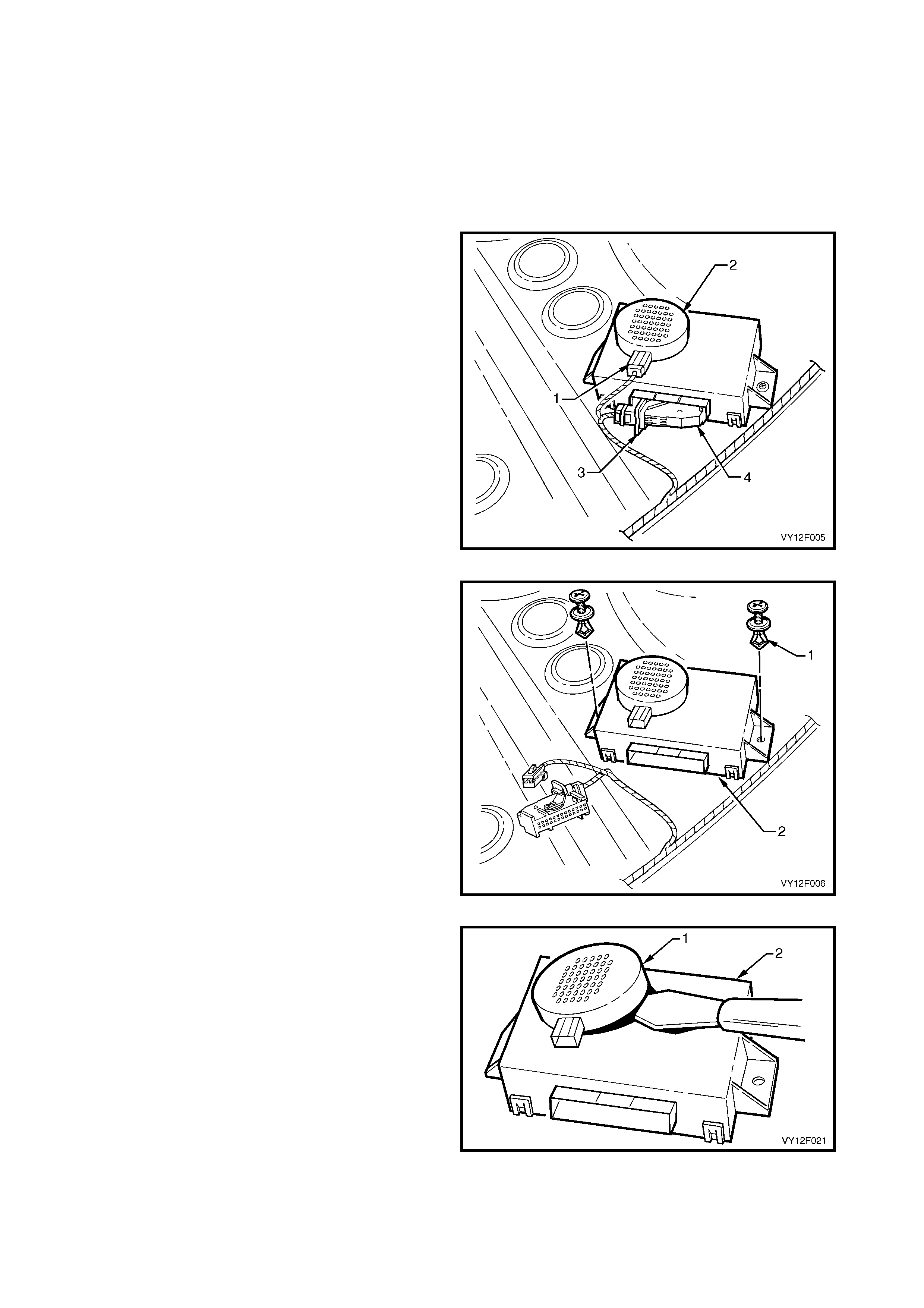
Rear Object Sensor Control Module Assembly
The rear object sensor control module (1) and alarm (2) are the one assembly. For Sedan models it is mounted to
the rear window panel, refer to Figure 12F-1.
Figure 12F-1
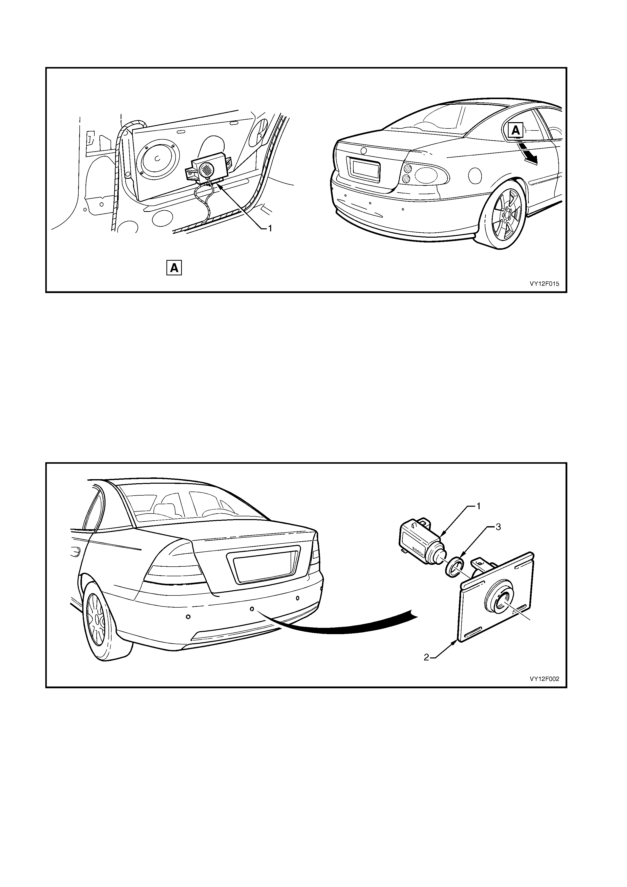
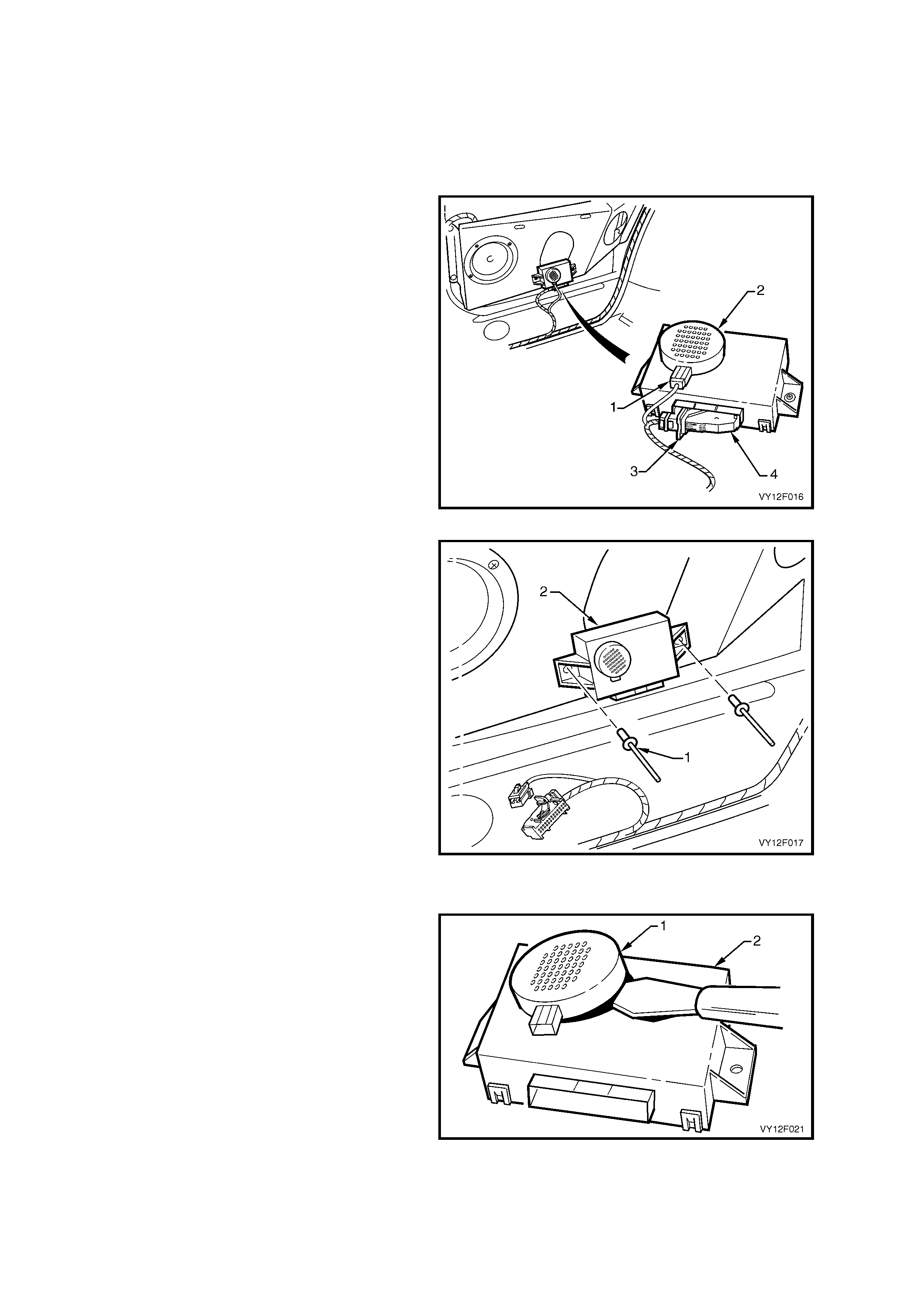
For the Coupe, the rear object sensor control module assembly (1) is mounted to the right-hand rear radio speaker
bracket, refer to Figure 12F-2.
Figure 12F-2
The ro le of the contr ol m odule is to trigger ultrasonic pulses s equentially from each sens or and m onitor the sens ors
for any received pulses (echoes from an object). The signals are then filtered and the distance of the object is
calculated from the time elapsed between the transmission of the signal and its reception using triangulation data
from one or more sensors. The control module also has a self-diagnosis function and controls the output tones
through the alarm.
Other peripheral functions of the control module include protective circuits against over-voltage, voltage stabilisation
and voltage supply to the sensors.
Rear Object Sensor Assembly
Each of the four rear object sensor assemblies (1) are mounted in a rear object sensor housing (2) which is heat-
staked to the rear bumper fascia. The housings allow easy removal of the sensor and rear object sensor ring (3),
refer to Figure 12F-3. Sedan shown, Coupe is similar.
Figure 12F-3

If the rear bumper fascia assem bly is replaced, undam aged housings can be rem oved from the old bumper fascia
by c utting the four attac hing heat-stak es . The hous ing can then be heat-s taked onto the new fasc ia with a soldering
iron, refer to Section 1D BUMPER BARS. If the housings are damaged, replacement parts are available. New
housings are to be painted to match the bumper fascia using similar methods to painting the fascia, also refer to
Section 1D BUMPER BARS.
Each sensor operates as a transmitter and receiver of ultrasonic pulses and the exposed surface painted in the
vehicle’s body colour.
IMPORTANT: Replacement sensor assemblies are supplied pre-painted in the vehicle’s body colour. DO NOT
apply further paint to the sensor as it will have a detrimental effect on the sensor’s operation.
The rear object sensor ring is made from silicone and prevents vibrations from the sensor being transferred to the
surrounding components. Without the sensor ring a change to the sensor characteristics would result.
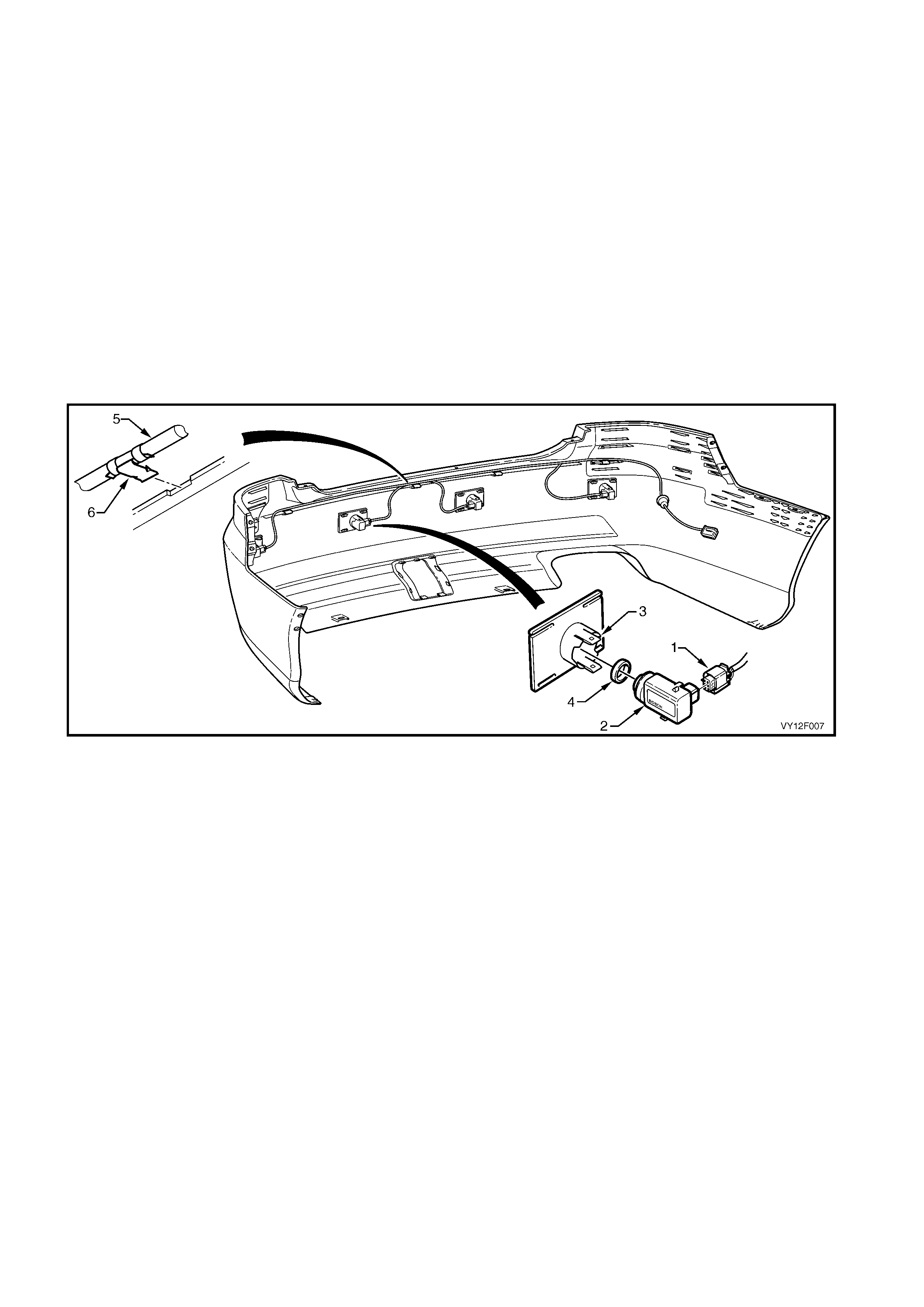
Wiring Harness Assembly
The body wiring harness is routed (1), refer to Figure 12F-4 for Sedan or 12F-5 for Coupe.
The rear obj ect sens or harness (2) connects to the body wiring harness with connector X905 (3) near the left-hand
tail lamp assembly and is routed across the inner side of the rear bumper fascia, connecting each of the four
sensors.
The white wiring connector X906 (4) is provided to enable modification of the detection area for the fitment of a
towbar tongue.
When fitted, a circuit from the trailer harness is connected to the black wiring connector X907 (5) and is used to
detect tr ailer attac hment. When a trailer , c aravan, bike car r ier with lights, etc. is c onnec ted to the trailer harnes s the
system is then temporarily disabled, refer to TOWING for further information.
The diagnostic connector X156 (6) is located on the left-hand side of the rear compartment. Refer to
3. DIAGNOSIS for further information..
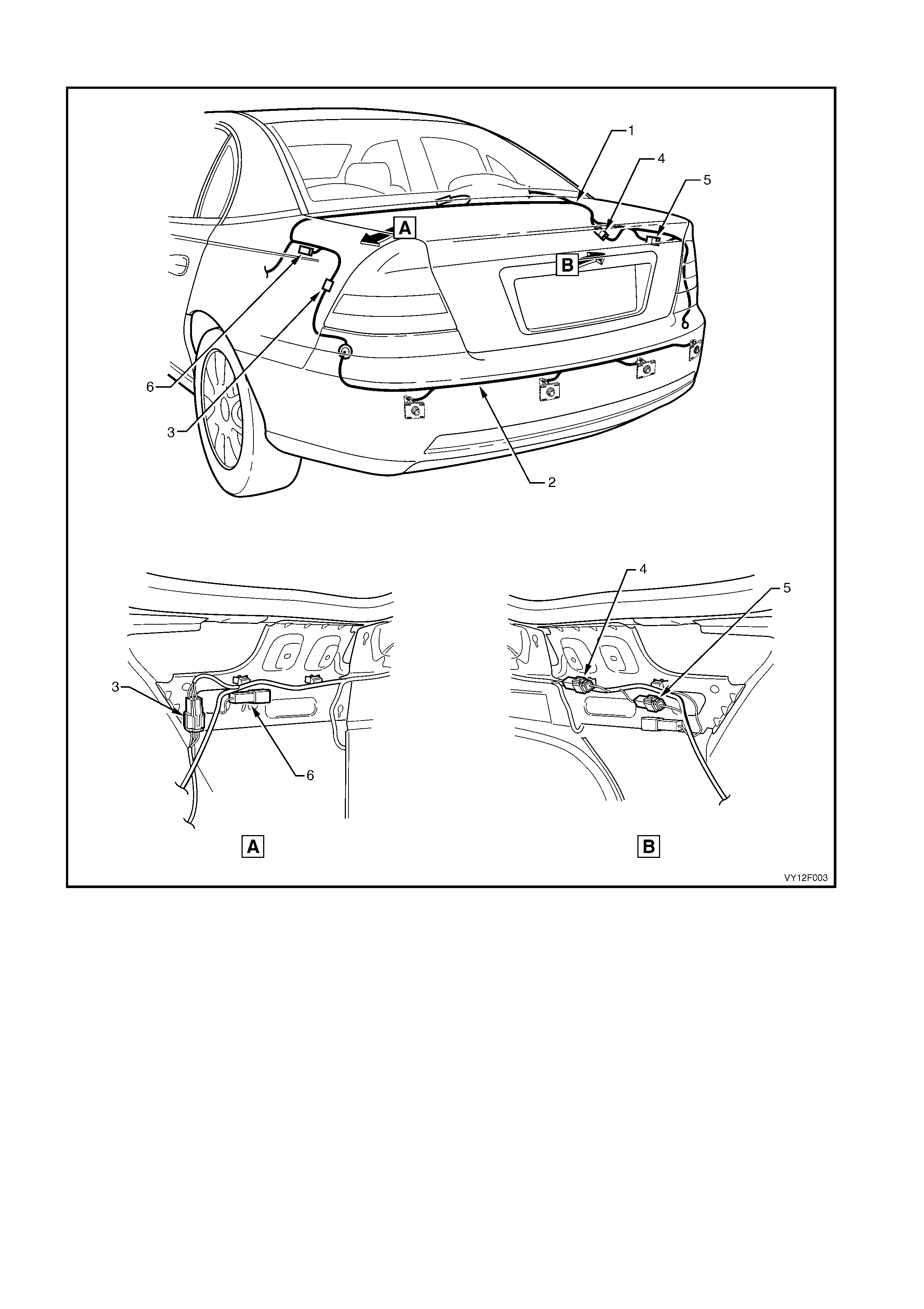
Sedan
Figure 12F-4
Legend
1. Body Wiring Harness 4. Towbar Tongue Modification Connector X906 (white)
2. Rear Object Sensor Harness 5. Trailer Harness Connector X907 (black)
3. Rear Object Sensor to Body Harness Connector X905 6. Diagnosis Connector X156
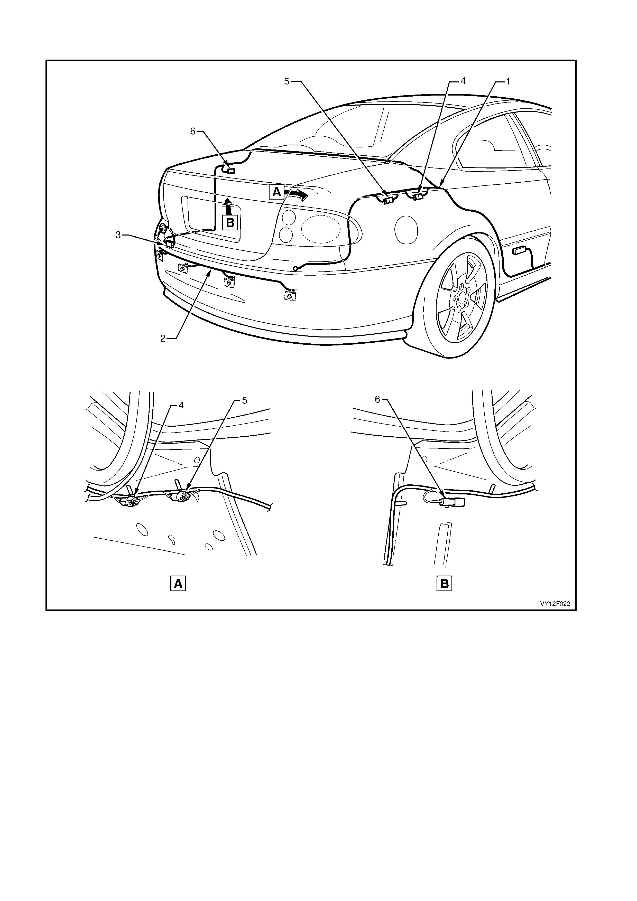
Coupe
Figure 12F-5
Legend
1. Body Wiring Harness 4. Towbar Tongue Modification Connector X906 (white)
2. Rear Object Sensor Harness 5. Trailer Harness Connector X907 (black)
3. Rear Object Sensor to Body Harness Connector X905 6. Diagnosis Connector X156
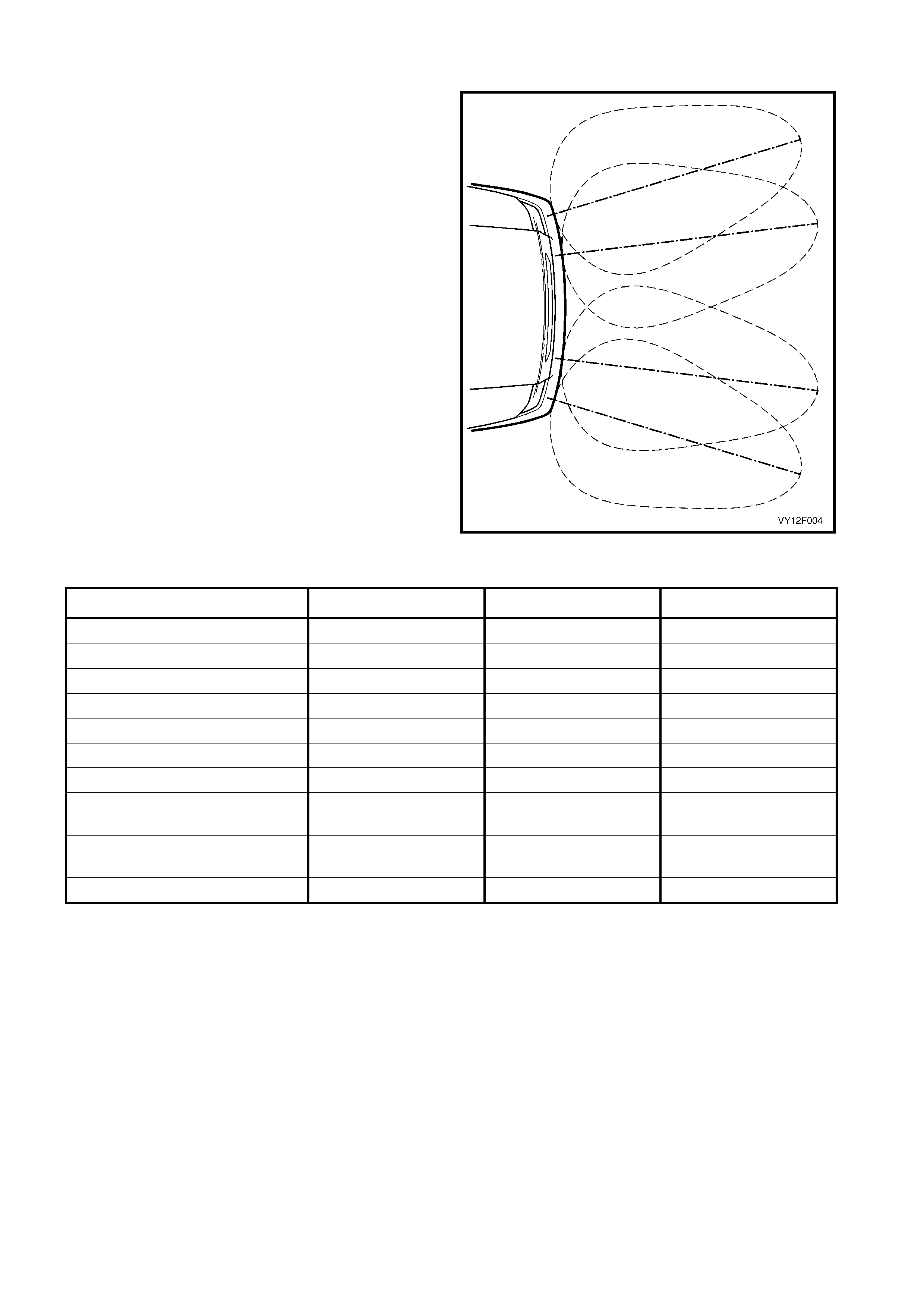
DETECTION & WARNING
The four sensors are mounted onto the rear bumper
fasc ia in an arrangement that pr ovides a slight overlap
of the polar patterns. This provides the best coverage
of the detection area.
The maximum detection distance is set to 150 cm by
the control module software.
When the ignition is on and revers e gear is s elected, a
ready tone will sound from the alar m f or a per iod of 0.5
seconds.
The control module provides a voltage to each sensor
sequentially which is converted into an ultrasonic
pulse.
Where an object is within the detection range, the
ultrasonic pulse is reflected (echoed) and received by
the same and/or adjacent sensors.
The echoes are amplified, processed and returned to
the control module as a digital signal. The control
module processes this information and informs the
driver of the object by activating an intermittent
acoustic tone through the alarm.
The detection area is divided into five warning zones.
As listed in the following table, the tone-on to tone-off
period shortens as the distance to the detected object
decreases.
Figure 12F-6
Warning Range (cm) Frequency (Hz) Tone On Tone Off
Less than 30 1200 Continuous
30 – 40 1200 75 ms 75 ms
40 – 60 1200 75 ms 150 ms
60 – 80 1200 75 ms 225 ms
80 – 100 1200 75 ms 300 ms
100 – 120 1200 75 ms 375 ms
120 – 150 1200 75 ms 450 ms
Hardware Error 600 Continuous at power
up
Error Message 600 Continuous at power
up
Ready Tone, Reverse Engaged 1200 0.5 sec
TOWING
W hen a towbar is f itted, the continuous tone activation area is inc reased from 30 to 45cm to allow f or the length of
the tow bar tongue. This is achieved by the towbar installer disconnecting the white wiring connector X906 (4 in
Figure 12F-4- Sedan or 12F -5- Coupe), c aus ing an open in the power supply circuit 24 and 796 to the control m odule
(pin 15). Refer to 4.2 WIRING SCHEMATIC in this Section.
When the c or rec t ac c es sor y trailer wiring har nes s is ins talled, the s ystem c an be temporar ily disabled when a trailer
or caravan, etc . is attached. The black connec tor X 907 ( 5 in Figure 12F-4-Sedan or 12F-5-Coupe) in circuit 650 and
471 is also disconnected by the installer and the grey wire in the trailer harness connected.
• W hile the trailer socket dust-flap is closed, a magnet in the dust-flap closes a reed-switch in the trailer socket
which connects this circuit to ground through circuit 22.
• W hen the dus t-flap is opened, as in connecting a trailer plug, the switch opens. The control m odule detects the
open circuit and disables the system.
If a bicycle carrier is fitted onto the towbar, a licence plate lamp and tail lamp should be fitted to the carrier and
plugged into the trailer socket. This will also temporarily disable the system, as it is highly likely the bicycles will
cause a disturbance to the detection field.
2. SERVICE OPERATIONS
2.1 REAR OBJECT SENSOR CONTROL MODULE ASSEMBLY, SEDAN
LT Section No. –
REMOVE
1. Remove the rear window trim panel assembly, refer to Section 1A8, 2.9 REAR WINDOW TRIM PANEL
ASSEMBLY.
2. Disconnect the wiring connec tor (1) f rom the alarm
assembly (2).
3. Unlock the connector lock lever (3) and open the
lever, disconnecting the connector (4) from the
rear object sensor control module.
Figure 12F-7
4. Remove the two retainers (1) attaching the control
module assembly (2) to the back panel upper.
5. Remove the control module assembly .
Figure 12F-8
DISASSEMBLE
1. Using a knife or paint scraper, carefully prise the
alarm assembly (1) from the control module (2),
separating the double-sided tape.
2. Remove the alarm assembly.
REASSEMBLE
1. If reusing the alarm, remove any remaining
double-sided tape from the control module and
alarm. Apply new tape such as 3M 4428 or
equivalent.
2. Peel off the adhesive backing paper and affix the
alarm asse m bly on to the control module, ensuring
it is correctly positioned.
Figure 12F-9
REINSTALL
Reinstallation of the control module assembly is the reverse of removal.
2.2 REAR OBJECT SENSOR CONTROL MODULE ASSEMBLY, COUPE
LT Section No. –
REMOVE
1. Rem ove the right-hand quar ter trim panel, refer
to Section 1A8, 4.2 QUARTER TRIM PANEL
ASSEMBLY.
2. Disconnect the wiring connector (1) from the
alarm assembly (2).
3. Unlock the connector lock lever (3) and open
the lever, disconnecting the connector (4) from
the rear object sensor control module.
Figure 12F-10
4. Carefully drill out the two pop-rivets (1)
attaching the control module (2) to the radio
speaker bracket.
5. Remove the control module.
Figure 12F-11
DISASSEMBLE
1. Using a knife or paint scraper, carefully prise
the alarm ass em bly (1) from the control module
(2), separating the double-sided tape.
2. Remove the alarm assembly.
REASSEMBLE
1. If reusing the alarm, remove any remaining
double-sided tape from the control m odule and
alarm. Apply new tape such as 3M 4428 or
equivalent.
2. Peel off the adhesive backing paper and affix
the alarm assembly on to the control module,
ensuring it is correctly positioned.
Figure 12F-12
REINSTALL
Reinstallation of the control module assembly is the
reverse of removal using new pop-rivets.
2.3 REAR OBJECT SENSOR ASSEMBLY
LT Section No. –
REMOVE
1. Remove the rear bumper fascia assembly, refer to Section 1D, 2.5 REAR BUMPER FASCIA ASSEMBLY,
SEDAN & COUPE.
IMPORTANT: Replacement rear object sensor assemblies are supplied pre-painted in the vehicle’s body colour.
DO NOT apply further paint to the sensor as it will have a detrimental effect on the sensor’s operation.
2. Disconnect the wiring connector (1) from the rear object sensor assembly (2), refer to Figure 12F-13. Sedan
shown, Coupe is similar.
3. Lift the top and bottom housing tabs (3) and remove the sensor assembly with the rear object sensor ring (4)
from the rear object sensor housing.
4. If required, remove the sensor ring from the sensor.
NOTE: For removal procedures of the rear object sensor housing assembly, refer to
Section 1D, 2.5 REAR BUMPER FASCIA ASSEMBLY, SEDAN & COUPE.
5. If required, remove the wiring harness (5) by prising the clips (6), four places from the bumper fascia rib.
Figure 12F-13
REINSTALL
Reinstallation of the sensor assembly is the reverse of removal noting the following:
IMPORTANT: Ensure the rear object sensor ring is correctly seated on the sensor and the sensor assembly is
securely located in the housing. The sensor ring prevents vibrations from the sensor being transferred to the
surrounding components. Incorrect fitment will result in a change to the sensor characteristics.
1. Ensure the sensor s are correct ly ins talled in the housing with the connector side f acing to the centreline of the
vehicle.
2. Attach the wiring harness to the upper side of the bumper fascia rib, aligning each clip at the notches.
3. DIAGNOSIS
IMPORTANT: Where it is possible to touch connector pins, correct Electro-Static Discharge (ESD) protection
procedures, including the use of a grounded wrist strap and an anti-static mat, must be followed.
3.1 DESCRIPTION
The RPA is initialised once the ignition is switched on and reverse gear is selected. A ready tone will sound for a
period of 0.5 seconds. In this state, the rear object sensor control module continuously monitors the system and
should a fault be detected, a continuous 600 Hz tone will sound.
NOTE: Faults are stored in non-volatile memory within the control module while present. Past faults are not
retained.
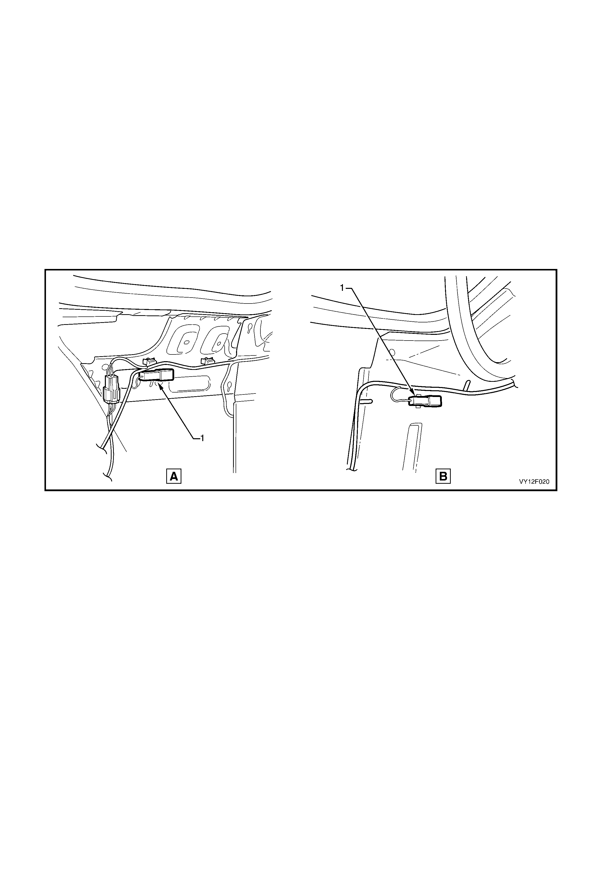
The system can then be placed in diagnostic mode by grounding the light-blue wire connector X156 (1) on circuit
5213, located on the left- hand s ide of the rear com partm ent, pr ior to switching the ignition on and engaging rever se
gear, refer to Figure 12F-14, A – Sedan or B – Coupe.
Using the following table may assist in locating the fault area. However before replacing any components refer to
the following procedures for the relevant circuit diagnosis.
Figure 12F-14

3.2 SELF-DIAGNOSIS
1. Ground the light-blue wire single connector (X156), refer to Figure 12F-14.
2. Switch the ignition on. Do not start the engine.
3. Select reverse gear.
4. A START tone will sound from the alarm, followed by one or more tone patterns as listed.
5. Note the tones and refer to the relevant diagnostic tests in the following pages.
No Fault Continuous cyclic tone of 3 seconds ON, 3 seconds OFF (START and END
tone only)
Sensor 1 (right) Fault ON OFF END
Sensor 2 (right middle)
Fault ON OFF ON OFF END
Sensor 3 (left middle) Fault ON OFF ON OFF ON OFF END
Sensor 4 (left) Fault ON OFF ON OFF ON OFF ON OFF END
ECM Fault INT INT INT END
NOTE: If more than one error is detected, the tone will be output in sequence separated by the END pause.
The sequence of faults will be repeated continuously while the system remains in self-diagnosis mode.
• START – Tone ON for three seconds and OFF for one second.
• ON – Tone ON for one second.
• OFF – Tone OFF for one second.
• END – Tone OFF for two seconds.
• INT – Interval tone (ON / OFF) for one second.
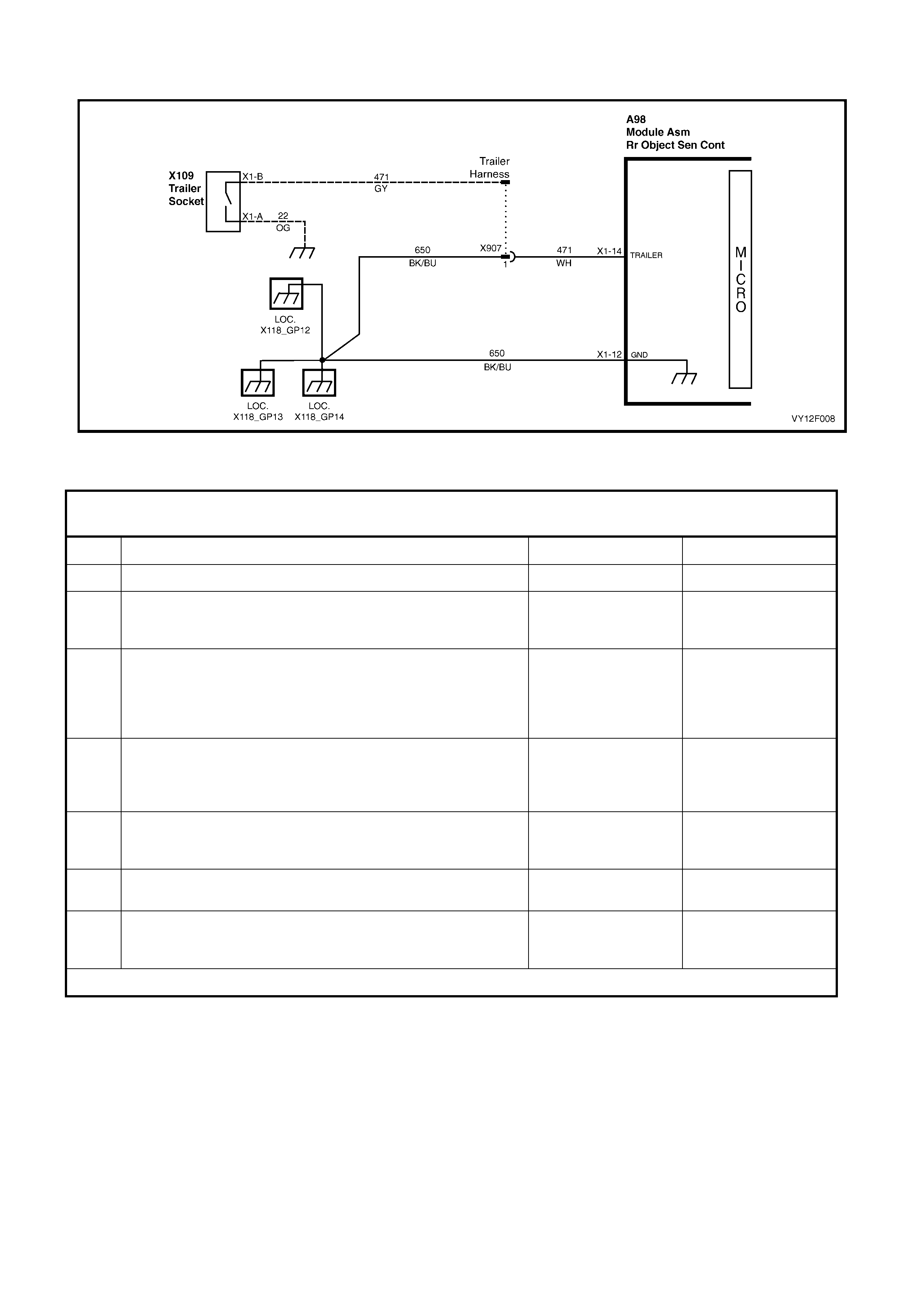
3.3 GROUND CONNECTION CIRCUIT TES T
Figure 12F-15
NOTE: For connector details refer to 4.3 CONNECTOR VIEWS.
For connector and ground point locations refer to Section 12P, WIRING DIAGRAMS.
STEP ACTION YES NO
1 Is the vehicle fitted with a trailer harness? Go to 2. Go to 5.
2 Back-probe the control module connector A98 pin 14 and
check for continuity to ground on circuits 471 (white wire) and
(grey wire).
OK. Go to 7. Go to 3.
3 Check the trailer harness socket.
Is anything plugged into the socket or is the socket dust flap
open?
Trailer socket switch
is open. Remove the
plug from the socket
or close the flap.
Repeat step 2.
Go to 4.
4 Back-probe connector X907 pin 1 and check for continuity to
ground on circuit 471 (grey wire) and circuit 22 (orange wire). Repair circuit 471
(white wire). Go to 7. Repair circuit 471
and / or 22 or replace
the trailer harness.
Go to 7.
5 Back-probe the control module connector A98 pin 14 and
check for continuity to ground on circuits 471 (white wire) and
650 (black/blue wire).
OK. Go to 7. Go to 6.
6 Back-probe connector X907 pin 1 for continuity to ground on
circuit 650. Repair circuit 471.
Go to 7. Repair circuit 650.
Go to 7.
7 Back-probe the control module connector A98 pin 12 for
continuity to ground on circuit 650 (black/blue wire), locations
GP12, GP13 & GP14.
Ground check OK. Repair circuit 650.
WHEN ALL DIAGNOSIS AND REPAIRS ARE COM PLETE, VERIFY CORRECT OPERATION.
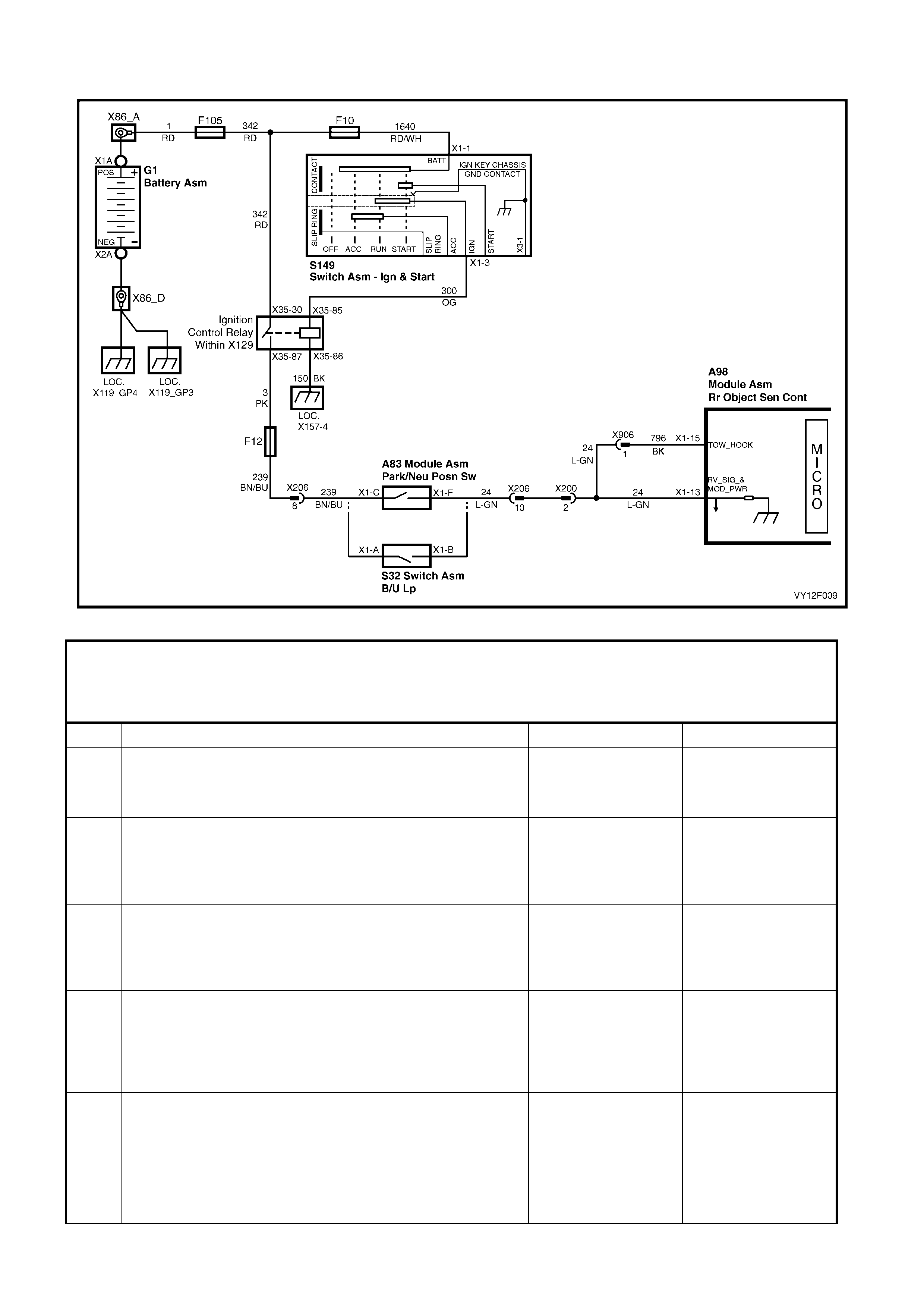
3.4 POWER INPUT CIRCUIT TEST
Figure 12F-16
NOTE: Prior to performing this test, ensure the ground circuits function correctly and nothing is connected
into the trailer socket.
For connector details refer to 4.3 CONNECTOR VIEWS.
For connector and ground point locations refer to Section 12P, WIRING DIAGRAMS.
STEP ACTION YES NO
1 Back-probe the control module connector A98 pin 13 circuit 24
(light green wire) with a test lamp or voltmeter.
Switch the ignition on and select reverse gear.
Does the light illuminate or is there B+ volts shown?
OK. Go to 11. Go to 2.
2 Check Fuse 105 in the engine compartment fuse and relay
panel assembly. Is it OK? Go to 3. Replace fuse and
retest. If the fuse
blows again test for a
short to ground.
Go to 11.
3 Check Fuse 12 in the passenger compartment fuse and relay
panel assembly. Is it OK? Go to 4. Replace fuse and
retest. If the fuse
blows again test for a
short to ground.
Go to 11.
4 Switch the ignition on.
Does the ignition control relay emit a clicking sound as the
switch is turned on?
Go to 5. Check Fuse F10, the
ignition control relay
ground circuit 150 or
the ignition control
relay power circuit
300. Go to 11.
5 With the ignition on, select reverse gear. Back-probe with a
test lamp or voltmeter at the following connectors:
- Auto Trans. Park / neutral position switch connector A83 pin
F circuit 24 (light green wire).
- Man Trans. Back-up lamp switch connector S32 pin B circuit
24 (light green wire).
Does the light illuminate or is there B+ volts shown?
Repair circuit 24.
Go to 11. Go to 6.

STEP ACTION YES NO
6 With the ignition on, back-probe with a test lamp or voltmeter
at the following connectors:
- Auto Trans. Park/neutral position switch connector A83 pin
C circuit 239 (brown/blue wire).
- Man Trans. Back-up lamp switch connector S32 pin A circuit
239 (brown/blue wire).
Does the light illuminate or is there B+ volts shown?
Switch faulty, replace.
Go to 11. Go to 7.
7 With the ignition on, check for B+ at fuse F12 in the passenger
compartment fuse and relay panel assembly. Repair circuit 239.
Go to 11. Go to 8.
8 With the ignition on, check for B+ at the ignition control relay
connector X35 pin 87 circuit 3 (pink wire) in the passenger
compartment fuse and relay panel assembly.
Repair circuit 3.
Go to 11. Go to 9.
9 With the ignition on, check for B+ at the ignition control relay
connector X35 pin 30 circuit 342 (red wire) in the passenger
compartment fuse and relay panel assembly.
Replace ignition
control relay.
Go to 11.
Go to 10.
10 With the ignition on, check for B+ at fuse F105 circuit 1 (red
wire) in the engine compartment fuse and relay panel
assembly.
Repair circuit 342.
Go to 11. Repair circuit 1.
Go to 11.
11 Is the vehicle fitted with a towbar? Connector X906
disconnected by
towbar installer to
modify sensor
detection range for
towbar tongue. OK.
Go to 12.
12 Back-probe the control module connector A98 pin 15 circuit
796 (black wire) with a test lamp or voltmeter.
Switch the ignition on and select reverse gear.
Does the light illuminate or is there B+ volts shown?
OK. End. Ensure connector
X906 is not
disconnected. Repair
circuit 796 or 24.
WHEN ALL DIAGNOSIS AND REPAIRS ARE COM PLETE, VERIFY CORRECT OPERATION.
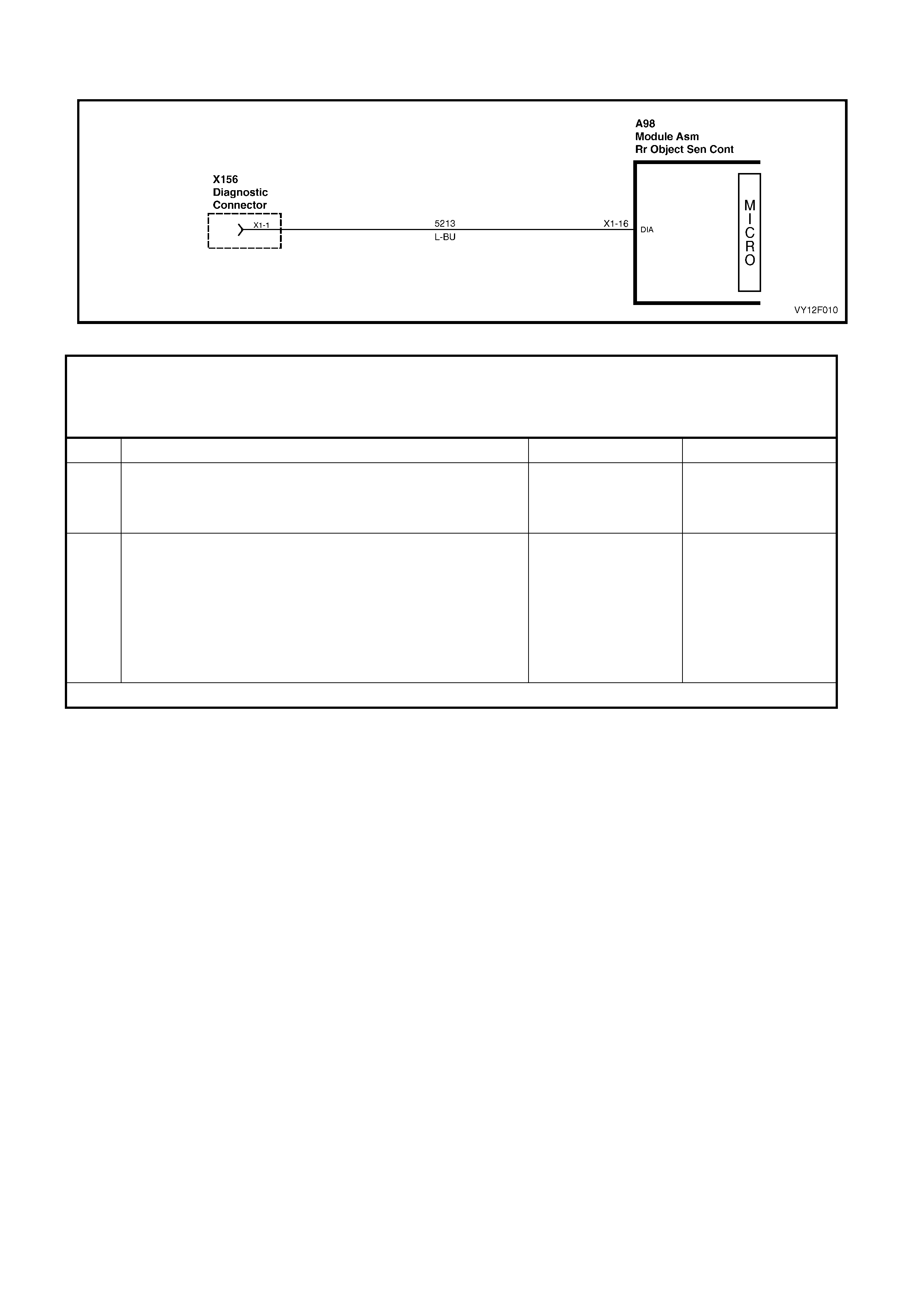
3.5 DIAGNOSTIC CIRCUIT TEST
Figure 12F-17
NOTE: Prior to performing this test, ensure the ground and power circuits function correctly and nothing is
connected into the trailer socket.
For connector details refer to 4.3 CONNECTOR VIEWS.
For connector and ground point locations refer to Section 12P, WIRING DIAGRAMS.
STEP ACTION YES NO
1 Ground the light-blue wire single diagnostic connector X156
on the left-hand side of the rear compartment. Switch the
ignition on and select reverse gear. Does an audible tone
sound from the alarm?
End. Go to 2.
2 Ground the light-blue wire single diagnostic connector X156
located on the left-hand side of the rear compartment, refer to
Figure 12F-14. Back-probe the control module connector A98
pin 16 for continuity to ground on circuit 5213.
Check alarm circuit. If
OK replace faulty
control module, refer
2.1 REAR OBJECT
SENSOR CONTROL
MODULE or
2.2 REAR OBJECT
SENSOR CONTROL
MODULE, COUPE.
Repair circuit 5213.
WHEN ALL DIAGNOSIS AND REPAIRS ARE COM PLETE, VERIFY CORRECT OPERATION.
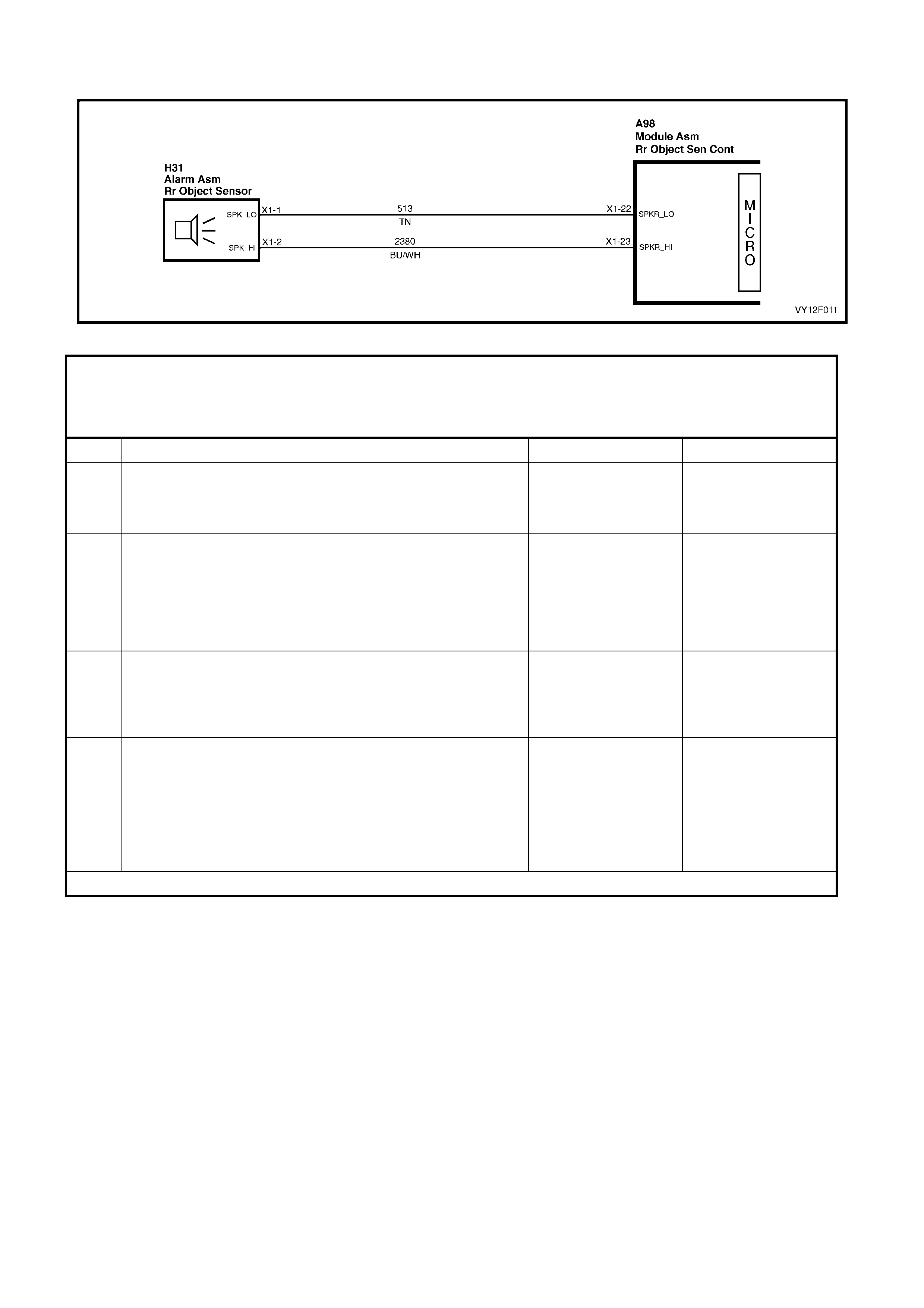
3.6 NO AUDIBLE TONE FROM ALARM
Figure 12F-18
NOTE: Prior to performing this test, ensure the ground and power circuits function correctly and nothing is
connected into the trailer socket.
For connector details refer to 4.3 CONNECTOR VIEWS.
For connector and ground point locations refer to Section 12P, WIRING DIAGRAMS.
STEP ACTION YES NO
1 Ground the light-blue wire single diagnostic connector X156
on the left-hand side of the rear compartment.
Switch the ignition on and select reverse gear.
Does an audible tone sound from the alarm?
End. Go to 2.
2 Disconnect the alarm wiring connector H31 and connect an
ohmmeter between the alarm pins 1 and 2.
Test for a resistance value of 100 ohms.
Go to 3. Replace the alarm,
refer 2.1 REAR
OBJECT SENSOR
CONTROL MODULE
ASSEMBLY, SEDAN
or 2.3 ALARM
ASSEMBLY, COUPE.
3 Disconnect the control module wiring connector A98 and
alarm wiring connector H31.
Connect an ohmmeter between connector A98 pin 22 and
connector H31 pin 1.
Test for continuity on circuit 513 (tan wire).
Go to 4. Repair circuit 513.
4 Connect an ohmmeter between connector A98 pin 23 and
connector H31 pin 2.
Test for continuity on circuit 2380 (blue/white wire).
Replace control
module, refer 2.1
REAR OBJECT
SENSOR CONTROL
MODULE or 2.2
REAR OBJECT
SENSOR CONTROL
MODULE, COUPE.
Repair circuit 2380.
WHEN ALL DIAGNOSIS AND REPAIRS ARE COM PLETE, VERIFY CORRECT OPERATION.
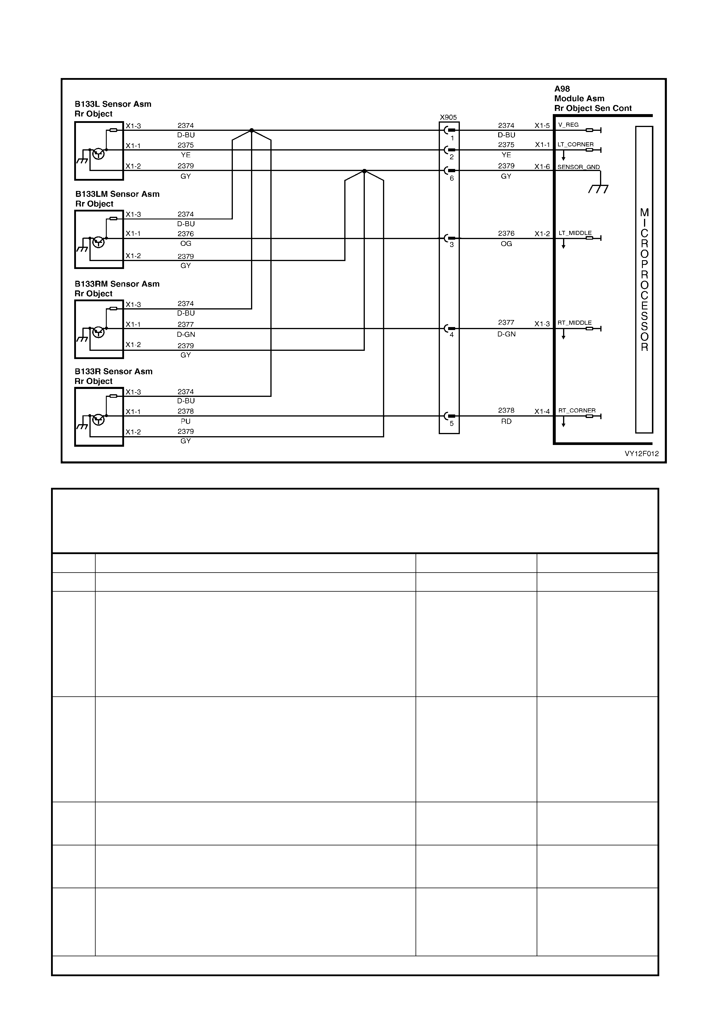
3.7 SENSOR CIRCUIT TEST
Figure 12F-19
NOTE: Prior to performing this test, ensure the ground and power circuits function correctly and nothing is
connected into the trailer socket.
For connector details refer to 4.3 CONNECTOR VIEWS.
For connector and ground point locations refer to Section 12P, WIRING DIAGRAMS.
STEP ACTION YES NO
1 Perform self-diagnosis test. Does the test indicate a fault? Go to 2. End.
2 Switch the ignition on and select reverse gear.
Back-probe the control module connector A98 pin 5 circuit
2374 (dark blue wire) with a voltmeter. Is approximately +8V
present?
Go to 3. Replace control
module, refer 2.1
REAR OBJECT
SENSOR CONTROL
MODULE or 2.2
REAR OBJECT
SENSOR CONTROL
MODULE, COUPE.
3 Back-probe the control module connector A98 pin 6 circuit
2379 (grey wire) and test for continuity to ground. Go to 4. Replace control
module, refer 2.1
REAR OBJECT
SENSOR CONTROL
MODULE or 2.2
REAR OBJECT
SENSOR CONTROL
MODULE, COUPE.
4 Disconnect the sensor connectors B133 and control module
connector A98. Check for continuity on circuits 2374 to each
sensor.
Go to 5. Repair any faulty
circuit.
5 As required, check for continuity on circuits 2375, 2376, 2377
and 2378 between connector A98 to each sensor connector
B133.
Go to 6. Repair any faulty
circuit.
6 Check for continuity on circuits 2379 between connectors A98
to each sensor connector B133. Replace faulty
sensor, refer 2.4
REAR OBJECT
SENSOR
ASSEMBLY.
Repair any faulty
circuit.
WHEN ALL DIAGNOSIS AND REPAIRS ARE COM PLETE, VERIFY CORRECT OPERATION.

4. WIRI NG
4.1 REAR OBJECT SENSOR CONTROL MODULE PIN-OUTS
Pin No. Circuit Number Designation Wire Colour
1 2375 Sensor signal outer left Yellow
2 2376 Sensor signal middle left Orange
3 2377 Sensor signal middle right Dark green
4 2378 Sensor signal outer right Red
5 2374 Sensor feed Dark blue
6 2379 Sensor ground Grey
12 650 Ground Black / Blue
13 24 Reverse input Light green
14 471 System disable White
15 796 Towbar offset Black
16 5213 Diagnostics Light blue
22 513 Alarm - Tan
23 2380 Alarm + Blue / White

4.2 WIRING SCHEMATIC
On vehicles produced after the start of W K production, connector X907 has been changed from a male connector
to a female connector on the trailer harness to eliminate the use of a short patch harness. On the trailer harness,
connector X907 has been changed from a female to a male connector.
• For vehicles produced after the start of VY production, refer to Figure 12F-20.
• For vehicles produced after the start of WK production, refer to Figure 12F-21.
The above changes in the circuit do not affect the diagnostic procedures.
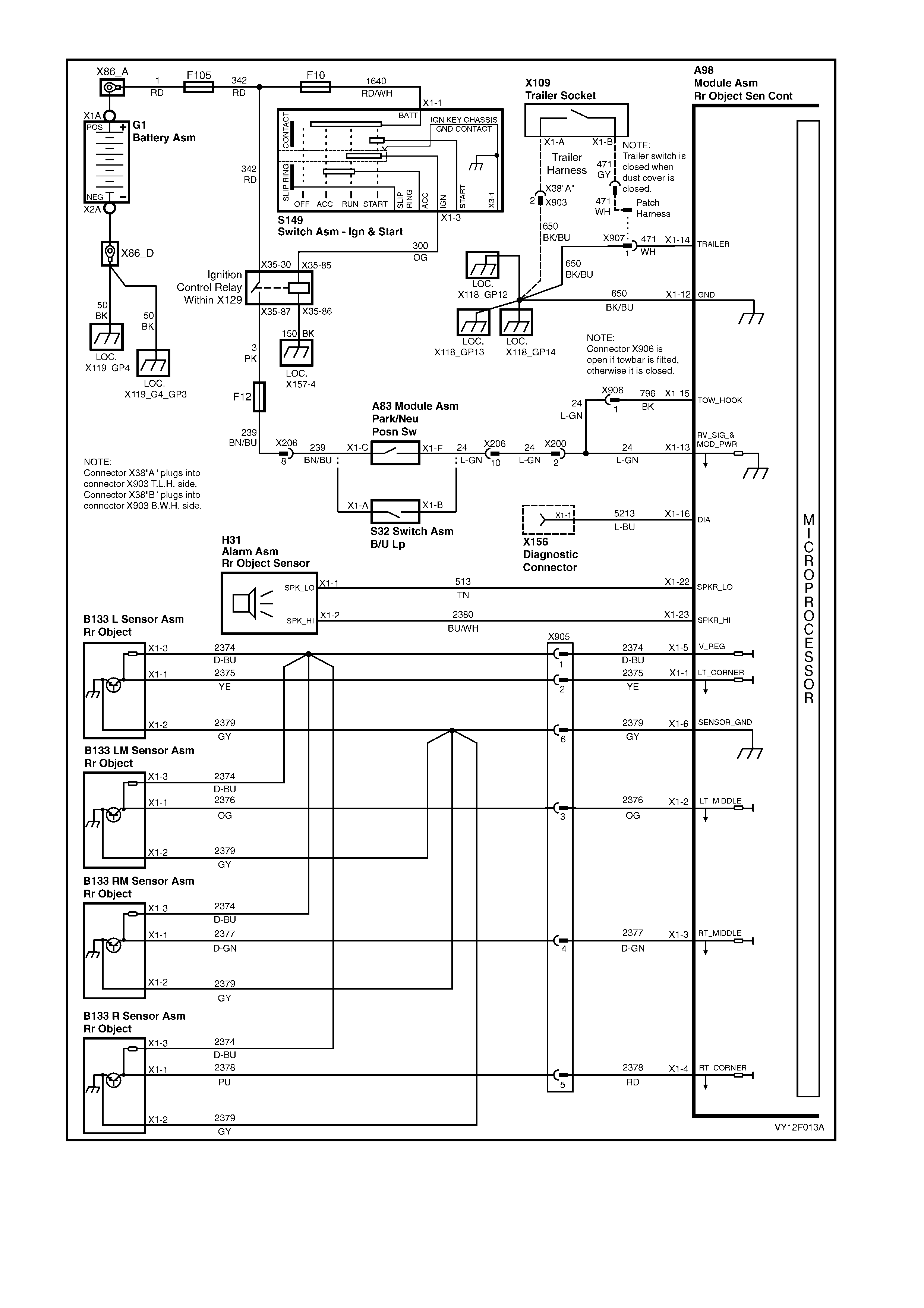
Figure 12F-20
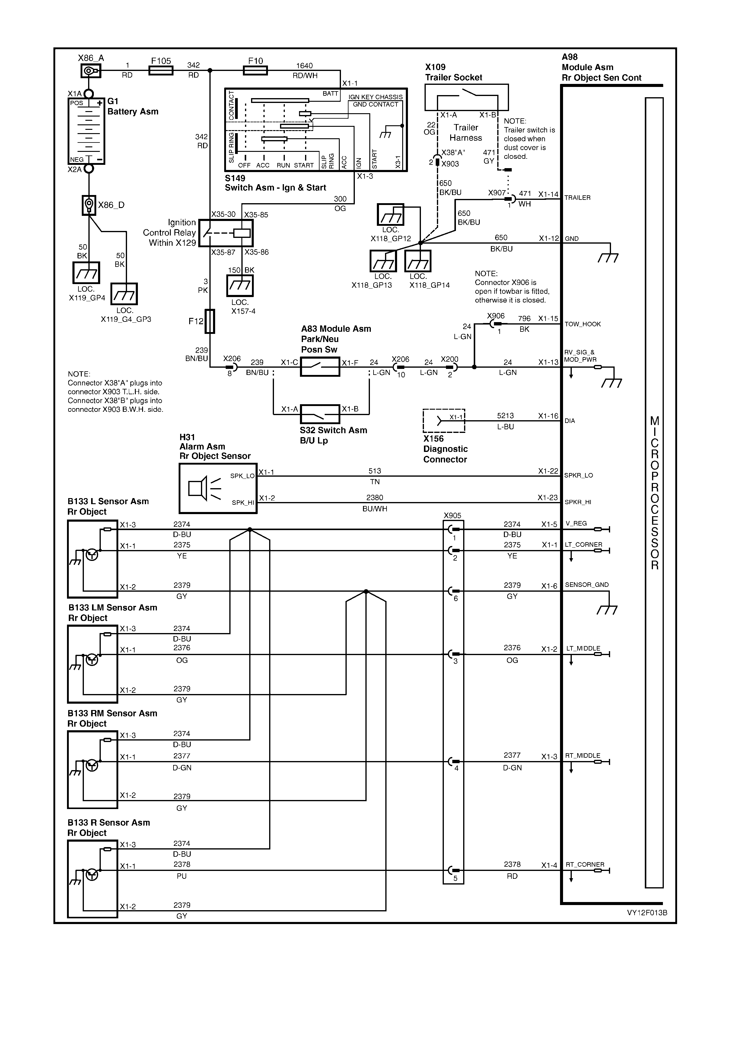
Figure 12F-21
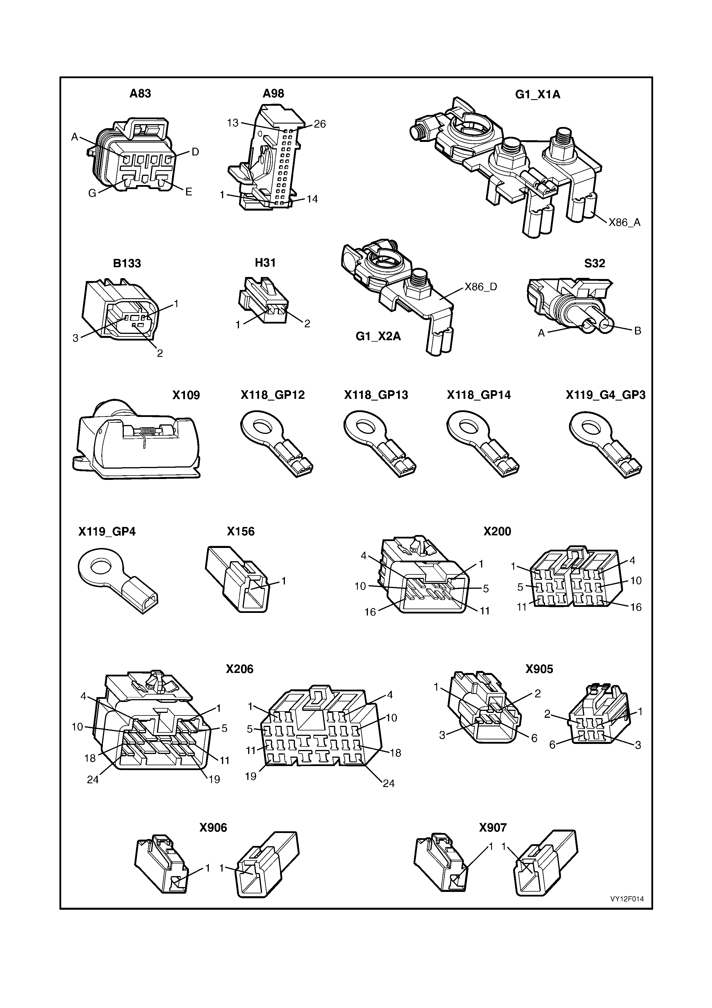
4.3 CONNECTOR VI EWS
Figure 12F-22