
SECTION 12G - CELLULAR PHONE
IMPORTANT
Before performing any Service Operation or other procedure described in this Section, refer to Section 00
CAUTIONS AND NOTES for correct workshop practices with regard to safety and/or property damage.
CONTENTS
1. GENERAL DESCRIPTION
RADIO TELEPHONE MUTE
RADIO TELEPHONE INPUT
2. SERVICE OPERATIONS
2.1 CELLULAR PHONE CONNECTOR
REMOVE
REINSTALL
2.2 WIRING
SCHEMATIC, WITHOUT TELEMATICS
SCHEMATIC, WITH TELEMATICS
CONNECTORS
3. TORQUE WRENCH SPECIFICATIONS

1. GENERAL DESCRIPTION
This Section describes the cellular phone hands-fr ee kit connec tion incorporated into the m ain wiring harness of all
MY 2003 VY and V2 Series vehicles.
The cellular phone connector is taped back to the m ain wiring harness and is located at the left front of the centre
console f or right- hand drive vehic les . For lef t- hand dr ive vehicles it is located at the r ight f r ont of the c entre c ons ole.
To ac cess the connector , rem oval of the appropriate ins trum ent panel lower extens ion side panel is required, which
is described in this Section. A connection kit is available through an authorised retailer.
The connector provides constant and accessory position battery power outputs and ground connection for the
cellular phone. It also provides the following connections that interface with the radio when a telephone hands-free
kit with the appropriate functions is connected.
RADIO TELEPHONE MUTE
W henever a call is m ade or received, the radio will display VOICE IN and the volume of the radio will be muted or
the CD will be paused. A suitable hands-free cellular phone kit with a mute output function is required to be
connected to pin X1_4 (mute) of the cellular phone connector.
RADIO TELEPHONE INPUT
This function allows the audio from a suitable hands-free cellular telephone kit to be reproduced through the radio
speakers. A suitable hands-free cellular phone kit with mute output and external speaker functions is required and
is connected to pins X1_4 (mute), X1_5 (voice signal) and X1_6 (voice return) of the cellular phone connector.
The phone input has independent tone from the nor mal audio sources. T he bass, treble, fader and balance can be
adjusted to suit the particular phone/preference whenever VOICE IN is displayed on the radio. These settings will
then be used whenever the phone input is activated, and does not interfere with the settings for radio or CD
playback.
With both functions, the radio returns to the previous playing mode and audio settings when the call ends.
IMPORTANT: Before connecting a cellular phone hands-free kit to the vehicle, refer to the relevant installation or
operators manual(s) for the correct installation procedures.
2. SERVICE OPERATIONS
NOTE: For diagnosis procedures of the cellular phone connection circuits refer to Section 12D, 3.12 AUDIO
SYSTEM DIAGNOSTIC PROCEDURES.
2.1 CELLULAR PHONE CONNECTOR
LT Section –
REMOVE
1. Move the front passenger seat to its most rearward position.
2. Remove the instr um ent panel com partm ent, r efer to 3.2 INST RUM ENT PANEL COM PARTMENT ASSEMBLY
in Section 1A3.
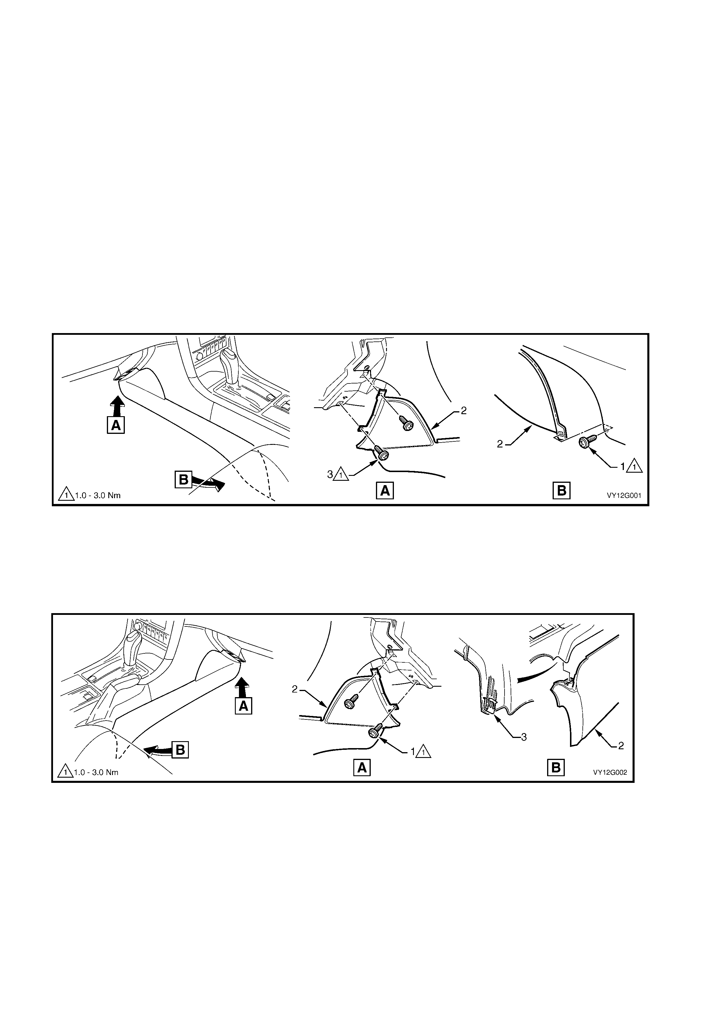
3. Right-hand drive vehicles:
a. Remove the screw (1) attaching the left-hand instrument panel lower extension side trim (2) to the floor
console.
b. Open the instrument panel compartment and remove the two screws (3) attaching the side trim to the
instrument panel.
c. Remove the side trim.
Figure 12G-1
4. Left-hand drive vehicles:
a. Remove the two screws (1) attaching the right-hand instrument panel lower extension side trim (2) to the
instrument panel.
b. Prise the rear of the trim panel downward to disengage it from the floor console retaining clip (3).
c. Remove the side trim.
Figure 12G-2
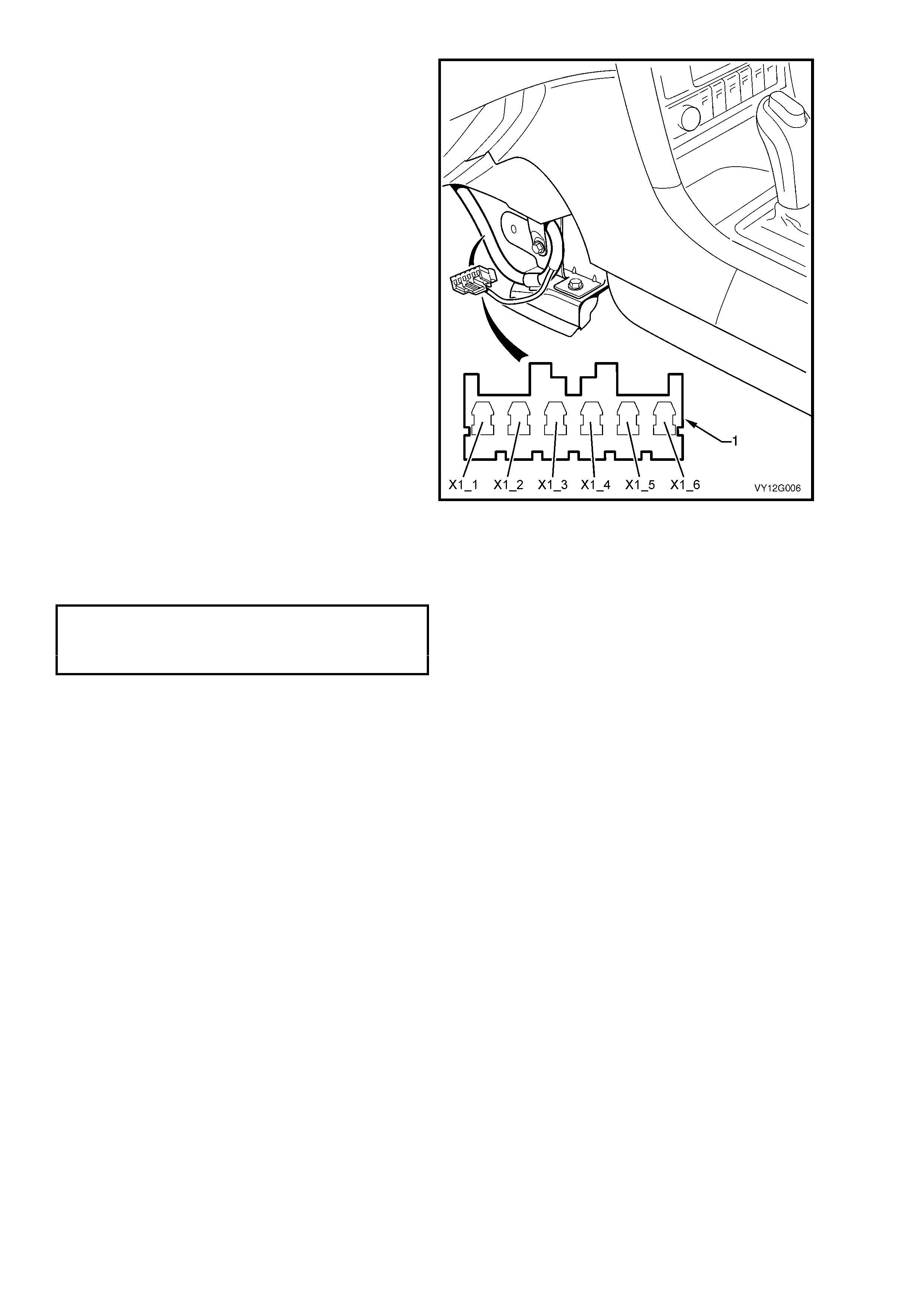
5. Locate the main wiring harness where it is
clipped to the cockpit module mounting
bracket.
NOTE: Right- hand drive is s hown, left-hand drive is
similar on the opposite side of the console.
6. The cellular phone connector (1) is taped back
to the harness across the retaining clip.
7. Remove the tape to access the connector.
8. As required, connect the cellular phone hands-
free k it to the applicable term inals. Als o refer to
2.2 WIRING for the schematic and connector
details.
X1_1 Battery voltage supply.
X1_2 Vehicle ground.
X1_3 Ignition accessory position voltage
supply.
X1_4 Radio mute input.
X1_5 Voice signal.
X1_6 Voice return.
Figure 12G-3
REINSTALL
Installation is the reverse of removal. Tighten the
screws to the specified torque.
INSTRUMENT PANEL LOWER
EXTENSION SIDE TRIM
PANEL ATTACHING SCREW
TORQUE SPECIFICATION 1.0 – 3.0 Nm
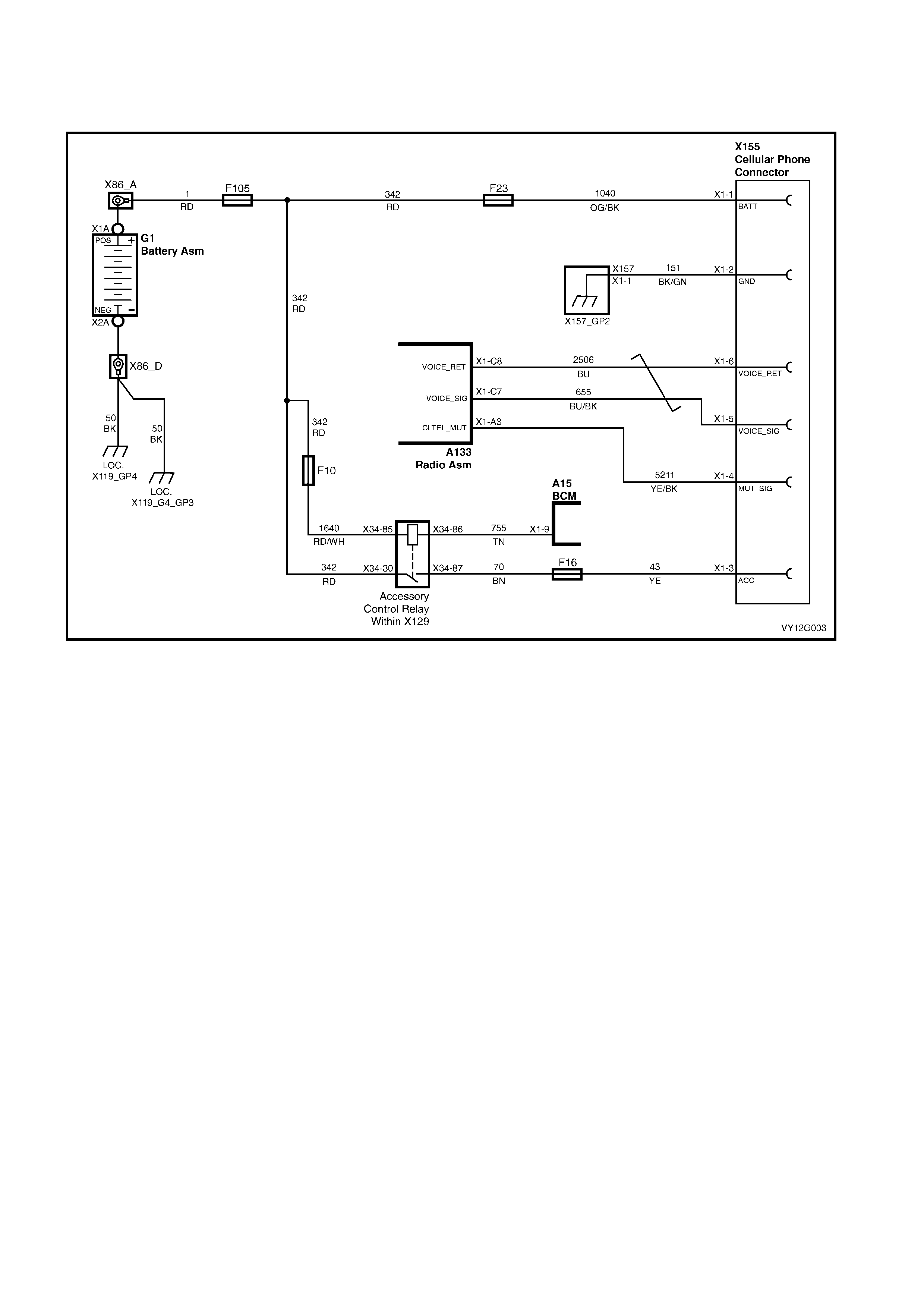
2.2 WIRING
SCHEMATIC, WITHOUT TELEMATICS
Figure 12G-4

SCHEMATIC, WITH TELEMATICS
Figure 12G-5
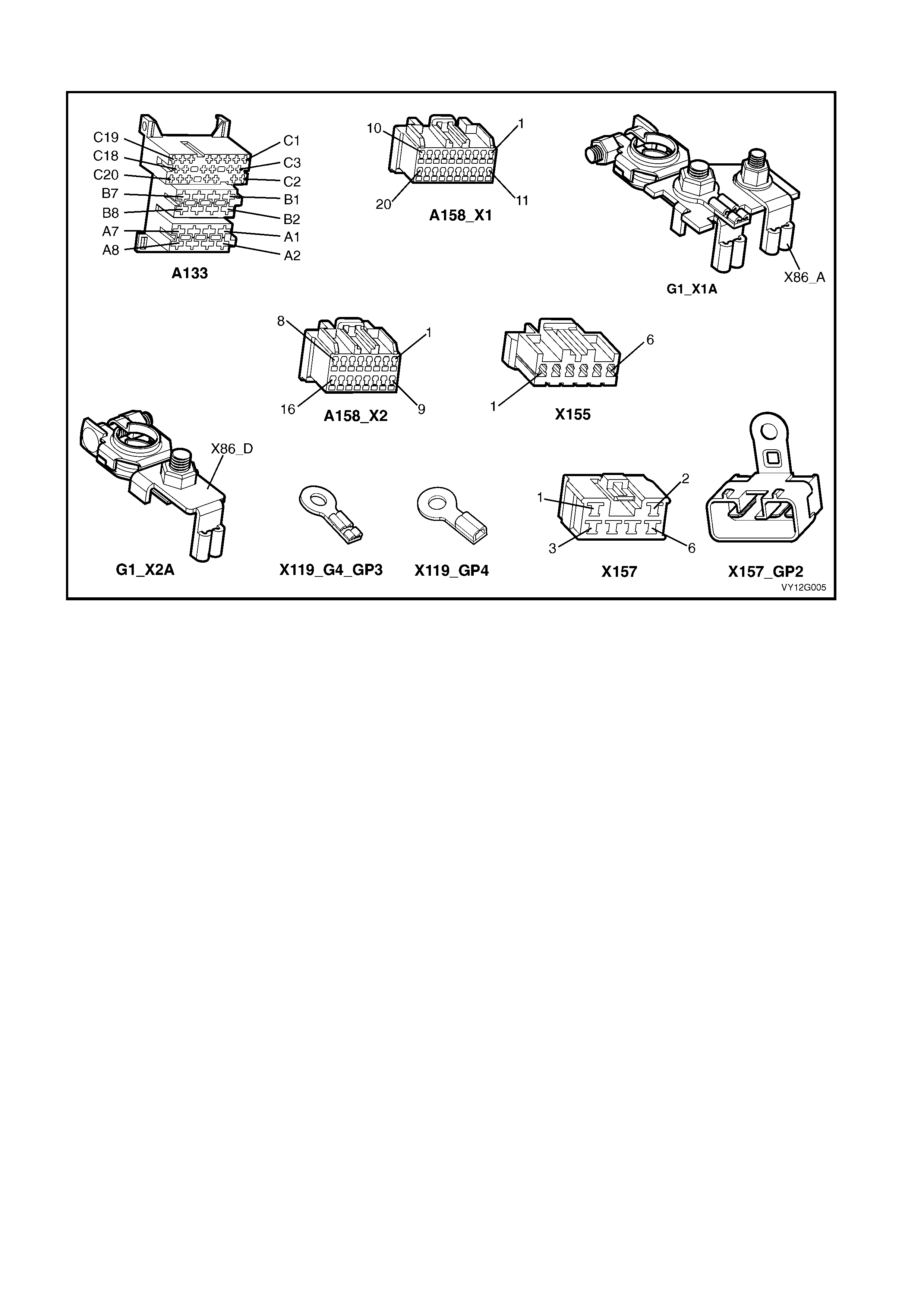
CONNECTOR DETAIL
Figure 12G-6

3. TORQUE WRENCH SPECIFICATIONS
Instrument panel lower extension side trim panel attaching screw................................1.0 – 3.0 Nm