
SECTION 12H - REAR-VIEW MIRRORS
IMPORTANT
Before p erforming any Serv ice Operation or other procedure d escribed in this Section , refer to Section 00,
CAUTIONS AND NOTES for correct workshop practices with regard to safety and/or property damage.
CONTENTS
1. GENERAL INFORMATION
1.1 INTERIOR MIRROR OPERATION
DAY/NIGHT SETTING
1.2 CONTROL SWITCH OPERATION
TILT DOWNWARDS
TILT UPWARDS
TILT OUTWARDS
TILT INWARDS
LH VS. RH MIRROR OPERATION
2. SERVICE OPERATIONS
2.1 EXTERIOR MIRROR ASSEMBLY
REMOVE
TEST
REINSTALL
2.2 EXTERIOR MIRROR GLASS
REMOVE
REINSTALL
2.3 MIRROR CONTROL SWITCH
REMOVE
TEST THE SWITCH CONTACTS
REINSTALL
2.4 INTERIOR REAR-VIEW MIRROR
REMOVE
REINSTALL
3. DIAGNOSIS
ELECTRIC MOTOR INOPERATIVE
DIAGNOSTIC CHART
EXTERIOR MIRROR LOSS OF FUNCTION
DIAGNOSTIC CHART
CONNECTOR DIAGRAM – RIGHT-HAND
DRIVE
CONNECTOR DIAGRAM – LEFT-HAND DRIVE
CIRCUIT DIAGRAM – RIGHT-HAND DRIVE
CIRCUIT DIAGRAM – LEFT-HAND DRIVE
4. TORQUE WRENCH SPECIFICATIONS
5. SPECIAL TOOLS
1. GENERAL I NFORMATION
Electrically adjustable exterior rear-view mirrors are fitted as standard equipment on all VY Series Models.
Each exterior mirror assem bly has two reversible m otors: one to tilt the mirror face up and down (vertical position)
and one to tilt the mirror face left and right (horizontal position).
The ex terior rear-view m irrors are adjusted electr ically from ins ide the vehicle using the mirror control switch, whic h
is mounted in the driver’s door pull-handle.
Replacement exterior rear-view mirror assemblies are available in Black. These are made of acrylate styrene
acrylonitrile (ASA) plastic. Replacement assemblies requiring a colour-coded contrast need to be masked and
painted using correct refinishing procedures as outlined by the paint manufacturer.
The interior rear-view mirror is manually adjusted to suit the driving position. Models fitted with production option
UE1 (Comm unication System Te lem atics) have som e c om ponents of this system installed into the rear-view mirror.
Refer to Section 12K, TELEMATICS for service information relating to the interior rear-view mirror of these models.
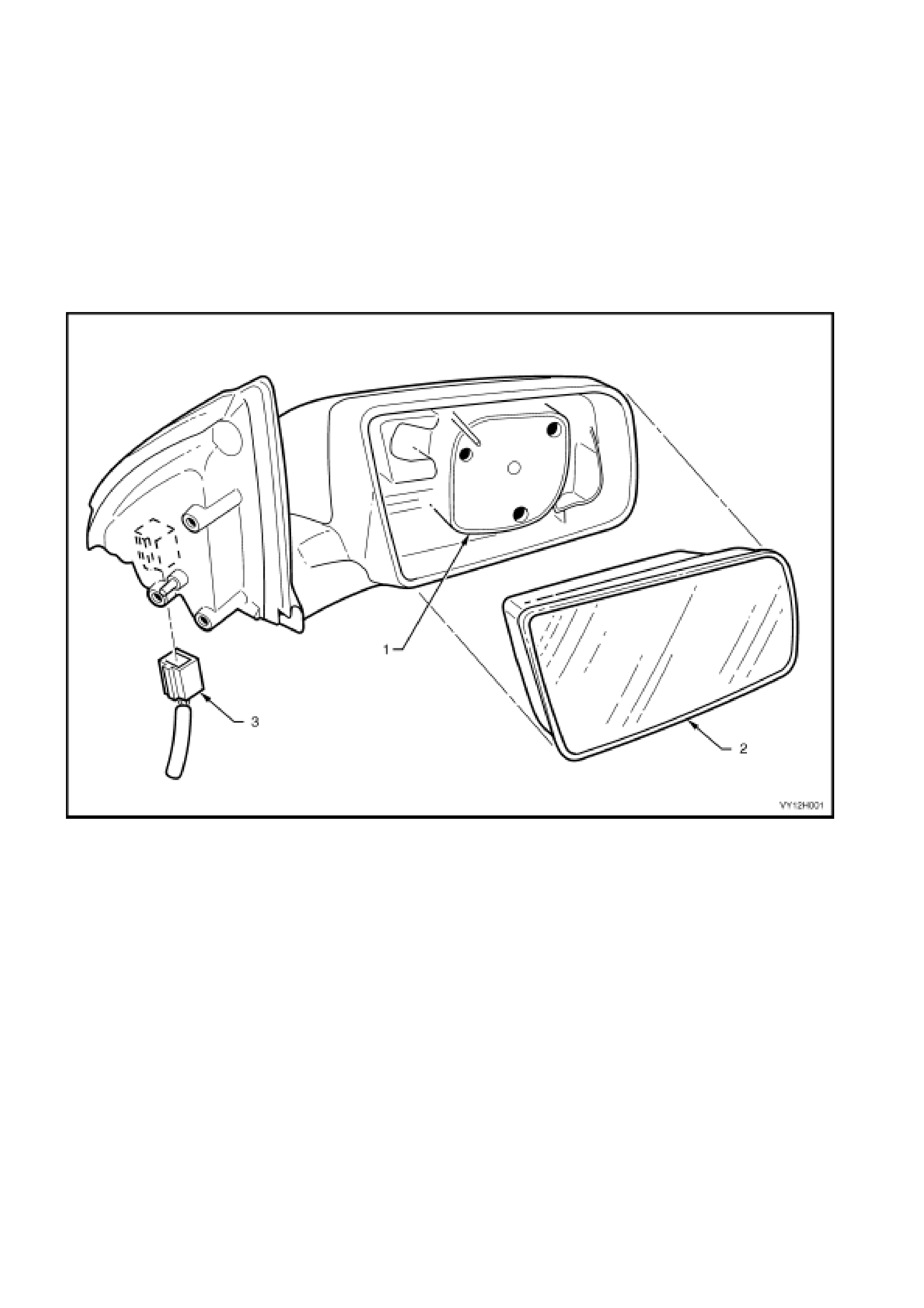
Figure 12H-1
Legend
1. Vertical and horizontal motor housing
2. Mirror glass
3. Mirror harness connector
1.1 INTERIOR MIRROR OPERATION
For vehicle models fitted with production option UE1 (Communication System Telematics), refer to
Section 12K, TELEMATICS.
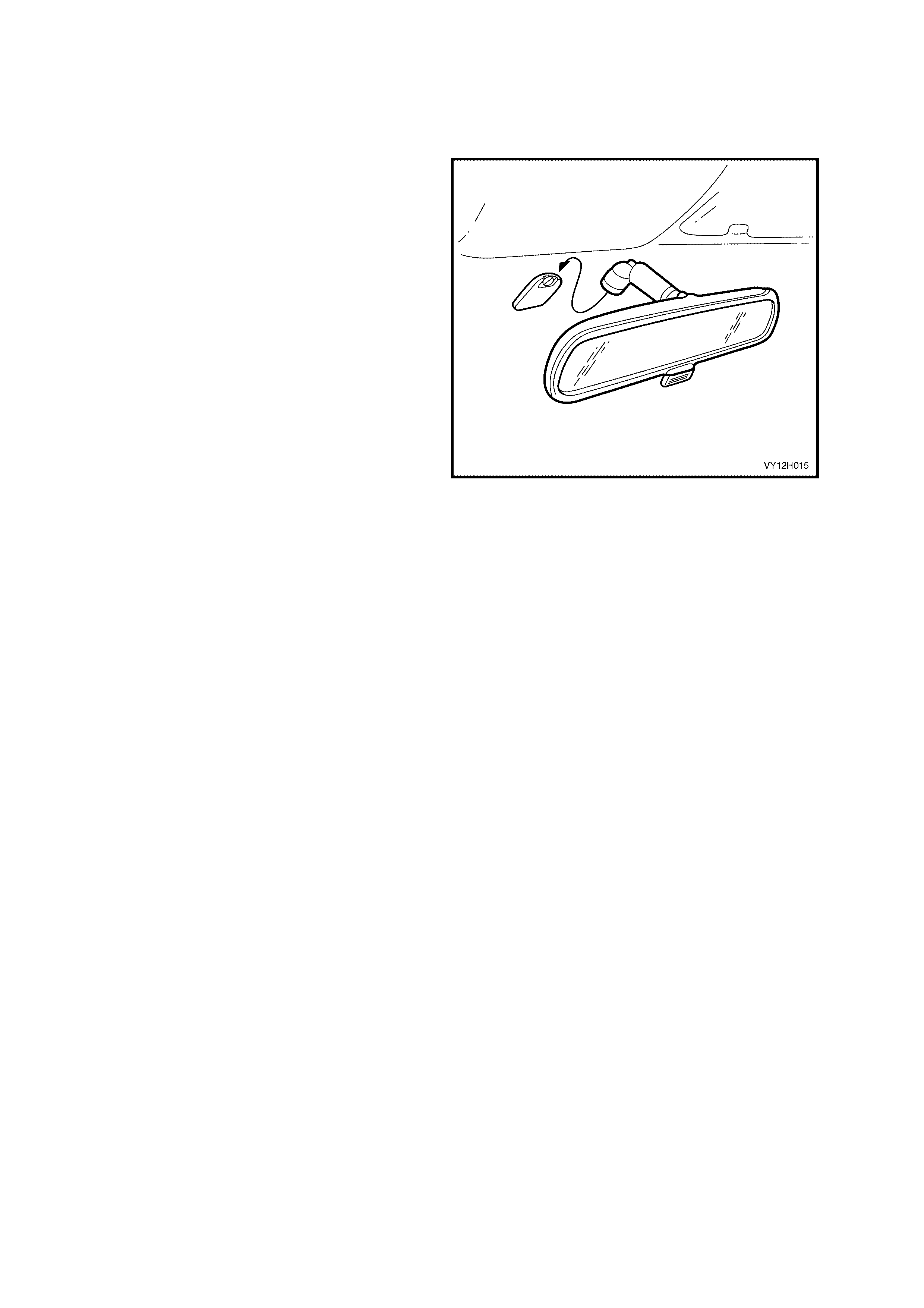
DAY/NIGHT SETTING
A lever is fitted at the base of the interior rear-view
mirror. When the lever is pulled to the forward
position, the fac e of the m ir ror tilts slightly upwar ds.
This maintains rear vision but reduces the glare of
reflected light for night-time driving. The lever
should be reset to the rearward position for all
daytime driving.
Figure 12H-2
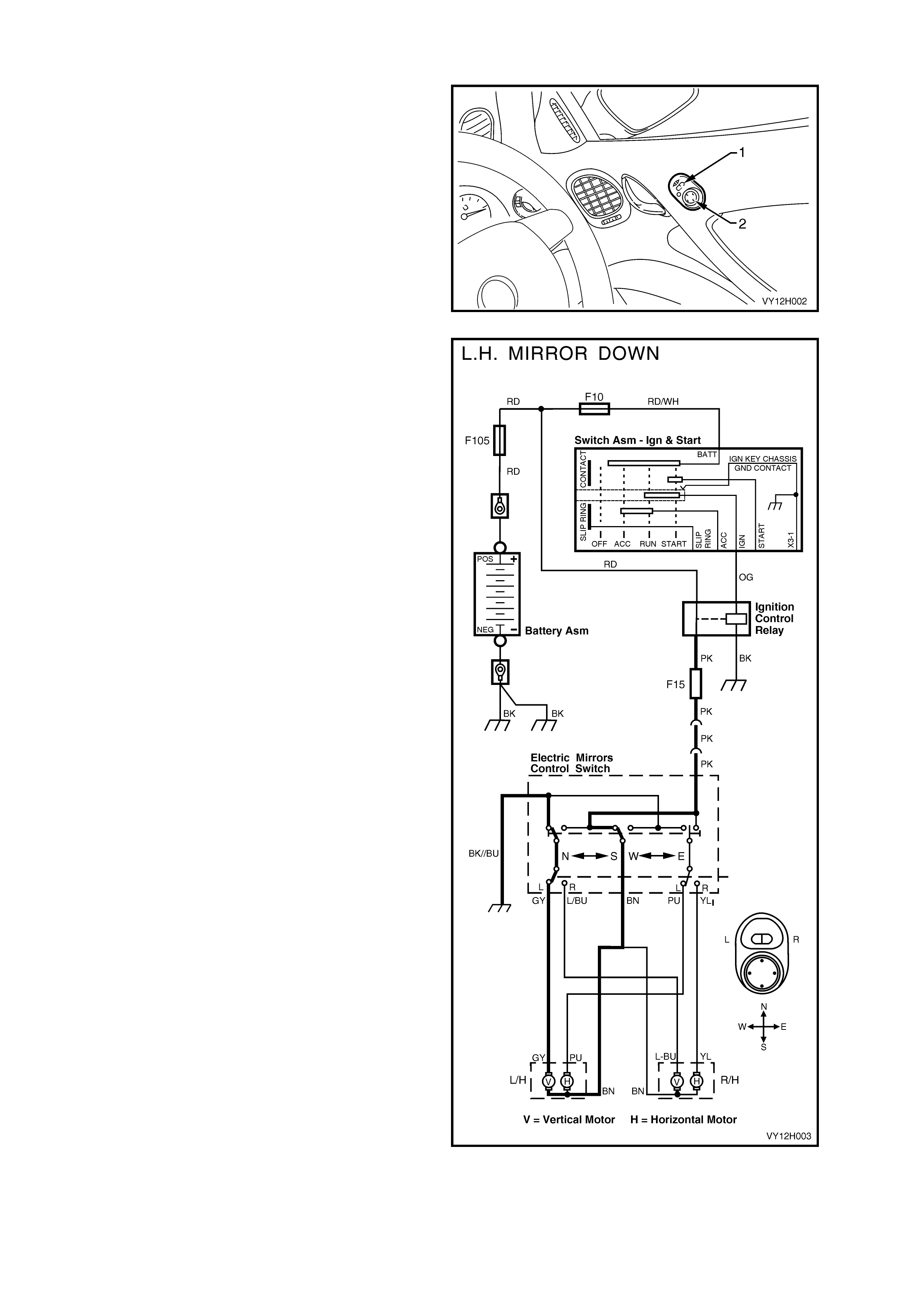
1.2 CONTROL SWITCH OPERATION
The exterior-mirror control switch has two controls:
a slide-select switch (1) (with left mirror and right
mirror positions) and a directional toggle switch (2)
to control the direction of adjustment.
The dire ctional toggle switch is designed to operate
in only one direction at a time and is activated by
pressing the edge of the toggle in the required
direction.
Figure 12H-3
TILT DOWNWARDS
With the switches positioned as shown in
Figure 12H-4, the LH exterior mirr or is selected and
the toggle switch is set to activate the vertical
position motor to tilt the mirror DOWNWARDS.
The following circuit is activated.
Battery voltage is supplied to the toggle switch
contacts via fuse F15. This voltage is applied via
circuit 330 (Brown wire) to one side of the vertical
position motor. The circuit is completed on the
other s ide of the LH ver tic al pos ition motor, with the
following path to ground:
• through circuit 89 (Grey wire)
• to the LH side select-switch contacts
• through the toggle switch directional contacts
and
• circuit 650 (Black / Blue wire) to ground.
This activates the vertical position motor until the
directional toggle switch is released.
TILT UPWARDS
When the toggle switch is pressed to move the
mirror UPWARDS, it switches the circuit so that
voltage is applied to the same motor, but in the
opposite direction.
That is, from fuse F15 to the toggle switch then
through the select s witch c ontacts and via c irc uit 89
to the motor.
The path to ground is now via circuit 330 to the
toggle switch contacts, then through circuit 650 to
ground.
Figure 12H-4
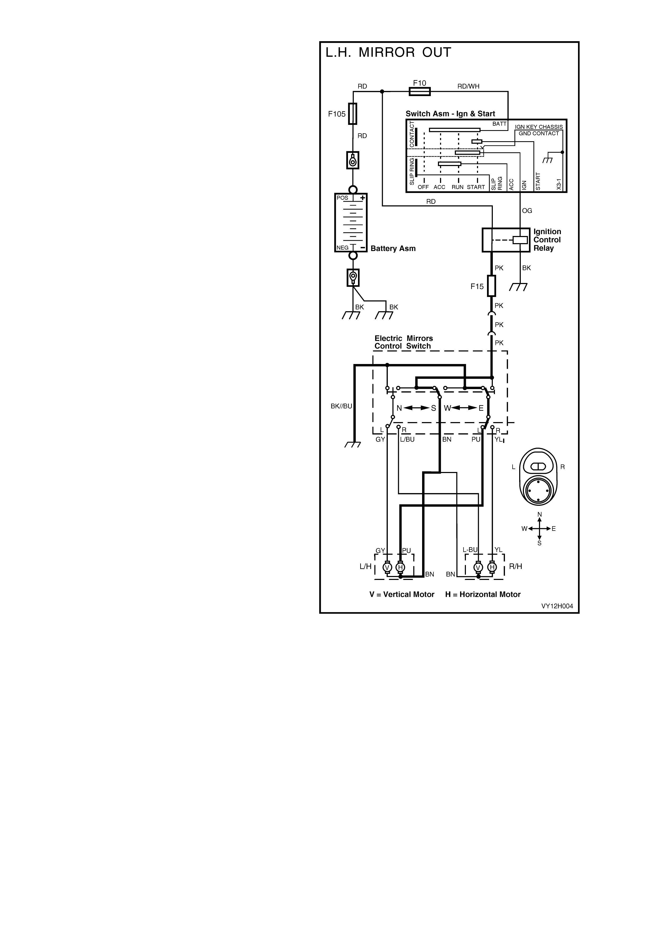
TILT OUTWARDS
When the directional switch is pressed in the
OUTWARD position, the circuit in Figure 12H-5 is
activated as follows:
Battery voltage from fuse F15 is supplied through
the directional centre contacts of the toggle switch
and circuit 330 (Brown wire) to one side of the
horizontal mirror motor.
The LH mirror horizontal position motor has a path
to ground through:
• circuit 82 (Purple wire)
• the LH side select switch contacts
• the directional contacts
• circuit 650 (Black / Blue wire) to ground.
This energises the LH m irror horizontal m otor to tilt
the mirror OUTWARDS until the toggle switch is
released.
TILT INWA RDS
W hen the directional toggle switch is pressed to tilt
the mirror INWARDS, the LH mirror horizontal
motor is supplied voltage in the opposite direction.
Power to the motor is supplied through the
directional and LH side select switch c ontacts, then
through circuit 82 (Purple wire). The motor is
grounded though circuit 330 (Brown wire) and the
directional switch c ontacts, then through circuit 650
(Black / Blue wire).
LH vs. RH MIRROR OPERATION
The RH motors operate by the same principles as
the LH motors (outlined previously).
By moving the side-select switch to adjust the RH
side mirror, power and ground connections are
made as for the LH side, but using different wires
(different circuit numbers).
To tilt the RH mirror DOW N, power is supplied via
circuit 889 (Light Blue wire) and grounded via
circuits 330 (Brown wire) and 650 (Black wire).
To tilt the RH m irror UP, power is supplied through
circuit 330 and grounded via circuits 889 and 650.
To tilt the RH mirror OUT, power is supplied
through circuit 90 and grounded via circuits 330
and 650.
To tilt the RH mirror IN, power is supplied through
circuit 330 and grounded via circuits 90 and 650.
Figure 12H-5
2. SERVICE OPERATIONS
IMPORTANT
All fasteners are important attaching parts as they affect the performance of components and failure
could result in major repair. Where specified in this section, fasteners MUST be replaced with parts of
the same part number or a GM approved equivalent. Do not use fasteners of an inferior quality or
substitute des ign.
Torque values must be used as specified during reassembly to ensure proper retention of the
components.
Throughout this section, fastener torque specifications may be accompanied by the following
identification marks:
+
++
+ Fasteners must be replaced after loosening.
&
&&
& Vehicle must be at curb height before final tightening.
6
66
6 Fasteners either have micro encapsulated sealant applied or incorporate a mechanical thread lock
and
should only be re-used once. If in doubt, replacement is recommended.
These recommendations must be adhered to.
2.1 EXTERIOR MIRROR ASSEMBLY
LT Section No. – 10-400
NOTE: The following fasteners MUST be replaced
when performing this operation:
+
++
+ Exterior-mirror assembly retaining screws.
REMOVE
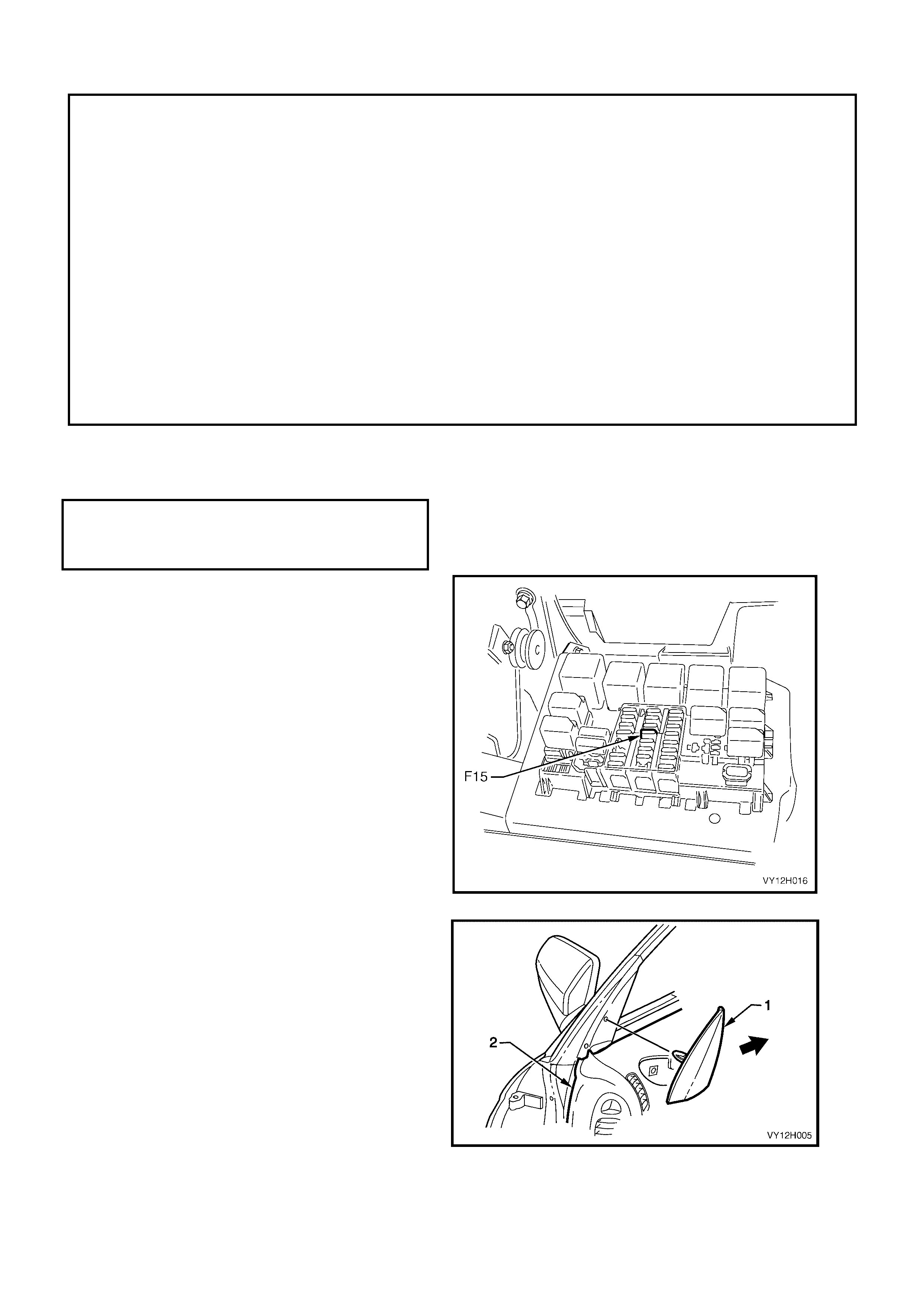
1. Remove fuse F15 from the interior fuse panel.
Figure 12H-6
2. Remove the mirror inner dress cover (1) by
gently prying the cover away from the door and
sliding it back (towards the side window).
3. Pull the door demist duct (2) up and out of the
door trim panel.
Figure 12H-7
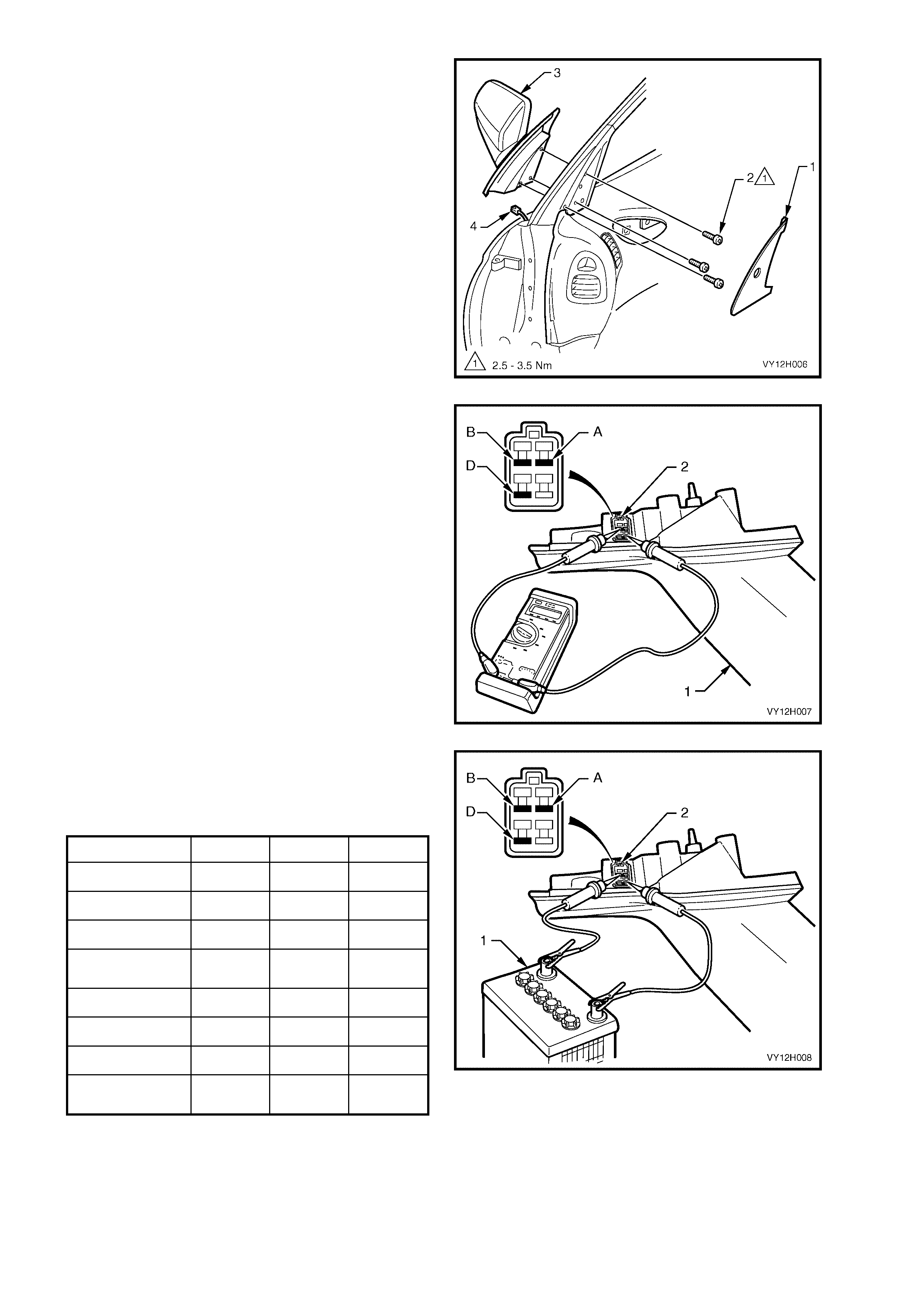
4. Remove the dust cover (1).
5. Remove the door trim to gain access to the
retaining screws. Refer to Section 1A5,
FRONT AND REAR DOOR ASSEMBLIES.
6. Remove the three screws (2) securing the
mirror to the door.
7. While supporting the mirror assembly (3),
disconnect the mirror wiring harness connector
(4).
8. Remove the mirror assembly.
Figure 12H-8
TEST
The following operations are performed with the
mirror assembly (1) removed from the vehicle.
1. Check the mirror assembly horizontal and
vertical motors . If the following operations prove
that a mirror component is faulty, replace the
mirror assembly.
2. Connect an ohmmeter to the electric mirror
connector (2) to check the continuity of the
wiring between the following terminals:
$%A and B
$%A and D
$%B and D.
3. If the ohmmeter indicates an open circuit or a
resistance of more than 200 ohms between
these terminals, replace the mirror assembly.
Figure 12H-9
4. Connect the positive (+) and negative (–) leads
from a 12 volt battery (1) to the connector
terminals, as outlined in the following chart.
5. Observe the mirror movement.
FUNCTION TE RM. A TERM. B TERM . D
LH MIRROR – IN – +
LH MIRROR – OUT + –
LH MIRROR – UP + –
LH MIRROR –
DOWN – +
RH MIRROR – IN + –
RH MIRROR – OUT – +
RH MIRROR – UP + –
RH MIRROR –
DOWN – +
+ = battery positive (12 volts)
– = battery negative
6. If the m ovement of the m ir ror is not as s hown in
the above chart, replace the mirror assembly.
Figure 12H-10

REINSTALL
Installation of the exterior rear-view mirror is the reverse of the removal procedure, noting the following:
1. Ensure that the wiring harness for the mirror is correctly routed.
2. Tighten the three mirror-to-door retaining screws to the correct torque specification.
( + ) EXTERIOR MIRROR ASSEMBLY
RETAINING SCREW
TORQUE SPECIFICATION 2.5 – 3.5 Nm
3. Install the door trim.
4. Install the door demist duct, ensuring that the duct clips into position.
5. Install fuse F15 ensuring that it is positioned into the correct fuse receptacle.
6. Check for correct mirror operation.
2.2 EXTERIOR MIRROR GLASS
LT Section No. – 10-400
REMOVE
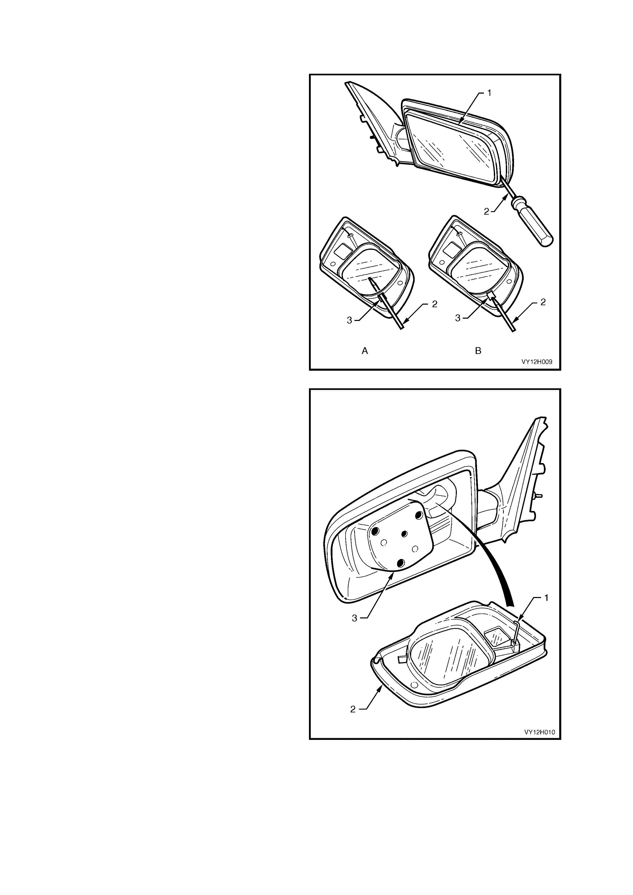
1. Adjust the mirror glass (1) so it is in the fully UP
and fully IN position.
2. Refer to Figur e 12H-11, views A and B. Insert a
screwdriver (2) into the slot (3) on the inside of
the mirror glass.
3. Gently lever the mirror glass away from the
moto r assembly.
4. Remove the mirror glass from the motor
assembly.
Figure 12H-11
REINSTALL
1. Ensure the anti-vibration spring rod (1) is at a
right angle to the mirror glass (2) and that it
aligns with the corresponding aperture in the
mirror housing.
2. Suppor t the mirr or housing and push the m irror
glass squarely onto the motor assembly (3)
until it is firmly seated.
Figure 12H-12
2.3 MIRROR CONTROL SWITCH
LT Section No. – 02-775
REMOVE
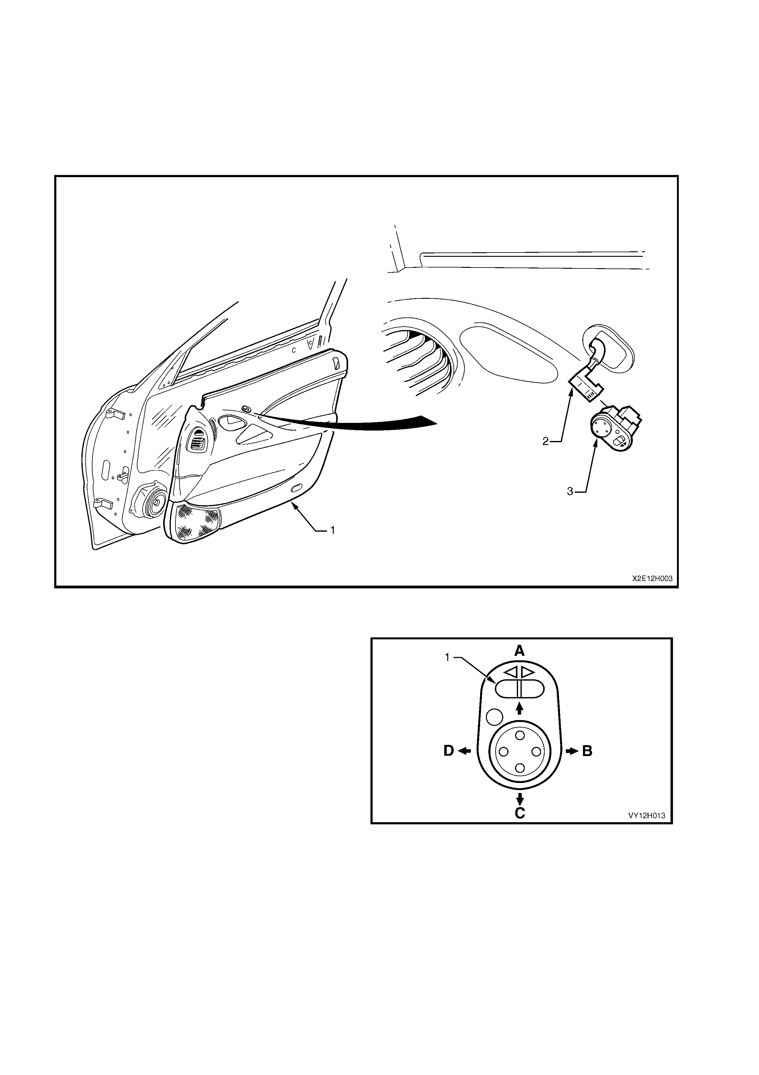
1. Remove the door inner trim panel (1). Refer to Section 1A5, FRONT AND REAR DOOR ASSEMBLIES.
2. Disconnect the door electrical harness (2) from the control switch (3).
3. From the inside of the door trim assembly, push the control switch to free it and remove it.
Figure 12H-13
TEST THE SWITCH CONTACTS
1. Using Figures 12H-134and 12H-15 and the
following two charts, use an ohmmeter to
check the mirror control switch contacts for
continuity between terminals.
2. Select the desired mirror with the selector
switch (1).
Legend
A. Tilt UP
B. Tilt OUT – right-hand mirror
Tilt IN – left-hand mirror
C. Tilt DOWN
D. Tilt IN – right-hand mirror
Tilt OUT – left-hand mirror
Figure 12H-14
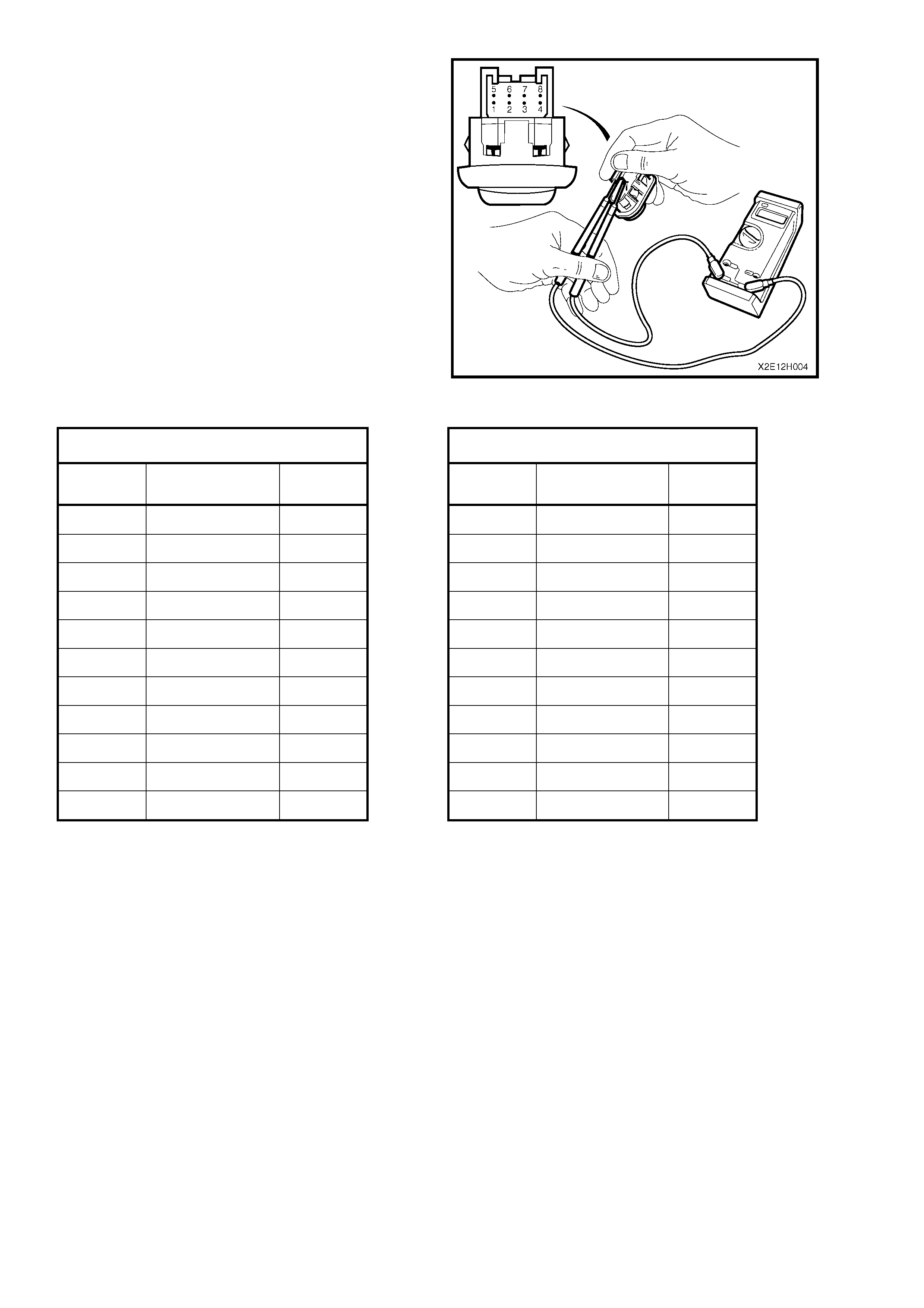
3. Attach the ohmmeter to the terminals listed in
the following two charts.
4. Press the directional toggle switch as if
adjusting the selected mirror in the direction
indicated in the chart.
The ohmmeter must indicate continuity
between the terminals listed.
Figure 12H-15
LEFT-HAND MIRROR CONNECTIONS RIGHT-HAND MIRROR CONNECTIONS
TILT SWITCH
TERMINALS SUPPLY TILT SWITCH
TERMINALS SUPPLY
IN 1 and 4 + IN 1 and 5 +
2 and 5 – 2 and 8 –
OUT 1 and 5 + OUT 1 and 8 +
2 and 4 – 2 and 5 –
UP 1 and 5 + UP 1 and 5 +
2 and 7 – 2 and 3 –
DOWN 1 and 7 + DOWN 1 and 3 +
2 and 5 –
2 and 5 –
REINSTALL
Installation is the reverse of the removal procedure.
2.4 INTERIOR REAR-VIEW MIRROR
For vehicle models fitted with production option
UE1 (Communication System Telematics), refer to
Section 12K, TELEMATICS.
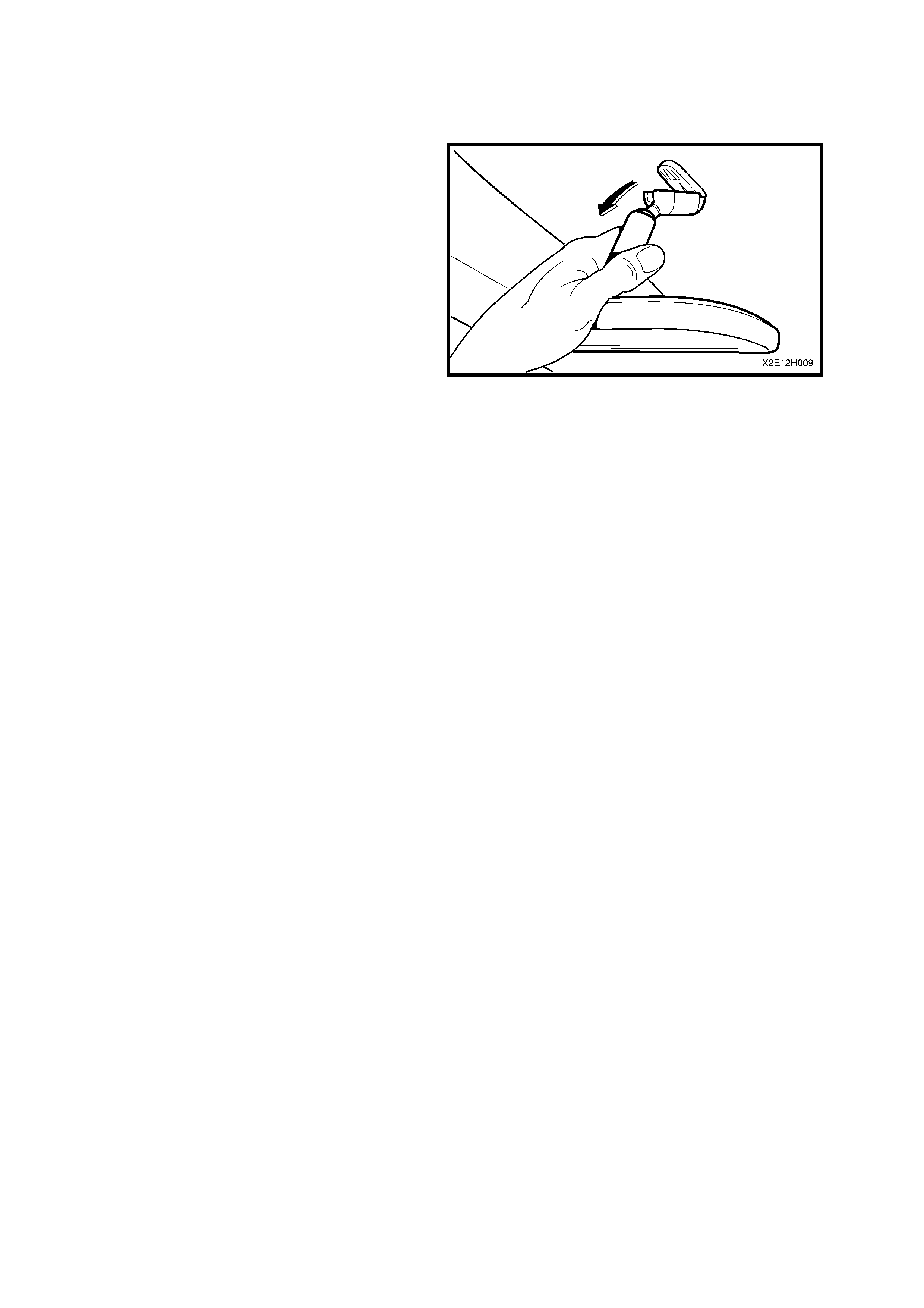
REMOVE
The interior rear-view mirror is held in position by
spring force onto the boss that is fixed to the
windscreen.
1. Disengage the interior mirror from the boss on
the windscreen by grasping the mirror lens
firm ly by hand and peeling the mirror assem bly
downwards towards the lower edge of the
windscreen.
REINSTALL
Installation is the r everse of the removal procedur e,
noting the following:
1. W hen inst alling the mirror onto the boss on the
windscreen, slide the m irror assem bly from the
top of the boss downwards, ensuring that it is
pushed down fully. An audible click should
occur as the mirror assembly locks into
position.
Figure 12H-16

3. DIAGNOSIS
ELECTRIC MOTOR INOPERATIVE DIA GNOSTIC CHART
STEP ACTION VALUE YES NO
1 Are both electric rear-view mirrors inoperative? Go to Step 2. Go to Step 3.
2 Is Fuse F15 (located in fuse panel) OK? Go to Step 3. Replace blown
fuse and check
wiring for cause
of fuse blowing.
Verify repair.
3 Remove the driver’s door inner trim panel, refer to Section
1A5, FRONT AND REAR DOOR ASSEMBLIES.
Reconnect the mirror control switch.
Turn the ignition on.
Using a test light, check for power at connector S169,
terminal X1-1, circuit 139 (Purple wire).
Does the test light illuminate?
Go to Step 4. Check and
repair open
circuit in circuit
139 (Pink wire)
from fuse F15 to
the control
switch. Verify
repair.
4 1. Turn the ignition off.
2. Using an ohmmeter, check circuit 650 (Black / Blue
wire) for continuity between connector S169, terminal
X1-2, and the ground connection at location X118.
Is the wiring OK?
Go to Step 5. Check and
repair open
circuit in ground
circuit 650
(Black / Blue
wire). Verify
repair.
5 1. At connector S169, terminal X1-5, check for continuity
between circuit 330 (Brown wire) and the following
circuits:
• Circuit 82 (Purple wire), terminal X1-4 (LH mirror
horizontal motor).
• Circuit 89 (Grey wire), terminal X1-7 (LH mirror vertical
motor).
• Circuit 90 (Yellow wire), terminal X1-8. (RH mirror
horizontal motor).
• Circuit 889 (Light Blue wire), terminal X1-3 (RH mirror
vertical motor).
Is the wiring OK?
Go to Step 6. Check and
repair open
circuit. Verify
repair.
6 1. Disconnect the mirror control switch connector and test
the switch contacts. Refer to 2.3 MIRROR CONTROL
SWITCH, in this Section.
Is mirror control switch OK?
System OK. Replace mirror
control switch.
Refer to 2.3
MIRROR
CONTROL
SWITCH, in this
Section. Verify
repair.

EXTERIOR MIRROR LOSS OF FUNCTION DIAGNOSTIC CHART
STEP ACTION VALUE YES NO
1 1. Remove the mirror control switch and test the switch
contacts, refer to 2.3 MIRROR CONTROL SWITCH in
this Section.
Are the mirror switch contacts OK?
Go to Step 2. Replace mirror
control switch.
Refer to 2.3
MIRROR
CONTROL
SWITCH, in this
Section. Verify
repair.
2 1. At connector S169, terminal X1-5, check for continuity
between circuit 330 (Brown wire) and the following
circuits:
• Circuit 82 (Purple wire), terminal X1-4 (LH mirror
horizontal motor).
• Circuit 89 (Grey wire), terminal X1-7 (LH mirror vertical
motor).
• Circuit 90 (Yellow wire), terminal X1-8. (RH mirror
horizontal motor).
• Circuit 889 (Light Blue wire), terminal X1-3 (RH mirror
vertical motor).
Is the wiring OK?
Go to Step 3. Check and
repair open
circuit. Verify
repair.
3 1. Check the faulty mirror assembly. Refer to
2.1 MIRROR ASSEMBLY in this Section.
Is the mirror OK?
System OK. Replace mirror
assembly. Refer
to 2.3 MIRROR
CONTROL
SWITCH, in this
Section. Verify
repair.
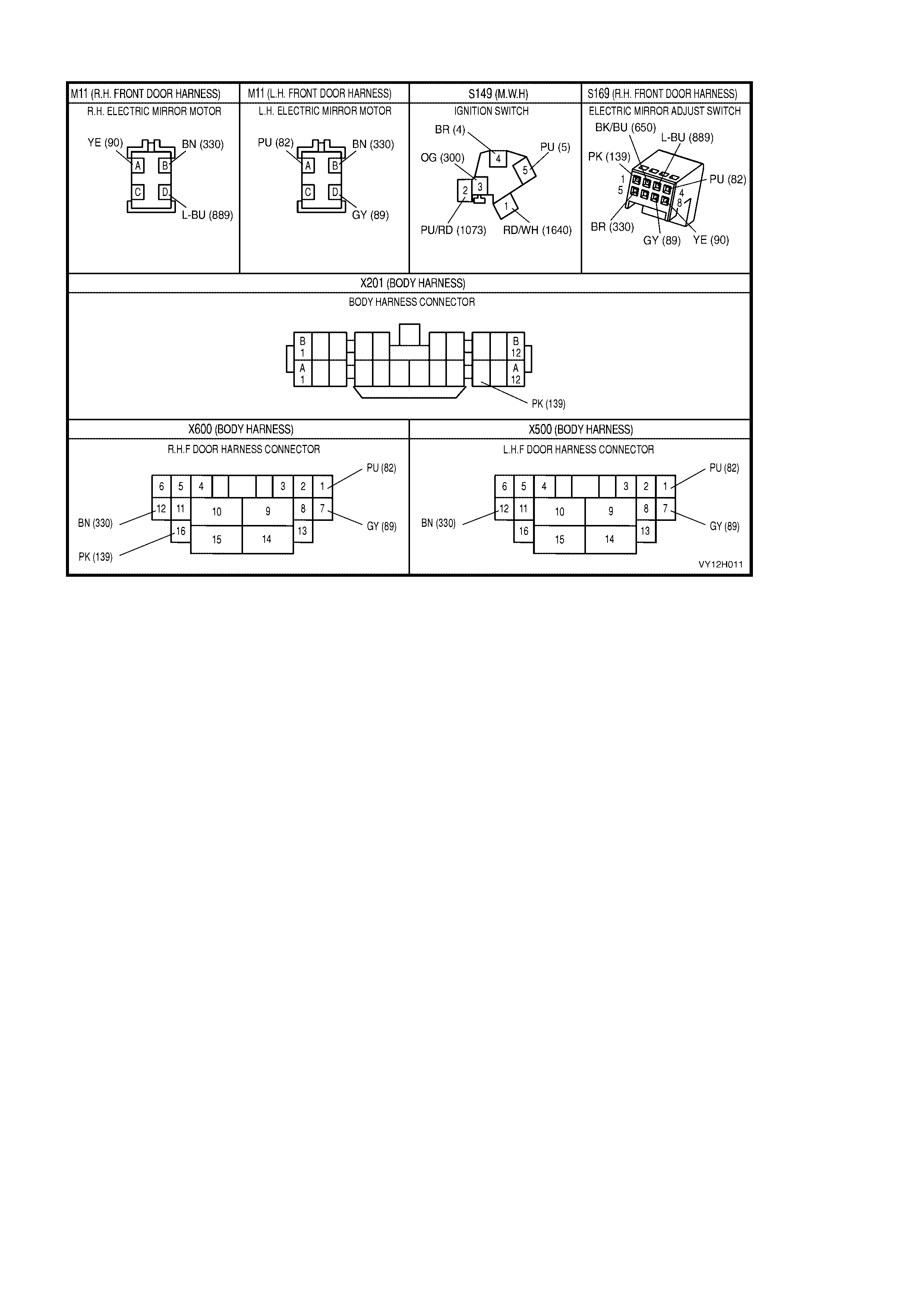
CONNECTOR DIAGRAM – RIGHT-HAND DRIVE
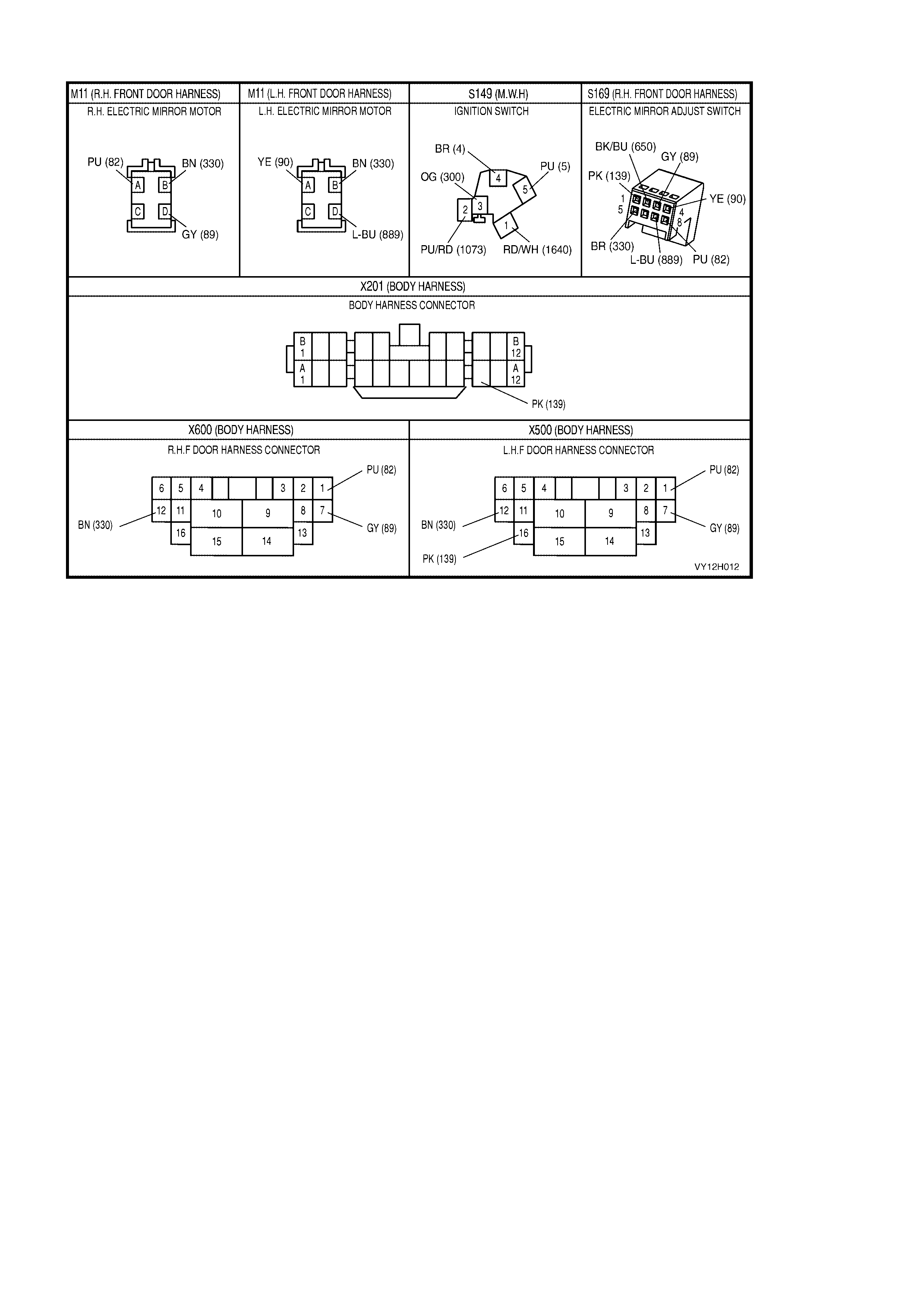
CONNECTOR DIAGRAM – LEFT-HAND DRIVE
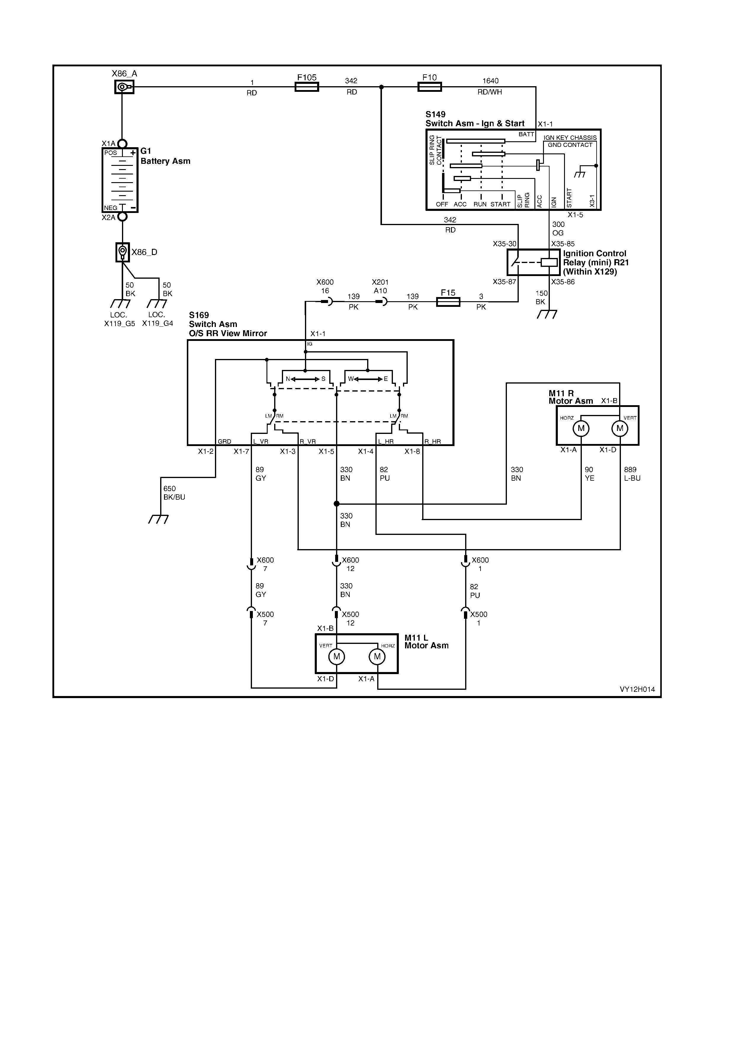
CIRCUIT DIAGRAM – RIGHT-HAND DRIVE
Figure 12H-17
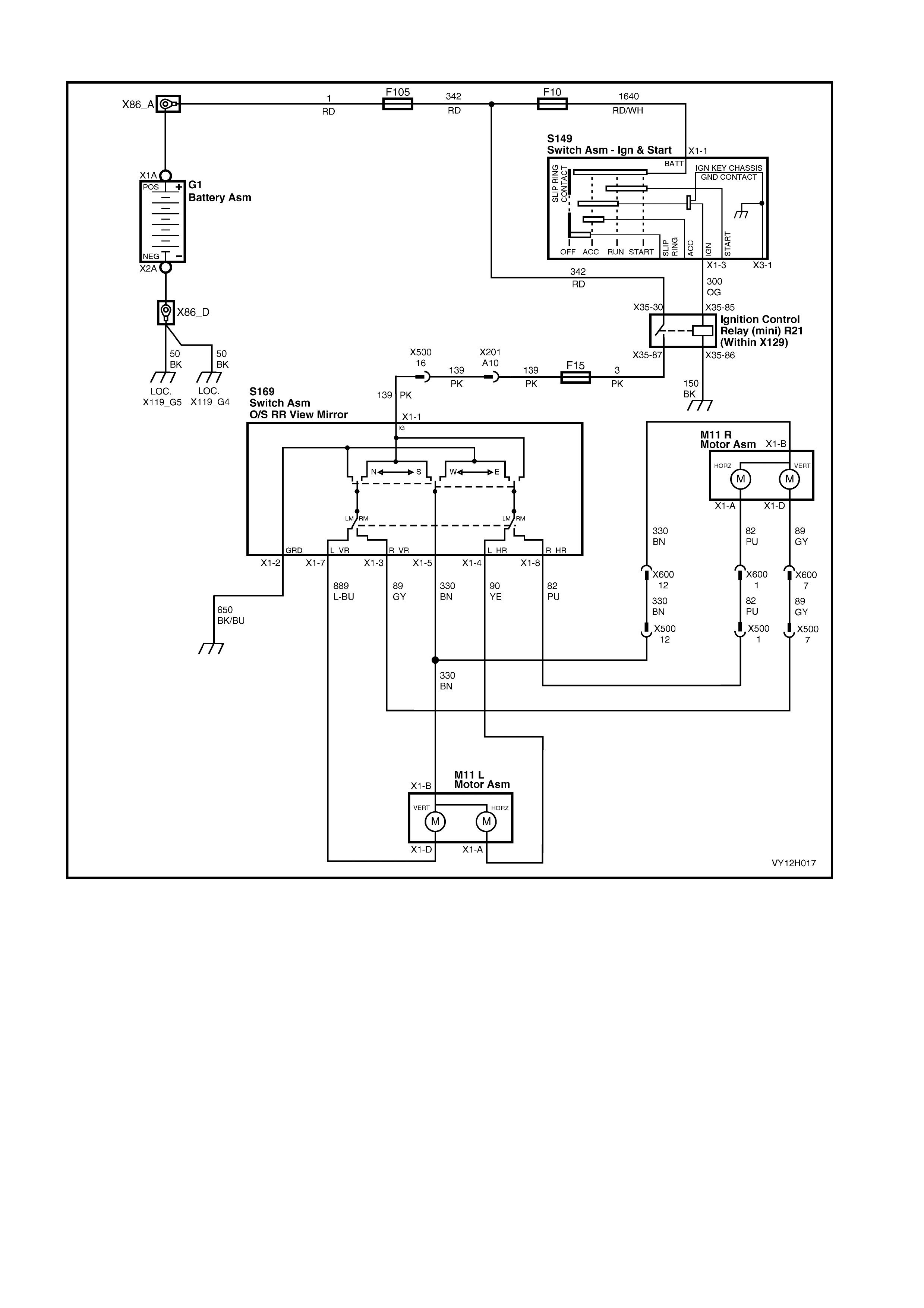
CIRCUIT DIAGRAM – LEFT-HAND DRIVE
Figure 12H-18

4. TORQUE WRENCH SPECIFICATIONS
Mirror to Door Attaching Screws 2.5 – 3.5 Nm
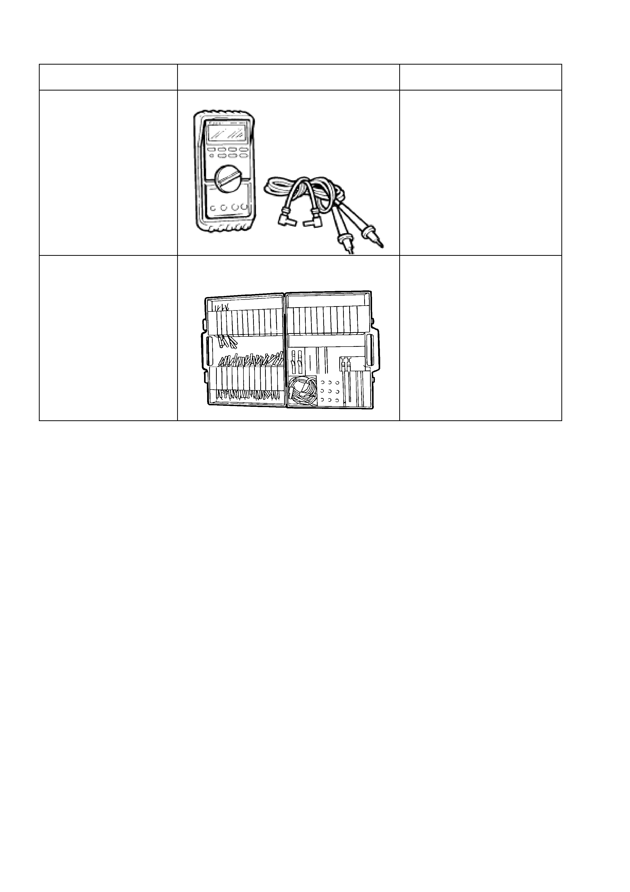
5. SPECIAL TOOLS
TOOL NO. REF IN TEXT TOOL DESCRIPTION COMMENTS
j39200 DIGITAL MULTIMETER TOOL NO. J39200
PREVIOUSLY RELEASED, OR
USE COMMERCIALLY
AVAILABLE EQUIVALENT.
MUST HAVE 10 MEG OHM
INPUT IMPEDANCE OR
GREATER
J35616-A
(KM609) CONNECTOR test ADAPTOR KIT
USED IN CONJUNCTION
WITH A MULTIMETER FOR
MEASURING VOLTAGES AND
RESISTANCES WITHOUT
damaging WIRING HARNESS
CONNECTORS