
SECTION 12J - BODY CONTROL MODULE
IMPORTANT
Before performing any Service Operation or other procedure described in this Section, refer to Section 00
CAUTIONS AND NOTES for correct workshop practices with regard to safety and / or property damage.
CONTENTS
1. GENERAL INFORMATION
ABBREVIATIONS
BODY CONTROL MODULE
CIRCUIT DIAGNOSTICS – PULL-UP
CIRCUIT DIAGNOSTICS – PULL-DOWN
SERIAL COMMUNICATION
BCM — RIGHT-HAND DRIVE LOCATION AND
CONNECTORS
BCM — LEFT-HAND DRIVE LOCATION AND
CONNECTORS
BCM TERMINAL IDENTIFICATION
1.1 BCM MODES
BATTERY SAVER M ODE
PRE-DELIVERY MODE
1.2 SERIAL DATA COMMUNICATION (BUS MASTER)
SYSTEM OVERVIEW
POWERTRAIN INTERFACE MODULE (PIM )
INPUTS AND OUTPUTS
1.3 REMOTE RECEIVER / KEY
SYSTEM OPERATION
CIRCUIT OPERATION
1.4 ACCESSORY POWER CONTROL
SYSTEM OPERATION
SYSTEM OVERVIEW
CIRCUIT OPERATION
1.5 CENTRAL DOOR LOCKING
SYSTEM OPERATION
SYSTEM CHECK
SYSTEM OVERVIEW
CIRCUIT OPERATION
1.6 REAR COMPARTM ENT RELEASE
SYSTEM OPERATION
CIRCUIT OPERATION
1.7 THEFT DETERRENT SYSTEM
GENERAL INFORMATION
SYSTEM OVERVIEW
SYSTEM OPERATION
CIRCUIT OPERATION
1.8 ENTRY DETERRENT SYSTEM
CIRCUIT DESCRIPTION
SYSTEM OVERVIEW
CIRCUIT OPERATION
1.9 POWER WINDOW SYSTEM
SYSTEM FUNCTIONS
SYSTEM OVERVIEW
CIRCUIT OPERATION
1.10 ENGINE COOLING FAN LOW-SPEED CONTROL
RHD
LHD
SYSTEM OVERVIEW
FAN OPERATION: STANDARD COOLING FAN
SYSTEM – V6
FAN OPERATION: HIGH POWER COOLING FAN
SYSTEM– V6
FAN OPERATION: HIGH POWER COOLING FAN
SYSTEM– GEN III V8
1.11 WIPER SYSTEM
GENERAL INFORMATION
LEVEL 1 VEHICLES
LEVEL 2 AND LEVEL 3 VEHICLES
1.12 DOME LAMP DELAY CONTROL
SYSTEM OPERATION
CIRCUIT OPERATION
SYSTEM OPERATION
CIRCUIT OPERATION
1.13 AUTOMATIC LAMP CONTROL
SYSTEM OPERATION
SYSTEM OVERVIEW
CIRCUIT OPERATION
1.14 INSTRUMENT DIMMING CONTROL
SYSTEM OPERATION
SYSTEM OVERVIEW
CIRCUIT OPERATION
1.15 AIR CONDITIONING INTERFACE
SYSTEM OPERATION
SYSTEM OVERVIEW
CIRCUIT OPERATION
1.16 SRS DEPLOYMENT VEHICLE SHUTDOWN
SYSTEM OPERATION
SYSTEM OVERVIEW
CIRCUIT OPERATION
1.17 PRIORITY KEY SYSTEM
OPERATING PARAMETERS
SYSTEM OVERVIEW
CIRCUIT OPERATION
1.18 POWER ANTENNA CONTROL
SYSTEM OPERATION
SYSTEM OVERVIEW
CIRCUIT OPERATION
1.19 HEATED REAR WINDOW
SYSTEM OPERATION
SYSTEM OVERVIEW
CIRCUIT OPERATION
1.20 REAR LAMP FAILURE WARNING SYSTEM
SYSTEM OPERATION
SYSTEM OVERVIEW
CIRCUIT OPERATION
1.21 HAZARD LAMP CONTROL
SYSTEM OPERATION
CIRCUIT OPERATION
2. SERVICE OPERATIONS
2.1 BODY CONTROL MODULE
SAFETY AND PRECAUTIONARY MEASURES
BCM CONNECTORS AND RHD LOCATION
BCM CONNECTORS AND LHD LOCATION
REMOVE
REINSTALL
BCM RELEARN PROCEDURE
2.2 REMOTE CODED KEY
KEY REPLACEMENT
Techline
Techline
Techline
Techline
Techline

2.3 REMOTE RECEIVER
REMOVE
REINSTALL
2.4 POWER WINDOW DOOR SWITCHES
REMOVE
REINSTALL
3. TECH 2 DIAGNOSIS FOR BCM
3.1 BASIC KNOWLEDGE REQUIRED
3.2 CONNECTING TECH 2 FOR SYSTEM DIAGNOSIS
3.3 TECH 2 TEST MODES AND DISPLAYS
MAIN MENU
BODY MENU
3.4 NORMAL MODE
3.5 DIAGNOSTIC TROUBLE CODES
DIAGNOSTIC TROUBLE CODES MENU
READ DTC INFORMATION
RE AD ALARM CODES
3.6 DATA DISPLAY
INPUTS AND OUTPUTS
BCM INTERNAL STATUS
SERIAL DATA INPUTS
PRIORITY 1 USER SETTINGS
PRIORITY 2 USER SETTINGS
ALARM / THEFT DETERRENT
CENTRAL DOOR LOCKING
POWER WINDOWS
WIPERS
HEADLAMPS
INSTRUMENT ILLUMINATION
INTERIOR ILLUMINATION
REAR LAMP FAILURE
AIR CONDITIONING INTERFACE
ANTENNA
SYSTEM IDENTIFICATION
3.7 SNAPSHOT
3.8 MISCELLANEOUS TESTS
LAMPS
LOW SPEED COOLING FAN
DATA BUS ISOLATOR
CENTRAL LOCKING
REAR COMPARTMENT
WIPERS
POWER WINDOWS
ANTENNA
HORN
INTERIOR ILLUMINATION RELAY
ACCESSORY RELAY
SECURITY SYSTEM
3.9 PROGRAM
F0: USER SETTINGS
F1: OPTIONS
F2: SET KEY TO PRIORITY 1
F3: LEARN BCM SETTINGS
F4: PROGRAM LEARNT BCM SETTINGS
3.10 SECURITY
F0: BCM LINK TO PCM/PIM
F1: SECURITY INFORMATION
F2: PROGRAM
4. BCM DIAGNOSTICS
4.1 PREREQUISITES TO DIAGNOSIS AND
TROUBLESHOOTING
PRELIMINARY SYSTEM REQUIREMENTS
PRE-DELIVERY MODE
SAFETY REQUIREMENTS
EQUIPMENT AND CHECKING
MODULE LOCATION
ABBREVIATIONS
4.2 SERIAL DATA COMMUNICATION (BUS MASTER)
CIRCUIT DESCRIPTION
4.3 REMOTE RECEIVER / KEY
CIRCUIT DESCRIPTION
4.4 ACCESSORY POWER CONTROL
CIRCUIT DESCRIPTION
4.5 CENTRAL DOOR LOCKING
CIRCUIT DESCRIPTION
PART A – UNLOCKING DOORS USING DRIVER’S
DOOR LOCK MICROSWITCH
PART B – LOCKING DOORS USING DRIVER’S
DOOR LOCK MICROSWITCH
PART C – UNLOCKING DOORS USING DRIVER’S
DOOR LOCK SNIB ACTUATOR
PART D – LOCKING DOORS USING DRIVER’S
DOOR LOCK SNIB ACTUATOR
PART E – UNLOCKING DOORS USING
PASSENGERS’ DOOR LOCK SNIB ACTUATORS
PART F – LOCKING DOORS USING FRONT
PASSENGER DOOR LOCK SNIB ACTUATOR
PART G – UNLOCKING THE TAILGATE
PART H – DEADLOCKING DOORS USING
DRIVER’S DOOR LOCK MICROSWITCH
PART I – UNLOCKING DOORS FROM DEADLOCK
PART J – AUTO DOOR LOCKING (GEARSHIFT
OUT OF PARK POSITION)
PART K – AUTO DOOR UNLOCKING (GEARSHIFT
INTO PARK POSITION)
PART L – DOOR AJAR SWITCHES
4.6 REAR COMPARTM ENT RELEASE
CIRCUIT DESCRIPTION
4.7 THEFT DETERRENT SYSTEM
CIRCUIT DESCRIPTION
4.8 ENTRY DETERRENT SYSTEM
CIRCUIT DESCRIPTION
4.9 POWER WINDOW SYSTEM
CIRCUIT DESCRIPTION
4.10 ENGINE COOLING FAN LOW-SPEED CONTROL
CIRCUIT DESCRIPTION
4.11 WIPER SYSTEM
CIRCUIT DESCRIPTION
4.12 DOME LAMP DELAY CONTROL
CIRCUIT DESCRIPTION
4.13 AUTOMATIC LAMP CONTROL
CIRCUIT DESCRIPTION
4.14 INSTRUMENT DIMMING CONTROL
CIRCUIT DESCRIPTION
4.15 AIR CONDITIONING INTERFACE
CIRCUIT DESCRIPTION
4.16 SRS DEPLOYMENT VEHICLE SHUTDOWN
CIRCUIT DESCRIPTION
4.17 PRIORITY KEY SYSTEM
DESCRIPTION
4.18 POWER ANTENNA CONTROL
CIRCUIT DESCRIPTION
4.19 HEATED REAR WINDOW
CIRCUIT DESCRIPTION
4.20 REAR LAMP FAILURE WARNING SYSTEM
CIRCUIT DESCRIPTION
4.21 HAZARD LAMP CONTROL
CIRCUIT DESCRIPTION
5. TORQUE WRENCH SPECIFICATIONS
6. SPECIAL TOOLS
1. GENERAL I NFORMATI O N
ABBREVIATIONS
Abbreviations are used in this Section to represent the following components:
BCM – Body Control Module
PCM – Powertrain Control Module
PIM – Powertrain Interface Module
RF – Radio Frequency
MFD – Multi-function Display (part of the Instrument Cluster)
SRS – Supplemental Restraint System
VSS – Vehicle Speed Sensor
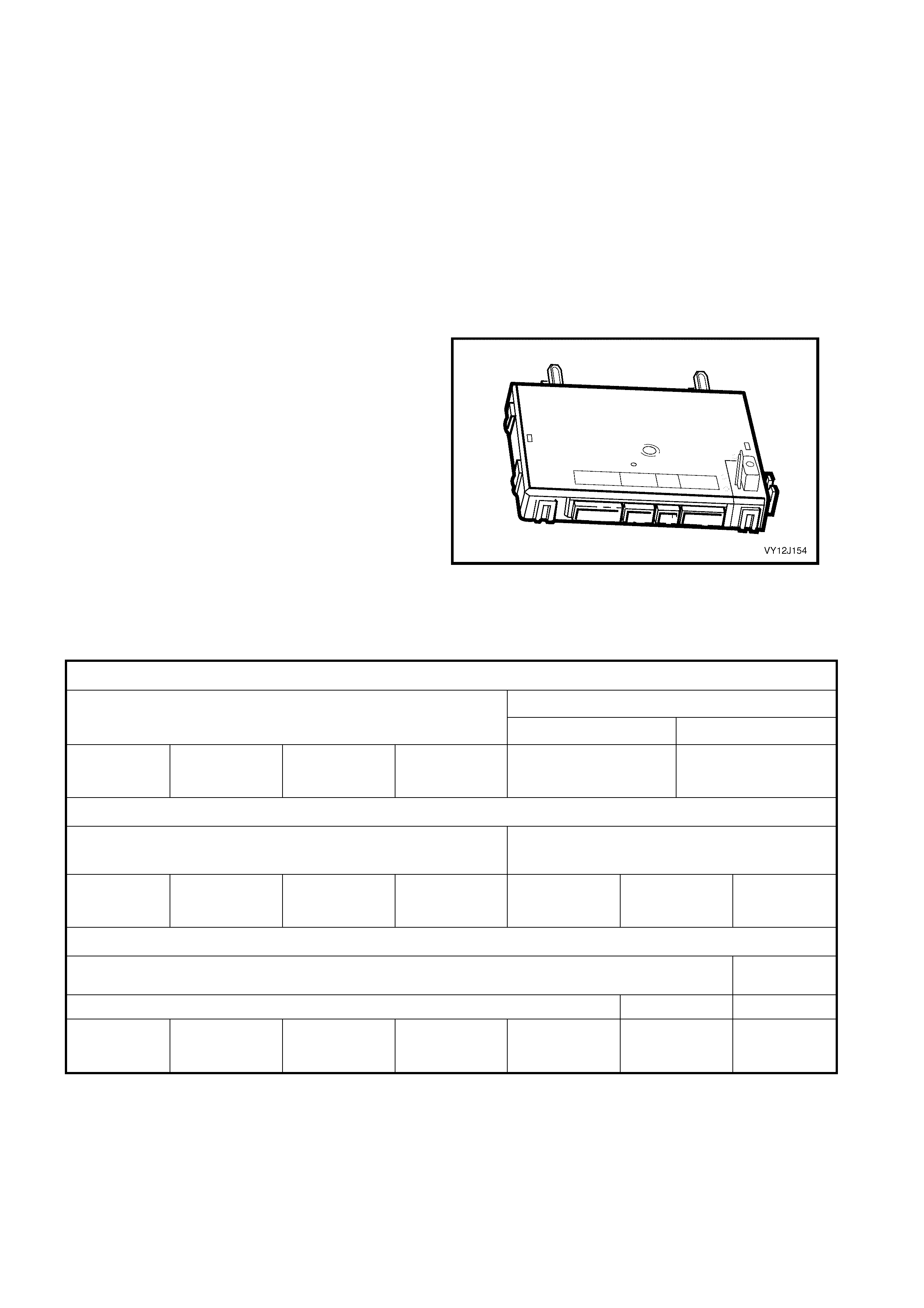
BODY CONTROL MODULE
The Body Control Module (BCM) controls various
vehicle electrical systems or features from one
central m odule, instead of using individual modules
for each system or feature.
The BCM is located beneath the instrument cluster
to the right of the steering column. On right-hand
drive vehicles the BCM is mounted vertically (refer
to Figure 12J-4) , but on left-hand drive vehicles the
BCM is mounted in a f lat (horizontal) position (re fer
to Figure 12J-5). The BCM fitted to the various
levels of vehicle is physically the same, but with
different functions enabled via the BCM software.
The various vehicle levels are detailed in the
following table.
Figure 12J-1
NOTE: Dis connect and r em ove all vehicle m odules ( after disconnec ting the battery) before perf orm ing any welding,
anywhere on the vehicle. Refer to Section 00, 5. BATTERY DISCONNECT ION PROCEDURES. Failing to do this
can cause permanent damage to the modules.
Right-hand Drive Vehicles — Domestic
Holden Holden Commodore
Level 1 Level 2 Level 3
Executive
Sedan, Wagon
and Utility
Acclaim
Sedan and
Wagon
S Sedan, Utility
and Monaro
Coupe
SS
Sedan and Utility Berlina
Sedan and Wagon Calais S edan and
SS Monaro Coupe
Right-hand Drive Vehicles — Export
Chevrolet Lumina
Level 1
LS
Sedan, Wagon
and Utility
S
Sedan SS
Sedan and Utility
Left-hand Drive Vehicles — Export
Chevrolet Lumina Chevrolet
Omega
Level 1 Level 2
LS
Sedan and
Wagon
SS
Sedan LTZ
Sedan CD
Sedan
The BCM functions enabled for the various levels of vehicle are detailed in the following table. If a BCM is to be
replaced, ensur e that the corr ect BCM is us ed. The las t three digits of the BCM part num ber identify each particular
BCM.

LOW SERIES VEHICLES HIGH SERIES VEHICLES
BCM FEATURE LEVEL 1
LOW LEVEL 1+
MID LEVEL 2
LUX LEVEL 3
HIGH
BCM Part Number 92084603 92084601 92084602 92084596
With deadlocking A A A A
Central door loc king Auto lock in drive A – User A – User A – User A – User
With speed interlock A A A A
Rear com partment
release Disabled when armed A A A A
With driver’ s express down N/A A A A
Power window s ystem With f ront passenger’s
express down N/A A A A
Approach illuminated entry at night only A – User A – User A – User A – User
Power antenna control N/A N/A A A
Entry delay and central locking A A A A
Long term timeout A A A A
Dome lamp delay
control Ign. OFF courtesy illumination
(night only) A A A A
Rear lamp failure warning system N/A N/A N/A A
Road speed dependent and
fixed dwell A A N/A N/A
Intermittent front wiper
control Road speed dependent and
variable dwell N/A N/A A A
Intermittent and synchronised
to front N/A A A N/A
Stati on wagon rear
wiper control Full wipe with reverse N/A A A N/A
Instrument dimming control A A A A
No delay N/A N/A N/A N/A
Automatic lights OFF With adj ustable delay A – User A – User A – User A – User
Automatic l i ghts ON – twilight sentinel with wiper
dependence A – User A – User A – User A – User
Vehicle immobilisation A A A A
Theft deterrent system Entry alarm A A A A
Engine cool ing l ow speed f an control A A A A
Antenna height / dim mer N/A N/A N/A A
Priority key system Light timers, remote key
functions N/A N/A N/A A
Reduce standing current A A A A
Courtesy and compartment
illumination, timed cut-out A A A A
Batt ery saver
Pre-delivery 3 minute cu t -out A A A A
Remot e central loc king with
two-stage unloc k A A A A
Remot e deadl ock and
undeadlock with state
feedback A A A A
Remot e control via
coded key
Remot e rear compart ment
release (sedan) A A A A
Cruise control interface N/A N/A N/A N/A
Airbag deployment vehicle shutdown A A A A
Heated rear window control with delay A A N/A N/A
Air condi tioning sys tem interface (A /C switch) A A N/A N/A
Occupant clim ate control i nterface – sun sensor A - Not Used A - Not Used A A
Multi-function display support A A A A
Acc essory power control (del ay accessories bus) A A A A
Serial data interface A A A A
Legend
A = Available
N/A = Not avai l abl e
User = User c onfigurable usi ng t he Instrument Cluster Multi-f unction Display (MFD)

The following list provides a sum mar y of the detailed infor mation of individual features that c an be found within this
Section.
• Remote deadlocking via remote key (two lock switch presses within 10 seconds).
• Battery saver feature; turns off all internal lamps after 1 hour (default setting) of the ignition being switched off.
NOTE: This featur e includes a pr e-delivery mode, which sets the tim er to a shor ter period of 3 minutes until the
vehicle has travelled above 20 km/h for a cumulative period of 30 minutes. After this period, the battery saver
timer sets to 1 hour.
• The standing current in the BCM is 10 mA (average value for VY SOP).
• Key off courtesy lamp; courtesy lamp comes on for 30 seconds when the ignition is switched off at night only
(sun sensor activated).
• Disablement of the in-vehicle rear compartment release switch when security system armed.
• Approach illumination entry, headlamps and / or park lamps are turned on for 30 seconds (dependent on
headlamp switch position) when the vehicle is unlocked via the remote key.
The Powertrain Control Module (PCM) for the GEN III V8 engine uses ‘Class 2’ serial communication, while all other
control modules, including the BCM, communicate serial data in UART (Universal Asynchronous Receiver and
Transmitter). The ‘Class 2’ communication is more sophisticated than UART, and as such, requires a Powertrain
Interface Module (PIM) to convert Class 2 communication into UART.
In sim ple term s, the G EN III V8 engine PCM comm unicates in a diff erent language than the other control m odules
and therefore requires the PIM to translate the PCM information into the same language as the other control
modules com m unic ate in. Refer to 1.2 SERIAL DATA COM M UNICAT ION (BUS M AST ER) in this Sec tion for m ore
information.
The PIM is mounted in the same location as a V6 PCM; behind the passenger side shroud lower trim assembly.
Specific software has been developed for use with the TECH 2 diagnostic scan tool to assist with faultfinding vehicle
electrical systems, including the various BCM functions and controls.
The T ECH 2 connection f or the BCM serial data comm unication is via the Data Link Connector (DLC), attached to
the instrument panel lower right-hand trim, to the right of the steering column.
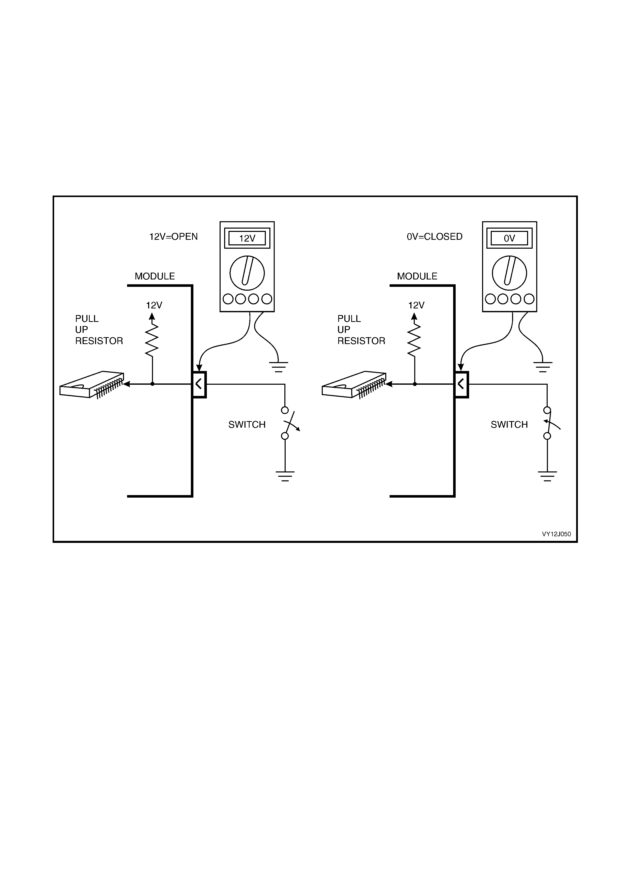
CIRCUIT DIAGNOSTICS – PULL-UP
A pull-up is a resistor that has one end connected to a voltage and the other end connected to a switch.
The pull-up r esistor allows the BCM to sense whether a s witc h is open or closed. A voltage is applied to the switch
through the pull-up resistor so that when the switch closes there is not a short-circuit between the power and
ground, ref er to F igure 12J-2. The BCM regis ters the voltage at the bottom of the pull-up to determine if the switch
is open or closed.
When the s witch is open, there is no curr ent f lowing in the resistor and therefor e no voltage drop occ urs ac ross the
resistor so the voltage sensed by the BCM is the supply voltage.
W hen the switch closes , a current f lows in the pull- up resistor causing a voltage dr op across the res istor. Because
the bottom of the pull-up res istor is s horted to ground, the voltage at the bottom of the pull-up r esistor is 0 volt. This
indicates to the BCM that the switch is closed.
Figure 12J-2
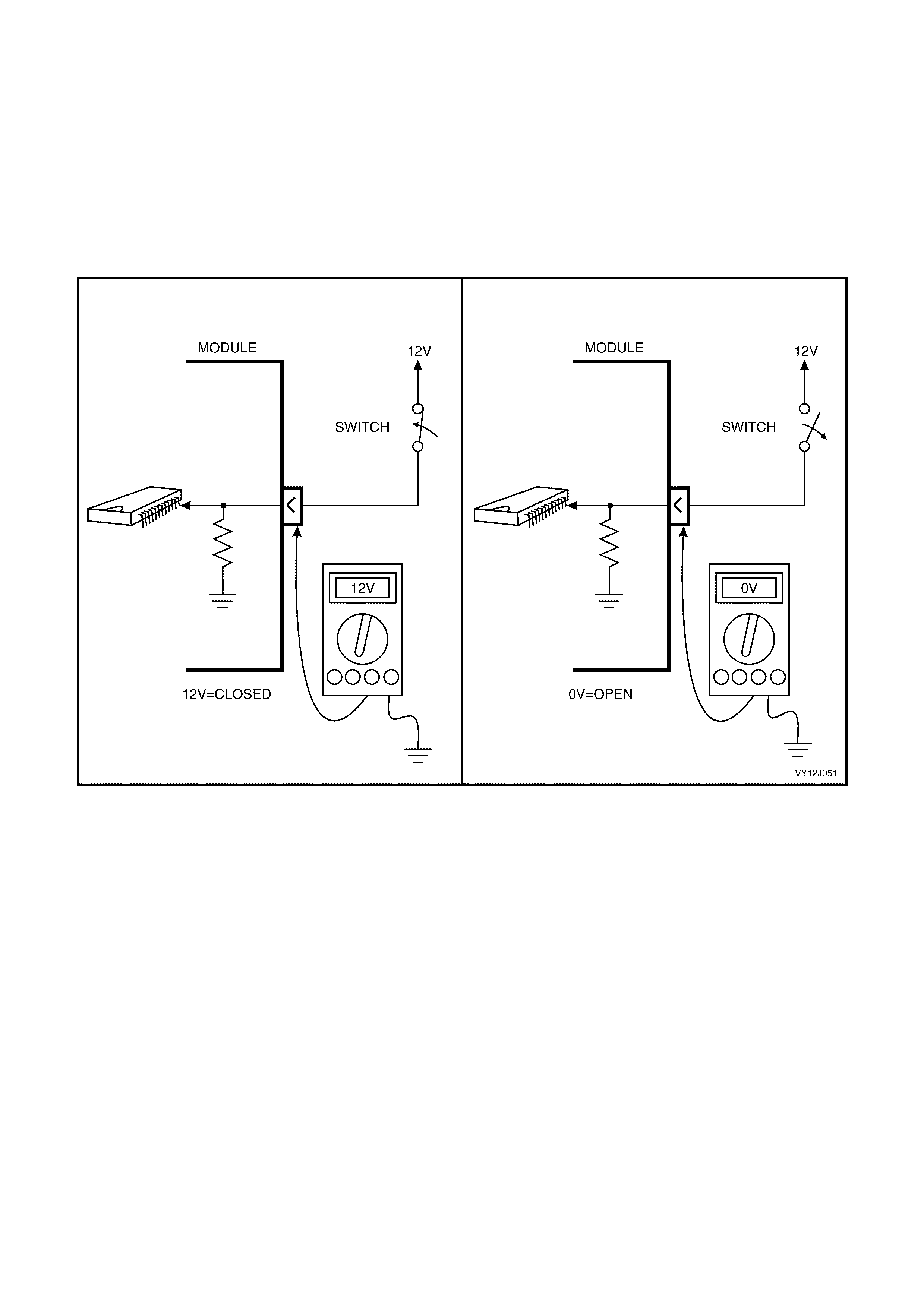
CIRCUIT DIAGNOSTICS – PULL-DOWN
A pull-down is a resistor that has one end connected to a switch and the other end connected to ground.
The pull-down resistor allows the BCM to sense whether a switch is open or closed. W hen the switch is closed, a
voltage is applied to the circuit and current flows through the pull-down resistor so there is no short-circuit to ground,
refer to Figure 12J-3. The BCM registers whether the switch is open or closed by m easuring the voltage at the top
of the pull-down resistor.
W hen the switch is closed, a current flows through the pull-down resistor, which causes a voltage drop across the
resistor. Because the top of the pull-down resistor is connected to 12 volts via the switch, the voltage at the top of
the resistor is 12 volts.
When the switch is open, no current flows in the pull-down resistor and the voltage at the top of the resistor is then 0
volt.
Figure 12J-3
SERIAL COMMUNICATION
The vehic le system control m odules, as well as the TECH 2 diagnostic sc an tool, com munic ate with each other via
the serial communication lines using serial data. Serial data transfers information, one bit at a time, over a single
line called the ‘data bus’.
Excluding the GEN III V8 PCM, all control modules communicating on the data bus use UART communication.
UART is a 5 volt data line that toggles the voltage to ground ( 0 volt) at a f ixed bit puls e width during communication.
UART transmits data at the rate of 8.2 kilobits per second (8192 bits / second). In UART communications, when
there is no communication on the data line, the system voltage is 5 volts.
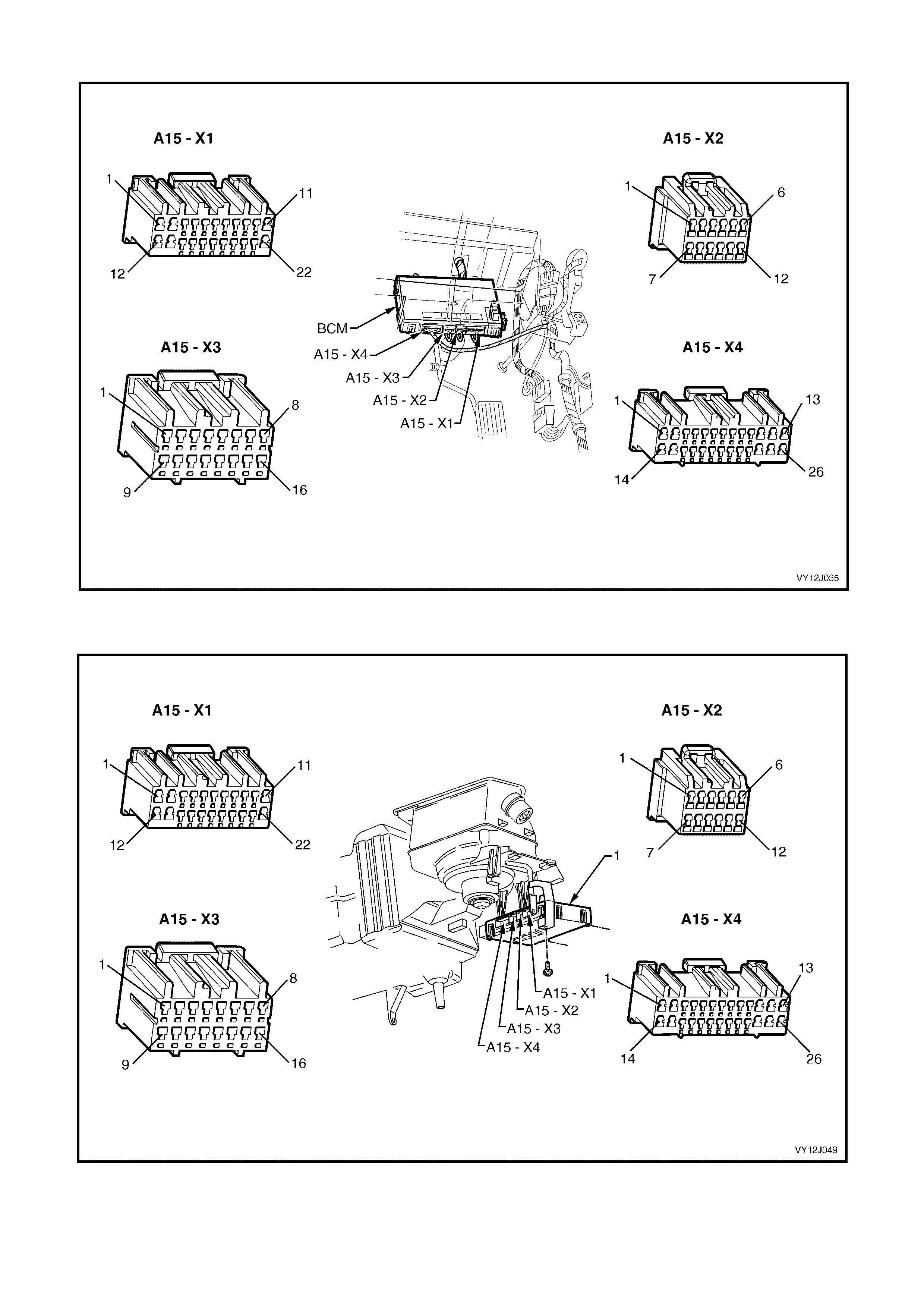
BCM — RIGHT-HAND DRIVE LOCATION AND CONNECTORS
Figure 12J-4
BCM — LEFT-HAND DRIVE LOCATION AND CONNECTORS
Figure 12J-5

BCM TERMINAL IDENTIFICATION
A15 CONNECTOR X1
PIN NO. DESCRIPTION CIRCUIT WIRE COLOUR CIRCUIT TYPE
X1–1 Front wiper park switch 196 YE Pull to B+
X1–2 Intermittent front wiper motor power 243 BN/WH ACC and IGN
X1–3 Right indicator drive 1315 BU Switch to B+
X1–4 Left indicator drive 1314 L-BU Switch to B+
X1–5 Instrument illumination drive 230 GY Switch to GND
X1–6 Auto headlamps on ground 103 WH/RD Switch to GND
X1–7 Rear wiper drive 113 GY/BU Switch to GND
X1–8 Power window drive 1351 BU Switch to GND
X1–9 Accessories relay drive 755 TN Switch to GND
X1–10 Battery main power 740 OG/BK Always active
X1–11 Power ground 151 BK/GN Always active
X1–12 Front wiper drive 96 L-GN Switch to GND
X1–13 Turn signal and rear compartment solenoid power 140 OG/RD Always active
X1–14 Receiver ground 219 BN/GN GND
X1–15 Low speed fan drive 335 OG/BK Switch to GND
X1–16 Interior lamps drive 1393 WH Switch to GND
X1–17 Horn drive 28 BK/YE Switch to GND
X1–18 Priority 1 output (Level 3) 782 TN Switch to GND
X1–18 Demist drive (Level 1) 681 BK/RD Switch to GND
X1–19 Priority 2 output (Level 3) 1985 YE/BK Switch to GND
X1–19 Air conditioner LED (Level 1) 762 RD/BK Switch to GND
X1–20 Electronic ground 251 BK/YE Always active
X1–21 Security status telltale LED 264 BU Switch to GND
X1–22 Door-lock power 440 OG/PU Always active
A15 CONNECTOR X2
PIN NO. DESCRIPTION CIRCUIT WIRE COLOUR CIRCUIT TYPE
X2–1 Receiver data 218 YE COMMS
X2–2 Twilight sensor input 1784 YE/BK 0–5 V
X2–3 Instrument dim setting 44 WH 0–5 V
X2–4 Wiper dwell setting 477 GY/BK 0–5 V
X2–5 Primary serial data bus 800 RD/BK COMMS
X2–6 Tertiary serial data bus 774 WH/GN COMMS
X2–7 Key reader 1073 PU/RD COMMS
X2–8
X2–9 Secondary serial data bus 1061 GN/WH COMMS
X2–10 Auto headlamps off ground 306 BK Switch to GND
X2–11 Bonnet pull up 109 YE/BK RES to B+
X2–12 Demist switch 292 OG Pull to B+

A15 CONNECTOR X3
PIN NO. DESCRIPTION CIRCUIT WIRE COLOUR CIRCUIT TYPE
X3–1 Battery – 150 BK Always GND
X3–2 Ignition input 300 OG Pull to B+
X3–3 Front intermittent wiper switch position 112 BU/WH Pull to B+
X3–4 Accessories on 4 BN Pull to B+
X3–5 S t o p l a m p f u s e (L e ve l s 2 and 3) 640 OG/BU Pull to B+
X3–5 A / C S wi t c h ( L e v e l 1) 66 RD/WH Pull to B+
X3–6
X3–7 Rear wiper 391 GY/RD Pull to B+
X3–8 Rear compartment release request 1576 BK/RD Pull to GND
X3–9 Air conditioner blower switch 63 D-GN/YE Pull to GND
X3–10 Radio on 314 YE/RD Pull to GND
X3–11 Hood open 263 YE/BK Pull to GND
X3–12 Park lamp fuse (Level 3) 840 OG/WH Pull to B+
X3–13 Front wash / wipe 228 L-BU Pull to B+
X3–14 Rear wash 227 WH/BU Pull to B+
X3–15 Theft horn drive 1149 GN Switch to B+
X3–16 Hazard lamps 111 WH Pull to GND
A15 CONNECTOR X4
PIN NO. DESCRIPTION CIRCUIT WIRE COLOUR CIRCUIT TYPE
X4–1 Passenger door unlock drive 294 BK/RD Switch to B+
X4–2 Rear compartment release relay 56 RD/GN Switch to B+
X4–3 Dome light switch ‘door’ (Levels 2 and 3) 328 YE/BU Pull to B+
X4–4 Passenger’s door ajar 745 WH Pull to GND
X4–5 Passenger door unlock request 194 BN/OG Pull to GND
X4–6 Rear compartment lamp switch 744 YE/GN Pull to GND
X4–7 Antenna direction 161 GY Switch to B+
X4–8 Driver’s door unlock drive 694 BU/BK Switch to B+
X4–9 Deadlock drive 5171 PU/WH Switch to B+
X4–10 Door-lock drive 295 BK/YE Switch to B+
X4–11 Window power source 638 OG/YE Active via relay
X4–12 Driver window down request 167 GN/BK Pull to B+
X4–13 Driver side window motor 667 BU/WH Switch to B+
X4–14 Driver window up request 666 BU/WH Pull to B+
X4–15 Passenger window up request 164 GN Pull to B+
X4–16 Driver’s door unlock request 781 L-GN/YE Pull to GND
X4–17 Lock and deadlock request 780 BN/WH Pull to B+
X4–18
X4–19 Driver’s door ajar 746 GY/WH Pull to GND
X4–20 Lock request 195 BN/RD Pull to GND
X4–21 Dome light switch ‘on’ (Levels 2 and 3) 157 PU Pull to B+
X4–22 Dome light drive (Level 1) 660 WH/GN Switch to GND
X4–23 Antenna drive 160 GN Switch to B+
X4–24 Stop / tail light sensor 1251 BN/WH GND return
X4–25 Passenger side window motor 165 YE Switch to B+
X4–26 Passenger window down request 1136 BU Pull to B+

Glossary
BK Black GY Grey PU Purple
BN Brown L-BU Light-blue RD Red
BU Blue L-GN Light-green TN Tan
D-GN Dark-green OG Orange WH White
GN Green PK Pink YE Yellow

1.1 BCM MODES
BATTERY SAVER MODE
The BCM battery saver mode provides vehicle battery protection through reduced current consumption.
After a preset delay period, controlled by the shut down timer, the BCM:
• De-energises the interior illumination relay, which supplies battery voltage to all interior dome, ignition lock,
glove compartment and rear compartment lamps. This protects the battery when:
1. A lamp is mistakenly left on because a door is
left open, or
2. A faulty illumination circuit or component is
causing excess current consumption.
• De-energises the power window relay after the power window delay times either 60 minutes or 45 seconds.
• Disables the BCM inputs normally not required when the ignition is off. This reduces the BCM current
consumption.
The battery saver delay period has a default value of 65 minutes, however it c an be set f rom 3 – 180 minutes using
TECH 2. The delay period starts when the ignition is switched off.
If the BCM is in battery saver mode, all the BCM inputs are re-enabled when:
• The bonnet, rear compartment or any door is opened.
• The BCM receives a valid RF key Lock, Unlock or Rear Compartment signal.
• The ignition switch is turned on or to the accessories position.
• The doors are unlocked via the driver’s door microswitch.
• The deadlock switch is operated.
• TECH 2 is communicating with the BCM.
• The headlamp switch is cycled from Off to On or from On to Off.
• The rear compartment release switch, located in the glove box, is operated.
• The alarm is activated.
• The hazard switch is activated.
• After receipt of a valid accessories request from the AHU through serial data communications.
PRE-DELIVERY MODE
To provide additional battery protection the vehic le is delivered with the BCM in pre-deliver y mode. In this m ode the
battery saver period is set to 3 minutes.
Pre-delivery mode is disabled once the vehicle has travelled for a total of 30 minutes at speeds above 20 km/h. This
value is estimated to be the equivalent period prior to customer delivery.
Pre-delivery mode may be enabled or disabled by using TECH 2.
1.2 SERIAL DATA COMMUNICATION (BUS MASTER)
SYSTEM OVERVIEW
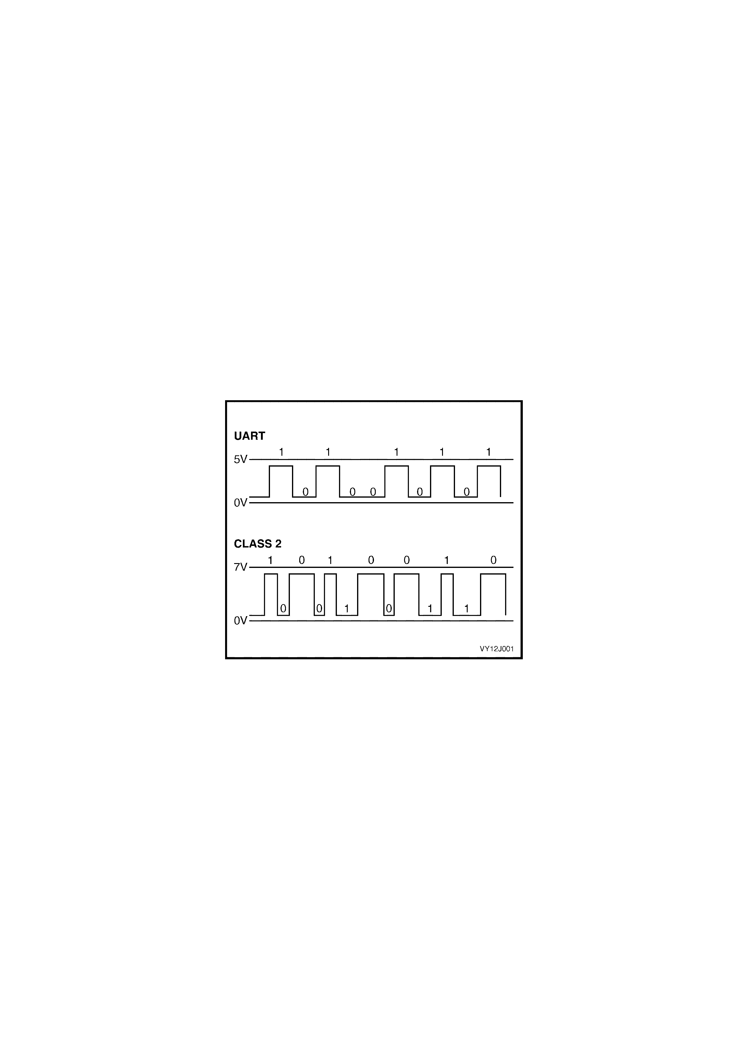
UART Communication
The TECH 2 diagnostic scan tool and the vehicle system control modules communicate with and between each
other on the serial c omm unication lines us ing serial data. Serial data transf ers inf orm ation, one bit at a time, over a
single line called the ‘data bus’.
Excluding the GEN III V8 PCM, all control modules communicating on the data bus use UART communication.
UART is a 5-volt data line that toggles the voltage to ground ( 0 volt) at a f ixed bit pulse- width during comm unic ation
and transmits data at the rate of 8.2 kilobits per second (8192 bits / second). W hen there is no comm unication on
the data line, the system voltage is 5 volts. Refer to Figure 12J-6.
Class 2 Communication
The G EN III V8 PCM uses Class 2 com munic ation. This type of comm unication toggles the data line f rom 0 volt to
7 volts with either a short or long pulse-width at an average rate of 10.4 kilobits per second. In Class 2
communications, when there is no communication on the data line, the system voltage is 0 volt. Refer to Figure
12J-6.
Class 2 uses a different communication language to UART; therefore, direct com munication between the modules
is incompatible and requires an interface to convert Class 2 communication into UART and UART into Class 2.
Refer to ‘Powertrain Interface Module (PIM)’ in this Section.
TECH 2 Communication
TECH 2 is able to communicate with both UART and Class 2 control modules.
Figure 12J-6
Data Bus Device Polling
On all VY Models, the BCM is the bus m aster of the ser ial data comm unication s ystem . T he BCM periodically polls
(surveys) each device on the data bus, including the BCM itself, and requests status data. The following devices
and control modules are polled:
• V6 and V6 supercharged engine PCM.
• PIM (GEN III V8 engines only).
• Instrument cluster (INS).
• Antilock Brake / Traction Control System (ABS/TCS) module.
• Supplemental Restraint System (SRS) Sensing and Diagnostic Module (SDM).
• Occupant Climate Control (OCC) module.
• Radio.
• TECH 2 diagnostic scan tool.
• BCM itself.
The BCM polls each device for a status update every 300 millis econds, with the exc eption of the PCM (V6) and the
PIM (GEN III V8) and radio which are polled twice every 300 milliseconds.

Serial Data Bus
The serial data bus comprises three sections:
• The primary data bus. The BCM uses the primary data bus, circuit 800 (Red / Black wire), for communication
with the PCM and PIM.
• The secondary data bus. The BCM uses the secondary data bus, circuit 1061 (Green / White wire), for
communication with the remaining modules, except the SRS SDM.
• The tertiary data bus. The BCM uses the tertiary data bus, c ircuit 774 (W hite / Green wire), f or com munication
with the SRS SDM.
An internal switch within the BCM can be used to isolate the sec ondary data bus and the tertiary data bus f rom the
primary data bus for diagnostic and vehicle starting purposes. The switch is illustrated in Figure 12J-7.
Data Messages
Any device connected to the bus can use the data provided by each device.
Each device has a unique response Message Identif ier W ord (MIW) for ease of identif ication. The BCM polls each
device with a serial data message that includes the device MIW . The device responds with a serial data message
including its MIW with the data, which is retrieved and used by any device requiring it.
Theft Deterrent Check
When the ignition switch is turned from off to on, the BCM communicates with the PCM (via the PIM on vehicles
with GEN III V8 engines) for a thef t deterrent chec k. If the BCM does not receive an OK TO START message fr om
the PCM within 0.5 second of the ignition ON signal, the BCM isolates the secondary data bus.
Isolation of the s econdary / tertiar y data bus elim inates the possibility of a device f ailure, other than the BCM, PCM
or PIM, causing a problem on the bus and inhibiting theft deterrent communications. This continues until the PCM
responds with an acknowledgment or for a maximum of 5 seconds, after which the BCM switches to the standard
polling sequenc e. Following suc cessf ul anti-thef t com m unications, the BCM begins sequential polling of devic es on
the bus and normal system operation is established.
When the ignition is off, the BCM continues to poll, allowing for Radio and TECH 2 communications and external
control of the bus prior to the ignition being switched on.
POWERTRAIN INTERFACE MODULE (PIM)
The PIM is the hardware and serial comm unications interf ace between the GEN III V8 PCM and the vehicle UART
Serial Data Bus. The PIM acts as a transparent bi-directional translation device that allows data to flow between
modules with Class 2 protocol and modules with UART protocol.
W hen the ignition switch is turned from off to on and the PIM receives a poll from the BCM, the PIM requests data
from the GEN III PCM via its Class 2 interface. This data is transferred to the other control modules via the serial
communications UART bus. The PIM also monitors responses from other control modules on the UART bus and
using its Class 2 connection, transfers any information relevant to the GEN III PCM as requested.
INPUTS AND OUTPUTS
Serial Data Signal – Primary
The BCM prim ary serial data bus term inal X2-5 is connected to the PCM (via the PIM on vehicles with GEN III V8
engines) and the Data Link Connector (DLC) via circuit 800 (Red / Black wire). Refer to Figure 12J-7. It is through
this circuit that the BCM communicates with the PCM and with external devices also connected to the DLC.
Serial Data Signals – Secondary and Tertiary
The BCM s econdar y serial data bus terminal X2- 9 is connec ted to the ins trument c luster , ABS/T C S, radio and O CC
modules via circuit 1061 (Green / W hite wire). The BCM tertiary serial data bus terminal X2-6 is connected to the
SRS via circuit 774 (White / Green wire). Refer to Figure 12J-7. It is through circuits 1061 and 774 that the BCM
communicates with these devices after successful theft deterrent communications between the PCM and BCM.
The secondary and tertiary serial data buses are isolated from the primary serial data bus within the BCM if the
BCM does not r eceive an OK T O ST ART m ess age from the PCM within 0.5 second of ignition on. If there is s till no
acknowledgment from the PCM, this isolation continues for a 5 second period before it starts polling.
Ignition Switch On
The BCM us es this input s ignal to determ ine when the ignition switch is turned to ignition or start. When the ignition
switch is turned to ignition or start, battery voltage is applied to BCM terminal X3-2 from the ignition switch via
circuit 300 (Orange wire). Refer to Figure 12J-7.
NOTE: The circuit diagram in this section is to aid in understanding the operation of the circuit and therefore, only
the main connectors and wiring colours are shown. For complete circuit details, refer to either the relevant
diagnostic procedure in this Section or Section 12P, WIRING DIAGRAMS.

Figure 12J-7

1.3 REMOTE RECEIVER / KEY
SYSTEM OPERATION
Unlocking
When operating the Unlock button on the remote coded key, an RF signal is transmitted. If the Unlock button is
operated for 0.25 second within approximately 4 metres of the driver’s side B-pillar, the BCM receives an unlock
request. This is received from the remote coded key via the remote receiver, located in the instrument panel
between the demist ducts.
The BCM then:
• unlocks all the doors (single-stage unlock) or just the driver’s door (two-stage unlock)
• disarms the theft and entry deterrent sy stems
• turns on the dome lamp (at night only)
• flashes the indicators twice.
Locking
When operating the Lock button on the remote coded key for 0.25 second within approximately 4 meters of the
driver’s side B-pillar, a lock request signal is received by the BCM via the remote receiver.
The BCM then:
• locks all the doors
• arms the theft and entry deterrent systems
• turns the dome lamp off if it is illuminated
• flashes the indicators once.
Rear Compartment Lid Release
W hen operating the boot lid release button on the rem ote coded key for 0.3 second within approximately 2 meters
of the rear compartment lid, the BCM checks that the vehicle speed is less than 20 km/h then activates the rear
compartment lock actuator.
Remote Coded Key Battery Failure
The rem ote coded key is powered by it’s own internal battery. If this battery fails, no RF signal is transmitted when
operating the lock , unlock and boot releas e buttons. However, the rem ote c oded k ey r eader has the ability to power
the key when the key is inserted into the ignition switch and turned on, or to the start position. This enables theft
deterrent disarming.
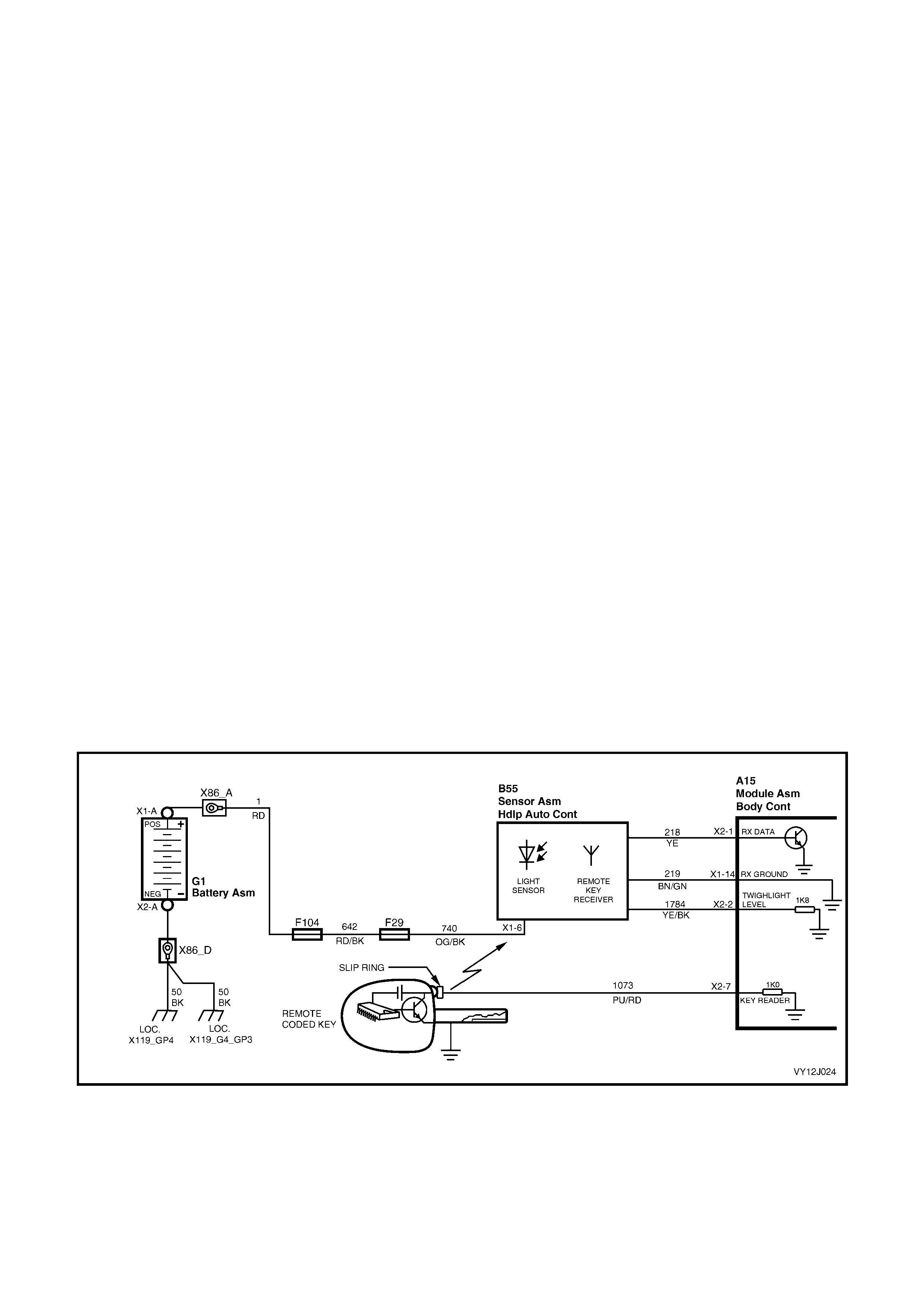
CIRCUIT OPERATION
When operating the remote coded key, an RF signal is transmitted to the Remote Key Receiver. This receiver
transf ers the received data f rom r eceiver ter m inal X1-2 to BCM ter m inal X2-1 , via circuit 218 ( Yellow wire) . Refer to
Figure 12J-8. The receiver ground connection is from receiver terminal X1-7 to BCM terminal X1-14, circuit 219
(Brown / Green wire). T he BCM r esponds to the rec eived s ignal based on the frequency of the RF signal (the button
on the key that is pressed).
NOTE: The Remote Key Receiver is also referred as the Headlamp Auto Control Assembly (B55) due to the
incorporated twilight monitoring function.
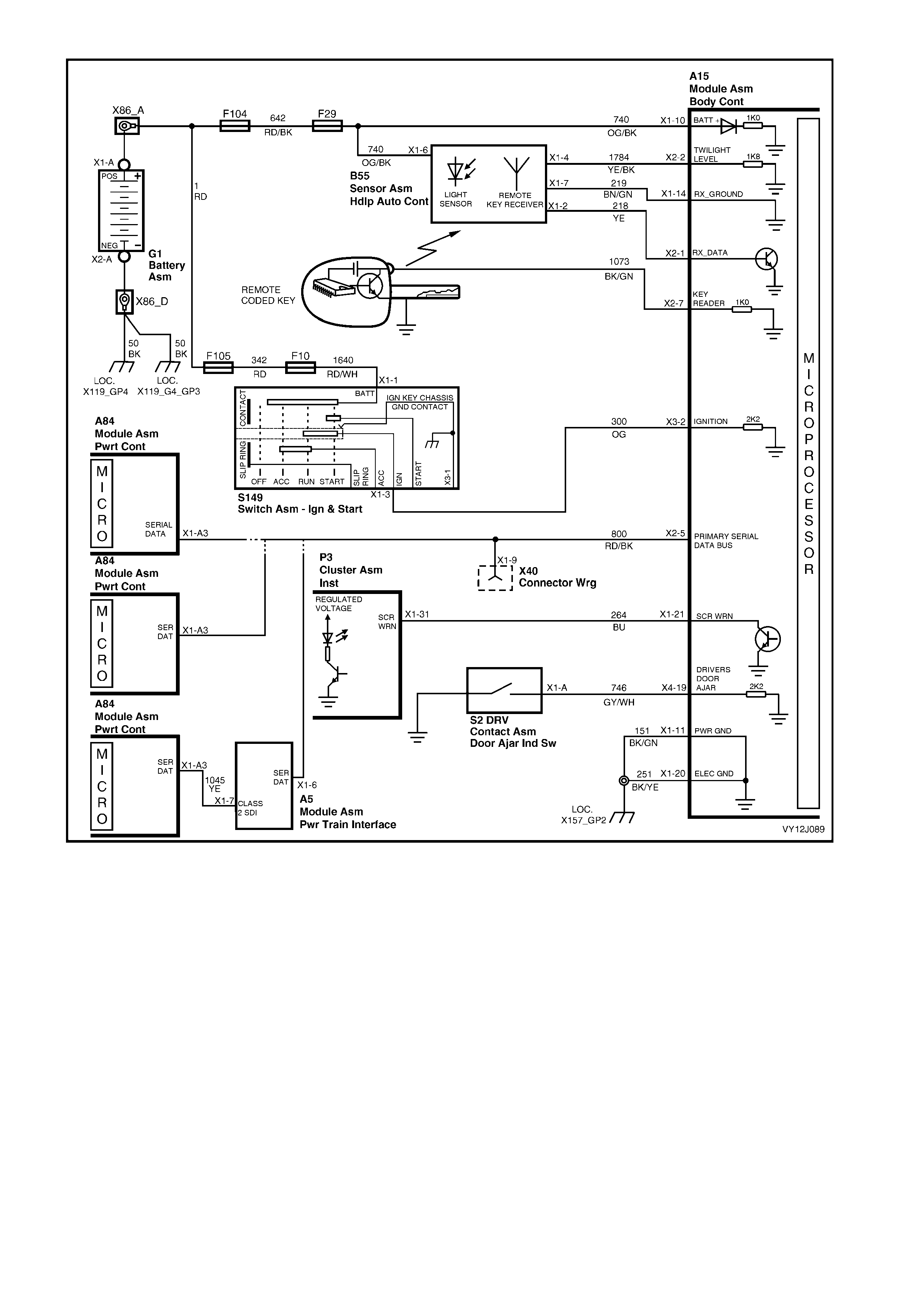
Figure 12J-8
1.4 ACCESSORY POWER CONTROL
SYSTEM OPERATION
The ground circuit to the Accessory Control Relay is switched by the BCM to control the relay when the ignition is
turned to accessories or turned on or via smart switching as requested by the Radio (no key is required by the
ignition barrel for this). W hen the relay is energised, power is supplied to the radio, windscreen wiper system s and
other accessories, if fitted.
There are two options for disabling the accessory power:
• switching off the ignition, or
• opening the driver’s door after the ignition is turned off.
The shut down options can be selected using the MFD or TECH 2. The default option is set to Door Open.
However, if the Radio is switched on after disabling the accessory power, the BCM will energise the Accessory
Control Relay for a period of 63 minutes. The Accessory Control Relay is switched off immediately if the radio is
switched off within this time frame.
If the intermittent wiper system is in operation after the accessory power is disabled by the BCM, the Accessory
Control Relay will be disabled by the BCM when the wiper park signal is sensed. If the wiper park signal is not
sensed within 3 seconds, the BCM will automatically disable the relay.
NOTE: The c ircuit diagr am s shown in this G eneral Desc ription Section ar e to aid in interpreting the oper ation of the
circuit and therefore, only the main connectors and wiring colours are shown. For complete circuits details refer to
either the relevant diagnostic section or Section 12P, WIRING DIAGRAMS.
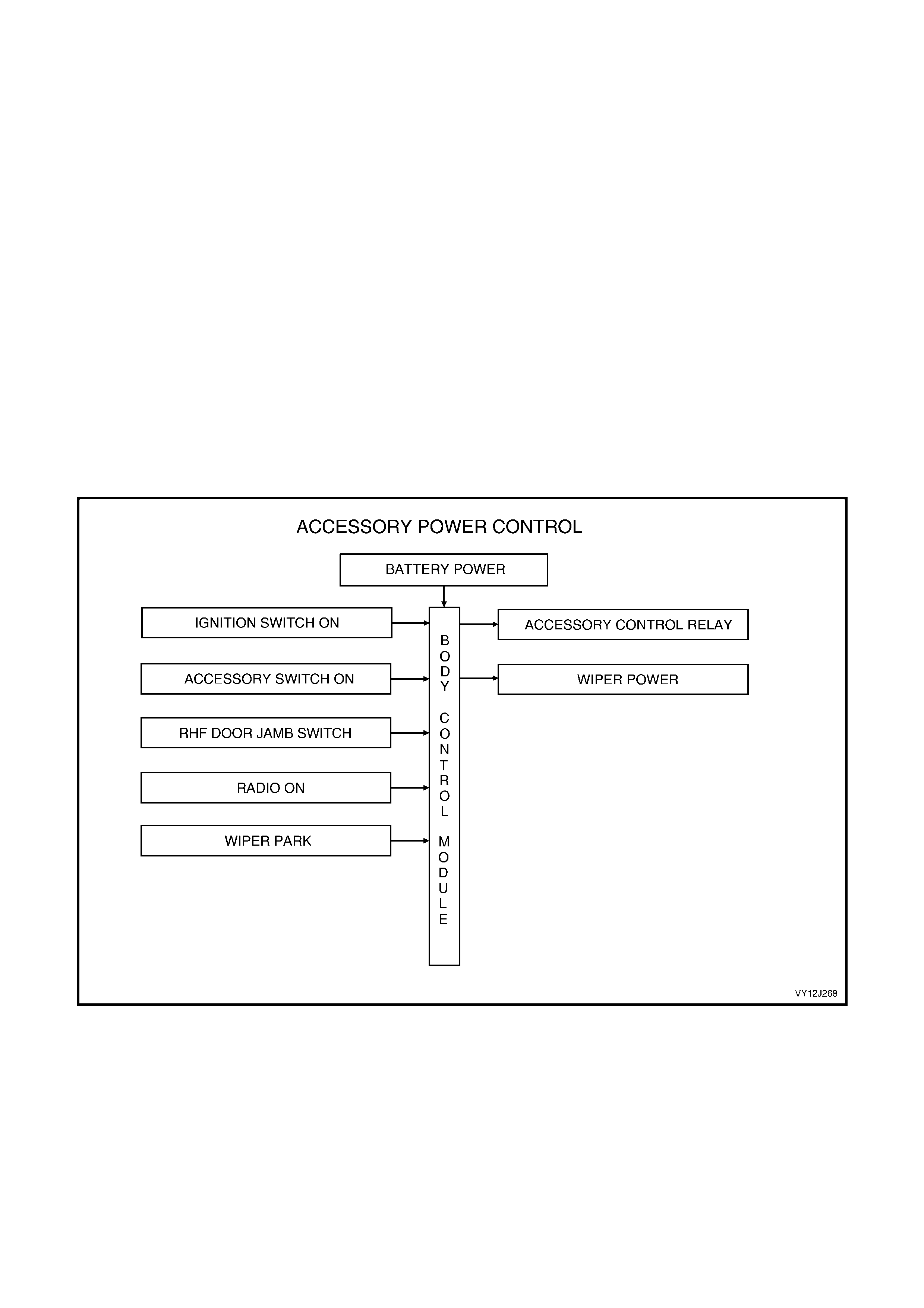
SYSTEM OVERVIEW
Figure 12J-9
CIRCUIT OPERATION
Radio ON and Ignition Switch Input
Refer to Figure 12J-10.
W hen the ignition switch is turned to ac cessories or on, a 12 volt supply from the ignition switch is detected by the
BCM at either terminal X3-4, (accessories output via circuit 4, Brown wire) or terminal X3-2 (on output via circuit
300, Orange wire).
The BCM provides a ground connection to the Accessory Control Relay at terminal X1-9 via circuit 755 (Tan wire).
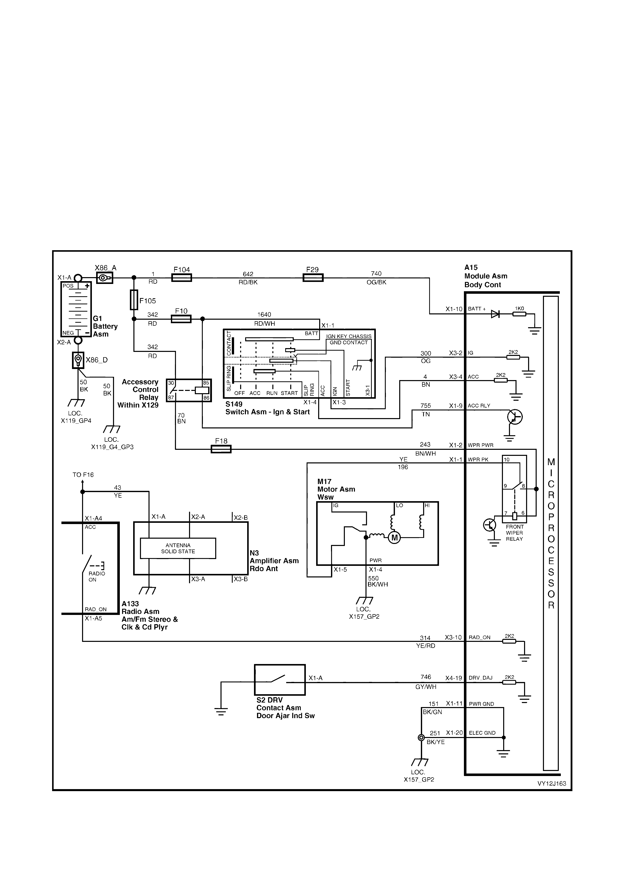
This causes the relay contacts to close, supplying 12 volts to the BCM accessory circuits, including:
• the front wipers, circuit 243 (Brown / White wire) via fuse F18
• the rear wiper system, also circuit 243 (Brown / White wire) via fuse F18
• the radio and, circuit 43 (Yellow wire), and
• the accessory socket.
If the radio is switched on when the ignition is off, the BCM will detect 12 volts at terminal X3-10 from circuit 314
(Yellow / Red wire) and energise the Accessory Control Relay for 63 minutes.
Depending on the selected option, the BCM disables the Accessory Control Relay when 0 volt is detected at BCM
terminal X3-4 (ACC output via circuit 4, Brown wire) or when the driver’s door is opened. Opening of the driver’s
door closes the driver ’s door aj ar switch c ontac ts , pulling the signal at BCM terminal X4-19 low, via c irc uit 746 (Grey
/ White wire).
If the front wiper is in operation after disabling the accessory power has been initiated, the BCM will monitor the
wiper park input at terminal X1-1 through circuit 196 (Yellow wire). W hen 12 volts is detected at term inal X1-1, the
Accessory Control Relay is then disabled. If the wiper park signal is not detected within 3 seconds, the BCM will
automatically disable the relay.
Figure 12J-10

1.5 CENTRAL DOOR LOCKING
NOTE: The c ircuit diagr am s shown in this G eneral Inf orm ation Section ar e to aid in interpreting the operation of the
circuit and only the main connector s and wiring colours are shown. For c om plete circ uit details, ref er to the relevant
diagnostic section or to Section 12P, WIRING DIAGRAMS.
SYSTEM OPERATION
On VY Models with central door locking, it is possible to deadlock the doors via the remote coded key.
The central door locking system provides for locking or unlocking of all doors and the station wagon tailgate,
enhanced locking or ‘deadlocking' of the doors as well as single-stage and two-stage unlocking.
Door and Tailgate Locking
The following triggers are used to activate this system:
The driver's door-lock actuator, which is mechanically linked to the interior door snib and the door latch.
The front passenger’s door-lock actuator, which is mechanically linked to the interior snib button.
The microswitches in the driver’s door key barrel, which are also mechanically linked to the door latch and
therefore, to the actuators.
The lock button on the remote coded key when all the doors are closed.
Door and Tailgate Unlocking
The following triggers are used to activate the system:
Any door-lock actuator.
The microswitch in the driver’s door key barrel.
The unlock button on the remote coded key.
Moving the driver’s door key barrel independently of the actuator. If the battery is discharged, this allows
unlock ing of the driver’s door latch when the actuator is held down becaus e the snib will not rise if deadloc ked
in this scenario.
Deadlocking
Deadlocking provides for mechanical jamming of the door-lock actuators. The deadlocking feature applies to all four
doors, but not to the luggage compartment lid or tailgate. This is achieved electrically using the driver’s door lock
microswitch or by an RF signal from the remote key.
Deadlocking is engaged by two sequential operations of the door-lock microswitch or pressing the lock button on
the remote coded key twice within 10 seconds.
If the remote coded key is used, the turn signal lamps illuminate for three seconds when deadlocking is successful.
If the vehicle is already deadlocked, press ing the lock button on the rem ote coded key c auses the turn signal lamps
to illuminate for 3 seconds. This indicates the vehicle is already deadlocked.
If the vehicle is locked but not deadlocked, press ing the loc k button on the remote coded key over ten seconds after
the previous press does not deadlock the doors and the turn signal lamps will flash briefly. This indicates that the
doors are only locked. Pressing the lock button again within a 10 second period deadlocks the doors and the turn
signal lamps illuminate for 3 seconds.
If the deadlocking operation is not fully successful, a series of warning chirps will sound.
After deadlocking, outside unlocking at the driver’s door is achieved by turning the key in the driver’s door-lock to
the unlock position or pressing the unlock button on the remote coded key. If two-stage unlocking is enabled,
pressing the remote coded key button removes the deadlock on all doors, but only unlocks the driver’s door.
If the electrical system fails after the system has been engaged, the driver’s door-lock cylinder can be moved
independently of the actuator. This allows unlocking of the driver’s door latch.
The rear compartment lid or tailgate can be locked or unlocked when mechanical deadlocking is actuated, while
leaving the doors secured.
NOTE: Remote central locking and deadlocking is not possible when the ignition is on.
Single-stage and Two-stage Unlocking
The BCM is capable of operating in either single-stage unlock or two-stage unlock mode.
W ith TECH 2 and through the vehicle customisation m enu, the BCM can be programm ed to operate in either two-
stage or single-stage unlock, depending on the vehicle’s owner or operator requirements. This can also be
programmed via the instrument cluster MFD.
If a faulty circuit exists on either the lock or unlock signal inputs, the opposing input is still able to perform its
function. This enables the doors to be unlocked when a faulty circuit exists on the lock input or vice versa.
If the lock / unlock system is operated several times in a defined time period, the system times out. After a fixed
time delay, the system re-activates as norm al. This action is to protect the door-locking actuator m otors. (Refer to
System Check, Overheating Prevention, following.)
NOTE: Remote central locking and deadlocking is inhibited while the ignition is switched on. The Theft Deterrent
System also affects operation of this system. Refer to 1.7 THEFT DETERRENT SYSTEM in this Section.
SINGLE-STAGE UNLOCK
In single-stage unlock mode, when the remote coded key unlock button is pressed for 0.25 second or longer; the
BCM unlocks all doors simultaneously .
TWO-STAGE UNLOCK
This mode can be enabled or disabled by the customer. Refer to Section 12C, 1.8 CUSTOMISATION MODE.
In the two-stage unlock mode, pressing the rem ote coded key unlock button for 0.25 second sends a signal to the
remote receiver. W hen the BCM receives the unlock request from the remote receiver, it unlock s the driver’s door
only. If the remote coded key unlock button is pressed again for 0.25 second, the BCM unlocks all passenger doors.
If the remote coded key is pressed continuously for 0.5 second, the BCM unlocks all doors; first the driver’s door,
then all passenger doors.
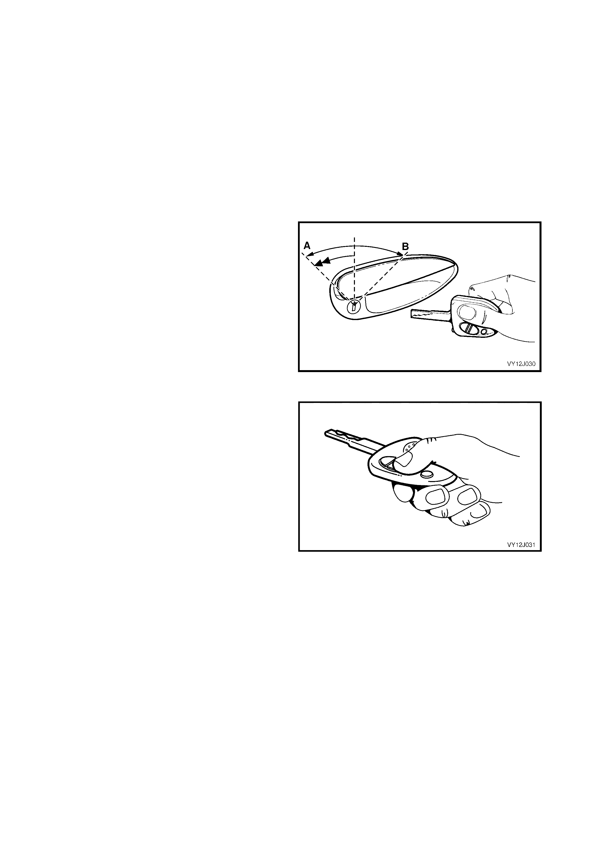
SYSTEM CHECK
Key Locking
Figure 12J-11 shows the key positions on the
driver’s door for the various key locking functions.
One lock operation to position A locks the vehicle.
Two lock operations to position A deadlocks the
vehicle. One operation to position B unlocks the
vehicle.
Deadlocking means securing the vehicle by
electro-mechanically inhibiting door-lock snib
operation.
Even though the electronic theft deterrent system
(using the remote coded key) can activate the door-
locks, it does not automatically deadlock the doors.
Figure 12J-11
Remote Coded Key Check
Check that the remote coded key locks all doors
when the key lock button is pressed within
approximately 4 metres of the driver’s side B-pillar.
If the vehicle is programmed for two-stage unlock,
the driver's s ide door unlocks , the passenger doors
undeadlock and the tailgate on station wagon
models unlocks when the key unlock button is
pressed. Pressing the unlock button again unlocks
all the passenger doors.
If the vehicle is programmed for single-stage
unlock, a single press of the unlock button unlocks
all doors and the tailgate on station wagon models.
If this check is not satisfactory, refer to
2.2 REMOTE CODED KEY in this Section for a
more detailed diagnosis before continuing with the
central locking system check.
Figure 12J-12
Deadlocking Check
1. Open all windows.
2. Close all doors.
3. Use the key to operate the deadlock from the driver’s door.
4. Check that all door-lock buttons are blocked and cannot be pulled up.
NOTE: The door-lock buttons can be pulled up slightly, but they will be under tension.
Door-lock Failure Warning
If a door fails to lock due to a mechanical or electrical fault, the system alerts the driver by giving a series of rapid
horn chirps . The indicator s do not flash when the rem ote lock button is pressed on non-alarm enabled vehic les. On
alarm enabled vehicles, the indicators will flash meaning the entry deterrent system is armed.
Auto Door-lock In Drive
This feature applies only to automatic trans m ission vehicles and can be enabled or dis abled by the custom er. Refer
to Section 12C, 1.8 CUSTOMISATION MODE.
The BCM pr ovides automatic loc k ing of the door s when the ignition is on and the gears hif t lever is moved out of the
P (park) position. The gearshift transition is detected by the BCM via the SDI bus.
The door-locks will unlock when the ignition is off and/or the gearshift lever is moved into the P (park) position.
NOTE 1: Only the driver’s door unlocks if two-stage unlock is enabled.
NOTE 2: Auto door locking is inhibited while any door is open.
Overheating Prevention
If there are multiple door-locking operations within a defined time period, the central door locking system will be
deactivated and remain inoperative for a defined time period. This is to prevent the door actuators from overheating.
After a fixed time delay, the system will re-activate and operate as normal. TECH 2 can be used to view the
appropriate door overload protection DTC when it has occurred.
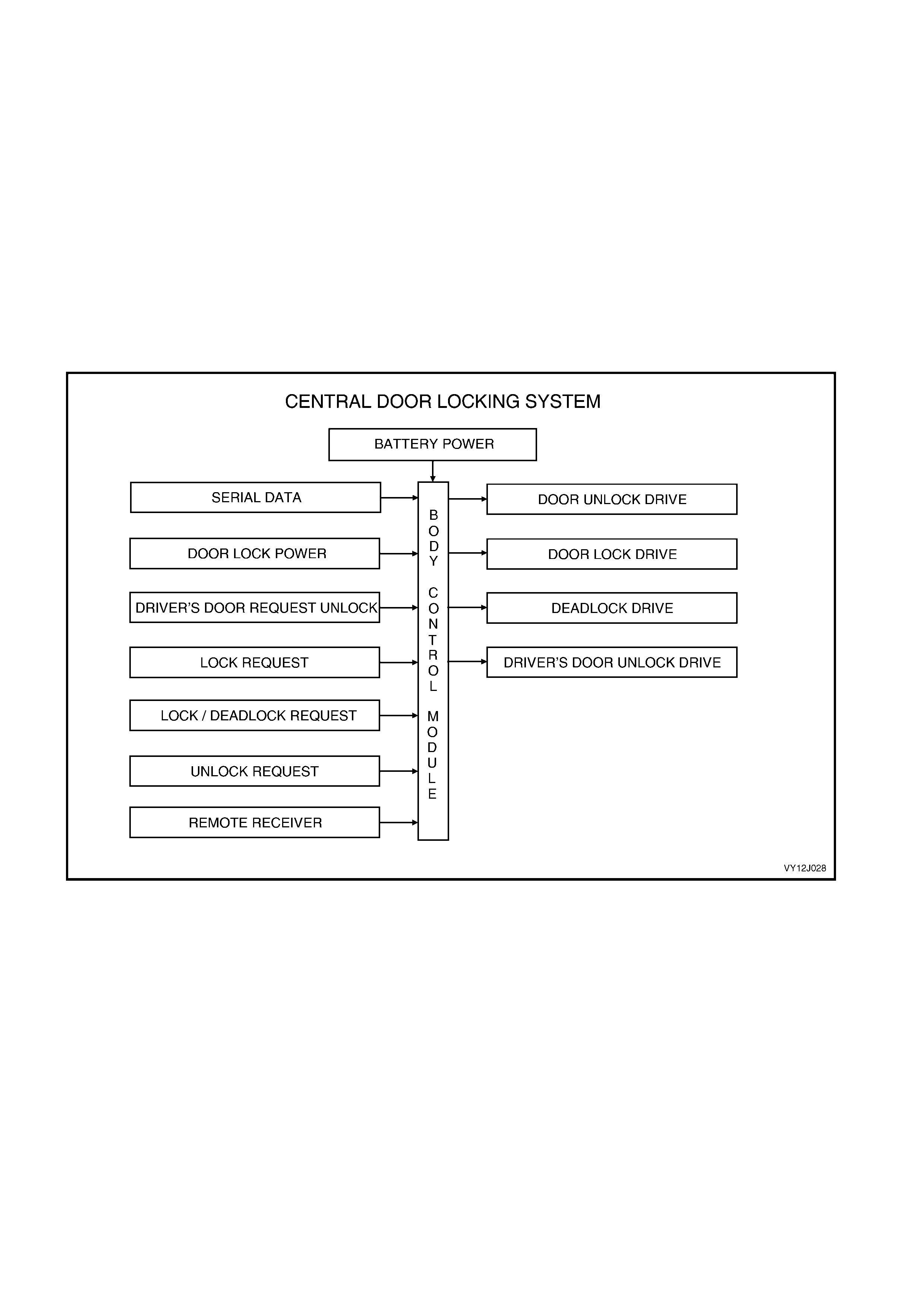
SYSTEM OVERVIEW
Figure 12J-13
CIRCUIT OPERATION
Reversible m otors c ontrolled by BCM re lays operate the door and tailgate locks . These r elays apply battery voltage
to one side of each motor and ground to the other side.
The central door locking system has five operational phases:
Lock to unlock.
Deadlock to unlock.
Unlock to lock.
Lock to deadlock.
Deadlock to lock.
Unlocking
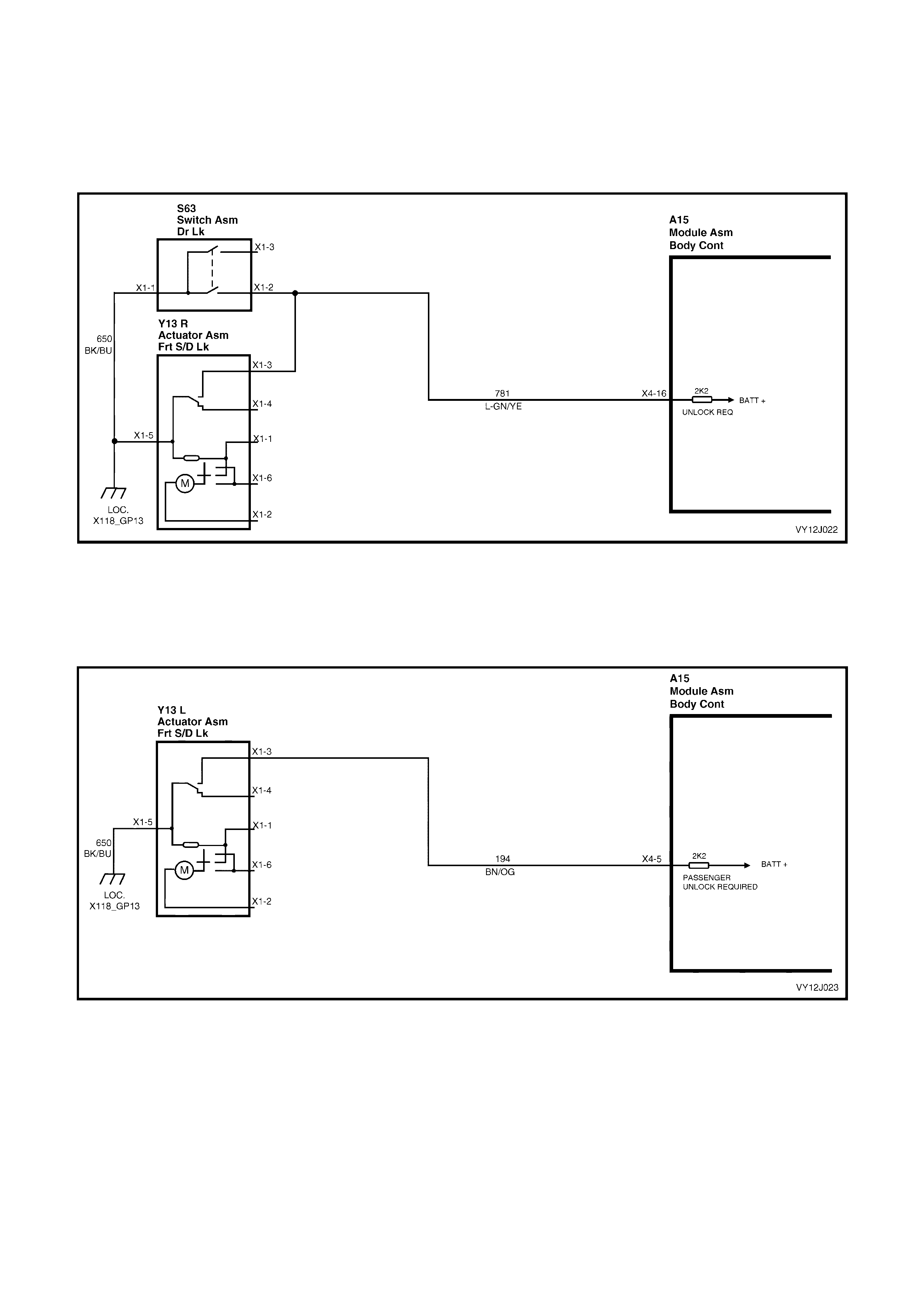
DRIVER’S DOOR UNLOCK INPUT SIGNAL
When unlocking the doors and tailgate from the driver’s door-lock or door-lock button, BCM terminal X4-16 is
connected to ground, r ef er to Figure 12J - 14. T his c auses the voltage on ter minal X4-16 to be pulled low to less than
0.2 volt, which is seen by the BCM as a driver’s door unlock request signal.
NOTE: Manually activating any unlock request circuit triggers all doors to be unlocked.
Figure 12J-14
PASSENGER DOOR UNLOCK INPUT SIGNAL
When unlocking the doors using any passenger door interior lock button, BCM terminal X4-5 is connected to
ground, refer to Figure 12J-15. This causes the voltage on terminal X4-5 to be pulled low to less than 0.2 volt, which
is seen by the BCM as a passenger door unlock request signal.
Figure 12J-15
A low voltage at terminal X 4- 16 or X 4- 5 is seen by the BCM as a system unlock request and the BCM energises the
internal Door Unlock Drive relay for approximately 0.75 second. The relay contacts close and battery voltage is
applied to:
• terminal X1-2 of each of the passenger door-lock actuators
• the tailgate lock actuator terminal X1-3 in station wagon models, and
• terminal X1-2 of the driver’s door-lock actuator.
The oppos ite terminal of the door -loc k ac tuator s, ter minal X1- 1, is c onnected to gr ound within the BCM, via terminal
X4-9, the internal Deadloc k Drive relay contacts and BCM term inal X1-11 (r efer to Figure 12J-18). This c auses the
door-lock actuator to rotate from the lock to the unlock position, and the door-lock actuator switch contacts to
change fr om term inal X1-1 to X1-6. T he rotation of the passenger door-lock ac tuator motor arm atures also causes
the door-lock snib button to change from the lock to the unlock position. The tailgate lock actuator motor is
grounded via BCM terminal X4-10 and the BCM internal Door Lock Drive relay contacts.
TWO-STAGE UNLOCK
Remote coded key unlock: Refer to Figure 12J-16 for the remote receiver / key, Figure 12J-19 for first stage of two-
stage unlock and Figure 12J-20 for the second stage of two-stage unlock.
If the BCM is operating in the two-stage unlock mode and the remote coded key Unlock button is depressed for
greater than 0.1 second and less than 0.5 second, the BCM activates the microprocessor within the BCM. This
causes the Driver’s Door Unlock Drive relay to toggle to the unlock state, unlocking the driver’s door only.
If the rem ote coded k ey unloc k button is again depr essed for 0.25 second, the BCM toggles the Door Unloc k Drive
relay contacts to the unlock state and the passenger doors and tailgate unlock.
If the rem ote c oded k ey is depressed continuously for 0.5 sec ond, the BCM unloc ks all doors: first the driver’s door,
then the passenger doors and tailgate.
SINGLE-STAGE UNLOCK
If the BCM is operating in the single-stage unlock mode and the remote coded key unlock button is depressed for
0.25 second, the BCM toggles both the Driver’s Door Unlock Drive relay and the Door Unlock Drive relay to the
unlock state and all doors and the tailgate unlock.
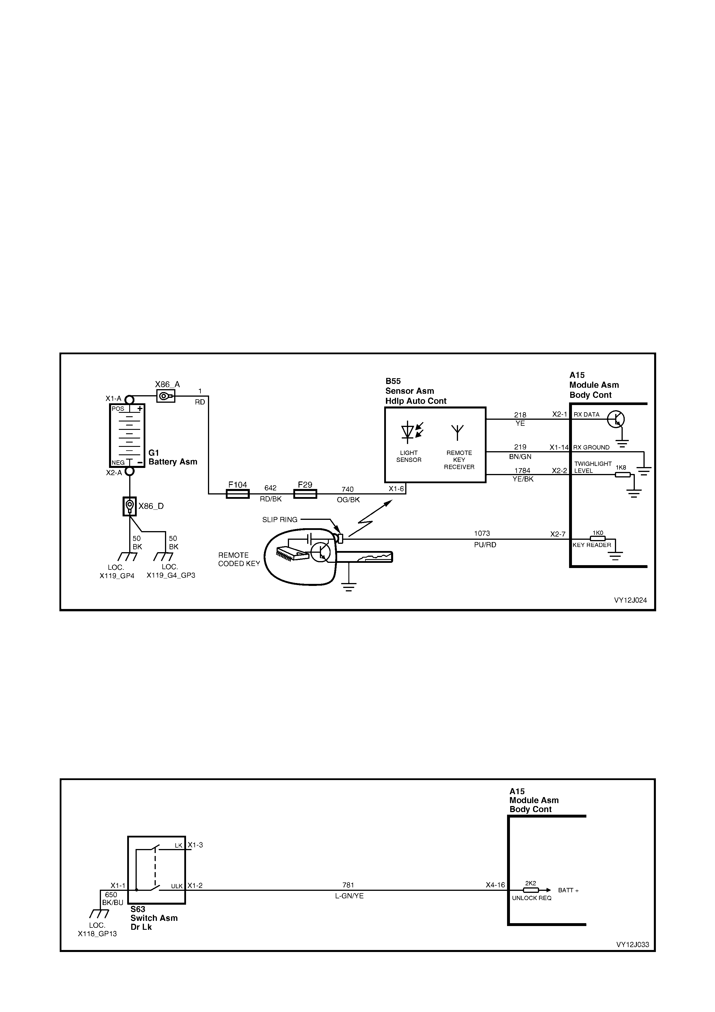
Figure 12J-16
DEADLOCK TO UNLOCK OPERATION
When manually unlocking the doors at the driver’s door-lock from the deadlock position, the Driver’s Door Lock
Switch m icros witch contac ts change to the unlock position, ref er to Figur e 12J-17. T his c onnects BCM ter m inal X4-
16, circuit 781 (Light-green / Yellow wire) to ground from circuit 650 (Black / Blue wire) causing the voltage at
terminal X4-16 to be pulled low to less than 0.2 volt.
This low voltage at terminal X4-16 is seen by the BCM as the driver’s door unlock request signal and the BCM
energises the both the Driver’s Door Unlock Drive relay and the Door Unlock Drive relay for approximately 0.75
second. This causes the relay contacts to toggle and battery voltage is applied to terminal X1-2 of each door-lock
actuator and to terminal X1-3 of the tailgate actuator through circuit 294 (Black / Red wire). Refer to Figure 12J-21.

Figure 12J-17
Initially, actuator terminal X1-6 is connected to ground through BCM terminal X4-10, the internal Door Lock Drive
relay contacts. This causes the passenger door-lock actuator to rotate and move from the deadlock position,
through the lock position to the unlock position. As this movement occurs, the passenger door-lock actuator
contacts momentarily switch from terminal X1-6 to terminal X1-1 before switching back to terminal X1-6 and the
door lock snib button is moved to the unlock position.
SINGLE-STAGE
If the vehicle is set for single-stage unlock, all doors change from the deadlock position, through the lock position, to
the unlock position.
NOTE: If the ignition is switched off , the doors can be unloc ked fr om the deadloc k position by activating the unlock
button on the remote key.
TWO-STAGE
If the vehicle is set for two-stage unlock, the driver’s door-lock changes from deadlock through to the unlock
position, but the passenger door actuators stop when they are in the lock position.
When the BCM detects a subsequent unlock request signal, the Door Unlock Drive relay is activated to again
energise the door-lock actuator motors. With a ground connection within the BCM via terminal X4-9 and the
Deadlock Drive relay, the actuators rotate to the unlock position.
This rotation of the passenger door-lock actuators causes the passenger door-lock snib buttons to change to the
unlock position and switches the door-lock actuator contacts back to terminal X1-6.

Figure 12J-18
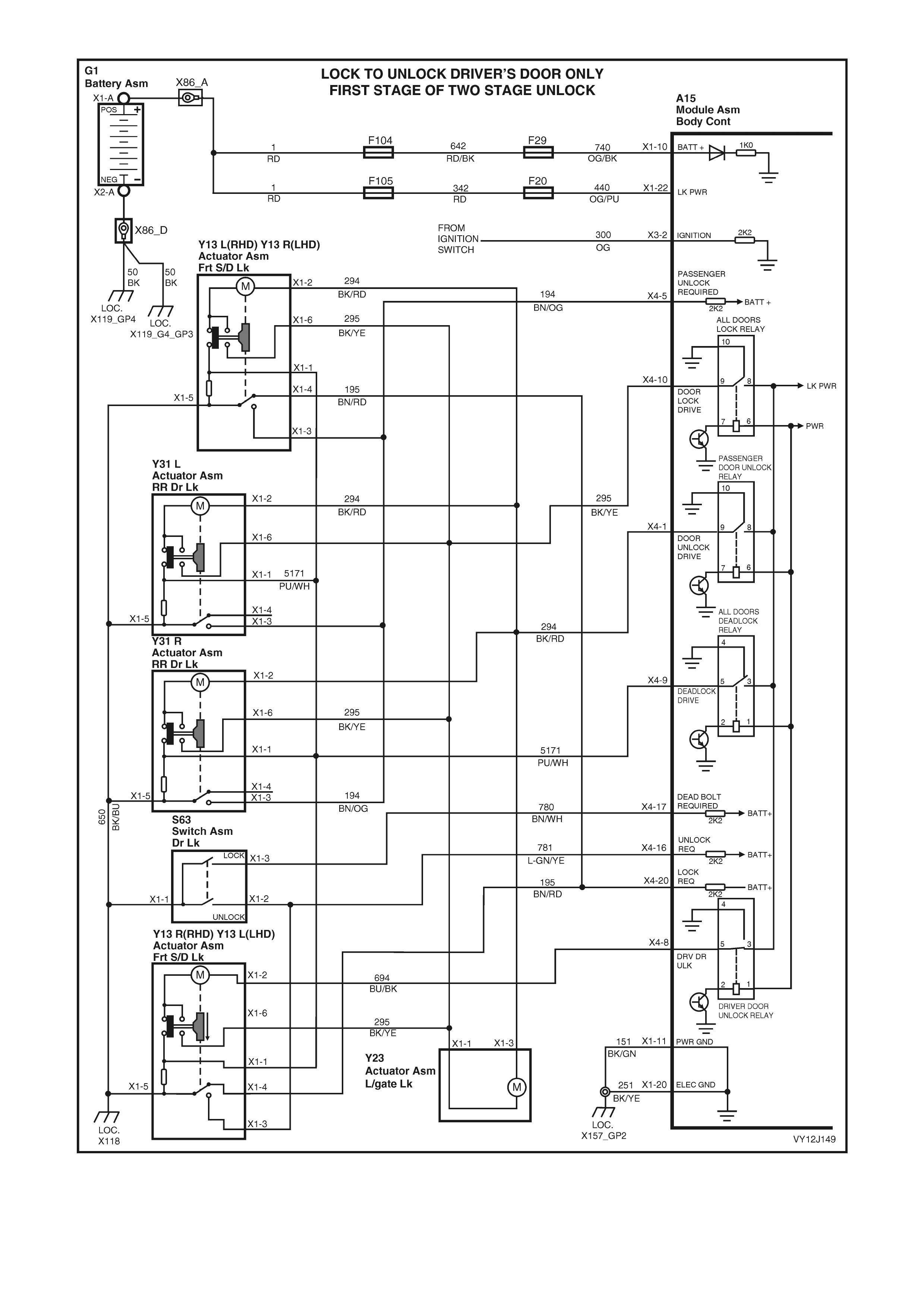
Figure 12J-19
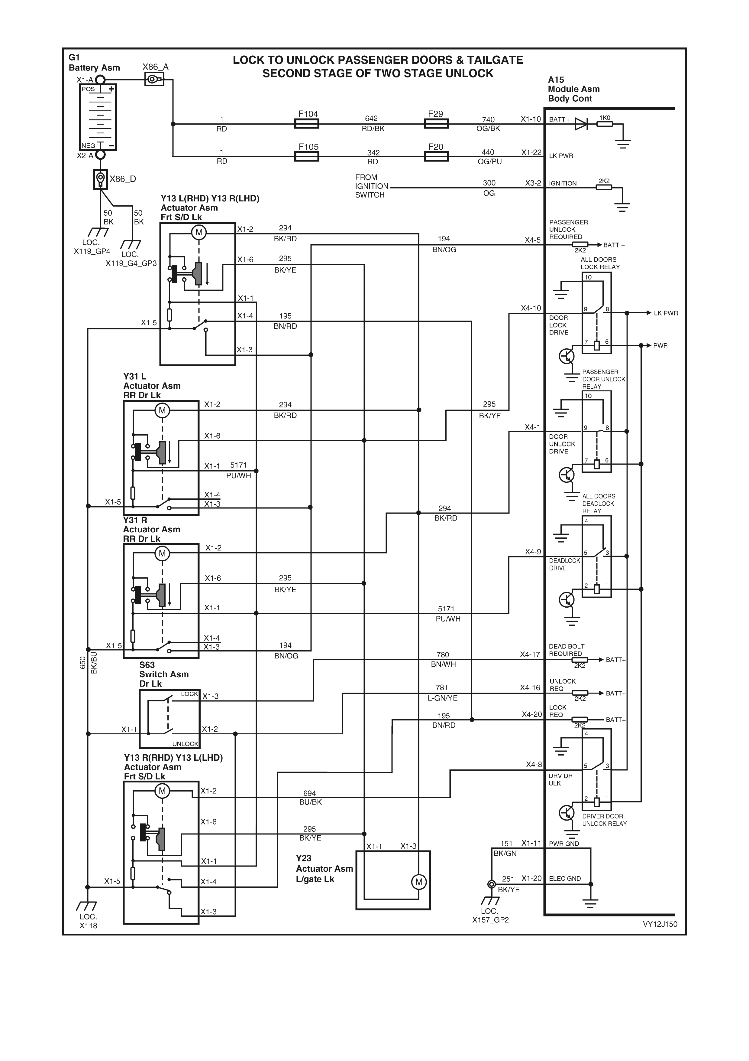
Figure 12J-20
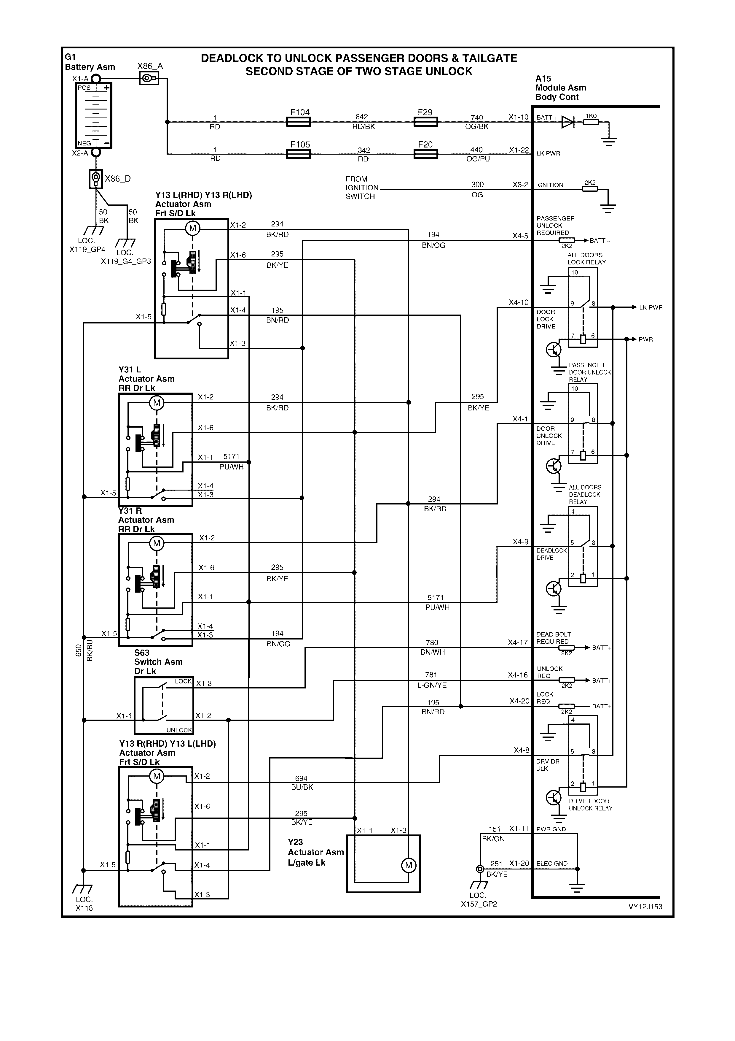
Figure 12J-21
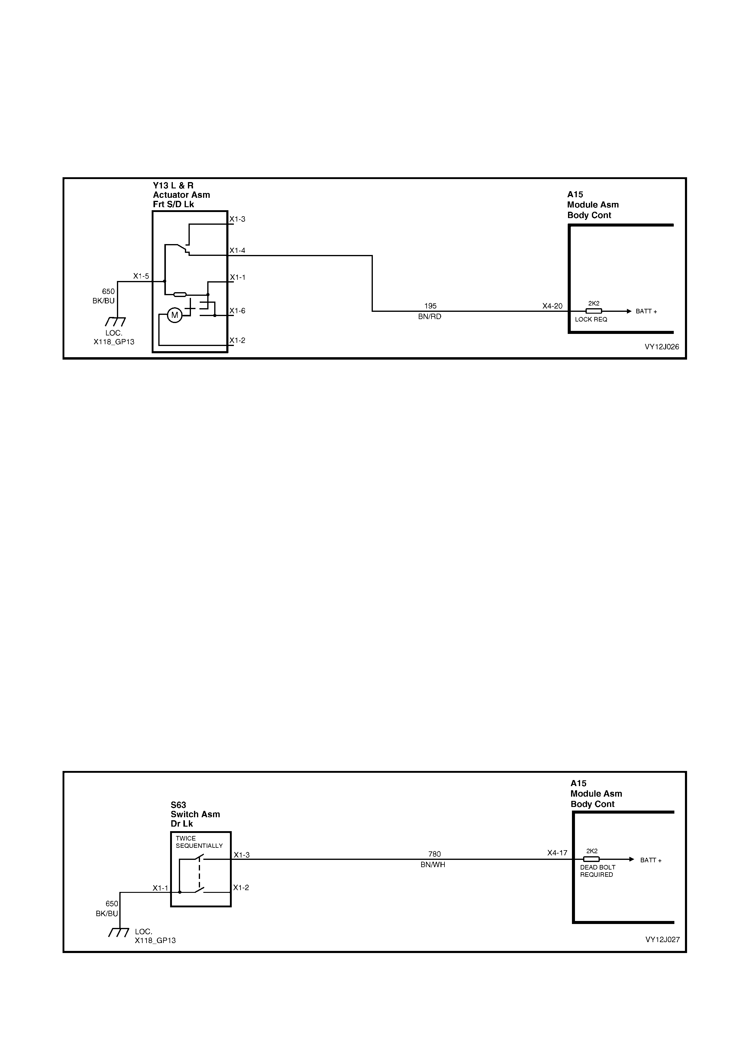
Locking and Deadlocking
LOCK REQUEST
With the doors clos ed, all doors and the tailgate c an be locked via the driver ’s or fr ont passenger ’s interior door snib
or a single locking operation of the driver’s door-lock using the key.
Either of these actions with the snib causes the Driver’s Door Lock Switch microswitch contacts to change to the
lock position, which connects BCM term inal X4-20 to ground f rom c ircuit 650 (Black / Blue wire) . This changes the
voltage on terminal X4-20 to less than 0.2 volt, which is seen by the BCM as a system lock request. Refer to
Figures 12J-22 and 12J-26.
Figure 12J-22
A lock request triggers the BCM to energise the internal Door Lock Drive relay for approxim ately 0.75 second. T he
relay contacts close and apply battery voltage through terminal X4-10 of the BCM to terminal X1-6 of each door-lock
actuator and to terminal X 1-1 of the tailgate actuator. T erminal X 1-2 of each passenger door actuator and term inal
X1-3 of the tailgate actuator is c onnected to ground through BCM term inal X4-1 and the inter nal Door Unlock Drive
relay contacts. Terminal X1-2 of the driver’s door-lock actuator is connected to ground through BCM terminal X4-8
and the internal Driver’s Door Unlock Drive relay contacts.
Thes e connec tions energis e the door -loc k ac tuator s to r otate to the loc k pos ition, which moves the pas s enger door -
lock snib buttons to the lock position and also changes the switch contacts from terminals X1-6 to terminals X1-1.
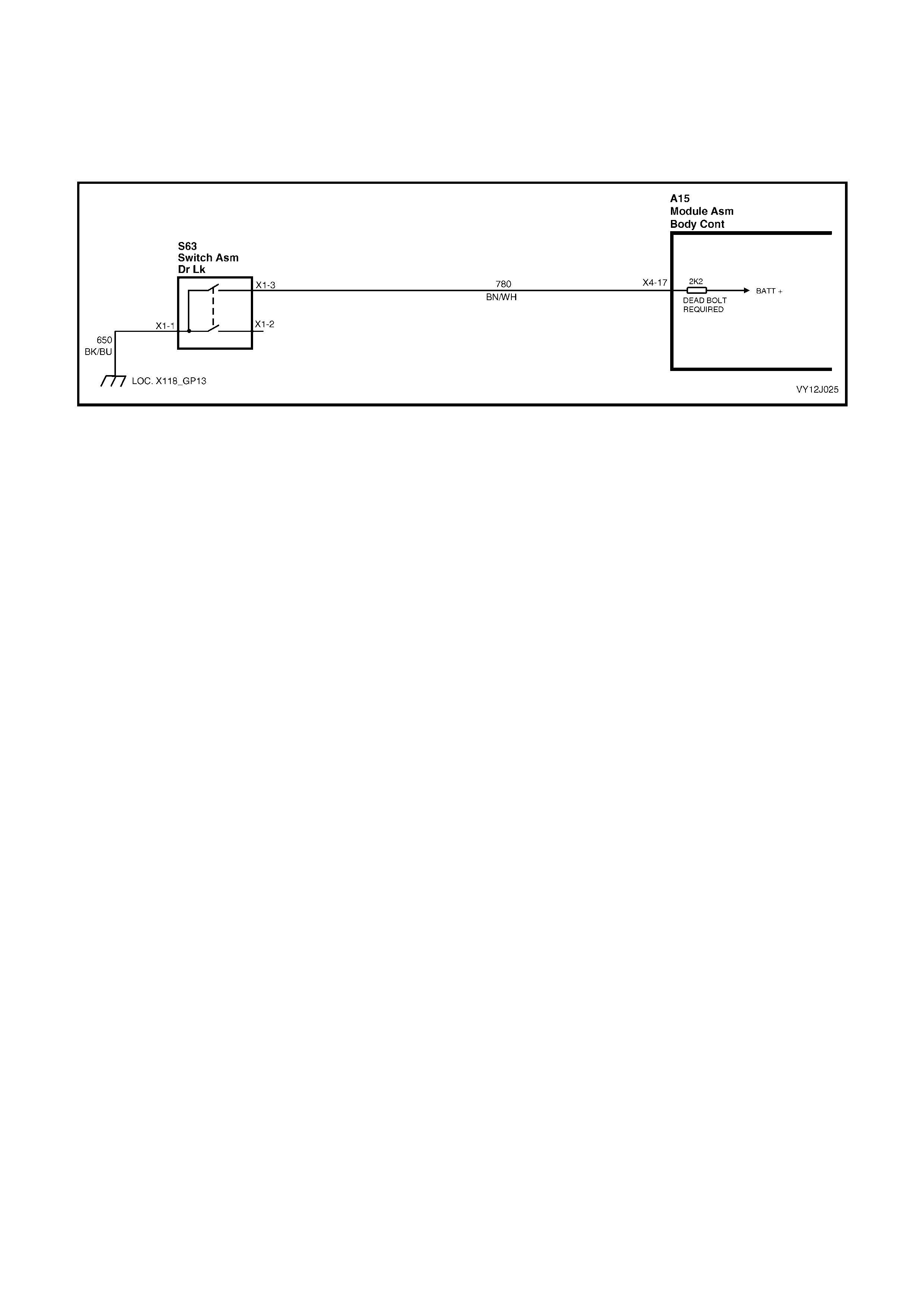
DEADLOCK REQUEST
W hen the ignition is off and all doors are c losed, the doors can be deadloc ked by two sequential lock operations of
the driver’s door-lock. Refer to Figure 12J-11. If any door is open, or if the ignition is on, the doors will not deadlock.
Two sequential lock operations causes the Driver’s Door Lock Switch microswitch contacts to change to the lock
position and connect BCM terminal X4-17 to ground from circuit 650 (Black / Blue wire). Refer to Figure 12J-23.
This changes the voltage on ter minal X 4-17 to les s than 0.2 volt, which is s een by the BCM as the system deadloc k
request. The BCM then energises the internal Door Lock Drive relay and Deadlock Drive relay for approximately
0.75 second, which supplies battery voltage to term inal X1-6 and term inal X1-1 of the door -lock actuators. Refer to
Figure 12J-26.
Term inal X1-2 of each passenger door-lock motor is connected to ground within the BCM, via BCM terminal X4-1
and the internal Door Unlock Drive relay contacts. Terminal X1-2 of the driver’s door-lock motor is connected to
ground within the BCM, via BCM terminal X4-8 and the Driver’s Door Unlock Drive relay contacts.
These connections energise the door-lock actuator motors to rotate to the deadlock position. This rotation causes
the actuator switch contacts to change from terminal X1-6 to terminal X1-1 and back to terminal X1-6 and moves
the door lock snib buttons to the lock position.
NOTE: The tailgate actuator is designed to lock but not to deadlock.
Figure 12J-23
REMOTE CODED KEY – LOCKING
When locking the doors using the remote coded key, the RF output signal from the key activates the BCM
microprocessor, which energises the door-lock relay to lock all doors and the tailgate. If any door does not lock,
either BCM terminal X4-16 or terminal X4-5 remains low and this low voltage is seen by the BCM as an
unsuccessful attempt to lock all doors. If the driver’s door is closed, the BCM then momentarily sounds the theft
deterrent horns.
Figure 12J-24
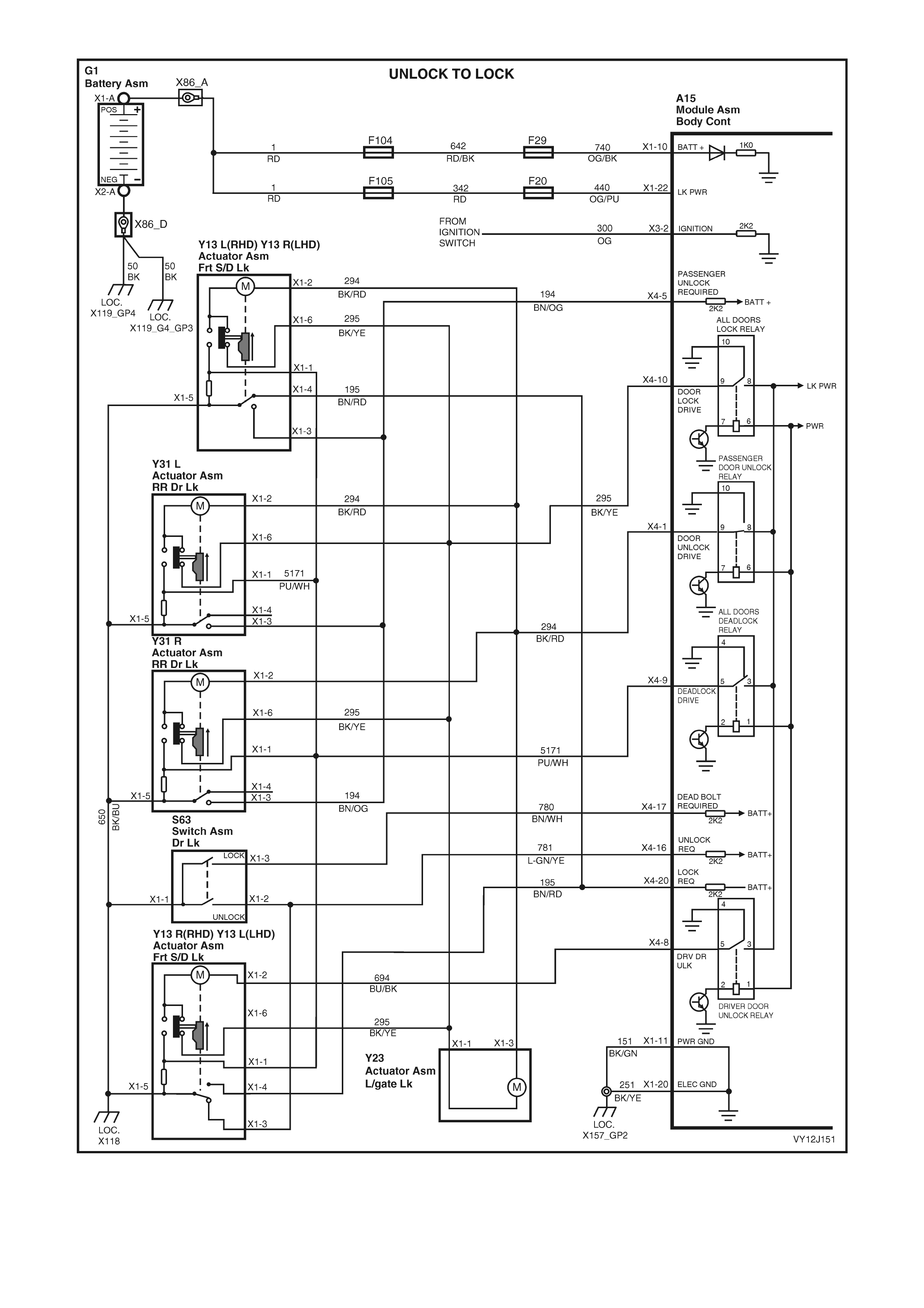
Figure 12J-25
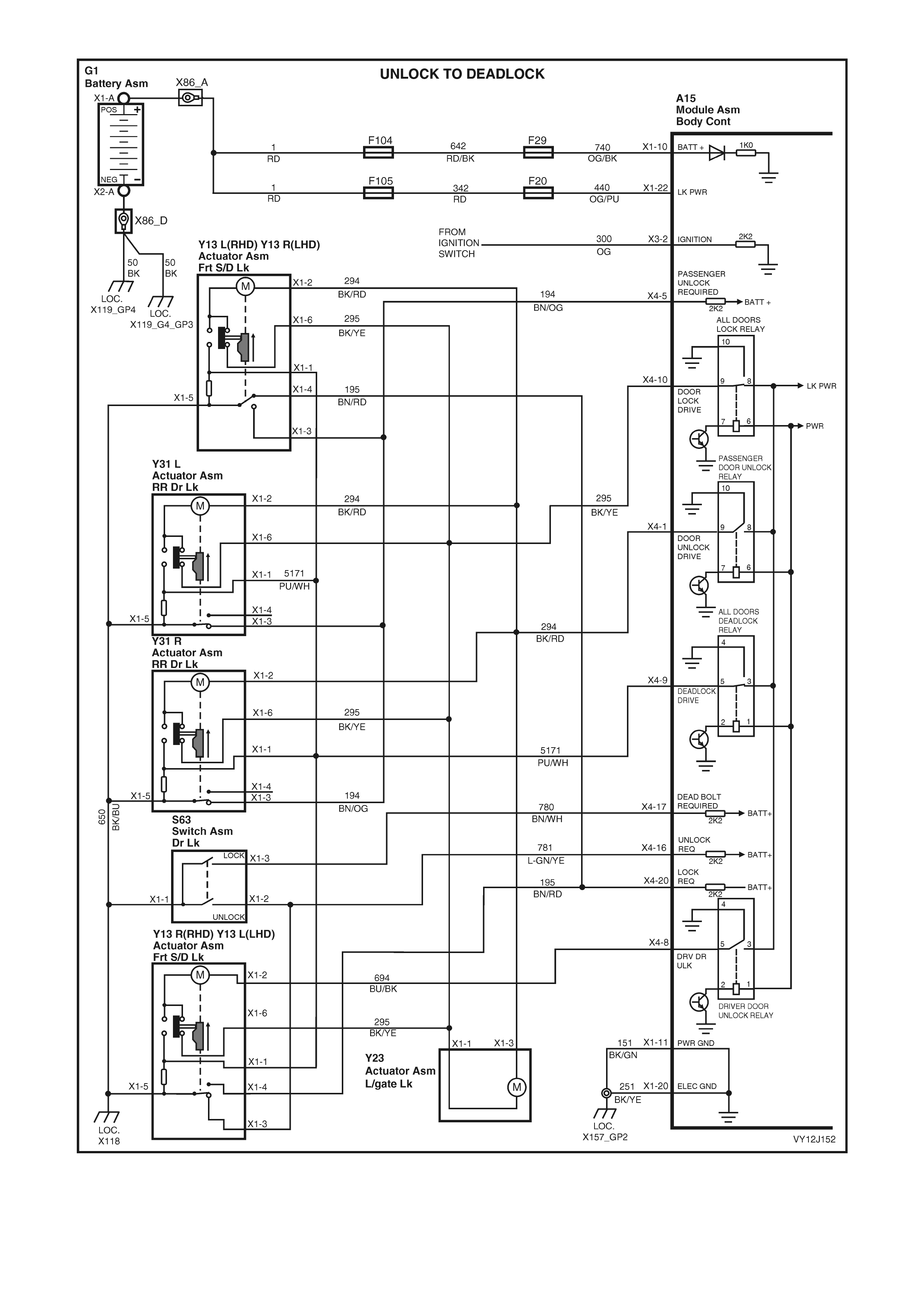
Figure 12J-26
Door Input Signals
DOOR CLOSURE INDICATION
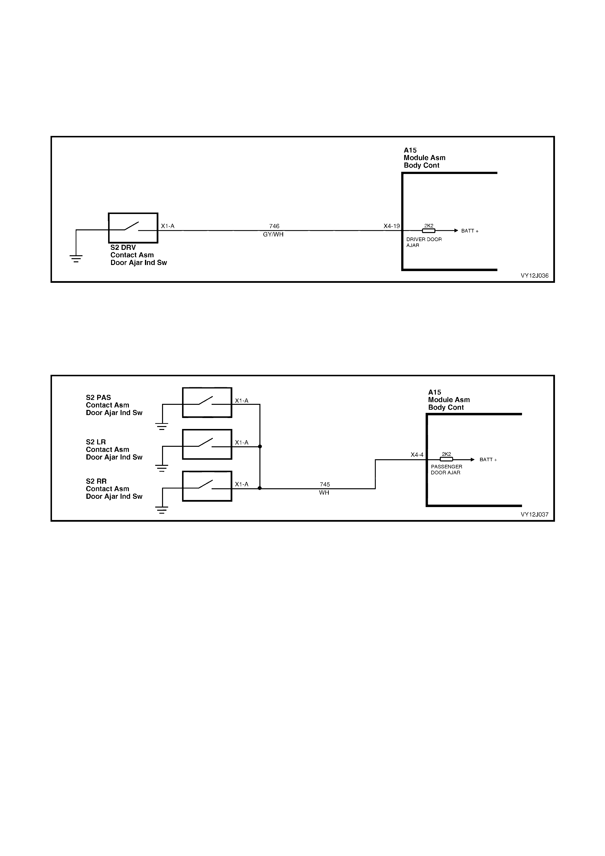
DRIVER’S DOORJAMB SWITCH INPUT SIGNAL
The BCM uses this input signal to determine if the driver’s door is open or closed. When the door is open, the
doorjamb switch grounds ter minal X4- 19 via cir cuit 746 ( G rey / White wire). Refer to Figure 12J-27. T his causes the
voltage at terminal X4-19 to be pulled low to less than 0.2 volt, which is seen by the BCM as the driver’s door ajar
input signal.
Figure 12J-27
PASSENGER’S DOORJAMB SWITCH INPUT SIGNAL
The BCM uses this input signal to determine if a passenger’s door is open. If either rear door or the front
passenger’s door is open, term inal X4-4 is grounded through circuit 745 ( W hite wire). Refer to Figure 12J -28. This
causes the voltage at terminal X4-4 to be pulled low to less than 0.2 volt, which is seen by the BCM as the
passenger door ajar input signal.
Figure 12J-28
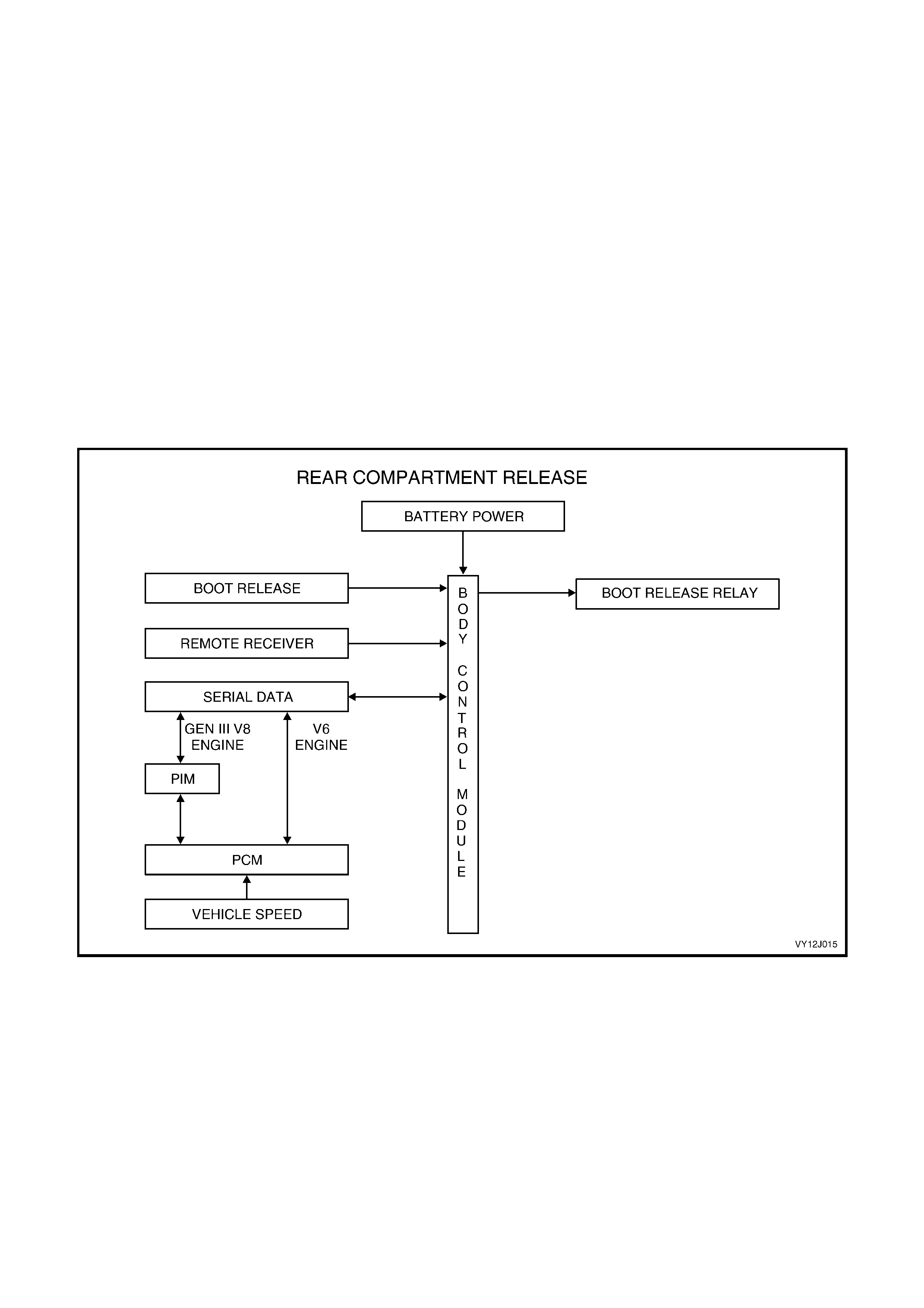
1.6 REAR COMPARTMENT RELEASE
SYSTEM OPERATION
Pressing either the rear compartment release switch located in the glove compartment or the rear compartment
release button on the remote coded key releases the rear compartment. Pressing the rear compartment release
button on the remote coded key transmits an RF output signal. The BCM remote receiver detects this signal and the
BCM activates the microprocessor in the BCM.
The rear compartment release switch is disabled when the theft deterrent system is armed via:
• the remote code key
• the driver’s door microswitch
• the vehicle deadlock.
The rear compartment release switch is only enabled when the theft deterrent system is disarmed either by
pressing the unloc k button on the rem ote coded k ey, or the remote key reader receiving a valid secur ity code when
the ignition is turned on.
The BCM monitors the rear compartment release switch and remote rear compartment signal and stops the rear
compartment release operating if the vehicle speed is above 20 km/h.
NOTE: T he cir cuit diagram s shown in this section are to aid in under standing the system oper ation. Theref ore only
the main connectors and wiring colours are shown. For complete circuit details, refer to either the relevant
diagnostic section or Section 12P, WIRING DIAGRAMS.
Figure 12J-29
CIRCUIT OPERATION
Battery Power
Battery voltage is applied to the BCM microprocessor terminal X1-10, refer to Figure 12J-26, through fusible link
F104 and fuse F29 via circuit 740 (Orange / Black wire).
Inputs
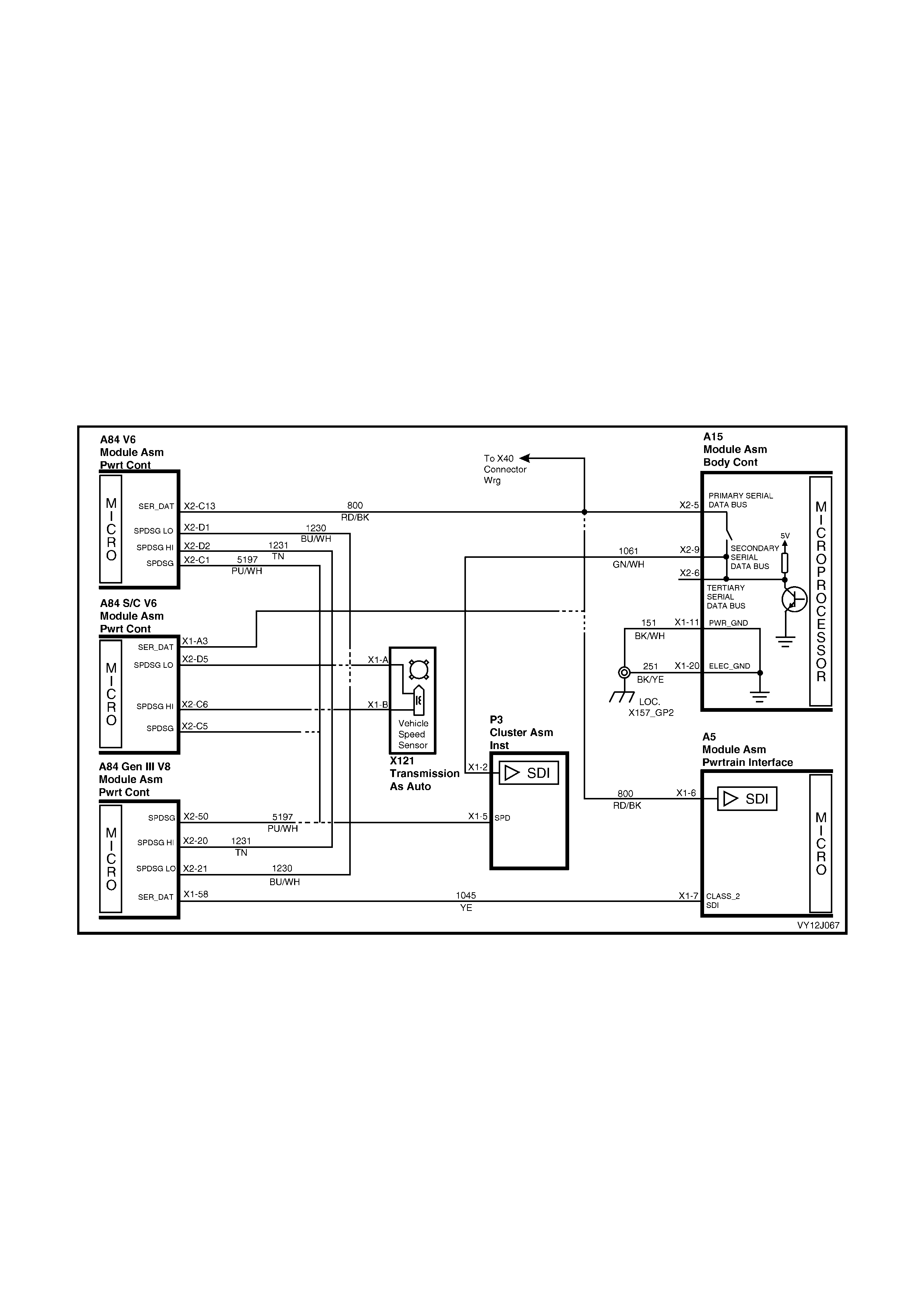
SERIAL DATA SIGNAL — V6 and V6 S/C
The serial data bus BCM terminal X2-5, refer to Figur e 12J-30, is connec ted to the PCM term inal X1-A3, via circ uit
800 (Red / Black wire). This serial data bus line supplies the BCM with serial data relating to the speed of the
vehicle.
SERIAL DATA SIGNAL — V8
The serial data bus BCM terminal X2-5 (refer to Figure 12J-30) is connected to the PIM terminal X1-6. A Class 2
serial data is connected between PIM terminal X1-7, via circuit 1049 (Yellow wire), and PCM terminal X1-58. This
serial data bus line supplies the BCM with serial data relating to the speed of the vehicle.
SECURITY AND CENTRAL DOOR L OCKING STATUS SIGNALS
The BCM internal status includes the state of both the security system (Armed, Disarmed, Triggered, Passively
armed) and the central locking system (locked, unlocked etc).
If the BCM detects the security system as armed or the central locking as deadlocked, the Rear Compartment
(boot) release function will be inhibited.
Figure 12J-30
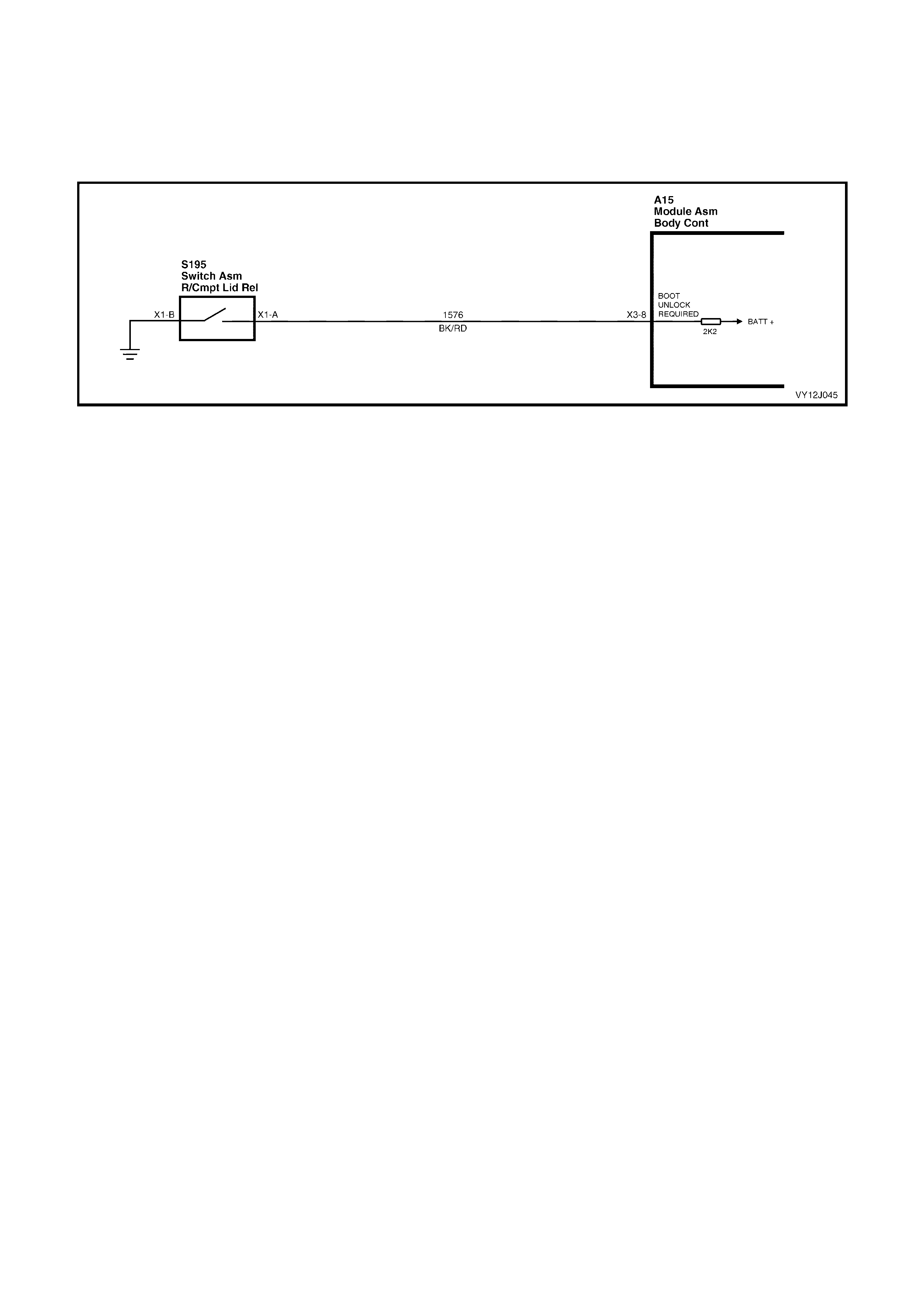
REAR COMPARTMENT RELEASE INPUT
Pressing the rear compartment release switch causes the contacts to close, connecting BCM terminal X3-8 to
ground via circuit 1576 (Black / Red wire). Refer to Figure 12J-31. This causes the voltage at terminal X3-8 to be
reduced to less than 0.2 volt, which is seen by the BCM as a rear compartment release switch input signal. The
BCM will not actuate the rear com partm ent release r elay if the vehicle speed is greater than 20 km/h, the system is
armed via the remote coded key, or the driver’s door-lock microswitch is deadlocked.
Figure 12J-31
Outputs
The BCM activates the rear compartment lock actuator by energising the internal rear compartm ent release relay.
Power from terminal X4-2 (BCM) is applied to terminal X1-A of the rear compartment release actuator assembly
circuit 56 ( Red / G reen wire). T he gr ound cir c uit f or the r ear c ompartment releas e s olenoid is via the body and main
wiring harness.
1.7 THEFT DETERRENT SYSTEM
GENERAL INFORMATION
The theft deterrent system on VY Series Models uses a remote coded key to arm and disarm the system. The
remote coded key is also used to electrically lock or unlock all doors and the station wagon tailgate or sedan boot
lock.
NOTE: The c ircuit diagr am s shown in this G eneral Desc ription Section ar e to aid in interpreting the oper ation of the
circuit and therefore, only the main connectors and wiring colours are shown. For complete circuit details, refer to
either the relevant diagnostic procedure in this Section or Section 12P, WIRING DIAGRAMS.
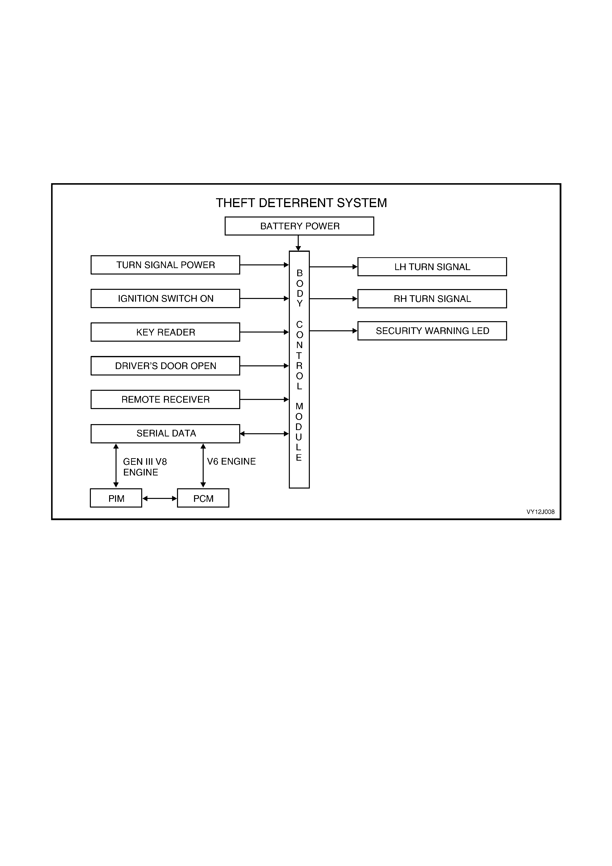
SYSTEM OVERVIEW
Figure 12J-32
SYSTEM OPERATION
V6 AND V6 SUPERCHARGED ENGINE
When the ignition is turned on, the BCM polls the PCM and sends an encrypted BCM / Key security code. The
security code is rec eived via the slip ring, or by the remote re ceiver in the event of no s lip ring com munic ation. The
PCM compares the received security code with its stored security code and if the codes match, the PCM enables
injector fuelling and continued engine cranking. The PCM returns an OK TO START message telling the BCM to
jump from SHORT LOOP mode to the LONG LOOP mode.
GEN III V8 ENGINE
When the ignition is tur ned on, the BCM sends the PIM an enc rypted BCM / Key sec ur ity code. The secur ity code is
received via the slip ring, or the by remote receiver in the event of no slip ring com munication. The PIM compares
the received security code with the PCM stored security code and if the codes match, the PIM allows engine
cranking and sends a separate encrypted security code to the PCM. The PCM compares this code with its stored
security code and if the codes match, the PCM allows injector fuelling to continue. The PIM returns an OK TO
START message, which tells the BCM to jump from SHORT LOOP mode to the LONG LOOP mode.
Armed
The theft deterrent system can be armed actively, by pressing the lock button on the remote coded key or passively,
when the BCM automatically arms the system 30 seconds after the ignition is turned off.
When the thef t deterr ent system is arm ed, the following com ponents are disabled pr eventing the engine from being
started:
• The start relay located in the engine compartment relay housing.
• The PCM.
• The PIM (on vehicles with GEN III V8 engines).
Disarmed
The theft deterrent system can be disarmed by pressing the unlock button on the remote coded key (which will
unlock the doors, turn the interior dom e lamp on and disar m the sys tem for 30 seconds) or by inser ting the rem ote
coded key into the ignition switch and turning the ignition on.
With the system disarmed and the PCM / PIM enabled, the engine can be started.
The BCM then reads a security code (serial data output) from the remote coded key contact pin via the remote
coded key reader assembly.
NOTE 1: Both the V6 and V8 systems allow up to 1 second of cranking time if the code is invalid. This usually
results in the engine starting but then dying after two to three seconds. Normally this allows for fuel priming and
reduces start delays while the security message is being validated. Engine crank is then disabled until the next
ignition cycle of key off - key on.
NOTE 2: If the engine crank s briefly when the ignition switch is turned to the START pos ition, there m ay be a faulty
remote coded key reader. Press the unlock button on the remote coded key to disarm the theft deterrent system.
Remote Coded Key
The theft deterrent system uses a remote coded key to arm and disarm the sy stem and electrically lock or unlock all
doors and the station wagon tailgate or the sedan boot lock.
The Radio Fr equency (RF) transm itted by the rem ote coded k ey is received by the BCM r emote rec eiver located in
the instrument panel between the demist ducts.
After pr essing the rem ote c oded key lock button to ar m the theft deterrent system, the indicators flash once and the
security status telltale LED begins to flash. After disarming the system by pressing the key unlock button, the
indicators flash twice and the security status telltale LED stops flashing.
NOTE: Passive arming of the system does not automatically operate the door-locks or flash the indicators.
BATTERY
The rem ote coded key is powered by its own internal battery. If this battery fails, the remote coded key reader can
power the key when it is inserted into the ignition switch and turned on or to the start position.
Figure 12J-33
Security Status Telltale
The Security Status Telltale LED indicates the state of the system. When flashing, the LED indicates that the
system is armed and the vehicle cannot be started. When the BCM is disarmed, the LED is turned off and the
engine can be started.
The Security Status Telltale LED is located in the instrument cluster assembly.
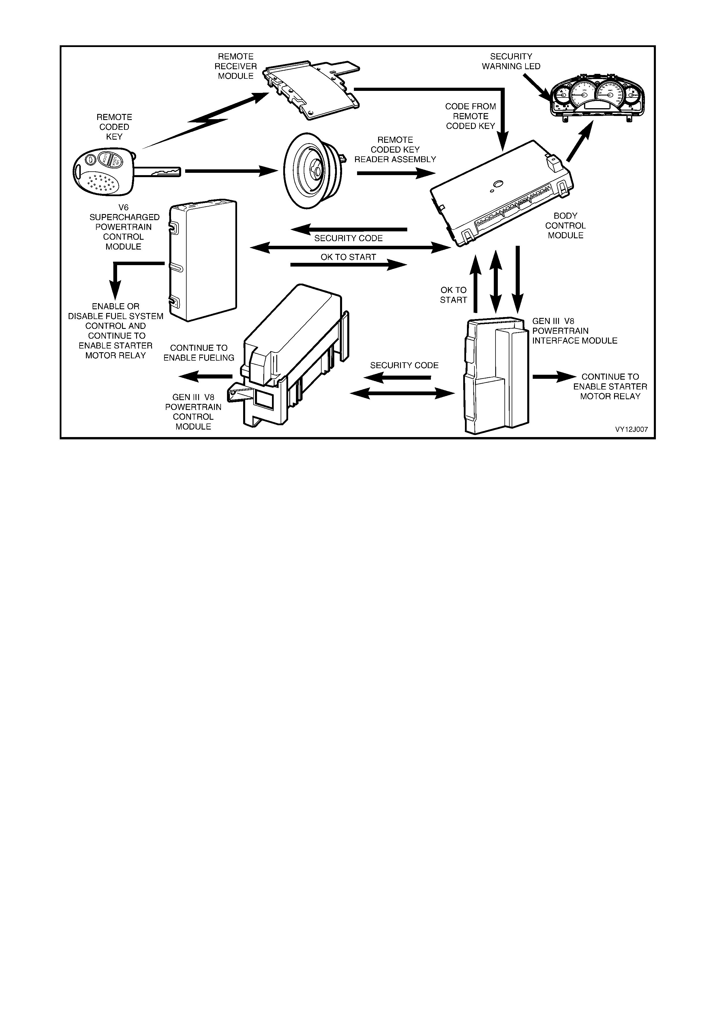
Figure 12J-34
CIRCUIT OPERATION
Battery Power
Battery voltage is applied to the BCM microprocessor terminal X1-10 at all times from fusible link F104 and fuse
F29, circuit 740 (Orange / Black wire).
Indicator Power
Battery voltage is applied to BCM terminal X1-13 at all tim es from fusible link F102 and fuse F7, circuits 442 (Red
wire) and 140 (Orange / Red wire).
Inputs
IGNITION SWITCH ON INPUT SIGNAL
The BCM us es this input s ignal to determine when the ignition is turned on or to the s tar t pos ition. When the ignition
is turned on or to the start position, battery voltage is applied to BCM term inal X3-2 from the ignition switch, circuit
300 (Orange wire). Refer to Figure 12J-35.
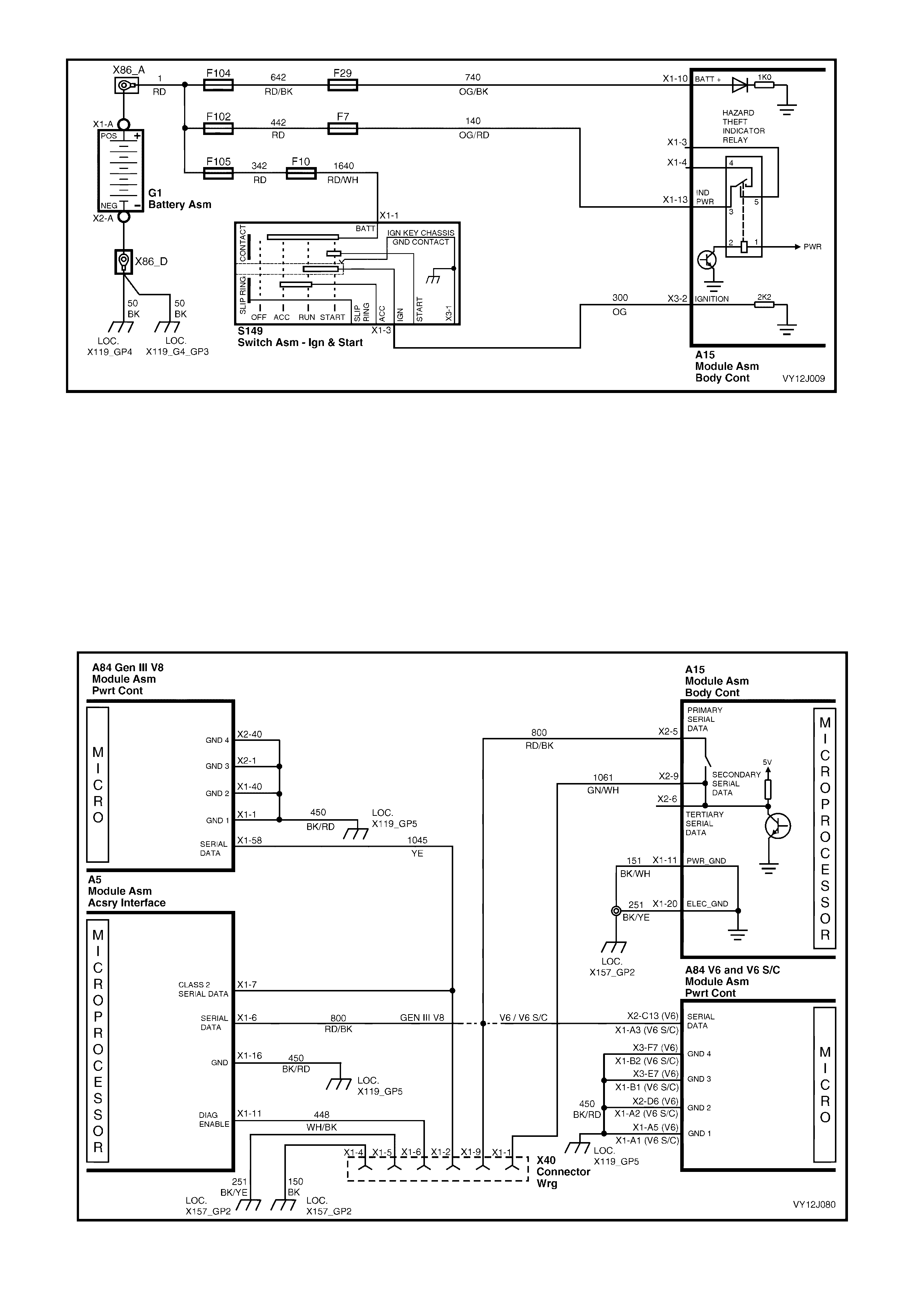
Figure 12J-35
BCM AND PCM SERIAL DATA COMMUNICATION
V6 ENGINES:
W hen the ignition is turned on, the BCM com munic ates with the PCM via the serial data com m unication line. Refer
to Figure 12J-32.
BCM terminal X2-7, circuit 1073 (Purple / Red wire) receives serial data from the remote coded key .
GEN III V8 ENGINE:
When the ignition is turned on, the BCM comm unic ates with the PIM via the serial data com munic ation line and the
PIM communicates with the GEN III V8 PCM. The GEN III V8 PCM via the serial data communication line.
BCM terminal X2-7, circuit 1073 (Purple / Red wire), receives serial data from the remote coded key. Refer to
Figure 12J-33.
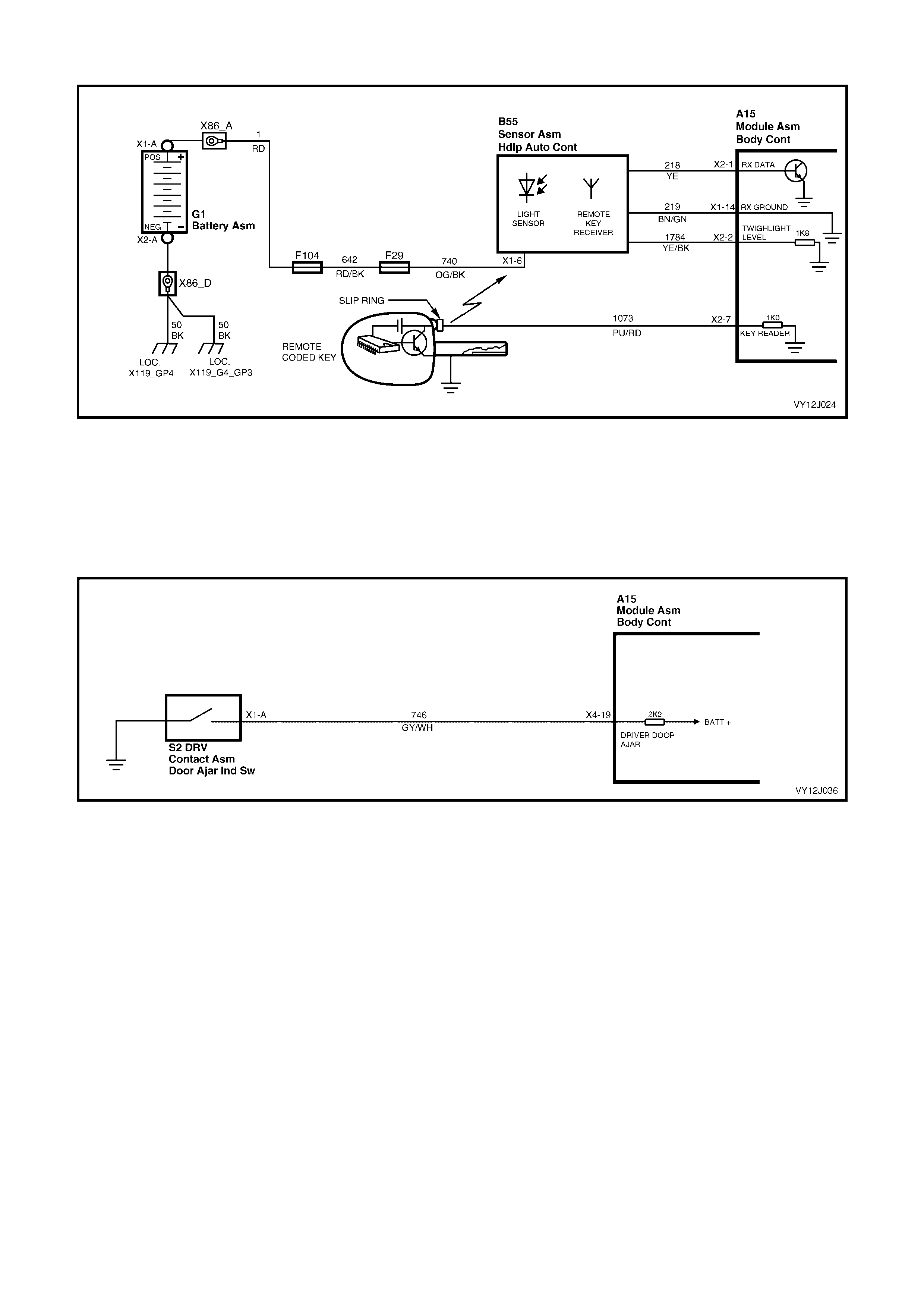
Figure 12J-36
Figure 12J-37
DRIVER'S DOORJAMB SWITCH
The BCM us es this input signal to determ ine if the driver 's door is opened or c losed. The BCM must sense that the
driver's door is closed before the theft deterrent system can be actively armed.
When the door is open (or not fully closed), the door ajar switch grounds terminal X4-19 via circuit 746 (Grey /
White wire). This causes the voltage at terminal X4-19 to be pulled low to less than 0.2 volt. This low voltage at
terminal X4-19 is seen by the BCM as the driver's door ajar input signal. Refer to Figure 12J-38.
Figure 12J-38
Outputs
LEFT-HAND INDICATORS
The BCM controls the operation of the left-hand indicators by pulsing the BCM internal Hazard / Theft Indicator
relay. This causes the relay contacts to close and open a number of times applying battery voltage intermittently
from term inal X1-13 to ter minal X1-4 and the lef t-hand indicator lam ps through circ uit 1314 (Light-blue wire). Refer
to Figure 12J-39.
RIGHT-HAND INDICATORS
The BCM controls the operation of the right-hand indicators through the same relay used to control the left hand
indicators. Puls ing of the BCM Hazard / T hef t Indic ator r elay causes the indicator relay contacts to close and open a
number of times . This applies battery voltage intermittently from terminal X 1-13 to term inal X1-3 and the r ight-hand
indicator lamps through circuit 1315 (Blue wire). Refer to Figure 12J-39.
SECURITY STATUS TELLTALE LED
The security status telltale LED c ontinuously flashes while the system is arm ed. The BCM contr ols the operation of
the security status telltale LED by turning an internal switch on and off . T his switch puls es the voltage applied to the
security status telltale LED via terminal X1-21 and circuit 264 (Blue wire). Refer to Figure 12J-39.
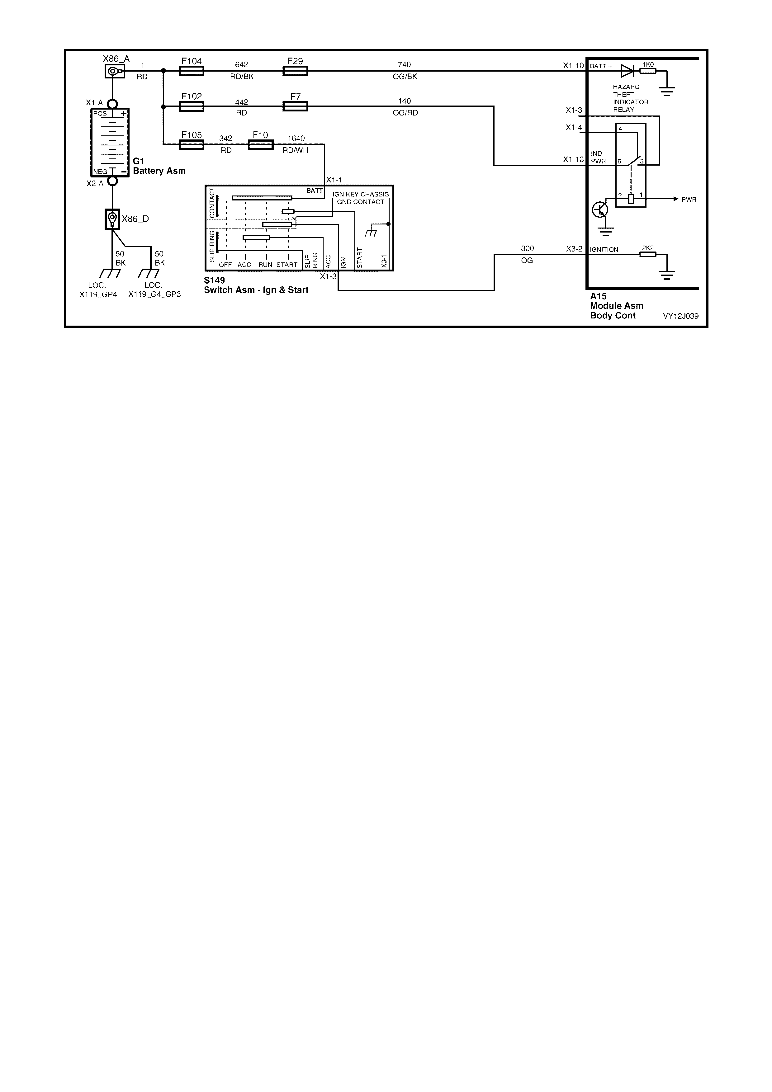
Figure 12J-39

1.8 ENTRY DETERRENT SYSTEM
CIRCUIT DESCRIPTION
The BCM entry deterrent system is designed to deter unwanted access to the vehicle's passenger compartment.
The system provides an audible and visual warning of illegal entry to the vehicle.
Arming of the theft and entry deterrent systems is by pressing the lock button on the remote coded key.
NOTE 1:
• The entry deterrent system does not arm passively.
• The remote coded key also incorporates a rear compartment release function button.
NOTE 2: The circuit diagrams shown in this section are to aid in interpreting the operation of the circuit and
therefore, only the main connectors and wiring colours are shown. For complete circuit details, refer to either the
relevant diagnostic section or Section 12P, WIRING DIAGRAMS.
Arming the System
Upon pressing the loc k button on the r emote coded key the system will arm 10 seconds after lock ing the doors. The
output signal from the key activates the BCM microprocessor if the ignition is off and the vehicle road speed input
indicates the speed is zero. One continuous press on a remote coded key button should cause only one arm /
disarm operation. It is not possible to arm the system or remote lock the doors with the driver's door open.
When the system is armed, the following actions take place:
• All doors and the station wagon tailgate lock.
• All indicator lights flash once.
• The power antenna retracts.
• The power window system deactivates.
• The dome light is switched off provided it has not been turned on by another system.
• The security status telltale LED flashes.
Triggered Operation
Once the entry deterrent system is armed, it is triggered by any one of the following inputs:
• Bonnet opening (circuit 263).
• Rear compartment opening (circuit 744).
• Any door being opened (circuit 746).
• The ignition being switched on with an invalid key (circuit 300).
If any of the previous conditions exist at the time of the system arming, they are ignored until the fault condition is
cleared.
Once triggered, the system operates as follows:
• All indicator lights flash at a rate of one flash per second with a duty cycle of 50%.
• All vehicle horns pulse at a rate of one pulse per second.
• The dome light flashes at a rate of one flash per second.
The indicators and dome lamp flash, and the horn/s sound for 30 seconds.
Disarming Procedure
The system is disarmed by:
• Pressing the unlock button on the r emote coded k ey which generates an RF output s ignal to activate the BCM
microprocessor via circuit 218, or
• Turning the ignition on if the remote coded key is not working due to a flat battery. This allows the BCM to
provide a power supply to the remote coded key, enabling reading of the key security code.
The following actions occur when the system is disarmed:
• All doors and the station wagon tailgate unlock.
• All indicator lights flash twice, but if the system has been triggered since being armed, they will flash three
times.
• The dome light is activated for 30 seconds and normal delay cancellation conditions apply (at night only).
If the system has been triggered since being armed, an alarm-triggered message is displayed on the instrument
cluster centre MFD at Ignition On. This message will advise the custom er of the trigger sector. Pressing the Mode
button on the trip computer switch can clear the message. The message disappears at the next ignition cycle.
The power window system is enabled with a 45-second delay.

Multi-function Display (MFD) Trigger Point Displays
The MFD displays the codes of the triggered points. The BCM sends the information to the MFD via the serial
communications bus. The Alarm Activated screen is displayed first for 1 second, followed by the trigger point
screens.
The trigger point screens are also displayed for 1 second. If more than one trigger point has been activated the
MFD will display each trigger point screen in s equenc e f or 1 sec ond, r eturning to the Alarm Activated screen. (Ref er
to Section 12C, 1.6 INSTRUMENT OPERATION — ALL MODELS).
The trigger points are driver’s door, passenger door, boot, bonnet and hotwire.
NOTE: Alarm codes are stored in the BCM until they are cleared with an ignition cycle.
Remote Rear Compartment Release
Pressing the rear compartment button on the remote coded key activates the rear compartment release solenoid.
The RF output signal from the remote coded key activates the BCM microprocessor.
The rear compartment release solenoid is activated when the rear compartment button on the remote coded key
has been press ed continuously for m ore than 0.3 s econd and the vehicle r oad speed is les s than or equal to twenty
kilometres per hour.
The remote rear compartment release function can also operate while the entry deterrent is armed without
triggering the system. W hen the rear com partment input is inhibited from triggering the entry deterrent system , the
bonnet input is also inhibited. After the r ear compar tment has been clos ed for 30 seconds, the s ystem re-arm s the
rear compartment and the bonnet sensing.
Loss of Vehicle Battery Power
If there is a re-connection of battery power to the BCM, the theft and entry deterrent systems resume in the same
state as when the battery power was disconnected, except if the system was disarmed. If the system was disarmed,
it will default to passive arm.
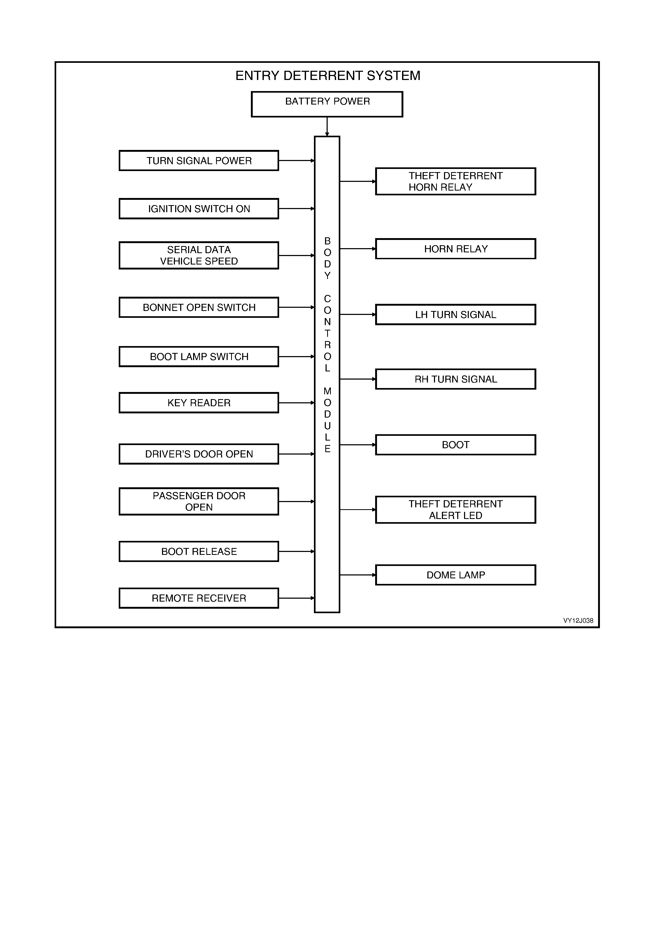
SYSTEM OVERVIEW
Figure 12J-40
CIRCUIT OPERATION
Power Supplies
BATTERY POWER
Battery voltage is applied to the BCM microprocessor from terminal X1-10 at all times from fusible link F104 and
fuse F29 via circuit 740 (Orange / Black wire). Refer to Figure 12J-41.
TURN SIGNAL POWER
Battery voltage is applied to BCM terminal X1-13 at all times from fusible link F102 and fuse F7 via circuit 140
(Orange / Red wire). Refer to Figure 12J-41.
Inputs
IGNITION SWITCH ON INPUT SIGNAL
The BCM us es this input s ignal to determine when the ignition is turned on or to the s tar t pos ition. When the ignition
is turned on or to the start position, battery voltage is applied to BCM terminal X3-2 from the ignition switch via
circuit 300 (Orange wire). Refer to Figure 12J-41.
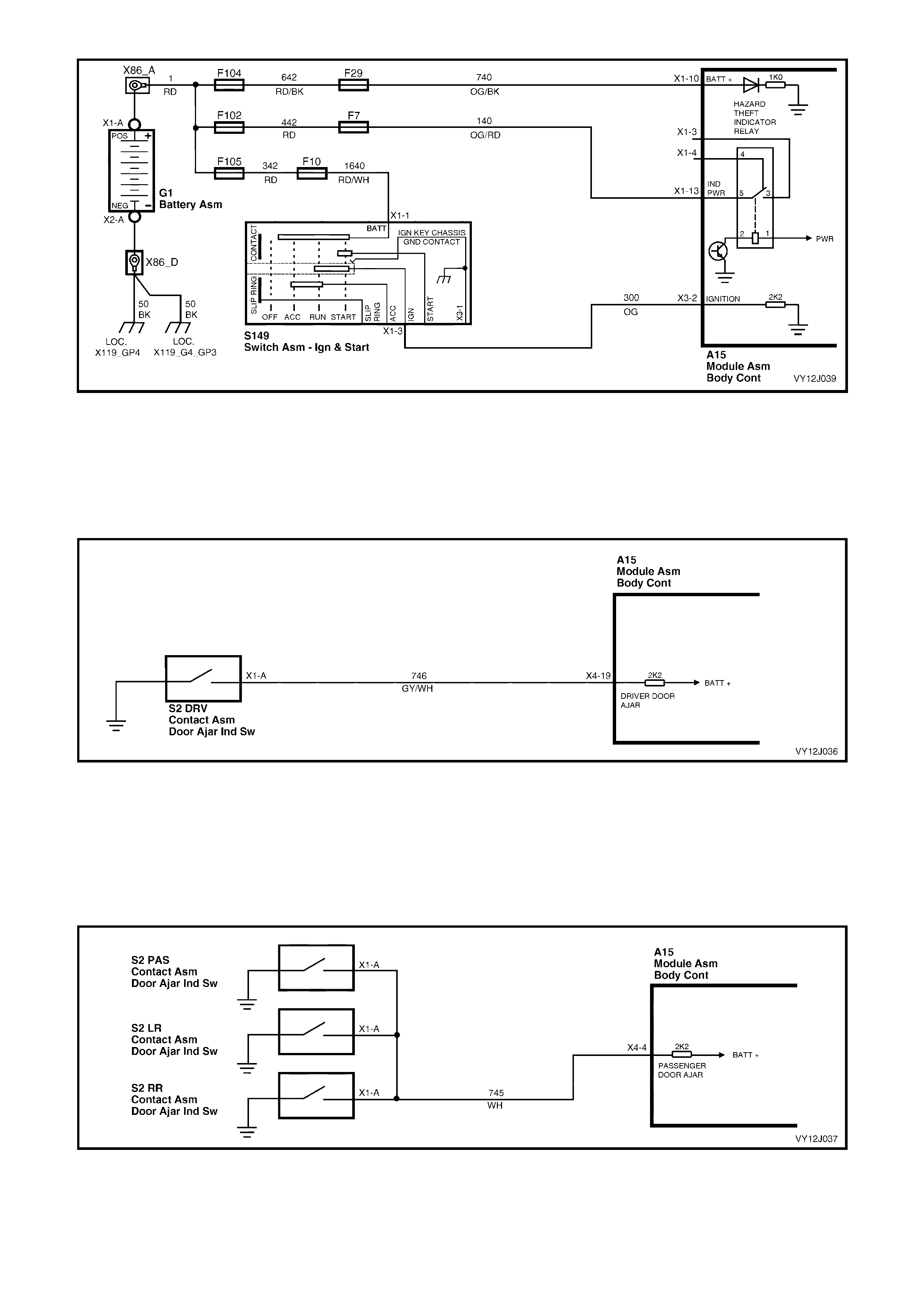
Figure 12J-41
DRIVER'S DOORJAMB SWITCH INPUT SIGNAL
The BCM uses this input signal to determ ine if the driver 's door is opened or c losed. W hen the door is opened, the
jam b s witch gr ounds terminal X 4-19 via c irc uit 746 ( Gr ey / White wire). This c aus es the voltage at ter minal X4- 19 to
be pulled low to less than 0.2 volt (driver 's door ajar ). This low voltage at terminal X4- 19 is seen by the BCM as the
driver's door ajar input signal. Refer to Figure 12J-42.
Figure 12J-42
PASSENGER’S DOORJAMB SWITCH INPUT SIGNAL
The BCM uses this input signal to determ ine if any of the passenger doors are open or if all passenger doors are
closed. If the right-hand rear, left-hand rear, or front passenger door is open, terminal X4-4 is grounded through
circuit 745 (W hite wire). If any passenger door is open, the voltage at terminal X4-4 is pulled low to less than 0.2
volt. T his low voltage at terminal X4- 4 is seen by the BCM as the passenger door ajar input s ignal. Refer to Figure
12J-43.
Figure 12J-43
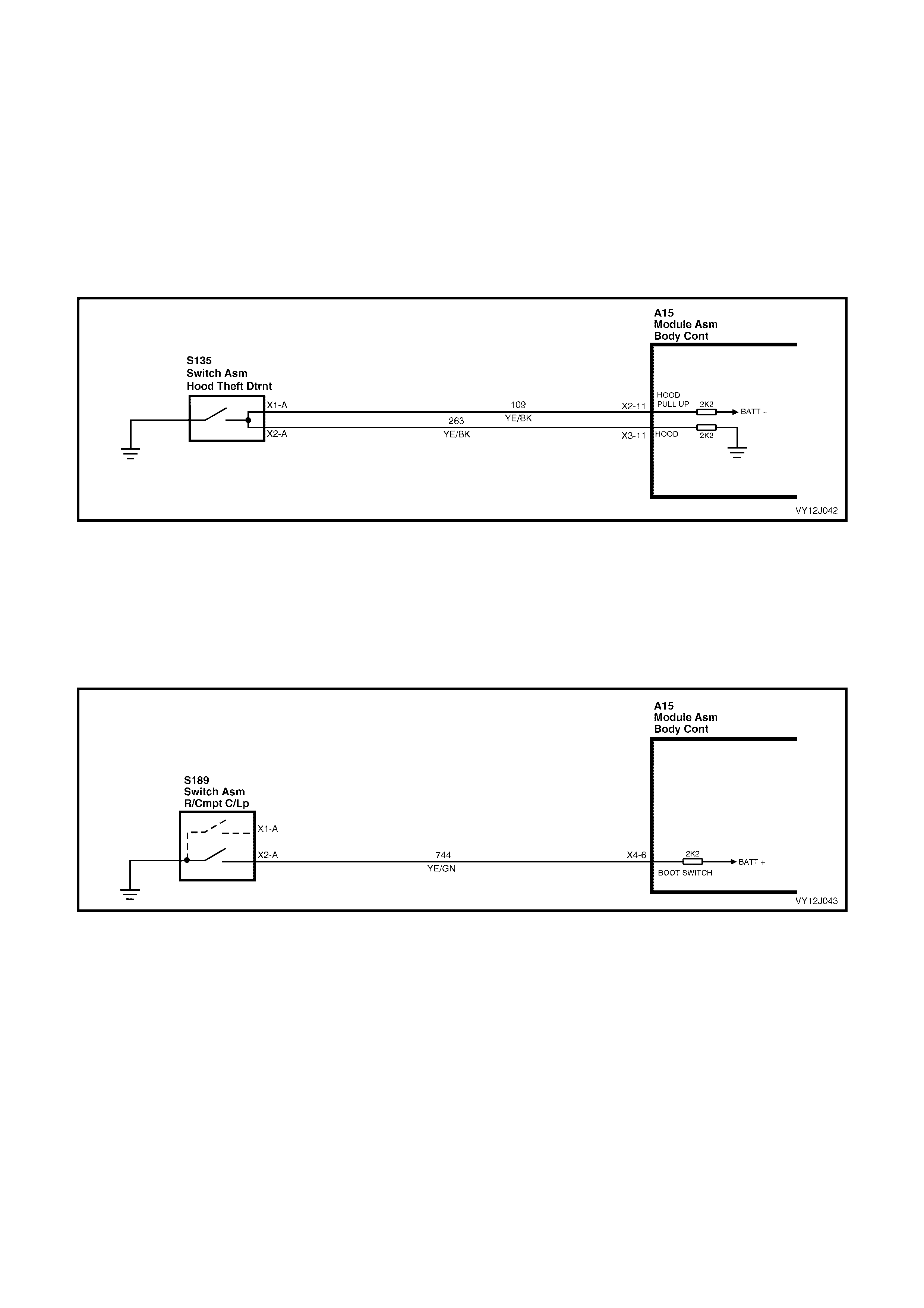
BONNET OPEN SWITCH INPUT SIGNAL
The BCM uses this input signal to determine if the bonnet is open or closed. When the bonnet is closed, battery
voltage from BCM terminal X2-11, via circuit 109 (Yellow / Black wire) passes through the bonnet switch to BCM
term inal X 3- 11, via c irc uit 263 (Yellow / Black wire). Ref er to Figur e 12J -44. This voltage at the BCM terminal X 3- 11
is seen by the BCM as the bonnet closed input signal. In the event of an open circ uit in either circuit 109 or 263, the
BCM internal pull down resistor ensur es that the voltage at the input to the micropr oc ess or is less than 0.2 volt. T his
low voltage at the microprocessor is seen as the bonnet open signal. This is to ensure that if either of these two
circuits is tampered with, the alarm will be triggered. Refer to Figure 12J-44.
When the bonnet is opened, the theft deterrent bonnet open switch closes and grounds the BCM terminal X3-11
through c irc uit 263 (Yellow / Black wire). This ac tion caus es the voltage at the BCM terminal X 3-11 to be pulled low,
less than 0.2 volt (bonnet open). This low voltage at BCM terminal X3-11 is seen by the BCM as the bonnet open
input signal.
Figure 12J-44
REAR COMPARTMENT LAMP SWITCH INPUT SIGNAL FOR SEDAN MODELS
The BCM uses this input signal to determine if the rear compartment is open or closed. When the rear compartment
is open, the rear compartment lamp switch grounds BCM terminal X4-6 through circuit 744 (Yellow / Green wire).
Refer to Figure 12J-45. This causes the voltage at BCM terminal X4-6 to be pulled low to less than 0.2 volt. This low
voltage at BCM terminal X4-6 is seen by the BCM as the rear compartment open input signal.
Figure 12J-45
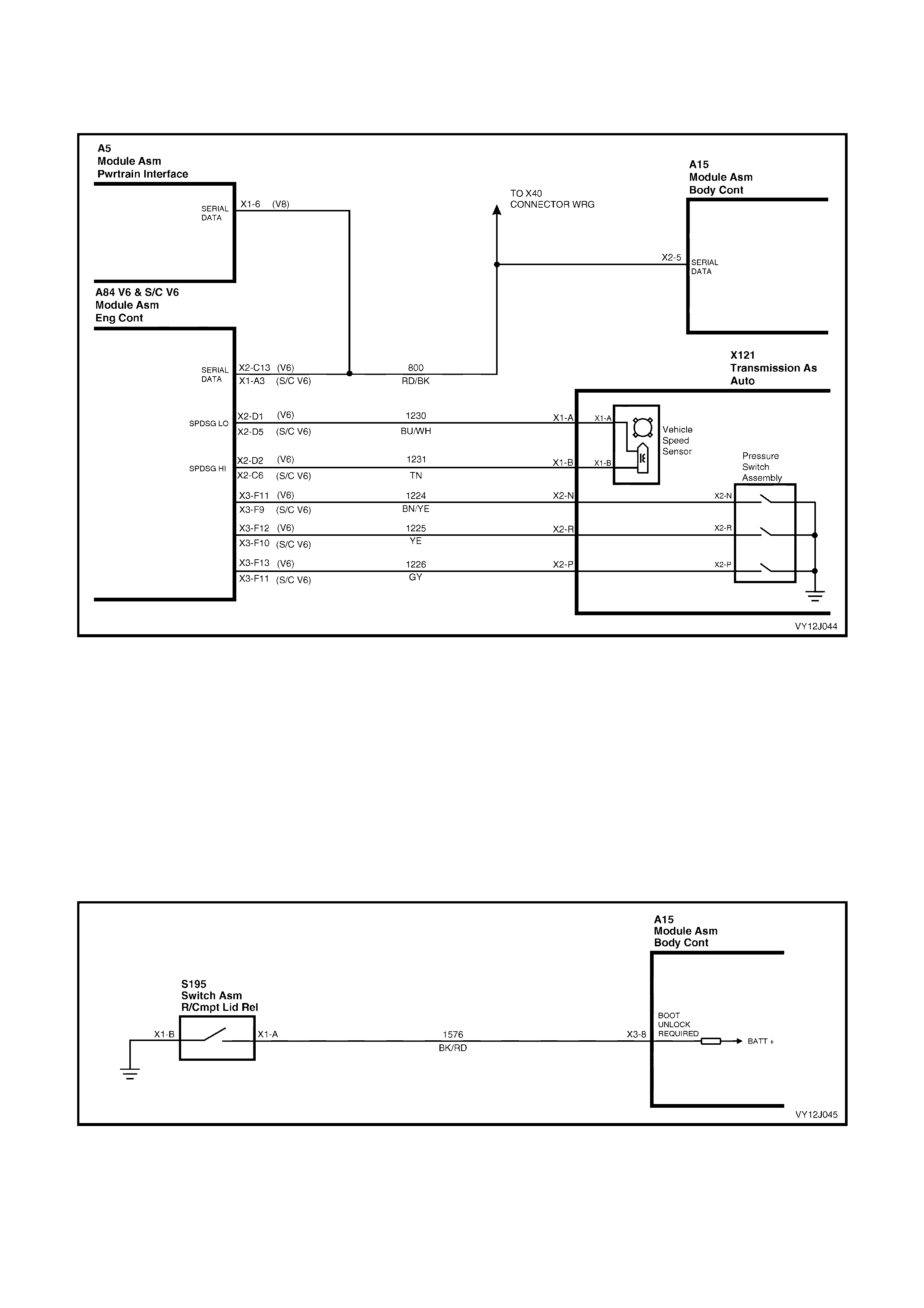
VEHICLE SPEED SIGNAL
The BCM terminal X2-5, receives the vehicle speed from the PCM via the serial data communications bus, circuit
800 (Red / Black wire). Refer to Figure 12J-46.
Figure 12J-46
REMOTE CODED KEY RF SIGNALS
When the lock, unlock or rear compartment button on the remote coded key is pressed, the remote coded key
transm its a Radio Frequenc y ( RF) signal. W hen the BCM rec eives one of these RF signals , it determines f rom the
signal characteristics which button was pressed.
REAR COMPARTMENT RELEASE INPUT SIGNALS
Pressing the rear compartment lock switch causes the switch contacts to close, connecting BCM terminal X3-8 to
ground via circuit 1576 (Black / Red wire). Refer to Figure 12J-47. This causes the voltage at terminal X3-8 to be
pulled low to less than 0.2 volt. This low voltage at terminal X3-8 is seen by the BCM as the rear compartment
release switch input signal.
NOTE: The BCM will not activate the rear compartment lock solenoid if the vehicle speed is above twenty
kilometres per hour.
Figure 12J-47

Outputs
SECURITY STATUS TELLTALE LED
The s ecurity status telltale LED flashes c ontinuously when the system is arm ed. The BCM controls the operation of
the security status telltale LED by pulsing an internal switch on and off. This switches the voltage applied to the
security status telltale LED through terminal X1-21, circuit 264 (Blue wire). Refer to Figure 12J-48.
DOME LA MP
Battery voltage is applied to all interior lamps through f use F6 and c ircuit 1140 (O range wire). T he opposite sides of
the dome lam ps are connected to ground via circuit 660 (W hite / Green wire) and BCM terminal X4-22. The BCM
controls the operation of the dom e lamps connected to this ground circuit by energising the BCM dome lamp relay
coil. This causes the internal relay contacts to close, completing the circuit to ground. Refer to Figure 12J-48.
HORN RELAY
The BCM can control the operation of the vehicle horn/s by pulsing the horn relay coil to ground through BCM
terminal X1-17, circuit 28 (Black / Yellow w ire). Refer to Figure 12J-48.
THEFT DETERRENT HORN RELAY
The BCM controls the operation of the theft deterrent horn by providing power through the internal theft deterrent
relay within the BCM at terminal X3-15, circuit 1149 (Green wire). Refer to Figure 12J-48.
LEFT-HAND INDICATORS
The BCM controls the operation of the left-hand indicators by pulsing the BCM internal indicator relay. This allows
battery voltage from term inal X1-13 to be applied in puls es to the lef t-hand indicator lam ps via terminal X 1-4, cir cuit
1314 (Light-blue wire). Refer to Figure 12J-48.
RIGHT-HAND INDICATORS
The BCM controls the operation of the right- hand indicators by pulsing the BCM internal indicator relay. This allows
battery voltage from terminal X1-13 to be applied in pulses to the right-hand indicator lamps via terminal X1-3,
circuit 1315 (Blue wire). Refer to Figure 12J-48.
REAR COMPARTMENT RELEASE SOLENOID
The BCM activates the rear compartment release solenoid by energising the BCM internal rear compartment
solenoid relay. This applies batter y voltage through the r ear com partm ent release relay contacts and term inal X4-2,
to the rear compartment release solenoid, circuit 56 (Red / Green wire). The ground circuit for the rear compartment
release solenoid is via the body and main wiring harness. Refer to Figure 12J-48.
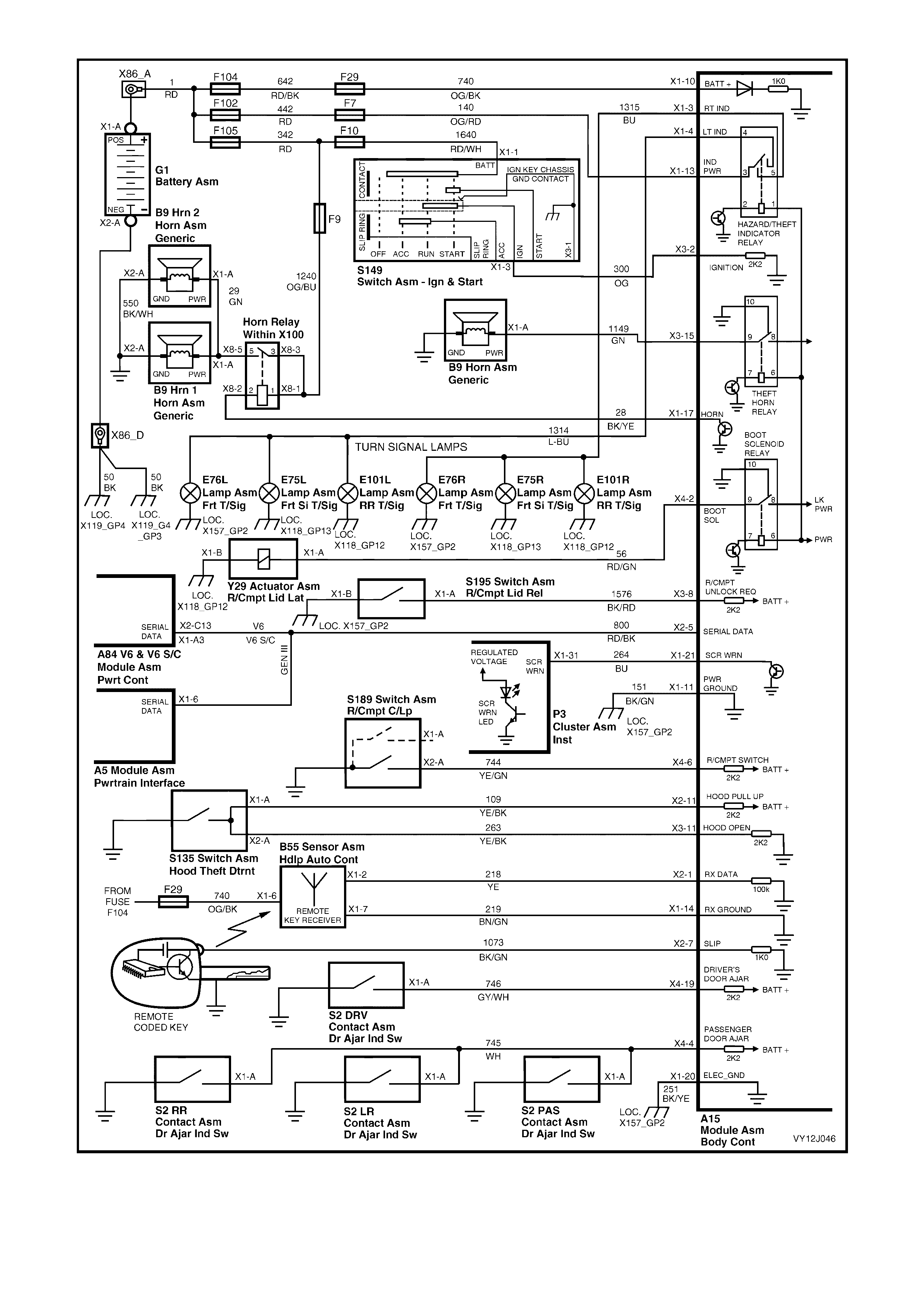
Figure 12J-48
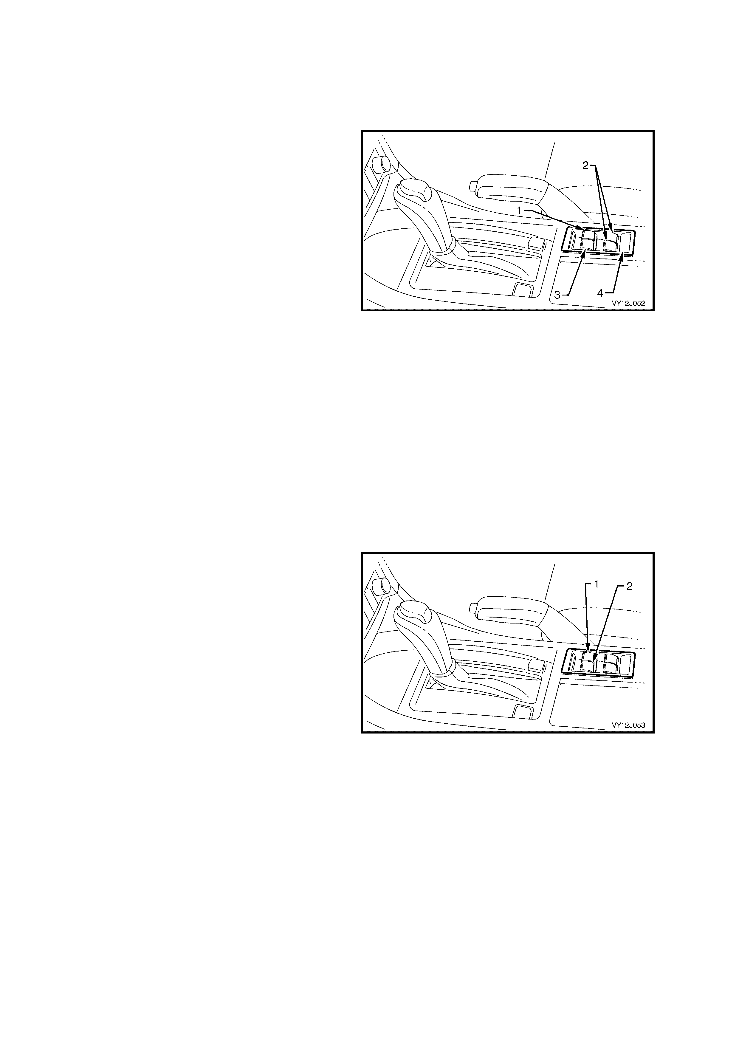
1.9 POWER WINDOW SYSTEM
SYSTEM FUNCTIONS
The BCM controls the operation of the power window relay, which controls the power supply to all window motors
and also the automatic down function of the driver and front passenger windows.
Legend (RHD Illustrated)
1. Driver’s Window Switch
2. Rear Passenger Window Switc hes (Left and Right-hand)
3. Front Passenger Window Switch
4. Lockout Switc h
Figure 12J-49
System Active
Before the power windows can operate, the lockout switch must be closed. An illuminated Light Emitting Diode
(LED) in each of the window rocker switches indicates that the system is active.
All switches are active when the ignition is on. When the ignition is tur ned off , all window switches rem ain ac tive for
45 seconds after a door is opened or for 60 m inutes if no doors are opened. If a power window switch is activated
during the 45-second period, the period recommences.
The 60-minute delay is cancelled when the doors are locked using the remote coded key.
NOTE: If the BCM has entered battery saver m ode, power is rem oved f rom the window system when the ignition is
switched off.
System Inactive
The window switch LEDs are not illuminated.
Automatic Down Operation of Front Windows
The driver and front passenger windows are activated when the DOWN button is pressed for more than 0.4 second.
1. With the ignition on, press the driver’s window
switch (1) to the DOW N position for more than
0.4 second and release it.
The window will continue to lower until it is in
the fully down position.
2. Interrupt the automatic down feature by:
• operating the window UP switch momentarily
• pressing the DOW N switch again. The window
stops when the DOWN button is released.
The s ame operations apply to the front passenger ’s
window and switch (2).
Figure 12J-50
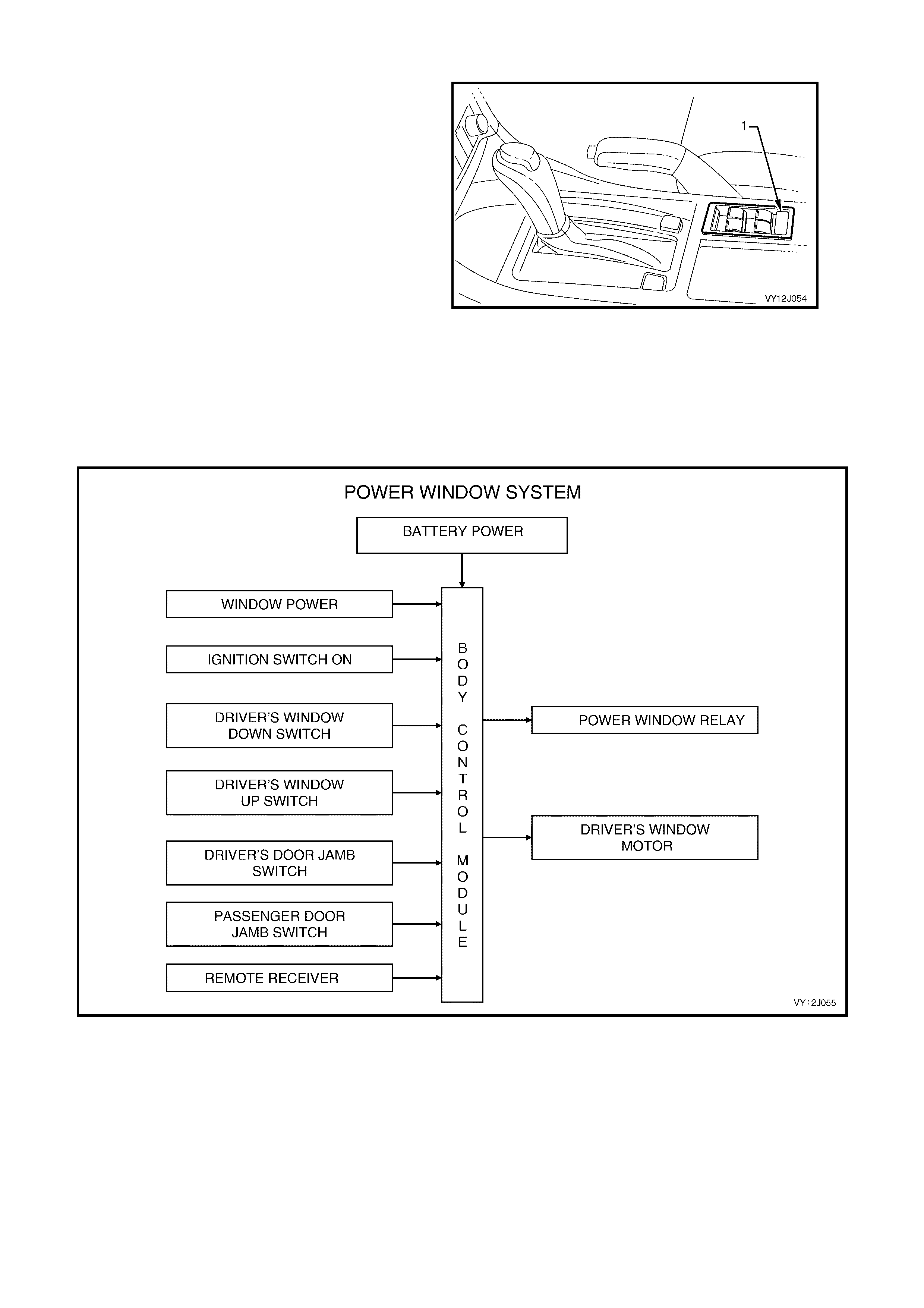
Lockout Switch
When the lockout switch is closed, the rear
windows can be raised or lowered from the centre
console switch or from the rocker switches in the
rear doors.
Check the operation of the lockout switch as
follows:
1. Turn on the ignition.
2. Check that the Green LEDs are illuminated in
all door switches.
3. Open and close the rear windows using the
rocker switches in the rear doors.
4. Press the lockout switch button (1) in the centre
of the switch console.
5. Check that the Green LEDs are not illuminated.
6. Check that the rear windows can only be raised
and lowered from the centre console switch.
Figure 12J-51
SYSTEM OVERVIEW
Figure 12J-52
CIRCUIT OPERATION
A permanent-magnet motor operates each of the power window mechanisms to raise or lower the window glass.
The direction in which the motor turns depends on the polarity of the voltage supplied to the motor terminals. The
power window switches control the voltage polarity.
Ignition ON Input Signal
The BCM us es this input s ignal to determ ine when the ignition switch is turned to the ignition or to the star t position.
When the ignition is turned on or to the start position (refer to Figure 12J-53), battery voltage from the ignition switch
is applied to BCM terminal X3-2 via circuit 300 (Orange wire).
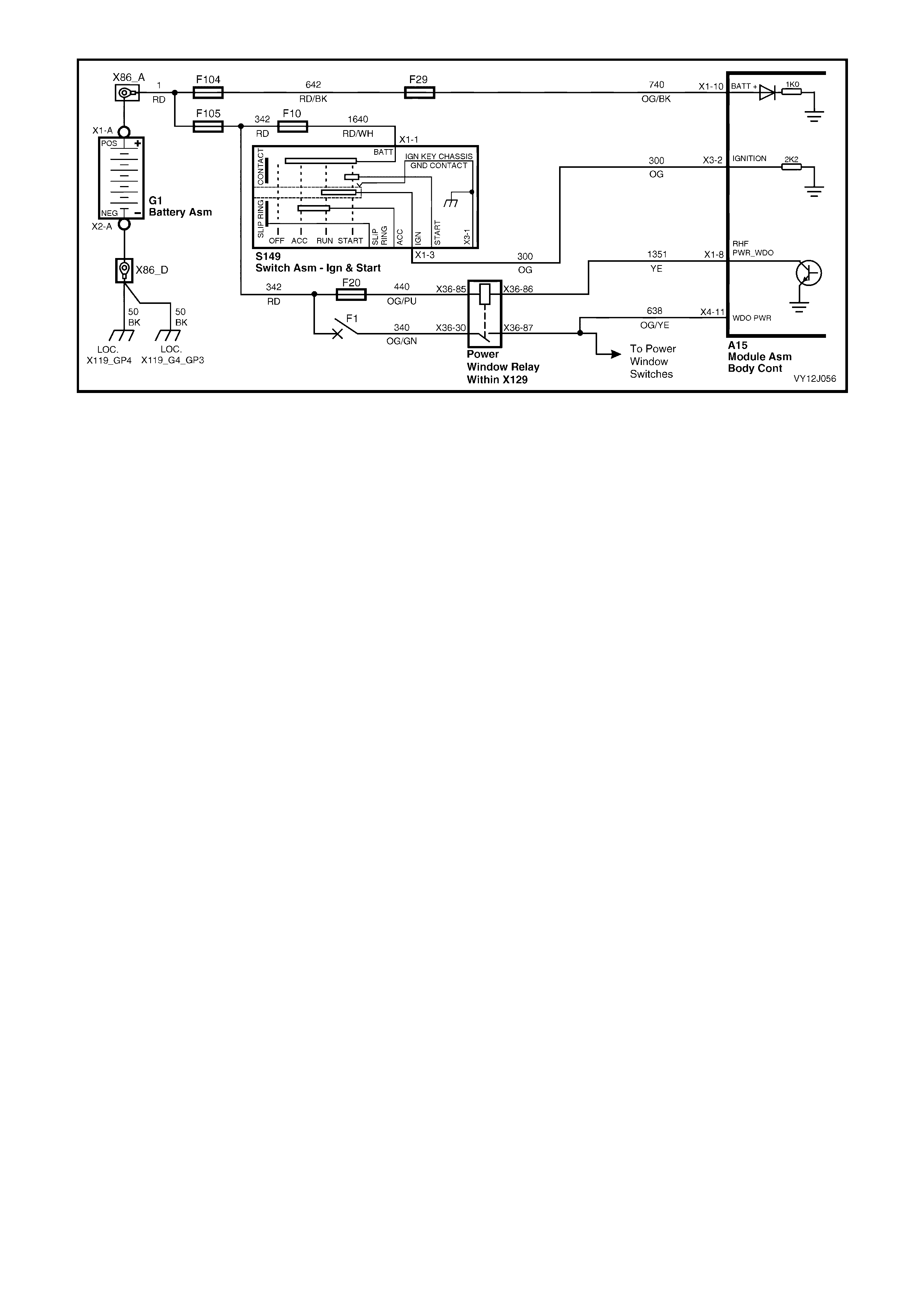
Figure 12J-53
When the BCM receives an ignition ON input, it energises the power window relay by grounding the relay coil
through circuit 1351 (Yellow wire) and BCM terminal X1-8.
With the relay coil energised, the relay contacts close and power is applied to the power window switches via fusible
link F105 and circuit breaker F1. The opposite side of each window switch LED is connected to ground, therefore
they illuminate, indicating that the system is active.
NOTE: The power window lockout switch in the centre console must be closed to activate the rear door window
switches.
Driver and Front Passenger Window-DOWN Circuit
Press the driver’s window switch f or less than 0.4 second so as not to engage the autom atic down feature. Cur rent
from the power window relay, circuit 638 (Orange / Yellow wire) passes through the power window switch to BCM
terminal X4-12. Refer to Figure 12J-54.
From BCM term inal X 4-12, the cur rent pass es through the c ontacts of the BCM driver’s window relay to the driver ’s
window motor via BCM terminal X4-13 and circuit 667 (Green / Orange wire). The opposite side of the motor is
grounded through circuit 666 (Blue / White wire), the driver’s door window switch and circuit 650 (Black / Blue wire).
The BCM microprocessor senses the length of time that the button is operated, at terminal X4-12. If the DOWN
switch is pressed for more than 0.4 second, the BCM energises the internal relay to allow the w indow to lower fully.
This auto-down feature also applies to the front passenger’s window. The voltage from the power window relay is
applied through terminal X1-13 of the front passenger’s window switch to BCM terminal X4-26, circuit 1136 (Blue
wire). Then through the BCM relay contacts and BCM terminal X4-25, circuit 165 (Yellow wire) to one side of the
front passenger’s power window motor. The opposite side of the motor is connected to ground on circuit 164 (Green
wire) via switch terminals X1-12 and X1-9 to circuit 650 (Black / Blue wire).
WINDOW-DOWN INPUT SIGNAL
W ith the driver’s window DOW N switch pressed, voltage from the power window relay is applied to window switch
terminal X1-10, circuit 638 (Orange / Yellow wire). Refer to Figure 12J-54. This voltage is also applied to BCM
terminal X4-12 indicating the ‘window down’ signal input.
When the BCM receives a dr iver ’s or f r ont pass enger ’s window down input signal, it energis es an internal relay. T he
internal relay contacts change over, allowing battery voltage from the BCM terminal X4-11, through the internal relay
contacts and BCM terminal X4-13 to one side of the driver’s power window motor on circuit 667 (Green / Orange
wire).
If the window is moving down and the down switch is again pressed, the BCM m icroprocessor senses this voltage
at terminal X 4- 12 and de- energis es the internal r elay. The relay contacts open and the motor stops when the switch
is released.
If the up button is momentarily pressed while the window in moving down, a positive battery supply is present on
both sides of the m otor armature and the m otor stops . If the up button is continuously pressed while the window is
moving down, the window-down function is cancelled and the window moves up.
The power window motor s eac h c ontain an internal over load ther mal breaker which is activated (opens) if the power
window switch is held in the Up or Down position for more than approximately 20 seconds. This prevents
overheating of the power window motor. After a cool-down time of approximately 40 seconds, the thermal breaker
closes again and allows normal motor operation.
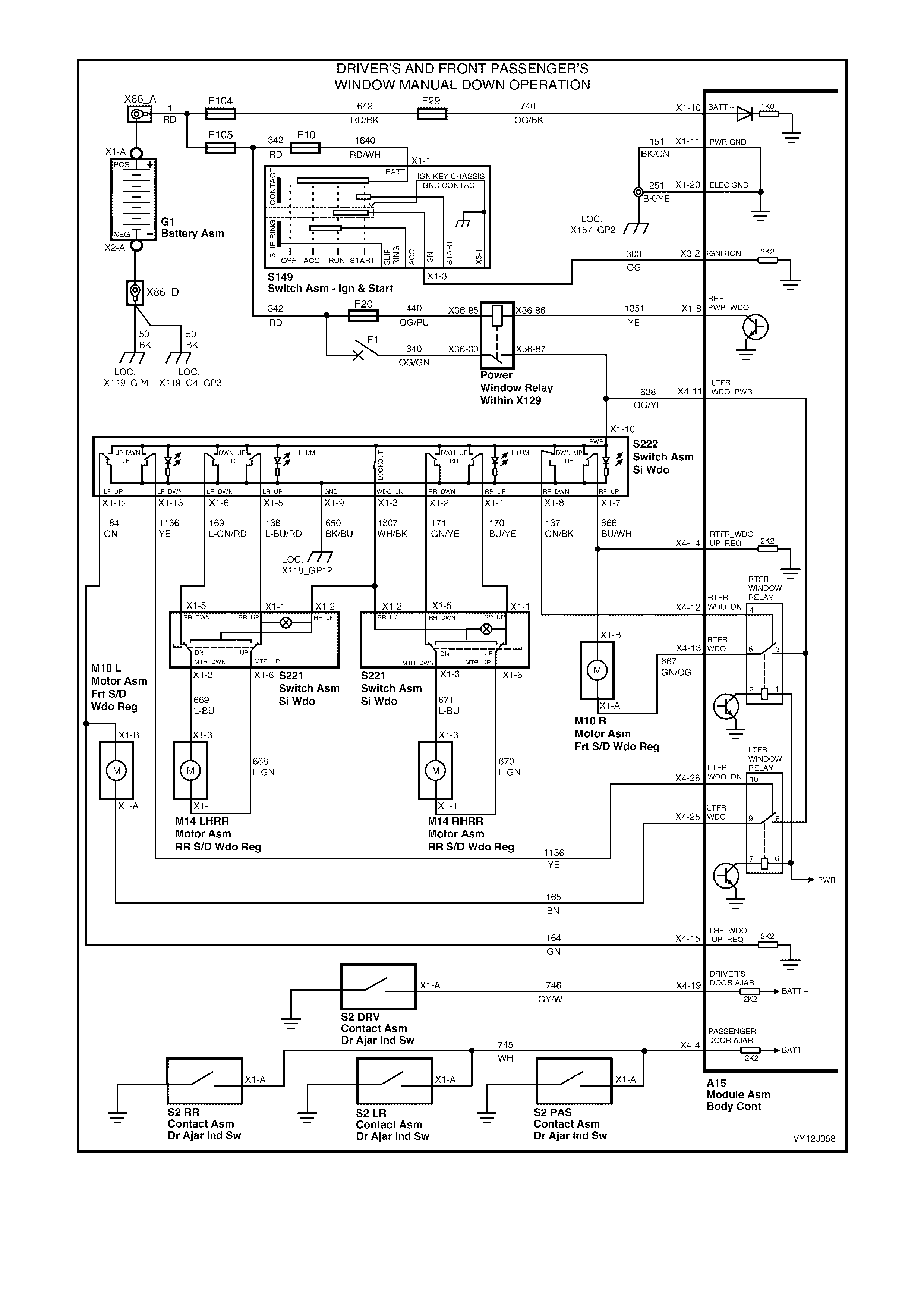
Figure 12J-54
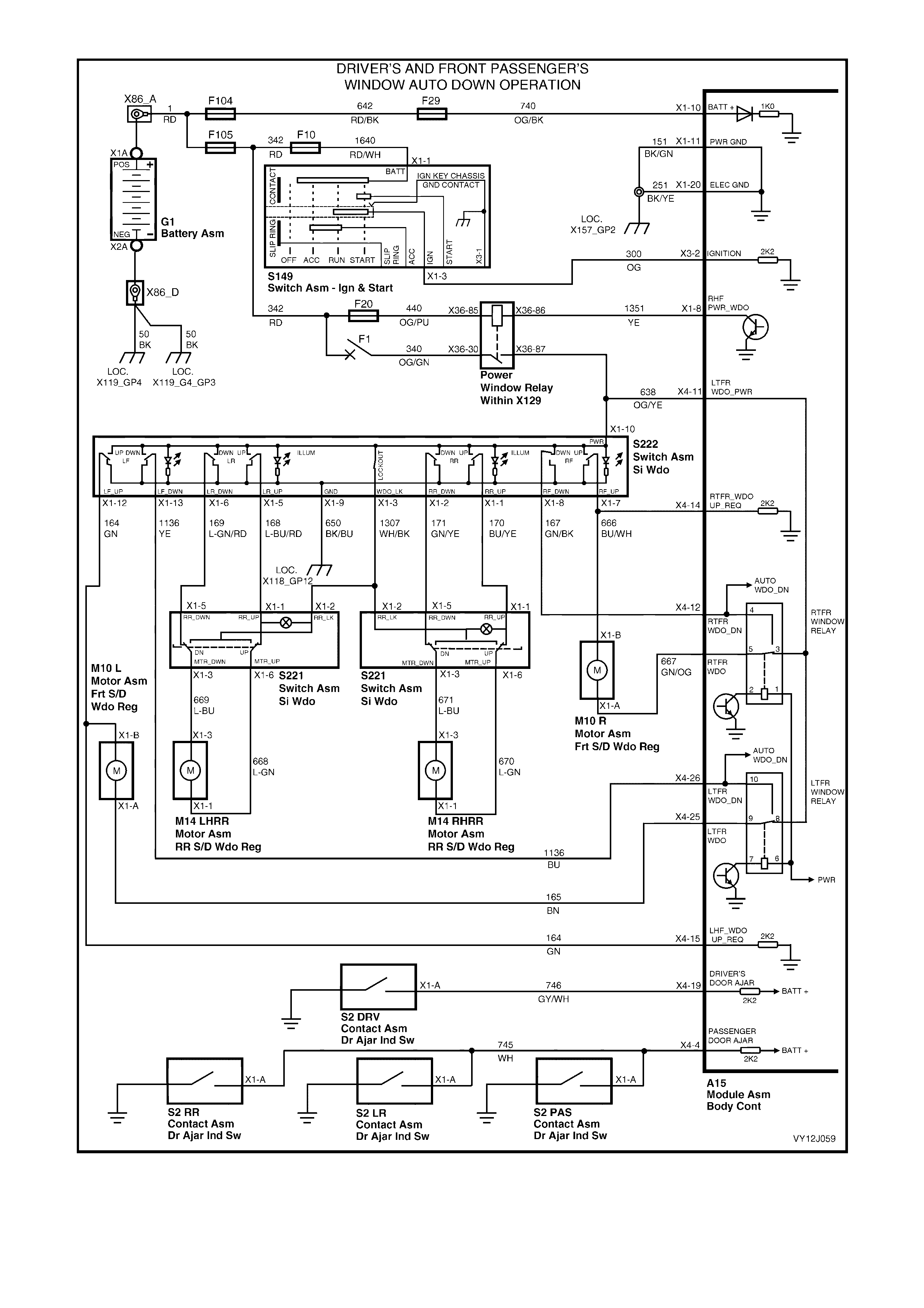
Figure 12J-55

Driver and Front Passenger Window-up Circuit
DRIVER WINDOW-UP INPUT SIGNAL
By pr ess ing and holding down the driver’s window-up button, battery voltage from the power window relay is applied
to the driver’s window motor through switch terminal X1-7 and circuit 666 (Blue / White wire). Refer to Figure
12J-56. Circuit 667 (G reen / Or ange wire) is connected to ground thr ough BCM term inal X4- 13, term inal X4- 12, the
power window switch and circuit 650 (Black / Blue wire). This causes the motor armature to rotate and raise the
window as long as the button on the power window-up switch is pressed.
FRONT PASSENGER WINDOW-UP INPUT SIGNAL
By pr ess ing and holding down the f r ont pas senger ’s window-up button, battery voltage from the power window relay
is applied to the passenger’s window motor through switch terminal X1-12 and circuit 164 (Green wire). Refer to
Figure 12J-56. Circuit 165 (Yellow wire) is connected to ground through BCM terminal X4-25, terminal X4-26, the
power window switch and circuit 650 (Black / Blue wire). This causes the motor armature to rotate and raise the
window as long as the button on the power window-up switch is pressed.
Rear Passenger Window Operation
Power is supplied to all the centre power window switches from the power window relay. Power is supplied to the
rear window switches when the lockout switch is closed.
By pressing the appropriate down or up window switch, battery voltage is applied to the window motor through the
lockout switch and the window switch contacts. The other side of the m otor is connected to ground through circuit
650 (Black / Blue wire) and the motor armature rotates as long as the motor switch is pressed.

Figure 12J-56
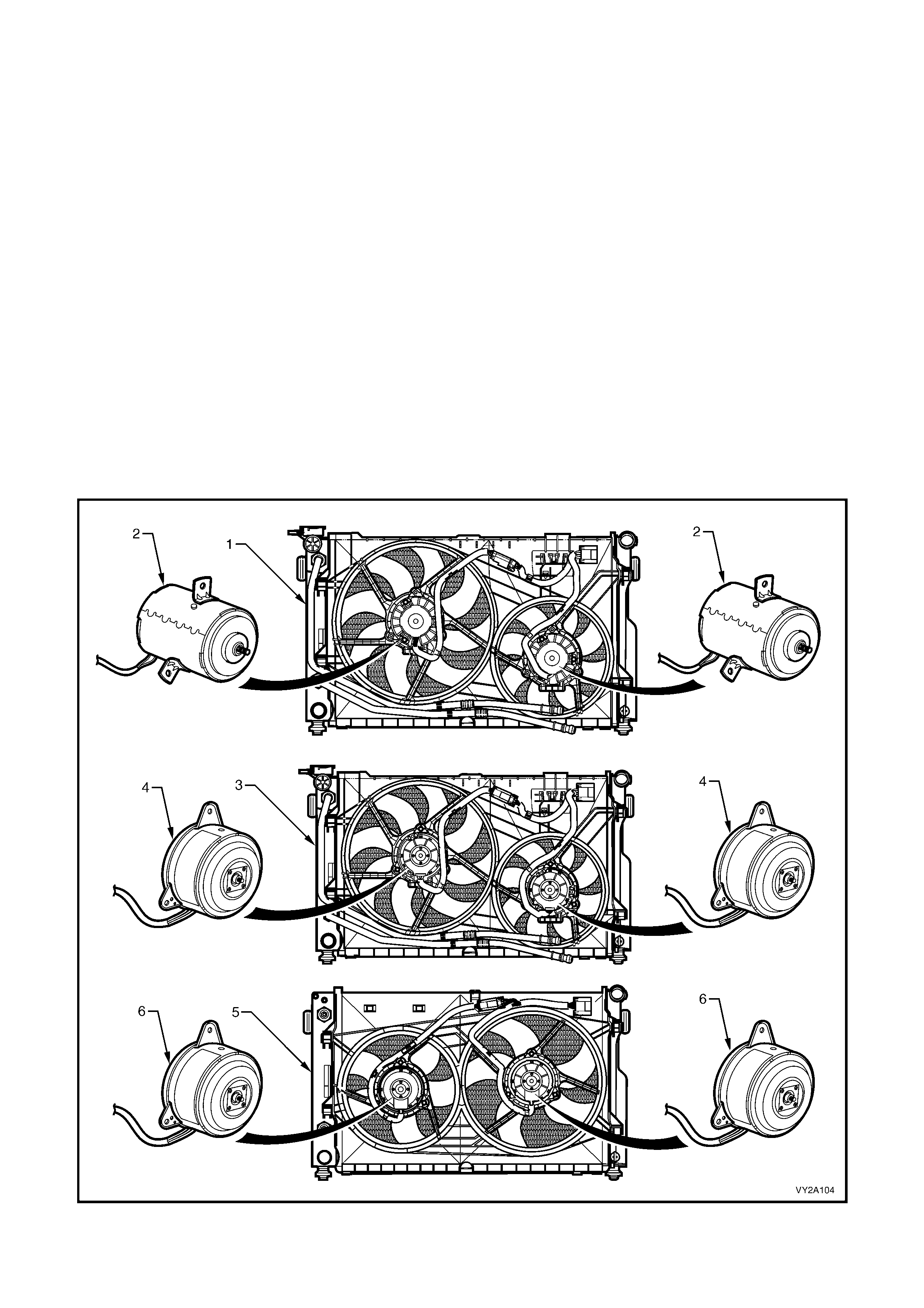
1.10 ENGINE COOLING FAN LOW-SPEED CONTROL
The c ooling f ans provide the pr imary means of m oving air through the engine. Two electric f ans are us ed to rem ove
heat from both the engine coolant (flowing through the radiator) and the refrigerant (flowing through the air
conditioning condenser).
The f an and m otor ass em blies are mounted on a c om m on shroud, which in tur n is m ounted onto the engine side of
the radiator. All of these components are part of the Condenser, Radiator and Fan Module (CRFM). For further
information relating to the CRFM, refer to Section 2A, 2.8 UNDER-HOOD COMPONENTS.
All VY and V2 Series vehicles use two-stage fan operation, however, two different strategies are used. These fan
configurations are used on all vehicles even if not equipped with air conditioning. There is no fan in front of the air
conditioning condenser.
RHD
All V6 RHD (except Indonesia) and V6 supercharged models are fitted with a standard cooling fan system
(280 Watt) consisting of twin single-speed fans, operating as follows:
• 1st stage – large diameter fan operates at maximum speed.
• 2nd stage – small and large diameter fans both operate at maximum speed.
LHD
All V6 LHD, V6 Indonesia RHD, and GEN III V8 m odels are fitted with a high power cooling fan system (400 W att)
consisting of twin dual speed fans, operating as follows:
• 1st stage – both fans operate at low speed.
• 2nd stage – both fans operate at high speed.
Figure 12J-57
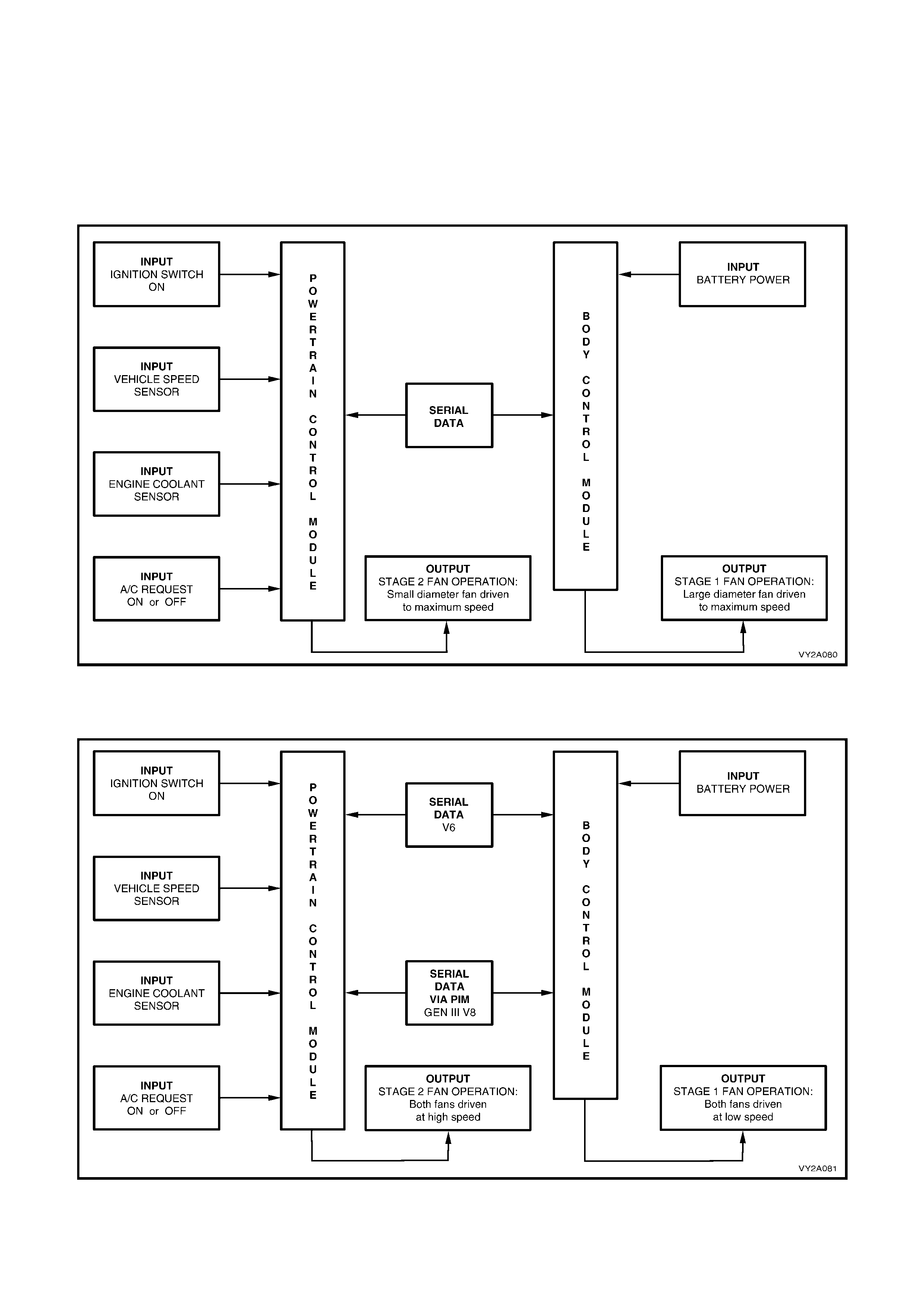
Legend
1. V6 Radiat or and S tandard Cooling Fan System 4. V6 High Power Fan Motors – Dual Speed, 400 Watts Total
2. Standard Fan Motors – Single Speed, 280 Watts Total 5. GE N III V8 Radi ator and Cooling Fan System
3. V6 Radiat or and Hi gh P ower Cooling Fan S ys tem 6. GEN II I V8 High Power Fan Motors – Dual Speed, 400 Watts Total
SYSTEM OVERVIEW
Standard Cooling Fan System – V6 and V6 S/C RHD models (excluding Indonesia)
Figure 12J-58
High Power Cooling Fan System – V6 LHD, V6 RHD (Indonesia) and GEN III V8 models
Figure 12J-59
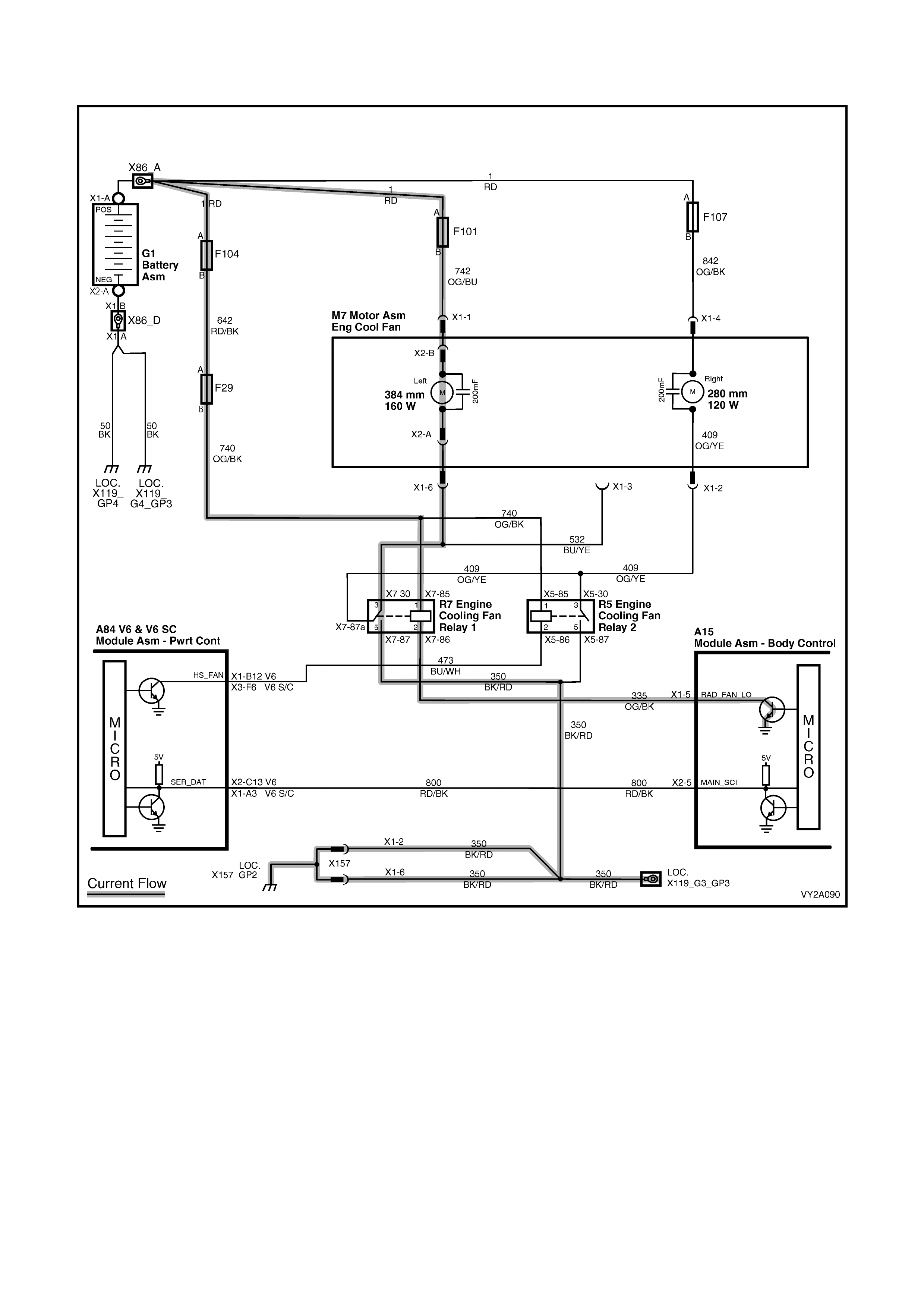
FAN OPERATION: STANDARD COOLING FAN SYSTEM – V6
1st Stage: Large diameter fan only driven at maximum speed
Figure 12J-60
On V6 models fitted with the standard cooling fan system, the engine cooling fan motors are single speed. Each
motor has one positive wire connected to one positive brush and one negative wire connected to one negative
brush. The pos itive wire is per manently supplied with battery voltage. When the negative wire of the lar ge diameter
cooling fan motor is grounded, it operates at maximum speed.
The BCM activates the COOL FAN RELAY 1 (in the engine compartment relay housing) after it detects a request
from the PCM. The relay then supplies a ground connection to energise the large-diameter cooling fan.
The PCM requests the large-diameter fan ‘enable’ and ‘disable’ using serial data communication to the BCM on
circuit 800 (R ed/Black wire). After the PCM requests a change in the state of the COOL F AN RELAY 1 (ie. off to on
or on to off), the BCM sends a message back to the PCM confirming it received the request.
The PCM enables this relay based on inputs from the air conditioning request signal, Cooling T emperature Sens or
and the Vehicle Speed Sensor.
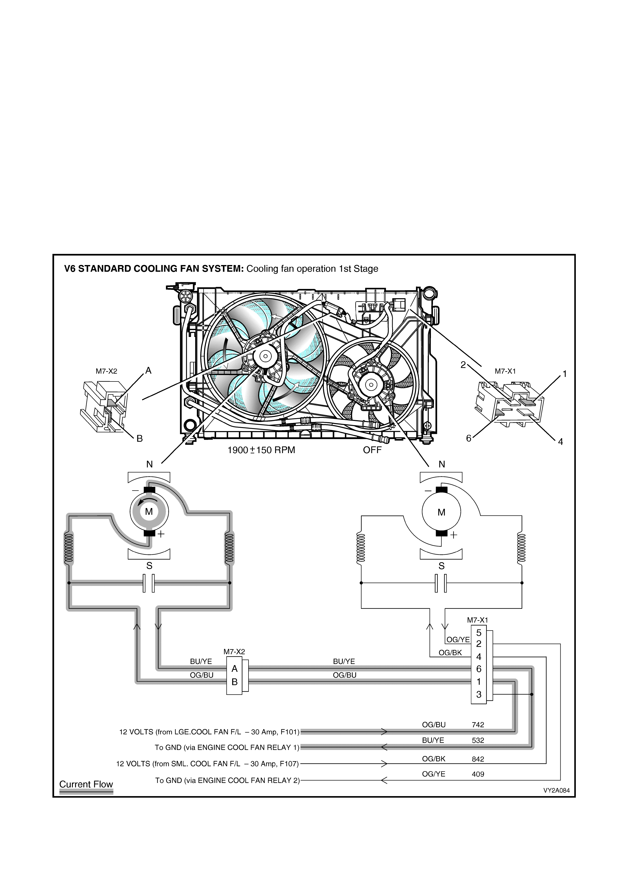
COOL FAN RELAY 1 – ENABLE
The COOL FAN RELAY 1 will be enabled w hen:
• the air conditioning request is indicated (YES) and the vehicle speed is less than 30 km/h
• the air conditioning pressure is greater than 1500 kPa
• the coolant temperature is greater than 104°C
• an engine coolant temperature sensor failure is detected by the PCM, (refer to Section 6C1, POWERTRAIN
MANAGEMENT – V6 ENGINE), or
• when the ignition switch is turned from on to off and the engine coolant temperature is above 117°C.
The BCM will continue to energise the COOL FAN RELAY 1 for four minutes.
COOL FAN RELAY 1 – DISABLE
The PCM will request the BCM to disable the COOL FAN RELAY 1 when the following conditions have been met:
• The air conditioning request is not indicated (NO) and the coolant temperature is less than 99°C, or
• the air conditioning request is indicated (YES) with pressure less than 1170 kPa for V6, vehicle speed greater
than 50 km/h and coolant temperature less than 99°C.
Figure 12J-61
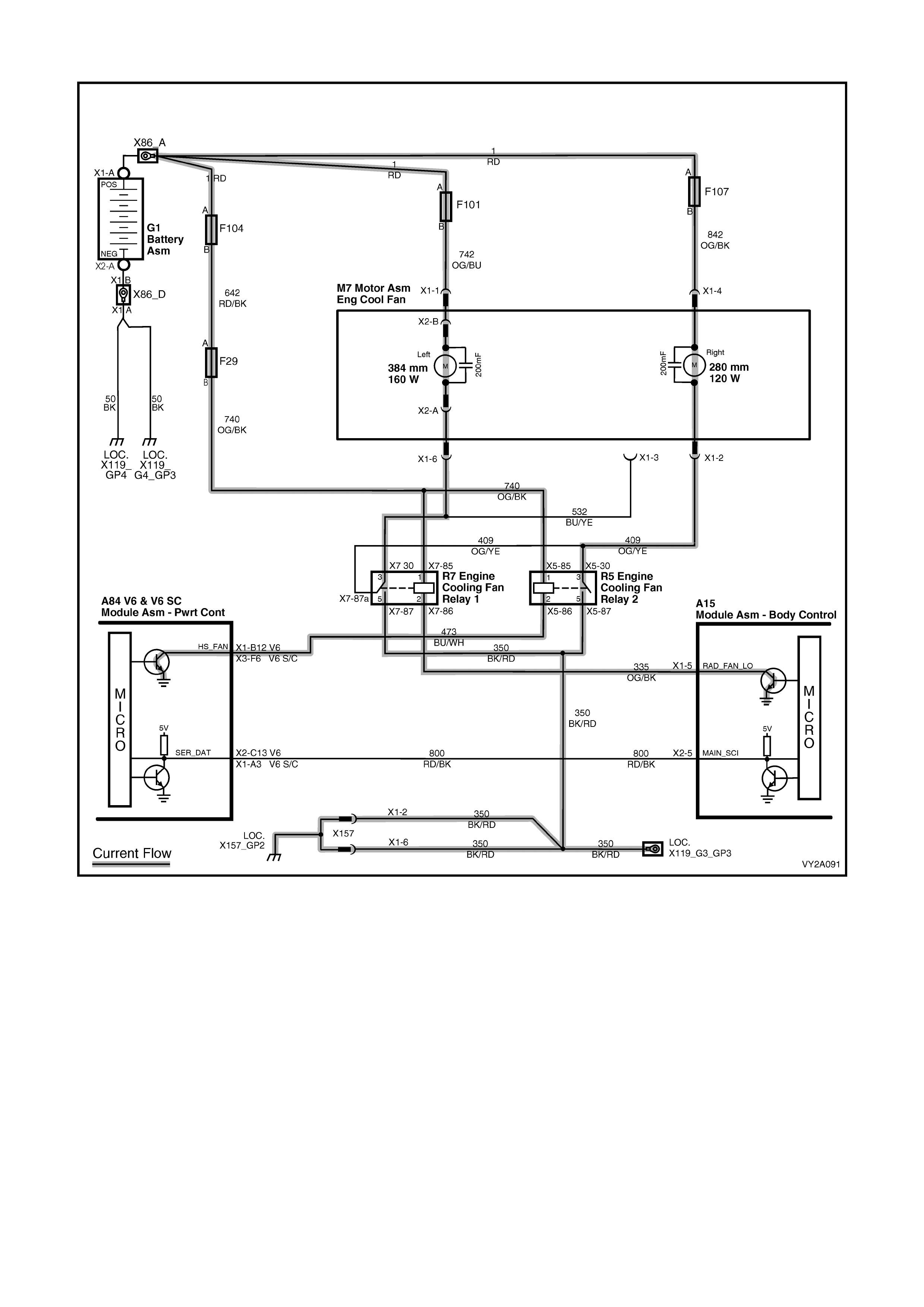
2nd Stage: Large and small diameter fans driven at maximum speed
Figure 12J-62
COOL FAN RELAY 2 – ENABLE
At the 2nd stage, the small dimeter fan activates and operates at maximum speed along with the large diameter
fan.
To initiate this function, the COOL FAN RELAY 2 will be turned on if the low speed relay has been energised for
1 second and:
• there is a BCM message response fault, setting DTC P1064 for V6, and DTC 92 for V6 supercharged.
• an engine coolant temperature sensor failure is detected by the PCM, (refer to Section 6C1, POWERTRAIN
MANAGEMENT – V6 ENGINE)
• the engine coolant temperature is above 107°C, or
• the air conditioning pressure is greater than 2000 kPa for V6 and 2600 kPa for V6 supercharged.
NOTE: If the large diam eter cooling f an is off when the criter ia for tur ning the sm all diam eter cooling fan on are f irst
met, the small diameter cooling fan will turn on 5 seconds after the large diameter cooling fan is switched on.
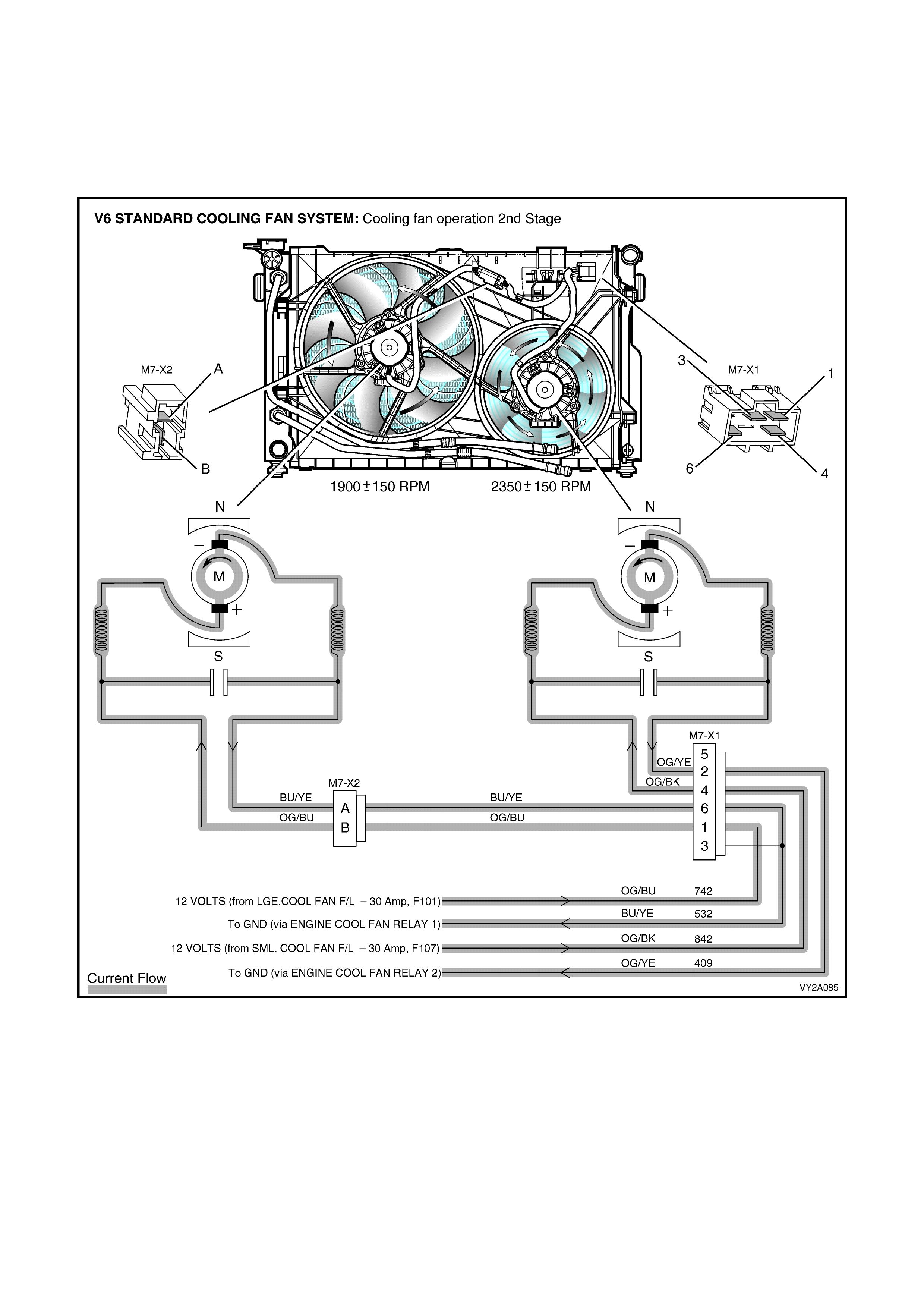
COOL FAN RELAY 2 – DISABLE
If both cooling fans are enabled, the PCM will turn the 2nd stage cooling function off (small diameter fan off) when:
• the engine coolant temperature is less than 108°C, and
• the air conditioning request is not indicated (NO), or
• the air conditioning request is indicated ( YES) and the pr essure is less than 1500 k Pa for V6 and 2300 k Pa for
V6 supercharged.
Figure 12J-63
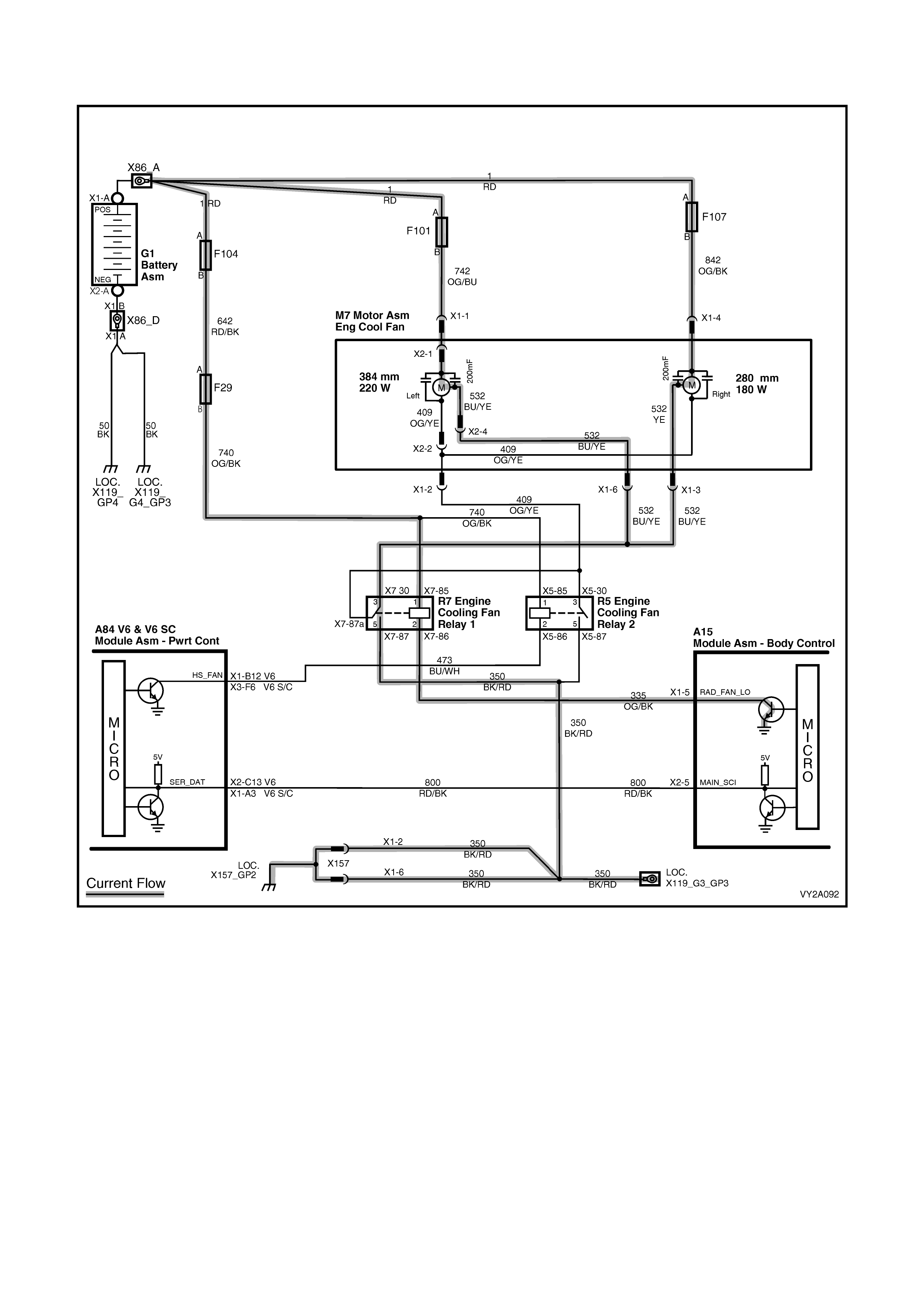
FAN OPERATION: HIGH POWER COOLING FAN SYSTEM– V6
1st Stage: Both fans driven at low speed
Figure 12J-64
The high power cooling f an system has dual-s peed cooling f an m otors a three-wire harness. Each harness has one
positive and two negative wires. The positive wire permanently supplies battery voltage to the two positive brushes
of each fan motor. The negative wires are each connected to one negative brush. When one negative wire per
motor is grounded via the COOL FAN RELAY 1, both cooling fan motors operate at low speed.
The low speed c ooling fan operation is enabled when the COOL FAN RELAY 1 is energised by the BCM. The PCM
will request low speed fan function enable and disable via serial data communication to the BCM on circuit 800
(Red/Black wire). After the PCM requests a change in the state of low speed relay (ie. off to on or on to off), the
BCM sends a message back to the PCM confirming it received the request.
The PCM determines when to enable COOL FAN RELAY 1 based on inputs from the air conditioning request
signal, Cooling Temperature Sensor and the Vehicle Speed Sensor.
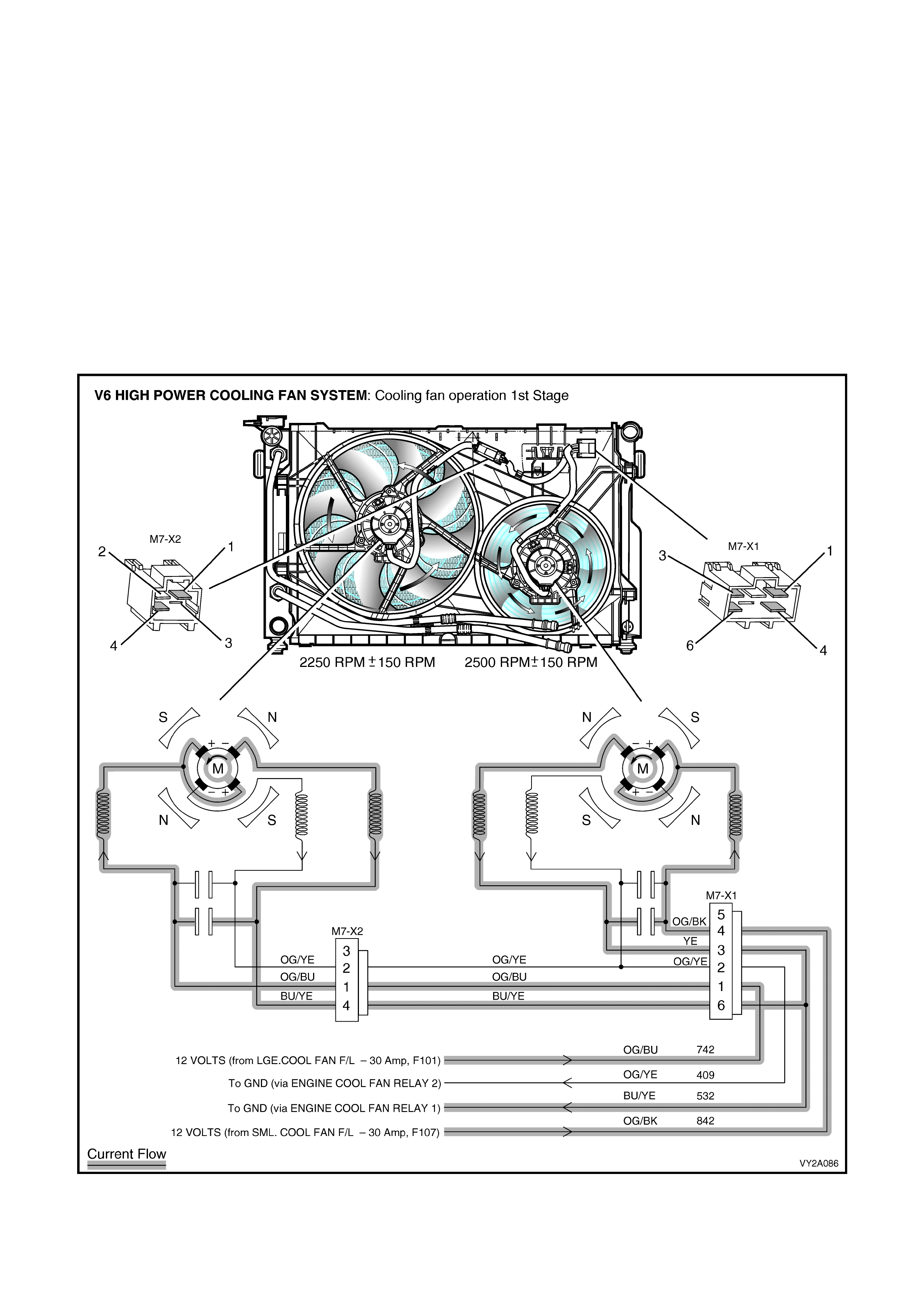
COOL FAN RELAY 1 – ENABLE
The COOL FAN RELAY 1 will be enabled w hen:
• the air conditioning request indicated (YES) and the vehicle speed is less than 30 km/h
• the air conditioning pressure is greater than 1500 kPa
• the coolant temperature is greater than 104°C
• an engine coolant temperature sensor failure is detected by the PCM (refer to Section 6C1 POWERTRAIN
MANAGEMENT – V6 ENGINE), or
• the ignition switch is turned from on to off and the engine coolant temperature is above 117°C.
The BCM will continue to energise COOL FAN RELAY 1 for four minutes.
COOL FAN RELAY 1 – DISABLE
The PCM will request the BCM to disable the COOL FAN RELAY 1 when the following conditions have been met:
• the air conditioning request not indicated (NO) and the coolant temperature is less than 99°C, or
• the air conditioning request is indicated (YES) with pressure less than 1170 kPa, vehicle speed greater than
50 km/h and coolant temperature less than 99°C.
Figure 12J-65
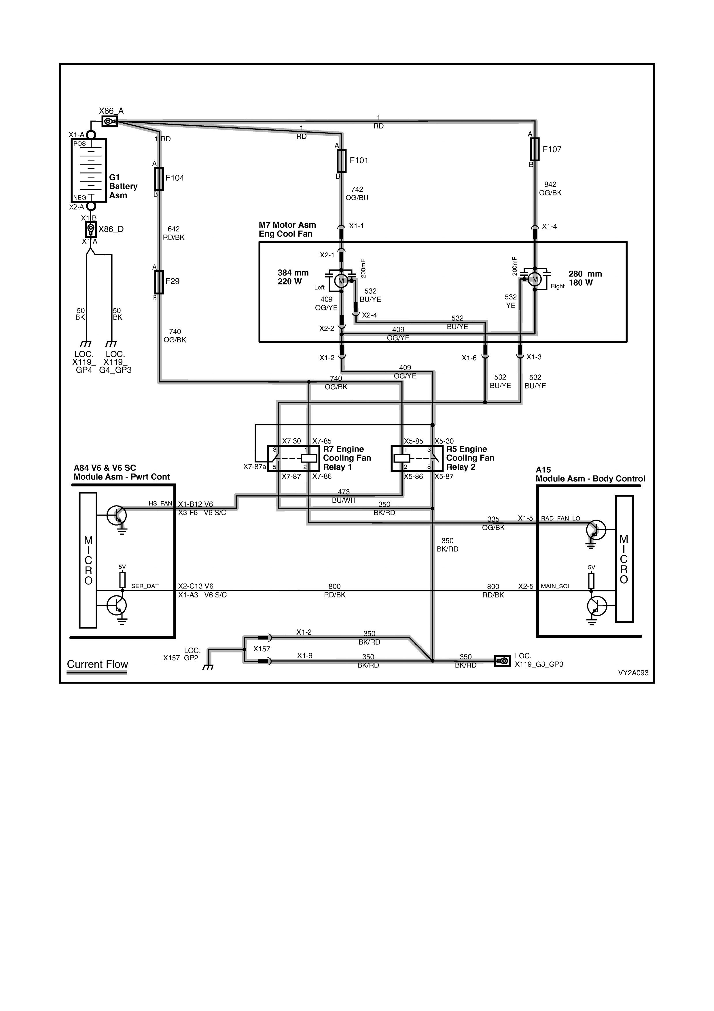
2nd Stage: Both fans driven at high speed
Figure 12J-66
W hen the sec ond negative wire ( internally connected to the s econd negative brush of each f an motor) is grounded
via the COOL FAN RELAY 2 (in the engine compartment relay housing), both high and low speed negative wires
are now grounded allowing more current to flow through the motor. Both cooling fans then operate at high speed.
COOL FAN RELAY 2 – ENABLE
The CO OL FAN RELAY 2 cooling fan relay will be enabled if the COOL FAN RELAY 1 has been energised for one
second and the following conditions have been met:
• there is a BCM message response fault, setting DTC P1064 for V6 engine
• an engine coolant temperature sensor failure is detected by the PCM, (refer to Section 6C1, POWERTRAIN
MANAGEMENT – V6 ENGINE)
• the engine coolant temperature is above 107°C, or
• the air conditioning pressure is greater than 2000 kPa.
NOTE: If the low speed (LHS) cooling fan function is off when the criteria for turning on the high speed (RHS)
cooling fan function are first met, the high speed cooling fan function will operate for an interval of 5 seconds after
the low speed cooling fan function is switched on.
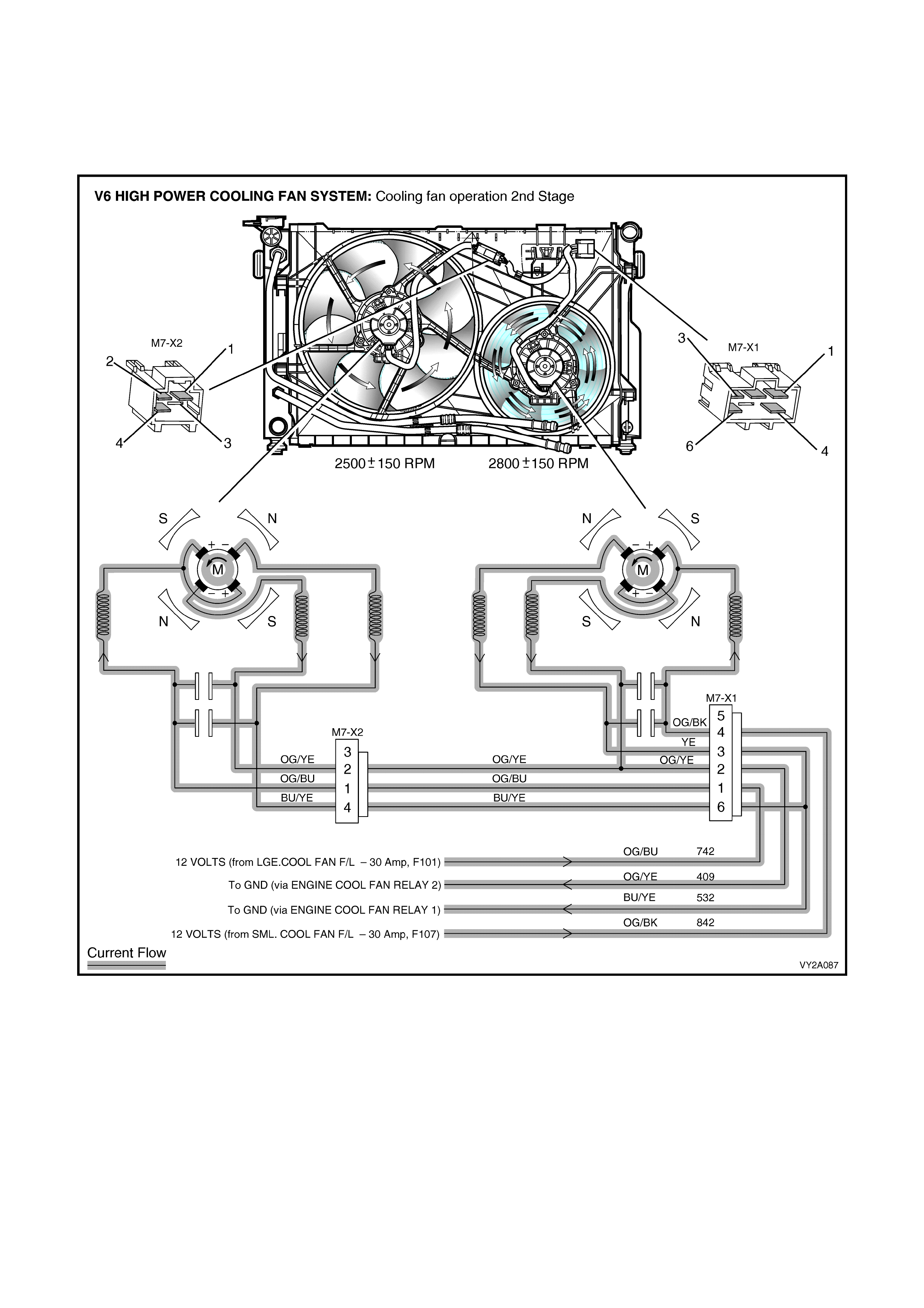
COOL FAN RELAY 2 – DISABLE
The PCM will disable the high speed cooling fan function when:
• the engine coolant temperature is less than 108°C, and
• the air conditioning request is not indicated (NO), or
• the air conditioning request is indicated (YES) and the pressure is less than 1500 kPa.
Figure 12J-67
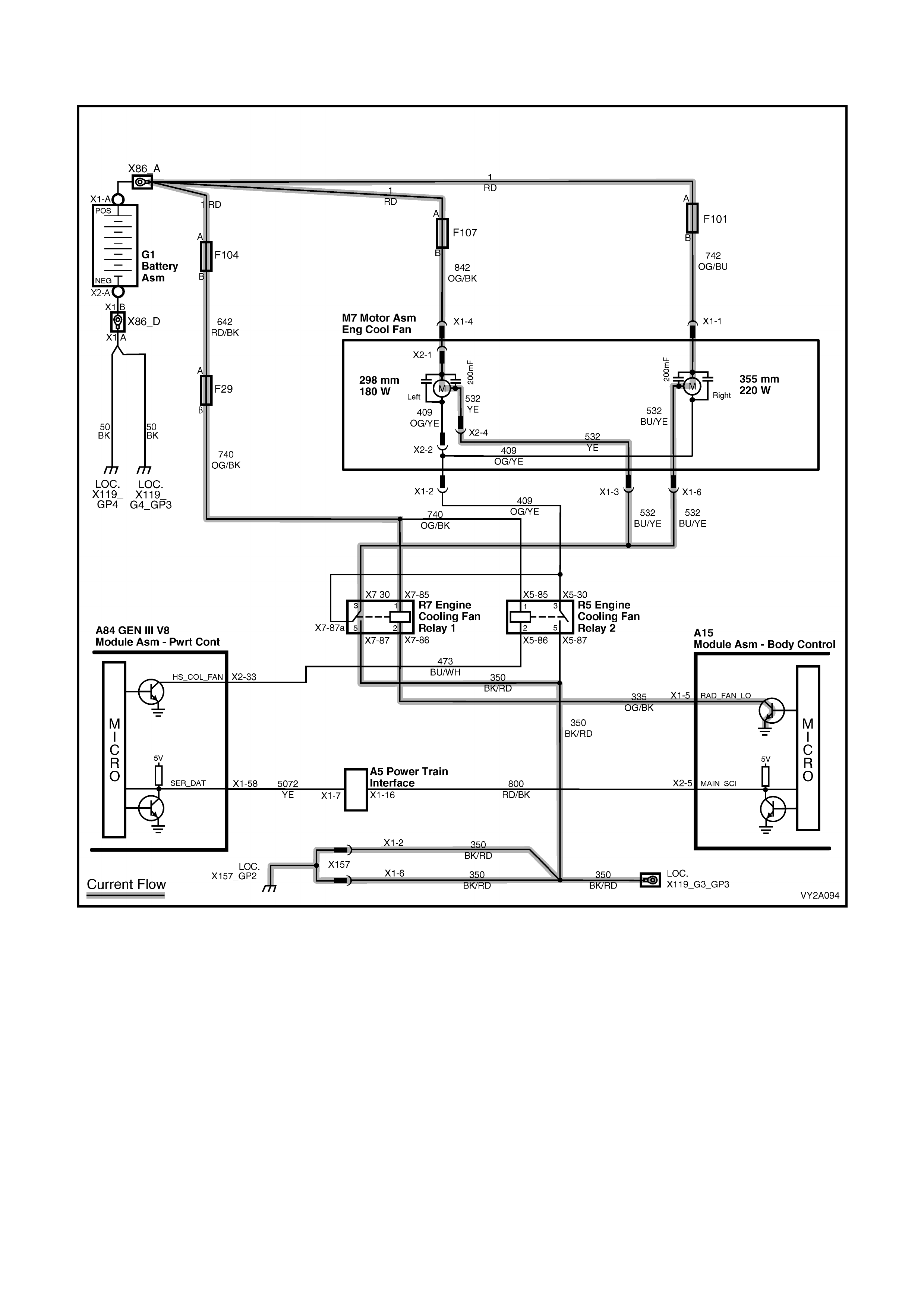
FAN OPERATION: HIGH POWER COOLING FAN SYSTEM– GEN III V8
1st Stage: Both fans driven at low speed
Figure 12J-68
On all models fitted with GEN III V8 engines, the c ooling f an motors are dual s peed with a three wire harness . Eac h
harness has one positive and two negative wires. The pos itive wire permanently supplies battery voltage to the two
positive brushes of each fan motor. The negative wires are each connected to one negative brush. When one
negative wire per motor is grounded via the COOL FAN RELAY 1 (located in the engine compartment relay
housing), both cooling fan motors operate at low speed.
The low speed cooling fan operation is enabled when the COOL FAN RELAY 1 is energised by the BCM after a
PCM request. T he PCM requests low speed f an function ‘enable’ and ‘dis able’ via serial data com m unication to the
BCM on circuit 800 (R ed / Black wire). Af ter the PCM r equests a c hange in the st ate of COOL FAN RELAY 1 (ie. off
to on or on to off), the BCM sends a message back to the PCM confirming it received the message.
NOTE: Serial data communication between the PCM and BCM is via the PIM.
The PCM determines when to enable COOL FAN RELAY 1 based on inputs from the air conditioning request
signal, Cooling Temperature Sensor and the Vehicle Speed Sensor.
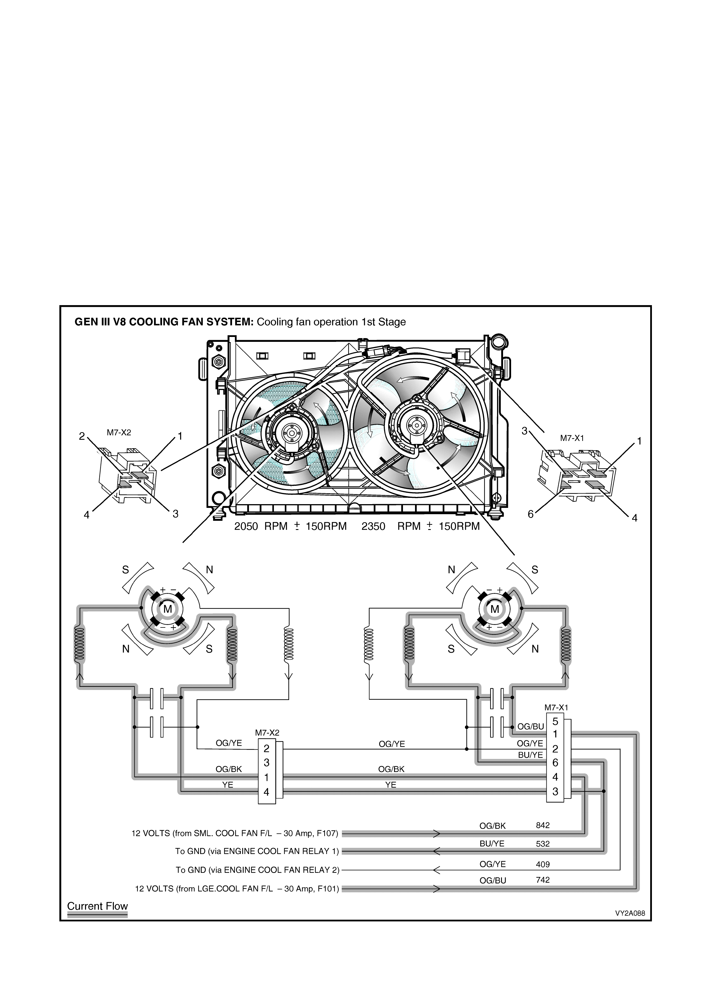
COOL FAN RELAY 1 – ENABLE
The COOL FAN RELAY 1 will be enabled w hen:
• the air conditioning request indicated (YES) and the vehicle speed is less than 30 km/h
• the air conditioning pressure is greater than 1500 kPa
• the coolant temperature is greater than 98°C
• a coolant tem perature s ensor f ailure in c onjunction with an Intak e Air T em perature s ensor f ailure is detected by
the PCM (re fer to Section 6C3, POWERTRAIN MANAGEMENT – GEN III V8 ENGINE), or
• the ignition switch is turned from on to off and the engine coolant temperature is above 113°C.
The BCM will continue to energise COOL FAN RELAY 1 for four minutes.
COOL FAN RELAY 1 – DISABLE
The PCM will request the BCM to disable the COOL FAN RELAY 1 when the following conditions have been met:
• the air conditioning request is not indicated (NO) and the coolant temperature is less than or 95°C or
• the air conditioning request is indicated (YES) with pressure less than 1170 kPa, vehicle speed greater than
50 km/h and coolant temperature less than 98°C.
NOTE: The LHS cooling fan (low speed) has a minimum run on time function of 30 seconds.
Figure 12J-69
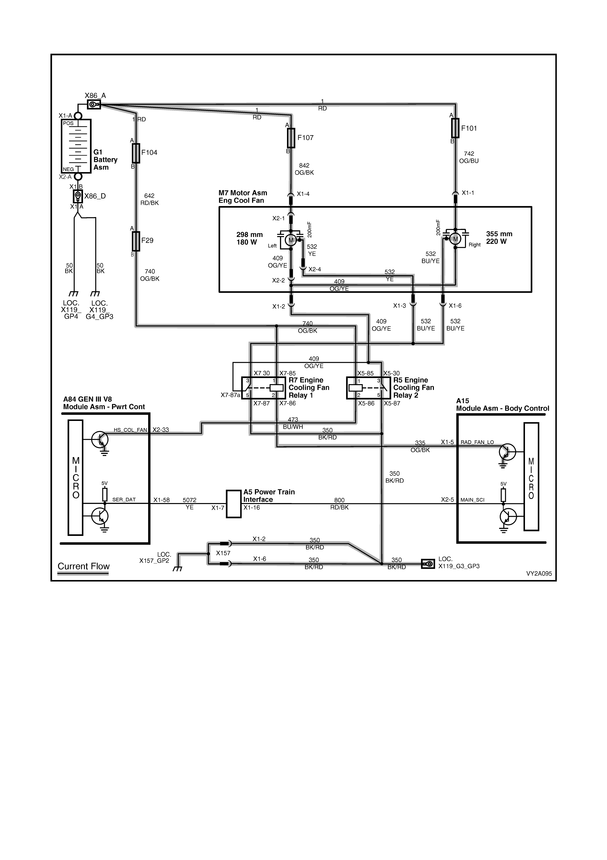
2nd Stage: Both fans driven at high speed
Figure 12J-70
W hen the sec ond negative wire ( internally connected to the s econd negative brush of each f an motor) is grounded
via the COOL FAN RELAY 2 (located in the engine compartment relay housing), both the high and low speed
negative wires are grounded, allowing current to flow through the motor. Both cooling fans then operate at high
speed.
COOL FAN RELAY 2 – ENABLE
The COOL FAN RELAY 2 cooling fan relay will be enabled if the COOL FAN RELAY 1 has been energised for
2 seconds and the following conditions have been met:
• there is a BCM message response fault, setting DTC B2002
• an engine coolant temperature sensor fault is detected and a DTC such as DTC P0117, P0118, P1114 or
P1115 is set
• the engine coolant temperature is above 108°C, or
• the air conditioning pressure is greater than 2400 kPa.
NOTE: If the low speed (LHS) cooling fan function is off when the criteria for turning on the high speed (RHS)
cooling fan function are first met, the high speed cooling fan function will operate for an interval of 5 seconds after
the low speed cooling fan function is switched on.
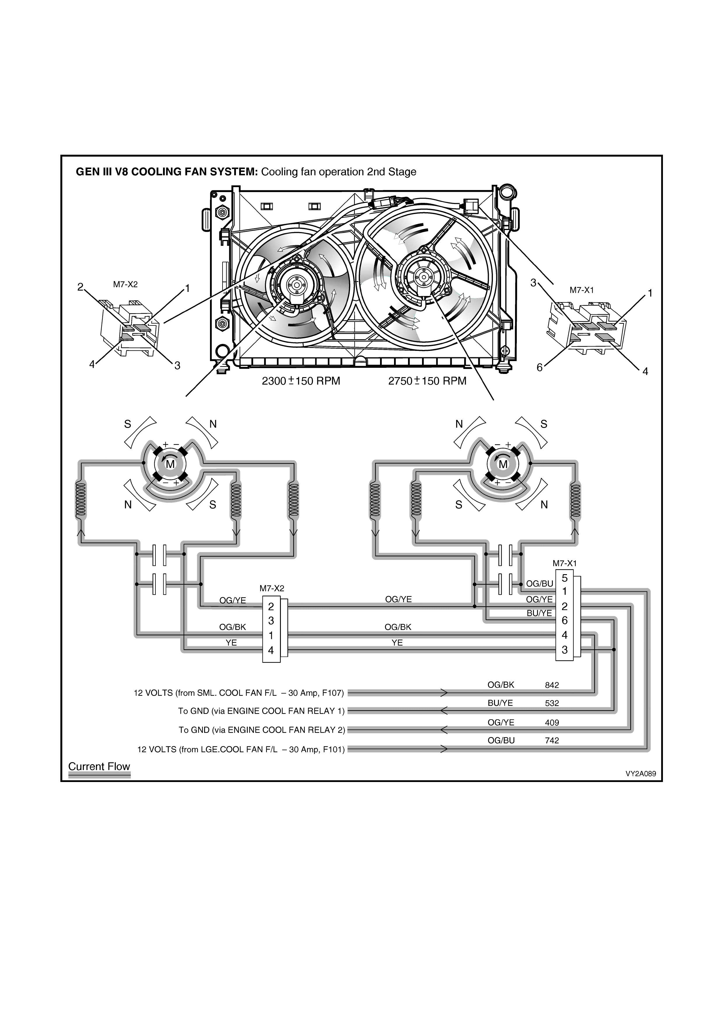
COOL FAN RELAY 2 – DISABLE
The PCM will disable the high speed cooling fan function when:
• the engine coolant temperature is less than 102°C, and
• the air conditioning request is not indicated (NO), or
• the air conditioning request is indicated (YES) and the pressure is less than 1900 kPa.
NOTE: The RHS cooling fan (high speed) has a minimum run on time function of 30 seconds.
Figure 12J-71

1.11 WIPER SYSTEM
GENERAL INFORMATION
This system controls the front intermittent wiper and the rear wiper function. The front wiper dwell on Level 2 and
Level 3 vehicles is dependent on the vehicle road speed as well as the position of the adjustable potentiometer
(located on the wiper control stalk). Within limits, the faster the vehicle speed, the shorter the dwell time.
The operation of the intermittent rear wiper is independent of the operation of the front intermittent wiper except
when the vehicle is stationary with the ignition s witch in the Acces sories position. In this s ituation, the front and r ear
intermittent wipers are synchronised. Due to a different wipe action between the front and rear wipers, the rear
wiper starts 0.25 second before the front wiper.
The rear wiper has an optional function of wiping continuously when the vehicle is in reverse gear with the rear
wiper switch turned on. This option is set using communication between the PCM and BCM via the primary serial
data bus, circuit 800.
The front and rear wipers use a 'wipe after wash' function. W hen a washer pump switch is pressed for more than
0.5 s econd, the assoc iated wipers sweep continuously, at low speed, until the washer pum p has been deactivated.
The wiper is then energised for a calculated time period to enable the wiper sweeps to be completed, as follows:
• One additional sweep if the washer switch is pressed for less than 1 second.
• Two additional sweeps if the washer switch is pressed for less than 1.5 seconds.
• Three additional sweeps if the washer switch is pressed for more than 1.5 seconds.
To perform the correct number of additional sweeps, the wiper motor park switch is monitored by the BCM via
circuit 196. This ensures that the wiper power is supplied to the park switch at the optimum time.
Refer to Section 12P, WIRING DIAGRAMS when diagnosing a circuit fault with the wiper system.
LEVEL 1 VEHICLES
On level 1 vehicles the wiper system is f itted with the Road-Speed Dependent Fixed-Dwell wiper system, noting the
following:
• Communication between the PCM and the BCM on vehicles with GEN III V8 engines is via the PIM.
• The variations in the dwell time are determined by the vehicle road speed. The faster the vehicle travels, the
shorter the dwell time. Refer to Figure 12J-72.
NOTE: The intermittent wiper relay is internal to the BCM.
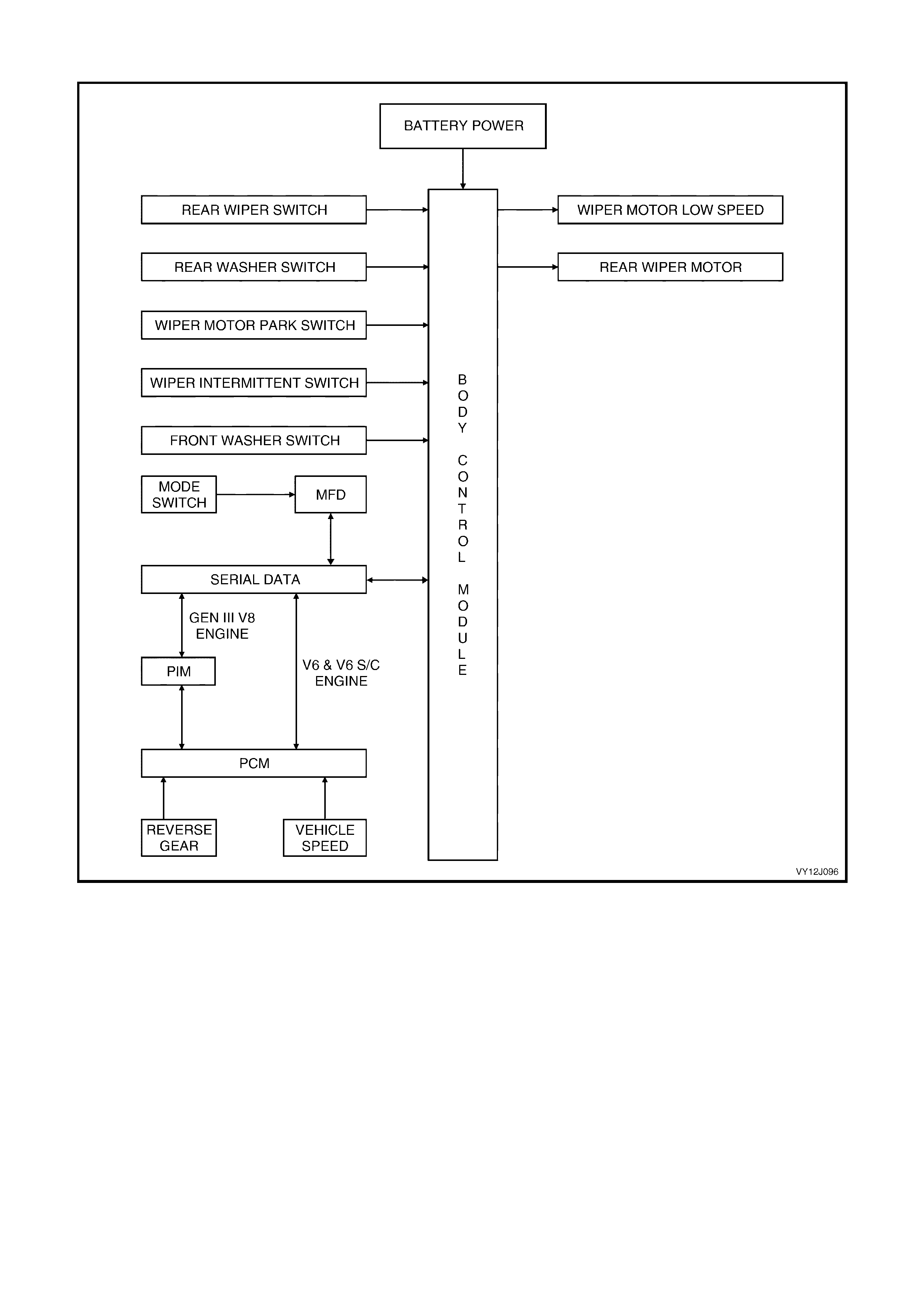
Overview
Figure 12J-72
LEVEL 2 AND LEVEL 3 VEHICLES
On Level 2 and Level 3 vehicles the wiper system is fitted with the Road-Speed Dependent Variable-Dwell wiper
system, noting the following:
• Communication between the PCM and the BCM on vehicles with GEN III V8 engines is via the PIM.
• Refer to Figure 12J-75 for circuit operation.
NOTE: The intermittent wiper relay is internal to the BCM.
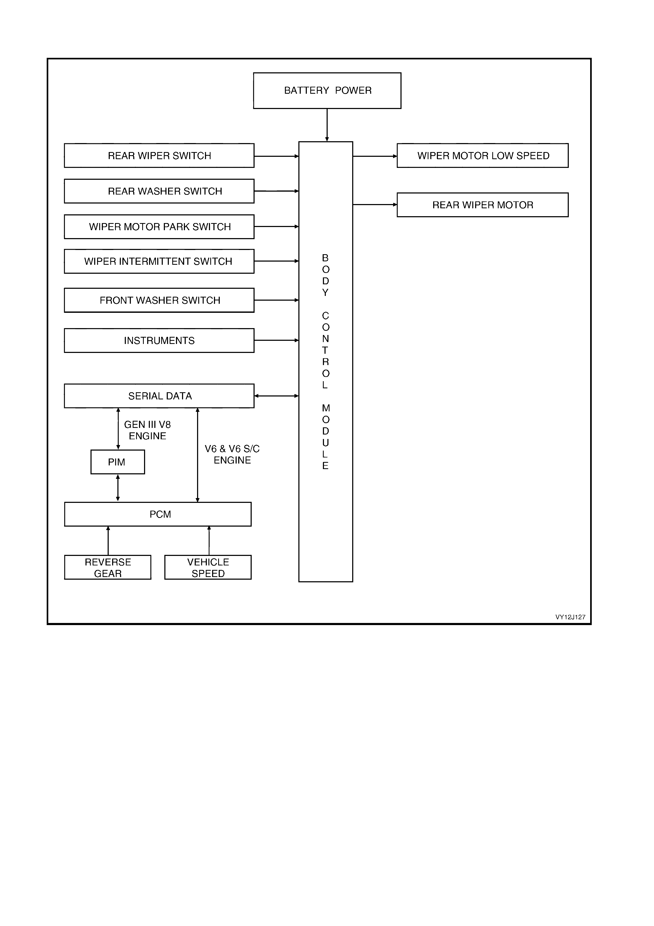
Overview
Figure 12J-73
Inputs
INTERMITTENT WIPER SWITCH
Placing the wiper / washer s witch in the INT pos ition applies battery voltage to BCM term inal X3-3, c ircuit 112 (Blue
/ White wire) via:
• fusible link F105
• accessory control relay contacts
• fuse F18
• circuit 243 (Brown / White wire), and
• the wiper washer switch INT contacts.

Battery voltage at BCM terminal X3-3 is seen by the BCM as the intermittent wiper input signal and triggers the
BCM to energise the f ront wiper relay within the BCM. T his applies battery voltage f rom fus e F18 and BCM term inal
X1-2, to the wiper motor low speed circuit via:
• BCM terminal X1-12
• circuit 96 (Light-green wire)
• wiper switch ‘intermittent’ terminals, and
• circuit 95 (Grey / Red wire).
This voltage supply causes the wiper motor armature to rotate, which changes the wiper motor park switch from
contacts A - B to contacts A - C. Refer to Figure 12J-75. Voltage from fuse F18 is now applied through contacts
A - C and circuit 196 (Yellow wire) to BCM terminal X1-1. Once the wiper motor park switch enter the 'parked'
region, the park switch contacts change back to A - B which changes the input at BCM terminal X1-1 to ground
through circ uit 196 (Yellow wire), the park switch contacts A - B and circuit 550 (Black / White wire). T he voltage at
BCM terminal X1-1 is now less than 0.2 volt, which is seen by the BCM as the park switch, input signal and the
BCM turns off the intermittent wiper relay to stop the wiper motor.
WIPER DWELL CONTROL SWITCH
BCM terminal X2-4 is connected to ground through the wiper dwell-control switch, circuit 477 (Grey / Black wire)
and circuit 251 (Black / Yellow wire). Refer to Figure 12J-75. Adjusting the switch from slow to fast causes the
potentiometer (variable resistor) inside the switch to var y in res istance, which changes the voltage at BCM ter minal
X2-4 within a range of approximately 0.6 to 2.5 volts. As the voltage increases, the dwell time decreases.
NOTE: If the battery is disconnec ted then connected, it is necess ary for the dwell potentiom eter to be rotated fr om
one extreme to the other to enable the BCM to re-learn the range values and properly calculate the dwell values.
VEHICLE SPEED AND REVERSE GEAR
BCM term inal X2- 5 receives vehicle speed inf orm ation f rom the PCM via the ser ial communic ations bus, circuit 800
(Red / Black wire). Refer to Figure 12J-74. TECH 2 can be used to view the vehicle speed via the diagnostic
connector.
Terminal X2-5 also receives data from the PCM relating to the selection of reverse gear, via the serial data bus,
circuit 800 (Red / Black wire).
WINDOW WASHER SWITCH
W hen the washer pump s witch is activated, battery voltage is applied to the washer pum p (M19) term inal X1-1 and
BCM terminal X3-13, via fuse F18, circuit 243 (Brown / White wire) and the washer switch contacts, circuit 228
(Light-blue wire). Ref er to Figure 12J -74. T his c auses the voltage at BCM ter minal X3- 13 to incr eas e f r om less than
0.2 volt to 12 volts, which is s een by the BCM as the washer switch input signal. The length of tim e that this voltage
is present at BCM terminal X3-13 determines the number of additional wiper sweeps.
The BCM determines the number of completed wiper sweeps by monitoring the voltage at terminal X1-1, park
switch input; the voltage at terminal X1-1 changes from 12 volts to less than 0.2 volt at the completion of each
sweep.
REAR WIPER SWITCH
Placing the wiper washer switch in the rear wipe position causes battery voltage, via fusible link F105, the ignition
switch c ontacts, f use F18, circuit 243 (Brown / W hite wire) and the wiper washer switch r ear contacts to be applied
to BCM terminal X3-7, circuit 391 (Grey / Red wire). Refer to Figure 12J-74. This voltage at X3-7 is seen by the
BCM as the rear wiper input signal.
REAR WASHER SWITCH
When the r ear washer pum p switch is activated, battery voltage is applied to the washer pum p (M19) ter m inal X1-2
and BCM term inal X3-14 via fuse F 18, circuit 243 (Brown / W hite wire) and the washer switch c ontacts, circuit 227
(White / Blue wire). Refer to Figure 12J-74. This causes the voltage at BCM terminal X3-14 to increase from less
than 0.2 volt to 12 volts, which is seen by the BCM as the rear washer switch input signal.
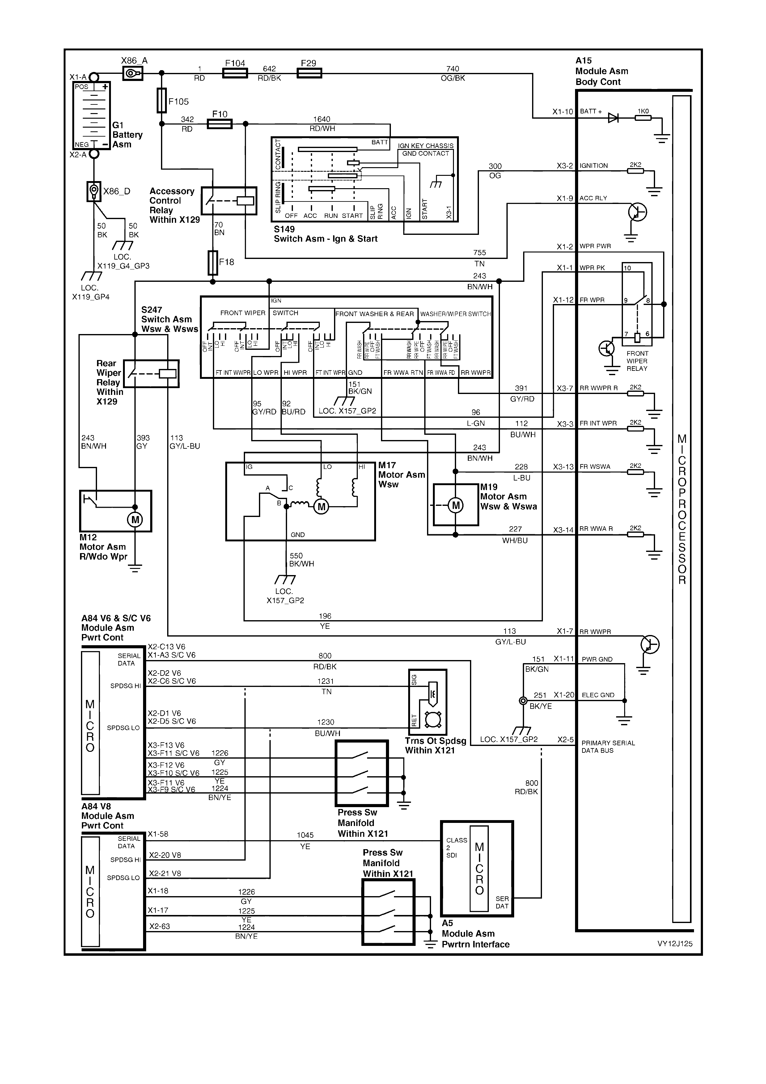
Figure 12J-74
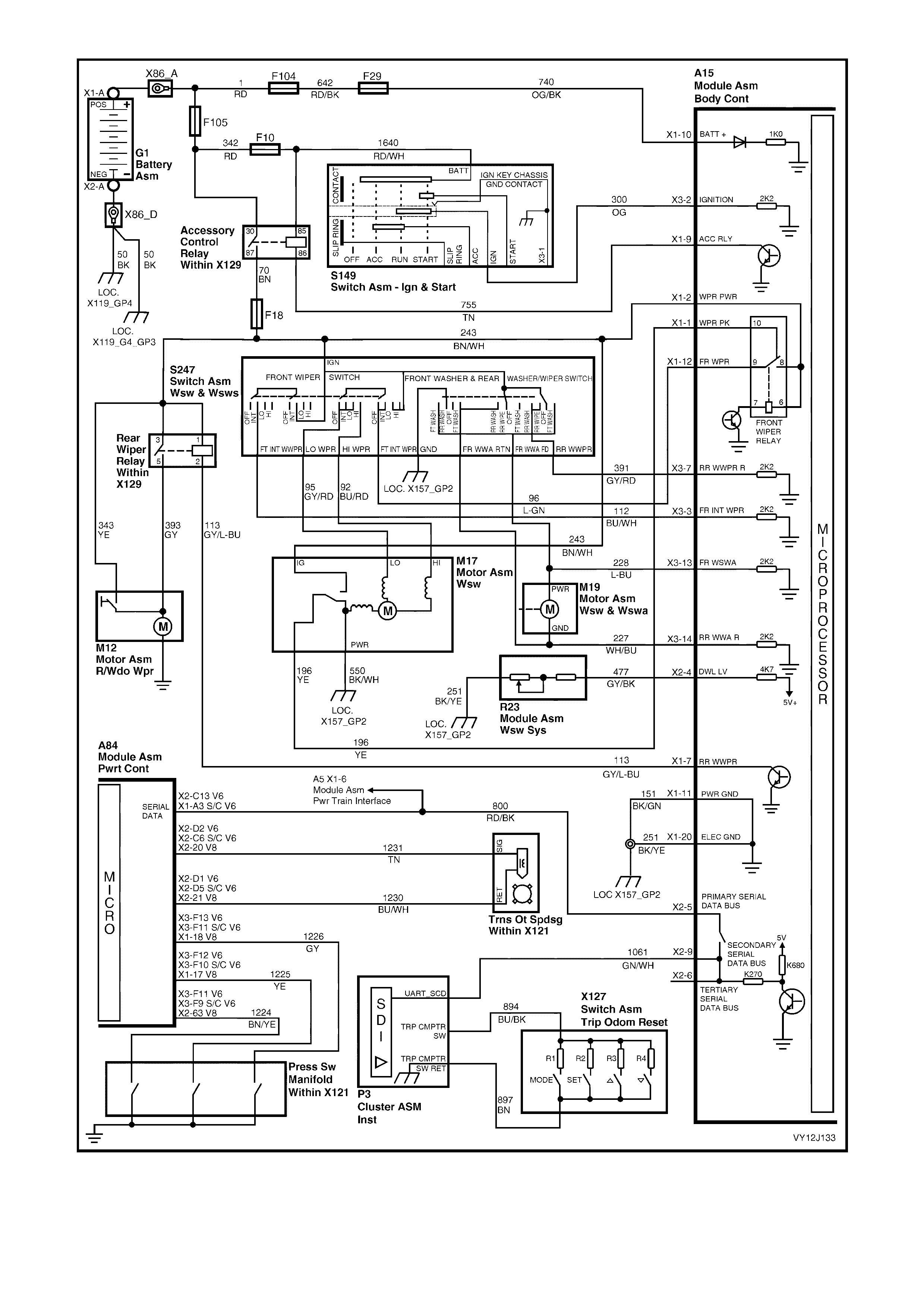
Figure 12J-75
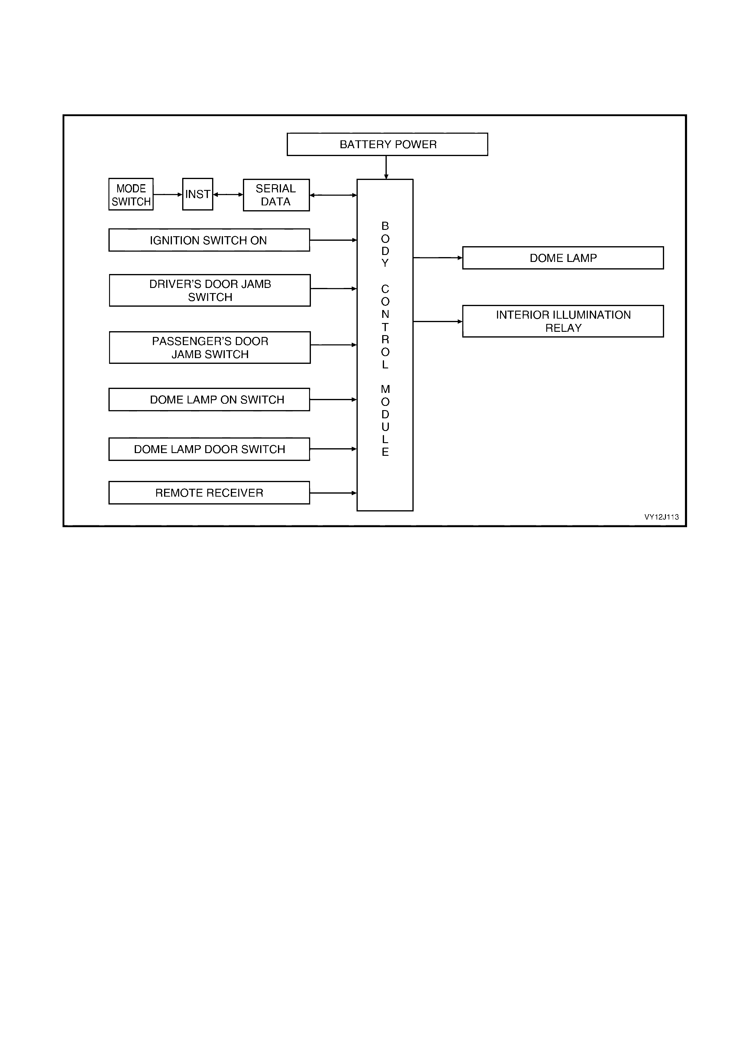
1.12 DOME LAMP DELAY CONTROL
SYSTEM OPERATION
Overview — Level 2 and Level 3 Vehicles
Figure 12J-76
CIRCUIT OPERATION
The interior lighting operates for a 30 second period after an open door is closed; the ignition is switched from the
on position to either the accessory or off position, or with the operation of central door unlocking (night only).
Battery voltage is applied to all interior lights via fuse F6, circuit 1140 (Orange wire), the interior illumination relay
(controlled by the BCM battery saver mode) and circuit 149 (Orange / Black wire). Refer to Figure 12J-77. The
opposite side of the dome lamps are connected to ground via circuit 660 (W hite / Green wire) and BCM terminal
X4-22. The BCM c ontrols the oper ation of thes e dom e lam ps by switching the internal dom e lam p relay. Energising
the relay closes the relay contacts, which complete the circuit to ground.
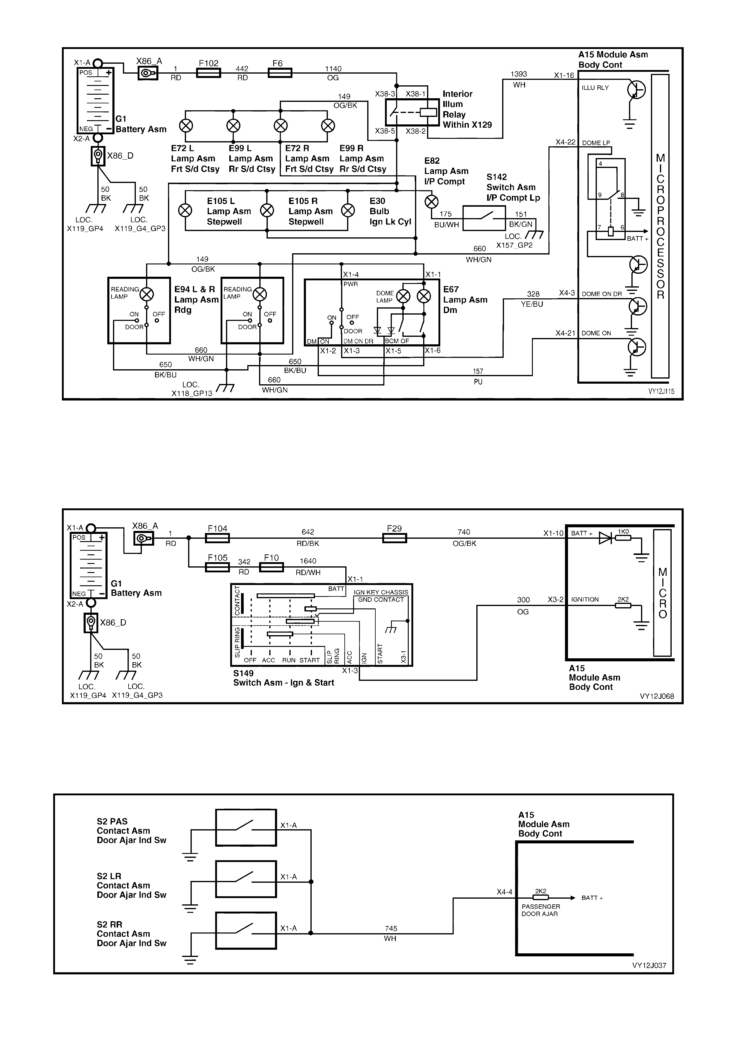
Figure 12J-77
Inputs
IGNITION SWITCH ON
The BCM us es this input signal to deter mine when the ignition switch is in the on or s tar t pos ition. When the ignition
switch is in the on or start position, battery voltage is applied to the BCM terminal X3-2 from the ignition switch via
circuit 300 (Orange wire). Refer to Figure 12J-78.
Figure 12J-78
PASSENGER DOOR OPEN
When any passenger door is opened, BCM terminal X4-4 is connected to ground via circuit 745 (W hite wire) and
the passenger doorjamb switch. Refer to Figure 12J-79. This causes the voltage at terminal X4-4 to be pulled to
less than 0.2 volt, which is seen by the BCM as the passenger door open input signal.
Figure 12J-79
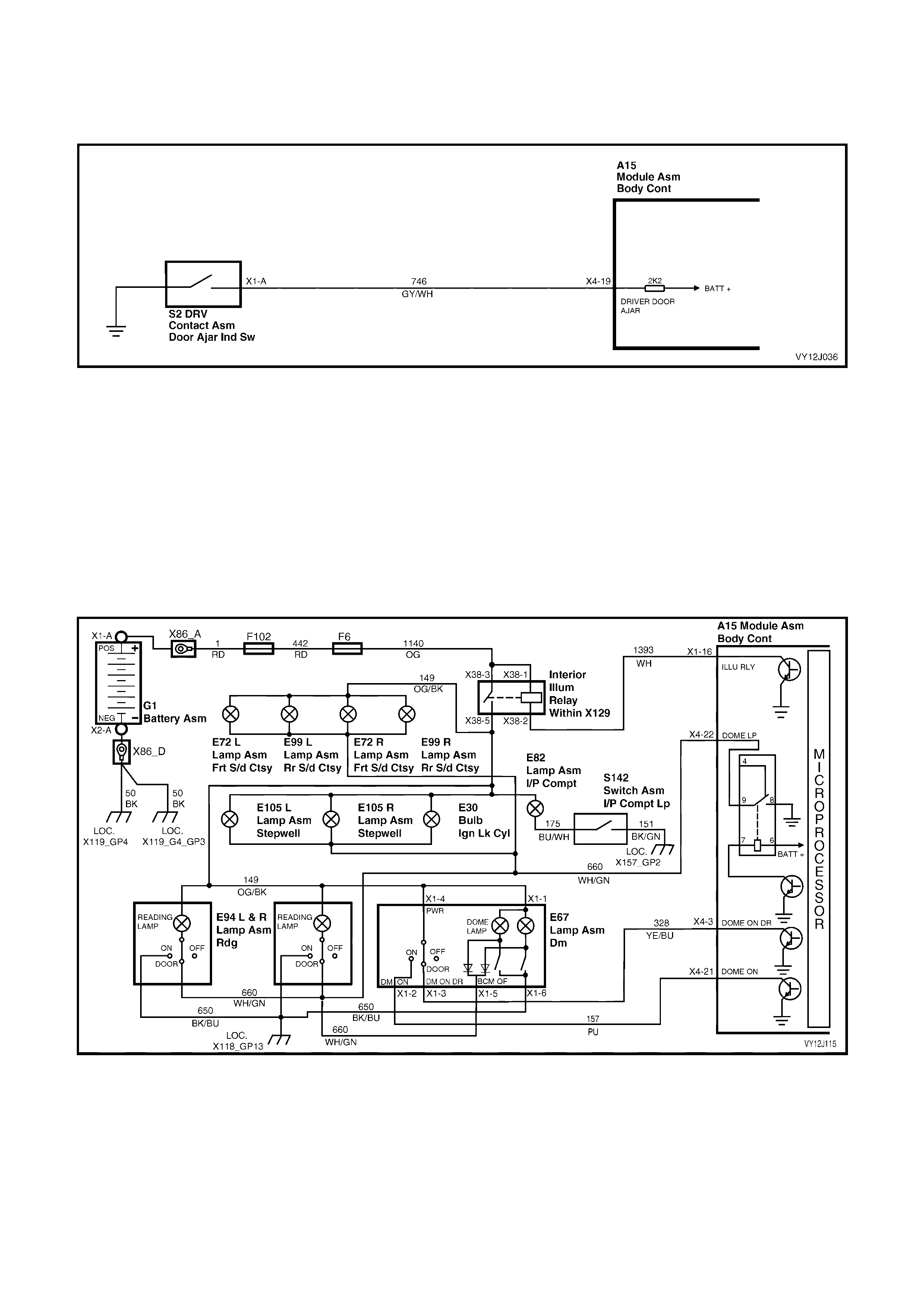
DRIVER’S DOOR OPEN
W hen the driver’s door is opened, BCM terminal X4-19 is connected to ground via circuit 746 (Grey / White wire)
and the driver’s doorjamb switch. Refer to Figure 12J-80. This changes the voltage at terminal X4-19 to less than
0.2 volt, which is seen by the BCM as the driver's door input signal.
Figure 12J-80
DOME LAMP
DOME ON SIGNAL — LEVELS 2 AND 3 VEHICLES
W hen the dome lamp switch is in the ON position, battery voltage is applied to BCM terminal X4-21 from fuse F6
via circ uit 1140 ( O range wire), the inter ior illumination relay, circuit 149 (O r ange / Black wire), the dome lamp switch
contacts and circ uit 157 (Pur ple wire). Ref er to F igure 12J -81. Batter y voltage at BCM terminal X 4- 21 is s een by the
BCM as the dome lamp switch on input signal.
DOME DOOR SIGNAL — LEVELS 2 AND 3 VEHICLES
When the dome lamp switch is positioned in the DOOR position, battery voltage is applied to BCM terminal X4-3
from fuse F6 via circuit 1140 (Orange wire), the interior illumination relay, circuit 149 (Orange / Black wire), dome
lamp switch contacts, and circuit 328 (Yellow / Blue wire). Refer to Figure 12J-81. Battery voltage at terminal X4-3 is
seen by the BCM as the dome lamp door input signal.
Figure 12J-81
DOME ON SIGNAL — LEVEL 1 VEHICLES
When the dome lamp switch is in the ON position, battery voltage is applied to ground via circuit 1140 (Orange
wire), the interior illum ination relay, circuit 149 (Or ange / Black wire), the dome lam p switch contacts and circuit 650
(Black / Blue wire). Refer to Figure 12J-82. T he ignition lock cylinder lamp is on the s ame c ircuit as the dom e lam p
and illuminates in conjunction with the dome lamp.
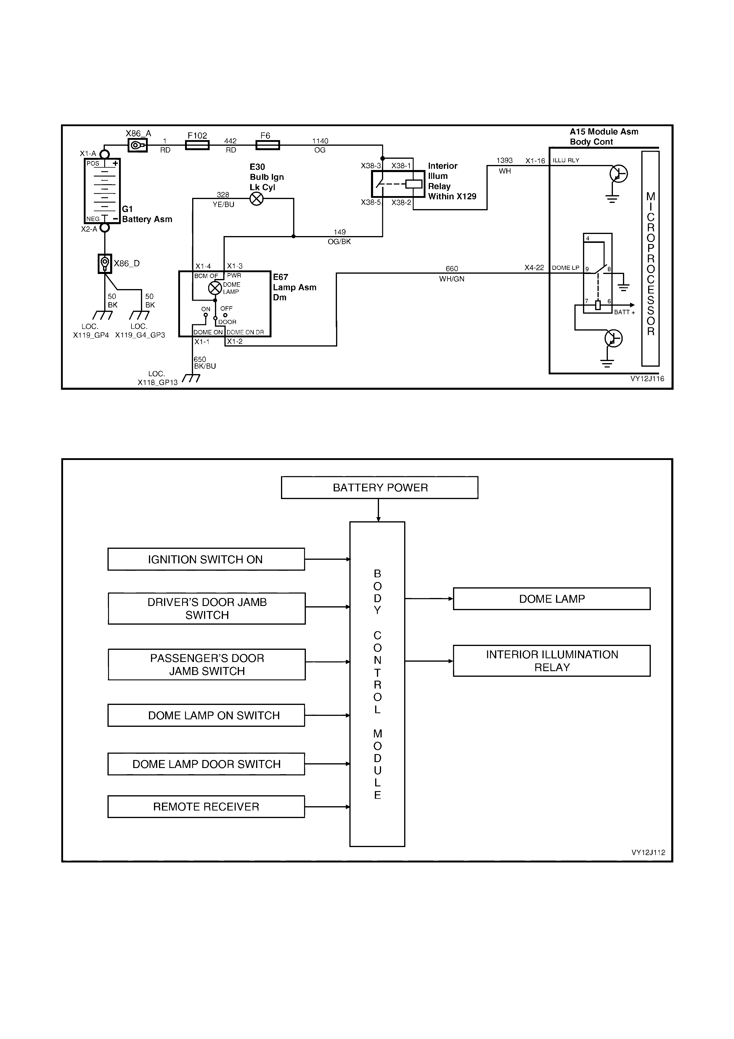
DOME DOOR SIGNAL — LEVEL 1 VEHICLES
W hen the dom e lamp switch is positioned in the DOOR position, battery voltage is applied to BCM terminal X4-22
from fuse F6 via circuit 1140 (Orange wire), the interior illumination relay, circuit 149 (Orange / Black wire), dome
lamp switch contacts, and circuit 660 (White / Green wire). Refer to Figure 12J-82. Battery voltage at terminal X4-22
is seen by the BCM as the dome lamp door input signal.
Figure 12J-82
SYSTEM OPERATION
Overview — Level 1 Vehicles
Figure 12J-83
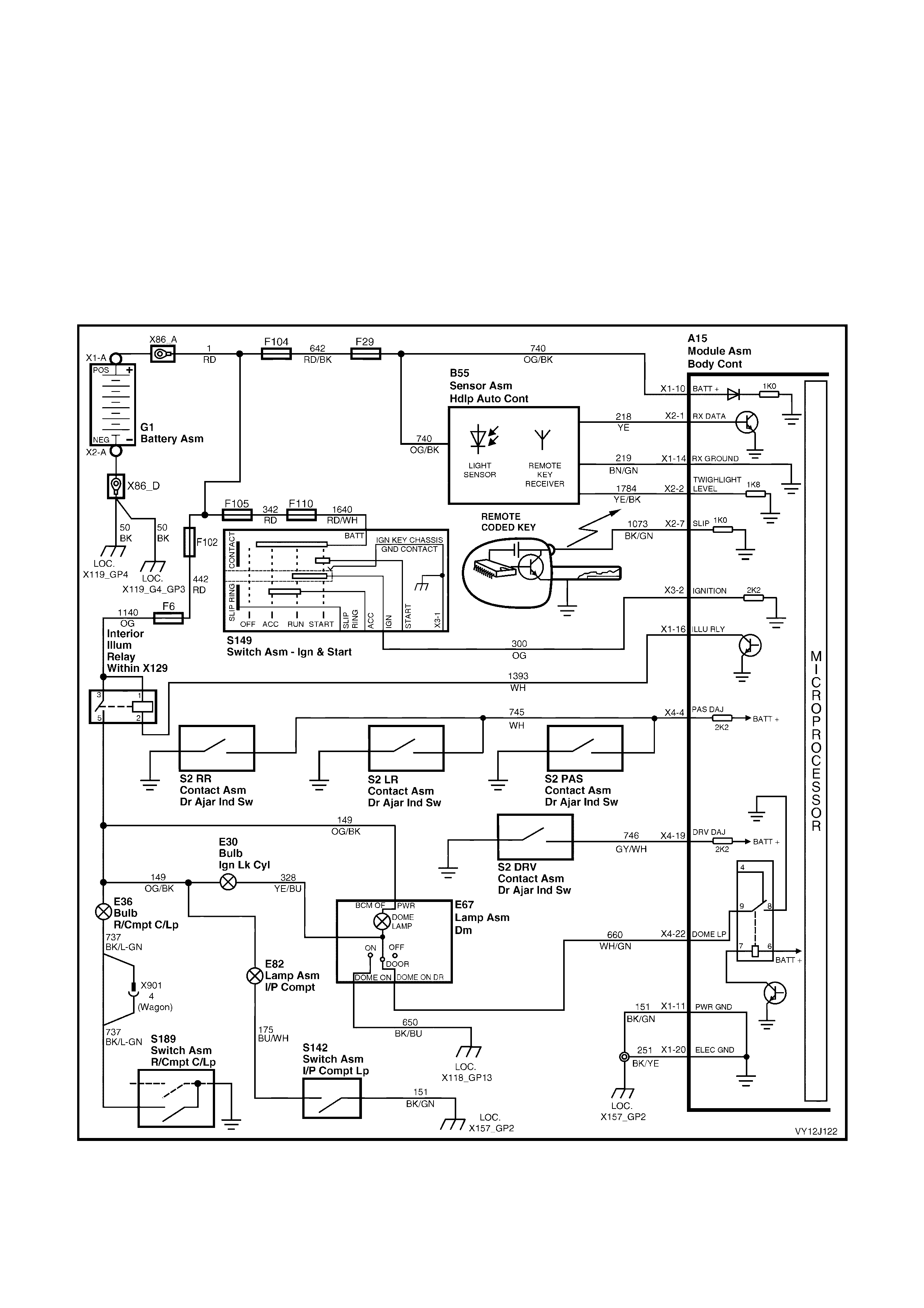
CIRCUIT OPERATION
Battery voltage is applied to all interior lam ps via fuse F6, circuit 1140 (Orange wire), the interior illumination relay
and circuit 149 (Orange / Black wire).
For Level 1 vehicles, when the dome lamp is switched to ON, the opposite side of the dom e lamp is connected to
ground via circuit 650 (Black / Blue wire). Refer to Figure 12J-84. W hen the dom e lamp is switched to DOOR, the
opposite side of the dome lamp is connected to ground via circuit 660 (White / Green wire) and BCM terminal
X4-22. The BCM controls the operation of the dome lamp by switching the internal dome lamp relay contacts to
close, completing the circuit to ground.
For Level 2 and 3 vehicles, the opposite side of the dome lamps is connected to ground via circuit 660
(W hite / Green wire) and BCM term inal X4-22. Refer to Figure 12J-85. However, when the dome lam p is switched
to ON, the opposite side of the dome lam p is connected to ground via circuit 157 (Purple wire) and BCM terminal
X4-21. W hen the dom e lam p is switched to DO OR, the opposite side of the dome lam p is c onnected to ground via
circuit 328 (Yellow / Blue wire) and BCM terminal X4-3.
Figure 12J-84
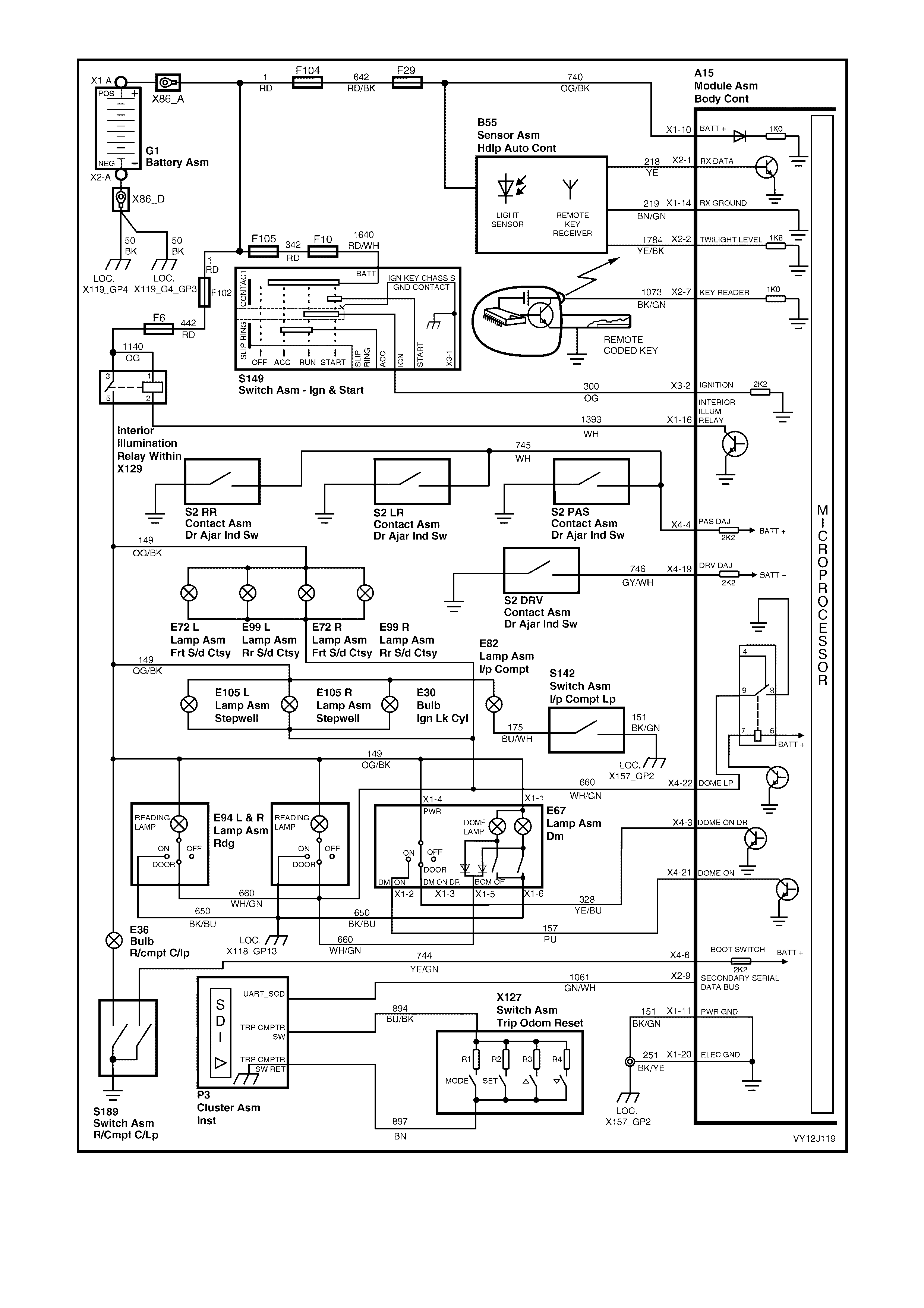
Figure 12J-85

1.13 AUTOMATIC LAMP CONTROL
SYSTEM OPERATION
This system includes the following features:
• automatic lights on
• automatic lights off
• approach illumination.
Automatic Lights On
The automatic lights on and off contr ol with twilight sentinel, turns the vehicle headlamps on and of f, depending on
the outside light level. This feature work s only while the headlamp switch is in the AUT O position and the ignition is
on. The lights operate as normal in other switch positions.
W hen the headlam p switch is in the AUT O position and the ignition is switched of f, the operation of the headlamps
is the same as the AUTO lights off operation.
LIGHT LEVEL ON / OFF ADJUSTMENT
A light (sun) sensor is m ounted in the instrument panel pad of the vehicle to m onitor the amount of light in front of
the vehicle. The BCM monitors the output of this sensor and determines when the light levels are low enough to turn
the headlights on. TECH 2 can be used to select several different ON / OFF light levels to suit customer
preferences. The light levels can also be adjusted by the customer to Early / Normal / Late modes via the
instrument cluster MFD, using the trip computer switch (refer to Section 12C, INSTRUMENTS).
Automatic Lights Off
The autom atic lights of f f eature autom atically switches the headlam ps and par k lam ps off after the driver leaves the
vehicle.
NOTE: Since this s ystem is s afety related, it is m andatory that the BCM light control outputs default to the O N state
in the event of a system f ailur e, when the ignition switch is in the on pos ition. T his gives direc t c ontr ol of the lights to
the headlamp switch.
ACTIVATION
The sequence of events required to switch the lights off automatically are as follows:
1. The vehicle r oad speed input to the BCM is les s than 10 km /h and there has not been a sudden loss of speed
(ignition being switched off with the vehicle travelling above 10 km/h).
2. The BCM senses that the ignition switch is turned from the on position to the accessory or off position and
remains in the accessory or off position.
3. The headlamp switch has not been turned on after the ignition switch was turned off.
4. The BCM senses that the driver's door is open.
When the ignition switch is turned bac k to the on pos ition, the lights rever t to the position selec ted by the headlamp
switch and the mode of headlamp operation (ie. high beam, low beam or fog lamps). This is determined by the
position of the relevant switches.
LIGHTS OFF DELAY
There is a delay period before the automatic lights of f feature turns of f the vehicle lights. This tim e period can be set
via the instrument cluster MFD, using the trip computer switch. Refer to Section 12C, INSTRUMENTS. The delay
period can be set for the Priority 1 and Priority 2 keys. The time delay is recalled when the unlock button on the
remote is pressed and a Priority 1 or a Priority 2 key is used.
A maximum of 180 seconds can be set, with the default setting of 1 second.
The delay period adjustment is possible only when road speed input to the BCM is zero and is dependent on the
priority key system.
NOTE: The c irc uit diagrams shown in this s ec tion ar e to aid in interpr eting the operation of the c ir cuit and ther ef or e,
only the main connectors and wiring colours are shown. For complete circuit details, refer to either the relevant
diagnostic section or Section 12P, WIRING DIAGRAMS.
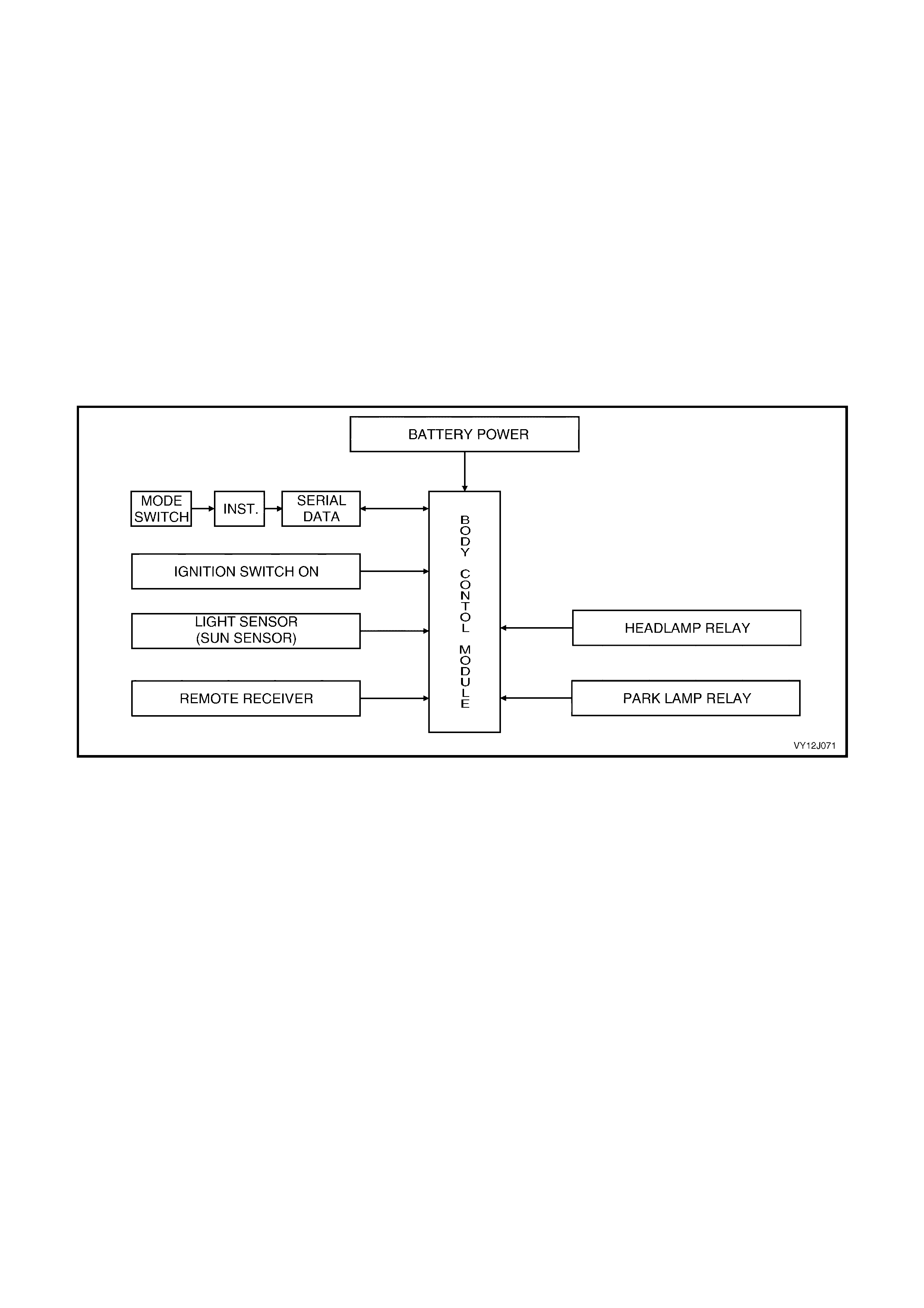
DEACTIVATION
Turning the headlamp switch to OFF deactivates the automatic lights system.
Approach Illumination
The approac h illum ination featur e in the BCM turns on the headlam ps and / or park lam ps for 30 seconds when the
doors are unlocked with the remote coded key.
This provides additional cust omer s ecurity when appr oaching the vehicle at night. The lights will turn off again if the
vehicle is locked with the remote coded key within 30 seconds of the approach illumination being activated.
When the approach f eature is ac tivated, s ubsequent oper ation of the r emote coded key unlock button will reactivate
the lights to remain on for a further 30 seconds.
The approach illumination feature only operates during dark conditions. The BCM monitors the output of the sun
sensor and determines when the light levels are low enough to enable the approach illumination feature.
The lights resume normal operation when the ignition is switched to the on position.
The customer can enable or disable the approach illumination via the instrument cluster MFD, using the trip
computer switch (refer t o Section 12C, INSTRUMENTS).
SYSTEM OVERVIEW
Automatic Lights On
Figure 12J-86
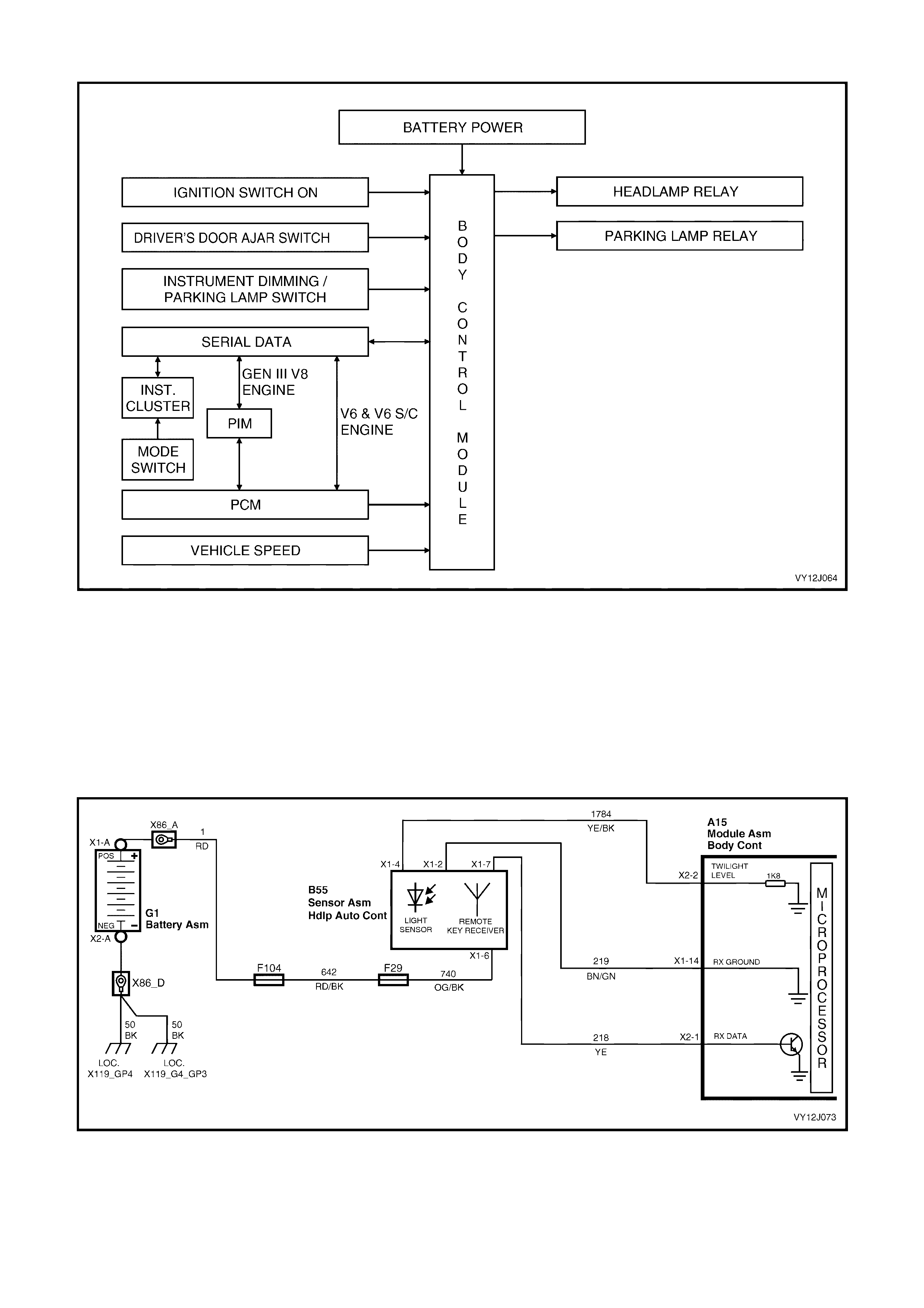
Automatic Lights Off
Figure 12J-87
CIRCUIT OPERATION
Automatic Lights On – Inputs
LIGHT SENSOR CONTROL / REMOTE CODED KEY
The light sensor produces a voltage proportional to the amount of ambient light. This voltage can vary between 0
volt and 5 volts. T he BCM m onitors the voltage on ter m inal X2-2, c ircuit 1784 (Yellow / Black wire) to determ ine the
light level. TECH 2 should be used to measure the performance of the light sensor. Refer to Figure 12J-88,
The BCM m onitors the input at ter minal X 2-1, circuit 218 (Yellow wire) to determine when the un-loc k button on the
remote coded key has been pressed.
Figure 12J-88

IGNITION SWITCH ON
The BCM us es this input s ignal to determine when the ignition switch is the on pos ition or the of f position. When the
ignition switch is in the on or s tart position, battery voltage is applied to BCM terminal X 3-2 from the ignition switch
via circuit 300 (Orange wire). Refer to Figure 12J-89.
Figure 12J-89
Automatic Lights On – Power Supplies
Battery voltage is applied to the low and high beam relays from fusible link F102, circuit 442 (Red wire) and fuses
F30 and F31. Refer to Figure 12J-95.
Battery voltage is applied to the park lam p relay f rom f usible link F102, circuit 2 (Red wir e) and fus e F4, circ uit 840
(Orange / White wire).
The BCM controls the operation of the exterior lights by switching the internal ground circuits for the relays. If the
ambient light level is low, or the approach illum ination has been activated, the BCM energises the ground circuits,
turning the lights on. If the ambient light level is high, the BCM open the ground circuit, turning the lights off.
Automatic Lights On – Ground Circuits
HIGH BEAM RELAY GROUND CIRCUIT
The ground circuit for the high beam headlamp relay is via circuit 1969 (Blue / Yellow wire), through the headlamp
and turn signal control switch assem bly, circuit 10 (W hite / Black wire) and through the headlamp switch contacts.
Refer to Figure 12J-95. From the headlamp switch contacts, it passes through BCM terminal X1-6, circuit 103
(W hite / Red wire) or to BCM terminal X 2–3, circuit 44 (W hite wire) and then to ground thr ough the internal control
circuit.
LOW BEAM RELAY GROUND CIRCUIT
For Level 1 vehicles , the ground c irc uit f or the low beam headlamp relay is via circuit 1970 ( White wire), through the
headlamp and tur n signal control switch ass embly, circuit 10 (W hite / Black wire) and through the headlam p switch
contacts. Refer to Figure 12J-94. From the headlamp switch contacts, it passes through BCM terminal X2-10,
circuit 306 (Black wire) or to BCM terminal X2-3 through circuit 44 (White wire) and then to ground through the
internal control circuit.
For Level 2 and 3 vehicles, the ground c ircuit f or the low beam headlam p relay is via circuit 10 ( White / Black wire).
through the headlamp and turn signal control switch assembly, circuit 10 (White / Black wire) and through the
headlamp switch contacts. Refer to Figure 12J-95. From the headlamp switch contacts, it passes through BCM
term inal X2-10, c ircuit 306 (Black wire) or to BCM ter minal X2-3 thr ough circuit 44 (W hite wire) and then to ground
through the internal control circuit.
PARK LAMP RELAY GROUND CIRCUIT
W ith the headlamp switch in the auto position the ground circuit for the park lam p relay is via circuit 13 (Light-blue
wire), the clos ed park lamp c ontacts in the headlamp s witch, to BCM terminal X1- 6 thr ough cir cuit 103 ( White / Red
wire). Refer to Figure 12J-95.
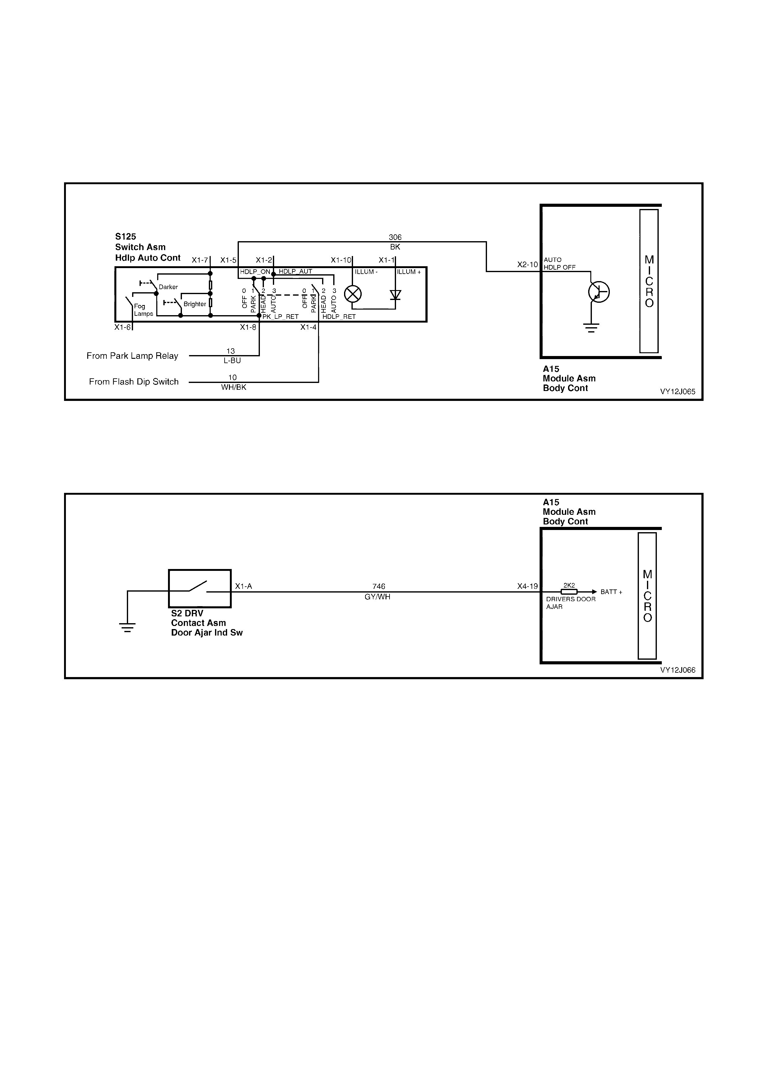
Automatic Lights Off – Inputs
HEADLAMP SWITCH INPUT SIGNAL
The BCM monitor s the voltage on term inal X2-10 to determ ine the position of the headlam p and park lam p switch.
Refer to F igure 12J -90. When the headlam ps or park lam ps are on, the voltage at BCM ter m inal X2-10 is less than
0.2 volt. W hen the autom atic lights system has turned the lights off, the voltage at ter minal X2- 10 is 12 volts. If the
headlamp switch is turned off, the voltage at term inal X2-10 is less than 0.2 volt. T he BCM sees this low voltage at
terminal X2-10 as a change in status of the headlamp switch and turns the automatic lights system off. The lights
turn back on when another change in switch status occurs.
Figure 12J-90
DRIVER’S DOOR AJAR INPUT SIGNAL
When the dr iver’s door is open, BCM term inal X4- 19 is grounded via c ircuit 746 (G rey / W hite wire) and the dr iver's
door jamb switch. Ref er to Figur e 12J- 91. This pulls the voltage at terminal X 4-19 low, to less than 0.2 volt. This low
voltage at terminal X4-19 is seen by the BCM as the driver's door ajar input signal.
Figure 12J-91
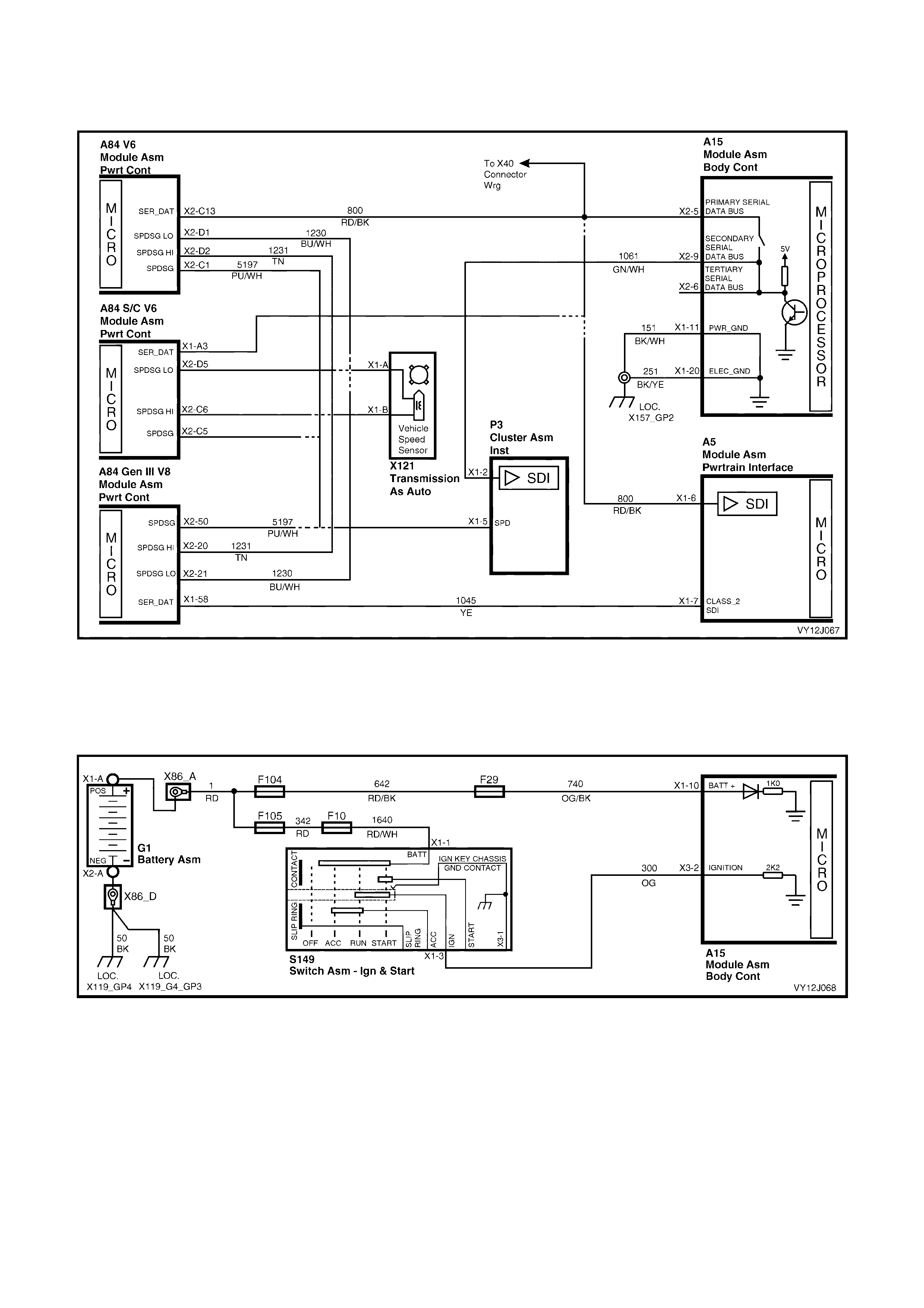
VEHICLE SPEED SIGNAL
BCM terminal X2-5 receives vehicle speed information from the PCM / PIM via the serial communications bus,
circuit 800 (Red / Black wire). Refer to Figure 12J-92.
Figure 12J-92
IGNITION SWITCH ON INPUT SIGNAL
The BCM uses this input signal to determine if the ignition switch is in either the on or start position. When the
ignition switch is in either the on or start position, battery voltage is applied to the BCM terminal X3-2 from the
ignition switch via circuit 300 (Orange wire). Refer to Figure 12J-93.
Figure 12J-93
Automatic Lights Off – Power Supplies
Battery voltage, from fusible link F102, circuit 442 (Red wire) and fuses F30 and F31, is applied to the low beam
relay, high beam relay and, if fitted, fog lamp relay. Refer to Figure 12J-94 and Figure 12J-95.
Battery voltage is applied to the park lamp relay from fusible link F102 circuit 442 (Red wire) and fuse F4, circuit 840
(Orange / White wire).
The BCM c ontrols the oper ation of the exter ior light c irc uits by enabling its internal control circuit, which provides the
ground circuit for the relays.

Automatic Lights Off – Ground Cir cuits
HIGH BEAM RELAY GROUND CIRCUIT
The ground c ircuit for the high beam headlamp r elay is via circuit 1969, (Blue / Yellow wire), through the headlamp
and turn signal flash / dip switch and circuit 10 (White / Black wire), through the headlamp switch contacts and
circuit 306 (Black wire) to BCM terminal X2-10. Refer to Figure 12J-95. From BCM terminal X2-10, the circuit is
grounded via internal switching.
LOW BEAM RELAY GROUND CIRCUIT — LEVEL 1 VEHICLES
The ground c ircuit for the low beam headlam p relay is via circuit 1970 (White wire), through the headlam p and turn
signal flash / dip switch and circuit 10 (White / Black wire), through the headlamp switch contacts and circuit 306
(Black wire) to BCM terminal X2-10. Refer to Figure 12J-94. From BCM term inal X2-10 the circuit is grounded via
internal switching.
LOW BEAM RELAY GROUND CIRCUIT — LEVEL 2 AND LEVEL 3 VEHICLES
The ground circuit for the low beam headlamp relay is via circuit 10 (White / Black wire), through the headlamp
switch contacts and circuit 306 (Black wire) to BCM terminal X2-10. Refer to Figure 12J-95. From BCM terminal X2-
10 the circuit is grounded via internal switching.
PARK LAMPS RELAY GROUND CIRCUIT
W ith the headlamp s witc h in the park lam p position the ground c ircuit for the park lamps relay is through c ircuit 13
(Light-blue wire), the clos ed park lamps contac ts in the light s witch, through c irc uit 306 (Blac k wire) to BCM terminal
X2-10. Refer to Figure 12J-94 or Figure 12J-95. From BCM terminal X2-10, the circuit is grounded via internal
switching.
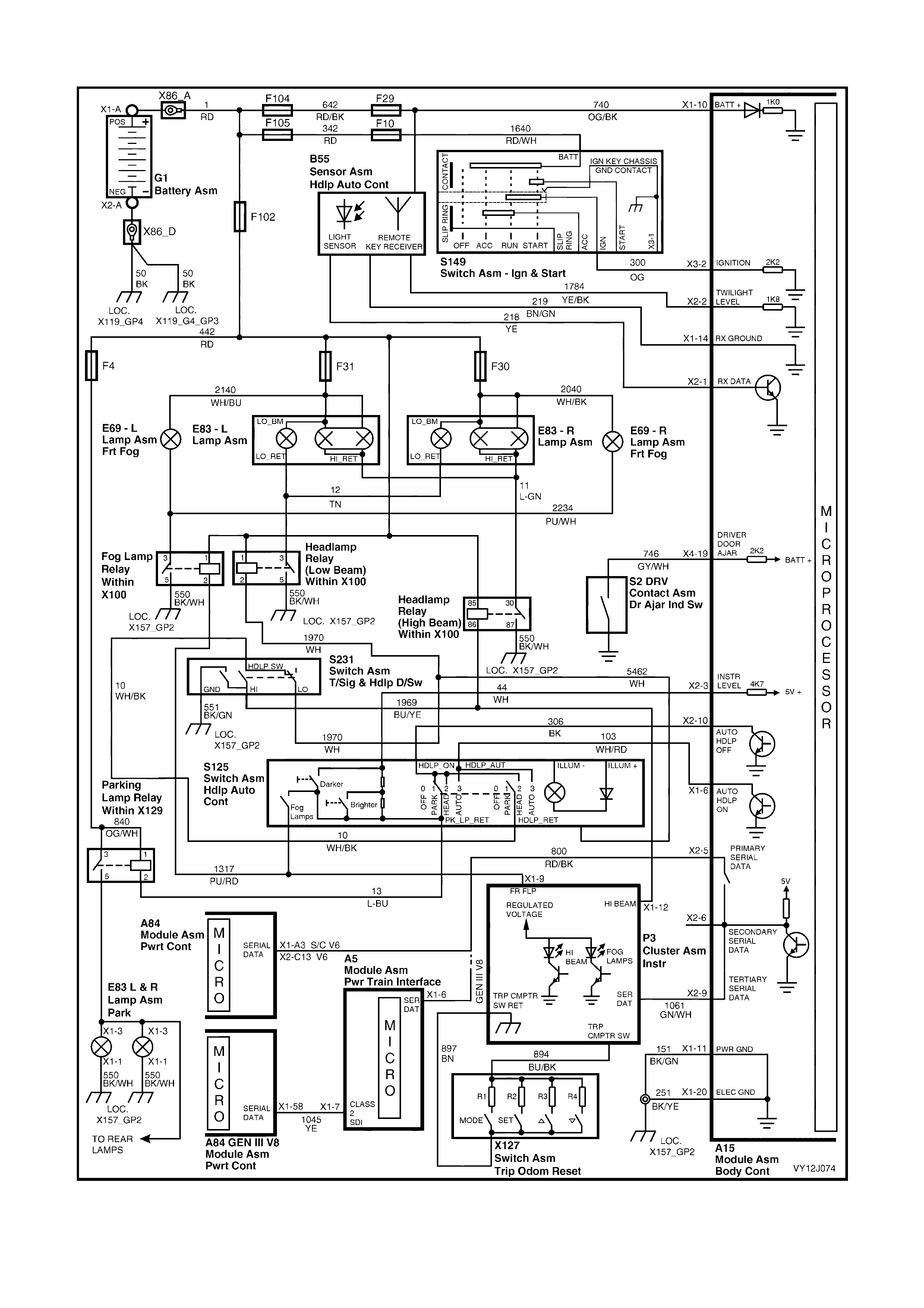
Automatic Lights On
Figure 12J-94
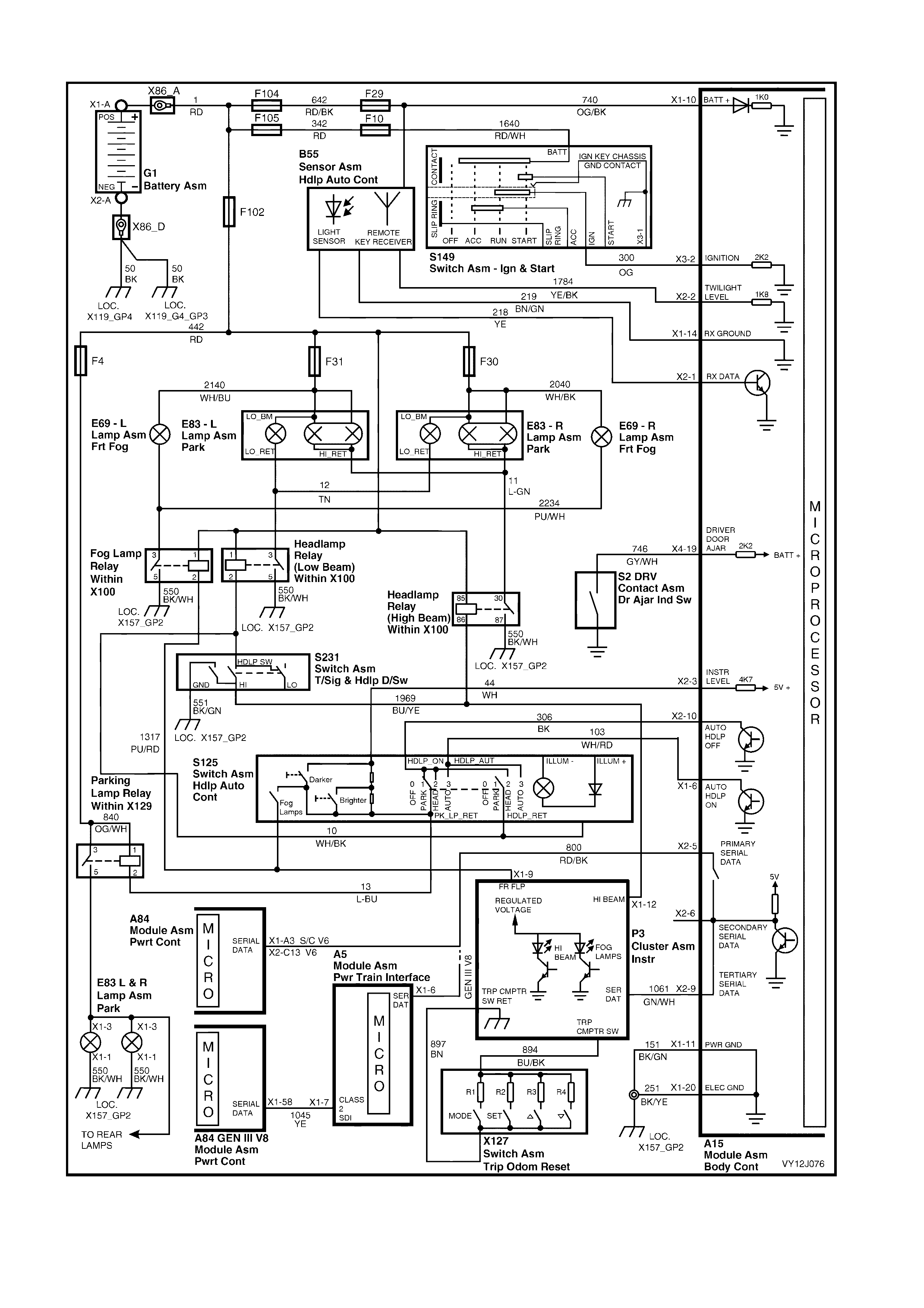
Automatic Lights Off
Figure 12J-95
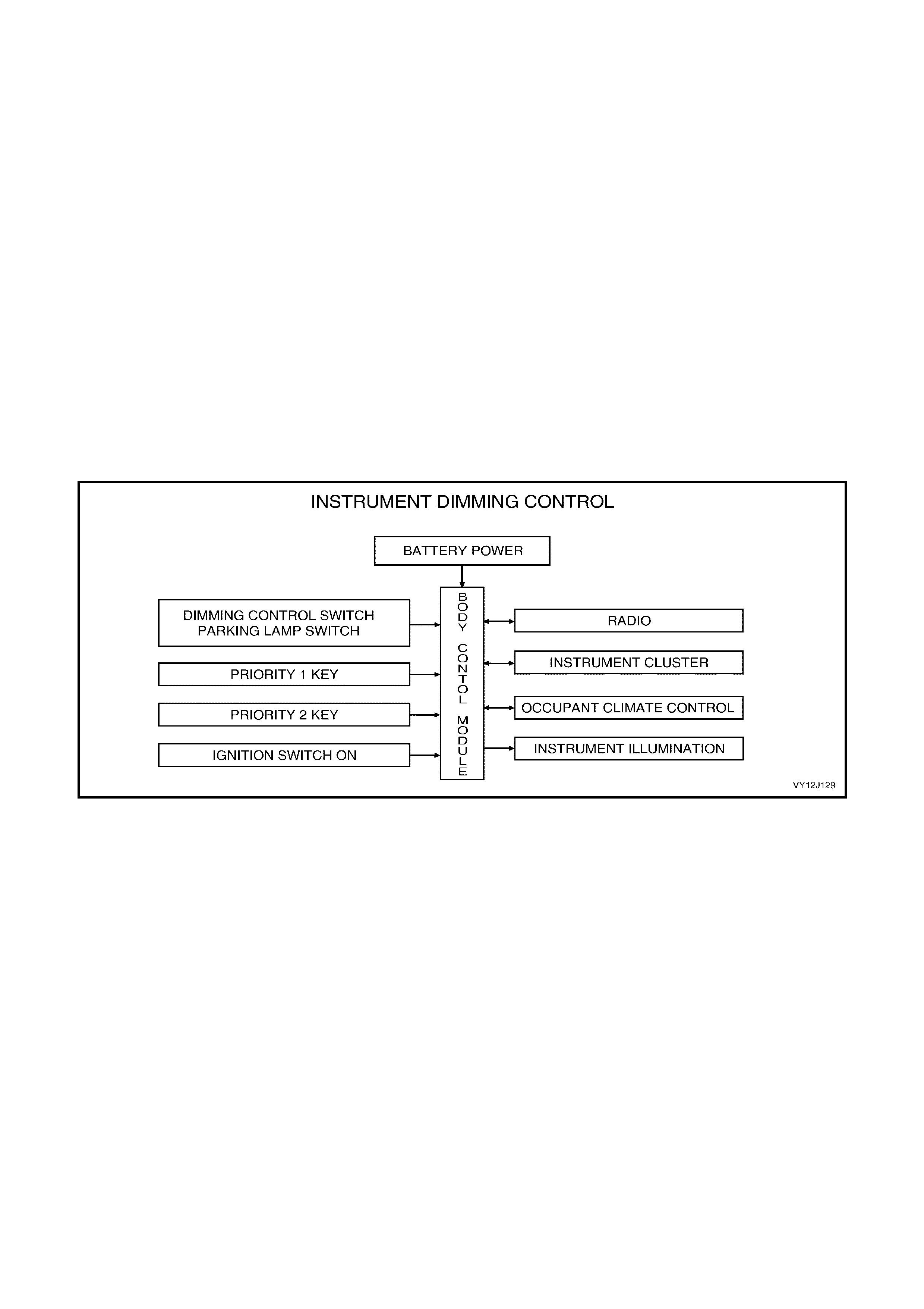
1.14 INSTRUMENT DIMMING CONTROL
SYSTEM OPERATION
The BCM controls the illumination level of the instrument dial faces, radio and back lighting of the MFD and side
LCDs (High series cluster) via the auxiliary serial bus. All dash and centre console illumination, display windows of
the trip computer and the Occupant Climate Control (OCC), is controlled via the BCM illumination drive.
The illumination level is adjusted by moving the spring loaded control lever on the headlamp switch. The lever
operates two m omentary contact switches in the headlam p switch. The dimm er drives to full load, giving m aximum
illumination intensity, when the ignition is on and the park lamps are switched off.
W hen the park lamps are switched on, the dim mer operates according to the level previously set and provides the
voltage variation compensation required to maintain the same brightness, irrespective of the ignition switch position.
The instrument illumination intensity is also dependent on the priority key system; this intensity can be set for Priority
1 and Priority 2 keys. The setting is recalled when the unlock button or the remote coded key is pressed, and is
dependent on which priority key is used.
To dec rease ins trum ent clus ter and trip computer illum ination intensity, the switch control lever m ust be pr essed f or
the required time for the BCM to make this adjustment. To increase illumination intensity, the switch control lever
must be held up for the required time.
NOTE: The c irc uit diagrams shown in this s ec tion ar e to aid in interpr eting the operation of the c ir cuit and ther ef or e,
only the m ain connec tors and wiring c olours are shown. For c om plete circ uit details, ref er to the relevant diagnos tic
section or Section 12P, WIRING DIAGRAMS.
SYSTEM OVERVIEW
Figure 12J-96
CIRCUIT OPERATION
The BCM controls instrument illumination by regulating the current flow through the instrument illumination circuit.
This is achieved by regulating the ground-circuit duty-cycle, adjusting the on time versus off time. As the on time
increases, the current flowing through the circuit increases. As this current flow increases, illumination intensity
increases.
The level of illumination for the instrument cluster, OCC and the radio is transmitted on the secondary serial data
bus by the BCM. The instrument and the radio interpret this illumination level and control the illumination
accordingly .
Battery voltage is applied to the climate control illumination from the park lamp relay, through fuse F11 and circuit
32 (Brown / White wire). Battery voltage is applied to the instrument cluster from the ignition switch via fuse F13.
The earth circuit for the illumination is via circuit 230 (Grey wire) through BCM terminal X1-5. Refer to Figure
12J-97.
NOTE: Only the instrument cluster, radio, climate control and trip computer have BCM controlled variable intensity
lighting.

Inputs
PARK LAMP SWITCH
W hen the park lamps are turned on, the park lamps relay coil is grounded through circuit 13 (Light-blue wire), the
park lamp switch c ontacts, circ uit 306 (Black wire), BCM term inal X2-10 and to ground via an internal switch. Refer
to Figure 12J-97. Approximately 2.5 volts is present at BCM terminal X2-3 due to the dividing-network dimmer
resistor s (in the headlamp switch as sembly) and the BCM internal resistor . This indicates to the BCM that the park
lamps are turned on and the BCM activates internal switching to turn on the instrument illumination lamps.
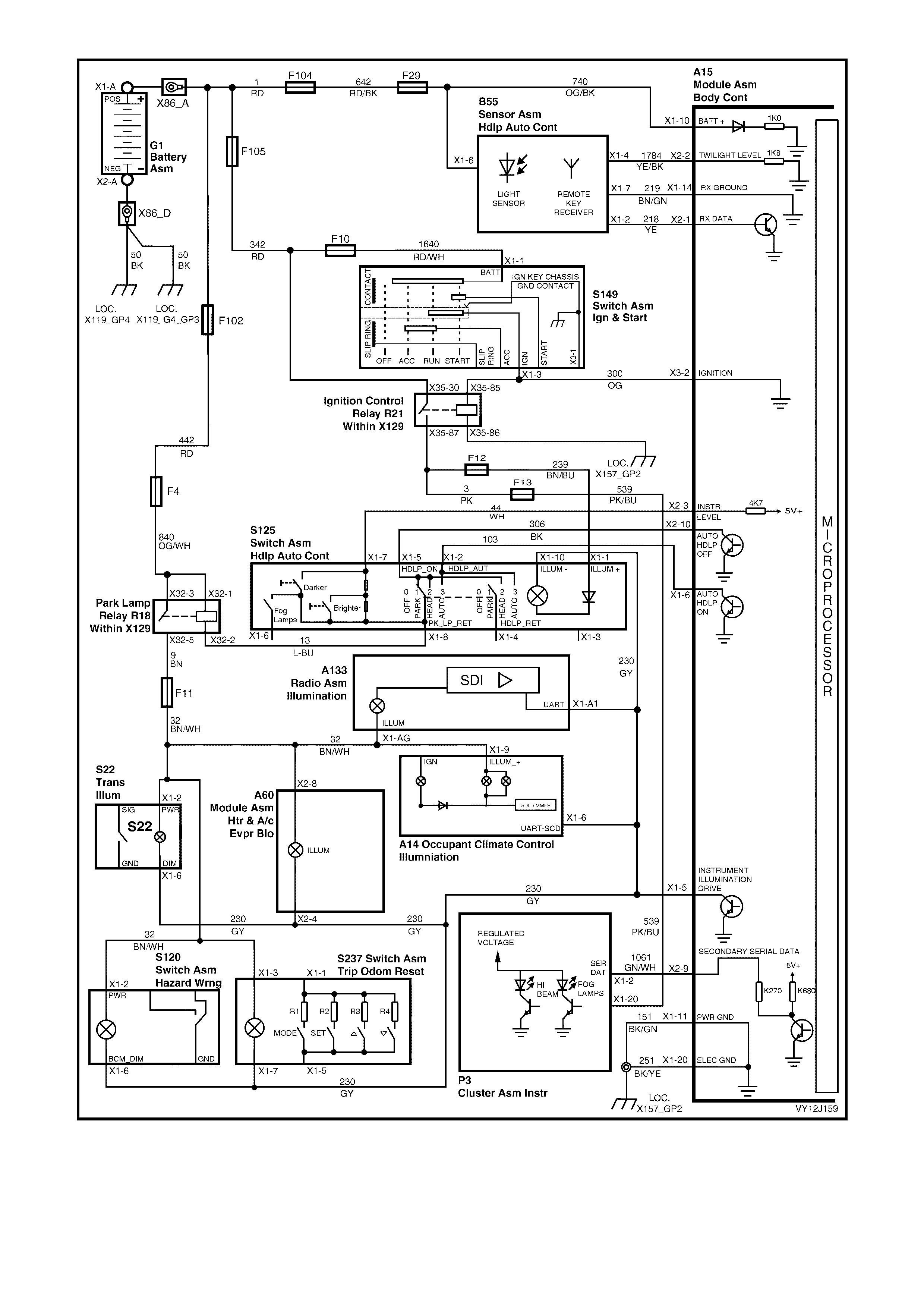
Figure 12J-97
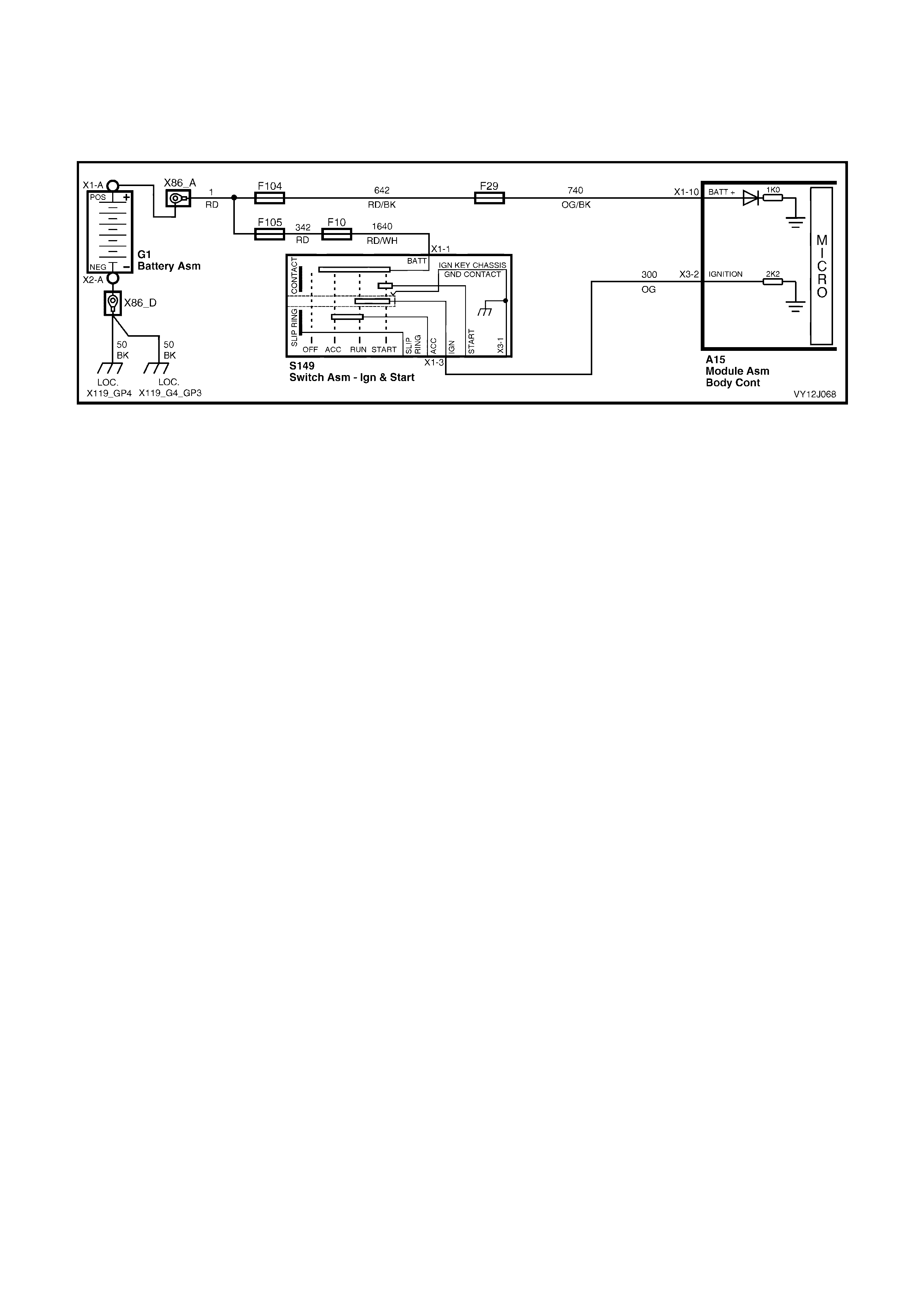
IGNITION SWITCH ON
When the ignition switch is in the on or s tart pos ition, battery voltage is applied to BCM terminal X 3-2 via circ uit 300
(Orange wire). Ref er to Figure 12J-98. T his causes the voltage at ter minal X3-2 to inc rease from less than 0.2 volt
with the ignition switched OFF to 12 volts with the ignition switched to the on or start position. This voltage at
terminal X3-2 is seen by the BCM as the ignition on input signal.
Figure 12J-98
INSTRUMENT ILLUMINATION ON / OFF
BCM terminal X2-3 is connected to ground when the headlamp switch is in the PARK position. Refer to Figure
12J-97. The ground connection is via circuit 44 (White wire), two 2.7 kohms series resistors (in the headlamp switch
control lever mechanism), the headlamp switch contacts, circuit 306 (Black wire), BCM terminal X2-10 and an
internal switch.
With the headlamp switch in the OFF position, the voltage at BCM terminal X2-3 is approximately 8.0 volts.
With the headlamp switch in the PARK position, the voltage at the BCM terminal is approximately 2.5 volts.
From this, the BCM determines that the park lamps are turned on and activates internal switching to turn on the
instrum ent illum ination lam ps. When the BCM detects that the lamps are turned off , the instrum ent dim ming output
is set to full brightness for the trip computer illumination.
ILLUMINATION BRIGHTNESS
When the headlamp switch control lever is held up, both resistors are shorted and the voltage at BCM terminal X2-3
is approximately 0.2 volt.
W hen the headlamp s witch control lever is held down, one of the two series resis tors is shorted and the voltage at
BCM terminal X2-3 is approximately 1.5 volts.
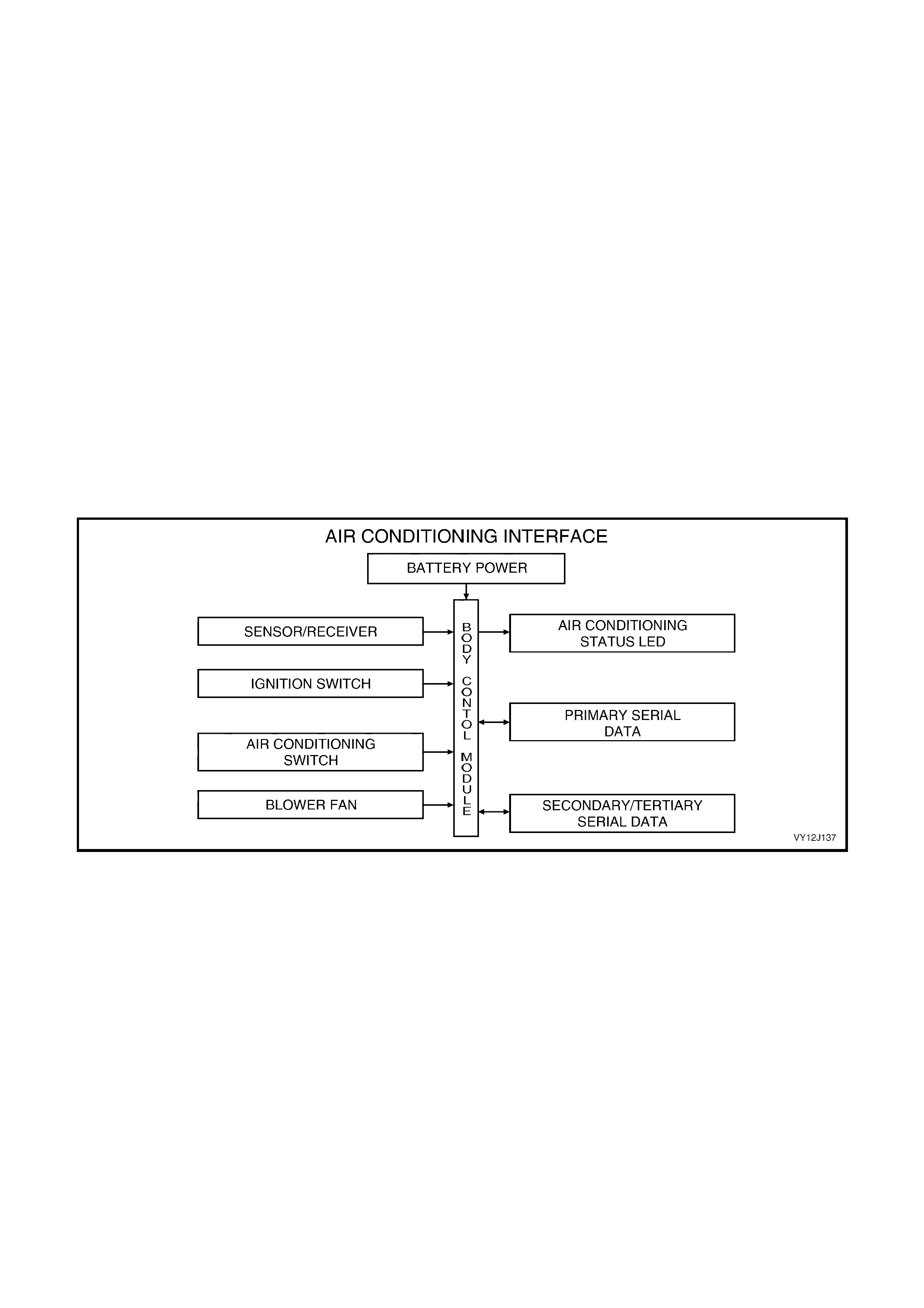
1.15 AIR CONDITIONING INTERFACE
SYSTEM OPERATION
NOTE: The circuit diagrams shown in this section are to aid in interpreting the operation of the circuit. Only the main
connectors and wiring colours are shown. For com plete circuit details, refer to either the relevant diagnostic section
or Section 12P, WIRING DIAGRAMS.
Level 1 model vehicles are fitted with a manual air conditioning system which incorporates and air conditioning
interfac e in the BCM. Level 2 and 3 m odel vehicles are f itted with Occupant Clim ate Contr ol (OCC) , which does not
use an interf ace. Refer to Section 2F, HVAC OCCUPANT CLIMAT E CONTROL (AUT O A/C) – DIAGNOSTICS for
further information.
The air-c onditioning interf ace is used to turn the air conditioning system on and off . T he BCM reads the s ignal from
the momentar y air conditioning switch; m onitor s f an speed and the ignition pos ition. If thes e s ignals are satisf ac tor y,
the BCM requests the PCM to ac tivate the air conditioning c ompres s or. The air conditioning status LED is turned on
by the BCM when the air conditioning s ystem is active and toggles with the air conditioning select switch. The status
is remembered when the ignition or the blower is switched off. The status resets to off when the battery is
disconnected. If the blower is off and the air c onditioning select button is press ed, the air conditioning s tatus c om es
on the next time the blower is switched on. Turning the ignition off cancels this button press function.
The blower fan is controlled by the blower f an inhibit relay. T he BCM controls the output of this relay; only allowing
operation with the ignition in the on pos ition. Ther efor e, operation of this relay is inhibited while the ignition switch is
in the accessory or start position.
NOTE: The BCM has provision for an air conditioning thermostat, which prevents the evaporator from icing up. In
the absence of this thermostat, this input is connected to ignition.
SYSTEM OVERVIEW
Figure 12J-99
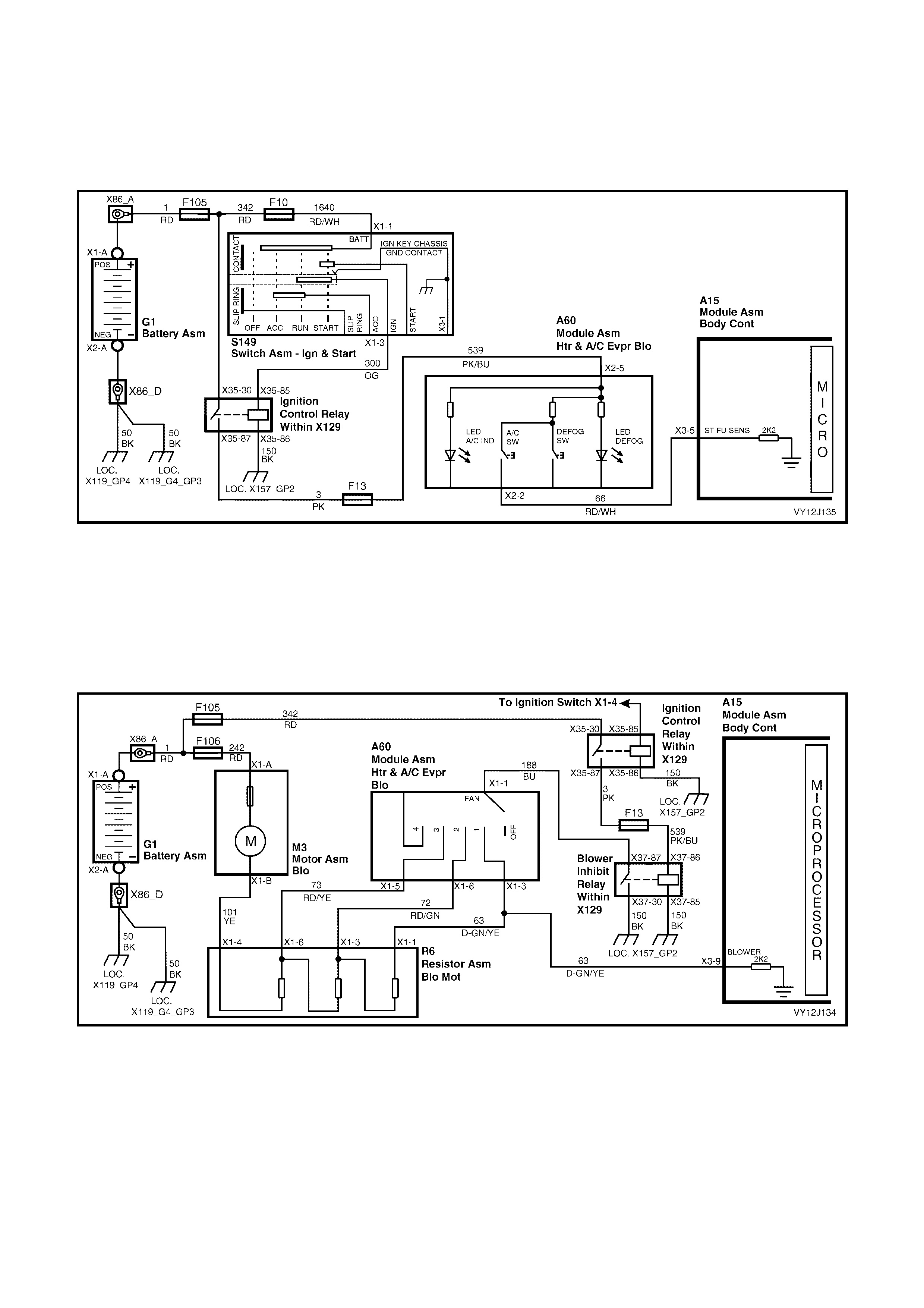
CIRCUIT OPERATION
Inputs
AIR CONDITIONING SWITCH
Activating the air conditioning s witch. Ref er to Figur e 12J- 100, c auses batter y voltage to be applied to BCM terminal
X3-5 via the ignition c ontrol r elay contacts and f use F13, c ircuit 539 (Pink / Blue wire), the A/C s witch and circuit 66
(Red / White wire). This voltage is seen by the BCM as the air conditioning switch input signal.
Figure 12J-100
BLOWER MOTOR
BLOWER MOTOR — LEFT-HAND DRIVE VEHICLE
The BCM uses the blower motor input signal to monitor the operating state of the blower motor. W hen the blower
motor is running, BCM input X3-9 is pulled to ground via circuit 63 (Dark-green / Yellow wire), the blower switch,
circuit 188 (Blue wire) and the blower inhibit relay. Refer to Figure 12J-101. This causes the voltage at BCM
terminal X3-9 to change from battery voltage to less than 0.3 volt, which is seen by the BCM as the blower 'on'
signal.
Figure 12J-101
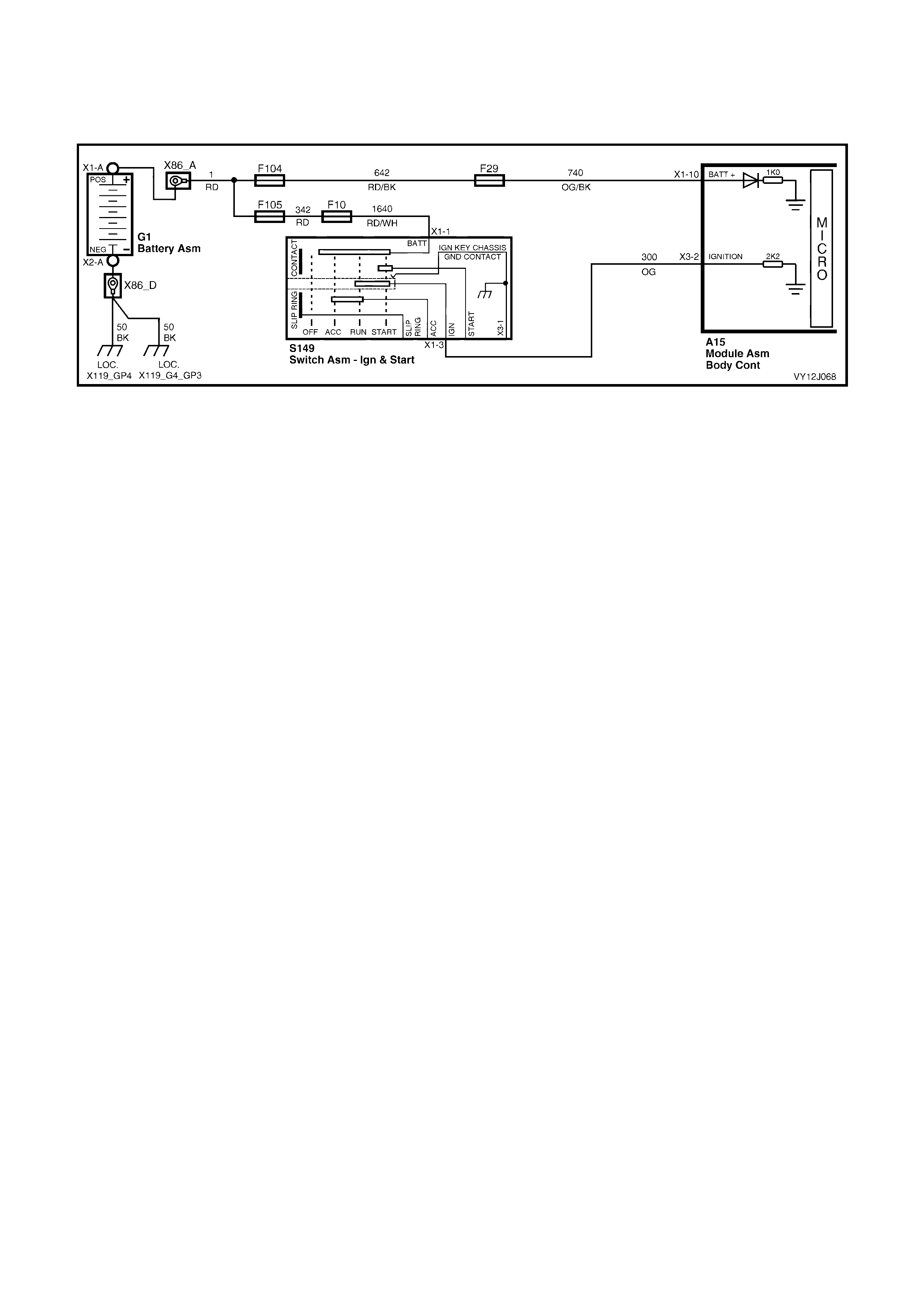
IGNITION SWITCH ON
The BCM us es this input signal to deter mine when the ignition switch is in the on or s tar t pos ition. When the ignition
switch is in the on or start pos ition, battery voltage is applied to BCM ter minal X 3-2 from the ignition switch thr ough
circuit 300 (Orange wire). Refer to Figure 12J-102.
Figure 12J-102
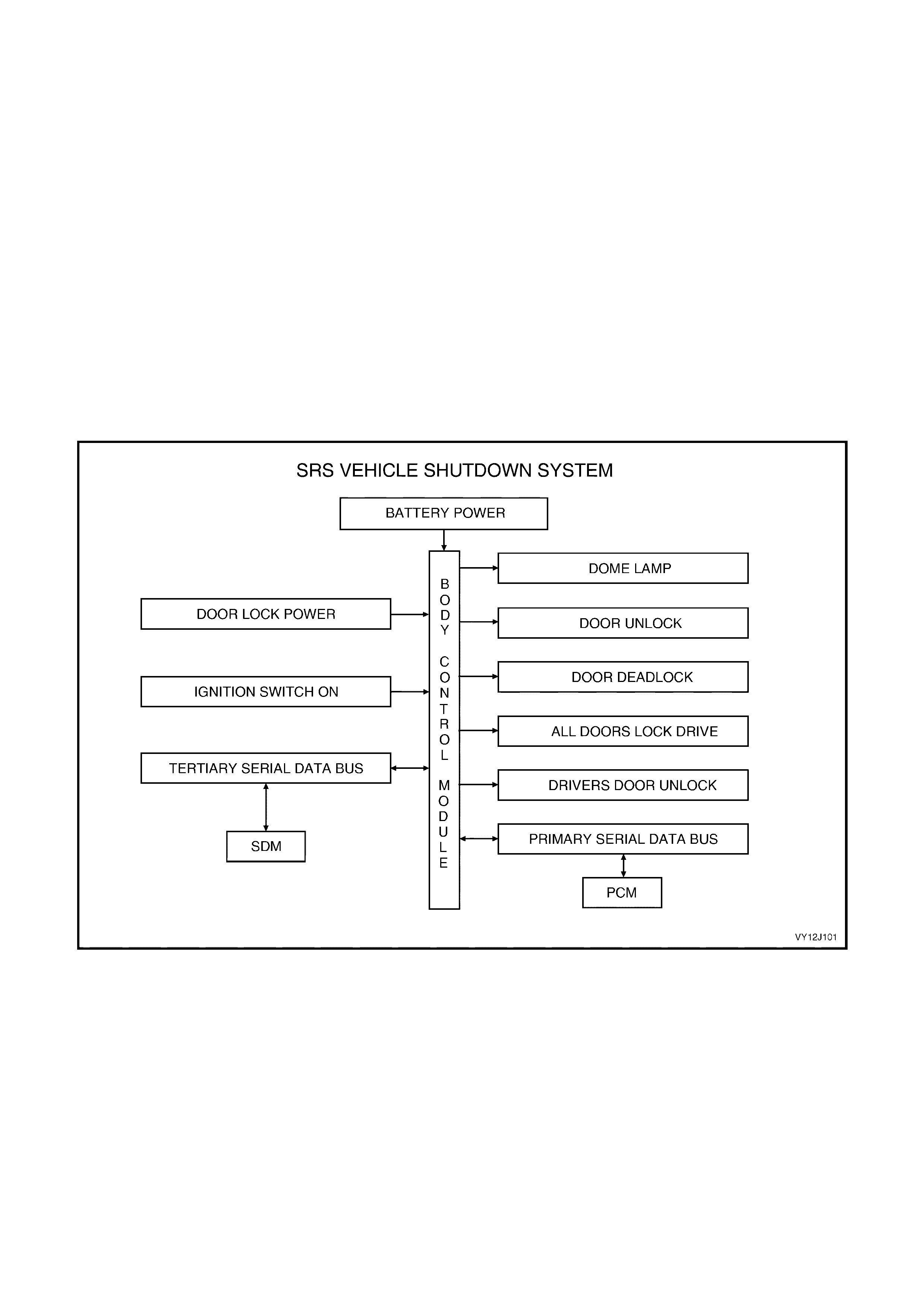
1.16 SRS DEPLOYMENT VEHICLE SHUTDOWN
SYSTEM OPERATION
NOTE: The c irc uit diagrams shown in this s ec tion ar e to aid in interpr eting the operation of the c ir cuit and ther ef or e,
only the main connectors and wiring colours are shown. For complete circuit details, refer to either the relevant
diagnostic section or Section 12P, WIRING DIAGRAMS.
SRS Deployment Signals
If the Supplemental Restraint System (SRS) deploys, the Sensing Diagnostic Module (SDM) sends signals, via the
tertiary serial data bus, to shutdown various vehicle systems.
The BCM monitors this serial data via the tertiary serial data bus and performs the following actions when the
specific data signals are identified and the vehicle speed is zero km/h for longer than 10 seconds:
• The dome lamp is turned on continuously.
• All doors are unlocked.
The dome lam ps are switched off when the ignition switch is cycled from off to on and the SRS deployment f lag is
removed by the SDM or when the BCM is reset due to battery disconnection.
NOTE: The PCM also monitors this serial data via the tertiary serial data bus and performs a vehicle shutdown
under the same conditions.
SYSTEM OVERVIEW
Figure 12J-103
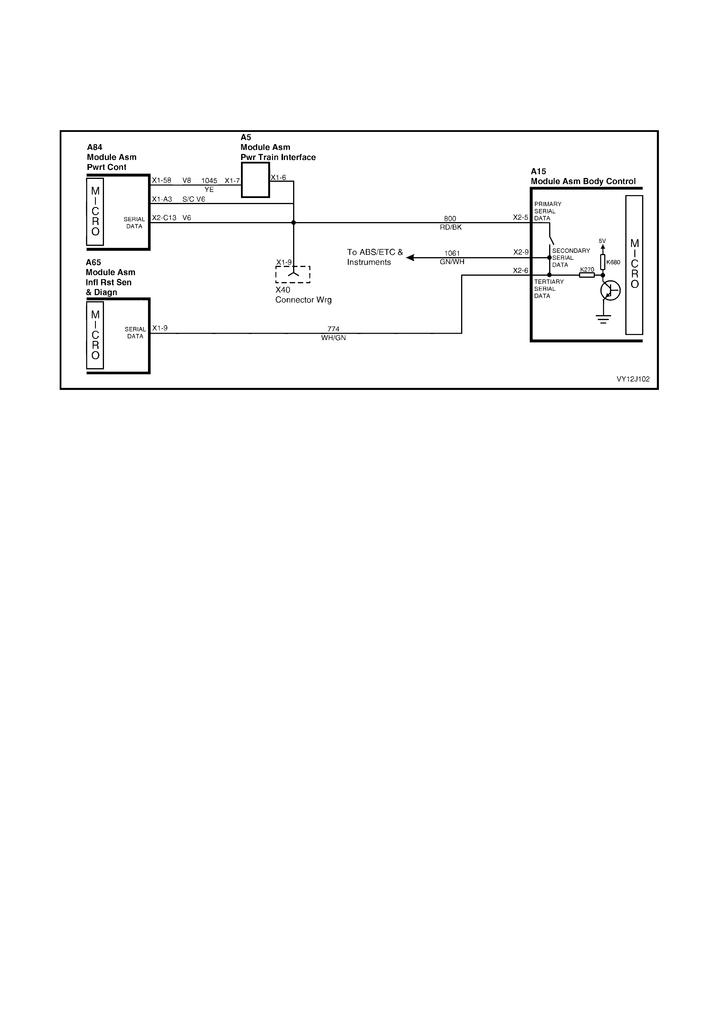
CIRCUIT OPERATION
SRS Serial Data Bus (Serial Data)
When the SRS deploys, the SDM sends ser ial data via the tertiary serial data bus to the BCM. Within the BCM, the
tertiary serial data bus is linked to the secondary serial data bus via a wire link. Refer to Figure 12J-104. This link
enables the SDM to advise various systems, via serial data, to take appropriate action. This includes the BCM.
Figure 12J-104

1.17 PRIORITY KEY SYSTEM
OPERATING PARAMETERS
The BCM remembers two sets of key operating parameters. These operating parameters are recalled when a
specific remote coded key is used. When a Priority 1 remote coded key is used, the BCM recalls the operating
parameters related to the Priority 1 key. When a Priority 2 key is used, the BCM recalls the operating parameters
related to the Priority 2 key.
The operating parameters recalled are for the following functions:
• Time delay for automatic headlamps off.
• Antenna height memory.
• Instrument panel dimmer level.
• Two-stage unlock.
• Lock status indicator.
• Auto lock in drive.
• Courtesy lamp time delay.
• Ignition on courtesy lamp delay.
• Approach lamp time delay.
• Headlamp sensitivity.
These operating parameters are recalled when the UNLOCK button on the remote coded key is pressed or when
the ignition is turned to the accessories position. All operating parameters are maintained on a last used basis.
Parameter Checks
The BCM also communicates with other modules via the serial data bus, ensuring that each module is in the correct
mode. The following modules use the priority information:
• Trip computer, mode and overspeed setting.
• Occupant Climate Control settings.
• Power / Economy switch position.
• Audio system volume, tone and presets.
• Seat memory for all positions through hard wire priority outputs.
• Mirror memory via the seat memory module.
Priority Output Lines
The BCM has two priority output lines, which set the seat m emory priority m ode. T he seat memory module monitor s
both priority lines and res ponds bas ed on which line has been pulled low by the BCM. The priority modes ar e set as
follows:
• With Priority 1 output low and Priority 2 output high, the seat memory is in Priority 1 mode.
• With Priority 2 output low and Priority 1 output high, the seat memory is in Priority 2 mode.
W hen a new rem ote c oded k ey is program m ed, it is as signed as the Priority 1 key and all remaining r emote coded
keys become Priority 2 keys. Any rem ote coded key can be assigned as the Priority 1 key using TECH 2; all other
keys then become Priority 2 key s.
NOTE: The circuit diagrams shown in section are to aid in interpreting the operation of the circuit and therefore, only
the main connectors and wiring colours are shown. For complete circuit details, refer to either the relevant
diagnostic section or Section 12P, WIRING DIAGRAMS.
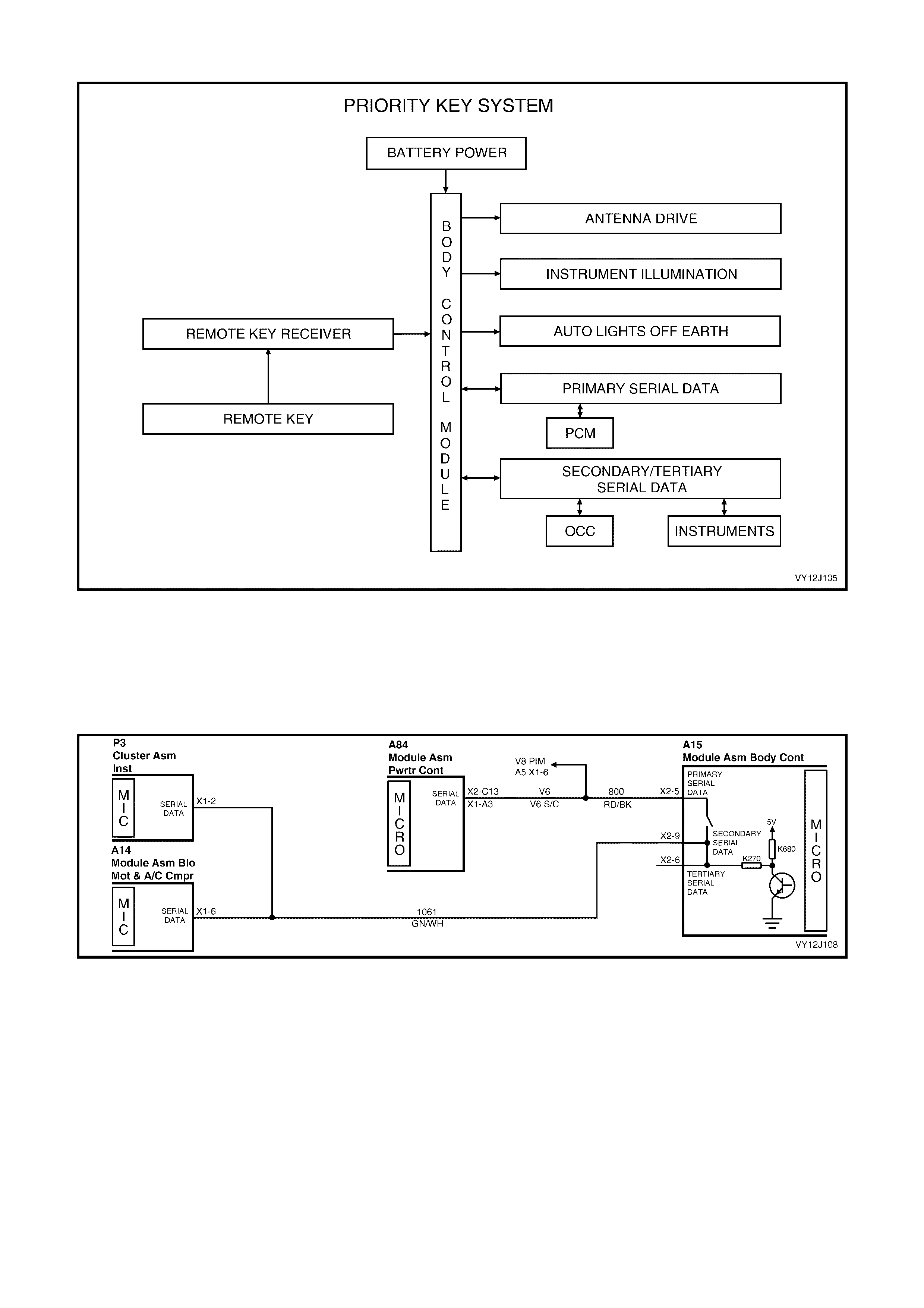
SYSTEM OVERVIEW
Figure 12J-105
CIRCUIT OPERATION
When the ignition is switched on or the UNLOCK button on the remote coded key is activated, the BCM sends serial
data via the s ec ondar y serial data bus to the tr ip computer and the OCC module and via the primary serial data bus
to the PCM. Refer to Figure 12J-106 and Figure 12J-107. From this serial data, the BCM identifies which mode
each module should be in, depending on whether the Priority 1 or Priority 2 key is activated.
Figure 12J-106
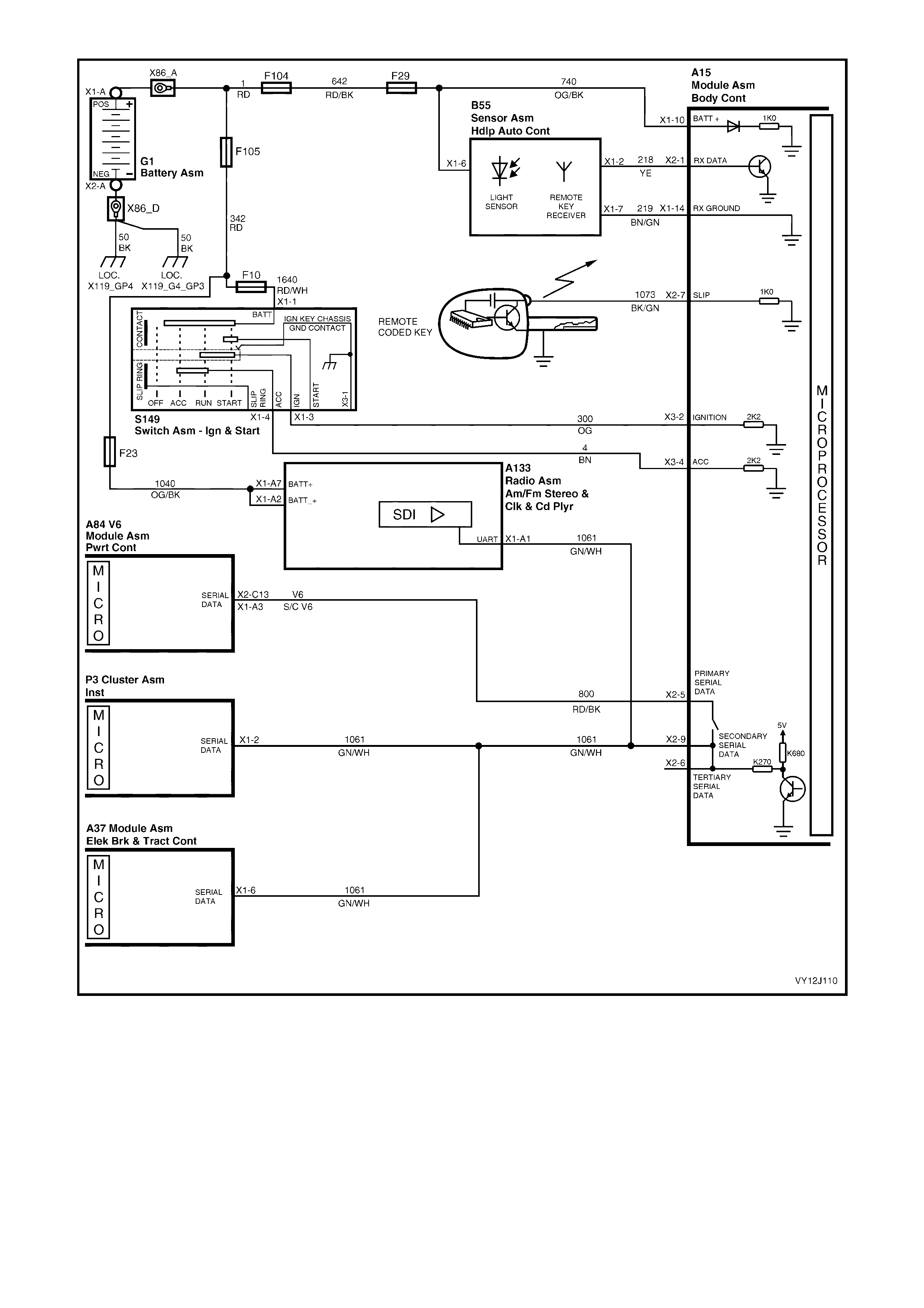
Figure 12J-107
Priority Key Mode – Radio
The Priority 1 output line sets the priority mode for the radio. The radio settings are set for Priority 1 when the
Priority 1 output voltage is pulled low. When the Priority 1 output is high, the radio is set for Priority 2.

1.18 P O WER ANTENNA CONTROL
SYSTEM OPERATION
The power antenna has two inputs from the BCM that control the power antenna:
• Input 1 provides power to the antenna motor.
• Input 2 controls the antenna mast direction (up or down).
The power antenna assembly incorporates maximum and minimum height limit switches and a slip clutch.
NOTE: The c irc uit diagrams shown in this s ec tion ar e to aid in interpr eting the operation of the c ir cuit and ther ef or e,
only the main connectors and wiring colours are shown. For complete circuit details, refer to either the relevant
diagnostic section or Section 12P, WIRING DIAGRAMS.
Power Antenna
W hen the BCM senses a hardwired antenna reques t from the r adio, the antenna mast extends to the same height
as it was when las t in operation (f or the Pr iority key us ed) provided the antenna m em or y height option is enabled. If
the battery is disconnected, the antenna height m emor y setting defaults to 5 sec onds of mas t upward travel, which
raises the antenna approximately 600 mm.
The antenna mast height memory is dependent on correct battery voltage; a clean antenna mast and no kinks in the
mas t drive cord. T he height m emory is also dependent on the prior ity k ey system. A toleranc e of plus or m inus 100
mm is acceptable for the mast height.
The antenna m ast is m oved when antenna UP or antenna DOW N s ignals are sensed f rom the switches. However,
these switches do not oper ate if the BCM does not sens e the radio / CD player antenna r equest signal or when the
ignition switch is not in the accessory or on position.
When the radio is turned off, the antenna operates as follows:
1. If the ignition is turned off, there is a delay of approximately 15 seconds before the antenna mast fully retracts.
2. If the ignition is turned on or to the accessories position, the antenna mast will fully retract after 3 seconds.
NOTE: The antenna mast also retracts when the theft deterrent system is armed (immediately on remote lock).
During engine starting, the r adio / CD player antenna request signal is m omentarily lost. During this tim e, the BCM
assum es that the s ignal is still ac tive as it sens es ignition and acc esso ries inputs, as well as the radio s tatus signal.
This ensures unaffected antenna operation and control during engine cranking.
ANTENNA HEIGHT – PRIORITY KEY SYSTEM
Antenna height m em ory can be s et and s tored for the Pr iority 1 and Prior ity 2 k eys. When the unloc k button on the
remote coded key is pressed, the antenna height is recalled based on the priority key (1 or 2) that is used.
The priority information for antenna height memory is stored in the BCM.
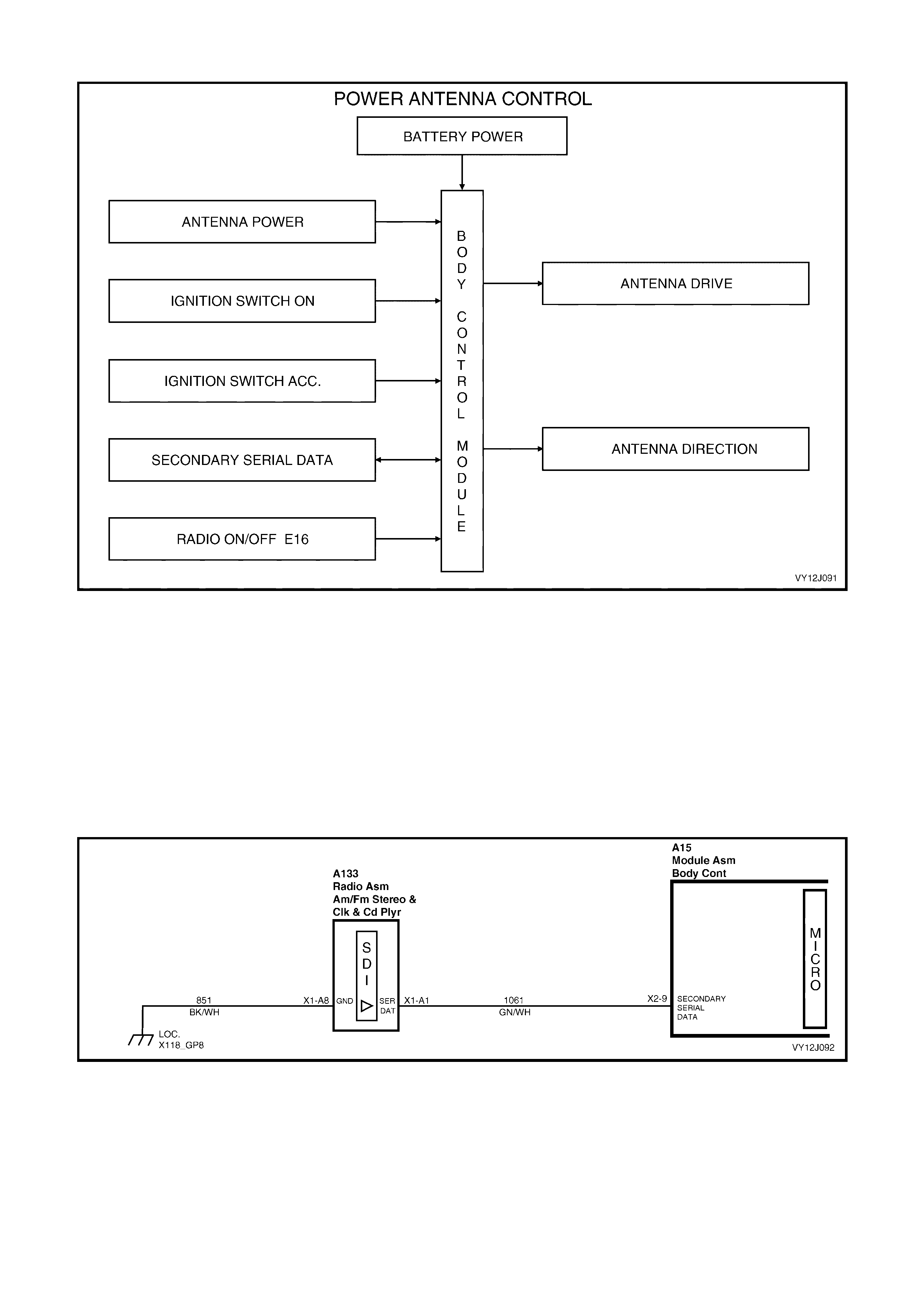
SYSTEM OVERVIEW
Figure 12J-108
CIRCUIT OPERATION
Antenna Up Switch Input Signal
When the antenna UP switch is pressed, the radio / CD player sends an antenna UP signal to the BCM via the
secondary serial data bus. Refer to Figure 12J-109.
The BCM then applies battery voltage to the antenna direction relay in the power antenna assembly, from BCM
terminal X4-7 via circuit 161 (Grey wire). Refer to Figure 12J-110. This energises the antenna direction relay
causing the relay contacts to switch to the antenna UP position.
As battery voltage is also applied to the antenna motor from BCM terminal X4-23, circuit 160 (Green wire), the
antenna motor rotates driving the antenna m ast upward. The ground circuit for the power antenna motor is via the
antenna internal ground lead.
Figure 12J-109

Figure 12J-110
Antenna Up Memory Height
When the radio / CD is turned on, battery voltage is applied to BCM terminal X3-10 from the radio via circuit 314
(Yellow / Red wire). Refer to Figure 12J-110. This causes the voltage at terminal X3-10 to increase from less than
1.0 volt (radio OFF) to battery voltage (radio ON).
This radio ON signal trigger s the BCM to apply batter y voltage to the antenna direc tion relay f rom terminal X 4-7 via
circuit 161 (Grey wire). This energis es the antenna direction r elay, which switches the relay contacts to the antenna
UP position. The BCM also energises its internal relay, which supplies battery voltage to the power antenna motor
for enough time to allow the antenna m otor armature to r otate and drive the antenna mas t to the same height it was
when last operated.
NOTE: If the power supply via fuse F29 to the BCM is disconnected, antenna memory is lost and will need to be
reset.
Antenna Down
The down travel of the power antenna is also controlled by the BCM. When the antenna DOWN switch is
depressed, the radio / CD player sends a DOW N input signal to the BCM through the secondary serial data bus.
Refer to Figure 12J-109.
The BCM does not apply battery voltage to the antenna direction relay, so the relay contacts rem ain in the DOW N
position. As battery voltage is applied to the antenna m otor from BCM term inal X4-23, the antenna m otor armature
rotates, driving the antenna mast down.
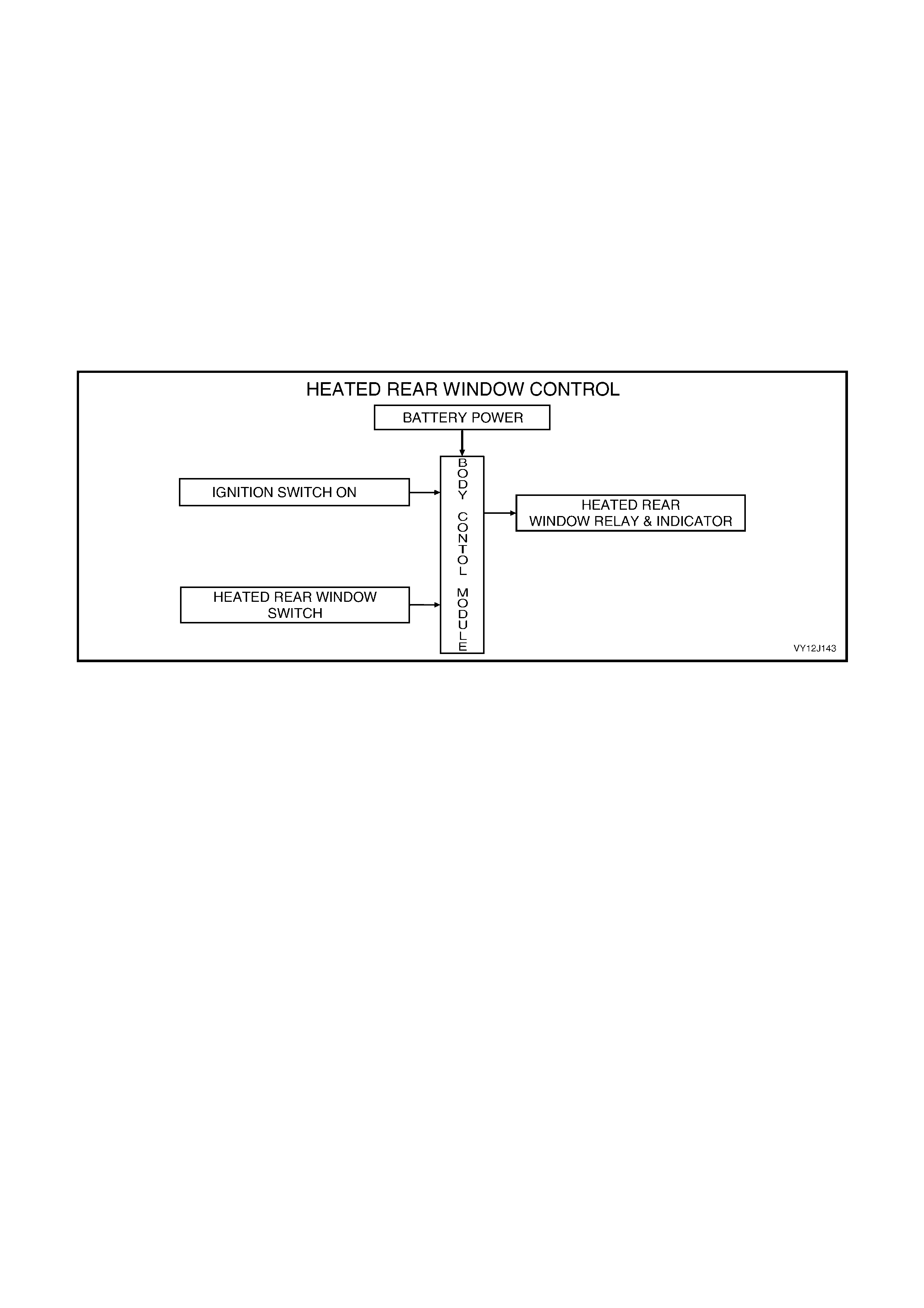
1.19 HEATED REAR WINDOW
SYSTEM OPERATION
Delay Timer
This system imposes a time limit on the heating of the rear window in order to avoid excess load on the vehicle
battery.
The heating operation is controlled using the heated-rear-window switch located in the instrument facia. This is a
momentary-contact switch, which toggles power on or off when it is pressed. The heating is timed to continue for
15 minutes and each new activation of the heated-rear-window switch resets the delay timer.
Heating the rear window is only available when the ignition is on; it defaults back to OFF when the ignition is
switched to OFF.
NOTE: The c irc uit diagrams shown in this s ec tion ar e to aid in interpr eting the operation of the c ir cuit and ther ef or e,
only the main connectors and wiring colours are shown. For complete circuit details, refer to either the relevant
diagnostic section or Section 12P, WIRING DIAGRAMS.
SYSTEM OVERVIEW
Figure 12J-111
CIRCUIT OPERATION
Control of the heated-rear-window is through the heated-rear-window relay. This relay is located on the fuse panel
and is connected in parallel with the heated-rear-window indicator lamp in the instrument cluster.
Heated Rear Window Switch Input Signal
Pressing the heated r ear window switch closes the switch c ontacts and c onnects BCM ter m inal X2-12 to circuit 539
(Pink / Blue wire) via circuit 292 (O range wir e). Refer to Figure 12J -112. This incr eases the voltage at term inal X2-
12 to over 3.5 volts, which is seen by the BCM as the heated rear window switch input signal.
After the heated-rear-window switch is pressed to the on position, the BCM controls the operation of the system.
Power is applied to the rear window relay coil from the output of the ignition control relay, circuit 539 (Pink / Blue
wire) via fus e F13. The tim er cir cuit energises a tr ansistor, which c onnects the heated-r ear-window relay pull-in c oil
circuit to ground via BCM terminal X1-18, circuit 681 (Black / Red wire). This causes the relay contacts to close,
supplying battery voltage from fuse F22 through circuit 40 (Orange wire) to the heated rear window, circuit 293
(Purple / Red wire).
The ground connection for the heated-rear-window is via circuit 1850 (Black wire).
Demis ting of the r ear window can only oc cur when the ignition is on and defaults to off when the ignition is switched
from OFF to on position.
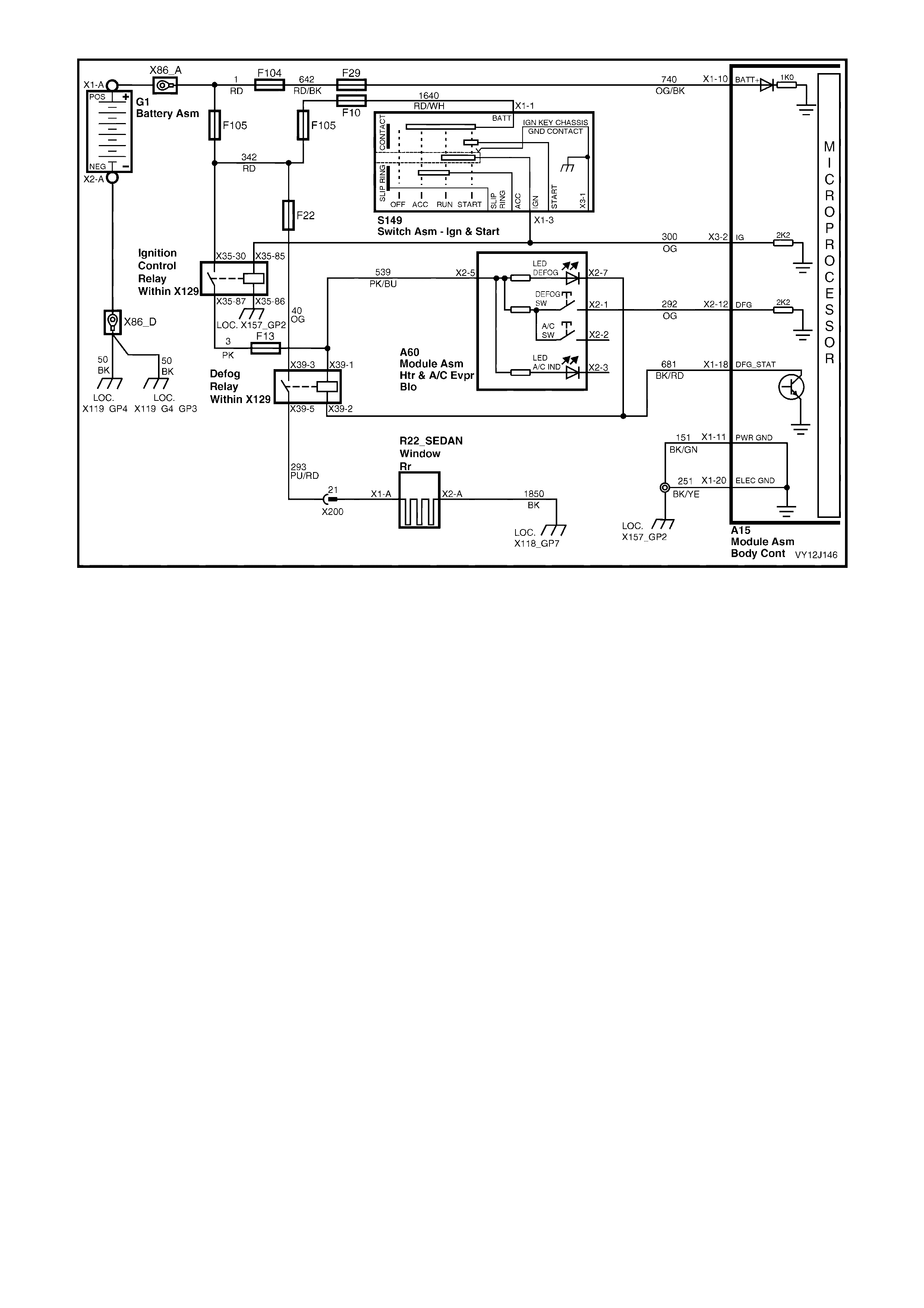
Figure 12J-112

1.20 REAR LAMP FAILURE WARNING SYSTEM
SYSTEM OPERATION
NOTE: The circuit diagrams shown in this section are to aid in interpreting the operation of the circuit and
therefore, only the main connectors and wiring colours are shown. For complete circuit details, refer to either
4.20 REAR LAMP FAILURE WARNING SYSTEM in this section or Section 12P, WIRING DIAGRAMS.
Components Monitored
This system m onitor s the tail, stop and lic ence plate lam ps for bulb failur es, as well as the integr ity of the park lamp
and stop lam p f uses f eeding these s ys tem s. T he system does not sens e trailer lights and will not be affec ted if they
are connected to the vehicle.
Bulb failures are detected within the following circuit loads (at 12 volts):
• Tail lamps – 5 Watt (2 x) = 10 Watt
• Stop lamps – 21 Watt (2 x) + 18 Watt (1 x) = 60 Watt
• Licence plate lamps – 5 Watt (2 x) = 10 Watt
A rear lam p bulb or system failure warning is c onveyed to the driver via an animated warning dis play in the MFD of
the instrument cluster with the following indications:
• Steady illumination of the warning icon with tail / park lamps turned on indicates a rear tail-lamp failure.
• Steady illumination of the warning icon while the brake pedal is pressed indicates a rear stop-lamp failure.
• Illumination the rear lam p fuse fail warning lam p indicates that either the stop lam p fuse or the park lamp fuse
has failed.
The system only operates while the ignition is on but a warning-lamp test of 1.2 seconds is performed when the
ignition is switched on. Detected failures are cleared when the ignition is switched off.
All current warnings in the MFD are displayed in a cycle until the driver acknowledges each by pressing the trip
computer switch MODE button.
NOTE 1: If the batter y is dis connected during any service operation, a bulb re-lear n procedure m ust be carried out.
Refer to the f ollowing procedure. Additionally, the ABS or ABS / T CS m ust be functional for the rear lamp failur e to
operate.
NOTE 2: The circuit diagrams shown in this section are to aid in interpreting the operation of the circuit and
therefore, only the main connectors and wiring colours are shown. For complete circuit details, refer to either the
relevant diagnostic section or Section 12P, WIRING DIAGRAMS.
BULB RE-LEARN PROCEDURE
Carry out this procedure if the battery has been disconnected.
Techline
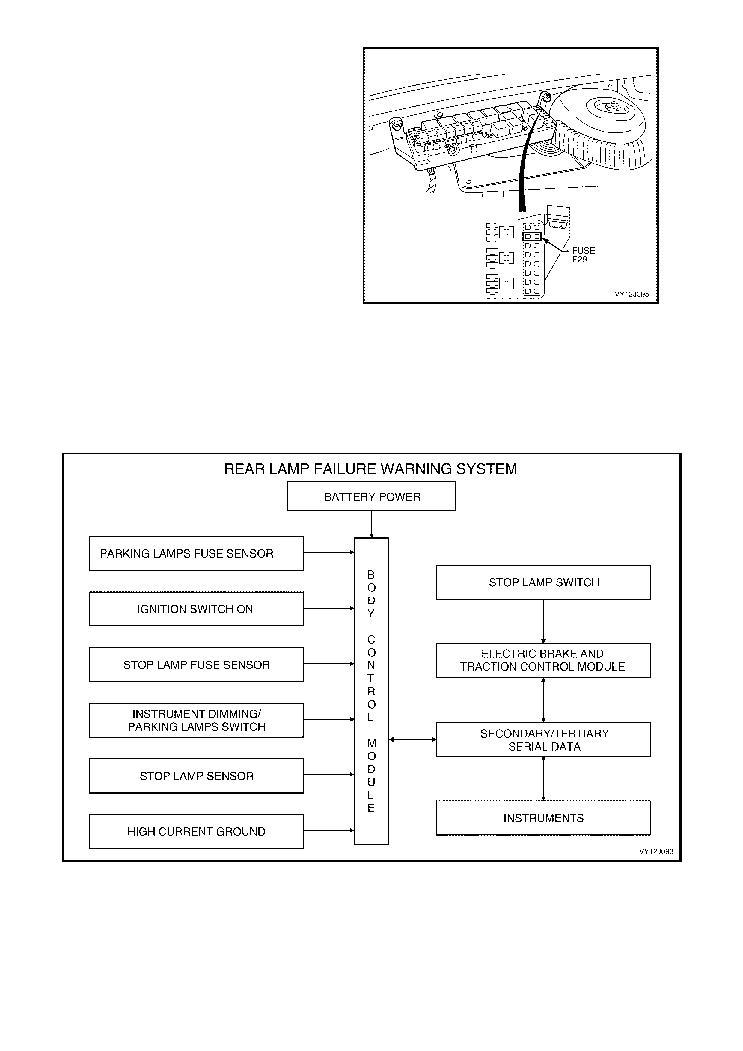
1. Ensure that the battery is fully charged and
functional.
2. Ensure all rear light bulbs are work ing. Replace
/ repair any faulty bulbs / wiring.
3. Turn the ignition OFF, park lamps OFF and
stop lamps OFF.
4. For vehicles fitted with Telematics, enable the
Service mode. Refer to Section 12K,
TELEMATICS.
5. Remove and install fuse F29 from the engine
compartment relay housing, to reset the BCM.
6. Start the engine and allow it to idle.
7. Switch the park lamps ON.
8. Wait 5 seconds.
9. Press brake pedal and hold it down.
10. Wait 5 seconds.
11. Switch the park lamps OFF while continuing to
hold down the brake pedal.
12. Wait 5 seconds.
13. For vehicles fitted with Telematics, disable the
Service mode. Refer to Section 12K,
TELEMATICS.
14. Bulb re- learn is now complete. T urn the engine
OFF and release the brake pedal.
Figure 12J-113
SYSTEM OVERVIEW
Figure 12J-114

CIRCUIT OPERATION
Ground Circuit Monitoring
The BCM monitors the gr ound cir cuit c ur rent flow to the stop, tail and licence plate lamps. T he gr ound cir cuit for the
stop and tail lam ps is through the BCM between term inal X4- 24, circuit 1251 (Brown / White wire) and term inal X1-
11, circuit 151 (Black / Green wire). Refer to Figure 12J-115.
Rear Lamp Failure Warning Lamp
W hen the ignition switch is turned to the on position, battery voltage is applied to the instrument c luster module. In
the event of a stop, tail or licence plate lamp failure, the BCM sends a serial data signal via the serial data bus to the
instrument cluster module which activates a large bulb with a flashing exclamation mark on the instrument cluster.
When the MODE button on the trip computer is pr ess ed, the animated symbol r evert s to a s mall bulb f ailure ic on on
the left of the MFD.
Inputs
PARK LAMP FUSE
Battery voltage is applied to BCM terminal X3-12 from fuse F4, circuit 840 (Orange / W hite wire). Refer to Figure
12J–115. If batter y voltage is not available at ter minal X 3-12 when the ignition switch is in the on position, the BCM
determines that the park lam p fuse (or circuit) has failed. The Rear Lamp Fuse Fail and animated warning will be
activated in the MFD of the instrum ent c luster via the sec ondary s erial data bus. W hen the MODE button on the trip
com puter is pres s ed, the animated symbol r ever ts to a s mall f us e f ailur e icon on the left of the MF D. The small icon
remains illuminated until the problem is rectified.
PARK LAMP SWITCH
W hen the park lamps ar e turned on, the instrum ent dimm ing series resis tors are connected to gr ound via the park
lamp s witch contacts , BCM term inal X 2-10 and an internal BCM trans istor s witched to ground. Refer to Figure 12J–
115. The voltage at terminal X2-3 of the BCM is approximately 2.5 volts, which is seen by the BCM as the park
lamps on input signal.
W ith the park lam ps on, the BCM monitor s the current f lowing from term inal X4-24 to term inal X1-11. If the current
flow does not match the learnt current flow, the BCM sends a message via the secondary serial data bus to the
instrument cluster to display the Rear Lamp Bulb Fail.
STOP LAMP FUSE
Battery voltage is applied to BCM terminal X 3-5 from fuse F5, cir cuit 640 (Orange / Blue wire) and fr om circ uit 442
(Red wire). Refer to Figure 12J–115. If battery voltage is not sensed at X3-5 when the ignition switch is in the on
position, the BCM determines that the stop lam p fuse (or circuit) has failed and displays the Rear Lamp Fuse Fail
animated warning in the MFD of the instrument cluster, via the secondary serial data bus.
STOP LAMP SWITCH
W hen the brake pedal is depres sed, the stop lamp s witc h contacts close and batter y voltage is applied to the ABS
module from fuse F5, circuit 640 (Orange / Blue wire) and the stop lamp switch contacts, circuit 20 (Blue / Red
wire). Ref er to F igure 12J–115. This action causes the ABS module to s end a serial data signal to the BCM via the
secondary serial data bus. This serial data is interpr eted by the BCM as the s top lamp s witch input signal. W ith the
stop lam ps on, the BCM monitors the cur r ent f lowing between term inal X4- 24 and ter minal X1-11. If the curr ent flow
does not m atch the learnt current f low (ref er to the BULB RE-LEARN PROCEDURE outlined previously), the BCM
sends a message via the secondary serial data bus to the instrument cluster to display the Rear Lamp Fuse Fail
warning.
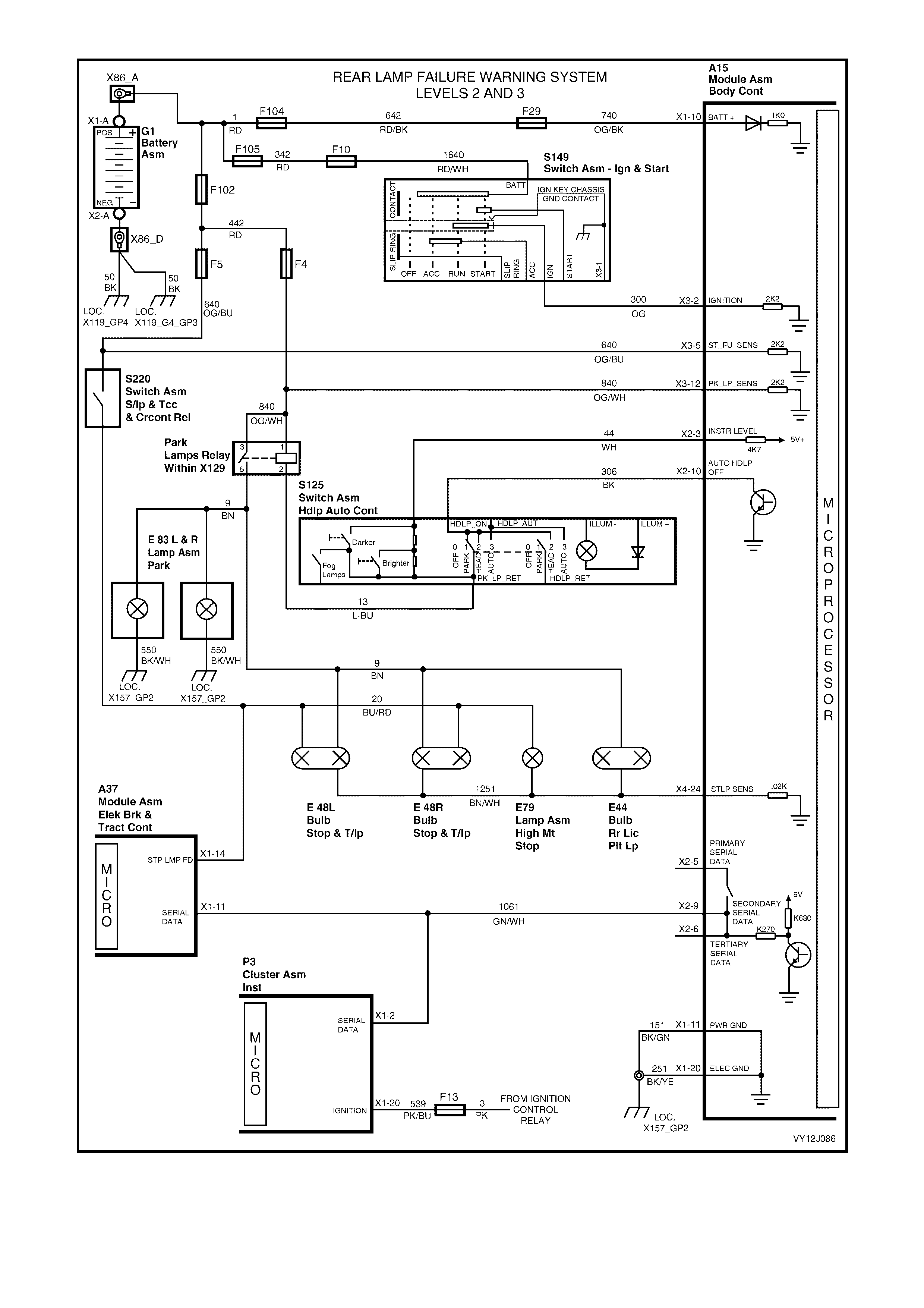

1.21 HAZARD LAMP CONTROL
SYSTEM OPERATION
Pressing the remote c oded key lock button to ar m the theft deter rent system and loc k the doors s ignals the BCM to
drive the left and right indicator lamps to simultaneously flash once. Pressing the lock button on the remote again
activates the deadlock function and signals the BCM to turn on the left and right indicator lamps continuously for
approxim ately 3 seconds. Pres sing the k ey unlock button s ignals the BCM to dr ive the left and r ight indicator lam ps
to simultaneously flash twice.
NOTE: Passive arming of the system does not signal the BCM to operate the door-locks or flash the indicators.
As the hazard-warning switch is activated the BCM senses the input and uses an internal relay to simultaneously
flash the left and right indicator lamps.
CIRCUIT OPERATION
As the r emote coded key is operated it sends an RF signal to the BCM, the BCM s ens es a valid RF s ignal. If a valid
lock signal is detected, the BCM will pulse the left side indicator lamps once via circuit 1314 (Light-blue wire) and
the right side indicator lamps via circuit 1315 (Blue wire). Refer to Figure 12J-116.
Inputs
As the hazard-warning switch is ac tivated, the hazard lamp c ontrol input cir cuit 111 (Brown wire) is pulled to ground
via BCM terminal X3-16. Refer to Figure 12J-116. The BCM senses this input and drives the internal hazard
indicator relay to pulse 12 volts to circuits 1314 (Light-blue wire) and 1315 ( Blue wire). Power applied to the internal
indicator relay is via fuse F7, circuit 140 (Orange / Red wire) and BCM terminal X1-13.
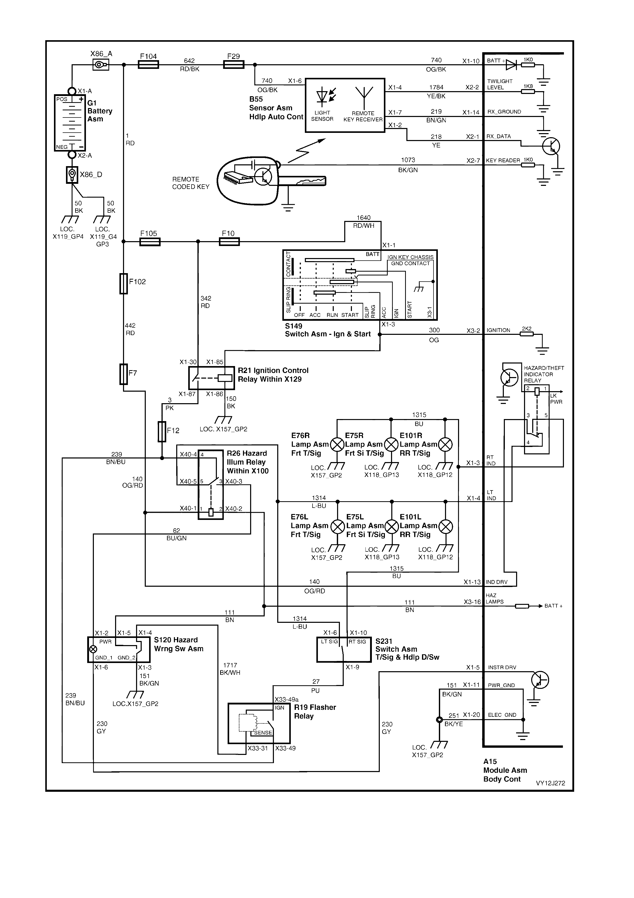
Figure 12J-116

2. SERVICE OPERATIONS
IMPORTANT
All fasteners are important attaching parts as they affect the performance of vital components and / or
could result in major repair expense. Where specified in this section, fasteners MUST be replaced with
parts of the same part number or a GM approved equivalent. Do not use fa steners of an inferior quality
or substitute design.
Torque values must be used as specified during reassembly to ensure proper retention of all
components.
Throughout this section, fastener torque wrench specifications may be accompanied w ith the following
identification marks:
+
++
+ Fasteners must be replaced after loosening.
&
&&
& Vehicle must be at curb height before final tightening.
6
66
6 Fasteners either have micro encapsulated sealant applied or incorporate a mechanical thread lock
and should only be re-used once. If in doubt, replacement is recommended.
If one of these identification marks is present alongside a fastener torque wrench specification, the
recommendation regarding that fastener must be adhered to.
2.1 BODY CONTROL MODULE
LT Section – 02-000
On RHD vehicles, the BCM is located under the right-hand side of the instrument panel, positioned vertically behind
the fuse panel. On LHD ve hic les, the BC M is pos it ioned hor i zont al ly on the base of the HVAC unit.
The BCM has four wiring harness connectors: X1, X2, X3 and X4. For a list of each terminal within these
connectors, and their associated circuit and function, refer to 1. GENERAL INFORMATION in this Section.
SAFETY AND PRECAUTIONARY MEASURES
The main power supply to the BCM is via Fuse 31. Other power supplies to the BCM also exist and so
disconnection of the battery is necessary before disconnection of the BCM.
IMPORTANT: Disconnection of the battery affects certain vehicle electronic systems. Refer to Section 00, 5.
BATTERY DISCONNECTION PROCEDURES before dis c onn ecting the battery.
NOTE: Disc onnect and r emove all ve hicl e modules (aft er dis c onnecti ng the b atter y) befor e perf orming an y weldin g,
anywhere o n the vehicle. Ref er to Section 00, 5. BATTERY DISCONNECTION PROCEDURES. Fa iling to do this
can cause permanent damage to the modules.
• Never subject the BCM to temperatures above 85° C (such as in a paint oven). If this temperature is to be
exceeded, remove the BCM first.
• For normal use, ensure that all wiring harness connectors are fitted solidly and that the battery terminals are
thoroughly clean and fitted firmly.
Disconnect the batt ery when charging it. Ref er to Section 00, 5. BATTERY DISCONNECTION PROCEDURES.
Never connect or disconnect the BCM wiring harness connector while the ignition is switched on.
Never disconnect the battery while the engine is running.
Connecting the battery will reset the following functions:
• antenna height (resets to maximum)
• instrument illumination value (resets to maximum)
• various instrumentation values. Refer to Section 12C, INSTRUMENTS.
Following battery connection, the BCM relearn procedure will be required for the following systems:
• stop lamp monitoring (relearns the current draw)
• rear park lamps (relearns the current draw)
• wiper dwell (relearns the dwell interval value).
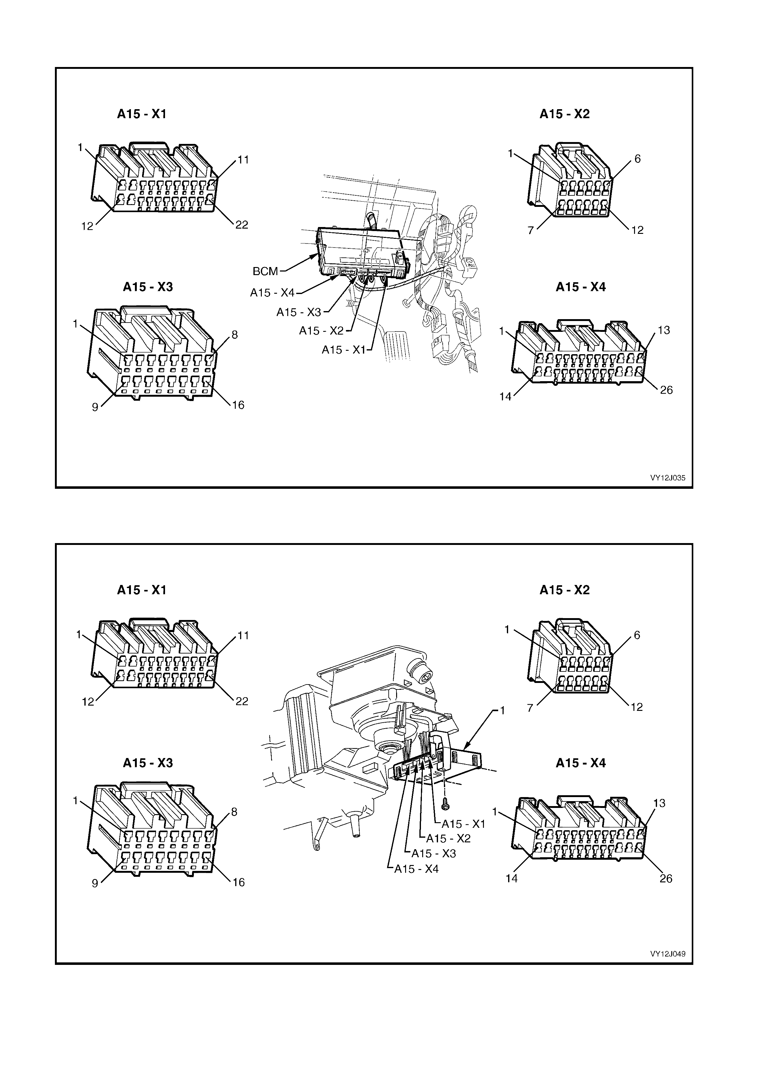
BCM CONNECTORS AND RHD LOCATION
Figure 12J-116
BCM CONNECTORS AND LHD LOCATION
Figure 12J-117
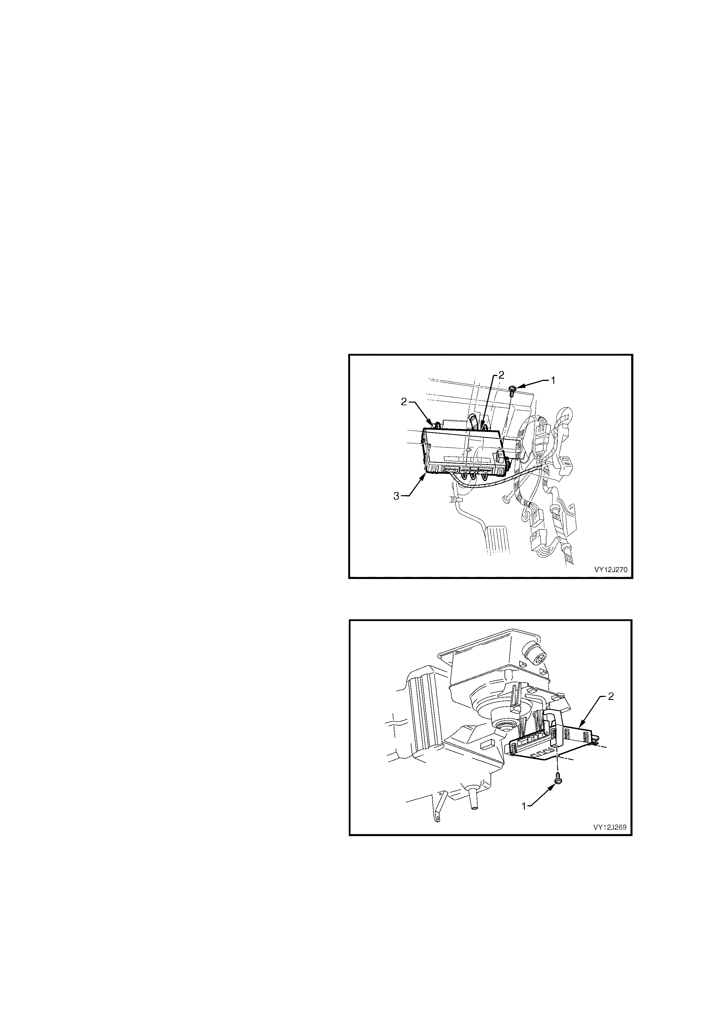
REMOVE
Access to BCM without disconnection
If accessing the BCM but n ot removing it (ie. to c arry out BCM diagnostic check s as outlined in some tests in this
Section), perform only Steps 5 and 6 of the Removal procedure.
Removal
NOTE: If the BCM is being removed and will be replaced by a new BCM, start at Step 1. If the original BCM is to be
installed again, start at Step 3.
1. Connect TECH 2 to the DLC.
2. Perform the TECH 2 Learn BCM Settings
procedure. Refer to 3.9 PROGRAM, LEARN
BCM SETTINGS in this Section.
3. Before disconnecting the battery, refer to
Section 00, 5. BATTERY DISCONNECTION
PROCEDURES.
4. Disconnect the battery negati ve terminal.
5. From beneat h the instr um ent panel r em ove the
scrivets securing the bottom (foot well) cover,
and remove the cover.
RHD Vehicles
6. Remove the scrivet (1) attaching the BCM (3)
to the steering column outer support bracket.
7. Release the two rear retaining tangs (2) and
gently manoeuvre the BCM from the top
mounting bracket. (Remember that the wiring
harness is still connected.)
Figure 12J-118
LHD Vehicles
6. Remove the scrivet (1) attaching the BCM (2)
to the passenger air bag rail.
7. Release the rear retaining tang and gently
manoeuvre the BCM from the mounting
bracket. (Remember that the wiring harness is
still connected.)
Figure 12J-119
8. Disconnect the four wiring harness connectors
by pressing each connector tang and pulling
the connector away from the module.

REINST ALL
1. Install the BCM in the reverse of the removal procedure ensuring that the lugs adjacent to the retaining tangs
are correctly located.
2. Ensure that the BCM is firmly installed in the mounting brackets.
BODY CONTROL MODULE
RETAINING SCREW
TORQUE SPECIFICATION 1 - 3 Nm
3. Perform the appropriate procedure following, based on whether the BCM is the one previously fitted (original)
or a replacement (new).
Original BCM
a. Perform the Program Learnt BCM Settings procedure. Refer to 3.9 PROGRAM, PROGRAM BCM
SETTINGS in this Section.
New BCM
NOTE: The replacement BCM must be the same feature level as the removed BCM. TECH 2 will identify an
incorrect BCM and indicate a mismatch.
a. Connect TECH 2 to the DLC.
b. Perform the Program Learnt BCM Settings procedure. Refer to 3.9 PROGRAM, PROGRAM LEARNT
BCM SETTINGS in this Section.
c. Perform the BCM linking procedure. Refer to 3.10 SECURITY, BCM LINK TO PCM/PIM in this Section.
d. Perform the BCM Relearn Procedure. Refer to BCM RELEARN PROCEDURE following.
For additional information regarding TECH 2, refer to Section 0C, TECH 2.
BCM RELEARN PROCEDURE
NOTE: The following procedure is not applicable to low series vehicles.
The following procedure must be carried out if the battery has been disconnected, or upon the installation of a
BCM.
1. Ensure that all rear lights are working.
2. Ensure that the ignition is off, park lamps are off and the brake pedal is released (stop lights off).
3. Remove and install fuse F31 from the engine compartment relay housing.
4. Start the engine and allow the engine to idle.
5. Press the brake pedal and hold for 5 seconds. Release the brake pedal.
6. Turn the park lamps on and leave on for 5 seconds.
7. W ith the park lamps still on, press the brake pedal and hold for 5 seconds. Release the brake pedal and turn
the park lamps off.
8. If fitted, turn the windscreen wiper dwell control fully clockwise and hold for 5 seconds, then turn it fully
anticlockwise and hold for 5 seconds. Turn the wipers off.
9. Turn the ignition off.
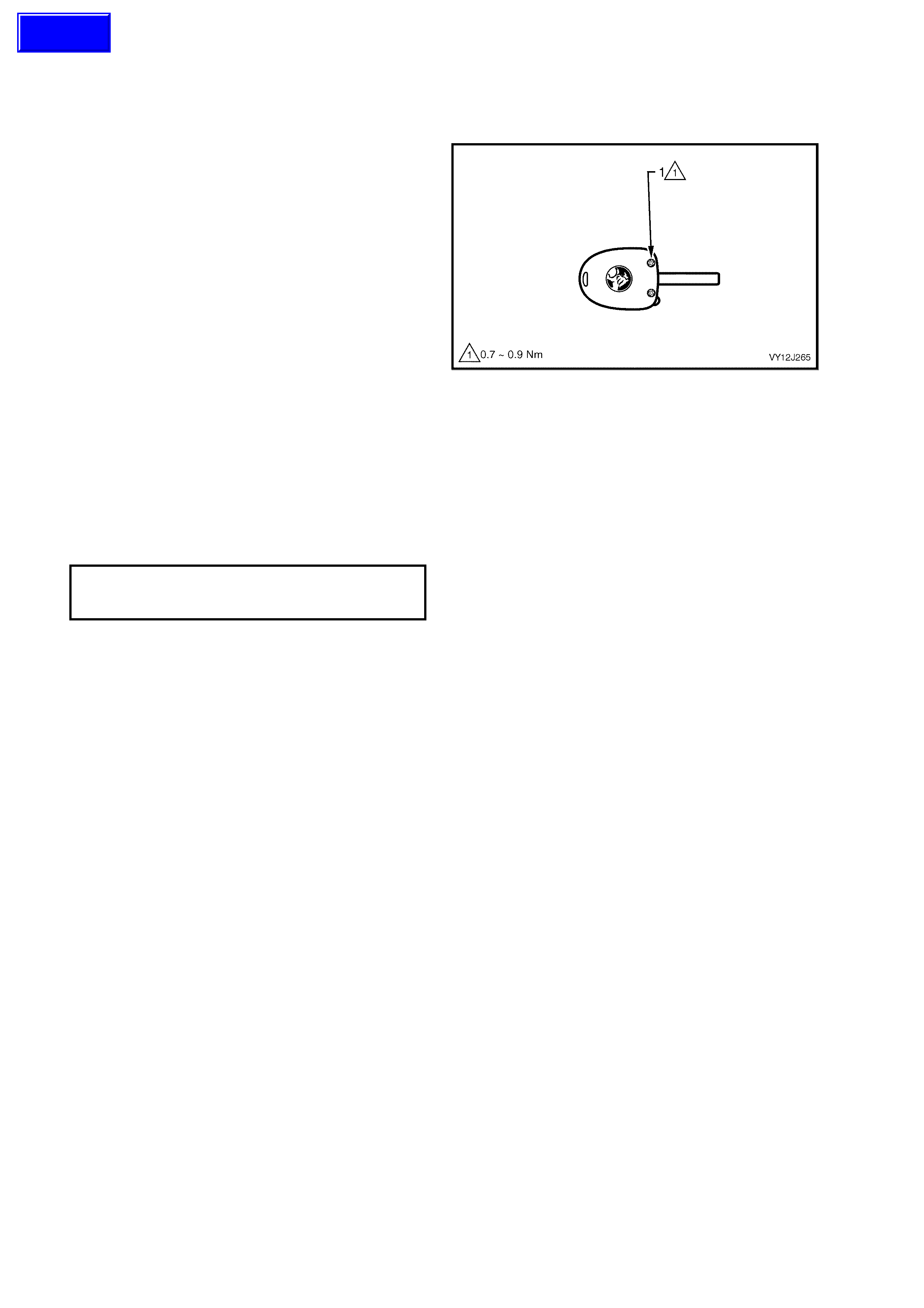
2.2 RE MOTE CODED KEY
LT Section – 06-255
KEY REPLACEMENT
NOTE 1: The r em ote c ode d key is a ‘s ea led f or lif e’
unit (non rem ovable batter y) , therefore the hous ing
cannot be s eparated. T he batter y life expec tanc y is
approximately five to ten years.
NOTE 2: Replacement of a remote coded key will
necessitate programming the BCM to accept the
new key’s serial output data. Programming of the
remote coded key can only be performed by an
authorised Holden service outlet or authorised
lock smiths, when provi ded with the corr ect security
information.
1. Loosen and remove the two (posi-drive)
screws (1), securing the key to the remote key
holder.
2. Grab hold of the key tip and pull it from the
remote key holder.
3. Assemble the key into the new remote key
holder.
4. Insert the two (posi-drive) screws and start
threads by hand. Tighten the screws to the
correct torque specification. Discard the
unserviceable key holder.
REMOTE CODED KEY
HOUSING SCREW
TORQUE SPECIFICATION 0.7 – 0.9 Nm
Figure 12J-120
Techline
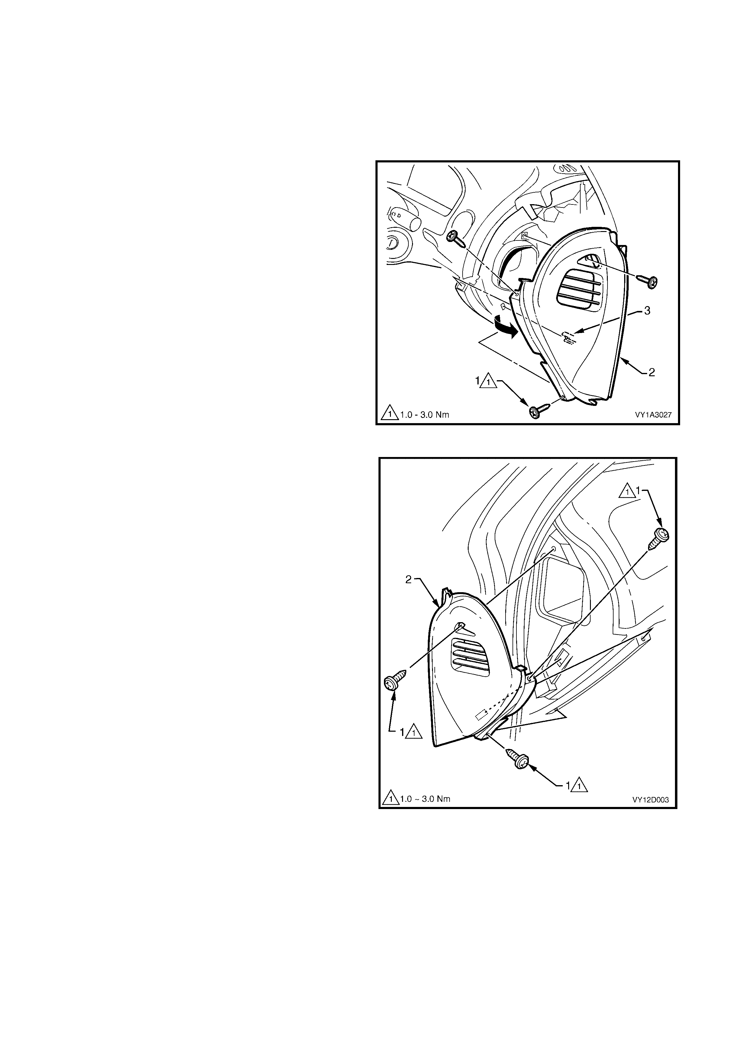
2.3 REMOTE RECEIVER
LT Section – 08-155A
NOTE: The sun load and am bient ligh t s ens or is par t
of the remote receiver.
REMOVE
1. Ensure that the radio/CD player is turned off.
2. Remove the three screws (1) securing the
right-hand side instrument panel outer cover (2)
and remove the cover.
3. Remove the cover by rotating it outward to
disengage the retaining clip (3) and the
ventilat ion duc ts .
Figure 12J-121
4. Remove the three screws (1) securing the left-
hand side instrument panel outer cover (2) and
remove the cover.
Figure 12J-122
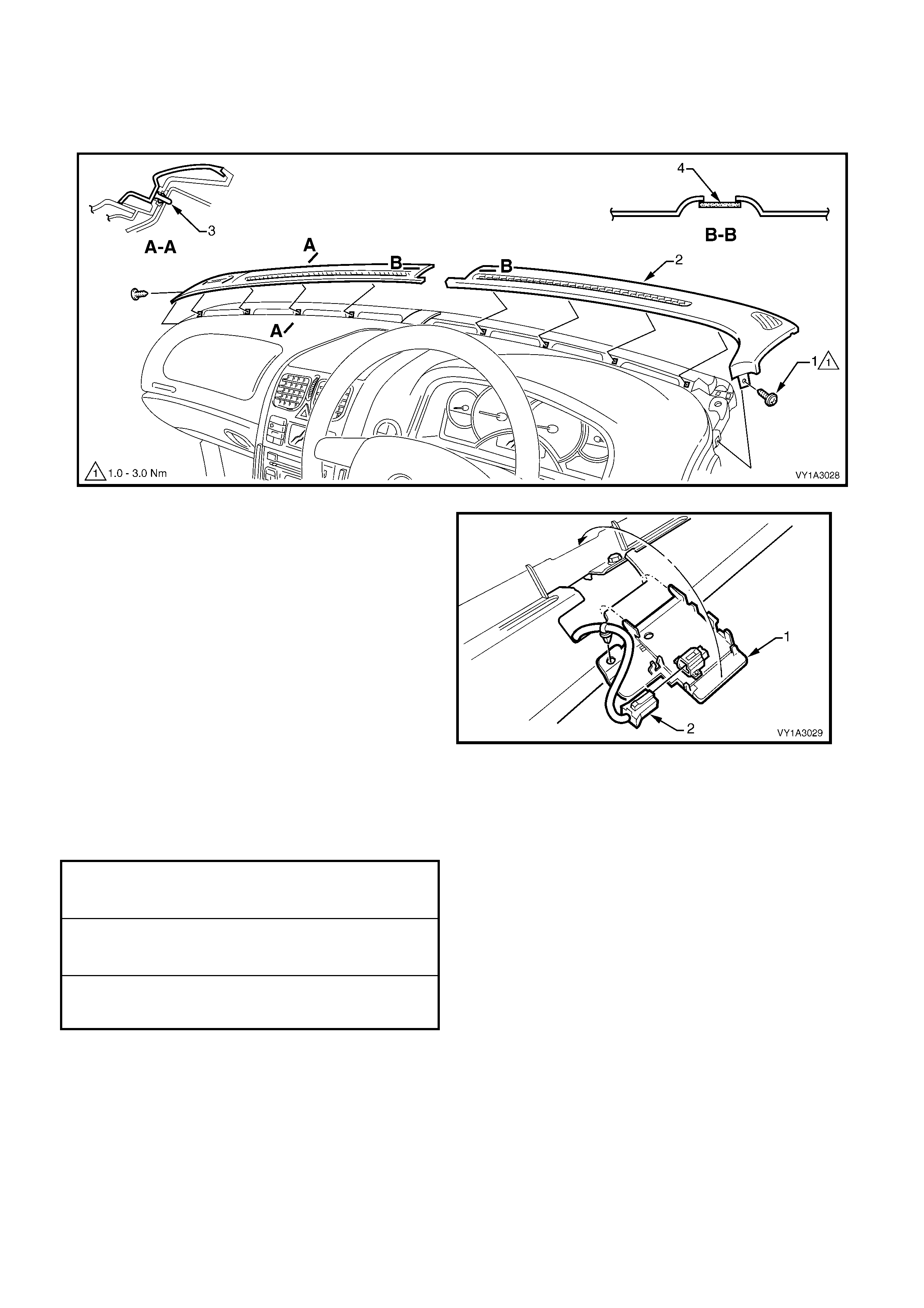
5. Remove the retaining screw (1) from the right-hand side windshield defroster grille (2) and remove the grille.
6. Carefully remove the grille by unclipping (3), four places, at an angle equal to the windshield.
7. Repeat for the left-hand defroster grille.
NOTE: On all vehicles, care must be taken to avoid damage to the sun load sensor (4).
Figure 12J-123
8. Carefully unclip the remote receiver and
sensor (1) from the instrument panel.
9. Disconnect the wiring connector (2), unclip the
wiring harness from the sensor assembly and
remove.
NOTE: For service and diagnosis of the sun load
sensor, refer to Section 2F, HVAC OCCUPANT
CLIMATE CONTROL (AUTO A/C) –
DIAGNOSTICS.
Figure 12J-124
REINST ALL
Installation is the reverse of the removal procedure.
Tighten the retaining screws to the correct torque
specification.
INSTRUMENT PANEL SPEAKER
RETAINING SCREW
TORQUE SPECIFICATION 1.0 – 3.0 Nm
DEFROSTER GRILLE
RETAINING SCREW
TORQUE SPECIFICATION 1.0 – 3.0 Nm
INSTRUMENT PANEL OUTER
COVER RETAINING SCREW
TORQUE SPECIFICATION 1.0 – 3.0 Nm

2.4 POWER WINDOW DOOR SWITCHES
LT Section – 02-775
REMOVE
1. Carefully prise the lower edge of the switch (1)
from the rear door trim assembly.
2. Disconnect the harness connector and remove
the switch.
REINST ALL
Installation of the rear door window switch is the
reverse of the removal, noting the following.
1. Insert the upper edge of the switch then press
the assembly firmly into the door trim.
Figure 12J-125

3. TECH 2 DIAGNOSIS FOR BCM
3.1 BASIC KNOWLEDGE REQUIRED
Before attempting to diagnose the BCM you must have a good understanding of electrical system basics and the
use of c ircuit testing t ools. W ithout this basic k nowledge it will be d ifficult to us e the diag nostic proc edures d etailed
in this Section.
Some electrical basics, as well as basic troubleshooting procedures and hints, such as the use of circuit testing
tools are cover ed in Section 12P, WIRING DIAGRAMS.
Basic Electrical Circuits — You should understand the basic theory of electricity, series and parallel circuits and
voltage drops across series resistors. You should know the meaning of voltage (volts), current (amps), and
resistanc e (o hms ). You s ho uld un der st an d what ha ppe ns in a c irc uit with an op en or shor te d wir e (s hor t ed eit her t o
voltage or ground). You should also be able to read and understand a wiring diagram.
Additionally, knowledge of AC theory including inductance, capacitance and impedance would be useful.
Use of Circuit T esting Tools — You should know how to use a jumper lead to test circuits. You shou ld be familiar
with the use of a hig h input im pedance ( 10 Megohm ) digital type m ultim eter suc h as T ool No. J392 00 or e quivale nt
and be ab le to m easure v oltage, cur rent and r esistanc e. You sh ould be f amiliar with the pr oper use of the T ECH 2
Diagnostic Sc an Tool .
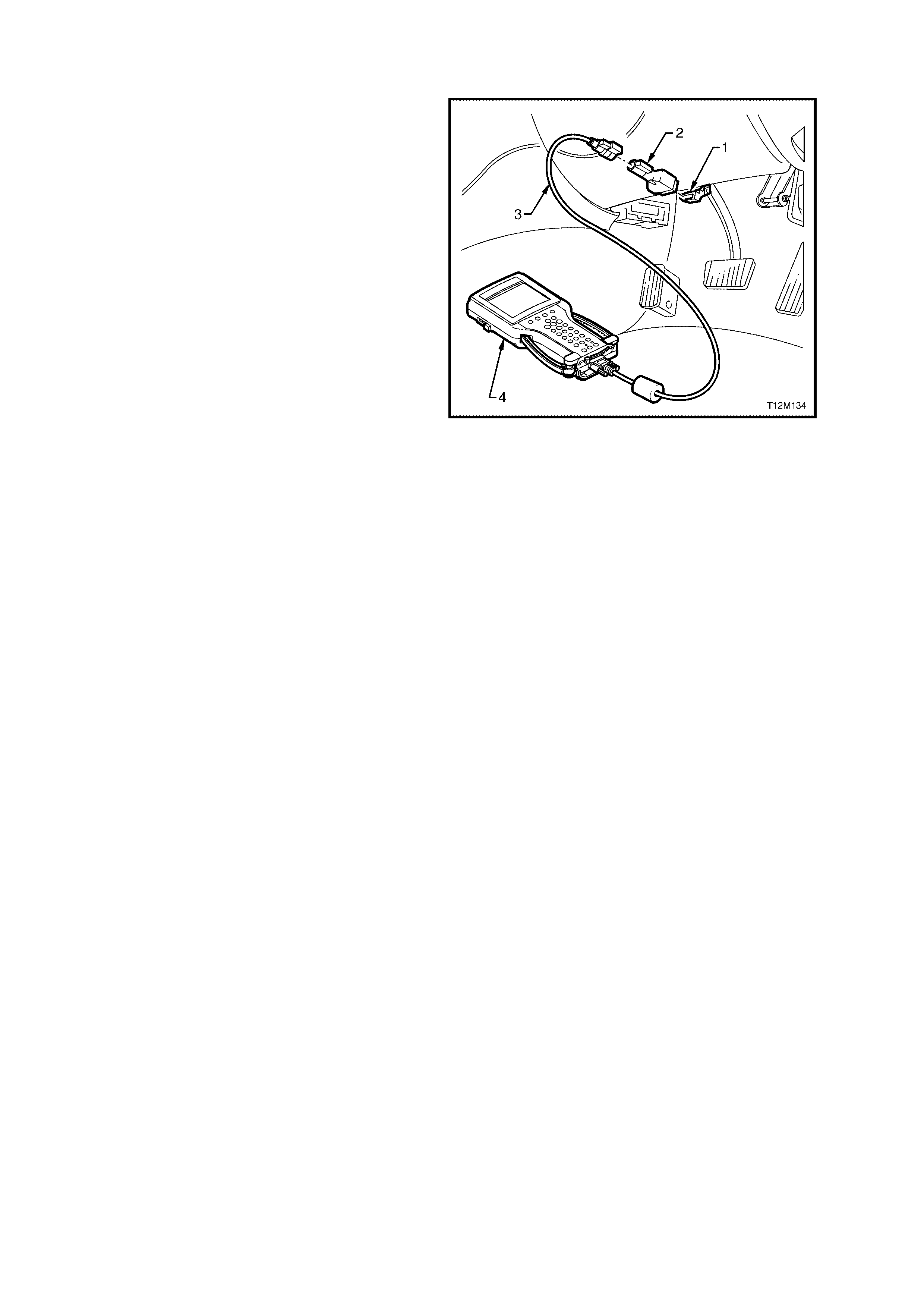
3.2 CONNECTING TECH 2 FOR SYSTEM DIAGNOSIS
TECH 2, with the appropriate software, cables and
adaptors, is capable of reading the BCM serial data
when connec t ed t o th e Dat a Li nk Connec tor (DL C ).
The DLC is connected to the instrument panel
lower right-hand trim, to the right of the steering
column.
1. Data Link Connector (DLC)
2. DLC Adaptor
3. DLC Cable
4. TECH 2
For additional general information on
connecting and operating TECH 2, refer to
Section 0C, TECH 2.
Figure 12J-127
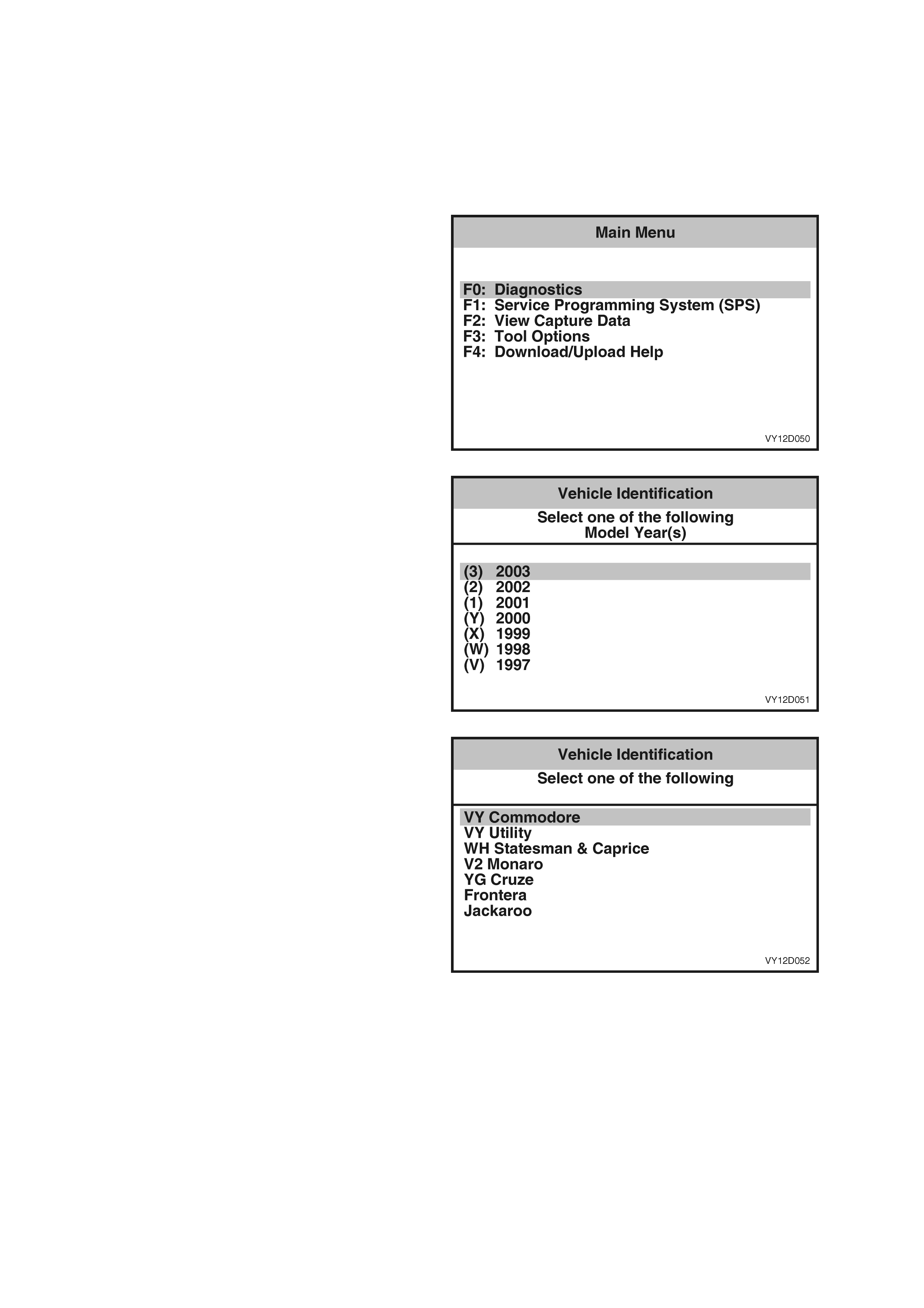
3.3 TECH 2 TES T MODES AND DISPLAYS
A prerequisite of this diagnostic section is for the user to be f amiliar with the pro per use of TECH 2. The following
pages illustrate only the major TECH 2 screen displays and provide a brief explanation of their function for
diagnosing the BCM system . If additional information is required on the operation of TECH 2, reference should be
made to either Section 0C TECH 2 or the TECH 2 User’s Guide.
W ith the ignition turne d off, connect the T ECH 2 to the Data Link Connector (DLC ) using the DLC Adaptor, r efer to
3.2 CONNECTING TECH 2 FOR SYSTEM DIAGNOSIS in this Section.
MAIN MENU
Turn the ignition on and press the power button
(PWR) on TECH 2.
TECH 2 will perform a series of self-diagnosing
power on self-tests (POST). Once this has been
completed successfully, the TECH 2 startup screen
will be displayed. Press the Enter key to continue.
The Main Menu screen is displayed.
Press the F0 function button or Select F0:
Diagnostics by using the arrow keys until F0:
Diagnostics is highlighted and pressing the Enter
key.
Figure 12J-128
Model Year
Select the appropriate Model Year and press
Enter.
Figure 12J-129
Vehicle Identification Menu
Select the appropriate vehicle type from the list and
press Enter.
Figure 12J-130
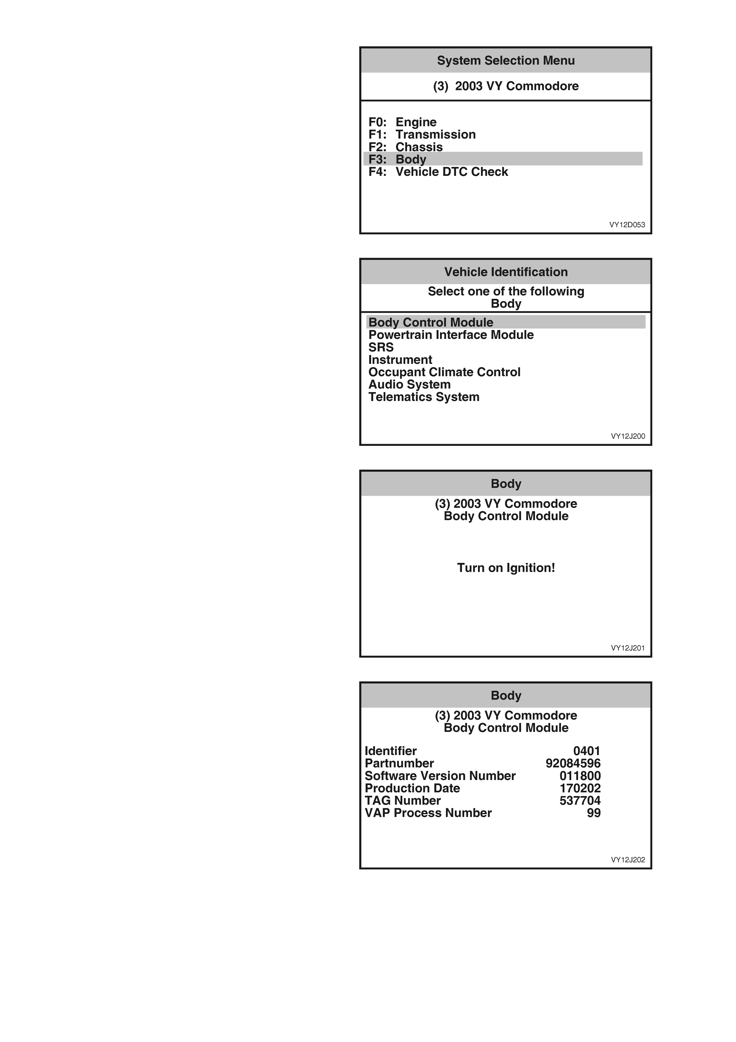
System Selection Menu
Select F3: Body from the System Selection Menu
and press Enter .
Figure 12J-131
Body Control Module Selection
Select Body Control Module and press Enter.
Figure 12J-132
Turn the ignition on (as requested) and press the
Confirm soft key to continue.
Figure 12J-133
The BCM identification details will be displayed.
Scroll through the list using the TECH 2 Up and
Do wn a r ro w k eys.
Figure 12J-134
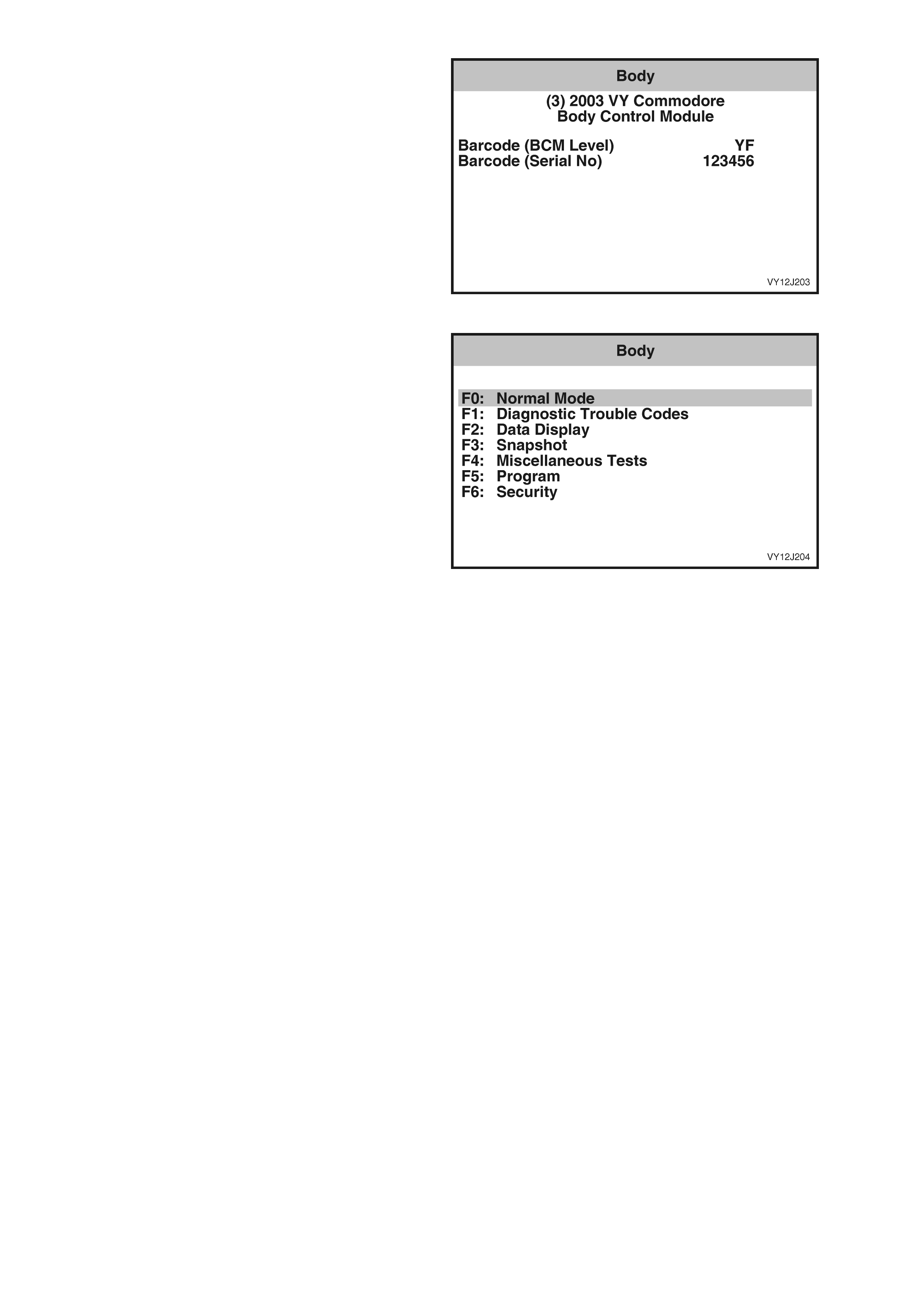
Press the C onfirm soft key to confirm these details
and the Bod y Menu will be displ a yed.
Figure 12J-135
BODY MENU
1. Select Body Control Module at the Vehicle
Identification Menu and press the Enter key.
The Body Menu provides the TECH 2 user with
access to the various functions used to diagnose
faults in the BCM.
F0: Normal Mode
The normal mode data list is used to view serial
data being sent to and from the BCM. Refer to
3.4 NORMAL MODE in this Section.
F1: Diagnostic Trouble Codes
In this mode, Diagnostic Trouble Codes can be
read and cleared. Refer to 3.5 DIAGNOSTIC
TROUBLE CODES in this Sec ti on.
F2: Data Display
In this mode, TECH 2 displays the status of BCM
inputs an d ou tputs . Ref er to 3.6 DATA DISPLAY in
this Section.
F3: Snapshot
In this test mode, TECH 2 captures data before
and after a forced manual error. Refer to
3.7 SN APSHOT in this Section.
F4: Miscellaneous Tests
In this test mode, TECH 2 can test and diagnose
faults in the BCM. Refer to 3.8 MISCELLANEOUS
TESTS in this Section.
F5: Program
User settings and options controlled by the BCM
can be programmed when this mode is selected.
Refer to 3.9 PROGRAM in this Section.
F6: Security
Security information can be viewed and
programmed when this mode is selected. Refer to
3.10 SECURITY in this Section.
Figure 12J-136

3.4 NORMAL MODE
1. From the Body Menu, select Normal Mode
and press the Enter k e y.
Figure 12J-137
The Normal Mode data list is used to view serial data being sent to and from the BCM.
The Normal Mode data list is as follows.
TECH 2 DISPLAY RANGE REMARKS
Ignition Switch Off = 0 volts
On = 12 volts Displays the current status of the ignition
switch.
Ignition Off Time XX min Displays the length of time in minutes since
the ignition was last switched off.
Accesso ries Switch On / Off Displays the current status of the
accessories switch.
Instrument Lamps 0% – 100% Displays the instrument cluster illumination
level.
Lights On Yes / No Displays the current status of the headlamp
switch.
Sun Load Between 0 and 254 Displays the ambient light level as detected
by the sun sensor.
Rear Compartment Closed / Open Displays the status of the rear
compartment lid switch.
Rear Lamp Fuse Fail Yes / No Displays the status of the rear lamp fuse.
Rear Brake Bulb Fail Yes / No Displays the status of the stop lamps.
Rear Lamp Bulb Fail Yes / No Displays the status of the rear park lamps.
Front Wiper Status On / Off Displays the status of the front wiper drive.
A/C Request
(Air Conditioning) On / Off Displays the status of the air conditioner.
BCM Low Fan Drive On / Off Displays the status of the engine low speed
fan.
Alarm Inactive / Triggered Indicates if an alarm has been activated.
Alarm Trigger Source Driver’s Door / Passenger’s Door / Rear
Compartment / Bonnet / Ignition / Not
Detected Indicates the source of a triggered alarm.
Key Priority 1 / 2 Displays the priority key in use.
BCM DTC Status No DTC / DTCs Set Indicates if any BCM DTC have been set.
MFD Message
(Multi-Function
Display) Yes / No Indicates when a message is sent to the
instrument cluster.
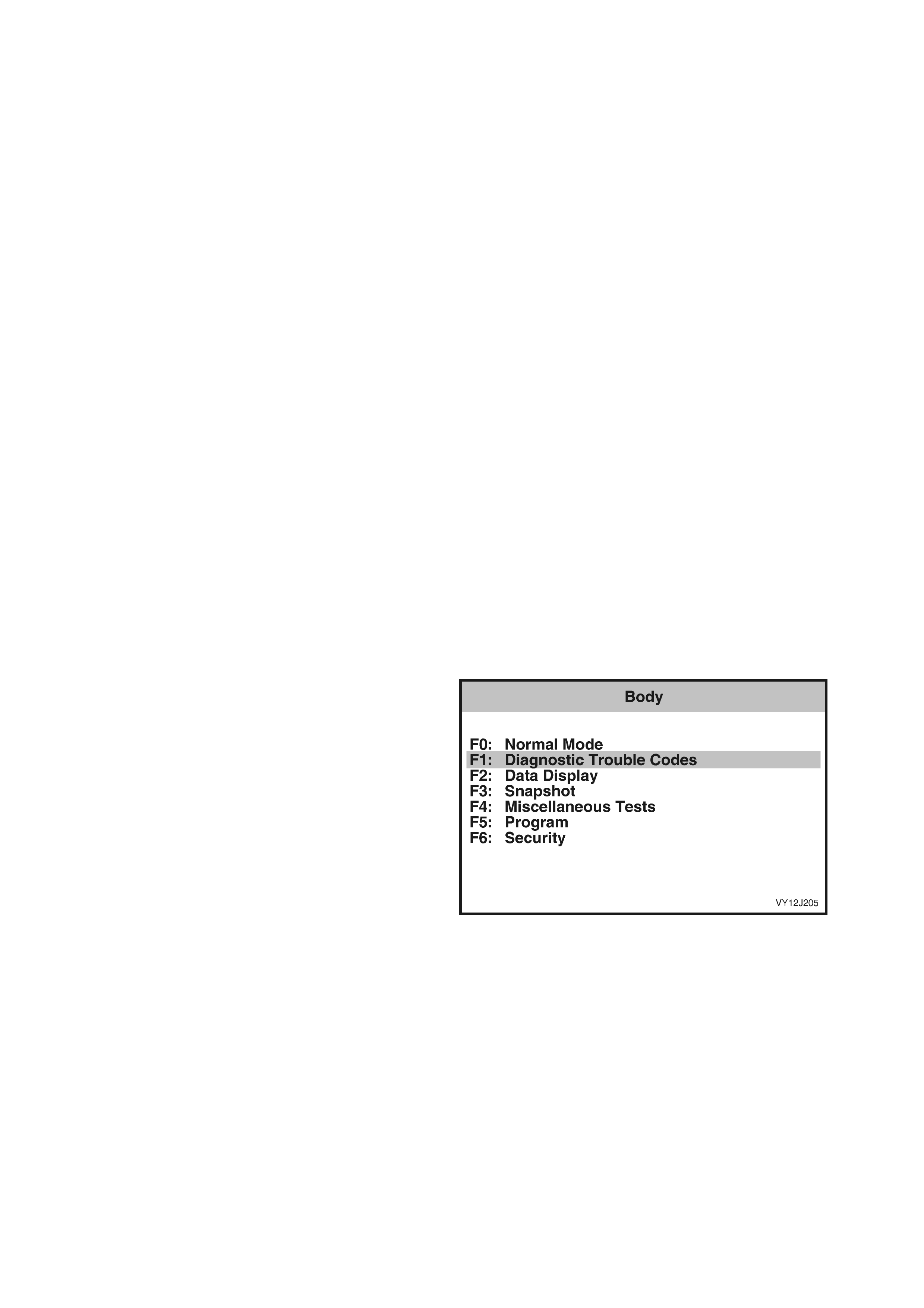
3.5 DIAGNOSTIC TR OUBLE CODES
The maximum number of individual DTCs associated with the BCM is 24. The five most recent DTCs that have
occurr ed will be log ged into EE PROM i n the BCM int o a tab le known as the DTC List. T he DTC List only has spac e
allocate d f or f ive en tries . T her ef or e, if more than f ive DTCs are logge d, o nly the las t f ive will be tr acked. T hat is , the
oldest DTC will be removed from the list regardless of its position within the list.
The format of the DTC List is as follows:
List Position Position within the list numbered from 1 to 5.
DTC Number The DTC number is the number used to identify a particular fault condition.
Occurrence Count
(0 to 255) The Occurrence Count is the number of times the particular fault condition has been
detected.
History Count
(0 to 255) The History Count is the number of ignition cycles that have occurred since the fault
was last detecte d. A count of 0 indicates the fault has occurred on the current ignition
cycle, whil e a c ount of 255 i ndicates that the f aul t occ urr ed 255 or more igniti on c yc les
ago.
Algorit hm s for detec ting ea ch f ault conditi on and s ettin g the corr espond ing DT C var y. However, a p articu lar DTC is
only set once per ignition cycle. When a DTC is set, the following occurs:
• If the DTC does not exist in the DTC List, it is inserted into the list at the first vacant location with the
Occurrence Count set to 1 and the History Count set to 0. In the event of the DTC List being full, the oldest
DTC will be rem oved from the list. The H istory Count determ ines the age of a D TC List entr y. The it em in the
list with the highest History Count will be removed to make space for the new DTC.
• If the DT C already exis ts in the DT C List, then th e Occurrence Cou nt will be increm ented (up to 255, at which
point it is no longer incremented). Each time the DTC is set, the History Count is cleared.
This ensures that the f ive m ost recent f ault condi tions ar e track ed. The O ccur rence and Hist ory Count ers pr ovide a
means of determ ining how often the f ault has occ urred, and how long it has be en since th e fault las t occur red. For
instance, if the DTC Occurrence Count is 1, and the History Count is 201, then it can be determ ined that the fault
condition existed only once, and it happened 201 ignition cycles ago (and has not been detected since). Another
exam ple would be an Occ urrence Count of 4 and a Histor y Cou nt of 0. This woul d indicate that the f ault has bee n
detected a total of four times, and that it was detected on the current ignition cycle.
The DT Cs are not removed f rom the list un less five ne wer fault c onditi ons occ ur pushin g the old est f ault off the list ,
or they are cleared using TECH 2.
1. From the Body Menu, select Diagnostic
Trouble Codes and press the Enter key.
Figure 12J-138
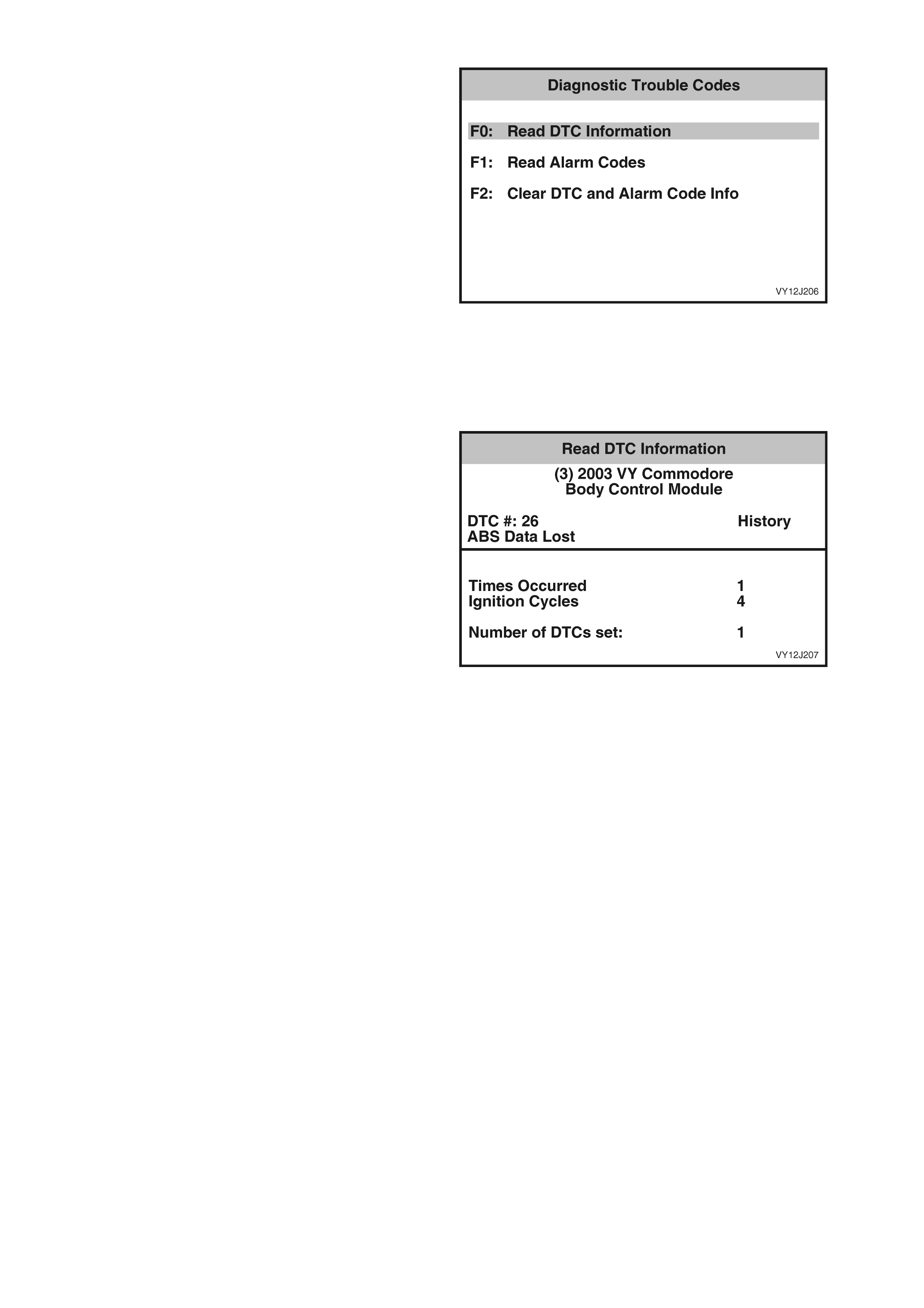
DIAGNOSTIC TROUBLE CODES MENU
F0: Read DTC Information. If this mode is
selected , a l istin g of a ll (if a n y) DT C th at ha ve bee n
set by the BCM will be displayed.
NOTE: If any DTC are set, reference should be
made to the relevant diagnostic charts in this
Section.
F1: Read Alarm Codes. All Alarm Codes are
displa yed in seque nc e.
F2: Clear DTC and Alarm Code Info. DTCs and
Alarm Codes can be cleared together in this mode
by simply selecting F2: Clear DTCs and Alarm
Codes, pressing the Enter key on TECH 2 and
confirming the action as instructed by TECH 2.
NOTE: TECH 2 will displa y Clear DTCs and Alarm
Codes Failed if any DTC or Alarm Codes are still
current.
Figure 12J-139
READ DTC INFORMA TION
1. Select F0: Read DTC Information and press
the Enter ke y.
Use the following table to assist in diagnosing and
rectifying DTC.
2. Press the Exit key to return to the Diagnostic
Trouble Codes screen.
Figure 12J-140

The following table sets out the diagnostic trouble codes for the BCM.
DTC CODE DESCRIPTION REFER
1 Output Overload. The DTC sets when a short to
battery voltage is detected on the following outputs:
Indicators, Front Intermittent Wiper, Aircon / Priority 2,
Demist / Priority 1, Main Horn, Accessory Relay and
Low Speed Fan.
When DTC 1 is set, refer to the section relevant to the
function listed.
Note: DTC 1 can also be set by electrical transients.
Therefore, if DTC 1 is set and there are no noticeable
problems with the vehicle, clear DTC and check
function of BCM outputs. If DTC does not reset and
BCM outputs are functioning correctly, disregard
DTC 1.
2 Slip Ring Communication Error. Each time the BCM
receives a message with an invalid checksum via the
slip ring a counter is incremented. Twenty consecutive
bad messages mu st be received to set the DTC .
Refer to 4.7 THEFT DETERRENT SYSTEM in this
Section.
5 Tail Lamp Bulb Failure. The BCM monitors the
current in the tail lamp circuit. The DTC sets and
illuminates a telltale in the instrument cluster if the tail
lamp current is below the factory preset value for more
than 3 seconds.
Refer to 4.20 REAR LAMP FAILURE WARNING
SYSTEM in this Section.
6 Stop Lamp Bulb Failure. The BCM monitors the
current in the stop lamp circuit. The DTC sets and
illuminates a telltale in the instrument cluster if the stop
lamp current is below the factory preset value for more
than 3 seconds.
Refer to 4.20 REAR LAMP FAILURE WARNING
SYSTEM in this Section.
7 No Serial Data From PCM. The DTC sets if PCM
serial data lost for 10 seconds. Refer to 4.2 SERIAL DATA COMMUNICATION in this
Section.
17 Not Okay To Start Received From PCM. The DTC
sets when the BCM is in passive arm mode and
attempting to start without a valid slip ring message.
Refer to 4.3 REMOTE RECEIVER / KEY in this
Section.
18 Auxiliary (Secondary and Tertiary) Serial Data Bus
Fault. The data bus isolator will remain closed for
625 ms after entering the short loop poll sequence. If
no PCM communication is received, the isolator will be
opened. If the BCM receives PCM communication after
the isolator has been opened the DTC is set.
Refer to 4.2 SERIAL DATA COMMUNICATION in this
Section.
19 EEPROM Error. The EEPROM data is divided into
eight tables, and each table has a checksum. When
each table is loaded into RAM, the checksum is
verified. If the checksum is wrong the DTC is set.
Clear the DTC. If the DTC sets again, remove fuse F29
to reset the BCM.
20 RAM Error. The BCM maintains a RAM copy of the
EEPROM data. Each of the eight tables is checked
periodically to verify the checksum. If the checksum is
wrong the DTC is set.
Clear the DTC. If the DTC sets again, remove fuse F29
to reset the BCM.
21 Battery Voltage Too Low. The DTC sets if the battery
voltage drops below 8 V for 20 seconds. Refer to Section 6D1-1A, CHARGING SYSTEM – V6
ENGINE (100 AMP), Section 6D1-1B, CHARGING
SYSTEM – V6 ENGINE (120 AMP), Section 6D2-1,
CHARGING SYSTEM – V6 S/C ENGINE, or Section
6D3-1, CHARGING SYSTEM – GEN III V8 ENGINE as
appropriate for further diagnosis.
22 Battery Voltage Too High. The DTC sets if the battery
voltage is above 16 V for 20 seconds. Refer to Section 6D1-1A, CHARGING SYSTEM – V6
ENGINE (100 AMP), Section 6D1-1B, CHARGING
SYSTEM – V6 ENGINE (120 AMP), Section 6D2-1,
CHARGING SYSTEM – V6 S/C ENGINE, or Section
6D3-1, CHARGING SYSTEM – GEN III V8 ENGINE as
appropriate for further diagnosis.
23 Door Lock / Unlock Circuit Overload. The DTC sets
when the doors have been activated 10 times in rapid
succession. Once activated the doors will timeout for a
period of 32 seconds.
Refer to 4.5 CENTRAL DOOR LOCKING in this
Section.
24 Remote Key Rolling Code Error. Each time an RF
message is received the Rolling Code is checked. The
DTC sets if the Rolling Code is out of range.
To resynchronize the rolling code, turn the ignition on
with the remote key.
Techline
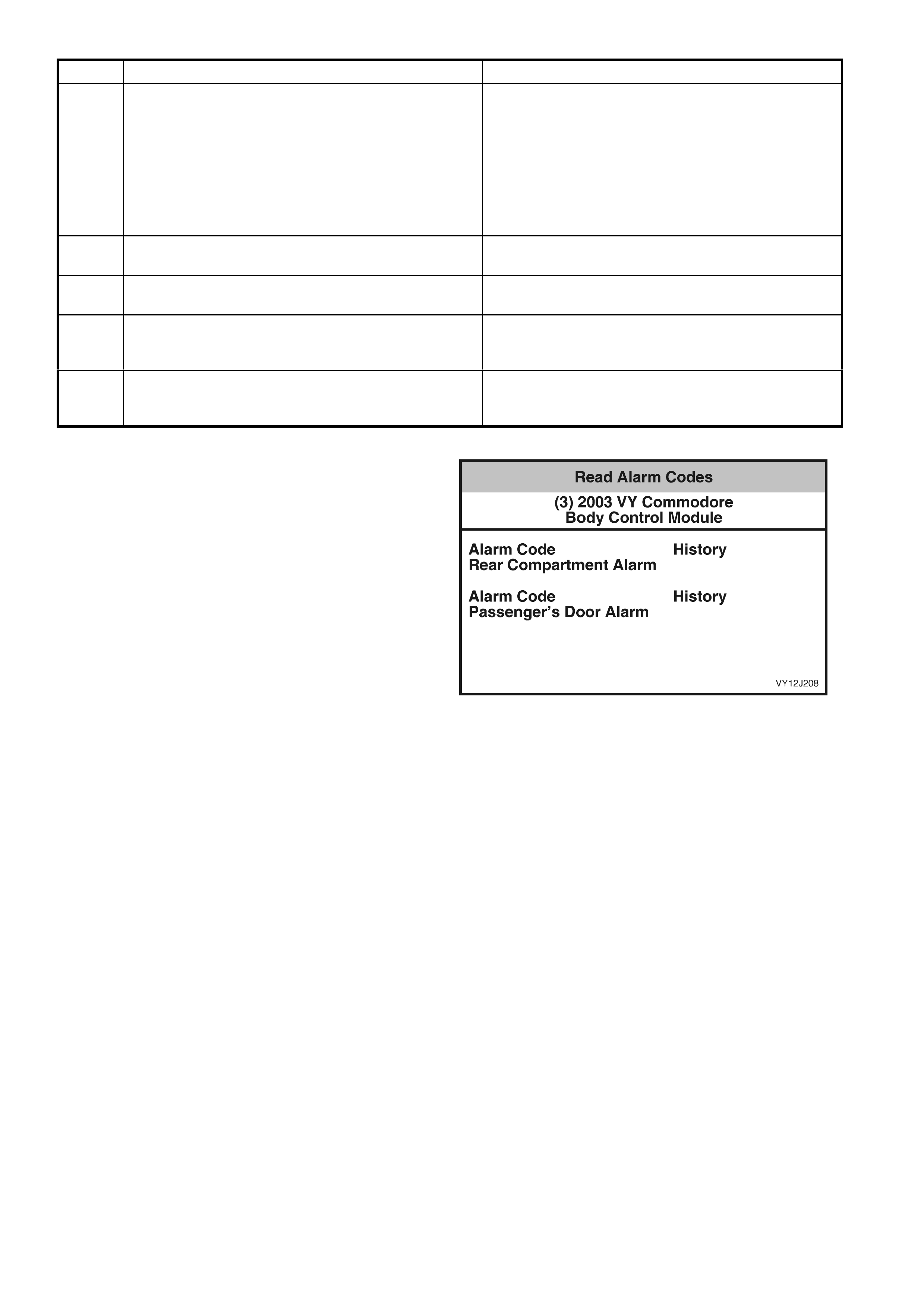
DTC CODE DESCRIPTION REFER
25 Engine Start Without Slip Ring Communications.
During key reading the BCM checks the engine speed
from the PCM. When the engine speed is above
500 rpm, the BCM will start a counter to track the
number of times the key has been powered up without
a valid message being received. When the counter
exceeds 20 the DTC is set. This corresponds to
5 seconds of invalid key communications after the
engine has been started.
Refer to 4.3 REMOTE RECEIVER / KEY in this
Section.
26 No Serial Data From ABS/ETC. The DTC is set if
ABS serial data lost for 10 seconds. Refer to 4.2 SERIAL DATA COMMUNICATION in this
Section.
27 No Serial Data From Instrument. The DTC is set if
instrument serial data lost for 10 seconds. Refer to 4.2 SERIAL DATA COMMUNICATION in this
Section.
28 Antenna Drive Circuit Overload. The DTC sets on
detection of a short to ground on the antenna drive
output.
Refer to 4.18 POWER ANTENNA CONTROL in this
Section.
29 Stop Lamp or Park Lamp Fuse Failure. The DTC
sets when the stop lamp or park lamp fuse voltage is
below battery voltage.
Refer to 4.20 REAR LAMP FAILURE WARNING
SYSTEM in this Section.
READ ALAR M CO D ES
1. From the Diagnostic Trouble Codes screen,
select F1: Read Alarm Codes and press the
Enter key.
Only History Alarm Codes are displayed.
Information on the number of times that the Alarm
has occurred and the number of ignition cycles
since the last occurrence are not displayed.
2. Press the Exit key to return to the Diagnostic
Trouble Codes screen.
Figure 12J-141

3.6 DATA DISPLAY
1. From the Body Menu, select Data Display and
press the Enter key.
Figure 12J-142
The Data Display screen provides a further breakdown to individual data lists for the following BCM functions.
1. The s erial data for e ach func tion can be viewed b y selecting the item and press ing the Enter k ey. The l ist can
be scrolled by using the Up and Down arrow keys. Press the Exit key to exit the data list.
• Inputs and Outputs • Central Door Locking • Rear Lamp Failure
• BCM Internal St atus • Power Windows • Air Conditioning Interface
• Serial Data Inputs • Wipers • Low Speed Cooling Fan
• Priorit y 1 User Settin gs • Headlamps • Antenna
• Priorit y 2 User Settin gs • Instrument panel Illumination • System Identification
• Alarm / Theft Deterrent • Interior Illumination
INPUTS AND OUT PUTS
The Inputs and Outputs data list is as follows. Press the Exit key at any time to return to the Data Display screen.
NOTE: Only the data relevant to the level of BCM installed and vehicle configuration will be displayed.
TECH 2 DISPLAY UNIT RANGE
Battery Voltage Volts
Ignition Switch On / Off
Accessory Switch On / Off
Accessory Relay On / Off
Interior Illumination Relay On / Off
Slip Ring Enabled Yes / No
Remote Key Function Boot Release Request / Lock Request / Unlock Request
Remote Key Number 1 / 2
Remote Key Status Valid Key / Invalid Code
Remote Key Priority 1 / 2
Key Priority Signal 1 / 2
Driver's Door Open / Closed
Passenger Doors Open / Closed
Bonnet Open / Closed
Rear Compartment Status Open / Closed
Rear Compartment Release Switch On / Off
Rear Compartment Solenoid Drive On / Off
Driver’s Door Unlock Switch On / Off
Passenger Doors Unlock Switch On / Off
Lock Switch On / Off
Deadlock Switch On / Off
Driver’s Door Unlock Drive On / Off

TECH 2 DISPLAY UNIT RANGE
Passenger’s Door Unlock Drive On / Off
Door Lock Drive On / Off
Deadlock Drive On / Off
Horn On / Off
Indicators On / Off
Hazard Warning Switch On / Off
Theft Deterrent Horn On / Off
Security LED On / Off
Power Window Relay Disabled / Enabled
Driver’s Window Switch Off / Down / Up / Invalid
Driver’s Window Auto Down Inactive / Active
Front Passenger’s Window Switch Off / Up / Down / Invalid
Front Passenger’s Window Auto Down Inactive / Active
Front Wiper Intermittent Switch On / Off
Front Wiper Intermittent Switch Voltage Volts
Intermittent Wiper Drive On / Off
Front Washer Pump Switch On / Off
Front Wiper Park Switch On / Off
Rear Wiper Switch On / Off
Rear Wiper Drive Not Present / Present
Rear Washer Pump Switch On / Off
Heated Rear Window Switch On / Off
Heated Rear Window Drive On / Off
Headlamp Switch On / Off
Headlamp Drive On / Off
Auto Headlamp Drive On / Off
Ambient Light Lux
Sun Load W/m2
Dome Lamp Switch On / Off / Door / Invalid
Dome Lamp Drive On / Off
Instrument Illumination Switch Off / Down / Up / Invalid
Instrument Illumination Switch Voltage Volts
Instrument Illumination Level % 35 – 100%
Rear Brake Lamp Fuse Failed / Okay
Rear Park Lamp Fuse Failed / Okay
Rear Brake Lamp Current Amps
Rear Park Lamp Current Amps
Radio Status On / Off
Antenna Off / Down / Up
A/C Switch (Air Conditioning) On / Off
A/C Blower Switch (Air Conditioning) On / Off
A/C Indicator (Air Conditioning) On / Off
Low Speed Cooling Fan On / Off
Serial Data Bus Isolation Normal / Data Cutoff

BCM INTERNAL STATUS
The BCM Internal Status data list is as follows. Press the Exit key at any time to return to the Data Display screen.
NOTE: Only the data relevant to the level of BCM installed and vehicle configuration will be displayed.
TECH 2 DISPLAY UNIT RANGE
Headlamp Switch On / Off
Low Speed Cooling Fan Run-On
Request Yes / No
Low Speed Cooling Fan Run-On Timer Seconds
Driver’s Window Auto Down Yes / No
Driver’s Window Auto Down Timer Seconds
Front Passenger’s Window Auto Down Yes / No
Front Passenger’s Window Auto Down
Timer Seconds
Filtered Ambient Ligh t Lux
Filtered Sun Load W /m 2
Front Wiper Dwell Time Seconds
Central Door Locking Unlocked / Unlocking / Locked / Locking /
Deadlocked / Undeadlocking / Deadlocking / Driver’s
Door Unlocking / Unlocking Door / Locking Failed /
Unlocking Failed / Driver Unlocking Failed
Rear Park and Brake Lamp Current A
Rear Park Lamp Current A
Rear Brake Lamp Current A
Instrument Illumination Switch Off / Down / Up / Invalid
Instrument Illumination Level % 35 – 100%
Antenna Height Target Seconds
Antenna Height Setting Seconds
Auto Lights Delay Seconds
Pre Delivery Mode Disabled / Enabled
Batter y Saver Shutdown T ime Minutes
Autolock in Drive Yes / No
Antenna Height Memory On / Off
Door Lock Indication Indicators / Horn and Indicators
Rear Wiper Continuous in Reverse Yes / No
Security Status Passenger Armed / Disarmed / Armed / Triggered
DTC Status No DTC / DTCs Set

SERIAL DATA INPUTS
The Serial Data Inputs data list is as follows. Press the Exit key at any time to return to the Data Display screen.
NOTE: Only the data relevant to the level of BCM installed and vehicle configuration will be displayed.
TECH 2 STRINGS UNIT RANGE
Vehicle Sp eed km/h
PRNDL Switch Invalid / 1 / 2 / 3 / D / N / R / P
PCM Theft Status Start / No Start
Low Speed Fan Request On / Off
Low Speed Fan Run On Yes / No
SRS Deployed This Ignition Cycle Yes / No
Radio On / Off
Antenna Required Yes / No
Antenna Switch Off / Down / Up
Stop Lamp Switch On / Off
PRIORITY 1 USER SETTINGS
The Priority 1 User Settings data list is as follows. Press the Exit key at any time to return to the Data Display
screen.
NOTE: Only the data relevant to the level of BCM installed and vehicle configuration will be displayed.
TECH 2 DISPLAY UNIT RANGE
Instrument Illumination Level % 35 – 100%
Antenna Height Memory Seconds
Approach Illumination Seconds 0 to 90
Headlamps Auto Off Delay Seconds 0 to 180
Interior Lamp Timeout Seconds 0 to 255
Ignition Off Interior Lamp Timeout Seconds 0 to 255
Two Stage Unlock Yes / No
Door Lock Indication Indicators / Horn and Indicators
Autolock in Drive Yes / No
Accessory Relay Timeout Ignition Off / Driver’s Door
Auto Headlamps Early / Normal / Late
PRIORITY 2 USER SETTINGS
The Priority 2 User Settings data list is as follows. Press the Exit key at any time to return to the Data Display
screen.
NOTE: Only the data relevant to the level of BCM installed and vehicle configuration will be displayed.
TECH 2 DISPLAY UNIT RANGE
Instrument Illumination Level % 35 – 100%
Antenna Height Memory Seconds
Approach Illumination Seconds 0 to 90
Headlamps Auto Off Delay Seconds 0 to 180
Interior Lamp Timeout Seconds 0 to 255
Ignition Off Interior Lamp Timeout Seconds 0 to 255
Two Stage Unlock Yes / No
Door Lock Indication Indicators / Horn and Indicators
Autolock in Drive Yes / No
Accessory Relay Timeout Ignition Off / Driver’s Door
Auto Headlamps Early / Normal / Late

ALARM / THEFT DETERRENT
The Alarm / Theft Deterrent data list is as follows. Press the Exit key at any time to return to the Data Display
screen.
NOTE: Only the data relevant to the level of BCM installed and vehicle configuration will be displayed.
TECH 2 DISPLAY UNIT RANGE
Batter y Voltag e Volts
Ignition Switch On / Off
Accessory Switch On / Off
Slip Ring Enabled Yes / No
Remote Key Function Boot Release Request / Lock Request / Unlock
Request
Remote Key Number 1 / 2
Remote Key Status Valid Key / Invalid Code
Driver's Door Open / Closed
Passenger Door Open / Closed
Bonnet Open / Closed
Rear Compartment Status Open / Closed
Horn On / Off
Indicators On / Off
Theft Deterrent Horn On / Off
Security LED On / Off
Security Status Passenger Armed / Disarmed / Armed / Triggered
PCM Theft Status Start / No Start
DTC Status No DTC / DTCs Set
CENTRAL DOOR LOCKING
The Central Door Locking data list is as follows. Press the Exit key at any time to return to the Data Display screen.
NOTE: Only the data relevant to the level of BCM installed and vehicle configuration will be displayed.
TECH 2 STRINGS UNIT RANGE
Batter y Voltag e Volts
Ignition Switch On / Off
Accessory Switch On / Off
Slip Ring Enabled Yes / No
Remote Key Function Boot Release Request / Lock Request / Unlock
Request
Remote Key Number 1 / 2
Remote Key Status Valid Key / Invalid Code
Remote Key Priority 1 / 2
Key Priority Signal 1 / 2
Driver's Door Open / Closed
Passenger Doors Open / Closed
Bonnet Open / Closed
Rear Compartment Status Closed / Open
Rear Compartment Release Switch On / Off
Rear Compartment Solenoid Drive On / Off
Central Door Locking Unlocked / Unlocking / Locked / Locking /
Deadlocked / Undeadlocking / Deadlocking / Driver’s
Door Unlocking / Unlocking Door / Locking Failed /
Unlocking Failed / Driver Unlocking Failed

TECH 2 STRINGS UNIT RANGE
Driver’s Door Unlock Switch On / Off
Passenger Doors Unlock Switch On / Off
Lock Switch On / Off
Deadlock Switch On / Off
Driver’s Door Unlock Drive On / Off
Passenger Doors Unlock Drive On / Off
Door Lock Drive On / Off
Deadlock Drive On / Off
Autolock in Drive Yes / No
Horn On / Off
Indicators On / Off
Security LED On / Off
Door Lock Indication Indicators / Horn and Indicators
DTC Status No DTC / DTCs Set
POWER WINDOWS
The Power Windows data list is as follows. Press the Exit key at any time to return to the Data Display screen.
NOTE: Only the data relevant to the level of BCM installed and vehicle configuration will be displayed.
TECH 2 DISPLAY UNIT RANGE
Batter y Voltag e Volts
Ignition Switch On / Off
Accessory Switch On / Off
Power Window Relay Disabled / Enabled
Driver‘s Window Switch Off / Down / Up / Invalid
Driver‘s Window Auto Down Inactive / Active
Driver‘s Window Auto Down Timer Seconds
Front Passenger’s Window Switch Off / Up / Down / Invalid
Front Passenger‘s Window Auto Down Inactive / Active
Front Passenger‘s Window Auto Down
Timer Seconds
DTC Status No DTC / DTCs Set

WIPERS
The Wipers data list is as follows. Press the Exit key at any time to return to the Data Display screen.
NOTE: Only the data relevant to the level of BCM installed and vehicle configuration will be displayed.
TECH 2 STRINGS UNIT RANGE
Batter y Voltag e Volts
Ignition Switch On / Off
Accessory Switch On / Off
Accesso ry Relay On / Off
Front Wiper Intermittent Switch On / Off
Intermittent Wiper Drive On / Off
Front Wiper Intermittent Switch Voltage Volts
Front Wiper Dwell Time Seconds
Front Washer Pump Switch On / Off
Front Wiper Park Switch On / Off
Rear Wiper Switch On / Off
Rear Wiper Drive Not Present / Present
Rear Washer Pump Switch On / Off
PRNDL Switch Invalid / 1 / 2 / 3 / D / N / R / P
Rear Wiper Continuous in Reverse Yes / No
DTC Status No DTC / DTCs Set
HEADLAMPS
The Headlamps data list is as follows. Press the Exit key at any time to return to the Data Display screen.
NOTE: Only the data relevant to the level of BCM installed and vehicle configuration will be displayed.
TECH 2 DISPLAY UNIT RANGE
Batter y Voltag e Volts
Ignition Switch On / Off
Accessory Switch On / Off
Headlamp Switch On / Off
Headlamp Drive On / Off
Auto Headlamp Drive On / Off
Ambient Light Lux
Sun Load W /m2
Auto Lights Delay Seconds
DTC Status No DTC / DTCs Set
INSTRUMENT ILLUMINATION
The Instrument Illumination data list is as follows. Press the Exit key at any time to return to the Data Display
screen.
NOTE: Only the data relevant to the level of BCM installed and vehicle configuration will be displayed.
TECH 2 DISPLAY UNIT RANGE
Batter y Voltag e Volts
Ignition Switch On / Off
Accessory Switch On / Off
Headlamp Switch On / Off
Instrument Illumination Switch Off / Down / Up / Invalid
Instrument Illumination Switch Voltage Volts
Instrument Illumination Level % 35 – 100%
DTC Status No DTC / DTCs Set

INTERIOR ILLUMINATION
The Interior Illumination data list is as follows. Press the Exit key at any time to return to the Data Display screen.
NOTE: Only the data relevant to the level of BCM installed and vehicle configuration will be displayed.
TECH 2 STRINGS UNIT RANGE
Batter y Voltag e Volts
Ignition Switch On / Off
Accessory Switch On / Off
Interior Illumination Relay On / Off
Driver's Door Open / Closed
Passenger Doors Open / Closed
Dome Lamp Switch On / Off / Door / Invalid
Dome Lamp Switch (Luxury Vehicles) On / Off / Door
Dome Lamp Drive On / Off
Pre Delivery Mode Disabled / Enabled
Batter y Saver Shutdown T ime Minutes
DTC Status No DTC / DTCs Set
REAR LAMP FAILURE
The Rear Lamp Failure data list is as follows. Press the Exit key at any time to return to the Data Display screen.
NOTE: Only the data relevant to the level of BCM installed and vehicle configuration will be displayed.
TECH 2 DISPLAY UNIT RANGE
Batter y Voltag e Volts
Ignition Switch On / Off
Accessory Switch On / Off
Rear Brake Lamp Fuse Failed / Okay
Rear Park Lamp Fuse Failed / Okay
Rear Park and Brake Lamp Current Amps
Rear Park Lamp Current Amps
Rear Brake Lamp Current Amps
DTC Status No DTC / DTCs Set
AIR CONDITIONING INTERFACE
The Air Conditioning Interface data list is as follows. Press the Exit key at any time to return to the Data Display
screen.
NOTE: Only the data relevant to the level of BCM installed and vehicle configuration will be displayed.
TECH 2 DISPLAY UNIT RANGE
Batter y Voltag e Volts
Ignition Switch On / Off
Accessory Switch On / Off
A/C Switch (Air Conditioning) On / Off
A/C Blo wer Switch (Air Con dit ion ing) On / O f f
A/C Indicator (Air Conditioning) On / Off
Sun Load W /m2
Filtered Sun Load
Low Speed Cooling Fan On / Off
Low Speed Cooling Fan Run-On
Request Yes / No
Low Speed Cooling Fan Run-On Timer Seconds
Serial Data Bus Isolation Normal / Data Cutoff
DTC Status No DTC / DTCs Set

ANTENNA
The Antenna data list is as follows. Press the Exit key at any time to return to the Data Display screen.
NOTE: Only the data relevant to the level of BCM installed and vehicle configuration will be displayed.
TECH 2 DISPLAY UNIT RANGE
Batter y Voltag e Volts
Ignition Switch On / Off
Accessory Switch On / Off
Accesso ry Relay On / Off
Radio Status On / Off
Antenna Off / Down / Up
Antenna Height Target Seconds
Antenna Height Setting Seconds
DTC Status No DTC / DTCs Set
SYSTEM IDENTIFICATION
The System Identification data list is as follows. Press the Exit key at any time to return to the Data Display screen.
NOTE: Only the data relevant to the level of BCM installed and vehicle configuration will be displayed.
TECH 2 DISPLAY UNIT RANGE
Identifier BCM Diagnostic Data Identifier
0101 = Low, 0201 = Mid, 0301 = Lux, 0401 = High
Partnumber Eight-digit number
Software Version Number Six-digit number
Production Date Six-digit number
TAG Number The last six digits of the Vehicle Identification Number
(VIN).
VAP Process Number Two-digit number indicating if programming was EOL
(12) or by TECH 2 (99).
Barcode (BCM Level) BCM Level
YA = Low, YB = Mid, YD = Lux , YF = Hig h
Barcode (Serial Number) BCM Serial Number
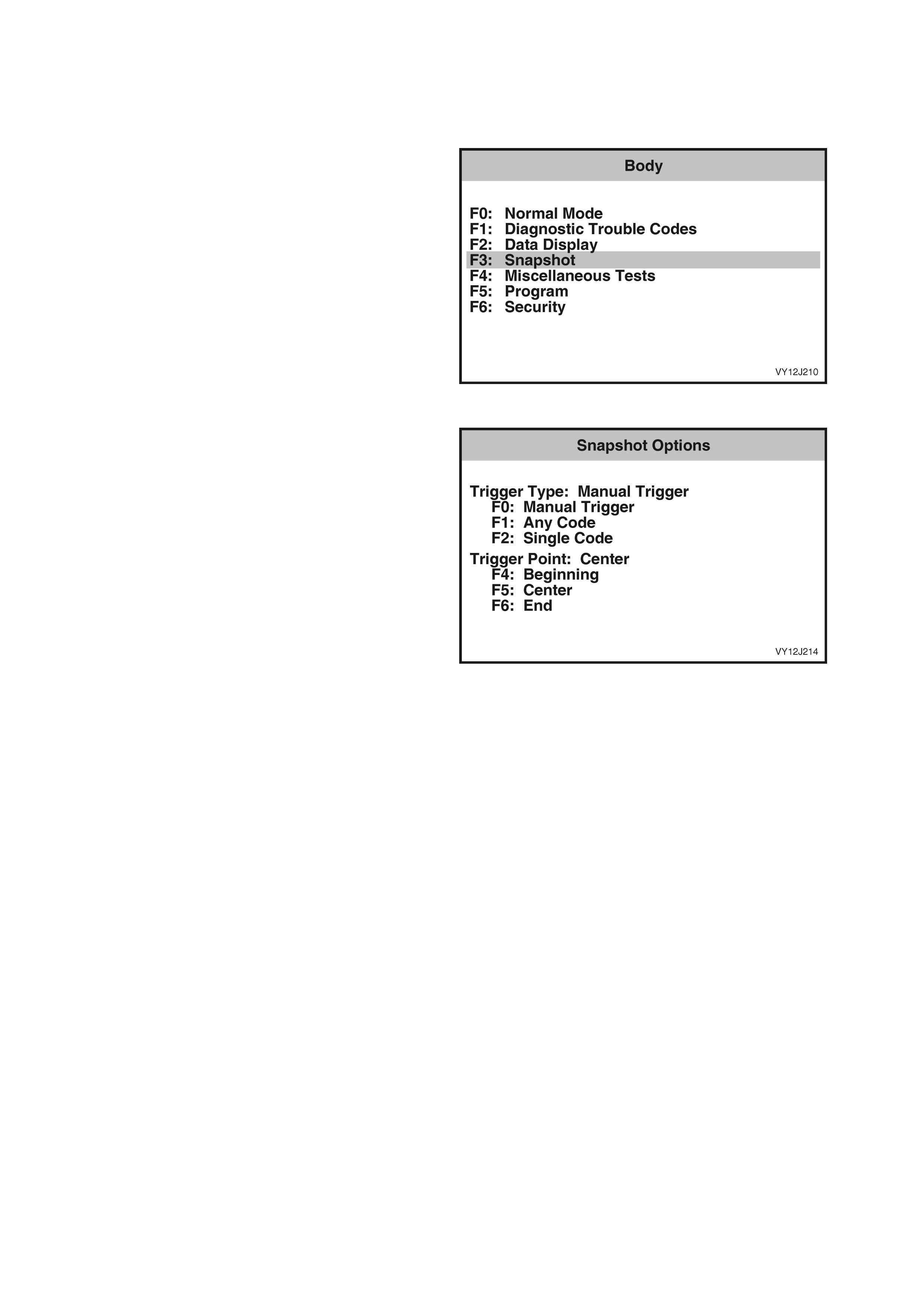
3.7 SNAPSHOT
TECH 2 can be use d to rec ord s ystem inform ation t hat is occur ring at a part icular m oment in tim e, bef ore and after
a forced manual trigger, and this is called a snapshot. For more details, refer to Section 0C, TECH 2.
1. From the Body Menu, select Snapshot and
press the Enter key. TECH 2 will then display
the Data Display data list.
Figure 12J-143
2. Scroll through the data list using the Up and
Down arrow keys. Make the required selection
and press the Enter k e y to continue.
3. For more details on Snapshot, refer to
Section 0C, TECH 2.
Figure 12J-144
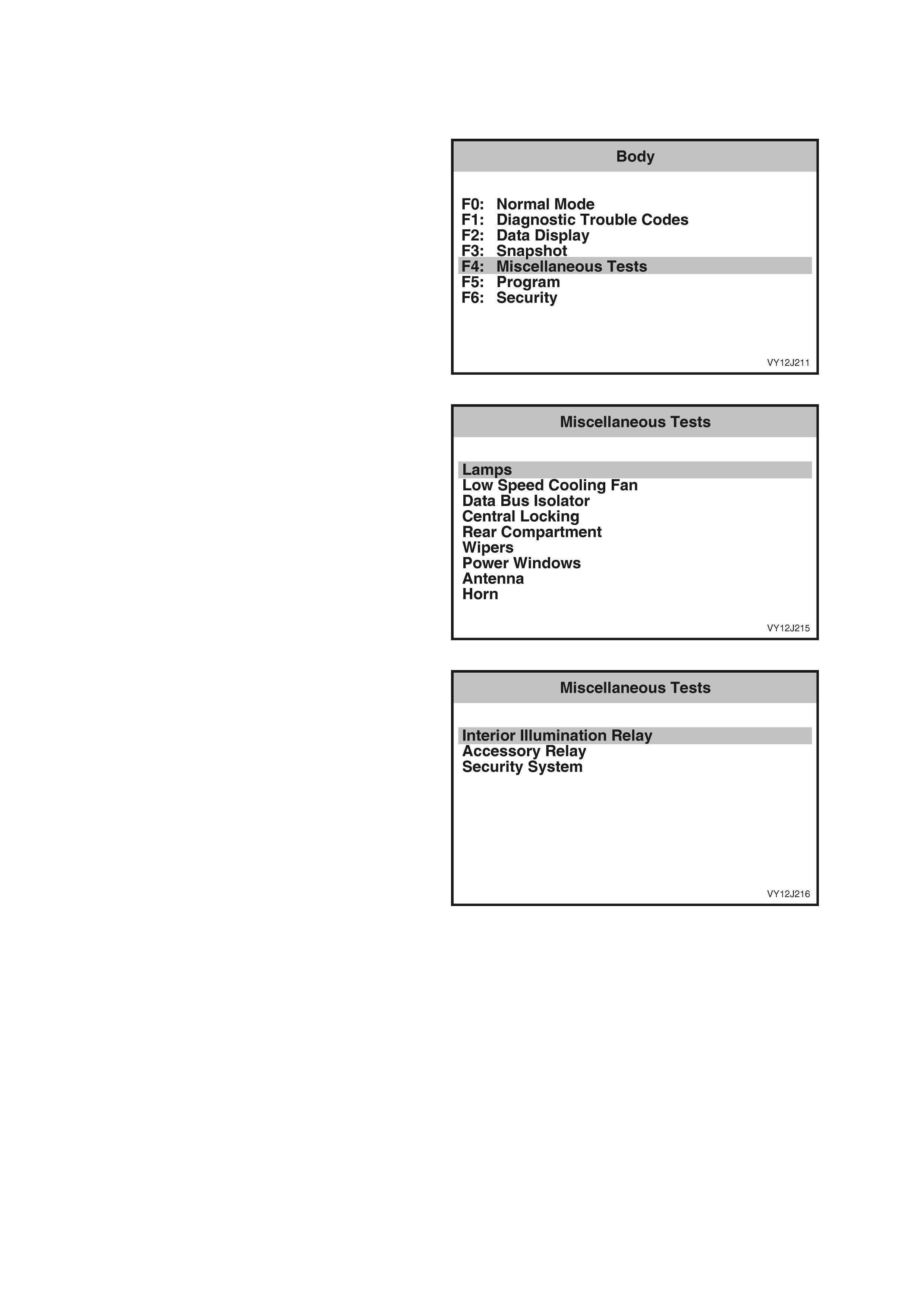
3.8 MISCELLANEOUS TESTS
TECH 2 can be used to ver if y corr ect operat ion of the various BC M functions to ass ist in isolati ng a fault con dition.
TECH 2 can be used to force various functions on or off and monitors the response.
1. From the Body Menu select Miscellaneous
Tests and press the Enter key.
Figure 12J-145
2. Scroll through the Miscellaneous Tests list
using the Up and Down arrow keys.
NOTE: Only the Miscellaneous Tests relevant to
the level of BCM insta lled a nd vehic le conf igur ation
will be displayed.
Figure 12J-146
3. Make the required selection and press the
Enter key to continue.
NOTE: Some Miscellaneous Tests will set
Diagnostic Tr ouble Cod es. O n completi on of a tes t,
ensure that any DTC set during the test are
cleared. Refer to 3.5 DIAGNOSTIC TROUBLE
CODES in this Section.
Figure 12J-147
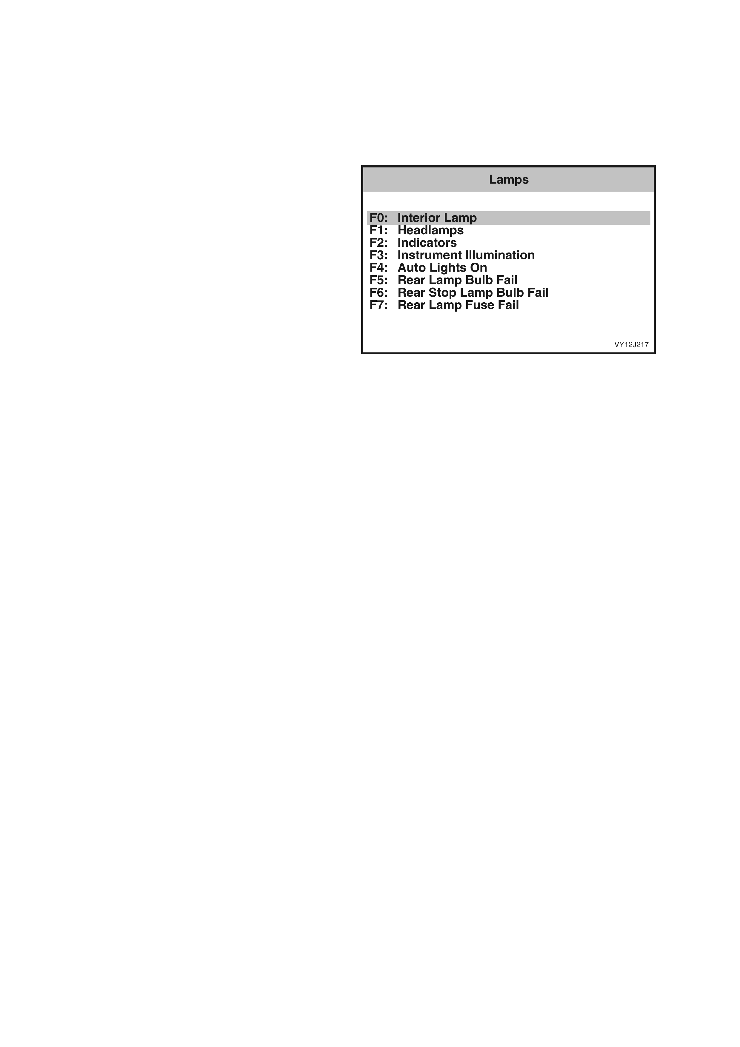
LAM PS
The Lam ps tests are perf orm ed using TECH 2 and
allow the switching of various lamps to verify
correct operation.
NOTE: Only the tests relevant to the level of BCM
installed and vehicle configuration will be
displayed.
1. From the Body Menu, select Body Control
Module / Miscellaneous Tests / Lamps and
press the Enter key.
2. Scroll through the L amps list using the Up and
Down arrow keys. Make the required selection
and press the Enter k e y to continue.
Figure 12J-148
F0: Interior Lamp
1. Use the Up and Down arrow keys to scroll through the list and highlight F0: Interior Lamp.
2. Press the Enter key to select the test function. Follow any test precondition instructions as detailed on the
TECH 2 screen.
3. Once the test function has been highlighted and selected, TECH 2 will display the current serial data
associated with the selected test function and the current status of the interior lamp at the bottom of the screen.
4. Use the On and Off soft keys on TECH 2 to test the interior lamp. Verify that the interior lamp status on the
TECH 2 displa y also ch anges as the lam p is turne d on and of f . If the interi or lamp fails to operat e as expec ted,
refer to 4.12 DOME LAMP DELAY CONTROL in this Section.
5. Press the Quit soft key or the Exit key to exit the test and return to the Lamps screen.
F1: Headlamps
1. Use the Up and Down arrow keys to scroll through the list and highlight F1: Headlamps.
2. Press the Enter key to select the test function. Follow any test precondition instructions as detailed on the
TECH 2 screen.
3. Once the test function has been highlighted and selected, TECH 2 will display the current serial data
associated with the selected test function and the current status of the headlamps at the bottom of the screen.
4. Use the O n and Off s oft keys on TECH 2 to tes t the head lamps. Ver ify that the status of the headlam ps on the
TECH 2 display also changes as the headlamps are turned on and off. If the headlamps fail to operate as
expected, refer to 4.13 AUTOMATIC LAMP CONTROL in this Section.
5. Press the Quit soft key or the Exit key to exit the test and return to the Lamps screen.
F2: Indicators
1. Use the Up and Down arrow keys to scroll through the list and highlight F2: Indicators.
2. Press the Enter key to select the test function. Follow any test precondition instructions as detailed on the
TECH 2 screen.
3. Once the test function has been highlighted and selected, TECH 2 will display the current serial data
associated with the selected test function and the current status of the indicators at the bottom of the screen.
4. Use the On and Off soft keys on TECH 2 to test the indicators. Verify that the status of the indicators on the
TECH 2 display also changes as the indicators are turned on and off. Note that when turned on using the
TECH 2 soft k ey, the indic ators will ext inguis h af ter a fe w seconds. If the indic ators fail to o perat e as exp ecte d,
refer to 4.7 THEFT DETERRENT SYSTEM in this Section.
5. Press the Quit soft key or the Exit key to exit the test and return to the Lamps screen.

F3: Instrument Illumination
1. Use the Up and Down arrow keys to scroll through the list and highlight F3: Instrument Illumination.
2. Press the Enter key to select the test function. Follow any test precondition instructions as detailed on the
TECH 2 screen.
3. Once the test function has been highlighted and selected, TECH 2 will display the current serial data
associated with the s elected test function a nd the curr ent status of the instrum ent illum ination at th e bottom of
the screen.
4. Use the Increase and Decrease soft keys on TECH 2 to vary the illumination level and verify that the
illum inati on le ve l of the ins t r uments changes ac cor di n gly. Verify that the illumination le ve l s tatus on th e TECH 2
displa y a lso changes as the illuminatio n level is incr eased and dec reased. If the instr ument illum ination fails to
operate as expected, refer to 4.14 INSTRUMENT DIMMING CONTROL in this Section.
5. Press the Quit soft key or the Exit key to exit the test and return to the Lamps screen.
F4: Auto Lights On
1. Use the Up and Down arrow keys to scroll through the list and highlight F4: Auto Lights On.
2. Press the Enter key to select the test function. Follow any test precondition instructions as detailed on the
TECH 2 screen.
3. Once the test function has been highlighted and selected, TECH 2 will display the current serial data
associated with th e selec te d test f unction an d the c urrent s tatus of the Auto L ight s O n function at t he bottom of
the screen.
4. Use the On and Off s of t k eys on T ECH 2 to test th e Auto Lights O n function. Veri fy that the stat us of the Auto
Lights On function on the TECH 2 display also changes as the headlamps are turned on and off. If the auto
lights on function fails to operate as expected, refer to 4.13 AUTOM ATIC LAM P CONTROL in this Section.
5. Press the Quit soft key or the Exit key to exit the test and return to the Lamps screen.
F5: Rear Lamp Bulb Fail
1. Use the Up and Down arrow keys to scroll through the list and highlight F5: Rear Lamp Bulb Fail.
2. Press the Enter key to select the test function. Follow any test precondition instructions as detailed on the
TECH 2 screen.
3. Once the test function has been highlighted and selected, TECH 2 will display the current serial data
associated with the selected test function and the current status of the rear lamp bulb at the bottom of the
screen.
4. Use the On and Off soft keys on TECH 2 to test th e rear lamp bulb monitoring circuit. Verify that the sta tus of
the rear lam p bulb on the TECH 2 display also changes as the lig hts are turned on and of f. Note that a chime
will sound when the On soft key is pressed. If the rear lamp bulb fail function does not operate as expected,
refer to 4.20 REA R LAMP FAILURE WARNING SYSTEM in this Section.
5. Press the Quit soft key or the Exit key to exit the test and return to the Lamps screen.
F6: Rear Stop Lamp Bulb Fail
1. Use the Up and Down arrow keys to scroll through the list and highlight F6: Rear Stop Lamp Bulb Fail.
2. Press the Enter key to select the test function. Follow any test precondition instructions as detailed on the
TECH 2 screen.
3. Once the test function has been highlighted and selected, TECH 2 will display the current serial data
associated with th e s elec te d test function and th e cur rent s tatus of the r ear s top lamp bulbs at the bottom of the
screen.
4. Use the On and Off soft keys on TECH 2 to test the rear stop lamp bulbs monitoring circuit. Verify that the
status of the rear lamp bulb on the TECH 2 display also changes as the lights are turned on and off. Note that a
chime will sound when the On soft key is pressed. If the rear stop lamp bulb fa il function does not operate as
expected, refer to 4.20 REAR LAMP FAILURE WARNING SYSTEM in this Section.
5. Press the Quit soft key or the Exit key to exit the test and return to the Lamps screen.

F7: Rear Lamp Fuse Fail
NOTE: The rear lamp fuse circuit monitors the correct operation of both the stop lamps fuse and the park lamps
fuse.
1. Use the Up and Down arrow keys to scroll through the list and highlight F7: Rear Lamp Fuse Fail.
2. Press the Enter key to select the test function. Follow any test precondition instructions as detailed on the
TECH 2 screen.
3. Once the test function has been highlighted and selected, TECH 2 will display the current serial data
associated with the se lected test function and the current status of the rear lam p fuse monitoring circuit a t the
bottom of the screen.
4. Use the On an d Off s oft k eys on T ECH 2 to test the r e ar s top lamp fus e m onitor ing c irc uit. V erify that the stat us
of the fuse on the TECH 2 display also changes as the test is conducted. Note that a chime will sound when
the On soft key is pressed. If the rear stop lamp fuse fail function does not operate as expected, refer to
4.20 REAR LAMP FAILURE WARNING SYSTEM in this Section.
5. Press the Quit soft key or the Exit key to exit the test and return to the Lamps screen.
LOW SPEED COOLING FAN
The Low Speed Cooling Fan test is performed using TECH 2 and verifies the correct operation of the engine low
speed cooling fan and circuit.
1. From the Bod y Menu, sele ct Body Control Module / Miscellaneous Tests / Low Speed Coo ling Fan and press
the Enter ke y.
2. Follow any test precondition instructions as detailed on the TECH 2 screen.
3. Once the test function has been highlighted and selected, TECH 2 will display the current serial data
associated with the selected test function and t he current status of the low speed cooling fan at t he bottom of
the screen.
4. W ith the en gin e of f, press the O n soft k e y and ch ec k that the low sp eed coo ling fan s tarts operating. Verif y that
the status indicated on the TECH 2 screen changes to On.
5. Press the Of f soft key and check that the low speed f an stops. Verif y that the status indicated o n the TECH 2
screen changes to Off. If the low speed cooling fan test function fails to operate as expected, refer to
4.10 ENGINE COOLING FAN LOW-SPEED CONTROL in this Section.
6. Press the Quit soft key or the Exit key to exit the test and return to the Miscellaneous Tests screen.
DATA BUS ISOLATOR
The Data Bus Isolator test is performed using TECH 2. The data bus isolator is a switch located in the BCM and
can be for ced open or closed b y TECH 2 . In the ope n posit ion, the s witch isol ates the sec ondar y data bus and the
tertiary data bus from the primary serial data bus.
1. From the Body Menu, select Body Control Module / Miscellaneous Tests / Data Bus Isolator and press the
Enter key.
2. Follow any test precondition instructions as detailed on the TECH 2 screen.
3. Once the test function has been highlighted and selected, TECH 2 will display the current serial data
associated with the selected test function and the current data bus isolator status at the bottom of the screen.
4. With the engine running, press the Cutoff soft key every 2 seconds for a period in excess of 10 seconds and
verif y that the SRS tell ta le LED in the ins tru ment cluster illuminates.
5. Press the Normal s oft ke y to e nsure that the data bus isolat or is in t he closed p osition. If the data bus isolator
function fails to operate as expected, refer to 4.2 SERIAL DATA COMMUNICATION in this Section.
6. Press the Quit soft key or the Exit key to exit the test and return to the Miscellaneous Tests screen.
NOTE: The SRS telltale will set a DTC. Ensure that all DTC are cleared. Refer to 3.5 DIAGNOSTIC TROUBLE
CODES in this Section.
CENTRAL LOCKING
The Central Locking test is performed using TECH 2 and tests the operation of all door lock actuators.
1. F rom the B od y Menu, s ele ct Bod y Contro l Mod ule / Misc ellane ous T ests / Centr al Loc king and pr ess the Ent er
key.
2. Follow any test precondition instructions as detailed on the TECH 2 screen.
3. Once the test function has been highlighted and selected, TECH 2 will display the current serial data
associated with the selected test function and the current status of the central loc king system at the bottom of
the screen.
4. Pres s the Lock Deadlock soft k ey and chec k that all d oors lock . Verif y that the s tatus indicated on the TECH 2
screen indicates Locked.
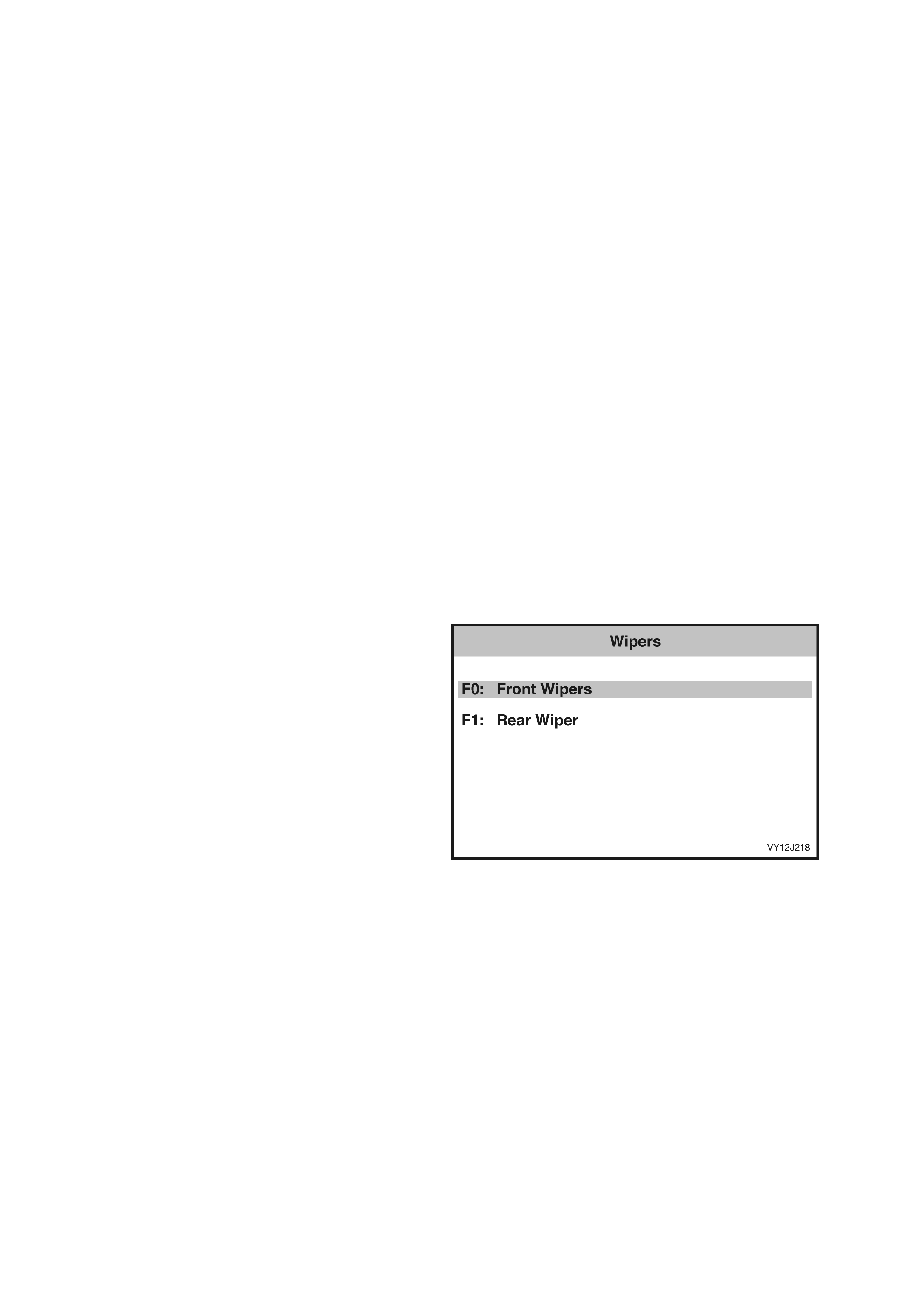
5. Pres s the Lock Deadlock soft ke y aga in and listen f or the soun d of the dead lock actuator o peratin g. Verif y that
the status indicated on the TECH 2 screen indicates Deadlocked.
6. Press the Unlock Drv./All soft key and check that the driver’s door (two-stage unlock selected) or all
doors unlock. Verify that the status indicated on the TECH 2 screen indicates Dr. D. Unlocked (two-stage
unlock selected) or Unlocked. If two-stage unlock is selected, press the Unlock Drv./All soft key again and
check that all doors are now unlocked. If the central locking function fails to operate as expected, refer to
4.5 CEN TRAL DOOR LOCKING in this Section.
7. Press the Quit soft key or the Exit key to exit the test and return to the Miscellaneous Tests screen.
REAR COMPARTMENT
The Rear Compartment test is performed using TECH 2 and tests the operation of the rear compartment lid release
solenoid.
1. From the Body Menu, select Body Control Module / Miscellaneous Tests / Rear Compartment and press the
Enter key.
2. Follow any test precondition instructions as detailed on the TECH 2 screen.
3. Once the test function has been highlighted and selected, TECH 2 will display the current serial data
associated with th e s el ec te d tes t f unc tion a nd the current stat us of the r e ar c ompartm ent lid r e le ase s ol eno id at
the bottom of the screen.
4. Pr ess the O pen s oft k e y and c heck that the so lenoi d operates and opens the rear c om partment. Ver if y that the
status indicated on the TECH 2 screen indicates Open.
5. Close the r ear c ompartment lid and ver ify that the s tat us in dic at ed on the TECH 2 scr een c h ang es to Cl os e d. If
the rear compartment release solenoid fails to operate as expected, refer to 4.6 REAR COMPARTMENT
RELEASE in this Section.
6. Press the Quit soft key or the Exit key to exit the test and return to the Miscellaneous Tests screen.
WIPERS
The Wiper tests are performed using TECH 2, and allow the switching of the front and rear wipers to verify their
correct operation.
NOTE: Only the tests relevant to the level of BCM installed and vehicle configuration will be displayed.
1. From the Body Menu, select Body Control
Module / Miscellaneous Tests / Wipers and
press the Enter key.
2. Scroll thr ough the W ipers lis t using the Up and
Down arrow keys. To select the required test,
press the Enter key.
Figure 12J-149
F0: Front Wipers
1. Use the Up and Down arrow keys to scroll through the list and highlight F0: Front Wipers.
2. Press the Enter key to select the test function. Follow any test precondition instructions as detailed on the
TECH 2 screen.
3. Once the test function has been highlighted and selected, TECH 2 will display the current serial data
associated with the selected test function and the current status of the front wipers at the bottom of the screen.
4. Use the On and Off s oft k eys on TECH 2 to test the f ront wipers . Ver ify that the status of the front wiper s on the
TECH 2 display also changes as the wipers are turned on and off. If the front wipers fail to operate as
expected, refer to 4.11 WIPER SYSTEM in this Section.
5. Press the Quit soft key or the Exit key to exit the test and return to the Wiper Tests screen.
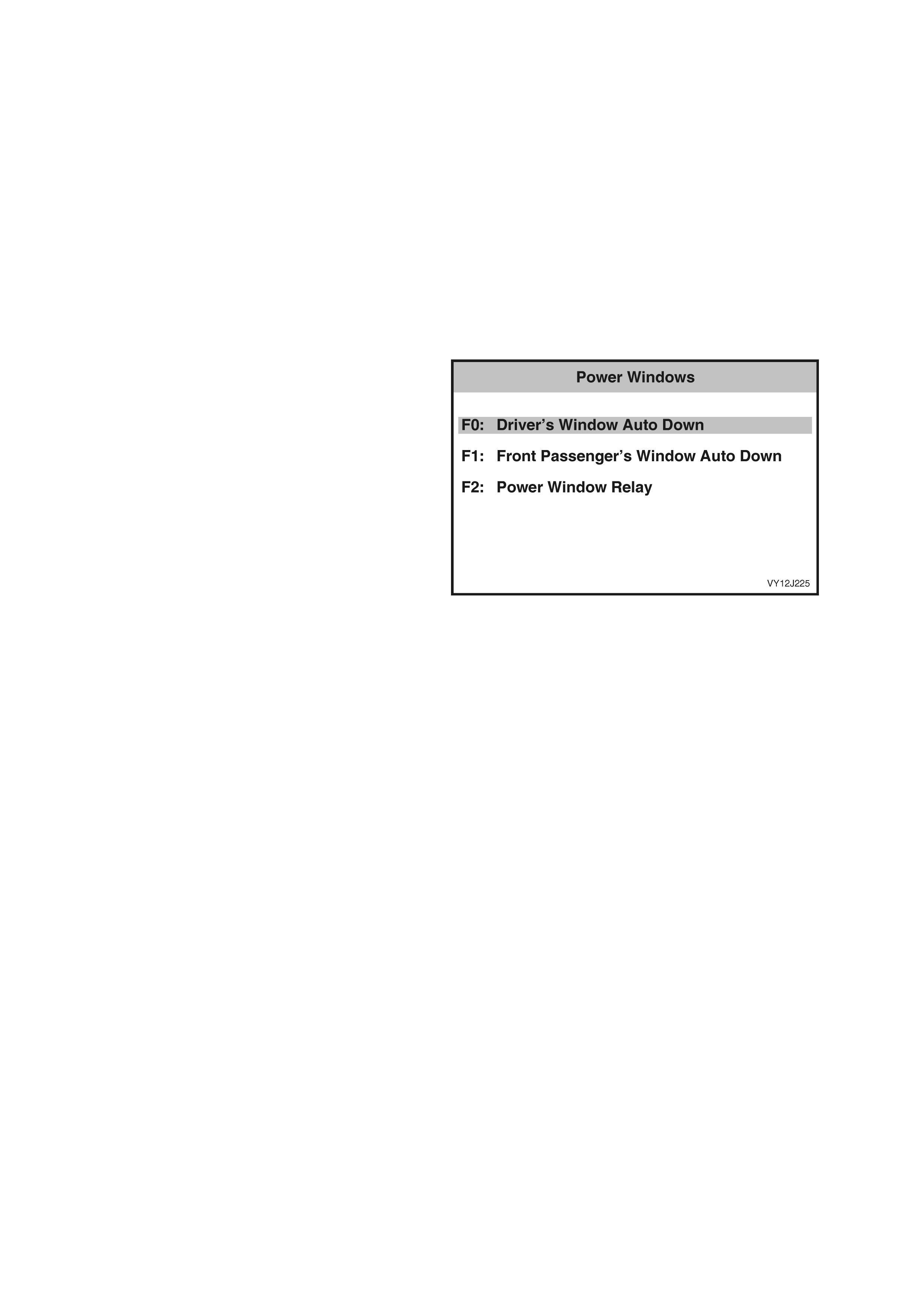
F1: Rear Wiper
1. Use the Up and Down arrow keys to scroll through the list and highlight F1: Rear Wiper.
2. Press the Enter key to select the test function. Follow any test precondition instructions as detailed on the
TECH 2 screen.
3. Once the test function has been highlighted and selected, TECH 2 will display the current serial data
associated with the selected test function and the current status of the rear wiper at the bottom of the screen.
4. Use the On and Off soft keys on TECH 2 to test the rear wiper. Verify that the status of the rear wiper on the
TECH 2 display also changes as the wiper is turned on and off. If the rear wiper fails to operate as expected,
refer to 4.11 WIPER SYSTEM in this Section.
5. Press the Quit soft key or the Exit key to exit the test and return to the Wiper Tests screen.
POWER WINDOWS
The power Windows tests are per f ormed using T ECH 2 and a ll o w the test in g of the po wer windo ws t o ver ify correc t
operation.
NOTE: Only the tests relevant to the level of BCM installed and vehicle configuration will be displayed.
1. From the Body Menu select Body Control
Module / Miscellaneous Tests / Power
Windows and press the Enter key.
2. Scroll through the Power Windows list using
the Up and Down arrow keys. To select the
required test, press the Enter key.
Figure 12J-150
F0: Driver’s Window Auto Down
The Driver’s W indow Auto Down test is performed using TECH 2 and verifies the correct operation of the driver’s
window and associated circuit.
1. From the Body Menu, select Body Control Module / Miscellaneous Tests / Power Windows / F0: Driver’s
Window Auto Down and press the Enter key.
2. Follow any test precondition instructions as detailed on the TECH 2 screen.
3. Once the test function has been highlighted and selected, TECH 2 will display the current serial data
associated with the s elected tes t functi on and the cur rent stat us of the dr iver’s window auto down si gnal at t he
bottom of the screen.
4. Press the Down soft k ey and check that the window lowers completely. Verify that the sta tus indicated on the
TECH 2 screen indicates Active.
5. Raise the window.
6. Press the Do wn soft k ey agai n. As the wind ow is lower ing, press the Sto p soft ke y and c heck that the window
stops. Verify that the status indicated on the TECH 2 screen changes to Inactive. If the driver’s window auto
down test function fails to operate as expected, refer to 4.9 POW ER WINDOW SY STEM in this Section.
7. Press the Quit soft key or the Exit key to exit the test and return to the Miscellaneous Tests screen.
F1: Front Passenger’s Window Auto Down
The Front Passenger’s Window Auto Down test is performed using TECH 2 and verifies the correct operation of the
front passenger’s window and associated circuit.
1. From the Body Menu, select Body Control Module / Miscellaneous Tests / Power Windows / F1: Front
Passeng er’s Window Auto Do wn and press the Enter k ey.
2. Follow any test precondition instructions as detailed on the TECH 2 screen.
3. Once the test function has been highlighted and selected, TECH 2 will display the current serial data
associated with the selected test function and the current status of the front passenger’s window auto down
signal at the bottom of the screen.
4. Press the Down soft k ey and check that the window lowers completely. Verify that the sta tus indicated on the
TECH 2 screen indicates Active.

5. Raise the window.
6. Press the Do wn soft k ey agai n. As the wind ow is lower ing, press the Sto p soft ke y and c heck that the window
stops. Verify that the status indicated on the TECH 2 screen changes to Inactive. If the front passenger’s
window auto down test function fails to operate as expected, refer to 4.9 POWER WINDOW SYSTEM in this
Section.
7. Press the Quit soft key or the Exit key to exit the test and return to the Miscellaneous Tests screen.
F2: Power Window Relay
The Power Window Relay test is performed using TECH 2 and allows the testing of the power windows and
associated circuits to verify their correct operation.
1. From the Body Menu, select Body Control Module / Miscellaneous Tests / Power Windows / F2: Power
Window Relay and press the Enter key.
2. Follow any test precondition instructions as detailed on the TECH 2 screen.
3. Once the test function has been highlighted and selected, TECH 2 will display the current serial data
associated with the s electe d test f unction a nd the cur rent status of the po wer windo w rela y at the bottom of the
screen.
4. While raising or lowering the driver’s window, press the Disable soft key and check that the window stops.
Verify that the status indicated on the TECH 2 screen changes to Disabled.
5. Press the Enable soft key and check that the window commences to move again. Verify that the status
indicate d o n t he TECH 2 scr een ch ang es to En ab led. If the po wer wind o w re lay tes t f unc tion f ai ls to o per ate as
expected, refer to 4.9 POWER WINDOW SYSTEM in this Section.
6. Press the Quit soft key or the Exit key to exit the test and return to the Miscellaneous Tests screen.
ANTENNA
The Antenna test is performed using TECH 2 and verifies the correct operation of the power antenna and
associated circuit.
1. From the Body Menu, select Body Control Module / Miscellaneous Tests / Antenna and press the Enter key.
2. Follow any test precondition instructions as detailed on the TECH 2 screen.
3. Once the test function has been highlighted and selected, TECH 2 will display the current serial data
associated with the selected test function and the current status of the antenna at the bottom of the screen.
4. Use the Up and Down sof t ke ys to r aise and lo wer the anten na. Verif y that the status in dicated o n the TEC H 2
screen c hanges as the antenna is rais ed a nd lo wered . If the ant enna tes t func tio n fails to oper ate as expec ted,
refer to 4.18 POWER ANTENNA CONTROL in this Section.
5. Press the Quit soft key or the Exit key to exit the test and return to the Miscellaneous Tests screen.
HORN
The Horn test is performed using TECH 2 and verifies correct operation of the horn and associated circuit.
1. From the Body Menu, select Body Control Module / Miscellaneous Tests / Horn and press the Enter key.
2. Follow any test precondition instructions as detailed on the TECH 2 screen.
3. Once the test function has been highlighted and selected, TECH 2 will display the current serial data
associated with the selected test function and the current status of the horn at the bottom of the screen.
4. Use the On and Off soft keys to test the horn operation. Verify that the status indicated on the TECH 2
screen changes as the horn is operated. If the horn test function fails to operate as expected, refer to
4.8 ENTRY DETERRENT SYSTEM in this Section.
5. Press the Quit soft key or the Exit key to exit the test and return to the Miscellaneous Tests screen.
INTERIOR ILLUMINATION RELAY
The Interi or Il lum ination Rela y test is per form ed usin g T ECH 2 and verif ies the co rrec t operat ion of the inter ior li ght
and associate d circ uit .
1. F rom the Bod y Menu, s ele ct Bo dy Con trol Mo dule / Mis cellane ous T ests / Interior Illum inati on Rel ay and pre ss
the Enter ke y.
2. Follow any test precondition instructions as detailed on the TECH 2 screen.
3. Once the test function has been highlighted and selected, TECH 2 will display the current serial data
associated with the selected test function and the current status of the interior illumination relay at the bottom of
the screen.
4. Press the On soft key and check that the interior lights illuminate. Verify that the status indicated on the
TECH 2 screen changes to On.
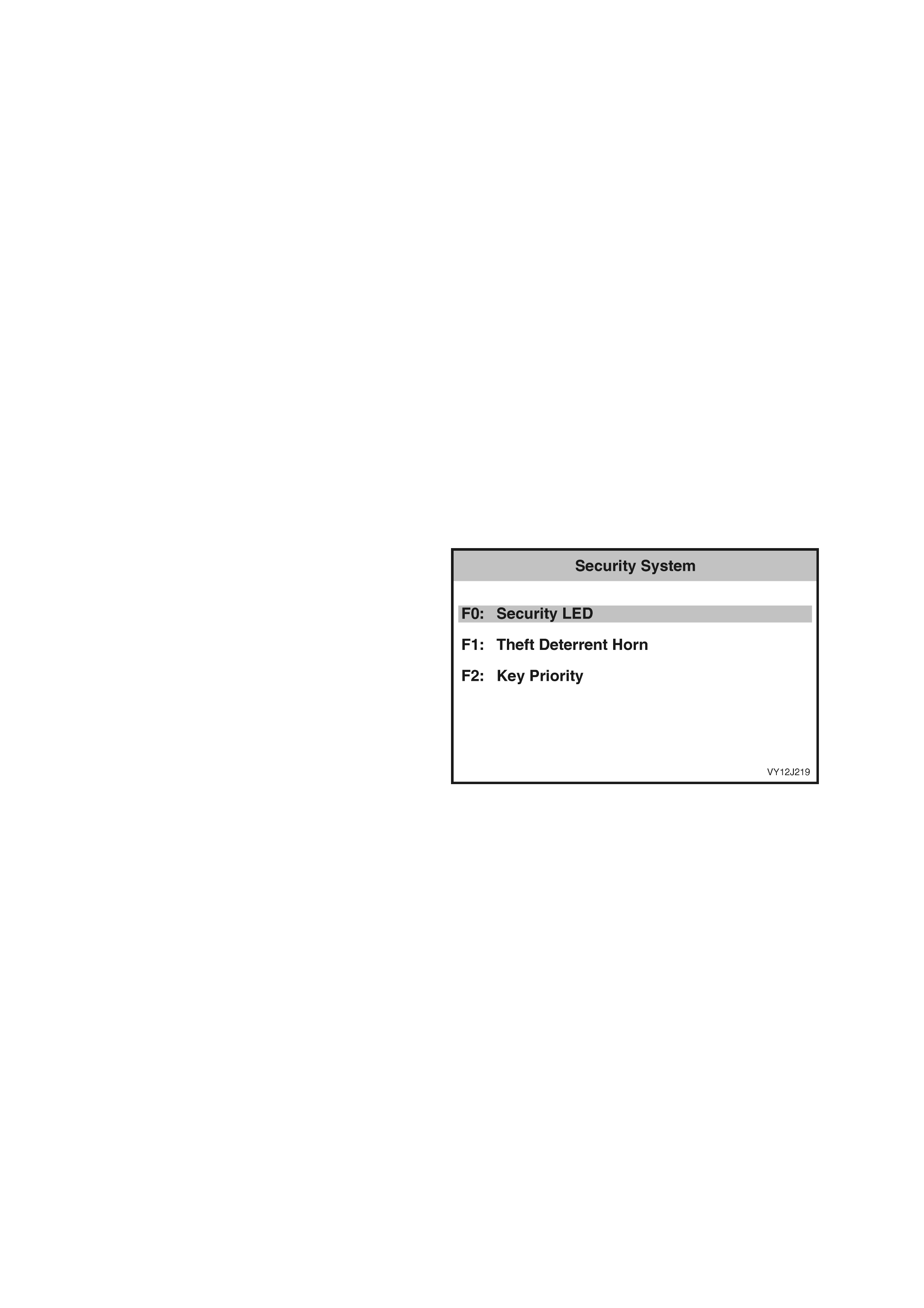
5. Press the Off soft key and check that the interior lights extinguish. Verify that the status indicated on the
TECH 2 screen changes to Off. If the interior illumination rela y test function fails to operate as expected, refer
to 4.12 DOME LAMP DELAY CONTROL in this Section.
6. Press the Quit soft key or the Exit key to exit the test and return to the Miscellaneous Tests screen.
ACCESSORY RELAY
The Ac cessor y Re lay test i s perform ed using T ECH 2 and verifies the c orrect ope ration of the accessor y relay and
associated circuit.
1. From the Body Menu, select Body Control Module / Miscellaneous Tests / Accessory Relay and press the
Enter key.
2. Follow any test precondition instructions as detailed on the TECH 2 screen.
3. Once the test function has been highlighted and selected, TECH 2 will display the current serial data
associated with the selected test function and the current status of the accessory relay at the bottom of the
screen.
4. W ith the audio s ystem operatin g, pres s the O ff sof t ke y and check that the audio s yst em stops operating. V er ify
that the status indicated on the TECH 2 screen changes to Off.
5. Press the On soft k ey and check that the audio s ys tem resumes operation. Verify that the status indicated on
the TECH 2 screen changes to On. If the accessory relay test function fails to operate as expected, refer to
4.4 ACCESSORY CONTROL in this Section.
6. Press the Quit soft key or the Exit key to exit the test and return to the Miscellaneous Tests screen.
SECURITY SYSTEM
The Security System tests are performed using TECH 2 and allow the testing of the vehicle anti-theft system to
verify correct operation.
NOTE: Only the tests relevant to the level of BCM installed and vehicle configuration will be displayed.
3. From the Body Menu select Body Control
Module / Miscellaneous Tests / Security
System and press the Enter key.
4. Scroll through the Security System list using
the Up and Down arrow keys. To select the
required test, press the Enter key.
Figure 12J-151
F0: Security LED
1. Use the Up and Down arrow keys to scroll through the list and highlight F0: Security LED.
2. Press the Enter key to select the test function. Follow any test precondition instructions as detailed on the
TECH 2 screen.
3. Once the test function has been highlighted and selected, TECH 2 will display the current serial data
associated with the selected test function and the current status of the Security LED at the bottom of the
screen.
4. Use the On and Of f soft keys on TECH 2 to test th e operation of the LED. Verify that the status of the LED on
the TECH 2 display also changes as the Security LED is turned on and off. If the Security LED test function
fails to operate as expected, refer to 4.7 THEFT DETERRENT SYSTEM in this Section.
5. Press the Quit soft key or the Exit key to exit the test and return to the Security System screen.
F1: Theft Deterre nt Horn
1. Use the Up and Down arrow keys to scroll through the list and highlight F1: Theft Deterrent Horn.
2. Press the Enter key to select the test function. Follow any test precondition instructions as detailed on the
TECH 2 screen.
3. Once the test function has been highlighted and selected, TECH 2 will display the current serial data
associated with the se lected test f unction an d the curr ent status of the theft deter rent horn at the bottom of the
screen.

4. Use the On and Off s oft keys on T ECH 2 to test the operation of the th eft deterre nt horn. Ver ify that t he stat us
of the horn on the TECH 2 display also changes as the theft deterrent horn is turned on and off. If the theft
deterrent horn fails to operate as expected, refer to 4.8 ENTRY DETERRENT SYSTEM in this Section.
5. Press the Quit soft key or the Exit key to exit the test and return to the Security System screen.
F2: Key Priority
1. Use the Up and Down arrow keys to scroll through the list and highlight F2: Key Priority.
2. Press the Enter key to select the test function. Follow any test precondition instructions as detailed on the
TECH 2 screen.
3. Once the test function has been highlighted and selected, TECH 2 will display the current serial data
associated with the selected test function and the current key priority status at the bottom of the screen.
4. W ith the audio s ystem operating, us e the Pr iority 1 an d Priorit y 2 soft k eys on TECH 2 to test the operation of
the key priority function. As the soft keys are pressed the audio system will change to reflect the priority key
chosen. If the key priority function fails to operate as expected, refer to 4.17 PRIORITY KEY SYSTEM in this
Section.
5. Press the Quit soft key or the Exit key to exit the test and return to the Security System screen.
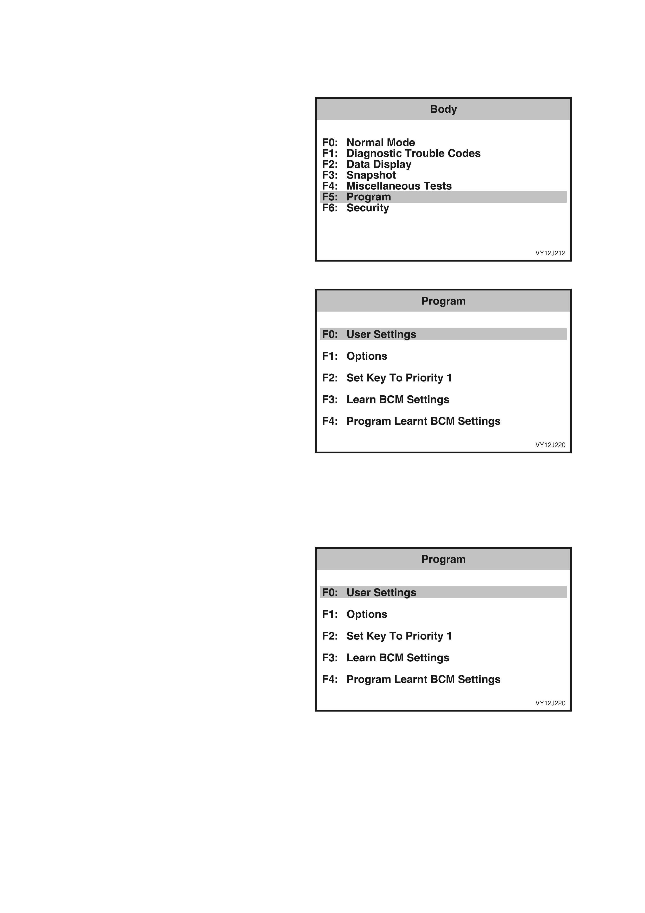
3.9 PROGRAM
The TECH 2 can be used to program various BCM User Settings and Options to suit individual owner
requirements.
1. From the Body Menu select Program and
press the Enter key.
Figure 12J-152
2. Scroll through the Program list using the Up
and Down arrow keys. To select the required
item, press the Enter key.
Figure 12J-153
F0: USER SETTINGS
NOTE: Only the data relevant to the level of BCM
installed and vehicle configuration will be
displayed.
1. From the Program screen, select F0: User
Settings and pr ess the Ent er k e y.
Figure 12J-154
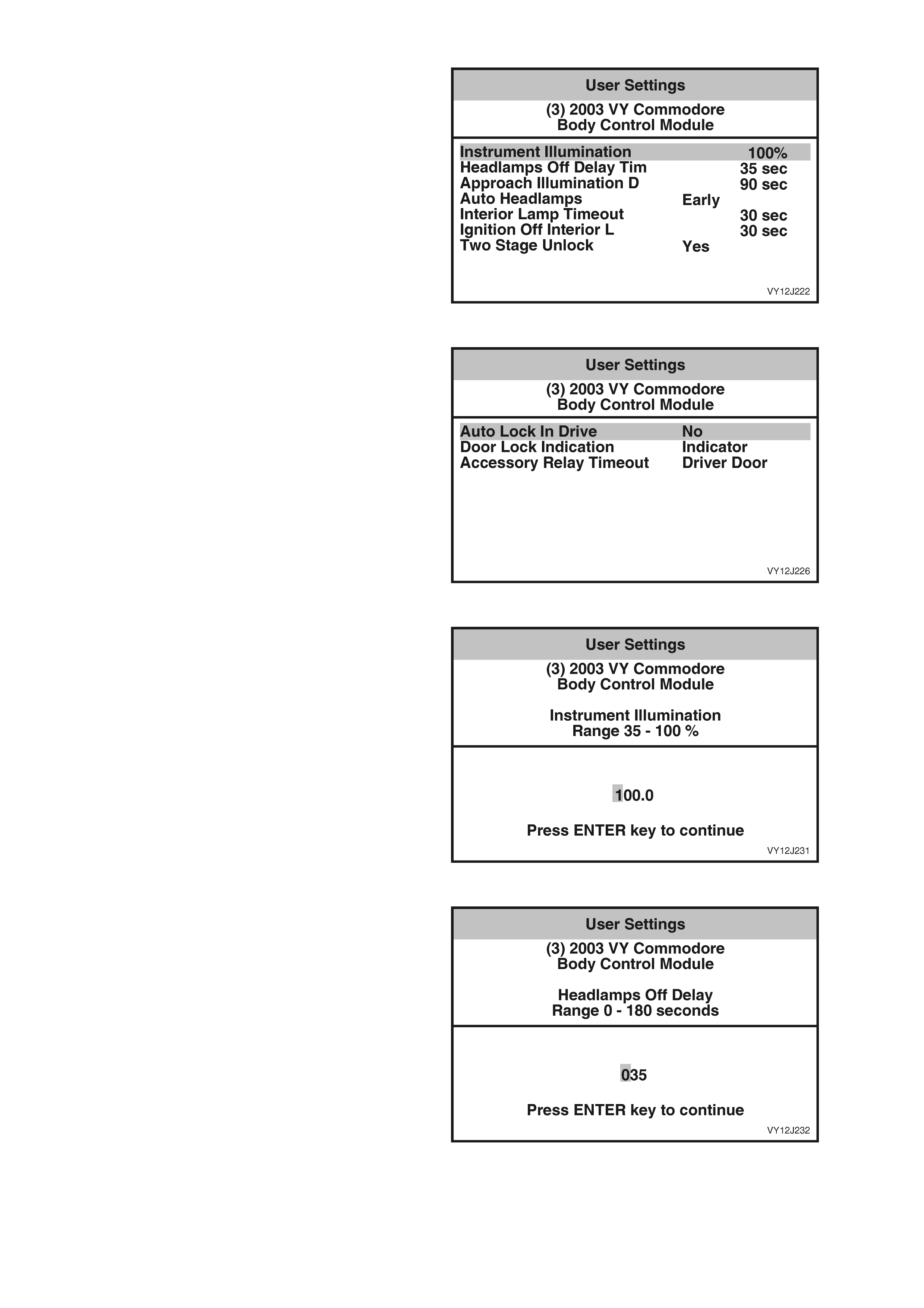
2. The User Settings screen will be displayed
showing the current settings for the vehicle.
3. To modify any item, select the item using the
Up and Down arrow keys, and press the
Modify soft key or the Enter key. The
appropriate screen will then be displayed.
4. When all user setting changes have been
made, press the Program soft key to initiate the
programming process.
5. Press the Confirm soft key when notified that
the programming has been completed
successfully.
Figure 12J-155
Figure 12J-156
Instrument Illumination
NOTE: The default Instrument Illumination setting
is 35%.
1. Use the Left and Right arrow keys to scroll
across the number displayed on the TECH 2
screen and modify using the numeral keys.
2. W hen selec ted, pres s the Enter key to return to
the User Settings screen.
3. To return to the User Settings screen without
changing the selection shown, press the Exit
key.
Figure 12J-157
Headlamps Off Delay Time
NOTE: The default Headlamps Off Delay Time
setting is 1 second.
1. Use the Left and Right arrow keys to scroll
across the number displayed on the TECH 2
screen and modify using the numeral keys.
2. W hen selec ted, pres s the Enter key to return to
the User Settings screen.
3. To return to the User Settings screen without
changing the selection shown, press the Exit
key.
Figure 12J-158
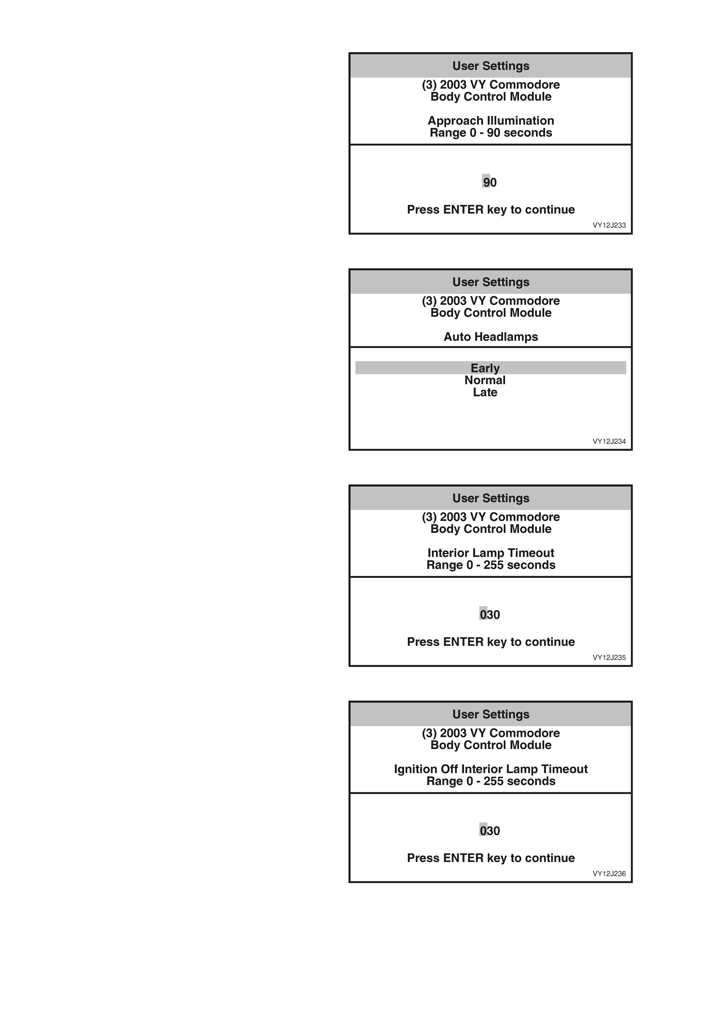
Approach Illumination Delay Time
NOTE: The default Approach Illumination Delay
Time setting is 30 seconds.
1. Use the Left and Right arrow keys to scroll
across the number displayed on the TECH 2
screen and modify using the numeral keys.
2. W hen selec ted, pres s the Enter key to return to
the User Settings screen.
3. To return to the User Settings screen without
changing the selection shown, press the Exit
key.
Figure 12J-159
Auto Headlamps
NOTE: The def ault Automatic Head lamp Sens it iv ity
setting is Normal.
1. Use the Up and Down arrow keys to highlight
the selection required.
2. W hen selec ted, pres s the Enter key to return to
the User Settings screen.
3. To return to the User Settings screen without
changing the selection shown, press the Exit
key.
Figure 12J-160
Interior Lamp Timeout
NOTE: The def ault Int er ior Lamp T im eout s etting is
30 seconds.
1. Use the Left and Right arrow keys to scroll
across the number displayed on the TECH 2
screen and modify using the numeral keys.
2. W hen selec ted, pres s the Enter key to return to
the User Settings screen.
3. To return to the User Settings screen without
changing the selection shown, press the Exit
key.
Figure 12J-161
Ignition Off Interior Lamp Timeout
NOTE: The default Ignition Off Interior Lamp
Timeout setting is 30 seconds.
1. Use the Left and Right arrow keys to scroll
across the number displayed on the TECH 2
screen and modify using the numeral keys.
2. W hen selec ted, pres s the Enter key to return to
the User Settings screen.
3. To return to the User Settings screen without
changing the selection shown, press the Exit
key.
Figure 12J-162
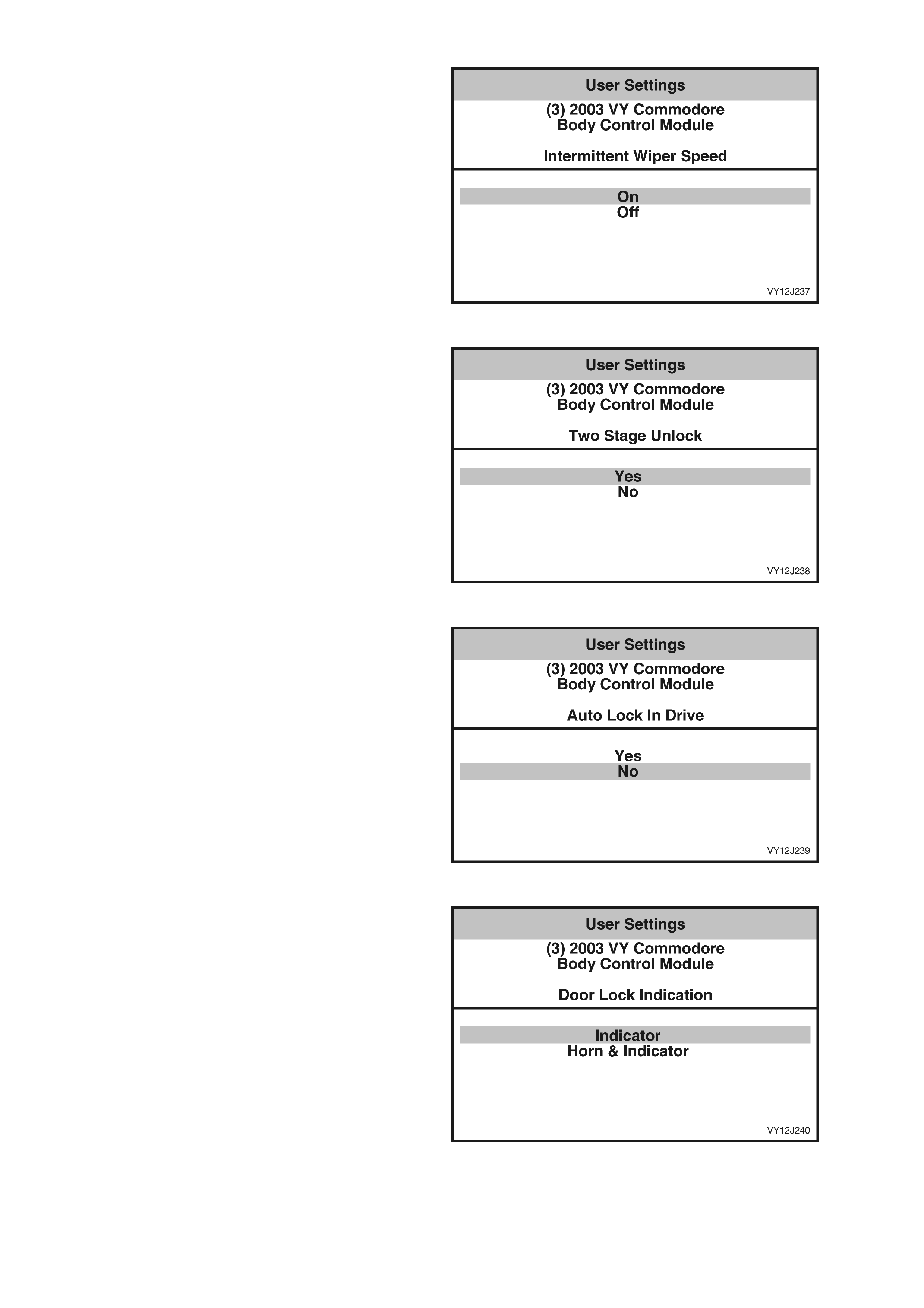
Intermittent Wiper Speed
NOTE: The default Intermittent Wiper Speed
setting is On.
1. Use the Up and Down arrow keys to highlight
the selection required.
2. W hen selec ted, pres s the Enter key to return to
the User Settings screen.
3. To return to the User Settings screen without
changing the selection shown, press the Exit
key.
Figure 12J-163
Two Stage Unlock
NOTE: The default Two Stage Unlock setting is
Yes.
1. Use the Up and Down arrow keys to highlight
the selection required.
2. W hen selec ted, pres s the Enter key to return to
the User Settings screen.
3. To return to the User Settings screen without
changing the selection shown, press the Exit
key.
Figure 12J-164
Autolock in Drive
NOTE: The default Autolock In Drive setting is No.
1. Use the Up and Down arrow keys to highlight
the selection required.
2. W hen selec ted, pres s the Enter key to return to
the User Settings screen.
3. To return to the User Settings screen without
changing the selection shown, press the Exit
key.
Figure 12J-165
Door Lock Indication
NOTE: The default Door Lock Indication setting is
Indicator.
1. Use the Up and Down arrow keys to highlight
the selection required.
2. W hen selec ted, pres s the Enter key to return to
the User Settings screen.
3. To return to the User Settings screen without
changing the selection shown, press the Exit
key.
Figure 12J-166
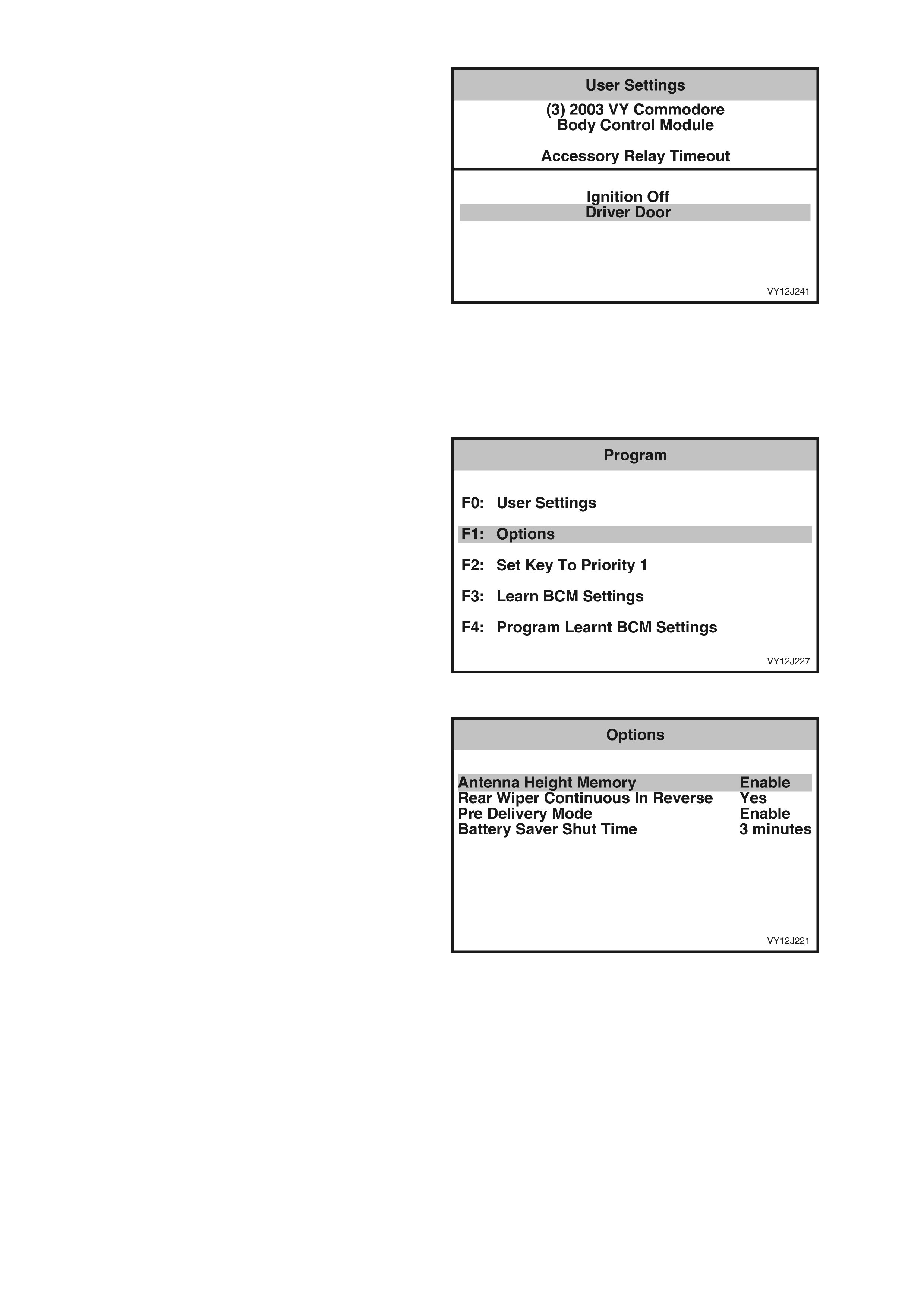
Accessory Relay Timeout
NOTE: The default Accessory Relay Timeout
setting is Driver Door.
1. Use the Up and Down arrow keys to highlight
the selection required.
2. W hen selec ted, pres s the Enter key to return to
the User Settings screen.
3. To return to the User Settings screen without
changing the selection shown, press the Exit
key.
Figure 12J-167
F1: OPTIONS
NOTE: Only the data relevant to the level of BCM
installed and vehicle configuration will be
displayed.
1. From the Program screen, select F1: Options
and press the Enter k e y.
Figure 12J-168
2. The Options screen will be displayed showing
the current option selection for the vehicle.
3. To modify any item, select the item using the
Up and Down arro w keys and press the Mod ify
soft key or the Enter key. The appropriate
screen will then be displayed.
4. When all option changes have been made,
press the Program soft key to initiate the
programming process.
5. Press the Confirm soft key when notified that
the programming has been completed
successfully.
Figure 12J-169
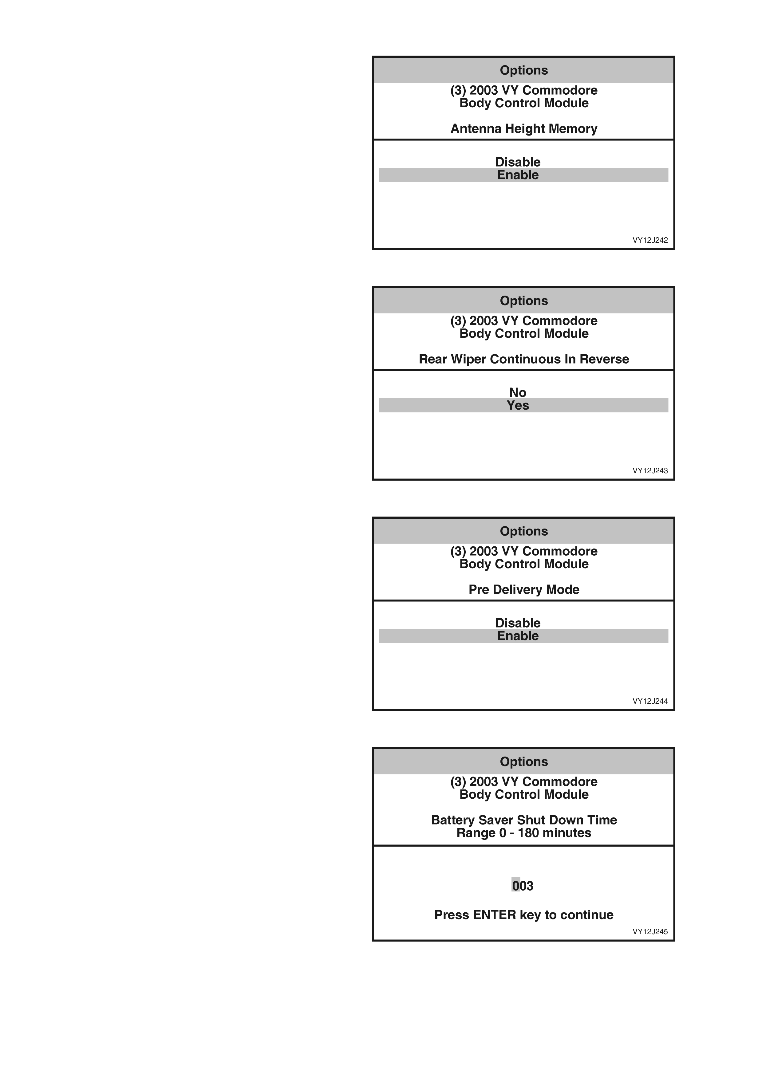
A ntenna Height Memory
NOTE: The def au lt Ante nn a He igh t M emor y settin g
is Enable.
1. Use the Up and Down arrow keys to highlight
the selection required.
2. W hen selec ted, pres s the Enter key to return to
the Options screen.
3. To return to the Options screen without
changing the selection shown, press the Exit
key.
Figure 12J-170
Rear Wiper Continuous In Reverse
NOTE: The default Rear Wiper Continuous In
Reverse setting is No.
1. Use the Up and Down arrow keys to highlight
the selection required.
2. W hen selec ted, pres s the Enter key to return to
the Options screen.
3. To return to the Options screen without
changing the selection shown, press the Exit
key.
Figure 12J-171
Pre Delivery Mode
NOTE: The default Pre Delivery Mode setting is
Enable.
1. Use the Up and Down arrow keys to highlight
the selection required.
2. W hen selec ted, pres s the Enter key to return to
the Options screen.
3. To return to the Options screen without
changing the selection shown, press the Exit
key.
Figure 12J-172
Battery Saver Shut Down Time
NOTE: The def ault Batter y Saver Shut Down T ime
setting is 65 minutes.
1. Use the Left and Right arrow keys to scroll
across the number displayed on the TECH 2
screen and modify using the numeral keys.
2. W hen selec ted, pres s the Enter key to return to
the Options screen.
3. To return to the Options screen without
changing the selection shown, press the Exit
key.
Figure 12J-173
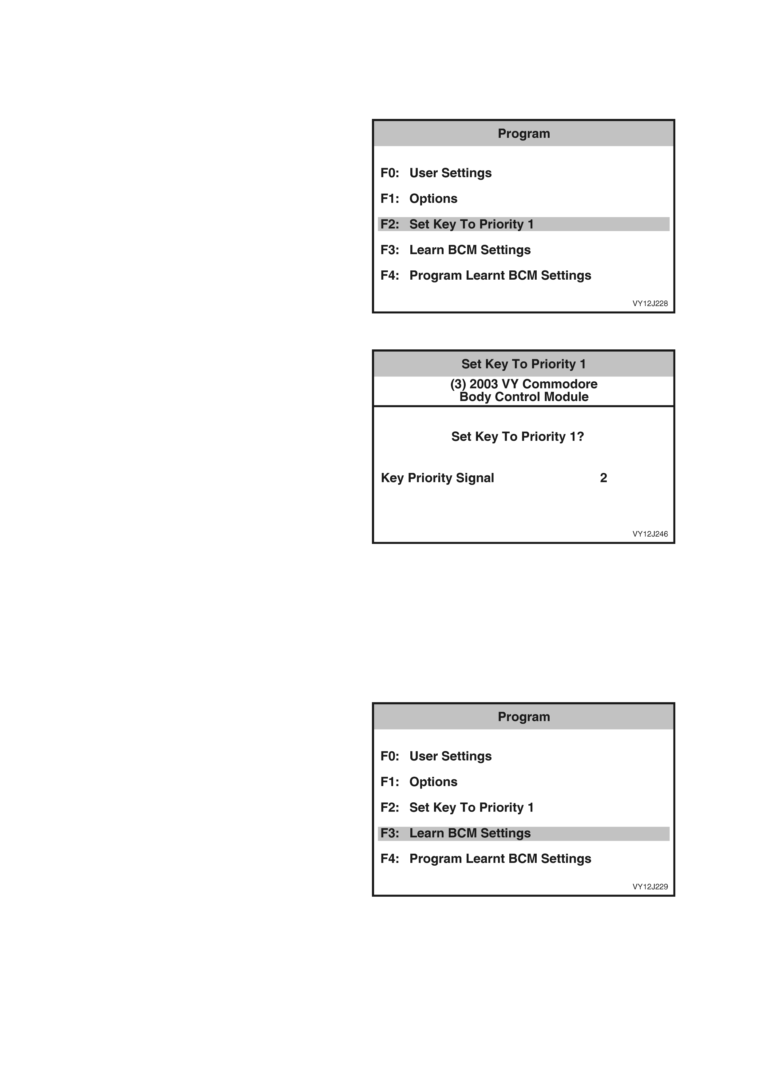
F2: SET KEY TO PRIORITY 1
This function allows the priority key in the ignition switch to be set as the Priority 1 key.
NOTE: Only the data relevant to the level of BCM installed and vehicle configuration will be displayed.
1. From the Program screen, select F2: Set Key
To Priority 1 and press the Enter key.
Figure 12J-174
2. Press the Set soft key to set the key selection
to Priority Key 1.
3. To return to the Program screen without
changing the selection shown, press the Exit
key.
Figure 12J-175
F3: LEARN BCM SETTINGS
The following process allows the TECH 2 to learn
the vehicle BCM settings to enable a replacement
BCM to be programmed with the same settings.
NOTE: Only the data relevant to the level of BCM
installed and vehicle configuration will be
displayed.
1. From the Program screen, select F3: Learn
BCM Settings and press the Enter key.
Figure 12J-176

2. Press the Okay soft key to initiate the process.
Figure 12J-177
3. When notified that the process is completed,
press the Confirm soft key to return to the
Program screen.
4. To return to the Program screen without
learning the BCM settings, press the Exit key.
Figure 12J-178
F4: PROGRAM LEARNT BCM SETTINGS
The following process allows the TECH 2 to
program the learnt BCM settings into a
replacement BCM.
NOTE: Only the data relevant to the level of BCM
installed and vehicle configuration will be
displayed.
1. From the Program screen, select F4: Program
Learnt BCM Settings and press the Enter key.
Figure 12J-179
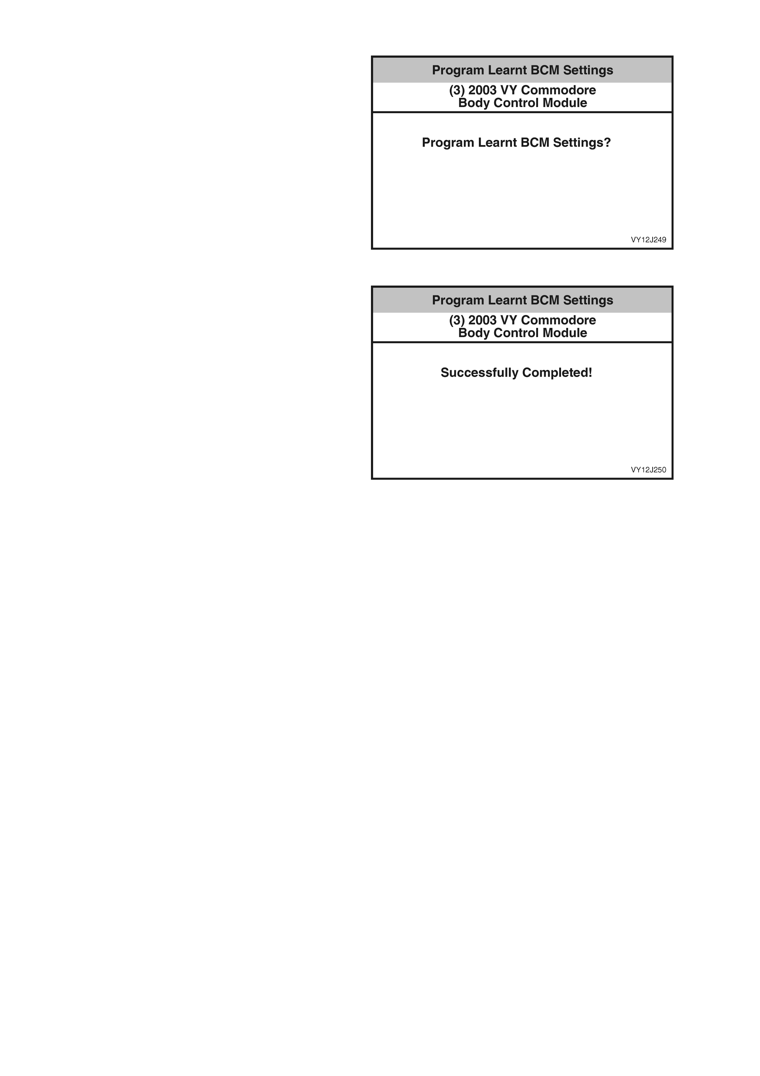
2. Press the Okay soft key to initiate the process.
3. To return to the Program screen without
programming the BCM, press the Exit key.
Figure 12J-180
4. When notified that the process is completed,
press the Confirm soft key to return to the
Program screen.
Figure 12J-181
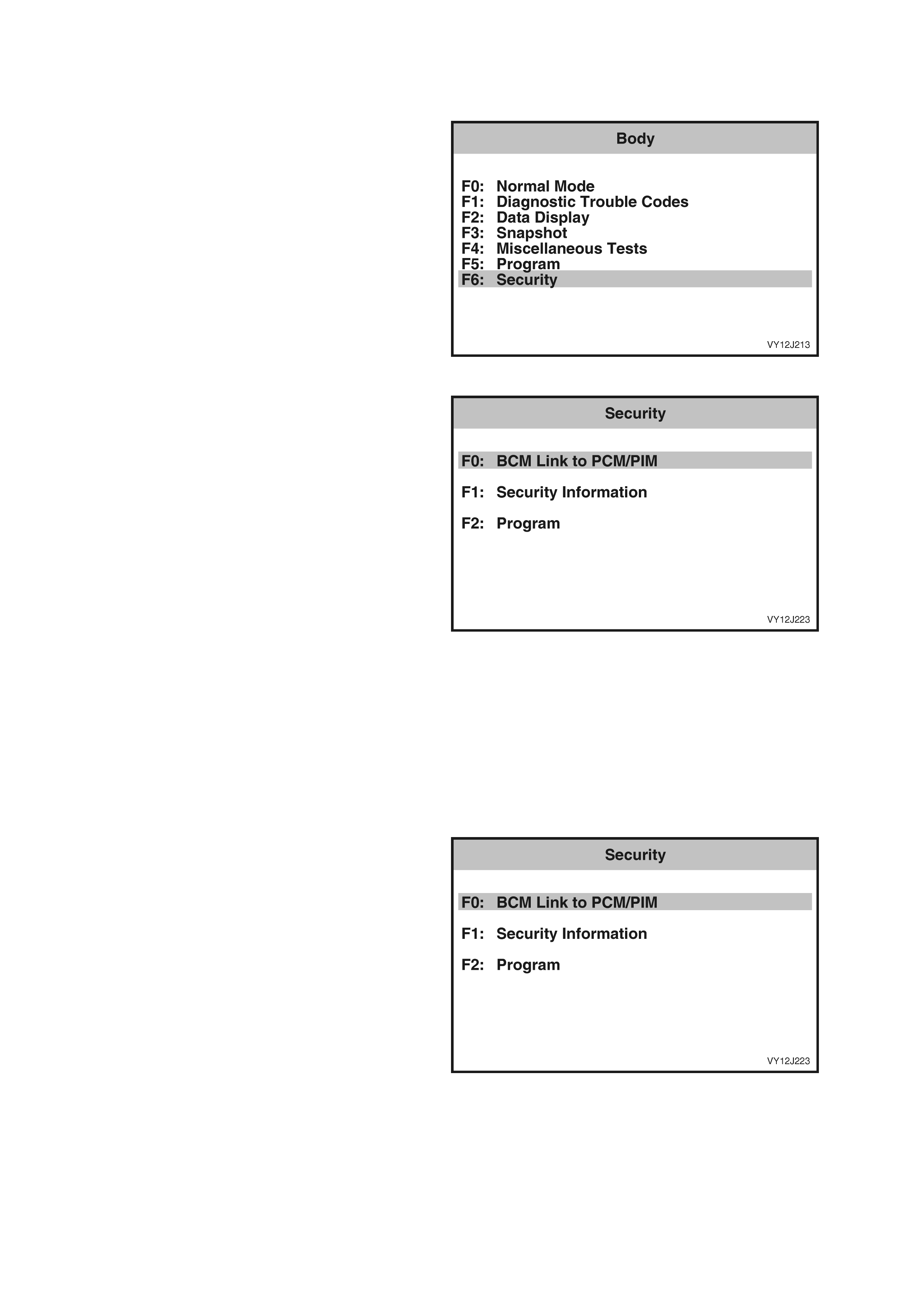
3.10 SECURITY
The TECH 2 can be used to view and program various vehicle security information.
1. F rom the Bod y Menu s elec t Secur ity an d press
the Enter ke y.
Figure 12J-182
2. Scroll through the Security list using the Up
and Down arrow keys. To select the required
item, press the Enter key.
Figure 12J-183
F0: BCM LINK TO PCM/PIM
NOTE: It is only possible to perform the BCM Link procedure after TIS approval (Enable Programming) and the
(BCM) Secur it y Code have been o btained. The (BCM) security code inform ation is contained on the IM PORTANT
SECURITY INFORMATION card issued with the vehicle when new. Refer to Section 0C, TECH 2 for further
details to enable programming.
The following procedure should be carried out after replacement of a BCM, PCM or PIM to allow the replaced
module to be linked with the other modules.
NOTE: Only the data relevant to the level of BCM installed and vehicle configuration will be displayed.
1. From the Security screen select F0: BCM Link
to PCM/PIM and press the Enter key.
Figure 12J-184
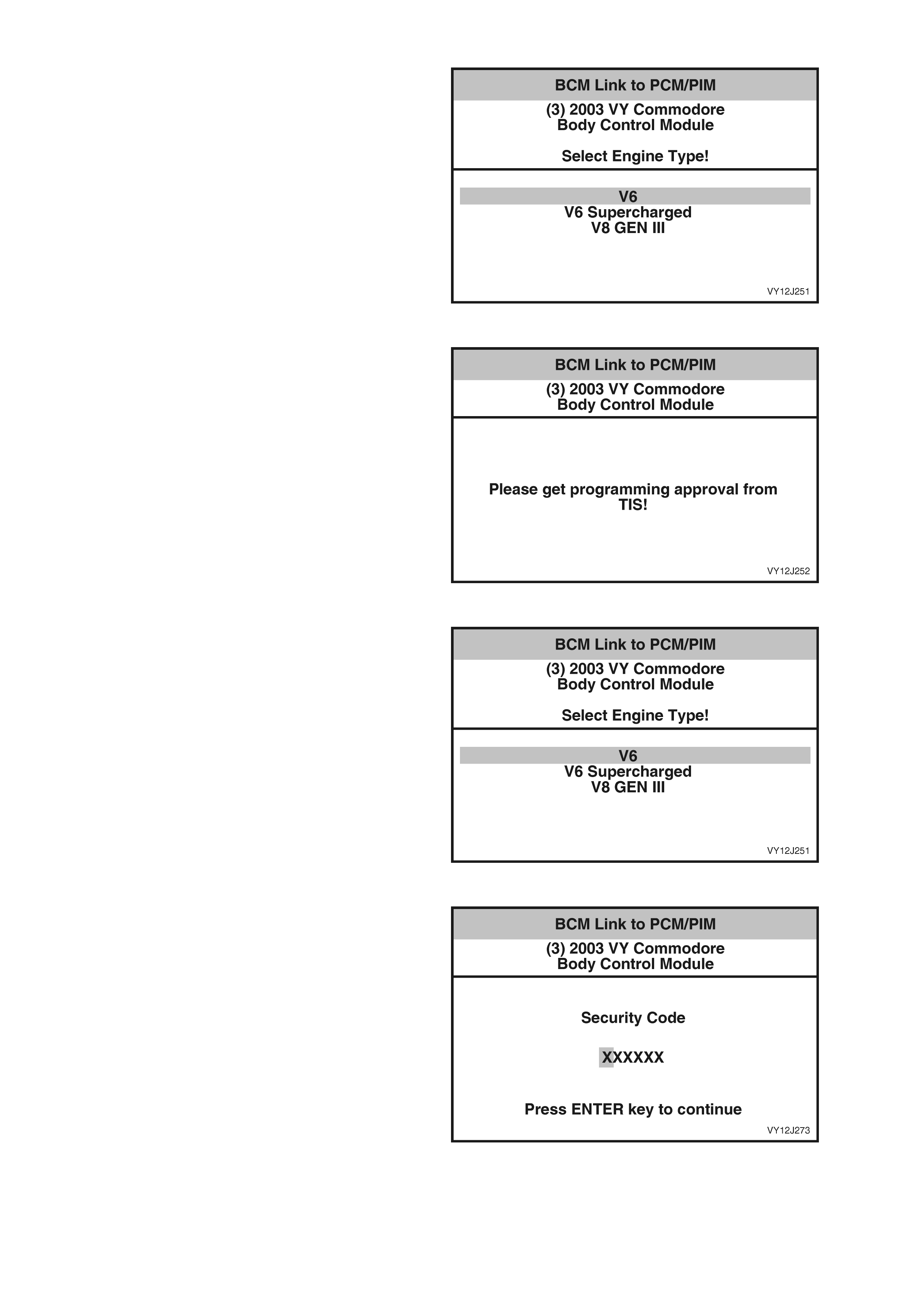
2. Scroll through the list using the Up and Down
arrow keys. To select the required item, press
the Enter ke y.
3. To return to the Security screen without
changing the selection shown, press the Exit
key.
Figure 12J-185
4. Obtain TIS approval when this screen is
displayed.
Figure 12J-186
5. When TIS approval has been obtained, return
to this screen.
6. Scroll through the list using the Up and Down
arrow keys. To select the required item, press
the Enter ke y.
Figure 12J-187
7. Enter the six-digit (BCM) security code,
including any leading zeros, using the numeral
keys on TECH 2.
8. Press the Enter key to continue.
Figure 12J-188
9. Follow the instructions as shown on the
TECH 2 screen.
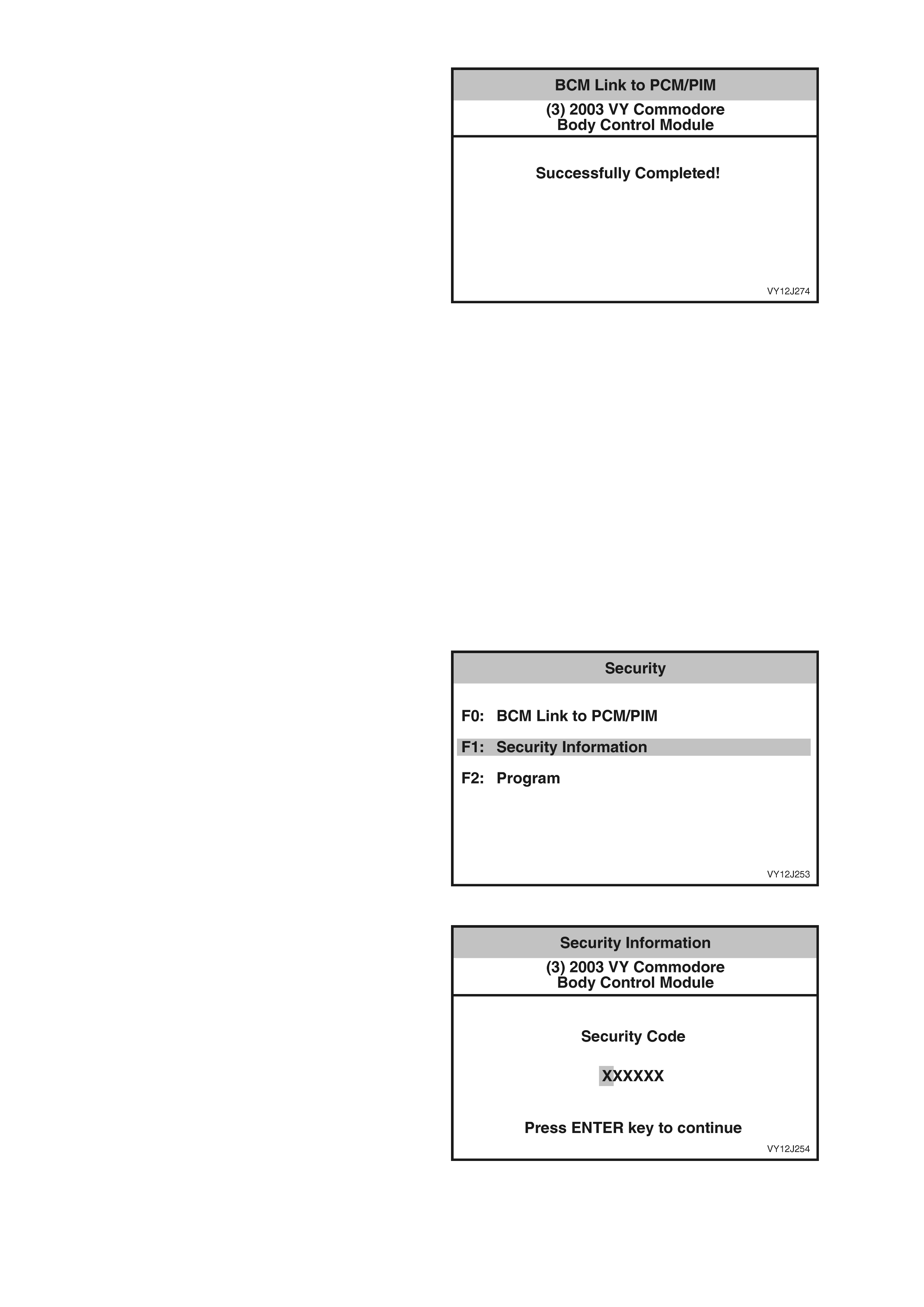
10. When notified that the process is completed,
press the Confirm soft key to return to the
Security screen.
Figure 12J-189
F1: SECURITY INFORMATION
NOTE: The (BCM) Security Code is required to
access the Security Information. The securit y code
is contained on the IMPORTANT SECURITY
INFORMATION card issued with the vehicle when
new.
The security information relevant to the current
vehicle fit for the following items can be accessed
using TECH 2:
• Radio PIN Number,
• TIS Hardware Key Number, and
• Mechanical Key Number.
NOTE: Only the data relevant to the level of BCM
installed and vehicle configuration will be
displayed.
1. From the Security screen select F1: Security
Information and press the Enter key.
Figure 12J-190
2. Enter the six-digit (BCM) security code,
including any leading zeros, using the numeral
keys on TECH 2.
3. Press the Enter key to continue.
Figure 12J-191
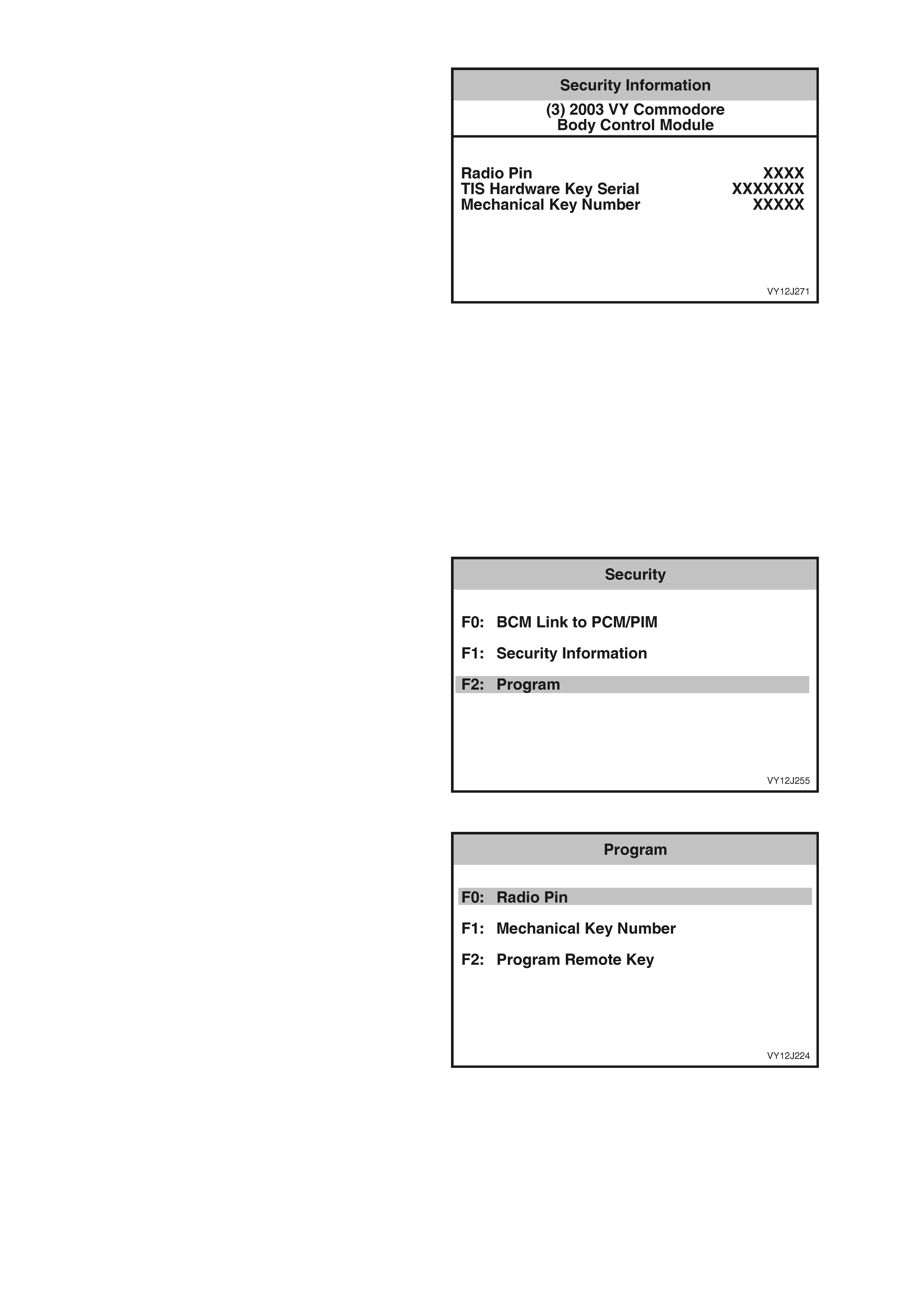
4. TECH 2 screen displays the relevant security
information.
5. Pr ess the Q uit sof t k ey to r eturn t o the Securi ty
screen.
Figure 12J-192
F2: PROGRAM
The Program function allows:
• the R adio Pin N um ber to b e chan ged if the
audio system head unit has been replaced,
• the Door Key number to be changed if
door locks have been replaced, and
• the programming of a new Key.
NOTE: Only the data relevant to the level of BCM
installed and vehicle configuration will be
displayed.
1. From the Security screen select F2: Program
and press the Enter k e y.
Figure 12J-193
2. Scroll through the Program list using the Up
and Down arrow keys. To select the required
item, press the Enter key.
Figure 12J-194
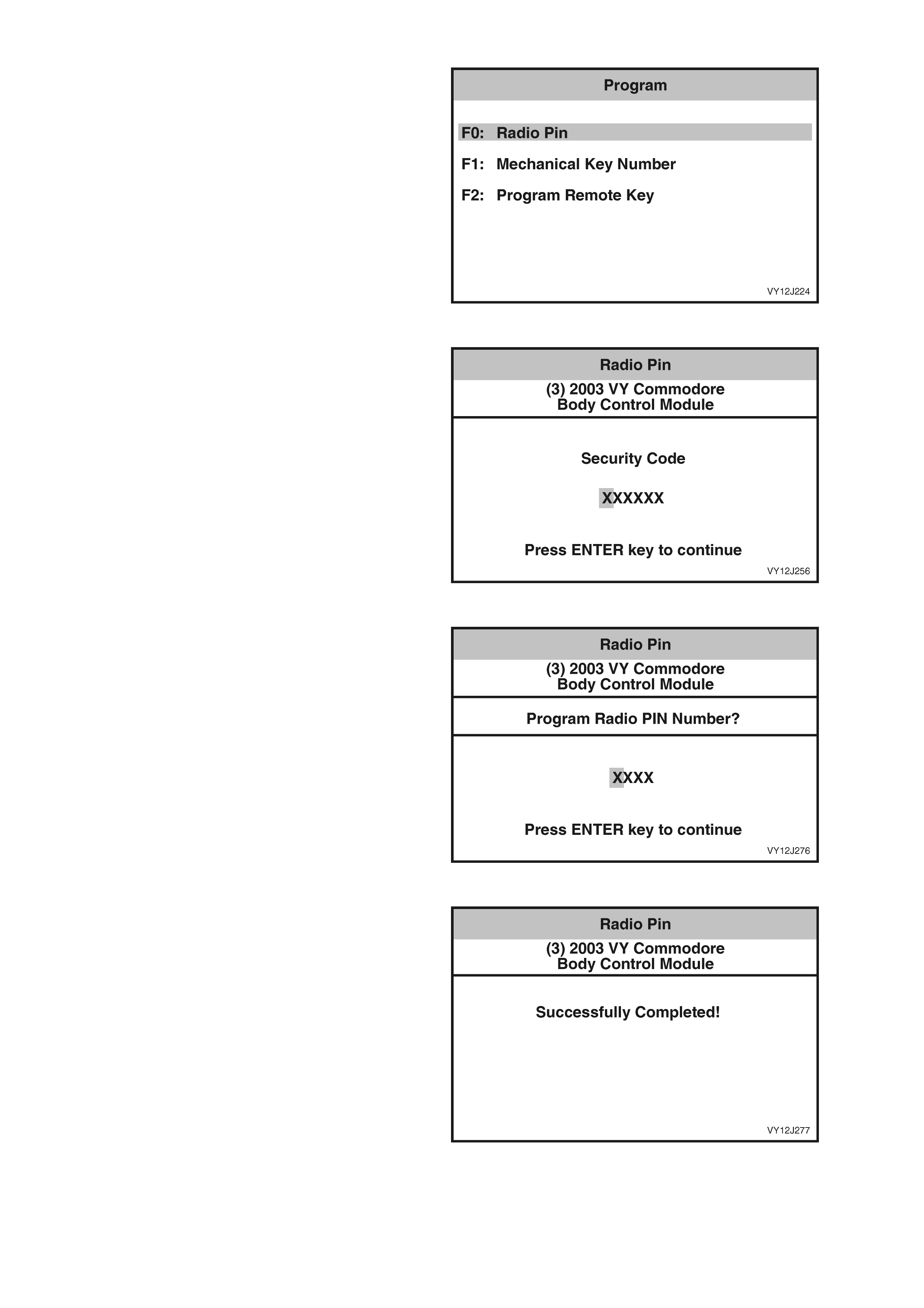
F0: Radio Pin
NOTE: The (BCM) Security Code is required to
change the R adio Pin number. T he s ec urit y co de is
contained on the IMPORTANT SECURITY
INFORMATION card issued with the vehicle when
new.
1. From the Pr ogram screen select F 0: Radio Pin
and press the Enter k e y.
Figure 12J-195
2. Enter the six-digit (BCM) security code,
including any leading zeros, using the numeral
keys on TECH 2.
3. Press the Enter key to continue.
Figure 12J-196
4. Enter the ne w r adio PIN number , including an y
leading zeros, using the numeral keys on
TECH 2.
5. Press the Enter key to continue.
Figure 12J-197
6. When notified that the process is completed,
press the Confirm soft key to return to the
Program screen.
Figure 12J-198
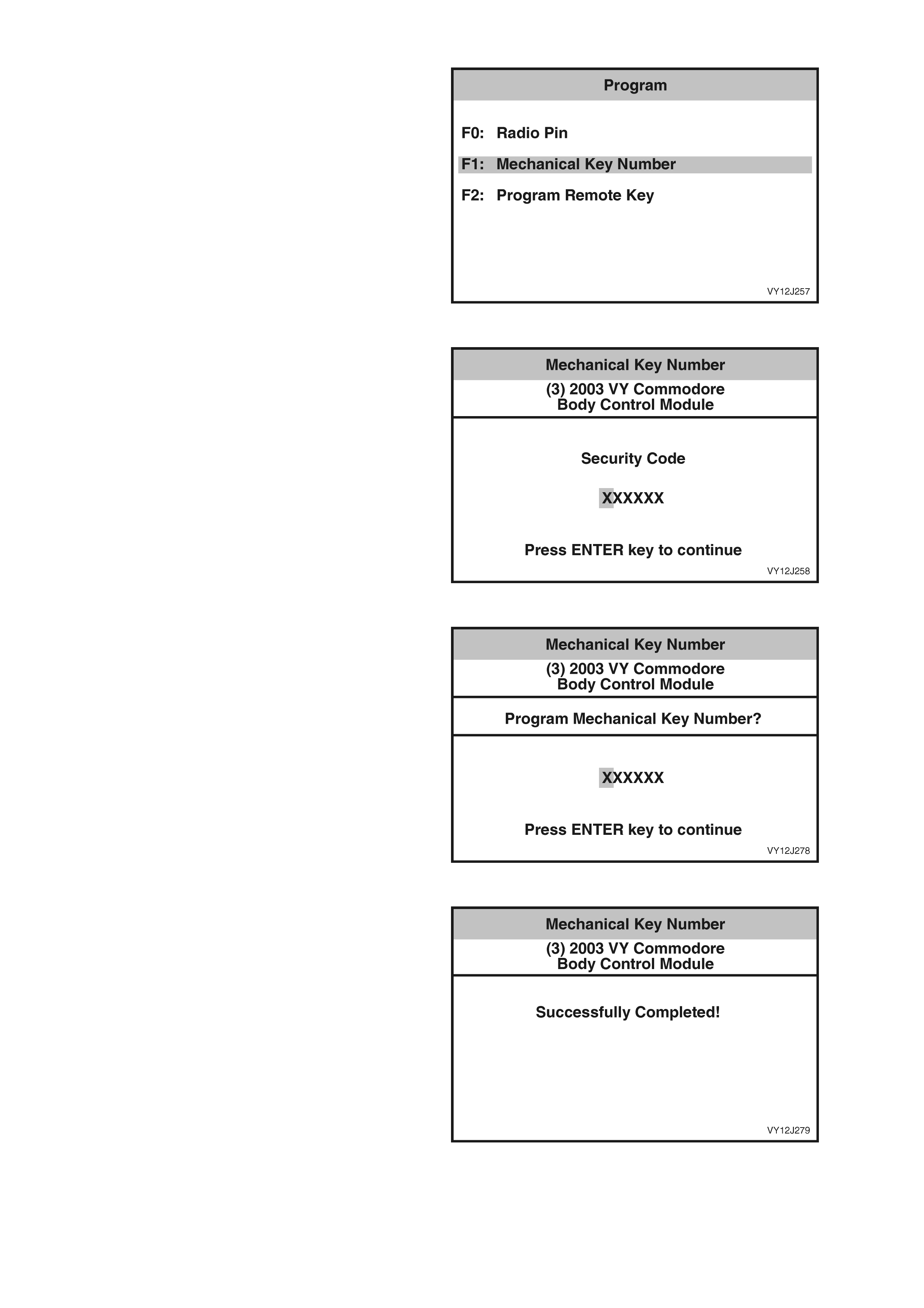
F1: Mechanical Key Number
NOTE: The (BCM) Security Code is required to
change the Mechanical Key Number. The security
code is contained on the IMPORTANT SECURITY
INFORMATION card issued with the vehicle when
new.
1. From the Program screen select F1:
Mechanical Key Number and press the Enter
key.
Figure 12J-199
2. Enter the six-digit (BCM) security code,
including any leading zeros, using the numeral
keys on TECH 2.
3. Press the Enter key to continue.
Figure 12J-200
4. Enter the new mechanical key number,
including any leading zeros, using the numeral
keys on TECH 2.
5. Press the Enter key to continue.
Figure 12J-201
6. When notified that the process is completed,
press the Confirm soft key to return to the
Program screen.
Figure 12J-202
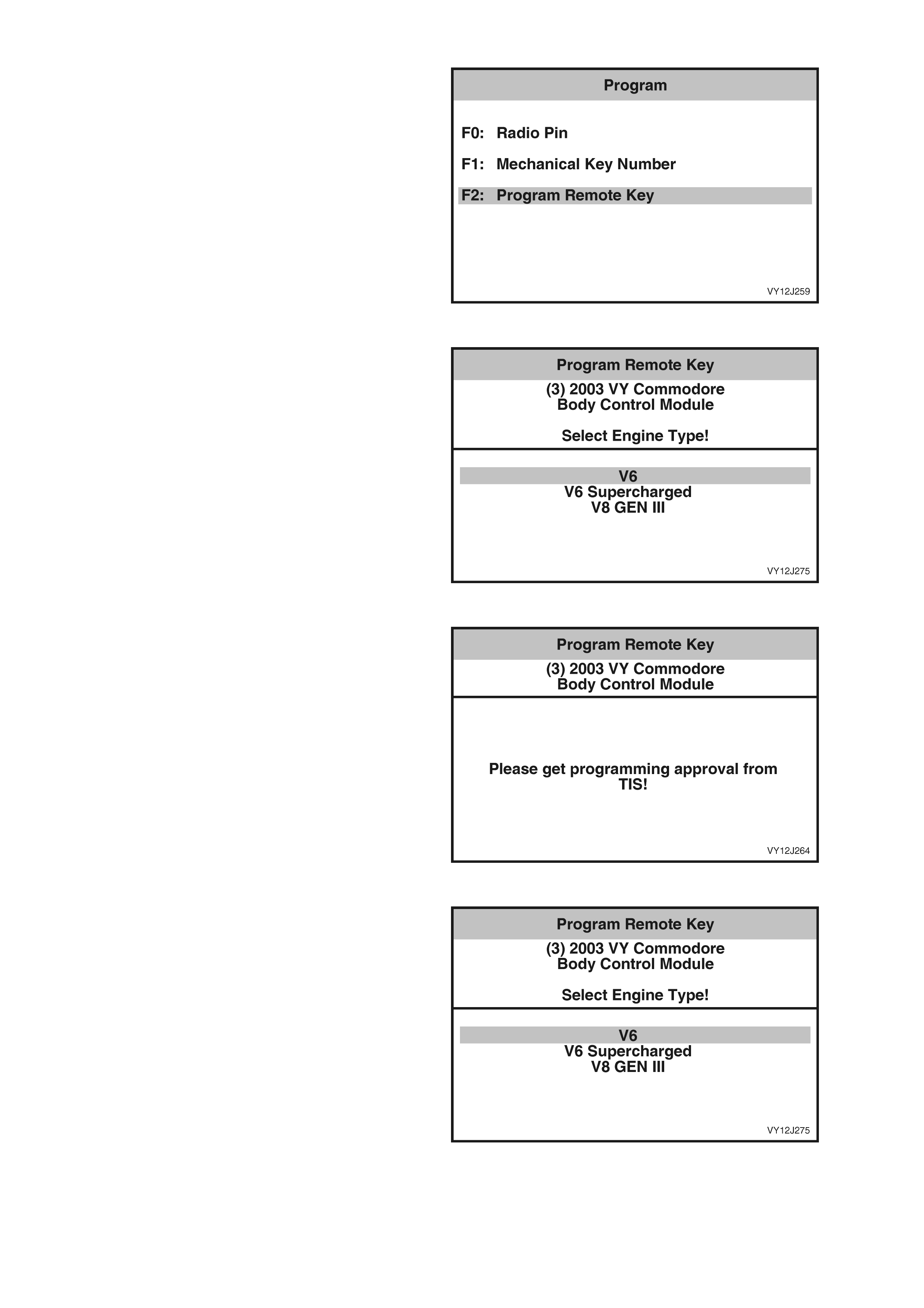
F2: Program Remote Key
NOTE: It is only possible to program a Remote Key
after TIS approval (Enable Programming) and the
(BCM) Security Code have been obtained. The
security code is contained on the IMPORTANT
SECURITY INFORMATION card issued with the
vehicle when new. Refer to Section 0C, TECH 2
for further details to enable programming.
1. From the Program screen select F2: Program
Remote Key and press the Enter key.
Figure 12J-203
2. Scroll through the list using the Up and Down
arrow keys. To select the required item, press
the Enter ke y.
3. To return to the Program screen without
changing the selection, press the Exit key .
Figure 12J-204
4. Obtain TIS approval when this screen is
displayed.
Figure 12J-205
5. When TIS approval has been obtained, return
to this screen.
6. Scroll through the list using the Up and Down
arrow keys. To select the required item, press
the Enter ke y.
Figure 12J-206
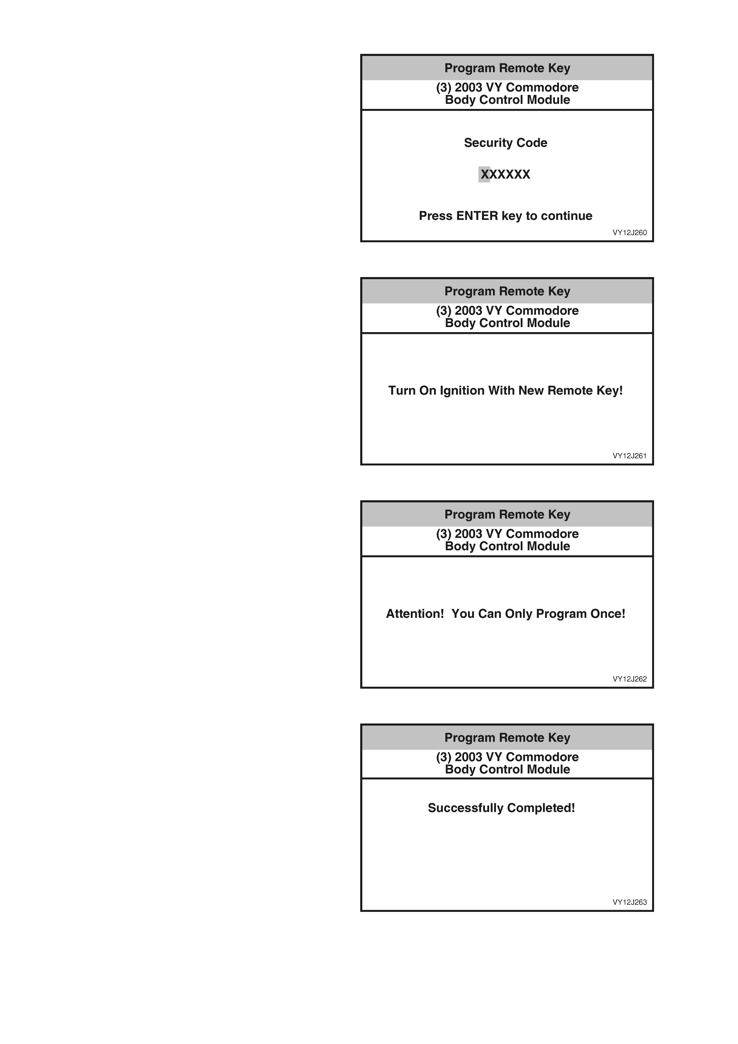
7. Enter the new remote key number, including
any leading zeros, using the numeral keys on
TECH 2.
8. Press the Enter key to continue.
Figure 12J-207
9. Follow the instructions as shown on the
TECH 2 screen, and press the Confirm soft key
to continue.
Figure 12J-208
10. Press the Abort soft key to cancel, or the
Program soft key to continue.
11. If an extra key is required to be programmed,
press the Extra Key soft key and follow the
instructions on the TECH 2 screen.
Figure 12J-209
12. When notified that the process is completed,
press the Q u it s of t key to retur n t o th e Pr ogram
screen.
Figure 12J-210

4. BCM DI AGNOSTICS
4.1 PREREQUISITES TO DIAGNOSIS AND TROUBLESHOOTING
PRELIM IN ARY SY ST EM REQUIREMENT S
Before proceeding with system checks, ensure the following:
• No moisture is present in the wiring harness connections in the A-pillars.
• Sound ground connections are available for all functioning components, particularly at the body ground
connection (adjacent to the battery).
• The battery is in good condition and charged above 11.5 volts.
PRE-DELIVERY MODE
To provide additional battery protection, the vehicle is delivered with the BCM in pre-delivery mode. In this mode,
the battery saver period is set to 3 minutes. For further information refer to 1.1, BATTERY SAVER MODE in this
Section.
Pre-delivery mode is disabled once the vehicle has travelled for a total of 30 minutes at speeds above 20 km/h.
This value is estimated to be the equivalent period prior to customer delivery.
Pre-delivery mode can be enabled or disabled by using the trip computer buttons and the Multi-Function Display
(MFD) or by using TECH 2.
SAFETY REQUIREMENTS
W hen carrying out work that involves th e risk of an elec trical short c ircuit, disco nnect the batt ery. However , refer to
Section 00, 5. BATTERY DISCONNECT ION PROCE DURES before disconnecting the battery.
To avoid the risk of being caught in the mechanism, do not touch mechanical components during function checks.
EQUIPMENT AND CHECKING
When undertaking any electrical checks on these systems, any digital multimeter that is used MUST have a
minimum impedance of 10 megohms.
Exercise care when taking readings from wiring harness connectors. It is preferred that the back probing method
with individual connectors is employed wherever possible to avoid terminal damage and subsequent connection
failure.
W hen carrying out wir ing check s as dir ected by the di agnostic c harts, use the adaptors c ontained in th e applicab le
connector t es t ad aptor k it J 3561 6-A ( previous l y KM 60 9) r ather than pr ob e terminals an d c on nec tor s us i ng in c orr ect
sized multimeter connections. This prevents spreading the terminals and damaging the wiring harness.
NOTE: Some steps in the diagnostic charts test for an abnormal or ‘false’ signal. This method is used when the
normal or ‘correct’ signal is of limited diagnostic value.
IMPORTANT:
• Ensure that the ignition is turned off and the battery ground lead is disconnected before any test requiring
disconnection or reconnection of BCM connectors X1, X2 or X3.
• When checking the system, observe the exact order of the test steps.
• If the required nominal value is not achieved in any stage, the problem must be rectified before proceeding
further.
• Check that the correct multimeter range is selected (as specified) before the test is carried out, unless the
multimeter being used has an auto ranging function.
• To lower the BCM s o as to gain acc ess to wiring harne ss connector s, refer to 2.1 BODY CONTROL MO DULE
in this Section.
• Testing various systems requires access to specific wiring harness connectors. For the location of these
connectors, refer to Section 12O, FUSES AND WIRING HARNESSES.
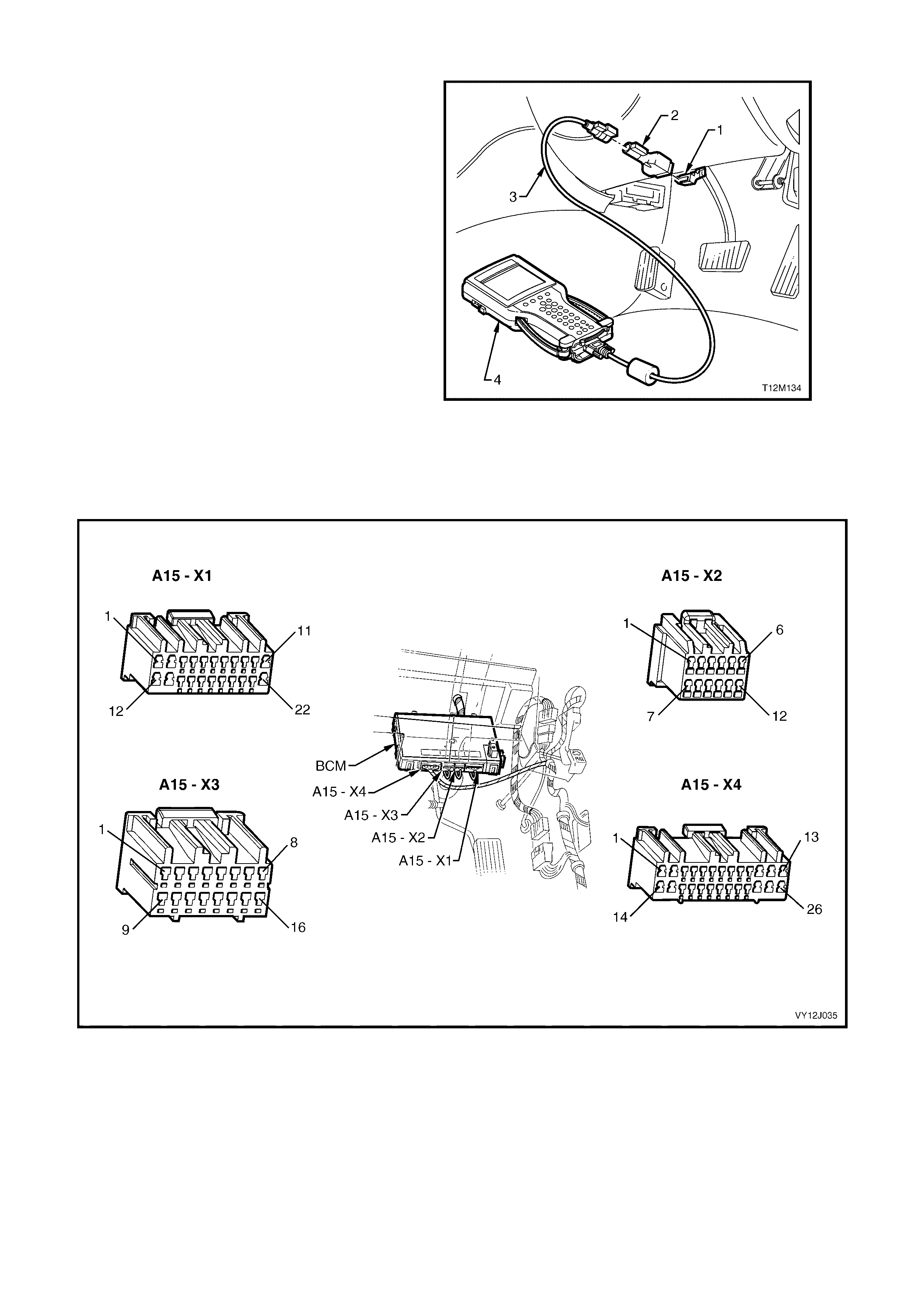
TECH 2 Diagnostic Tool
TECH 2 is a hand-held diagnostic computer
designed specifically to help Holden Retailer
technicians to diagnose and repair electronic
systems used on Holden vehicles.
TECH 2, with the appropriate software, cables
and adaptors, is capable of reading serial data
when connected to the Data Link Connector
(DLC). T he DLC is locat ed in th e instr um ent panel
lower right-hand trim, below the steering column.
Legend
Data Link Connector (DLC)
DLC Adaptor
DLC Cable
TECH 2 diagnostic tool.
For additional general information on connecting
and operating TECH 2, refer to Section 0C,
TECH 2.
Figure 12J-211
MODULE LOCATION
Right-hand Drive
Figure 12J-212
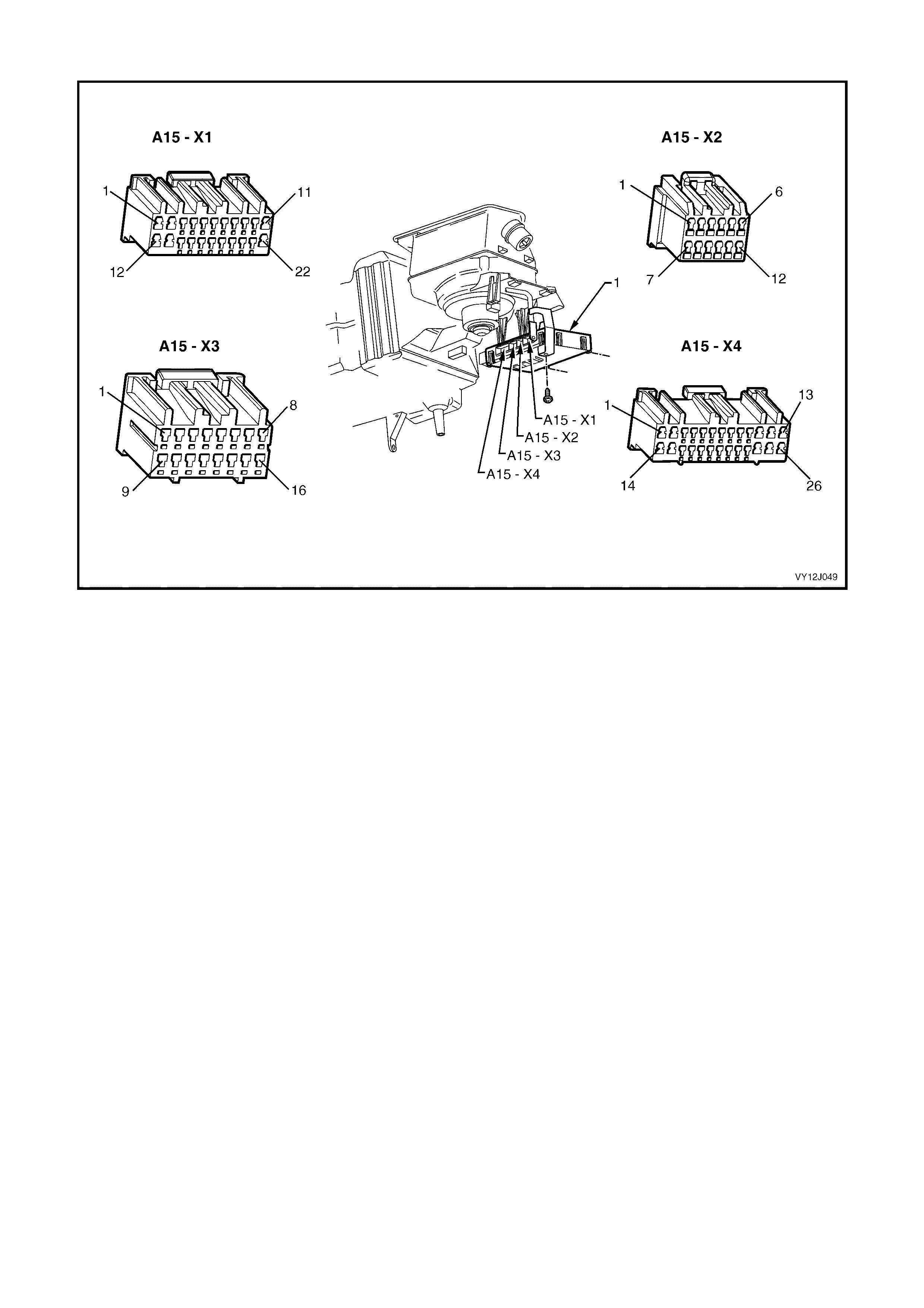
Left-hand Drive
Figure 12J-213
ABBREVI ATIONS
The following abbreviations are used in this Section:
BCM – Body Control Module
PCM – Powertra in Contr o l Modu le
PIM – Powertrain Interface Module
RF – Radio Frequency
MFD – Multi Function Display
HVAC – Heating, Ventilation and Air Conditioning
SRS – Supplemental Restraint System
DLC – Data Link Connector.
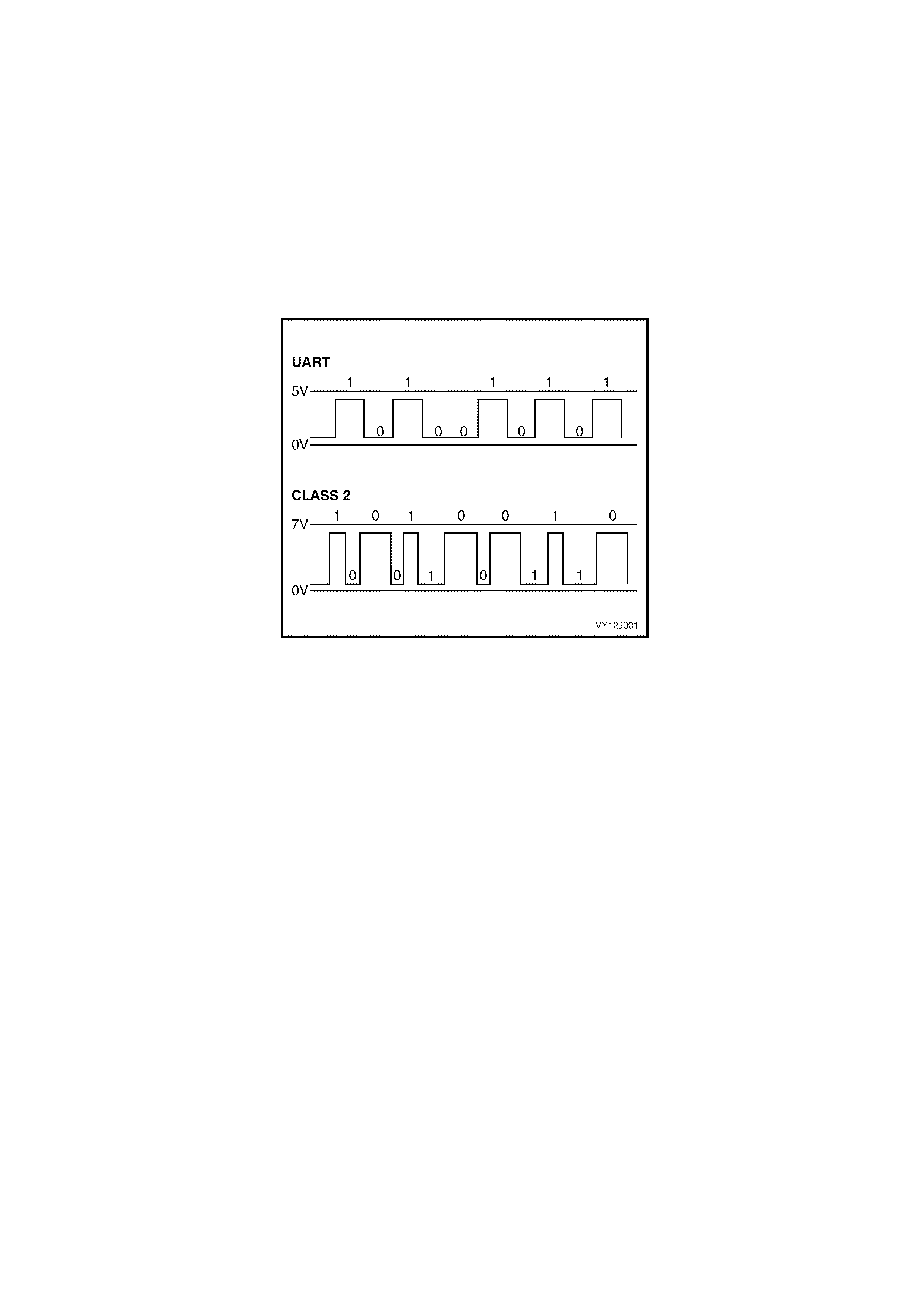
4.2 SERIAL DATA COMMUNICATION (BUS MASTER)
CIRCUIT DESCRIPTION
The vehic le system control m odules, as we ll as the TECH 2 diagnostic sc an tool, comm unicate with e ach other vi a
the data bus. Excluding the GEN III V8 PCM, all control modules communicating on the data bus use UART
communication.
UART is a 5 volt data b us t hat togg les the v oltage to g round (0 vo lt) at a f ixed-bit puls e width an d tra nsm its data at
8.2 kilobits per second. When there is no communication on the UART data bus, the system voltage is 5 volts.
The GEN III V8 PCM uses Class 2 communication. This toggles the data bus from 0 volt to 7 volts with either a
short or long pulse width at an average rate of 10.4 kilobits per second. W hen there is no communication on the
Class 2 dat a b us , th e syste m voltag e is 0 vo lt. The PIM con verts C las s 2 com munication in to UART an d U A RT into
Class 2.
TECH 2 is able to communicate with both UART and Class 2 control modules.
Figure 12J-214
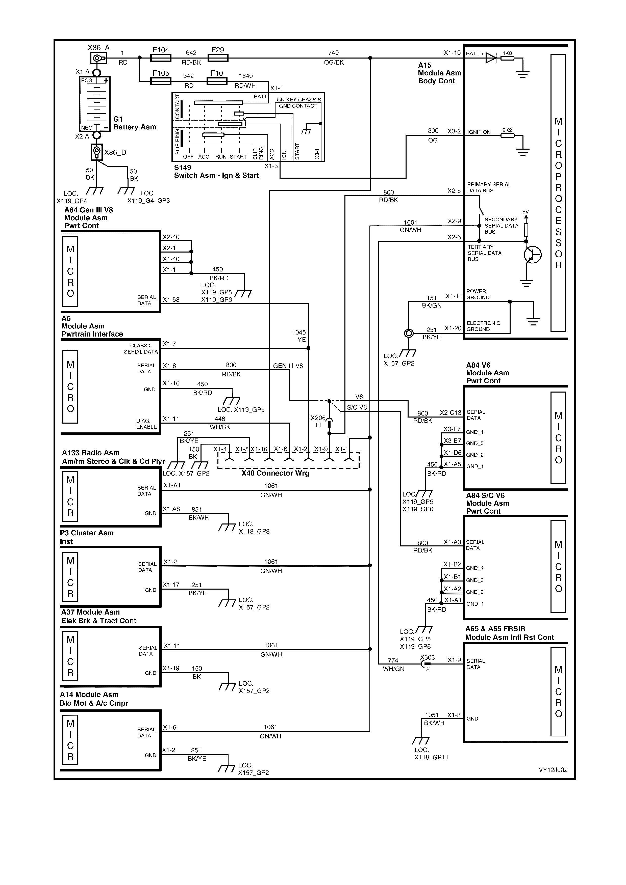
Figure 12J-215
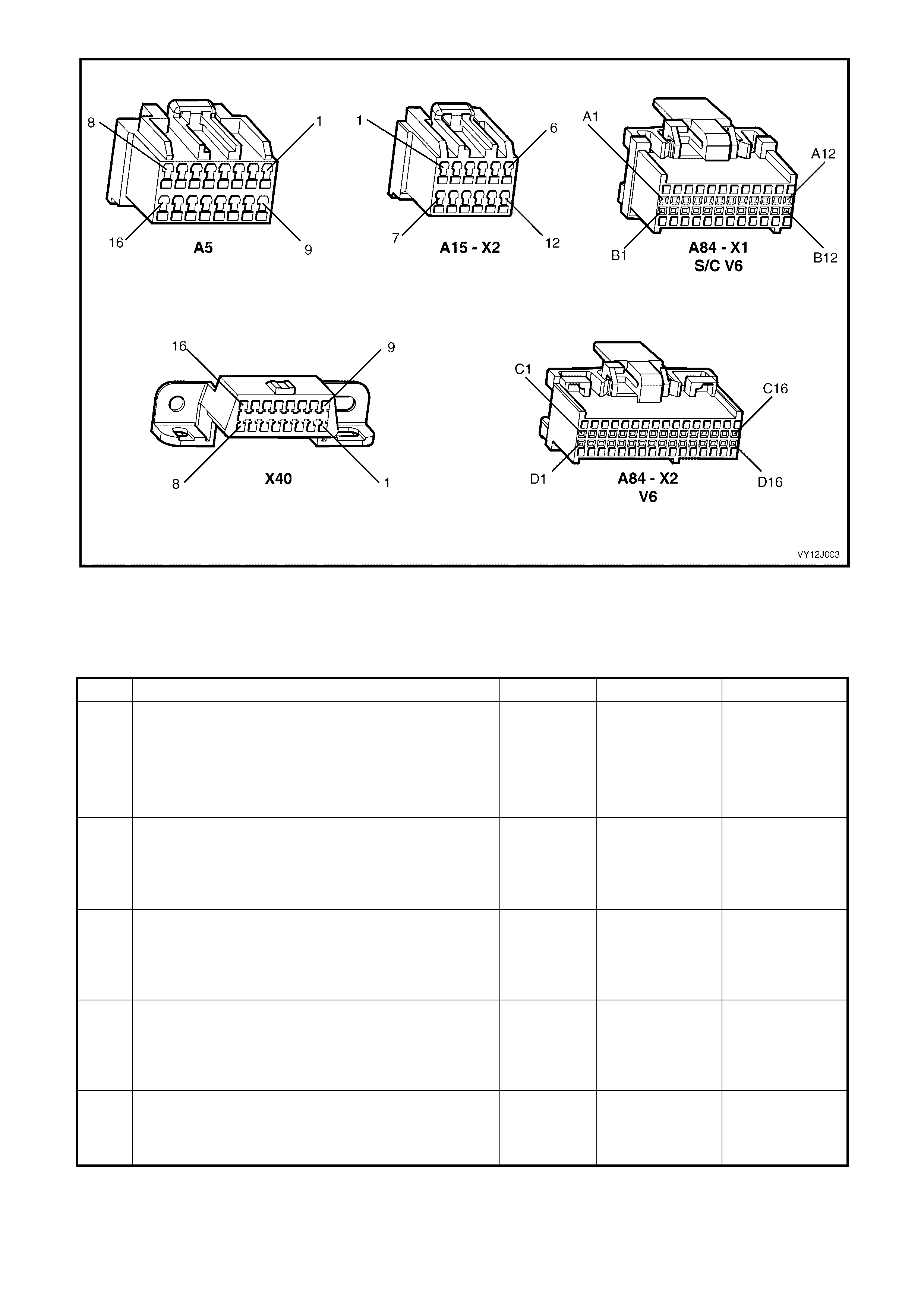
Figure 12J-216
SERIAL DATA COMMUNICATION DIAGNOSTIC CHART
IMPORTANT: Disconnection of the battery affects certain vehicle electronic systems. Refer to
Section 00, 5. BATTERY DISCONNECT ION PROCE DURES before disconnecting the battery.
STEP ACTION VALUE YES NO
1 1. Turn the ignition off.
2. Connect TECH 2 to the DLC.
3. Turn the ignition on.
4. Push power button on TECH 2.
Does TECH 2 power up (screen illuminates and displays
TECH 2)?
Go to Step 2. Go to TECH 2
diagnosis. Refer to
Section 0C,
TECH 2.
2 1. With TECH 2 still connected and the ignition on,
select Diagnostics / Model Year / Vehicle Model /
Body / Body Control Module.
Does TECH 2 display BCM system identification
information (BCM level and type)?
For V6 or V6 S/C
go to Step 3.
For GEN III V8 go
to Step 4.
Go to Step 8.
3 1. With TECH 2 still connected and the ignition on, exit
to the System Selection Menu and select Engine /
Engine Type (ie. V6 Supercharged).
Does TECH 2 display PCM system identification
information?
Go to Step 6. Go to Step 14.
4 1. With TECH 2 still connected and the ignition on, exit
Body Control Module and select Powertrain Interface
Module.
Can TECH 2 communicate with the Powertrain Interface
Module?
Go to Step 5. Go to Step 15.
5 1. With TECH 2 still connected and the ignition on, exit
Body and select Diagnostics / Engine / Engine Type.
Does TECH 2 display GEN III V8 PCM system
identificati on information?
Go to Step 6. Go to Step 7.

STEP ACTION VALUE YES NO
6 1. With TECH 2 still connected and the ignition on, exit
to the System Selection Menu and select Vehicle
DTC Check.
Can TECH 2 communicate with all control modules fitted
to the vehicle? (If No Data displays next to a control
module, then there is no communication between TECH 2
and that control modu le.)
NOTE: If the vehicle is not equipped with a particular
feature, for example ABS / TCS, No Data displays next to
this module .
System OK. Go to Step 16.
7 1. Turn the ignition off.
2. Disconnect the PCM connector A84.
3. Disconnect the PIM connector A5.
4. Back-probe DLC (X40) terminal X1-2 and PCM (A84)
terminal X1-58, circuit 1049 (Yellow wire) with an
ohmmeter.
Is the value as specified?
Less then 1
ohm Go to PCM
diagnostics in
Section 6C-3,
POWERTRAIN –
GEN III V8. Install
all connect ors.
Repair faulty
circuit 1049. Instal l
all connect ors.
8 1. With TECH 2 still connected and the ignition on,
back-probe DLC connector terminal X1-9, circuit 800
(Red / Black wire) with a voltmeter to ground.
Is the value as specified?
3 to 4 volts
(unstable) Go to Step 9. Go to Step 11.
9 1. Turn the ignition on.
2. Disc onnect TECH 2 from the DLC.
3. Back-probe DLC connector terminal X1-9, circuit 800
(Red / Black wire) with a voltmeter to ground.
Is value as specified?
3 to 4 volts
(unstable) Go to Step 10. Go to TECH 2
diagnosis. Refer to
Section 0C,
TECH 2. Repair
TECH 2 and
return to Step 1.
10 1. One at a time, disconnect the control modules on the
secondary serial data bus (ABS, ABS / TCS, SRS,
INS, Radio) and the PCM (PIM for GEN III V8
engine) on the primary serial data bus. Check each
time if TECH 2 can communicate with the BCM (refer
to Step 2), before restoring the connection.
NOTE: The secondary serial data bus comprises the
secondary serial data bus, circuit 1061 (Green / White
wire) and the tertiary serial data bus, circuit 774 (White /
Green wire).
Does communication between the BCM and TECH 2
resume after disconnecting any of the control modules?
Go to relevant part
of this Section for
diagnosis of
suspect control
module.
Install all
connectors. Go to
Step 13.
11 1. Turn the ignition on.
2. Back-probe DLC connector terminal X1-9, circuit 800
(Red / Black wire) with a voltmeter to ground.
Is the value as specified?
3 to 4 volts
(unstable) Go to TECH 2
diagnosis. Refer to
Section 0C,
TECH 2. Repair
TECH 2 and
return to Step 1.
Go to Step 12.
12 1. Turn the ignition off.
2. Disconnect the battery.
3. Disconnect all control modules (refer to Step 10) and
the BCM.
4. Check the integrity of circuits 800 (Red / Black wire),
1061 (Green / White wire) and 774 (White / Green
wire) (ie. short to voltage supply, short to ground).
Are the circuits OK?
Replace the BCM.
Refer to 2.1 BODY
CONTROL
MODULE in this
section. Connect
the battery and
refer to 2.1 BODY
CONTROL
MODULE,
REINSTALL in this
Section.
Repair faulty
circuits 800, 1061
or 774 as
necessary.
Connect the
battery and refer
to 2.1 BODY
CONTROL
MODULE,
REINSTALL in this
Section.
13 1. Perform the TECH 2 Self Test. Refer to Section 0C,
TECH 2.
Did TECH 2 test OK?
Replace the BCM.
Refer to 2.1 BODY
CONTROL
MODULE in this
section.
Repair TECH 2
and return to
Step 1.

STEP ACTION VALUE YES NO
14 1. Turn the ignition off.
2. Disconnect PCM (A84) connector.
3. Turn the ignition on.
4. Back-probe PCM terminal (X2-C13 for V6 or X1-A3
for V6 S/C), circuit 800 (Red / Black wire) with a
voltmeter to ground.
Is the value as specified?
3 to 4 volts
(unstable) Repair faulty
circuit 800. Go to Section
6C1,
POWERTRAIN
MANAGEMENT –
V6 or 6C2,
POWERTRAIN
MANAGEMENT –
V6 S/C for
diagnosis of the
PCM.
15 1. Turn the ignition off.
2. Disconnect PIM (A5) connector.
3. Turn the ignition on.
4. Back-probe PIM terminal X1-6, circuit 800 (Red /
Black wire) with a voltmeter to ground.
Is the value as specified?
3 to 4 volts
(unstable) Repair faulty
circuit 800. Go to PCM
diagnostics in
Section 6C-3,
POWERTRAIN –
GEN III V8.
16 1. Turn the ignition off.
2. In Step 6, was TECH 2 able to communicate with at
least one of the control modules on the secondary
serial data bus (ABS, ABS / TCS, INS, SRS, Radio)?
NOTE: TECH 2 will display No Data next to a control
module that it cannot communicate with in the DTC
Check mode.
Go to Step 17. Go to Step 18.
17 1. Disconnect the battery.
2. Use an ohmmeter to check continuity in circuits 1061
(White / Green wire) and 774 (Green / White wire)
between the BCM and the suspect control module/s.
Is there continuity?
Go to relevant part
of this Section for
diagnosis of
suspect control
module. Connect
the battery and
refer to 2.1 BODY
CONTROL
MODULE,
REINSTALL in this
Section.
Repair open circuit
in circuit 1061 or
774 between the
control modu le
and the BCM.
Connect the
battery and refer
to 2.1 BODY
CONTROL
MODULE,
REINSTALL in this
Section.
18 1. Disconnect the battery.
2. Check continuity between the BCM and all control
modules on the secondary serial data bus.
NOTE: The secondary serial data bus comprises the
secondary serial data bus, circuit 1061 (Green / White
wire) and the tertiary serial data bus, circuit 774 (White /
Green wire).
Is there continuity?
Replace the BCM.
Refer to 2.1 BODY
CONTROL
MODULE in this
Section.
Repair faulty
circuit 1061 or
774. Connect the
battery and refer
to 2.1 BODY
CONTROL
MODULE,
REINSTALL in this
Section.
WHEN ALL DIAGNOSIS AND REPAIRS ARE COMPLETE, CLEAR ALL DIAGNOSTIC TROUBLE CODES AND
VERIFY CORRECT OPERATION
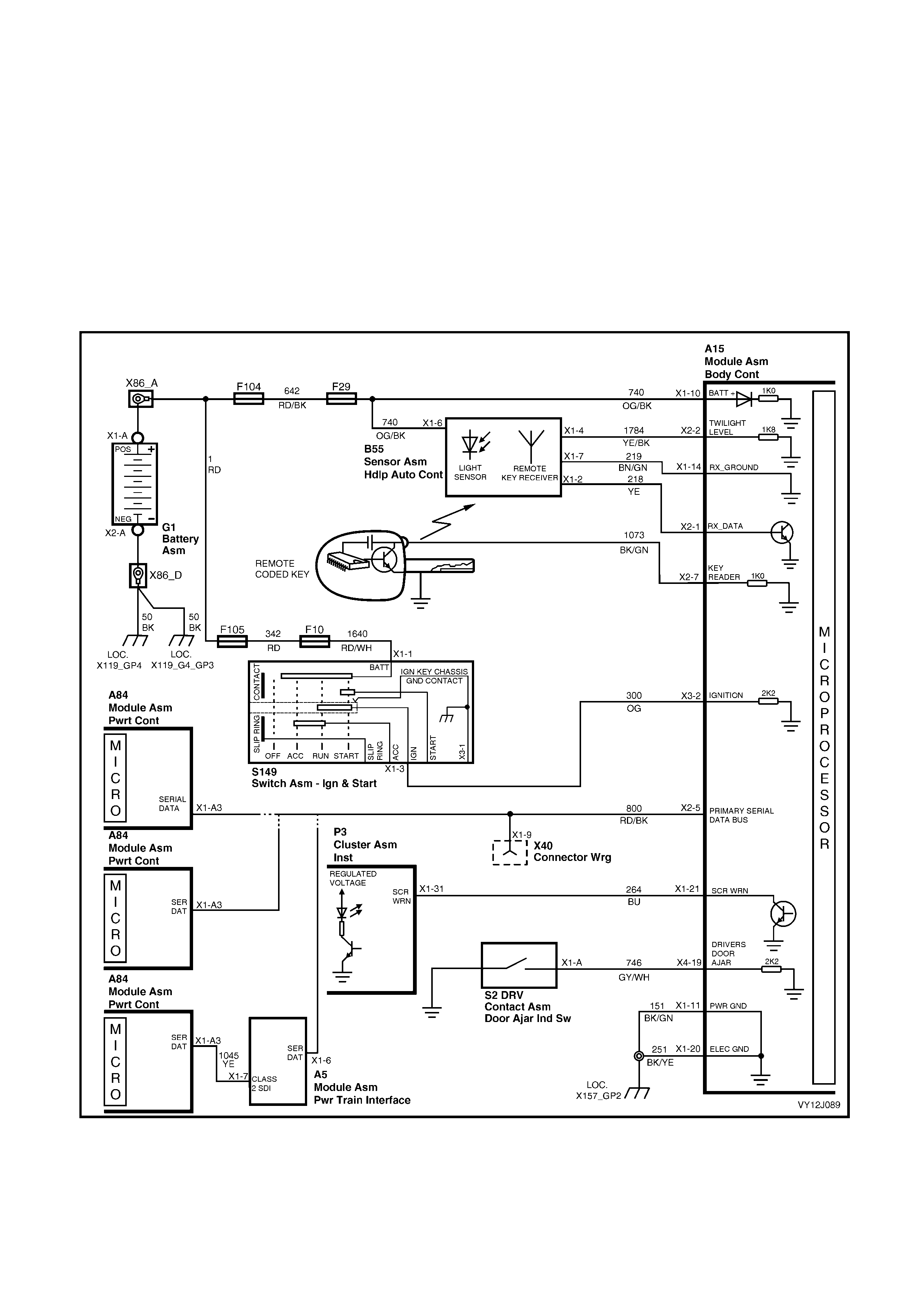
4.3 REMOTE RECEIVER / KEY
CIRCUIT DESCRIPTION
W hen operatin g the r em ote coded k ey, an RF sig nal is trans m itted to th e Rem ote Rec eiver. T his rec ei ver tra nsfer s
the received data from receiver terminal X1-2 to BCM terminal X2-1 via circuit 218 (Yellow wire). The receiver
ground connection is from receiver terminal X1-7 to BCM terminal X1-14, circuit 219 (Brown / Green wire). The
BCM responds to the received signal based on the frequency of the RF signal (the button on the key that is
pressed) . Ther e are three buttons o n the rem ote c oded ke y: Unlock, Loc k and Rear Com partm ent Release (s tatio n
wagon tailgate or sedan boot).
Remote Coded Key Battery Failure
The rem ote coded ke y is powered b y its own int ernal batter y. If this batter y f ails, no RF s ignal is trans mitted when
operating the Lock, Unlock and Rear Compartment release buttons. However, if the battery loses power, the
rem ote c oded key reader h as the ab il ity to power the k e y onc e it is in ser ted into t h e ign it ion switch and t ur ne d on or
to start. This enables theft deterrent disarming.
Figure 12J-217

Figure 12J-218
REMOTE RECEIVER / KEY DIAGNOSTIC CHART
STEP ACTION VALUE YES NO
1 1. Close and lock the doors.
2. Insert the remote coded key (the key) into the driver’s
door lock.
3. Use the key to unlock and lock the door.
Do all the doors unlock and lock?
Go to Step 2. Go to central door
locking diagnosis.
Refer to 4.5
CENTRAL DOOR
LOCKING in this
Section.
2 1. Unlock the driver’s door with the key.
2. With the theft deterrent LED flashing, insert the key
into the ignition switch and Turn the ignition on.
Does the theft deterrent LED turn off?
Go to Step 3. Go to theft
deterrent
diagnosis. Refer to
4.7 THE FT
DETERRENT
SYSTEM in this
Section.
3 1. Lock the driver’s door with the key.
2. Remove the key from the driver’s door lock.
3. Operate the key Unlock button within 2 metres of the
driver’s door B-pillar.
Does the driver’s door only (two-stage unlock) or all doors
(single-stage unlock) unlock?
Go to Step 4. Go to Step 8.
4 When performing Step 3, did all of the following occur
when the key Unlock button was pressed:
• indicators flashed twice
• dome lamp illuminated (dome lamp switch in Door
position), and
• theft deterrent LED turned off?
Go to Step 5. Go to theft
deterrent
diagnosis. Refer to
4.7 THE FT
DETERRENT
SYSTEM in this
Section.
5 1. Close all the doors.
2. Operate the Lock button on the key within 2 metres
of the driver’s door B-pillar.
Do all doors lock?
Go to Step 6. Go to Step 8.
6 When performing Step 5, did all of the following occur
when the key Lock button was pressed:
• theft deterrent LED began flashing
• indicators flashed once, and
• dome lamp turned off if illuminated (ensure switch is
in Door position)?
Go to Step 7. Go to theft
deterrent
diagnosis. Refer to
4.7 THE FT
DETERRENT
SYSTEM in this
Section.
7 1. Stand within 2 metres of the rear of the vehicle and
press the key rear compartment release button for 2
seconds.
Does the rear compartment lid unlock?
System OK. Go to Step 8.
8 1. Connect TECH 2 to the DLC.
2. Select Diagnostics / Model Year / Vehicle Model /
Body / Body Control Module / Data Display / Central
Door Locking / Remote Key Status.
3. Operate the Unlock, Lock and Boot lid release
buttons on the key.
Are the values as specified?
Valid Key Correct signal.
Replace the BCM.
Refer to 2.1 BODY
CONTROL
MODULE in this
Section.
Go to Step 9.

STEP ACTION VALUE YES NO
9 1. On another VY Series vehicle with a fully functional
key and receiver, connect TECH 2 to the DLC.
2. Select Remote Key Status as per Step 8.
3. Operate the Unlock, Lock and Boot lid release
buttons on the key.
Are the values as specified?
Invalid Code Correct signal. Go
to Step 10. Program me a new
key to the original
vehicle. Refer to
2.3 REMOTE
CODED KEY in
this Section.
10 1. Return to the original vehicle which has the
suspected faulty remote coded key / receiver.
2. Back-probe the remote receiver (B55) connector
terminal X1-6, circuit 740 (Orange / Black wire) with a
voltmeter to ground.
Is the value as specified?
Battery
voltage Go to Step 11. Check and repair
faulty circuit 740.
11 1. Check the integrity of circuit 219 (Brown / Green
wire) between BCM connector terminal X1-14 and
remote receiver connector terminal X1-7.
Is circuit 219 OK?
Go to Step 12. Repair faulty
circuit 219.
12 1. Check the integrity of circuit 218 (Yellow wire)
between BCM connector terminal X2-1 and remote
receiver connector terminal X1-2.
Is circuit 218 OK?
Go to Step 13. Repair faulty
circuit 218.
13 1. Replace the remote receiver with a known functional
remote receiver.
2. Connect TECH 2 to the DLC.
3. Select Body / Body Control Module / Data Display /
Central Door Locking / Remote K ey Fu nction.
4. Operate the Unlock, Lock and Boot lid release button
on the remote coded key.
Are the values as specified?
Unlock
request,
Lock request,
Boot release
request
Replace faulty
remote receiver.
Refer to 2.5
REMOTE
RECEIVER in this
Section.
Replace the BCM.
Refer to 2.1 BODY
CONTROL
MODULE in this
Section.
WHEN ALL DIAGNOSIS AND REPAIRS ARE COMPLETE, VERIFY CORRECT OPERATION

4.4 ACCESSORY POWER CONTROL
CIRCUIT DESCRIPTION
W hen the ignit ion is s witched o n or to Ac cess ories or if the rad io is switch ed on, the BCM en ergises the Acces sor y
Control Relay supplying power to the radio and the wiper system. The BCM disables the relay (disconnecting the
power) when the ign it ion is s witc hed off or when the dri ver’s door is opened (depe ndi ng on the acc ess ory shutdo wn
option selected).
Turning the radio on when the ignition is off triggers the BCM to energise the Accessory Control Relay for a 60
minute period. However, if the radio is switched off within this period, the relay will be disabled immediately.
If the f ront wip er is active when disab ling of the ac c es sory power is in iti ate d, th e B CM monitors the wip er park input
before disabling the Accessory Control Relay, which allows the wipers to park. If the wiper park input is not
detected within 3 minutes, the BCM will automatically disable the relay.
W hen the ke y is switch ed t o Acces sories or On, a 12 volt s uppl y from the ig nitio n swit ch is d etecte d b y the BCM at
either terminal X3-4, (Accessories output via circuit 4, Brown wire) or terminal X3-2 (On output via circuit 300,
Orange wire) .
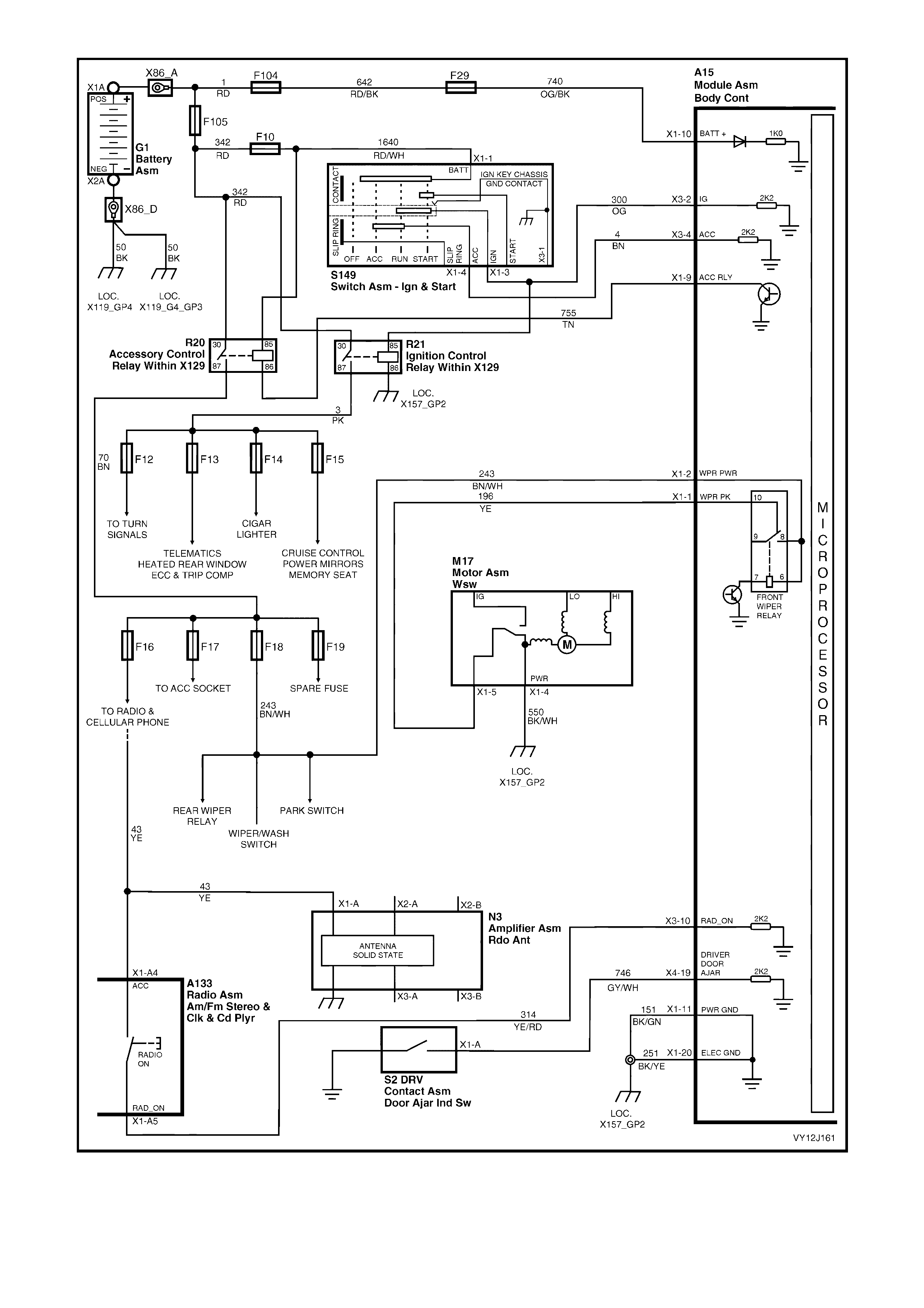
Figure 12J-219
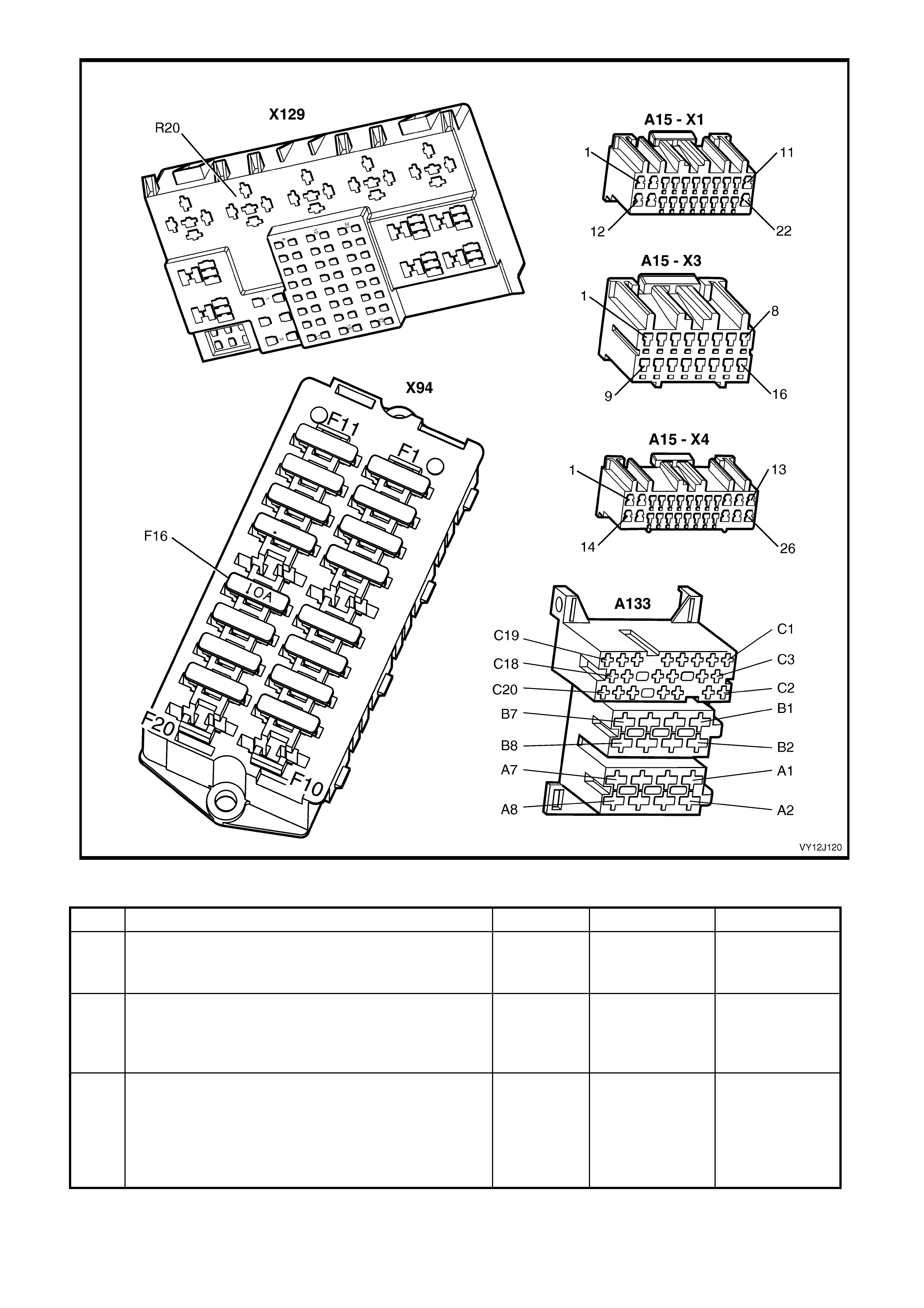
Figure 12J-220
ACCESSORY POWER CONTROL DIAGNOSTIC CHART
STEP ACTION VALUE YES NO
1 1. Turn the ignition off.
2. Turn on the radio.
Does the radio operate?
Go to Step 2. Go to Step 3.
2 1. With the radio on, turn the ignition on then off.
2. If the Driver’s Door shutdown user-option is selected,
open the driver’s door.
Does the radio stop operating?
System OK. Go to Step 12.
3 1. With the ignition off, turn off the radio and close the
driver’s door.
2. Probe both terminals of fuse F16 with a voltmeter to
ground.
3. Turn on the radio.
Are the values as specified?
Radio off =
0 volt
Radio on =
battery
voltage
Go to Step 4. Go to Step 5.

STEP ACTION VALUE YES NO
4 1. Check the integrity of circuit 43 (Yellow wire)
connecting fuse F16 to radio terminal X1-A4.
Is the circuit OK?
Go to Section
12D, 3.12 AUDIO
SYSEM
DIAGNOSTIC
PROCEDURES.
Repair faulty
circuit 43.
5 1. Turn off the radio.
2. Remove the Accessory Control Relay (R20) and
back-probe the relay holder terminals 30 and 85 with
a voltmeter to ground.
Are the values as specified?
Battery
voltage Install the relay
and go to Step 6. Check and repair
faulty circuit 1640
(Red / White wire)
or circuit 342 (Red
wire) as
necessary.
6 1. W ith the radio and ignition off, back-probe Accessory
Control Relay terminal 87 with a voltmeter to ground.
2. Turn on the radio.
Is the value as specified?
Battery
voltage
(Relay
audibly
switches)
Repair faulty
circuit 70 (Brown
wire).
Go to Step 7.
7 1. Connect the voltmeter as in Step 6.
2. With the radio off and ignition off, back-probe
Accessory Control Relay connector terminal 86 with
a jumper lead to ground.
Is the value as specified?
Battery
voltage
(Relay
audibly
switches)
Go to Step 8. Replace the
Accessory Control
Relay (R20) . Refer
to Section 12O,
1.2 RELAYS.
8 1. Check the integrity of circuit 755 (Tan wire)
connecting BCM terminal X1-9 to the Accessory
Control Relay terminal 86.
Is the circuit OK?
Go to Step 9. Repair faulty
circuit 755.
9 1. Connect TECH 2 to the DLC.
2. Select Diagnostics / Model Year / Vehicle Model /
Body / Body Control Module / Data Display / Inputs
and Outputs / Accessory Relay.
3. With the ignition off, turn on the radio.
Does TECH 2 display On?
Replace the BCM.
Refer to 2.1 BODY
CONTROL
MODULE in this
Section.
Go to Step 10.
10 1. With TECH 2 connected, exit Accessory Relay and
select Radio Status.
2. Turn the ignition off and then on.
3. Turn the radio on.
Does TECH 2 display On?
Replace the BCM.
Refer to 2.1 BODY
CONTROL
MODULE in this
Section.
Go to Step 11.
11 1. Check the integrity of circuit 314 (Yellow / Red wire)
connecting BCM terminal X3-10 to the radio
terminal X1-A5.
Is the circuit OK?
Refer to Section
12D, 3.12 AUDIO
SYSTEM
DIAGNOSTIC
PROCEDURES.
Repair faulty
circuit 314.
12 1. Connect TECH 2 to the DLC.
2. Select Diagnostics / Model Year / Vehicle Model /
Body / Body Control Module / Data Display / Inputs
and Outputs / Ignition Switch.
3. Ensure the ignition is off.
Does TECH 2 display Off?
Go to Step 13. Go to Step 18.
13 1. With TECH 2 connected and the ignition turned off,
exit Ignition Switch and select Accessory Switch.
Does TECH 2 display Off?
Go to Step 14. Go to Step 19.
14 1. Back-probe BCM connector terminal X4-19,
circuit 746 (Grey / White wire) with a voltmeter to
ground.
2. Open the driver’s door.
Is the value as specified?
Less then 0.5
volt Go to Step 15. Check and repair
faulty door ajar
signal. Refer to
4.5 CENTRAL
DOOR LOCKING,
Part L – Door Ajar
Switches in this
Section.
15 1. With the ignition off and TECH 2 connected, exit
Accessory Switch and select Accessory Relay.
Does TECH 2 display On?
Go to Step 16. Replace the BCM.
Refer to 2.1 BODY
CONTROL
MODULE in this
Section.

STEP ACTION VALUE YES NO
16 1. With the driver’s door closed, the radio and ignition
off and the Accessory Control Relay installed,
back-probe the Accessory Control Relay terminal 86
with a voltmeter to ground.
Is the value as specified?
Battery
voltage Replace the
Accessory Control
Relay (R20) . Refer
to Section 12O,
1.2 RELAYS.
Go to Step 17.
17 1. Check the integrity of circuit 755 (Tan wire)
connecting BCM terminal X1-9 to the Accessory
Control Relay terminal 86.
Is the circuit OK?
Replace the BCM.
Refer to 2.1 BODY
CONTROL
MODULE in this
Section.
Repair faulty
circuit 755.
18 1. Check the integrity of circuit 300 (Orange wire)
connecting BCM terminal X3-2 to the ignition switch.
Is the circuit OK?
Replace the BCM.
Refer to 2.1 BODY
CONTROL
MODULE in this
Section.
Repair faulty
circuit 300.
19 1. Check the integrity of circuit 4 (Brown wire)
connecting BCM terminal X3-4 to the ignition switch.
Is the circuit OK?
Replace the BCM.
Refer to 2.1 BODY
CONTROL
MODULE in this
Section.
Repair faulty
circuit 4.
WHEN ALL DIAGNOSIS AND REPAIRS ARE COMPLETE, VERIFY CORRECT OPERATION

4.5 CENTR AL DOOR LOCKING
CIRCUIT DESCRIPTION
The central door-locking system enables simultaneous locking or unlocking of all doors and the station wagon
tailgate, enhanced locking or ‘deadlocking' of the doors as well as single-stage and two-stage unlocking.
NOTE: When investigating a complaint of a central door system locking problem or malfunction, always start the
diagnosis with the functional check in this Section.
Functional check
The functional check is a quick check of the central door locking system. Perform this check with the purpose of
locating which part of the syst em requires attention and ther efore ide ntif ying whic h diag nost ic char t to use. Refer to
the list of charts following.
Diagnostic testing
Following the Functional Check Diagnostic Chart, there are twelve diagnostic charts to which you may be referred
for further system diagnosis:
• Part A – Unlocking Doors using Driver’s Door Lock Microswitch
• Part B – Locking Doors using Driver’s Door Lock Microswitch
• Part C – Unlocking Doors using Driver’s Door Lock Snib Actuator
• Part D – Locking Doors using Driver’s Door Lock Snib Actuator
• Part E – Unlocking Doors using Passengers’ Door Lock Snib Actuators
• Part F – Locking Doors using Front Passenger Door Lock Snib Actuator
• Part G – Unlocking the Tailgate
• Part H – Deadlocking Doors using Driver’s Door Lock Microswitch
• Part I – Unlocking Doors From Deadlock
• Part J – Auto Door Locking (Gearshift out of Park Position)
• Part K – Auto Door Unlocking (Gearshift into Park Position)
• Part L – Door Ajar Switches.
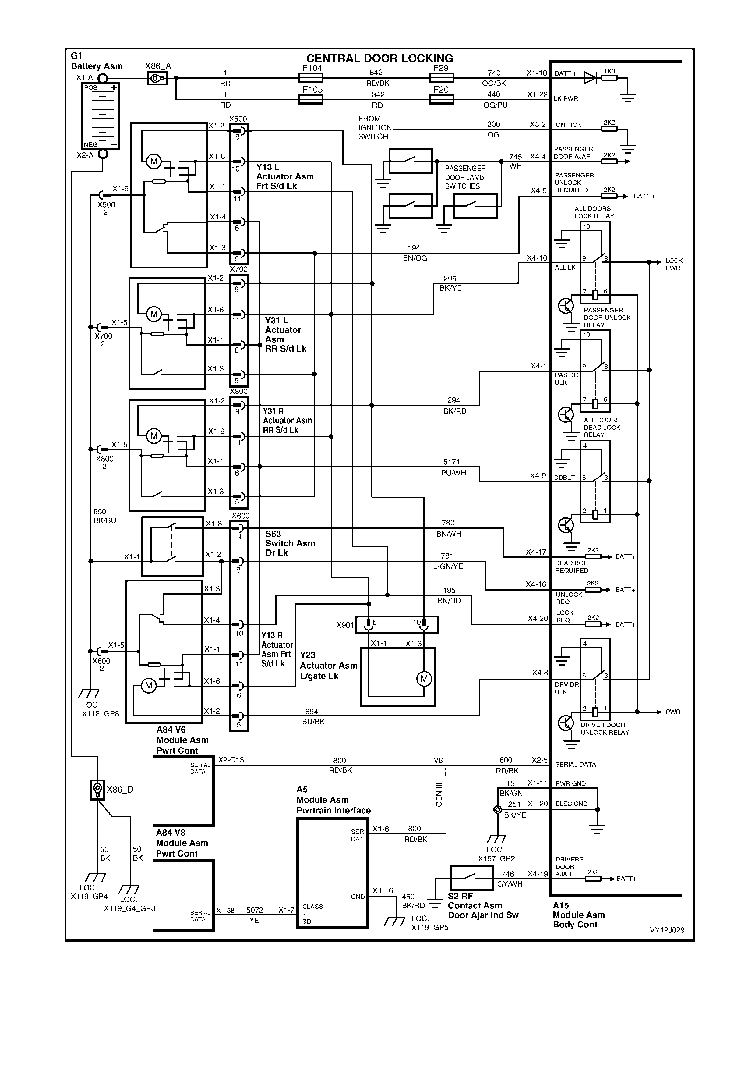
Figure 12J-221
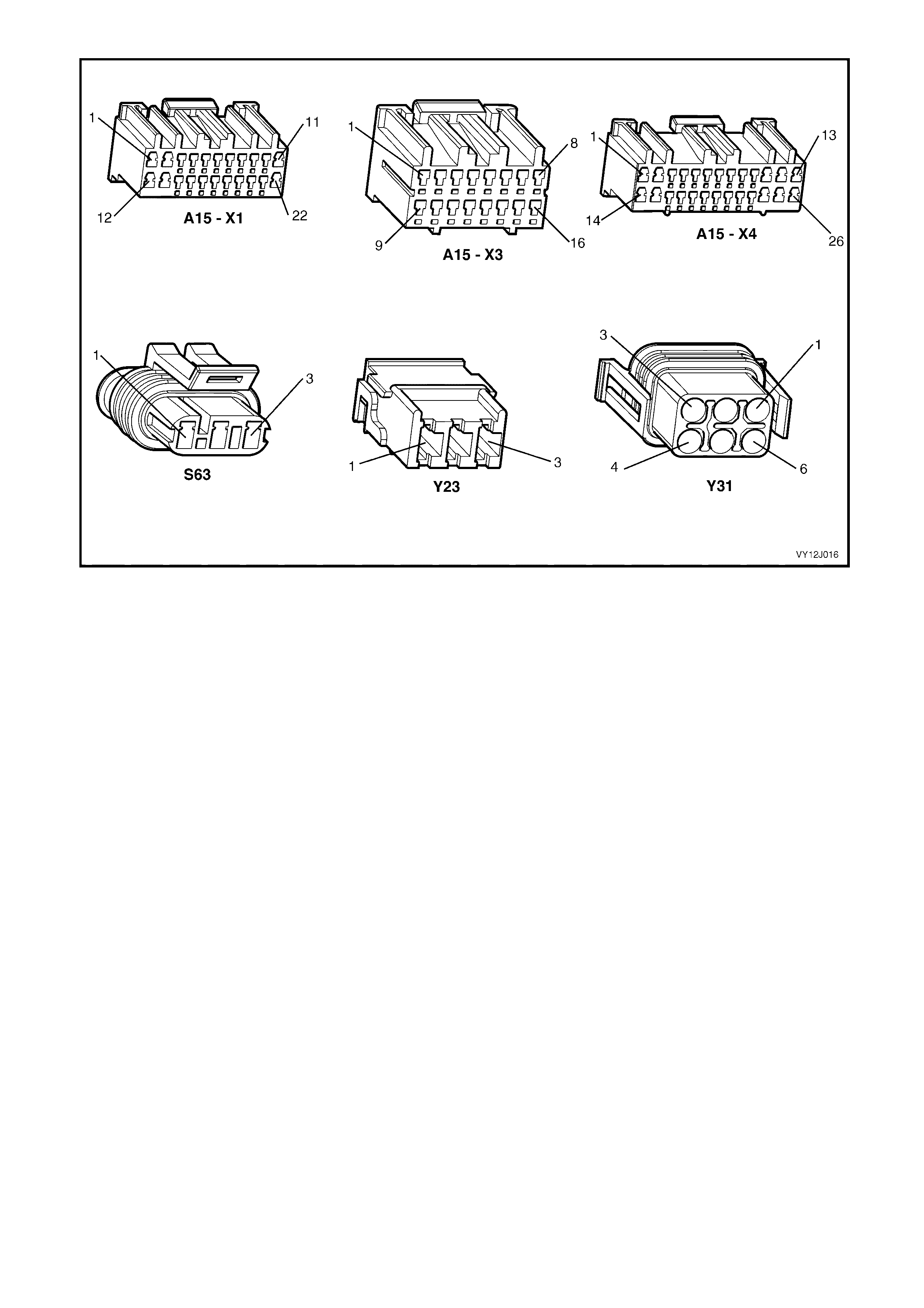
Figure 12J-222

FUNCTIONAL CHECK DIAGNOSTIC CHART
STEP ACTION VALUE YES NO
1 Are all door ajar switches and associated circuits
functioning correctly? Go to Step 2. Go to Part L, Door
Ajar Switches.
2 1. Lock all doors.
2. Operate the remote coded key Unlock button within
4 metres of driver’s side B-pillar.
Does driver’s door unlock (2 stage unlocking) or all doors
unlock (single-stage unlocking)?
Go to Step 4. Go to Step 3.
3 1. Lock all doors.
2. Insert the ignition key into driver’s door lock and
operate the microswitch by turning the key to the
unlock positi on.
Do all doors unlock?
Go to remote
receiver diagno sis .
Refer to 4.3
REMOTE
RECEIVER / KEY
in this Section.
Go to Part A
UNLOCKING
DOORS USING
DRIVER’S DOOR
LOCK
MICROSWITCH.
4 1. Unlock all doors.
2. Close all doors.
3. Operate the remote coded key Lock button within
4 metres of the driver’s side B-pillar.
Do all doors lock?
Go to Step 6. Go to Step 5.
5 1. Unlock all doors.
2. Close all doors.
3. Insert the ignition key into the driver’s door lock and
operate the microswitch by turning the key to the lock
position.
Do all doors lock?
Go to remote
receiver diagno sis .
Refer to 4.3
REMOTE
RECEIVER / KEY
in this Section.
Go to Part B
LOCKING
DOORS USING
DRIVER’S DOOR
LOCK
MICROSWITCH.
6 1. Close all doors.
2. Lock all doors.
3. Insert the ignition key into the driver’s door lock and
operate the microswitch by turning the key to the
unlock positi on.
Do all doors unlock?
Go to Step 7. Go to Part A
UNLOCKING
DOORS USING
DRIVER’S DOOR
LOCK
MICROSWITCH.
7 1. Close all doors.
2. Unlock all doors.
3. Insert the ignition key into the driver’s door lock and
operate the microswitch by turning the key to the lock
position.
Do all doors lock?
Go to Step 8. Go to Part B
LOCKING
DOORS USING
DRIVER’S DOOR
LOCK
MICROSWITCH.
8 1. Lock, but do not deadlock, all doors.
2. Operate the driver’s door lock snib to unlock the
door.
Do all doors unlock?
Go to Step 9. Go to Part C
UNLOCKING
DOORS USING
DRIVER’S DOOR
LOCK SNIB
ACTUATOR.
9 1. Close all doors.
2. Operate the driver’s door lock snib to lock the door.
Do all doors lock?
Go to Step 10. Go to Part D
LOCKING
DOORS USING
DRIVER’S DOOR
LOCK SNIB
ACTUATOR.
10 1. Lock, but do not deadlock, all doors.
2. Operate each passenger’s door lock snib to unlock
each door.
Does each door unlock?
Go to Step 11. Go to Part E
UNLOCKING
DOORS USING
PASSENGERS’
DOOR LOCK
SNIB
ACTUATORS.

STEP ACTION VALUE YES NO
11 1. Close all doors.
2. Operate the front passenger’s door lock snib to lock
the door.
Do all doors lock?
Go to Step 12
(wagon)
or
Go to Step 14
(sedan).
Go to Part F
LOCKING
DOORS USING
FRONT
PASSENGER’S
DOOR LOCK
SNIB
ACTUATOR.
12 1. Lock the tailgate.
2. Insert the ignition key into the driver’s door lock and
operate the microswitch by turning the key to the
unlock positi on.
Does the tailgate unlock?
Go to Step 13. Go to Part G
UNLOCKING THE
TAILGATE.
13 1. Unlock the tailgate.
2. Insert the ignition key into the driver’s door lock and
operate the microswitch by turning the key to the lock
position.
Does the tailgate lock?
Go to Step 14. Replace tailgate
lock actuator.
Refer to Section
1A4, HOOD,
REAR
COMPARTMENT
LID, LIFTGATE
AND ENDGATE.
14 1. Unlock the doors.
2. Insert the ignition key into the driver’s door lock and
deadlock the doors by turning the key twice
sequentially to the lock position.
Are all the doors deadlocked?
Go to Step 15. Go to Part H
DEADLOCKING
DOORS USING
DRIVER’S DOOR
LOCK
MICROSWITCH.
15 1. Unlock all doors.
2. Close all doors.
3. Turn the ignition on.
4. Move the gearshift lever out of the P (park) position.
Do all doors lock?
Go to Step 16. Go to Part J,
AUTO DOOR
LOCKING
(GEARSHIFT
OUT OF PARK
POSITION).
16 1. Turn the ignition off.
2. Lock all doors.
3. Move the gearshift lever into the N (neutral) position.
4. Turn the ignition on.
5. Move the gearshift lever into the P (park) position.
6. Turn the ignition off.
Do all doors unlock?
Go to Step 17. Go to Part K,
AUTO DOOR
UNLOCKING
(GEARSHIFT
INTO PARK
POSITION).
17 1. Deadlock the doors.
2. Insert the ignition key into the driver’s door lock and
operate the microswitch by turning the key to the
unlock positi on.
Do all the doors unlock?
System OK. Go to Part I
UNLOCKING
DOORS FROM
DEADLOCK.
WHEN ALL DIAGNOSIS AND REPAIRS ARE COMPLETE, VERIFY CORRECT OPERATION
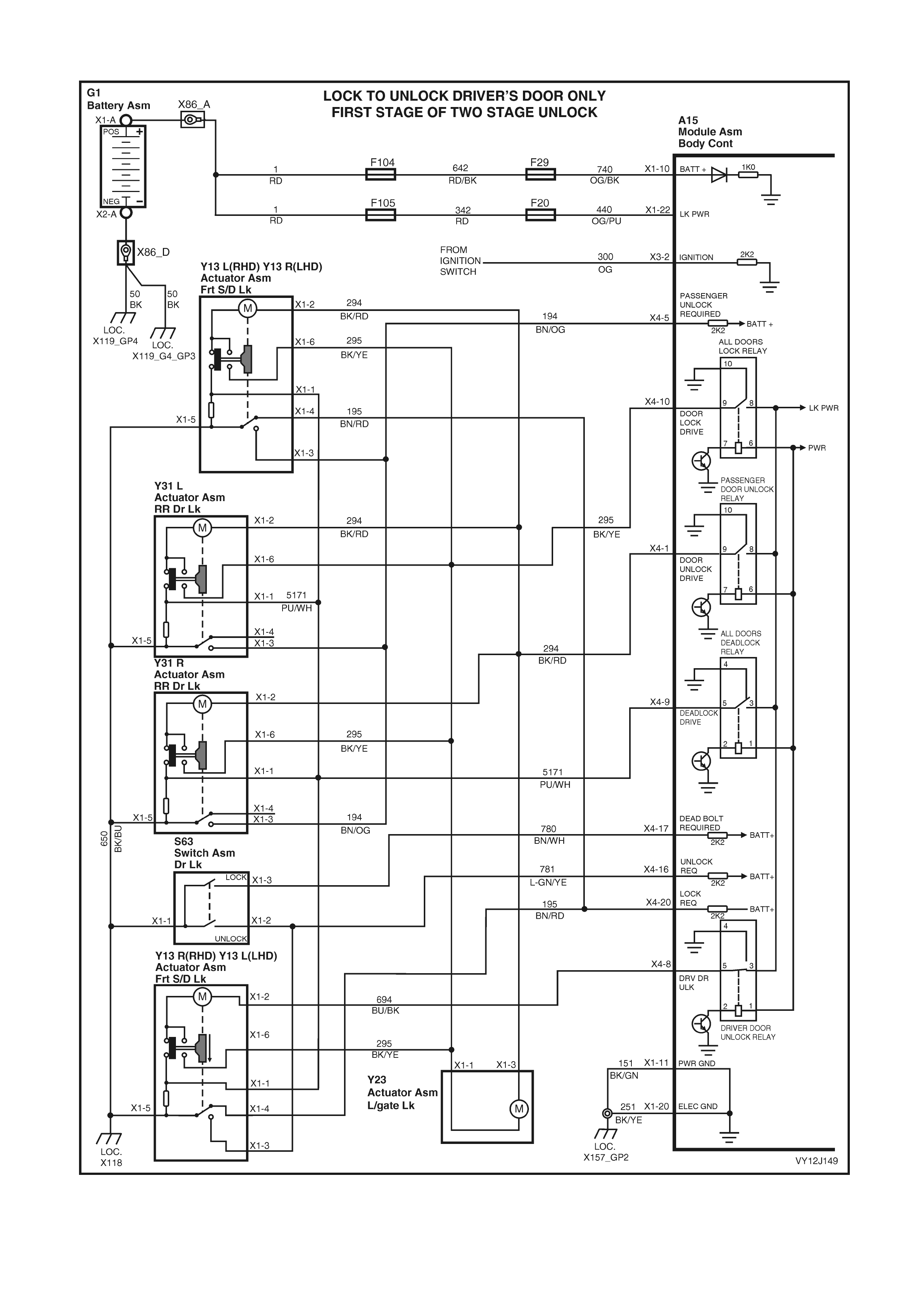
PART A – UNLOCKING DOORS USING DRIVER’S DOOR LOCK MICROSWITCH
Figure 12J-223
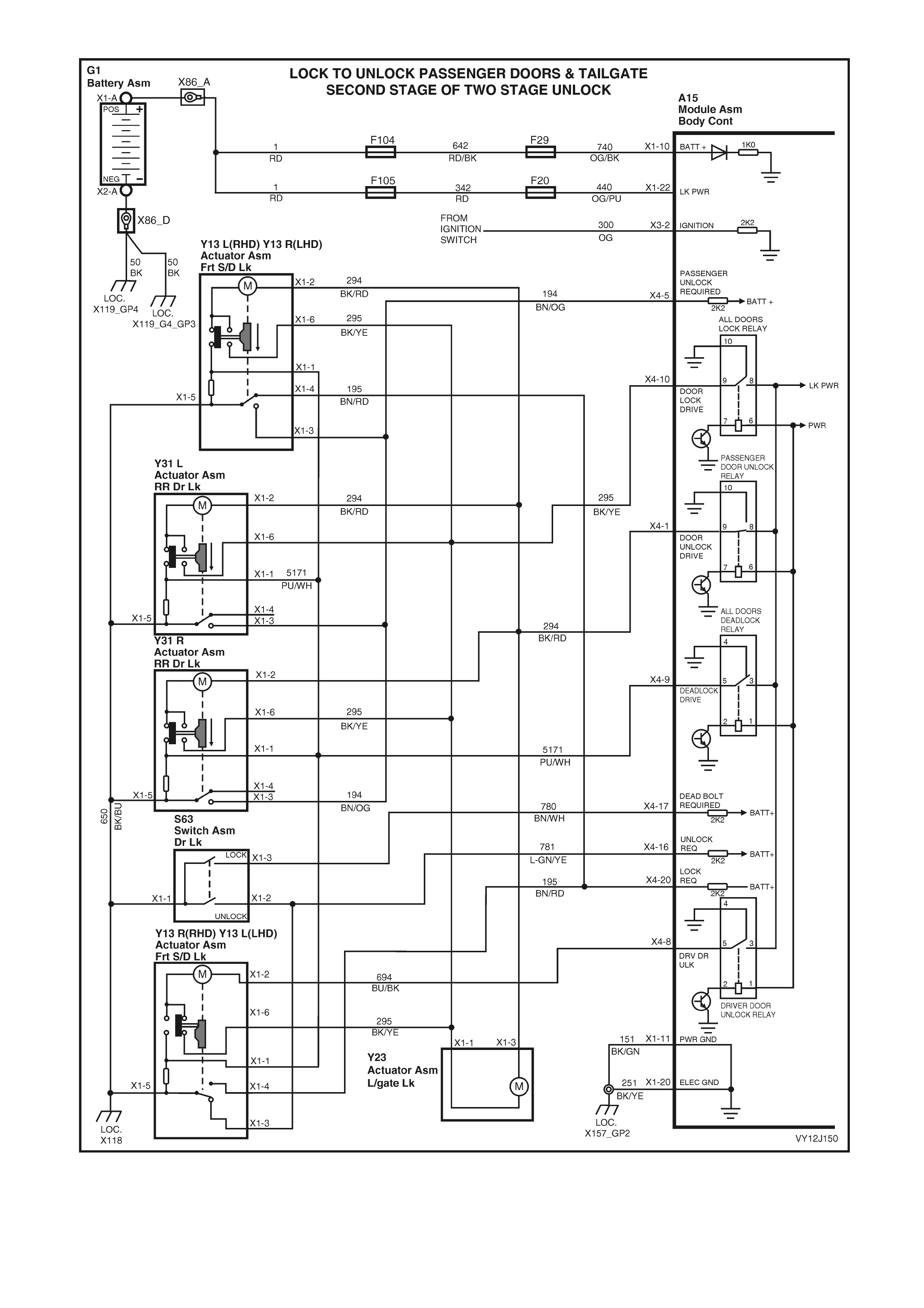
Figure 12J-224

Test description
The numbered descriptions below refer to selected steps in the following diagnostic chart.
3. Checks for the presence of an Unlock signal (false signal) while the doors are in the Locked state.
4. Checks if the false signal (from Step 3) is due to a BCM fault.
5. Checks if the false signal (from Step 4) is due to a fault in the driver’s door lock actuator.
6. Checks if the false signal (from Step 5) is due to a fault in the driver’s door lock switch.
UNLOCKING DOORS USING DRIVER’S DOOR LOCK MICROSWITCH DIAGNOSTIC CHART
STEP ACTION VALUE YES NO
1 Are all door ajar switches and associated circuits
functioning correctly? Go to Step 2. Go to Part L, Door
Ajar Switches.
2 1. Turn the ignition off.
2. Connect TECH 2 to the DLC.
3. Lock the doors.
4. Select Diagnostics / Model Year / Vehicle Model /
Body / Body Control Module / Miscellaneous Tests /
Central Locki ng.
5. Perform the test as instructed by TECH 2 and unlock
the doors.
Do all of the doors unlock?
Go to Step 3. Go to Step 7.
3 1. Lock the doors.
2. With TECH 2 still connected, exit to the Body Menu
and select Data Display / Central Door Locking /
Driver’s Door Unlock Switch.
Does TECH 2 display On (unlocked)?
False signal. Go to
Step 4. Go to Step 17.
4 1. W ith TECH 2 still connected and Driver’s Door Unlock
Switch status displayed, disconnect BCM
connector X4.
2. Close and lock the doors .
Does TECH 2 display On?
False signal.
Replace the BCM.
Refer to 2.1 BODY
CONTROL
MODULE in this
Section.
Install BCM
connector X4 and
go to Step 5.
5 1. With TECH 2 still connected and Driver’s Unlock
Switch status displayed, disconnect the driver’s door
actuator (Y13) connector X1.
Does TECH 2 display On?
False signal.
Install the driver’s
door actuator
(Y13) and go to
Step 6.
Replace the
driver’s door lock
actuator (Y13).
Refer to Section
1A5, 2.7 FRONT
DOOR LOCK
ASSEMBLY.
6 1. With TECH 2 still connected and Driver’s Unlock
Switch status displayed, disconnect the driver’s door
lock switch (S63) connector.
Does TECH 2 display On?
False signal.
Install the driver’s
door lock switch
(S63) connector.
Repair faulty
circuit 781
(Light-green /
Yel l ow wi r e ) .
Replace the
driver’s door lock
switch. Refer to
Section 1A5, 2.8
FRONT DOOR
OUTSIDE
HANDLE
ASSEMBLY.
7 While performing Step 1, did at least one door unlock? Go to Step 8. Go to Step 10.
8 1. Back-probe BCM connector terminal X4-8, circuit 694
(Blue / Black wire) with a voltmeter to ground.
2. Connect TECH 2 to the DLC.
3. Lock all doors.
4. Select Diagnostics / Model Year / Vehicle Model /
Body / Body Control Module / Miscellaneous Tests /
Central Locki ng.
5. Conduct test as instructed by TECH 2 and unlock the
doors.
Is the value as specified?
12 volts for
0.7 second Go to Step 9. Replace the BCM.
Refer to 2.1 BODY
CONTROL
MODULE in this
Section.
9 1. Back-probe BCM connector terminal X4-1, circuit 294
(Black / Red wire) with a voltmeter to ground.
2. Lock the doors.
3. Repeat TECH 2 Central Lock test (Step 7) and unlock
the doors.
Is value as specified?
12 volts for
0.7 second Go to Step 10. Replace the BCM.
Refer to 2.1 BODY
CONTROL
MODULE in this
Section.

STEP ACTION VALUE YES NO
10 1. Back-probe BCM terminal X1-22, circuit 440 (Orange /
Purple wire) with a voltmeter to ground.
Is the value as specified?
Battery
voltage Go to Step 11. Check and repair
fuses F20 and
F105 and circuits
to battery.
11 1. Back-probe BCM connector terminals X1-11, X1-20
and X3-1 with an ohmmeter to ground.
Is the value as specified?
Less then
1 ohm Go to Step 8. Repair faulty
circuit 151, 251
150 and check for
positive ground
connections to
BCM.
12 1. Lock the doors.
2. Back-probe each door actuator connector
terminal X1-2 (liftgate terminal X1-3), circuit 294
(Black / Red wire) with a voltmeter to ground.
3. Repeat TECH 2 Central Lock test (Step 7) and unlock
the doors.
Are the values as specified?
12 volts for
0.7 second Go to Step 13. Repair faulty
circuit 694 or 294.
13 1. Disconnect BCM connector X4.
2. Back-probe BCM terminal X4-9 with a voltmeter to
ground.
Is the value as specified?
0 volt Go to Step 14. Replace the BCM.
Refer to 2.1 BODY
CONTROL
MODULE in this
Section.
14 1. Back-probe BCM terminal X4-9 with an ohmmeter to
ground.
Is the value as specified?
Less then
1 ohm Install BCM
connector X4 and
go to Step 15.
Replace the BCM.
Refer to 2.1 BODY
CONTROL
MODULE in this
Section.
15 1. Back-probe each door lock actuator connector
terminal X1-1, with a voltmeter to ground.
Is the value as specified?
0 volt Go to Step 16. Repair faulty
circuit 294.
16 1. Back-probe each door lock actuator connector
terminal X1-1 with an ohmmeter to ground.
Is the value as specified?
Less then
1 ohm Replace the faulty
door lock actuator
(Y13 / Y31). Refer
to Section 1A5, 2.7
FRONT DOOR
LOCK ASSEMBLY
or 3.7 REAR
DOOR LOCK
ASSEMBLY as
necessary.
Repair faulty
circuit 294.
17 1. With the doors locked, TECH 2 connected and
Driver’s Door Unlock Switch status displayed, insert
the key into the driver’s door lock and turn the key to
the unlock position.
Does TECH 2 display On?
Correct signal.
Replace the BCM.
Refer to 2.1 BODY
CONTROL
MODULE in this
Section.
Go to Step 18.
18 1. Back-probe driver’s door lock switch terminal X1-1,
circuit 650 (Black / Blue) with an ohmmeter to ground.
Is the value as specified?
Less then 1
ohm Go to Step 19. Repair faulty
circuit 650.
19 1. Disconnect the driver’s door lock switch (S63)
connector.
2. Back-probe the driver’s door lock switch between
terminals X1-2 and X1-1 with an ohmmeter.
3. With the doors locked, insert the key into the driver’s
door lock and turn the key to the unlock position.
Is the value as specified?
Less then 1
ohm Go to Step 20. Replace the
driver’s door lock
switch. Refer to
Section 1A5, 2.8
FRONT DOOR
OUTSIDE
HANDLE
ASSEMBLY.
20 1. Disconnect BCM connector X4.
2. Back-probe between driver’s door lock switch
terminal X1-2 and BCM connector terminal X4-16,
circuit 781 (Light-green / Yellow) with an ohmmeter.
Is the value as specified?
Less then 1
ohm Replace the BCM.
Refer to 2.1 BODY
CONTROL
MODULE in this
Section.
Repair faulty
circuit 781.
WHEN ALL DIAGNOSIS AND REPAIRS ARE COMPLETE, VERIFY CORRECT OPERATION

PART B – LOCKING DOORS USING DRIVER’S DOOR LOCK MICROSWITCH
Figure 12J-225

Test description
The numbered descriptions below refer to selected steps in the following diagnostic chart.
3. Checks for the presence of a Lock signal (false signal) while the doors are in the Unlocked state.
4. Checks if the false signal (from Step 3) is due to a BCM fault.
5. Checks if the false signal (from Step 4) is due to a fault in the driver’s door lock actuator.
6. Checks if the false signal (from Step 5) is due to a fault in the passenger’s door lock actuator.
LOCKING DOORS USING DRIVER’S DOOR LOCK MICROSWITCH DIAGNOSTIC CHART
STEP ACTION VALUE YES NO
1 Are all door ajar switches and associated circuits
functioning correctly? Go to Step 2. Go to Part L, Door
Ajar Switches.
2 1. Turn the ignition off.
2. Connect TECH 2 to the DLC.
3. Close and unlock the doors.
4. Select Diagnostics / Model Year / Vehicle Model /
Body / Body Control Module / Miscellaneous Tests /
Central Locki ng.
5. Perform the test as instructed by TECH 2 and lock
the doors.
Do all of the doors lock?
Go to Step 3. Go to Step 7.
3 1. Close and unlock the doors.
2. With TECH 2 still connected, exit to the System
Selection Menu and select Data Display / Central
Door Locking / Lock Switch.
Does TECH 2 display On (locked)?
False signal. Go to
Step 4. Go to Step 16.
4 1. With TECH 2 still connected, doors closed and Lock
Switch status displayed, disconnect BCM
connector X4.
Does TECH 2 display On?
False signal.
Replace the BCM.
Refer to 2.1 BODY
CONTROL
MODULE in this
Section.
Install BCM
connector X4 and
go to Step 5.
5 1. Disconnect the driver’s door actuator (Y13)
connector X1.
2. With TECH 2 still connected, and Lock Switch status
displayed, cl ose all doors.
Does TECH 2 display On?
False signal.
Install the driver’s
door actuator
(Y13) and go to
Step 6.
Replace the
driver’s door lock
actuator (Y13).
Refer to Section
1A5, 2.7 FRONT
DOOR LOCK
ASSEMBLY.
6 1. With TECH 2 still connected and Lock Switch status
displayed, disconnect the front passenger’s door
actuator (Y13) connector X1.
Does TECH 2 display On?
False signal.
Install the
passenger’s door
actuator (Y13) and
repair faulty circuit
195 (Brown / Red
wire).
Replace the
passenger’s door
lock actuator
(Y13). Refer to
Section 1A5, 2.7
FRONT DOOR
LOCK
ASSEMBLY.
7 While performing Step 1, did at least one door lock? Go to Step 11. Go to Step 8.
8 1. Back-probe BCM terminal X1-22 with a voltmeter to
ground.
Is the value as specified?
Battery
voltage Go to Step 9. Check and repair
fuses F20 and
F105 and circuits
to battery.
9 1. Back-probe BCM connector terminals X1-11, X1-20
and X3-1, circuits 151, 251 and 150, with an
ohmmeter to ground.
Is the value as specified?
Less then
1 ohm Go to Step 10. Repair faulty
circuit 151, 251
150 and check for
positive ground
connections to
BCM.

STEP ACTION VALUE YES NO
10 1. Back-probe BCM connector terminal X4-10,
circuit 295 (Black / Yellow wire) with a voltmeter to
ground.
2. Connect TECH 2 to the DLC.
3. Close and unloc k the doors.
4. Select Diagnostics / Model Year / Vehicle Model /
Body / Body Control Module / Miscellaneous Tests /
Central Locki ng.
5. Conduct test as instructed by TECH 2 and lock
doors.
Is the value as specified?
12 volts for
0.7 second Go to Step 11. Replace the BCM.
Refer to 2.1 BODY
CONTROL
MODULE in this
Section.
11 1. Back-probe each door actuator connector
terminal X1-6 (liftgate terminal X1-1), circuit 295
(Black / Yellow wire) with a voltmeter to ground.
2. For each actuator, repeat the central locking test
(Step 9) test as instructed by TECH 2 and lock the
doors.
Are the values as specified?
12 volts for
0.7 second Go to Step 12. Repair faulty
circuit 295.
12 1. Disconnect BCM connector X4.
2. Back-probe BCM terminal X4-1 with a voltmeter to
ground.
Is the value as specified?
0 volt Go to Step 13. Replace the BCM.
Refer to 2.1 BODY
CONTROL
MODULE in this
Section.
13 1. Back-probe BCM terminal X4-1 with an ohmmeter to
ground.
Is the value as specified?
Less then
1 ohm Install BCM
connector X4 and
go to Step 14.
Replace the BCM.
Refer to 2.1 BODY
CONTROL
MODULE in this
Section.
14 1. Back-probe each door lock actuator connector
terminal X1-2, with a voltmeter to ground.
Is the value as specified?
0 volt Go to Step 15. Repair faulty
circuit 294.
15 1. Back-probe each door lock actuator connector
terminal X1-2 with an ohmmeter to ground.
Is the value as specified?
Less then
1 ohm Replace the faulty
door lock actuator
(Y13 / Y31). Refer
to Section 1A5,
2.7 FRONT
DOOR LOCK
ASSEMBLY or 3.7
REAR DOOR
LOCK
ASSEMBLY as
necessary.
Repair faulty
circuit 294.
16 1. With the doors unlocked, TECH 2 connected and
Lock Switch status displayed, insert the key into the
driver’s door lock and turn the key to the lock
position.
Does TECH 2 display On?
Correct signal.
Replace the BCM.
Refer to 2.1 BODY
CONTROL
MODULE in this
Section.
Go to Step 17.
17 1. Back-probe driver’s door lock actuator (Y13) terminal
X1-5, circuit 650 (Black / Blue) with an ohmmeter to
ground.
Is the value as specified?
Less then 1
ohm Go to Step 18. Repair faulty
circuit 650.
18 1. Disconnect BCM connector X4.
2. Back-probe between driver’s door lock actuator (Y13)
terminal X1-4 and BCM connector terminal X4-20,
circuit 195 (Brown / Red wire) with an ohmmeter.
Is the value as specified?
Less then 1
ohm Replace faulty
door lock actuator
(Y13). Refer to
Section 1A5, 2.7
FRONT DOOR
LOCK
ASSEMBLY.
Repair faulty
circuit 195.
WHEN ALL DIAGNOSIS AND REPAIRS ARE COMPLETE, VERIFY CORRECT OPERATION

PART C – UNLOCKING DOORS USING DRIVER’S DOOR LOCK SNIB ACTUATOR
Figure 12J-226

Test description
The numbered descriptions below refer to selected steps in the following diagnostic chart.
4. Checks for the presence of an Unlock signal (false signal) while the doors are in the Locked state.
Checks if the false signal (from Step 4) is due to a BCM fault.
Checks if the false signal (from Step 5) is due to a circuit fault.
UNLOCKING DOORS USING DRIVER’S DOOR LOCK SNIB ACTUATOR DIAGNOSTIC CHART
STEP ACTION VALUE YES NO
1 Are all door ajar switches and associated circuits
functioning correctly? Go to Step 2. Go to Part L, Door
Ajar Switches.
2 Does the TECH 2 Central Locking Test unlock all doors? Go to Step 3. Go to Part A,
Unlocking Doors
using Driver’s
Door Lock
Microswitch.
3 Is the driver’s door lock switch (S63) functioning
correctly? Go to Step 4. Go to Part A,
Unlocking Doors
using Driver’s
Door Lock
Microswitch.
4 1. Connect TECH 2 to the DLC.
2. Lock the doors.
3. Select Diagnostics / Model Year / Vehicle Model /
Body / Body Control Module / Data Display / Central
Door Locking / Driver’s Door Unlock Switch.
Does TECH 2 display On?
False signal. Go to
Step 5. Go to Step 6.
5 1. With TECH 2 still connected and Driver’s Door
Unlock Switch status displayed, disconnect BCM
connector X4.
Does TECH 2 display On?
False signal.
Replace the BCM.
Refer to 2.1 BODY
CONTROL
MODULE in this
Section.
Install BCM
connector X4 and
go to Step 6.
6 1. With TECH 2 still connected and Driver’s Unlock
Switch status displayed, disconnect the driver’s door
actuator (Y13) connector X1.
Does TECH 2 display On?
False signal.
Repair faulty
circuit 781
(Light-green /
Yel l ow wi r e ) .
Go to Step 9.
7 1. With the doors locked, TECH 2 connected and
Driver’s Door Unlock Switch status displayed, move
the driver’s door lock snib button to the unlock
position.
Does TECH 2 display On?
Correct signal.
Replace the BCM.
Refer to 2.1 BODY
CONTROL
MODULE in this
Section.
Go to Step 8.
8 1. Disconnect BCM connector X4.
2. Disconnect driver’s door lock actuator (Y13)
connector X1.
3. Back-probe between driver’s door lock switch
terminal X1-3 and BCM connector terminal X4-16,
circuit 781 (Light-green / Yellow) with an ohmmeter.
Is the value as specified?
Less then 1
ohm Go to Step 9. Repair faulty
circuit 781.
9 1. Back-probe driver’s door lock actuator (Y13) terminal
X1-5, circuit 650 (Black / Blue) with an ohmmeter to
ground.
Is the value as specified?
Less then 1
ohm Replace the
driver’s door lock
actuator (Y13).
Refer to Section
1A5, 2.7 FRONT
DOOR LOCK
ASSEMBLY.
Repair faulty
circuit 650.
WHEN ALL DIAGNOSIS AND REPAIRS ARE COMPLETE, VERIFY CORRECT OPERATION
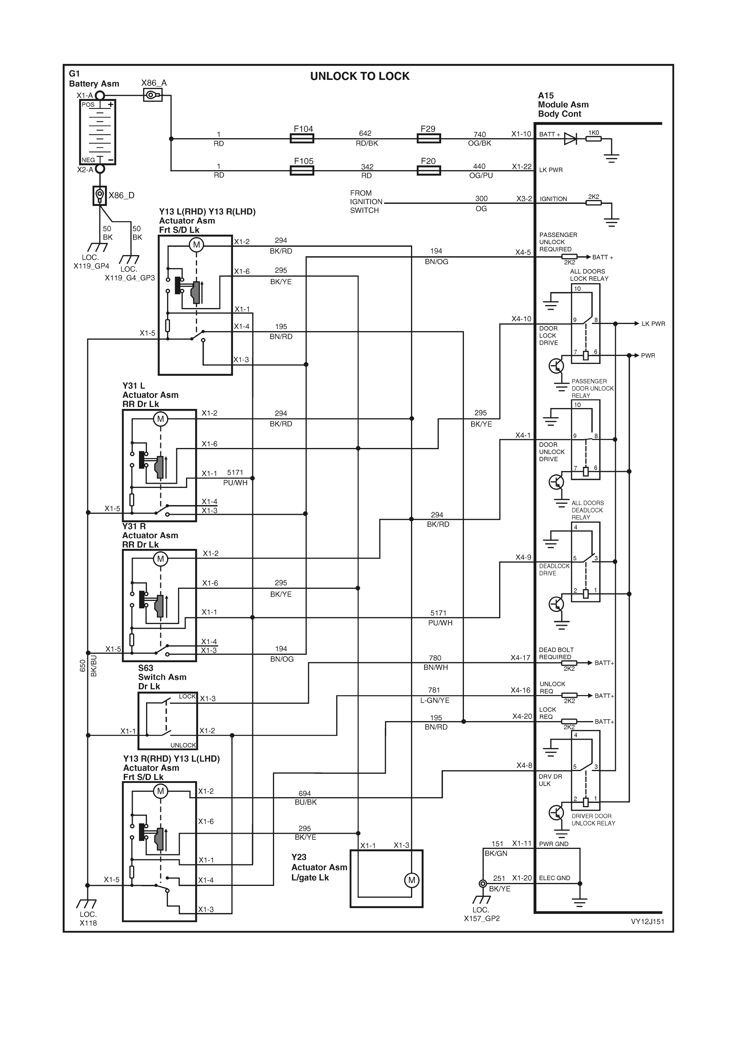
PART D – LOCKING DOORS USING DRIVER’S DOOR LOCK SNIB ACTUATOR
Figure 12J-227

Test description
The numbered descriptions below refer to selected steps in the following diagnostic chart.
5. Checks for the presence of a Lock signal (false signal) while the doors are in the Unlocked state.
6. Checks if the false signal (from Step 5) is due to a BCM fault.
7. Checks if the false signal (from Step 6) is due to a fault in the driver’s door lock actuator or its ground
connection.
8. Checks if the false signa l ( f r om Step 7) is d ue t o a f au l t in t he front pass eng er ’s door lock actuator or its gr o u nd
connection.
LOCKING DOORS USING DRIVER’S DOOR LOCK SNIB ACTUATOR DIAGNOSTIC CHART
STEP ACTION VALUE YES NO
1 Are all door ajar switches and associated circuits
functioning correctly? Go to Step 2. Go to Part L, Door
Ajar Switches.
2 Does the TECH 2 Central Locking Test lock all doors? Go to Step 3. Go to Part B,
Locking Doors
using Driver’s
Door Lock
Microswitch.
3 Is the driver’s door ajar indicator switch (S2) functioning
correctly? Go to Step 4. Go to Part B,
Locking Doors
using Driver’s
Door Lock
Microswitch.
4 Is the driver’s door lock switch (S63) is functioning
correctly? Go to Step 5. Go to Part A,
Unlocking Doors
using Driver’s
Door Lock
Microswitch.
5 1. Connect TECH 2 to the DLC.
2. Close and unloc k the doors.
3. Select Diagnostics / Model Year / Vehicle Model /
Body / Body Control Module / Data Display / Central
Door Locking / Lock Switch.
Does TECH 2 display On?
False signal. Go to
Step 10. Go to Step 13.
6 1. With TECH 2 still connected and Lock Switch status
displayed, disconnect BCM connector X4.
Does TECH 2 display On?
False signal.
Replace the BCM.
Refer to 2.1 BODY
CONTROL
MODULE in this
Section.
Install BCM
connector X4 and
go to Step 7.
7 1. With TECH 2 still connected and Lock Switch status
displayed, disconnect the driver’s door actuator (Y13)
connector X1.
Does TECH 2 display On?
False signal.
Install driver’ s
door actuator
connector and go
to Step 8.
Go to Step 11.
8 1. With TECH 2 still connected and Lock Switch status
displayed, disconnect the front passenger’s door lock
actuator (Y13) connector X1.
Does TECH 2 display On?
False signal.
Repair faulty
circuit 781
(Light-green /
Yel l ow wi r e ) .
Go to Step 12.
9 1. With the doors unlocked, TECH 2 connected and
Lock Switch status displayed, move the driver’s door
lock snib button to the lock position.
Does TECH 2 display On?
Correct signal.
Replace the BCM.
Refer to 2.1 BODY
CONTROL
MODULE in this
Section.
Go to Step 10.
10 1. Disconnect BCM connector X4.
2. Disconnect driver’s and front passenger’s door lock
actuators (Y13) connector X1.
3. Back-probe between BCM connector terminal X4-20
and terminal X1-4 of the driver and passenger door
lock actuators, circuit 195 (Brown / Red) with an
ohmmeter.
Are the values as specified?
Less then 1
ohm Go to Step 11. Repair faulty
circuit 781.

STEP ACTION VALUE YES NO
11 1. Back-probe the driver’s door lock actuator (Y13)
terminal X1-5, circuit 650 (Black / Blue) with an
ohmmeter to ground.
Is the value as specified?
Less then 1
ohm Replace the
driver’s door lock
actuator (Y13).
Refer to Section
1A5, 2.7 FRONT
DOOR LOCK
ASSEMBLY.
Repair faulty
circuit 650.
12 1. Back-probe the front passenger’s door lock actuator
(Y13) terminal X1-5, circuit 650 (Black / Blue) with an
ohmmeter to ground.
Is the value as specified?
Less then 1
ohm Replace the front
passenger’s door
lock actuator
(Y13). Refer to
Section 1A5, 2.7
FRONT DOOR
LOCK
ASSEMBLY.
Repair faulty
circuit 650.
WHEN ALL DIAGNOSIS AND REPAIRS ARE COMPLETE, VERIFY CORRECT OPERATION

PART E – UNLOCKING DOORS USING PASSENGERS’ DOOR LOCK SNIB ACTUATORS
Figure 12J-228

Test description
The numbered descriptions below refer to selected steps in the following diagnostic chart.
3. Checks for the presence of an Unlock signal (false signal) while the doors are in the Locked state.
4. Checks if the false signal (from Step 3) is due to a BCM fault.
5. Checks if the false signal (from Step 4) is due to a fault in the front passenger’s door lock actuator.
6. Checks if the false signal (from Step 5) is due to a fault in the LHS rear passenger’s door actuator.
7. Checks if the false signal (from Step 6) is due to a fault in the RHS rear passenger’s door actuator or the
circuit.
UNLOCKING DOORS USING PASSENGERS’ DOOR LOCK SNIB ACTUATORS DIAGNOSTIC CHART
STEP ACTION VALUE YES NO
1 Are all door ajar switches and associated circuits
functioning correctly? Go to Step 2. Go to Part L, Door
Ajar Switches.
2 Does the TECH 2 Central Locking Test unlock all doors? Go to Step 3. Go to Part A,
Unlocking Doors
using Driver’s
Door Lock
Microswitch.
3 1. Connect TECH 2 to the DLC.
2. Lock the doors.
3. Select Diagnostics / Model Year / Vehicle Model /
Body / Body Control Module / Data Display / Central
Door Locking / Passenger Doors Unlock Switch.
Does TECH 2 display On?
False signal. Go to
Step 4. Go to Step 8.
4 1. With TECH 2 still connected and Passenger Doors
Unlock Switch status displayed, disconnect BCM
connector X4.
Does TECH 2 display On?
False signal.
Replace the BCM.
Refer to 2.1 BODY
CONTROL
MODULE in this
Section.
Install BCM
connector X4 and
go to Step 5.
5 1. With TECH 2 still connected and Passenger Doors
Switch status displayed, disconnect the front
passenger’s door actuator (Y13) connector X1.
Does TECH 2 display On?
False signal. Go to
Step 6. Replace the front
passenger’s door
lock actuator
(Y13). Refer to
Section 1A5, 2.7
FRONT DOOR
LOCK
ASSEMBLY.
6 1. With TECH 2 still connected and Passenger Doors
Switch status displayed, disconnect the LHS rear
passenger’s door actuator (Y31) connector X1.
Does TECH 2 display On?
False signal. Go to
Step 7. Replace the LHS
rear passenger’s
door lock actuator
(Y31). Refer to
Section 1A5, 3.7
REAR DOOR
LOCK
ASSEMBLY.
7 1. With TECH 2 still connected and Passenger Doors
Switch status displayed, disconnect the RHS rear
passenger’s door actuator (Y31) connector X1.
Does TECH 2 display On?
False signal.
Repair faulty
circuit 194 (Brow n
/ Orange wire).
Replace the RHS
rear passenger’s
door lock actuator
(Y31). Refer to
Section 1A5, 3.7
REAR DOOR
LOCK
ASSEMBLY.
8 1. With the doors locked, TECH 2 connected and
Driver’s Door Unlock Switch status displayed, move
the front passenger door lock snib button to the
unlock positi on.
2. Lock all doors and repeat this for each rear
passenger door.
Does TECH 2 display On for each passenger door lock?
Correct signal.
Replace the BCM.
Refer to 2.1 BODY
CONTROL
MODULE in this
Section.
Go to Step 9.

STEP ACTION VALUE YES NO
9 1. Disconnect each suspect passenger door lock
actuator connector.
2. Back-probe each disconnected passenger door lock
actuator terminal X1-5, circuit 650 (Black / Blue wire)
with an ohmmeter to ground.
Is the value as specified?
Less then
1 ohm Replace the faulty
door lock actuator
(Y13 / Y31). Refer
to Section 1A5,
2.7 FRONT
DOOR LOCK
ASSEMBLY or 3.7
REAR DOOR
LOCK
ASSEMBLY as
necessary.
Repair faulty
circuit 650.
WHEN ALL DIAGNOSIS AND REPAIRS ARE COMPLETE, VERIFY CORRECT OPERATION

PART F – LOCKING DOORS USING FRONT PASSENGER DOOR LOCK SNIB ACTUATOR
Figure 12J-229

LOCKING DOORS USING FRONT PASSENGER DOOR LOCK SNIB ACTUATOR DIAGNOSTIC CHART
STEP ACTION VALUE YES NO
1 Are all door ajar switches and associated circuits
functioning correctly? Go to Step 2. Go to Part L, Door
Ajar Switches.
2 Does the TECH 2 Central Locking Test lock all doors? Go to Step 3. Go to Part B,
Locking Doors
using Driver’s
Door Lock
Microswitch.
3 Is the driver’s door lock actuator (Y13) functioning
correctly? Go to Step 4. Go to Part A and
Part B, Unlocking
and Locking Doors
using Driver’s
Door Lock
Microswitch.
4 Is the driver’s door lock switch (S63) is functioning
correctly? Go to Step 5. Go to Part A and
Part B, Unlocking
and Locking Doors
using Driver’s
Door Lock
Microswitch.
5 1. Turn the ignition off.
2. Disconnect BCM connector X4.
3. Disconnect the front passenger’s door lock actuator
(Y13) connector X1.
4. Back-probe between BCM connector terminal X4-20
and terminal X1-4 of the passenger door lock
actuator, circuit 195 (Brown / Red) with an ohmmeter.
Are the values as specified?
Less then 1
ohm Go to Step 6. Repair faulty
circuit 195.
6 1. Back-probe the front passenger’s door lock actuator
(Y13) terminal X1-5, circuit 650 (Black / Blue wire)
with an ohmmeter to ground.
Is the value as specified?
Less then 1
ohm Replace the front
passenger’s door
lock actuator
(Y13). Refer to
Section 1A5, 2.7
FRONT DOOR
LOCK
ASSEMBLY.
Repair faulty
circuit 650.
WHEN ALL DIAGNOSIS AND REPAIRS ARE COMPLETE, VERIFY CORRECT OPERATION

PART G – UNLOCKING THE TAILGATE
Figure 12J-230

UNLOCKING THE TAILGATE DIAGNOSTIC CHART
STEP ACTION VALUE YES NO
1 Are all door ajar switches and associated circuits
functioning correctly? Go to Step 2. Go to Part L, Door
Ajar Switches.
2 Does the TECH 2 Central Locking Test unlock all doors? Go to Step 3. Go to Part A,
Unlocking Doors
using Driver’s
Door Lock
Microswitch.
3 1. Lock the doors and tailgate.
2. Connect TECH 2 to the DLC.
3. Select Diagnostics / Model Year / Vehicle Model /
Body / Body Control Module / Miscellaneous Test /
Central Locki ng.
4. Back-probe tailgate lock actuator (Y23) connector
terminal X1-3, circuit 294 (Black / Red wire) with a
voltmeter to ground.
5. Conduct test as instructed by TECH 2 and unlock the
doors.
Is the value as specified?
12 volts for
0.7 second Go to Step 4. Repair faulty
circuit 294.
4 1. Back-probe tailgate lock actuator connector
terminal X1-1, circuit 295 (Black / Yellow wire) with an
ohmmeter to ground.
Is the value as specified?
Less then
1 ohm Replace tailgate
lock actuator.
Refer to Section
1A4,
4.8 LIFTGATE
ACTUATOR
ASSEMBLY.
Repair faulty
circuit 295.
WHEN ALL DIAGNOSIS AND REPAIRS ARE COMPLETE, VERIFY CORRECT OPERATION

PART H – DEADLOCKING DOORS USING DRIVER’S DOOR LOCK MICROSWITCH
Figure 12J-231

Test description
The numbered descriptions below refer to selected steps in the following diagnostic chart.
4. Checks for the presence of an Ignition On signal (false signal) while the ignition switch is turned off.
5. Checks if the false signal (from Step 4) is due to a BCM fault.
DEADLOCKING DOORS USING DRIVER’S DOOR LOCK MICROSWITCH DIAGNOSTIC CHART
STEP ACTION VALUE YES NO
1 Are all door ajar switches and associated circuits
functioning correctly? Go to Step 2. Go to Part L, Door
Ajar Switches.
2 Does the TECH 2 Central Locking Test unlock all doors? Go to Step 3. Go to Part A,
Unlocking Doors
using Driver’s
Door Lock
Microswitch.
3 Does the TECH 2 Central Locking Test lock all doors? Go to Step 4. Go to Part B,
Locking Doors
using Driver’s
Door Lock
Microswitch.
4 1. Turn the ignition off.
2. Connect TECH 2 to the DLC.
3. Turn the ignition on.
4. Select Diagnostics / Model Year / Vehicle Model /
Body / Body Control Module / Data Display / Central
Door Locking / Ignition Switch.
Does TECH 2 display On?
False signal. Go to
Step 5. Go to Step 7.
5 1. Back-probe BCM connector terminal X3-2, circuit 300
(Orange wire) with a voltmeter to ground.
2. While reading the voltmeter, Turn the ignition on and
then turn it off.
Are the values as specified?
Ignition ON
= 12 volts
Ignition OFF
= 0 volt
Replace the BCM.
Refer to 2.1 BODY
CONTROL
MODULE in this
Section.
Go to Step 6.
6 1. Disconnect ignition switch (S149) connector.
2. Back-probe ignition switch terminal X1-3 with a
voltmeter to ground.
3. While reading the voltmeter, Turn the ignition on and
then turn it off.
Are the values as specified?
Ignition ON
= 12 volts
Ignition OFF
= 0 volt
Repair faulty
circuit 300. Check ignition
switch function.
Refer to Section
9A, 2.6 IGNITION
SWITCH.
7 1. With the ignition off, the doors unlocked and TECH 2
still connected, exit to the Body Menu and select
Miscellaneous Tests / Central Door Locking.
2. Conduct test as instructed by TECH 2 and deadlock
the doors.
Do all of the doors deadlock?
Go to Step 11. Go to Step 8.
8 In Step 4, did at least one door deadlock? Go to Step 10. Go to Step 9.
9 1. Back-probe BCM terminal X4-9 with a voltmeter to
ground.
2. W ith the ignition turned off and doors closed, conduct
the TECH 2 Central Locking Test and deadlock the
doors.
Is the value as specified?
12 volts for
0.7 second Replace the BCM.
Refer to 2.1 BODY
CONTROL
MODULE in this
Section.
Go to Step 10.
10 1. Lock the doors.
2. Back-probe each door actuator connector
terminal X1-1, circuit 5171 (Purple / White wire) with
a voltmeter to ground.
3. From the Body Menu in TECH 2, select
Miscellaneous Tests / Central Locking.
4. For each door, Perform the test as instructed by
TECH 2 and deadlock the doors.
Are the values as specified?
12 volts for
0.7 second Replace the faulty
door lock actuator
(Y13 / Y31). Refer
to Section 1A5,
2.7 FRONT
DOOR LOCK
ASSEMBLY or 3.7
REAR DOOR
LOCK
ASSEMBLY as
necessary.
Repair faulty
circuit 5171.

STEP ACTION VALUE YES NO
11 1. With the ignition turned off, doors closed and TECH 2
still connected, exit to the Body Menu and select
Data Display / Central Door Locking / Deadlock
Switch.
2. Insert the key into the driver’s door lock and turn the
key to the lock position twice sequentially.
Does TECH 2 display On (deadlock)?
Correct signal.
Replace the BCM.
Refer to 2.1 BODY
CONTROL
MODULE in this
Section.
Go to Step 12.
12 1. Disconnect the driver’s door lock switch (S63)
connector.
2. Back-probe the driver’s door lock switch between
terminals X1-3 and X1-1 with an ohmmeter.
3. Insert the key into the driver’s door lock and turn the
key to the lock position.
Is the value as specified?
Less then 1
ohm Go to Step 13. Replace the
driver’s door lock
switch. Refer to
Section 1A5, 2.8
FRONT DOOR
OUTSIDE
HANDLE
ASSEMBLY.
13 1. Back-probe the driver’s door lock switch terminal
X1-5, circuit 650 (Black / Blue wire) with an
ohmmeter to ground.
Is the value as specified?
Less then 1
ohm Repair faulty
circuit 780 (Brow n
/ White wire).
Repair faulty
circuit 650.
WHEN ALL DIAGNOSIS AND REPAIRS ARE COMPLETE, VERIFY CORRECT OPERATION
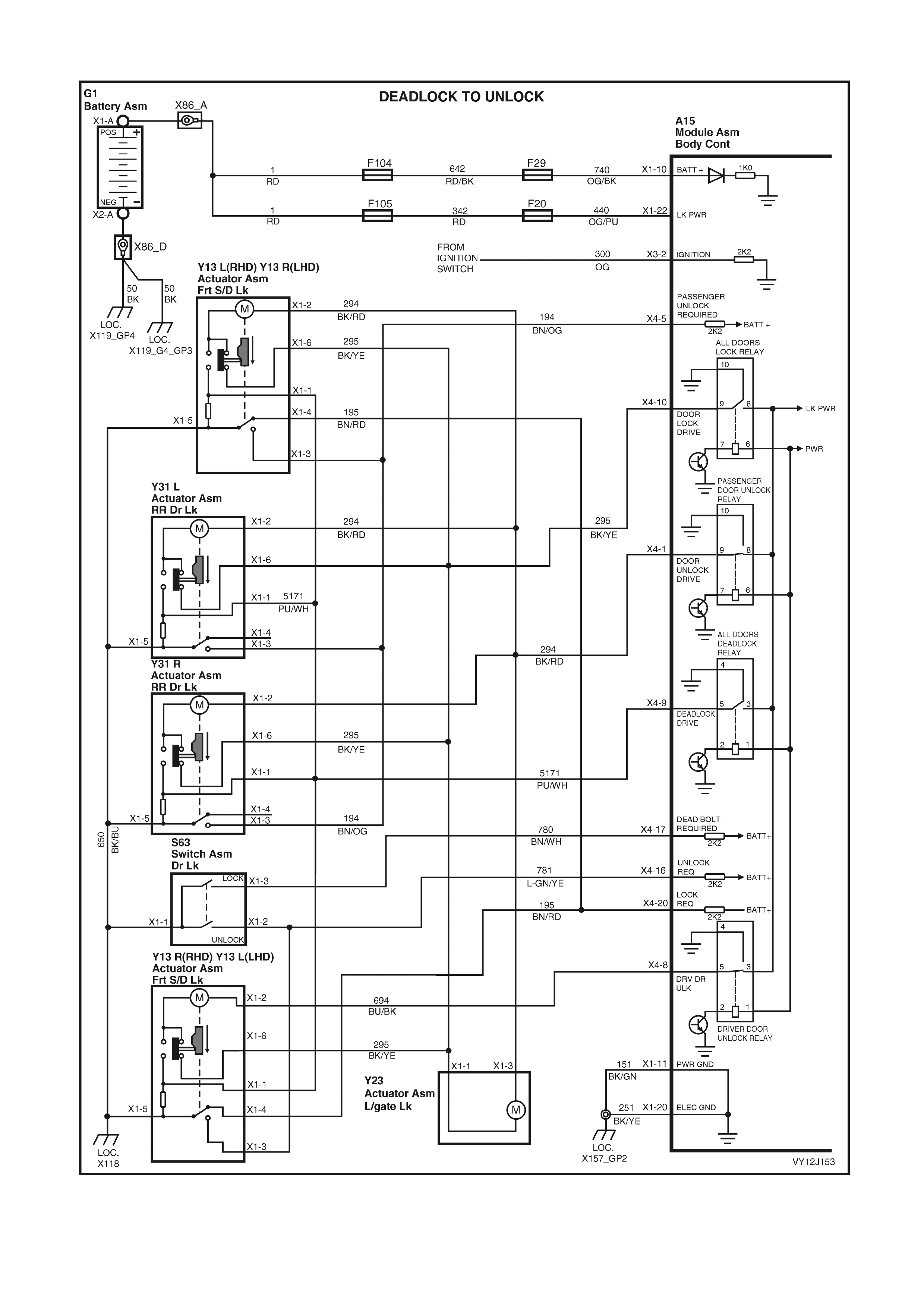
PART I – UNLOCKING DOORS FROM DEADLOCK
Figure 12J-232

UNLOCKING DOORS FROM DEADLOCK DIAGNOSTIC CHART
STEP ACTION VALUE YES NO
1 Are all door ajar switches and associated circuits
functioning correctly? Go to Step 2. Go to Part L, Door
Ajar Switches.
2 Does the TECH 2 Central Locking Test unlock all doors? Go to Step 3. Go to Part A,
Unlocking Doors
using Driver’s
Door Lock
Microswitch.
3 Does the TECH 2 Central Locking Test lock all doors? Go to Step 4. Go to Part B,
Locking Doors
using Driver’s
Door Lock
Microswitch.
4 Do the doors deadlock using the driver’s door lock
microswitch? Go to Step 5. Go to Part H,
Deadlocking
Doors using
Driver’s Door Lock
Microswitch.
5 1. Back-probe BCM connector terminal X4-10, circuit
295 (Black / Yellow wire) with a voltmeter to ground.
Is the value as specified?
0 volt Go to Step 6. Replace the BCM.
Refer to 2.1 BODY
CONTROL
MODULE in this
Section.
6 1. Back-probe BCM connector terminal X4-10, circuit
295 (Black / Yellow wire) with an ohmmeter to
ground.
Is the value as specified?
Less then 1
ohm Check actuator
adjustment. Refer
to Section 1A5,
2.7 FRONT
DOOR LOCK
ASSEMBLY or 3.7
REAR DOOR
LOCK
ASSEMBLY as
necessary.
Replace the BCM.
Refer to 2.1 BODY
CONTROL
MODULE in this
Section.
WHEN ALL DIAGNOSIS AND REPAIRS ARE COMPLETE, VERIFY CORRECT OPERATION

PART J – AUTO DOOR LOCKING (GEARSHIFT OUT OF PARK POSITION)
Figure 12J-233

AUTO DOOR LOCKING (GEARSHIFT OUT OF PARK POSITION) DIAGNOSTIC CHART
STEP ACTION VALUE YES NO
1 Are all door ajar switches and associated circuits
functioning correctly? Go to Step 2. Go to Part L, Door
Ajar Switches.
2 Does the TECH 2 Central Locking Test unlock all doors? Go to Step 3. Go to Part A,
Unlocking Doors
using Driver’s
Door Lock
Microswitch.
3 Does the TECH 2 Central Locking Test lock all doors? Go to Step 4. Go to Part B,
Locking Doors
using Driver’s
Door Lock
Microswitch.
4 Is Autolock in drive enabled? Go to Step 5. Enable autolock in
drive (YES) in the
BCM Program /
User Settings.
5 1. Turn the ignition off.
2. Connect TECH 2 to the DLC.
3. Turn the ignition on.
4. Select Diagnostics / Model Year / Vehicle Model /
Body / Body Control Module / Data Display / Central
Door Locking / Ignition Switch.
Does TECH 2 display On?
Go to Step 8. Go to Step 6.
6 1. Back-probe BCM connector terminal X3-2, circuit 300
(Orange wire) with a voltmeter to ground.
2. While reading the voltmeter, Turn the ignition on and
then turn it off.
Are the values as specified?
Ignition ON
= 12 volts
Ignition OFF
= 0 volt
Replace the BCM.
Refer to 2.1 BODY
CONTROL
MODULE in this
Section.
Go to Step 7.
7 1. Disconnect ignition switch (S149) connector.
2. Back-probe ignition switch terminal X1-3 with a
voltmeter to ground.
3. While reading the voltmeter, Turn the ignition on and
then turn it off.
Are the values as specified?
Ignition ON
= 12 volts
Ignition OFF
= 0 volt
Repair faulty
circuit 300. Check ignition
switch function.
Refer to Section
9A, 2.6 IGNITION
SWITCH.
8 1. From the TECH 2 Body Menu, select Data Display /
Serial Data Inputs / PRNDL Switch.
2. Close the doors.
3. Turn the ignition on.
4. Move the Gearshift lever from P (park) to the
N (neutral) position.
Does TECH 2 display Neutral?
Replace the BCM.
Refer to 2.1 BODY
CONTROL
MODULE in this
Section.
Refer to the
relevant PCM
diagnostics from
either Section
6C1,
POWERTRAIN –
V6, Section 6C2,
POWERTRAIN –
V6 S/C or Section
6C3,
POWERTRAIN –
GEN III V8
WHEN ALL DIAGNOSIS AND REPAIRS ARE COMPLETE, VERIFY CORRECT OPERATION
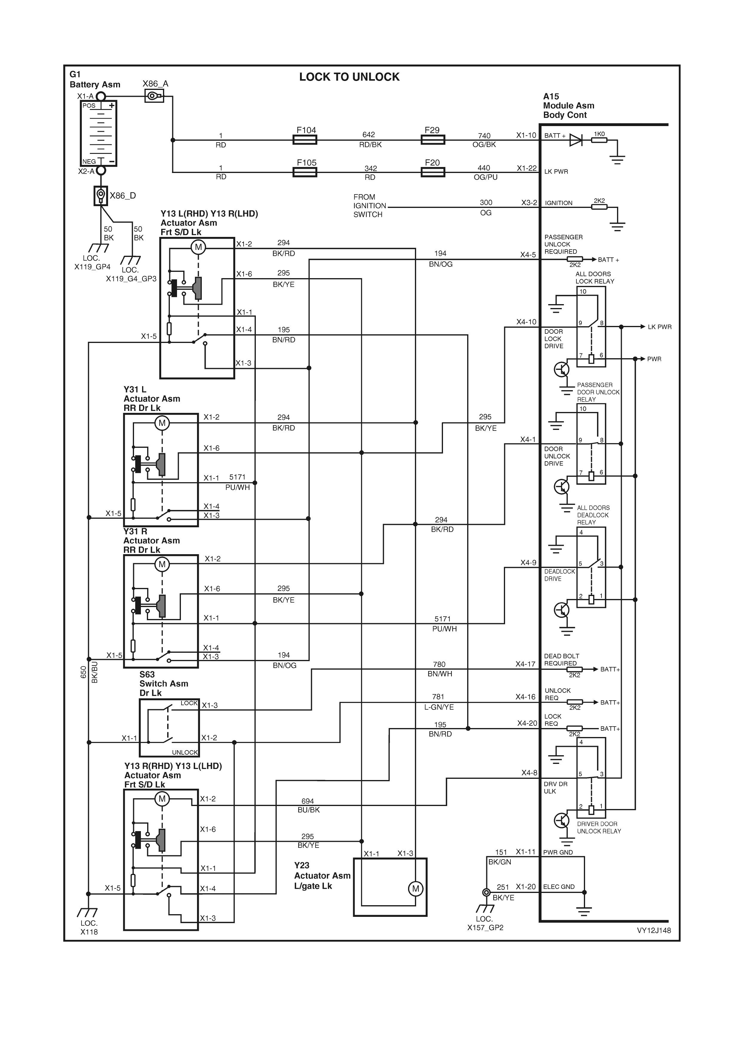
PART K – AUTO DOOR UNLOCKING (GEARSHIFT IN PARK POSITION, KEY OFF)
Figure 12J-234

AUTO DOOR UNLOCKING – KEY OFF. DIAGNOSTIC CHART
STEP ACTION VALUE YES NO
1 Are all door ajar switches and associated circuits
functioning correctly? Go to Step 2. Go to Part L, Door
Ajar Switches.
2 Does the TECH 2 Central Locking Test unlock all doors? Go to Step 3. Go to Part A,
Unlocking Doors
using Driver’s
Door Lock
Microswitch.
3 Does the TECH 2 Central Locking Test lock all doors? Go to Step 4. Go to Part B,
Locking Doors
using Driver’s
Door Lock
Microswitch.
4 Is Autolock in drive enabled? Go to Step 5. Enable autolock in
drive (YES) in the
BCM Program /
User Settings.
5 1. Turn the ignition off.
2. Connect TECH 2 to the DLC.
3. Turn the ignition on.
4. Select Diagnostics / Model Year / Vehicle Model /
Body / Body Control Module / Data Display / Central
Door Locking / Ignition Switch.
Does TECH 2 display On?
Go to Step 8. Go to Step 6.
6 1. Back-probe BCM connector terminal X3-2, circuit 300
(Orange wire) with a voltmeter to ground.
2. W hile reading the voltmeter, Turn the ignition on and
then turn it off.
Are the values as specified?
Ignition ON
= 12 volts
Ignition OFF
= 0 volt
Replace the BCM.
Refer to 2.1 BODY
CONTROL
MODULE in this
Section.
Go to Step 7.
7 1. Disconnect ignition switch (S149) connector.
2. Back-probe ignition switch terminal X1-3 with a
voltmeter to ground.
3. W hile reading the voltmeter, Turn the ignition on and
then turn it off.
Are the values as specified?
Ignition ON
= 12 volts
Ignition OFF
= 0 volt
Repair faulty
circuit 300. Check ignition
switch function.
Refer to Section
9A, 2.6 IGNITION
SWITCH.
8 1. From the TECH 2 Body Menu, select Data Display /
Serial Data Inputs / PRNDL Switch.
2. Close the doors.
3. Turn the ignition on.
4. Ensure that the Gearshift lever is in the P (park)
position.
Does TECH 2 display Park?
Replace the BCM.
Refer to 2.1 BODY
CONTROL
MODULE in this
Section.
Refer to the
relevant PCM
diagnostics from
either Section
6C1,
POWERTRAIN –
V6, Section 6C2,
POWERTRAIN –
V6 S/C or Section
6C3,
POWERTRAIN –
GEN III V8
WHEN ALL DIAGNOSIS AND REPAIRS ARE COMPLETE, VERIFY CORRECT OPERATION
Test description
The numbered descriptions below refer to selected steps in the following diagnostic chart.
1. Checks for the presence of a Closed signal (false signal) while the driver’s door is open.
2. Checks for the presence of an Open signal (false signal) while the driver’s door is closed.
3. Checks for the presence of a Closed signal (false signal) while a passenger door is open.
4. Checks for the presence of an Open signal (false signal) while the passenger doors are closed.
6. Checks if the false signal (from Step 2) is due to a BCM fault.
9. Checks if the false signal (from Step 4) is due to a BCM fault.

PART L – DOOR AJAR SWITCHES
DIAGNOSTIC CHART
STEP ACTION VALUE YES NO
1 1. Open the driver’s door.
2. Connect TECH 2 to the DLC.
3. Select Diagnostics / Model Year / Vehicle Model /
Body / Body Control Module / Data Display / Central
Door Locking / Driver’s Door.
Does TECH 2 display Closed?
False signal. Go to
Step 5. Go to Step 2.
2 1. W ith TECH 2 still connected and Driver’s Door status
displayed, cl ose the door.
Does TECH 2 display Open?
False signal. Go to
Step 6. Go to Step 3.
3 1. With TECH 2 still connected, exit Driver’s Door and
select Passenger Doors.
2. Open each passenger door, only one at a time.
Does TECH 2 display Closed for any door?
Closed False signal. Go to
Step 8. Go to Step 4.
4 1. With TECH 2 still connected and Passenger Doors
status displayed, close the doors.
Does TECH 2 display Open?
Open False signal. Go to
Step 9. System OK.
5 1. Connect an ohmmeter between the ajar switch base
and a known good ground.
Is the value as specified?
Less then
1 ohm Go to Step 6. Repair faulty
ground connection
to switch.
6 1. With TECH 2 still connected, the driver’s door open
and Driver’s Door status displayed, disconnect BCM
connector X4.
Does TECH 2 display Closed?
False signal.
Replace the BCM.
Refer to 2.1 BODY
CONTROL
MODULE in this
Section.
Install BCM
connector X4 and
go to Step 7.
7 1. Remove and disconnect the Driver’s Door Ajar
Switch (S2). (Refer to Section 12B, 3.11 DOOR
JAMB SWITCHES.)
2. Connect an ohmmeter between the ajar switch
connector terminal and the ajar switch base.
3. Press in the ajar switch plunger fully
Are the values as specified?
Switch at rest
= less then
1 ohm
Switch
pressed
= open circuit
Repair faulty
circuit 746 (Grey /
White wire).
Replace driver’s
door ajar switch.
Refer to Section
12B, 3.11 DOOR
JAMB
SWITCHES.
8 1. Connect an ohmmeter between each suspect
passenger door ajar switch base and a known good
ground.
Are the values as specified?
Less then
1 ohm Go to Step 9. Repair faulty
ground connection
to switch.
9 1. With TECH 2 connected, Passenger Door status
displayed and the suspect passenger door open,
disconnect BCM connector X4.
Does TECH 2 display Closed?
False signal.
Replace the BCM.
Refer to 2.1 BODY
CONTROL
MODULE in this
Section.
Install BCM
connector X4 and
go to Step 10.
10 1. Remove and disconnect each passenger door ajar
switch (S2). (Refer to Section 12B, 3.11 DOOR
JAMB SWITCHES.)
2. Connect an ohmmeter between the ajar switch
connector terminal and the ajar switch base.
3. Press in the ajar switch plunger fully
Are the values as specified?
Switch at rest
= less then
1 ohm
Switch
pressed
= open circuit
Repair faulty
circuit 745
(White wire).
Replace
passenger door
ajar switch. Refer
to Section 12B,
3.11 DOOR JAMB
SWITCHES.
WHEN ALL DIAGNOSIS AND REPAIRS ARE COMPLETE, VERIFY CORRECT OPERATION

4.6 REAR COMPARTMENT RELEASE
CIRCUIT DESCRIPTION
Pressing t he Rear Com partm ent Lid Switch closes the switch c ontacts, pro viding a groun d connec tion to the BCM.
This is seen by the BCM as a rear compartment lid release switch input signal. The BCM actuates the Boot
Solenoid Relay unless:
• the vehicle speed is greater than 20 km/h
• the system is armed via the remote coded key
• the driver’s door lock microswitch is locked or deadlocked.
The BCM actuates the rear compartment lid release solenoid by energising the B oot Solenoid rela y. This supplies
battery voltage to actuate and release the Rear Compartment Lid Latch.
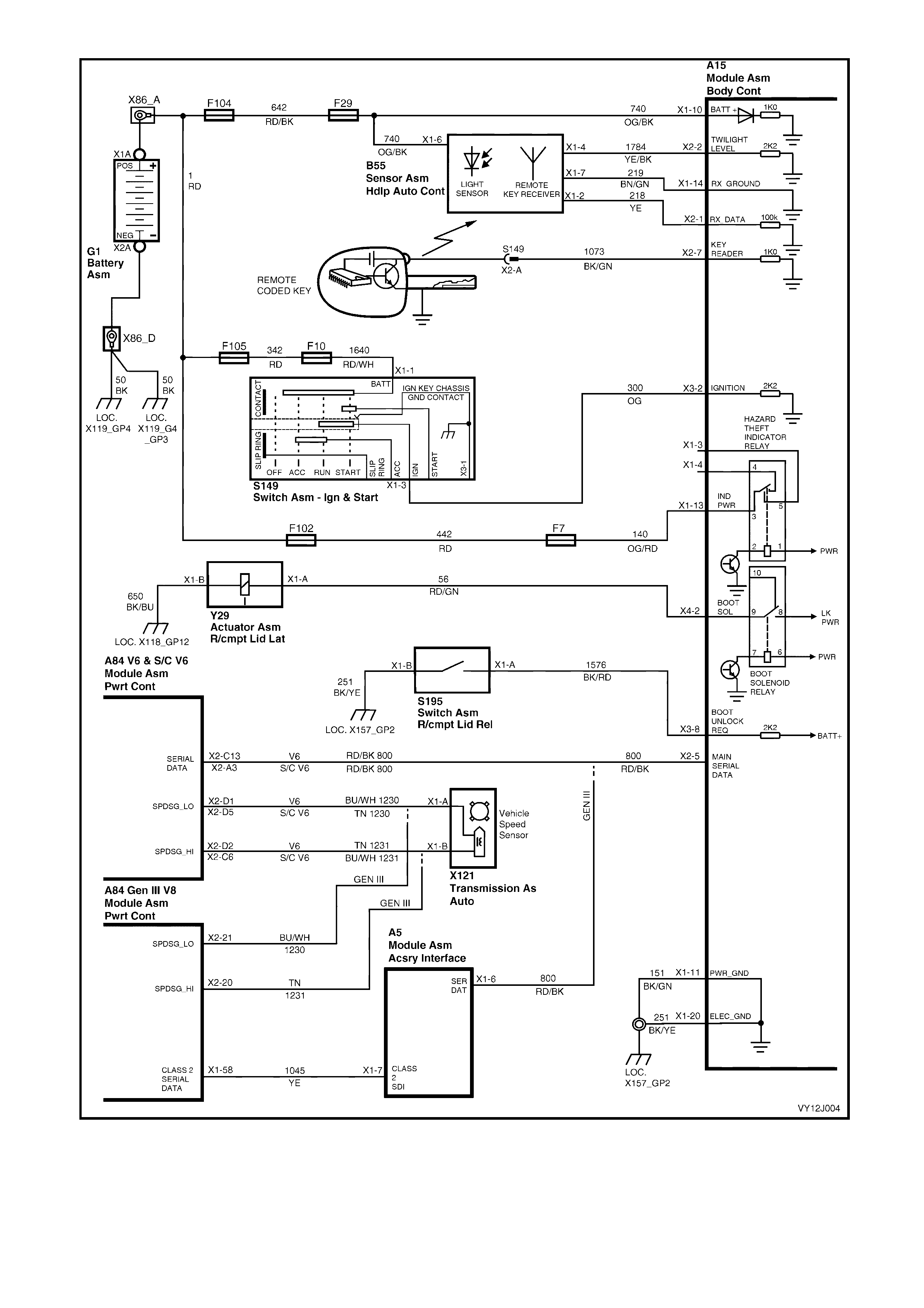
Figure 12J-235
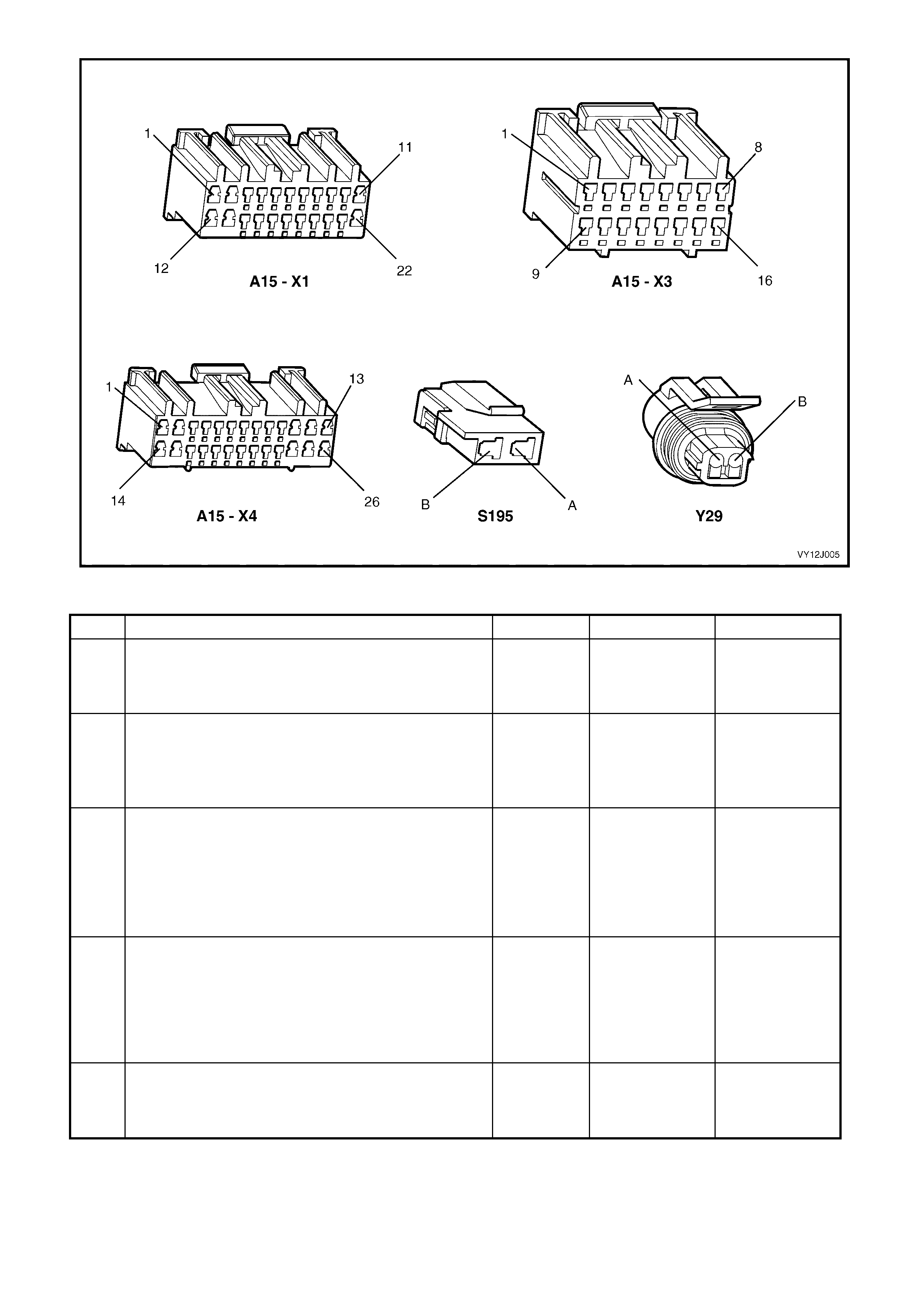
Figure 12J-236
REAR COMPARTMENT RELEASE DIAGNOSTIC CHART
STEP ACTION VALUE YES NO
1 1. Activate the Rear Compartment Lid release switch (in
the glove compartment) with the vehicle speed below
10 km/h, doors unlocked.
Does the rear compartment lid open?
Go to Step 2. Go to Step 3.
2 1. Close the rear compart ment lid.
2. Press the rear compartment lid release button on the
remote coded key (within two metres of the rear of
the vehicle).
Does the rear compartment lid open?
System OK. Go to 3.9
REMOTE
RECEIVER KEY
in this Section.
3 1. Connect TECH 2 to the DLC.
2. Select Diagnostics / Model Year / Vehicle Model /
Body / Body Control Module / Miscellaneous Tests /
Rear Compartment.
3. Perform the test as instructed by TECH 2 and open
the rear compartment lid.
Does the rear compartment lid open?
Go to Step 4. Go to Step 10.
4 1. With TECH 2 connected, exit to the Body Menu and
select Data Display / Inputs and Outputs / Rear
Compartment Release Switch.
2. W hile r ead in g TECH 2 , p res s th e s witc h fu lly to close
the switch contacts.
Does TECH 2 display Off with the switch at rest and On
with the switch pressed?
Go to Step 7. Go to Step 5.
5 1. Back-probe the rear compartment lid release switch
connector terminal X1-B, circuit 251 (Black / Yellow
wire) with an ohmmeter to ground.
Is the value as specified?
Less then
1 ohm Go to Step 6. Repair faulty
circuit 650.

STEP ACTION VALUE YES NO
6 1. Disconnect the rear compartment lid release switch
connector.
2. Back-probe the rear compartment release switch
between terminals X1-A and X1-B with an ohmmeter.
3. W hile reading the ohmmeter, press the switch to fully
close the switch contacts.
Is the value as specified?
Switch at rest
= open
Pressed
= less then 1
ohm
Repair faulty
circuit 1576. Replace Rear
Compartment Lid
Release Switch.
Refer to Section
1A3, 3.9
INSTRUMENT
PANEL LOWER
EXTENSION.
7 1. Close and unlock the doors.
2. With TECH 2 connected, exit to the Body Menu and
select BCM Internal Status / Central Door Locking.
Does TECH 2 display Unlocked?
Go to Step 8. Go to 3.3 PART I
– UNLOCKING
DOORS FROM
DEADLOCK in
this Section.
8 1. With TECH 2 connected, exit Central Door Locking
and select Security Status.
Does TECH 2 display Disarmed?
Go to Step 9. Go to Section
3.5 THEFT
DETERRENT in
this Section.
9 1. Ensure that the vehicle is stationary.
2. With TECH 2 connected, exit to the Body Menu and
select Data Display / Serial Data Inputs / Vehicle
Speed.
Does TECH 2 display0 km/h?
Inputs correct.
Replace the BCM.
Refer to 2.1 BODY
CONTROL
MODULE in this
Section.
Refer to Section
6C1 (V6), 6C2
(V6 S/C) or 6C3
DIAGNOSTIC
CHART.
10 1. Back-probe BCM connector terminal X4-2, circuit 56
(Red / Green wire) with a voltmeter to ground.
2. Repeat the rear compartment lid release test as per
Step 3.
Are the values as specified?
Test not
conducted:
0 volt
Test
conducted:
12 volts for
0.7 second
Go to Step 11. Go to Step 13.
11 1. Back-probe the rear compartment actuator (Y29)
connector terminal X1-A, circuit 56 (Red / Green
wire) with voltmeter to ground.
2. Repeat rear compartment lid release test as per
Step 3.
Are the values as specified?
Test not
conducted:
0 volt
Test
conducted:
12 volts for
0.7 second
Go to Step 12. Repair faulty
circuit 56.
12 1. Back-probe the rear compartment lid release actuator
connector terminal X1-B, circuit 650 (Black / Blue
wire) with an ohmmeter to ground.
Is the value as specified?
Less then
1 ohm Replace rear
compartment
release solenoi d.
Refer to Section
1A4, HOOD,
REAR
COMPARTMENT
LID, LIFTGATE
AND ENDGATE.
Repair faulty
circuit 650.
13 1. Back-probe BCM connector terminal X1-13, circuit
140 (Orange / Red wire) with a voltmeter to ground.
Is the voltage as specified?
Battery
voltage Go to Step 14. Check and repair
fuses F102 and F7
and circuit 140.
14 1. Back-probe BCM connector terminals X1-11, X1-20
and X3-1, circuits 151, 251 and 150, with an
ohmmeter to ground.
Is the value as specified?
Less then
1 ohm Replace the BCM.
Refer to 2.1 BODY
CONTROL
MODULE in this
Section.
Repair faulty
circuit 151, 251
150 and check for
positive ground
connections to
BCM.
WHEN ALL DIAGNOSIS AND REPAIRS ARE COMPLETE, VERIFY CORRECT OPERATION

4.7 THEFT DETERRENT SYSTEM
CIRCUIT DESCRIPTION
The thef t deterrent system can be armed b y pres sing the loc k button on the rem ote coded ke y or pas sively arm ed
automatically by the BCM (30 seconds after the ignition is switched off). The driver’s door must be closed to allow
arming of the system.
W hen the s ystem is armed, the PC M (V6 and V 6 supercharged engines) or PIM (GEN II I V8 engine) prevents the
engine from starting. The theft deterrent system can be disarmed by:
• pressing the unlock button on the remote coded key (this unlocks the doors, turns on the interior lamp and
disarms the system for 30 seconds), or
• inserting th e rem ote c oded ke y into the igniti on s witch c ylinder and tur ning on the ign ition. T his all ows the BCM
to read the security code serial data output from the remote coded key contact pin via the remote coded key
reader assembly.
If the system does not disarm when the ignition switch is turned on (security warning LED off), press the lock or
unlock button on the remote coded k ey to disarm the theft deterrent s ystem . This may be ca used by a misaligne d
or faulty remote coded key reader or a faulty key.
The remote coded key is powered by it’s own internal battery. If the battery fails however, the key reader can power
the key when the key is inserted into the ignition cylinder and the ignition turned on or turned to start.
When arming the system by pressing the lock button on the remote coded key, the indicators flash once and the
theft deterrent alert indicator (LED) flashes continually.
W hen dis arming the system by pr essing the unlock button on the rem ote coded key, the indicators flash twice and
the theft deterrent alert indicator (LED) remains off.
V6 and V6 Supercharged Engines
On vehicles with a V6 or V6 supercharged engine, the BCM polls the PCM and sends an encrypted BCM / key
securit y c ode when the ignition is turned on. The s ecurity code is rec eived via the BCM s lip ring, or via the rem ote
receiver in the event of no slip ring communication.
The PCM compares the received security code with its stored security code and if the codes match, enables
injector fuelling and continued engine cranking. The PCM returns an OK TO START message to the BCM, which
tells the BCM to jump from SHORT LOOP mode to the LONG LOOP mode.
GEN III V8 Engine
On vehicles with a GEN III V8 engine, the BCM polls the PIM and sends an encrypted BCM / key security code
when the ign ition is turned on. T he secur ity code is rec eived via t he BCM s lip ri ng, or via the r em ote receive r in the
event of no slip ring communication. The PIM compares the received security code with its stored security code
and if the codes match, enables continued engine cranking and sends a separate encrypted security code to the
PCM. The PCM compares this code with its stored security code and if the codes match, enables injector fuelling to
continue. The PIM returns an OK TO START message to the BCM, which tells the BCM to jump from SHORT
LOOP mode to LONG LOOP mode.
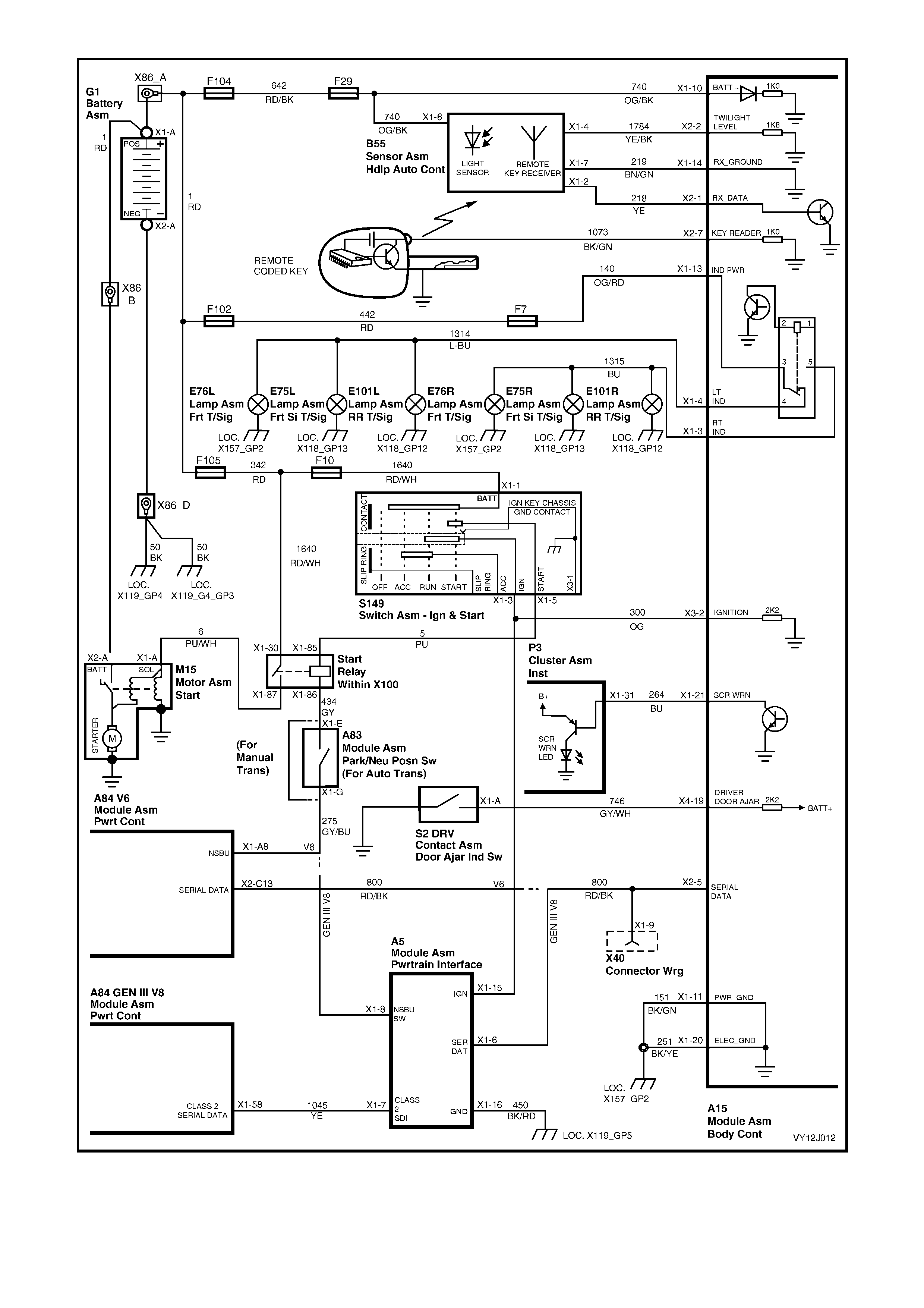
Figure 12J-237
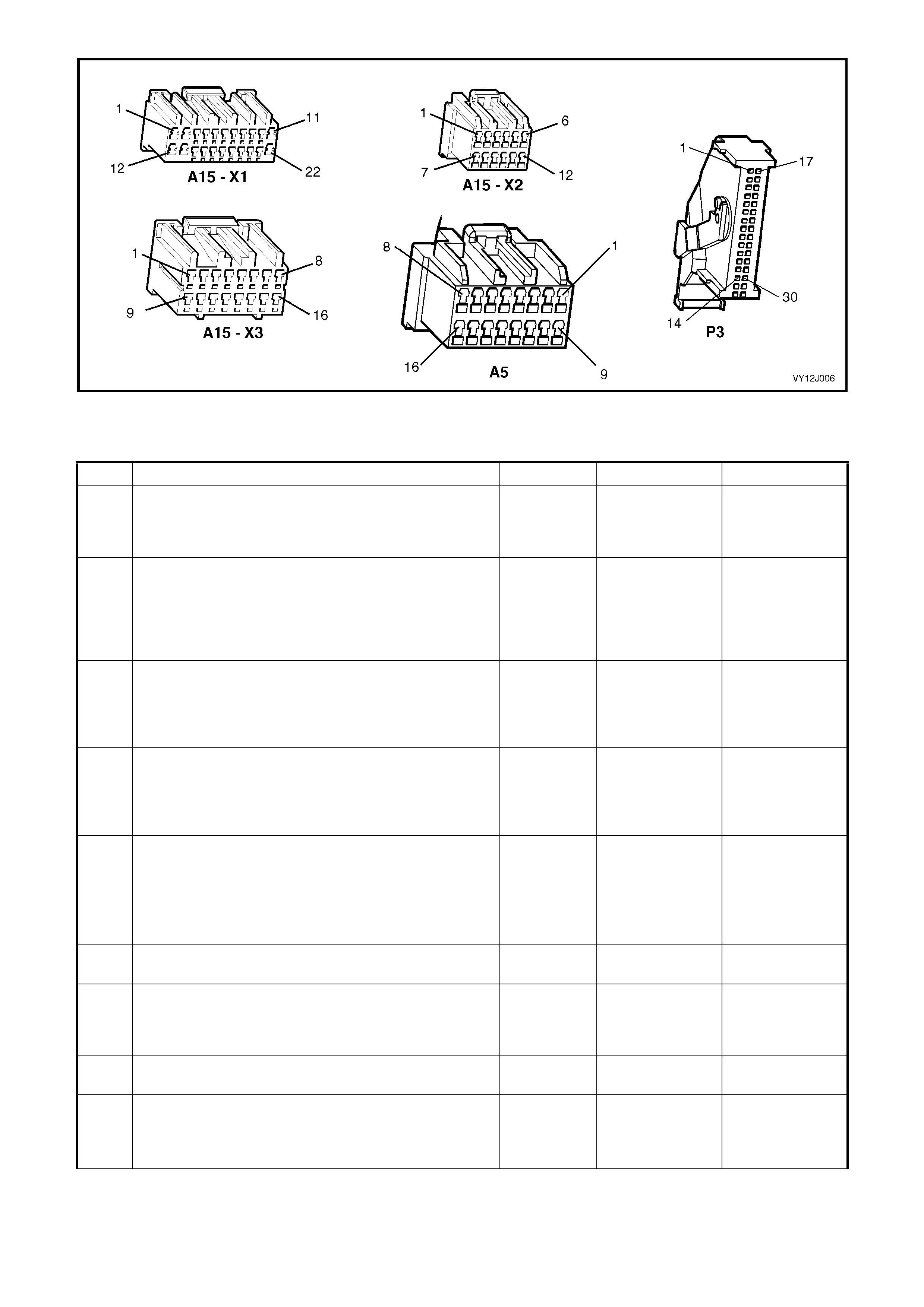
Figure 12J-238
THEFT DETERRENT SYSTEM DIAGNOSTIC CHART
STEP ACTION VALUE YES NO
1 Is the remote coded key functioning correctly? Go to Step 2. Go to 4.3
REMOTE
RECEIVER / KEY
in this Section.
2 Are all door ajar switches and associated circuits
functioning correctly? Go to Step 3. Go to 4.5
CENTRAL DOOR
LOCKING Part L,
Door Ajar
Switches in this
Section.
3 Does the key in the driver’s door switch unlock all doors? Go to Step 4. Go to Part A,
Unlocking Doors
using Driver’s
Door Lock
Microswitch.
4 Does the key in the driver’s door switch lock all doors? Go to Step 5. Go to Part B,
Locking Doors
using Driver’s
Door Lock
Microswitch.
5 1. Close and lock all door s.
Operate the Unlock button on the remote coded key
within 4 metres of the driver’s side B-pillar (taking
note of any indicator lamp flashes).
Does the driver’s door unlock (two-stage unlocking) or all
doors unlock (single-stage unlocking)?
Go to Step 6. Go to Step 14.
6 In Step 5, did the left and right hand side indicator lamps
flash twice? Go to Step 7. Go to Step 15.
7 In Step 5, did the dome lamp illuminate? Go to Step 8. Go to 4.12 DOME
LAMP DELA Y
CONTROL in this
Section.
8 In Step 5, did the security warning LED extinguish
immediately and begin flashing 30 seconds later? Go to Step 11. Go to Step 19.
9 1. Operate the Lock button on the remote coded key
within 4 metres of the driver’s side B-pillar.
Did the dome lamp extinguish immediately after the lock
button was activated?
Go to Step 10. Go to 4.12 DOME
LAMP DELA Y
CONTROL in this
Section.

STEP ACTION VALUE YES NO
10 When locking the vehicle in Step 5, did the left and right
hand side indicator lamps flash once? Go to Step 11. Replace the BCM.
Refer to 2.1 BODY
CONTROL
MODULE in this
Section.
11 Is the security warning LED flashing? Go to Step 12. Go to Step 19.
12 1. Unlock the vehicle with the remote coded key.
Wait for the vehicle to passively arm and for the security
warning LED to start flashing.
With the vehicle passively armed, insert the ignition key
into the ignition switch and Turn the ignition on.
Does the security warning LED extinguish?
Go to Step 14. Go to Step 24.
13 1. Turn the ignition key to start the engine.
Does the vehicle crank and start? System OK. For vehicles with a
V6 engine, go to
Step 35.
For vehicles with a
GEN III V8 engine,
go to Step 36.
14 NOTE: The alarm may sound during this Step.
1. Insert the key into ignition switch and cycle the switch
from off to on then off.
Remove the key, close all doors and lock all doors using
the driver’s door lock cy lind er switch.
Operate the Unlock button on the remote coded key
within 4 metres of the driver’s door B-pillar (taking
note of any indicator lamp flashes).
Does the driver’s door unlock (two-stage unlocking
programmed) or all doors unlock (single-stage unlocking
programmed)?
Go to Step 6. Go to 4.3
REMOTE
RECEIVER / KEY
in this Section.
15 In Step 1, did any indicator lamps flash twice? Go to Step 16. Go to Step 17.
16 1. Back-probe BCM connector terminal X1-4,
circuit 1314 (Light-blue wire) with a voltmeter to
ground.
Connect TECH 2 to the DLC.
Select Diagnostics / Model Year / Vehicle Model / Body /
Body Control Module / Miscellaneous Tests / Lamps /
Indicators.
Perform the test as instructed by TECH 2.
Back-probe BCM connector terminal X1-3, circuit 1315,
Blue wire with a voltmeter to ground.
Repeat the TECH 2 Indicator Illumination test.
Are the values as specified?
Battery
voltage Repair faulty LHS
indicator circuit
1314 or RHS
indicator circuit
1315, as
necessary.
Replace the BCM.
Refer to 2.1 BODY
CONTROL
MODULE in this
Section.
17 1. Connect TECH 2 to the DLC.
Select Diagnostics / Model Year / Vehicle Model / Body /
Body Control Module / Miscellaneous Tests / Lamps /
Indicators.
Close the driver’s door.
Perform the test as instructed by TECH 2.
Do all indicator lamps illuminate?
Replace the BCM.
Refer to 2.1 BODY
CONTROL
MODULE in this
Section.
Go to Step 18.
18 1. Back-probe BCM connector terminal X1-13,
circuit 140 (Orange / Red wire) with a voltmeter to
ground.
Is the value as specified?
Battery
voltage Go to Step 16. Check and repair
faulty circuit 140
(including fuse
F7).
19 Is the Security warning LED illuminated continuously? Go to Step 20. Go to Step 22.
20 1. Disconnect the Instrument Cluster (P3) connector.
Is the Security warning LED still illuminated? Replace
instrument cluster.
Refer to Section
12C, 2.3
INSTRUMENT
CLUSTER
ASSEMBLY.
Install the
instrument cluster
connector and go
to Step 21.

STEP ACTION VALUE YES NO
21 1. Check the integrity of circuit 264 (Blue wire).
Is the circuit OK? Replace the BCM.
Refer to 2.1 BODY
CONTROL
MODULE in this
Section.
Repair faulty
circuit 264.
22 Is the Security warning LED still flashing? Go to Step 12. Go to Step 23.
23 1. Connect TECH 2 to the DLC.
Select Diagnostics / Model Year / Vehicle Model / Body /
Body Control Module / Miscellaneous Tests / Security
System / Security LED.
Perform the test as instructed by TECH 2.
Does the security warning LED illuminate?
Replace the BCM.
Refer to 2.1 BODY
CONTROL
MODULE in this
Section.
Go to Step 24.
24 1. Back-probe between BCM connector terminal X1-21,
circuit 264 (Blue wire) and terminal X1-22, circuit 440
(Orange / Purple wire) with a voltmeter.
Repeat the TECH 2 Security warning LED test.
Are the values as specified?
Before test =
0 volts.
After test =
Approx.
battery
voltage
Go to Step 25. Replace the BCM.
Refer to 2.1 BODY
CONTROL
MODULE in this
Section.
25 1. Back-probe Instrument Cluster Assembly connector
terminal X1-31, circuit 264 (Blue wire) with a jumper
wire to ground.
Does the LED illuminate?
Repair faulty
circuit 264. Replace
instrument cluster.
Refer to Section
12C, 2.3
INSTRUMENT
CLUSTER
ASSEMBLY.
26 1. With the ignition on, operate the unlock button on the
remote coded key.
Does the security warning LED extinguish?
Go to Step 27. Go to 3.9
REMOTE
RECEIVER / KEY
in this Section.
27 1. Remove remote coded key, key shaft.
Clean the ground contact (shaft ground).
Reinstall key shaft and tighten screws to the correct
torque specific ation (0.7 – 0.9 Nm).
With the system passively armed and the security
warning LED flashing, insert the key into the ignition
switch and Turn the ignition on.
Does the security warning LED extinguish?
Go to Step 13. Go to Step 27.
28 1. Turn the ignition on.
Visually check to see if the remote coded key contact pin
is making good contact with the remote coded key
reader slip ring.
Is the key contact pin ma kin g good con tact?
Go to Step 29. Check the remote
coded key reader,
key shaft and
contact pin. Refer
to 2.2 REMOTE
CODED KEY in
this Section.
29 1. Check the operation of the second remote coded
key.
Is the second key OK?
Replace suspect
key. Go to Step 30.
30 1. Isolate the remote coded key contact pin using a
thick piece of paper to cover the pin.
Insert the key into the ignition switch and Turn the ignition
on.
Measure the voltage between the remote coded key
reader slip ring and a known good ground.
Is the value as specified?
Fluctuates
between
0-10 volts AC
Go to Step 31. Go to Step 32.
31 1. Back-probe between the ignition switch housing and
a known good ground with an ohmmeter.
Is the value as specified?
Less then
1 ohm Replace the BCM.
Refer to 2.1 BODY
CONTROL
MODULE in this
Section.
the ignition switch
and repair open or
poor ground
connect ion at.

STEP ACTION VALUE YES NO
32 1. Ensure that the ignition is off.
Connect TECH 2 to the DLC.
Select Diagnostics / Model Year / Vehicle Model / Body /
Body Control Module / Data Display / Inputs and
Outputs / Ignition Switch display.
Ensure the ignition is on.
Does TECH 2 display On?
Go to Step 33. Go to Step 34.
33 1. Back-probe BCM connector terminal X2-7,
circuit 1073 (Purple / Red wire) with a voltmeter to
ground.
Cover the remote coded key contact pin with thick paper
(to isolate it).
Insert the key into the ignition switch and Turn the ignition
on.
Is the value as specified?
Fluctuates
between
0-10 volts AC
Repair faulty
circuit 1073 or
faulty remote key
reader.
Go to Step 34.
34 1. Check the integrity of circuit 1073 (Purple / Red wire).
Is the circuit OK? Repair faulty
circuit 1073. Replace the BCM.
Refer to 2.1 BODY
CONTROL
MODULE in this
Section.
34 1. Back-probe BCM connector terminal X3-2, circuit 300
(Orange wire) with a voltmeter to ground.
Turn the ignition on.
Is the value as specified?
Approx.
12 volts Replace the BCM.
Refer to 2.1 BODY
CONTROL
MODULE in this
Section.
Repair faulty
circuit 300.
35 1. Connect TECH 2 to the DLC.
With the system disarmed and the security warning LED
off, select Body / Body Control Module / Data Display
/ Alarm/ Theft Deterrent/ Security Status.
Does TECH 2 display Disarm?
Go to PCM
diagnostics in
Section 6C1,
POWERTRAIN –
V6.
For V8 GENIII
vehicle Go to
Step 38.
Replace the BCM.
Refer to 2.1 BODY
CONTROL
MODULE in this
Section.
36 1. Turn the ignition key to the start position.
Does the engine crank and continue to crank after
1 second?
Go to PCM
diagnostics in
Section 6C3,
POWERTRAIN –
GEN III V8.
Go to Step 38.
37 1. With TECH 2 still connected and ignition ON, exit
Body Control Module and select Body / Powertrain
Interface Module (PIM).
Can TECH 2 communicate with the PIM and display the
software version number?
Go to Step 39. Go to Step 41.
38 1. Ensure the BCM has been linked to the PIM. (Refer
to 2.1 BODY CONTROL MODULE in this Section.)
With TECH 2 connected and the ignition turned on, exit to
the Body menu and select Powertrain Interface
Module / Data Display / Starter Relay.
Exit Starter Relay and select Fuel Disable Timeout
Exit Fuel Disable Timeout and select Fuel Disable Cycle
Ignition.
Does TECH 2 display OFF for each of these items?
Go to Step 40. Replace the PIM.
Refer to 6C3,
POWERTRAIN –
GEN III V8.
39 1. With TECH 2 connected and the ignition on, exit to
the Body menu and select Powertrain Interface
Module / Miscellaneous Tests / Starter Relay.
Hold the ignition switch in the start position.
Perform the starter motor relay test as instructed by
TECH 2.
Does the engine crank?
Replace the PIM.
Refer to 6C3,
POWERTRAIN –
GEN III V8.
Go to Step 41.
40 1. Back-probe PIM connector terminal X1-15,
circuit 300 (Orange wire) with a voltmeter to ground.
Turn the ignition on.
Is the value as specified?
12 volts Go to Step 42. Repair faulty
circuit 300.

STEP ACTION VALUE YES NO
41 1. Turn ignition OFF.
Back-probe PIM connector terminal X1-16, circuit 450
(Black / Red wire) with an ohmmeter to ground.
Is the value as specified?
Less then
1 ohm Go to Step 43. Repair faulty
circuit 450.
42 1. Back-probe BCM connector terminal X2-5, circuit 800
(Red / Black wire) and PIM connector terminal X1-6,
circuit 800 (Red / Black wire) with an ohmmeter.
Is the value as specified?
Less then
1 ohm Replace the PIM.
Refer to 6C3,
POWERTRAIN –
GEN III V8.
Repair faulty
circuit 800
between PIM and
BCM.
43 1. Back-probe PIM connector terminal X1-8, circuit 275
(Grey / Blue wire) with a voltmeter to ground.
Connect TECH 2 to the DLC.
Select Diagnostics / Model Year / Vehicle Model / Body /
Powertrain Interface Module / Miscellaneous Tests /
Starter Relay.
Hold the ignition switch in the start position.
Perform the starter relay test as instructed by TECH 2.
Is the value as specified?
Less then 1
volt Go to Section
6D1-2, Starting
System – V6,
6D2-2, Starting
System – V6 S/C
or 6D3-2, Starting
System –
GEN III V8
Replace the PIM.
Refer to 6C3,
POWERTRAIN –
GEN III V8.
WHEN ALL DIAGNOSIS AND REPAIRS ARE COMPLETE, VERIFY CORRECT OPERATION

4.8 ENTRY DETERRENT SYSTEM
CIRCUIT DESCRIPTION
This system pr ovides an a udible and vis ual war ning o f illegal e ntry to the veh icle. T he entry deterre nt syste m arms
when:
• the lock button on the remote coded key is pressed
• all doors lock successfully, and
• 10 seconds has elapsed.
The Entry Deterrent software is TECH 2 programmable and requires a patch harness to enable sensing of boot and
bonnet switches and fitment of anti-theft horns.
NOTE: The entry deterrent system does not arm passively.

Figure 12J-239
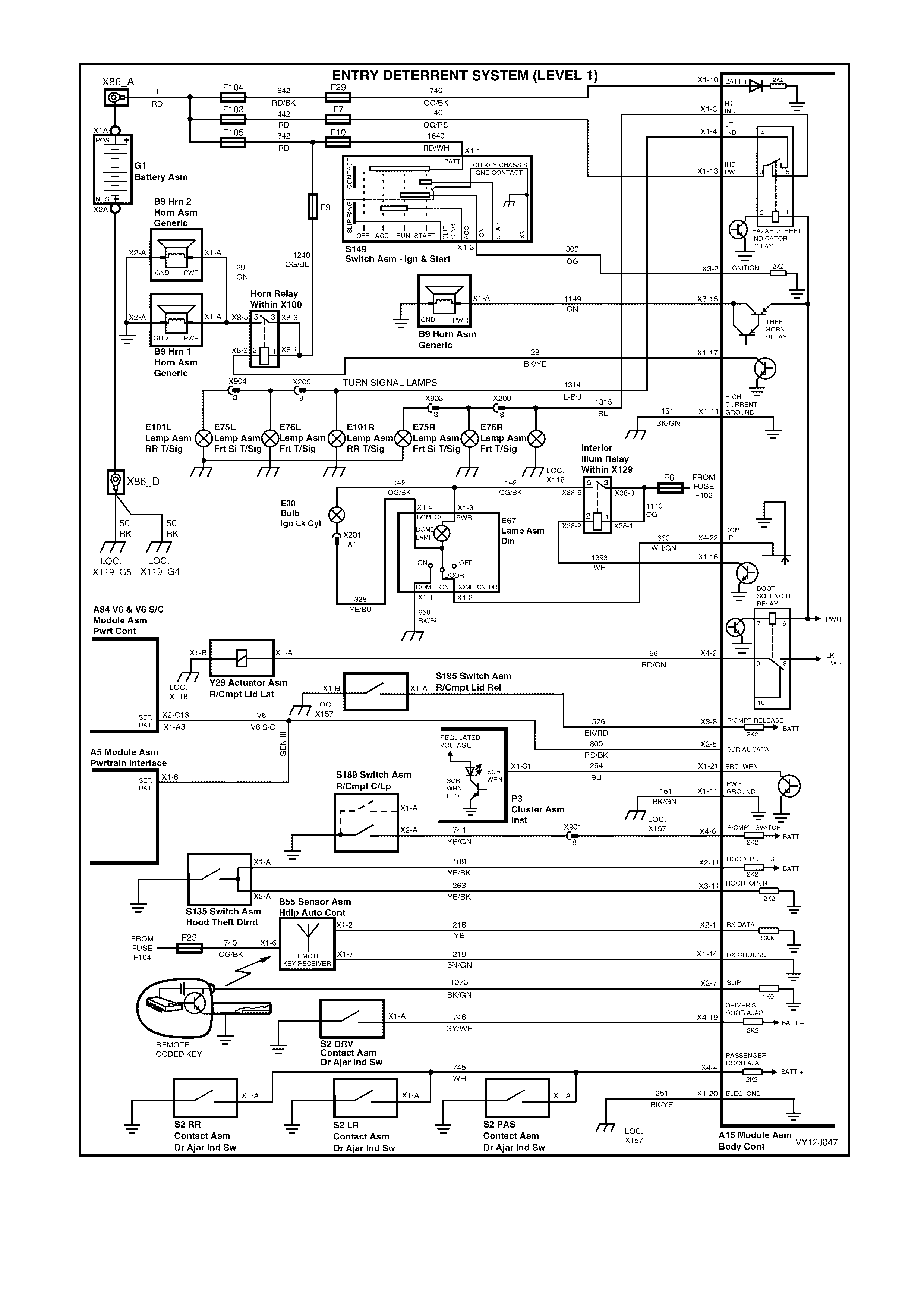
Figure 12J-240
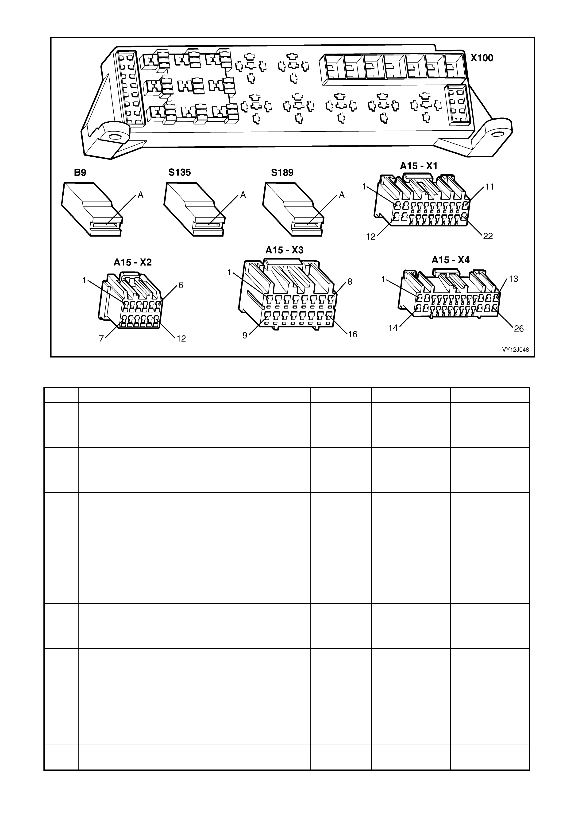
Figure 12J-241
ENTRY DETERRENT SYSTEM DIAGNOSTIC CHART
STEP ACTION VALUE YES NO
1 Is the Central Door Locking system fully functional? Go to Step 2. Go to 4.5
CENTRAL DOOR
LOCKING in this
Section.
2 Are all door ajar switches and associated circuits
functioning correctly? Go to Step 3. Go to 4.5
CENTRAL DOOR
LOCKING, Part L,
in this Section.
3 Is the Theft Deterrent system fully functional? Go to Step 4. Go to 4.7 THEFT
DETERRENT
SYSTEM in this
Section.
4 Do all indicators operate correctly? Go to Step 5. Go to Section
12B, 3.22 TURN
SIGNAL SWITCH
ASSEMBLY (&
CRUISE
CONTROL).
5 Is the dome lamp fully functional using the manual
switch? Go to Step 6. Go to 4.12 DOME
LAMP DELA Y
CONTROL in this
Section.
6 NOTE: The alarm may sound in this Step.
Fully open the windows.
Close the doors.
1. Arm the system by pressing the remote coded key
Lock button.
2. Lift the driver’s door snib button and open the driver’s
door.
Is the alarm triggered?
Go to Step 7. Go to Step 14.
7 In Step 6, did both the theft deterrent and standard
vehicle horns (alarm) sound? Go to Step 8. Go to Step 16.

STEP ACTION VALUE YES NO
8 In Step 6, did both indicators and the dome lamp flash
once every second? Go to Step 9. Replace the BCM.
Refer to 2.1 BODY
CONTROL
MODULE in this
Section.
9 1. Disarm the system by pressing the remote coded key
Unlock button.
Do the indicators flash 3 times and does the MFD display
the alarm trigger point?
Go to Step 10. Replace the BCM.
Refer to 2.1 BODY
CONTROL
MODULE in this
Section.
10 NOTE: The alarm may sound in this Step.
1. Turn the ignition from off to on to off (to cancel the
Alarm trigger point display).
2. Arm the system.
3. Test the front passenger door input by opening the
door to trigger an alarm.
4. Disarm the system by operating the Unlock button on
the remote coded key.
5. Observe the MFD display for alarm trigger point.
6. Cancel the flash code.
7. Repeat Steps 2 to 6 for the rear passenger doors.
Does each passenger door trigger the alarm?
Go to Step 11. Go to Step 23.
11 NOTE: The alarm may sound in this Step.
1. Cancel the Alarm trigger point display.
2. Arm the system.
3. Open the rear compartment using the key in the rear
compartment lo ck.
Does opening the rear compartment trigger the alarm?
Go to Step 12. Go to Step 26.
12 NOTE: The alarm may sound in this Step.
1. Cancel the Alarm trigger point display.
2. Arm the system.
3. Open the bonnet.
Is the alarm triggered?
Go to Step 13. Go to Step 25.
13 1. Cancel the Alarm trigger point display.
2. With the driver’s window open and the doors closed,
arm the system.
3. Place a thick piece of paper over the remote coded
key slip ring contact.
4. From outside of the vehicle, insert the key into the
ignition switch and Turn the ignition on.
Is the alarm triggered?
Go to Step 14. Go to Step 34.
14 1. Cancel the Alarm trigger point display.
2. Disarm the system by pressing the remote coded key
Unlock button.
3. Connect TECH 2 to the DLC.
4. Select Diagnostics / Model Year / Vehicle Model /
Body / Body Control Module / Data Display / Inputs
and Outputs / Driver’s Door.
5. Open and close the driver’s door.
Does the screen display the correct driver’s door status?
Replace the BCM.
Refer to 2.1 BODY
CONTROL
MODULE in this
Section.
Go to Step 15.
15 1. Back-probe BCM connector terminal X4-19,
circuit 746 (Grey / White wire) with a voltmeter to
ground.
2. Open and close the driver’s door.
Are the values as specified?
Door open
= 0 volt
Door closed
= 3 volts
Replace the BCM.
Refer to 2.1 BODY
CONTROL
MODULE in this
Section.
Repair faulty
circuit 746.

STEP ACTION VALUE YES NO
16 NOTE: The alarm may sound in this Step.
1. Disarm the system.
2. Connect TECH 2 to the DLC.
3. Select Diagnostics / Model Year / Vehicle Model /
Body / Body Control Module / Miscellaneous Tests /
Alarm/Theft Deterrent / Horn.
4. Perform the test as instructed by TECH 2.
Is the alarm triggered?
Go to Step 17. Go to Step 18.
17 1. With TECH 2 connected, select Body / Body Control
Module / Miscellaneous Tests / Horn.
2. Perform the test as instructed by TECH 2.
Is the alarm triggered?
Replace the BCM.
Refer to 2.1 BODY
CONTROL
MODULE in this
Section.
Go to Step 21.
18 1. Disarm the system.
2. Back-probe BCM connector terminal X3-15,
circuit 1149 (Green wire) with a voltmeter to ground.
3. Repeat the TECH 2 Theft Deterrent Horn test.
Is the value as specified?
On= Approx.
Battery
voltage
Off = Approx
1 volt
Go to Step 19. Replace the BCM.
Refer to 2.1 BODY
CONTROL
MODULE in this
Section.
19 1. Disarm the system.
2. Back-probe the theft deterrent horn connector
terminal X1-A, circuit 1149 (Green wire) with a
voltmeter to ground.
3. Repeat the TECH 2 Theft Deterrent Horn test.
Is the value as specified?
On= Approx.
Battery
voltage
Off = Approx
1 volt
Go to Step 20. Repair faulty
circuit 1149.
20 1. Back-probe between the theft deterrent horn base
and a known good ground with an ohmmeter.
Is the value as specified?
Less than
1 ohm Replace the theft
deterrent horn
(B9).
Repair faulty
ground
connection.
21 1. Press the horn pad on the steering wheel.
Is the horn triggered? Go to Step 22. Go to Section
12N, 3.1 Horn
Assembly.
22 1. Back-probe BCM connector terminal X1-17, circuit 28
(Black / Yellow wire) with a jumper lead to ground.
Is the alarm triggered?
Replace the BCM.
Refer to 2.1 BODY
CONTROL
MODULE in this
Section.
Repair faulty
circuit 34.
23 In Step 5, did at least one passenger door trigger the
alarm? Repair faulty
circuit 745. Go to Step 24.
24 1. Disarm the system.
2. Connect TECH 2 to the DLC.
3. Select Diagnostics / Model Year / Vehicle Model /
Body / Body Control Module / Data Display / Inputs
and Outputs / Passenger Doors.
4. Open and close the passenger door.
Does TECH 2 display the door status?
Replace the BCM.
Refer to 2.1 BODY
CONTROL
MODULE in this
Section.
Go to Step 25.
25 1. Back-probe BCM connector terminal X4-4, circuit 745
(White wire) with a voltmeter to ground.
2. Open any passenger door.
Is the value as specified?
Less than 0.5
volt Replace the BCM.
Refer to 2.1 BODY
CONTROL
MODULE in this
Section.
Repair faulty
circuit 745.
26 1. Disarm the system.
2. Connect TECH 2 to the DLC.
3. Select Diagnostics / Model Year / Vehicle Model /
Body / Body Control Module / Data Display / Inputs
and Outputs / Rear Compartment Status.
4. Open then close the rear compartment lid.
Does TECH 2 display the rear compartment status (open
then close)?
Replace the BCM.
Refer to 2.1 BODY
CONTROL
MODULE in this
Section.
Go to Step 27.
27 1. Back-probe BCM connector terminal X4-6, circuit 744
(Yellow / Green wire) with a voltmeter to ground.
2. Open the boot.
Is the value as specified?
Less than 0.5
volt Replace the BCM.
Refer to 2.1 BODY
CONTROL
MODULE in this
Section.
Go to Step 28.

STEP ACTION VALUE YES NO
28 1. Open the rear compartment lid.
2. Disconnect the Rear Compartment Switch (S189)
connector.
3. Back-probe the rear compartment switch
terminal X2-A, circuit 744 (Yellow / Green wire) with
an ohmmeter to ground.
Is the value as specified?
Less than
1 ohm Repair faulty
circuit 744. Go to Step 29.
29 1. With the Rear Compartment Switch connector
disconnected, probe between the switch base and a
known good ground with an ohmmeter.
Is the value as specified?
Less than
1 ohm Replace rear
compartment la mp
switch.
Repair faulty
ground
connection.
30 1. Disarm the system.
2. Connect TECH 2 to the DLC.
3. Select Diagnostics / Model Year / Vehicle Model /
Body / Body Control Module / Data Display / Inputs
and Outputs / Bonnet.
4. Open then close the bonnet.
Does TECH 2 display the bonnet status (open then
closed)?
Replace the BCM.
Refer to 2.1 BODY
CONTROL
MODULE in this
Section.
Go to Step 31.
31 1. Open the bonnet.
2. Disconnect the Theft Deterrent Hood Switch (S135)
connectors X1 and X2.
3. Back-probe the hood switch terminal X1-A,
circuit 109 (Yellow / Black wire) with an ohmmeter to
ground.
4. Back-probe the hood switch terminal X2-A,
circuit 263 (Yellow / Black wire) with an ohmmeter to
ground.
Are the values as specified?
Less than
1 ohm (both
circuits)
Install the Theft
Deterrent Hood
Switch connectors
and go to Step 32.
Go to Step 32.
32 1. With the Theft Deterrent Hood Switch (S135)
connectors disconnected, probe between the hood
switch base and the battery negative post with an
ohmmeter.
Is the value as specified?
Less than
1 ohm Replace the hood
switch (S135). Repair faulty
ground
connection.
33 1. With the Theft Deterrent Hood Switch (S135)
connectors disconnected, check the integrity of
circuits 109 and 263 (Yellow / Black wires).
Are the circuits OK??
Replace the BCM.
Refer to 2.1 BODY
CONTROL
MODULE in this
Section.
Repair faulty
circuit 109 and / or
263 as necessary.
34 1. Disarm the system.
2. Connect TECH 2 to the DLC.
3. Select Diagnostics / Model Year / Vehicle Model /
Body / Body Control Module / Data Display / Inputs
and Outputs / Ignition Switch.
4. Turn the ignition on.
Is the value as specified?
On Replace the BCM.
Refer to 2.1 BODY
CONTROL
MODULE in this
Section.
Go to Step 35.
35 1. Back-probe BCM connector terminal X3-2, circuit 300
(Orange wire) with a voltmeter to ground.
2. Turn the ignition on.
Is the value as specified?
Battery
voltage
(ignition on)
Replace the BCM.
Refer to 2.1 BODY
CONTROL
MODULE in this
Section.
Repair faulty
circuit 300.
WHEN ALL DIAGNOSIS AND REPAIRS ARE COMPLETE, VERIFY CORRECT OPERATION

4.9 POWER WINDOW SYSTEM
CIRCUIT DESCRIPTION
The BCM controls the power supply to each window motor. It also controls the automatic down function of the
driver and front-passenger door windows. This function is activated when the respective power window down
button is pressed for more than 0.4 second.
Once activ ated, the autom atic do wn feature is c ancelled b y pressing the dr iver / front- passenger window up switch
and then releasing it. The window remains stationary until the up or down button is pressed again.
Power is s upplied to th e window s ys tem c ontinuousl y when the ignit ion is on. W hen the ignition is switched of f and
no door has been opened, power is supplied to the window system for a maximum of one hour. If any door is
opened, power is supplied to the system for a maximum of 45 seconds after the door is opened.
When the doors are unlocked using the remote coded key, power is supplied to the system for 45 seconds after
door opening. The delay is cancelled when the doors are locked by the remote coded key.

Figure 12J-242
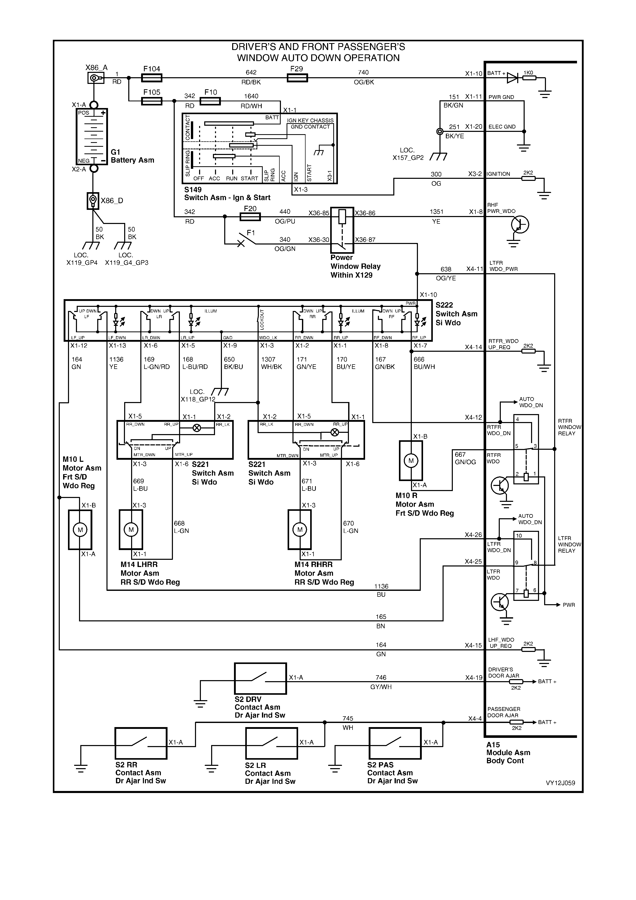
Figure 12J-243
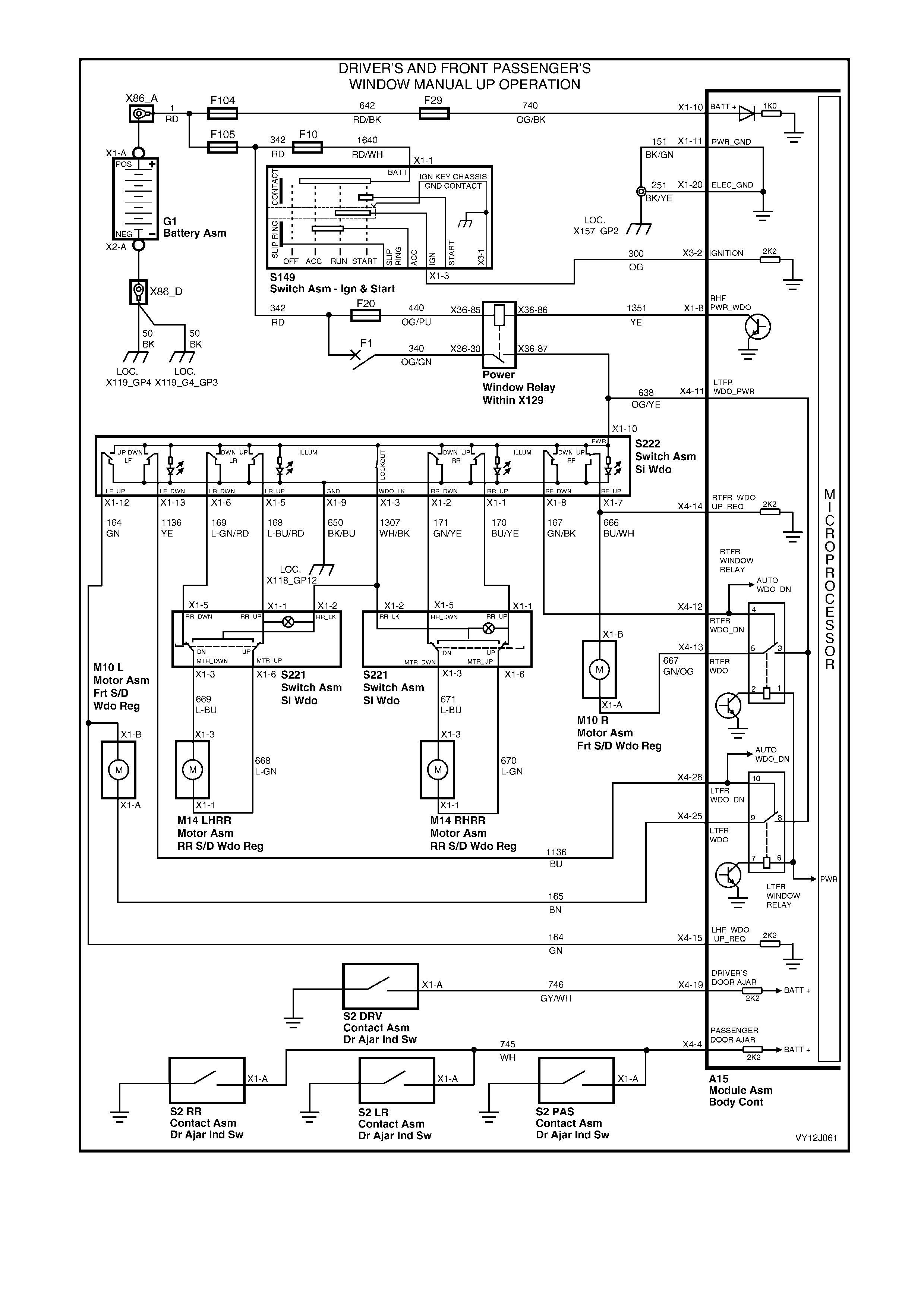
Figure 12J-244
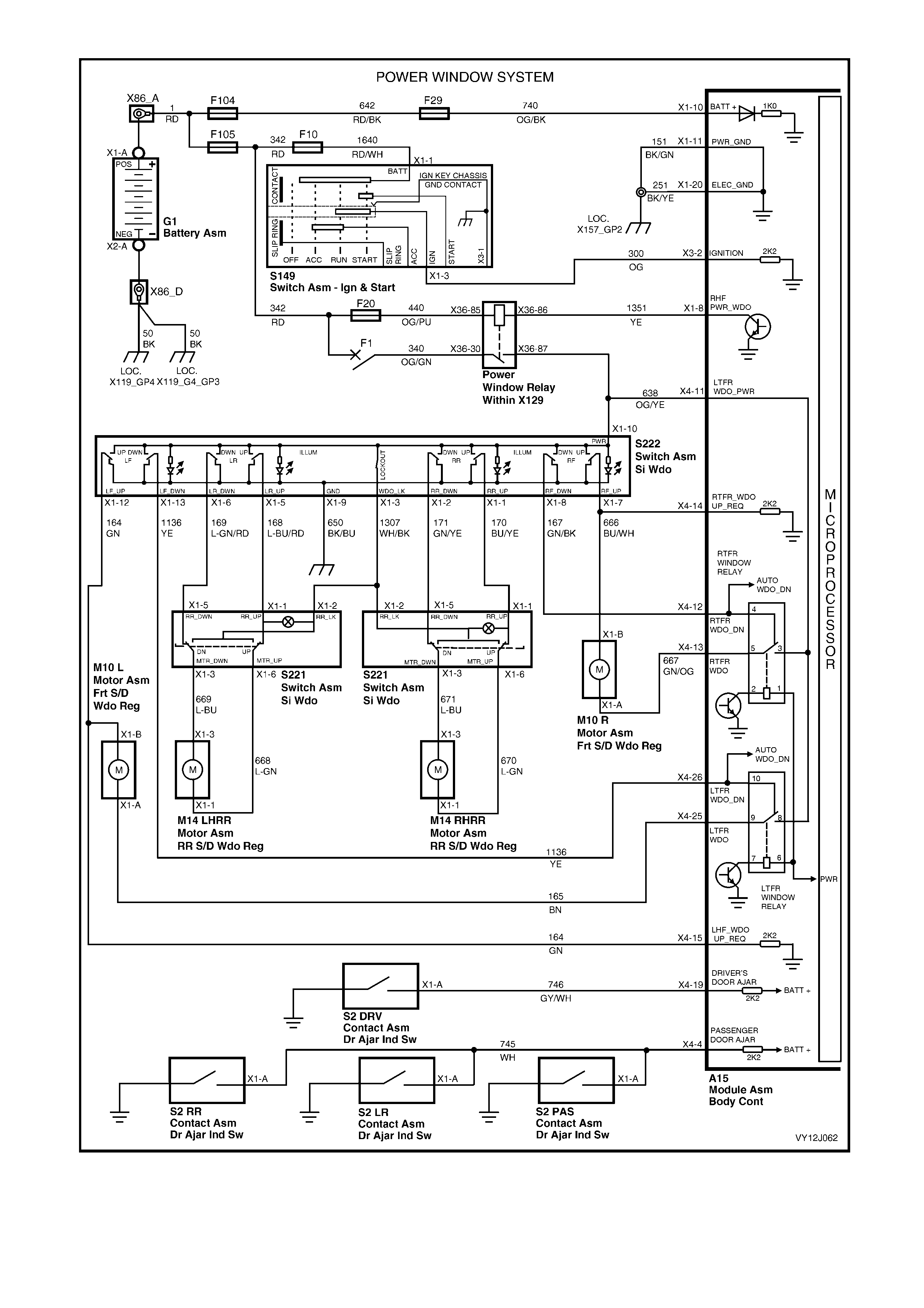
Figure 12J-245
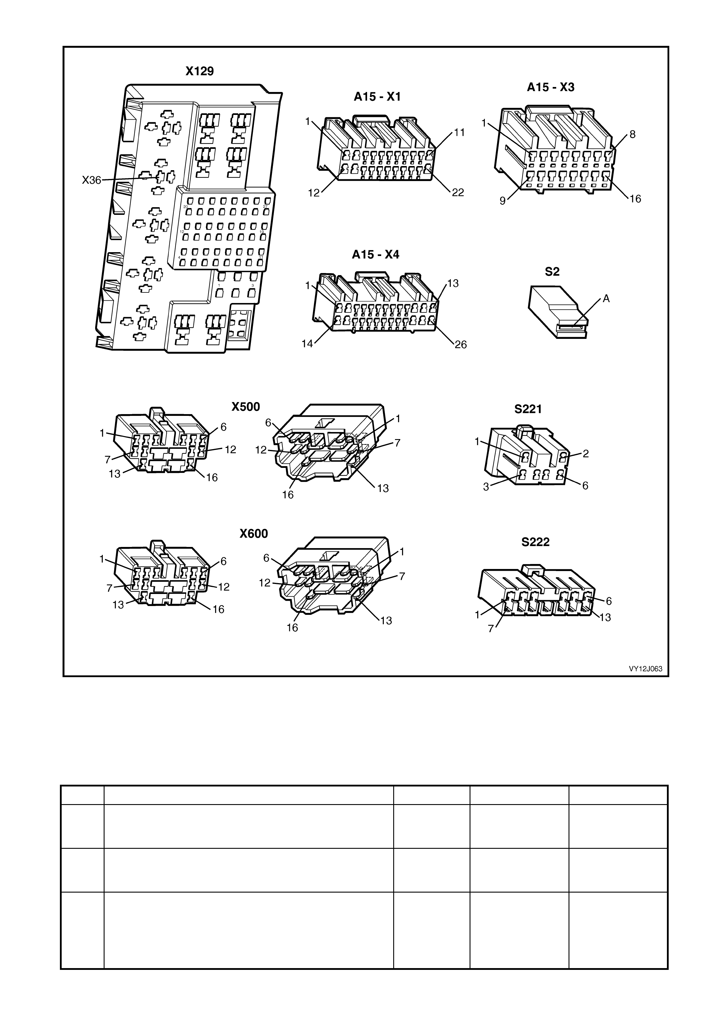
Figure 12J-246
POWER WINDOW SYSTEM DIAGNOSTIC CHART
NOTE: To access the internal components of the door assemblies, refer to Section 1A5.
Test description
The numbered description below refers to the selected step in the following diagnostic chart.
39. Checks for the presence of a battery voltage signal (false signal).
STEP ACTION VALUE YES NO
1 Are all power windows free from mechanical faults such
as a damaged window regulator or badly worn guide
rubbers?
Go to Step 2. Repair the power
windows.
2 Are all door ajar switches and associated circuits
functioning correctly? Go to Step 3. Go to 4.5, Part L,
Door Ajar
Switches.
3 1. Turn the ignition on.
2. Close the doors.
3. Operate the driver’s window down button for
1 second.
Does the window travel all the way down automatically?
Go to Step 4. Go to Step 23.

STEP ACTION VALUE YES NO
4 1. With the ignition on and the doors closed, operate the
driver’s window up button.
Does the window travel up while activating the button?
Go to Step 5. Go to Step 37.
5 1. With the ignition on, operate the driver’s window
down button for 1 second.
2. As the window is travelling down automatically,
operate the up button momentarily.
Does the window stop?
Go to Step 6. Go to Step 40.
6 1. Turn the ignition off.
2. With the doors closed, use the button on the remote
coded key to lock the doors.
Is the window system power supply interrupted? (The
green indicator lamps in the front and rear window
switches go out.)
Go to Step 7. Go to Step 67.
7 1. Use the button on the remote coded key to unlock
the doors.
Is the window system power supply restored? (The green
indicator lamps in the window switches turn on.)
Go to Step 8. Replace the BCM.
Refer to 2.1 BODY
CONTROL
MODULE in this
Section.
8 1. With the doors closed, turn the ignition on then off.
2. Open the driver’s door.
Is the window system power supply interrupted after
45 seconds?
Go to Step 9. Replace the BCM.
Refer to 2.1 BODY
CONTROL
MODULE in this
Section.
9 1. Close the doors.
2. Turn the ignition on then off.
3. Open any passenger door.
Is the window system power supply interrupted after
45 seconds?
Go to Step 10. Replace the BCM.
Refer to 2.1 BODY
CONTROL
MODULE in this
Section.
10 1. Turn the ignition on.
2. With the doors closed, operate the front passenger
door window down button for 1 second.
Does the window travel all the way down automatically?
Go to Step 11. Go to Step 41.
11 1. With the ignition on, operate the front passenger
window up button.
Does the window travel up while the button is activated?
Go to Step 12. Replace the
centre console
switch (S222).
Refer to 1A3, 2.1
FLOOR
CONSOLE
COVER
ASSEMBLY.
12 1. With the ignition on, operate the front passenger
window do wn button for 1 second.
2. As the window is travelling down automatically,
operate the up button momentarily.
Does the window stop?
Go to Step 13. Go to Step 48.
13 Do any rear door windows operate while the lockout
switch is on (rear door window switched disabled)? Go to Step 14. Go to Step 15.
14 1. Turn the ignition on.
2. Ensure the power window ove rride switch is off.
3. Back-probe the centre console power window switch
connector terminal X1-3, circuit 1307 (White / Black
wire) with a voltmeter to ground.
Is the value as specified?
Battery
voltage Replace the
centre console
switch (S222).
Refer to 1A3, 2.1
FLOOR
CONSOLE
COVER
ASSEMBLY.
Check and repair
circuit 1307 ( White
/ Black wire) for
short circuit to
power supply.
15 1. Turn off the lockout switch (enable the rear door
window s witches).
2. W ith the i gnition on, opera te the c entre console RHR
window do wn button.
Does the RHR window travel down while the button is
activated?
Go to Step 16. Go to Step 49.

STEP ACTION VALUE YES NO
16 1. With the ignition on and the lockout switch off,
operate the RHR power window up button on the
centre console power window switch.
Does the RHR window travel up while the button is
activated?
Go to Step 17. Replace the
centre console
switch (S222).
Refer to 1A3, 2.1
FLOOR
CONSOLE
COVER
ASSEMBLY.
17 1. With the ignition on and the lockout switch off,
operate the LHR power window down button on the
centre console power window switch.
Does the LHR window travel down while the button is
activated?
Go to Step 18. Go to Step 56.
18 1. With the ignition on, operate the LHR power window
up button on the centre console power window
switch.
Does the LHR window travel up while the button is
activated?
Go to Step 19. Replace the
centre console
switch (S222).
Refer to 1A3, 2.1
FLOOR
CONSOLE
COVER
ASSEMBLY.
19 1. Turn off the power window override switch. (Enable
the rear door window switches.)
2. W ith the ignition on, operate the window down button
on the RHR door.
Does the RHR window travel down while the button is
activated?
Go to Step 20. Go to Step 63.
20 1. With the power window override switch turned off and
the ignition on, operate the window up button on the
RHR door.
Does the RHR window travel up while the button is
activated?
Go to Step 21. Rep lace the RHR
power window
switch. Refer to
2.5 POWER
WINDO W DOOR
SWITCHES in this
Section.
21 1. With the power window override switch turned off and
the ignition on, operate the window down button on
the LHR door.
Does the LHR window travel down while the button is
activated?
Go to Step 22. Go to Step 65.
22 1. With the power window override switch turned off and
the ignition on, operate the window up button on the
LHR door.
Does the LHR window travel up while the button is
activated?
System OK. Replace LHR
power window
switch. Refer to
2.5 POWER
WINDO W DOOR
SWITCHES in this
Section.
23 1. With the ignition on, press and hold the driver’s
window do wn button.
Does the driver’s window travel down?
Replace the BCM.
Refer to 2.1 BODY
CONTROL
MODULE in this
Section.
Go to Step 24.
24 With the ignition on, are the green indicator lamps
illuminated in the centre console power window switch? Go to Step 25. Go to Step 31.
25 1. With the ignition on, back-probe centre console
switch assembly connector terminal X1-8, circuit 167
(Green / Black wire) with a voltmeter to ground.
2. Operate the driver’s window down button.
Is the value as specified?
Battery
voltage Go to Step 26. Replace the
centre console
switch (S222).
Refer to 1A3, 2.1
FLOOR
CONSOLE
COVER
ASSEMBLY.
26 1. Back-probe centre console switch assembly
connector terminal X1-7, circuit 666 (Blue / White
wire) with a voltmeter to ground.
Is the value as specified?
Less than
1 volt Go to Step 27. Go to Step 32.

STEP ACTION VALUE YES NO
27 1. Back-probe BCM connector terminal X4-12,
circuit 167 (Green / Black wire) with a voltmeter to
ground.
2. Operate the driver’s door window down button.
Is the value as specified?
Battery
voltage Go to Step 28. Repair faulty
circuit 167.
28 1. Turn the ignition off.
2. Disconnect BCM connector X4.
3. Back-probe between BCM terminals X4-12 and
X4-13 with an ohmmeter.
Is the value as specified?
Less than
1 ohm Install BCM
connector X4 and
go to Step 29.
Replace the BCM.
Refer to 2.1 BODY
CONTROL
MODULE in this
Section.
29 1. Back-probe the driver’s door power window motor
connector X1-A, circuit 667 (Green / Orange wire)
with a voltmeter to ground.
2. Turn the ignition on.
3. Operate the driver’s door window down button.
Is the value as specified?
Battery
voltage Go to Step 30. Repair faulty
circuit 667.
30 1. Back-probe the driver’s door power window motor
connector X1-B, circuit 666 (Blue / W hite wire) with a
voltmeter to ground.
2. With the ignition on, operate the driver’s door window
down button.
Is the value as specified?
Less than
1 volt Replace the
driver’s door
power window
motor (M10).
Refer to Section
1A5, 2.9 FRONT
DOOR WINDOW
REGULATOR
ASSEMBLY.
Repair faulty
circuit 666.
31 1. With the ignition on, back-probe the centre console
power window switch assembly connector
terminal X1-10, circuit 638 (Orange / Yellow wire)
with a voltmeter to ground.
Is the value as specified?
Battery
voltage Go to Step 32. Go to Step 33.
32 1. Turn the ignition off.
2. Back-probe the centre console power window switch
assembly connector terminal X1-9, circuit 650 (Black
/ Blue wire) with an ohmmeter to ground.
Is the value as specified?
Less than
1 ohm Replace the
centre console
switch (S222).
Refer to 1A3, 2.1
FLOOR
CONSOLE
COVER
ASSEMBLY.
Repair open in
circuit 650.
33 1. With the ignition on, back-probe power window relay
terminal X36-87, circuit 638 (Orange / Yellow wire)
with a voltmeter to ground.
Is the value as specified?
Battery
voltage Repair faulty
circuit 638. Go to Step 34.
34 1. With the ignition on, back-probe power window relay
terminal X36-85, circuit 440 (Orange / Purple wire)
and terminal X36-30, circuit 340 (Orange / Green
wire) with a voltmeter to ground.
Are the values as specified?
Battery
voltage Go to Step 35. Check and repair
faulty circuit 440,
342, 340 fuse F20
and / or circuit
breaker F1.
(Check for
excessive current
if F1 is tripped.)
35 1. With the ignition on, back-probe power window relay
terminal X36-86, circuit 1351 (Yellow wire) with a
jumper lead to ground.
Do the green front and rear window switch indicator
lamps turn on?
Go to Step 36. Replace the power
window relay (R22
in X129).
36 1. Turn the ignition on.
2. Back-probe BCM connector terminal X1-8,
circuit 1351 (Blue wire) with a jumper lead to ground.
Do the green front and rear window switch indicator
lamps turn on?
Replace the BCM.
Refer to 2.1 BODY
CONTROL
MODULE in this
Section.
Repair faulty
circuit 1351.

STEP ACTION VALUE YES NO
37 1. Back-probe the centre console power window switch
connector terminal X1-7, circuit 666 (Blue / White
wire) with a voltmeter to ground.
2. With the ignition on, operate the driver’s window up
button.
Is the value as specified?
Battery
voltage Go to Step 38. Replace the
centre console
switch (S222).
Refer to 1A3, 2.1
FLOOR
CONSOLE
COVER
ASSEMBLY.
38 1. With the ignition on, back-probe centre console
power window switch connector terminal X1-8,
circuit 667 (Green / Orange wire) with a voltmeter to
ground.
Is the value as specified?
Less than
1 volt Go to Step 39. Replace the
centre console
switch (S222).
Refer to 1A3, 2.1
FLOOR
CONSOLE
COVER
ASSEMBLY.
39 1. Back-probe BCM connector terminal X4-13,
circuit 667 (Green / Orange wire) with a voltmeter to
ground.
Is the value as specified?
Battery
voltage False signal.
Replace the BCM.
Refer to 2.1 BODY
CONTROL
MODULE in this
Section.
Replace the
centre console
switch (S222).
Refer to 1A3, 2.1
FLOOR
CONSOLE
COVER
ASSEMBLY.
40 1. Back-probe BCM connector terminal X4-14,
circuit 666 (Blue / White wire) with a voltmeter to
ground.
2. W ith the doors closed and the ignition on, operate the
driver’s window up button.
Is the value as specified?
Battery
voltage Replace the BCM.
Refer to 2.1 BODY
CONTROL
MODULE in this
Section.
Repair faulty
circuit 666.
41 1. With the ignition on, press and hold the front
passenger window down button.
Does the front passenger window travel down?
Replace the BCM.
Refer to 2.1 BODY
CONTROL
MODULE in this
Section.
Go to Step 42.
42 With the ignition on, are the green indicator lamps
illuminated in the centre console power window switch? Go to Step 43. Go to Step 31.
43 1. Back-probe centre console switch assembly
connector terminal X1-13, circuit 1136 (Yellow wire)
with a voltmeter to ground.
2. Operate the front passenger window down button.
Is the value as specified?
Battery
voltage Go to Step 44. Replace the
centre console
switch (S222).
Refer to 1A3, 2.1
FLOOR
CONSOLE
COVER
ASSEMBLY.
44 1. Back-probe centre console switch assembly
connector terminal X1-12, circuit 164 (Green wire)
with a voltmeter to ground.
2. Operate the front passenger window down button.
Is the value as specified?
Less than
1 volt Go to Step 45. Replace the
centre console
switch (S222).
Refer to 1A3, 2.1
FLOOR
CONSOLE
COVER
ASSEMBLY.
45 1. Turn the ignition off.
2. Disconnect BCM connector X4.
3. Back-probe between BCM terminals X4-25 and
X4-26 with an ohmmeter.
Is the value as specified?
Less than
1 ohm Install BCM
connector X4 and
go to Step 46.
Replace the BCM.
Refer to 2.1 BODY
CONTROL
MODULE in this
Section.
46 1. Back-probe the front passenger window motor
connector terminal X1-
A
, circuit 165 (Brown wire)
with a voltmeter to ground.
2. With the ignition on, operate the front passenger
window do wn button.
Is the value as specified?
Battery
voltage Go to Step 47. Repair faulty
circuit 165.

STEP ACTION VALUE YES NO
47 1. With the window switch in the rest position,
back-probe the front passenger window motor
connector terminal X1-B, circuit 164 (Green wire)
with a voltmeter to ground.
Is the value as specified?
Less than
1 volt Replace the LHF
door power
window motor
(M10). Refer to
Section 1A5, 2.9
FRONT DOOR
WINDOW
REGULATOR
ASSEMBLY.
Repair faulty
circuit 164.
48 1. Back-probe BCM connector terminal X4-15,
circuit 164 (Green wire) with a voltmeter to ground.
2. With the ignition on, operate the front passenger
window do wn button.
Is the value as specified?
Battery
voltage Replace the BCM.
Refer to 2.1 BODY
CONTROL
MODULE in this
Section.
Repair faulty
circuit 164.
49 1. Back-probe the centre console switch connector
terminal X1-2, circuit 171 (Green / Yellow wire) with a
voltmeter to ground.
2. With the ignition on, operate the RHR power window
down button on the centre console switch.
Is the value as specified?
Battery
voltage Go to Step 50. Replace the
centre console
switch (S222).
Refer to 1A3, 2.1
FLOOR
CONSOLE
COVER
ASSEMBLY.
50 1. Back-probe RHR door power window switch
connector S221, terminal X1-5, circuit 171 (Green /
Yellow wire) with a voltmeter to ground.
2. With the ignition on, operate the RHR power window
down button on the centre console switch.
Is the value as specified?
Battery
voltage Go to Step 51. Repair faulty
circuit 171.
51 1. Back-probe the RHR door power window switch
connector terminal X1-3, circuit 671 (Light-blue wire)
with a voltmeter to ground.
2. With the ignition on, operate the RHR window down
button on the centre console switch.
Is the value as specified?
Battery
voltage Go to Step 52. Rep lace the RHR
power window
switch. Refer to
2.5 POWER
WINDO W DOOR
SWITCHES in this
Section.
52 1. Back-probe the centre console switch connector
terminal X1-1, circuit 170 (Blue / Yellow wire) with an
ohmmeter to ground.
Is the value as specified?
Less than
1 ohm Go to Step 53. Replace the
centre console
switch (S222).
Refer to 1A3, 2.1
FLOOR
CONSOLE
COVER
ASSEMBLY.
53 1. Back-probe RHR door power window switch
connector terminal X1-1, circuit 170 (Blue / Yellow
wire) with an ohmmeter to ground.
Is the value as specified?
Less than
1 ohm Go to Step 54. Repair faulty
circuit 170.
54 1. Back-probe the RHR door power window switch
connector terminal X1-6, circuit 670 (Light-green
wire) with an ohmmeter to ground.
Is the value as specified?
Less than
1 ohm Go to Step 55. Rep lace the RHR
power window
switch. Refer to
2.5 POWER
WINDO W DOOR
SWITCHES in this
Section.
55 1. Check the integrity of circuit 670 (Light-green wire).
Is the circuit OK? Re place the RHR
door power
window motor
(M14). Refer to
Section 1A5, 3.13
REAR DOOR
WINDOW
REGULATOR
ASSEMBLY.
Repair faulty
circuit 670.

STEP ACTION VALUE YES NO
56 1. Back-probe the centre console power window switch
connector terminal X1-6, circuit 169, (Light-green /
Red wire) with a voltmeter to ground.
2. With the ignition on, operate the LHR window down
button on the centre console power window switch.
Is the value as specified?
Battery
voltage Go to Step 57. Replace the
centre console
switch (S222).
Refer to 1A3, 2.1
FLOOR
CONSOLE
COVER
ASSEMBLY.
57 1. Back-probe the LHR door power window switch
connector terminal X1-5, circuit 169 (Light-green /
Red wire) with a voltmeter to ground.
2. With the ignition on, operate the LHR window down
button on the centre console power window switch.
Is the value as specified?
Battery
voltage Go to Step 58. Repair faulty
circuit 169.
58 1. Back-probe the LHR door power window switch
connector terminal X1-3, circuit 669 (Light-blue wire)
with a voltmeter to ground.
2. With the ignition on, operate the LHR window down
button on the centre console power window switch.
Is the value as specified?
Battery
voltage Go to Step 59. Replace LHR
power window
switch. Refer to
2.5 POWER
WINDO W DOOR
SWITCHES in this
Section.
59 1. Back-probe the centre console power window switch
connector terminal X1-5, circuit 168 (Light-blue / Red
wire) with an ohmmeter to ground.
Is the value as specified?
Less than
1 ohm Go to Step 60. Replace the
centre console
switch (S222).
Refer to 1A3, 2.1
FLOOR
CONSOLE
COVER
ASSEMBLY.
60 1. Back-probe the LHR door power window switch
connector terminal X1-1, circuit 168 (Light-blue / Red
wire) with an ohmmeter to ground.
Is the value as specified?
Less than
1 ohm Go to Step 61. Repair faulty
circuit 168.
61 1. Back-probe the LHR door power window switch
connector terminal X1-6, circuit 668 (Light-green
wire) with an ohmmeter to ground.
Is the value as specified?
Less than
1 ohm Go to Step 62. Replace LHR
power window
switch. Refer to
2.5 POWER
WINDO W DOOR
SWITCHES in this
Section.
62 1. Check the integrity of circuit 668 (Light-green wire).
Is the circuit OK? Replace the LHR
door power
window motor
(M14). Refer to
Section 1A5, 3.13
REAR DOOR
WINDOW
REGULATOR
ASSEMBLY.
Repair faulty
circuit 668.
63 With the ignition on, is the green indicator lamp
illuminated in the RHR door power window switch? Replace RHR
power window
switch. Refer to
2.5 POWER
WINDO W DOOR
SWITCHES in this
Section.
Go to Step 64.
64 1. With the ignition on, back-probe the RHR power
window door switch connector terminal X1-2,
circuit 1307 (White / Black wire) with a voltmeter to
ground.
Is the value as specified?
Battery
voltage Repl ac e RHR
power window
switch. Refer to
2.5 POWER
WINDO W DOOR
SWITCHES in this
Section.
Repair open in
circuit 1307

STEP ACTION VALUE YES NO
65 With the ignition on, is the green indicator lamp
illuminated on the LHR door power window switch? Replace LHR
power window
switch. Refer to
2.5 POWER
WINDO W DOOR
SWITCHES in this
Section.
Go to Step 66.
66 1. With the ignition on, back-probe the LHR power
window door switch connector terminal X1-2,
circuit 1307 (White / Black wire) with a voltmeter to
ground.
Is the value as specified?
Replace LHR
power window
switch. Refer to
2.5 POWER
WINDO W DOOR
SWITCHES in this
Section.
Repair open in
circuit 1307.
67 1. Check the integrity of circuit 1351 (Yellow wire)
especially for short circuit to ground.
Is the circuit OK?
Go to Step 68. Repair faulty
circuit 1351.
68 1. Check the integrity of circuit 638 (Orange / Yellow
wire) especially for short circuit to voltage supply.
Is the circuit OK?
Replace the BCM.
Refer to 2.1 BODY
CONTROL
MODULE in this
Section.
Repair faulty
circuit 638.
WHEN ALL DIAGNOSIS AND REPAIRS ARE COMPLETE, VERIFY CORRECT OPERATION
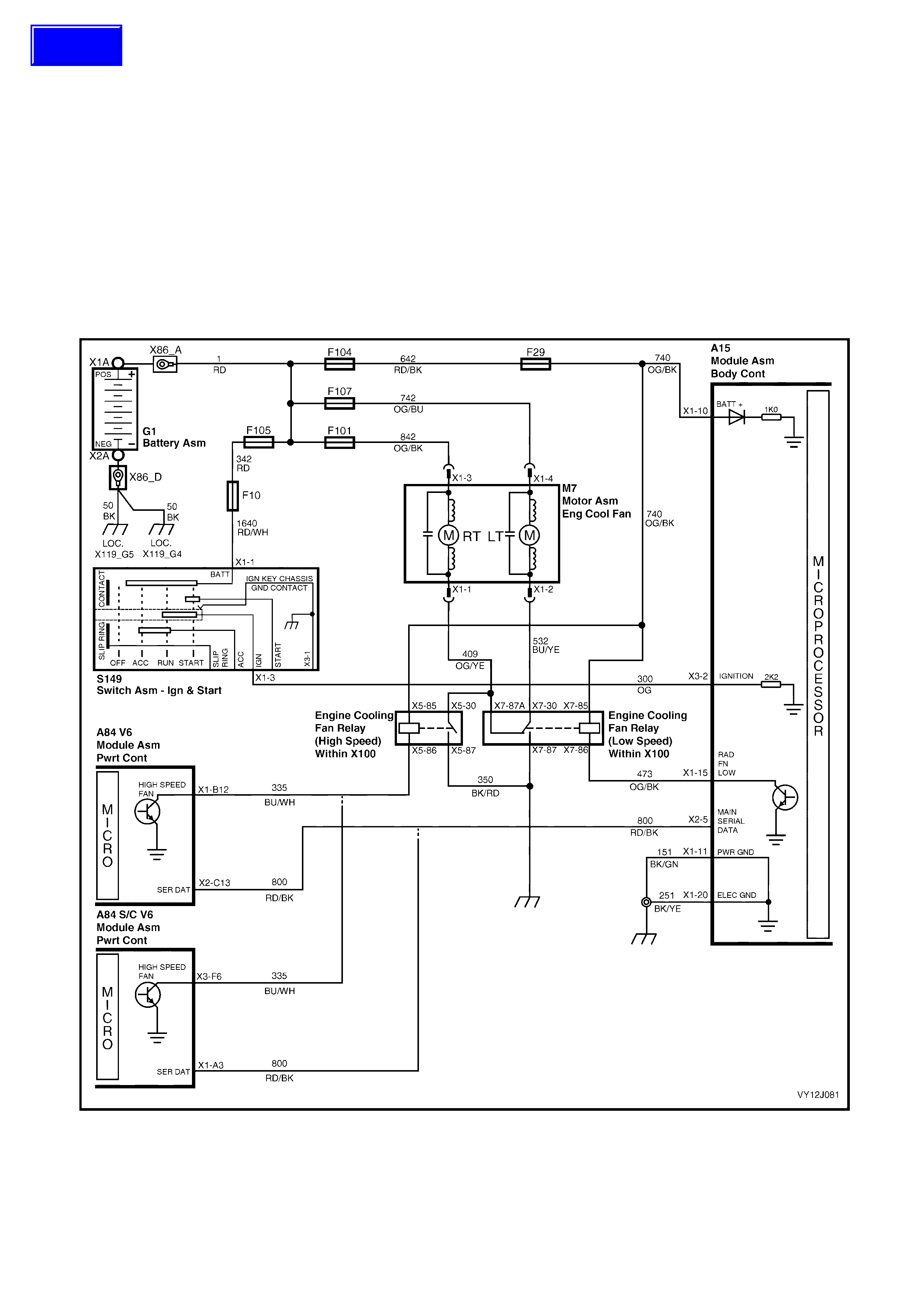
4.10 ENGINE COOLING FAN LOW-SPEED CONTROL
CIRCUIT DESCRIPTION
The cooling fan low-speed operates when the engine cooling fan low-speed micro-relay (in the engine
compar tm ent r el a y ho usin g, labe lle d CO O L F AN R EL A Y 1) is energise d. The BCM ener gis es the r elay in re s pons e
to a request from the PCM. The PCM requests low-speed fan enable (and disable) using serial data communication
to the BCM on circuit 800 (Red / Black wire).
The PCM determines when to enable the low-speed fan relay based on inputs from the A/C request signal, the
Cooling Temperature Sensor (CTS) and the Vehicle Speed Sensor (VSS).
When the ignition switch is turned from on to off and the engine coolant temperature is above 117°C (V6 or
V6 supercharged engine) or above 113°C (GEN III V8 engine), the BCM continues to energise the relay for
4 minutes.
NOTE: On veh icles with a GEN III V8 e ngine, the low-speed co oling fan r un-on tim e has a minim um default value
of 30 seconds.
Figure 12J-247
Techline
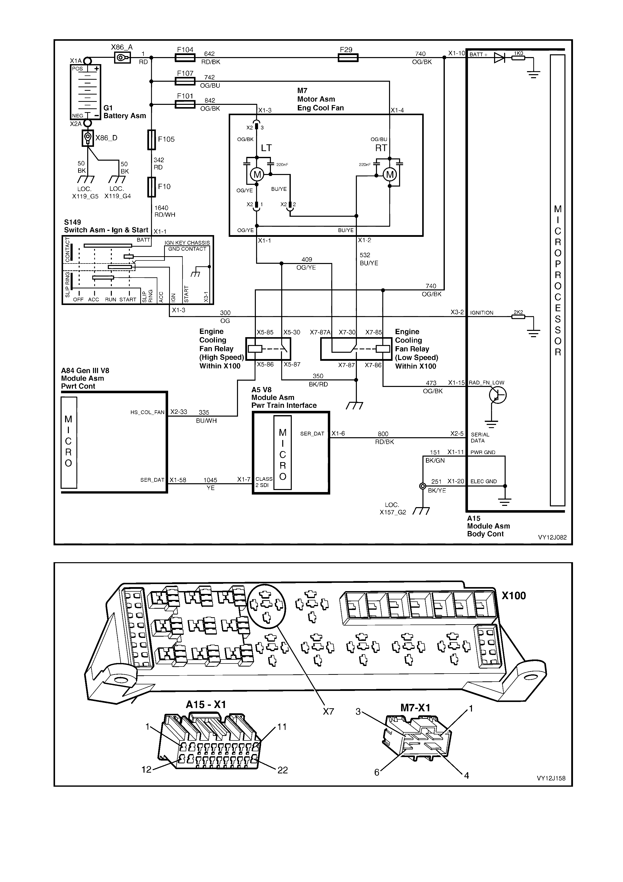
Figure 12J-248
Figure 12J-249

ENGINE COOLING FAN LOW-SPEED CONTROL DIAGNOSTIC CHART
STEP ACTION VALUE YES NO
1 Is the low-speed fan running continuously? Go to Step 13. Go to Step 2.
2 1. Connect TECH 2 to the DLC.
2. Select Diagnostics / Model Year / Vehicle Model /
Body / Body Control Module / Miscellaneous Tests /
Low Speed Cooling Fan.
3. Perform the test as instructed by TECH 2 and turn on
the low-speed fan.
Does the fan run?
Go to Step 3. Go to Step 5.
3 1. With TECH 2 connected and Low Speed Cooling Fan
selected, Perform the test as instructed by TECH 2
and turn off the low-speed fan.
Does the fan stop?
Go to Step 4. Go to Step 10.
4 1. With TECH 2 connected, exit to the Body Control
Module menu and select Data Display / Serial Data
Inputs / Low Speed Fan Request.
2. Start and run the engine.
3. Use TECH 2 to turn the fan on and off.
Does TECH 2 display On (fan running) and Off (fan
stopped)?
System OK. PCM / PIM fault.
Go to:
• (V6)
Section 6C1
• (V6 S/C)
Section 6C2
• (GEN III V8)
Section 6C3.
5 1. Back-probe the engine cooling fan motor connector
terminal X1-4, circuit 742 (Orange / Blue wire) with a
voltmeter to ground.
Is the value as specified?
Battery
voltage Go to Step 6. Check and repair
fuse F107 and
power circuit 742.
6 1. Back-probe BCM connector terminal X1-15, circuit
335 (Orange / Black wire) with a jumper lead to
ground.
Does the low-speed fan turn on?
0 volt Go to Step 7. Go to Step 8.
7 1. With TECH 2 connected, exit to the Body Control
Module menu and select Data Display / Serial Data
Inputs / Low Speed Fan Request.
Does TECH 2 display On (fan running) and Off (fan
stopped)?
Replace the BCM.
Refer to 2.1 BODY
CONTROL
MODULE in this
Section.
PCM / PIM fault.
Go to:
• (V6)
Section 6C1
• (V6 S/C)
Section 6C2
(GEN III V8)
Section 6C3.
8 1. Back-probe COOL FAN RELAY 1 connector (X100
X7) terminal X7-86, circuit 335 (Orange / Black wire)
with a jumper lead to ground.
Does the low-speed fan turn on?
0 volt Check and repair
open in circuit
473.
Go to Step 9.
9 1. Back-probe COOL FAN RELAY 1 connector
terminal X7-85, circuit 740 (Orange / Black wire) with
a voltmeter to ground.
Is the value as specified?
Battery
voltage Go to Step 10. Check and repair
open in circuit
740.
10 1. Back-probe COOL FAN RELAY 1 connector
terminal X7-87, circuit 350 (Black / Red wire) with an
ohmmeter to ground.
Is the value as specified?
Less than
1 ohm Go to Step 11. Check and repair
open in circuit
350.
11 1. Back-probe COOL FAN RELAY 1 connector
terminal X7-30, circuit 532 (Blue / Yellow wire) with a
jumper lead to ground.
Does the low-speed fan turn on?
Replace the
Engine Cooling
Fan Relay 1.
Go to Step 12.

STEP ACTION VALUE YES NO
12 1. Back-probe the engine cooling fan motor connector
terminal X1-2, circuit 532 (Blue / Yellow wire) with a
jumper lead to ground.
Does the low-speed fan turn on?
Repair faulty
circuit 532. Check / replace
the Low Speed
Cooling Fan (M7).
Refer to Section
6B1, ENGINE
COOLING – V6,
6B2, ENGINE
COOLING –
V6 S/C or
6B3, ENGINE
COOLING –
GENIII V8.
13 1. Connect TECH 2 to the DLC.
2. Select Diagnostics / Model Year / Vehicle Model /
Body / Body Control Module / Data Display / Inputs
and Outputs / Low Speed Cooling Fan.
Does TECH 2 display On?
Go to Step 14. Go to Step 16.
14 1. W ith the TECH 2 connected, exit to the Data Display
menu and select Serial Data Inputs / Low Speed Fan
Request.
Does TECH 2 display Off?
Replace the BCM.
Refer to 2.1 BODY
CONTROL
MODULE in this
Section.
Go to Step 15.
15 1. Check the integrity of circuit 800 (Red / Black wire).
Is the circuit OK? PCM / PIM fault.
Go to:
• (V6)
Section 6C1
• (V6 S/C)
Section 6C2
• (GEN III V8)
Section 6C3.
Repair faulty
circuit 800.
16 1. Check circuit 473 (Orange / Black wire) for a short to
ground.
Is the circuit OK?
Go to Step 17. Repair faulty
circuit 473.
17 1. Disconnect Low Speed Cooling Fan relay (R7).
Does the cooling fan stop? Replace the Low
Speed Cooling
Fan relay.
Install the relay
and go to Step 18.
18 1. Check circuit 532 (Blue / Yellow wire) for a short to
ground.
Is the circuit OK?
Check / replace
the Low Speed
Cooling Fan (M7).
Refer to Section
6B1, ENGINE
COOLING – V6,
6B2, ENGINE
COOLING –
V6 S/C or
6B3, ENGINE
COOLING –
GENIII V8.
Repair faulty
circuit 532.
WHEN ALL DIAGNOSIS AND REPAIRS ARE COMPLETE, VERIFY CORRECT OPERATION

4.11 WIPER SYSTEM
CIRCUIT DESCRIPTION
This system controls the front intermittent wiper and the rear wiper function. The front wiper dwell on level 2 and
level 3 model vehicles is dependent on the vehicle road speed as well as the position of the adjustable
potentiometer (located on the wiper control stalk). Within limits, the faster the vehicle speed, the shorter the dwell
time.
On Low and Mid series BCM, the customer can choose from fixed or speed dependent dwell when in the
interm ittent wiper p osition . T his c an be perf orm ed thr ough the veh icle cust om isation m enu or TECH 2. In the ev ent
of speed data loss, the system will revert back to the fixed 8-second dwell irrespective of vehicle speed. The OE
default is speed sensitive dwell.
The operation of the intermittent rear wiper is independent of the operation of the front intermittent wiper except
when the veh icle is stati ona ry with the ign it ion switch i n the Acc es s ories p ositi on. I n this s it uat ion, the f r ont a n d rear
intermittent wipers are synchronised. Due to a different wipe action between the front and rear wipers, the rear
wiper starts 0.25 second before the front wiper.
The rear wiper has an optional function of wiping continuously when the vehicle is in reverse gear with the rear
wiper s witch turne d on. T his optio n is s et using c omm unicat ion bet ween the PCM and BCM v ia the ser ial d ata bus,
circuit 800.
The front and rear wipers use a 'wipe after wash' function. When a washer pump switch is pressed for more than
0.5 second, the associated wipers sweep contin uously at low speed until t he washer pum p has been deactivated .
The wiper is then energised for a calculated time period to enable the wiper sweeps to be completed, as follows:
• One additional sweep if the washer switch is pressed for less than 1 second.
• Two additional sweeps if the washer switch is pressed for less than 1.5 seconds.
• Three additional sweeps if the washer switch is pressed for more than 1.5 seconds.
To perform the correct number of additional sweeps, the wiper motor park switch is monitored by the BCM via
circuit 196. This ensures that the wiper power is supplied to the park switch at the optimum time.

Figure 12J-250
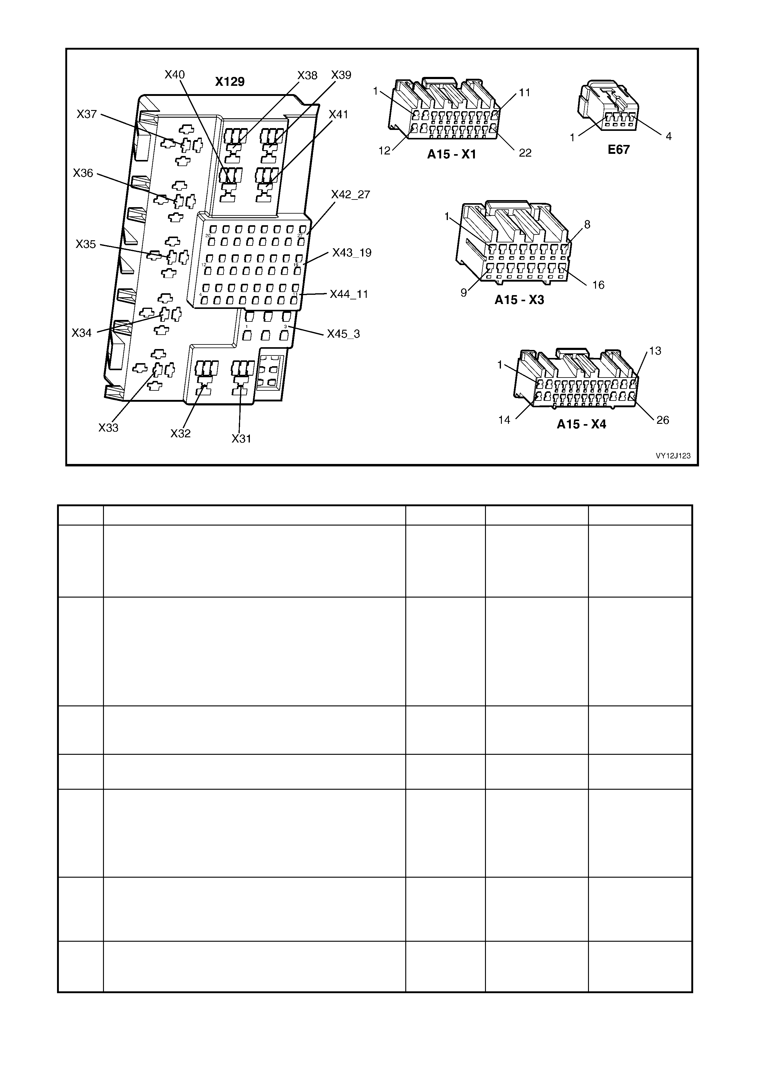
Figure 12J-251
WIPER SYSTEM DIAGNOSTIC CHART
STEP ACTION VALUE YES NO
1 Is the Accessory Power Control system is functioning
correctly? Go to Step 2. Go to 4.4
ACCESSORY
POWER
CONTROL in this
Section.
2 1. Connect TECH 2 to the DLC.
2. Select Diagnostics / Model Year / Vehicle Model /
Body / Body Control Module / Miscellaneous Tests /
Wipers / Front Wipers.
3. Turn the ignition switch to Accessories.
4. Perform the test as instructed by TECH 2.
Do the front wipers sweep continuously?
Go to Step 3. Go to Step16.
3 1. With the ignition switch turned to Accessories, turn
the wiper / washer switch to the intermittent position.
Do the front wipers sweep?
Go to Step 4. Go to Step 16.
4 1. Adjust the wiper dwell control to the fastest setting.
Are the wiper sweeps intermittent (not continuous)? Go to Step 5. Go to Step 26.
5 1. Turn the ignition on.
2. Turn the wiper switch to the intermittent position and
vary the wiper dwell control setting from minimum to
maximum.
Are the values as specified?
Minimum
dwell time:
3 seconds.
Maximum
dwell time:
24 seconds
Go to Step 6. Go to Step 49.
6 1. Road test the vehicle with the wiper switch set to the
intermittent position.
2. Do not adjust the wiper dwell control.
Does the wiper dwell vary as the vehicle speed is varied?
Go to Step 7. Go to Step 53.
7 1. Turn the ignition switch to Accessories.
2. Operate the front washer switch for 2 seconds.
Do the front wipers commence continuous operation?
Go to Step 8. Go to Step 30.

STEP ACTION VALUE YES NO
8 1. With the ignition switch turned to Accessories, again
operate the front washer switch (for 2 seconds).
2. Release the switch and count the number of wiper
sweeps.
Did the front wipers continue for three additional sweeps
after the washer switch was released?
For sedan,
system OK.
For wagon,
go to Step 9.
Replace the BCM.
Refer to 2.1 BODY
CONTROL
MODULE in this
Section.
9 1. Turn the ignition switch to Accessories.
2. Turn on the rear wiper.
Does the rear wiper sweep?
Go to Step 10. Go to Step 32.
10 In Step 9, were the rear wiper sweeps intermittent (not
continuous)? Go to Step 11. Go to Step 42.
11 1. With the ignition turned to Accessories, again operate
the rear wiper.
2. Time the period between each sweep.
Is the value as specified?
Approx.
8 seconds Go to Step 12. Replace the BCM.
Refer to 2.1 BODY
CONTROL
MODULE in this
Section.
12 1. With the ignition turned to Accessories, operate the
rear washer switch for 2 seconds.
Does the rear washer commence operation?
Go to Step 13. Go to Step 45.
13 1. With the ignition turned to Accessories, operate the
rear washer switch for 2 seconds.
Does the rear wiper commence continuous operation?
Go to Step 14. Replace the BCM.
Refer to 2.1 BODY
CONTROL
MODULE in this
Section.
14 1. With the ignition turned to Accessories, turn the wiper
/ washer switch to the intermittent position and turn
on the rear wiper.
2. Keep the vehicle stationary.
Are the front and rear wipers synchronised?
Go to Step 15. Replace the BCM.
Refer to 2.1 BODY
CONTROL
MODULE in this
Section.
15 1. With TECH 2 connected, exit to the Body Control
Module menu and select Program / Options / Rear
Wiper Continuous in Reverse.
2. Ensure the Rear Wiper Continuous in Reverse option
is enabled.
3. Turn the ignition on.
4. Turn the front wipers on to the intermittent position.
5. Select reverse gear.
Does the rear wiper operate continuously when reverse
gear is selected?
System OK. For a V6 engine,
go to Step 47.
For a GEN III V8
engine, go to
Step 48.
16 1. With TECH 2 connected, exit to the Body Control
Module menu and select Data Display / Wipers /
Front Wiper Intermitt ent Switch.
2. Turn the ignition switch to Accessories.
3. Turn the wiper / washer switch to the intermittent
position.
Does TECH 2 display Front Wiper Intermittent On?
Go to Step 17. Go to Step 23.
17 1. Turn the ignition switch to Accessories.
2. Back-probe BCM connector terminal X1-2, circuit 243
(Brown / White wire) with a voltmeter to ground.
Is the value as specified?
Battery
voltage Go to Step 18. Check and repair
circuit 243 and / or
fuse F18.
18 1. Back-probe BCM connector terminal X1-12, circuit 96
(Light-green wire) with a voltmeter to ground.
Is the value as specified?
Battery
voltage Go to Step 19. Replace the BCM.
Refer to 2.1 BODY
CONTROL
MODULE in this
Section.
19 1. Back-probe wiper / washer switch (S247) connector
terminal X1-8, circuit 96 (Light-green wire) with a
voltmeter to ground.
Is the value as specified?
Battery
voltage Go to Step 20. Repair faulty
circuit 96.

STEP ACTION VALUE YES NO
20 1. Back-probe wiper / washer switch (S247) connector
terminal X1-9, circuit 95 (Grey / Red wire) with a
voltmeter to ground.
2. Turn the ignition on.
3. With TECH 2 connected, exit to the Body Control
Module menu and select Miscellaneous Tests /
Wipers / Front Wipers and Perform the test as
instructed by TECH 2.
Is the value as specified?
Battery
voltage Go to Step 21. Replace wiper /
washer switch
assembly.
21 1. W ith TECH 2 connected and the ignition switch in the
Accessories position, back-probe wiper motor (M17)
connector terminal X1-1, circuit 95 (Grey / Red wire)
with a voltmeter to ground.
2. Repeat the TECH 2 Front Wiper test as in Step 18.
Is the value as specified?
Battery
voltage Go to Step 22. Repair faulty
circuit 95.
22 1. Back-probe front wiper motor connector
terminal X1-4, circuit 550 (Black / White wire) with an
ohmmeter to ground.
Is the value as specified?
Less than
1 ohm Replace front
wiper motor
assembly. Refer to
Section 12N,
WIPERS /
WASHERS &
HORN.
Repair faulty
circuit 550.
23 1. With the ignition switch turned to Accessories,
back-probe BCM connector terminal X3-3, circuit 112
(Blue / White wire) with a voltmeter to ground.
2. Turn the wiper / washer switch to the intermittent
position.
Is the value as specified?
Battery
voltage Replace the BCM.
Refer to 2.1 BODY
CONTROL
MODULE in this
Section.
Go to Step 24.
24 1. With the ignition switch turned to Accessories,
back-probe wiper / washer switch connector
terminal X1-7, circuit 112 (Blue / White wire) with a
voltmeter to ground.
2. Turn the wiper / washer switch to the intermittent
position.
Is the value as specified?
Battery
voltage Repair faulty
circuit 112. Go to Step 25.
25 1. With the ignition switch turned to Accessories,
back-probe wiper / washer switch connector terminal
X1-6, circuit 243 (Brown / White wire) with a
voltmeter to ground.
Is the value as specified?
Battery
voltage Replace wiper /
washer switch.
Refer to Section
12N, WIPERS /
WASHERS &
HORN.
Check and repair
circuit 243 and / or
fuse F18.
26 1. With TECH 2 connected and the ignition switch
turned to Accessories, exit to the Body Control
Module menu and select Data Display / Wipers /
Front Wiper Park Switch.
2. Turn the wiper / washer switch to the intermittent
position.
Does TECH 2 display Wiper Park Switch Off (wiper
parked) and Wiper Park Switch On (wiper operating)?
Go to Step 27. Replace the BCM.
Refer to 2.1 BODY
CONTROL
MODULE in this
Section.
27 1. With the ignition switch turned to Accessories, turn
the wiper / washer switch to the intermittent position.
2. Back-probe BCM connector terminal X1-1, circuit 196
(Yellow wire) with a voltmeter to ground.
Are the values as specified?
Operating
= Battery
voltage
Park
= 0 volt
Replace the BCM.
Refer to 2.1 BODY
CONTROL
MODULE in this
Section.
Go to Step 28.
28 1. With the ignition switch turned to Accessories,
back-probe the wiper motor connector terminal X1-3,
circuit 243 (Brown / White wire) with a voltmeter to
ground.
Is the value as specified?
Battery
voltage Go to Step 29. Repair faulty
circuit 243.

STEP ACTION VALUE YES NO
29 1. With the ignition switch turned to Accessories, turn
the wiper / washer switch to the intermittent position.
2. Back-probe the wiper motor connector terminal X1-5,
circuit 196 (Yellow wire) with a voltmeter to ground.
Are the values as specified?
Operating
= Battery
voltage
Park
= 0 volt
Repair faulty
circuit 196. Replace front
wiper motor. Refer
to Section 12N,
WIPERS /
WASHERS &
HORN.
30 1. With the ignition switch turned to Accessories,
back-probe BCM connector terminal X3-13,
circuit 228 (Light-blue wire) with a voltmeter to
ground.
2. Operate the front washer switch.
Is the value as specified?
Battery
voltage Replace the BCM.
Refer to 2.1 BODY
CONTROL
MODULE in this
Section.
Go to Step 31.
31 1. Turn the ignition switch to Accessories.
2. Back-probe the wiper / washer switch (S247)
connector terminal X1-1, circuit 228 (Light-blue wire)
with a voltmeter to ground.
3. Operate the front washer switch.
Is the value as specified?
Battery
voltage Repair faulty
circuit 228. Replace wiper /
washer switch.
Refer to Section
12N, WIPERS /
WASHERS &
HORN.
32 1. With TECH 2 connected and the ignition turned to
Accessories, exit to the Body Control Module menu
and select Miscellaneous Tests / Wipers / Rear
Wiper.
2. Perform the test as instructed by TECH 2.
Does the rear wiper operate?
Go to Step 33. Go to Step 34.
33 1. With TECH 2 connected and the ignition turned to
Accessories, exit to the Body Control Module menu
and select Data Display / W ipers / Rear Wiper.
2. Turn on the rear wiper.
Does TECH 2 display Rear Wiper Switch On?
Replace the BCM.
Refer to 2.1 BODY
CONTROL
MODULE in this
Section.
Go to Step 40.
34 1. With the ignition switch turned to Accessories,
back-probe the rear wiper relay terminals X31-1 and
X31-3, circuit 243 (Brown / White wire) with a
voltmeter to ground.
Is the value as specified?
Battery
voltage Go to Step 35. Repair faulty
circuit 243.
35 1. With the ignition switch turned to Accessories,
back-probe the rear wiper relay terminal X31-2,
circuit 113 (Grey / Light-blue wire) with a jumper lead
to ground.
Does the rear wiper operate?
Go to Step 39. Go to Step 36.
36 1. With the ignition switch turned to Accessories and
terminal X31-2 connected to ground via a jumper
lead, back-probe the rear wiper relay terminal X31-5,
circuit 393 (Grey wire) with a voltmeter to ground.
Is the value as specified?
Battery
voltage Go to Step 37. Replace rear
wiper relay.
37 1. With the ignition switch turned to Accessories and
terminal X31-2 connected to ground via a jumper
lead, back-probe the rear wiper motor (M12)
connector terminal X1-B, circuit 393 (Grey wire) with
a voltmeter to ground.
Is the value as specified?
Battery
voltage Go to Step 38. Repair faulty
circuit 393.
38 1. Check the rear wiper motor ground connection with
an ohmmeter to ground.
Is the value as specified?
Less than
1 ohm Replace rear
wiper motor. Refer
to Section 12N,
WIPERS /
WASHERS &
HORN.
Repair rear wiper
motor ground
connection.
39 1. Turn the ignition switch to Accessories.
2. Back-probe BCM connector terminal X1-7, circuit 113
(Grey / Light-blue wire) with a jumper lead to ground.
Does the rear wiper operate?
Replace the BCM.
Refer to 2.1 BODY
CONTROL
MODULE in this
Section.
Repair faulty
circuit 113.

STEP ACTION VALUE YES NO
40 1. With the ignition switch turned to Accessories,
back-probe BCM connector terminal X3-7, circuit 391
(Grey / Red wire) with a voltmeter to ground.
2. Turn on the rear wiper.
Is the value as specified?
Battery
voltage Replace the BCM.
Refer to 2.1 BODY
CONTROL
MODULE in this
Section.
Go to Step 41.
41 1. With the ignition switch turned to Accessories,
back-probe the wiper / washer switch connector
terminal X1-4, circuit 391 (Grey / Red wire) with a
voltmeter to ground.
2. Turn on the rear wiper.
Is the value as specified?
Battery
voltage Repair faulty
circuit 391. Replace wiper /
washer switch.
Refer to Section
12N, WIPERS /
WASHERS &
HORN.
42 1. Check the integrity of circuit 113 (Grey / Light-blue
wire).
Is the value as specified?
Less than
1 ohm Go to Step 43. Repair faulty
circuit 113.
43 1. Replace the rear wiper relay with a known good
relay.
2. Turn the ignition switch to Accessories.
3. Turn on the rear wiper.
Does the rear wiper sweep only once (not continuous)?
Replace rear
wiper relay. Install the original
relay and go to
Step 44.
44 1. With TECH 2 connected, exit to the Body Control
Module menu and select Data Display / Wipers /
Rear Wiper Switch.
2. Turn off the rear wiper switch.
Does TECH 2 display On?
For a V6 engine,
go to Step 54.
For a GEN III V8
engine, go to
Step 55.
Replace the BCM.
Refer to 2.1 BODY
CONTROL
MODULE in this
Section.
45 1. Turn the ignition switch to Accessories.
2. Back-probe BCM connector terminal X3-14,
circuit 227 (White / Blue wire) with a voltmeter to
ground.
3. Operate the rear washer switch.
Is the value as specified?
Battery
voltage Replace the BCM.
Refer to 2.1 BODY
CONTROL
MODULE in this
Section.
Go to Step 46.
46 1. Turn the ignition switch to Accessories.
2. Back-probe wiper / washer switch connector
terminal X1-3, circuit 227 (White / Blue wire) with a
voltmeter to ground.
3. Operate the rear washer switch.
Is the value as specified?
Battery
voltage Repair faulty
circuit 227. Replace wiper /
washer switch.
Refer to Section
12N, WIPERS /
WASHERS &
HORN.
47 1. With TECH 2 connected, exit from the Body menu
and select Engine / V6 / Normal Mode / Commanded
Gear.
2. Start the engine.
3. Put the vehicle in reverse gear.
Does TECH 2 display –R–?
Replace the BCM.
Refer to 2.1 BODY
CONTROL
MODULE in this
Section.
Go to the relevant
PCM diagnostics
in either Section
6C1,
POWERTRAIN –
V6 or Section 6C2
POWERTRAIN–
V6 S/C.
48 1. With TECH 2 connected, exit to the Body menu and
select Powertrain Interface Module / Normal Mode /
Commanded Gear.
2. Start the engine.
3. Put the vehicle in reverse gear.
Does TECH 2 display –R–?
Replace the BCM.
Refer to 2.1 BODY
CONTROL
MODULE in this
Section.
Go to PCM
diagnostics in
Section 6C3,
POWERTRAIN –
GEN III V8.
49 1. Turn the ignition switch to Accessories.
2. With TECH 2 connected, exit to the Body Control
Module menu and select Data Display / Wipers /
Front Wiper Intermitt ent Switch.
3. Vary the wiper dwell control switch on wiper washer
switch stalk from maximum to minimum dwell time.
Is the value as specified?
Ranging
between
5 volts and
0 volt
Replace the BCM.
Refer to 2.1 BODY
CONTROL
MODULE in this
Section.
Go to Step 50.

STEP ACTION VALUE YES NO
50 1. Turn the ignition off.
2. Back-probe BCM connector terminal X2-4, circuit 477
(Grey / Black wire) with a voltmeter to ground.
3. Turn the ignition on.
4. Adjust the wiper dwell control from minimum to
maximum.
Is the value as specified?
Ranging
between
5 volts and
0 volt
Replace the BCM.
Refer to 2.1 BODY
CONTROL
MODULE in this
Section.
Go to Step 51.
51 1. Turn the ignition off.
2. Back-probe the dwell control (A122) connector
terminal X1-A, circuit 477 (Grey / Black wire) with a
voltmeter to ground.
3. Turn the ignition on.
4. Adjust the wiper dwell control from minimum to
maximum.
Is the value as specified?
Ranging
between
5 volts and
0 volt
Repair faulty
circuit 477. Go to Step 52.
52 1. Back-probe the dwell control (A122) connector
terminal X1-B, circuit 251 (Black / Yellow wire) with
an ohmmeter to ground.
Is the value as specified?
Less than
1 ohm Replace the dwell
control assembly
(A122).
Repair faulty
circuit 251.
53 1. With TECH 2 connected, exit to the Body Control
Module menu and select Data Display / Serial Data
Inputs / Vehicle Speed.
2. Road test the vehicle.
Does TECH 2 indicate the correct road speed?
Replace the BCM.
Refer to 2.1 BODY
CONTROL
MODULE in this
Section.
Go to the relevant
PCM diagnostics
in either Section
6C1,
POWERTRAIN –
V6, Section 6C2,
POWERTRAIN–
V6 S/C or Section
6C3,
POWERTRAIN –
GEN III V8.
54 1. Place the vehicle in neutral gear.
2. With TECH 2 connected, exit from the Body menu
and select Engine / Normal Mode / Commanded
Gear.
Does TECH 2 display –R–?
Go to the relevant
PCM diagnostics
in either Section
6C1,
POWERTRAIN –
V6 or Section
6C2,
POWERTRAIN–
V6 S/C.
Replace the BCM.
Refer to 2.1 BODY
CONTROL
MODULE in this
Section.
55 1. Place the vehicle in neutral gear.
2. With TECH 2 connected, exit to the Body menu and
select Powertrain Interface Module / Normal Mode /
Commanded Gear.
Does TECH 2 display –R–?
Go to Section
6C3,
POWERTRAIN –
GEN III V8.
Replace the BCM.
Refer to 2.1 BODY
CONTROL
MODULE in this
Section.
WHEN ALL DIAGNOSIS AND REPAIRS ARE COMPLETE, VERIFY CORRECT OPERATION

4.12 DOME LAMP DELAY CONTROL
CIRCUIT DESCRIPTION
The inter ior lig hting is controll ed by th e BCM or by the dom e lam p switch incorpo rated in the overh ead dom e lam p
and switc h as sem bly. W hen contro lled b y the BCM , the dom e lam p is s witched to grou nd vi a two diodes whi ch ar e
internal to the s witch ass em bl y. Theref ore, the dom e lam p is brighter when t urned on at th e dome lam p and switc h
assembly (the reading lamp switches), which bypasses these diodes.
NOTE: For level 1 model vehicles, refer to Figure 12J-252. For level 2 and 3 model vehicles, refer to Figure
12J-254.
Lighting Activation
The interior lighting is activated when:
• any door is opened
• any door is unlocked with the remote coded key (night only)
• the ignition is switched from on to the Accessories position or off (provided the feature is enabled or the
conditions are sufficiently dark)
• the dome lamp switch is operated.
The interior lighting (including the dome lamp) is activated when any door is open. After all the doors have been
closed, the lighting remains activated for an additional 30 seconds at night only.
The BCM monitors the doors and the switch settings and controls the dome lamp accordingly.
If the interior lighting has been activated by a BCM control s ystem action, the dome lamp switch turns the interior
lighting off when it is switched from the Door to the Off position. Therefore, this switch can cancel any delay time
and switc h th e l ightin g off whi le a door is op en, ex ce pt if the th ef t deter rent s ystem has been tr igg ered. In this c as e,
even with the switch in the Off position, the dome lamp flashes.
W ith c entral door unlock ing, the interior lighting is s witched on for 30 seconds at night on ly. If the ignition is turned
on during this period, the interior lighting is switched off immediately. Interior lighting is also switched off with
central door locking (unless the dome lamp switch is turned on or if a door remains open).
There ar e two interior lam p delay m odes: ignition off (Ignition OF F interior lam p time out) and Door Unlock / Close
delay (Interior Lamp timeout). T hes e modes of del ay times (def ault 30 sec onds ) a r e adj usta bl e by the us e of TECH
2 (BCM / Program / User Settings / Interior Lamp Timeout) or via the MFD mode button.
Battery Saver Mode
As part of the battery saver function, the BCM controls internal, dome, ignition lock surround, glove compartment
and door lamps. The BCM controls battery voltage to these circuits via the interior illumination relay.
There is a dela y period bef ore the batter y saver f unction of the BCM deact ivates the i nterior i lluminatio n rela y. The
delay default time is set to 60 minutes. The dela y can be reprogrammed with TECH 2 from 3 – 180 minutes. The
delay period starts when the ignition is switched off.
The system will also shut down after a remote lock (and arm) signal is received as well as a driver's door lock
signal (10 seconds stabilisation time).
Note that the delay defau lt t ime is set to 3 m inutes wh e n the BC M is in pre- d el iver y m ode. T he delay time rev ert s to
60 minutes after the vehicle has exceeded 20 km/h for a total of 30 minutes.
When in from battery saver mode, the BCM activates the interior lighting relay when:
• the bonnet, boot or a door is opened
• a valid remote signal is received
• the ignition is switched on or to Accessories
• the doors are unlocked via the driver’s door microswitch
• TECH 2 is connected and communicating with the BCM
• the headlamp switch is cycled from Off to On or On to Off
• the deadlock switch is activated
• the alarm is activated
• the boot release button is pressed
• the hazard switch is activated
• there is an accessories power request from the radio via serial communications
• there is a hardwired antenna request.
NOTE: If an input is active during a rem ote lock i.e. Dom e Lamp O n, Access ories on, door ope n, Hazard s witch or
boot open, the system is to shut down after the default time of 1 hour unless it has been re-triggered where the
timer is re-set for a further 1 hour.
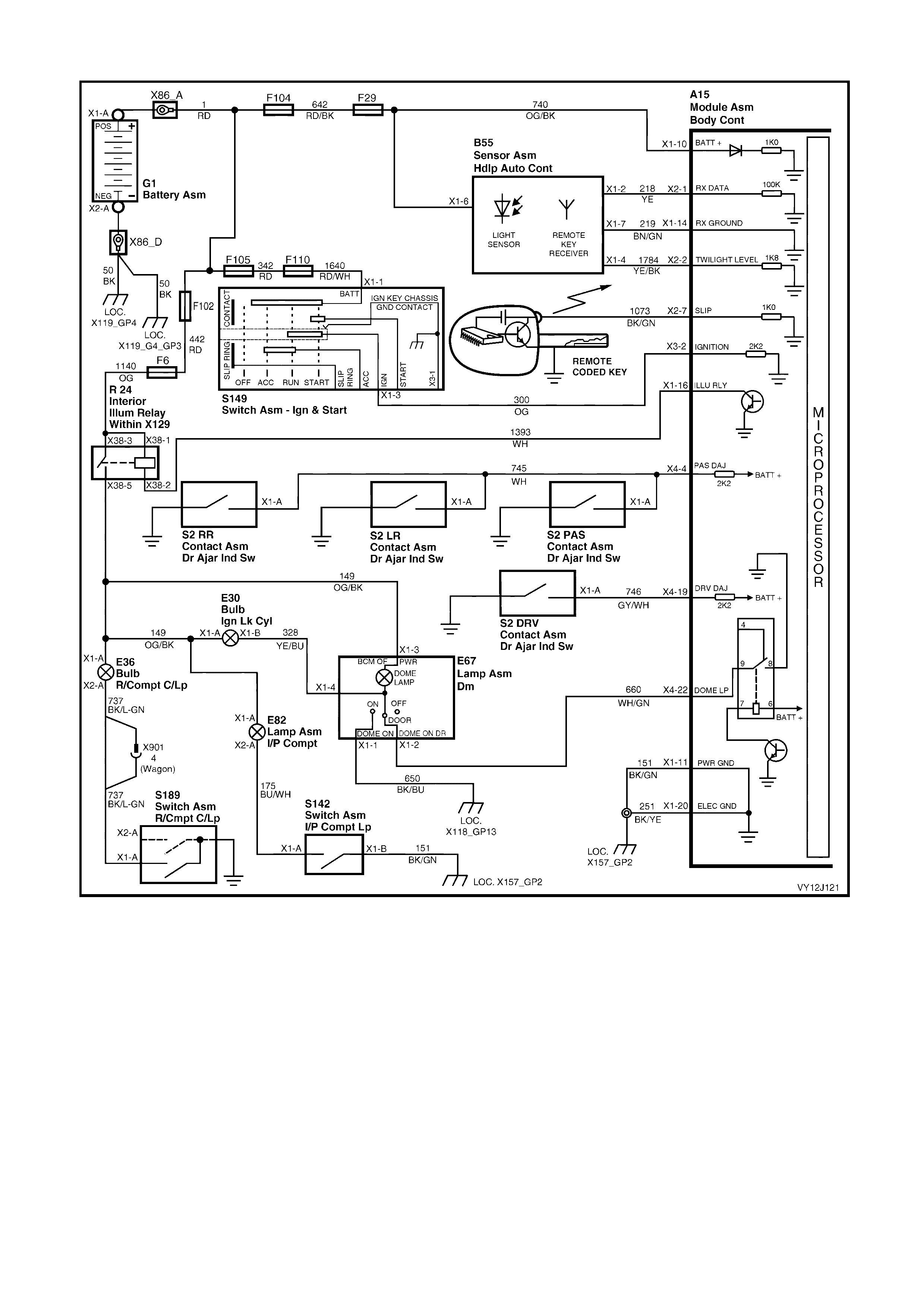
Level 1 model vehicles
Figure 12-252
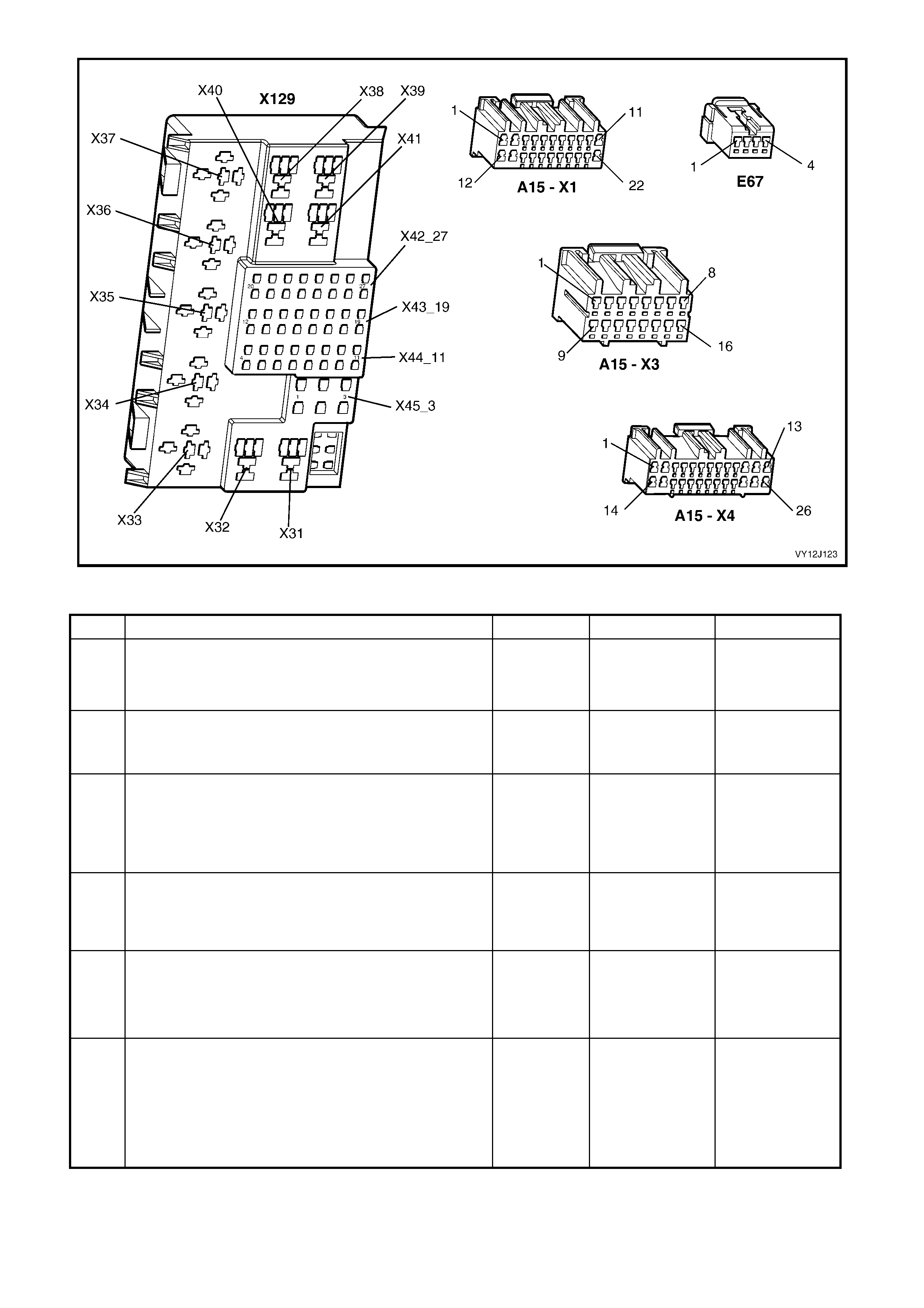
Figure 12J-253
DOME LA MP DELAY CONTROL DIAGNOSTIC CHART (LEVEL 1 MODEL VEHICLES)
STEP ACTION VALUE YES NO
1 Are all door ajar switches and associated circuits
functioning correctly? Go to Step 2. Go to 4.5, Part L,
Door Ajar
Switches in this
Section.
2 1. Close all the doors.
2. Set the dome lamp switch to the On position.
Does the dome lamp illuminate?
Go to Step 3. Go to Step 8.
3 1. Set the dome lamp switch to the Door position.
2. Lock all the doors.
3. Unlock the doors by pressing the remote key Unlock
button.
Does the dome lamp illuminate?
Go to Step 4. Go to Step 15.
4 1. With the dome lamp switch set to Door, close the
doors but do not lock them (wait for dome lamp off).
2. Open the driver’s door.
Does the dome lamp illuminate?
Go to Step 5. Go to Step 16.
5 1. W ith the dome lamp switch set to Door, open a door
to illuminate the dome lamp.
2. Close all doors.
Does the dome lamp extinguish after 30 seconds?
Go to Step 6. Replace the BCM.
Refer to 2.1 BODY
CONTROL
MODULE in this
Section.
6 1. With the dome lamp switch set to Door, close the
doors but do not lock them (wait for the dome lamp to
extinguish).
2. Use the remote coded key to lock and then unlock
the doors.
3. W ithin 30 seconds, Turn the ignition on.
Does the dome lamp turn off immediately?
Go to Step 7. Go to Step 18.

STEP ACTION VALUE YES NO
7 1. Turn the ignition off.
2. With the dome lamp switch set to Door, close the
doors but do not lock them (wait for the dome lamp to
extinguish).
3. Turn the ignition on.
4. Turn the ignition off.
Does the dome lamp illuminate?
System OK Replace the BCM.
Refer to 2.1 BODY
CONTROL
MODULE in this
Section.
8 1. Check the dome lamp globe.
Is the globe OK? Go to Step 9. Replace globe.
9 1. Back-probe the dome lamp and switch assembly
(E67) connector terminal X1-3, circuit 149 (Orange /
Black wire) with a voltmeter to ground.
Is the value as specified?
Battery
voltage Go to Step 14. Go to Step 10.
10 1. Back-probe the interior illumination relay (R24)
connector terminals X38-1 and X38-3, circuit 1140
(Orange wire) with a voltmeter to ground.
2. Turn the ignition off.
Is the value as specified?
Battery
voltage Go to Step 11. Repair faulty
circuit 1140 or
fuse F6, as
required.
11 1. Back-probe the interior illumination relay (R24)
connector terminal X38-5, circuit 149 (Orange / Black
wire) with a voltmeter to ground.
2. Turn the ignition on.
Is the value as specified?
Battery
voltage Repair faulty
circuit 149. Go to Step 12.
12 1. W ith the dome lamp switch set to On, back-probe the
interior illumination relay connector terminal X38-2,
circuit 1393 (White wire) with a jumper lead to
ground.
Does the dome lamp illuminate?
Go to Step 13. Replace the
interior illumination
relay (R24).
13 1. Back-probe BCM terminal X1-16, circuit 1393 (White
wire) with a jumper lead to ground.
Does the dome lamp illuminate?
Go to Step 19. Repair faulty
circuit 1393.
14 1. Back-probe the dome lamp and switch assembly
(E67) connector terminal X1-1, circuit 650 (Black /
Blue wire) with an ohmmeter to ground.
Is the value as specified?
Less than
1 ohm Replace dome
lamp and switch
assembly. Refer to
Section 12B,
3.8 DOME LAMP
ASSEMBLY.
Repair faulty
circuit 650.
15 1. Turn the ignition off.
2. Connect TECH 2 to the DLC.
3. Select Diagnostics / Model Year / Vehicle Model /
Body / Body Control Module / Miscellaneous Tests /
Lamps / Interior Lamp.
4. Perform the teat as ins truc ted by TECH 2.
Does the dome lamp illuminate?
Replace the BCM.
Refer to 2.1 BODY
CONTROL
MODULE in this
Section.
Go to Step 16.
16 1. Back-probe BCM terminal X4-22, circuit 660 (W hite /
Green wire) with a voltmeter to ground.
2. Repeat the TECH 2 Interior Lamp test (in Step 17).
Is the value as specified?
On =
less than
0.5 volt
Off =
Battery
voltage
Go to Step 17. Replace the BCM.
Refer to 2.1 BODY
CONTROL
MODULE in this
Section.
17 1. Check the integrity of circuit 660 (White / Green
wire).
Is the circuit OK?
Replace dome
lamp and switch
assembly. Refer to
Section 12B,
3.8 DOME LAMP
ASSEMBLY.
Repair faulty
circuit 660.
18 1. With the dome lamp switch set to Door, disconnect
BCM connector X4.
Does the dome lamp turn off?
Replace the BCM.
Refer to 2.1 BODY
CONTROL
MODULE in this
Section.
Go to Step 16.

STEP ACTION VALUE YES NO
19 1. Back-probe BCM terminal X3-2, circuit 300 (Orange
wire) with a voltmeter to ground.
2. Turn the ignition on.
Is the value as specified?
Battery
voltage Replace the BCM.
Refer to 2.1 BODY
CONTROL
MODULE in this
Section.
Repair faulty
power supply
(including circ uit
300, and the
ignition sw itch).
WHEN ALL DIAGNOSIS AND REPAIRS ARE COMPLETE, VERIFY CORRECT OPERATION
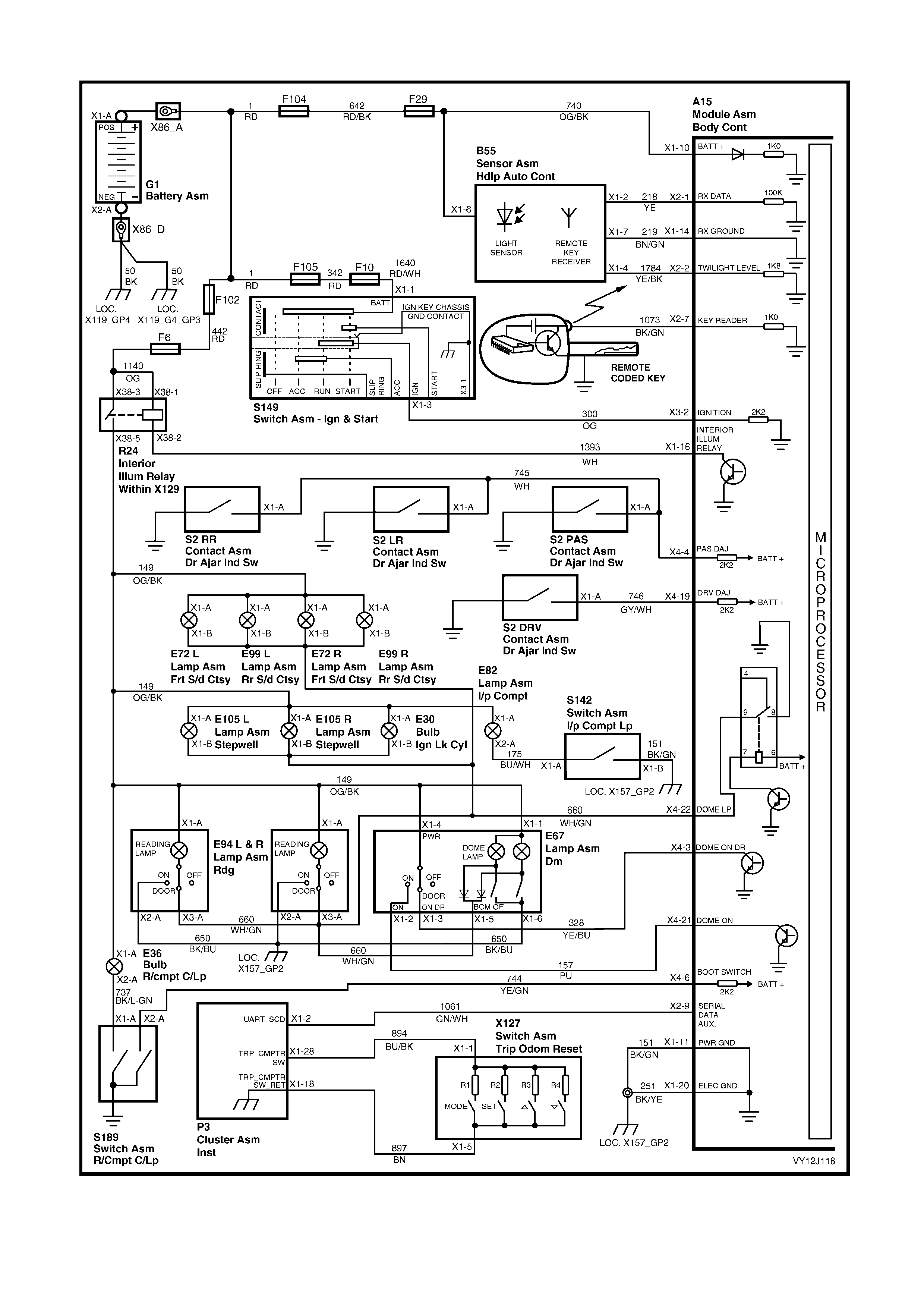
Level 2 and 3 model vehicles
Figure 12J-254

DOME LAMP DELAY CONTROL DIAGNOSTIC CHART (LEVEL 2 AND 3 MODEL VEHICLES)
STEP ACTION VALUE YES NO
1 Are all door ajar switches and associated circuits
functioning correctly? Go to Step 2. Go to 4.5, Part L,
Door Ajar
Switches in this
Section.
2 Is the Accessory power supply and associated circuits
functioning correctly? Go to Step 3. Go to 4.4,
ACCESSORY
CONTROL in this
Section.
3 1. Turn the ignition switch to the Accessories position.
2. Turn the dome lamp assembly (E67) reading lamps
on.
Do the lamps illumi nate ?
Go to Step 4. Go to Step 13.
4 1. Turn the reading lamps off.
2. Set the dome lamp switch to the On position.
Does the dome lamp illuminate?
Go to Step 5. Go to Step 20.
5 1. Close the doors.
2. Set the dome lamp switch to the Off position.
Does the dome lamp turn off?
Go to Step 6. Go to Step 25.
6 1. With the doors closed, set the dome lamp switch
from the Off position to the Door position.
2. Open the driver’s door.
Does the dome lamp illuminate?
Go to Step 7. Go to Step 28.
7 1. Turn the ignition off.
2. Connect TECH 2 to the DLC.
3. Select Diagnostics / Model Year / Vehicle Model /
Body / Body Control Module / Program / Interior
Lamp Timeout.
4. Set the interior lamp timeout delay to 10 seconds.
5. Exit and turn off TECH 2.
6. With the dome lamp switch set to the Door position,
open a door to turn the dome lamp on.
7. Close the door.
Does the dome lamp turn off after 10 seconds?
Go to Step 8. Replace the BCM.
Refer to 2.1 BODY
CONTROL
MODULE in this
Section.
8 1. W ith the dome lamp switch set to Door and the doors
closed, wait for the dome lamp to turn off and then
open a passenger door.
Does the dome lamp illuminate?
Go to Step 9. Replace the BCM.
Refer to 2.1 BODY
CONTROL
MODULE in this
Section.
9 1. W ith the dome lamp switch set to Door and the doors
closed, open a door to illuminate the dome lamp.
2. Close the door.
3. Turn the ignition on.
Does the dome lamp turn off immediately?
Go to Step 10. Replace the BCM.
Refer to 2.1 BODY
CONTROL
MODULE in this
Section.
10 1. With the dome lamp switch set to Door, lock all the
doors.
2. Unlock the doors using the remote coded key Unlock
button.
Does the dome lamp illuminate?
Go to Step 11. Go to Step 32.
11 1. W ith the dome lamp switch set to Door and the doors
closed, lock and then unlock the doors with the
remote coded key.
2. Turn the ignition on within 30 seconds.
Does the dome lamp turn off immediately?
Go to Step 12. Replace the BCM.
Refer to 2.1 BODY
CONTROL
MODULE in this
Section.
12 1. W ith the ignition off and the dome lamp switch set to
Door, close the doors.
2. Turn the ignition on and then off.
Does the dome lamp illuminate?
System OK Replace the BCM.
Refer to 2.1 BODY
CONTROL
MODULE in this
Section.
13 1. Check the dome lamp globes.
Are the globes OK? Go to Step 14. Replace globes as
necessary.

STEP ACTION VALUE YES NO
14 1. With the ignition switch turned to Accessories,
back-probe the dome lamp and switch assembly
connector terminal X1-1, circuit 149 (Orange / Black
wire) with a voltmeter to ground.
Is the value as specified?
Battery
voltage Go to Step 15. Go to Step 16.
15 1. Turn the ignition off.
2. Back-probe dome lamp and switch assembly
connector terminal X1-6, circuit 650 (Black / Blue
wire) with an ohmmeter to ground.
Is the value as specified?
Less than
1 ohm Replace dome
lamp and switch
assembly. Refer to
Section 12B,
3.8 DOME LAMP
ASSEMBLY,
3.9 DOME AND
READING LAMP
ASSEMBLY or
3.10 ROOF
CONSOLE
depending on the
vehicle level.
Repair faulty
circuit 650.
16 1. Turn the ignition switch to the Accessories position.
2. Back-probe the interior illumination relay (R24)
connector terminal X38-5, circuit 149 (Orange / Black
wire) with a voltmeter to ground.
Is the value as specified?
Battery
voltage Repair faulty
circuit 149. Go to Step 17.
17 1. Back-probe the interior illumination relay connector
terminals X38-1 and X38-3, circuit 1140 (Orange
wire) with a voltmeter to ground.
Is the value as specified?
Battery
voltage Go to Step 18. Repair faulty
power supply
includin g circ uit s
1140 and 442, and
fuses F6 and
F102.
18 1. With the ignition switch turned to the Accessories
position and the reading lamps turned on, back-probe
the interior illumination relay connector
terminal X38-2, circuit 1393 (White wire) with a
jumper lead to ground.
Do the reading lamps illuminate?
Go to Step 19. Replace the
interior illumination
relay (R24).
19 1. Back-probe BCM connector terminal X1-16,
circuit 1393 (White wire) with a jumper lead to
ground.
Do the reading lamps illuminate?
Replace the BCM.
Refer to 2.1 BODY
CONTROL
MODULE in this
Section.
Repair faulty
circuit 1393.
20 1. Turn the ignition off.
2. Connect TECH 2 to the DLC.
3. With the dome lamp switch set to the On position and
the doors closed, select Diagnostics / Model Year /
Vehicle Model / Body / Body Control Module / Data
Display / Inputs and Outputs / Dome Lamp Switch.
Does TECH 2 display On?
Go to Step 21. Go to Step 24.
21 1. With TECH 2 connected, exit to the Body Control
Module menu and select Miscellaneous Tests /
Lamps / Interior Lamp.
2. With the doors closed, perform the test as instructed
by TECH 2 and turn on the dome lamp.
Does the dome lamp illuminate?
Replace the BCM.
Refer to 2.1 BODY
CONTROL
MODULE in this
Section.
Go to Step 22.
22 1. With the ignition switch turned to the Accessories
position and the dome lamp switch in the On position,
back-probe BCM terminal X4-22, circuit 660 (White /
Green wire) with a jumper lead to ground.
Does the dome lamp illuminate?
Replace the BCM.
Refer to 2.1 BODY
CONTROL
MODULE in this
Section.
Go to Step 23.

STEP ACTION VALUE YES NO
23 1. With the ignition switch turned to the Accessories
position and the dome lamp switch in the On position,
back-probe dome lamp and switch assembly
connector terminal X1-5, circuit 660 (White / Green
wire) with a jumper lead to ground.
Does the dome lamp illuminate?
Repair faulty
circuit 660. Rep lace dome
lamp and switch
assembly. Refer to
Section 12B,
3.8 DOME LAMP
ASSEMBLY,
3.9 DOME AND
READING LAMP
ASSEMBLY or
3.10 ROOF
CONSOLE
depending on the
vehicle level.
24 1. Turn the ignition off.
2. Disconnect BCM connector X4.
3. Turn the ignition switch to the Accessories position.
4. W ith the dome lamp switch set to the On position and
the doors closed, back-probe the connector terminal
X4-21, circuit 157 (Purple wire) with a voltmeter to
ground.
Is the value as specified?
Battery
voltage Replace the BCM.
Refer to 2.1 BODY
CONTROL
MODULE in this
Section.
Turn the ignition
off, install BCM
connector X4 and
go to Step 27.
25 1. Connect TECH 2 to the DLC.
2. With the dome lamp switch set to the Off position,
select Diagnostics / Model Year / Vehicle Model /
Body / Body Control Module / Data Display / Inputs
and Outputs / Dome Lamp Switch.
Does TECH 2 display Off?
Go to Step 33. Go to Step 26.
26 1. With the dome lamp switch set to the Off position and
the doors closed, back-probe BCM connector
terminal X4-21, circuit 157 (Purple wire) with a
voltmeter to ground.
Is the value as specified?
0 volt Replace the BCM.
Refer to 2.1 BODY
CONTROL
MODULE in this
Section.
Go to Step 27.
27 1. Check the integrity of circuit 157 (Purple wire).
Is the circuit OK? Replace dome
lamp and switch
assembly. Refer to
Section 12B,
3.8 DOME LAMP
ASSEMBLY,
3.9 DOME AND
READING LAMP
ASSEMBLY or
3.10 ROOF
CONSOLE
depending on the
vehicle level.
Repair faulty
circuit 157.
28 1. Connect TECH 2 to the DLC.
2. With the dome lamp switch set to the Door position
and the doors closed, select Diagnostics / Model
Year / Vehicle Model / Body / Body Control Module /
Data Display / Inputs and Outputs / Dome Lamp
Switch.
Does TECH 2 display Door?
Replace the BCM.
Refer to 2.1 BODY
CONTROL
MODULE in this
Section.
Go to Step 29.
29 1. Check the integrity of circuit 328 (Yellow / Blue wire).
Is the circuit OK? Go to Step 30. Repair faulty
circuit 328.
30 1. Turn off the ignition.
2. Disconnect BCM connector X4.
3. With the dome lamp switch set to the Door position,
back-probe the connector terminal for X4-3,
circuit 328 (Yellow / Blue wire) with a voltmeter to
ground.
Is the value as specified?
Battery
voltage Replace the BCM.
Refer to 2.1 BODY
CONTROL
MODULE in this
Section.
Install BCM
connector X4 and
go to Step 31.

STEP ACTION VALUE YES NO
31 1. With the ignition switch turned to Accessories,
back-probe the dome lamp and switch assembly
connector terminal X1-4, circuit 149 (Orange / Black
wire) with a voltmeter to ground.
Is the value as specified?
Battery
voltage Replace dome
lamp and switch
assembly. Refer to
Section 12B,
3.8 DOME LAMP
ASSEMBLY,
3.9 DOME AND
READING LAMP
ASSEMBLY or
3.10 ROOF
CONSOLE
depending on the
vehicle level.
Repair faulty
circuit 149.
32 In Step 10, did the doors unloc k? Replace the BCM .
Refer to 2.1 BODY
CONTROL
MODULE in this
Section.
Go to 4.5
CENTRAL DOOR
LOCKING in this
Section.
33 1. Check the integrity of circuit 660 (White / Green
wire).
Is the circuit OK?
Go to Step 34. Repair faulty
circuit 660.
34 1. Turn the ignition off.
2. Disconnect BCM connector X4.
Does the dome lamp turn off?
Replace the BCM.
Refer to 2.1 BODY
CONTROL
MODULE in this
Section.
Replace dome
lamp and switch
assembly. Refer to
Section 12B,
3.8 DOME LAMP
ASSEMBLY,
3.9 DOME AND
READING LAMP
ASSEMBLY or
3.10 ROOF
CONSOLE
depending on the
vehicle level.
WHEN ALL DIAGNOSIS AND REPAIRS ARE COMPLETE, VERIFY CORRECT OPERATION

4.13 AUTOMATIC LAMP CONTROL
CIRCUIT DESCRIPTION
The automatic lamp control includes Automatic Lamps Off, Automatic Lamps On and Approach Illumination
features.
Automatic Lamps Off
This feature switches the headlamps and park lamps off automatically; the BCM must sense the following
sequence of events before the lamps are switched off automatically:
• A vehic le road-speed of less than 10 k m/h without a s udden loss of s peed (ignition be ing switched of f with the
vehicle travel li ng abo ve 10 km/h).
• The ignition has been switched from on to off or accessories and remains at this position.
• The headlamp switch has not been turned on after the ignition switch was turned off.
• The driver’s door has been opened.
W hen the ignition is switch ed back on, the lamps turn on again bas ed on the m ode of head lam p operation and the
position s e lec ted on th e he adl amp switch. Turning th e head lamp switch t o O f f deac tiva tes the Automatic Lam ps O ff
feature.
In the event of a s ystem failure, th e BC M default s tatu s of the lamp c ontrol output is to O n. Th is gives dir ect contr ol
of the lamps to the headlamp switch.
Automatic Lamps On
This feature switches the head lamps and park lam ps on and off automaticall y based on the outs ide light le vel. T he
headlamp switch must be in the AUTO position and the ignition switched on to enable this feature. The lamps
operate as per normal in other switch positions.
A light sensor, located in the instrument panel p ad between the dem ist ducts, monitors the am ount of light in front
of the veh icle. The BCM monit ors the outp ut of this sens or via BCM con nector ter minal X 2-2, circuit 1784 ( Yello w /
Black wire) and determines when the light level is low enough to turn the lamps on. The Automatic Lamps Off
feature works as per normal when Automatic Lamp On is enabled.
NOTE: The light sensor is part of the remote receiver module.
ADJUSTMENT
If the headlamps are turning on too early (during daylight) or too late (after dusk), adjust the on / off light level to
suit the customer preferences. TECH 2 can be used to select the sensitivity value; adjust the value down to turn the
headlamps on later or up to turn the headlamps on earlier.
NOTE: The sensitivity range is 0 – 7. If a sensitivity value of 8 or 9 is selected, the value will default to 0.
A pproach Illumination
This feature turns the ve hicle he adlam ps and / or park lam ps on (bas ed on the po sitio n of the hea dlam p swit ch) f or
30 seconds when the doors are unlocked using the remote coded key, to provide additional security when
approac hin g the veh icle at nig ht.
The lamps turn off again if the vehicle is locked with the remote coded key within 30 seconds of the approach
illumination feature being activated. The lamps turn on for a further 30 seconds with subsequent operation of the
remote coded key unlock button.
The approach illumination feature only operates during dark conditions, as determined by the BCM via the light
sensor. TECH 2 can be used to enable and disable this feature.
The lamps resume to normal operation when the ignition is switched on.
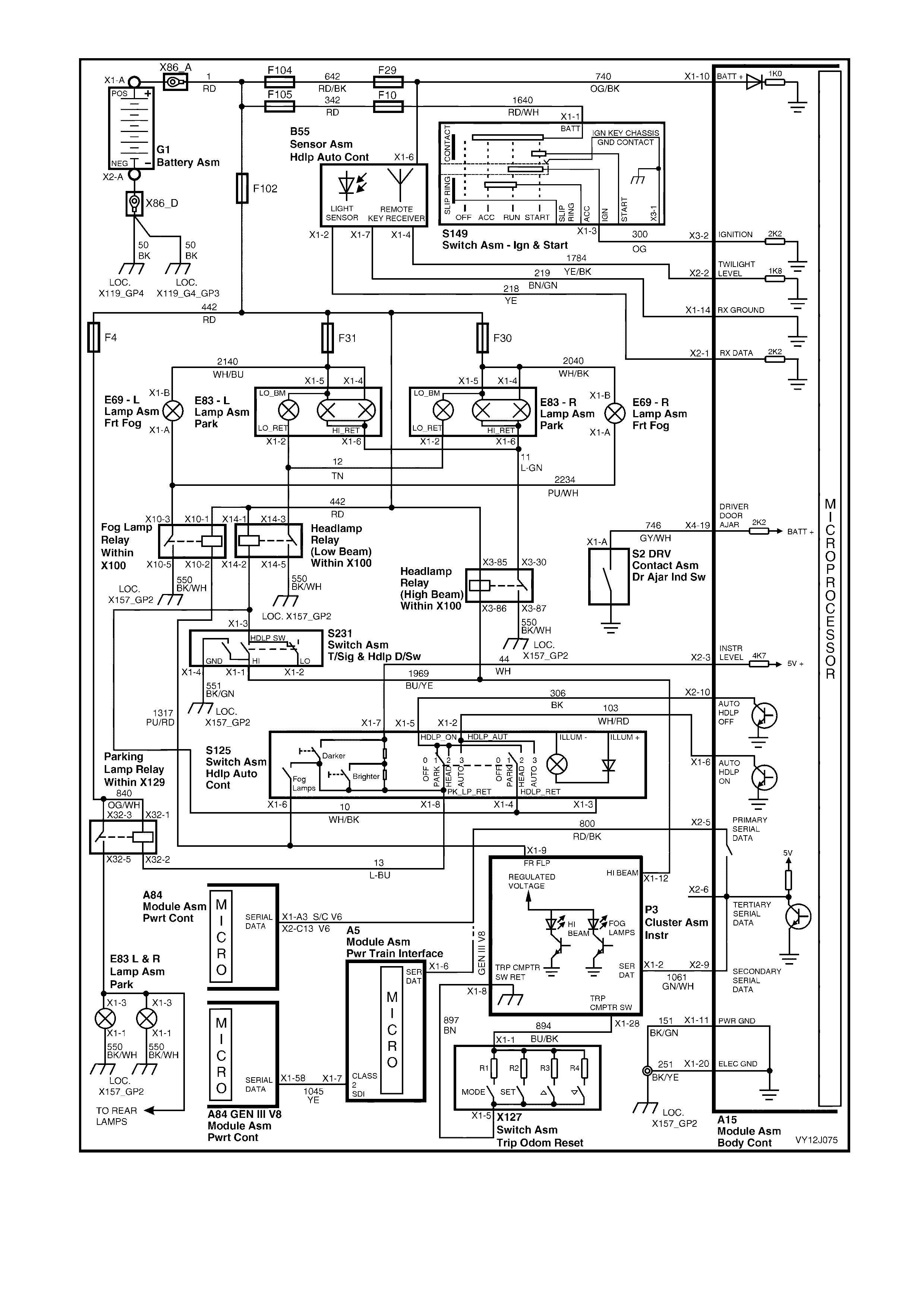
Figure 12J-255

Figure 12J-256
AUTOMATIC LAMP CONTROL DIAGNOSTIC CHART
STEP ACTION VALUE YES NO
1 Is the remote coded key operating correctly? Go to Step 2. Go to 4.3
REMOTE
RECEIVER / KEY
in this Section.
2 Do the headlamps function correctly when the headlamp
switch is in the ON or OFF position? Go to Step 3. Go to Section
12B, LIGHTING
SYSTEM.
3 1. Turn the ignition on.
2. Turn the headlamp switch to AUTO.
3. Cover the light sensor (B55).
Do the headlamps turn on?
Go to Step 4. Go to Step 7.
4 1. W ith the ignition on and the headlamp switch (S125)
in the AUTO position, uncover the light sensor.
2. Shine a torch on the light sensor.
Do the headlamps turn off?
Go to Step 5. Go to Step 17.
5 1. Turn the ignition off.
2. Connect TECH 2 to the DLC.
3. Turn the ignition on.
4. Select Diagnostics / Model Year / Vehicle Model /
Body / Body Control Module / Program / User
Settings / Headlamps Off Delay.
5. Set the delay time to 5 seconds.
6. With the headlamp switch in the AUTO position,
cover the light sensor to turn on the headlamps.
7. Turn the ignition off.
8. Open then close the driver’s door.
Do the headlamps turn off after 5 seconds?
Go to Step 6. Go to Step 14.
6 1. With TECH 2 connected, exit to the User Settings
menu and select Approach Illumination Delay Time.
2. Set the delay time to 10 seconds.
3. Turn the headlamp switch to the ON position.
4. Turn the ignition off.
5. Close all doors.
6. Open then close the driver’s door.
7. W ait for the headlamps to turn off.
8. Lock the doors using the lock button on the remote
coded key.
9. Unlock the doors using the unlock button on the
remote coded key.
Do the headlamps turn on for 10 seconds?
System OK. Replace the BCM.
Refer to 2.1 BODY
CONTROL
MODULE in this
Section.

STEP ACTION VALUE YES NO
7 1. Turn the ignition off.
2. Connect TECH 2 to the DLC.
3. Select Diagnostics / Model Year / Vehicle Model /
Body / Body Control Module / Miscellaneous Tests /
Lamps / Auto Lights On.
4. Turn the headlamp switch to the AUTO position.
5. Perform the test as instructed by TECH 2 and turn on
the headlamps.
Do the headlamps turn on?
Go to Step 11. Go to Step 8.
8 1. With the headlamp switch in the AUTO position, the
light sensor covered and TECH 2 connected, exit to
the Body Control Module menu and select Data
Display / Headlamps / Auto Headlamp Drive.
Does TECH 2 display On?
Go to Step 9. Go to Step 11.
9 1. With the headlamp switch in the AUTO position,
back-probe BCM connector terminal X1-6, circuit 103
(White / Red wire) with a jumper lead to ground.
Do the headlamps turn on?
Replace the BCM.
Refer to 2.1 BODY
CONTROL
MODULE in this
Section.
Go to Step 10.
10 1. Disconnect the headlamp switch (S125).
2. With the headlamp switch in the AUTO position,
back-probe between headlamp switch terminals X1-4
and X1-2 with an ohmmeter.
Is the value as specified?
Less than
1 ohm Repair faulty
circuit 103. Replace the
headlamp switch.
Refer to Section
12B, 3.23
HEADLAMP
SWITCH
ASSEMBLY.
11 1. With TECH 2 connected, exit to the Body Control
Module menu and select Data Display / Headlamps /
Ambient Light.
2. Cover the light sensor.
3. Uncover and shine a torch on the light sensor.
Are the values as specified?
Covered =
0 volt
Uncovered =
between
0-5 volts
Replace the BCM.
Refer to 2.1 BODY
CONTROL
MODULE in this
Section.
Go to Step 12.
12 1. Disconnect the light sensor (B55) connector.
2. Back-probe the light sensor terminal X1-6 with a
jumper lead to battery voltage.
3. Back-probe the light sensor terminal X1-4, circuit
1784 (Yellow / Black wire) with a voltmeter to ground.
4. Turn the ignition on.
5. Cover the light sensor.
6. Uncover and shine a torch on the light sensor.
Are the values as specified?
Covered =
less than
0.5 volt
Uncovered =
above
0.5 volt, up to
5 volts
Go to Step 13. Replace light
sensor / remote
receiver module
(B55). Refer to
2.3 REMOTE
RECEIVER
MODULE in this
Section.
13 1. Check the integrity of circuit 1784 (Yellow / Black
wire).
Is the circuit OK?
Replace the BCM.
Refer to 2.1 BODY
CONTROL
MODULE in this
Section.
Repair faulty
circuit 1784.
14 1. In Step 3, did the headlamps turn off after longer than
5 seconds? Go to Step 15. Replace the BCM.
Refer to 2.1 BODY
CONTROL
MODULE in this
Section.
15 1. Disconnect the headlamp switch connector.
2. Back-probe connector terminal X1-5, circuit 306
(Black wire) with an ohmmeter to ground.
Is the value as specified?
Less than
1 ohm Go to Step 16. Replace the
headlamp switch.
Refer to Section
12B, 3.23
HEADLAMP
SWITCH
ASSEMBLY.
16 1. Check the integrity if circuit 306 (Black wire).
Is the circuit OK? Replace the BCM.
Refer to 2.1 BODY
CONTROL
MODULE in this
Section.
Repair faulty
circuit 306.

STEP ACTION VALUE YES NO
17 1. Connect TECH 2 to the DLC.
2. Select Diagnostics / Model Year / Vehicle Model /
Body / Body Control Module / Miscellaneous Test /
Lamps / Auto Lights On.
3. Turn the ignition on.
4. Turn the headlamp switch to AUTO.
5. Perform the test as instructed by TECH 2 and turn off
the headlamps.
Do the headlamps turn off?
Go to Step 18. Go to Step 19.
18 1. Back-probe BCM connector terminal X2-2,
circuit 1784 (Yellow / Black wire) with a voltmeter to
ground.
2. Turn the ignition on.
3. Shine a torch on the light sensor.
Is the value as specified?
More than
0.5 volt,
up to
5 volts
Replace the BCM.
Refer to 2.1 BODY
CONTROL
MODULE in this
Section.
Go to Step 12.
19 1. With TECH 2 connected, exit to the Body Control
Module menu and select Data Display / Headlamps /
Headlamp Drive.
Does TECH 2 display Off?
Go to Step 20. Replace the BCM.
Refer to 2.1 BODY
CONTROL
MODULE in this
Section.
20 1. Disconnect the headlamp switch (S125) connector.
2. Back-probe connector terminal X1-2, circuit 103
(White / Red wire) with an ohmmeter to ground.
Is the value as specified?
Less than
1 ohm Go to Step 21. Replace the
headlamp switch.
Refer to
Section 12B,
3.23 HEADLAMP
SWITCH
ASSEMBLY.
21 1. Check the integrity if circuit 103 (White / Red wire).
Is the circuit OK? Replace the BCM.
Refer to 2.1 BODY
CONTROL
MODULE in this
Section.
Repair faulty
circuit 103.
WHEN ALL DIAGNOSIS AND REPAIRS ARE COMPLETE, VERIFY CORRECT OPERATION
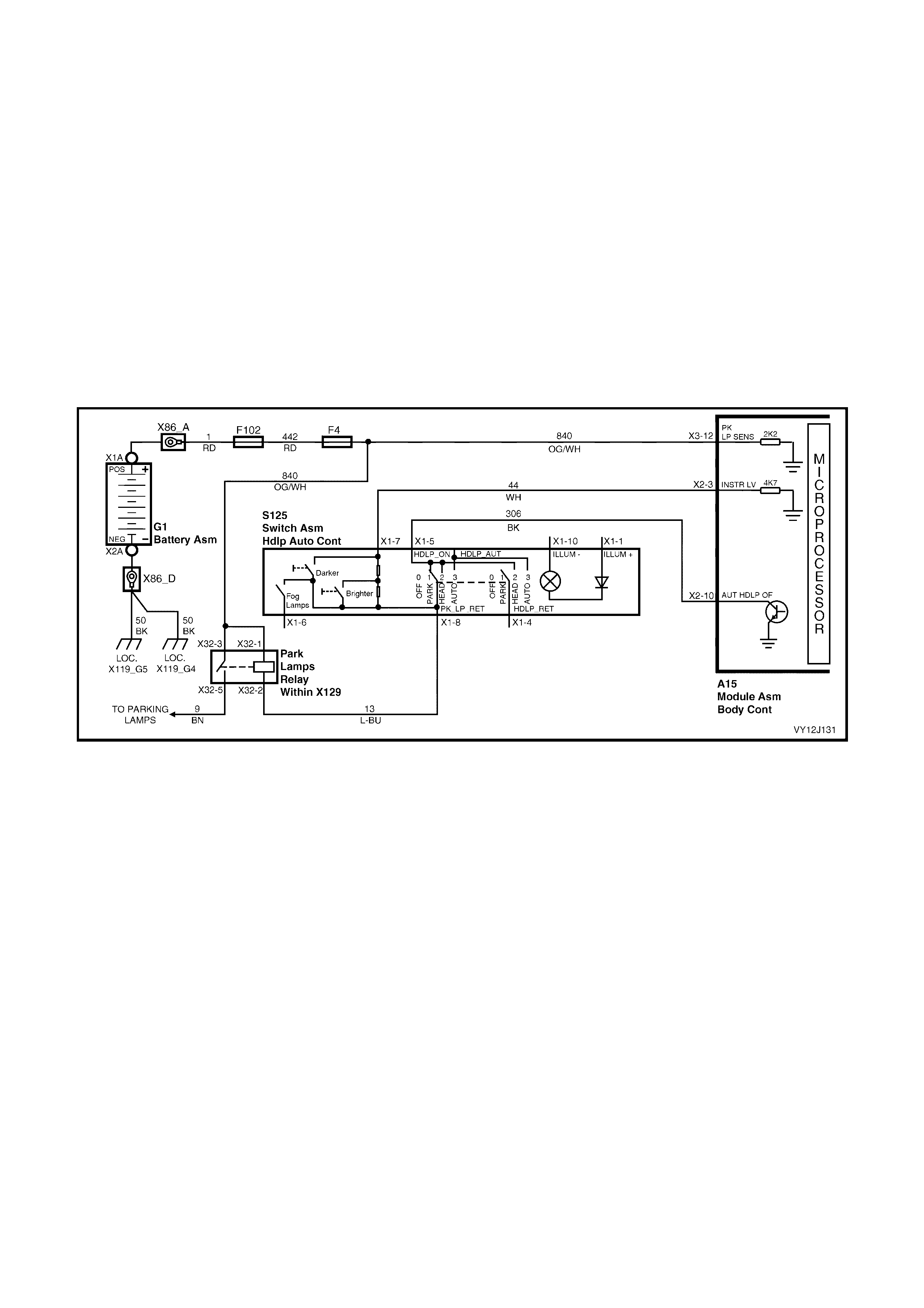
4.14 INSTRUMENT DIMMING CONTROL
CIRCUIT DESCRIPTION
The BCM regulates the illumination level of the instrument dial faces and the backlighting of the MFD and LCDs.
The illumination level is transmitted from the BCM via the secondary data bus and the receiving assemblies read
the signal and adjust the illumination level accordingly. The BCM illumination drive controls the dash and centre-
console illumination, th e display window of the trip computer, the Occupant Climate Control (OCC) HVAC display,
radio illumination and the I/P switches.
Two m omentar y contact switc hes in the h eadlam p swit ch ram p the illum ination int ensit y up and do wn to adju st the
level of brightness.
The dimm er drives to 100% when the ignition is on a nd the park lamps are off. This enables m axim um brightness
for the trip computer, HVAC and radio illumination. When the park lamps are switched on, the dimmer operates
according to the previously set percentage value. This intensity value is based on the Priority key used.
The dim mer control inputs are r esistor encode d onto one inp ut line. A ‘ bright’ inp ut occurs whe n DIM+ is act ivated
and there is a 0 ohm reference to the park lamp control output. A ‘dull’ output occurs when DIM– is activated and
there is a 2700 ohm reference to the park lamp control output. The resting point of this line is 5400 ohms. The
system default is 100% when the circuit for this line is open. The default dimmer is 100%, which occurs if the
battery or BCM is disconnected.
Figure 12J-257
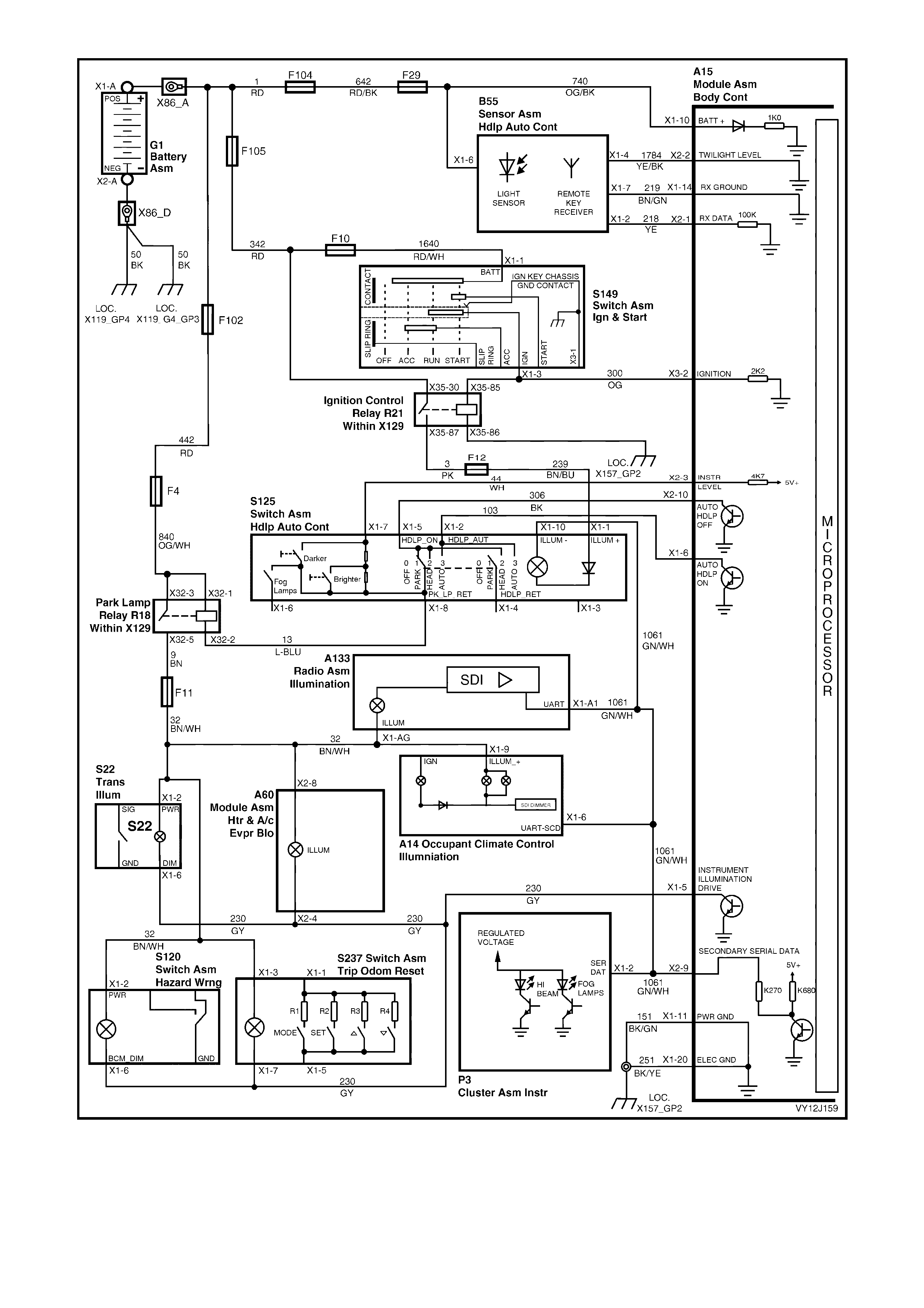
Figure 12J-258
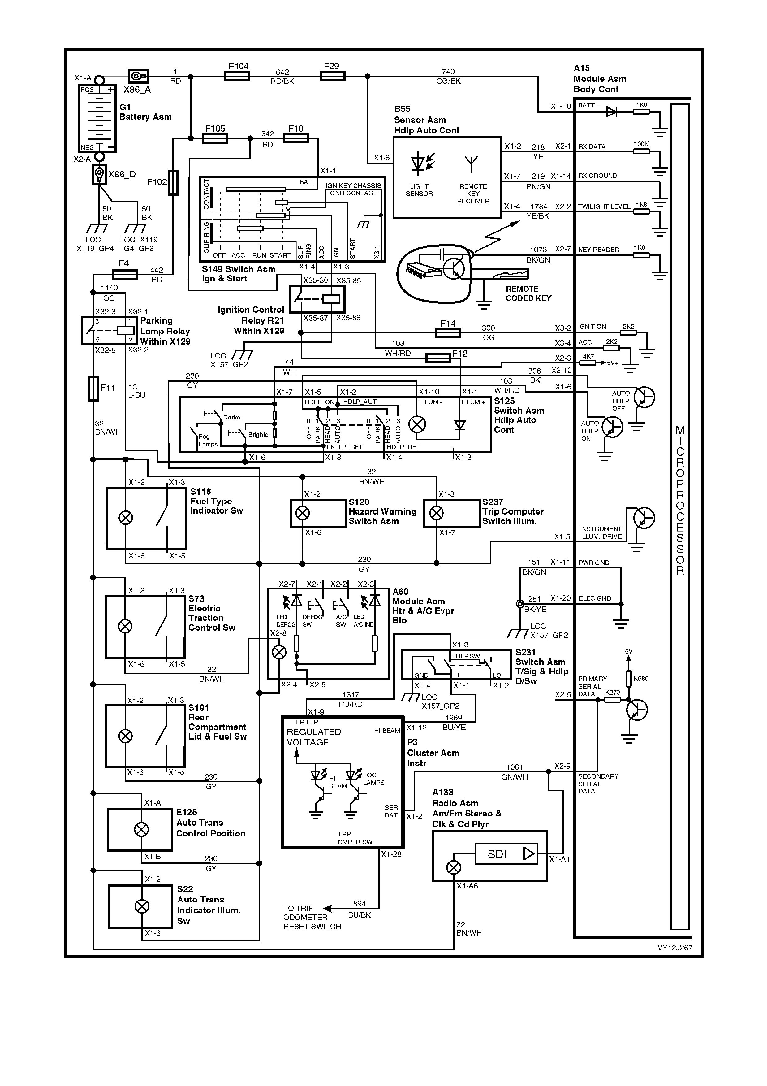
Figure 12J-259
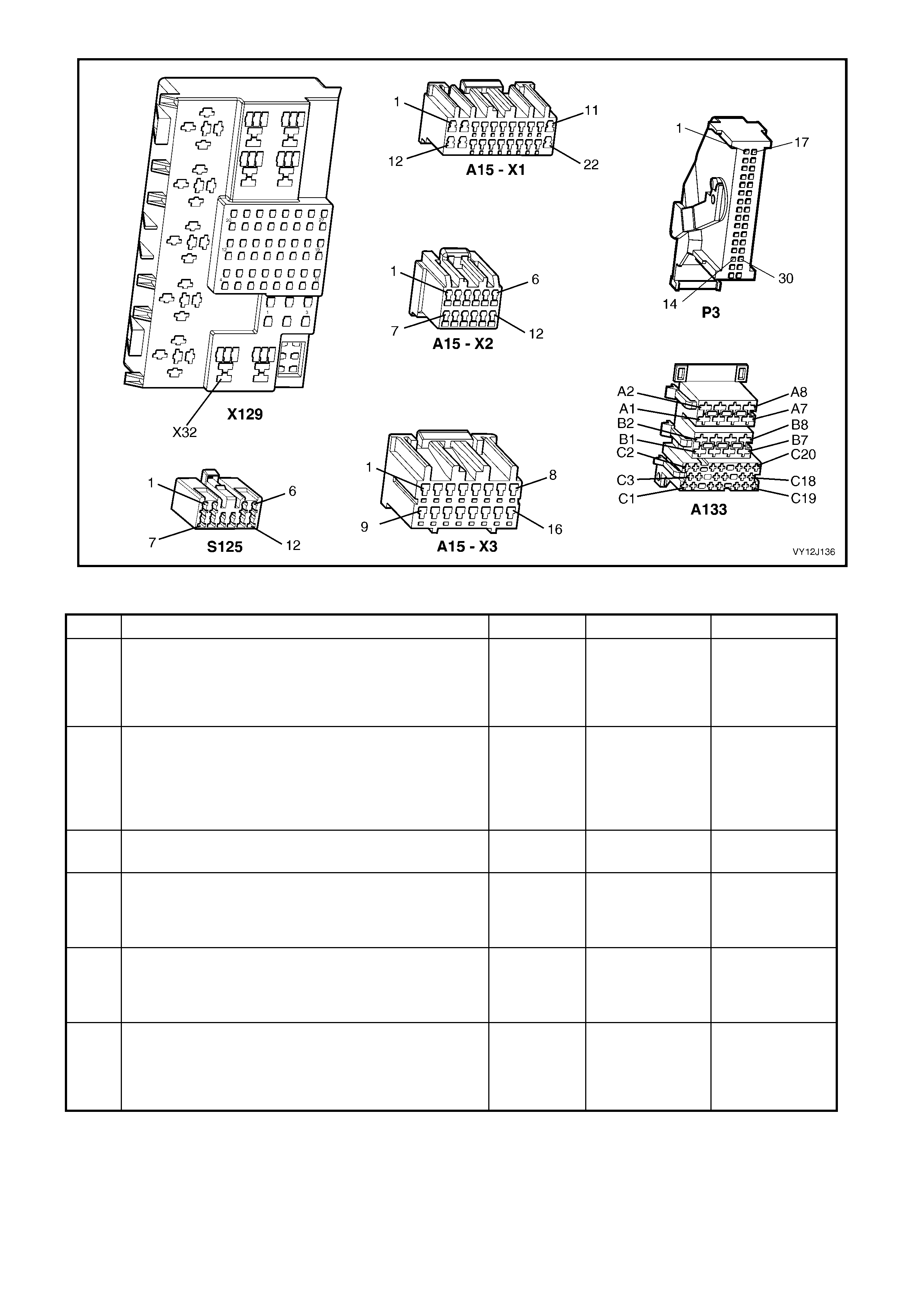
Figure 12J-260
INSTRUMENT DIMMING CONTROL DIAGNOSTIC CHART
STEP ACTION VALUE YES NO
1 Are the globes/LEDs for the control switches
(transmission illumination, HVAC illumination, OCC
illumination, hazard switch assembly,
tripmeter/odometer assembly TCS), radio and
instrument cluster operational
Go to Step 2. Go to Section
12B, LIGHTING
SYSTEM.
2 Turn the ignition on.
Does the trip computer illuminate? Go to Step 3. Go to
Section12C, 3.4
INSTRUMENT
ILLUMINATION
DIAGNOSTIC
CHART.
3 1. With the ignition on, turn on the park lamps.
Is the backlighting of the control switches illuminated? Go to Step 4. Go to Section
12B, LIGHTING.
4 1. With both the ignition and the park lamps turned on,
move and hold the light dimmer slider (part of the
headlamp switch assembly) upwards.
Does the illumination level ramp up to full intensity?
Go to Step 5. Go to Step 7.
5 1. With both the ignition and the park lamps turned on,
move and hold the light intensity slider downwards.
Does the illumination level fade to minimum intensity
(35%)?
Go to Step 6. Go to Step 14.
6 When operating the Priority 1 and Priority 2 keys, is the
illumination intensity as set for each key? System OK. Go to 4.3
REMOTE
RECEIVER /
KEY in this
Section.

STEP ACTION VALUE YES NO
7 1. Turn the ignition off and the headlamp switch.
Connect TECH 2 to the DLC.
Turn the ignition on.
Turn on the park lamps.
Select Diagnostics / Model Year / Vehicle Model / Body /
Body Control Module / Miscellaneous Tests / Lamps
/ Instrument Illumination.
Perform the test as directed by TECH 2 and vary the
light intensity from minimum to maximum.
Is the value as specified?
Minimum
= 35%
Maximum
= 100%
Go to Step 8. Go to Step 12.
8 1. With TECH 2 connected, exit to the Body Control
Module menu and select Data Display / Instrument
Illumination / Instrument Illumination.
2. Move and hold the light dimmer slider upwards.
Does TECH 2 display Up?
Go to Step 9. Go to Step 10.
9 1. With TECH 2 connected, exit to the Body Control
Module menu and select Miscellaneous Tests /
Lamps / Instrument Illumination Switch Voltage.
2. Perform the test as directed by TECH 2 and vary
the light intensity up and down.
Are the values as specified?
Minimum
= 1 volt
Maximum
= 3.5 volts
Replace the
BCM. Refer to
2.1 BODY
CONTROL
MODULE in this
Section.
Go to Step 10.
10 1. With both the ignition and the park lamps turned on,
back-probe BCM connector terminal X2-3, circuit 44
(White wire) with a voltmeter to ground.
2. Vary the light intensity from minimum to maximum.
Is the value as specified?
Minimum
= 0 volt
Maximum
= 5 volts
Replace the
BCM. Refer to
2.1 BODY
CONTROL
MODULE in this
Section.
Go to Step 11.
11 1. Check the integrity of circuit 44 (W hite wire).
Is the circuit OK? Replace the
headlamp switch
assembly. Refer
to Section 12B,
3.23 HEADLAMP
SWITCH
ASSEMBLY.
Repair faulty
circuit 44.
12 When performing the TECH 2 Instrument Illumination
test, did the light intensity alter slightly but not through
the full range?
Replace the
BCM. Refer to
2.1 BODY
CONTROL
MODULE in this
Section.
Go to Step 13.
13 1. With both the ignition and the park lamps turned on,
back-probe BCM connector terminal X1-5, circuit
230 (Grey wire) with a jumper lead to ground.
Does the backlighting of the control switches illuminate
at full intensity?
Replace the
BCM. Refer to
2.1 BODY
CONTROL
MODULE in this
Section.
Repair faulty
circuit 230.
14 1. Turn the ignition off and the headlamp switch.
2. Connect TECH 2 to the DLC.
3. Turn the ignition on.
4. Turn on the park lamps.
5. Select Diagnostics / Model Year / Vehicle Model /
Body / Body Control Module / Miscellaneous Tests /
Lamps / Instrument Illumination.
6. Perform the test as directed by TECH 2 and vary
the light intensity from maximum to minimum.
Is the value as specified?
Maximum
= 100%
Minimum
= 35%
Go to Step 15. Go to Step 12.
15 1. With TECH 2 connected, exit to the Body Control
Module menu and select Data Display / Instrument
Illumination / Instrument Illumination Switch.
2. Move the light dimmer slider downwards.
Does TECH 2 display Down?
Go to Step 9. Go to Step 11.
WHEN ALL DIAGNOSIS AND REPAIRS ARE COMPLETE, VERIFY CORRECT OPERATION

4.15 AIR CONDITIONING INTERFACE
CIRCUIT DESCRIPTION
Level 1 model vehicles are fitted with a manual air conditioning system which incorporates an air conditioning
interfac e in the BCM . Le ve l 2 and 3 model ve hicl es are fitted with O cc upa nt Cl im ate Co ntr ol (O CC), whic h d oes not
use an interface.
The engine must be running for the air conditioner to cool or dry the air.
Manual system
The BCM remembers the system status when the ignition is switched from on to off or when the blower fan is
turned off, but resets the system status to Off when the battery is disconnected.
If the air conditioner switch is pressed while the blower fan is turned off, the BCM will turn the air conditioning on
next time the blower fan is turned on, provided that the ignition has not been turned off in the meantime.
The blower fan is controlled by the blower inhibit relay, which is energised when the ignition is on. When the air
conditioner switch is pressed to turn on the air condit ioner, a batter y voltage signal is sent to the BC M. W hen this
signal is received in conjunction with a blower fan On signal (and an ignition On signal), the BCM sends an air
conditio ner On requ est to the PCM (via the PIM on ve hicles wit h a GEN III V8 engine) via the pr imar y data bus. If
the PCM inp uts ar e with in pres et param eters , the PC M ener gises th e air co nditi oner rel ay to s witch on and enga ge
the air compressor clutch.
When the air conditioning system is energised, the BCM provides a ground connection to illuminate the air
conditioner indicator LED.
For more information about this system, refer to Section 2C, HVAC CLIMATE CONTROL (MANUAL A/C)
SERVICI NG AND DI AGNOSIS.
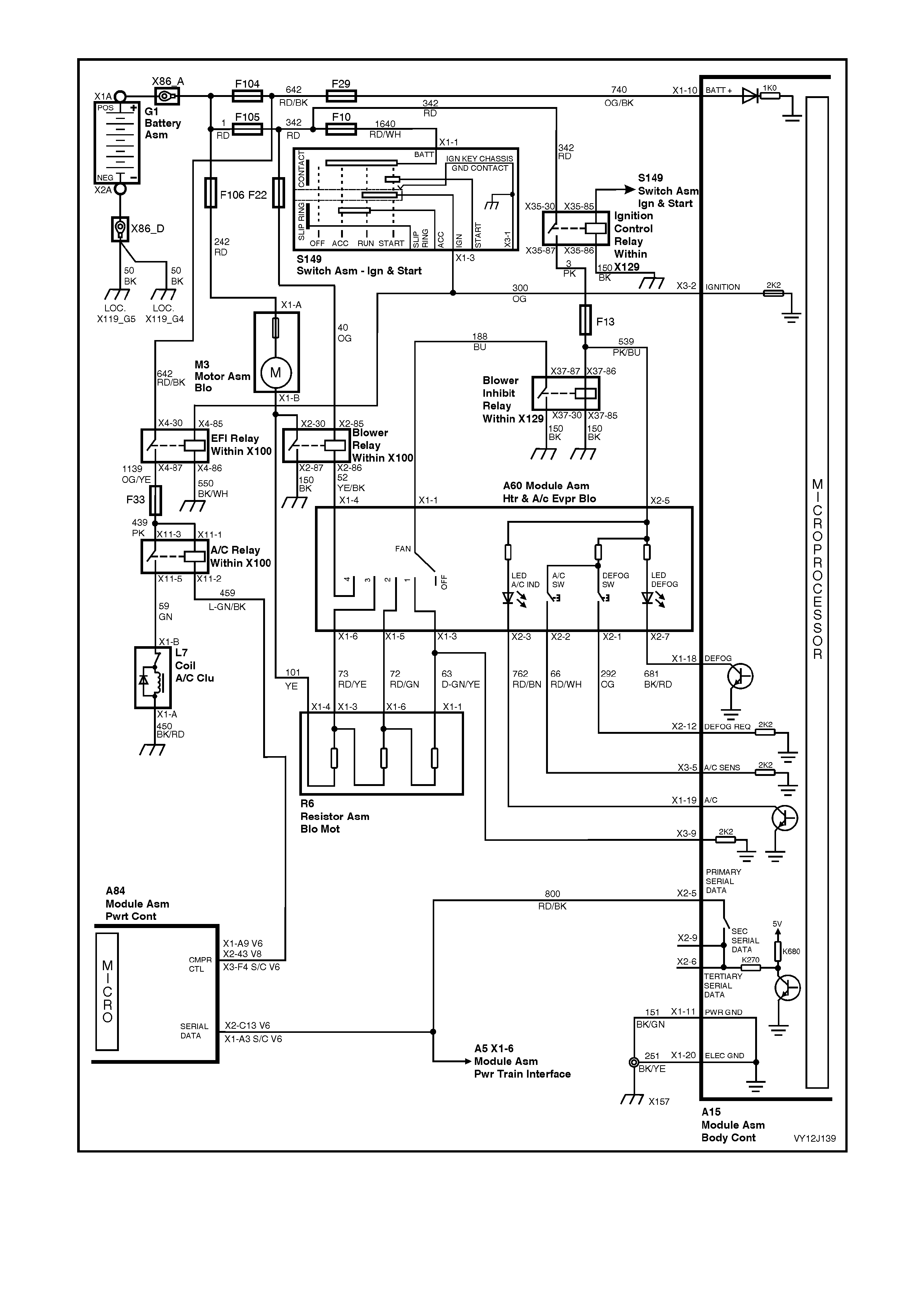
Figure 12J-261

Figure 12J-262
AIR CONDITIONING INTERFACE DIAGNOSTIC CHART – LEVEL 1
STEP ACTION VALUE YES NO
1 1. Turn the ignition on.
2. Back-probe BCM connector terminal X3-2,
circuit 300 (Orange wire) with a voltmeter to ground.
Is the value as specified?
Battery
voltage Go to Step 2. Check and repair
ignition pow er
supply to BCM.
2 1. Start the engine
2. Turn the ignition on.
3. Turn the blower fan switch to speed 1.
4. Turn on the air conditioner.
Does the air compressor clutch engage?
Go to Step 3. Go to Step 7.
3 1. Start the engine.
2. Adjust the temperature control dial to cold.
3. Run the air conditioner for 2 minutes.
Is the air being cooled?
Go to Step 4. Go to Section
2C, HVAC
CLIMATE
CONTROL
(MANUAL A/C)
SERVICING
AND
DIAGNOSIS.
4 In Step 2, did the air conditioning indicator LED
illuminate? Go to Step 5. Go to Step 8.
5 1. In turn, switch off the blower fan then the air
conditioner checking that the air compressor clutch
disengages with each change.
Does the air compressor clutch disengage?
Stop the engine
and go to Step 6. Go to Step 15.
6 In Step 5, did the air conditioning indicator LED
extinguish? System OK at
BCM. For further
diagnosis, go to
Section 2C,
HVAC CLIMATE
CONTROL
(MANUAL A/C)
SERVICING
AND
DIAGNOSIS.
Go to Step 18.

STEP ACTION VALUE YES NO
7 1. Turn the ignition off.
2. Connect TECH 2 to the DLC.
3. Turn the ignition on.
4. Select Diagnostics / Model Year / Vehicle Model /
Body / Body Control Module / Data Display / Inputs
and Outputs / A/C Switch.
5. Press the A/C sw itch mo ment arily .
Does TECH 2 display the A/C switch status?
On = switch
pressed
Off = switch
released
Go to Step 8. Go to Step 11.
8 1. W ith TECH 2 connected, exit A/C Switch and select
A/C Indicator.
2. Press the A/C switch.
Does TECH 2 display On?
Go to Step 9. Go to Step 13.
9 1. With TECH 2 connected, exit A/C Indicator and
select A/C Blower Switch.
2. Turn the A/C blower fan switch to speed 1.
Does TECH 2 display On?
Go to Step 10. Go to Step 12.
10 1. W ith TECH 2 connected, exit A/C Switch and select
Ignition Switch.
2. Turn the ignition on.
Does TECH 2 display On?
System OK at
BCM. For further
diagnosis, go to
Section 2C,
HVAC CLIMATE
CONTROL
(MANUAL A/C)
SERVICING
AND
DIAGNOSIS.
Replace the
BCM. Refer to
2.1 BODY
CONTROL
MODULE in this
Section.
11 1. Check the integrity of circuit 66 (Red / White wire).
Is the circuit OK? Go to Section
2C, HVAC
CLIMATE
CONTROL
(MANUAL A/C)
SERVICING
AND
DIAGNOSIS.
Repair faulty
circuit 66.
12 1. Check the integrity of circuit 63 (Dark-green / Yellow
wire).
Is the circuit OK?
Go to Section
2C, HVAC
CLIMATE
CONTROL
(MANUAL A/C)
SERVICING
AND
DIAGNOSIS.
Repair faulty
circuit 63.
13 1. With the ignition turned on, back-probe the HVAC
switch module connector terminal X2-3, circuit 762
(Red / Black wire) with a jumper lead to ground.
Does the air conditioning indicator LED illuminate?
Go to Step 14. Go to Section
2C, HVAC
CLIMATE
CONTROL
(MANUAL A/C)
SERVICING
AND
DIAGNOSIS.
14 1. With the ignition turned on, back-probe BCM
connector terminal X1-19, circuit 762 (Red / Black
wire) with a jumper lead to ground.
Does the air conditioning indicator LED illuminate?
Replace the
BCM. Refer to
2.1 BODY
CONTROL
MODULE in this
Section.
Repair faulty
circuit 762.
15 1. Turn the ignition off.
2. Connect TECH 2 to the DLC.
3. Turn the ignition on.
4. Select Diagnostics / Model Year / Vehicle Model /
Body / Body Control Module / Data Display / Air
Conditioning Interface / A/C Switch.
Does TECH 2 display Off?
Go to Section
2C, HVAC
CLIMATE
CONTROL
(MANUAL A/C)
SERVICING
AND
DIAGNOSIS.
Go to Step 16.
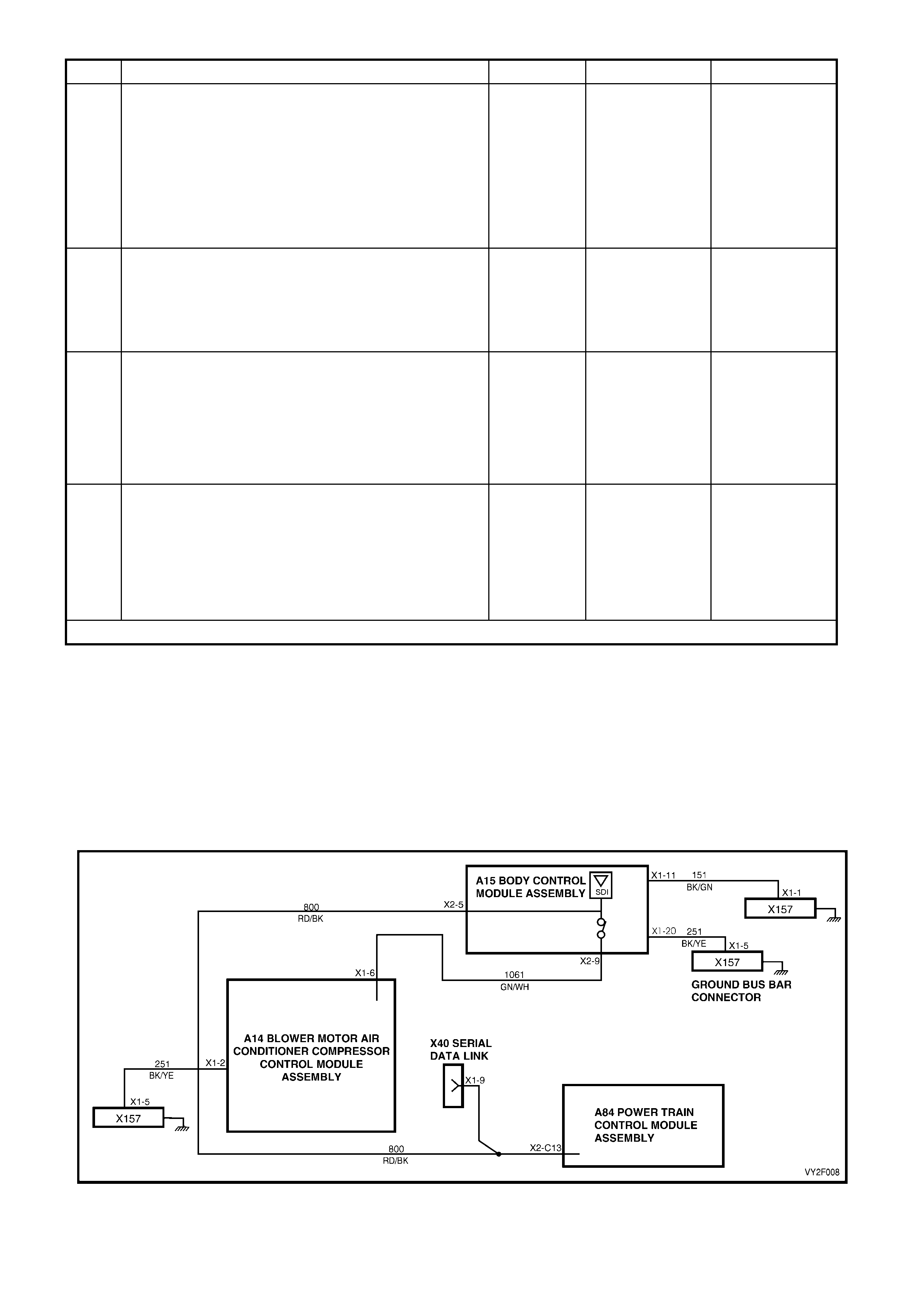
STEP ACTION VALUE YES NO
16 V6 engine
1. With TECH 2 connected, exit to the Vehicle Model
menu and select Engine / V6 / Data Display / All
Data / A/C Request.
Gen III V8 engine
1. With TECH 2 connected, exit to the Vehicle Model
menu and select Engine / GEN III V8 / Data Display
/ Engine Data / A/C Request.
Does TECH 2 display Off?
Go to Section
2C, HVAC
CLIMATE
CONTROL
(MANUAL A/C)
SERVICING
AND
DIAGNOSIS.
Go to Step 17.
17 1. Check the integrity of circuit 800 (Red / Black wire).
Is the circuit OK? Replace the
BCM. Refer to
2.1 BODY
CONTROL
MODULE in this
Section.
Repair faulty
circuit 800.
18 1. Turn the ignition off.
2. Connect TECH 2 to the DLC.
3. Turn the ignition on.
4. Select Diagnostics / Model Year / Vehicle Model /
Body / Body Control Module / Data Display / Air
Conditioning Interface / A/C Indicator.
Does TECH 2 display Off?
Go to Step 19. Replace the
BCM. Refer to
2.1 BODY
CONTROL
MODULE in this
Section.
19 1. Check the integrity of circuit 762 (Red / Black wire).
Is the circuit OK? Go to Section
2C, HVAC
CLIMATE
CONTROL
(MANUAL A/C)
SERVICING
AND
DIAGNOSIS.
Repair faulty
circuit 762.
WHEN ALL DIAGNOSIS AND REPAIRS ARE COMPLETE, VERIFY CORRECT OPERATION
OCC Air Conditioner
The OCC control module communicates with the PCM using both the primary and secondary data buses.
When the air conditioner switch is pressed to turn on the air conditioner, the OCC turns on the blower fan and
sends an air conditioner On request signal to the PCM (via the PIM on vehicles with a GEN III V8 engine). The
signal is sent on t he seco ndar y data bus which l inks to the prim ary data bus within t he BCM (t hrough the data bus
isolator switch), then on the primary data bus to the PCM (via the PIM on vehicles with a GEN III V8 engine).
W hen the air cond it ioner O n r eq ues t is r ec e iv ed, the P CM e ns ur es its inpu ts ar e with in pr eset parameters and then
energises the air conditioner relay to switch on and engage the air compressor clutch.
For more information about this system, refer to Section 2F, HVAC OCCUPANT CLIMATE CONTROL (AUTO
A/C) – DIAGNOSTICS.
Figure 12J-263

AIR CONDITIONING INTERFACE DIA GNOSTIC CHART – LEVEL 2 AND LEVEL 3
STEP ACTION VALUE YES NO
1 1. Start the engine.
2. Turn on the air conditioner.
Does the air compressor clutch engage?
System OK at
BCM. For further
diagnosis, go to
Section 2F,
HVAC
OCCUPANT
CLIMATE
CONTROL
(AUTO A/C)
DIAGNOSTICS.
Go to Step 2.
2 1. Turn the ignition off.
2. Connect TECH 2 to the DLC.
3. Turn the ignition on.
4. Select Diagnostics / Model Year / Vehicle Model /
Body / Body Control Module / Miscellaneous Tests /
Data Bus Isolator.
5. Start the engine.
6. Press the Cutoff soft key on TECH 2 every
2 seconds for a period in excess of 10 seconds.
Does the SRS telltale LED in the instrument cluster
illuminate?
NOTE: The SRS telltale will set a DTC. To clear the
DTC, refer to 3.5 DAIGNOSTIC TROUBLE CODES in
this Section.
Press the Normal
soft key to reset
the data bus
isolator. System
OK at BCM. For
further diagnosis ,
go to Section 2F,
HVAC
OCCUPANT
CLIMATE
CONTROL
(AUTO A/C)
DIAGNOSTICS.
Press the Normal
soft key to reset
the data bus
isolator and go to
4.2 SERIAL
DATA
COMMUNIC-
ATION in this
Section.
WHEN ALL DIAGNOSIS AND REPAIRS ARE COMPLETE, VERIFY CORRECT OPERATION
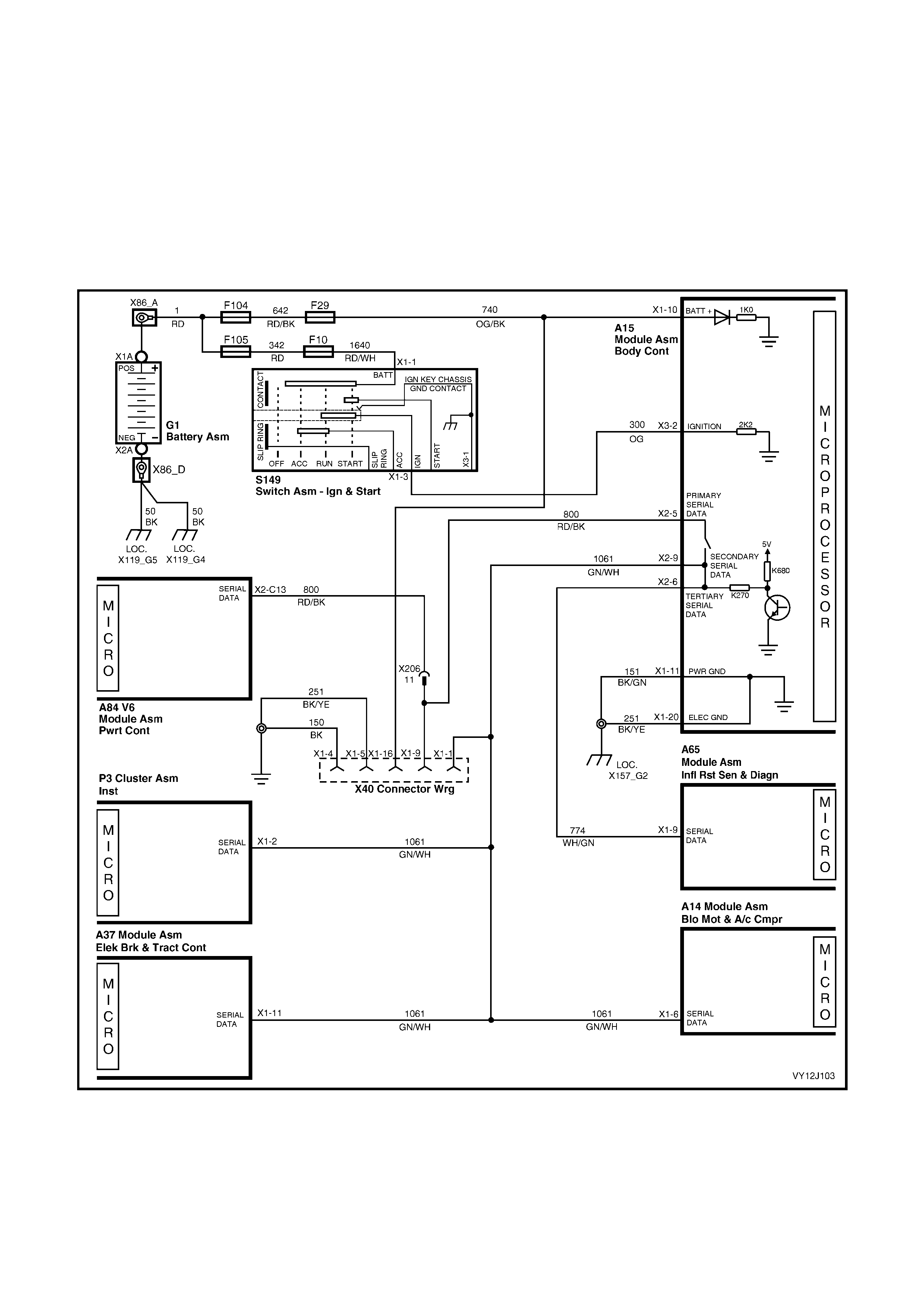
4.16 SRS DEPLOYMENT VEHICLE SHUTDOWN
CIRCUIT DESCRIPTION
In the event of SRS (Supplemental Restraint System) deployment, the Sensing Diagnostic Module (SDM) sends
serial data via the tertiar y serial data bus to the BCM. Within the BCM, the tertiary serial data bus is linked to the
prim ary and sec ondary ser ial data buses. T he SDM a dvises v arious vehic le s ystems to tak e appropr iate shutdo wn
action and signals the BCM to illuminate the SRS indicator in the instrument cluster.
Once the appropriate data is identified and the vehicle speed has been zero for 10 seconds, the BCM turns the
dome lamp on continuously and unlocks the doors.
The dom e lamp wil l be swit ched off when the ignit ion switch is cycled f rom off to on or when t he BCM is reset (ie.
due to ba tter y disconnec tio n) and the SR S depl oymen t flag has been r em oved b y the SDM. F or f urther inf or m ation
on this system, refer to Section 12M, 1.1 SYSTEM COMPONENTS.
Figure 12J-264

Figure 12J-265
SRS DEPLOYMENT VEHICLE SHUTDOWN DIAGNOSTIC CHART
STEP ACTION VALUE YES NO
1 Is the Central Door Locking system fully functional? Go to Step 2. Go to 4.5
CENTRAL
DOOR LOCKING
in this Section.
2 Are the dome lamp functions controlled by the BCM
functioning correctly? Go to Step 3. Go to 4.12
DOME LAMP
DELAY
CONTROL in this
Section.
3 1. Connect TECH 2 to the DLC.
2. Select Diagnostics / Model Year / Vehicle Model /
Body / Body Control Module.
3. Turn the ignition on.
Does the screen display BCM system identification?
Go to Step 4. Go to 4.2
SERIAL DATA
COMMUNIC-
ATION (BUS
MASTER) in this
Section.
4 1. With the ignition on and TECH 2 connected, exit to
the Body menu and select SRS.
Is TECH 2 able to communicate with the SDM after
5 seconds?
Go to Section
12M, 4.
DIAGNOSTICS.
Go to Step 5.
5 1. With the ignition on and TECH 2 connected, exit to
the Body menu and select Instruments.
After 5 seconds, is TECH 2 able to communicate with
the instruments?
Go to Step 6. Go to 4.2
SERIAL DATA
COMMUNIC-
ATION (BUS
MASTER) in this
Section.
6 1. Turn the ignition off.
2. Back-probe between BCM connector terminal X2-9,
circuit 1061 (Green / W hite wire) and terminal X2-6,
circuit 774 (White / Green wire) with an ohmmeter.
Is the value as specified?
Less than
1 ohm Go to Step 7. Replace the
BCM. Refer to
2.1 BODY
CONTROL
MODULE in this
Section.
7 1. With the ignition turned off, back-probe between
BCM connector terminal X2-6 and SDM (A65)
connector terminal X1-9, circuit 774 (White / Green
wire) with an ohmmeter.
Is the value as specified?
Less than
1 ohm Go to Section
12M, 4.
DIAGNOSTICS.
Repair faulty
circuit 774.
WHEN ALL DIAGNOSIS AND REPAIRS ARE COMPLETE, VERIFY CORRECT OPERATION
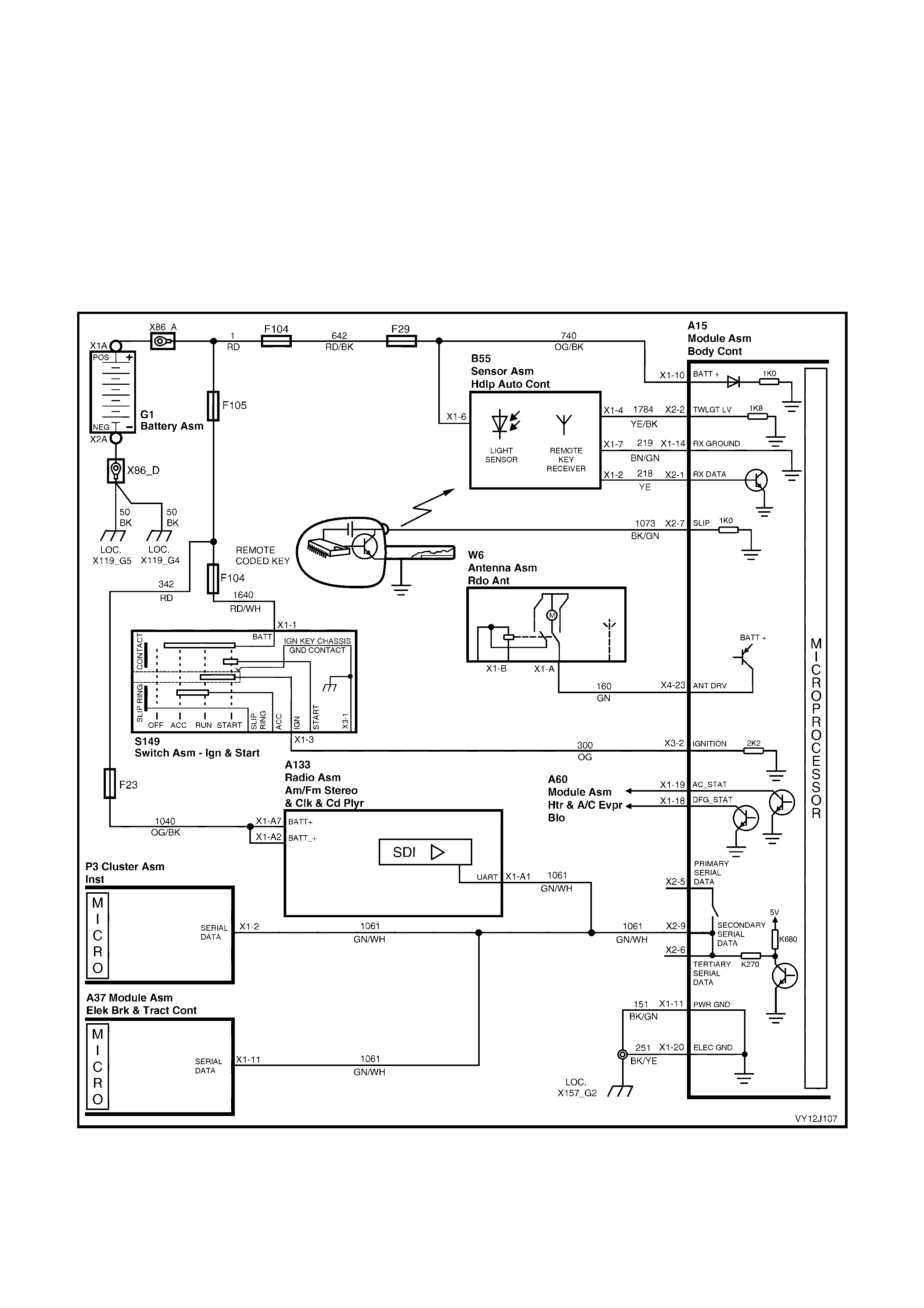
4.17 PRIORITY KEY SYSTEM
DESCRIPTION
The BCM remembers two sets of key operating parameters. These operating parameters are recalled when a
specific remote key is used. When a Priority 1 remote coded key is used, the BCM recalls the operating parameters
related to t he Pr iorit y 1 k ey. When a Pr iorit y 2 k ey is used, th e BCM r ecalls the op erating par am eter s related to the
Priority 2 k ey.
The operating p ar ameters are r ec a lle d when th e r emote cod ed key Unloc k button is pr es s ed or when the i gni tion is
turned to the accessory position. All operating parameters are maintained on a Last Used basis.
The BCM also communicates with other modules via the serial data bus, ensuring that each module is in the
correct mode.
W hen a new rem ote k ey is program m ed, it is as signed as the Prior ity 1 k e y and all r em aining r em ote k eys becom e
Priority 2 k eys.
Figure 12J-266

Figure 12J-267
PRIORITY KEY SYSTEM DIAGNOSTIC CHART
Complete the following steps before proceeding with the Priority Key System diagnostic chart:
1. Have both remote keys at hand.
2. Ensure that both keys have serviceable batteries fitted.
3. Operate the unlock button on the first remote coded key.
4. Connect TECH 2 to the DLC.
5. Insert the first remote coded key into the ignition switch and turn the ignition on.
6. Using TECH 2, re-program this key to Priority 1. (Select Diagnostics / Model Year / Vehicle Model / Body /
Body Control Module / Program / Set Key to Priority 1.)
7. Turn the ignition off.
8. Set the prior it y func tions f or this k ey (ie. instrum ent illum ination level, a uto headla m p off delay, antenna h eight,
radio stations, two-stage unlock, lamp delay times and TCS).
9. Remove the first remote coded key and lock the doors.
10. Press the unlock button on the second remote coded key.
11. Insert the second remote coded key into the ignition switch and turn the ignition on.
12. Set the priority functions for this key.
NOTE: If the Priority settings cannot be set, refer to 4.2 SERIAL DATA COMMUMICATION (BUS MASTER).
If a required function operates from one key but not the other key and it is established that both keys are fully
operational, replace the BCM. Refer to 2.1 BODY CONT ROL MODULE in this Section.
STEP ACTION VALUE YES NO
1 1. Operate the unlock button on the Priority 1 and
Priority 2 remote coded keys alternately, checking
that the instrument illumination level is as set for
each key.
Is the instrument illumination level recalled for both
keys?
Go to Step 2. Go to 4.14
INSTRUMENT
DIMMER
CONTROL in this
Section.
2 1. Operate the unlock button on the Priority 1 and
Priority 2 remote coded keys alternately, checking
that the antenna height is as set for each key.
Is the antenna height recalled for both keys?
Go to Step 3. Go to 4.18
POWER
ANTENNA
CONTROL in this
Section.
3 1. Operate the unlock button on the Priority 1 and
Priority 2 remote coded keys alternately, checking
that the approach illumination delay is as set for
each key.
Is the approach illumination delay recalled for both
keys?
Go to Step 4. Go to 4.13
AUTOMATIC
LAMP
CONTROL in this
Section.
4 1. Operate the unlock button on the Priority 1 and
Priority 2 remote coded keys alternately, checking
that the automatic headlamp off delay is as set for
each key.
Is the automatic headlamp off delay recalled for both
keys?
Go to Step 5. Go to 4.13
AUTOMATIC
LAMP
CONTROL in this
Section.

STEP ACTION VALUE YES NO
5 1. Operate the unlock button on the Priority 1 and
Priority 2 remote coded keys alternately, checking
that the interior lamp timeout is as set for each key.
Is the interior lamp timeout recalled for both keys?
Go to Step 6. Go to 4.12
DOME LAMP
DELAY
CONTROL in this
Section.
6 1. Operate the unlock button on the Priority 1 and
Priority 2 remote coded keys alternately, checking
that the two stage unlock settings are as set for
each key.
Are the two stage unlock settings recalled for both keys?
Go to Step 7. Go to 4.5
CENTRAL
DOOR LOCKING
in this Section.
7 1. Operate the unlock button on the Priority 1 and
Priority 2 remote coded keys alternately, checking
that the door lock indication is as set for each key.
Is the door lock indication recalled for both keys?
Go to Step 8. Go to 4.5
CENTRAL
DOOR LOCKING
in this Section.
8 1. Operate the unlock button on the Priority 1 and
Priority 2 remote coded keys alternately, checking
that the autolock in drive settings are as set for each
key.
Are the autolock in drive settings recalled for both keys?
Go to Step 9. Go to 4.5
CENTRAL
DOOR LOCKING
in this Section.
9 1. Operate the unlock button on the Priority 1 and
Priority 2 remote coded keys alternately, checking
that the accessory relay timeout is as set for each
key.
Is the accessory relay timeout recalled for both keys?
Go to Step 10. Go to 4.4
ACCESSORY
POWER
CONTROL in this
Section.
10 1. Operate the unlock button on the Priority 1 and
Priority 2 remote coded keys alternately, checking
that the auto headlamps off timing is as set for each
key.
Is the auto headlamps off setting recalled for both keys?
Go to Step 11. Go to 4.13
AUTOMATIC
LAMP
CONTROL in this
Section.
11 1. Operate the unlock button on the Priority 1 and
Priority 2 remote coded keys alternately, checking
that the trip computer mode and overspeed settings
are as set for each key.
Are the trip computer mode and overspeed settings
recalled for both keys?
System OK. Go to Section
12C, 3.4
DIAGNOSTIC
FAULTS NOT
COVERED BY
DIAGNOSTIC
TROUBLE
CODES – TRIP
COMPUTER
SWITCH.
WHEN ALL DIAGNOSIS AND REPAIRS ARE COMPLETE, VERIFY CORRECT OPERATION
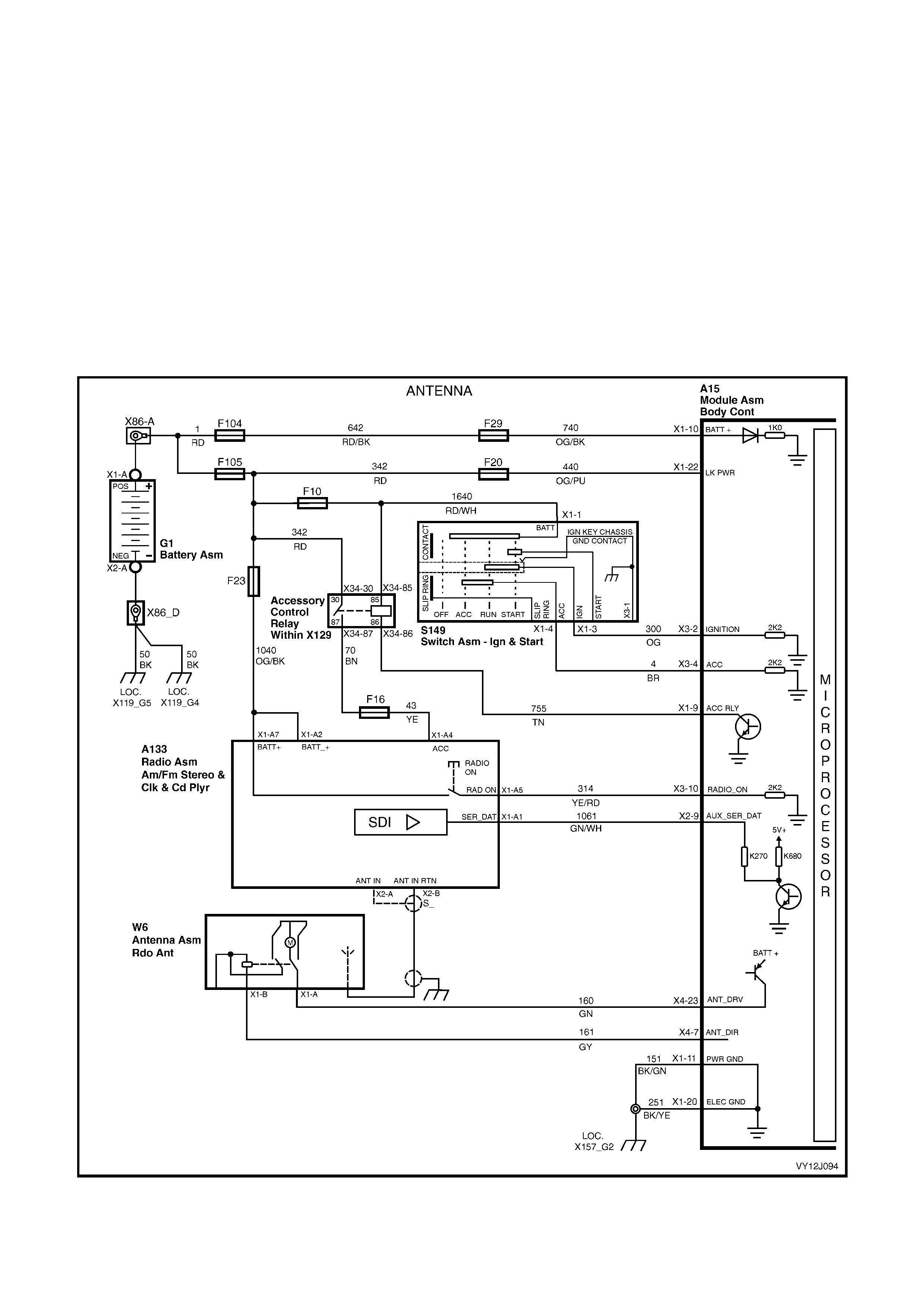
4.18 POWER ANTENNA CONTROL
CIRCUIT DESCRIPTION
The antenna up and down request signals are communicated from the radio to the BCM via the serial
comm unic ations bus.
For level 1 vehicle models, the antenna height is adjusted by operating the antenna mast height switch.
For level 2 and 3 vehicle models, the antenna height is determined by the BCM based on user settings and the
radio / CD player select ions.
For level 3 vehicle models, when the unlock button on the remote key is pressed, the antenna height is recalled
based on which k e y is used (Priori t y 1 or Priorit y 2).
During engine starting, the on signal is momentarily lost but the BCM assumes the signal is still active when it
senses both ign it ion and ac ces s or y inputs as well as th e radi o / CD p layer status s ignal. This en ab les un int er rupte d
antenna operation and control during engine cranking. A hardwired signal is used from the Radio to the BCM to
request the antenna, whenever tuner mode has been selected on the radio.
When the antenna down switch is pressed, the radio / CD player sends a Down input signal to the BCM through the
secondary data bus.
Figure 12J-268
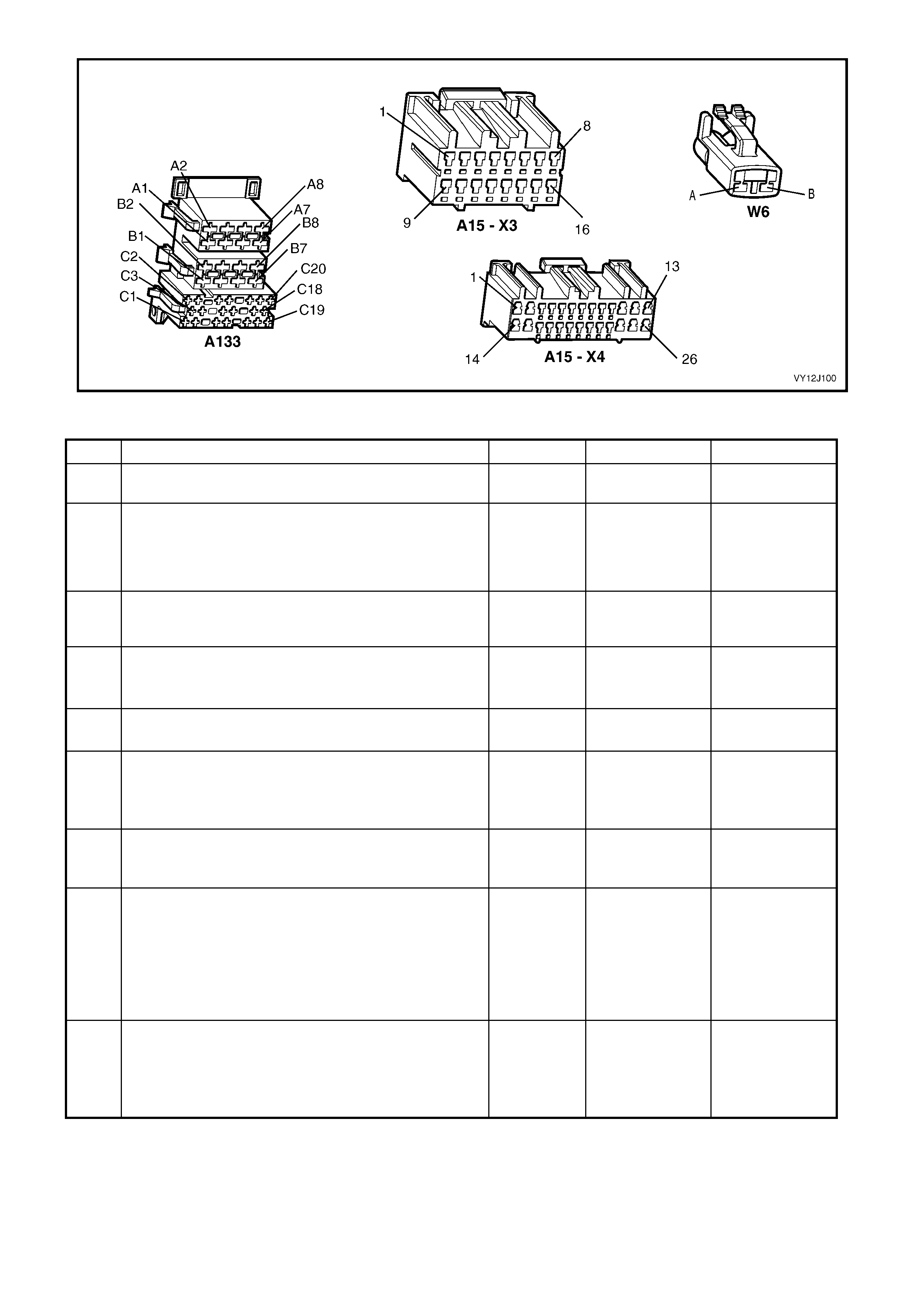
Figure 12J-269
POWER ANTENNA CONTROL DIAGNOSTIC CHART
STEP ACTION VALUE YES NO
1 Is the ignition switch functioning correctly? Go to Step 2. Replace the
ignition sw itch.
2 Is the accessory control circuit functioning correctly? Go to Step 3. Go to 4.4
ACCESSORY
POWER
CONTROL in this
Section.
3 Is battery power maintained at BCM connector
terminal X1-22? Go to Step 4. Check and repair
the power supply
circuit.
4 1. Turn the ignition switch to the accessories position.
2. Turn on the radio.
Does the antenna mast extend automatically?
Go to Step 5. Go to Step 8.
5 1. Turn off the radio.
Does the antenna start retracting within 3 seconds? Go to Step 6. Go to Step 21.
6 1. With the ignition turned to accessories, turn on the
radio.
2. Operate the antenna down switch.
Does the antenna mast retract?
Go to Step 7. Go to Step 23.
7 1. With the ignition turned to accessories and the radio
on, operate the antenna up switch.
Does the antenna mast extend?
System OK. Go to Step 24.
8 1. Turn the ignition off.
2. Connect TECH 2 to the DLC.
3. Select Diagnostics / Model Year / Vehicle Model /
Body / Body Control Module / Data Display / Inputs
and Outputs / Accessory Switch.
4. Turn the ignition switch to the accessories position.
Does TECH 2 display On?
Go to Step 9. Go to Step 16.
9 1. With TECH 2 connected, exit to the Data Display
menu and select Serial Data Inputs / Radio.
2. Turn the ignition switch to the accessories position.
3. Turn on the radio.
Does TECH 2 display On?
Go to Step 10. Go to Step 17.

STEP ACTION VALUE YES NO
10 1. With the radio on and TECH 2 connected, exit to the
Body Control Module menu and select
Miscellaneous Tests / Antenna.
2. Turn the ignition switch to the Accessories position.
3. Perform the test as instructed by TECH 2 and
extend the antenna mast.
Does the antenna mast extend?
Go to Step 11. Go to Step 14.
11 1. With the ignition switch turned to accessories, the
radio on and TECH 2 connected, back-probe BCM
connector terminal X4-7, circuit 161 (Grey wire) with
a voltmeter to ground.
2. Perform the TECH 2 antenna test and extend the
antenna mast .
Is the value as specified while the mast is in motion?
Battery
voltage False reading.
Replace the
BCM. Refer to
2.1 BODY
CONTROL
MODULE in this
Section.
Go to Step 12.
12 1. Check the integrity of circuit 161 (Grey wire).
Is the circuit OK? Go to Step 13. Repair faulty
circuit 161.
13 1. Turn the ignition off.
2. Check the integrity of the antenna assembly ground
connection.
Is the ground connection OK?
Replace the
antenna
assembly (W6).
Refer to Section
12D,
ENTERTAIN-
MENT SYSTEM.
Repair faulty
circuit 851.
14 1. With the radio on and Miscellaneous Tests /
Antenna selected, back-probe BCM connector
terminal X4-23, circuit 160 (Green wire) with a
voltmeter to ground.
2. Turn the ignition switch to the Accessories position.
3. Perform the test as instructed by TECH 2 and
extend the antenna mast.
Is the value as specified?
Battery
voltage Go to Step 15. Replace the
BCM. Replace
the BCM. Refer
to 2.1 BODY
CONTROL
MODULE in this
Section.
15 1. With the ignition switch turned to accessories, the
radio on and TECH 2 connected, back-probe the
power antenna assembly (W6) connector terminal
X1-A, circuit 160 (Green wire) with a voltmeter to
ground.
2. Perform the TECH 2 antenna test and extend the
antenna mast .
Is the value as specified?
Battery
voltage Go to Step 13. Repair faulty
circuit 160.
16 1. With the ignition turned to accessories, back-probe
BCM connector terminal X3-4, circuit 4 (Brown wire)
with a voltmeter to ground.
Is the value as specified?
Battery
voltage Replace the
BCM. Refer to
2.1 BODY
CONTROL
MODULE in this
Section.
Repair faulty
circuit 7.
17 1. With the ignition and the radio turned on,
back-probe BCM connector terminal X3-10,
circuit 314 (Yellow / Red wire) with a voltmeter to
ground.
Is the value as specified?
Battery
voltage Replace the
BCM. Refer to
2.1 BODY
CONTROL
MODULE in this
Section.
Go to Step 18.
18 1. With the ignition and the radio turned on,
back-probe radio (A133) connector terminal X1-A5,
circuit 314 (Yellow / Red wire) with a voltmeter to
ground.
Is the value as specified?
Battery
voltage Repair faulty
circuit 314. Go to Step 19.
19 1. With the ignition turned on, back-probe radio
connector terminal X1-A4 with a voltmeter to
ground.
Is the value as specified?
Battery
voltage Go to Radio
system diagnosis
in Section 12D,
ENTERTAIN-
MENT SYSTEM.
Go to Step 20.

STEP ACTION VALUE YES NO
20 1. With the ignition turned on, back-probe the
accessory control relay (R20) terminal X34-87 with
a voltmeter to ground.
Is the value as specified?
Battery
voltage Check and repair
faulty circuits 43,
70 and / or
fuse F16.
Go to 4.4
ACCESSORY
POWER
CONTROL.
21 1. With the ignition turned on, back-probe BCM
connector terminal X4-7, circuit 161 (Grey wire) with
a voltmeter to ground.
2. Turn on the radio.
3. Turn off the radio.
Are the values as specified?
Radio on
= battery
voltage
Radio off
= less than
0.5 volt
Go to Step 22. Replace the
BCM. Refer to
2.1 BODY
CONTROL
MODULE in this
Section.
22 1. Turn on the radio.
2. Back-probe the antenna connector terminal X1-B,
circuit 161 (Grey wire) with a voltmeter to ground.
3. Turn off the radio.
Is the value as specified?
Radio on
= battery
voltage
Radio off
= less than
0.5 volt
Replace antenna
motor. Refer to
Section 12D,
ENTERTAIN-
MENT SYSTEM.
Repair faulty
circuit 161.
23 1. Turn the ignition off.
2. Connect TECH 2 to the DLC.
3. Turn the ignition on and then to ACC.
4. Turn on the radio.
5. Select Diagnostics / Model Year / Vehicle Model /
Body / Body Control Module / Data Display /
Antenna / Antenna and operate the antenna mast
down switch.
Does TECH 2 display Down?
Replace the
BCM. Refer to
2.1 BODY
CONTROL
MODULE in this
Section.
Go to Step 27.
24 1. Turn the ignition off.
2. Connect TECH 2 to the DLC.
3. Select Diagnostics / Model Year / Vehicle Model /
Body / Body Control Module / Data Display /
Antenna / Antenna.
4. Turn the ignition to the accessories position.
5. With the radio turned on, operate the antenna mast
up switch.
Does TECH 2 display Up?
Go to Step 25. Go to Step 28.
25 1. With the ignition and the radio turned on,
back-probe BCM connector terminal X4-7,
circuit 161 (Grey wire) with a voltmeter to ground.
2. Operate the antenna mast up switch.
Is the value as specified?
Battery
voltage Go to Step 26. Replace the
BCM. Refer to
2.1 BODY
CONTROL
MODULE in this
Section.
26 1. Back-probe BCM connector terminal X4-23,
circuit 160 (Green wire) with a voltmeter to ground.
2. Operate the antenna mast up switch.
Is the value as specified?
Battery
voltage Replace antenna
assembly. Refer
to Section 12D,
ENTERTAIN-
MENT SYSTEM.
Replace the
BCM. Refer to
2.1 BODY
CONTROL
MODULE in this
Section.
27 1. Check the integrity of circuit 1061 (Green / White
wire) between the BCM and the radio / cassette
player.
Is the circuit OK?
Go to Radio
system diagnosis
in Section 12D,
ENTERTAIN-
MENT SYSTEM.
Repair faulty
circuit 1061.
28 1. With TECH 2 connected and the ignition turned to
the accessories position, exit to the Data Display
menu and select / Antenna / Radio Status.
2. Turn on the radio.
Does TECH 2 display On?
Go to Radio
system diagnosis
in Section 12D,
ENTERTAIN-
MENT SYSTEM.
Go to Step 29.
29 1. Back-probe BCM connector terminal X3-10,
circuit 314 (Yellow / Red wire) with a voltmeter to
ground.
Is the value as specified?
Battery
voltage Replace the
BCM. Refer to
2.1 BODY
CONTROL
MODULE in this
Section.
Go to Radio
system diagnosis
in Section 12D,
ENTERTAIN-
MENT SYSTEM.
WHEN ALL DIAGNOSIS AND REPAIRS ARE COMPLETE, VERIFY CORRECT OPERATION
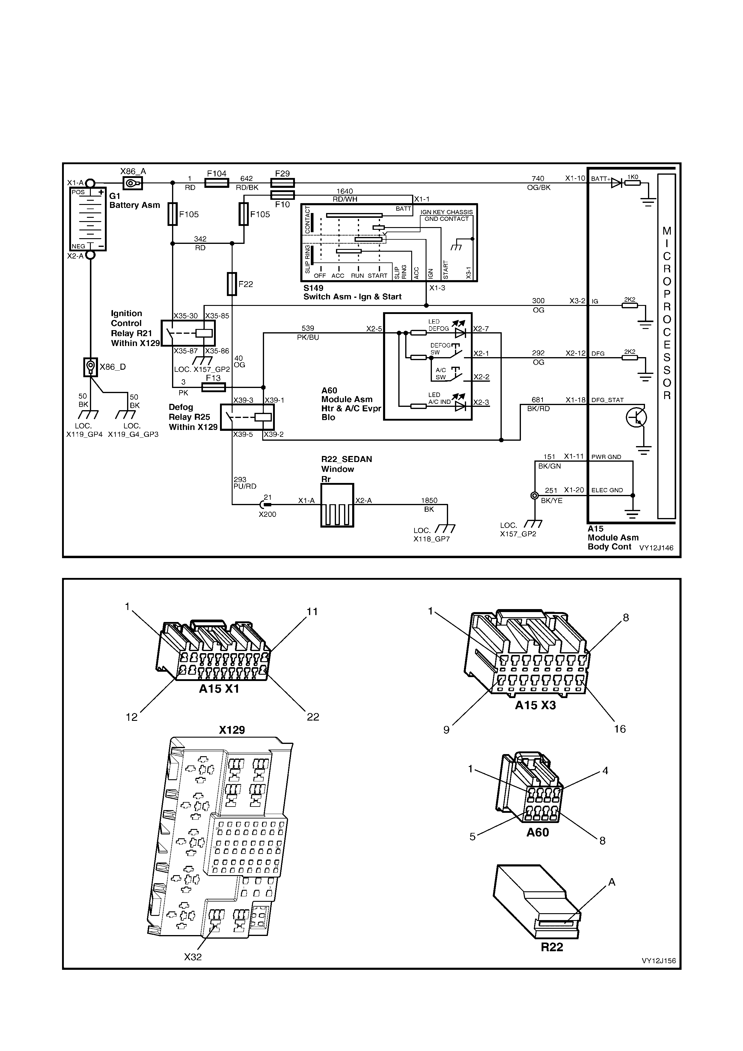
4.19 HEATED REAR WINDOW
CIRCUIT DESCRIPTION
W ith this system , the BCM imposes a time limit on the heat ing of the re ar wind o w. Po wer is t oggled on or of f as the
heated-rear-window momentary-contact switch is pressed. The BCM enables heating of the rear window for a
period of 15 minutes with subsequent activation of the switch resetting the time (to 15 minutes).
Rear window heating is available only when the ignition is on. This system defaults to Off when the ignition is
turned off. The BCM controls the heated-rear-window operation after the system is switched on.
Figure 12J-270
Figure 12J-271

HEATED-REAR-WINDOW DI AGNOSTIC CH ART
STEP ACTION VALUE YES NO
1 Are the ignition switch and ignition control circuits
functioning correctly? Go to Step 2. Replace the
ignition sw itch or
repair ignition
control circuit
fault/s as
necessary.
2 1. Turn the ignition on.
2. Operate the heated-rear-window switch.
Does the heated-rear-window switch LED illuminate?
Go to Step 3. Go to Step 4.
3 With the ignition on and the heated-rear-window switch
LED illuminated, does the rear window demist? System OK. Go to Step 12.
4 1. Turn the ignition off.
2. Connect TECH 2 to the DLC.
3. Turn the ignition on.
4. Select Diagnostics / Model Year / Vehicle Model /
Body / Occupant Climate Control / Data Display /
Switch Data / Rear Demist Switch.
5. 0Press and hold the heated-rear-window switch.
Does TECH 2 display On?
Go to Step 5. Go to Step 10.
5 1. With the ignition on, back-probe BCM connector
terminal X1-18, circuit 681 (Black / Red wire) with a
jumper lead to ground.
Does the heated-rear-window LED illuminate?
Replace the
BCM. Refer to
2.1 BODY
CONTROL
MODULE in this
Section.
Go to Step 6.
6 1. With the ignition on, back-probe heated-rear-
window s witch (A60) connector terminal X2-7 circuit
681 (Black / Red wire) with a jumper lead to ground.
Does the heated-rear-window LED illuminate?
Repair faulty
circuit 681. Go to Step 7.
7 1. With the ignition on, back-probe heated-rear-
window switch connector terminal X2-5, circuit 539
(Pink / Blue wire) with a voltmeter to ground.
Is the value as specified?
Battery
voltage Replace the
heated-rear-
window switch.
Go to Step 8.
8 1. Back-probe fuse F13, circuit 539 (Pink / Blue wire)
with a voltmeter to ground.
Is the value as specified?
Battery
voltage Repair faulty
circuit 539. Go to Step 9.
9 1. Check fuse F13.
Is the fuse OK? Repair faulty
circuit 3 (Pink
wire).
Replace fuse
F13.
10 1. With the ignition on, back-probe BCM connector
terminal X2-12, circuit 292 (Orange wire) with a
voltmeter to ground.
2. Press and hold the heated-rear-window switch.
Is the value as specified?
Battery
voltage Replace the
BCM. Refer to
2.1 BODY
CONTROL
MODULE in this
Section.
Go to Step 11.
11 1. With the ignition on, back-probe heated-rear-
window switch connector terminal X2-1, circuit 292
(Orange wire) with a voltmeter to ground.
2. Press and hold the heated-rear-window switch.
Is the value as specified?
Battery
voltage Repair faulty
circuit 292. Replace the
heated-rear-
window switch.
12 1. With the ignition on, back-probe heated-rear-
window (R22) connector terminal X1-A, circuit 293
(Purple / Red wire) with a voltmeter to ground.
2. Operate the heated-rear-window switch.
Is the value as specified?
Battery
voltage Go to Step 13. Go to Step 14.
13 1. Turn the ignition off.
2. Back-probe heated-rear-window connector
terminal X2-A, circuit 1850 (Black wire) with an
ohmmeter to ground.
Is the reading as specified?
Less than
1 ohm Replace or repair
the heated-rear-
window element.
Repair faulty
circuit 1850.

STEP ACTION VALUE YES NO
14 1. With the ignition on, back-probe heated-rear-
window relay connector terminal X39-5, circuit 293
(Purple / Red wire) with a voltmeter to ground.
2. Operate the heated-rear-window switch.
Is the value as specified?
Battery
voltage Repair faulty
circuit 293. Go to Step 15.
15 1. Back-probe heated-rear-window relay connector
terminal X39-3, circuit 40 (Orange wire) with a
voltmeter to ground.
Is the value as specified?
Battery
voltage Go to Step 16. Repair the power
supply circuit,
including
circuit 40
(Orange wire)
and fuse F22.
16 1. Turn the ignition off.
2. Back-probe heated-rear-window relay connector
terminal X39-1, circuit 539 (Pink / Blue wire) with a
voltmeter to ground.
Is the value as specified?
Battery
voltage Go to Step 17. Repair faulty
circuit 539.
17 1. Back-probe heated-rear-window relay connector
terminal X39-2, circuit 681 (Black / red wire) with a
voltmeter to ground.
2. Operate the heated-rear-window switch.
3. Switch on the ignition.
Is the value as specified?
Less than
1 volt Go to Step 18. Repair faulty
circuit 681.
18 1. With the ignition on, back-probe heated-rear-
window relay connector terminal X39-2, circuit 681
(Black / red wire) with an ohmmeter to ground.
Is the value as specified?
Less than
1 ohm Replace the
heated-rear-
window relay.
Repair faulty
circuit 681.
WHEN ALL DIAGNOSIS AND REPAIRS ARE COMPLETE, VERIFY CORRECT OPERATION

4.20 REAR LAMP FAILURE WARNING SYSTEM
CIRCUIT DESCRIPTION
The BCM monitors current flow of the tail, stop and licence plate lamps (for bulb failure, poor power and ground
circuits and fuse integrit y). W hen the ignition is tur ned on, the MFD disp lays the appro priate warning via data fr om
the instrument cluster. Refer to Section 12C, INSTRUMENT OPERATION – ALL MODELS, ANIMATED
WARNINGS.
If batter y voltage is no t present at both the par k lamp and sto p lamp BCM inputs when the ignitio n is on, the BCM
determ ines that one of these two fuses has failed. T he BCM then sig nals the ins trument clus ter (which sign als the
MFD) via the secondary data bus, that a fuse is faulty.
When the parking lamps are turned on, the BCM checks the current flowing from the lamp circuits. If this
current does not match the pre-learnt current flow, the BCM signals the instrument cluster (and MFD). Refer to
1.20, BULB RE-LEARN PROCEDURE.
W hen the brake pedal is pr essed, batter y voltage is applied to th e ABS or ABS / T CS control m odule, which sends
a signal to the BC M via the sec ondary seria l data bus . The BCM inter prets this si gnal as the s top lam p switch inpu t
signal and checks the current flowing from the rear lamp circuits. If this current does not match the pre-learnt
current flow, the BCM signals the instrument cluster (and MFD).
If one of these signals is received, the MFD displays the appropriate warning message, following, and an icon:
• Rear Brake Bulb Fail
• Rear Lamp Bulb Fail
• Rear Lamp Fuse Fail.
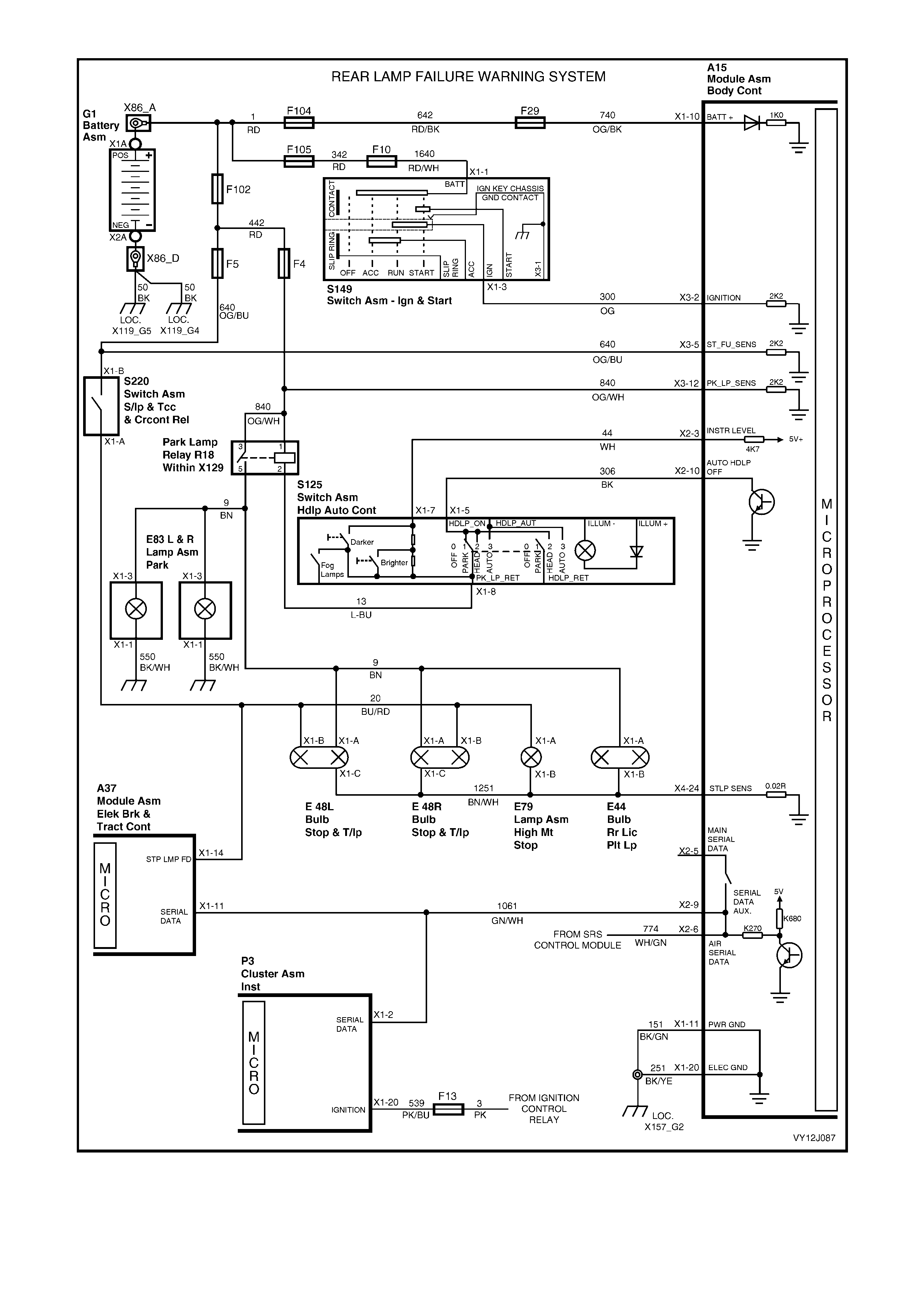
Figure 12J-272
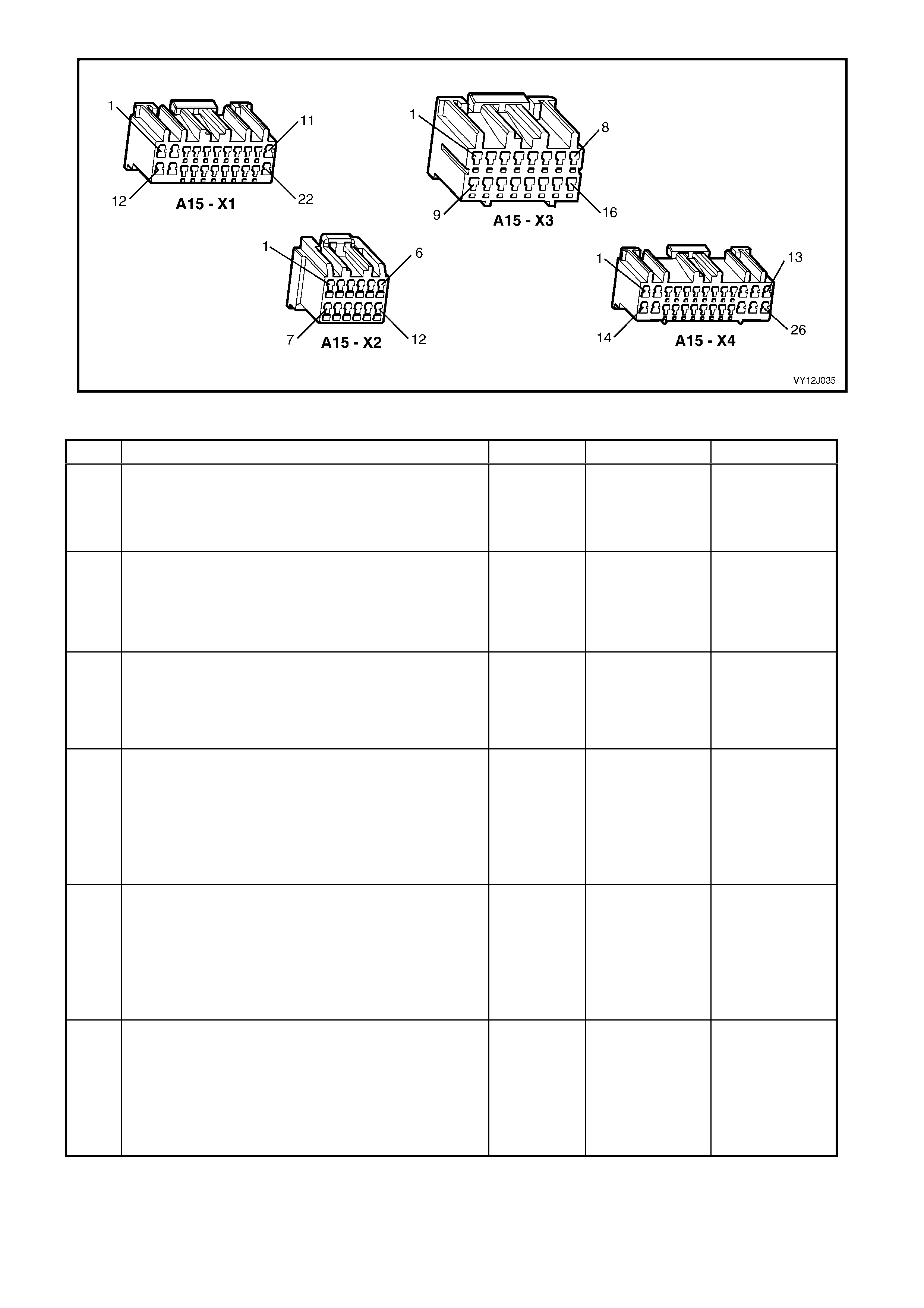
Figure 12J-273
REAR LAMP FAILURE WARNING SYSTEM DIAGNOSTIC CHART
STEP ACTION VALUE YES NO
1 Is the MFD is functioning correctly? Go to Step 2 Refer to
Section 12C,
INSTRUMEN-
TATION in t his
Section.
2 1. Turn off the ignition.
2. Turn off the headlamp switch.
3. Ensure the brake pedal is in its rest position.
4. Turn on the ignition.
Does the MFD display Rear Lamp Fuse Fail warning?
Go to Step 7. Go to Step 3.
3 1. Turn off the ignition.
2. Turn on the park lamps.
3. Turn on the ignition.
Does the MFD display the Rear Lamp Bulb Fail
warning?
Go to Step 12. Go to Step 4.
4 1. Turn off the ignition.
2. Turn off the headlamp switch.
3. Remove a tail lamp bulb.
4. Turn on the park lamps.
5. Turn on the ignition.
Does the MFD display the Rear Lamp Bulb Fail
warning?
Go to Step 5. Go to Step 17.
5 1. Turn off the ignition.
2. Turn off the headlamp switch.
3. Install the rear tail lamp bulb.
4. Turn on the ignition.
5. Press the brake pedal.
Does the MFD display the Rear Brake Bulb Fail
warning?
Go to Step 21. Go to Step 6.
6 1. Turn off the ignition.
2. Turn off the headlamp switch.
3. Remove a brake lamp bulb.
4. Turn on the ignition.
5. Press the brake pedal.
Does the MFD display the Rear Brake Bulb Fail
warning?
System OK. Go to Step 23.

STEP ACTION VALUE YES NO
7 1. Turn off the ignition.
2. Turn off the headlamp switch.
3. Ensure the brake pedal is in its rest position.
4. Connect TECH 2 to the DLC.
5. Turn on the ignition.
6. Select Diagnostics / Model Year / Vehicle Model /
Body / Body Control Module / Data Display / Rear
Lamp Failure / Rear Brake Lamp Fuse.
Does TECH 2 display Failed?
Go to Step 8. Go to Step 9.
8 1. Back-probe BCM connector terminal X3-5,
circuit 640 (Orange / Blue wire) with a voltmeter to
ground.
Is the value as specified?
Battery
voltage Replace the
BCM. Refer to
2.1 BODY
CONTROL
MODULE in this
Section.
Repair faulty
circuit 640 or
replace fuse F5
or fusible link
F102, as
required.
9 1. With TECH 2 connected, exit to the Rear Lamp
Failure menu and selec t Rear Park Lamp Fus e.
Does TECH 2 display Failed?
Go to Step 10. Go to Step 11.
10 2. Back-probe BCM connector terminal X3-12,
circuit 840 (Orange / White wire) with a voltmeter to
ground.
Is the value as specified?
Battery
voltage Replace the
BCM. Replace
the BCM. Refer
to 2.1 BODY
CONTROL
MODULE in this
Section.
Repair faulty
circuit 840 or
replace fuse F4
or fusible link
F102, as
required.
11 1. Ensure that the headlamp switch is off and the
brake pedal is in its rest position.
2. With TECH 2 connected, exit to the Normal Mode
menu and select Rear Lamp Bulb Failed Warning.
3. Turn the ignition off then on.
Does the screen display Bulb Failed Warning Lamp On?
Replace the
BCM. Refer to
2.1 BODY
CONTROL
MODULE in this
Section.
Go to Section
12C, 3.4
DIAGNOSING
FAULTS NOT
COVERED BY
TECH 2
DIAGNOSTIC
TOOL, Brake Fail
/ Park Brake
Warning
12 1. Turn on the park lamps.
2. Check to see if all tail lamps are illuminated.
Are all tail lamps illuminated?
Go to Step 13. Go to Step 14.
13 1. Perform the relearn procedure as detailed in
1.14 REAR LAMP FAILURE WARNING SYSTEM in
this Section.
2. Turn on the ignition.
3. Turn on the park lamps.
Does the MFD display the Rear Lamp Bulb Fail
warning?
Go to Step 4. Replace the
BCM. Refer to
2.1 BODY
CONTROL
MODULE in this
Section.
14 While carrying out Step 12, did at least one tail lamp
illuminate? Check and repair
faulty bulb and /
or tail lamp
circuit.
Go to Step 15.
15 1. Turn off the ignition.
2. Disconnect BCM connector X1 and back-probe the
harness terminal X1-11, circuit 151 (Black / Green
wire) with an ohmmeter to ground.
Is the value as specified?
Below
1 ohm Go to Step 16 Repair faulty
circuit 151.
16 1. Turn on the ignition.
2. Back-probe BCM connector terminal X4-24,
circuit 1251 (Brown / W hite wire) with a jumper lead
to ground.
3. Turn on the park lamps.
Do the lamps illumi nate ?
Replace the
BCM. Refer to
2.1 BODY
CONTROL
MODULE in this
Section.
Repair faulty
circuits 1251 and
/ or 9 (including
park lamp relay).

STEP ACTION VALUE YES NO
17 1. Turn off the ignition.
2. Connect TECH 2 to the DLC.
3. Turn on the ignition.
4. Turn on the park lamps.
5. Select Diagnostics / Model Year / Vehicle Model /
Body / Body Control Module / Normal Mode / Rear
Lamp Bulb Fail.
Does TECH 2 display status?
Yes Go to
Instruments
diagnosis in
Section 12C,
INSTRUMENTS.
Go to Step 18.
18 1. With the ignition on, the park lamps on and TECH 2
connected, exit to the Data Display menu and select
Headlamps / Headlamp Switch.
Does TECH 2 display On?
Install the tail
lamp bulb and go
to Step 19.
Install the tail
lamp bulb and go
to Step 20.
19 1. Perform the relearn procedure as detailed in
1.14 REAR LAMP FAILURE WARNING SYSTEM in
this Section.
2. Remove a tail lamp bulb.
3. Turn on the park lamps.
4. Turn on the ignition.
Does the rear lamp failure warning-lamp illuminate?
Go to Step 5. Replace the
BCM. Refer to
2.1 BODY
CONTROL
MODULE in this
Section.
20 1. Turn on the ignition.
2. Turn on the park lamps.
3. Back-probe BCM connector terminal X2-3, circuit 44
(White wire) with a voltmeter to ground.
Is the value as specified?
3.3 volts Replace the
BCM. Refer to
2.1 BODY
CONTROL
MODULE in this
Section.
Check and repair
faulty circuit 44
(including
headlamp
switch).
21 1. Turn on the ignition.
2. Press the brake pedal.
Are all brake lamps illuminated?
Go to Step 22. Check and repair
brake lamp
circuit (including
faulty bulb).
22 1. Perform the relearn procedure as detailed in
1.14 REAR LAMP FAILURE WARNING SYSTEM in
this Section.
2. Turn on the ignition.
3. Press the brake pedal.
Does the MFD display the Rear Brake Bulb Fail
warning?
Go to Step 6. Replace the
BCM. Refer to
2.1 BODY
CONTROL
MODULE in this
Section.
23 1. Connect TECH 2 to the DLC.
2. Turn on the ignition.
3. Select Diagnostics / Model Year / Vehicle Model /
Body / Body Control Module / Data Display / Serial
Data Inputs/ Stop Lamp Switch.
4. Press the brake pedal.
Does TECH 2 display On?
Go to Step 24. Go to ABS and
ABS / TCS
diagnosis in
Section 5B, ABS
& TCS.
24 1. Perform the relearn procedure as detailed in
1.14 REAR LAMP FAILURE WARNING SYSTEM in
this Section.
2. Remove a brake lamp bulb.
3. Turn on the ignition.
4. Press the brake pedal.
Does the MFD display the Rear Brake Bulb Fail
warning?
System OK. Replace the
BCM. Refer to
2.1 BODY
CONTROL
MODULE in this
Section.
WHEN ALL DIAGNOSIS AND REPAIRS ARE COMPLETE, VERIFY CORRECT OPERATION

4.21 HAZARD LAMP CONTROL
CIRCUIT DESCRIPTION
The BCM drives the sim ultaneous operation of the left and right indicator lam ps when the BCM receives a groun d
(On) signal from the hazard warning switch, or a valid RF signal as:
• the theft deterrent system is being armed
• the doors are being deadlocked
• the key unlock button is pressed.
NOTE: As the vehicle is being passively armed, the indicators are not automatically operated.
When the hazard warning switch is activated, the BCM receives a hazard lamp On request and activates the
internal Hazard/theft Indicator Relay to simultaneously flash the left and right indicator lamps.
Hazard Illumination Relay
General Mot ors Br a zil veh ic les are f itted with th e Ha z ar d Ill umination Re lay (R26) . This supplies po wer to i lluminate
the hazard warning switch while the ignition is on and also causes the hazard warning switch illum ination to flash
while the hazard lamps are activated.
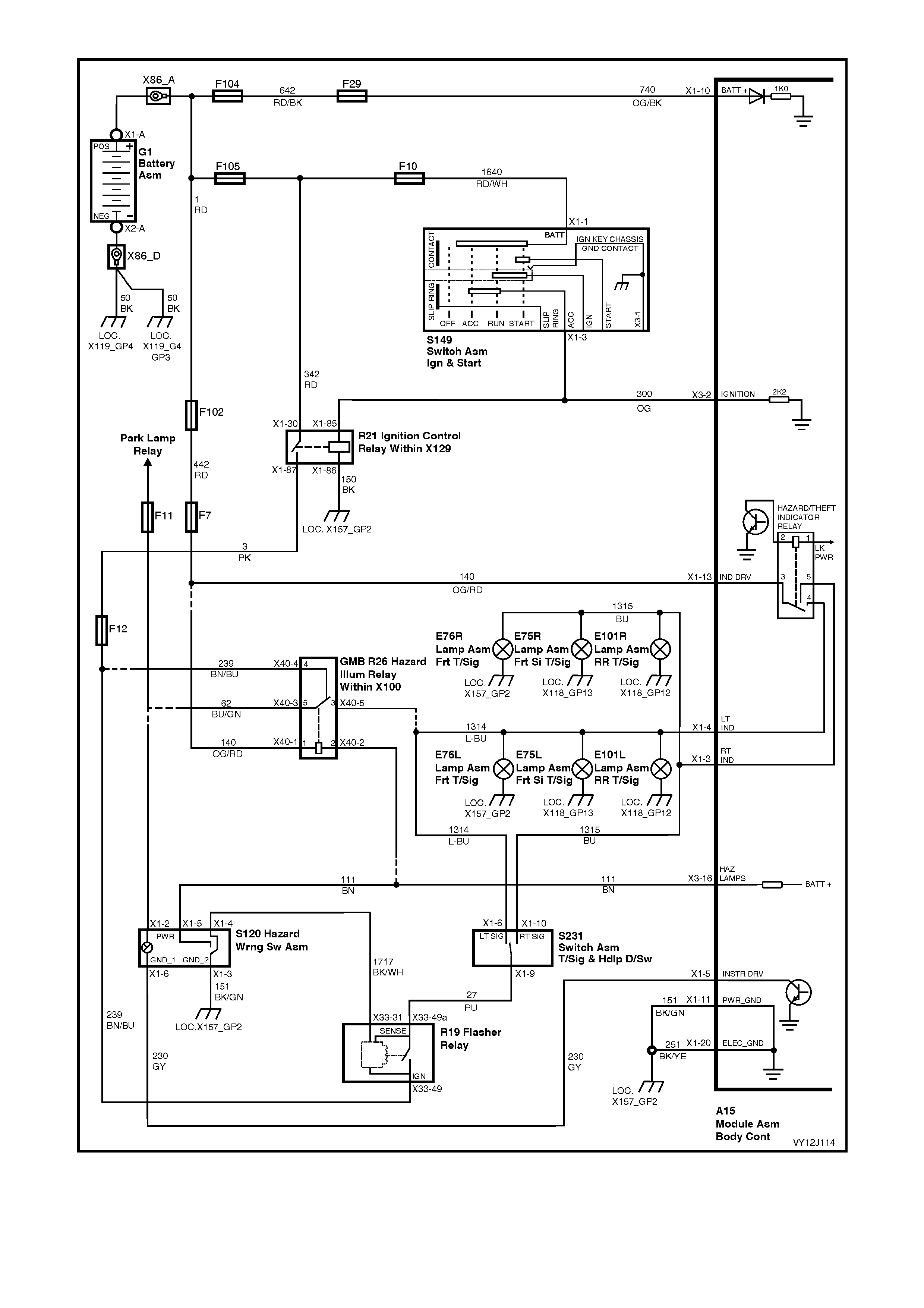
Figure 12J-274

HAZARD LAMP CONTROL DIAGNOSTIC CHART
STEP ACTION VALUE YES NO
1 Does the remote key function correctly? Go to Step 2. Go to 4.3 REMOTE
RECEIVER / KEY in
this Section.
2 Does the central locking system operate correctly? Go to Step 3. Go to 4.5 CENTRAL
DOOR LOCKING in
this Section.
3 1. Close all doors
With the doors unlocked, press the remote coded key
lock button.
Do the indicator lamps flash?
Go to Step 5. Go to Step 4.
4 In Step 3, did one side of indicator lamps flash? Right-side OK – Go
to Step 8.
Left-side OK – Go
to Step 9.
Go to Step 6.
5 1. Press the hazard warning switch to activate the
hazard lamps (on).
Do all indicator lamps flash and continue to flash?
System OK. Go to Step 7.
6 1. Switch the ignition off.
Connect TECH 2 to the DLC.
Select Diagnostics / Model Year / Vehicle Model / Body
/ Body Control Module / Miscellaneous Tests /
Lamps / Indicators.
Perform the test as instructed by TECH 2.
Do the indicator lamps illuminate (for a short time)?
Replace the BCM.
Refer to 2.1 BODY
CONTROL
MODULE in this
Section.
Go to Step 9.
7 1. Press the hazard warning switch (on).
Back probe BCM connector terminal X3-16 circuit 111
(Brown wire) with an ohmmeter to ground.
Is the value as specified?
Less than
1 ohm. Replace the BCM.
Refer to 2.1 BODY
CONTROL
MODULE in this
Section.
Check and repair
circuit 111 (includ ing
the hazard warning
switch assembly).
8 1. Turn the ignition off.
2. Turn the hazard lamps off.
3. Back-probe BCM connector terminal X1-4,
circuit 1314 (Light-blue wire) with a jumper lead to
battery voltage.
Do the left side indicator la mp s illum ina te?
Replace the BCM.
Refer to 2.1 BODY
CONTROL
MODULE in this
Section.
Check and repair
circuit 1314
(including left-side
hazard lamps).
9 1. Turn the ignition off.
2. Turn the hazard lamps off.
3. Back-probe BCM connector terminal X1-3,
circuit 1315 (Blue wire) with a jumper lead to
battery voltage.
Do the right side indicator lamps illuminate?
Replace the BCM.
Refer to 2.1 BODY
CONTROL
MODULE in this
Section.
Check and repair
circuit 1315
(including right-side
hazard lamps).
10 1. Back probe BCM connector terminal X1-13,
circuit 140 (Orange / Red wire) with a voltmeter to
ground.
Is the value as specified?
Battery
voltage Replace the BCM.
Refer to 2.1 BODY
CONTROL
MODULE in this
Section.
Check and repair
circuit 140 (includ ing
fuses F7 and F102).
WHEN ALL DIAGNOSIS AND REPAIRS ARE COMPLETED, VERIFY CORRECT OPERATION

5. TORQUE WRENCH SPECIFIC ATIONS
Nm
Body Control Module Retaining Screw ................................... 0.1 – 0.3
Remote Coded Key Housing Screw Torque Specification...... 0.7 – 0.9
Instrument Panel Outer Cover Retaining Screws ................... 0.1 – 0.3
Windshield Defroster Grille Retaining Screws ........................ 0.1 – 0.3
Door Speaker Retaining Screws ............................................. 0.1 – 0.3
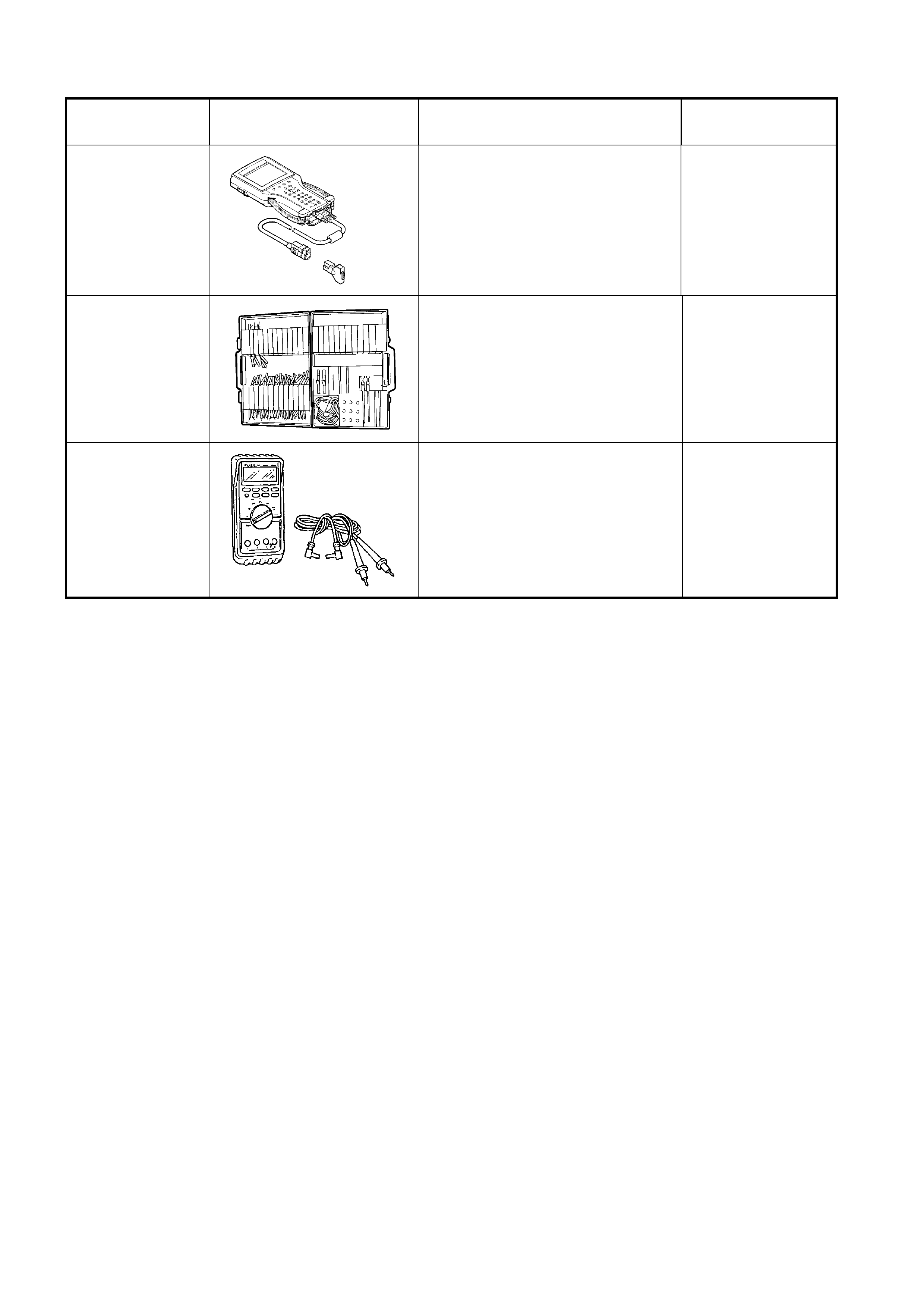
6. SPECIAL TOOLS
TOOL NUMBER ILLUSTRATION DESCRIPTION TOOL
CLASSIFIC ATION
7000086I
TECH 2
DIAGNOSTIC SCAN TOOL
Used for diagnosis of vehicle
electrical system.
Previously released.
Mandatory
J35616-A
(KM609)
CONNECTOR TEST ADAPTOR
KIT
Used when carrying out electrical
diagnostic circuit checks.
Previously released.
Desirable
3588
(J39200)
DIGITAL MULTIMETER
Must have at least 10 MΩ input
impedance and be capable of
reading frequencies.
Previously released.
Available