
SECTION 12K - TELEMATICS
IMPORTANT
Before performing any Service Operation or other procedure described in this Section, refer to Section 00
CAUTIONS AND NOTES for correct workshop practices with regard to safety and/or property damage.
CONTENTS
1 GENERAL INFORMATION
2. PRINCIPLES OF OPERATION
2.1 OPERATING MODES
PRE DELIVERY MODE
SERVICE MODE
ACTIVE MODE
STAND-BY MODE
SLEEP MODE
BATTERY SAVER MODE
2.2 ALERTS
AIRBAG ACTIVATION ALERT
LOW BATTERY VOLTAGE ALERT
BATTERY REMOVAL ALERT
UNAUTHORISED ENTRY ALERT
2.3 HOLDEN ASSIST REMOTE REQUESTS
ENGINE IMMOBILISATION
REMOTE UNLOCKING
2.4 TELEMATICS MODULE
2.5 INTERIOR REAR VIEW MIRROR
TELEMATICS BUTTON PAD
MICROPHONE
STATUS INDICATOR LEDS
2.6 AUDIO SYSTEM INTERFACE
AUDIO SYSTEM AND RHF SPEAKERS
AUDIBLE TONES
2.7 BACKUP BATTERY
2.8 BATTERY VOLTAGE
2.9 BACKUP BATTERY CHARGER
2.10 SERIAL DATA
2.11 DRIVER’S DOOR AJAR SWITCH
2.12 PASSANGER DOOR AJAR SWITCHES
2.13 ALARM INPUT (THEFT DETERRENT HORN)
2.14 TELEMATICS ANTENNA
GSM ANTENNA
GPS ANTENNA
2.15 FUEL PUMP RELAY DRIVE CIRCUIT
2.16 WIRING HARNESSES
3. SERVICE OPERATIONS
3.1 TELEMATICS MODULE
REMOVE
REINSTALL
TELEMATICS MODULE CHANGEOVER
PROCESS
3.2 BACKUP BATTERY
REMOVE
REINSTALL
3.3 TELEMATICS ANTENNA
REMOVE
REINSTALL
3.4 INTERIOR REAR VIEW MIRROR
REMOVE
REINSTALL
4. TECH 2 DIAGNOSIS FOR TELEMATICS
4.1 BASIC KNOWLEDGE REQUIRED
4.2 CONNECTING TECH 2
4.3 TECH 2 TEST MODES
SYSTEM SELECT MENU
F0: DIAGNOSTIC TROUBLE CODES
F1: DATA DISPLAY
F2: SNAPSHOT
F3: MISCELLANEOUS TESTS
F4: ADDITIONAL FUNCTIONS
F5: PROGRAM
5. DIAGNOSIS
5.1 BASIC KNOWLEDGE AND TOOLS REQUIRED
5.2 DIAGNOSTIC PRECAUTIONS
5.3 DIAGNOSTIC CHART DESCRIPTION
5.4 STRATEGY BASED DIAGNOSTICS
5.5 ON-BOARD DIAGNOSTIC SYSTEM CHECK
5.6 DIAGNOSTIC TROUBLE CO DES
5.7 TELEMATICS MODULE TERMINAL
DESCRIPTIONS
5.8 DIAGNOSTIC CHARTS
ON-BOARD DIAGNOSTIC SYSTEM CHECK
DTC 1 - NO SERIAL DATA FROM BCM
DTC 2 - NO SERIAL DATA FROM
INSTRUMENT
DTC 3 - NO SERIAL DATA FROM SDM
(SENSING DIAGNOSTIC MODULE)
DTC 4 - NO SERIAL DATA FROM AUDIO
SYSTEM
DTC 5 – NO SERIAL DATA
DTC 7 – GPS MODULE FAILURE
DTC 8 - SIM MISMATCH
DTC 9 - VEHICLE BATTERY VOLTAGE TOO
HIGH
DTC 10 - VEHICLE BATTERY VOLTAGE TOO
LOW
DTC 11 - RAM ERROR
DTC 12 - EEPROM ERROR
DTC 13 - BACKUP BATTERY TIMER EXPIRED
DTC 14 - BACKUP BATTERY VOLTAGE TOO
HIGH
DTC 15 - BACKUP BATTERY VOLTAGE TOO
LOW
DTC 16 - BACKUP BATTERY NOT DETECTED
DTC 17 - MICROPHONE NOT DETECTED
DTC 18 - MICROPHONE CIRCUIT VOLTAGE
TOO LOW
DTC 19 - MICROPHONE CIRCUIT VOLTAGE
TOO HIGH
DTC 21 - SPEAKER CIRCUIT VOLTAGE TOO
LOW
DTC 22 - SPEAKER CIRCUIT VOLTAGE TOO
HIGH
DTC 30 - KEYPAD CIRCUIT VOLTAGE TOO
HIGH
DTC 35 – GPS ANTENNA CIRCUIT VOLTAGE
TOO LOW
DTC 39 - TELEPHONE NUMBER ERROR
DTC 40 - VEHICLE IDENTIFICATION NUMBER
MISMATCH
Techline
Techline
Techline
Techline
Techline
Techline

DTC 42 - FUEL PUMP CIRCUIT VOLTAGE
TOO LOW
DTC 43 - FUEL PUMP CIRCUIT VOLTAGE
TOO HIGH
DTC 44 – GSM NOT LOGGED WIT H SIGNAL
STRENGTH PRESENT
DTC 45 – END CALL / INFORMATION
BUTTON STUCK
DTC 46 - HOLDEN ASSIST BUTTON STUCK
DTC 47 - EMERGENCY BUTTON STUCK
5.9 SYMPTOMS CHARTS
NO SERIAL DATA
STATUS INDICATOR LEDS DO NOT
ILLUMINATE
VEHICLE BATTERY VOLTAGE
BACKUP BATTERY
NO GPS SIGNAL
NO GSM SIGN AL
EMERGENCY BUTTON
HOLDEN ASSIST BUTTON
END CALL / INFORMATION BUTTON
THEFT DETERRENT HORN CIRCUIT
DRIVER’S DOOR AJAR SWITCH
PASSENGERS DOOR AJAR SWITCHES
MICROPHONE
FUEL PUMP RELAY DRIVE CIRCUIT
AUDIO MUTE CIRCUIT
AUDIO SYSTEM INTERFACE
UNABLE TO MAKE OR RECEIVE A CALL
HOLDEN ASSIST TELEMATICS SYSTEM
TEST
6. TORQUE WRENCH SPECIFICATIONS
1. GENERAL INFORMAT ION
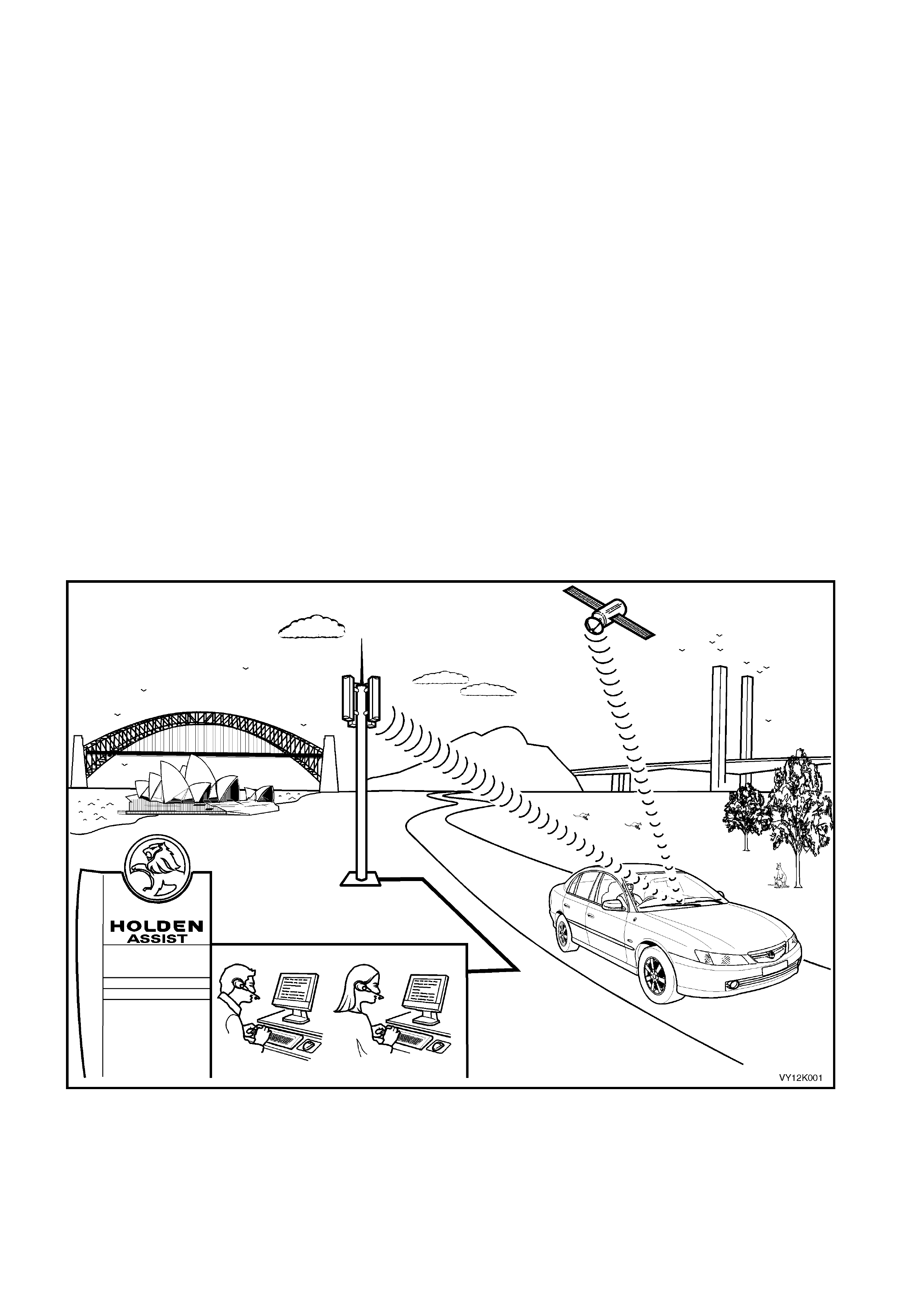
The telematics system has been developed using some of the most advanced Global Positioning System (GPS)
and telecommunications technology, Global System for Mobile (GSM) Communications available. The telematics
system provides in-vehicle safety, security and information services by providing a two way, hands free
communication to either the Holden Assist Centre or, in the case of an emergency, to the National Emergency
Response Centr e (NER C™ ) .
Holden Assist provides several services, some of which include remote door unlocking, connection to Holden
Roadside Assistance, Low Battery Alert and Accident Inquiry. In addition it will know if theft of the vehicle is
attempted, c an then tr ack the vehicl e and in c ertain c irc ums tances, r emotel y immobilis e the en gine. F or a ful l list of
services provided by Holden Assist, refer to the Holden Assist Handbook Supplement.
The link betwee n th e vehicl e and the H ol den As sis t Ce ntre or th e Nat ion al Emergency Respons e C entr e us e s GPS
for vehic le location a nd tracking an d the Australi an digital m obile phone n etwork to trans mit and recei ve voice and
SMS (S hort Mess age Serv ice) data. If the v ehicle is outside network coverag e, the link to and from the vehic le will
not be available and no services can be provided. Signal strength may be affected in locations like basement car
parks or tunnels. However, in most cases, as the vehicle emerges from the obstruction or re-enters the digital
phone network area the signal will be available again.
A vehicle equippe d with the telem atics system will be delivered from the vehicle assembly plant to the retail outlet
with the telematics system in the pre delivery mode. During the pre delivery of the vehicle, the telematics module
pre deli very mode must be dis ab led and t he s ervice m ode must be enab led usin g TECH 2. In servic e mode, limited
service will be provided until the customer has signed the terms and conditions document and the customer has set
up the system by pressing the Holden Assist button located in the telematics button pad on the interior rear view
mirror . The Holden Assist operat or will th en disable service m ode and the s ystem will be f ully operatio nal. T he set
up procedure information is provided in the Holden Assist Handbook Supplement.
The telematics module has a built-in diagnostic system that identifies system operational problems and alerts the
driver by illuminating the Red LED in the interior rear view mirror. If the LED is continuously illuminated with the
ignition o n, the tel em atics syst em will not be f unctional and the ca use of the lam p coming on s hould be check ed as
soon as is reasonably possible.
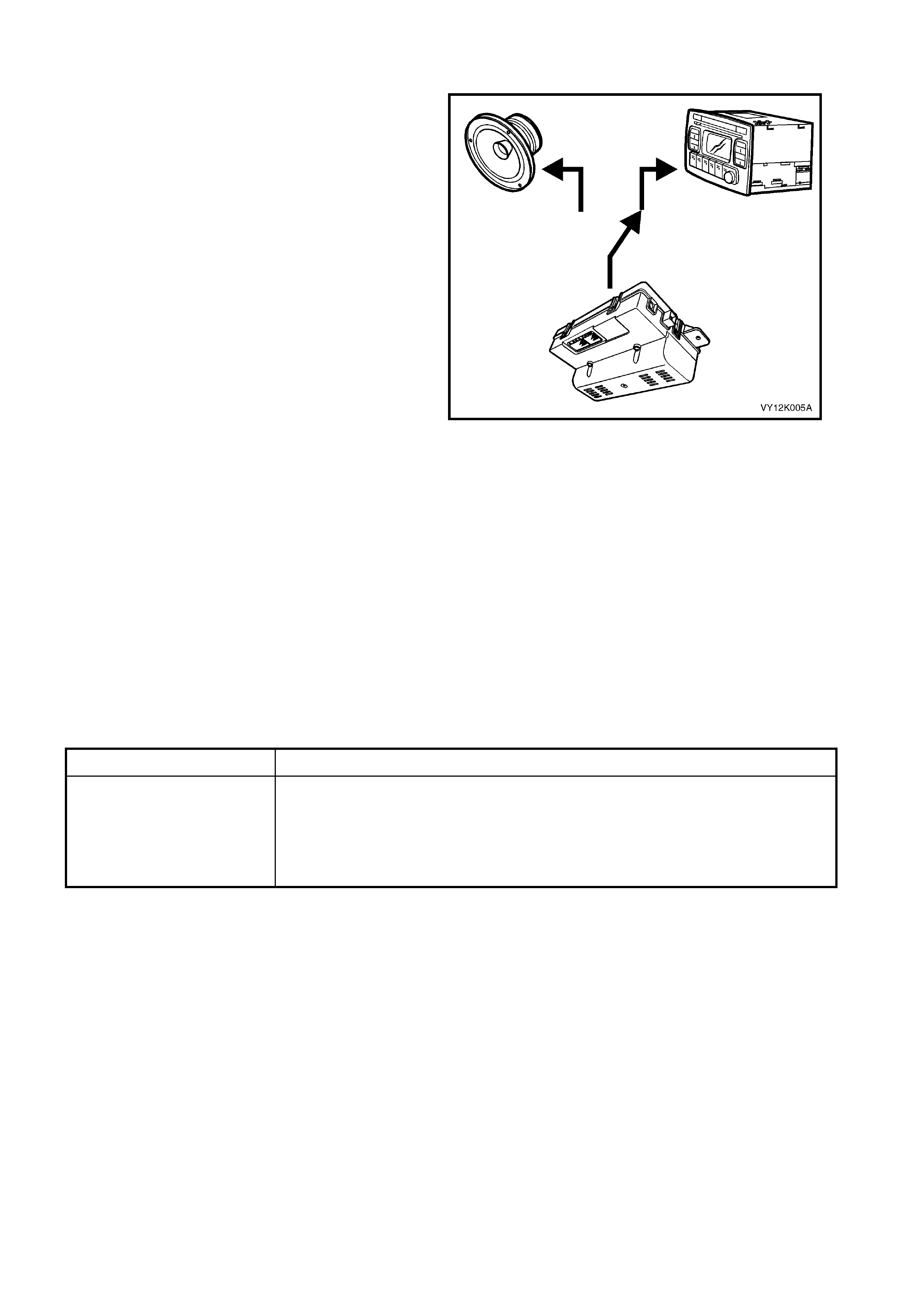
Figure 12K-1
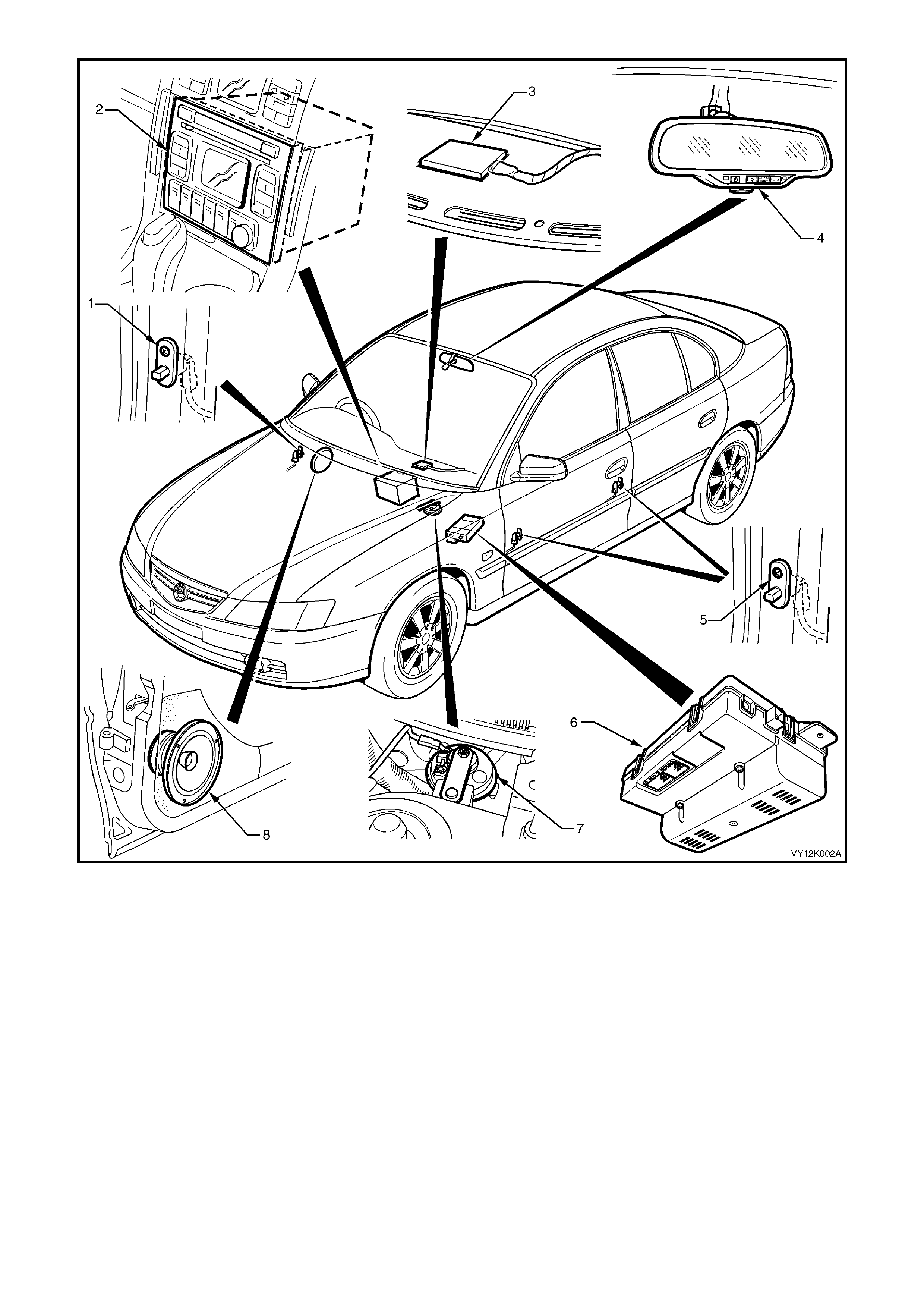
Figure 12K-2
Legend:
1. Driver’s Door Ajar Switch 4. Interior Rear View Mirror 7. Theft Deterrent Horn
2. Audio Head Unit 5. Passengers Door Ajar Switches 8. Right Front Door Speaker
3. Telematics GSM & GPS Antenna 6. Telematics Module

2. PRINCIPLES OF OPERATION
2.1 OPERATING MODES
The telem atics system has six operat ing m odes, Pre Deliver y, Ser vice, Act ive, Sta nd-by, S leep and Batter y Saver.
The purpose of these different operating modes is to minimise the system current draw and allow features to be
enabled or disabled depending on the operating mode.
PRE DELIVERY MODE
In the pr e del iver y mode the s ystem is n ot opera tiona l. T he ve hicle will b e d eliver ed f rom the ass em bly plant to the
dealer with the telematics system in the pre delivery mode. Before the vehicle is delivered to the customer, the
telematic s system mus t be taken out of the pr e deliver y mode us ing TECH 2. Ref er to 4.3 T ECH 2 TEST M ODES
F5: Program, F1: Operating Mode, in this Section. When in pre delivery mode the telematics module will only
communicate with TECH 2, and only when the ignition is ON.
SERVICE MODE
When the vehicle is scheduled to be serviced, the telematics system service mode should be activated. The
custom er may request the Holden Assist C entre to remotely enable or disab le service m ode. A service technician
can also activate or inactivate service mode with TECH 2. Refer to 4.3 TECH 2 TEST MODES F5: Program,
F1: Operating Mode, in this Section.
When the service mode is activated the telematics module will ignore all button presses except for the Holden
Assist button. In addition, the module will not transmit alert messages for unauthorised entry or low battery.
However the module will transmit an airbag activation alert.
ACTIVE MODE
This is the norm al telem atic s s ystem oper ating m ode. In this m ode the telem atic s system is fully function al an d can
mak e and receive cal ls, and transm it data via the GSM net work. The c urrent draw of the telem atics module is this
mode will be approximately 150 mA.
STAND-BY MODE
Two hours after the ignition has been turned off or two minutes after the ignition has been turned off and a door has
been opened and closed, or two minutes after the conclusion of a call while the ignition is off if stand-by mode is
pending, the telematics module will enter stand-by mode. In stand-by mode the GPS, audio and the keypad buttons
are turned off to reduce the standing current of the telematics module.
The telematics module will enter the stand-by mode:
Two hours af ter the ignit ion is turned of f, or two m inutes after the ignit ion has bee n turned off and a door has bee n
opened, or two minutes after the conclusion of a call when the ignition is off if stand-by mode is pending.
The telematics module will be “woken” from the stand-by mode by any of the following:
An incoming message / call.
The ignition is turned on.
Any door is opened.
The alarm is triggered.
The vehicle batt ery is disconnec te d.
A TECH 2 diagnostic request.
SLEEP MODE
The telematics module will enter the sleep mode on request from the Holden Assist Centre or 30 minutes after a
low battery alert has been sent to Holden Assist Centre, or after five days of uninterrupted ignition off. In sleep
mode the telematics module only monitors the inputs required for it to be “woken” from sleep mode.
The system may be “woken” from sleep mode by any of the following:
Any door is opened.
The alarm is triggered.
A battery removal alert.
BATTERY SAVER MODE
The purpos e of the battery saver mode is to lim it the standing curr ent of the telem atics module while s till providi ng
the abilit y to rem otel y unloc k the vehicle. Af ter 24 hour s of no activit y (igniti on on, any door open ed, SM S recei ved,
unauthorised entry alert, low battery alert) the telematics module will enter battery saver mode. In this mode, the
telematics module will switch between sleep mode and active mode. During active mode operation the telematics
module wil l lo g onto t he G S M net work and an y pendi n g remote unloc k SMS mes sages stor ed i n the ne t work will be
received by the telematics module, and the doors will be unlocked. If no SMS messages are received, the
telematics module will return to sleep mode. After four days of this mode operation and no activity, the telematics
module will remain in sleep mode.

2.2 ALERTS
AI R BAG AC TIVATI ON ALER T
If the vehicle is involved in an accident where the airbags and/or the seat belt pre-tensioners are activated, an
“Airbag Activation Alert” message will be transmitted to the Holden Assist Centre. If the Holden Assist Centre
operator is unable to contact the driver via two-way voice communication in the vehicle, or if the driver cannot
respond, the operator will hand the call over to the National Emergency Response Centre, who will then contact the
Police. T he Police m ay then c ontact the am bulance service. F or further inf ormation r egarding the air bag activati on
alert, refer to the Holden Assist Handbook Supplement.
LOW BATTERY VOLTAGE ALERT
If the vehicle battery voltage falls below a preset voltage for longer than 30 minutes, the telematics module will
transmit a “Low Battery Alert” message to the Holden Assist Centre. The low battery alert voltage is displayed in
the TECH 2 data list. For further information regarding the low battery alert refer to the Holden Assist Handbook
Supplement.
BATTERY REMOVAL ALERT
If the vehicle battery is disconnected, (battery voltage less than one volt), the telematics module will transmit a
“Batter y Rem oval A ler t” message to the Hol den As s ist Centr e. For f ur ther inf ormation regardin g the bat ter y re moval
alert refer to the Holden Assist Handbook Supplement.
UNAUTHORISED ENTRY ALERT
If the veh icle entr y deterren t system is trigger ed for lon ger than 20 seconds , the telem atics module will trans mit an
“Unauthorised Entry Alert” message to the Holden Assist Centre. For further information regarding the unauthorised
entry alert refer to the Holden Assist Handbook Supplement.

2.3 HOLDEN ASSIST REMOTE REQUESTS
ENGINE IMMOBILISATION
In the event of the v ehic le being s tolen, it is pos sib le for the N ERC™ to rem otel y imm obilis e the en gine b y s ending
an “immobilise” message to the telematics module. This function can only be activated by the NERC™ under
instruc tion fr om the Polic e. On rec eiving the “ imm obilise” m essage, the telem atics module wil l then turn of f the f uel
pump relay, cutting off the suppl y of fuel to the engine an d command the BCM (via the serial data circuit) to flash
the indicators. The engine will remain immobilised until the “re-mobilise” message is received from NERC™.
There are two types of remote immobilisation:
IMMEDIATE ENGINE IMMOBILISATION
On receiving an “Immediate Engine Immobilisation” message from the NERC™, the telematics module will
imm ediatel y turn off the fuel pum p rela y, cutting of f the supply of f uel to the engin e and com m and the BCM ( via the
serial data circuit) to flash the indicators.
UNDER 10 KPH ENGINE IMMOBILISATION
On recei ving an “Under 10 k ph Engine Im mobilisat ion” m essage f rom the NERC™, the t elematic s m odule will wai t
until the ve hicle s peed is les s than 10 k ph befor e turning of f the f uel pum p rela y, cutting of f the s upply of f uel to the
engine and command the BCM (via the serial data circuit) to begin flashing the indicators.
REMOTE UNLOCKING
On recei ving a “Rem ote Un lock” m essage fr om the Holde n Assist C entre, the tel em atics m odule will comm and the
BCM (via th e seria l data circ uit) to un lock the doors. W hen an y door is ope ned aft er a r emote unloc k , the alarm will
be activated . To tur n the alar m off, loc ate the k eys and either press th e unlock button, or turn the ignit ion on. If the
telematics module is operating in Battery Saver Mode the remote unlock may be delayed as much as 15 minutes.
NOTE: A Remote Unlock from the Holden Assist Centre will not funct ion while the TECH 2 is acc essi ng an y
module diagnostic information.
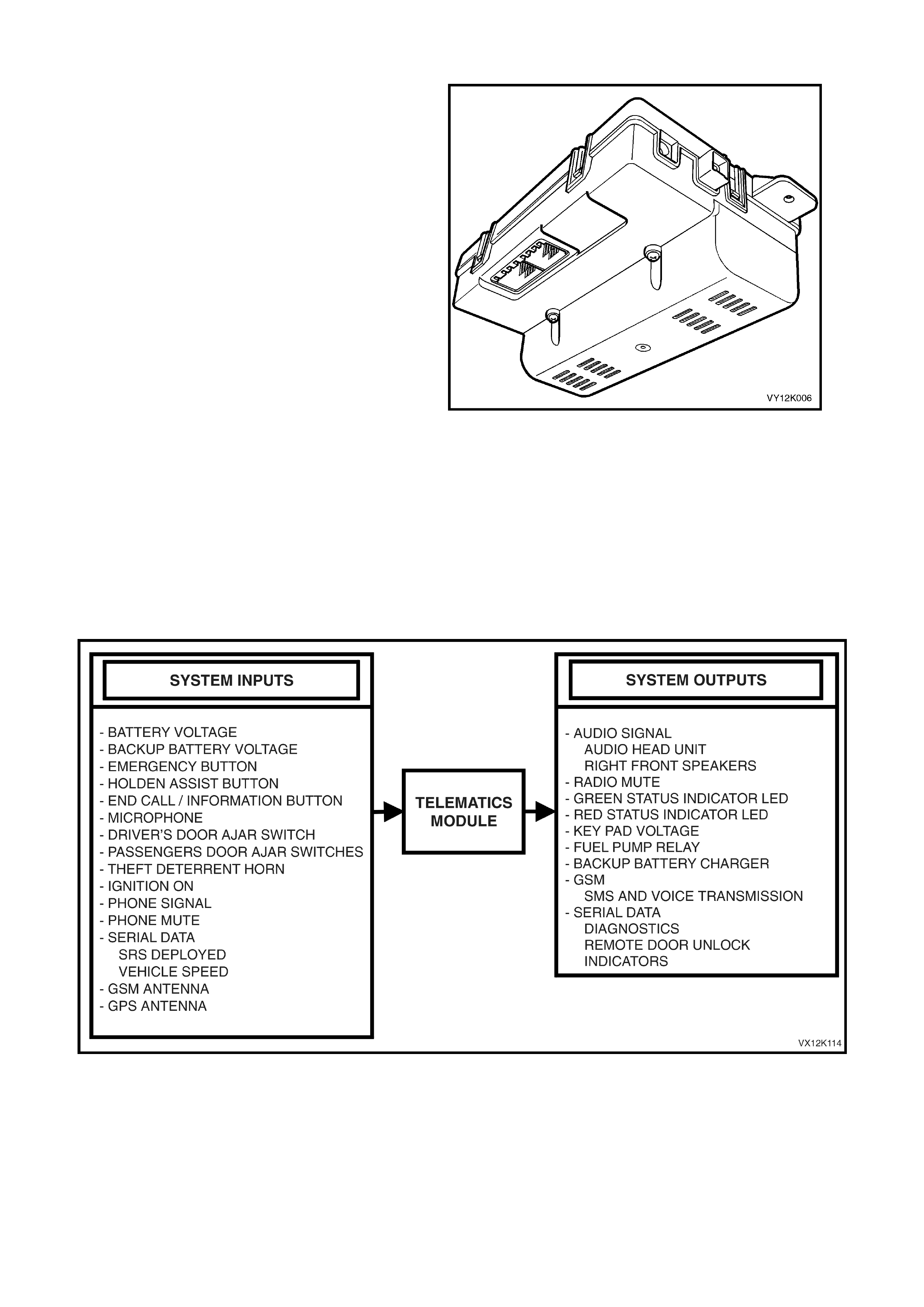
2.4 TELEMATICS MODULE
The telematics module, located under the
instrument panel, above and to the left of the
instrument panel compartment, controls the
operation of the telematics system. The telematics
module consists of a GPS and GSM engine and a
Serial Data Interface. The telematics module
monitors vehicle operating conditions via discrete
inputs, the serial data bus and controls system
outputs.
The telem atics m odule also receives an d transm its
GSM information via the GSM antenna and
receives GPS information via the GPS antenna.
The telematics module interfaces with other control
modules in the vehicle via the serial data circuit
normal mode message. For further information
regarding the serial data bus and normal mode
message refer Section 1.2 SERIAL DATA
COMMUNICATION in Section 12J Body Control
Module. TECH 2 is also capable of communicating
with the telematics module via the serial data
circuit.
NOTE:
If at any time a new telematics module is
installed into the vehicle, then this new module
must be registered with Holden Assist. To register
this new module with Holden Assist refer to
3. SERVICE OPERATIONS Telematics Module
Changeo ver Pr oces s in this Section.
Figure 12K-3
Figure 12K-4
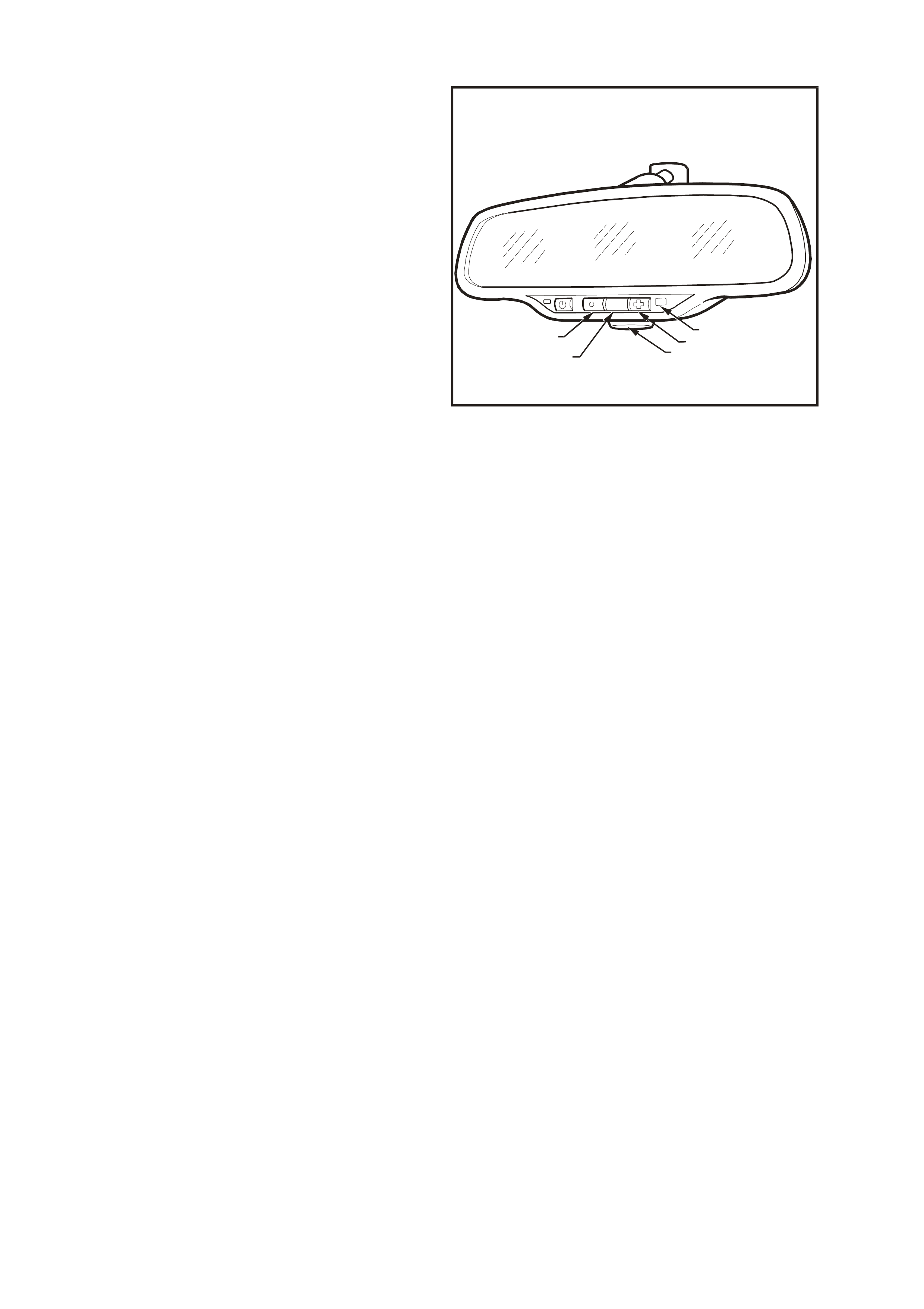
2.5 INTERIOR RE AR VIEW MIRROR
The interior rear vie w m irror ass em bly contains th e
telematics button pad, microphone and the status
LEDs.
Legend:
1. End Call / Information Button
2. Holden Assist Butt on
3. Microphone
4. Emergency Button
5. Status Indicator LEDs
VX12K008
HOLDEN
ASSIST
124
35
Figure 12K-5
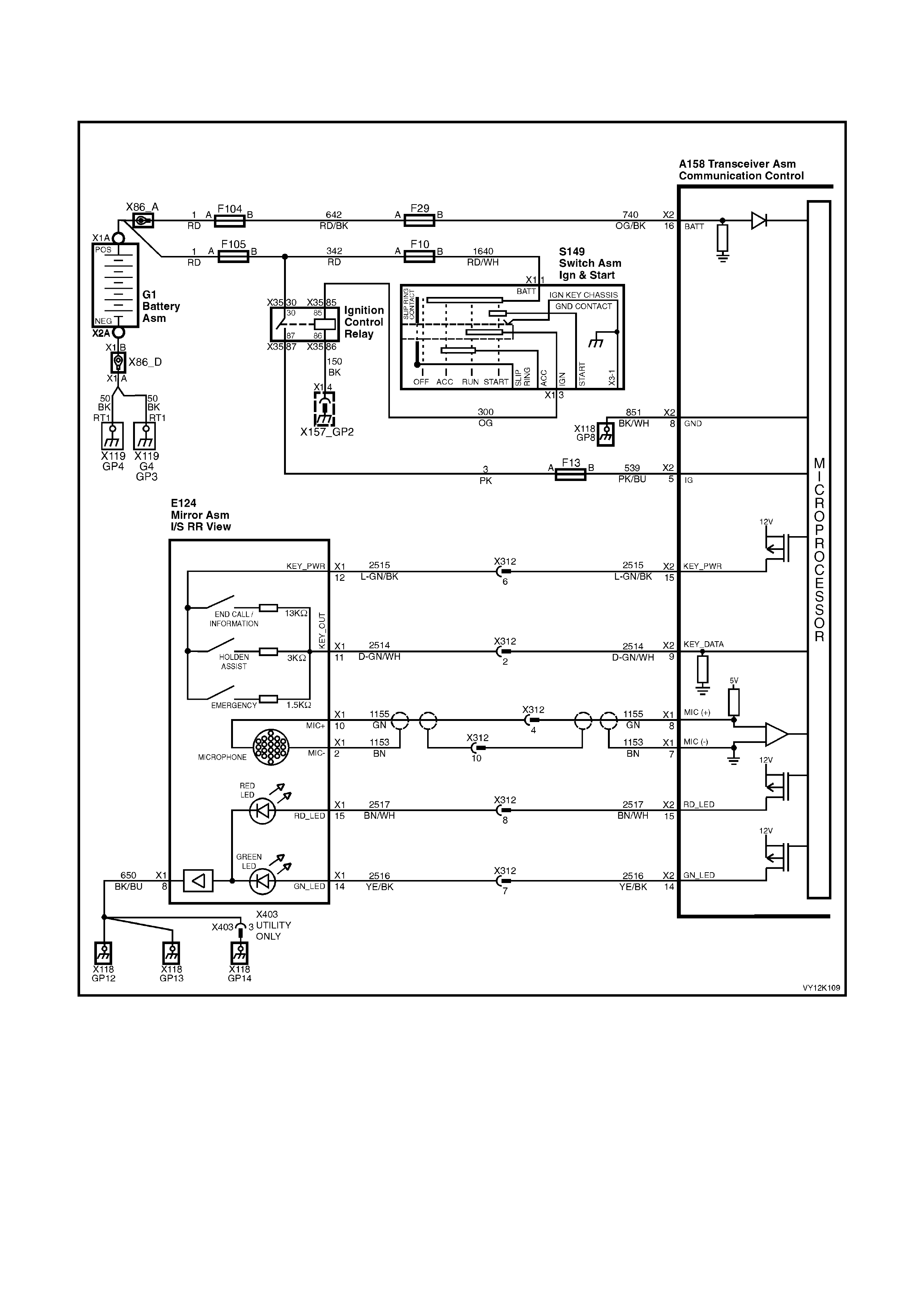
TELEMATICS BUTTON PAD
The telem atic s button pad is a resistor encod ed switch , which m eans that each b utton has a sep arate and diff erent
value resistor connected to it. The telematics module uses a voltage divider circuit to determine which button has
been pres sed. T he telem ati cs module A158 (r efer Figur e 12K-6) supp lies a 12 vo lt signa l vo ltage to term inal X1- 12
of the rear view mirror connector circuit 2515 (Light Green/Black wire). Whenever a button is pressed the
corres ponding s witch is clos ed and circ uit 2514 ( Dark Gr een/W hite wire) is conne cted to gr ound t hrough a r es istor,
each switch having a different value resistor. The telematics module monitors the voltage on circuit 2514 (Dark
Green/White wire) at terminal X2-9, which will change when any of the buttons are pressed.
EMERGENCY BUTTON
W hen the em er gency button is pr ess ed, t he voltage at ter minal X 2-9 of the telem atic s module will be a pprox i mately
3.8 Volts. The telematics module determines this voltage at terminal X2-9 as an emergency button press. The
telematics module will initiate a voice call to an operator at the National Emergency Response Centre and then
send an SMS m es sage contai ning status and loc atio n data. If the call can n ot be c onnecte d, the telem atics m odule
will imm ediatel y re-attem pt to connect the call a second tim e. If the sec ond attempt als o fails, the un it shall wait for
60 seconds and make a third and final attempt.
If the emergency button is pressed while a Holden Assist call is in progress then the status of the call shall be
upgraded to an emergency call, and the telematics module will not be permitted to terminate the call by pressing
the “End Call / Information” button.
If the emergency button is pressed while the vehicle is outside GSM network range, the telematics module will
enter “Em er gency Call M od e” wher e b y the emergency call reques t wil l b e reta in ed. When contac t is re- es tab lis he d
with the GSM network, the emergency call will be placed immediately.
HOLDEN ASSIST BUTTON
When the Holden Assist button is pressed, the voltage at terminal X2-9 of the telematics module will be
approximatel y 2.3 Vol ts , th e tel ematic s m odule determines this vo lta ge a t ter minal X2- 9 as an H old en Ass ist But t o n
press. The telem atics m odule will initiate a voice ca ll to the call c entre and then send a n SMS m essage c ontaining
status and location data. If the call can not be connected, the telematics module will immediately re-attempt to
connect th e call a second tim e. If the second attem pt also f ails, the un it shall wai t for 60 s econds and m ake a third
and final attempt.
END CALL / INFORMATION BUTTON
When the end call / information button is pressed, the voltage at terminal X2-9 of the telematics module will be
approximatel y 0.7 Vo lts , th e telem atic s module d eter mines this vo lt age at ter minal X2- 9 as a n e nd c a ll / inf o rmation
button press. If end call / information button is pressed to make a call, you will be connected to Holden Assist
information services. Pressing this button while a call is connected will disconnect the call. It however will not
disconnect a call while the call is ringing the information service number or the Holden Assist number. It is not
possible f or the end call / i nformation butt on to disc onnect an em ergenc y c all or a Holden As sist call tha t has been
upgraded to emergency call status.
MICROPHONE
The active microphone in the interior rear view mirror provides a means for voice communication to the vehicle
occupants and the Holden Assist Centre.
Figure 12K-6

STATUS INDICATOR LEDS
The red a nd green s tatus indicat or L EDs in the interio r rear view m irror indic ate the c urrent stat us of the te lem atic s
system. The telematics module activates the LEDs by switching a 12 power supply to each LED on or off. The
brightnes s of the LEDs is control led b y the int erior rea r vie w mir ror elec tronic s, which will vary the brig htn ess of the
LEDs depending on the ambient light and the ignition switch position. If the ambient light is low the brightness of
the LEDs will be decreased when the ignition is on. If the ambient light is high there will be no change to the
brightness of the LEDs when the ignition is turned on.
LED Condition Current Status
Green Continuous Self-test pass, system OK (no current DTC logged).
Green Flashing
(0.5 sec ON / 0.75 sec OFF) Sy stem OK (no current DTC logged), and
• Call being connected, or
• Call in progress.
• Emergency call mode
Red Continuous • Self-test failure (current DTC logged), or
• Unit is in Service Mode, or
• System test in progress.
Red Flashing
(0.5 sec ON / 0.75 sec OFF) Self-test failure (current DTC logged), and
• Call being connected, or
• Call in progress.
Red & Green OFF • Performing power-up self-test
• Stand-by mode
• Sleep mode
• No power to telematics module
Orange
(Red & Green) Continuous • Vehicle is not within GSM network range
Orange
(Red & Green) Flashing • Unit is in “Emergency Call Mode”
Red/Green Alternate Flashing
(0.5 second alternating)
(5 second duration after ignition on)
• Unit in service mode, or
• Unit in VAP mod e.
The colour of the LED indicates the status of the system. If there is a system fault during a call the LED will flash
red. If there are no system faults, then the LED will flash green.
2.6 AUDIO SYSTEM INTERFACE
AUDIO SYSTEM AND RHF SPEAKERS
The telematics system uses the vehicle audio
system to provide a means for voice
communication from the Holden Assist call centre.
The telematics m odule als o has the ab il it y to d etec t
if the audio system is not operational, and will
switch from the vehicle audio system to the RHF
speakers, if it detects that the audio system is not
operational.
Whenever the telematics audio is activated the
radio mute signal is also activated and the
telematics module grounds the radio mute circuit
5211 (Yel lo w/B lack wire) c aus in g the cir cuit voltag e
to be pulled low, less than two Volts. This low
voltage is detected by the radio as a mute request
and when received, the audio system will mute.
The volume of the telematics call can then be
adjusted using the audio system volume control. If
the telematics module switches to the RHF
speakers the volume is fixed by the telematics
module.
Whilst the telematics system is not on a call the
audio and m ute requ est f rom the cell ular telep hone
connector will be passed through the telematics
module to the au dio s ystem . W hen a Holden Ass ist
call is active, the telematics module will ignore the
phone audio and transmit the telematics audio to
the audio system.
AUDIBLE TONES
Audible tones are also provided to indicate the
system status and ar e broadc ast via t he speak er to
alert the customer to certain operating conditions.
Figure 12K-7
Tone Operating Condition
Five Tones • Attempting to make call when vehicle is not within GSM network range, or
if the five tones occur after the ignition is turned off, the vehicle is not within
GSM network range.
• Warning that Service Mode is active or a system malfunction has been
detected and a Diagnostic Trouble Code has been stored in the telematics
module.
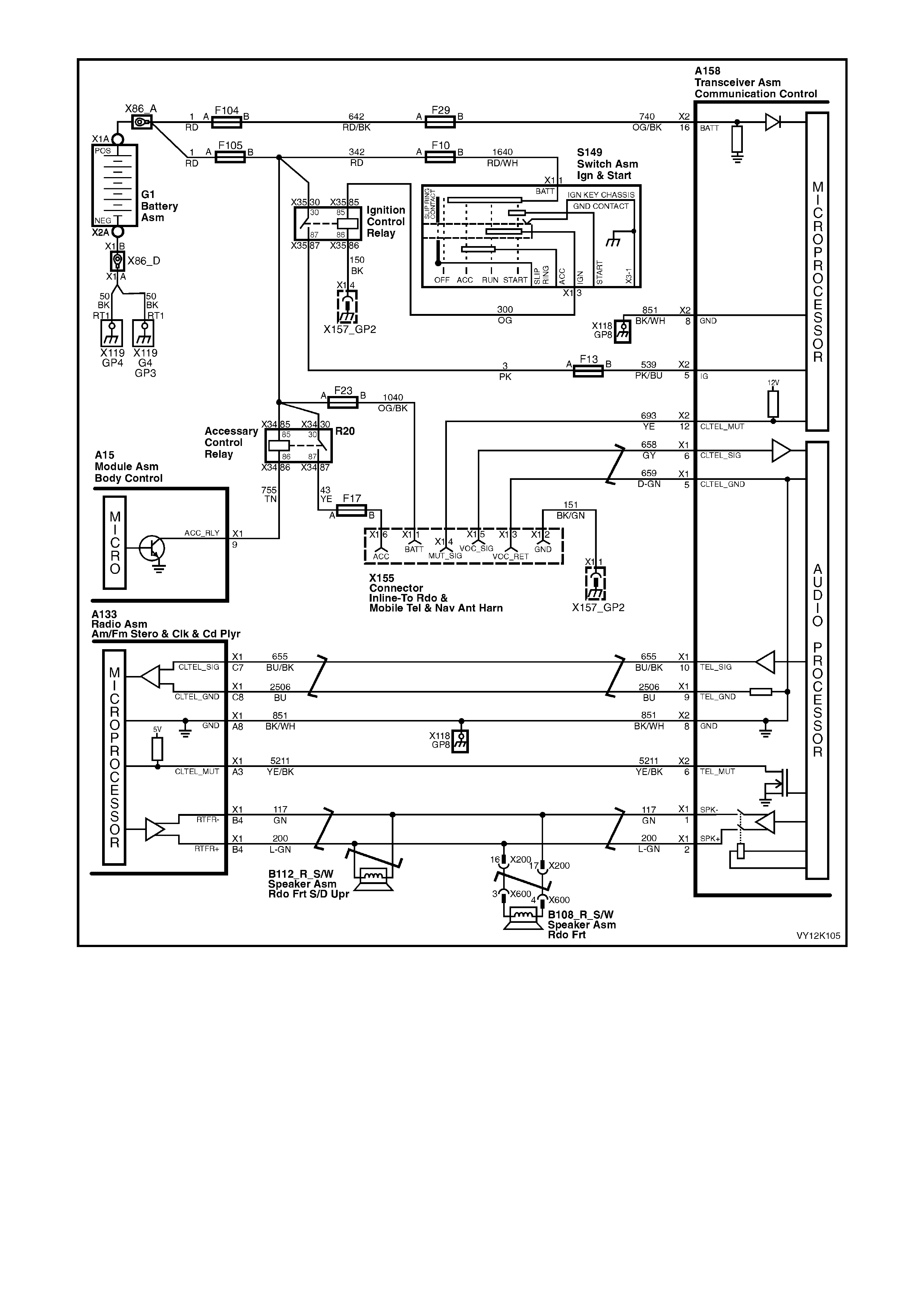
Figure 12K-8
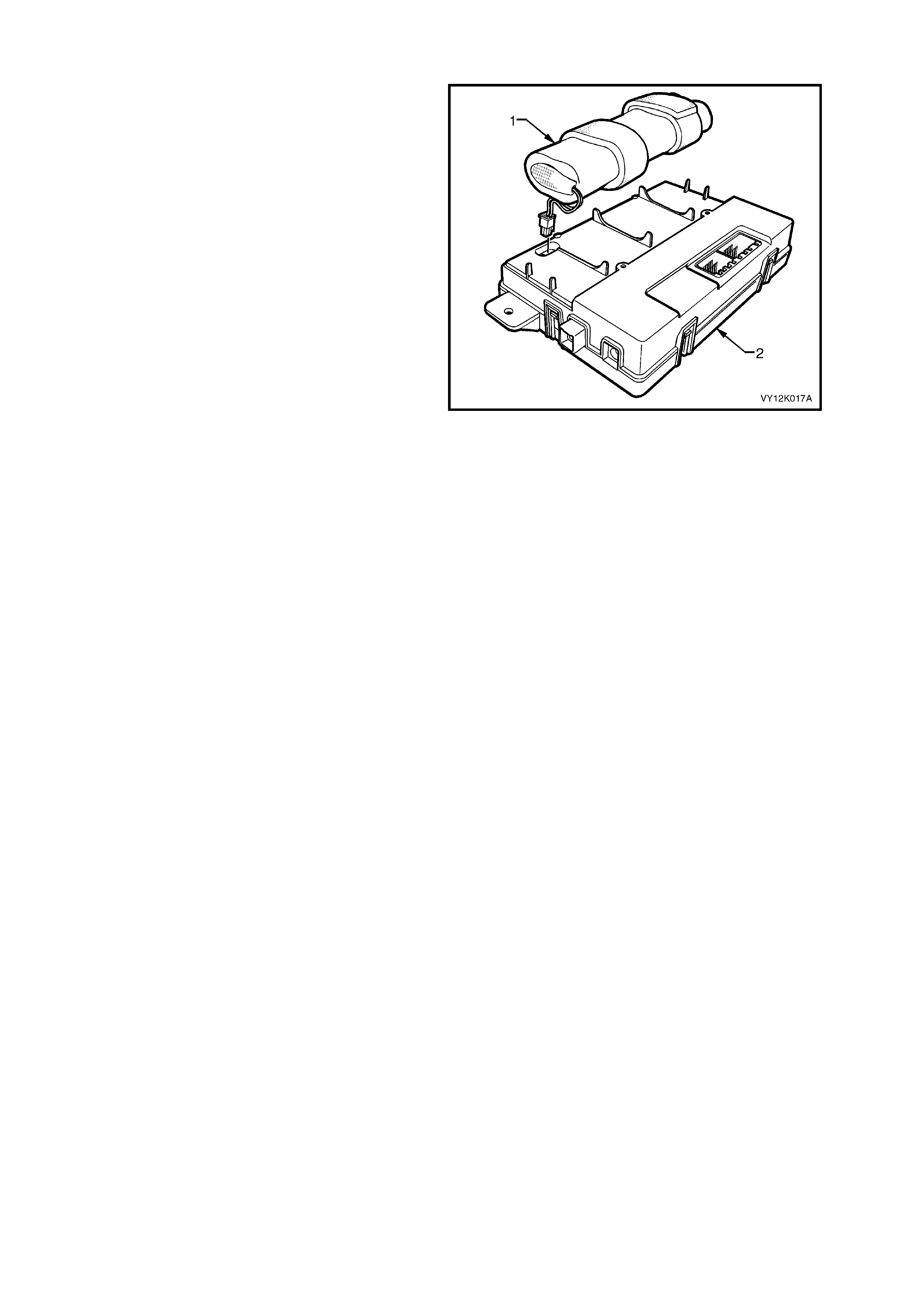
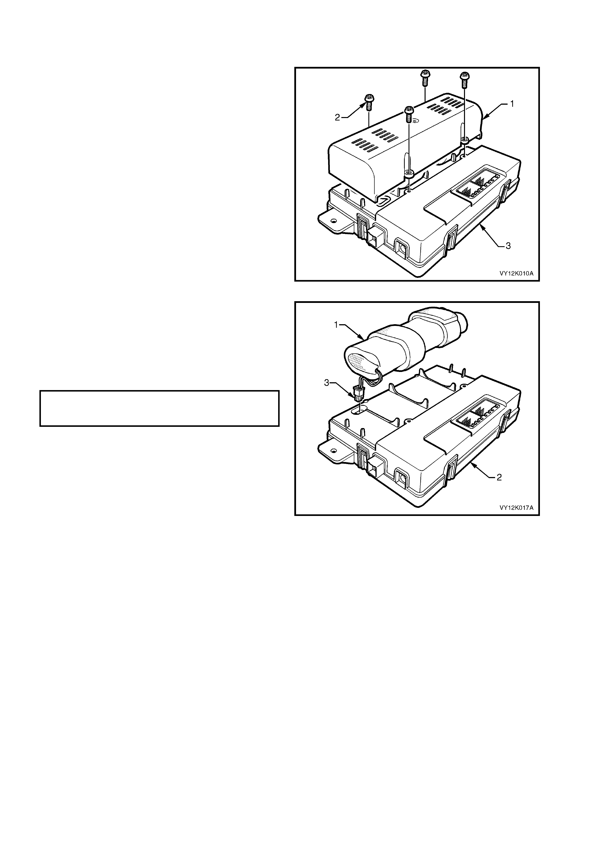
2.7 BAC KUP B ATTERY
The backup battery (1) is housed in the battery
compar tm ent of the telematics m odule. The backup
battery will provide power to the telematics module
for at least 30 minutes in the event of the vehicle
battery being discharged or disconnected. The
telematics module has a backup battery charging
circuit that maintains the backup battery state of
charge. This circuit also includes an over current
protection device. The telematics module has a
back up battery timer that monitors the time the
back up battery has been in the vehicle.
After the back up battery has been in the vehicle
for 5 years (4 3680 h ours) it has r eached t he end of
its useful life (internal deterioration causing low
charge ac cepta nce) DT C 13 will be s et a nd the red
status LED will be illuminated, for further
information refer DTC 13 - Backup Battery Timer
Expired in this Section.
Figure 12K-9
2.8 BATTERY VOLTAGE
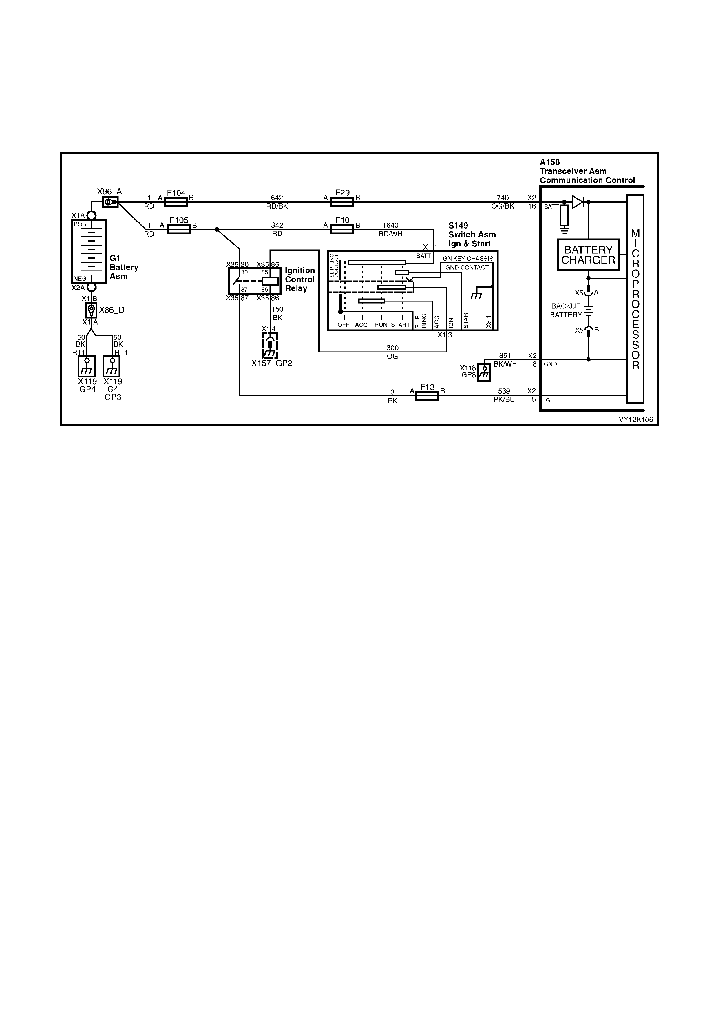
Battery voltage is applied to the telematics module terminal X2-16 at all times via circuit 740 (Orange/Black wire),
fuse F29 and fusible link F104 (refer Figure 12K-10). If the battery voltage fails below a preset voltage for longer
than 30 minutes, the telematics module will transmit a Low Battery Alert to the Holden Assist Centre. Refer
2.2 ALERTS, Low Battery Voltage Alert in this Section for further information. If the battery is removed the
telematics module will transmit a Battery Removal Alert to the Holden Assist Centre. Refer 2.2 ALERTS, Battery
Removal Alert in this Section for further information.
Figure 12K-10
2.9 B ACKUP BATTERY CHARGER
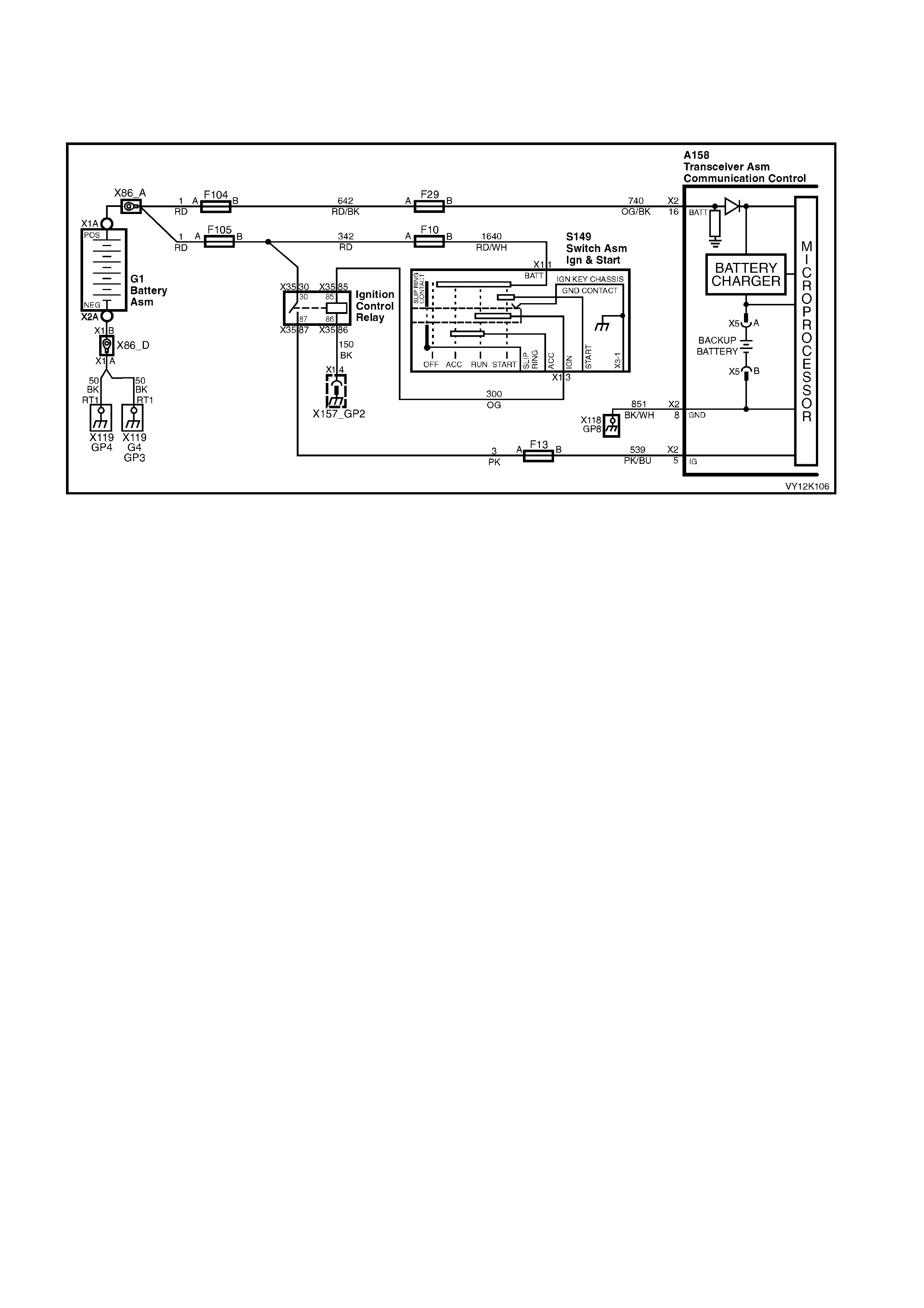
The telematics module constantly monitors both vehicle batter y voltage and backup battery voltage. The charging
circuit constantl y m onitors the back up battery voltage to determine if the back up battery needs to be charged at a
maximum of up to 300mA.
Figure 12K-11

2.10 SERIAL DATA
The telematics module monitors the auxiliary serial data circuit 1061 (Green/White wire) normal mode message
for the following information: Airbag Deployed this Ignition Cycle from the SRS SDM and Vehicle Speed from
the PCM. For further information regarding the serial data bus and normal mode message, refer
1.2 Serial Data Communication in Section 12J Body Control Module in this Service Information.
If the telematics module receives a “Remote Unlock” message from the Holden Assist Centre, the telematics
module will request the BCM (via the serial data circuit) to unlock the doors. For further information regarding the
BCM door lock operation, refer Section 12J Body Control Module, Central Door Locking Systems in this
Service Information.
If the telematics module receives a “Immobilise” message from NERCTM, the telematics module will then turn off the
fuel pump relay (refer 2.15 Fuel Pump Relay Drive Circuit in this Section) cutting off the supply of fuel to the
engine and re quest the BCM (via the seri al dat a c irc u it ) to flash th e ind icator s . F or f ur ther i nf ormation regar d i ng t he
BCM indicator operation, refer Section 12J Body Control Module, Theft Deterrent System in this Service
Information.
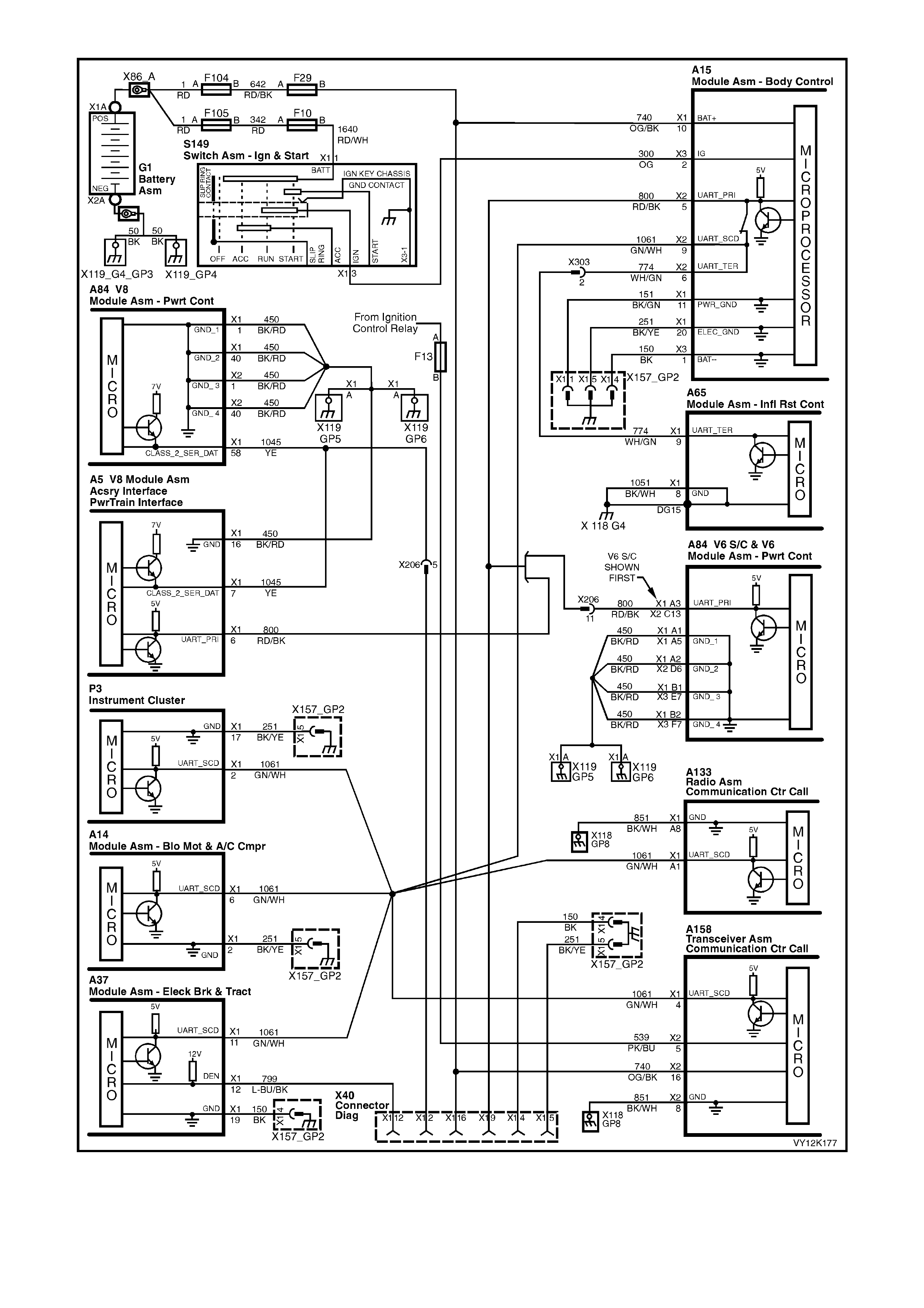
Figure 12K-12
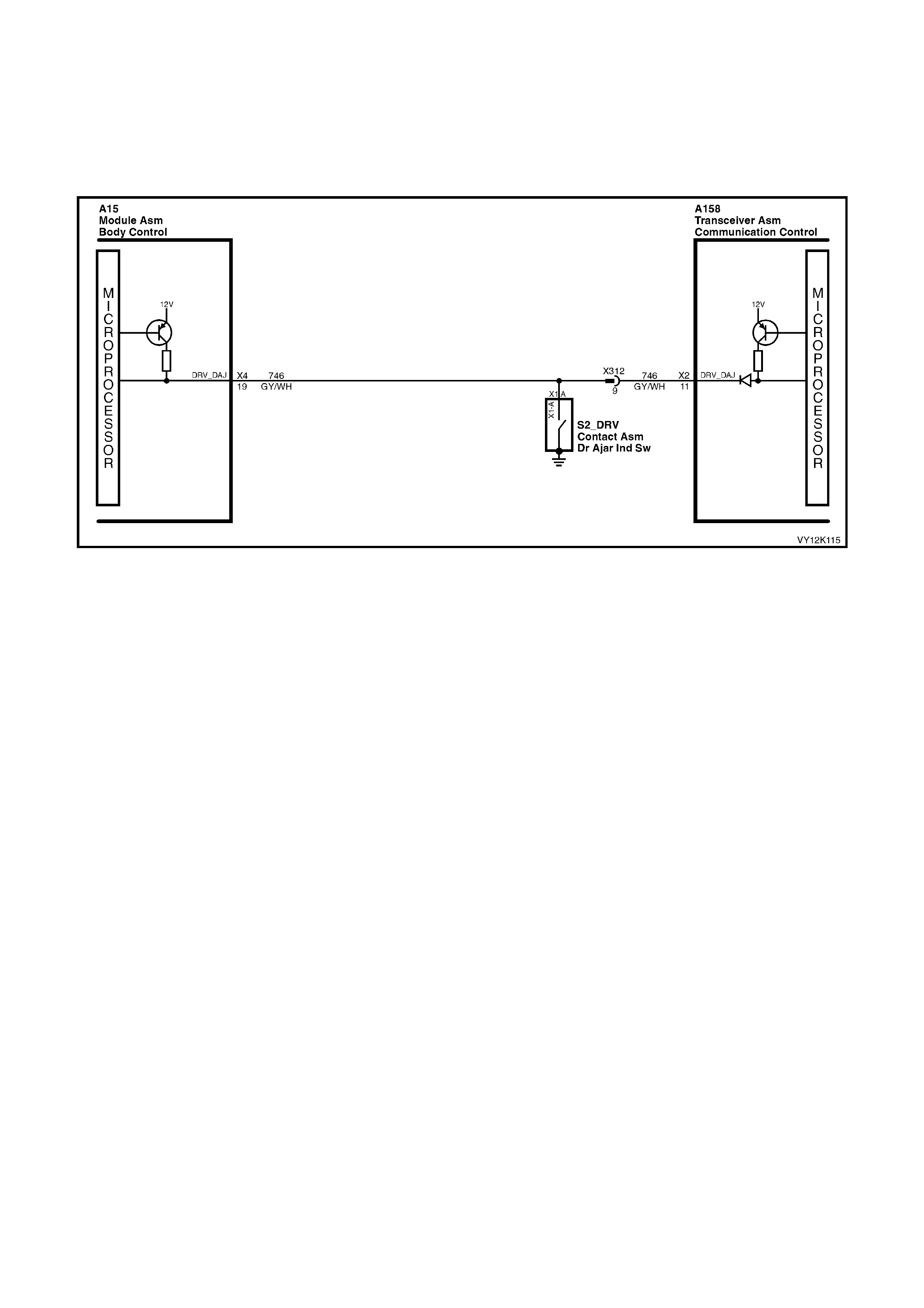
2.11 DRIVER’S DOOR AJAR SWITCH
The telematics module uses the driver’s door ajar input signal to determine if the driver's front door is opened or
closed. W hen the door is o pened, the driver ’s door ajar s witch gro unds term inal X 2-11 of the telem atics module via
circuit 746 (Grey/White wire). This causes the voltage at terminal X2-11 to be pulled low, less than 0.2 Volts
(driver's door open). This low voltage at terminal X2-11 is detected by the telematics module as the driver's door
open input signal. This is one of the inputs the telematics module uses to determine the system operating mode,
refer 2.1 OPERATING MODES in this Section.
Figure 12K-13
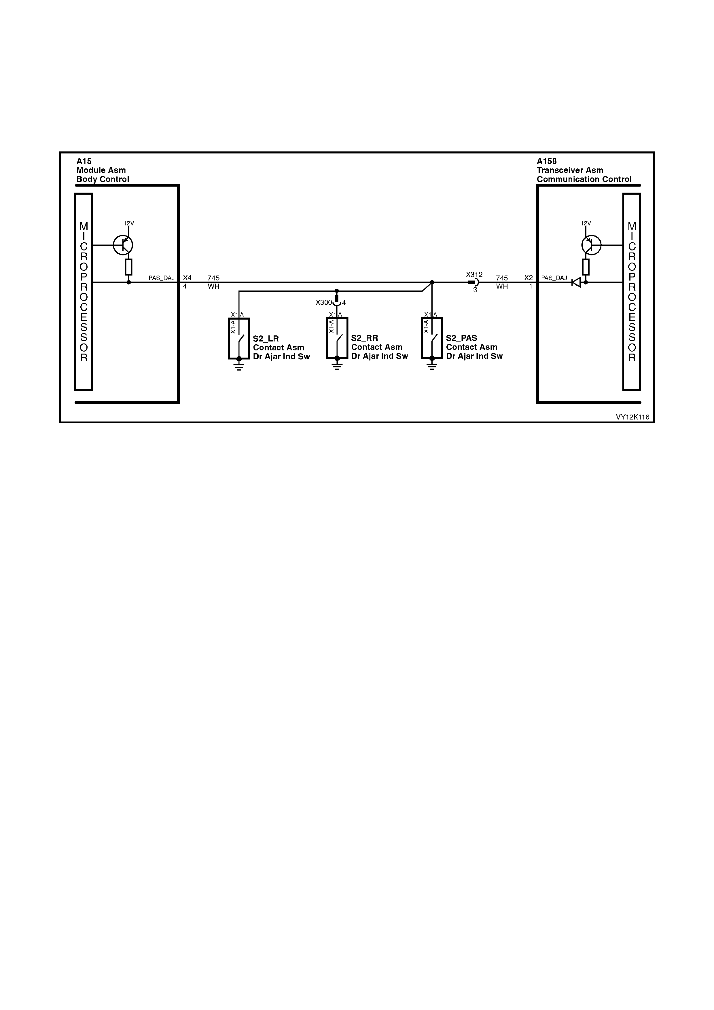
2.12 PASSENGER DOOR AJAR SWITCHES
The telem atics module uses this passengers do or ajar input signal to determ ine if any of the passenger door s are
opened or if all passenger doors are closed. If the right hand rear, left hand front or left hand rear door is open,
term inal X2- 1 of th e telem atic s m odule is groun ded v ia cir cuit 745 (White wire). T his c auses t he volta ge at te rm inal
X2-1 to be pulled low, less than 0.2 Volts (if any one of the passenger doors is opened). The telematics module
determ ines th is low vol tag e at t e rminal X 2-1 as the pa s s enger s do or op en in put signal. T his is o ne of the inp uts th e
telematics module uses to determine the system operating mode, refer 2.1 OPERATING MODES in this Sec tion.
Figure 12K-14

2.13 ALARM INPUT (THEFT DETERRENT HORN)
The telem atics module m onitors the theft deterrent ho rn circuit to determine if the alarm has been triggere d. If the
alarm has been triggered, the BCM pulses the vehicles horns at a rate of once per second. To pulse the theft
deterrent horn the BCM supplies 12 Volts to the theft deterrent horn circuit 1149 (Green wire). When the theft
deterrent horn circuit is activated, the voltage at terminal X2-2 of the telematics module is pulled high. The
telematics module determines this high voltage at terminal X2-2 as the theft deterrent system having been
triggered. If the vehicle theft deterrent system is triggered for longer than 20 seconds, the telematics module will
transm it an “Unauthorised Entr y Alert” m essage to the Holden Assist Centre. F or further information regarding the
unauthorised entry alert, refer to the Holden Assist Handbook Supplement.
Figure 12K-15
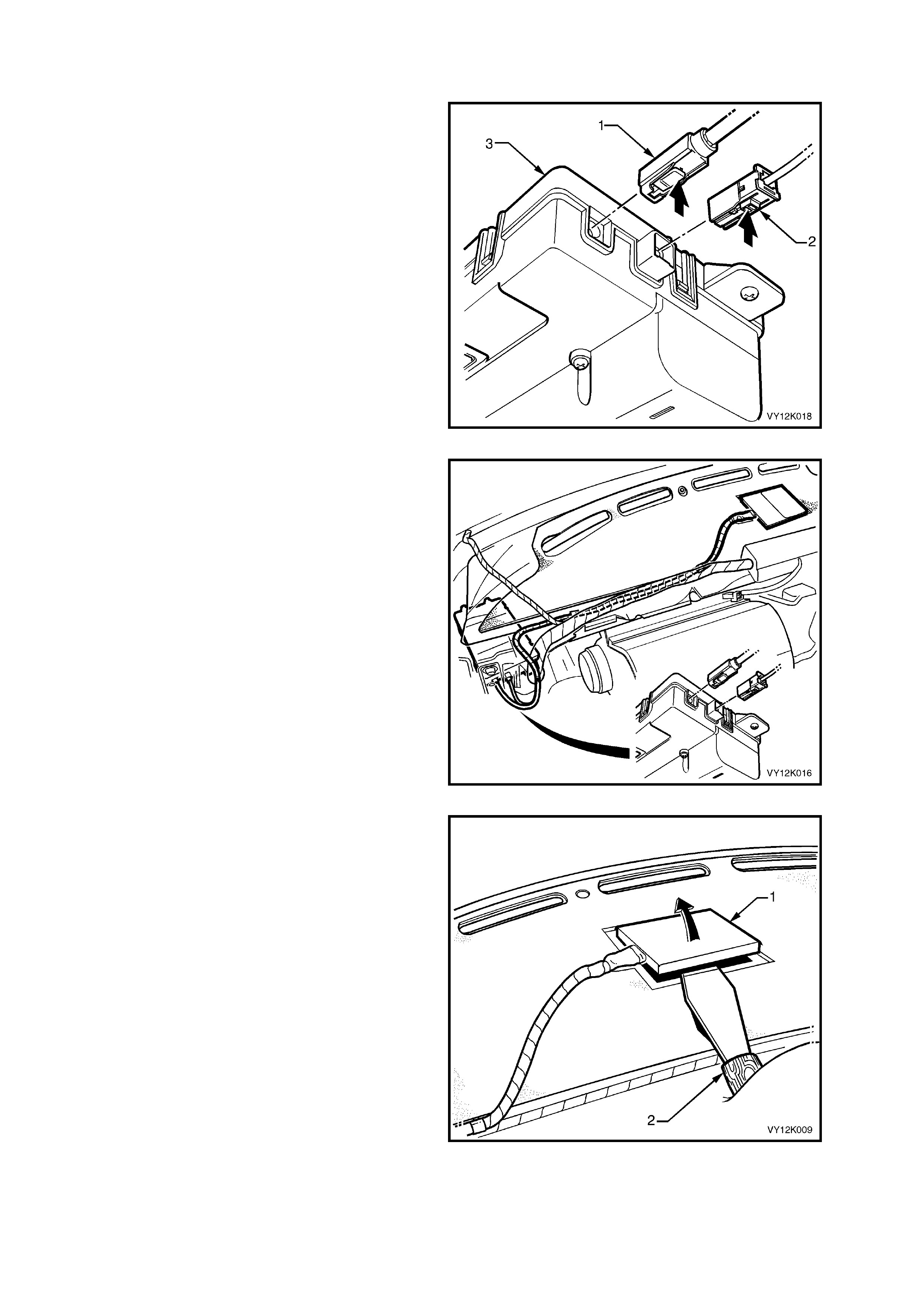
2.14 TELEMATICS ANTENNA
The telematics antenna (1) contains both the GPS
and GSM antennas in one unit, and is located
under the instrument panel. The antenna has two
leads, one for the GPS antenna and the other for
the GSM antenna.
NOTE: The area directly above the telematics
antenna should be free from obstructions as
they may adversely affect antenna operation
and the system may not have full functionality.
Aftermarket window tinting may also affect the
antenna operation.
GSM ANT ENNA
The GSM antenna is capable of transmitting and
receiving both voice and data signals via the GSM
network. The telematics module uses the GSM
network to transmit and receive voice and data.
Signal strength may be affected in locations like
basement car parks or tunnels. However, in most
cases, as the vehicle em erges fr om the obstruction
or re-enters the digital phone network area the
signal will be available again and any stored data
will be trans m itted. T he GSM antenn a is c onnected
to the telematics module by a plug in type
connector, refer Figure 12K-17 (1).
TECH 2 displays the GSM signal strength in dBm,
which is decibels per milliwatt. When measuring
GSM signal strength, the measurement is
referenced to 1 mW, and as the signal strength is
less than the reference, it is always negative. The
signal strength will range from –113 dBm (poor
signal) to –50 (good signal).
G PS AN TEN NA
The GPS antenna receives signals from satellites
orbiting the earth and transmits these to the
telematics module to determine the vehicle’s
position. Signals from at least three GPS satellites
must be received to accurately determine the
vehicle’s two dimensional (2D) position. Signals
from at least four GPS satellites must be received
to accurately determine the vehicle’s three
dimens iona l ( 3D) positi on. I f signals fr om onl y three
satellites are received, the telematics module
cannot determine the vehicle’s altitude. The GPS
antenna must not be obscured by any objects,
such as under groun d car par ks, tunn els, brid ges or
buildings as any of these may affect GPS
reception. The GPS antenna is connected to the
telematics module by a plug in type connector,
refer Figure 12K-17 (2).
Figure 12K-16
Figure 12K-17
The telematics module uses a principle called triangulation to determine the location of the vehicle. This
principle states that you can determine the location of an object if you know its distance from three known
locations. GPS uses 24 satellites orbiting the earth, the location of each satellite is known at any given time.
The s atellites constant ly broadcast radi o signals and the tel ematics G PS m odule compares the amount of tim e
it takes for the signals from at least three different satellites to reach the GPS m odule. By converting tim e into
distance , it can calcu late the m odules loc ation on eart h. The telem atics m odule receives GPS data, dec odes it,
and transmits the vehicles location via SMS when requested by Holden Assist or NERCTM.
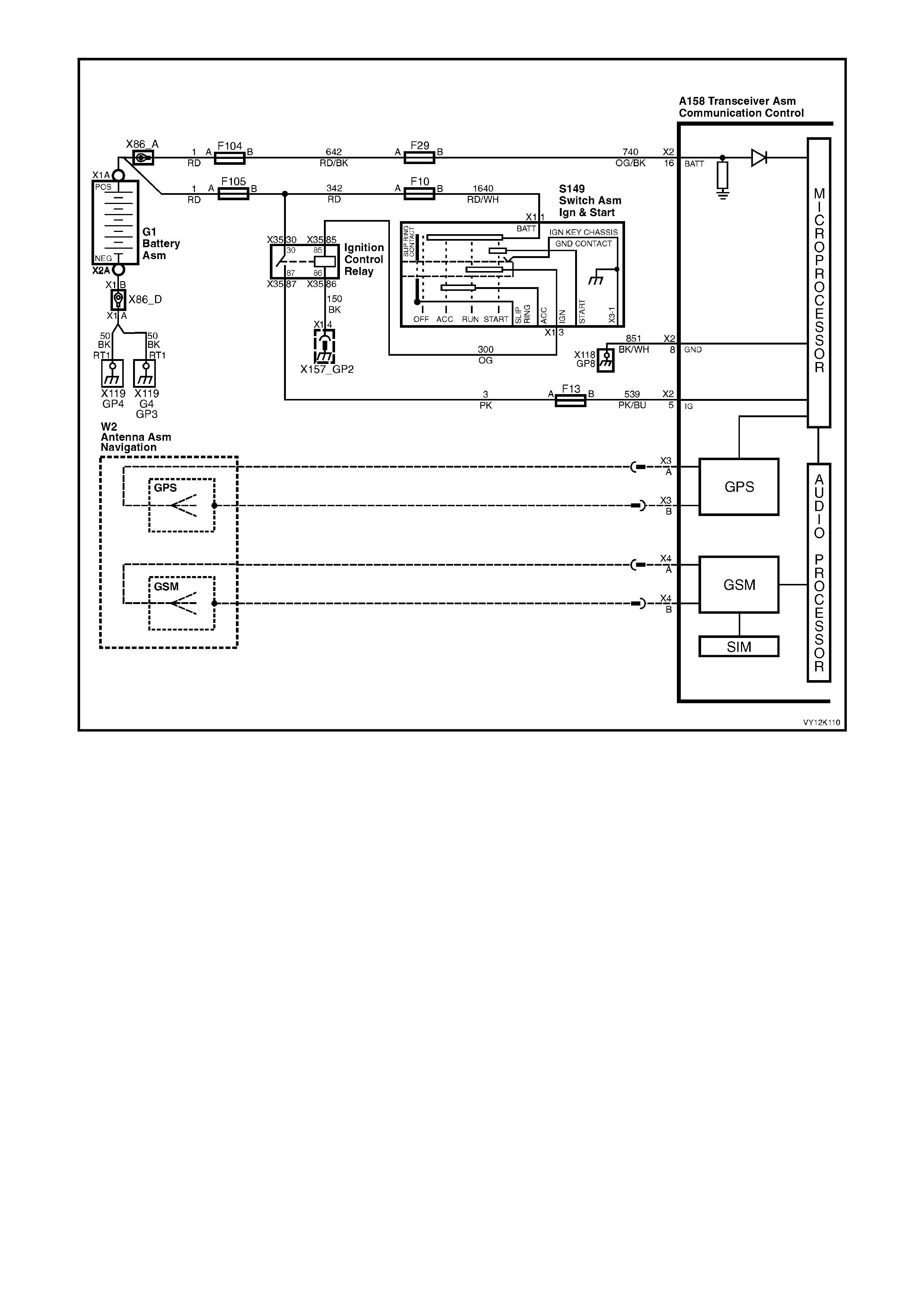
Figure 12K-18
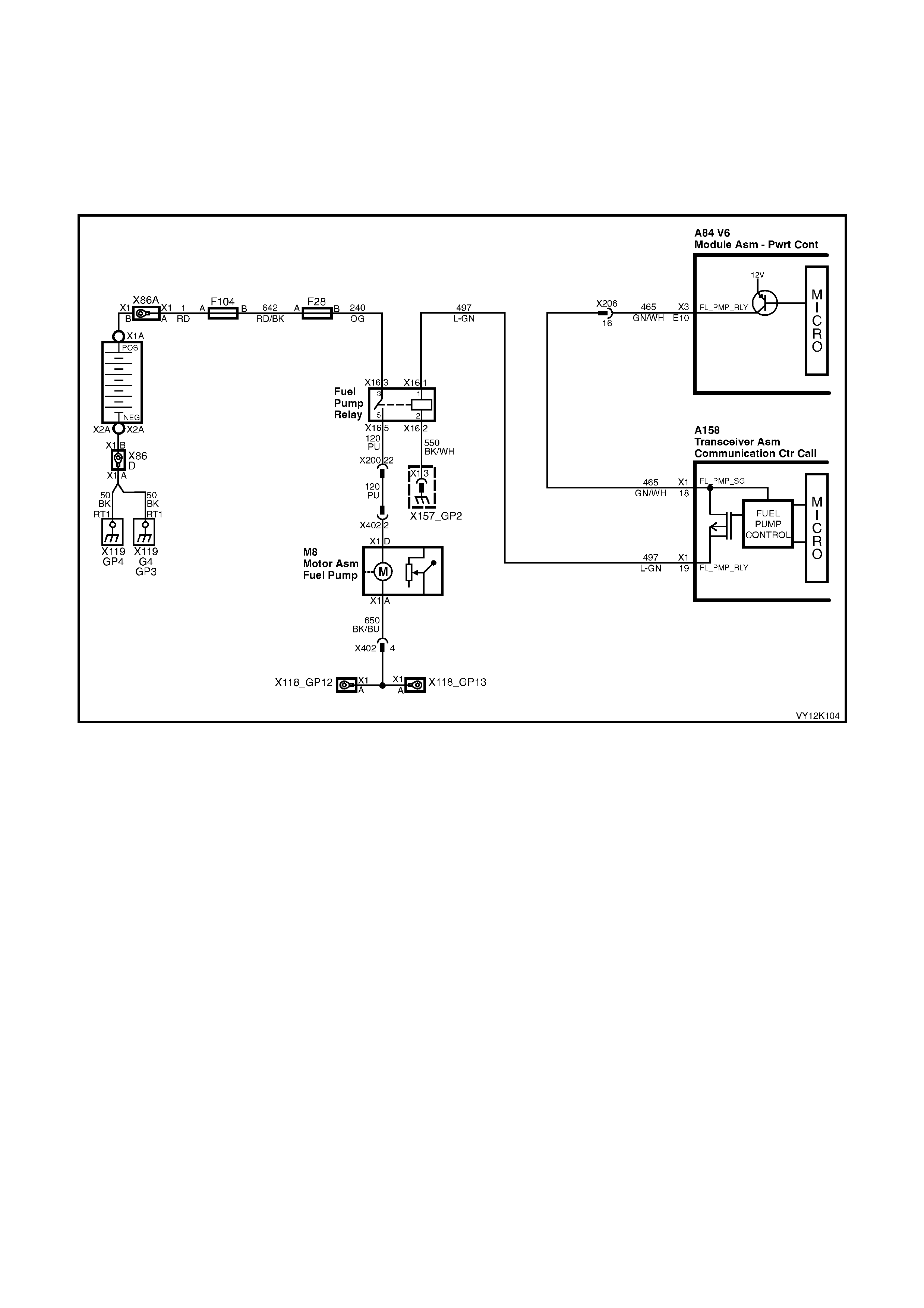
2.15 FUEL PUMP RELAY DRIVE CIRCUIT
The PCM energises the fuel pump relay drive circuit via circuit 465 (Green/White wire), the telematics module
terminals X1.18 circuit 497 (Light/Green wire) and X1.19 circuit 465 (Dark Green/W hite wire). The fuel pum p rela y
drive circuit is grounded through circuit 550 (Black/White wire) at ground location X157_GP2. The telematics
module can immobilise the vehicle by opening the fuel pump relay drive circuit, causing the fuel pump to stop
operating. This function can only be activated by the National Emergency Response Centre (NERC™) under
instruction from the Police. For further information refer 2.3 HOLDEN ASSIST REMOTE REQUESTS, Engine
Immobilisation in this Section.
Figure 12K-19 V6 Fuel Pump Circuit
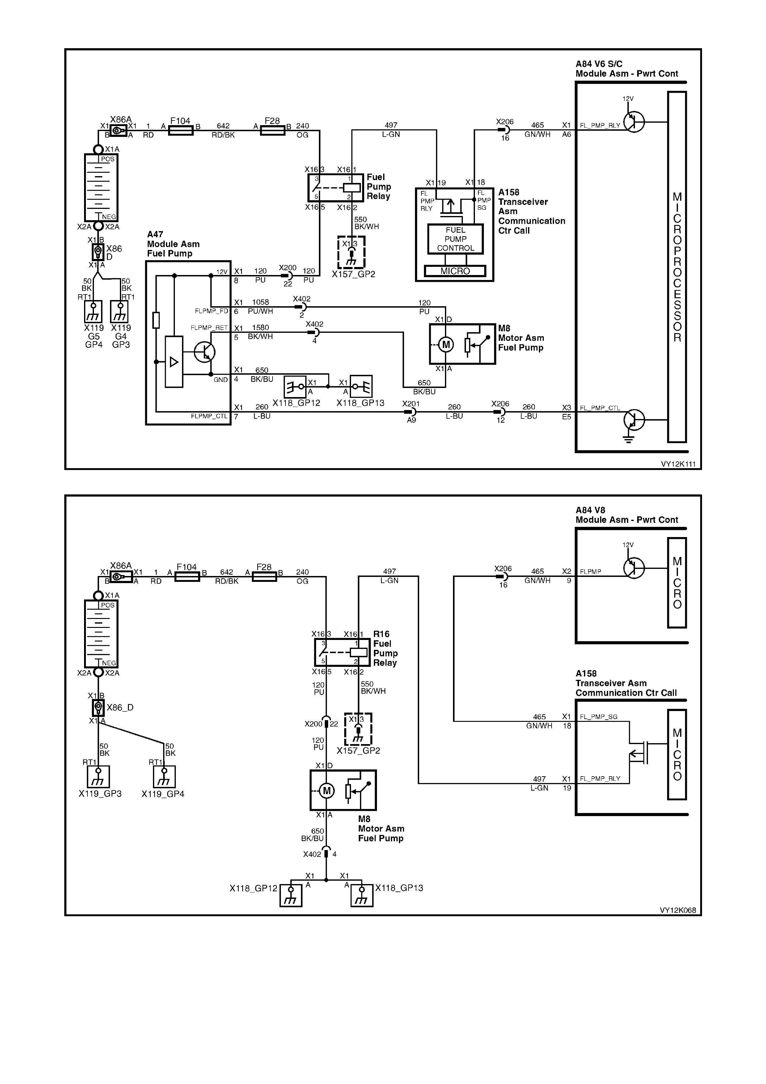
Figure 12K-20 V6 S/C Fuel Pump Circuit
Figure 12K-21 V8 Fuel Pump Circuit
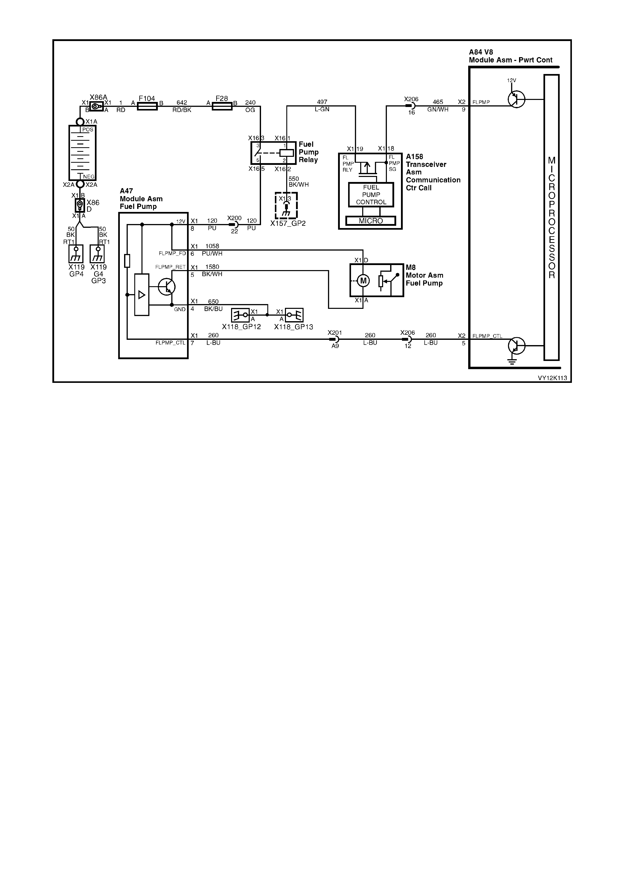
Figure 12K-22 V8 Utility Fuel Pump Circuit
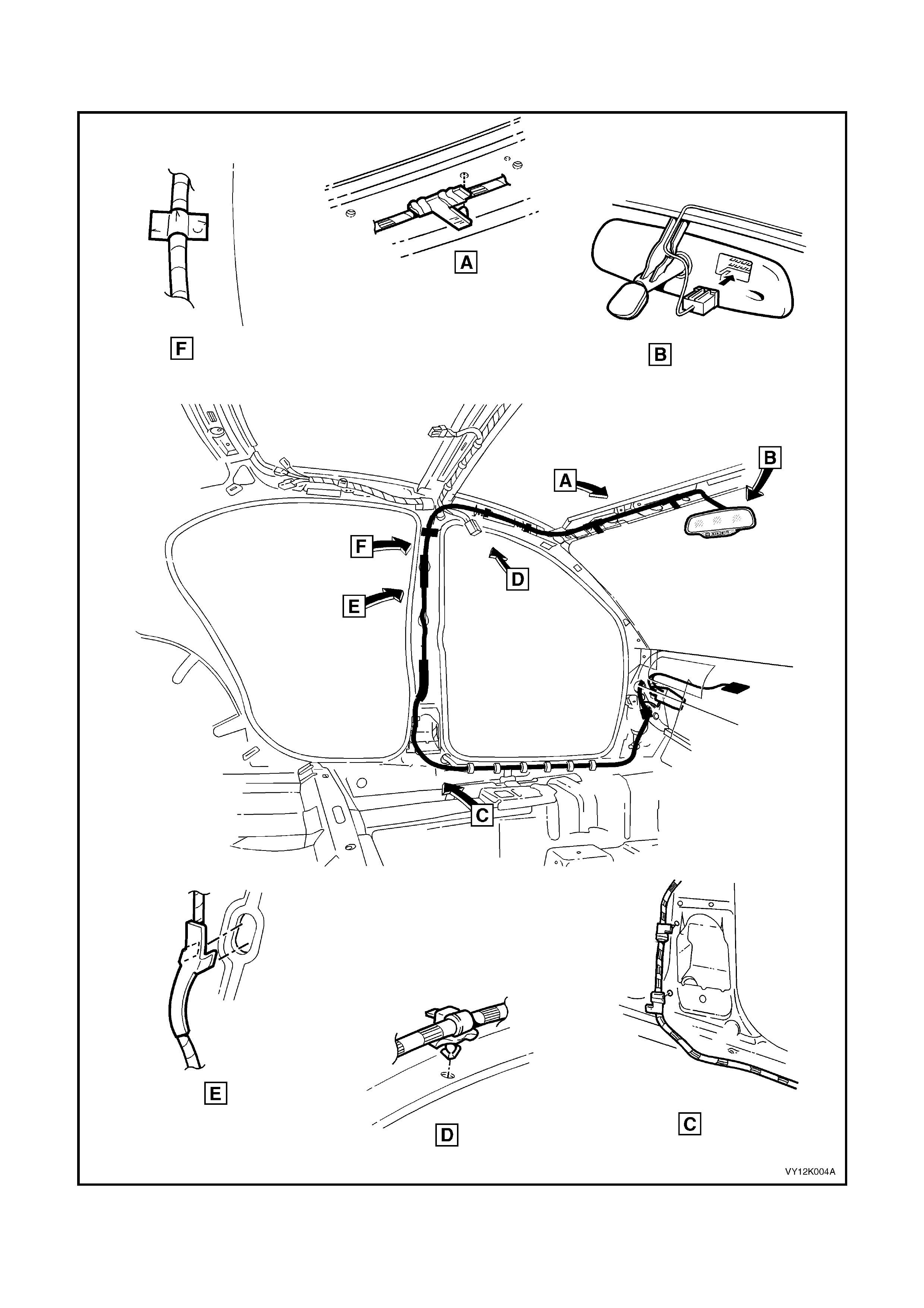
2.16 WIRING HARNESSES
VY Series vehicles equipped with the telematics system have specific main and body harnesses.
Figure 12K-23
3. SERVICE OPERATIONS
When carrying out any service procedure on the vehicle that involves disc onnecting the battery cables or
any procedure that may cause the battery voltage to fall below 12 Volts, the telematics module Service
Mode MUST BE ENABLED. Refer to 4.3 TECH 2 TEST MODES, F5: Program, F1 Operating Mode, in this
Section.
If the telematics module service mode is not enabled, a “Battery Removal Alert” will be t ransmitted to the
Holden Assist Centre whenever the battery is disconnected, or a “Low Battery Voltage Alert” when the
battery voltage is low.
3.1 TELEMATICS MODULE
LT Section No. 09-540
REMOVE
1. Using TECH 2, put the telematics module into
service mode. Refer to 4.3 TECH 2 TEST
MODES F5: Program, F1: Operating Mode, in
this Section.
2. Disconnect the negative battery cable from the
battery.
3. Remove the instrument panel compartment,
refer 3.2 INSTRUMENT PANEL
COMPARTMENT in Section 1A3
INSTRUMENT PANEL & CONSOLE.
4. Remove the left-hand side instrument panel
lower trim plate assembly., refer
3.1 INSTRUMENT PANEL LOWER TRIM
PLATE ASSEMBLY in Section 1A3,
INSTRUMENT PANEL & CONSOLE in this
Service Information.
5. Remove air conditioning vacuum tank, refer
8.1 VACUUM T ANK in Section 2B HVAC
CLIMATE CONTROL (MANUAL A/C) in this
Service Information.
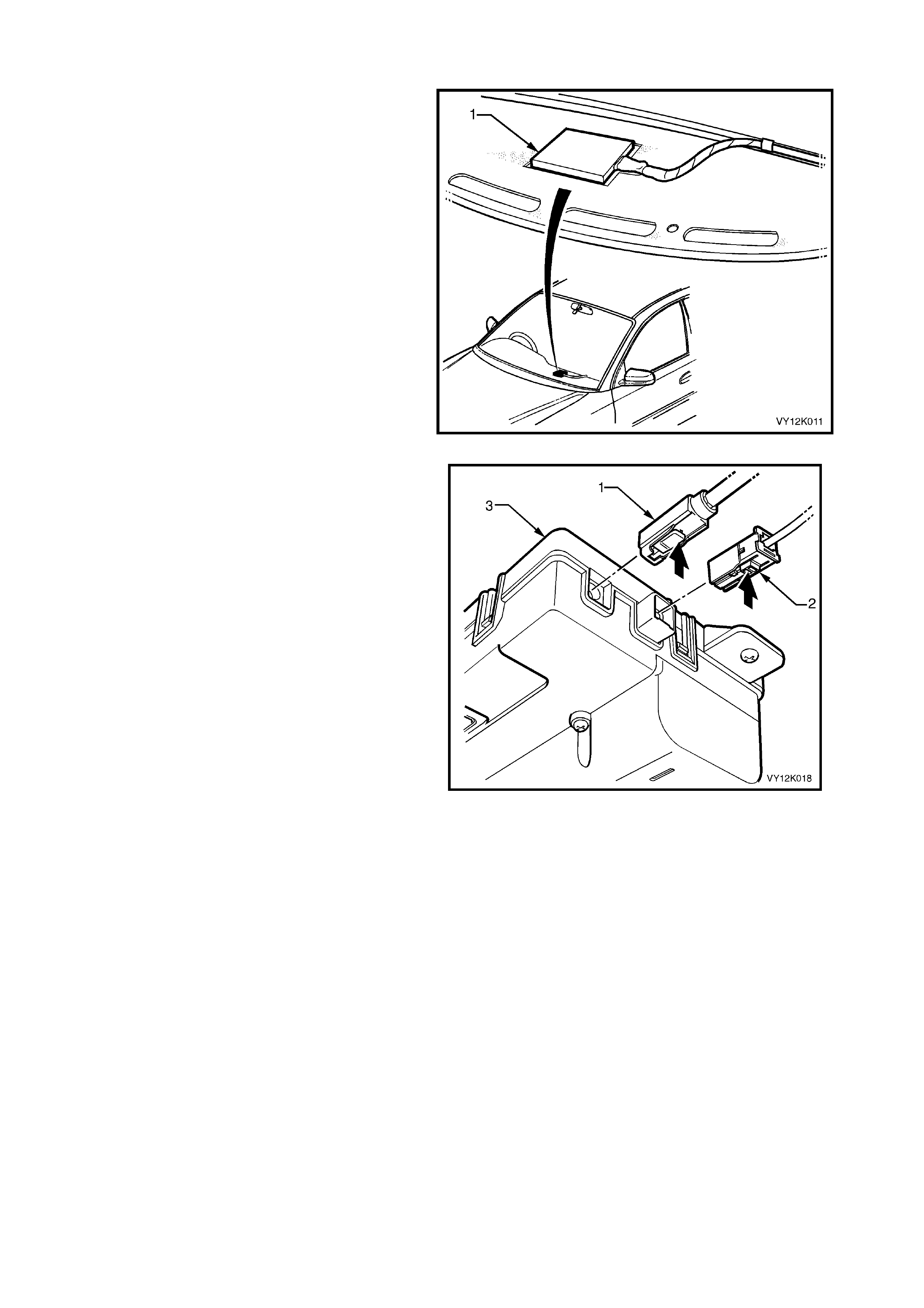
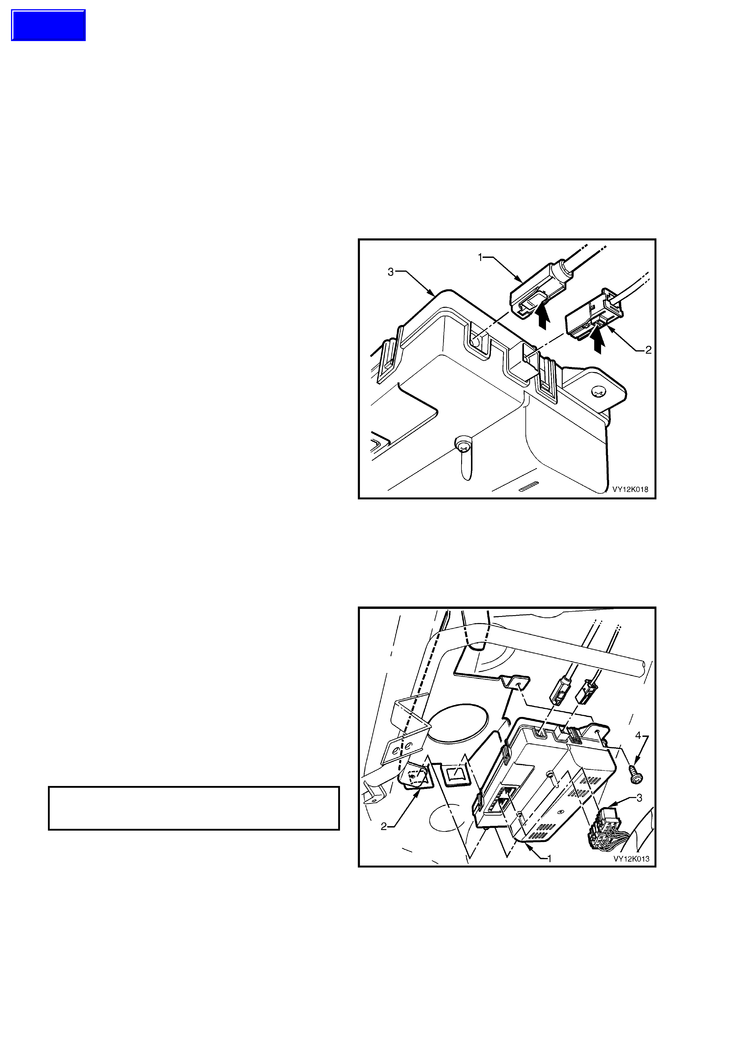
6. Disconnect telematics module, GSM antenna
connector ( 1), and t he GP S antenna connector
(2), from the telematics module (3).
Figure 12K-24
7. Disconnect telematics module harness
connector (3), from the telematics module.
8. Remove the telematics module assembly
retaining screw (4).
9. Lower the f r ont end of the module and sl ide th e
telematics module out of the retaining bracket.
REINST ALL
1. Reverse of the removal, noting the following.
2. Tighten the telematics module assembly
retaining screw to the correct torque
specification.
TELEMATICS MODULE ASSE MBLY
RETAINING SCREW
TORQUE SPECIFICATION 1 – 3 Nm
3. Use TECH 2 to disable the telematics module
Service Mode. Refer to 4.3 TECH 2 TEST
MODES F5: Program, F1: Operating Mode, in
this Section.
NOTE: If the telematics module service mode is
not disabled, the system will not have full
functionality.
Figure 12K-25
Techline

TELEMATICS MODULE CHANGEOVER PROCESS
If a new telematics module has been installed into the vehicle, then this new module must be registered with
Holden Assist. To register this new module with Holden Assist the following procedure must be performed.
1. Onc e the new module has been ins talled int o the vehi cle turn the ign ition on and m ake a ca ll to Holden As sist
by pressing the Holden Assist button.
2. When the Holden As sis t op erator answers , inf orm the oper at or who you are an d what r et ai l outlet you are f r om,
and that you have just installed a new telem atics module into the vehicle. You will also be required to pro vide
the operator with the complete Vehicle Identification Number (VIN) and if the vehicle is registered, the
registration number of the vehicle.
3. The new telematics module is now registered to this vehicle.
3.2 BAC KUP B ATTERY
LT Section No. 09-540
REMOVE
1. Using TECH 2, enable the telematics module
service mode. Refer to 4.3 TECH 2 TEST
MODES F5: Program, F1: Operating Mode, in
this Section.
2. Remove the telematics module. Refer
3.1 TELEMATICS MODULE ASSEMBLY in
this Section
3. Remove the four backup battery cover
retaining screws (2) and remove the backup
battery.
Figure 12K-26
4. Disconnect the backup battery connector (3)
from the telematics module (2).
REINST ALL
1. Reverse of the removal noting the following.
2. Tighten backup battery cover retaining screws
to the correct torque specification.
TELEMATICS BACKUP BATTERY
COVER RETAINING SCREWS
TORQUE SPECIFICATION 1 – 3 Nm
3. Use TECH 2 to reset the Back Up Battery
Timer, 4.3 TECH 2 TEST MODES F4:
Additional Functions, Backup Battery Timer
Reset.
4. Use TECH 2 to disable the telematics module
Service Mode. Refer to 4.3 TECH 2 TEST
MODES F5: Program, F1: Operating Mode in
this Section.
NOTE: If the telematics module service mode is
not disabled, the system will not have full
functionality.
Figure 12K-27
3.3 TELEMATICS ANTENNA
LT Section No. 09-540
REMOVE
1. Using TECH 2, enable the telematics module
service mode. Refer 4.3 TECH 2 TEST
MODES F5: Program, F1: Operating Mode, in
this Section.
2. Disconnect the negative battery cable from the
battery.
3. Remove the instrument panel pad assembly,
refer to 3.21 INSTRUMENT PANEL PAD
ASSEMBLY in Section 1A3 INSTRUMENT
PANEL & CONSOLE in this Service
Information.
4. Disconnect the GSM and GPS antenna
connectors (1&2) from the telematics module
(3).
Figure 12K-28
5. Remove the telematics antenna lead retaining
clips.
Figure 12K-29
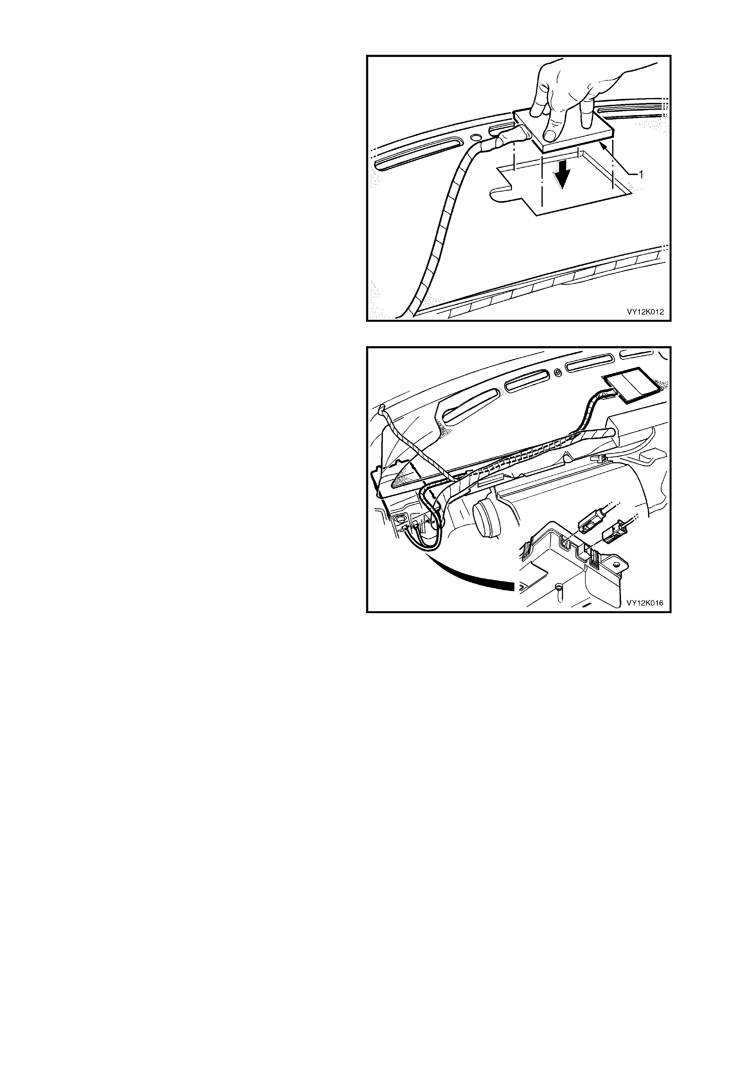
6. Using a commercial available paint scraper (2)
prise the antenna (1) from the dash panel.
Figure 12K-30
REINST ALL
1. Ensure the dash panel to telematics antenna
mating surface is clean.
2. If you are reinstalling the original antenna
remove the used double sided tape, and apply
new double sided tape (3M 4428 or
equivalent), m eeting Holden Standar d HN2021
Type 6 to the antenna mating surface.
3. Remove the backing from the double sided
tape.
4. Reinstall the antenna to the dash panel by
aligning the antenna into the cut out in the
dash panel insulation and then press down
firmly on the antenna.
5. Reinstall the telematics antenna lead retaining
clips.
Figure 12K-31
6. Reinstall the GSM and GPS antenna
connectors to the telematics module.
7. Reinstall the instrument panel pad assembly,
refer 3.21 INSTRUMENT PANEL PAD
ASSEMBLY in Section 1A3 INSTRUMENT
PANEL & CONSOLE in this Service
Information.
8. Reconnect the negative battery cable to the
battery.
9. Use TECH 2 to disable the telematics module
Service Mode. Refer 4.3 TECH 2 TEST
MODES F5: Program, F1: Operating Mode, in
this Section.
NOTE: If the telematics module service mode is
not disabled, the system will not have full
functionality.
Figure 12K-32
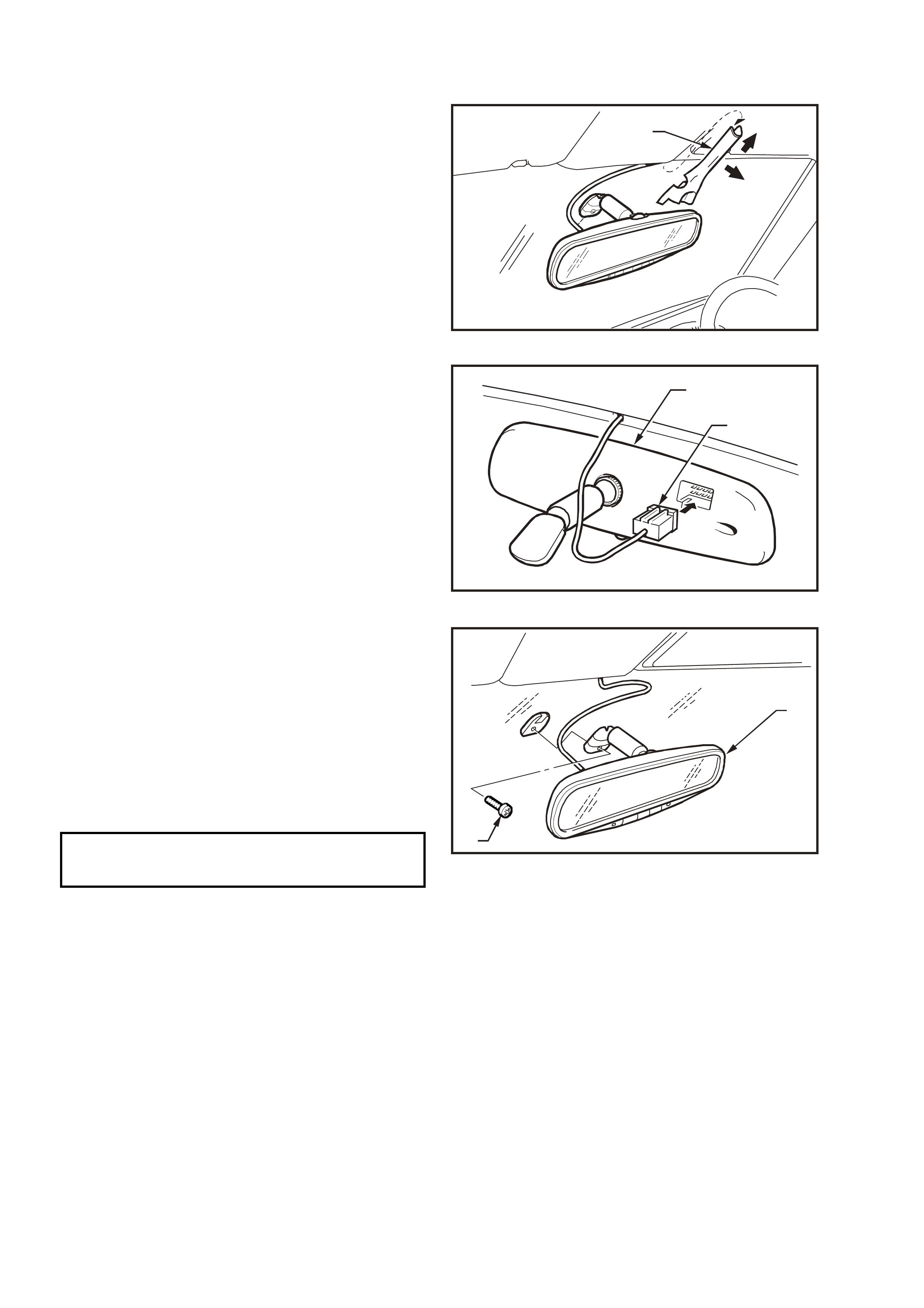
3.4 INTERIOR RE AR VIEW MIRROR
LT Section No. 09-540
REMOVE
1. Remove mirror wiring harness cover (1) by
sliding cover upwards slightly (direction A) and
pull cover outwards (direction B).
VX12K022
B
1A
Figure 12K-33
2. Disconnect the interior rear view mirror wiring
harness connector.
VX12K024
1
2
Figure 12K-34
3. Remove the interior rear view mirror retaining
screw and disengage the interior mirror from
the boss on the windscreen by sliding the
mirror (2) upwards.
REINST ALL
Reinstallation of the interior rear view mirror is the
reverse of the removal procedure, noting the
following:
Tighten the inter ior rear view m irror retainin g screw
to the correct torque specification.
INTERIOR REAR VIEW
MIRROR RETAINING SCREW
TORQUE SPECIFICATION 2.5 – 4.5 Nm
VX12K023
2
1
Figure 12K-35

4. TECH 2 DI AGNOSIS FOR TELEMATICS
4.1 BASIC KNOWLEDGE REQUIRED
Before attempting to diagnose the telematics system, you must have a good understanding of electrical system
basics and the use of circuit testing tools. Without this basic knowledge it will be difficult to use the diagnostic
procedures detailed in this Section.
Some elec trical basics, tr oubl eshootin g procedures and h ints as well as the use of circuit testing tools are covered
in Section 12P WIRING DIAGRAMS in the VY Service Information.
Basic Electrical Circuits - You should understand the basic theory of electricity, series and parallel circuits, and
voltage drops across series resistors. You should know the meaning of voltage (Volts), current (Amps), and
resistance (Ohms). You should understand what happens in a circuit with an open or shorted wire (shorted either to
voltage or ground). You should also be able to read and understand a wiring diagram.
Use of Circuit Testing Tools - You should know how to use a jumper lead to test circuits. You should be familiar
with the use of a high in put impedanc e (10 Meg O hm) digita l type m ultimeter s uc h as tool No. J3 92 00 or e quiva lent
and be able to measure voltage, current, and resistance. You should be familiar with the proper use of the TECH 2.
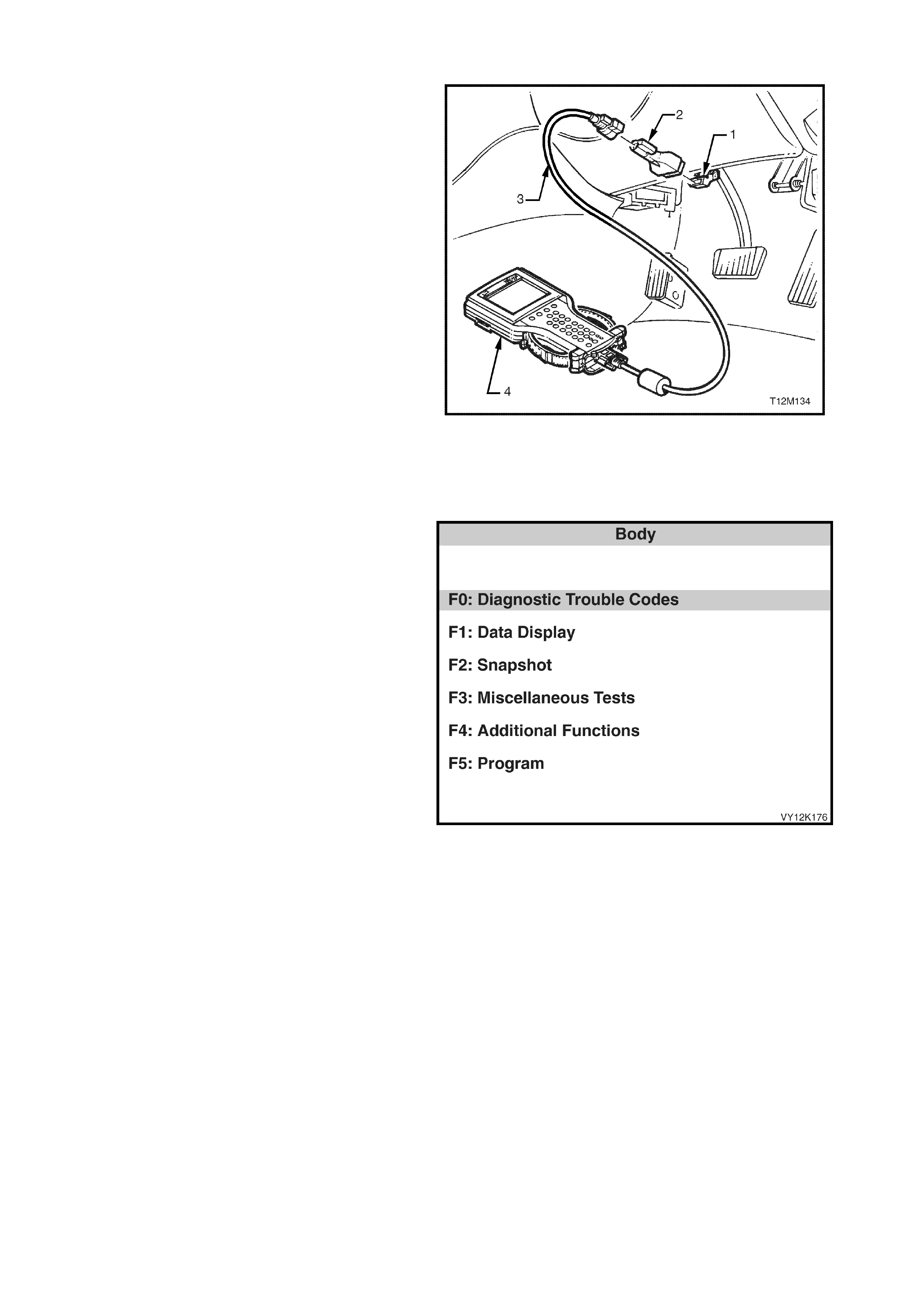
4.2 CONNECTING TECH 2
TECH 2, with the appropriate software, cables and
adaptors, when connected to the Data Link
Connector (DLC) is capable of reading telematics
module serial data. The DLC is connected to the
instrument panel lower right hand trim, to the right
of the steering column.
For additional general information on
connecting and operating TECH 2, refer to
Section 0C TECH 2 in this Service Information.
1. DLC
2. DLC Adaptor
3. DLC Cable
4. TECH 2
TECH 2 has five test modes for diagnosing the
telematics module. The five test modes are as
follows:
Figure 12H-36
MODE F0: DIAGNOSTIC TROUBLE CODES
In this mode TECH 2 has the ability to display and
clear DTCs.
MODE F1: DATA DISPLAY
In this test mode, TECH 2 displays the status of
inputs and outputs of the telematics module.
MODE F2: SNAPSHOT
In this test mode, TECH 2 captures telematics
module data before and after a forced manual
trigger.
MODE F3: MISCELLANEOUS TESTS
In this tes t mode, T ECH 2 perf orms var ious tes ts to
assist in problem isolation during troubleshooting.
MODE F4: ADDITIONAL FUNCTIONS
In this test mode, TECH 2 performs a system
function tes t, of the Microp hone, Speak er, End Call
/ Information Button, Holden Assist Button and the
Emergency Button.
MODE F5: PROGRAM
In this test m ode, T ECH 2 allows the programm ing
of various features by enabling or disabling the
feature or adjusting settings.
Figure 12K-37

4.3 TECH 2 TEST MODES
As a prere quisite to t his diagnost ic section th e user m ust be familiar with the pr oper use of T ECH 2. The follo wi ng
information illustrates only the telematics module TECH 2 screen displays and provides an explanation of their
function for diagnosing the telematics module. If additional information is required on the operation of TECH 2,
reference should be made to either Section 0C TECH 2 in this Service Information, or the TECH 2 Operators
Manual.
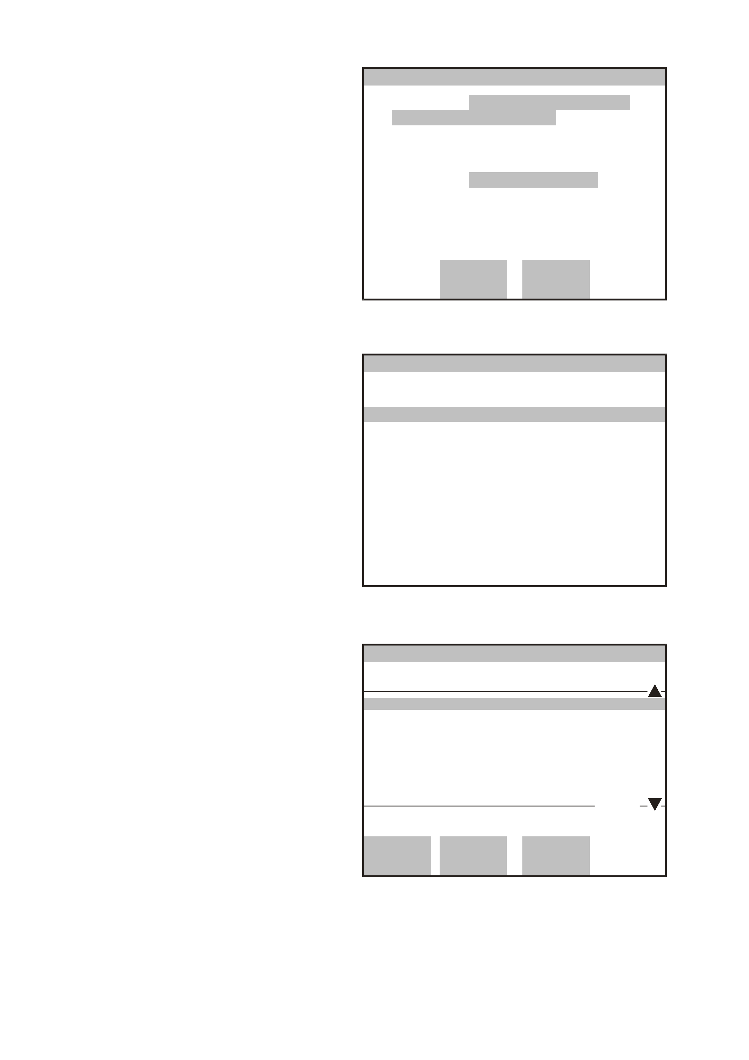
SYSTEM SELECT MENU
W ith T ECH 2 connected to the DLC and turned on,
and the F0: Diagnostics selected from the Main
Menu, the appropriate Model Year and Vehicle
Type must be selected for access to the System
Select Menu. From the System Select Menu,
Select F3: BODY.
This mode contains all functions to test, diagnose,
monitor and program the vehicles body systems
including the telematics module as well as
providing the opportunity to check all DTCs that
may be set in the vehicle.
VY12K174
System Select Menu
(3) 2003 VY Com modore
F0: E n gine
F1: T ransmission
F2: Chassis
F3: Body
F4: V ehicle DTC Check
Figure 12K-38
BODY APPLICATION MENU
Once F3: BODY has been selected from the
System Select Menu, the Telematics Module can
be selected from the body application menu.
Select Telematics Module and press enter to
continue.
Once the Telematics Module has been selected
and entered, the following Telematics Module
System Identification screen will be displayed,
once the ignition has been turned on (as
requested).
V ehicle Identification
Se lec t on e of the fo llowing
Body
Body Control Module
Powertrain Interface Module
SRS
Instrument
Occupant Climate Control
Telematics Module
Audio System
Telematics Module
VY12K174
6 / 7
Figure 12K-39

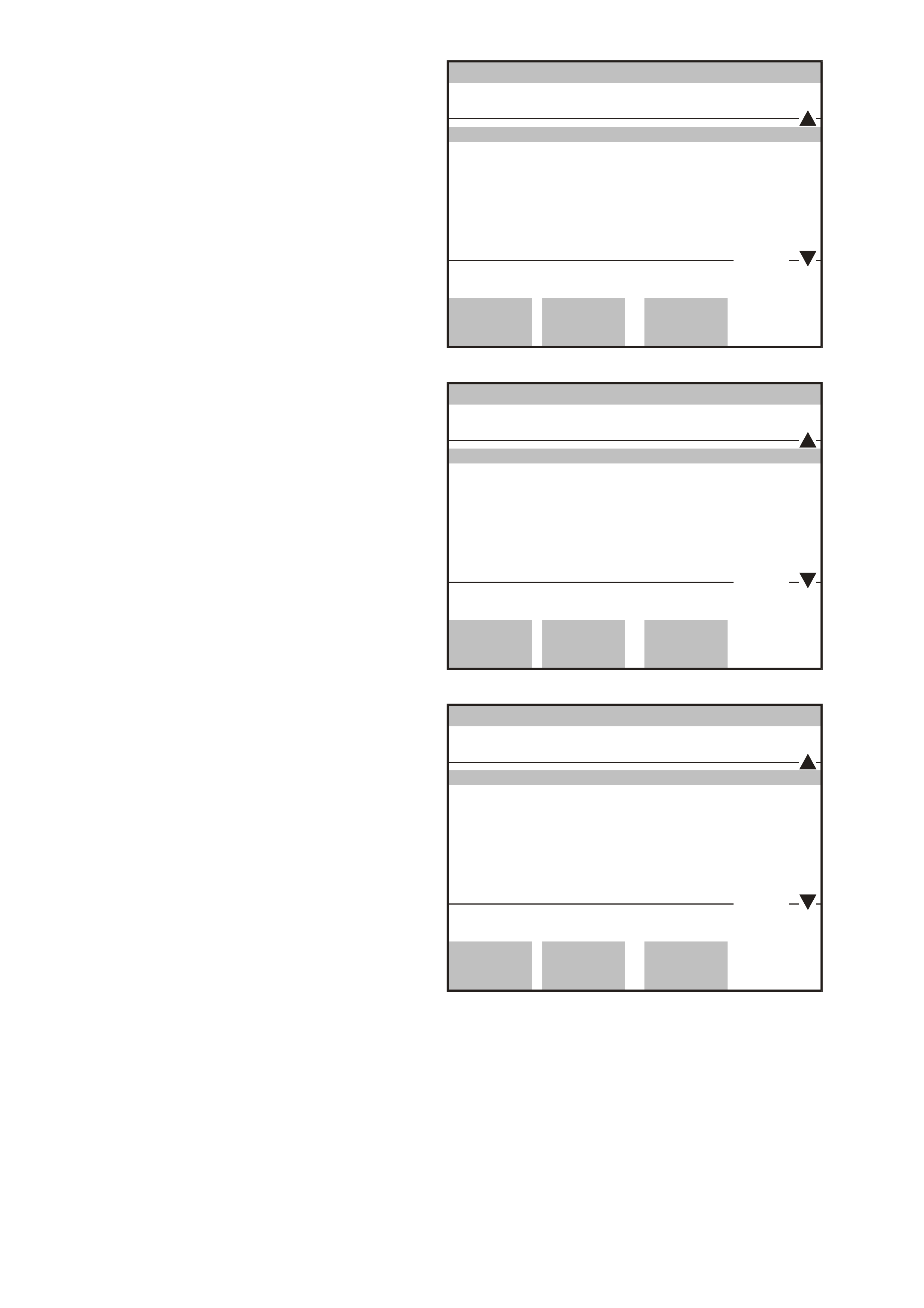
SYSTEM IDENTIFICATION
The telem atics module system identif ication sc reen
will then display the following information:
Identifier
(Diagnostic Data Identifier)
Partnumber
(telematics module part number)
Production Date
(telematics module production date)
(DD/MM/YY)
Software Version Number
(Eg. 001.000.002)
SIM Serial Number
(SIM serial number)
Telematics Module Serial Number
(telematics module serial number)
Code Index
(software index number)
Code Version
(sof tware vers io n num ber )
VAP Process Number
(vehicle as s embly plant proc es s num ber)
TIS Hardware Key Number
(TIS 2000 Hardware Key Number)
VIN Digit 1-10
(Vehicle Identification Number digits 1-10)
VIN Digit 11-17
(Vehicle Identification Number digits 11-17)
Press the Confirm soft k ey, t he telematics module
application menu will then be displayed.
Body
(3) 2003 VY Comm odore
Telematics Module
Identifier
Partnumber
Production D ate
SIM Serial Nu mber
Telematics Module
Code Index
Identifier
101
92084575
231102
5050101962136400
123456123456
1
VY0C105
Confirm
1 / 11
Figure 12K-40
APPLICATION MENU
The following functions will now be available:
F0: Diagnostic Trouble Codes
F1: Data Display
F2: Snapshot
F3: Miscellaneous Tests
F4: Additional Functions
F5: Program
Body
VY12K120
F0: Diagnostic Trouble Codes
F 1: Da ta D is p lay
F2: Snapshot
F3: Miscellaneous Tests
F4: A dd ition a l Func tion s
F5: Program
Figure 12K-41

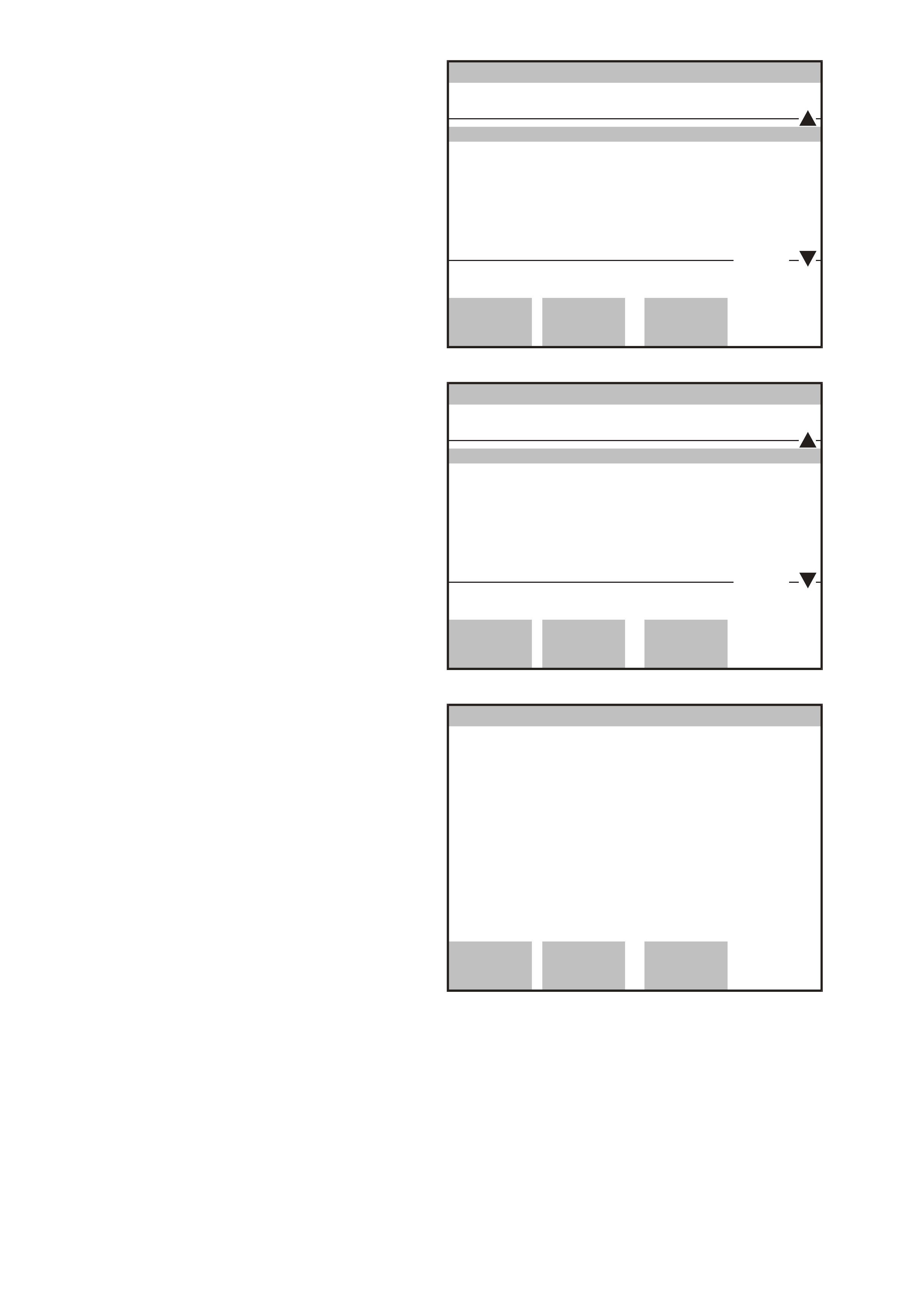
F0: DIAGNOSTIC TROUBLE CODES
In this tes t mode, DT Cs s tored by the t el ematic s m odule c an be dis p layed or c lear ed. When F 0: Diag nos tic T r oub le
Codes is selected the following two modes are available:
F0: Read DTC Information: All current DTC(s) will be displayed.
F1: Clear DTC Information History DTC. The telematics module is capable of storing history data for six DTCs.
F0: READ DTC INFORMATION
When this mode is selected TECH 2 will display
the following DTC information:
The DTC Number.
DTC Status either Current or History.
DTC Description
Times Occurred
Ignition Cycles since the DTC last set.
Number of DTCs set.
NOTE: Times occurred and Ignition cycles since
DTC last set is only available for the six most
recent DTCs.
Read DTC Information
(3) 2003 VY Comm odore
Telematics Module
Times Occurred
Ignition C ycles
Number of DTC’s set: 5
2
3
History
VY12K170
Quit Previous
DTC Next DTC
DTC#: 4
No Serial Data From Audio System
Figure 12K-42
F1: CLEAR DTC INFORMATION
W hen F1: Clear DT C Inform ation is selecte d T ECH
2 will display “Do you want to clear DTCs?” If the
Yes soft key is pressed TECH 2 will clear all DTC
information. If the No soft key is depressed the
TECH 2 will exit to menu.
No Yes
Clear DTC Information
VY12K172
Do you want to clear DTCs? (Y es/No)
(3) 2003 VY Comm odore
Telematics Module
Figure 12K-43
F1: DATA DISPLAY
NOTE: Before referring to any Data Display to diagnose a system problem the Telematics On-Board Diagnostic
System must be performed.
F0: INPUTS AND OUTPUTS
In this test mode, TECH 2 checks if the telematics module is actually receiving an input or inputs from the
appropriate sensor/s or antenna/s. If the sensor/s or antenna/s input/s are not being received, then carry out the
relevant system diagnosis as defined in the following chart.
Typical data list parameter nominal values, relevant telematics module pin number and specific diagnostic charts
are detailed in the following chart. If the actual data does not match the nominal value, then refer to the specific
diagnostic chart for that data parameter.
Data Parameter Display Pin No Nominal Values Diagnostic
Chart
Battery Voltage Volts X2-16 Should be within 0.5 Volts of
actual vehicle battery voltage. Refer Vehicle Battery
Voltage Diagnostic Chart
in this Section.
Backup Battery
Voltage Volts X5-A
X5-B Backup Battery Voltage, should
be greater than 7.2 Volts. Refer Backup Battery
Diagnostic Char t, in this
Section.

Data Parameter Display Pin No Nominal Values Diagnostic
Chart
Backup Battery
Charger Active / Inactive X5-A
X5-B Backup Battery Charger, will
display Active when the
telematics backup battery is
being charged via the telematics
backup battery charging circuit.
Refer Backup Battery
Diagnostic Chart in this
Section.
Ignition Switch On / Off X2-5 Should display the current
status of the ignition switch. Refer No Serial Data
Diagnostic Chart in this
Section.
Accessories
Switch On / Off SD Should display the current
status of the accessories switch. Refer No Serial Data
Diagnostic Chart in this
Section.
Operating Mode VAP
Pre-Delivery
Service
Active
Stand By
Sleep
Int Telematics module Operating
Mode. When the system is
operating, should display
Active.
Refer 2.15 OPERATING
MODES in this Section for
further information.
Refer 4.3 TECH 2 TEST
MODES F5: Program,
F1: Operating Mode, in
this Section.
Fuel Pump Relay
Drive Circuit Active / Inactive X1-18
X1-19 Fuel pump relay drive circuit,
should be active at all times.
Should only display Inactive if
remote immobilisation has been
requested.
Refer
Fuel Pum p Rela y Drive
Circuit Diagnostic Chart
in this Section.
Keypad Supply
Voltage On / Off X2-15 Displays the commanded state
of the interior rear view mirror
key pad supply voltage. Should
be On whenever this system is
in active or service mode.
Refer
4.3 TECH 2 TEST
MODES F3:
Miscellaneous Tests F3:
Keypad Power Supply
in this Section.
Keypad Signal
Voltage Volts X2-9
Signal voltage from the resistor
encoded keypad in the interior
rear view mirror. Will vary
depending upon which button is
depressed.
Emergency Button 3.8 Volts.
Holden Ass ist Butto n 2.3
Volts.
End Call / Info Button 0.7
Volts.
Note: This will make a call to
the Holden Assist Centre.
Refer
End Call / Inform ation
Button Diagnostic Chart
in this Section.
End Call /
Information Button On / Off X2-9 End Call / Information Button
status, should display On when
button is depressed.
Note: This will make a call to
the Holden Assist Centre.
Refer
End Call / Inform ation
Button Diagnostic Chart
in this Section.
Holden Assist
Button On / Off X2-9 Holden Assist Button status,
should display On when button
is depressed.
Note: This will make a call to
the Holden Assist Centre.
Refer
Hold en Assist Button
Diagnostic Chart
in this Section.
Emergency Button On / Off X2-9 Emergency Button status,
should display On when button
is depressed.
Note: This will make a call to
the National Emergency
Response Cent re .
The operation of this button
should only be tested using
the F1: Function Test.
Refer
Emergency Button
Diagnostic Chart
in this Section.

Data Parameter Display Pin No Nominal Values Diagnostic
Chart
Red Status LED On / Off X2-7 Displays the commanded state
of the interior rear view mirror
red status LED.
Refer Status Indicators
Do Not Illuminate
Diagnostic Chart in this
Section.
Green Status LED On / Off X2-9 Displays the commanded state
of the interior rear view mirror
green status LED.
Refer Status Indicators
Do Not Illuminate
Diagnostic Chart in this
Section.
Indicator Drive On / Off SD Display should change from Off
to On when the telematics
module is commanding the
indicators On.
Refer
4.3 TECH 2 TEST
MODES F3:
MISCELLANEOUS
TESTS F7: indicators
in this Section.
Theft Deterrent
Horn On / Off X2-2 Displays the commanded state
of the theft deterrent horn. Refer
Theft Deterrent Horn
Diagnostic Chart
in this Section.
Driver’s Door Door Closed /
Door Open X2-11 Driver’s door ajar switch status,
should display Door Open
when the driver’s door is open.
Refer
Driver’s Door Ajar Switch
Diagnostic Chart
in this Section.
Passenger Doors Door Closed/
Door Open X2-1 Passenger door ajar switch
status, should display Door
Open when any passenger door
is open.
Refer
Passenger Door Ajar
Switch Diagnostic Chart
in this Section.
Phone Mute Input Active / Inactive X2-12 When Active, Audio System
mute is required by the
telematics module.
Refer
Audio Mute Diagn os tic
Chart
in this Section.
Audio Source Hands Free
Telematics
Module
Tone Generation
int Display the current audio
source. Refer
Audio Sour c e
Diagnostic Chart
in this Section.
Unauthorised
Entry Alert D elay Seconds Int
Displays the amount of time in
seconds af ter the theft deter rent
system is activated that an
Unauthorised Entry Alert (UEA)
is sent to Holden Assist.
N/A
Low Battery Alert
Delay Seconds Int
Displays the amount of time in
seconds after the battery
voltage has reached the Low
Battery Alert (LBA) threshold
that a LBA is sent to Holden
Assist.
N/A
Vehicle Sp eed Km/h SD Display the current Vehicle
Speed Refer
DTC 5 No Serial Data
in this Section.
SRS Deployed
This ignition Cycle Yes/No SD
Displays the status of the SRS
Deployed this ignition cycle
serial data mess age.
Refer
DTC 3 No Serial Data
From SDM
in this Section.
Radio Status On / Off SD Displays the current status of
the Audio S ystem (Radio). Refer
DTC 5 No Serial Data
in this Section.
Low Battery Alert
Threshold 1 Volts Int
Displays the battery voltage at
which a Low Battery Alert (LBA)
will be sent to the Holden Assist
centre.
N/A

Data Parameter Display Pin No Nominal Values Diagnostic
Chart
Low Battery Alert
Threshold 1
Timeout
Minutes Int
Displays the length of time that
the battery must be at Low
Batter y A lert Threshold 1 before
a low battery alert is set.
N/A
Low Battery Alert
Threshold 2 Volts Int
Displays the battery voltage at
which a Low Battery Alert (LBA)
will be sent to the Holden Assist
centre.
N/A
Low Battery Alert
Threshold 2
Timeout
Minutes Int
Displays the length of time that
the battery must be at Low
Batter y A lert Threshold 2 before
a low battery alert is set.
N/A
Low Battery Alert
Threshold 3 Volts Int
Displays the battery voltage at
which a Low Battery Alert (LBA)
will be sent to the Holden Assist
centre.
N/A
Low Battery Alert
Threshold 3
Timeout
Minutes Int
Displays the length of time that
the battery must be at Low
Batter y A lert Threshold 3 before
a low battery alert is set.
N/A
Backup Battery In
Vehicle Timer Hours Int
Displays the amount of time the
backup battery has been in the
vehicle.
N/A
Backup Battery
Charge Time Hours Int
Displays the backup battery the
charge time. N/A
Backup Battery
Operating Time Minutes Int
Displays the amount of time the
system has been operating on
the backup battery.
N/A
SD = Serial Data, Int = Internal Telematics Module Value, N/A = Not Applicable
F1: GLOBAL POSITIONING SYSTEM
In this test mode, TECH 2 display Global Positioning System Information (GPS).
NOTE: If the “Time of Last Known GPS Fix” data list parameter is incrementing, then the telematics module is
receiving information from GPS satellites.
Data Parameter Display Nominal Values Diagnostic
Chart
GPS Module Inactive/Active GPS Module status, should display Active
when the GPS engine is operational.
Time of Last Known
GPS Fix Hours/Minutes/
Seconds Display the time of the last know GPS fix.
Distance from Last
Known GPS Fix Meters Display the distance in meters from the
last know GPS fix.
GPS Satel lites Vis i ble 0 - 99 Should display the actual number of
satellites visible, when the module had a
GPS fix.
Latitude Degrees/Minutes/
Seconds Display the vehicles last known Latitude
eg.
-37° 49'24.950
Minus (-) = South
Longitude Degrees/Minutes/
Seconds Displa y the last kno wn Longitu de eg.
144° 55'7.800
Minus (-) = West
UTC
(Coordinated Universal
Time)
Hours/Minutes/
Seconds Displays the
Coordinated Universal Time.
Will continuously update if the telematics
module has a valid GPS fix.
UTC Date Day/Month/Year Displays the current UTC Date.
Refer
No GPS Signal
Diagnostic
Chart
in this Section.

F2: GSM
In this test mode, TECH 2 display Global System for Mobile (GSM) Communications Information.
GSM Module Active / Inactive Should display Active if GSM Module is
active and registered on the mobile phone
network.
RSSI
(Received Signal Strength
Indication)
0 – 31 /
Not Available / Invalid Displays the GSM Received Signal
Strength Indication from 0 (poor signal) to
31 (good Signal). Refer RSSI Table below.
Refer
No GSM
Signal
Diagnostic
Chart
in this Section.
GSM Signal Strength | |
to
|>>>>>>|
Displa y the GSM Sign al Str engt h as a Bar
Graph. Refer RSSI Table below.
GSM Signal Stre ngth dBm -113 dBm (Poor
Signal)
to
- 50 dBm (Good
Signal)
Not Available / Invalid
Displa y the GSM Signal Strengt h, in
decibels per milliwatt dBm.
Refer RSSI Table below.
Last SMS Message
Status None Initiated,
Message Pending,
Initiated,
In Progress,
A waiting Reply,
Modem Busy,
No Coverage,
No Registration,
Modem Timeout,
Unknown Error,
Command Error
Displays the status of the last SMS
message.
GSM Registration None
Home
Seeking
Unknown
Roaming
Display the current GSM Registration.
RSSI (Received Signal Strength Indication)
TECH 2 displays the GSM signal strength in dBm, which is decibels per milliwatt, when measuring GSM signal
strength, t he measur ement is ref er enced to 1 mW, and as the signal s tr en gth is le ss than the r ef er ence, it is al wa ys
negative. T he signa l str ength will r ange f rom –113 dBm (poor signal) to –50 (goo d signa l). T ECH 2 will also displa y
the RSSI from 0 to 31 and as a bar graph.

RSSI Bar Graph dBm
0 | | -113
0 | | -112
1 | | -111
1 | | -110
2 |> | -109
2 |> | -108
3 |> | -107
3 |> | -106
4 |> | -105
4 |> | -104
5 |> | -103
5 |> | -102
6 |> | -101
6 |> | -100
7 |>> | -99
7 |>> | -98
8 |>> | -97
8 |>> | -96
9 |>> | -95
9 |>> | -94
10 |>> | -93
10 |>> | -92
11 |>> | -91
11 |>> | -90
12 |>> | -89
12 |>> | -88
13 |>>> | -87
13 |>>> | -86
14 |>>> | -85
14 |>>> | -84
15 |>>> | -83
15 |>>> | -82
RSSI Bar Graph dBm
16 |>>> | -81
16 |>>> | -80
17 |>>> | -79
17 |>>> | -78
18 |>>> | -77
18 |>>> | -76
19 |>>>> | -75
19 |>>>> | -74
20 |>>>> | -73
20 |>>>> | -72
21 |>>>> | -71
21 |>>>> | -70
22 |>>>> | -69
22 |>>>> | -68
23 |>>>> | -67
23 |>>>> | -66
24 |>>>> | -65
24 |>>>> | -64
25 |>>>>> | -63
25 |>>>>> | -62
26 |>>>>> | -61
26 |>>>>> | -60
27 |>>>>> | -59
27 |>>>>> | -58
28 |>>>>> | -57
28 |>>>>> | -56
29 |>>>>> | -55
29 |>>>>> | -54
30 |>>>>>>| -53
30 |>>>>>>| -52
31 |>>>>>>| -51
31 |>>>>>>| -50

F3: GSM Call Register
In this test mode, TECH 2 display the last ten GSM calls that have been made or received.
Data Parameter Display
GSM Call Number 1
GSM Call Number 2
GSM Call Number 3
GSM Call Number 4
GSM Call Number 5
GSM Call Number 6
GSM Call Number 7
GSM Call Number 8
GSM Call Number 9
GSM Call Number 10
Refer
following
GSM Call Register
Display Table
GSM Call Register Display Table
The TECH 2 can display any of the following incoming or outgoing calls for any or all of the ten call registers.
Display Description
No Activit y Will be displa yed if there is no GSM r egist er inf orm ation stor ed in th e telem atic s m odule,
this will occur after a GSM Call Register reset has been carried out.
Unlock An unlock request has been received from the Holden Assist Call Centre.
Unlock & Status An unlock request and telematics module operating mode status request has been
received from the Holden Assist Call Centre.
Unlock & Position An unlock request and vehicle position request has been received from the Holden
Assist Call Centre.
Lock A lock request has been received from the Holden Assist Call Centre
Lock & Stat us A lock request a nd telem atics m odule oper ating m ode status r equest h as been receiv ed
from the Holden Assist Call Centre.
Lock & Position A lock request and vehicle position request has been received from the Holden Assist
Call Centre.
Information An information call has been sent to the Holden Assist Call Centre.
Holden Assist A Holden Assist call has been sent to the Holden Assist Call Centre.
Emergency A Emergency call has been sent to the Holden Assist Call Centre.
Low Battery A low battery alert has been sent to the Holden Assist Call Centre.
Airbag A airbag deployed alert has been sent to the Holden Assist Call Centre.
Unauth. Entry An unauthorised entry alert (UEA) has been sent to the Holden Assist Call Centre.
Position A current vehicle position request has been received from the Holden Assist Call Centre.
Tracking A vehicle tracking request has been received from the Holden Assist Call Centre.
Tracking Change A change vehicle tracking request has been received from the Holden Assist Call
Centre.
Vehicle Locate A vehicle locate request has been received from the Holden Assist Call Centre.
Immobilisation An immobilisation request has been received from the Holden Assist Call Centre.
Remobilise A remobilise request has been received from the Holden Assist Call Centre.
Parameter
Update A parameter update request has been received from the Holden Assist Call Centre.
Identification An identification request has been received from the Holden Assist Call Centre.
Modify Operation A modify operation request has been received from the Holden Assist Call Centre.
Acknowledge An acknowledge has been set from the telematics module to the Holden Assist Call
Centre.
F4: SYSTEM IDENTIFICATION
In this test mode, TECH 2 display system identification information. Refer System Identification in this Section.
F2: SNAPSHOT
In this mode, TECH 2 captures data before and
after a forced manual trigger.
The purpose of the SNAPSHOT test mode is to
help isolate an intermittent or transient problem by
storing telematics module data parameters just
before and just after a problem occurs.
VX12K123
Snapshot Options
Trigger Type : M anua l Trigger
Trigger Po int : Center
F0: Manual T rigger
F4: Beginning
F5: Center
F6: End
Record
Snapshot Review
Data
Figure 12K-44
F3: MISCELLANEOUS TESTS
Miscel laneous tes ts al lo ws f or the tes ting of var ious
components of the telematics system, such as the
status LEDs, radio mute or fuel pump circuit to
assist in problem isolation during troubleshooting.
Each test will run for four seconds. Further
activation of the soft key will run the test for
another four seconds. Once miscellaneous tests
has been selected, the following tests will be
available.
F0: Fuel Pump Circuit
F1: Red Status LED
F2: Green Status LED
F3: Keypad Su pp l y Volta ge
F4: Audio System Mute
F5: Backup Battery Charger
F6: Unlock Doors
F7: Indicators
F8: Audio Output
VY12K122
Miscellaneous Tests
F0: Fuel Pump Circuit
F1: R e d Stat us LE D
F2: Green Status LED
F3: Keypad Supply V oltage
F4: Audio System Mute
F 5: B ack u p Ba tt ery Ch ar g e r
F6: Unlock Doors
F7: Indicators
F8: Audio output
Figure 12K-45
F0: Fuel Pump Circuit
Provides a means of activating and deactivating
the fuel pump relay drive circuit by pressing the
Inactive or Active soft keys.
When inactive, the telematics module opens the
fuel pump relay drive ground circuit and the fuel
pump will stop. The fuel pump relay drive circuit will
change form approximately 12 Volts engine
running to 1.4 Volts when the engine is not
running.
Pressing the Quit soft key will exit the test.
Precondition: System not in pre delivery mode.
If this miscellaneous test is unsuccessful replace
the telematics module refer 3.1 TELEMATICS
MODULE in this Section.
Fuel Pump Circuit
(3) 2003 VY Comm odore
Telematics Module
Ba tte ry Vol ta ge
Backup Battery Voltage
Backup Battery Charger
Ignition Switch
Operating Mode
Sleep Mode Pending
Fuel Pump Relay Drive C
Fuel Pump Relay Drive C Active
VY12K124
Quit
1 / 31
Inactive Active
13.0 V
7.7 V
Inactive
On
Active
No
Active
Figure 12K-46
F1: Red Status LED
Provid es a means of turnin g the red status LED on
and off using the On and Off soft keys.
Pressing the Quit soft key will exit the test.
Precondition: System not in pre delivery mode.
If this miscellaneous test is unsuccessful refer
Status Indicator LEDs Do Not Illuminate
Diagnostic Chart in this Section.
Re d Sta tus LED
(3) 2003 VY Comm odore
Telematics Module
Ba tte ry Vol ta ge
Backup Battery Voltage
Backup Battery Charger
Ignition Switch
Operating Mode
Sleep Mode Pending
Fuel Pump Relay Drive C
Re d Sta tus LE D O n
VY12K126
Quit
1 / 31
Off On
13.0 V
7.7 V
Inactive
On
Active
No
Active
Figure 12K-47
F2: Green Status LED
Provides a means of turning the green status LED
on and off using the On and Off soft keys.
Pressing the Quit soft key will exit the test.
Precondition: System not in pre delivery mode.
If this miscellaneous test is unsuccessful refer
Status Indicator LEDs Do Not Illuminate
Diagnostic Chart in this Section.
Green Status LED
(3) 2003 VY Comm odore
Telematics Module
Ba tte ry Vol ta ge
Backup Battery Voltage
Backup Battery Charger
Ignition Switch
Operating Mode
Sleep Mode Pending
Fuel Pump Relay Drive C
Green Status LED On
VY12K128
Quit
1 / 31
Off On
13.0 V
7.7 V
Inactive
On
Active
No
Active
Figure 12K-48
F3: Keypad Supply Voltage
This test provides the means of turning the supply
voltage from the telematics module to the keypad
on and off using the On and Off soft keys. When
the keypad supply voltage is turned off the keypad
illumination will go out and the keypad buttons will
not function.
Pressing the Quit soft key will exit the test.
Precondition: System not in pre delivery mode.
If this miscellaneous test is unsuccessful refer
Status Indicator LEDs Do Not Illuminate
Diagnostic Chart in this Section.
Keypad Supply V o ltage
(3) 2003 VY Comm odore
Telematics Module
Ba tte ry Vol ta ge
Backup Battery Voltage
Backup Battery Charger
Ignition Switch
Operating Mode
Sleep Mode Pending
Fuel Pump Relay Drive C
Keypad Supply Voltage
13.0 V
7.7 V
Inactive
On
Active
No
Active
On
VY12K128
Quit
1 / 31
Off On
Figure 12K-49
F4: Audio System Mute
Provides a means of activating and deactivating
the telematics audio system mute circuit. To
activate the audio system mute press the Active
soft key, to deactivate the radio mute press the
Inactive soft key.
Precondition: System not in pre delivery mode.
If this miscellaneous test is unsuccessful refer
Audio Mute Circuit Diagnostic Chart in this
Section.
Audio System Mute
(3) 2003 VY Comm odore
Telematics Module
Ba tte ry Vol ta ge
Backup Battery Voltage
Backup Battery Charger
Ignition Switch
Operating Mode
Sleep Mode Pending
Fuel Pump Relay Drive C
Audio System Mute
13.0 V
7.7 V
Inactive
On
Active
No
Active
Inactive
VY12K127
Quit
1 / 31
Inactive Active
Figure 12K-50
F5: Backup Battery Char ger
Provides a means of activating and deactivating
the telematics backup battery charging circuit. To
activate the backup battery charger press the
Active soft key, to inactivate the backup battery
charger press the Inactive soft key.
Precondition: System not in pre delivery mode.
If this miscellaneous test is unsuccessful refer
Backup Battery Diagnostic Chart in t his Sec ti on.
Backup Battery Charger
(3) 2003 VY Comm odore
Telematics Module
Ba tte ry Vol ta ge
Backup Battery Voltage
Backup Battery Charger
Ignition Switch
Operating Mode
Sleep Mode Pending
Fuel Pump Relay Drive C
Backup Battery Charger On
VY12K129
Quit
1 / 31
Inactive Active
13.0 V
7.7 V
Inactive
On
Active
No
Active
Figure 12K-51
F6: Unlock Doors
Provides a means of locking and unlocking the
doors.
Precondition: System not in pre delivery mode.
When the Lock soft key is depressed TECH 2 will
request the telematics module to send a lock
request to the BCM via the serial data bus. On
receiving this request from the telematics module
the BCM will then lock all doors.
When the Unlock soft key is depressed TECH 2
will request the telematics module to send an
unlock request to the BCM via the serial data bus.
On receiving this request from the telematics
module the BCM will then unlock all doors.
When the quit soft key is depressed the TECH 2
will send an Unlock request to the BCM, this will
cause the doors to unlock when quitting this test.
If this miscellaneous test is unsuccessful refer to
Section 12J Body Control Module in this Ser vice
Information.
Unlock Doors
(3) 2003 VY Comm odore
Telematics Module
Press the Appropriate Soft Key to Lock
or Unlock the Doors!
VY12K130
Quit Lock Unlock
Figure 12K-52

F7: Indicators
Provid es a m eans of caus ing the i ndic ators to flas h
On and Off.
Precondition: System not in pre delivery mode.
When the On soft key is depressed TECH 2 will
request the telematics module to send an
indicators on off request to the BCM via the serial
data bus. On receiving this request the BCM will
then flash the indicators on and off.
When the OFF soft key is depressed TECH 2 will
request the telematics module to stop sending
indicators on off request to the BCM.
If this miscellaneous test is unsuccessful refer to
Section 12J Body Control Module in this Ser vice
Information.
Indicators
(3) 2003 VY Comm odore
Telematics Module
Press the Appropriate Soft Key to flash
th e Indi cat or s!
VY12K155
Quit Off On
Figure 12K-53
F8: Audio Output
Provides a means of testing the two telematics
audio outputs either the audio system or the front
right speaker channel.
Precondition: System not in pre delivery mode.
When the Audio System soft key is depressed
TECH 2 will req uest the tel ematics m odule to send
a test tone to the Au dio Head Un it (AHU). T his test
tone should then be heard through all audio system
speaker channels.
W hen the Front Right soft key is depressed T ECH
2 will request the telematics module to send a test
tone to the right front speaker channel. This test
tone should then be heard through the front right
speaker channel. When this occurs a mute signal
is sent to the AHU.
If this miscellaneous test is unsuccessful refer
A udio Mute Circuit in this Service Information.
Audio Output
(3) 2003 VY Comm odore
Telematics Module
Press the Soft Key to start Test
VY12K156
Abort
A
udio
System Front
Right
Figure 12K-54
F 4: ADDI TIONAL FU NCTIONS
When additional functions has been selected the
following telematics module resets will be
available.
F0: GSM Call Register Reset
F1: Backup Battery Timer Reset
F2: Telematics Module Reset
VY12K158
Add it ional Fu ncti on s
F0: GSM Call Register Reset
F1: Backup battery Timer Reset
F2: Telematics Module Reset
Figure 12K-55

F0: GSM Call Register Reset
This additional function will reset the GSM call
register d ata list and a ll G SM Cal l Regis ter dat a lis t
param eter s will then d is play “No Acti vity” until a c al l
is made or received.
When selected, TECH 2 will display “Do you want
to reset the GSM Call Register?” Depressing the
Yes soft key will reset the GSM Call Register,
depressing the No soft key will exit the function.
On completion of the reset TECH 2 will display
GSM Call Register Reset Completed! Depress the
Confirm soft key to exit.
G SM Call Register Reset
(3) 2003 VY Comm odore
Telematics Module
Do you want to reset the GSM Call Register?
VY12K157
No Yes
Figure 12K-56
F1: Backup Battery Timer Reset
This additional function allows you to reset the
Backup Battery Timer. This should only be
performed after the backup battery has been
replaced.
Once this function has been selected, TECH 2 will
request that you “Please get programming
approval from TIS”. Refer Section 0C TECH 2,
Enabling Programing in this Service
Information.
Once enable programming has been successful,
return to and select F1: Backup Battery Timer
and TECH 2 will continue to the following screen.
Backup Battery Timer Reset
(3) 2003 VY Comm odore
Telematics Module
Please get programming approval from
TIS!
VY12K160
Confirm
Figure 12K-57
TECH 2 wi ll then displa y “Do you want t o reset the
Backup Battery Timer?”. Depressing the Yes soft
key will clear the GSM Call Register, Depressing
the No soft key will exit the function.
On completion of the reset TECH 2 will display
“Back up Battery Timer Reset Com pleted!” Depres s
the Confirm soft key to exit.
Backup Battery Timer Reset
(3) 2003 VY Comm odore
Telematics Module
Do you want to reset the Backup
Ba tte ry T im er ?
VY12K159
No Yes
Figure 12K-58
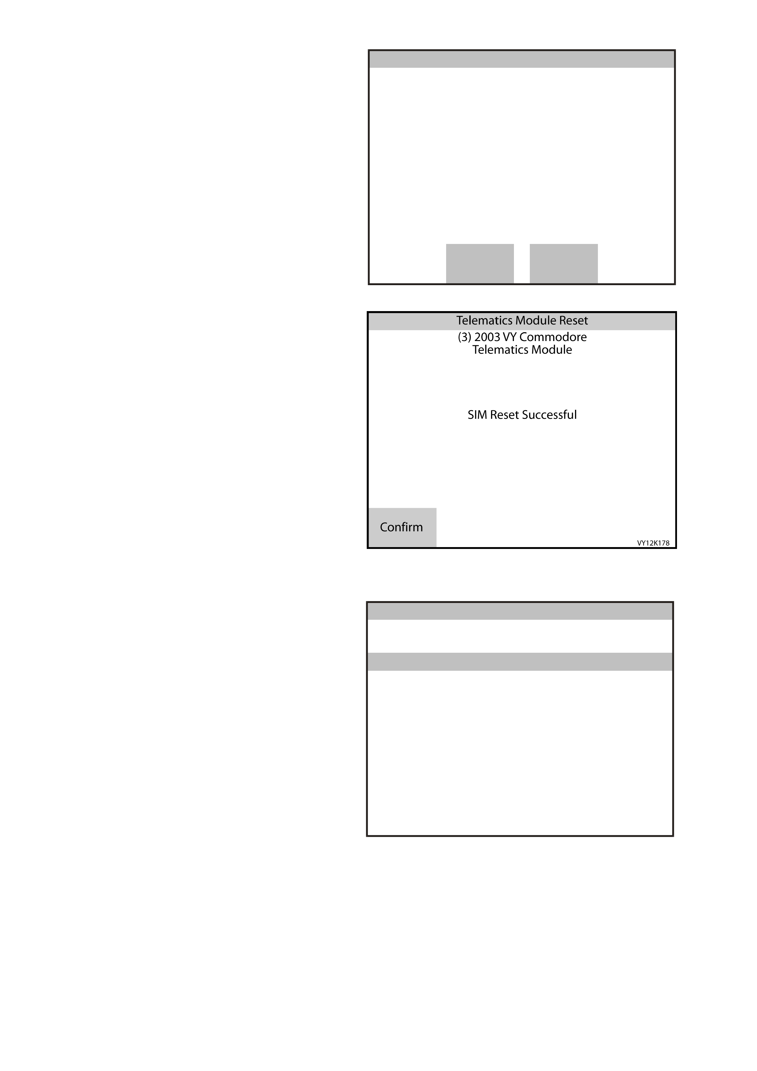
F2: Telematics Module Reset
This additional function allows you to reset the
telematics module. When selected TECH 2 will
display “Do you want to reset the Telematics
Module?” Depressing the Yes soft key will reset
the telematics module, depressing the No soft key
will exit the function.
On completion of the reset TECH 2 will display
“Telematics Module Reset Completed!” Depress
the Confirm soft key to exit.
Telematics Module Reset
(3) 2003 VY Comm odore
Telematics Module
Do you want to reset the
Telematics Module?
VY12K161
No Yes
Figure 12K-59
F3: SIM Reset
In this func tion, TECH 2 will reset the SIM n umber,
if required. If TECH 2 determines that a SIM
Number reset is not required, SIM Reset Not
Required wi ll be displ ayed.
On completion of the reset, TECH 2 will display
“SIM Reset Successful!” Depress the Confirm soft
key to exit.
This reset if successful, this will clear DTC 8 SIM
Mismatch.
Figure 12K-60
F5: PROGRAM
In this mode, TECH 2 allows the programming of
the telematics module. When the Pr ogram optio n is
selected, the following two options will be available:
F0: Program Code Index
F1: Operating Mode
VY12K173
Program
F0:
F1:
Program Code Index
Operating Mode
Figure 12K-61
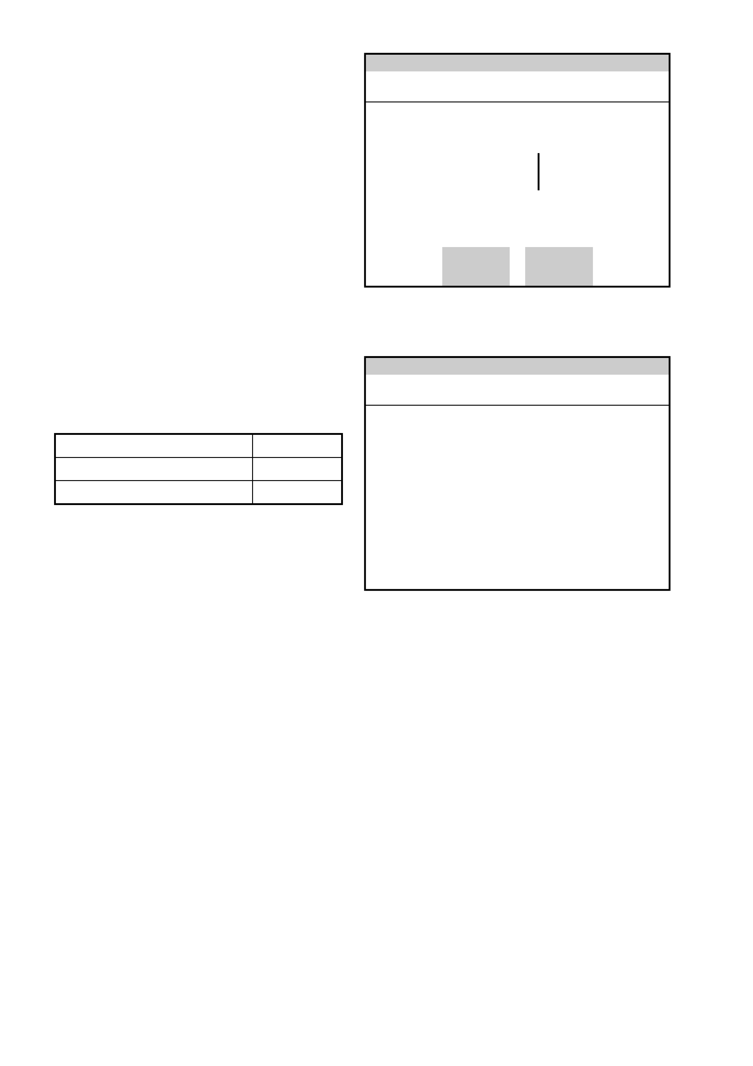
F0: Program Code Index
In this mode, the code index and programmed
code version are displayed, as well as providing
the operator the opt ion of reprogramming the code
version.
Code Index: The code index identifies the
telematics software level. A higher number
indicates the latest ver s i on of sof tware.
Code Version: The code version identifies the
calibration level. Each software level may have
different code versions, a higher number indicates
the latest versi on of calibr at ion.
Precondition: System not in Pre Delivery Mode.
Once F0: Program Code I ndex has been sel ected
the screen opposite showing the current code
index and code version numbers will be displayed.
If you wish to change the software level, press the
Modify soft key.
Modify Okay
Co de Index
Code Version 1
1
Co de Index
(3) 2003 VY Commodore
Elect ronic System: Telematics Module
VY12K178
Figure 12K-62
You will then be r equested to enter the c ode i ndex.
Once the code index has been entered using the
numerical keypad, press the Enter key to program.
NOTE: Leading zeros have to be entered.
Code Index
Enter Ecu Code Index
001
Co de Index
(3) 2003 VY Commodore
Elect ronic System: Telematics Module
VY12K179
Figure 12K-63
Model Code Index
Berlina & Calais 001
Executive, Acclaim, S & SS 002

F1: OPERATING MODE
This programm ing mode allows you to program the
telematics module into one of the four operating
modes.
Pressing the appropriate soft key will program the
telematics module into the selected operating
mode.
TIS approval is required to enable or disable
Pre Delivery Mode.
Service Mode
If the Service soft key is depressed, the telematics
module will immediately switch to service mode.
Active Mode
If the Active soft key is depressed, the telematics
module will switch to active mode.
Sleep Mode
If the Sleep soft key is depressed the telematics
module will switch to active mode the telematics
module will then switch to sleep mode
approxim ately two minutes after TECH 2 has been
removed the ignition has been turned off and all
doors have been shut.
Pre Delivery Mode
If the Pre-Delivery soft key is depressed TECH 2
will request that you “Please get programming
approval from TIS”. Refer to Section 0C TECH 2,
Enabling Programing in this Service
Information.
Once enable programming has been successful,
return to and select Pre Delivery Mode and TECH
2 will enable pre de li very mode.
A
ctiveService Sleep Pre-
Delivery
Operating Mode Pre De livery
Operating Mode
VY12K149
(3) 2003 VY Comm odore
Telematics Module
Pr e ss E x it to Quit !
Figure 12K-64
Vehicles will be delivered to the dealer with
the pre delivery mode enabled. With the pre
delivery mode enabled the telematics system is
turned off. The pre delivery mode must be
disabled and the telematics module the service
mode enabled by pressing the Service Mode
Soft Key. TECH 2 will request that you
“Please get programming approval from TIS”.
Refer to Section 0C TECH 2, Enabling
Programing in this Service Information.
Confirm
Operating Mode
(3) 2003 VY Comm odore
Telematics Module
VY12K148
Please get programming approval from
TIS!
Figure 12K-65

Once F1: Operating Mode as been selected the
current telematics module operating mode will be
displayed. To change the operating mode press
the appropr iate soft Ke y and the telem atics module
will switch to the selected operating mode.
Note: TIS Approval is required to enable or
disable Pre D eliver y mode. If Pre Deliver y mode
is enabled then only the Service M ode Soft key
will be displayed.
Press the Exit key to quit.
A
ctiveService Sleep Pre-
Delivery
Ope r ati ng Mode Service
Ope r ati ng Mo de
VY12K149
(3) 2003 VY Commodore
Te lema tics M odul e
Pres s Exit to Quit !
Figure 12K-66
Service
Ope r ati ng Mode P re Delivery
Ope r ati ng Mo de
(3) 2003 VY Commodore
Te lema tics M odul e
Pres s Exit to Quit !
VY12K180
Figure 12K-67

5. DIAGNOSIS
The information contained in this Section is where to start all system diagnosis. Once you have read and
understood the General Information Section, which contains reference material: wiring diagrams, telematics module
terminal end views and nominal voltages, and component locations. (Remember, this inform ation is for reference;
do not start diagnosis using these pages). Always start diagnosis on the page titled On-Board Diagnostic System
Check . This check first verif ies that the diagnos tic circuits are operati ng properl y and then sends you to the c orrect
chart for diagnosis.
5.1 BASIC KNOWLEDGE AND TOOLS REQUIRED
To us e the Servic e Inf orm ation eff ective ly, you sho uld unders tand the basic theor y of electr ic ity, s eries and par allel
circuits, and voltage drops. You should know the meaning of voltage (Volts), current (Amps), and resistance
(Ohm s) . You shou ld understand what ha ppe ns in a c ircuit with an ope n or s hor t ed wire ( s horte d e ith er to vo lta ge or
ground). You should also be able to read and understand a wiring diagram, refer to Section 12P WIRING
DIAGRAMS in this Service Information.
To perform system diagnosis, the use of a TECH 2 is required. Tech 31 or a Digital Multimeter (DMM) with 10
megohms impedance, a test light, and jumper wires are also required. Please become acquainted with the tools
and their use before attempting to diagnose a vehicle.
Exercise care when taking readings from wiring harness connectors. It is preferred that the back probing method
with individual connectors is employed wherever possible, to avoid terminal damage and subsequent connection
failure. Carrying out wiring checks as directed b y the diagnostic charts, r ather than prob e term inals and connectors
with incor rect s ized multim eter connec tions . Use th e adapt ors containe d in c onne ctor tes t adapt or k it KM- 609. T his
will prevent any possibility of spreading or damaging wiring harness terminals.
Testing of the various systems will also involve gaining access to specific wiring harness connectors. For the
location of these connectors, refer to Section 12P WIRING DIAGRAMS in this S er vice Inf or mation.
Techline

5.2 DIAGNOSTIC PRECAUTIONS
The following requirements must be observed when working on vehicles:
1. Before performing any Service Operation or other procedure described in this Section, refer to
Section 00 CAUTIONS AND NOTES in this Service Inf orm ation for correct workshop practices with regar d to
safety and/or property damage.
2. Disconnect the negative battery cable before removing any system component.
3. Never start the engine without the battery being connected correctly.
4. Never separate the battery from the on board electrical system while the engine is running.
5. When charging the battery, disconnect it from the vehicle's electrical system.
6. Never subject the telematics module to temperatures above 80°C eg. a paint oven. Always remove the
telematics module first, if this temperature is to be exceeded.
7. Ensure that all cable harness plugs are connected solidly and that battery terminals are thoroughly clean.
8. The har ness con nectors are design ed to f it in onl y one wa y, forcing c onnect ors into place is not neces sary i f it
is being ins ta lled with t he proper or i enta tio n. Fa il ur e to take care to matc h the ind ex ing t abs a nd s lo ts to e nsure
the connector is being installed correctly can caus e damage to the connector, the telem atics module, or other
vehicle components or systems.
9. Never connect or disconnect telematics module cable harness connectors when the ignition is switched on.
10. Before attempting any electric arc welding on the vehicle, disconnect the battery leads and the telematics
module connectors.
11. Use only the test equipment specified in the diagnostic charts, since other test equipment may either give
incorrect results or damage good components.
12. All voltage meas ur em ents us ing a vol tmeter m ust use a d igi tal v oltmeter with a n i nter na l impedanc e r at ing of at
least 10 million ohms per volt (10 meg ohms).
13. W hen a test light is spec ifie d, a lo w-power tes t lig ht must be used. Do not use a hig h - watta ge tes t light. W hile
a particu lar brand of tes t light is not sugges ted, a sim ple tes t on any test light will ensure it to be O K for circuit
testing. Connect an accurate ammeter (such as the high-impedance digital multimeter) in series with the test
light being tested, and power the test light-ammeter circuit with the vehicle battery.
If the ammeter indicates less than 3/10 amp current flow (0.3 A or 300 mA), the test light is OK to use.
If the ammeter indicates more than 3/10 amp current flow (0.3 A or 300 mA), the test light is NOT OK to use.
BLOCKING DRIVE WHEELS
The vehicle drive wheels should always be blocked and the parking brake firmly applied while checking the system.
VISUAL/PHYSICAL INSPECTION
A careful visual and physical inspection must be performed as part of any diagnostic procedure. This can
often lead to fixing a problem without further steps. I nspect all electrical wires for correct routing, p inches, cuts, or
disconnections. Be sure to inspect wires that are difficult to see. Inspect all the wires for proper connections,
burned or chafed spots, or contact with sharp edges or hot exhaust manifolds. This visual/physical inspection is
very important. It must be done carefully and thoroughly.
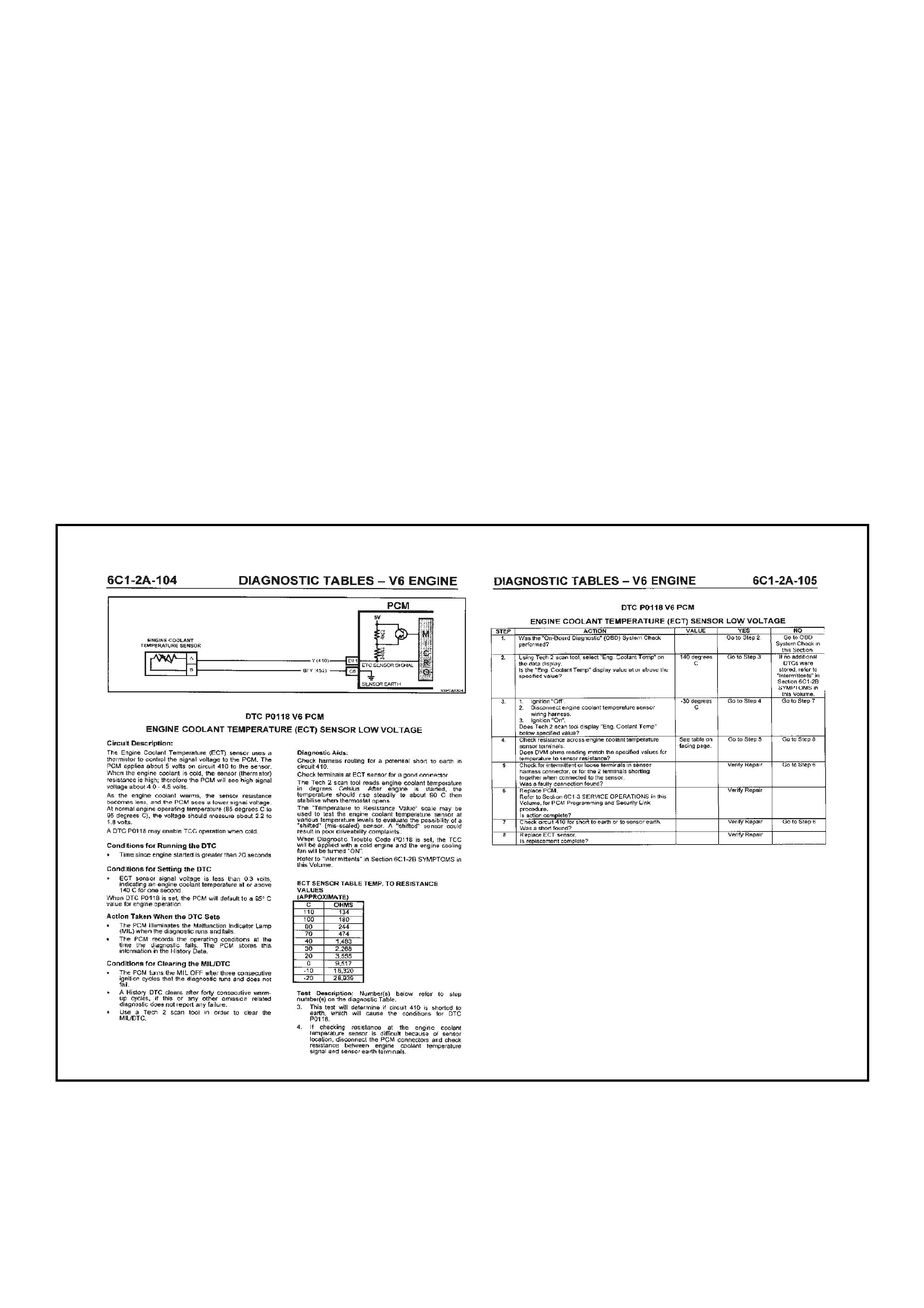
5.3 DIAGNOSTIC CHART DESCRIPTION
The diagnostic charts are designed to provide fast and efficient means of fault location for all functions associated
with the te lematics m odule. Each diagnos tic chart use s 2 pages; a chart on th e right side pag e, and a facing pag e
on the left side page. The left side "facing page" contains pertinent information and circuit diagrams. The chart
steps are explained by the corresponding numbered paragraph on the left side facing page.
When diagnosing any problem, always begin with the On-Board Diagnostic System Check. The On-Board
Diagnostic System Check will lead you to the other charts. DO NOT GO DIRECTLY TO A SPECIFIC CHART or
false diag nosis and re placem ent of ser viceable parts c ould result. After a f ault is correc ted and all DTCs have been
cleared, repeat the On-Board Diagnostic System Check to assure that the proper repairs have been made.
The box at the top of the left page contains a circuit diagram showing the components involved in each circuit.
Immediately below the box is a brief circuit description. On the facing right hand page a troubleshooting chart for
diagnosing conditions. Step numbers on the right-hand page next to the action boxes in the chart relate to the
items in the Test Description on the left-hand page. These items provide an explanation of each test in the chart.
The facing right hand page also contains a three quarter view of the connectors that are listed in the diagnostic
charts.
The appropriate step in any of the trouble shooting chart will instruct you either to make a specific repair or to
continue diagnosis. If further diagnosis is needed, the step will specify where to continue.
The Yes or No column in any diagnostic chart will instruct you either to make a specific repair or to continue
diagnosis. If further diagnosis is needed, the Yes or No column will specify where to continue.
If the condition is intermittent, the trouble shooting chart will direct you to the diagnostic aids on the facing page.
This Section gives suggestions for diagnosing intermittent conditions and explains how some faults can occur.
Remember, charts are for solving active conditions, not intermittent conditions.
Figure 12K-68

5.4 STRATEGY BASED DIAGNOSTICS
The strategy based diagnostic is a uniform approach to repair all Electrical/Electronic systems. The diagnostic flow
can always be used to resolve an Electrical/Electronic system problem and is a starting point when repairs are
necessary. The steps below are defined to instruct the technician how to proceed with a diagnostic process. Steps
below also refer to step numbers found on the Strategy Based Diagnostic chart.
1. Verify the Driver Concern: To verify the driver concern, the technician should know the normal operation of
the system.
2. Preliminary Check: Conduct a thorough visual and operational inspection, review the service history, detect
unusual sounds or odours, and gather diagnostic trouble code information to achieve effective repair.
3. Service information System Check(s): System checks verify proper operation of the system. This will lead
the technician in an organised approach to diagnostics.
4. Check Bulletins and Other Service Information: This should include, Service Techlines, All Dealer letters,
and Service T r ain ing Pu bl ications.
5. Service Diagnostics (Paper/Electronic)
5.1 Current DTC Stored: Follow the designed DTC chart exactly to make an effective repair.
5.2 Symptom, No DTC: Select the symptom from the diagnostic charts and follow the diagnostic paths or
suggestions to complete the repair, or refer to the applicable component/system checks in this Service
Information.
5.3 No Published Diagnostics: Analyse the com plaint and develop a plan for diagnostics. Utilise the wiring
diagrams and theory of operation.
Call Technical Assistance for similar cases where repair history may be available. Combine technician
knowledge with efficient use of the available service information.
5.4 Intermittent faults: Conditions that are not always present are intermittent. To resolve intermittence,
perform the following steps:
5.4.1 Observe history DTCs, DTC modes and Freeze Frame data if available.
5.4.2 Evaluate the symptoms and conditions described by the driver.
5.4.3 Use a check sheet or other method to identify the circuit or electrical system component.
5.4.4 Follow the suggestions for intermittent diagnosis found in the service documentation.
The TECH 2, Tech 31 and a DMM have data capturing capabilities that can assist in detection of intermittents.
5.5 Vehicle Operates As Designed/No Trouble Found: This condition exists when the vehicle is found to
be operating normally. The condition described by the driver may be normal. Verify against another
vehicle that is operating norm ally. T he condition may be interm ittent. Contact Technical Assistance if the
concern is common. Verify the complaint under the conditions described by the driver before releasing
the vehicle.
6. Re-examine the Concern: When the complaint cannot be successfully found or isolated, a re-evaluation is
necessary. The complaint should be re-verified and could be intermittent or normal as per step 5.3 or 5.5.
7. Repair and Verific ation Test s: After is olating th e cause, the r epair sho uld be m ade. Then v alidate for pr oper
operation and verify that the symptom has been corrected. This may involve road testing or other methods to
verify the complaint has been resolved under the following conditions:
• Conditions noted by the driver.
• If a DTC was diagnosed, verify a repair by duplicating conditions present when a DTC was set.
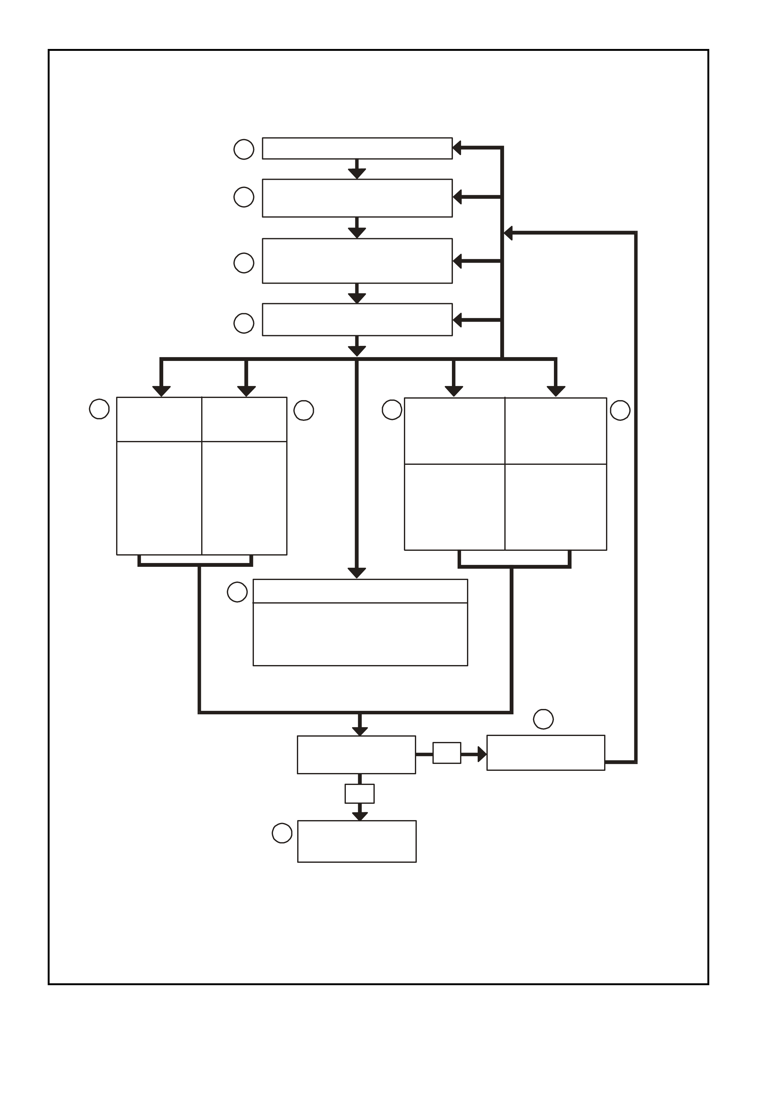
12K D IAGNOSTIC CH AR T
VERIFY DRIVER CONCERN
PRELIMINARY CHECKS
(VISUAL AND OPERATIONAL)
PERFORM
TELEMATICS SYSTEM
OBD SYSTEM CHECK
CHECK FOR
BULLENTINS
1
2
3
4
STORED
DTC(S)
FOLLOW
PUBLISHED
DTC
DIAGNOSTICS
FOLLOW
PUBLISHED
SYMPTOM
DIAGNOSTICS
ANALYSE &
DEVELOP
DIAGNOSTICS
FROM WIRING
DIAGRAMS
& THEORY
REFER TO
INTERMITTENT
DIAGNOSTIC
DETAILS
Explain Operation to Driver
Call Technical Assistance
DRIVER MISUNDERSTANDING OF SYSTEM
PRODUCT PROBLEM
ISOLATE
THE PROB L EM RE-EXAMINE
THE CONCERN
NO
YES
7
REPAIR/RESOLVE
& VERIFY
SYMPTOM
NO DTC(S)
NO
PUBLISHED
DIAGNOSTICS
OPERATING AS DESIGNED
INTERMITTENT
5.1 5.2
6
5.3 5.4
5.5
Figure 12K-69 Strategy Based Diagnostic

5.5 ON-BOARD DIAGNOSTIC SYSTEM CHECK
After the visual/physical vehicle inspection, the On-Board Diagnostic System Check is the starting point for all
diagnostic procedures or finding the cause of a system malfunction or failure.
All Diagnostic procedures must always begin with the ON-BOARD DIAGNOSTIC SYSTEM CHECK.
Diagnostic procedures must begin with the On-Board Diagnostic System Check, which represents an organised
approach for identifying system problems.
The ON-BOARD DIAGNOSTIC SYSTEM CHECK makes an initial check of the system, then will direct the
technician to other charts in the Service Information. It must be used as a starting point for all procedures. The
entire diagnostic section in the Service Information is set up in a specific order, that is, the ON-BOARD
DIAGNOSTIC SYSTEM CHECK will lead the technician to other charts, and those charts may lead to still other
charts. THE SEQUENCE MUST BE FOLLOWED. The telematics module uses many input signals and controls
many output functions. If the correct diagnostic sequence is not followed, incorrect diagnosis and replacement of
good parts may happen.
Diagnostic charts incor porate diagnos is procedures using a TECH 2 wher e possible. T ECH 2 is a sm all hand-hel d
computer in itself. Its job is to give information to a technician about what is happening in the system.
The Data Link Connector (DLC) is used by the as sembl y plant to perf orm end of line tests. T his c onnector c an also
be used by technicians to monitor certain inputs and outputs as detected by the telematics module. The TECH 2
reads and displays the information (serial data) supplied to the data link connector from the telematics module.
The correct procedure to diagnose a problem is to follow three basic steps.
1. Are the On-Board Diagnostics working? This is determined by performing the On-Board Diagnostic System
Check. Since this is the starting point for the diagnostic procedures or finding the cause of a failure, always
begin here.
If the On-Board Diagnostics are not working, the On-Board Diagnostic System Check will lead to a diagnostic
chart to correct the problem. If the On-Board Diagnostics are working correctly, the next step is:
2. Is there a Diagnostic Trouble Code stored? If a diagnostic trouble code is stored, go directly to the numbered
diagnostic trouble code chart. This will determine if the fault is still present. If no diagnostic trouble code is
stored, then:
3. Observe Serial Data transmitted by the telematics module: This involves reading the TECH 2 information.
TECH 2 Information and the meaning of the various displays can be found in the Service Information. Typical
data readi ngs under a part icular oper ating cond ition c an be found on th e TECH 2 Data page . If the actual data
does not match the typical data, then refer to the specific diagnostics for that data parameter.

5.6 DIAGNOSTIC TROUBLE CODES
W hen the telematic s modul e detects an op erating param eter which is outside its calibr ated va lues it will set a DT C
and stored this DTC into its memory as a current DTC. When a current DTC is set the Red Status LED may be
illum inated whe ne ver the ig nition is on.
The s ix mos t recent DT Cs that hav e occur red will be l ogged into t he telem atic s m odule m em ory into a t able k nown
as the “DTC List”. The DTC list can contain histor y data for the six most recent DTCs. Therefore, if m ore than six
DTCs are set, only hist ory data for the last six will be t racked. T hat is, the ol dest DT C will be rem oved from the list
regardless of its position within the list.
NOTE: Once a DTC has been removed from the “DTC List” it is maintained in the memory of the telematics module
as a History DTC, however there will be no DTC history data available for this DTC.
The DTC history data contained in the “DTC List” is as follows:
List Position Position within the list numbered from 1 to 6.
DTC Number The DTC number is the number used to identify a particular fault condition.
Occurrence Count
(0 to 255) The Occurrence Count is the number of tim es the particular fault condition has been
detected.
History Count
(0 to 255) The History Count is the number of ignition cycles that have occurred since the fault
was last detec ted. A cou nt of 0 indicates th e fault has occur red on the curr ent igni tion
cycle, while a count of 255 indicates that the fault occurred 255 or more ignition
cycles ago.
Algorit hm s for detec ting ea ch f ault conditi on and s ettin g the corr espond ing DT C var y. However, a p articu lar DTC is
only set once per ignition cycle. When a DTC is set, the following occurs:
• If the DTC does not exist in the DTC List, it is inserted into the list at the first vacant location with the
Occurrence Count set to 1 and the History Count set to 0. In the event of the DTC List being full, the oldest
DTC will be removed from the list. The Histor y Count determines the age of a DTC List entry. T he item in the
list with the highest History Count will be removed to make space for the new DTC.
• If the DT C already exists in the DT C List, then the Occurrenc e Count will be incremented ( up to 255, at which
point it is no longer incremented). Each time the DTC is set, the History Count is cleared.
This ensures th at the six most rec ent fault condit ions are tr acked. T he Occ urrenc e and Hist ory Counters provide a
means of determ ining how often the f ault has occ urred, and how long it has be en since th e fault las t occur red. For
instance, if the DTC Occurrence Count is 1, and the History Count is 201, then it can be de termined that the fault
condition existed only once, and it happened 201 ignition cycles ago (and has not been detected since). Another
exam ple would be an Occ urrence Count of 4 and a Histor y Cou nt of 0. This woul d indicate that t he fault has bee n
detected a total of four times, and that it was detected on the current ignition cycle.
The DT Cs are not rem oved f rom the list u nless six newer f ault condi tions occ ur pushin g the oldest f ault off the list,
or they are cleared using TECH 2.
NOTE: Once a DT C has been rem oved fr om the “ DTC List” it is m aintained in th e telem atics module m emor y as a
History DTC, however there will be no DTC history data available for this DTC.

DIAGNOSTIC TROUBLE CODES
DTC # TECH 2 DISPLAY RED ST ATUS
LED
ILLUMINATED
1 No Serial Data From BCM No
2 No Serial Data From Instrument No
3 No Serial Data From SDM Yes
4 No Serial Data From Audio System No
5 No Serial Data Yes
7 GPS Mod ule Failure Yes
8 SIM Mismatc h No
9 Vehicle Battery Voltage Too High No
10 Vehicle Battery Voltage Too Low Yes
11 RAM Error Yes
12 EEPRO M Err or Yes
13 Backup Battery Timer Expired Yes
14 Backup Battery Voltage Too High Yes
15 Backup Battery Voltage Too Low Yes
16 Backup Battery Not Detected Yes
17 Microphone Not Detected Yes
18 Microphone Circuit Voltage Too Low Yes
19 Microphone Circuit Voltage Too High Yes
21 Speaker Circuit Voltage Too Low Yes
22 Speaker Circuit Voltage Too High Yes
30 Keypad Circuit Voltage Too High Yes
35 GPS Antenna Circuit Voltage Too Low Yes
39 Telephone Number Error Yes
44 GSM Not Logged With Signal Strength Present Yes
45 End Call / Information Button Stuck Yes
46 Holden Assist Button Stuck Yes
47 Emergency Button Stuck Yes

5.7 TELEMATICS MODULE TERMINAL DESCRIPTIONS
Terminal
No A158 Circuit No Circuit Colour IVED ABV. Description Circuit Type
X1-1 117 Green SPK_- Speaker Negative Output
X1-2 200 Light Green SPK_+ Speaker Positive Output
X1-4 1061 Green / White UART_SCD Serial Data (Secondary) I/O
X1-5 659 Dark Green CLTEL_GND Phone Signal In Ground Ground
X1-6 658 Grey CLTEL_SIG Phone Signal In Input
X1-7 1153 Brown MIC- Microphone Negative Ground
X1-8 1155 Green MIC+ Microphone Positive Input
X1-9 2506 Black TEL_GND Phone Signal Out Ground Ground
X1-10 655 Blue / Blac k TEL_SIG Pho ne Si gna l Out O utput
X1-18 465 Gr een White FL_P MP _SG Fuel Pump Relay In Input
X1-19 497 Light Green FL_PMP_RLY Fuel Pump Relay Out Output
X2-1 745 White PAS_D_AJ Passenger Door Switches Input
X2-2 1149 Green THRN Theft Deterrent Horn
Relay Input
X2-5 539 Pink / Blue IG Ignition Input
X2-6 5211 Yellow / Black TEL_MUT Radio Mute Output
X2-7 2517 Brown / White RD_LED Red LED Output
X2-8 851 Black / White GND Ground Ground
X2-9 2514 Dark Green /
White KEY_DAT Key Pad Signal Input
X2-11 746 Grey / White DRV_DAJ Driver’s Door Switch Input
X2-12 693 Yellow CLTEL_MUT Phone Mute In Input
X2-14 2516 Yellow / Black GN_LED Green LED Output
X2-15 2515 Light Green /
Black KEY_PWR Key Pad Suppl y Voltage Output
X2-16 740 Red / White BATT+ Battery Positive B+
X3-A N/A N/A N/A GPS Antenna Signal Input
X3-B N/A N/A N/A GPS Antenna Ground Ground
X4-A N/A N/A N/A GSM Antenna Signal Input
X4-B N/A N/A N/A GSM Antenna Ground Ground
X5-A N/A N/A N/A Back Up Battery Positive 7.2 Volts
X5-B N/A N/A N/A Back Up Battery Negative Ground
A158 X1 A158 X2

5.8 DIAGNOSTIC CHARTS
ON-BOARD DIAGNOSTIC SYST EM CHECK
Figure 12K-70
CIRCUIT DESCRIPTION
The On-Board Diagnostic System Check is an organised approach in identifying a telematics system problem. It
must be the s tarting p oint for an y system diag nostics, as it directs the s ervice tec hnician to th e next logic al step in
diagnosing a complaint. Understanding the diagnostic chart and using it correctly will reduce diagnostic time and
prevent the replacement of good parts.
TEST DESCRIPTION
Number(s) below refer to step number(s) on the diagnostic chart.
1. If either the RED or Green or both (Orange) Status indicator LEDs are illuminated, the telematics module is
powered up and supply power to the interior rear view mirror.
2. Confirms TECH 2 operation and that TECH 2 is being powered up.
3. Confirms that TECH 2 can communicate with the telematics module.

4. The VIN in the telematics module must match the actual vehicle VIN. The correct VIN is critical for proper
telematics system operation.
5. If the engine starts and runs then the fuel pump relay drive circuit is OK.
6. In this you are checking if there are any current DTCs. If there are current DTCs, refer to the applicable
diagnostic chart.
7. This test determines if the telematics module is in pre delivery mode. In pre delivery mode the telematics
module is turned off. If the pre delivery mode is enabled it should be disabled and the On-Board Diagnostic
System Check should be performed again.
8. In this tes t you should ref er to the telematics data lis t nominal va lues. If the value s in the TECH 2 Data List do
not meet the nominal values listed, refer to the applicable diagnostic chart.
9. In this test step all of the TECH 2 Miscellaneous Tests should be conducted and all tests should pass
successfully, if any test fails you should refer to the applicable diagnostic chart.
10. T he vehicle m ust be positioned where the GSM s ignal stren gth is great er than –90 dbm and the GPS data list
parameter “Time of Last Known GPS Fix” is updating. You can then begin the Holden Assist Telematics
System Test. You must refer to the Holden Assist Telematics System Test in this Section.
11. This test step confirms that the connector terminal retention is OK, Terminal retention should always be
checked before any component is replaced.
12. The telem atics s ystem is operating as design ed and h as passed t he On- Board Di agnostic S ystem Check. You
should discuss the system complaint with the driver (System Subscriber) of the vehicle to ensure that they
understand the correct operation of the system, have them demonstrate the problem.
STEP ACTION YES NO
1. 1. Turn ignition on, engine off.
Are either the Red or Green or both (Orange) the Status
indicator LEDs in the interior rear view mirror
illuminated?
Go to Step 2. Refer Status Indicator
LEDs Do Not Illuminate
in this Section.
2. 1. Turn ignition off, install TECH 2 to DLC, turn ignition
on and turn on TECH 2.
Does TECH 2 power up and display the title display
screen?
Go to Step 3. Refer TECH 2
Diagnosis, Section 0C
TECH 2 in this Service
Information.
3. 1. With TECH 2 still connected and ignition on, press
the ENTER key, then select Diagnostics / (3) 2003 /
VY Commodore / F4: Body / Telematics Module and
then follow the screen instructions.
Does TECH 2 display telematics system identification
information?
Go to Step 4. Go to No Serial Data
Chart in this Section.
4. Did the VIN displayed in step 3 match the actual VIN of
the vehicle? Go to Step 5. Go to Step 11.
5. Does the engine start and run? Go to Step 6. Go to Fuel Pump Relay
Drive Circuit Chart in
this Section.
6. 1. From the Telematics Application Menu,
select F0: Diagnostic Trouble / F0: Read DTC
Information.
Are there any current DTCs?
Go to the applicable DTC
Diagnostic Chart in this
Section.
Go to Step 7.
7. 1. From the Telematics Application Menu,
Select F1: Data Display / F0: Inputs and Outputs.
Scroll to “Operating Mode”.
Does TECH 2 display “Pre Delivery”?
Disable Pre Delivery Mode.
Refer F5: Program /
F1: Operating Mode
in this Section.
Go to Step 8.
8. 1. From the Telematics Application Menu
Select / F1: Data Display
(Refer 4.3 TECH 2 TEST MODES, F1: Data Display
in this Section).
Do the Telematics Data List pa rameters match the
Nominal Values?
Go to Step 9. Refer to the appropriate
Data Display Diagnost ic
Chart in this Section.
9. 1. From the TECH 2 Telematics application menu
Select / F2: Miscellaneous Tests
(Refer 4.3 TECH 2 TEST MODES /
F3: Miscellaneous Tests in this Section).
2. Perform all the Miscellaneous Tests.
Were all the Miscellaneous Tests successful?
Go to Step 10. Refer to the Applicable
Miscellaneous Test
Failure Diagnostic Chart
in this Section.

STEP ACTION YES NO
10. 1. Ignition on.
2. Position the vehicle where the GSM Signal strength
is greater than –90 dbm and the GPS data list
parameter “Time of Last Known GPS Fix” is
updating.
3. Perform a Holden Assist Telematics System Test.
(Refer Holden Assist Telematics System Test Chart
in this Section).
Was the Telematics System Test successful?
Go to Step 12. Go to Step 11.
11. 1. Check telematics module connector A158 X1 & X2
terminal re tention.
Is the terminal retention OK?
Replace telematics module.
Refer 3.1 Telematics Module
in this Section.
Repair connector
terminal re tention.
12. Telematics system is operating correctly.
If the owner (System Subscriber) was complaining about a system fault, discuss the complaint with the owner, and
have them demonstrate the problem.

DTC 1 - NO SERIAL DATA FROM BCM
Figure 12K-71
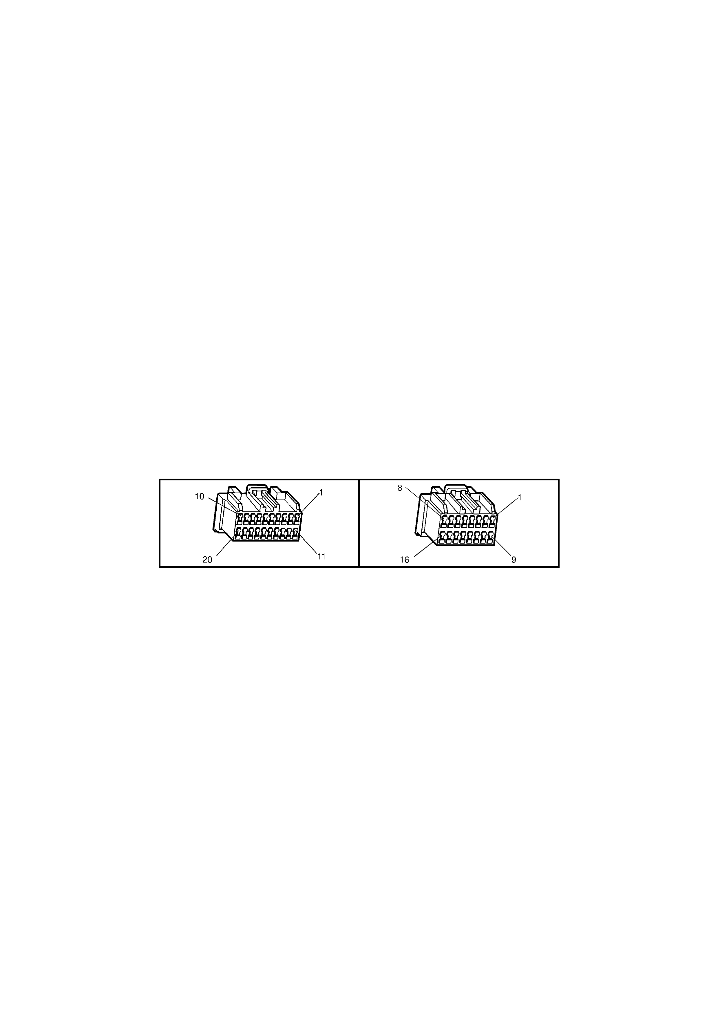
CIRCUIT DESCRIPTION
The telem atic s m odule m onitors the auxi liar y seria l dat a circuit 1 061 (G reen/W hite wire) norm al m ode m essage f or
the following information: Airbag Deployed this Ignition Cycle from the SRS SDM, Vehicle Speed from the PCM and
Audio System status information from the Audio Head Unit. For further information regarding the serial data bus
and normal mode message, refer 1.2 Serial Data Communication in Section 12J BODY CONTROL MODULE in
this Service Information
If the telematics module receives a “Remote Unlock” message from the Holden Assist Centre, the telematics
module will request the BCM (via the serial data circuit) to unlock the doors. For further information regarding the
BCM door lock operation, refer Section 12J-1 BODY CONTROL MODULE, Central Door Locking Systems in
this Service Information.
If the telematics module receives a “Immobilise” message from the Holden Assist Centre, the telematics module will
then turn of f the fuel pum p r elay cutting of f the s upp ly of f uel to the engine and request th e BC M ( via the seri al d at a
circuit) to flash the indicators. For further information regarding the BCM indicator operation, refer to
Section 12J BODY CONTROL MODULE, Theft Deterrent System in this Service Information.
CONDITIONS FOR SETTING THE DTC
• The telematics module does not receive any BCM serial data for more than ten second.
ACTION TAKEN WHEN THE DTC SETS
• When the diagnostic runs and fails, the telematics module stores the DTC into memory as a current DTC.
TEST DESCRIPTION
Number(s) below refer to step number(s) on the diagnostic chart.
1. Confirmation that the Telematics On-Board Diagnostic System Check has been performed.
2. If “NO Communication with the Vehicle” or “No Data” is displayed next to BCM DTC Status, then there is no
communication between TECH 2 and the BCM. If TECH 2 can communicate with the BCM the primary serial
data circuit 800 and the BCM are OK.
3. If DTC 1 is intermittent check for an open or short to ground or voltage in circuit 1061.
4. This test step confirms that the connector terminal retention is OK. Terminal retention should always be
checked before any component is replaced.
A158 X1 A158 X2

DTC 1 - NO SERIAL DATA FROM BCM
STEP ACTION VALUE YES NO
1. Has a Telematics On-Board Diagnosis System Check
been performed? Go to Step 2. Refer Telematics
On-Board
Diagnostic
System Check
chart in this
Section.
2. 1. From the TECH 2 System Select Menu select
F5: Vehicle DTC Check, Ignition On and follow
screen instructions.
Does TECH 2 Display “NO Communication with Vehicle”
or “BCM DTC Status, No Data”?
Refer BCM Serial
Data
Communication
diagnostics in
Section 12J BCM
in this Service
Information.
Go to Step 3.
3. 1. With TECH 2 still connected, switch Ignition On,
Engine Off.
2. From the Telematics Menu Select F0: Diagnostic
Trouble Codes / F1: Clear DTC Information and
clear the Telematics Module DTCs.
3. Ignition on for at least ten seconds.
Is DTC 1 No Serial Data from BCM set?
Go to Step 4. DTC 1 is
intermittent,
Refer Test Step
Description.
4. 1. Check telematics module connectors A158 X1 and
X2 terminal retention.
Is the terminal retention OK?
Replace
telematics
module. Refer
3.1 Telematics
Module in this
Section.
Repair connector
terminal
retention.
WHEN ALL DIAGNOSIS AND REPAIRS ARE COMPLETED, CLEAR DTCS AND VERIFY CORRECT OPERATION

DTC 2 - NO SERIAL DATA FROM INSTRUMENT
Figure 12K-72

CIRCUIT DESCRIPTION
The telem atic s m odule m onitors the auxi liar y seria l dat a circuit 1 061 (G reen/W hite wire) norm al m ode m essage f or
the following information: Airbag Deployed this Ignition Cycle from the SRS SDM, Vehicle Speed from the PCM and
Audio System status information from the Audio Head Unit. For further information regarding the serial data bus
and normal mode message, refer 1.2 Serial Data Communication in Section 12J BODY CONTROL MODULE in
this Service Information.
If the telematics module receives a “Remote Unlock” message from the Holden Assist Centre, the telematics
module will request the BCM (via the serial data circuit) to unlock the doors. For further information regarding the
BCM door lock operation, refer Section 12J-1 BODY CONTROL MODULE, Central Door Locking Systems in
this Service Information.
If the telematics module receives a “Immobilise” message from the Holden Assist Centre, the telematics module will
then turn of f the fuel pum p r elay cutting of f the s upp ly of f uel to the engine and request th e BC M ( via the seri al d at a
circuit) to flash the indicators. For further information regarding the BCM indicator operation, refer to
Section 12J BODY CONTROL MODULE, Theft Deterrent System in this Service Information.
CONDITIONS FOR SETTING THE DTC
• The telematics module does not receive any instrument serial data for more than ten second.
ACTION TAKEN WHEN THE DTC SETS
• When the diagnostic runs and fails, the t elematics modu le stores the DTC into m em or y as a curren t DTC and
activates the red status LED.
TEST DESCRIPTION
Number(s) below refer to step number(s) on the diagnostic chart.
1. Confirmation that the Telematics On-Board Diagnostic System Check has been performed.
2. If “No Data” is displa yed next to Instr ument DTC Statu s, then there is no c omm unication betwee n TECH 2 and
the Instrument. If TECH 2 can com municate with the in s trum ents the s econd ary serial dat a c irc uit 1 061 and t he
instrument are OK.
3. If DTC 2 is intermittent check for an open or short to ground or voltage in circuit 1061.
4. This test step confirms that the connector terminal retention is OK. Terminal retention should always be
checked before any component is replaced.
A158 X1 A158 X2

DTC 2 - NO SERIAL DATA FROM INSTRUMENT
STEP ACTION VALUE YES NO
1. Has a Telematics On-Board Diagnosis System Check
been performed? Go to Step 2. Refer Telematics
On-Board
Diagnostic
System Check
chart in this
Section.
2. 1. From the TECH 2 System Select Menu select
F5: Vehicle DTC Check, Ignition On and follow
screen instructions.
Does TECH 2 Display “Instrument DTC Status”, “No
Data”?
Refer Instrument
Serial Data
Communication
diagnostics in
Section 12C
INSTRUMENTS
in this Service
Information.
Go to Step 3
3. 1. With TECH 2 still connected, switch Ignition On
engine Off.
2. From the Telematics menu Select F0: Diagnostic
Trouble Codes / F1: Clear DTC Information and
clear the Telematics Module DTCs.
3. Ignition on for at least ten seconds.
Is DTC 2 No Serial Data from Instrument set?
Go to Step 4. DTC 2 is
intermittent,
Refer to
Test Step.
4. 1. Check telematics module connectors A158 X1 and
X2 terminal retention.
Is the terminal retention OK?
Replace
telematics
module. Refer
3.1 Telematics
Module in this
Section.
Repair connector
terminal
retention.
WHEN ALL DIAGNOSIS AND REPAIRS ARE COMPLETED, CLEAR DTCS AND VERIFY CORRECT OPERATION
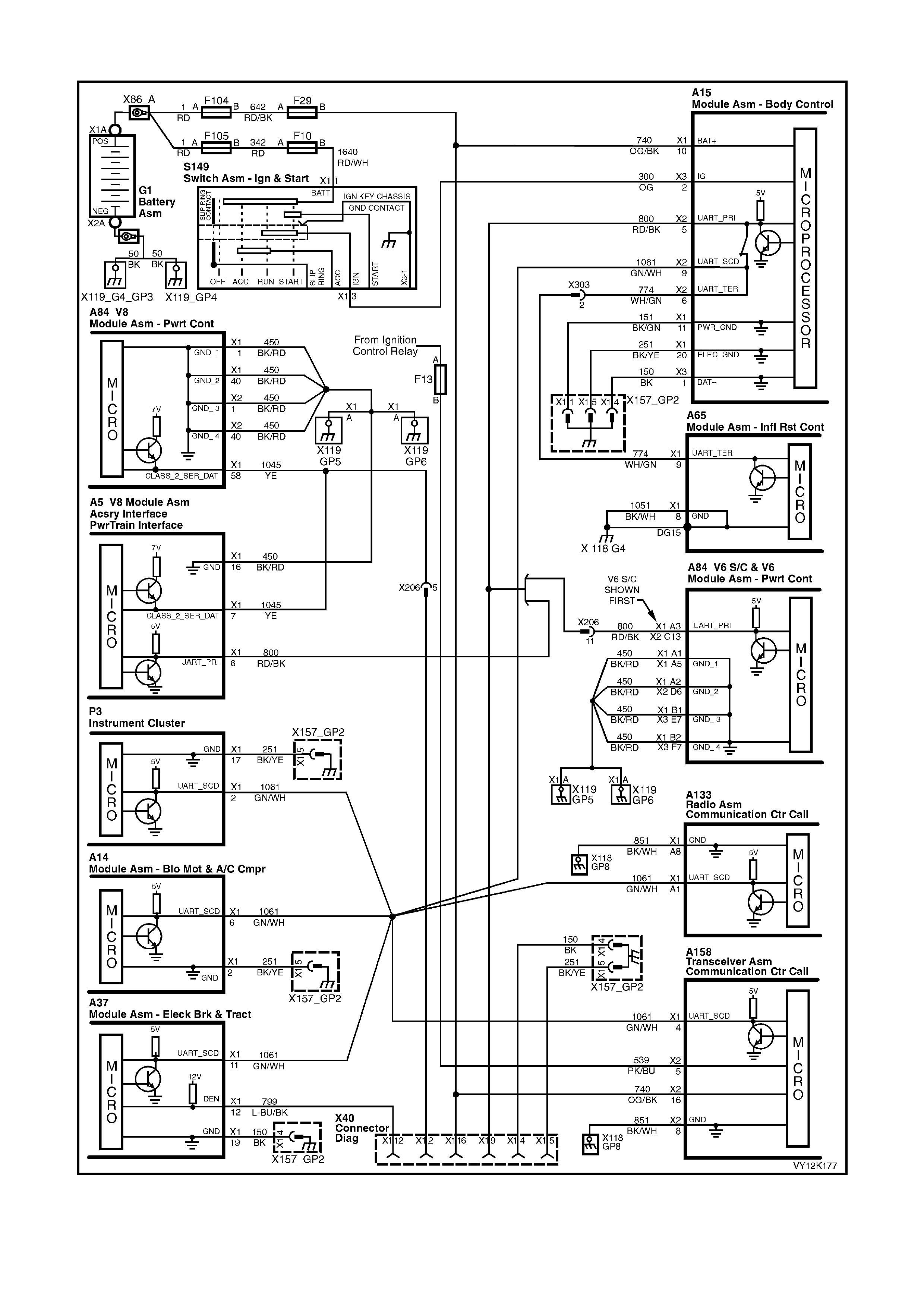
DTC 3 - NO SERIAL DATA FROM SDM (SENSING DIAGNOSTIC MODULE)
Figure 12K-73
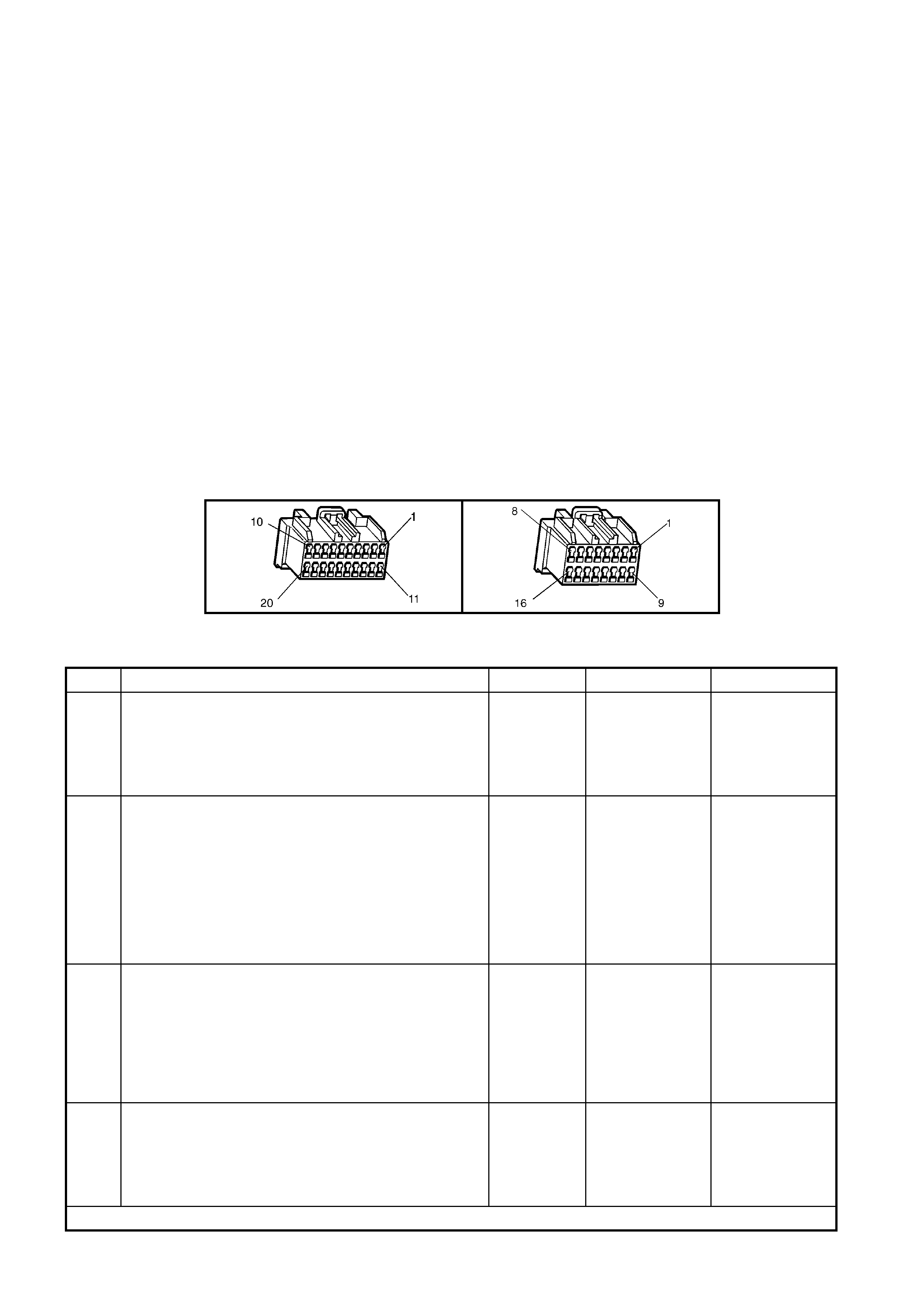
CIRCUIT DESCRIPTION
The telem atic s m odule m onitors the auxi liar y seria l dat a circuit 1 061 (G reen/W hite wire) norm al m ode m essage f or
the following information: Airbag Deployed this Ignition Cycle from the SRS SDM (Sensing Diagnostic Module,
Vehicle Speed from the PCM and Audio System status information from the Audio Head Unit. For further
information regarding the serial data bus and normal mode message, refer 1.2 Serial Data Communication in
Section 12J-1 BODY CONTROL MODULE in this Service Information. On receiving an Airbag Deployed this
Ignition Cycle from the SRS SDM the telematics module will send a “Airbag Activation Alert” to the National
Emergency Response Centre refer 2.2 Airbag Activati on Al ert in this Section.
CONDITIONS FOR SETTING THE DTC
• The telematics module does not receive any SDM serial data for more than ten seconds.
ACTION TAKEN WHEN THE DTC SETS
• When the diagnostic runs and fails, the telematics module stores the DTC into memory as a current DTC.
TEST DESCRIPTION
Number(s) below refer to step number(s) on the diagnostic chart.
1. Confirmation that the Telematics On-Board Diagnostic System Check has been performed.
2. If “No Data” is displayed next to SDM DTC Status, then there is no communication between TECH 2 and the
SDM. If T ECH 2 can communicat e with the SDM the s econdary circuit 1 061 and tertiar y s erial data circui t 774
and the SDM are OK.
3. If DTC 3 is intermittent check for an open or short to ground or voltage in circuits 1061and 774.
4. This test step confirms that the connector terminal retention is OK. Terminal retention should always be
checked before any component is replaced.
A158 X1 A158 X2
DTC 3 - NO SERIAL DATA FROM SDM
STEP ACTION VALUE YES NO
1. Has a Telematics On-Board Diagnosis System Check
been performed? Go to Step 2. Refer Telematics
On-Board
Diagnostic
System Check
chart in this
Section.
2. 1. From the TECH 2 System Select Menu select
F5: Vehicle DTC Check, Ignition On and follow
screen instructions.
Does TECH 2 Displa y “SDM DTC Status”, “No Data”?
Refer SDM Serial
Data
Communication
diagnostics in
Section 12M
Occupant
Protection
System
in this Service
Information.
Go to Step 3
3. 1. With TECH 2 still connected, switch Ignition On
engine Off.
2. From the Telematics menu Select F0: Diagnostic
Trouble Codes / F1: Clear DTC Information and
clear the Telematics Module DTCs.
3. Ignition on for at least ten seconds.
Is DTC 2 No Serial Data from Instrument set?
Go to Step 4. DTC 2 is
intermittent,
Refer Test Step
Description.
4. 1. Check telematics module connectors A158 X1 and
X2 terminal retention.
Is the terminal retention OK?
Replace
telematics
module. Refer
3.1 Telematics
Module in this
Section.
Repair connector
terminal
retention.
WHEN ALL DIAGNOSIS AND REPAIRS ARE COMPLETED, CLEAR DTCS AND VERIFY CORRECT OPERATION

DTC 4 - NO SERIAL DATA FROM AUDIO SYSTEM
Figure 12K-74
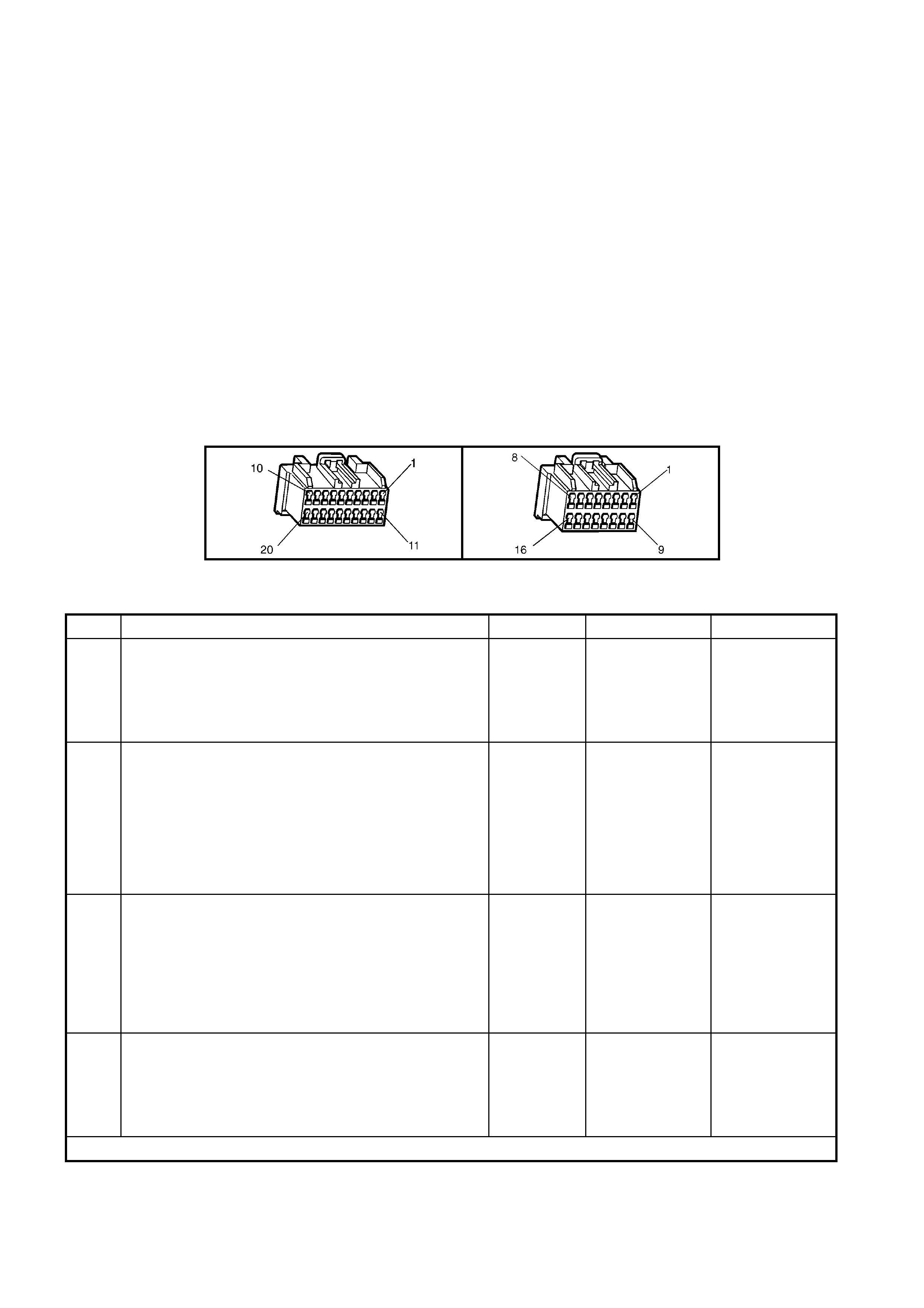
CIRCUIT DESCRIPTION
The telem atic s m odule m onitors the auxi liar y seria l dat a circuit 1 061 (G reen/W hite wire) norm al m ode m essage f or
the following information: Airbag Deployed this Ignition Cycle from the SRS SDM, Vehicle Speed from the PCM and
Audio S ystem status information from the Audio System . For further inform ation regarding the serial data bus and
normal mode message, refer 1.2 Serial Data Communication in Section 12J-1 BODY CONTROL MODULE in this
Service Information.
CONDITIONS FOR SETTING THE DTC
• The telematics module does not receive any audio system serial data for more than ten second.
ACTION TAKEN WHEN THE DTC SETS
• When the diagnostic runs and fails, the telematics module stores the DTC into memory as a current DTC.
TEST DESCRIPTION
Number(s) below refer to step number(s) on the diagnostic chart.
1. Confirmation that the Telematics On-Board Diagnostic System Check has been performed.
2. If “No Data” is displa yed n ext to Audio System DTC Status, then ther e is no communication bet ween TECH 2
and the Audio System.
3. If DTC 4 is intermittent check for an open or short to ground or voltage in circuit 1061.
4. This test step confirms that the connector terminal retention is OK. Terminal retention should always be
checked before any component is replaced.
A158 X1 A158 X2
DTC 4 - NO SERIAL DATA FROM AUDIO SYSTEM
STEP ACTION VALUE YES NO
1. Has a Telematics On-Board Diagnosis System Check
been performed? Go to Step 2. Go to Telematics
On-Board
Diagnostic
System Check
chart in this
Section.
2. 1. From the TECH 2 System Select Menu select
F5: Vehicle DTC Check, Ignition On and follow
screen instructions.
Does TECH 2 Display “Audio System DTC Status” No
Data?
Refer AHU Serial
Data
Communication
diagnostics in
Section 12D
Entertainment
System in this
Service
Information.
Go to Step 3.
3. 1. With TECH 2 still connected, switch Ignition On
engine Off.
2. From the Telematics Menu Select F0: Diagnostic
Trouble Codes / F1: Clear DTC Information and
clear the Telematics Module DTCs.
3. Ignition on for at least ten seconds.
Is DTC 4 No Serial Data from Audio System set?
Go to Step 4. DTC 4 is
intermittent,
Refer Test Step
Description.
4. 1. Check telematics module connectors A158 X1 and
X2 terminal retention.
Is the terminal retention OK?
Replace
telematics
module. Refer
3.1 Telematics
Module in this
Section.
Repair connector
terminal
retention.
WHEN ALL DIAGNOSIS AND REPAIRS ARE COMPLETED, CLEAR DTCS AND VERIFY CORRECT OPERATION

DTC 5 – NO SERIAL DATA
Figure 12K-75
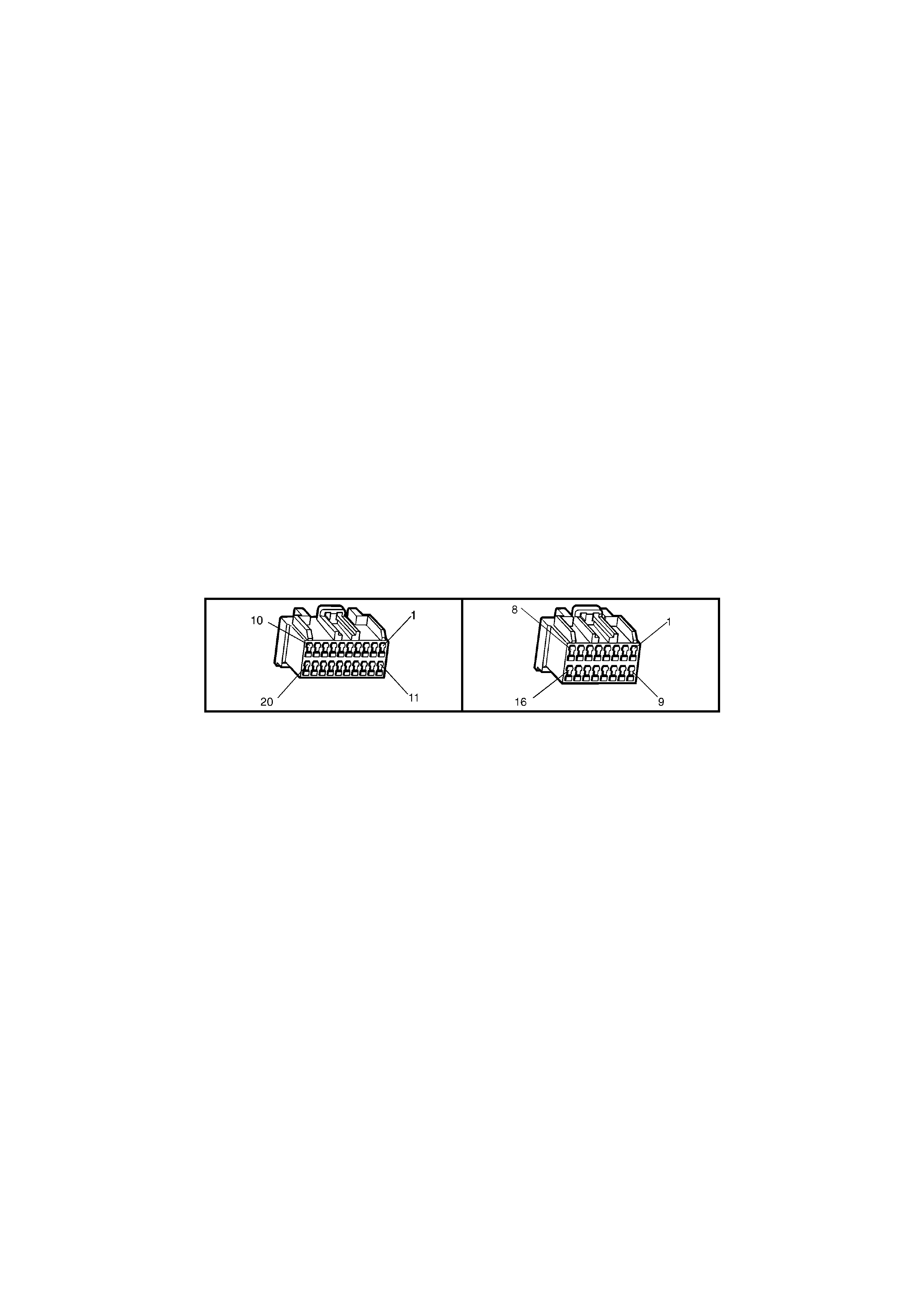
CIRCUIT DESCRIPTION
The telem atic s m odule m onitors the auxi liar y seria l dat a circuit 1 061 (G reen/W hite wire) norm al m ode m essage f or
the following information: Airbag Deployed this Ignition Cycle from the SRS SDM, Vehicle Speed from the PCM and
Audio S ystem status information from the Audio System . For further inform ation regarding the serial data bus and
normal mode message, refer 1.2 Serial Data Communication in Section 12J-1 BODY CONTROL MODULE in this
Service Information.
If the telematics module receives a “Remote Unlock” message from the Holden Assist Centre, the telematics
module will request the BCM (via the serial data circuit) to unlock the doors. For further information regarding the
BCM door lock operati on, r efer to Section 12J-1 BODY CONT ROL MODULE, Central Door Locking Systems in
this Service Information.
If the telematics module receives a “Immobilise” message from the Holden Assist Centre, the telematics module
will then turn off the fuel pump relay cutting off the supply of fuel to the engine and request the BCM (via the
serial data circuit) to flash the indicators. For further information regarding the BCM indicator operation, refer to
Section 12J-1 BODY CONTROL MODULE, Theft Deterrent System in this Service Information.
CONDITIONS FOR SETTING THE DTC
• The telematics module does not receive any serial data for more than ten second.
ACTION TAKEN WHEN THE DTC SETS
• When the diagnostic runs and fails, the t elematics modu le stores the DTC into m em or y as a curren t DTC and
activates the red status LED.
TEST DESCRIPTION
Number(s) below refer to step number(s) on the diagnostic chart.
1. Confirmation that the Telematics On-Board Diagnostic System Check has been performed.
2. This test step determines if TECH 2 is able communicate with the BCM.
3. If DTC 5 is intermittent check for an open or short to ground or voltage in circuits 774, 800 and 1061.
4. This test step confirms that the connector terminal retention is OK. Terminal retention should always be
checked before any component is replaced.
A158 X1 A158 X2

DTC 5 – NO SERIAL DATA
STEP ACTION VALUE YES NO
1. Has a Telematics On-Board Diagnosis System Check
been performed? Go to Step 2. Refer Telematics
On-Board
Diagnostic
System Check
chart in this
Section.
2. 1. From the TECH 2 System Select Menu select
F5: Vehicle DTC Check, Ignition On and follow
screen instructions.
2. Does TECH 2 Display “NO Communication with
Vehicle” or “BCM DTC Status, No Data”?
NOTE: If “No Data” is displayed next to BCM DTC
Status, then there is no communication between TECH
2 and the BCM.
Refer BCM Serial
Data
Communication
diagnostics in
Section 12J BCM
in this Service
Information.
Go to Step 3.
3. 1. With TECH 2 still connected, switch Ignition On
engine Off.
2. From the Telematics Menu Select F0: Diagnostic
Trouble Codes / F1: Clear DTC Information and
clear the Telematics Module DTCs.
3. Ignition on for at least ten seconds.
Is DTC 5 No Serial Data set?
Go to Step 4. DTC 5 is
intermittent,
Refer to
Test Step.
4. 1. Check telematics module connectors A158 X1 and
X2 terminal retention.
Is the terminal retention OK?
Replace
telematics
module. Refer
3.1 Telematics
Module in this
Section
Repair connector
terminal
retention.
WHEN ALL DIAGNOSIS AND REPAIRS ARE COMPLETED, CLEAR DTCS AND VERIFY CORRECT OPERATION
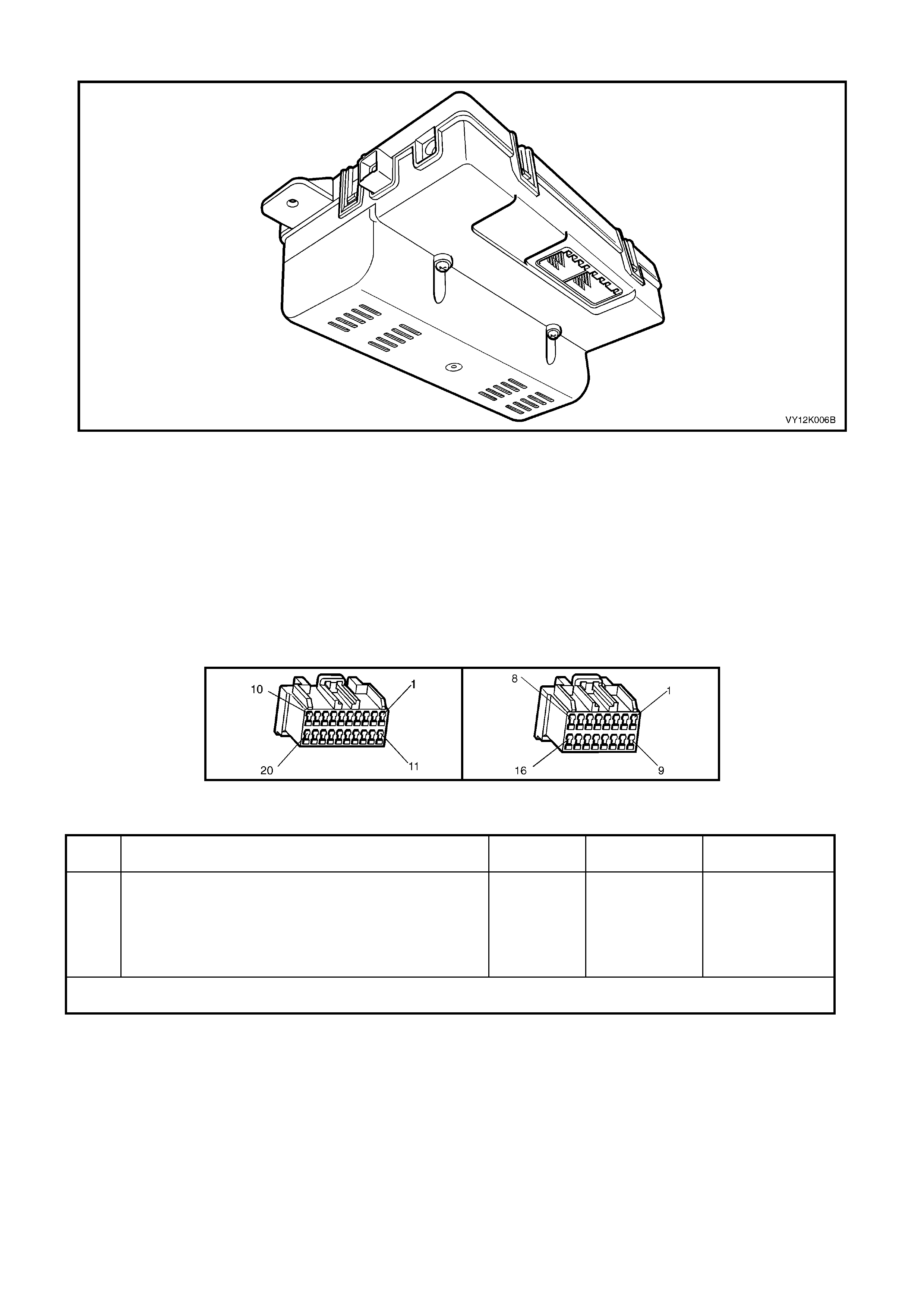
DTC 7 – GPS MODULE FAILURE
Figure 12K-76
CONDITIONS FOR SETTING THE DTC
• This DTC will set if the telematics module detects a GPS module failure.
ACTION TAKEN WHEN THE DTC SETS
• When the diagnostic runs and fails, the t elematics modu le stores the DTC into m em or y as a curren t DTC and
activates the red status LED.
TEST DESCRIPTION
Number(s) below refer to step number(s) on the diagnostic chart.
1. Confirmation that the Telematics On-Board Diagnostic System Check has been performed. If an incorrect
vehicle identification number is detected the telematics module should be replaced.
A158 X1 A158 X1
DTC 7 – GPS MODULE FIALURE
STEP ACTION VALUE YES NO
1. Has a Telematics On-Board Diagnosis System Check
been performed? Replace
telematics
module.
Refer 3.1
Telematics
Module in this
Section.
Refer Telematics
On-Board
Diagnostic
System Check
chart in this
Section.
WHEN ALL DIAGNOSIS AND REPAIRS ARE COMPLETED, CLEAR DTCS AND VERIFY CORRECT OPERATION
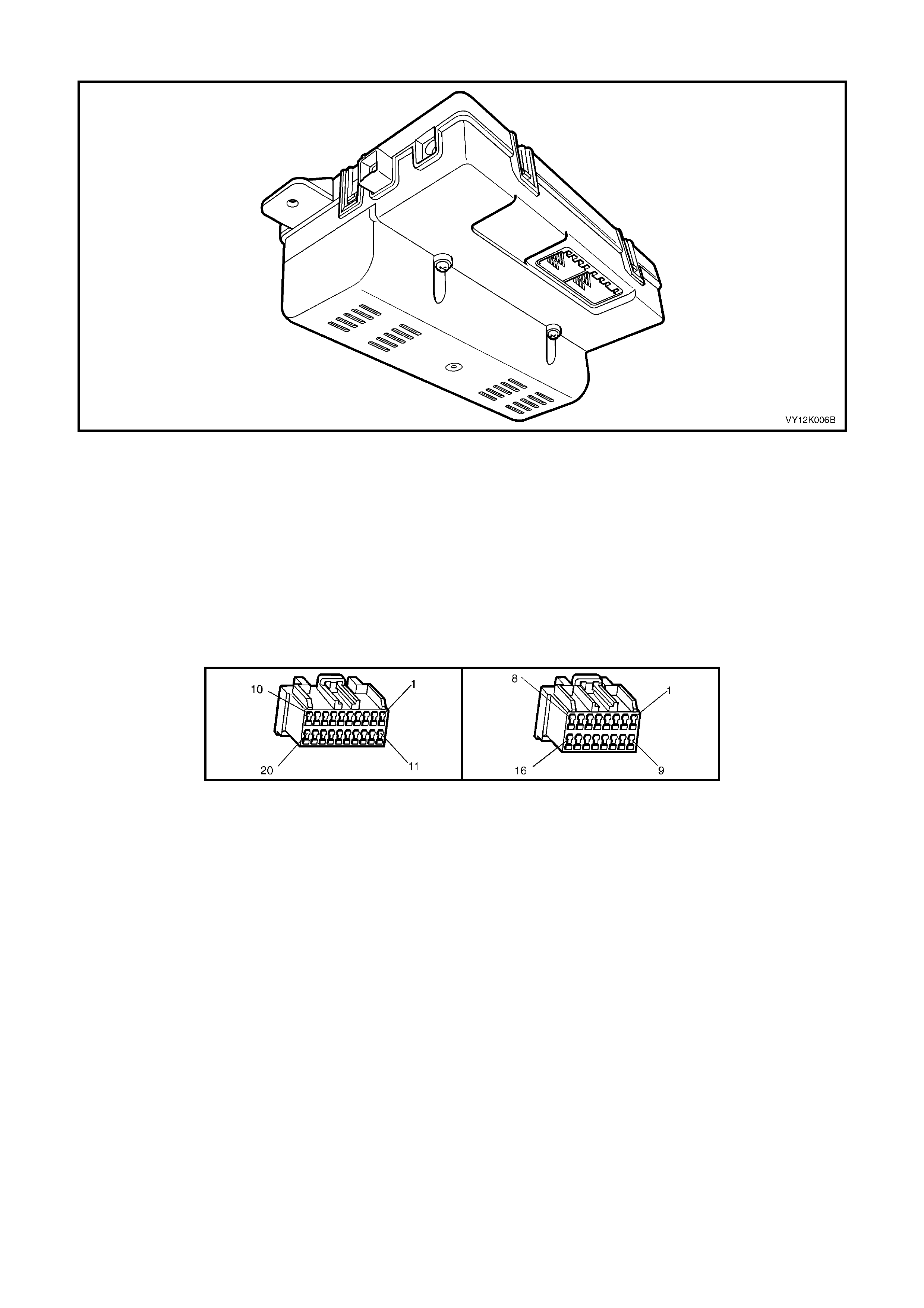
DTC 8 - SIM MISMATCH
Figure 12K-77
CONDITIONS FOR SETTING THE DTC
• During the telematics module self test a faulty or incorrect SIM is detected.
ACTION TAKEN WHEN THE DTC SETS
• When the diagnostic runs and fails, the t elematics modu le stores the DTC into m em or y as a curren t DTC and
activates the red status LED.
TEST DESCRIPTION
Number(s) below refer to step number(s) on the diagnostic chart.
1. Confirm ation that the Telematics On-Board Diagnostic System Check has been performed. If the SIM is fault y
or an incorrect SIM is detected the telematics module should be replaced.
A158 X1 A158 X2

DTC 8 – SIM MISMATCH
STEP ACTION VALUE YES NO
1. Has a Telematics On-Board Diagnosis System Check
been performed? Go to Step 2 Refer Telematics
On-Board
Diagnostic
System Check
chart in this
Section.
2. 1. From the Telematics Application Menu,
Select F4: Additional Functions / F3: SIM Reset and
perform a SIM Reset.
Does TECH 2 display SIM Reset Not Required?
Go to Step 4 Go to Step 3
3. In Test Step 2 was the SIM Reset Successful? Complete
Telematics On-
Board Diagnostic
System Check.
Refer
Telematics On-
Board Diagnostic
System Check
chart in this
Section.
Go to Step 4
4. 1. Check telematics module connectors A158 X1 & X2
terminal re tention.
Is the terminal retention OK?
Replace
telematics
module.
Refer
3.1 Telematics
Module in this
Section
Repair connector
terminal
retention.
WHEN ALL DIAGNOSIS AND REPAIRS ARE COMPLETED, CLEAR DTCS AND VERIFY CORRECT OPERATION
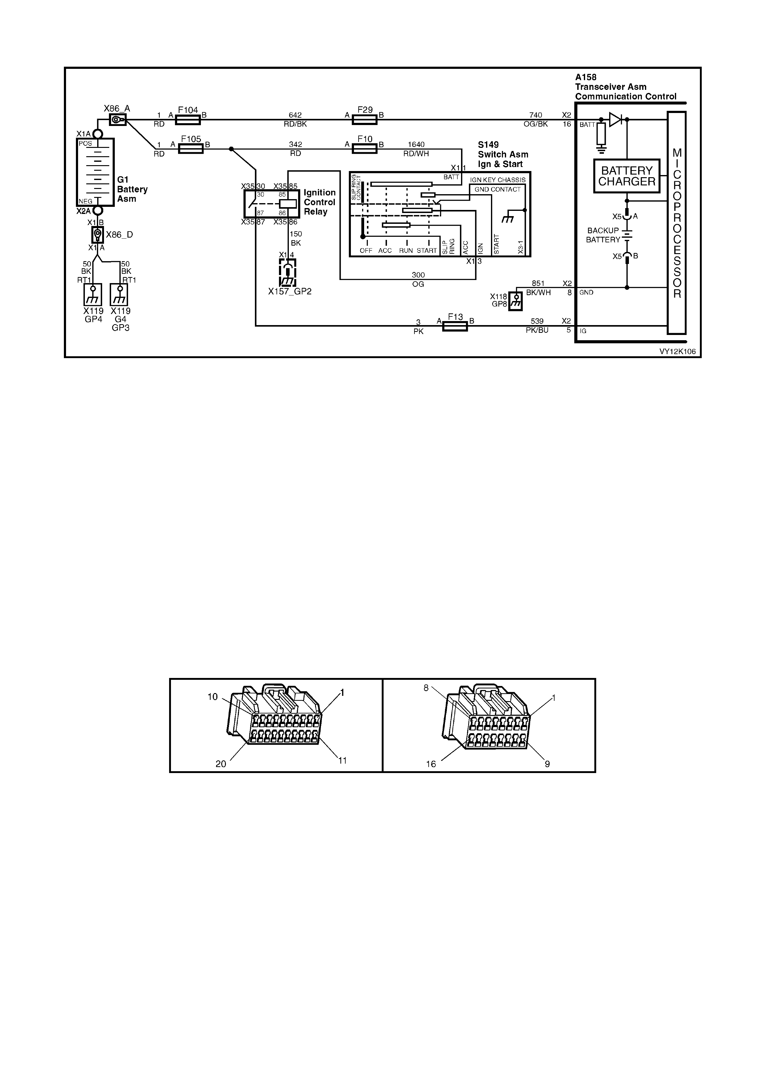
DTC 9 - VEHICLE BATTERY VOLTAGE TOO HIGH
Figure 12K-78
CIRCUIT DESCRIPTION
Battery voltage is applied to the telematics module terminal X2-16 at all times via circuit 740 (Orange/Black wire),
fuse F29 and fusible link F104.
CONDITIONS FOR SETTING THE DTC
• The voltage at the telematics module terminal A158 X2-16 is greater than 16 Volts for more than one second.
ACTION TAKEN WHEN THE DTC SETS
• When the diagnostic runs and fails, the t elematics modu le stores the DTC into m em or y as a curren t DTC and
activates the red status LED.
TEST DESCRIPTION
Number(s) below refer to step number(s) on the diagnostic chart.
1. Confirmation that the Telematics On-Board Diagnostic System Check has been performed.
2. This step determines if the DTC is current. If the DTC is not current the vehicle charging system should be
checked, refer to Section 12A BATTERY AND CABLES, 3. Diagnosis in this Service Information.
3. This step determines if there is a current fault with the charging system.
4. This test step confirms that the connector terminal retention is OK. Terminal retention should always be
checked before any component is replaced.
A158 X1 A158 X2

DTC 9 - VEHICLE BATTERY VOLTAGE TOO HIGH
STEP ACTION VALUE YES NO
1. Has a Telematics On-Board Diagnosis System Check
been performed? Go to Step 2 Refer Telematics
On-Board
Diagnostic
System Check
chart in this
Section.
2. 1. From the Telematics Application Menu,
Select F0: Diagnostic Trouble Codes / F0: Clear
DTCs and clear all DTCs.
2. Start engine and increase engine RPM to 1000 for
one minute.
Does DTC 9 Vehicle Battery Voltage Too High Set?
Go to Step 3 DTC 9 is
intermittent
Refer Test Step
Description.
3. 1. From the Telematics Application Menu,
Select F1: Data Display / F0: Inputs and Outputs
and scroll to Battery Voltage.
2. Start engine and increase engine RPM to 1000 for
at least one minute, while observing TECH 2
battery Voltage display.
Does TECH 2 display the battery voltage greater than
the specified value?
16 Volts Refer Section
12A BATTERY
AND CABLES,
3. DIAGNOSIS
in this Service
Information.
Go to Step 4
4. 1. Check telematics module connectors A158 X1 &
X2 terminal retention.
Is the terminal retention OK?
Replace
telematics
module.
Refer
3.1 Telematics
Module in this
Section
Repair connector
terminal
retention.
WHEN ALL DIAGNOSIS AND REPAIRS ARE COMPLETED, CLEAR DTCS AND VERIFY CORRECT OPERATION

DTC 10 - VEHICLE BATTERY VOLTAGE TOO LOW
Figure 12K-79
CIRCUIT DESCRIPTION
Battery voltage is applied to the telematics module terminal X2-16 at all times via circuit 740 (Orange/Black wire),
fuse F29 and fusible link F104.
CONDITIONS FOR SETTING THE DTC
• The battery voltage at the telematics module terminal A158 X2-16 is less than:
Ten Volts for three minutes or
Nine Volts for one minute
Six Volts for ten seconds.
ACTION TAKEN WHEN THE DTC SETS
• When the diagnostic runs and fails, the t elematics modu le stores the DTC into m em or y as a curren t DTC and
activates the red status LED.
TEST DESCRIPTION
Number(s) below refer to step number(s) on the diagnostic chart.
1. Confirmation that the Telematics On-Board Diagnostic System Check has been performed.
2. This step determines if the DTC is current. If the DTC is not current the vehicle charging system should be
checked. Circuit 740 and 851 should also be checked for an intermittent open.
3. This test step determines the voltage the telematics module is reading from terminal A158 X2-16.
4. The test step check the actual voltage at terminal A158 X2-16.
5. This test step checks for a voltage drop in the battery supply circuit 740.
6. This test step checks for a voltage drop in the ground circuit 851.
7. This test step confirms that the connector terminal retention is OK. Terminal retention should always be
checked before any component is replaced.
A158 X1 A158 X2

DTC 10 - VEHICLE BATTERY VOLTAGE TOO LOW
STEP ACTION VALUE YES NO
1. Has a Telematics On-Board Diagnosis System Check
been performed? Go to Step 2. Refer Telematics
On-Board
Diagnostic
System Check
chart in this
Section.
2. 1. From the Telematics Application Menu,
Select F0: Diagnostic Trouble Codes / F0: Clear
DTCs and clear all DTCs.
2. Start engine and increase engine RPM to 1000 for
at least three minute.
Does DTC 10 Vehicle Battery Voltage Too Low Set?
Go to Step 3. DTC 10 is
intermittent
Refer Test Step
Description.
3. 1. From the Telematics Application Menu,
Select F1: Data Display / F0: Inputs and Outputs
and scroll to Battery Voltage.
2. Start engine and increase engine RPM to 1000 for
three minute, while observing TECH 2 battery
Voltage display.
Does TECH 2 display the battery voltage less than the
specified value?
Less than 10
Volts for
3 Minutes
Less than
9 Volts for
1 Minutes
Less than
6 Volts for
10 Seconds
Go to Step 4. Go to Step 5.
4. 1. Using a DMM check the voltage at the telematics
module connector A158 X2-16 circuit 740,
(red/white wire) and a known good ground.
Is voltage less than the specified value.
Less than 10
Volts for
3 Minutes
Less than
9 Volts for
1 Minutes
Less than
6 Volts for
10 Seconds
Go to Step 5. Go to Step 7.
5. 1. Check for voltage drop in circuit 740, (Red/White
wire) between the battery and the telematics
module.
Is voltage greater than specified value.
200 mV Repair cause of
excessive
voltage drop in
circuit 740.
Go to Step 6.
6. 1. Check for voltage drop in ground circuit 851,
(Black/White wire) between the battery and the
telematics module.
Is voltage greater than specified value.
200 mV Repair cause of
excessive
voltage drop in
circuit 851.
Refer Section
12A BATTERY
AND CABLES,
3. DIAGNOSIS in
this Service
Information.
7. 1. Check telematics module connector A158 X1 & X2
terminal re tention.
Is the terminal retention OK?
Replace
telematics
module.
Refer 3.1
Telematics
Module in this
Section
Repair connector
terminal
retention.
WHEN ALL DIAGNOSIS AND REPAIRS ARE COMPLETED, CLEAR DTCS AND VERIFY CORRECT OPERATION
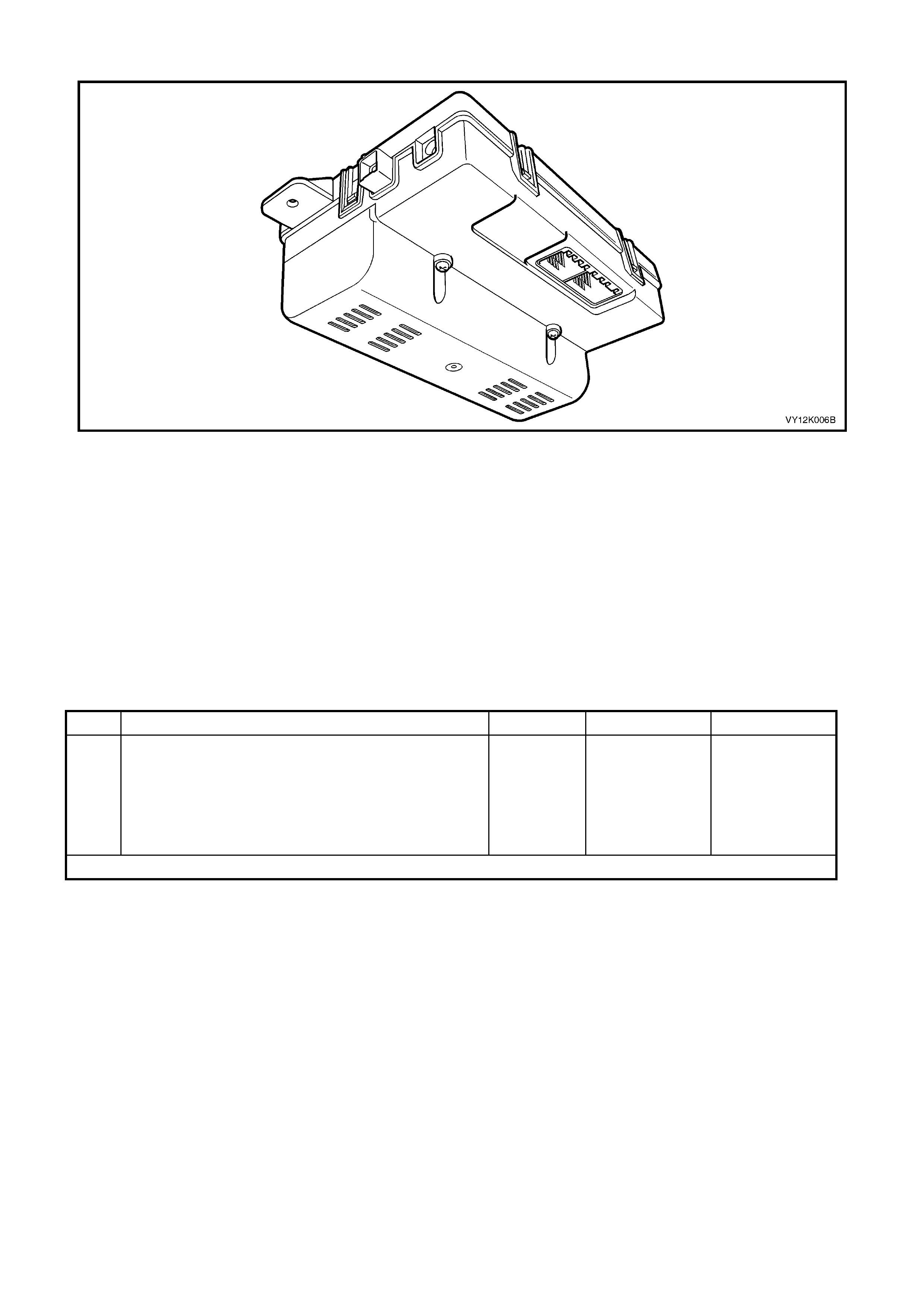
DTC 11 - RAM ERROR
Figure 12K-80
CONDITIONS FOR SETTING THE DTC
• DTC 11 RAM Error is set if the telematics module detects a fault with the internal memory (RAM) during the
telematics module self test.
ACTION TAKEN WHEN THE DTC SETS
• When the diagnostic runs and fails, the t elematics modu le stores the DTC into m em or y as a curren t DTC and
activates the red status LED.
TEST DESCRIPTION
Number(s) below refer to step number(s) on the diagnostic chart.
1. Conf irmation that th e Telem atics On-Boar d Diagnostic S ys tem Check has been perform ed. If the a RAM Error
is detected the telematics module should be replaced.
DTC 11 – RAM ERROR
STEP ACTION VALUE YES NO
1. Has a Telematics On-Board Diagnosis System Check
been performed? Replace
telematics
module.
Refer 3.1
Telematics
Module in this
Section
Refer Telematics
On-Board
Diagnostic
System Check
chart in this
Section.
WHEN ALL DIAGNOSIS AND REPAIRS ARE COMPLETED, CLEAR DTCS AND VERIFY CORRECT OPERATION

DTC 12 - EEPROM ERROR
Figure 12K-81
CONDITIONS FOR SETTING THE DTC
• DTC 11 EEPROM Error is set if the telem atics m odule detects a fault with the EEPRO M during t he telem atics
module self test.
ACTION TAKEN WHEN THE DTC SETS
• When the diagnostic runs and fails, the t elematics modu le stores the DTC into m em or y as a curren t DTC and
activates the red status LED.
TEST DESCRIPTION
Number(s) below refer to step number(s) on the diagnostic chart.
1. Confirmation that the Telematics On-Board Diagnostic System Check has been performed. If the a EEPROM
Error is detected the telematics module should be replaced.
DTC 12– EEPROM ERROR
STEP ACTION VALUE YES NO
1. Has a Telematics On-Board Diagnosis System Check
been performed? Replace
telematics
module.
Refer 3.1
Telematics
Module in this
Section
Refer Telematics
On-Board
Diagnostic
System Check
chart in this
Section.
WHEN ALL DIAGNOSIS AND REPAIRS ARE COMPLETED, CLEAR DTCS AND VERIFY CORRECT OPERATION
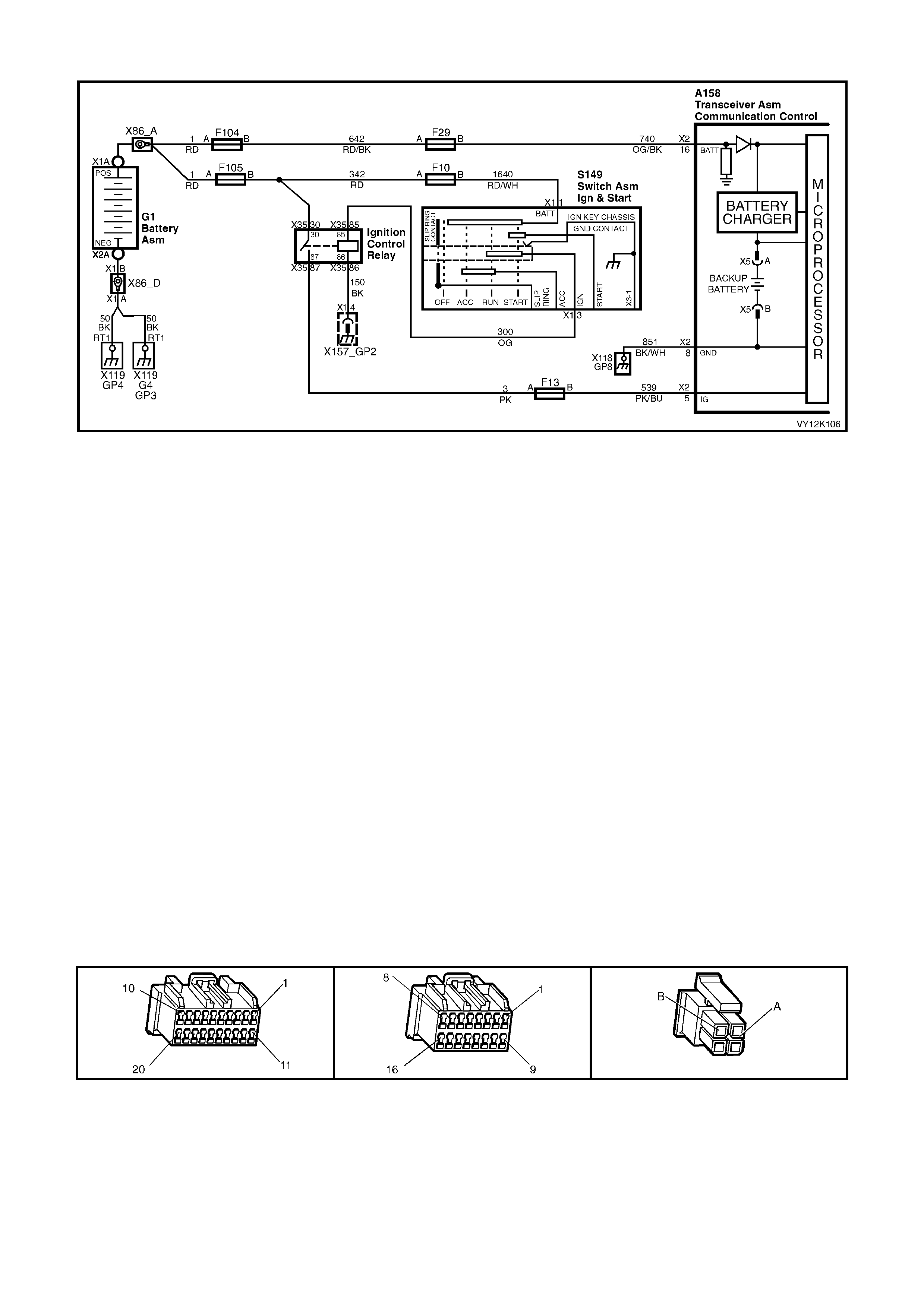
DTC 13 - BACKUP BA TTERY TIMER EXPIRED
Figure 12K-82
CIRCUIT DESCRIPTION
The back up batter y is housed in the b atter y compar tment of the telem atics module. T he back up batter y will provi de
power to the telematics module for at least 30 minutes in the event of the vehicle battery being discharged or
disconn ected. The te lemati cs module has a back up battery char ging circui t that m aintains the bac kup batte ry state
of charge. This circuit also includes an over current protection device. After the back up battery has been in the
vehicle for 5 years ( 4368 0 hour s) it has re ache d the e nd of its us eful life, ( int ernal d eteri oration caus ing low charge
acceptance) DTC 13 will be set and the red status LED will be illuminated.
CONDITIONS FOR SETTING THE DTC
• DTC 13 is set if the bac k up batter y timer in the telem atic s m odule has exceede d 5 years (436 80 hours ). At thi s
time the backup battery has reached the end of its useful life (internal deterioration causing low charge
acceptance).
ACTION TAKEN WHEN THE DTC SETS
• When the backup battery timer exceeds 5 years the telematics module stores the DTC into memory as a
current DTC and activates the red status LED.
TEST DESCRIPTION
Number(s) below refer to step number(s) on the diagnostic chart.
1. Confirmation that the Telematics On-Board Diagnostic System Check has been performed.
2. If the a backup battery timer has exceeded 5 years (43680 hours) the backup battery will need to be replaced.
3. Onc e the back up batter y has been r eplac ed the bac k up batter y tim er mus t be reset with T ECH 2. TIS ap prova l
will be required to perform the TECH 2 function.
4. This test step checks that the DTC has been cleared and that a fault in the telematics module is not causing
the DTC to set.
5. This test step confirms that the connector terminal retention is OK. Terminal retention should always be
checked before any component is replaced.
A158 X1 A158 X2 A158 X5

DTC 13 – BACKUP BATTERY TIMER EXPIRED
STEP ACTION VALUE YES NO
1. Has a Telematics On-Board Diagnosis System Check
been performed? Go to Step 2. Refer Telematics
On-Board
Diagnostic
System Check
chart in this
Section.
2. 1. Replace telematics module backup battery.
(refer 3.2 BACKUP BATTERY in this Section).
Has telematics module backup battery been replaced?
Go to Step 3. Replace
telematics
module backup
battery.
3. 1. Reset telematics module backup battery timer.
Refer 4.3 TECH 2 TEST MODES F4: Additional
Functions, F1: Backup Battery Timer Reset in this
Section.
Has telematics module backup battery timer been reset?
Go to Step 4. Reset telematics
module backup
battery timer.
4. 1. With TECH 2 still connected, switch Ignition On
engine Off.
2. From the Telematics Menu Select F0: Diagnostic
Trouble Codes / F1: Clear DTC Information and
clear the Telematics Module DTCs.
3. Ignition on for at least ten seconds.
Is DTC 13 Backup Battery Timer Expired set?
Go to Step 5. Complete
Telematics On-
Board Diagnostic
System.
5. 1. Check telematics module connectors A158 X1, X2
& X5 terminal retention.
Is the terminal retention OK?
Replace
telematics
module.
Refer
3.1 Telematics
Module in this
Section.
Repair connector
terminal
retention.
WHEN ALL DIAGNOSIS AND REPAIRS ARE COMPLETED, CLEAR DTCS AND VERIFY CORRECT OPERATION
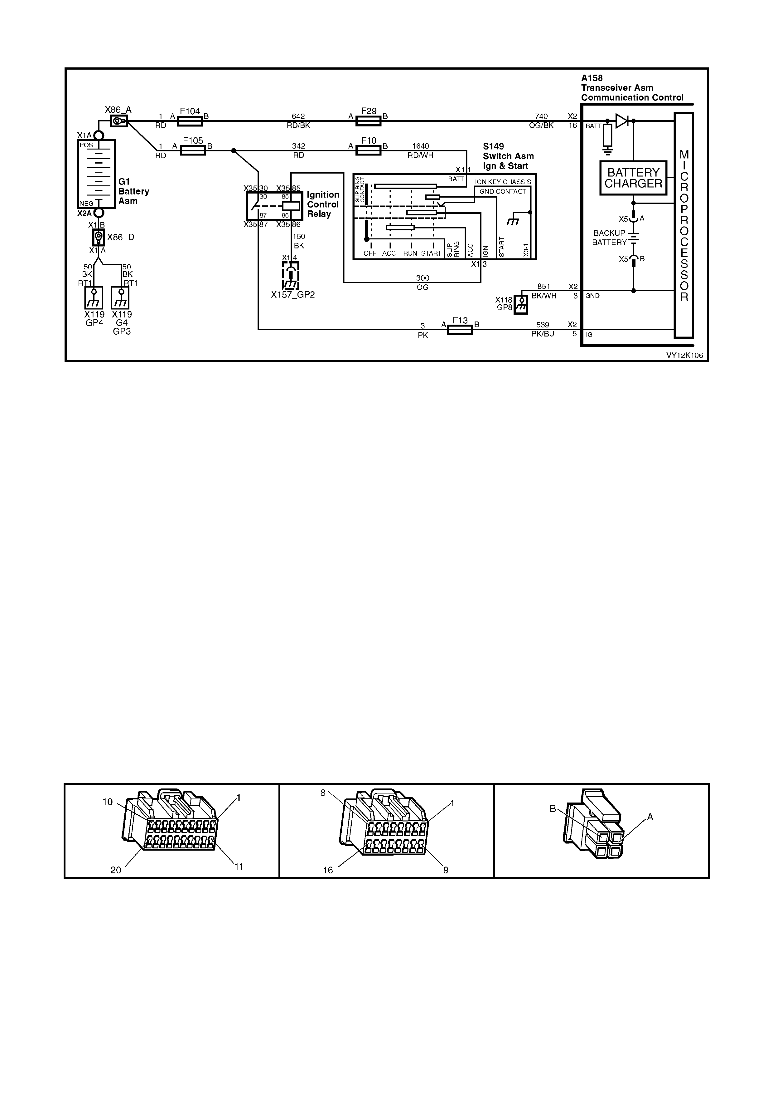
DTC 14 - BACKUP BATTERY VOLTAGE TOO HIGH
Figure 12K-83
CIRCUIT DESCRIPTION
The back up batter y is housed in the b atter y compar tment of the telem atics module. T he back up batter y will provi de
power to the telematics module for at least 30 minutes in the event of the vehicle battery being discharged or
disconn ected. The te lemati cs module has a back up battery char ging circui t that m aintains the bac kup batte ry state
of charge. This circuit also includes an over current protection device.
CONDITIONS FOR SETTING THE DTC
• DTC 14 is set if the backup battery voltage is greater than 9.8 Volts for more that one second.
ACTION TAKEN WHEN THE DTC SETS
• When the diagnostic runs and fails, the t elematics modu le stores the DTC into m em or y as a curren t DTC and
activates the red status LED.
TEST DESCRIPTION
Number(s) below refer to step number(s) on the diagnostic chart.
1. Confirmation that the Telematics On-Board Diagnostic System Check has been performed.
2. If DTC 14 Backup Battery Voltage Too High does not set then the DTC is intermittent.
3. This test step checks the backup battery voltage, if the backup battery voltag e is less than the spec ified value
and the DTC is being set then the telematics module should be replaced.
4. This test step checks the open circuit voltage of the backup battery. If the backup battery is greater than the
specified value then the backup battery should be replaced.
5. This test step confirms that the backup battery connector terminal retention is OK. Terminal retention should
always be checked before any component is replaced.
6. This test step confirms that the connector terminal retention is OK. Terminal retention should always be
checked before any component is replaced.
A158 X1 A158 X2 A158 X5

DTC 14 – BACKUP BATTERY VOLTAGE TOO HIGH
STEP ACTION VALUE YES NO
1. Has a Telematics On-Board Diagnosis System Check
been performed? Go to Step 2. Refer Telematics
On-Board
Diagnostic
System Check
chart in this
Section.
2. 1. From the Telematics Application Menu,
Select F0: Diagnostic Trouble Codes / F0: Clear
DTCs and clear all DTCs.
2. Start engine and increase engine RPM to 1000 for
at least five minutes.
Does DTC 14 Backup Battery Voltage Too High Set?
Go to Step 3. DTC 14 is
intermittent.
Refer Test Step
Description.
3. 1. From the Telematics Application Menu,
Select F1: Data Display / F0: Inputs and Outputs
and scroll to Backup Battery Voltage.
2. Start engine and increase engine RPM to 1000 for
five minutes, while observing TECH 2 Backup
Battery Voltage display.
Does TECH 2 display the battery voltage greater than
the specified value?
Greater than
7.5 Volts. Go to Step 4. Go to Step 6.
4. 1. Disconnect the backup battery from the telematics
module connector A158 X5.
2. Using a DMM check the backup voltage at the
backup battery connector A158 X5-A and X5-B.
Is the backup battery voltage greater than the spec ified
value.
Greater than
7.5 Volts. Go to Step 5. Go to Step 6.
5. 1. Check telematics module connectors A158 X1, X2
& X5 terminal retention.
Is the terminal retention OK?
Replace backup
battery refer
3.2 Backup
Battery
in this Section
Repair connector
terminal
retention.
6. 1. Check telematics module connectors A158 X1 &
X2 terminal retention.
Is the terminal retention OK?
Replace
telematics
module refer
3.1 Telematics
Module
in this Section.
Repair connector
terminal
retention.
WHEN ALL DIAGNOSIS AND REPAIRS ARE COMPLETED, CLEAR DTCS AND VERIFY CORRECT OPERATION

DTC 15 - BACKUP BATTERY VOLTAGE TOO LOW
Figure 12K-84
CIRCUIT DESCRIPTION
The back up batter y is housed in the b atter y compar tment of the telem atics module. T he back up batter y will provi de
power to the telematics module for at least 30 minutes in the event of the vehicle battery being discharged or
disconn ected. The te lemati cs module has a back up battery char ging circui t that m aintains the bac kup batte ry state
of charge. This circuit also includes an over current protection device.
CONDITIONS FOR SETTING THE DTC
• DTC 15 is set if the backup battery voltage is less than 5.5 Volts for more than three minutes.
ACTION TAKEN WHEN THE DTC SETS
• When the diagnostic runs and fails, the t elematics modu le stores the DTC into m em or y as a curren t DTC and
activates the red status LED.
TEST DESCRIPTION
Number(s) below refer to step number(s) on the diagnostic chart.
1. Confirmation that the Telematics On-Board Diagnostic System Check has been performed.
2. If DTC 15 Backup Battery Voltage Too Low does not set then the DTC is intermittent. Check backup battery
open circuit voltage refer step 4.
3. This test step checks the backup battery voltage, if the backup battery voltag e is less than the spec ified value
go to step 4, if th e b ack up batter y voltag e is great er than th e spec ifie d va lue and the DT C is b eing s et then t he
telematics module should be replaced.
4. This test step checks the open circuit voltage of the backup battery. If the backup battery is less than the
specified value then the backup battery should be replaced.
5. This test step confirms that the backup battery connector terminal retention is OK. Terminal retention should
always be checked before any component is replaced.
6. This test step confirms that the connector terminal retention is OK. Terminal retention should always be
checked before any component is replaced.
A158 X1 A158 X2 A158 X5

DTC 15 – BACKUP BATTERY VOLTAGE TOO LOW
STEP ACTION VALUE YES NO
1. Has a Telematics On-Board Diagnosis System Check
been performed? Go to Step 2. Refer Telematics
On-Board
Diagnostic
System Check
chart in this
Section.
2. 1. From the Telematics Application Menu,
Select F0: Diagnostic Trouble Codes / F0: Clear
DTCs and clear all DTCs.
2. Start engine and increase engine RPM to 1000 for
at least five minutes.
Does DTC 15 Backup Battery Voltage Too Low Set?
Go to Step 3. DTC 15 is
intermittent.
Refer Test Step
Description.
3. 1. From the Telematics Application Menu,
Select F1: Data Display / F0: Inputs and Outputs
and scroll to Backup Battery Voltage.
2. Start engine and increase engine RPM to 1000 for
five minutes, while observing TECH 2 Backup
Battery Voltage display.
Does TECH 2 display the backup battery voltage less
than the specified value?
Less than 5.5
Volts. Go to Step 4. Go to Step 6.
4. 1. Disconnect the backup battery from the telematics
module connector A158 X5.
2. Using a DMM check the backup battery voltage at
the backup battery connector terminals A158 X5-A
and X5-B.
Is the backup battery voltage less than the specified
value.
Less than 5.5
Volts. Go to Step 5. Go to Step 6.
5. 1. Check telematics module connectors A158 X1, X2
& X5 terminal retention.
Is the terminal retention OK?
Replace backup
battery refer
3.2 Backup
Battery in this
Section
Repair connector
terminal
retention.
6. 1. Check telematics module connectors A158 X1 &
X2 terminal retention.
Is the terminal retention OK?
Replace
telematics
module refer
3.1 Telematics
Module in this
Section.
Repair connector
terminal
retention.
WHEN ALL DIAGNOSIS AND REPAIRS ARE COMPLETED, CLEAR DTCS AND VERIFY CORRECT OPERATION

DTC 16 - BACKUP BATTERY NOT DETECTED
Figure 12K-85
CIRCUIT DESCRIPTION
The back up batter y is housed in the b atter y compar tment of the telem atics module. T he back up batter y will provi de
power to the telematics module for at least 30 minutes in the event of the vehicle battery being discharged or
disconn ected. The te lemati cs module has a back up battery char ging circui t that m aintains the bac kup batte ry state
of charge. This circuit also includes an over current protection device.
CONDITIONS FOR SETTING THE DTC
• DTC 16 is set if the backup battery voltage is less than one volt.
ACTION TAKEN WHEN THE DTC SETS
• When the diagnostic runs and fails, the t elematics modu le stores the DTC into m em or y as a curren t DTC and
activates the red status LED.
TEST DESCRIPTION
Number(s) below refer to step number(s) on the diagnostic chart.
1. Confirmation that the Telematics On-Board Diagnostic System Check has been performed.
2. If DTC 16 Back up Battery Not Detec ted does not set then the DT C is interm ittent. Check bac kup batter y o pen
circuit voltage refer step 4.
3. This test step checks the backup battery voltage, if the backup battery voltag e is less than the spec ified value
go to step four, if the backup batter y voltag e is greate r than the spec ified val ue and the DT C is being set then
the telematics module should be replaced.
4. This test step checks the open circuit voltage of the backup battery. If the backup battery is less than the
specified value then the backup battery should be replaced.
5. This test step confirms that the backup battery connector terminal retention is OK. Terminal retention should
always be checked before any component is replaced.
6. This test step confirms that the connector terminal retention is OK. Terminal retention should always be
checked before any component is replaced.
A158 X1 A158 X2 A158 X5

DTC 16 – BACKUP BATTERY NOT DETECTED
STEP ACTION VALUE YES NO
1. Has a Telematics On-Board Diagnosis System Check
been performed? Go to Step 2. Refer Telematics
On-Board
Diagnostic
System Check
chart in this
Section.
2. 1. From the Telematics Application Menu,
Select F0: Diagnostic Trouble Codes / F0: Clear
DTCs and clear all DTCs.
2. Start engine and increase engine RPM to 1000 for
at least five minutes.
Does DTC 16 Backup Battery Not Detected Set?
Go to Step 3. DTC 16 is
intermittent.
Refer Test Step
Description.
3. 1. From the Telematics Application Menu,
Select F1: Data Display / F0: Inputs and Outputs
and scroll to Backup Battery Voltage.
2. Start engine and increase engine RPM to 1000 for
five minutes, while observing TECH 2 Backup
Battery Voltage display.
Does TECH 2 display the backup battery voltage less
than the specified value?
Less than 1.0
volt. Go to Step 4. Go to Step 6.
4. 1. Disconnect the backup battery from the telematics
module connector A158 X5.
2. Using a DMM check the backup voltage at the
backup battery connector terminals A158 X5-A and
X5-B.
Is the backup battery voltage less than the specified
value.
Less than 1.0
volt. Go to Step 5. Go to Step 6.
5. 1. Check telematics module connectors A158 X1, X2
& X5 terminal retention.
Is the terminal retention OK?
Replace backup
battery refer
3.2 Backup
Battery in this
Section
Repair connector
terminal
retention.
6. 1. Check telematics module connectors A158 X1 &
X2 terminal retention.
Is the terminal retention OK?
Replace
telematics
module refer
3.1 Telematics
Module in this
Section
Repair connector
terminal
retention.
WHEN ALL DIAGNOSIS AND REPAIRS ARE COMPLETED, CLEAR DTCS AND VERIFY CORRECT OPERATION

DTC 17 - MICROPHONE NOT DETECTED
Figure 12K-86

CIRCUIT DESCRIPTION
The ac tive m icrophon e in t he inter ior r ear v iew m ir ror prov ides a m eans f or two way voic e c omm unication bet ween
the vehic le occupants and Holden Assist Centr e. During the s ys tem self tes t the microphone and circuit are tested
to determine if there is a microphone or microphone circuit malfunction.
CONDITIONS FOR SETTING THE DTC
• DTC 17 is set if the microphone circuit (1155) input voltage is greater than 2.5 Volts.
ACTION TAKEN WHEN THE DTC SETS
• When the diagnostic runs and fails, the t elematics modu le stores the DTC into m em or y as a curren t DTC and
activates the red status LED.
TEST DESCRIPTION
Number(s) below refer to step number(s) on the diagnostic chart.
1. Confirmation that the Telematics On-Board Diagnostic System Check has been performed.
2. T his test step det erm ines if DT C 17 is interm ittent. If DT C 17 is inter m ittent check f or an inter m ittent ope n, or a
short to ground or voltage in the microphone circuit 1155 and 1153.
3. Checks that the telematics module is supplying five Volts to the microphone.
4. If the voltage is greater than five Volts then circuit 1155 is shorted to voltage.
5. If the voltage is less than five Volts then circuit 1155 is shorted to ground.
6. Checks if the telematics module is supplying five Volts to circuit 1155.
7. This test determines if circuit 1153 has continuity.
8. Before the mirror is replaced the retention of the interior mirror connector E124 X1 terminals should be
checked.
9. Before the telematics module is replaced the retention of the telematics module connectors A158 X1 and X2
terminals should be checked.
A158 X1 A158 X2 E124 X1

DTC 17 - MICROPHONE NOT DETECTED
STEP ACTION VALUE YES NO
1. Has a Telematics On-Board Diagnosis System Check
been performed? Go to Step 2 Refer Telematics
On-Board
Diagnostic
System Check
chart in this
Section.
2. 1. From the Telematics Application Menu,
Select F0: Diagnostic Trouble Codes / F0: Clear
DTCs and clear all DTCs.
2. Switch Ignition off then On again for at lease 1
minute.
Does DTC 17 Microphone Not Detected Set?
Go to Step 3. DTC 17 is
intermittent.
Refer Test Step
Description.
3. 1. Disconnect the interior rear view mirror connector
E124 X1.
2. Ignition on.
3. Using a DMM, check the voltage at the interior rear
view mirror connector terminal E124 X1-10 circuit
1155 (Green wi re).
Is the voltage as specified?
5 Volts. Go to Step 7. Go to Step 4.
4. In step 3 was the voltage greater than specified? 5 Volts. Repair short to
voltage in circuit
1155.
Go to Step 5.
5. In step 3 was the voltage less than specified? 5 Volts. Go to Step 6. Go to Step 7.
6. 1. Ignition on.
2. Interior rear view mirror connector E124 X1 still
disconnected.
3. Using a DMM, check the voltage at the telematics
module connector terminal A158 X1-8 circuit 1155
(Green wire).
Is voltage as specified?
5 Volts. Repair open or
short to ground in
circuit 1155.
Go to Step 9.
7. 1. Using a DMM, measure continuity of circuit 1153
(Brown wire) between the telematics module
connector terminal A158 X1-7 and the interior rear
view mirror connector terminal E124 X1-2.
Is there continuity?
Repair open
circuit 1153.
Go to Step 8.
8. 1. Check interior rear view mirror connector E124 X1
terminal re tention.
Is the terminal retention OK?
Replace interior
rear view mirror.
Refer 3.5 Interior
Rear View Mirror
in this Section.
Repair connector
terminal
retention.
9. 1. Check telematics module connectors A158 X1 and
X2 terminal retention.
Is the terminal retention OK?
Replace
telematics
module. Refer
3.1 Telematics
Module in this
Section.
Repair connector
terminal
retention.
WHEN ALL DIAGNOSIS AND REPAIRS ARE COMPLETED, VERIFY CORRECT OPERATION

DTC 18 - MICROPHONE CIRCUIT VOLTAGE TOO LOW
Figure 12K-87
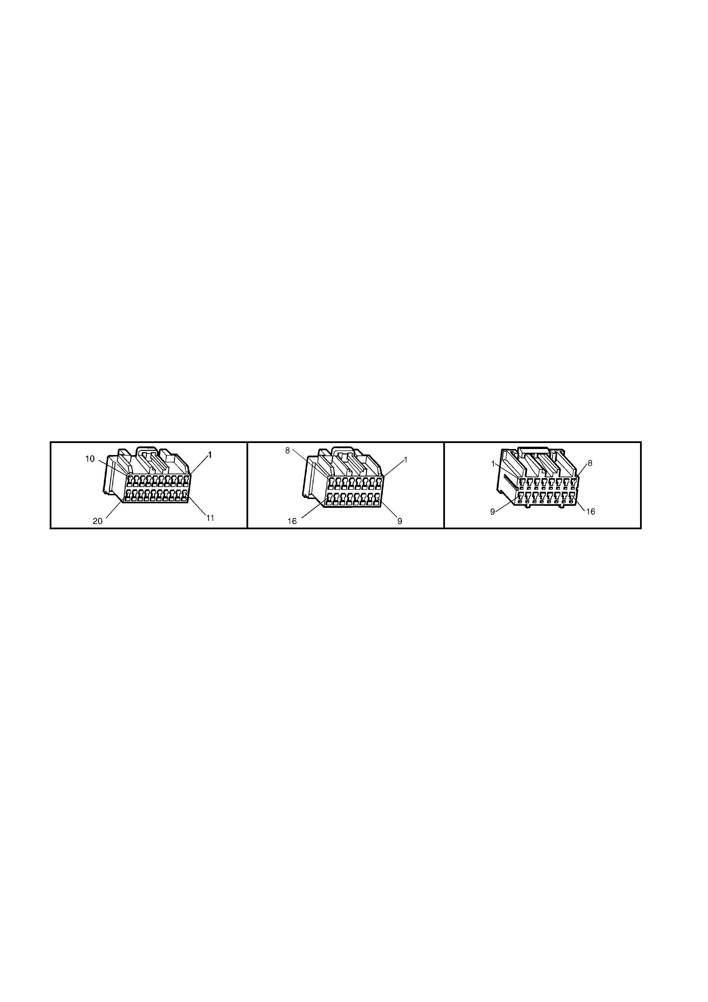
CIRCUIT DESCRIPTION
The ac tive m icrophon e in t he inter ior r ear v iew m ir ror prov ides a m eans f or two way voic e c omm unication bet ween
the vehic le occupants and Holden Assist Centr e. During the s yst em self tes t the microphone and circuit are tested
to determine if there is a microphone or microphone circuit malfunction.
CONDITIONS FOR SETTING THE DTC
• DTC 18 is set if the telematics module detect that the microphone circuit (1155) input voltage is less than 1.8
Volts.
ACTION TAKEN WHEN THE DTC SETS
• When the diagnostic runs and fails, the t elematics modu le stores the DTC into m em or y as a curren t DTC and
activates the red status LED.
TEST DESCRIPTION
Number(s) below refer to step number(s) on the diagnostic chart.
1. Confirmation that the Telematics On-Board Diagnostic System Check has been performed.
2. This test s tep d eter mines if DTC 18 is int er mittent. If D TC 18 is i ntermittent, check for an inter mittent ope n, or a
short to ground or voltage in the microphone circuit 1155 and 1153.
3. Checks that the telematics module is supplying five Volts to the microphone.
4. If the voltage is greater than five Volts then circuit 1155 is shorted to voltage.
5. If the voltage is less than five Volts then circuit 1155 is shorted to ground.
6. Checks if the telematics module is supplying five Volts to circuit 1155.
7. This test determines if circuit 1153 has continuity.
8. Before the mirror is replaced the retention of the interior mirror connector E124 X1 terminals should be
checked.
9. Before the telematics module is replaced the retention of the telematics module connectors A158 X1 and X2
terminals should be checked.
A158 X1 A158 X2 E124 X1

DTC 18 - MICROPHONE CIRCUIT VOLTAGE TOO LOW
STEP ACTION VALUE YES NO
1. Has a Telematics On-Board Diagnosis System Check
been performed? Go to Step 2 Refer Telematics
On-Board
Diagnostic
System Check
chart in this
Section.
2. 1. From the Telematics Application Menu,
Select F0: Diagnostic Trouble Codes / F0: Clear
DTCs and clear all DTCs.
2. Switch Ignition off then On again for at lease 1
minute.
Does DTC 18 Microphone Circuit Voltage Too Low Set?
Go to Step 3. DTC 18 is
intermittent.
Refer Test Step
Description.
3. 1. Disconnect the interior rear view mirror connector
E124 X1.
2. Ignition on.
3. Using a DMM, check the voltage at the interior rear
view mirror connector terminal E124 X1-10 circuit
1155 (Green wi re).
Is the voltage as specified?
5 Volts. Go to Step 7. Go to Step 4.
4. In step 3 was the voltage greater than specified? 5 Volts. Repair short to
voltage in circuit
1155.
Go to Step 5.
5. In step 3 was the voltage less than specified? 5 Volts. Go to Step 6. Go to Step 7.
6. 1. Ignition on.
2. Interior rear view mirror connector E124 X1 still
disconnected.
3. Using a DMM, check the voltage at the telematics
module connector terminal A158 X1-8 circuit 1155
(Green wire).
Is voltage as specified?
5 Volts. Repair open or
short to ground in
circuit 1155.
Go to Step 9.
7. 1. Using a DMM, measure continuity of circuit 1153
(Brown wire) between the telematics module
connector terminal A158 X1-7 and the interior rear
view mirror connector terminal E124 X1-2.
Is there continuity?
Go to Step 8. Repair open
circuit 1153.
8. 1. Check interior rear view mirror connector E124 X1
terminal re tention.
Is the terminal retention OK?
Replace interior
rear view mirror.
Refer 3.5 Interior
Rear View Mirror
in this Section.
Repair connector
terminal
retention.
9. 1. Check telematics module connectors A158 X1 and
X2 terminal retention.
Is the terminal retention OK?
Replace
telematics
module. Refer
3.1 Telematics
Module in this
Section.
Repair connector
terminal
retention.
WHEN ALL DIAGNOSIS AND REPAIRS ARE COMPLETED, VERIFY CORRECT OPERATION

DTC 19 - MICROPHONE CIRCUIT VOLTAGE TOO HIGH
Figure 12K-88

CIRCUIT DESCRIPTION
The ac tive m icrophon e in t he inter ior r ear v iew m ir ror prov ides a m eans f or two way voic e c omm unication bet ween
the vehic le occupants and Holden Assist Centr e. During the s yst em self tes t the microphone and circuit are tested
to determine if there is a microphone or microphone circuit malfunction.
CONDITIONS FOR SETTING THE DTC
• DTC 19 is set if the telematics module detect that the microphone circuit (1155) input voltage is greater than
4.8 Volts.
ACTION TAKEN WHEN THE DTC SETS
• When the diagnostic runs and fails, the t elematics modu le stores the DTC into m em or y as a curren t DTC and
activates the red status LED.
TEST DESCRIPTION
Number(s) below refer to step number(s) on the diagnostic chart.
1. Confirmation that the Telematics On-Board Diagnostic System Check has been performed.
2. This test s tep d eter mines if DTC 19 is int er mittent. If D TC 19 is i ntermittent, check for an inter mittent ope n, or a
short to ground or voltage in the microphone circuit 1155 and 1153.
3. Checks that the telematics module is supplying five Volts to the microphone.
4. If the voltage is greater than five Volts then circuit 1155 is shorted to voltage.
5. If the voltage is less than five Volts then circuit 1155 is shorted to ground.
6. Checks if the telematics module is supplying five Volts to circuit 1155.
7. This test determines if circuit 1153 has continuity.
8. Before the mirror is replaced the retention of the interior mirror connector E124 X1 terminals should be
checked.
9. Before the telematics module is replaced the retention of the telematics module connectors A158 X1 and X2
terminals should be checked.
A158 X1 A158 X2 E124 X1

DTC 19 - MICROPHONE CIRCUIT VOLTAGE TOO HIGH
STEP ACTION VALUE YES NO
1. Has a Telematics On-Board Diagnosis System Check
been performed? Go to Step 2 Refer Telematics
On-Board
Diagnostic
System Check
chart in this
Section.
2. 1. From the Telematics Application Menu,
Select F0: Diagnostic Trouble Codes / F0: Clear
DTCs and clear all DTCs.
2. Switch Ignition off then On again for at lease 1
minute.
Does DTC 19 Microphone Circuit Voltage Too High Set?
Go to Step 3. DTC 19 is
intermittent.
Refer Test Step
Description.
3. 1. Disconnect the interior rear view mirror connector
E124 X1.
2. Ignition on.
3. Using a DMM, check the voltage at the interior rear
view mirror connector terminal E124 X1-10 circuit
1155 (Green wi re).
Is the voltage as specified?
5 Volts. Go to Step 7. Go to Step 4.
4. In step 3 was the voltage greater than specified? 5 Volts. Repair short to
voltage in circuit
1155.
Go to Step 5.
5. In step 3 was the voltage less than specified? 5 Volts. Go to Step 6. Go to Step 7.
6. 1. Ignition on.
2. Interior rear view mirror connector E124 X1 still
disconnected.
3. Using a DMM, check the voltage at the telematics
module connector terminal A158 X1-8 circuit 1155
(Green wire).
Is voltage as specified?
5 Volts. Repair open or
short to ground in
circuit 1155.
Go to Step 9.
7. 1. Using a DMM, measure continuity of circuit 1153
(Brown wire) between the telematics module
connector terminal A158 X1-7 and the interior rear
view mirror connector terminal E124 X1-2.
Is there continuity?
Go to Step 8. Repair open
circuit 1153.
8. 1. Check interior rear view mirror connector E124 X1
terminal re tention.
Is the terminal retention OK?
Replace interior
rear view mirror.
Refer 3.5 Interior
Rear View Mirror
in this Section.
Repair connector
terminal
retention.
9. 1. Check telematics module connectors A158 X1 and
X2 terminal retention.
Is the terminal retention OK?
Replace
telematics
module. Refer
3.1 Telematics
Module in this
Section.
Repair connector
terminal
retention.
WHEN ALL DIAGNOSIS AND REPAIRS ARE COMPLETED, VERIFY CORRECT OPERATION
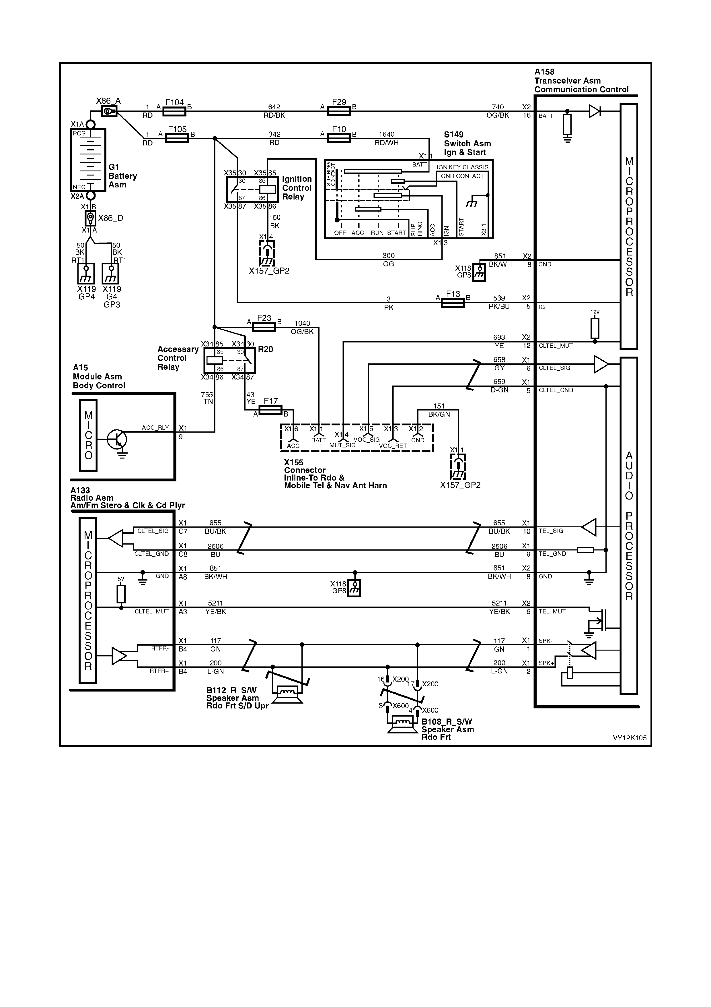
DTC 21 - SPEAKER CIRCUIT VOLTAGE TOO LOW
Figure 12K-89
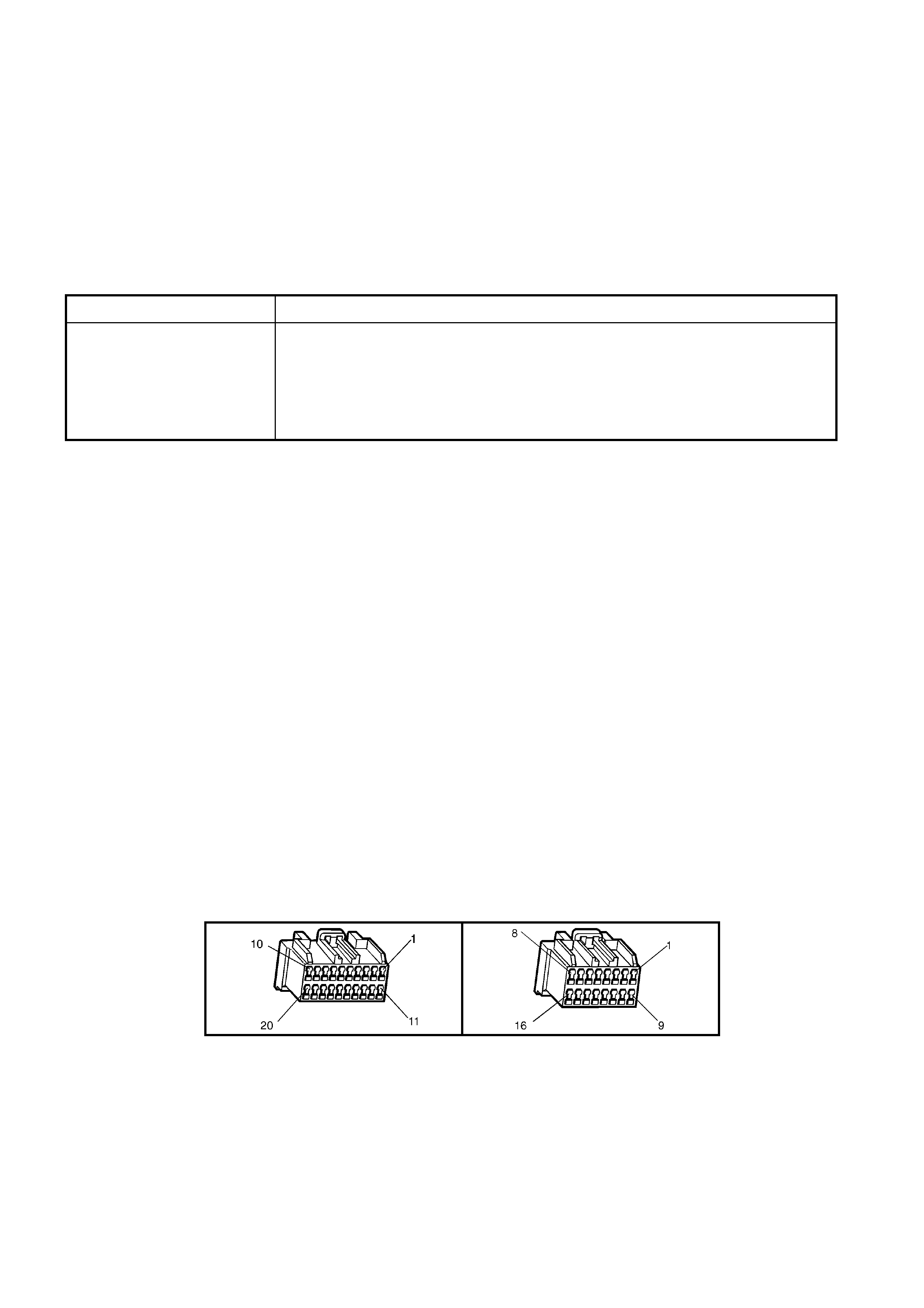
CIRCUIT DESCRIPTION
The telematics system us es the veh icl e au di o system to provide a means f or vo ic e co m munication f r om the Holden
Assist call centre. The telematics module also has the ability to detect if the audio system is not operational, and
will switch from the vehicle audio system to the RHF speakers, if it detects that the audio system is not operational.
Audible tones are also provided to indicate the system status and are broadcast via the speaker to alert the
customer to certain operating conditions.
Whenever the telematics audio is activated the radio mute signal is also activated and the telematics module
grounds the radio mute circuit 5211 (Yellow/Black wire) causing the circuit voltage to be pulled low, less than two
Volts. This low voltage is detected by the radio as a mute request and when received, the audio system will mute.
W hilst the telematic s system is not on a call t he audio and m ute request f rom the cellu lar telephone c onnector will
be passed through the t elematics module to the audio system. When a Holden Assist call is active, the telematics
module will ignore the phone audio and transmit the telematics audio to the audio system.
Tone Operating Condition
Five Tones • Attempting to make call when vehicle is not within GSM network range, or
if the five tones occur after the ignition is turned off, the vehicle is not within
GSM network range.
• Warning that Service Mode is active or a system malfunction has been
detected and a Diagnostic Trouble Code has been stored in the telematics
module.
CONDITIONS FOR SETTING THE DTC
• The output v oltage of the audi o amplifier circuit is m eas ured to detect if the speaker is s horted to ground. T his
test is performed whenever the ignition is turned on and only if the audio system is off, the emergency
speakers are switched in and the telematics audio output is muted.
• DTC 21 will set if the emergency speaker circuit voltage is less than 1.8 Volts.
ACTION TAKEN WHEN THE DTC SETS
• When the diagnostic runs and fails, the t elematics modu le stores the DTC into m em or y as a curren t DTC and
activates the red status LED.
TEST DESCRIPTION
Number(s) below refer to step number(s) on the diagnostic chart.
1. Confirmation that the Telematics On-Board Diagnostic System Check has been performed.
2. T his test step det erm ines if DT C 21 is interm ittent. If DT C 21 is inter m ittent check f or an inter m ittent ope n, or a
short to ground or voltage in the speaker circuits 117 and 200.
3. T he test st ep check s for a short to grou nd in cir cuit 11 7, If c ircuit 117 is not shor ted to gr oun d, and DT C 21 still
sets the telematics module should be replaced.
4. This test step checks for a short to ground in circuit 200. Disconnect all speakers to isolate circuit 200.
5. This test step checks for a short to ground in circuit 117.
6. In this test step you should check if the either RHF door speaker and the RHF tweeter is shorted to ground.
7. This test step checks if there is an internal fault in the telematics module (speaker connection X1.2)
8. This test step checks if there is an internal fault in the telematics module (speaker connection X1.1)
9. Before the telematics module is replaced the retention of the telematics module connectors A158 X1 and X2
terminals should be checked.
A158 X1 A158 X2

DTC 21 - SPEAKER CIRCUIT VOLTAGE TOO LOW
STEP ACTION VALUE YES NO
1. Has a Telematics On-Board Diagnosis System Check
been performed? Go to Step 2. Refer Telematics
On-Board
Diagnostic
System Check
chart in this
Section..
2. 1. From the Telematics Application Menu,
Select F0: Diagnostic Trouble Codes / F0: Clear
DTCs and clear all DTCs.
2. Ignition on engine off, turn off audio system (radio).
3. Press the End Call/Information button.
Does DTC 21 Speaker Circuit Voltage Low Set?
Go to Step 3. DTC 21 is
intermittent
Refer Test Step
Description.
3. 1. Disconnect the telematics connector A158 X1 and
the radio connector A133 X1.
2. Using a DMM measure the resistance between
terminal X1-1 circuit 117 and g r ound.
Is the resistance as specified?
Open circui t
(greater than
1 MOhm)
Go to step 4. Go to Step 9.
4. 1. Disconnect all speakers connected to circuits 200
(light green wire) and to circ uits 117 (green wire).
2. Using a DMM measure the resistance between
circuit 200 (light green wire) and ground.
Is the resistance as specified?
Open circui t
(greater than
1 MOhm)
Go to step 5. Repair short to
ground in circuit
200.
5. 1. Using a DMM measure the resistance between
circuit 117 (green wire) and ground.
Is the resistance as specified?
Open circui t
(greater than
1 MOhm)
Go to step 6. Repair short to
ground in circuit
117.
6. 1. Using a DMM measure the resistance between the
speaker(s) terminals and ground.
Is the resistance as specified?
Open circui t
(greater than
1 MOhm)
Go to step 7. Replace speaker
that is shorted to
ground.
7. 1. Using a DMM measure the resistance between the
telematics module terminal A158 X1-2 and ground.
Is the resistance as specified?
Open circui t
(greater than
1 MOhm)
Go to step 8. Go to Step 9.
8. 1. Measure the resistance between the telematics
module terminal A 158X1-1 and ground.
Is the resistance as specified?
Open circui t
(greater than
1 MOhm)
Refer to audio
system
diagnostics in
Section 12D in
this Section.
Go to Step 9.
9. 1. Check telematics module connectors A158 X1 and
X2 terminal retention.
Is the terminal retention OK?
Replace
telematics
module. Refer
3.1 Telematics
Module.
Repair connector
terminal
retention.
WHEN ALL DIAGNOSIS AND REPAIRS ARE COMPLETED, CLEAR DTCS AND VERIFY CORRECT OPERATION

DTC 22 - SPEAKER CIRCUIT VOLTAGE TOO HIGH
Figure 12K-90
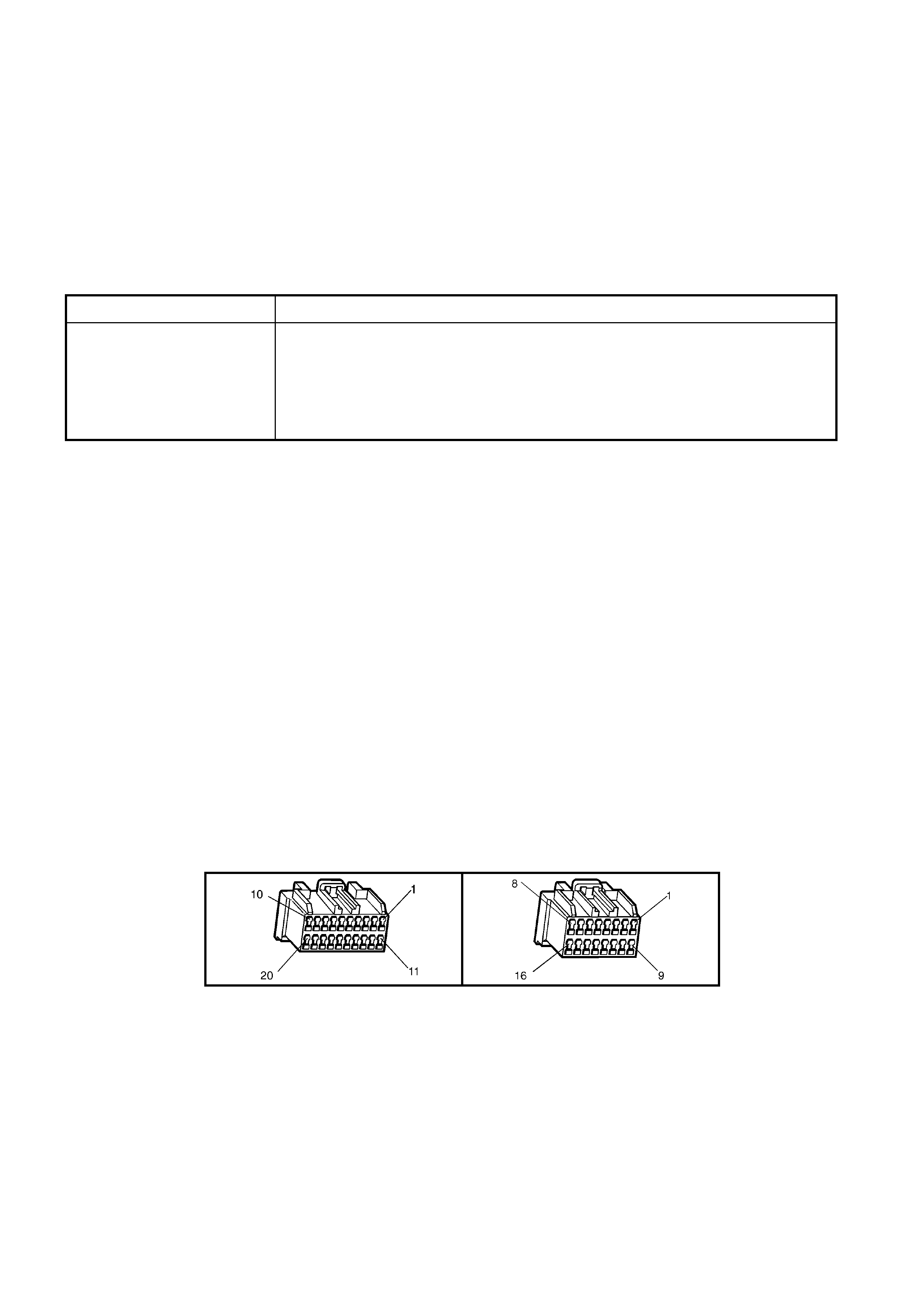
CIRCUIT DESCRIPTION
The telematics system us es the veh icl e au di o system to provide a means f or vo ic e co m munication f r om the Hold e n
Assist call centre. The telematics module also has the ability to detect if the audio system is not operational, and
will switch from the vehicle audio system to the RHF speakers, if it detects that the audio system is not operational.
Audible tones are also provided to indicate the system status and are broadcast via the speaker to alert the
customer to certain operating conditions.
Whenever the telematics audio is activated the radio mute signal is also activated and the telematics module
grounds the radio mute circuit 5211 (Yellow/Black wire) causing the circuit voltage to be pulled low, less than two
Volts. This low voltage is detected by the radio as a mute request and when received, the audio system will mute.
W hilst the telematic s system is not on a call t he audio and m ute request f rom the cellu lar telephone c onnector will
be passed through the t elematics module to the audio system. When a Holden Assist call is active, the telematics
module will ignore the phone audio and transmit the telematics audio to the audio system.
Tone Operating Condition
Five Tones • Attempting to make call when vehicle is not within GSM network range, or
if the five tones occur after the ignition is turned off, the vehicle is not within
GSM network range.
• Warning that Service Mode is active or a system malfunction has been
detected and a Diagnostic Trouble Code has been stored in the telematics
module.
CONDITIONS FOR SETTING THE DTC
• The output v oltage of the audi o amplifier circuit is m eas ured to detect if the speaker is s horted to ground. T his
test is performed whenever the ignition is turned on and only if the audio system is off, the emergency
speakers are switched in and the telematics audio output is muted.
• DTC 22 will set if the emergency speaker circuit voltage is greater than 2.5 Volts.
ACTION TAKEN WHEN THE DTC SETS
• When the diagnostic runs and fails, the t elematics modu le stores the DTC into m em or y as a curren t DTC and
activates the red status LED.
TEST DESCRIPTION
Number(s) below refer to step number(s) on the diagnostic chart.
1. Confirmation that the Telematics On-Board Diagnostic System Check has been performed.
2. The test step checks for a short to voltage in circuit 117 and circuit 200. If circuit 117 or 200 is not shorted to
voltage th en DTC 22 is interm ittent, check for an interm ittent open short ground, or voltage on c ircuit 117 and
200.
3. This test step check s f or a short to voltage in circuit 117 and circuit 200. If circuit 117 or 200 is not shorted to
voltage and DTC 22 still sets then the telematics is should be replaced.
4. This test steps check if the audio system (radio) is causing the short to voltage.
5. This test steps check if the telematics module is causing the short to voltage.
6. Before the telematics module is replaced the retention of the telematics module connectors A158 X1 and X2
terminals should be checked.
A158 X1 A158 X2

DTC 22 - SPEAKER CIRCUIT VOLTAGE TOO HIGH
STEP ACTION VALUE YES NO
1. Has a Telematics On-Board Diagnosis System Check
been performed? Go to Step 2. Refer Telematics
On-Board
Diagnostic
System Check
chart in this
Section.
2. 1. From the Telematics Application Menu,
Select F0: Diagnostic Trouble Codes / F0: Clear
DTCs and clear all DTCs.
2. Ignition on engine off, turn off audio system (radio).
3. Press the End Call/Information button.
Does DTC 22 Speaker Circuit Voltage High Set?
Go to Step 3. DTC 22 is
intermittent
Refer Test Step
Description.
3. 1. Ignition on engine off.
2. Using a DMM measure the voltage on circuit 117
between terminal A158 X1-1 and ground and the
voltage on circuit 200 between A158 X1-2 and
ground.
Is either or both voltages greater than the specified
value?
2.5 Volts Go to step 4. Go To Step6.
4. 1. Ignition off, disconnect the audio system (radio)
connector A133 X1.
2. Ignition on engine off.
3. Using a DMM measure the voltage on circuit 117
between terminal A158 X1-1 and ground and the
voltage on circuit 200 between A158 X1-2 and
ground.
Is either or both voltages greater than the specified
value?
2.5 Volts Go to step 5. Replace Radio
(AHU).
Refer 12D
Entertainment
Systems in this
Service
Information.
5. 1. Using TECH 2, enable the telematics module
service mode. Refer to 4.3 TECH 2 TEST MODES
F5: Program, F1: Operating Mode, in this Section.
(The telematics module should remain in service
mode until this diagnostics chart is completed).
2. Ignition Off, disconnect the telematics module
connectors A158 X1 and X2.
3. Ignition on, engine off.
4. Using a DMM measure the voltage on circuit 117
between terminal A158 X1.1 and ground and the
voltage on circuit 200 between A158 X1-2 and
ground.
Is either or both voltages greater than the specified
value?
2.5 Volts Repair short to
voltage in the
circuit that was
greater than 2.5
Volts.
Go to Step 6.
6. 1. Check telematics module connectors A158 X1 and
X2 terminal retention.
Is the terminal retention OK?
Replace
telematics
module. Refer
3.1 Telematics
Module in this
Section.
Repair connector
terminal
retention.
WHEN ALL DIAGNOSIS AND REPAIRS ARE COMPLETED, CLEAR DTCS AND VERIFY CORRECT OPERATION

DTC 30 - KEYPAD CIRCUIT VOLTAGE TOO HIGH
Figure 12K-91
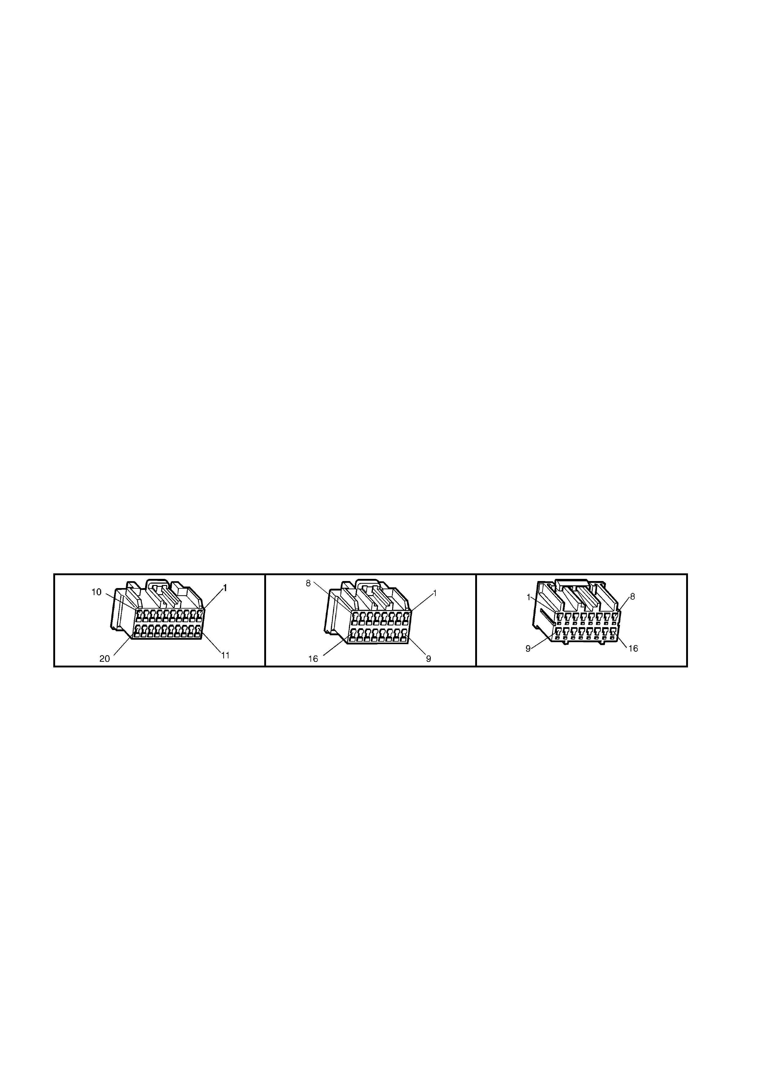
CIRCUIT DESCRIPTION
W hen the em er gency button is pr ess ed, t he voltage at ter minal X 2-9 of the telem atic s module will be a pprox i mately
3.8 Volts.The telematics module determines this voltage at terminal X2-9 as an emergency button press. The
telematics module will initiate a voice call to an operator at the National Emergency Response Centre and then
send an SMS m es sage contai ning status and loc atio n data. If the call can n ot be c onnecte d, the telem atic s m odule
will imm ediatel y re-attem pt to connect the call a second tim e. If the sec ond attempt als o fails, the un it shall wait for
60 seconds and make a third and final attempt.
If the emergency button is pressed while a Holden Assist call is in progress then the status of the call shall be
upgraded to an emergency call, and the telematics module will not be permitted to terminate the call by pressing
the “end call / information” button.
If the emergency button is pressed while the vehicle is outside GSM network range, the telematics module will
enter “Em er gency Call M od e” wher e b y the emergency call reques t wil l b e reta in ed. When contac t is re- es tab lis he d
with the GSM network, the emergency call will be placed immediately.
CONDITIONS FOR SETTING THE DTC
• During the telem atics module self test, the k eypad circuit voltage is m easured to detect if the circuit voltage is
too high. T his self test is only perf orm ed once whene ver the tel em atics is powered up, at th is tim e the po wer to
the keypad is off.
• DTC 30 will set if the keypad circuit voltage is high (logic 1) during the self test.
ACTION TAKEN WHEN THE DTC SETS
• When the diagnostic runs and fails, the t elematics modu le stores the DTC into m em or y as a curren t DTC and
activates the red status LED.
TEST DESCRIPTION
Number(s) below refer to step number(s) on the diagnostic chart.
1. Confirmation that the Telematics On-Board Diagnostic System Check has been performed.
2. The test step checks for a short to voltage in circuit 2515.
3. This test s tep c hecks if the telematic s m odule c an t ur n of f the po wer s upp ly to circuit 25 15. If the v olt age is le s s
that 0.2 Vo lts when t he keypad vo ltage is c ommanded of f the DTC 30 is intermittent. If DTC 30 is i ntermittent ,
check for and open, or a short to ground or voltage in circuit 2515.
4. This test steps check if the interior rear view mirror is causing the short to voltage.
5. Before the telematics module is replaced the retention of the telematics module connectors A158 X1 and X2
terminals should be checked.
A158 X1 A158 X2 E124 X1

DTC 30 - KEYPAD CIRCUIT VOLTAGE TOO HIGH
STEP ACTION VALUE YES NO
1. Has a Telematics On-Board Diagnosis System Check
been performed? Go to Step 2. Refer Telematics
On-Board
Diagnostic
System Check
chart in this
Section.
2. 1. Using TECH 2, enable the telematics module
service mode. Refer to 4.3 TECH 2 TEST MODES
F5: Program, F1: Operating Mode, in this Section.
(The telematics module should remain in service
mode until this diagnostics chart is completed).
2. Ignition off, disconnect the telematics module
connectors A158 X1 and X2.
3. Ignition on, engine off.
4. Using a DMM measure the voltage on circuit 2515
(Light Green/Black wire) between terminal A158
X2-15 and ground.
Is voltage greater than the specified value?
0.2 Volts Go to step 4. Go to step 3.
3. 1. Reconnect the telematics module connectors A158
X1 and X2.
2. From the Telematics Application Menu,
Select F3: Miscellaneous Tests \ F3: Keypad Supply
Voltage.
3. Using a DMM measure the voltage on circuit 2515
(Light Green/Black wire) between terminal A158 X2-
15 and ground while commanding the keypad
supply voltage off.
Is the voltage greater than the specified value when the
keypad supply voltage is commanded off.
0.2 Volts Go to Step 5. DTC 30 is
intermittent.
Refer Test Step
Description.
4. 1. Disconnect the interior rear view mirror connector
E124 X1.
1. Ignition on engine off.
2. Using a DMM measure the voltage on circuit 2515
(Light Green/Black wire) between terminal A158
X2-15 and ground.
Is voltage greater than the specified value?
0.2 Volts Repair short to
voltage in circuit
2515.
Replace the
Interior Rear
View Mirror.
Refer 3.4 Interior
Rear View Mirror
in this Section.
5. 1. Check telematics module connectors A158 X1 and
X2 terminal retention.
Is the terminal retention OK?
Replace
telematics
module.
Refer 3.1
Telematics
Module in this
Section.
Repair connector
terminal
retention.
WHEN ALL DIAGNOSIS AND REPAIRS ARE COMPLETED, CLEAR DTCS AND VERIFY CORRECT OPERATION

DTC 35 - GPS ANTENNA CIRCUIT VOLTAGE TOO LOW
Figure 12K-92
CIRCUIT DESCRIPTION
The telem atic s antenna c ontai ns bot h the GPS and G SM ante nnas in on e unit, a nd is l ocate d under the inst rum ent
panel. T he anten na has t wo lea ds , one f or the GPS a ntenna and the oth er f or the GSM ant enn a. The GPS ante nna
receives signals from satellites orbiting the earth and transmits these to the telematics module to determine the
vehicle ’s pos ition. Signals fr om at least thre e GP S sat ellites m us t be rec eived t o accur ately deter m ine the vehicl e’s
two dimensional (2D) position. Signals from at least four GPS satellites must be received to accurately determine
the vehicle’s three dimensional (3D) position. If signals from only three satellites are received, the telematics
module cannot determine the vehicle’s altitude. The GPS antenna must not be obscured by any objects, such as
undergroun d car park s, tunnels, bridg es or bu ildi ngs, a s any of these m a y affec t GPS rece ption. T he GPS a ntenna
is connected to the telematics module by a push on type connector. To determine the vehicles position this GPS
information is transmitted via SMS to the Holden Assist Centre whenever a call is made to the Holden Assist
Centre. The Holden Assist Centre is also able to track the vehicle using this GPS information.
CONDITIONS FOR SETTING THE DTC
• DTC 35 will set if the GPS m odule is active and detects a low voltage in the GPS antenna or circuit for more
than 10 seconds.
Note: This DTC is only applicable on telematics module with software version 001.000.010 or later.
ACTION TAKEN WHEN THE DTC SETS
• When the diagnostic runs and fails, the t elematics modu le stores the DTC into m em or y as a curren t DTC and
activates the red status LED.

TEST DESCRIPTION
Number(s) below refer to step number(s) on the diagnostic chart.
1. Confirmation that the Telematics On-Board Diagnostic System Check has been performed.
2. If DTC is intermittent, check for loose or damaged GPS Antenna connector or lead.
A158 X3
DTC 35 - GPS ANTENNA CIRCUIT VOLTAGE TOO LOW
STEP ACTION VALUE YES NO
1. Has a Telematics On-Board Diagnosis System Check
been performed? Go to Step 2. Refer Telematics
On-Board
Diagnostic
System Check
chart in this
Section.
2. 1. From the Telematics Application Menu,
Select F0: Diagnostic Trouble Codes / F0: Clear
DTCs and clear all DTCs.
Does DTC 35, GPS Antenna Circuit Voltage Too Low
Set?
Go to Step 3. DTC 35 is
intermittent
Refer Test Step
Description.
3. 1. Disconnect GPS connector, A158 X3.
2. Using a DMM measure the resistance between
terminals ‘A’ and ‘B’ (Antenna Side).
For Terminal ‘A’ a 0.6 mm or less test probe must
be used.
Is the resistance as specified?
Replace
telematics
antenna. Refer
3.3 Telematics
Antenna in this
Section.
Replace
telematics
module. Refer
3.1 Telematics
Module in this
Section..
WHEN ALL DIAGNOSIS AND REPAIRS ARE COMPLETED, VERIFY CORRECT OPERATION
Between
80 and 110
Ohms

DTC 39 - TELEPHONE NUMBER ERROR
Figure 12K-93
CONDITIONS FOR SETTING THE DTC
• During the telematics module self test an incorrect phone number is detected.
ACTION TAKEN WHEN THE DTC SETS
• When the diagnostic runs and fails, the t elematics modu le stores the DTC into m em or y as a curren t DTC and
activates the red status LED.
TEST DESCRIPTION
Number(s) below refer to step number(s) on the diagnostic chart.
1. Confirmation that the Telematics On-Board Diagnostic System Check has been performed. If an incorrect
phone number is detected the telematics module should be replaced.
A158 X1 A158 X2
DTC 39 – TELEPHONE NUMBER ERROR
STEP ACTION VALUE YES NO
1. Has a Telematics On-Board Diagnosis System Check
been performed? Replace
telematics
module.
Refer 3.1
Telematics
Module in this
Section.
Refer Telematics
On-Board
Diagnostic
System Check
chart in this
Section.
WHEN ALL DIAGNOSIS AND REPAIRS ARE COMPLETED, CLEAR DTCS AND VERIFY CORRECT OPERATION
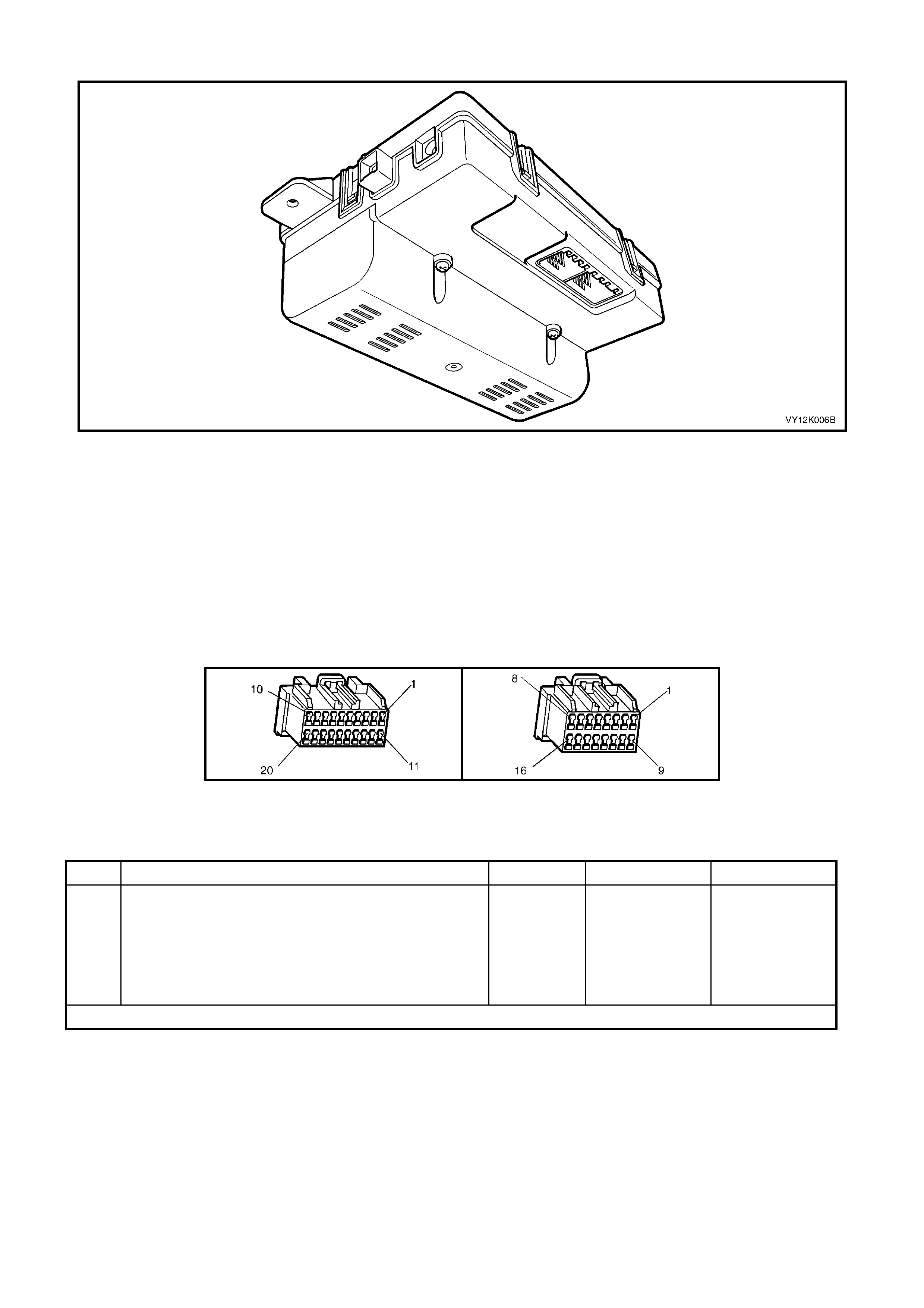
DTC 40 - VEHICLE IDENTIFICA TION NUMBER MISMATCH
Figure 12K-94
CONDITIONS FOR SETTING THE DTC
• During the telematics module self test an incorrect vehicle identification number is detected.
ACTION TAKEN WHEN THE DTC SETS
• When the diagnostic runs and fails, the t elematics modu le stores the DTC into m em or y as a curren t DTC and
activates the red status LED.
TEST DESCRIPTION
Number(s) below refer to step number(s) on the diagnostic chart.
1. Confirmation that the Telematics On-Board Diagnostic System Check has been performed. If an incorrect
vehicle identification number is detected the telematics module should be replaced.
A158 X1 A158 X1
DTC 40 - VEHICLE IDENTIFICATION NUMBER MISMATCH
STEP ACTION VALUE YES NO
1. Has a Telematics On-Board Diagnosis System Check
been performed? Replace
telematics
module.
Refer 3.1
Telematics
Module in this
Section.
Refer Telematics
On-Board
Diagnostic
System Check
chart in this
Section.
WHEN ALL DIAGNOSIS AND REPAIRS ARE COMPLETED, CLEAR DTCS AND VERIFY CORRECT OPERATION
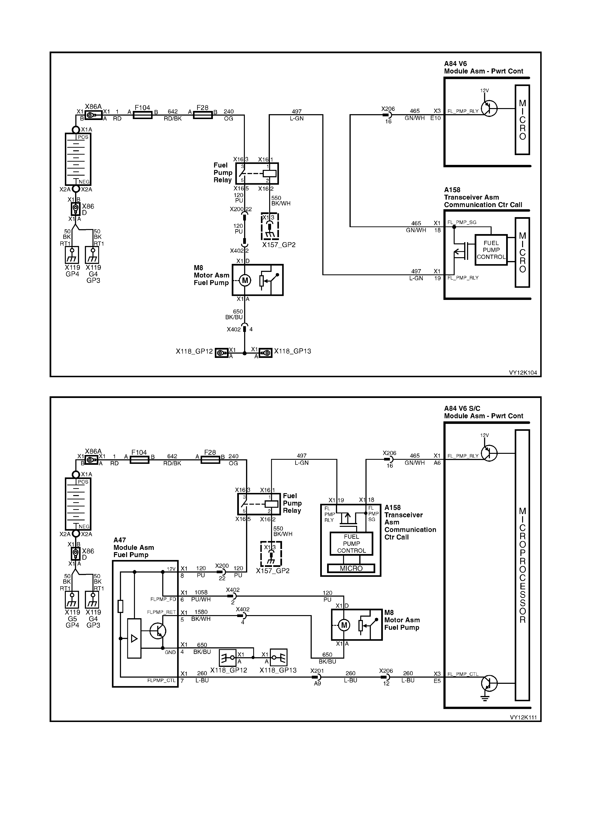
DTC 42 - FUEL PUMP CIRCUIT VOLTAGE TOO LOW
Figure 12K-95 V6 Fuel Pump Circuit
Figure 12K-96 V6 S/C Fuel Pump Circuit

Figure 12K-97 V8 Fuel Pump Circuit
Figure 12K-98 V8 Utility Fuel Pump Circuit

CIRCUIT DESCRIPTION
The PCM energises the fuel pump relay drive circuit via circuit 465 (Green/White wire) the telematics module
terminals X1-18 and X1-19, circuit 497 (Light/Green wire). The fuel pump relay drive circuit is grounded through
circuit 550 ( Black/W hite wire) at ground location X157_GP2. The telem atics module can imm obilise the vehicle by
opening the fuel pump relay drive circuit, causing the fuel pump to stop operating. This function can only be
activated by the National Emergency Response Centre (NERC™) under instruction from the Police.
CONDITIONS FOR SETTING THE DTC
• During the telematics module self test the fuel pump relay drive circuit voltage is measured to detect if the
circuit voltage is too low.
• DTC 42 will set if the fuel pump relay circuit voltage is low (logic 0) during the self test.
ACTION TAKEN WHEN THE DTC SETS
• When the diagnostic runs and fails, the t elematics modu le stores the DTC into m em or y as a curren t DTC and
activates the red status LED.
TEST DESCRIPTION
Number(s) below refer to step number(s) on the diagnostic chart.
1. Confirmation that the Telematics On-Board Diagnostic System Check has been performed.
2. This steps confirm s that the DTC is current or intermittent. If DT C 42 is intermittent check the fuel pump rela y
drive circuit for an intermittent open, or a short to ground or voltage.
3. This step checks if circuit 465 is shorted to ground.
4. This step determines if the fuel pump relay is causing the short to ground.
5. Before the telematics module is replaced the retention of the telematics module connectors A158 X1 and X2
terminals should be checked.
A158 X1 A158 X2

DTC 42 - FUEL PUMP CIRCUIT VOLTAGE TOO LOW
STEP ACTION VALUE YES NO
1. Has a Telematics On-Board Diagnosis System Check
been performed? Go to Step 2. Refer Telematics
On-Board
Diagnostic
System Check
chart in this
Section.
2. 1. From the Telematics Application Menu,
Select F0: Diagnostic Trouble Codes / F0: Clear
DTCs and clear all DTCs.
2. Start engine and allow to idle for one minute.
Does DTC 42 Fuel Pump Circuit Voltage Too Low Set?
Go to Step 3. DTC 42 is
intermittent.
Refer Test Step
Description.
3. 1. Using TECH 2, enable the telematics module
service mode. Refer to 4.3 TECH 2 TEST MODES
F5: Program, F1: Operating Mode, in this Section.
(The telematics module should remain in service
mode until this diagnostics chart is completed).
2. Ignition off, disconnect the telematics module
connectors A158 X1 and X2.
3. Using a DMM measure the resistance between
circuit 465 (green/white wire) and ground.
Is the resistance less than the specified value?
Less than 1
Ohm Go to step 4. Go to step 5.
4. 1. Remove the fuel pump relay.
2. Using a DMM measure the resistance between
circuit 465 (green/white wire) and ground.
Is the resistance less than the specified value?
Less than 1
Ohm Repair short to
ground in circuit
465.
Replace fuel
pump relay.
5. 1. Check telematics module connectors A158 X1 and
X2 terminal retention.
Is the terminal retention OK?
Replace
telematics
module.
Refer 3.1
Telematics
Module in this
Section.
Repair connector
terminal
retention.
WHEN ALL DIAGNOSIS AND REPAIRS ARE COMPLETED, CLEAR DTCS AND VERIFY CORRECT OPERATION

DTC 43 - FUEL PUMP CIRCUIT VOLTAGE TOO HIGH
Figure 12K-99 V6 Fuel Pump Circuit
Figure 12K-100 V6 S/C Fuel Pump Circuit

Figure 12K-101 V8 Fuel Pump Circuit
Figure 12K-102 V8 Utility Fuel Pump Circuit
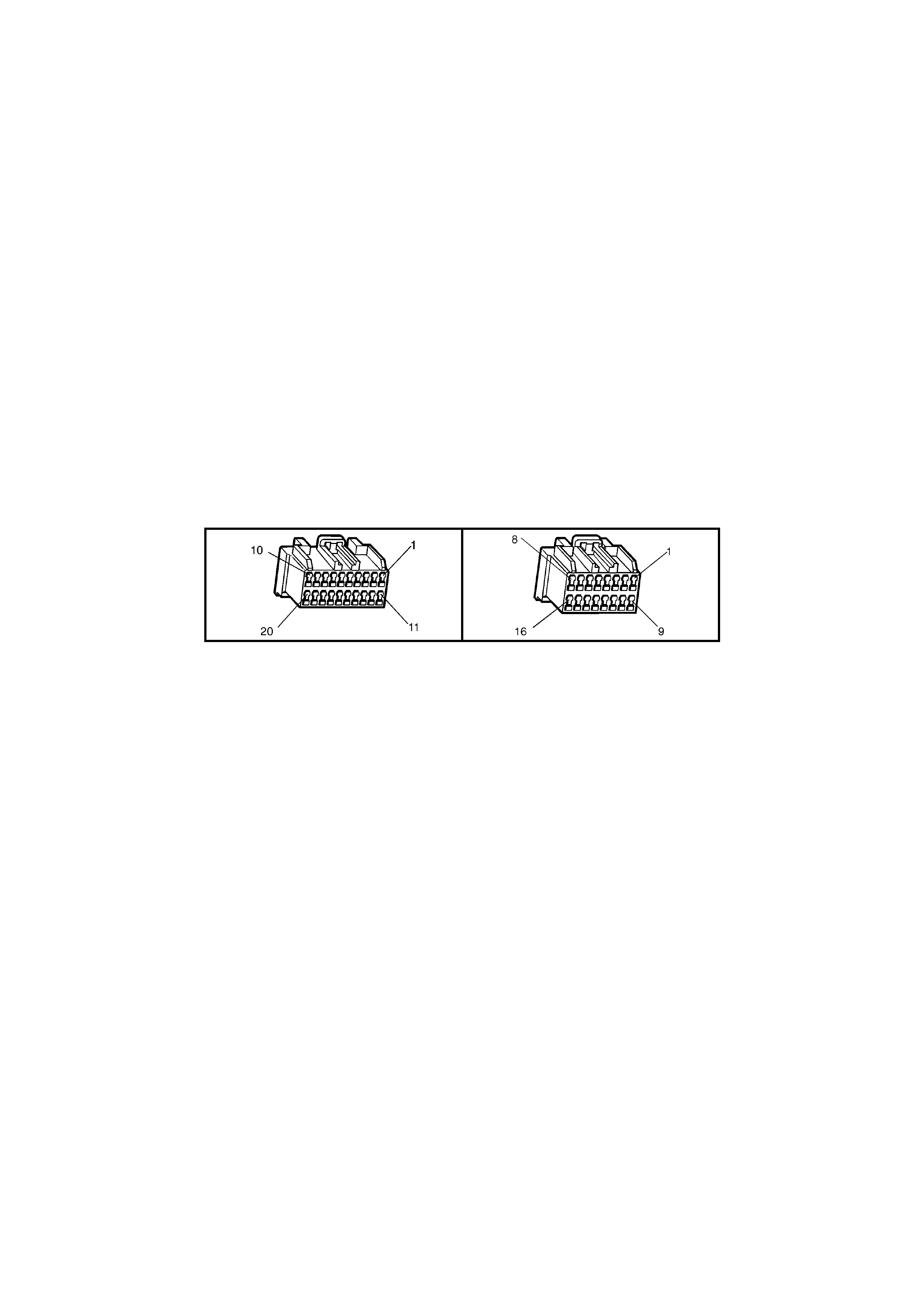
CIRCUIT DESCRIPTION
The PCM energises the fuel pump relay drive circuit via circuit 465 (Green/White wire) the telematics module
terminals X1-18 and X1-19, circuit 497 (Light/Green wire). The fuel pump relay drive circuit is grounded through
circuit 550 ( Black/W hite wire) at ground location X157_GP2. The telem atics module can imm obilise the vehicle by
opening the fuel pump relay drive circuit, causing the fuel pump to stop operating. This function can only be
activated by the National Emergency Response Centre (NERC™) under instruction from the Police.
CONDITIONS FOR SETTING THE DTC
• During the telematics module self test the fuel pump relay drive circuit voltage is measured to detect if the
circuit voltage is too high.
• DTC 43 will set if the fuel pump relay circuit voltage is high (logic 1) during the self test.
ACTION TAKEN WHEN THE DTC SETS
• When the diagnostic runs and fails, the t elematics modu le stores the DTC into m em or y as a curren t DTC and
activates the red status LED.
TEST DESCRIPTION
Number(s) below refer to step number(s) on the diagnostic chart.
1. Confirmation that the Telematics On-Board Diagnostic System Check has been performed.
2. This steps confirms that DT C 43 is current and not intermittent. If DTC 43 is interm ittent, check circuit 465 for
an intermittent open, or a short to ground or voltage.
3. This step checks if circuit 465 is shorted to B+.
4. This step determines if the fuel pump relay is causing the short to B+.
5. Before the telematics module is replaced the retention of the telematics module connectors A158 X1 and X2
terminals should be checked.
A158 X1 A158 X2

DTC 43 - FUEL PUMP CIRCUIT VOLTAGE TOO HIGH
STEP ACTION VALUE YES NO
1. Has a Telematics On-Board Diagnosis System Check
been performed? Go to Step 2. Refer Telematics
On-Board
Diagnostic
System Check
chart in this
Section.
2. 1. From the Telematics Application Menu,
Select F0: Diagnostic Trouble Codes / F0: Clear
DTCs and clear all DTCs.
2. Start engine and allow to idle for one minute.
Does DTC 43 Fuel Pump Circuit Voltage Too High Set?
Go to Step 3. DTC 43 is
intermittent.
Refer Test Step
Description.
3. 1. Using TECH 2, enable the telematics module
service mode. Refer to 4.3 TECH 2 TEST MODES
F5: Program, F1: Operating Mode, in this Section.
(The telematics module should remain in service
mode until this diagnostics chart is completed).
2. Ignition off, disconnect the telematics module
connectors A158 X1 and X2.
2. Disconnect the battery negative terminal.
2. Using a DMM measure the resistance between
circuit 465 (green/white wire) and battery B+
terminal.
Is the resistance less than the specified value?
Less than 1
Ohm Go to step 4. Go to step 5.
4. 1. Remove the fuel pump relay.
2. Using a DMM measure the resistance between
circuit 465 (green/white wire) and battery B+
terminal.
Is the resistance less than the specified value?
Less than 1
Ohm Repair short to
B+ in circuit 465. Replace fuel
pump relay.
5. 1. Check telematics module connectors A158 X1 and
X2 terminal retention.
Is the terminal retention OK?
Replace
telematics
module.
Refer 3.1
Telematics
Module in this
Section.
Repair connector
terminal
retention.
WHEN ALL DIAGNOSIS AND REPAIRS ARE COMPLETED, CLEAR DTCS AND VERIFY CORRECT OPERATION
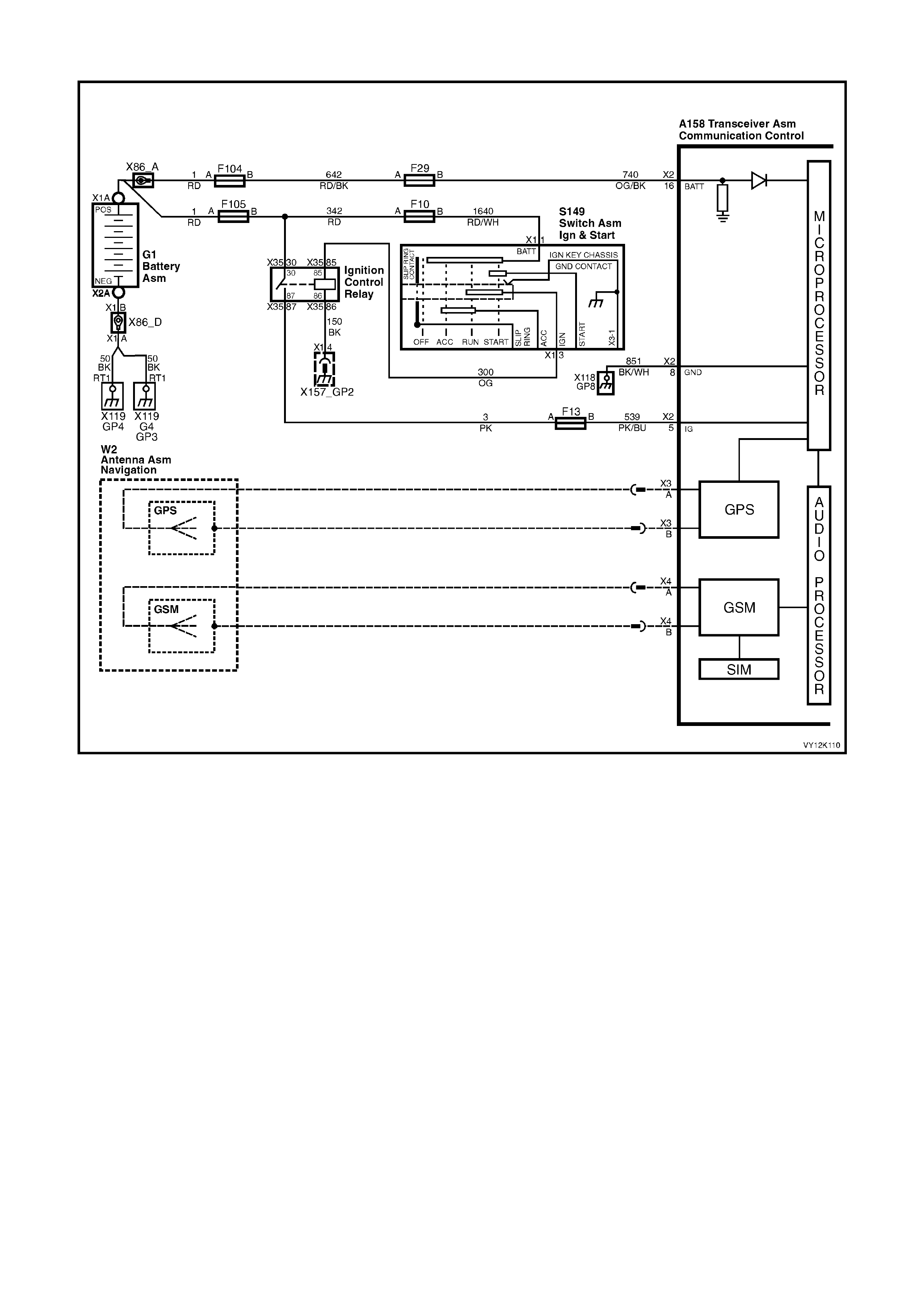
DTC 44 - GSM NOT LOGGED WITH SIGNAL STRENGTH PRESENT
Figure 12K-103
CIRCUIT DESCRIPTION
The telem atics antenn a contains both the GPS and GSM antennas in one unit, a nd is under th e instrum ent panel.
The antenna has two leads, one for the GPS antenna and the other for the GSM antenna. The GSM antenna is
capable of transmitting and receiving both voice and data signals via the GSM network. The telematics module
uses the GSM network to transmit and receive voice and data. Signal strength may be affected in locations like
basement car parks or tunnels. However, in m ost cases, as the vehicle emerges from the obstruction or re-enters
the digital phone network area the signa l will be availa ble again and an y stored data will be transm itted. The G SM
antenna is connected to the telematics module by a push on type connector.
CONDITIONS FOR SETTING THE DTC
• This DTC will set if the GSM has a valid GSM signal (of any signal strength), and the GSM module is active,
but unable to gain GSM registration for five minutes.
Possible causes are:
SIM card not valid (not registered).
SIM card faulty.
GSM module is faulty.
TEST DESCRIPTION
Number(s) below refer to step number(s) on the diagnostic chart.
1. Confirmation that the Telematics On-Board Diagnostic System Check has been performed.
2. If the SIM card is registered then the telematics module will have to be replaced. If the SIM card is not
registered then Australian Arrow will arrange to have the SIM card registered.

DTC 44 - GSM NOT LOGGED WITH SIGNAL STRENGTH PRESENT
STEP ACTION VALUE YES NO
1. Has a Telematics On-Board Diagnosis System Check
been performed? Go to Step 2. Refer Telematics
On-Board
Diagnostic
System Check
chart in this
Section.
2. 1. Call Australian Arrow Customer Service.
(03 97850792)
Does Australian Arrow advise that you replace the
telematics module?
Replace
telematics
module. Refer
3.1 Telematics
Module in this
Section.
Australian Arrow
will arrange SIM
card registration.
WHEN ALL DIAGNOSIS AND REPAIRS ARE COMPLETED, VERIFY CORRECT OPERATION

DTC 45 – END CALL / INFORMATION BUTTON STUCK
Figure 12K-104
CIRCUIT DESCRIPTION
The telem atic s button pad is a resistor encod ed switch , which m eans that each b utton has a sep arate and diff erent
value resistor connected to it. The telematics module uses a voltage divider circuit to determine which button has
been pressed. The telematics module supplies a 12 volt signal voltage to terminal X1-12 of the rear view mirror
connector circuit 2515 (Light Green/ Black wire). W henever a button is pressed the corresponding s witch is closed
and circuit 2 514 (Dark G reen/White wire) is connected to gr ound through a resis tor, each switc h having a diff erent
value res istor. T he telem atics m odule monitor s the vol tage on circ uit 2514 (D ark Green/White wire) at term inal X2-
9, which will change whe n an y of the buttons are pres sed.
When the end call / information button is pressed, the voltage at terminal X2-9 of the telematics module will be
approximately 0.7 Volts. The telematics module determines this voltage at terminal X2-9 as an end call /
inform ation button pr ess. If end call / inf orm ation button is pressed to m ak e a call, you will b e connec ted to Hold en
Assist information ser vices . Pr ess ing th is butto n while a c all is c onn ected wil l dis c onnec t th e c al l. It ho weve r wil l not
disconnect a call while the call is ringing the information service number or the Holden Assist number. It is not
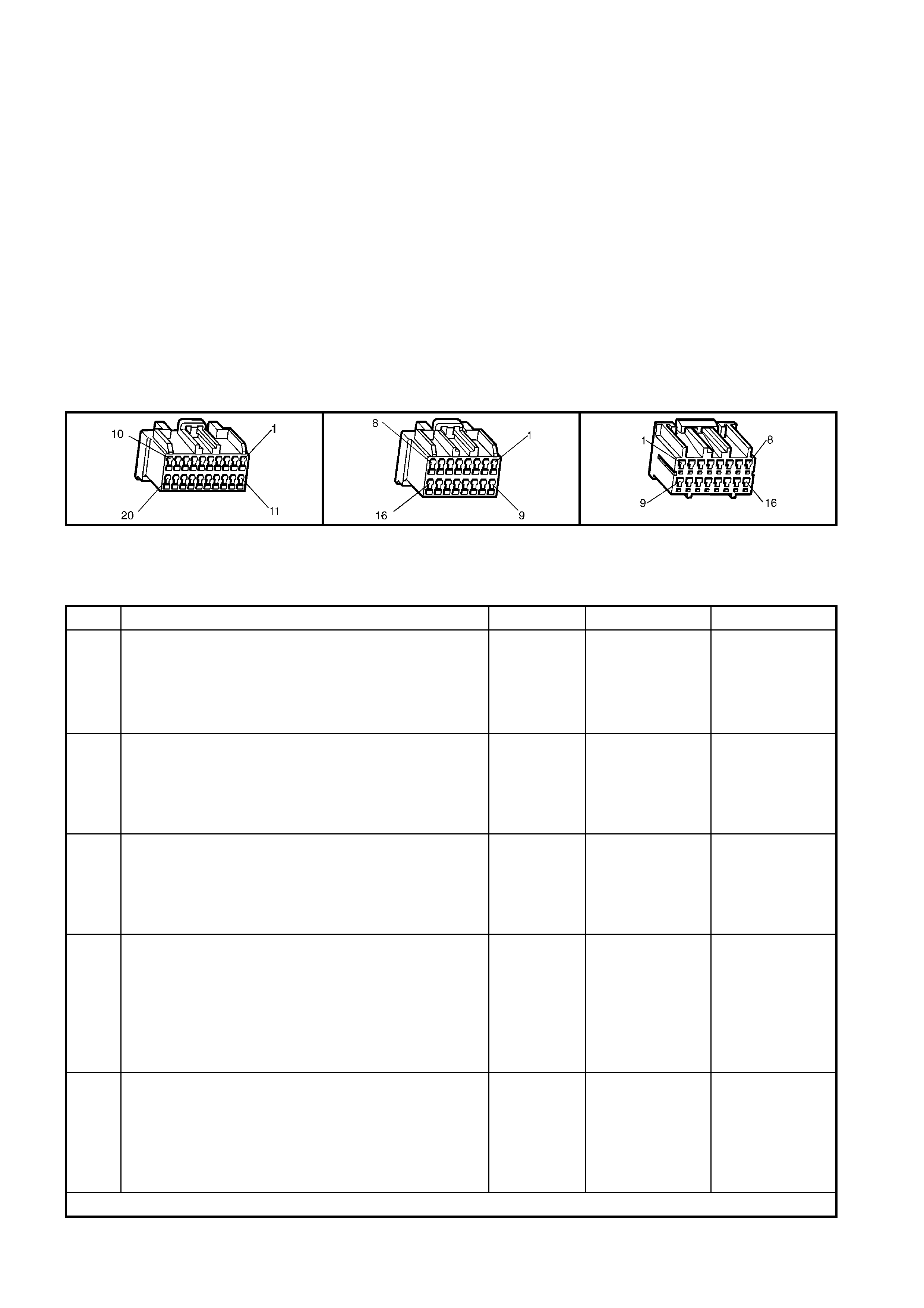
possible for this button to disconnect an emergency call or a Holden Assist call that has been upgraded to
emergency call status.
CONDITIONS FOR SETTING THE DTC
• DTC 45 will set if the keypad circuit voltage is at 0.7 Volts for greater than ten seconds.
ACTION TAKEN WHEN THE DTC SETS
• When the diagnostic runs and fails, the t elematics modu le stores the DTC into m em or y as a curren t DTC and
activates the red status LED.
TEST DESCRIPTION
Number(s) below refer to step number(s) on the diagnostic chart.
1. Confirmation that the Telematics On-Board Diagnostic System Check has been performed.
2. This test s tep d eter mines if DTC 45 is int er mittent. If D TC 45 is i ntermittent, check for an inter mittent ope n, or a
short to voltag e or groun d on circuit 2514, or an interm ittent interna l short in the int er ior rear vi e w mirr or .
3. The test step checks the actual voltage on circuit 2514.
4. This test step checks if the interior rear view mirror is causing DTC 45 to set.
5. Before the telematics module is replaced the retention of the telematics module connectors A158 X1 and X2
terminals should be checked.
A158 X1 A158 X2 E124 X1
DTC 45 – END CALL / INFORMATION BUTTON STUCK
STEP ACTION VALUE YES NO
1. Has a Telematics On-Board Diagnosis System Check
been performed? Go to Step 2. Refer Telematics
On-Board
Diagnostic
System Check
chart in this
Section.
2. 1. From the Telematics Application Menu,
Select F0: Diagnostic Trouble Codes / F0: Clear
DTCs and clear all DTCs.
2. Ignition on for at least one minute.
Does DTC 45 End Call / Information Button Stuck set?
Go to Step 3. DTC 45 is
intermittent
Refer Test Step
Description.
3. 1. Ignition on.
2. Using a DMM measure the voltage between the
interior rear view mirror connector E124 X1-11
circuit 2514 (Dark Green/White wire) and ground.
Is the voltage at the specified value?
0.7 Volts Go to step 4. Go to step 5.
4. 1. Ignition off, disconnect the interior rear view mirror
connector E124 X1.
2. Ignition on.
2. Using a DMM measure the voltage between the
interior rear view mirror connector E124 X1-11
circuit 2514 (Dark Green/White wire) and ground.
Is the voltage at the specified value?
0.7 Volts Go to step 5. Replace interior
rear view mirror.
Refer 3.4 Interior
Rear View Mirror
in this Section.
5. 1. Check telematics module connectors A158 X1 and
X2 terminal retention.
Is the terminal retention OK?
Replace
telematics
module.
Refer 3.1
Telematics
Module in this
Section.
Repair connector
terminal
retention.
WHEN ALL DIAGNOSIS AND REPAIRS ARE COMPLETED, CLEAR DTCS AND VERIFY CORRECT OPERATION

DTC 46 - HOLDEN ASSIST BUTTON STUCK
Figure 12K-105
CIRCUIT DESCRIPTION
The telem atic s button pad is a resistor encod ed switch , which m eans that each b utton has a sep arate and diff erent
value resistor connected to it. The telematics module uses a voltage divider circuit to determine which button has
been pressed. The telematics module supplies a 12 volt signal voltage to terminal X1-12 of the rear view mirror
connector circuit 2515 (Light Green/ Black wire). W henever a button is pressed the corresponding s witch is closed
and circuit 2 514 (Dark G reen/White wire) is connected to gr ound through a resis tor, each switc h having a diff erent
value res istor. T he telem atics m odule monitor s the vol tage on circ uit 2514 (D ark Green/White wire) at term inal X2-
9, which will change whe n an y of the buttons are pres sed.
When the Holden Assist button is pressed, the voltage at terminal X2-9 of the telematics module will be
approximately 2.3 Volts. The telematics module determines this voltage at terminal X2-9 as an Holden Assist
Button press. The telematics module will initiate a voice call to the call centre and then send an SMS message
containing status and location data. If the call can not be connected, the telematics module will immediately re-

attempt to connect the call a second time. If the second attempt also fails, the unit shall wait for 60 seconds and
make a third and final attempt.
CONDITIONS FOR SETTING THE DTC
• DTC 46 will set if the keypad circuit voltage is at 2.3 Volts for greater than ten seconds.
ACTION TAKEN WHEN THE DTC SETS
• When the diagnostic runs and fails, the t elematics modu le stores the DTC into m em or y as a curren t DTC and
activates the red status LED.
TEST DESCRIPTION
Number(s) below refer to step number(s) on the diagnostic chart.
1. Confirmation that the Telematics On-Board Diagnostic System Check has been performed.
2. This test s tep d eter mines if DTC 46 is int er mittent. If D TC 46 is i ntermittent, check for an inter mittent ope n, or a
short to voltag e or groun d on circuit 2514, or an interm ittent interna l short in the int er ior rear vi e w mirr or .
3. The test step checks the actual voltage on circuit 2514.
4. This test step checks if the interior rear view mirror is causing DTC 46 to set.
5. Before the telematics module is replaced the retention of the telematics module connectors A158 X1 and X2
terminals should be checked.
A158 X1 A158 X2 E124 X1
DTC 46 - HOLDEN ASSIST BUTTON STUCK
STEP ACTION VALUE YES NO
1. Has a Telematics On-Board Diagnosis System Check
been performed? Go to Step 2. Refer Telematics
On-Board
Diagnostic
System Check
chart in this
Section.
2. 1. From the Telematics Application Menu,
Select F0: Diagnostic Trouble Codes / F0: Clear
DTCs and clear all DTCs.
2. Ignition on for at least one minute.
Does DTC 46 Holden Assist Button Stuck set?
Go to Step 3. DTC 46 is
intermittent
Refer Test Step
Description.
3. 1. Ignition on.
2. Using a DMM measure the voltage between the
interior rear view mirror connector E124 X1-11
circuit 2514 (Dark Green/White wire) and ground.
Is the voltage at the specified value?
2.3 Volts Go to step 4. Go to step 5.
4. 1. Ignition off, disconnect the interior rear view mirror
connector.
2. Ignition on.
2. Using a DMM measure the voltage between the
interior rear view mirror connector E124 X1-11
circuit 2514 (Dark Green/White wire) and ground.
Is the voltage at the specified value?
2.3 Volts Go to step 5. Replace Interior
Rear View Mirror.
Refer 3.4 Interior
Rear View Mirror
in this Section.
5. 1. Check telematics module connectors A158 X1 and
X2 terminal retention.
Is the terminal retention OK?
Replace
telematics
module.
Refer 3.1
Telematics
Module in this
Section.
Repair connector
terminal
retention.
WHEN ALL DIAGNOSIS AND REPAIRS ARE COMPLETED, CLEAR DTCS AND VERIFY CORRECT OPERATION

DTC 47 - EMERGENCY BUTTON STUCK
Figure 12K-106
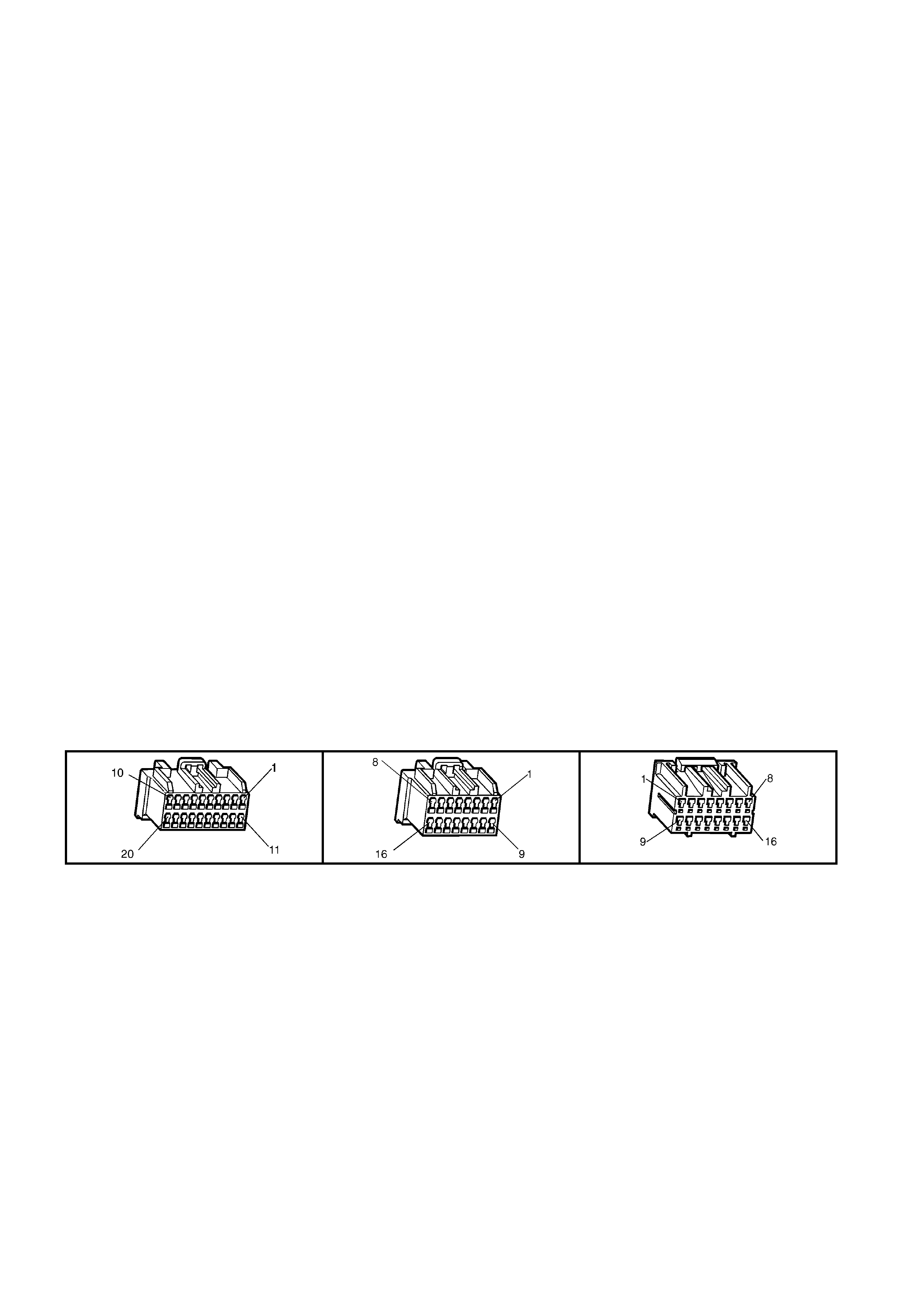
CIRCUIT DESCRIPTION
The telem atic s button pad is a resistor encod ed switch , which m eans that each b utton has a sep arate and diff erent
value resistor connected to it. The telematics module uses a voltage divider circuit to determine which button has
been pressed. The telematics module supplies a 12 Volt signal voltage to terminal X1-12 of the rear view mirror
connector circuit 2515 (Light Green/ Black wire). W henever a button is pressed the corresponding s witch is closed
and circuit 2 514 (Dark G reen/White wire) is connected to gr ound through a resis tor, each switc h having a diff erent
value res istor. T he telem atics m odule monitor s the vol tage on circ uit 2514 (D ark Green/White wire) at term inal X2-
9, which will change whe n an y of the buttons are pres sed.
W hen the em er gency button is pr ess ed, t he voltage at ter minal X 2-9 of the telem atic s module will be a pprox i mately
3.8 Volts. The telematics module determines this voltage at terminal X2-9 as an emergency button press. The
telematics module will initiate a voice call to an operator at the National Emergency Response Centre and then
send an SMS m es sage contai ning status and loc atio n data. If the call can n ot be c onnecte d, the telem atics m odule
will imm ediatel y re-attem pt to connect the call a second tim e. If the sec ond attempt als o fails, the un it shall wait for
60 seconds and make a third and final attempt.
If the emergency button is pressed while a Holden Assist call is in progress then the status of the call shall be
upgraded to an emergency call, and the telematics module will not be permitted to terminate the call by pressing
the End Call/Inf ormation button.
If the emergency button is pressed while the vehicle is outside GSM network range, the telematics module will
enter “Em er gency Call M od e” wher e b y the emergency call reques t wil l b e reta in ed. When contac t is re- es tab lis he d
with the GSM network, the emergency call will be placed immediately.
CONDITIONS FOR SETTING THE DTC
• DTC 47 will set if the keypad circuit voltage is at 3.8 Volts for greater than ten seconds.
ACTION TAKEN WHEN THE DTC SETS
• When the diagnostic runs and fails, the t elematics modu le stores the DTC into m em or y as a curren t DTC and
activates the red status LED.
TEST DESCRIPTION
Number(s) below refer to step number(s) on the diagnostic chart.
1. Confirmation that the Telematics On-Board Diagnostic System Check has been performed.
2. This test s tep d eter mines if DTC 47 is int er mittent. If D TC 47 is i ntermittent, check for an inter mittent ope n, or a
short to voltage or ground on circuit 2514, or an intermittent internal short in the interior rear view mirror.
3. The test step checks the actual voltage on circuit 2514.
4. This test step checks if the interior rear view mirror is causing DTC 47 to set.
5. Before the telematics module is replaced the retention of the telematics module connectors A158 X1 and X2
terminals should be checked.
A158 X1 A158 X2 E124 X1

DTC 47 - EMERGENCY BUTTON STUCK
STEP ACTION VALUE YES NO
1. Has a Telematics On-Board Diagnosis System Check
been performed? Go to Step 2. Refer Telematics
On-Board
Diagnostic
System Check
chart in this
Section.
2. 1. From the Telematics Application Menu,
Select F0: Diagnostic Trouble Codes / F0: Clear
DTCs and clear all DTCs.
2. Ignition on for at least one minute.
Does DTC 47 Emergency Button Stuck set?
Go to Step 3. DTC 47 is
intermittent
Refer Test Step
Description.
3. 1. Ignition on.
2. Using a DMM measure the voltage between the
interior rear view mirror connector E124 X1-11
circuit 2514 (Dark Green/White wire) and ground.
Is the voltage at the specified value?
3.8 Volts Go to step 4. Go to step 5.
4. 1. Ignition off, disconnect the interior rear view mirror
connector.
2. Ignition on.
2. Using a DMM measure the voltage between the
interior rear view mirror connector E124 X1-11
circuit 2514 (Dark Green/White wire) and ground.
Is the voltage at the specified value?
3.8 Volts Go to step 5. Replace interior
rear view mirror.
Refer 3.4 Interior
Rear View Mirror
in this Section.
5. 1. Check telematics module connectors A158 X1 and
X2 terminal retention.
Is the terminal retention OK?
Replace
telematics
module.
Refer 3.1
Telematics
Module in this
Section.
Repair connector
terminal
retention.
WHEN ALL DIAGNOSIS AND REPAIRS ARE COMPLETED, CLEAR DTCS AND VERIFY CORRECT OPERATION
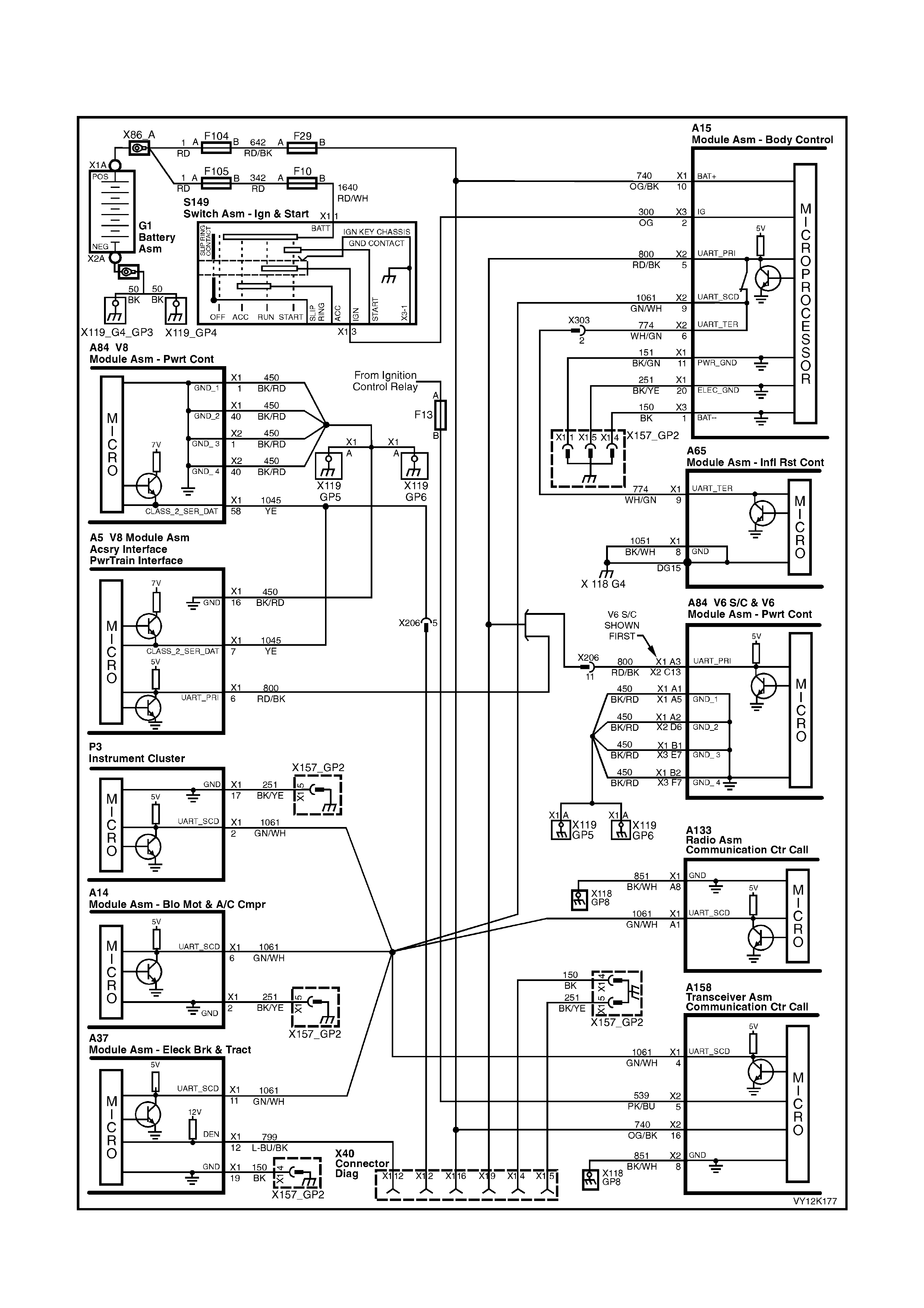
5.9 S YMPTO MS CHARTS
NO SERIAL DA TA
Figure 12K-107
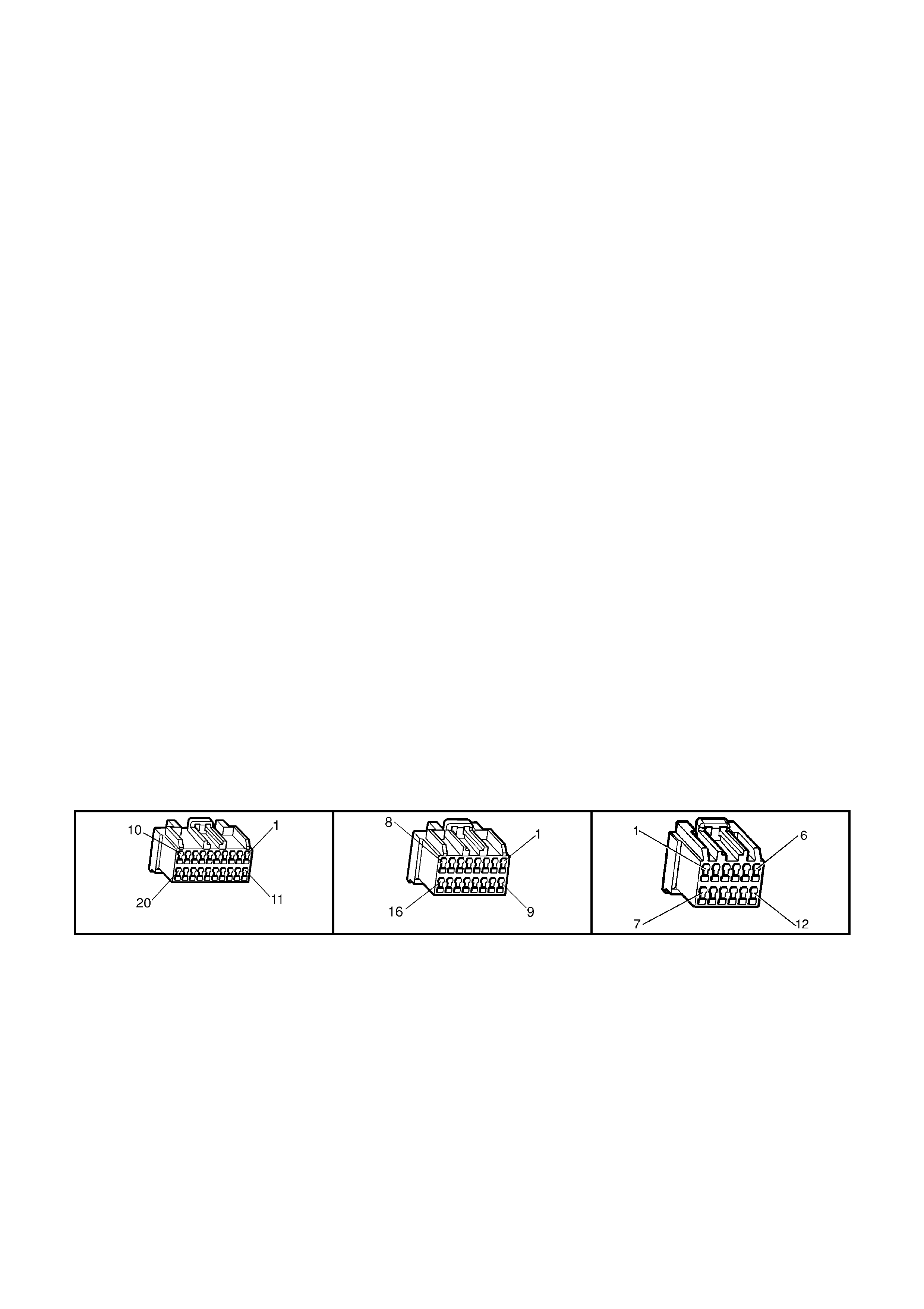
CIRCUIT DESCRIPTION
The telem atic s m odule m onitors the auxi liar y seria l dat a circuit 1 061 (G reen/W hite wire) norm al m ode m essage f or
the following information: Airbag Deployed this Ignition Cycle from the SRS SDM, Vehicle Speed from the PCM and
Audio System status information from the Audio Head Unit. For further information regarding the serial data bus
and normal mode message, refer to Section 1.2 Serial Data Communication in Section 12J BODY CONTROL
MODULE in this Service Information.
If the telematics module receives a “Remote Unlock” message from the Holden Assist Centre, the telematics
module will request the BCM (via the serial data circuit) to unlock the doors. For further information regarding the
BCM door lock operation, refer to Section 12J BODY CONTROL MODULE, Central Door Locking Systems in
this Service Information.
If the telematics module receives a “Immobilise” message from the Holden Assist Centre, the telematics module will
then turn of f the fuel pum p r elay cutting of f the s upp ly of f uel to the engine and request th e BC M ( via the seri al d at a
circuit) to flash the indicators. For further information regarding the BCM indicator operation, refer to
Section 12J BODY CONTROL MODULE, Theft Deterrent System in this Service Information.
TEST DESCRIPTION
Number(s) below refer to step number(s) on the diagnostic chart.
1. Confirmation that the Telematics On-Board Diagnostic System Check has been performed.
2. T his test step deter mines if T ECH 2 is ab le communic ate with the B CM. If “No c ommunic ation with Ve hicle” is
displayed next to BCM DTC Status, then there is no communication between TECH 2 and the BCM.
3. This test step determines if TECH 2 is able to communicate with other control modules that are on the
secondary serial data circuit.
4. T his test step chec ks the voltage a t the on the sec ondary data c ircuit at the tel ematics m odule connector. The
voltage should be vary between three to five Volts.
5. If the s econdary serial da ta c irc uit v olt age is s t eady or gr eater tha n five Vo lts t hen ther e is a sh or t t o vo ltag e on
this circuit.
6. Each c ontrol module on t he serial d ata circuit shoul d be disconnec ted to determ ine if that m odule is the caus e
of the short to voltage.
7. This test step checks the continuity of circuit 1061.
8. T his test step chec ks for an op en circuit in th e BCM data bus isolator. If the data bus isolator is o pen then the
BCM will have to be replaced.
9. T his test step check for a short to ground on cir cuit 1061. Eac h control m odule on the s erial data c ircuit sho uld
be disconnected to determine if that module is the cause of the short to ground.
10. This test step check for battery voltage at the telematics module.
11. This test step check for ignition voltage at the telematics module.
12. This test step checks the telematics module ground circuit.
13. This test step confirms that the telematics module connector terminal retention is OK. Terminal retention should
always be checked before any component is replaced.
A158 X1 A158 X2 A15 X 2

NO SERIAL DA TA
STEP ACTION VALUE YES NO
1. Has a Telematics On-Board Diagnosis System Check
been performed? Go to Step 2. Refer Telematics
On-Board
Diagnostic
System Check
chart in this
Section.
2. 1. From the TECH 2 System Select Menu select
F5: Vehicle DTC Check, Ignition On and follow
screen instructions.
2. Does TECH 2 Display “NO Communication with
Vehicle” or “BCM DTC Status, No Data”?
NOTE: If “No Data” is displayed next to BCM DTC
Status, then there is no communication between TECH 2
and the BCM.
Refer BCM
Serial Data
Communication
diagnostics in
Section 12J
BCM in this
Service
Information.
Go to Step 3.
3. In step 2 did TECH 2 display “No Data” for the all of the
following con trol mod ules?
INS DTC Status No Data.
ABS DTC Status No Data.
OCC DTC Status No Data.
Audio System No Data.
Go to Step 4. Go to Step 7.
4. 1. Ignition on.
2. Disconnect telematics module connectors A158
X1 and X2.
3. Using a DMM, check the voltage at the telematics
module connector A158 X1-4 circuit 1061
(Green/White wire).
Is the voltage varying between specified value?
3 – 5 Volts Go to step 9. Go to step 5.
5. In step 4 is voltage steady or above specified value? Go to step 6. Go to step 7.
6. 1. Repair for short to voltage in circuit 1061.
NOTE: Disconnect each control module connected
to circuit 1061 one at a time to isolate the fault in the
circuit or to identify the control module causing the
fault.
Is action complete.
Verify Repair. Complete Action.
7. 1. Using a DMM, check continuity of circuit
1061(Green/White wire) between the telematics
module connector terminal A158 X1-4 and the BCM
connector A15 X2-9.
Does continu ity ex ist?
Go to Step 8. Repair open in
circuit 1061.
8. 1. Using a DMM, check for continuity through the BCM
from circuit 1061 (Green/White wire) to circuit 800
(Red/Black wire) between BCM connector terminals
A15 X2-5 and X2-9.
Does continu ity ex ist?
Go to Step 9. Refer Section 12J
BCM in this
Service
Information.
Refer test step.
9. 1. Check for short to ground in circuit 1061.
NOTE: Disconnect each control module connected
to circuit 1061 one at a time to isolate the fault in the
circuit or to identify the control module causing the
fault.
Is circuit 1061 shorted to ground.
Repair short to
ground in circuit
1061.
Go to Step 10.
10. 1. Using a DMM, check the voltage at the telematics
module terminal A158 X2-16 circuit 740
(Orange/Black wire).
Is the voltage at the specified value?
B+ Go to Step 11. Repair open in
circuit 740.

STEP ACTION VALUE YES NO
11. 1. Ignition On.
2. Using a DMM, check the voltage at the telematics
module terminal A158 X2-5 circuit 539 (Pink/Blue
wire).
Is the voltage at the specified value?
B+ Go to Step 12. Repair open in
circuit 539.
12. 1. Check the integrity of the telematics module ground
circuit 851, by performing a voltage drop on circuit
851 (Black/White wire) between telematics module
connector, terminal A158 X2-8 and a known good
ground.
With connector A158 X1 & X2 connected to the
telematics module and the ignition on, is voltage less
than the specified value?
0.15 Volts Go to Step 13. Repair ground
circuit as
necessary.
13. 1. Check telematics module connectors A158 X1 & X2
terminal re tention.
Is the terminal retention OK?
Replace
telematics
module.
Refer 3.1
Telematics
Module in this
Section
Repair connector
terminal re tention.
WHEN ALL DIAGNOSIS AND REPAIRS ARE COMPLETED, CLEAR DTCS AND VERIFY CORRECT OPERATION

STATUS INDICATOR LEDS DO NOT ILLUMINATE
Figure 12K-108
CIRCUIT DESCRIPTION
The red a nd green s tatus indicat or L EDs in the interio r rear view m irror indic ate the c urrent stat us of the te lem atic s
system . The telem atics module ac tivates the LEDs b y switching a 1 2 volt po wer suppl y to each LED on or off. The
brightnes s of the LEDs is control led b y the int erior rea r vie w mir ror elec tronic s, which will vary the brig htn ess of the
LEDs depending on the ambient light and the ignition switch position. If the ambient light is low the brightness of
the LEDs will be decreased when the ignition is on. If the ambient light is high there will be no change to the
brightness of the LEDs when the ignition is turned on.
The colour of the LED indicates the status of the system. If there is a system fault during a call the LED will flash
red. If there are no system faults, then the LED will flash green.
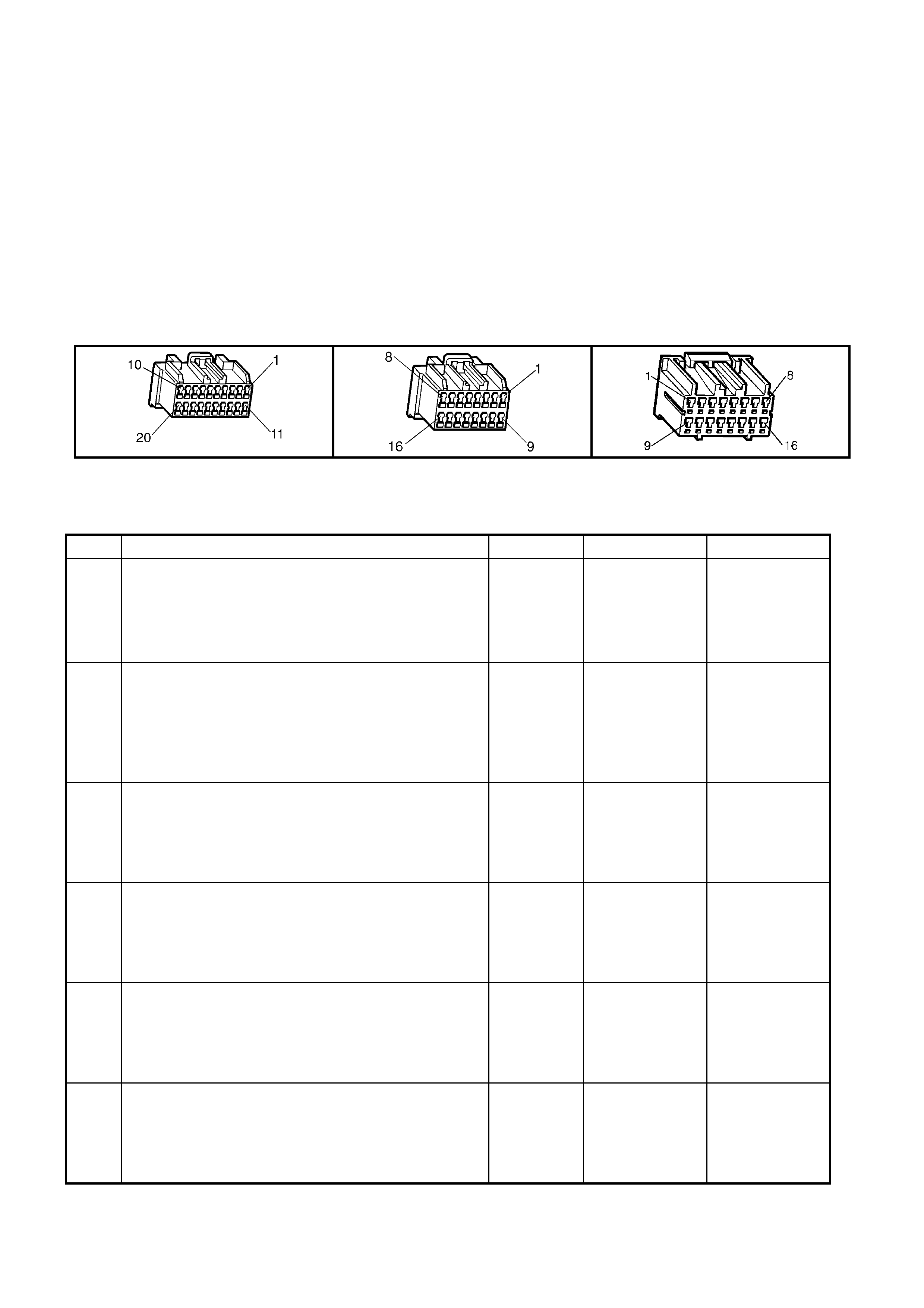
TEST DESCRIPTION
Number(s) below refer to step number(s) on the diagnostic chart.
1. Confirmation that the Telematics On-Board Diagnostic System Check has been performed.
2. If the telematics module is in pre delivery mode then the status LEDs will not illuminate.
3. If TECH 2 is capable of commanding the red status LED on and off the LED and circuit are OK.
4. Checks red status LED supply voltage on circuit 2517 (Brown/White wire).
5. Checks that the telematics module can command the red status LED supply on and off.
6. If TECH 2 is capable of commanding the green status LED on and off the LED and circuit are OK.
7. Checks green status LED supply voltage on circuit 2516 (Yellow/Black).
8. Checks that the telematics module can command the green status LED supply on and off.
9. Checks integrity of the interior rear view mirror ground circuit 156.
10. This test step confirms that the connector terminal retention is OK. Terminal retention should always be
checked before any component is replaced.
A158 X1 A158 X2 E124 X1
STATUS INDICATOR LEDS DO NOT ILLUMINATE
STEP ACTION VALUE YES NO
1. Has a Telematics On-Board Diagnosis System Check
been performed? Go to Step 2. Refer Telema tics
On-Board
Diagnostic
System Check
chart in this
Section.
2. 1. From the TECH 2 Telematics Application Menu,
Select F1: Data Display / F0: Inputs and Outputs.
2. Scroll to Operating Mode.
Does TECH 2 display Operating Mode “Active”?
Go to Step 3. Program the
Telematics into
Active Mode.
Refer
F4: Program/
Operating Mode
in this Section.
3. 1. From the TECH 2 Telematics Application Menu,
Select F3: Miscellaneous Tests / F1: Red Status
LED.
2. Command the LED on and off.
Did the Red Status LED turn on?
Red status LED
is OK.
Go to Step 6.
Go to Step 4.
4. 1. Using a DMM, check the voltage at the rear view
mirror connector terminal E124 X1-15 circuit 2517
(Brown/White wire).
2. Command the red LED on, as in step 2.
Is voltage as specified?
12 Volts Go to Step 9. Go to Step 5.
5. 1. Using a DMM, check the voltage at the telematics
module connector terminal E124 X1-15 circuit 2517
(Brown/White wire).
2. Command the red LED on, as in Step 2.
Is voltage as specified?
12 Volts Repair open
circuit 2517.
Go to Step 10.
6. 1. From the Telematics Application Menu,
Select F3: Miscellaneous Tests / F2: Green Status
LED.
2. Command the green LED on and off.
Did the Green Status LED turn off and on?
Green status
LED is OK. Go to Step 7.

STEP ACTION VALUE YES NO
7. 1. Using a DMM, check the voltage at the rear view
mirror connector terminal E124 X1-14 circuit 2516
(Yellow/Black wire).
2. Command the green LED on, as in Step 5.
Is voltage as specified?
12 Volts Go to Step 9 Go to Step 8.
8. 1. Using a DMM, check the voltage at the telematics
module connector terminal A158 X1-14 circuit 2516
(Yellow/Black wire).
2. Command the green LED on, as in step 5.
Is voltage as specified?
12 Volts Repair open
circuit 2516.
Go to Step 10.
9. 1. Using a DMM, measure the continuity of circuit 650
(Black/Blue wire) between the rear view mirror
connector terminal E124 X1-8 and a known good
ground.
Is there continuity?
Less than 1
Ohm. Replace rear
view Mirror.
Refer 3.4 Interior
Rear View Mirror
in this Section.
Repair open
circuit 650
between the rear
view mirror E124
connector and
ground
X118_GP13.
10. 1. Check telematics module connectors A158 X1 & X2
terminal re tention.
Is the terminal retention OK?
Replace
telematics
module.
Refer 3.1
Telematics
Module in this
Section
Repair connector
terminal
retention.
WHEN ALL DIAGNOSIS AND REPAIRS ARE COMPLETED, VERIFY CORRECT OPERATION
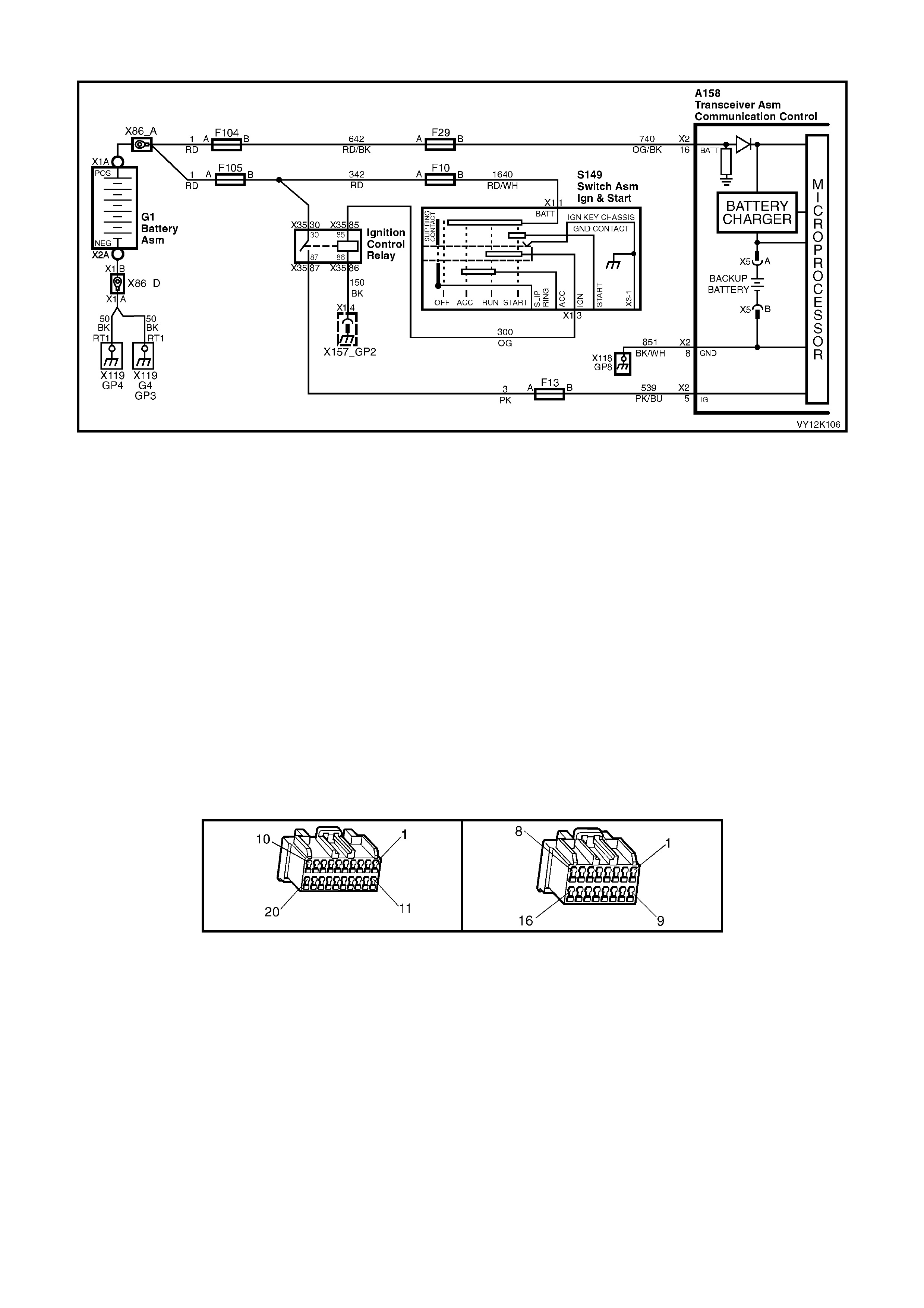
VEHICLE BATTERY VOLTAGE
Figure 12K-109
CIRCUIT DESCRIPTION
Battery voltage is applied to the telematics module terminal X2-16 at all times via circuit 740 (Orange/Black wire),
fuse F29 and fusible link F104. If the battery voltage fails below a preset voltage for longer than 30 minutes, the
telematics m odule will transm it a Low Battery Alert to the Holden Assist Centre. Refer 2.2 ALERT S, Low B attery
Voltage Alert in this Sec tion for f urther inform ation. If the battery is r emoved th e telem atics module will transm it a
Battery Removal Alert to th e Holden Assist Centre . Refer 2.2 ALERTS, Battery Removal Alert in this Section for
further information.
TEST DESCRIPTION
Number(s) below refer to step number(s) on the diagnostic chart.
1. Confirmation that the Telematics On-Board Diagnostic System Check has been performed.
2. Checks the open circuit voltage of the vehicle battery.
3. The displayed battery voltage should be within 0.5 Volts of the battery open circuit voltage in step 2.
4. This test step measures that actual voltage at the telematics module connector A158 X2-16.
5. This test step checks the continuity of circuit 740.
6. This test step checks the continuity of circuit 1151.
7. This test step confirms that the connector terminal retention is OK. Terminal retention should always be
checked before any component is replaced.
A158 X1 A158 X2

VEHICLE BATTERY VOLTAGE
STEP ACTION VALUE YES NO
1. Has a Telematics On-Board Diagnosis System Check
been performed? Go to Step 2 Refer Telematics
On-Board
Diagnostic
System Check
chart in this
Section.
2. 1. Using a DMM measure the vehicle battery voltage.
Refer SECTION 12A BATTERY AND CABLES,
3. DIAGNOSIS in this Service Information.
Is the vehicle battery open circuit voltage as specified?
Greater than
12.4 Volts. Go to Step 3 Refer 12A
BATTERY AND
CABLES,
3. DIAGNOSIS
in this Service
Information
3. 1. From the Telematics Application Menu,
Select F1: Data Display / F0: Input and Outputs.
2. Scroll to Battery Voltage.
Is the voltage as specified?
B+ Vehicle battery
voltage OK. Go to Step 4.
4. 1. Using a DMM measure the voltage at the
telematics module connector terminal A158 X2-16
circuit 740 (Orange/Black wire) and a known good
ground.
Is the voltage as specified?
B+ Go to Step 6. Go to Step 5.
5. 1. Using a DMM measure the resistance of circuit 740
(Orange/Black wire) between fuse F29 and
terminal A158 X2-16 of the telematics module
connector.
Is resistance as specified?
Less than
1 Ohm. Go to Step 6. Repair cause of
high resistance in
circuit 740.
6. 1. Using a DMM measure the resistance of circuit 851
(Black/white wire) between telematics module
connector terminal A158 X2-8 and a known good
ground.
Is resistance as specified?
Less than
1 Ohm. Go to Step 7. Repair cause of
high resistance in
circuit 851.
7. 1. Check telematics module connectors A158 X1 &
X2 terminal retention.
Is the terminal retention OK?
Replace
telematics
module. Refer
3.1 Telematics
Module in this
Section.
Repair connector
terminal
retention.
WHEN ALL DIAGNOSIS AND REPAIRS ARE COMPLETED, VERIFY CORRECT OPERATION
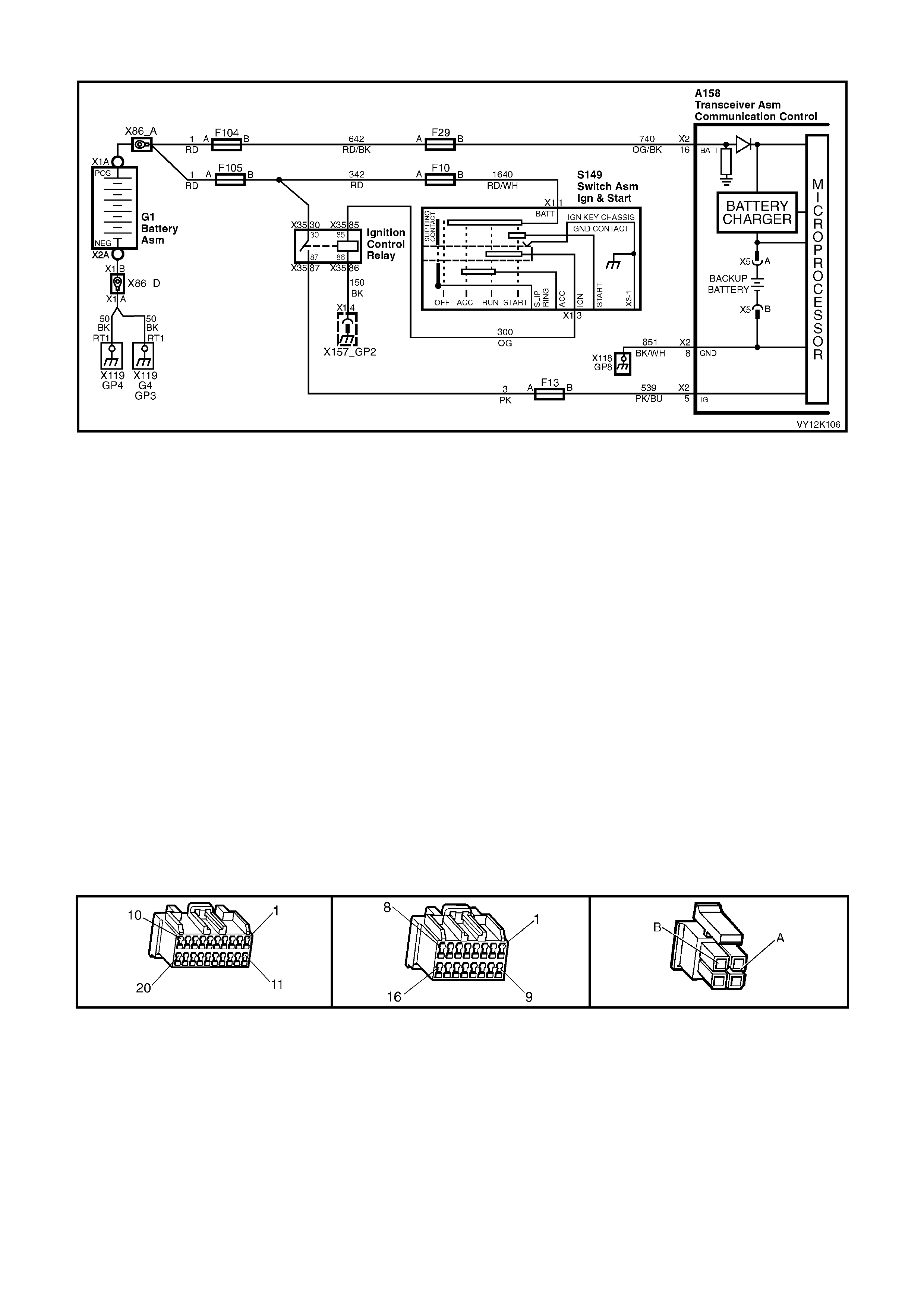
BACKUP BATTERY
Figure 12K-110
CIRCUIT DESCRIPTION
The backup battery (1) is housed in the battery compartment of the telematics module. The backup battery will
provide power to the t elema tics m odule for at leas t 30 m inutes in th e event of the vehicl e battery be ing disch arged
or disconnected. The telematics module has a backup battery charging circuit that maintains the backup battery
state of charge. This circuit also includes an over current protection device.
TEST DESCRIPTION
Number(s) below refer to step number(s) on the diagnostic chart.
1. Confirmation that the Telematics On-Board Diagnostic System Check has been performed.
2. Check vehicle battery voltage. If the vehicle battery voltage the actual vehicle battery voltage should be
checked.
3. Checks backup battery voltage via TECH 2.
4. Checks battery charger status via TECH 2. The backup battery charger should be able to be switched from
“Active” to “Inactive”.
5. Checks that the backup battery charger is functioning, the backup battery should display active when the
ignition is on and the backup battery voltage is less than 7.5 Volts.
6. Checks backup battery voltage using TECH 2.
7. Checks the actual backup battery terminal voltage using a DMM.
8. This test step confirms that the back up battery connector terminal retention is OK. Terminal retention should
always be checked before any component is replaced.
9. This test step confirms that the connector terminal retention is OK. Terminal retention should always be
checked before any component is replaced.
A158 X1 A158 X2 A158 X5

BACKUP BATTERY
STEP ACTION VALUE YES NO
1. Has a Telematics On-Board Diagnosis System Check
been performed? Go to Step 2 Refer Telematics
On-Board
Diagnostic
System Check
chart in this
Section.
2. 1. From the Telematics Application Menu,
Select F1: Da ta Display/F0: Input and Outputs.
2. Scroll to Battery Voltage.
Is the Battery Voltage as specified?
Greater than
12.4 Volts. Go to Step 3. Refer to Vehicle
Battery Voltage
Diagnostic chart
in this Section.
3. 1. Scroll to Backup Battery Voltage.
Is the backup battery voltage as specified? Greater than
7.5 Volts. Go to Step 4. Go to Step 7.
4. 1. From the Telematics Application Menu,
Select F2: Miscellaneous Tests \ F5: Backup
Battery Charger.
2. Carry out a Backup Battery Charger te st.
Does Backup Battery Charger switch from “Active” to
“Inactive” when commanded?
Go to Step 6. Go to Step 5.
5. 1. Start engine and increase the engine speed to 2000
RPM.
Does Backup Battery Charger display “Active”?
Go to Step 6. Go to Step 7.
6. 1. Scroll to Backup Battery Voltage.
Turn ignition On engine off.
Is backup battery voltage within specified limits?
Greater than
7.5 Volts. Backup battery
and charging
circuit OK.
Go to Step 7.
7. 1. Remove the telematics module refer
3.1 TELEMATICS MODUL E.
2. Remove the telematics module backup battery refer
3.2 BACKUP BATTERY.
3. Using a DMM measure the backup battery voltage
at the backup battery connector terminal A158 X5-A
and X5-B.
Is the voltage as specified?
Greater than
7.5 Volts. Go to step 9. Go to Step 8.
8. 1. Check terminal retention of the telematics module
backup battery connectors terminals A158 X5-A and
X5-B.YB55.
Is the terminal retention OK?
Replace backup
battery.
Refer 3.2 Backup
Battery in this
Section.
Repair connector
terminal
retention.
9. 1. Check telematics module connector A158 X1 & X2
terminal re tention.
Is the terminal retention OK?
Replace
telematics
module. Refer
3.1 Telematics
Module in this
Section.
Repair connector
terminal
retention.
WHEN ALL DIAGNOSIS AND REPAIRS ARE COMPLETED, VERIFY CORRECT OPERATION

NO GPS SIGNAL
Figure 12K-111
CIRCUIT DESCRIPTION
The telem atic s antenna c ontai ns bot h the GPS and G SM ante nnas in on e unit, a nd is l ocate d under the inst rum ent
panel. T he anten na has t wo lea ds , one f or the GPS antenna an d the oth er f or the GSM ant enn a. The GPS ante nna
receives signals from satellites orbiting the earth and transmits these to the telematics module to determine the
vehicles positio n. Signa ls fr om at leas t three GPS sat ellites mus t be rece ived to a ccur ately determ ine the vehicle ’s
two dimensional (2D) position. Signals from at least four GPS satellites must be received to accurately determine
the vehicle’s three dimensional (3D) position. If signals from only three satellites are received, the telematics
module cannot determine the vehicles altitude. The GPS antenna must not be obscured by any objects, such as
undergroun d car park s, tunnels, bridges or bu ildings, any of thes e may affect GPS reception. T he GPS antenna is
connected to the telematics module by a push on type connector. To determine the vehicles position this GPS
information is transmitted via SMS to the Holden Assist Centre whenever a call is made to the Holden Assist
Centre. The Holden Assist Centre is also able to track the vehicle using this GPS information.
TEST DESCRIPTION
Number(s) below refer to step number(s) on the diagnostic chart.
1. Confirmation that the Telematics On-Board Diagnostic System Check has been performed.
2. The GPS module should be active at all times.
3. T he positi on of the veh icle wil l aff ect the GP S si gnal. The veh icle sh ould b e m oved to a locat ion wher e ther e is
an unobstr ucted v iew of the sk y. There m a y be times during th e da y that ther e are ac tuall y no sate llites visi ble.
If poss ible the GPS info rm ation shou ld be c onf irm ed with a k no w good vehicle. If the Tim e of Last Kno wn G PS
Fix data list parameter is incrementing, then the telematics module is receiving information from GPS
satellites.
NOTE: Aftermarket window tinting may also affect the antenna operation.

4. Installing a known good antenna will confirm if the problem is being caused by the telematics antenna or the
telematics module.
NOTE: It may take at lease 120 minutes to obtain a GPS fix.
5. This test step confirms that the antenna is causing the problem, before it is replaced.
6. This test step confirms that the connector terminal retention is OK. Terminal retention should always be
checked before any component is replaced.
A158 X1 A158 X2 A158 X3
NO GPS SIGNAL
STEP ACTION VALUE YES NO
1. Has a Telematics On-Board Diagnosis System Check
been performed? Go to Step 2. Refer Telematics
On-Board
Diagnostic
System Check
chart in this
Section.
2. 1. From the Telematics Application Menu,
Select F1: Data Display/F1: Global Positioning
System.
2. Scroll to GPS Module.
Does TECH 2 display GPS Module “Active”?
Go to Step 3. Go to Step 6.
3. 1. Scroll to Time of Last Known GPS Fix.
Is the Time of Last Known GPS Fix display
incrementing?
GPS Antenna
OK. Go to Step 4.
4. 1. Check telematics module GPS antenna connector
A158 X3 for correct installation and terminal
retention.
Is the GPS antenna installation and terminal retention
OK?
Go to Step 5. Repair connector
installation or
terminal
retention.
5. 1. Temporally install a known good GPS antenna.
2. Scroll to Time of Last Known GPS Fix.
NOTE: It may take at lease 120 minutes to obtain a
GPS fix.
Is the Time of Last Known GPS Fix display
incrementing?
Replace
telematics
antenna. Refer
3.4 Telematics
Antenna in this
Section.
Go to Step 6.
6. 1. Check telematics module connectors A158 X1 & X2
terminal re tention.
Is the terminal retention OK?
Replace
telematics
module. Refer
3.1 Telematics
Module in this
Section.
Repair connector
terminal
retention.
WHEN ALL DIAGNOSIS AND REPAIRS ARE COMPLETED, VERIFY CORRECT OPERATION

NO GSM SIGNAL
Figure 12K-112
CIRCUIT DESCRIPTION
The telem atics antenn a contains both the GPS and GSM antennas in one unit, a nd is under th e instrum ent panel.
The antenna has two leads, one for the GPS antenna and the other for the GSM antenna. The GSM antenna is
capable of transmitting and receiving both voice and data signals via the GSM network. The telematics module
uses the GSM network to transmit and receive voice and data. Signal strength may be affected in locations like
basement car parks or tunnels. However, in m ost cases, as the vehicle emerges from the obstruction or re-enters
the digital phone network area the signa l will be availa ble again and an y stored data will be transm itted. The G SM
antenna is connected to the telematics module by a push on type connector.
TEST DESCRIPTION
Number(s) below refer to step number(s) on the diagnostic chart.
1. Confirmation that the Telematics On-Board Diagnostic System Check has been performed.
2. The GSM module should be active at all times.
3. If there is no GSM signal then either the telematics antenna or telematics module are faulty. The GSM signal
strength can vary from -113 (poor Signal) to –50 dBm (good signal), as low signal strength could cause call
dropout. The vehicle should be moved to a location that has a better GSM signal and the signal strength
checked again.
3. The G SM antenna conn ector shoul d be check ed to ens ure the connec tor is corr ectly insta lled and th e term inal
retention is OK.
4. Once the antenna is replaced and the signal strength still displays “No Signal” or “Invalid” the telematics
module is faulty.
5. This test step confirms that the connector terminal retention is OK. Terminal retention should always be
checked before any component is replaced.

A158 X1 A158 X2 A158 X4
NO GSM SIGNAL
STEP ACTION VALUE YES NO
1. Has a Telematics On-Board Diagnosis System Check
been performed? Go to Step 2. Refer Telematics
On-Board
Diagnostic
System Check
chart in this
Section.
2. 1. From the Telematics Application Menu,
Select F1: Da ta Display/F2: GSM.
2. Scroll to GSM Module.
Does TECH 2 display GSM Module “Active”?
Go to Step 3. Go to Step 6.
3. 1. Scroll to GSM Signal Strength.
Does TECH 2 display GSM Signal Strength
“No Signal” or “Invalid”?
Go to Step 4. GSM Antenna
OK.
4. 1. Check telematics module GPS antenna connector
A158 X4 for correct installation and terminal
retention.
Is the GSM antenna connector installation and terminal
tension OK?
Go to Step 5. Repair connector
installation or
terminal
retention.
5. 1. Replace Telematics Antenna.
Does TECH 2 display GSM Signal Strength
“No Signal” or “Invalid”?
Replace
telematics
module. Refer
3.1 Telematics
Module in this
Section.
GSM Antenna
OK.
6. 1. Check telematics module GSM antenna connector
A158 X4 terminal retention.
Is the terminal retention OK?
Replace
telematics
module. Refer
3.1 Telematics
Module in this
Section.
Repair connector
terminal
retention.
WHEN ALL DIAGNOSIS AND REPAIRS ARE COMPLETED, VERIFY CORRECT OPERATION

EMERGENCY BUTTON
Figure 12K-113
CIRCUIT DESCRIPTION
W hen the em er gency button is pr ess ed, t he voltage at ter minal X 2-9 of the telem atic s module will be a pprox i mately
3.8 Volts, the telematics module determines this voltage at terminal X2-9 as an emergency button press. The
telematics module will initiate a voice call to an operator at the National Emergency Response Centre and then
send an SMS m es sage contai ning status and loc atio n data. If the call can n ot be c onnecte d, the telem atics m odule
will imm ediatel y re-attem pt to connect the call a second tim e. If the sec ond attempt als o fails, the un it shall wait for
60 seconds and make a third and final attempt.
If the emergency button is pressed while a Holden Assist call is in progress then the status of the call shall be
upgraded to an emergency call, and the telematics module will not be permitted to terminate the call by pressing
the “end call / information” button.
If the emergency button is pressed while the vehicle is outside GSM network range, the telematics module will
enter “Em er gency Call M od e” wher e b y the emergency call reques t wil l b e reta in ed. When contac t is re- es tab lis he d
with the GSM network, the emergency call will be placed immediately.
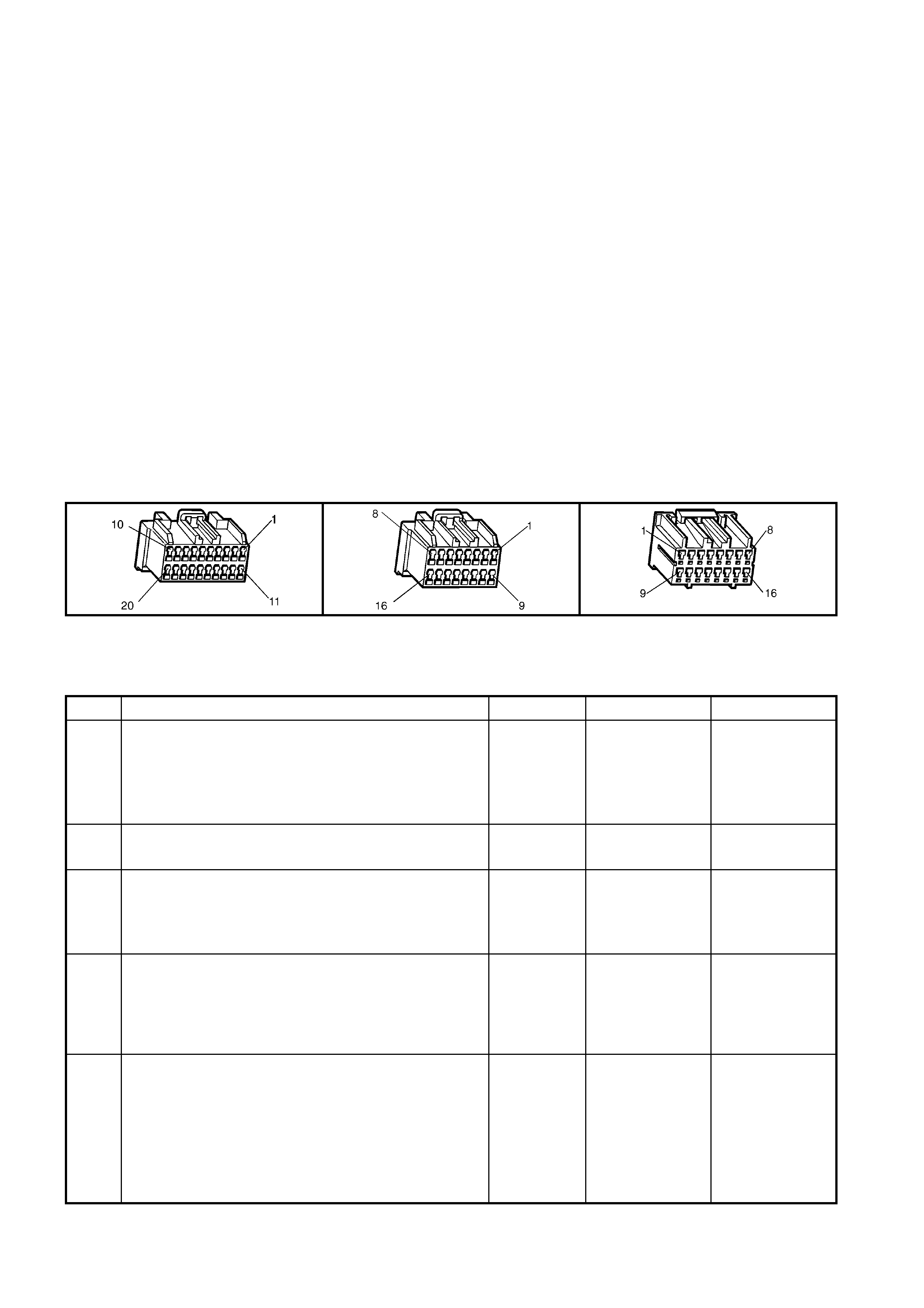
TEST DESCRIPTION
Number(s) below refer to step number(s) on the diagnostic chart.
1. Confirmation that the Telematics On-Board Diagnostic System Check has been performed.
2. Confirms that the telematics module is powering up the keypad.
3. Confirms that the telematics module has commanded the keypad supply voltage on.
4. The keypad signal voltage should display 0.0 Volts when there is no key being pressed.
5. Service mode should be enabled so that the telematics module does not call NERCTM when the emergency
button is pressed. The service mode should be enable until this diagnostic chart is completed.
6. When circuits 2414 and 2415 are jumped together TECH 2 should display a keypad signal voltage of 12.0
Volts.
7. T his test step confirm s that the te lematics m odule is s upplying batter y voltag e to circ uit 2515 at th e telemati cs
module connector A158 X2-15.
8. T his test step confirm s that the te lematics m odule is s upplying batter y voltag e to circ uit 2515 at th e telemati cs
rear view mirror connector E124 X1-12.
9. This test step check that the rear view mirror ground is OK
10. This test step check the complete emergency button and circuits.
11. This test step check the resistance of the rear view mirror emergency button.
12. T his test st ep confirms that the r ear vie w mirr or c onne c tor E1 24 X 1 terminal retention is OK. T er minal ret ent i on
should always be checked before any component is replaced.
13. This test step confirms that the telematics module connectors A158 X1 and X2 terminal retention is OK.
Terminal retention should always be checked before any component is replaced.
A158 X1 A158 X2 E124 X1
EMERGENCY BUTTON
STEP ACTION VALUE YES NO
1. Has a Telematics On-Board Diagnosis System Check
been performed? Go to Step 2. Refer Telematics
On-Board
Diagnostic
System Check
chart in this
Section.
2. 1. Ignition On.
Does the keypad back lighting illuminate. Go to Step 5. Go to Step 3.
3. 1. From the TECH 2 Telematics Application Menu,
Select F1: Data display/F0: Inputs and Outputs.
2. Scroll to Keypad Supply Voltage.
Does TECH 2 display Keypad Supply Voltage “On”?
Go to Step 4. Go to Step 13.
4. 1. From the TECH 2 Telematics Application Menu,
Select F1: Da ta Display / F0: Data List.
2. Scroll to Keypad Signal Voltage.
Does TECH 2 display the specified Keypad Signal
Voltage?
0.0 Volts. Go to step 5. Go to Step 6.
5. 1. Using TECH 2, enable the telematics module
service mode. Refer to 4.3 TECH 2 TEST MODES
F5: Program, F1: Operating Mode, in this Section.
(The telematics module should remain in service
mode until this diagnostics chart is completed).
2. Press the emergency butt on.
Does TECH 2 display the specified Keypad Signal
Voltage?
3.8 Volts. Emergency
Button OK.
Check for
intermittent open
or short to
voltage or ground
in circuit 2514.
Go to Step 6.

STEP ACTION VALUE YES NO
6. 1. Disconnect the rear view mirror connector E124
X-1.
2. Ignition on.
Jumper the rear view mirror connectors E124 X1-11
(Green/White wire) circuit 2514 and terminal E124
X1-12 (Light Green/Black wire) circuit 2515
together.
Does TECH 2 display the specified Keypad Signal
voltage?
12.0 Volts. Go to Step 11.
Go to Step 7.
7. 1. Ignition on.
Using a DMM measure the voltage at the telematics
module connector terminal A158 X2-15 circuit 2515
(Light Green/Black wire) and a known good ground.
Is the voltage as specified?
B+ Go to Step 8. Go to Step 13.
8. 1. Disconnect the rear view mirror connector E124 X1.
2. Ignition on.
3. Using a DMM measure the voltage between circuit
2515 (Light Green/Black wire) of the rear view
mirror connector E124 X1-12 and a known good
ground.
Is the voltage as specified?
B+ Go to Step 9. Repair open in
circuit 2515.
9. 1. Disconnect the battery negative terminal.
2. Disconnect the rear view mirror connector E124 X1.
3. Us ing a DMM meas ure th e resi stance of ci rcuit 650
(Black/Blue wire) between the rear view mirror
connector terminal E124 X1-8 and a known good
ground.
Is the resistance as specified?
Less than 1
Ohm. Go to Step 10. Repair open in
circuit 650.
10. 1. Reconnect the interior rear view mirror connector
YB186 and disconnect the telematics module
connectors A158 X1 and X2.
2. Using a DMM measure the resistance between the
telematics module connector terminal A158 X2-15
circuit 2515 (Light Green/Black wire) and terminal
A158 x2-9 circuit 2414 (Green/White wi re).
Is the resistance as specified when the Emergency
Button is pressed?
1.5 K Ohms. Go to Step 13. Go to Step 11.
11. 1. Disconnect the interior rear view mirror connector
E124 X1.
2. Using a DMM measure the resistance between the
interior rear view mirror terminals X1-12 and
terminal X1-11 of the interior rear view mirror.
Is the resistance as specified when the Emergency
Button is pressed?
1.5 K Ohms. Repair open in
circuit 2514. Replace interior
rear view mirror
Refer 3.1 Interior
Rear View Mirror
in this Section..
12. 1. Check interior rear view mirror connector E124 X1
terminal retention.
Is the terminal retention OK?
Replace interior
rear view mirror
Refer 3.1 Interior
Rear View Mirror
in this Section.
Repair connector
terminal
retention.
13. 1. Check telematics module connectors A158 X1 and
X2 terminal retention.
Is the terminal retention OK?
Replace
telematics
module. Refer
3.1 Telematics
Module in this
Section.
Repair connector
terminal
retention.
WHEN ALL DIAGNOSIS AND REPAIRS ARE COMPLETED, VERIFY CORRECT OPERATION

HOLDEN ASSIST BUTTON
Figure 12K-114
CIRCUIT DESCRIPTION
When the Holden Assist button is pressed, the voltage at terminal X2-9 of the telematics module will be
approximatel y 2.3 Vol ts , th e tel ematics m odule determines this vo lta ge a t ter minal X2- 9 as an H old en Ass ist But t o n
press. The telem atics m odule will initiate a voice ca ll to the c all c entre and then send a n SMS m essage c ontaining
status and location data. If the call can not be connected, the telematics module will immediately re-attempt to
connect th e call a second tim e. If the second attem pt also f ails, the un it shall wai t for 60 s econds and m ake a third
and final attempt.
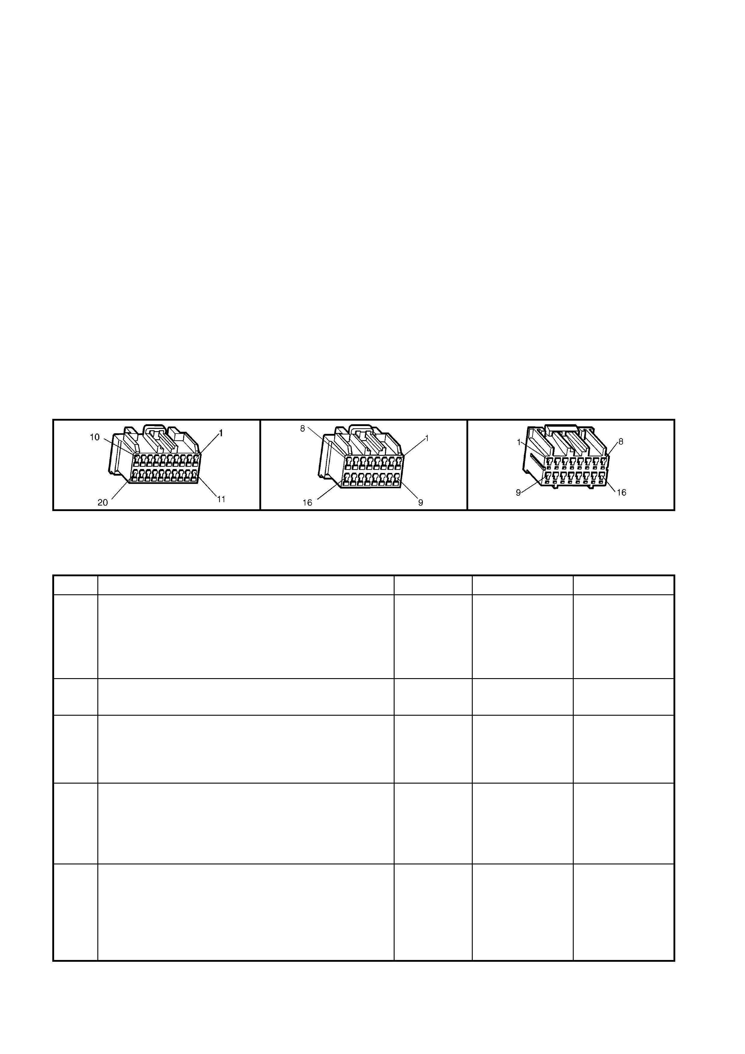
TEST DESCRIPTION
Number(s) below refer to step number(s) on the diagnostic chart.
1. Confirmation that the Telematics On-Board Diagnostic System Check has been performed.
2. Confirms that the telematics module is powering up the keypad.
3. Confirms that the telematics module has commanded the keypad supply voltage on.
4. The keypad signal should display on whenever the telematics module is in active mode.
5. The G SM antenna s hou ld be e nab le d durin g t his t es t s o that th e te lematics module do es not c al l H olden As s ist
when the Ho ld en Ass ist button is pres sed . The G SM antenna shou ld rem ain d isc onnected u ntil t his diagn os tic
chart is completed.
6. When circuits 2414 and 2415 are jumped together TECH 2 should display a keypad signal voltage of 12.0
Volts.
7. T his test step confirm s that the te lematics m odule is s upplying batter y voltag e to circ uit 2515 at th e telemati cs
module connector A158 X2-15.
8. T his test step confirm s that the te lematics m odule is s upplying batter y voltag e to circ uit 2515 at th e telemati cs
rear view mirror connector E124 X1-12.
9. This test step check that the rear view mirror ground circuit 650 is OK
10. This test step check the complete Holden Assist button and circuits.
11. This test step check the resistance of the rear view mirror Holden Assist button.
12. T his test st ep confirms that the r ear vie w mirr or c onne c tor E1 24 X 1 terminal retention is OK. T er minal ret ent i on
should always be checked before any component is replaced.
13. This test step confirms that the telematics module connectors A158 X1 and X2 terminal retention is OK.
Terminal retention should always be checked before any component is replaced.
A158 X1 A158 X2 E124 X1
HOLDEN ASSIST BUTTON
STEP ACTION VALUE YES NO
1. Has a Telematics On-Board Diagnosis System Check
been performed? Go to Step 2. Go Telematics
On-Board
Diagnostic
System Check
chart in this
Section.
2. 1. Ignition On.
Does the keypad back lighting illuminate. Go to Step 5. Go to Step 3.
3. 1. From the TECH 2 Telematics Application Menu,
Select F1: Data Display/F0: Inputs and Outputs.
2. Scroll to Keypad Supply Voltage.
Does TECH 2 display Keypad Supply voltage “On”?
Go to Step 4. Go to Step 13.
4. 1. From the Telematics Application Menu,
Select F1: Data Display/F0: Inputs and Outputs.
2. Scroll to Keypad Signal Voltage.
Does TECH 2 display the specified Keypad Signal
voltage?
0.0 Volts. Go to step 5. Go to Step 6.
5. 1. Disconnect the GSM Antenna.
(The GSM Antenna should remain disconnected
until this diagnostics chart is completed).
2. Press the Holden Assist button.
Does TECH 2 display the specified Keypad Signal
Voltage?
2.3 Volts. Holden Assist
Button OK.
Check for
intermittent open
short to voltage
or grounding in
circuit 2514.
Go to Step 6.

STEP ACTION VALUE YES NO
6. 1. Disconnect the rear view mirror connector E124 X1.
2. Ignition on.
3. Jumper the interior rear view mirror connector
terminals E124 X1-11 (Green/White wire) circuit
2514 and terminal E124 X1-12 (Light Green/Black
wire) circuit 2515 together.
Does TECH 2 display the specified Keypad Signal
Voltage?
12.0 Volts. Go to Step 11.
Go to Step 7.
7. 1. Ignition on.
2. Using a DMM measure the voltage at the telematics
module connector terminal A158 X2-15 circuit 2515
(Light Green/Black wire) and a known good ground.
Is the voltage as specified?
B+ Go to Step 8. Go to Step 13.
8. 1. Disconnect the rear view mirror connector E124 X1.
2. Ignition on.
3. Using a DMM measure the voltage between circuit
2515 (Light Green/Black wire) of the interior rear
view mirror connector terminal E124 X1-12 and a
known good ground.
Is the voltage as specified?
B+ Go to Step 9. Repair open in
circuit 2515.
9. 1. Disconnect the battery negative terminal.
2. Disconnect the rear view mirror connector E124 X1.
3. Us ing a DMM meas ure th e resi stance of ci rcuit 650
(Black/Blue wire) between the rear view mirror
connector E124 X1-8 and a known good ground.
Is the resistance as specified?
Less than 1
Ohm. Go to Step 10. Repair open in
circuit 650.
10. 1. Reconnect the rear view mirror connector E124 X1
and disconnect the telematics module connectors
A158 X1 and X2.
Using a DMM measure the resistance between the
telematics module connector terminal A158 X2-15
circuit 2515 (Light Green/Black wire) and terminal
X2-9 circuit 2414 (Green/White wire).
Is the resistance as specified when the Holden Assist
Button is pressed?
3 K Ohms. Go to Step 13. Go to Step 11.
11. 1. Disconnect the interior rear view mirror connector
E124 X1.
2. Using a DMM measure the resistance between the
interior rear view mirror terminals X1-12 and
terminal X1-11 of the rear view mirror.
Is the resistance as specified when the Holden Assist
Button is pressed?
3 K Ohms. Repair open in
circuit 2514. Replace interior
rear view mirror
Refer 3.1 Interior
Rear View Mirror
in this Section.
12. 1. Check interior rear view mirror connector E124 X1
terminal re tention.
Is the terminal retention OK?
Replace interior
rear view mirror
Refer 3.1 Interior
Rear View Mirror
in this Section.
Repair connector
terminal
retention.
13. 1. Check telematics module connectors A158 X1 and
X2 terminal retention.
Is the terminal retention OK?
Replace
telematics
module. Refer
3.1 Telematics
Module in this
Section.
Repair connector
terminal
retention.
WHEN ALL DIAGNOSIS AND REPAIRS ARE COMPLETED, VERIFY CORRECT OPERATION
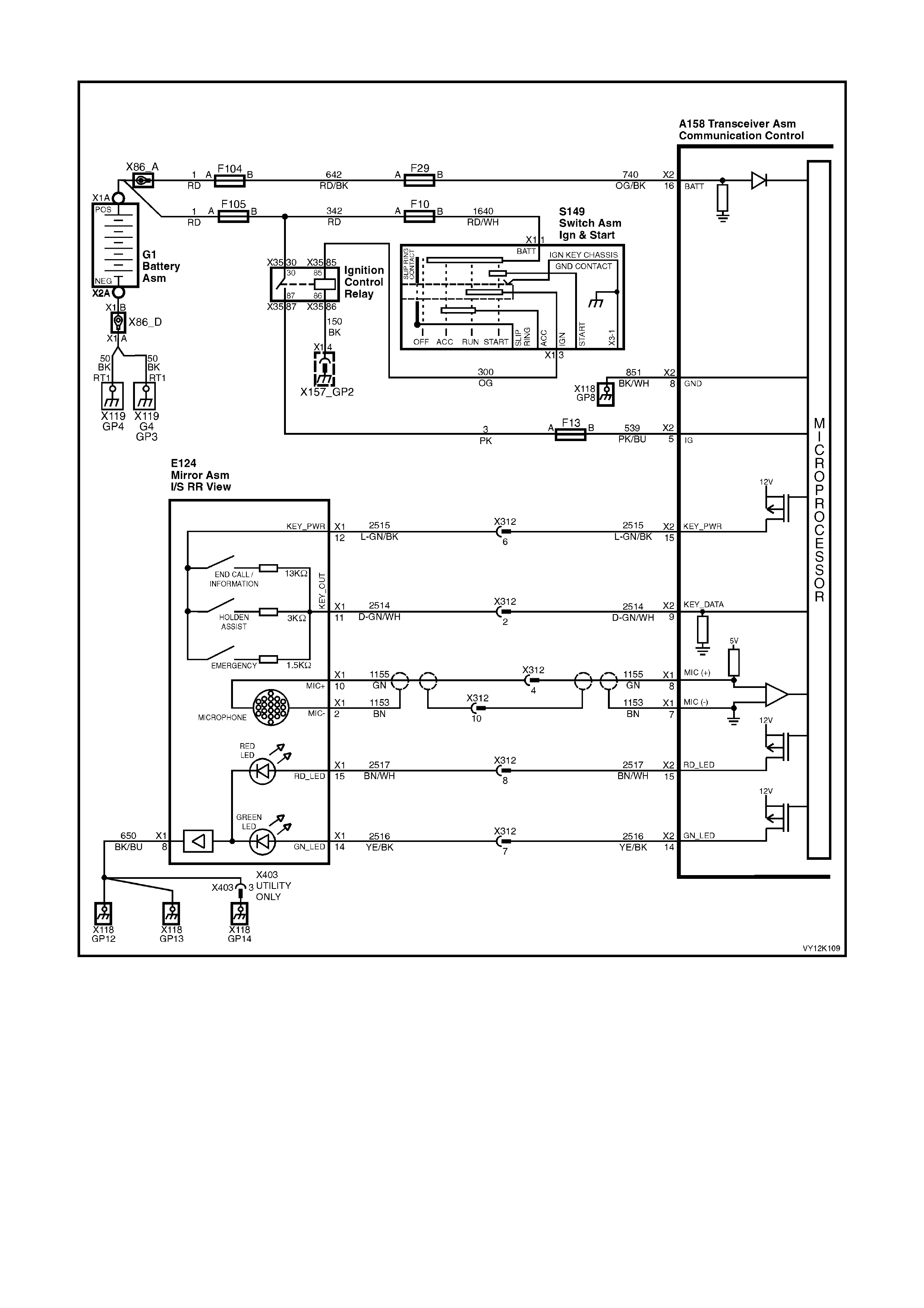
END CALL / INFORMATION BUTTON
Figure 12K-115
CIRCUIT DESCRIPTION
When the end call / information button is pressed, the voltage at terminal X2-9 of the telematics module will be
approximately 0.7 Volts. The telematics module determines this voltage at terminal X2-9 as an end call /
inform ation button pr ess. If end call / inf orm ation button is pressed to m ak e a call, you will b e connec ted to Hold en
Assist information ser vices . Pr ess ing th is butto n while a c all is c onn ected wil l dis c onnec t th e c al l. It ho wever wil l not
disconnect a call while the call is ringing the information service number or the Holden Assist number. It is not
possible for this button to disconnect an emergency call or a Holden Assist call that has been upgraded to
emergency call status.

TEST DESCRIPTION
Number(s) below refer to step number(s) on the diagnostic chart.
1. Confirmation that the Telematics On-Board Diagnostic System Check has been performed.
2. Confirms that the telematics module is powering up the keypad.
3. Confirms that the telematics module has commanded the keypad supply voltage on.
4. The keypad signal should display on whenever the telematics module is in active mode.
5. Service mode should be enabled so that the telematics module does not make call when the end call /
information button is pressed. The service mode should be enable until this diagnostic chart is completed.
6. When circuits 2414 and 2415 are jumped together TECH 2 should display a keypad signal voltage of 12.0
Volts.
7. T his test step confirm s that the te lematics m odule is s upplying batter y voltag e to circ uit 2515 at th e telemati cs
module connector A158 X2-15.
8. T his test step confirm s that the te lematics m odule is s upplying batter y voltag e to circ uit 2515 at th e telemati cs
rear view mirror connector E124 X1-12.
9. This test step check that the rear view mirror ground is OK
10. This test step checks the complete end call / information button and circuits.
11. This test step checks the resistance of the rear view mirror end call / information button.
12. T his test st ep confirms that the r ear vie w mirr or c onne c tor E1 24 X 1 terminal retention is OK. T er minal ret ent i on
should always be checked before any component is replaced.
13. This test step confirms that the telematics module connectors A158 X1 and X2 terminal retention is OK.
Terminal retention should always be checked before any component is replaced.
A158 X1 A158 X2 E124 X1
END CALL / INFORMATION BUTTON
STEP ACTION VALUE YES NO
1. Has a Telematics On-Board Diagnosis System Check
been performed? Go to Step 2. Refer Telematics
On-Board
Diagnostic
System Check
chart in this
Section.
2. Ignition On.
Does the keypad back lighting illuminate. Go to Step 5. Go to Step 3.
3. 1. From the Telematics Application Menu,
Select F1: Data Display / F0: Inputs and Outputs.
2. Scroll to Keypad Supply Voltage.
Does TECH 2 display “Keypad Supply Voltage On”?
Go to Step 4. Go to Step 13.
4. 1. From the Telematics Application Menu,
Select F1: Data Display / F0: Inputs and Outputs.
2. Scroll to Keypad Signal Voltage.
Does TECH 2 display the specified “Keypad Signal
Voltage”?
0.0 Volts. Go to step 5. Go to step 6.
5. 1. Using TECH 2, enable the telematics module
service mode. Refer to 4.3 TECH 2 TEST MODES
F5: Program, F1: Operating Mode, in this Section.
(The telematics module should remain in service
mode until this diagnostics chart is completed).
2. Press the end call / information butt on.
Does TECH 2 display the specified Keypad Signal
voltage?
0.7 Volts. End Call /
Information
Button OK.
Check for
intermittent in
circuit 2514.
Go to step 6.

STEP ACTION VALUE YES NO
6. Disconnect the rear view mirror connector E124 X1.
1. Ignition on.
2. Jumper the interior rear view mirror connector
terminals E124 X1-11 (Dark Green/White wire)
circuit 2514 and terminal E124 X1-12 (Light
Green/Black w ire) circuit 2515.
Does TECH 2 display the specified Keypad Signal
Voltage?
12.0 Volts. Go to Step 11.
Go to Step 7.
7. 1. Ignition on.
2. Using a DMM measure the voltage at the telematics
module connector terminal A158 X2-15 circuit 2515
(Light Green/Black wire) and a known good ground.
Is the Voltage as specified?
B+ Go to Step 8. Go to Step 13.
8. 1. Disconnect the rear view mirror connector E124 X1.
2. Ignition on.
3. Using a DMM measure the voltage between circuit
2515 (Light Green/Black wire) of the interior rear
view mirror connector terminal E124 X1-12 and a
known good ground.
Is the Voltage as specified?
B+ Go to Step 9. Repair open in
circuit 2515.
9. 1. Disconnect the battery negative terminal.
2. Disconnect the rear view mirror connector E124 X1.
3. Us ing a DMM meas ure th e resi stance of ci rcuit 650
(Black/Blue wire) between the rear view mirror
connector E124 X1-8 and a known good ground.
Is the resistance as specified?
Less than 1
Ohm. Go to Step 10. Repair open in
circuit 156.
10. 1. Reconnect the rear view mirror connector E124 X1
and disconnect the telematics module connectors
A158 X1 and X2.
2. Using a DMM measure the resistance between the
telematics module connector terminal A158 X2-15
circuit 2515 (Light Green/Black wire) and terminal
X2-9 circuit 2414 (Green/White wire).
Is the resistance as specified when the End Call /
Information Button is pres sed ?
13 K Ohms. Go to Step 13. Go to Step 11.
11. 1. Disconnect the interior rear view mirror connector
E124 X1.
2. Using a DMM measure the resistance between the
interior rear view mirror terminals X1-12 and
terminal X1-11 of the rear view mirror.
Is the resistance as specified when the End Call /
Information Button is pres sed ?
13 K Ohms. Repair open in
circuit 2514. Replace interior
rear view mirror
Refer 3.1 Interior
Rear View Mirror
in this Section.
12. 1. Check interior rear view mirror connector E124 X1
terminal re tention.
Is the terminal retention OK?
Replace interior
rear view mirror
Refer 3.1 Interior
Rear View Mirror
in this Section.
Repair connector
terminal
retention.
13. 1. Check telematics module connectors A158 X1 and
X2 terminal retention.
Is the terminal retention OK?
Replace
telematics
module. Refer
3.1 Telematics
Module in this
Section.
Repair connector
terminal
retention.
WHEN ALL DIAGNOSIS AND REPAIRS ARE COMPLETED, VERIFY CORRECT OPERATION
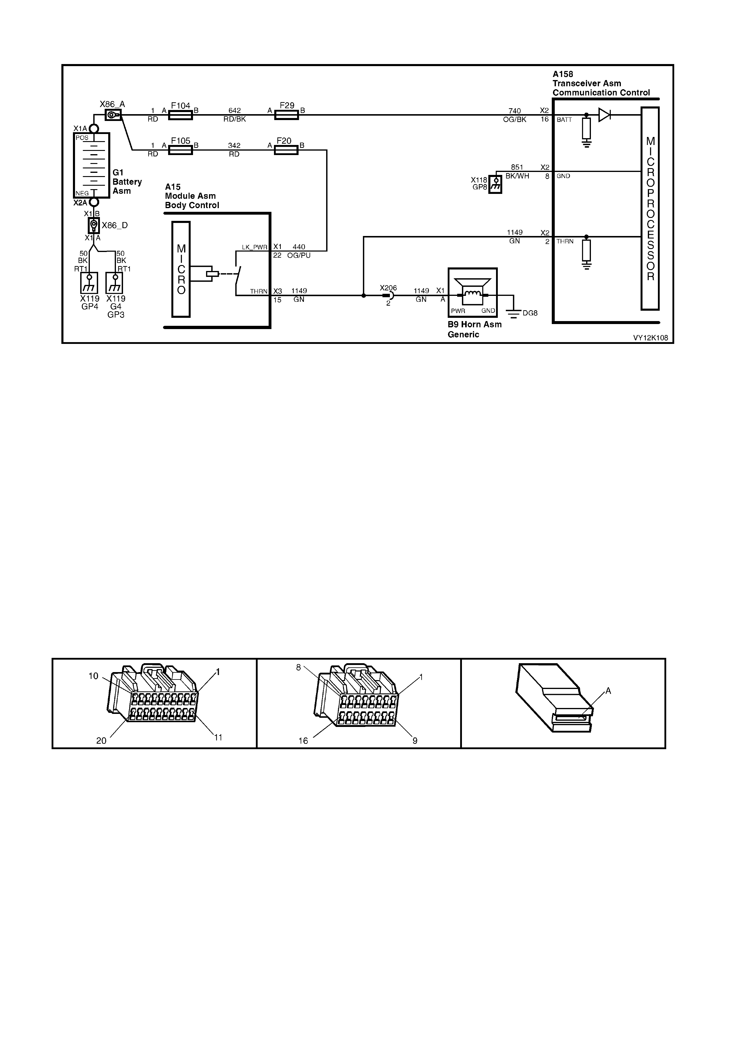
THEFT DETERRENT HORN CIRCUIT
Figure 12K-116
CIRCUIT DESCRIPTION
The telem atics module m onitors the theft deterrent ho rn circuit to determine if the alarm has been triggere d. If the
alarm has been triggered, the BCM pulses the vehicles horns at a rate of once per second. To pulse the theft
deterrent horn the BCM supplies 12 Volts to the theft deterrent horn circuit 1149 (Green wire). When the theft
deterrent horn circuit is activated, the voltage at terminal X2-2 of the telematics module is pulled high. The
telematics module determines this high voltage at terminal X2-2 as the theft deterrent system having been
triggered. If the vehicle theft deterrent system is triggered for longer than 20 seconds, the telematics module will
transm it an “Unauthorised Entr y Alert” m essage to the Holden Assist Centre. F or further information regarding the
unauthorised entry alert, refer to the Holden Assist Handbook Supplement.
TEST DESCRIPTION
Number(s) below refer to step number(s) on the diagnostic chart.
1. Confirmation that the Telematics On-Board Diagnostic System Check has been performed.
2. This test confirms that the telematics module is receiving a theft deterrent horn signal. If the alarm does not
trigger in this step refer to Sect ion 12J BCM in this Service Information.
3. The test step confirms that the telematics module is applying 12 Volts to circuit 1128.
4. The test step confirms that circuit 1128 is OK.
5. This test step confirms that the telematics module connectors A158 X1 and X2 terminal retention is OK.
Terminal retention should always be checked before any component is replaced.
A158 X1 A158 X2 B9 X1 A

THEFT DETERRENT HORN CIRCUIT
STEP ACTION VALUE YES NO
1. Has a Telematics On-Board Diagnosis System Check
been performed? Go to Step 2. Refer Telematics
On-Board
Diagnostic
System Check
chart in this
Section.
2. 1. Using TECH 2, enable the telematics module
service mode. Refer to 4.3 TECH 2 TEST MODES
F5: Program, F1: Operating Mode, in this Section.
(The telematics module should remain in service
mode until this diagnostics chart is completed).
2. Open the driver’s Window.
3. Shut all doors.
4. Enable the Theft Deterrent System by pressing the
lock button the remote key once.
5. From the Telematics Application Menu,
Select F1: Data Display / F0: Inputs and Outputs.
6. Scroll to Theft Deterrent Horn.
7. Trigger the theft deterrent system by lifting the
driver’s door lock snip and opening the driver’s
door.
8. Does TECH 2 display the Theft Deterrent Horn ON
and OFF in time with theft deterrent horn?
Disarm theft
deterrent system
by pressing the
unlock butt on on
the remote key.
Theft deterrent
horn circuit is
OK.
Check for
intermittent in
circuit 1149.
Disarm theft
deterrent system
by pressing the
unlock butt on on
the remote key.
Go to Step 3.
3. In test Step 2 did the theft deterrent horn sound when
the alarm was triggered. Go to step 4. Refer to Section
12J BCM
Diagnostics
In this Service
Information
4. 1. Using a DMM, measure continuity of circuit 1149
(Green wire) between the telematics module
connector A158 X2-2 and the BCM connector
terminal A1 5 X3-15.
Is there continuity?
Go to step 5. Repair open in
circuit 1149.
5. 1. Check telematics module connectors A158 X1 and
X2 terminal retention.
Is the terminal retention OK?
Replace
telematics
module. Refer
3.1 Telematics
Module in this
Section.
Repair connector
terminal
retention.
WHEN ALL DIAGNOSIS AND REPAIRS ARE COMPLETED, VERIFY CORRECT OPERATION
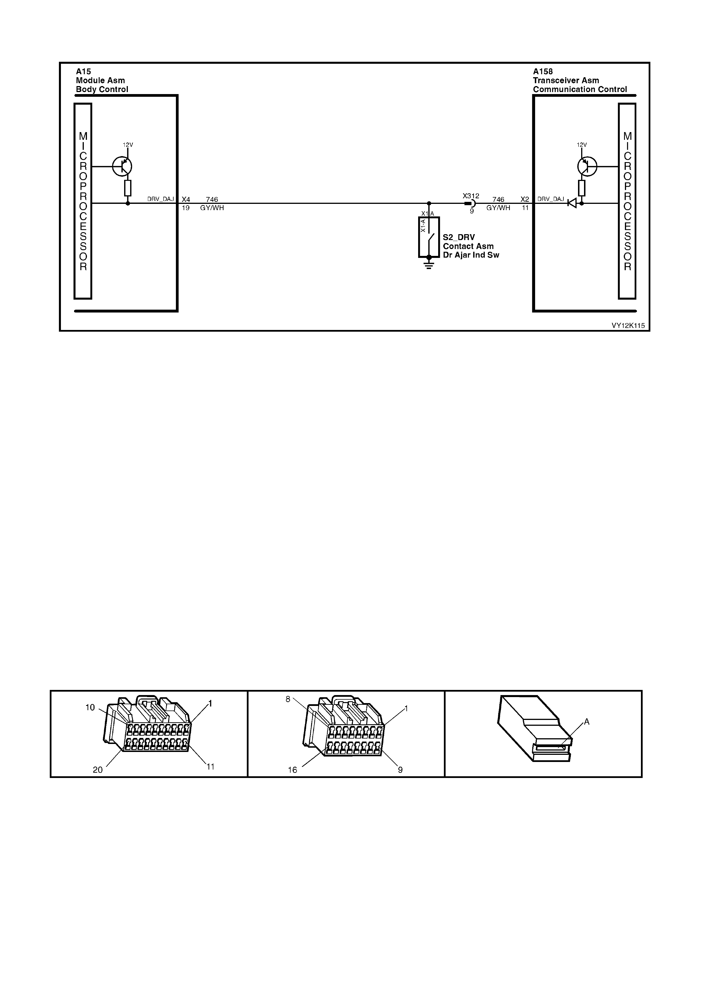
DRIVER’S DOOR AJAR SWITCH CIRCUIT
Figure 12K-117
CIRCUIT DESCRIPTION
The telematics module uses this input signal to determine if the driver's front door is opened or closed. W hen the
door is opened, the door ajar switch ground’s terminal A158 X2-11 via circuit 746 (Grey/W hite wire). This causes
the voltage at terminal X2-11 to be pulled low, less than 0.2 Volts (driver's door open). The telematics module
determines this low voltage at terminal X2-11 as the driver's door open input signal. When a driver's door open
input signal is received, the telematics module will switch from its current operating mode to active mode.
TEST DESCRIPTION
Number(s) below refer to step number(s) on the diagnostic chart.
1. Confirmation that the Telematics On-Board Diagnostic System Check has been performed.
2. This test uses TECH 2 determine that the driver’s door ajar switch is operating correctly.
3. This test uses TECH 2 to determine if the BCM is receiving the correct drivers door ajar switch information. If
the BCM is not receiving the correct information refer to the appropriate BCM diagnostics chart in
Section 12J BCM of this Service Information.
4. If TECH 2 displays “Driver’s Door Closed” when the door is open then circuit 746 may be shorted to ground.
5. If TECH 2 displays “Driver’s Door Open” when the door is closed then circuit 746 may be open or shorted to
voltage.
6. This test step checks if circuit 746 is shorted to ground.
7. This test step checks if circuit 746 is open or shorted to voltage.
8. This test step determines if the pulsed pull up in the telematics module is OK.
9. This test step confirms that the telematics module connectors A158 X1 and X2 terminal retention is OK.
Terminal retention should always be checked before any component is replaced.
A158 X1 A158 X2 S2 X1

DRIVER’S DOOR AJAR SWITCH CIRCUIT
STEP ACTION VALUE YES NO
1. Has a Telematics On-Board Diagnosis System Check
been performed? Go to Step 2. Refer Telematics
On-Board
Diagnostic
System Check
chart in this
Section.
2. 1. From the TECH 2 Telematics Application Menu,
Select F1: Data Display / F0: Inputs and Outputs.
2. Scroll to Driver’s Door.
Does TECH 2 display the “Driver’s Door “Open” when
the driver’s door is open, and “Driver’s Door Closed”
when the driver’s door is closed.
Driver’s door ajar
switch and circuit
is operating
correctly.
Go to Step 3.
3. 1. From the TECH 2 Body Control Module Application
Menu select F2: Data Display / F0: Inputs and
Outputs.
2. Scroll to Driver’s Door.
3. Does TECH 2 display the “Driver’s Door Open”
when the driver’s door is open and “Driver’s Door
Closed” when the driver’s door is closed.
Go to Step 4. Refer to Section
12J BCM
Diagnostics
in this Service
Information
4. 1. In test step 2 did TECH 2 display “Driver’s Door
Open” when the driver’s door is closed. Go to Step 6. Go to Step 5.
5. In test Step 2 did TECH 2 display “Driver’s Door Closed”
when the driver’s door is open. Go to Step 7. Go to Step 8.
6. Check for short to ground in circuit 746.
Is circuit 746 shorted to ground? Repair short to
ground in circuit
746.
Go to Step 8.
7. Check for open or short to voltage in circuit 746.
Is circuit 126 open or shorted to voltage? Repair open or
short to voltage
in circuit 746.
Go to Step 8.
8. 1. Disconnect the BCM connectors.
2. Ignition on and driver’s door closed.
3. Using a DMM measure the voltage at the telematics
module connector terminal A158 X2-11, circuit 746
(Grey/White wi re).
Is the voltage as specified?
Greater than
5.0 Volts. Check for an
intermittent open
or short to
voltage or ground
in circuit 746.
Go to Step 9.
9. 1. Check telematics module connectors A158 X1 and
X2 terminal retention.
Is the terminal retention OK?
Replace
telematics
module. Refer
3.1 Telematics
Module in this
Section.
Repair connector
terminal
retention.
WHEN ALL DIAGNOSIS AND REPAIRS ARE COMPLETED, VERIFY CORRECT OPERATION
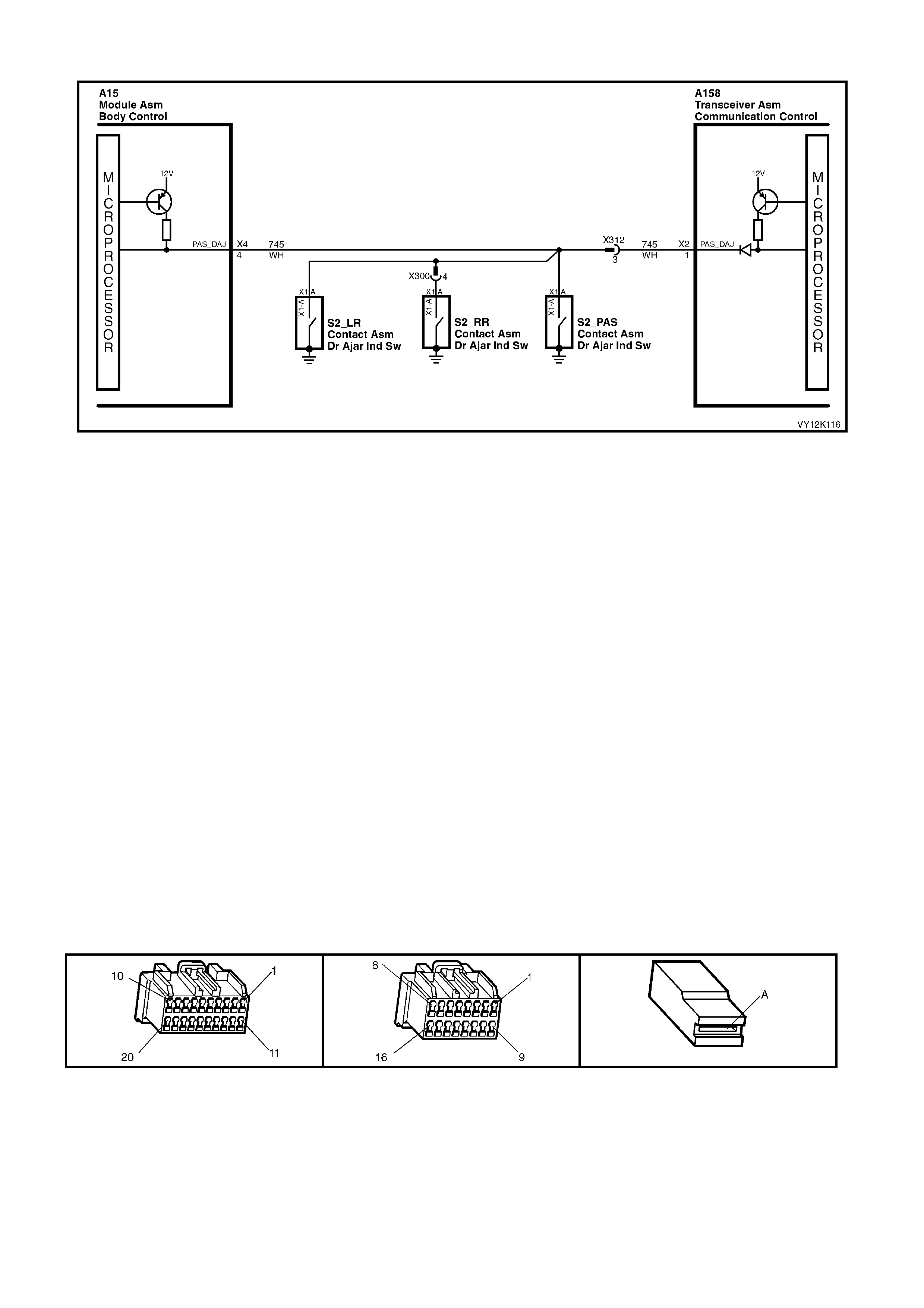
PASSENGERS DOOR AJAR SWITCHES
Figure 12K-118
CIRCUIT DESCRIPTION
The telematics module uses this input signal to determine if any of the passenger doors are opened or if all
passenger doors are closed. If the right hand rear, left hand front or left hand rear door is open, the telematics
module ter minal A158 X 2-1 is gr ounded through circuit 745 (W hite wire). T his c auses the volta ge at the tele matic s
module ter minal A1 58 X 2-1 to be p ul led l o w, les s tha n 0.2 Vo lts (if any one of the pas s enger door s is op ened) . T he
telematics module determines this low voltage at terminal A158 X2-1 as the passengers door open input signal.
W hen a passengers do or open inp ut signal is recei ved, the telem atics m odule will switch from its cur rent operating
mode to active mode.
TEST DESCRIPTION
Number(s) below refer to step number(s) on the diagnostic chart.
1. Confirmation that the Telematics On-Board Diagnostic System Check has been performed.
2. This test uses TECH 2 determine that the Passengers door ajar switch is operating correctly.
3. This test uses TECH 2 to determine if the BCM is receiving the correct drivers door ajar switch information. If
the BCM is not receiving the correct information refer to the appropriate BCM diagnostics chart in
Section 12J BCM of this Service Information..
4. If TECH 2 displays “Passengers Door Closed” when the door is open then circuit 745 may be shorted to
ground.
5. If TECH 2 displa ys “Passengers Door Open” wh en the door is c losed then circ uit 745 may be ope n or shorted
to voltage.
6. This test step checks if circuit 745 is shorted to ground.
7. This test step checks if circuit 745 is open or shorted to voltage.
8. This test step determines if the pulsed pull up in the telematics module is OK.
9. This test step confirms that the telematics module connectors A158 X1 and X2 terminal retention is OK.
Terminal retention should always be checked before any component is replaced.
A158 X1 A158 X2 S2 X1

PASSENGERS DOOR AJAR SWITCHES
STEP ACTION VALUE YES NO
1. Has a Telematics On-Board Diagnosis System Check
been performed? Go to Step 2. Refer Telematics
On-Board
Diagnostic
System Check
chart in this
Section.
2. 1. From the Telematics Application Menu,
Select F1: Data Display, F0: Inputs and Outputs.
2. Scroll to Passenger Door.
3. Does TECH 2 display the “Passenger Door Open”
when any passenger door is open?
Does TECH 2 display the “Passenger Door Clos ed”
when the all the passenger doors are closed?
Passenger door
ajar switches are
operating
correctly.
Go to Step 3.
3. 1. From the Body Application Menu select Body
Control Module then select F1: Data Display F0:
Inputs and Outputs.
2. Scroll to Passenger Door.
3. Does TECH 2 display the “Passenger Door Open”
when any passenger door is open?
Does TECH 2 display “Passenger Door Closed”
when all the passenger doors are closed?
Go to Step 4. Refer
12J BCM
Diagnosti cs in
this Service
Information.
4. In test Step 2 did TECH 2 display “Passenger Door
Open” when the passenger door is closed? Go to Step 6. Go to Step 5.
5. In test Step 2 did TECH 2 display “Passenger Door
closed” when the passenger door is open. Go to Step 7. Go to Step 8.
6. 1. Check for short to ground in circuit 745.
Is circuit 745 shorted to ground? Repair short to
ground in circuit
745.
Go to Step 8.
7. 1. Check for open or short to voltage in circuit 745.
Is circuit 745 open or shorted to voltage? Repair open or
short to voltage
in circuit 745.
Go to Step 8.
8. 1. Disconnect the BCM connectors.
2. Ignition on all doors door closed.
3. Using a DMM measure the voltage at the telematics
module connector terminal A158 X2-1, circuit 745
(White wi re).
Is the voltage as specified?
Greater than
5 Volts. Check for an
intermittent on
circuit 745.
Go to Step 9.
9. 1. Check telematics module connectors A158 X1 and
X2 terminal retention.
Is the terminal retention OK?
Replace
telematics
module. Refer
3.1 Telematics
Module in this
Section.
Repair connector
terminal
retention.
WHEN ALL DIAGNOSIS AND REPAIRS ARE COMPLETED, VERIFY CORRECT OPERATION

MICROPHONE
Figure 12K-119
CIRCUIT DESCRIPTION
The ac tive m icrophon e in t he inter ior r ear v iew m ir ror prov ides a m eans f or two way voic e c omm unication bet ween
the vehicle occ upa nts and Hold en Ass ist Centre..
TEST DESCRIPTION
Number(s) below refer to step number(s) on the diagnostic chart.
1. Confirmation that the Telematics On-Board Diagnostic System Check has been performed.
2. Confirmation that the telematics function test has been completed.
3. Checks that the telematics module is supplying five Volts to the microphone.
4. If the voltage is greater than five Volts then circuit 1155 is shorted to voltage.
5. If the voltage is less than five Volts then circuit 1155 is shorted to ground or open.
6. Checks if the telematics module is supplying eight Volts to circuit 1155.

7. This test determines if circuit 1153 has continuity.
8. Before the mirror is replaced the retention of the interior mirror connector E124 X1 terminals should be
checked.
9. Before the telematics module is replaced the retention of the telematics module connectors A158 X1 and X2
terminals should be checked.
A158 X1 A158 X2 E124 X1
MICROPHONE
STEP ACTION VALUE YES NO
1. Has a Telematics On-Board Diagnosis System Check
been performed? Go to Step 2 Refer Telematics
On-Board
Diagnostic
System Check
chart in this
Section.
2. 1. Disconnect the interior rear view mirror connector
E124 X1.
2. Ignition on.
3. Using a DMM, check the voltage at the interior rear
view mirror connector terminal E124 X1-10 circuit
1155 (Green wi re).
Is the voltage as specified?
5 Volts. Go to Step 4. Go to Step 3.
3. In Step 3 was the voltage greater than specified? 5 Volts. Repair short to
voltage in circuit
1155.
Go to Step 4.
4. In Step 3 was the voltage less than specified? 5 Volts. Go to Step 5. Go to Step 6.
5. 1. Ignition on.
2. With the interior rear view mirror connector E124 X1
still disconnected.
3. Using a DMM, check the voltage at the telematics
module connector terminal A158 X1-8 circuit 1155
(Green wire).
Is voltage as specified?
5 Volts. Repair open or
short to ground in
circuit 1155.
Go to Step 8.
6. 1. Using a DMM, measure continuity of circuit 1153
(Brown wire) between the telematics module
connector terminal A158 X1-7 the interior rear view
mirror connector terminal E124 X1-2.
Is there continuity?
Go to Step 7. Repair open
circuit 1153.
7. 1. Check interior rear view mirror connector E124 X1
terminal re tention.
Is the terminal retention OK?
Replace Rear
view Mirror.
Refer 3.5 Interior
Rear View Mirror
in this Section.
Repair connector
terminal
retention.
8. 1. Check telematics module connectors A158 X1 and
X2 terminal retention.
Is the terminal retention OK?
Replace
telematics
module. Refer
3.1 Telematics
Module in this
Section.
Repair connector
terminal
retention.
WHEN ALL DIAGNOSIS AND REPAIRS ARE COMPLETED, VERIFY CORRECT OPERATION

FUEL PUMP RELAY DRIVE CIRCUIT
Figure 12K-120 V6 Fuel Pump Circuit
Figure 12K-121 V6 S/C Fuel Pump Circuit
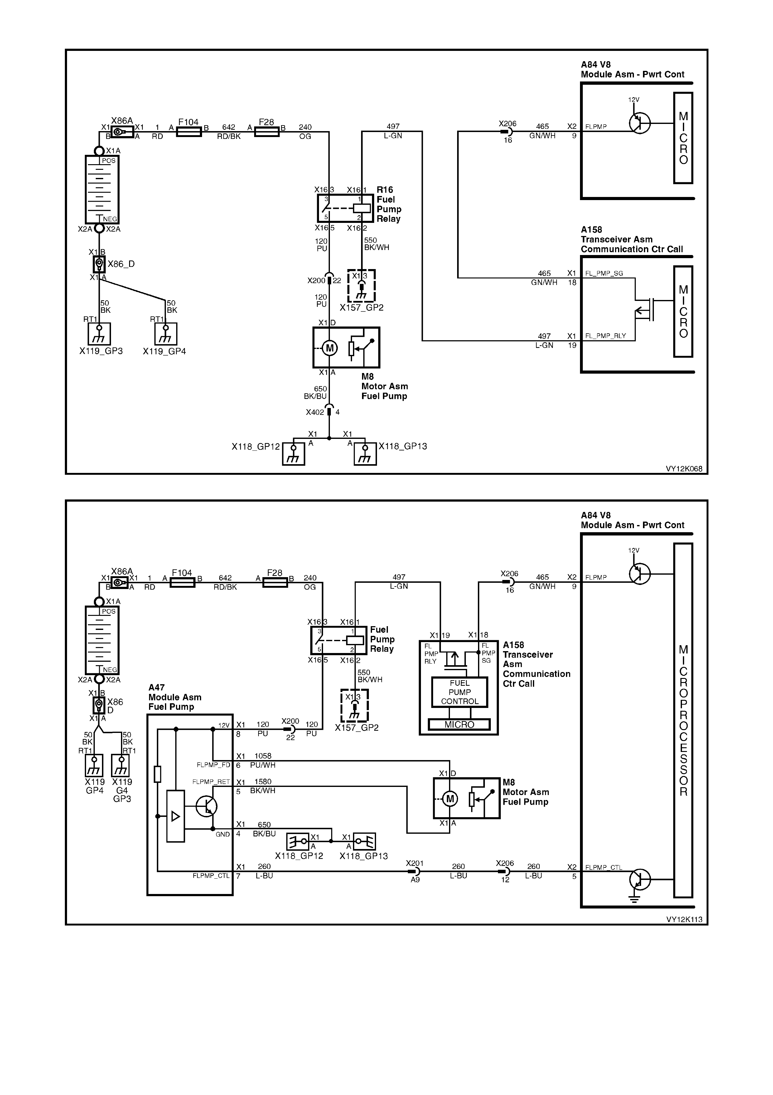
Figure 12K-122 V8 Fuel Pump Circuit
Figure 12K-123 V8 Utility Fuel Pump Circuit
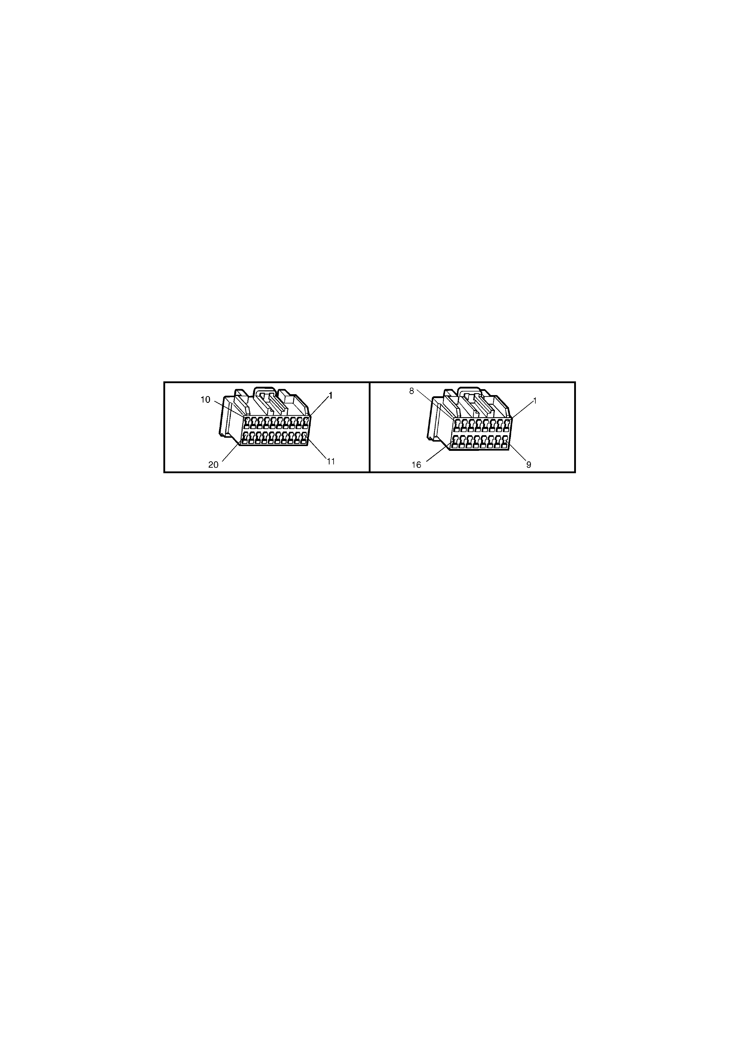
CIRCUIT DESCRIPTION
The PCM energises the fuel pump relay drive circuit via circuit 465 (Green/White wire) the telematics module
terminals X1-18 and X1-19, circuit 497 (Light/Green wire). The fuel pump relay drive circuit is grounded through
circuit 550 ( Black/W hite wire) at ground location X157_GP2. The telem atics module can imm obilise the vehicle by
opening the fuel pump relay drive circuit, causing the fuel pump to stop operating. This function can only be
activated by the National Emergency Response Centre (NERC™) under instruction from the Police.
TEST DESCRIPTION
Number(s) below refer to step number(s) on the diagnostic chart.
1. Confirmation that the Telematics On-Board Diagnostic System Check has been performed.
2. This step confirms that the fuel pump relay drive circuit within the telematics module is active.
3. This step confirms that battery voltage is being applied to the telematics module fuel pump relay drive
circuit from the PCM. If the PCM is not applying voltage to this circuit you should refer to the
On-Board Diagnostic System Check in Section 6C1 V6 Engine, Section 6C2 V6 Supercharged Engine or
Section 6C3 V8 GEN III Engine in this Ser vic e Inf ormation.
4. This step conf irms that th e fuel pum p rela y drive cir cuit in the telem atics module i s OK and a pplying voltage to
circuit 497. If the telematics module is applying voltage to this circuit then you should refer to the On-Board
Diagnostic System Check in Section 6C1 V6 Engine, Section 6C2 V6 Supercharged Engine and
Section 6C3 V8 G EN III E ngine. If the telematic s m odul e is not applying vo lta ge to c irc u it 4 97 the n you sho uld
replace the telematics module, refer step 5 in this diagnostic chart.
5. Before the telematics module is replaced the retention of the telematics module connectors A158 X1 and X2
terminals should be checked.
A158 X1 A158 X2

FUEL PUMP RELAY DRIVE CIRCUIT
STEP ACTION VALUE YES NO
1. Has a Telematics On-Board Diagnosis System Check
been performed? Go to Step 2. Refer Telematics
On-Board
Diagnostic
System Check
chart in this
Section.
2. 1. From the TECH 2 Telematics Application Menu,
Select F1: Data Display/F0: Inputs and Outputs.
2. Scroll to Fuel Pump Relay Drive Circuit.
Does TECH 2 display Fuel Pump Relay Drive Circuit
“Active”?
Go to Step 3. Go to Step 5.
3. 1. Using a DMM, check the voltage at the telematics
module connector terminal A158 X1-19 circuit 465
(Dark Green/White wire).
2. Ignition off for at lease 20 seconds.
Is the voltage as specified for at least two seconds when
the ignition is turned from off to on?
B+ Go to step 4. Refer to PCM
On-Board
Diagnostic
System Check
6C1 V6 Engine,
6C2 V6
Supercharged
Engine
OR
6C3 V8 GEN III
Engine in this
Service
Information.
4. 1. Using a DMM, check the voltage at the telematics
module connector terminal A158 X1-18 circuit 497
(Light Green wire).
2. Ignition off for at least 20 seconds.
Is the voltage as specified for at least two seconds when
the ignition is turned from off to on?
B+ Refer to PCM
On-Board
Diagnostic
System Check
6C1 V6 Engine,
6C2 V6
Supercharged
Engine
OR
6C3 V8 GEN III
Engine in this
Service
Information..
Go to Step 5.
5. 1. Check telematics module connectors A158 X1 and
X2 terminal retention.
Is the terminal retention OK?
Replace
telematics
module. Refer
3.1 Telematics
Module in this
Section.
Repair connector
terminal
retention.
WHEN ALL DIAGNOSIS AND REPAIRS ARE COMPLETED, CLEAR DTCS AND VERIFY CORRECT OPERATION

AUDIO MUTE CIRCUIT
Figure 12K-124
CIRCUIT DESCRIPTION
Whenever the telematics speaker is activated the audio system (radio) mute signal is also activated and the
telematics module grounds the audio s ystem m ute circuit 656 (Yellow/Black wire) causing the circuit voltag e to be
pulled low, less than 0.2 Volts. This low voltage is detected by the audio system as a radio mute request. When
received, the radio will mute.
TEST DESCRIPTION
Number(s) below refer to step number(s) on the diagnostic chart.
1. Confirmation that the Telematics On-Board Diagnostic System Check has been performed.
2. The audio system should only display “Audio Source / External Source” when the telematics module is
telepho ne sign al li ne is active.

3. This test step determines if the telematics module can command the radio to mute when the mobile phone
connector mute signal line is grounded.
4. This test determines if the telematics module is able to switch the audio system mute active circuit on and off.
5. If the radio mutes when commanded the radio mute is working correctly.
6. This test step confirms that the radio is applying five Volts to circuit 5211.
7. If the radio mutes when circuit 656 is grounded then circuit 656 and the audio system are OK.
8. This test step checks for an open in circuit 656.
9. This test step checks for an open or short in circuit 693.
10. Before the telematics module is replaced the retention of the telematics module connectors A158 X1 and X2
terminals should be checked.
A158 X1 A158 X2
AUDIO MUTE CIRCUIT
STEP ACTION VALUE YES NO
1. 1. Has a Telematics On-Board Diagnosis System
Check been performed? Go to Step 2. Refer Telematics
On-Board
Diagnostic
System Check
chart in this
Section.
2. 1. Turn the audio system (radio) on.
2. From the TECH 2 Audio System Application Menu,
Select F1: Data Display / F0 Inputs and Outputs.
3. Scroll to Audio Source.
Does TECH 2 display the “Audio Source / External
Source”?
Go to Step 8. Go to Step 3.
3. 1. Turn the audio system (radio) on.
2. Using a fused jumper wire, jumper the mobile phone
connector mute signal input circuit 693 terminal
A158 X1-4 to ground.
3. Scroll to Audio Source.
Does TECH 2 display the “Audio Source / External
Source”?
Go to Step 5. Go to Step 4.
4. 1. Turn the audio system (radio) on.
2. From the Telematics Application Menu,
Select F3: Miscellaneous Test, F4: Audio System
Mute.
Does TECH 2 display “Audio System Mute Active” and
“Audio System Mute Inactive” when commanded?
Go to step 5. Go to Step 9.
5. In test step 3 did the audio system mute when the TECH
2 displayed “Audio System Mute Active? Audio System
Mute OK. Go to Step 6.
6. 1. Turn the audio system (radio) on.
2. Disconnect the telematics module connectors X158
X1 and X2.
3. Using a DMM, check the voltage at the telematics
module connector terminal X158 X2-6 circuit 5211
(Yellow/Black wire).
Is the voltage as specified?
5 Volts Go to Step 7. Go to Step 8.

STEP ACTION VALUE YES NO
7. 1. Turn the audio system (radio) on.
2. Using a fused jumper wire, jumper circuit 656
(Yellow/Black) to ground.
Did the audio system (radio) mute?
Go to Step 8. Replace Audio
System AHU.
Refer to Section
12D
Entertainment
System in this
Service
Information.
8. 1. Disconnect the telematics module connectors X158
X1 and X2.
2. Turn the audio system (radio) on.
3. From the TECH 2 Audio System Application Menu,
Select F1: Data Display / F0 Inputs and Outputs.
4. Scroll to Audio Source.
Does TECH 2 display the “Audio Source / External
Source”?
Repair short to
ground in circuit
5211.
Go to Step 9.
9. 1. Using a DMM check for open or short to ground in
circuit 693 (Yellow wire).
Is circuit 693 (Yellow wire) open or shorted to ground?
Repair open or
short to Ground
in circuit 693.
Go to Step 10.
10. 1. Check telematics module connectors A158 X1 and
X2 terminal retention.
Is the terminal retention OK?
Replace
telematics
module. Refer
3.1 Telematics
Module in this
Section.
Repair connector
terminal
retention.
WHEN ALL DIAGNOSIS AND REPAIRS ARE COMPLETED, VERIFY CORRECT OPERATION
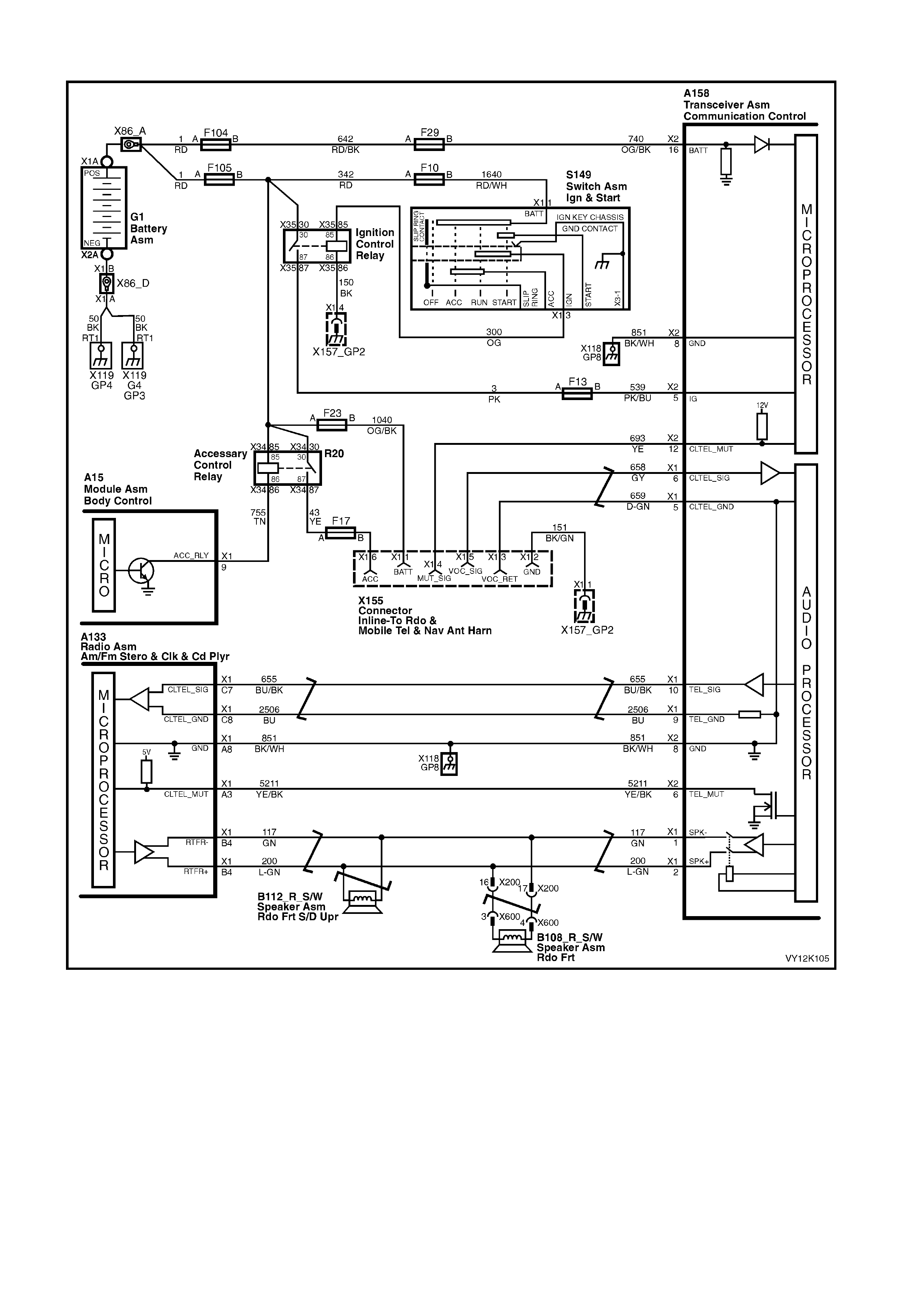
AUDIO SYSTEM INTERFACE
Figure 12K-125
CIRCUIT DESCRIPTION
The telematics system us es the veh icl e au di o system to provide a means f or vo ic e co m munication f r om the Holden
Assist call centre. The telematics module also has the ability to detect if the audio system is not operational, and
will switch from the vehicle audio system to the RHF speakers, if it detects that the audio system is not operational.
Whenever the telematics audio is activated the radio mute signal is also activated and the telematics module
grounds the radio mute circuit 5211 (Yellow/Black wire) causing the circuit voltage to be pulled low, less than two
Volts. This low voltage is detected by the radio as a mute request and when received, the audio system will mute.
W hilst the telematic s system is not on a call t he audio and m ute request f rom the cellu lar telephone c onnector will
be passed through the t elematics module to the audio system. When a Holden Assist call is active, the telematics
module will ignore the phone audio and transmit the telematics audio to the audio system.
Audible tones are also provided to indicate the system status and are broadcast via the speaker to alert the
customer to certain operating conditions.

TEST DESCRIPTION
Number(s) below refer to step number(s) on the diagnostic chart.
1. Confirmation that the Telematics On-Board Diagnostic System Check has been performed.
2. The test step determines if the telematics module or mobile phone circuit is causing the audio system to mute.
3. This test step determines audio system (radio) mutes when the mobile phone connector mute signal line is
grounded.
4. This test step uses the TECH 2 audio output m isc ellaneous test to d eterm ine if the audio i nterface is operating
correctly.
5. To confirm correct operation of the audio interface, you will need to connect a mobile phone hands free kit to
the mobile phone connector.
6. This test step checks for a short to voltage or short to ground in circuits 655 and 2506.
7. The service mode should be enabled, so that the telematics module does not send out a Unauthorised Entry
Alert (UEA) when the telematics module is disconnected.
Disconnecting the telematics module determines if the short to voltage or ground in circuits 655 and 2506 is
being caused by the telematics module.
8. Removing the audio system (radio) Audio Head Unit (AHU) determines if the short to voltage or ground in
circuits 655 and 2506 is being caused by the audio system AHU.
9. This test step checks for an open in circuits 655 and 2506.
10. This test step checks for a short to voltage or short to ground in circuits 658 and 659.
11. T his test step determines if the t elematics module is causin g the short to voltage or short to gro und in circuits
658 and 659.
12. This test step checks for an open in circuits 658 and 659.
13. Before the telematics module is replaced the retention of the telematics module connectors A158 X1 and X2
terminals should be checked.
AUDIO SYSTEM INTERFACE
STEP ACTION VALUE YES NO
1. Has a Telematics On-Board Diagnosis System Check
been performed ? Go to Step 2. Refer Telematics
On-Board
Diagnostic
System Check
chart in this
Section.
2. 1. Switch the audio system (radio) on and set the
volume and tune the radio so that the audio can be
clearly heard.
Is the audio output OK? Not muted.
Go to Step 3. Refer
Audio Mute
Circuit chart
in this Section.
3. 1. Ensure the audio system (radio) is still on and set
the volume and tune the radio so that the audio can
be clearly heard.
2. Using a fused jumper wire, jumper the mobile phone
connector X155 terminal X1-4 to ground.
Does the audio system (radio) mute?
Go to Step 4. Refer
Audio Mute
Circuit chart
in this Section.
4. 1. Remove the fused jumper wire from the mobile
phone connector X155.
2. Ensure the audio system (radi o) is still on.
3. From the TECH 2 Telematics System Application
Menu, Select F3: Miscellaneous Tests / F8 Audio
Output. Refer 4.3 TECH 2 TEST MODES F3:
Miscellaneous Tests F8: Audio Output in this
Section.
Was the Audio Output Test successful?
Go to Step 5. Go to Step 6.
5. 1. Connect a mobile phone hands free kit to the mobile
phone connector.
2. With the mobile phone installed into the hands free
kit, make a call.
Does the audio system (radio) mute and allow a call to
conducted, i.e. can the caller communicate through the
audio system.
System OK.
Go to Step 6.

STEP ACTION VALUE YES NO
6. 1. Using a DMM check for a short to ground or voltage
on circuits 655 (Blue/Black wire) or 2506 (Blue
wire).
Is either circuit shorted to ground or voltage.
Go to Step 7. Go to Step 9.
7. 1. Using TECH 2, enable the telematics module
service mode. Refer to 4.3 TECH 2 TEST MODES
F5: Program, F1: Operating Mode, in this Section.
(The telematics module should remain in service
mode until this diagnostics chart is completed).
2. Ignition off, disconnect the telematics module
connectors A158 X1 and X2.
3. Ignition on engine off.
4. Using a DMM check for a short to ground or voltage
on circuits 655 (Blue/Black wire) or 2506 (Blue
wire).
Is either circuit shorted to ground or voltage.
Go to Step 8. Go to Step 13.
8. 1. With the telematics module connectors A158 X1
and X2 still disconnected.
2. Remove the audio system (radio) Audio Head Unit
(AHU).
3. Using a DMM check for a short to ground or voltage
on circuits 655 (Blue/Black wire) or 2506 (Blue
wire).
Is either circuit still sh orted to ground or voltage.
Repair cause of
short to voltage
or ground.
Replace Audio
System AHU.
Refer
Section 12D
Entertainment
System in this
Service
Information
9. 1. Using a DMM measure continuity of circuits 655
(Blue/Black wire) or 2506 (Blue wire).
Is there continuity.
Go to Step 10. Repair open
circuit.
10. 1. Using a DMM check for a short to ground or voltage
on circuits 658 (Grey wire) or 659 (Dark Green
wire).
Is either circuit shorted to ground or voltage.
Repair cause of
short to voltage
or ground.
Go to Step 11.
11. 1. Reconnect the telematics module connectors A158
X1 and X2.
2. Using a DMM check for a short to ground or voltage
on circuits 658 (Grey wire) or 659 (Dark Green
wire).
Is either circuit shorted to ground or voltage.
Go to Step 13. Go to Step 12.
12. 1. Using a DMM measure continuity of circuits 658
(Grey wire) or 659 (Dark Green wire).
Is there continuity.
Go to Step 13. Repair open
circuit.
13. 1. Check telematics module connectors A158 X1 and
X2 terminal retention.
Is the terminal retention OK?
Replace
telematics
module.
Refer 3.1
Telematics
Module in this
Section.
Repair connector
terminal
retention.
WHEN ALL DIAGNOSIS AND REPAIRS ARE COMPLETED, CLEAR DTCS AND VERIFY CORRECT OPERATION
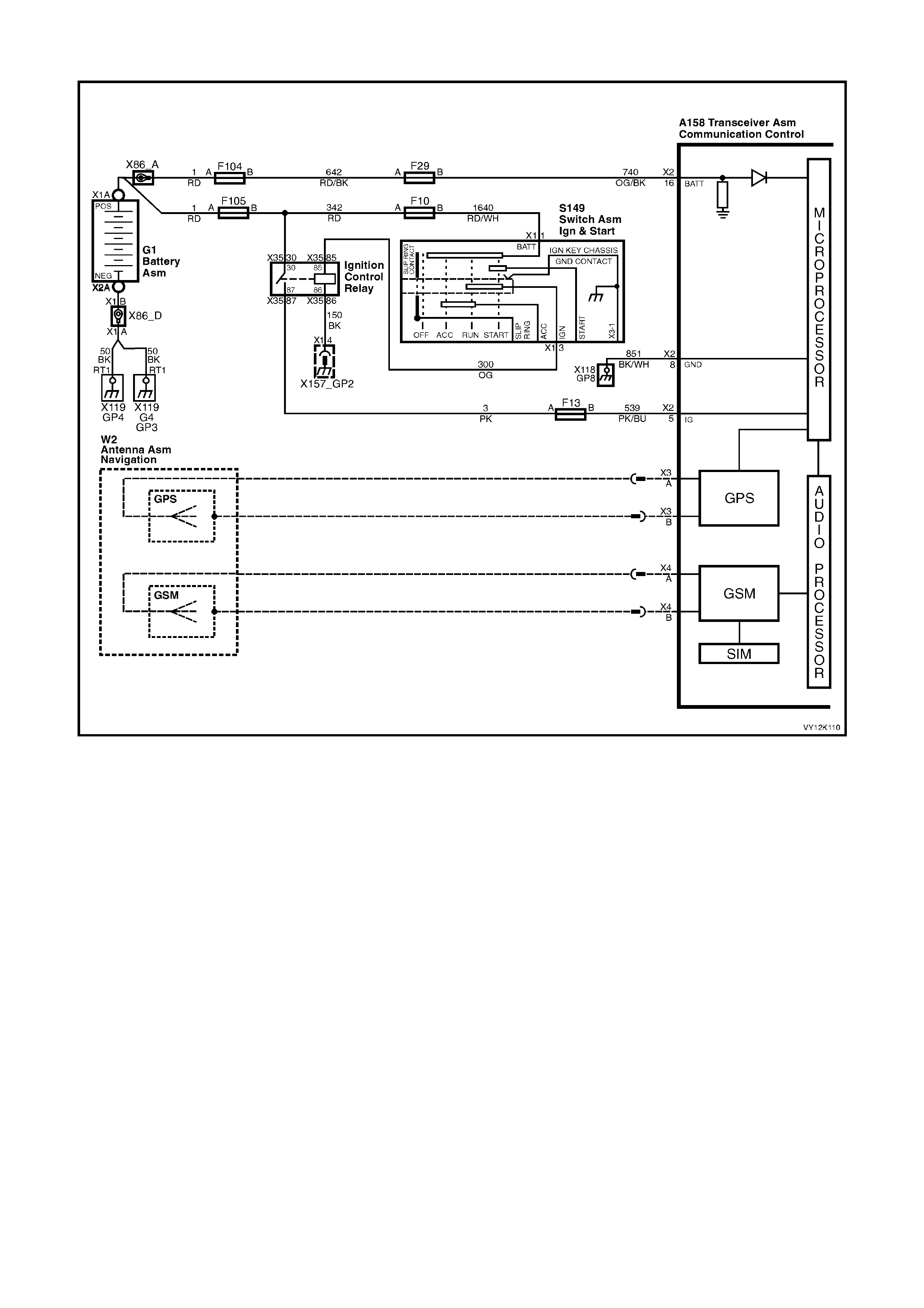
UNABLE TO MAKE OR RECEIVE A CALL
Figure 12K-126
CIRCUIT DESCRIPTION
The link between the vehicle and the Holden Assist Centre or NERCTM uses G PS for veh icle locatio n and track ing
and the Australian digital mobile phone network to transmit and receive voice and SMS (Short Message Service)
data. If the vehicle is outside network coverage, the link to and from the vehicle will not be available and no
services can be provided. Signal strength may be affected in locations like basement car parks or tunnels.
However, in most cases, as the vehicle emerges from the obstruction or re-enters the digital phone network area
the signal will be available again.
TEST DESCRIPTION
Number(s) below refer to step number(s) on the diagnostic chart.
1. Confirmation that the Telematics On-Board Diagnostic System Check has been performed.
2. For the telematics system to operate correctly the Vehicle Identification Number (VIN) displayed by TECH 2
must match the actual VIN.
3. For the telematics module to make or receive any calls the GSM must be active.
4. During this test step the telematics module must be reprogrammed with the correct code index. By
reprogram m ing the m odule this will ens ure that the c orrec t phone num ber s are reprogram m ed into the m odule .
Refer Code Index Programming in this Section.
5. Five beeps when attempting a make call is an indication of no GSM signal. You should refer to the
No GSM Signal Diagnostic Chart in this Section.
6. If the telematics m odule mak es a call but is contin ually connect ed to a recorded m essage, this m eans that the
module can make a call, but the number being called is not allowed. The module was reprogrammed during
test step 4, which should have reprogrammed the module with the correct phone numbers, therefore the
module should be replaced.
7. Before the telematics module is replaced the retention of the telematics module connectors A158 X1 and X2
should be checked.

CODE INDEX
Model Code Index
Executive, Acclaim, S & SS 001
Berlina & Calais 002
A158 X1 A158 X2
UNABLE TO MAKE OR RECEIVE A CALL
STEP ACTION VALUE YES NO
1. Has a Telematics On-Board Diagnosis System Check
been performed? Go to Step 2. Refer Telematics
On-Board
Diagnostic
System Check
chart in this
Section.
2. 1. From the TECH 2 Body Application Menu select
Telematics Module and follow screen instructions.
At the Telematics Module System Identification screen
does the VIN displayed match the actual vehicle VIN?
Go to Step 3. Go to Step 7.
3. 1. From the Telematics Application Menu,
Select F1: Data Display / F2: GSM Data.
2. Scroll to GSM Module.
Does TECH 2 display the “GSM Module Active”?
Go to Step 4. Go to Step 7.
4. 1. From the TECH 2 Telematics Module Application
Menu select F5: Program / F1: Program Code
Index.
2. Reprogram the code index to the correct number.
(Refer 4.3 TECH 2 TEST MODES,
F4: Program/F1: Program Code Index in this
Section).
Has problem been rectified?
Complete
Telemat i cs
On-Board
Diagnostic
System Check
in this section.
Go to Step 5.
5. Did you hear five beeps when a keypad button is
pressed?
or
Is the red status LED on all the time when the ignition is
on?
Refer
No GSM Signal
Diagnostic Chart
in this Section.
Go to Step 6.
6. When making a call does the telematics module connect
to the network but only to recorded message saying that
the number is not available from this service?
Go to step 7. Complete
Telemat i cs
On-Board
Diagnostic
System Check
in this Section
7. 1. Check telematics module connectors A158 X1 and
X2 terminal retention.
Is the terminal retention OK?
Replace
telematics
module.
Refer 3.1
Telematics
Module in this
Section.
Repair connector
terminal
retention.
WHEN ALL DIAGNOSIS AND REPAIRS ARE COMPLETED, CLEAR DTCS AND VERIFY CORRECT OPERATION

HOLDEN ASSIST TELEM ATICS SYST EM TEST
This Holden Assist Telematics System Test should only be carried out as the final steps in the Telematics On-
Board Dia gnos t ic S ystem Check. All oth er s teps in th e O n-Boar d D iag nostic S ystem Check m ust be c om pleted an d
have been successful before performing this Holden Assist Telematics System Test.
1. Ignition on.
2. Fr om the T ECH 2 Telematics Applic at ion Menu, S elect F1: D a ta Disp lay / F1: Glo bal Position ing System , s c roll
to GPS 2D or 3D Fix and note the current Time of Last Known GPS Fix.
3. Select F1: Data Display / F2: GSM, scroll to GSM Signal strength and note the current GSM signal strength.
4. Position the vehicle where the Time of Last Known GPS Fix display is updating and the GSM Signal Strength is
greater than –90 dbm . You m a y need to s witc h bet ween t he dat a list us ing t he N ext Lis t an d Pr evio us Lis t S oft
Keys.
5. Program the telematics module into Active Mode (refer F5: Program / Operating Mode in this Section).
Disconnect the TECH 2 from the vehicle.
6. Press the Holden Assist Button.
7. When the call is answered, identify yourself and your retail outlet and request a Holden Assist Telematics
System Test.
(ie "Hello, this is Robert Smith from Jonestown Holden, could you please carry out a Holden Telematics
System Test").
9. The Holden Assist operator will then carry out a Holden Telematics System Test. During the test the operator
will inform you that you pressed the Holden Assist button and they have received a vehicle location.
9. Depending on the current Holden Assist telematics system status the operator will be able to either remotely
unlock the doors or enable the telematics module service mode. The operator will inform which function they
are going to perform. If they are going to perform a Remote unlock go to step 8A, if the are going to enable
service mode go to step 8B.
9A. Lower the driver’s window.
Shut and lock all doors.
The operator wil l then s end a r emote u nloc k reques t, t he d oors s ho ul d t hen un lock within 30 s ec onds ( this ti me
to unlock will vary depending on SMS traffic).
O n receiving a ver ification mess age that the doors ha ve unlock ed, the o perator will inf orm you that the s ystem
has passed the Holden Assist Telematics Test.
Thank the Holden Assist operator.
Press the End Call / Information button to end the call.
9B. The operator will send a remote request to enable service mode.
On rec eiving a ver ification m essage that the s ervice m ode has been e nabled, the o perator will inform yo u that
that the system has passed the Holden Assist Telematics Test.
Thank the Holden Assist operator.
Press the End Call / Information button to end the call.
From the Telematics Application Menu, Select F1: Data Display / F0: Inputs and Outputs, Scroll to Operating
mode. The operating mode should display Service.
Program the telematics module into Active Mode (refer F5: Program / F1:Operating Mode in this Section).
10. Press the Emergency Button.
11. When the call is answered, identify yourself and your retail outlet and request a Holden Telematics System
Test.
(ie "Hello, this is Robert Smith from Jonestown Holden, could you please carry out a Holden Telematics
System Test").
12. The NERCTM will then carr y out a Holden T elematics System T est. During the test the op erator will inform you
that you pressed the emergency button and they have received a vehicle location. The operator will then end
the call.
13. If all the above steps have been completed successfully the system has passed the Holden Telematics System
Test.

6. TORQUE WRENCH SPECIFI CATIONS
Nm
Telematics module assembly retaining screws............................... 1 – 3
Telematics backup battery cover retaining screws......................... 1 – 3
Interior rear view mirror retaining screw ......................................... 2.5 – 4.5