
SECTION 12L - NAVIGATION SYSTEM
IMPORTANT
Before performing any Service Operation or other procedure described in this Section, refer to Section 00
CAUTIONS AND NOTES for correct workshop practices with regard to safety and/or property damage.
CONTENTS
1. GENERAL DESCRIPTION
VEHICLE SPEED & DIRECTION
GLOBAL POSITI ONING SYSTEM
DIGITAL ROAD MAP
1.1 GENERAL OPERATION
1.2 COMPONENT LAYOUT
2. OPERATING INSTRUCTIONS
3. SERVICE OPERATIONS
3.1 PROCESSOR ASSEMBLY
PROCESSOR
MOUNTING BRACKETS
3.2 REMOTE CONTROL ASSEMBLY
REMOTE CONTROL CRADLE
WITH PRESENTER
PRESENTER MOUNTING WEDGE
3.3 DISPLAY ASSEMBLY
REMOVE
DISASSEMBLE
REASSEMBLE
REINSTALL
3.4 NAVIGATION SPEAKER ASSEMBLY
REMOVE
DISASSEMBLE
REASSEMBLE
REINSTALL
3.5 NAVIGATION WIRING HARNESS
REMOVE
REINSTALL
3.6 COCKPIT NAVIGATION WIRING
HARNESS
REMOVE
REINSTALL
3.7 GPS ANTENNA ASSEMBLY
REMOVE
REINSTALL
3.8 FITTING A NEW FLOOR CONSOLE
COVER ASSEMBLY
3.9 FITTING A NEW FLOOR CONSOLE
ASSEMBLY
3.10 NAVIGATION SYSTEM CALIBRATION
4. SYSTEM DIAGNOSIS
PREREQUISITES
4.1 WIRING DIAGRAM
4.2 CONNECTOR CHART
4.3 NAVIGATION SYSTEM DOES
NOT START
CONDITION ONE
CONDITION TWO
CONDITION THREE
4.4 NO RESPONSE FROM REMOTE
CONTROL
NO RESPONSE FROM REMOTE
CONTROL
CONDITION ONE
CONDITION TWO
4.5 CD–ROM ERROR
CONDITION ONE
CONDITION TWO
CONDITION THREE
4.6 AUDIO PROBLEMS
4.7 GUIDANCE PROBLEMS
CONDITION ONE
CONDITION TWO
CONDITION THREE
CONDITION FOUR
4.8 DISPLAY QUALITY
4.9 DISPLAY DIMMING INOPERATIVE
4.10 VEHICLE DIRECTION INCORRECT
5. PROCESSOR DIAGNOSTICS
5.1 ACCESSING DIAGNOSTIC MENU
5.2 READ I/O STATE
5.3 SET I/O STATE
5.4 READ GPS DATA
5.5 READ ERROR MEMORY
6. TORQUE WRENCH SPECIFICATIONS
7. SPECIAL TOOLS

1. GENERAL DESCRIPTION
The Occupant Information Navigation System (navigation system) fitted to the MY 2003 VY Series Sedan and V2
Series II Coupe vehicles is adapted from the Siemens VDO Dayton MS 5000 Navigation System. The MS 5000 has
been modified to Holden specifications for easy vehicle installation. The navigation system is a production option
and is fitted by Holden B y Design (HBD).
The navigation system uses three principal technologies:
• The navigation processor uses the vehicle speed signal (VSS) and an internal gyroscope.
• Global Pos it io nin g S ystem (GPS).
• Digital road mapping.
The navigation system consists of the following components:
• Proce ssor assembly (1)
• Display assembly (2) and escutcheon (3)
• GPS antenna assembly (4)
• Remote control assembly (5) with presenter (6)
• Speaker assembly (7)
• Wiring harness and cockpit wiring harness (8)
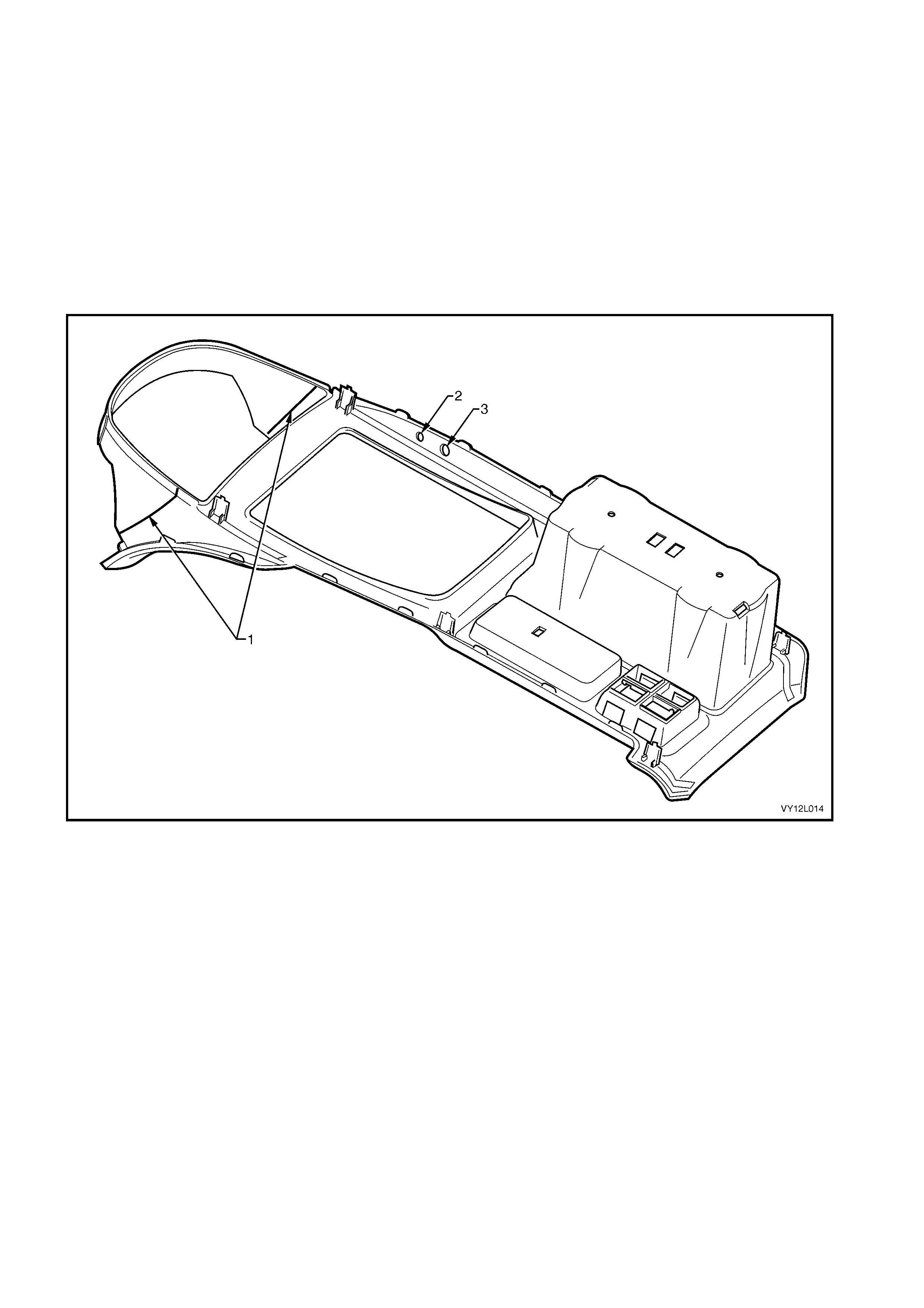
The following modifications are made to the floor console cover assembly to accommodate the navigation system:
• Holes are drilled in the floor console cover assembly so that the navigation remote control assembly and
presenter can be fitted.
• The f loor c ons ol e c o ver as s em bl y is c ut to s p ec if ic atio n to al lo w f or the ins t al lat io n of the nav igat io n d is pl ay
assem bly.
NOTE: Although there are obvious interior trim and body shape differences between the Sedan and Coupe, the
navigation system remains the same for both except for the harness lengths and harness clips.
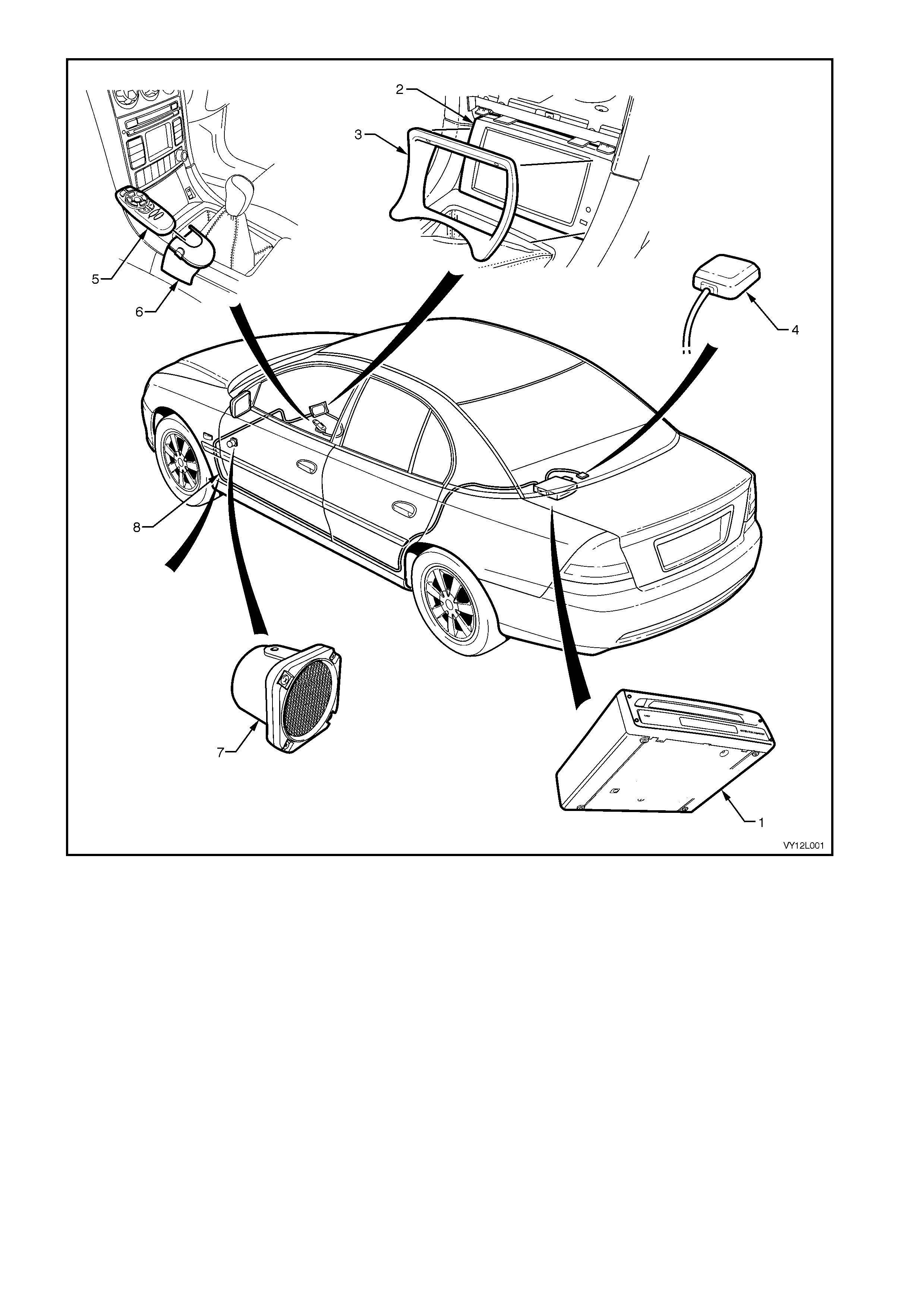
Figure 12L–1
Legend
1. Processor Assembly
2. Display Assembly
3. Escutcheon
4. GPS Antenna
5. Remote Control Assembly
6. Remote Control Cradle and Presenter
7. Speaker Assembly
8. Wiring Harness and Cockpit Wiring Harness

VEHICLE SPEED AND DIRECT ION
The veh icle spe ed sensor and the gyroscope work together to provide direct ion and s peed. I n conjunc tion with the
position signal received from the GPS, the vehicle speed sensor and gyroscope provide the processor with the
necessary information to produce vehicle navigation to the user.
GLOBAL POSITIONING SYSTEM
The GPS is a series of 27 satellites (nominally 24) which orbit the earth at an altitude of 20 372 km. The signals
from f our satellites m ust be r eceived b y a GPS rece iver to get an ac curate thr ee-dim ensional pos ition. If only three
satellit e signals are re ceived a posit ion is attaine d, but with reduced ac curacy. The pos ition calc ulated by the GPS
receiver is acc ur ate to bet w een 30 a nd 1 00 metr es. GPS r ec ept io n ma y be interrupte d, es pec i al ly due to t he natur e
of the navigation system, in the following instances:
• between tall buildings
• in car parks, tunnels or under bridges
• in forests or avenues
• during storms
• in valleys and mountains
• If the GPS antenna assembly and the position of the satellites are not favourable due to the satellite’s orbit
DIGITAL ROAD MAP
The digital road map is supplied b y Siemens VDO Da yton. The map is contained on a Com pact Disc (CD–ROM),
which is read b y the proces sor assem bly. This CD mus t be inserted into the pr ocessor as sembly for the s ystem to
work. Update versions of the map are available from Holden Spare Parts Organisation (HSPO).

1.1 GENERAL OPERATION
NOTE: For inf ormation on t he navigat ion s yst em operatio n, refer to the Satellite Navigatio n Handbook Supplem ent
supplied with the navigation system.
The navigation system works in the following manner:
• Initially, with power supplied, the navigation display activates and the receiver acquires a GPS signal. This
provides a position accurate to within 30 to 100 metres. This position is translated onto the digital road map
and shown o n the n aviga tion dis pla y in the f orm of an ar row. Initi ally, the vehic le m ay not be s ho wn in its exac t
position, as the navigation system may not be calibrated.
• The user can now enter a destination using the navigation system menus. The remote control, which can be
used whil e i n its cr ad le or p oint ed a t th e dis p lay, is use d to n a vig ate t hr oug h th e n av igat io n system m enus . The
map screen highlights the route to be taken.
• The navigation system begins calibration automatically when the vehicle moves. The VSS provides electrical
pulses which are converted into distance signals; the gyroscope detects and measures any change in direction.
The GPS signal continues to be received and is used as a reference by the navigation system.
• After the na vigation s ystem is calibrat ed, the arro w will be dis pla yed on the map i n the correct position and t he
correct direction. To get to this stage, one or two changes of direction of the vehicle may be necessary. The
navigation system supplies audio commands to the user during this time for any direction changes required.
Audio commands are supplied through the speaker assembly, mounted under the instrument panel assembly
on the instrument panel lower bracket.
• If the driver does not take a recommended turning point, the navigation system calculates an alternate route
and supply audio command for that route.
Further:
• Calibration takes longer if the vehicle is driven along a straight road for some distance.
• The vehic le’s posit ion is sto red by the proces sor after the v ehic le’s ign ition is turn ed off . T he navigati on s ystem
requires 30 seconds to shut down properly.
• If the veh icle ’s posit ion h as been s tored previ ousl y, the na vigat ion s ystem operat es with out G PS rec eptio n and
still be accurate.
• The vehicle’s position remains in memory after the battery has been disconnected, but only if the navigation
system has been allowed 30 seconds to shut down properly before disconnection.

1.2 COMPONENT LAYOUT
The navigation s ystem is provided by Siem ens VDO Dayton to Holden specif ications. This is a brief description of
the layout and functions of equipment, refer to Fi gure 12L –2.
The processor assembly (1) is mounted in the rear compartment below the rear window panel assembly. The
processor assembly contains a CD–ROM and other components required for the navigation system to operate.
The G PS antenna assem bly (2) is mounted on top of the rear window pan el asse mbly with doub le-sid ed tape. T he
harness is routed through the panel and connects to the processor assembly with connector A139 – X4 (3).
The navigation wiring harness (4) is connected at the processor assembly by three connectors, A139 – X1 (5),
A139 – X2 (6) and A139 – X3 (7). The navigation wiring harness leads from the processor assembly , down the left-
hand side of the vehicle and terminates at the left-hand hinge pillar trim assembly. At this point, the navigation
wiring harness is split into connectors X207 (8), XO1 (9), XO2 (10) and B104 (11).
Connector X207 connects the navigation wiring harness to the body harness. Through this connection, the
navigation system uses the following vehicle resources:
• X207 pin 3 — constant battery power to the processor in all states. This is the supply of power for the
navigation system.
• X207 pin 2 — supplies a signal to the processor assembly when the vehicle is in use. This is active only
when the ignition switch is in the ON or ACC position.
• X207 pin 7 — park lamp relay signal which informs the navigation system when the vehicles headlamps
are turn ed on. This dat a is used to c ontrol the i llumination level of the displa y dur ing da ytim e or night-tim e
operation
• X207 pin 5 — back-up lamp signal which supplies a signal to the navigation system when the vehicle is
moving in the reverse. This uses either the back-up lamp switch (manual transmission) or the
neutral / safety back-up switch (automatic transmission) to supply this signal.
• X201 pin 6 — c luster ass em bl y data, which pro vides VS S puls es f or the navigat ion s ystem . The navi gation
system uses this signal to calculate the speed at which the vehicle is travelling.
• X201 pin 8 — earth.
Connector B104 is attached to the speaker assembly (12) by a clip. B104 connects the speaker assembly to the
navigati on wirin g har nes s.
Connector s XO 1 and XO2 c onnect th e navigat io n wiring harn ess to the cock pit n avigatio n wiri ng harnes s (1 3). T he
cock pit navigat ion wiring h arness c ontains two se parate har nesses of connector XO1 and XO 2 which are wrapped
together. This harness is routed behind the instrument panel and attached to the instrument panel bracing.
The cockpit navigation wiring harness terminates at the navigation display assembly (14), and connects to the
displa y with connec tor P6 ( 15) .
The cockpit navigation wiring harness terminates under the instrument panel lower extension side trim with
connector A35 (16).
The remote control assembly with presenter (17) is secured to the front console assembly. The remote control
cradle wiring harness (18) is routed under the presenter, behind the transmission selector and to under the right-
hand console extension where it connects to the cockpit navigation wiring harness at connector A35.
The display assembly is mounted to the radio housing with a bracket. The display assembly has an
escutcheon (19) placed in front of this to blend it into the centre instrument console. The front console cover is
modified to allow for the display assembly and escutcheon.
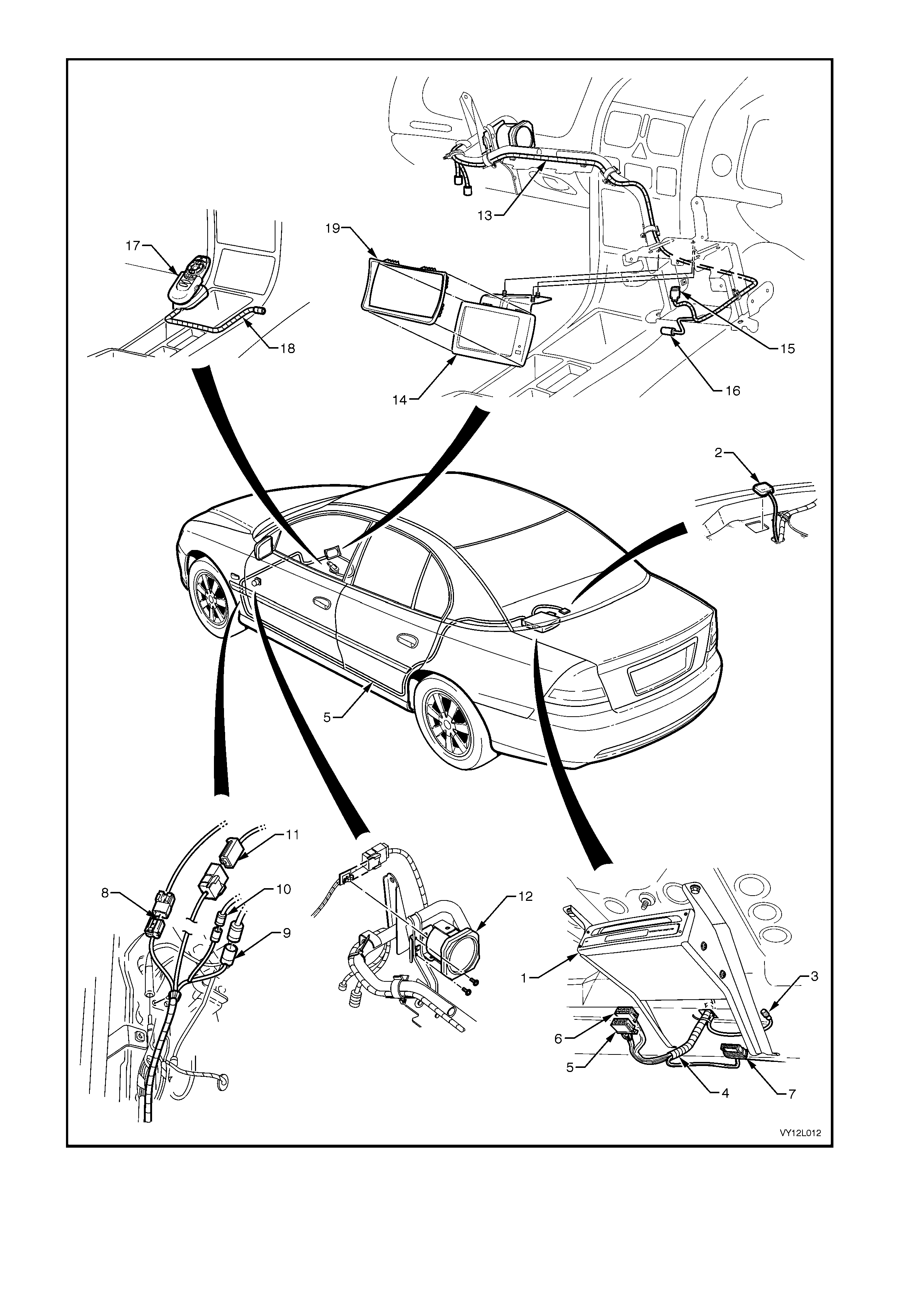
Figure 12L–2

Legend
1. Processor Assembly
2. GPS Antenna Assembly
3. Connector A139 – X4
4. Navigation Wiring Harness
5. Connector A139 – X1
6. Connector A139 – X2
7. Connector A139 – X3
8. Connector X207
9. Connector XO1
10. Connector XO2
11. Connector B104
12. Speaker Assembly
13. Cockpit Navigation Wiring Harness
14. Display Assembly
15. Connector P6
16. Connector A35
17. Remote Control Assembly with
Presenter
18. Remote Control Cradle Wiring
Harness
19. Escutcheon

2. OPERATING INSTRUCTIONS
For a detailed description of operation of the navigation system, refer to the Satellite Navigation Handbook
Supplement supplied with the navigation system.
3. SERVICE OPERATIONS
The f ollowing S ectio n cont ains th e proced ures requir ed to r em ove and re insta ll th e navig ation s ystem com ponents.
Modification procedures are included for the front floor console cover if a replacement cover is being fitted.
3.1 PROCESSOR ASSEMBLY
LT Section –
The processor assembly is located inside the rear compartment.
PROCESSOR
Remove
The processor can be removed from the vehicle without removing the processor case and assembly mounting
brackets.
1. Remove the following fuses from the passenger compartment fuse and relay assembly :
a. radio fuse F23.
b. radio cellular phone fuse F16. Refer to Section 12O, 1.1 FUSES for location details .
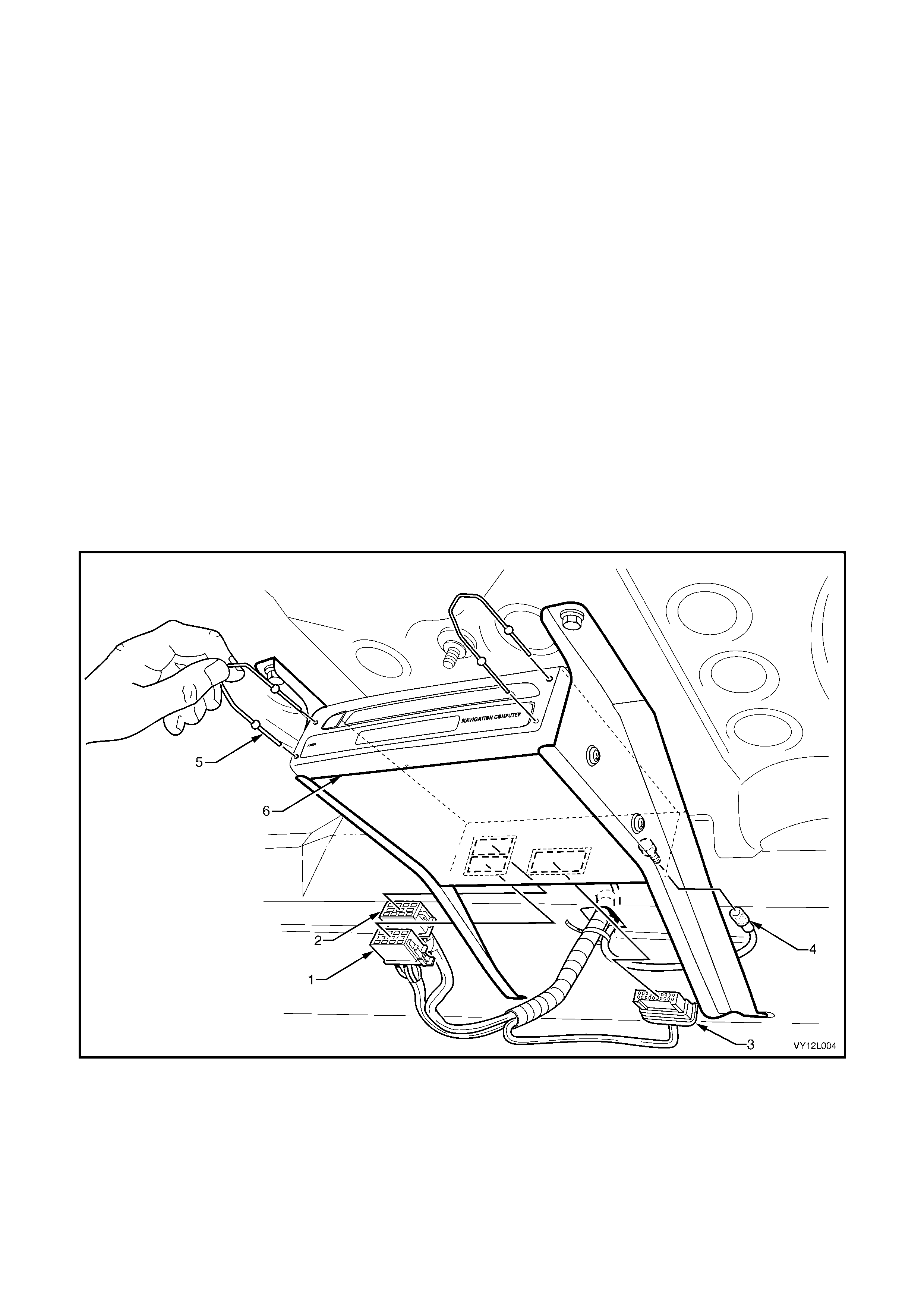
2. Open the rear compartment lid and remove the following from the rear of the processor, refer to Figure 12L–3:
a. Connector A139 – X1 (1).
b. Connector A139 – X2 (2).
c. Connector A139 – X3 (3).
d. Connector A139 – X4 (4).
3. Using the processor assembly removal tools (5) inserted as shown, carefully pull the processor assembly out of
the processor assembly case (6). The processor assembly removal tool can be obtained from Siemens VDO
Dayton or alternatively, the radio/CD removal tool (service tool 179 1308 0000) can be used.
Figure 12L–3
Legend
1. Connector A139 – X1
2. Connector A139 – X2 3. Connector A139 – X3
4. Connector A139 – X4 5. Processor Assembly Removal
Tool
6. Processor Assembly Case
Reinstall
Reinstallation of the processor is the reverse of the removal procedure noting the following. Upon completion of
installation, check the operation of the navigation system.
MOUNTING BRACKETS
Remove
The mounting brackets can be removed or reinstalled with the processor installed.
1. Remove the following fuses from the passenger compartment fuse and relay assembly :
a. radio fuse F23.
b. radio cellular phone fuse F16. Refer to Section 12O, 1.1 FUSES for location details .
2. Open the rear compartment lid and, referring to Figure 12L–3, remove the following from the rear of the
processor:
a. Connector A139 – X1 (1).
b. Connector A139 – X2 (2).
c. Connector A139 – X3 (3).
d. Connector A139 – X4 (4).
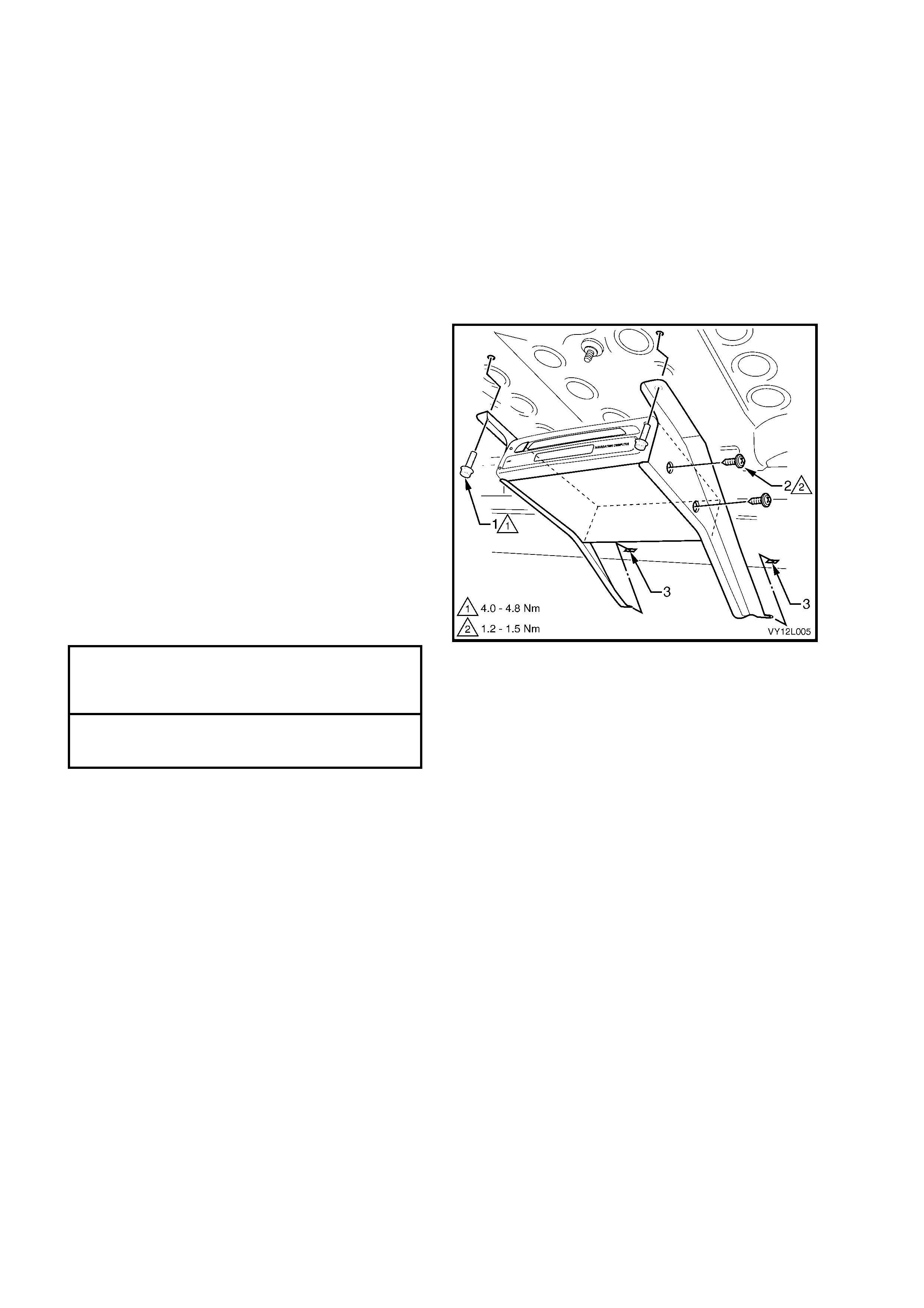
3. Remove the two screws (1) securing the
brackets to the rear window panel assembly.
NOTE: Support the processor assembly and
brackets when removing the screws (1). After
removing these screws, the processor assembly
drops away from the rear window panel assembly
unless supported.
4. Lower the processor assembly and pull away
from the retaining holes (3).
5. If required, remove the screws (2) in two
places attaching either bracket to the
processor assembly case.
Reinstall
Reinstallation of the brackets is the reverse of the
removal procedure. Tighten the screws to the
specified torque.
Figure 12L–4
PROCESSOR ASSEMBL Y MOUNTING
BRACKET TO REAR WINDOW PANEL
ASSEMBLY ATTACHING SCREWS
TORQUE SPECIFICATION 4.0 – 4.8 Nm
PROCESSOR ASSEMBL Y TO
MOUNTING BRACKET ATTACHING
SCREWS TORQUE SPECIFICATION 1.2 – 1.5 Nm
3.2 REMOTE CONTROL ASSEMBLY
LT Section –
The remote control assembly is located on the floor
console assembly, next to the automatic transmission
selector / manual gear lever assembly and consists of
the following items, refer to Figure 12L–8:
a. Remote control (1)
b. Remote control cradle (2)
c. Presenter (5)
d. Presenter m ounting wed ge ( 8)
REMOTE CONTROL CRADLE WITH PRESENTER
Remove
1. Remove the following fuses from the passenger compartment fuse and relay assembly :
a. Radio fuse F23.
b. Radio cellular phone fuse F16. Refer to Section 12O, 1.1 FUSES for location details.
2. Insert the special tools KM6067 (1) into the
holes on each side of the radio assembly.
3. While applying outwards pressure on the tools
(towards each outer side of the vehicle), pull
the radio assembly out of the radio housing.
NOTE: The wiring connectors remain attached to
the radio housing and disconnect when the radio
assembly is removed.
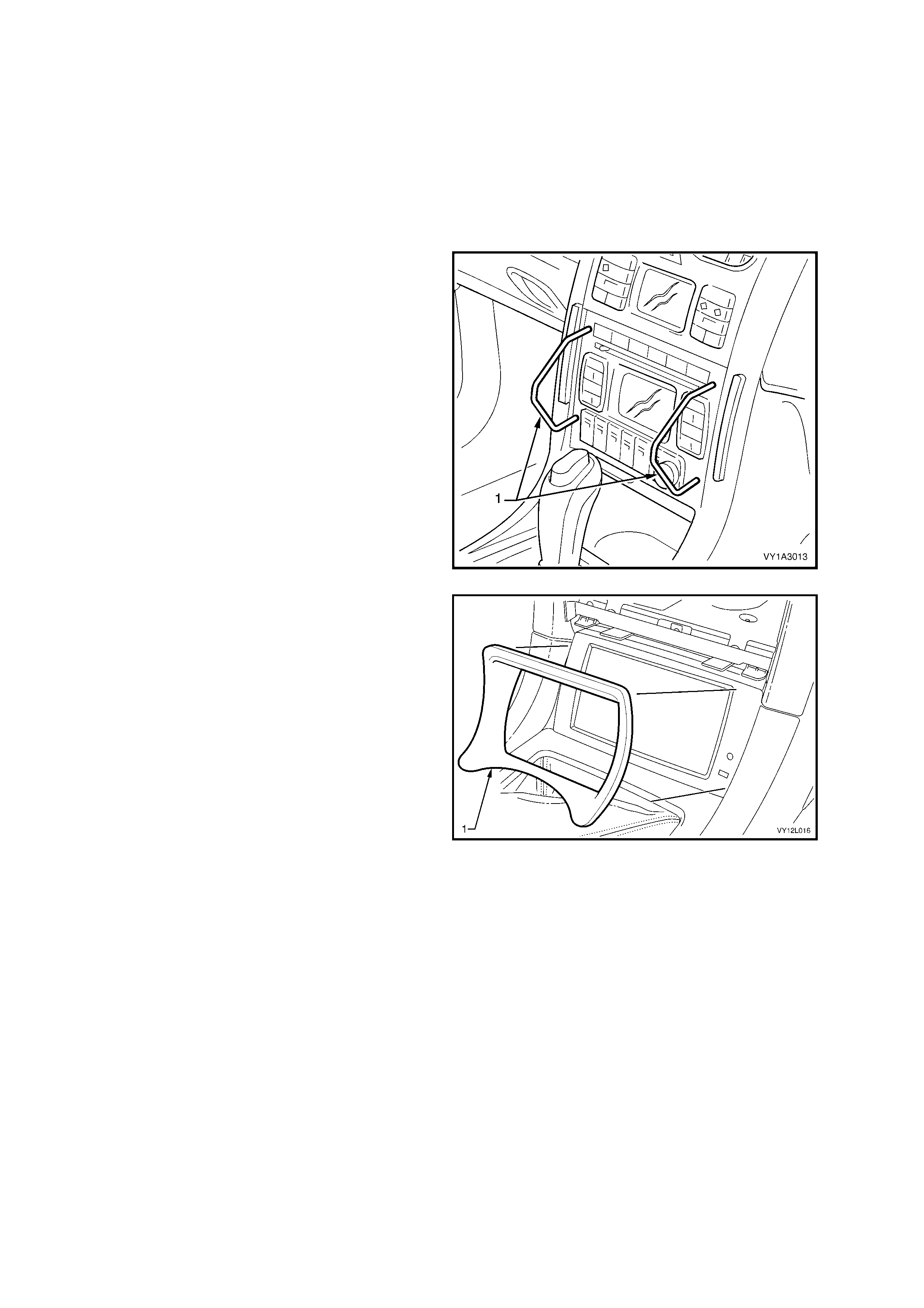
Figure 12L–5
4. Remove the escutcheon (1).
5. Inspect the foam tape on the escutcheon for
serviceability.
Figure 12L–6
Refer to Figure 12L–7 for the following steps:
6. Open the instrument panel lower trim panel and remove the two screws (1) attaching the instrument panel
lower extension side trim (2) to the instrument panel.
7. Prise the rear of the extension side trim downward to disengage it from the floor console retaining clip (3).
8. Remove the extension side trim.
9. Disconnect the navigation wiring harness from the cockpit navigation wiring harness connector A35 (4).
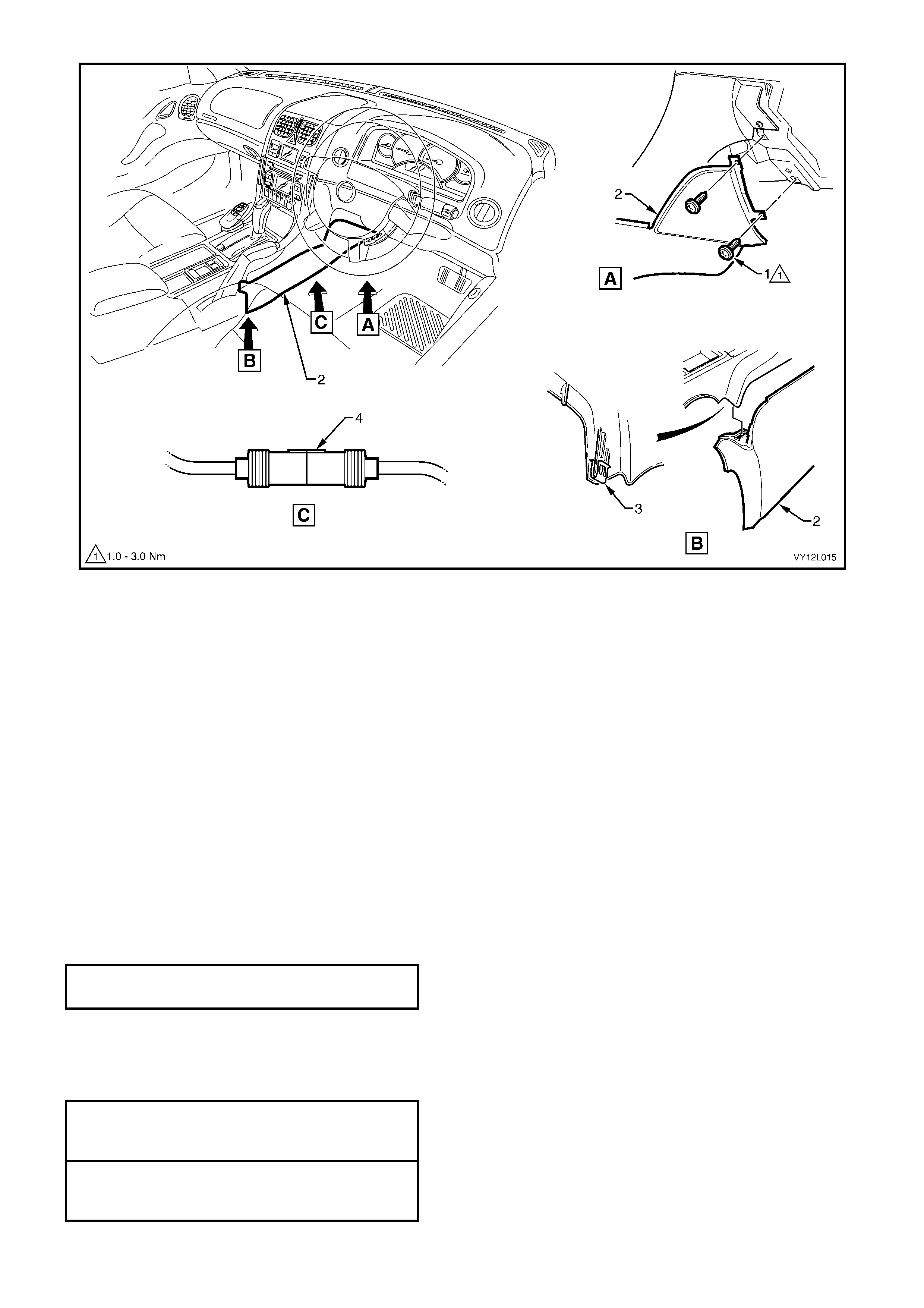
Figure 12L–7
Legend
1. Screw
2. Instrument Panel Lower Extension Side Trim, Right-
hand Side
3. Floor Console Retaining Clip
4. Connector A35
Refer to Figure 12L–8 for the following steps:
10. Remove the remote control (1) from the remote control cradle (2).
Important: Do not pull or tug on the remote control cradle wiring harness.
11. Remove the three screws (3) and lift the cradle and place to one side.
12. Remove the two screws (4) and lift the presenter (5) and place to one side.
13. Remove the floor console cover, refer to Section 1A3, 2.1 FLOOR CONSOLE COVER ASSEMBLY.
14. Feed the remote control cradle wiring harness and connector (6) through the aperture in the floor console cover
assem bly.
Reinstall
Reinstallation of the remote control cradle with presenter is the reverse of the removal procedure noting the
following:
1. Replace the escutcheon foam tape if required.
2. Tighten the presenter attaching screws to the specified torque.
PRESENTER ATTACHING SCREWS
TORQUE SPECIFICATION 0.6 – 1.0 Nm
3. Do not pull or tug on the remote control cradle cable wiring harness when routeing to the navigation main wiring
harness connector.
4. Tighten the remote control cradle attaching screws to the specified torque.
5. Tighten the instrument panel lower extension side trim attaching screw to the specified torque.
REMOTE CONTROL CRADLE
ATTACHING SCREWS
TORQUE SPECIFICATION 0.7 – 1.0 Nm
INSTRUMENT PANEL LOWER EXTENSION
SIDE TRIM PANEL ATTACHING SCREW
TORQUE SPECIFICATION 1.0 – 3.0 Nm
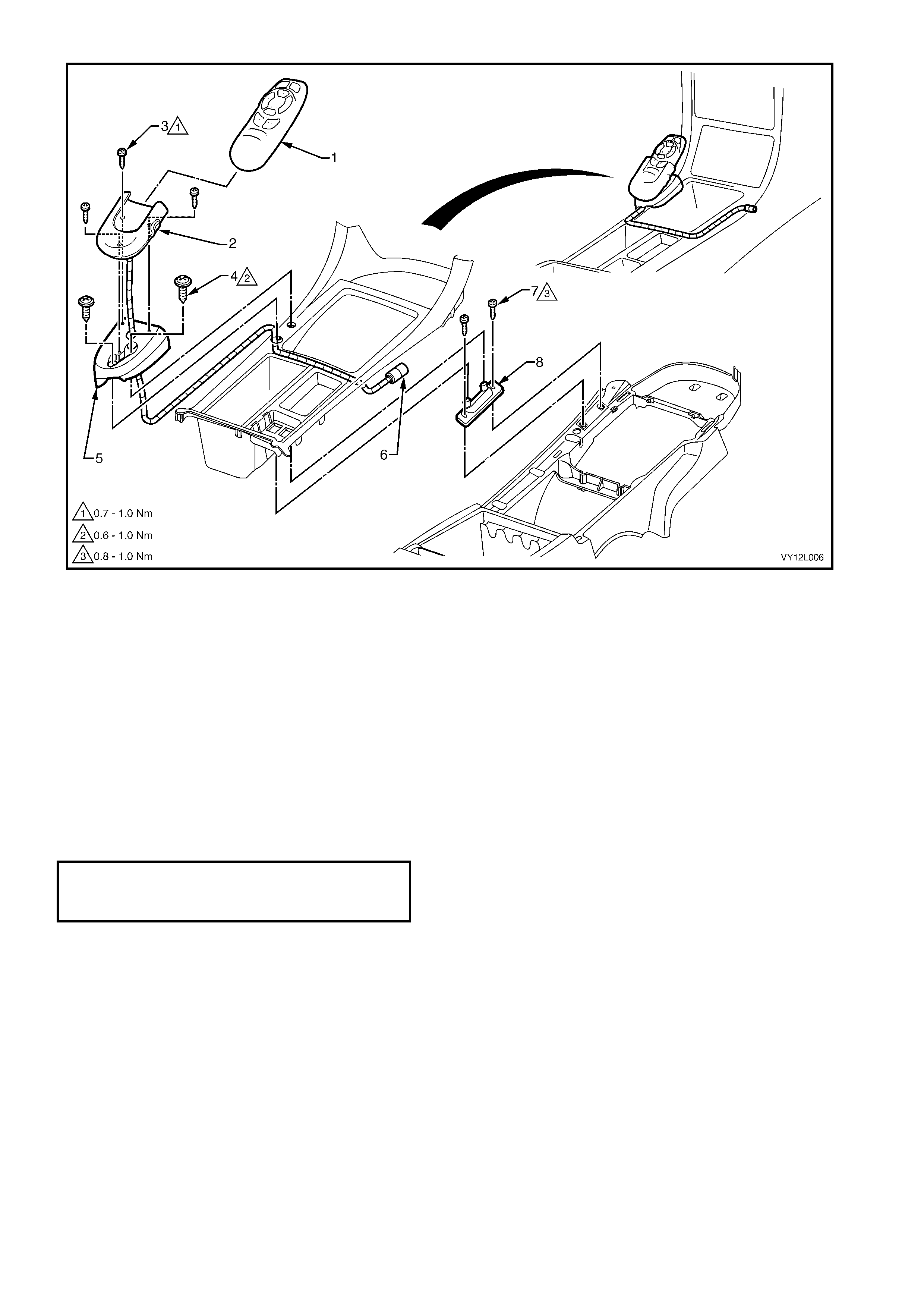
Figure 12L–8
Legend
1. Remote Control
2. Remote Control Cradle
3. Screw
4. Screw
5. Presenter
6. Connector A35
7. Screw
8. Presenter Mounting Wedge
PRESENTER MOUNTING WEDGE
Remove
1. Remove the remote control cradle with presenter as detailed in this Section.
2. Remove the two screws (7) that secure the presenter mounter wedge (8) to the floor console cover assembly
and remove the presenter mounter wedge, refer to Figure 12L–8.
Reinstall
Reinstallation of the presenter mounter wedge is the reverse of the removal procedure. Tighten the screws to the
specified torque.
PRESENTER MOUNTING W EDGE
ATTACHING SCREWS
TORQUE SPECIFICATION 0.8 – 1.0 Nm
3.3 DISPLAY ASSEMBLY
LT Section –
The display assembly is located in the floor console assembly.
REMOVE
1. Remove the following fuses from the passenger compartment fuse and relay assembly :
a. Radio fuse F23.
b. Radio cellular phone fuse F16. Refer to Section 12O, 1.1 FUSES AND CIRCUIT BREAKERS for location
details.
2. Insert the special tools KM6067 (1) into the
holes on each side of the radio assembly.
3. While applying outwards pressure on the tools
(towards each outer side of the vehicle), pull
the radio assembly out of the radio housing.
NOTE: The wiring connectors remain attached to
the radio housing and disconnect when the radio
assembly is removed.
Figure 12L–9
4. Remove the escutcheon (1).
5. Inspect the foam tape on the escutcheon for
serviceability.
Figure 12L–10
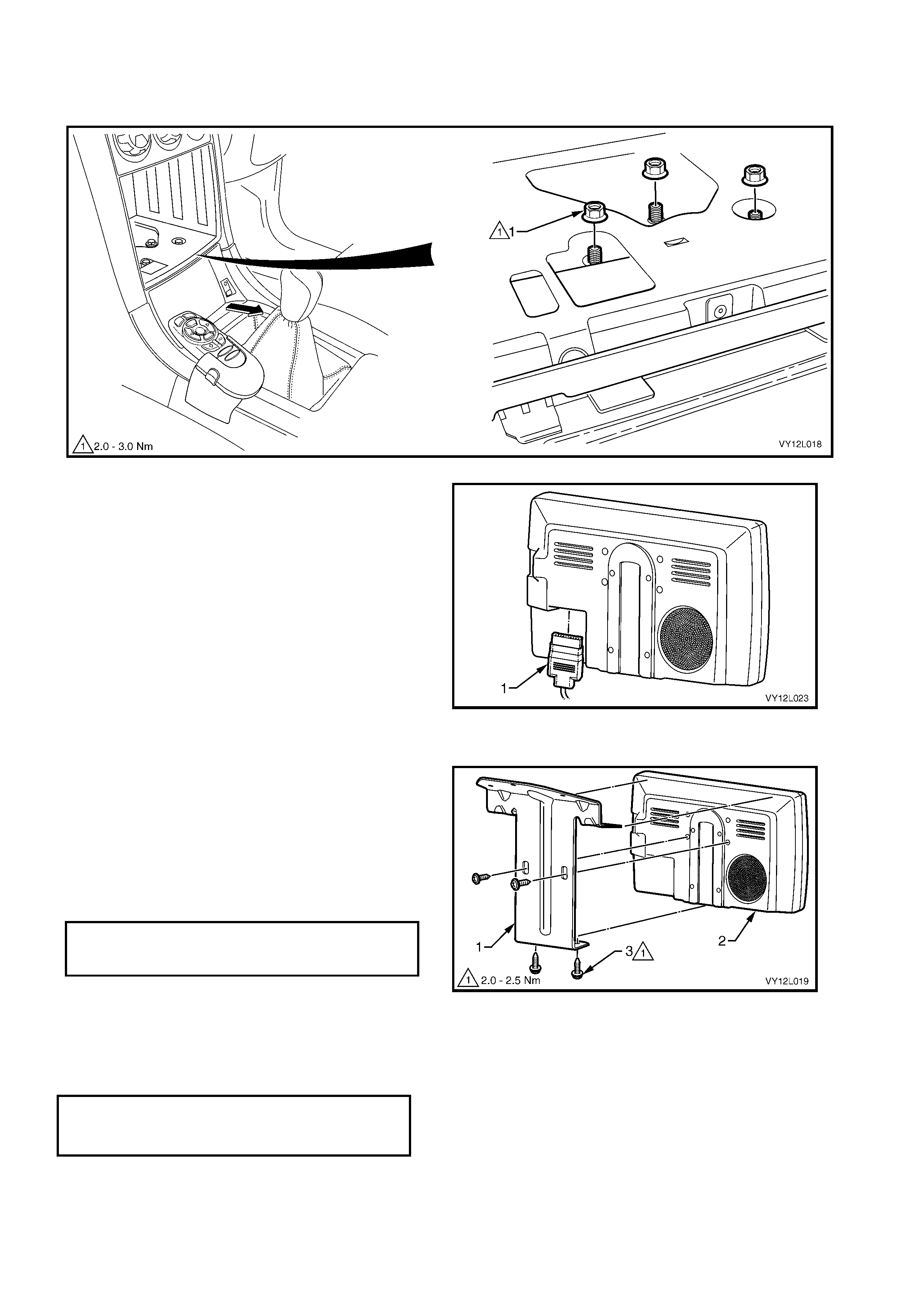
6. Remove the three nuts (1) securing the display assembly mounting bracket to the radio housing, refer to
Figure 12L–11 .
7. Slowly pivot the lower part of the display assembly up and to the rear of the vehicle.
Figure 12L–11
8. Disconnect the cockpit navigation wiring
harness connector P6 (1), from the display
assem bly.
9. Remove the display assembly.
Figure 12L–12
DISASSEMBLE
1. Remove the three screws (3) securing the
display assembly mounting bracket (1) to the
display assem bly (2).
REASSEMBLE
Reassem bly of the displa y assem bly is th e reverse
of the disassembly procedure. Tighten the screws
to the specified torque.
Figure 12L–13
REINST ALL
Reinstallation of the display assembly is the reverse of the removal procedure noting the following:
1. Tighten the three nuts to the specified torque.
DISPLAY ASSEMBLY MOUNTING
BRACKET ATTACHING NUTS
TORQUE SPECIFICATION 2.0 – 3.0 Nm
2. Check for the correct operation of the display.
DISPLAY ASSEMBLY MOUNTING
BRACKET TO DISPLAY ATTACHING
SCREW TORQUE SPECIFICATION 2.0 – 2.5 Nm
3.4 NAVIGATION SPEAKER ASSEMBLY
LT Section –
REMOVE
1. R em ove the follow ing fuses from the passenger compartment fu se and relay asse m bly:
a. Radio fuse F23.
b. Radio cellular p hone fuse F16. Refer to Section 12O, 1.1 FUSES for location details.
2. Remove the left-hand instrument panel lower trim plate assembly, refer to Section 1A3, 3.1 INSTRUMENT
PANEL LOWER TRIM PLATE ASSEMBLY .
3. Remove the instrument panel compartment assembly, refer to Section 1A3, 3.2 INSTRUMENT PANEL
COMPARTMENT ASSEM BLY.
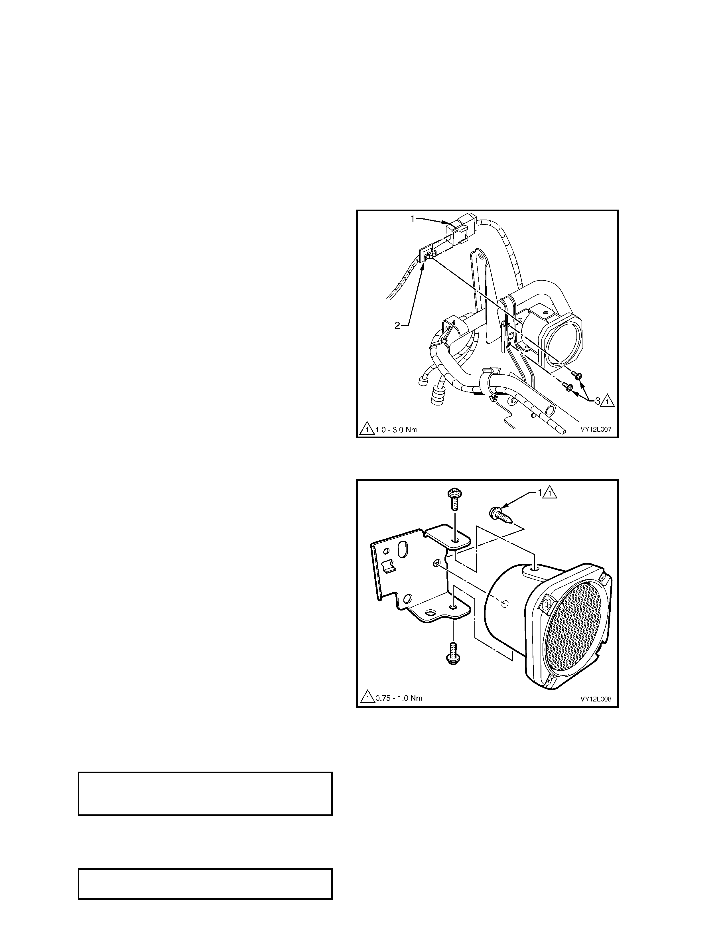
4. Disconnect the speaker connector B104 (1)
from the navigation wiring harness.
5. Remove the clip (2) from the speaker assembly
plate.
6. Remove th e speaker assem bl y attach ing scr ew
(3) and rem ove the speaker assembly.
Figure 12L–14
DISASSEMBLE
1. Remove the screws (1 and 2) securing the
speaker to the speaker assembly plate and
separate the two items.
Figure 12L–15
REASSEMBLE
Reassembly of the speaker assembly is the reverse of the disassembly procedure. Tighten the screws to the
speci fied torqu e.
SPEAKER TO SPEAKER ASSEMBLY
PLATE ATTACHING SCREWS
TORQUE SPECIFICATION 0.75 – 1.0 Nm
REINSTALL
Reinstallation of the navigation speaker assembly is the reverse of the removal procedure. Tighten the screws to
the spe cif ied to rque.
SPEAKER ASSEMBLY ATTACHING
SCREW TORQUE SPECIFICATION 1.0 – 3.0 Nm
3.5 NAVIGATION WIRING HA RNESS
LT Section –
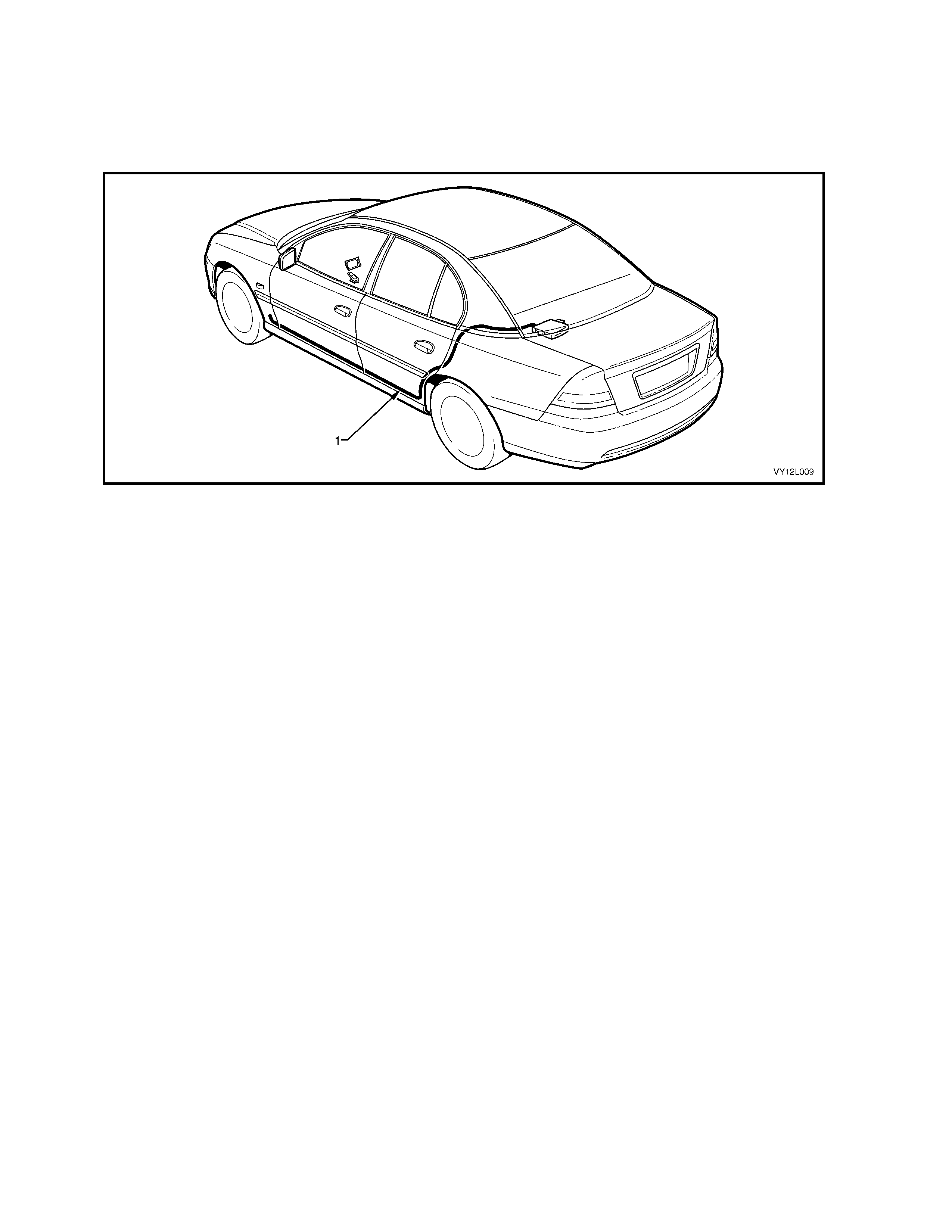
The na vigation wiring har ness (1) is rout ed from t he rear com partment , along the lef t-hand sid e of the veh icle and
termi nate s at the h inge pilla r trim a ssembl y, ref er to Fi gure 12L– 16. Her e, the h ar ness con nects to the bo dy w iring
harne ss of the ve hicle at co nne ctor X207 and t he cock pit naviga tion wiring h arne ss with conn ectors XO 1, XO 2 and
B104.
Figure 12L–16
REMOVE
1. R em ove the follow ing fuses from the passenger compartment fu se and relay asse m bly:
a. Radio fuse F23.
b. Radio cellular p hone fuse F16. Refer to Section 12O, 1.1 FUSES for location details.
2. Open the rear compartment lid and, referring to Figure 12L–3 , remove the following from the rear of the
processor:
a. Conn e cto r A139 – X1 (1).
b. Conn e cto r A139 – X2 (2).
c. Conne ctor A139 – X3 (3).
d. Conn e cto r A139 – X4 (4).
3. Remove the rear seat cushion and seat back. Refer to Section 1A7:
a. 6.2 REAR SEAT CUSHION ASSEMBLY for the sedan rear seat cushion assembly, and
b. 6.3 REAR SEAT — BACK ASSEMBLY for the sedan rear seat back assembly. Or
c. 8.1 REAR SEAT CUSHI ON ASSEMBLY for th e coupe rear seat cushion a ssembly, and
d. 8.2 REAR SEAT — BACK ASSEMBLY for the cou pe rear back assembly.
4. R em ove the left- hand side sill t rim and plate, refer to Section 1A8, 2. 4 S IDE SILL TRIM AND PLATE.
5. Remove the left-hand hinge pillar trim assembly, refer to Section 1A8, 2.8 HINGE PILLA R TRIM ASSEMBLY.
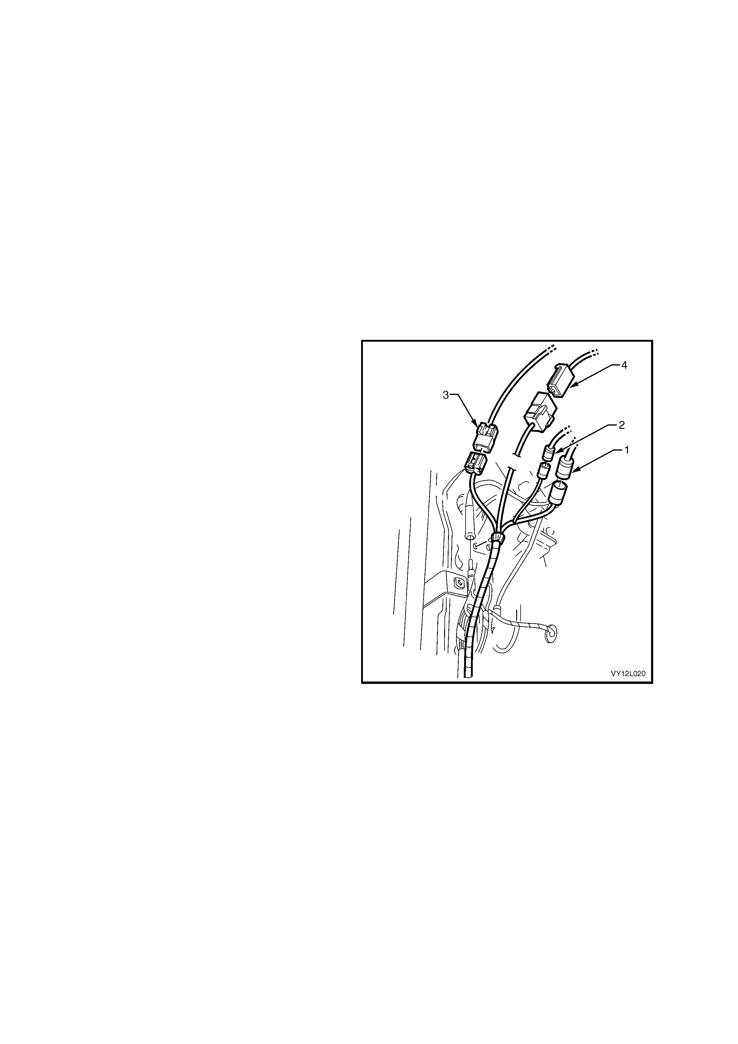
6. Disconnect the following at the left-hand hinge
pillar trim assembly:
a. XO1 (1).
b. XO2 (2).
c. X207 (3).
d. B104 (4).
Figure 12L–17
7. As required, cut the cable ties securing the navigation wiring harness (1) to the sheetmetal, refer to
Figure 12L–18 for Sedan and Figure 12L–19 for Coupe.
Figure 12L–18

Figure 12L–19
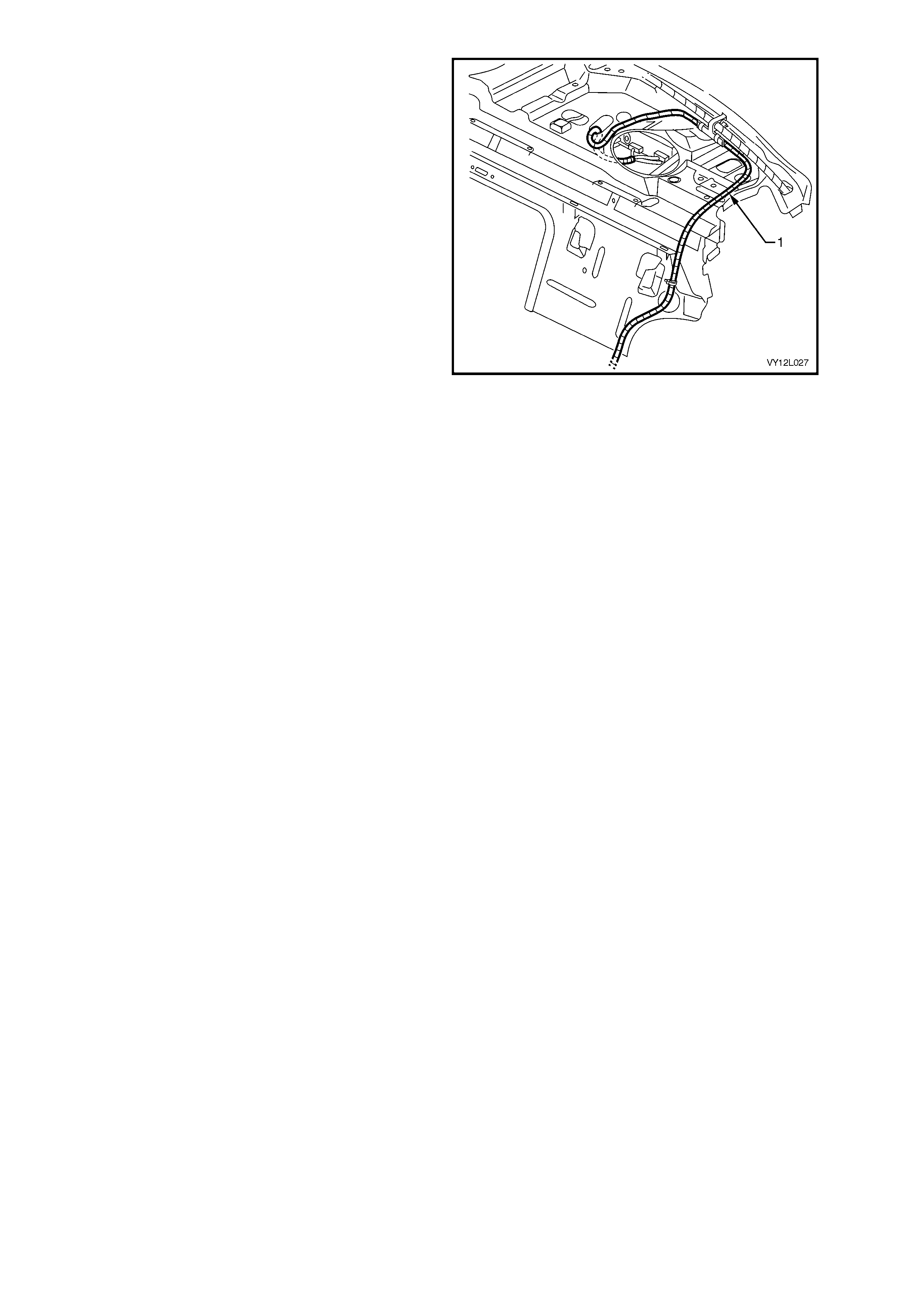
8. For Sedan, remove all clips attaching the
navigation wiring harness (1) to the rear
window panel assembly. Feed the navigation
wiring harness through the rear window panel
assem bly.
NOTE: The navigation wiring harness is too long
for Sedan vehicl es. Any exc ess har nes s is car ef ull y
looped and tied together, and placed through the
panel assembly at the designated point (2).
Figure 12L–20
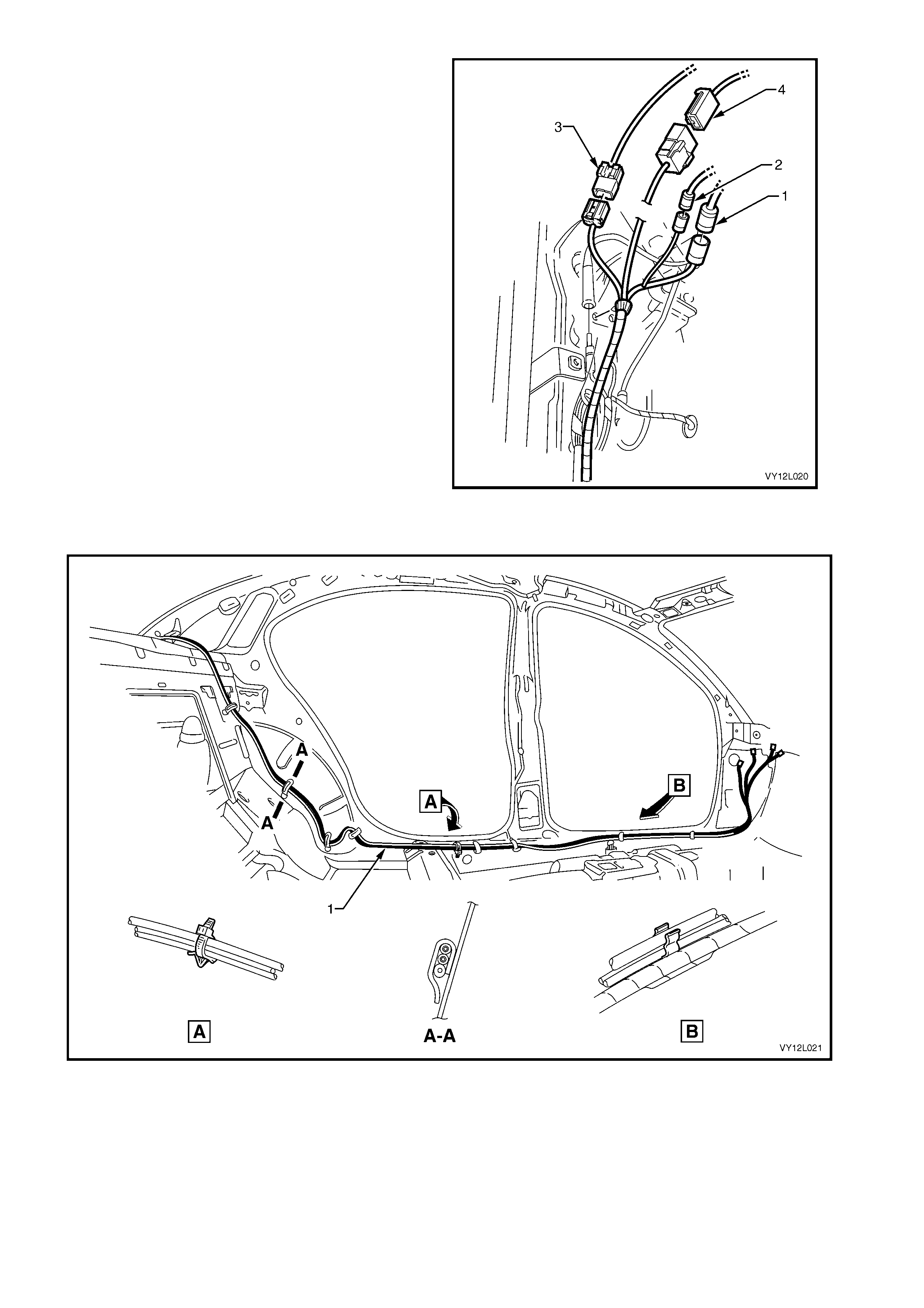
9. For Coupe:
a. Lift the rear window panel insulator to gain
access to the navigation wiring harness
b. Remove all clips attaching the navigation
wiring harness to the rear window panel
assem bly.
c. Feed the naviga tion wiring har ness thr ough t he
rear windo w panel assembly.
10. Rem ove the na v igat io n wir ing harness f r om the
vehicle.
Figure 12L–21
REINST ALL
Reinstallation of the navigation wiring harness is the reverse of the removal procedure noting the following:
1. Replace all the clips and ties where required.
2. Ensure that excess wiring harness is looped, tied and placed through t he rear window panel assem bly (at the
designated point (2), refer to Figure 12L–20).
3. Connect all electrical connectors and check the operation of the navigation system before installing the seat
and trim assemblies.
3.6 COCKPIT NAVIGATION WIRING HARNESS
LT Section –
The cockpit navigation wiring harness connects to the navigation wiring harness under the left-hand hinge pillar trim
assembly, using connectors XO1 and XO2. The cockpit navigation wiring harness is then routed under the hinge
pillar trim assembly, along the instrument panel lower bracket, behind the radio housing and terminates under the
front right-hand side of the floor console cover assembly.
REMOVE
1. Remove the display assembly, refer to 3.3 DISPLAY ASSEMBLY.
2. Remove both the ins tr ument panel lo wer ex tensi ons , r ef er to Sectio n 1 A3, 3.9 IN ST RUM ENT P ANEL LOWER
EXTENSION.
3. Remove the right-hand instrument panel lower extension side trim, refer to Section 1A3, 2.2 INSTRUMENT
PANEL LOWER EXTENSION SIDE TRIM.
4. Remove the left-hand instrument panel lower trim plate assembly, refer to Section 1A3, 3.1 INSTRUMENT
PANEL LOWER PLATE ASSEMBLY.
5. Remove the instrument panel compartment assembly, refer to Section 1A3, 3.2 INSTRUMENT PANEL
COMPARTMENT ASSEMBLY.
6. Remove the left-hand hinge pillar trim assembly, refer to Section 1A8, 2.8 HINGE PILLAR TRIM ASSEMBLY.
7. Disconnect the following from beneath the left-
hand hinge pillar trim assembly:
a. XO1 (1).
b. XO2 (2).
c. X207 (3).
Figure 12L–22
Refer to Figure 12L–23 for the following steps:
8. Disconnect the remote control cradle from the cockpit wiring harness connector A35 (1).
9. As requir ed cut the cable t ies secur ing the cockpit nav igation wiring har ness (2) to the v ehicle and rem ove the
harness.
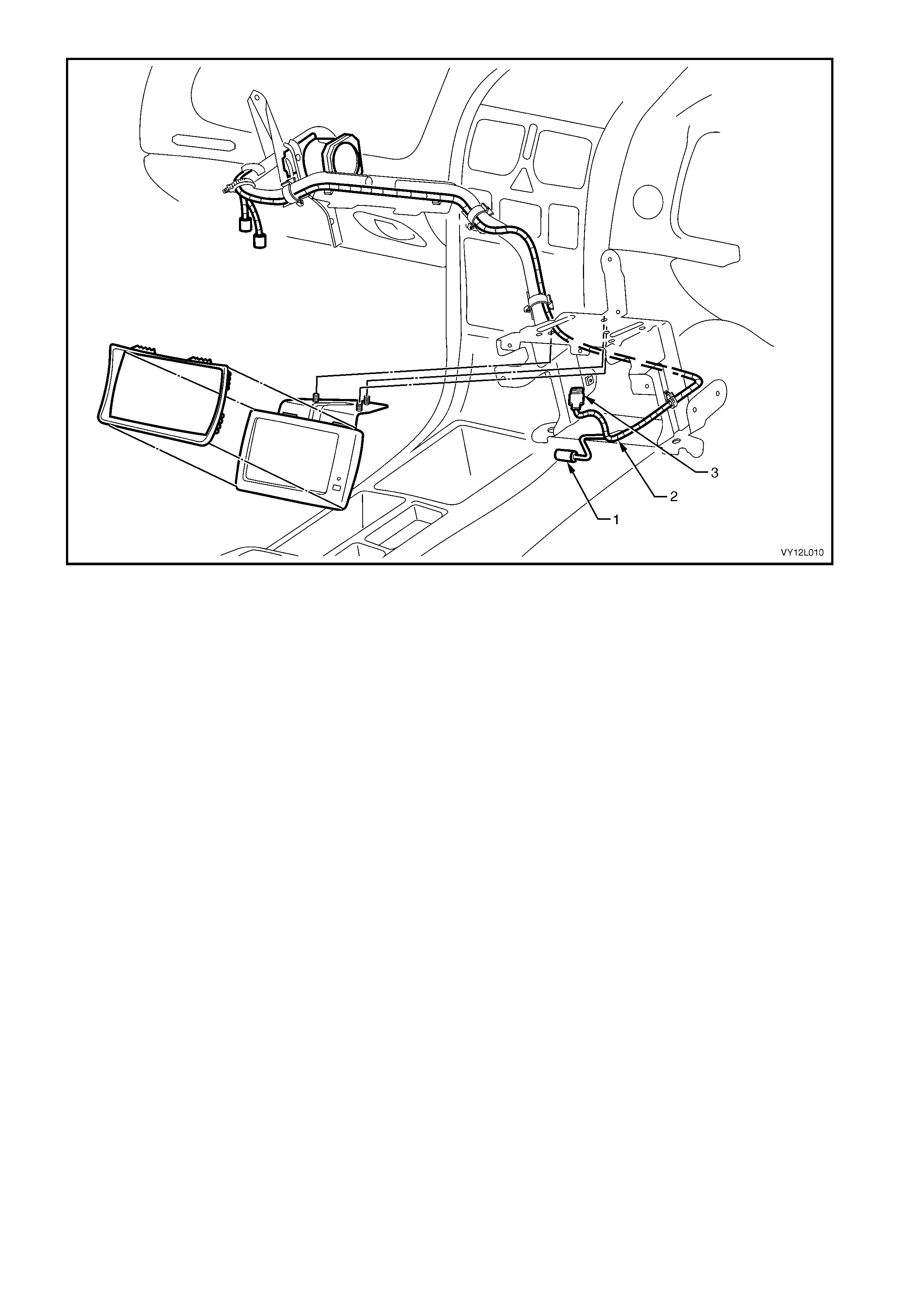
Figure 12L–23
Legend
1. Connector A35
2. Cockpit Navigation Wiring Harness 3. Connector P6
REINST ALL
Reinstallation of the cockpit navigation wiring harness is the reverse of removal procedure, noting the following:
1. Ensure that all clips and ties are installed in the correct locations.
2. Check the operation of the navigation system.
3.7 GPS ANTENNA ASSEMBLY
LT Section –
REMOVE
1. Remove the following fuses from the passenger compartment fuse and relay assembly :
a. Radio fuse F23.
b. Radio cellular phone fuse F16. Refer to Section 12O, 1.1 FUSES AND for location details.
2 Disconnect the navigation antenna connector A139 – X4 from the rear of the processor assembly, refer to
Figure 12L–3.
3. Remove the rear window trim panel assembly, refer to Section 1A8, 2.9 REAR WINDOW TRIM PANEL
ASSEM BLY.
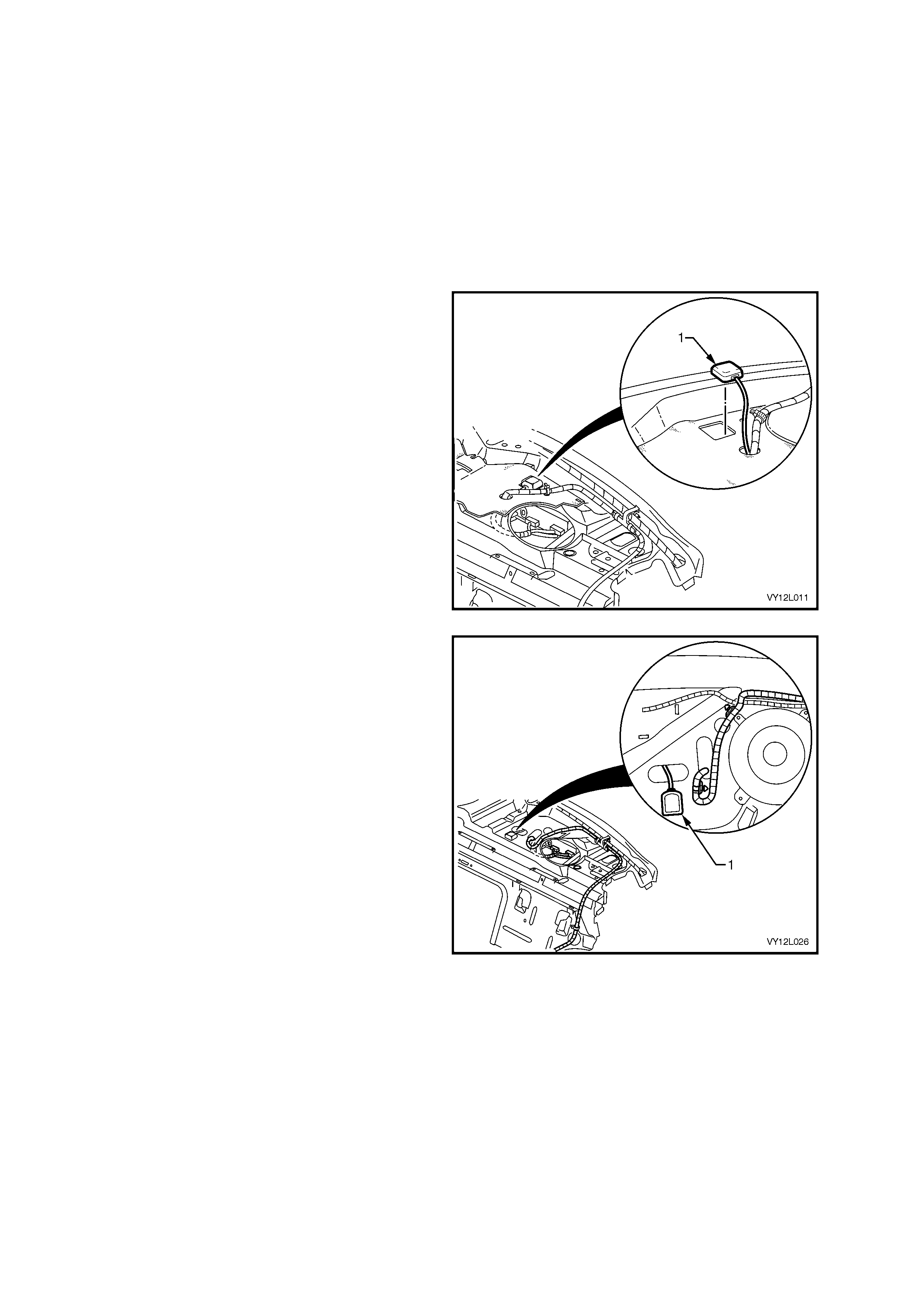
4. For Sedan, using a flat blade screwdriver,
carefully prise the antenna (1) from the rear
window panel assembly.
IMPORTANT: The GPS antenna assembly is
secured in place with dou bl e-s ided tap e.
Figure 12L–24
5. For Coupe:
a. Lift the rear window panel insulator to gain
access to the navigation wiring harness.
b. Using a flat blade screwdriver, carefully prise
the antenna (1) from the rear window panel
assem bly.
IMPORTANT: The GPS antenna assembly is
secured in place with dou bl e-s ided tap e.
6. Pull the GPS antenna assembly cable through
the rear window panel assembly and remove
the antenna.
Figure 12L–25
REINST ALL
Reinstallation of the GPS antenna assembly is the reverse of the removal procedure, noting the following:
1. Clean the rear window panel assembly to remove any residue of the double-sided tape.
2. If required, replace the double-sided tape on the navigation antenna with 3M® brand 4428 or equivalent.
3. Ensure the GPS antenna assembly is secured to the rear window panel assembly.
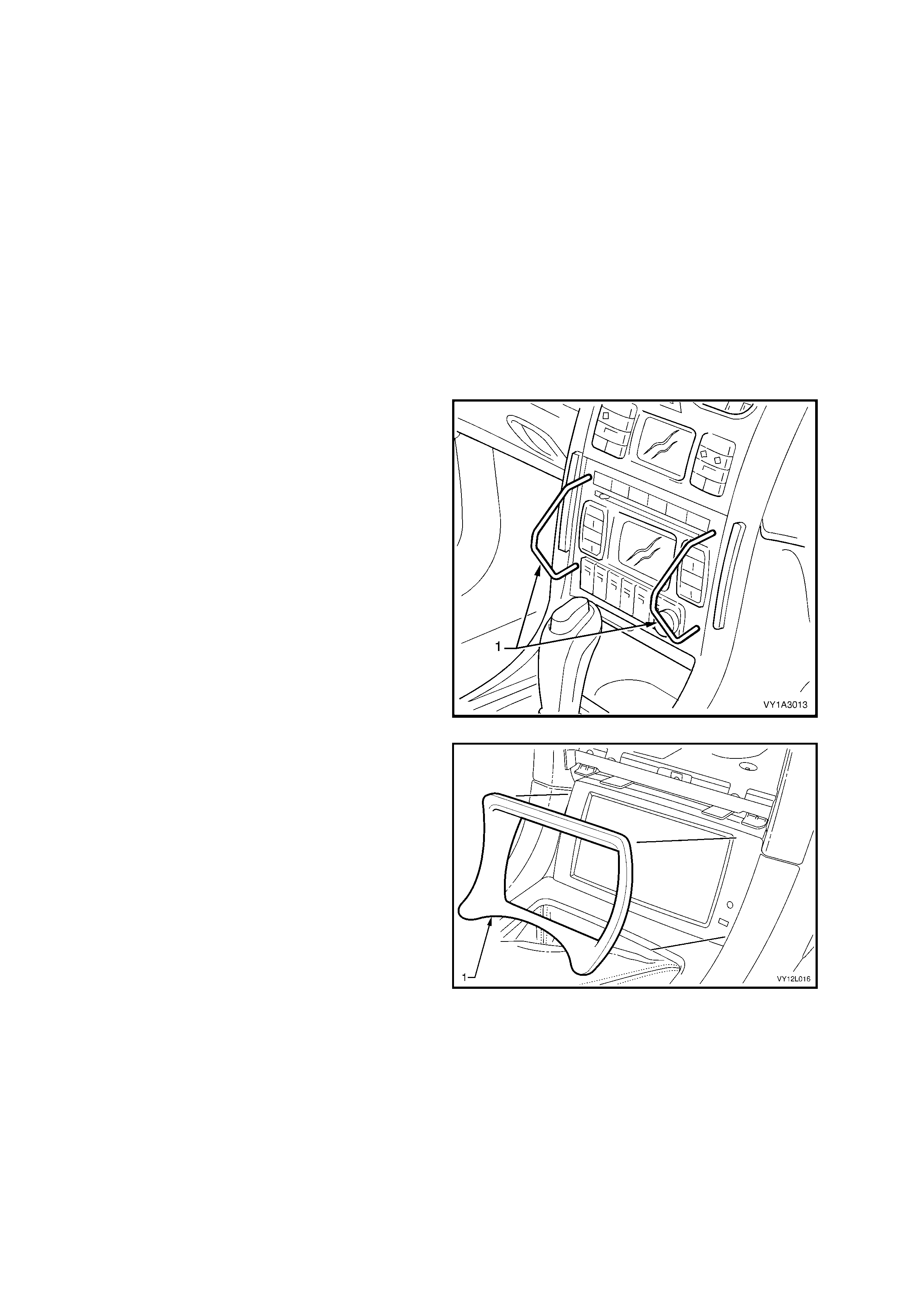
3.8 FITTING A NEW FLOOR CONSOLE COVER ASSEMBLY
LT Section –
The following procedure details how to modify the floor console cover assembly to allow for installation of the
navigation system.
1. Cut through the two lines (1) marked on the underside of the floor console cover assembly.
IMPORTANT: Use blunt drill bits to avoid the plastic splitting.
2. Drill two pilot holes thr ough the floor c onsole cover as sembly at the m arks (2 and 3) on th e underside, ref er to
Figure 12L–26 .
3. Enlarge the hole (2) to 10 mm and the hole (3) to 14 mm.
4. Remove any burrs from both holes.
5. To install the new floor console cover assembly, refer to 3.2 REMOTE CONTROL ASSEMBLY in this Section.
Figure 12L–26

3.9 FITTING A NEW FLOOR CONSOLE ASSEMBLY
LT Section –
If a floor console assembly needs to be replaced on a navigation s ystem-equipped vehicle, the new floor console
assembly does not have the nutserts required for the attachment of the presenter mounting wedge. Two nutserts
and scre ws ar e used to att ac h the pr ese nter mounting wed ge, r ef er to F ig ure 12L –8, t o th e f loor co ns ol e assembly.
The nutserts can be used from the previous console assembly or new nutserts can be ordered.

3.10 NAVIGATION SYSTEM CALIBR ATION
LT Section –
The navigation system requires calibration only if the vehicle has been moved without the navigation system
activate d or if the vehic le’s batter y had been dis connected withou t allowing th e system to shut down properl y. T he
navigation system requires 30 seconds to shut down before disconnection.
Calibrat ion of the n aviga tion s ystem is per form ed auto m aticall y when t he ve hicl e m oves and the navi gation system
activated. Calibration does not need to be performed by the technician, but if the customer is unaware of
calibration requirements, he/she may believe the system is not functioning correctly.
For the system to calibrate, the following must be performed:
• The navigation system must be activated.
• The vehicle must be driven until the arrow representing the vehicle is correctly aligned with the digital map
displayed on the monitor.
NOTE: The more turns taken during calibration, the faster the system calibrates.

4. SYSTEM DIAGNOSIS
Diagnostic tables contained in this Section, list both t echnical problems and comm on faults found due to im proper
use of the navigation system. 4.1 WIRING DIAGRAM and 4.2 CONNECTOR CHART should be used with the
diagnostic tables to fault-find the navigation system.
It is advantageous to read the Satellite Navigation Handbook Supplement supplied with the navigation system
before performing diagnosis on the system.
NOTE: If the proc essor ass em bly needs t o be r em oved or disc onnec ted f rom the veh icle p ower s uppl y, ensu re the
processor assembly has shut down completely. The red LED on the processor assembly extinguishes when the
processor assembly is shut off. Allow approximately 30 seconds after the ignition is turned off for the processor
assembly to shut down.
PREREQUISITES
Safety Requirements
When operating the navigation s ystem as part of any of the Steps in the diagnos is charts, ensure tha t fingers and
limbs are clear of moving parts.
Equipment
The following equipment is required to diagnose the navigation system:
1. An unpowered test lamp with a current draw of less than 3 A.
2. A digital multimeter with a minimum impedance of 10 MΩ.
Testing Proc e dur es
Adhere to the following points when performing diagnostic testing on navigation system components:
1. Care must be taken when using testing equipment to diagnose wiring harness connectors. The technician
should back-probe the connector to avoid terminal damage.
2. When tests are required on connector terminals, use the adapters in the connector adapter kit KM–609 to
prevent damage to the terminals.
3. Unless the multimeter being used has an auto-ranging function, ensure the correct range is selected.
4. When back-probing connectors, ensure the test lamp earth lead is connected to a suitable earth point on the
vehicle. Ensure this earth point is not part of the circuit being tested.
Important:
When following the Steps in the diagnosis charts, ensure work is performed in the order in which they are
presented. If the required nominal value or result is not achieved, rectify the problem before proceeding.
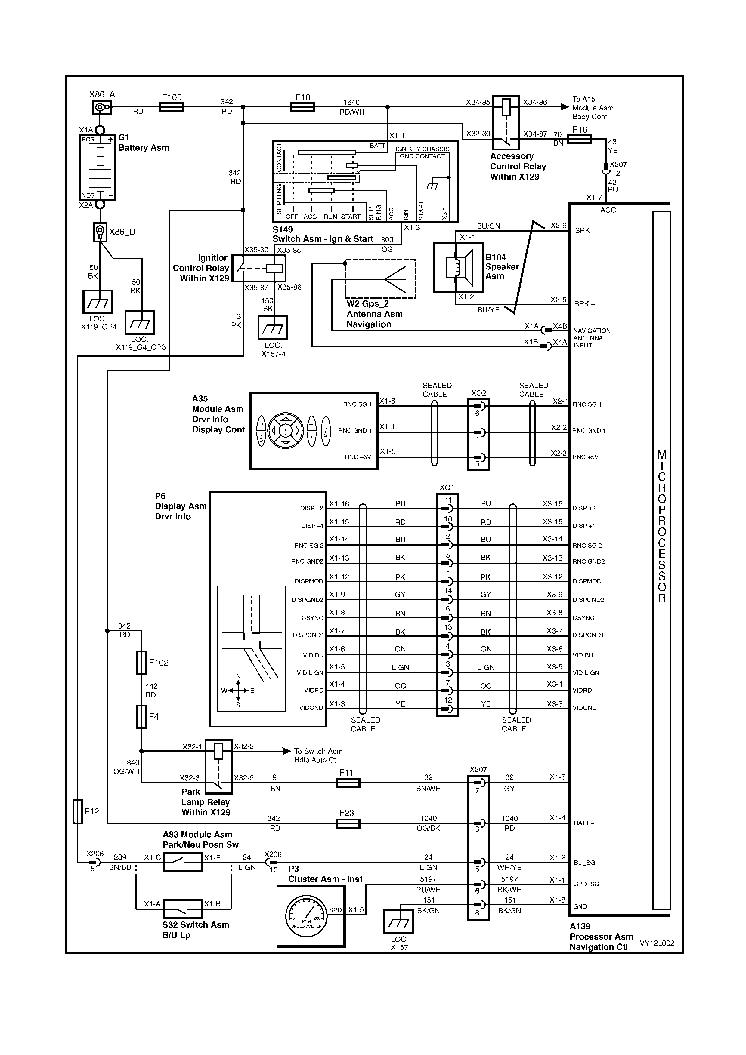
4.1 WIRING DIAGRAM
Figure 12L–27
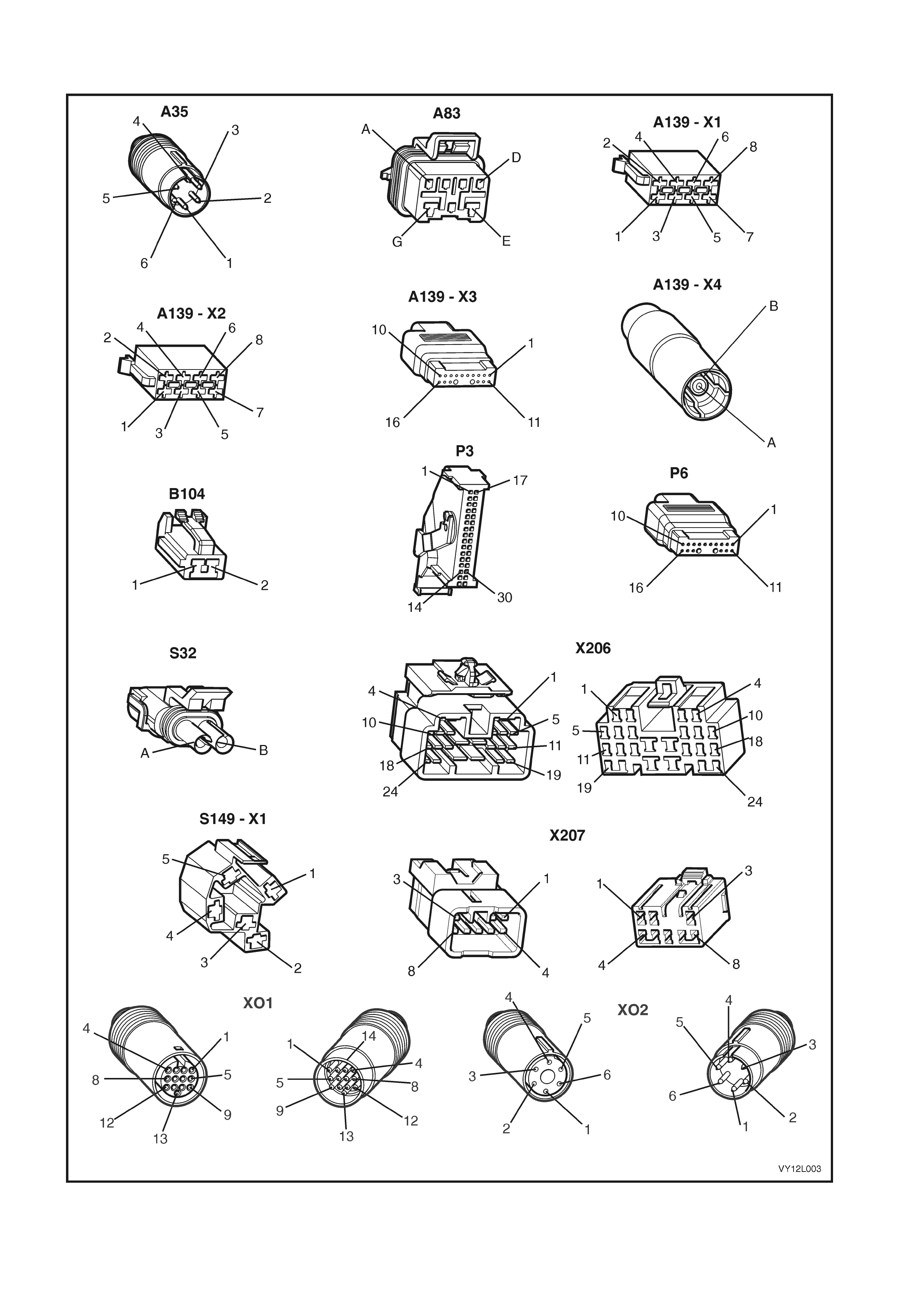
4.2 CONNECTOR CHART
Figure 12L–28

4.3 NAVIGATION SYSTEM DOES NOT START
CONDITION ONE
Introduction
Accessory power supplied to the processor assembly is used by the processor only as an indication that the vehicle
is in use and the navigation system is required. The battery supply provides power for the navigation system to
operate. If the processor does not receive accessory power, the navigation system can not operate because the
navigation system can not determine if the vehicle is in use.
The following symptoms are presented when accessory power is not supplied to the processor assembly with the
ignition switch in either the ACC or IGN position:
• There is no picture on the display.
• The red power LED on the processor assembly is flashing.
• The system does not respond to commands from the remote control.
If the red power LED flashes on the processor assembly, battery power and an earth circuit are present and
serviceable.
To assist in the diagnosing the navigation system, refer to 4.1 WIRING DIAGRAM and 4.2 CONNE CT OR CHART.
Test Description
The numbers following refer to the Step numbers in the diagnostic chart.
1. Checks if the ignition switch is in the ACC or IGN position to supply accessory power to the vehicle. If
access ory power is not s upplied to the vehicle when t he ignition s witch is in the ACC or IGN position, t he fault
does not lie with the navigation system. Refer to Section 12J, 4.4 ACCESSORY POWER CIRCUIT for further
diagnosis.
2. Checks that the connector required for accessory power to be supplied to the processor assembly is in place
and positiv ely connecte d.
3. Check s if there is ac cess ory power at the proc essor assem bly. Isolates whether t he supp ly of acc essor y power
or the processor assembly is at fault.
4. Checks if fuse F16 on the passenger compartment fuse and relay panel assembly is serviceable. Isolates
whether the fuse is the fault affecting the circuit between the accessory control relay and the processor
assem bly.
5. Checks if there is accessory power at the connector X207. Isolates whether the fault in the circuit is between
connector X207 and the processor, or X207 and the accessory control relay.
6. Checks if there is accessory power at fuse F16. Isolates whether the fault in the circuit is between fuse F16 and
connector X207, or between fuse F16 and the accessory power circuit.
STEP POSSIBLE CAUSE / REMEDY YES NO
1. Is the ignition switch in the ACC or IGN
position? Go to Step 2. Turn the ignition switch to
the ACC or IGN position.
2. Is connector A139 – X1 secure? Go to Step 3. Ensure that connector
A139 – X1 is secure.
3. 1. Back-probe connector A139 – X1 pin 7
with a test lamp.
Does the test lamp illuminate?
The processor assembly is
faulty. Send the processor
assembly to the vendor for
further assessment.
Contact Siemens VDO
Customer Service on
1800 335 – 282
Go to Step 4.
4. 1. Inspect fuse F16, refer to Section 12O,
2.1 FUSES.
Is fuse F16 blown? Replace fuse F16. Go to Step 5.
5. 1. Remove the left-hand hinge pillar trim
assembly to gain access to connector
XO1, refer to Section 1A8, 2.8 HINGE
PILLAR TRIM ASSEMBLY.
2. Back-probe connector X207 pin 2 with a
test lamp.
Does the test lamp illuminate?
There is a fault in circuit 43
between connectors
A139 – X1 pin 7 and X207
pin 2. Repair or replace
circuit 43.
Go to Step 6.

STEP POSSIBLE CAUSE / REMEDY YES NO
6. 1. Remove fuse F16 from the passenger
compartment fuse and relay panel
assembly, refer to Section 12O,
2.1 FUSES.
2. Using a multimeter with the negative lead
to earth, check if there is battery voltage at
connector X129 – X43 pin 16.
Is there battery voltage across the connector
X129 – X43 pin 16?
A fault exists in circuit 43
between connector X207
pin 2 and connector
X129 – X43 pin 16. Repair
or replace circuit 43.
A fault exists in circuit 70
that supplies acc es sory
power for the navigation
system. Refer to Section
12J, 4.4 ACCESSORY
POWER CIRCUIT for
further diagnosis .
When all diagnosis and repairs are completed, check the system for correct operation.

CONDITION TWO
Introduction
The batter y power connection provides two functions to the navigation system . When the vehicle ignition s witch is
in the ACC or IGN position, the processor determines that the vehicle is in use. The processor draws its power
through the battery supply circuit to supply the navigation system.
When the vehicle’s ignition is in the OFF position, the battery supply circuit provides power to the processor
assembly to allow the processor assembly to store data such as current location etc.
The following symptoms are presented when battery power is not supplied to the processor assembly:
• There is no picture on the display until the ignition switch is in either the ACC or IGN position.
• The red power LED on the processor assembly is extinguished.
To assist in diagnosing the navigation system, refer to 4.1 WIRING DIAGRAM and 4.2 CONNECTOR CHART.
Test Description
The numbers following refer to the Step numbers in the diagnostic chart.
1. The red power LED illuminates if the 12 volt battery power and chassis earth are OK.
2. Check s that the connector required for battery power to be s upplied to the proc essor ass em bly is in place and
positively connected.
3. Checks that battery voltage is more than 12 volts. The navigation system requires more than 12 volts to
operate correctly.
4. Checks if the fuse located on the rear of the processor assembly has not blown.
5. Checks if fuse F23 located on the passenger compartment fuse and relay panel assembly has not blown.
6. Checks if there is battery voltage to the processor assembly. Isolates whether there is a fault between the
battery and the processor assembly, or the fault is in the earth circuit or processor assembly.
7. Checks if connec tor X207 i s in plac e an d pos i tive l y connec te d. Co nnector X 20 7 i s par t of the batt ery circuit and
earth circuit for the processor assembly.
8. Check s if there is battery voltage a t connector X207 p in 3. Isolates whether there is a f ault between c onnector
X207 and the processor assembly.
9. Checks if there is battery voltage at fuse F23 on the passenger compartment fuse and relay panel assembly.
Isolates whether there is a fault bet ween fuse F 23 and connec tor X207 pin 3, or bet ween fusible link F105 an d
fuse F23.
10. Checks if there is battery voltage at connector X139 – X1 pin 8. Isolates if there is a fault with the processor
assem bly.
11. Checks if there is battery voltage at connector X207 pin 8. Isolates whether the fault is in earth circuit 151
(between connector X207 and the processor assembly), or between connectors X207 and X157.
STEP POSSIBLE CAUSE / REMEDY YES NO
1. 1. Press the EJECT button on the processor.
Does the red LED illuminate? If there is still no response
from the system, refer to
CONDITION THREE in this
Section.
Go to Step 2.
2. Is connector A139 – X1 secure? Go to Step 3. Ensure that connector
A139 – X1 is secure.
3. 1. Check the battery voltage, refer to Section
12A, 2.9 BATTERY.
Is the battery voltage more than 12 V? Go to Step 4. Refer to Section 12A,
2.9 BATTERY for further
diagnosis.
4. 1. Inspect the fuse on the rear of the
processor assembly.
Is the fuse on the rear of the processor blown? Replace the fuse. Go to Step 5.
5. 1. Inspect fuse F23, refer to Section 12O, 2.1
FUSES.
Is fuse F23 blown? Replace the fuse. Go to Step 6.
6. 1. Back-probe connector A139 – X1 pin 4
with a test lamp.
Does the test lamp illuminate? Go to Step 10. Go to Step 7
7. 1. Remove the left-hand hinge pillar trim
assembly to gain access to connector
XO1, refer to Section 1A8, 2.8 HINGE
PILLAR TRIM ASSEMBLY.
Is connector X207 secure?
Go to Step 8. Ensure that connector
X207 is se cure.

STEP POSSIBLE CAUSE / REMEDY YES NO
8. 1. Back-probe connector X207 pin 3 with a
test lamp.
Does the test lamp illuminate? Go to Step 9.
A fault exists in circuit 1040
between connectors X207–
3 and A139 – X1–4. Repair
or replace circuit 1040.
9. 1. Remove fuse F23 from the passenger
fuse and relay panel assembly.
2. Back-probe connector X129 – X42 pin 23
with a test lamp.
Does the test lamp illuminate?
A fault exists in circuit 1040
between the connector
X129 – X42 pin 23 and
X207. Repair or replace
circuit 1040.
A fault exists in circuit 342
between fusible link F105
and connect or
X129 – X42 pin 23. Repair
or replace circuit 342.
10. 1. Back-probe connector A139 – X1 pin 8
with a test lamp.
Does the test lamp illuminate? Go to Step 11.
The processor assembly is
faulty. Send the processor
assembly to the vendor for
further diagnosi s.
Contact Siemens VDO
Customer Service on
1800 335 – 282.
11. 1. Back-probe connector X207 pin 8 with a
test lamp.
Does the test lamp illuminate?
A fault exists in circuit 151
between connector X207
pin 8 and X157. Repair or
replace circuit 151.
A fault exists in circuit 151
between connector A139 –
X1 pin 8 and X207 pin 8.
Repair or replace circuit
151.
When all diagnosis and repairs are completed, check the system for correct operation.

CONDITION THREE
Introduction
When the vehicle ignition switch is in the ACC or IGN position and the battery, accessory and earth circuits are
serviceable, the red LED on the processor assembly illuminates continuously.
The following conditions exist when there is power to the processor assembly, but there is no picture on the
display:
• No picture on the display.
• Red power LED on the processor is illuminated.
To assist in diagnosing the navigation system, Refer to 4.1 WIRING DIAGRAM and 4.2 CONNECTOR CHART.
Test Description
The numbers following refer to the Step numbers in the diagnostic chart.
1. Checks if the system is in an idle state. Attempts to restore system operation by using the remote control.
2. Checks if the system is in a n i dle s tate . Attem pts to r es t ore system oper a tio n by u sing the r emote contr ol. If t he
system is restored, there is a fault in the remote control assembly when it is being used outside the cradle.
3. Checks that the battery voltage is above 12 V. The navigation system requires more than 12 V to operate
correctly.
4. Navigation control buttons are located on top of the display. If the system responds when these buttons are
pressed, there is a problem with the remote control and associated circuits when the control is operated.
5. Checks if all the connectors required for the navigation system display to function correctly are in place and
positively connected.
6. Checks if there is continuity between connectors A139 – X3 and XO1 which is part of the navigation wiring
harness. This isolates whether the navigation wiring harness that supplies power to the display is at fault.
7. Checks if there is continuity between connectors P6 – X1 and XO1 which is part of the cockpit navigation wiring
harness. This isolates whether the cockpit navigation wiring harness that supplies power to the display is at
fault.
8. Checks if the dis p lay ass embly is th e f au lt in the system. Isolates wheth er th e f a ult is with the d is pl a y ass e mbly
or the processor assembly.
STEP POSSIBLE CAUSE / REMEDY YES NO
1. 1. Remove the remote control from the
remote control cradle.
2. Point the remote control at the display and
press the OK button to restore display
operation.
Does this activate the display?
System serviceable. Go to Step 2.
2. 1. Seat the remote control in the remote
control cradle and press the OK button on
the remote control.
Does this activate the display?
Refer to 4.4 NO
RESPONSE FROM
REMOTE CONTROL,
Condition One.
Go to Step 3.
3. 1. Check the battery voltage, refer to Section
12A, 2.9 BATTERY.
Is the battery voltage more than 12 V? Go to Step 4. Refer to Section 12A,
2.9 BATTERY for further
diagnosis.
4. 1. Remove the display assembly and the
display assembly mounting bracket, refer
to 3.3 NAVIGATION DISPLAY
ASSEMBLY.
2. Connect the connector P6 to the back of
the display.
3. Operate the navigation system using the
keys on top o f the display.
Does this activate the display?
Refer to 4.4 NO
RESPONSE FROM
REMOTE CONTROL. Go to Step 5.
5. Are the following connections secure:
• A139 – X3
• X01
• P6
Go to Step 6. Ensure the connectors
are secure.

STEP POSSIBLE CAUSE / REMEDY YES NO
6. 1. Remove the left-hand hinge pillar trim
assembly to gain access to connector
XO1, refer to Section 1A8, 2.8 HINGE
PILLAR TRIM ASSEMBLY.
2. Using a multimeter, check for continuity
between the following connectors:
• A139 – X3 pin 16 and X01 pin 11
• A139 – X3 pin 15 and X01 pin 10
• A139 – X3 pin 14 and X01 pin 2
• A139 – X3 pin 13 and X01 pin 5
• A139 – X3 pin 12 and X01 pin 1
• A139 – X3 pin 9 and X01 pin 14
• A139 – X3 pin 8 and X01 pin 6
• A139 – X3 pin 7 and X01 pin 13
• A139 – X3 pin 6 and X01 pin 4
• A139 – X3 pin 5 and X01 pin 3
• A139 – X3 pin 4 and X01 pin 7
• A139 – X3 pin 3 and X01 pin 12
Is there continuity between all of the terminals
of connectors A139 – X3 and X01? Ensure
resistance is minimal and consistent across all
pins checked.
Go to Step 7.
A fault exists in the display
cable which is part of the
navigation wiring harness.
Repair or replace the
navigation wiring harness
as required.
7. 1. Remove the display assembly, refer to 3.3
NAVIGATION DISPLAY ASSEMBLY.
2. Using a multimeter, check for continuity
between the following connectors:
• P6 – X1 pin 16 and X01 pin 11
• P6 – X1 pin 15 and X01 pin 10
• P6 – X1 pin 14 and X01 pin 2
• P6 – X1 pin 13 and X01 pin 5
• P6 – X1 pin 12 and X01 pin 1
• P6 – X1 pin 9 and X01 pin 14
• P6 – X1 pin 8 and X01 pin 6
• P6 – X1 pin 7 and X01 pin 13
• P6 – X1 pin 6 and X01 pin 4
• P6 – X1 pin 5 and X01 pin 3
• P6 – X1 pin 4 and X01 pin 7
• P6 – X1 pin 3 and X01 pin 12
Is there continuity between all of the terminals
of connectors P6 – X1 and X01?
Go to Step 8.
A fault exists in the display
cable which is part of the
cockpit navigation wiring
harness. Repair or replace
the cockpit navigation
wiring harness as required.
8. 1. Replace the display assembly.
Does the display now operate?
System servic eabl e.
The processor assembly is
faulty. Send the processor
assembly to the vendor for
further assessment.
Contact Siemens VDO
Customer Service on
1800 335 – 282.
When all diagnosis and repairs are completed, check the system for correct operation.

4.4 NO RESPONSE FROM REMOTE CONTROL
NO RESPONSE FROM REMOTE CONTROL
Introduction
The rem ote control sends signals to t he process or assembly in e ither of two m ethods. In the f irst method, with t he
rem ote control rem oved from the r emote control c radle and pointe d at the disp lay assem bly, the signal is received
by the display assembly, then transmitted through the display wiring harness to the processor assembly. In this
case the power to transmit the signal is from the remote control batteries.
The second method is with the remote control situated in the remote control cradle. In this case, signals from the
rem ote c ontrol tr ans mit dire ctl y through the r emote con tr ol cr adl e a nd its wiring ha r ness to the pr oces s or as s embly.
The power to tr ansm it the sign al from the rem ote control is pro vided b y the vehic le via the pr ocess or ass embl y and
remote control cradle.
The following conditions exist when the remote control is inoperative:
• The navigation system is operational, with the title screen on the display.
• The navigation system does not respond to commands from the remote control.
Test Description
The numbers following refer to the Step numbers in the diagnostic chart.
1. Chec ks if there is an y response f rom the rem ote control i n any of its operating c onditio ns. Isola tes whether the
remote control or the system that transmits the signal to the processor is at fault.
2. Checks if the r em ote c ontro l f unc tions c orr ectly when operate d f rom the cradle. Is o lates wheth er the c radle an d
associated circuitry is at fault.
3. Checks if the remote control functions correctly when operated through the display. Isolates whether the
display and associated circuitry is at fault.
4. Repl aces the rem ote contr ol with a ser viceabl e item . Isolates wheth er the rem ote control or th e processor is at
fault.
STEP POSSIBLE CAUSE / REMEDY YES NO
1. 1. Place the remote control in the remote
control cradl e.
2. Press the ‘OK’ button on the remote
control.
3. Remove the remote control from the
remote control cradle.
4. Point the remote control at the display
assembly and press the ‘OK’ button.
Does the system respond to the remote control
during any part of the procedure?
Go to Step 2. Go to Step 4.
2. 1. Place the remote control in the remote
control cradl e.
2. Press the ‘OK’ button on the remote
control.
Does the system respond when the remote
control is operated from the cradle?
Go to Step 3.
Refer to 4.4 NO
RESPONSE FROM
REMOTE CONTROL,
Condition Two.
3. 1. Remove the remote control from the
remote control cradle.
2. Point the remote control at the display
assembly and press the ‘OK’ button.
Does the system respond when the remote
control is operated though the display (that is,
when it is not seated in the cradle)?
System servic eabl e
Refer to 4.4 NO
RESPONSE FROM THE
REMOTE CONTROL,
Condition One.
4. 1. Replace the remote control with a
serviceable item.
2. Repeat the processes in Step 1 and 2.
Does the system respond when the remote
control is operated? System servic eabl e.
The processor assembly is
faulty. Send the processor
assembly to the vendor for
further assessment.
Contact Siemens VDO
Customer Service on
1800 335 – 282
When all diagnosis and repairs are completed, check the system for correct operation.

CONDITION ONE
Introduction
In this con dition t he titl e scr een appe ars when th e vehi cle ignit ion s witch is i n the ACC or IGN pos ition. T he syst em
does not respond when the remote control is operated via the display (that is, when it is not seated in the remote
control cradle).
To assist in diagnosing the navigation system, Refer to 4.1 WIRING DIAGRAM and 4.2 CONNECTOR CHART.
Test Description
The numbers following refer to the Step numbers in the diagnostic chart.
1. Checks if anything is preventing the transmission of commands between the remote control and the infrared
screen that is part of the display assembly.
2. After the batteries are changed, checks if the system responds when the remote control is operated via the
display.
3. Check s that all the c onnectors required for the remote c ontrol to oper ate effec tively are in place and p ositively
connected.
4. Check s if there is c ontin uit y between the r ele vant p ins on t he navig ation wiring harnes s that transm it the s ignal
from the display assembly to the processor. Isolates whether the navigation wiring harness is at fault.
5. Checks if there is continuity between the relevant pins on the cockpit navigation wiring harness that transmit
the signa ls from the dis play assem bly to the pr ocessor . Isolates wh ether the co ckpit navi gation wiring harness
is at fault.
6. Isolates whether the remote control as at fault.
7. Replac es th e d isp lay asse mbl y with a s erv ic eab le it e m. Is olates wh ether the dis play asse mbly or th e proc e s s or
is at fault.
STEP POSSIBLE CAUSE / REMEDY YES NO
1. 1. Remove any obstructions in front of the
infrared screen on the display.
2. Clean the infrared screen on the display.
3. Clean the infrared screen on the remote
control.
Does the system respond when the remote
control is operated though the display (that is,
when it is not seated in the cradle)?
System serviceable. Go to Step 2.
2. 1. Replace the batteries in the remote
control.
Does the system respond when the remote
control is operated though the display (that is,
when it is not seated in the cradle)?
System serviceable. Go to Step 3.
3. 1. Remove the left-hand hinge pillar trim
assembly to gain access to connector
XO1, refer to Section 1A8, 2.8 HINGE
PILLAR TRIM ASSEMBLY.
2. Check the following connectors are
secured:
• A139 – X3
• XO1
• P6
Go to Step 4. Ensure the connectors are
secure.
4. 1. Perform continuity checks on the
following:
• A139 – X3 pin 14 to XO1 pin 10
• A139 – X3 pin 13 to XO1 pin 2
Is there continuity between connectors
A139 – X3 and XO1?
Go to Step 5. Repair or replace the
navigation wiring harness
as required.
5. 1. Remove the display assembly, refer to 3.3
NAVIGATION DISPLAY ASSEMBLY.
2. Perform continuity checks on the
following:
• P6 – X1 pin 14 to XO1 pin 10
• P6 – X1 pin 13 to XO1 pin 2
Is there continuity between connectors P6 –
X1 and XO1?
Go to Step 6. Repair or replace the
cockpit navigation wiring
harness as requir ed.

STEP POSSIBLE CAUSE / REMEDY YES NO
6. 1. Replace the remote control with a
serviceable unit.
Does the system respond when the remote
control is operated though the display (that is,
when it is not seated in the cradle)?
System serviceable. Go to Step 7.
7. 1. Replace the display with a serviceable
item.
Does the system respond when the remote
control is operated though the display (that is,
when it is not seated in the cradle)? System servic eabl e.
The processor assembly is
faulty. Send the processor
assembly to the vendor for
further assessment.
Contact Siemens VDO
Customer Service on
1800 335 – 282
When all diagnosis and repairs are completed, check the system for correct operation.
CONDITION TWO
Introduction
In this condition the title screen appears when the vehicle ignition switch is in the ACC or IGN position.
The following conditions are presented:
• Title screen appears.
• System does not respond when the remote control is operated when installed correctly in the cradle.
To assist in diagnosing the navigation system, Refer to 4.1 WIRING DIAGRAM and 4.2 CONNECTOR CHART.
Test Description
The numbers following refer to the Step numbers in the diagnostic chart.
1. Checks if the contacts between the remote control and the remote control cradle are clean and serviceable.
2. Checks that all connectors required for the remote control to operate effectively are in place and positively
connected.
3. Check s if there is c ontin uit y between the r ele vant p ins on t he navig ation wiring harnes s that transm it the s ignal
from the remote control cradle to the processor. Isolates whether the navigation wiring harness is at fault.
4. Checks if there is continuity between the relevant pins on the cockpit navigation wiring harness that transmit
signals from the remote c ontrol cradle to the proc essor. Isolates whether the cock pit navigation wir ing harness
is at fault.
5. Isolates whether the remote control as at fault.
6. Replaces the remote control cradle with a serviceable item. Isolates whether the remote control cradle or the
processor is at fault.
STEP POSSIBLE CAUSE / REMEDY YES NO
1. 1. Inspect the contacts on the base of
the remote control and the
corresponding contacts in the remote
control cradle
Are the contacts clean and serviceable?
Go to Step 2. Clean the contacts. If the
contacts are damaged,
replace the af f ec ted part.
2. 1. Rem ove the left-hand hinge pillar trim
assembly to gain access to connector
XO1, ref er to Section 1A8, 2.8 HINGE
PILLAR TRIM ASSEMBLY.
2. Remove the right-hand instrument
panel ex tension si de trim , refer to 3.2
REMOTE CONTROL ASSEMBLY
within this Section.
3. Check the following connectors are
secured:
• A139 – X2
• XO2
• A35
Go to Step 3. Ensure that the
connectors are secure.

STEP POSSIBLE CAUSE / REMEDY YES NO
3. 1. Perform continuity checks on the
following:
• A139 – X2 pin 1 to XO2 pin 6
• A139 – X2 pin 2 to XO2 pin 1
• A139 – X2 pin 3 to XO2 pin 5
Is there continuity between connectors
A139 – X3 and XO2?
Go to Step 4. Repair or replace the
navigati on wir ing
harness as required.
4. 1. Perform continuity checks for the
following:
• A35 – X1 pin 6 to XO2 pin 6
• A35 – X1 pin 1 to XO2 pin 1
• A35 – X1 pin 5 to XO2 pin 5
Is there continuity between connectors
A35 – X1 and XO2?
Go to Step 5. Repair or replace the
cockpit navigation wiring
harness as required.
5. 1. Replace the remote control with a
serviceable unit.
Does the system respond when the
remote control is operated via the remote
control cradle?
System serviceable. Go to Step 6.
6. 1. Replace the remote control cradle
assembly with a serviceable item,
refer to 3.2 REMOTE CONTROL
ASSEMBLY.
Does the system respond when the
remote control is operated via the remote
control cradle?
System serviceable.
The processor assembly
is faulty. Send the
processor assembly to
the vendor for further
assessment.
Contact Siemens VDO
Customer Service on
1800 335 – 282
When all diagnosis and repairs are completed, check the system for correct operation.

4.5 CD–ROM ERROR
The CD–ROM is supplied as part of the navigation system. It contains all map and relevant information for
Australia. The CD–ROM must be inserted correctly in the processor for the navigation system to operate correctly.
CONDITION ONE
Introduction
When the vehicle ignition switch is in the ACC or IGN position and the navigation system is operational, the
NAVIGATION and ADDRESS book can not be selected via the remote control.
Test Description
The numbers following refer to the Step numbers in the diagnostic chart.
1. Checks if there is a CD–ROM inserted in the processor.
2. Checks if the CD–ROM is inserted correctly, or is dirty or damaged in some way. Isolates whether the CD–
ROM or the processor is at fault.
STEP POSSIBLE CAUSE / REMEDY YES NO
1. Is the map CD–ROM inserted in the processor
assembly? Go to Step 2. Insert the CD–ROM in the
processor.
2. 1. Remove the CD–ROM from the
processor.
2. Inspect the CD–ROM surface.
Is the map CD–ROM scratched, dirty,
damaged or inser ted ups ide d own?
Clean the CD–ROM.
Replace the CD–ROM as
required.
The processor assembly is
faulty. Send the processor
assembly to the vendor for
further assessment.
Contact Siemens VDO
Customer Service on
1800 335 –282
When all diagnosis and repairs are completed, check the system for correct operation.
CONDITION TWO
Introduction
With the vehicle ignition switch in the ACC or IGN position, the CD–ROM ejects from the processor without
somebody pressing the EJECT button.
Test Description
The numbers following refer to the Step numbers in the diagnostic chart.
1. Checks if the CD–ROM is inserted correctly, or is dirty or damaged in some way. Isolates whether the CD–
ROM or the processor is at fault.
STEP POSSIBLE CAUSE / REMEDY YES NO
1. 1. Remove the CD–ROM from the
processor.
2. Inspect the CD–ROM surface.
Is the map CD–ROM scratched, dirty,
damaged or inser ted ups ide d own?
Clean the CD–ROM.
Replace the CD–ROM as
required.
The processor assembly is
faulty. Send the processor
assembly to the vendor for
further assessment.
Contact Siemens VDO
Customer Service on
1800 335 –282
When all diagnosis and repairs are completed, check the system for correct operation.
CONDITION THREE
Introduction
With the vehicle ignition switch in the ACC or IGN position, a message of “Please insert CD” or “Please insert
correct CD” is displayed.
Test Description
The numbers following refer to the Step numbers in the diagnostic chart.
1. Checks if the CD–ROM is inserted correctly, or is dirty or damaged in some way. Isolates whether the CD–
ROM or the processor is at fault.

STEP POSSIBLE CAUSE / REMEDY YES NO
1. Is the map CD–ROM scratched, dirty,
fault y or insert ed upsid e down? Clean the CD–ROM.
Replace the CD–ROM
as required.
The processor assembly
is faulty. Send the
processor assembly to
the vendor for further
assessment.
Contact Siemens VDO
Customer Service on
1800 335 –282
When all diagnosis and repairs are completed, check the system for correct operation.

4.6 AUDIO PROBLEMS
Introduction
With the vehicle ignition switch in the ACC or IGN position and the system operational and in use, there are no
audio commands through the speaker, but the system is displaying the guidance arrow.
Test Description
The numbers following refer to the Step numbers in the diagnostic chart.
1. Press the ‘+’ button on the rem ote c ontrol inc reases the au dio l evel of the navig ation s ystem . If the s ystem has
been muted, pressing the ‘+’ button will resort audio guidance. When the system is muted, there will be a
symbol in the form of a loudspeaker with a red diagonal line through it on the display.
2. Checks that all the connectors required for the speaker to operate effectively are in place and positively
connected.
3. Checks if there is continuity in the navigation wiring harness that supplies power from the processor to the
speaker. Isolates whether the navigation wiring harness is at fault.
4. Check if the speaker has a resistance of 8 Ω across its terminals. Isolates whether the speaker or the
processor is at fault.
STEP POSSIBLE CAUSE / REMEDY YES NO
1. 1. Press the ‘+’ button on the remote control
eight times.
Is the word ‘louder’ audible through the
navigation spe aker?
System serviceable. Go to Step 2.
2. 1. Check the following connectors are
secure:
• A139 – X2
• B104
Go to Step 4. Ensure the connectors are
secure.
3. 1. Perform continuity checks on the
following:
• A139 – X2 pin 6 to B104 – X1 pin 1
• A139 – X2 pin 5 to B104 – X1 pin 2
Go to Step 5. Repair or replace the
navigation wiring harness
as required.
4. 1. Disconnect connector B104 from the
navigation wiring harness.
2. Using a multimeter, measure the
resistance across terminals B104 – X1
pin 1 and pin 2 on the speaker side.
Is there a resistance of 8 Ω across the B104 –
X1 pin 1 and pin 2?
The processor assembly is
faulty. Send the processor
assembly to the vendor for
further assessment.
Contact Siemens VDO
Customer Service on
1800 335 –282
Replace the speaker
assembly.
When all diagnosis and repairs are completed, check the system for correct operation.

4.7 GUIDANCE PROBLEMS
The proc es s or c ontin uously c alcul ates th e veh ic le posit ion. When a destinati on is enter e d, t he process or c alculates
the best pos sible rout e depending on the user's preferences. If the user do es not follo w the directions provided b y
the processor, the processor must recalculate another route, then provide the user with new directions. Problems
may occur in guidance when the user does not follow the processor route instructions and makes a number of
changes in directions before the processor can recalculate the route. The processor eventually calculates the
correct route, but must be given som e time. In this case, the user has obviously strayed from processor guidance
instructions; the processor always maintains the correct location of the vehicle.
CONDITION ONE
Introduction
With the navigation system operational and in use, incorrect guidance instructions are given by the processor.
Test Description
The numbers following refer to the Step numbers in the diagnostic chart.
1. W ith the navigation s ystem operat ional and in M AP mode, the s cale is not a t a level that ca n show the corr ect
position of the vehicle. A change of scale may show a more accurate position.
2. If the system has been driven along straight long roads for excessive periods or has been recently disabled,
the navigation system may need calibrating.
3. Checks that the DIRECTION option in the SET I/O STATE menu is set to ACT_HIGH.
4. Checks that the processor is receiving an adequate GPS signal to ensure an accurate calculation of the
position of the vehicle. Isolates whether the GPS antenna is at fault.
5. Check that the processor’s internal gyroscope is not faulty.
6. Checks if the CD–ROM is out of date. This will especially affect people who travel into newly-developed areas.
7. Checks that the processor is receiving VSS. Isolates whether there is a VSS fault or the processor is faulty. If
there is a VSS fault, the check isolates whether it is contained in the navigation system or within the other
systems of the vehicle.
8. Checks for continuity between X207 and A139 at the processor. Isolates whether the fault is in the processor or
the navigation wiring harness.
STEP POSSIBLE CAUSE / REMEDY YES NO
1. 1. Switch the system display to MAP mode in
100M scale.
Is the vehicle position now accurate? System serviceable. Go to Step 2.
2. 1. Calibrate the navigation system, refer to
3.10 NAVIGATION SYSTEM
CALIBRATION
Is the vehicle position now accurate?
System serviceable. Go to Step 3.
3. 1. Using the remote control, access the SET
I/O STATE menu, refer to 5.3 SET I/O
STATE.
2. Check that the DIRECTION is set to
ACT_HIGH.
Is the DIRECTION set to ACT_HIGH?
Go to Step 4. Change the DIRECTION to
ACT_HIGH, refer to 5.3
SET I/O STATE.
4. 1. Check that the connector A139 – X4 is
secure to the rear of the processor.
2. Ensure that the vehicle is outside with no
major structures around it that might
cause a disruption in GPS reception.
3. Using the remote control, access the
READ GPS DATA menu, refer to
5.4 READ GPS DATA.
Is the receiver state in either 3D or 2D
POSITION?
Go to Step 5. Replace the antenna, refer
to 3.7 NAVIGATION GPS
ANTENNA.
5. 1. Using the remote control, switch the
system to MAP mode
Does the position arrow rotate while the
vehicle is stationary?
Disconnect the power from
the processor assembly
and allow the system to
reset.
If the vehicle position arrow
still rotates after the system
has been reset, send the
processor assembly to the
vendor for further
Go to Step 6.

STEP POSSIBLE CAUSE / REMEDY YES NO
assessment.
Contact Siemens VDO
Customer Service on
1800 335 – 282.
6. 1. Replace the CD–ROM.
2. Calibrate the system, refer to 3.10
NAVIGATION SYSTEM CALIBRATION.
Is the vehicle position now accurate?
System serviceable. Go to Step 7.
7. 1. Using the remote control, access the
READ I/O STATE menu, refer to
5.2 READ I/O STATE.
2. Drive the vehicle at a speed greater than
5 km/h.
Is the SPEED PULSES reading greater
than 0?
The processor assembly is
faulty. Send the processor
assembly to the vendor for
further assessment.
Contact Siemens VDO
Customer Service on
1800 335 – 282.
Check the VSS circuit.
Refer to:
• Section 6C1-2A for V6.
• Section 6C2-2A for
V6 S/C.
• Section 6C3-2A for
GEN III.
• Go to Step 8 if there is
no fault found with the
VSS circuit.
8. 1. Remove the left-hand hinge pillar trim
assembly to gain access to connector
XO1, refer to Section 1A8, 2.8 HINGE
PILLAR TRIM ASSEMBLY.
2. Check the continuity between the
following:
• A139 – X1 pin 1 to X207 pin 6
The processor assembly is
faulty. Send the processor
assembly to the vendor for
further assessment.
Contact Siemens VDO
Customer Service on
1800 335 – 282.
Repair or replace the
navigation wiring harness
as required.
When all diagnosis and repairs are completed, check the system for correct operation.
CONDITION TWO
Introduction
W ith the naviga ti on s ystem operatio nal a nd i n us e, a d es tina tio n (eg CITY or ROAD etc .) is entered with th e r emote
control, but is not recognised by the system.
Test Description
The numbers following refer to the Step numbers in the diagnostic chart.
1. Checks if the destination has been correctly entered.
2. Checks if the street number being entered is correct. Isolates whether the CD–ROM is out of date or the
number being entered is on a road that extends through more than one suburb.
STEP POSSIBLE CAUSE / REMEDY YES NO
1. 1. Change the search criteria. Search by a
region (eg Sydney) and then by the road
name.
Is the destination now recognised?
System serviceable. Go to Step 2.
2. 1. Replace the CD–ROM with the current
version.
Is the destination now recognised? System servic eabl e.
When a long road
continue s from one sub urb
to the next the house
number may restart in the
new suburb or continue in
sequence from the original
suburb.
When all diagnosis and repairs are completed, check the system for correct operation.

CONDITION THREE
Introduction
With the navigation system operational, the GUIDANCE function can not be selected.
Test Description
The numbers following refer to the Step numbers in the diagnostic chart.
1. There is only one instance when, with all other functions operating correctly, guidance can not be selected.
This occurs if a destination has not been entered.
STEP POSSIBLE CAUSE / REMEDY YES NO
1. 1. Enter the destination. System serviceable.
When all diagnosis and repairs are completed, check the system for correct operation.
CONDITION FOUR
Introduction
With the navigation system operational, there are no guidance instructions after the destination has been entered
and the GUIDANCE function selected.
Test Description
The numbers following refer to the Step numbers in the diagnostic chart.
1. Checks if the GUIDANCE function has been selected and activated.
2. Ensures that, if the ve hicle is on a road held withi n the navig ation system database, the appr opriate secti on of
map is displayed. The system does not give guidance instructions until the vehicle is on such a road.
STEP POSSIBLE CAUSE / REMEDY YES NO
1. 1. Activate the GUIDANCE function.
Are guidance instructions restored? System serviceable. Go to Step 2.
2. 1. Ensure the vehicle is on a road held within
the navigation system database. If the
vehicle is not on such a road, an arrow
appears in the top right-hand corner of the
map screen.
Are guidance instructions restored?
If the location of the vehicle
is incorrect when it has
been moved to a digitised
road, calibrate the
navigation system, refer to
3.10 NAVIGATION
SYSTEM CALIBRATION.
When all diagnosis and repairs are completed, check the system for correct operation.

4.8 DISPLAY QUALITY
Introduction
With the navigation system operational, the display quality is poor.
Test Description
The numbers following refer to the Step numbers in the diagnostic chart.
1. Checks if there is a problem in the dimm ing circuit for the display. The display is designed to be bright during
the day and is dimmed when the park lights are turned on.
2. Checks the battery voltage is above 12 V. The navigation system requires more than 12 V to operate correctly.
3. Checks if the brightness of the display as at its maximum. Brightness can not be controlled by the remote
control; this is controlled from the top of the display.
4. Checks if ther e is c ontinu ity betwee n connector A1 39 – X3 and X O 1. T her e s hould be minimal r esis tanc e in t h e
harness, but it should be consistent across all pins. Any degradation in continuity could result in poor picture
quality.
5. Checks if there is continuity between connector XO1 and P6 –X1. There should be minimal resistance in the
harness, but it should be consistent across all pins. Any degradation in continuity could result in poor picture
quality.
STEP POSSIBLE CAUSE / REMEDY YES NO
1. 1. Switch on the park lamps.
Is there any change in the display quality? Go to Step 2. Refer to 4.9 DISPLAY
DIMMING INOPERATIVE.
2. 1. Check the battery voltage, refer to Section
12A, 2.9 BATTERY.
Is the battery voltage more than 12 V? Go to Step 3. Refer to Section 12A,
2.9 BATTERY for further
diagnosis.
3. 1. Remove the display assembly, refer to
3.3 NAVIGATION DISPLAY ASSEMBLY.
2. Connect connector P6 to the rear of the
display.
3. Using the controls on top of the display,
increase the brightness.
Is the quality of the picture increased?
System serviceable. Go to Step 4.
4. 1. Remove connector A139 – X3 from the
rear of the processor.
2. Remove the left-hand hinge pillar trim
assembly to gain access to connector
XO1, refer to Section 1A8, 2.8 HINGE
PILLAR TRIM ASSEMBLY.
3. Check the continuity of the navigation
wiring harness between the processor and
the connector XO1, refer to Step 6,
4.3 SYSTEM DOES NOT START,
Condition Three. Ensure resistance is
minimal and consistent across all pins
checked.
Is the navigation wiring harness serviceable?
Go to Step 5. Repair or replace the
navigation wiring harness.
5. 1. Remove connector P6 from the display.
2. Check the continuity of the cockpit
navigation wiring harness, refer to Step 7,
4.3 NAVIGATION SYSTEM DOES NOT
START, Condition Three. Ensure
resistance is minimal and consistent
across all pins chec ke d.
Is the cockpit navigation wiring harness
serviceable?
The display is faulty.
Replace the faulty display
with a serviceable item.
Repair or replace the
cockpit navigation wiring
harness.
When all diagnosis and repairs are completed, check the system for correct operation.

4.9 DISPLAY DIMMING INOPERATIVE
The display is designed to be bright during the day and dim when the park lamps are switched on.
Introduction
There ar e two condit ions th at can be pres ented when t here is a fau lt in the cir cuitry tha t inform s the proces sor that
it is either daytime or night time.
In the first case, the display does not dim when the park lamps are switched on. The second case is when the
display is dim during the daytime and bright when the park lamps are switched on.
Test Description
The numbers following refer to the Step numbers in the diagnostic chart.
1. Checks if the park lamps work. The processor receives a signal from the parks lamps when they are on, and
dims the display. Isolates whether the fault is in the park lamp relay and its power supply or on the circuit
proceeding the relay.
2. Checks that the LIGHT option in the SET I/O STATE menu is set to ACT_HIGH.
3. Checks if the fuse F11 on the passenger compartment fuse and relay panel assembly has not blown.
4. Checks if there is battery voltage at connector A139 – X1 pin 6. Isolates whether the processor or the circuit
supplying the signal to the processor is at fault.
5. Checks if there is battery voltage at connector X207 pin 7. Isolates whether circuit 32 between connector
X207 pin 7 and A139 – X1 pin 6 is at fault.
6. Checks if there is battery power to the fuse F11. Isolates whether circuit 32 between fuse F11 and connector
X207 pin 7 is at fault.
7. Check s if the relay R18 is serviceabl e. Isolates wheth er rela y R18, circ uit 9 (between re lay R18 and fuse F 11)
or the power supply to relay R18 is at fault.
STEP POSSIBLE CAUSE / REMEDY YES NO
1. 1. Switch the park lamps on.
2. Visually check if the park lamps are on.
Are the park lamps illuminated? Go to Step 2. Go to Step 7.
2. 1. Using the remote control, access the SET
I/O STATE menu, refer to 5.3 SET I/O
STATE.
2. Check that the LIGHT is set to ACT HIGH.
Does the dimming function operate correctly?
System serviceable. Go to Step 3.
3. 1. Inspect fuse F11, refer to Section 12O, 2.1
FUSES.
Is fuse F11 blown? Replace the fuse. Go to Step 4.
4. 1. Switch the park lamps on.
2. Using a test lamp, back-probe connector
A139 – X1 pin 6.
Does the test lamp illuminate?
The processor assembly is
faulty. Send the processor
assembly to the vendor for
further assessment.
Contact Siemens VDO
Customer Service on 1800
335 282
Go to Step 5.
5. 1. Remove the left-hand hinge pillar trim
assembly to gain access to connector
XO1, refer to Section 1A8, 2.8 HINGE
PILLAR TRIM ASSEMBLY.
2. Switch the park lamps on.
3. Using a test lamp, back-probe connector
X207 pin 7.
Does the test lamp illuminate?
There is a fault in circuit 32
between connector
X207 pin 7 and
A139 – X1 pin 6. Repair or
replace circuit 32.
Go to Step 6.
6. 1. Remove fuse F11 from the passenger
compartment fuse and relay panel.
2. Using a test lamp, back-probe connector
X129 – X44 pin 11–1.
There is a fault in circuit 32
between fuse F11 and
connector X207 pin 7.
Repair or replace circuit 32.
Go to Step 7.
7. 1. Replace relay R18 located on the
passenger compartment fuse and relay
panel.
2. Switch the park lamps on.
Are the park lamps illuminated?
There is a fault in circuit 9
between relay R18 and
fuse F11. Repair or replace
circuit 9.
There is a problem in the
power circuit sup ply ing par k
lamp relay R18. Inspect
fuses F4, F102 and F105.
Diagnose cir cuit s 840, 342,
1 and 442.
When all diagnosis and repairs are completed, check the system for correct operation.

4.10 VEHICLE DIRECTION INCORRECT
The veh icle dir ect ion ch ang es 180 degrees when t he c ar is in rev erse ge ar. T his i s r epresente d b y the veh icle ic on
on the display changing 180 degrees in direction.
Introduction
There are two conditions that can be presented when the circuitry that transmits vehicle reversing data to the
processor is faulty.
In the first case, the vehicle icon does not change direction by 180 degrees when the vehicle’s transmission is
placed i n re verse. T he sec ond cas e is when t he ve hic le icon is po int ing in the op posite dir ec tion to the tr ave l of the
vehicle.
Test Description
The numbers following refer to the Step numbers in the diagnostic chart.
1. Checks if the back-up lamps work. The processor receives a signal from the back-up lamp circuit when the
back-up lamps are on and reverses the direction of the vehicle. Isolates whether the fault is in the switch
assembly and its power supply, or on the circuit preceding the switch assembly.
2. Checks that the DIRECTION option in the SET I/O STATE menu is set to ACT_HIGH.
3. Checks there is a signal to connector A139 – X1 pin 2. Isolates whether the processor or the circuit supplying
the signal to the processor is at fault.
4. Checks if there is a signal at connector X207 pin 5. Isolates whether there is a fault in circuit 24 between
connector X207 and A139.
5. Checks if ther e is a sig nal at c on nec tor x 2 06 pin 10 when the v ehicle is i n re ver se gear. Iso lat es wheth er th er e
is a fault in circuit 24 between connector X206 and X207.
6. Checks if the fuse F12 on the passenger compartment fuse and relay panel assembly has not blown.
7. Chec ks if ther e is power to the bac k-up lam p switch f or manual trans miss ions or, to the neutra l start an d back-
up lam p switch for automatic transm issions. Isolates whether there is a fault in t he circuits supplying power to
these switches
8. Checks if the bac k-up lamp switch f or manual tra ns missions or, to the n eutr a l s tart and bac k-up lamp switc h f or
automatic tr ansmis sions is fault y. Is ol ates if the switch is at f aul t or c irc u it 2 4 b et w een t he switch a nd c o nnec t or
X206 pin 10.
STEP POSSIBLE CAUSE / REMEDY YES NO
1. 1. Place the ignition switch to the ON
position.
2. Move the transmission selector into
reverse.
3. Visually check whether the back-up lamps
are on.
Are the back-up lamps illuminated?
Go to Step 2. Go to Step 7.
2. 1. Using the remote control, access the SET
I/O STATE menu, refer to 5.3 SET I/O
STATE.
2. Check the DIRECTION is set to
ACT_HIGH.
Is the DIRECTION set to ACT_HIGH?
Go to Step 3. Change the DIRECTION to
ACT_HIGH, refer to 5.3
SET I/O STATE.
3. 1. Place the ignition switch to the ON
position.
2. Move the transmission selector into
reverse.
3. Using a test lamp, back-probe connector
A139 – X1 pin 2.
Does the test lamp illuminate?
The processor assembly is
faulty. Send the processor
assembly to the vendor for
further assessment.
Contact Siemens VDO
Customer Service on 1800
335 282
Go to Step 4.
4. 1. Remove the left-hand hinge pillar trim
assembly to gain access to connector
XO1, refer to Section 1A8, 2.8 HINGE
PILLAR TRIM ASSEMBLY.
2. Place the ignition switch to the ON
position.
3. Move the transmission selector into
reverse.
4. Using a test lamp, back-probe connector
X207 pin 5.
Does the test lamp illuminate?
There is a fault in circuit 24
between connector
X207 pin 5 and
A139 – X1 pin 2. Repair or
replace circuit 24.
Go to Step 5.

STEP POSSIBLE CAUSE / REMEDY YES NO
5. 1. Place the ignition switch to the ON
position.
2. Move the transmission selector into
reverse.
3. Using a test lamp, back-probe connector
X206 pin 10.
Does the test lamp illuminate?
There is a fault in circuit 24
between connector
X206 pin 10 and
X207 pin 5. Repair or
replace circuit 24.
Go to Step 6.
6. 1. Inspect fuse F12, refer to Section 12O, 2.1
Fuses.
Is the fuse blown? Replace the fuse. Go to Step 7.
7. 1. For manual transmissions:
a. Disconnect connector S32 – X1 from the
back-up lamp switc h.
b. Using a test lamp, back-probe the
connector S32 –X1 pin A.
2. For automatic transmissions:
a. Disconnect connector A83 – X1 from the
neutral start and back-up lamp switch.
Does the test lamp illuminate?
Go to Step 8.
There is a problem in the
power circuit sup plying the
switch. Inspect fuses the
ignition control relay and
fuse F105. Diagno se
circuits 239, 3, 342 and 1.
8. 1. For manual transmissions, test the
back-up lamp switch, refer to:
• Section 7B1, 3.1 BACK-UP LAMP
SWITCH for V6 Manual Transmission
• Section 7B2, 3.1 BACK-UP LAMP
SWITCH for GEN III Manual
Transmission
2. For automatic transmissions, test the
neutral start and back-up lamp switch,
refer to Section 7C4, 3.4 NEUTRAL
START AND BACK-UP LAMP SWITCH.
Is the switch serviceable?
There is a fault in circuit 24
between the switch and
connector X206 pin 10.
Repair or replace circuit 24.
Replace the defective
switch.
When all diagnosis and repairs are completed, check the system for correct operation.

5. PROCESSOR DIAGNOSTICS
The navigation processor software features a comprehensive diagnostic menu to monitor system signals and
values. T his data can be used to determ ine if the navigation processor or vehicle perip herals are the cause of the
incorrect operation. Use the diagnostic screens and 4. SYSTEM DIAGNOSIS to pinpoint the nature and cause of
the fault.

5.1 ACCESSING DIAGNOSTIC MENU
Use the remote control to operate the system. To select the various on-screen items, use the up, down, left and
right arrow buttons on the remote control. To activate those items, press the OK button.
1. From the START MENU, select SETTINGS.
2. From the SETTINGS MENU, select SYSTEM INFORMATION.
3. From the SYSTEM INFORMATION MENU, select DIAGNOSIS MENU, press OK, then enter 6330 into the
CODE input screen using the up arrow; press OK.
The screen now displays the various sub-menus for system interrogation.
NOTE: Wait for 2 seconds when viewing the values on the diagnostic screens – the processor ‘polls’ the various
circuits approx imately ever y 1.5 sec on ds.
SUBMENU NAME DESCRIPTION
READ I/O STATE Shows the values and state of
each input from the vehicle
electrical sy ste m.
SET I/O STATE Allows the processor to react to
positive or negative vehicle
signals.
READ GPS DATA Displays the current GPS receiver
condition.
READ ERROR Shows error event type and
frequency.
DEMO Enables and disables the
demonstration mode.
RETURN Returns to START MENU.
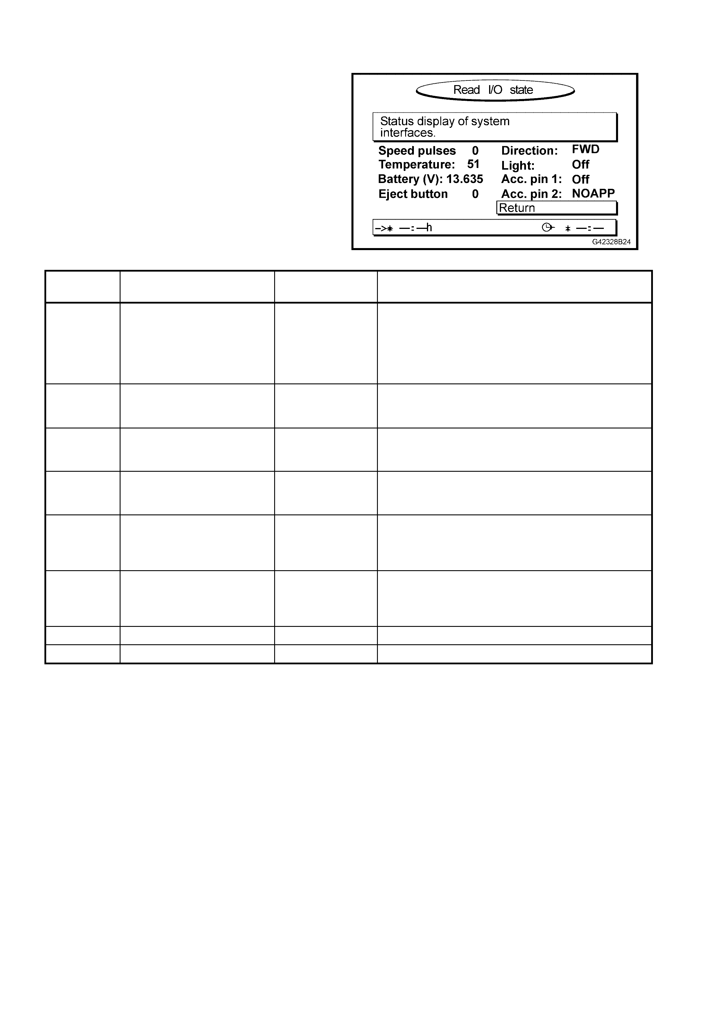
5.2 READ I/O STATE
This represents the READ I/O STATE screen. The
RETURN f ield is aut omaticall y highlight ed to return
to the START MENU when OK on the remote
control is pres s ed.
Figure 12L–29
FUNCTION DESCRIPTION NOMINAL
VALUE COMMENT
Speed
Pulse Displays the number of
speedometer (VSS) pulses
per second being read by the
processor.
Approximately
100 at 60 km/h. If no pulses are shown while the vehicle is moving,
confirm the integrity of the VSS circuit. If the circuit is
OK, replace the processor assembly. The pulse value
should always be positive when the vehicle is
travelling forwards. Check the DIRECTION on the
same screen.
Temperatur
e Displays the temperature
inside the navigation
processor.
45°C at 20°C
outside ambient
temperature.
System delivers specification to 70°C. Internal
processor fan turns on at 65°C and off at 60°C.
Battery (V) Displays the voltage level
present on the BATT circuit. 13 – 15 V Low values (below 11 V) cause deterioration in
picture quality. Low values (below 10 V) cause
unstable operation.
Eject button Displays the condition of the
eject button located on the
processor front panel.
0 (released)
I (pressed)
Direction Displays the current state of
the reverse lamp circuit. FWD while in P,
N, or FORWARD
gears.
If value displayed is REV while in PARK, NEUTRAL
or FORWARD gear, confirm the value set in SET I/O
STATE is ACT_HIGH. If the setting is incorrect,
change the setting from the SET I/O STATE screen.
Light Displays the current state of
the park lamp circuit. ON (lights on)
OFF (lights off) If value displayed is ON when lights are off, confirm
the value set in the SET I/O STATE is ACT_HIGH. If
the setting is incorrect, change the setting from the
SET I/O STATE screen.
ACC. pin 1 Optional accessory input 1. OFF Not applicable.
ACC. pin 2 Optional accessory input 2. OFF Not applicable.
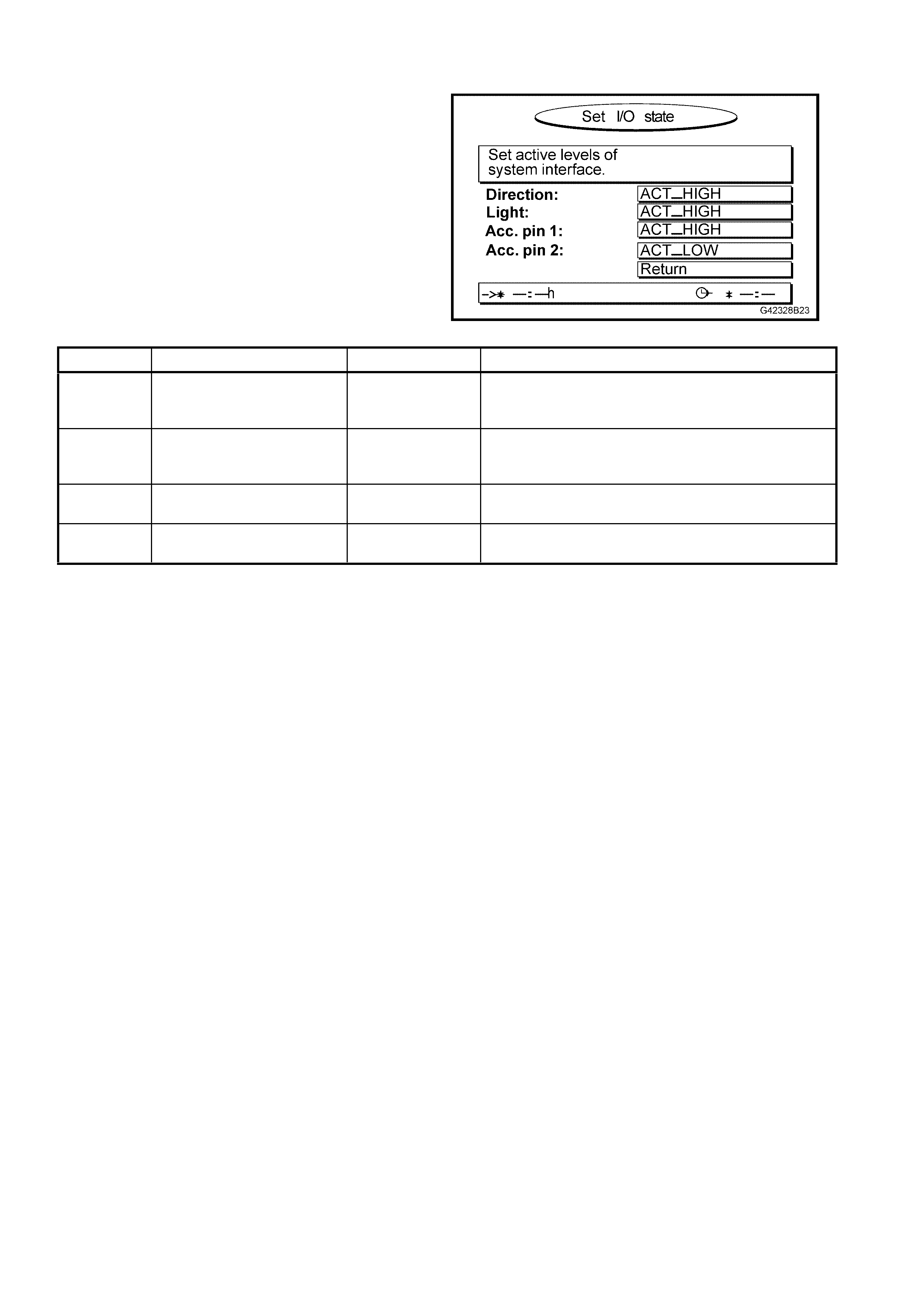
5.3 SET I/O STATE
This represents the SET I/O STATE screen. The
RETURN f ield is aut omaticall y highlight ed to return
to the START MENU when the OK button on the
remote control is pressed.
Figure 12L–30
FUNCTION DESCRIPTION NOMINAL VALUE COMMENT
Direction Sets the polarity of the
reverse lamp circuit for
processor purposes.
ACT_HIGH For positive polarity reverse lamps, this is the correct
setting.
Light Sets the polarity of the park
lamp circuit for processor
purposes.
ACT_HIGH For positive polarity park lamps, this is the correct
setting.
ACC. pin 1 Sets the polarity of optional
accessory input 1. ACT_HIGH These values may change when optional
navigation/multimedi a accessories are connected.
ACC. pin 2 Sets the polarity of optional
accessory input 2. ACT_LOW These values may change when optional
navigation/multimedi a accessories are connected.
For Holden Navigation System installations, DI RECTION and LIGHT should be set to ACT_HIG H. ACC. pin 1 and
ACC. pin 2 are for system upgrades.

5.4 READ GPS DATA
Service p ersonnel com monly susp ect bad sate llite recepti on as the caus e of poor navigation s yst em perform ance.
GPS data s uppl ied to t he pr ocess or is pr ocess ed every fe w seco nds to co nf irm the pos itio n calc ulat ed b y the m ap-
matching software is correct. Good GPS data is essential to the system when it is first installed in the vehicle or
when the vehicle is moved from one location to another without the navigation sy stem being active.
W ithin the n avigation process or unit, there is a separa te GPS rece iver which r eceives GP S data fr om the antenna
and trans m its calc ulated data to the pr ocess or. If the internal GP S rece iver is f aulty, t he na vigat ion pr ocess or mus t
be replaced.
RECEIVER STATE DESCRIPTION COMMENT
3D POSITION 3D data on the location of
the vehicle is available
when the system
receives data from four or
more satellites.
In this condition, the satellite icon on the guidance screen is
GREEN. This is the normal condition.
2D POSITION 2D data on the location of
the vehicle is available
when the system
receives data from three
or more satellites.
No geographic height can be determined in this mode. Positional
accuracy is reduced.
The satellite icon on the guidance screen is RED. This is not the
normal condition, but indicates poor or reduced reception.
TRACKING Data from one satellite
has been received by the
system.
This condition is normally encountered when the system is first
powered up. The GPS receiver is in this mode for up to 10
minutes depending upon reception conditions.
The satellite icon on the guidance screen is RED.
SEARCH SAT The system has a valid
almanac and is searching
for satellites.
This condition is normally encountered when the system is first
powered up. The GPS receiver is in this mode for up to 10
minutes depending upon reception conditions.
The satellite icon on the guidance screen is RED.
REC ERROR The system does not
receive sat ell ite sig nal s. This condition usually occurs if the GPS antenna is not
connected or the cable is damaged. If the GPS antenna and
cable are serviceable, the GPS receiver is faulty and should be
replaced.
The satellite icon on the guidance screen is RED.
COM ERROR The GPS receiver is not
providing any data to the
navigation proc es sor.
Internal communication between the GPS receiver and the
navigation proc es sor is not po ssi ble.
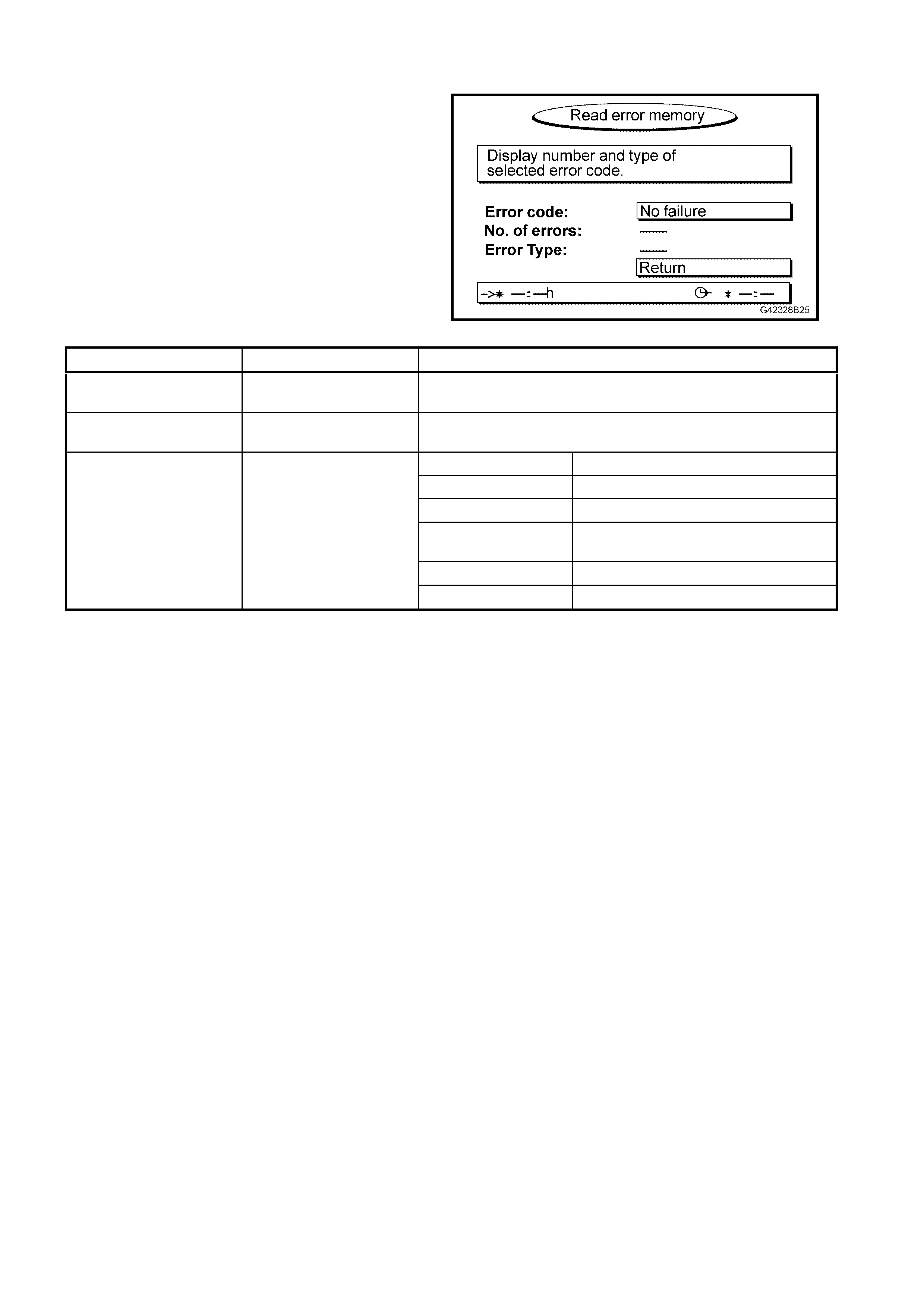
5.5 READ ERROR MEMORY
This represents the READ ERROR MEMORY
screen. The RETURN field is automatically
highlighted to return to the START MENU when the
OK button on the remote control is pressed.
The self-diagnosis function of the processor stores
error events to its internal memory. The errors
detected may be due to internal (processor) or
external (environmental or vehicle) conditions. You
may need to view this screen when asked by a
technical consultant during fault diagnosis.
Figure 12L–31
MENU ITEM DESCRIPTION COMMENT
ERROR CODE Lists the errors that have
occurred. Scroll through the errors using the < and > buttons. Press OK
when each error is highlig hte d to see a descriptio n of the error.
NO. OF ERRORS The number of times the
error has occurred.
SW Software error.
HW Hardware error.
SENSOR No VSS signal.
TEMP Temperature extreme has caused
system error.
GPS Lac k of satell ite signal.
ERROR TYPE Shows the error type.
NO FAILURE No errors have occurred.

6. TORQUE WRENCH SPECIFIC ATIONS
Processor assembly mounting bracket to rear window
panel assembly attaching screws ........................................4.0 – 4.8 Nm
Processor assembly to mounting bracket
attaching screws ..................................................................1.2 – 1.5 Nm
Presenter attaching screws ..................................................0.6 – 1.0 Nm
Remote control cradle attaching screws...............................0.7 –1.0 Nm
Instrument panel lower extension side trim panel
attaching screws...................................................................1.0 – 3.0 Nm
Presenter mounting wedge attaching screws.......................0.8 – 1.0 Nm
Display mounting bracket to display attaching screws.........2.0 – 2.5 Nm
Display mounting bracket attaching nuts..............................2.0 – 3.0 Nm
Speaker to speaker assembly plate attaching screws..........0.75 – 1.0 Nm
Speaker assembly attaching screws ....................................1.0 – 3.0 Nm
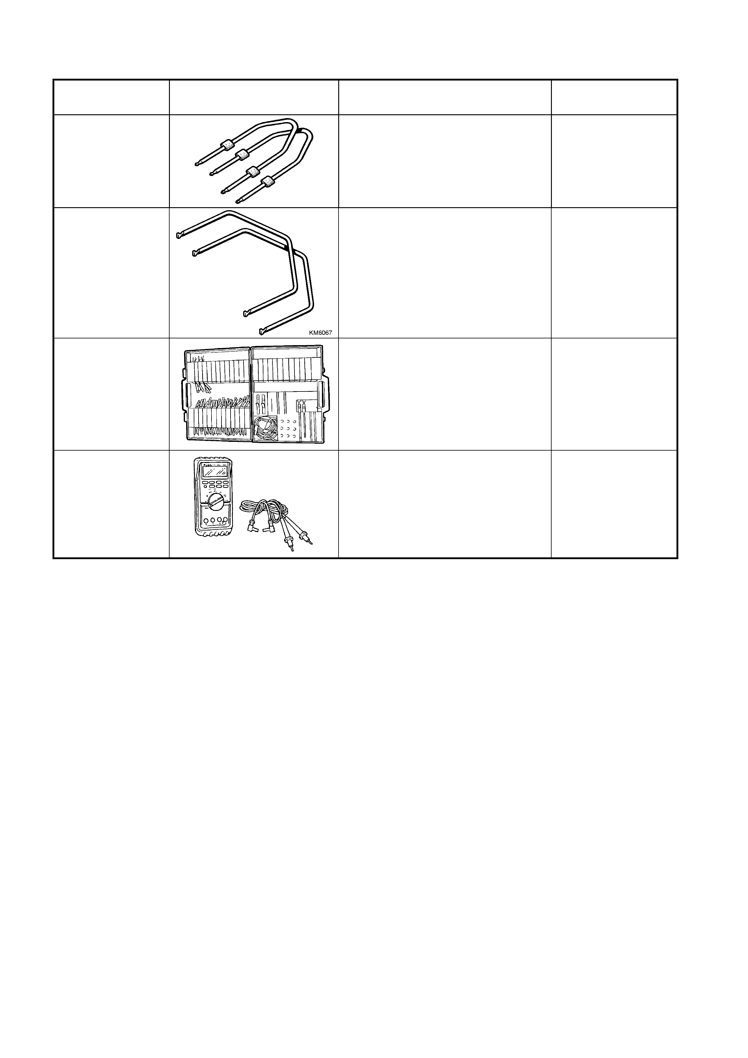
7. SPECIAL TOOLS
TOOL NUMBER ILLUSTRATION DESCRIPTION TOOL
CLASIFICATION
179 1308 0000
RADIO REMOVAL TOOL
Used for removing navigation
processor from its mount ing location.
Previously released.
Mandatory
KM6067
RADIO REMOVAL TOOL
Used for removing VY audio unit from
its mounting location.
New tool for VY.
Mandatory
KM-609
(J35616-A)
ELECTRONIC KIT
Used in conjunction with a multimeter
for measuring voltages and resistances
without damaging wiring harness
connectors.
Desirable
3588
(J39200)
DIGITAL MULTIMETER
Used for various measurement
functions. Must have at least 10 MΩ
input impedance and be capable of
reading frequencies.
Previously released (or use commercial
equivalent).
Available