
SECTION 12M - OCCUPANT PROTECTION SYSTEM
(VERSIONS 8.0 AND 8.1)
IMPORTANT
Before p erforming any Serv ice Operatio n or ot her procedu re desc ribed in this Sect ion, ref er to Section 00
CAUTIONS AND NOTES for correct workshop practices with regard to safety and/or property damage.
CONTENTS
1. GENERAL INFORMATION
1.1 SYSTEM COMPONENTS
INFLATABLE RESTRAINT CONTROL
MODULE
SRS WARNING INDICATOR
MULTI FUNCTION DISPLAY
CHIME ALERT
SYSTEM OPERATION
STEERING WHEEL INFLATABLE RESTRAINT
MODULE ASSEMBLY
INSTRUMENT PANEL INFLATABLE
RESTRAINT MODULE ASSEMBLY
DRIVERS SEATBELT BUCKLE WARNING
INDICATOR SWITCH
SEAT BELT PRETENSIONERS
SIDE-IMPACT SENSOR
CLOCK SPRING COIL ASSEMBLY
SIDE-IMPACT INFLATABLE RESTRAINT
MODULE ASSEMBLY
WIRING HARNESS
WARNING LABELS
2. SERVICE OPERATIONS
2.1 SAFETY PRECAUTIONS
2.2 SYSTEM DISABLING AND ENABLING
PROCEDURE
DISABLING THE OPS / SRS
ENABLING THE OPS / SRS
2.3 STEERING WHEEL INFLATABLE
RESTRAINTMODULE ASSEMBLY
REMOVE
REINSTALL
STEERING WHEEL INFLATABLE RESTRAINT
MODULE SCRAPPING PROCEDURE
2.4 INSTRUMENT PANEL INFLATABLE
RESTRAINT MODULE ASSEMBLY
REMOVE
REINSTALL
INSTRUMENT PANEL INFLATABLE
RESTRAINT MODULE ASSEMBLY
SCRAPPING PROCEDURE
2.5 SEAT BELT BUCKLE AND PRETENSIONER
ASSEMBLY
REMOVE
REINSTALL
SEAT BELT BUCKLE AND PRETENSIONER
ASSEMBLY SCRAPPING PROCEDURE
2.6 CLOCK SPRING COIL
REMOVE
CENTRING THE CLOCK SPRING COIL
REINSTALL
2.7 SIDE-IMPACT INFLATABLE
RESTRAINT MODULE ASSEMBLY
REMOVE
REINSTALL
SIDE-IMPACT INFLATABLE RESTRAINT
MODULE ASSEMBLY SCRAPPING
PROCEDURE
2.8 INFLATABLE RESTRAINT CONTROL
MODULE (SDM)
REMOVE
REINSTALL
2.9 SIDE-IMPACT SENSOR (PERIPHERAL
ACCELERATION SENSOR)
REMOVE
REINSTALL
2.10 REPAIRS AND INSPECTIONS
REQUIRED AFTER AN ACCIDENT
2.11 OPS / SRS WIRING REPAIRS
3 SERVICE OPERATIONS – SEATBELTS
3.1 FRONT SEATBELT ASSEMBLY,
SEDAN & WAGON
REMOVE
REINSTALL
3.2 FRONT SEATBELT ASSEMBLY, UTILITY
REMOVE
REINSTALL
3.3 FRONT SEATBELT ASSEMBLY, COUPE
REMOVE
REINSTALL
3.4 FRONT SEATBELT BUCKLE AND
PRETENSIONER ASSEMBLY
REMOVE
REINSTALL
3.5 REAR SEATBELT ASSEMBLY –
OUTBOARD, SEDAN
REMOVE
REINSTALL
3.6 REAR SEATBELT ASSEMBLY –
CENTRE, SEDAN
REMOVE
REINSTALL
3.7 REAR SEATBELT BUCKLE ASSEMBLY,
SEDAN
REMOVE
REINSTALL
3.8 REAR SEATBELT ASSEMBLY –
OUTBOARD, WAGON
REMOVE
REINSTALL
3.9 REAR SEATBELT ASSEMBLY –
CENTRE, WAGON
REMOVE
REINSTALL
3.10 REAR SEATBELT BUCKLE ASSEMBLY,
WAGON
RIGHT-HAND SIDE
REMOVE
REINSTALL
LEFT-HAND SIDE
REMOVE
REINSTALL
3.11 REAR SEATBELT ASSEMBL Y, COUPE
REMOVE
REINSTALL
Techline
Techline
Techline

3.12 REAR SEATBELT BUCKLE ASSEMBLY,
COUPE
REMOVE
REINSTALL
3.13 CHILD SEAT ANCHORS
REMOVE
SEDAN
WAGON
UTILITY
COUPE
REINSTALL
4 DIAGNOSTICS
4.1 BASIC KNOWLEDGE REQUIRED
4.2 PRELIMINARY SYSTEM DIAGNOSIS
4.3 OPS / SRS SELF DIAGNOSTICS
4.4 TECH 2 DIAGNOSTICS
4.5 TECH 2 TEST MODES AND DISPLAYS
FOR OPS / SRS DIAGNOSIS
4.6 DIAGNOSTIC CHARTS
INTRODUCTION
CHART A -- DIAGNOSTIC CIRCUIT CHECK
CHART B -- SRS WARNING INDICATOR
INOPERATIVE
CHART C SRS WARNING INDICATOR
ILLUMINATED (NO DTCS STORED)
DTC 17 -- DRIVER’S AIRBAG CIRCUIT
SHORT TO BATTERY
DTC 18 -- DRIVER’S AIRBAG CIRCUIT
SHORT TO EARTH
DTC 19 -- DRIVER’S AIRBAG
CIRCUIT CAPACITANCE TOO HIGH
DTC 20 -- DRIVER’S AIRBAG
CIRCUIT CAPACITANCE TOO LOW
DTC 21 -- DRIVER’S AIRBAG
CIRCUIT RESISTANCE TOO HIGH
DTC 22 -- DRIVER’S AIRBAG
CIRCUIT RESISTANCE TOO LOW
DTC 247 – DRIVER’S AIRBAG CIRCUIT
POWER STAGE ERROR
DTC 33 -- PASSENGER’S AIRBAG
CIRCUIT SHORT TO BATTERY
DTC 34 -- PASSENGER’S AIRBAG
CIRCUIT SHORT TO EARTH
DTC 35 -- PASSENGER’S AIRBAG
CIRCUIT CAPACITANCE TOO HIGH
DTC 36 -- PASSENGER’S AIRBAG
CIRCUIT CAPACITANCE TOO LOW
DTC 37 -- PASSENGER’S AIRBAG
CIRCUIT RESISTANCE TOO HIGH
DTC 38 -- PASSENGER’S AIRBAG
CIRCUIT RESISTANCE TOO LOW
DTC 247 -- PASSENGER’S AIRBAG CIRCUIT
POWER STAGE ERROR
DTC 49 -- LEFT-HAND PRETENSIONER
CIRCUIT SHORT TO BATTERY
DTC 50 -- LEFT-HAND PRETENSIONER
CIRCUIT SHORT TO EARTH
DTC 51 -- LEFT-HAND PRETENSIONER
CIRCUIT CAPACITANCE TOO HIGH
DTC 52 -- LEFT-HAND PRETENSIONER
CIRCUIT CAPACITANCE TOO LOW
DTC 53 -- LEFT-HAND PRETENSIONER
CIRCUIT RESISTANCE TOO HIGH
DTC 54 -- LEFT-HAND PRETENSIONER
CIRCUIT RESISTANCE TOO LOW
DTC 247 -- LEFT-HAND PRETENSIONER
CIRCUIT POWER STAGE ERROR
DTC 65 -- RIGHT-HAND PRETENSIONER
CIRCUIT SHORT TO BATTERY
DTC 66 -- RIGHT-HAND PRETENSIONER
CIRCUIT SHORT TO EARTH
DTC 67 -- RIGHT-HAND PRETENSIONER
CIRCUIT CAPACITANCE TOO HIGH
DTC 68 -- RIGHT-HAND PRETENSIONER
CIRCUIT CAPACITANCE TOO LOW
DTC 69 -- RIGHT-HAND PRETENSIONER
CIRCUIT RESISTANCE TOO HIGH
DTC 70 -- RIGHT-HAND PRETENSIONER
CIRCUIT RESISTANCE TOO LOW
DTC 247 -- RIGHT-HAND PRETENSIONER
CIRCUIT POWER STAGE ERROR
DTC 81 -- LEFT-HAND SIDE IMPACT
AIRBAG CIRCUIT SHORT TO BATTERY
DTC 82 -- LEFT-HAND SIDE IMPACT
AIRBAG CIRCUIT SHORT TO EARTH
DTC 83 -- LEFT-HAND SIDE IMPACT AIR
BAG CIRCUIT CAPACITANCE TOO HIGH
DTC 84 -- LEFT-HAND SIDE IMPACT AIR
BAG CIRCUIT CAPACITANCE TOO LOW
DTC 85 -- LEFT-HAND SIDE IMPACT AIR
BAG CIRCUIT RESISTANCE TOO HIGH
DTC 86 -- LEFT-HAND SIDE IMPACT AIR
BAG CIRCUIT RESISTANCE TOO LOW
DTC 247 -- LEFT-HAND SIDE-IMPACT
AIRBAG CIRCUIT POWER STAGE ERROR
DTC 97 -- RIGHT-HAND SIDE IMPACT AIR
BAG CIRCUIT SHORT TO BATTERY
DTC 98 -- RIGHT-HAND SIDE IMPACT AIR
BAG CIRCUIT SHORT TO EARTH
DTC 99 -- RIGHT-HAND SIDE IMPACT AIR
BAG CIRCUIT CAPACITANCE TOO HIGH
DTC 100 -- RIGHT-HAND SIDE IMPACT AIR
BAG CIRCUIT CAPACITANCE TOO LOW
DTC 101 -- RIGHT-HAND SIDE IMPACT AIR
BAG CIRCUIT RESISTANCE TOO HIGH
DTC 102 -- RIGHT-HAND SIDE IMPACT AIR
BAG CIRCUIT RESISTANCE TOO LOW
DTC 247 -- RIGHT-HAND SIDE-IMPACT
AIRBAG CIRCUIT POWER STAGE ERROR
DTC 129 -- LEFT PERIPHERAL
ACCELERATION SENSOR LINE FAULT
DTC 130 -- RIGHT PERIPHERAL
ACCELERATION SENSOR LINE FAULT
DTC 131 -- LEFT PERIPHERAL
ACCELERATION SENSOR COMMUNICATION
FAULT
DTC 132 -- RIGHT PERIPHERAL
ACCELERATION SENSOR COMMUNICATION
FAULT
DTC 133 -- LEFT PERIPHERAL
ACCELERATION SENSOR IDENTIFICATION
FAULT
DTC 134 -- RIGHT PERIPHERAL
ACCELERATION SENSOR IDENTIFICATION
FAULT
DTC 135 -- LEFT PERIPHERAL
ACCELERATION SENSOR HARDWARE
FAULT
DTC 136 -- RIGHT PERIPHERAL
ACCELERATION SENSOR HARDWARE
FAULT
DTC 161 -- CONFIGURATION MISMATCH:
TOO LITTLE OR TOO MANY LOOPS IN
OPS / SRS
DTC 163 -- INFLATABLE RESTRAINT
CONTROL MODULE (SDM) INTERNAL
FAULT
4.7 DRIVERS SEATBELT WARNING INDICATOR
SWITCH DIAGNOISIS
5. TORQUE WRENCH SPECIFICATIONS
6. SPECIAL TOOLS

1. GENERAL DESCRIPTION
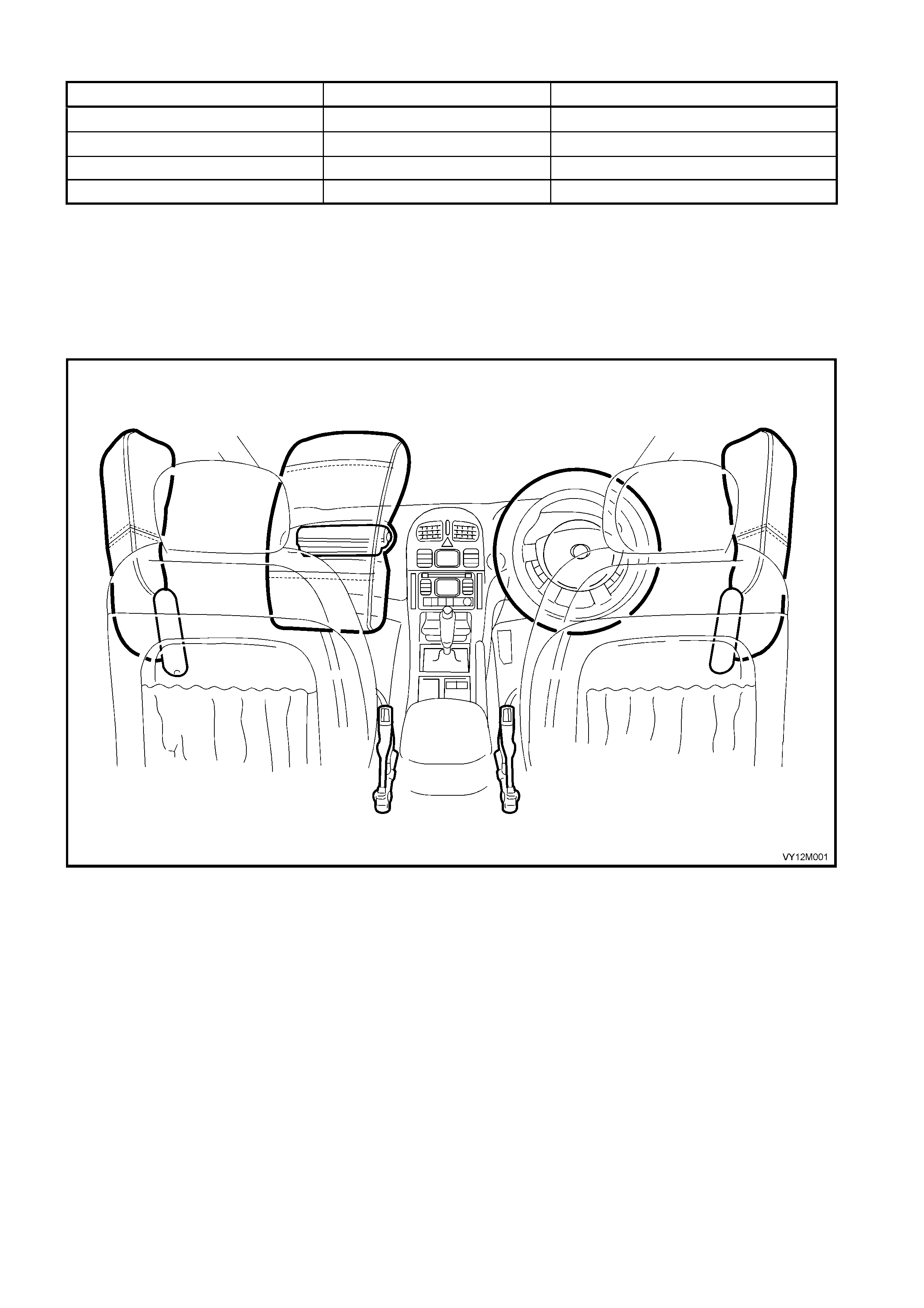
The Occupant Protection System (OPS) incorporating the Supplemental Restraint System (SRS) used on MY
2003 VY and V2 Series is intended as a su pplement to the pro tection off ered by the driver a nd front passen ger’s
seat belts b y deploying a S teering wheel inflata ble restr aint (Driver’s airbag) f rom the centre of the steering wheel
and a I nstr ument pan el inf l atab le r es tr ain t (P as s enger ’ s airb a g) f r om the top lef t- h and s ide of the ins trument pane l
pad assem bly during certai n frontal collis ions. On veh icles equipped with Pretension er assembl y’s for the driver’s
and front passenger’s seat belts (pretensioners), the front seat belt pretensioners are also activated.
On vehicles e qu ipp ed with a Inf lata ble Res trai nt Co ntrol Modu le ( S ens ing an d Di agnos t ic Module or SDM) ver s ion
8.1, the addition of side-impact inflatable restraints (Side-impact airbags) provide further protection for the driver
and front passenger’s during certain side-impact collisions. Refer to Figure 12M-1 for airbag and pretensioner
locations.
Deployment of the inflatable restraint/s and front seat belt pretensioners is automatic, making the occupant
protection system a passive restraint system. The driver does not control the operation or activation of the system.
The pretensioners and front inflatable restraints (Driver’s airbag and passenger’s airbag) operate if the vehicle is
involved in certain frontal, or near frontal impacts. The frontal impact would normally be within a 60 degree
window, occurring up to 30 degrees off the centre line of the vehicle, refer to Figure 12M-2. The pre-conditions
that determine the operation of the Side-impact airbags are much harder to quantify in terms of set speeds or
quotable angles of impact.
The OPS / SRS) controller, the SDM has the ability to command some aspects of the OPS / SRS restraint devices
independently of each other; deployment of the front seat belt pretensioners only, front seat belt pretensioners
and front inflatable restraints (Airbags), or side-impact airbags. Activation is not designed to occur in situations
that would not provide any driver/front passenger’s protection benefit.
A side-impac t airbag will o n l y dep lo y on the s i de o n whic h a s id e-impac t collision o c cur s and is independ ent of the
front seat belt pretensioners and front inflatable restraints. Side-impact airbag deployment conditions are not
readily quantifiable. The side-impact airbags are calibrated to deploy in accidents where there is risk of serious
injury to the (relevant) occupant. However, while the side-impact airbag will deploy and offer protection in most
serious side-impact collisions, it will not do so in all collisions. The limited time available to detect some events
means that it is not pos sib l e to d ep loy the sid e-impact air ba g i n e very situati on it woul d b e des ir ab le to do s o . This
is particularly true of some pole type collisions.
The follo wing tab le sum marises the versi on usage on MY 2003 VY and V2 Series.
SDM SEAT BELT
PRETENSIONE
R FRONT LEFT
SEAT BELT
PRETENSIONE
R FRONT
RIGHT
STEERING
WHEEL
INFLATABLE
RESTRAINT
(DRIVER’S
AIRBAG)
INSTRUMENT
PANEL
INFLATABLE
RESTRAINT
(PASSENGER’S
AIRBAG)
SIDE-IMPACT
INFLATABLE
RESTRAINT (SIDE-
IMPACT AIRBAG
FRONT LEFT
SIDE-IMPACT
INFLATABLE
RESTRAINT
(SIDE-IMPACT
AIRBAG) FRONT
RIGHT
8.0
(Two
Loops) ✷ ✷
8.0
(Three
Loops) ✷ ✷ ✷
8.0
(Four
Loops) ✷ ✷ ✷ ✷
8.1
(Six
Loops) ✷ ✷ ✷ ✷ ✷ ✷
As a result of the side-impact airbag deployment conditions not being readily quantifiable, the following pre-
conditions determine the operation of the OPS / SRS front seat belt pretensioners and front inflatable restraints
only. The seat belt pretensioners and front inflatable restraints will deploy independently of the side-impact
airbags.
NOTE: The f igures quoted in the table be low are the m inim um required for the O PS / SRS to depl oy and are the
equivalent of a head on contact between the vehicle and a barrier or other immovable object.
In mos t accident scenarios, the vehicle speed r equired to activate the pretens ioners and front inflatable res traints
would be much greater than these values.
SITUATION PRETENSIONER FRONT INFLATABLE RESTRAINTS
No Deployment 15 km/h∗ 20 km/h∗∗
Complete Deployment 20 km/h∗ 28 km/h∗∗
Inflation/Tension Time 5 ms 30 ms
Max. Displacement Free Moving Mass 3.0 cm 12.5 cm
• If the vehicle is travelling below 15 km/h and is involved in a frontal, or near frontal collision, the seat belt
pretension er will not deplo y, bet ween 15 and 20 km /h, the seat belt Prete nsioner m ay or may not deplo y, an d
over 20 km/h, the seat belt pretensioners will deploy.
• If the vehicle is travelling below 20 km/h and is involved in a frontal, or near frontal collision, the inflatable
restraint/s will not dep loy, bet ween 20 and 28 km /h, the inflatable r estraint/s ma y or ma y not deplo y, and over
28 km/h, the inflatable restraint/s will deploy.
• The inflation time for a side-impact inflatable restraint (Side-impact airbag) is approximately 10 ms.
Figure 12M-1
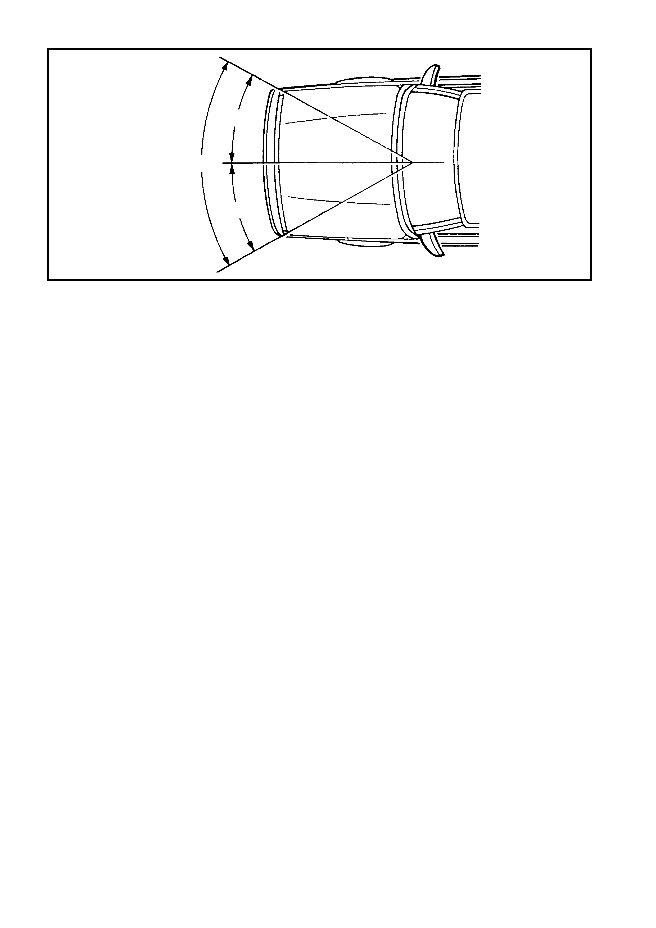
Figure 12M-2
For deplo ym ent to occur, n umerous f actors must be tak en into account. F or instance, th e crush are a of the other
vehicle if in vol ved in the c ollisi on, its m ass and s peed would a ll contr ibute to ra ising or lo wering th e f orce requir ed
for deplo yment to occur as designed. As a ge neral ru le, for front inf latable res traints and pretens ioners, t he ang le
of impact force will be within the 60 degree window for OPS / SRS deployment to occur (refer Figure 12M-2),
although the physical damage to the vehicle may appear that it was.
The sensors that control the front inflatable restraints and seat belt Pretensioner deployment are incorporated in
the Inflatable Restraint Control Module, located beneath the centre console.
There are two side-impact sensors (Peripheral acceleration sensors) that control the deployment of the side-
impact inflatable restraints; one in the left-hand B-pillar, and the other in the right-hand B-pillar. If a peripheral
acceleration sensor detects a collision situation, it will send a signal to the Inflatable Restraint Control Module
requesting a side-impact inflatable restraint be deployed. If the Inflatable Restraint Control Module is in
agreement, deployment will occur.
Regular maintenance of OPS / SRS is not required. If at anytime the OPS / SRS warning indicator comes on while
drivin g, or does n ot c ome o n when the vehicle is s tarte d, there is a system f ault a nd t h is mus t be r ec tif ied as s oon
as possible.
The TECH 2 diagnostic scan tool is programmed to assist with MY 2003 VY and V2 Series electrical diagnosis
and problem solving, including the OPS / SRS.
TECH 2 connects to the OPS / SRS serial data communication information via the Serial Data Link Connector
(DLC), attached to the instrument panel lower right-hand trim, to the right of the steering column. For additional
information on DLC location and system diagnosis, refer to 4 DIAGNOSIS in this Section. For more specific and
comprehensive information regarding TECH 2, refer to Section 0C TECH 2.
IMPORTANT: Accessory type or after market bull bars or such devices not approved by Holden's and fitted to
vehicles with the OPS / SRS may adversely affect the vehicles desired threshold characteristics for OPS / SRS
deployment.
Accessory and after market seat covers MUST NOT be fitted to a vehicle with side-impact inflatable restraints
unless appr ove d b y Holde n. Seat c over s t hat are not a pprov ed b y Hold en coul d g reatl y inhib it the perfor m ance of
the side-impact inflatable restraint and occupants safety in the event of side-impact inflatable restraint
deployment.
On vehicles with a Passenger’s airbag, accessor y type or after mark et type dash panel carpet covers, or th e like
MUST NO T be i ns tal le d, as this wi ll gr eat ly inhib it the per f ormance of the i nf lata bl e res tr aint an d f r ont pas seng er ’s
safety in the event of an inflatable restraint deployment.
Fitting of accessories such as drink holders, cassette racks additional mirrors, etc. are not permitted in the
immediate deployment area of the front instrument panel and side-impact inflatable restraints as these may be
ripped off and propelled towards the vehicle's occupants when the inflatable restraint is deployed.
Figure 12M-3 illustrates the locations within the passenger’s compartment of the OPS / SRS components.
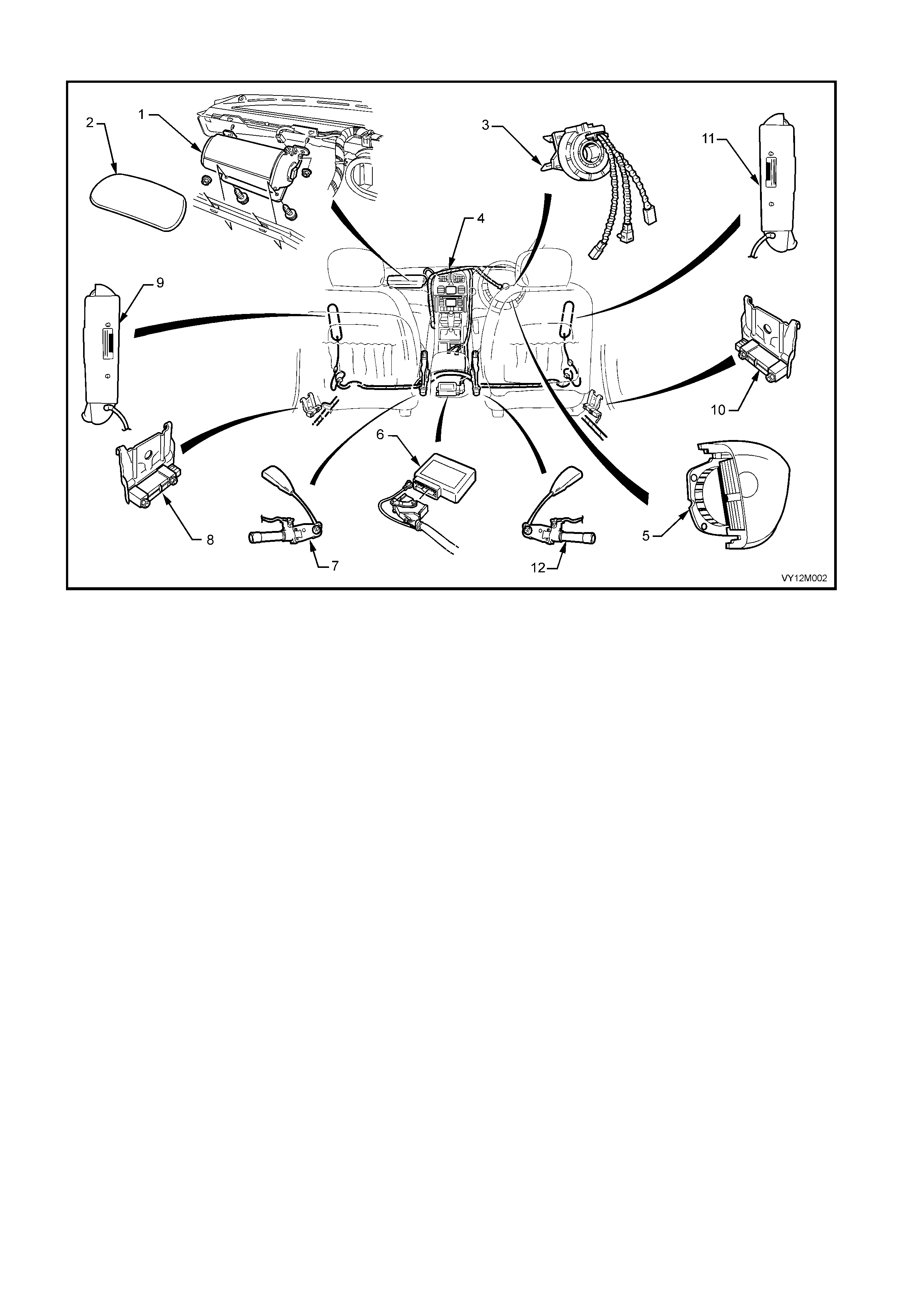
Figure 12M-3
Legend
1. Instrument Panel Inflatable Restraint (Passenger’s
Airbag) Inflator Asse mb ly .
2. Instrument Panel Inflatable Restraint (Passenger’s
Airbag) Door.
3. Clock Spring Coil Assembly.
4. OPS / SRS Wiring Harness (Part of Body W iring
Harness).
5. Steering Wheel Inflatable Restraint (Driver’s Airbag)
Module.
6. Inflatable Restraint Control Module (SDM).
7. Left-hand Seat Belt Pretensioner Assembly.
8. Left Side-impact Sensor (Peripheral Acceleration Sensor).
9. Left Side-impact Inflatable Restraint (Side-impact Airbag).
10. Right Side-impact Sensor (Peripheral Acceleration
Sensor).
11. Right Side-impact Inflatable Restraint (Side-impact
airbag).
12. Right-hand Seat Belt Pretensioner Assembly.
The O PS / SR S o perates t he airbag modules in f our s tages to pr otect th e dr i ver o r f ront s eat pas senger’s during a
side-impact collision, refer to Fig’s. 12M-4, 12M-5 and 12M-6.
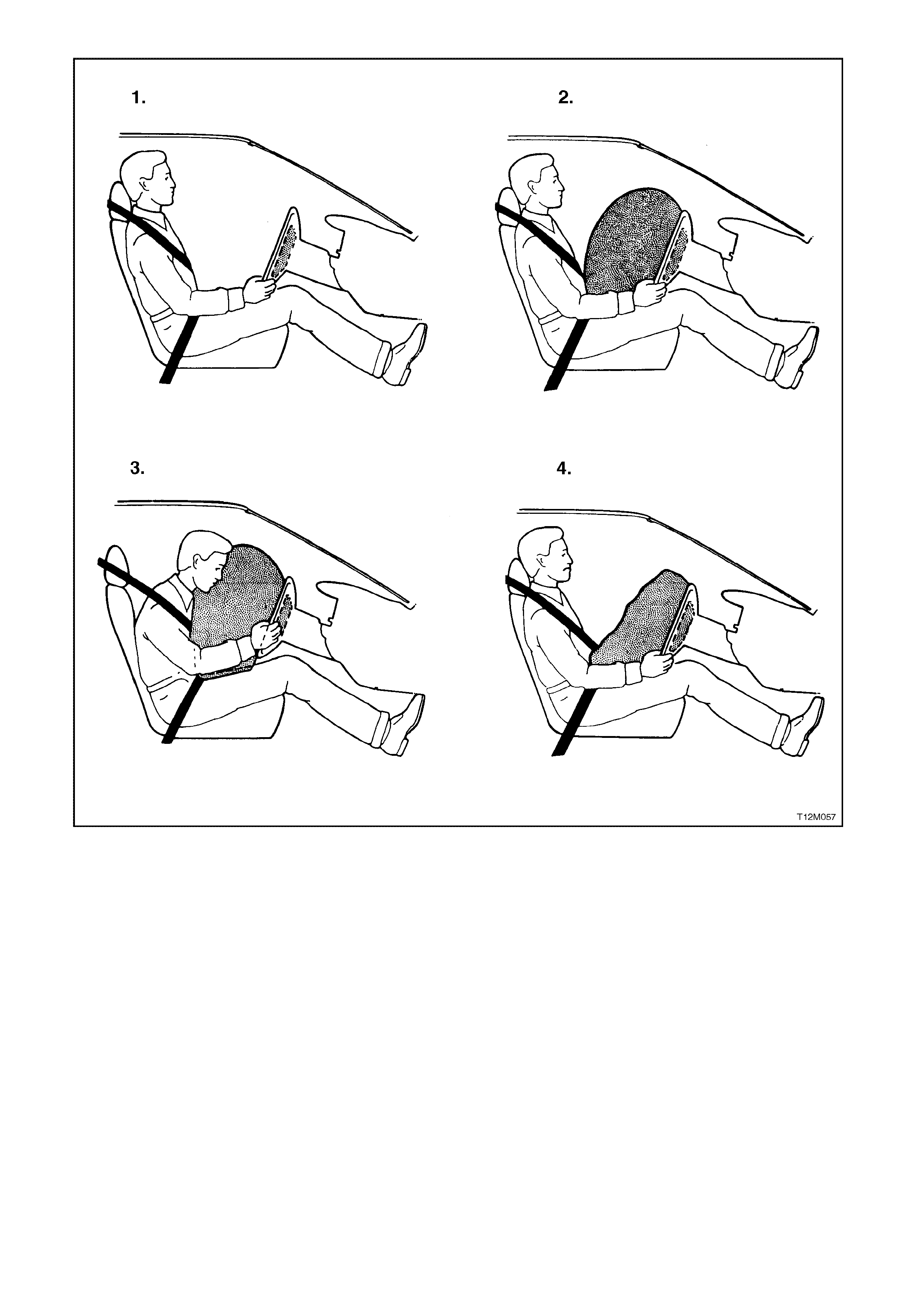
Figure 12M-4
Legend
1. Before Deployment: The OPS / SRS is in a state of
readiness, unless the Inflatable Restraint Control
Module (SDM) detects a fault and alerts the vehicle
driver via the OPS / SRS warning indicator in the
instrument cluster warning indicator panel.
2. Fully Deployed: The airbag is inflated and the SDM
records the data related to the OPS / SRS conditions
and operation.
3. During Restraint:: The force of the collision causes the
head and upper torso of the driver to move forward into
the inflated airbag. Gas is vented from the thorax or
chest region of the bag to the head region, reducing the
chest loads and providing support for the head and neck.
4. End of Collision
NOTE: A side-impact airbag will deploy independently of the other OPS / SRS inflatable restraints and
pretensioners.
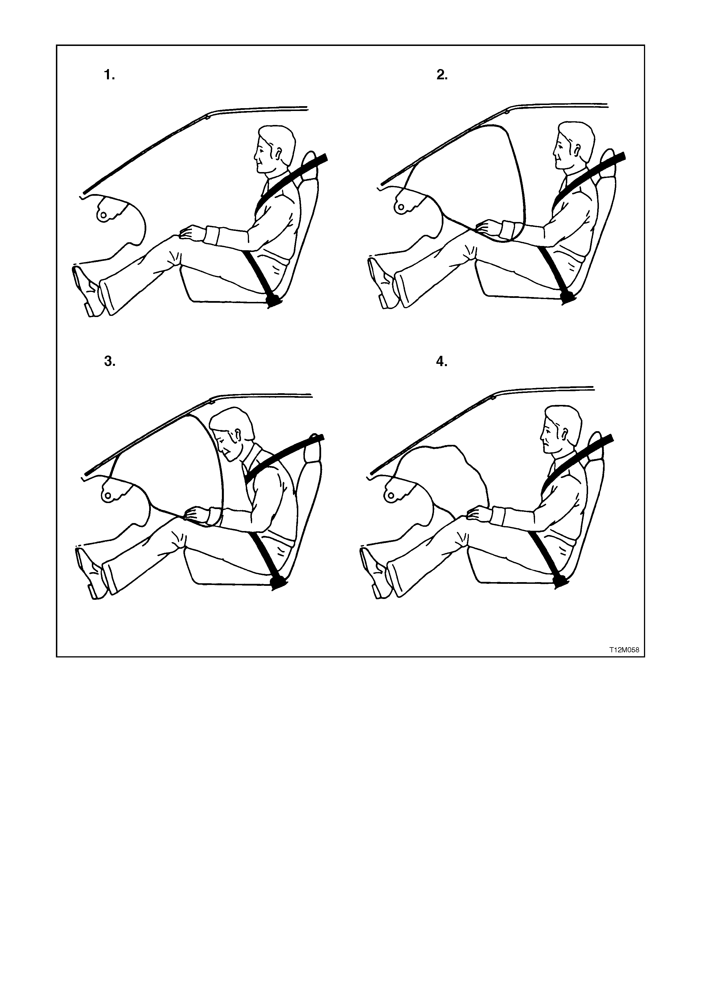
Figure 12M-5
Legend
1. Before Deployment: The OPS / SRS is in a state of
readiness, unless the Inflatable Restraint Control
Module (SDM) detects a fault and alerts the vehicle
driver via the OPS / SRS warning indicator in the
instrument cluster warning indicator panel.
2. Fully Deployed: The airbag is inflated and the SDM
records the data related to the OPS / SRS conditions
and operation.
3. During Restraint:: The force of the collision causes the
head and upper torso of the driver to move forward into
the inflated airbag. Gas is vented from the thorax or
chest region of the bag to the head region, reducing the
chest loads and providing support for the head and neck.
4. End of Collision
NOTE: A side-impact airbag will deploy independently of the other OPS / SRS inflatable restraints and
pretensioners.
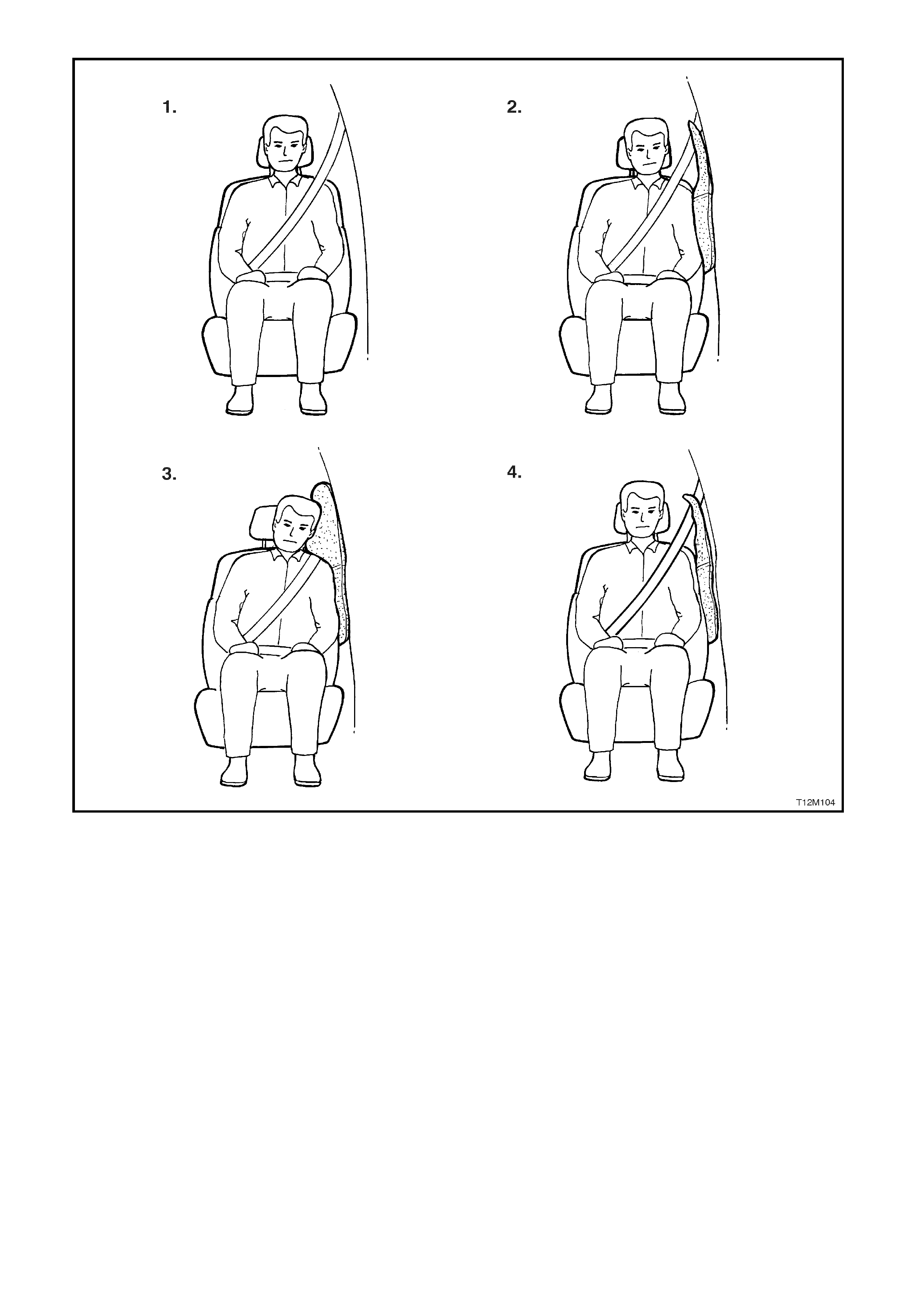
Figure 12M-6
Legend
1. Before Deployment: The OPS / SRS is in a state of
readiness, unless the Inflatable Restraint Control
Module (SDM) detects a fault and alerts the vehicle
driver via the OPS / SRS warning indicator in the
instrument cluster warning indicator panel.
2. Fully Deplo yed: The airbag is inflated and the SDM
records the data related to the OPS / SRS conditions
and operation.
3. During Restraint: The force of the collision causes the
head and upper torso of the driver to move forward into
the inflated airbag. Gas is vented from the thorax or
chest region of the bag to the head region, reducing the
chest loads and providing support for the head and neck.
4. End of Collision
NOTE: A side-impact airbag will deploy independently of the other OPS / SRS inflatable restraints and
pretensioners.

1.1 SYSTEM COMPONENTS
INFLATABLE RESTRAINT CONTROL MODULE
The Inflatable Restraint Control Module (SDM) is
mounted under the centre console assembly, consists
of an electr onic acceler ation sensor s ystem , electronic
control system, energy storage devices, self
diagnostics, fault memory and collision event
recording facility, refer Figure 12M-7.
The primary function of the SDM (1), as part of the
OPS / SRS, is to sense collision events and
discriminate between non-deployment and required
deployment events.
The SDM is a centralised, self contained collision
sensing and triggering system that, with exception of
the two side-impact sensors (Peripheral acceleration
sensors) for detecting la teral acceleration for the side-
impact inflatable restraint (Side-impact airbags),
requires no additional external sensing inputs. The
SDM also per f orm s c ontinu al tes ts on the Pr et ens ioner
and inflatable restraint circuits for the front seat belt
pretensioners, the steering wheel inflatable restraint
(Driver’s airbag) and front instrument panel and side-
impact airbags (if fitted).
Figure 12M-7
In the case of a deployment event, the function of the sensing system is to initiate the pretensioners or the
pretensioners and front inflatable restraint/s or relevant side-impact airbag in a timely manner in order to protect
the vehicle occupants. Secondary to this, the SDM can diagnose system faults, which may prevent airbag
deplo yment or inc rease the probab ility of an inadver tent deplo yment. T he SDM can also provi de a warning to the
driver in the case of a system fault.
NOTE: The SDM is designed for a one-time deployment use only, and must be replaced after a deployment. If
deployment occur s and t he SDM is not re plac e d, th e O PS / SRS war n ing in dic at or in th e i nstr ument c luster will be
continually illuminated.
Integrated in the SDM are two piezoelectric sensors (collision sensor) that constantly monitor the acceleration
data of the vehicle. Microprocessors within the SDM run the outputs from these acceleration sensors
(accelerometers) through a complex mathematical algorithm. A similar function is performed by each peripheral
accelerat ion sens or ( where f itted). The r espective out p uts are c ompared to a s et of stored va lues in t he proce ss or
memory. If the processed values exceed their set of stored values, the SDM provides an AC output signal to ignite
the pyrotechnic gas generators of the relevant OPS / SRS components.
An energ y reser ve (capacit or) in t he SDM s tores suf ficient en ergy to activate th e inf latable res traint /s in the event
of the electrical system being damaged by the impact.
The electronic diagnostic facility within the SDM constantly monitors the electrical circuits and the firing circuit.
Faults that occur in t he system are stored in the m emory and the OPS / SRS warning indicator in the instrum ent
cluster warning indicator panel will be switched on.
1. The SDM performs the following functions:
(a) Continuously monitors the OPS / SRS electrical circuits.
(b) Controls the OPS / SRS warning indicator in the instrument cluster to alert the vehicle driver of a
detected system fault.
(c) Provides back-up power (in case the vehicle system power is lost during a collision) to operate the
airbag module/s.
2. The SDM during deployment, records and stores OPS / SRS and collision event information:
(a) Diagnostic Trouble Codes (DTC’s) for detected faults.
(b) OPS / SRS warning indicator operation data.
3. The SDM communicates diagnostic information through the Serial Data Link Connector (DLC) for the
follo wing purposes :
(a) System checks at the vehicle assembly plant.
(b) Service diagnosis (using TECH 2).
(c) Transmitting of collision event recording data for post collision analysis.

For details on connecting TECH 2 to the DLC, refer to 4.4 TECH2 DIAGNOSTICS in this Section, or for more
detailed information regarding TECH 2, refer to Section 0C TECH 2.
Addition ally, in th e even t of O PS / SRS d eplo yment, the SDM will s end ser ial dat a via t he aux iliar y serial dat a bus
(circuit 774) to advise various vehicle systems to take appropriate shutdown action.
The Powertrain Control Module (PCM) monitors this serial data and performs a vehicle shutdown once the
appropriate data is identified and the vehicle speed is zero for more than 10 seconds.
The Body Control Module (BCM) also monitors this serial data and performs the following actions once the
appropriate data is identified and the vehicle speed is zero for more than 10 seconds:
1. Turn the interior compartment lamp on continuously.
2. Unlock all doors.
NOTE: This is only effective for the ignition cycle in which the deployment(s) occurred. Providing the vehicle
electric’s are functional, cycling the ignition will restore normal function.
For MY 2003 VY and V2 Series with OPS / SRS 8.0 and 8.1 systems, four different and non-interchangeable
SDM’s are released. These systems can be identified by the last digit of the part number:
• 2 − 2 loop system for pretensioners only (8.0 SDM).
• 3 − 3 loop system for pretensioners and driver’s airbag only (8.0 SDM).
• 4 − 4 loop system for pretensioners, driver’s airbag and Passenger’s airbag (8.0 SDM).
• 6 − 6 loop system for pretensioners, driver’s airbag, Passenger’s airbag and side-impact airbags (8.1 SDM).
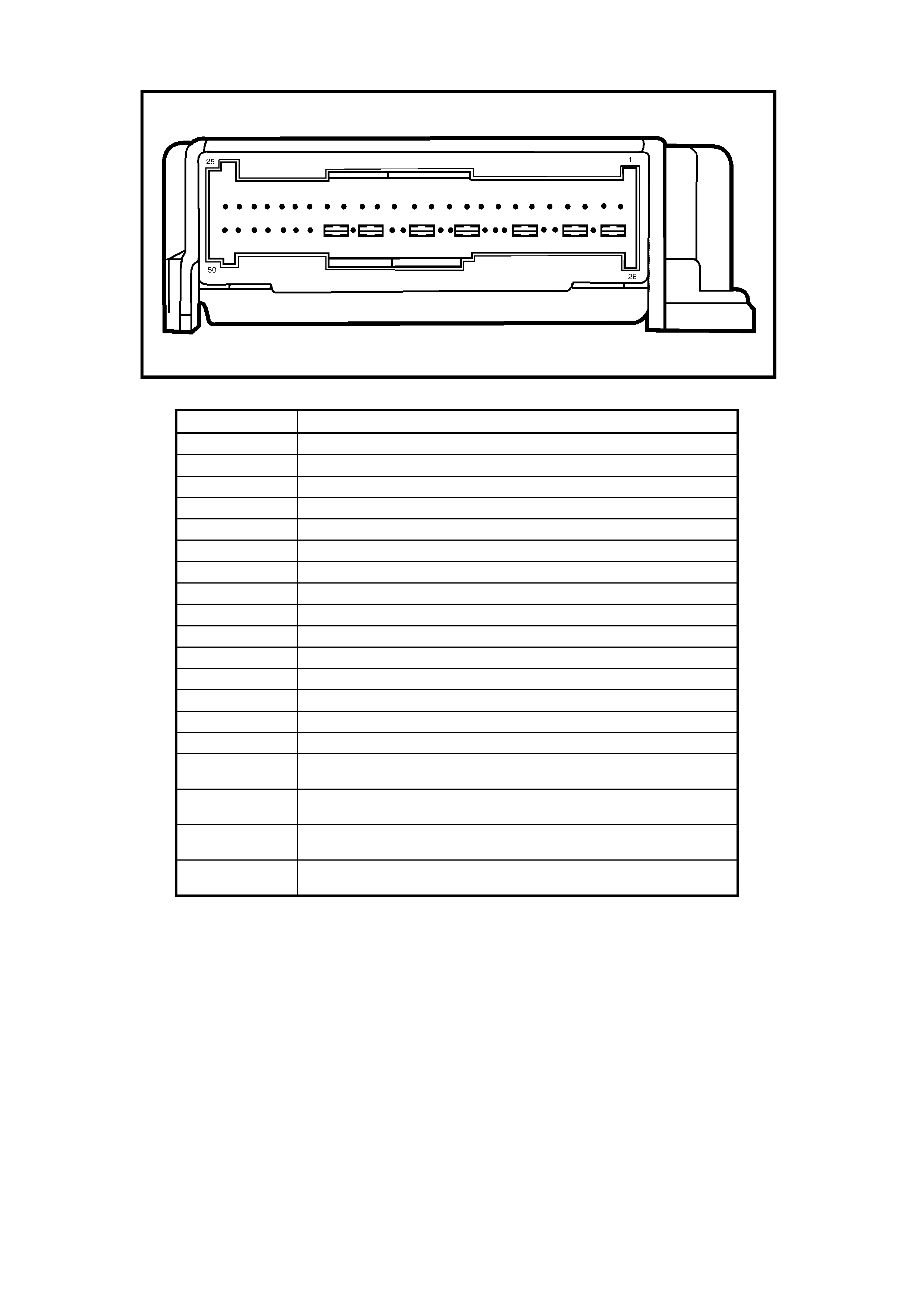
Refer to F igure 12M-8 for SDM version 8.0 t erminal as signments and F igure 12M-9 f or SDM version 8.1 te rminal
assignments.
NOTE: Always refer to the latest MY 2003 VY and V2 Series spare parts information for the latest part numbers
when ordering O PS / SRS c om ponents.
INFLATABLE RESTRAINT CONTROL MODULE (SDM) VERSION 8.0 TERMINAL ASSIGNMENTS
Figure 12M-8
TERMIN AL NO. FUNCTION
X1 – 1 PRETENSIONER _ PASSENGER’S _ HIGH (Left-hand Pretensi oner, plus)
X1 – 2 PRETENSIONER _ PASSENGER’S _ LOW (Left-hand Pretensioner, mi nus)
X1 – 3 PRETENSIONER _ DRIVER _ HIGH (Right-hand Pretensioner, plus)
X1 – 4 PRETENSIONER _ DRIVER _ LOW (Right-hand Pretensi oner, mi nus)
X1 – 5 IGNITION (B attery voltage)
X1 – 8 GROUND (Earth)
X1 – 9 SERIAL _ DATA (Serial data)
X1 – 10 DRIVER _ HIGH (Driver’s ai rbag, plus)
X1 – 11 DRIVER _ LOW (Driver’s ai rbag, minus )
X1 – 13 PASSENGER’S _ HIGH (Passenger’s airbag, pl us)
X1 – 14 PASSENGER’S _ LOW (Passenger’s airbag, minus)
INFLATABLE RESTRAINT CONTROL MODULE (SDM) VERSION 8.1 TERMINAL ASSIGNMENTS
Figure 12M-9
TERMINAL NO. FUNCTION
X1 – 1 PRETENSIONER _ PASSENGER’S _ HIGH (Left-hand Pretensi oner, plus)
X1 – 2 PRETENSIONER _ PASSENGER’S _ LOW (Left-hand Pretensioner, mi nus)
X1 – 3 PRETENSIONER _ DRIVER _ HIGH (Right-hand P ret ensi oner, plus)
X1 – 4 PRETENSIONER _ DRIVER _ LOW (Right-hand Pretensi oner, mi nus)
X1 – 5 IGNITION (B att e ry vol tage)
X1 – 8 GROUND (Earth)
X1 – 9 SERIAL _ DATA (Serial data)
X1 – 10 DRIVER _ HIGH (Driver’s airbag, plus)
X1 – 11 DRIVER _ LOW (Driver’s airbag, minus )
X1 – 13 PASSENGER’S _ HIGH (Passenger’s airbag, plus)
X1 – 14 PASSENGER’S _ LOW (Passenger’s airbag, minus)
X1 – 16 LEFT-HAND INFLATOR _ HIGH (Left-hand side-impact ai rbag, pl us)
X1 – 17 LEFT-HAND INFLATOR _ LOW (Left -hand si de-impact airbag, minus)
X1 – 18 RIGHT-HAND INFLATOR _ HIGH (Right-hand side-impact airbag, plus)
X1 – 19 RIGHT-HAND INFLATOR _ LOW (Right-hand side-impact airbag, minus)
X1 – 20 LEFT-HAND SIDE-IMPACT SENSOR MODULE _ HIGH (Left-hand
peripheral acc el eration sensor, plus)
X1 – 21 RIGHT-HAND SIDE-IMPA CT SENSOR MODULE _ HIGH (Right-hand
peripheral acc el eration sensor, plus)
X1 – 33 LE FT-HAND SIDE-IMPACT SENSOR MODULE _ LOW (Left-hand
peripheral acceleration sensor, minus)
X1 – 34 RIGHT-HAND SIDE-IMPA CT SENSOR MODULE _ LOW (Right-hand
peripheral acceleration sensor, minus)

SRS WARNING INDICATOR
The SRS warning indicator (SRS warning lamp) is located in the instrument cluster refer to Figure 12M-10.
The SRS warning indicator is controlled by the Inflatable Restraint Control Module (SDM), via the serial data
circuit and will illuminate to warn the driver that the system has been disabled or there is a fault in the system.
The SRS warning indicator will illuminate when:
• The ignition is switched ON; the SRS warning indicator will be illuminated for approximately five seconds to
indicate the system start-up sequence. During this period the SDM performs system wiring and self check. If
no system faults are detected, the SRS warning indicator will be switched OFF.
• If communication is lost between the SDM and the instruments (for example SDM wiring harness
disconn ected or no BCM p oll) the SRS warning indic ator will be i lluminated when the ignition is f irst switche d
ON and then c om manded O N c onstantly unt il t he f au lt is remedied ( com munic atio n r esumed) (No DTC will be
set).
• If the OPS / SRS is deplo yed, the SRS warning indica tor will be illuminated until t he problem is resolved (No
DTC will be set).
• If one or m or e curr ent or his tory Diagn ostic T rouble Codes (DT C’s) are det ected when t he ign ition is s witch ed
ON, the SRS warning indicator will illuminate and rem ain illuminated until the DTC is cleared. Additionally, 3
seconds after the ignition is switched ON, an audible warning chime will sound.
• During an ignition cycle, if the SDM detects a current DTC, the SRS warning indicator will be illuminated. If
during th is c yc le, t he cur r ent DT C f ault c o ndi ti on cl ears, a h is tor y DTC will be log ged in the SD M and the S RS
warning indicator will still remain illuminated.
• When TECH 2 is communicating with the SDM, the SRS warning indicator will be illuminated and the OPS /
SRS will be disab le d.
• For details on all DTC’s, refer to 4 DIAGNOSTICS in this Section.
MULTI- FUNCTION DISPLAY
In addition to th e SRS warnin g indicator, th e instrum ent cluster has a Multi-f unction Disp la y (MFD) which displa ys
a warning message (SRS Fault) to alert the driver of a possible problem with the system.
The MFD war ning mes sage is controlled b y the BCM. The MFD warnin g mess age is acti vated by the BC M when
the SDM sets a poll response message, via the serial data circuit.
The MFD warning message flashes with the wording (SRS Fault) stationary until the MODE button on the trip
computer switch is pressed. The SRS warning indicator illuminates as soon as the MFD warning message is
activated and remains illuminated until the problem is rectified.
The MFD has two types of SRS fault displa ys this is dependent on whether the vehicle is equipped with airbags
and pretensioners or just pretensioners. For more information refer to Section 12C, INSTRUMENTS,
1.7 MULTI-FUNCTION DISPLAY −
−−
− ALL MODELS.
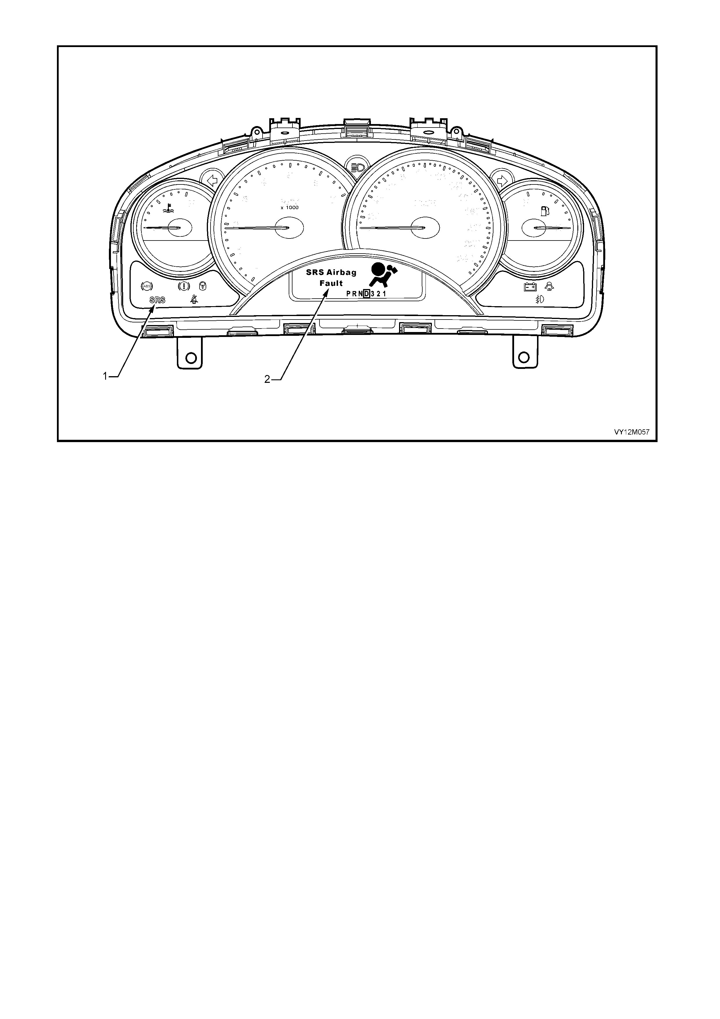
Figure 12M-10
Legend
1. SRS warning indicator (SRS warning lamp) 2. Multi Function Display (MFD)
CHIME ALERT
The SRS warning indicator and Multi-function Display (MFD) are complemented by a warning chime to alert the
driver audibly of a possible problem with the system.
Like the MFD warning message, the warning chime alert is controlled by the BCM. The warning chime alert is
activated by the BCM when the SDM sets a poll response message, via the serial data circuit.
The warn ing chim e alert s ounds thre e tim es, the MFD war ning m essage flashes (with the wording st ationar y until
the MODE button on the trip computer switch is pressed) and SRS warning indicator illuminates as soon as the
warning chime alert is activated. For more information refer to Section 12C, INSTRUMENTS,
1.6 INSTRUMENT OPERATION ALL −
−−
− MODE LS
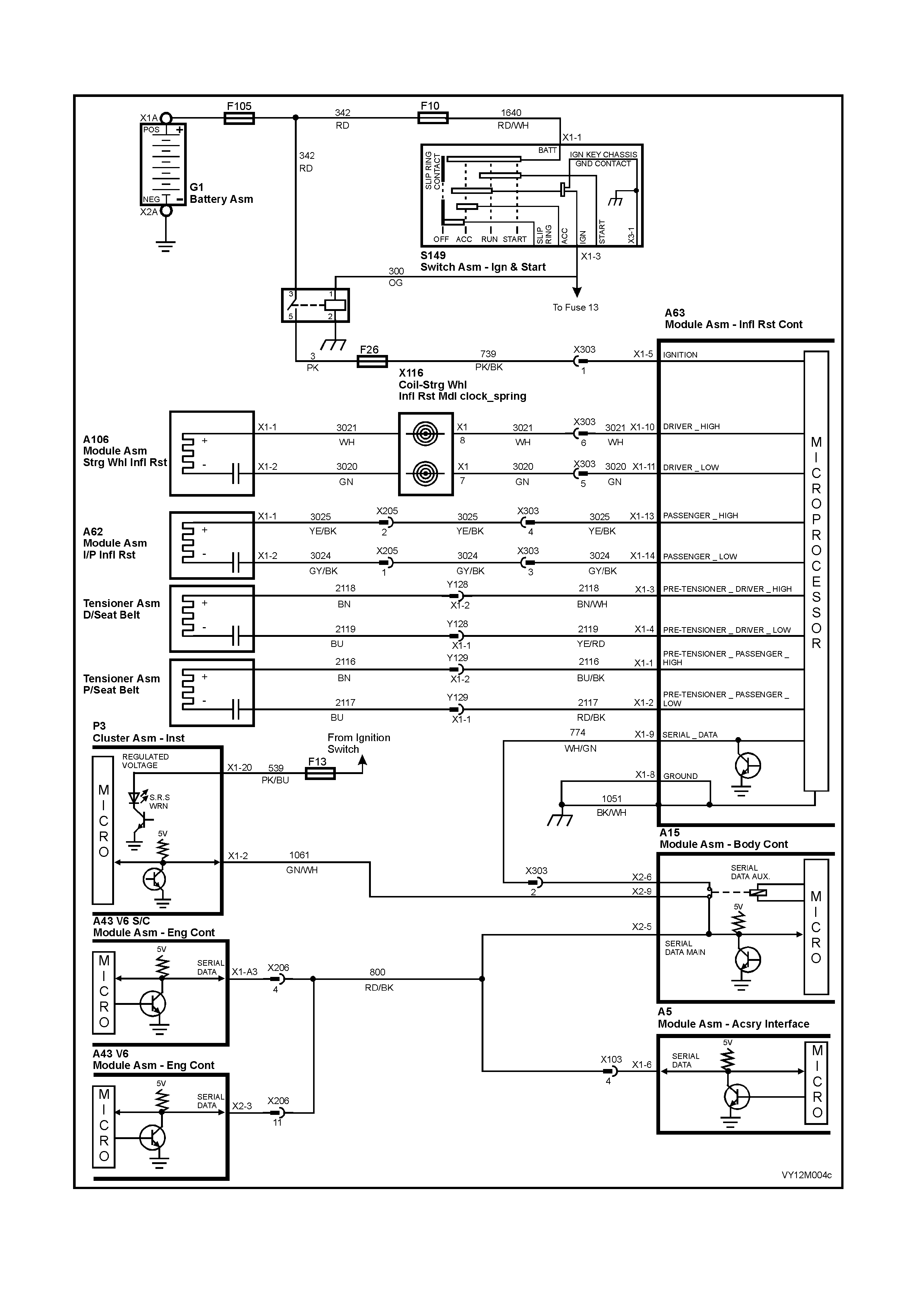
CIRCUIT DIAGRAM FOR VEHICLES WITH A 8.0 INFLATABLE RESTRAINT CONTROL MODULE
Figure 12M-11
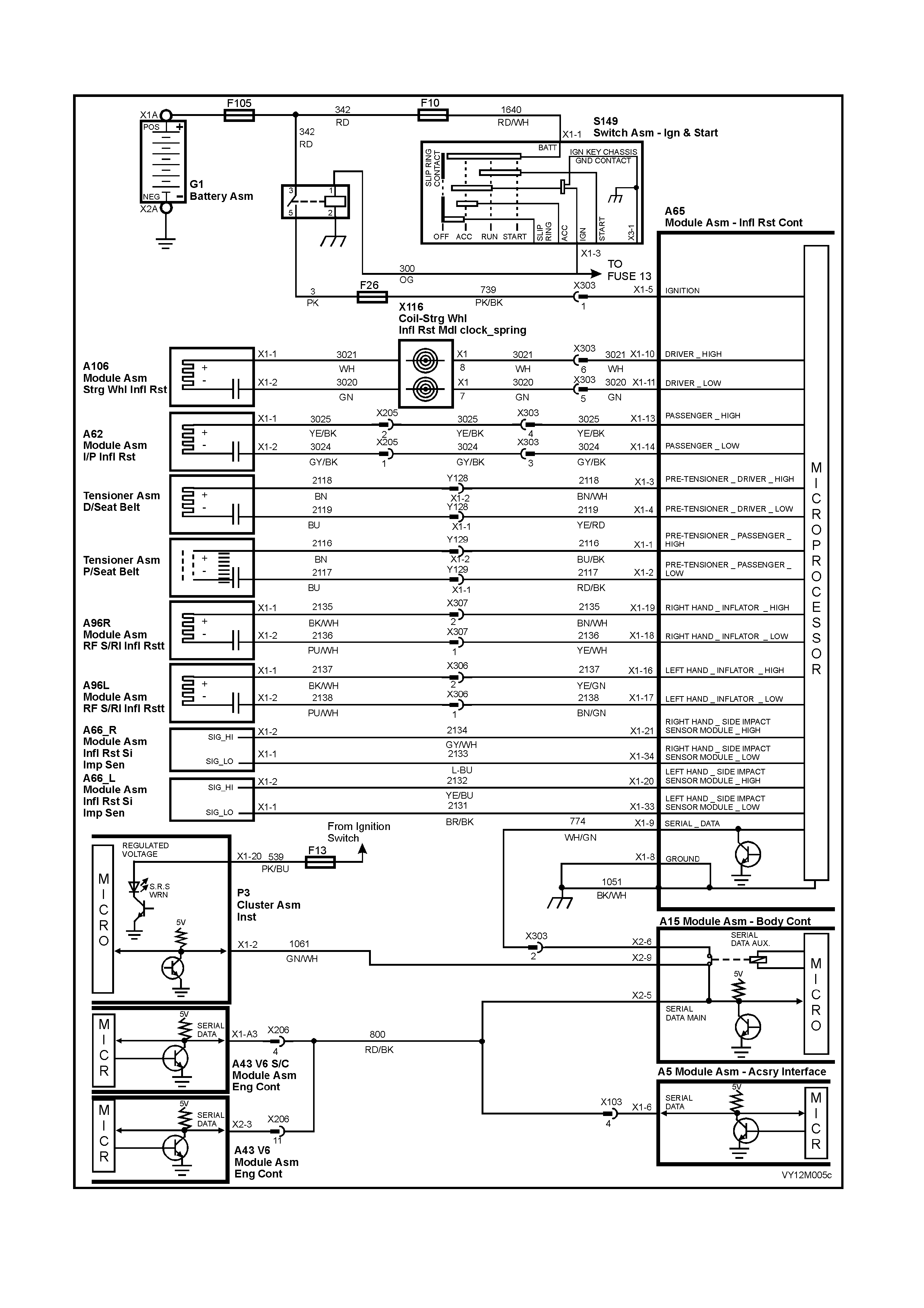
CIRCUIT DIAGRAM FOR VEHICLES WITH A 8.1 INFLATABLE RESTRAINT CONTROL MODULE
Figure 12M-12
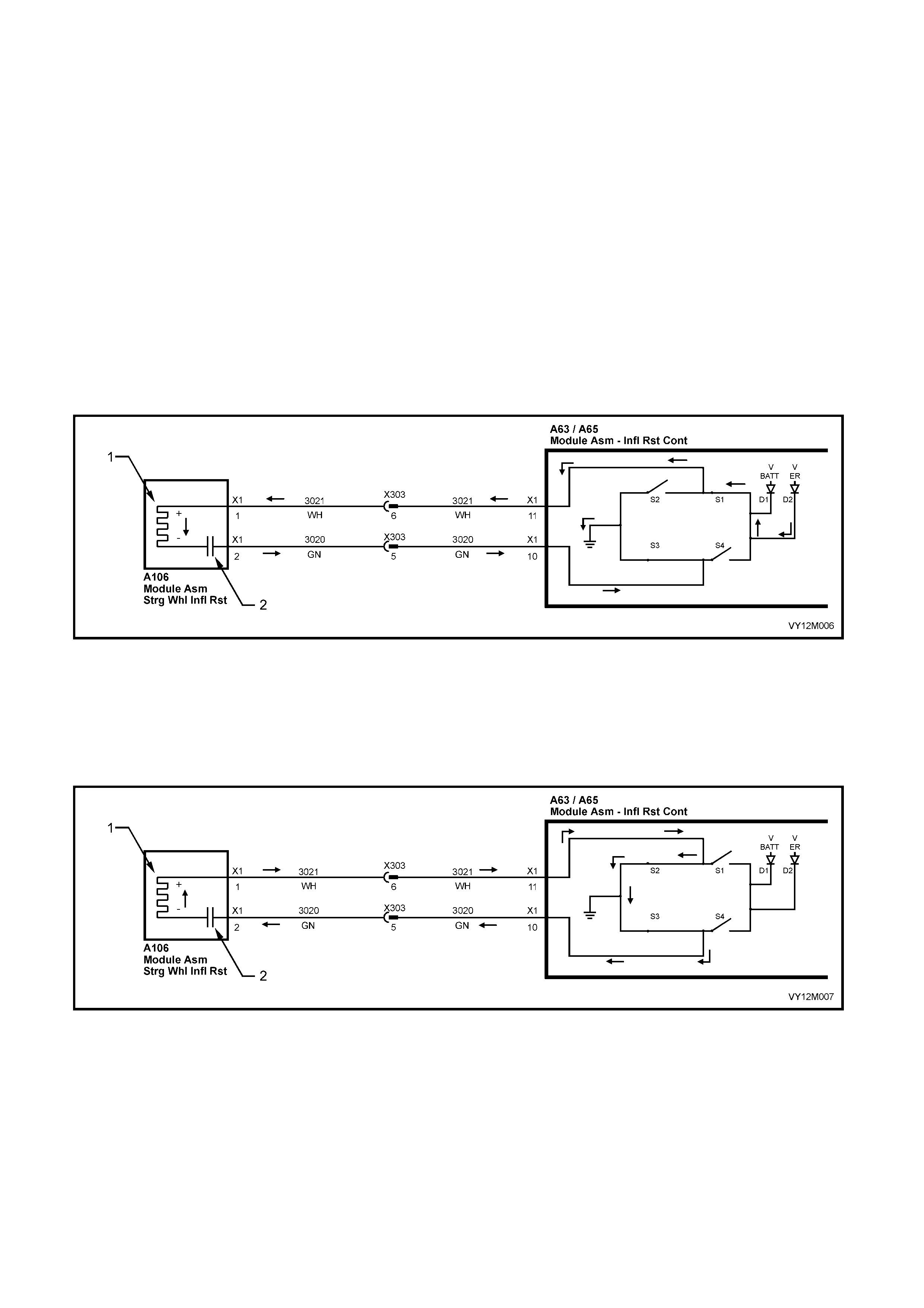
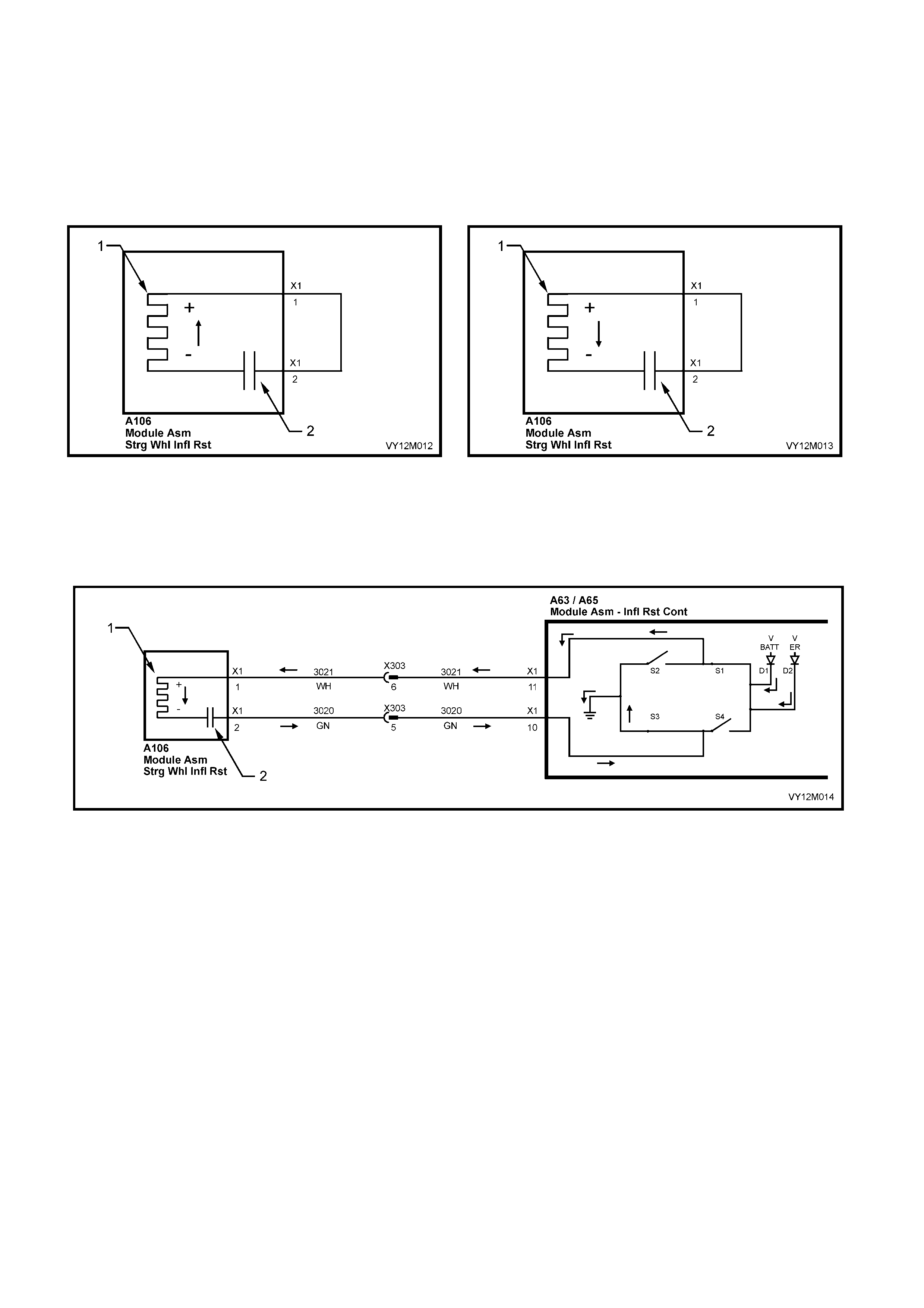
SYSTEM OPERATION
W ith an AC fir ing system it is pos s ible to f ir e t he i nf lata ble res tr a ints a nd pretensi o ners eve n if a ( s ing le wire) s hort
circuit exists, this is possible due to the use of a ‘H’ firing circuit refer Figure 12M-13.
The ‘H’ bridge circuit is used to allow readiness in the case of single wiring harness faults. The bridge structure
allows several firing paths so that the initiator can still be fired even if one of the four power transistors is faulty.
The firing energy is fed from the energy reserve by diode D2 and from the battery by diode D1.
This means that the higher of the two voltages is always present at the power stages. Normally this energy
reser ve vo ltage is 45 volts. If for any reaso n the reser ve volta ge is unavai lable if a f iring is req uired, it is possible
to trigger from the battery voltage.
NOTE: The oper ati on of on l y one f iring l oop is d esc r ib ed i n t he f ol lo wing ex p lan at ion. Ho wev er the oper at ion of all
firing loops is the same.
FIRING MODE 1 −−−− CHARGING
• S1 is closed.
• S2 is open.
• S3 is closed connecting the firing loop (−) to ground.
• S4 is open.
Figure 12M-13
Legend
1. Initiator 2. Capacitor
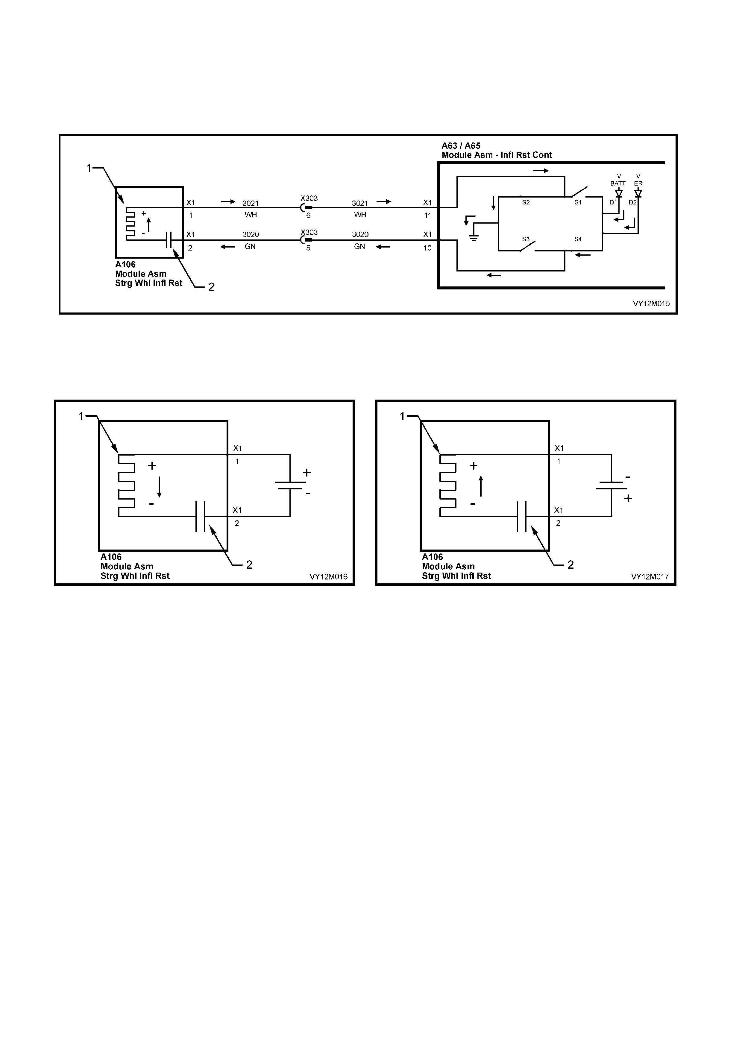
FIRING MODE 1 −−−− DISCHARGING
S1 and S2 are switched alternately for approximately 5 µs, thereby causing charging and discharging cycles at
the initiator .
Figure 12M-14
Legend
1. Initiator 2. Capacitor
In the firing m ode 1 phase of the oper ation a shorted f iring loop (−) has no influenc e on firing, as the f iring current
flows thr oug h th e in it iator vi a S1 and S2 . S 3 is n ot d am aged du e to the curr ent l imiting of the p ower stag es e ven if
a short to b attery exists . Fir ing t hen tak es place in to th e s hor t cir cuit to battery volt age, r ef er to Fi gur e 1 2M-1 3 and
Figure 12M- 14.
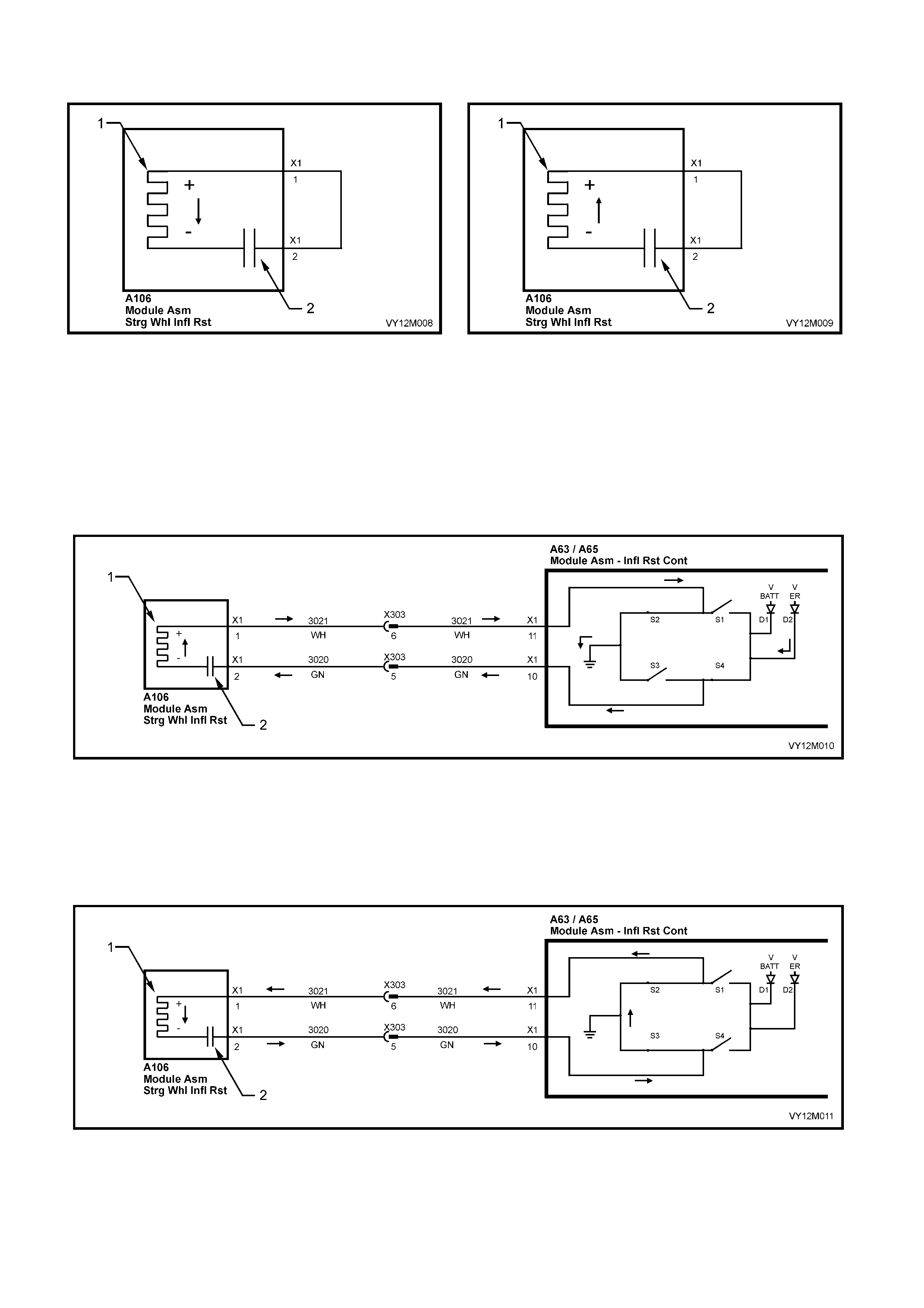
FIRING MODE 1 −−−− CHARGING FIRING MODE 1 −−−− DISCHARGING
Figure 12M-15
Legend
1. Initiator 2. Capacitor
FIRING MODE 2 −−−− CHARGING
• S1 is open.
• S2 is closed and firing loop (+) is therefore connected to ground.
• S3 is open.
• S4 is closed.
Figure 12M-16
Legend
1. Initiator 2. Capacitor
FIRING MODE 2 – DISCHARGING
S4 and S3 are switched alternately for approximately 5 µs, thereby causing charging and discharging cycles at
the initiator .
Figure 12M-17
Legend
1. Initiator 2. Capacitor
In the f iring m ode 2 p hase of the oper ation a short circ uit at th e firin g loop (+) h as no inf luenc e sinc e firing cu rrent
flows through the initiator via S4 and S3. S2 is not damaged due to the current limitation of the power stages,
even if a short circ uit to batter y voltage ex ists on the f iring loop (+) line. F iring takes place into t he short circ uit to
battery voltage, refer to Figure 12M-16 and Figure 12M-17.
Modes 1 and 2 are activated alternately for several cycles respectively. If the voltage at the power stages has
dropped to below 25 volts, phase 3 is started. If the energy reserve is not available f or any reason when fir ing is
required, only battery voltage at the power stage is present, and firing occurs immediately with firing mode 3.
FIRING MODE 2 −−−− CHARGING FIRING MODE 2 −−−− DISCHARGING
Figure 12M-18
Legend
1. Initiator 2. Capacitor
FIRING MODE 3 −−−− CHARGING
S2 and S4 are switched open, S1 and S3 are switched closed. This charges the capacitor to battery voltage.
Figure 12M-19
Legend
1. Initiator 2. Capacitor
FIRING MODE 3 −−−− DISCHARGING
S1 and S3 are s witched open, S2 a nd S4 are switche d closed. This dis charges the c apacitor and then c harges it
in the reverse direction. Due to this recharging of the capacitor via the firing element from positive voltage to
negative voltage, the firing voltage of this mode can be considered to be doubled to 2 x VER (Energy Reserve
Voltage) or 2 x VBAT (Battery Voltage). As a result AC firing from battery voltage is possible.
Figure 12M-20
Legend
1. Initiator 2. Capacitor
FIRING MODE 3 −−−− CHARGING FIRING MODE 3 −−−− DISCHARGING
Figure 12M-21
Legend
1. Initiator 2. Capacitor
FIRING LOOP MONITORING
The firing loop monitoring ensures that failures in the firing leads and initiators that could affect triggering are
identified.
The following errors in the firing loops or initiators are detected:
• Short circuit or leakage resistance to ground or battery voltage.
• Short circuit or shunt circuit between firing leads of the firing loop.
• Resistance of the initiator too high or too low.
• Capacitance of the firing loop capacitor too high or too low.
In the case of AC firing, m easurement of the init iator resistance is more difficult because no direct measurem ent
of this r esistanc e is poss ible due t o the in seri es capa citor. T he d ynam ic meas urem ent descr ibed belo w allo ws an
accurate measurement of the firing loop resistance.
The following sequence is used for diagnosis:
1. Test whether a short circuit or leakage resistance from the firing line to battery voltage or ground exists.
2. The firing loop capacitor is charged from the energy reserve through a resistor. The charging is interrupted
after a short time and the voltage across the firing loop capacitor is measured. This voltage is a measure of
the capacitance of the firing loop capacitor.
3. The initiator resistance measurement is performed directly after the capacitance measurement by briefly
discharging the firing loop capacitor through the initiator. The discharge of the capacitor is a measure of the
loop resistance.
STEERING WHEEL INFLATABLE RESTRAINT MODULE ASSEMBLY
The steering wheel inflatable restraint module assembly (Drivers Airbag Module) contains 4 main components
refer to Figure 12M-22.
IMPORTANT: The airbag module assembly components are not repairable. Under no circumstances are the
components of the horn bar and airbag module assembly to be disassembled. The assembly contains a
pyrotechnic gas generator and the airbag cushion fold is critical to airbag performance and driver safety.
Figure 12M-22
Legend
1. Inflator Assembly.
2. Cloth Cushion 3. Trim Cover
4. Base Plate and Locating Legs
The airba g module (inflator) contains several com ponents, refer to F igure 12M-23 which shows a typical inf lator
assembly:
1. An Elec tro Exp losi ve Devic e ( EED), with a n electr ica l heat ing el em ent (calle d an initia tor) an d a sm all am ount
of Lead Styphnate covered with a mixture of Titanium Hydride and Potassium Perchlorate.
2. An enhancer pack with approximately 3 grams of Barium Potassium Nitrate.
3. A carbon based non-toxic composite propellant.
4. A fine particle filter.
5. Nitrogen gas outlets for airbag inflation.
6. EED Connector pins for connector A106 – X1
During deployment, the airbag module operates in the following sequence:
1. The EED initiator receives current from the Inflatable Restraint Control Module (SDM) and begins the
chemical reaction by igniting the Lead Styphnate and the mixture of Titanium Hydride and Potassium
Perchlorate.
2. The EED ignites the Barium Potassium Nitrate in the enhancer pack.
3. The enhancer pack chemical reaction causes the carbon based non-toxic composite propellant to rapidly
produce Nitro gen gas .
4. The Nitrogen gas pushes the airbag cushion, which separates the steering wheel horn bar trim cover and
inflates.
5. As the airbag c ushion inflates, s ome of the Nitroge n begins to exit int o the pas senger’s compar tment thr ough
vent holes of a calibrated size; allowing the gas to escape in this manner allows for deflation and also
enhances the cushioning effect.
After deployment, the surface of the cushion may contain a powdery residue. This powder consists primarily of
cornstarch (used to lubricate the cushion) and by-products of the chemical reaction. The by-products of airbag
module deployment are Carbon Monoxide (CO), Nitrogen (N), Carbon Dioxide (CO2), Water (H2O) with trace
amounts of Oxides of Nitr ogen (NOΧ) and Ammonia (NH3). However, as a precautio n, gloves and safet y glasses
are recommended when handling a deployed airbag to prevent any possible irritation of the skin or eyes.
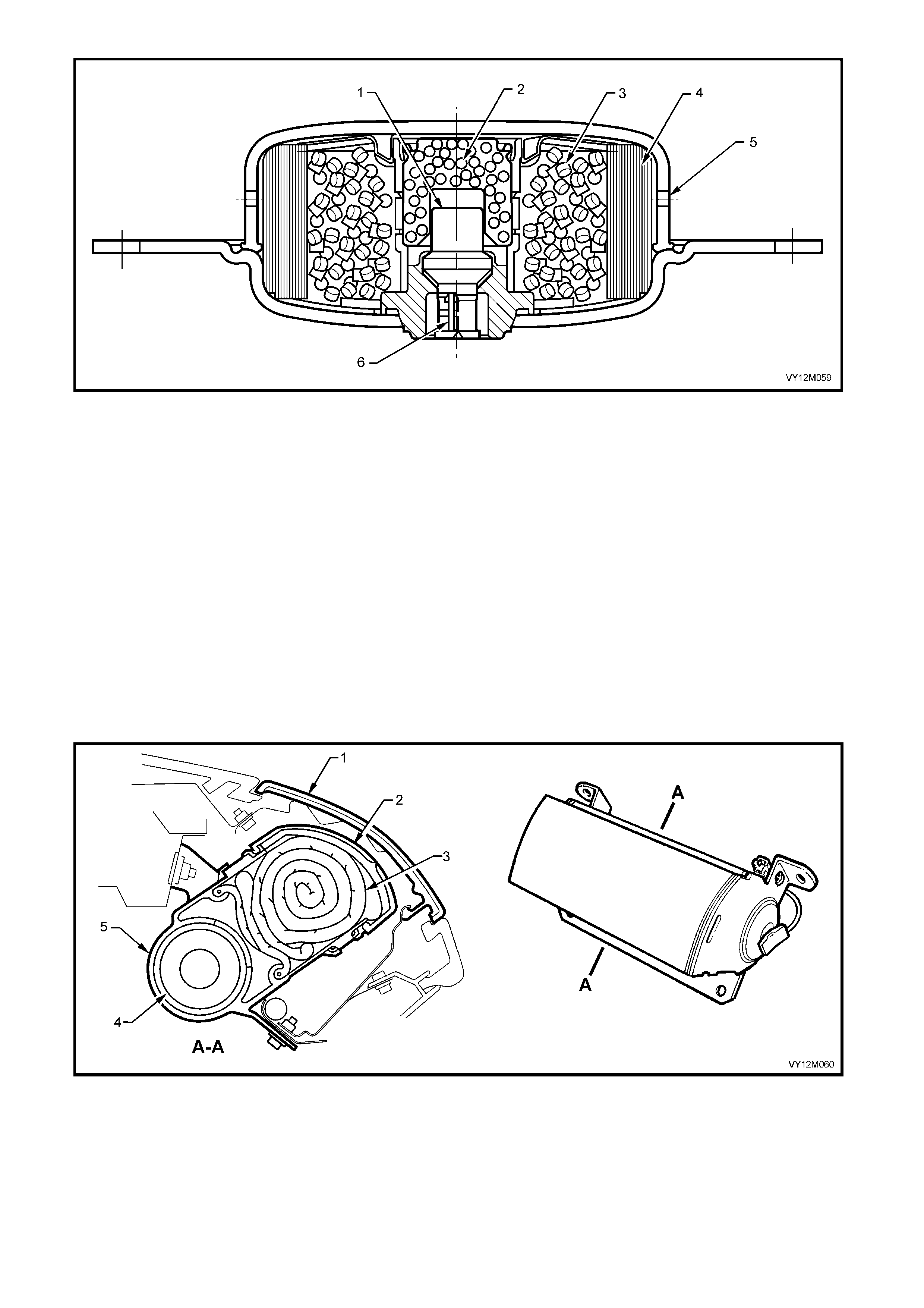
Figure 12M-23
Legend
1. Electro Explosive Device (EED)
2. Enhancer Pack
3. Propellant
4. Fine Particle Filter
5. Nitrogen Gas Exhaust Port
6. EED Connector Pins For Connector A106 – X1
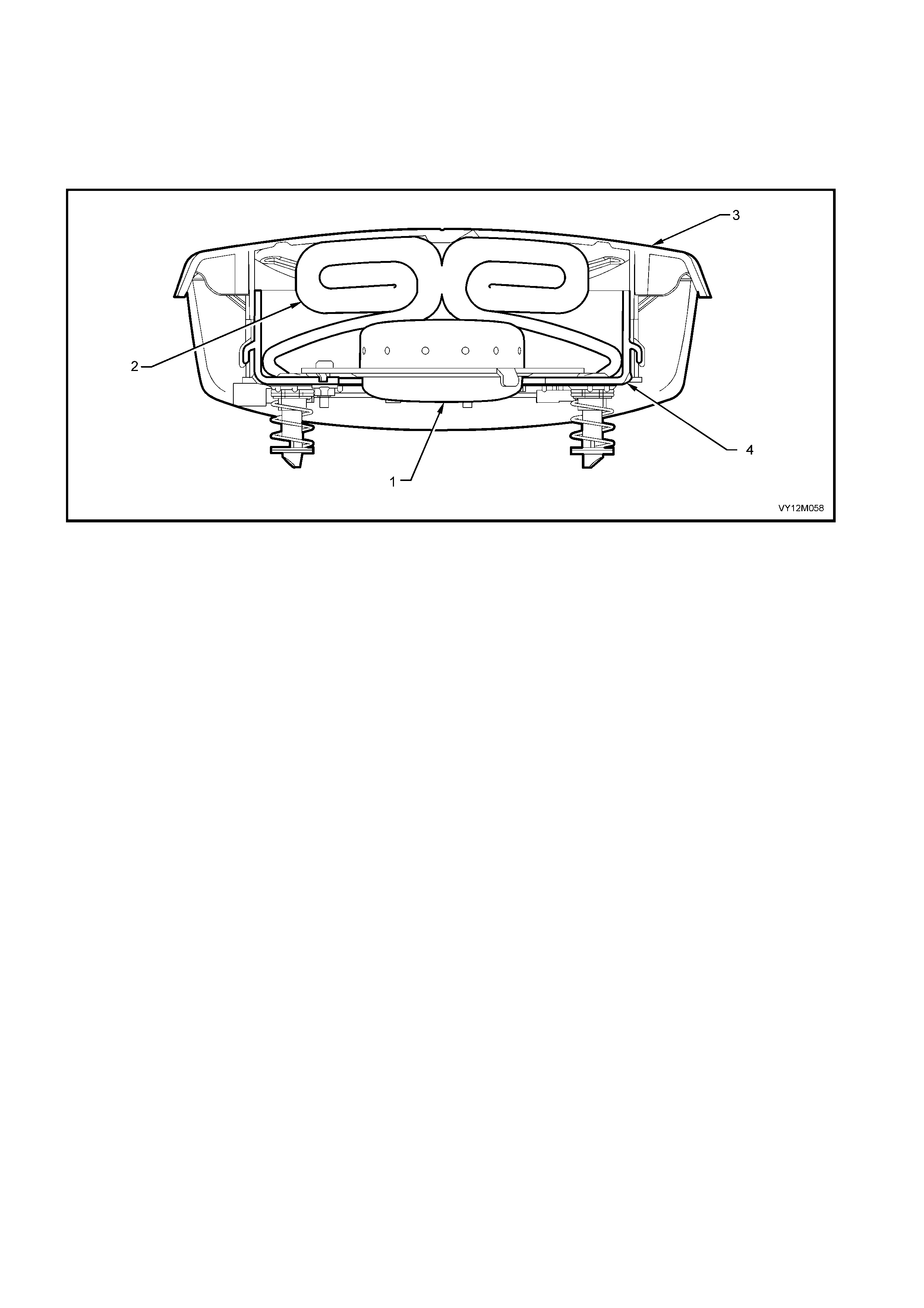
INSTRUMENT PANEL INFLATABLE RESTRAINT MODULE ASSEMBLY
The ins trument panel i nflatabl e restraint ( Passeng er’s airba g) module as sem bly c ontains the fol lowing par ts, refer
to Figure 12M-24.
The passenger’s airbag deploys through a cut out in the instrument panel pad assembly substrate and a
Passenger’s airbag door. The PAB door assembly is a skin and foam laminate over an injection moulded plastic
insert with a s he et metal h inge heat staked to the r e ar sur f ac e. T his as s em bl y is then attac h ed, us in g f our sc r ews,
to the instrument panel pad assembly.
IMPORTANT: Components of the front passenger’s side airbag module are not repairable. Under no
circumstances are the components of the front passenger’s airbag module to be disassembled. The airbag
module contains a pyrotechnic gas generator and the airbag cushion fold is critical to airbag performance and
front passenger’s safety.
Figure 12M-24
Legend
1. Instrument Panel Inflatable Restraint (Passenger’s
Airbag) Door
2. Passenger’s Airbag Plastic Protective Cover
3. Passenger’s Airbag Plastic Cushion
4. Inflator Module
5. Instrument Panel Inflatable Restraint (Passenger’s
Airbag) Module
As the inflatable restraint airbag cushion inflates, some of the Nitrogen and argon begins to exit into the
passenger’s compartment through vent holes of a calibrated size.
Internal tethering controls the fill and placement of the airbag cushion, to maximise the benefits to the front
passenger’s.
In some deployment conditions, the windshield may be broken by the opening of the Passenger’s airbag Door
when the airbag cush ion deplo ys.
As with the steering wheel inflatable restraint (Driver’s airbag) cushion, the surface of the instrument panel
inflatable restraint (Passenger’s airbag) cushion may contain a powdery residue after deployment. This powder
consists primarily of cornstarch (used to lubricate the cushion as it inflates) and by-products of the chemical
reaction . T he by-produc ts o f air bag module d ep loyment ar e C ar bon M onox ide ( C O ), Nitr og en ( N), Carbo n D i oxide
(CO2), Water (H2O) with trace amounts of Oxides of Nitrogen (NOΧ) and Ammonia (NH3). However, as a
precaution, gloves and safety glasses are recommended when handling a deployed airbag to prevent any
possible irritation of the skin or eyes.
During deployment, the front passenger’s airbag module operates in four stages:
1. The EED i nitiator rec eives current f rom the Inflatable Restr aint Control Modu le (SDM) and i gnites, driving t he
projectile to strike an actuator piston that moves striking primers that fire and ignite the enhancer pack.
2. The enhancer pack’s chemical reaction causes the propellant to rapidly produce Nitrogen gas, heat and
pressure.
3. The heat and pressure releases the stored argon gas.
4. The Nitroge n gas heats th e argon gas, bot h gases ve nt from the inf lator t hrough the fine particle and d iffuser
filling the airbag cushion. The force produced by the gas and the rapidly inflating airbag cushion, separates
the protective cover then forces the hinged PAB door open to fully deploy the airbag cushion.
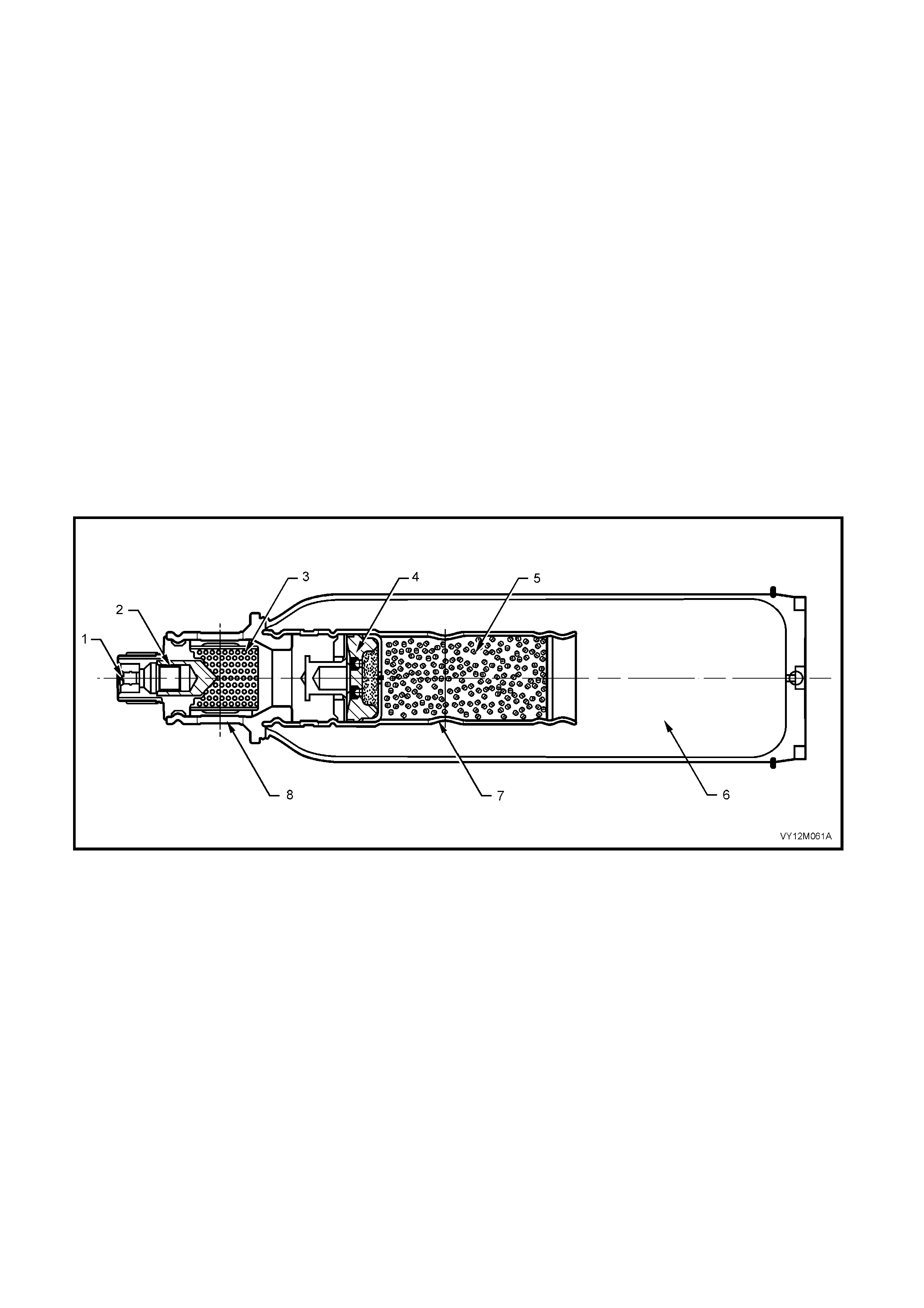
The inflator contains several components Figure 12M-25 shows a typical inflator assembly.
Figure 12M-25
Legend
1. EED Connector Pins For Connector A62 − X1
2. Electro Explosive Device (EED) And Projectile
3. Fine Particle Filter Diffuser
4. Actuator Piston, Striking Primers and Enhancer Pack
5. Hybrid Propellant
6. Argon Gas
7. Propellant Gas Exhaust Port
8. Airbag Deployment Gas Exhaust Port

DRIVERS SEATBELT BUCKLE WARNING INDICATOR SWITCH
On MY 2003 VY Series vehicles ex cluding Utilit y and Cab Chassis built on April 3rd 2003, and f rom L102858 f or
W agon and L10295 2 f or Sedan, the dri ver’s sea tbelt buck le is equ ipped with a seatbelt warni ng ind icator s witch
(Production Option WD4).
The purpose of the switch is to activate a se atbelt warning indicator located in the instrument cluster when the
ignition is turned to the on position with the seatbelt disengaged from the buckle.
When the seatbelt is buck led, the warning lam p switch is in an open circuit condition and when un-buckled the
switch is in a closed circuit condition.
MODES OF OPERATION
• Seatbelt fastened in the buckle after the ignition switch is turned on, the seatbelt warning indicator and
chime (if activated) will turn off.
• Seatbelt fastened in the buckle then the ignition switch is turned on, the seatbelt warning indicator will
turn on for four seconds and then turn off.
• Seatbelt not fastened in the buckle and the ignition switch turned on, the seatbelt warning indicator will
turn on, staying on until the seatbelt is fastened or the ignition switch is turned off
Or
After a 150 second time delay, the warning indicator will flash on and off along with a warning chime
until the seatbelt is fastened or the ignition switch is turned off.
• Seatbelt not fastened in the buckle and the vehicle travelling at 25 km/h, the warning indicator will flash
on and off. The rate of the chime sound increases and a warning message ‘FASTEN SEATBELT’ is
displayed on the Multi Function Display until the seatbelt is fastened.
For more information on instrumentation refer to Section 12C, INSTRUMENTS, 1.6 INSTRUMENT
OPER ATION ALL −
−−
− MODE LS
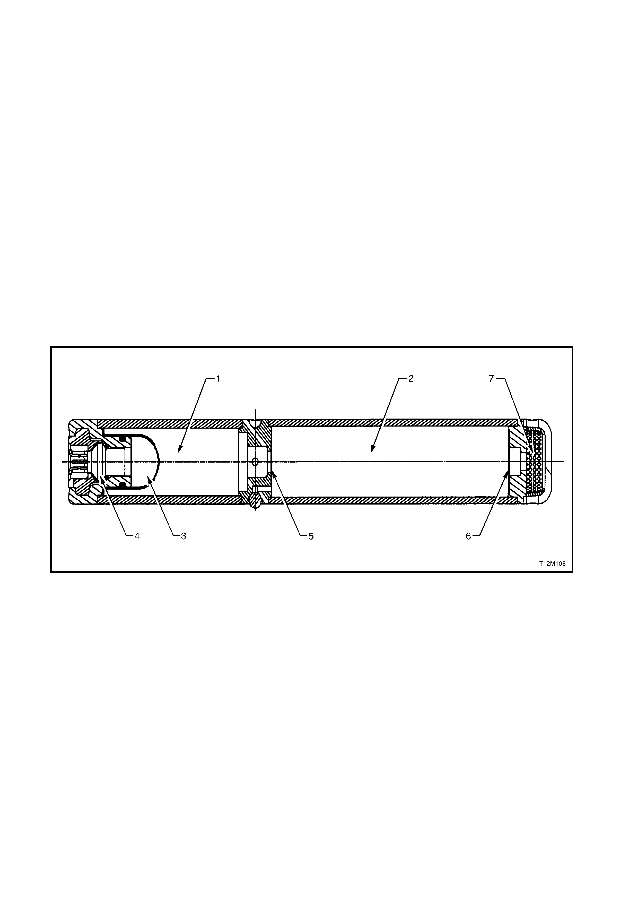
SEAT BELT PR ET ENSIONERS
The front seat belts are equipped with a pyrotechnical seat belt Pretensioner. The purpose of the seat belt
pretensioner is to remove all webbing slack from the seat belt before the occupant has moved forward as the
result of a frontal collision.
The seat belt pretensioners have a gas generator complete with an igniter connected to a cylinder. Inside the
cylinder is a piston connected to both ends of a cable, the cable passes through a locking device and then forms
a loop internally in the seat belt buckle assembly.
When an ignition signal from the SDM is sent to the igniter, the gas generator is activated driving the retractor
cable pis ton do wn the c ylinder . This action pulls the c able t hroug h a retrac tor c able int erlock ing cam devic e and
pulls the b uck le towards th e seat tak ing up t he slack in the seat b elt. T he retr actor c able along with the pis ton is
prevented from moving back up the cylinder by the retractor cable interlocking cam device once a load has been
applied in the opposite direction of deployment, activating the clamping action of the locking device directly on
the cable to prevent further movement.
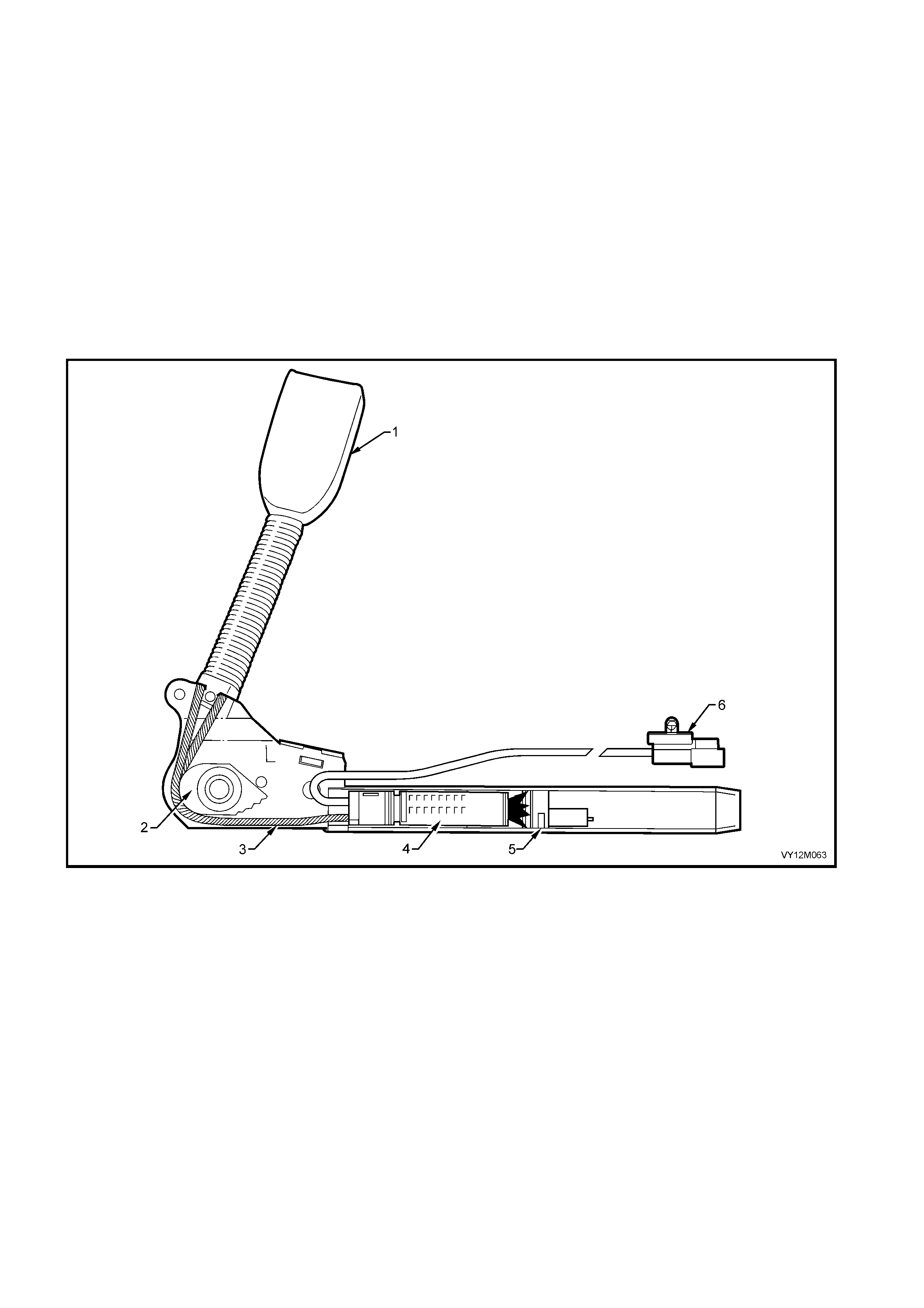
Figure 12 M-26 sho ws the Pr etensioner assem bly being dep loyed b y the igniter t hat is par t of the gas gener ator
(4).
Figure 12M-26
Legend
1. Buckle Assembly
2. Retractor Cable Interlocking Cam Device
3. Buckle Retractor Cable
4. Igniter and Gas Generator
5. Retractor Cable Piston
6. Pretensioner Connector (Y128 − X1 Right-hand)
(Y129 − X1 Left-hand)
Figure 12 M-27 s ho ws the Prete nsioner assem bl y full y deplo yed with the b uck le as sem bly (2) full y re tracted, the
retractor cable int erlocking cam (1) in the ap plied or lock ed position, the igniter and gas generator expired with
the retractor cable piston fully deployed.
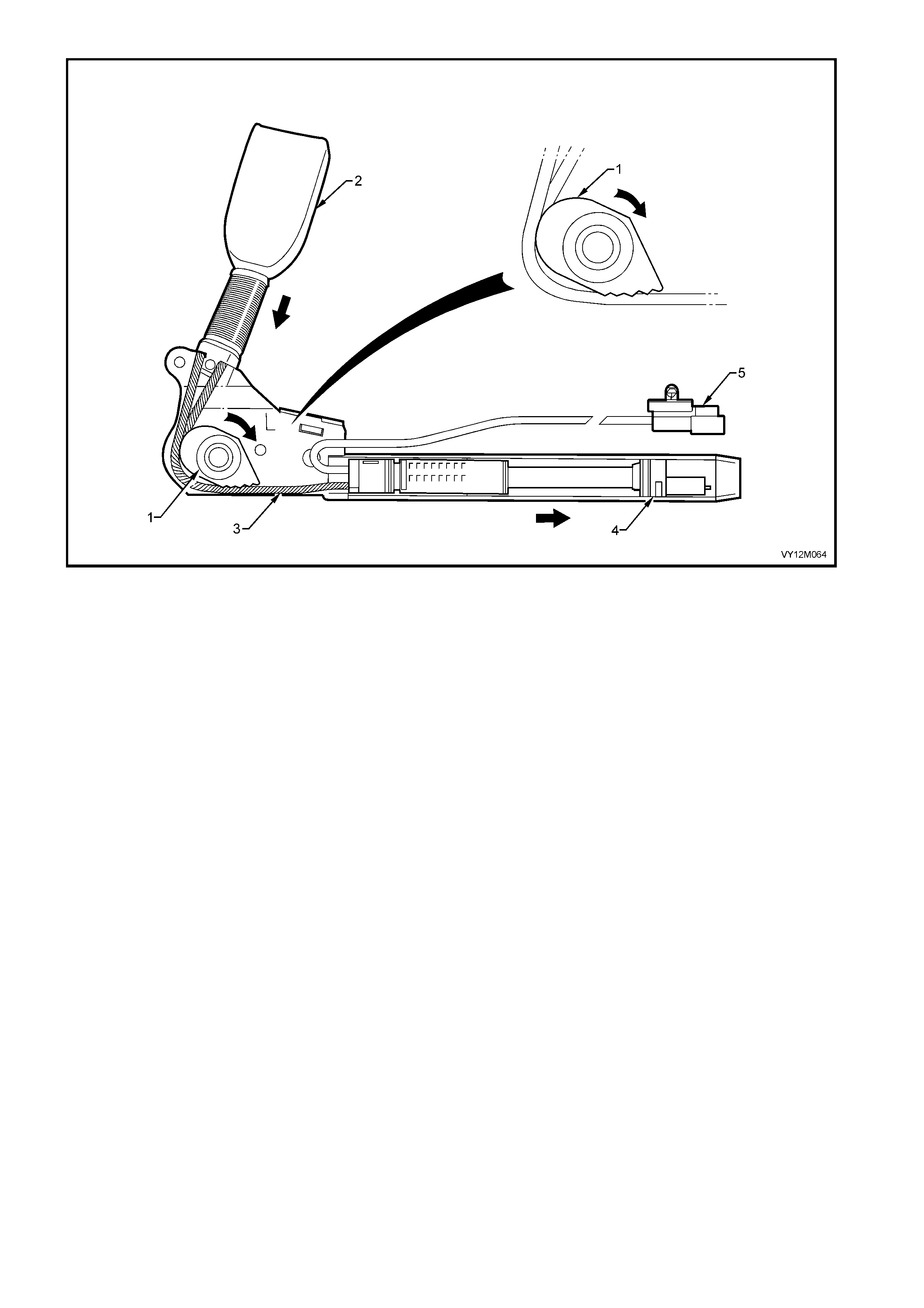
Figure 12M-27
Legend
1. Retractor Cable Interlocking Cam Device
2. Buckle Assembly
3. Buckle Retractor Cable
4. Retractor Cable Piston
5. Pretensioner Connector (Y128 − X1 Right-hand)
(Y129 − X1 Left-hand)
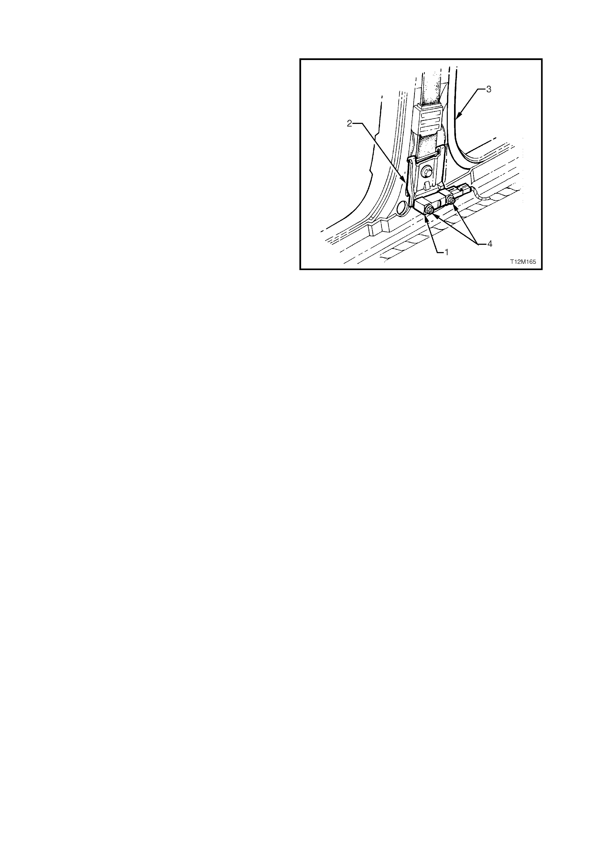
SIDE-IMPACT SENSOR
The side-impact sensor (Peripheral acceleration
sensor) (1), is a sensin g component whic h is m ounted
on the B-pillars (3) (one each side) which is able to
detect lateral acceleration, recognise a collision and
send a signal to the SDM that a side-impact inflatable
restraint (Side-impact airbag) deployment situation
exists or not.
The SDM can then decide whether to deploy the
relevant side-impact airbag the side facing the
collision.
Peripheral acceleration sensors are only fitted to
vehicles with side-impact airbags (8.1 SDM).
NOTE 1: Due to the critical nature of the torque
specification of the two nuts (4) securing the peripheral
acceleration sensor (1) to the mounting bracket (2),
the peripheral acceleration sensor is serviced with the
mounting bracket as an assembly only.
If there is a need to remove the acceleration sensor
from the vehicle, it must be removed as an assembly
with the mounting br ac k et attached .
NOTE 2: A per ipheral ac celeration sensor is designed
for a one-time deployment use only. If a side-impact
airbag de ploys, th e periphe ral acceler ation s ensor and
mounting bracket assembly on the same side as the
deployed airbag must be replaced.
NOTE 3: Figure 12M-28 shows the RHS peripheral
acceleration sensor and the OPS / SRS wiring
harness facing the rear of the vehicle. The peripheral
acceleration sensors are uni-directional. The LHS
peripheral acceleration sensor has the OPS / SRS
wiring harness facing the front of the vehicle.
Figure 12M-28
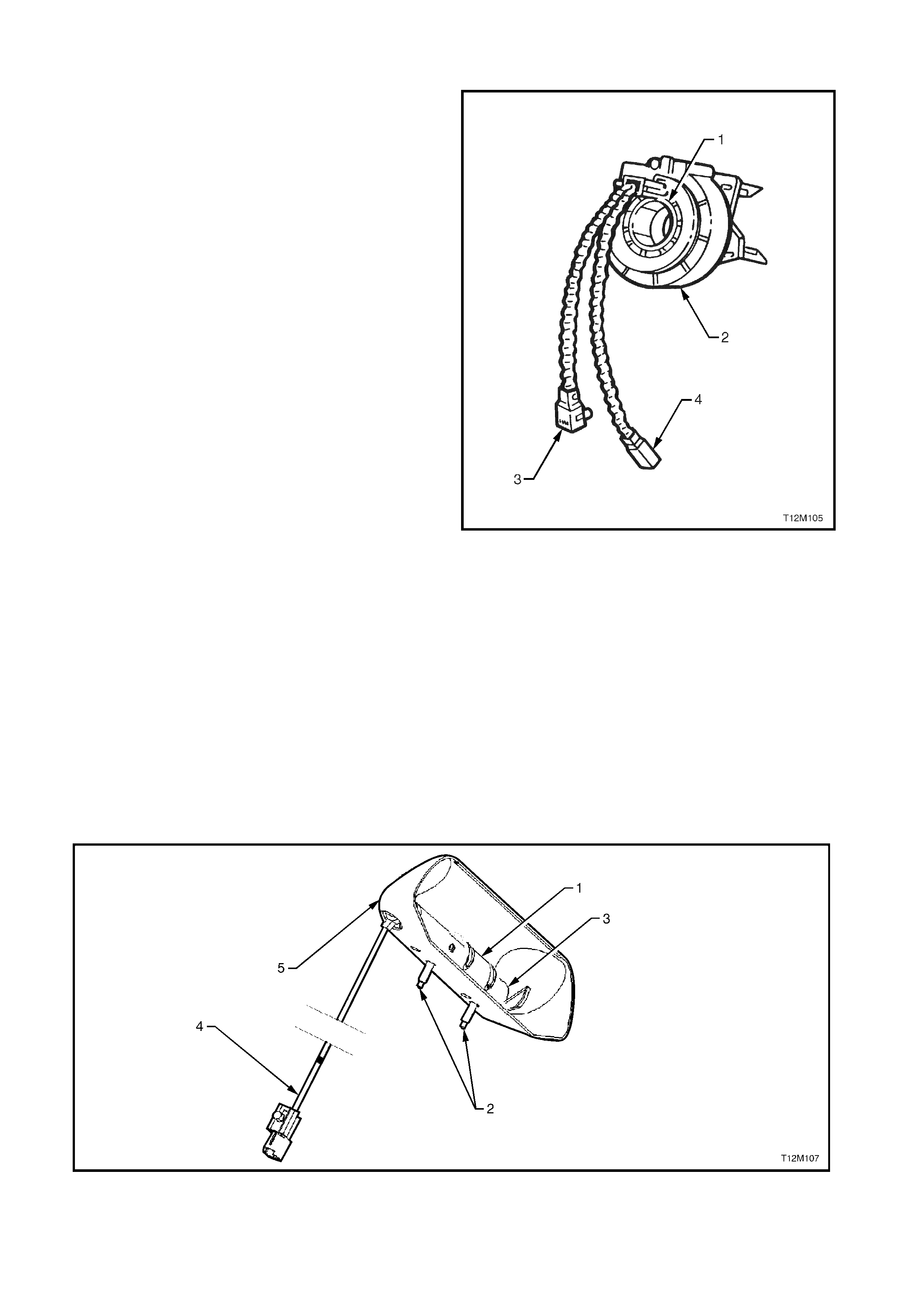
CLOCK SPRING COIL ASSEMBLY
The clock spring coil assembly has the following parts:
1. A pigtail wiring harness (3) that connects to the
airbag module at the top of the steering column
(connector A106 − X1).
2. A lower wiring harness connector which is
incorporated with the clock spring coil outer
housing assembly (2).
3. A rotating inner hub (1) which engages with the
rear of the steering wheel.
4. A ribbon wire assem bly that provides an unbroken
connection between the SDM and airbag module
(not sho wn) as th e s teer in g whee l is rotate d during
vehicle operation.
5. The coil assembly also has pigtail-wiring
harnesses and wires in the ribbon wire assembly
(4) f or the horn contac ts in the ste ering wheel a nd
if fitted, the remote audio controls (not shown).
The coil assembly operates in the following manner:
• When the steering wheel is in the straight-ahead
position, the inner hub and outer housing are
aligned to provide approximately 2.5 turns of the
steering wheel in either direction.
• When the steering wheel is turned in a clockwise
direction (right turn), the inner hub winds the
ribbon wire as it rotates with the steering wheel.
• When the steering wheel is turned in an anti-
clockwise direction (left turn), the inner hub
unwinds the ribbon wire as it rotates with the
steering wheel .
Figure 12M-29
SIDE-IMPACT INFLATABLE RESTRAINT MODULE ASSEMBLY
The side-impact inflatable restraint (Side-impact airbag) module assembly contains the following parts (refer to
Figure 12M- 30):
• A housing (1) , fas tened to the outb oard sid e of eac h front seat, s eat back frame with studs (2) and nuts (not
shown).
• A nylon fabric cushion (not shown) folded inside the housing and mounted in a plastic container (5).
• A protective reinforcement paper (Tyvek) cover with the seam around the container (not shown for clarity).
• An inflator (3) and wir ing lo om (4).
Figure 12M-30
The side-impact airbag deploys through the seat back foam and seat back fabric at approximately the forward
most side seam, providing a protective barrier between the occupant and the vehicle door.
IMPORTANT: Components of the side-impact airbag module are not repairable. Under no circumstances are
the components of the side-impact airbag module to be disassembled. The airbag module contains compressed
gas and a small pyrotechnic charge. Additionally, the airbag cushion fold is critical to airbag performance and
front occupant safety.
TYPICAL SIDE-IMPACT INFLATOR CONSTRUCTION
The inflator contains several components, refer to Figure 12M-31, which shows a typical inflator assembly:
• An initiator (4), which consists of an electrical heating element, covered with a mixture of sensitive
py rotechnical charge.
• A small amount of fuel (3) and oxidiser (1).
• Compressed inert gas (typically Argon) in a sealed chamber (2).
During deployment, the side-impact airbag inflator operates in three stages:
1. The initiator receives current from the SDM, heating the sensitive pyrotechnic charge, which ignites the fuel.
2. The combustion of the fuel and oxidiser creates enough pressure to burst the disk(s), heating the
compressed gas and allowing it to escape into the cushion.
3. The heated expanding gas starts to unfold the airbag cushion, which separates the protective cover, the
seat back foam and the seat back fabric and inflates.
As the cush ion inflates, s ome of the gas begins to exit into the pass enger’s com partment through vent h oles or
through the pores of the cushion fabric. Internal tethering controls the fill and placement of the airbag to
maximise the benefits to the front occupant.
Figure 12M-31
Legend
1. Oxygen
2. Argon
3. Ethanol
4. Initiator
5. Burst disk
6. Burst disk
7. Diffuser screen

WIRING HARNESS
The OPS / SRS wiring harness can be identified by
the yellow PVC tubing or yellow tape covering the
harness wiring. The specific OPS / SRS wiring
harness connectors are either coloured yellow,
mustard or orange, or have a yellow retaining clip or
slide to identify them as OPS / SRS connectors.
The connectors on the OPS / SRS wiring harness
which interface with the igniters have an in-built
capacitor which is connected in series with the trigger
circuit. The purpose of the capacitor is to prevent
unintentional triggering of the OPS / SRS by blocking
any Direct Current (DC) in the circuit .
Figure 12M-32 illustrates the OPS / SRS wiring
harness connector with an in-built capacitor. The
connector consists of:
• Capacitor (1).
• A ‘Service Hole’ to aid in diagnosis of the
system (2).
• Terminal (3).
• Terminal (4).
Due to the sens itive nat ure of the OPS / SRS cir cuitry,
special wiring repair procedures have been developed.
The proc edur es des c ribed i n 2.1 1 O P S / SRS W IR ING
REPAIR in this Section, are the only recommended
and approved OPS / SRS wiring repair methods.
These procedures are to be read in conjunction with
2.11 WIRING REPAIRS also located in Section 12M.
IMPORTANT: The ‘pigtail’ wiring harness that
connects to the side-impact airbag module, and runs
through the front seat down to the seat rail, is not
serviced separately from the side-impact airbag
module due to the design of the anti back out
connector on the module assembly. If this ‘pigtail’
wiring harness, as with any other OPS / SRS ‘pigtail’
wiring h arness, becom es dam aged no wire, con nector
or terminal repairs are to be attempted. REPLACE
THE SIDE-IMPACT AIRBAG MODULE AND PIGTAIL
WIRING HARNESS ASSEMBLY.
CAUTION: No alternative repair methods are to be
used.
Figure 12M-32
WARNING LABELS
In order to provide adequate warning of the OPS / SRS operation and service requirement to the vehicle’s
owner, driver or service technicians, OPS / SRS warning labels are located on various components of the
vehicle, refer to Figure 12M-33.
IMPORTANT: If at any time any these components are replaced ensure that the appropriate warning label is
applied to the replacement part.
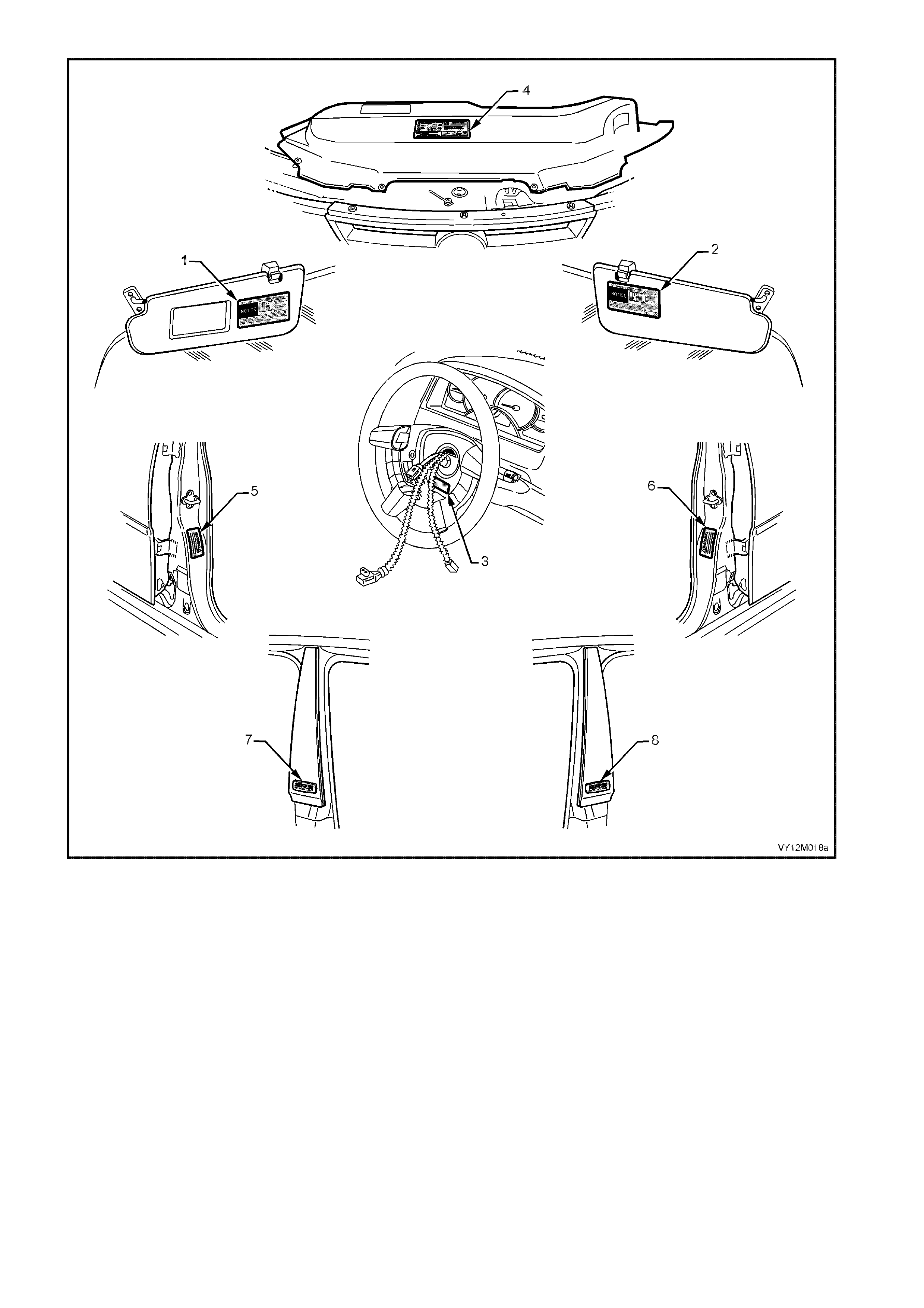
Figure 12M-33
Legend
1. Passenger’s sunvisor (vehicles with Instrument panel
inflatable restraint (Passenger’s airbag).
2. Driver’s sunvisor
3. Steering wheel (inflatable restraint removed).
4. Engine cooling fan shroud.
5. Right-hand B-pillar (vehicles with side-impact airbags).
6. Left-hand B-pillar (vehicles with side-impact airbags).
7. Right-hand B-pillar moulding (vehicles with side-impact
airbags).
8. Left-hand B-pillar moulding (vehicles with side-impact
airbags).

2. SERVICE OPERATIONS
2.1 SAFETY PRECAUTIONS
1. Do not use a fast battery charger for starting the vehicle.
2. Never disconnect the battery from the vehicle’s electrical system while the engine is running.
3. Disconnect the battery from the vehicle’s electrical system before fast battery charging.
4. Never disconnect or connect the SDM connector with the ignition turned on.
5. After an accident, the individual OPS / SRS components must be replaced if the following circumstances
apply:
a. Deformation of the SDM. (If the floor pan is deformed where the SDM is mounted, it must be
repaired).
b. Deformation of the side-impact sensor (Peripheral acceleration sensor) or mounting bracket.
c. Deformation of the B-pillar or surrounding area where the peripheral acceleration sensor and
mounting bracket assembly is mounted.
d. Pretens ioners, steer ing wheel i nflatable r estraint (Dri ver’s airbag) module, Ins trum ent panel inflata ble
restraint (Passenger’s airbag) module and side-im pact airbag modules that have not been triggered,
but are damaged.
e. Prete nsioners , Driver’s a irbag m odule, Pass enger’s a irbag m odule, s ide-im pact airbag m odule, SD M,
or deployed side peripheral acceleration sensor assemblies that have been triggered.
f. If a vehicle is involved in an accident which was severe enough to deploy the pretensioners but not
severe enough to deploy inflatable restraint/s, the following components must be replaced: Any seat
belt worn in the accident, front seat belt pretensioners, front seat guide rail and adjuster assembly
(provided seat was occupied in accident) and the SDM.
g. If a vehicle is involved in an accident where the front seat belt pretensioners and the front inflatable
restraint/s are deployed, the following components must be replaced: The same components as in a
Pretensioner only deployment, plus the driver’s airbag module assembly, SDM, clock spring coil,
steering colum n, steering, Passenger’s airbag module (vehicles with Passenger’s airbag), instrum ent
panel pad and PASSENGER’S AIRBAG door assembly (vehicles with Passenger’s airbag),
instrum ent panel p ad nam e plate (v ehicles with Passe nger’s a irbag), f ront Passe nger’s air bag inf lator
support rail assembly (vehicles with Passenger’s airbag).
h. If a vehicle is involved in an accident where a side-impact airbag is deployed, the following
components must be replaced: any seat belt worn in the accident, SDM, relevant side front seat
assembly and relevant side peripheral acceleration sensor.
NOTE: Damaged or defective components of the system must not be repaired, but must always be replaced.
6. When fasteners are removed, always reinstall them in the same location from which they were removed. If a
fastener needs to be replaced, use a fastener with the correct part number for that application. If a fastener
with the cor rect part num ber is not ava ilable, a f astener of equal size and str ength (or stronger) m ay be used.
Fasteners that should not be reused, and those requiring thread locking compound will be identified in this
Section. The correct torque value must be used when installing fasteners that require it. If these conditions are
not adhered to, parts or system damage could result.
7. The windshield plays an active part during the deployment of the Passenger’s airbag. The strength of the
windshie ld and its ur ethane adhes ive is c ritical to ens ure that the f ront seat pass enger’s is correc tly protect ed
during deployment. Replacement windshield glass and adhesives complying to Holden specifications may
only be used. Only use the correct urethane adhesive when installing a windshield to maintain original
installation integrity. Failure to use the correct product will result in poor retention of the glass. For vehicles
with front passenger’s side-impact airbag, the windshield must be replaced properly so that occupant
protection provided by the OPS / SRS is maintained.
8. SDM. Take care when handling the SDM. Never strike or jar the module or body structure adjacent to the
module in a manner , which c ould caus e dep loyment of the Pretensi oner ’s or inf lata ble res tr a int/s . If an SD M is
dropped from a height, greater than one metre, it must be replaced.
9. Peripheral acceleration sensor. Take care when handling the peripheral acceleration sensor. Never strike or
jar the module or body structure adjacent to the sensor in a manner, which could cause deployment of the
side-im pact airbag /s. Never car ry a peripheral ac celera tion sensor b y the wiring h arness leads . If a perip heral
acceleration sensor is dropped from a height, greater than on metre, it must be replaced.

10. Undeployed airbag m odule. When carrying a live (undeployed) airbag m odule, ensure that it is pointed away
from you. In case of an accidental deployment, the airbag will then deploy with minimal chance of injury.
W hen placing a live a irbag m odule on a bench or othe r surf ace, always f ace the assembl y up, awa y from the
surface. This is necessary in order to provide free space for the airbag to expand, in case of accidental
deployment. Also, never place anything on top of airbag module.
a. Never carry the driver’s airbag module by the horn bar contact wires on the underside of the
assembly.
b. Never carry a side-impact airbag module by the wiring harness leads.
c. If still connected, never carry the front passenger’s airbag module or Pretensioner’s by their wiring
harness lead.
d. Do not apply power to the module except as specified in this Section.
e. Do not att empt to m ake any repairs to the module or sensors. A dam aged or def ective dri ver’s airbag
module, Passenger’s airbag module or side-impact airbag module assembly must be replaced.
f. Do not weld, solder, braze, hammer, machine, drill, or otherwise heat seat belt pretensioners or
airbag modules.
11. Deployed airbag module /s .
a. Always wear gloves and safety glasses when handling a deployed Pretensioner or airbag module.
b. The surface of these components may contain chemicals as a result of the gas generated during
combustion. This can irritate your skin. Wash hands with mild soap and water afterwards.
12. Steering column.
a. During any service operation that requires removal and reinstallation of a steering column fitted with
an airbag m odul e, alwa ys carr y the steer ing col um n with two han ds and with the steer ing wheel a wa y
from your body.
b. Never carry the column by one hand or with steering wheel toward you.
c. Never set a steering column on the floor with the steering wheel toward the floor.
NOTE: During any service operation that requires remova l of a steering colum n, ensure that the steering shaf t is
locked to the colum n to prevent any possibilit y of allowing the steer ing shaft to rotate and possibly dam aging the
clock spring coil ribbon wire. For details of locking the steering shaft to the column, refer to
Section 9, STEERING.
CAUTION: When performing service on or around OPS / SRS components or wiring, follow the
procedur es listed in this Sect ion to temp orarily di sable the OPS / S RS. Failu re to follow these procedu res
could result in possible OPS / SRS deployment, personal injury or otherwise unnecessary OPS / SRS
repairs.
13. Disconnect ing the battery W ILL NOT imm ediatel y deactivate t he OP S / SRS. A r esidual en erg y reserve in the
SDM is incorporated to enable the pretensioners and inflatable restraint/s to deploy in the event of a battery
failure. The SDM has the power to deploy the pretensioners and inflatable restraint/s for up to 10 seconds
after the battery has been disconnected or the ignition turned off.
14. T he SDM can m aintain s ufficien t voltag e to cause a deplo ym ent for up t o 10 sec onds after the ign ition switc h
is turned OFF or the battery is disconnected. Many of the service operations require disconnection of the
battery to avoid an accidental deployment of the pretensioners or inflatable restraint/s.
15. W hen car r ying out steering gear removal and ins t al lat io n proc ed ur es, r emove the i gnit io n k ey from the ignition
lock and ens ure that th e s teer in g c olumn is loc ked. If this opera tio n is not car r ied out and the steering wheel is
spun while the steering gear is removed, the clock spring coil will be destroyed. This will result in the SDM
setting a DTC and non-deployment of the driver’s airbag.
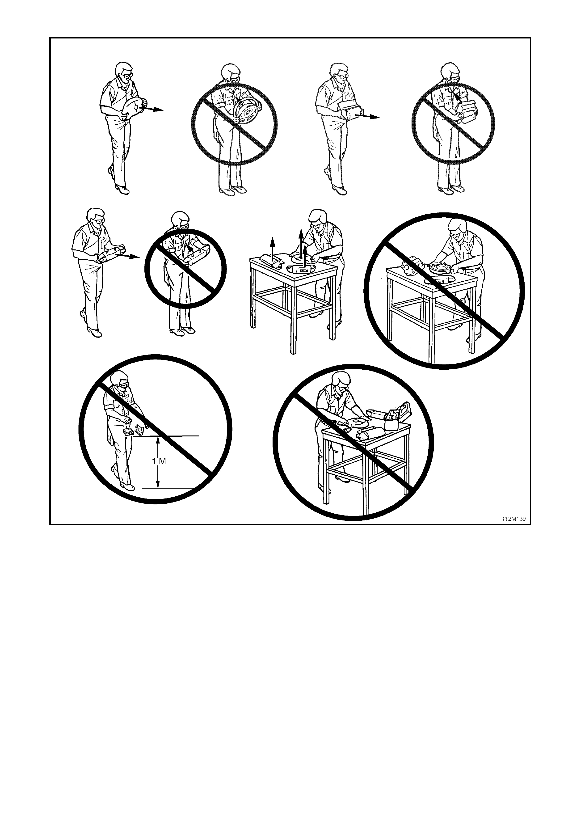
Figure 12M-34

2.2 SYSTEM DISABLING AND ENABLING PROCEDURE
LT Section No. −
−−
− 06-225
DISABLING THE OPS / SRS
Disconnect both the battery earth and power leads and wait at least 10 seconds before performing any work on
the vehicle.
CAUTION: The SDM can maintain sufficient voltage to cause OPS / SRS deployment for up to 10 seconds
after the ignition s witch is turned OFF or the battery is disconnected.
ENABLING THE OPS / SRS
NOTE: Ensure all wiring harness connectors are connected before reconnecting the battery leads.
1. Reconnect both the battery power and earth leads.
2. Switch ignition on, and observe the SRS warning indicator in the instrument cluster. The warning indicator
should be illum inated for approxim ately five secon ds. During this period the SDM performs a wiring and self-
check.
3. If no system faults are detected, the SRS warning indicator will be switched off. If the warning indicator
rem ains illuminated a nd an audible alarm chimes, or the SRS warning indicator illuminates t wo seconds afte r
it was originally switched off, a OPS / SRS fault is present. Refer to 4 DIAGNOSTICS in this Section
to rectify fault.
2.3 STEERING WHEEL INFLATABLE RESTRAINT MODULE ASSEMBLY
LT Section No. −
−−
− 06-225
The steering wheel inflatable restraint (Driver’s airbag) module is mounted to the steering wheel by four spring
loaded retaining clips located in the hub of the steering wheel assembly.
If conducting the following operation on a airbag that has deployed, ensure that you are wearing safety glasses
and gloves to protect your eyes and hands from possible irritation when handling the deployed DRIVER’S
AIRBAG MO DUL E AS SE M BL Y.
After the driver’s airbag module assembly has been deployed, the surface of the airbag cushion may contain a
powdery residue. This powder consists primarily of cornstarch (used to lubricate the bag as it inflates) and by-
products of the chemical reaction. The by-products of airbag module deployment are Carbon Monoxide (CO),
Nitrogen (N), Carbon Dioxide (CO2), W ater (H2O) with trace am ounts of Oxides of Nitrogen (NOΧ) and Ammonia
(NH3). However, as a precaution, g loves and safety glasses are recommended when handling a deplo yed airbag
to prevent any possible irritation of the skin or eyes.
REMOVE
1. Disable the OPS / SRS, refer to
2.2 SYSTEM DISABLING AND ENABLING
PROCEDURE in this Section.
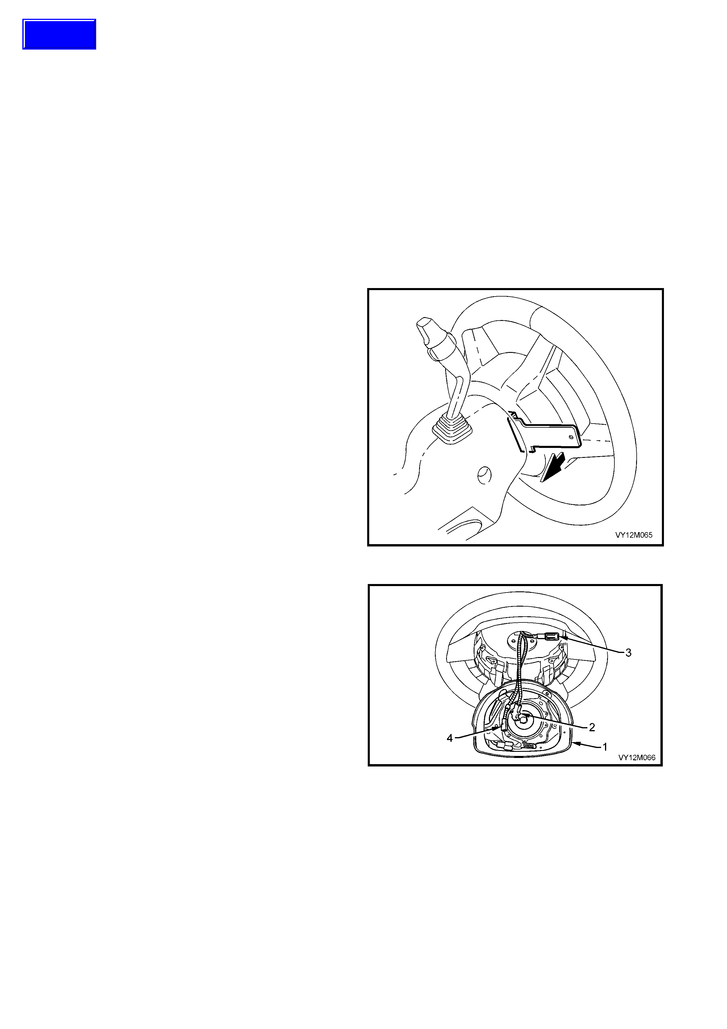
2. Rotate the steering wheel 90 degrees from the
straight-ahead position to expose two of the four
access aperture holes (3) in the rear of the
steering wheel hub.
3. Use Tool No. AU 595 to relieve the tension of the
two spring-loaded retaining clips. The release of
clip tens ion is ac hieved by pivot ing the tool to ward
the instrum ent panel to move the tangs of the tool
in a outward direction, refer to Figure 12M-35.
When tension is released, the airbag module
assem bly will m ove s lightl y awa y from the steer ing
wheel.
4. Rotate the steering wheel 180 degrees to expose
the remaining two access aperture holes. Repeat
step 3. The airbag module assembly will move
slightly away from the steering wheel and is fully
released from the retaining clips.
Figure 12M-35
5. Lift the driver’s airbag module assembly (1) from
the steer ing wheel, r em ove the yell ow cl ock spr ing
to inflator assem bly connec tion (2) a nd discon nect
wiring harness connectors (3 and 4) from rear of
assembly, refer to Fig 12M-36.
6. Remove the driver’s airb ag module assembl y.
NOTE: If removing a driver’s airbag module assembly
from a steering wheel fitted with stereo controls (as
shown), take extreme care when disconnecting the
left-hand horn pad connector (3) from the stereo
control wiring connector otherwise damage to the
stereo control wiring could result.
CAUTION: When carrying a live (undeployed)
driver’s airbag module assembly, make sure the
bag opening in the horn bar is pointed away from
you. In case of an accidental deployment, the bag
will then deploy with minimal chance of injury.
When placing a live driver’s airbag module
assembl y on a bench o r other surf ace, alw ays fac e
the bag and horn bar up, away from the surface.
Never rest the driver’s airbag module assembly
with the horn bar face down. This is necessary so
that a free space is provided to allow the airbag
cushion to expand in the unlikely event of
accidental deployment. Otherwise, personal injury
may result.
Figure 12M-36
Techline

REINSTALL
1. Offer the Driver’s airbag module assembly up to steering wheel hub and reconnect all wiring harness
connectors to rear of assembly.
2. Locate the driver’s airbag module assembly to the four spring loaded retaining clip mounting points located in
the base of the steering wheel hub.
3. Ensure that all wiring harness connectors and wiring is not exposed or trapped between airbag module and
steering wheel hub.
4. Pressing firmly on the driver’s airbag module assembly, push the module toward the steering wheel hub until
the spring-loaded retaining clips lock and retain the module in place.
5. Enable the OPS / SRS, refer to 2.2 SYSTEM DISABLING AND ENABLING PROCEDURE in this Section.
6. Switch ignition on, and observe the SRS warning indicator in the instrument cluster. The warning indicator
should be illuminated for approximately five seconds. During this period of time the SDM performs a
wiring and self-check. If no system faults are detected, the SRS warning indicator will be switched off.
If the warning indicator remains illuminated and an audible alarm chimes, or the warning lamp illuminates two
seconds after it was originally switched off, a OPS / SRS fault is present. Refer to
4 DIAGNOSTICS in this Section to rectify fault.
STEERING WHEEL INFLATABLE RESTRAINT MODULE SCRAPPING PROCEDURE
During the course of a vehicle's useful life, certain situations may arise which will necessitate the disposal of a live
(undeployed) steering wheel inflatable restraint (Driver’s airbag) module assembly. The following information
covers proper procedures for deploying a live assembly.
CAUTION: Failure to follow proper OPS / SRS driver’s airbag module assembly disposal procedures can
result in airbag deployment which may cause personal injury. The undeployed airbag module contains
substances that can cause severe illness or personal injury if the sealed container is damaged during
disposal.
In situations, which require deployment of a live driver’s airbag module assembly, deployment may only be
accomplished outside the vehicle. The driver’s airbag module assembly needs to be removed so the OPS / SRS
wiring harness with the capacitor built into the connector can be removed. Intentional deployment of the driver’s
airbag module can not be accomplished using a 12 volt DC supply with the capacitor in the OPS / SRS circuit.
STEERING WHEEL INFLATABLE RESTRAINT MODULE DEPLOYMENT OUTSIDE VEHICLE
There may be some circumstances that require the deployment of a steering wheel inflatable restraint (Driver’s
airbag) m odule as sembl y bef or e a vehic le is to be r etu r ned to ser vice. F or example, s ituat ions in whic h the ve hic le
will be r eturned t o an owne r after a function ally or cos metic ally malf unctionin g driver’s airba g module assembl y is
replaced. Deployment and disposal of a malfunctioning module is, of course, subject to any required retention
period.
For deployment of a live (undeployed) driver’s airbag module assembly outside the vehicle, the deployment
procedure must be followed exactly. Always wear safety glasses during the deployment procedure until the
assembly is rem oved. Before perf orming the procedur e you should be fam iliar with servicing the OPS / SR S and
with proper handling of the driver’s airbag module assembly.
NOTE 1: The following must be read fully and understood before performing the actual procedure.
NOTE 2: The f ollowing pro cedure requ ires use of J38826-1 O PS / SRS d eplo yment har ness with a daptor E 1992.
Do not attempt procedure without J38826-1 and E1992.
CAUTION: Failure to follow procedures in the order listed may result in personal injury. Never connect
deployment harness to any power source before connecting deployment harness to the driver’s airbag
module assembly. The deployment harness must remain shorted and not be connected to a power source
until the driver’s airbag module assembly is ready to be deployed. The module will immediately deploy
the airbag when a power source is connected to it. Wear safety glasses and gloves throughout this entire
deployment and disposal procedure.
1. Turn the ignition switch OFF and put on safety glasses.
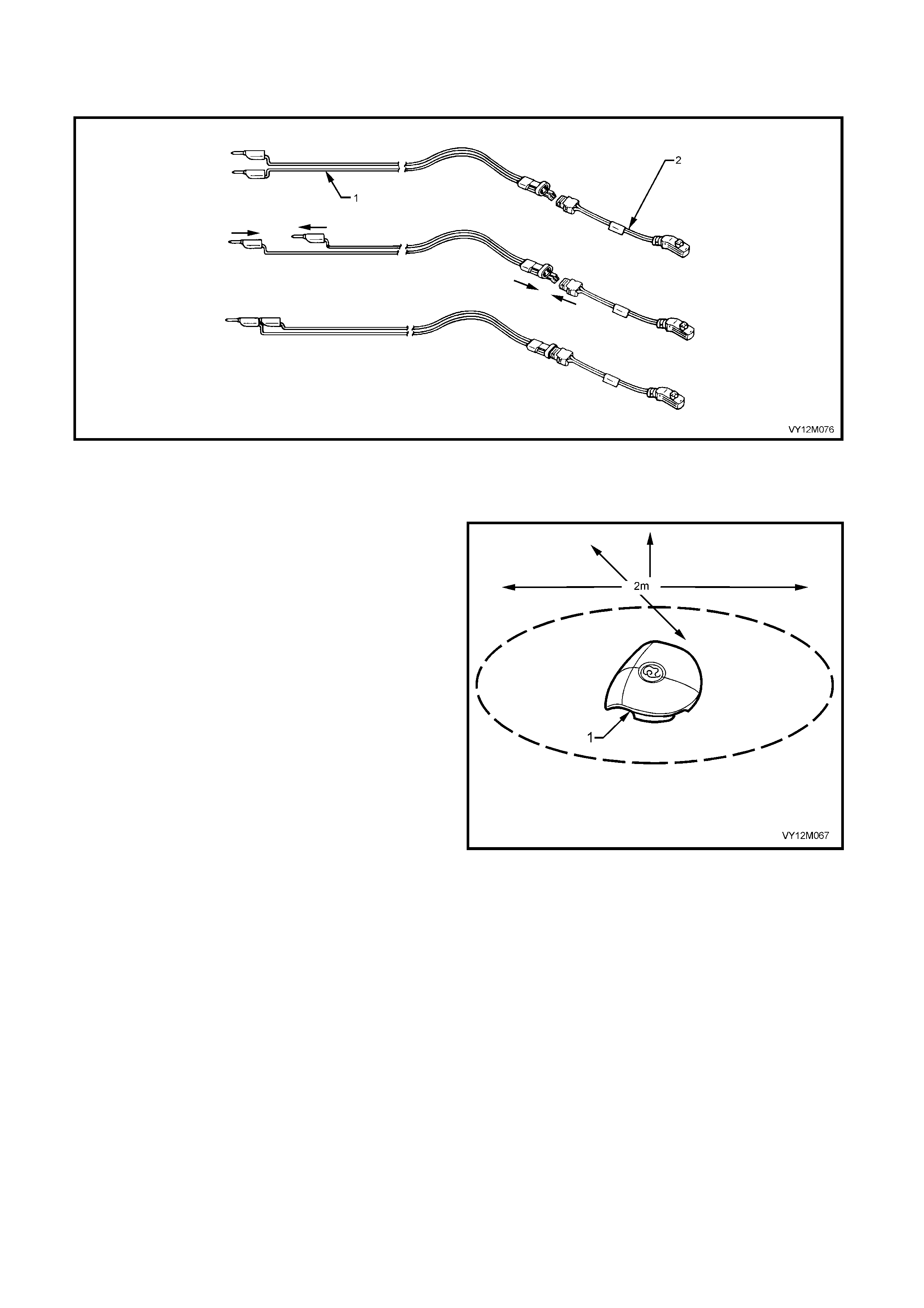
2. Inspect J38826-1 OPS / SRS deployment harness and adaptor, E1992 for damage. If harness or adaptor is
damaged, discard and obtain a replacement.
3. Short two OPS / SRS deployment harness leads together by fully seating one banana plug into the other.
OPS / SRS deployment harness MUST remain shorted and NOT connected to a power source until the airbag
is to be deployed.
4. Connect the appropriate pigtail adaptor to the OPS / SRS deployment harness.
5. Remove the driver’s airbag module assembly from vehicle, refer to 2.3 STEERING WHEEL INFLATABLE
RESTRAINT MODULE ASSEMBLY in this Section.
CAUTION: The deployment harness MUST remain shorted and NOT connected to a power source until the
airbag is to be deployed. The module will immediately deploy the airbag when a power source is
connected to it, refer to Figure 12M - 37.
Figure 12M-37
Legend
1. SRS Deployment Harness − J38826-1 2. Deployment Harness Adaptor − E1992
CAUTION: When storing a live driver’s airbag
module assembly or when leaving a live assembly
unattended on a bench or other surface, always
face the a ssembly w it h the trim cov er up and aw ay
from the surface. This is necessary so that a free
space is provided to allow the airbag cushion to
expand in the unlikely event of accidental
deployment. Failure to follow procedures may
result in personal injury.
6. Place the assembly (1) on a workbench or other
surface away from all loose or flammable objects
with its trim cover facing up, away from the
surface.
7. Clear a space on the ground about 2 metres in
diameter where the assembly is to deploy. A
paved, outdoor location where there is no activity
is pref erred. If an outdoor loc ation is not ava ilable,
a space on the workshop floor where there is no
activity and sufficient ventilation is recommended.
Ensure no loose or flammable objects are within
the deployment area.
8. Place the assembly, with its trim cover facing up,
on the ground in the space just cleared.
9. Stretch the OPS / SRS deployment harness and
adaptor from the driver’s airbag module assembly
to its full length.
10. Place a po wer source near the shorted end of the
OPS / SRS deployment harness. Recommend
application: 12 volts minimum, 2 amps minimum (a
vehicle battery is suggested).
11. Connect the driver’s airbag module assembly to
the adaptor E1992 on the OPS / SRS deployment
harness.
CAUTION: The deployment harness MUST remain
shorted and NOT connected to a power source
until the airbag is to be deployed. The module will
immediately deploy the airbag when a power
source is connected to it, refer to Figure 12M-39.
Figure 12M-38
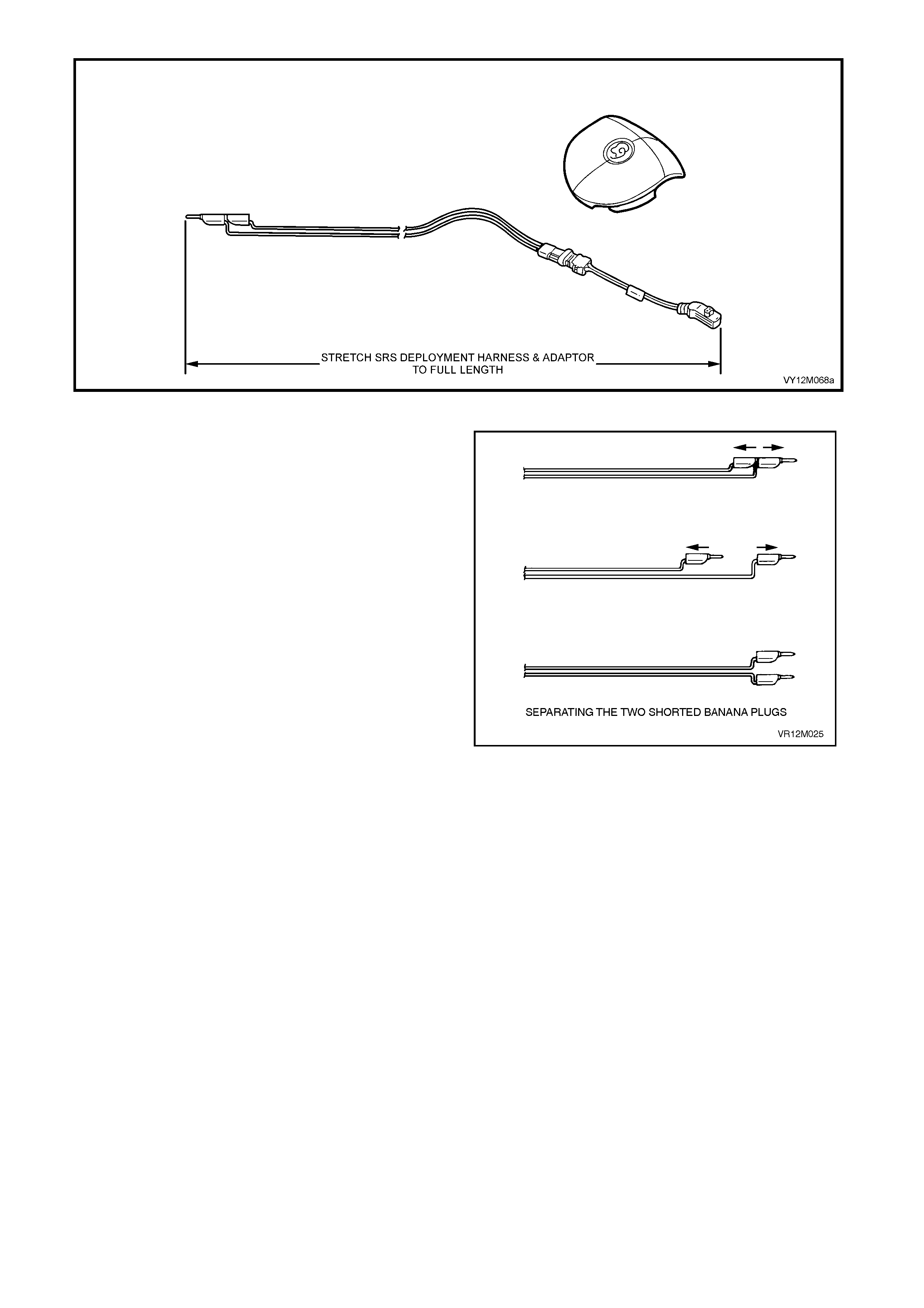
Figure 12M-39
12. Verify that the area around the driver’s airbag
module assembly is clear of all people and loose
or flammable objects.
13. Verify that the driver’s airbag module assembly is
resting with trim cover facing up.
14. Notify all people in the immediate area that you
intend to deploy the driver’s airbag module
assembly. The deployment will be accompanied
by an explosion, which may startle the uninformed.
15. Sep arate the t wo banana plugs on t he OPS / SR S
deployment harness.
16. Connect OPS / SRS deployment h arness leads to
the power source to immediately deploy the
driver’s airbag module assembly.
NOTE 1: When the airbag deploys, the rapid gas
expansi on will create an ex plosion. N otify all peo ple in
the immediate area that you intend to deploy the
module.
NOTE 2: When the airbag dep loys, the assembly m ay
jump about 30 cm vertically. This is a normal reaction
of the module to the force of the rapid gas expansion
inside the airbag cushion.
CAUTION: The deployment harness MUST remain
shorted and NOT connected to a power source
until the airbag is to be deployed. The module will
immediately deploy the airbag when a power
source is connected to it. Connecting the
deployment harness to the power source should
always be the last step prior to deployment of the
airbag. Failure to follow procedures in the order
listed may result in personal injury.
Figure 12M-40
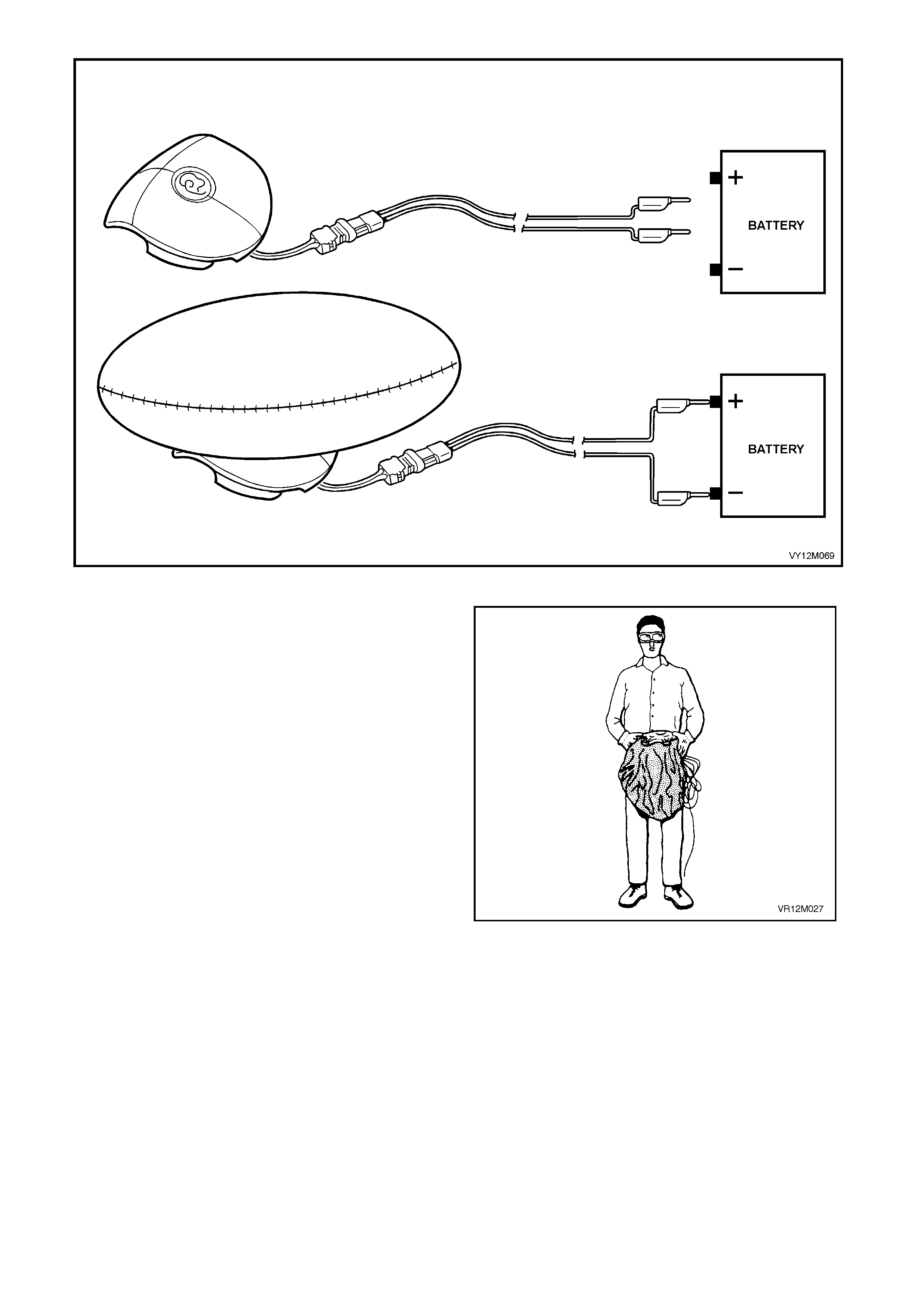
Figure 12M-41
17. Disconnect the OPS / SRS deployment harness
from the power source.
18. Short the two OPS / SRS deployment harness
leads together by fully seating one banana plug
into the other.
Ensure that you are wearing safety glasses and gloves
to protect your eyes and hands from possible
irritation and heat when handling the deployed
driver’s airbag module assembly.
Note: After the driver’s airbag module assembly has
been deplo yed, the surface of the air bag cushion m ay
contain a powdery residue. This powder consists
primarily of cornstarch (used to lubricate the bag as it
inflates) and b y-produc ts of the chem ical reac tion. The
by-products of airbag module deployment are Carbon
Monoxide (CO), Nitrogen (N), Carbon Dioxide (CO2),
Water (H2O) with trace amounts of Oxides of Nitrogen
(NOΧ) and Amm onia (NH3). Howev er, as a precaution,
gloves and safety glasses are recommended when
handling a deployed airbag to prevent any possible
irritation of the skin or eyes.
Figure 12M-42
CAUTION: Safety precautions must be observed when handling a deployed driver’s airbag module
assembly. After deployment, the metal surfaces of the module will be very hot. Do not touch these metal
areas of the module for about 10 minutes after deployment. Do not place the deployed driver’s airbag
module assembly near any flammable objects. If the deployed driver’s airbag module assembly must be
moved before it has cooled, wear gloves and handle by the airbag cushion or the trim cover.

19. Disconnect the adaptor E1992 from the module as soon as possible after deployment. This will prevent
damage to the adaptor or OPS / SRS deployment harness due to possible contact with the hot module
canister. The adaptor and OPS / SRS deployment harnesses are designed to be reused. They should,
however, be inspected for damage after each deployment and replaced if necessary.
20. Dispose of the deployed module assembly through normal refuse channels after it has cooled for at least 10
minutes.
Wash your hands with mild soap and water afterward.
DEPLOYED STEERING WHEEL RESTRAINT MODULE HANDLING
After the m odule h as been deplo yed, the surf ace of the inf latable r estraint airbag cushion m ay co ntain a pow dery
residue. This powder consists primarily of cornstarch (used to lubricate the bag as it inflates) and by-products of
the chemical reaction. The by-products of airbag module deployment are Carbon Monoxide (CO), Nitrogen (N),
Carbon Dioxide (CO2), Water (H2O) with trace amounts of Oxides of Nitrogen (NOΧ) and Ammonia (NH3).
However, as a precaution, gloves and safety glasses are recommended when handling a deployed airbag to
prevent any possible irritation of the skin or eyes.
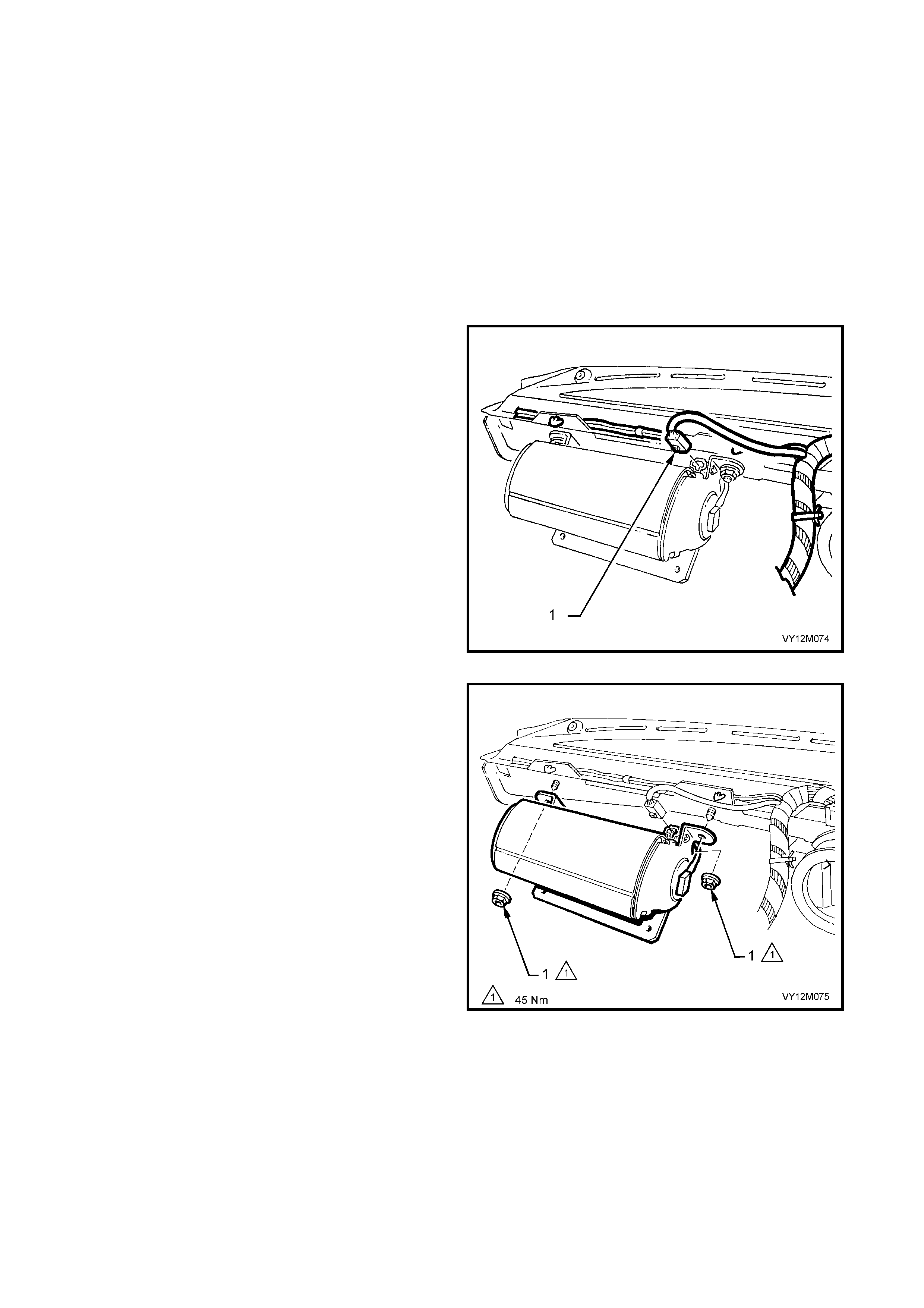
2. 4 INSTRUMENT PANEL INFLATABLE RESTRAINT MODULE ASSEMBLY
LT Section No. −
−−
− 06-225
If conducting the following operation on a airbag that has deployed, ensure that you are wearing safety
glasses and gloves to protect your eyes and hands from possible irritation when handling the deployed airbag
module assembly.
After the airbag module assembly has been deployed, the surface of the airbag cushion may contain a powdery
residue. This powder consists primarily of cornstarch (used to lubricate the bag as it inflates) and by-products of
the chemical reaction. The by-products of airbag module deployment are Carbon Monoxide (CO), Nitrogen (N),
Carbon Dioxide (CO2), Water (H2O) with trace amounts of Oxides of Nitrogen (NOΧ) and Ammonia (NH3).
However, as a precaution, gloves and safety glasses are recommended when handling a deployed airbag to
prevent any possible irritation of the skin or eyes.
REMOVE
1. Disable the OPS / SRS, refer to
2.2 SYSTEM DISABLING AND ENABLING
PROCEDURE in this Section.
2. Remove instrument panel pad assembly, refer to
Section 1A3 INSTRUMENT PANEL AND
CONSOLE.
3. Disconnect the passenger’s airbag module
wiring harness connector X205, (1) from airbag
module assembly.
NOTE: Do not disconnect the passenger’s airbag
wiring harness connector A62 − X1.
Figure 12M-43
4. Remove passenger’s airbag module assembly to
upper dash panel attaching nuts (1), refer to
Figure 12M–4 4.
CAUTION: When carrying a live (undeployed) front
passenger’s airbag module assembly, make sure
the bag opening is pointed away from you. In case
of an accidental deployment, the bag will then
deploy with minimal chance of injury. When
placing a live front passenger’s airbag module
assembl y on a bench o r other surf ace, alw ays fac e
wit h the airb ag cushio n u p, aw ay from th e surf ace.
Never rest the airbag module assembly with the
airbag cushion face down. This is necessary so
that a free space is provided to allow the airbag
cushion to expand in the unlikely event of
accidental deployment. Otherwise, personal injury
may result.
Figure 12M-44
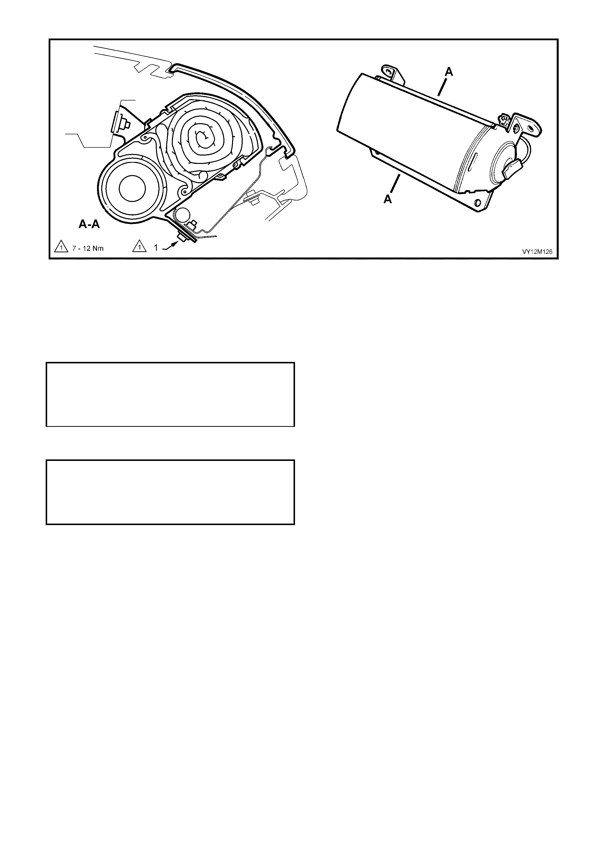
Figure 12M-45
5. Remove passenger’s airbag module assembly to lower dash panel attaching bolts (1) and remove module
assembly, refer to Figure 12M–45.
REINST ALL
1. Assemble front passenger’s airbag module onto position, over the dash panel upper two mounting studs.
2. Install airbag module to upper dash panel attaching nuts and tighten to the correct torque specification.
3. Install airbag module to lower dash panel attaching bolts and tighten to the correct torque specification.
4. Reinstall instrument panel pad assembly, refer to Section 1A3 INSTRUMENT PANEL AND CONSOLE.
5. Enable the OPS / SRS, refer to 2. 2 SYSTEM DISABLING AND ENABLING PROCEDUR E in this Sec ti on.
6. S witch ig nitio n on, a nd obs er ve the SRS warnin g ind icator in th e ins trum ent clus ter. T he warning lam p shoul d
be illuminated for approximately five seconds.
7. During this period the Inflatable Restraint Control Module (SDM) performs a wiring and self-check.
If no system faults are detected, the SRS warning indicator will be switched off. If the warning indicator remains
illuminated and an audible alarm chimes, or the warning indicator illuminates two seconds after it was originally
switched off, a OPS / SRS fault is present. Refer to 4 DIAGNOSTICS in this Section to rectify fault.
INSTRUMENT PANEL INFLATABLE
RESTRAINT (PASSENGER’S AIRBAG)
MODULE TO UPPER DASH PANEL
ATTACHNING NUT
TORQUE SPECICATION 45 Nm
INSTRUMENT PANEL INFLATABLE
RESTRAINT (PASSENGER’S AIRBAG)
MODULE TO UPPER DASH PANEL
ATTACHNING BOLT
TORQUE SPECICATION 7 – 12 Nm

INSTRUMENT PANEL INFLATABLE RESTRAINT MODULE ASSEMBLY SCRAPPING PROCEDURE
During the course of a vehicle's useful life, certain situations may arise which will necessitate the disposal of a live
(undeployed) airbag module assembly. The following information covers proper procedures for deploying a live
front passenger’s airbag module assembly.
CAUTION: Failure to follow proper OPS / SRS airbag module assembly disposal procedures can result in
airbag deployment, which may cause personal injury. The undeployed airbag module contains
substances that can cause severe illness or personal injury if the sealed container is damaged during
disposal.
In situations, which require deployment of a live front passenger’s airbag module assembly, deployment may only
be accomplished outside the vehicle. The passenger’s airbag module assembly needs to be removed so the OPS
/ SRS wiring harness with the capacitor built into the connector can be removed. Intentional deployment of the
passenger’s airbag module can not be accomplished using a 12 volt DC supply with the capacitor in the OPS /
SRS circuit.
INSTRUMENT PANEL INFLATABLE RESTRAINT MODULE DEPLOYMENT OUTSIDE VEHICLE
There m ay be som e circumstanc es that require the deployment of the front passenger’s airbag m odule assembl y
before a vehicle is to be returned to service. For example, situations in which the vehicle will be returned to an
owner after a functionally or cosmetically deficient front passenger’s airbag module assembly is replaced.
Deployment and disposal of a malfunctioning airbag module is, of course, subject to any required retention period.
For deployment of a live (undeployed) front passenger’s airbag module assembly outside the vehicle, the
deplo ym ent procedur e must be f ollowed ex actly. ALW AYS wear saf ety glass es during the de ployment pr ocedure
until the assembly is removed. Before performing the procedure you should be familiar with servicing the OPS /
SRS and with proper handling of the front passenger’s airbag module assembly.
NOTE 1: The following must be read fully and understood before performing the actual procedure.
NOTE 2: The f ollowing pro cedure requ ires use of J38826-1 O PS / SRS d eplo ym ent har ness with ada ptor E1992 .
Do not attempt procedure without J38826-1 and E1992.
CAUTION: Failure to follow procedures in the order listed may result in personal injury. Never connect
deplo yment harness t o any pow er so ur ce bef ore co nn ectin g d eployment ha rness t o t he front passenger’s
airbag module assembly. The deployment harness must remain shorted and not be connected to a power
source until the front passenger’s airbag module assembly is ready to be deployed. The module will
immediately deploy the airbag when a power source is connected to it. Wear safety glasses and gloves
throughout this entire deployment and disposal procedure.
1. Turn ignition switch OFF and put on safety glasses.
2. Inspect J38826-1 OPS / SRS deployment harness and adaptor E1992 for damage. If harness or adaptor is
damaged, discard and obtain a replacement.
3. Short two OPS / SRS deployment harness leads together by fully seating one banana plug into the other.
OPS / SRS deployment harness MUST remain shorted and NOT connected to a power source until the airbag
is to be deployed.
4. Connect the appropriate pigtail adaptor to the OPS / SRS deployment harness.
CAUTION: The deployment harness MUST remain shorted and NOT connected to a power source until the
airbag is to be deployed. The module will immediately deploy the airbag when a power source is
connected to it, refer to Figure 12M-45.
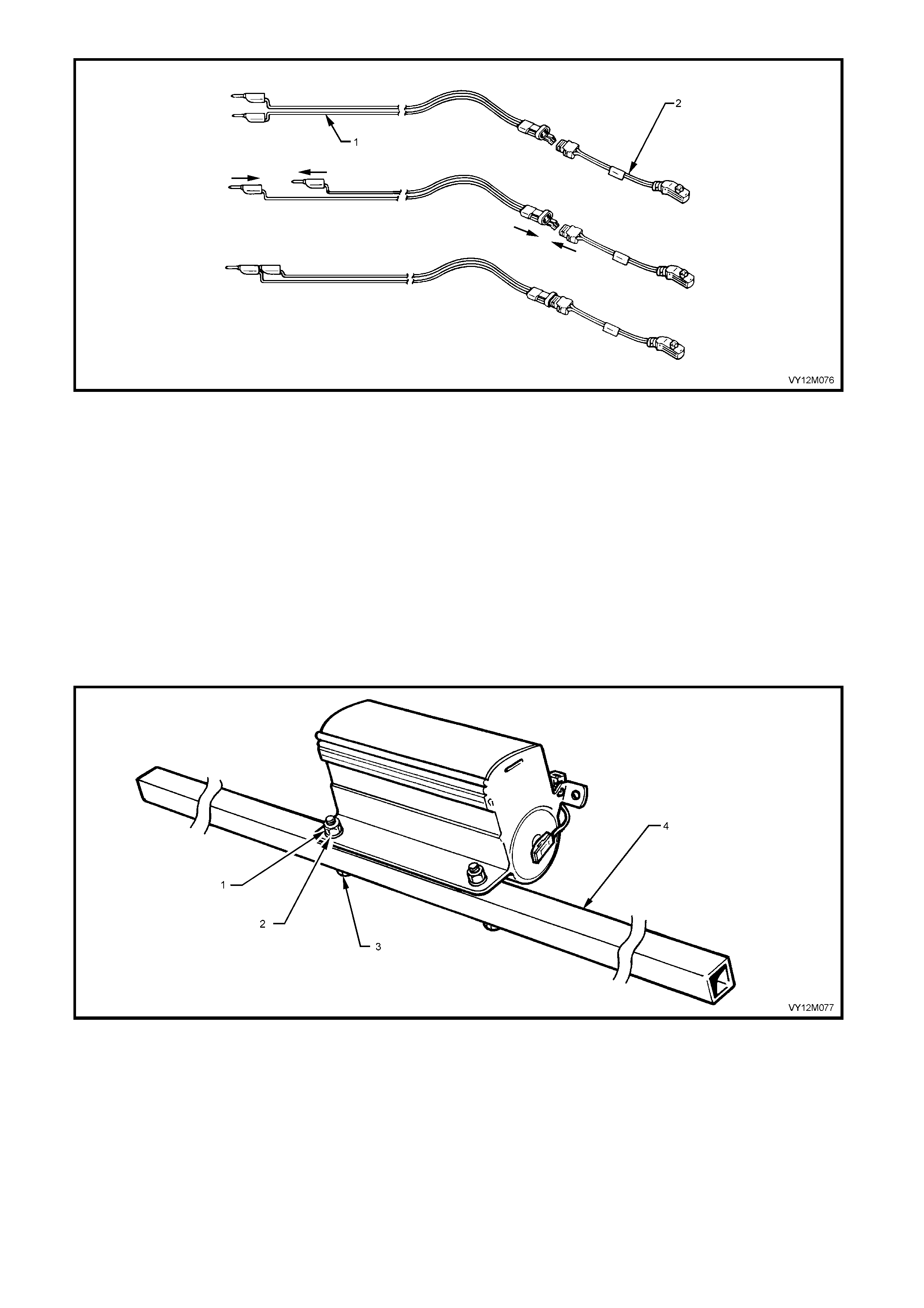
Figure 12M-46
Legend
1. SRS Deployment Harness − J38826-1 2. Deployment Harness Adaptor − E1992
5. Remove the front passenger’s airbag module assembly from vehicle, refer to 2.4 INSTRUMENT PANEL
INFLATABLE RESTRAINT (PASSENGER’S AIRBAG) MODULE ASSEMBLY in this Section.
CAUTION: When storing a live front passenger’s side airbag module assembly or when leaving a live
assembly unattended on a bench or other surface, always face the assembly with the airbag cushion up
and aw ay from the surfac e. This is necessa ry so th at a free space is pro vided to allow th e airbag cushion
to expand in the unlikely event of accidental deployment. Failure to follow procedures may result in
personal injury.
6. Using a 2 metre long square steel tube with suitable sized and positioned holes, bolt the tubing to the lower
bracket of the airbag module assembly as shown in Figure 12M-46.
7. Position two wheel and tyre assemblies on each end of the tubing as shown in Figure 12M-47.
Figure 12M-47
Legend
1. Nut
2. Washer 3. Bolt
4. Square Steel Tubing −200 CM
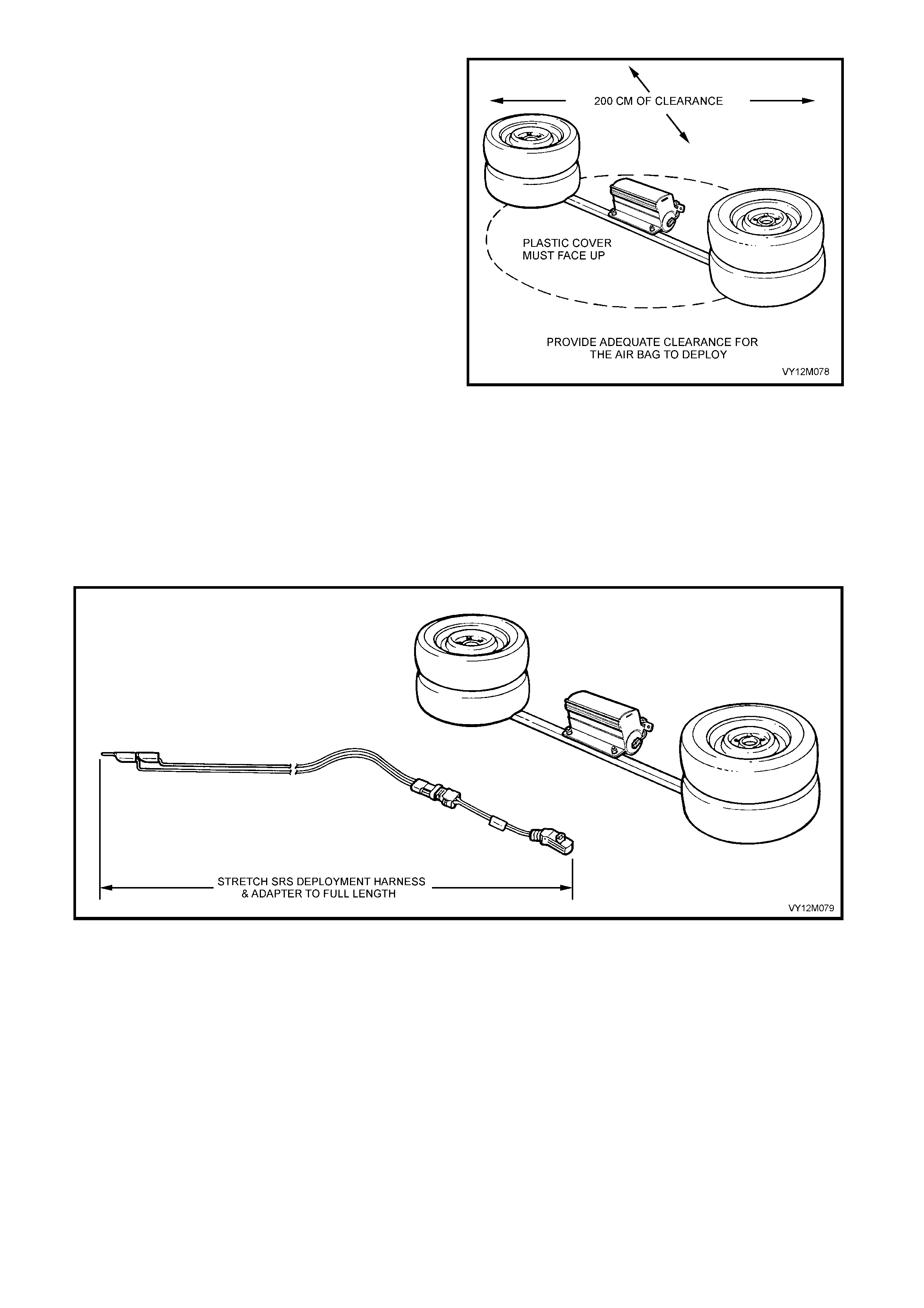
8. Clear a space on the gr oun d about 2 metres in
diameter where the assembly is to deploy. A
paved, outdoor location where there is no
activity is preferred. If an outdoor location is
not available, a space on the workshop floor
where there is no activity and sufficient
ventilation is recommended. Ensure no loose
or flammable objects are within the
deployment area.
9. Ensure that the front passenger’s airbag
module assembly is positioned with its airbag
cushion facing up.
10. Stretch the OPS / SRS deployment harness
and adaptor from the front passenger’s airbag
module assembly to its full length.
11. Place a power source near the shorted end of
the OPS / SRS deployment harness.
Recomm ended application: 12 volts minimum ,
2 amps minimum (a vehicle battery is
suggested).
12. Connect adaptor E1992 and OPS / SRS
deployment harness lead J38826-1 to the
front passenger’s airbag module assembly.
CAUTION: The deployment harness MUST remain
shorted and NOT connected to a power source
until the airbag is to be deployed. The module will
immediately deploy the airbag when a power
source is connected to it.
Figure 12M-48
Figure 12M-49
13. Verify that the area around the front passenger’s airbag module assembly is clear of all people and loose or
flammable objects.
14. Verify that the passeng er ’s airba g m odule as s embl y is resting wit h airbag cushion f ac ing up.
15. Notify all people in the im m edi ate area t hat you intend to depl o y the airbag m odul e ass embly. The deplo yme nt
will be accompanied by an explosion, which may startle the uninformed.
16. Separate the two banana plugs on the OPS / SRS deployment harness, refer to Figure 12M-49.

NOTE 1: When the airbag deploys, the rapid gas
expansi on will create an ex plosion. N otify all peo ple in
the immediate area that you intend to deploy the
module.
NOTE 2: When the airbag dep loys, the assembly m ay
jump ver t ic al l y. T his is a no rm al r eac ti on of the module
to the force of the rapid gas expansion inside the
airbag cushion.
CAUTION: The deployment harness MUST remain
shorted and NOT connected to a power source
until the airbag is to be deployed. The module will
immediately deploy the airbag when a power
source is connected to it. Connecting the
deployment harness to the power source should
always be the last step prior to deployment of the
inflatable restraint. Failure to follow procedures in
the order listed may result in personal injury.
Figure 12M-50
17. Connect O PS / SR S de pl o yment harnes s leads to
the power source to immediately deploy the front
passenger’s airbag module assembly.
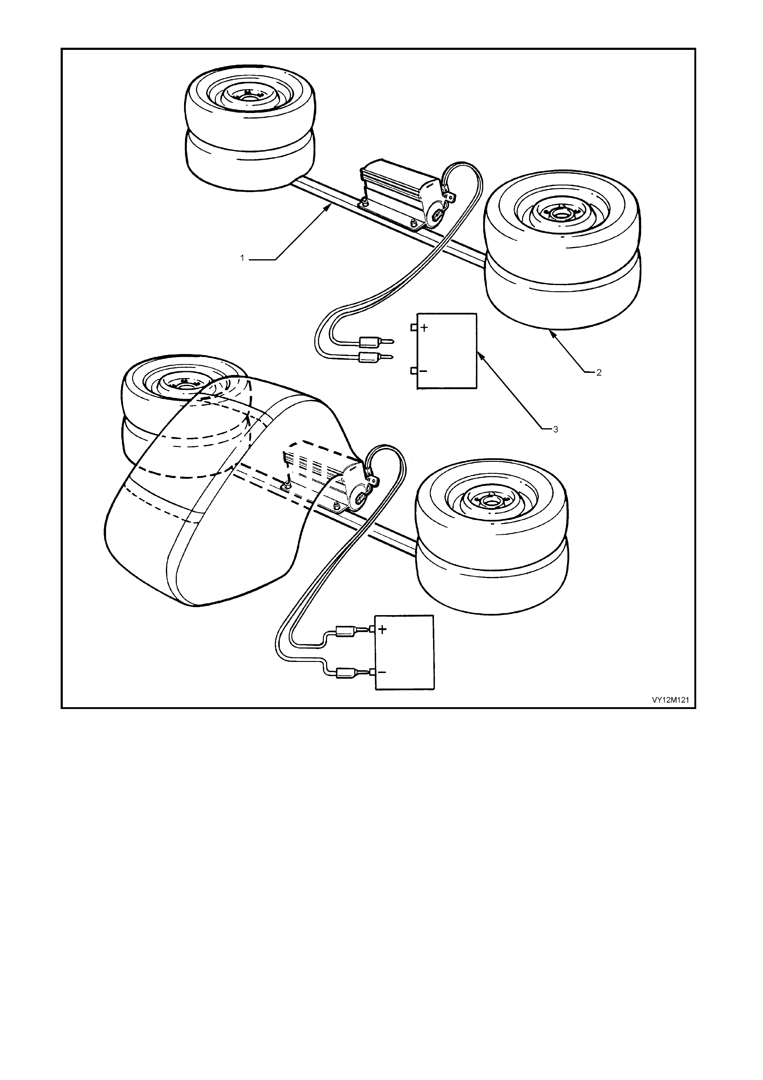
Figure 12M-51
Legend
1. Square Steel Tubing −200 CM 2. Wheel and Tyre Assembly 3. Battery − 12 Volt
18. Disconnect the OPS / SRS deployment harness from the power source.
19. Short the two OPS / SRS deployment harness leads together by fully seating one banana plug into the
other.
20. Ensure that you are wearing safety glasses and gloves to protect your eyes and hands from possible
irritation and heat when handling the deployed passenger’s airbag module assembly.

After the airbag m odule ass em bly has been deplo yed,
the surface of the airbag cushion may contain a
powdery residue. This powder consists primarily of
cornstar ch (us ed to lubric at e the bag as it i nflates) and
by-products of the chemical reaction. The by-products
of airbag module deployment are Carbon Monoxide
(CO), Nitrogen (N), Carbon Dioxide (CO2), Water
(H2O) with trace amounts o f O x ides of Nitrogen ( NO X)
and Ammonia (NH3). As a precaution, however,
gloves and safety glasses are recommended to
prevent any possible irritation of the skin or eyes.
CAUTION: Safety precautions must be observed
when handling a deployed passenger’s airbag
module assembly. After deployment, the metal
surfaces of the module will be very hot. Do not
touch these metal areas of the module for about 10
minutes after deployment. Do not place the
deployed passenger’s airbag module assembly
near any flammable objects. If the deployed
driver’s airbag module assembly must be moved
before it has cooled, wear gloves and handle by
the airbag cushion or the trim cover.
21. Disconnect the adaptor E1992 from the module
as soon as possible after deployment. This will
prevent damage to the adaptor or OPS / SRS
deployment harness due to possible contact with
the hot module canister. The adaptor and OPS /
SRS deployment harness is designed to be
reused. They should be inspected for damage
after each deployment and replaced if necessary.
22. Dispos e of the deplo yed air bag assem bly through
normal refuse channels after it has cooled for at
least 10 minutes.
23. Wash your hands with mild soap and water
afterward.
Figure 12M-52
DEPLOYED MODULE HANDLING
Note: After the module has been deployed, the surface of the airbag cushion may contain a powdery residue.
This powder consists primarily of cornstarch (used to lubricate the bag as it inflates) and by-products of the
chemical reaction. The by-products of airbag module deployment are Carbon Monoxide (CO), Nitrogen (N),
Carbon Diox ide ( CO 2), Water (H2O ) with trace amount s of O xides of Nitr ogen (NO X ) and Amm onia ( NH3) . As a
precaution gloves and safety glasses are recommended to prevent any possible irritation of the skin or eyes.
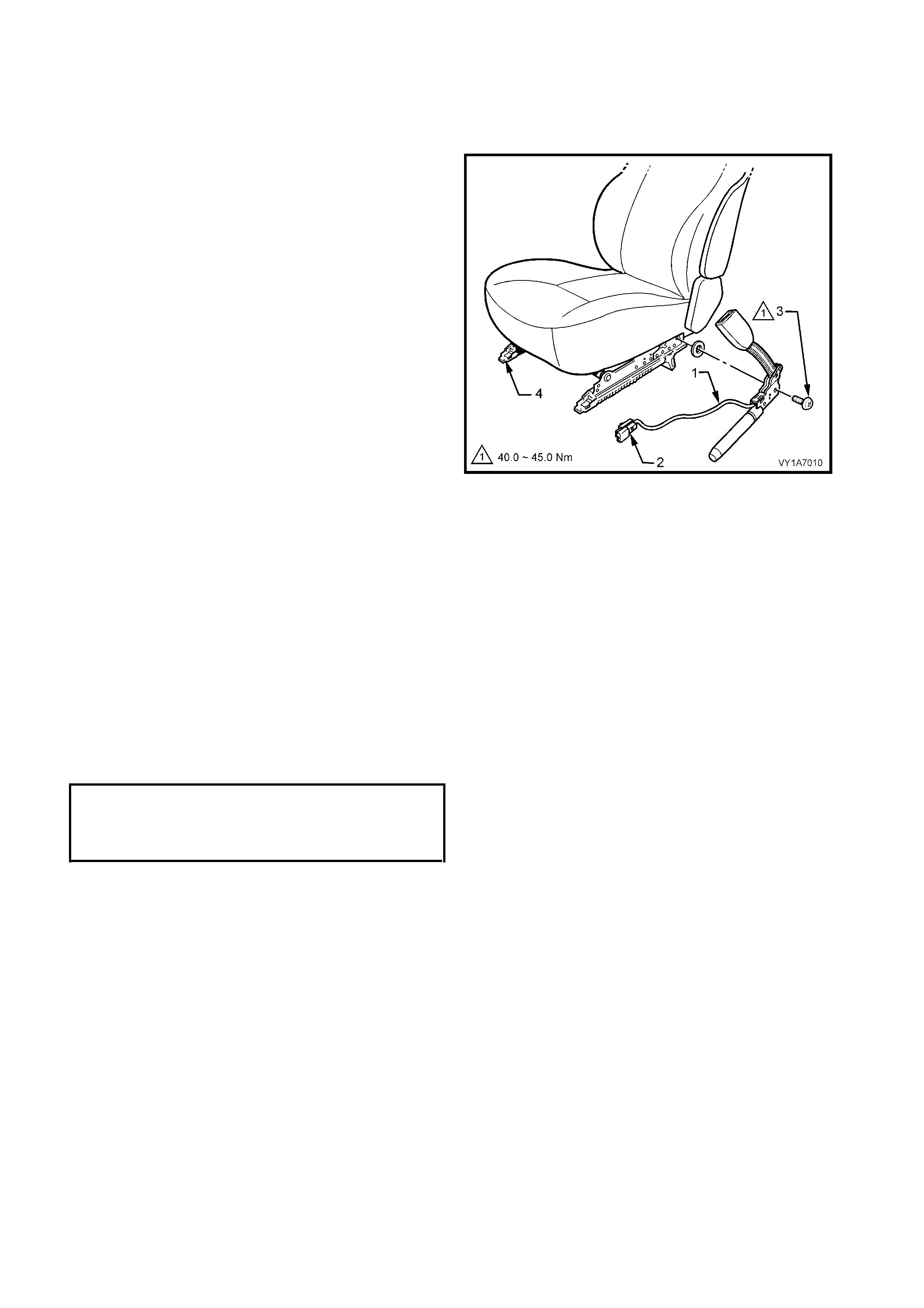
2.5 SEAT BELT BUCKLE AND PRETENSIONER ASSEMBLY
LT Section No. −−−− 14-400
REMOVE
CAUTION: If a seatbelt pretensioner is deployed,
the seatbelt pretensioner assembly together with
the seat adjuster and guide rail assembly must be
replaced.
NOTE: If disposing of an undeployed seat belt buckle
and Pretensioner assembly, refer to the disabling
procedure in Section 12M OCCUPANT
PROTECTION SYSTEM.
IMPORTANT: Disconnection of the battery affects
certain vehicle electronic systems. Refer to
Section 00, 5. BATTERY DISCONNECTION
PROCEDURES before disconnecting the battery.
1. Adjust seat to its rear most position and
disconn ect batter y to disa ble the OPS / SR S, refer
to 2.2 SYSTEM DISABLING AND ENABLING
PROCEDURE in this Section.
2. Remove the front seat from the vehicle, refer to
Section 1A7, SEAT ASSEMBLIES.
3. Disconnect the wiring harness connector (2) for
the seat belt buckle and Pretensioner assembly,
refer Figure 12M-52.
4. Rem ove the bolt (3) securing seat belt buck le and
Pretensioner assembly to frame (4) and remove
seat belt buckle and Pretensioner assembly, refer
Figure 12M- 52.
Figure 12M-53
REINST ALL
Installation is the reverse of the removal operation, noting the following:
1. When installing seat belt buckle and Pretensioner assembly, ensure that the front locating pin is aligned with
seat frame.
2. Ensure all bolts are fastened to the correct torque specifications.
3. Enable the OPS / SRS, refer to 2. 2 SYSTEM DISABLING AND ENABLING PROCEDUR E in this Sec ti on.
SEAT BELT BUCKLE AND PRETENSIONER ASSEMBLY SCRAPPING PROCEDURE
During the course of a vehicle's useful life, certain situatio ns may arise which will necessitate the disposal of a
live (undeployed) Pretensioner assembly. The following information covers proper procedures for deploying a
live Prete ns io ner ass embl y.
CAUTION: Failure to follow proper O PS / SRS Pretensio ner assembl y dispo sal procedures can result in
Pretensioner deployment, which may cause personal injury.
In situations, which require deployment of a live Pretensioner assembly, deployment may only be
accomplished outside the vehicle. The Pretensioner needs to be removed and the OPS / SRS wiring
harness with the capacitor built into the connector removed. Intentional deployment of the Pretensioner
assembly can not be accomplished using a 12 volt DC supply with the capacitor in the OPS / SRS
circuit.
SEAT BELT BUCKLE AND
PRETENSIONER ASSEMBLEY
ATTACHNING BOLT
TORQUE SPECICATION 40 – 45 Nm
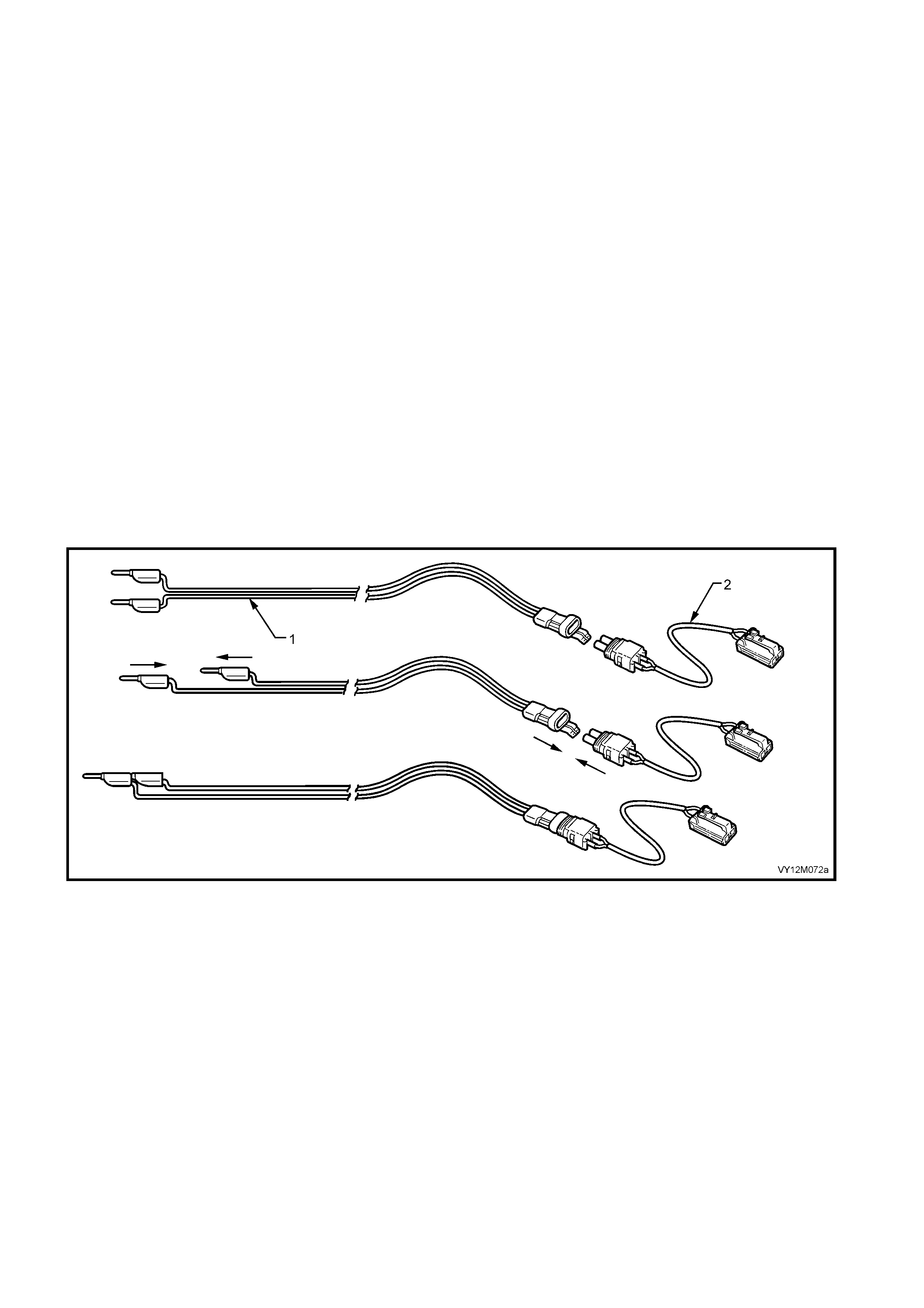
PRETENSIONER ASSEMBLY DEPLOYMENT OUTSIDE VEHICLE
For deployment of a live (undeployed) Pretensioner assembly outside the vehicle, the deployment procedure
must be followed exactly. ALWAYS wear safety glasses during this deployment procedure. Before performing
the proc edure you s h ou ld b e fam iliar with s er vic i ng t he O PS / SRS an d with proper hand li ng of the Pr et ens io ner
assembly.
NOTE 1: The following must be read fully and understood before performing the actual procedure.
NOTE 2: The following procedure requires use of J38826-1 OPS / SRS deployment harness with adaptor
AU596. Do not attempt procedure without J38826-1 and AU596.
NOTE 3: Adaptor E1992 was previously released as the deployment harness adaptor for the airbag module
only. This harness adaptor is to be used for the deployment of all OPS / SRS components.
CAUTION: Failure to follow procedures in the order listed may result in personal injury. Never connect
deployment harness to any power source before connecting deployment harness to the Pretensioner
assembl y. The d eployment harness must remain short ed and not be conn ected to a pow er source u ntil
the Pretensioner assembly is ready to be deployed. The Pretensioner will deploy immediately a power
source is connected to it. Wear safety glasses and gloves throughout this entire deployment and
disposal procedure.
1. Turn ignition switch OFF and put on safety glasses.
2. Inspec t J38826-1 O PS / SRS de ployment har ness and ada ptor AU596 f or dam age. If harness or adaptor is
damaged, discard and obtain a replacement.
3. Short two OPS / SRS deployment harness leads together by fully seating one banana plug into the other.
OPS / SRS deployment harness MUST remain shorted and NOT connected to a power source until the
Pretensioner is to be deployed.
4. Connect the deployment harness adaptor (AU596) to the OPS / SRS deployment harness (J38826-1).
Figure 12M-54
Legend
1. SRS Deployment Harness − J38826-1 2. Deployment Harness Adaptor − AU596
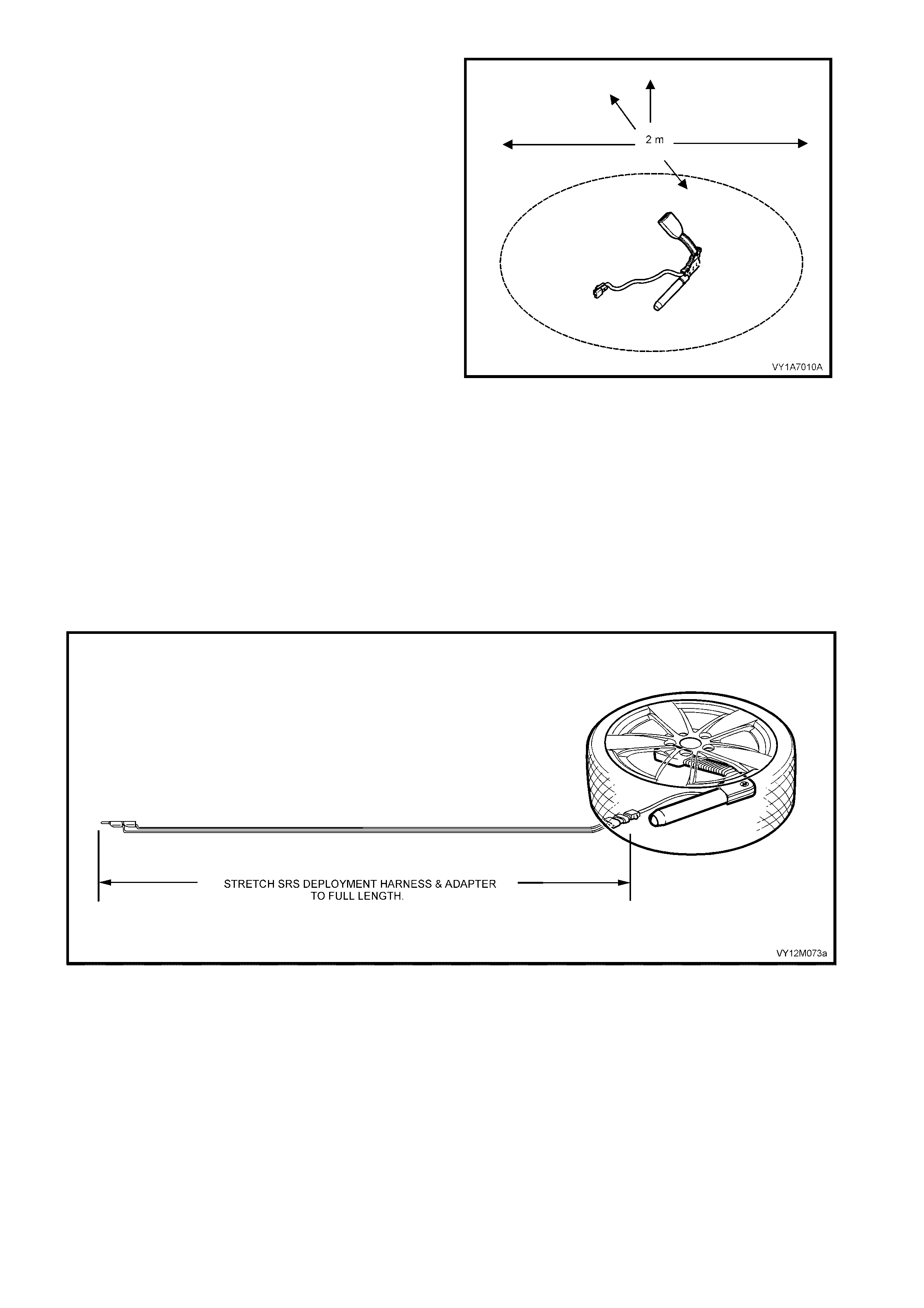
5. Remove the appropriate Pretensioner assembly
from the vehicle, refer to Section 1A7 SEAT
ASSEMBLIES.
NOTE 4: Leave Pretensioner to seat assembly
retaining bolt installed in the Pretensioner once
removed from the seat assembly.
6. Clear a space on the ground about 2 metres in
diameter where the Pretensioner assembly is to
deploy. A paved, outdoor location where there is
no activ ity is pref er r ed. If a n out do or loc a tio n is not
available, a space on the workshop floor where
there is no activity and sufficient ventilation is
recommended. Ensure no loose or flammable
objects are within the deployment area.
7. Stretch the OPS / SRS deployment harness and
adaptor from the Pretensioner assembly to its full
length.
8. Connect adaptor AU596 and OPS / SRS
deployment harness lead J38826-1 to the
Pretensioner assembly.
CAUTION 1: The deployment harness and adaptor
MUST be stretched to its full length.
CAUTION 2: The deployment harness MUST
remain shorted and NOT connected to a power
source until the Pretensioner assembly is to be
deployed. The Pretensioner assembly will
immediately deploy when a power source is
connected to it.
9. Position a wheel and tyre assembly over the
Pretensioner assembly, refer to Figure 12M-55.
Figure 12M-55
Figure 12M-56
10. Place a power source near the shorted end of the OPS / SRS deployment harness. Recommended
application: 12 volts minimum, 2 amps minimum (a vehicle battery is suggested).
11. Verify that the area around the Pretensioner assembly is clear of all people and loose or flammable objects.
12. Notify all people in the immediate area that you intend to deploy the Pretensioner assembly. The
deployment will be accompanied by an explosion, which may startle the uninformed.
13. Separate the t wo banana plugs on the OPS / SRS depl o yment harn es s.
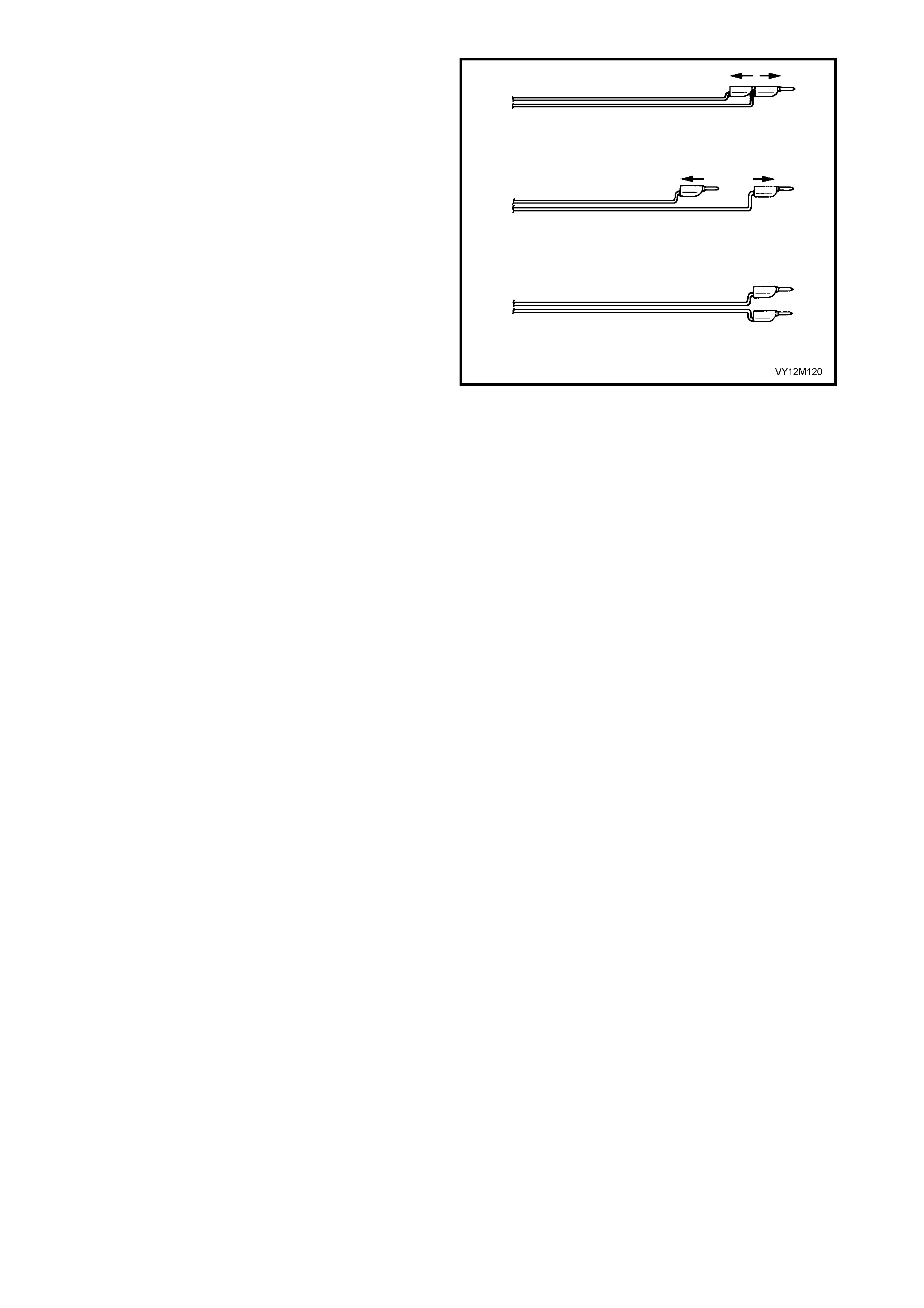
NOTE 5: When the Pretensioner deploys, the rapid
gas expansion will create an explosion. Notify all
people in t he im m ediate area tha t you intend to deploy
the Pretens ioner .
CAUTION: The deployment harness MUST remain
shorted and NOT connected to a power source
until the Pretensioner is to be deployed. The
Pretensioner will immediately deploy when a
power source is connected to it. Connecting the
deployment harness to the power source should
always be the last step prior to deployment of the
Pretensioner. Failure to follow procedures in the
order listed may result in personal injury.
14. Connect OPS / SRS deployment h arness leads to
the power source to immediately deploy the
Pretensioner assembly.
15. Disconnect the OPS / SRS deployment harness
from the power source.
16. Short the two OPS / SRS deployment harness
leads together by fully seating one banana plug
into the other.
17. To prevent damage to the adaptor or OPS / SRS
deployment harness, disconnect the adaptor
AU596. f rom the Pre tensio ner as soon as p ossibl e
after deployment. The adaptor and OPS / SRS
deployment harness is designed to be reused.
They should, however, be inspected for damage
after each deployment and replaced if necessary.
18. Dispose of the deployed Pretensioner assembly
through normal refuse channels.
Figure 12M-57
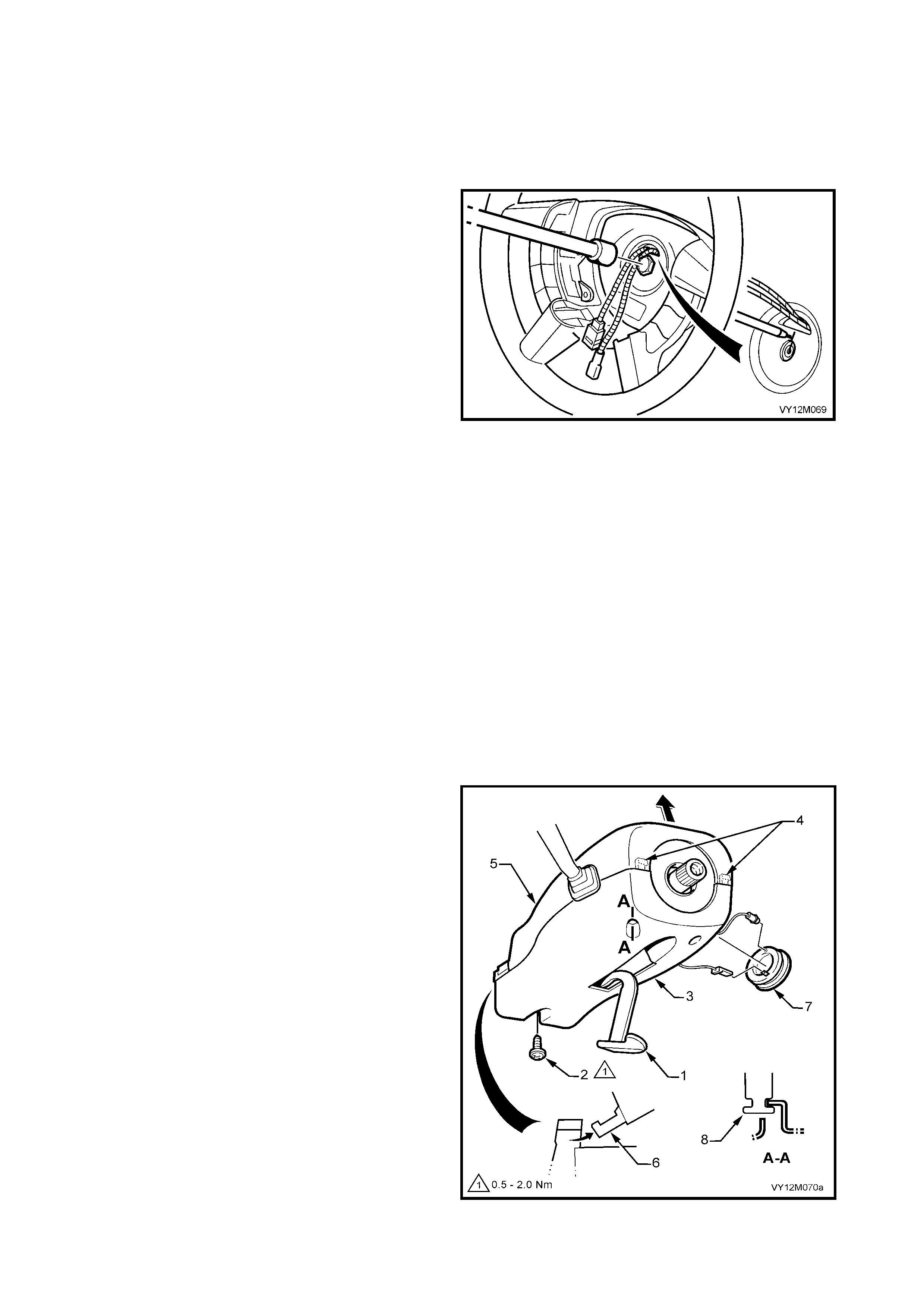
2.6 CLOCK SPRING COIL ASSEMBLY
LT Section No. −
−−
− 06-225
IMPORTANT: Absolutely no wire, connector or terminal repairs are to be attempted on the clock spring coil If
the clock spring coil is damage in any way, REPLACE IT.
REMOVE
1. Disable the OPS / SRS, refer to
2.2 SYSTEM DISABLING AND ENABLING
PROCEDURE in this Section.
2. Remove airbag module, refer to
2.3 STEERING WHEEL AIRBAG MODULE
ASSEMBLY in this Section.
NOTE 1: This is important to ensure that clock spring
coil is locked when the steering wheel is removed to
prevent the steering shaft from being rotated.
1. Ensure the front wheels and the steering wheel
are in the straight-ahead position and remove keys
from ignition switch. To aid the installation of the
steering wheel to it’s original position, scribe an
aligning m ark on the s teering wheel centre s ection
and steering shaft. A felt tipped pen could also be
used.
NOTE 2: Do not use a centre punch for this operation.
2. Using a commercially available socket, remove the
steering wheel retaining bol t.
3. Remove the s teering wheel fr om the s teering shaf t
splines and feed the clock spring coil wiring and
connectors through the steering wheel aperture.
NOTE: 3: W hen the steering wh eel is rem oved, check
that the green coloured tang has engaged the inner
clock spring coil member to lock it in the centralised
position.
NOTE: 4: With the increased diameter of the steering
shaft and the angle of the locating bevel, it is not
usually necessary to require a puller to remove the
steering wheel. However, if a puller is required, refer to
Section 9, 2.4 STEERING WHEEL.
Figure 12M-58
4. Lower instrument pa nel r ight- han d c o ver as s embly
(fuse panel cover) by grasping the top edge on
either side of the steering column with the finger
tips and pulling the top edge out, to free the
retaining lugs from the clips.
5. Release steering column height adjuster,
completely lower steering column and leave lever
(1) in the release position.
6. Remove the upper steering column cover (5) by
applying a small amount of pressure on the lower
steering column cover (pushing towards
instrument cluster) while lifting the upper cover
upwards and rearwards.
7. Remove screw (2) securing the lower cover to the
steering column.
8. Push the lower steering column cover (3) up
towards the top of the steering column to release
the retaining tangs (4, 6 and 8) on the steering
column, refer to Figure 12M-58.
9. While feeding the remote coded key reader outer
surround (7) from the lower cover (3), remove the
low er steering column cover.
Figure 12M-59
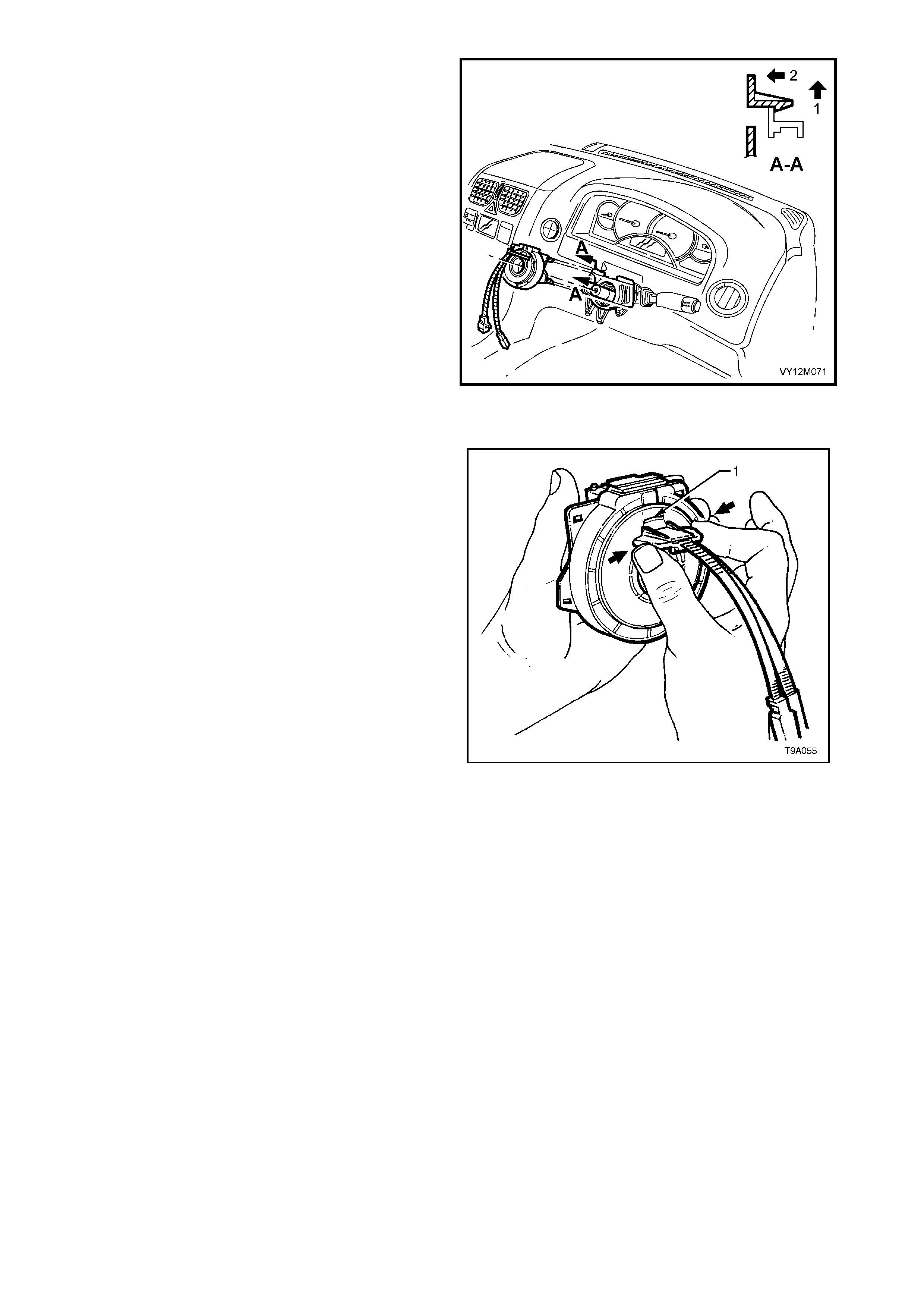
10. Disengage the two top locking tangs on the clock
spring coil assembly by lifting first in direction (1)
then pulling the clock spring coil assembly in
direction (2), refer to Figure 12M-59. Repeat for
the lower two tangs, th en rem ove clock spr ing coil
assembly from the steering column.
Figure 12M-60
CENTRING THE CLOCK SPRING COIL
NOTE: The following procedure must be followed
when reusing a clock spring coil that has been
removed from a steering column without the steering
wheel or clock spring coil being centred.
1. Ensure t hat steering gear is in c entralised position
before installing the clock spring coil assembly,
otherwise irreparable damage to the clock spring
coil may result. Refer to Section 9 STEERING
for details on centralising the steering gear.
2. Hold the clock spring coil outer housing by one
hand while holding each of the two locking lugs
inward with the other hand, refer to Figure
12M-60.
3. Rotat e th e inn er m ember of the c lock spring coi l in
a clockwise direction until a mechanical stop is
felt.
4. While still holding the two locking lugs as before,
rotate the inner member of the clock spring coil in
an anti-clockwise direction for approximately 2.5
turns, until the green indexing tab is seen in the
upper window (1) of the clockspring coil assembly.
5. Release the locking lu gs and the inner rotor of the
clock spring coil assembly should now be locked
to the outer member with the clock spring coil in
the centralised position.
Figure 12M-61

REINST ALL
Installation of the clock spring coil is the reverse of removal procedures, noting the following points:
1. Ensure that s teering gear is in c entr al ised pos it io n before inst alli ng the c lock spr ing c oil ass embl y, otherwis e
irreversible damage to the clock spring coil may result. Refer to Section 9, 2.4 STEERING WHEEL for
details on centralising the steering gear.
2. With the clock spr ing coil a ssem bly loc ked in t he ce ntr alise d pos ition, i nstal l clock s pring co il ass em bly over
the end of steer ing c olum n, ind exing th e lo wer loc atin g pins on t he c lock spring c oil with th e m atching holes
in the switch housing.
NOTE 1: If the clock spring coil assembly was removed without being centred, refer to the previous service
procedure; refer to 2.6 CENTRING THE CLOCK SPRING COIL in this Section.
3. Push the clock spring coil assembly onto the switch housing until the four locking tangs fully engage.
4. Install the steering wheel to steering shaft, aligning marks made prior to removal and ensuring the drive tang
of the clock spring coil is aligned with the steering wheel aperture.
NOTE 2: This action automatically releases the clock spring coil centralising lock.
5. After cleaning the threadlock residue from the bolt threads, apply Loctite 242 or equivalent, to Holden
Specific at io n HN 12 56 Clas s 2, Type 2 to b olt threa ds . Ins tal l an d ti ght en s teering whee l r eta in ing bo lt to t h e
correct torque specification using a commercially available socket.
6. Reinstall airbag module, refer to 2.3 STEERING WHEEL INFLATABLE RESTRAINT MODULE
ASSEMBLY in this Section.
7. Enable the OPS / SRS, refer to 2. 2 SYSTEM DISABLING AND ENABLING PROCEDUR E in this Sec ti on.
8. Switch the ignition on, and observe the SRS warning indicator in the instrument cluster. The warning lamp
should be illuminated for approximately five seconds. During this period of time the Inflatable Restraint
Control Module (SDM) performs a wiring and self-check.
If no s ystem f aults are dete cted, the SRS warning indi cator wil l be sw itched of f . If the warning lam p rem ains
illum inated and an audi ble alarm chimes , or the warning lam p illum inates two sec onds after it was or iginal ly
switched off, a OPS / SRS fault is present. Refer to 4 DIAGNOSTICS in this Section to rectify the fault.
STEERING WHEEL
RETAINING BOLT
TORQUE SPECICATION 40 – 50 Nm
LOWER COVER
RETAINING SCREW
TORQUE SPECICATION 0.5 – 2.0 Nm
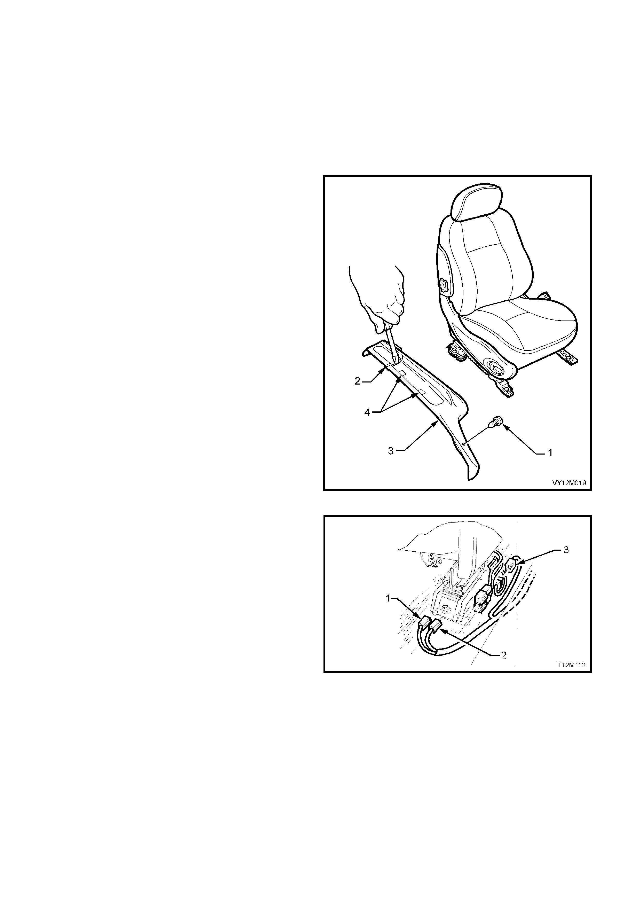
2.7 SIDE-IMPACT INFLATABLE RESTRAI NT MODULE ASSEMBLY
LT Section No. −
−−
− 06-225
NOTE: Due to the critical nature of how the side-impact inflatable restraint (Side-impact airbag) wiring harness is
routed an d re taine d to th e s eat, the seat m ust be rem oved t o ensure this routin g is cor rect when ins tal ling the s ide-
impact airbag module assembly. If the side-impact airbag module’s wiring harness is not routed and retained
correc tly, damage to the wiring harnes s ma y oc cur, resulti ng in the s ide-impac t airbag becom ing inoperati ve and a
DTC being set.
REMOVE
1. Disable the OPS / SRS, refer to
2.2 SYSTEM DISABLING AND ENABLING
PROCEDURE in this Section.
2. If removing the front driver’s or passenger seat
and outer seat guide rail covers (2, 3 and 4) refer
to Figure 12M- 61 and refer to Section 1 A7, SEAT
ASSEMBLIES.
Figure 12M-62
3. Disconnect seat, seat belt Pretensioner and side-
impact airbag module wiring harness connectors
(1,2 and 3) from outer side of the relevant seat.
Figure 12M-63
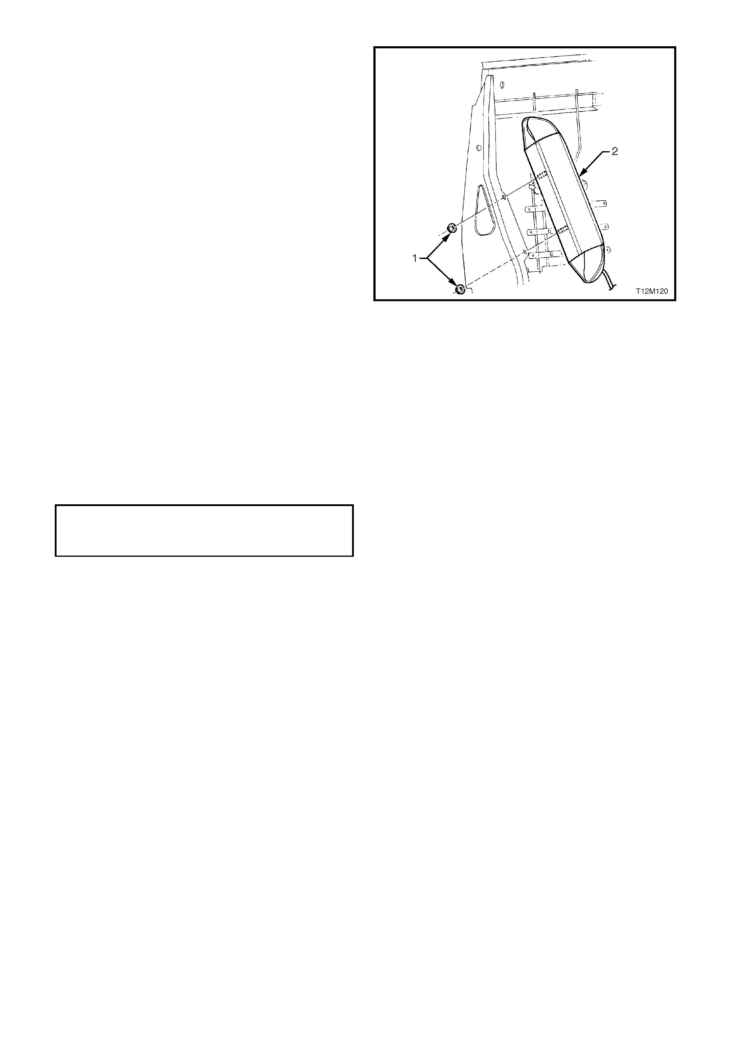
4. Loosen and remove the two nuts (1) securing the
side-impact airbag module (2) to the front seat
back frame, refer to Figure 12M-63.
5. Remove side-impact airbag module (2) and
‘pigtail’ wiring harness assembly from front seat
back frame.
CAUTION: When carrying a live (undeployed) side-
impact airbag module assembly, make sure the
bag opening is pointed away from you. Never
carry the side-impact airbag module assembly by
the wiring harness or connectors. In case of an
accidental deployment, the bag will then deploy
with minimal chance of injury.
When placing a live side-impact airbag module
assembl y on a bench o r other surf ace, alw ays fac e
the inflatable restraint opening up, away from the
surface. Never rest the inflatable restraint module
assembly with the opening face down. This is
necessar y so t hat a fr ee sp ace is pro v ided t o allo w
the inflatable restraint to expand in the unlikely
event of accidental deployment. Otherwise,
personal injury may result.
Figure 12M-64
REINST ALL
Installation of the side-impact airbag module is the reverse of removal procedures, noting the following points:
1. Install side-impact airbag module (2) to front seat back frame retaining nuts (1), and tighten to the correct
torque specification, refer to Section Figure 12M-63.
2. If reinstalling the front driver’s or passenger seat and outer seat guide rail covers refer to Section 1A7, SEAT
ASSEMBLIES.
NOTE 1: If the side-impact airbag module’s wiring harness is not routed and retained correctly, damage to the
wiring harness may occur, resulting in the side-impact airbag becoming inoperative and a DTC being set
3. Enable the OPS / SRS, refer to 2. 2 SYSTEM DISABLING AND ENABLING PROCEDUR E in this Sec ti on.
4. Switch ignition on, and observe the SRS warning indicator in the instrument cluster. The warning indicator
should be i llum inated for approx im ately five s econ ds. Durin g this p eriod the SDM per form s a wiring a nd s ystem
self check.
NOTE 2: If no system faults are detected, the SRS warning indicator will be switched off. If the warning indicator
remains illuminated and an audible alarm chimes, or the warning indicator illuminates two seconds after it was
originally switched off, an OPS / SRS fault is present. Refer to 4 DIAGNOSTICS in this Section to rectify
fault.
5. Check operation of front seat mechanical and electrical adjustments / operation. While checking the seat
adjustm ent / operat ion, also c heck to ens ure that th e side-im pact airba g ‘pigtail ’ harness does not f oul with any
of the seats moveable components (i.e. seat motor drive shafts, etc.).
AIR BAG MODULE
RETAINING NUT
TORQUE SPECICATION 5 – 6 Nm

SIDE-IMPACT INFLATABLE RESTRAINT MODULE ASSEMBLY SCRAPPING PROCEDURE
During the course of a vehicle's useful life, certain situations may arise which will necessitate the disposal of a live
(undeployed) side-impact inflatable restraint (Side-impact airbag) module assembly. The following information
covers proper procedures for deploying a live side-impact airbag module.
CAUTION: Failure to follow proper OPS / SRS side-impact airbag module assembly disposal procedures
can result in airbag deployment which may cause personal injury. The undeployed airbag module contains
substances that can cause severe illness or personal injury if the sealed container is damaged during
disposal.
In situations which require deployment of a live side-impact airbag module assembly, deployment may only be
accomplished outside the vehicle.
The side-impact airbag module needs to be removed so the OPS / SRS wiring harness with the capacitor built into
the connector can be removed. Intentional deployment of the side-impact airbag module can not be accomplished
using a 12 volt DC supply with the capacitor in the OPS / SRS circuit.
NOTE: Due to an anti-back-out lug being moulded into the plastic housing of the side-impact airbag module, it will
be necessary to cut part of the housing away from the airbag module to disconnect the OPS / SRS wiring harness
connector from the airbag module.
SIDE-IMPACT INFLATABLE RESTRAINT MODULE DEPLOYMENT OUTSIDE VEHICLE
There may be some circumstances that require the deployment of a side-impact inflatable restraint (Side-impact
airbag) module assem bly before a veh icle is to be retu rned to service. For example, s ituations in which the vehic le
will be returned to an owner after a functionally malfunctioning side-impact airbag module assembly is replaced.
Deployment and disposal of a malfunctioning airbag module is, of course, subject to any required retention period.
For deployment of a live (undeployed) side-impact airbag module assembly outside the vehicle, the deployment
procedure must be followed exactly. Always wear safety glasses during the deployment procedure until the
assembly is removed. Before performing the procedure you should be familiar with servicing the OPS / SRS and
with proper handling of the side-impact airbag module assembly.
The following must be read fully and understood before performing the actual procedure.
The following procedure requires use of special tools; J213526-1 OPS / SRS deployment harness with adaptor
E1992. Do not attempt procedure without J213526-1 and E1992.
CAUTION: Failure to follow procedures in the order listed may result in personal injury. Never connect
deplo yment harness to any power so urce befo re connectin g deplo yment harness to the side-impa ct airbag
module assembly. The deplo yment harn ess must remain shorted and not be connected to a power source
until the side-impact airbag module as sembly is r eady to be deployed. Th e module will immediately deploy
the airbag when a power source is connected to it. Wear safety glasses and gloves throughout this entire
deployment and disposal procedure.
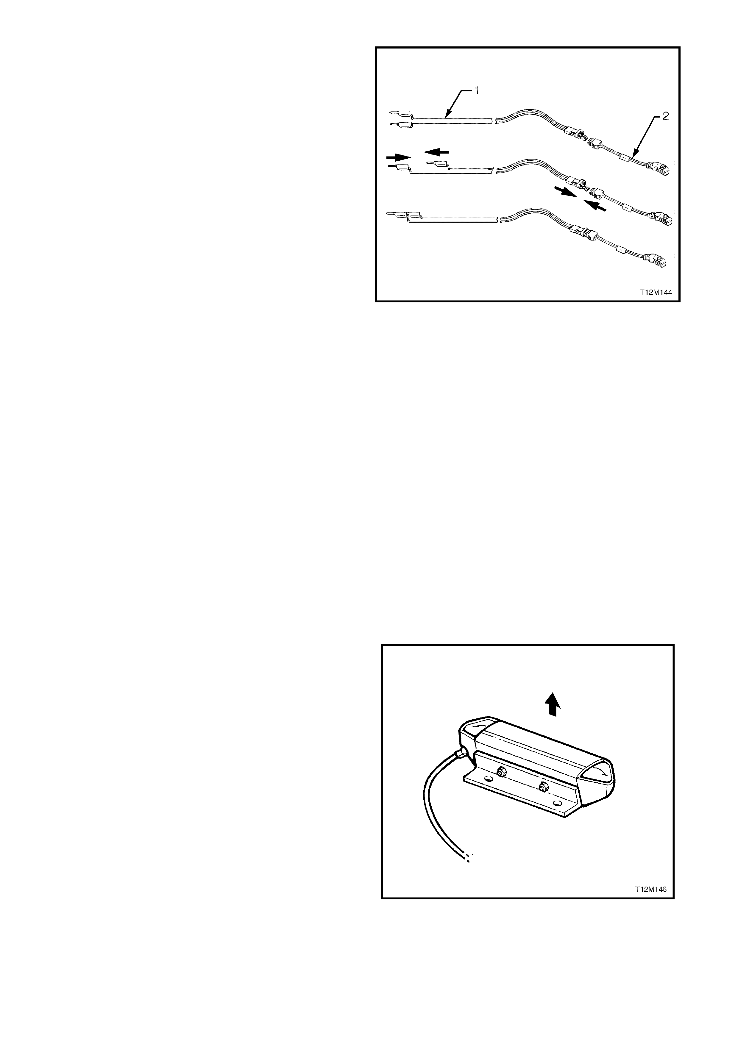
1. Turn ignition switch OFF and put on safety
glasses.
2. Inspect J213526-1 OPS / SRS deployment
harness ( 1) and adaptor , E1992 (2) f or damage. If
harness or adaptor is damaged, discard and
obtain a replacement.
3. Short two OPS / SRS deployment harness leads
together by fully seating one banana plug into the
other. OPS / SRS deployment harness MUST
remain shorted and NOT connected to a power
source until the inflatable restraint is to be
deployed.
4. Connect adaptor E1992 to the OPS / SRS
deployment harness J213526-1.
CAUTION: The OPS / SRS deployment harness
must remain shorted and not connected to a
power source until the inflatable restraint is to be
deployed.
5. Remove relevant side-impact airbag
module assembly from vehicle, refer to
2.7 SIDE-IMPACT INFLATABLE RESTAINT
MODULE ASSEMBLY in this Section.
CAUTION: When carrying a live (undeployed) side-
impact airbag module assembly, make sure the
bag opening is pointed away from you. Never
carry the side-impact airbag module assembly by
the wiring harness or connectors. In case of an
accidental deployment, the bag will then deploy
with minimal chance of injury.
When placing a live side-impact airbag module
assembl y on a bench o r other surf ace, alw ays fac e
the airbag opening up, away from the surface.
Never rest the airbag module assembly with the
opening face down. This is necessary so that a
free space is provided to allow the airbag to
expand in the unlikely event of accidental
deployment. Otherwise, personal injury may
result.
Figure 12M-65
6. Using a piece of angle iron (approximately 60cm
long) dr il l t wo holes on o ne s ur f ac e that will a l lo w it
to be bolted to a p iec e of square s te el tubin g (r ef er
to Step 9 and Step 11).
7. On the other surface of the angle iron, drill two
more holes that are suitably sized and positioned
to allow the side-impact airbag to be attached to it.
8. Using the existing airbag retaining studs and
appropriate nuts, attach the side-impact airbag
module to the angle iron, ensuring the opening of
the airbag will be able to face upwards when
bolted to the square steel tubing.
Figure 12M-66
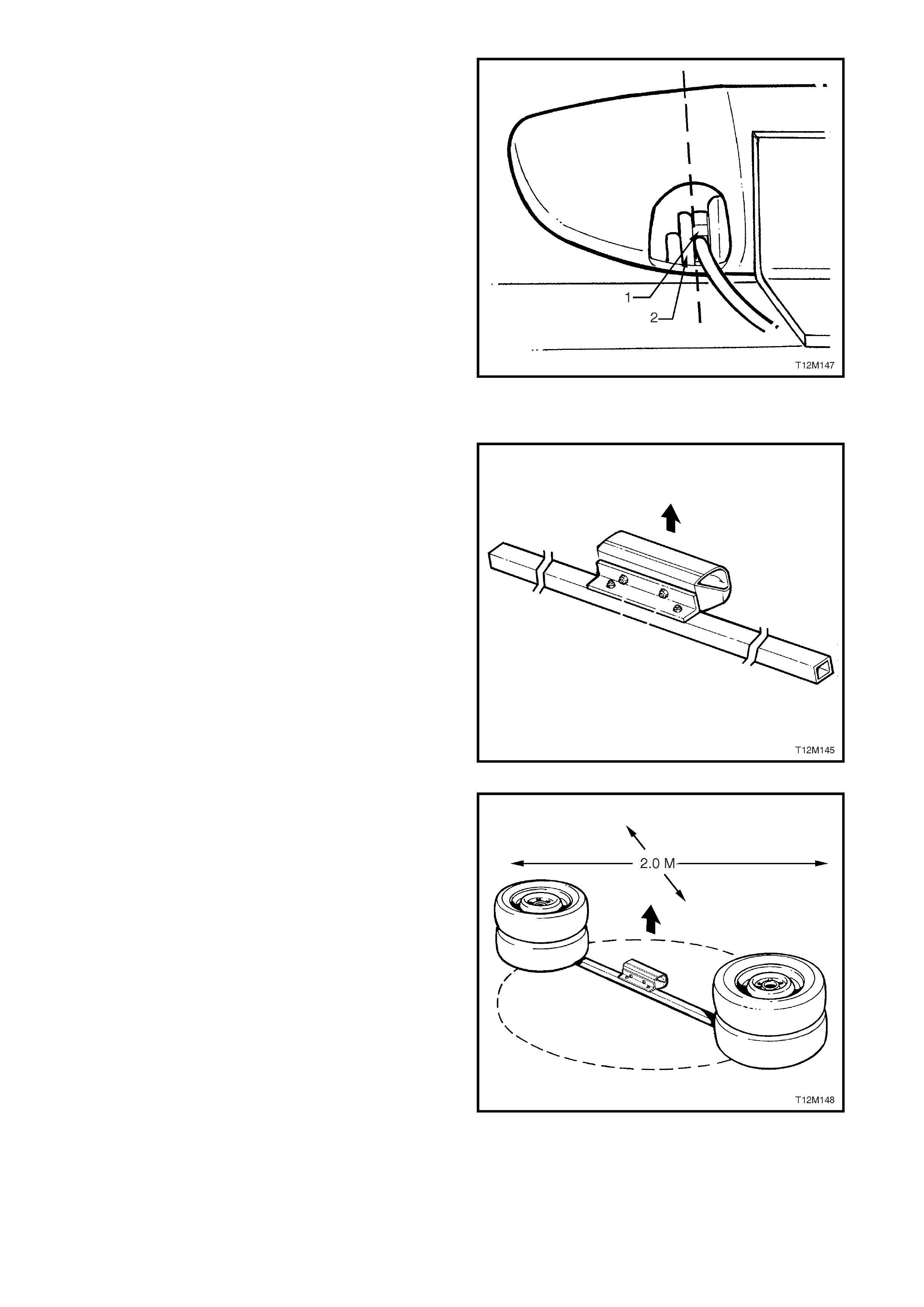
NOTE: The side-im pact airbag m odule plastic ho using
has an anti-back-out lug (2) moulded into it which will
prevent the OPS / SRS wiring harness connector (1)
from being disconnected. Due to the in-built capacitor
in this connector, a side-impact airbag cannot be
intentiona ll y depl oyed wit h this co nnector in t he c ircuit,
therefore, it will be necessary to cut part of the side-
impact airbag housing away from the side-impact
airbag module assembly to allow the OPS / SRS
wiring harness connector be disconnected.
9. Clamp angle iron (with side-impact airbag
attached) in a vice with the airbag opening facing
upwards. Using a hack saw, cut the end off the
side-impact airbag module plastic housing so that
it will enable the OPS / SRS wiring harness
connector (1), with in-built capacitor, to be
disconnected from the side-impact airbag module,
refer to Figure 12M-66.
10. Disconnect OPS / SRS wiring harness from side-
impact airbag module assembly.
Figure 12M-67
11. Using a 2 metre long square steel tube and
suitable nuts and bolts, attach the angle iron and
side-impact airbag module assembly to the centre
of the square steel tube, refer to Figure 12M-67.
Figure 12M-68
12. Clear a space on the ground about two metres in
diameter where th e assembl y is to be deplo ye d. A
paved, outdoor location where there is no activity
is pref erred. If an outdoor loc ation is not ava ilable,
a space on the workshop floor where there is no
activity and sufficient ventilation is recommended.
Ensure no loose or flammable objects are within
the deployment area.
13. Position two wheel and tyre assemblies on each
end of the square steel tubing, ensuring the side-
impac t air bag module’s op e n in g is facing up war ds ,
refer to Figure 12M-68.
Figure 12M-69
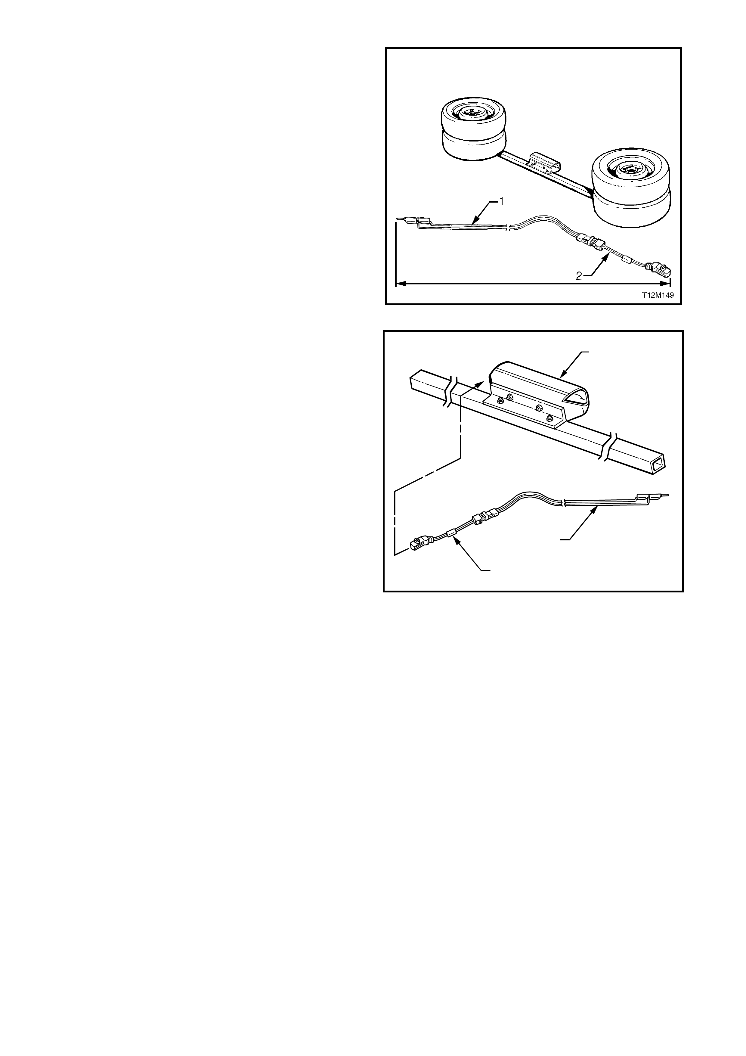
14. Extend the OPS / SRS deployment harness (1)
and adaptor (2) to its full length from the side-
impact airbag module, refer to Figure 12M-69.
15. Place a po wer source near the shorted end of the
OPS / SRS deployment harness. Recommended
applicat ion: 12 volts minim um, two amps minim um
(a vehicle battery is suggested).
Figure 12M-70
16. Connect the adaptor E1992 (1) and OPS / SRS
deployment harness lead J213526-1 (2) to the
Passenger airbag module assembly (3), refer to
Figure 12M- 70.
CAUTION: OPS / SRS deployment harness must
remain shorted and not connected to a power
source until the airbag is to be deployed. The
module will immediately deploy the airbag when a
power source is connected to it.
17. Verify that the area around the side-impact airbag
module assembly is clear of all people and loose
or flammable objects.
18. Verify that the side-impact airbag module
assembly is resting with the airbag facing up.
19. Notify all people in the immediate area that you
intend to deploy the side-impact airbag module
assembly. The deployment will be accompanied
by an explosion, which may startle the uninformed.
T12M150
1
2
3
Figure 12M-71
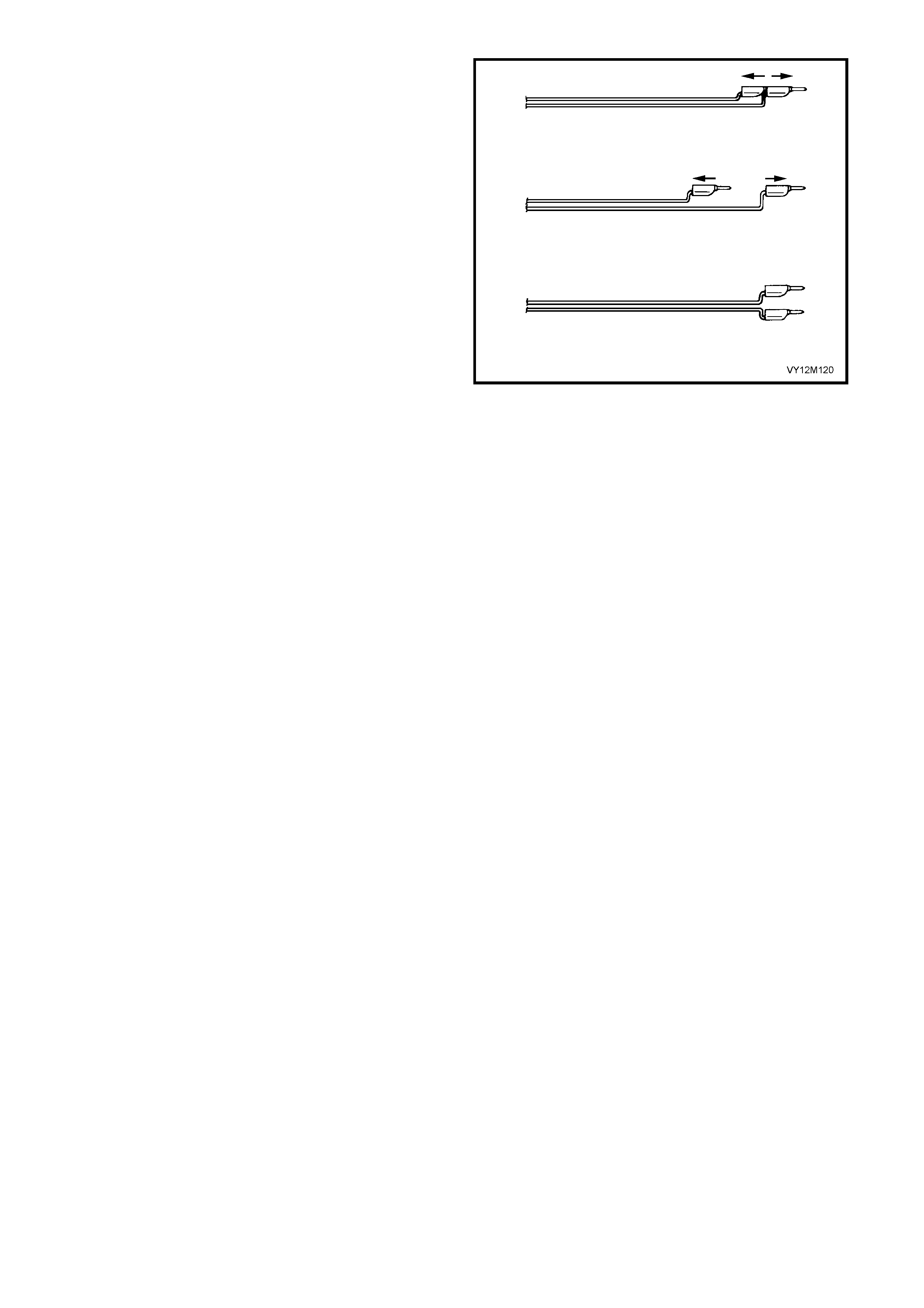
20. Sep arate the t wo banana plugs on t he OPS / SR S
deployment harness, refer to Figure 12M-71.
NOTE: 1. When the airbag deploys, the rapid gas
expansi on will create an ex plosion. N otify all peo ple in
the immediate area that you intend to deploy the
module.
NOTE: 2. W hen the airbag deplo ys, the assem bly may
jump ver t ic al l y. T his is a no rm al r eac ti on of the module
to the force of the rapid gas expansion inside the
airbag.
CAUTION: The deployment harness MUST remain
shorted and NOT connected to a power source
until the airbag is to be deployed. The module will
immediately deploy the airbag when a power
source is connected to it. Connecting the
deployment harness to the power source should
always be the last step prior to deployment of the
airbag. Failure to follow procedures in the order
listed may result in personal injury.
21. Connect OPS / SRS deployment h arness leads to
the power source to immediately deploy the side-
impact airbag module assembly, refer to Figure
12M-72.
NOTE: Should this procedure fail to deploy the airbag
for any reason, provided it is not due to a discharged
deployment battery or a faulty deployment harness,
contact Holden Ltd. For advise.
22. Disconnect the OPS / SRS deployment harness
from the power source.
23. Short the two OPS / SRS deployment harness
leads together by fully seating one banana plug
into the other.
24. Disconnect the adaptor E1 992 fr om the m odule as
soon as possible after deployment. This will
prevent damage to the adaptor or OPS / SRS
deplo ym ent harnes s. The adaptor and OPS / S RS
deployment harness is designed to be reused.
They should, however, be inspected for damage
after each deployment and replaced if necessary.
25. Dispose of the deployed side-impact airbag
module assembly through normal refuse channels.
Figure 12M-72
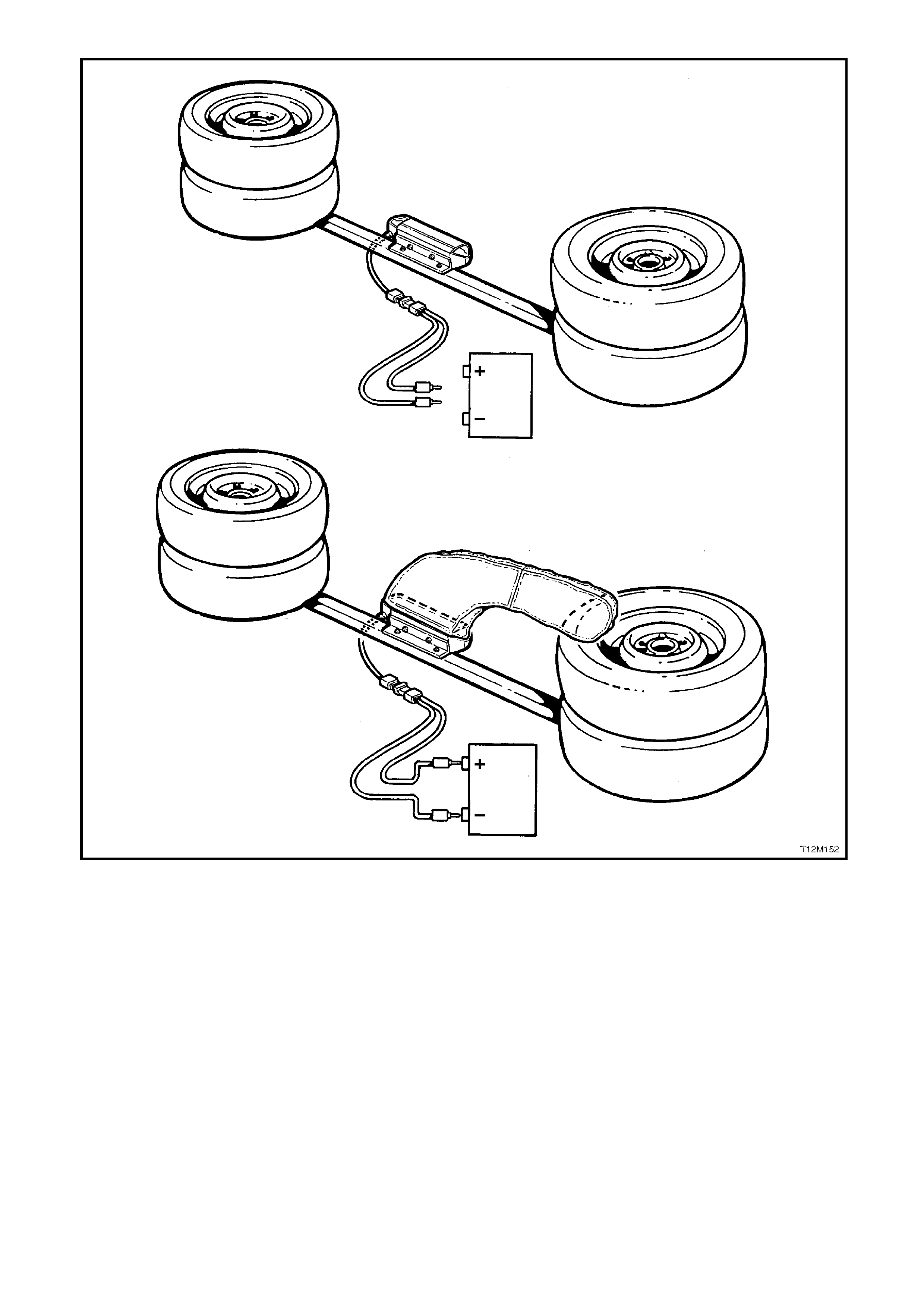
Figure 12M-73
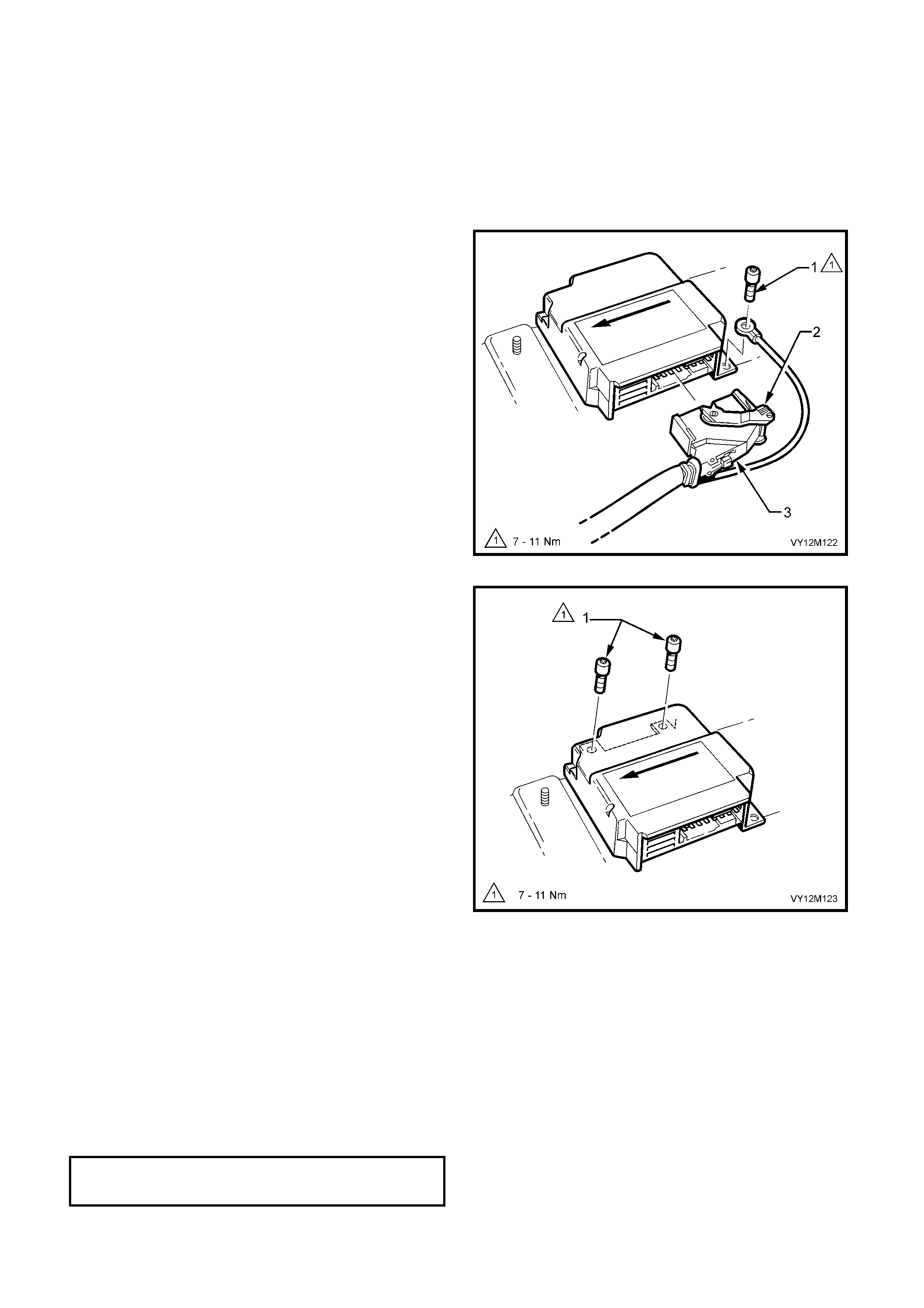
2.8 INFL ATABLE RESTRAINT CONTROL MODULE
LT Section No. −
−−
− 06-225
The inflatable restraint control module (SDM) controls the deployment sequencing of all airbags and seat belt
pretensioners. This module also controls the poling signals required for the illumination of the SRS warning
indicator and m ulti f unc ti on dis pl a y SRS mes sage. of the ins tr ument cluster as s embly. For more inf or mation ref er t o
1.1 SYST EM COM PON ENT S in this section.
REMOVE
1. Disable the OPS / SRS refer to
2.2 SYSTEM DISABLING AND ENABLING
PROCEDURE in this Section.
2. Remove the centre console assembly, refer to
Section 1A3 INSTRUMENT PANEL AND
CONSOLE.
3. Using a number T30H Torx bit, Tool No. ETX30H
and suitable holder such as Tool No. J25359-8,
loosen and remove the SDM to floor attaching
screw (1) with the earth lea d attac hed to it
4. Lift up OPS / SRS wiring harness connector
locking lever (2) and pull harness connector (3)
out of SDM.
Figure 12M-74
5. Using the number T30H Torx bit, Tool No.
ETX30H and suitable holder such as Tool No.
J25359-8, loosen and remove the remaining two
SDM to floor attaching screws (1).
6. Remove SDM.
Figure 12M-75
REINST ALL
Installation of the SDM is the reverse of removal procedures, noting the following points:
1. Ensure that the directional arrow on the SDM identification label is pointing towards the front of the vehicle.
2. Install the OPS / SRS wiring harness earth lead to the left-hand rear SDM retaining screw.
3. Using a number T30H Torx bit, T ool No. ET X30H and suitable holder such as Tool No. J2 5359-8, t ighten SD M
to floor attaching screws to the correct torque specification.
NOTE: It is very important that the SDM is mounted securely to the floor. The screws must be tightened to the
correc t torque spec if ic ati on and not exc eede d.
SDM RETAINING SCREW
TORQUE SPECICATION 7 – 11 Nm

4. Conn ect the O PS / SRS wiring harn ess c onnector, en sur ing that the conn ector is f ully seated int o SDM and the
locking lever is locked down.
5. Enable the OPS / SRS, refer to 2. 2 SYSTEM DISABLING AND ENABLING PROCEDUR E in this Sec ti on.
6. Switch the ignition on, and observe the SRS warning indicator in the instrument cluster. The warning indicator
should be illuminated for approximately five seconds. During this period the SDM performs a wiring and self-
check.
7. If no s ystem faults are detec ted, the SRS warnin g indi cator wil l be switch ed off . If the warning in dica tor rem ains
illum inated a nd an audib le alarm c him es, or the warn ing indicator i llum inates t wo s econds af ter it was origin all y
switched off, a OPS / SRS fault is present. Refer to 4 DIAGNOSTICS in this Section to rectify the fault.
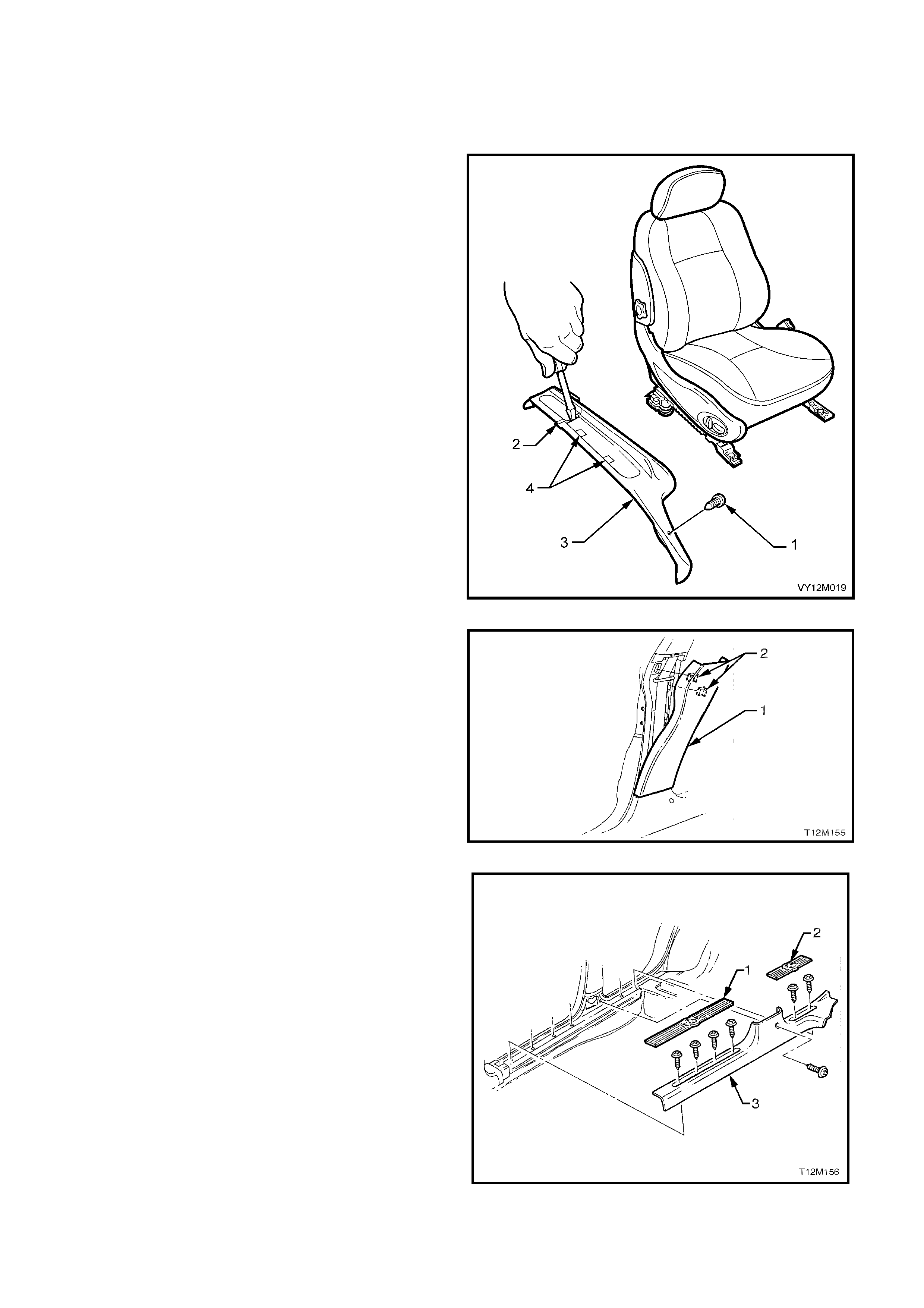
2.9 SIDE-IMPACT SENSOR (PERIPHERAL ACCELERATION SENSOR)
LT Section No. −
−−
− 06-225
REMOVE
1. Disable the OPS / SRS, refer to
2.2 SYSTEM DISABLING AND ENABLING
PROCEDURE in this Section.
2. If removing the driver’s side side-impact sensor
(Peripheral acceleration sensor), remove the
retaining screw (1) from the driver’s side outer
front guide rail cover.
3. Using a small screwdriver, push in the centre of
the front (3) and rear (2) outer seat guide rail
covers where the two parts meet.
4. Remove the front outer guide rail covers by lifting
the outer edge of the front cover up and pulling it
forward. Lift the driver’s outer front seat guide rail
cover over fuel filler door, release lever.
5. Lift the two rear guide rail covers up and off the
guide rails.
Figure 12M-76
6. From the top of the lower B-pillar trim (1), gently
lever tr im out a way fr om B-pillar to r elease th e two
retaining clips (2).
7. Lift lower B-pillar trim up to disengage it from the
rocker panel trim, and remove the lower B-pillar
trim.
Figure 12M-77
8. Gently pry the front (1) and rear (2) rocker panel
cover inserts from the rocker panel cover (3).
9. Loosen and remove the rocker panel cover
retainin g s c rew (s e ve n p laces) , and re move roc ker
panel cover.
Figure 12M-78
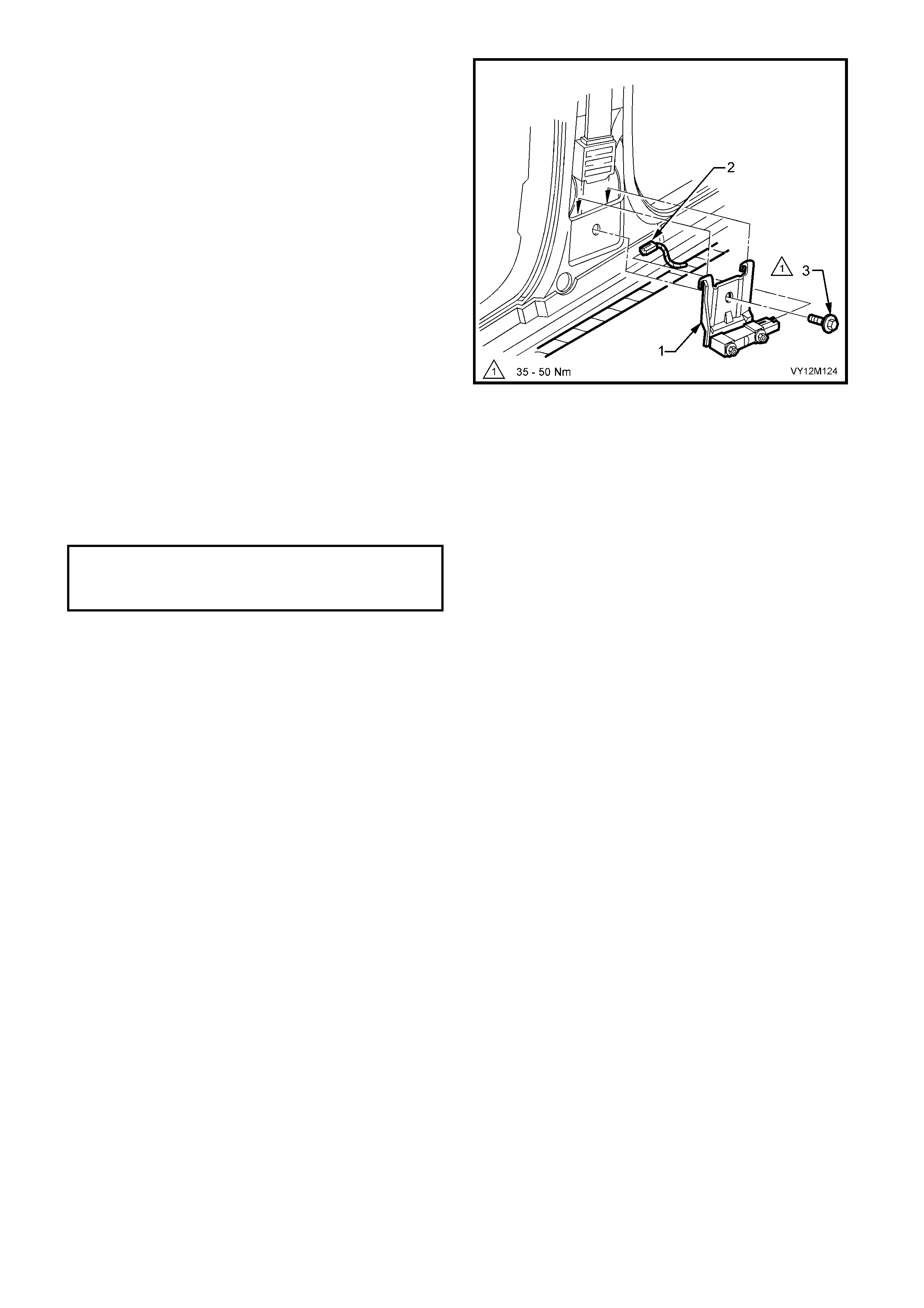
10. Disconnect the peripheral acceleration sensor
wiring harness connector (2) from peripheral
acceleration sensor and bracket assembly (1).
11. Loosen and remove the bolt (3) retaining the
peripheral acceleration sensor and bracket
assembly (together with seat belt retractor
assembly) to the B-pillar.
NOTE: Do not loosen or unscrew the two nuts
retaining the peripheral acceleration sensor to the
mounting bracket. The peripheral acceleration sensor
is only serviced with the mounting bracket as an
assembly.
12. Remove the peripheral acceleration sensor and
bracket assembly from the B-pillar.
Figure 12M-79
REINST ALL
Installation of the peripheral acceleration sensor and bracket assembly is the reverse of the removal procedure,
noting the following:
1. Tighten peripheral acceleration sensor and mounting bracket assembly retaining bolt (front seat belt retractor
retaining bolt) to the correct torque specification.
2. Enable the OPS / SRS, refer to 2. 2 SYSTEM DISABLING AND ENABLING PROCEDUR E in this Sec ti on.
3. Switch the ignition on, and observe the SRS warning indicator in the instrument cluster. The warning indicator
should be illuminated for approximately five seconds. During this period the SDM performs a wiring and self-
check.
4. If no s ystem faults are detec ted, the SRS warnin g indi cator wil l be switch ed off . If the warning in dica tor rem ains
illum inated a nd an audib le alarm c him es, or the warn ing indicator i llum inates t wo s econds af ter it was origin all y
switched off, a OPS / SRS fault is present. Refer to 4 DIAGNOSTICS in this Section to rectify the fault.
PERIPHERAL ACCELERATION SENSOR
RETAINING BOLT
TORQUE SPECICATION 35 – 50 Nm

2.10 REPAIRS AND INSPECTIONS REQUIRED AFTER AN ACCIDENT
If any OPS / SRS components are damaged, they must be replaced. If OPS / SRS component mounting points
are damaged, they must be repaired or replaced.
Never use OPS / SRS components from another vehicle.
CAUTION: Proper operation of the OPS / SRS, requires that any repairs to the vehicle structure must
return it to its original production configuration.
The steering column must be dimensionally inspected, whether deployment occurred or not, refer to
Section 9 STEERING, Checking Steering Column for Accident Damage.
If a vehicle is involved in an accident which was severe enough to deploy the pretensioners but not severe
enough to deploy inflatable restraint/s, the following components must be replaced:
• Any seat belt worn in the accident.
• Seat belt pretensioners.
• Front seats, guide rails and adjuster assembly (provided seat was occupied in accident).
• Inflatable Res tr aint C ontro l Modu le.
If a vehic le is invol ved in a n acc ident wh ere the f ront s eat belt pret ensi oners an d the f ront inf latab le res traint /s ar e
deployed, the following components must be replaced:
• Any seat belt worn in the accident.
• Seat belt pretensioners.
• Front seats, guide rails and adjuster assemblies (provided seat was occupied in accident).
• Inflatable restraint module assembly.
• Inflatable Res tr aint C ontro l Modu le.
• Clock spring coil.
• Steering column.
• Steering wheel.
• The Instrument panel inflatable restraint (Passenger airbag) module (vehicles with Passenger airbag).
• The instrument panel pad and passenger airbag door assembly (vehicles with Passenger airbag).
• Instrument panel pad name plate (vehicles with Passenger airbag).
• Front Passenger airbag inflator support rail assembly (vehicles with Passenger airbag).
If a vehic le is i nvolve d in a n acciden t wher e a sid e-impac t inflat able r estrai nt (Sid e-im pac t airbag) is depl oyed, the
following components must be replaced:
• Any seat belt worn in the accident.
• Inflatable Res tr aint C ontro l Modu le.
• Relevant side front seat assembly.
• Relevant side side-impact sensor (Peripheral acceleration sensor).

2.11 OPS / SRS WIRING REPAIRS
Special wiring harness repair procedures have been developed for use on the OPS / SRS due to the sensitive
nature of the circuitry. These procedures remain unchanged from those detailed in this section noting the
following:
• The ‘pigtail’ wiring harness that connects to the side-impact inflatable restraint (Side-impact airbag) module,
and runs through the front seat down to the seat rail, is not serviced separately from the side-impact airbag
module due to the design of the anti-back-out connector on the module assembly.
• If this ‘pigtail’ wiring harness, as with any other OPS / SRS ‘pigtail’ wiring harness, becomes damaged no
wire, connector or terminal repairs are to be attempted. REPLACE THE SIDE-IMPACT AIRBAG MODULE
AND PIGTAIL WIRING HARNESS ASSEM BL Y.
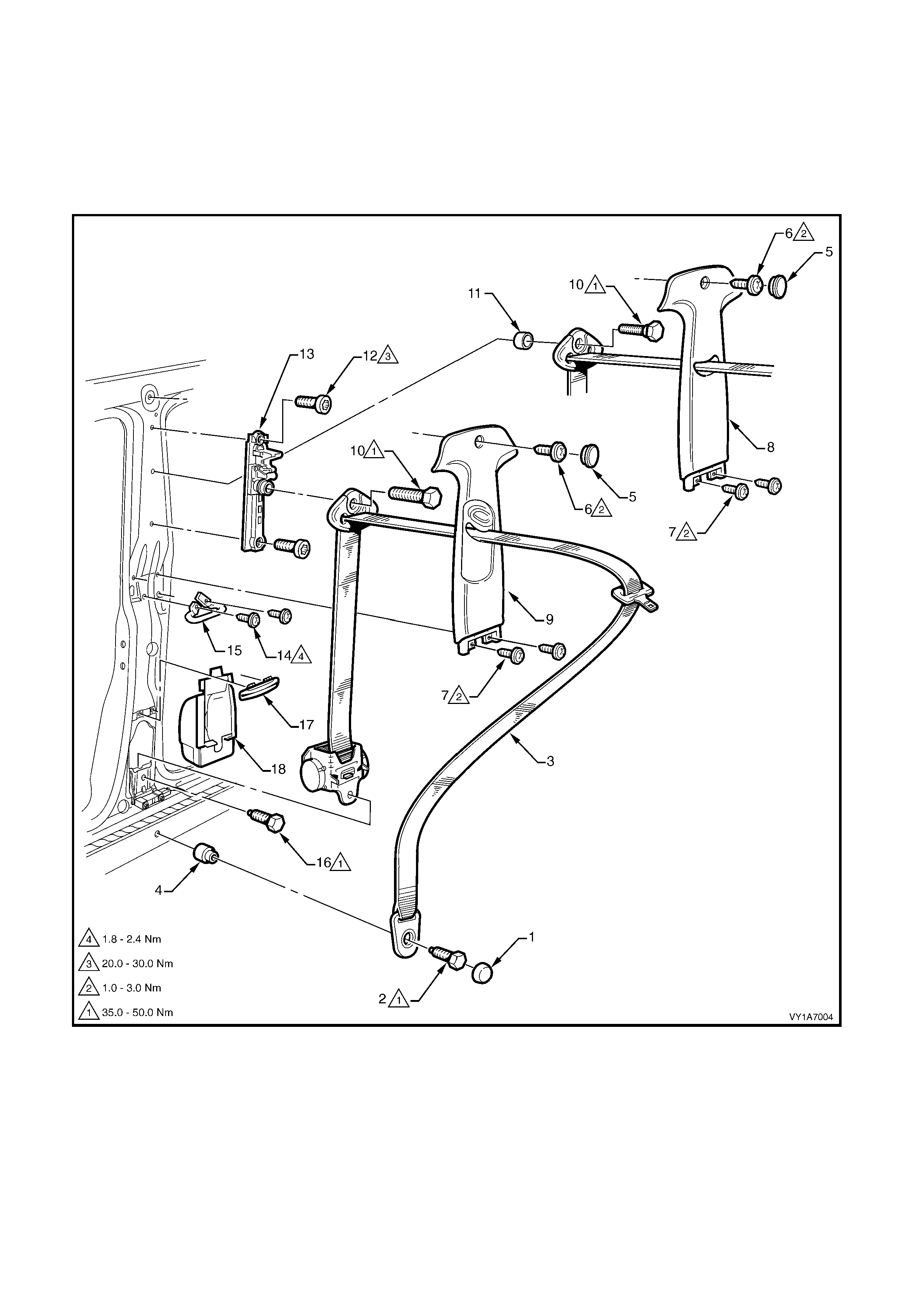
3. SERVICE OPERATIONS – SEATBELTS
3.1 FRONT SEATBELT ASSEMBLY, SEDAN & WAGON
LT Section No. – 14-400
NOTE: The following charts are included to assist with component identification.
RIGHT-HAND DRIVE
Figure 12M-80
Legend
1. Seatbelt Anchor Attaching Screw Cap
2. Seatbelt Anchor Attaching Screw
3. Front Seatbelt Assembly
4. Seatbelt Anchor Spacer
5. Centre Pillar Trim Screw Cap
6. Centre Pillar Trim Upper Attaching Screw
7. Centre Pillar Trim Lower Attaching Screw
8. Centre Pillar Trim, Without Height Adjuster
9. Centre Pillar Trim, With Height Adjuster
10. Upper Seatbelt Guide Attaching Screw
11. Upper Seatbelt Guide Spacer
12. Seatbelt Height Adjuster Attaching Screw
13. Seatbelt Height Adjuster Assembly
14. Intermediate Seatbelt Guide Attaching Screw
15. Intermediate Seatbelt Guide
16. Seatbelt Retractor Attaching Screw
17. Lower Seatbelt Guide
18. Seatbelt Retractor Dust Cap
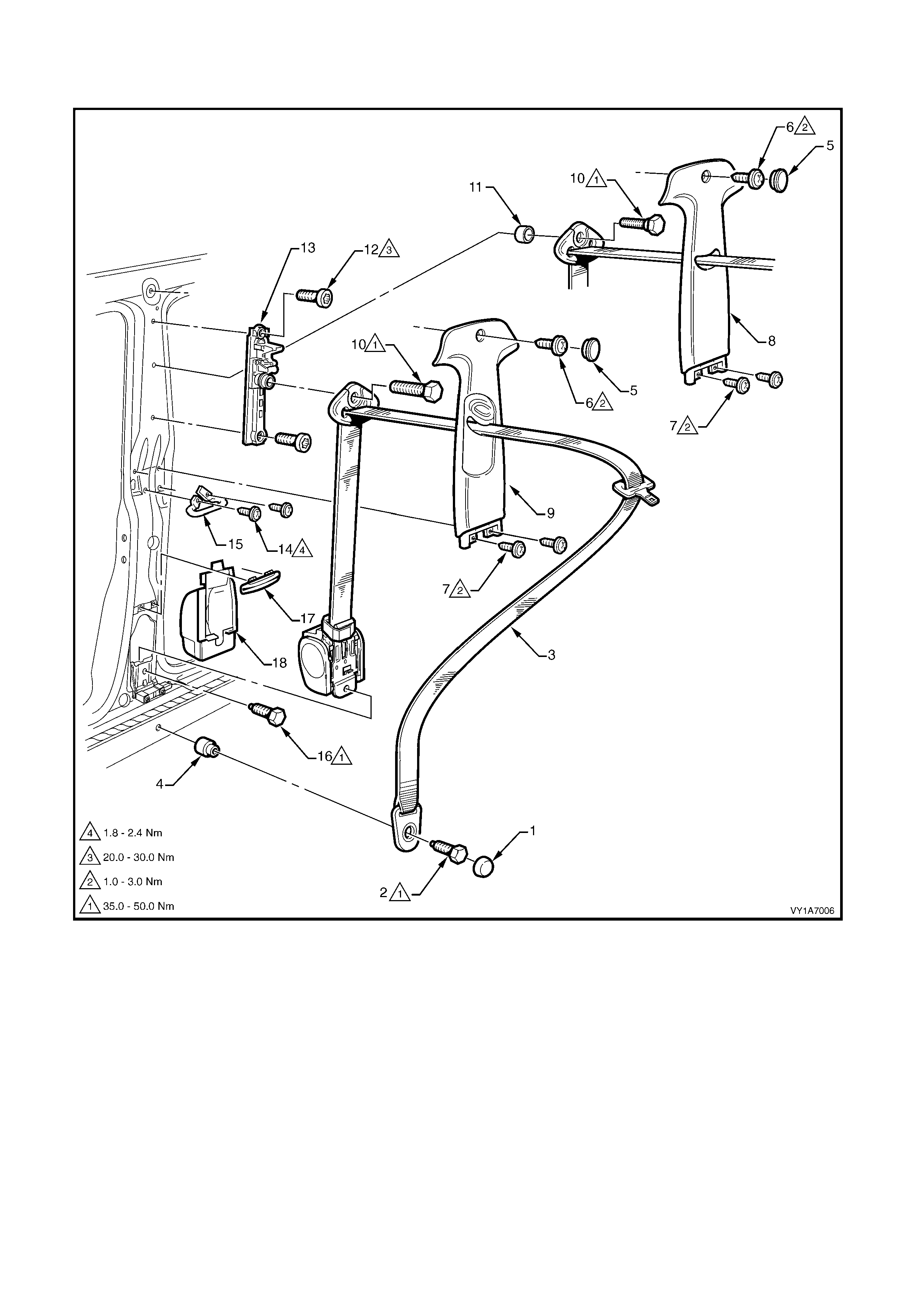
LEFT-HAND DRIVE
Figure 12M-81
Legend
1. Seatbelt Anchor Attaching Screw Cap
2. Seatbelt Anchor Attaching Screw
3. Front Seatbelt Assembly
4. Seatbelt Anchor Spacer
5. Centre Pillar Trim Screw Cap
6. Centre Pillar Trim Upper Attaching Screw
7. Centre Pillar Trim Lower Attaching Screw
8. Centre Pillar Trim, Without Height Adjuster
9. Centre Pillar Trim, With Height Adjuster
10. Upper Seatbelt Guide Attaching Screw
11. Upper Seatbelt Guide Spacer
12. Seatbelt Height Adjuster Attaching Screw
13. Seatbelt Height Adjuster Assembly
14. Intermediate Seatbelt Guide Attaching Screw
15. Intermediate Seatbelt Guide
16. Seatbelt Retractor Attaching Screw
17. Lower Seatbelt Guide
18. Seatbelt Retractor Dust Cap
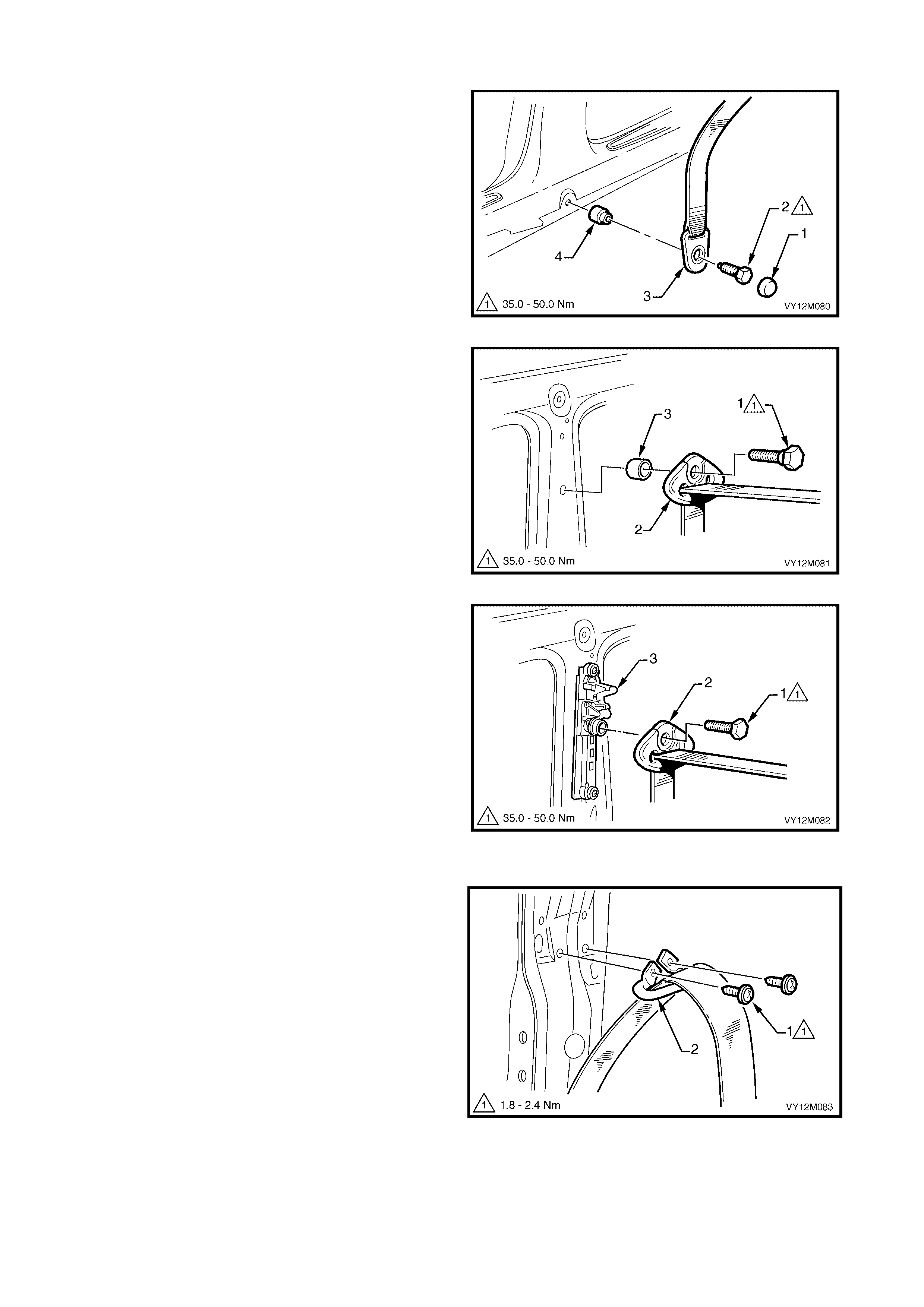
REMOVE
1. Prise the cap (1) from the lower anchor screw (2).
2. Remove the screw attaching the seatbelt lower
anchor (3) to the vehicle. Ensure the spacer (4)
remains with the screw.
3. Remove the centre pillar lower trim, centre
pillar upper trim and side sill trim, refer to
Section 1A8, 2.2 CENTRE PILLAR LOWER
TRIM, 2.3 CENTRE PILLAR UPPER TRIM and
2.4 SIDE SILL TRIM AND PLATE.
Figure 12M-82
4. For vehicles without a seatbelt height adjuster:
a. Remove the screw (1) attaching the upper
seatbelt guide (2) to the vehicle. Ensure the
spacer (3) remains with the screw.
Figure 12M-83
5. For vehicles with a seatbelt height adjuster:
a. Remove the screw (1) attaching the upper
seatbelt guide (2) to the height adjuster assembly
(3).
Figure 12M-84
6. Remove the screw (1), two places, attaching the
intermediate seatbelt guide (2) to the vehicle.
Figure 12M-85
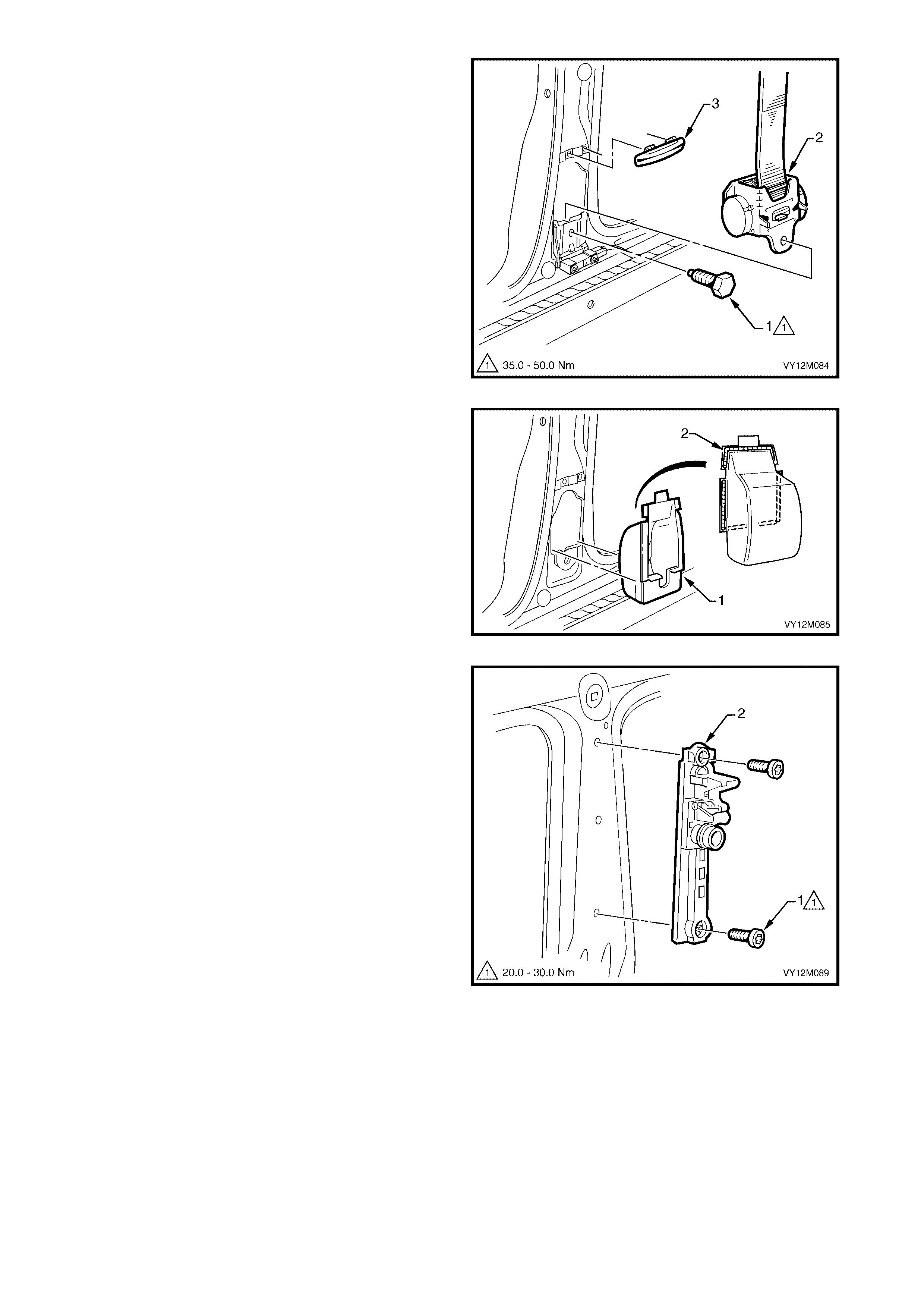
7. Remove the screw (1) attaching the retractor
assembly (2) to the vehicle and remove the
seatbelt assembly from within the pillar cavity.
NOTE: Right-hand drive retractor assembly is shown,
left-hand drive is similar, refer to Figure 12M–81.
8. If required, unclip the lower guide (3) by prising
with a fine flat-blade screwdriver.
Figure 12M-86
9. If required , carefull y rem ove the retrac tor dust cap
(1) f rom the pillar ca vity b y break ing the sea ler (2)
around the perimeter.
Figure 12M-87
10. If required and fitted, remove the screw (1), two
places, attaching the seatbelt height adjuster
assembly to the vehicle, and remove the adjuster
assembly.
Figure 12M-88

REINST ALL
IMPORTANT: If reinstalling the same retractor
assembly, inspect the anchor plates, guides and
retractor assembly for damage, and the webbing for
abrasions, fraying, cuts, etc. Replace the seatbelt
assembly with a new part if any damage, etc. is found.
Installation of the front seatbelt assembly is the
reverse of removal noting the following.
1. Appl y a bead of non-h ardenin g seal er (winds cree n
sealer) around the perimeter of the retractor dust
cap, refer to Figure 12M–87.
2. Ensure the webbing is not twisted and the anchor
plate is installed in the correct orientation.
3. Hand t ighten all seat belt sc rews a minim um of five
turns before using tools.
4. Tighten the screws to the specified torque.
5. If fitted, set the seatbelt height adjuster to the full
up position prior to installation of the centre pillar
upper trim.
6. Perform a functional check of the seatbelt to
ensure correct operation.
SEATBELT ASSEMBLY MOUNTING
SCREW TORQUE SPECIFICATION 35.0 – 50.0 Nm
INTERMEDIATE SEATBELT GUIDE
ATTACHING SCREW TORQUE
SPECIFICATION 1.8 – 2.4 Nm
SEATBELT HEIGHT ADJUSTER
ASSEMBLY ATTACHING SCREW
TORQUE SPECIFICATION 20.0 – 30.0 Nm
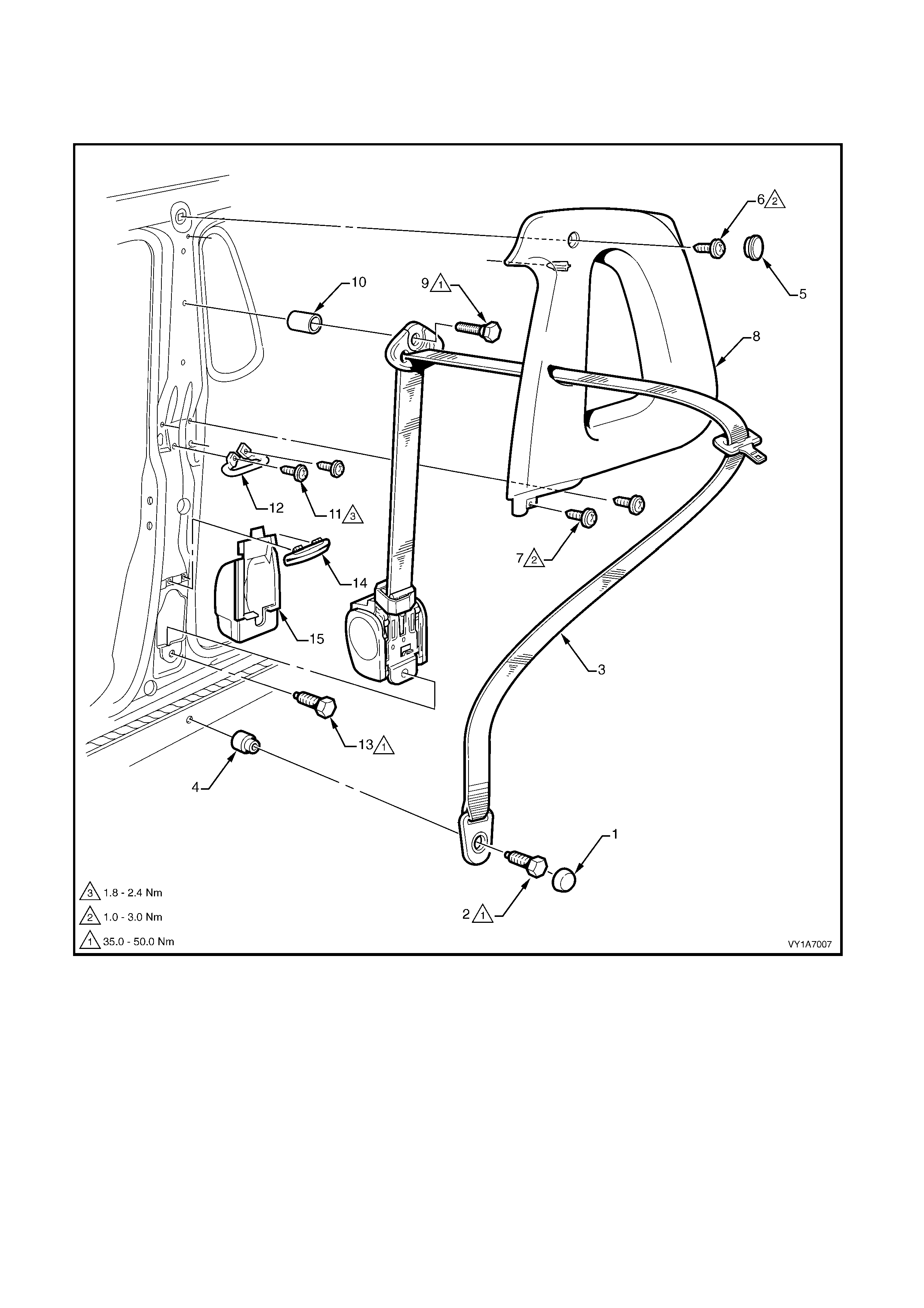
3. 2 FRONT SEATBELT ASSEMBLY, UTILITY
LT Section No. – 14-400
NOTE: The following chart is included to assist with component identification.
Figure 12M-89
Legend
1. Seatbelt Anchor Attaching Screw Cap
2. Seatbelt Anchor Attaching Screw
3. Front Seatbelt Assembly
4. Seatbelt Anchor Spacer
5. Body Lock Pillar Trim Screw Cap
6. Body Lock Pillar Trim Attaching Screw
7. Body Lock Pillar Trim Lower Attaching Screw
8. Body Lock Pillar Trim
9. Upper Seatbelt Guide Attaching Screw
10. Upper Seatbelt Guide Spacer
11. Intermediate Seatbelt Guide Attaching Screw
12. Intermediate Seatbelt Guide
13. Seatbelt Retractor Attaching Screw
14. Lower Seatbelt Guide
15. Seatbelt Retractor Dust Cap
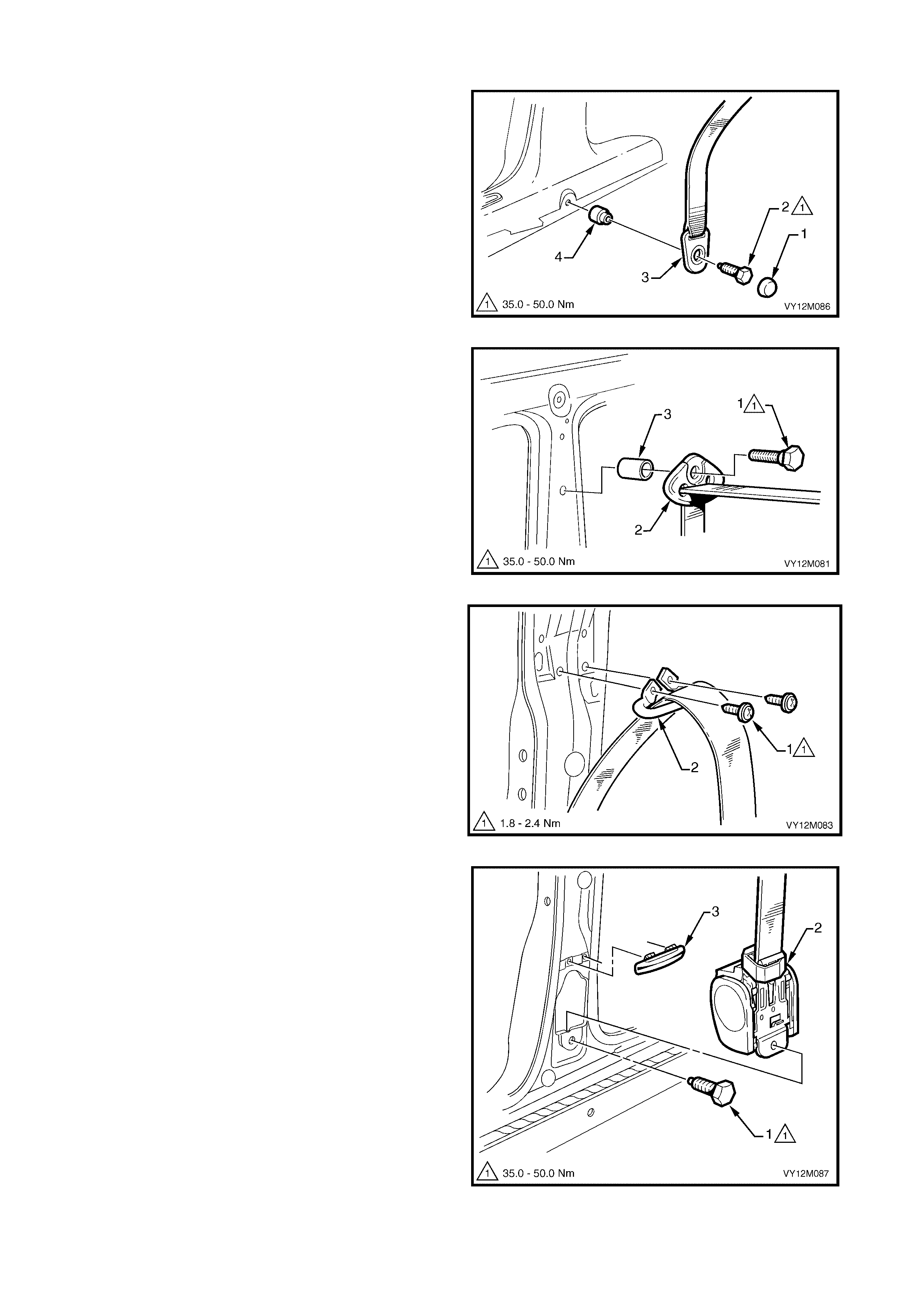
REMOVE
1. Prise the cap (1) from the lower anchor screw (2).
2. Remove the screw attaching the seatbelt lower
anchor (3) to the vehicle. Ensure the spacer (4)
remains with the screw.
3. Remove the centre pillar lower trim, body
lock pillar upper trim and side sill trim, refer to
Section 1A8, 5.2 CENTRE PILLAR LOWER
TRIM, 5.3 BODY LOCK PILLAR UPPER TRIM
and 5.4 SIDE SILL TRIM AND PLATE.
Figure 12M-90
4. Remove the sc rew (1) att achin g the upper seatb elt
guide (2) to the vehicle. Ensure the spacer (3)
remains with the screw.
Figure 12M-91
5. Remove the screw (1), two places, attaching the
intermediate seatbelt guide (2) to the vehicle.
Figure 12M-92
6. Remove the screw (1) attaching the retractor
assembly (2) to the vehicle and remove the
seatbelt assembly from within the pillar cavity.
7. If required, unclip the lower guide (3) by prising
with a fine flat-blade screwdriver.
Figure 12M-93
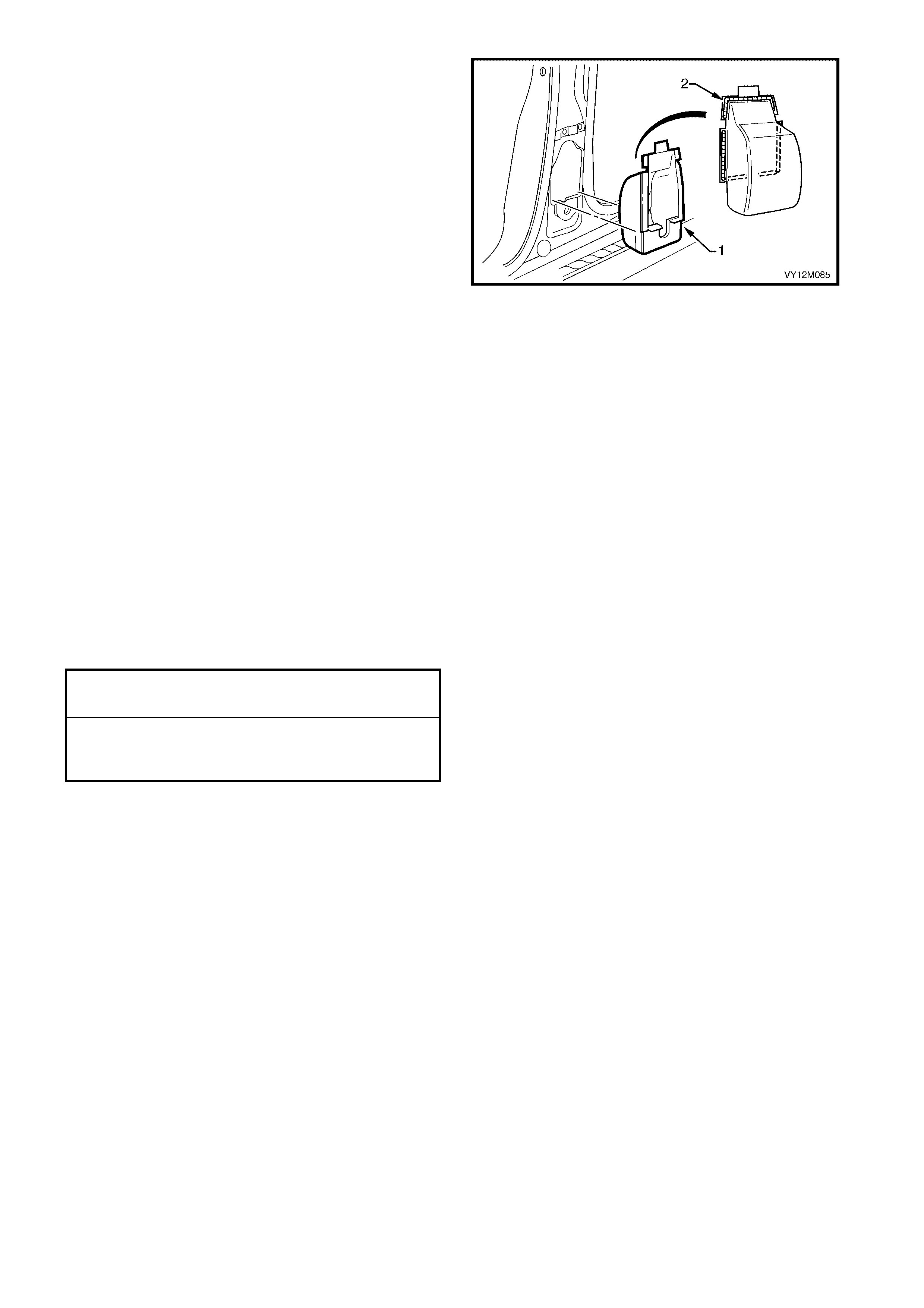
8. If required , carefull y rem ove the retrac tor dust cap
(1) f rom the pillar ca vity b y break ing the sea ler (2)
around the perimeter.
Figure 12M-94
REINST ALL
IMPORTANT: If reinstalling the same retractor
assembly, inspect the anchor plates, guides and
retractor assembly for damage, and the webbing for
abrasions, fraying, cuts, etc. Replace the seatbelt
assembly with a new part if any damage, etc. is found.
Installation of the front seatbelt assembly is the
reverse of removal noting the following.
1. Appl y a bead of non-h ardenin g seal er (winds cree n
sealer) around the perimeter of the retractor dust
cap, refer to Figure 12M–94.
2. Ensure the webbing is not twisted and the anchor
plate is installed in the correct orientation.
3. Hand t ighten all seat belt sc rews a minim um of five
turns before using tools.
4. Tighten the screws to the specified torque.
5. Perform a functional check of the seatbelt to
ensure correct operation.
SEATBELT ASSEMBLY MOUNTING
SCREW TORQUE SPECIFICATION 35.0 – 50.0 Nm
INTERMEDIATE SEATBELT GUIDE
ATTACHING SCREW
TORQUE SPECIFICATION 1.8 – 2.4 Nm
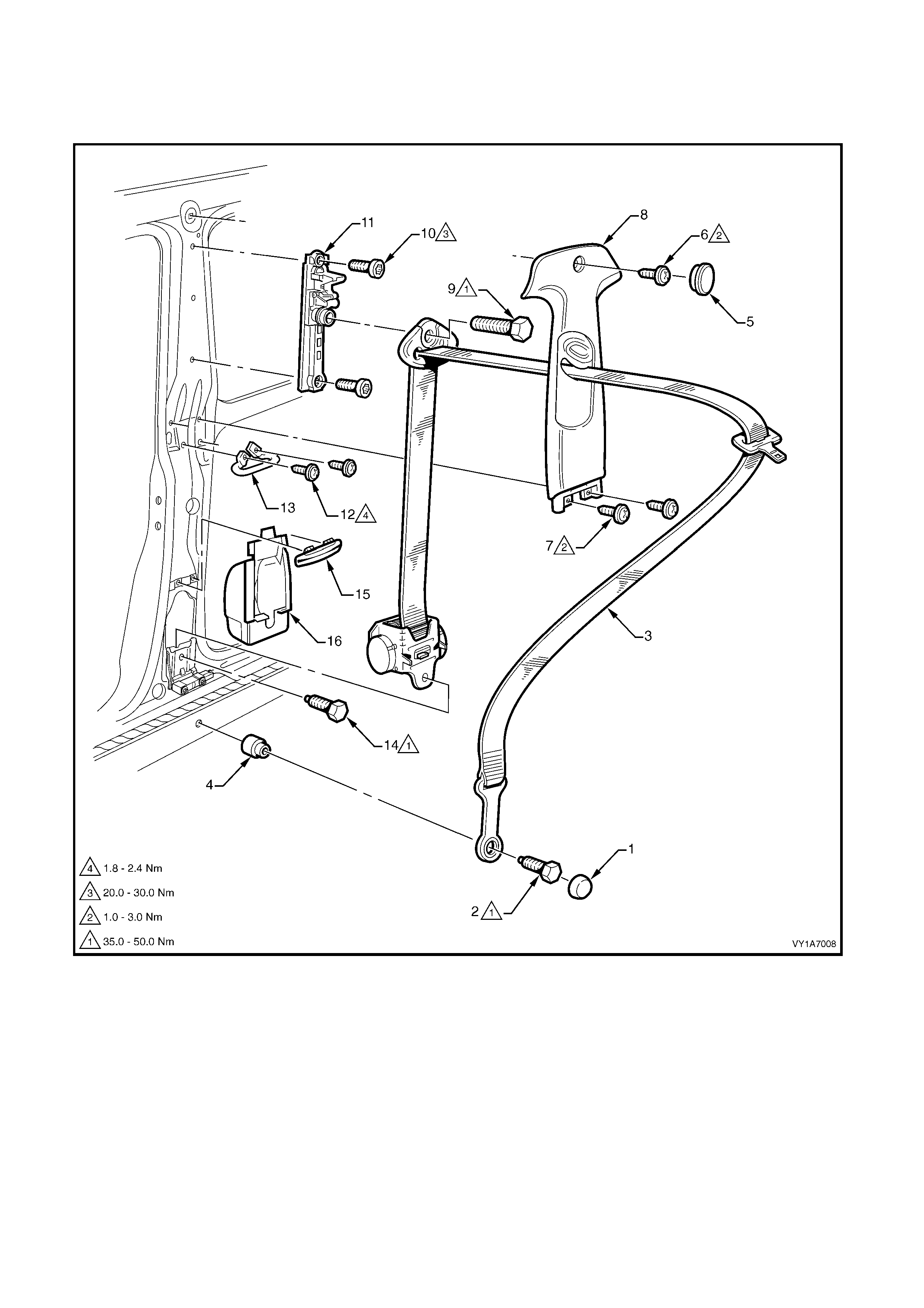
3. 3 FRONT SEATBELT ASSEMBLY, COUPE
LT Section No. – 14-400
NOTE: The following chart is included to assist with component identification.
Figure 12M-95
Legend
1. Seatbelt Anchor Attaching Screw Cap
2. Seatbelt Anchor Attaching Screw
3. Front Seatbelt Assembly
4. Seatbelt Anchor Spacer
5. Centre Pillar Trim Screw Cap
6. Centre Pillar Trim Upper Attaching Screw
7. Centre Pillar Trim Lower Attaching Screw
8. Centre Pillar Trim, With Height Adjuster
9. Upper Seatbelt Guide Attaching Screw
10. Seatbelt Height Adjuster Attaching Screw
11. Seatbelt Height Adjuster Assembly
12. Intermediate Seatbelt Guide Attaching Screw
13. Intermediate Seatbelt Guide
14. Seatbelt Retractor Attaching Screw
15. Lower Seatbelt Guide
16. Seatbelt Retractor Dust Cap
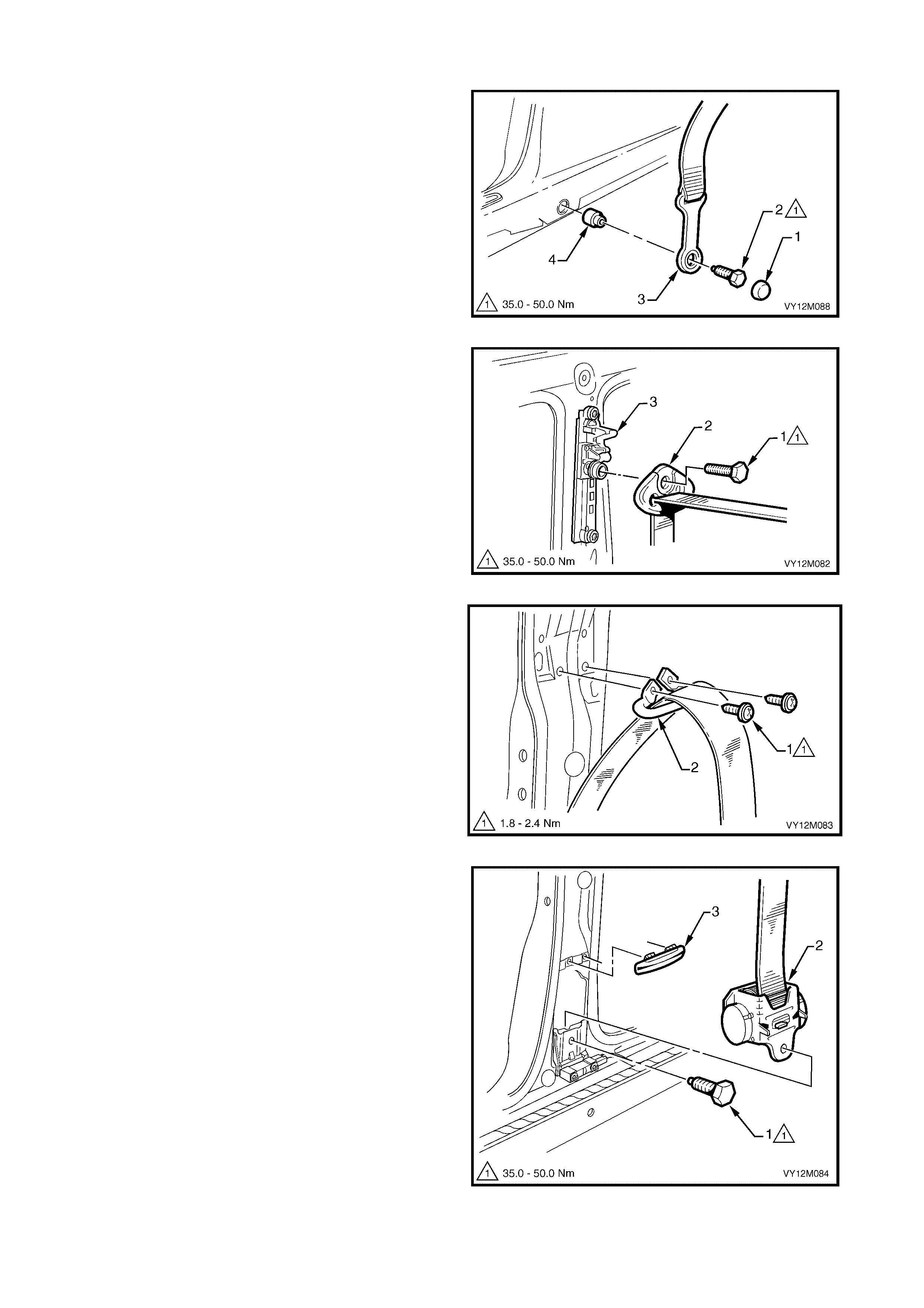
REMOVE
1. Prise the cap (1) from the lower anchor screw (2).
2. Remove the screw attaching the seatbelt lower
anchor (3) to the vehicle. Ensure the spacer (4)
remains with the screw.
3. Remove the rear seat cushion, refer to Section
1A7, 8.1 REAR SEAT CUSHION ASSEMBLY.
4. Remove the side sill trim, quarter panel trim
assembly and centre pillar upper trim and refer to
Section 1A8, 3.1 SIDE SILL TRIM AND PLATE,
3.2 QUARTER PANEL TRIM ASSEMBLY and
3.3 CENTRE PILLAR UPPER TRIM.
Figure 12M-96
5. Remove the sc rew (1) att achin g the upper seatb elt
guide (2) to the height adjuster assembly (3).
Figure 12M-97
6. Remove the screw (1), two places, attaching the
intermediate seatbelt guide (2) to the vehicle.
Figure 12M-98
7. Remove the screw (1) attaching the retractor
assembly (2) to the vehicle and remove the
seatbelt assembly from within the pillar cavity.
8. If required, unclip the lower guide (3) by prising
with a fine flat-blade screwdriver.
Figure 12M-99
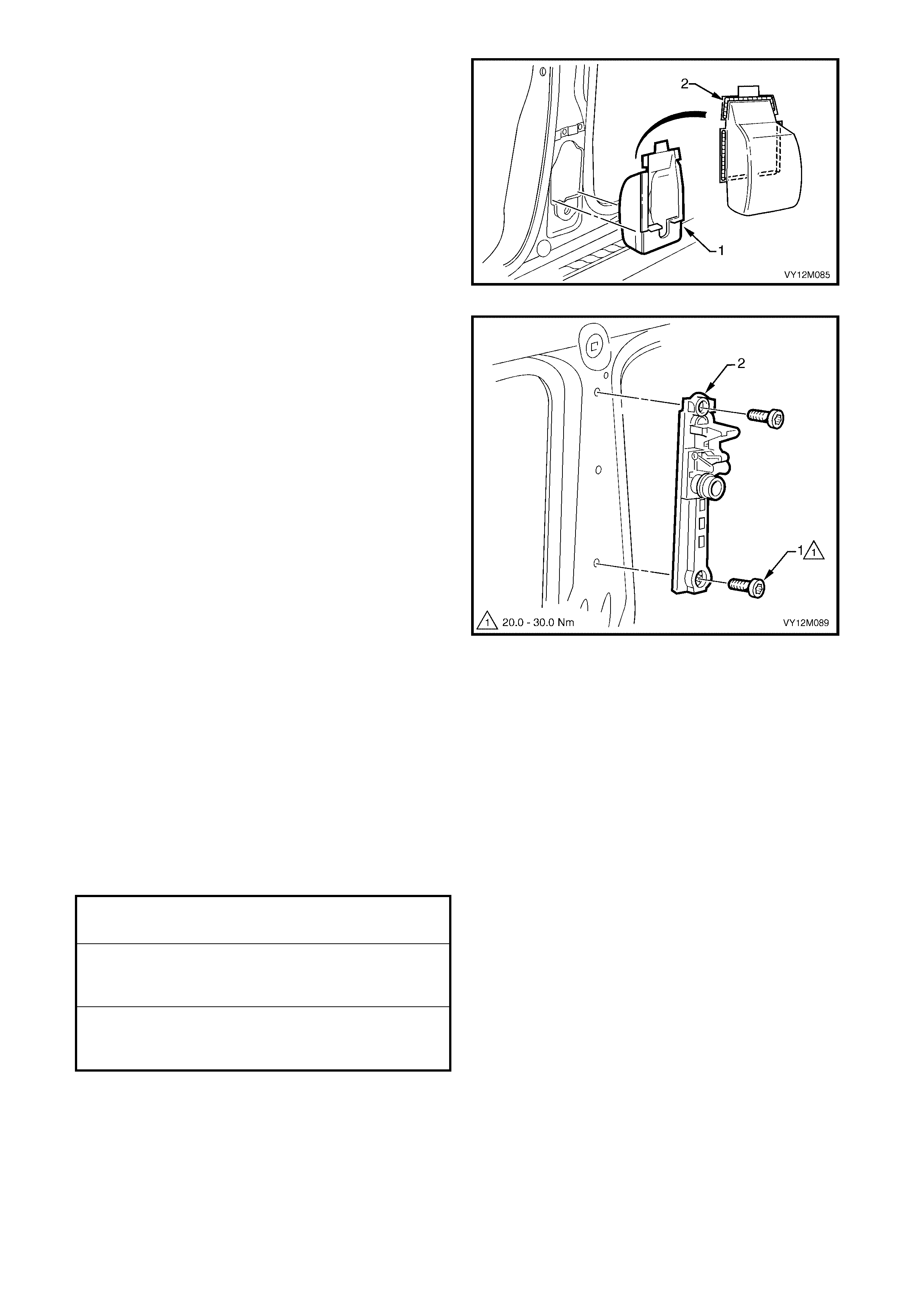
9. If required , carefull y rem ove the retrac tor dust cap
(1) f rom the pillar ca vity b y break ing the sea ler (2)
around the perimeter.
Figure 12M-100
10. If required, remove the screw (1), two places,
attaching the seatbelt height adjuster assembly to
the vehicle, and remove the adjuster assembly.
Figure 12M-101
REINST ALL
IMPORTANT: If reinstalling the same retractor assembly, inspect the anchor plates, guides and retractor
assembly for damage, and the webbing for abrasions, fraying, cuts, etc. Replace the seatbelt assembly with a
new part if any damage, etc. is found.
Installation of the front seatbelt assembly is the reverse of removal noting the following.
1. Apply a bead of non-hardening sealer (windscreen sealer) around the perimeter of the retractor dust cap,
refer to Figure 12M–100.
2. Ensure the webbing is not twisted and the anchor plate is installed in the correct orientation.
3. Hand tighten all seatbelt screws a minimum of five turns before using tools.
4. Tighten the screws to the specified torque.
5. Set the seatbelt height adjuster to the full up position prior to installation of the centre pillar upper trim.
6. Perform a functional check of the seatbelt to ensure correct operation.
SEATBELT ASSEMBLY MOUNTING
SCREW TORQUE SPECIFICATION 35.0 – 50.0 Nm
INTERMEDIATE SEATBELT
GUIDE ATTACHING SCREW
TORQUE SPECIFICATION 1.8 – 2.4 Nm
SEATBELT HEIGHT ADJUSTER
ASSEMBLY ATTACHING SCREW
TORQUE SPECIFICATION 20.0 – 30.0 Nm
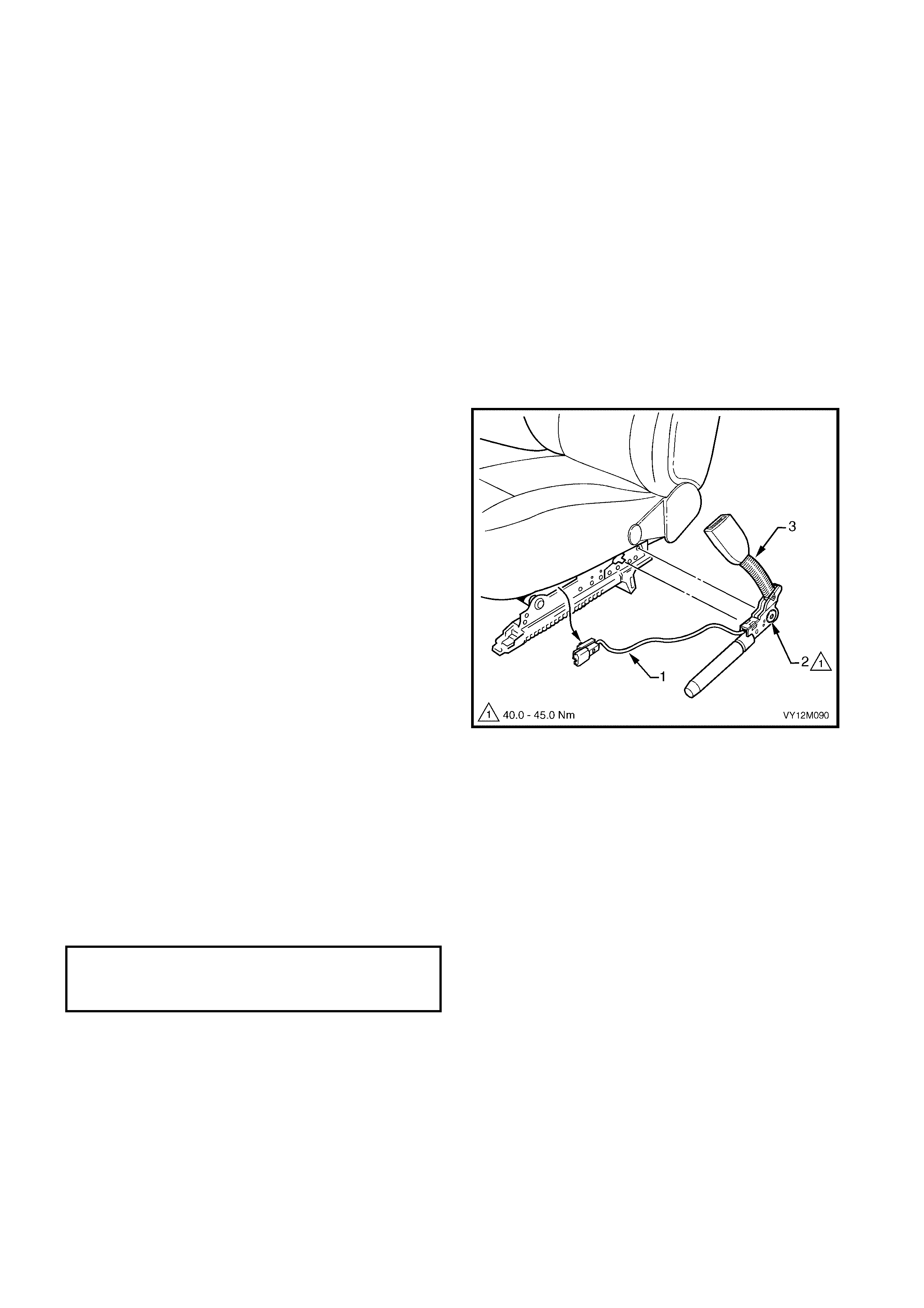
3. 4 FRONT SEATBELT BUCKLE AND PRETENSIONER ASSEMBLY
LT Section No. – 14-400
CAUTION 1: If a seatbelt pretensioner is deployed, the seatbelt pretensioner assembly together with the
seat adjuster and guide rail assembly must be replaced.
CAUTION 2: If disposing of an undeployed seatbelt buckle and pretensioner assembly, refer to
2.5 SEAT BELT BUCKLE AND PR ET ENSIONER ASSEMBLY
REMOVE
IMPORTANT: Disconnection of the battery affects
certain vehicle electronic systems. Refer to Section
00, 5. BATTERY DISCONNECTION PROCEDURES
before disconnecting the battery.
1. Disc onnect the batt ery.
2. Remove the front seat from the vehicle, refer to
Section 1A7, 2.2 FRONT SEAT ASSEMBLIES,
EXCEPT COUPE or 4.2 FRONT SEAT
ASSEMBLY, COUPE.
3. Cut the cable ties attaching the pretensioner
assembly, wiring harness (1) to the underside of
the seat assembly.
4. Unscrew the torx-head screw (2) attaching the
seatbelt buckle and pretensioner assembly (3) to
the seat.
NOTE: The screw is captive to the assembly.
5. Remove the seatbelt buckle and pretensioner
assembly and withdraw the wiring harness from
the seat,
IMPORTANT: Store the seatbelt buckle and
pretensioner assembly in a safe place.
Figure 12M-102
REINST ALL
Installation is the reverse of the removal operation,
noting the following:
1. When installing the seatbelt buckle and
pretensioner assembly, ensure that the seat
frame-locating pin is aligned within the
pretensioner assembly.
2. Tighten the screw to the specified torque.
SEATBELT BUCKLE & PRETENSIONER
ASSEMBLY MOUNTING SCREW
TORQUE SPECIFIECATION 40.0 – 45.0 Nm
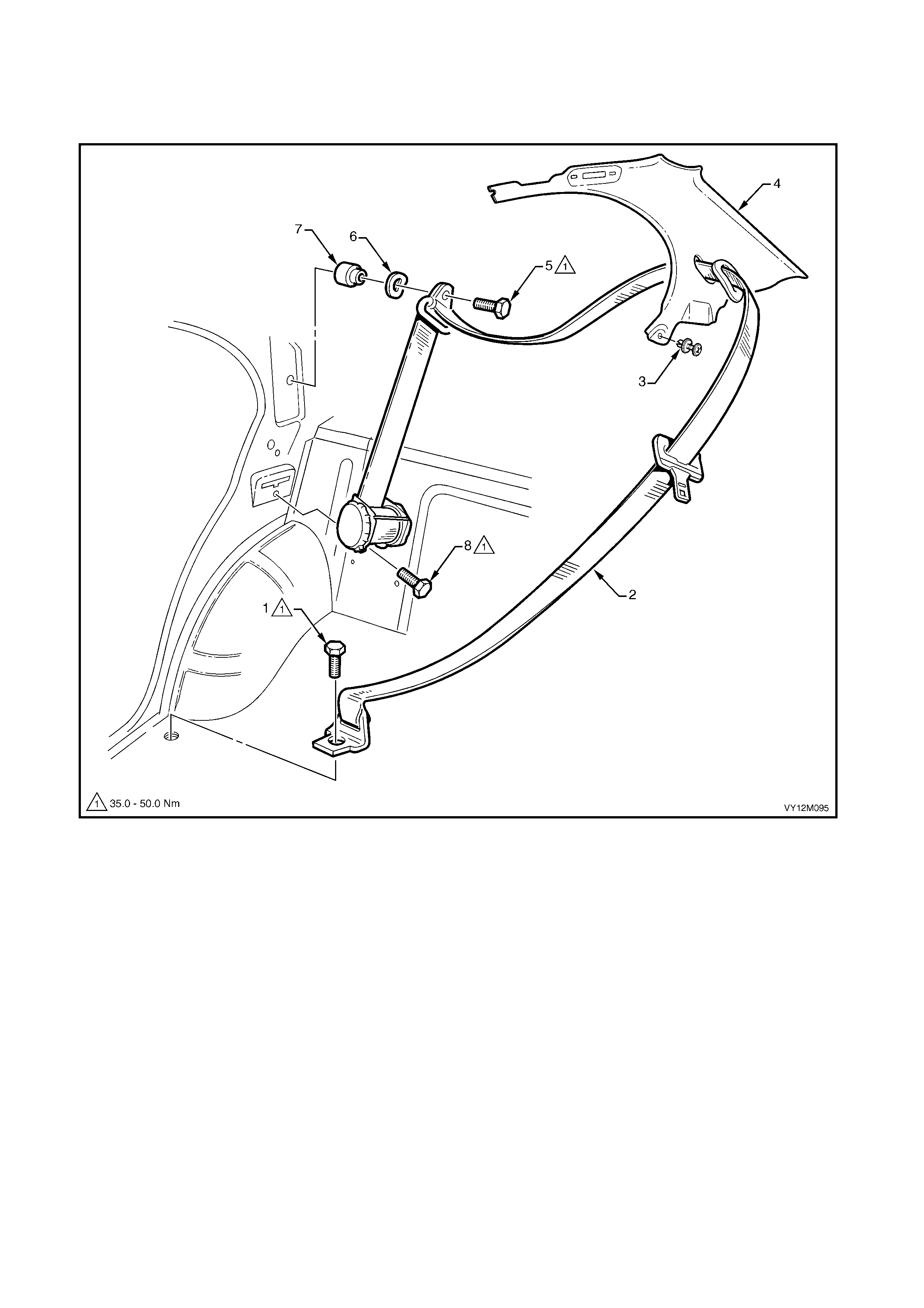
3. 5 REAR SEATBELT ASSEMBLY – OUTBOARD, SEDAN
LT Section No. – 14-425
NOTE: The following chart is included to assist with component identification.
Figure 12M-103
Legend
1. Seatbelt Anchor Attaching Screw
2. Rear Seatbelt Assembly, Outer
3. Body Lock Pillar Garnish Retainer
4. Body Lock Pillar Garnish
5. Upper Seatbelt Guide Attaching Screw
6. Upper Seatbelt Guide Wave Washer
7. Upper Seatbelt Guide Spacer
8. Seatbelt Retractor Attaching Screw
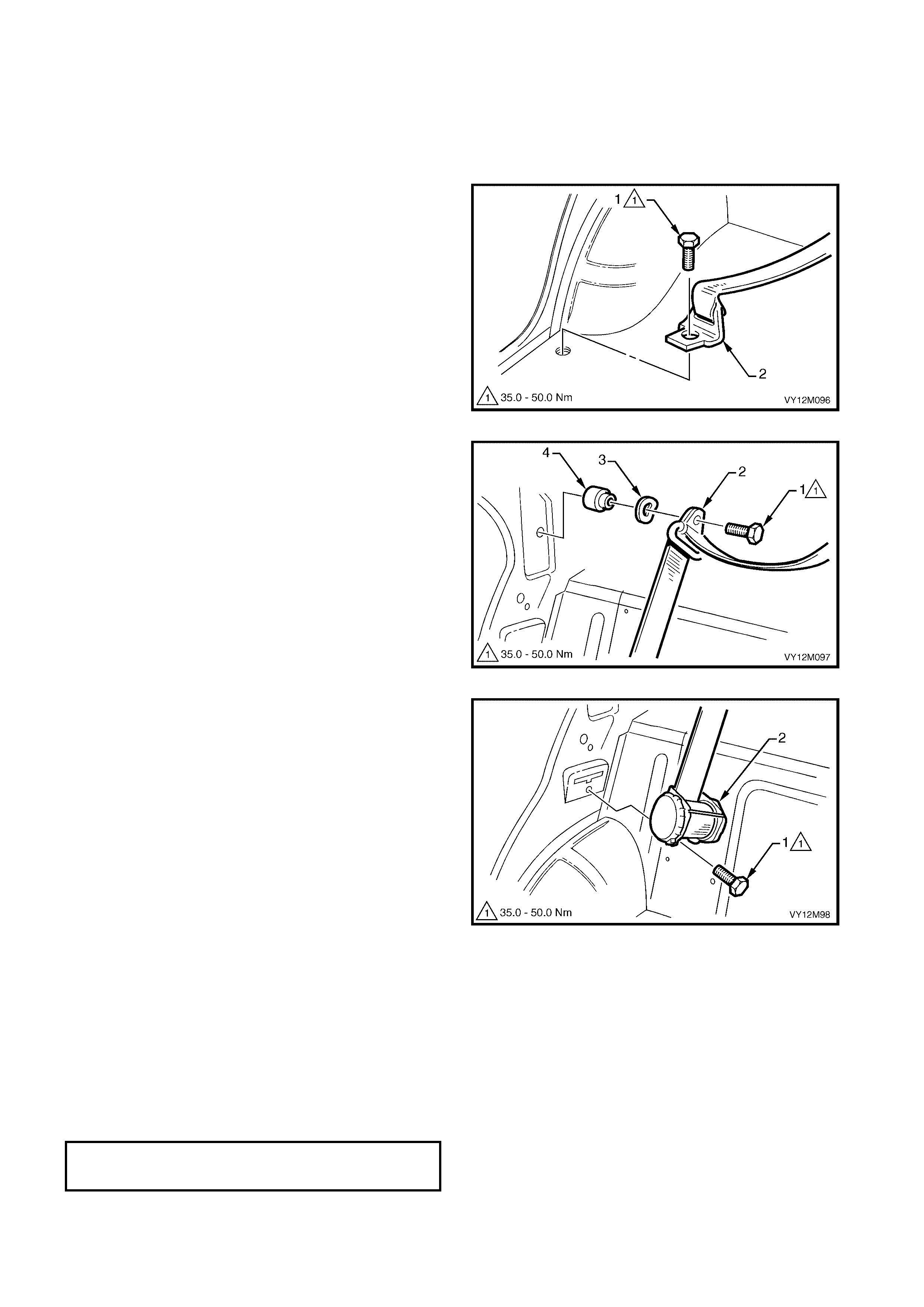
REMOVE
1. Remove rear seat cushion Section 1A7,
6.2 REAR SEAT CUSHION ASSEMBLY and
either the left or right- hand back seat assembl y as
applicable, refer to Section 1A7, 6.3 REAR SEAT
BACK ASSEMBLY.
2. Rem ove the scre w (1) atta ching the sea tbelt lo wer
anchor (2) to the vehicle.
3. Remove the body lock pillar garnish, refer to
Section 1A8, 2.6 BODY LOCK PILLAR
GARNISH.
Figure 12M-104
4. Remove the scr e w (1) att ac hin g the upp er s eatb elt
guide (2) to the vehicle. Ensure the wave washer
(3) and spacer (4) remain with the screw.
Figure 12M-105
5. Remove the screw (1) attaching the retractor
assembly (2) to the vehicle and remove the
seatbelt assembly.
Figure 12M-106
REINST ALL
IMPORTANT: If reinstalling the same retractor assembly, inspect the anchor plates, guides and retractor
assembly for damage, and the webbing for abrasions, fraying, cuts, etc. Replace the seatbelt assembly with a
new part if any damage, etc. is found.
Installation of the front seatbelt assembly is the reverse of removal noting the following.
1. Ensure the webbing is not twisted and the anchor plate is installed in the correct orientation.
2. Hand tighten all seatbelt screws a minimum of five turns before using tools.
3. Tighten the screws to the specified torque.
4. Perform a functional check of the seatbelt to ensure correct operation.
SEATBELT ASSEMBLY MOUNTING
SCREW TORQUE SPECIFICATION 35.0 – 50.0 Nm
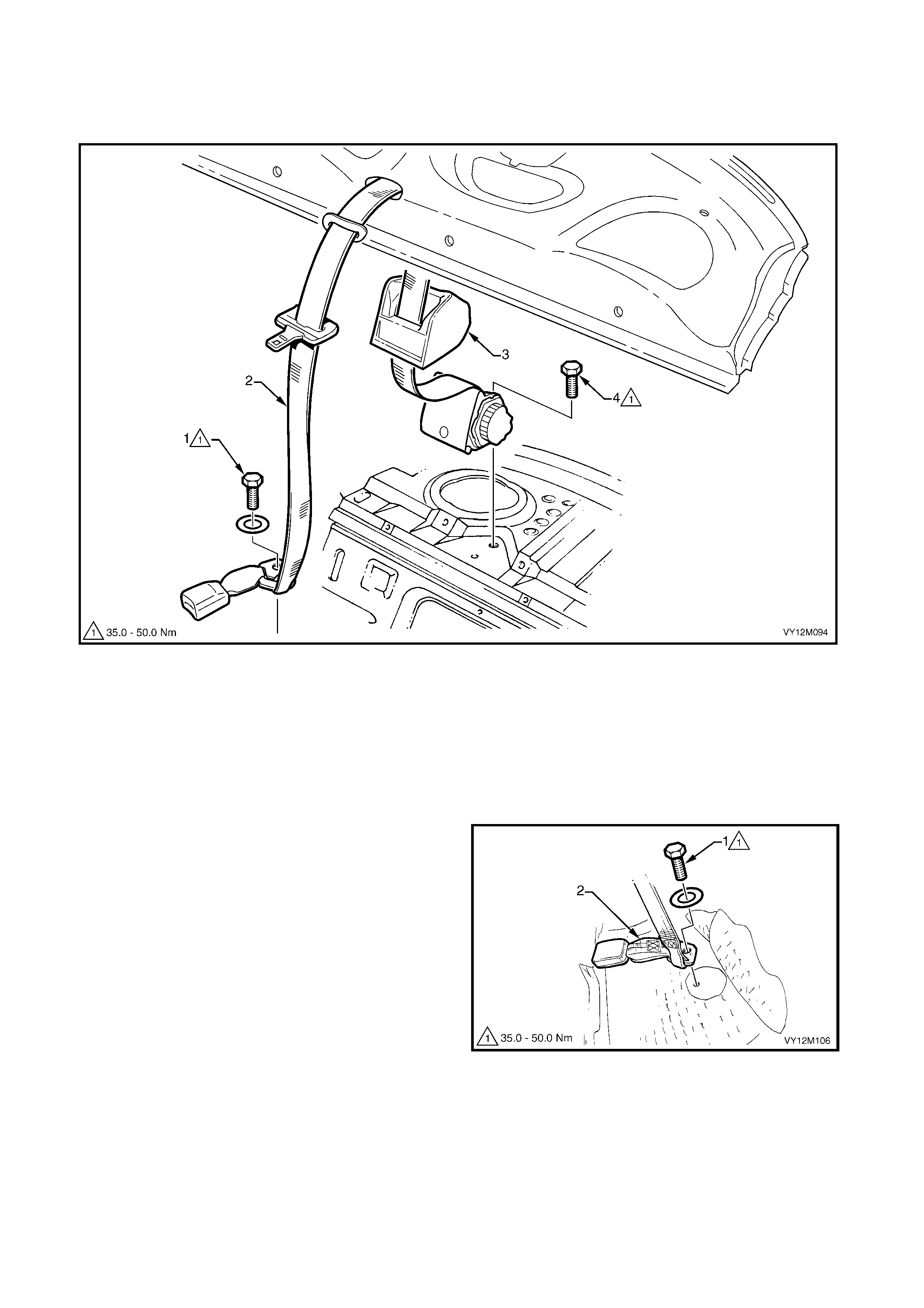
3. 6 REAR SEATBELT ASSEMBLY – CENTRE, SEDAN
LT Section No. – 14-425
NOTE: The following chart is included to assist with component identification.
Figure 12M-107
Legend
1. Seatbelt Anchor Attaching Screw and Washer
2. Rear Centre Seatbelt Assembly 3. Insulator
4. Seatbelt Retractor Attaching Screw
REMOVE
1. Remove the rear seat cushion, refer to Section
1A7, 6.2 REAR SEAT CUSHION ASSEMBLIES.
2. Remove the screw and washer (1) attaching the
seatbelt lower anchor (2) to the vehicle.
3. Remove the rear window trim panel, refer to
Section 1A8, 2.9 REAR WINDOW TRIM PANEL.
Figure 12M-108
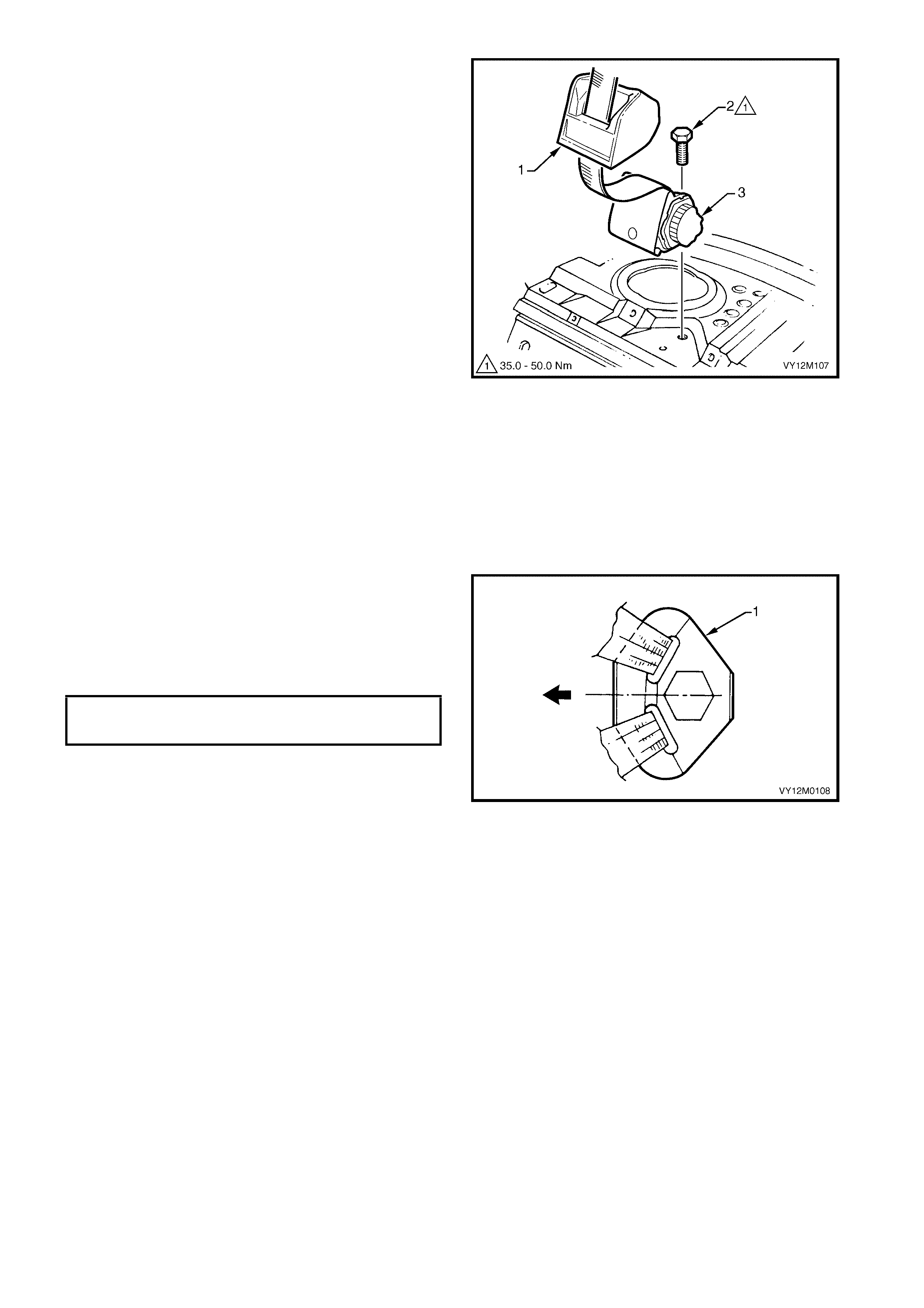
4. Lift off the insulator (1).
5. Remove the screw (2) attaching the retractor
assembly (3) to the vehicle and remove the
seatbelt assembly.
Figure 12M-109
REINST ALL
IMPORTANT: If reinstalling the same retractor
assembly, inspect the anchor plates, guides and
retractor assembly for damage, and the webbing for
abrasions, fraying, cuts, etc. Replace the seatbelt
assembly with a new part if any damage, etc. is found.
Installation of the front seatbelt assembly is the
reverse of removal noting the following.
1. Ensure the webbing is not twisted and the anchor
plate (1) is installed in the correct orientation.
2. Hand t ighten all seat belt sc rews a minim um of five
turns before using tools.
3. Tighten the screws to the specified torque.
4. Perform a functional check of the seatbelt to
ensure correct operation.
Figure 12M-110
SEATBELT ASSEMBLY MOUNTING
SCREW TORQUE SPECIFICATION 35.0 – 50.0 Nm

3. 7 REAR SEATBELT BUCKLE ASSEMBLY, SEDAN
LT Section No. – 14-425
REMOVE
Right-Hand Side
NOTE: The right-hand rear seatbelt buckle is part of
the centre rear seatbelt assembly. For service
procedure ref er to 3.6 REAR SEATBELT ASSEMBLY
– CENTRE, SEDAN.
Left-Hand Side
1. Remove the rear seat cushion, refer to Section
1A7, 6.2 REAR SEAT CUSHION ASSEMBLIES.
2. Remove the screw and washer (1) attaching the
rear seatbelt buckle anchor assembly (2) to the
vehicle.
3. Remove the buckle assembly.
Figure 12M-111
REINST ALL
IMPORTANT: If reinstalling the same seatbelt buckle
assembly, inspect for damage, abrasions, fraying,
cuts, etc. R eplace the seat belt buck le assem bly with a
new part if any damage, etc. is found.
Installation of the seatbelt buckle assembly is the
reverse of removal noting the following.
1. Ensure the anchor plate (1) is installed in the
correct orientation.
2. Hand t ighten all seat belt sc rews a minim um of five
turns before using tools.
3. Tighten the screws to the specified torque.
4. Perform a functional check of the seatbelt to
ensure correct operation.
Figure 12M-112
SEATBELT ASSEMBLY MOUNTING
SCREW TORQUE SPECIFICATION 35.0 – 50.0 Nm
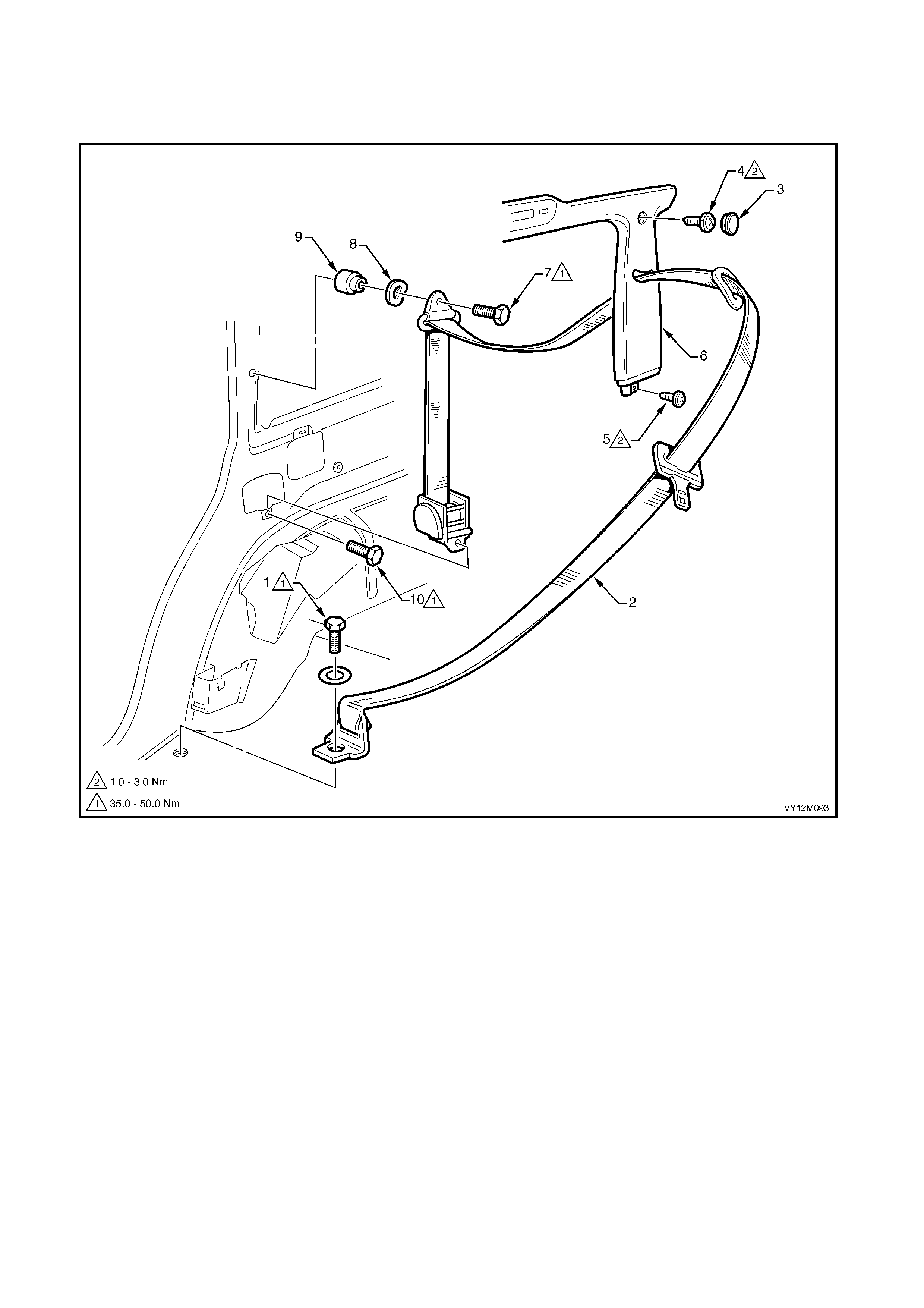
3. 8 REAR SEATBELT ASSEMBLY – OUTBOARD, WAGON
LT Section No. – 14-425
NOTE: The following chart is included to assist with component identification.
Figure 12M-113
Legend
1. Seatbelt Anchor Attaching Screw and Washer
2. Rear Seatbelt Assembly, Outer
3. Body Lock Pillar Garnish Screw Cap
4. Body Lock Pillar Garnish Upper Screw
5. Body Lock Pillar Garnish Lower Screw
6. Body Lock Pillar Garnish
7. Upper Seatbelt Guide Attaching Screw
8. Upper Seatbelt Guide Wave Washer
9. Upper Seatbelt Guide Spacer
10. Seatbelt Retractor Attaching Screw
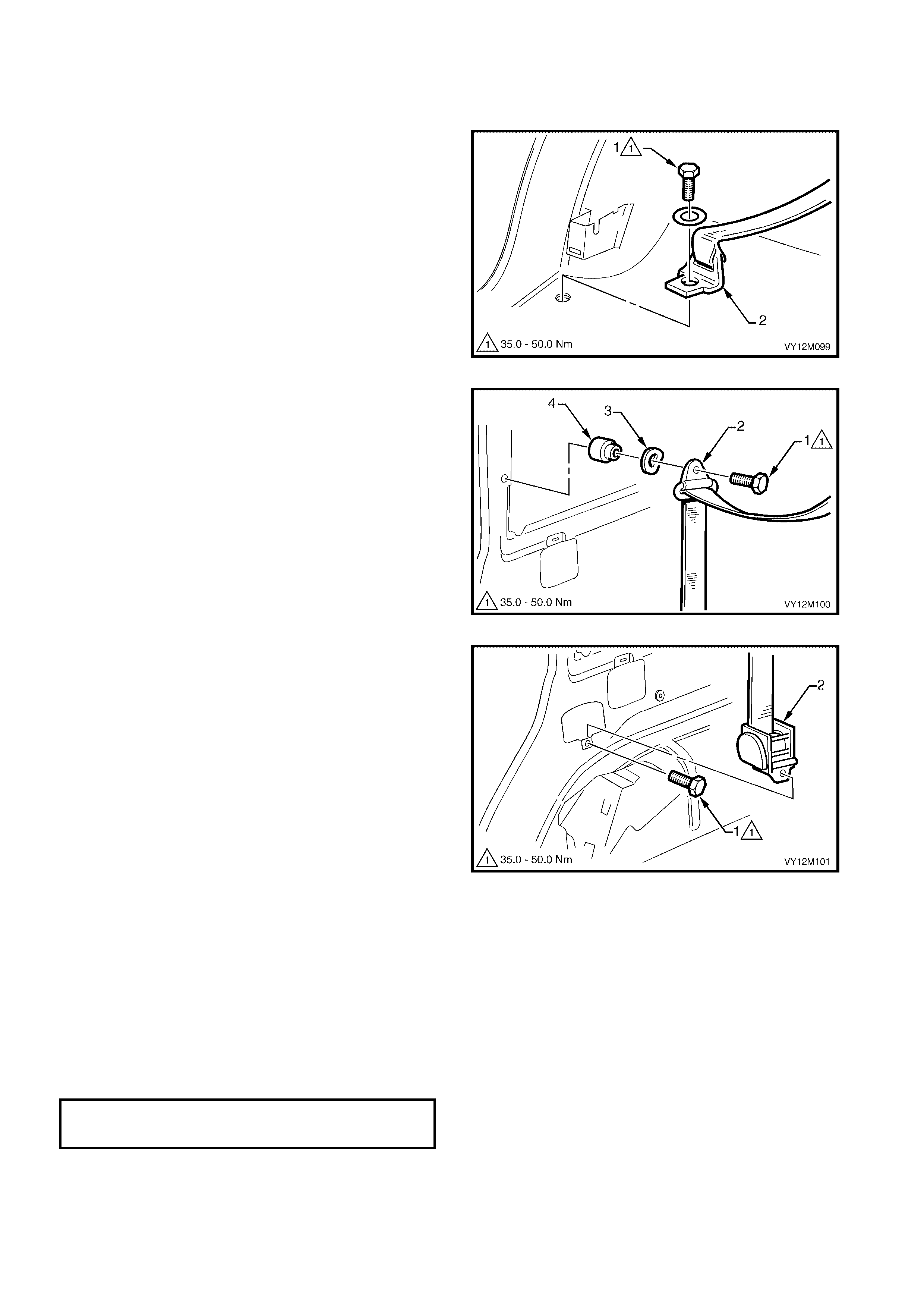
REMOVE
1. Remove rear seat cushion, refer to Section 1A7,
7.2 REAR SEAT CUSHION ASSEMBLIES.
2. Remove the screw and washer (1) attaching the
seatbelt lower anchor (2) to the vehicle.
3. Remove the body lock pillar garnish, refer to
Section 1A8, 3.7 BODY LOCK PILLAR
GARNISH.
Figure 12M-114
4. Remove the scr e w (1) att ac hin g the upp er s eatb elt
guide (2) to the vehicle. Ensure the wave washer
(3) and spacer (4) remain with the screw.
Figure 12M-115
5. Remove the screw (1) attaching the retractor
assembly (2) to the vehicle and remove the
seatbelt assem bly from wit hin the inn er side pan el
cavity.
Figure 12M-116
REINST ALL
IMPORTANT: If reinstalling the same retractor assembly, inspect the anchor plates, guides and retractor
assembly for damage, and the webbing for abrasions, fraying, cuts, etc. Replace the seatbelt assembly with a
new part if any damage, etc. is found.
Installation of the front seatbelt assembly is the reverse of removal noting the following.
1. Ensure the webbing is not twisted and the anchor plate is installed in the correct orientation.
2. Hand tighten all seatbelt screws a minimum of five turns before using tools.
3. Tighten the screws to the specified torque.
4. Perform a functional check of the seatbelt to ensure correct operation.
SEATBELT ASSEMBLY MOUNTING
SCREW TORQUE SPECIFICATION 35.0 – 50.0 Nm
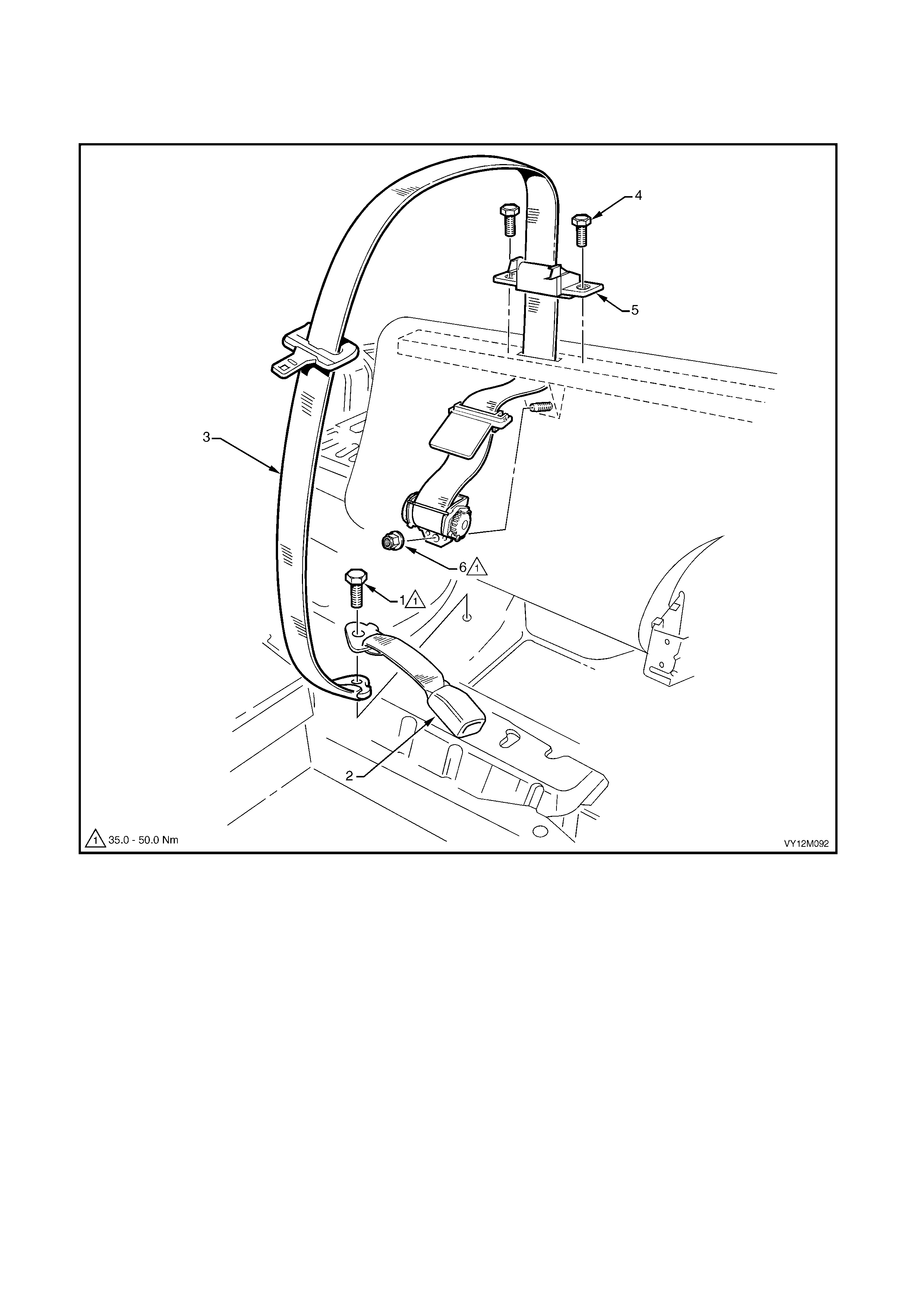
3. 9 REAR SEATBELT ASSEMBLY – CENTRE, WAGON
LT Section No. – 14-425
NOTE: The following chart is included to assist with component identification.
Figure 12M-117
Legend
1. Seatbelt Anchor Attaching Screw
2. Left-hand Side Seatbelt Buckle
3. Rear Seatbelt Assembly, Centre
4. Seatbelt Guide Bracket Screw
5. Seatbelt Guide Bracket
6. Seatbelt Retractor Attaching Nut
REMOVE
1. Remove the rear seat cushion, refer to Section
1A7, 7.2 REAR SEAT CUSHION ASSEMBLY.
2. Rem ove the centr e rear seatbe lt anch or plat e fr om
the vehicle floor, refer to 3.10 REAR SEATBELT
BUCKLE ASSEMBLY, WAGON.
3. Fold the rear seat back down.
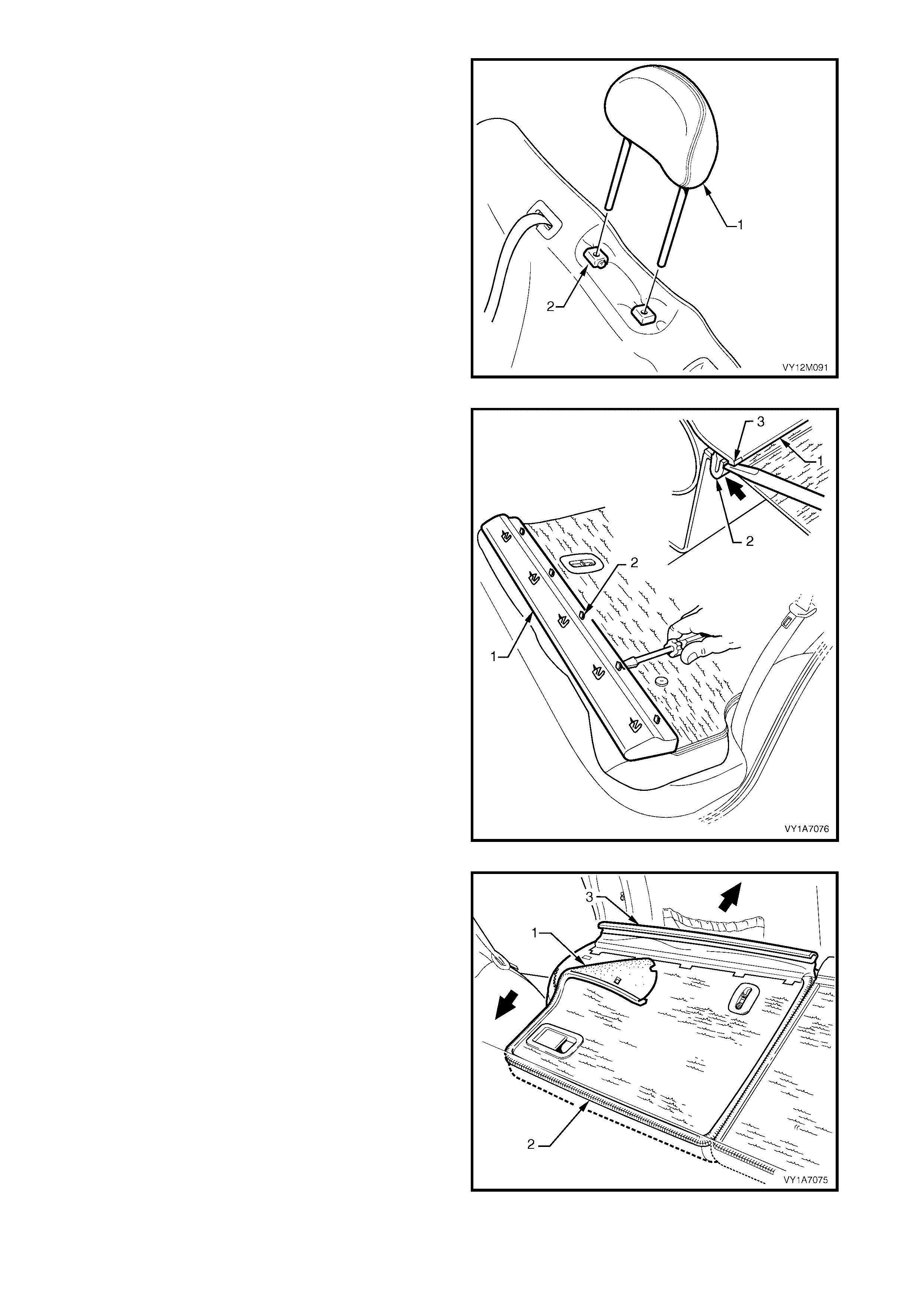
4. If fitted, remove the head restraint (1) by
depressing the head restraint guide height
adjuster loc k (2), pull the h ead res traint c om pletel y
out of the guide.
5. Fold the rear seat back down.
Figure 12M-118
6. Carefully remove the rear seat back trim cover (1),
by inserting a small screwdriver at the tab (2)
position, highlighted by small polished areas (3).
Push in to disengage the retaining tabs (3) five
places on the left-hand seat and three places on
the right-hand seat.
7. Start at o ne en d to d isengage the c o ver a way from
the seat back and work your way along until all
retaining tabs have been disengaged.
NOTE: Care must be taken not to break the lower
retaining tabs from the rear seat back trim cover,
otherwise a replacement part will be required.
Figure 12M-119
8. Partly remove the rear seat back cover (1), unzip
(2) the cover down one side of the rear seat back.
9. Pull the outer top finisher strip (3) from the rear
seat back frame.
NOTE: To ease in the r emoval of the top finis her strip,
gently lever the strip away from the frame using a
screwdriver.
Figure 12M-120
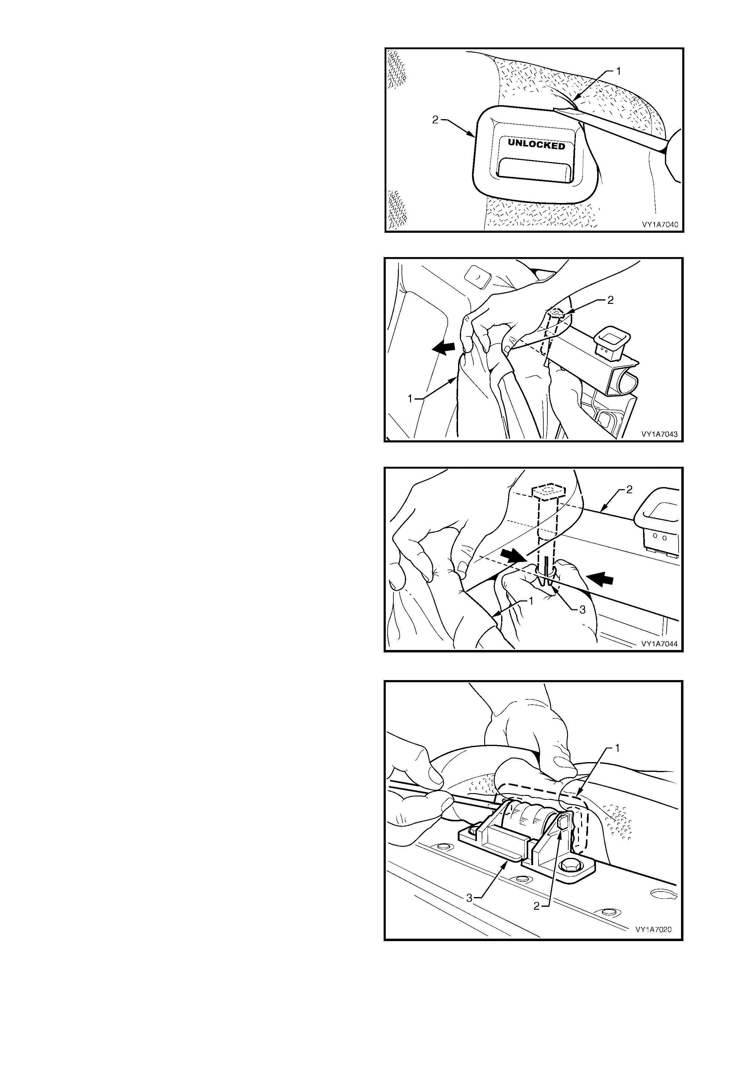
10. Lever the cover and pad assembly (1) over the
release butt on (2).
Figure 12M-121
11. Pull the top corner of the cover and pad assembl y
(1) down to allow for the removal of the head
restraint guides (2).
Figure 12M-122
12. While holding the cover and pad assembly (1),
reach in between the seat back frame (2) and the
pad assembly.
13. Squeeze the head restraint guide locating prongs
(3) together and remove the guide up and out of
the seat back assembly.
Figure 12M-123
14. Using a screwdriver, release the centre seatbelt
escutcheon (1) from inside the rear seat back by
pushing the tangs (2) of the escutcheon through
the seatbelt guide bracket (3).
NOTE: Care must be taken not to break the attaching
tangs from the escutcheon.
Figure 12M-124
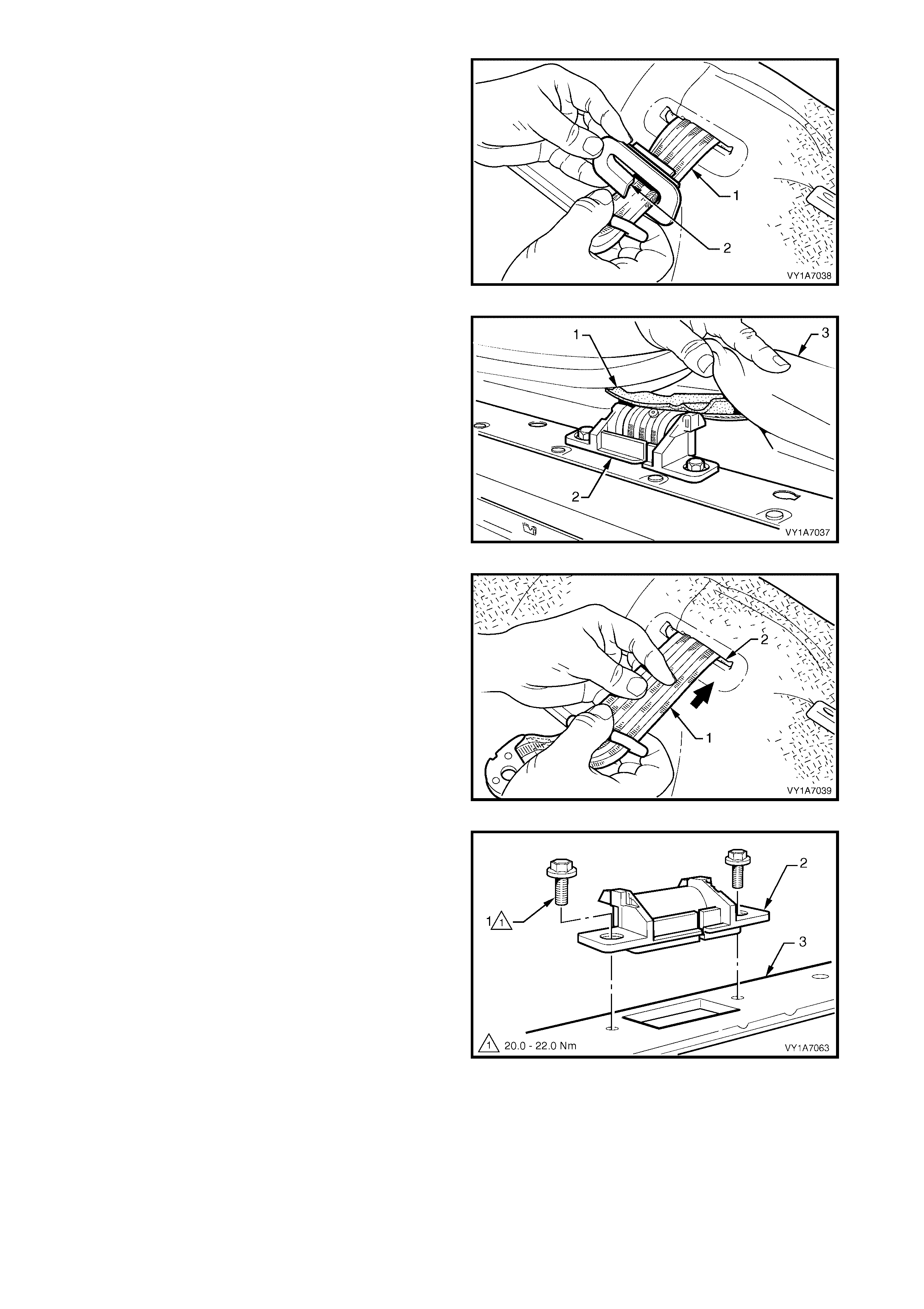
15. Remove the escutcheon (1) from the seatbelt (2).
Figure 12M-125
16. Feed the seat back cover flap (1), over the
seatbelt guide bracket assembly (2) and through
the pad assembly (3).
Figure 12M-126
17. Feed the seatbelt (1) through the slot (2) in the
cover and pad assembly.
18. Remove the cover and pad assembly away from
the seat back fr am e to gain access to the seat belt
retractor and guide.
Figure 12M-127
19. Remove the two screws (1) securing the seatbelt
guide brack et (2) to t he top of the seat back fram e
(3).
20. Remove seatbelt guide bracket by feeding the
seatbelt webbing through the slot in the seatbelt
guide bracket.
Figure 12M-128
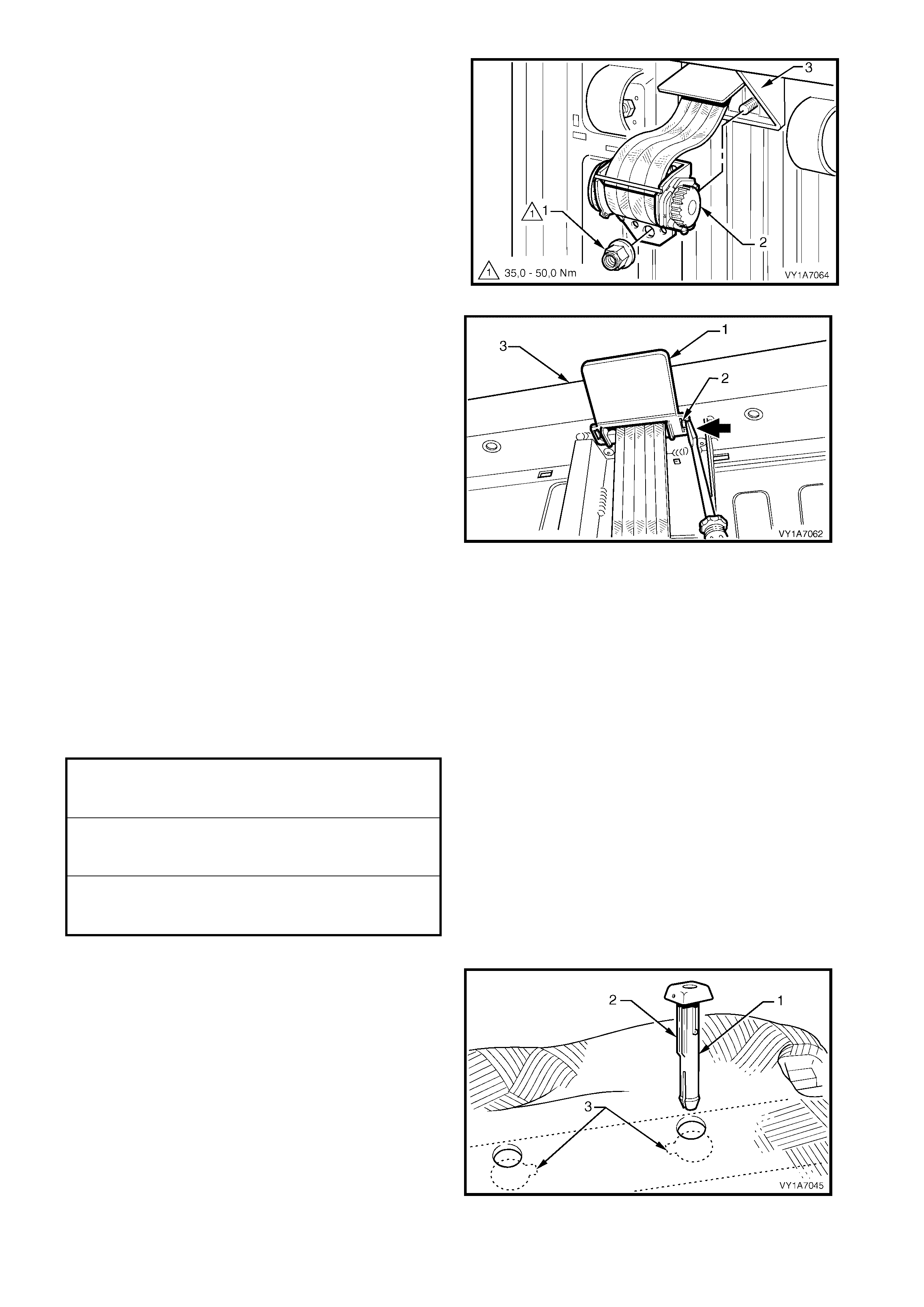
21. Rem ove the nut (1) r etaining the s eatbelt retrac tor
(2) to the rear seat back frame (3).
22. Remove seatbelt retractor from the stud in the
seat back frame.
Figure 12M-129
23. Remove the seatbelt retractor escutcheon (1) by
pushing in the tangs (2) and releasing it from the
seat back frame (3).
24. Feed the seatbelt webbing through seat back
frame and remove the retractor assembly.
NOTE: The seatbelt retractor will not function unless
the seat back is in an upright position.
Figure 12M-130
REINST ALL
Installation of the centre rear seatbelt assembly is the
reverse of removal, noting the following:
1. If a new centre rear seatbelt assembly is fitted,
ensure the web clip is removed after the retaining
nut is tightened.
2. Ensure all fasteners are tightened to the correct
torque specification.
3. When installing the head restraint guide (1), align
the locating ribs (2) with the key-way (3) in the
seat-back frame.
NOTE: Ensure the guide with the height adjuster lock
is inst al led o n th e s i de tha t c orr es ponds t o the notc h es
in the head restraint shaft.
Figure 12M-131
SEATBELT GUIDE BRACKET
ATTACHING SCREW
TORQUE SPECIFICATION 20.0 – 22.0 Nm
SEATBELT RETRACTOR
RETAINING NUT
TORQUE SPECIFICATION 35.0 – 50.0 Nm
SEATBELT ASSEMBLY
MOUNTING SCREW
TORQUE SPECIFICATION 35.0 – 50.0 Nm
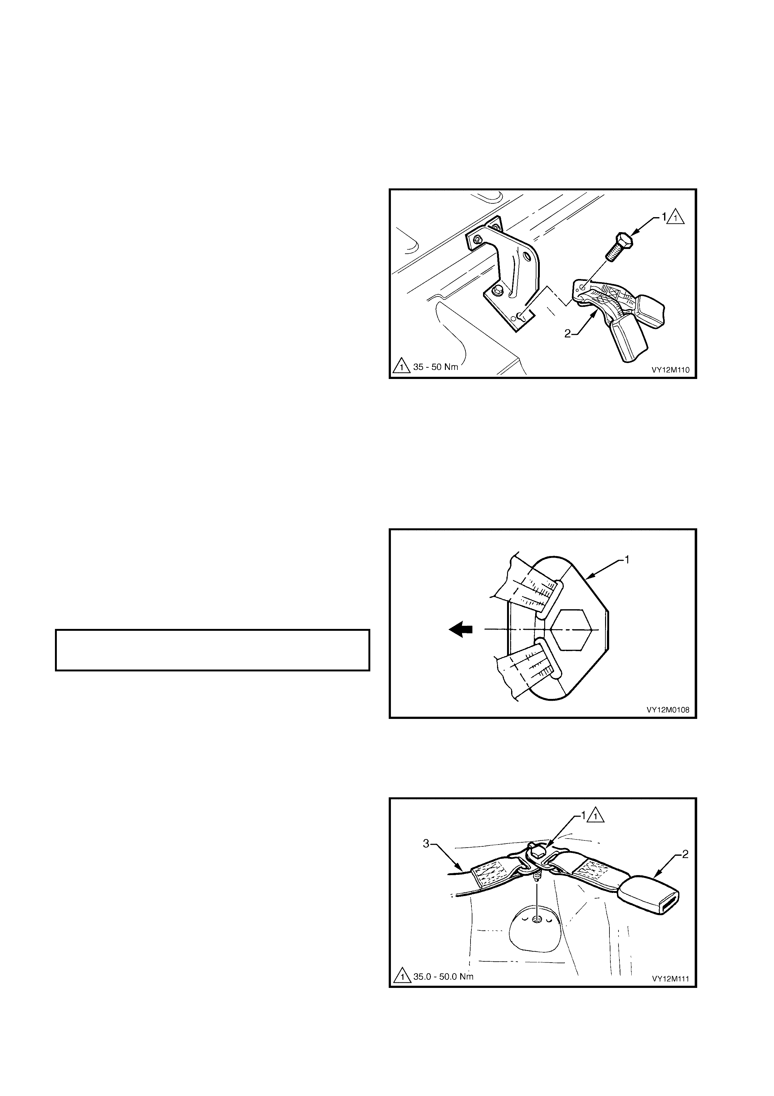
3. 10 REAR SEATBELT BUCKLE ASSEMBLY, WAGON
LT Section No. – 14-425
RIGHT-HAND SIDE
REMOVE
1. Remove the rear seat cushion, refer to Section
1A7, 7.2 REAR SEAT CUSHION ASSEMBLY.
2. Remove the screw (1) attaching the rear seatbelt
buckle anchor assembly (2) to the vehicle.
3. Remove the buckle assembly.
Figure 12M-132
REINST ALL
IMPORTANT: If reinstalling the same seatbelt buckle
assembly, inspect for damage, abrasions, fraying,
cuts, etc. R eplace t he seat belt buck le assem bly with a
new part if any damage, etc. is found.
Installation of the seatbelt buckle assembly is the
reverse of removal noting the following.
1. Ensure the anchor plate (1) is installed in the
correct orientation.
2. Hand tight en all seatb elt screws a m inim um of five
turns before using tools.
3. Tighten the screws to the specified torque.
4. Perform a functional check of the seatbelt to
ensure correct operation.
Figure 12M-133
LEFT-HA ND SIDE & CENTRE
REMOVE
1. Remove the rear seat cushion, refer to Section
1A7, 7.1 REAR SEAT CUSHION ASSEMBLY.
2. Remove the screw (1) attaching the left-hand rear
seatbelt buc kle ( 2) and cen tre rear seatbelt anc hor
assembly (3) to the vehicle.
3. Remove the buckle and belt assembly.
Figure 12M-134
SEATBELT ASSEMBLY MOUNTING
SCREW TORQUE SPECIFICATION 35.0 – 50.0 Nm
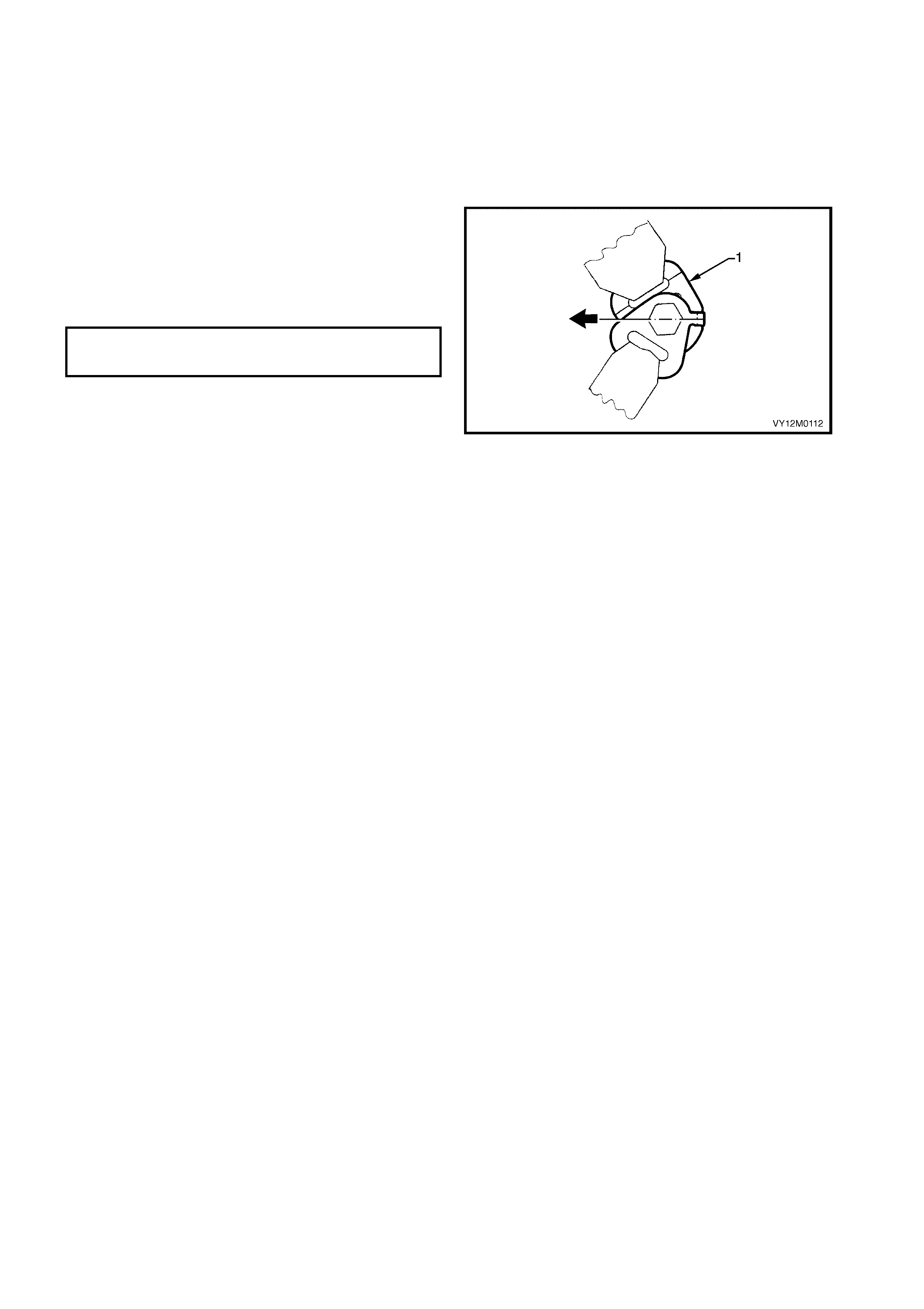
REINST ALL
IMPORTANT: If reinstalling the same seatbelt buckle
assembly, inspect for damage, abrasions, fraying,
cuts, etc. R eplace t he seat belt buck le assem bly with a
new part if any damage, etc. is found.
Installation of the seatbelt buckle assembly is the
reverse of removal noting the following.
1. Ensure the anchor plate (1) is installed in the
correct orientation.
2. Hand tight en all seatb elt screws a m inim um of five
turns before using tools.
3. Tighten the screws to the specified torque.
4. Perform a functional check of the seatbelt to
ensure correct operation.
Figure 12M-135
SEATBELT ASSEMBLY MOUNTING
SCREW TORQUE SPECIFICATION 35.0 – 50.0 Nm
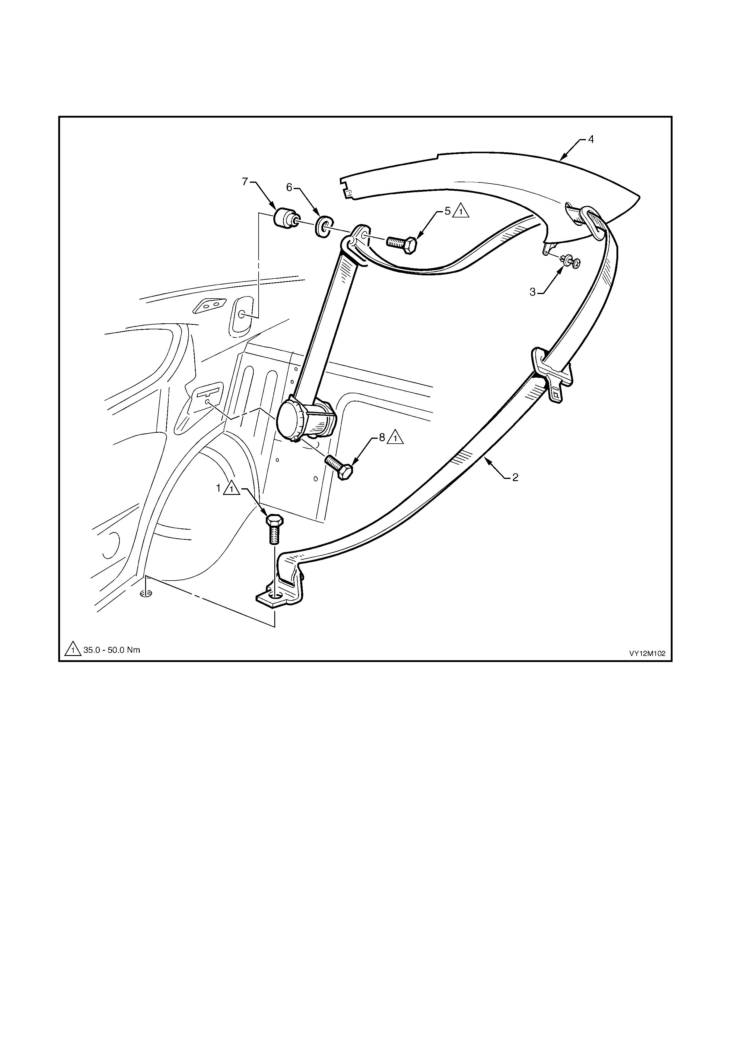
3. 11 REAR SEATBELT ASSEMBLY, COUPE
LT Section No. – 14-425
NOTE: The following chart is included to assist with component identification.
Figure 12M-136
Legend
1. Seatbelt Anchor Attaching Screw
2. Rear Seatbelt Assembly
3. Body Rear Corner Garnish Retainer
4. Body Rear Corner Garnish
5. Upper Seatbelt Guide Attaching Screw
6. Upper Seatbelt Guide Wave Washer
7. Upper Seatbelt Guide Spacer
8. Seatbelt Retractor Attaching Screw

REMOVE
1. As applicable, remove either the left or right-hand
rear seat cushion back assembly, refer to Section
1A7, 8.1 REAR SEAT CUSHION ASSEM BLY and
the rear seat back assem bly, refer to Sectio n 1A7,
8.2 REAR SEAT BACK ASSEMBLY.
2. Rem ove the scre w (1) attaching t he seatbe lt lower
anchor (2) to the vehicle.
3. Remove the body rear corner garnish, refer to
Section 1A8, 3.9 BODY REAR CORNER
GARNISH.
Figure 12M-137
4. Remove the scr e w (1) attachin g the upp er seatb elt
guide (2) to the vehicle. Ensure the wave washer
(3) and spacer (4) remains with the screw.
Figure 12M-138
5. Remove the screw (1) attaching the retractor
assembly (2) to the vehicle and remove the
seatbelt assembly.
Figure 12M-139
REINST ALL
IMPORTANT: If reinstalling the same retractor assembly, inspect the anchor plates, guides and retractor
assembly for damage, and the webbing for abrasions, fraying, cuts, etc. Replace the seatbelt assembly with a
new part if any damage, etc. is found.
Installation of the front seatbelt assembly is the reverse of removal noting the following.
1. Ensure the webbing is not twisted and the anchor plate is installed in the correct orientation.
2. Hand tighten all seatbelt screws a minimum of five turns before using tools.
3. Tighten the screws to the specified torque.
4. Perform a functional check of the seatbelt to ensure correct operation.
SEATBELT ASSEMBLY MOUNTING
SCREW TORQUE SPECIFICATION 35.0 – 50.0 Nm
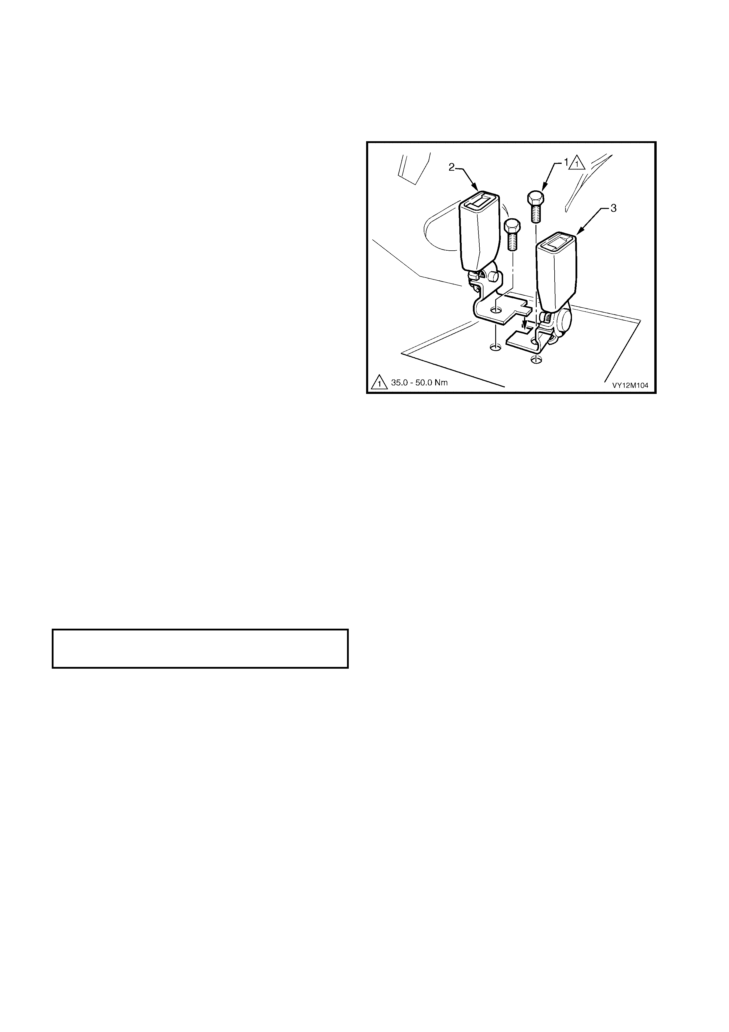
3. 12 REAR SEATBELT BUCKLE ASSEMBLY, COUPE
LT Section No. – 14-425
REMOVE
1. Remove the rear seat cushion, refer to Section
1A7, 8.1 REAR SEAT CUSHION ASSEMBLY.
2. Remove the appropriate screw (1) securing the
rear -hand (2) or left -hand seatbelt buckle (3) to
the vehicle.
Figure 12M-140
REINST ALL
IMPORTANT: If reinstalling the same seatbelt buckle
assembly, inspect for damage, abrasions, etc.
Replace the seatbelt buck le assem bly with a new part
if any damage, etc. is found.
Installation of the seatbelt buckle assembly is the
reverse of removal noting the following.
1. Ensure the anchor plates are installed in the
correct orientation.
2. Hand tight en all seatb elt screws a m inim um of five
turns before using tools.
3. Tighten the screws to the specified torque.
4. Perform a functional check of the seatbelt to
ensure correct operation.
SEATBELT ASSEMBLY MOUNTING
SCREW TORQUE SPECIFICATION 35.0 – 50.0 Nm
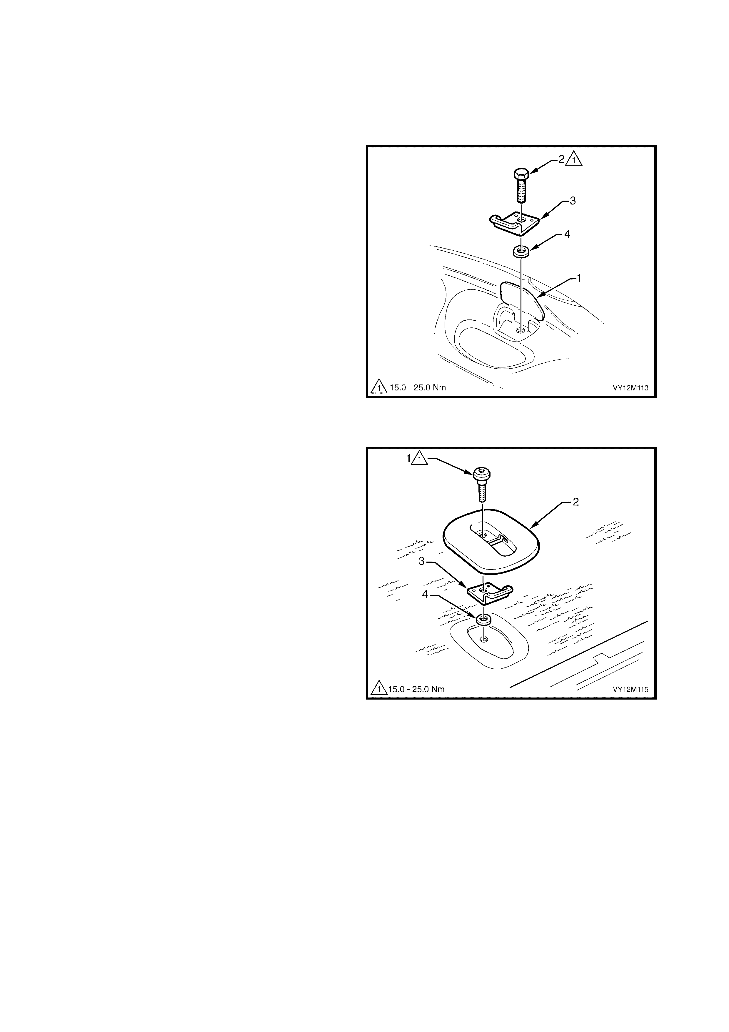
3. 13 CHILD SEAT ANCHORS
LT Section No. – AA-020
REMOVE
SEDAN
1. Open the flap (1) in the rear window trim panel.
2. Remove the screw (2) attaching the anchor (3)
and washer (4) to the vehicle and remove.
Figure 12M-141
WAGON
1. From the rear of the rear seat back, remove the
bolt (1) attaching the escutcheon (2), anchor (3)
and washer (4) to the seat back and remove.
Figure 12M-142

UTILITY
1. Prise open the child seat anchor cover (1).
2. Remove the screw (2) attaching the anchor (3)
and washer (4) to the vehicle and remove.
Figure 12M-143
COUPE
1. Remove the rear window trim panel, refer to
Section 1A8, 4.7 REAR WINDOW TRIM PANEL
ASSEMBLY.
2. Remove the screw (1) attaching the anchor (2)
and washer (3) to the vehicle and remove.
Figure 12M-144
REINST ALL
Installation of the child seat anchors is the reverse of
removal noting the following.
1. Ensure the anchors are installed in the correct
orientation.
2. Hand tighten the bolt a minimum of five turns
before using tools.
3. Tighten the bolt to the specified torque.
CHILD SEAT ANCHOR MOUNTING
SCREW TORQUE SPECIFICATION 15.0 – 25.0 Nm

4. DIAG NOSTICS
4.1 BASIC KNOWLEDGE REQUIRED
Before attempting to diagnose the OPS / SRS you must have a good understanding of electrical system basics
and the use of c irc uit tes ti n g too ls. Without th is bas ic k no wledg e it wil l b e d if f icult to us e t he dia gnos t ic proc e dur es
detailed in this Sec ti on.
Some elec tr ical bas ics , as well as b as ic tr o ubles ho oti n g pr ocedures a nd hin t s of the use of c irc uit t es tin g t ool s are
covered in Section 12P, WIRING DIAGRAMS.
Basic Electrical Circuits − You sh ould underst and the bas ic theory of electricit y, direct c urrent (DC) the ory, series
and parallel circuits, and voltage drops across series resistors. You should know the meaning of voltage (volts),
current ( am ps), and res istance (ohms) . You s hould understand what happens in a c ircuit with an o pen or shorted
wire (shorted either to voltage or earth). You should also be able to read and understand a wiring diagram.
Additionally, a knowledge of alternating current (AC) theory including; inductance, capacitance and impedance
would be useful.
Use of Circuit Testing Tools – You sho uld know how to use a jum per lead to test circuits. You shou ld be familiar
with the use of a hig h in put im pedanc e (10 Mohm ) digital t ype m ultim eter suc h as T ool No. J213 200 or equ iv alent
and be ab le to m easure voltage, current, and resis tanc e. You shou ld be f am iliar with the proper us e of th e TECH
2 Diagnostic Scan Tool.

4.2 PRELIMINARY SYSTEM DIAGNOSIS
W hen investigatin g any com plaint of an OPS / SRS problem or malfunc tion, always begin diagnosis with a circuit
check, refer to 4.6 DIAGNOSTIC CHARTS, CHART A – DIAGNOSTIC CIRCUIT CHECK in this Section.
The diagnostic circuit check is a preliminary procedure that checks to ensure the SDM is communicating on the
serial data line as well as helping to identify the problem and directing the reader to the appropriate diagnostic
chart in this Sect ion.

4.3 OPS / SRS SELF DIAGNOSTIC
The O PS / SRS h as a se lf-dia gnostic f acilit y that c an detect and isolate OPS / SRS pro blem s or f ailures. When a
problem or failure is detected, the SDM sets a fault code that represents that particular problem or failure. Fault
codes will cause the SRS warning indicator to be illuminated along with a SRS fault message displayed by the
MFD window located in the instrument cluster. Depending on the fault, the SDM may disable the OPS / SRS.
If pres ent, dia gnos able s ystem faults are de tected b y the SDM dur ing a n init ialis ation proces s when th e ign ition is
first turned on. Upon first detection of an external system fault condition, the SDM records the failure and is
classed as an 'Intermittent Failure'. If the fault condition is maintained to meet the failure duration conditions for
the individual system problem (approximately three – five seconds), the fault then becomes a current Diagnostic
Trouble Code (DTC). If the fault duration conditions are not met, the intermittent fault is cleared from the SDM.
Current DTCs are permanently stored in the SDM's memory. When the fault conditions are no longer met, the
DTC will become a History DTC.
CURRENT DTCS
Current DT Cs when det ected are s tored in the SDM's RA M during the current ig nition c yc le and the n maintain ed
in an EEPROM. Current DTCs are set or cleared based on the condition of the OPS / SRS during ignition on or
continuous monitoring of the current ignition cycle.
NOTE: A current DTC can be identified on the TECH 2 display by the word ‘Current’ between the DTC number
and the DT C description. T he word ‘His tory’ bet ween the DT C number and the DTC descr iption indicat es that the
DTC displayed is a history DTC.
Current DTCs will be reset to History DTC’s upon the next diagnostic test sequence that the fault conditions are
not met. Current DTCs can be cleared (changed to history DTC) by removing the fault conditions.
TECH 2 is unable to clear current DTC’s if the fault conditions still exist; TECH 2 will display ‘Clear DTC
Information Failed’.
DTCs stored in the SDM memory can only be displayed and / or cleared using the TECH 2 diagnostic scan tool.
The TECH 2 communicates with SDM serial data via the Serial Data Link Connector (DLC), which is
attached to the instrument panel lower right-hand trim, to the right of the steering column, refer to
4.4 TECH 2 DIAGNOSTICS in this Section.
HISTORY DTCS
Histor y DT Cs ar e s et u pon the cl ear ing of a c ur rent DTC fault c o ndi tio n. H istory DTCs are m aintai ned by the SDM
over m ultiple ignitio n cycles in the EEPRO M. The SDM c an only clear histor y D TCs fr om its EEPROM b y a clear
DTCs serial data message via TECH 2.
CLEARING FAULT CODES
Once an y s ystem fault has been r ectified, us ing TECH 2 ‘Clear DT Cs’ selection c an erase any fault c odes stored
in the SDM’s memory, refer to 4.5 TECH 2 TEST MODES AND DISPL AY S FOR OPS / SRS DI AGNOSIS in th is
Section.
IMPORTANT: O nc e DTC’s have be en c le ared, be s ure to verify proper system operati on an d abs ence of any fau lt
codes when clearing procedure is com pleted. If TECH 2 displays ‘Clear DTC Information Failed’ after attempting
to clear DTC’s, the fault condition still exists.
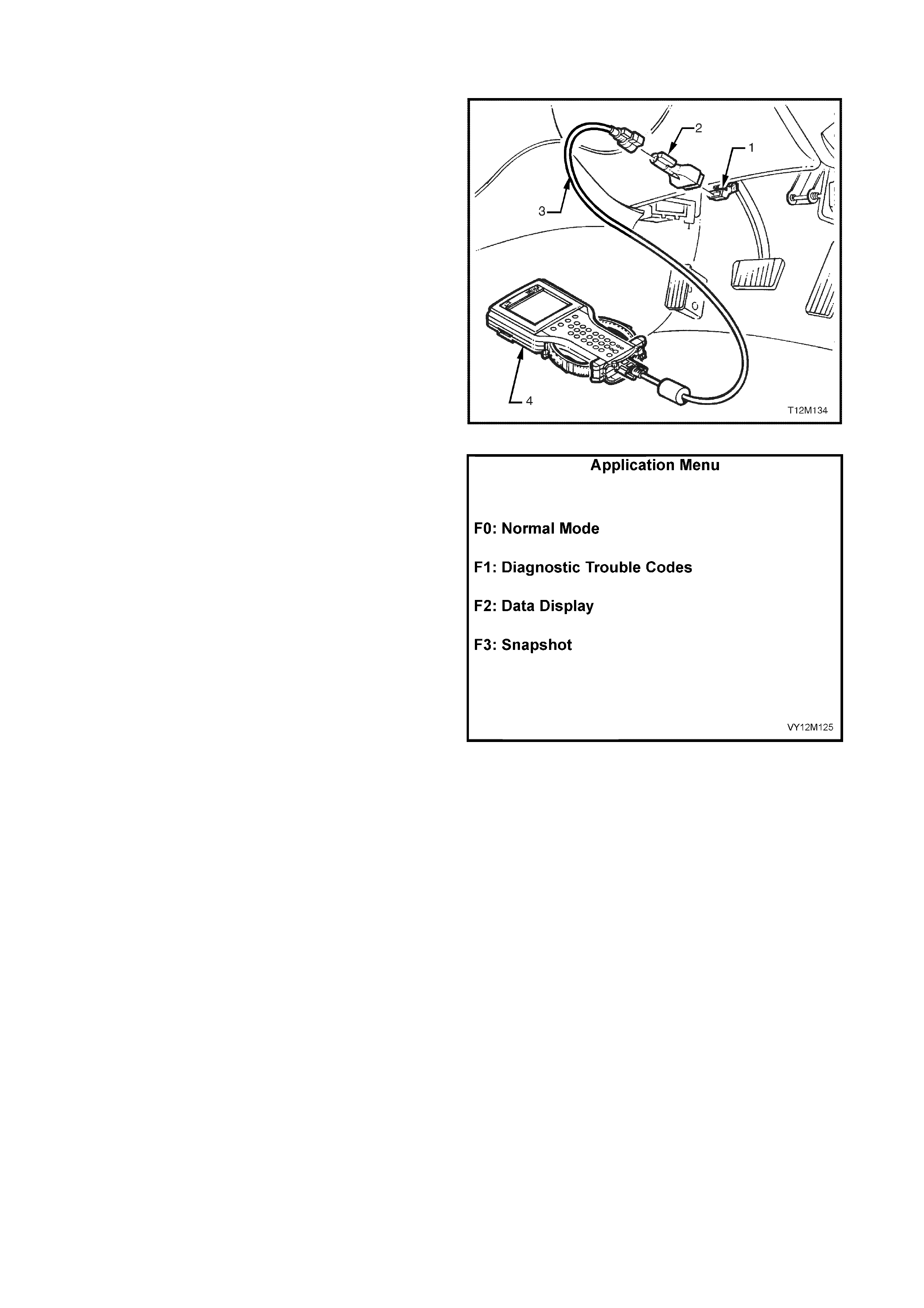
4.4 TECH 2 DIAG NOSTICS
TECH 2, with the appropriate software, cables and
adaptors, when connected to the Serial Data Link
Connector (DLC) is capable of reading OPS / SRS
serial data. The DLC is connected to the instrument
panel lower right-hand trim , to the right of the st eering
column, refer to Section Figure 12M-145.
1. DLC
2. DLC Adaptor
3. DLC Cable
4. TECH 2
For additional general information on connecting and
operating TECH 2, refer to Section 0C T ECH2.
Figure 12M-145
TECH 2 has f our test m odes for diagnos ing the OPS /
SRS. The four test modes are as follows:
1. Mode F0: Norm al Mode − In th is mode, t he TECH
2 monitors the communication between control
modules on the serial data line. The information
displayed on the TECH 2 screen in this mode is
what the inflatable restraint control module (SDM)
is communicating to the other modules via the
serial data line .
2. Mode F1: Diagnostic Trouble Codes − If F1:
Diagnostic Trouble Codes is selected, a selection
list is disp layed whic h cont ains :
a. F0: Read DTC Information − Once this
mode is selected, both current and histor y
Diagnostic Trouble Codes (DTCs) stored
in the control modules memory may be
displayed.
b. F1: Clear DTC Information − once this
mode is selected, DTCs stored in the
control module memory may be cleared.
3. Mode F2: Data Display − In this test mode, TECH
2 displays the status of inputs and outputs of the
OPS / SRS.
4. Mode F 3: Snapsh ot − In thi s test m ode, the T ECH
2 captures OPS / SRS data before and after a
forced manual trigger.
Figure 12M-146

4.5 TECH 2 TEST MODES AND DISPL AYS FOR OPS / SRS DIAGNOSIS
A prereq uisite to this diagnostic section is f or the user to be f amiliar with the proper use of TECH 2, the f ollowing
pages illustrate only the major TECH 2 screen displays and provide a brief explanation of their function for
diagnosing the OPS / SRS. If additiona l information is required on the operation of TECH 2, reference should be
made to either Section 0C TECH 2 or the TECH 2 User’s Guide.
SYSTEM SELECT MENU
With TECH 2 connected to the DLC, the ‘F0:
Diagnostics’ selected from the Main Menu, the correct
Model Year and Vehicle Type must be selected for
access to the System Select Menu.
Select F3: Body.
This mode contains all functions to test, diagnose,
monitor and program the vehicles body systems
including the OPS / SRS as well as providing the
opportunity to check all DTC’s that may be set in the
vehicle.
System Select Menu
(3) 2003 VY Commodore
F0: Engine
F1: Transmissi on
F2: Chassis
F3: Body
VY12M128
F4: Vehicle DTC Check
Figure 12M-147
BODY APPLICATION MENU
Once ‘F3: Body’ has been selected from the System
Select Menu, OPS / SRS can be selected.
Select SRS.
NOTE: If information regarding DTC’s set for the
vehicle is required, se lect DTC Check and press ente r
to continue. To return to the ‘SRS’ mode option from
the ‘DTC Check’ mode option screen display, simply
press the EXIT key on TECH 2.
Once the ‘SRS’ has been selected, the following two
System Identification screens will appear which
require action.
Electronic Climate Control
Vehicle Identification
Select one of the following
Body
Body Control Module
Powertrain Interface Module
SRS
VY12M129
Instruments
Figure 12M-148
SYSTEM IDENTIFICATION
Turn the ignition ON (as requested) and press the
Confirm soft key to continue.
System Identificatio n
(3) 2003 VY Commodore
Electronic System : SRS
T urn On Ignition!
VY12M130
Confirm
Figure 12M-149

The System Identification screen will then display the
control module part number, production date and type
of control module (80 or 81). Press the Confirm soft
key to continue to the SRS Application Menu.
NOTE: There are different control modules for OPS /
SRS depending on the system and system
configuration.
Module type 8.0 is used on vehicles with;
pretensioners only (2 loops), pretensioners and
Driver’s airbag only (3 loops) or pretensioners and
Driver’s and Passenger airbags (4 loops).
Module type 8.1 is used on vehicles with Driver’s and
Passeng er airbags al ong with Si de-im pact airbags and
pretensioners (6 loops).
Always refer to Section the latest Holden spare parts
Part finder CD for the correct part number information.
System Identification
(3) 2003 VY Commodore
Electronic System: SRS
Pa rt Number XXXXXX
Prod uction Date XXXX
Modu l e Type XX
VY12M131
Confirm
Figure 12M-150
APPLICATION MENU
The following functions will now be available:
F0: Normal Mode
F1: Diagnostic Trouble Codes
F2: Data Display
F3: Snapshot
Body
F0: Normal Mode
F1: Diagnostic Trouble Codes
F2: Data Display
F3: Snapshot
VY12M132
Figure 12M-151
F0: NORMAL MODE
In the ‘F0: Normal Mode’, the TECH 2 monitors the
communication between the various control modules
on the ser ial data c ircuit. T he inf ormation d ispla yed on
the TECH 2 screen in this particular m ode is what the
SDM is sen ding out to the other m odules via the s erial
data circuit.
For example: As displayed opposite, the SRS warning
indicator status is ON. This means the SDM is
communicating with the instruments requesting the
SRS warning indicator to be displayed.
The following table provides a description of the
information displayed on TECH 2 for this mode.
Normal Mode
SRS Warning Lam p
SRS D epl oyed this Ignition Cy cle
SRS DTC Status
ON
No
No DTC
SRS Module 8.0/8.1
VY12M133
Figure 12M-152
DATA STREAM /
SCREEN DISPLAY DESCRIPTION
SRS Warning Lamp Displays the commanded status of the ‘SRS Warning Lamp’
• on / off
SRS Deployed this
Ignition Cycle Displays if the SRS has deployed on the current ignition cycle, ‘Yes’ should be displayed. Once
the ignition has been cycled, ‘No’ should be displayed.
• yes / no
SRS DTC Status Displays the current SDM DTC Status. Should display ‘Yes’ if there is a DTC set in the SDM.
• yes / no
SRS Module Displays the SRS Module Type
• 8.0 / 8.1

F1: DIAGNOSTIC TROUBLE CODES
If ‘F1: Diagnostic Trouble Codes’ is selected, a
selecti on lis t is disp layed whic h con tai ns:
F0: Read DTC Information – If this m ode is selected,
a listing of all (if any) DTCs that have been set by the
SDM will be displayed. Information displayed with the
DTC number/s that have been set is; a short
description of what the DTC is and whether it is a
current (fault present) or history (stored, but not
necessarily on this ignition cycle) DTC.
NOTE: If an y DTCs are s et, ref er ence s houl d be made
to the relevant diagnostic charts in this section.
F1: Clear DT C Information – DT Cs can be c leared in
this mode by simply selecting F1: CLEAR DTC
INFORMAT ION, pres sing t he ENT ER button on T ECH
2 and confirming the action as instructed by TECH 2.
If a DTC c onditi on is pr es e nt, T ECH 2 will b e una bl e t o
clear the DTC and will display ‘Clear DTC Information
Failed’.
The following table sets out all the possible diagnostic
trouble codes as indicated by TECH 2.
Diagn os tic Trou ble Code s
F0: Read DTC Information
F1: Clear DTC Information
VY12M134
Figure 12M-153
Clear DT C information
(3) 2003 VY Commodore
Clear DTC Information Successful
VY12M135
Confirm
Figure 12M-154

DIAGNOSTIC TROUBLE CODES
DTC
Code Location Fault
17 Driver’s air bag Circ ui t Short to Battery
18 Driver’s air bag Circ ui t Short to Ground
19 Driver’s air bag Circ ui t Capacitanc e Hig h
20 Driver’s air bag Circ ui t Capacitanc e Lo w
21 Driver’s air bag Circ ui t Resistance Hig h
22 Driver’s air bag Circ ui t Resistance Lo w
247 Driver’s airbag Circuit Power Stage Error
(Displayed as a History DTC only) Driver’s airbag Firing Loop Resistance or
Capacitance out of Range less than 500
milliseconds during a initial ignition/key on cycle.
33 Passeng er air bag Circ ui t Short to Battery
34 Passeng er air bag Circ ui t Short to Ground
35 Passeng er air bag Circ ui t Capacitance High
36 Passeng er air bag Circ ui t Capacitance Low
37 Passeng er air bag Circ ui t Resistance Hig h
38 Passeng er air bag Circ ui t Resistance Lo w
247 Passenger airbag Circuit Power Stage Error
(Displayed as a History DTC only) Passenger airbag Firing Loop Resistance or
Capacitance out of Range less than 500
milliseconds during a initial ignition/key on cycle.
49 Belt Tensioner Circuit – left-hand Short to Battery
50 Belt Tensioner Circuit – left-hand Short to Ground
51 Belt Tensioner Circuit – left-hand Capacitance High
52 Belt Tensioner Circuit – left-hand Capacitance Low
53 Belt Tensioner Circuit – left-hand Resistance High
54 Belt Tensioner Circuit – left-hand Resistance Low
247 Left-hand Belt Tensioner Circuit Power Stage
Error
(Displayed as a History DTC only)
Left-hand Belt Tensioner Firing Loop Resistance
or Capacitance out of Range less than 500
milliseconds during a initial ignition/key on cycle.
65 Belt Tensioner Circuit – right-hand Short to Battery
66 Belt Tensioner Circuit – right-hand Short to Ground
67 Belt Tensioner Circuit – right-hand Capacitance High
68 Belt Tensioner Circuit – right-hand Capacitance Low
69 Belt Tensioner Circuit – right-hand Resistance High
70 Belt Tensioner Circuit – right-hand Resistance Low
247 Right-hand Belt Tensioner Circuit Power Stage
Error (Displayed as a History DTC only)
Right-hand Belt Tensioner Firing Loop Resistance
or Capacitance out of Range less than 500
milliseconds during a initial ignition/key on cycle.
81 Side-impact airbag Circuit – left-hand Short to Battery
82 Side-impact airbag Circuit – left-hand Short to Ground
83 Side-impact airbag Circuit – left-hand Capacitance High
84 Side-impact airbag Circuit – left-hand Capacitance Low
85 Side-impact airbag Circuit – left-hand Resistance High
86 Side-impact airbag Circuit – left-hand Resistance Low
247 Left-hand Side-impact airbag Circuit Power
Stage Error (Displayed as a History DTC only)
Left-hand Side-impact airbag Firing Loop
Resistance or Capacitance out of Range less than
500 milliseconds during a initial ignition/key on
cycle.

DTC
Code Location Fault
97 Side-impact airbag Circuit – right-hand Short to Battery
98 Side-impact airbag Circuit – right-hand Short to Ground
99 Side-impact airbag Circuit – right-hand Capacitance High
100 Side-impact airbag Circuit – right-hand Capacitance Low
101 Side-impact airbag Circuit – right-hand Resistance High
102 Side-impact airbag Circuit – right-hand Resistance Low
247 Right-hand Side-impact airbag Circuit Power
Stage Error (Displayed as a History DTC only)
Right-hand Side-impact airbag Firing Loop
Resistance or Cap acita nce out of Ran ge les s tha n
500 milliseconds during a initial ignition/key on
cycle.
129 Peripheral acceleration sensor – left-hand Line fault
130 Peripheral acceleration sensor – right-hand Line fault
131 Peripheral acceleration sensor – left-hand Communication fault
132 Peripheral acceleration sensor – right-hand Communication fault
133 Peripheral acceleration sensor – left-hand Identification fault
134 Peripheral acceleration sensor – right-hand Identification fault
135 Peripheral acceleration sensor – left-hand Hardware fault
136 Peripheral acceleration sensor –right-hand Hardware fault
161 Configuration Mismatch (Displayed as a History
DTC only) Mismatch to instrument fault
163 Sensing Diagnostic Module (Displayed as a
History DTC only) Internal fault
F2: DATA DISPLAY
In this test mode, TECH 2 displays the status of inputs and outputs of the OPS / SRS.
The following table lists each item contained in the data stream together with a brief description of its meaning.
NOTE: Depending on the system / system configuration it is possible that some data list parameters may not
appear in the data stream / screen display. In that case, these data list parameters are not applicable for this
system / system configuration.
The last four columns of the following table identify whether any of the data list parameters will be displayed for
that particu lar s ystem.
2 = 2 loop system; pretensioners only.
3 = 3 loop system; pretensioners and driver’s airbag only.
4 = 4 loop system; pretensioners, driver’s airbag and passenger airbag.
6 = 6 loop system; pretensioners, driver’s airbag, passenger airbag and side-impact airbag.
A = Data parameter displayed for this system.
N/A = Data is not applicable and thus not displayed for this system.

DATA STREAM /
SCREEN DISPLAY DESCRIPTION 2 3 4 6
Battery Voltage Displays the current vehicle system input voltage to the inflatable
restraint control module (SDM) (approximately 12 volts).
• If the voltage is below 8 volts for greater than three seconds, a
DTC 241 will be set and the SRS warning indicator is switched
on.
• If the voltage is above 21.2 volts for more than three seconds, a
DTC 242 will be set and the SRS warning indicator is switched
on.
A A A A
Driver’s airbag Loop
Capacitance Displays capacitance in the driver’s airbag circuit. The capacitance
should be approximately 470 nF.
If the capacitance reading is outside ± 17% of this specification for
greater than three seconds or less than one second during a
ignition/key on cycle, a DTC will be set.
• If the capacitance reading is greater than 549.9 nF for greater
than three seconds, a DTC 19 will be set.
• If the capacitance reading is less than 390.1 nF for greater than
three seconds, a DTC 20 will be set.
N/A A A A
Driver’s airbag Loop
Resistance Displays the resistance in the driver’s airbag circuit. The resistance
should be approximately two ohms.
• If resistance of this circuit is greater than 8.4 ohms for greater
than three seconds, a DTC 21 will be set.
• If resistance of this circuit is less than one ohm for greater than
three seconds, a DTC 22 will be set.
N/A A A A
Passenger airbag Loop
Capacitance Displays capacitance in the passenger airbag circuit. The capacitance
should be approximately 470 nF.
If the capacitance reading is outside ± 17% of this specification for
greater than three seconds or less than one second during a
ignition/key on cycle, a DTC will be set.
• If the capacitance reading is greater than 549.9 nF for greater
than three seconds, a DTC 35 will be set.
• If the capacitance reading is less than 390.1 nF for greater than
three seconds, a DTC 36 will be set.
N/A N/A A A
Passenger airbag Loop
Resistance Displays resistance in the passenger airbag circuit. The resistance
should be approximately two ohms.
• If resistance of this circuit is greater than 8.4 ohms for greater
than three seconds, a DTC 37 will be set.
• If resistance of this circuit is less than 0.6 ohm for greater than
three seconds, a DTC 38 will be set.
N/A N/A A A
Left-hand Pretensioner
Loop Capacitance Displays capacitance in the left-hand Pretensioner circuit. The
capacitance should be approximately 470 nF.
If the capacitance reading is outside ± 17% of this specification for
greater than three seconds or less than one second during a
ignition/key on cycle, a DTC will be set.
• If the capacitance reading is greater than 549.9 nF for greater
than three seconds, a DTC 51 will be set.
• If the capacitance reading is less than 390.1 nF for greater than
three seconds, a DTC 52 will be set.
A A A A
Left-hand Pretensioner
Loop Resistance Displays resistance in the left-hand Pretensioner circuit. The
resistance should be approximately two ohms.
• If the resistance of this circuit is greater than 8.4 ohms for greater
than three seconds, a DTC 53 will be set.
• If the resistance of this circuit is less than 0.6 ohm for greater
than three seconds, a DTC 54 will be set.
A A A A

DATA STREAM /
SCREEN DISPLAY DESCRIPTION 2 3 4 6
Right-hand Pretensioner
Loop Capacitance Displays capacitance in the right-hand Pretensioner circuit. The
capacitance should be approximately 470 nF.
If the capacitance reading is outside ± 17% of this specification for
more than three seconds or less than one second during a
ignition/key on cycle, a DTC will be set.
• If the capacitance reading is greater than 549.9 nF for greater
than three seconds, a DTC 67 will be set.
• If the capacitance reading is less than 390.1 nF for greater than
three seconds, a DTC 68 will be set.
A A A A
Right-hand Pretensioner
Loop Resistance Displays resistance in the Right-hand Pretensioner circuit. The
resistance should be approximately two ohms.
• If the resistance of this circuit is greater than 8.4 ohms for greater
than three seconds, a DTC 69 will be set.
• If the resistance of this circuit is less than 0.6 ohm for greater
than three seconds, a DTC 70 will be set.
A A A A
Left-hand Side-impact
airbag Loop Capacitance Displays capacitance in the Left-hand Side-impact airbag circuit. The
capacitance should be approximately 470 nF.
If the capacitance reading is outside ± 17% of this specification for
more than three seconds or less than one second during a
ignition/key on cycle, a DTC will be set.
• If the capacitance reading is greater than 549.9 nF for greater
than three seconds, a DTC 83 will be set.
• If the capacitance reading is less than 390.1 nF for greater than
three seconds, a DTC 84 will be set.
N/A N/A N/A A
Left-hand Side-impact
airbag Loop Resistance Displays resistance in the Left-hand Side-impact airbag circuit. The
resistance should be approximately two ohms.
• If the resistance of this circuit is greater than 8.4 ohms for greater
than three seconds, a DTC 85 will be set.
• If the resistance of this circuit is less than 0.6 ohm for greater
than three seconds, a DTC 86 will be set.
N/A N/A N/A A
Right-hand Side-impact
airbag Loop Capacitance Displays capacitance in the Right-hand Side-impact airbag circuit.
The capacitance should be approximately 470 nF.
If the capacitance reading is outside ± 17% of this specification for
more than three seconds or less than one second during a
ignition/key on cycle, a DTC will be set.
• If the capacitance reading is greater than 549.9 nF for greater
than three seconds, a DTC 99 will be set.
• If the capacitance reading is less than 390.1 nF for greater than
three seconds, a DTC 100 will be set.
N/A N/A N/A A
Right-hand Side-impact
airbag Loop Resistance Displays resistance in the Right-hand Side-impact airbag circuit. The
resistance should be approximately two ohms.
• If the resistance of this circuit is greater than 8.4 ohms for greater
than three seconds, a DTC 101 will be set.
• If the resistance of this circuit is less than 0.6 ohm for greater
than three seconds, a DTC 102 will be set.
N/A N/A N/A A
Driver’s airbag Loop Display indicates whether the SDM has been programmed for the
driver’s airbag loop cir cui t.
• enabled / disabled.
N/A A A A
Passenger airbag Loop Display indicates whether the SDM has been programmed for the
passenger airbag loop circuit.
• enabled / disabled.
N/A N/A A A

DATA STREAM /
SCREEN DISPLAY DESCRIPTION 2 3 4 6
Left-hand Pretensioner
Loop Display indicates whether the SDM has been programmed for the left-
hand Pretensioner loop circuit.
• enabled / disabled.
A A A A
Right-hand Pretensioner
Loop Display indicates whether the SDM has been programmed for the
right-hand Pretensioner loop circuit.
• enabled / disabled.
A A A A
Left-hand Side-impact
airbag Loop Display indicates whether SDM has been programmed for the left-
hand side-impact airbag loop circuit.
• enabled / disabled.
N/A N/A N/A A
Right-hand Side-impact
airbag Loop Display indicates whether the SDM has been programmed for the
right-hand side-impact airbag loop circuit.
• enabled / disabled.
N/A N/A N/A A
SRS Indicator Displays the current state of the SDM’s internal SRS warning
indicator driver.
• on / off.
A A A A
Indicator Check Display indicates the status of the SRS warning indicator during the
indicator check for the first five seconds after the ignition is switched
on.
• on / off.
A A A A
Battery Voltage
(After 3 Seconds) Display indicates the vehicle input voltage to the SDM. If votage is
below 9 volts or above 20 volts for more than 3 seconds, the SRS
warning indicator is switched on.
• < 9 Volts / Okay / > 20 Volts.
A A A A
Energy Reserve Display indicates status of the energy reserve. If the battery voltage
falls below 7.5 volts, the energy reserve will be switched on.
• on / off.
A A A A
Serial Data From
Instrument Display indicates whether the instrument configuration of the OPS /
SRS is correct. The instruments must be programmed for the SRS
configuration of the vehicle; pretensioners only, pretensioners and
driver’s airbag, pretensioners and drivers and passenger airbag, or
pretensioners, drivers, instrument panel and side-impact airbag.
• yes / no.
A A A A
BCM Poll Display indicates whether the SDM is receiving a request (a poll via
the serial data line) from the BCM for its status of deployment and
malfunction data.
• Rece ived / Not Received
A A A A
Left-hand Peripheral
acceleration sensor
Communication
Display indicates whether the SDM is receiving data from the left-
hand peripheral acceleration sensor.
• Received / Not Received.
• If the SDM does not receive data, a DTC 131 will be set.
N/A N/A N/A A
Right-hand Peripheral
acceleration sensor
Communication
Display indicates whether the SDM is receiving data from the right-
hand peripheral acceleration sensor.
• Received / Not Received.
• If the SDM does not receive data, a DTC 132 will be set.
N/A N/A N/A A
Module has deployed Display indicates whether the SDM has deployed any OPS / SRS
components.
• yes / no.
A A A A
MODE F3: SNAPSHOT
In the ‘F3: Snapshot’ mode, TECH 2 enables the user to capture data before and after a forced manual trigger.

4.6 DIAG NOS TIC CHARTS
INTRODUCTION
The following diagnostic charts are designed to provide fast and efficient fault location of the OPS / SRS for
vehicles fitted with an 8.0 or 8.1 SDM. The diagnostic charts contain: a ‘diagnostic chart’, pertinent information,
circuit diagrams, and where necessary, the steps are explained by the corresponding numbered paragraphs.
Figure 12M-155 illustrates the terminal layout of the various connectors used in the 8.0 and 8.1 system. This
illustration should be used in conjunction with t he diagnostic chart circuit d iagram s when checking circuit faults if
the connector diagram is not included in the chart.
When carrying out wiring checks as directed to by the diagnostic charts, rather than probe terminals and
connectors with incorrect sized multimeter connections, use the adaptors contained in connector test adaptor kit
KM-609 and test lead set KM-609-20. This will prevent any possibility of spreading or damaging wiring harness
terminals and later on causing a system intermittent failure.
Figure 12M-156 illustrates the correct use and installation of the various OPS / SRS diagnostic tools (SD28280B
& AU485) and test lead set (KM-609-20).
IMPORTANT: Und er no c ircum stances is 12 volts t o be appl ied to th e dumm y load; S D28280b or AU485, as this
will damage the internal resistor in the load, rendering the dummy load useless for any further diagnostic work.
Ensure that at the completion of any diagnostic procedure, all diagnostic tools are removed and all OPS / SRS
components are correctly reconnected.

Figure 12M-155
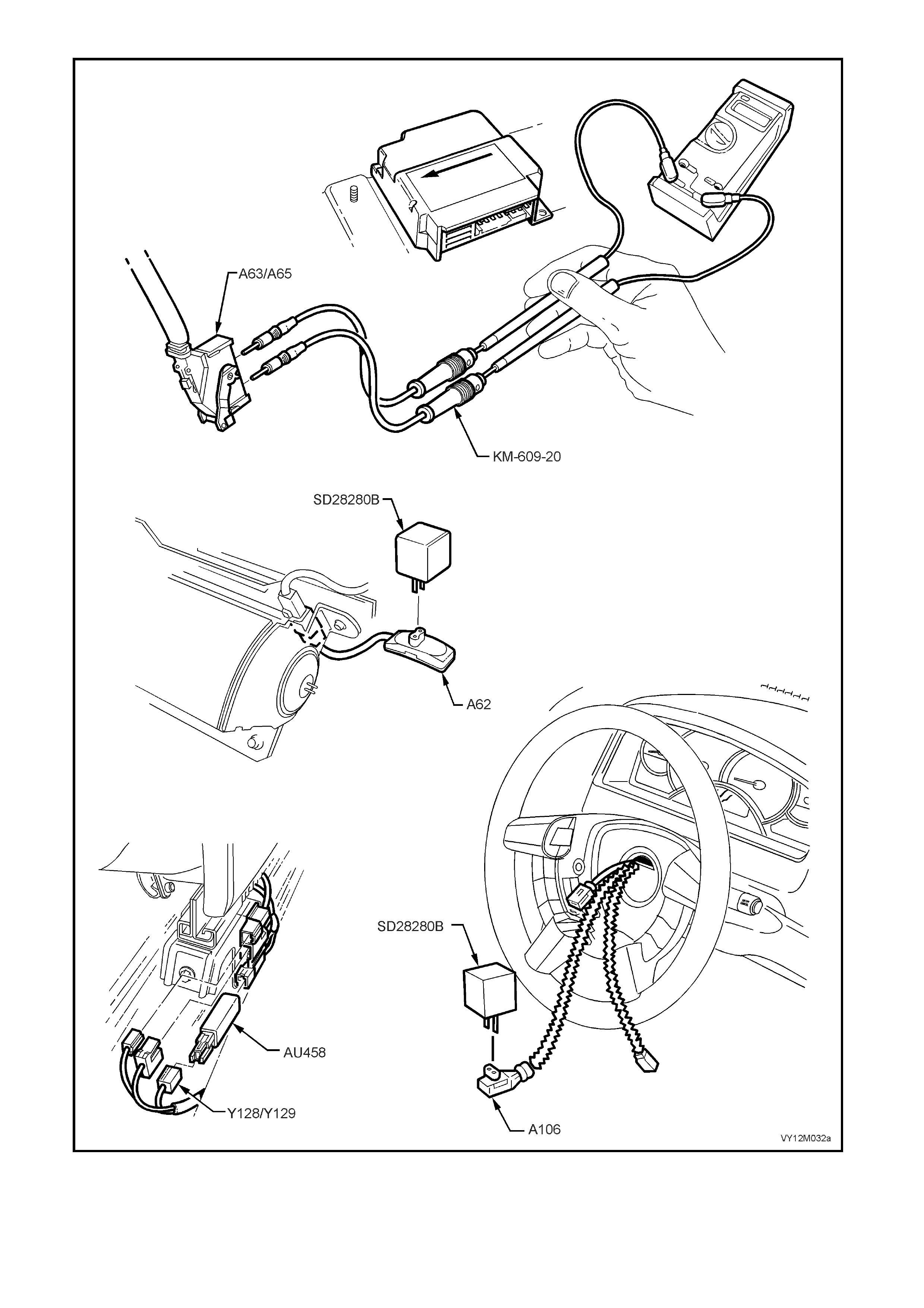
Figure 12M-156

CHART A – DIAGNOSTIC CIRCUIT CHECK
Figure 12M-157
CIRCUIT DESCRIPTION
When investigating any complaint of an OPS / SRS problem or malfunction, always begin diagnosis with the
following diagnostic circuit check. This check is a preliminary procedure that checks to ensure the inflatable
restraint c ontr ol m odule (S DM) is communic ating on the s erial data line as well as helpin g to id entif y a pr oble m or
malfunction and directing the reader to the appropriate diagnostic chart in this Section.
With TECH 2 connected to the DLC and the ignition switched on, TECH 2 should display serial data
communication. If TECH 2 does not display serial data, the serial data circuit maybe open of shorted.
There are several other control modules that are connected to the serial data line (PCM, BCM, ABS/ETC, ECC,
instruments and SDM). ANY one of these control modules could cause a fault on the serial data line. This fault
could result in TECH 2 not being able to display serial data
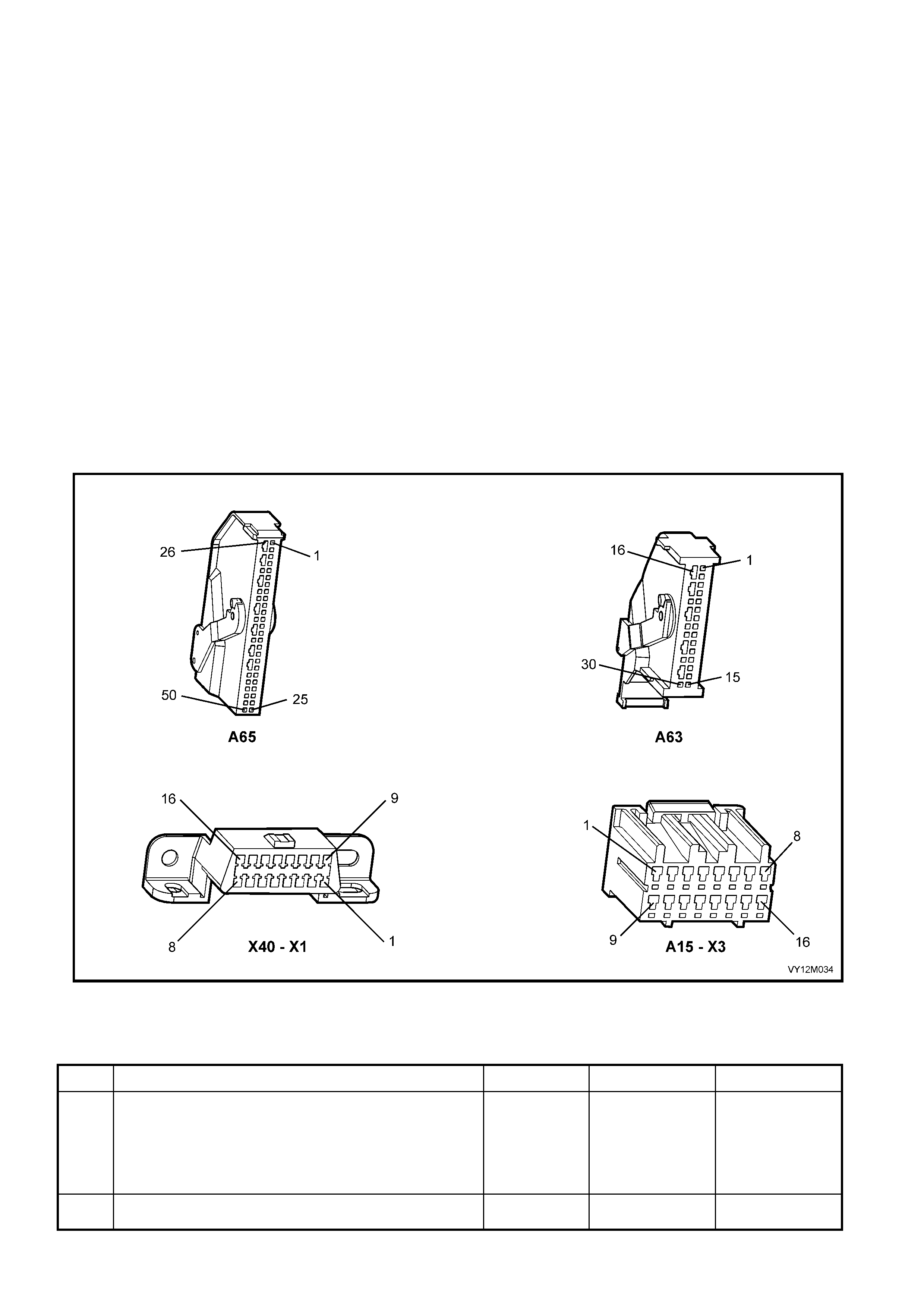
TEST DESCRIPTION:
The following numbers refer to Section step numbers in diagnostic chart ‘A’:
1-2. This test is a function check of the SRS warning indicator during a system self check.
3. Checks to see if TECH 2 can communicate with the SDM.
4. Uses TECH 2 to check for DTCs.
5. If TECH 2 is unable to com m unicate with the BCM and PCM , there is a f ault (sh ort to earth) in the seri al data
communication circuit (circuits 1061 or 800).
6. Checks fuse F26 and circuit 739 for short to earth.
7. Checks for power to SDM.
8. Checks continuity of earth circuit 1051.
9. Checks earth connection at SDM.
10. Checks for continuity in circuit 774 between SDM and BCM to determine if SDM is faulty.
11. Checks if fault is with BCM or open in circuit 774 between BCM and SDM.
NOTES ON DIAGNOSTIC CHART:
1. Refer to 4.4 TECH 2 DIAGNOSTICS in this Section for connecting and using TECH 2.
2. Refer to Section 12P WIRING DIAGRAMS for procedures on checking wiring faults.
3. To ensure none of the other control modules on the serial data circuit are causing this voltage problem,
unplug each control module, one at a time, to isolate the short to voltage.
Figure 12M-158
CHART A – DIAGNOSTIC CIRCUIT CHECK
STEP ACTION VALUE YES NO
1. 1. Turn ignition on while monitoring the SRS warning
indicator in the instrument cluster.
Does the SRS warning indicator illuminate?
Go to Step 2. Go to CHART B
– ‘SRS’
WARNING
INDICATOR
INOPERATIVE,
in this Section.
2. After five seconds of the igniti o n being switched on, does
the SRS warning indicator turn off and remain off? Fault not present. Go to Step 3

STEP ACTION VALUE YES NO
3. 1. Connect TECH 2 to DLC (refer to Section NOTE 1
on the previous page).
2. Select Body / SRS / Turn ignition ON
Does TECH 2 display System Identification (ie. SDM part
number)?
Go to Step 4. Go to Step 5
4. 1. With TECH 2 connected, select Body / SRS /
Diagnostic Trouble Codes / Read DTC Information.
Are there any DTCs set?
Check and repair
fault causing
DTC to set, refer
to Section
relevant
diagnost ic cha rt
in this Section.
Go to CHART C
‘SRS’ WARNING
INDICATOR
ILLUMINATED
(NO DTC’S
STORED), in this
Section.
5. 1. With TECH 2 connected and ignition on, select Body
/ DTC Check / F0: DTC Check and press the
‘Confirm’ soft key as instructed.
Can TECH 2 communicate with the BCM and PCM of
the vehicle (if NO DATA is displayed next to a control
module, then there is no communication between TECH
2 and that particular contr ol m odule) ?
Go to Step 6 Go to BCM
diagnostics in
Section 12J
BCM.
6. 1. Check SDM fuse F26 in instrument panel
compartment.
Is fuse OK?
Go to Step 7. Check and repair
short to earth in
circuit 739.
Replace fuse
F26. Recheck
and verify repair
7. 1. Turn Ignition off.
2. Disconnect SDM connector A63/A65 – X1
3. Using OPS / SRS test lead set KM-609-20, turn
ignition ON and measure voltage between the SDM
connector A63/A65 – X1, terminal 5, circuit 739
(Pink/Black wire) and earth (refer to Section NOTE 2
on previous page).
Is voltage as specified?
Battery + Go to Step 8. Check and repair
open in circuit
739. Recheck
and verify repair.
8. 1. Turn ignition OFF.
2. With SDM connector A63/A65 – X1 disconnected,
and using OPS / SRS test lead set KM-609-20,
check for continuity between SDM connector
A63/A65 – X1, terminal 8, circuit 1051 (Black/White
wire) and earth at location GP11, connector X118 –
G4 (refer to Section NOTE 2 on previous page).
Does continu ity ex ist?
Go to Step 9. Repair open in
earth circuit 1051
as necessary.
Recheck and
verify repair.
9. 1. Turn ignition OFF.
2. Check for continuity between SDM earth (location
GP11, connector X118 – G4) and a known good
earth (refer to Section NOTE 2 on previous page).
Does continuity exist?
Go to Step 10. Repair earth as
necessary.
Recheck and
verify repair.
10. 1. Disconnect SDM connector A63/A65 – X1.
2. Check for continuity in circuit 774 (White/Green
wire) between BCM and SDM by back probing BCM
connector A15X2, terminal 9 and SDM connector
A63/A65 – X1, terminal 9 using OPS / SRS test lead
set KM-609-20 (refer to Section NOTE 2 on previous
page).
NOTE: Use OPS / SRS test lead set KM-609-20 to
probe terminals on connectors A63/A65 – X1 and
A15X2.
Does continu ity ex ist?
Replace SDM,
refer to Section
2.8 INFLATABLE
RESTRAINT
CONTROL
MODULE in this
Section. Recheck
circuit to verify
repair.
Go to Step 11.
11. 1. Disconnect BCM connector A15 – X2.
2. With SDM connector A63/A65 – X1 disconnected,
check for continuity between BCM connector
A15X2, terminal 9 and SDM connector A63/A65 –
X1, terminal 6 (refer to Section NOTE 2 on previous
page).
NOTE: Use OPS / SRS test lead set KM-609-20 to
probe terminals on connector A63/A65 – X1.
Does continuity exist?
Replace BCM,
refer to Section
12J BCM.
Repair open in
circuit 774
between SDM
and BCM.
Recheck and
verify repair.
WHEN ALL DIAGNOSIS AND REPAIRS ARE COMPLETED, ENSURE ALL OPS / SRS COMPONENTS ARE
RECONNECTED, CLEAR ALL DTC’s, ENABLE THE OPS / SRS AND VERIFY CORRECT OPERATION

CHART B – SRS WARNING INDICATOR INOPERATIVE
Figure 12M-159
CIRCUIT DESCRIPTION
Battery voltage is supplied to the SRS warning indicator with the ignition switch in the IGN or START positions
through fuse F13 (located in the passenger compartment fuse panel). To illuminate the indicator, the inflatable
restraint control module (SDM) sends a serial data message to the instrument cluster, requesting the SRS
Indicator to illuminate.
The SRS warning indicator will be illuminated when:
• The ignition is switched on (system wiring and self-check) and if no faults are detected, the SRS warning
indicator will be turned off.
• If communication is lost between the SDM and the instrument cluster.
• If the instrument cluster has not been programmed for the vehicle configuration; 2, 3, 4 or 6 loop system
(configuration problem).
• If battery voltage is below 8 volts or above 21.2 volts.

• If the OPS / SRS is deployed.
• If one or m ore cur rent or hi story Diagnos tic Tr ouble Codes ( DTCs) are detected when the ig nition is switche d
on.
• During an ignition cycle, if the SDM detects a current DTC, the SRS warning indicator will be illuminated.
• If the energy reserve in the SDM is switched on (battery voltage less than 7.5 volts).
TEST DESCRIPTION:
The following numbers refer to Section step numbers in diagnostic chart ‘B’:
1. This test checks for any DTCs that may cause the SRS warning indicator to be inoperative.
2. This test determines if the SDM is faulty by using TECH 2 to drive the warning indicator on.
3. This is a simple test to determine if power is being supplied to the instrum ent cluster warning indicators (the
OPS / SRS and ABS warning indicators share a common power source).
4. This test checks for a faulty voltage supply to the warning indicator.
CHART B – SRS WARNING INDICATOR INOPERATIVE
STEP ACTION VALUE YES NO
1. 1. Install TECH 2 to DLC and select Body / SRS /
Diagnostic Trouble Codes / Read DTC Information
(refer to Section NOTE 1 on previous page).
Are any DTCs set?
Repair conditions
which set DTCs.
Recheck and
verify repair.
Go to Step 2.
2. 1. With TECH 2 still connected, select Body /
Instruments / Miscellaneous Tests / Indicators and
command the SRS warning indicator on (refer to
Section NOTE 1 on previous page).
Does SRS warning indicator illuminate?
Replace SDM,
refer to Section
2.8 INFLATABLE
RESTRAINT
CONTROL
MODULE in this
Section. Recheck
circuit to verify
repair.
Go to Step 3.
3. 1. Disconnect TECH 2 from DLC.
2. Turn ignition on whilst observing ABS warning
indicator.
Does ABS warning indicator illuminate for approximately
5 seconds then turn off?
Fault not present.
Check all system
wiring harness
connect ors and
terminals. Repair
as necessary and
recheck system
to verify repair.
Go to Step 4
4. 1. Remove instrument cluster, refer to Section 12C
INSTRUMENTS, WIPERS/WASHERS AND HORN.
Switch ignition on and measure voltage between
connector P3, terminal 20, circuit 539 (Pink/Blue wire)
and earth (refer to Section NOTE 2 on previous page).
Is voltage as specified?
Battery + Fault not present.
Check all system
wiring harness
connect ors and
terminals. Repair
as necessary and
recheck system
to verify repair.
Check fusible link
F105 and fuse
F13. Check
wiring between
ignition sw itch
and instrument
cluster con nec tor
P3. Check
ignition sw itch
contacts.
Recheck circuit
to verify repair.
WHEN ALL DIAGNOSIS AND REPAIRS ARE COMPLETED, ENSURE ALL OPS / SRS COMPONENTS ARE
RECONNECTED, CLEAR ALL DTC’s, ENABLE THE OPS / SRS AND VERIFY CORRECT OPERATION
Figure 12M-160
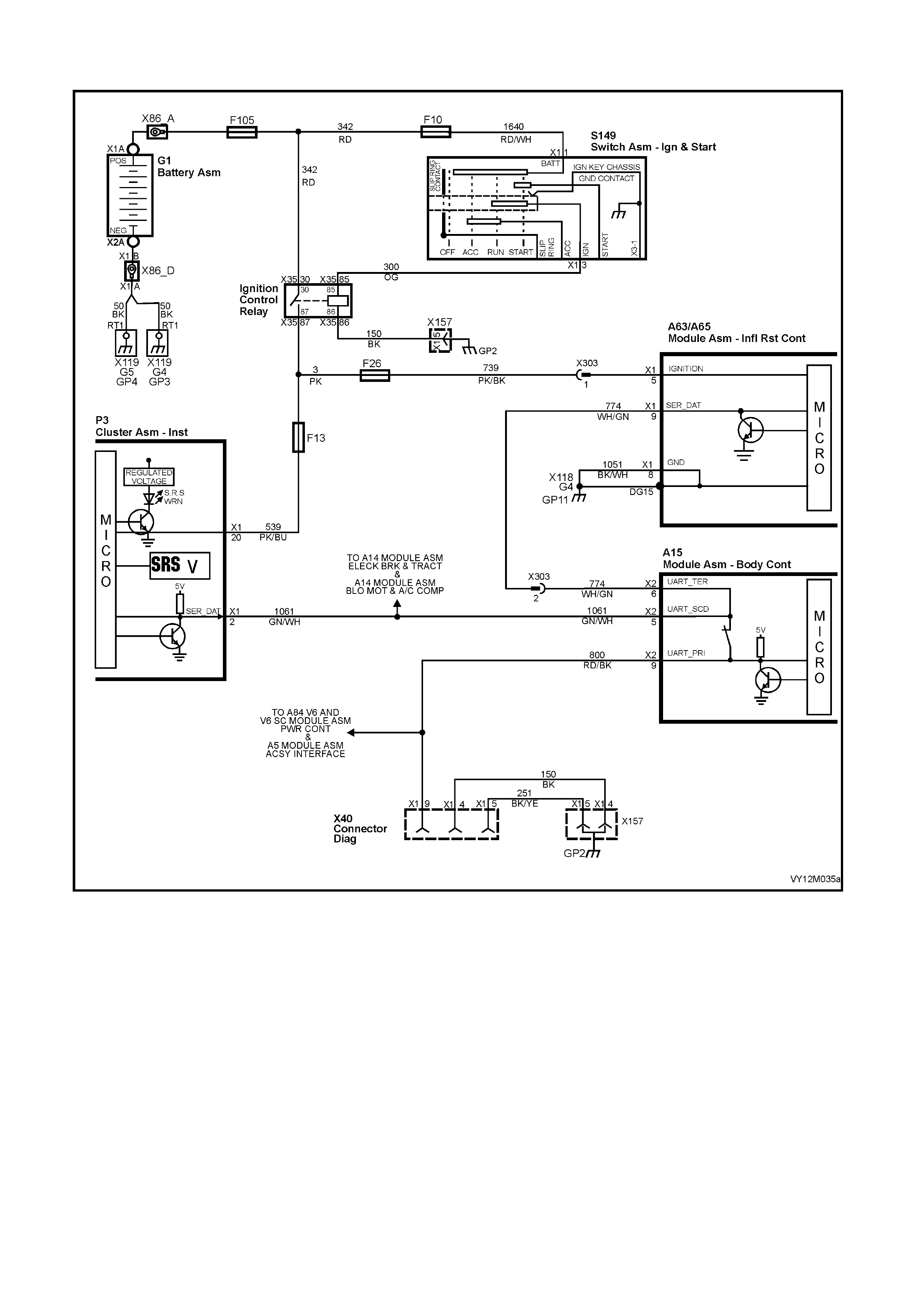
CHART C – SRS WARNING INDICATOR ILLUMINATED (NO DTC STORED)
Figure 12M-161

CIRCUIT DESCRIPTION
Battery voltage is supplied to the SRS warning indicator with the ignition switch in the IGN or START positions
through fuse F13 (located in the passenger compartment fuse panel). To illuminate the indicator, the inflatable
restraint control module (SDM) sends a serial data message to the BCM via circuit 774, the BCM sends a serial
data message to the instrument cluster via circuit 1061, requesting the SRS Indicator to illuminate.
When the ignition is switched on, the SRS warning indicator should illuminate for approximately five seconds to
indicate the system start up sequence / system wiring and self check. If no system faults are detected, the SRS
warning indicator will be switched off.
If a fault is detected (either during this system check or during the ignition cycle), the SRS warning indicator will
either remain on until the fault is remedied or if a DTC is set, until it is cleared. If a fault is remedied during an
ignition cycle, unless the fault caused a DTC to set, the SRS warning indicator will turn off immediately.
The OPS / SRS SDM will send a serial data message to the instrument cluster requesting the indicator be
illuminated if it detects any of the following:
1. If battery voltage is below 8 volts or above 21.2 volts.
2. If the energy reserve in the SDM is switched on (battery voltage less than 7.5 volts).
3. If the OPS / SRS is deployed.
4. If the SDM does not receive a poll from the BCM.
5. If one or more current or history DTCs are detected when the ignition is switched ON.
6. During an ignition cycle, if the SDM detects a current DTC.
The SRS warning ind icator wil l also b e illum inated if c omm unication is los t (no ser ial data) bet ween the SDM and
the instrument cluster.
TEST DESCRIPTION:
The following numbers refer to Section step numbers in diagnostic chart ‘C’:
1. Ensures the D iagnos tic C ircuit Ch ec k was per f or med which deter mines if there is a s eria l d ata comm unic ati on
fault and checks if any DTCs are set.
2. Checks if fault is current or intermittent.
3. Using TECH 2, this step checks the voltage supply to the SDM . If battery voltage to the SDM falls below 8
volts or above 21.2 volts for more than 3 seconds, the SRS warning indicator is switched on.
4. Checks generator output.
5. Determines if the ignition input voltage at the inflatable restraint control module (SDM) is approximately the
same as what the generator output voltage was during Step 5.
6. Checks continuity of earth circuit 1051.
7. Checks earth connection at SDM , location GP11, connector X118 – G4.
8. Using TECH 2, this step checks if the energy reserve has been switched on. If the voltage suppl y to the SDM
falls below 7.5 volts, the energy reserve in the SDM is switched on.
9. Using TECH 2, this step checks if the SDM has deployed the OPS / SRS.
10. If TECH 2 is unable to drive the SRS warning indicator on and off, it indicates fault is within the instrument
cluster.
NOTES ON DIAGNOSTIC CHART:
Refer to 4.4 TECH 2 DIAGNOSTICS in this Section for connecting and using TECH 2.
1. Refer to Section 12P WIRING DIAGRAMS for procedures on checking wiring faults.
2. F ault Int erm ittent; conn ect T ECH 2 to DLC, s elect F 3 Body / SR S / DAT A DI SPLA Y and m onitor the f ollowin g
to see if TECH 2 display changes state while wiggling circuit wires and/or road testing vehicle:
a. Battery voltage (after 3 sec)
b. Module deployed
c. Energy reserve
d. Configuration from instruments
e. BCM poll
Repair fault as necessary, recheck circuit to verify repair.
3. Refer to Section 6D1-1 CHARGING SYSTEM – V6 ENGINE or Section 6D3-1 CHARGING SYSTEM –
V8 ENGINE for generator testing details.
4. If the vehicle is involved in an accident in which the OPS / SRS was deployed (even if only pretensioners
where deployed) refer to Section for information on system components that need to be replaced.
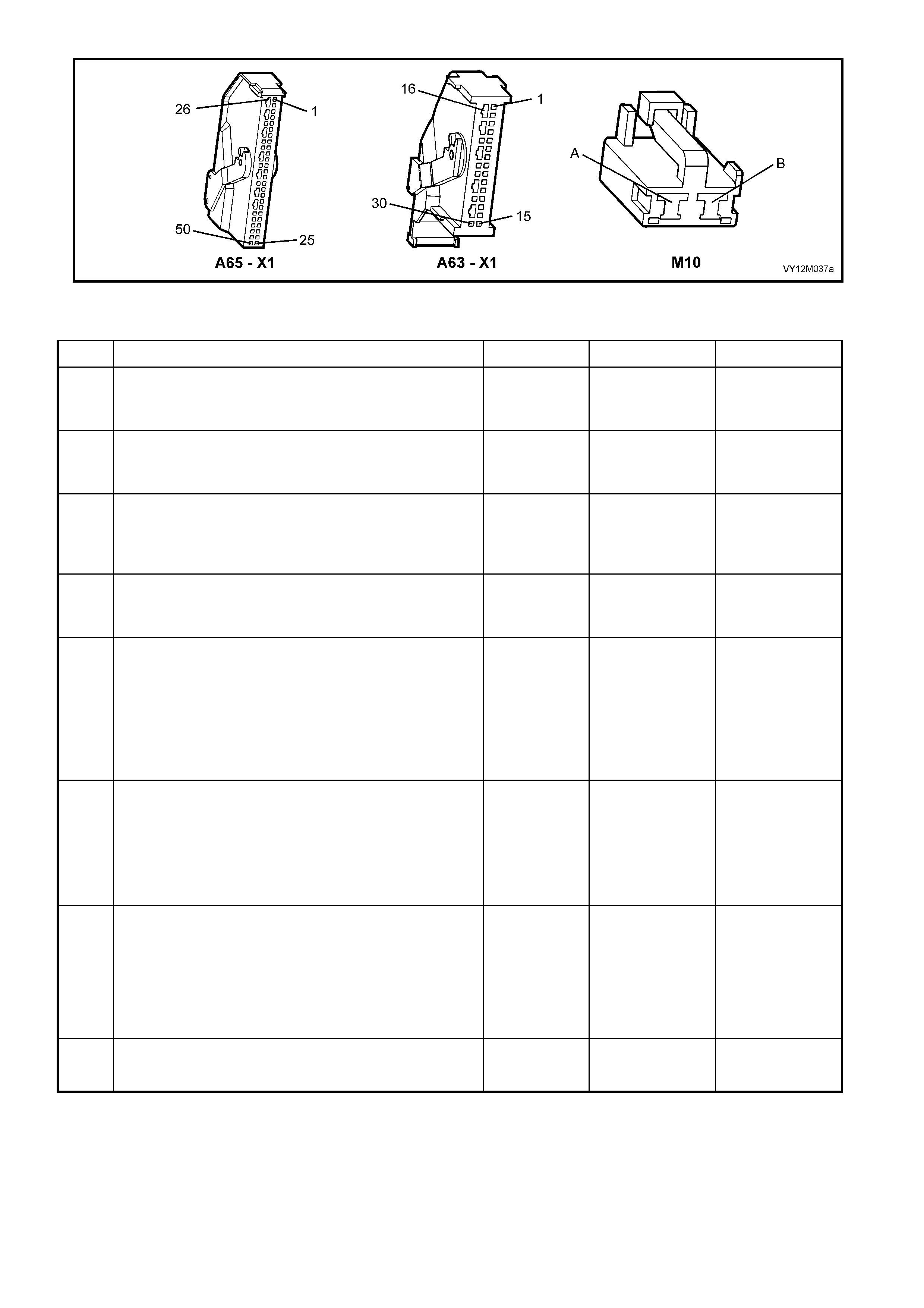
Figure 12M-162
CHART C – SRS WARNING INDICATOR ILLUMINATED (NO DTC’S SET)
STEP ACTION VALUE YES NO
1. Was the Diagnostic Circuit Check preformed? Go to Step 2. Go to CHART A
– DIAGNOSTIC
CIRCUIT CHECK
in this Section.
2. 1. Turn ignition on.
Does SRS warning indicator remain illuminated after 5
seconds?
Go to Step 3. Fault intermittent,
refer to Section
NOTE 3 on
previous page.
3. 1. With TECH 2 connected, and Body / SRS / Data
Display selected, scroll to BATTERY VOLTAGE
(AFTER 3 SECONDS).
Does TECH 2 display battery voltage (after 3 seconds) is
OKAY?
Go to Step 8. Go to Step 4.
4. 1. Carry out checks of generator output (refer to
Section NOTE 4 on previous page).
Is generator output OK?
Go to Step 5. Repair generator
as necessary.
Recheck and
verify repair.
5. 1. Disconnect the SDM connector A63/A65 – X1.
2. Start engine, turn headlamps on and raise engine
idle speed to approximately 2500 RPM.
3. Using Tool KM-609-20, check voltage between SDM
wiring harness connector A63/A65 – X1, terminal 5,
circuit 739 and a known good earth (refer to Section
NOTE 2 on previous page).
Is the voltage measured approximately the same as
measured during Step 4 (generator output tests)?
Go to Step 6. Check and repair
circuit 739 as
necessary.
Recheck and
verify repair.
6. 1. Turn ignition off.
2. With SDM connector A63/A65 – X1 disconnected,
and using OPS / SRS test lead set KM-609-20,
check for continuity between SDM connector
A63/A65 – X1, terminal 8, circuit 1051 (Black/White
wire) and earth at location GP11, connector X118 –
G4 (refer to Section NOTE 2 on previous page).
Does continu ity ex ist?
Go to Step 7. Repair open in
earth circuit 1051
as necessary.
Recheck and
verify repair.
7. 1. Check for continuity between SDM earth location
GP11, connector X118 – G4 and a known good
earth (refer to Section NOTE 2 on previous page).
Does continu ity ex ist?
Replace SDM,
refer to Section
2.8 INFLATABLE
RESTRAINT
CONTROL
MODULE in this
Section. Recheck
circuit to verify
repair.
Repair earth as
necessary.
Recheck and
verify repair.
8. 1. With TECH 2 connected, and Body / SRS / Data
Display selected, scroll to ENERGY RESERVE.
Does TECH 2 display energy reserve off?
Go to Step 9. Go to Step 4.

STEP ACTION VALUE YES NO
9. 1. With TECH 2 connected, and Body / SRS / Data
Display selected, scroll to MODULE HAS
DEPLOYED.
Does TECH 2 display MODULE HAS DEPLOYED YES?
Replace SDM,
refer to Section
2.8 INFLATABLE
RESTRAINT
CONTROL
MODULE in this
Section.
(see NOTE 4 on
previous page).
Recheck circuit
to verify repair.
Go to Step 10.
10. 1. W ith TECH 2 connected, select Body / Instruments /
Miscellaneous Tests / Indicators / SRS Indicator.
2. Using the UP and DOWN keys on TECH 2, drive the
SRS warning indicator on and off.
Is TECH 2 able to drive the SRS warning indicator on
and off?
Replace SDM,
refer to Section
2.8 INFLATABLE
RESTRAINT
CONTROL
MODULE in this
Section.
Recheck circuit
to verify repair.
Replace
instrument
cluster assembly,
refer Section 12C
INSTRUMENTS,
WIPERS /
WASHERS &
HORN.
WHEN ALL DIAGNOSIS AND REPAIRS ARE COMPLETED, ENSURE ALL OPS / SRS COMPONENTS ARE
RECONNECTED, CLEAR ALL DTC’s, ENABLE THE OPS / SRS AND VERIFY CORRECT OPERATION
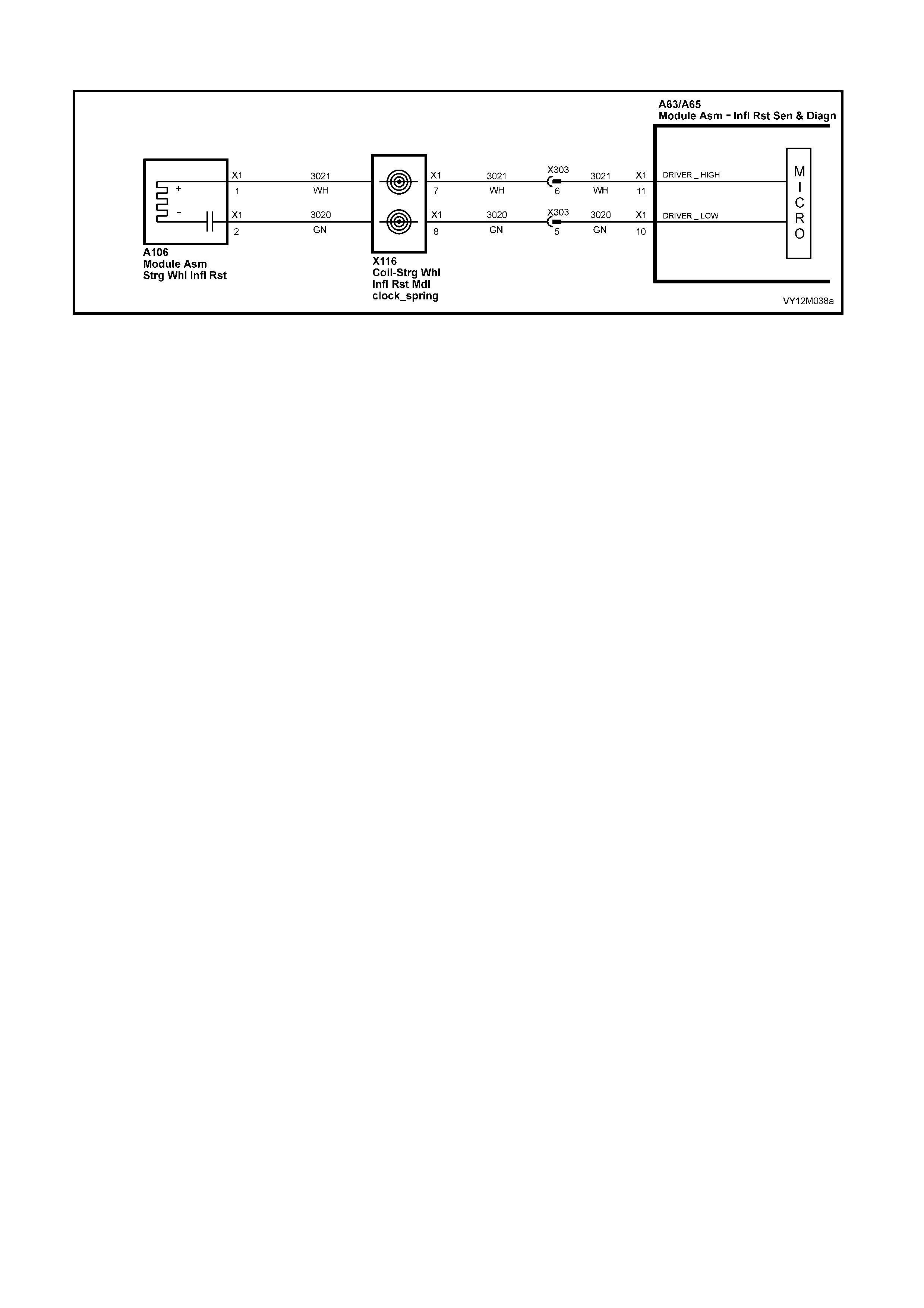
DTC 17 – DRIVER’S AIRBAG CIRCUIT SHORT TO BATTERY
Figure 12M-163
CIRCUIT DESCRIPTION
At igniti on on, an d on a c o n s tant monitori ng cycle of every 500 m ill is ec on ds duri ng the ig nit ion cycle, t he inf lat abl e
restraint control module (SDM) performs a system self check.
If the SDM detects a resistance to battery supply is less than 5 kohms in either the positive and/or the negative
circuit for more than 3 – 5 seconds, a current DTC 17 will set (refer to 4.3 OPS / SRS SELF DIAGNOSTICS in
this Section for more details)
A DTC 17 will set if circuits 3021 (driver’s airbag positive side) and/or 3020 (driver’s airbag negative side) are
shorted to battery +.
When DTC 17 sets, the SDM illuminates the SRS warning indicator and sets a current DTC 17. Should the fault
conditions detected by the SDM clear during the same ignition cycle, the current code will clear and become a
history DTC 17. The SRS warning indicator will remain on for the remainder of the ignition cycle.
If a DTC 17 is set, the SRS warning indicator is illuminated on each ignition cycle, even if the DTC is set as a
histor y DTC, until the f ault condit ions f or setting DT C 17 are r ectif ied an d the DTC ( current or histor y) can th en be
cleared from the SDM via TECH 2.
If DTC 17 is set, the OPS / SRS, including the driver’s airbag, will still be operational due to the reserve energy
supply stored in the SDM.
TEST DESCRIPTION
The following numbers refer to Section step numbers in the following diagnostic chart.
1. Uses TECH 2 to check if DTC 17 is current or history.
2. Check s for interm ittent fault b y m onitoring TECH 2 s creen displa y. If scr een display chan ges during a ‘wigg le’
test, a fault with the wiring is at that location.
3. Checks circuits 3021 and 3020 for a short to battery +.
NOTES ON DIAGNOSTIC CHART
1. For all wiring harness checking procedures, refer to Section 12P WIRING DIAGRAMS.
2. Refer to 2.11 OPS / SRS WIRING REPAIR in Section 12M OCCUPANT PROTECTION SYSTEM, before
conducting any OPS / SRS wiring harness repairs.
3. Resistance cannot be measured between the two terminals in connector A106 – X1 as the in-built capacitor
blocks measurement. Therefore, a ‘service hole’ is incorporated into the connector for fault tracing. Refer to
1.1 SYSTEM COMPONENTS, WIRING HARNESS in this Section for more details on this type of connector.
4. W iring should be check ed at the point where TECH 2 s creen dis play cha nged status . If nec essar y, split ope n
harness.
5. If the fault can not be identified, the harness should be replaced.
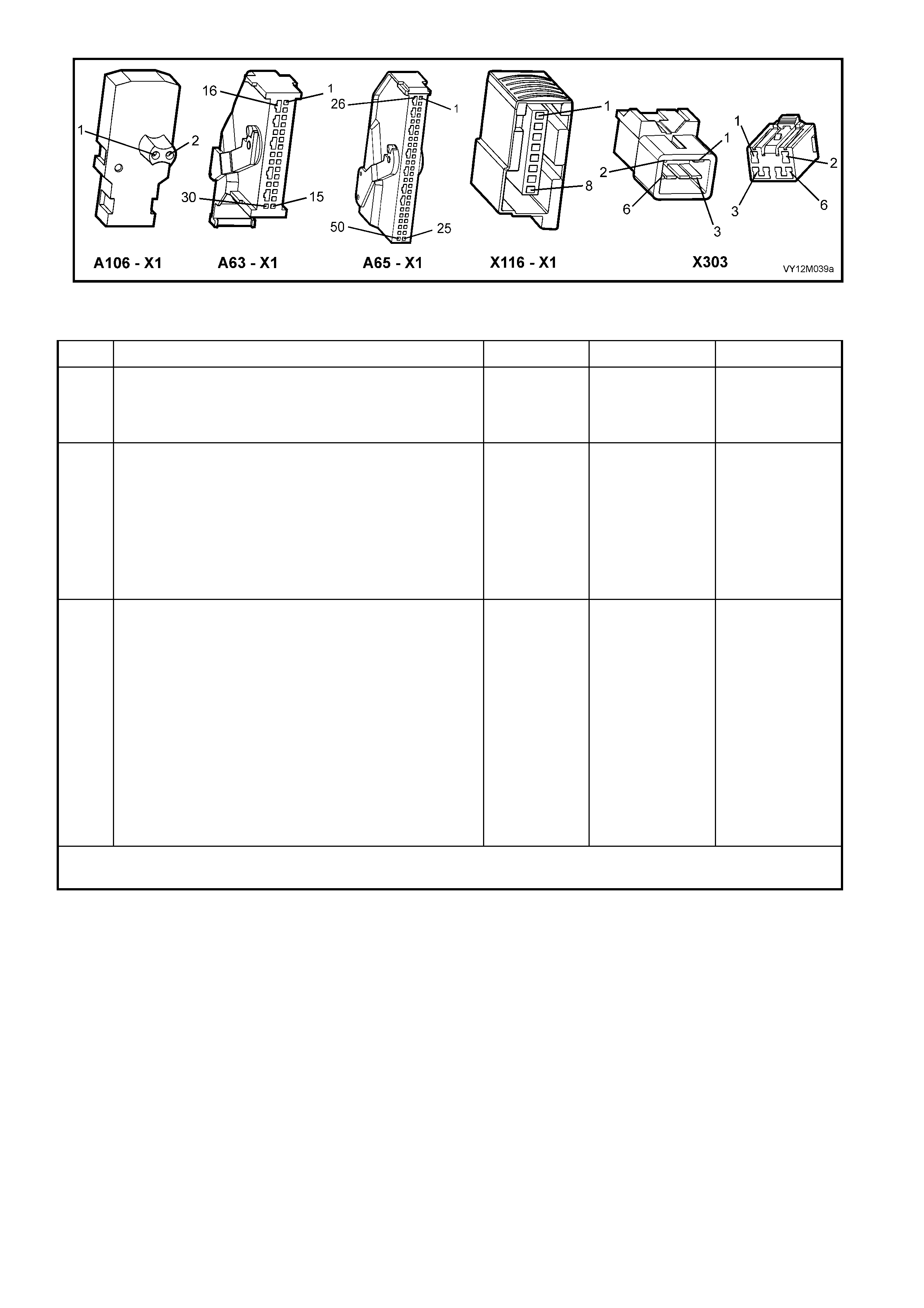
Figure 12M-164
DTC 17 – DRIVER’S AIRBAG CIRCUIT SHORT TO BATTERY
STEP ACTION VALUE YES NO
1. 1. Connect TECH 2 to DLC.
2. Select Body / SRS / Diagnostic Trouble Codes /
Read DTC Information.
Is DTC 17 current?
Go to Step 3. Go to Step 2..
2. 1. Remove steering column upper and lower cover.
2. With TECH 2 still connected, select Diagnostic
Trouble Codes / Clear DTC Information and clear all
(if any) DTCs.
3. Select Diagnostic Trouble Codes / Read DTC
Information, 'wiggle' OPS / SRS wiring harness at all
locations between the SDM and the clock spring coil
and monitor TECH 2 screen display.
Does TECH 2 screen display change status from No
Diagnostic Trouble Codes?
Make repairs as
necessary (refer
NOTE 2 & 4 on
previous page).
Clear DTC and
recheck system
to verify repair.
Fault not present.
Check all system
wiring harness
connect ors and
terminals, refer to
Section NOTE 5
on previous
page.
Clear DTC and
recheck system.
3. 1. Disable the OPS / SRS, refer to Section 2.2 SYTEM
DISABLING AND ENABLING PROCEDURE in this
Section.
2. Remove driver’s airbag module, refer to Section 2.3
STEERING WHEEL INFLATABLE RESTRAINT
MODULE ASSEMBLY in this Section.
3. Disconnect the SDM wiring harness connector
A63/A65 – X1 from the SDM.
4. Reconnect battery.
5. Using Tool KM-609-20, check wiring between SDM
wiring harness connector A63/A65 – X1, terminals
10 and 11 and driver’s airbag connector A106 – X1,
circuits 3021 (White wi re) and 3020 (Green wire) for
short to battery + (refer to Section NOTES 1 and 3
on previous page).
Is all OK?
Replace SDM,
refer to Section
2.8 INFLATABLE
RESTRAINT
CONTROL
MODULE in this
Section. Recheck
circuit to verify
repair.
Make repairs as
necessary (refer
to Section NOTE
2 on previous
page).
Clear DTC and
recheck system
to verify repair.
WHEN ALL DIAGNOSIS AND REPAIRS ARE COMPLETED, ENSURE ALL OPS / SRS COMPONENTS ARE
RECONNECTED, CLEAR ALL DTC’s, ENABLE THE OPS / SRS AND VERIFY CORRECT OPERATION

DTC 18 – DRIVER’S AIRBAG CIRCUIT SHORT TO EARTH
Figure 12M-165
CIRCUIT DESCRIPTION
At ignition on and on a constant monitoring cycle of every 500 milliseconds during the ignition cycle, the
inflatabl e rest raint c ontrol m odule (SDM) perf orm s a system s elf check . If the SDM det ects a resis tance t o earth
of less tha n 3 kohms in ei th er the pos i ti ve or n egat i ve inflator circ ui t f or more than 3 – 5 s econds, a c urr ent D T C
18 will set (refer to 3.3 OPS / SRS SELF DIAGNOSTICS in this Section for more details)
DTC 18 will set if circuits 3021 (driver’s airbag positive side) and/or 3020 (driver’s airbag negative side) are
shorted to earth.
When DTC 18 sets, the SDM illuminates the SRS warning indicator and sets a ‘current’ DTC 18. Should the
fault conditions detected by the SDM clear during the same ignition cycle, the current code will clear and
become a history DTC 18. The SRS warning indicator will remain on for the remainder of the ignition cycle.
If a DTC 18 is set, the SRS warning indicator is illuminated on each ignition cycle, even if the DTC is set as a
histor y DTC, until the fault condit ions for s etting DTC 18 are rectified an d the DTC (c urrent or histor y) ca n then
be cleared from the SDM via TECH 2.
If DT C 18 is set, the OPS / SRS, including the dri ver’s airb ag, will still be operati onal du e to the r eserve energy
supply stored in the SDM.
TEST DESCRIPTION
The following numbers refer to Section Step numbers in the following diagnostic chart.
1. Uses TECH 2 to check if DTC 18 is current or history.
2. TECH 2 in this mode should display approximately 2.0 – 6.4 ohms if the driver’s airbag loop circuit is OK.
3. If screen display changes during a wiring 'wiggle' test, a fault with the wiring is at that location.
4. Tool SD28280B is a dummy load taking the place of the driver’s airbag module. If TECH 2 displays the
correct resistance of the dummy load, the system fault is in the driver’s airbag module assembly.
5. This test checks the wiring between the SDM wiring harness connector A65 – X1 (8.1 SDM) or A63 – X1
(8.0 SDM), terminal 11 and the driver’s airbag module connector A106 – X1 for faults.
6. This test checks the wiring between the SDM wiring harness connector A65 – X1 (8.1 SDM) or A63 – X1
(8.0 SDM), terminal 10 and the driver’s airbag module connector A106 – X1 for faults.
NOTES ON DIAGNOSTIC CHART
1. For all wiring harness checking procedures, refer to Section 12P WIRING DIAGRAMS.
2. Refer to 2.11 OPS / SRS WIRING REPAIR in Section 12M OCCUPANT PROTECTION SYSTEM, before
conducting any OPS / SRS wiring harness repairs.
3. Refer to Section 12O FUSES & WIRING HARNESSES for OPS / SRS wiring harness routing.
4. Resistance cannot be measured between the two terminals in connector A106 – X1 as the in-built capacitor
blocks measurement. Therefore, a ‘service hole’ is incorporated into the connector for fault tracing. Refer to
1.1 SYSTEM COMPONENTS, WIRING HARNESS in this Section for more details on this type of connector.
5. Wiring should be checked at point where TECH 2 screen display changed. If necessary, split open wiring
harness.
6. If the fault cannot be identified, the wiring harness should be replaced.
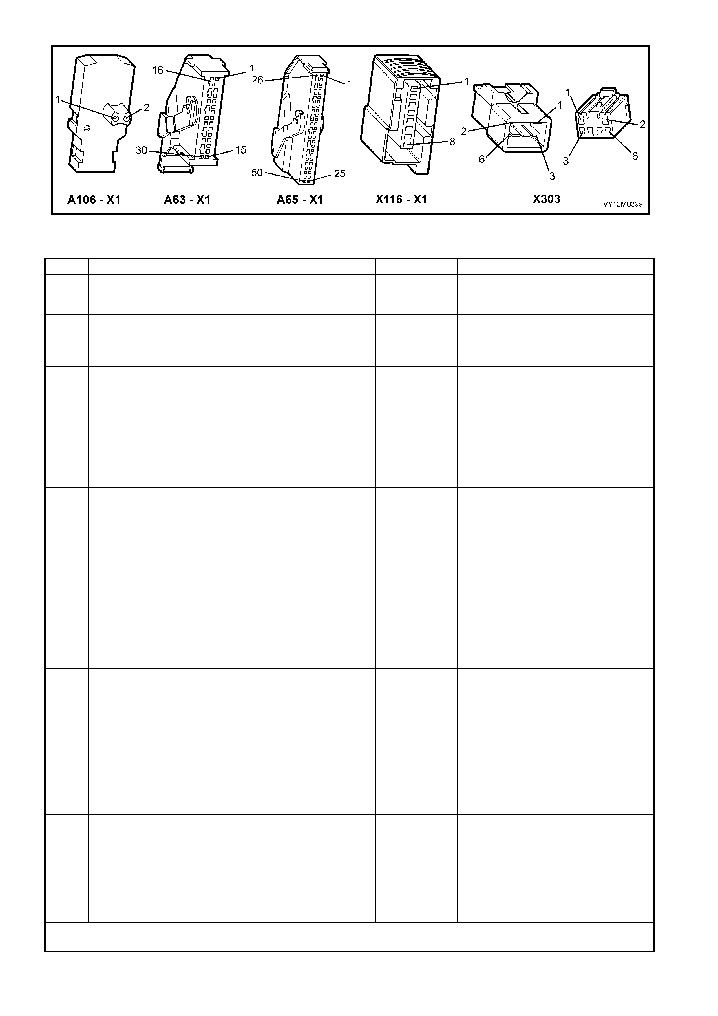
Figure 12M-166
DTC 18 – DRIVER’S AIRBAG CIRCUIT SHORT TO EARTH
STEP ACTION VALUE YES NO
1. 1. Connect TECH 2 to DLC and select Body / SRS /
Diagnostic Trouble Codes / Read DTC Information.
Does TECH 2 display DTC 18 as a Current DTC?
Go to Step 2. Go to Step 3.
2. 1. With TECH 2 still connected, select Body / SRS /
Data Display and scroll to DRIVER’S AIRBAG
LOOP RESISTANCE.
Is value displayed on TECH 2 as specified?
Approx.
2.0 – 6.4
Ohms
Go to Step 3. Go to Step 4.
3. 1. Remove steering column upper and lower cover.
2. With TECH 2 still connected, select Diagnostic
Trouble Codes / Clear DTC Information and clear all
(if any) DTCs.
3. Select Diagnostic Trouble Codes / Read DTC
Information, 'wiggle' OPS / SRS wiring harness at all
locations between the SDM and the clock spring coil
and monitor TECH 2 screen display.
Does TECH 2 screen display change status from No
Diagnostic Trouble Codes?
Make repairs as
necessary (refer
to Section
NOTES 2 & 5 on
previous page).
Clear DTC and
recheck system
to verify repair.
Fault not present.
Check all system
wiring harness
connectors, and
terminals, refer to
Section NOTE 6
on previous
page.
Clear DTC and
recheck system.
4. 1. Disable the OPS / SRS, refer to Section 2.2
SYSTEM DISABLING AND ENABLING
PROCEDURE in this Section.
2. Remove driver’s airbag module, refer to Section 2.3
STEERING WHEEL INFLATABLE RESTRAINT
MODULE ASSEMBLY in this Section.
3. Connect Tool No. SD28280B to OPS / SRS wiring
harness connector A106 – X1.
4. Enable the OPS / SRS, refer to Section 2.2
SYSTEM DISABLING AND ENABLING
PROCEDURE in this Section.
5. With TECH 2 still connected, select Body / SRS /
Data Display and scroll to DRIVER’S AIRBAG
LOOP RESISTANCE.
Is value displayed on TECH 2 as specified?
Approx.
3.0 Ohms Replace Driver’s
airbag module
assembly, refer
to Section 2.3
STEERING
W HEEL
INFLATABLE
RESTRAINT
(DRIVER’S
AIRBAG)
MODULE
ASSEMBLY in
this Section.
Clear DTC and
recheck system
to verify repair.
Go to Step 5.
5. 1. Disable the OPS / SRS, refer to Section 2.2
SYSTEM DISABLING AND ENABLING
PROCEDURE in this Section.
2. Disconnect the SDM wiring harness connector
A63/A65 – X1 from the SDM.
3. Remove Tool SD28280B from A106 – X1.
4. Using Tool KM-609-20, check wiring between SDM
wiring harness connector A63/A65 – X1, terminal 11
and driver’s airbag module connector A106 – X1,
circuit 3020 (Green wire) for short to earth (refer to
Section NOTE 1 on previous page).
Is all OK?
Go to Step 6. Make repairs as
necessary (refer
to Section NOTE
2 on previous
page).
Clear DTC and
recheck system
to verify repair.
6. 1. With system disabled, SDM wiring harness
connector A63/A65 – X1 disconnected and using
Tool KM-609-20. Check the wiring between SDM
wiring harness connector A63/A65 – X1, terminal 10
and driver’s airbag module connector A106 – X1,
circuit 3021 (White wire) for a s hort to earth (refer to
Section NOTES 1 and 4 on previous page).
Is all OK?
Replace SDM,
refer to Section
2.8 INFLATABLE
RESTRAINT
CONTROL
MODULE in this
Section.
Recheck circuit
to verify repair.
Make repairs as
necessary (refer
to Section NOTE
2 on previous
page).
Clear DTC and
recheck system
to verify repair.
WHEN ALL DIAGNOSIS AND REPAIRS ARE COMPLETED, ENSURE ALL OPS / SRS COMPONENTS ARE
RECONNECTED, CLEAR ALL DTC’s, ENABLE THE OPS / SRS AND VERIFY CORRECT OPERATION

DTC 19 – DRIVER’S AIRBAG CIRCUIT CAPACITANCE TOO HIGH
Figure 12M-167
CIRCUIT DESCRIPTION
At ignition on, and on a constant monitoring cycle of every 500 milliseconds during the ignition cycle, the
inflatable restraint control module (SDM) performs a system self check.
If the SDM d etects the cap acitance in th e driver’s a irbag circ uit is too h igh (great er than 550 nF) f or longer than
3 – 5 seconds, a current DTC 19 will set (refer to 4.3 OPS / SRS SELF DIANOSTICS in this section for more
details).
DTC 19 will set if the in-built capacitor in the OPS / SRS wiring harness connector A106 – X1 is faulty.
W hen DTC 19 sets, the SD M illuminates the SR S war ning in dicat or and sets a cur rent DT C 19. Should t he fault
conditions detected by the SDM c lear during the same ignition cycle, t he current code will clear and become a
history DTC 19. The SRS warning indicator will remain on for the remainder of the ignition cycle.
If a DTC 19 is set, the SRS warning indicator is illuminated on each ignition cycle, even if the DTC is set as a
histor y DTC, until the fault condit ions for s etting DTC 19 are rectified an d the DTC (c urrent or histor y) ca n then
be cleared from the SDM via TECH 2.
ACTION REQUIRED
If DTC 19 is set, the driver’s airbag may not operate and therefore, the clock spring coil assembly must be
replaced (connector A106 – X1 with the in-built capacitor is part of the clockspring coil assembly). Refer to
2.6 CLOCK SPRING COIL in this Section for the correct procedure on replacing the clock spring coil assembly.
After the clock spring coil assembly has been replaced, ensure that all OPS / SRS components are
reconnected, clear DTCs, enable the OPS / SRS and verify the correct operation of the system (i.e. warning
indicator not illuminated after five seconds of ignition being switched ON).
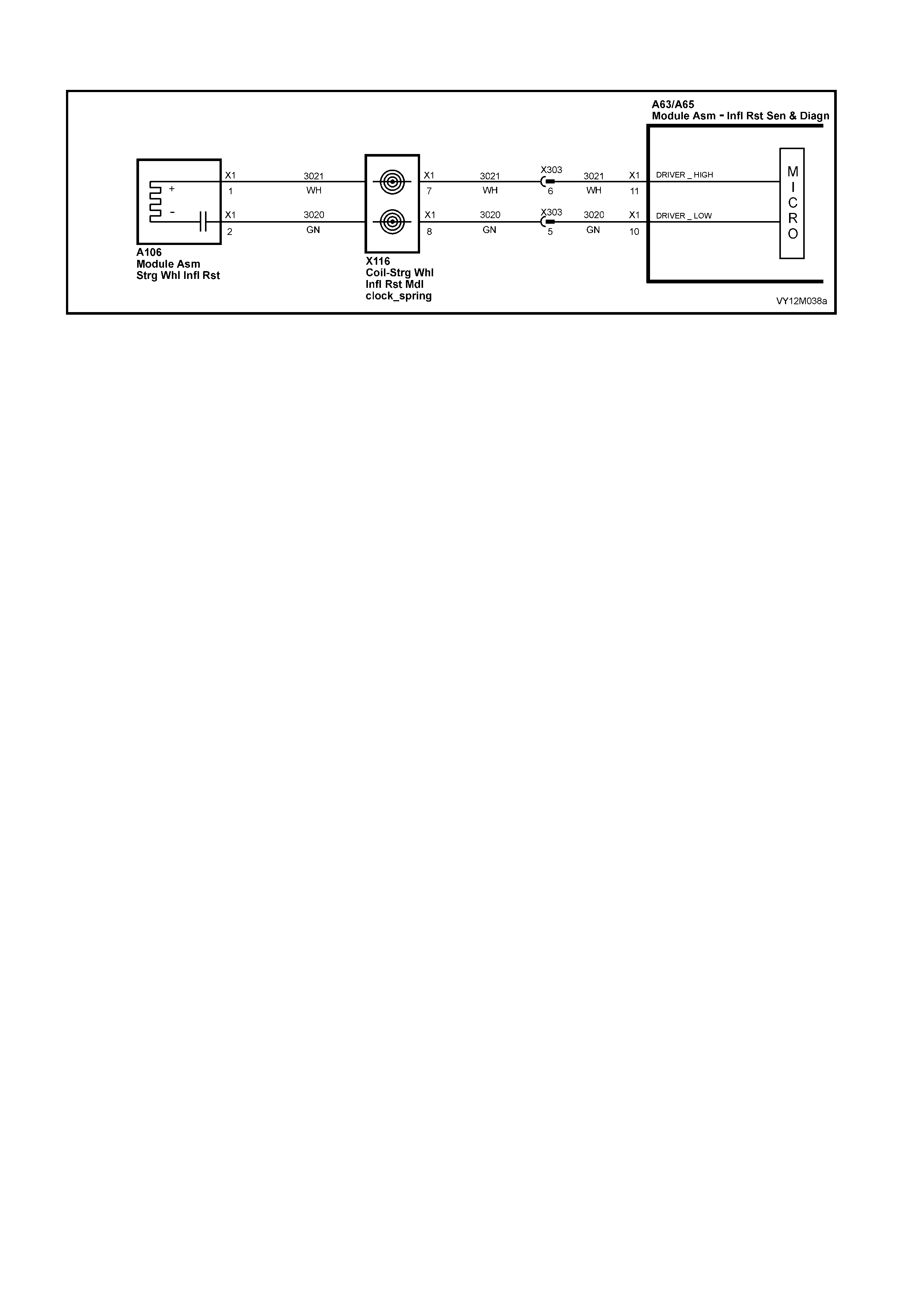
DTC 20 – DRIVER’S AIRBAG CIRCUIT CAPACITANCE TOO LOW
Figure 12M-168
CIRCUIT DESCRIPTION
At ignition on, and on a constant monitoring cycle of every 500 milliseconds during the ignition cycle, the
inflatable restraint control module (SDM) performs a system self check.
If the SDM detects the c apacitance in the dr iver’s a irbag circ uit is too lo w (less th an 390 nF) f or longer than 3 –
5 seconds, a current DTC 20 will set (refer to 4.3 OPS / SRS SELF DIANOSTICS in this section for more
details).
DTC 20 will set if the in-built capacitor in the OPS / SRS wiring harness connector A106 – X1 is faulty.
W hen DTC 20 sets, the SD M illuminates the SR S war ning in dicat or and sets a cur rent DT C 20. Should t he fault
conditions detected by the SDM c lear during the same ignition cycle, t he current code will clear and become a
history DTC 20. The SRS warning indicator will remain on for the remainder of the ignition cycle.
If a DTC 20 is set, the SRS warning indicator is illuminated on each ignition cycle, even if the DTC is set as a
histor y DTC, until the fault condit ions for s etting DTC 20 are rectified an d the DTC (c urrent or histor y) ca n then
be cleared from the SDM via TECH 2.
ACTION REQUIRED
If DTC 20 is set, the driver’s airbag may not operate and therefore, the clock spring coil assembly must be
replaced (connector A106 – X1 with the in-built capacitor is part of the clockspring coil assembly). Refer to
2.6 CLOCK SPRING COIL in this Section for the correct procedure on replacing the clock spring coil assembly.
After the clock spring coil assembly has been replaced, ensure that all OPS / SRS components are
reconnected, clear DTCs, enable the OPS / SRS and verify the correct operation of the system (i.e. warning
indicator not illuminated after five seconds of ignition being switched ON).
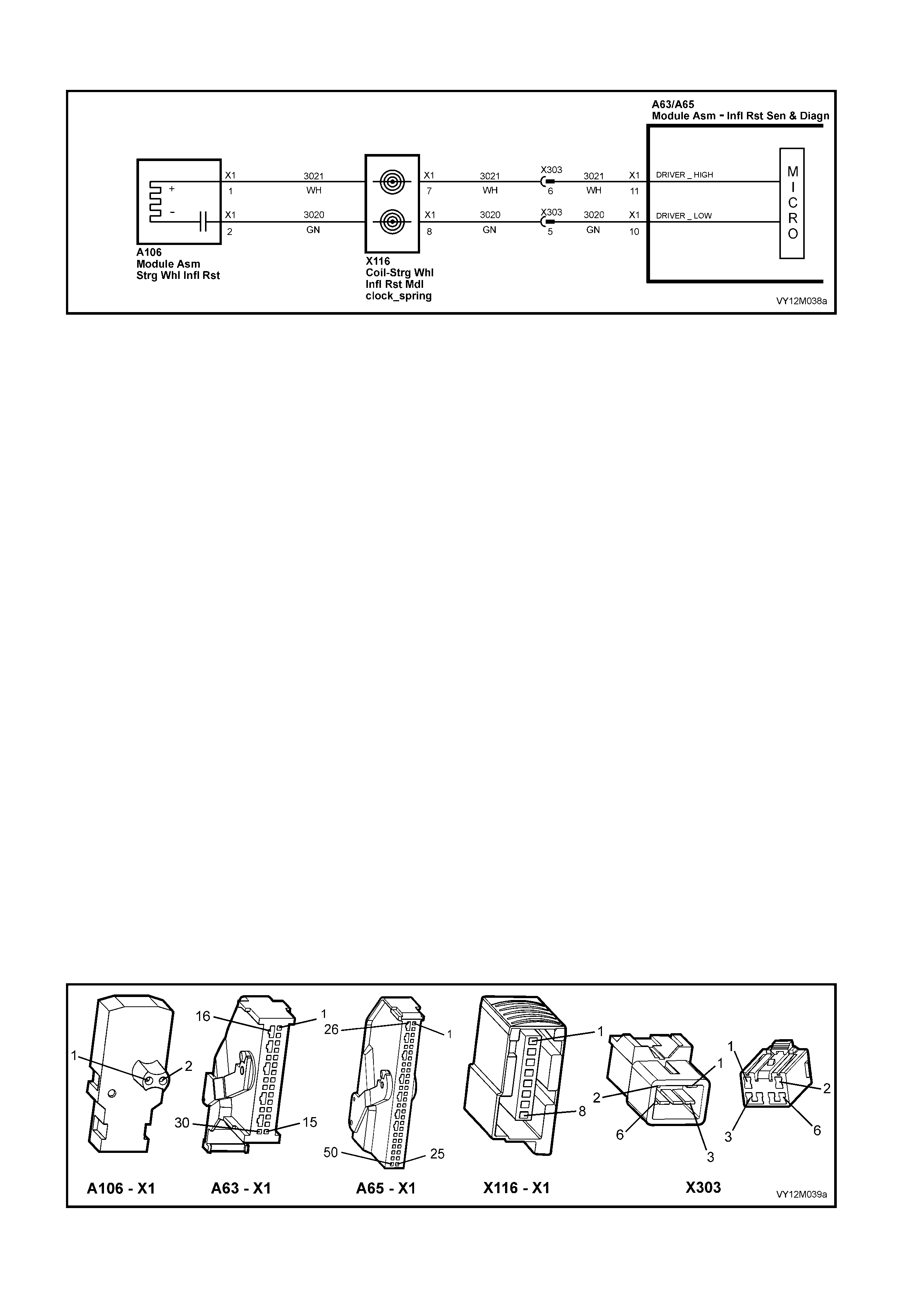
DTC 21 – DRIVER’S AIRBAG CIRCUIT RESISTANCE TOO HIGH
Figure 12M-169
CIRCUIT DESCRIPTION
At ignition on, and on a constant monitoring cycle of every 500 milliseconds during the ignition cycle, the
inflatable restraint control module (SDM) performs a system self check.
If the SDM detects a resistance in the driver’s airbag circuit that is too high (greater than 8.4 ohm) for longer
than 3 – 5 seconds, a current DTC 21 will set (refer to 4.3 OPS / SRS SELF DIANOSTICS in this section for
more details).
DTC 21 will set if circuits 3021 or 3020, (including the inflatable restraint m odule and the clock spring coil) are
open circuited.
W hen DTC 21 sets, the SD M illum inates the SR S war ning in dicat or and sets a cu rrent DT C 21. Should t he f ault
conditions detected by the SDM c lear during the same ignition cycle, t he current code will clear and become a
history DTC 21. The SRS warning indicator will remain on for the remainder of the ignition cycle.
If a DTC 21 is set, the SRS warning indicator is illuminated on each ignition cycle, even if the DTC is set as a
histor y DTC, until the fault condit ions for s etting DTC 21 are rectified an d the DTC (c urrent or histor y) ca n then
be cleared from the SDM via TECH 2.
If DTC 21 is set, dependent on where the fault is, the driver’s airbag may not operate.
TEST DESCRIPTION
The following numbers refer to Section Step numbers in the following diagnostic chart.
1. Uses TECH 2 to check if DTC 21 is current or history.
2. Checks for inter mittent fault by m onitori ng TECH 2 scr een. If s cr een dis p lay changes dur i ng a wirin g 'wiggle'
test, a fault with the wiring is at that location.
3. Tool SD28280B is a dummy load taking the place of the driver’s air bag module. If DTC 21 becomes a
history DTC with dummy load connected, the system fault is in the driver’s air bag module.
4. Check s if open circuit is in the c lock spring c oil. If the c lock spring c oil is disc onne cted f rom the system , and
terminals 7 & 8 in connector X116 – X1 bridged together, DTC 21 will become a history DTC if the clock
spring coil is faulty.
5. Checks circuit 3020 for open circuit.
6. Checks circuit 3021 for open circuit.
NOTES ON DIAGNOSTIC CHART
1. For all wiring harness checking procedures, refer to Section 12P WIRING DIAGRAMS.
2. Refer to 2.11 OPS / SRS WIRING REPAIR in this Se c tion bef or e c onducting an y O PS / SRS wir ing h arnes s
repairs.
Figure 12M-170

DTC 21 – DRIVER’S AIRBAG CIRCUIT RESISTANCE TOO HIGH
STEP ACTION VALUE YES NO
1. 1. Install TECH 2 to DLC.
2. Select Body / SRS / Diagnostic Trouble Codes /
Read DTC Information.
Is DTC 21 current?
Go to Step 3. Go to Step 2.
2. 1. Remove steering column upper and lower cover.
2. With TECH 2 still connected, select Diagnostic
Trouble Codes / Clear DTC Information and clear all
(if any) DTCs
3. Select Diagnostic Trouble Codes / Read DTC
Information, 'wiggle' OPS / SRS wiring harness at all
locations between the SDM and the clock spring coil
while monitoring the TECH 2 screen display.
Does TECH 2 screen display change status from No
Diagnostic Trouble Codes?
Make repairs as
necessary (refer
to Section NOTE
2 on previous
page).
Clear DTC and
recheck system
to verify repair.
Fault not present.
Check all system
wiring harness
connectors, and
terminals.
Clear DTC and
recheck system.
3. 1. Disable the OPS / SRS, refer to Section 2.2
SYSTEM DISABLING AND ENABLING
PROCEDURE in this Section.
2. Remove driver’s airbag module, refer to Section 2.3
STEERING WHEEL INFLATABLE RESTRAINT
MODULE ASSEMBLY in this Section.
3. Connect Tool No. SD28280B to OPS / SRS wiring
harness connector A106 – X1.
4. Connect TECH 2 to DLC and select Body / SRS /
Diagnostic Trouble Codes / Read DTC Information.
Is DTC 21 still current?
Go to Step 4. Replace driver’s
airbag module
assembly, refer
to Section 2.3
STEERING
W HEEL
INFLATABLE
RESTRAINT
MODULE
ASSEMBLY in
this Section.
Clear DTC and
recheck system
to verify repair.
4. 1. Disable the OPS / SRS, refer to Section 2.2
SYSTEM DISABLING AND ENABLING
PROCEDURE in this Section.
2. Disconnect OPS / SRS wiring harness connector
X116 – X1 from clock spring coil assembly.
3. Reconnect battery.
4. Using a suitable jumper wire from KM-609, bridge
connector X116 – X1, terminals 7 and 8 together.
(NOTE: This step may set a current DTC 22).
5. With TECH 2 still connected, select Body / SRS /
Diagnostic Trouble Codes / Read DTC Information.
Does DTC 21 become history?
Replace clock
spring coil
assembly, refer
to Section 2.6
CLOCK SPRING
COIL in this
Section 12M.
Clear all DTCs
and recheck
system to verify
repair.
Go to Step 5
5. 1. Disable the OPS / SRS, refer to Section 2.2
SYSTEM DISABLING AND ENABLING
PROCEDURE in this Section.
2. Disconnect the SDM wiring harness connector
A63/A65 – X1 from the SDM.
3. Remove Tool No. SD28280B from the OPS / SRS
wiring harness connector A106 – X1.
4. Using Tool KM-609-20, check wiring between SDM
wiring harness connector A63/A65 – X1, terminal 11
and clock spring coil connector X116 – X1, terminal
7, circuit 3020 (Green wire) for open circuit (refer to
Section NOTE 1 on previous page).
Is all OK?
Go to Step 6. Make repairs as
necessary (refer
to Section NOTE
2 on previous
page).
Clear DTC and
recheck system
to verify repair.
6. 1. With system disabled, SDM wiring harness
connector A63/A65 – X1 disconnected and using
Tool KM-609-20, check wiring between SDM wiring
harness connector A63/A65 – X1, terminal 10 and
clock spring coil connector X116 – X1, terminal 8,
circuit 3021 (White wire) for open circuit (refer to
Section NOTE 1 on previous page).
Is all OK?
Replace SDM,
refer to Section
2.8 INFLATABLE
RESTRAINT
CONTROL
MODULE in this
Section.
Recheck circuit
to verify repair.
Make repairs as
necessary (refer
to Section NOTE
2 on previous
page).
Clear DTC and
recheck system
to verify repair.
WHEN ALL DIAGNOSIS AND REPAIRS ARE COMPLETED, ENSURE ALL OPS / SRS COMPONENTS ARE
RECONNECTED, CLEAR ALL DTC’s, ENABLE THE OPS / SRS AND VERIFY CORRECT OPERATION

DTC 22 – DRIVER’S AIRBA G CIRCUIT RESISTANCE TOO LOW
Figure 12M-171
CIRCUIT DESCRIPTION
At ignition on, and on a constant monitoring cycle of every 500 milliseconds during the ignition cycle, the
inflatable restraint control module (SDM) performs a system self check.
If the SDM d etects a resis tance in the driver ’s airbag circuit tha t is too lo w (less than 1 ohm) for longer than 3 –
5 seconds, a current DTC 22 will set (refer to 4.3 OPS / SRS SELF DIANOSTICS in this section for more
details).
DTC 22 will set if circuits 3021 or 3020, (including the driver’s airbag module and the clock spring coil) are
shorted together.
W hen DTC 22 sets, the SD M illuminates the SR S war ning in dicat or and sets a cur rent DT C 22. Should t he fault
conditions detected by the SDM c lear during the same ignition cycle, t he current code will clear and become a
history DTC 22. The SRS warning indicator will remain on for the remainder of the ignition cycle.
If a DTC 22 is set, the SRS warning indicator is illuminated on each ignition cycle, even if the DTC is set as a
histor y DTC, until the fault condit ions for s etting DTC 22 are rectified an d the DTC (c urrent or histor y) ca n then
be cleared from the SDM via TECH 2.
If DTC 22 is set, dependent on where the fault is, the driver’s airbag may not operate.
TEST DESCRIPTION
The following numbers refer to Section step numbers in the following diagnostic chart.
1. Uses TECH 2 to check if DTC 22 is current or history.
2. Checks for inter mittent fault by m onitori ng TECH 2 scr een. If s cr een dis p lay changes dur i ng a wirin g 'wiggle'
test, a fault with the wiring is at that location.
3. Tool SD28280B is a dummy load taking the place of the steering wheel inflatable restraint module. If DTC
22 becom es a history DT C with dumm y load connected, the system fault is in the steering wheel inflatable
restraint module.
4. Checks if short circuit is in the clock spring coil. If the clock spring coil is disconnected from the system, a
DTC 21 (open c irc u it) will set and DTC 22 will b ec ome history. If DTC 21 sets and DTC 22 becomes his tory,
the clock spring coil is faulty.
5. This test checks the wiring between the SDM harness connector A65 – X1 (8.1 SDM) or A63 – X1 (8.0
SDM) and OPS / SRS connector X116 – X1 for a short circuit.
NOTES ON DIAGNOSTIC CHART
1. For all wiring harness checking procedures, refer to Section 12P WIRING DIAGRAMS.
2. Refer to 2.11 OPS / SRS WIRING REPAIR in this Se c tion bef or e c onducting an y O PS / SRS wir ing h arnes s
repairs.
Figure 12M-172

DTC 22 – DRIVER’S AIRBA G CIRCUIT RESISTANCE TOO LOW
STEP ACTION VALUE YES NO
1. 1. Install TECH 2 to DLC.
2. Select Body / SRS / Diagnostic Trouble Codes /
Read DTC Information.
Is DTC 22 current?
Go to Step 3. Go to Step 2.
2. 1. Remove steering column upper and lower cover.
2. With TECH 2 still connected, select Diagnostic
Trouble Codes / Clear DTC Information and clear all
(if any) DTCs
3. Select Diagnostic Trouble Codes / Read DTC
Information, 'wiggle' OPS / SRS wiring harness at all
locations between the SDM and the clock spring coil
while monitoring the TECH 2 screen display.
Does TECH 2 screen display change status from No
Diagnostic Trouble Codes?
Make repairs as
necessary (refer
to Section NOTE
2 on previous
page).
Clear DTC and
recheck system
to verify repair.
Fault not present.
Check all system
wiring harness
connect ors, and
terminals.
Clear DTC and
recheck system.
3. 1. Disable the OPS / SRS, refer to Section 2.2
SYSTEM DISABLING AND ENABLING
PROCEDURE in this Section.
2. Remove driver’s airbag module, refer to Section 2.3
STEERING WHEEL INFLATABLE RESTRAINT
MODULE ASSEMBLY in this Section.
3. Connect Tool No. SD28280B to OPS / SRS wiring
harness connector A106 – X1.
4. Reconnect battery.
5. Connect TECH 2 to DLC and select Body / SRS /
Diagnostic Trouble Codes / Read DTC Information.
Is DTC 22 still current?
Go to Step 4. Replace driver’s
airbag module
assembly, refer
to Section 2.3
STEERING
W HEEL
INFLATABLE
RESTRAINT
MODULE
ASSEMBLY in
this Section.
Clear DTC and
recheck system
to verify repair.
4. 1. Disable the OPS / SRS, refer to Section 2.2
SYSTEM DISABLING AND ENABLING
PROCEDURE in this Section.
2. Disconnect OPS / SRS wiring harness connector
X116 – X1 from clock spring coil assembly.
3. Reconnect battery.
4. With TECH 2 still connected, select Body / SRS /
Diagnostic Trouble Codes / Read DTC Information.
Does DTC 22 become history?
Replace clock
spring coil
assembly, refer
to Section 2.6
CLOCK SPRING
COIL in this
Section 12M.
Clear all DTCs
and recheck
system to verify
repair.
Go to Step 5
5. 1. Disable the OPS / SRS, refer to Section 2.2
SYSTEM DISABLING AND ENABLING
PROCEDURE in this Section.
2. Disconnect the SDM wiring harness connector
A63/A65 – X1 from the SDM.
3. Remove Tool No. SD28280B from the OPS / SRS
wiring harness connector A106 – X1.
4. With OPS / SRS wiring harness connector X116 –
X1 disconnected, and using Tool KM-609-20, check
for continuity between SDM wiring harness
connector A63/A65 – X1, terminal 10, circuit 3021
(White wire) and terminal 11, circuit 3020 (Green
wire)(refer to Section NOTE 1 on previous page).
Is all OK?
Go to Step 6. Make repairs as
necessary (refer
to Section NOTE
2 on previous
page).
Clear DTC and
recheck system
to verify repair.
6. 1. With system disabled, SDM wiring harness
connector A63/A65 – X1 disconnected and using
Tool KM-609-20, check wiring between SDM wiring
harness connector A63/A65 – X1, terminal 11 and
clock spring coil connector X116 – X1, terminal 8,
circuit 3021 (White wire) for open circuit (refer to
Section NOTE 1 on previous page).
Is all OK?
Replace SDM,
refer to Section
2.8 INFLATABLE
RESTRAINT
CONTROL
MODULE in this
Section.
Recheck circuit
to verify repair.
Make repairs as
necessary (refer
to Section NOTE
2 on previous
page).
Clear DTC and
recheck system
to verify repair.
WHEN ALL DIAGNOSIS AND REPAIRS ARE COMPLETED, ENSURE ALL OPS / SRS COMPONENTS ARE
RECONNECTED, CLEAR ALL DTC’s, ENABLE THE OPS / SRS AND VERIFY CORRECT OPERATION

DTC 247 – DRIVER’S AIRBAG CIRCUIT POWER STAGE ERROR
Figure 12M-173
CIRCUIT DESCRIPTION
At ignition o n, the SDM perf orms an initial s ystem self check of the SDM po wer stages. If during this initial s elf-
test the SDM detects a fault with the driver’s airbag power stage a current DTC 247 Driver’s Airbag Circuit
Power Stage Error will set. On completion of the initial system self test the SDM then performs a test of the
Driver’s Airbag C ircuit. If the SD M detects a probl em with th is circ uit the as sociated Dri ver’s A irbag C ircuit D TC
will be set and the DTC 247 Driver’s Airbag Circuit Power Stage Error will become a history DTC.
DTC 247 Driver’s Airbag Circuit Power Stage Error will set if a fault occurs in the driver’s airbag circuit, clock
spring coi l assem bl y with the in-built c apacit or c onnector A106 – X1, c onnector X116 – X1, c onnect or X303, the
OPS / SRS wiring harness, connector A63/A65 – X1 or SDM.
W hen a history DT C 247 Driver ’s Airbag C ircuit Po wer Stage Er ror sets, the SDM illum inates the SRS warn ing
indicator. Should the fault conditions detected by the SDM clear during the same ignition cycle the code will
rem ain a h is tory DT C 247 Dr iver ’s A irbag C irc uit Po w e r St age Error f or a ll ig nition cycles until c le ared. T he SRS
warning indicator will remain on for the remainder of the ignition cycle.
When a DTC 247 Driver’s Airbag Circuit Power Stage Error sets, the SDM illuminates the SRS warning indicator
for the remainder of the ignition cycle. Should the fault conditions detected by the SDM clear during the same
ignition cycle the code will remain a history DTC 247 Driver’s Airbag Circuit Power Stage Error for all ignition
cycles u ntil cl eared . SRS warnin g ind icator will also re m ain illum inated un til th e hi stor y DTC 24 7 Driver ’s A irbag
Circuit Power Stage Error is cleared.
If a DT C 247 Dr iver ’s Airbag Cir cuit Power St age is se t, dependent on wher e th e f ault is , th e dr i ver’s airbag may
not operate.
ACTION REQUIRED
If DTC 247 Dr iver ’s Air b ag Circ uit P o wer St ag e Err or a nd any other DTC is s et then the d iagnos tic s for the ot her
DTC s hould be car ried o ut f irst. F or exam ple if a DT C 247 Driv er’s A irbag C irc uit Po wer Stage Error and a DT C
21 Driver’s Airbag Circuit Resistance High are set, the diagnostics for a DTC 21 Driver’s Airbag Circuit
Resistance High should be carried out first.
If only a DTC 247 Driver’s Airbag Circuit Power Stage Error is set then the SDM should be replaced.
NOTE: An intermittent in the driver’s airbag circuit may cause a DTC 247 Driver’s Airbag Circuit Power Stage
Error to set.
After the fault has been rectified, ensure that all SRS components are reconnected, clear DTC’s, enable the
SRS and verify the correct operation of the system (i.e. warning indicator not illuminated after five seconds of
ignition being switched ON).
TEST DESCRIPTION
The following numbers refer to Section Step numbers in the following diagnostic chart.
1. Uses TECH 2 to check if a DTC 247 Driver’s Airbag Circuit Power Stage Error is history code, and if any
other driver’s airbag circuit current or history DTC’s are set. If any other DTC’s are set refer to Section
these DTC’s first.
2. Checks for intermittent fault by monitoring TECH 2 screen during ignition on cycle. If screen display
changes duri ng a wir ing 'wiggl e' tes t, a f ault wit h the wir ing is at t hat loc at ion . If no other DTC’s ar e se t an d
there are no intermittents in the driver’s airbag circuit then the SDM should be replaced.
NOTES ON DIAGNOSTIC CHART
1. For all wiring harness checking procedures, refer to Section 12P WIRING DIAGRAMS.
2. Refer to 2.11 OPS / SRS WIRING REPAIR in this Se c tion bef or e c onducting an y O PS / SRS wir ing h arnes s
repairs.
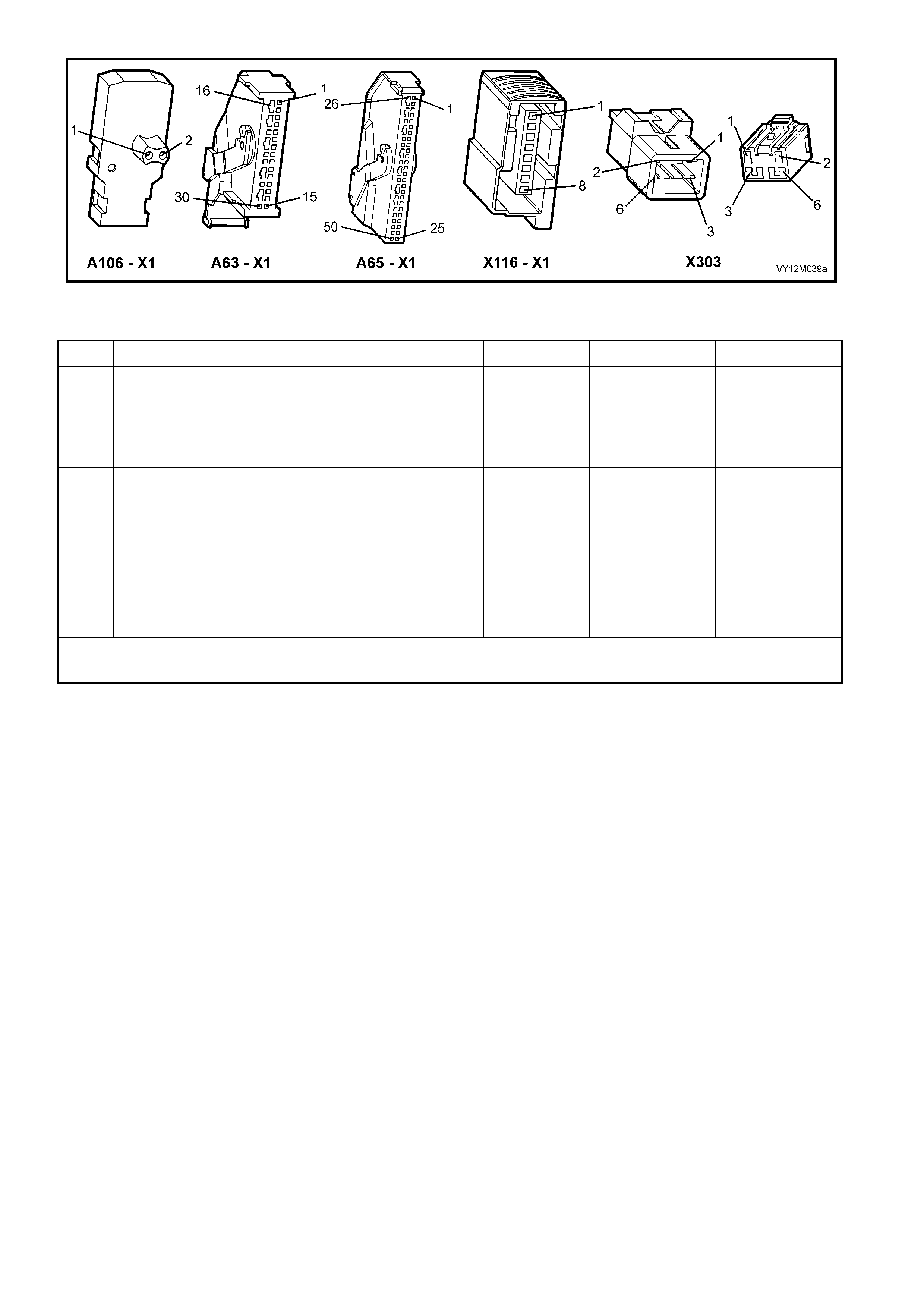
Figure 12M-174
DTC 247 – DRIVER’S AIRBAG CIRCUIT POWER STAGE ERROR
STEP ACTION VALUE YES NO
1. 1. Install TECH 2 to DLC.
2. Select Body / SRS / Diagnostic Trouble Codes /
Read DTC Information.
Is a DTC 247 Driver’s Airbag Circuit Power Stage Error a
history DTC, and are any other driver’s airbag circuit
DTCs set?
Go to other
driver’s airbag
circuit DTC
diagnost ic cha rt
in this Section.
Go to Step 2.
2. 1. Remove steering column upper and lower cover.
2. With TECH 2 still connected, select Diagnostic
Trouble Codes / Clear DTC Information and clear all
(if any) DTCs
3. Select Diagnostic Trouble Codes / Read DTC
Information, 'wiggle' OPS / SRS wiring harness at all
locations between the SDM and the clock spring coil
while monitoring the TECH 2 screen display.
Does TECH 2 screen display change status from No
Diagnostic Trouble Codes?
Go to applicable
DTC chart in this
Section.
Replace SDM,
refer to Section
2.8 INFLATABLE
RESTRAINT
CONTROL
MODULE in this
Section.
Recheck circuit
to verify repair.
WHEN ALL DIAGNOSIS AND REPAIRS ARE COMPLETED, ENSURE ALL OPS / SRS COMPONENTS ARE
RECONNECTED, CLEAR ALL DTC’s, ENABLE THE OPS / SRS AND VERIFY CORRECT OPERATION

DTC 33 – PASSENGER AIRBAG CIRCUIT SHORT TO BATTERY
Figure 12M-175
CIRCUIT DESCRIPTION
At ignition on, and on a constant monitoring cycle of every 500 milliseconds during the ignition cycle, the
inflatable restraint control module (SDM) performs a system self check.
If the SDM detects a resistance to battery supply is less than 5 kohms in either the positive and/or negative
circuit for more than 3 – 5 seconds, a current DTC 33 will set (refer to 4.3 OPS / SRS SELF DIAGNOSTICS in
this Section for more details).
DTC 33 will set if circuits 3025 (passenger airbag positive side) and/or 3024 (passenger airbag negative side)
are shorted to battery +.
W hen DTC 33 sets, the SD M illuminates the SR S war ning in dicat or and sets a cur rent DT C 33. Should t he fault
conditions detected by the SDM c lear during the same ignition cycle, t he current code will clear and become a
history DTC 33. The SRS warning indicator will remain on for the remainder of the ignition cycle.
If a DTC 33 is set, the SRS warning indicator is illuminated on each ignition cycle, even if the DTC is set as a
histor y DTC, until the fault condit ions for s etting DTC 33 are rectified an d the DTC (c urrent or histor y) ca n then
be cleared from the SDM via TECH 2.
If DTC 33 is set, the OPS / SRS, including the passenger airbag, will still be operational due to the reserve
energy supply stored in the SDM.
TEST DESCRIPTION
The following number refer to Section step numbers in the following diagnostic chart:
1. Uses TECH 2 to check if DTC 33 is current or history.
2. Checks for intermittent fault by monitoring TECH 2 screen display. If screen display changes during a
‘wiggle’ test, a fault with the wiring is at that location.
3. Checks circuits 3025 and 3024 for a short to battery +.
NOTES ON DIAGNOSTIC CHART
1. For all wiring harness checking procedures, refer to Section 12P WIRING DIAGRAMS.
2. Refer to 2.11 OPS / SRS WIRING REPAIR in this Section, before conducting any OPS / SRS wiring
harness repairs.
3. Resistance cannot be m easured b etween the two ter minals in conn ector A62 – X 1, as the in-built c apacit or
block s measur ement. Theref ore, a ‘servic e hole’ is incorpor ated into the c onnecto r for fault trac ing. Refer to
1.1 SYSTEM COMPONENTS, WIRING HARNESS in this Section for more details on this type of connector.
4. Wiring should be checked at point where TECH 2 screen display changed status. If necessary, split open
the harness.
5. If the fault can not be identified, the harness should be replaced.
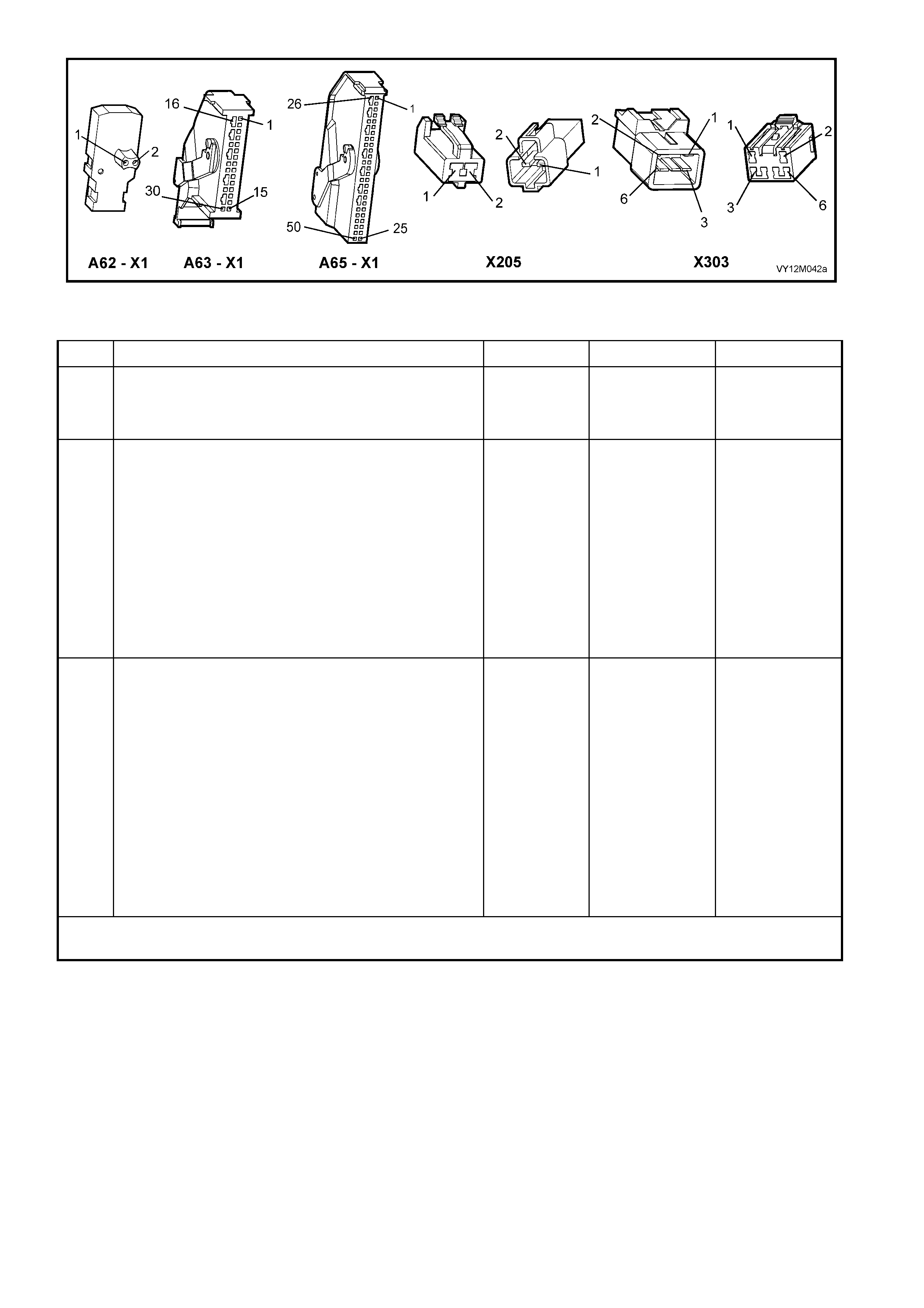
Figure 12M-176
DTC 33 – PASSENGER AIRBAG CIRCUIT SHORT TO BATTERY
STEP ACTION VALUE YES NO
1. 1. Install TECH 2 to DLC.
2. Select Body / SRS / Diagnostic Trouble Codes /
Read DTC Information.
Is DTC 33 current?
Go to Step 3. Go to Step 2.
2. 1. Remove instrument panel compartment to gain
access to passenger airbag, refer to Section 1A3
INSTRUMENT PANEL AND CONSOLE.
2. With TECH 2 still connected, select Diagnostic
Trouble Codes / Clear DTC Information and clear all
(if any) DTCs.
3. Select Diagnostic Trouble Codes / Read DTC
Information, 'wiggle' OPS / SRS wiring harness at all
locations between the SDM and the passenger
airbag wiring harness connector A62 – X1, while
monitoring TECH 2 screen display.
Does TECH 2 screen display change status from No
Diagnostic Trouble Codes?
Make repairs as
necessary (refer
to Section
NOTES 2 & 4 on
previous page).
Clear DTC and
recheck system
to verify repair.
Fault not present.
Check all system
wiring harness
connect ors, and
terminals (refer to
Section NOTE 5
on previous
page).
Clear DTC and
recheck system.
3. 1. Disable the OPS / SRS, refer to Section 2.2
SYSTEM DISABLING AND ENABLING
PROCEDURE in this Section.
2. Disconnect passenger airbag module, wiring
harness connector A62 – X1.
3. Disconnect SDM wiring harness connector A63/A65
– X1 from the SDM.
4. Reconnect battery.
5. Using Tool KM-609-20, check wiring between SDM
wiring harness connector A63/A65 – X1, terminals
13 and 14 and passenger airbag connector A62 –
X1, circuits 3025 (Yellow/Black wire) and 3024
(Grey/Black wire) for short to battery + (refer to
Section NOTES 1 and 3 on previous page).
Is all OK?
Replace SDM,
refer to Section
2.8 INFLATABLE
RESTRAINT
CONTROL
MODULE in this
Section.
Recheck circuit
to verify repair.
Make repairs as
necessary (refer
to Section NOTE
2 on previous
page).
Clear DTC and
recheck system
to verify repair.
WHEN ALL DIAGNOSIS AND REPAIRS ARE COMPLETED, ENSURE ALL OPS / SRS COMPONENTS ARE
RECONNECTED, CLEAR ALL DTC’s, ENABLE THE OPS / SRS AND VERIFY CORRECT OPERATION
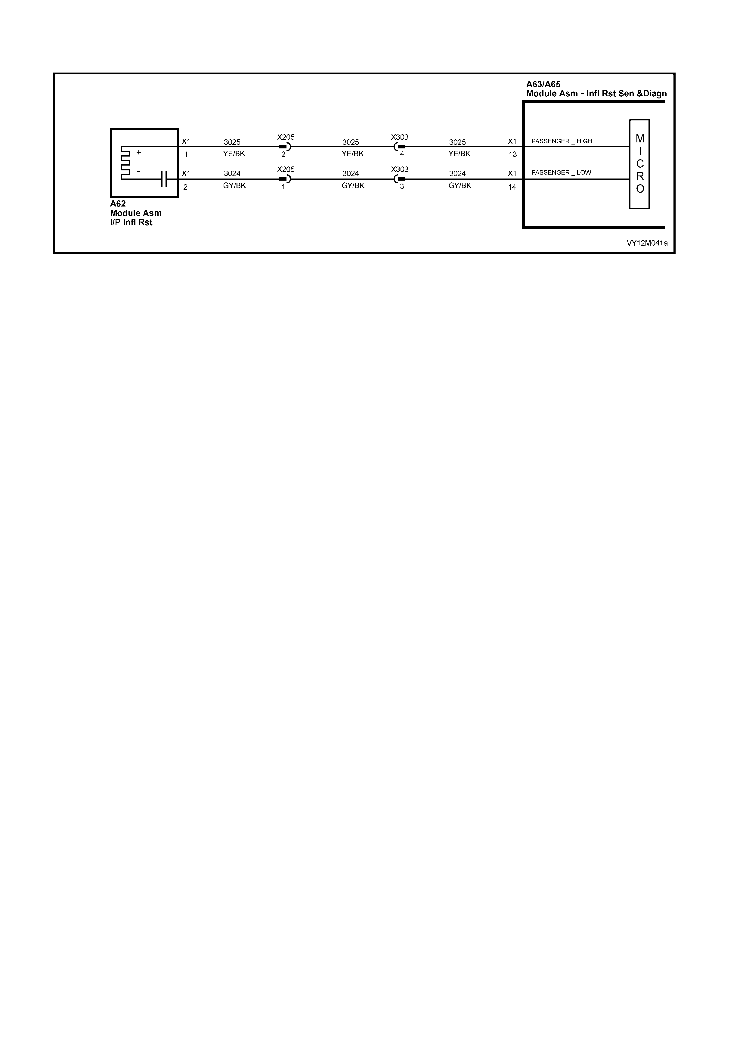
DTC 34 – PASSENGER AIRBAG CIRCUIT SHORT TO EARTH
Figure 12M-177
CIRCUIT DESCRIPTION
At ignition on, and on a constant monitoring cycle of every 500 milliseconds during the ignition cycle, the
inflatabl e rest raint c ontrol m odule (SDM) perf orm s a system s elf check . If the SDM det ects a resis tance t o earth
of less tha n 3 kohms in ei th er the pos i ti ve or n egat i ve i nf lator cir cui t f or more than 3 – 5 s econ ds , a c urr ent D TC
34 will set (refer to 4.3 OPS / SRS SELF DIAGNOSTICS in this Section for more details).
DTC 34 will set if circuits 3025 (passenger airbag positive side) and/or 3024 (passenger airbag negative side)
are shorted to earth.
W hen DTC 34 sets, the SD M illuminates the SR S war ning in dicat or and sets a cur rent DT C 34. Should t he fault
conditions detected by the SDM c lear during the same ignition cycle, t he current code will clear and become a
history DTC 34. The SRS warning indicator will remain on for the remainder of the ignition cycle.
If a DTC 34 is set, the SRS warning indicator is illuminated on each ignition cycle, even if the DTC is set as a
histor y DTC, until the fault condit ions for s etting DTC 34 are rectified an d the DTC (c urrent or histor y) ca n then
be cleared from the SDM via TECH 2.
If DTC 34 is set, the OPS / SRS, including the passenger airbag, will still be operational due to the reserve
energy supply stored in the SDM.
TEST DESCRIPTION
The following number refer to Section step numbers in the following diagnostic chart:
1. Uses TECH 2 to check if DTC 34 is current or history.
2. TECH 2 in this mode should display approximately 1.6 – 6.4 ohms if the passenger airbag loop circuit is OK.
3. If screen display changes during a wiring 'wiggle' test, a fault with the wiring is at that location.
4. Tool SD28280B is a dummy load taking the place of the passenger airbag module. If TECH 2 displa ys t he
correct resistance of the dummy load, the system fault is in the passenger airbag module assembly.
5. This test checks the wiring between the SDM wiring harness connector A65 – X1 (8.1 SDM) or A63 – X1
(8.0 SDM), terminal 13 and the passenger airbag module connector A62 – X1 for faults.
6. This test checks the wiring between the SDM wiring harness connector A65 – X1 (8.1 SDM) or A63 – X1
(8.0 SDM), terminal 14 and the passenger airbag module connector A62 – X1 for faults.
NOTES ON DIAGNOSTIC CHART
1. For all wiring harness checking procedures, refer to Section 12P WIRING DIAGRAMS.
3. Refer to 2.11 OPS / SRS WIRING REPAIR in this Section, before conducting any OPS / SRS wiring
harness repairs.
4. Refer to Section 12O FUSES & WIRING HARNESSES for OPS / SRS wiring harness routing.
3. Resistance cannot be m easured b etween the two ter minals in conn ector A62 – X 1, as the in-built c apacit or
block s measur ement. Theref ore, a ‘servic e hole’ is incorpor ated into the c onnecto r for fault trac ing. Refer to
1.1 SYSTEM COMPONENTS, WIRING HARNESS in this Section for more details on this type of connector.
4. Wiring should be checked at point where TECH 2 screen display changed status. If necessary, split open
the harness.
5. If the fault can not be identified, the harness should be replaced.
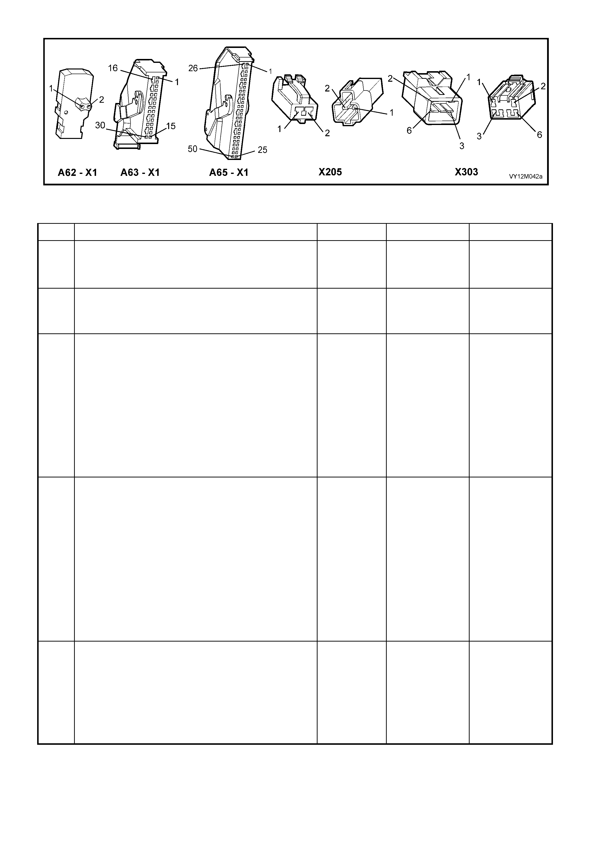
Figure 12M-178
DTC 34 – PASSENGER AIRBAG CIRCUIT SHORT TO EARTH
STEP ACTION VALUE YES NO
1. 1. Install TECH 2 to DLC.
2. Select Body / SRS / Diagnostic Trouble Codes /
Read DTC Information.
Does TECH 2 display DTC 34 as a Current DTC?
Go to Step 2. Go to Step 3.
2. 1. With TECH 2 still connected to DLC, select Body /
SRS / Data Display and scroll to PASSENGER
AIRBAG LOOP RESISTANCE'.
Is value displayed on TECH 2 as specified?
Approx.
1.6 – 6.4
Ohms
Go to Step 3. Go to Step 4.
3. 1. Remove instrument panel compartment to gain
access to passenger airbag, refer to Section 1A3
INSTRUMENT PANEL AND CONSOLE.
2. With TECH 2 still connected, select Diagnostic
Trouble Codes / Clear DTC Information and clear all
(if any) DTCs.
3. Select Diagnostic Trouble Codes / Read DTC
Information, 'wiggle' OPS / SRS wiring harness at all
locations between the SDM and the passenger
airbag wiring harness connector A62 – X1, while
monitoring TECH 2 screen display.
Does TECH 2 screen display change status from No
Diagnostic Trouble Codes?
Make repairs as
necessary (refer
to Section
NOTES 2 & 5 on
previous page).
Clear DTC and
recheck system
to verify repair.
Fault not present.
Check all system
wiring harness
connect ors, and
terminals (refer to
Section NOTE 6
on previous
page).
Clear DTC and
recheck system.
4. 1. Disable the OPS / SRS, refer to Section 2.2
SYSTEM DISABLING AND ENABLING
PROCEDURE in this Section.
2. Disconnect passenger airbag module, wiring
harness connector A62 – X1.
3. Connect Tool No. SD28280B to OPS / SRS wiring
harness connector A62 – X1.
4. With TECH 2 still connected, select Body / SRS /
Data Display and scroll to PASSENGER AIRBAG
LOOP RESISTANCE'.
Is value displayed on TECH 2 as specified?
Approx.
3.0 Ohms
Replace
passenger airbag
module
assembly, refer
to Section 2.4
INSTRUMENT
PANEL
INFLATABLE
RESTRAINT
MODULE
ASSEMBLY in
this Section.
Clear DTC and
recheck system
to verify repair.
Go to Step 5..
5. 1. Disconnect SDM wiring harness connector A63/A65
– X1 from the SDM.
2. Remove Tool SD28280B from A62 – X1.
3. Using Tool KM-609-20, check wiring between SDM
wiring harness connector A63/A65 – X1, terminals
13 and passenger airbag module connector A62 –
X1, circuit 3025 (Yellow/Black wire) for short to earth
(refer to Section NOTE 1 on previous page).
Is all OK?
Go to Step 6. Make repairs as
necessary (refer
to Section NOTE
2 on previous
page).
Clear DTC and
recheck system
to verify repair.

STEP ACTION VALUE YES NO
6. 1. With SDM wiring harness connector A63/A65 – X1
disconnected from the SDM, and using Tool KM-
609-20. Check wiring between SDM wiring harness
connector A63/A65 – X1, terminal 14 and passenger
airbag module connector A62 – X1, terminal 2,
circuit 3024 (Grey/Black wire) for a short to earth
(refer to Section NOTES 1 and 4 on previous page).
Is all OK?
Replace SDM,
refer to Section
2.8 INFLATABLE
RESTRAINT
CONTROL
MODULE in this
Section.
Recheck circuit
to verify repair.
Make repairs as
necessary (refer
to Section NOTE
2 on previous
page).
Clear DTC and
recheck system
to verify repair.
WHEN ALL DIAGNOSIS AND REPAIRS ARE COMPLETED, ENSURE ALL OPS / SRS COMPONENTS ARE
RECONNECTED, CLEAR ALL DTC’s, ENABLE THE OPS / SRS AND VERIFY CORRECT OPERATION

DTC 35 – PASSENGER AIRBAG CIRCUIT CAPACITANCE TOO HIGH
Figure 12M-179
CIRCUIT DESCRIPTION
At ignition on, and on a constant monitoring cycle of every 500 milliseconds during the ignition cycle, the
inflatable restraint control module (SDM) performs a system self check.
If the SDM detects the capacitance in the passenger airbag circuit is too high (greater than 550 nF) for longer
than 3 – 5 seconds, a current DTC 35 will set (refer to 4.3 OPS / SRS SELF DIAGNOSTICS in this Section for
more details).
DTC 35 will set if the in-built capacitor in the OPS / SRS wiring harness connector A62 – X1 is faulty.
W hen DTC 35 sets, the SD M illuminates the SR S war ning in dicat or and sets a cur rent DT C 35. Should t he fault
conditions detected by the SDM c lear during the same ignition cycle, t he current code will clear and become a
history DTC 35. The SRS warning indicator will remain on for the remainder of the ignition cycle.
If a DTC 35 is set, the SRS warning indicator is illuminated on each ignition cycle, even if the DTC is set as a
histor y DTC, until the fault condit ions for s etting DTC 35 are rectified an d the DTC (c urrent or histor y) ca n then
be cleared from the SDM via TECH 2.
ACTION REQUIRED
If DTC 35 is set, the passenger airbag may not operate and therefore, the OPS / SRS ‘pigtail’ wiring harness
with connector A62 – X1 (between Passenger airbag and OPS / SRS wiring harness) must be replaced.
After the OPS / SRS ‘pigtail’ wiring harness between the Passenger airbag and the OPS / SRS wiring harness
has been replaced, ensure that all OPS / SRS components are reconnected, clear DTC’s, enable the OPS /
SRS and verify the correct operation of the system (i.e. warning indicator not illuminated after five seconds of
ignition being switched ON).

DTC 36 – PASSENGER AIRBAG CIRCUIT CAPACITANCE TOO LOW
Figure 12M-180
CIRCUIT DESCRIPTION
At ignition on, and on a constant monitoring cycle of every 500 milliseconds during the ignition cycle, the
inflatable restraint control module (SDM) performs a system self check.
If the SDM detects the capacitance in the passenger airbag circuit is too low (less than 390 nF) for longer than 3
– 5 seconds, a current DTC 36 will set (refer to 4.3 OPS / SRS SELF DIAGNOSTICS in this Section for more
details).
DTC 36 will set if the in-built capacitor in the OPS / SRS wiring harness connector A62 – X1 is faulty.
W hen DTC 36 sets, the SD M illuminates the SR S war ning in dicat or and sets a cur rent DT C 36. Should t he fault
conditions detected by the SDM c lear during the same ignition cycle, t he current code will clear and become a
history DTC 36. The SRS warning indicator will remain on for the remainder of the ignition cycle.
If a DTC 36 is set, the SRS warning indicator is illuminated on each ignition cycle, even if the DTC is set as a
histor y DTC, until the fault condit ions for s etting DTC 36 are rectified an d the DTC (c urrent or histor y) ca n then
be cleared from the SDM via TECH 2.
ACTION REQUIRED
If DTC 36 is set, the passenger airbag may not operate and therefore, the OPS / SRS ‘pigtail’ wiring harness
with connector A62 – X1 (between Passenger airbag and OPS / SRS wiring harness) must be replaced.
After the OPS / SRS ‘pigtail’ wiring harness between the Passenger airbag and the OPS / SRS wiring harness
has been replaced, ensure that all OPS / SRS components are reconnected, clear DTCs, enable the OPS /
SRS and verify the correct operation of the system (i.e. warning indicator not illuminated after five seconds of
ignition being switched ON).
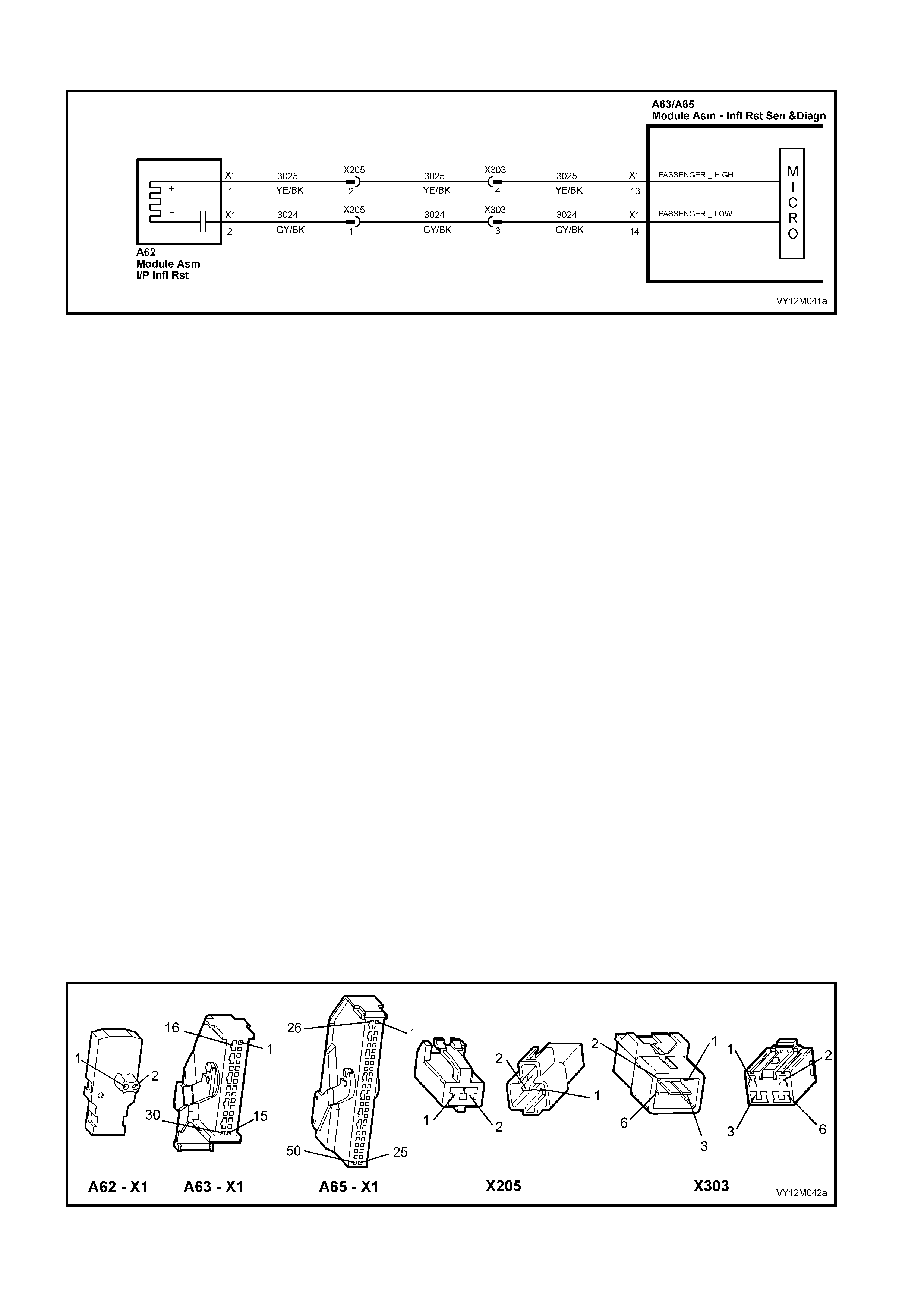
DTC 37 – PASSENGER AIRBAG CIRCUIT RESISTANCE TOO HIGH
Figure 12M-181
CIRCUIT DESCRIPTION
At ignition on, and on a constant monitoring cycle of every 500 milliseconds during the ignition cycle, the
inflatable restraint control module (SDM) performs a system self check.
If the SDM detects a resistance in th e passeng er airbag cir cuit that is too hi gh (greater tha n 8.4 ohm) for longer
than 3 – 5 seconds, a current DTC 37 will set (refer to 4.3 OPS / SRS SELF DIAGNOSTICS in this Section for
more details).
DTC 37 will set if circuits 3025 or 3024 (including the passenger airbag module) are open circuit.
W hen DTC 37 sets, the SD M illuminates the SR S war ning in dicat or and sets a cur rent DT C 37. Should t he fault
conditions detected by the SDM c lear during the same ignition cycle, t he current code will clear and become a
history DTC 37. The SRS warning indicator will remain on for the remainder of the ignition cycle.
If a DTC 37 is set, the SRS warning indicator is illuminated on each ignition cycle, even if the DTC is set as a
histor y DTC, until the fault condit ions for s etting DTC 37 are rectified an d the DTC (c urrent or histor y) ca n then
be cleared from the SDM via TECH 2.
If DTC 37 is set, dependent on where the fault is, the passenger airbag may not operate.
TEST DESCRIPTION
The following number refer to Section step numbers in the following diagnostic chart:
1. Uses TECH 2 to check if DTC 37 is current or history.
2. Checks for intermittent fault by monitoring TECH 2 screen. If screen display changes during a wiring
'wiggle' test, a fault with the wiring is at that location.
3. Tool SD28280B is a dummy load taking the place of the passenger airbag m odule. If DTC 37 becom es a
history DTC with dummy load connected, the system fault is in the passenger airbag module.
4. Checks circuit 3025 for open circuit.
5. Checks circuit 3024 for open circuit.
NOTES ON DIAGNOSTIC CHART
1. For all wiring harness checking procedures, refer to Section 12P WIRING DIAGRAMS.
2. Refer to 2.11 OPS / SRS WIRING REPAIR in this Section, before conducting any OPS / SRS wiring
harness repairs.
3. Resistance cannot be measured between the two terminals in connector A62 – X1, as the in-built capacitor
blocks measurement. Therefore, a ‘service hole’ is incorporated into the connector for fault tracing. Refer
to 1.1 SYSTEM COMPONENTS, WIRING HARNESS in this Section for more details on this type of
connector.
Figure 12M-182

DTC 37 – PASSENGER AIRBAG CIRCUIT RESISTANCE TOO HIGH
STEP ACTION VALUE YES NO
1. 1. Install TECH 2 to DLC.
2. Select Body / SRS / Diagnostic Trouble Codes /
Read DTC Information.
Is DTC 37 current?
Go to Step 3. Go to Step 2.
2. 1. Remove instrument panel compartment to gain
access to passenger airbag, refer to Section 1A3
INSTRUMENT PANEL AND CONSOLE.
2. With TECH 2 still connected, select Diagnostic
Trouble Codes / Clear DTC Information and clear all
(if any) DTCs.
3. Select Diagnostic Trouble Codes / Read DTC
Information, 'wiggle' OPS / SRS wiring harness at all
locations between the SDM and the passenger
airbag wiring harness connector A62 – X1, while
monitoring TECH 2 screen display.
Does TECH 2 screen display change status from No
Diagnostic Trouble Codes?
Make repairs as
necessary (refer
to Section NOTE
2 on previous
page).
Clear DTC and
recheck system
to verify repair.
Fault not present.
Check all system
wiring harness
connect ors, and
terminals.
Clear DTC and
recheck system.
3. 1. Disable the OPS / SRS, refer to Section 2.2
SYSTEM DISABLING AND ENABLING
PROCEDURE in this Section.
2. Disconnect passenger airbag module, wiring
harness connector A62 – X1.
3. Connect Tool No. SD28280B to OPS / SRS wiring
harness connector A62 – X1.
4. Reconnect battery.
5. Connect TECH 2 to DLC.
6. Select Body / SRS / Diagnostic Trouble Codes /
Read DTC Information.
Is DTC 37 still current?
Go to Step 4. Replace
passenger airbag
module
assembly, refer
to Section 2.4
INSTRUMENT
PANEL
INFLATABLE
RESTRAINT
MODULE
ASSEMBLY in
this Section.
Clear DTC and
recheck system
to verify repair.
4. 1. Disable the OPS / SRS, refer to Section 2.2
SYSTEM DISABLING AND ENABLING
PROCEDURE in this Section.
2. Disconnect SDM wiring harness connector A63/A65
– X1 from the SDM.
3. Remove Tool No. SD28280B from OPS / SRS
wiring harness connector A62 – X1.
4. W ith OPS / SRS wiring harness connector A62 – X1
disconnected, and using Tool KM-609-20, check
wiring between SDM wiring harness connector
A63/A65 – X1, terminal 13 and OPS / SRS wiring
harness connector A62 – X1, circuit 3025
(Yellow/Black wire) for open circuit (refer to Section
NOTE 1 and 3 on previous page).
Is all OK?
Go to Step 5. Make repairs as
necessary (refer
to Section NOTE
2 on previous
page).
Clear DTC and
recheck system
to verify repair.
5. 1. With SDM wiring harness connector A63/A65 – X1
and OPS / SRS wiring harness connector A62 – X1
disconnected. Using Tool KM-609-20, check wiring
between SDM wiring harness connector A63/A65 –
X1, terminal 14 and OPS / SRS wiring harness
connector A62 – X1, circuit 3024 (Grey / Black wire)
for open circuit (refer to Section NOTE 1 and 3 on
previous page).
Is all OK?
Replace SDM,
refer to Section
2.8 INFLATABLE
RESTRAINT
CONTROL
MODULE in this
Section. Recheck
circuit to verify
repair.
Make repairs as
necessary (refer
to Section NOTE
2 on previous
page).
Clear DTC and
recheck system
to verify repair.
WHEN ALL DIAGNOSIS AND REPAIRS ARE COMPLETED, ENSURE ALL OPS / SRS COMPONENTS ARE
RECONNECTED, CLEAR ALL DTC’s, ENABLE THE OPS / SRS AND VERIFY CORRECT OPERATION

DTC 38 – PASSENGER AIRBAG CIRCUIT RESISTANCE TOO LOW
Figure 12M-183
CIRCUIT DESCRIPTION
At ignition on, and on a constant monitoring cycle of every 500 milliseconds during the ignition cycle, the
inflatable restraint control module (SDM) performs a system self check.
If the SDM det ects a r esis tance in the pass en ger air b ag cir cuit th at is too l o w (les s than 0.6 ohm) for longer tha n
3 – 5 seconds, a current DTC 38 will set (refer to 4.3 OPS / SRS SELF DIAGNOSTICS in this Section for more
details).
DTC 38 will set if circuits 3025 or 3024, (including the passenger airbag module assembly) are shorted together.
W hen DTC 38 sets, the SD M illuminates the SR S war ning in dicat or and sets a cur rent DT C 38. Should t he fault
conditions detected by the SDM c lear during the same ignition cycle, t he current code will clear and become a
history DTC 38. The SRS warning indicator will remain on for the remainder of the ignition cycle.
If a DTC 38 is set, the SRS warning indicator is illuminated on each ignition cycle, even if the DTC is set as a
histor y DTC, until the fault condit ions for s etting DTC 38 are rectified an d the DTC (c urrent or histor y) ca n then
be cleared from the SDM via TECH 2.
If DTC 38 is set, dependent on where the fault is, the passenger airbag may not operate.
TEST DESCRIPTION
The following number refer to Section step numbers in the following diagnostic chart:
1. Uses TECH 2 to check if DTC 38 is current or history.
2. Checks for intermittent fault by monitoring TECH 2 screen. If screen display changes during a wiring
'wiggle' test, a fault with the wiring is at that location.
3. Tool SD28280B is a dummy load taking the place of the passenger airbag m odule. If DTC 34 becom es a
history DTC with dummy load connected, the system fault is in the passenger airbag module.
4. This test checks the wiring between the SDM wiring harness connector A65 – X1 (8.1 SDM) or A63 – X1
(8.0 SDM) and OPS / SRS wiring harness connector A62 – X1 for a short circuit.
NOTES ON DIAGNOSTIC CHART
1. For all wiring harness checking procedures, refer to Section 12P WIRING DIAGRAMS.
2. Refer to 2.11 OPS / SRS WIRING REPAIR in this Section, before conducting any OPS / SRS wiring
harness repairs.
3. Resistance cannot be measured between the two terminals in connector A62 – X1, as the in-built capacitor
blocks measurement. Therefore, a ‘service hole’ is incorporated into the connector for fault tracing. Refer
to 1.1 SYSTEM COMPONENTS, WIRING HARNESS in this Section for more details on this type of
connector.
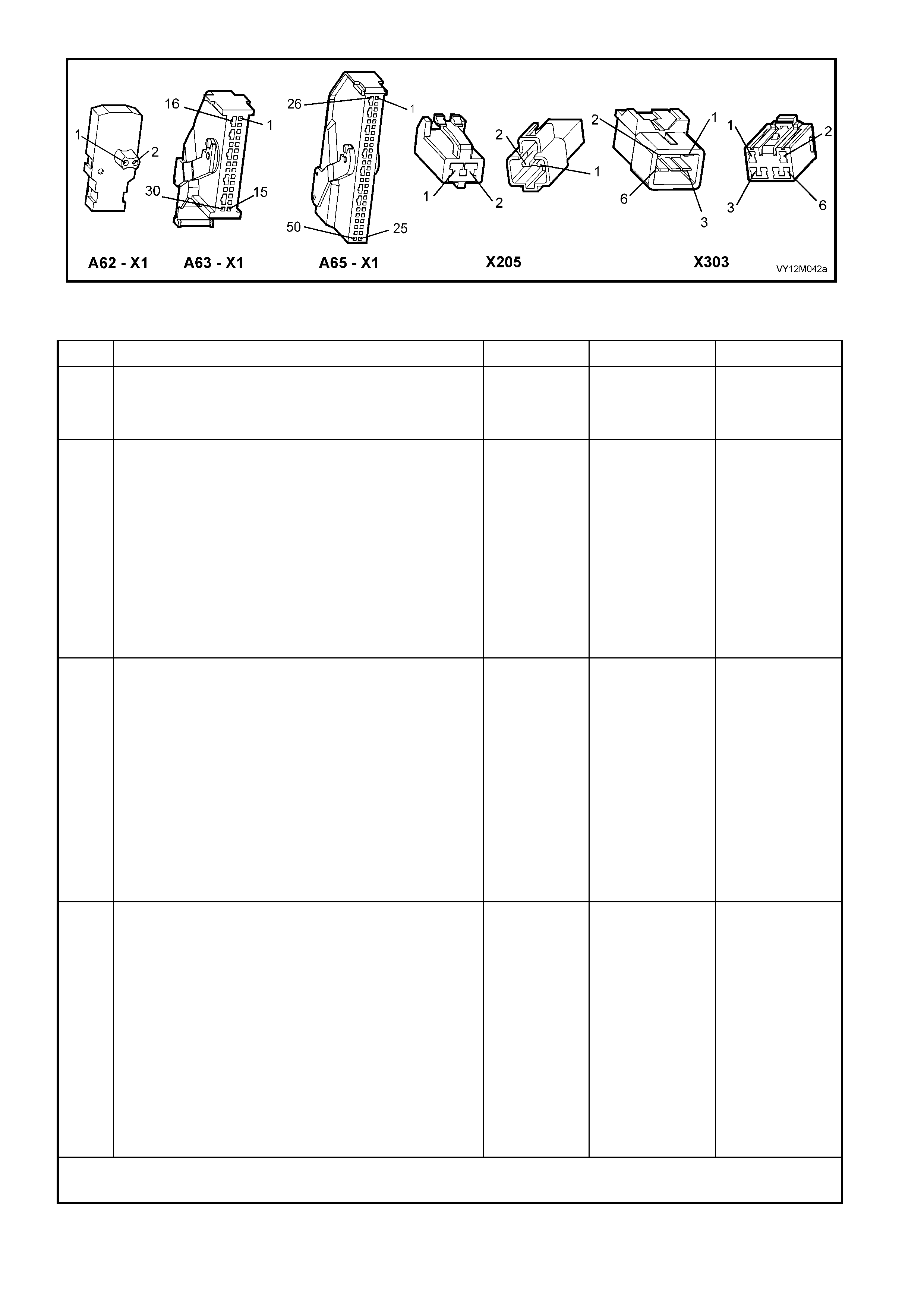
Figure 12M-184
DTC 38 – PASSENGER AIRBAG CIRCUIT RESISTANCE TOO LOW
STEP ACTION VALUE YES NO
1. 1. Install TECH 2 to DLC.
2. Select Body / SRS / Diagnostic Trouble Codes /
Read DTC Information.
Is DTC 38 current?
Go to Step 3. Go to Step 2.
2. 1. Remove instrument panel compartment to gain
access to passenger airbag, refer to Section 1A3
INSTRUMENT PANEL AND CONSOLE.
2. With TECH 2 still connected, select Diagnostic
Trouble Codes / Clear DTC Information and clear all
(if any) DTCs.
3. Select Diagnostic Trouble Codes / Read DTC
Information, 'wiggle' OPS / SRS wiring harness at all
locations between the SDM and the passenger
airbag wiring harness connector A62 – X1, while
monitoring TECH 2 screen display.
Does TECH 2 screen display change status from No
Diagnostic Trouble Codes?
Make repairs as
necessary (refer
to Section NOTE
2 on previous
page).
Clear DTC and
recheck system
to verify repair.
Fault not present.
Check all system
wiring harness
connect ors, and
terminals.
Clear DTC and
recheck system.
3. 1. Disable the OPS / SRS, refer to Section 2.2
SYSTEM DISABLING AND ENABLING
PROCEDURE in this Section.
2. Disconnect passenger airbag module, wiring
harness connector A62 – X1.
3. Connect Tool No. SD28280B to OPS / SRS wiring
harness connector A62 – X1.
4. Reconnect battery.
5. Connect TECH 2 to DLC.
6. Select Body / SRS / Diagnostic Trouble Codes /
Read DTC Information.
Is DTC 38 still current?
Go to Step 4. Replace
passenger airbag
module
assembly, refer
to Section 2.4
INSTRUMENT
PANEL
INFLATABLE
RESTRAINT
MODULE
ASSEMBLY in
this Section.
Clear DTC and
recheck system
to verify repair.
4. 1. Disable the OPS / SRS, refer to Section 2.2
SYSTEM DISABLING AND ENABLING
PROCEDURE in this Section.
2. Disconnect SDM wiring harness connector A63/A65
– X1 from the SDM.
3. Remove Tool No. SD28280B from OPS / SRS
wiring harness connector A62 – X1.
4. W ith OPS / SRS wiring harness connector A62 – X1
disconnected, and using Tool KM-609-20, check
wiring between SDM wiring harness connector
A63/A65 – X1, terminal 13 and OPS / SRS wiring
harness connector A62 – X1, circuit 3025
(Yellow/Black wire) for open circuit (refer to Section
NOTE 1 and 3 on previous page).
Does continu ity ex ist?
Repair short in
circuits 3025 and
3024, between
SDM wiring
harness
connector
A63/A65 – X1
and A62 – X1 as
necessary (refer
to Section NOTE
2 on previous
page).
Clear DTC and
recheck system
to verify repair.
Replace SDM,
refer to Section
2.8 INFLATABLE
RESTRAINT
CONTROL
MODULE in this
Section.
Recheck circuit
to verify repair.
WHEN ALL DIAGNOSIS AND REPAIRS ARE COMPLETED, ENSURE ALL OPS / SRS COMPONENTS ARE
RECONNECTED, CLEAR ALL DTC’s, ENABLE THE OPS / SRS AND VERIFY CORRECT OPERATION

DTC 247 – PASSENGER AIRBAG CIRCUIT POWER STAGE ERROR
Figure 12M-185
CIRCUIT DESCRIPTION
At ignition on, the SDM performs an initial system self check of the SDM power stages. If durin g this initial self
test the SDM detects a fault with the passenger’s airbag power stage a current DTC 247 Passenger’s Airbag
Circuit Power Sta ge Error wil l set. On completio n of the in itial system self tes t the SDM the n perform s a test of
the Pass eng er’s A irba g C irc uit. If the SD M detects a p roblem with t his c irc u it t he as soc iated P ass enger’s A irbag
Circuit DTC will be set and the DTC 247 Passenger’s Airbag Circuit Power Stage Error will become a history
DTC.
DTC 247 Passenger Airbag Circuit Power Stage Error will set if a fault occurs in the passenger airbag circuit,
connector A62 – X 1 with the in- b ui lt cap ac itor, conn ec tor X 205, c on nec tor X 30 3, t he O P S / SR S wir ing harn e s s ,
connector A63/A65 – X1 or SDM.
When a history DTC 247 Passenger’s Airbag Circuit Power Stage Error sets, the SDM illuminates the SRS
warning indic a tor . S hou ld t he f ault c on dit ions d etec te d b y the SD M c lear d ur ing th e s ame igniti on c ycl e the c ode
will rem ain a histor y DTC 247 Pas senger’s A irbag Circuit Power Stage Error for all ignit ion cycles unti l cleared.
The SRS warning indicator will remain on for the remainder of the ignition cycle.
When a DTC 247 Passenger’s Airbag Circuit Power Stage Error sets, the SDM illuminates the SRS warning
indicator for the rem ainder of the ignit io n cycle. Shou ld the f ault c ondit io ns detec te d b y the SDM c lear during the
same ign ition c ycle t he cod e will remain a hist or y DTC 247 Pas senger ’s Airbag C i rcuit Po wer Stag e Err or for all
ignition cycles until cleared. The SRS warning indicator will also remain illuminated until the history DTC 247
Passenger’s Airbag Circuit Power Stage Error is cleared.
If a DTC 247 Passenger’s Airbag Circuit Power Stage is set, dependent on where the fault is, the passenger’s
airbag m a y not operate.
ACTION REQUIRED
If DTC 247 Pas senger’s Airbag Circ uit Power St age Error and any other DT C is set then the d iagnostics for the
other DT C should be car ried out f irst. For ex ample if a DTC 247 Pas senger’s A irbag Circui t Power St age Error
and a DTC 37 Passenger’s Airbag Circuit Resistance High are set, the diagnostics for a DTC 37 Passenger’s
Airbag Circuit Resistance High should be carried out first.
If only a DTC 247 Passenger’s Airbag Circuit Power Stage Error is set then the SDM should be replaced.
NOTE: An inter mittent in th e pas s enger ’s air ba g cir cuit ma y cause a DT C 247 Pas s enger ’s A ir ba g Circ uit P o wer
Stage Error to set.
After the fault has been rectified, ensure that all SRS components are reconnected, clear DTCs, enable the
SRS and verify the correct operation of the system (ie. warning indicator not illuminated after five seconds of
ignition being switched ON).
TEST DESCRIPTION
The following numbers refer to Section Step numbers in the following diagnostic chart.
1. Us es T ECH 2 to chec k if a DT C 247 Passeng er Airb ag Cir cuit Power Sta ge Error is histor y code, a nd if an y
other passenger airbag circuit current or history DTCs are set. If any other DTCs are set refer to Section
these DTCs first.
2. Checks for intermittent fault by monitoring TECH 2 screen during ignition on cycle. If screen display
changes during a wiring 'wiggle' test, a f ault with th e wiring is at th at location. If no other DT Cs are set and
there are no intermittents in the passenger airbag circuit then the SDM should be replaced.
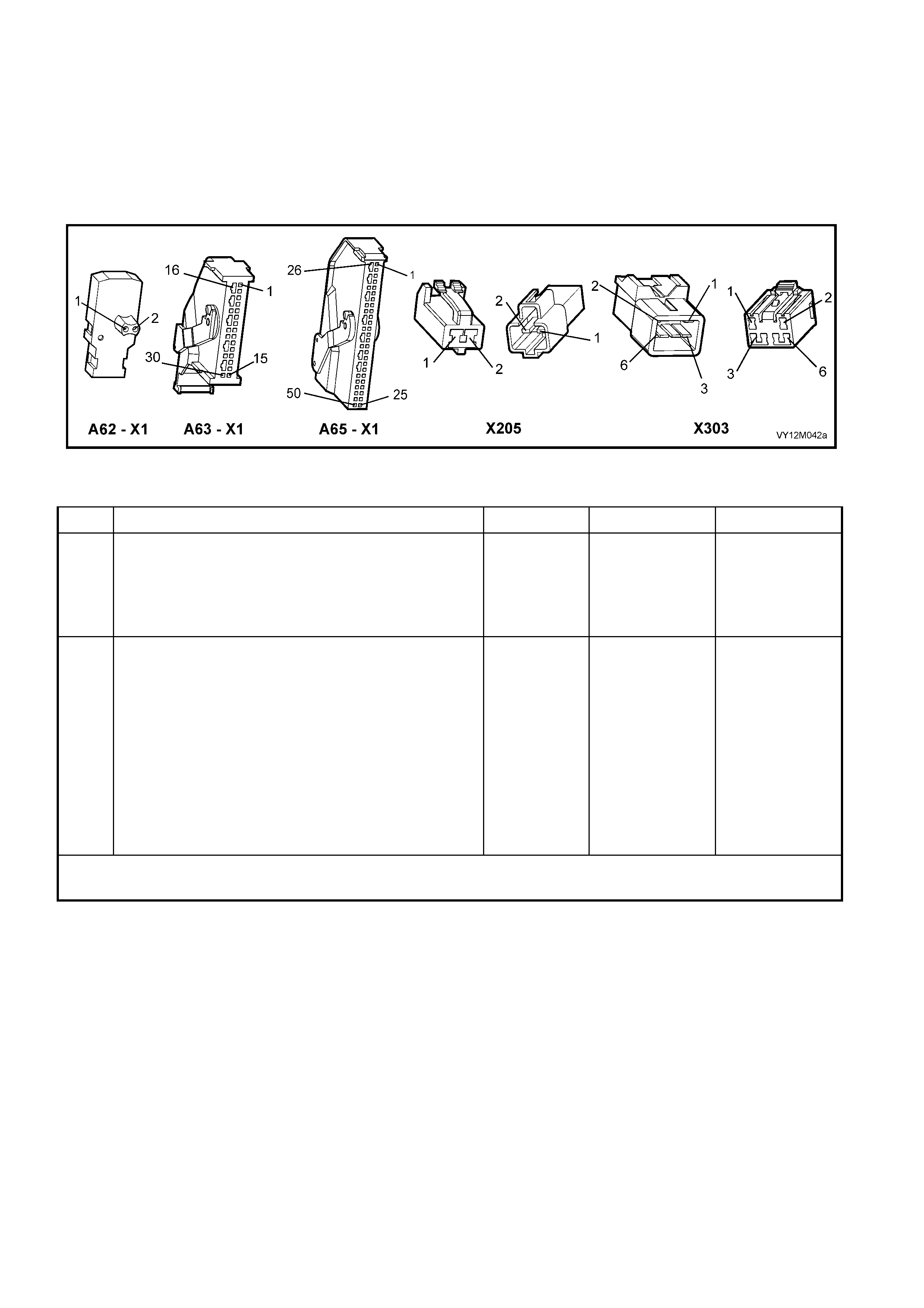
NOTES ON DIAGNOSTIC CHART
1. For all wiring harness checking procedures, refer to Section 12P WIRING DIAGRAMS.
2. Refer to 2.11 OPS / SRS WIRING REPAIR in this Section, before conducting any OPS / SRS wiring
harness repairs.
3. Resistance cannot be measured between the two terminals in connector A62 – X1, as the in-built capacitor
blocks measurement. Therefore, a ‘service hole’ is incorporated into the connector for fault tracing. Refer
to 1.1 SYSTEM COMPONENTS, WIRING HARNESS in this Section for more details on this type of
connector.
Figure 12M-186
DTC 247 – PASSENGER AIRBAG CIRCUIT POWER STAGE ERROR
STEP ACTION VALUE YES NO
1. 1. Install TECH 2 to DLC.
2. Select Body / SRS / Diagnostic Trouble Codes /
Read DTC Information.
Is a DTC 247 Passenger’s Airbag Circuit Power Stage
Error a history DTC, and are any other passenger’s
airbag circuit DTCs set?
Go to other
passenger’s
airbag circuit
DTC diagnostic
chart in this
Section.
Go to Step 2.
2. 1. Remove instrument panel compartment to gain
access to passenger airbag, refer to Section 1A3
INSTRUMENT PANEL AND CONSOLE.
2. With TECH 2 still connected, select Diagnostic
Trouble Codes / Clear DTC Information and clear all
(if any) DTCs.
3. Select Diagnostic Trouble Codes / Read DTC
Information, 'wiggle' OPS / SRS wiring harness at all
locations between the SDM and the passenger
airbag wiring harness connector A62 – X1, while
monitoring TECH 2 screen display.
Does TECH 2 screen display change status from No
Diagnostic Trouble Codes?
Go to applicable
DTC chart in this
Section.
Replace SDM,
refer to Section
2.8 INFLATABLE
RESTRAINT
CONTROL
MODULE in this
Section.
Recheck circuit
to verify repair.
WHEN ALL DIAGNOSIS AND REPAIRS ARE COMPLETED, ENSURE ALL OPS / SRS COMPONENTS ARE
RECONNECTED, CLEAR ALL DTC’s, ENABLE THE OPS / SRS AND VERIFY CORRECT OPERATION
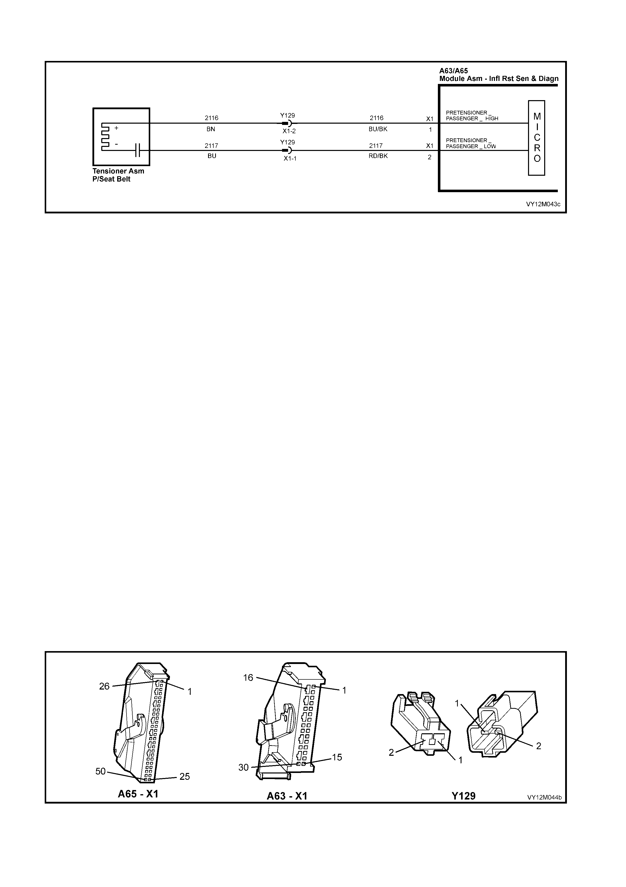
DTC 49 – LEFT-HAND PRETENSIONER CIRCUIT SHORT TO BATTERY
Figure 12M-187
CIRCUIT DESCRIPTION
At ignition on, and on a constant monitoring cycle of every 500 milliseconds during the ignition cycle, the
inflatable restraint control module (SDM) performs a system self check.
If the SDM detects a resistance to battery supply is less than 5 kohms in either the positive and/or negative
circuit for more than 3 – 5 seconds, a current DTC 49 will set (refer to 4.3 OPS / SRS SELF DIAGNOSTICS in
this Section for more details).
DTC 49 will set if circuits 2116 (left-hand Pretensioner positive side) and/or 2117 (left-hand Pretensioner
negative side) are shorted to battery +.
W hen DTC 49 sets, the SD M illuminates the SR S war ning in dicat or and sets a cur rent DT C 49. Should t he fault
conditions detected by the SDM c lear during the same ignition cycle, t he current code will clear and become a
history DTC 49. The SRS warning indicator will remain on for the remainder of the ignition cycle.
If a DTC 49 is set, the SRS warning indicator is illuminated on each ignition cycle, even if the DTC is set as a
histor y DTC, until the fault condit ions for s etting DTC 49 are rectified an d the DTC (c urrent or histor y) ca n then
be cleared from the SDM via TECH 2.
If DTC 49 is set, the OPS / SRS, inc luding the le ft-hand Pr etension er, will stil l be operatio nal due to the r eserve
energy supply stored in the SDM.
TEST DESCRIPTION
The following number refer to Section step numbers in the following diagnostic chart:
1. Uses TECH 2 to check if DTC 49 is current or history.
2. Checks for intermittent fault by monitorin g TECH 2 scr een. If s cr een dis p lay changes dur i ng a wirin g 'wig gl e'
test, a fault with the wiring is at that location.
3. Checks circuits 2116 and 2117 for a short to battery +.
NOTES ON DIAGNOSTIC CHART
1. For all wiring harness checking procedures, refer to Section 12P WIRING DIAGRAMS.
2. Refer to 2.11 OPS / SRS WIRING REPAIR in this Section, before conducting any OPS / SRS wiring
harness repairs.
3. Resistance cannot be m easured b etween the two ter minals in conn ector A62 – X 1, as the in-built c apacit or
block s measur ement. Theref ore, a ‘servic e hole’ is incorpor ated into the c onnecto r for fault trac ing. Refer to
1.1 SYSTEM COMPONENTS, WIRING HARNESS in this Section for more details on this type of connector.
Figure 12M-188

DTC 49 – LEFT-HAND PRETENSIONER CIRCUIT SHORT TO BATTERY
STEP ACTION VALUE YES NO
1. 1. Install TECH 2 to DLC.
2. Select Body / SRS / Diagnostic Trouble Codes /
Read DTC Information.
Is DTC 49 current?
Go to Step 3. Go to Step 2.
2. 1. With TECH 2 still connected, select Diagnostic
Trouble Codes / Clear DTC Information and clear all
(if any) DTCs.
2. Select Diagnostic Trouble Codes / Read DTC
Information, 'wiggle' OPS / SRS wiring harness at all
locations between the SDM and the left-hand
Pretensioner wiring harness, while monitoring TECH
2 screen display.
Does TECH 2 screen display change status from No
Diagnostic Trouble Codes?
Make repairs as
necessary (refer
to Section NOTE
2 & 4on previous
page).
Clear DTC and
recheck system
to verify repair.
Fault not present.
Check all system
wiring harness
connect ors, and
terminals, refer to
Section NOTE 5
on previous
page.
Clear DTC and
recheck system.
3. 1. Disable the OPS / SRS, refer to Section 2.2
SYSTEM DISABLING AND ENABLING
PROCEDURE in this Section.
2. Disconnect SDM wiring harness connector A63/A65
– X1 from the SDM.
3. Disconnect the OPS / SRS wiring harness
connector Y129 – X1 for the left-hand pretensioner.
4. Reconnect battery.
5. Using Tool KM-609-20, check wiring between SDM
wiring harness connector A63/A65 – X1, terminals 1
and 2, and left-hand Pretensioner connector X305,
circuits 2116 (Blue/Black wire) and 2117 (Red/Black
wire) for short to battery + (refer to Section NOTES
1 and 3 on previous page).
Is all OK?
Replace SDM,
refer to Section
2.8 INFLATABLE
RESTRAINT
CONTROL
MODULE in this
Section.
Recheck circuit
to verify repair.
Make repairs as
necessary (refer
to Section NOTE
2 on previous
page).
Clear DTC and
recheck system
to verify repair.
WHEN ALL DIAGNOSIS AND REPAIRS ARE COMPLETED, ENSURE ALL OPS / SRS COMPONENTS ARE
RECONNECTED, CLEAR ALL DTC’s, ENABLE THE OPS / SRS AND VERIFY CORRECT OPERATION

DTC 50 – LEFT-HAND PRETENSIONER CIRCUIT SHORT TO EARTH
Figure 12M-189
CIRCUIT DESCRIPTION
At ignition on, and on a constant monitoring cycle of every 500 milliseconds during the ignition cycle, the
inflatabl e rest raint c ontrol m odule (SDM) perf orm s a system s elf check . If the SDM det ects a resis tance t o earth
of less than 3 k ohm s in either the posit ive or n egati ve c ircuit f or mor e than 3 – 5 seconds , a curre nt DT C 50 wil l
set (refer to 4.3 OPS / SRS SELF DIAGNOSTICS in this Section for more details).
DTC 50 will set if circuits 2116 (left-hand Pretensioner positive side) and or 2117 (left-hand Pretensioner
negative side) are shorted to earth.
W hen DTC 50 sets, the SD M illuminates the SR S war ning in dicat or and sets a cur rent DT C 50. Should t he fault
conditions detected by the SDM c lear during the same ignition cycle, t he current code will clear and become a
history DTC 50. The SRS warning indicator will remain on for the remainder of the ignition cycle.
If a DTC 50 is set, the SRS warning indicator is illuminated on each ignition cycle, even if the DTC is set as a
histor y DTC, until the fault condit ions for s etting DTC 50 are rectified an d the DTC (c urrent or histor y) ca n then
be cleared from the SDM via TECH 2.
If DTC 50 is s et, the OPS, i nc lud ing t he l ef t- hand Prete ns ion er, wil l s ti ll b e oper ati o nal d ue to t he r es erv e energy
supply stored in the SDM.
TEST DESCRIPTION
The following number refer to Section step numbers in the following diagnostic chart:
1. Uses TECH 2 to determine if DTC 50 is current or history.
2. TECH 2 in this m ode should displa y approxim ately 1.6 – 6.4 ohm s if the left-hand Pretensioner loop circuit
is OK.
3. If screen display changes during a wiring 'wiggle' test, a fault with the wiring is at that location.
4. Tool AU4 58 is a d umm y load tak ing the place of the Prete nsioner ass embl y. If TECH 2 disp lays the c orrect
resistance of the dummy load, the system fault is in the Pretensioner assembly.
5. This test checks the wiring between the SDM wiring harness connector A65 – X1 (8.1 SDM) or A63 – X1
(8.0 SDM), terminal 1 and the left-hand Pretensioner connector X305 for faults.
6. This test checks the wiring between the SDM wiring harness connector A65 – X1 (8.1 SDM) or A63 – X1
(8.0 SDM), terminal 2 and the left-hand Pretensioner connector X305 for faults.
NOTES ON DIAGNOSTIC CHART
1. For all wiring harness checking procedures, refer to Section 12P WIRING DIAGRAMS.
2. Refer to 2.11 OPS / SRS WIRING REPAIR in this Section, before conducting any OPS / SRS wiring
harness repairs.
3. Refer to Section 12O FUSES & WIRING HARNESSES for OPS / SRS wiring harness routing.
4. Resistance cannot be measured between the two terminals in left-hand pretensioner connector Y129 as
the in-built capacitor blocks measurement.
5. W iring should b e checked at point where TECH 2 screen display changed. If necessary, split open wiring
harness.
6. If fault cannot be identified, the wiring harness should be replaced.

Figure 12M-190
DTC 50 – LEFT-HAND PRETENSIONER CIRCUIT SHORT TO EARTH
STEP ACTION VALUE YES NO
1. 1. Install TECH 2 to DLC.
2. Select Body / SRS / Diagnostic Trouble Codes /
Read DTC Information.
Does TECH 2 display DTC 50 as a Current DTC?
Go to Step 2. Go to Step 3.
2. 1. With TECH 2 still connected, select Body / SRS /
Data Display and scroll to LEFT-HAND
PRETENSIONER LOOP RESISTANCE'.
Is the resistance value displayed on TECH 2 as
specified?
Approx.
1.6 – 6.4
Ohms
Go to Step 3. Go to Step 4.
3. 1. With TECH 2 still connected, select Diagnostic
Trouble Codes / Clear DTC Information and clear all
(if any) DTCs.
2. Select Diagnostic Trouble Codes / Read DTC
Information, 'wiggle' OPS / SRS wiring harness at all
locations between the SDM and the left-hand
Pretensioner INCLUDING wiring harness connector
Y129, while monitoring TECH 2 screen display.
Does TECH 2 screen display change status from No
Diagnostic Trouble Codes?
Make repairs as
necessary (refer
to Section NOTE
2 & 5 on previous
page).
Clear DTC and
recheck system
to verify repair.
Fault not present.
Check all system
wiring harness
connect ors, and
terminals, refer to
Section NOTE 6
on previous
page.
Clear DTC and
recheck system.
4. 1. Disable the OPS / SRS refer to Section 2.2
DISABLING AND ENABLING PROCEDURE in this
Section.
2. Disconnect left-hand Pretensioner wiring harness
connector Y129.
3. Connect Tool No. AU458 to OPS / SRS wiring
harness connec tor Y 129.
4. With TECH 2 still connected, select Body / SRS /
Data Display and scroll to LEFT-HAND
PRETENSIONER LOOP RESISTANCE'.
Is the resistance value displayed on TECH 2 as
specified?
Approx.
3.0 Ohms
Replace left-hand
Pretensioner
assembly, refer
to Section 2.5
SEAT BELT
BUCKLE AND
PRETENSIONE
R ASSEMBLY.
Clear DTC and
recheck system
to verify repair.
Go to Step 5.
5. 1. Disconnect SDM wiring harness connector A63/A65
– X1 from the SDM.
2. Remove Tool AU458 from Y129.
3. Using Tool KM-609-20, check wiring between SDM
wiring harness connector A63/A65 – X1, terminal 1
and left-hand Pretensioner connector Y129, terminal
2, circuit 2116 (Blue/Black wire) for short to earth
(refer to Section NOTE 1 on previous page).
Is all OK?
Go to Step 6. Make repairs as
necessary (refer
to Section NOTE
2 on previous
page).
Clear DTC and
recheck system
to verify repair.
6. 1. With SDM wiring harness connector A63/A65 – X1
disconnected from the SDM. Using Tool KM-609-20,
check wiring between SDM wiring harness
connector A63/A65 – X1, terminal 2 and left-hand
Pretensioner connector Y129, terminal 1, circuit
2117 (Red/Black wire) for a short to earth (refer to
Section NOTES 1 and 4 on previous page).
Is all OK?
Replace SDM ,
refer to Section
2.8 INFLATABLE
RESTRAINT
CONTROL
MODULE in this
Section. Recheck
circuit to verify
repair.
Make repairs as
necessary (refer
to Section NOTE
2 on previous
page).
Clear DTC and
recheck system
to verify repair.
WHEN ALL DIAGNOSIS AND REPAIRS ARE COMPLETED, ENSURE ALL OPS / SRS COMPONENTS ARE
RECONNECTED, CLEAR ALL DTC’s, ENABLE THE OPS / SRS AND VERIFY CORRECT OPERATION

DTC 51 – LEFT-HAND PRETENSIONER CIRCUIT CAPACITANCE TOO HIGH
Figure 12M-191
CIRCUIT DESCRIPTION
At ignition on and on a constant monitoring cycle of every 500 milliseconds during the ignition cycle, the
inflatable restraint control module (SDM) performs a system self check.
If the SDM detects the capacitance in the left-hand Pretensioner circuit is too high (greater than 550 nF) for
longer than 3 – 5 seconds, a current DTC 51 will set (refer to 4.3 OPS / SRS SELF DIAGNOSTICS in this
Section for more details).
DTC 51 will set if the in-built capacitor in the left-hand Pretensioner is faulty.
W hen DTC 51 sets, the SD M illuminates the SR S war ning in dicat or and sets a cur rent DT C 51. Should t he fault
conditions detected by the SDM c lear during the same ignition cycle, t he current code will clear and become a
history DTC 51. The SRS warning indicator will remain on for the remainder of the ignition cycle.
If a DTC 51 is set, the SRS warning indicator is illuminated on each ignition cycle, even if the DTC is set as a
histor y DTC, until the fault condit ions for s etting DTC 51 are rectified an d the DTC (c urrent or histor y) ca n then
be cleared from the SDM via TECH 2.
ACTION REQUIRED
If DTC 51 is set, the left-hand Pr etensioner ma y not o perate and ther efore, the le ft-hand Prete nsioner ( between
left-hand Pretensioner OPS / SRS connector Y129) must be replaced.
NOTE: Before removing the OPS / SRS Pretensioner wiring harness, take note of wiring harness routing and
how it is retained to the front seat.
After the OPS / SRS Pretensioner wiring harness, the Pretensioner and wiring harness connector Y129 has
been replaced, ensure all OPS / SRS components are reconnected, clear DTCs, enable the OPS / SRS and
verify the correct operation of the system (i.e. warning indicator not illuminated after five seconds of ignition
being switched ON).
NOTE: After the wiring harness has been replaced, the front seat should be put through its full adjustment
(forward/backwards, full recline and up and down) to ensure that the wiring harness does not foul with any of the
seat components.

DTC 52 – LEFT-HAND PRETENSIONER CIRCUIT CAPACITANCE TOO LOW
Figure 12M-192
CIRCUIT DESCRIPTION
At ignition on, and on a constant monitoring cycle of every 500 milliseconds during the ignition cycle, the
inflatable restraint control module (SDM) performs a system self check.
If the SDM detects the capacitance in the left-hand Pretensioner circuit is too low (less than 390 nF) for longer
than 3 – 5 seconds, a current DTC 52 will set (refer to 4.3 OPS / SRS SELF DIAGNOSTICS in this Section for
more details).
DTC 52 will set if the in-built capacitor in the left-hand Pretensioner is faulty.
W hen DTC 52 sets, the SD M illuminates the SR S war ning in dicat or and sets a cur rent DT C 52. Should t he fault
conditions detected by the SDM c lear during the same ignition cycle, t he current code will clear and become a
history DTC 52. The SRS warning indicator will remain on for the remainder of the ignition cycle.
If a DTC 52 is set, the SRS warning indicator is illuminated on each ignition cycle, even if the DTC is set as a
histor y DTC, until the fault condit ions for s etting DTC 52 are rectified an d the DTC (c urrent or histor y) ca n then
be cleared from the SDM via TECH 2.
ACTION REQUIRED
If DTC 52 is set, the left-hand Pr etensioner ma y not o perate and ther efore, the le ft-hand Prete nsioner ( between
left-hand Pretensioner OPS / SRS connector Y129) must be replaced.
NOTE: Before removing the OPS / SRS Pretensioner wiring harness, take note of wiring harness routing and
how it is retained to the front seat.
After the OPS / SRS Pretensioner wiring harness, the Pretensioner and wiring harness connector Y129 has
been replaced, ensure all OPS / SRS components are reconnected, clear DTCs, enable the OPS / SRS and
verify the correct operation of the system (i.e. warning indicator not illuminated after five seconds of ignition
being switched ON).
NOTE: After the wiring harness has been replaced, the front seat should be put through its full adjustment
(forward/backwards, full recline and up and down) to ensure that the wiring harness does not foul with any of the
seat components.
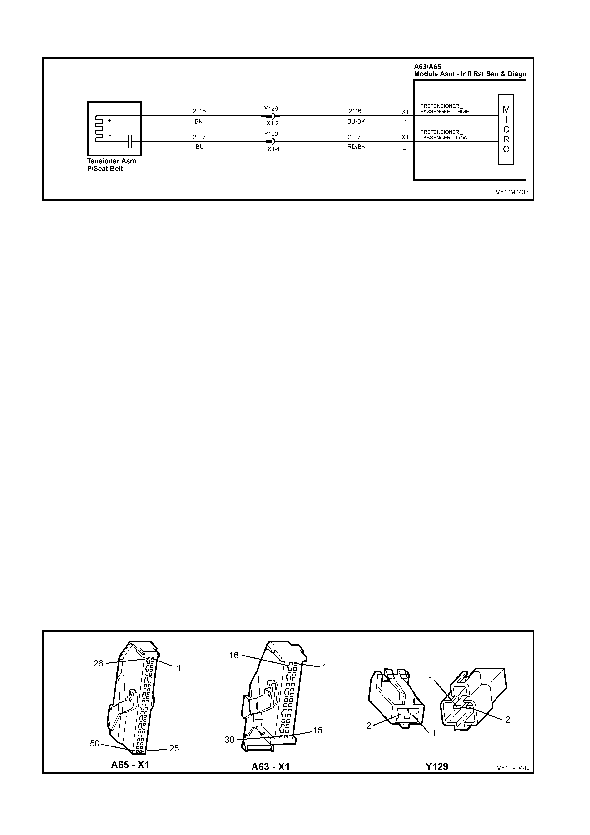
DTC 53 – LEFT-HAND PRETENSIONER CIRCUIT RESISTANCE TOO HIGH
Figure 12M-193
CIRCUIT DESCRIPTION
At ignition on and on a constant monitoring cycle of every 500 milliseconds during the ignition cycle, the
inflatable restraint control module (SDM) performs a system self check.
If the SDM detects a resistance in the left-hand Pretensioner circuit that is too high (greater than 8.4 ohm) for
longer than 3 – 5 seconds, a current DTC 53 will set (refer to 4.3 OPS / SRS SELF DIAGNOSTICS in this
Section for more details).
DTC 53 will set if circuits 2116 or 2117 (including the left-hand Pretensioner assembly ) are open circuit.
W hen DTC 53 sets, the SD M illuminates the SR S war ning in dicat or and sets a cur rent DT C 53. Should t he fault
conditions detected by the SDM c lear during the same ignition cycle, t he current code will clear and become a
history DTC 53. The SRS warning indicator will remain on for the remainder of the ignition cycle.
If a DTC 53 is set, the SRS warning indicator is illuminated on each ignition cycle, even if the DTC is set as a
histor y DTC, until the fault condit ions for s etting DTC 53 are rectified an d the DTC (c urrent or histor y) ca n then
be cleared from the SDM via TECH 2.
If DTC 53 is set, dependent on where the fault is, the left-hand Pretensioner may not operate.
TEST DESCRIPTION
The following number refer to Section step numbers in the following diagnostic chart:
1. Uses TECH 2 to check if DTC 53 is current or history.
2. Checks for intermittent fault by monitoring TECH 2 screen. If screen display changes during a wiring
'wiggle' test, a fault with the wiring is at that location.
3. Tool SD28280B is a dummy load taking the place of the left-hand Pretensioner assembly. If DTC 53
becomes a history DTC with dummy load connected, the system fault is in the left-hand Pretensioner
assembly.
4. Checks if open circuit is in the OPS / SRS connector harness. If connector Y129 is disconnected and it’s
terminal’s are bridged together, DTC 53 will become a history DTC if this connector harness is faulty.
5. Checks circuit 2116 for open circuit.
6. Checks circuit 2117 for open circuit.
NOTES ON DIAGNOSTIC CHART
1. For all wiring harness checking procedures, refer to Section 12P WIRING DIAGRAMS.
2. Refer to 2.11 OPS / SRS WIRING REPAIR in this Section, before conducting any OPS / SRS wiring
harness repairs.
Figure 12M-194

DTC 53 – LEFT-HAND PRETENSIONER CIRCUIT RESISTANCE TOO HIGH
STEP ACTION VALUE YES NO
1. 1. Install TECH 2 to DLC.
2. Select Body / SRS / Diagnostic Trouble Codes /
Read DTC Information.
Is DTC 53 current?
Go to Step 3. Go to Step 2.
2. 1. With TECH 2 still connected, select Diagnostic
Trouble Codes / Clear DTC Information and clear all
(if any) DTCs.
2. Select Diagnostic Trouble Codes / Read DTC
Information, 'wiggle' OPS / SRS wiring harness at all
locations between the SDM and the left-hand
Pretensioner INCLUDING wiring harness connector
Y129, while monitoring TECH 2 screen display.
Does TECH 2 screen display change status from No
Diagnostic Trouble Codes?
Make repairs as
necessary (refer
to Section NOTE
2 on previous
page).
Clear DTC and
recheck system
to verify repair.
Fault not present.
Check all system
wiring harness
connect ors, and
terminals.
Clear DTC and
recheck system.
3. 1. Disable the OPS / SRS refer to Section 2.2
DISABLING AND ENABLING PROCEDURE in this
Section.
2. Disconnect left-hand Pretensioner wiring harness
connector Y129.
3. Connect Tool No. AU458 to OPS / SRS wiring
harness connec tor Y 129.
4. Reconnect battery.
5. Connect TECH 2 to DLC.
6. Select Body / SRS / Diagnostic Trouble Codes /
Read DTC Information.
Is DTC 53 still current?
Go to Step 4. Replace left-hand
Pretensioner
assembly, refer
to Section 2.5
SEAT BELT
BUCKLE AND
PRETENSIONE
R ASSEMBLY.
Clear DTC and
recheck system
to verify repair.
4. 1. Disable the OPS / SRS refer to Section 2.2
DISABLING AND ENABLING PROCEDURE in this
Section.
2. Disconnect left-hand Pretensioner wiring harness
connector Y129.
3. Reconnect battery.
4. Using a suitable jumper wire from KM-609, bridge
terminals in connector Y129 together
(NOTE: This step may set a current DTC 54).
5. With TECH 2 still connected, select Body / SRS /
Diagnostic Trouble Codes / Read DTC Information.
Does DTC 53 become history?
Replace left-hand
Pretensioner
assembly, refer
to Section 2.5
SEAT BELT
BUCKLE AND
PRETENSIONE
R ASSEMBLY.
Clear DTC and
recheck system
to verify repair.
Go to Step 5.
5. 1. Disable the OPS / SRS refer to Section 2.2
DISABLING AND ENABLING PROCEDURE in this
Section.
2. Disconnect SDM wiring harness connector A63/A65
– X1 from the SDM.
3. Using Tool KM-609-20, check wiring between SDM
wiring harness connector A63/A65 – X1, terminal 1
and OPS / SRS wiring harness connector Y129,
circuit 2116 (Blue/Black wire) for open circuit (refer
to Section NOTE 1 on previous page).
Is all OK?
Go to Step 6. Make repairs as
necessary (refer
to Section NOTE
2 on previous
page).
Clear DTC and
recheck system
to verify repair.
6. 1. With SDM wiring harness connector A63/A65 – X1
disconnected from the SDM and using Tool KM-
609-20, check wiring between SDM wiring harness
connector A63/A65 – X1, terminal 2 and OPS / SRS
wiring harness connector Y129, circuit 2117
(Red/Black wire) for open (refer to Section NOTE 1
on previous page).
Is all OK?
Replace SDM,
refer to Section
2.8 INFLATABLE
RESTRAINT
CONTROL
MODULE in this
Section. Recheck
circuit to verify
repair.
Make repairs as
necessary (refer
to Section NOTE
2 on previous
page).
Clear DTC and
recheck system
to verify repair.
WHEN ALL DIAGNOSIS AND REPAIRS ARE COMPLETED, ENSURE ALL OPS / SRS COMPONENTS ARE
RECONNECTED, CLEAR ALL DTC’s, ENABLE THE OPS / SRS AND VERIFY CORRECT OPERATION
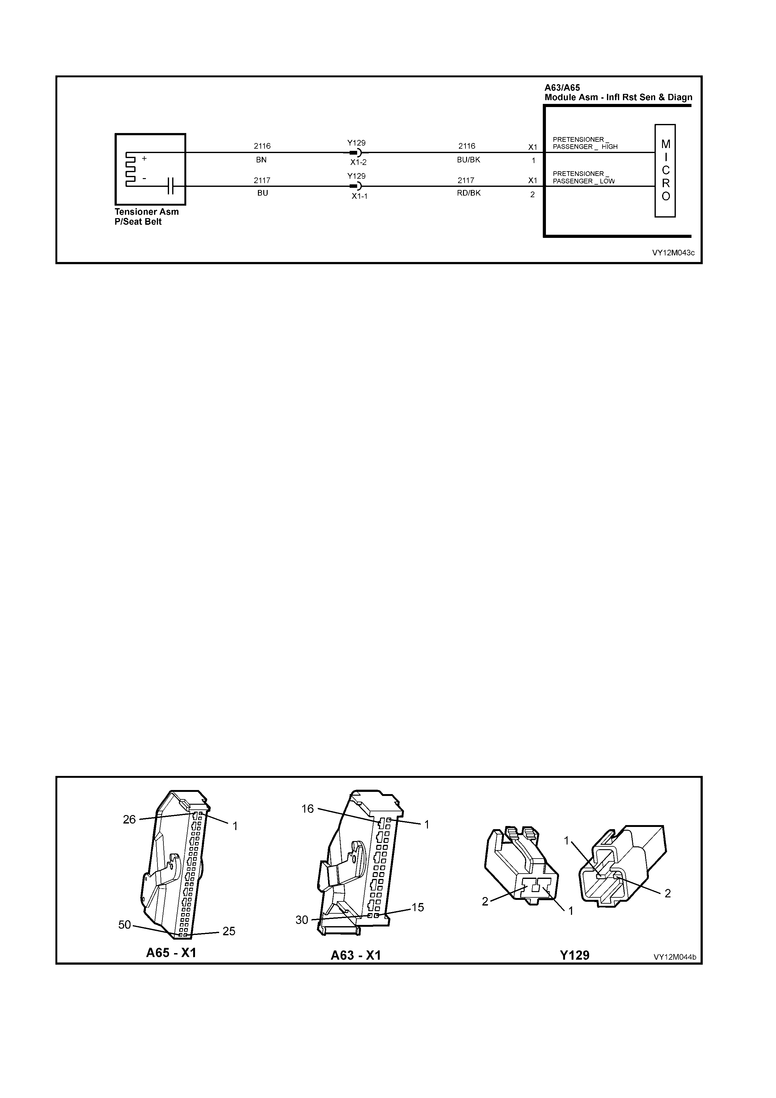
DTC 54 – LEFT-HAND PRETENSIONER CIRCUIT RESISTANCE TOO LOW
Figure 12M-195
CIRCUIT DESCRIPTION
At ignition on, and on a constant monitoring cycle of every 500 milliseconds during the ignition cycle, the
inflatable restraint control module (SDM) performs a system self check.
If the SD M d etec ts a resis t anc e i n t he lef t- hand Pretens ion er c irc uit that is to o lo w ( les s tha n 0.6 ohm) f or longer
than 3 – 5 seconds, a current DTC 54 will set (refer to 4.3 OPS / SRS SELF DIAGNOSTICS in this Section for
more details).
DTC 54 will set if circuits 2116 or 2117, (including the Pretensioner assembly) are shorted together.
W hen DTC 54 sets, the SD M illuminates the SR S war ning in dicat or and sets a cur rent DT C 54. Should t he fault
conditions detected by the SDM c lear during the same ignition cycle, t he current code will clear and become a
history DTC 54. The SRS warning indicator will remain on for the remainder of the ignition cycle.
If a DTC 54 is set, the SRS warning indicator is illuminated on each ignition cycle, even if the DTC is set as a
histor y DTC, until the fault condit ions for s etting DTC 54 are rectified an d the DTC (c urrent or histor y) ca n then
be cleared from the SDM via TECH 2.
If DTC 54 is set, dependent on where the fault is, the belt Pretensioner may not operate.
TEST DESCRIPTION
The following number refer to Section step numbers in the following diagnostic chart:
1. Uses TECH 2 to check if DTC 54 is current or history.
2. Checks for intermittent fault by monitoring TECH 2 screen. If screen display changes during a wiring
'wiggle' test, a fault with the wiring is at that location.
3. T ool AU458 is a d umm y load tak ing the place of the left- hand Pretensi oner asse mbl y. If DTC 54 bec omes
a history DTC with dummy load connected, the system fault is in the left-hand Pretensioner assembly.
4. This test checks the wiring between the SDM wiring harness connector A65 – X1 (8.1 SDM) or A63 – X1
(8.0 SDM) and OPS / SRS wiring harness connector Y129 for a short circuit.
NOTES ON DIAGNOSTIC CHART
1. For all wiring harness checking procedures, refer to Section 12P WIRING DIAGRAMS.
2. Refer to 2.11 OPS / SRS WIRING REPAIR in this Section, before conducting any OPS / SRS wiring
harness repairs.
Figure 12M-196

DTC 54 – LEFT-HAND PRETENSIONER CIRCUIT RESISTANCE TOO LOW
STEP ACTION VALUE YES NO
1. 1. Install TECH 2 to DLC.
2. Select Body / SRS / Diagnostic Trouble Codes /
Read DTC Information.
Is DTC 53 current?
Go to Step 3. Go to Step 2.
2. 1. With TECH 2 still connected, select Diagnostic
Trouble Codes / Clear DTC Information and clear all
(if any) DTCs.
2. Select Diagnostic Trouble Codes / Read DTC
Information, 'wiggle' OPS / SRS wiring harness at all
locations between the SDM and the left-hand
Pretensioner INCLUDING wiring harness connector
Y129, while monitoring TECH 2 screen display.
Does TECH 2 screen display change status from No
Diagnostic Trouble Codes?
Make repairs as
necessary (refer
to Section NOTE
2 on previous
page).
Clear DTC and
recheck system
to verify repair.
Fault not present.
Check all system
wiring harness
connect ors, and
terminals.
Clear DTC and
recheck system.
3. 1. Disable the OPS / SRS refer to Section 2.2
DISABLING AND ENABLING PROCEDURE in this
Section.
2. Disconnect left-hand Pretensioner wiring harness
connector Y129.
3. Connect Tool No. AU458 to OPS / SRS wiring
harness connec tor Y 129.
4. Reconnect battery.
5. Connect TECH 2 to DLC.
6. Select Body / SRS / Diagnostic Trouble Codes /
Read DTC Information.
Is DTC 54 still current?
Go to Step 4. Replace left-hand
Pretensioner
assembly, refer
to Section 2.5
SEAT BELT
BUCKLE AND
PRETENSIONE
R ASSEMBLY.
Clear DTC and
recheck system
to verify repair.
4. 1. Disable the OPS / SRS refer to Section 2.2
DISABLING AND ENABLING PROCEDURE in this
Section.
2. Disconnect SDM wiring harness connector A63/A65
– X1 from the SDM.
3. Disconnect Tool No. AU458 from OPS / SRS wiring
harness connec tor Y 129.
4. With OPS / SRS wiring harness connector Y129
disconnected, and using Tool KM-609-20, check for
continuity between SDM wiring harness connector
A63/A65 – X1, terminal 1, circuit 2116 (Blue/Black
wire) and terminal 2, circuit 2117 (Red/Black
wire)(refer to Section NOTES 1 and 3 on previous
page).
Does continu ity ex ist?
Repair short in
circuits 2116 and
2117, between
SDM wiring
harness
connector
A63/A65 – X1
and Y129 as
necessary (refer
to Section NOTE
2 on previous
page).
Clear DTC and
recheck system
to verify repair.
Replace SDM,
refer to Section
2.8 INFLATABLE
RESTRAINT
CONTROL
MODULE in this
Section. Recheck
circuit to verify
repair.
WHEN ALL DIAGNOSIS AND REPAIRS ARE COMPLETED, ENSURE ALL OPS / SRS COMPONENTS ARE
RECONNECTED, CLEAR ALL DTC’s, ENABLE THE OPS / SRS AND VERIFY CORRECT OPERATION

DTC 247 – LEFT-HAND PRETENSIONER CIRCUIT POWER STAGE ERROR
Figure 12M-197
CIRCUIT DESCRIPTION
At ignition on, the inflatable restraint control module (SDM) performs an initial system self check of the SDM
power stag es. If during this init ial s elf- test the SDM det ects a f ault with the Lef t-hand Pr etens ioner C ircuit po wer
stage a current DTC 247 Left-hand Pretensioner Circuit Power Stage Error will set. On completion of the initial
system self test the SDM then performs a test of the Left-hand Pretensioner Circuit. If the SDM detects a
problem with this circuit the associated Left-hand Pretensioner Circuit DTC will be set and the DTC 247 Left-
hand Pretensioner Circuit Airbag Circuit Power Stage Error will become a history DTC.
DTC 247 Lef t- hand Prete ns ion er Cir c uit Power Stage Er ror wil l set if a fault oc c urs in the Lef t- hand Pr etensio ner
Y129 – X1 with the in-built capac itor, connector Y129, the OPS / SRS wiring har ness, connec tor A63/A65 – X 1
or SDM.
When a history DTC 247 Left-hand Pretensioner Circuit Power Stage Error sets, the SDM illum inates the SRS
warning indic a tor . S hou ld t he f ault c on dit ions d etec te d b y the SD M c lear d ur ing th e s ame igniti on c ycl e the c ode
will remain a history DTC 247 Left-hand Pretensioner Circuit Power Stage Error for all ignition cycles until
cleared. The SRS warning indicator will remain on for the remainder of the ignition cycle.
W hen a DTC 247 Left-han d Pretension er Circuit Power Stage Er ror sets, the SD M illum inates the SRS warning
indicator for the rem ainder of the ignit io n cycle. Shou ld the f ault c ondit io ns detec te d b y the SDM c lear during the
same ign iti on cycle the c o d e will remain a h is tory DTC 247 Lef t- hand Pretensi one r Cir c uit Po wer Stage Er ror f or
all ignit ion cycles until clear ed. T he SRS warning i ndicator will also rem ain illum inated unti l the histor y DTC 247
Left-hand Pretensioner Circuit Power Stage Error is cleared.
If a DT C 247 Left-hand Pretens ioner Circu it Po wer Sta ge is set, depende nt on where the f ault is, the Left- hand
Pretens ioner m a y not operate.
ACTION REQUIRED
If DTC 247 Lef t-hand Pretens ioner Circuit Po wer Stage Error and any other DTC is s et then the diagnostics for
the other DTC should b e carr ied out f irs t. For example if a DTC 247 Left-hand Pr etens io ner Circuit P o wer S tage
Error an d a DTC 53 Lef t-hand Pret ensioner Cir cuit Resistanc e High are s et, the di agnostics f or a DTC 53 Left-
hand Pretensioner Circuit Resistance High should be carried out first.
If only a DTC 247 Left-hand Pretensioner Circuit Power Stage Error is set then the SDM should be replaced.
NOTE: An intermittent in the Left-hand Pretensioner Circuit may cause a DTC 247 Left-hand Pretensioner
Circuit Power Stage Error to set.
After the fault has been rectified, ensure that all SRS components are reconnected, clear DTCs, enable the
SRS and verify the correct operation of the system (i.e. warning indicator not illuminated after five seconds of
ignition being switched ON).
TEST DESCRIPTION
The following numbers refer to Section Step numbers in the following diagnostic chart.
1. Uses TECH 2 to check if a DTC 247 Left-hand Pretensioner Circuit Power Stage Error is history code, and if
any other Left-hand Pretensioner Circuit current or history DTCs are set. If any other DTCs are set refer to
Section these DTC’s first.
2. Checks for intermittent fault by monitoring TECH 2 screen during ignition on cycle. If screen display
changes during a wiring 'wiggle' test, a f ault with th e wiring is at th at location. If no other DT Cs are set and
there are no intermittents in the Left-hand Pretensioner Circuit then the SDM should be replaced.
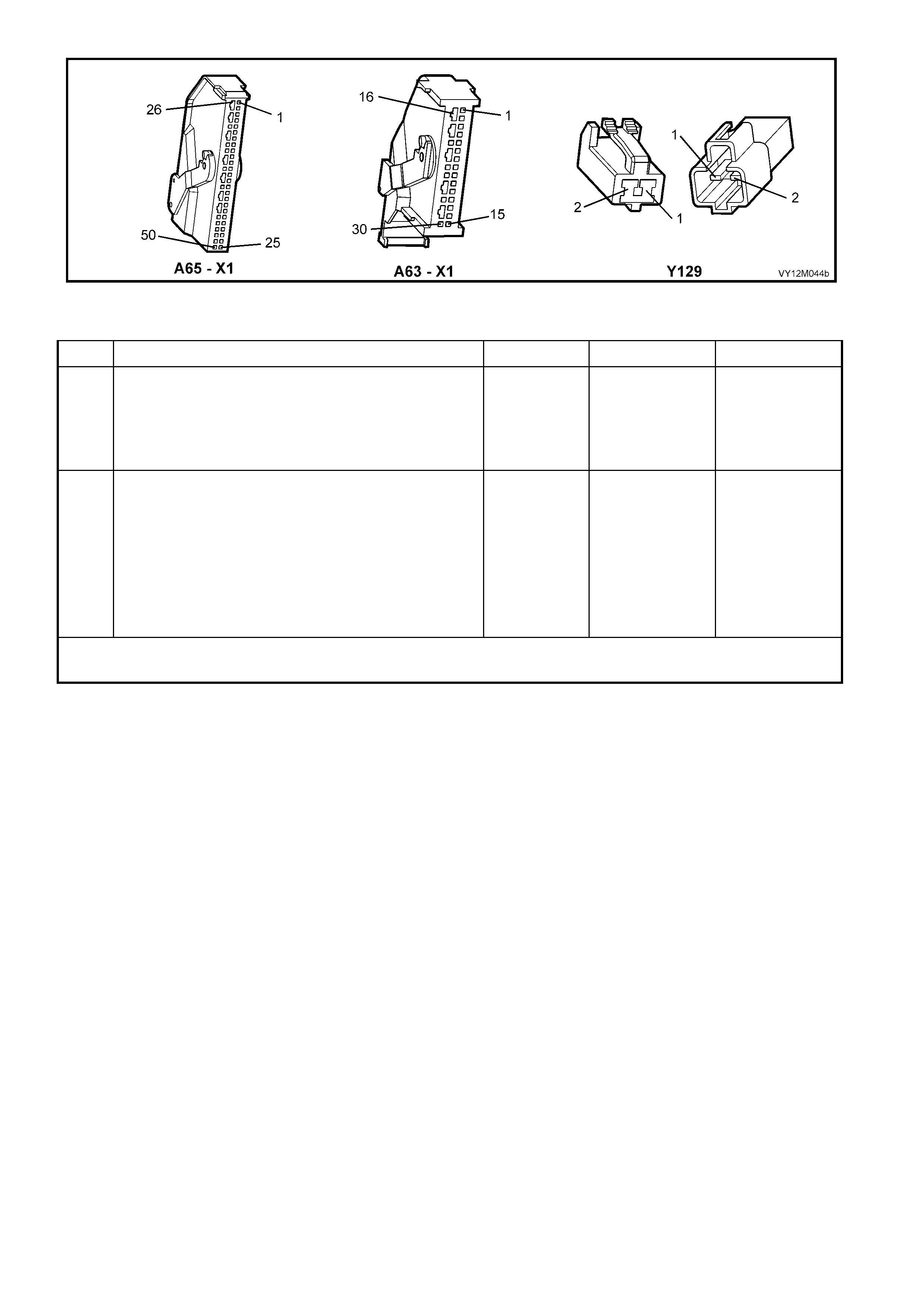
Figure 12M-198
DTC 247 – LEFT-HAND PRETENSIONER CIRCUIT POWER STAGE ERROR
STEP ACTION VALUE YES NO
1. 1. Install TECH 2 to DLC.
2. Select Body / SRS / Diagnostic Trouble Codes /
Read DTC Information.
Is a DTC 247 Left-hand Pretensioner Circuit Power
Stage Error a history DTC, and are any other Left-hand
Pretensioner Circuit DTCs set?
Go to other Left-
hand
Pretensioner
Circuit DTC
diagnost ic cha rt
in this Section.
Go to Step 2.
2. 1. With TECH 2 still connected, select Diagnostic
Trouble Codes / Clear DTC Information and clear all
(if any) DTCs.
2. Select Diagnostic Trouble Codes / Read DTC
Information, 'wiggle' OPS / SRS wiring harness at all
locations between the SDM and the left-hand
Pretensioner INCLUDING wiring harness connector
Y129, while monitoring TECH 2 screen display.
Does TECH 2 screen display change status from No
Diagnostic Trouble Codes?
Go to applicable
DTC chart in this
Section.
Replace SDM,
refer to Section
2.8 INFLATABLE
RESTRAINT
CONTROL
MODULE in this
Section.
Recheck circuit
to verify repair.
WHEN ALL DIAGNOSIS AND REPAIRS ARE COMPLETED, ENSURE ALL OPS / SRS COMPONENTS ARE
RECONNECTED, CLEAR ALL DTC’s, ENABLE THE OPS / SRS AND VERIFY CORRECT OPERATION

DTC 65 – RIGHT-HAND PRETENSIONER CIRCUIT SHORT TO BA TTERY
Figure 12M-199
CIRCUIT DESCRIPTION
At ignition on, and on a constant monitoring cycle of every 500 milliseconds during the ignition cycle, the
inflatable restraint control module (SDM) performs a system self check. If the SDM detects a resistance to
batter y suppl y is less than 5 k ohms in either t he positi ve and/or negati ve circuit f or more than 3 – 5 se conds, a
current DTC 65 will set (refer to 4.3 OPS / SRS SELF DIAGNOSTICS in this Section for more details).
DTC 65 will set if circuits 2118 (right-hand Pretensioner positive side) and/or 2119 (right-hand Pretensioner
negative side) are shorted to battery +.
W hen DTC 65 sets, the SD M illuminates the SR S war ning in dicat or and sets a cur rent DT C 65. Should t he fault
conditions detected by the SDM c lear during the same ignition cycle, t he current code will clear and become a
history DTC 65. The SRS warning indicator will remain on for the remainder of the ignition cycle.
If a DTC 65 is set, the SRS warning indicator is illuminated on each ignition cycle, even if the DTC is set as a
histor y DTC, until the fault condit ions for s etting DTC 65 are rectified an d the DTC (c urrent or histor y) ca n then
be cleared from the SDM via TECH 2.
If DTC 65 is set, the OPS / SRS, including the right-hand Pretensioner, will still be operational due to the
reserve energy supply stored in the SDM.
TEST DESCRIPTION
The following number refer to Section step numbers in the following diagnostic chart:
1. Uses TECH 2 to check if DTC 65 is current or history.
2. Checks for intermittent fault by monitorin g TECH 2 scr een. If s cr een dis p lay changes dur i ng a wirin g 'wig gl e'
test, a fault with the wiring is at that location.
3. Checks circuits 2118 and 2119 for a short to battery +.
NOTES ON DIAGNOSTIC CHART
1. For all wiring harness checking procedures, refer to Section 12P WIRING DIAGRAMS.
2. Refer to 2.11 OPS / SRS WIRING REPAIR in this Section, before conducting any OPS / SRS wiring
harness repairs.
3. W iring should be checked at point where TECH 2 screen display changed status. If necessary, split open
the harness.
4. If the fault can not be identified, the harness should be replaced.
Figure 12M-200

DTC 65 – RIGHT-HAND PRETENSIONER CIRCUIT SHORT TO BA TTERY
STEP ACTION VALUE YES NO
1. 1. Install TECH 2 to DLC.
2. Select Body / SRS / Diagnostic Trouble Codes /
Read DTC Information.
Is DTC 65 current?
Go to Step 3. Go to Step 2.
2. 1. With TECH 2 still connected, select Diagnostic
Trouble Codes / Clear DTC Information and clear all
(if any) DTCs.
2. Select Diagnostic Trouble Codes / Read DTC
Information, 'wiggle' OPS / SRS wiring harness at all
locations between the SDM and the left-hand
Pretensioner INCLUDING wiring harness connector
Y128, while monitoring TECH 2 screen display.
Does TECH 2 screen display change status from No
Diagnostic Trouble Codes?
Make repairs as
necessary (refer
to Section
NOTES 2 & 4 on
previous page).
Clear DTC and
recheck system
to verify repair.
Fault not present.
Check all system
wiring harness
connect ors, and
terminals, refer to
Section NOTE 5
on previous
page.
Clear DTC and
recheck system.
3. 1. Disable the OPS / SRS refer to Section 2.2
DISABLING AND ENABLING PROCEDURE in this
Section.
2. Disconnect right-hand Pretensioner wiring harness
connector Y128.
3. Disconnect SDM wiring harness connector A63/A65
– X1 from the SDM.
4. Reconnect battery.
5. Using Tool KM-609-20, check wiring between SDM
wiring harness connector A63/A65 – X1, terminals 3
and 4 and right-hand Pretensioner connector Y128
– X1, circuits 2118 (Brown/White wire) and 2119
(Yellow/Red wire) for short to battery + (refer to
Section NOTES 1 and 3 on previous page).
Is all OK?
Replace SDM,
refer to Section
2.8 INFLATABLE
RESTRAINT
CONTROL
MODULE in this
Section.
Recheck circuit
to verify repair.
Make repairs as
necessary (refer
to Section NOTE
2 on previous
page).
Clear DTC and
recheck system
to verify repair.
WHEN ALL DIAGNOSIS AND REPAIRS ARE COMPLETED, ENSURE ALL OPS / SRS COMPONENTS ARE
RECONNECTED, CLEAR ALL DTC’s, ENABLE THE OPS / SRS AND VERIFY CORRECT OPERATION
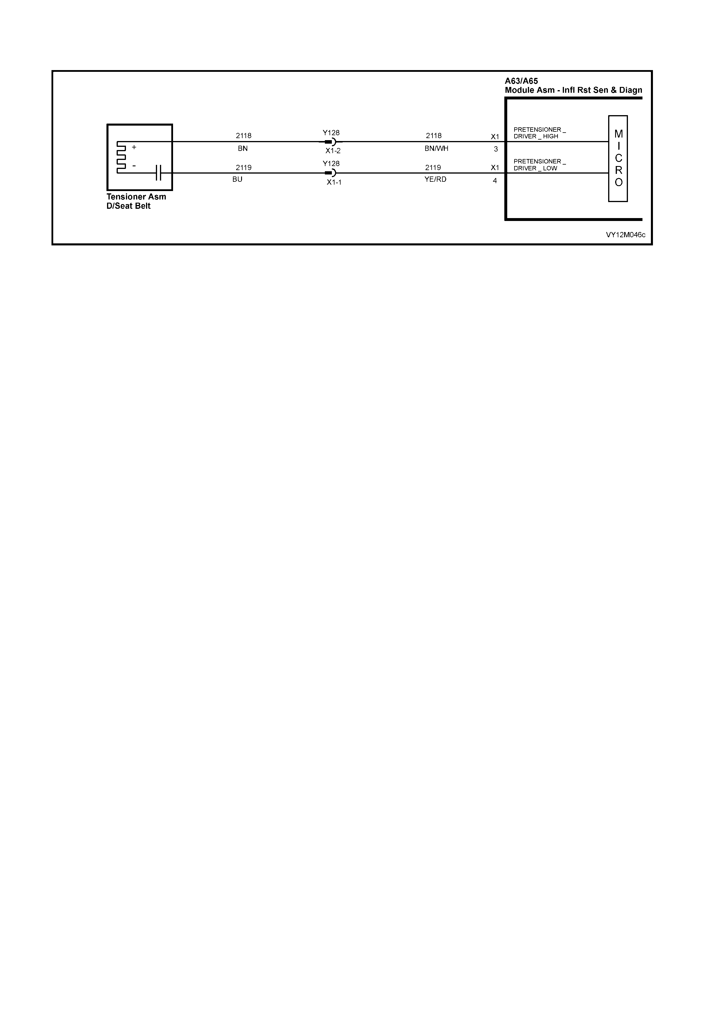
DTC 66 – RIGHT-HAND PRETENSIONER CIRCUIT SHORT TO EARTH
Figure 12M-201
CIRCUIT DESCRIPTION
At ignition on and on a constant monitoring cycle of every 500 milliseconds during the ignition cycle, the
inflatabl e rest raint c ontrol m odule (SDM) perf orm s a system s elf check . If the SDM det ects a resis tance t o earth
of less than 3 k ohm s in either the posit ive or n egati ve c ircuit f or mor e than 3 – 5 seconds , a curre nt DT C 66 wil l
set (refer to 4.3 OPS / SRS SELF DIAGNOSTICS in this Section for more details).
DTC 66 will set if circuits 2118 (right-hand Pretensioner positive side) and/or 2119 (right-hand Pretensioner
negative side) are shorted to earth.
W hen DTC 66 sets, the SD M illuminates the SR S war ning in dicat or and sets a cur rent DT C 66. Should t he fault
conditions detected by the SDM c lear during the same ignition cycle, t he current code will clear and become a
history DTC 66. The SRS warning indicator will remain on for the remainder of the ignition cycle.
If a DTC 66 is set, the SRS warning indicator is illuminated on each ignition cycle, even if the DTC is set as a
histor y DTC, until the fault condit ions for s etting DTC 66 are rectified an d the DTC (c urrent or histor y) ca n then
be cleared from the SDM via TECH 2.
If DTC 66 is set, the OPS / SRS, including the right-hand Pretensioner, will still be operational due to the
reserve energy supply stored in the SDM.
TEST DESCRIPTION
The following number refer to Section step numbers in the following diagnostic chart:
1. Uses TECH 2 to determine if DTC 66 is current or history.
2. T ECH 2 in this m ode should dis pla y approx im ately 1.6 – 6.4 o hm s if the r ight-han d Prete nsioner loop circ uit
is OK.
3. If screen display changes during a wiring 'wiggle' test, a fault with the wiring is at that location.
4. Tool AU4 58 is a d umm y load tak ing the place of the Prete nsioner ass embl y. If TECH 2 disp lays the c orrect
resistance of the dummy load, the system fault is in the Pretensioner assembly.
5. This test checks the wiring bet we en the SDM wiring harness connector A65 – X1 (8.1 SDM) or A63 – X1
(8.0 SDM), terminal 3 and the right-hand Pretensioner connector Y128 for faults.
6. This test checks the wiring bet we en the SDM wiring harness connector A65 – X1 (8.1 SDM) or A63 – X1
(8.0 SDM), terminal 4 and the right-hand Pretensioner connector Y128 – X1 for faults.
NOTES ON DIAGNOSTIC CHART
1. For all wiring harness checking procedures, refer to Section 12P WIRING DIAGRAMS.
2. Refer to 2.11 OPS / SRS WIRING REPAIR in this Section, before conducting any OPS / SRS wiring
harness repairs.
3. Refer to Section 12O FUSES & WIRING HARNESSES for OPS / SRS wiring harness routing.
4. W iring should be checked at point where TECH 2 screen display changed status. If necessary, split open
the harness.
5. If the fault can not be identified, the harness should be replaced.
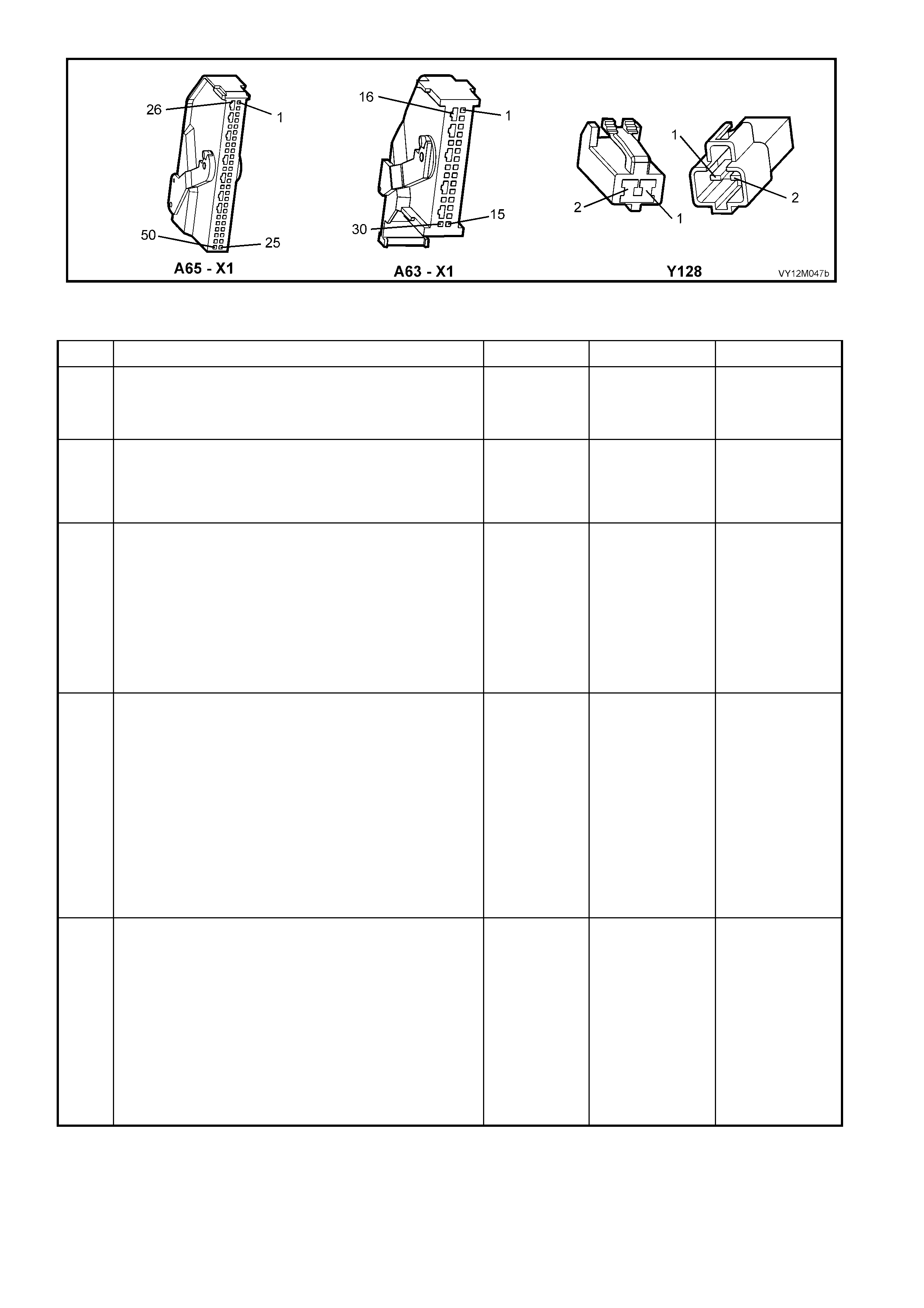
Figure 12M-202
DTC 66 – RIGHT-HAND PRETENSIONER CIRCUIT SHORT TO EARTH
STEP ACTION VALUE YES NO
1. 1. Install TECH 2 to DLC.
2. Select Body / SRS / Diagnostic Trouble Codes /
Read DTC Information.
Does TECH 2 display DTC 66 as a Current DTC?
Go to Step 2. Go to Step 3.
2. 1. With TECH 2 still connected to DLC, select Body /
SRS / Data Display and scroll to RIGHT-HAND
PRETENSIONER LOOP RESISTANCE.
Is the resistance value displayed on TECH 2 as
specified?
Approx.
1.6 – 6.4
Ohms
Go to Step 3. Go to Step 4.
3. 1. With TECH 2 still connected, select Diagnostic
Trouble Codes / Clear DTC Information and clear all
(if any) DTCs.
2. Select Diagnostic Trouble Codes / Read DTC
Information, 'wiggle' OPS / SRS wiring harness at all
locations between the SDM, the right-hand
Pretensioner wiring harness and connector Y128
while monitoring TECH 2 screen display.
Does TECH 2 screen display change status from No
Diagnostic Trouble Codes?
Make repairs as
necessary (refer
to Section
NOTES 2 & 5 on
previous page).
Clear DTC and
recheck system
to verify repair.
Fault not present.
Check all system
wiring harness
connect ors, and
terminals (refer to
Section NOTE 6
on previous
page).
Clear DTC and
recheck system.
4. 1. Disable the OPS / SRS refer to Section 2.2
DISABLING AND ENABLING PROCEDURE in this
Section.
2. Disconnect right-hand Pretensioner wiring harness
connector Y128.
3. Connect Tool No. AU458 to OPS / SRS wiring
harness connec tor Y 128.
4. Reconnect battery.
5. With TECH 2 still connected, select Body / SRS /
Data Display and scroll to RIGHT-HAND
PRETENSIONER LOOP RESISTANCE.
Is the resistance value displayed on TECH 2 as
specified?
Approx.
3.0 Ohms
Replace right-
hand
Pretensioner
assembly, refer
to Section 2.5
SEAT BELT
BUCKLE AND
PRETENSIONE
R ASSEMBLY.
Clear DTC and
recheck system
to verify repair.
Go to Step 5.
5. 1. Disable the OPS / SRS refer to Section 2.2
DISABLING AND ENABLING PROCEDURE in this
Section.
2. Disconnect SDM wiring harness connector A63/A65
– X1 from the SDM.
3. Remove Tool AU458 from Y128.
4. Using Tool KM-609-20, check wiring between SDM
wiring harness connector A63/A65 – X1, terminal 3
and right-hand Pretensioner connector Y128, circuit
2118 (Brown/White wire) for short to earth (refer to
Section NOTE 1 on previous page).
Is all OK?
Go to Step 6. Make repairs as
necessary (refer
to Section NOTE
2 on previous
page).
Clear DTC and
recheck system
to verify repair.

STEP ACTION VALUE YES NO
6. 1. With SDM wiring harness connector A63/A65 – X1
disconnected from the SDM and using Tool KM-
609-20, check wiring between SDM wiring harness
connector A63/A65 – X1, terminal 4 and right-hand
Pretensioner connector Y128, circuit 2119
(Yellow/Red wire) for a short to earth (refer to
Section NOTES 1 and 4 on previous page).
Is all OK?
Replace SDM,
refer to Section
2.8 INFLATABLE
RESTRAINT
CONTROL
MODULE in this
Section. Recheck
circuit to verify
repair.
Make repairs as
necessary (refer
to Section NOTE
2 on previous
page).
Clear DTC and
recheck system
to verify repair.
WHEN ALL DIAGNOSIS AND REPAIRS ARE COMPLETED, ENSURE ALL OPS / SRS COMPONENTS ARE
RECONNECTED, CLEAR ALL DTC’s, ENABLE THE OPS / SRS AND VERIFY CORRECT OPERATION

DTC 67 – RIGHT-HAND PRETENSIONER CIRCUIT CAPACITANCE TOO HIGH
Figure 12M-203
CIRCUIT DESCRIPTION
At ignition on, and on a constant monitoring cycle of every 500 milliseconds during the ignition cycle, the
inflatable restraint control module (SDM) performs a system self check.
If the SDM detects the capacitance in the right-hand Pretensioner circuit is too high (greater than 550 nF) for
longer than 3 – 5 seconds, a current DTC 67 will set (refer to 4.3 OPS / SRS SELF DIAGNOSTICS in this
Section for more details).
DTC 67 will set if the in-built capacitor in the right-hand Pretensioner is faulty.
W hen DTC 67 sets, the SD M illuminates the SR S war ning in dicat or and sets a cur rent DT C 67. Should t he fault
conditions detected by the SDM c lear during the same ignition cycle, t he current code will clear and become a
history DTC 67. The SRS warning indicator will remain on for the remainder of the ignition cycle.
If a DTC 67 is set, the SRS warning indicator is illuminated on each ignition cycle, even if the DTC is set as a
histor y DTC, until the fault condit ions for s etting DTC 67 are rectified an d the DTC (c urrent or histor y) ca n then
be cleared from the SDM via TECH 2.
ACTION REQUIRED
If DTC 67 is set, the right-hand Pretensioner may not operate and therefore, the right-hand Pretensioner
(between right-hand Pretensioner and OPS / SRS connector Y128) must be replaced.
NOTE: Before removing the OPS / SRS Pretensioner wiring harness, take note of wiring harness routing and
how it is retained to the front seat.
After the OPS / SRS Pretensioner wiring harness, the Pretensioner and wiring harness connector Y128 has
been replaced, ensure that all OPS / SRS components are reconnected, clear DTCs, enable the OPS / SRS
and ver if y the correc t oper ation of the system ( i.e. warnin g indic ator n ot il lum inated af ter f ive seco nds of igni tion
being switched ON).
NOTE: After the wiring harness has been replaced, the front seat should be put through its full adjustment
(forward/backwards, full recline and up and down) to ensure that the wiring harness does not foul with any of the
seat components.

DTC 68 – RIGHT-HAND PRETENSIONER CIRCUIT CAPACITANCE TOO LOW
Figure 12M-204
CIRCUIT DESCRIPTION
At ignition on, and on a constant monitoring cycle of every 500 milliseconds during the ignition cycle, the
inflatable restraint control module (SDM) performs a system self check.
If the SD M detect s the c apac itance i n the rig ht-ha nd P retensio ner circ uit is too low (les s tha n 390 nF) f or longer
than 3 – 5 seconds, a current DTC 68 will set (refer to 4.3 OPS / SRS SELF DIAGNOSTICS in this Section for
more details).
DTC 68 will set if the in-built capacitor in the right-hand Pretensioner is faulty.
W hen DTC 68 sets, the SD M illuminates the SR S war ning in dicat or and sets a cur rent DT C 68. Should t he fault
conditions detected by the SDM c lear during the same ignition cycle, t he current code will clear and become a
history DTC 68. The SRS warning indicator will remain on for the remainder of the ignition cycle.
If a DTC 68 is set, the SRS warning indicator is illuminated on each ignition cycle, even if the DTC is set as a
histor y DTC, until the fault condit ions for s etting DTC 68 are rectified an d the DTC (c urrent or histor y) ca n then
be cleared from the SDM via TECH 2
ACTION REQUIRED
If DTC 68 is set, the right-hand Pretensioner may not operate and therefore, the Pretensioner wiring harness,
with connector x304 (between right-hand Pretensioner and OPS / SRS connector Y128) must be replaced.
NOTE: Before removing the OPS / SRS Pretensioner wiring harness, take note of wiring harness routing and
how it is retained to the front seat.
After the OPS / SRS Pretensioner wiring harness, the Pretensioner and wiring harness connector Y128 has
been replaced, ensure that all OPS / SRS components are reconnected, clear DTCs, enable the OPS / SRS
and ver if y the correc t oper ation of the system ( i.e. warnin g indic ator n ot il lum inated af ter f ive seco nds of igni tion
being switched ON).
NOTE: After the wiring harness has been replaced, the front seat should be put through its full adjustment
(forward/backwards, full recline and up and down) to ensure that the wiring harness does not foul with any of the
seat components.
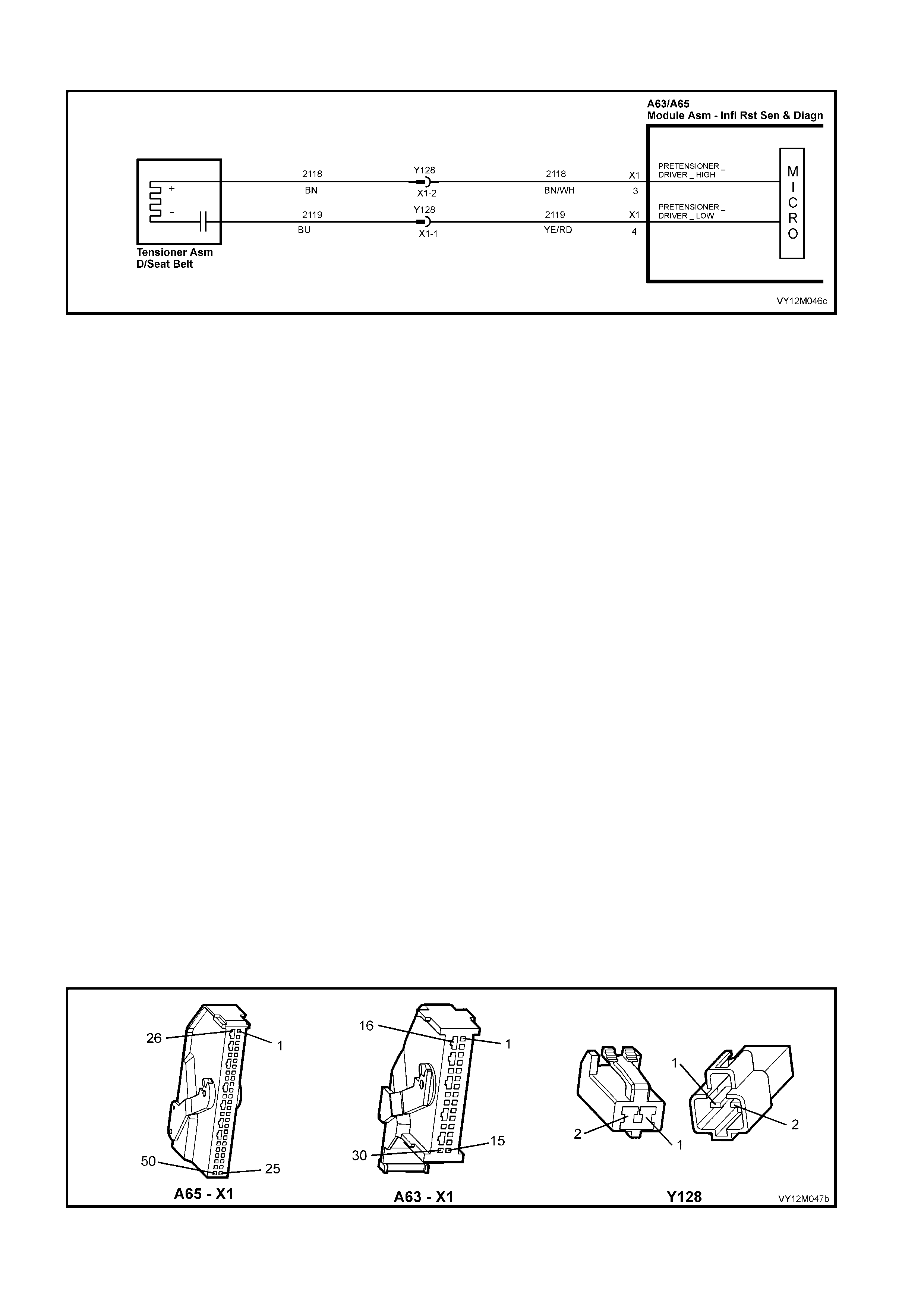
DTC 69 – RIGHT-HAND PRETENSIONER CIRCUIT RESISTANCE TOO HIGH
Figure 12M-205
CIRCUIT DESCRIPTION
At ignition on, and on a constant monitoring cycle of every 500 milliseconds during the ignition cycle, the
inflatable restraint control module (SDM) performs a system self check.
If the SD M detects a res istance in th e right-hand Pr etensioner c ircuit that is too high ( greater than 8 .4 ohm) f or
longer than 3 – 5 seconds, a current DTC 69 will set (refer to 4.3 OPS / SRS SELF DIAGNOSTICS in this
Section for more details).
DTC 69 will set if circuits 2118 or 2119 (including the right-hand Pretensioner assembly) are open circuit.
When DTC 69 sets, the SDM illuminates the SRS warning indicator and sets a current DTC. Should the fault
conditions detected by the SDM c lear during the same ignition cycle, t he current code will clear and become a
history DTC 69. The SRS warning indicator will remain on for the remainder of the ignition cycle.
If a DTC is set, the SRS warning indicator is illuminated on each ignition cycle, even if the DTC is set as a
histor y DTC, until the fault condit ions for s etting DTC 69 are rectified an d the DTC (c urrent or histor y) ca n then
be cleared from the SDM via TECH 2.
If DTC 69 is set, dependent on where the fault is, the right-hand Pretensioner may not operate.
TEST DESCRIPTION
The following number refer to Section step numbers in the following diagnostic chart:
1. Uses TECH 2 to check if DTC 69 is current or history.
2. Checks for intermittent fault by monitoring TECH 2 screen. If screen display changes during a wiring
'wiggle' test, a fault with the wiring is at that location.
3. Tool AU458 is a dummy load taking the place of the right-hand Pretensioner assembly. If DTC 69
becomes a history DTC with dummy load connected, the system fault is in the right-hand Pretensioner
assembly.
4. Checks if open circuit is in the OPS / SRS connector harness. If connector Y128 is disconnected and it’s
terminals are bridged together, DTC 69 will become a history DTC if this connector harness is faulty.
5. Checks circuit 2118 for open circuit.
6. Checks circuit 2119 for open circuit.
NOTES ON DIAGNOSTIC CHART
1. For all wiring harness checking procedures, refer to Section 12P WIRING DIAGRAMS.
2. Refer to 2.11 OPS / SRS WIRING REPAIR in this Section, before conducting any OPS / SRS wiring
harness repairs.
Figure 12M-206

DTC 69 – RIGHT-HAND PRETENSIONER CIRCUIT RESISTANCE TOO HIGH
STEP ACTION VALUE YES NO
1. 1. Install TECH 2 to DLC.
2. Select Body / SRS / Diagnostic Trouble Codes /
Read DTC Information.
Is DTC 69 current?
Go to Step 3. Go to Step 2.
2. 1. With TECH 2 still connected, select Diagnostic
Trouble Codes / Clear DTC Information and clear all
(if any) DTCs.
2. Select Diagnostic Trouble Codes / Read DTC
Information, 'wiggle' OPS / SRS wiring harness at all
locations between the SDM, the right-hand
Pretensioner wiring harness and connector Y128,
while monitoring TECH 2 screen display
Does TECH 2 screen display change status from No
Diagnostic Trouble Codes?
Make repairs as
necessary (refer
to Section NOTE
2 on previous
page).
Clear DTC and
recheck system
to verify repair.
Fault not present.
Check all system
wiring harness
connect ors, and
terminals.
Clear DTC and
recheck system.
3. 1. Disable the OPS / SRS, refer to Section 2.2
DISABLING AND ENABLING PROCEDURE in this
Section.
2. Disconnect the right-hand Pretensioner wiring
harness connec tor Y 128.
3. Connect Tool No. AU458 to OPS / SRS wiring
harness connec tor Y 128.
4. Reconnect battery.
5. Connect TECH 2 to DLC.
6. Select Body / SRS / Diagnostic Trouble Codes /
Read DTC Information.
Is DTC 69 still current?
Go to Step 4. Replace right-
hand
Pretensioner
assembly, refer
to Section 2.5
SEAT BELT
BUCKLE AND
PRETENSIONE
R ASSEMBLY.
Clear DTC and
recheck system
to verify repair.
4. 1. Disable the OPS / SRS, refer to Section 2.2
DISABLING AND ENABLING PROCEDURE in this
Section.
2. Disconnect OPS / SRS wiring harness connector
Y128 (located next to right-hand front seat) from
right-hand Pretensioner connector harness.
3. Reconnect battery.
4. Using a suitable jumper wire from KM-609, bridge
terminals in connector Y128 together
(NOTE: This step may set a current DTC 70).
5. With TECH 2 still connected, select Body / SRS /
Diagnostic Trouble Codes / Read DTC Information.
Does DTC 69 become history?
Replace right-
hand
Pretensioner
assembly, refer
to Section 2.5
SEAT BELT
BUCKLE AND
PRETENSIONE
R ASSEMBLY.
Clear DTC and
recheck system
to verify repair.
Go to Step 5.
5. 1. Disable the OPS / SRS refer to Section 2.2
DISABLING AND ENABLING PROCEDURE in this
Section.
2. Disconnect SDM wiring harness connector A63/A65
– X1 from the SDM.
3. Using Tool KM-609-20, check wiring between SDM
wiring harness connector A63/A65 – X1, terminal 3
and right-hand Pretensioner connector Y128, circuit
2118 (Brown/White wire) for short to earth (refer to
Section NOTE 1 on previous page).
Is all OK?
Go to Step 6. Make repairs as
necessary (refer
to Section NOTE
2 on previous
page).
Clear DTC and
recheck system
to verify repair.
6. 2. With SDM wiring harness connector A63/A65 – X1
disconnected from the SDM and using Tool KM-
609-20, check wiring between SDM wiring harness
connector A63/A65 – X1, terminal 4 and right-hand
Pretensioner connector Y128, circuit 2119
(Yellow/Red wire) for a short to earth (refer to
Section NOTES 1 and 4 on previous page).
Is all OK?
Replace SDM,
refer to Section
2.8 INFLATABLE
RESTRAINT
CONTROL
MODULE in this
Section.
Recheck circuit
to verify repair.
Make repairs as
necessary (refer
to Section NOTE
2 on previous
page).
Clear DTC and
recheck system
to verify repair.
WHEN ALL DIAGNOSIS AND REPAIRS ARE COMPLETED, ENSURE ALL OPS / SRS COMPONENTS ARE
RECONNECTED, CLEAR ALL DTC’s, ENABLE THE OPS / SRS AND VERIFY CORRECT OPERATION
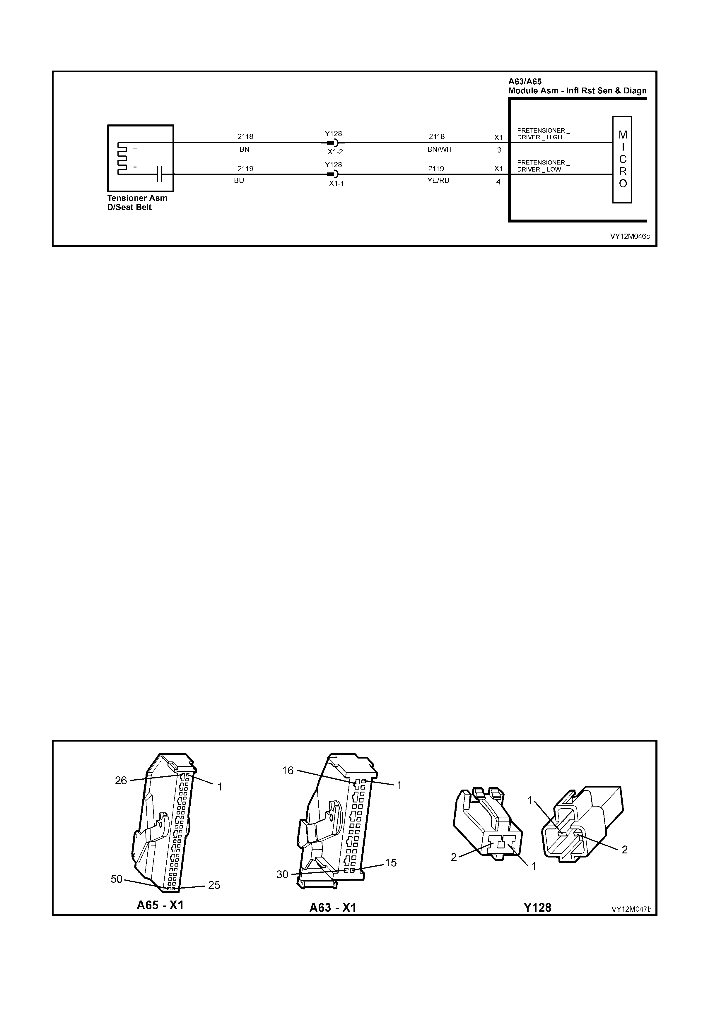
DTC 70 – RIGHT-HAND PRETENSIONER CIRCUIT RESISTANCE TOO LOW
Figure 12M-207
CIRCUIT DESCRIPTION
At ignition on, and on a constant monitoring cycle of every 500 milliseconds during the ignition cycle, the
inflatable restraint control module (SDM) performs a system self check.
If the SDM detects a resistance in the right-hand Pretensioner circuit that is too low (less than 0.6 ohm) for
longer than 3 – 5 seconds, a current DTC 70 will set (refer to 4.3 OPS / SRS SELF DIAGNOSTICS in this
Section for more details).
DTC 70 will set if circuit 2118 or 2119, (including the Pretensioner assembly) is shorted together.
W hen DTC 70 sets, the SD M illum inates the SR S war ning in dicat or and sets a cu rrent DT C 70. Should t he f ault
conditions detected by the SDM c lear during the same ignition cycle, t he current code will clear and become a
history DTC 70. The SRS warning indicator will remain on for the remainder of the ignition cycle.
If a DTC 70 is set, the SRS warning indicator is illuminated on each ignition cycle, even if the DTC is set as a
histor y DTC, until the fault condit ions for s etting DTC 70 are rectified an d the DTC (c urrent or histor y) ca n then
be cleared from the SDM via TECH 2.
If DTC 70 is set, dependent on where the fault is, the right-hand belt Pretensioner may not operate.
TEST DESCRIPTION
The following number refer to Section step numbers in the following diagnostic chart:
1. Uses TECH 2 to check if DTC 70 is current or history.
2. Checks for intermittent fault by monitoring TECH 2 screen. If screen display changes during a wiring
'wiggle' test, a fault with the wiring is at that location.
3. Tool AU458 is a dummy load taking the place of the right-hand Pretensioner assembly. If DTC 70
becomes a history DTC with dummy load connected, the system fault is in the right-hand Pretensioner
assembly.
4. This test checks the wiring between the SDM wir ing harness c onnector A65 – X1 ( 8.1 SDM) or A63 – X 1
(8.0 SDM) and OPS / SRS wiring harness connector Y128 for a short circuit.
NOTES ON DIAGNOSTIC CHART
1. For all wiring harness checking procedures, refer to Section 12P WIRING DIAGRAMS.
2. Refer to 2.11 OPS / SRS WIRING REPAIR in this Section, before conducting any OPS / SRS wiring
harness repairs.
Figure 12M-208

DTC 70 – RIGHT-HAND PRETENSIONER CIRCUIT RESISTANCE TOO LOW
STEP ACTION VALUE YES NO
1. 1. Install TECH 2 to DLC.
2. Select Body / SRS / Diagnostic Trouble Codes /
Read DTC Information.
Is DTC 70 current?
Go to Step 3. Go to Step 2.
2. 1. With TECH 2 still connected, select Diagnostic
Trouble Codes / Clear DTC Information and clear all
(if any) DTCs.
2. Select Diagnostic Trouble Codes / Read DTC
Information, 'wiggle' OPS / SRS wiring harness at all
locations between the SDM, the right-hand
Pretensioner wiring harness and connector Y128,
while monitoring TECH 2 screen display
Does TECH 2 screen display change status from No
Diagnostic Trouble Codes?
Make repairs as
necessary (refer
to Section NOTE
2 on previous
page).
Clear DTC and
recheck system
to verify repair.
Fault not present.
Check all system
wiring harness
connect ors, and
terminals.
Clear DTC and
recheck system.
3. 1. Disable the OPS / SRS, refer to Section 2.2
DISABLING AND ENABLING PROCEDURE in this
Section.
2. Disconnect the right-hand Pretensioner wiring
harness connec tor Y 128.
3. Connect Tool No. AU458 to OPS / SRS wiring
harness connec tor Y 128.
4. Reconnect battery.
5. Connect TECH 2 to DLC.
6. Select Body / SRS / Diagnostic Trouble Codes /
Read DTC Information.
Is DTC 69 still current?
Go to Step 4. Replace right-
hand
Pretensioner
assembly, refer
to Section 2.5
SEAT BELT
BUCKLE AND
PRETENSIONE
R ASSEMBLY.
Clear DTC and
recheck system
to verify repair.
4. 1. Disable the OPS / SRS, refer to Section 2.2
DISABLING AND ENABLING PROCEDURE in this
Section.
2. Disconnect SDM wiring harness connector A63/A65
– X1 from the SDM.
3. Disconnect Tool No. AU458 from OPS / SRS wiring
harness connec tor Y 128.
4. With OPS / SRS wiring harness connector Y128
disconnected, and using Tool KM-609-20, check for
continuity between SDM wiring harness connector
A63/A65 – X1, terminal 3, circuit 2118 (Brown/W hite
wire) and terminal 4, circuit 2119 (Yellow/Red
wire)(refer to Section NOTES 1 and 3 on previous
page).
Does continu ity ex ist?
Repair short in
circuits 2118 and
2119, between
SDM wiring
harness
connector
A63/A65 – X1
and Y128 as
necessary (refer
to Section NOTE
2 on previous
page).
Clear DTC and
recheck system
to verify repair.
Replace SDM,
refer to Section
2.8 INFLATABLE
RESTRAINT
CONTROL
MODULE in this
Section.
Recheck circuit
to verify repair.
WHEN ALL DIAGNOSIS AND REPAIRS ARE COMPLETED, ENSURE ALL OPS / SRS COMPONENTS ARE
RECONNECTED, CLEAR ALL DTC’s, ENABLE THE OPS / SRS AND VERIFY CORRECT OPERATION

DTC 247 – RIGHT-HAND PRETENSIONER CIRCUIT POWER STAGE ERROR
Figure 12M-209
CIRCUIT DESCRIPTION
At ignition on, the SDM performs an initial system self check of the SDM power stages. If durin g this initial self
test the SDM detects a fault with the Right-hand Pretensioner Circuit power stage a current DTC 247 Right-
hand Pret ensioner C ircuit Power Sta ge Error will se t. On com pletion of the initi al s ystem self test the SD M then
performs a test of the Right-hand Pretensioner Circuit. If the SDM detects a problem with this circuit the
associated Right-hand Pretensioner Circuit DTC will be set and the DTC 247 Right-hand Pretensioner Circuit
Airbag Circuit Power Stage Error will become a history DTC.
DTC 247 Right-hand Pretensioner Circuit Power Stage Error will set if a fault occurs in the Right-hand
Pretensioner, connector Y128, the OPS / SRS wiring harness, connector A63/A65 – X1 or SDM.
W hen a histor y DTC 247 R ight-han d Pret ensi oner Cir cuit Po wer Sta ge Err or sets , the SDM illum inates t he S RS
warning indic a tor . S hou ld t he f ault c on dit ions d etec te d b y the SD M c lear d ur in g th e same igniti on cycle the c ode
will remain a history DTC 247 Right-hand Pretensioner Circuit Power Stage Error for all ignition cycles until
cleared. The SRS warning indicator will remain on for the remainder of the ignition cycle.
When a DTC 247 Right-hand Pretensioner Circuit Power Stage Error sets, the SDM illuminates the SRS
warning indicator f or the rem ainder of the ignition cycle. Should the fau lt conditions detected b y the SD M clear
during the same ignition cycle the code will remain a history DTC 247 Right-hand Pretensioner Circuit Power
Stage Error for all ignition cycles until cleared. The SRS warning lamp will also remain illuminated until the
history DTC 247 Right-hand Pretensioner Circuit Power Stage Error is cleared.
If a DTC 247 Right-hand Pretensioner Circuit Power Stage is set, dependent on where the fault is, the Right-
hand Pretensioner may not operate.
ACTION REQUIRED
If DTC 247 Right- ha nd Pretensio ner Cir c uit Po wer St a ge Err or and any other DT C is s et then the di agn os tics for
the other DTC should be carried out first. For example if a DTC 247 Right-hand Pretensioner Circuit Power
Stage Error and a DT C 69 Right-han d Pretensioner Circuit Resistance High are set, the diagnostics f or a DTC
69 Right-hand Pretensioner Circuit Resistance High should be carried out first.
If only a DTC 247 Right-hand Pretensioner Circuit Power Stage Error is set then the SDM should be replaced.
NOTE: An intermittent in the Right-hand Pretensioner Circuit may cause a DTC 247 Right-hand Pretensioner
Circuit Power Stage Error to set.
After the fault has been rectified, ensure that all SRS components are reconnected, clear DTCs, enable the
SRS and verify the correct operation of the system (i.e. warning indicator not illuminated after five seconds of
ignition being switched ON).
TEST DESCRIPTION
The following numbers refer to Section Step numbers in the following diagnostic chart.
1. Uses TECH 2 to check if a DTC 247 Right-hand Pretensioner Circuit Power Stage Error is history code,
and if an y other Right-ha nd Pretensioner Circuit current or history DTCs are set. If any other DTCs are set
refer to Section these DTC’s first.
2. Checks for intermittent fault by monitoring TECH 2 screen during ignition on cycle. If screen display
changes during a wiring 'wiggle' test, a f ault with th e wiring is at th at location. If no other DT Cs are set and
there are no intermittents in the Right-hand Pretensioner Circuit then the SDM should be replaced.
NOTES ON DIAGNOSTIC CHART
1. For all wiring harness checking procedures, refer to Section 12P WIRING DIAGRAMS.
2. Refer to 2.11 OPS / SRS WIRING REPAIR in this Section, before conducting any OPS / SRS wiring
harness repairs.

Figure 12M-210
DTC 247 – RIGHT-HAND PRETENSIONER CIRCUIT POWER STAGE ERROR
STEP ACTION VALUE YES NO
1. 1. Install TECH 2 to DLC.
2. Select Body / SRS / Diagnostic Trouble Codes /
Read DTC Information.
Is a DTC 247 Right-hand Pretensioner Circuit Power
Stage Error a history DTC, and are any other Right-hand
Pretensioner Circuit DTCs set?
Go to other
Right-hand
Pretensioner
Circuit DTC
diagnost ic cha rt
in this Section.
Go to Step 2.
2. 1. With TECH 2 still connected, select Diagnostic
Trouble Codes / Clear DTC Information and clear all
(if any) DTCs.
2. Select Diagnostic Trouble Codes / Read DTC
Information, 'wiggle' OPS / SRS wiring harness at all
locations between the SDM, the right-hand
Pretensioner wiring harness and connector Y128,
while monitoring TECH 2 screen display
Does TECH 2 screen display change status from No
Diagnostic Trouble Codes?
Go to applicable
DTC chart in this
Section.
Replace SDM,
refer to Section
2.8 INFLATABLE
RESTRAINT
CONTROL
MODULE in this
Section.
Recheck circuit
to verify repair.
WHEN ALL DIAGNOSIS AND REPAIRS ARE COMPLETED, ENSURE ALL OPS / SRS COMPONENTS ARE
RECONNECTED, CLEAR ALL DTC’s, ENABLE THE OPS / SRS AND VERIFY CORRECT OPERATION

DTC 81 – LEFT-HAND SIDE-IMPACT AIRBAG CIRCUIT SHORT TO BATTERY
Figure 12M-211
CIRCUIT DESCRIPTION
At ignition on, and on a constant monitoring cycle of every 500 milliseconds during the ignition cycle, the
inflatable restraint control module (SDM) performs a system self check.
If the SDM detects a resistance to battery supply is less than 5 kohms in either the positive and/or negative
circuit for more than 3 – 5 seconds, a current DTC 81 will set (refer to 4.3 OPS / SRS SELF DIAGNOSTICS in
this Section for more details).
DTC 81 will set if circuits 2137 (s ide-impac t airbag pos itive si de) and/or 2 138 ( side- im pact airb ag neg ative s ide)
are shorted to battery +.
W hen DTC 81 sets, the SD M illuminates the SR S war ning in dicat or and sets a cur rent DT C 81. Should t he fault
conditions detected by the SDM c lear during the same ignition cycle, t he current code will clear and become a
history DTC 81. The SRS warning indicator will remain on for the remainder of the ignition cycle.
If a DTC 81 is set, the SRS warning indicator is illuminated on each ignition cycle, even if the DTC is set as a
histor y DTC, until the fault condit ions for s etting DTC 81 are rectified an d the DTC (c urrent or histor y) ca n then
be cleared from the SDM via TECH 2.
If DTC 81 is set, the OPS / SRS, including the left-hand side-im pact airbag, may still be operational due t o the
reserve energy supply stored in the SDM.
TEST DESCRIPTION
The following number refer to Section step numbers in the following diagnostic chart:
1. Uses TECH 2 to check if DTC 81 is current or history.
2. Checks for intermittent fault by monitoring TECH 2 screen. If screen display changes during a wiring
'wiggle' test, a fault with the wiring is at that location.
3. Tool AU485 is a dum my load taking the p lac e of th e l ef t- hand si de- impact air b ag module ass embly. If DTC
81 becomes a history DTC with dummy load connected, the system fault is in the side-impact airbag
module assembly (or the ‘pigtail’ wiring harness that connects to the side-impact airbag module).
4. Checks circuit 2137 and 2138 for short to battery +.
NOTES ON DIAGNOSTIC CHART
1. For all wiring harness checking procedures, refer to Section 12P WIRING DIAGRAMS.
2. Refer to 2.11 OPS / SRS WIRING REPAIR in this Section before conducting any OPS / SRS wiring
harness repairs.
3. Due to the design of the anti-back-out connector on the side-impact airbag module assembly, connector
A96 – X1 – X1 can not be disconnected from the side-impact airbag module assembly without dam aging
the assembly. Therefore, repairs to the OPS / SRS ‘pigtail’ wiring harness that run through the front seat
are not to be attempted. If t his ‘p igt ai l’ har nes s is d amaged in a n y wa y, the harn es s and s ide- impact air bag
module assembly must be replaced as an assembly.
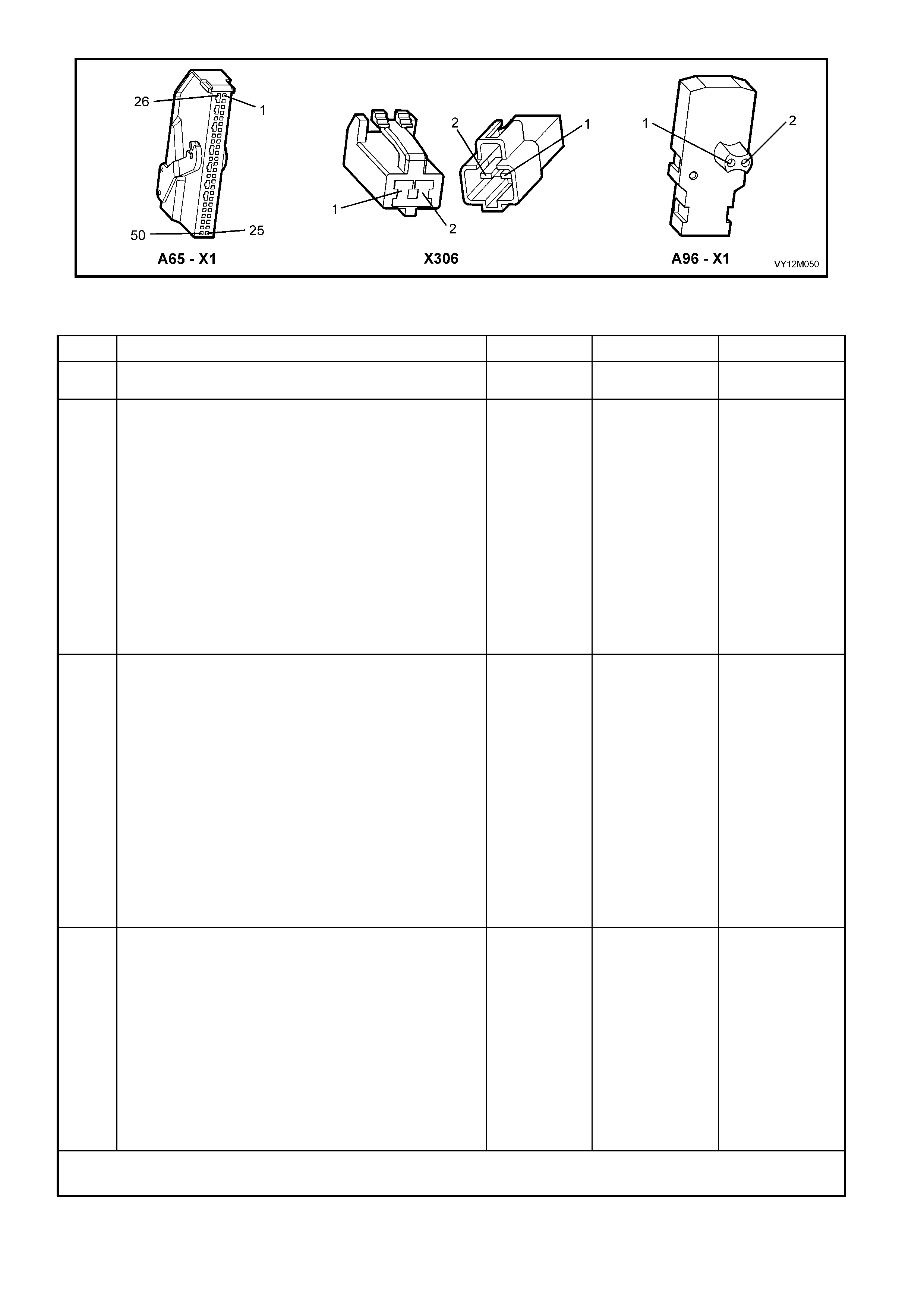
Figure 12M-212
DTC 81 – LEFT-HAND SIDE-IMPACT AIRBAG CIRCUIT SHORT TO BATTERY
STEP ACTION VALUE YES NO
1. 1. Install TECH 2 to DLC.
Is DTC 81 current? Go to Step 3. Go to Step 2.
2. 1. With TECH 2 still connected, select Diagnostic
Trouble Codes / Clear DTC Information and clear all
(if any) DTCs.
2. Select Diagnostic Trouble Codes / Read DTC
Information and monitor the TECH 2 screen display
to see if it changes status while performing the
following:
Put left-hand front seat through it’s full adjustment
(forward / backward, up / down and full recline).
'Wiggle' OPS / SRS wiring harness at all
accessible locations between the SDM and the
side-impact airbag wiring harness connector
X306.
Does TECH 2 screen display change status from No
Diagnostic Trouble Codes?
Make repairs as
necessary (refer
to Section
NOTES 2 & 3 on
previous page).
Clear DTC and
recheck system
to verify repair.
Fault not present.
Check all system
wiring harness
connect ors, and
terminals.
Clear DTC and
recheck system.
3. 1. Disable the OPS / SRS, refer to Section 2.2
DISABLING AND ENABLING PROCEDURE in this
Section.
2. Disconnect OPS / SRS wiring harness connector
X306 (located next to the left-hand front seat) from
the left-hand side-impact airbag module ‘pigtail’
harness.
3. Connect Tool No. AU485 to OPS / SRS wiring
harness connec tor X 306.
4. Reconnect battery.
5. Connect TECH 2 to DLC and select: Body / SRS /
Diagnostic Trouble Codes / Read DTC Information.
Is DTC 81 still current?
Go to Step 4. Replace left-hand
side-impact
airbag and
‘pigtail’ wiring
harness
assembly, refer
2.7 SIDE-
IMPACT
INFLATABLE
RESTRAINT
MODULE
ASSEMBLY in
this Section (refer
to Section NOTE
3 on previous
page). Clear DTC
and recheck
system to verify
repair
4. 1. Disable the OPS / SRS, refer to Section 2.2
DISABLING AND ENABLING PROCEDURE in this
Section.
2. Disconnect SDM wiring harness connector A65 – X1
from the SDM.
3. Reconnect battery.
4. Using Tool KM-609-20, check wiring between SDM
wiring harness connector A65 – X1, terminals 16
and 17 and OPS / SRS connector X306, circuits
2137 (Yellow/Green wire) and 2138 (Brown/Green
wire) for short to battery + (refer to Section NOTE 1
on previous page).
Is all OK?
Replace SDM,
refer to Section
2.8 INFLATABLE
RESTRAINT
CONTROL
MODULE in this
Section. Recheck
circuit to verify
repair.
Make repairs as
necessary (refer
to Section NOTE
2 on previous
page).
Clear DTC and
recheck system
to verify repair.
WHEN ALL DIAGNOSIS AND REPAIRS ARE COMPLETED, ENSURE ALL OPS / SRS COMPONENTS ARE
RECONNECTED, CLEAR ALL DTC’s, ENABLE THE OPS / SRS AND VERIFY CORRECT OPERATION
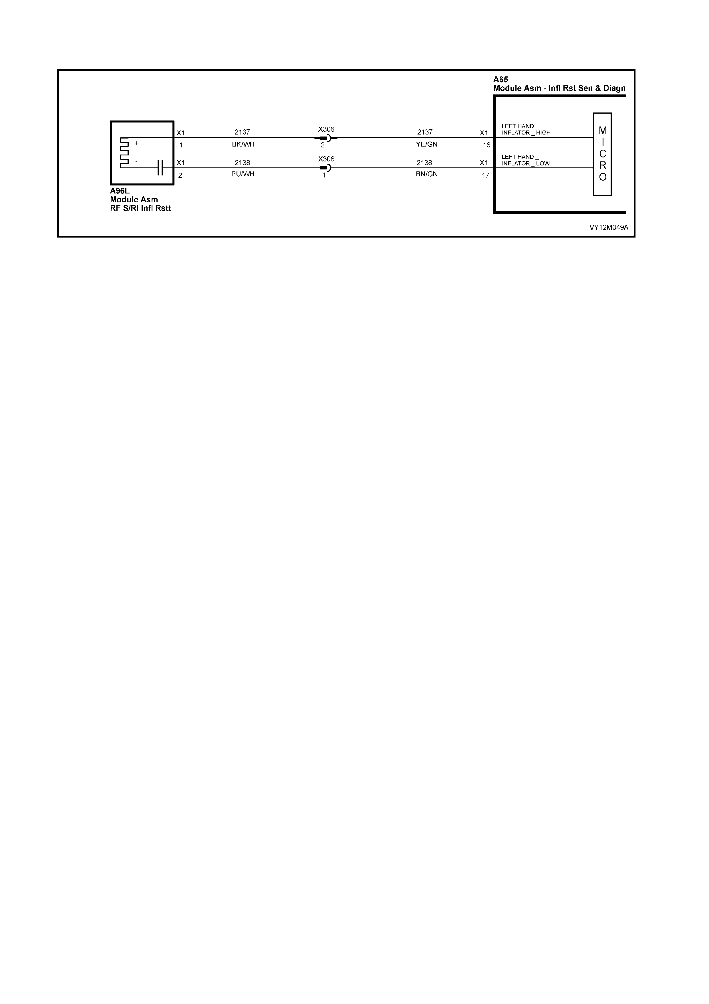
DTC 82 – LEFT-HAND SIDE-IMPACT AI RBAG CIRCUIT SHORT TO EARTH
Figure 12M-213
CIRCUIT DESCRIPTION
At ignition on, and on a constant monitoring cycle of every 500 milliseconds during the ignition cycle, the
inflatabl e rest raint c ontrol m odule (SDM) perf orm s a system s elf check . If the SDM det ects a resis tance t o earth
of less tha n 3 kohms in ei th er the pos i ti ve or n egat i ve i nf lator cir cui t f or more than 3 – 5 s econ ds , a c urr ent D TC
82 will set (refer to 4.3 OPS / SRS SELF DIAGNOSTICS in this Section for more details).
DTC 82 will set if circuits 2137 (left-hand side-impact airbag positive side) and/or 2138 (left-hand side-impact
airbag negative side) are shorted to earth.
W hen DTC 82 sets, the SD M illuminates the SR S war ning in dicat or and sets a cur rent DT C 82. Should t he fault
conditions detected by the SDM c lear during the same ignition cycle, t he current code will clear and become a
history DTC 82. The SRS warning indicator will remain on for the remainder of the ignition cycle.
If a DTC 82 is set, the SRS warning indicator is illuminated on each ignition cycle, even if the DTC is set as a
histor y DTC, until the fault condit ions for s etting DTC 82 are rectified an d the DTC (c urrent or histor y) ca n then
be cleared from the SDM via TECH 2.
If DTC 82 is set, the OPS / SRS, including the left-hand side-im pact airbag, may still be operational due t o the
reserve energy supply stored in the SDM.
TEST DESCRIPTION
The following number refer to Section step numbers in the following diagnostic chart:
1. Uses TECH 2 to check if DTC 82 is current or history.
2. TECH 2 in this mode should display approximately 1.6 – 6.4 ohms if the passenger airbag loop circuit is OK.
3. If screen display changes during a wiring 'wiggle' test, a fault with the wiring is at that location.
4. Tool AU485 is a dummy load taking the place of the side-impact airbag module. If TECH 2 displays the
correc t resis tance of the dum m y load, the s ystem f ault is i n the s ide- im pact airba g m odule as sem bl y (or the
‘pigtail’ wiring harness that connects to the side-impact airbag module).
5. This test checks the wiring between the SDM wiring harness connector A65 – X 1, terminal 16 and the lef t-
hand side-impact airbag module connector X306 for faults.
6. This test checks the wiring between the SDM wiring harness connector A65 – X 1, terminal 17 and the lef t-
hand side-impact airbag module connector X306 for faults.
NOTES ON DIAGNOSTIC CHART
1. For all wiring harness checking procedures, refer to Section 12P WIRING DIAGRAMS.
2. Refer to 2.11 OPS / SRS WIRING REPAIR in this Section before conducting any OPS / SRS wiring harness
repairs.
3. Due to the design of the anti-back-out connector on the side-impact airbag module assembly, connector
A96 – X1 can not be disconnected from the side-impact airbag module assembly without damaging the
assem bl y. Therefore, repairs to the O PS / SR S ‘ pigtail’ wirin g har n es s that r un thro ugh the fr ont seat ar e not
to be attem pted. If this ‘p igtail’ h arness is damaged i n any way, the harness an d side-im pact airba g m odule
assembly must be replaced as an assembly.
4. Wiring should be checked at point where TECH 2 screen display changed status. If necessary, split open
wir ing harness

Figure 12M-214
DTC 82 – LEFT-HAND SIDE-IMPACT AI RBAG CIRCUIT SHORT TO EARTH
STEP ACTION VALUE YES NO
1. 1. Install TECH 2 to DLC.
2. Select Body / SRS / Diagnostic Trouble Codes /
Read DTC Information
Does TECH 2 display DTC 82 as a Current DTC?
Go to Step 2. Go to Step 3.
2. 1. With TECH 2 still connected to DLC, select Body /
SRS / Data Display and scroll to LEFT-HAND SIDE-
IMPACT AIRBAG LOOP RESISTANCE.
Is the resistance value displayed on TECH 2 as
specified?
Approx.
1.6 – 6.4
Ohms
Go to Step 3. Go to Step 4.
3. 1. With TECH 2 still connected, select Diagnostic
Trouble Codes / Clear DTC Information and clear all
(if any) DTCs.
2. Select Diagnostic Trouble Codes / Read DTC
Information and monitor the TECH 2 screen display
to see if it changes status while performing the
following:
Put left-hand front seat through it’s full adjustment
(forward / backward, up / down and full recline).
'Wiggle' OPS / SRS wiring harness at all
accessible locations between the SDM and the
side-impact airbag wiring harness connector
X306.
Does TECH 2 screen display change status from No
Diagnostic Trouble Codes?
Make repairs as
necessary (refer
to Section
NOTES 2 & 3 on
previous page).
Clear DTC and
recheck system
to verify repair.
Fault not present.
Check all system
wiring harness
connect ors, and
terminals.
Clear DTC and
recheck system.
4. 1. Disable the OPS / SRS, refer to Section 2.2
DISABLING AND ENABLING PROCEDURE in this
Section.
2. Disconnect OPS / SRS wiring harness connector
X306 (located next to the left-hand front seat) from
the left-hand side-impact airbag module ‘pigtail’
harness.
3. Connect Tool No. AU485 to OPS / SRS wiring
harness connec tor X 306.
4. Reconnect battery.
5. Connect TECH 2 to DLC and select Body / SRS /
Data Display and scroll to LEFT-HAND SIDE-
IMPACT AIRBAG LOOP RESISTANCE'.
Is the resistance value displayed on TECH 2 as
specified?
Approx.
2.0 Ohms Replace left-hand
side-impact
airbag and
‘pigtail’ wiring
harness
assembly, refer
2.7 SIDE-
IMPACT
INFLATABLE
RESTRAINT
MODULE
ASSEMBLY in
this Section (refer
to Section NOTE
3 on previous
page). Clear DTC
and recheck
system to verify
repair
Go to Step 5.

STEP ACTION VALUE YES NO
5. 1. Disable the OPS / SRS, refer to Section 2.2
DISABLING AND ENABLING PROCEDURE in this
Section.
2. Disconnect SDM wiring harness connector A65 – X1
from the SDM.
3. Remove Tool AU485 from X306.
4. Using Tool KM-609-20, check wiring between SDM
wiring harness connector A65 – X1, terminal 16 and
OPS / SRS connector X306, circuit 2137
(Yellow/Green wire) for short to earth (refer NOTE 1
on previous page).
Is all OK?
Go to Step 6. Make repairs as
necessary (refer
to Section NOTE
2 on previous
page).
Clear DTC and
recheck system
to verify repair.
6. 1. With SDM wiring harness connector A65 – X1
disconnected from the SDM and using Tool KM-
609-20, check wiring between SDM wiring harness
connector A65 – X1, terminal 17 and OPS / SRS
connector X306, circuit 2138 (Brown/Green wire) for
a short to earth (refer to Section NOTE 1 on
previous page).
Is all OK?
Replace SDM,
refer to Section
2.8 INFLATABLE
RESTRAINT
CONTROL
MODULE in this
Section. Recheck
circuit to verify
repair.
Make repairs as
necessary (refer
to Section NOTE
2 on previous
page).
Clear DTC and
recheck system
to verify repair.
WHEN ALL DIAGNOSIS AND REPAIRS ARE COMPLETED, ENSURE ALL OPS / SRS COMPONENTS ARE
RECONNECTED, CLEAR ALL DTC’s, ENABLE THE OPS / SRS AND VERIFY CORRECT OPERATION

DTC 83 – LEFT-HAND SIDE-IMPACT AIRBAG CIRCUIT CAPACITANCE TOO HIGH
Figure 12M-215
CIRCUIT DESCRIPTION
At ignition on, and on a constant monitoring cycle of every 500 milliseconds during the ignition cycle, the
inflatable restraint control module (SDM) performs a system self check.
If the SDM detects the capacitance in the left-hand side-impact airbag circuit is too high (greater than 550 nF)
for longer than 3 – 5 seconds, a current DTC 83 will set (refer to 4.3 OPS / SRS SELF DIAGNOSTICS in this
Section for more details).
DTC 83 will set if the in-built capacitor in the OPS / SRS wiring harness connector A96 – X1 is faulty.
W hen DTC 83 sets, the SD M illuminates the SR S war ning in dicat or and sets a cur rent DT C 83. Should t he fault
conditions detected by the SDM c lear during the same ignition cycle, t he current code will clear and become a
history DTC 83. The SRS warning indicator will remain on for the remainder of the ignition cycle.
If a DTC 83 is set, the SRS warning indicator is illuminated on each ignition cycle, even if the DTC is set as a
histor y DTC, until the fault condit ions for s etting DTC 83 are rectified an d the DTC (c urrent or histor y) ca n then
be cleared from the SDM via TECH 2.
ACTION REQUIRED
If DTC 83 is set, the left-hand side-impact airbag may not operate and therefore, the OPS / SRS side-impact
airbag and ‘pigtail’ wiring harness assembly must be replaced. Refer to 2.7 SIDE AIRBAG MODULE
ASSEMBLY in this Section for the correct procedure on replacing the side-impact airbag and ‘pigtail’ wiring
harness connector.
NOTE: Due to t he des ign o f the ant i-bac k- out connect or on t he si de-im pact air ba g m odule assem bl y, connec tor
A96 – X1 – X1 can not be disconnected from the side-impact airbag module assembly without damaging the
assem bly. Ther efore, repairs to the OPS / SRS ‘pigt ail’ wiring harn ess that run through t he front seat are not to
be attemp ted (this i ncludes the c apacit or in conn ector A96 – X1 – X1 ). If this ‘pigtail ’ harn ess is dam aged in any
way, the harness and side-impact airbag module assembly must be replaced as an assembly.
After the O PS / SRS side- impact airbag and ‘p igtail’ wiring harness assembly have been replaced, ensure that
all OPS / SRS components are reconnected, clear DTCs, enable the OPS / SRS and verify the correct
operation of the system (i.e. warning indicator not illuminated after five seconds of ignition being switched ON).
NOTE: After replacement, the front seat should be put through its full adjustment (forward/backwards, full
recline and up and down) to ensure that the wiring harness does not foul with any of the seat components.

DTC 84 – LEFT-HAND SIDE-IMPACT AIRBAG CIRCUIT CAPACITANCE TOO LOW
Figure 12M-216
CIRCUIT DESCRIPTION
At ignition on, and on a constant monitoring cycle of every 500 milliseconds during the ignition cycle, the
inflatable restraint control module (SDM) performs a system self check.
If the SDM detects the capacitance in the left-hand side-impact airbag circuit is too low (less than 390 nF) for
longer than 3 – 5 seconds, a current DTC 84 will set (refer to 4.3 OPS / SRS SELF DIAGNOSTICS in this
Section for more details).
DTC 84 will set if the in-built capacitor in the OPS / SRS wiring harness connector A96 – X1 is faulty.
W hen DTC 84 sets, the SD M illuminates the SR S war ning in dicat or and sets a cur rent DT C 84. Should t he fault
conditions detected by the SDM c lear during the same ignition cycle, t he current code will clear and become a
history DTC 84. The SRS warning indicator will remain on for the remainder of the ignition cycle.
If a DTC 84 is set, the SRS warning indicator is illuminated on each ignition cycle, even if the DTC is set as a
histor y DTC, until the fault condit ions for s etting DTC 84 are rectified an d the DTC (c urrent or histor y) ca n then
be cleared from the SDM via TECH 2.
ACTION REQUIRED
If DTC 84 is set, the left-hand side-impact airbag may not operate and therefore, the OPS / SRS side-impact
airbag and ‘pigtail’ wiring harness assembly must be replaced. Refer to 2.7 SIDE-IMPACT INFLATABLE
RESTRAINT (SIDE-IMPACT AIRBAG) MODULE ASSEMBLY in this Section for the correct procedure on
replacing the side-impact airbag and ‘pigtail’ wiring harness connector.
NOTE: Due to t he des ign o f the ant i-bac k- out connect or on t he si de-im pact air ba g m odule assem bl y, connec tor
A96 – X1 can not be disconnected from the side-impact airbag module assembly without damaging the
assem bly. Ther efore, repairs to the OPS / SRS ‘pigt ail’ wiring harn ess that run through t he front seat are not to
be attemp ted (this includes the c apacit or in con nector A96 – X1) . If this ‘pigta il’ ha rness is dam aged in an y wa y,
the harness and side-impact airbag module assembly must be replaced as an assembly.
After the OPS / SRS side- impact airbag and ‘pigtail’ wiring harness assem blies have been replaced, ensure all
OPS / SRS c omponents are rec onnect ed, c le ar DT Cs , enable th e O P S / SR S an d ver ify the corr ect oper at ion of
the system (i.e. warning indicator not illuminated after five seconds of ignition being switched ON).
NOTE: After replacement, the front seat should be put through its full adjustment (forward/backwards, full
recline and up and down) to ensure the wiring harness does not foul with any of the seat components.

DTC 85 – LEFT-HAND SIDE-IMPACT AIRBAG CIRCUIT RESISTANCE TOO HIGH
Figure 12M-217
CIRCUIT DESCRIPTION
At ignition on, and on a constant monitoring cycle of every 500 milliseconds during the ignition cycle, the
inflatable restraint control module (SDM) performs a system self check.
If the SDM det ects a resistance in th e left-hand s ide-im pact airbag circuit that is too high (greater than 8.4 ohm
for longer than 3 – 5 seconds, a current DTC 85 will set (refer to 4.3 OPS / SRS SELF DIAGNOSTICS in this
Section for more details).
DTC 85 will set if circuits 2137 or 2138 (including the side-impact airbag module) are open circuit.
W hen DTC 85 sets, the SD M illum inates the SR S war ning in dicat or and sets a cu rrent DT C 85. Should t he f ault
conditions detected by the SDM c lear during the same ignition cycle, t he current code will clear and become a
history DTC 85. The SRS warning indicator will remain on for the remainder of the ignition cycle.
If a DTC 85 is set, the SRS warning indicator is illuminated on each ignition cycle, even if the DTC is set as a
histor y DTC, until the fault condit ions for s etting DTC 85 are rectified an d the DTC (c urrent or histor y) ca n then
be cleared from the SDM via TECH 2.
If DTC 85 is set, dependent on where the fault is, the left-hand side-impact airbag may not operate.
TEST DESCRIPTION
The following number refer to Section step numbers in the following diagnostic chart:
1. Uses TECH 2 to check if DTC 85 is current or history.
2. Checks for inter mittent fault by m onitori ng TECH 2 scr een. If s cr een dis p lay changes dur i ng a wirin g 'wiggle'
test, a fault with the wiring is at that location.
3. Tool AU485 is a dummy load taking the place of the side-impact airbag module. If DTC 85 becomes a
histor y DTC with dum m y load c onnected , the system fault is in the si de-im pact airbag m odule ass embl y (or
the ‘pigtail’ wiring harness that connects to the side-impact airbag module).
4. Checks circuit 2137 for open circuit.
5. Checks circuit 2138 for open circuit.
NOTES ON DIAGNOSTIC CHART
1. For all wiring harness checking procedures, refer to Section 12P WIRING DIAGRAMS.
2. Refer to 2.11 OPS / SRS WIRING REPAIR in this Se c tion bef or e c onducting an y O PS / SRS wir ing h arnes s
repairs.
3. Due to the design of the anti-back-out connector on the side-impact airbag module assembly, connector
A96 – X1 can not be disconnected from the side-impact airbag module assembly without damaging the
assem bl y. Therefore, repairs to the O PS / SRS ‘p igta il ’ wir ing har n es s that r un thr o ugh th e f r ont seat ar e not
to be attem pted. If this ‘ pigtail ’ harness is dam aged in an y way, the harn ess and side-im pact airbag m odule
assembly must be replaced as an assembly.
4. Wiring should be checked at point where TECH 2 screen display changed status. If necessary, split open
wir ing harness.

Figure 12M-218
DTC 85 – LEFT-HAND SIDE-IMPACT AIRBAG CIRCUIT RESISTANCE TOO HIGH
STEP ACTION VALUE YES NO
1. 1. Install TECH 2 to DLC.
2. Select Body / SRS / Diagnostic Trouble Codes /
Read DTC Information
Is DTC 85 current?
Go to Step 3. Go to Step 2.
2. 1. With TECH 2 still connected, select Diagnostic
Trouble Codes / Clear DTC Information and clear all
(if any) DTCs.
2. Select Diagnostic Trouble Codes / Read DTC
Information and monitor the TECH 2 screen display
to see if it changes status while performing the
following:
Put left-hand front seat through it’s full adjustment
(forward / backward, up / down and full recline).
'Wiggle' OPS / SRS wiring harness at all
accessible locations between the SDM and the
side-impact airbag wiring harness connector
X306.
Does TECH 2 screen display change status from No
Diagnostic Trouble Codes?
Make repairs as
necessary (refer
to Section
NOTES 2 & 3 on
previous page).
Clear DTC and
recheck system
to verify repair.
Fault not present.
Check all system
wiring harness
connect ors, and
terminals.
Clear DTC and
recheck system.
3. 1. Disable the OPS / SRS, refer to Section 2.2
DISABLING AND ENABLING PROCEDURE in this
Section.
2. Disconnect the OPS / SRS wiring harness
connector X306 (located next to the left-hand front
seat) from the left-hand side-impact airbag module
‘pigtail’ harness.
3. Connect Tool No. AU485 to OPS / SRS wiring
harness connec tor X 306.
4. Reconnect battery.
5. Connect TECH 2 to DLC and select Body / SRS /
Diagnostic Trouble Codes / Read DTC Information.
Is DTC 85 still current?
Go to Step 4. Replace left-hand
side-impact
airbag module
and ‘pigtail’
wiring harness
assembly, refer
to Section 2.7
SIDE-IMPACT
INFLATABLE
RESTRAINT
MODULE
ASSEMBLY in
this Section (refer
NOTE 3 on
previous page).
Clear DTC and
recheck system
to verify repair.
4. 1. Disable the OPS / SRS, refer to Section 2.2
DISABLING AND ENABLING PROCEDURE in this
Section.
2. Disconnect SDM wiring harness connector A65 – X1
from the SDM.
3. Using Tool KM-609-20, check wiring between SDM
wiring harness connector A65 – X1, terminal 16 and
OPS / SRS wiring harness connector X306, circuit
2137 (Yellow/Green wire) for open circuit (refer to
Section NOTE 1 on previous page).
Is all OK?
Go to Step 5. Make repairs as
necessary (refer
to Section NOTE
2 on previous
page).
Clear DTC and
recheck system
to verify repair.

STEP ACTION VALUE YES NO
5. 1. With SDM wiring harness connector A65 – X1
disconnected from the SDM and using Tool KM-
609-20, check wiring between SDM wiring harness
connector A65 – X1, terminal 17 and OPS / SRS
wiring harness connector X306, circuit 2138 (Brown
/ Green wire) for open circuit (refer to Section NOTE
1 on previous page).
Is all OK?
Replace SDM,
refer to Section
2.8 INFLATABLE
RESTRAINT
CONTROL
MODULE in this
Section. Recheck
circuit to verify
repair.
Make repairs as
necessary (refer
to Section NOTE
2 on previous
page).
Clear DTC and
recheck system
to verify repair.
WHEN ALL DIAGNOSIS AND REPAIRS ARE COMPLETED, ENSURE ALL OPS / SRS COMPONENTS ARE
RECONNECTED, CLEAR ALL DTC’s, ENABLE THE OPS / SRS AND VERIFY CORRECT OPERATION

DTC 86 – LEFT-HAND SIDE-IMPACT AIR BAG CIRCUIT RESISTANCE TOO LOW
Figure 12M-219
CIRCUIT DESCRIPTION
At ignition on, and on a constant monitoring cycle of every 500 milliseconds during the ignition cycle, the
inflatable restraint control module (SDM) performs a system self check.
If the SDM detects a resistance in the lef t-hand side-i mpact airbag circ uit that is too low (les s than 0.6 ohm) for
longer than 3 – 5 seconds, a current DTC 86 will set (refer to 4.3 OPS / SRS SELF DIAGNOSTICS in this
Section for more details).
DTC 86 will set if circuits 2137 or 2138, (including the side-impact airbag module assembly) are shorted
together.
W hen DTC 86 sets, the SD M illuminates the SR S war ning in dicat or and sets a cur rent DT C 86. Should t he fault
conditions detected by the SDM c lear during the same ignition cycle, t he current code will clear and become a
history DTC 86. The SRS warning indicator will remain on for the remainder of the ignition cycle.
If a DTC 86 is set, the SRS warning indicator is illuminated on each ignition cycle, even if the DTC is set as a
histor y DTC, until the fault condit ions for s etting DTC 86 are rectified an d the DTC (c urrent or histor y) ca n then
be cleared from the SDM via TECH 2.
If DTC 86 is set, dependent on where the fault is, the left-hand side-impact airbag may not operate.
TEST DESCRIPTION
The following number refer to Section step numbers in the following diagnostic chart:
1. Uses TECH 2 to check if DTC 86 is current or history.
2. Checks for inter mittent fault by m onitori ng TECH 2 scr een. If s cr een dis p lay changes dur i ng a wirin g 'wiggle'
test, a fault with the wiring is at that location.
3. Tool AU485 is a dummy load taking the place of the side-impact airbag module. If DTC 85 becomes a
histor y DTC with dum m y load c onnected , the system fault is in the si de-im pact airbag m odule ass embl y (or
the ‘pigtail’ wiring harness that connects to the side-impact airbag module).
4. This test checks the wiring between the SDM wiring harness connector A65 – X1 and OPS / SRS wiring
harness connector X306 for a short circuit..
NOTES ON DIAGNOSTIC CHART
1. For all wiring harness checking procedures, refer to Section 12P WIRING DIAGRAMS.
2. Refer to 2.11 WIRING REPAIR in this Section before conducting any OPS / SRS wiring harness repairs.
3. Due to the design of the anti-back-out connector on the side-impact airbag module assembly, connector
A96 – X1 can not be disconnected from the side-impact airbag module assembly without damaging the
assem bl y. Therefore, repairs to the O PS / SRS ‘p igta il ’ wir ing har n es s that r un thr o ugh th e f r ont seat ar e not
to be attem pted. If this ‘ pigtail ’ harness is dam aged in an y way, the harn ess and side-im pact airbag m odule
assembly must be replaced as an assembly.
4. Wiring should be checked at point where TECH 2 screen display changed status. If necessary, split open
wir ing harness.
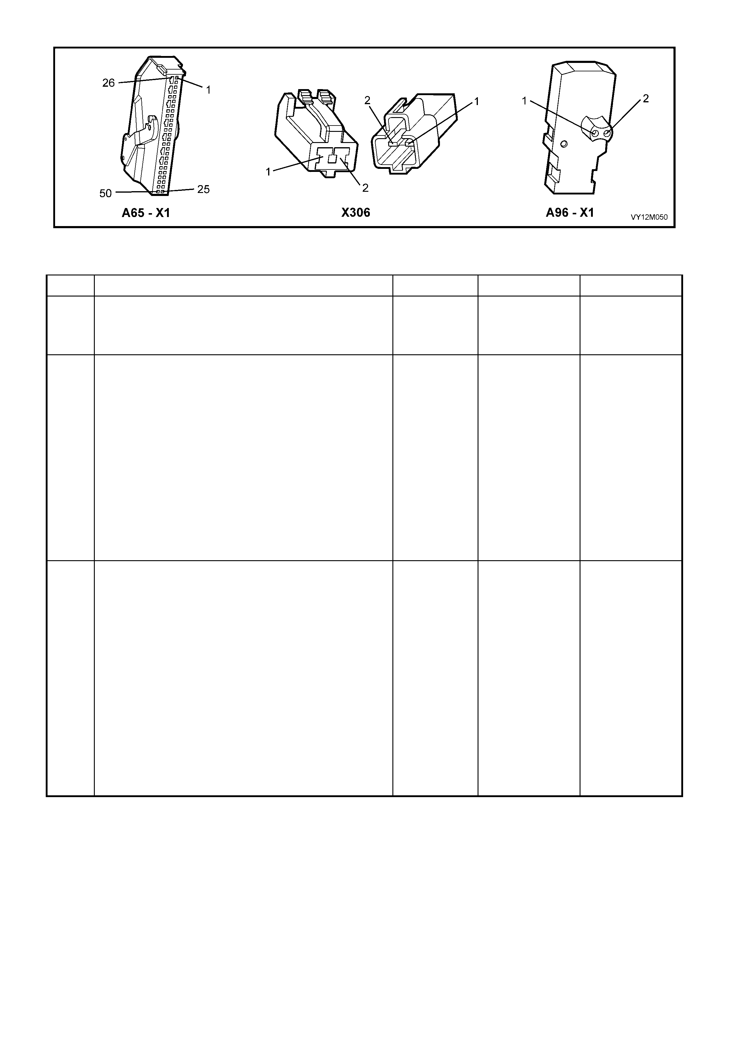
Figure 12M-220
DTC 86 – LEFT-HAND SIDE-IMPACT AIR BAG CIRCUIT TOO LOW
STEP ACTION VALUE YES NO
1. 1. Install TECH 2 to DLC.
2. Select Body / SRS / Diagnostic Trouble Codes /
Read DTC Information
Is DTC 86 current?
Go to Step 3. Go to Step 2.
2. 1. With TECH 2 still connected, select Diagnostic
Trouble Codes / Clear DTC Information and clear all
(if any) DTCs.
2. Select Diagnostic Trouble Codes / Read DTC
Information and monitor the TECH 2 screen display
to see if it changes status while performing the
following:
Put left-hand front seat through it’s full adjustment
(forward / backward, up / down and full recline).
'Wiggle' OPS / SRS wiring harness at all
accessible locations between the SDM and the
side-impact airbag wiring harness connector
X306.
Does TECH 2 screen display change status from No
Diagnostic Trouble Codes?
Make repairs as
necessary (refer
to Section
NOTES 2 & 3 on
previous page).
Clear DTC and
recheck system
to verify repair.
Fault not present.
Check all system
wiring harness
connect ors, and
terminals.
Clear DTC and
recheck system.
3. 1. Disable the OPS / SRS, refer to Section 2.2
DISABLING AND ENABLING PROCEDURE in this
Section.
2. Disconnect the OPS / SRS wiring harness
connector X306 (located next to the left-hand front
seat) from the left-hand side-impact airbag module
‘pigtail’ harness.
3. Connect Tool No. AU485 to OPS / SRS wiring
harness connec tor X 306.
4. Reconnect battery.
5. Connect TECH 2 to DLC and select Body / SRS /
Diagnostic Trouble Codes / Read DTC Information.
Is DTC 86 still current?
Go to Step 4. Replace left-hand
side-impact
airbag module
and ‘pigtail’
wiring harness
assembly, refer
to Section 2.7
SIDE-IMPACT
INFLATABLE
RESTRAINT
MODULE
ASSEMBLY in
this Section (refer
NOTE 3 on
previous page).
Clear DTC and
recheck system
to verify repair.

STEP ACTION VALUE YES NO
4. 1. Disable the OPS / SRS, refer to Section 2.2
DISABLING AND ENABLING PROCEDURE in this
Section.
2. Disconnect SDM wiring harness connector A65 – X1
from the SDM.
3. Disconnect Tool No. AU485 from OPS / SRS wiring
harness connec tor X 306.
4. With OPS / SRS wiring harness connector X306
disconnect ed, and usi ng Tool KM-609-20, check for
continuity between SDM wiring harness connector
A65 – X1, terminal 17, circuit 2138 (Brown / Green
wire) and terminal 16, circuit 2137 (Yellow/Green
wire) (refer to Section NOTES 1 and 3 on previous
page).
Does continu ity ex ist?
Repair short in
circuits 2138 and
2137, between
wiring harness
connector A65 –
X1 and X306 as
necessary (refer
to Section NOTE
2 on previous
page). Clear DTC
and recheck
system to verify
repair.
Replace SDM,
refer to Section
2.8 INFLATABLE
RESTRAINT
CONTROL
MODULE in this
Section. Recheck
circuit to verify
repair.
WHEN ALL DIAGNOSIS AND REPAIRS ARE COMPLETED, ENSURE ALL OPS / SRS COMPONENTS ARE
RECONNECTED, CLEAR ALL DTC’s, ENABLE THE OPS / SRS AND VERIFY CORRECT OPERATION

DTC 247 – LEFT-HAND SIDE-IMPACT AIR BAG CIRCUIT POWER STAGE ERROR
Figure 12M-221
CIRCUIT DESCRIPTION
At ignition on, the SDM performs an initia l system self check of the SDM power stages. If durin g this initial self
test the SDM det ects a fault with th e Left-hand Sid e-impact Air bag Circuit power stage a current DT C 247 Left-
hand Side- impact Air ba g Ci rc uit Po wer Stag e Er ror wil l s et. O n c om pletion of the i nit ial system self test the SDM
then performs a test of the Left-hand Side-impact Airbag Circuit. If the SDM detects a problem with this circuit
the associated Left-hand Side-impact Airbag Circuit DTC will be set and the DTC 247 Left-hand Side-impact
Airbag Circuit Airbag Circuit Power Stage Error will become a history DTC.
DTC 247 Lef t-hand Side-impac t Airbag Circ uit Po wer Stage Er ror will set if a f ault occurs in the Lef t-hand Si de-
impac t Airbag, co nn ector A 96 – X1R with the in-buil t capacit or, c onnec tor X306, t he OP S / SRS wiring har ne ss,
connector
A63/A65 – X1 or SDM.
W hen a histor y DTC 247 Lef t-hand Side- impac t Airbag Cir cuit Po wer Stage Erro r sets, the SD M illum inates the
SRS warn in g indic ator. Sho uld the fault c on d it ions det e c ted by the SD M c lear dur i ng t he s ame ig nit io n cycle t he
code will remain a history DTC 247 Left-hand Side-impact Airbag Circuit Power Stage Error for all ignition cycles
until cleared. The SRS warning indicator will remain on for the remainder of the ignition cycle.
When a DTC 247 Left-hand Side-impact Airbag Circuit Power Stage Error sets, the SDM illuminates the SRS
warning indicator for the rem ainder of the ignition cycle. Should the f ault conditions detected by the SDM clear
during the same ignition cycle the code will remain a history DTC 247 Left-hand Side-impact Airbag Circuit
Power Stage Error for all ignition cycles until cleared. The SRS warning indicator will also remain illuminated
until the history DTC 247 Left-hand Side-impact Airbag Circuit Power Stage Error is cleared.
If a DTC 247 Left-hand Side-impact Airbag Circuit Power Stage is set, dependent on where the fault is, the
Right-hand Pretensioner may not operate.
ACTION REQUIRED
If DTC 247 Left-hand Side-impact Airbag Circuit Power Stage Error and any other DTC is set then the
diagnostics for the other DTC should be carried out first. For example if a DTC 247 Left-hand Side-impact
Airbag Circuit Power Stage Error and a DTC 85 Left-hand Side-impact Airbag Circuit Resistance High are set,
the diagnostics for a DTC 85 Left-hand Side-impact Airbag Circuit Resistance High should be carried out first.
If only a DTC 247 Left-hand Side-impact Airbag Circuit Power Stage Error is set then the SDM should be
replaced.
NOTE: An interm ittent in the Lef t-hand Side-im pact Airbag Cir cuit m ay cause a DTC 247 Lef t-hand Side-im pact
Airbag Circui t Power Stage Error to set.
After the fault has been rectified, ensure that all SRS components are reconnected, clear DTCs, enable the
SRS and verify the correct operation of the system (i.e. warning indicator not illuminated after five seconds of
ignition being switched ON).
TEST DESCRIPTION
The following numbers refer to Section Step numbers in the following diagnostic chart.
1. Uses TECH 2 to check if a DTC 247 Left-hand Side-impact Airbag Circuit Power Stage Error is history code,
and if any other Left-hand Sid e-im pact Airbag Circ uit current or history DTCs are set. If any other DT Cs are
set refer to Section these DTCs first.
2. Checks for intermittent fault by monitoring TECH 2 screen during ignition on cycle. If screen display
changes during a wiring 'wiggle' test, a fault with the wiring is at that location.

NOTES ON DIAGNOSTIC CHART
1. For all wiring harness checking procedures, refer to Section 12P WIRING DIAGRAMS.
2. Refer to 2.11 WIRING REPAIR in this Section before conducting any OPS / SRS wiring harness repairs.
3. Due to the design of the anti-back-out connector on the side-impact airbag module assembly, connector
A96 – X1 can not be disconnected from the side-impact airbag module assembly without damaging the
assem bl y. Therefore, repairs to the O PS / SR S ‘pi gta il ’ wir ing har n es s that run thr o ugh th e f r ont seat ar e no t
to be attem pted. If this ‘ pigtail ’ harnes s is dam aged in an y way, the harn ess and side-im pact airbag m odule
assembly must be replaced as an assembly.
4. Wiring should be checked at point where TECH 2 screen display changed status. If necessary, split open
wir ing harness.
DTC 247 – LEFT-HAND SIDE-IMPACT AIR BAG CIRCUIT POWER STAGE ERROR
STEP ACTION VALUE YES NO
1. 1. Install TECH 2 to DLC.
2. Select Body / SRS / Diagnostic Trouble Codes /
Read DTC Information
Is a DTC 247 Left-hand Side-impact Airbag Circ uit
Power Stage Error a history DTC, and are any other
Left-hand Side-impact Airbag Circuit DTCs set?
Go to other Left-
hand Side-impact
Airbag Circuit
DTC diagnostic
chart in this
Section.
Go to Step 2.
2. 1. With TECH 2 still connected, select Diagnostic
Trouble Codes / Clear DTC Information and clear all
(if any) DTCs.
2. Select Diagnostic Trouble Codes / Read DTC
Information and monitor the TECH 2 screen display
to see if it changes status while performing the
following:
Put left-hand front seat through it’s full adjustment
(forward / backward, up / down and full recline).
'Wiggle' OPS / SRS wiring harness at all
accessible locations between the SDM and the
side-impact airbag wiring harness connector
X306.
Does TECH 2 screen display change status from No
Diagnostic Trouble Codes?
Go to applicable
DTC chart in this
Section.
Replace SDM,
refer to Section
2.8 INFLATABLE
RESTRAINT
CONTROL
MODULE in this
Section.
Recheck circuit
to verify repair.
WHEN ALL DIAGNOSIS AND REPAIRS ARE COMPLETED, ENSURE ALL OPS / SRS COMPONENTS ARE
RECONNECTED, CLEAR ALL DTC’s, ENABLE THE OPS / SRS AND VERIFY CORRECT OPERATION

DTC 97 – RIGHT-HAND SIDE-IMPACT AIR BAG CIRCUIT SHORT TO BATTERY
Figure 12M-222
CIRCUIT DESCRIPTION
At ignition on, and on a constant monitoring cycle of every 500 milliseconds during the ignition cycle, the
inflatable restraint control module (SDM) performs a system self check.
If the SDM detects a resistance to battery supply is less than 5 kohms in either the positive and/or negative
circuit for more than 3 – 5 seconds, a current DTC 97 will set (refer to 4.3 OPS / SRS SELF DIAGNOSTICS in
this Section for more details).
DTC 97 will set if circuits 2135 (s ide-impac t airbag pos itive si de) and/ or 2 136 ( side- im pact airb ag neg ative side)
are shorted to battery +.
W hen DTC 97 sets , the SDM illum inates th e SR S warnin g in dicator and sets a c ur rent DT C 97. Should t he fault
conditions detected by the SDM c lear during the same ignition cycle, the current code will clear and become a
history DTC 97. The SRS warning indicator will remain on for the remainder of the ignition cycle.
If a DTC 97 is set, the SRS warning indicator is illuminated on each ignition c ycle, even if the DTC is set as a
histor y DTC, until the fault c onditions for setting DTC 97 are rectified and the DTC ( current or histor y) can the n
be cleared from the SDM via TECH 2.
If DTC 97 is set, the OPS / SRS, including the right-hand side-impact airbag, may still be operational.
TEST DESCRIPTION
The following number refer to Section step numbers in the following diagnostic chart:
1. Uses TECH 2 to check if DTC 97 is current or history.
2. Checks f or intermittent fault by m onitorin g TECH 2 scr een. If s c reen dis p lay changes duri ng a wir ing 'wiggle'
test, a fault with the wiring is at that location.
3. Tool AU485 is a dum my load taking the p lace of the right- ha nd s i de-impact air b a g module as sembl y. If DT C
97 becomes a history DTC with dummy load connected, the system fault is in the side-impact airbag module
assembly (or the ‘pigtail’ wiring harness that connects to the side-impact airbag module).
4. Checks circuit 2135 and 2136 for short to battery +.
NOTES ON DIAGNOSTIC CHART
1. For all wiring harness checking procedures, refer to Section 12P WIRING DIAGRAMS.
2. Refer to 2.11 OPS / SRS WIRING REPAIR in this Section before conducting any OPS / SRS wiring harness
repairs.
3. Due to the design of the anti-back-out connector on the side-impact airbag module assembly, connector
A96 – X1 can not be disconnected from the side-impact airbag module assembly without damaging the
assem bl y. Ther ef ore, r epa ir s to the O PS / SR S ‘p igtail’ wir ing harn es s that run thr o ugh th e f r ont s eat are not
to be attem pted. If this ‘pigtail ’ harness is dam aged in an y way, the harn ess and side-im pact airbag m odule
assembly must be replaced as an assembly.
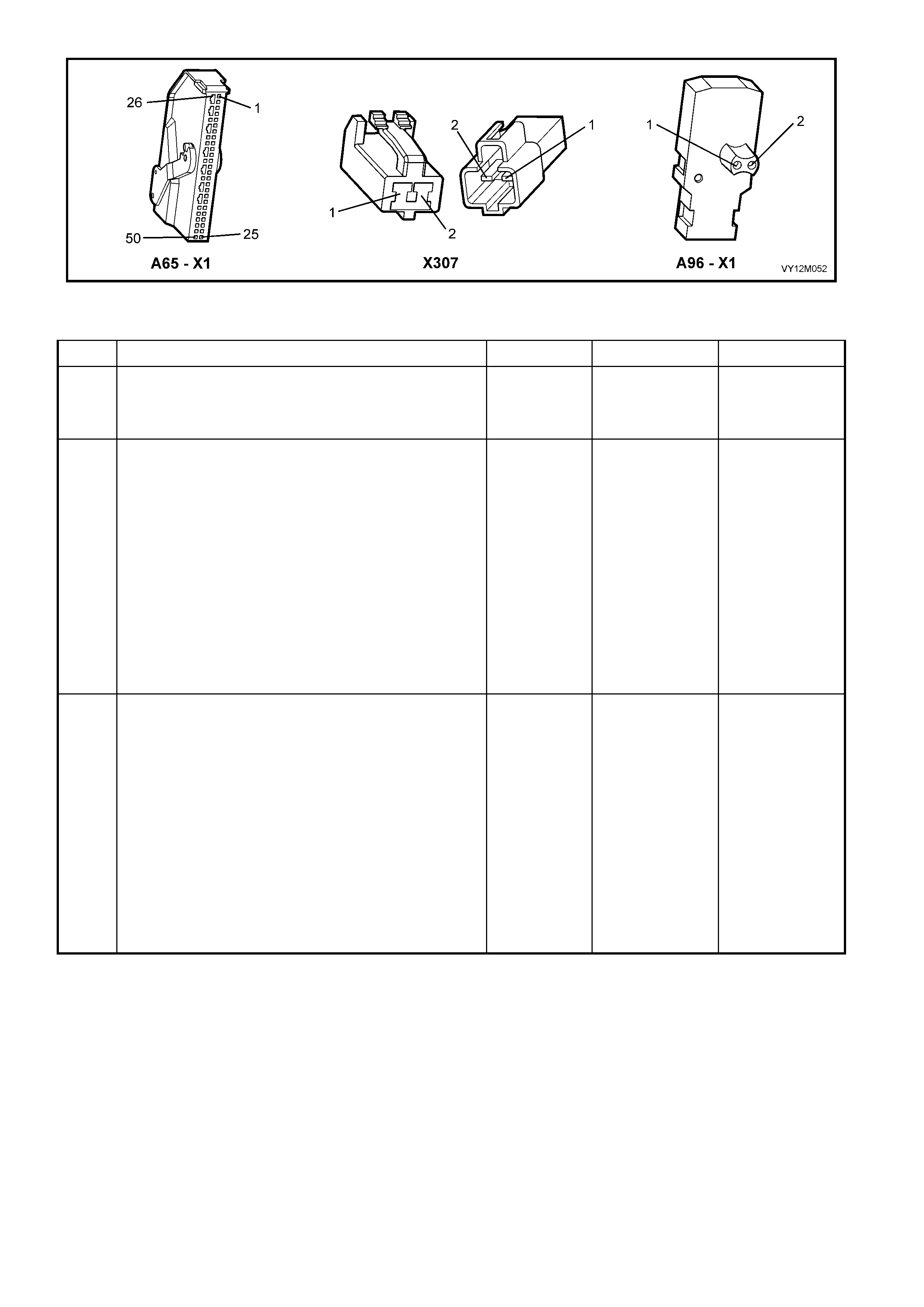
Figure 12M-223
DTC 97 – RIGHT-HAND SIDE-IMPACT AIR BAG CIRCUIT SHORT TO BATTERY
STEP ACTION VALUE YES NO
1. 1. Install TECH 2 to DLC.
2. Select Body / SRS / Diagnostic Trouble Codes /
Read DTC Information
Is DTC 97 current?
Go to Step 3. Go to Step 2.
2. 1. With TECH 2 still connected, select Diagnostic
Trouble Codes / Clear DTC Information and clear all
(if any) DTCs.
2. Select Diagnostic Trouble Codes / Read DTC
Information and monitor the TECH 2 screen display
to see if it changes status while performing the
following:
Put left-hand front seat through it’s full adjustment
(forward / backward, up / down and full recline).
‘Wiggle’ OPS / SRS wiring harness at all
accessible locations between the SDM and the
side-impact airbag wiring harness connector
X307.
Does TECH 2 screen display change status from No
Diagnostic Trouble Codes?
Make repairs as
necessary (refer
to Section NOTE
2 & 3 on previous
page).
Clear DTC and
recheck system
to verify repair.
Fault not present.
Check all system
wiring harness
connect ors, and
terminals.
Clear DTC and
recheck system.
3. 1. Disable the OPS / SRS, refer to Section 2.2
DISABLING AND ENABLING PROCEDURE in this
Section.
2. Disconnect OPS / SRS wiring harness connector
X307 (located next to the right-hand front seat) from
the left-hand side-impact airbag module ‘pigtail’
harness.
3. Connect Tool No. AU485 to OPS / SRS wiring
harness connec tor X 307.
4. Reconnect battery.
5. Connect TECH 2 to DLC and select: Body / SRS /
Diagnostic Trouble Codes / Read DTC Information.
Is DTC 97 still current?
Go to Step 4. Replace right-
hand side-impa ct
airbag and
‘‘pigtail’’ wiring
harness
assembly, refer
to Section 2.7
SIDE-IMPACT
INFLATABLE
RESTRAINT
MODULE in this
Section (refer to
Section NOTE 3
on previous
page). Clear DTC
and recheck
system to verify
repair

STEP ACTION VALUE YES NO
4. 1. Disable the OPS / SRS, refer to Section 2.2
DISABLING AND ENABLING PROCEDURE in this
Section.
2. Disconnect OPS / SRS wiring harness connector
X307 (located next to the right-hand front seat) from
the left-hand side-impact airbag module ‘pigtail’
harness.
3. Disconnect Tool No. AU485 from OPS / SRS wiring
harness connec tor X 307.
4. Reconnect battery.
5. Using Tool KM-609-20, check wiring between SDM
wiring harness connector A65 – X1, terminals 16
and 17 and OPS / SRS connector X307, circuits
2137 (Yellow/White wire) and 2138 (Brown/White
wire) for short to battery + (refer to Section NOTE 1
on previous page).
Is all OK?
Replace SDM,
refer to Section
2.8 INFLATABLE
RESTRAINT
CONTROL
MODULE in this
Section.
Recheck circuit
to verify repair..
Make repairs as
necessary (refer
to Section NOTE
2 on previous
page).
Clear DTC and
recheck system
to verify repair.
WHEN ALL DIAGNOSIS AND REPAIRS ARE COMPLETED, ENSURE ALL OPS / SRS COMPONENTS ARE
RECONNECTED, CLEAR ALL DTC’s, ENABLE THE OPS / SRS AND VERIFY CORRECT OPERATION
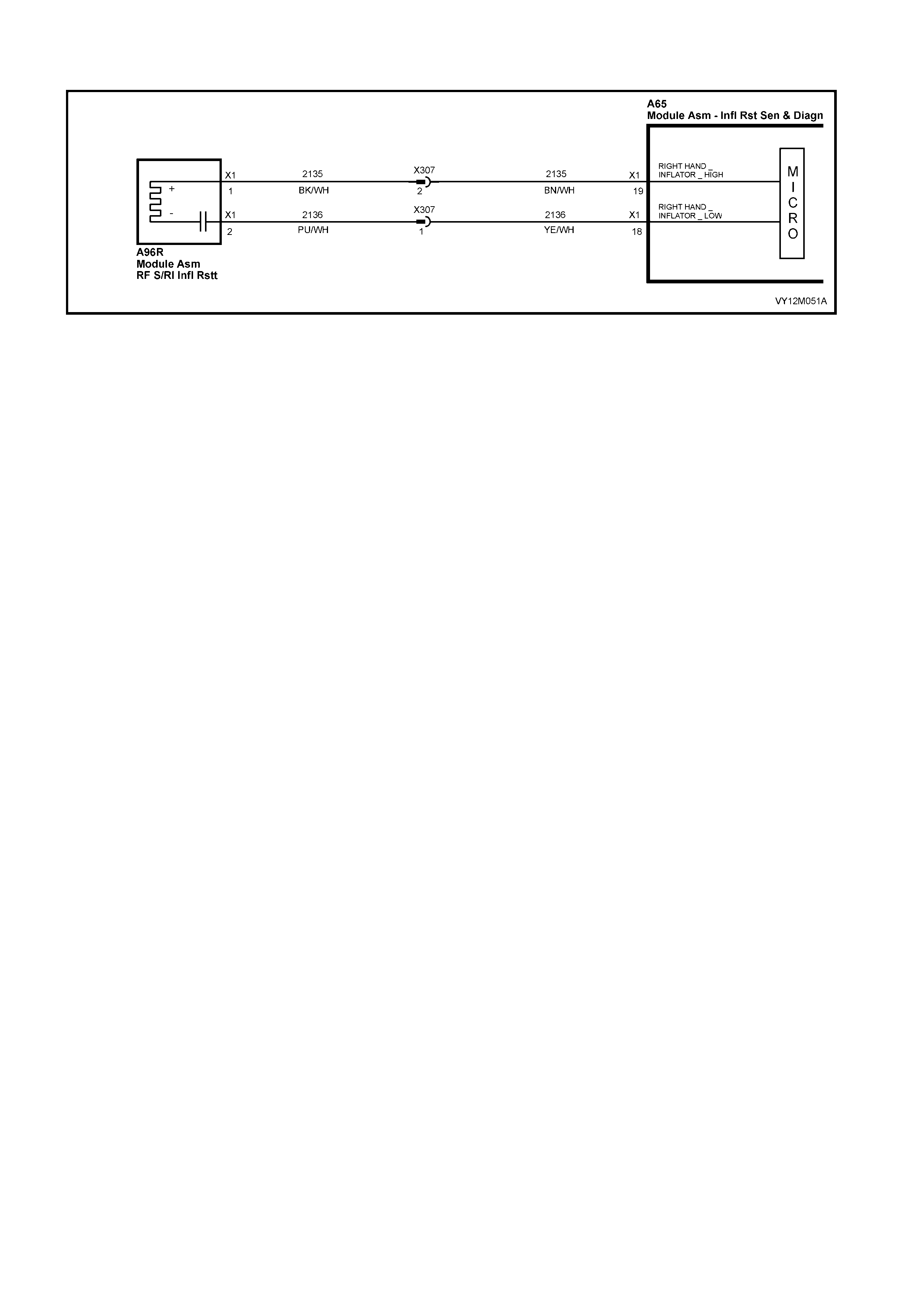
DTC 98 – RIGHT-HAND SIDE-IMPACT AIR BAG CIRCUIT SHORT TO EARTH
Figure 12M-224
CIRCUIT DESCRIPTION
At ignition on, and on a constant monitoring cycle of every 500 milliseconds during the ignition cycle, the
inflatabl e restr aint c ontrol m odule (SDM) p erf orm s a system self check . If the SDM det ects a resistanc e to earth
of less tha n 3 kohms in e ith er the positive or n ega ti ve inflator circ ui t f or mor e than 3 – 5 sec on ds , a c urr ent D TC
98 will set (refer to 4.3 OPS / SRS SELF DIAGNOSTICS in this Section for more details).
DTC 98 will set if circuits 2135 (s ide-impac t airbag pos itive si de) and/ or 2 136 ( side- im pact airb ag neg ative side)
are shorted to earth.
W hen DTC 98 sets , the SDM illum inates th e SR S warnin g in dicator and sets a c ur rent DT C 98. Should t he fault
conditions detected by the SDM c lear during the same ignition cycle, the current code will clear and become a
history DTC 98. The SRS warning indicator will remain on for the remainder of the ignition cycle.
If a DTC 98 is set, the SRS warning indicator is illuminated on each ignition c ycle, even if the DTC is set as a
histor y DTC, until the fault c onditions for setting DTC 98 are rectified and the DTC ( current or histor y) can the n
be cleared from the SDM via TECH 2.
If DTC 98 is set, the OPS / SRS, including the right-hand side-impact airbag, may still be operational.
TEST DESCRIPTION
The following number refer to Section step numbers in the following diagnostic chart:
1. Uses TECH 2 to check if DTC 98 is current or history.
2. TECH 2 in this mode should display approximately 1.6 – 6.4 ohms if the passenger airbag loop circuit is OK.
3. If screen display changes during a wiring 'wiggle' test, a fault with the wiring is at that location.
4. Tool AU485 is a dummy load taking the place of the side-impact airbag module. If TECH 2 displays the
correc t resis tance of the dum m y load, the system f ault is in the side- im pact airba g m odule assem bl y (or th e
‘pigtail’ wiring harness that connects to the side-impact airbag module).
5. T his test checks the wiring bet ween the SDM wiring harness connector A65 – X1 , term inal 18 and the r ight-
hand side-impact airbag module connector X307 for faults.
6. T his test checks the wiring bet ween the SDM wiring harness connector A65 – X1 , term inal 19 and the r ight-
hand side-impact airbag module connector X307 for faults.
NOTES ON DIAGNOSTIC CHART
1. For all wiring harness checking procedures, refer to Section 12P WIRING DIAGRAMS.
2. Refer to 2.11 OPS / SRS WIRING REPAIR in this Section before conducting any OPS / SRS wiring harness
repairs.
3. Due to the design of the anti-back-out connector on the side-impact airbag module assembly, connector
A96 – X1 can not be disconnected from the side-impact airbag module assembly without damaging the
assem bl y. Therefore, repairs to the O PS / SR S ‘ pigta il ’ wir in g harn es s that run thr o ugh th e f r ont seat ar e no t
to be attem pted. If this ‘ pigtail ’ harnes s is dam aged in an y way, the harn ess and side-im pact airbag m odule
assembly must be replaced as an assembly.

Figure 12M-225
DTC 98 – RIGHT-HAND SIDE-IMPACT AIR BAG CIRCUIT SHORT TO EARTH
STEP ACTION VALUE YES NO
1. 1. Install TECH 2 to DLC.
2. Select Body / SRS / Diagnostic Trouble Codes /
Read DTC Information
Does TECH 2 display DTC 98 as a Current DTC?
Go to Step 2. Go to Step 3.
2. 1. With TECH 2 still connected to DLC, select Body /
SRS / Data Display and scroll to RIGHT-HAND
SIDE-IMPACT AIRBAG LOOP RESISTANCE.
Is the resistance value displayed on TECH 2 as
specified?
Approx.
1.6 – 6.4
Ohms
Go to Step 3. Go to Step 4.
3. 1. With TECH 2 still connected, select Diagnostic
Trouble Codes / Clear DTC Information and clear all
(if any) DTCs.
2. Select Diagnostic Trouble Codes / Read DTC
Information and monitor the TECH 2 screen display
to see if it changes status while performing the
following:
Put left-hand front seat through it’s full adjustment
(forward / backward, up / down and full recline).
'Wiggle' OPS / SRS wiring harness at all
accessible locations between the SDM and the
side-impact airbag wiring harness connector
X307.
Does TECH 2 screen display change status from No
Diagnostic Trouble Codes?
Make repairs as
necessary (refer
NOTES 2, 3 & 4
on previous
page).
Clear DTC and
recheck system
to verify repair.
Fault not present.
Check all system
wiring harness
connect ors, and
terminals.
Clear DTC and
recheck system.
4. 1. Disable the OPS / SRS, refer to Section 2.2
DISABLING AND ENABLING PROCEDURE in this
Section.
2. Disconnect OPS / SRS wiring harness connector
X307 (located next to the right-hand front seat) from
the left-hand side-impact airbag module ‘pigtail’
harness.
3. Connect Tool No. AU485 to OPS / SRS wiring
harness connec tor X 307.
4. Reconnect battery.
5. Connect TECH 2 to DLC and select Body / SRS /
Data Display and scroll to RIGHT-HAND SIDE-
IMPACT AIRBAG LOOP RESISTANCE'.
Is the resistance value displayed on TECH 2 as
specified?
Approx.
2.0 Ohms Replace right-
hand side-impa ct
airbag module
and ‘pigtail’
wiring harness
assembly, refer
to Section 2.7
SIDE-IMPACT
INFLATABLE
RESTRAINT
MODULE
ASSEMBLY in
this Section (refer
NOTE 3 on
previous page).
Clear DTC and
recheck system
to verify repair.
Go to Step 5.

STEP ACTION VALUE YES NO
5. 1. Disable the OPS / SRS, refer to Section 2.2
DISABLING AND ENABLING PROCEDURE in this
Section.
2. Disconnect SDM wiring harness connector A65 – X1
from the SDM
3. Remove Tool AU485 from X307.
4. Using Tool KM-609-20, check wiring between SDM
wiring harness connector A65 – X1, terminal 18 and
OPS / SRS connector X307, circuit 2136
(Yellow/White wire) for short to earth (refer NOTE 1
on previous page).
Is all OK?
Go to Step 6. Make repairs as
necessary (refer
to Section NOTE
2 on previous
page).
Clear DTC and
recheck system
to verify repair..
6. 1. With SDM wiring harness connector A65 – X1
disconnected from the SDM and using Tool KM-
609-20, check wiring between SDM wiring harness
connector A65 – X1, terminal 19 and OPS / SRS
connector X307, circuit 2135 (Brown/White wire) for
a short to earth (refer to Section NOTE 1 on
previous page).
Is all OK?
Replace SDM,
refer to Section
2.8 INFLATABLE
RESTRAINT
CONTROL
MODULE in this
Section.
Recheck circuit
to verify repair.
Make repairs as
necessary (refer
to Section NOTE
2 on previous
page).
Clear DTC and
recheck system
to verify repair.
WHEN ALL DIAGNOSIS AND REPAIRS ARE COMPLETED, ENSURE ALL OPS / SRS COMPONENTS ARE
RECONNECTED, CLEAR ALL DTC’s, ENABLE THE OPS / SRS AND VERIFY CORRECT OPERATION

DTC 99 – RIGHT-HAND SIDE-IMPACT AIR BAG CIRCUIT CAPACITANCE TOO HIGH
Figure 12M-226
CIRCUIT DESCRIPTION
At ignition on, and on a constant monitoring cycle of every 500 milliseconds during the ignition cycle, the
inflatable restraint control module (SDM) performs a system self check.
If the SDM detects the cap acitance in t he righ t-hand s ide-impac t airbag c ircuit is too hig h (greater t han 5 50 nF)
for longer than 3 – 5 seconds, a current DTC 99 will set (refer to 4.3 OPS / SRS SELF DIAGNOSTICS in this
Section for more details).
DTC 99 will set if the in-built capacitor in the OPS / SRS wiring harness connector A96 – X1 is faulty.
W hen DTC 99 sets , the SDM illum inates th e SR S warnin g in dicator and sets a c ur rent DT C 99. Should t he fault
conditions detected by the SDM c lear during the same ignition cycle, t he current code will clear and become a
history DTC 99. The SRS warning indicator will remain on for the remainder of the ignition cycle.
If a DTC 99 is set, the SRS warning indicator is illuminated on each ignition cycle, even if the DTC is set as a
histor y DTC, until the fault condit ions for s etting DTC 99 are rectified an d the DTC (c urrent or histor y) can the n
be cleared from the SDM via TECH 2.
ACTION REQUIRED
If DTC 99 is set, the right-hand side-im pact airbag may not operate and therefore, the OPS / SRS side-impact
airbag and ‘pigtail’ wiring harness assembly must be replaced. Refer to 2.7 SIDE-IMPACT INFLATABLE
RESTRAINT MODULE ASSEMBLY in this Section for the correct procedure on replacing the side-impact
airbag and ‘pigtail’ wiring harness connector.
NOTE: Due to t he des ign of the anti- back -out conn ector on the s ide-im pact a irba g m odule assem bl y, conn ector
A96 – X1 can not be disconnected from the side-impact airbag module assembly without damaging the
assem bly. Ther efore, repairs to the OPS / SRS ‘pig tail’ wiring harn ess that run through t he front seat are no t to
be attemp ted (this includes the c apacit or in con nector A96 – X1) . If this ‘pigt ail’ h ar ness is dam aged in an y way,
the harness and side-impact airbag module assembly must be replaced as an assembly.
After the OPS / SRS side-im pact airbag and ‘pigta il’ wiring harness assem blies have been replac ed, ensure all
OPS / SRS c omponents are rec onnect ed, c le ar DT Cs , enab le th e O P S / SR S an d ver ify the corr ect oper at io n of
the system (i.e. warning indicator not illuminated after five seconds of ignition being switched ON).
NOTE: After replacement, the front seat should be put through its full adjustment (forward/backwards, full
recline and up and down) to ensure that the wiring harness does not foul with any of the seat components.

DTC 100 – RIGHT-HAND SIDE-IMPACT AIR BAG CIRCUIT CAPACITANCE TOO LOW
Figure 12M-227
CIRCUIT DESCRIPTION
At ignition on, and on a constant monitoring cycle of every 500 milliseconds during the ignition cycle, the
inflatable restraint control module (SDM) performs a system self check.
If the SDM detects the capacitance in the right- hand side-impact airbag circuit is too low (less than 390 nF) for
longer than
3 – 5 seconds, a current DTC 100 will set (refer to 4.3 OPS / SRS SELF DIAGNOSTICS in this Section for more
details).
DTC 100 will set if the in-built capacitor in the OPS / SRS wiring harness connector A96 – X1 is faulty.
When DTC 100 sets, the SDM illuminates the SRS warning indicator and sets a current DTC 100. Should the
fault conditions detected by the SDM clear during the same ignition cycle, the current code will clear and
become a history DTC 100. The SRS warning indicator will remain on for the remainder of the ignition cycle.
If a DT C 100 is set, the SR S warning indic ator is illum inated on eac h ignition c ycle, even if the DTC is set as a
histor y DTC, until t he fault condit ions for s etting DTC 100 ar e rect ified an d the D TC (cur rent or his tory) can then
be cleared from the SDM via TECH 2.
ACTION REQUIRED
If DT C 100 is set, the r ight-hand side-im pact airba g ma y not operate a nd therefor e, the OPS / SRS sid e-impac t
airbag and ‘pigtail’ wiring harness assembly must be replaced. Refer to 2.7 SIDE-IMPACT INFLATABLE
RESTRAINT MODULE ASSEMBLY in this Section for the correct procedure on replacing the side-impact
airbag and ‘pigtail’ wiring harness connector.
NOTE: Due to t he des ign of the anti- back -out conn ector on the s ide-im pact a irba g m odule assem bl y, conn ector
A96 – X1 can not be disconnected from the side-impact airbag module assembly without damaging the
assem bly. Ther efore, repairs to the OPS / SRS ‘pig tail’ wiring harn ess that run through t he front seat are no t to
be attemp ted (this includes the c apacit or in con nector A96 – X1) . If this ‘pigt ail’ h ar ness is dam aged in an y way,
the harness and side-impact airbag module assembly must be replaced as an assembly.
After the OPS / SRS side-im pact airbag and ‘pigta il’ wiring harness assem blies have been replac ed, ensure all
OPS / SRS c omponents are rec onnect ed, c le ar DT Cs , enab le th e O P S / SR S an d ver ify the corr ect oper at io n of
the system (i.e. warning indicator not illuminated after five seconds of ignition being switched ON).
NOTE: After replacement, the front seat should be put through its full adjustment (forward/backwards, full
recline and up and down) to ensure that the wiring harness does not foul with any of the seat components.

DTC 101 – RIGHT-HAND SIDE-IMPACT AIR BAG CIRCUIT RESISTANCE TOO HIGH
Figure 12M-228
CIRCUIT DESCRIPTION
At ignition on, and on a constant monitoring cycle of every 500 milliseconds during the ignition cycle, the
inflatable restraint control module (SDM) performs a system self check.
If the SDM detects a r es ist anc e i n th e rig ht-ha nd s id e- impact air bag c irc u it that is too h igh (gr eat er tha n 8. 4 o hm
for longer than 3 – 5 seconds), a current DTC 101 will set (refer to 4.3 OPS / SRS SELF DIAGNOSTICS in this
Section for more details).
DTC 101 will set if circuits 2136 or 2135 (including the side-impact airbag module) are open circuit.
When DTC 101 sets, the SDM illuminates the SRS warning indicator and sets a current DTC 101. Should the
fault conditions detected by the SDM clear during the same ignition cycle, the current code will clear and
become a history DTC 101. The SRS warning indicator will remain on for the remainder of the ignition cycle.
If a DT C 101 is set, the SR S warning indic ator is illum inated on eac h ignition c ycle, even if the DTC is set as a
histor y DTC, until t he fault condit ions for s etting DTC 101 ar e rect ified an d the D TC (cur rent or his tory) can then
be cleared from the SDM via TECH 2.
If DTC 101 is set, dependent on where the fault is, the right-hand side-impact airbag may not operate
TEST DESCRIPTION
The following number refer to Section step numbers in the following diagnostic chart:
1. Uses TECH 2 to check if DTC 101 is current or history.
2. Checks for intermittent faul t b y m onitori ng TECH 2 scr een. If s cr een dis p lay changes dur ing a wiring 'wiggle'
test, a fault with the wiring is at that location.
3. Tool AU485 is a dummy load taking the place of the side-impact airbag module. If DTC 101 becomes a
histor y DTC with dum m y load c onnected, th e system fault is i n the side- impact ai rbag m odule assem bly (or
the ‘pigtail’ wiring harness that connects to the side-impact airbag module).
4. Checks circuit 2135 for open circuit.
5. Checks circuit 2136 for open circuit.
NOTES ON DIAGNOSTIC CHART
1. For all wiring harness checking procedures, refer to Section 12P WIRING DIAGRAMS.
2. Refer to 2.11 OPS / SRS W IRING REPAIR in this Section bef or e conduc t ing a n y O PS / SRS wiring harness
repairs.
3. Due to the design of the anti-back-out connector on the side-impact airbag module assembly, connector
A96 – X1 can not be disconnected from the side-impact airbag module assembly without damaging the
assem bl y. Therefore, repairs to the O PS / SRS ‘pi gta il’ wir in g harness that r un thr o ugh th e f ront s eat ar e not
to be attem pted. If this ‘ pigtail ’ harness is dam aged in any wa y, the harn ess and s ide-impac t airbag m odule
assembly must be replaced as an assembly.
4. Wiring should be checked at point where TECH 2 screen display changed status. If necessary, split open
wir ing harness.
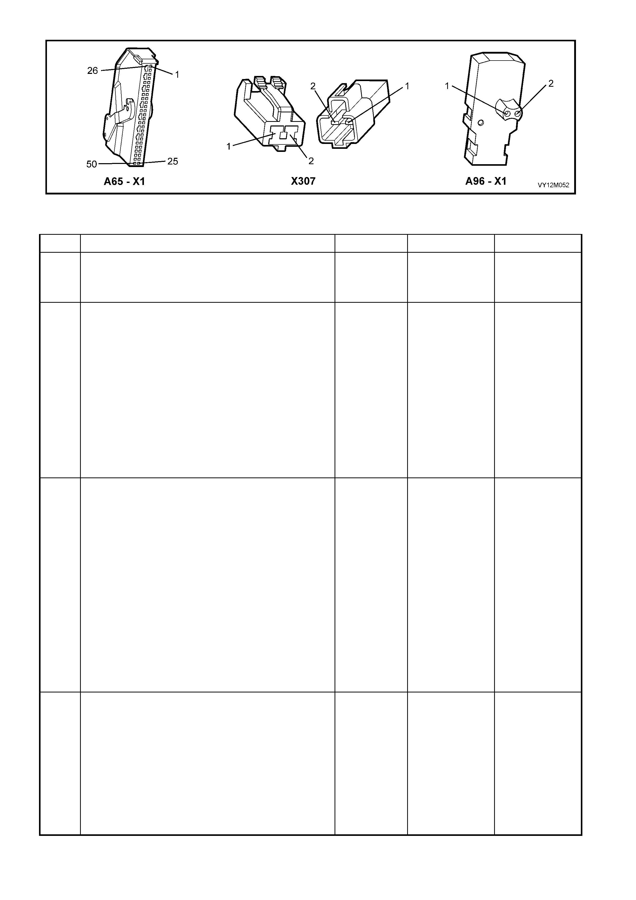
Figure 12M-229
DTC 101 – RIGHT-HAND SIDE-IMPACT AIR BAG CIRCUIT RESISTANCE TO HIGH
STEP ACTION VALUE YES NO
1. 1. Install TECH 2 to DLC.
2. Select Body / SRS / Diagnostic Trouble Codes /
Read DTC Information
Is DTC 101 current?
Go to Step 3. Go to Step 2.
2. 1. With TECH 2 still connected, select Diagnostic
Trouble Codes / Clear DTC Information and clear all
(if any) DTCs.
2. Select Diagnostic Trouble Codes / Read DTC
Information and monitor the TECH 2 screen display
to see if it changes status while performing the
following:
Put left-hand front seat through it’s full adjustment
(forward / backward, up / down and full recline).
'Wiggle' OPS / SRS wiring harness at all
accessible locations between the SDM and the
side-impact airbag wiring harness connector
X307.
Does TECH 2 screen display change status from No
Diagnostic Trouble Codes?
Make repairs as
necessary (refer
NOTES 2, 3 & 4
on previous
page).
Clear DTC and
recheck system
to verify repair.
Fault not present.
Check all system
wiring harness
connect ors, and
terminals.
Clear DTC and
recheck system.
3. 1. Disable the OPS / SRS, refer to Section 2.2
DISABLING AND ENABLING PROCEDURE in this
Section.
2. Disconnect OPS / SRS wiring harness connector
X307 (located next to the right-hand front seat) from
the left-hand side-impact airbag module ‘pigtail’
harness.
3. Connect Tool No. AU485 to OPS / SRS wiring
harness connec tor X 307.
4. Reconnect battery.
5. Connect TECH 2 to DLC and select Body / SRS /
Diagnostic Trouble Codes / Read DTC Information
Is DTC 101 still current?
Go to Step 4. Replace right-
hand side-impa ct
airbag module
and ‘pigtail’
wiring harness
assembly, refer
to Section 2.7
SIDE-IMPACT
INFLATABLE
RESTRAINT
MODULE
ASSEMBLY in
this Section (refer
to Section NOTE
3 on previous
page).
Clear DTC and
recheck system
to verify repair.
4. 1. Disable the OPS / SRS, refer to Section 2.2
DISABLING AND ENABLING PROCEDURE in this
Section.
2. Disconnect SDM wiring harness connector A65 – X1
from the SDM
3. Remove Tool AU485 from X307.
4. Using Tool KM-609-20, check wiring between SDM
wiring harness connector A65 – X1, terminal 19 and
OPS / SRS wiring harness connector X307, circuit
2135 (Brown/White wire) for open circuit (refer to
Section NOTE 1 on previous page).
Is all OK?
Go to Step 5. Make repairs as
necessary (refer
to Section NOTE
2 on previous
page).
Clear DTC and
recheck system
to verify repair..

STEP ACTION VALUE YES NO
5. 1. With SDM wiring harness connector A65 – X1
disconnected from the SDM and using Tool KM-
609-20, check wiring between SDM wiring harness
connector A65 – X1, terminal 18 and OPS / SRS
wiring harness connector X307, circuit 2136
(Yellow/White wire) for open circuit (refer to Section
NOTE 1 on previous page).
Is all OK?
Replace SDM,
refer to Section
2.8 INFLATABLE
RESTRAINT
CONTROL
MODULE in this
Section. Recheck
circuit to verify
repair.
Make repairs as
necessary (refer
to Section NOTE
2 on previous
page).
Clear DTC and
recheck system
to verify repair.
WHEN ALL DIAGNOSIS AND REPAIRS ARE COMPLETED, ENSURE ALL OPS / SRS COMPONENTS ARE
RECONNECTED, CLEAR ALL DTC’s, ENABLE THE OPS / SRS AND VERIFY CORRECT OPERATION

DTC 102 – RIGHT-HAND SIDE-IMPACT A IR BAG CIRCUIT RESISTANCE TOO LOW
Figure 12M-230
CIRCUIT DESCRIPTION
At ignition on, and on a constant monitoring cycle of every 500 milliseconds during the ignition cycle, the
inflatable restraint control module (SDM) performs a system self check.
If the SDM detects a r es ist anc e i n the righ t-han d s id e-impact air bag c ircuit that is too l o w (l ess than 0.6 o hm) for
longer than 3 – 5 seconds, a current DTC 102 will set (refer to 4.3 OPS / SRS SELF DIAGNOSTICS in this
Section for more details).
DTC 102 will set if circuits 2136 or 2135, (including the side-impact airbag module assembly) are shorted
together.
When DTC 102 sets, the SDM illuminates the SRS warning indicator and sets a current DTC 102. Should the
fault conditions detected by the SDM clear during the same ignition cycle, the current code will clear and
become a history DTC 102. The SRS warning indicator will remain on for the remainder of the ignition cycle.
If a DT C 102 is set, the SR S warning indic ator is illum inated on eac h ignition c ycle, even if the DTC is set as a
histor y DTC, until t he fault condit ions for s etting DTC 102 ar e rect ified an d the D TC (cur rent or his tory) can then
be cleared from the SDM via TECH 2.
If DTC 102 is set, dependent on where the fault is, the right-hand side-impact airbag may not operate.
TEST DESCRIPTION
The following number refer to Section step numbers in the following diagnostic chart:
1. Uses TECH 2 to check if DTC 102 is current or history.
2. Checks for inter mittent fault by m onitori ng TECH 2 scr een. If s cr een dis p lay chan ges dur i ng a wiri ng 'wiggle'
test, a fault with the wiring is at that location.
3. Tool AU485 is a dummy load taking the place of the side-impact airbag module. If DTC 102 becomes a
histor y DTC with dum m y load c onnecte d, the s ystem fault is in the s ide-im pact airbag m odule as sem bly (or
the ‘pigtail’ wiring harness that connects to the side-impact airbag module).
4. This test checks the wiring between the SDM wiring harness connector A65 – X1 and OPS / SRS wiring
harness connector X307 for a short circuit.
NOTES ON DIAGNOSTIC CHART
1. For all wiring harness checking procedures, refer to Section 12P WIRING DIAGRAMS.
2. Refer to 2.11 WIRING REPAIR in this Section before conducting any OPS / SRS wiring harness repairs.
3. Due to the design of the anti-back-out connector on the side-impact airbag module assembly, connector
A96 – X1 can not be disconnected from the side-impact airbag module assembly without damaging the
assem bl y. Therefore, repairs to the O PS / SRS ‘pig ta il’ wir in g harn es s that run thr o ugh th e f r ont s eat are not
to be attem pted. If this ‘ pigtail ’ harness is dam aged in any wa y, the harn ess and s ide-impac t airbag m odule
assembly must be replaced as an assembly.
4. Wiring should be checked at point where TECH 2 screen display changed status. If necessary, split open
wir ing harness.

Figure 12M-231
DTC 102 – RIGHT-HAND SIDE-IMPACT A IR BAG CIRCUIT RESISTANCE TO LOW
STEP ACTION VALUE YES NO
1. 1. Install TECH 2 to DLC.
2. Select Body / SRS / Diagnostic Trouble Codes /
Read DTC Information
Is DTC 102 current?
Go to Step 3. Go to Step 2.
2. 1. With TECH 2 still connected, select Diagnostic
Trouble Codes / Clear DTC Information and clear all
(if any) DTCs.
2. Select Diagnostic Trouble Codes / Read DTC
Information and monitor the TECH 2 screen display
to see if it changes status while performing the
following:
Put left-hand front seat through it’s full adjustment
(forward / backward, up / down and full recline).
'Wiggle' OPS / SRS wiring harness at all
accessible locations between the SDM and the
side-impact airbag wiring harness connector
X307.
Does TECH 2 screen display change status from No
Diagnostic Trouble Codes?
Make repairs as
necessary (refer
NOTES 2, 3 & 4
on previous
page).
Clear DTC and
recheck system
to verify repair.
Fault not present.
Check all system
wiring harness
connect ors, and
terminals.
Clear DTC and
recheck system.
3. 1. Disable the OPS / SRS, refer to Section 2.2
DISABLING AND ENABLING PROCEDURE in this
Section.
2. Disconnect OPS / SRS wiring harness connector
X307 (located next to the right-hand front seat) from
the left-hand side-impact airbag module ‘pigtail’
harness.
3. Connect Tool No. AU485 to OPS / SRS wiring
harness connec tor X 307.
4. Reconnect battery.
5. Connect TECH 2 to DLC and select Body / SRS /
Diagnostic Trouble Codes / Read DTC Information
Is DTC 102 still current?
Go to Step 4. Replace right-
hand side-impa ct
airbag module
and ‘pigtail’
wiring harness
assembly, refer
to Section 2.7
SIDE-IMPACT
INFLATABLE
RESTRAINT
MODULE
ASSEMBLY in
this Section (refer
to Section NOTE
3 on previous
page).
Clear DTC and
recheck system
to verify repair.

STEP ACTION VALUE YES NO
4. 1. Disable the OPS / SRS, refer to Section 2.2
DISABLING AND ENABLING PROCEDURE in this
Section.
2. Disconnect SDM wiring harness connector A65 – X1
from the SDM
3. Remove Tool AU485 from X307.
4. With OPS / SRS wiring harness connector X307
disconnected, and using Tool KM-609-20, check for
continuity between SDM wiring harness connector
A65 – X1, terminal 18, circuit 2136 (Yellow/White
wire) and terminal 19, circuit 2135 (Brown/White
wire)(refer to Section NOTES 1 and 3 on previous
page).
Does continu ity ex ist?
Repair short in
circuits 2136 and
2135, between
SDM wiring
harness
connector A65 –
X1 and X307 as
necessary (refer
to Section NOTE
2 on previous
page).
Clear DTC and
recheck system
to verify repair.
Replace SDM,
refer to Section
2.8 INFLATABLE
RESTRAINT
CONTROL
MODULE in this
Section. Recheck
circuit to verify
repair.
WHEN ALL DIAGNOSIS AND REPAIRS ARE COMPLETED, ENSURE ALL OPS / SRS COMPONENTS ARE
RECONNECTED, CLEAR ALL DTC’s, ENABLE THE OPS / SRS AND VERIFY CORRECT OPERATION

DTC 247 – RIGHT-HAND SIDE-IMPACT AIR BAG CIRCUIT POWER STAGE ERROR
Figure 12M-232
CIRCUIT DESCRIPTION
At ignit ion on, the SDM perf orms an initial s ystem self check of the SDM power stages. If during this init ial self-
test the SDM detects a fault with the Right-hand Side-impact Airbag Circuit power stage a current DTC 247
Right-hand Side-impact Airbag Circuit Power Stage Error will set. On completion of the initial system self test
the SDM then performs a test of the Right-hand Side-impact Airbag Circuit. If the SDM detects a problem with
this circuit the associated Right-hand Side-impact Airbag Circuit DTC will be set and the DTC 247 Right-hand
Side-impact Airbag Circuit Airbag Circuit Power Stage Error will become a history DTC.
DTC 247 Right-hand Side-impact Airbag Circuit Power Stage Error will set if a fault occurs in the Right-hand
Side-impact Airbag, connector A96 – X1R with the in-built capacitor, connector X307, the OPS / SRS wiring
harness, connector A63/A65 – X1 or SDM.
When a history DTC 247 Right-hand Side-impact Airbag Circuit Power Stage Error sets, the SDM illuminates
the SRS warni ng indic ator. Should the f ault condi tions detected b y the SDM clear durin g the sam e ignition c ycle
the code will remain a h istory DTC 247 R ight-hand S ide-impac t Airbag Circu it Power Stage Er ror for all i gnition
cycles until cleared. The SRS warning indicator will remain on for the remainder of the ignition cycle.
W hen a DTC 24 7 Right-ha nd Side-im pact Airbag C ircuit Power Stage Er ror sets, the SDM illum inates the SRS
warning indicator f or the rem ainder of the ignition cycle. Should the f ault conditions detected by the SDM clear
during the same ignition cycle the code will remain a history DTC 247 Right-hand Side-impact Airbag Circuit
Power Stage Error for all ignition cycles until cleared. The SRS warning indicator will also remain illuminated
until the history DTC 247 Right-hand Side-impact Airbag Circuit Power Stage Error is cleared.
If a DTC 247 Right-hand Side-impact Airbag Circuit Power Stage is set, dependent on where the fault is, the
Right-hand Pretensioner may not operate.
ACTION REQUIRED
If DTC 247 Right-hand Side-impact Airbag Circuit Power Stage Error and any other DTC is set then the
diagnostics for the other DTC should be carried out first. For example if a DTC 247 Right-hand Side-impact
Airbag Circuit Po wer St age Err or and a DTC 85 R ight- hand Sid e-im pact Air bag Circuit Res is tance Hi gh ar e set,
the diagnostics for a DTC 85 Right-hand Side-impact Airbag Circuit Resistance High should be carried out first.
If only a DTC 247 Right-hand Side-impact Airbag Circuit Power Stage Error is set then the SDM should be
replaced.
NOTE: An intermittent in the Right-hand Side-impact Airbag Circuit may cause a DTC 247 Right-hand Side-
impact Airbag Circuit Power Stage Error to set.
After the fault has been rectified, ensure that all SRS components are reconnected, clear DTCs, enable the
SRS and verify the correct operation of the system (i.e. warning indicator not illuminated after five seconds of
ignition being switched ON).
TEST DESCRIPTION
The following numbers refer to Section Step numbers in the following diagnostic chart.
1. Uses TECH 2 to check if a DTC 247 Right-hand Side-impact Airbag Circuit Power Stage Error is history
code, and if any other Right-hand Side-impact Airbag Circuit current or history DTCs are set. If any other
DTCs are set refer to Section these DTCs first.
2. Checks for intermittent fault by monitoring TECH 2 screen during ignition on cycle. If screen display
changes during a wirin g 'wiggle' test, a fault with the wiring is at that locat ion. If no oth er DTCs are set a nd
there are no intermittents in the Right-hand Side-impact Airbag Circuit then the SDM should be replaced.
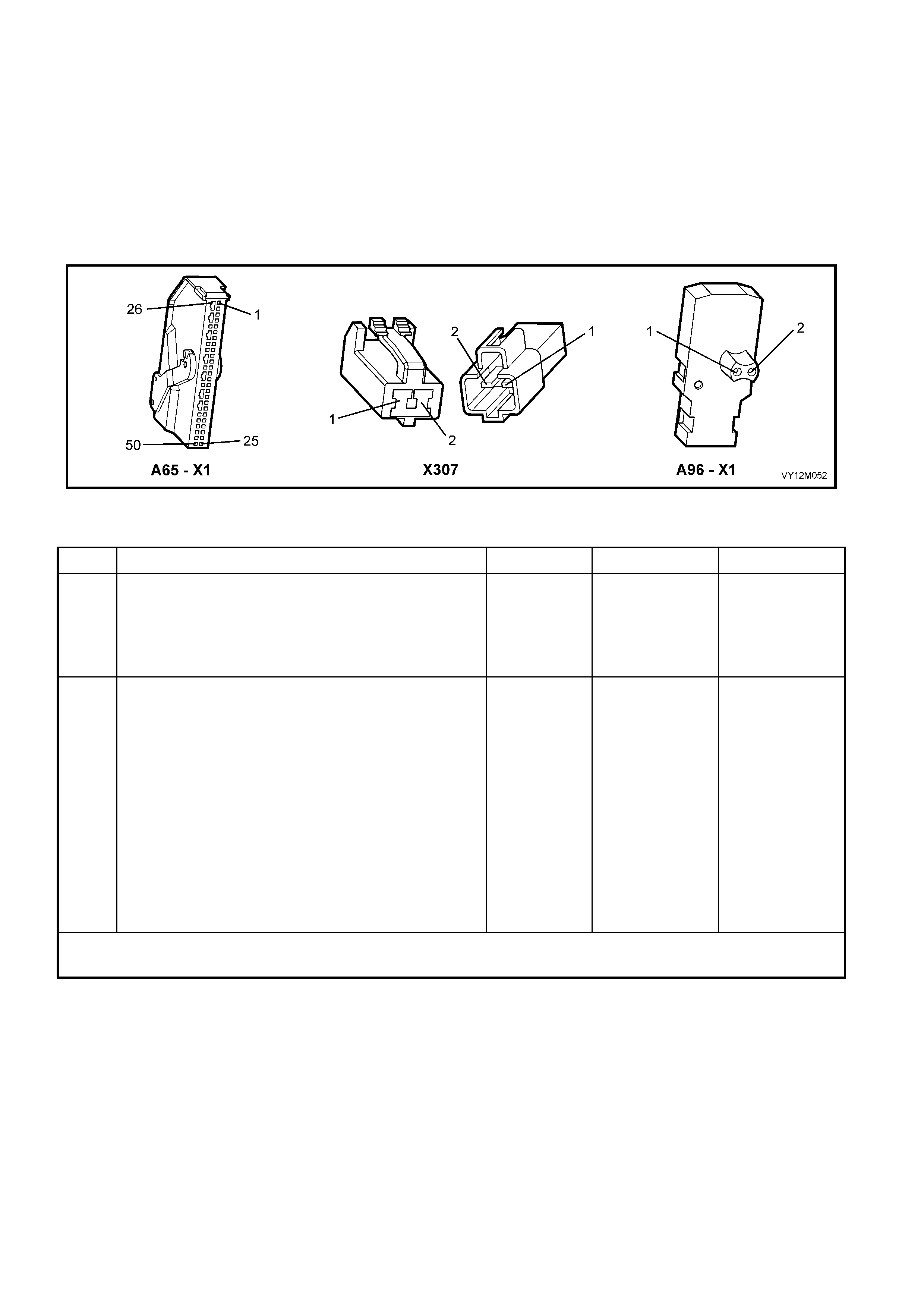
NOTES ON DIAGNOSTIC CHART
1. For all wiring harness checking procedures, refer to Section 12P WIRING DIAGRAMS.
2. Refer to 2.11 WIRING REPAIR in this Section before conducting any OPS / SRS wiring harness repairs.
3. Due to the design of the anti-back-out connector on the side-impact airbag module assembly, connector
A96 – X1 can not be disconnected from the side-impact airbag module assembly without damaging the
assem bl y. Therefore, repairs to the O PS / SRS ‘p igta il ’ wir ing har n es s that r un thr o ugh th e f r ont seat ar e not
to be attem pted. If this ‘ pigtail ’ harness is dam aged in an y way, the harn ess and side-im pact airbag m odule
assembly must be replaced as an assembly.
4. Wiring should be checked at point where TECH 2 screen display changed status. If necessary, split open
wir ing harness.
Figure 12M-233
DTC 247 – RIGHT-HAND SIDE-IMPACT AIR BAG CIRCUIT POWER STAGE ERROR
STEP ACTION VALUE YES NO
1. 1. Install TECH 2 to DLC.
2. Select Body / SRS / Diagnostic Trouble Codes /
Read DTC Information
Is a DTC 247 Right-hand Side-impact Airbag Circuit
Power Stage Error a history DTC, and are any other
Right-hand Side-impact Airbag Circuit DTCs set?
Go to other
Right-hand Side-
impact Airbag
Circuit DTC
diagnost ic cha rt
in this Section.
Go to Step 2.
2. 1. With TECH 2 still connected, select Diagnostic
Trouble Codes / Clear DTC Information and clear all
(if any) DTCs.
2. Select Diagnostic Trouble Codes / Read DTC
Information and monitor the TECH 2 screen display
to see if it changes status while performing the
following:
Put left-hand front seat through it’s full adjustment
(forward / backward, up / down and full recline).
'Wiggle' OPS / SRS wiring harness at all
accessible locations between the SDM and the
side-impact airbag wiring harness connector
X307.
Does TECH 2 screen display change status from No
Diagnostic Trouble Codes?
Go to applicable
DTC chart in this
Section.
Replace SDM,
refer to Section
2.8 INFLATABLE
RESTRAINT
CONTROL
MODULE in this
Section. Recheck
circuit to verify
repair.
WHEN ALL DIAGNOSIS AND REPAIRS ARE COMPLETED, ENSURE ALL OPS / SRS COMPONENTS ARE
RECONNECTED, CLEAR ALL DTC’s, ENABLE THE OPS / SRS AND VERIFY CORRECT OPERATION
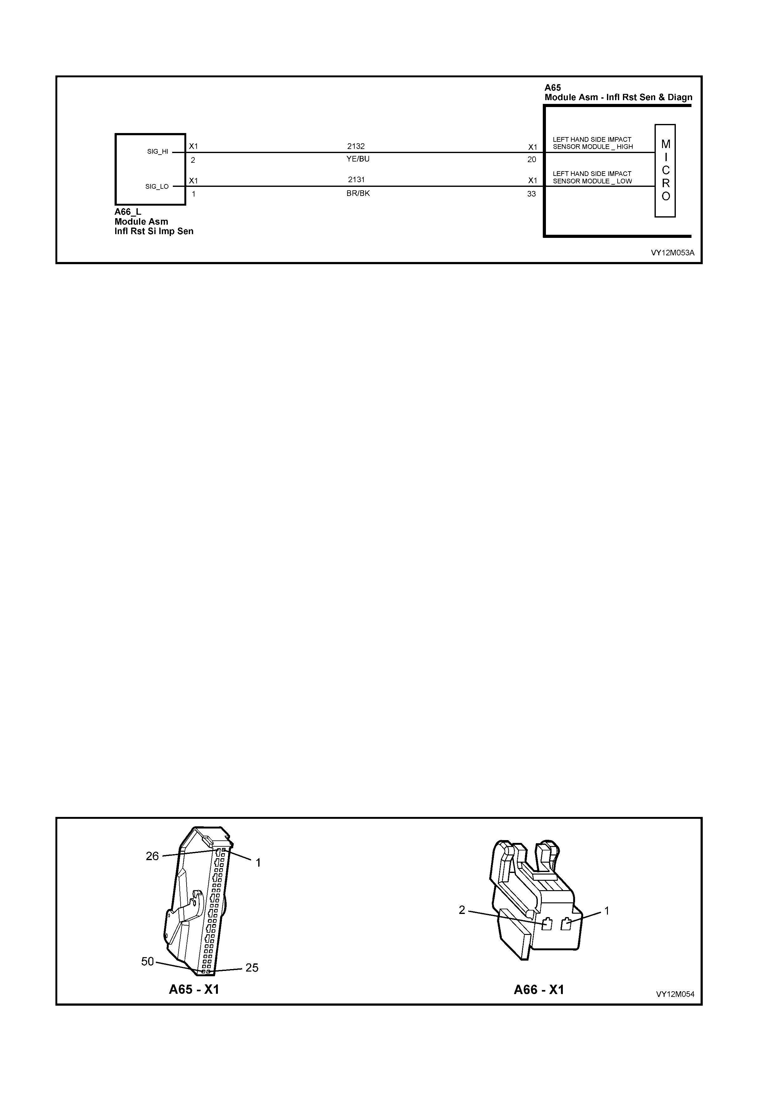
DTC 129 – LEFT-HAND PERIPHERAL ACCELERATION SENSOR LINE FAULT
Figure 12M-234
CIRCUIT DESCRIPTION
The peripheral acceleration sensor communicates continuously with the inflatable restraint control module
(SDM) by modulating the consumed current at a constant voltage.
If this comm unication is interrupted or disturb ed by a short circuit to earth, between the SDM and the left-hand
peripheral acceleration sensor, for longer than 3 – 5 seconds, a current DTC 129 is set (refer to 4.3 OPS / SRS
SELF DIAGNOSTICS in this Section for more details).
DTC 129 will set if circuit 2132 is shorted to earth.
When DTC 129 sets, the SDM illuminates the SRS warning indicator and sets a current DTC 129. Should the
fault conditions detected by the SDM clear during the same ignition cycle, the current code will clear and
become a history DTC 129. The SRS warning indicator will remain on for the remainder of the ignition cycle.
If a DT C 129 is set, the SR S warning in dicator is illum inated on eac h ignition c ycle, ev en if the DTC is set as a
histor y DTC, until t he fault condit ions f or s etting DTC 129 ar e rect ified an d the D T C (current or histor y) can then
be cleared from the SDM via TECH 2.
If DTC 129 is set the left-hand side-impact airbag may not operate.
TEST DESCRIPTION
The following number refer to Section step numbers in the following diagnostic chart:
1. Uses TECH 2 to check if DTC 129 is current or history.
2. Checks for inter mittent fault by m onitori ng TECH 2 scr een. If s cr een dis p lay changes dur i ng a wirin g ' wiggl e'
test, a fault with the wiring is at that location.
3. Checks circuit 2132 for short to earth.
4. By swapping the left-hand peripheral acceleration sensor with a known good one (i.e. right-hand side
peripheral acceleration sensor), determines whether the peripheral acceleration sensor or the SDM is
causing the prob lem.
NOTES ON DIAGNOSTIC CHART
1. For all wiring harness checking procedures, refer to Section 12P WIRING DIAGRAMS.
2. Refer to 2.11 OPS / SRS W IRING REPAIR in this Se c tion bef or e conduc t in g any OPS / SRS wiring h ar nes s
repairs.
3. Do not loos en or u nscr ew the t wo nuts r etain ing the per ipheral acc eleratio n sens or to the m ount ing br ack et.
The peripheral acceleration sensor must only be removed from the B-pillar with the mounting bracket
attached, refer to 2.9 SIDE-IMP ACT SEN SOR in this Section for the correct removal procedure.
Figure 12M-235

DTC 129 – LEFT-HAND PERIPHERAL ACCELERATION SENSOR LINE FAULT
STEP ACTION VALUE YES NO
1. 1. Install TECH 2 to DLC.
2. Select Body / SRS / Diagnostic Trouble Codes /
Read DTC Information
Is DTC 129 current?
Go to Step 3. Go to Step 2.
2. 1. With TECH 2 still connected, select Diagnostic
Trouble Codes / Clear DTC Information and clear all
(if any) DTCs.
2. Select Diagnostic Trouble Codes / Read DTC
Information, ‘wiggle’ OPS / SRS wiring harness at all
locations between the SDM and the left-hand
peripheral acceleration sensor wiring harness
connector A66, while monitoring TECH 2 screen
display.
Does TECH 2 screen display change status from No
Diagnostic Trouble Codes?
Make repairs as
necessary (refer
to Section NOTE
2 on previous
page).
Clear DTC and
recheck system
to verify repair
Fault not present.
Check all system
wiring harness
connect ors, and
terminals.
Clear DTC and
recheck system.
3. 1. Disable the OPS / SRS, refer to Section 2.2
DISABLING AND ENABLING PROCEDURE in this
Section.
2. Disconnect OPS / SRS wiring harness connector
A66 from the left-hand peripheral acceleration
sensor.
3. Disconnect SDM wiring harness connector A65 – X1
from the SDM.
4. Using Tool KM-609-20, check wiring between SDM
wiring harness connector A65 – X1, terminal 20 and
OPS / SRS wiring harness connector A66, circuit
2132 (Yellow/Blue wire) for a short to earth (refer to
Section NOTE 1 on previous page).
Is all OK?
Go to Step 4 Make repairs as
necessary (refer
to Section NOTE
2 on previous
page).
Clear DTC and
recheck system
to verify repair.
4. 1. Disable the OPS / SRS, refer to Section 2.2
DISABLING AND ENABLING PROCEDURE in this
Section.
2. Reconnect OPS / SRS wiring harness connector
A65 – X1 to the SDM.
3. Disconnect the left-hand peripheral acceleration
sensor from connector A66 and install a known
good, peripheral acceleration sensor into connector
A66 (right peripheral acceleration sensor and
bracket assembly). Refer to Section NOTE 3 on
previous page.
4. Reconnect battery.
5. Install TECH 2 to DLC
6. Select Body / SRS / Diagnostic Trouble Codes /
Read DTC Information.
Is DTC 129 current?
Replace SDM,
refer to Section
2.8 INFLATABLE
RESTRAINT
CONTROL
MODULE in this
Section. Recheck
circuit to verify
repair.
Replace left-hand
peripheral
acceleration
sensor and
bracket assembly
(refer to Section
2.9 SIDE-
IMPACT
SENSOR in this
Section).
Clear DTC and
recheck system
to verify repair.
WHEN ALL DIAGNOSIS AND REPAIRS ARE COMPLETED, ENSURE ALL OPS / SRS COMPONENTS ARE
RECONNECTED, CLEAR ALL DTC’s, ENABLE THE OPS / SRS AND VERIFY CORRECT OPERATION

DTC 130 – RIGHT-HAND PERIPHERAL ACCELERATION SENSOR LINE FAULT
Figure 12M-236
CIRCUIT DESCRIPTION
The peripheral acceleration sensor communicates continuously with the inflatable restraint control module
(SDM) by modulating the consumed current at a constant voltage.
If this c omm unic ation is int errupted or dis turb ed b y a short c ircuit to eart h, bet we en the SDM a nd the rig ht-hand
peripheral acceleration sensor, for longer than 3 – 5 seconds, a current DTC 130 is set (refer to 4.3 OPS / SRS
SELF DIAGNOSTICS in this Section for more details).
DTC 130 will set if circuit 2134 is shorted to earth.
When DTC 130 sets, the SDM illuminates the SRS warning indicator and sets a current DTC 130. Should the
fault conditions detected by the SDM clear during the same ignition cycle, the current code will clear and
become a history DTC 130. The SRS warning indicator will remain on for the remainder of the ignition cycle.
If a DT C 130 is set, the SR S warning in dicator is illum inated on eac h ignition c ycle, ev en if the DTC is set as a
histor y DTC, until t he fault condit ions f or s etting DTC 130 ar e rect ified an d the D T C (current or histor y) can then
be cleared from the SDM via TECH 2.
If DTC 130 is set the right-hand side-impact airbag may not operate
TEST DESCRIPTION
The following number refer to Section step numbers in the following diagnostic chart:
1. Uses TECH 2 to check if DTC 130 is current or history.
2. Checks for inter mittent fault by m onitori ng TECH 2 scr een. If s cr een dis p lay changes dur i ng a wirin g ' wiggl e'
test, a fault with the wiring is at that location.
3. Checks circuit 2134 for short to earth.
4. By swappin g th e ri ght- h and peri pher a l acc e ler at io n se ns or with a known go od one (left- han d s id e p erip her a l
acceleration sensor), determines whether the peripheral acceleration sensor or the SDM is causing the
problem.
NOTES ON DIAGNOSTIC CHART
1. For all wiring harness checking procedures, refer to Section 12P WIRING DIAGRAMS.
2. Refer to 2.11 OPS / SRS W IRING REPAIR in this Se c tion bef or e conduc t in g any OPS / SRS wiring h ar nes s
repairs.
3. Do not loos en or u nscr ew the t wo nuts r etain ing the per ipheral acc eleratio n sens or to the m ount ing br ack et.
The peripheral acceleration sensor must only be removed from the B-pillar with the mounting bracket
attached, refer to 2.9 SIDE-IMP ACT SEN SOR in this Section for the correct removal procedure.
Figure 12M-237

DTC 130 – RIGHT-HAND PERIPHERAL ACCELERATION SENSOR LINE FAULT
STEP ACTION VALUE YES NO
1. 1. Install TECH 2 to DLC.
2. Select Body / SRS / Diagnostic Trouble Codes /
Read DTC Information
Is DTC 130 current?
Go to Step 3. Go to Step 2.
2. 1. With TECH 2 still connected, select Diagnostic
Trouble Codes / Clear DTC Information and clear all
(if any) DTCs.
2. Select Diagnostic Trouble Codes / Read DTC
Information, 'wiggle' OPS / SRS wiring harness at all
locations between the SDM and the left-hand
peripheral acceleration sensor wiring harness
connector A66, while monitoring TECH 2 screen
display.
Does TECH 2 screen display change status from No
Diagnostic Trouble Codes?
Make repairs as
necessary (refer
to Section NOTE
2 on previous
page).
Clear DTC and
recheck system
to verify repair
Fault not present.
Check all system
wiring harness
connect ors, and
terminals.
Clear DTC and
recheck system.
3. 1. Disable the OPS / SRS, refer to Section 2.2
DISABLING AND ENABLING PROCEDURE in this
Section.
2. Disconnect OPS / SRS wiring harness connector
A66 from the left-hand peripheral acceleration
sensor.
3. Disconnect SDM wiring harness connector A65 – X1
from the SDM.
4. Using Tool KM-609-20, check wiring between SDM
wiring harness connector A65 – X1, terminal 21 and
OPS / SRS wiring harness connector A66, circuit
2134 (Grey/W hite wire) for a short to earth (refer to
Section NOTE 1 on previous page).
Is all OK?
Go to Step 4 Make repairs as
necessary (refer
to Section NOTE
2 on previous
page).
Clear DTC and
recheck system
to verify repair.
4. 1. Disable the OPS / SRS, refer to Section 2.2
DISABLING AND ENABLING PROCEDURE in this
Section.
2. Reconnect OPS / SRS wiring harness connector
A65 – X1 to the SDM.
3. Disconnect the right-hand peripheral acceleration
sensor from connector A66 and connect a known
good peripheral acceleration sensor into connector
A66 (left peripheral acceleration sensor and bracket
assembly). Refer to Section NOTE 3 on previous
page.
4. Reconnect battery.
5. Install TECH 2 to DLC
6. Select Body / SRS / Diagnostic Trouble Codes /
Read DTC Information.
Is DTC 130 current?
Replace SDM,
refer to Section
2.8 INFLATABLE
RESTRAINT
CONTROL
MODULE in this
Section.
Recheck circuit
to verify repair.
Replace left-hand
peripheral
acceleration
sensor and
bracket assembly
(refer to Section
2.9 SIDE-
IMPACT
SENSOR in this
Section).
Clear DTC and
recheck system
to verify repair.
WHEN ALL DIAGNOSIS AND REPAIRS ARE COMPLETED, ENSURE ALL OPS / SRS COMPONENTS ARE
RECONNECTED, CLEAR ALL DTC’s, ENABLE THE OPS / SRS AND VERIFY CORRECT OPERATION
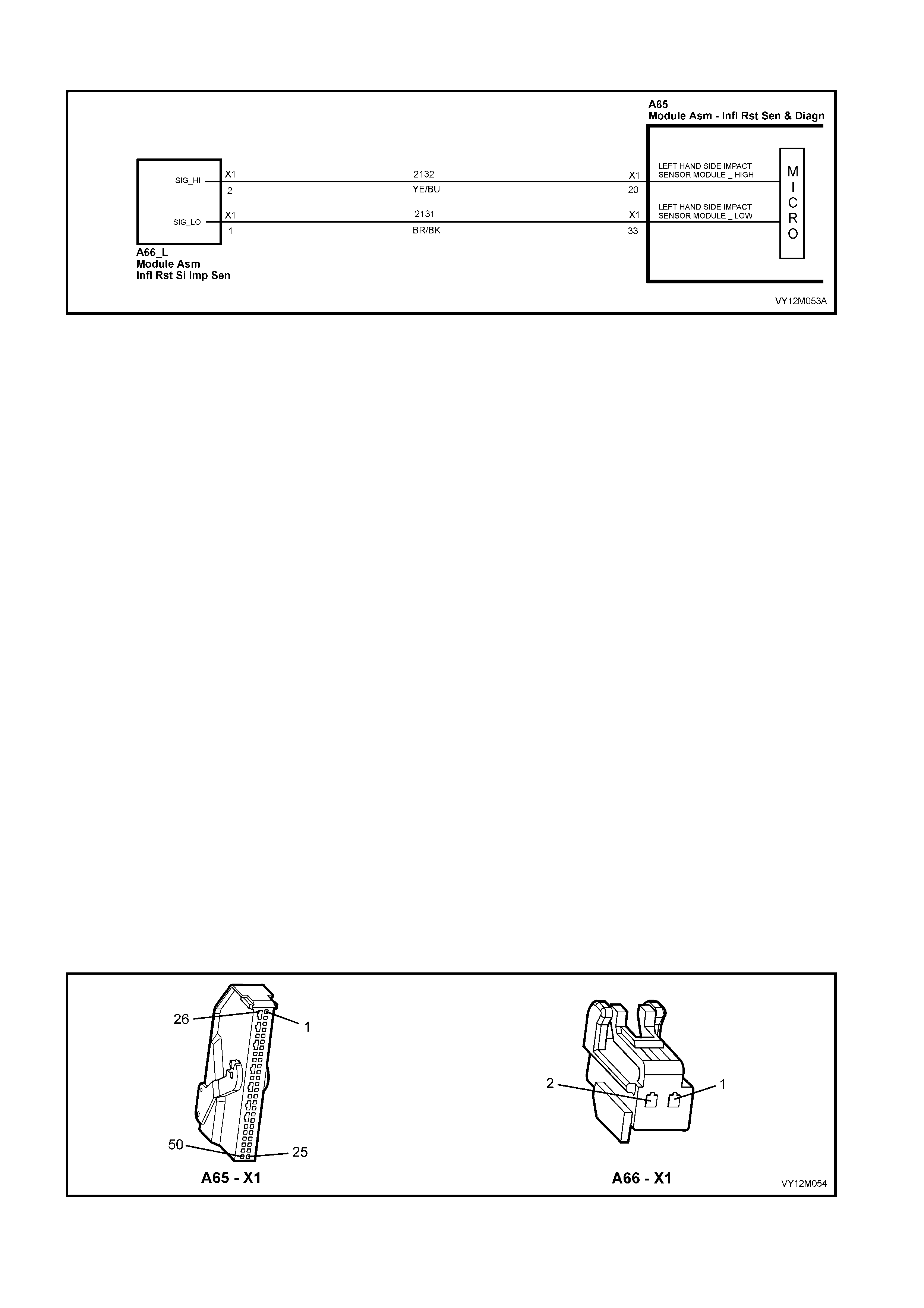
DTC 131 – LEFT-HAND PERIPHERAL ACCELERATION SENSOR COMMUNICATION FAULT
Figure 12M-238
CIRCUIT DESCRIPTION
The peripheral acceleration sensor communicates continuously with the inflatable restraint control module
(SDM) by modulating the consumed current at a constant voltage.
If this communication is interrupted between the SDM and the left-hand peripheral acceleration sensor for
longer than 3 – 5 seconds, a current DTC 131 is set (refer to 4.3 OPS / SRS SELF DIAGNOSTICS in this
Section for more details).
DTC 131 will set if circuits 2132 or 2131 (including the peripheral acceleration sensor) are open circuit.
When DTC 131 sets, the SDM illuminates the SRS warning indicator and sets a current DTC 131. Should the
fault conditions detected by the SDM clear during the same ignition cycle, the current code will clear and
become a history DTC 131. The SRS warning indicator will remain on for the remainder of the ignition cycle.
If a DT C 131 is set, the SR S warning in dicator is illum inated on eac h ignition c ycle, ev en if the DTC is set as a
histor y DTC, until t he fault condit ions f or s etting DTC 131 ar e rect ified an d the D T C (current or histor y) can then
be cleared from the SDM via TECH 2.
If DTC 131 is set, the left-hand side-impact airbag may not operate.
TEST DESCRIPTION
The following number refer to Section step numbers in the following diagnostic chart:
1. Uses TECH 2 to check if DTC 131 is current or history.
2. Checks for inter mittent fault by m onitori ng TECH 2 scr een. If s cr een dis p lay changes dur i ng a wirin g ' wiggl e'
test, a fault with the wiring is at that location.
3. Checks circuit 2132 for an open circuit.
4. Checks circuit 2131 for an open circuit.
5. By swappin g th e lef t- hand per ip hera l ac ce ler at ion s en sor with a known goo d o ne (r ight-ha nd s i de per ipheral
acceleration sensor), determines whether the peripheral acceleration sensor or the SDM is causing the
problem.
NOTES ON DIAGNOSTIC CHART
1. For all wiring harness checking procedures, refer to Section 12P WIRING DIAGRAMS.
2. Refer to 2.11 OPS / SRS W IRING REPAIR in this Se c tion bef or e conduc t in g any OPS / SRS wiring h ar nes s
repairs.
3. Do not loos en or u nscr ew the t wo nuts r etain ing the per ipheral acc eleratio n sens or to the m ount ing br ack et.
The peripheral acceleration sensor must only be removed from the B-pillar with the mounting bracket
attached, refer to 2.9 SIDE-IMP ACT SEN SOR in this Section for the correct removal procedure.
Figure 12M-239

DTC 131 – LEFT-HAND PERIPHERAL ACCELERATION SENSOR COMMUNICATION FAULT
STEP ACTION VALUE YES NO
1. 1. Install TECH 2 to DLC.
2. Select Body / SRS / Diagnostic Trouble Codes /
Read DTC Information
Is DTC 131 current?
Go to Step 3. Go to Step 2.
2. 1. With TECH 2 still connected, select Diagnostic
Trouble Codes / Clear DTC Information and clear all
(if any) DTCs.
2. Select Diagnostic Trouble Codes / Read DTC
Information, 'wiggle' OPS / SRS wiring harness at all
locations between the SDM and the left-hand
peripheral acceleration sensor wiring harness
connector A66, while monitoring TECH 2 screen
display.
Does TECH 2 screen display change status from No
Diagnostic Trouble Codes?
Make repairs as
necessary (refer
to Section NOTE
2 on previous
page).
Clear DTC and
recheck system
to verify repair
Fault not present.
Check all system
wiring harness
connect ors, and
terminals.
Clear DTC and
recheck system.
3. 1. Disable the OPS / SRS, refer to Section 2.2
DISABLING AND ENABLING PROCEDURE in this
Section.
2. Disconnect OPS / SRS wiring harness connector
A66 from the left-hand peripheral acceleration
sensor.
3. Disconnect SDM wiring harness connector A65 – X1
from the SDM.
4. Using Tool KM-609-20, check wiring between SDM
wiring harness connector A65 – X1, terminal 20 and
OPS / SRS wiring harness connector A66, circuit
2132 (Yellow/Blue wire) for a short to earth (refer to
Section NOTE 1 on previous page).
Is all OK?
Go to Step 4 Make repairs as
necessary (refer
to Section NOTE
2 on previous
page).
Clear DTC and
recheck system
to verify repair.
4. 1. W ith the OPS / SRS disabled and connectors A65 –
X1 and A66 disconnected, use Tool KM-609-20 to
check wiring between SDM wiring harness
connector A65 – X1, terminal 33 and OPS / SRS
wiring harness connector A66, circuit 2131
(Brown/Black wire) for an open circuit (refer to
Section NOTE 1 on previous page).
Is all OK?
Go to Step 5. Make repairs as
necessary (refer
to Section NOTE
2 on previous
page).
Clear DTC and
recheck system
to verify repair.
5. 1. Disable the OPS / SRS, refer to Section 2.2
DISABLING AND ENABLING PROCEDURE in this
Section.
2. Reconnect OPS / SRS wiring harness connector
A65 – X1 to the SDM.
3. Disconnect the left-hand peripheral acceleration
sensor from connector A66 and connect a known
good, peripheral acceleration sensor into connector
A66 (i.e. right peripheral acceleration sensor and
bracket assembly). Refer to Section NOTE 3 on
previous page.
4. Reconnect battery.
5. Install TECH 2 to DLC
6. Select Body / SRS / Diagnostic Trouble Codes /
Read DTC Information.
Is DTC 131 current?
Replace SDM,
refer to Section
2.8 INFLATABLE
RESTRAINT
CONTROL
MODULE in this
Section. Recheck
circuit to verify
repair.
Replace left-hand
peripheral
acceleration
sensor and
bracket assembly
(refer to Section
2.9 SIDE-
IMPACT
SENSOR in this
Section).
Clear DTC and
recheck system
to verify repair.
WHEN ALL DIAGNOSIS AND REPAIRS ARE COMPLETED, ENSURE ALL OPS / SRS COMPONENTS ARE
RECONNECTED, CLEAR ALL DTC’s, ENABLE THE OPS / SRS AND VERIFY CORRECT OPERATION
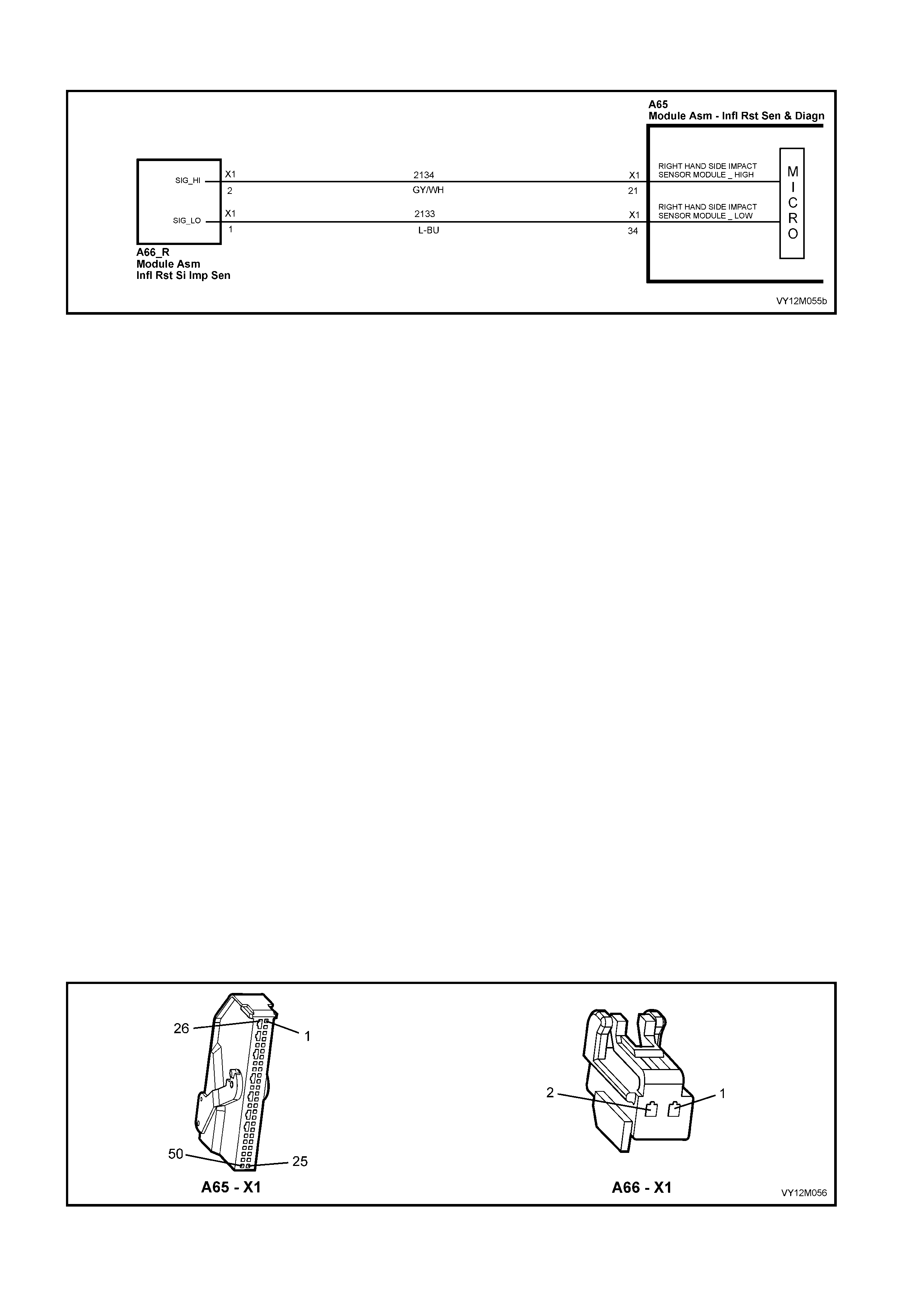
DTC 132 – RIGHT-HAND PERIPHERAL ACCELERATION SENSOR COMMUNICATION FAULT
Figure 12M-240
CIRCUIT DESCRIPTION
The peripheral acceleration sensor communicates continuously with the inflatable restraint control module
(SDM) by modulating the consumed current at a constant voltage.
If this communication is interrupted between the SDM and the right-hand side-impact for longer than 3 – 5
seconds, a current DTC 132 is set (refer to 4.3 OPS / SRS SELF DIAGNOSTICS in this Section for more
details).
DTC 132 will set if circuits 2134 or 2133 (including the peripheral acceleration sensor) are open circuit.
When DTC 132 sets, the SDM illuminates the SRS warning indicator and sets a current DTC 132. Should the
fault conditions detected by the SDM clear during the same ignition cycle, the current code will clear and
become a history DTC 132. The SRS warning indicator will remain on for the remainder of the ignition cycle.
If a DT C 132 is set, the SR S warning in dicator is illum inated on eac h ignition c ycle, ev en if the DTC is set as a
histor y DTC, until t he fault condit ions f or s etting DTC 132 ar e rect ified an d the D T C (current or histor y) can then
be cleared from the SDM via TECH 2.
If DTC 132 is set, the right-hand side-impact airbag may not operate.
TEST DESCRIPTION
The following number refer to Section step numbers in the following diagnostic chart:
1. Uses TECH 2 to check if DTC 132 is current or history.
2. Checks for inter mittent fault by m onitori ng TECH 2 scr een. If s cr een dis p lay changes dur i ng a wirin g ' wiggl e'
test, a fault with the wiring is at that location.
3. Checks circuit 2134 for an open circuit.
4. Checks circuit 2133 for an open circuit.
5. By swappin g th e ri ght- h and peri pher a l acc e ler at io n se ns or with a known go od one (left- han d s id e p erip her a l
acceleration sensor, determines whether the peripheral acceleration sensor or the SDM is causing the
problem).
NOTES ON DIAGNOSTIC CHART
1. For all wiring harness checking procedures, refer to Section 12P WIRING DIAGRAMS.
2. Refer to 2.11 OPS / SRS W IRING REPAIR in this Se c tion bef or e conduc t in g any OPS / SRS wiring h ar nes s
repairs.
3. Do not loos en or u nscr ew the t wo nuts r etain ing the per ipheral acc eleratio n sens or to the m ount ing br ack et.
The peripheral acceleration sensor must only be removed from the B-pillar with the mounting bracket
attached, refer to 2.9 SIDE-IMP ACT SEN SOR in this Section for the correct removal procedure.
Figure 12M-241

DTC 132 – RIGHT-HAND PERIPHERAL ACCELERATION SENSOR COMMUNICATION FAULT
STEP ACTION VALUE YES NO
1. 1. Install TECH 2 to DLC.
2. Select Body / SRS / Diagnostic Trouble Codes /
Read DTC Information
Is DTC 132 current?
Go to Step 3. Go to Step 2.
2. 1. With TECH 2 still connected, select Diagnostic
Trouble Codes / Clear DTC Information and clear all
(if any) DTCs.
2. Select Diagnostic Trouble Codes / Read DTC
Information, 'wiggle' OPS / SRS wiring harness at all
locations between the SDM and the left-hand
peripheral acceleration sensor wiring harness
connector A66, while monitoring TECH 2 screen
display.
Does TECH 2 screen display change status from No
Diagnostic Trouble Codes?
Make repairs as
necessary (refer
to Section NOTE
2 on previous
page).
Clear DTC and
recheck system
to verify repair
Fault not present.
Check all system
wiring harness
connect ors, and
terminals.
Clear DTC and
recheck system.
3. 1. Disable the OPS / SRS, refer to Section 2.2
DISABLING AND ENABLING PROCEDURE in this
Section.
2. Disconnect OPS / SRS wiring harness connector
A66 from the left-hand peripheral acceleration
sensor.
3. Disconnect SDM wiring harness connector A65 – X1
from the SDM.
4. Using Tool KM-609-20, check wiring between SDM
wiring harness connector A65 – X1, terminal 21 and
OPS / SRS wiring harness connector A66, circuit
2134 (Grey/W hite wire) for a short to earth (refer to
Section NOTE 1 on previous page).
Is all OK?
Go to Step 4 Make repairs as
necessary (refer
to Section NOTE
2 on previous
page).
Clear DTC and
recheck system
to verify repair.
4. 1. W ith the OPS / SRS disabled and connectors A65 –
X1 and A66 disconnected, use Tool KM-609-20 to
check wiring between SDM wiring harness
connector A65 – X1, terminal 34 and OPS / SRS
wiring harness connector A66, circuit 2133 (Light
Blue wire) for an open circuit (refer to Section NOTE
1 on previous page).
Is all OK?
Go to Step 5. Make repairs as
necessary (refer
to Section NOTE
2 on previous
page).
Clear DTC and
recheck system
to verify repair.
5. 1. Disable the OPS / SRS, refer to Section 2.2
DISABLING AND ENABLING PROCEDURE in this
Section.
2. Reconnect OPS / SRS wiring harness connector
A65 – X1 to the SDM.
3. Disconnect the right-hand peripheral acceleration
sensor from connector A66 and connect a known
good peripheral acceleration sensor into connector
A66 (left peripheral acceleration sensor and bracket
assembly). Refer to Section NOTE 3 on previous
page.
4. Reconnect battery.
5. Install TECH 2 to DLC
6. Select Body / SRS / Diagnostic Trouble Codes /
Read DTC Information.
Is DTC 132 current?
Replace SDM,
refer to Section
2.8 INFLATABLE
RESTRAINT
CONTROL
MODULE in this
Section.
Recheck circuit
to verify repair.
Replace left-hand
peripheral
acceleration
sensor and
bracket assembly
(refer to Section
2.9 SIDE-
IMPACT
SENSOR in this
Section).
Clear DTC and
recheck system
to verify repair.
WHEN ALL DIAGNOSIS AND REPAIRS ARE COMPLETED, ENSURE ALL OPS / SRS COMPONENTS ARE
RECONNECTED, CLEAR ALL DTC’s, ENABLE THE OPS / SRS AND VERIFY CORRECT OPERATION

DTC 133 – LEFT-HAND PERIPHERAL ACCELERATION SENSOR IDENTIFICATION FAULT
CIRCUIT DESCRIPTION
Peripheral acceleration sensors are programm ed during manufacture for a particular vehicle / application type.
During th is proces s, the pe ripheral acc elerat ion senso r is given a unique identif ication c ode, whic h corres ponds
with the SDM. If this code does not correspond with the SDM, a current DTC 133 will be set and the SRS
warning ind icator wil l be illu minated with the igniti on on ..
ACTION REQUIRED
If DTC 133 is set, the left-hand side-impact inflatable restraint (Side-impact airbag) may not operate and
therefore, the left-hand side peripheral acceleration sensor and bracket assembly must be replaced with the
correct peripheral acceleration sensor for that particular vehicle.
Always ref er to Sectio n the lates t Hold en spare par ts in f ormation ( Part Finder ) for the correct par t num ber of the
peripheral acceleration sensor and bracket assembly for that particular vehicle. To replace the peripheral
acceleration sensor and bracket assembly, refer to 2.9 SIDE-IMPACT SENSOR (SIDE-IMPACT AIRBAG
SENSOR) in this Section.
After the peripher al acceleratio n sensor and bracket assembly have been replaced, ensure that all OPS / SRS
components are recon nect ed, clear DT Cs, enab le the O PS / SRS an d ver ify the c orrect operation of the s ystem
(i.e. warning indicator not illuminated after five seconds of ignition being switched ON).

DTC 134 – RIGHT-HAND PERIPHERAL ACCELERATION SENSOR IDENTIFICATION FAULT
CIRCUIT DESCRIPTION
Peripheral acceleration sensors are programm ed during manufacture for a particular vehicle / application type.
During th is proces s, the pe ripheral acc elerat ion senso r is given a unique identif ication c ode, whic h corres ponds
with the inf lata ble r estr a int c ontrol module (SDM). If this c ode does no t c or res pon d with t he SDM, a c urr ent DTC
134 will be set and the SRS warn in g indicator will be illuminated with the ignition on.
ACTION REQUIRED
If DTC 134 is set, the right-hand side-impact airbag may not operate and therefore, the right-hand side
peripheral acce leration sensor and bracket assem bly must be replaced with the correct peripheral acceleration
sensor for that particular vehicle.
Always ref er to Sectio n the lates t Hold en spare par ts in f ormation ( Part Finder ) for the correct par t num ber of the
peripheral acceleration sensor and bracket assembly for that particular vehicle. To replace the peripheral
acceleration sensor and bracket assembly, refer to 2.9 SIDE-IMPACT SENSOR in this Section.
After the peripher al acceleratio n sensor and bracket assembly have been replaced, ensure that all OPS / SRS
components are recon nect ed, clear DT Cs, enab le the O PS / SRS an d ver ify the c orrect operation of the s ystem
(i.e. warning indicator not illuminated after five seconds of ignition being switched ON).

DTC 135 – LEFT-HAND PERIPHERAL ACCELERATION SENSOR HARDWARE FAULT
CIRCUIT DESCRIPTION
At ignition on, and on a constant monitoring cycle of every 500 milliseconds during the ignition cycle, the
inflatable restraint control module (SDM) performs a system self check. If the SDM detects an internal fault in
the left-hand side peripheral acceleration sensor, a DTC 135 will be set and the SRS warning indicator will be
illuminated continuously with the ignition on.
ACTION REQUIRED
If DTC 135 is set, the left- hand side-im pact inflata ble restr aint ma y not operat e and theref ore, the lef t-hand side
periphera l ac c eler ati on se n s or and brac ket assembl y must be replac ed. Ref er to 2.9 SIDE-IM P ACT SEN SOR in
this Section for the correct replacement procedure.
After the peripher al acceleratio n sensor and bracket assembly have been replaced, ensure that all OPS / SRS
components are recon nect ed, clear DT Cs, enab le the O PS / SRS an d ver ify the c orrect operation of the s ystem
(i.e. warning indicator not illuminated after five seconds of ignition being switched ON).

DTC 136 – RIGHT-HAND PERIPHERAL ACCELERATION SENSOR HARDWARE FAULT
CIRCUIT DESCRIPTION
At ignition on, and on a constant monitoring cycle of every 500 milliseconds during the ignition cycle, the
inflatable restraint control module (SDM) performs a system self check. If the SDM detects an internal fault in
the right-han d side periphe ral accelerat ion sensor, a DT C 136 will be s et and the SRS war ning indicator will be
illuminated continuously with the ignition on.
ACTION REQUIRED
If DTC 136 is set, the right-hand side-impact airbag may not operate and therefore, the right-hand side
periphera l ac c eler ati on se n s or and brac k et as s embly must be replac ed. Ref er to 2.9 SIDE-IMP ACT SENSO R in
this Section for the correct replacement procedure.
After the peripher al acceleratio n sensor and bracket assembly have been replaced, ensure that all OPS / SRS
components are recon nect ed, clear DT Cs, enab le the O PS / SRS an d ver ify the c orrect operation of the s ystem
(i.e. warning indicator not illuminated after five seconds of ignition being switched ON).).

DTC 161 – CONFIGURATION MISMATCH: TOO LITTLE OR TOO MANY LOOPS IN OPS / SRS
CIRCUIT DESCRIPTION
NOTE 1: DTC 161 will only be set and displayed by TECH 2 as a history DTC even if it is current.
NOTE 2: The instruments must be programmed for the correct vehicle configuration, refer to
Section 12C INSTRUMENTS, for the procedure on programming the instruments.
The inflatable restraint control module (SDM) will set a history DTC 161 because it has been internally
configured for a two, three, four or six loop system but at the same time has detected a mismatch with the actual
vehicle configuration.
To identify the different inflatable restraint control modules (SDM’s), refer to Section the identification label on
the top of the SD M. The last digit of the part num ber identifies the number of loops the SDM is designed f or: 2,
3, 4 or 6
2 Loop System Seat Belt Pretensioners only
3 Loop System Seat Belt Pretensioners and Driver’s airbag Only
4 Loop System Seat Belt Pretensioners, Driver’s and Passenger airbag Only
6 Loop System Seat Belt Pretensioners, Driver’s, Passenger and Side-impact
airbag s
NOTE: Always ref er to Section the latest MY 2003 VY and V2 Series Part Finder information for the latest part
numbers when ordering OPS / SRS components.
TECH 2 is c apab le of displa ying the SDM p art num be r; connec t TECH 2 to DLC, select D iagnos is / Bod y / SRS
/ Turn Ignition ON and the system identification screen will display the SDM part number.
As an aid to the technician to diagnose the source of the mismatch, always check for other DTC set in the
system first. Faults setting other DTCs should be rectified first, all DTCs cleared from the SDM and system
retested to determine if DTC 161 would set again. If DTC sets again, install the correct SDM.
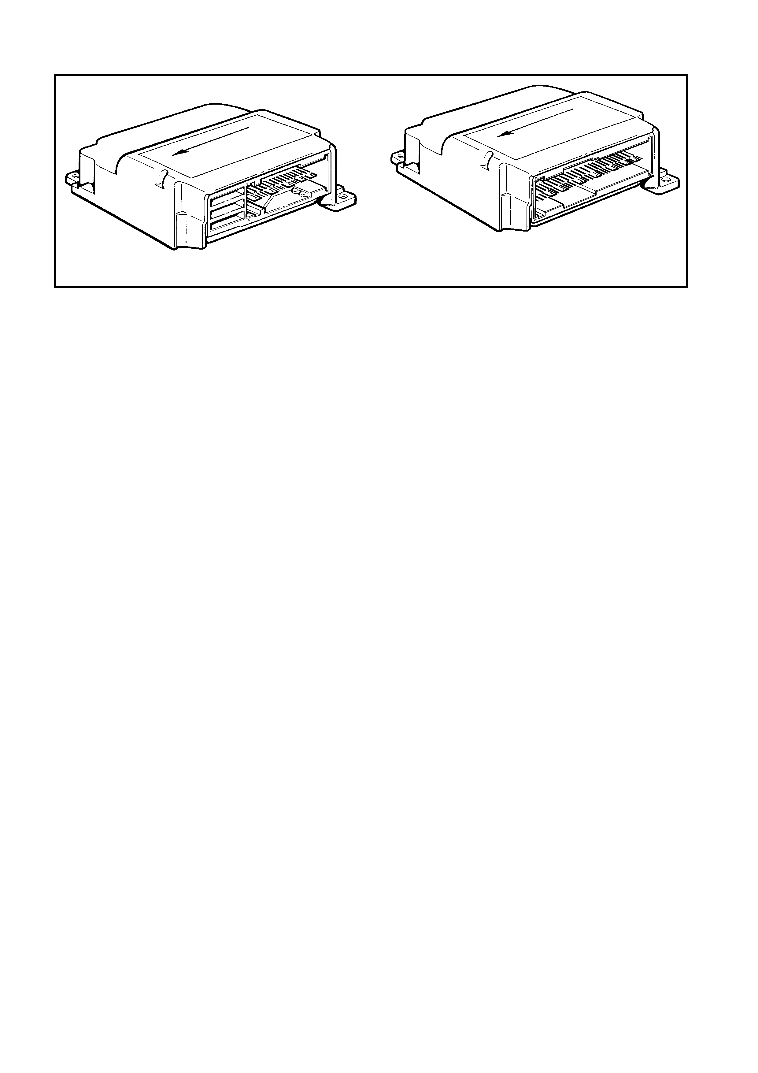
DTC 163 – INFLATA BLE RESTRAINT CONTROL MODULE INTERNAL FAULT
1
T12M171
Figure 12M-242
CIRCUIT DESCRIPTION
NOTE: DTC 163 will only be set and displayed by TECH 2 as a history DTC even if it is current.
At ignition on, and on a constant monitoring cycle of every 500 milliseconds during the ignition cycle, the
inflatable restraint control module (SDM) performs a system self check. If the SDM detects a fault in itself, a
DTC 163 will be set and the SRS warning indicator will be illuminated continuously with the ignition on.
ACTION REQUIRED
If DTC 163 is set, the OPS / SRS may not operate and therefore, the SDM must be replaced.
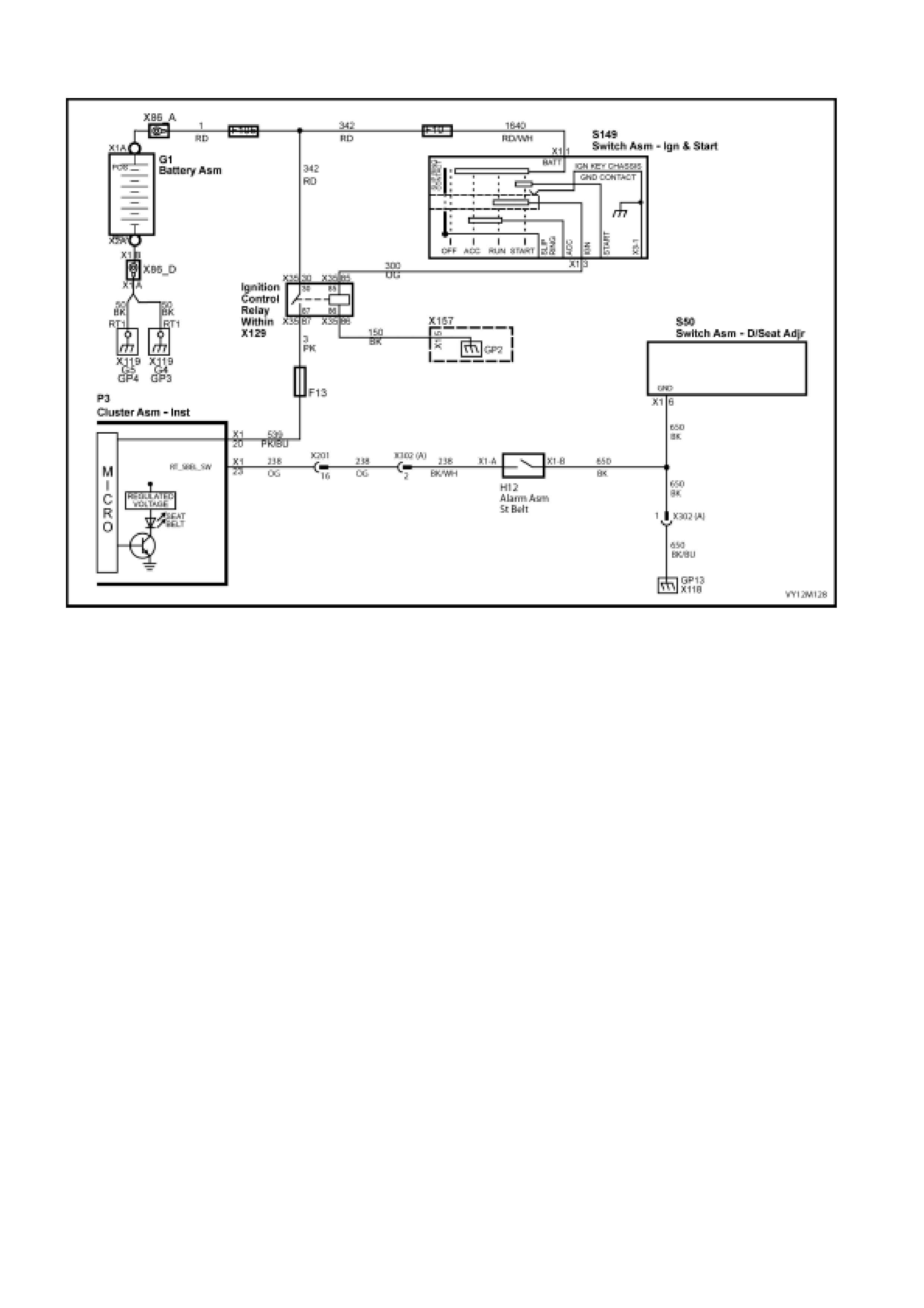
4.7 DRIVERS S EATBELT WARNING INDICATOR SWITCH DIAGNOSIS
Figure 12M-243
CIRCUIT DESCRIPTION
The purpose of the switch is to activate a seatbelt warning indicator located in the instrument cluster when the
ignition is turned to the on position with the seatbelt disengaged from the buckle.
When the seatbelt is buckled, the warning indicator switch is in an open circuit condition and when un-buckled
the switch is in a closed circuit condition.
Tech 2 can be used to check the drivers seatbelt warning switch operation, Tech 2 will only display ‘BUCKLED’
or ‘UN-BUCKLED’.
For more information on instrumentation refer to Section 12C INSTRUMENTS, 1.6 INSTRUMENT
OPER ATION ALL −
−−
− MODEL S.
TEST DESCRIPTION
The following number refer to Section step numbers in the following diagnostic chart:
1. Uses TECH 2 to check if a problem exists and checks circuits 238 and 650 for an open circuit.
2. Uses TECH 2 to check the operation of the seatbelt buckle and warning indicator
3. Uses TECH 2 to check if the fault is in circuit 238 to the instrument cluster.
4. Checks for intermittent fault by monitoring TECH 2 screen. If screen display changes during a wiring 'wiggle'
test, a fault with the wiring is at that location.
5. Checks circuit 650 and operation of the seatbelt buckle switch.
6. Checks circuit 650 for an open circuit.

SEAT BELT WARNING INDICATOR SWITCH AND WIRING CIRCUIT DIAGNOSIS
STEP ACTION YES NO
1 1. Install TECH 2 to DLC.
2. Turn the ignition on with the engine off.
3. Select BODY, INSTRUMENTS, DATA DISPLAY and
then INSTRUMENTS from the menu and scroll down to
DRIVERS SEATBELT.
4. Un-buckle the seatbe lt.
Is the seatbelt warning indicator illuminated and does Tech 2
displa y ‘UN-BUCKLED’?
Go to step 2 Go to step 4
2 1. Ignition on, engine off, Tech 2 installed with instruments
and seatbelt s selected.
2. Fasten the seatbelt into the bu ckl e.
Does the seatbelt warning indicator extinguish and Tech 2
display ‘BUCKLED’ ?
Operation appears to
be normal and a fault
not present. Check the
wiring harness
connect ors, and
terminals for damage
or poor connection.
Rep air as necessary.
Re-check oper a tio n
using steps 1 and 2 of
this chart.
Go to step 3
3 1. Ignition on, engine off, Tech 2 installed with instruments
and drivers seatbelt selected.
2. Un-buckle the seatbe lt.
3. Locate the seatbelt warning indicator switch connector
X302 under the drivers seat cushion (White body, two
pin) and disconnect.
4. Using suitable leads from Tool KM-609, bridge the male
terminals 1 and 2 of connector X302.
5. Observe the seatbelt warning indicator and Tech 2.
6. The seatbelt warning indicator should illuminate and
Tech2 should display ‘UN-BUCKLED’.
Does the seatbelt warning indicator illuminate and Tech 2
displa y ‘UN-BUCKLED’?
If no fault is found
using step 3, a fault
could still exist, go to
step 4.
Go to step 4.
4 1. Turn Ignition off.
2. Check the wiring of circuit 238 between connector X302,
terminal 2, connector X201, terminal 16 and connector
P3, terminal 23 – X1 for short to ground condition and
repair.
3. Ignition on, engine off, Tech 2 installed with instruments
and seatbelt s selected.
4. Un-buckle the seatbe lt.
5. Observe the seatbelt warning indicator and Tech 2.
Does the seatbelt warning indicator illuminate and Tech 2
displa y ‘UN-BUCKLED’?
If no fault is found
using step 4, a fault
could still exist, go to
step 5.
Go to step 5.
5 1. Turn the ignition off and disconnect connector X302.
2. Use a multimeter and suitabl e lead s from Tool KM -609
to check the operation of the switch at connector X302,
the female terminal 1 and the female terminal 2.
3. Buckle and un-buckle the seatbelt while observing the
multimeter.
Does the switch open and close the circuit when the seatbelt
buckle is engaged and disengaged?
Go to step 6 The switch is faulty,
replace the seatbelt
buckle and pre-
tensioner assembly,
refer to
3.4, FRONT
SEATBELT BUCKLE
and
PRETENSIONER
ASSEMBLY in this
section.
Re-check oper ation
using steps 1 and 2 of
this chart.

STEP ACTION YES NO
6 1. Turn the ignition off and disconnect connector X302. A fault exists in the
instrument cluster,
refer to Section 12C,
INSTRUMENT, 3
DIANOSTICS.
Check the wiring
harness con nec tors ,
and terminals for
damage or poor
connection.

5. TORQUE WRENCH SPECIFICATIONS
Instrument Panel Inflatable Restraint
(Passenger Airbag) Module Assembly To
Dash Panel Attaching Nut.....................................................15.0 – 25.0 Nm
Instrument Panel Inflatable Restraint
(Passenger Airbag) Module Assembly To
Support Rail Attaching Bolt...................................................07.0 – 12.0 Nm
Front Seat To Floor Securing Bolt........................................35.0 – 50.0 Nm
Side-Impact Sensor
(Peripheral Acceleration Sensor) And
Bracket Assembly Retaining Bolt
(Front Seat Belt Retractor Bolt) ............................................35.0 – 50.0 Nm
Seat Belt Buckle And Pretensioner
Assembly Retaining bolt .......................................................40.0 – 45.0 Nm
Inflatable Res tr aint C ontro l Modu le
To Floor Attaching Screw .....................................................07.0 – 11.0 Nm
Steering Wheel Retaining Bolt..............................................40.0 – 50.0 Nm
Side-Impact Inflatable Restraint
(Side-Impact Airbag) Module To Front
Seat Back Frame Retaining Nut ..........................................05.0 – 06.0 Nm
Seatbelt As s embly Screw.....................................................35.0 – 50.0 Nm
Intermediate Seatbelt Guide Screw......................................02.4 – 03.4 Nm
Seatbelt Height Adjuster Assembly Screw...........................20.0 – 30.0 Nm
Seatbelt Buc kle & Pretens ioner As sembl y Screw................40.0 – 45.0 Nm
Seatbelt Guide Bracket Screw, Wagon ................................20.0 – 22.0 Nm
Seatbelt Retractor Nut, Wagon.............................................35.0 – 50.0 Nm
Child Seat Anchor Screw......................................................15.0 – 25.0 Nm

6. SPECIAL TOOLS
TOOL NO. REF
IN TEXT TOOL DESCRIPTION COMMENTS
AU595 STEERING WHEEL INFLATABLE
RESTRAINT (DRIV ER ’S AI RBAG) MO DUL E
REMOVAL TOOL
USED FOR REMOVING THE
STEERING WHEEL
INFLATAB LE RE STRAINT
(DRIVER’S AIRBAG) MODULE
FROM THE STEERING
WHEEL HUB
ETX30H T30H TORX BIT
USE IN CONJUNCTION WITH
J25359-8, (OR ETX55HLD)
TOR X BIT HOLDER
USED FOR REMOVING
INFLATAB LE RE STRAINT
CONTROL MODULE (SDM)
TO FLOOR ATTACHING
SCREWS
J25359-8 TORX BIT HOLDER
PREVIOUSLY RELEASED
FOR V CAR
KM-609-20 OPS / SRS TEST LEAD SET
PREVIOUSLY RELEASED
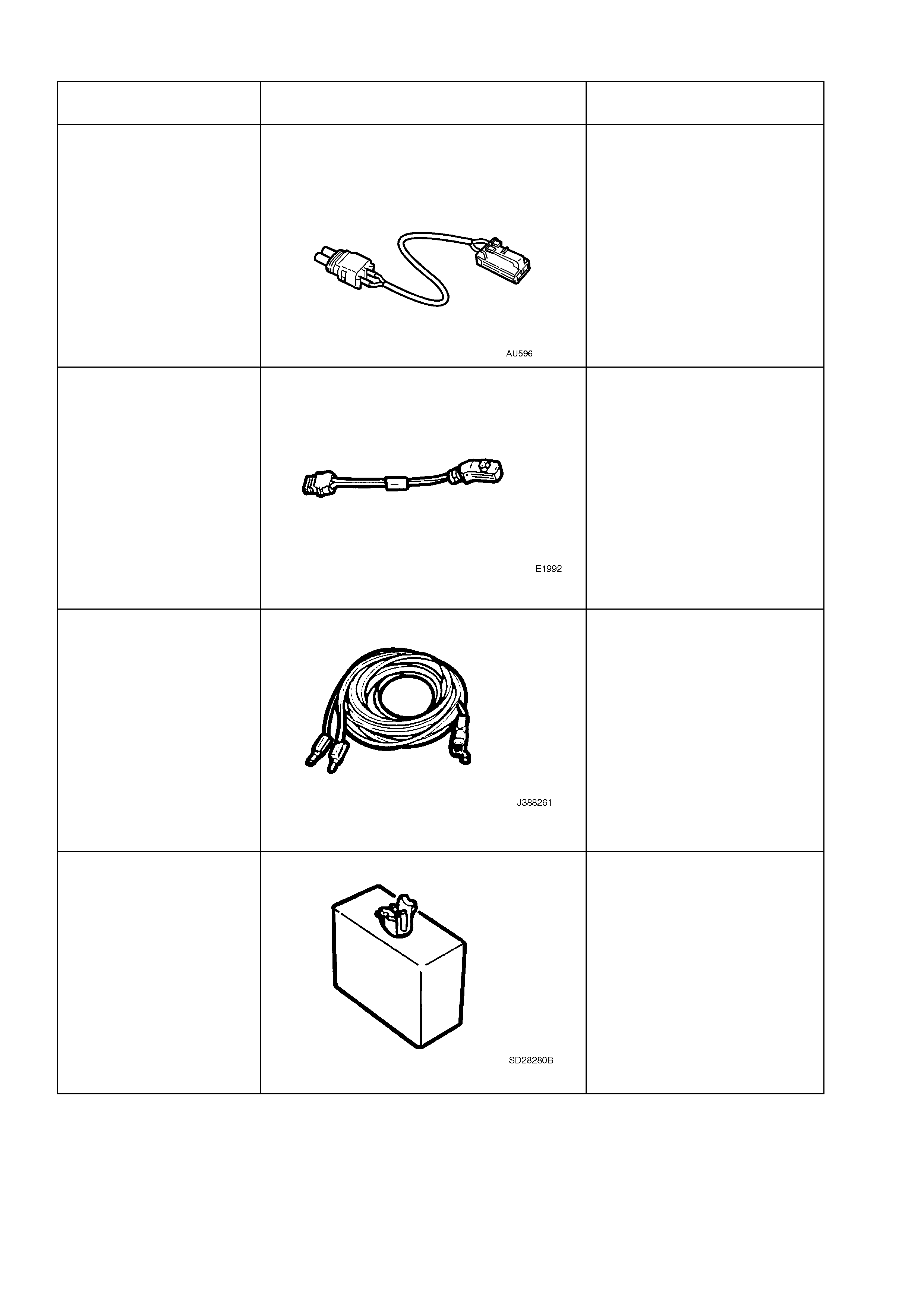
TOOL NO. REF
IN TEXT TOOL DESCRIPTION COMMENTS
AU596 DEPLOYMENT HARNESS ADAPTOR FOR
SEAT BELT PRETENSIONER
USED IN CONJUNCTION
WITH DEPLOYMENT
HARNESS J213526-1 FOR
DEPLO YING SEAT BELT
PRETENSIONER WHEN
REMOVED FROM THE
VEHICLE
E1992 DEPLOYMENT HARNESS ADAPTOR
PREVIOUSLY RELEASED
USED IN CONJUNCTION
WITH DEPLOYMENT
HARNESS J213526-1 FOR
DEPLOYING OPS / SRS
COMPONENTS WHEN
REMOVED FROM THE
VEHICLE
J213526-1 DEPLOYMENT HARNESS
PREVIOUSLY RELEASED
USED IN CONJUNCTION
WITH DEPLOYMENT
HARNESS ADA PTORS E1 992
AND AU596 FOR DEPLOYING
OPS / SRS COMPONENTS
WHEN REMOVED FROM THE
VEHICLE
SD28280B DUMMY LOAD
FOR STEERING WHEEL
INFLATAB LE RESTRAINT
(DRIVERS AIR BAG ) AND
INSTRUMENT PANEL
INFLATAB LE RE STRAINT
(PASSENGER AIRBAG)
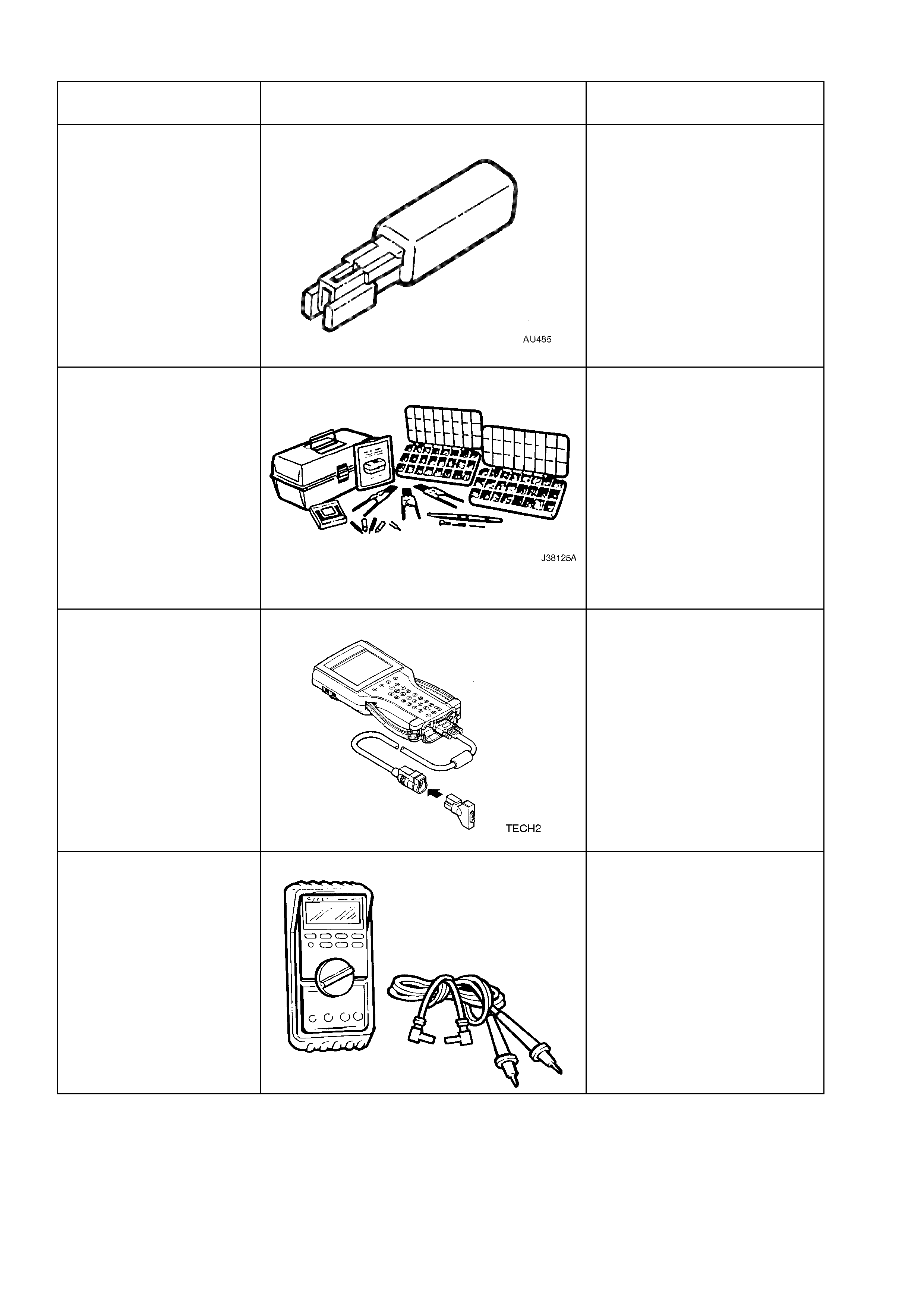
TOOL NO. REF
IN TEXT TOOL DESCRIPTION COMMENTS
AU485 DUMMY LOAD
FOR SIDE-IMPACT
INFLATAB LE RE STRAINT
(SIDE-IMPACT AIRBAG) AND
SEAT BELT PRETENSIONER
J38125-A TERMINAL REPAIR KIT
PREVIOUSLY RELEASED.
MUST BE USED WHEN
REPAIRING OPS / SRS
WIRING, REFER TO 2.11, OPS
/ SRS WIRING REPAIR IN
THIS SECTION.
TECH 2 DIAGNOSTIC SCAN TOOL
PREVIOUSLY RELEASED
J213200 DIGITAL MULTIMETER
TOOL NO. J213200
PREVIOUSLY RELEASED, OR
USE COMMERCIALLY
AVAILABLE EQUIVALENT.
MUST HAVE 10 MOHM INPUT
IMPEDANCE AND BE
CAPABLE OF READING
CAPACITANCE
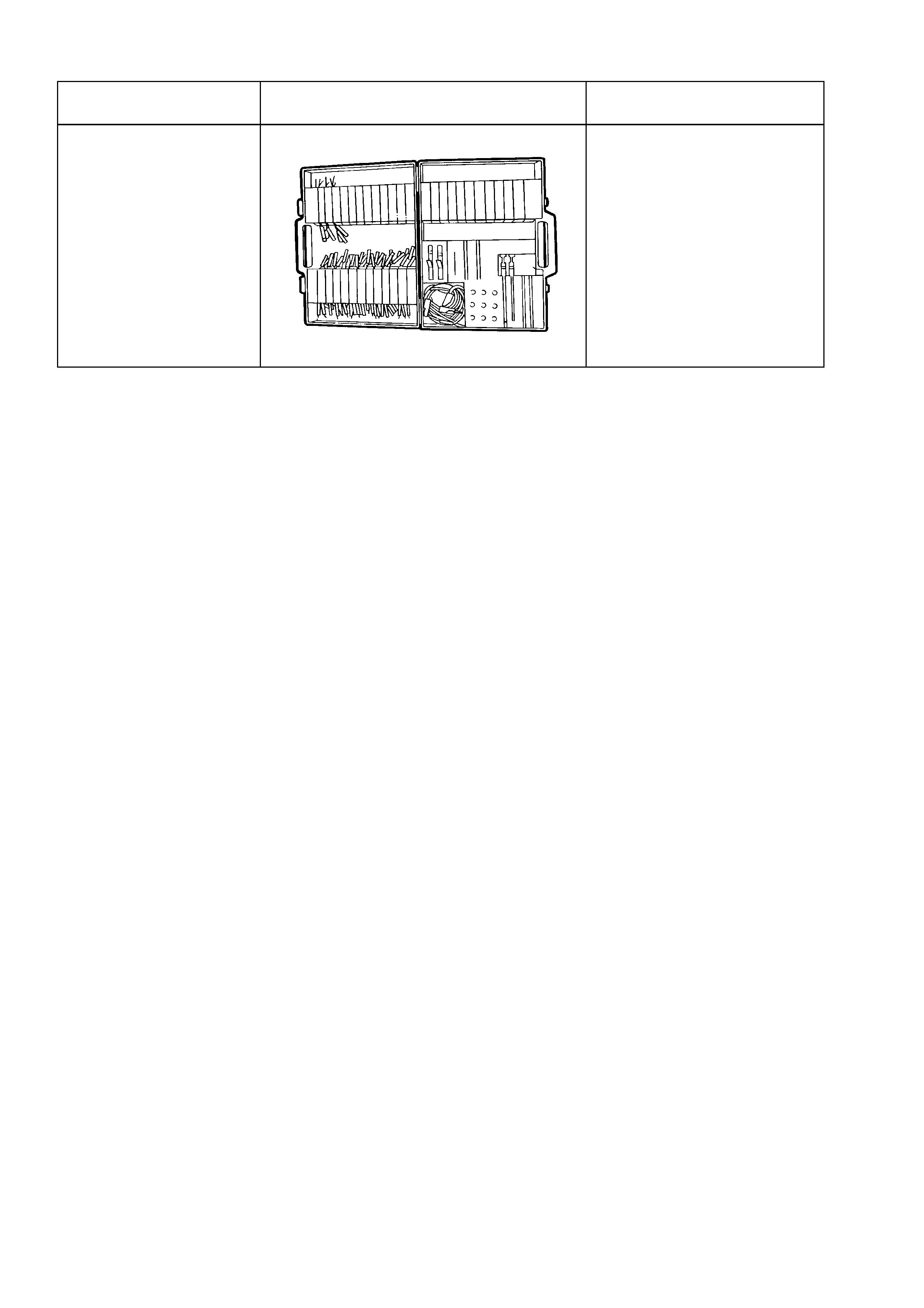
TOOL NO. REF
IN TEXT TOOL DESCRIPTION COMMENTS
KM-609 ELECTRONIC KIT
USED IN CONJUNCTION
WITH A MULTIMETER FOR
MEASURING VOLTAGES AND
RESISTANCE’S WITHOUT
DAMAGING WIRING
HARNESS CONNECTORS