
SECTION 12N - WIPERS, WASHERS AND HORN
IMPORTANT
Before p erforming any Serv ice Operation or other procedu re described in this Section , refer to Section 00
CAUTIONS AND NOTES for correct workshop practices with regard to safety and/or property damage.
CONTENTS
1. GENERAL INFORMATION
2. SERVICE OPERATIONS – WIPERS
AND WASHERS
2.1 FRONT AND REAR WIPER BLADE INSERT
REPLACE
2.2 FRONT AND REAR WIPER BLADE
ASSEMBLIES
REMOVE
REINSTALL
2.3 FRONT WIPER ARM ASSEMBLY
REMOVE
REINSTALL
2.4. REAR WIPER ARM ASSEMBLY, WAGON
REMOVE
REINSTALL
2.5 PLENUM COVER ASSEMBLY, EXCEPT COUPE
REMOVE
DISASSEMBLE
REASSEMBLE
REINSTALL
2.6 PLENUM COVER ASSEMBLY, COUPE
REMOVE
REINSTALL
2.7 FRONT WIPER MOTOR ASSEMBLY AND
LINKAGE
DIAGNOSE WIPER MOTOR ASSEMBLY
WIRING
DIAGNOSE WIPER MOTOR ASSEMBLY
OPERATION
REMOVE
REINSTALL
2.8 REAR WIPER MOTOR ASSEMBLY, WAGON
DIAGNOSE WIPER MOTOR ASSEMBLY
WIRING
DIAGNOSE WIPER MOTOR ASSEMBLY
OPERATION
REMOVE
REINSTALL
2.9 WIPER AND WASHER CONTROL SWITCH
REMOVE
TEST
REINSTALL
2.10 WASHER RESERVOIR ASSEMBLY
REMOVE
REINSTALL
FILLING WASHER RESERVOIR ASSEMBLY
2.11 FRONT WASHER HOSE – EXCEPT COUPE
REMOVE
REINSTALL
2.12 FRONT WASHER HOSE AND WASHER
NOZZLE ASSEMBLIES – COUPE
REMOVE
REINSTALL
2.13 REAR WASER HOSE ASSEMBLY
REMOVE
REINSTALL
2.14 WASHER PUMP ASSEMBLY AND WIRING
DIAGNOSIS
INTRODUCTION
TEST DESCRIPTION – FRONT WASHERS
TEST DESCRIPTION – REAR WASHERS
2.15 WIRING DIAGRAM – WIPERS AND
WASHERS
2.16 CONNECTOR DIAGRAMS – WIPERS AND
WASHERS
3. SERVICE OPERATIONS – HORN
3.1 HORN ASSEMBLY
REMOVE
REINSTALL
TEST
HORN RELAY
HORN ACTUATOR
3.2 THEFT-DETERRENT HORN ASSEMBLY
REMOVE
REINSTALL
TEST
THEFT-DETERRENT HORN RELAY
3.3 WIRING DIAGRAM – HORN ASSEMBLY
3.4 CONNECTOR DIAGRAMS – HORN ASSEMBLY
4. TORQUE WRENCH SPECIFICATIONS
5. SPECIAL TOOLS

1. GENERAL INFORMATION
This Section describes the service and testing procedures for the wiper and washer systems as well as the
horns fitted to MY 2003 VY Series and V2 Series II vehicles.
A new one piece plenum cover is fitted to Sedan, Wagon and Utility vehicles. The front washer nozzles are
incorporated in the plenum cover. Coupe vehicles retain the previous two piece plenum cover and have the
washer nozzles mounted in the hood assembly .
A single washer reservoir and pum p is used for all m odels. W agon vehicles, which have a rear washer for the
liftgate, have a dual outlet pump. To feed fluid to the rear washer nozzle, the polarity is reversed to the pump
motor, making it spin in the opposite direction, and forcing fluid to the rear washer nozzle.
All models not having optional trumpet horns, are fitted with a high-note horn, located behind the front bumper
fascia on the right hand side. Vehicles fitted with dual trumpet horns, have the low note horn fitted behind the
front bumper fascia on the left hand side of the vehicle.
A theft-deterrent horn is mounted in the rear of the engine compartment on the left hand side and is controlled by
the Body Control Module. This Section c overs the r em oval and testing of the horn, but f or mor e inform ation and
testing of the theft-deterrent horn, refer to Section 12J, BODY CONTROL MODULE.
2. SERVICE OPERATIONS – WIPERS AND WASHERS
2.1 FRONT AND REAR WIPER BLADE INSERT
LT Section – 10-505 (Front)
LT Section – 10-525 (Rear)
REPLACE
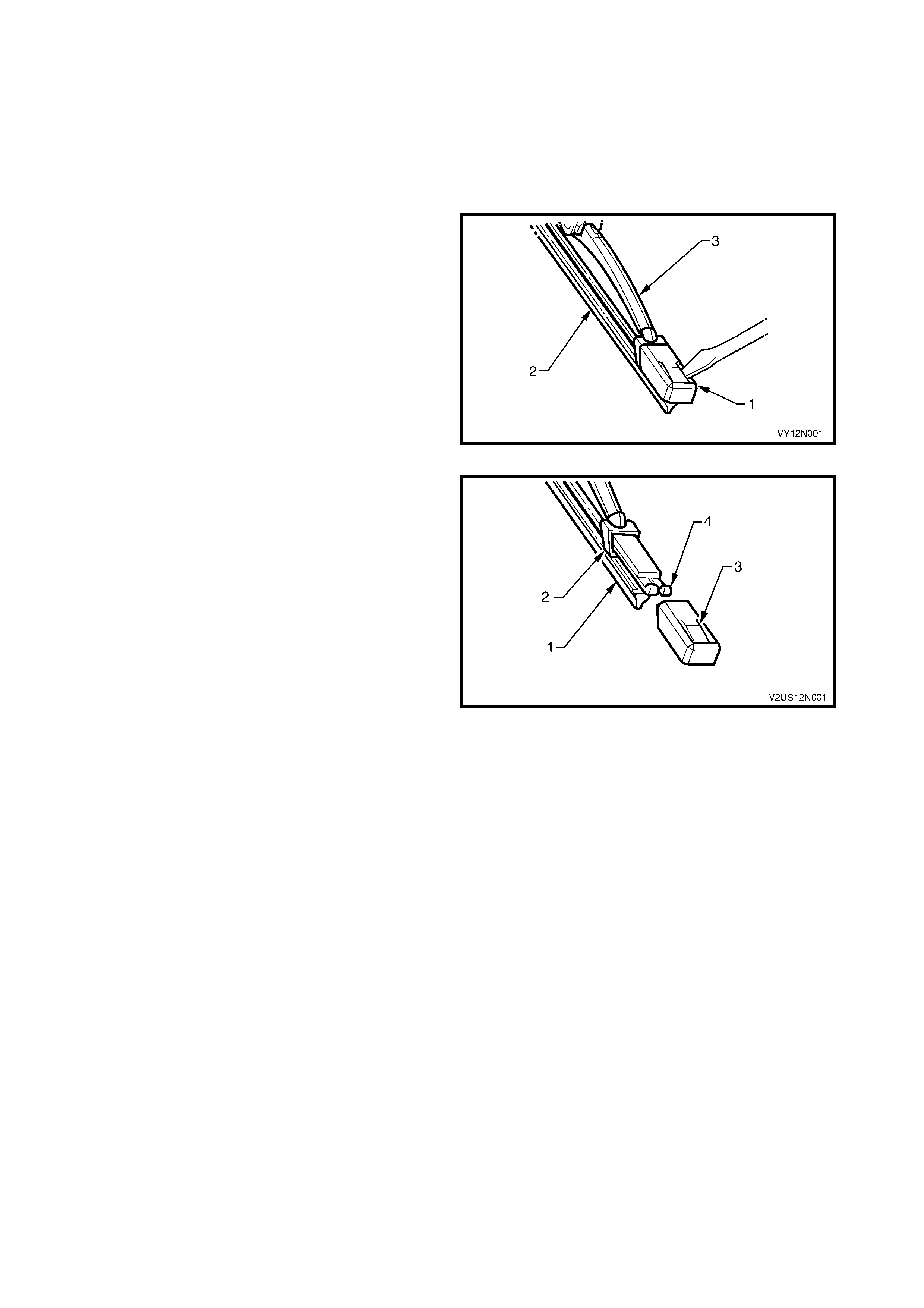
1. Using a sm all scr ewdriver, lift the retention lug and
slide the end cap (1) off the wiper insert (2), on
both ends of the wiper blade (3).
NOTE: Do not re-use the end cap. The replacement
insert will be supplied with end caps fitted.
2. Slide the insert out of the wiper blade and discard.
Figure 12N-1
3. Remove the end caps fr om the inser t (1) and slide
the insert into the wiper blade ensuring that the
insert passes through each metal claw (2).
4. Assemble the new end cap onto the ends of the
insert, ensuring that the retention lug (3) on the
end cap is located securely behind the two
upturned ends of the metal rails (4).
Figure 12N-2
2.2 FRONT AND REAR WIPER BLADE ASSEMBLIES
LT Section – 10-505 (Front)
LT Section – 10-525 (Rear)
REMOVE
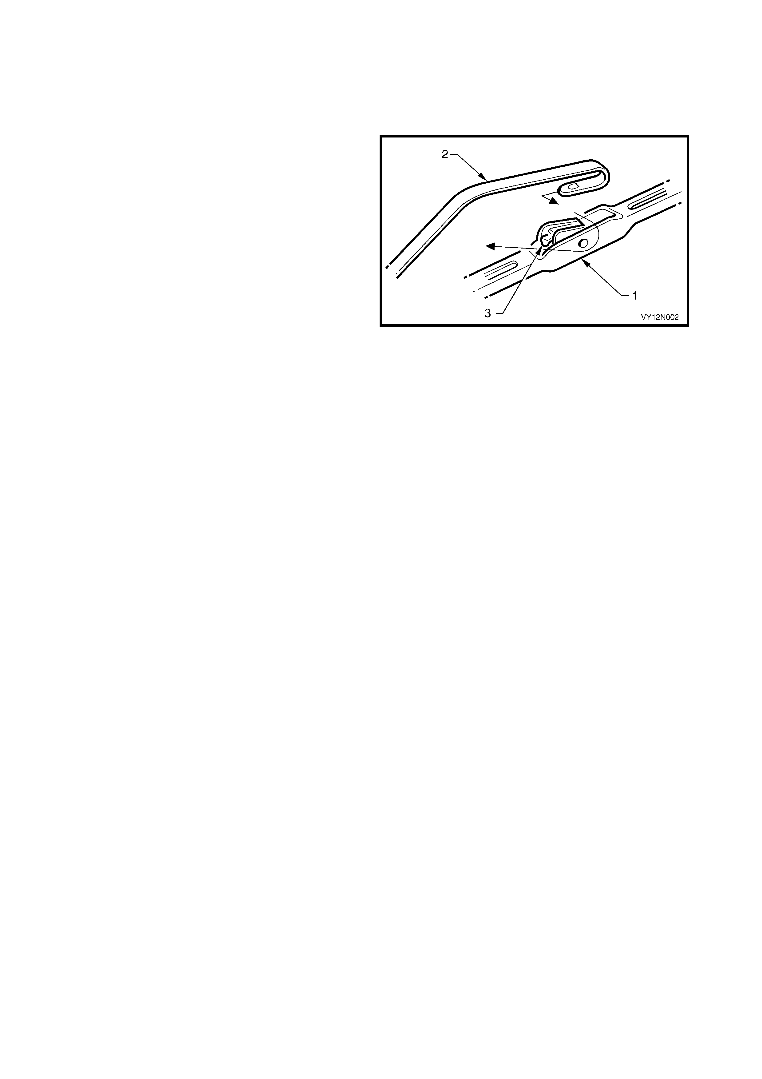
1. With the engine hood lowered, lift the wiper arm
assembly (2) from the glass.
2. Remove the wiper blade assembly (1) from the
arm by lifting up the re tainer (3) on the wiper blade
assem bly and pulling the blade assembly from the
arm.
Figure 12N-3
REINSTALL
1. Slide the wiper blade assembly into the wiper arm
until the wiper blade retainer locks into position.
2. Lower the wiper arm assembly onto the
windshield.
2.3 FRO NT WIPER ARM ASSEMBLY
LT Section – 10-505
REMOVE
1. Open the engine hood.
2. For Sedan, Wagon and Utility:
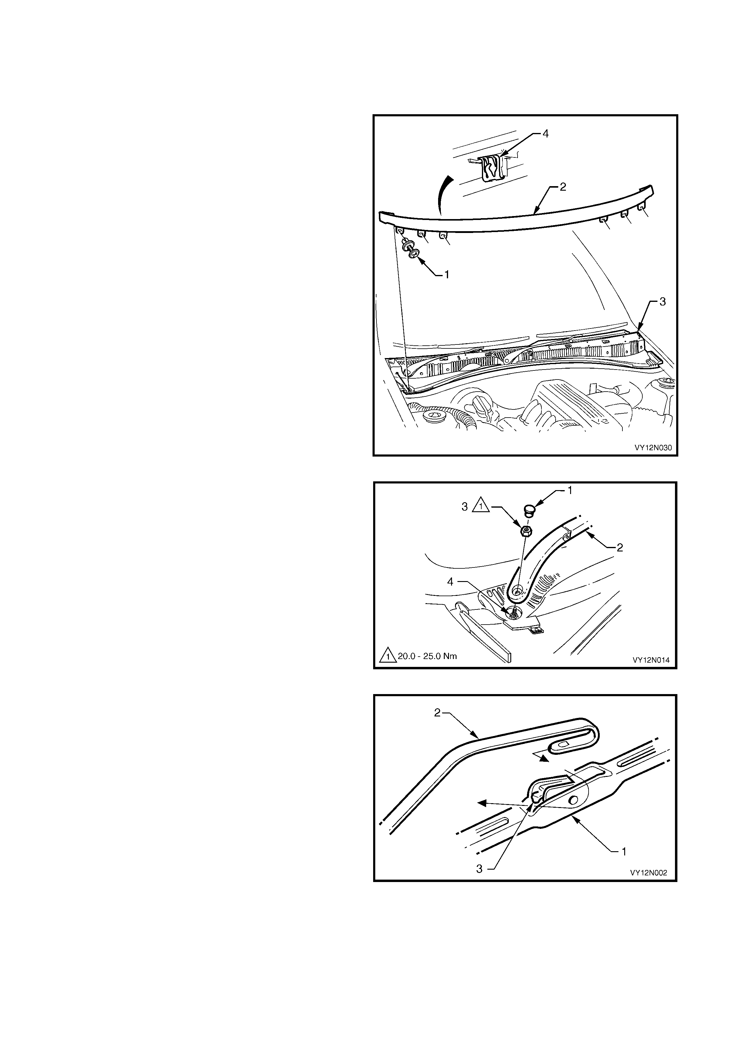
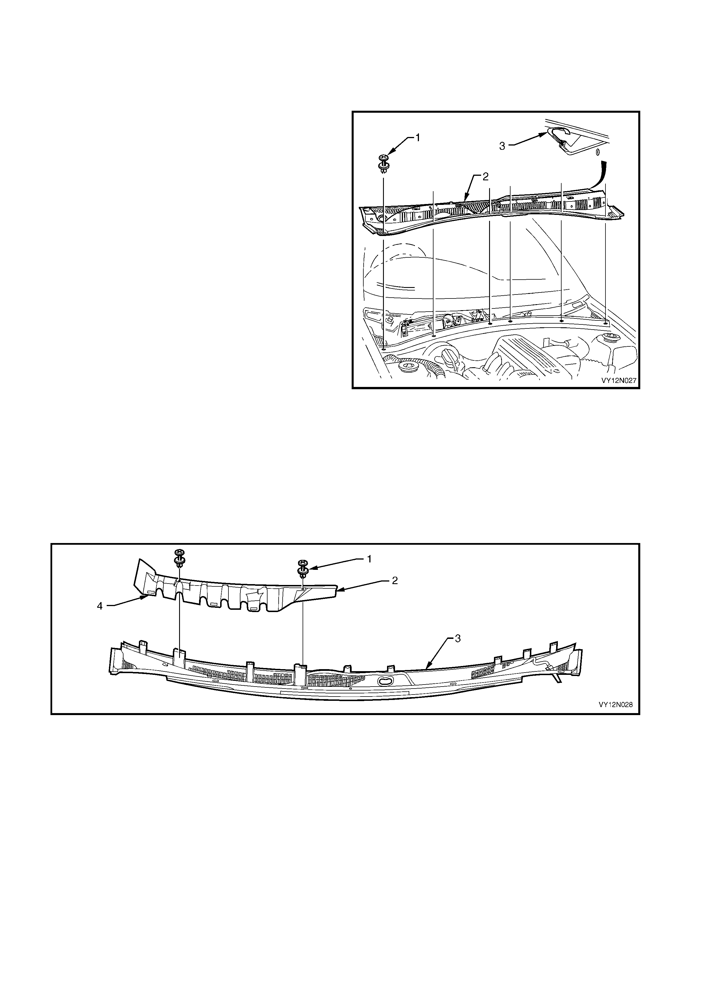
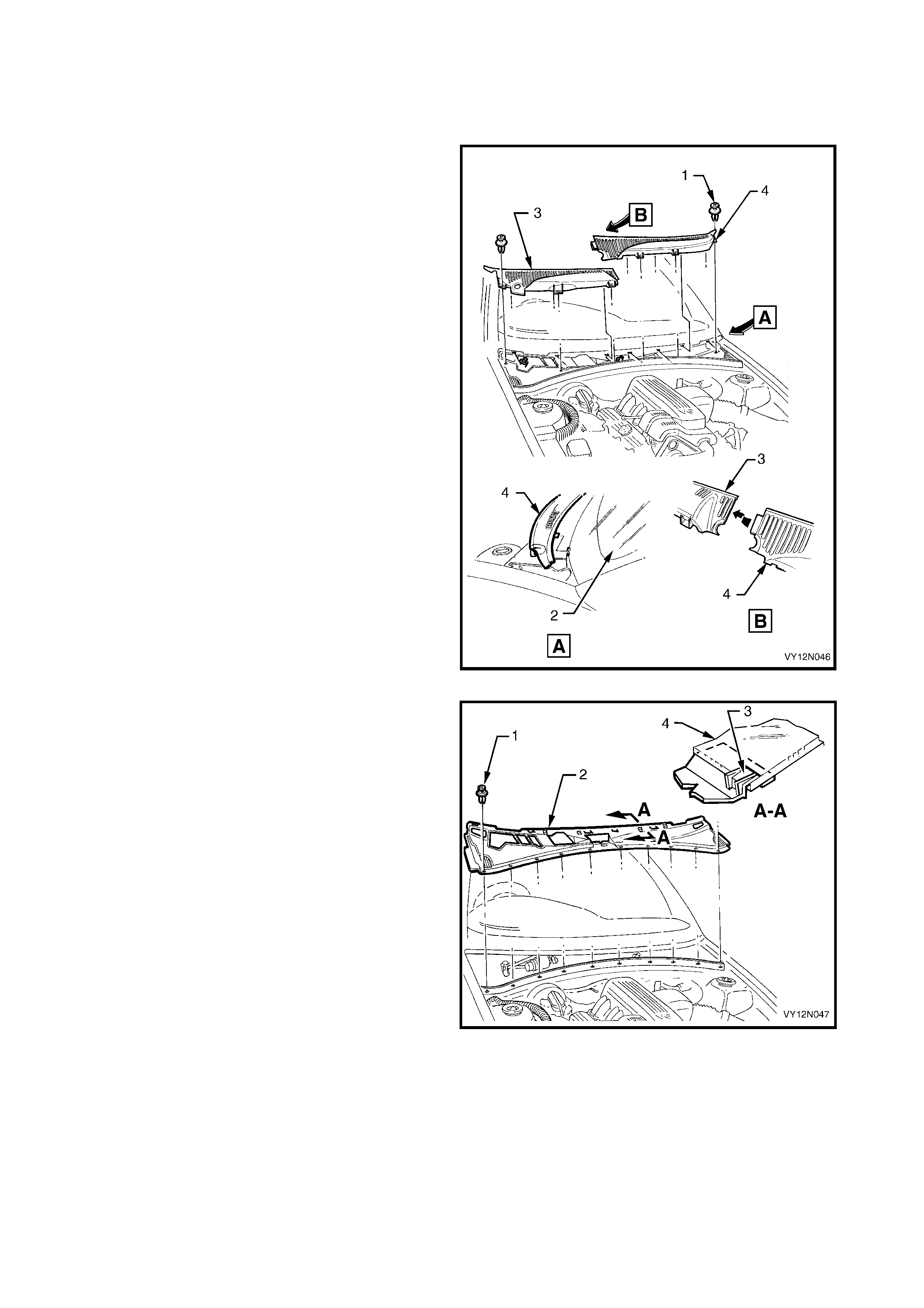
a. Remove the retainer (1), six places, securing
the air deflector assembly (2) to the plenum
cover assembly (3)
b. Unclip the seven clips (4) along the top edge
of the air deflector assembly and the one clip
in the centre of the bottom edge.
c. Remo ve the air deflector assembly taking care
not to contact the rear edge of the engine
hood.
NOTE: Right hand drive shown, Lef t hand dr ive is the
opposite.
Figure 12N-4
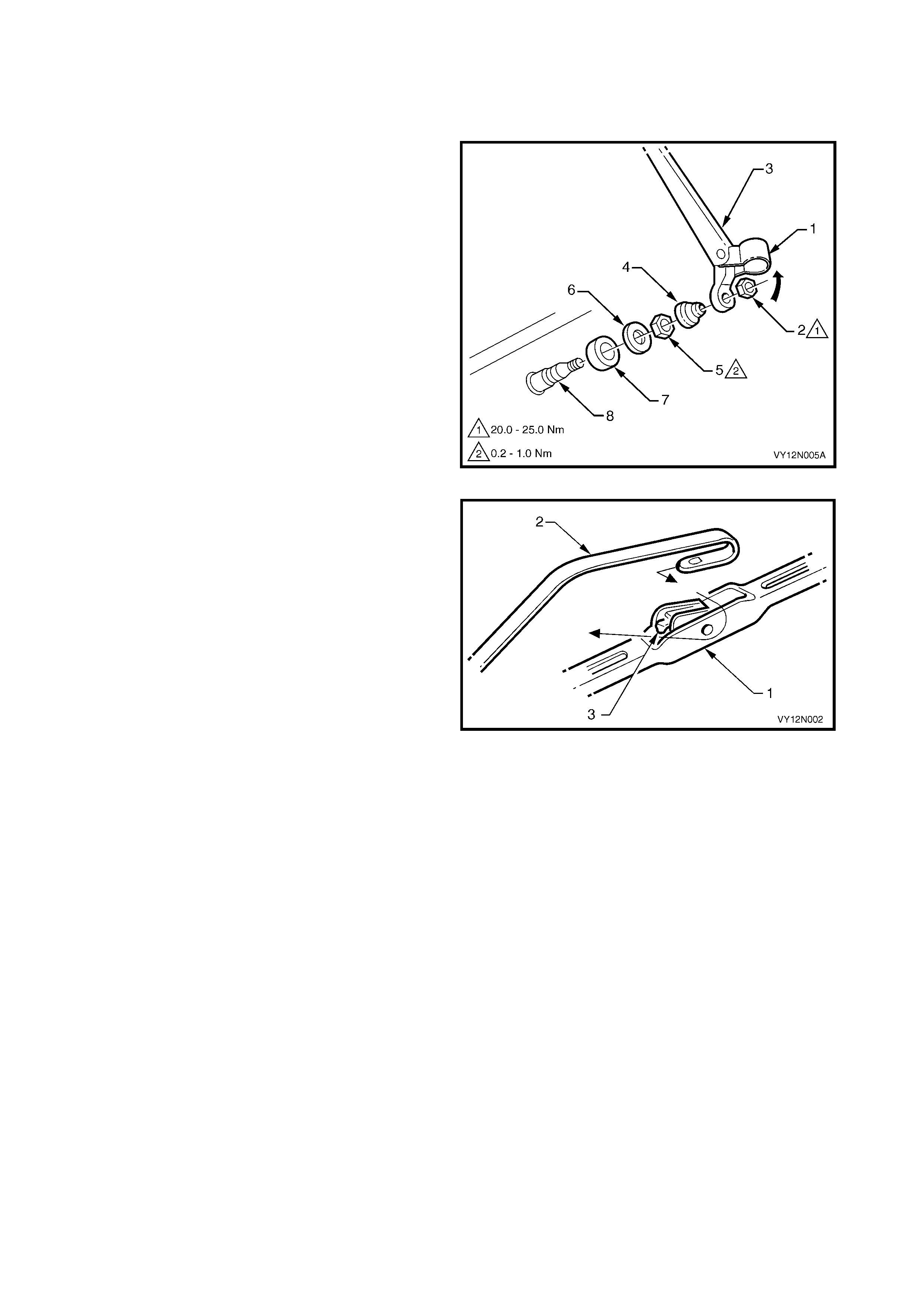
3. Using a small screwdriver or scribe, gently pry the
cap (1) from the front wiper arm (2).
4. Rem ove the nut (3) s ecuring the f ront wiper arm to
the drive spindle (4).
5. Remove the wiper arm from the drive spindle,
taking care not to allow the wiper arm to contact
the rear edge of the engine hood.
Figure 12N-5
6. If required, remove the wiper blade assembly (1)
from the ar m ( 2) by lifting up the retainer (3) on the
wiper blade assembly and pulling the blade
assembly from the arm.
Figure 12N-6
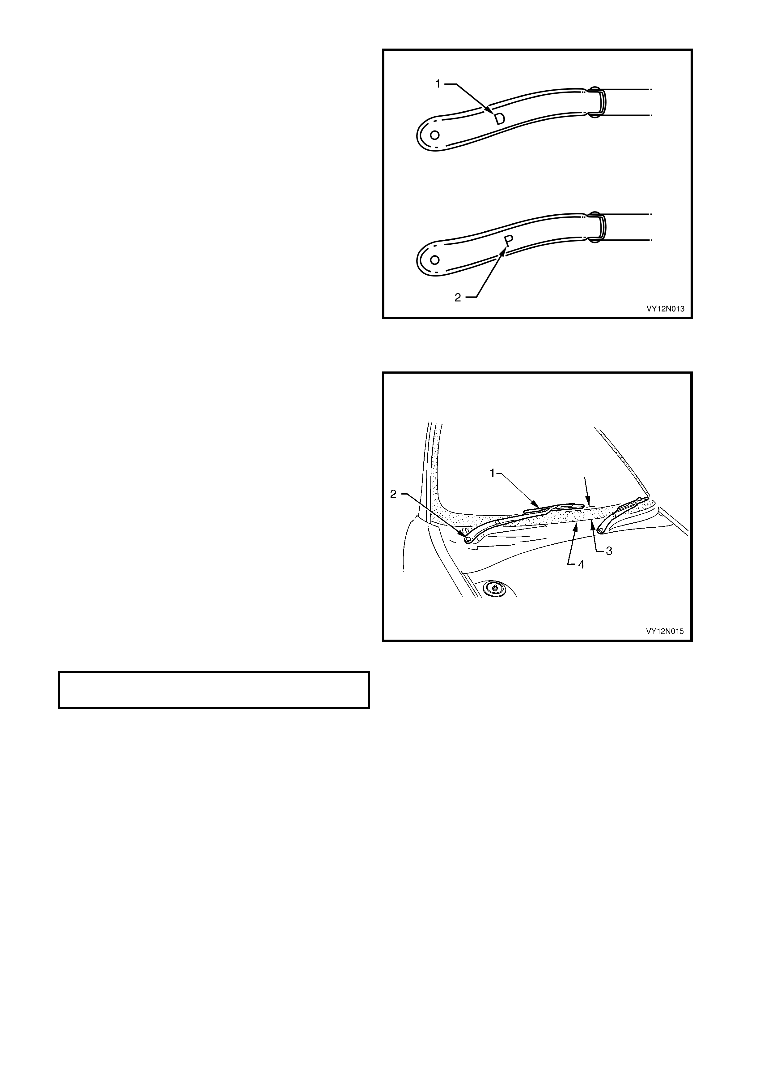
NOTE: There is a specific wiper arm and blade for
each side of the vehicle. The arms are identified by a
letter ‘D’ for the drivers side (1), and a letter ‘P’ for the
passengers side (2), located on the underside of the
arm.
Figure 12N-7
REINSTALL
NOTE: This illustration shows the wiper assemblies
with the hood removed. This is for clarity only. The
procedure can be performed with the hood fitted and
open.
1. If rem oved, slide the wiper blade assem bly into the
wiper arm until the wiper blade retainer locks into
position.
2. Ensure that the wiper motor linkages are in the
PARKED position.
3. Install the wiper arm assembly (1) onto the drive
spindle (2) so that the blade is positioned with the
tip 35 mm ± 5 mm (3) above the edge of the
plenum cover assembly (4).
NOTE: Ensure that the correct wiper arm and blades
are fitted to each side of the vehicle.
4. Install the nut securing the front wiper arm to the
drive spindle and tighten to the correct torque
specification.
5. Install the wiper arm cap.
Figure 12N-8
WIPER ARM NUT
TORQUE SPECIFICATION 20.0 – 25.0 Nm
2.4 REAR WIPER ARM ASSEMBLY, WAGON
LT Section – 10-525
REMOVE
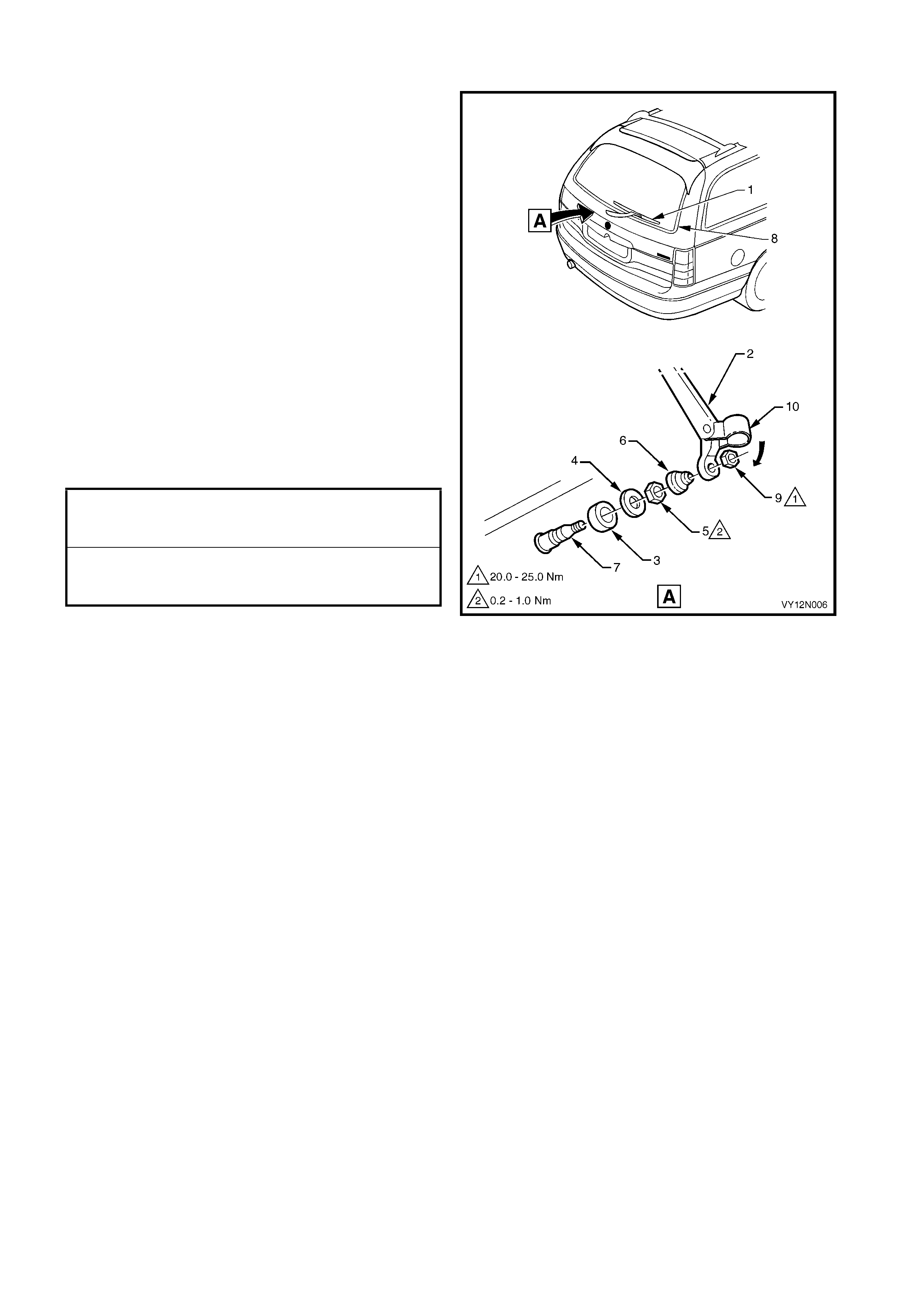
1. Lift the cap (1) and remove the nut (2) attaching
the rear wiper arm ass em bly (3) to the wiper motor
pivot (8).
2. Remove the rear wiper arm assembly from the
wiper motor pivot.
3. If needed remove the cover (4), nut (5), cap (6)
and outer spacer (7) from the wiper motor pivot.
Figure 12N-9
4. If required, remove the wiper blade assembly (1)
from the ar m ( 2) by lifting up the retainer (3) on the
wiper blade assembly and pulling the blade
assembly from the arm.
Figure 12N-10
REINSTALL
1. If rem oved, slide the wiper blade assembly (1) into
the wiper arm (2) until the wiper blade retainer (3)
locks into position, refer to Figure 12N-10.
2. Ensure that the wiper motor assembly is in the
PARKED position.
3. If removed, inst all the outer s pac er (3), c ap (4) and
nut (5). Tighten the nut to the correct torque
specification. Install the cover (6) onto the wiper
motor pivot (7). Install the wiper arm assembly
onto the wiper motor pivot so that the wiper blade
rests on the glass moulding (8).
NOTE: To ensure that the arm will not wipe over the
moulding in the park position, push the arm onto the
wiper motor pivot with the arm in the vertical position
and then rotate the wiper arm clockwise until the blade
rests on the glass moulding.
4. Install the nut (9) securing the wiper arm to the
wiper motor pivot and tighten to the correct torque
specification.
5. Push the trim cap (10) onto the wiper arm (2).
Figure 12N-11
REAR WINDOW WI PER ARM
ASSEMBLY ATTACHING NUT
TORQUE SPECIFICATION 20.0 – 25.0 Nm
REAR WINDOW WIPER MOTOR
PIVOT ATTACHING NUT
TORQUE SPECIFICATION 0.2 – 1.0 Nm
2.5 PLENUM COVER ASSEMBLY – EXCEPT COUPE
LT Section – 10-510
REMOVE
1. Remove the air deflector assembly and wiper arm
assemblies, refer to 2.3 FRONT WIPER ARM
ASSEMBLY.
2. Remove the retainer (1), six places, securing the
plenum cover assembly (2) to the plenum
chamber.
3. Lift the plenum cover assembly up, while pulling
forward to release the nine retaining tabs (3)
securing it to the windshield. Manoeuvre the cover
away from the engine hood hinge, and lift out.
Figure 12N-12
DISASSEMBLE
1. Remove the two fasteners (1) securing the water
deflector (2) to the plenum cover assembly (3),
refer to Figure 12N-13.
2. Pull the water deflector upward to release the three
retaining tabs (4) securing it to the plenum cover
assembly.
3. Remove the water deflector.
Figure 12N-13
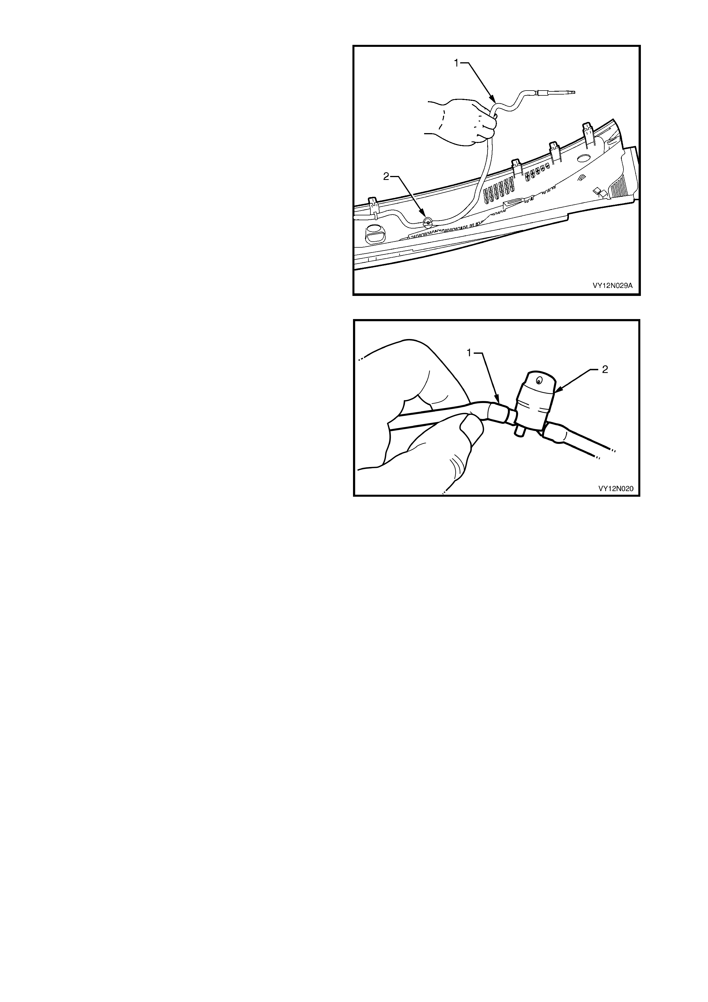
4. Unclip the washer hose (1) from the fasteners
securing it to the plenum cover assembly.
5. Pull washers (2) out from the plenum cover
assembly.
Figure 12N-14
6. Separate the washer hose (1) from the washers
(2).
Figure 12N-15
REASSEMBLE
Assembly of the plenum cover assembly is the reverse
of the disassembly noting the following:
1. Ensur e that the washers are pushed f ully up in the
plenum cover assembly.
REINSTALL
Installation of the washers, washer hose, water deflector and plenum cover assembly is the reverse of the
removal procedure, noting the following:
1. Ensure that the seal along the rear edge of the plenum cover assembly fits snug along the windshield.
2. Ensure that the washer hose is reconnected at the front edge of the plenum cover assembly.
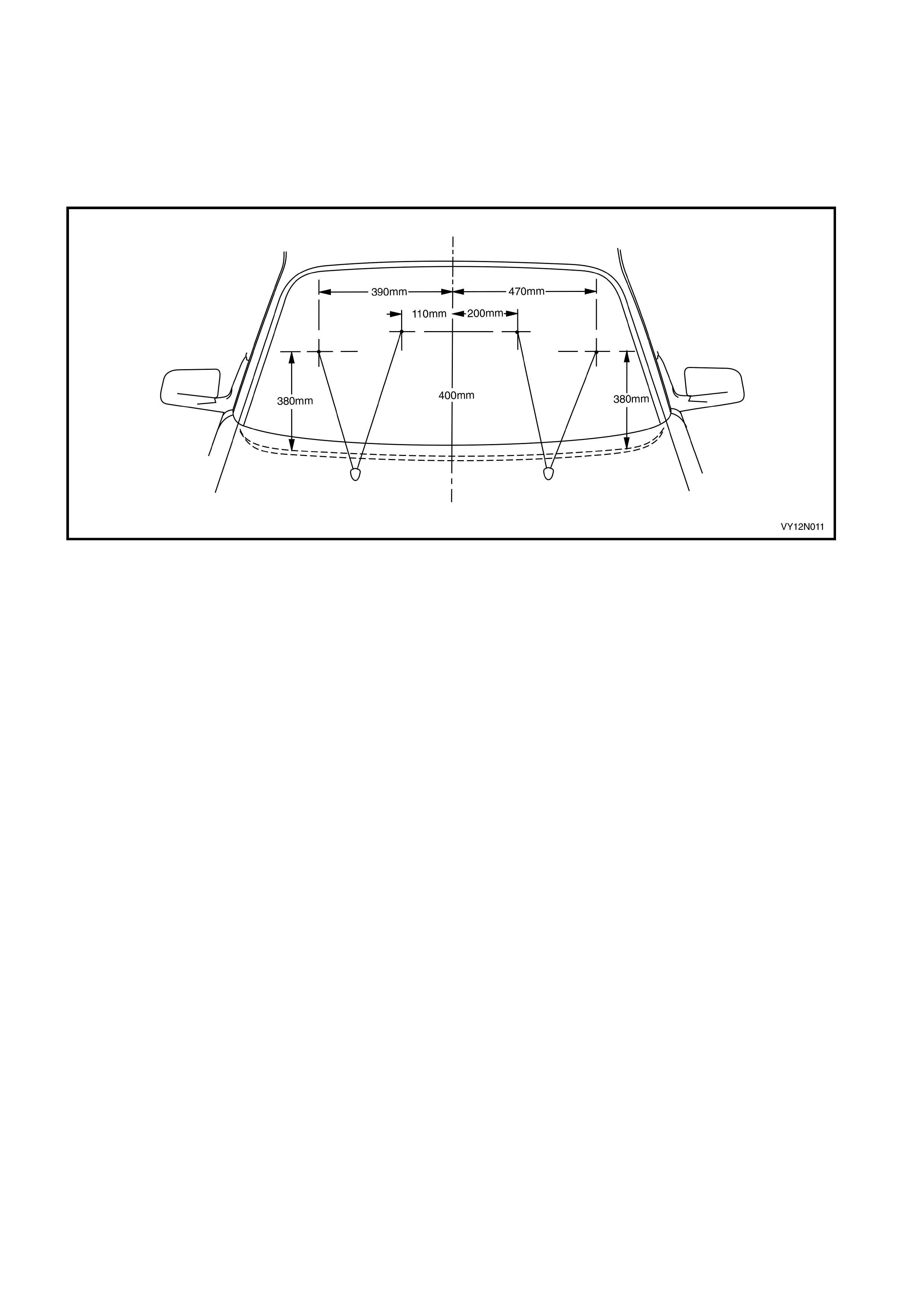
3. Ensure that the washers strike within 100mm of the target point, refer to Figure 12N-16. Use a pin inserted
into the ball of the nozzle and swivel to correct.
Figure 12N-16
2.6 PLENUM COVER ASSEMBLY – COUPE
LT Section – 10-510
REMOVE
1. Remove the wiper arm assemblies, refer to
2.3 FRONT WIPER ARM ASSEMBLY.
2. Remove the retainer (1), six places, securing the
plenum chamber covers to the plenum chamber.
3. Pull the plenum chamber covers forward to
release them from the retainer securing them to
the windshield (2).
4. Lift the right-hand plenum chamber cover (3)
upwards while manoeuvring the cover away from
the engine hood hinge, and remove the plenum
cover.
5. Remove the left-hand side plenum chamber
cover (4) using the same process as for the
right-hand.
NOTE: Remove the right hand plenum cover (3)
before the left hand (4).
Figure 12N-17
6. Remove the retainer (1), ten places, securing the
water deflector assembly (2) to the plenum
chamber.
7. Pull the water deflector assembly forward to
release it from the retainers (3) securing it to the
windshield (4), and remove the water deflector
assembly.
Figure 12N-18

REINSTALL
Installation of the plenum cover assembly is the
reverse of the removal procedure, noting the following:
1. Ensure all fasteners are tightened to the correct
torque specification.
2. When installing the water deflector assembly and
plenum covers, ensure that the retaining tabs
engage under the windshield.
WIPER ARM NUT
TORQUE SPECIFICATION 20.0 – 25.0 Nm
2.7 FRONT WIPER MOTOR ASSEMBLY AND LINKAGE
LT Section – 10-506
DIAGNOSE WIPER MOTOR ASSEMBLY WIRING
Introduction
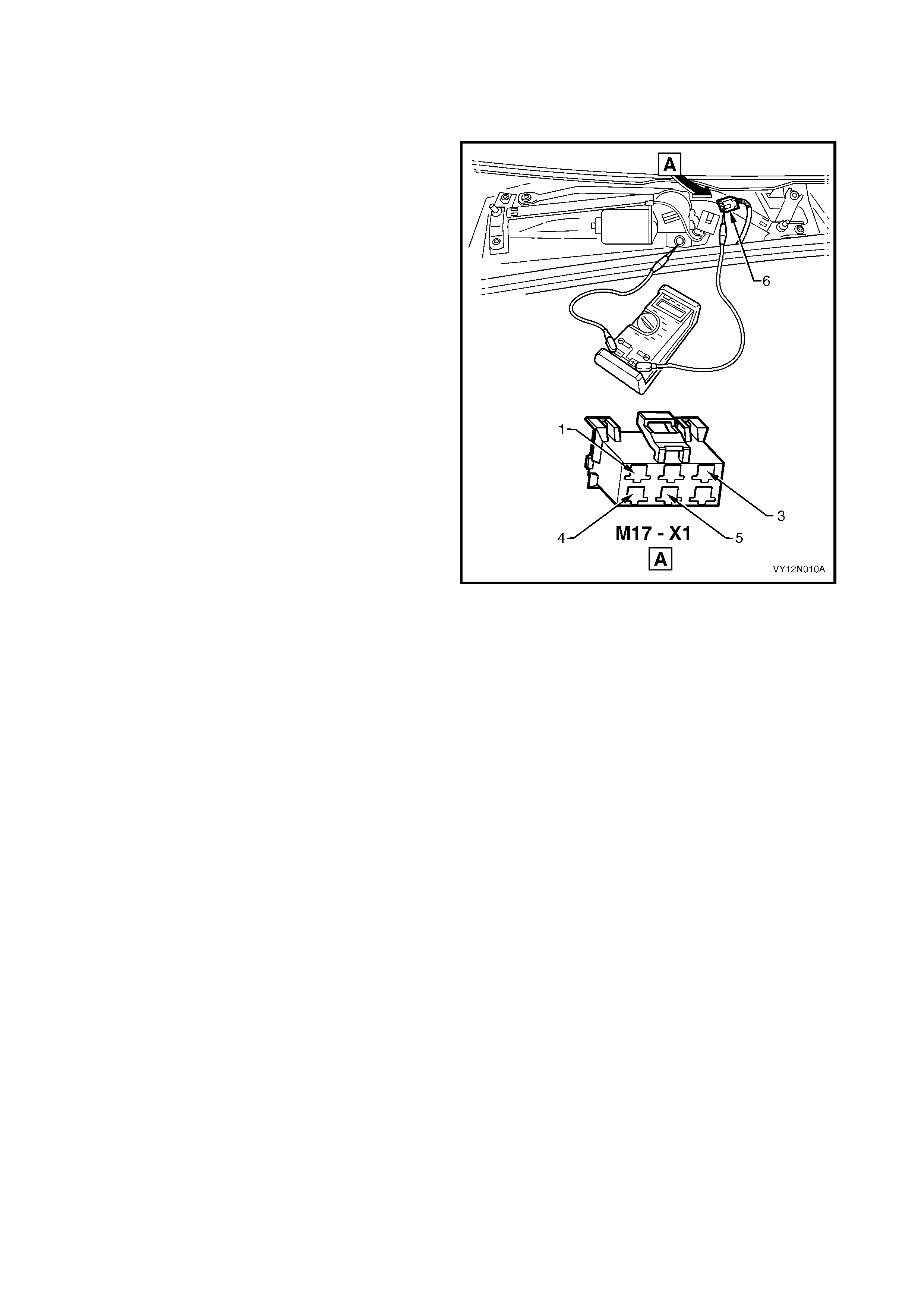
The following operation checks the wiper motor
assembly wiring at the wiper motor harness connector
M17–X1 (6), as an aid to diagnosing a fault in the
wiper motor assembly system. For a complete wiring
diagram of the wiper motor assembly circuits, refer to
2.15 WIRING DIAGRAM – WIPERS AND WASHERS.
NOTE 1: If ther e is a fault in the wiper s ystem , and the
following test proves that the system is serviceable,
refer to DIAGNOSE WIPER MOTOR ASSEMBLY
OPERATION as detailed in this Section, and
Section 12J, BODY CONTROL MODULE.
NOTE 2: The operation of the wiper intermittent dwell
is controlled by the body control module A15, and can
be checked with a TECH 2, refer to Section 12J,
BODY CONTROL MODULE.
Figure 12N-19
Test Description
The following numbers refer to the Steps in the diagnostic chart.
1. Check s whether the fuse F 18 between circuits 70 and 243, is ser viceable. Isolates whether the f use is the fault
affecting the battery power circuit supplying the wiper motor assembly.
2. Checks whether the accessory control relay within the passenger compartment fuse and relay panel assem bly
is serviceable. Isolates whether the accessory control relay is the fault affecting the battery power circuit
supplying the wiper motor assembly.
3. Checks if the system operates correctly, with battery voltage supplied to the wiper motor assembly for the low
speed operation. Isolates whether the electrical circuits for the low speed operation are at fault.
4. Checks that battery voltage is delivered to the harness connector M17 – X1 pin 1, with the wiper and washer
control switch in low speed pos ition. Isolates whether the battery power supply cir cuit or the earth circ uit for the
wiper motor low speed is at fault.
5. Checks whether the wiper and washer control switch S247 is serviceable. Isolates whether the wiper and
washer control switch S247 is the fault affecting the battery power circuit supplying the wiper motor assembly.
6. Checks that battery voltage is delivered to the harness connector M17 – X1 pin 1, with the wiper and washer
control switch in low speed pos ition. Isolates whether the battery power supplying circuits 342, 70, 243,or 95 are
at fault.
7. Checks that battery voltage is delivered to the harness connector M17 – X1 pin 2, with the wiper and washer
control switch in high-speed position. Isolates whether the battery power supplying circuit 92 is at fault.
8. Checks that battery voltage is delivered to the harness connector M17 – X1 pin 1, with the wiper and washer
control switch in INT position. Isolates whether the battery power supplying circuit 96 is at fault.
9. Checks that there is circuit continuity between the harness connector M17 – X1 pin 5 and the body control
module harness connector A15 – X1 pin 1. Isolates whether the battery power supplying circuit 196 is at fault.

STEP ACTION YES NO
1. 1. Check the fuse F18.
Is it serviceable? Go to Step 2. Replace fuse F18.
2. 1. Replace the accessory control relay within the
passenger compartment fuse and relay panel
assembly, refer to Section 12O, FUSES, RELAYS
AND WIRING HARNESSES.
Does the wiper system operate?
System serviceable. Go to Step 3.
3. 1. Remove the wiper arm assemblies, refer to
2.3 FRONT WIPER ARM ASSEMBLY.
2. Remove the plenum cover assembly and water
deflector assembly, refer to 2.5 PLENUM COVER
ASSEMBLY,EXEPT COUPE, or 2.6 PLENUM
COVER ASSEMBLY,COUPE.
3. Disconnect the wiring harness connector M17 – X1.
4. W ith a multimeter, probe with the positive lead to the
harness connector M17 – X1 pin 1 and the negative
lead to the harness connector M17 – X1 pin 4.
5. Switch the ignition to ACC or ON position, and the
wiper and washer control switch to low speed
position.
Is the reading on the multimeter battery voltage?
Go to Step 7. Go to Step 4.
4. 1. W ith a multimeter, probe with the positive lead to the
harness connector M17 – X1 pin 1 and the negative
lead to body earth.
2. Switch the ignition to ACC or ON position, and the
wiper and washer control switch to low speed
position.
Is the reading on the multimeter battery voltage?
There is a fault in circuit
550. Diagnose the
circuit. Repair or
replace circuit 550.
Go to Step 5.
5. 1. Test wi per and washer control switch S247, refer to
2.9 WIPER AND WASHER CONTROL SWITCH.
Is the wiper and washer control switch serviceable? Go to Step 6.
Replace the wiper and
washer control switch
S247, refer to
2.9 WIPER AND
WASHER CONTROL
SWITCH.
6. 1. Repeat step 3 and read the value of the multimeter.
Is the reading on the multimeter battery voltage? Go to Step 7.
There is a fault in circuit
342, 70, 243,or 95.
Diagnose the circuits.
Repair or replace circuit
342, 70, 243,or 95.
7. 1. W ith a multimeter, probe with the positive lead to the
harness connector M17 – X1 pin 2 and the negative
lead to body earth.
2. Switch the ignition to ACC or ON position, and the
wiper and washer control switch to high speed
position.
Is the reading on the multimeter battery voltage?
Go to Step 8. There is a fault in circuit
92. Diagnose the circuit.
Repair or replace circuit
92.
8. 1. W ith a multimeter, probe with the positive lead to the
harness connector M17 – X1 pin 1 and the negative
lead to body earth.
2. Switch the ignition to ACC or ON position, and the
wiper and washer control switch to INT position.
Is the reading on the multimeter battery voltage?
Go to Step 9.
There is a fault in circuit
96. Diagnose the circuit.
Repair or replace circuit
96.
9. 1. Disconnect the body control module harness
connector A15 – X1.
2. With a multimeter, check for continuity between the
harness connector M17 – X1 pin 5 and the harness
connector A15 – X1 pin 1.
Is there continuity?
System serviceable.
For further diagnosis,
refer to Section 12J,
BODY CONTROL
MODULE.
There is a fault in circuit
196. Diagnose the
circuit. Repair or
replace circuit 196.
When all diagnosis and repair are completed, check the system for correct operation.

DIAGNOSE WIPER MOTOR ASSEMBLY OPERATION
Introduction
The wiper motor assembly is attached to a set of
linkages, which in turn drives the wiper arm
assemblies. This test confirms the serviceability of the
wiper motor assembly, and diagnoses four functions,
the low-speed drive, the high-speed drive, the off
PARK position, and the PARK position. For pins
numbering within the connector M17 – X1 (6), refer to
Figure 12N-20.
NOTE: If there is a fault in the wiper system, and the
following test proves that the wiper motor assembly is
serviceable, refer to DIAGNOSE WIPER MOTOR
ASSEMBLY WIRING as detailed in this Section, and
Section 12J, BODY CONTROL MODULE.
Figure 12N-20
Test description
The following numbers refer to the Steps in the diagnostic chart.
1. Checks the low speed operation of the wiper motor assembly. Isolates whether the circuit within the wiper motor
assembly is serviceable between the motor connector M17 – X1 pin 1 and pin 4.
2. Checks the high speed operation of the wiper motor assembly. Isolates whether the circuit within the wiper
motor assembly is serviceable between the motor connector M17 – X1 pin 2 and pin 4.
3. Checks that there is continuity within the wiper motor c ontacts when the motor rotates past the PARK position.
Isolates whether the contacts within the motor assembly are faulty, or the circuit 196 is shorted to earth.
4. Checks that the wiper linkages are stoping at the park position. Isolates whether the contacts within the motor
assembly are faulty.
STEP ACTION YES NO
1. 1. Remove the wiper arm assemblies, refer to
2.3 FRONT WIPER ARM ASSEMBLY.
2. Remove the plenum cover assembly and water
deflector assembly, refer to 2.5 PLENUM COVER
ASSEMBLY,EXEPT COUPE, or 2.6 PLENUM
COVER ASSEMBLY,COUPE.
3. Disconnect the wiring harness connector M17 – X1.
4. Connect a jumper lead from the vehicle battery
positive terminal to the motor connector M17 – X1
pin 1 and a negative lead from the motor connector
M17 – X1 pin 4 to body earth.
Does the wiper motor assembly operate at low speed?
Go to Step 2. Replace the wiper
motor assembly as
detailed in this Section.
2. 1. Connect a jumper lead from the vehicle battery
positive terminal to the motor connector M17 – X1
pin 2 and a negative lead from the motor connector
M17 – X1 pin 4 to body earth.
Does the wiper motor assembly operate at high speed?
Go to Step 3. Replace the wiper
motor assembly as
detailed in this Section.
3. 1. Connect a jumper lead from the vehicle battery
positive terminal to the motor connector M17 – X1
pin 1 and a negative lead from the motor connector
M17 – X1 pin 4 to body earth.
2. Allow the motor to turn linkages approximately 1/4 of
a turn past the PARK position.
3. Connect a test lamp between the battery positive
and the motor connector M17 – X1 pin 5.
Does the test lamp illuminate?
Replace the wiper
motor assembly as
detailed in this Section. Go to Step 4.
STEP ACTION YES NO
4. 1. Probe the motor connector M17 – X1 pin 1 and pin 5
together.
2. Connect a jumper lead from the vehicle battery
positive terminal to the motor connector M17 – X1
pin 3.
Does the wiper motor assembly turn the linkages to the
PARK position and then stops?
The wi per motor
assembly is
serviceable.
Replace the wiper
motor assembly as
detailed in this Section.
When all diagnosis and repair are completed, check the system for correct operation.
REMOVE
1. Remove the air deflector assembly, and the wiper
arm assemblies, refer to 2.3 FRONT WIPER ARM
ASSEMBLY.
2. Remove the plenum cover assembly, refer to
2.5 PLENUM COVER ASSEMBLY, EXCEPT
COUPE, or 2.6 PLENUM COVER ASSEMBLY,
COUPE.
3. Squeeze the tang at the main wiring harness to
wiper motor harness connector M17 – X1 (1) and
disconnect the wiring harness (2).
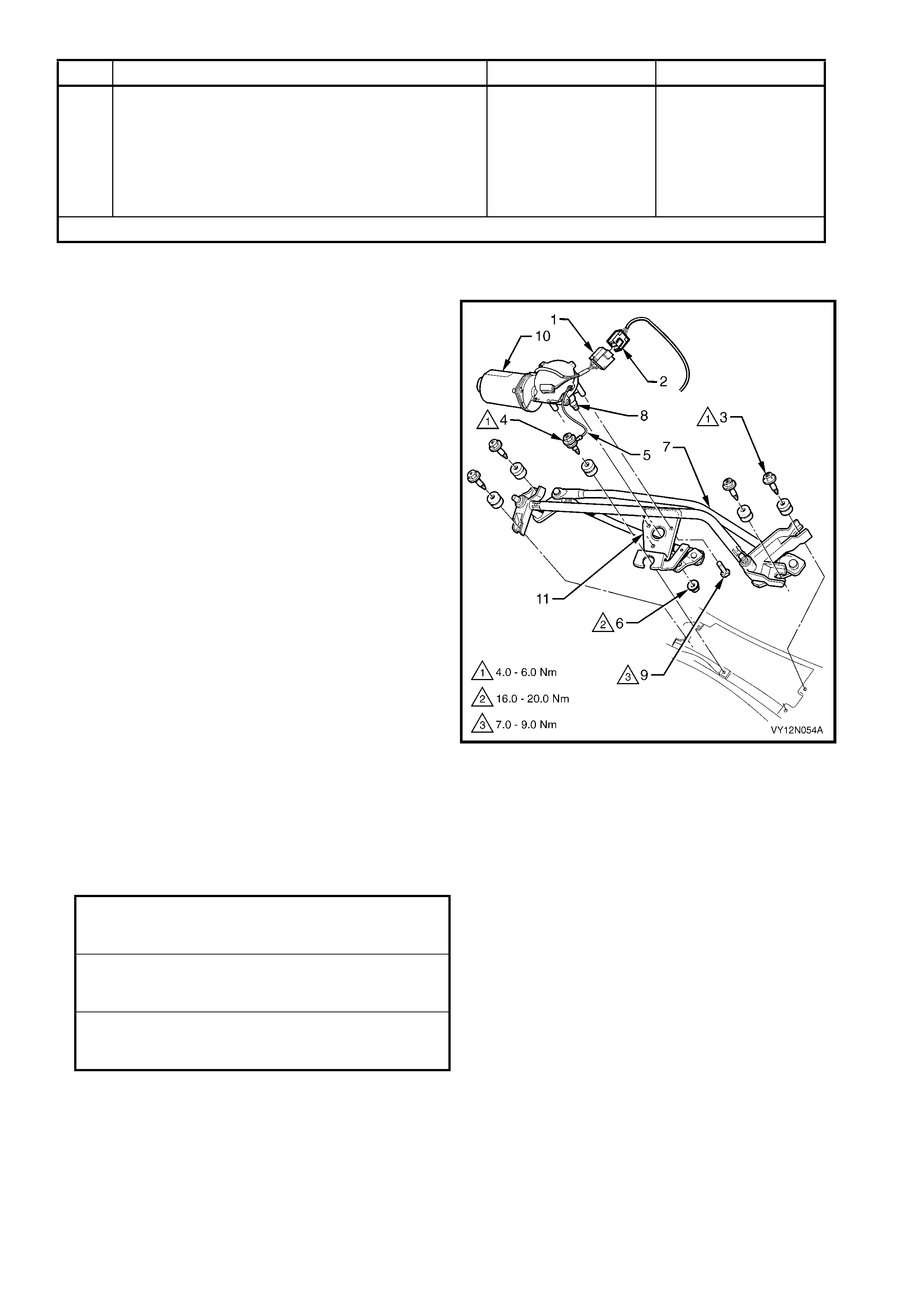
4. Remove the five fasteners (3 and 4) securing the
wiper motor assembly and linkages to the plenum
chamber and remove the wiper motor assembly
and linkages.
CAUTION: The screw (4) securing the wiper motor
and earth strap (5) is secured to the strap by a
spacer and cannot be separated.
5. If required, remove the nut (6) securing the wiper
linkages (7) to the wiper motor pivot (8) and the
screw (9), three places, securing the wiper
motor (10) to the bracket (11) on the wiper
linkages and separate the wiper motor from the
wiper linkages.
Figure 12N-21
REINSTALL
Installation of the wiper motor assembly is the reverse
of the removal procedure, noting the following:
1. Ensure that all fasteners are tightened to the
correct torque specification.
WIPER MOTOR TO LINKAGE
SECURING SCREWS
TORQUE SPECIFICATION 7.0 – 9.0 Nm
WIPER MOTOR PIVOT TO
LINKAGES ATTACHING NUT
TORQUE SPECIFICATION 16.0 – 20.0 Nm
WIPER MOTOR AND LINKAGE
ASSEMBLY SECURING SCREW S
TORQUE SPECIFICATION 4.0 – 6.0 Nm
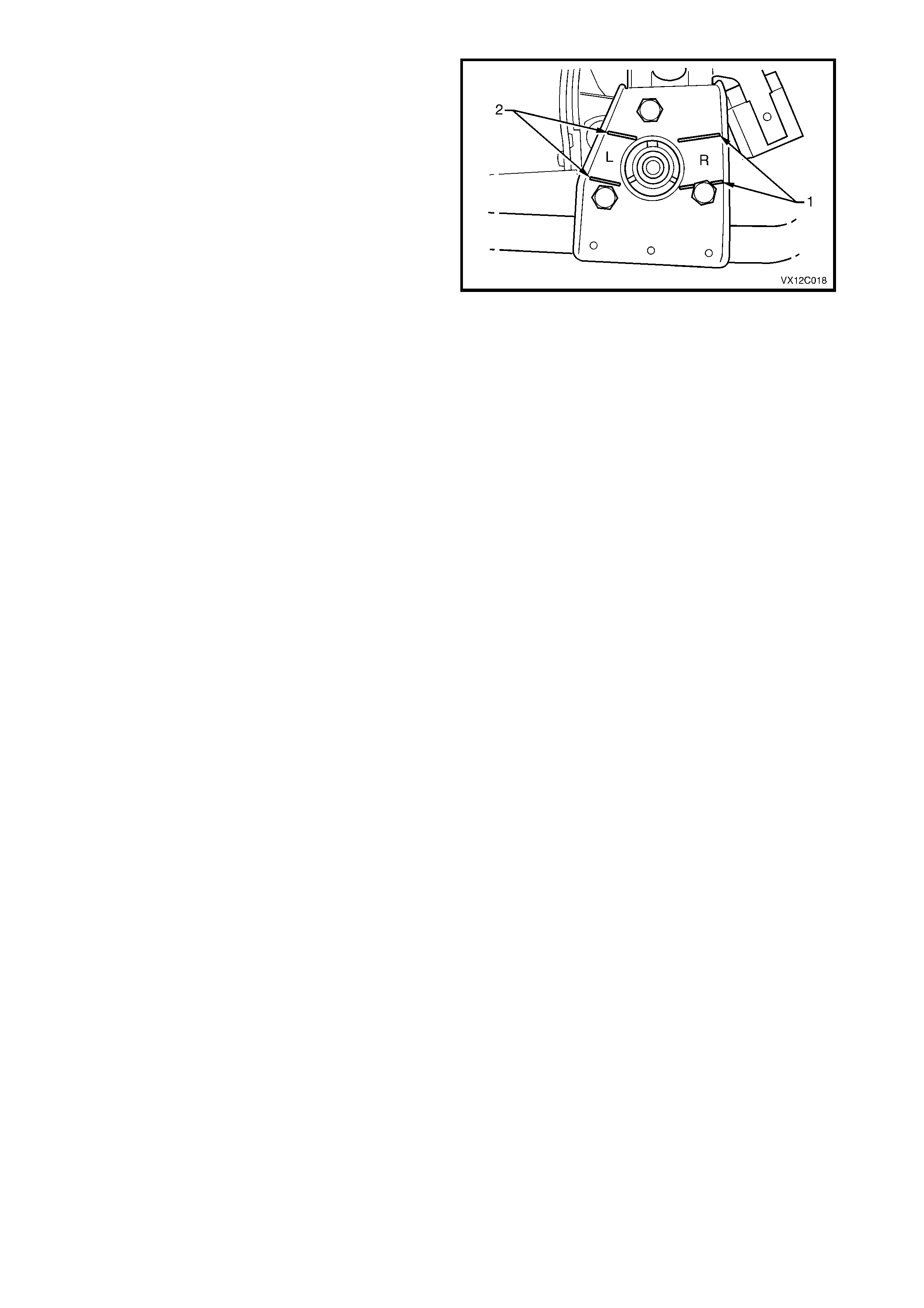
NOTE 1: If the wiper motor has been removed from
the link ages, the wiper m otor pivot mus t be installed in
the park position, by aligning the wiper motor pivot
within the lines on the mounting bracket marked R (1)
for right-hand drive, or L (2) for left-hand drive models.
NOTE 2: Ensure that the wires from the
connector M17 – X1 do not get caught or foul the wiper
motor linkages.
2. Operate the wiper motor assembly before installing
the wiper arms to ensure that it is in the correct
PARK position.
3. When installing the plenum cover assembly and
the air deflector assembly, ensure that the
retaining lugs engage under the windshield.
Figure 12N-22
2.8 REAR WIPER MOTOR ASSEMBLY, WAGON
LT Section – 10-525
DIAGNOSE WIPER MOTOR ASSEMBLY WIRING
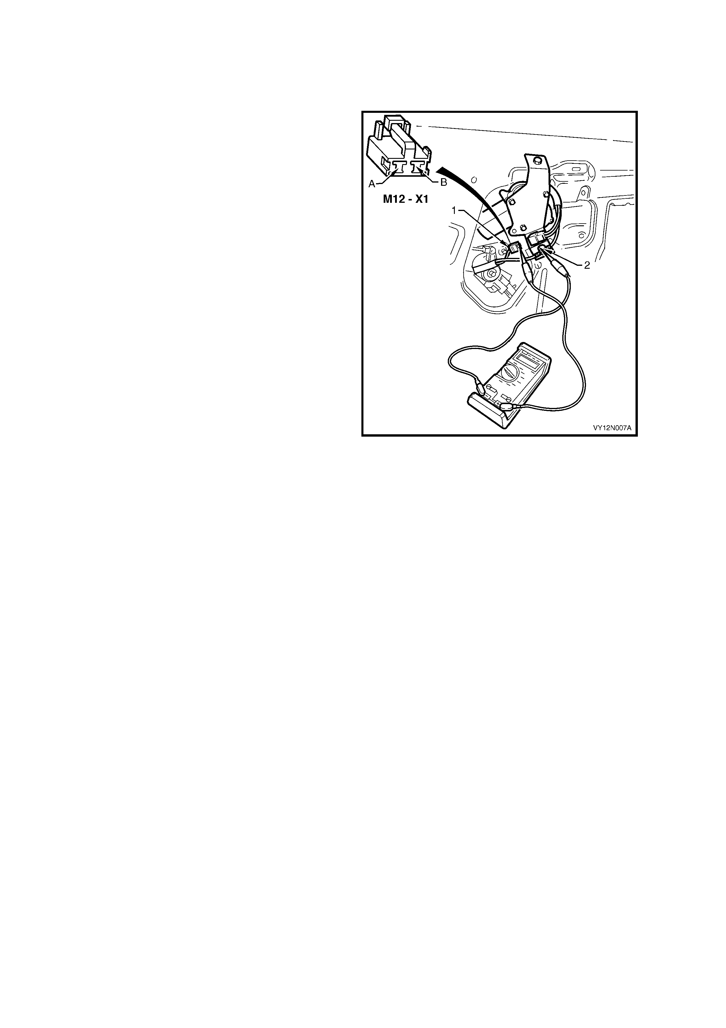
Introduction
The following operation checks the wiper motor
assembly wiring at the wiper motor harness connector
M12–X1 (1), as an aid to diagnosing a fault in the
wiper motor assembly system. For a complete wiring
diagram of the wiper motor assembly circuits, refer to
2.15 WIRING DIAGRAM – WIPERS AND WASHERS.
NOTE: If there is a fault in the wiper system, and the
following test proves that the wiper system is
serviceable, refer to DIAGNOSE WIPER MOTOR
ASSEMBLY OPERATION as detailed in this Section,
and Section 12J, BODY CONTROL MODULE.
Figure 12N-23
Test Description
The following numbers refer to the Steps in the diagnostic chart.
1. Check s whether the fuse F 18 between circuits 70 and 243, is ser viceable. Isolates whether the f use is the fault
affecting the battery power circuit supplying the wiper motor assembly.
2. Checks whether the rear wiper relay within the passenger compartment fuse and relay panel assembly is
serviceable. Isolates whether the rear wiper relay is the fault affecting the battery power circuit supplying the
wiper motor assembly
3. Checks whether the accessory control relay within the passenger compartment fuse and relay panel assem bly
is serviceable. Isolates whether the accessory control relay is the fault affecting the battery power circuit
supplying the wiper motor assembly.
4. Checks that battery voltage is delivered to the harness connector M12 – X1 pin B, with the wiper and washer
control switch in the rear wipe position, and the ignition switch to ACC or ON position. Isolates whether the
electrical circuits supplying the wiper motor assembly are at fault.
5. Checks whether the wiper and washer control switch S247 is serviceable. Isolates whether the wiper and
washer control switch S247, or the electrical circuits 342, 70, 243, 393, 391, or 113 are the fault affecting the
battery power being delivered the wiper motor assembly.
6. Checks that battery voltage is delivered to the harness connector M12 – X1 pin A, with the wiper and washer
control switch in the O FF pos ition, and the ignition switch to ACC or O N position. Isolates whether the electric al
circuit 243, is at fault.

STEP ACTION YES NO
1. 1. Check the fuse F18.
Is it serviceable? Go to Step 2. Replace fuse F18.
2. 1. Replace the rear wiper relay within the passenger
compartment fuse and relay panel assembly, refer to
Section 12O FUSES, RELAYS AND WIRING
HARNESSES.
2. Switch the ignition to ACC or ON position, and the
wiper and washer control switch to rear wiper
position.
Does the rear wiper system operate?
System serviceable. Go to Step 3.
3. 1. Replace the accessory control relay within the
passenger compartment fuse and relay panel
assembly, refer to Section 12O FUSES, RELAYS
AND WIRING HARNESSES.
2. Switch the ignition to ACC or ON position, and the
wiper and washer control switch to rear wiper
position.
Does the rear wiper system operate?
System serviceable. Go to Step 4.
4. 1. Remove the liftgate window lower garnish, and the
liftgate lower trim panel, refer to Section 1A4,
HOOD, REAR COMPARTMENT LID, LIFTGATE
AND ENDGATE.
2. Disconnect the rear compartment wiring harness
connector M12 – X1.
3. W ith a multimeter, probe with the positive lead to the
harness connector M12 – X1 pin B and the negative
lead to body earth at the lower wiper motor bracket
securing screw (2), refer to Figure 12N-26.
4 Switch the ignition to ACC or ON position, and the
wiper and washer control switch to rear wiper
position.
Is the reading on the multimeter battery voltage?
Go to Step 6. Go to Step 5.
5. 1. Test wiper and washer control switch S247, refer to
2.9 WIPER AND WASHER CONTROL SWITCH.
Is the wiper and washer control switch serviceable?
There is a fault in circuit
342, 70, 243, 393, 391,
or 113. Diagnose the
circuits 342, 70, 243,
391, 113 or circuit 393
between connectors
M12 – X1 pin B, X901
pin 1, X201 pin B5 and
rear wiper relay.
Repair or replace
circuits.
Replace the wiper and
washer control switch
S247, refer to
2.9 WIPER AND
WASHER CONTROL
SWITCH.
6. 1. W ith a multimeter, probe with the positive lead to the
harness connector M12 – X1 pin A and the negative
lead to body earth at the lower wiper motor bracket
securing screw (2), refer to Figure 12N-26.
2 Switch the ignition to ACC or ON position, and the
wiper and washer control switch to the OFF position.
Is the reading on the multimeter battery voltage?
System serviceable.
For further diagnosis,
refer to Section 12J,
BODY CONTROL
MODULE.
There is a fault in circuit
243. Diagnose the
circuit between
connectors M12 – X1
pin A, X901 pin 9, X201
pin B2 and fuse F18.
Repair or replace
circuit 243.
When all diagnosis and repair are completed, check the system for correct operation.
DIAGNOSE WIPER MOTOR ASSEMBLY OPERATION
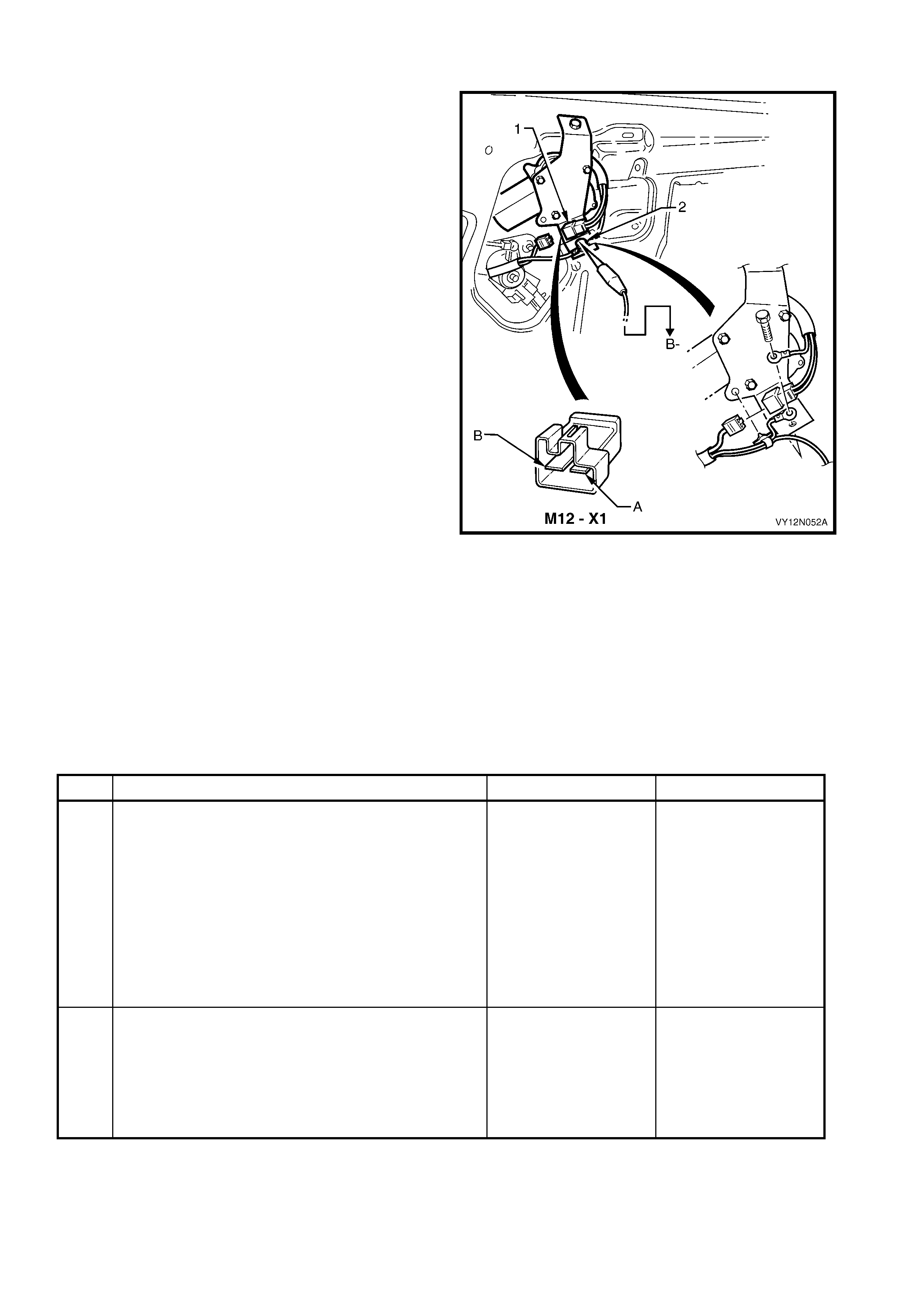
Introduction
The wiper motor assembly is attached to the liftgate
assembly, and drives the rear wiper arm assembly
directly through the motor shaft. T his test confirm s the
serviceability of the wiper motor assembly, and
diagnoses two func tions , the wiper drive and the PARK
position. For pins numbering within the connector
M12 – X1 (1) refer to Figure 12N-24.
NOTE: If there is a fault in the wiper system, and the
following test proves that the wiper motor assembly is
serviceable, refer to DIAGNOSE WIPER MOTOR
ASSEMBLY WIRING as detailed in this Section, and
Section 12J, BODY CONTROL MODULE.
Figure 12N-24
Test Description
The following numbers refer to the Steps in the diagnostic chart.
1. Check s the oper ation of the wiper m otor as sem bly. Isolates whether the circuit within the wiper motor assem b ly
is serviceable between the motor connector M12 – X1 pin B and the earth connector.
2. Checks the operation of the wiper motor assembly. Isolates whether the earth circuit within the wiper motor
assembly is serviceable.
3. Checks that the earth connection of the wiper motor assembly is effective. Isolates whether the earth
connection of the wiper motor assembly is at fault.
4. Checks that the wiper motor shaft stops at the park position. Isolates whether the contacts within the motor
assembly are faulty.
STEP ACTION YES NO
1. 1. Remove the wiper arm assembly, refer to 2.4 REAR
WIPER ARM ASSEMBLY, WAGON.
2. Remove the liftgate window lower garnish, and the
liftgate lower trim panel, refer to Section 1A4,
HOOD, REAR COMPARTMENT LID, LIFTGATE
AND ENDGATE.
3. Disconnect the wiring harness connector M12 – X1.
4. Connect a jumper lead from the vehicle battery
positive terminal to the motor connector M12 – X1
pin B.
Does the wiper motor assembly operate?
Go to Step 4. Go to Step 2.
2. 1. Connect a jumper lead from the vehicle battery
negative terminal to the wiper motor earth
connection, refer to Figure 12N-24.
2. Connect a jumper lead from the vehicle battery
positive terminal to the motor connector M12 – X1
pin B.
Does the wiper motor assembly operate?
Go to Step 3. Replace the wiper
motor assembly as
detailed in this Section.
STEP ACTION YES NO
3. 1 Remove the screw (2) attaching the earth
connections and the motor assembly to the liftgate
assembly, refer to Figure 12N-24.
2 Check and clean the earth connection, the attaching
screw, and reinstall.
3 Connect a jumper lead from the vehicle battery
positive terminal to the motor connector M12 – X1
pin B.
Does the wiper motor assembly operate?
Go to Step 4. Replace the wiper
motor assembly as
detailed in this Section.
4. 1. Connect a bridging wire between the wiper motor
connector M12 – X1 pin A and pin B.
2. Connect a jumper lead from the vehicle battery
positive terminal to the motor connector M12 – X1
pin A.
3. Allow the motor shaft to turn approximately 1/4 of a
turn past the PARK position, and disconnect the
bridging wire from the motor connector M12 – X1
pin B.
Does the wiper motor shaft continue to rotate, reach the
park position and then stops?
The wiper motor
assembly is
serviceable.
Replace the wiper
motor assembly as
detailed in this Section.
When all diagnosis and repair are completed, check the system for correct operation.
REMOVE
1. Remove the rear wiper arm assembly, refer to
2.4 REAR WIPER ARM ASSEMBLY, WAGON.
2. Remove the cover (1), nut (2), cap (3) and outer
spacer (4) from the wiper motor pivot (5).
3. Remove the liftgate window lower garnish, and
the liftgate lower trim panel, refer to
Section 1A4, HOOD, REAR COMPARTMENT
LID, LIFTGATE AND ENDGATE.
Figure 12N-25
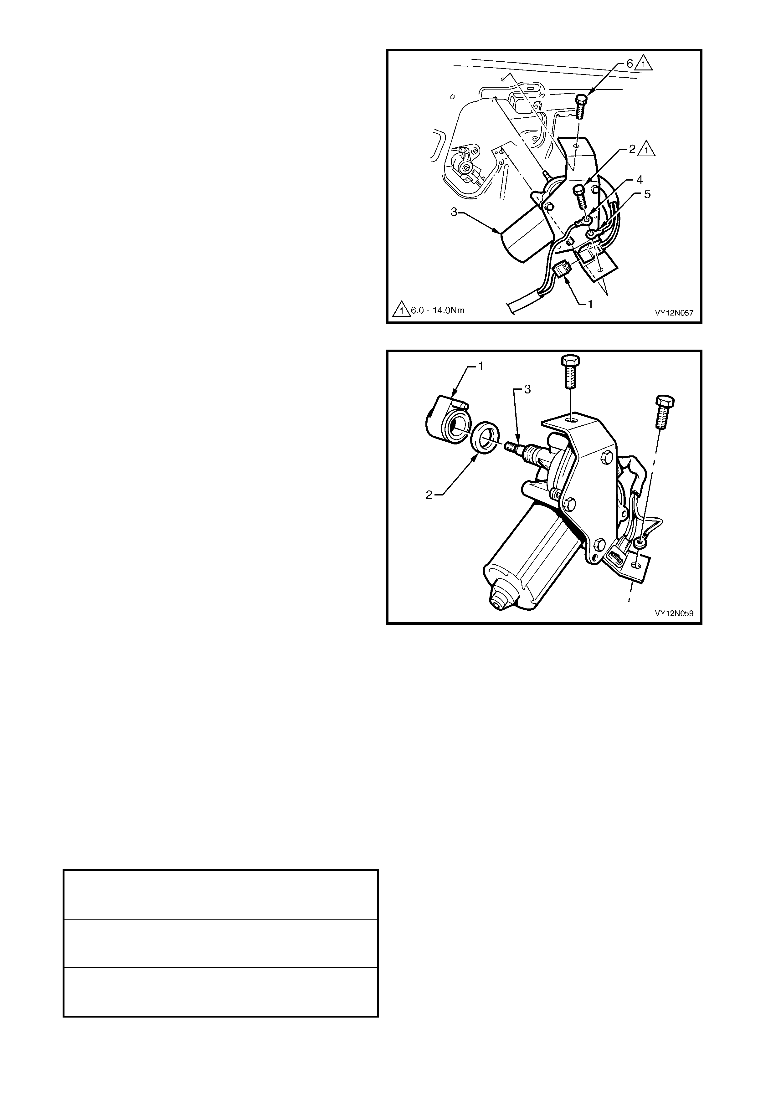
4. Disconnect the wiring harness connector (1).
5. Remove the screw (2) attaching the rear window
wiper motor assembly (3), liftgate harness earth
connection (4) and motor assembly earth
connection (5) to the liftgate assembly.
6. Remove the screw (6) and remove the motor
assembly from the liftgate assembly.
Figure 12N-26
7. Remove the inner spacer (1) and the cap (2) from
the wiper motor pivot (3).
Figure 12N-27
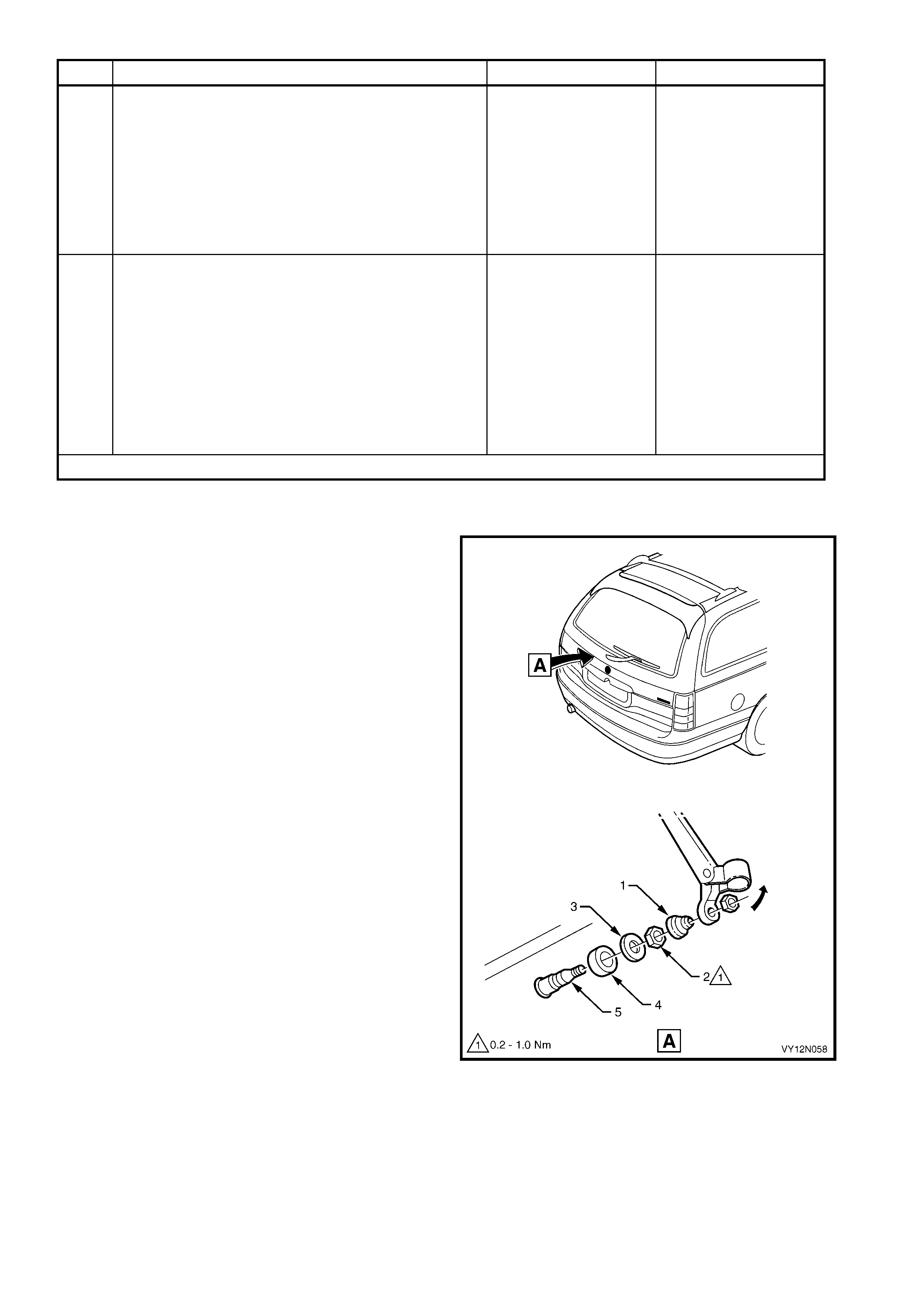
REINSTALL
Installation of the rear wiper motor assembly is the
reverse of the removal procedure, noting the following
points
1. Ensure that the spacer, cap, nut, and rubber seal
are fitted onto the wiper m otor shaf t correc tly, r efer
to Figure 12N-25.
2. To ensure sound earth connection, the wiper
motor earth connector (5) must be installed before
the liftgate harness earth connector (4), refer to
Figure 12N-26.
3. T ighten the wiper motor assem bly s ecuring scr ews
to the correct torque specification.
REAR WINDOW WIPER ARM ASSEMBLY
ATTACHING NUT TORQUE
SPECIFICATION 20.0 – 25.0 Nm
REAR WINDOW WIPER MOTOR
ASSEMBLY ATTACHING NUT TORQUE
SPECIFICATION 0.2 – 1.0 Nm
REAR WINDOW WIPER MOTOR
ASSEMBLY ATTACHING SCREW
TORQUE SPECIFICATION 6.0 – 14.0 Nm
2.9 WI PER AND WASHER CONTROL SWITCH
LT Section – 06-250
REMOVE
CAUTION: If vehicle is equipped with an AIRBAG,
disable the system. Refer to Section 12M,
OCCUPANT PROTECTION SYSTEM.
1. Turn the ignition to the OFF position, and remove
the ignition keys from the ignition switch.
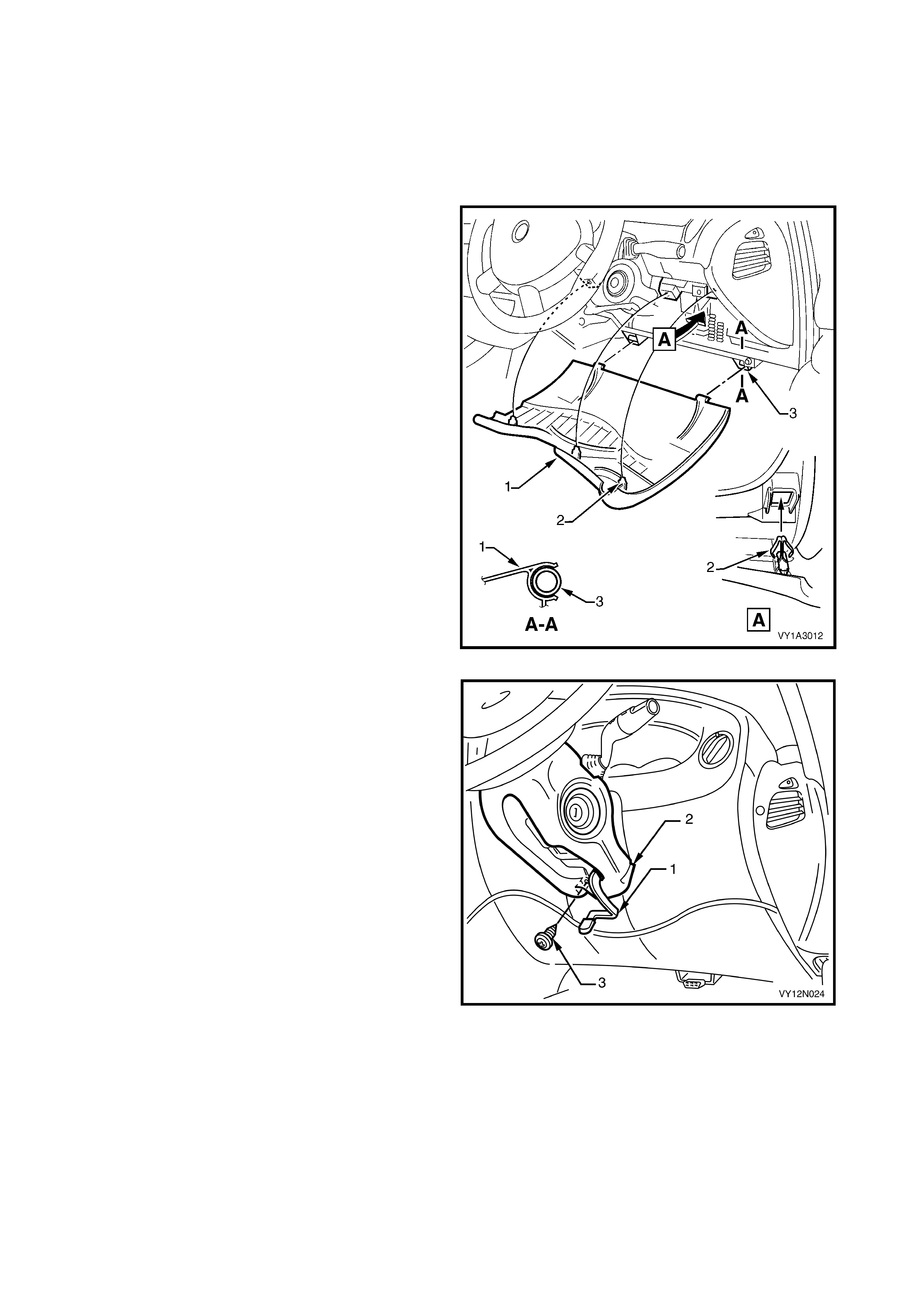
2. Gain access to the passenger compartment fuse
and relay assembly, grasp the upper edge of the
instrument panel lower trim panel assembly (1)
and disengage the three clips (2). Swing the panel
assembly open.
3. Rem ove the wiper and washers fuse F18 from the
passenger compartment fuse and relay panel
assembly. Refer to Section 12O, FUSES RELAYS
AND WIRING HARNESSES.
Figure 12N-28
4. Release the steering column height adjuster (1),
completely lower the steering column and leave
the lever in the release position.
5. Remove the screw (3) attaching the lower cover
(2) to the steering column.
Figure 12N-29
6. Place a clean shop rag over and around the
steering column upper cover. This prevents any
possibility of dam age to the cover should there be
any contact with the lower edge of the instrument
facia while removing the cover.
7. Insert a finger between the steering wheel and the
lower cover and apply a small am ount of pressure,
pushing towards the instrument cluster.
8. Pull the steering column upper cover (1) up and
toward the steering wheel at the sam e time pulling
the lower cover (2) down and away from the
steering wheel. This will release the steering
column lower cover end retainers from the mating
slots in the upper cover.
9 Remove the upper cover by lifting upwards and
rearwards.
10. While feeding the key reader outer surround from
the lower cover, remove the cover.
Figure 12N-30
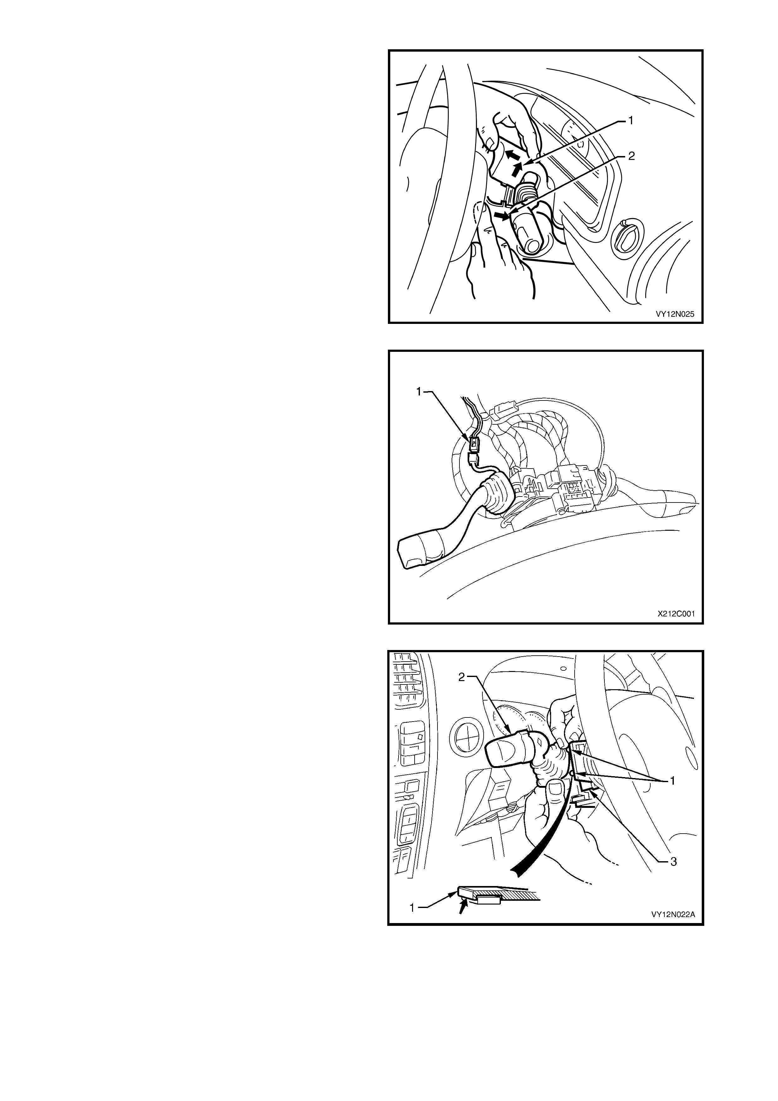
11. On vehicles fitted with intermittent dwell control,
disconnect the wiring harness connector to the
wiper dwell control switch harness connector (1) by
depressing the harness retaining tang and pulling
the connectors apart.
Figure 12N-31
12. Depress the retaining tangs (1) on the switch
assembly and withdraw the wiper and washer
switch (2) from the switch housing on the steering
column (3).
Figure 12N-32
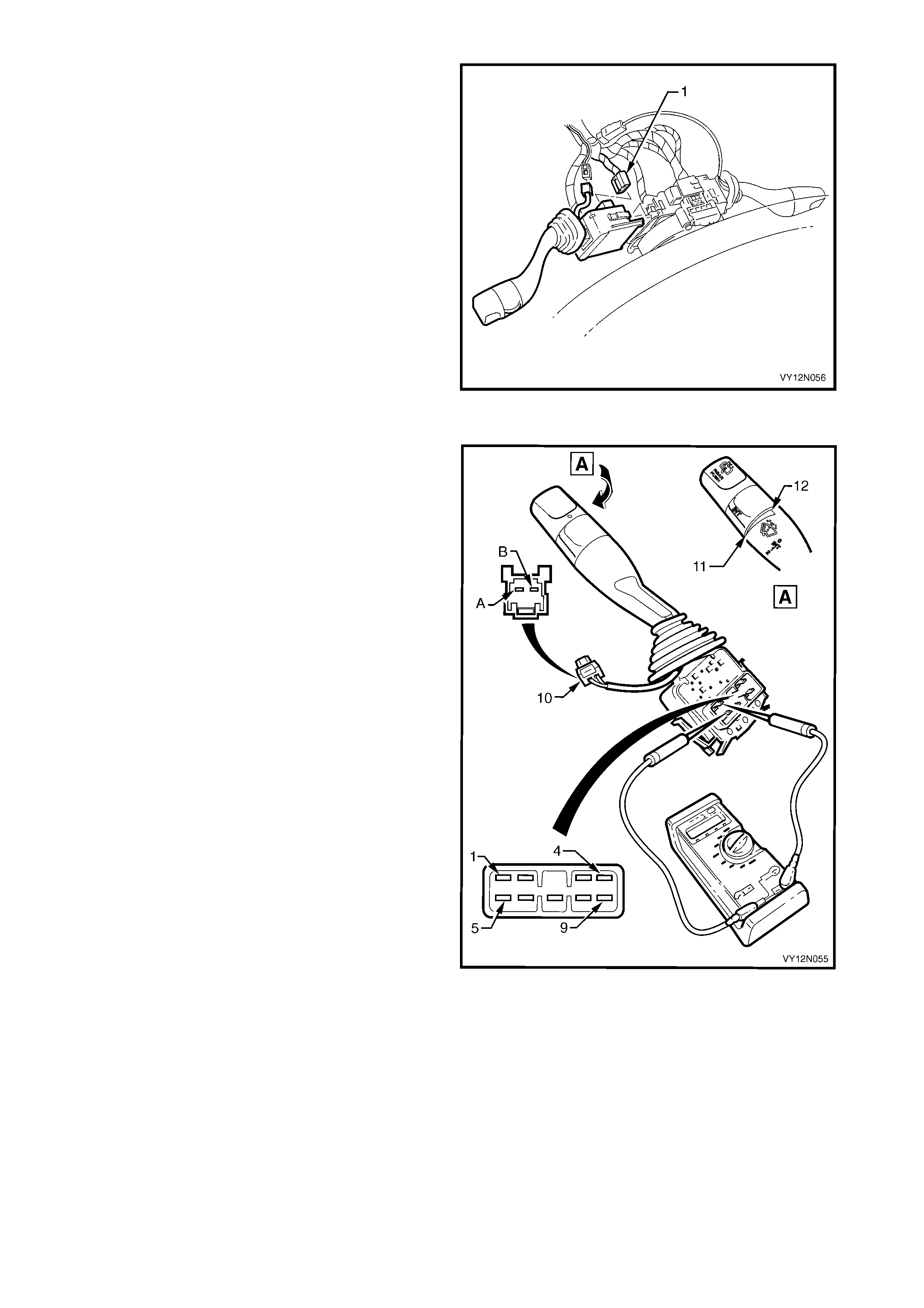
13. Lift up the wiring harness connector retaining
tangs on either side of the wiper and washer
switch body and pull the connector (1) from the
switch.
14. Remove the switch assembly.
Figure 12N-33
TEST
Using a multimeter, probe the various switch pin
combinations to check the operation of the wiper and
washer switch as per the following chart.
1. Perform the removal procedure for the wiper and
washer switch assembly as detailed in this
Section, but do not unclip and remove the switch
assembly from the steering column. When the
switch assembly is attached to the steering
column, it provides a stable platform with which to
carry out the testing.
2. Place the switch into the positions as detailed in
the following chart, and the multimeter probe tips
onto the corres ponding pins. Tak e the reading and
compare it with the indication in the chart below.
3. If there is continuity between any two pins, other
than the combinations listed in the following chart,
the switch assembly is faulty.
4. On vehicles fitted with intermittent dwell control,
turn the wiper and washer control switch to INT
(maximum dwell time position) (11) and place the
multim eter pr obe tips onto the pins A and B on the
connector R23 – X1 (10). Take the reading, and
compare it with the chart below. Repeat the check
with the wiper and washer control switch turned to
INT (minimum dwell time position) (12).
5. If the switch fails any part of the test, replace the
switch assembly with a serviceable item.
NOTE 1: The variable intermittent wiper switch,
through the détente, decreases or increases the
frequency that the wiper m otor is actuated. The switch
has seven increments.
NOTE 2: The dwell time is determined via a
combination of vehicle road speed and the wiper
control stalk.
Figure 12N-34

Switch Position Pins Indication if O.K.
0 (Off) 9 and 8 Continuity
9 and 8 Continuity
INT 7 and 6 Continuity
1 (Low Speed) 9 and 6 Continuity
2 (High Speed) 6 and 5 Continuity
1 and 6 Continuity
Front Wash 2 and 3 Continuity
Rear Wiper 6 and 4 Continuity
6 and 3 Continuity
6 and 4 Continuity
Rear Wash 1 and 2 Continuity
INT on max.
dwell time. A and B 476 Ω to 889 Ω
INT on min.
dwell time. A and B 4204 Ω to 6528 Ω
REINSTALL
1. Installation of the wiper and washer switch is the reverse of the removal procedure.
2. Check the operation of all the wiper and washer switch functions.
NOTE: The s witch side of the harnes s connec tor f or the wiper dwell control, is wrapped in f oam as an anti–r attle
measure. Should the foam wrap be damaged during the rem oval or test procedures, it must be replaced with a
suitable alternative.
2.10 WASHER RESERVOIR ASSEMBLY
LT Section – 10-500
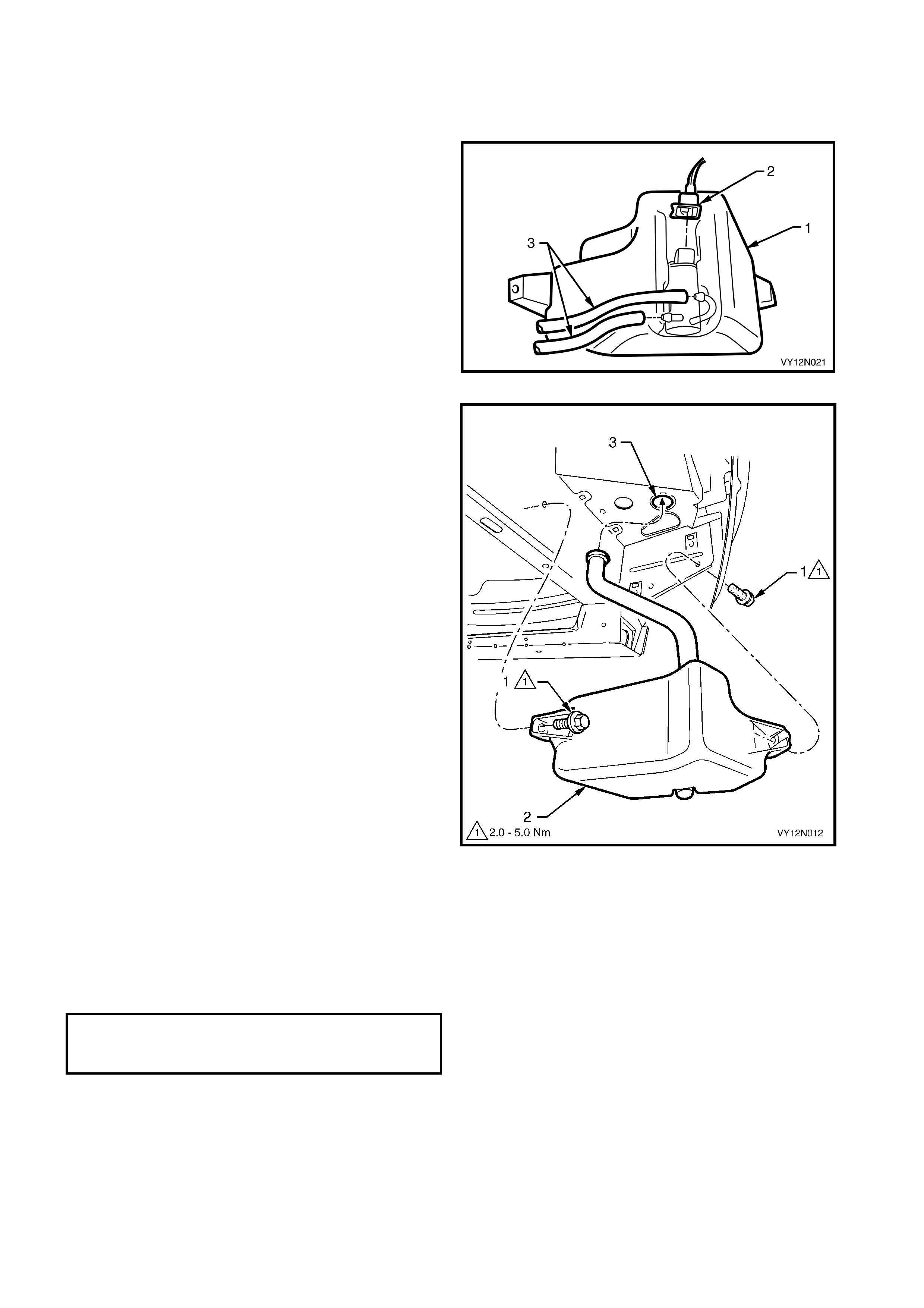
REMOVE
1. If required, remove the f ront r ight hand road wheel,
refer to Section 10, WHEELS AND TYRES.
2. Reach between the bumper assembly and the
washer reservoir assembly (1) and disconnect the
wiring harness connector (2) from the washer
pump assembly
3. Place a container under the washer reservoir
assembly, and disconnect the washer hose(s) (3)
from the washer pump assembly.
NOTE: Two washer hoses are fitted to wagon vehicle
only .
4. Allow the washer fluid to drain from the washer
reservoir assembly.
Figure 12N-35
5. Remove the two attaching screws (1) securing the
washer reservoir assembly (2).
6. Lower the washer reservoir assembly and
manoeuvr e the filler neck down through the hole in
the front wheelhouse panel (3). If required rem ove
the battery to allow more space, refer to
Section 12A, BATTERY AND CABLES.
7. Unclip the washer pump from the washer
reservoir.
Figure 12N-36
REINSTALL
Installation of the washer reservoir assembly is the
reverse of the removal procedure, noting the following:
1. Ensure that the washer reservoir assembly
attaching screws are tightened to the correct
torque specification.
2. Ensure that the washer hose(s) is installed before
filling the washer reservoir assembly.
WASHER RESERVOIR
ATTACHING SCREW
TORQUE SPECIFICATION 2.0 – 5.0 Nm
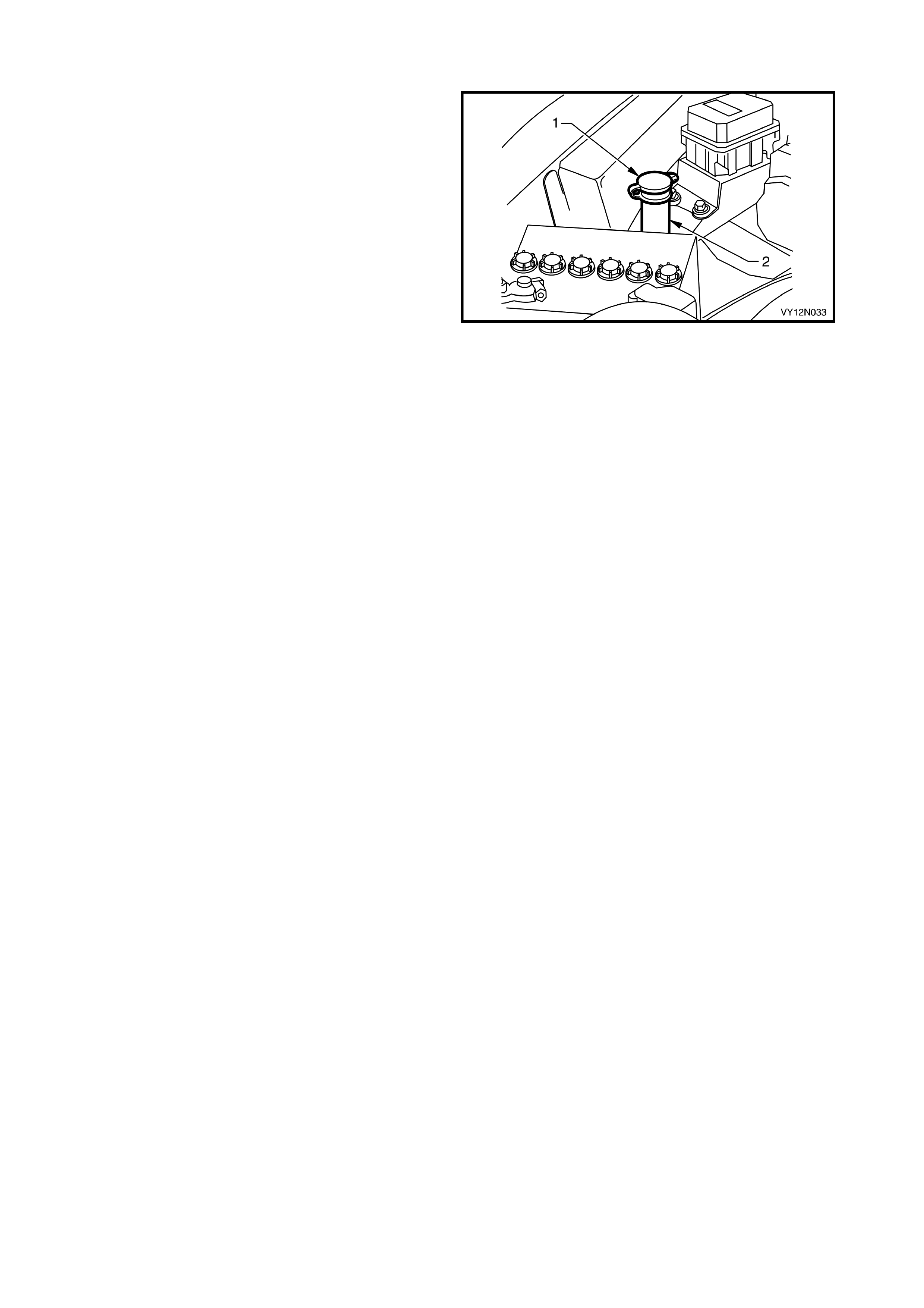
FILLING THE WASHER RESERVOIR ASSEMBLY
1. Open the flip top cap (1) located within the engine
bay at the top of the washer reservoir assembly
(2).
2. Fill the washer reservoir assem bly with the correct
amount of Optikleen or equivalent.
3. Secure the flip top cap.
Figure 12N-37
2.11 FRONT WASHER HOSE, EXCEPT COUPE
LT Section – 10-500
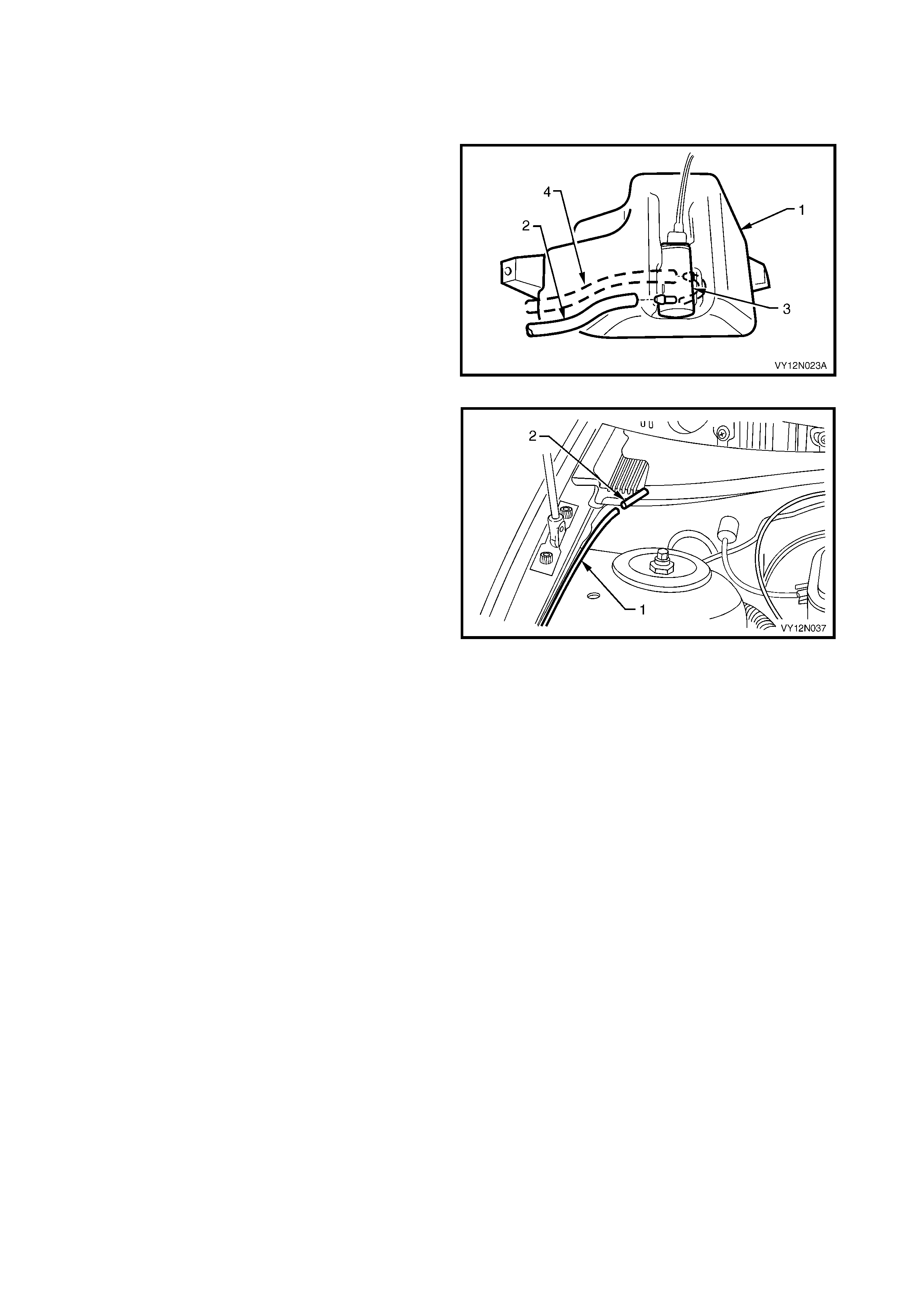
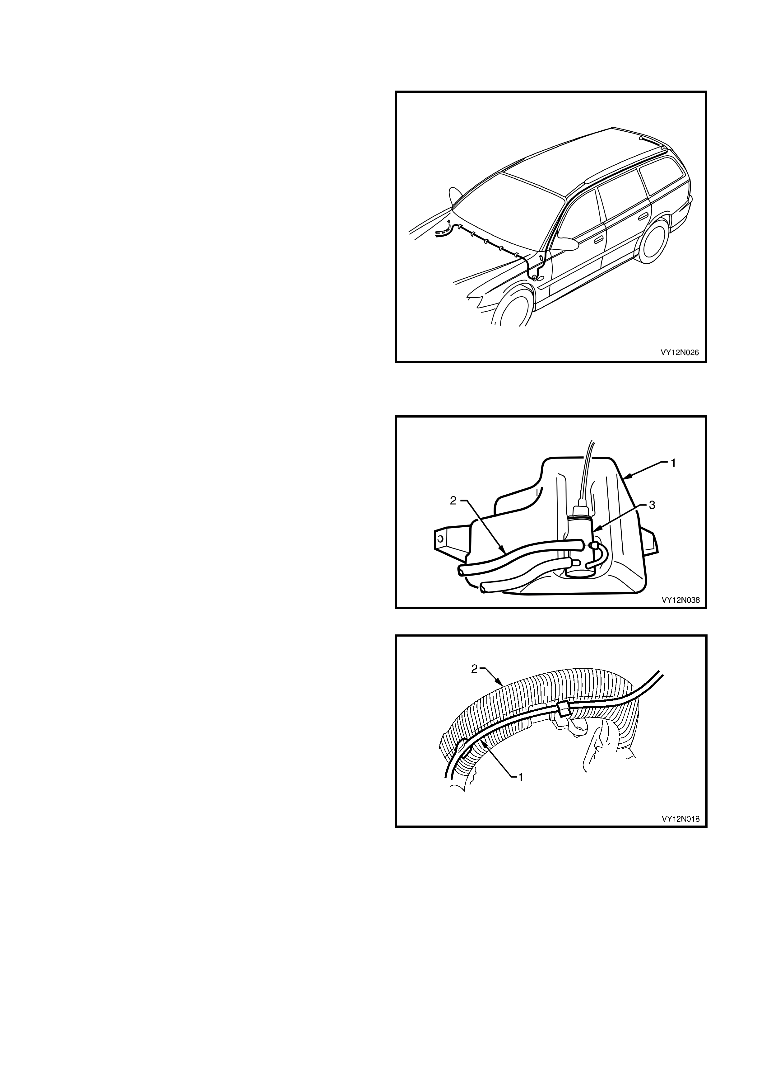
REMOVE
1. Place a container under neath the washer reservoir
assembly (1).
2. Reach between the bumper assembly and the
washer reservoir assembly and disconnect the
front washer hose (2) from the washer pump
assembly (3).
NOTE: A rear washer hose (4) is also fitted to wagon
vehicle.
3. Allow the washer fluid to drain from the washer
reservoir assembly.
Figure 12N-38
4. Separate the washer hose (1) at the point where it
enters the plenum chamber (2).
Figure 12N-39
5. Unclip the washer hose (1) from the fastener (2)
adjacent to the hood strut (3), refer to Figure
12N-40.
6. Carefully pull the washer hose from behind the
engine compartment fuse panel, and remove the
hose.
7. To remove the section of the washer hose
located within the plenum chamber, refer to
2.5 PLENUM COVER ASSEMBLY, EXCEPT
COUPE.
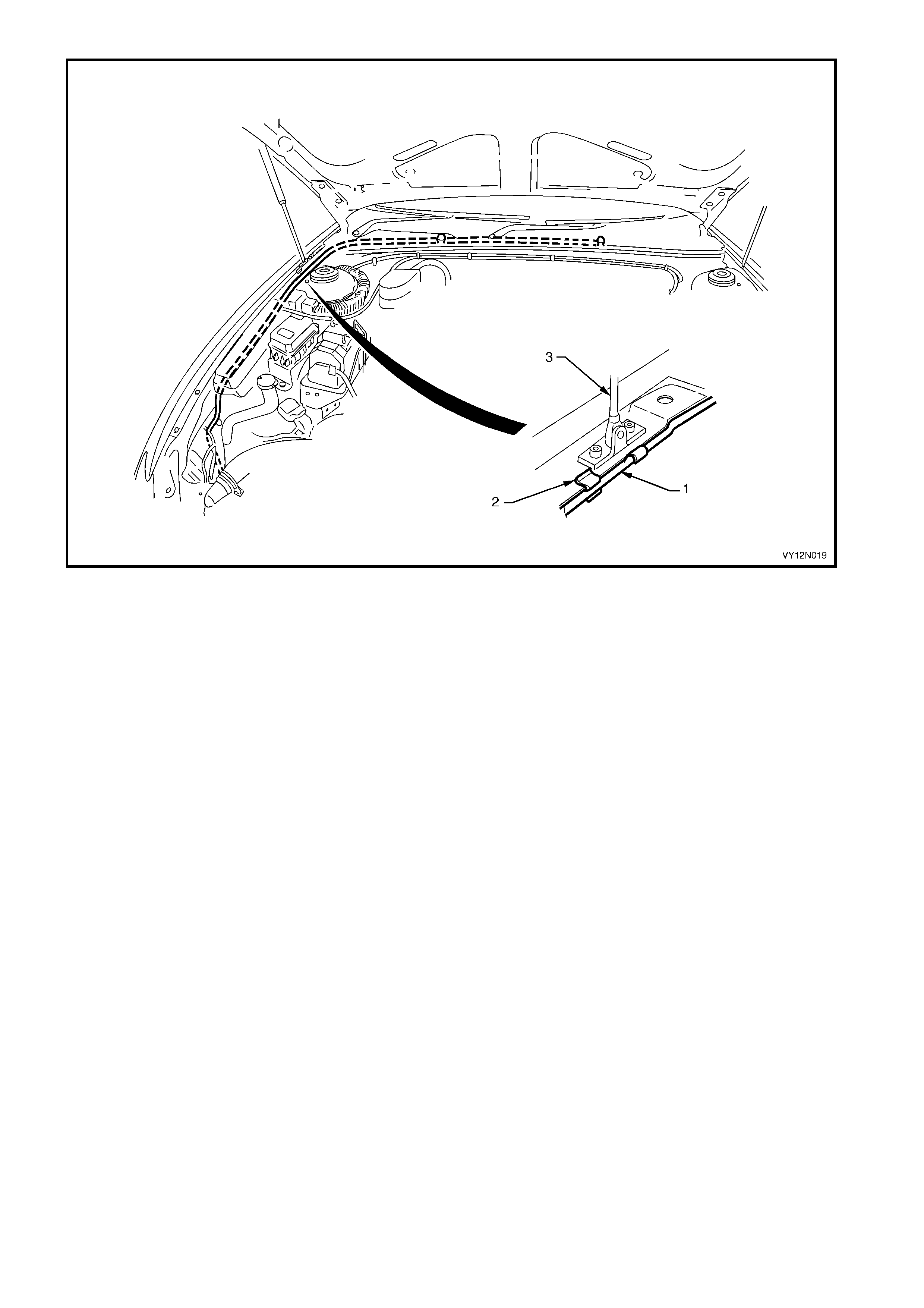
Figure 12N-40
REINSTALL
Installation of the front washer hose is the reverse of
the removal procedure, noting the following:
1. Connect the washer hose to the washer pump
assembly before filling the washer reservoir
assembly.
2. For information on filling the washer reservoir
assembly, refer to 2.10 WASHER RESERVOIR
ASSEMBLY.
2.12 FRONT WASHER HOSE AND WASHER NOZZLE ASSEMBLIES – COUPE
LT Section – 10-500
REMOVE
1. Place a container underneath the washer
reservoir (1).
2. Reach between the bumper assembly and the
washer reservoir and disconnect the washer
hose (2) from the washer pump assembly.
3. Allow the washer fluid to drain from the reservoir.
Figure 12N-41
4. Remove the washer hos e ( 1) f r om behind the fus e
panel, and unclip (2) the hose adjacent to the
hood strut (3), refer to Figure 12N-42.
Figure 12N-42
5. Separate the washer hoses from the two washers
located within the hood.
6. Remove the 14 fasteners from the hood
insulator, and remove the insulator. Refer to
Section 1A4, 2.4 HOOD INSULATOR.
7. Remove the hose from the vehicle.
8. W ith a pair of pliers, squeeze the tangs (1) on the
base of the washer nozzle as sem bly, and push the
nozzle out through the top of the hood.
Figure 12N-43
REINSTALL
Installation of the front washer hose and washer nozzle
assemblies is the reverse of the removal procedure,
noting the following:
1. Connect the washer hose to the washer pump
assembly before filling the washer reservoir
assembly.
2. For information on filling the washer reservoir
assembly, refer to 2.10 WASHER RESERVOIR
ASSEMBLY.
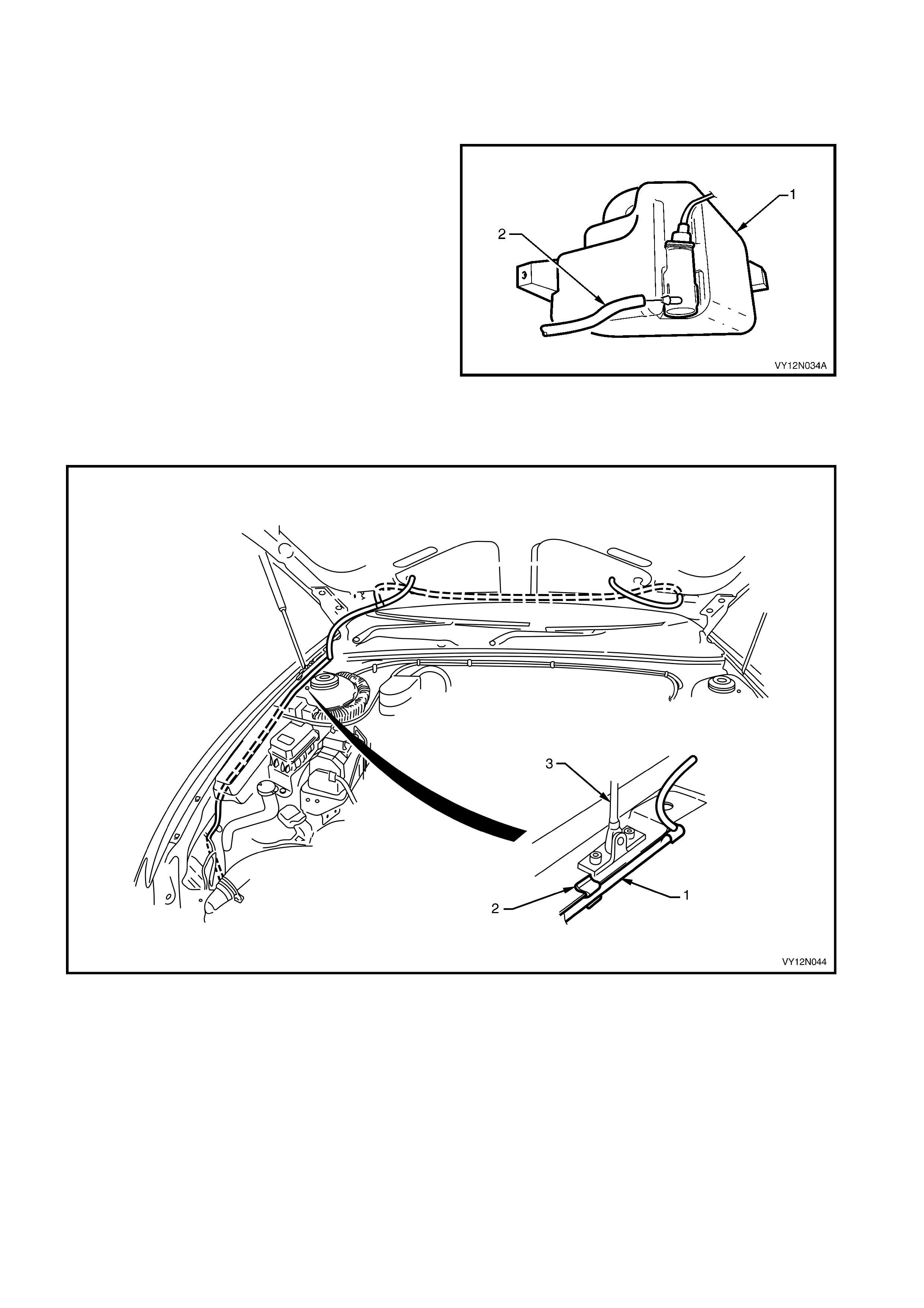
2.13 REAR WASHER HOSE, WAGON
LT Section – 10-500
The rear washer hose in the W agon is routed down the
left hand side of the vehicle in both right-hand and
left-hand drive vehicles.
Figure 12N-44
REMOVE
1. Place a container underneath the washer
reservoir (1).
2. Reach between the bumper assembly and the
washer reservoir and disconnect the washer hose
(2) from the washer pump assembly (3).
3. Allow the washer fluid to drain from the reservoir.
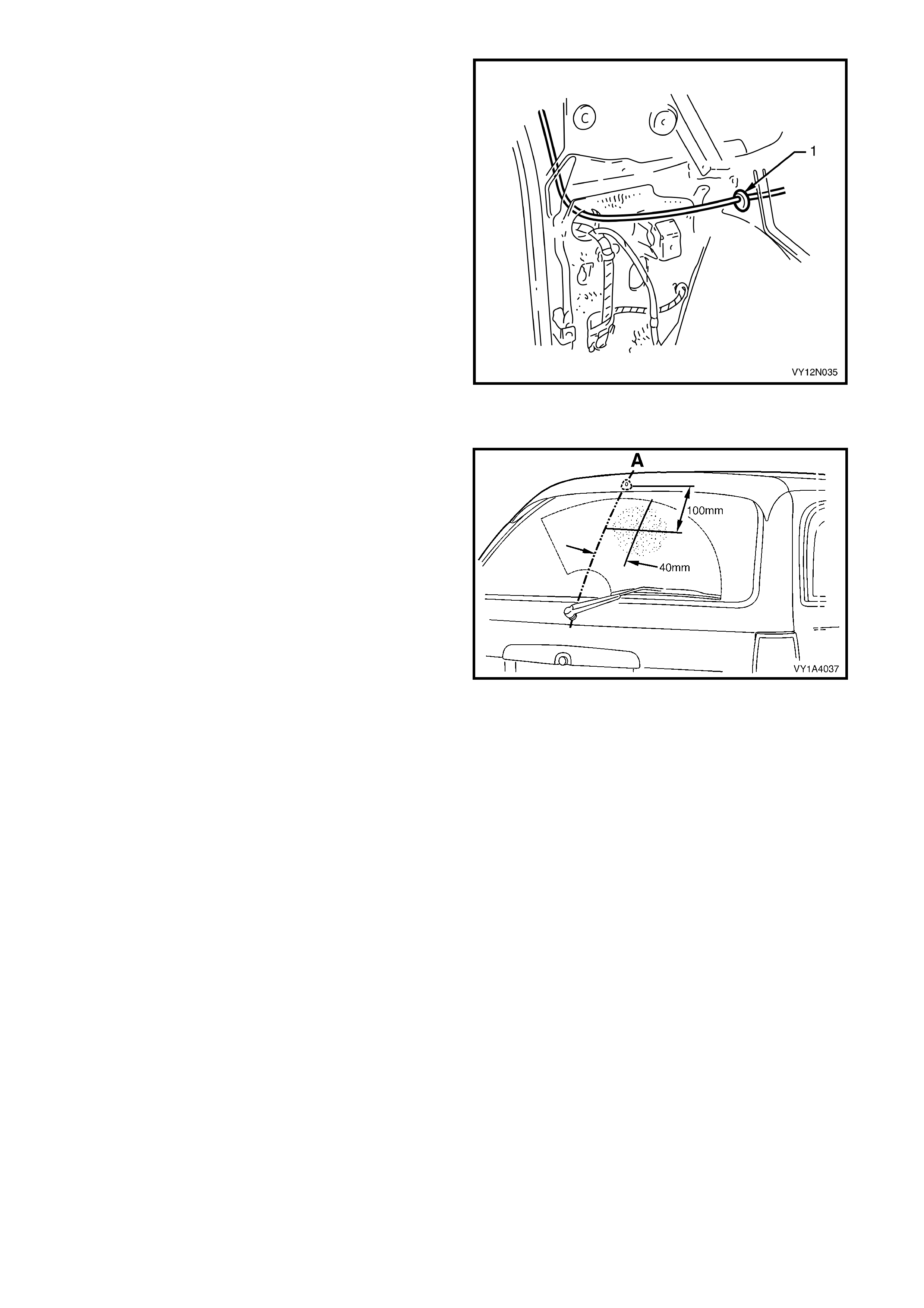
4. Withdraw the washer hose from behind the engine
compartment fuse panel.
Figure 12N-45
5. Unclip the washer hose (1) from the underside of
the main wiring harness (2), in two places around
the strut tower and five places along the dash panel.
Figure 12N-46
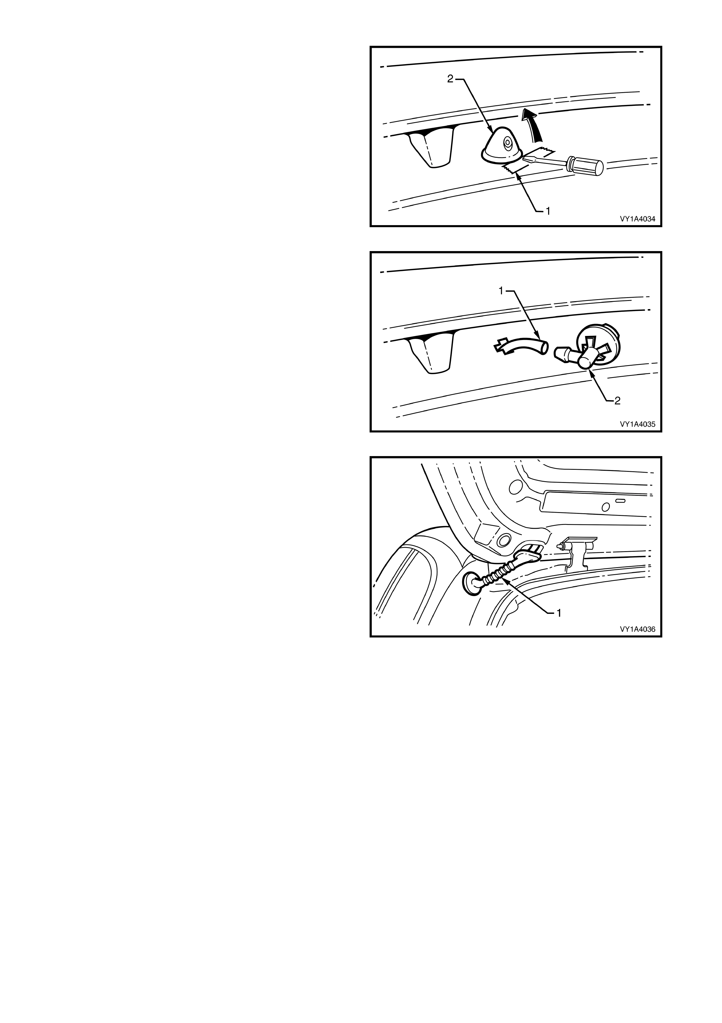
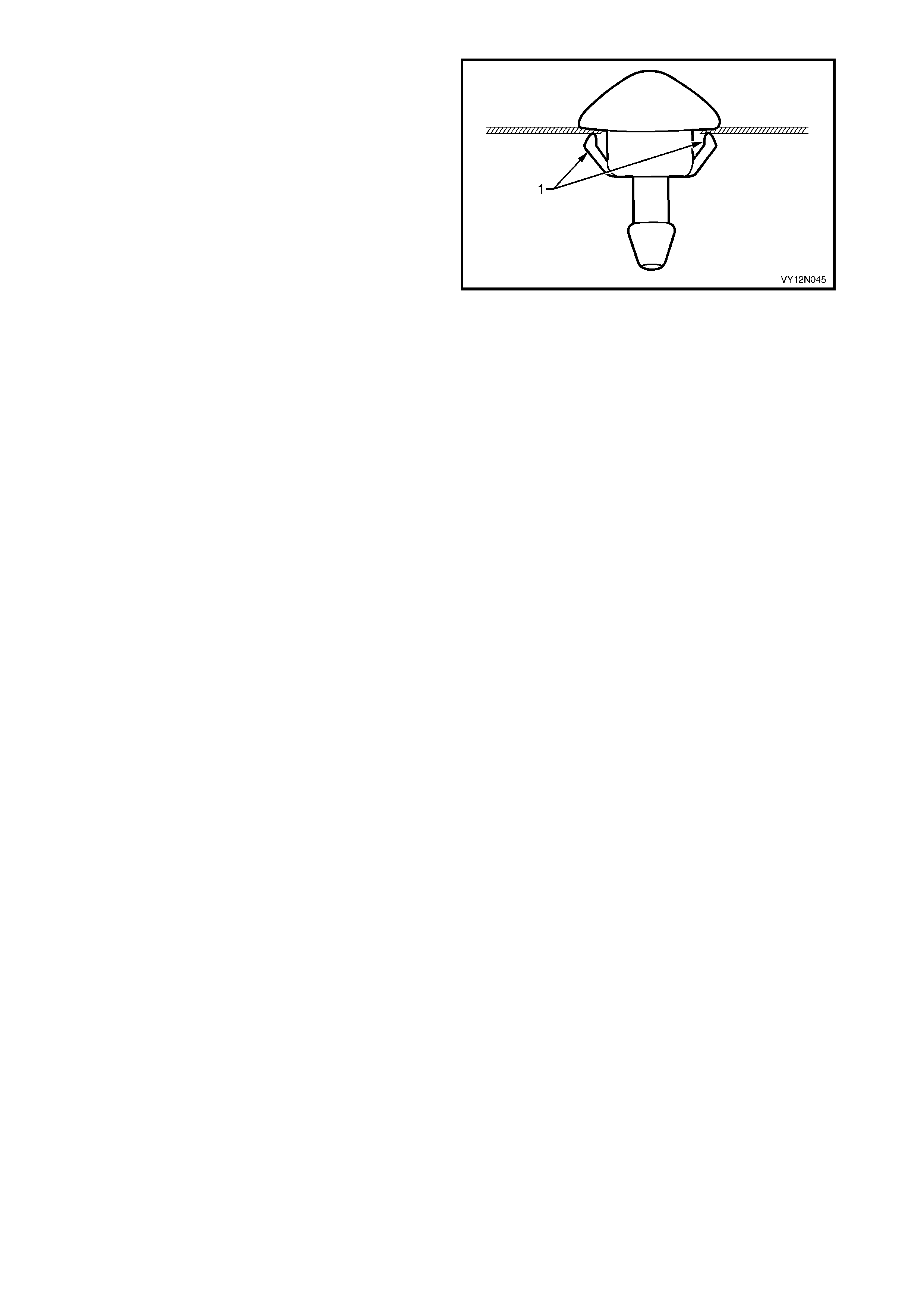
6. Place a piece of tape (1) or sim ilar on the paintwork
adjacent to the rear window washer nozzle
assem bly (2) and using a f ine flat blade screwdriver,
prise the nozzle from the liftgate assembly.
Figure 12N-47
7. Disconnect the washer hose (1) from the nozzle
assembly (2).
Figure 12N-48
8. Remove the rubber grommet (1) from the liftgate
assembly and withdraw the washer hose from the
liftgate.
9. Remove the Instrument Panel Compartment
assembly, refer to Section1A3, 3.2 INSTRUMENT
PANEL COMPARTMENT ASSEMBLY.
10. Remove both of the left hand side assist handles,
refer to Section 1A8, 3.1 ASSIST HANDLE.
11. Remove the windshield side garnish, refer to
Section 1A8, 3.5 WINDSHIELD SIDE GARNISH.
12. Remove the body lock pillar garnish, refer to
Section 1A8, 3.7 BODY LOCK PILLAR GARNISH.
13. Remove the body rear corner garnish, refer to
Section 1A8, 3.9 BODY REAR CORNER
GARNISH.
NOTE: Before removing the washer hose from the
vehicle, tie a piece of string to the end of the hose to
help guide the replacement hose.
Figure 12N-49
14. Remove the rubber grommet (1) from the fire wall,
and carefully feed the washer hose out through the
front of the vehicle.
Figure 12N-50
REINSTALL
Installation of the r ear washer hose is the revers e of the
removal procedure, noting the following:
1. Use the string to guide the replacement hose back
through the correct path.
2. Connect the washer hose to the washer pump
assembly before filling the washer reservoir
assembly.
3. For information on filling the washer reservoir, refer
to 2.10 WASHER RESERVOIR ASSEMBLY
4. The spray direction of the washer nozzle can be
adjusted by inserting the point of a pin into the ball of
the nozzle and swivelling the spray to the position
nominated in Figure 12N-51.
Figure 12N-51

2.14 WASHER PUMP ASSEMBLY AND WI RING DIAGNOSIS
LT Section – 10-500
INTRODUCTION
A com mon washer pum p assem bly with dual outlets is us ed for the windshield washers and the rear washer s. The
washer reservoir pump assembly is operated via the accessory control relay within the passenger compartment
fuse and relay panel assembly. The relay is activated when the ignition switch is in the ACC or ON position. The
motor M19 of the washer reservoir pum p assembly is activated when the wiper and washer control switch S247 is
pulled back for front washers, or pushed forward for rear washers. The motor of the washer pump’s polarity is
reversed for rear washers operation. This test confirms the serviceability of the washer reservoir pump assembly,
wiper and washer control switch and associated circuits. For a complete wiring diagram of the washer reservoir
assembly circuits, refer to 2.15 W IRING DIAGRAM – WIPERS AND WASHER S. For connector pin locations , r efer
to 2.16 CONNECTOR DIAGRAMS – WIPERS AND WASHERS.
NOTE: If there is a fault in the washer pump assembly and wiring system, and the following test proves that the
system is serviceable, refer to Section 12J BODY CONTROL MODULE.
TEST DESCRIPTION – FRONT WASHERS
The following numbers refer to the Steps in the diagnostic chart.
1. Check s whether the fuse F 18 between circuits 70 and 243, is ser viceable. Isolates whether the f use is the fault
affecting the battery power circuit supplying the washer reservoir assembly.
2. Check s whether the access ory contr ol relay within the pass enger com partm ent fuse and relay panel assem bly,
is serviceable. Isolates whether the accessory control relay is the fault affecting the battery power circuit
supplying the washer reservoir assembly.
3. Checks whether battery voltage is supplied to the washer pump assembly. Isolates whether the electrical
circuits or the washer motor are at fault.
4. Checks whether the washer hoses or nozzles assemblies are blocked. Isolates whether the washer hoses,
nozzles assemblies, or washer pump assembly are at fault.
5. Checks whether the wiper and washer control switch S247 is serviceable. Isolates whether the wiper and
washer control switch S247 is at fault.
6. Check s that batter y voltage is delivered to the harness c onnector S247 – X 1 pin 6. Isolates whether the batter y
supply circuits to the wiper and washer control switch S247 are at fault.
7. Checks whether battery voltage is supplied to the harness connector M19 – X1 pin 1.Isolates whether the
battery supply circuit 228 or the earth circuits 227, or 151 are faulty.
STEP ACTION YES NO
FRONT WASHERS
1. 1. Check the fuse F18.
Is it serviceable? Go to Step 2. Replace fuse F18.
2. 1. Replace the accessory control relay within the
passenger compartment fuse and relay panel
assembly, refer to Section 12O, FUSES, RELAYS
AND WIRING HARNESSES.
Does the washer pump assembly system operates?
System serviceable.
For further diagnosis,
refer to Section 12J,
BODY CONTROL
MODULE.
Go to Step 3.
3. 1. If required, hoist the vehicle, refer to Section 0A
GENERAL INFORMATION.
2. From beneath the vehicle disconnect the washer
pump harness connector M19 – X1.
3. W ith a multimeter, probe with the positive lead to the
harness connector M19 – X1 pin 1 and the negative
lead to M19 – X1 pin 2.
4. Switch the ignition to ACC or ON position.
5. Pull back and hold the wiper and washer control
switch.
Is the reading on the multimeter battery voltage?
Go to Step 4. Go to Step 5.

STEP ACTION YES NO
4. Is there a blockage in either the washer hoses or nozzle
assemblies? Repair / replace the
washer hoses or
nozzles, refer to
2.11 FRONT WASHER
HOSE – EXCEPT
COUPE or 2.12 FRONT
WASHER HOSE AND
WASHER NOZZLE
ASSEMBLIES -
COUPE.
Replace the washer
pump assembly, refer to
2.10 WASHER
RESERVOIR
ASSEMBLY.
5. 1. Test wiper and washer control switch S247, refer to
2.9 WIPER AND WASHER CONTROL SWITCH.
Is the wiper and washer control switch serviceable? Go to Step 6.
Replace the wiper and
washer control switch
S247, refer to
2.9 WIPER AND
WASHER CONTROL
SWITCH.
6. 1. With a multimeter probe the wiper and washer
control switch harness connector S247 – X1 pin 6
with the positive lead and the negative lead to body
earth.
2. Switch the ignition in ACC or ON position.
Is the reading on the multimeter battery voltage?
Go to Step 7.
There is a fault in circuit
342, 70, or 243.
Diagnose the circuits.
Repair or replace circuit
342, 70, or 243.
7. 1. Connect the wiper and washer control switch
harness connector S247 – X1.
2. Probe harness connector M19 – X1 pin 1 with the
positive lead of a multimeter and the negative lead to
body earth.
3. Switch the ignition in ACC or ON position.
4. Pull back and hold the wiper and washer control
switch.
Is the reading on the multimeter battery voltage?
There is a fault in circuit
227, or 151. Diagnose
the circuits. Repair or
replace circuit 227 or
151.
For further diagnosis,
refer to Section 12J,
BODY CONTROL
MODULE.
There is a fault in circuit
228. Diagnose the
circuit. Repair or
replace circuit 228.
For further diagnosis,
refer to Section 12J,
BODY CONTROL
MODULE.
When all diagnosis and repair are completed, check the system for correct operation.
TEST DESCRIPTION – REAR WASHERS
The following numbers refer to the Steps in the diagnostic chart.
1. Check s whether the fuse F 18 between circuits 70 and 243, is ser viceable. Isolates whether the f use is the fault
affecting the battery power circuit supplying the washer reservoir assembly.
2. Check s whether the access ory contr ol relay within the pass enger com partm ent fuse and relay panel assem bly,
is serviceable. Isolates whether the accessory control relay is the fault affecting the battery power circuit
supplying the washer reservoir assembly.
3. Checks whether battery voltage is supplied to the washer pump assembly. Isolates whether the electrical
circuits or the washer motor are at fault.
4. Checks whether the washer hoses or nozzles assemblies are blocked. Isolates whether the washer hoses,
nozzles assemblies, or washer pump assembly are at fault.
5. Checks whether the wiper and washer control switch S247 is serviceable. Isolates whether the wiper and
washer control switch S247 is at fault.
6. Check s that batter y voltage is delivered to the harness c onnector S247 – X 1 pin 6. Isolates whether the batter y
supply circuits to the wiper and washer control switch S247 are at fault.
7. Checks whether battery voltage is supplied to the harness connector M19 – X1 pin 1.Isolates whether the
battery supply circuit 228 or the earth circuits 227, or 151 are faulty.

STEP ACTION YES NO
REAR WASHERS
1. 1. Check the fuse F18.
Is it serviceable? Go to Step 2. Replace fuse F18.
2. 1. Replace the accessory control relay within the
passenger compartment fuse and relay panel
assembly, refer to Section 12O FUSES, RELAYS
AND WIRING HARNESSES.
Does the washer pump assembly system operates?
System serviceable.
For further diagnosis,
refer to Section 12J,
BODY CONTROL
MODULE.
Go to Step 3.
3. 1. If required, hoist the vehicle, refer to Section 0A,
GENERAL IN FORMATION.
2. From beneath the vehicle disconnect the washer
pump harness connector M19 – X1.
3. W ith a multimeter, probe with the positive lead to the
harness connector M19 – X1 pin 2 and the negative
lead to M19 – X1 pin 1.
4. Switch the ignition to ACC or ON position.
5. Push and hold forward the wiper and washer control
switch.
Is the reading on the multimeter battery voltage?
Go to Step 4. Go to Step 5.
4. Is there a blockage in either the washer hose or nozzle
assembly? Repair / replace the
washer hose or nozzle,
refer to 2.13 REAR
WASHER HOSE
ASSEMBLY.
Replace the washer
pump assembly, refer to
2.10 WASHER
RESERVOIR
ASSEMBLY.
5. 1. Test wiper and washer control switch S247, refer to
2.9 WIPER AND WASHER CONTROL SWITCH.
Is the wiper and washer control switch serviceable? Go to Step 6.
Replace the wiper and
washer control switch
S247, refer to
2.9 WIPER AND
WASHER CONTROL
SWITCH.
6. 1. With a multimeter probe the wiper and washer
control switch harness connector S247 – X1 pin 6
with the positive lead and the negative lead to body
earth.
2. Switch the ignition in ACC or ON position.
Is the reading on the multimeter battery voltage?
Go to Step 7.
There is a fault in circuit
342, 70, or 243.
Diagnose the circuits.
Repair or replace circuit
342, 70, or 243.
7. 1. Connect the wiper and washer control switch
harness connector S247 – X1.
2. Probe harness connector M19 – X1 pin 2 with the
positive lead of a multimeter and the negative lead to
body earth.
2. Switch the ignition in ACC or ON position.
3. Push and hold forward the wiper and washer control
switch.
Is the reading on the multimeter battery voltage?
There is a fault in circuit
228, or 151. Diagnose
the circuits. Repair or
replace circuit 228 or
151.
For further diagnosis,
refer to Section 12J,
BODY CONTROL
MODULE.
There is a fault in circuit
227, or 391. Diagnose
the circuits. Repair or
replace circuit 228, or
391.
For further diagnosis,
refer to Section 12J,
BODY CONTROL
MODULE.
When all diagnosis and repair are completed, check the system for correct operation.
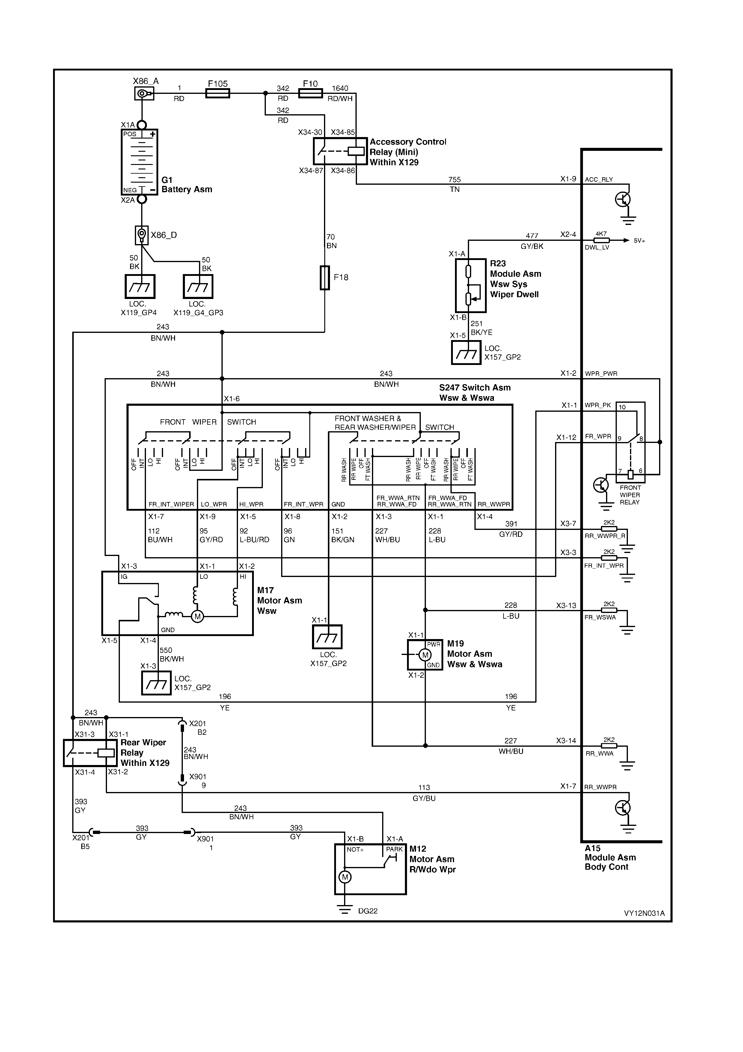
2.15 WIRING DIAGRAM – WIPERS AND WASHERS
Figure 12N-52
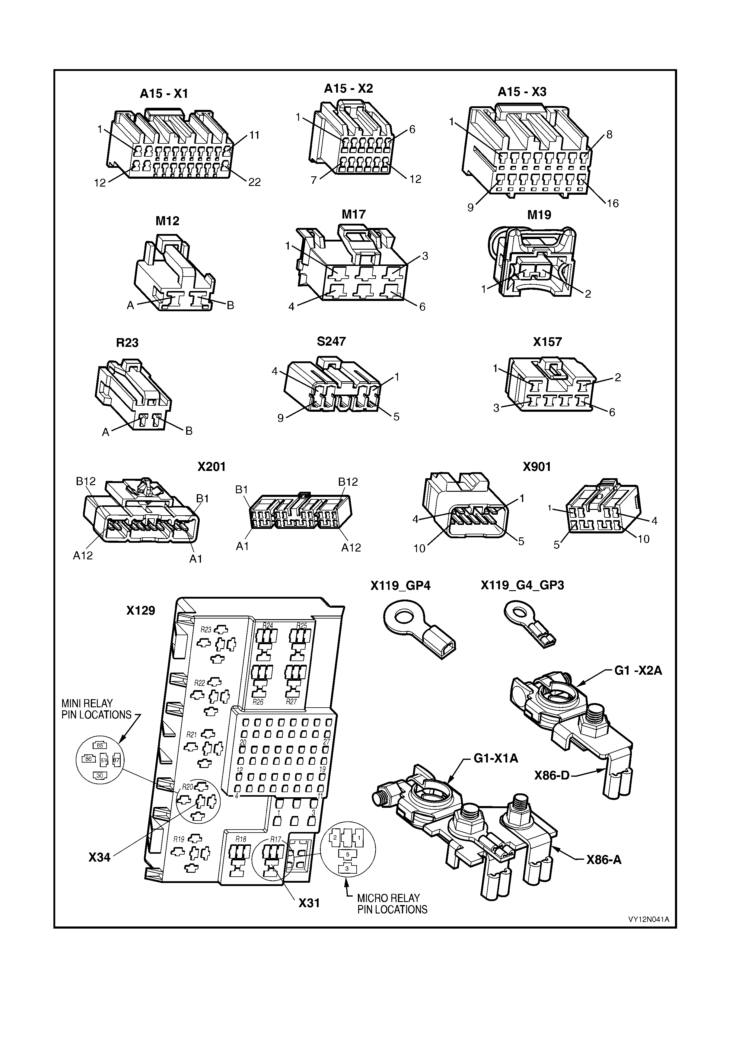
2.16 CONNE CTOR DIAGRAMS – W IPERS AND WASHERS
Figure 12N-53
SERVICE OPERATI O NS – HORN
3.1 HORN ASSEMBLY
LT Section – 02-400
REMOVE
1. For ease of access, raise the vehicle, refer to
Section 0A GENERAL INFORMATION.
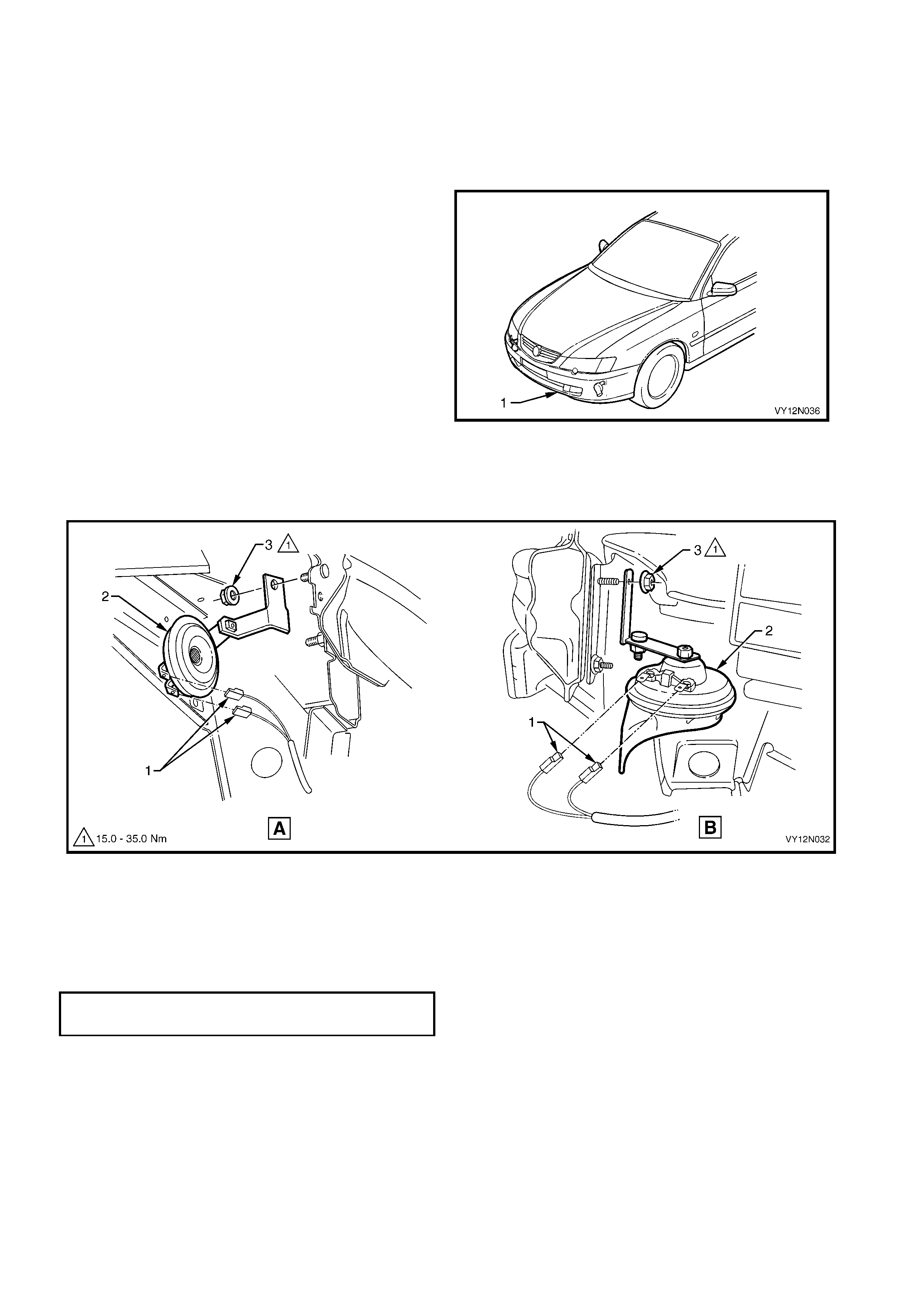
2. If required remove the Front Bumper Fascia
Assembly (1), refer to Section 1D, 2.2 FRONT
BUMPER FASCIA ASSEMBLY.
Figure 12N-54
3. Disconnect the wiring harness connectors (1) from the horn assembly (2), refer to Figure 12N-55.
4. Unscrew the horn/s attaching nut (3) and remove horn assembly/s.
NOTE: View A shows the low–note horn assembly, and View B show s the high–note horn assembly.
Figure 12N-55
REINSTALL
Installation of the horn assembly is the reverse of the removal procedure, noting the following:
1. Ensure that the connectors are installed correctly.
2. Ensure that the horn assembly/s securing nut/s are tightened to the correct torque specification.
HORN SECURING NUT
TORQUE SPECIFICATION 15.0 – 35.0 Nm

TEST
Introduction
The horn ass embly is operated via the relay R8 located in the engine com partm ent fuse and relay panel assem bly.
The relay is activated by a circuit, which is closed when the steering wheel horn contact switch is pushed in. This
test confirms the serviceability of the horn, switch and associated circuits. For a complete wiring diagram of the horn
circuits refer to 3.3 WIRING DIAGRAM – HORN ASSEMBLY and for the connectors pin locations refer to
3.4 CONNECTOR DIAGRAMS –HORN ASSEMBLY. There are four ranges in voltage that affect the horn
assembly operation, being 0 volts, below 9 volts, between 9 and 11 volts, or above 11 volts.
NOTE: If there is a fault in the horn ass embly syst em, and the following test proves that the syst em is serviceable,
refer to Section 12J, BODY CONTROL MODULE.
Test Description
The following numbers refer to the Steps in the diagnostic chart.
1. Checks the voltage supplied to the horn assembly as follow:
• Checks if the system operates correctly, with a normal voltage reading on the multimeter of 9 to 11 volts.
• Checks if there is no voltage reading on the multimeter.
• Chec ks if there is a low voltage reading on the multim eter above 0 volt and below 9 volts. Is olates whether
the horn assembly is at fault.
• Checks if there is a high voltage reading on the multimeter above 11 volts, caused by a faulty horn
assembly.
2. Chec ks whether the relay R8 on the engine compar tment f use and relay panel assembly is serviceable. Isolates
whether the relay is the fault affecting the battery power circuit supplying the horn assembly.
3. Checks the circuit continuity between the connector coil steering wheel inflatable restraint module X116 – X1
pin 6 and pin 5. Isolates whether the connector coil steering wheel inflatable restraint module X116 and/or the
contact steering wheel horn S7 are at fault.
4. Checks the circuit continuity between contact steering wheel S7 – X1 pin A and pin B. Isolates whether the
contact s teering wheel horn S7 is serviceable or the c onnector coil steer ing wheel inflatable res traint module is
at fault.
5. Checks the circuit continuity between the connector coil steering wheel inflatable restraint module X116 – X1
pin 6 and the harness connector S7 – X1 pin A, then between X116 – X1 pin 5 and S7 – X1 pin B. Isolates
whether the contact steering wheel horn S7 has to be replaced in conjunction with the connector coil steering
wheel inflatable restraint module X116.
6. Check s that ther e is battery voltage through the harness c onnector X 116 – X1 pin 6 and pin 5. Isolates whether
there is a fault in circuit 28, 151, or 1240.
7. Checks that battery voltage is delivered to the harness connector B9 – X1. Isolates whether there is a fault in
the horn assembly, or in circuit 29 or 1240.
STEP ACTION YES NO
1. If required, hoist the vehicle, refer to Section 0A,
GENERAL INFORMATION.
2. From beneath the vehicle, reach up between the
bumper bar and the front panel side support. W ith a
multimeter, back probe with the positive lead to the
connector B9 – X1 pin A (green wire), and the
negative lead to body earth connector B9 – X1 pin B.
3. Press the steering wheel horn contact to activate the
horn assembly.
Is the reading from the multimeter between 9 and 11
volts?
System serviceable.
For further diagnosis,
refer to Section 12J,
BODY CONTROL
MODULE.
Is the reading from the multimeter 0 volt? Go to Step 2.
Is the reading from the multimeter above 0 volt and
below 9 volts? Go to Step 7. Replace the horn
assembly, as detailed in
this Section.
1.
Is the reading from the multimeter above 11 volts? Replace the horn
assembly, as detailed in
this Section. Repeat step 1.

STEP ACTION YES NO
2. 1. Replace relay R8, refer to Section 12O, FUSES
RELAYS AND WIRING HARNESSES.
2. Press the steering wheel horn contact to activate the
horn assembly.
Does the horn operate?
System serviceable.
For further diagnosis,
refer to Section 12J,
BODY CONTROL
MODULE.
Go to step 3.
3. 1. Remove the steering column covers, refer to
2.9 WIPER AND WASHER CONTROL SWITCH.
2. Remove connector X116 – X1 from the rear of the
connector coil steering wheel inflatable restraint
module.
3. Probe connector X116 – X1 pin 5 and X116 – X1
pin 6 on the connector coil steering wheel inflatable
restraint module.
4. Press the steering wheel horn contact to activate the
horn assembly.
Is there continuity?
Go to Step 6. Go to Step 4.
4. 1. Remove the steering wheel inflatable restraint
module, refer to Section 12M, OCCUPANT
PROTECTION SYSTEM.
2. Probe connector S7 – X1 pin A and S7 – X1 pin B on
the steering wheel inflatable restraint module.
3. Press the steering wheel horn contact to activate the
horn assembly.
Is there continuity?
Replace the connector
coil steering wheel
inflatable restraint
module, refer to
Section 12M,
OCCUPANT
PROTECTION
SYSTEM.
Go to Step 5.
5. 1. Probe the connector coil steering wheel inflatable
restraint module X116 – X1 pin 6 and the harness
connector S7 – X1 pin A.
2. Probe the connector coil steering wheel inflatable
restraint module X116 – X1 pin 5 and the harness
connector S7 – X1 pin B.
Is there continuity?
Replace the steering
wheel inflatable restraint
module, refer to
Section 12M,
OCCUPANT
PROTECTION
SYSTEM.
Replace the steering
wheel inflatable restraint
module, and the
connector coil steering
wheel inflatable restraint
module, refer to
Section 12M,
OCCUPANT
PROTECTION
SYSTEM.
6. 1. W ith a multimeter, probe with the positive lead to the
harness connector X116 – X1 pin 6, and the
negative lead to the harness connector X116 – X1
pin 5.
Is the reading on the multimeter battery voltage?
Go to Step 7.
There is a fault in circuit
28, 151 or 1240.
Diagnose the circuits.
Repair or replace circuit
28, 151 or 1240.
7. 1. Remove the connector B9 – X1 pin A from the horn
assembly.
2. Probe the harness connector B9 – X1 pin A with the
positive lead of the multimeter and negative lead to
body earth.
3. Press the steering wheel horn contact to activate the
horn assembly.
Is the reading on the multimeter battery voltage?
Replace the horn
assembly, as detailed in
this Section. If new horn
does not operate, repair
or replace circuit 550.
There is a fault in circuit
29 or 1240. Diagnose
the circuits. Repair or
replace circuit 29 or
1240.
When all diagnosis and repair are completed, check the system for correct operation.
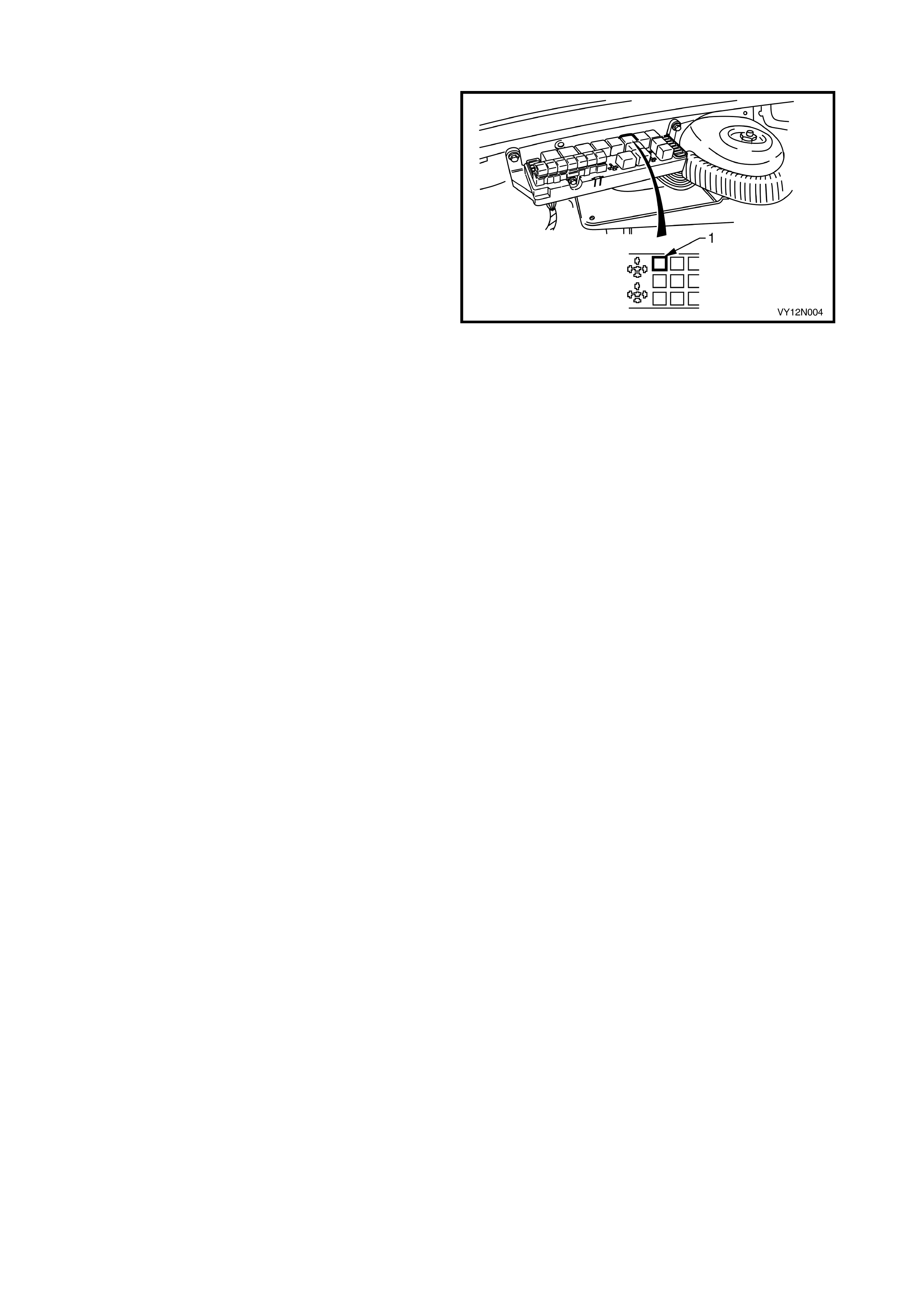
HORN RELAY
The horn relay (1) is located in the engine
compartment relay housing.
Figure 12N-56
HORN ACTUATOR
The horn pad is incorporated into the steering wheel
inflatable restraint module in the centre of the steering
wheel and theref ore, is not ser viced separately. For all
service oper ations, refer to Section 12M, OCCUPANT
PROTECTION SYSTEM.
CAUTION: If vehicle is equipped with an AIRBAG,
disable the system. Refer to Section 12M,
OCCUPANT PROTECTION SYSTEM.
3.2 THEFT-DETERRENT HORN ASSEMBLY
LT Section – 09-552
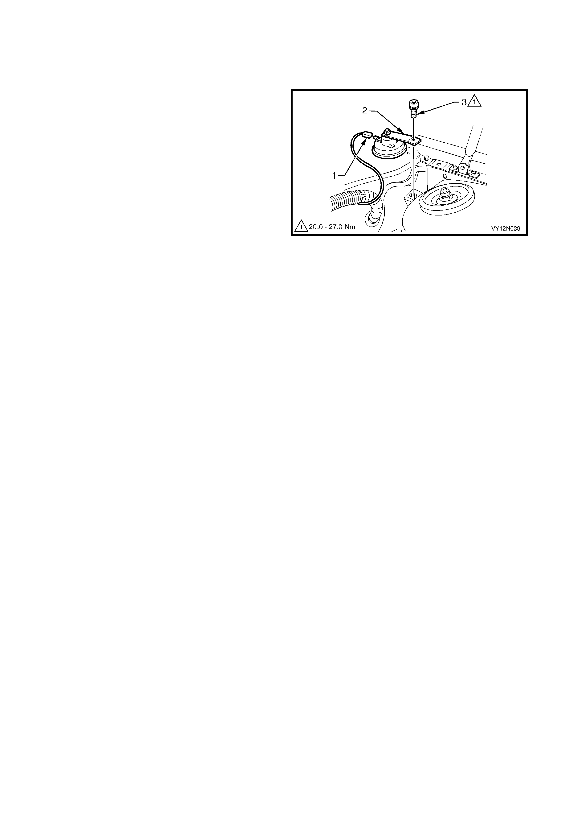
REMOVE
1. Disconnect the wiring harness connector (1) from
the theft-deterrent horn assembly (2).
2. Unscrew the horn attaching bolt (3) and remove
the horn assembly.
Figure 12N-57
REINSTALL
Installation of the theft-deterrent horn assembly is the
reverse of the removal procedure, noting the following:
1. Ensure that the connector is installed correctly.
2. Ensure that the theft-deterrent horn securing bolt is
tightened to the correct torque specification.
TEST
The test for the theft-deterrent horn assembly is
included within the entry deterrent system diagnostic
chart, refer to Section 12J, 4.8 ENTRY DETERRENT
SYSTEM.
THEFT-DETERRENT HORN RELAY
The theft-deterrent horn relay is located in the
Body Control Module, for details refer to
Section 12J, BODY CONTROL MODULE.
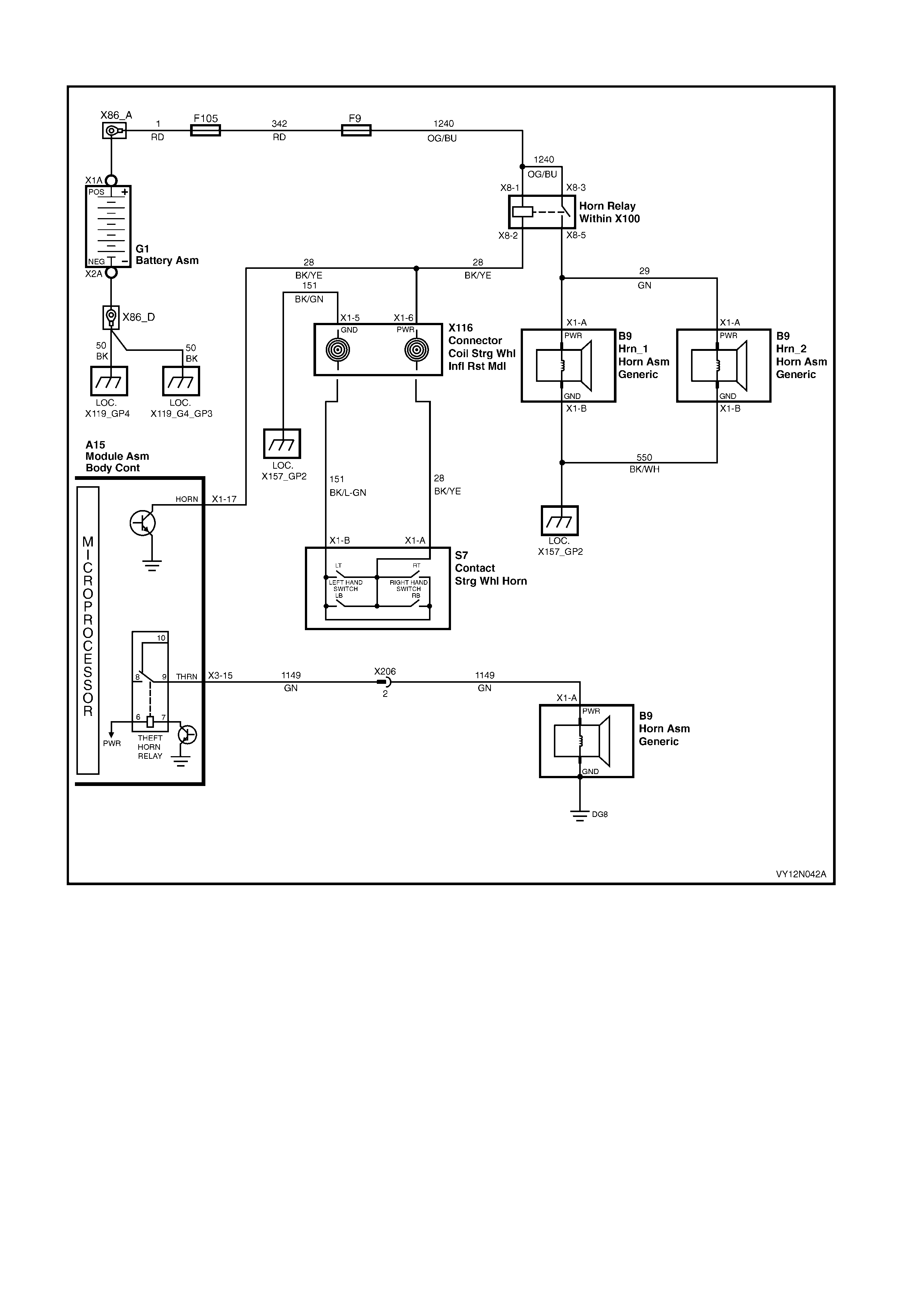
3.3 WIRING DIAGRAM – HORN ASSEMBLY
Figure 12N-58
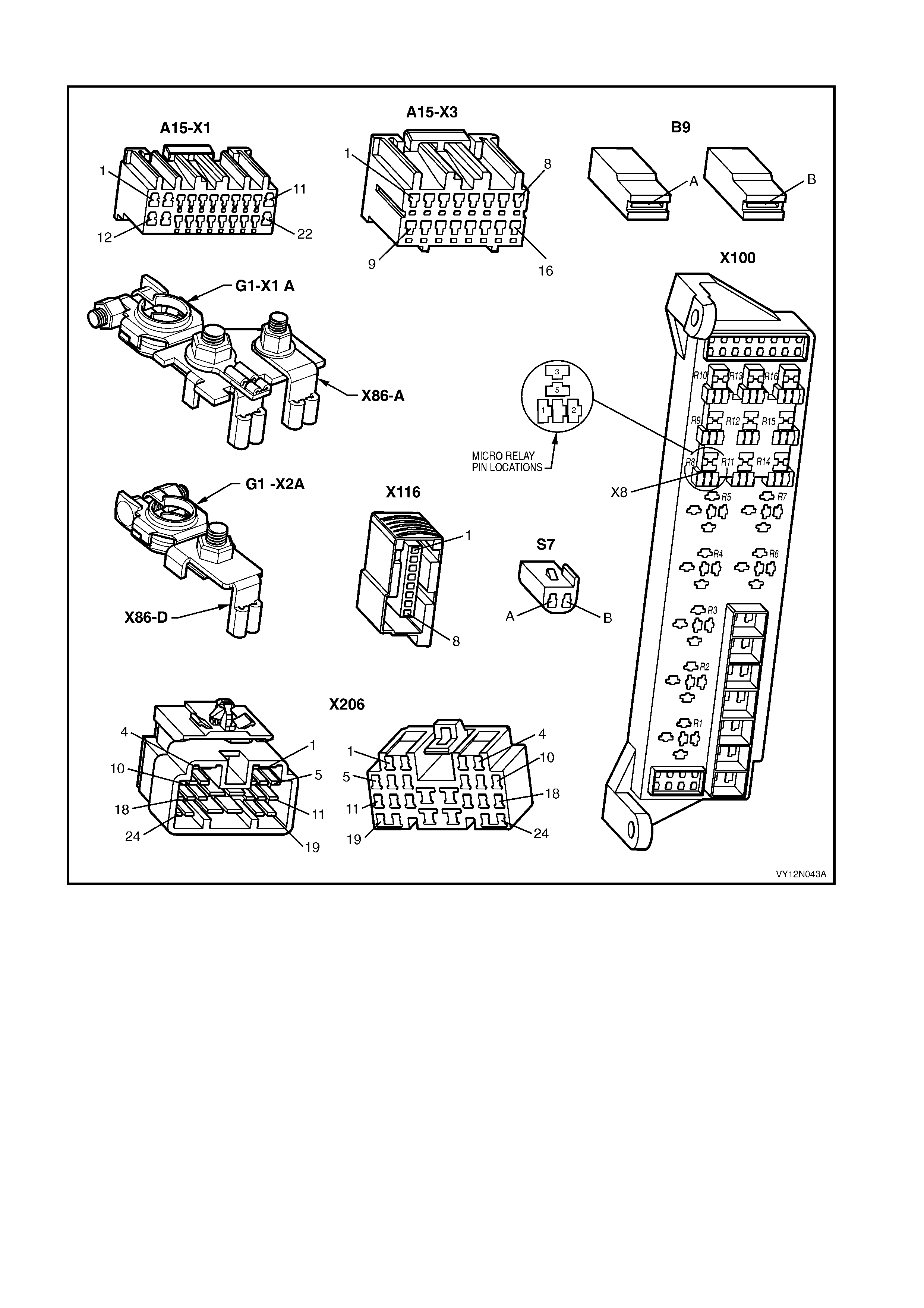
3.4 CONNECTOR DIAGRAMS – HORN ASSEMBLY
Figure 12N-59

4. TORQUE WRENCH SPECIFI CATIONS
Wiper arm nut ............................................................................................................. 20.0 – 25.0 Nm
Rear window wiper arm assembly attaching nut......................................................... 20.0 – 25.0 Nm
Rear window wiper motor pivot attaching nut ............................................................. 0.2 – 1.0 Nm
Wiper motor to linkage securing screws..................................................................... 7.0 – 9.0 Nm
Wiper motor pivot to linkages attaching nut................................................................ 16.0 – 20.0 Nm
Wiper motor and linkage assembly securing screw.................................................... 4.0 – 6.0 Nm
Rear window wiper motor assembly attaching screw ................................................. 6.0 – 14.0 Nm
Washer reservoir attaching screw .............................................................................. 2.0 – 5.0 Nm
Horn securing nut........................................................................................................ 15.0 – 35.0 Nm
Theft deterrent horn securing bolt............................................................................... 20.0 – 27.0 Nm
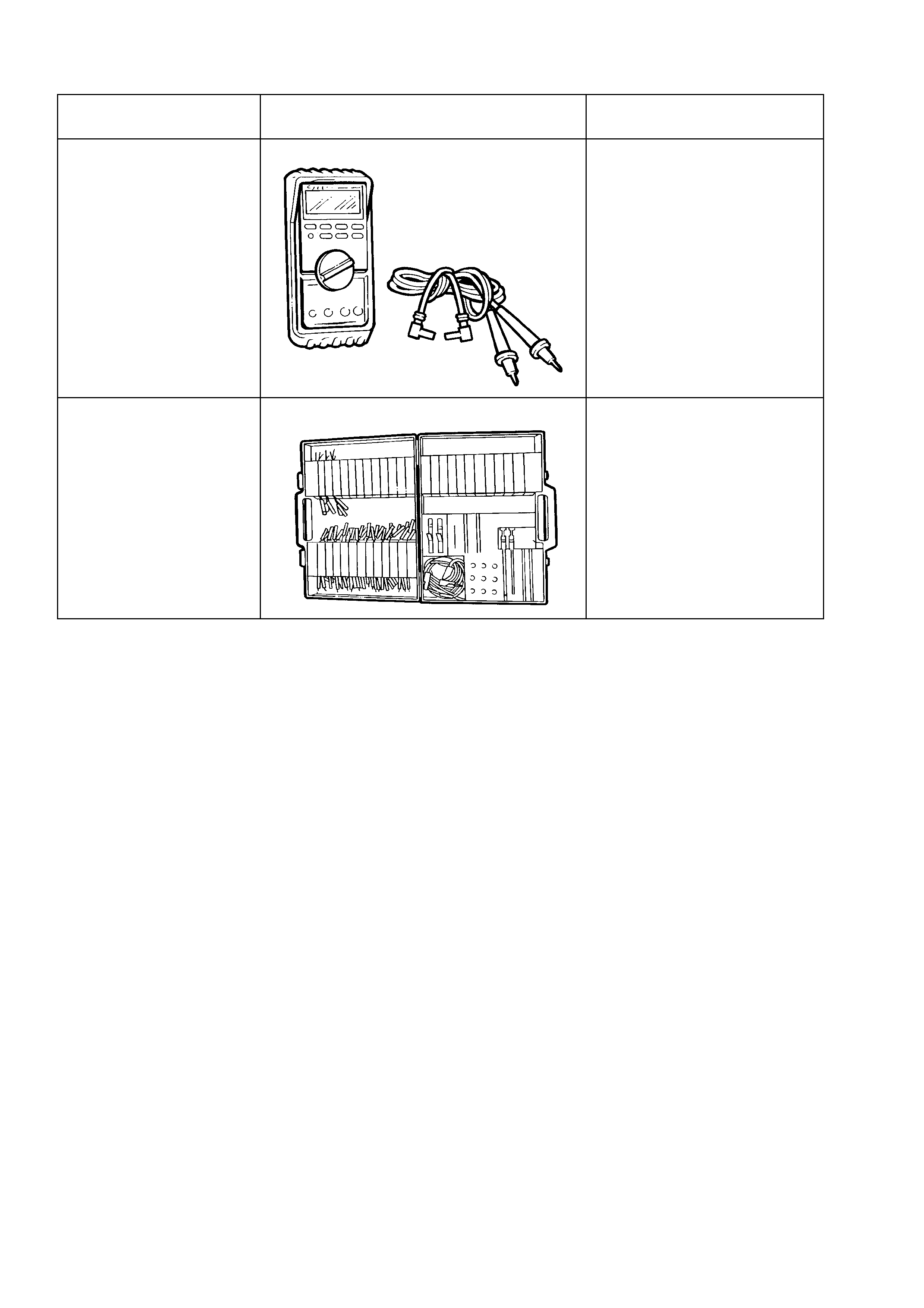
5. SPECIAL TOOLS
TOOL NO. REF
IN TEXT TOOL DESCRIPTION COMMENTS
J39200
DIGITAL MULTIMETER
TOOL NO. J39200
PREVIOUSLY RELEASED, OR
USE COMMERCIALLY
AVAILABLE EQUIVALENT.
MUST HAVE 10 MEG OHM
INPUT IMPEDANCE
KM–609 CONNECTOR TEST ADAPTOR KIT
PREVIOUSLY RELEASED
FOR V CAR. USED IN
CONJUNCTION WITH A
MULTIMETER FOR
MEASURING VOLTAGES AND
RESISTANCES WITHOUT
DAMAGING WIRING
HARNESS CONNECTORS