
SECTION 12O - FUSES, RELAYS AND
WIRING HARNESSES
IMPORTANT
Before performing any Service Operation or other procedure described in this section, refer to Section
00 CAUTIONS AND NOTES for correct workshop practices with regard to safety and/or property
damage.
1. GENERAL INFORMATION
1.1 FUSES
1.2 CIRCUIT BREAKERS
1.3 FUSIBLE LINKS
1.4 RELA YS
PASSENGER COMPARTMENT RELAYS
ENGINE COMPARTMENT RELAYS
1.5 DIODES
1.6 WIRING HARNESSES
1.7 WIRING HARNESS CONNECTORS
1.8 ELECTRONIC CONTROL DEVICE
LOCATIONS
2. SERVICE OPERATIONS
2.1 FUSES
PASSENGER COMPARTMENT FUSE AND
RELAY PANEL ASSEMBLY
ENGINE COMPARTMENT FUSE AND
RELAY PANEL ASSEMBLY
2.2 CIRCUIT BREAKERS
REMOVE
TEST
REINSTALL
2.3 FUSIBLE LINKS
ALL PLUG-IN TYPE FUSIBLE LINKS
EXCEPT FOR F104 60A ENGINE
PLUG-IN TYPE FUSIBLE LINK
F104 60A ENGINE
ONE-WIRE TYPE FUSIBLE LINK
2.4 RELA YS
PASSENGER COMPARTMENT RELAYS
ENGINE COMPARTMENT RELAYS
2.5 DIODES
A/C COMPRESSOR SUPPRESSION DIODE
2.6 WIRING REPAIRS
3. WIRING INSTALLATION DIAGRAMS –
RIGHT-HAND DRIVE SEDAN AND WAGON
BATTERY WIRING HARNESS – 1
BATTERY AND ABS
BATTERY WIRING HARNESS – 2
V6 ENGINE
BATTERY WIRING HARNESS – 3
ALL MODELS WITH GEN III V8 ENGINE
POWERTRAIN HARNESS – 1
ALL MODELS WITH V6 ENGINE
AND V6 SUPERCHARGED ENGINE
POWERTRAIN HARNESS – 2
V6 NORMALLY ASPIRATED ENGINE
POWERTRAIN HARNESS – 3
V6 WITH AIR CONDITIONING OR
ELECTRONIC CLIMATE CONTROL
POWERTRAIN HARNESS – 4
V6 ENGINE WITH AIR CONDITIONING
OR ELECTRONIC CLIMATE CONTROL
POWERTRAIN HARNESS – 5
V6 ENGINE WITHOUT AIR CONDITIONING
OR ELECTRONIC CLIMATE CONTROL
POWERTRAIN HARNESS – 6
V6 ENGINE WITH AUTOMATIC TRANSMISSION
POWERTRAIN HARNESS – 7
V6 ENGINE WITH AUTOMATIC TRANSMISSION
POWERTRAIN HARNESS – 8
V6 ENGINE WITH MANUAL TRANSMISSION
POWERTRAIN HARNESS – 9
V6 SUPERCHARGED ENGINE
POWERTRAIN HARNESS – 10
V6 SUPERCHARGED ENGINE WITH AIR
CONDITIONING OR ELECTRONIC
CLIMATE CONTROL
POWERTRAIN HARNESS – 11
V6 SUPERCHARGED ENGINE WITH
AUTOMATIC TRANSMISSION
POWERTRAIN HARNESS – 12
ALL MODELS WITH GEN III V8 ENGINE
POWERTRAIN HARNESS – 13
ALL MODELS WITH GEN III V8 ENGINE
POWERTRAIN HARNESS – 14
ALL MODELS WITH GEN III V8 ENGINE
POWERTRAIN HARNESS – 15
ALL MODELS WITH GEN III V8 ENGINE
POWERTRAIN HARNESS – 16
ALL MODELS WITH GEN III V8 ENGINE
POWERTRAIN HARNESS – 17
ALL MODELS WITH GEN III V8 ENGINE
POWERTRAIN HARNESS – 18
POWERTRAIN CONTROL MODULE –
ALL MODELS WITH V6 AND V6
SUPERCHARGED ENGINE
POWERTRAIN HARNESS – 19
ALL MODELS WITH GEN III V8 ENGINE
POWERTRAIN HARNESS – 20
ALL MODELS WITH GEN III V8 ENGINE
POWERTRAIN HARNESS – 21
ALL MODELS WITH GEN III V8 ENGINE
POWERTRAIN HARNESS – 22
ALL MODELS WITH GEN III V8 ENGINE
MAIN WIRING HARNESS – 1 – RHD
ENGINE COMPARTMENT
MAIN WIRING HARNESS – 2
PROTECTOR ASSEMBLY, CRUISE CONTROL
AND ENGINE HARNESS CONNECTORS
MAIN WIRING HARNESS – 3
UNDER HOOD FUSE & RELAY PANEL AND
WIPER MOTOR CONNECTORS
MAIN WIRING HARNESS – 4
FRONT LAMPS, BODY GROUND AND WASHER
PUMP CONNECTORS
MAIN WIRING HARNESS – 5
HEADLAMP, PARK LAMP AND TURN
INDICATOR WIRING HARNESS – LEVEL 2 & 3
MAIN WIRING HARNESS – 6
HEADLAMP, PARK LAMP AND TURN
INDICATOR WIRING HARNESS – LEVEL 1
MAIN WIRING HARNESS – 7
AMBIENT SENSOR, A/C FAN AND THEFT
DETERRENT CONNECTORS
Techline

MAIN WIRING HARNESS – 8
AMBIENT SENSOR, A/C FAN AND THEFT
DETERRENT CONNECTORS
MAIN WIRING HARNESS – 9 – RHD
FRONT LAMPS, FOG LAMPS AND HORN
CONNECTIONS
MAIN WIRING HARNESS – 10 – RHD
COCKPIT MODULE – LEVEL 1
MAIN WIRING HARNESS – 11 – RHD
COCKPIT MODULE – MODELS WITH
CRUISE CONTROL
MAIN WIRING HARNESS – 12 – RHD
COCKPIT MODULE – ALL MODELS
MAIN WIRING HARNESS – 13 – RHD
COCKPIT MODULE – ALL MODELS
MAIN WIRING HARNESS – 14 – RHD
FUSE BLOCK AND BODY CONTROL
MODULE – ALL MODELS
MAIN WIRING HARNESS – 15 – RHD
STEERING COLUMN
MAIN WIRING HARNESS – 16
IGNITION LOCK AND THEFT DETERRENT
RECEIVER – ALL MODELS
MAIN WIRING HARNESS – 17 – RHD
CRUISE CONTROL, STOP LAMP
SWITCHES, DATA LINK CONNECTOR &
STEPWELL LAMPS
MAIN WIRING HARNESS – 18 – RHD
INSIDE AIR TEMPERATURE SENSOR
& ACCESSORY JACK – ALL MODELS
MAIN WIRING HARNESS – 19
INSTRUMENT CLUSTER ASSEMBLY –
ALL MODELS
MAIN WIRING HARNESS – 20
AIR CONDITIONING & HEATING
CONTROLS – ALL MODELS
MAIN WIRING HARNESS – 21 – RHD
INSTRUMENT PANEL FACIA TRIM
SWITCHES – ALL MODELS
MAIN WIRING HARNESS – 22 – RHD
RADIO ASSEMBLY CONNECTORS &
INSTRUMENT PANEL FACIA
TRIM SWITCHES – ALL MODELS
MAIN WIRING HARNESS – 23 – RHD
PASSENGER SIDE AIRBAG WIRING –
ALL MODELS
MAIN WIRING HARNESS – 24
LIGHT SENSOR AND KEY RECEIVER &
INSTRUMENT PANEL SPEAKERS –
ALL MODELS
MAIN WIRING HARNESS – 25 – RHD
RADIO ANTENNA AMPLIFIER & HEATING,
VENTILATION & AIR CONDITIONER
CONNECTORS – ALL MODELS
MAIN WIRING HARNESS – 26 – RHD
INSTRUMENT PANEL COMPARTMENT –
ALL MODELS
MAIN WIRING HARNESS – 27
TRANSMISSION & SIR SENSING
DIAGNOSTIC MODULE CONNECTORS –
ALL MODELS
MAIN WIRING HARNESS – 28 – RHD
TRANSMISSION SELECTOR CONNECTORS
MAIN WIRING HARNESS – 29 – RHD
STOP LAMP, TRACTION & CRUISE CONTROL
RELEASE SWITCH CONNECTORS – MANUAL
TRANSMISSION WITH CRUISE CONTROL
RADIO POWER ANTENNA ASSEMBLY
WIRING – RHD
RADIO AMPLIFIER ASSEMBLY &
ANTENNA WIRING – 1 – RHD
RADIO AMPLIFIER ASSEMBLY &
ANTENNA WIRING – 2 – RHD
NAVIGATION SYSTEM ASSEMBLY AND
WIRING – 1 – RHD – SEDAN MODELS
NAVIGATION SYSTEM ASSEMBLY AND
WIRING – 2 – RHD – SEDAN MODELS
BODY & ROOF WIRING HARNESSES – 1
INTERIOR – SEDAN MODELS
BODY & ROOF WIRING HARNESSES – 2
INTERIOR – ALL MODELS
BODY & ROOF WIRING HARNESSES – 3
INTERIOR – RHD
BODY & ROOF WIRING HARNESSES – 4
INTERIOR – ALL MODELS
BODY & ROOF WIRING HARNESSES – 5
DOME & REAR PASSENGER COMPARTMENT
LAMPS – ALL MODELS
BODY & ROOF WIRING HARNESSES – 6
PARCEL SHELF & REAR COMPARTMENT
LAMP – SEDAN MODELS
BODY & ROOF WIRING HARNESSES – 7
SPEAKERS
BODY & ROOF WIRING HARNESSES – 8
REAR COMPARTMENT, FUEL TANK &
ABS – SEDAN MODELS
BODY & ROOF WIRING HARNESSES – 9
FUEL PUMP MODULE –
V6 SUPERCHARGED ENGINE
BODY & ROOF WIRING HARNESSES – 10
RE AR COMPARTMENT – SEDAN MODELS
BODY & ROOF WIRING HARNESSES – 11
REAR COMPARTMENT LID WIRING
BODY & ROOF WIRING HARNESSES – 12
REAR COMPARTMENT LIFTGATE WIRING
BODY & ROOF WIRING HARNESSES – 13
INTERIOR – STATION WAGON MODELS
BODY & ROOF WIRING HARNESSES – 14
REVERSE PARKING AID
BODY WIRING HARNESS – LPG– RHD
SEDAN AND STATION WAGON MODEL S
BODY & END GATE WIRING HARNESSES – 1
STATION WAGON MODELS
BODY & END GATE WIRING HARNESSES – 2
STATION WAGON MODELS
BODY & END GATE WIRING HARNESSES – 3
STATION WAGON MODELS
BODY & END GATE WIRING HARNESSES – 4
RE AR COMPARTMENT LAMP –
STATION WAGON MODELS
BODY & END GATE WIRING HARNESSES – 5
RE AR COMPARTMENT LAMP –
STATION WAGON MODELS
FRONT DOOR HARNESS – ALL MODELS
REAR DOOR HARNESS –ALL MODELS
TELEMATICS SYSTEM HARNESS –
ALL MODELS
4. WIRING INSTALLATION DIAGRAMS –
LEFT-HAND DRIVE SEDAN AND WAGON
MAIN WIRING HARNESS – 1
BAROMETRIC PRESSURE SENSOR
MAIN WIRING HARNESS – 2 – LHD
ENGINE COMPARTMENT
MAIN WIRING HARNESS – 3 – LHD
COCKPIT MODULE – MODELS WITHOUT
CRUISE CONTROL
MAIN WIRING HARNESS – 4 – LHD
COCKPIT MODULE – MODELS WITH
CRUISE CONTROL
MAIN WIRING HARNESS – 5 – LHD
BODY CONTROL MODULE AND BODY
HARNESS CONNECTORS

MAIN WIRING HARNESS – 6 – LHD
COCKPIT MODULE – ALL MODELS
MAIN WIRING HARNESS – 7 – LHD
COCKPIT MODULE – ALL MODELS
MAIN WIRING HARNESS – 8 – LHD
FUSE & RELAY PANEL AND BODY CONTROL
MODULE – ALL MODELS
MAIN WIRING HARNESS – 9 – LHD
PROTECTOR ASSEMBLY, CRUISE CONTROL
AND ENGINE HARNESS CONNECTORS
MAIN WIRING HARNESS – 10 – LHD
STEERING COLUMN
MAIN WIRING HARNESS – 11 – LHD
CRUISE CONTROL, STOP LAMP SWITCHES,
DATA LINK CONNECTOR & STEPWELL
LAMPS
MAIN WIRING HARNESS – 12 – LHD
INSIDE AIR TEMPERATURE SENSOR &
ACCESSORY JACK – ALL MODELS
MAIN WIRING HARNESS – 13 – LHD
INSTRUMENT PANEL FACIA TRIM
SWITCHES – ALL MODELS
MAIN WIRING HARNESS – 14 – LHD
RADIO ASSEMBLY CONNECTORS &
INSTRUMENT PANEL FACIA TRIM
SWITCHES – ALL MODELS
MAIN WIRING HARNESS – 15 – LHD
PASSENGER SIDE AIRBAG WIRING –
ALL MODELS
MAIN WIRING HARNESS – 16 – LHD
AMPLIFIER ASSEMBLY,
HEATING, VENTILATION & AIR
CONDITIONER CONNECTORS –
ALL MODELS
MAIN WIRING HARNESS – 17 – LHD
INSTRUMENT PANEL COMPARTMENT
CONNECTORS – ALL MODELS
MAIN WIRING HARNESS – 18 – LHD
TRANSMISSION & SIR SENSING
DIAGNOSTIC MODULE CONNECTORS –
ALL MODELS
MAIN WIRING HARNESS – 19 – LHD
BREAK TRANSMISSION SHIFT
INTERLOCK (BTSI) CONNECTORS
MAIN WIRING HARNESS – 20 – LHD
STOP LAMP, TRACTION & CRUISE CONTROL
RELEASE SWITCH CONNECTORS –
AUTOMATIC TRANSMISSION
MAIN WIRING HARNESS AND CONSOLE
WIRING HARNESS – LHD
FRONT & REAR CIGAR LIGHTER AND
ACCESSORY POWER CONNECTOR
BODY WIRING HARNESS
UNDERHOOD COURTESY LAMP
BODY & ROOF WIRING HARNESSES – 1
INTERIOR – LHD
BODY & ROOF WIRING HARNESSES – 2
FUEL TANK FILLER DOOR LOCK – LHD
RADIO POWER ANTENNA WIRING – LHD
RADIO AMPLIFIER ASSEMBLY
WIRING – LHD
5. WIRING INSTALLATION DIAGRAMS –
UTILITY
INTERIOR BODY WIRING HARNESS – 1
INTERIOR BODY WIRING HARNESS – 2
ROOF LAMP HARNESS – 1
ROOF LAMP HARNESS – 2
DOOR WIRING HARNESSES – SPEAKERS
BODY WIRING HARNESS – 1
LO AD COMPARTMENT
BODY WIRING HARNESS – 2
FUEL TANK
BODY WIRING HARNESS – 3
ABS
BODY WIRING HARNESS – 4
LPG
6. WIRING INSTALLATION DIAGRAMS –
RIGHT-HAND DRIVE COUPE
MAIN WIRING HARNESS – 1
FRONT LAMP, BODY GROUND AND WASHER
PUMP CONNECTORS
MAIN WIRING HARNESS – 2
HEADLAMP AND HORN CONNECTORS
MAIN WIRING HARNESS – 3
HEADLAMPS
BODY WIRING HARNESS – 1
FRONT DOOR HARNESS
BODY WIRING HARNESS – 2
INTERIOR HARNESS – RIGHT-HAND
BODY WIRING HARNESS – 3
INTERIOR HARNESS – LEFT-HAND
BODY WIRING HARNESS – 4
INTERIOR
BODY WIRING HARNESS – 5
INTERIOR HARNESS – ROOF
BODY WIRING HARNESS – 6
INTERIOR HARNESS – FRONT
BODY WIRING HARNESS – 7
INTERIOR HARNESS – REAR
BODY WIRING HARNESS – 8
REAR COMPARTMENT HARNESS –
ABS SENSORS AND FUEL TANK
BODY WIRING HARNESS – 9
REAR COMPARTMENT HARNESS –
REAR LAMPS
BODY WIRING HARNESS – 10
REAR COMPARTMENT LID HARNE SS
BODY WIRING HARNESS – 11
AUDIO SYSTEM
BODY WIRING HARNESS – 12
DIVERSITY ANTENNA
BODY & ROOF WIRING HARNESSES
REVERSE PARKING AID
NAVIGATION SYSTEM ASSEMBLY AND
WIRING – 1
NAVIGATION SYSTEM ASSEMBLY AND
WIRING – 2
7. WIRING INSTALLATION DIAGRAMS –
LEFT-HAND DRIVE COUPE
1. GENERAL INFORMAT ION
All MY 2003 VY and V2 Series II electrical circuits are protected against damage that m ight occur due to s hort
circuits or overloads in the wiring system by fuses, circuit breakers, fusible links and relays.
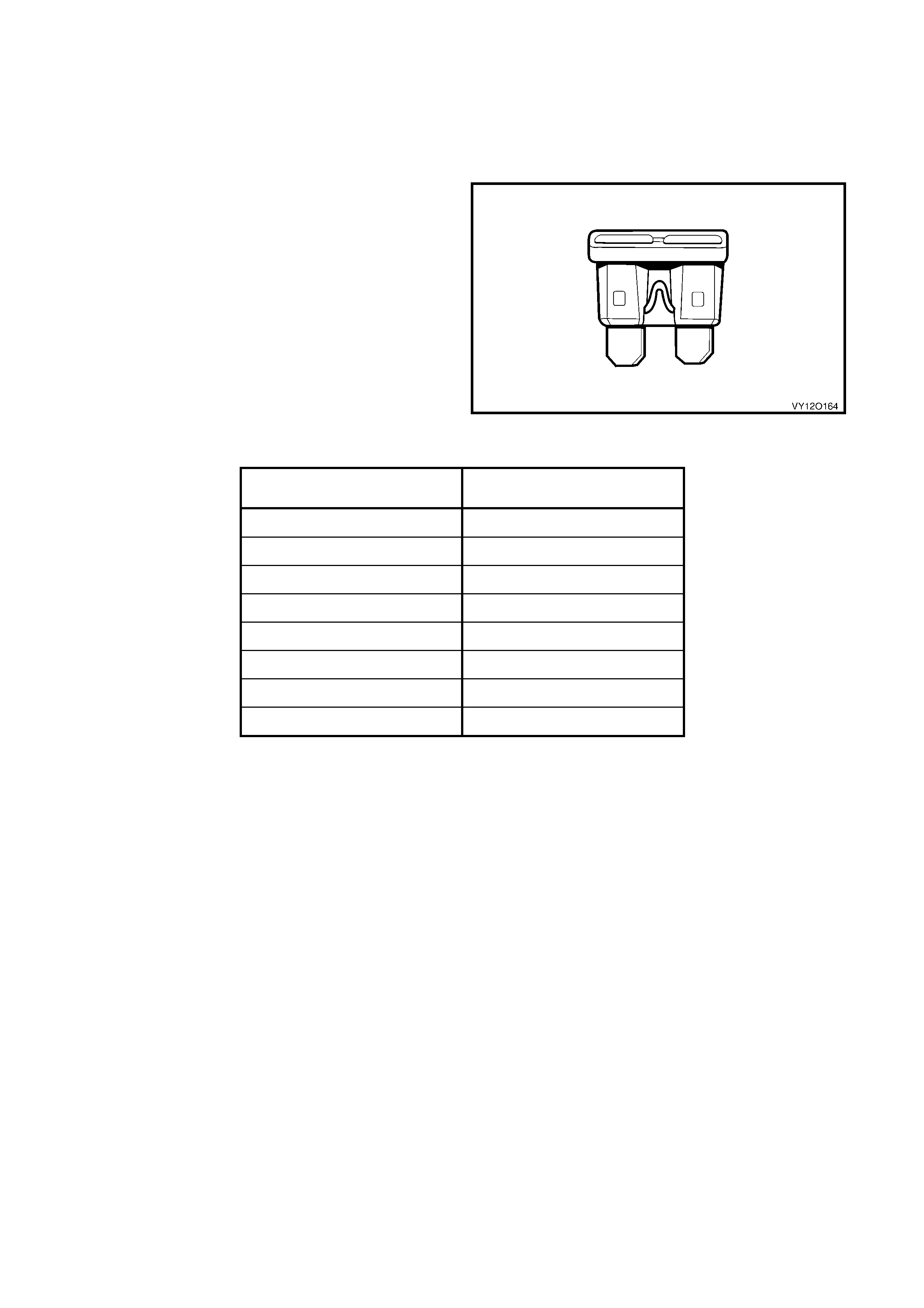
1.1 FUSES
Fuses are a blade type mini construction, with the
current rating in amps indicated on the top of the fuse
assembly, above the element, or identified by the
plastic body colour of the fuse. The fuse current
ratings and corresponding colour are listed in the
follo wing tab le.
Figure 12O-1
CURRENT RATING
(AMPS) FUSE COLOUR
3 Violet
5 Tan
7.5 Brown
10 Red
15 Blue
20 Yellow
25 White
30 Green
Fuses are located in two positions on MY 2003 VY and V2 series II. One group is located in the passenger
compartment fuse and relay panel assembly. Refer to Figure 12O-2. A label on the inside of the instrument
panel lower cover indicates the circuits protected by each fuse.
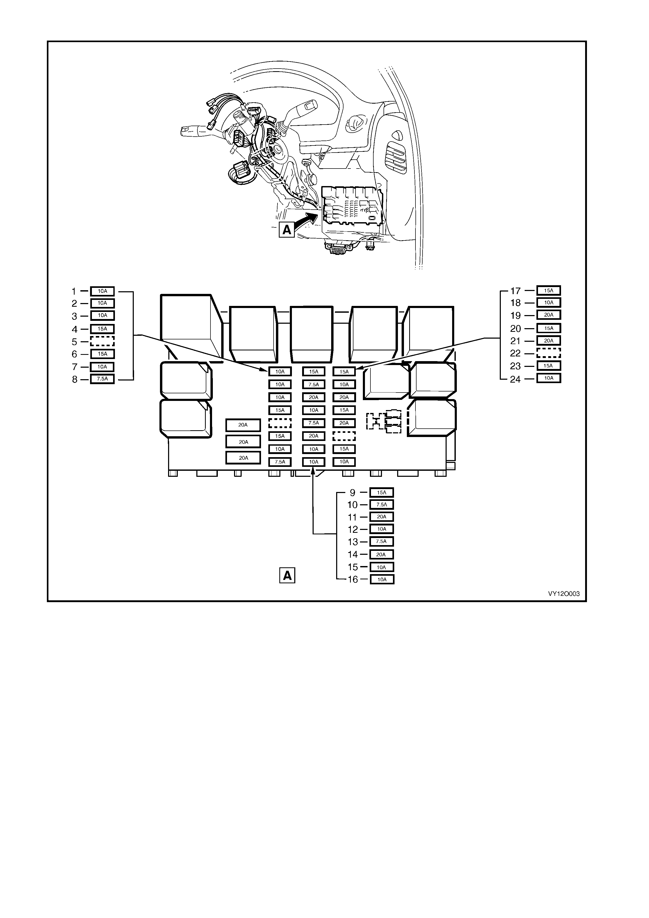
Figure 12O-2
Legend
1. F4 – Park Lamps & Instruments Fuse (10A)
2. F5 – Stop Lamps Fuse (10A)
3. F6 – Interior Illumination Fuse (10A)
4. F7 – Hazard Lamps / Antenna Drive via BCM Fuse (15A)
5. F8 – Spare
6. F9 – Horn Fuse (15A)
7. F10 – Ignition Fuse (10A)
8. F11 – Instrument Illuminat i on Fuse (7.5A)
9. F12 – Turn Signals & Back-up Lamps Fuse (15A)
10. F13 – ECC, Tri p Comput er, Instruments & Telematics Fuse
(7.5A)
11. F14 – Cigar Lighter Fuse (20A)
12. F15 – Cruise & Power Mirrors Fuse (10A)
13. F16 – Radio & Cell Phone Fuse (7.5A)
14. F17 – Acc essory Socket Fuse (20A)
15. F18 – Front Wiper Washer Fuse (10A)
16. F19 – Rear Wi per Fuse (10A)
17. F20 – Power Locks, Power Window s, Theft Horn Fuse (15A)
18. F21 – Instrument & Climate Control Fuse (10A)
19. F22 – Heated Rear Window Fuse (20A)
20. F23 – Radio Fuse (15A)
21. F24 – Sub-woofer Ampl i fier Fuse (20A)
22. F25 – Spare
23. F26 – SRS Fuse (15A)
24. F27 – Ant i -l ock B rakes Fuse (10A)
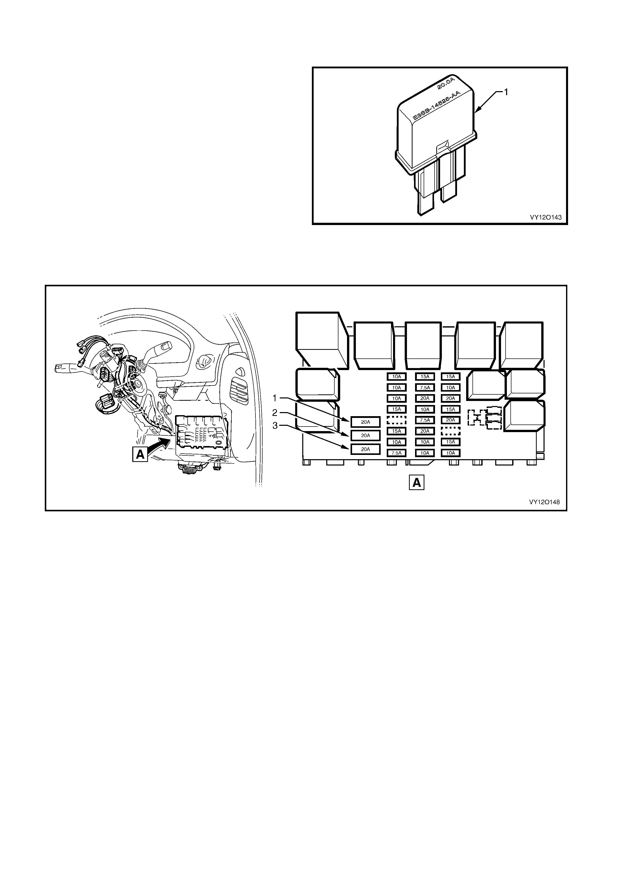
The second group of fuses are located in the engine compartment fuse and relay panel assembly, situated
forward of the right- hand s ide f ront sus pension s trut to wer. A la bel on th e inside o f the panel c over indica tes t he
circuits protected by each fuse. Refer to Figure 12O-3.
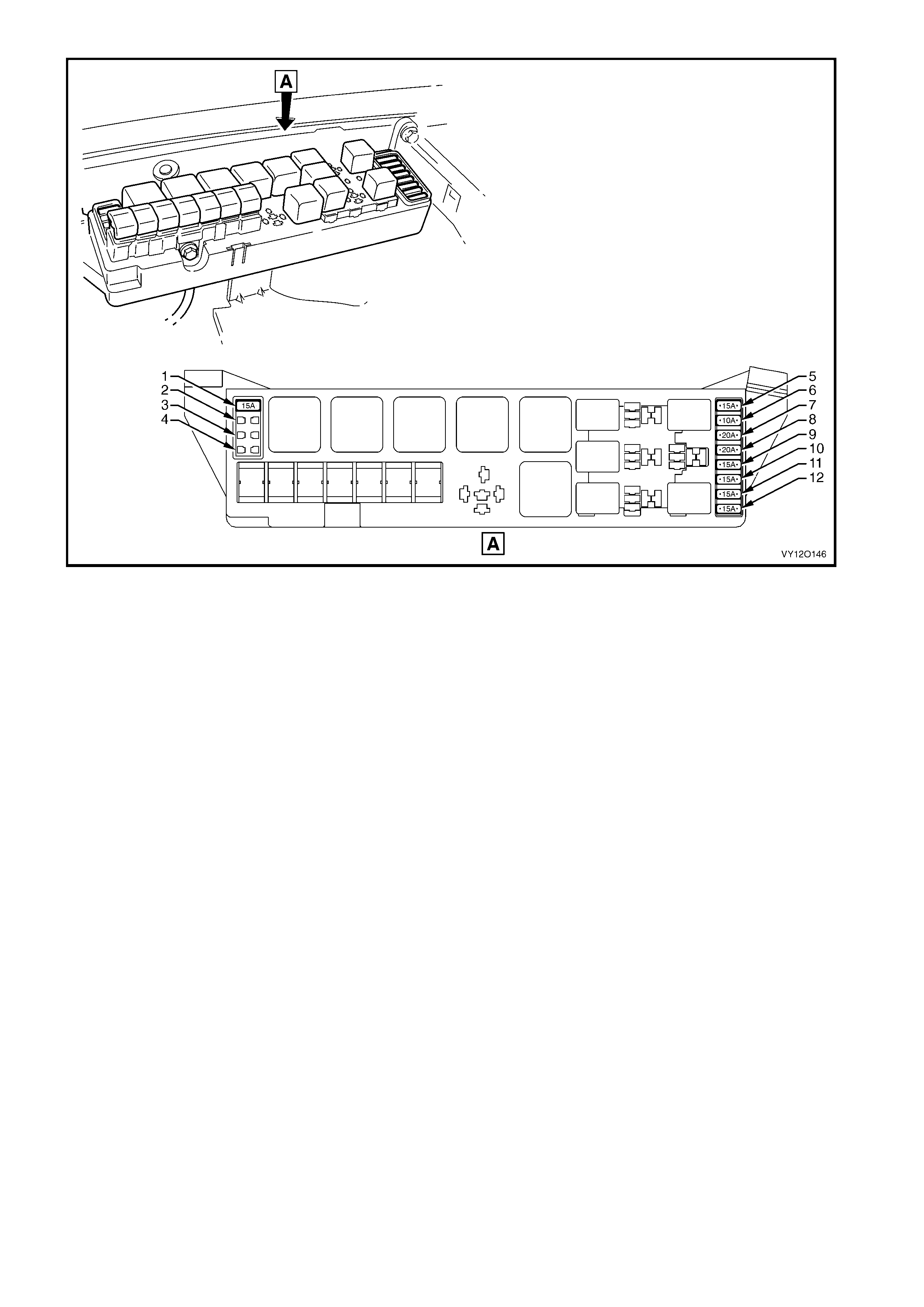
Figure 12O-3
Legend
1. F36 – Throttle Relaxer Module Fuse (15A)
2. F37 – Spare
3. F38 – Spare
4. F39 – Spare
5. F28 – Fuel Pump Fuse (15A)
6. F29 – Engine, BCM & Telematics Fuse (10A)
7. F30 – Right-hand Headlamp Fuse (20A)
8. F31 – Left-hand Headlamp Fuse (20A)
9. F32 – Automatic Transmission Fuse (15A)
10. F33 – Engine Sensors Fuse (15A)
11. F34 – Fuel Injectors & Ignition Modules Fuse (15A)
12. F35 – Fuel Injectors & Ignition Modules Fuse (15A)
1.2 CIRCUIT BREAKERS
A circuit breaker is a circuit protection device that will
trip when the circuit current exceeds its rating, the
circuit breaker is activated by heat and will reset after
being all owed to c ool. T he c ircuit br eak er has a lim ited
number of tripping cycles before its tripping time will
change. The circuit breaker will continue to open and
close until the cause of the excess current is
corrected.
Figure 12O-4
In the MY 20 03 VY and V2 Series II all the c ircuit bre ak ers are located i n the pas senger com partment f use and
relay panel assembly and have a 20A current rating. A label on the inside of the panel cover indicates the
circuits protected by each circuit breaker. Refer to Figure 12O-5.
Figure 12O-5
Legend
1. F1 – Power Windows Circuit Breaker (20A)
2. F2 – Power Seats Circuit Breaker (20A) 3. F3 – Memory Seats and Sunroof Circuit Break er (20A)
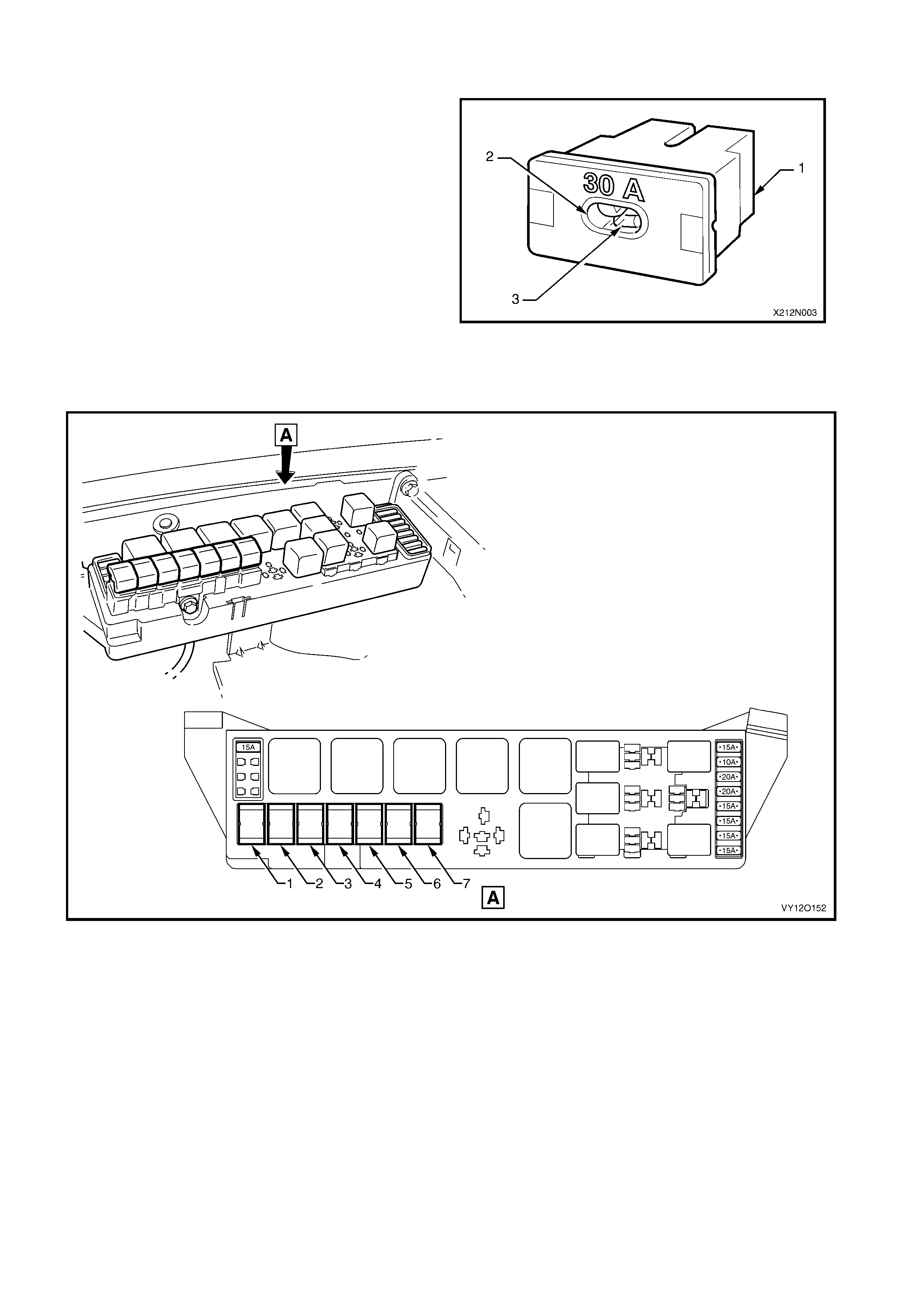
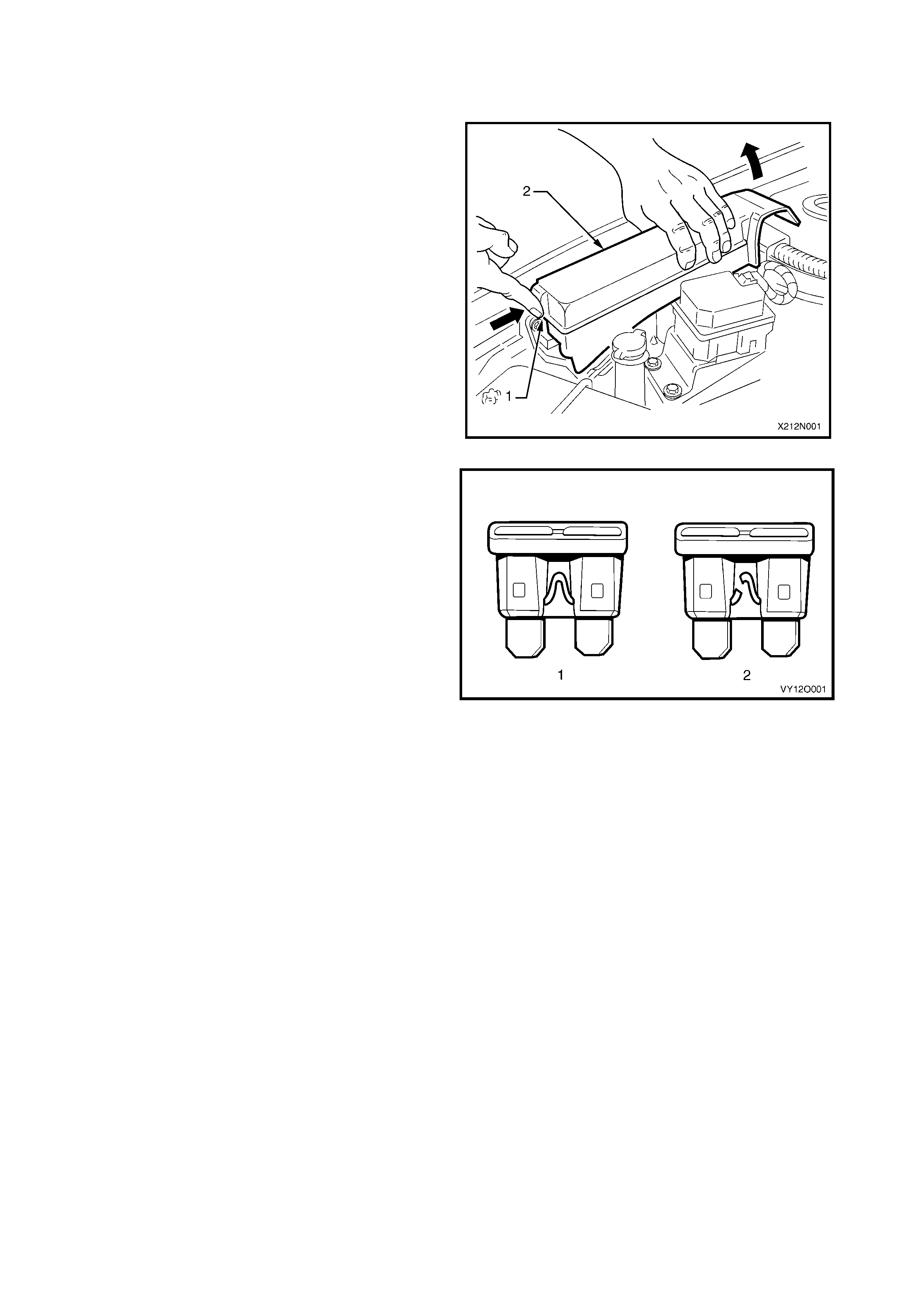
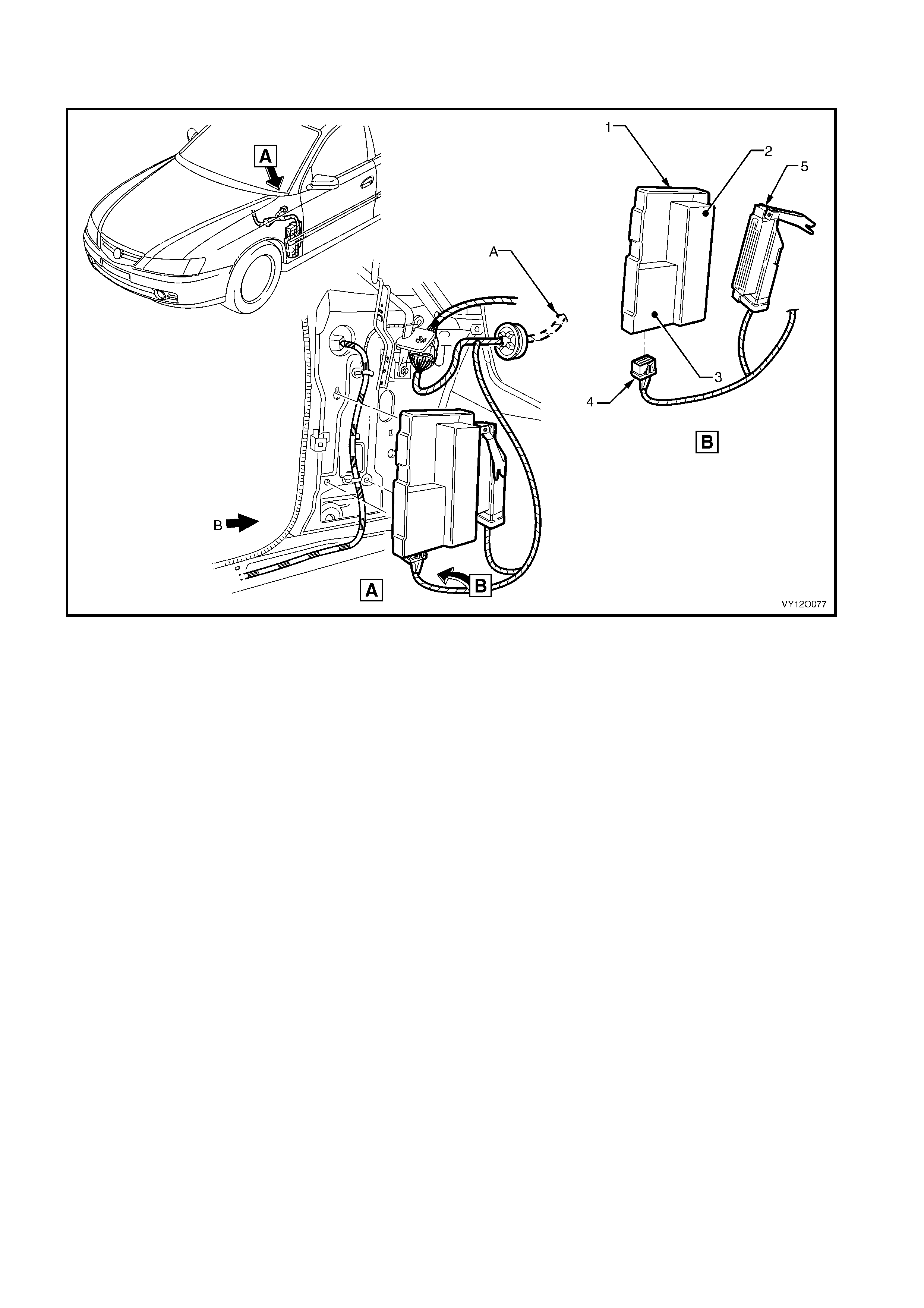
1.3 FUS IBLE LINKS
The chassis and engine electrical wiring is protected
against short circuit damage by fusible links.
Plug-in type fusible links (1) have an inspection
window (2) that allows a visual check of the condition
of the element (3).
Figure 12O-6
The plug-in type fusible links are located in the engine compartment fuse and relay panel assembly. Refer to
Figure 12O-7 for the location and usage of the fusible links. A label on the inside of the panel cover indicates the
circuits protected by each circuit breaker.
Figure 12O-7
Legend
1. F101 – Engine Cooling Large Fan (30A)
2. F102 – Lighting (60A)
3. F103 – Anti Lock Brakes (60A)
4. F104 – Engine (60A)
5. F105 – Main (60A)
6. F106 – Blower Fan (40A)
7. F107 – Engine Cooling Small Fan (30A)
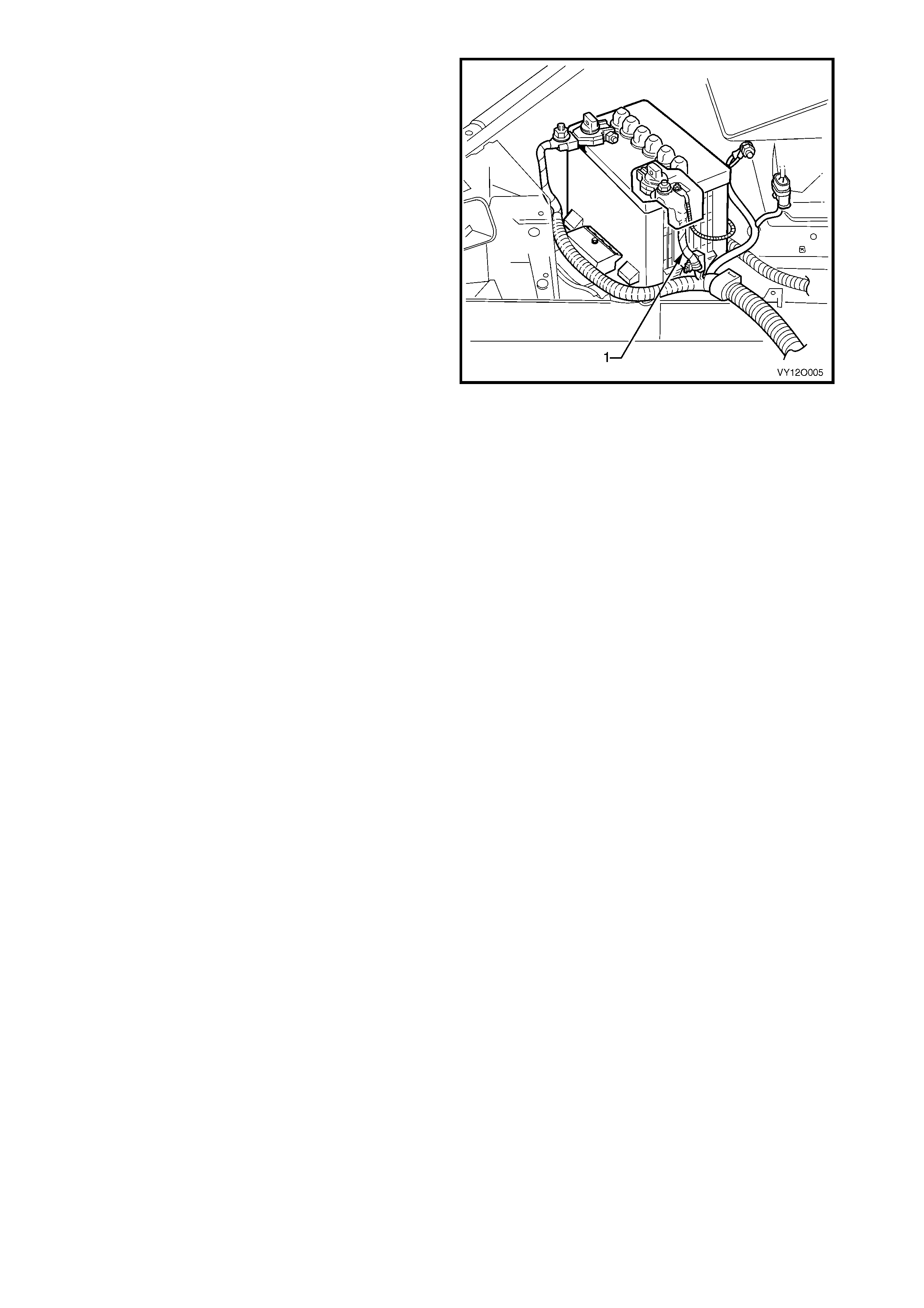
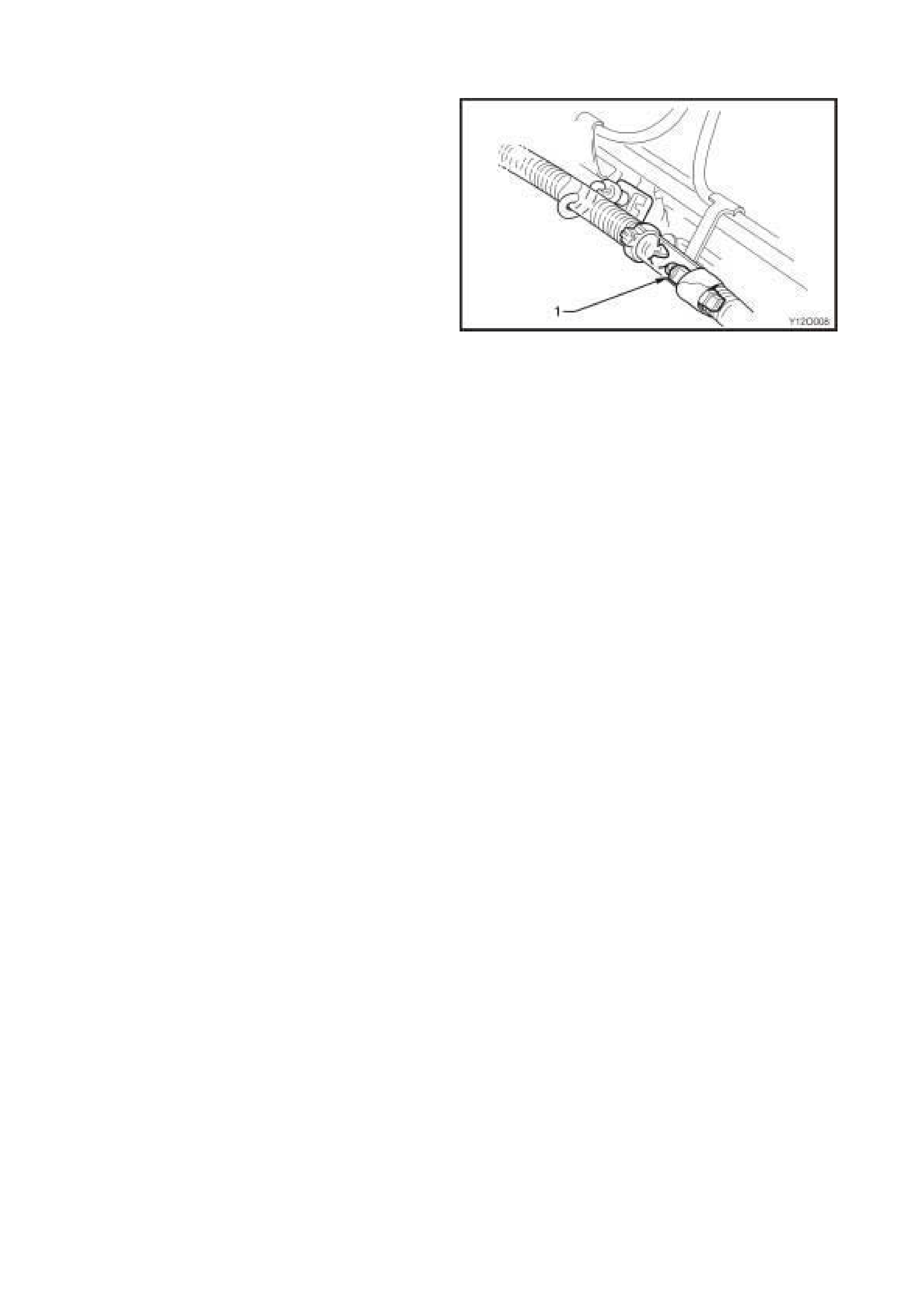
A one-wire type fusible link, consisting of an insulated
fuse wire (1) is attached to the battery harness with
cable ties. This is integrated as part of the battery
harness and is locat ed adjacent to t he batter y harness
positive terminal.
Figure 12O-8
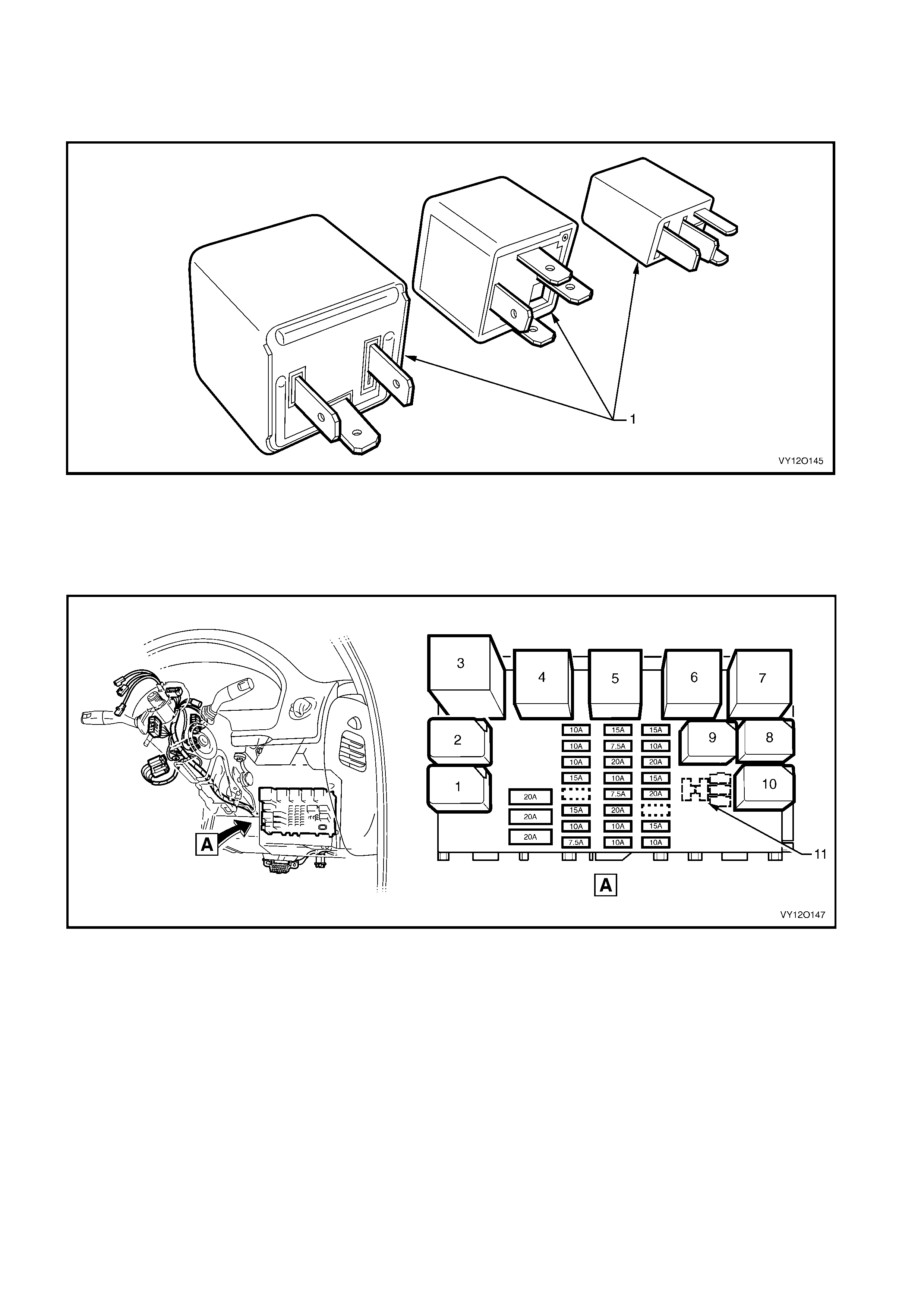
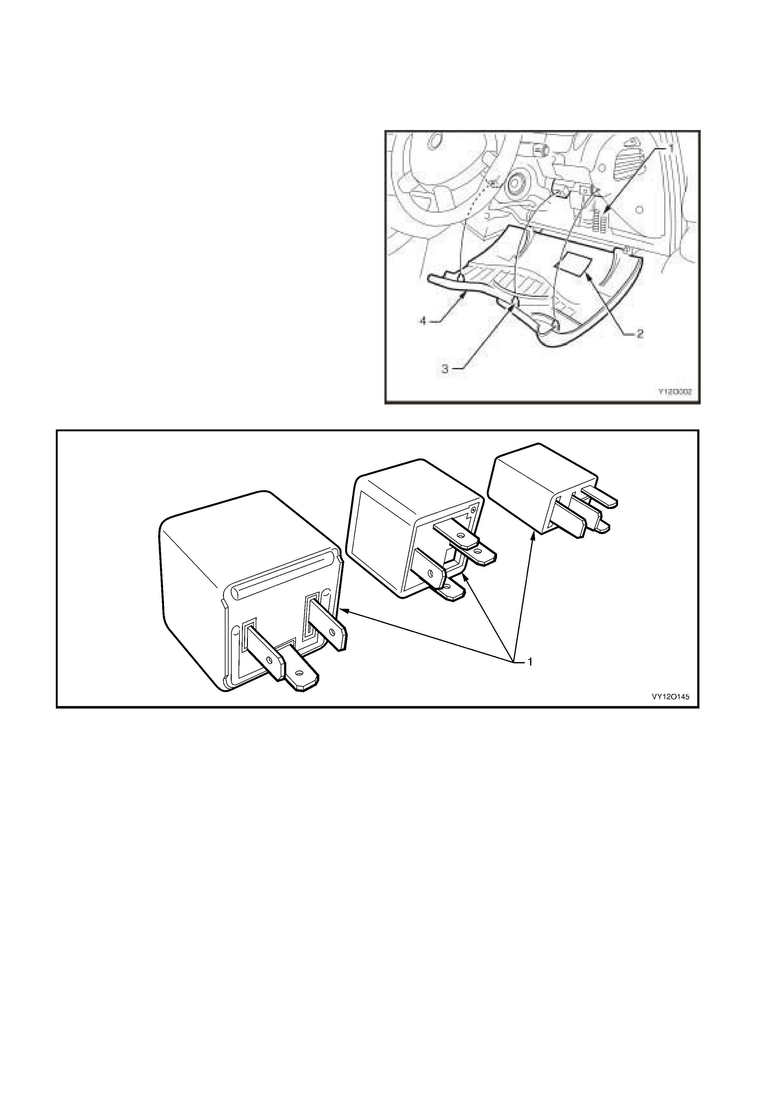
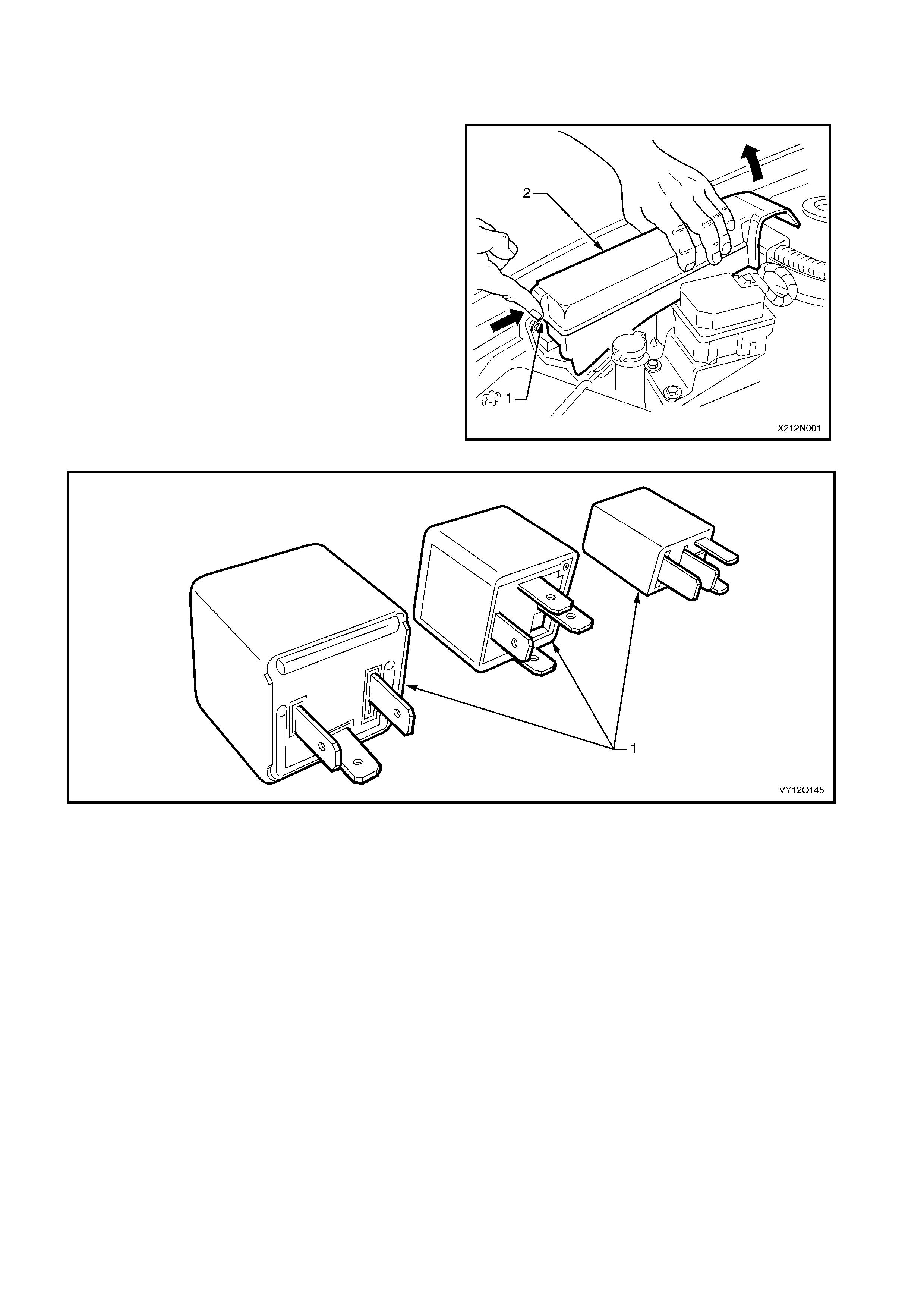
1.4 RELAYS
There ar e a variety of rela y assemblies ( 1) used in the MY 2003 V Y and V2 Series II. T he relays are locate d in
the engine compartment and passenger compartment fuse and relay panel assemblies.
Figure 12O-9
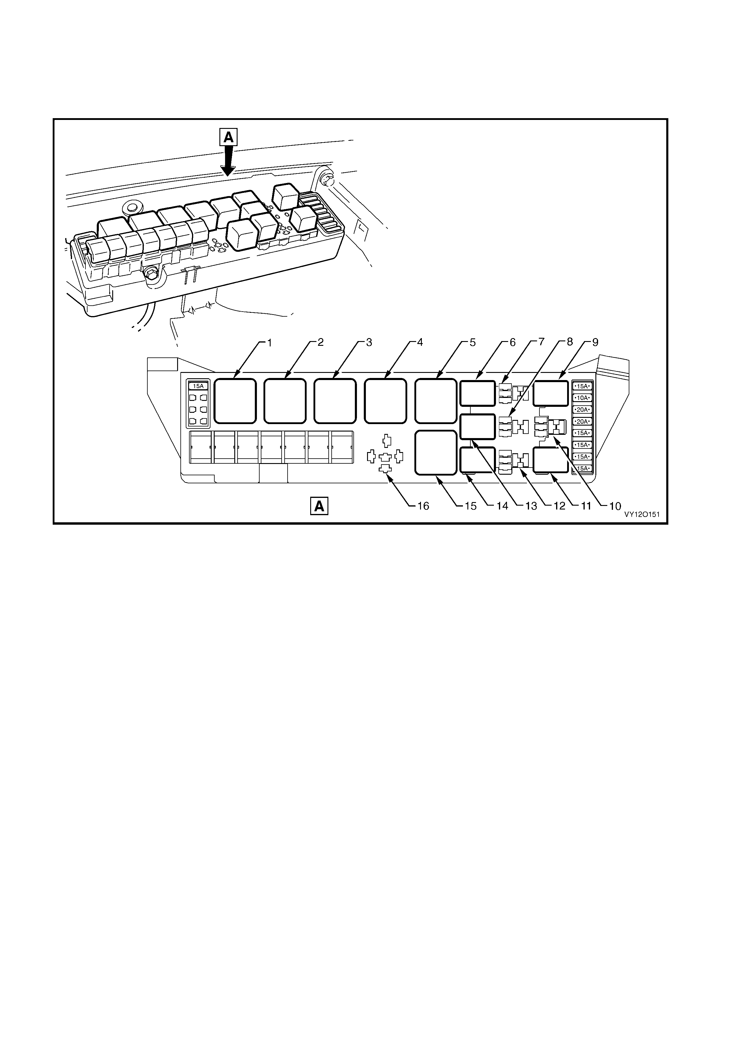
PASSENGER COM P ARTM ENT RELAYS
The pas senger c ompartm ent f use and rela y panel as sem bly is loc ated beh ind the instrum ent panel l ower c over.
A label on the inside of the cover indicates the fuse location and the circuits they protect. Refer to Figure 12 O-
10.
Figure 12O-10
Legend
1. R17 – Relay Assembly – Rear Wiper (4 Pin Micro)
2. R18 – Relay Assembly – Park Lamps (4 Pi n Micro)
3. R19 – Flasher Assembly – Turn Signal (3 Pin)
4. R20 – Relay Assembly – Accessory Control (4 Pin Mini)
5. R21 – Relay Assembly – Ignition Control (4 P i n Mini)
6. R22 – Relay Assembly – Power Windows (4 Pin Mini)
7. R23 – Relay Assembly – Blower Inhibit (4 Pin Mini)
8. R24 – Relay Assembly – Interi or Illumi nation, (4 Pin Mini)
9. R26 – Relay Assembly – Hazard Illumination (4 Pin Micro)
(Brazil Only)
10. R25 – Relay Assembly – Defog (4 Pin Micro)
11. R27 – Not Assigned
ENGINE COMPARTMENT RELAYS
The engine compartment fuse and relay panel assembly is located forward of the right-hand side front
suspens io n s trut tower. A labe l on the inside of the c o ver l is ts the f unc tio n of each relay as well as in dic at in g the
circuits each fuse protects. Refer to Figure 12O-11.
Figure 12O-11
Legend
1. R1 – Start Relay (4 Pin)
2. R2 – Blower Relay (4 Pin)
3. R3 – Headlamp Hi-beam Relay (4 Pin)
4. R4 – E.F.I. Relay (4 Pin)
5. R5 – Engine Cooling Fan Relay 2 – High Speed (4 Pin)
6. R8 – Horn Relay (4 Pin Micro)
7. R9 – Spare
8. R12 – Spare
9. R10 – Fog Lamp Relay (4 Pin Micro)
10. R13 – Spare (4 Pin Micro)
11. R16 – Fuel Pump Relay (4 Pin Micro)
12. R15 – Spare
13. R11 – A/C Relay (4 Pin Micro)
14. R14 – Headlamp Lo-beam Relay (4 Pin Micro)
15. R7 – Engine Cooling Fan Relay 1 – Lo Speed (5 Pin)
16. R6 – Spare
1.5 DIODES
All vehicles with air conditioning have an air
conditioning compressor clutch suppression diode (1)
fitted to the engine har ness .
For location of the air conditioning compressor clutch
feedback diode, refer to the following figures in this
section
a. POWERTRAIN H ARNESS – 3, V6 Engine, Figur e
12O-43, item 6.
b. V6 S/C – POWERTRAIN HARNESS – 9, V6
Supercharged Engine, Figure 12O-49, item 2.
c. POWERTRAIN HARNESS – 12, GEN III V8
Engine, Figure 12O-52, item 10.
Figure 12O-12
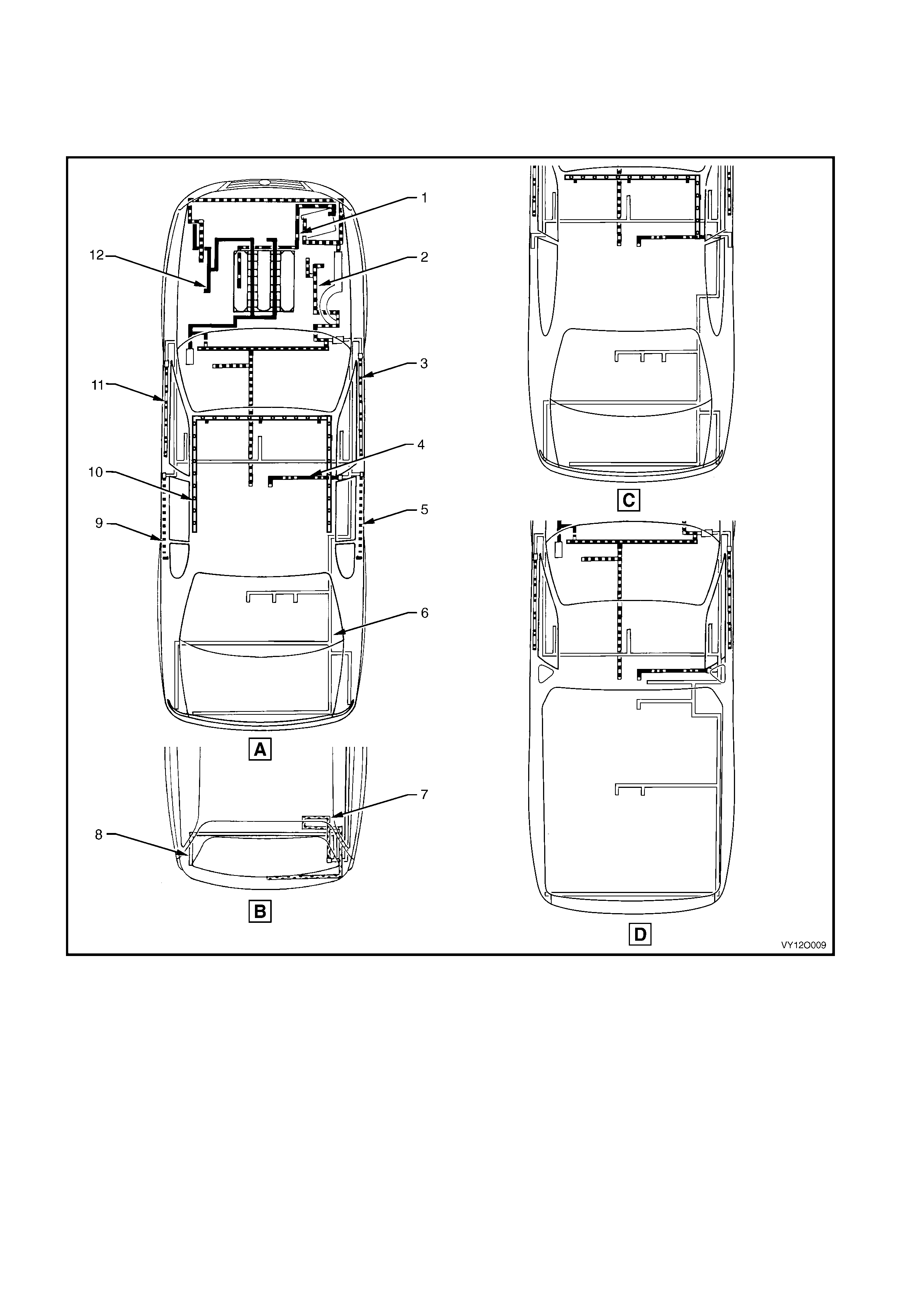
1.6 WIRING HARNESSES
Refer to Figure 12O-13 for the location of the wiring harnesses used in the MY 2003 VY and V2 series. For a
detailed layout of the various wiring harnesses and connectors refer to 3. WIRING INSTALLATION
DIAGRAMS.
Figure 12O-13
Legend
A. Sedan
B. Wagon
C. Coupe
D. Utility
1. Battery Wiring Harness
2. Main Wiring Harness
3. Right-hand Front Door Wi ri ng Harness
4. Roof Lamp Harness
5. Right-hand Rear Door W i ri ng Harness
6. Body Wiring Harness (Except Wagon)
7. End Gate Harness
8. Body Wiring Harness (Wagon)
9. Left-hand Rear Door Wiri ng Harness
10. Visor Lamp Harness
11. Left-hand Front Door Wiring Harness
12. Powertrain Harness

1.7 WIRING HARNESS CONNECTORS
The majority of the wiring harness connectors used on MY 2003 VY and V2 series are of an interlocking design.
The m ale and fem ale c onnector bod ies, when push ed toget her, cann ot be pul led apar t due to th e presenc e of a
locking tang on the connector body. Some connectors have anti-backout combs fitted for increased connector
terminal security.
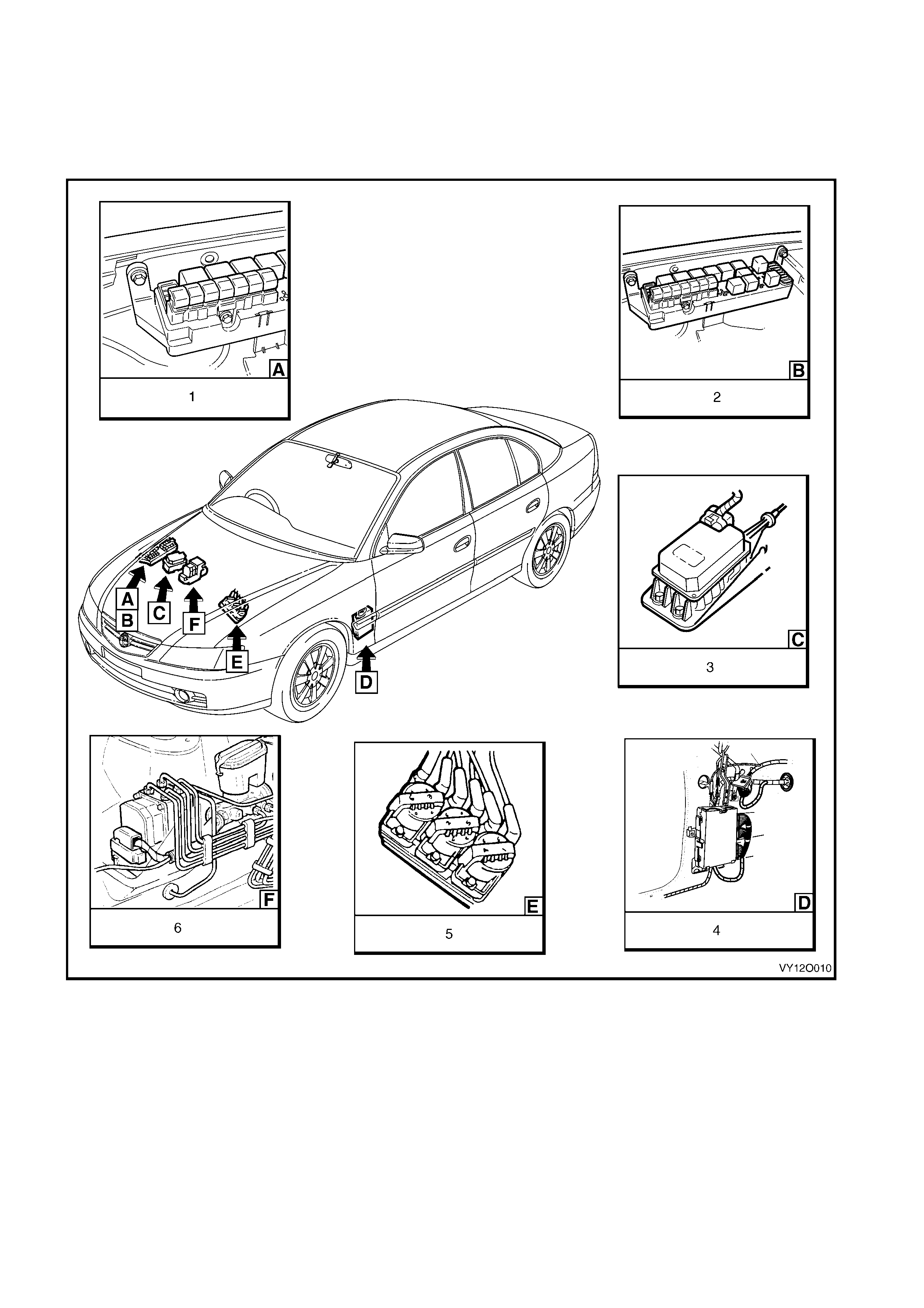
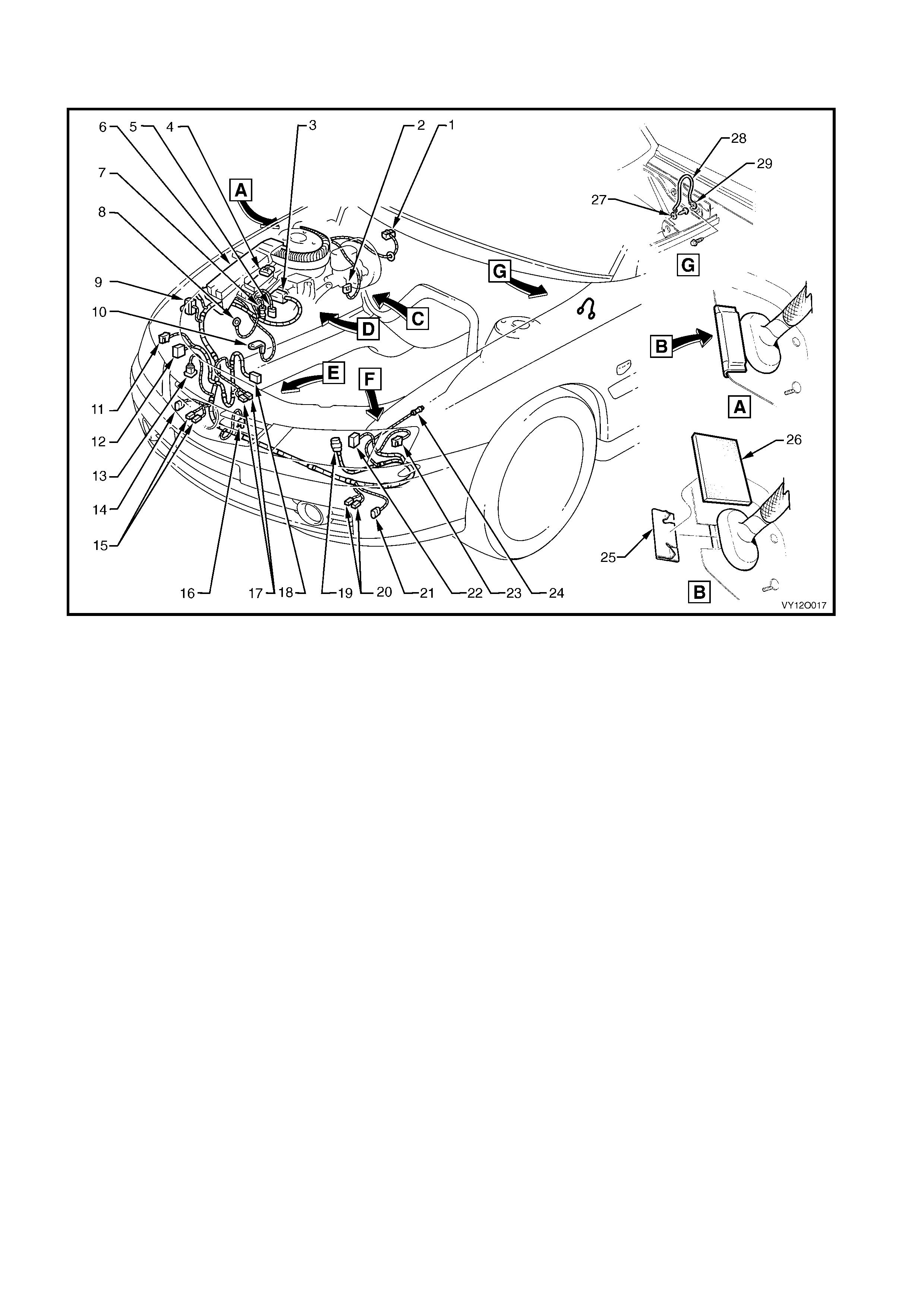
1.8 ELECTRONIC CONTROL DEVICE LOCATIONS
The f ollowing f igures illustr ate th e locat ion of the vario us elec tronic contro l de vices fitted to M Y 2003 V Y and V2
series.
Ensure that the precautionary and special handling instructions are followed (where applicable) for each
electronic control device as described in the corresponding sections.
Figure 12O-14
Legend
1. Fusible Links
2. Relays & Fuses – Engine compartment
3. Cruise Control Module
4. Powertrain Control Module (P CM) – V6 Engines
5. Direct Ignition System (DIS) Module – V6 Engines
6. ABS Hydraulic Modulator
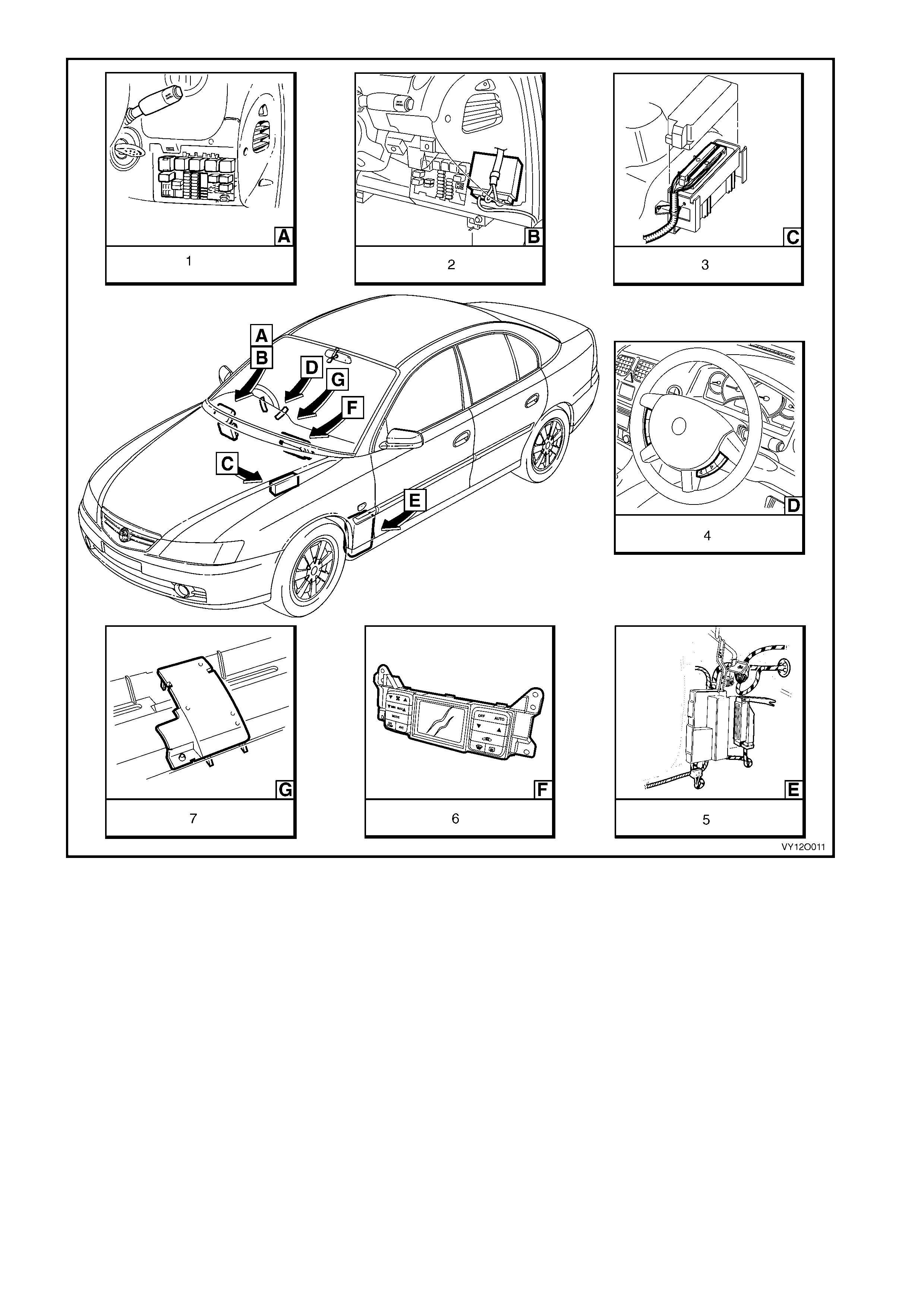
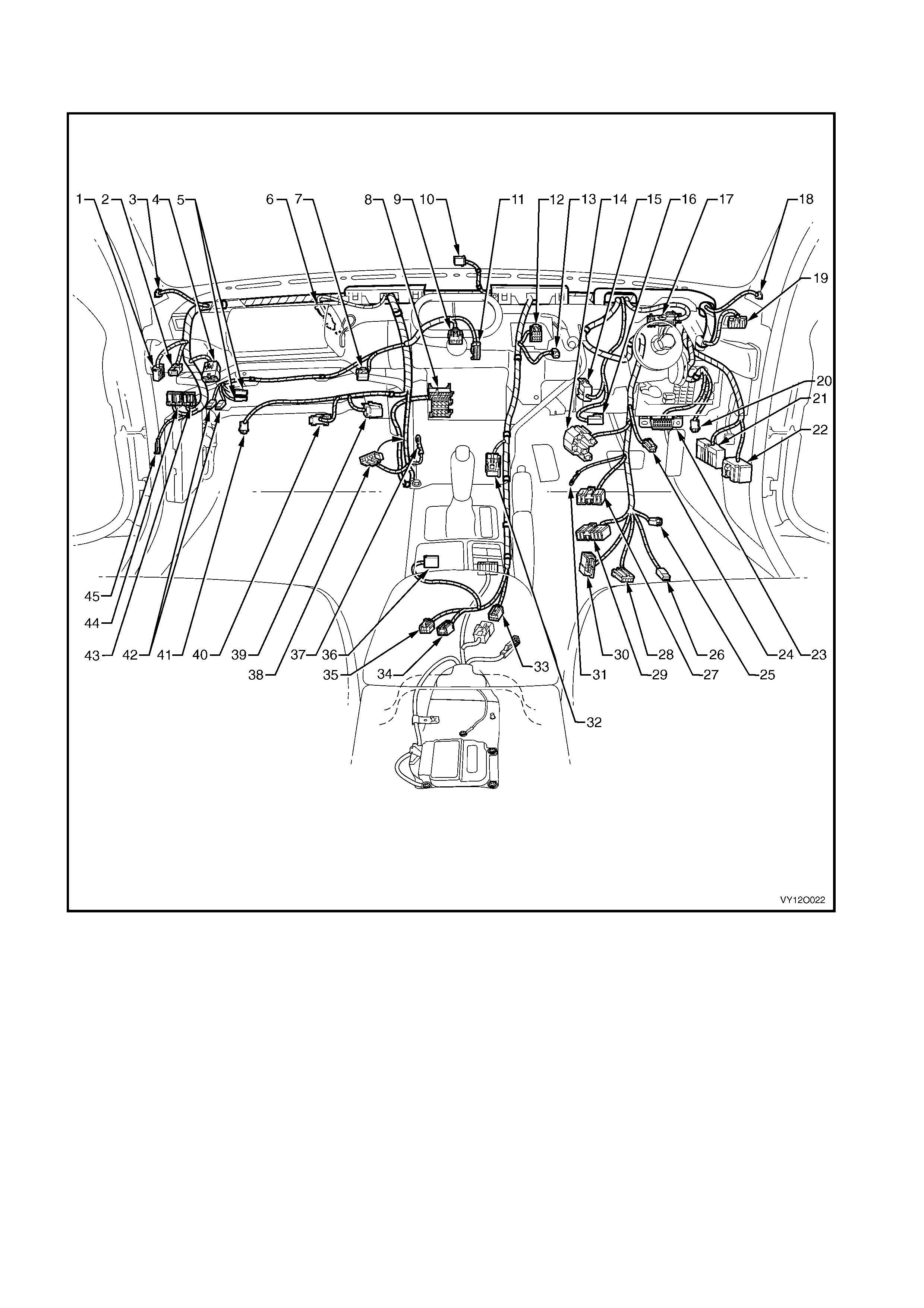
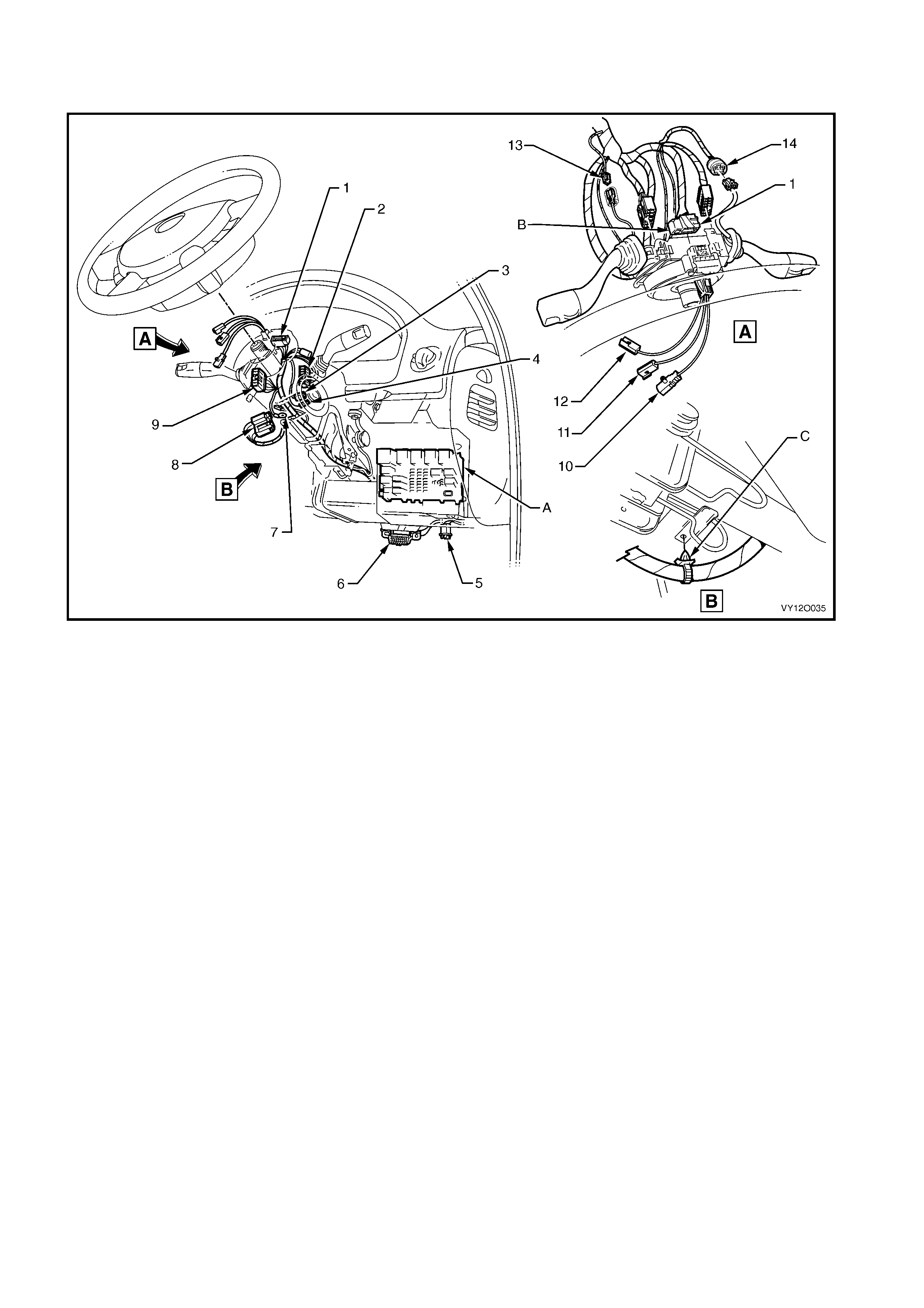
Figure 12O-15
Legend
1. Relays & Fuses – Instrument P anel
2. Body Control Module
3. Powertrain Control Module – Gen III V8
4. Steering Wheel Radio & CD Player Control s
5. Powertrain Interface Module (PIM) – GEN III V8 Engine
6. Climate Control Module
7. Ambient Light Sensor
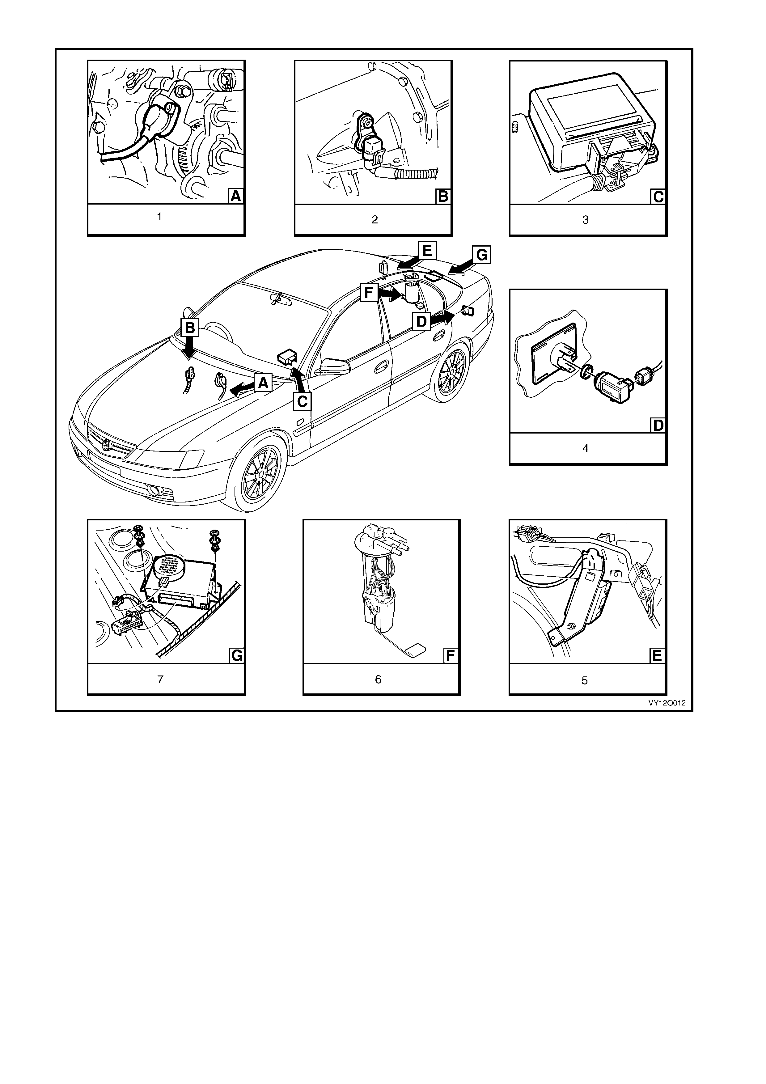
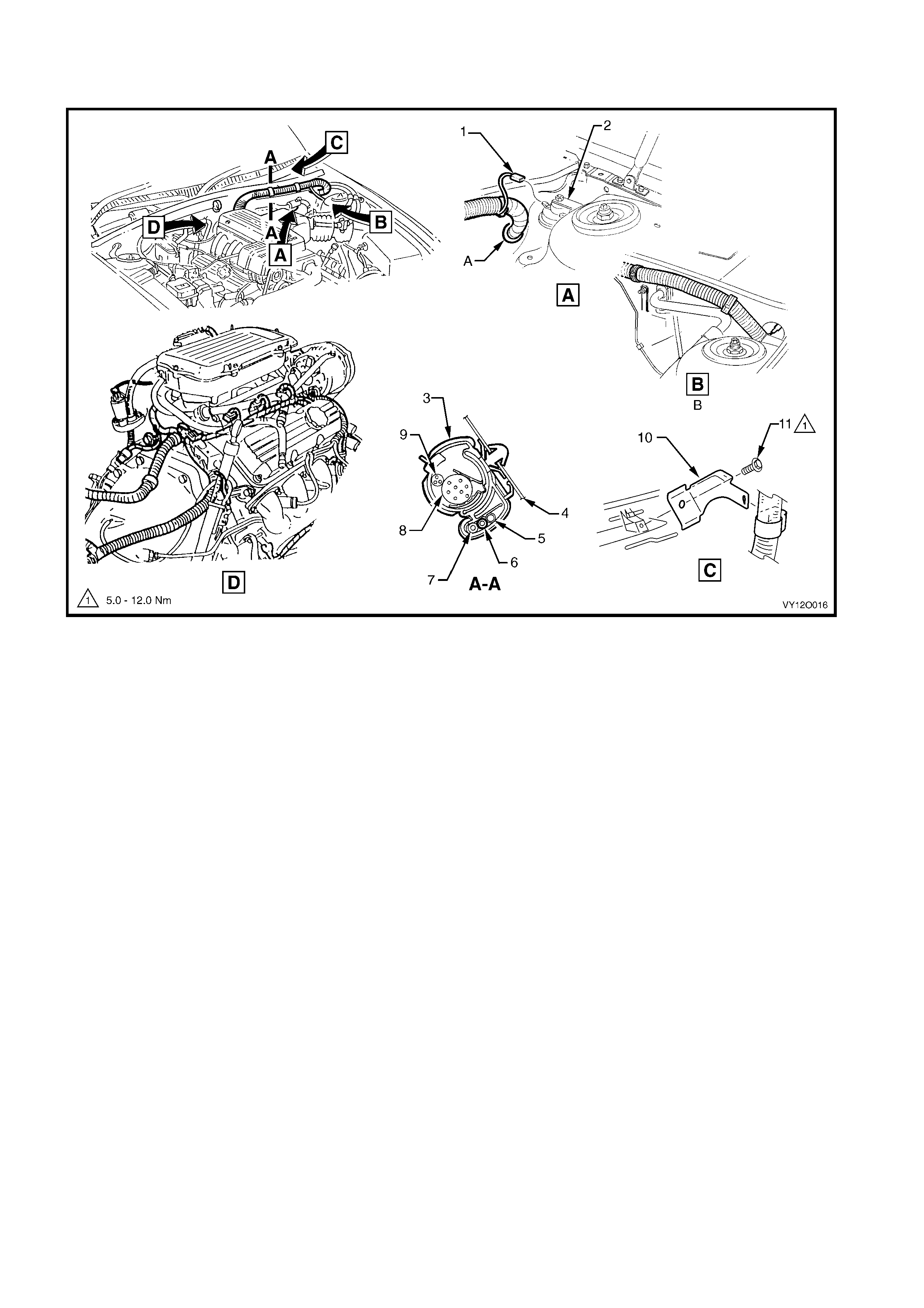
Figure 12O-16
Legend
1. Vehicle Speed Sensor – Manual Transmission (V6 Shown,
V8 Similar).
2. Vehicle Speed Sensor – Automatic Transmission
3. Sensing & Diagnostic Module – Occupant Protection System
4. Rear Object Sensor Assembl y
5. Fuel Pump Control Module – V6 Supercharged Engine
6. Modular Fuel Pump and Sender Assembly
7. Rear Object Sensor Control Module
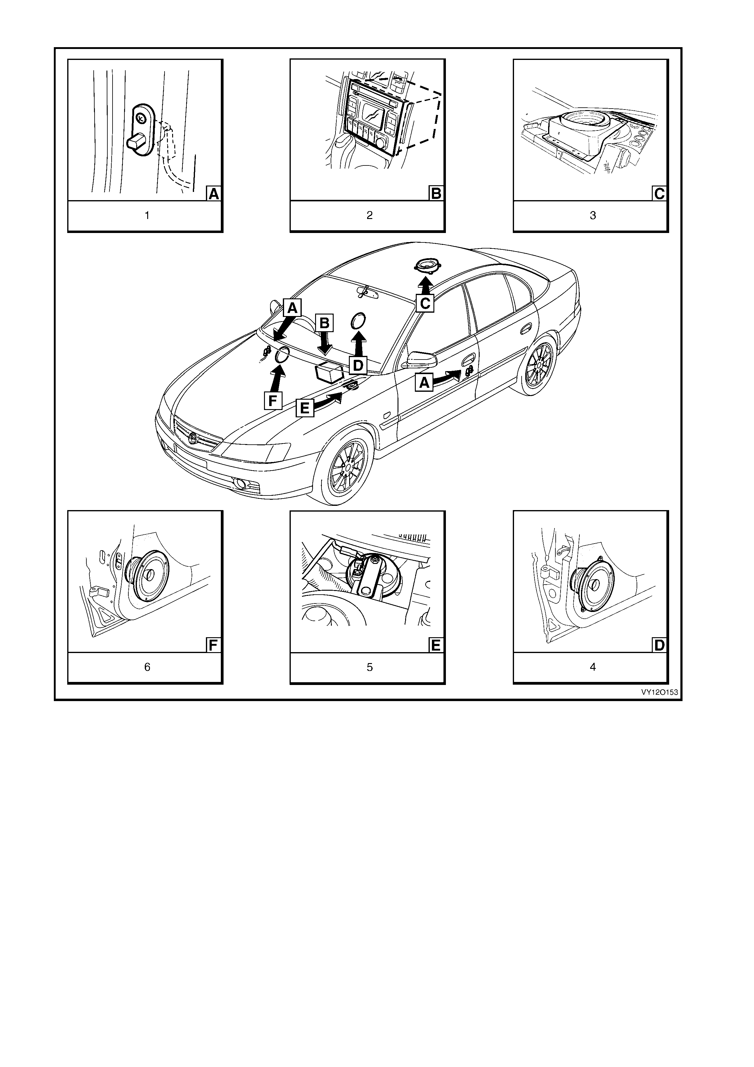
Figure 12O-17
Legend
1. Door Ajar Warning Switch Assem bly (4 plac es)
2. Radio Assembly
3. Rear Speaker
4. Front Door Speaker Assembly (2 Places)
5. Anti-theft Horn
6. Rear Door Speaker Assemb l y (2 Places )
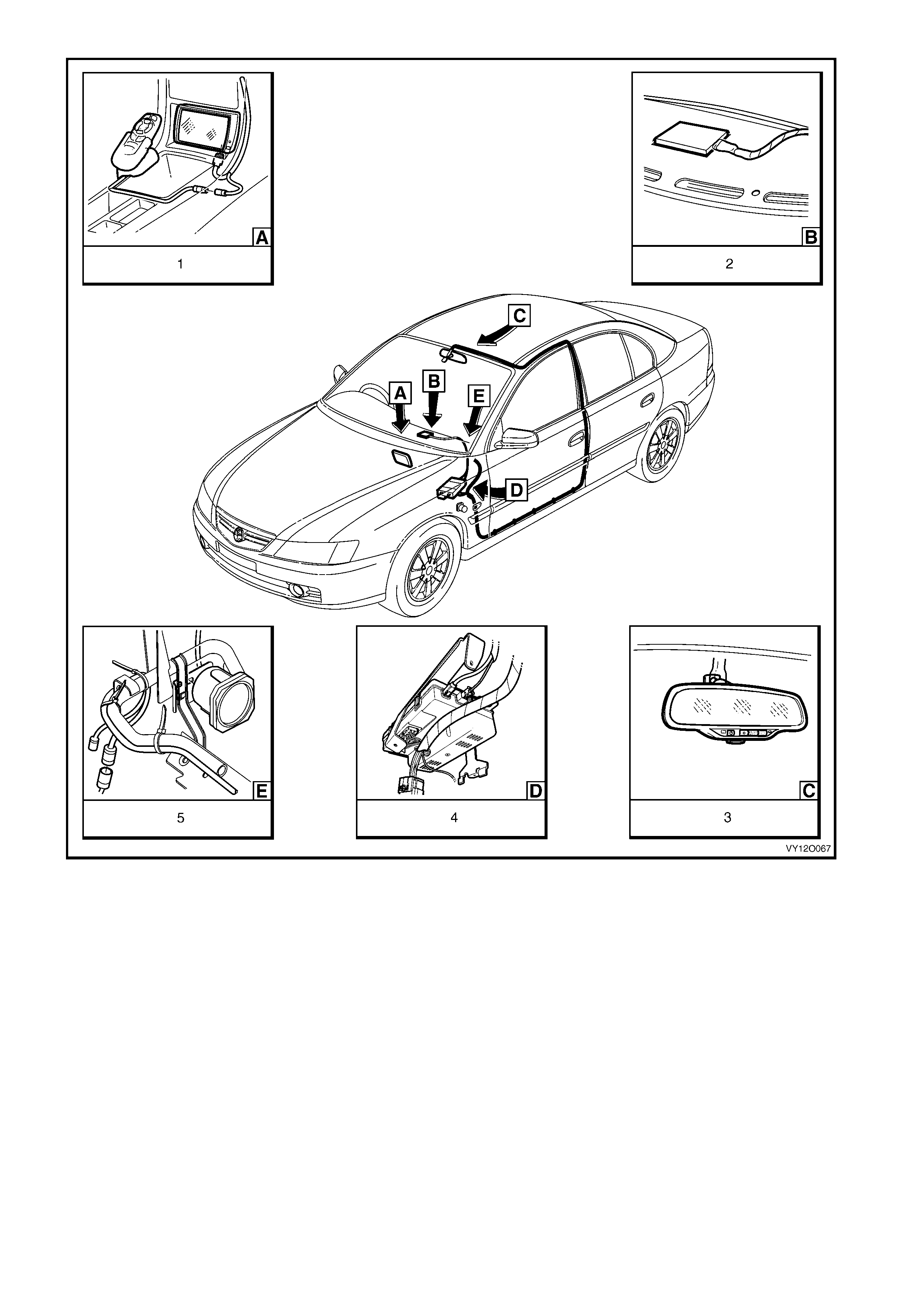
Figure 12O-18
Legend
1. Navigation S ystem Assembly
2. Telematics Antenna
3. Rear View Mirror Assembly with Telematics
4. Telematics Control Module
5. Navigation System Speaker
2. SE R VICE OP ERATIO NS
2.1 FUSES
PASSENGER COM PARTMENT FUSE AND RELAY PANEL ASSEM BLY
Replace
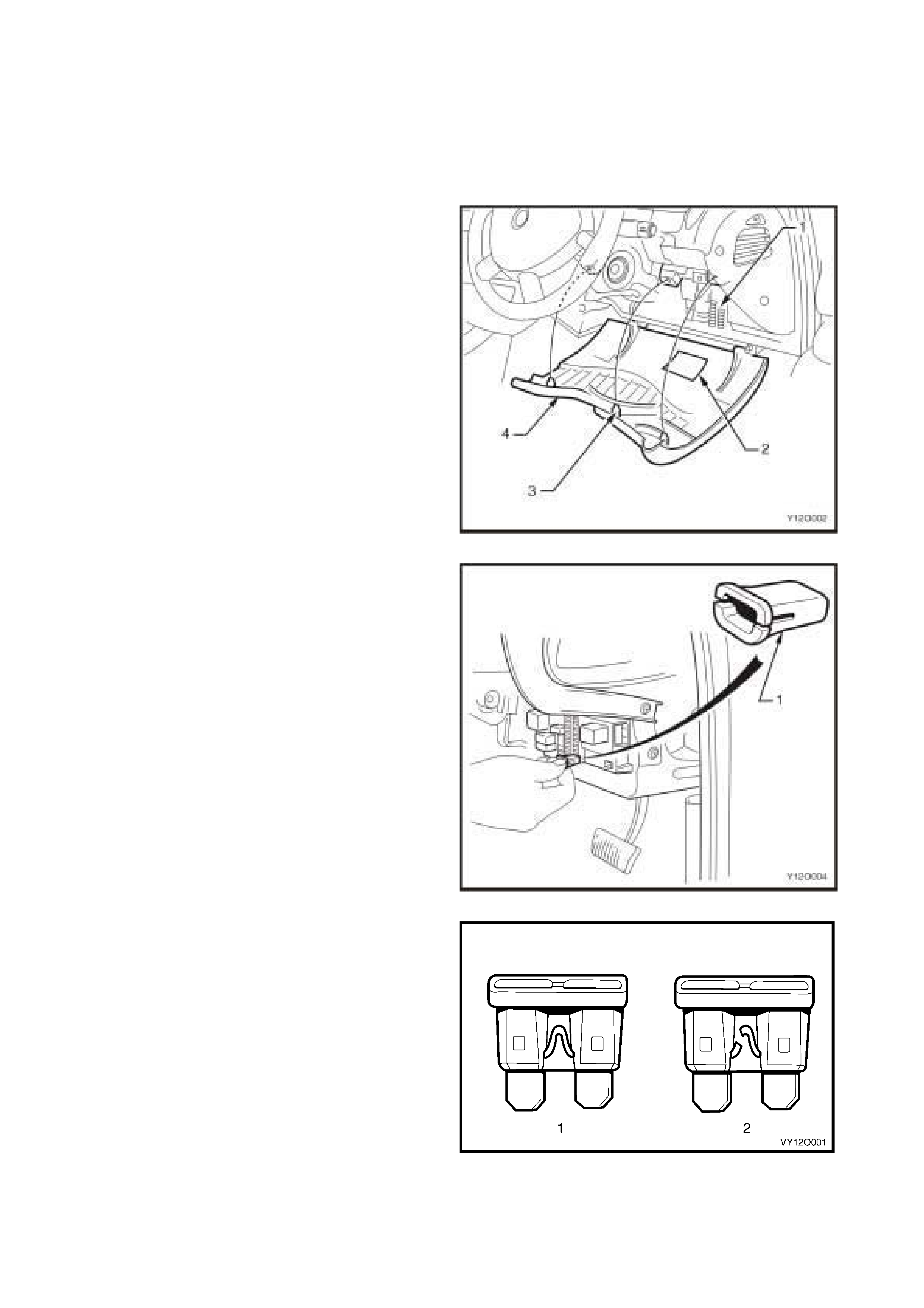
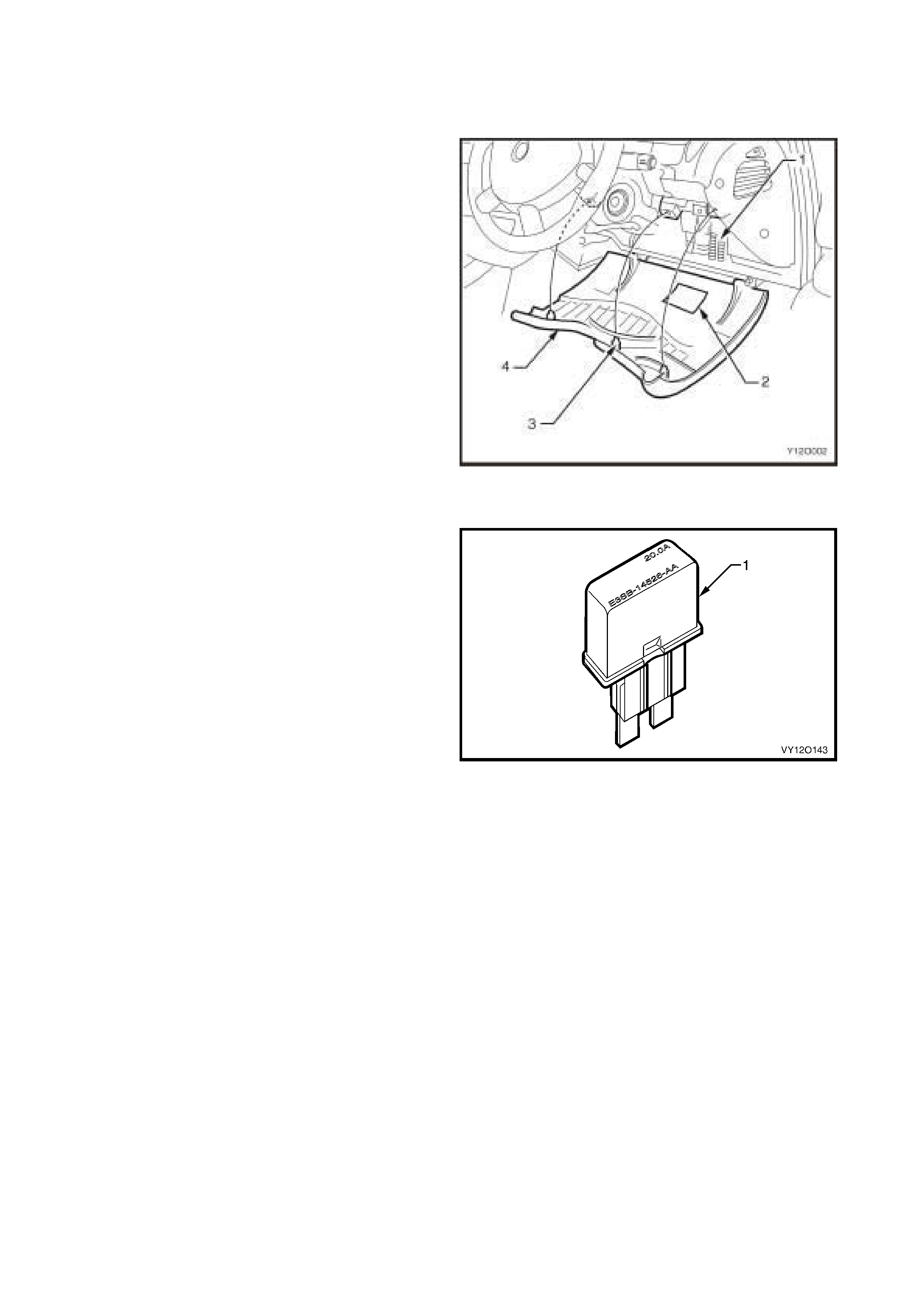
1. To gain access to the passenger compartment
fuse and relay panel assembly (1) move the
steering column to the upmost position. Firmly
grasp the instrument panel lower cover (4) and
pull the cover downwards to disengage the
locating clips (3).
2. Refer to the label (2) on the inside of the
instrument pan el lo wer c o v er to ide ntify the c ir cuits
protected by each fuse.
Figure 12O-19
3. Use the fus e remover (1) located in the p assenger
compartment fuse and relay panel assembly to
rem ove the suspect f use. To use, pu ll the rem over
from its location in the panel assembly and fully
insert t he remover ov er th e top of the f us e an d p ul l
the fuse from the panel.
Figure 12O-20
4. Determine if the fuse has blown by examining the
element for a break:
a. A good fuse (1) has an intact element.
b. A blown fuse (2) has a broken element.
5. Replace a blown fuse with a fuse of the same
current r ati ng. If the r e placem ent fuse blo ws r ect ify
the fault within the circ uit befor e replacing th e fuse
again.
6. Close the instrument panel lower cover. Ensure
that the locating c lips are cor r ectl y al ign ed a nd s lot
into the corresponding mating retainers securely.
Figure 12O-21
ENGINE COMPARTMENT FUSE AND RELAY PANEL ASSEMBLY
Replace
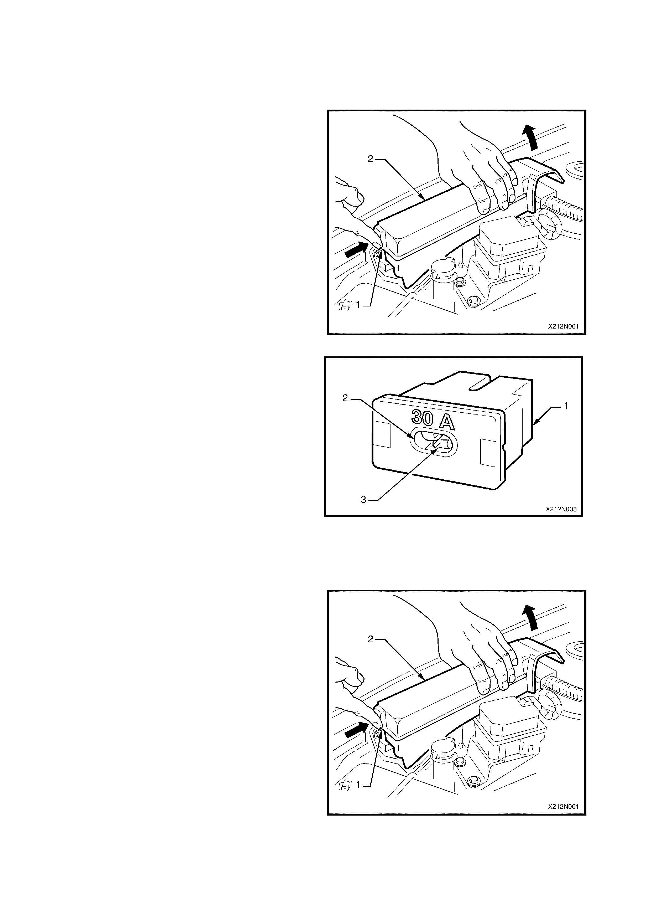
1. Remove the engine compartment fuse and relay
panel assembly cover (2) by releasing the
retaining tang (1) and lifting the cover up and
towards the suspension stru t tower.
2. Refer to th e lab el on the i n s ide co ver of the eng in e
compartment fuse and relay panel assembly to
identify the circuits protected by each fuse.
3. Use the fuse remover located in the passenger
compartment fuse and relay panel assembly to
remove the suspect fuse. Refer to PASSENGER
COMPARTMENT FUSE AND RELAY PANEL
ASSEMBLY for the locati on an d usa ge of the fus e
remover.
Figure 12O-22
4. Determine if the fuse has blown by examining the
element for a break:
a. A good fuse (1) has an intact element.
b. A blown fuse (2) has a broken element.
5. Replace a blown fuse with a fuse of the same
current r ati ng. If the r e placem ent fuse blo ws r ect ify
the fault before replacing the fuse again.
6. Replace the engine compartment fuse and relay
panel assembly cover. Ensure the retaining tang
locks into place.
Figure 12O-23
2.2 CIRCUIT BREAKERS
REMOVE
1. To gain access to the passenger compartment
fuse and relay panel assembly (1) move the
steering column to the upmost position. Firmly
grasp the instrument panel lower cover (4) and
pull the cover downwards to disengage the
locating clips (3).
2. Refer to the label (2) on the inside of the
instrument pan el lo wer c o v er to ide ntify the c ir cuits
protected by each fuse.
3. Pull the suspect circuit breaker from the
passenger compartment fuse and relay panel
assem bly.
Figure 12O-24
TEST
1. Remove the circuit breaker as described in this
Section.
2. Perform a continuity check on the circuit breaker.
If there is no conti nuit y wait 15 s econds a nd ch eck
the circuit breaker again.
a. If continuity exists after 15 seconds have elapsed
the circuit breaker has reset and can be replaced
in the passenger compartment fuse and relay
panel assembly. If the circuit breaker trips again
there is a problem within the circuit it is protecting
and the problem should be rectified before
continuing.
b. If there is no continuity after 15 seconds have
elapsed, the circuit breaker has blown and must
be replaced with another circuit breaker of the
same current rating.
3. Install the circuit breaker as described in this
Section.
Figure 12O-25
REINST ALL
1. Replace the passenger compartment fuse and
relay panel assembly cover. Ensure the retaining
tang locks into place.
2.3 FUS IBLE LINKS
ALL PLUG-IN TYPE FUSIBLE LINKS EXCEPT FOR F104 60A ENGINE
Replace
1. Remove the engine compartment fuse and relay
panel assembly cover by releasing the retaining
tang (1) on the cover (2) and lifting the cover up
and towards the suspension strut tower.
2. Refer to the label on the inside of the engine
compar tment f use and r ela y pane l assembl y cover
to identify the circuits protected by each fusible
link.
Figure 12O-26
3. Pull the suspect fusible link (1) from the panel
assembly and perform a visual check of the
element (3) through the inspection window (2) to
determ ine whether or not it has blown.
a. A good fusible link has an intact element.
b. A blown fusible link has a broken element.
4. Replace a blown fusible link with one of the same
current r ating. If the r eplacem ent fus ible link blo ws
this indicates a problem with the circuit it is
protecting. Rectify this fault before replacing the
fusible link again.
5. Replace the engine compartment fuse and relay
panel assembly cover. Ensure the retaining tang
locks into place.
Figure 12O-27
PLUG-IN TYPE FUSIBLE LINK F104 60A ENGINE
Replace
1. Remove the engine compartment fuse and relay
panel assembly cover by releasing the retaining
tang (1) on the cover (2) and lifting the cover up
and towards the suspension strut tower.
2. Refer to the label on the inside of the engine
compar tment f use and r ela y pane l assembl y cover
to identify the circuits protected by each fusible
link.
Figure 12O-28
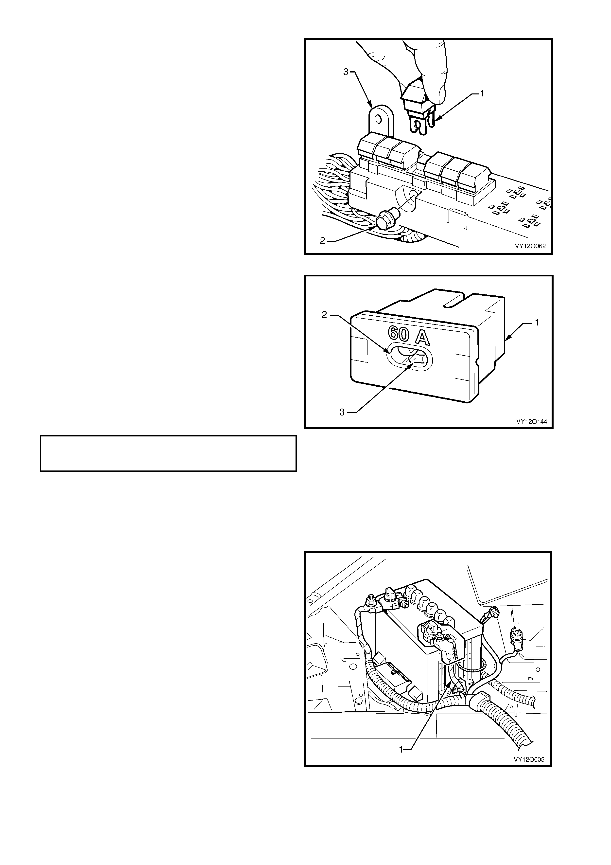
3. Remove the fusible link terminal attaching nut (2)
and pull fusible link F104 60A ENGINE (1) from
engine compartment fuse and relay panel
asse mbly (3).
Figure 12O-29
4. Perform a visual check of the element (3) through
the inspection windo w (2) to determine whether or
not it has blown.
a. A good fusible link has an intact element.
b. A blown fusible link has a broken element.
5. Replace a blown fusible link with another with a
60A current rating. If the replacement fusible link
blows this indicates a problem within the engine
circuitry it is protecting. Rectify this fault before
replac ing the fus ible li nk again.
6. Tighten the fusible link terminal attaching nut to
the correct torque specification.
FUSIBLE LINK TERMINAL
ATTACHING NUT
TORQUE SPECIFICATION 5.0 – 6.0 Nm
7. Replace the engine compartment fuse and relay
panel assembly cover. Ensure the retaining tang
locks into place.
Figure 12O-30
ONE-WIRE TYPE FUSIBLE LINK
Replace
1. Disconnect the end of the fusible link (1) further
from the positive battery terminal by cutting the
cable tie.
2. Test for a voltage drop between the positive
battery terminal and the end of the fusible link.
a. If there is a volt age drop th e fusible link has blown
and mus t be repl aced. If th e new f usible link blows
this indicates a fault in the circuit and it should be
rectified before replacing the fusible link again.
b. If there is no voltage drop the fusible link has not
blown and the problem lies elsewhere.
3. Reattach the fusible link to the battery harness.
Use new cable ties to fasten the fusible link to the
battery harness and cut the cable tie ends to a
suitable le ngth.
Figure 12O-31
2.4 RELAYS
PASSENGER COM P ARTM ENT RELAYS
Replace
1. To access to the passenger compartment fuse
and relay panel assembly (1) move the steering
column to the upmost position. Then firmly grasp
the instrument panel lower cover (4) and pull the
cover downwards to disengage the locating clips
(3).
2. Use the label (2) on the inside of the instrument
panel lower cover to identify the circuits protected
by each relay.
Figure 12O-32
Figure 12O-33
3. Pull the suspect relay assembly (1) from the passenger compartment fuse and relay panel assembly by
hand and replace it with a relay of the same type, refer to Figure 12O-33.
4. If the circuit functions as normal the problem was with the relay and has been rectified.
5. If the circuit does not function as norm al or functions for a s hort time then stops i t can be assumed that the
problem lies within the circuit and must be rectified before replacing the relay again.
6. Close the i nstrum ent panel lo wer cover. Ensure t hat the locati ng clips ar e correc tly align ed and slot i nto the
corresponding mating retainers securely.
ENGINE COMPARTMENT RELAYS
Remove
1. Remove the engine compartment fuse and relay
panel assembly cover (2) by releasing the
retaining tang (1) and lifting the cover up and
towards the suspension stru t tower.
2. Refer to th e lab el on the i n s ide co ver of the eng in e
compartment fuse and relay panel assembly to
identify the circuits protected by each relay.
Figure 12O-34
Figure 12O-35
3. Pull the suspect relay assembly (1) from the passenger compartment fuse and relay panel assembly by
hand and replace it with a relay of the same type, refer to Figure 12O-35.
4. If the circuit function as normal the problem was with the relay and has been rectified.
5. If the circuit does not func tions as norm al or f unctions for a shor t tim e then stops it c an be assum ed that the
problem lies within the circuit and must be rectified before replacing the relay again.
6. Close the i nstrum ent panel lo wer cover. Ensure t hat the locati ng clips ar e correc tly align ed and slot i nto the
corresponding mating retainers securely.
2.5 DIODES
A/C COMPRESSOR SUPPRESSION DIODE
Remove
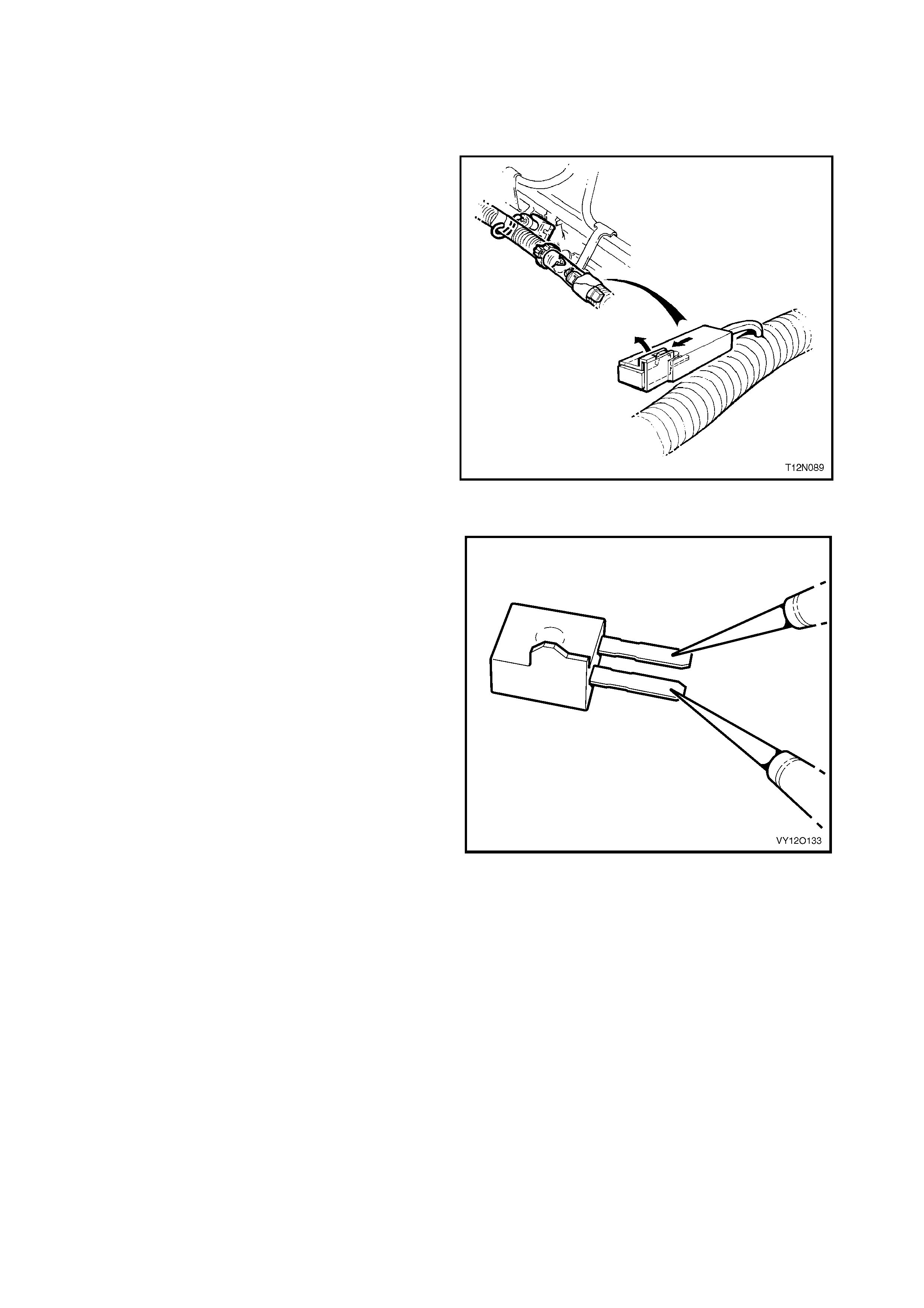
1. Locate the diode on the engine harness at the
injectors, refer to 1.5 DIODES.
2. Remove the tape securing the diode connector to
the wiring harness conduit.
3. Pull back the diode retainer on the diode
connector and use a pair of fine long nosed pliers
to pull the diode out of the connector.
Figure 12O-36
Test
1. Remove the diode as described in this Section.
2. Select ‘diode testing’ on a digital multimeter
(DMM) probably marked with a diode symbol.
3. Measure the resistance across the diode.
4. Reverse the multimeter probes and measure the
resistance again to determine the condition of the
diode.
a. If a finite and an infinite measurement are
obtained the diode does not require
replacement.
b. If both measurements are infinite or are both very
low resistances the diode must be replaced.
5. Reinstall the diodes as described in this Section.
Figure 12O-37
Reinstall
1. Insert the diode into the connector, align the tab
on the side of the diode with the connector
retainer.
2. Using suitable tape, secure diode connector to
wiring harness conduit.

3. WIRING INSTALLATIO N DIAGRAMS – RIGHT-HAND
DRIVE SEDAN AND WAGON
The following figures illustrate the vehicle wiring installation diagrams for MY 2003 VY right-hand drive Sedan
and Wagon.
NOTE: Som e of the following wiring i nstallatio n diagram s illustrate the upp er level harnes ses which incorporate
all necessary wiring harness connectors for all production options. Depending on equipment level and vehicle
model, some of the connectors may be taped back to the harness when a particular option is not fitted, or the
particular level of harness fitted to the vehicle may not incorporate some of the connectors illustrated.
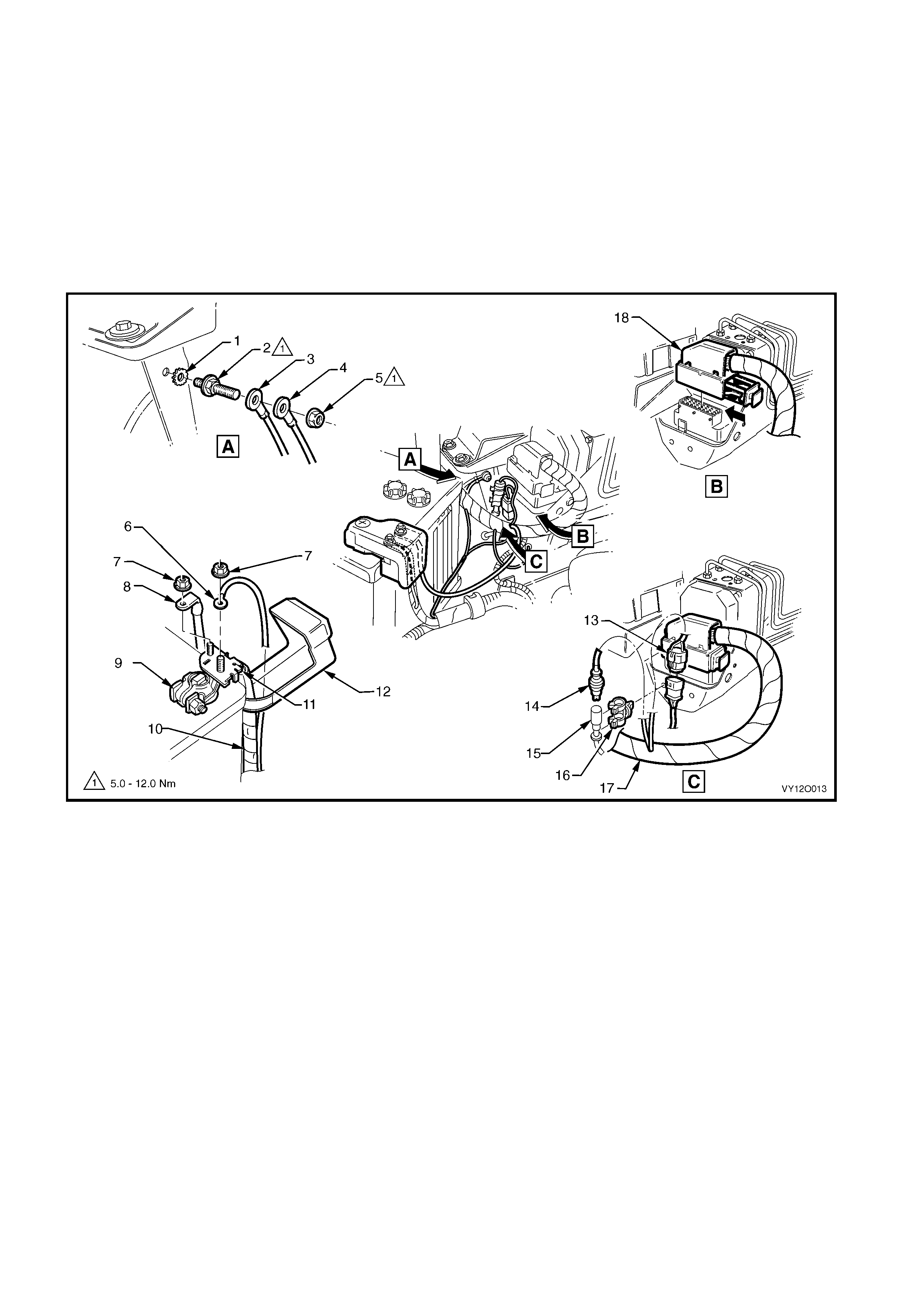
BATTERY WIRING HARNESS – 1
BATTERY AND ABS
Figure 12O-38
Legend
1. Washer
2. Stud
3. Body Ground Terminal
4. Battery Ground Terminal
5. Nut
6. Voltage Sense Terminal (X86 – C)
7. Nut
8. Fuse Panel Supply Terminal (X86 – A)
9. Batte ry Wi ring Harness Pos it i ve Terminal (G1–X1A)
10. Battery Wiring Harness to Starter Motor and Generator
11. Battery Positive Post Assembly (X86 – B)
12. Positive Battery Terminal Cover
13. Main Wiring Harness t o Batt ery Wiring Harness Connector
(X106)
14. ABS to Main Wiring Harness Connector (B52)
15. ABS to Front Left Wheel Connector (B52)
16. ABS Connector Retainer
17. Main Wiring Harness
18. Electronic Braking & Traction Control Connector (A37)
BATTERY WIRING HARNESS – 2
V6 ENGINE
Figure 12O-39
Legend
1. Nut
2. Generator Connector (G8 – X2)
3. Battery Wiring Harness
4. Generator Termi nal (G8 – X1)
5. Clip (2 places)
6. Powertrain Harness
7. Bracket – Battery W i ri ng Harness to E ngi ne
8. Batte ry Wi ring Harness to Main Wiring Harness Connector
(X106)
9. A.B.S. Bracket Terminal (X119 – G4 – GP3)
10. Battery Connector – Posit i ve (G1 – X1)
11. Battery Connector – Negative (G1 – GP1 – X2)
12. Engine Ground Terminal (X119 – GP4)
13. Engine Block Ground Bolt
14. Bolt
15. Oil Cooler Pipes
16. Nut
17. Starter Motor Terminal Connector (M15 – X1)
18. Starter Motor Terminal (M15 – X2)
BATTERY WIRING HARNESS – 3
ALL MODELS WITH GEN III V8 ENGINE
Figure 12O-40
Legend
1. Batte ry Wi ring Harness to Main Wiring Harness Connector
(X106)
2. A.B.S. Bracket Terminal (X119 – G4 – GP3)
3. Batt ery Connector – Positive (G1 – X1)
4. Battery Connector – Negative (G1 – GP1 – X2)
5. Generator Connector (G8 – X2)
6. Battery Wi ring Harness to Generator B+ Terminal Nut
7. Generator Terminal (G8 – X1)
8. Starter Motor Terminal Connector (M15 – X1)
9. Battery Wiring Harness to Starter Motor Solenoid Attaching Nut
10. Starter Motor Terminal (M15 – X2)
11. Battery Wiring Harness Ground to Block Screw
12. Battery Wiring Harness Bracket
13. Battery Wiring Harness Bracket to Engine Mounting Screw
14. Engine Ground Terminal (X119 – GP4)
POWERTRAIN HARNESS – 1
ALL MODELS WITH V6 ENGINE AND V6 SUPERCHARGED ENGINE
Figure 12O-41
Legend
1. Theft Deterent Horn Connect or (B9)
2. Anti-theft horn
3. Powertrain Harness Cl i p (2 Places)
4. Dash Upper Panel Assembly
5. Endgate Washer Hose
6. Cruise Control Cabl e
7. Throttle Cable
8. Powertrain Harness
9. Wiper Motor Harness
10. Powertrain Harness Attaching Bracket
11. Bolt
A. For continuation, refer to POWERTRAIN HARNESS – 18 in
this section.
B. View shows V6 supercharged engine.
POWERTRAIN HARNESS – 2
V6 NORMALLY ASPIRATED ENGINE
Figure 12O-42
Legend
1. Engine Ground Terminal (X119 – GP4)
2. Nut
3. Batte ry Wi ring Harness to Main Wiring Harness Connector
(X106)
4. A.B.S. Bracke t Terminal Connect or (X119 – G4 – GP3)
5. Batt ery Connector – Positive (G1 – X1)
6. Battery Connector – Negative (G1 – GP1 – X2)
7. Knock Sensor Connect or (B65)
8. Engine Oil Pressure Indicator Switch Connector (S87)
9. Camshaft Posit i on Sens or Connector (B28 – V6)
10. Engine Coolant Temperature Sensor Connector (B39)
11. Electronic Ignition Control Module Connector (A40 – V6)
12. Powertrain Harness Retainer
13. Electronic Ignition Control Module
14. Electronic Ignition Control Module Connector Retaining Bolt
A. Powertrain harness secured to bracket as shown.
B. Automatic transmission shown.
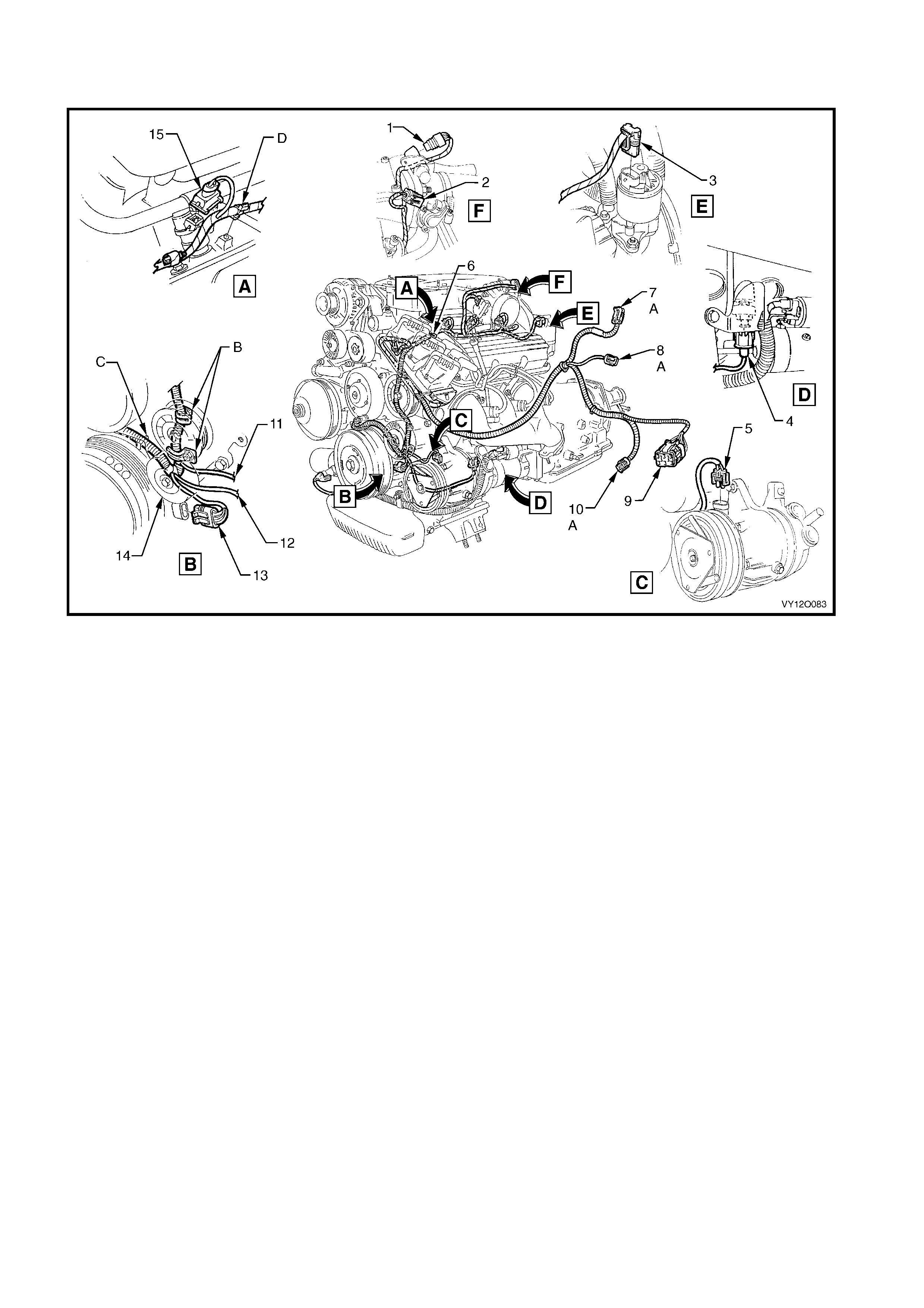
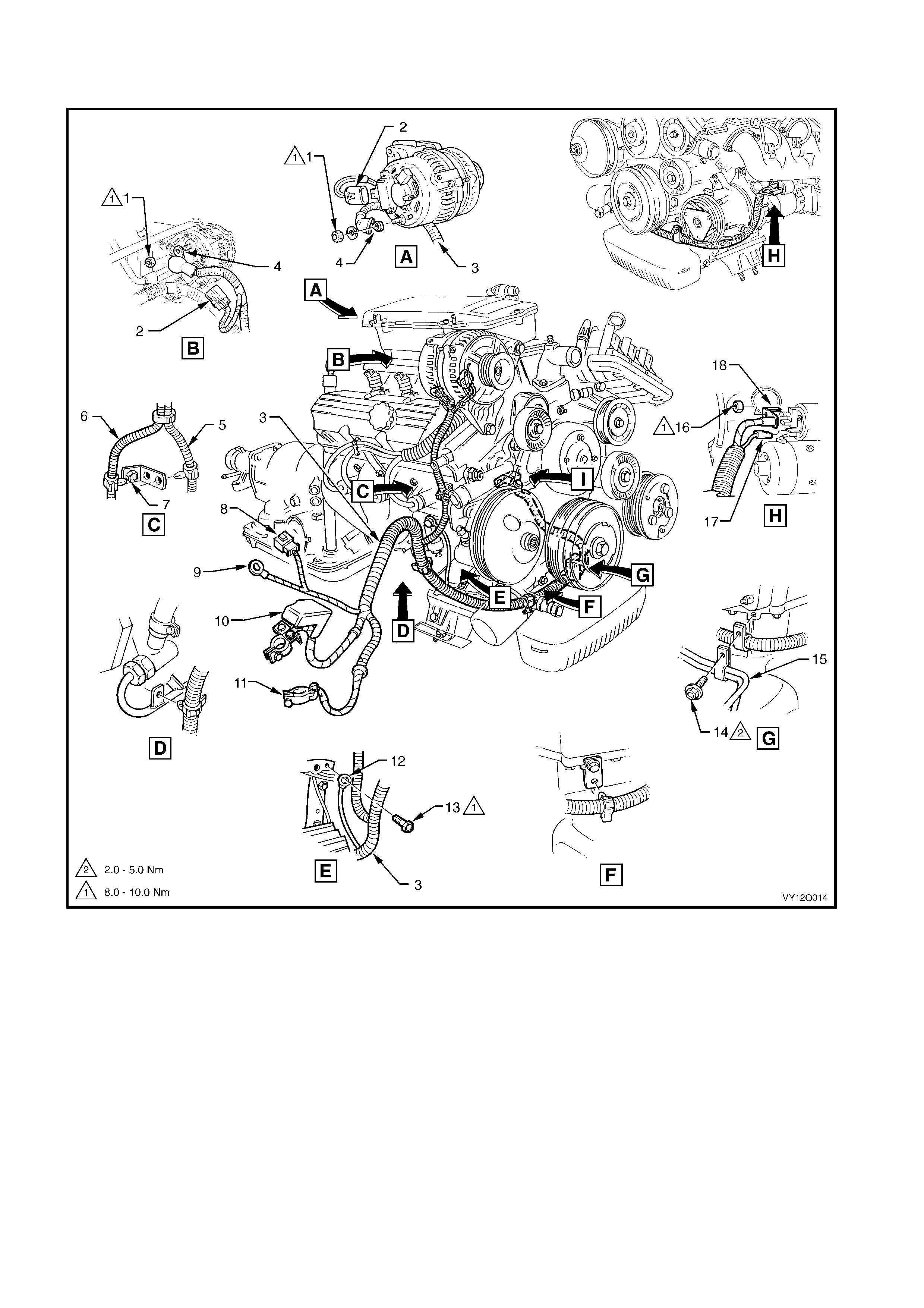
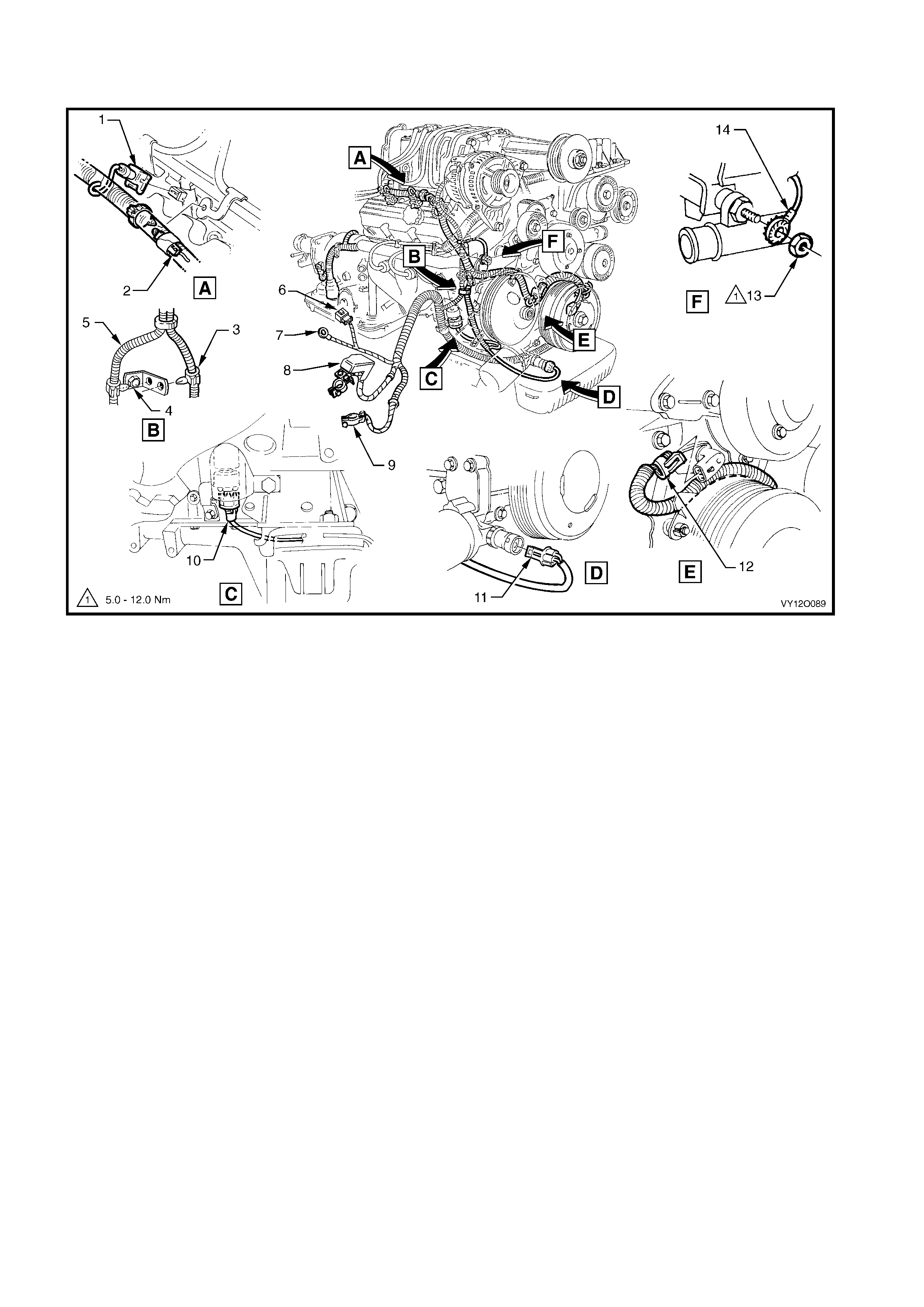
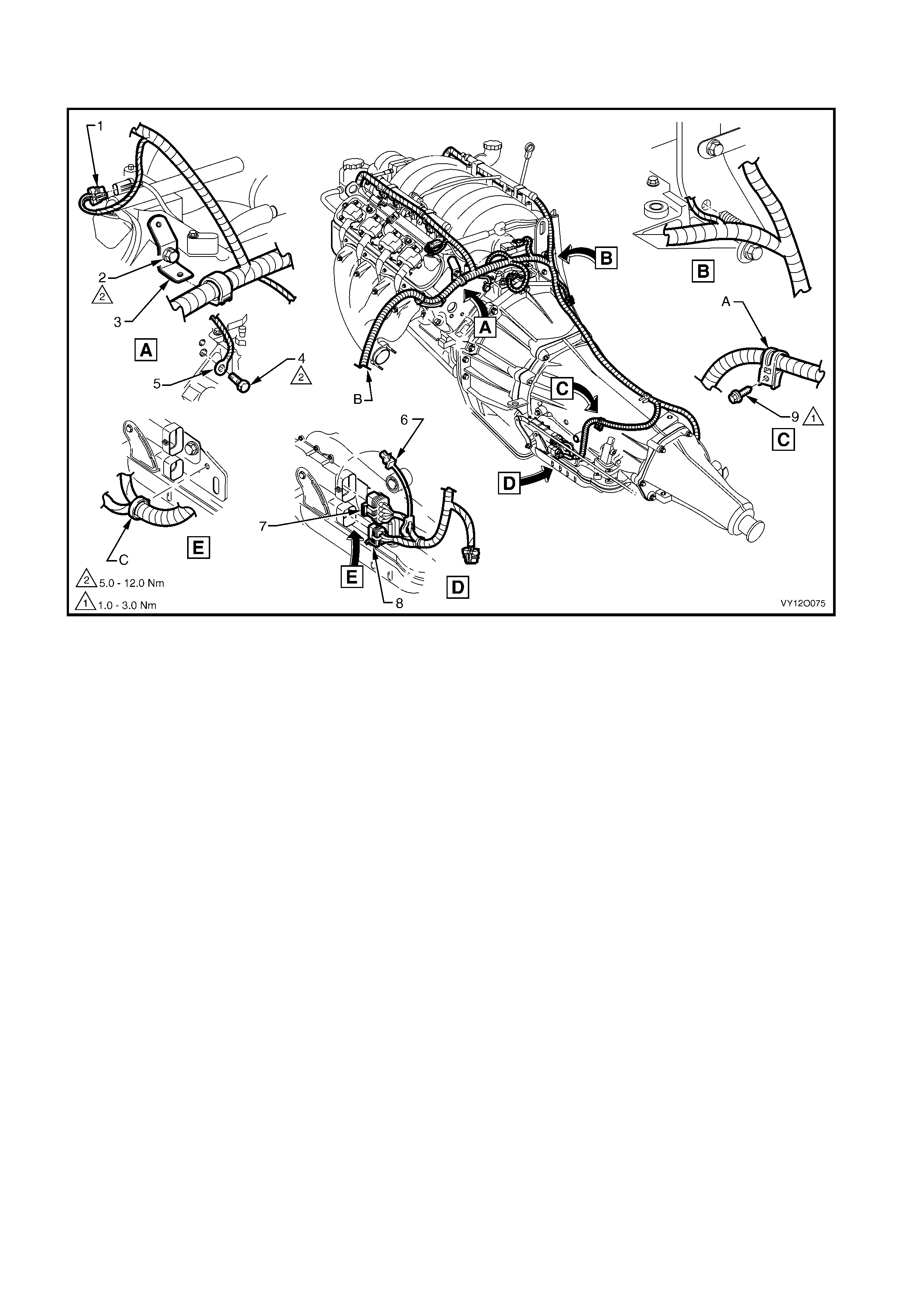
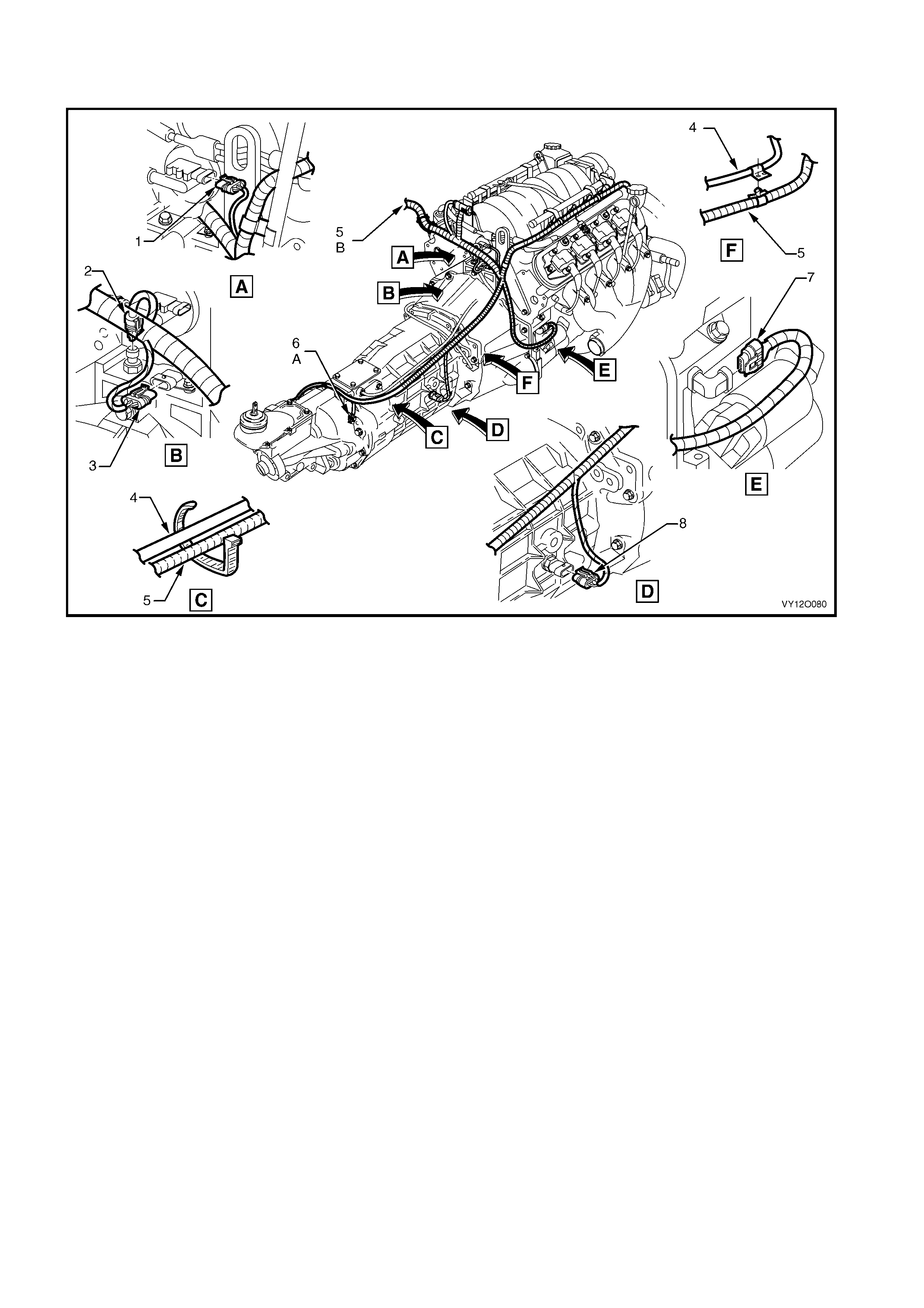
POWERTRAIN HARNESS – 3
V6 WITH AIR CONDITIONING OR ELECTRONIC CLIMA TE CONTROL
Figure 12O-43
Legend
1. Idle Speed Control Actuat or Connector (Y20)
2. Throttle Posit i on Sensor Connector (B82)
3. E.G.R. Valve Connector (Y56)
4. Knock Sensor Connect or (B65)
5. A/C Clutc h Connector (L7)
6. Suppression Di ode A/ C Compressor (V 6)
7. M.A.S.S Sensor Connector (B68)
8. Air Temperature Sensor Connect or (B64)
9. Powertrain Harness to Main Wiring Harness Connec tor
(X101)
10. A/C Pressure Sensor Connector (B18)
11. A/C Compressor Lead
12. Knock Sensor Lead, Left-hand Side
13. Crankshaft Position Sensor Connector (B30 – V6)
14. Idler Pulley
15. Fuel Injector Connector (L2)
A. For continuation, refer to POWERTRA IN HARNESS – 4 in this
section.
B. Clips bent over t o retain powertrain harness.
C. Powertrain harness routed through groove in crankshaft
position sensor shield.
D. Secure harness t o manifold as shown.
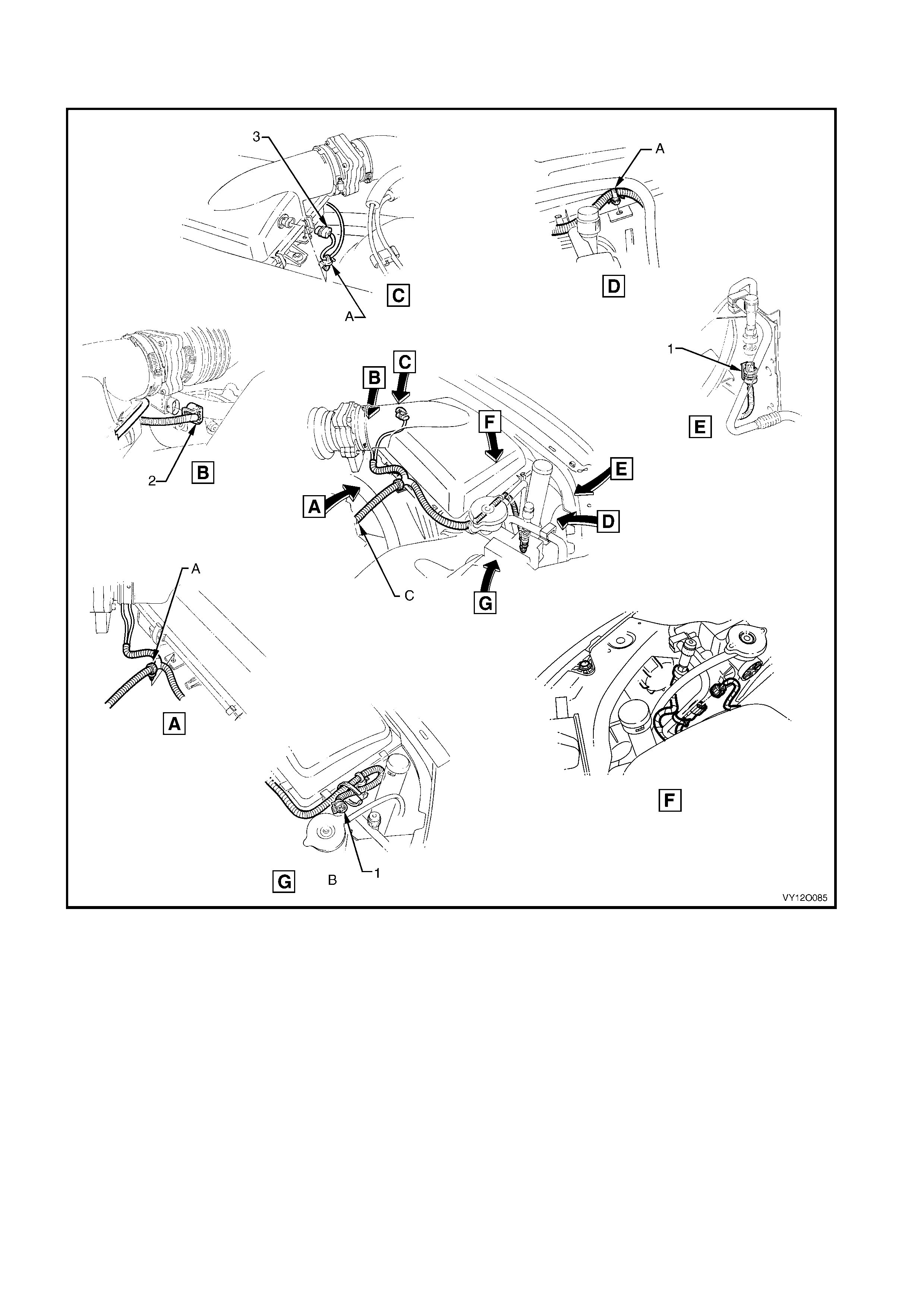
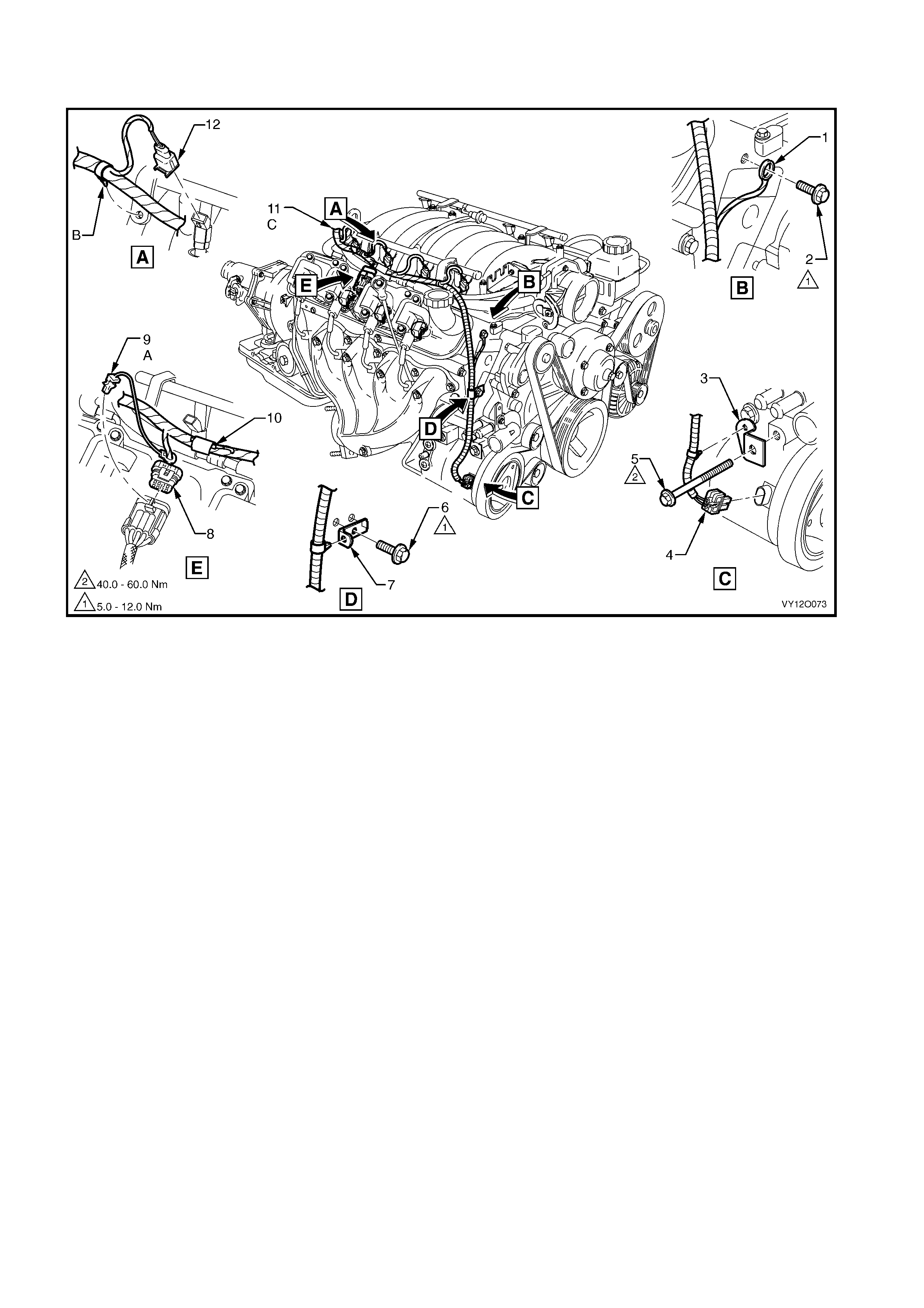
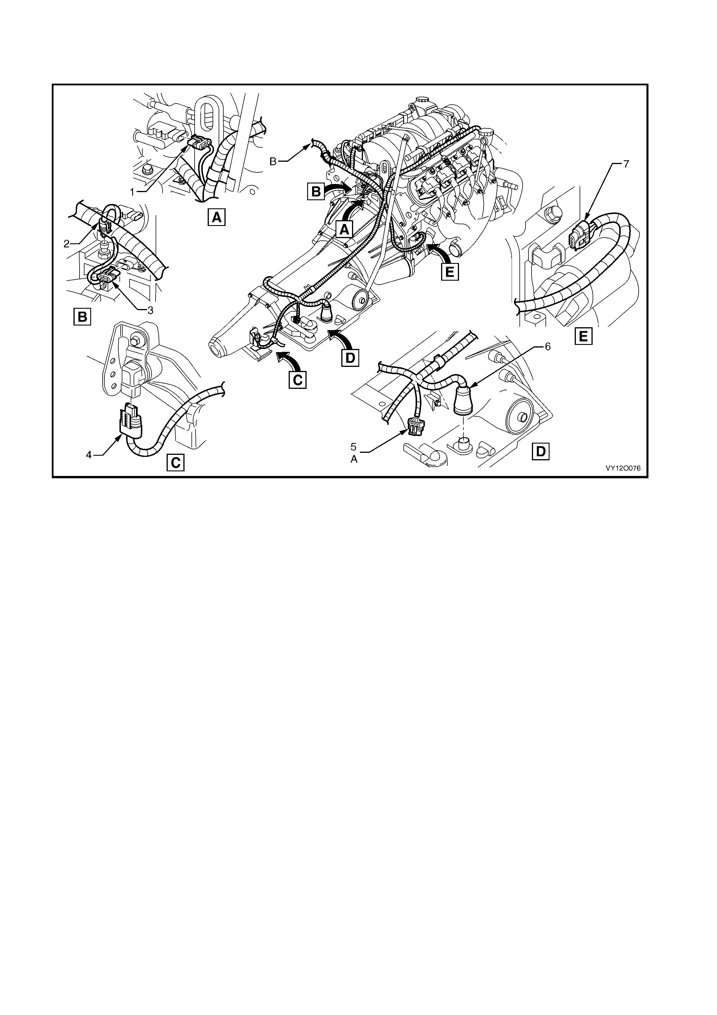
POWERTRAIN HARNESS – 4
V6 ENGINE WITH AIR CONDITIONING OR ELECTRONIC CLIMATE CONTROL
Figure 12O-44
Legend
1. A/C Pressure Sensor Connector (B18)
2. M.A.S.S Sensor Connector (B68)
3. Intake Air Temperature Sensor Connector (B 64)
A. Powertrain harness secured to air box as shown.
B. View shows vehicles without A/ C or electronic climat e control.
C. For continuation, refer to POWERTRAIN HARNESS – 10 in
this section.
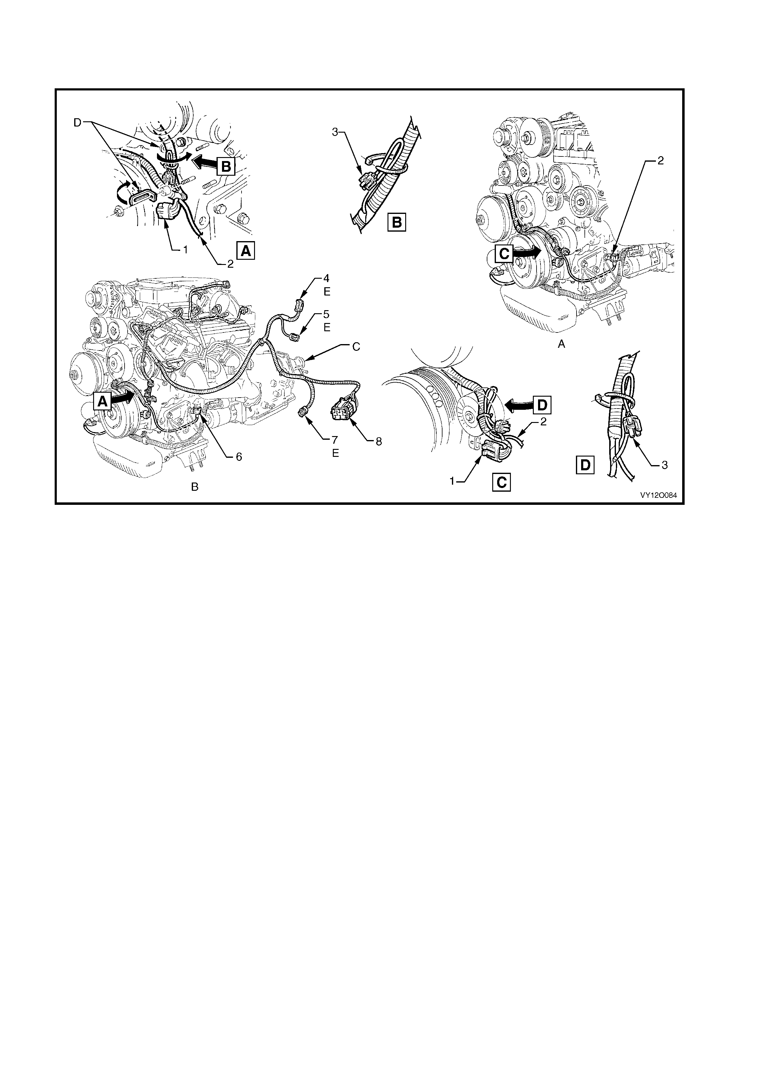
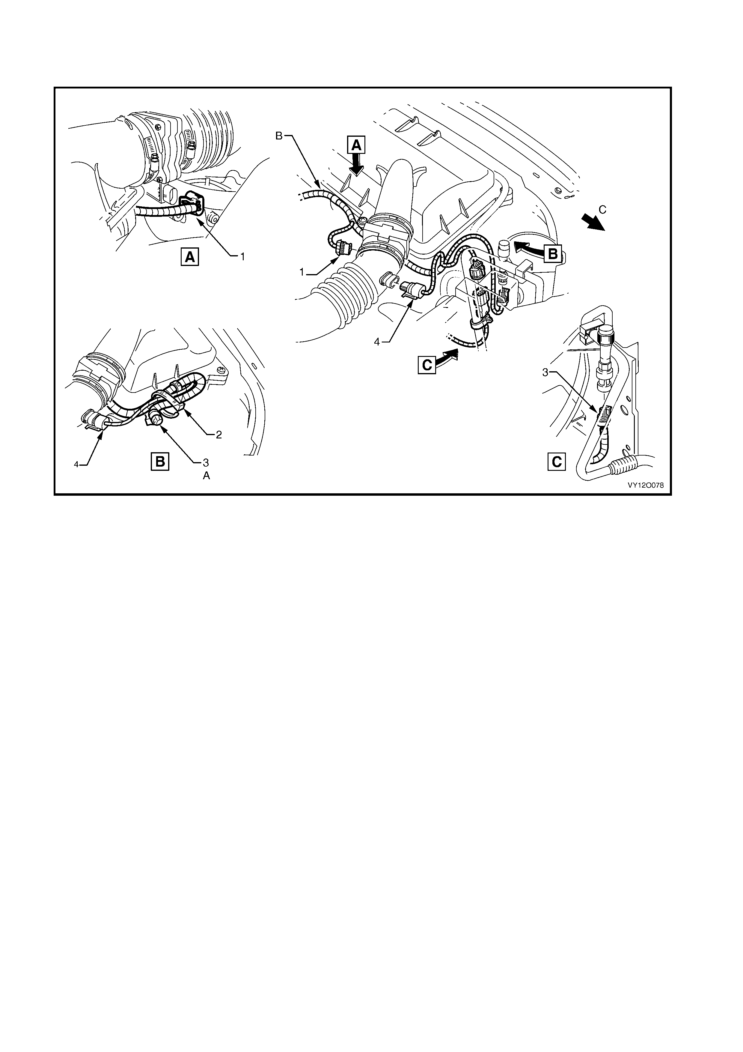
POWERTRAIN HARNESS – 5
V6 ENGINE WITHOUT AIR CONDITIONING OR ELECTRONIC CLIMATE CONTROL
Figure 12O-45
Legend
1. Crankshaft Position Sensor Connector (B30 – V6)
2. Knock Sensor Lead, Left-hand Side
3. A/C Clutc h Connector (L7)
4. M.A.S.S Sensor Connector (B68)
5. Intake Air Temperature Sensor Connector (B 64)
6. Knock Sensor Connect or (B65)
7. A/C Pressure Sensor Connector (B18)
8. Powertrain Harness to Main Wiring Harness Connec t o r (X101)
A. V6 supercharged engine shown.
B. V6 normally aspirat ed engine shown.
C. Automatic transmission shown.
D. Clips bent over t o retain powertrain harness.
E. For inst al l ation, refer to POW ERTRAIN HARNESS – 4 in this
section.
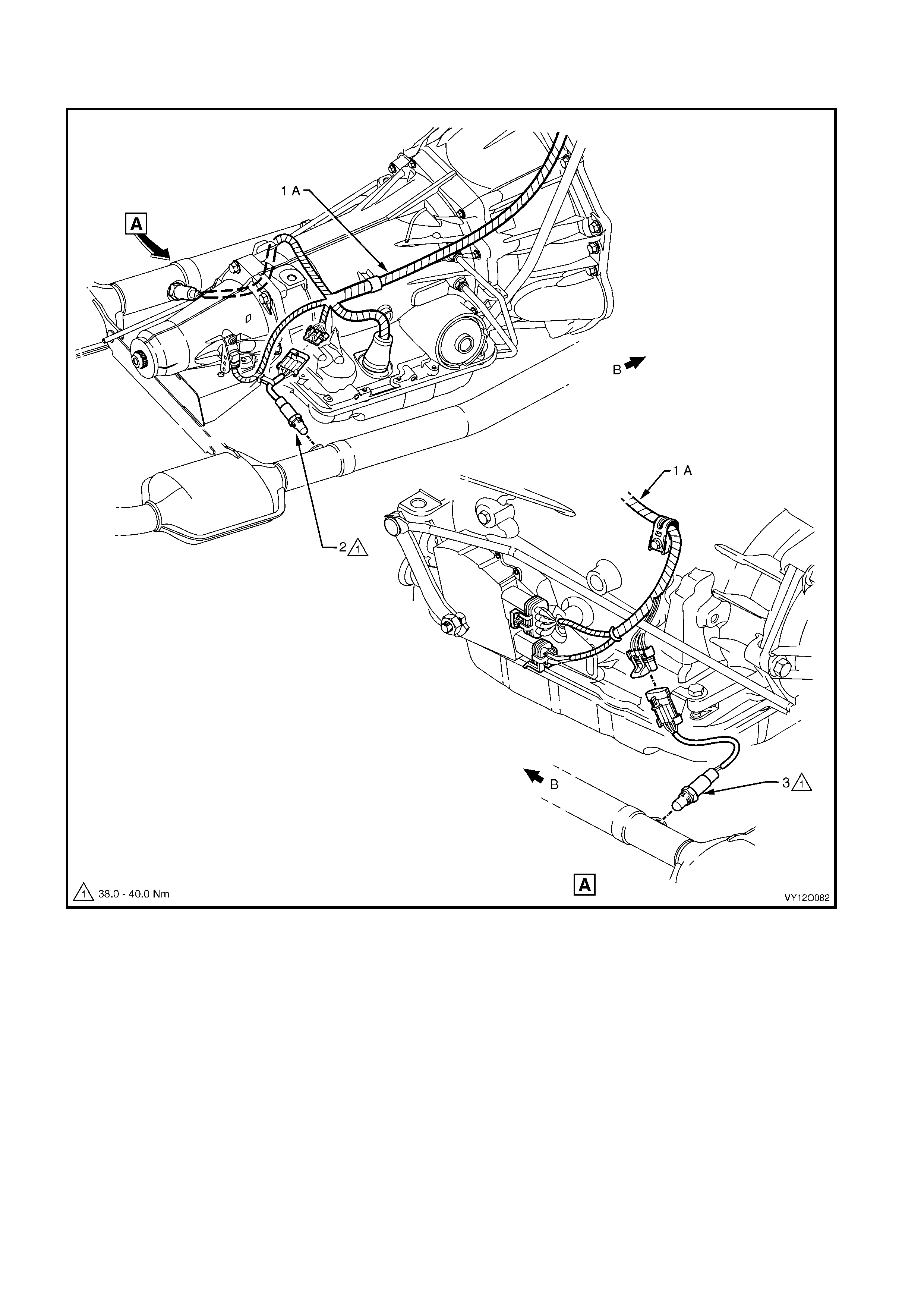
POWERTRAIN HARNESS – 6
V6 ENGIN E WIT H AUTOM ATIC T R ANSMISSION
Figure 12O-46
Legend
1. Powertrain Harness to Main Wiring Harness Connec tor
(X206)
2. Powertrain Control Module Connec tor (A84 – V6 – X1)
3. Powertrain Control Module Connec tor (A84 – V6 – X2)
4. Powertrain Control Module Connec tor (A84 – V6 – X3)
5. Horn Connector (B 9)
6. Canister Purge Sol enoi d Val ve Connector (Y123)
7. Exhaust Gas Sensor Connect or (B70)
8. Engine Ground Terminal (X119 – GP5)
9. Exhaust Gas Sensor Connect or (B70)
A. Powertrain harness secured to canister purge module as
shown.
B. Secure harness t o engi ne as shown.
For views B, C, D and E, refer to POWERT RAI N HARNES S – 7 in
this section.
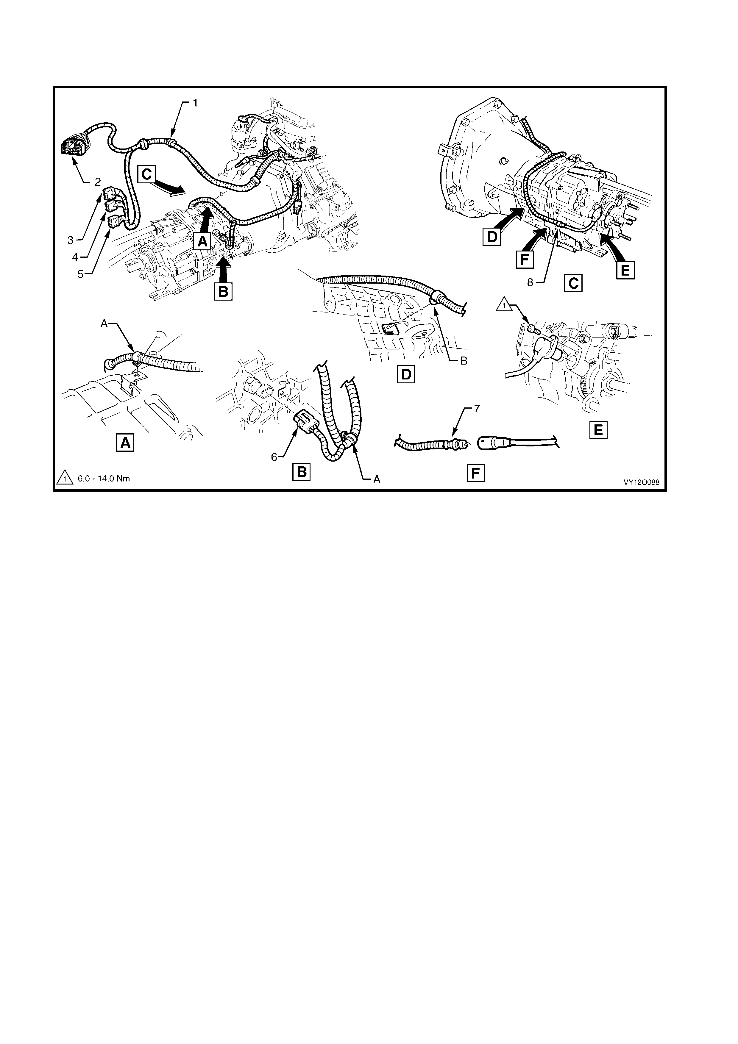
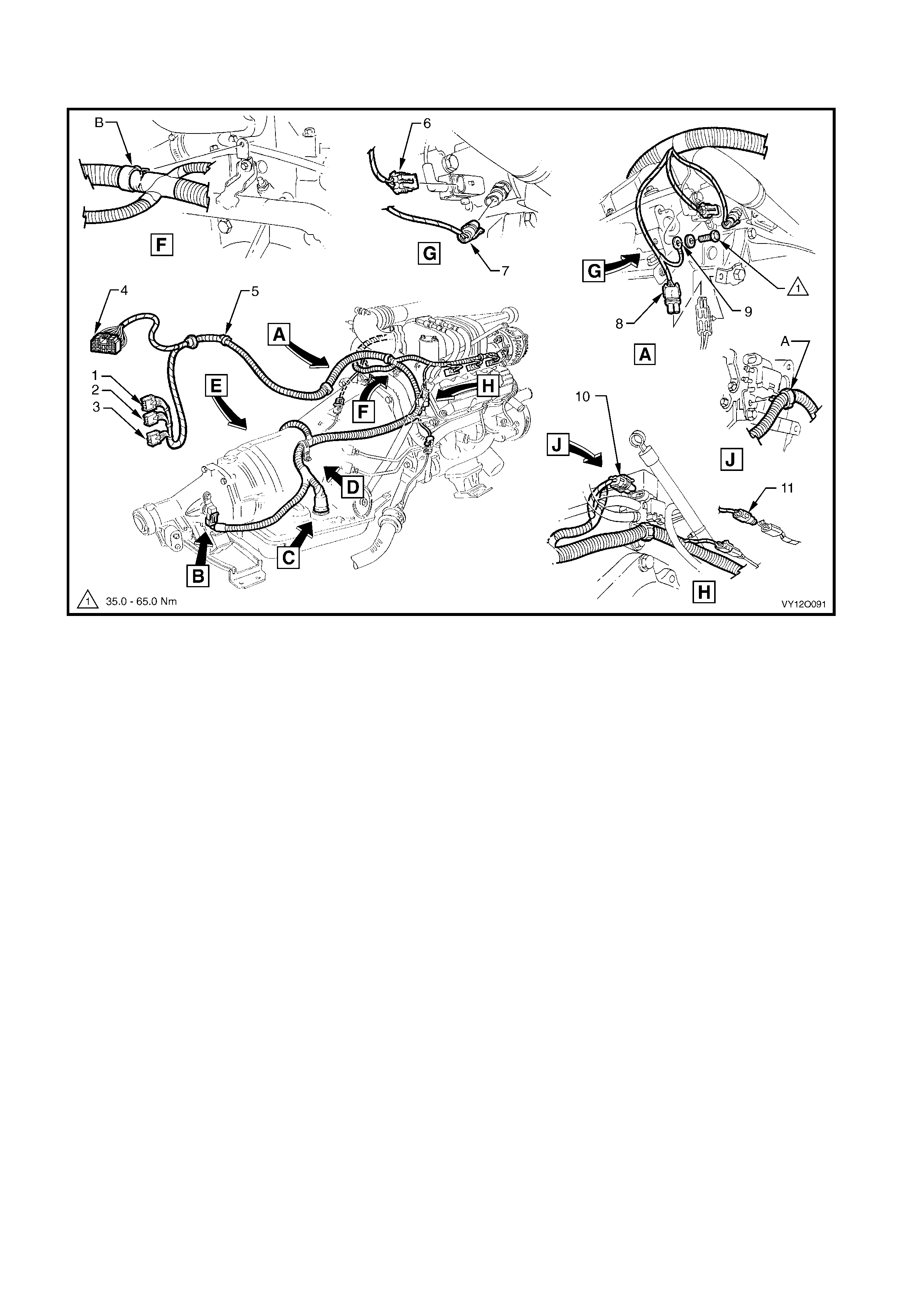
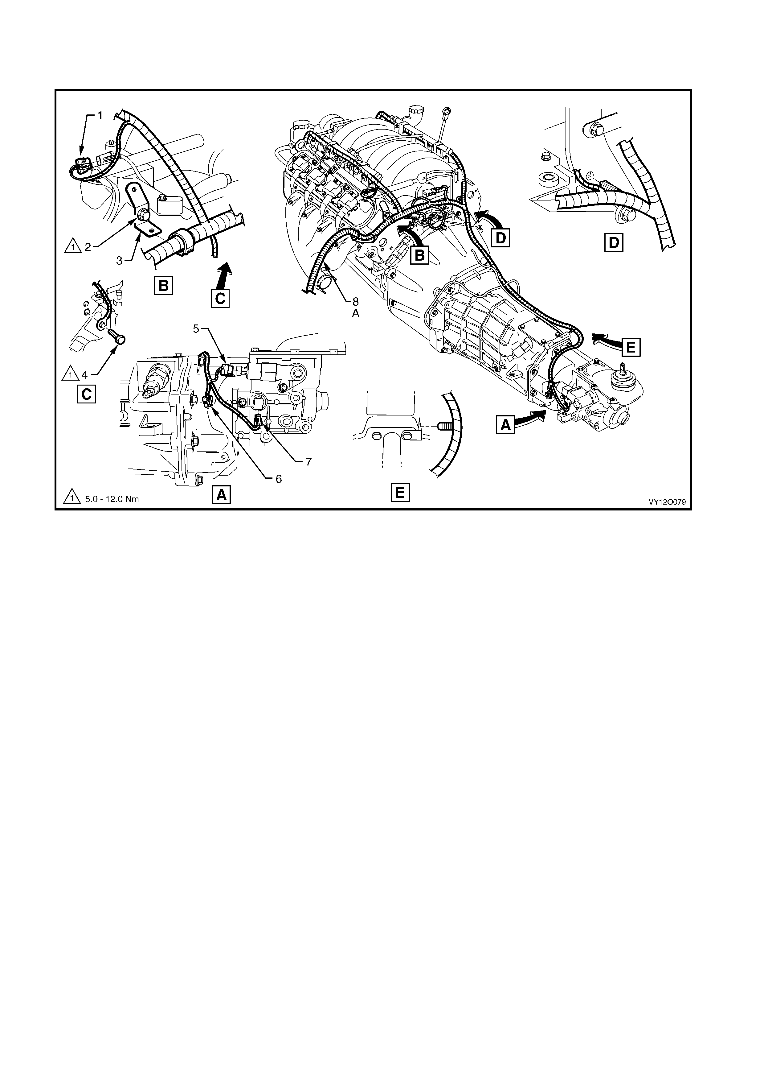
POWERTRAIN HARNESS – 7
V6 ENGIN E WIT H AUTOM ATIC T R ANSMISSION
Figure 12O-47
Legend
1. Speed Sender Connector (X121 – X1)
2. C.P.A. Lock
3. Park/Neutral Position Switch Connector (A83)
4. Transmission Ass em bl y Connect or (X121 – X2)
For location of views B, C, D & E, refer to
POWERT RAI N HARNES S – 6 in this section.
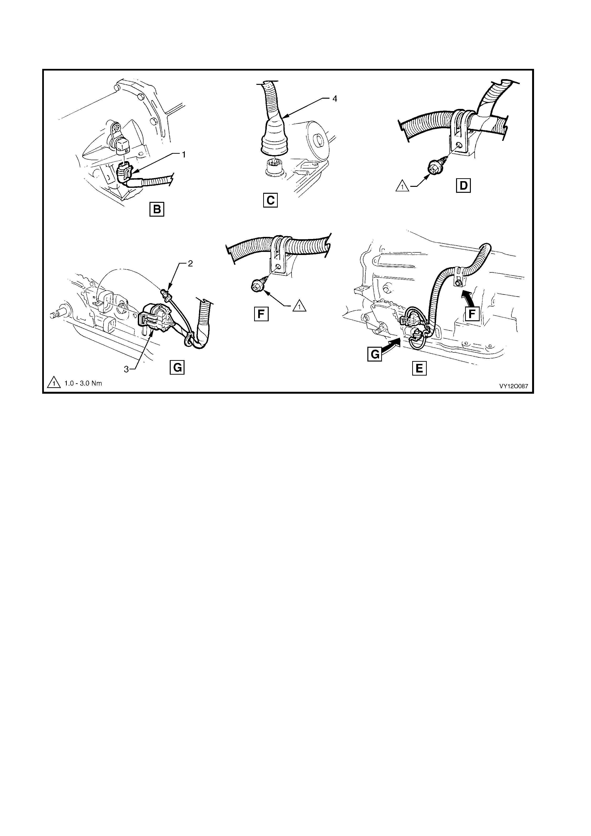
POWERTRAIN HARNESS – 8
V6 ENGINE WITH MANUAL TRANSMISSION
Figure 12O-48
Legend
1. Horn Connector (B 9)
2. Powertrain Harness to Main Wiring Harness Connec tor
(X206)
3. Powertrain Control Module Connec tor (A84 – V6 – X1)
4. Powertrain Control Module Connec tor (A84 – V6 – X2)
5. Powertrain Control Module Connec tor (A84 – V6 – X3)
6. Backup Lamp Switch Connect or (S32)
7. Front Wheel Speed Sensor Connector (B52)
8. Speed Sensor Lead
A. Powertrain harness secured to transmission bracket as shown.
B. Transmission output speed sensor lead secured to
transm issi on housi ng as shown.
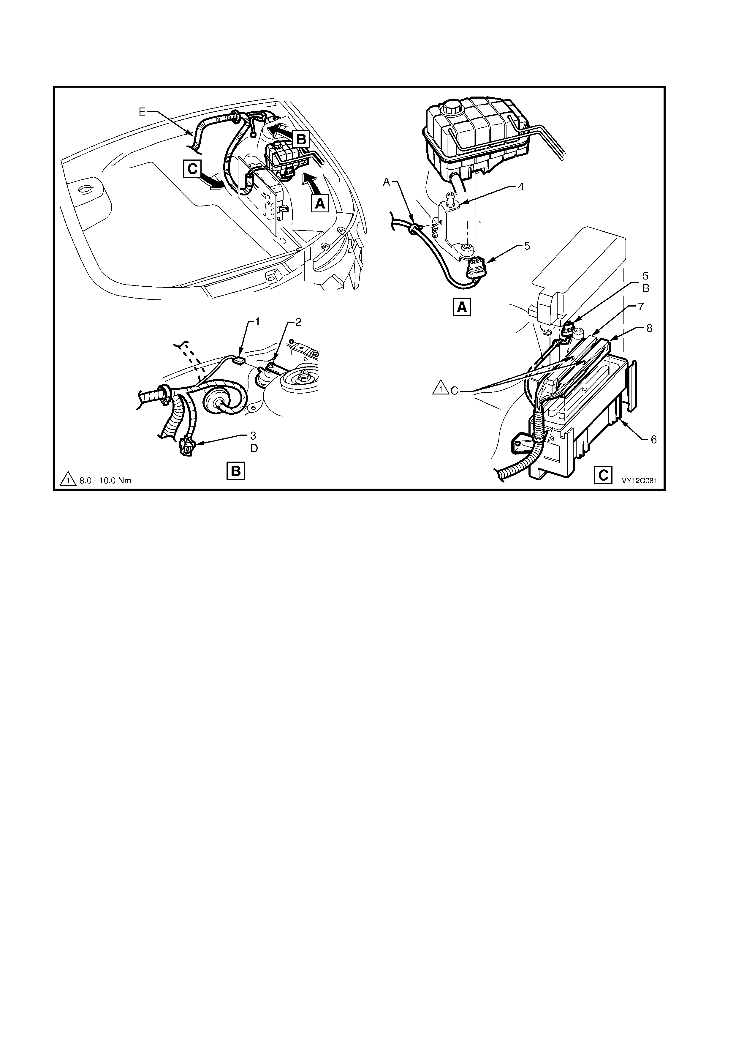
POWERTRAIN HARNESS – 9
V6 SUPERCHARGED ENGI NE
Figure 12O-49
Legend
1. Fuel Injector Connect or (L2) – (6 Places)
2. Suppression Di ode A/ C Compressor Connec tor (V6)
3. Clip
4. Bracket – Battery W i ri ng Harness to E ngi ne
5. Powertrain Harness
6. Batte ry Wi ring Harness to Main Wiring Harness Connector
(X106)
7. A.B.S. Bracket Terminal (X119 – G4 – GP3)
8. Batt ery Connector – Positive (G1 – X1)
9. Battery Connector – Negative (G1 – GP1 – X2)
10. Knock Sensor Connector (B65)
11. Engine Oil Pressure Indicator Switch Connecto r (S 87)
12. Camshaft Position Sensor Connector (B28 – V8)
13. Nut
14. Engine Ground Terminal (X119 – GP5)
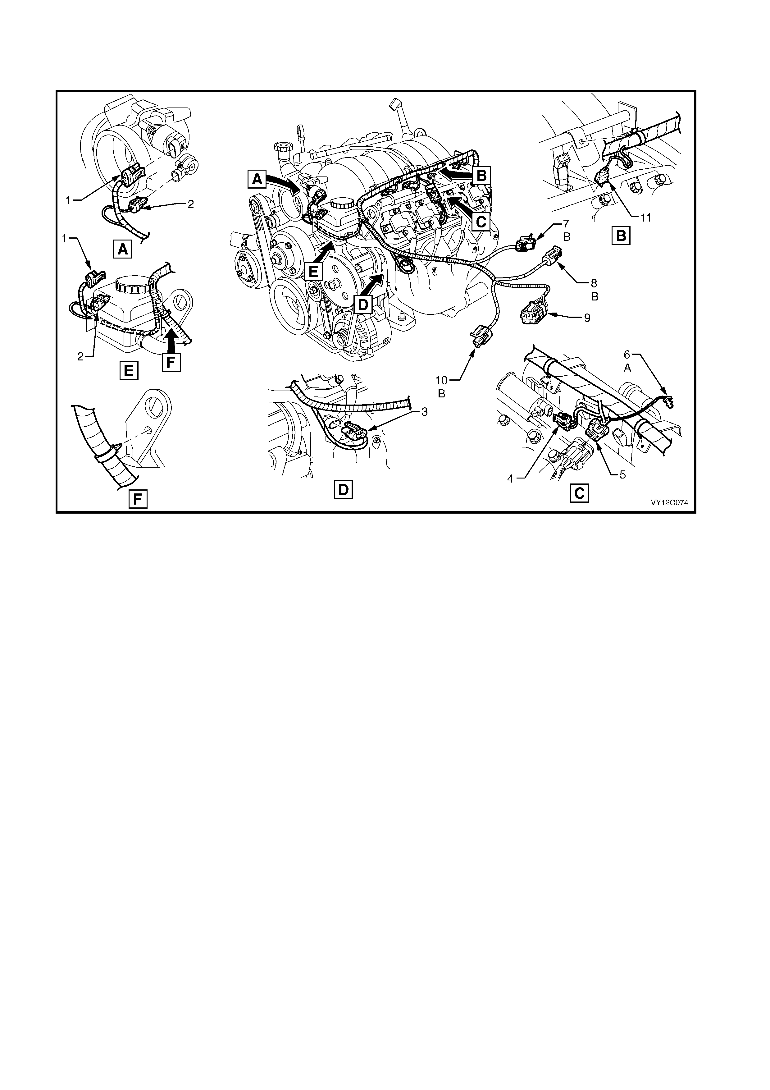
POWERTRAIN HARNESS – 10
V6 SUPERCHARGED ENGINE WITH AIR CONDITIONING OR ELECTRONIC CLIMATE CONTROL
Figure 12O-50
Legend
1. Throttle Posit i on Sensor Connector (B82)
2. Idle Speed Control Actuator Connector (Y20)
3. Electroni c I gnit i on Cont rol Module Connector (A40 – R)
4. Direct Ignition System Control Module
5. Fuel Injector Connect or (L2)
6. Knock Sensor Connect or (B65)
7. A/C Clutc h Connector (L7)
8. A/C Compressor Connector Lead
9. Crankshaft Position Sensor Connector (B30 – V6)
10. Idler Pulley
11. Knock Sensor Lead, Left-hand Side
12. A/C Pressure Sensor Connector (B18)
13. Powertrain Harness to Main Wiring Harness Connec tor
(X101)
14. Intake Air Temperature Sensor Connector (B 64)
15. M.A.S.S Airflow Sens or Connect or (B68)
A. Powertrain harness secured to bracket as shown.
B. Powertrain harness routed through groove in crankshaft
position sensor shield.
C. For instal lation, refer t o POWERTRAIN HARNESS – 4 in this
section.
POWERTRAIN HARNESS – 11
V6 SUPERCHARGED ENG INE WIT H AUTOMATIC TR ANSMISSIO N
Figure 12O-51
Legend
1. Powertrain Control Module Connec tor (A84 – V6SC – X1)
2. Powertrain Control Module Connec tor (A84 – V6SC – X2)
3. Powertrain Control Module Connec tor (A84 – V6SC – X3)
4. Main Wiring Harness to Powertrain Harness Connect or (X206)
5. Horn Connector (B 9)
6. Boost Control Valve Connector (Y142)
7. Engine Coolant Temperat ure Sensor Connector (B 39)
8. Heated Oxygen Sensor Connect or (B56 – L - V6SC)
9. Engine Ground Terminal (X119 – GP5)
10. Canister Purge Solenoid Valve Connector (Y 123)
11. Heated Oxygen Sensor (Position 2) Connector
(B57 – R – V6SC)
A. Powertrain harness secured to purge canister solenoid bracket
as shown.
B. Powertrain harness secured to bracket as shown.
For views B, C, D, & E, refer to POWERTRAIN HA RNESS – 7 in
this section.
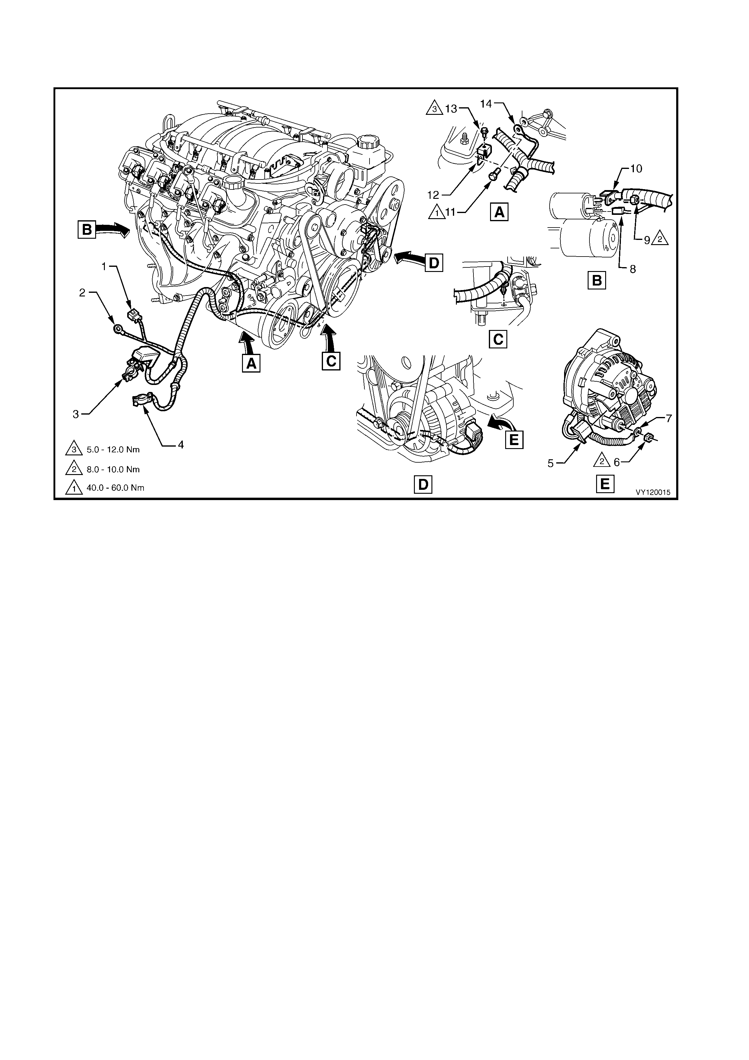
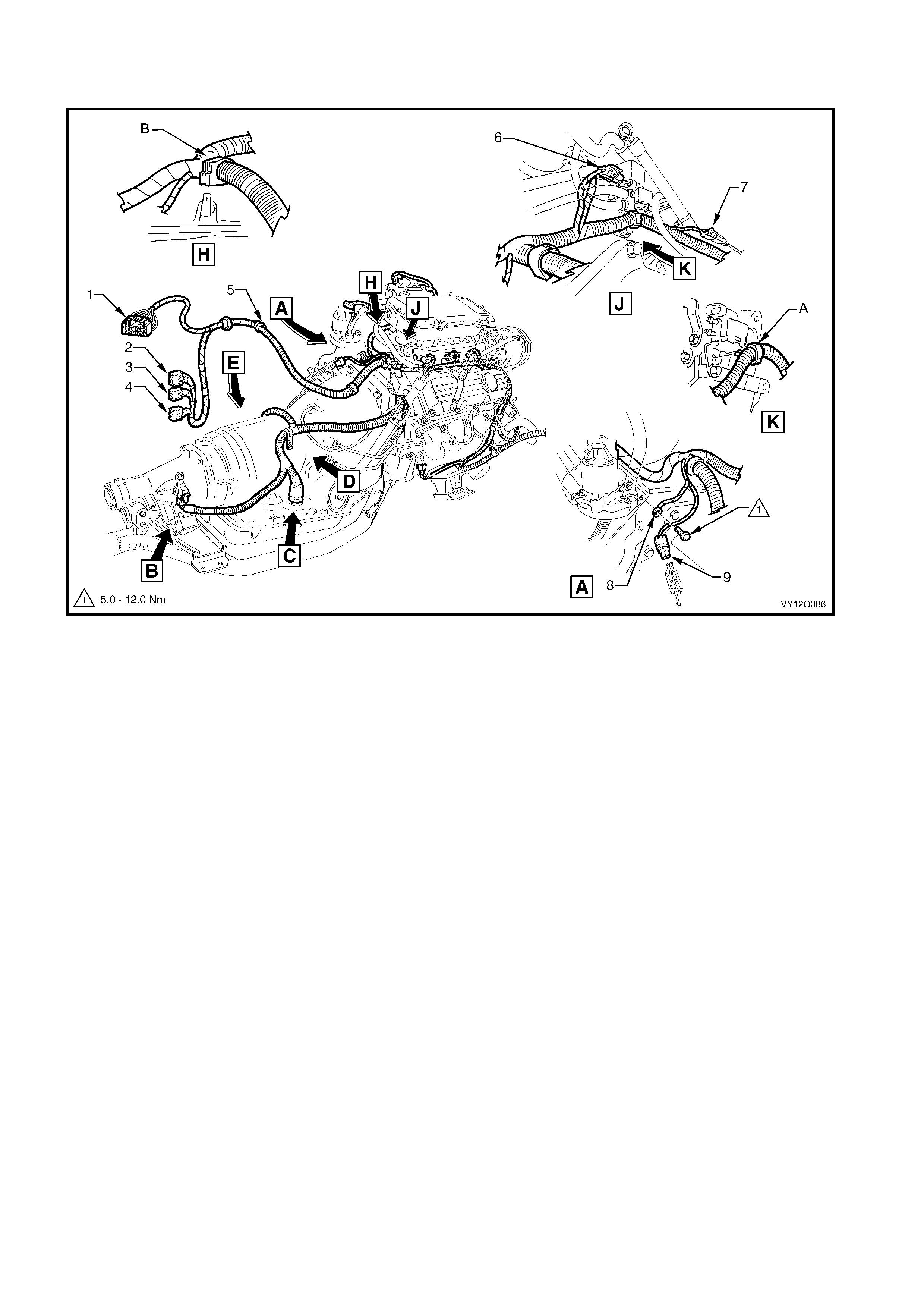
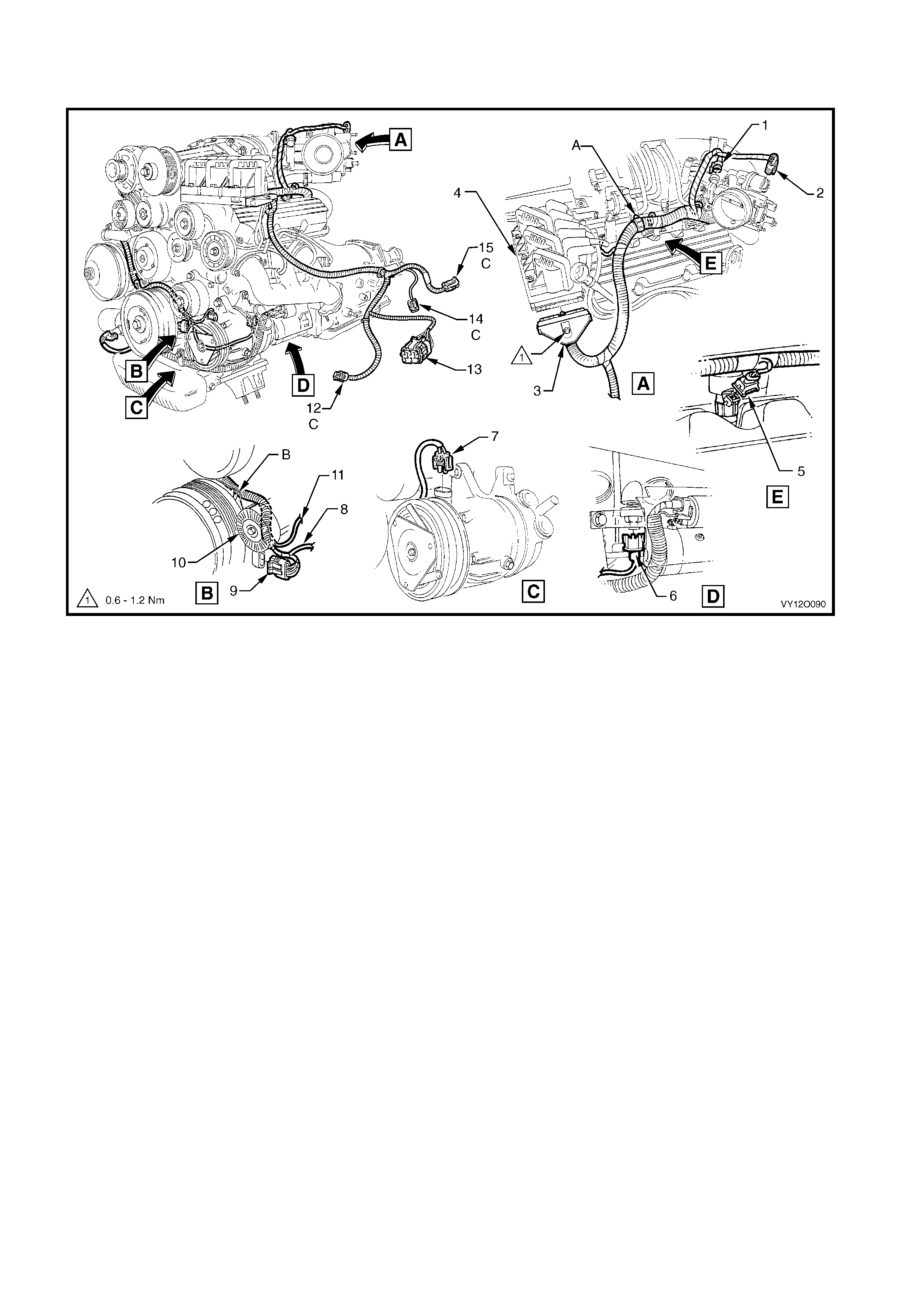
POWERTRAIN HARNESS – 12
ALL MODELS WITH GEN III V8 ENGINE
Figure 12O-52
Legend
1. Powertrain Harness to Engine Ground Termi nal
(X119 – GP5)
2. Ground Terminal Attaching Bolt
3. Air-condi tioni ng Compressor Powertrain Harness S upport
Bracket
4. A/C Clutc h Connector (L7)
5. Air conditi oni ng Compress or Mount i ng Bolt
6. Powertrain Harness Support Bracket Bolt
7. Powertrain Harness Support Bracket
8. Electroni c I gnit i on Cont rol Module Connector (A40 – R)
9. CPA Lock
10. Suppression Diode A/C Compressor Connect o r
11. Powertrain Harness
12. Fuel Injector Connector (L2)
A. CPA lock is part of the powertrain harness and is inserted i nto
the ignition modul e connector on assembly.
B. Powertrain harness is secured t o bracket in two places on
right-hand si de.
C. For continuation of the powertrain harness, refer to
POWERT RAI N HARNES S – 15 in this sec tion .
POWERTRAIN HARNESS – 13
ALL MODELS WITH GEN III V8 ENGINE
Figure 12O-53
Legend
1. Horn Connector (B 9)
2. Theft Deterrent Horn
3. Throttle Actuat or Connect or (Y38)
4. Coolant Surge Tank Bracket
5. Engine Coolant Level Switch Connector (S84)
6. Powertrain Control Module (P CM)
7. Powertrain Control Module Connector (A84 – V8 – X2)
8. Powertrain Control Module Connector (A84 – V8 – X1)
A. Clip fitt ed to bracket before s urge tank is fitted.
B. Lead for the surge tank low coolant level switc h is to be routed
on top of the PCM cover.
C. Ensure the PCM connector attaching bolts are not over
tightened.
D. Throttle rel axer connect or l ocat i on for dom estic ri ght-hand drive
vehicles onl y.
E. For continuation of powertrain harnes s, refer to
POWERT RAI N HARNES S – 14, 15 & 16 in this section .
POWERTRAIN HARNESS – 14
ALL MODELS WITH GEN III V8 ENGINE
Figure 12O-54
Legend
1. Idle Speed Control Actuat or Connector (Y20)
2. Throttle Posit i on Sensor Connector (B82)
3. Engine Coolant Temperat ure Sensor Connector (B 39)
4. Canister Purge Sol enoi d Val ve Connector (Y123)
5. Electroni c I gnit i on Module Connect o r (A 40 – L)
6. CPA Lock
7. M.A.S.S Sensor Connector (B68)
8. Intake Air Temperature Sensor Connector (B 64)
9. Powertrain Harness to Main Wiring Harness Connec tor
(X101)
10. A/C Pressure Sensor Connector (B18)
11. Fuel Injector Connector (L2) – Left-hand Side
A. CPA Lock is part of the powertrain harnes s and is ins ert ed
into the ignition modul e connect or on assem bl y.
B. For continuation of the powertrain harness, refer to
POWERT RAI N HARNES S – 17 in this sec tion .
POWERTRAIN HARNESS – 15
ALL MODELS WITH GEN III V8 ENGINE
Figure 12O-55
Legend
1. Knock Sensor Connect or (X107)
2. Bolt
3. Powertrain Harness Support Bracket
4. Powertrain Harness Ground Terminal Attaching Bolt
5. Engine Ground Terminal (X119 – GP6)
6. CPA Lock
7. Park/Neutral Position Switch Connector (A83)
8. Park/Neutral Position & Back-up Switch Connector (S187)
9. Powertrain Harness At taching Bolt (2 Places)
A. Clip (two places) bent over after fitting to harness ass embly.
B. For continuation of the powertrain harness, refer to
POWERT RAI N HARNES S – 13 in this sec tion .
C. Neutral start, back-up lamp and PRNDL connectors to be
inserted i nto switc h assem bl y before insert i ng harness-
retaining clip into hole.
POWERTRAIN HARNESS – 16
ALL MODELS WITH GEN III V8 ENGINE
Figure 12O-56
Legend
1. M.A.P. Sensor Connect or (B67)
2. Engine Oil Pressure Sensor Connector (B42)
3. Camshaft Posit i on Sens or Connector (B28 – V8)
4. Speed Sender Connector (X121 – X1)
5. Heated Oxygen Sensor Connector (B57 – R – V8)
6. Transmission Assembly Connect or (X121 – X2)
7. Crank Angle Sensor Connector (B30 – V8)
A. For continuation, refer to POWERTRAIN HARNESS – 22 in
this section.
B. For continuation, refer to POWERTRAIN HARNESS – 13 in
this section.
POWERTRAIN HARNESS – 17
ALL MODELS WITH GEN III V8 ENGINE
Figure 12O-57
Legend
1. M.A.P. Sensor Connect or (B67)
2. Cable Tie
3. A/C Pressure Sensor Connector (B18)
4. Intake Air Temperature Sensor Connector (B 64)
A. View for vehicl es fitt ed with non-ECC air-conditioni ng.
B. For continuation, refer to POWERTRAIN HARNESS – 14 in
this section.
C. Front of vehicle.
POWERTRAIN HARNESS – 18
POWERTRAIN CONTROL MODULE – ALL MODELS WITH V6 AND V6 SUPERCHARGED ENGINE
Figure 12O-58
Legend
1. Cowl Panel – Left-hand Side
2. Body Wiring Harness
3. Powertrain Harness
4. Powertrain Cont rol Module Mounti ng Bracket
5. Powertrain Cont rol Module
6. Powertrain Control Module Connec tor (A84 – V6 – X2)
7. Powertrain Control Module Connec tor (A84 – V6 – X1)
8. Powertrain Control Module Connec tor (A84 – V6 – X3
A. Front of vehicle.
POWERTRAIN HARNESS – 19
ALL MODELS WITH GEN III V8 ENGINE
Figure 12O-59
Legend
1. Mounting Bracket
2. Throttle Relaxer Control Module
3. Powertrain Interface Module (PIM)
4. Powertrain Interface Module Connector (A5)
5. Throttle Actuat or Control Module Connect or (A 111)
A. For continuation, refer to POWERTRAIN HARNESS – 13 in this
section.
B. Front of vehicle.
POWERTRAIN HARNESS – 20
ALL MODELS WITH GEN III V8 ENGINE
Figure 12O-60
Legend
1. M.A. P. Sens or Connect or (B67)
2. Engine Oi l Press ure Sensor Connec t or (B42)
3. Cams haft Pos iti on Sensor Connector (B28 – V8)
4. Transmission Breather Assembly
5. Powertrain Harness
6. Heated Oxygen Sensor (P osi tion 2) Connector
(B57 – R – V8)
7. Crankshaft Position Sensor Connector (B30 – V8)
8. Backup Lamp Switch Connect or (S32)
A. For continuation, refer to
POWERT RAIN WIRING HARNESS – 21 in this sec tio n .
B. For continuation, refer to
POWERT RAIN WIRING HARNESS – 13 in this sec tio n .
POWERTRAIN HARNESS – 21
ALL MODELS WITH GEN III V8 ENGINE
Figure 12O-61
Legend
1. Knock Sensor Connect or (B65)
2. Bolt
3. Powertrain Harness Support Bracket
4. Bolt
5. Reverse Lock out Solenoi d Connect or (Y144)
6. Heated Oxygen Sensor Connect or (B56 – L – V8)
7. Speed Sensor Connector (X121 – X1)
8. Powertrain Harness
A. For continuation, refer to POWERTRAIN HARNESS – 13 in this
section.
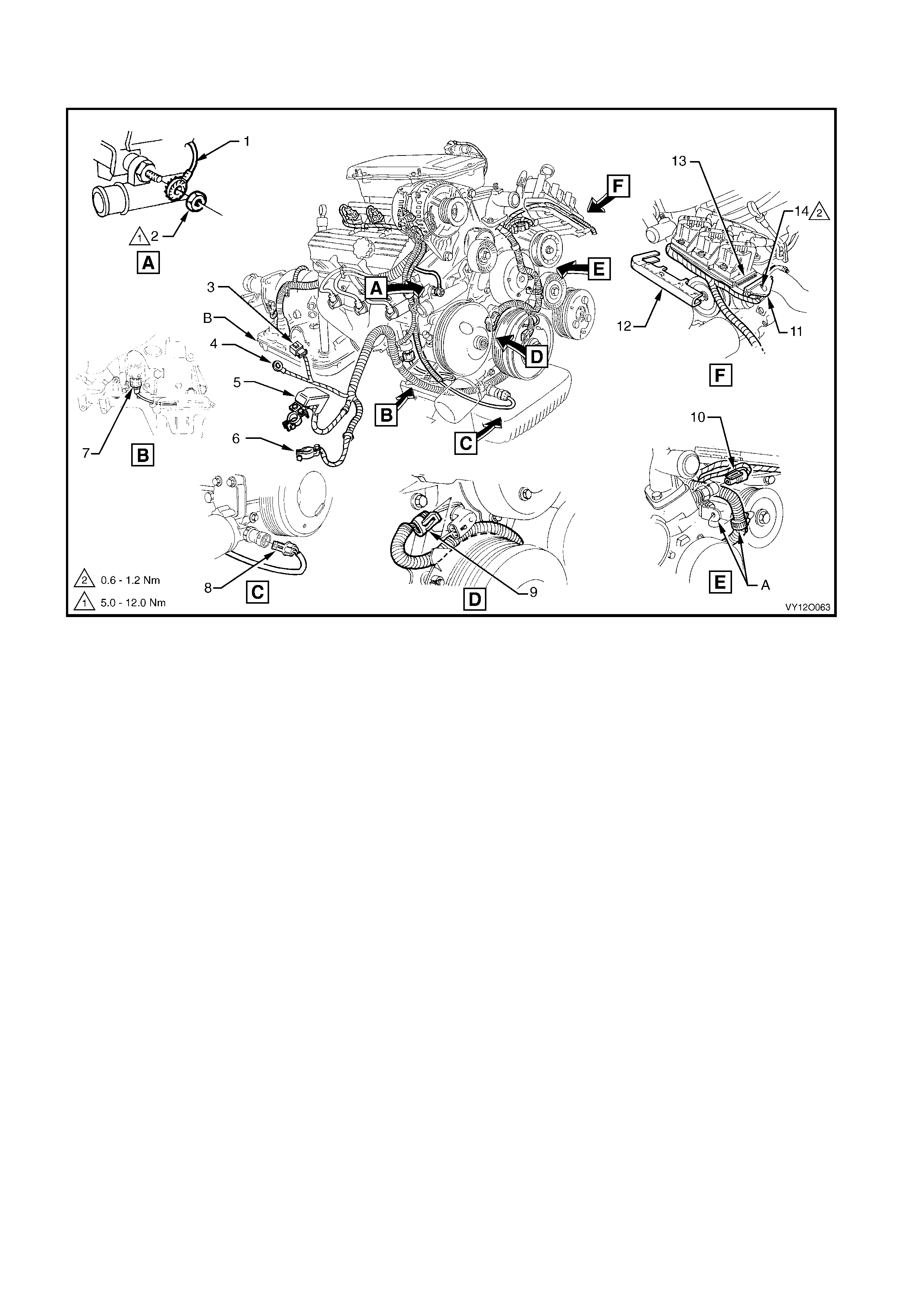
MAIN WIRING HARNESS – 1 – RHD
ENGINE COMPARTMENT
Figure 12O-63
Legend
1. Windshield Wiper Motor Connec t or (M17)
2. Brake Pressure Differential Connect or (S37)
3. Electronic Braking and Traction Control Module Connector
(A37)
4. Cruise Control Connect or (A18)
5. Main Wiring Harness to Battery Wiring Harness Connector
(X106)
6. Engine Wiring Harness J u nct i on Connector (X100)
7. Front Wheel Speed Sensor Connector (B52 – R)
8. A.B.S. Bracke t Connector (X119 – G3 – GP3)
9. Ground Connector (X157)
10. Fusible Link Supply Connector (X86 – A)
11. Turn Signal Lamp Connector (E76 – R)
12. Headlamp Connector (E83 – R)
13. Windshield Wiper and Windshield W asher Connect or (M19)
14. Front Fog Lamp Connector (E69)
15. Horn Connector (B9)
16. Ambient Air Temperature Sensor Connector (B23)
17. Hood Theft Deterrent Connector (S135)
18. Engine Cooling Fan Connector (M7 – X1)
19. Main Wiring Harness t o Powertrain Harness Connector
(X101)
20. Horn Connector (B9)
21. Front Fog Lamp Connector (E69)
22. Headlamp Connector (E83 – L)
23. Turn Signal Lamp Connector (E76 – L)
24. Front Wheel Speed Sensor Connector (B52 – L)
25. Sealing Patch Grommet
26. Grommet Insert
27. Instrument Panel to Body Ground Strap Terminal
(X118 – GP9)
28. Body to Instrument Panel Ground Strap
29. Body to Instrument Panel Ground Strap Terminal
(X119 – GP10)
For views C & D, refer to MAIN WIRING HA RNES S – 2 in this
section.
For view D, refer to MAIN WIRING HARNESS – 7 in this sectio n .
For view F, refer to MAIN WI RING HARNES S – 9 in this section.
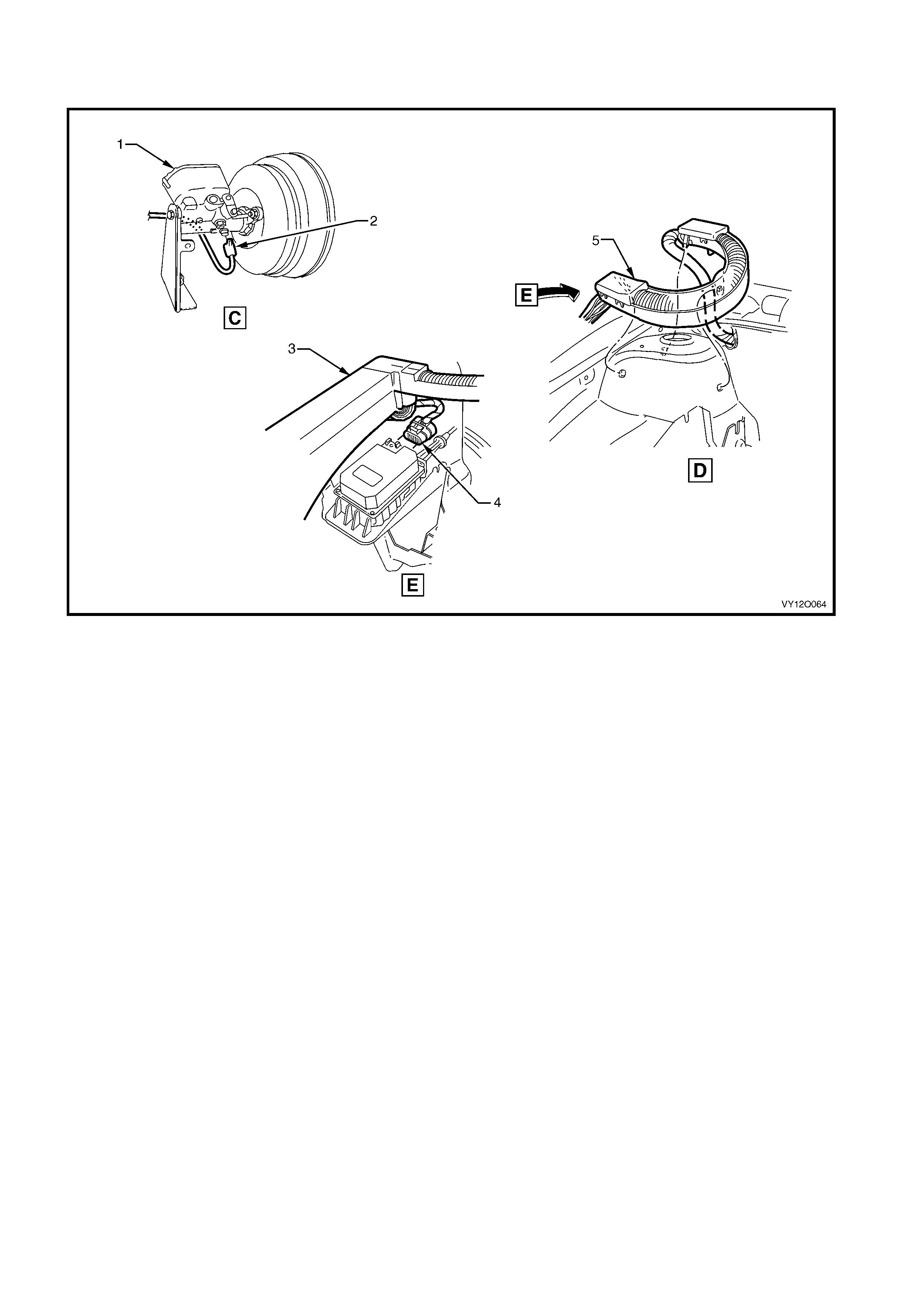
MAIN WIRING HARNESS – 2
PROTECT O R ASSEMBLY, CRUISE CONT ROL AND ENGINE HARNESS CONN ECT O RS
Figure 12O-64
Legend
1. Brake Master Cyl i nder and Brak e Boost er
2. Wiring Harness t o Brake Mast er Cylinder Support Ret ai ning
Clip
3. Brake Pressure Differential Connect or (S37)
4. Engine Wiring Harness Junction Connecter Cover
5. Cruise Control Connect or (A18)
6. Harness Former
For location of views C & D, refer to MAIN WIRING HARNESS – 1
in this section.

MAIN WIRING HARNESS – 3
UNDER HOOD FUSE & RELAY PANEL AND WIPER MOTOR CONNECTORS
Figure 12O-65
Legend
1. Engine Wiring Harness Junction Connector Cover
2. Engine Wiring Harness J u nct i on Connector (X100)
3. Attaching Screw
4. Windshield Wiper Motor Connec t or (M17)
5. Firewall Clip (2 Places)
MAIN WIRING HARNESS – 4
FRONT LAMPS, BODY GROUND AND WASHER PUMP CONNECTORS
Figure 12O-66
Legend
1. Attaching Stud – Body Ground
2. Body Ground Connector (X157 – GP2)
3. Washer – Body Ground
4. Attachi ng Nut – Body Ground
5. Headlamp Connect or (E83)
6. Turn Signal Lamp Connector (E 76)
7. Windshiel d Washer Connect or (M19)
8. Windshield Washer Reservoir
9. Battery Tray
A. Harness leads attached to right-hand side wheelhouse as
shown.
B. Level 2 and 3 indicated, Level 1 similar.

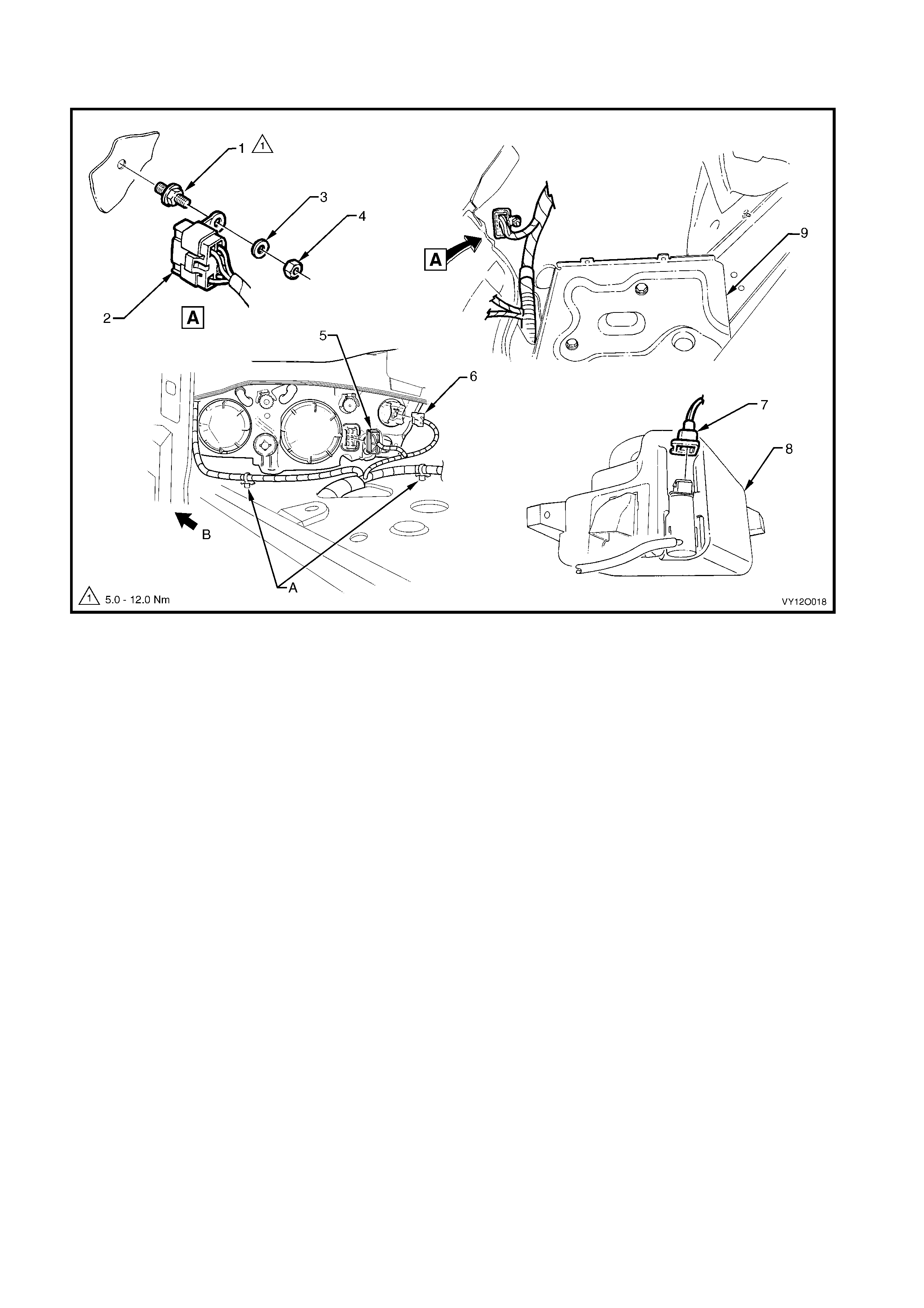
M AIN WIRING HARNESS – 5
HEADLAMP, PARK LAMP AND TURN INDICATOR WIRING HARNESS – LEVEL 2 & 3
Figure 12O-67
Legend
1. Main Wiring Harness
2. Turn Signal Lamp Connector (E 76)
3. Turn Signal Lamp Socket
4. Headlamp Connect or (E83)
5. Headlamp Low Beam Dust Cover
6. Headlamp Adjuster
7. Headlamp High Beam Dust Cover
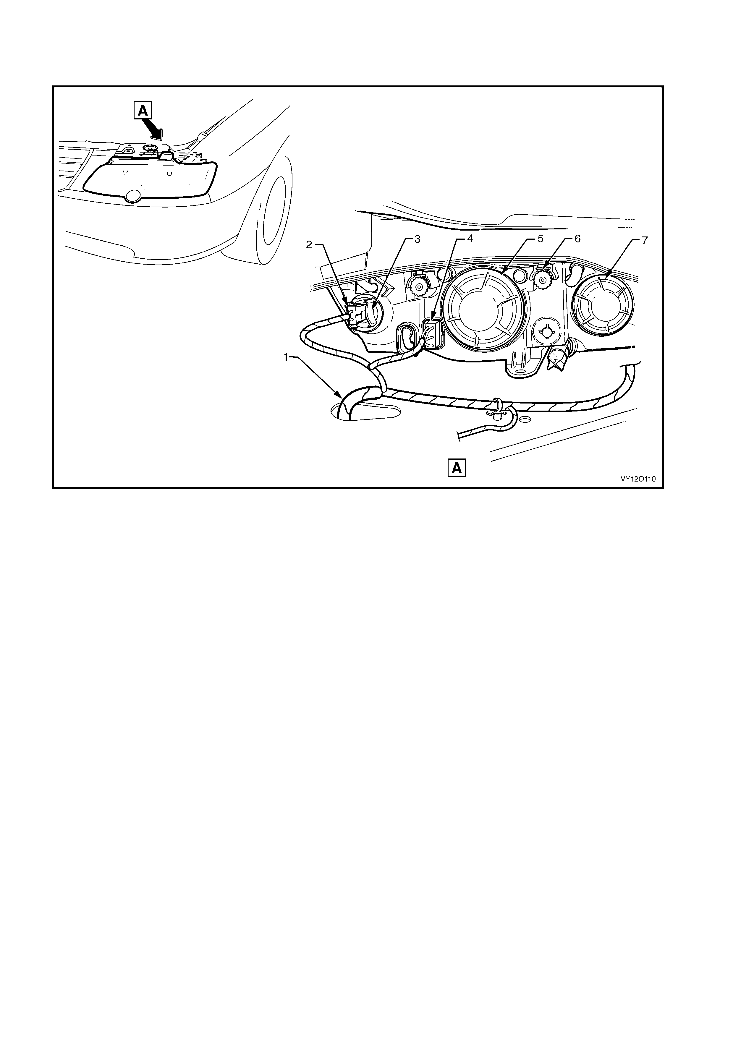
MAIN WIRING HARNESS – 6
HEADLAMP, PARK LAMP AND TURN INDICATOR WIRING HARNESS – LEVEL 1
Figure 12O-68
Legend
1. Main Wiring Harness
2. Turn Signal Lamp Connector (E 76)
3. Turn Signal Lamp Socket
4. Headlamp Connect or (E83)
5. Headlamp Low Beam Dust Cover
6. Headlamp Adjuster
7. Headlamp High Beam Dust Cover
MAIN WIRING HARNESS – 7
AMBIENT SENSOR, A/C FAN AND THEFT DETERRENT CONNECTORS
Figure 12O-69
Legend
1. Hood Anti-t heft Det errent Switc h Connect ors (S 135)
2. Main Wiring Harness t o Engine Cooling Fan Connect or
(M7 – X1)
3. Ambient Air Temperature Sensor Connector (B 23)
4. Attaching Screw – Hood Theft Deterrent Switch
5. Hood Anti-t heft Switch
A. Harness att ached t o side rail assembly as shown.
B. Blue strap to be aligned with centre line of vehicle as shown.
C. Harness attached t o radiat or l ower support assembly as shown
(5 places).
D. Front of vehicle.
For view C, refer to MAIN WIRING HARNESS – 8 in this sectio n .
For location of view E, refer t o MAIN WIRING HARNESS – 1 in this
section.
MAIN WIRING HARNESS – 8
AMBIENT SENSOR, A/C FAN AND THEFT DETERRENT CONNECTORS
Figure 12O-70
Legend
1. Main Wiring Harness
2. Condenser and Ambient Sens or
3. Ambi ent Air Temperature S ensor Connector (B23)
4. Hood Theft Deterrent Switch Connectors (S135)
5. Engine Cooling Fan Connector (M7 – X1)
A. Harness attached t o front wheelhous e panel brack et as shown.
B. Connectors f eed through end panel assem bl y to hood theft
deterrent s witc h.
MAIN WIRING HARNESS – 9 – RHD
FRONT LAMPS, FOG LAMPS AND HORN CONNECTIONS
Figure 12O-71
Legend
1. Front Fog Lamp
2. Front Fog Lamp Connector (E69)
3. Horn Connectors (B9)
4. Turn Signal Lamp Connector (E 75)
5. Headlamp Connect or (E83)
6. Clip
7. Front Wheel Speed Sensor Connector (B52)
8. Front Wheel Speed Sensor Tie-back
A. Connector clipped to body as shown.
B. Right-hand side shown. Similar for left-hand side.
C. High level models, right-hand side shown.
D. Harness attached t o wheelhouse panel as shown – left-hand
side.
For location of view F, refer to MAIN W IRI NG HA RNESS – 1 in this
section.
MAIN WIRING HARNESS – 10 – RHD
COCKPIT MODULE – LEVEL 1
Figure 12O-72

Legend
1. Main Wiring Harness t o Global Positioning System Harness
Connector (X207)
2. Radio Front Dash Upper Connector (B112)
3. Instrument P anel Compartment Lamp Switch Connector
(S142)
4. Main Wiring Harness t o Pass enger Airbag Harness
Connector (X205)
5. Rear Compartment Lid Release Switc h Connector (S195)
6. Heater & A/C Evaporator Module Connector (A 60 – X1)
7. Hazard Warning S witch Connector (S120)
8. Ambient Light Sensor Connect or (B55)
9. Heater & A/C Evaporator Module Connector (A 60 – X2)
10. Radio, Clock & CD Player Connector (A 133 – X1)
11. Trip Odometer Reset Switch Connector (S237)
12. Ignition & Start Switch Connector (S149 – X1)
13. Stop Lamp, Traction & Cruise Control Release Switch
Connector (S 220 – X1)
14. Instruments Connector (P3)
15. Radio Front Speaker Dash Upper Connector (B112)
16. Headlamp automatic Control switch Connec tor (S125)
17. Main Wiring Harness t o Body Wiring Harnes s Connector
(X201)
18. Main Wiring Harness t o Body Wiring Harnes s Connector
(X200)
19. Wiring (Diagnostic) Connect or (X40)
20. Ignition Lock Cylinder Bulb Connect or (E30)
21. Ignition & Start Switch Connector (S149 – X2)
22. Windshield Wiper & Washer Switch Connec t or (S247)
23. Cruise Control Switch Connector (S43)
24. Turn Signal & Headlamp Swit ch Connector (S231)
25. Steering Wheel Clock Spring Coil Connector (X116)
26. Ignition & Start Switch Terminal (S149 – GP15 – X3)
27. Front Cigar Lighter Connector (X113 – F)
28. Main Wiring Harness t o Body Wi ring Harness Connector
(X303)
29. LPG Selector Switch Connector (S118)
30. Main Wiring Harness t o Consol e Wiring Harness Connector
(X309)
31. Main Wiring Harness t o Transmission Selector Harness
Connector (X301)
32. Radio Ground Terminal (X118 – GP8)
33. Inline to Radio & Mobile Telephone Connector (X155)
34. Blower Motor Resistor Connect or (R6 – RHD)
35. Blower Motor Connector (M3 – RHD)
36. Instrument Panel Compartment Lam p Connectors (E82)
37. Main Wiring Harness t o Powertrain Harness Connector (X206)
MAIN WIRING HARNESS – 11 – RHD
COCKPIT MODULE – MODELS WITH CRUISE CONTROL
Figure 12O-73

Legend
1. Main Wiring Harness to Body Wiring Harness Connect or
(X312)
2. Main Wiring Harness t o Global Positioning System Harness
Connector (X207)
3. Radio Front Speaker Dash Upper Connector (B 112 – L)
4. Main Wiring Harness to Powertrain Harness Connector
(X206)
5 Instrument Panel Compartm ent Lam p Switch Connectors
(S142)
6. Main Wiring Harness t o Pass enger Airbag Harness
Connector (X205)
7. Rear Compartment Lid Release Switc h Connector (S195)
8. Radio, Clock & CD Pl ayer Connector (A133 – X1)
9. Hazard Warning S witch Connector (S120)
10. Ambient Light Sensor Connector (B55)
11. Blower Motor & A/C Compressor Connector (A 14 – X1)
12. Trip Odometer Reset Switch Connector (S237)
13. Inside Air Temperature Sensor Connector (B59)
14. Ignition & Start Switch Connector (S149 – X1)
15. Stop Lamp, Traction & Cruise Control Release Switch
Connector (S 220 – X1)
16. Stop Lamp, Traction & Cruise Control Release Switch
Connector (S 220 – X2)
17. Instruments Connector (P3)
18. Radio Front Speaker Dash Upper Connector (B112 – R)
19. Headlamp Automatic Control Switc h Connector (S125)
20. Right-hand Front Step Well Lamp Connector (E105)
21. Main Wiring Harness t o Body Wiring Harnes s Connector
(X201)
22. Main Wiring Harness t o Body Wi ring Harness Connector
(X200)
23. Wiring (Diagnostic) Connect or (X40)
24. Windshield Wiper Dwell Module Connector (R23)
25. Ignition Lock Cylinder Bulb Connect or (E30)
26. Ignition & Start Switch Connector (S149 – X2)
27. Windshield Wiper and Washer Switch Connector (S247)
28. Cruise Control Switch Connector (S43)
29. Turn Signal & Headlamp Swit ch Connector (S231)
30. Steering Wheel Clock Spring Coil Connector (X116)
31. Ignition & Start Switch Connector (S149 – GP15 – X3)
32. Front Cigar Lighter Connector (X113 – F)
33. Main Wiring Harness t o Body Wi ring Harness Connector
(X303)
34. LPG Selector Switch Connector (S118)
35. Main Wiring Harness t o Consol e Wiring Harness Connector
(X309)
36. Main Wiring Harness t o Transmission Selector Harness
Connector (X301)
37. Radio Ground Terminal (X118 – GP8)
38. Inline to Radio & Mobile Telephone Connector (X155)
39. Blower & Air Inlet Connector (A13 – RHD)
40. Blower Motor Connector (M3 – RHD)
41. Left-hand Front Foot Well Connector (E105)
42. Instrument Panel Compartment Lam p Connectors (E82)
43. Communication Centre Call Connector (A158 – X2)
44. Communication Centre Call Connector (A158 – X1)
45. Radio Antenna Amplifier Connector (N3)
MAIN WIRING HARNESS – 12 – RHD
COCKPIT MODULE – ALL MODELS
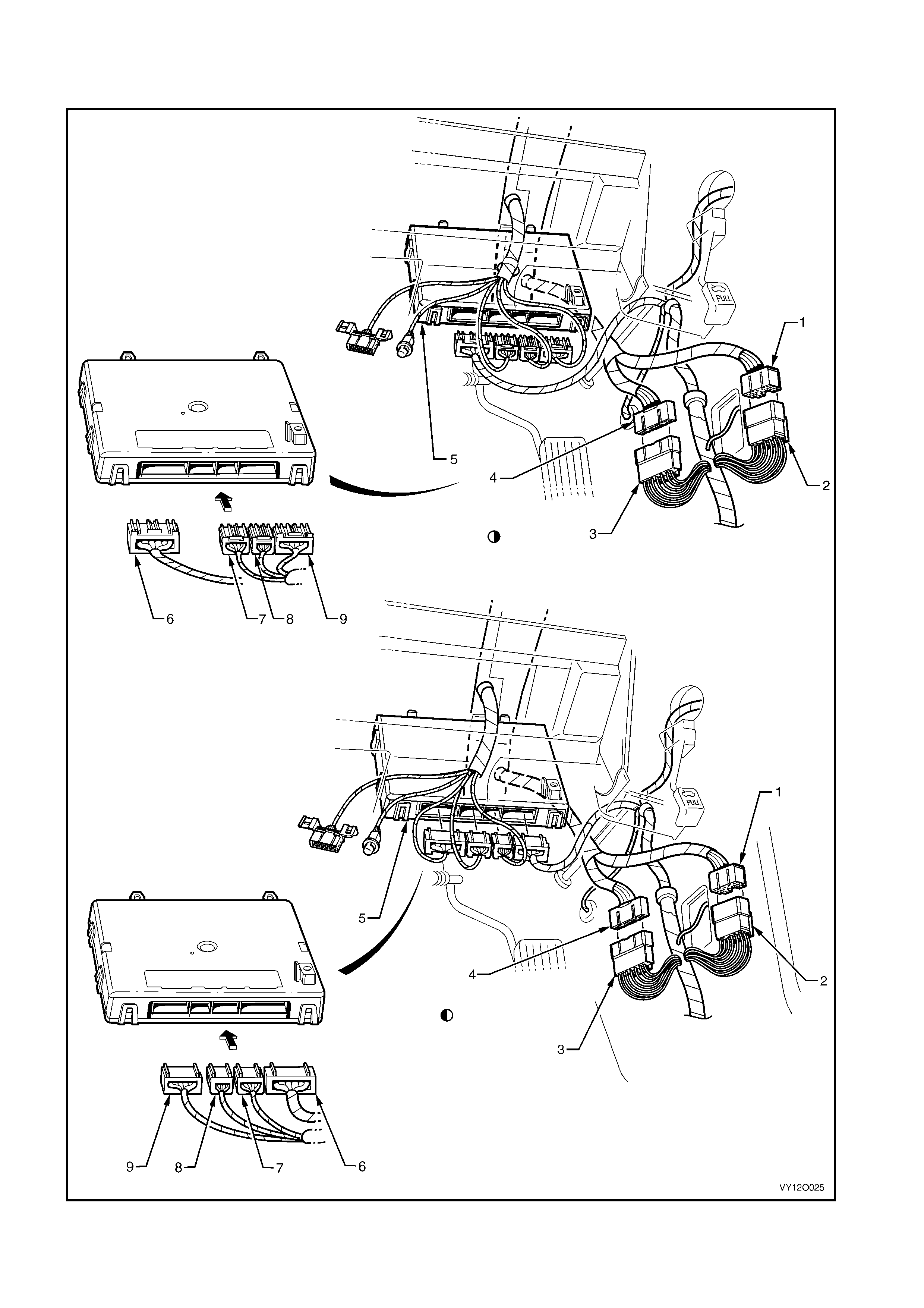
Figure 12O-74

Legend
1. Main Wiring Harness to Body Wiring Harness Connect or
(X200)
2. Body Wiring Harness to Main Wi ring Harness Connector
(X200)
3. Body Wiring Harness to Main Wi ring Harness Connector
(X201)
4. Main Wiring Harness to Body Wiring Harness Connect or
(X201)
5. Body Control Module
6. Body Control Module Connect or (A15 – X4)
7. Body Control Module Connect or (A15 – X3)
8. Body Control Module Connect or (A15 – X2)
9. Body Control Module Connector (A15 – X1)
Early Product ion Vehicles
Late Producti on Vehicles
MAIN WIRING HARNESS – 13 – RHD
COCKPIT MODULE – ALL MODELS
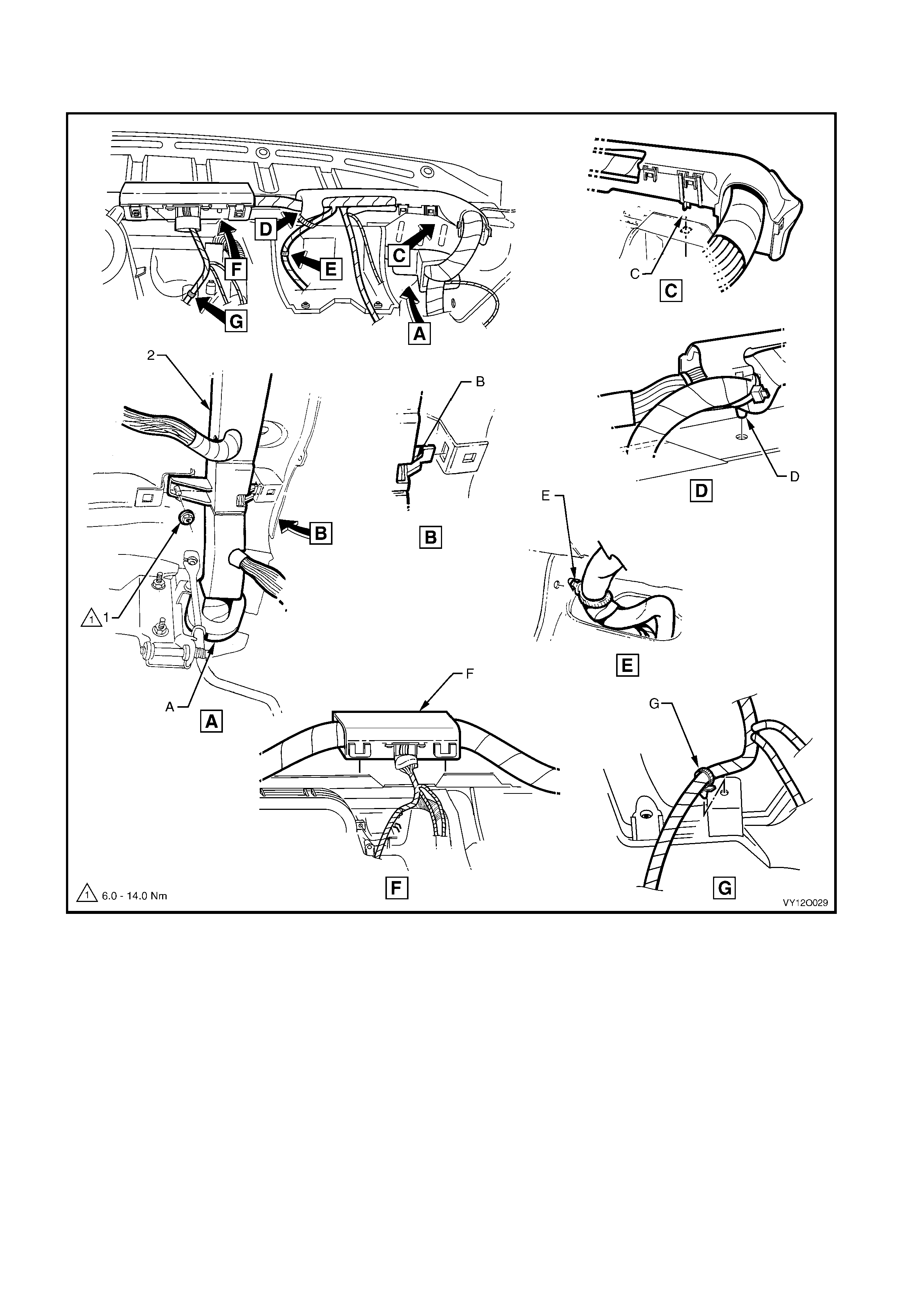
Figure 12O-75
Legend
1. Attachi ng Nut – Wiring Harness Retainer t o Instrument Panel
2. Main Wiring Harness Cabl e Retainer
A. Refer to MAIN WIRING HARNESS – 1 in this section fo r
sealing patch grommet and insert inst al l ation.
B. Main wiring harness form er att ached to inst rument panel c over
assembly as shown.
C. Main wiring harness form er att ached to inst rument panel cover
assembly as shown.
D. Main wiring harness form er att ached to inst rument panel cover
assembly as shown.
E. Main wiring harness retai ner att ached to steering column
bracket as shown.
F. Main wiring harness former att ached to inst rument panel cover
assembly as shown.
G. Main wiring harnes s retainer attached to vehicle as shown.
MAIN WIRING HARNESS – 14 – RHD
FUSE BLOCK AND BODY CONTROL MODULE – ALL MODELS
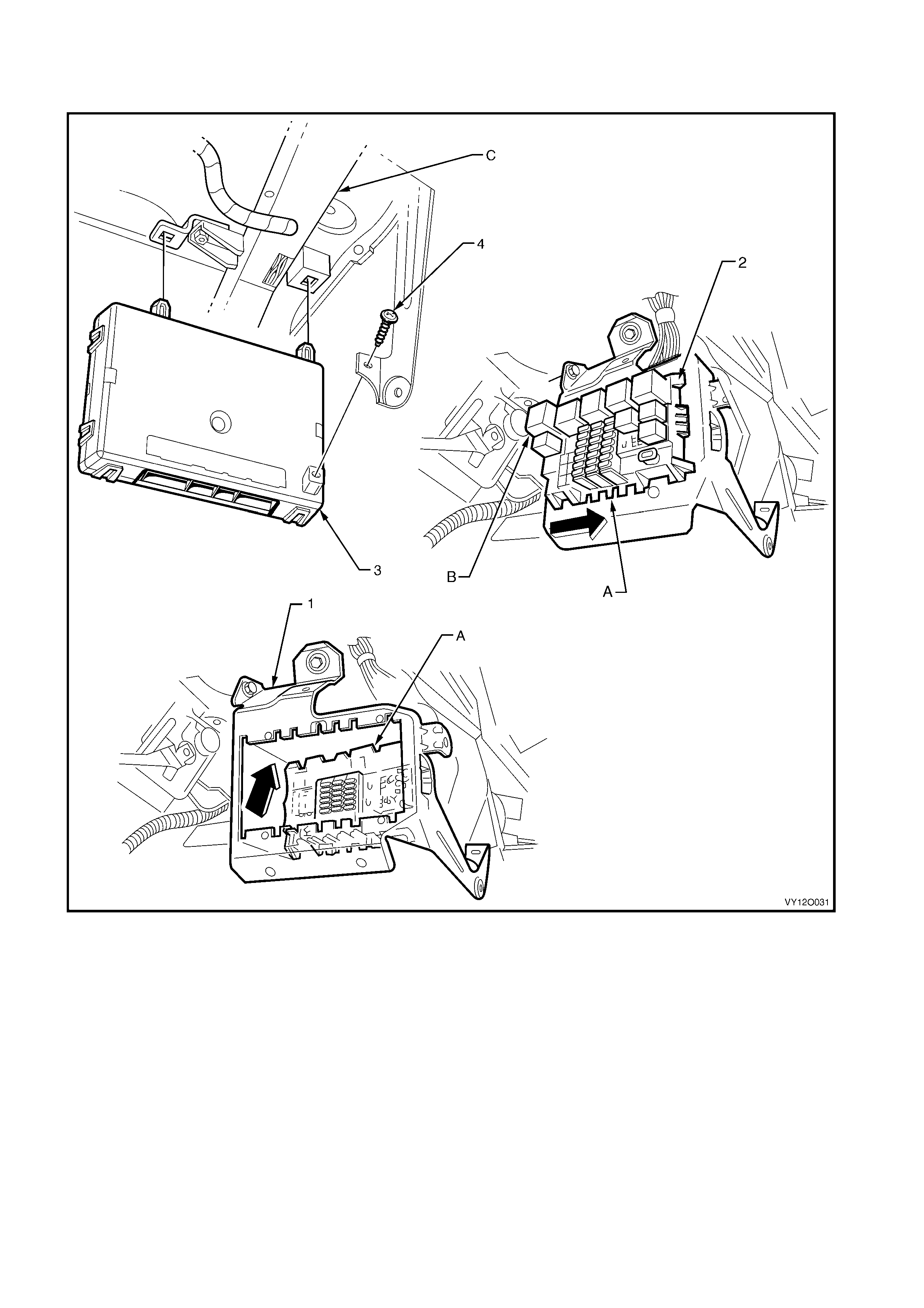
Figure 12O-76
Legend
1. Inst rument Panel Wiring Harness Fuse Block Support B racket
2. Inst rument Panel Wiring Harness Fuse Block (X129)
3. Body Cont rol Module
4. At taching Screw, Body Control Module Mounting to Support
A. Instrum ent panel wiring harness fuse block – installed as
shown.
B. For install ation of relays, fuses and circuit breakers ref er to
1. GENERA L INF O RMAT ION.
C. Main wiring harness former, refer to
MAIN WIRING HARNESS – 13 – RHD in this section.
MAIN WIRING HARNESS – 15 – RHD
STEERING COLUMN
Figure 12O-77
Legend
1. Steering Wheel Clock Spring Coi l Connector (X116)
2. Turn Signal & Headlamp Switch Connector (S231)
3. Igni t i on Lock Cyl i nder Bulb Connector (E30)
4. Ignition and Start Switch Connector (S149 – X2)
5. St epwell Lam p Connect or (E105)
6. Wiring (Diagnostic) Connect or (X40)
7. Ignition Switch Terminal (S149 – GP15 – X3)
8. Ignition & Start Switch Connector (S149 – X1)
9. Windshield Wiper & Washer Switch Connector (S247)
10. Steering Wheel Inflat abl e Rest rai nt Module Connec t or (A106)
11. Steering Wheel Horn Connect or (S7)
12. Radio Control Switch Connector (S208)
13. Windshield Wiper Dwell Module Connector (R23)
14. Cruise Control Switch Connector (S43)
A. For fuse and relay panel – instrument panel wiring harnes s
fuse block (X129) inst al l ati on, ref er to
MAIN WIRING HARNESS – 14 – RHD diagram in this section.
B. Clock s pri ng coil connect or i nst al l ed and secured by l ocking
retainer in direction of arrow shown.
C. Main wiring harness attached to steering column as shown.
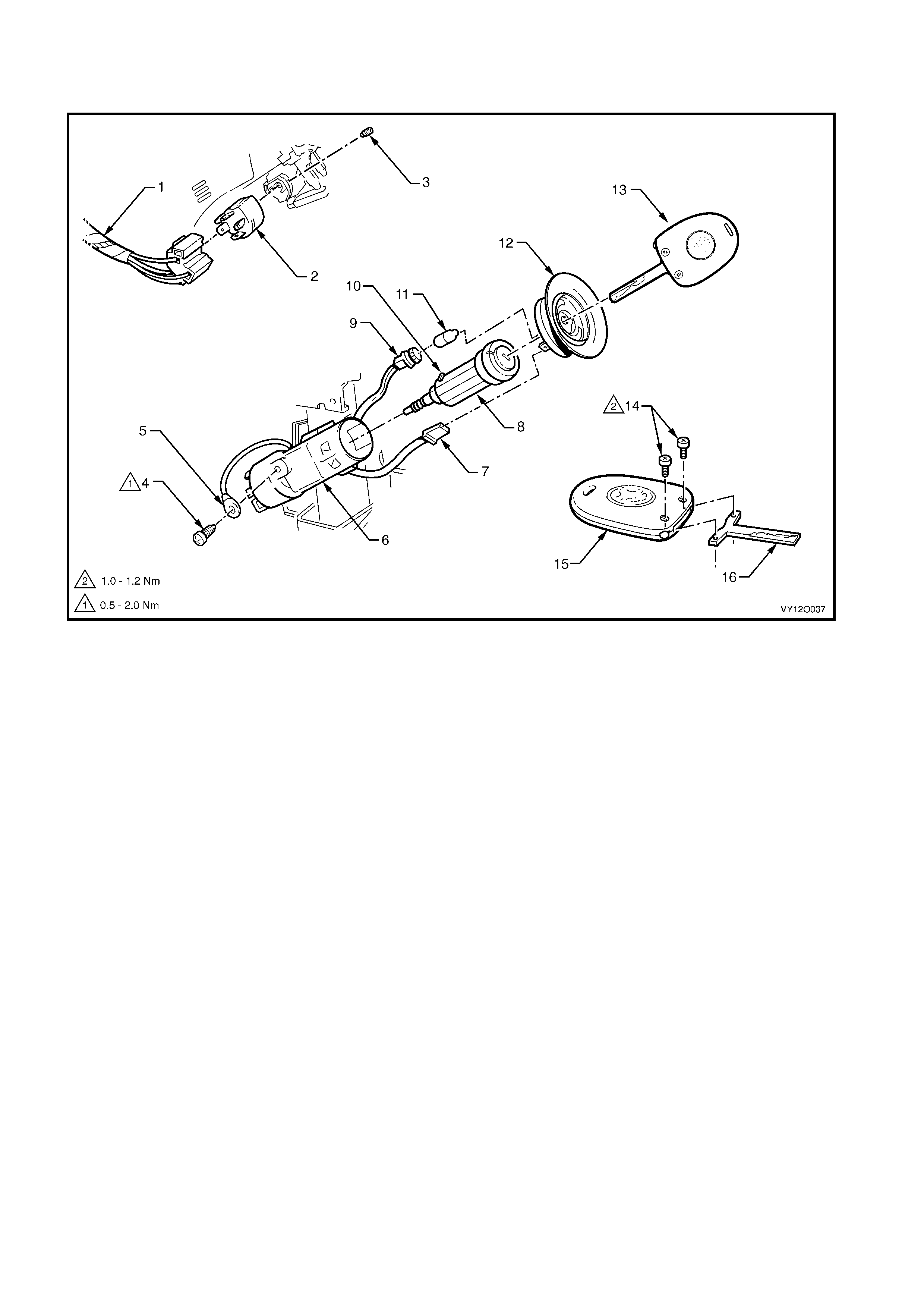
MAIN WIRING HARNESS – 16
IGNITION LOCK A ND THEFT DETERRENT RECEIVER – ALL MODELS
Figure 12O-78
Legend
1. Main Wiring Harness
2. Ignition & Start Switch Connector (S149 – X1)
3. Ignition & Start Switch to Ignition Lock Retaining Screw
4. Ground Terminal to Ignition Key Attaching Screw
5. Ignition & Start Switch Terminal (S149 – X3)
6. Igniti on Lock Housi ng
7. Ignition & Start Switch Connector (S149 – X2)
8. Ignition Lock
9. Igniti on Lock Cyl i nder Bulb Connect or (E30)
10. Ignition Lock Locking Pin
11. Ignition Lock Cylinder Bulb
12. Theft Deterrent Receiver Assembly
13. Coded Key Assembly
14. Coded Key Assembly Attaching Screw
15. Remote Control Transmitter
16. Key
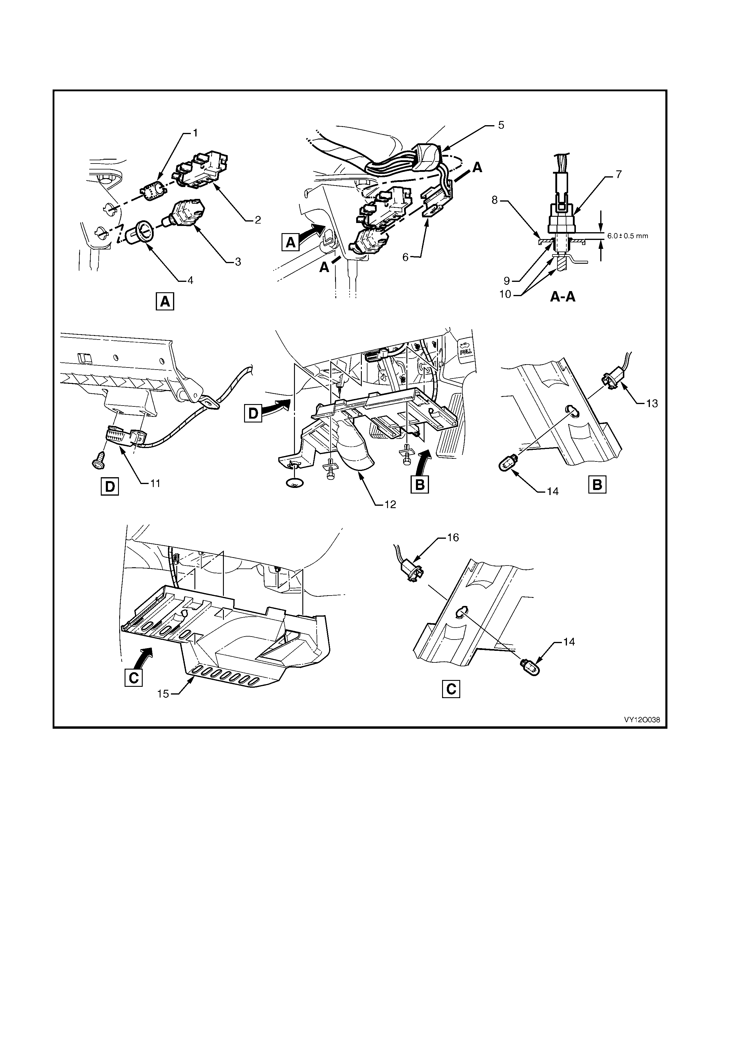
MAIN WIRING HARNESS – 17 – RHD
CRUISE CONTROL, STOP LAMP SWITCHES, DATA LINK CONNECTOR & STEPWELL LAMPS
Figure 12O-79
Legend
1. Nut
2. Cruise Control Rel ease Switc h
3. Stepwell Lamp Switch
4. Nut
5. Stop Lamp, Traction & Cruise Control Releas e Switc h
Connector (S 220 – X2)
6. Stop Lamp, Traction & Cruise Control Releas e Switc h
Connector (S 220 – X1)
7. Stop Lamp Switch
8. Support Bracket
9. Nut
10. Pedal Assembly
11. Wiring (Diagnostic) Connect or (X40)
12. Instrument Panel Lower Cover – Right-hand Si de
13. Stepwell Lamp Connector (E105 – R)
14. Stepwell Lamp
15. Instrument Panel Lower Cover – Left-hand Side
16. Stepwell Lamp Connector (E105 – L)
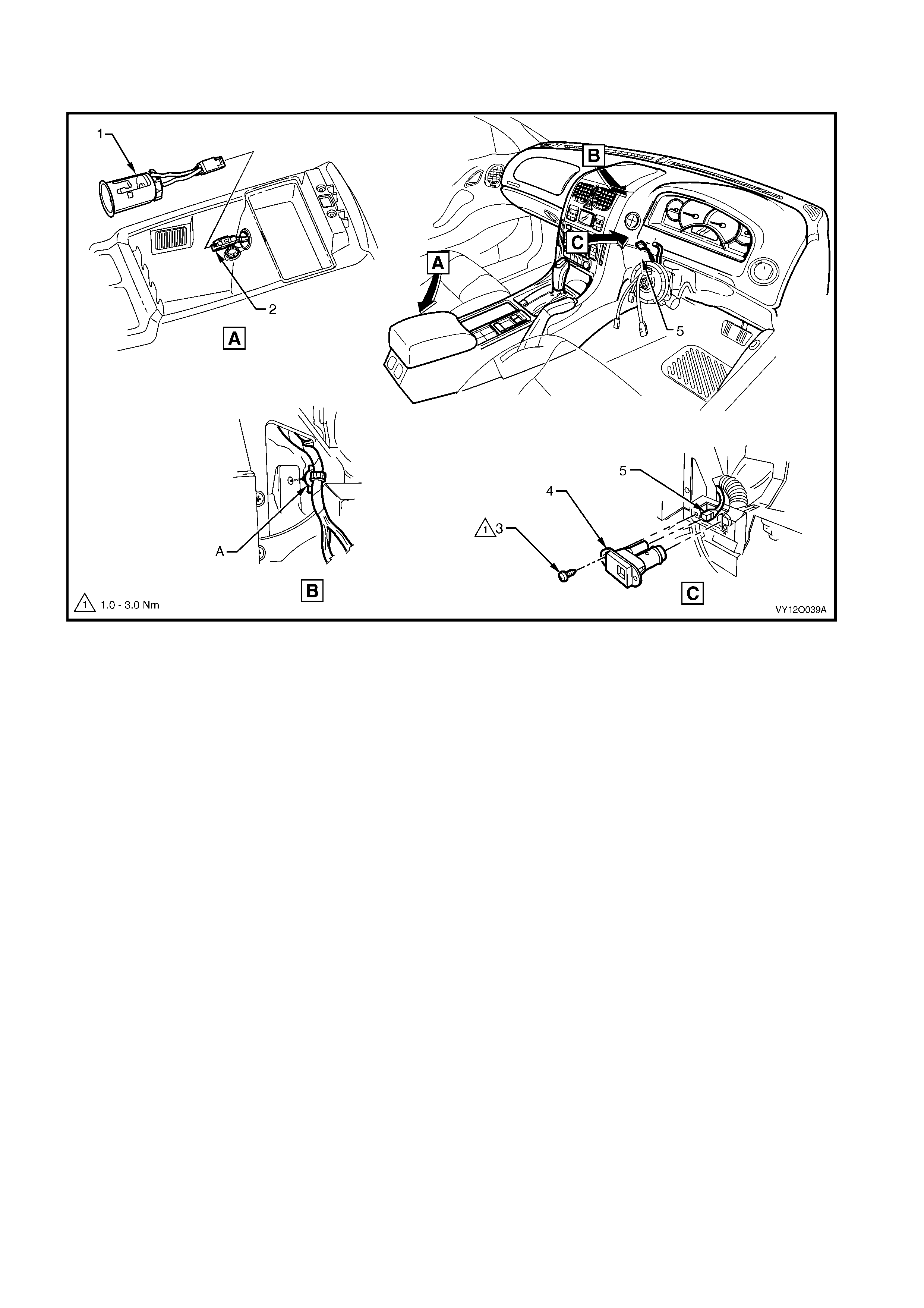
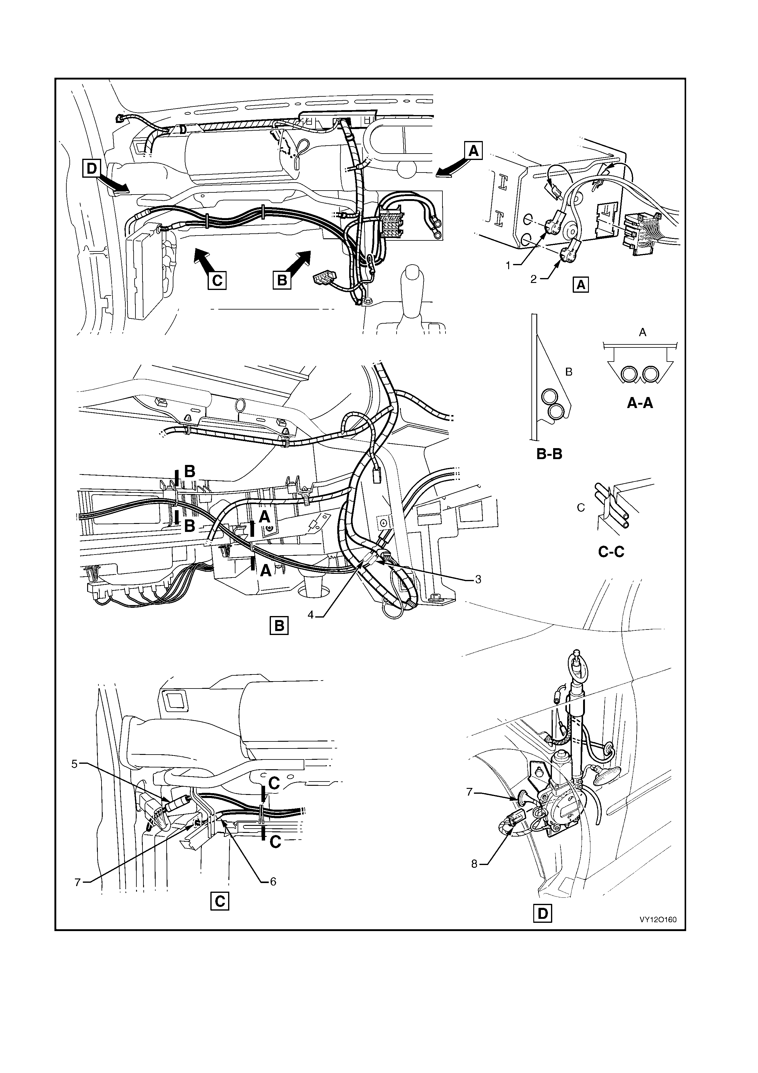
MAIN WIRING HARNESS – 18 – RHD
INSIDE AIR TEMPERATURE SENSOR & ACCESSORY JACK – ALL MODELS
Figure 12O-80
Legend
1. Accessory Power Socket
2. Access ory P ower Connector (X112 – AUX)
3. Inside Air Temperature Sensor Attaching Screw
4. Inside Air Temperature Sensor
5. Inside Air Temperature Sensor Connect or (B59)
A. W iring harness attached to instrument panel as shown.
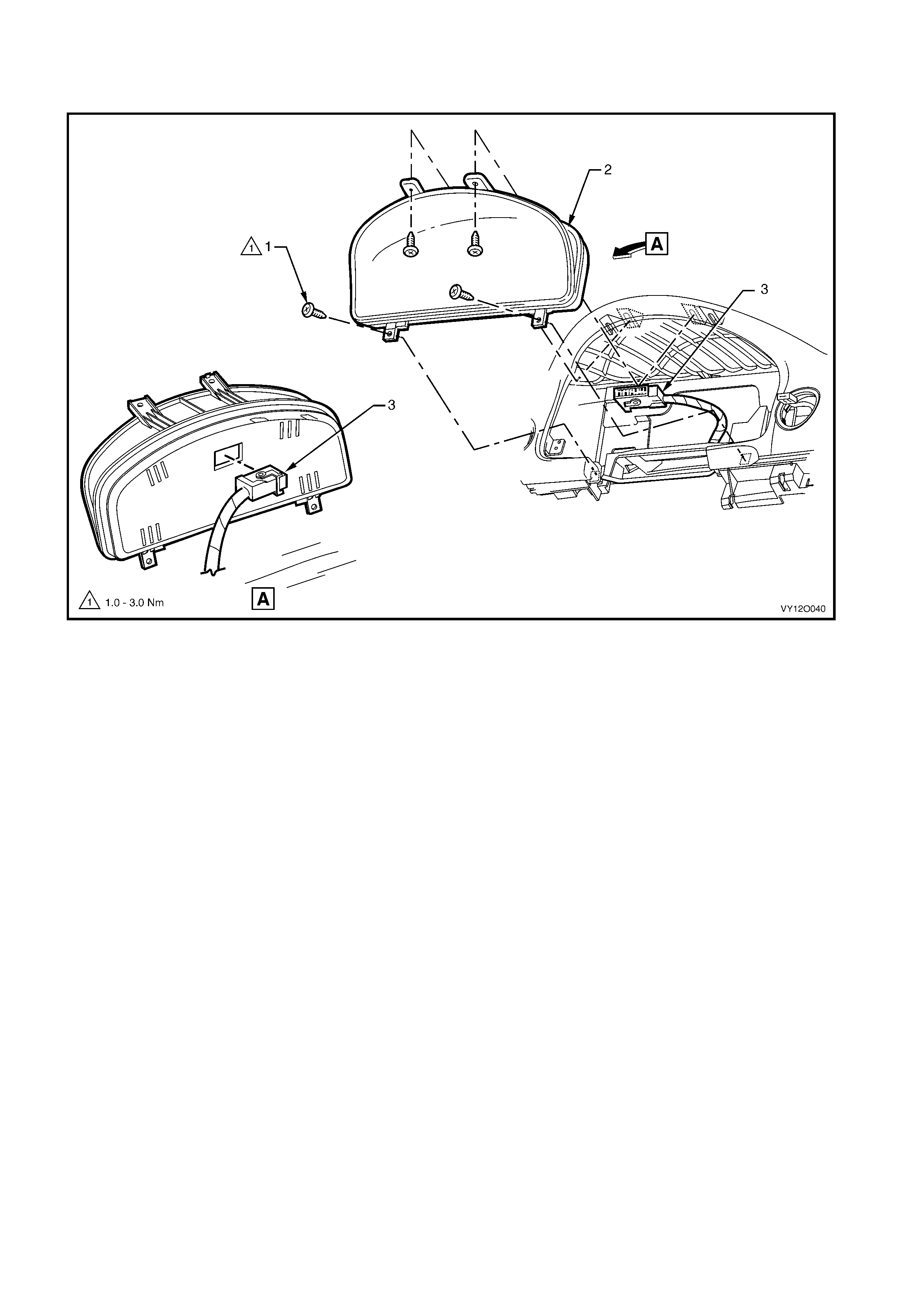
MAIN WIRING HARNESS – 19
INSTRUMENT CLUSTER ASSEMBLY – ALL MODELS
Figure 12O-81
Legend
1. Instrument Cl ust e r Attaching Screws – 4 Places
2. Instrum ent Cluster Assembly 3. Instrument Cl uster Connector (P3)
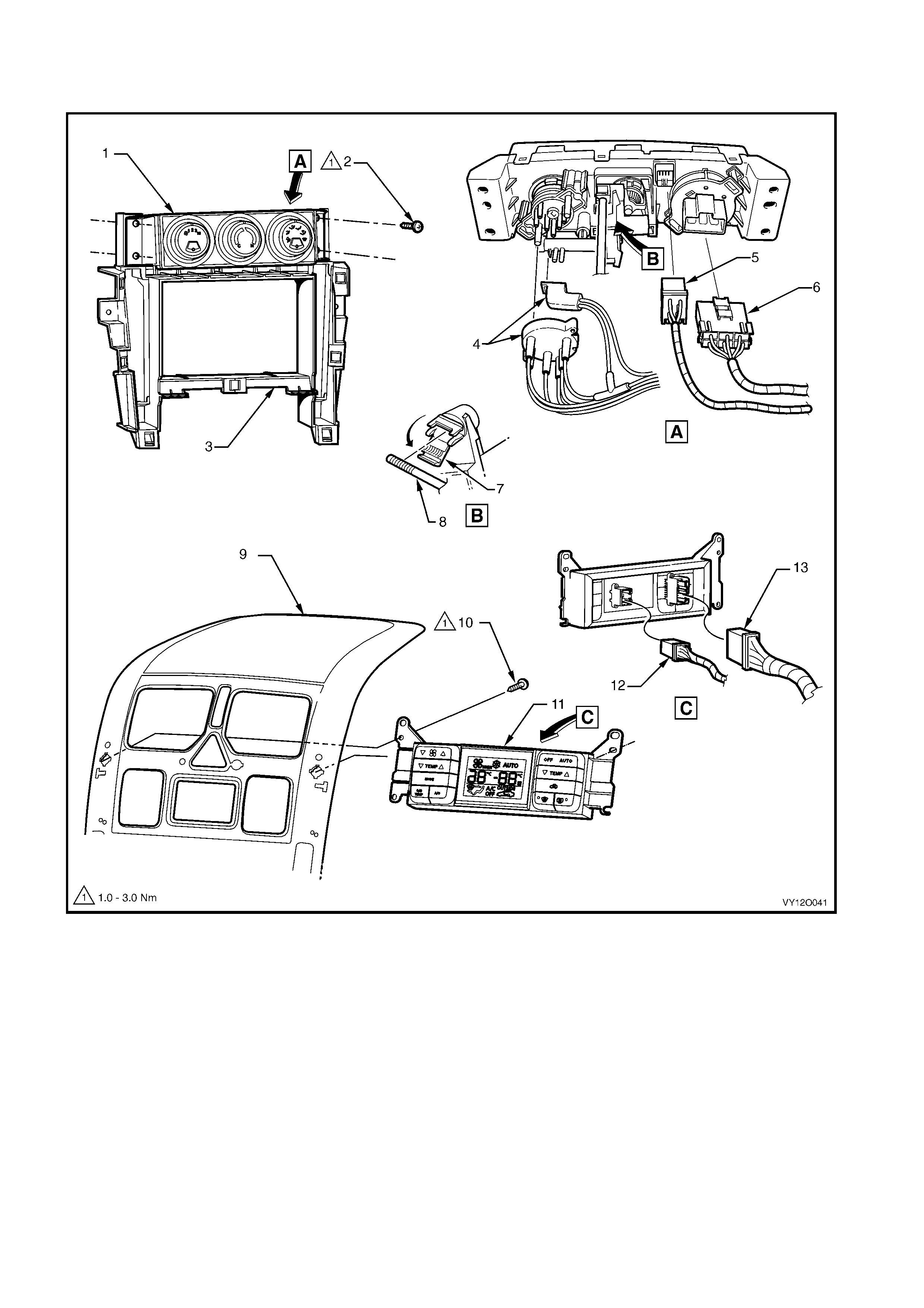
MAIN WIRING HARNESS – 20
AIR-CONDITIONING & HEATING CONTROLS – ALL MODELS
Figure 12O-82
Legend
1. Heater & A/C Evaporative Module
2. Attaching Screw – 4 Places
3. Radio Carrier
4. Vacuum Manifold Plug
5. Heater & A/C Evaporator Module Connector (A 60 – X2)
6. Heater & A/C Evaporator Module Connector (A 60 – X1)
7. Control Assembly
8. Heating & A/C Evaporative Module Rod
9. Centre Facia Escutcheon Assembly
10. Attaching Screws – 4 Places
11. Electronic Clim ate Cont rol Module
12. Blower Motor & A/C Compressor Connector (A 14 – X1)
13. Blower Motor & A/C Compressor Connector (A 14 – X2)
.
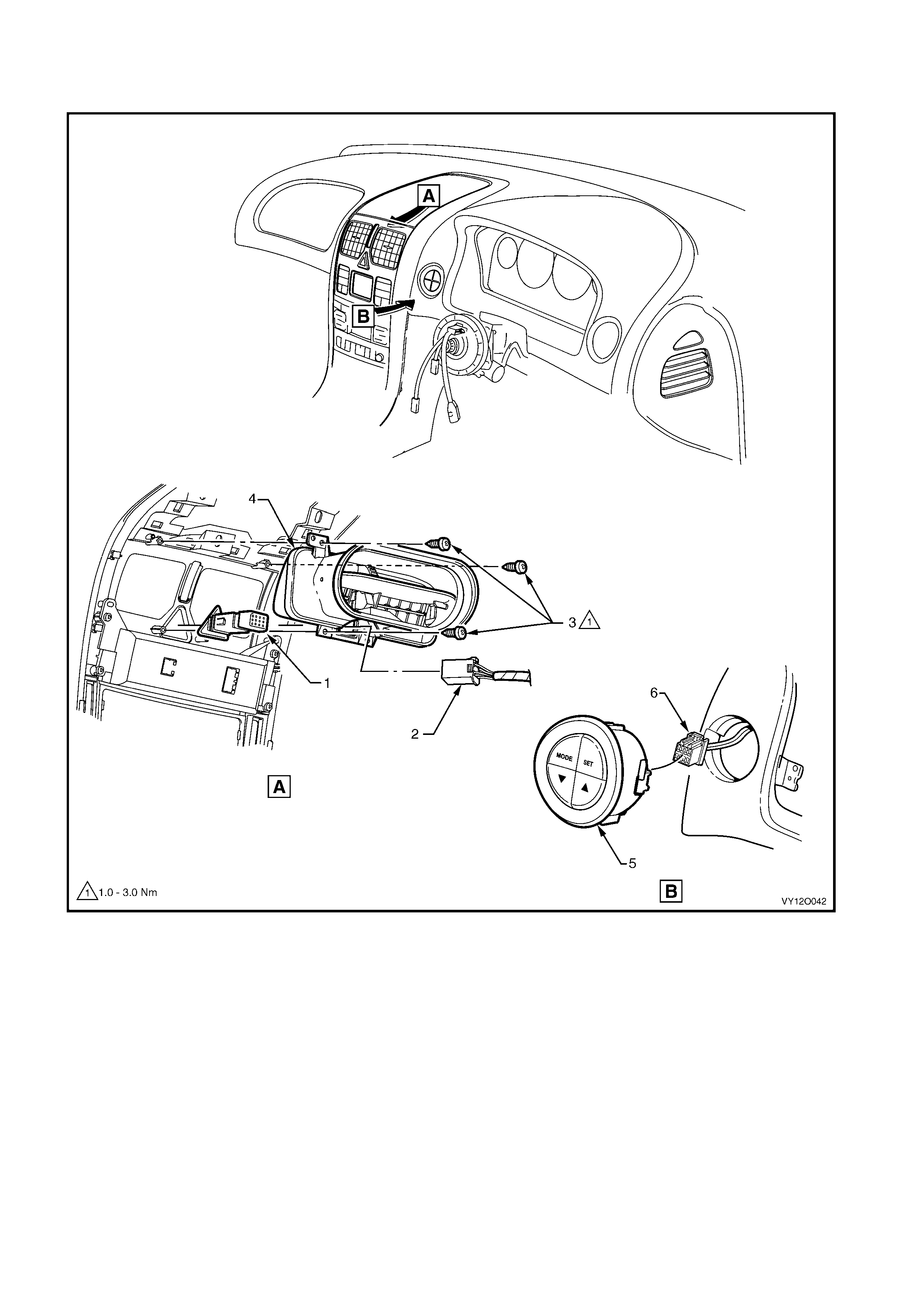
MAIN WIRING HARNESS – 21 – RHD
INSTRUMENT PANEL FACIA TRIM SWITCHES – ALL MODELS
Figure 12O-83
Legend
1. Hazard Warning Switch
2. Hazard Warning S witch Connector (S120)
3. Attaching Screws – 3 Places
4. Centre Air Outlet Assembl y
5. Trip Odometer Reset Switch
6. Trip Odometer Reset Switch Connector (S237)
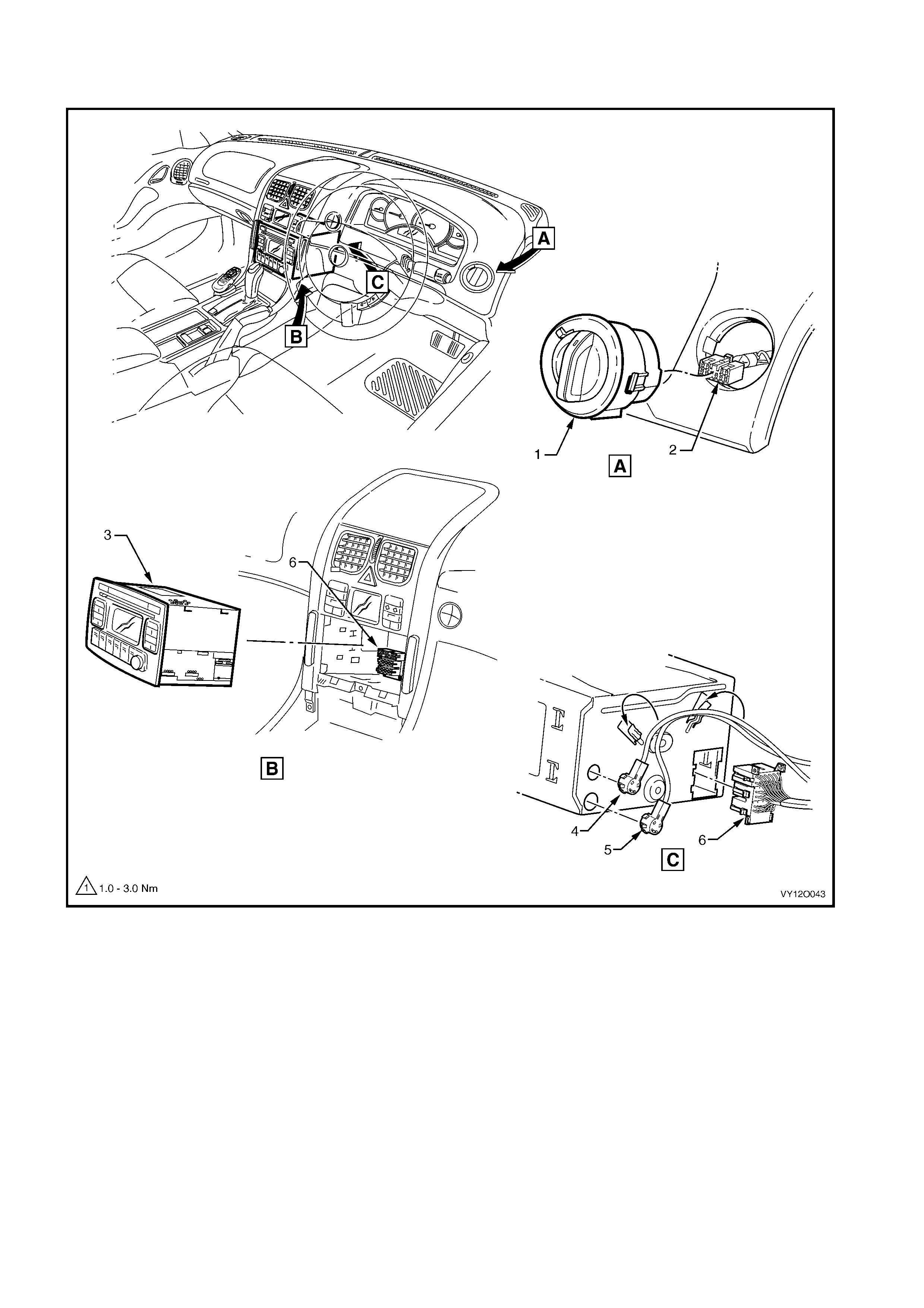
MAIN WIRING HARNESS – 22 – RHD
RADIO ASSEMBLY CONNECTORS & INSTRUMENT PANEL FACIA TRIM SWITCHES – ALL MODELS
Figure 12O-84
Legend
1. Headlamp Automatic Control Switch
2. Headlamp Automatic Control Switch Connect or (S 125)
3. Radio, Clock and CD Player As sembly
4. Diversit y Antenna Connector (A133 – X3)
5. Power Antenna Connect or (A133 – X2)
6. Radio, Clock and CD Player Connec tor (A133 – X1)
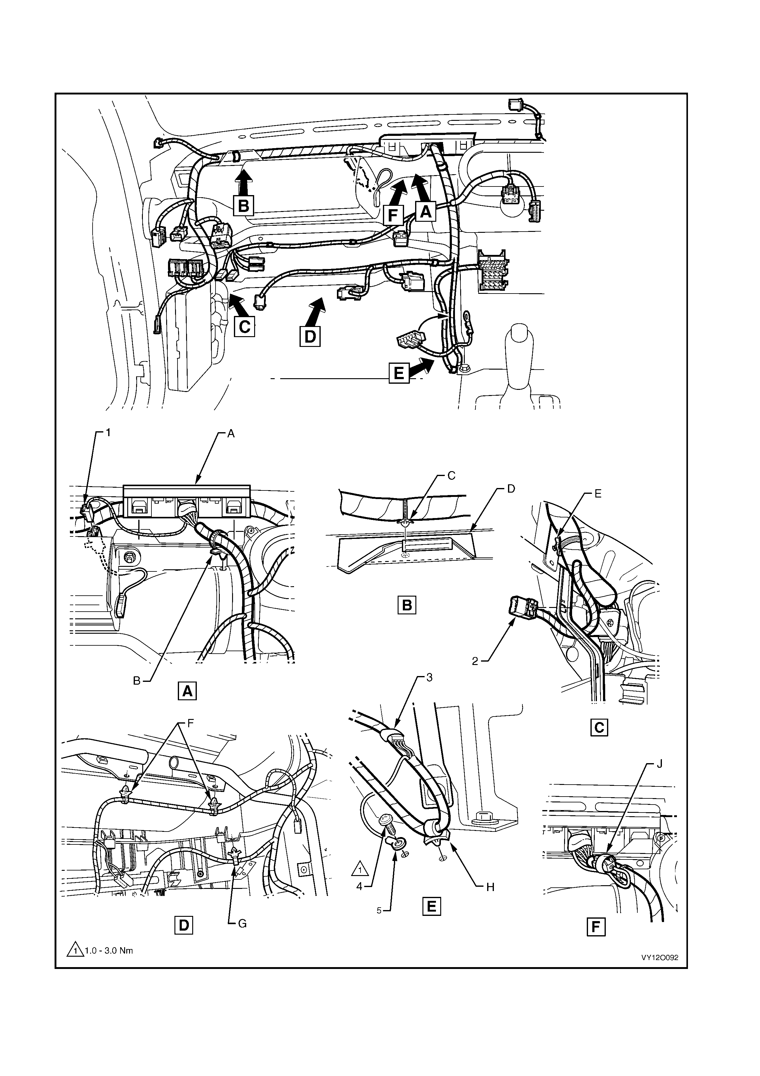
MAIN WIRING HARNESS – 23 – RHD
PASSENGER SIDE AIRBAG WIRI NG – ALL MODELS
Figure 12O-85

Legend
1. Main Wiring Harness to Passenger Air Bag Harness
Connector (X205)
2. Main Wi ri ng Harness to Global Positioning System Harness
Connector (X207)
3. Inli neto Radio and Mobile Telephone Connector (X155)
4. Radio Ground Terminal Att aching Sc rew
5. Radio Ground Terminal (X118 – GP8)
A. Harness former att ached to instrument panel cover assembly
as shown (2 places).
B. Harness attached t o heating, vent ilation & air conditioning unit
as shown.
C. Harness attached to dash panel cover assembly as shown.
D. Dash panel cover assembly.
E. Harness attached to bracket as shown.
F. Harness attached t o passenger side airbag support rail
assembly as shown.
G. Harness attached t o vehicl e as shown.
H. Harness attached to vehicle as shown.
J. Instrument panel i nflatable restraint modul e connect or taped
back as shown (vehicl es without instrument panel infl atabl e
restraint module).
MAIN WIRING HARNESS – 24
LIGHT SENSOR AND KEY RECEIVER & INSTRUMENT PA NEL SPEAKERS – ALL MODELS
Figure 12O-86
Legend
1. Radio Front Speaker Dash Upper Connector (B 112)
2. Attaching Screw
3. Radio Front Speaker Dash Upper
4. Carrier Instrument Panel Pad
5. Ambient Light Sensor
6. Ambient Light Sensor Connect or (B55)
A. Harness attached to light sensor and key receiver module as
shown.
B. Instrument panel front speaker bracket aligned with locating
pin.
MAIN WIRING HARNESS – 25 – RHD
RADIO ANTENNA AMPLIFIER & HEATING, VENTILATION & AIR CONDITIONER CONNECTORS –
ALL MODELS
Figure 12O-87
Legend
1. Blower Motor Resist or Connector (R6 – RHD)
2. Blower Motor Connector (M3 – RHD)
3. Radio Antenna Connect or (W6)
4. Radio Antenna Amplif i er Connect or (N3)
A. Harness attached to body as shown.
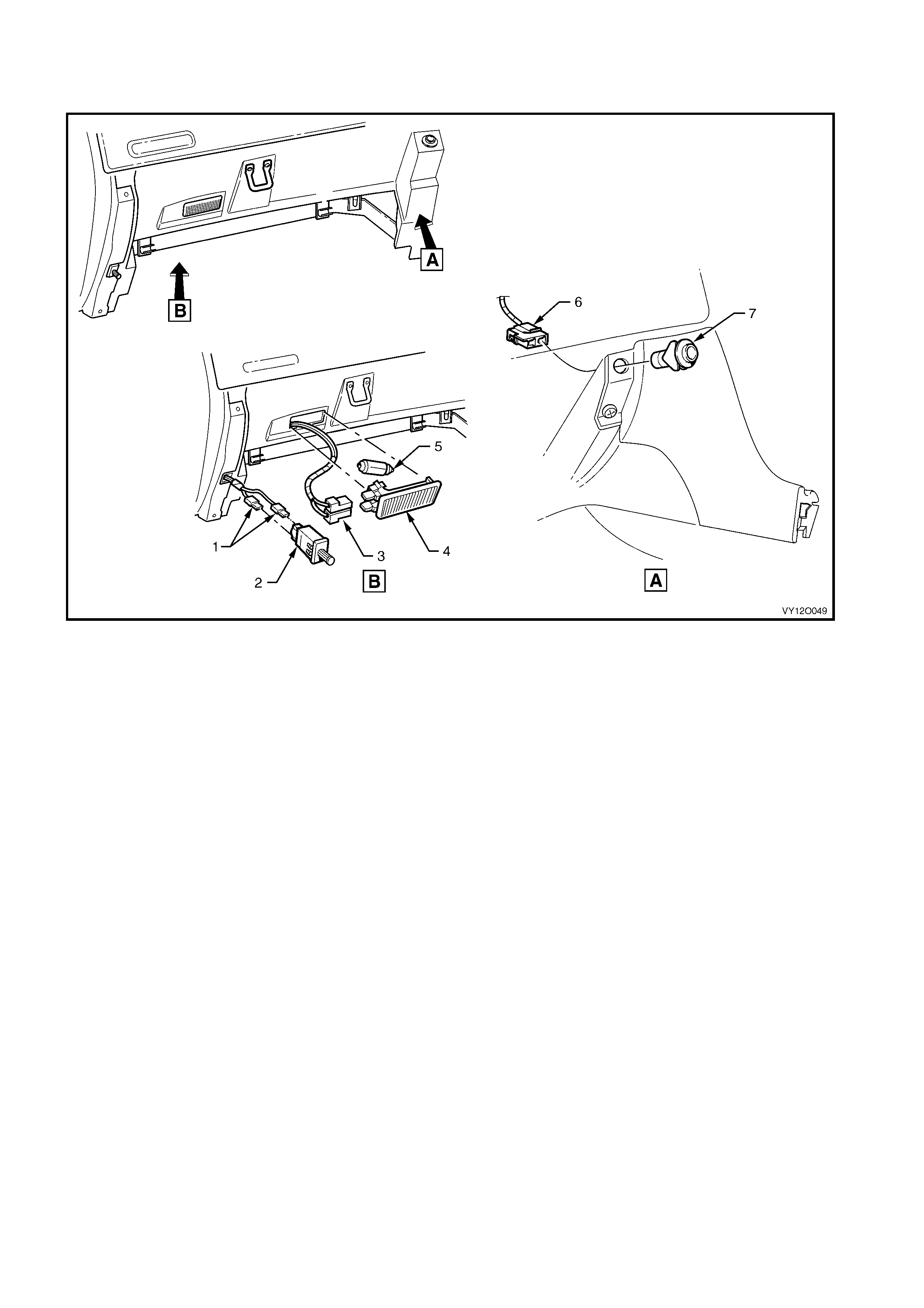
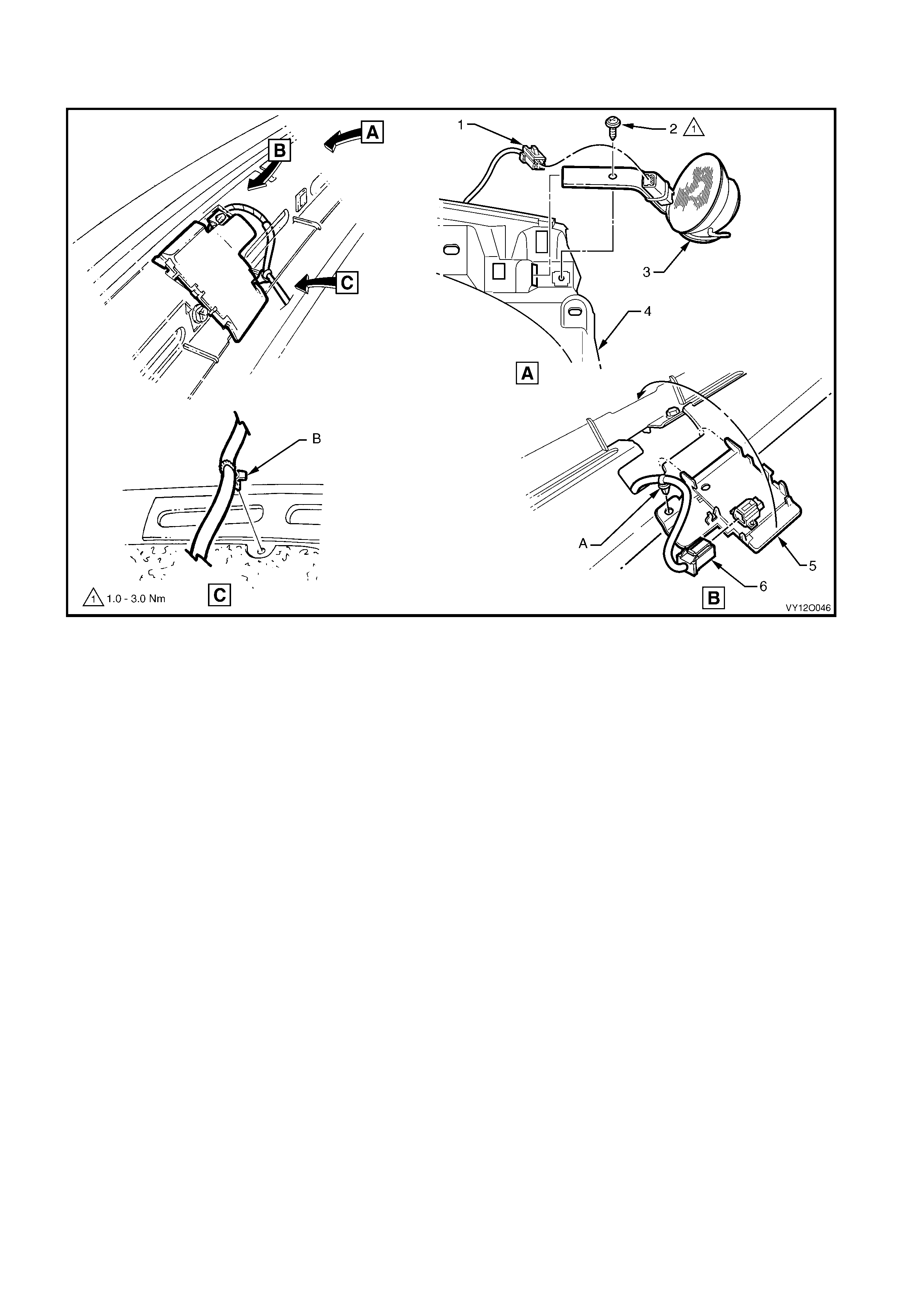
MAIN WIRING HARNESS – 26 – RHD
INSTRUMENT PA NEL COMPARTMENT – ALL MODELS
Figure 12O-88
Legend
1. Instrument P anel Compartment Lamp Switch Connectors
(S142)
2. Instrument P anel Compartment Lamp Switch
3. Instrument P anel Compartment Lamp Connector (E82)
4. Instrument P anel Compartment Lamp
5. Instrument P anel Compartment Lamp Bulb
6. Rear Compartment Lid Release Switc h Connector (S195)
7. Rear Compartment Lid Release Switc h
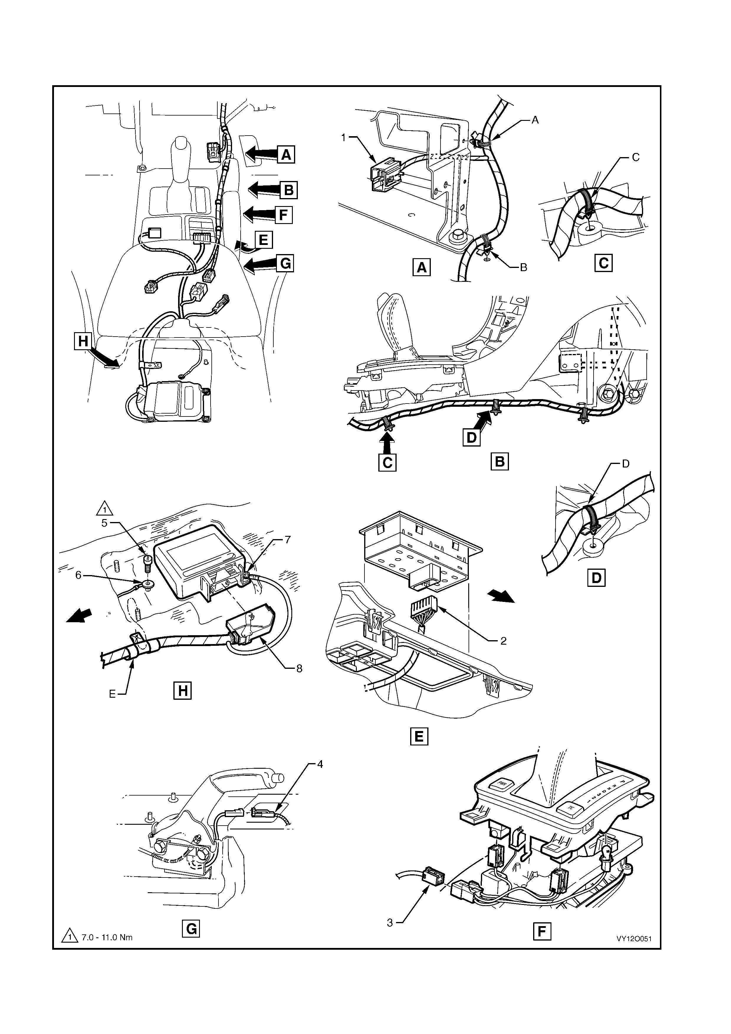
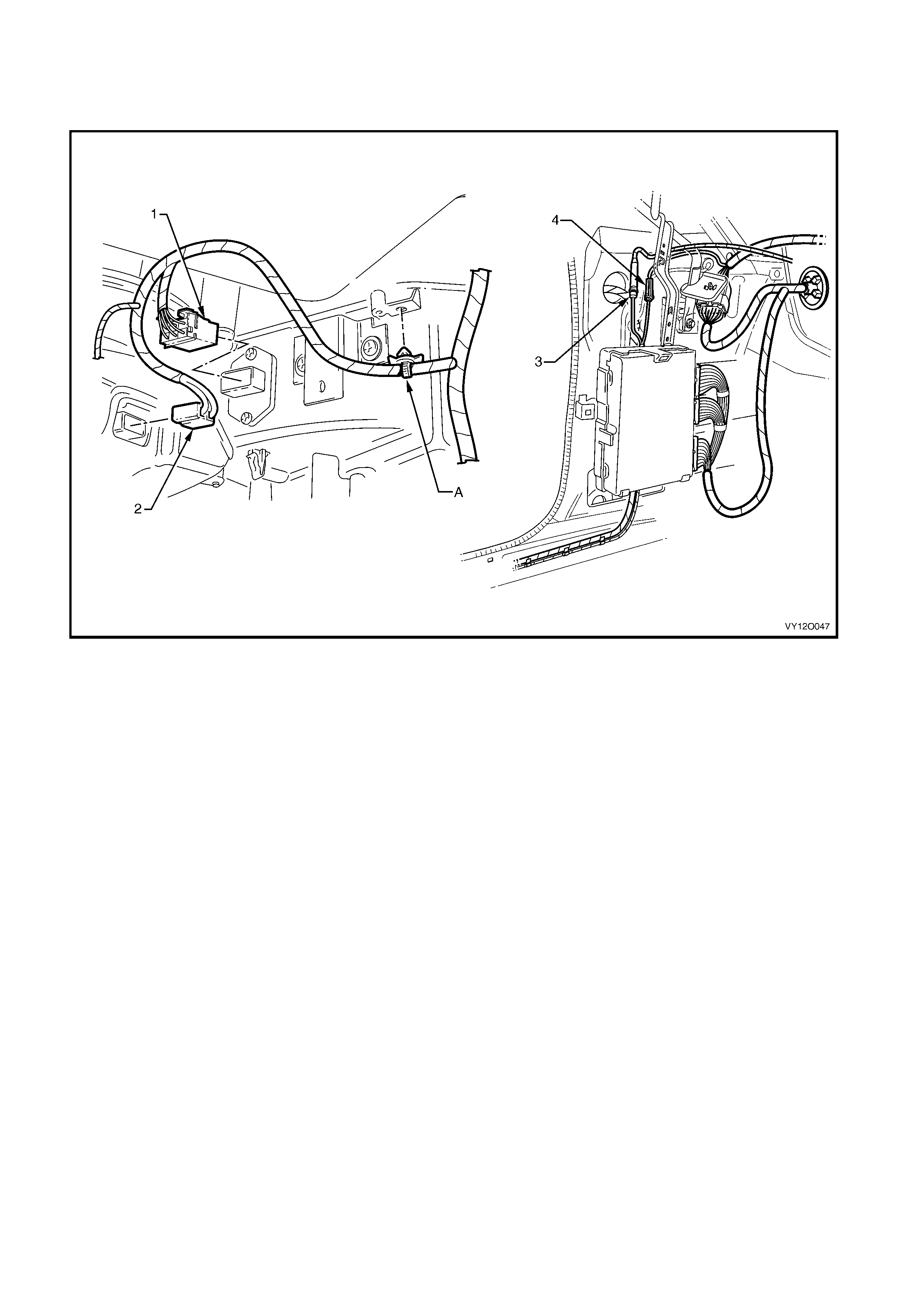
MAIN WIRING HARNESS – 27
TRANSMISSION & SIR SENSING DIAGNOSTIC MODULE CONNECTORS – ALL MODELS
Figure 12O-89

Legend
1. Front Cigar Lighter Connect or (X113 – F)
2. Side Window (Master) Switch Connector (S222)
3. Main W i ri ng Harness t o Transmission Selector Harness
Connector (X301)
4. Park Brak e Switc h Connect or (S181)
5. Body Harnes s Ground Term i nal Attac hi ng Screw
6. Ground Terminal (X118 – GP12)
7. Ground Terminal (X118 – GP11)
8. Inf lation Restraint Sensor Connector (A65)
A. Harness attached t o lower radio brack et as shown.
B. Harness attached at locat i on shown.
C. Main wiring harness att ached to tunnel as shown.
D. Main wiring harness att ached to tunnel as shown.
E. Harness attached to stud as shown.
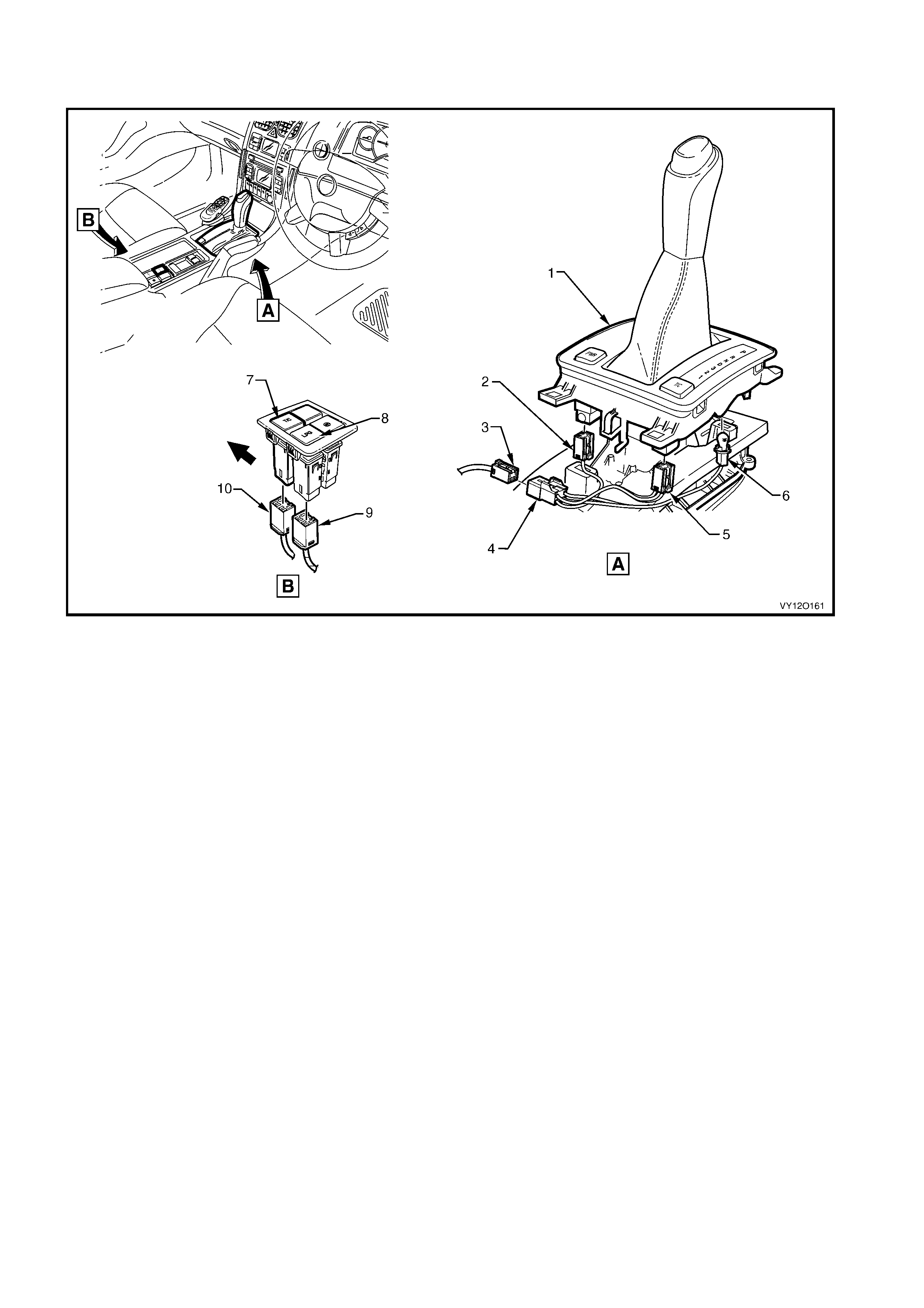
MAIN WIRING HARNESS – 28 – RHD
TR ANSM ISSION SELECT O R CONNECT O RS
Figure 12O-90
Legend
1. PRNDL Select or Housi ng
2. Auto/Trans Shift Program Connector (S22)
3. Main Wiring Harness to Transmission Selector Harness
Connector (X301)
4. Transmission Selector Harness to Main Wiring Harness
Connector (X301)
5. Electroni c Tract ion Control Switch Connector (S73)
6. Auto/Trans Control P ositi on Indicator Lamp Connector (E125)
7. Electroni c Tract ion Control Switch (Manual Transmiss i on)
8. LPG Selector Switch
9. LPG Selector Switch Connector (S118)
10. Electronic Traction Control Switch Connector (S73)
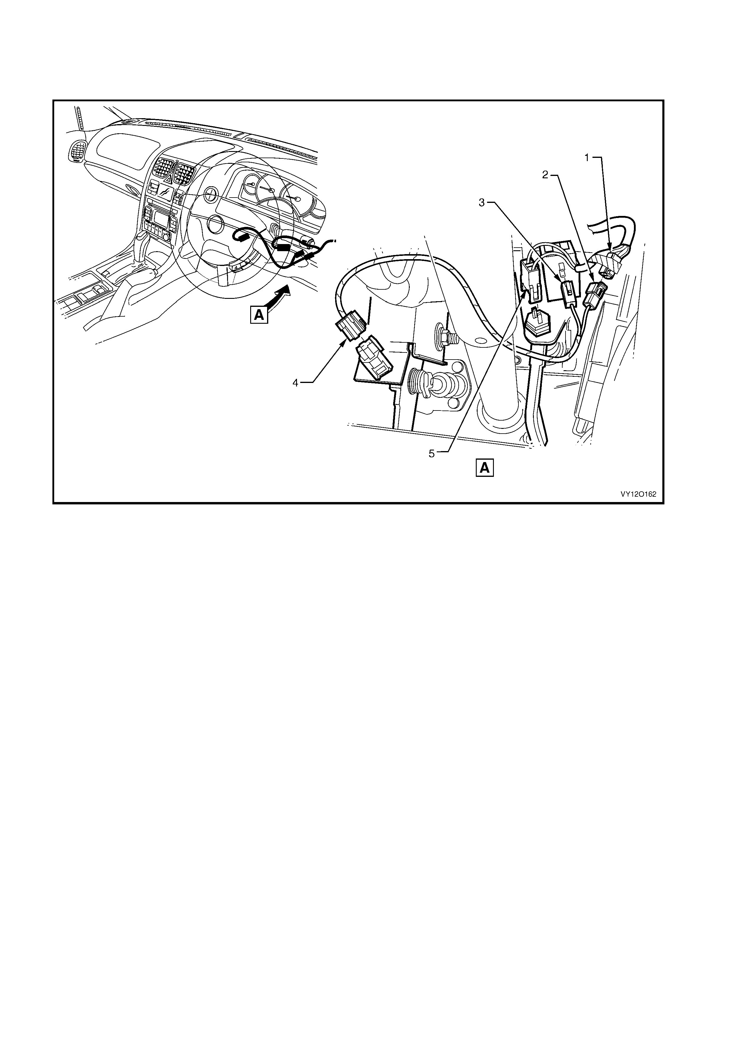
MAIN WIRING HARNESS – 29 – RHD
STOP LAMP, TRACTION & CRUISE CONTROL RELEASE SWITCH CONNECTORS –
MANUAL TRANSMISSION WITH CRUISE CONTROL
Figure 12O-91
Legend
1. Main W i ri ng Harness t o Cruis e Control P atch Harness
Connector (X316)
2. Cruis e Control Patch Harness to Main Wi ri ng Harness
Connector (X316)
3. St op Lamp, Traction & Cruise Control Rel ease Switch
Connector (S 220 – X2)
4. Cruis e Control Release & Clutch Pedal Switch Connect o r
(S46)
5. St op Lamp, Traction & Cruise Control Rel ease Switch
Connector (S 220 – X1)
RADIO POWER ANTENNA ASSEMBLY WIRING – RHD
Figure 12O-92

Legend
1. Diversit y Antenna Connector (A133 – X3)
2. Power Antenna Connect or (A133 – X2)
3. In-line Diversity Antenna Connector (X208)
4. In-line Radio Ant enna Connector (X209)
5. Diversit y Antenna Lead Connector
6. Radio Power Antenna Connector (W6 – X2)
7. Antenna Lead Panel Blanking Grommet
8. Radio Power Antenna Connector (W6 – X1)
A. Leads clipped t o underside of heating, vent i l ation and air
conditi oni ng assem bl y as shown.
B. Leads clipped t o front side of heating, vent i l ation and ai r
conditi oni ng assem bl y as shown.
C. Leads tucked behind rout i ng post on heating, vent i l ation and
air conditioning assembly as shown.
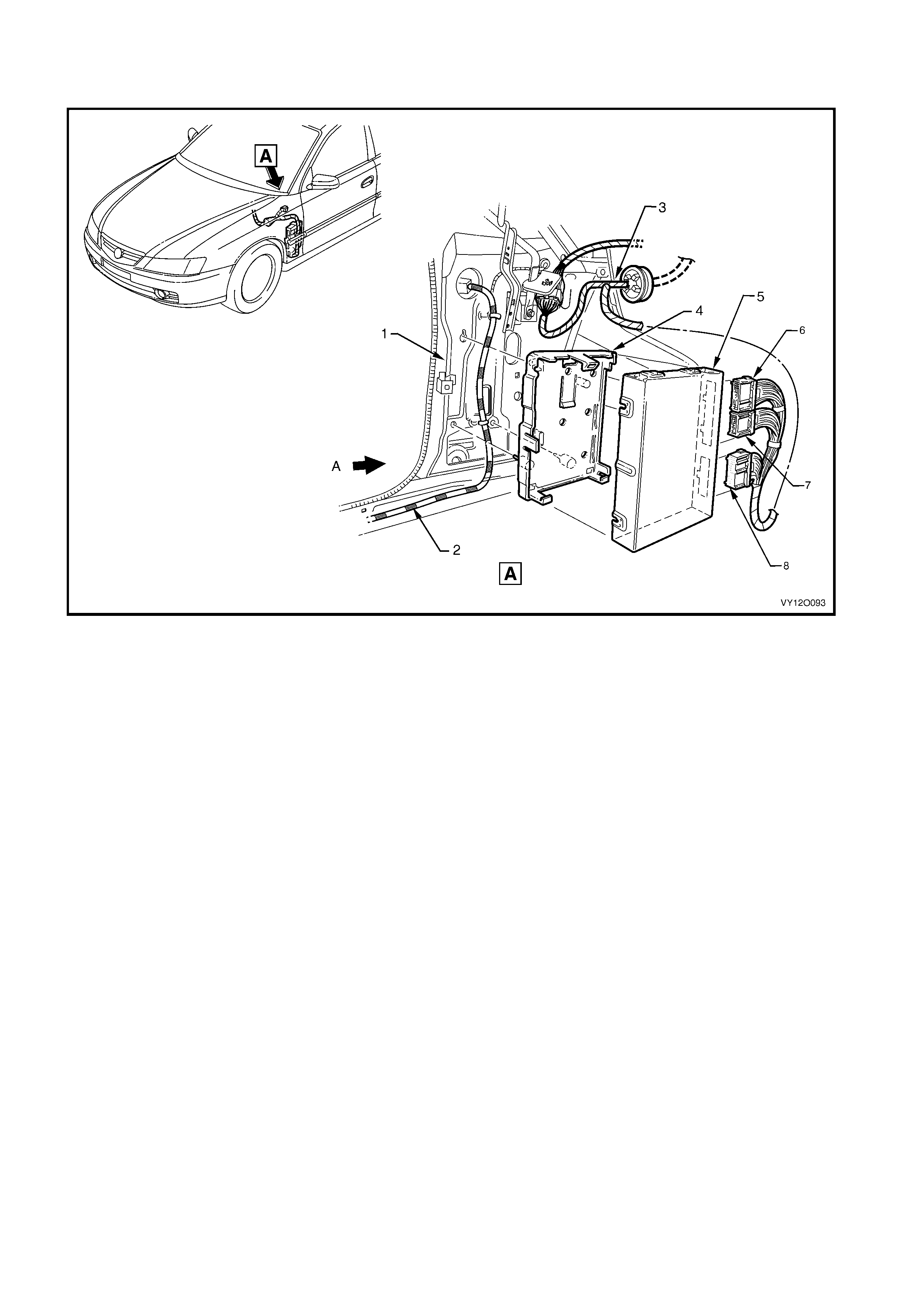
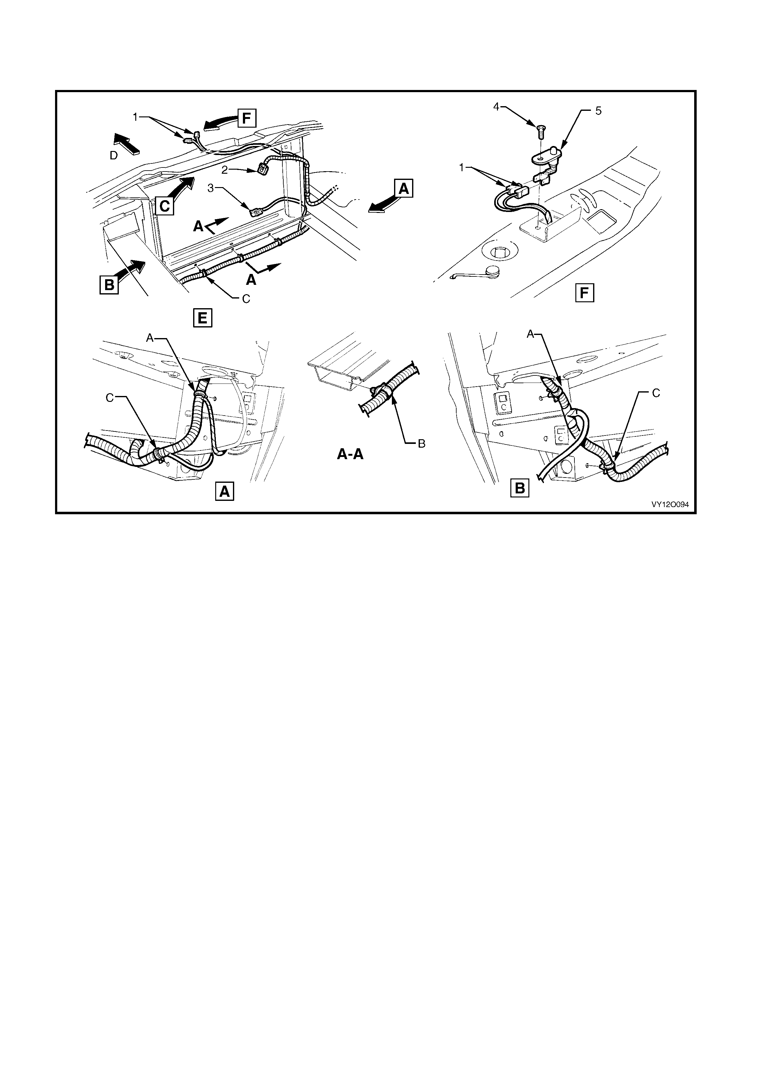
RADIO AMPLIFIER ASSEMBLY &
ANTENNA WIRING – 1 – RHD
Figure 12O-93
Legend
1. Divers i ty Antenna Lead
2. Body Wiring Harness
3. Ampl if i er Assem bl y & Radio Antenna Leads
A. Lead attached along sill as shown (3 places).
B. Lead attached along sill as shown (2 places).
For view D, refer to RADIO AMPLIFIER ASSEMBLY & A N TENNA
WIRING – 2 – RHD in this sectio n .
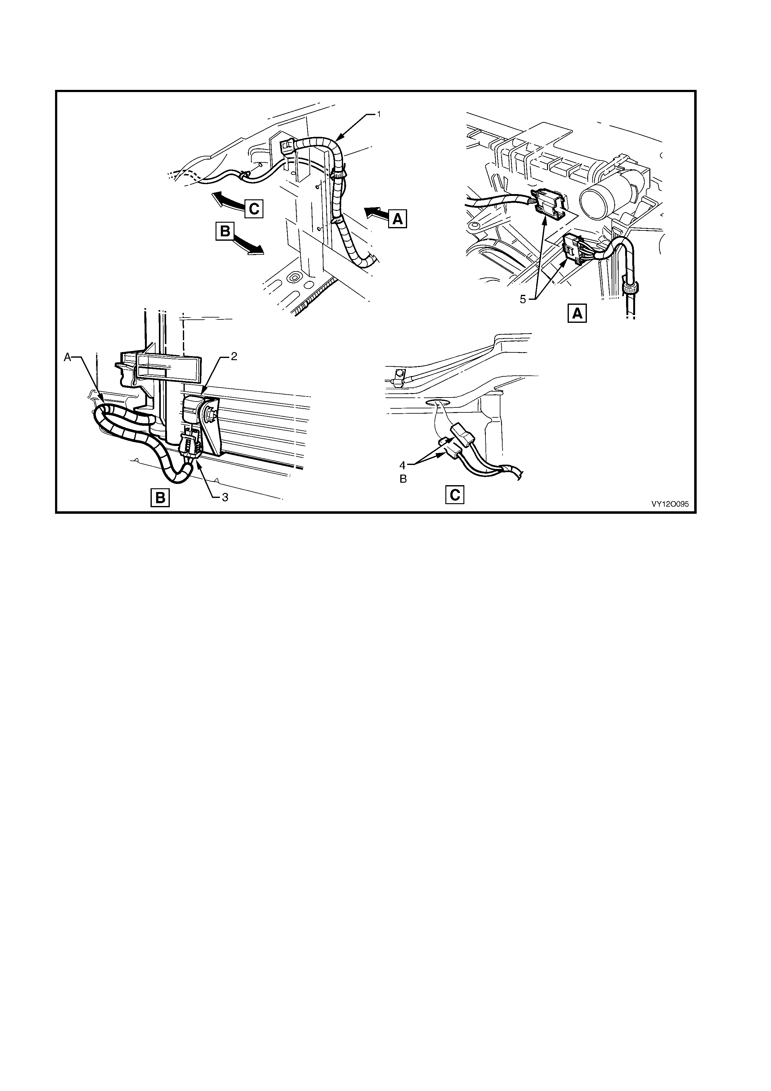
RADIO AMPLIFIER ASSEMBLY &
ANTENNA WIRING – 2 – RHD
Figure 12O-94
Legend
1. Attaching Screw Amplifi er Assem bly Radio Antenna Ground t o
C Pillar
2. Attachi ng Screw Amplifier Ass em bly Radio Antenna t o Body
3. Diversity Antenna Amplifier
4. Radio Antenna Connect or (W4)
5. Sub Speaker Amplifier
6. Radio Rear Speaker Amplif i er Connect or (N6)
A. Amplifier att aching screw positioned through hole (4 places).
B. Tab located in slot as shown.
For location of view D, refer to RADIO AMPLIFIER ASSEMBLY &
ANTENNA WIRING – 1 – RHD in t his sec tion
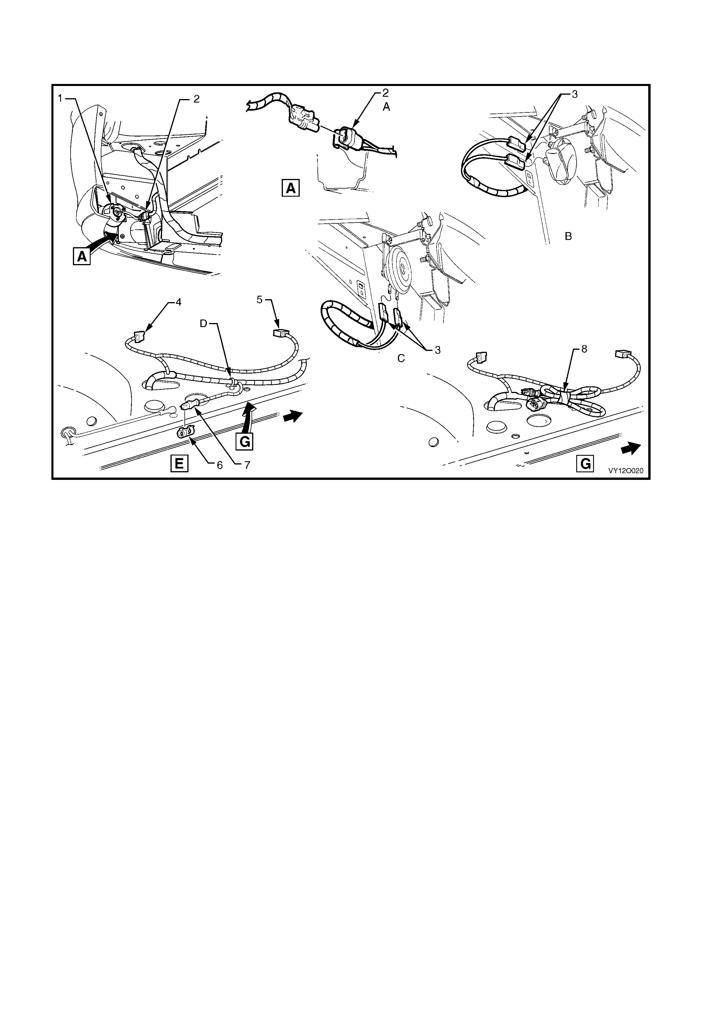
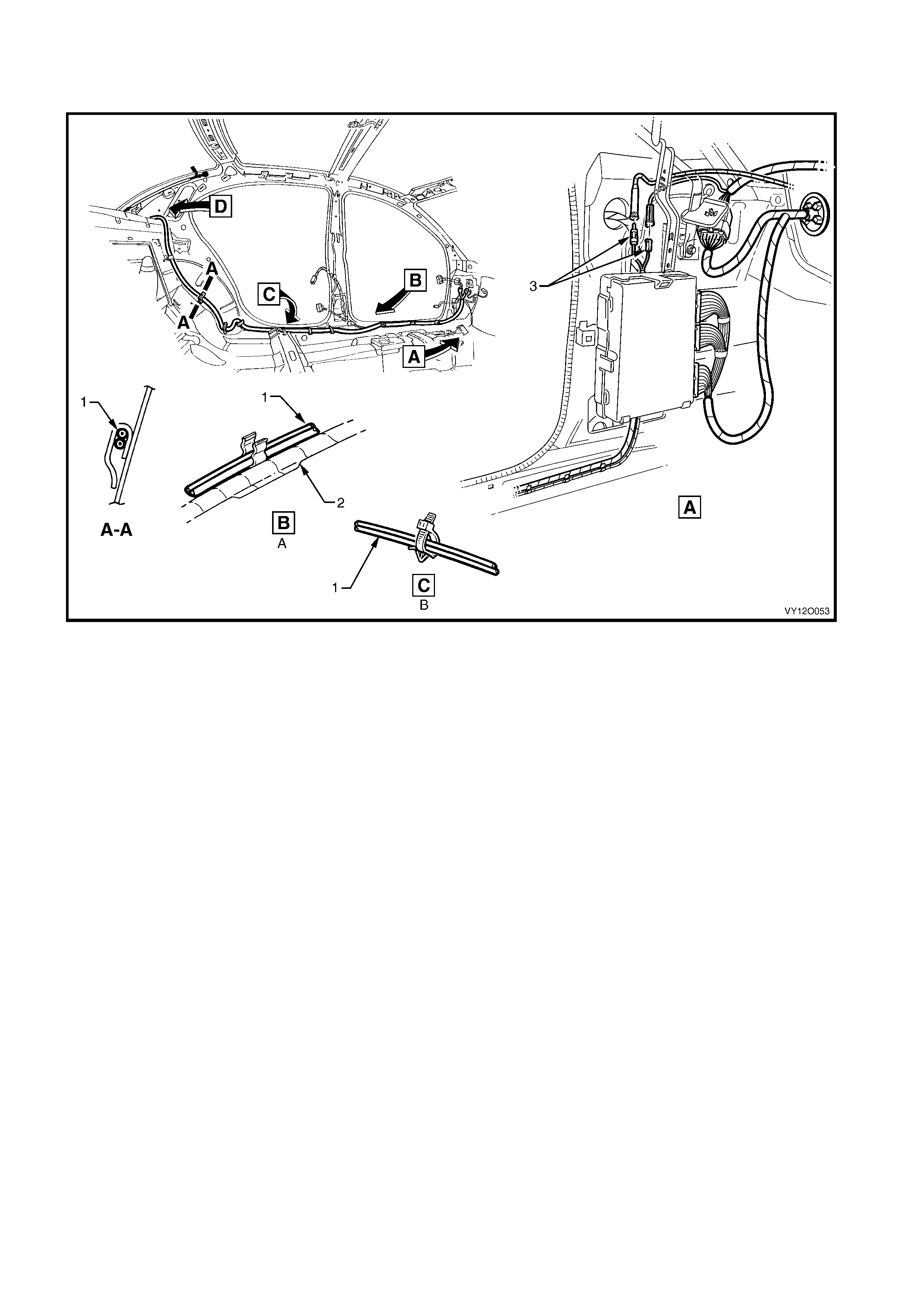
NAVIGATION SYSTEM ASSEMBLY AND WIRING – 1 – RHD – SEDAN MODELS
Figure 12O-95
Legend
1. Speaker Assembly
2. Global Positioning System Harness
3. Display Assembly
4. Driver Inform ation Display Connector (P6)
5. Driver Inform at i on Dis pl ay Control Connect or (A35)
6. Remote Control Cradle
7. Navigation S peaker Assembly Connector (B104)
8. Global Positioni ng System Harness Connectors (XO2)
9. Global Positioning Sys t em Harness Connector (XO1)
10. Global Positioning System Harness to Main Wiri ng Harness
Connector (X207)
11. Main Wiring Harness t o Global Positioning S yst em Harness
Connector (X207)
A. Harness attached t o passenger side airbag s upport rail
assembly as shown.
For views D, H & J, refer to NAVIGATION SYSTEM ASSEMBLY
AND WIRING – RHD SEDAN MODELS – 2 in this section.
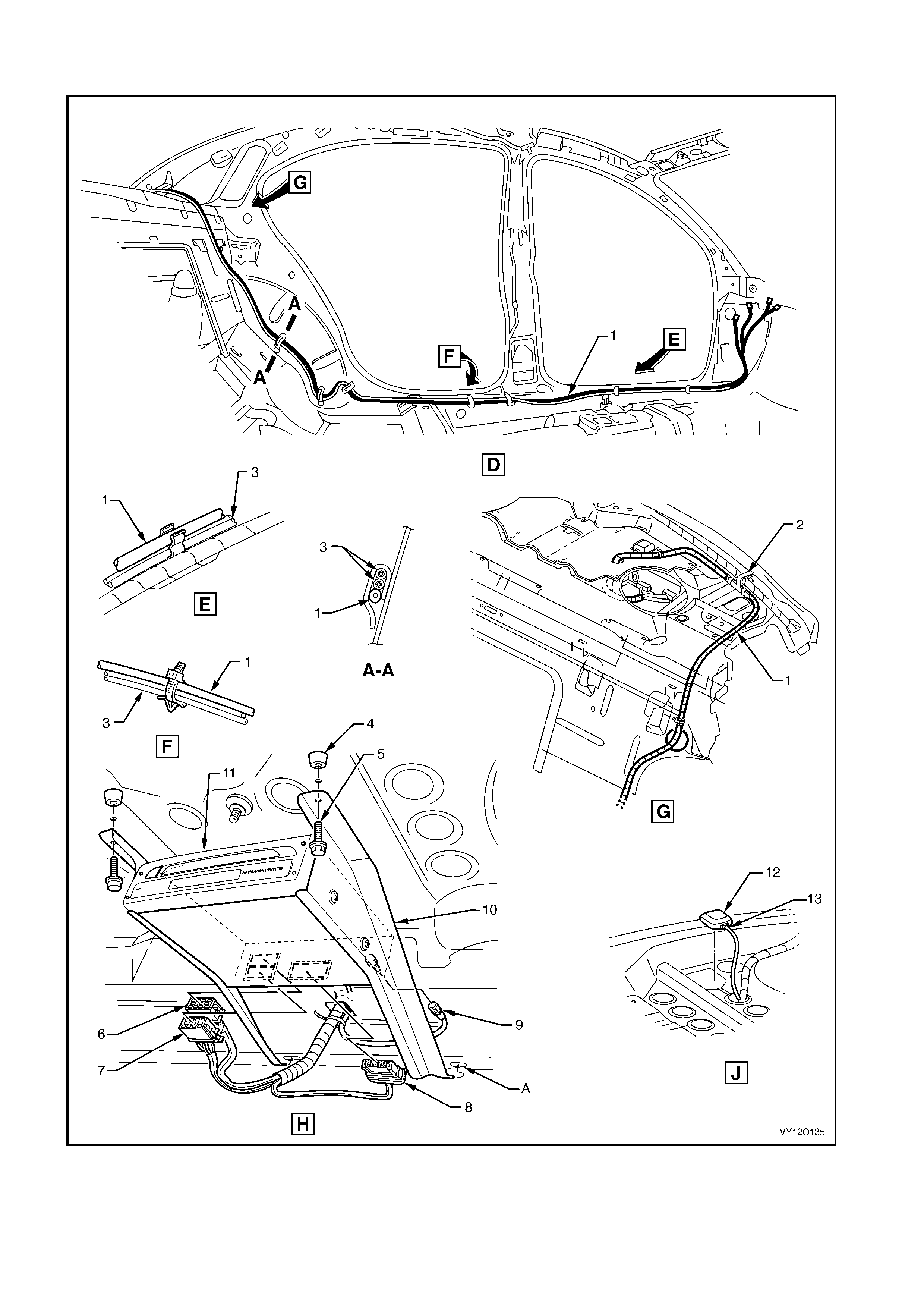
NAVIGATION SYSTEM ASSEMBLY AND WIRING – 2 – RHD – SEDAN MODELS
Figure 12O-96

Legend
1. Global Positioning System Harness
2. Global Positioni ng System Harness Vehicle Attachi ng Clip
3. Diversit y Antenna Lead
4. Processor Assembly Mounting Points
5. Processor Assembly Mounting Screws
6. Navigation Cont rol Proc essor Connector (A139 – X2)
7. Navigation Cont rol Proc essor Connector (A139 – X1)
8. Navigation Cont rol Proc essor Connector (A139 – X3)
9. Navigation Cont rol Proc essor Connector (A139 – X4)
10. Processor Assembly Mounting Brackets
11. Navigation Control Processor Assembly
12. Antenna
13. Antenna Connector (W2 – GPS – 2)
A. Process or assembl y brack et m ounting hol es.
For location of views D, H & J, refer to NAVIGAT IO N SYSTEM
ASSEMBLY AND WIRING – RHD SEDAN MODELS – 1 in th is
section.
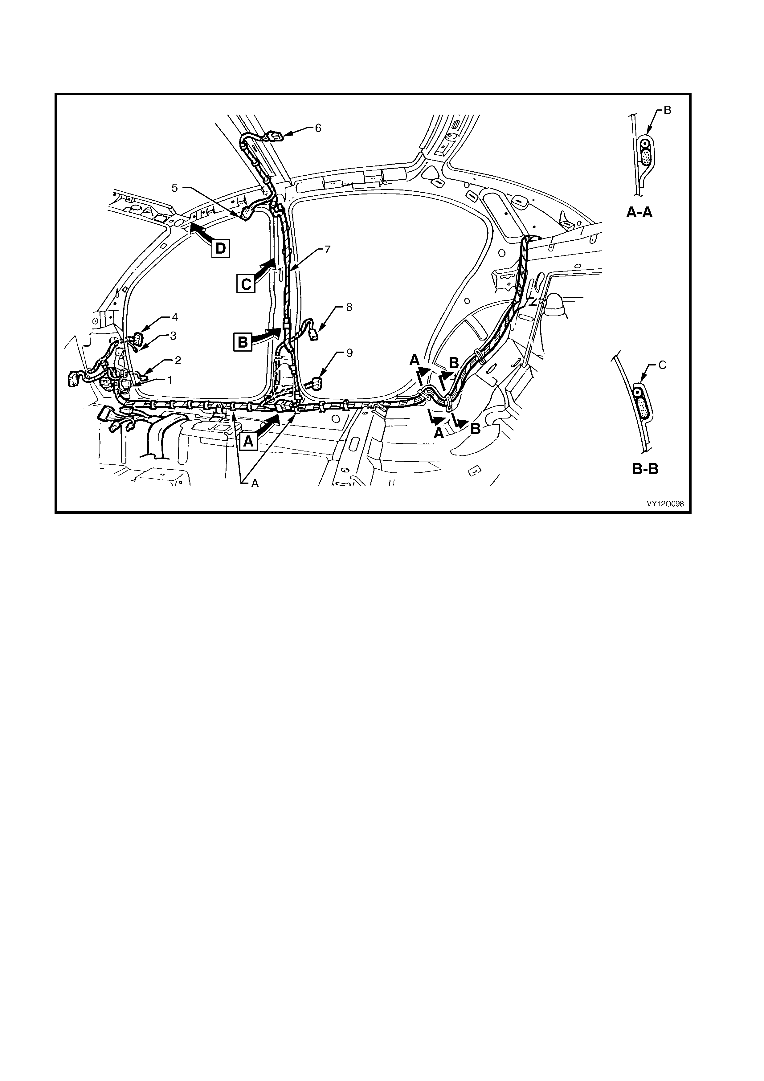
BODY & ROOF WIRING HARNESSES – 1
INTERIOR – SEDAN MODELS
Figure 12O-97
Legend
1. Body Wiring Harness to Main Wi ring Harness Connector
(X200)
2. Door Ajar Indicator Switch Connector (S2)
3. Body Wiring Harness to Right-hand Front Door Wi ri ng
Harness Connect or (X601)
4. Body Wiring Harness to Right-hand Front Door Wi ri ng
Harness Connect or (X600)
5. Roof Lamp Harness to Visor Lam p Harness
Connector (X310)
6. Dome Lamp Connector (E67)
7. Roof Lamp Harness
8. Door Ajar Indicator Switch Connector (S2)
9. Body Wiring Harness to Right-hand Rear Door Wiring
Harness Connect or (X800)
A. Harness clipped to underbody, refer to BODY & ROOF
WI RING HARNE SSES – 3 in this sectio n.
B. Clip bent to ret ain fuel filter door cable & body harness
(1 place).
C. Clip bent to retain f uel filter door cable & body harness
(2 places).
For views A throug h D, refer to BODY & ROOF WIRING
HARNESSES – 4 in this section.
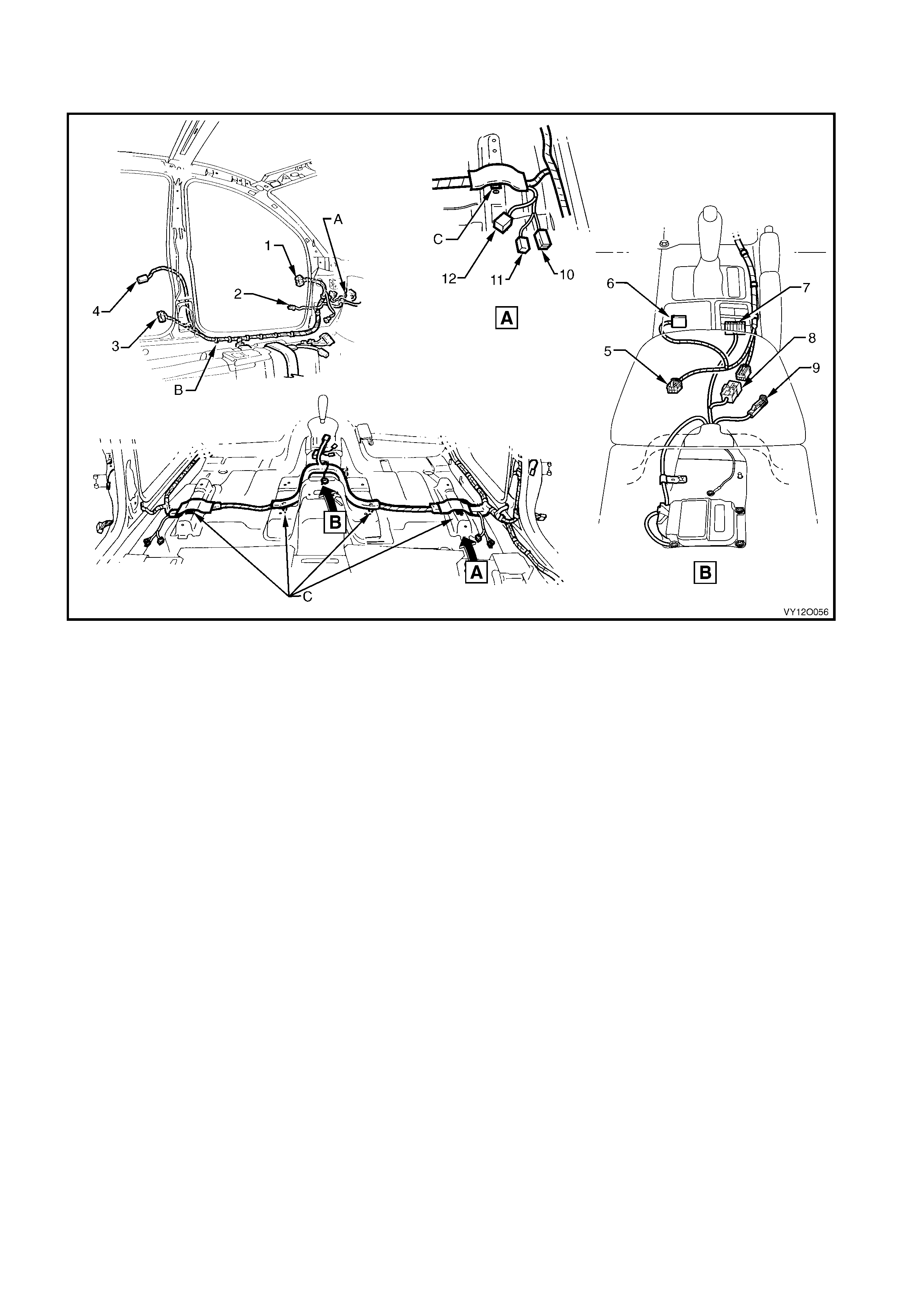
BODY & ROOF WIRING HARNESSES – 2
INTERIOR – ALL MODELS
Figure 12O-98
Legend
1. Body Wiring Harness to Left-hand Front Door Wiring Harness
Connector (X500)
2. Door Ajar Indicator Switch Connector (S 2)
3. Body Wi ri ng Harness to Left-hand Rear Door Wiring Harness
Connector (X700)
4. Door Ajar Indicator Switch Connector (S 2)
5. Main Wiring Harness to Console W iring Harness Connector
(X309)
6. Main W i ri ng Harness t o Transmission Selector Harness
Connector (X301)
7. Side Wi ndow (Master) S witch Connector (S222)
8. Body Wi ri ng Harness to Main Wiring Harness Connect or
(X303)
9. Park Brake Switc h Connect or (S181)
10. Seat Belt Connector (Y128 - D)(Y129 – P)
11. Body Wiring Harness to Side Airbag Harness Connector
(X306 – L) (X307 – R)
12. Body Wiring Harness to Power Seat Harness Connector
(X302 – D) (X308 – P)
A. For continuation, refer to BODY & ROOF WIRING
HARNESSES – 3 in this section.
B. Harness clipped to underbody, refer to BODY & ROOF
WI RING HARNE SSES – 3 in this sectio n.
C. Harness clipped to underbody as shown (4 places).

BODY & ROOF WIRING HARNESSES – 3
INTERIOR – RHD
Figure 12O-99
Legend
1. Body Wiring Harness
2. Front Side Turn Signal Lamp Connector (E75)
3. Radio Power Antenna Connector (W6 – X1)
4. Body Wiring Harness to Main Wi ring Harness Connector
(X201)
5. Body Control Module Connect or (A15 – X4)
6. Front Side Turn Signal Lamp Connector (E75)
7. Body Wiring Harness to Right-hand Front Door Wi ri ng
Harness Connect or (X600)
8. Body Wiring Harness to Main Wi ring Harness Connector
(X200)
9. Body Wiring Harness to Side Airbag Harness Connector
(X306 – L, X307 – R)
10. Seat Belt Connector (Y128 – D), (Y129 – P)
A. Attach body wiring harness to shroud side panel (2 places).
B. For continuation, refer to BODY & ROOF WIRING
HARNESSES – 1 in this section.
C. Body wiring harness att ached t o underbody as shown
(9 places).
D. Right-hand side shown.
E. Main wiring harness connect or cl i pped to shroud side panel as
shown.
F. Front of vehicle.
G. Left-hand side shown.
H. For continuation, refer to BODY & ROOF WIRING
HARNESSES – 2 in this section.
I. Body wiring harness attached to underbody as shown
(6 places).
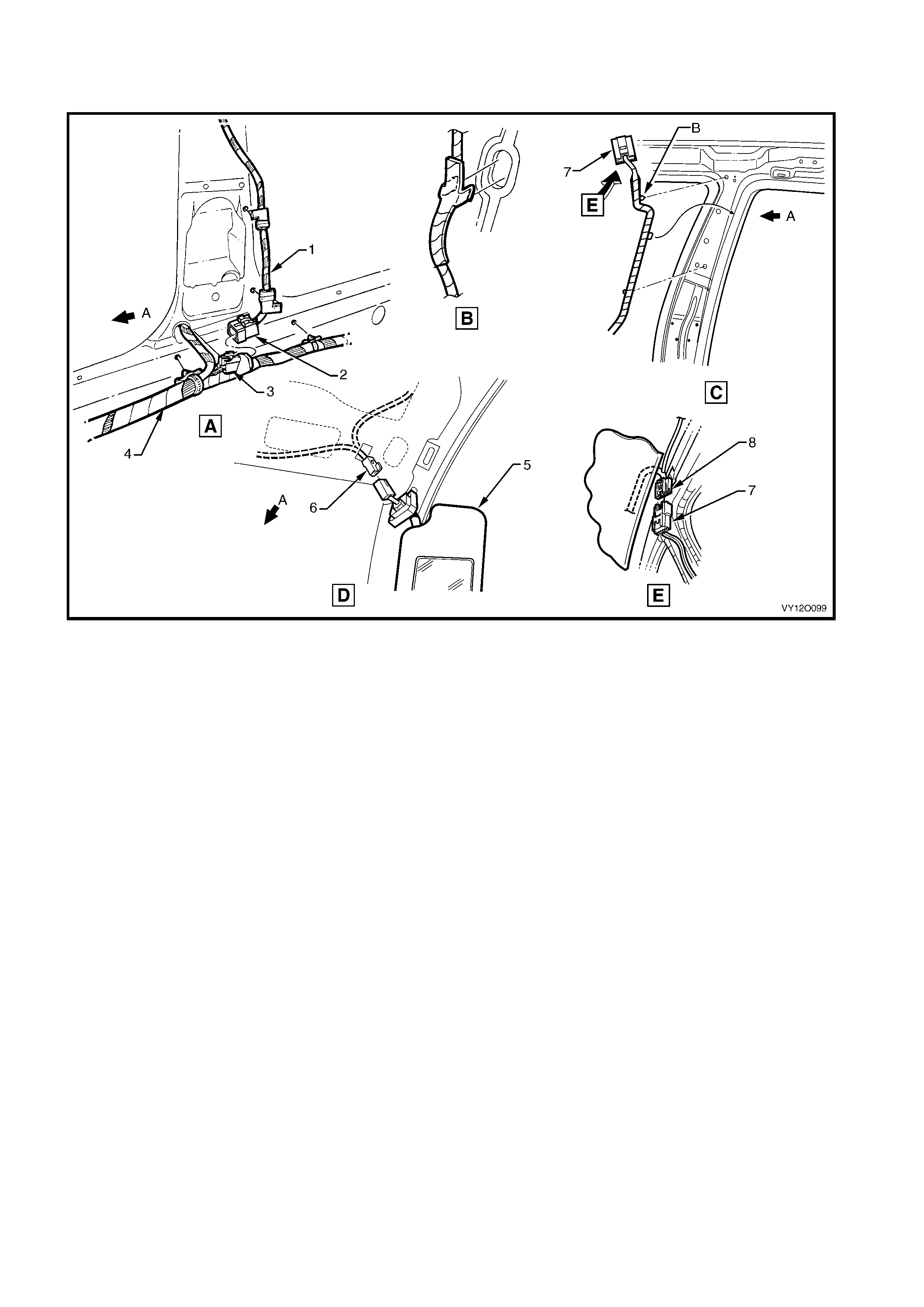
BODY & ROOF WIRING HARNESSES – 4
INTERIOR – ALL MODELS
Figure 12O-100
Legend
1. Roof Lamp Harness
2. Roof Lamp Harness to Body Wiri ng Harness Connector
(X300)
3. Body Wiring Harness to Roof Lamp Harness Connector
(X300)
4. Body Wiring Harness
5. Sun Visor
6. Sun Shade Lamp Connector (E120)
7. Roof Lamp Harness to Visor Lam p Harness Connector
(X310)
8. Visor Lamp Harness to Roof Lamp Harness Connector
(X310)
A. Front of vehicle.
B. For clipping, refer to BODY & ROOF WIRING HARNESSES –
2 and 3 diagrams in this section.
For location of views A through D, refer to
BODY & ROOF WIRI NG HARNES SES – 1 in this se ct ion .
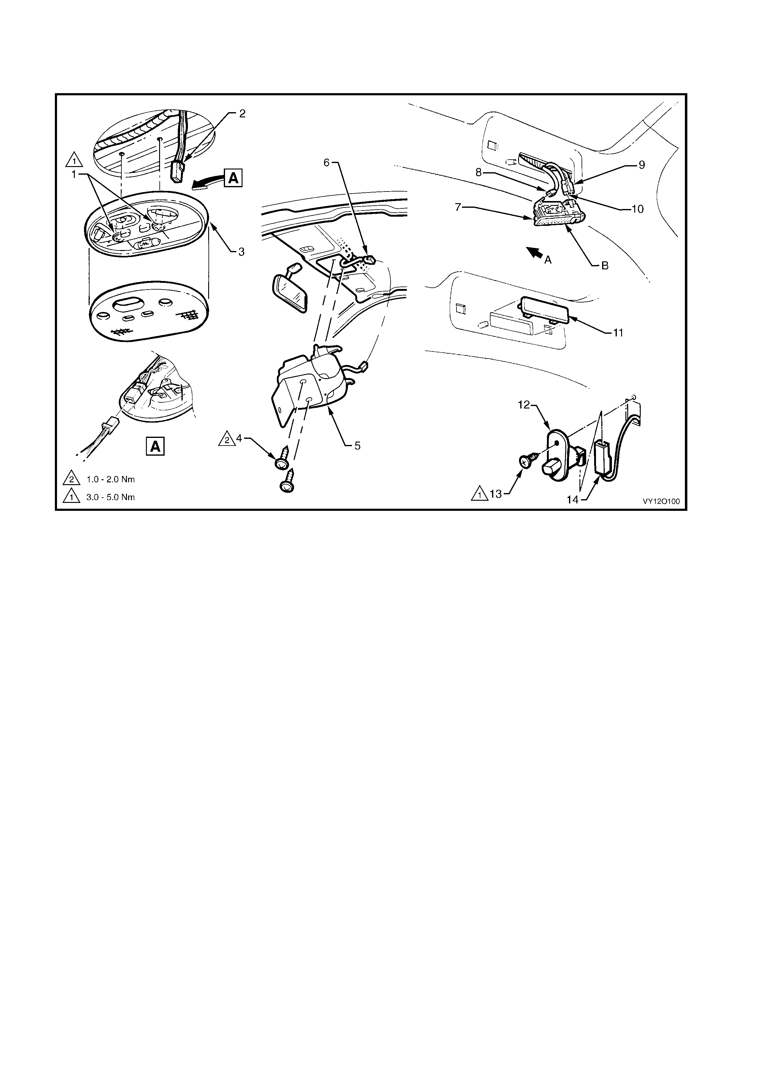
BODY & ROOF WIRING HARNESSES – 5
DOME & REAR PASSENGER COMPARTMENT LAMPS – ALL MODELS
Figure 12O-101
Legend
1. Attachi ng Screws, Dome Lamp
2. Dome Lamp Connector (E67)
3. Dome Lamp Assembly (Level 1)
4. Attachi ng Screws, Roof Consol e
5. Roof Console (Level 2 – 5)
6. Roof Console Lamp Connect or (E67)
7. Reading Lamp Assembly
8. Reading Lamp Connect or (E94 – X1)
9. Reading Lamp Connect or (E94 – X2)
10. Reading Lamp Connector (E94 – X3)
11. Blank for Models Without Roof Rail Courtes y Lamp Assem blies.
12. Door Ajar Warning Switch
13. Attaching Screw Door Ajar Warning Switch
14. Door Ajar Warning Switch Connect o r (S 2)
A. Front of vehicle.
B. Install l amp with switc h facing rear on ri ght-hand side, forward
on left-hand side.
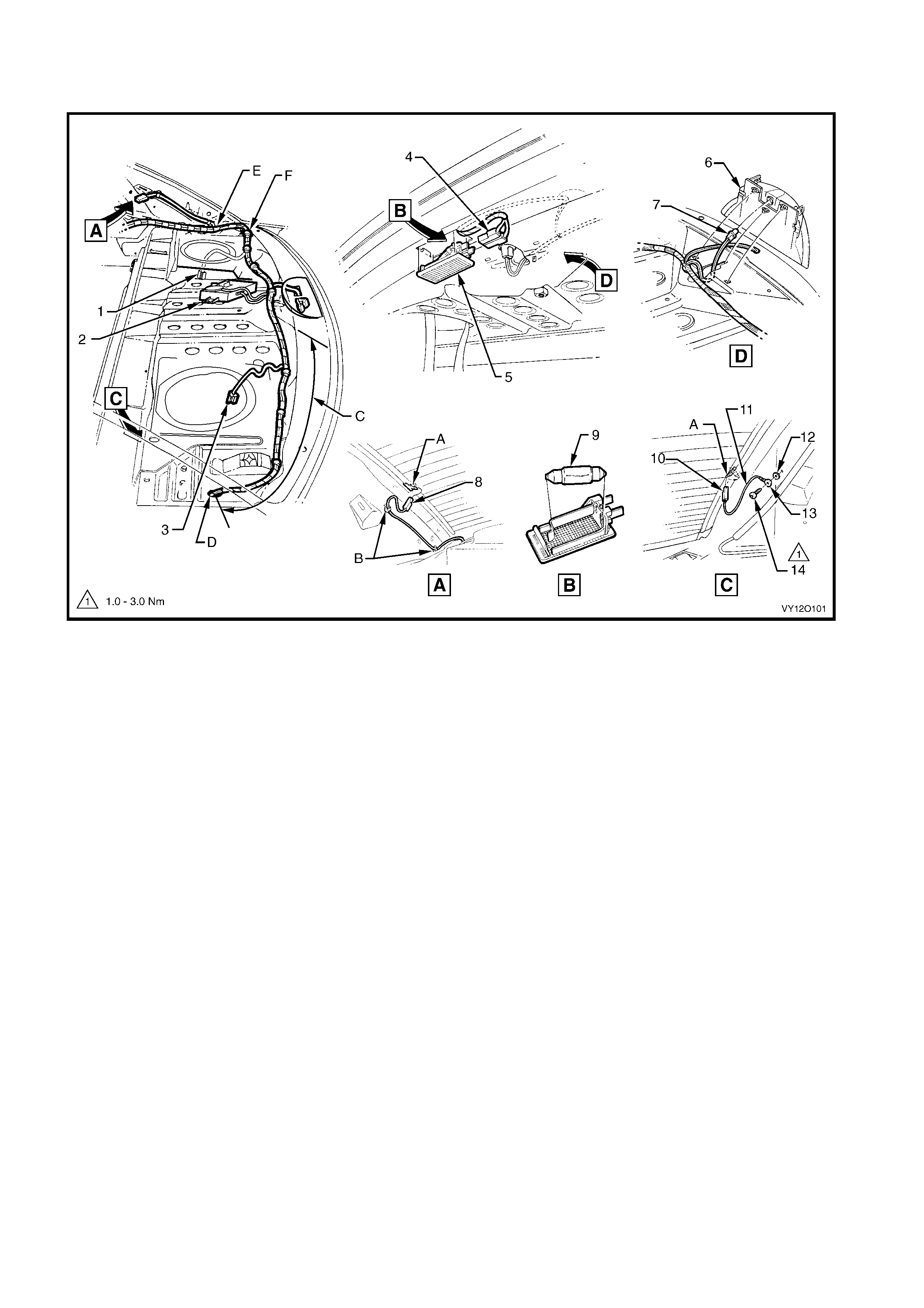
BODY & ROOF WIRING HARNESSES – 6
PARCEL SHELF & REAR COMPARTMENT LAMP – SEDAN MODELS
Figure 12O-102
Legend
1. Right-hand Rear Speak er Connector (B 131)
2. Reverse Park i ng Aid Module and Speaker Assembl y
3. Left-hand Rear Speaker Connect o r (B 131)
4. Rear Compartment Courtesy Lamp Connectors (E36)
5. Rear Compartment Courtesy Lamp
6. High Mounted Stop Lamp
7. High Mounted Stop Lamp Connector (E79 – S/W)
8. Rear Window Defog Grid Connector (R22 – X1)
9. Rear Compartment Courtesy Lamp Bulb
10. Rear Window Defog Grid Connector (R22 – X2)
11. Rear Window Defog Grid Ground Lead
12. Ground Lead Terminal Attaching Washer
13. Ground Lead Term i nal (X118 – GP7)
14. Ground Lead Term i nal Attaching Screw
A. Tab bent once lead connector is installed.
B. Rear window defog grid lead cli p to side inner panel (2 places).
C. Rear speaker wiring where fitted.
D. For continuation of subwoofer amplifi er, ref er t o AMPLIFIER
ASSEM BLY RADIO AN TENNA & WIRIN G – 1 & 2 in this
section.
E. For continuation, refer to BODY & ROOF WIRING
HARNESSES – 7 in this section.
F. Body wiring harness cli pped to rear seat upper panel
(7 places).
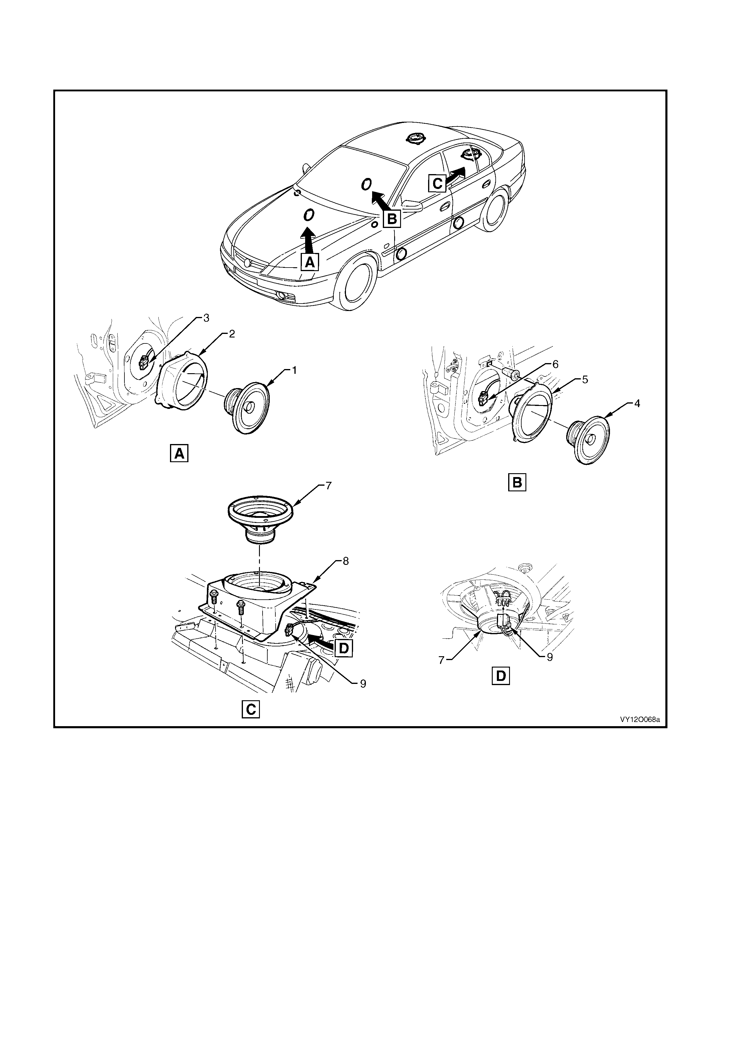
BODY & ROOF WIRING HARNESSES – 7
SPEAKERS
Figure 12O-103
Legend
1. Front Door Radio Speaker Assembly
2. Front Door Radio Speaker Mounting Box Assembly
3. Right-hand and Left -hand Front Door Radio Speak er
Connector (B 108)
4. Rear Door Radio Speaker Assembly
5. Rear Door Radio Speaker Mounti ng Box Assembl y
6. Rear Right-hand and Left -hand Rear Door Radio Speaker
Connector (B 117)
7. Rear Shelf Radio Sub Speaker
8. Rear Shelf Radio Sub Speaker Brack et
9. Rear Shelf Radi o Speaker Connector (B131)
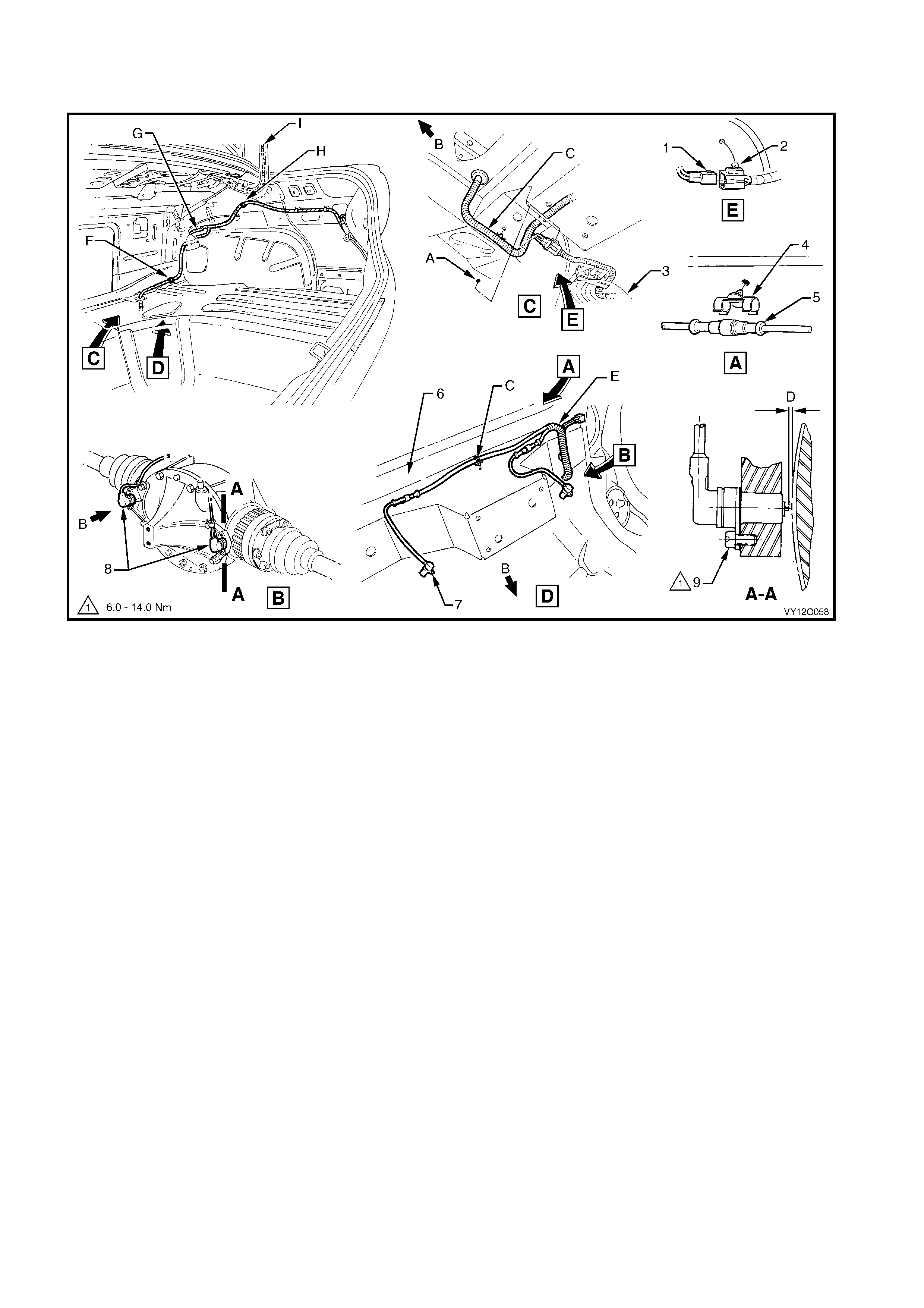
BODY & ROOF WIRING HARNESSES – 8
REAR COMPARTMENT, FUEL TANK & ABS – SEDAN MODELS
Figure 12O-104
Legend
1. Body Wiring Harness to Fuel Tank Harness Connector
(X402)
2. Fuel Tank Harness to Body Wiring Harness Connect or
(X402)
3. Fuel Tank Assembly
4. Rear Wheel Speed Sensor Connector Retainer
5. Rear Wheel Speed Sensor Connector (B76)
6. Attachi ng Screw Sensor Assembl y Rear Wheel Speed
7. Rear Axle Cross Member
8. Sensor Assembly Rear Wheel Speed
9. Differential Assembly with Rear Speed Sensors Installed
10. Sensor Assembly Rear Wheel Speed Attachin g Screw
A. Harness connector cl i ped to rear longitudi nal extens i on panel .
B. Front of vehicle.
C. Body wiring harness cl i pped to rear axle cross member
(2 places).
D. Shims used to achieve required clearanc e between tip of wheel
speed sensor and pulse ring of 0.3 to 1.1 mm.
E. For station wagon models, refer t o
BODY & LIFTGATE HARNESSES – 1 in this section.
F. Body wiring harness cli pped to lower wheelhouse brace – right
-hand side.
G. For continuation, refer to
BODY & ROOF WIRI NG HARNES SE S – 1 in this sect io n .
H. Body wiring harness clipped to side inner panel.
I. For c ontinuat i on, ref er to
BODY & ROOF WIRI NG HARNES SE S – 11 in this section.
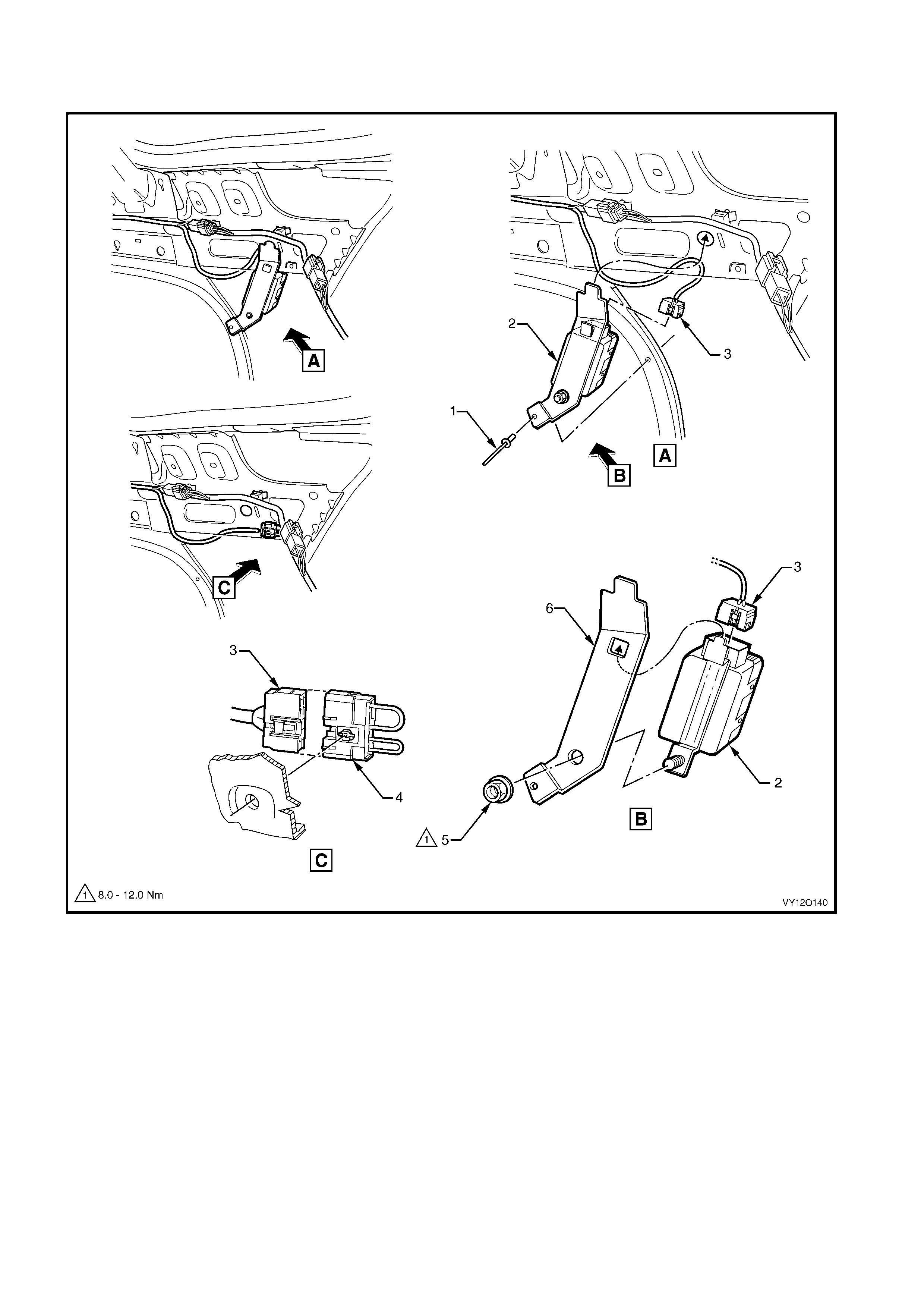
BODY & ROOF WIRING HARNESSES – 9
FUEL PUMP MODULE – V6 SUPERCHARGED ENGINE
Figure 12O-105
Legend
1. Pop Rivet
2. Fuel Pump Module Assembly
3. Fuel Pump Module Connector (A47)
4. Shorting Piece
5. Nut
6. Mounting Bracket
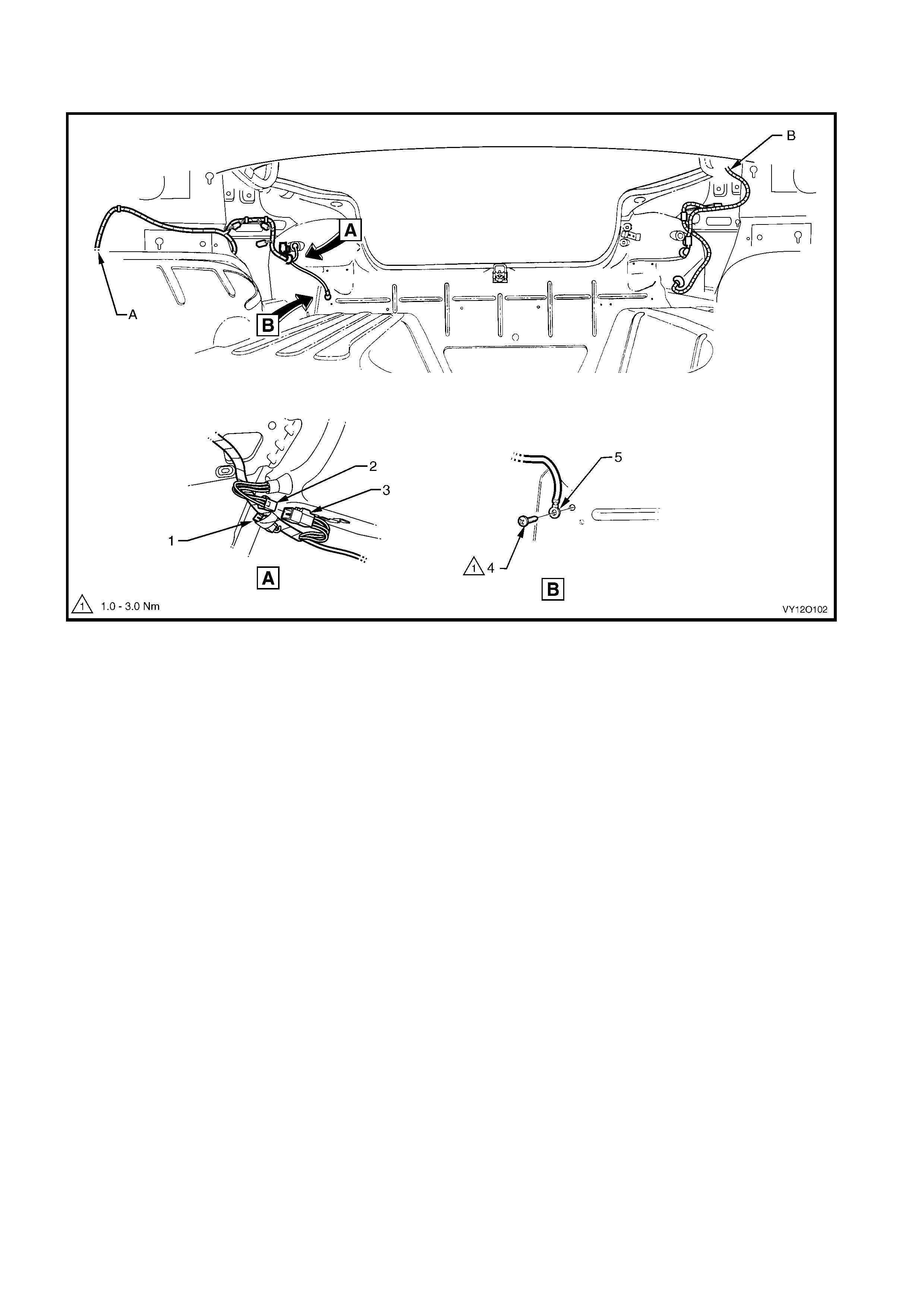
BODY & ROOF WIRING HARNESSES – 10
REAR COMPARTMENT – SEDAN MODELS
Figure 12O-106
Legend
1. Body Wiring Harness to Trailer Harness Connector (X908)
2. Tail Lamp Harness to Body Wiring Harnes s Connector
(X903 – R)
3. Body Wiring Harness to Tail Lamp Harness Connector
(X903 – R)
4. Body Ground, Attachi ng Screw
5. Body Wiring Harness Ground Tail Lam p Terminal
(X118 – GP13)
A. For continuation, refer to
BODY & ROOF WIRI NG HARNESSES – 2 in this section .
B. For continuation, refer to
BODY & ROOF WIRI NG HARNESSES – 6 in this sec tio n .
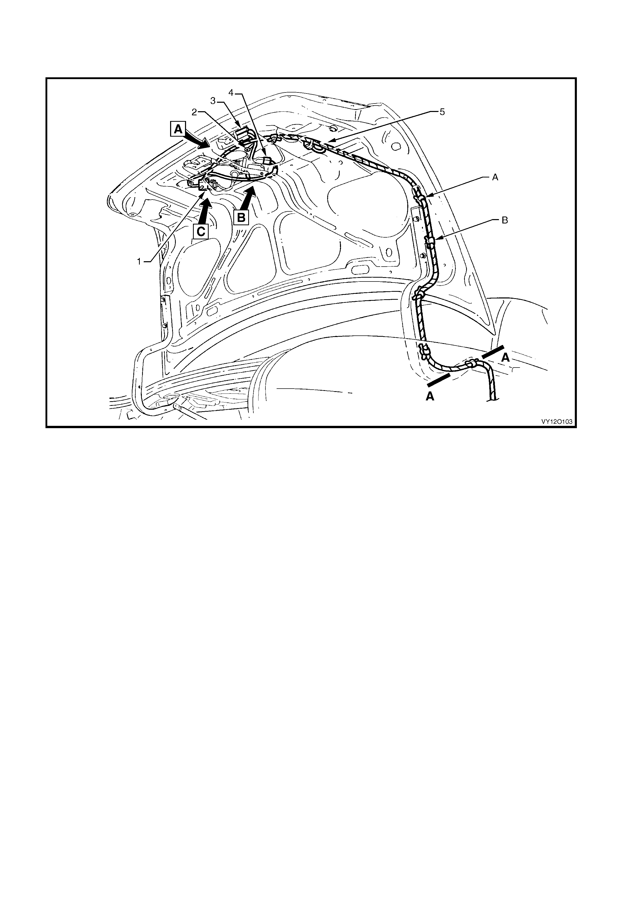
BODY & ROOF WIRING HARNESSES – 11
REAR COMPARTMENT LID WIRING
Figure 12O-107
Legend
1. Rear License Plate Lam p Connector (E44)
2. Body Wiri ng Harness Ground Rear Compartment Lid
Terminal (X118 -GP14)
3. Rear Compartment Courtesy Lamp Switch Connectors
(S189)
4. Rear Compartment Lid Latc h Actuator Connec tor (Y29)
5. Spoiler Stop Lam p Connector
A. Body wiring harness cli pped to rear compartm ent li d inner
(4 places).
B. Body wiring harness clipped to rear compartment lid hinge
(4 places).
For views A, B, C & section A–A, refer to
BODY & ROOF WIRI NG HARNES SE S – 12 in this section.
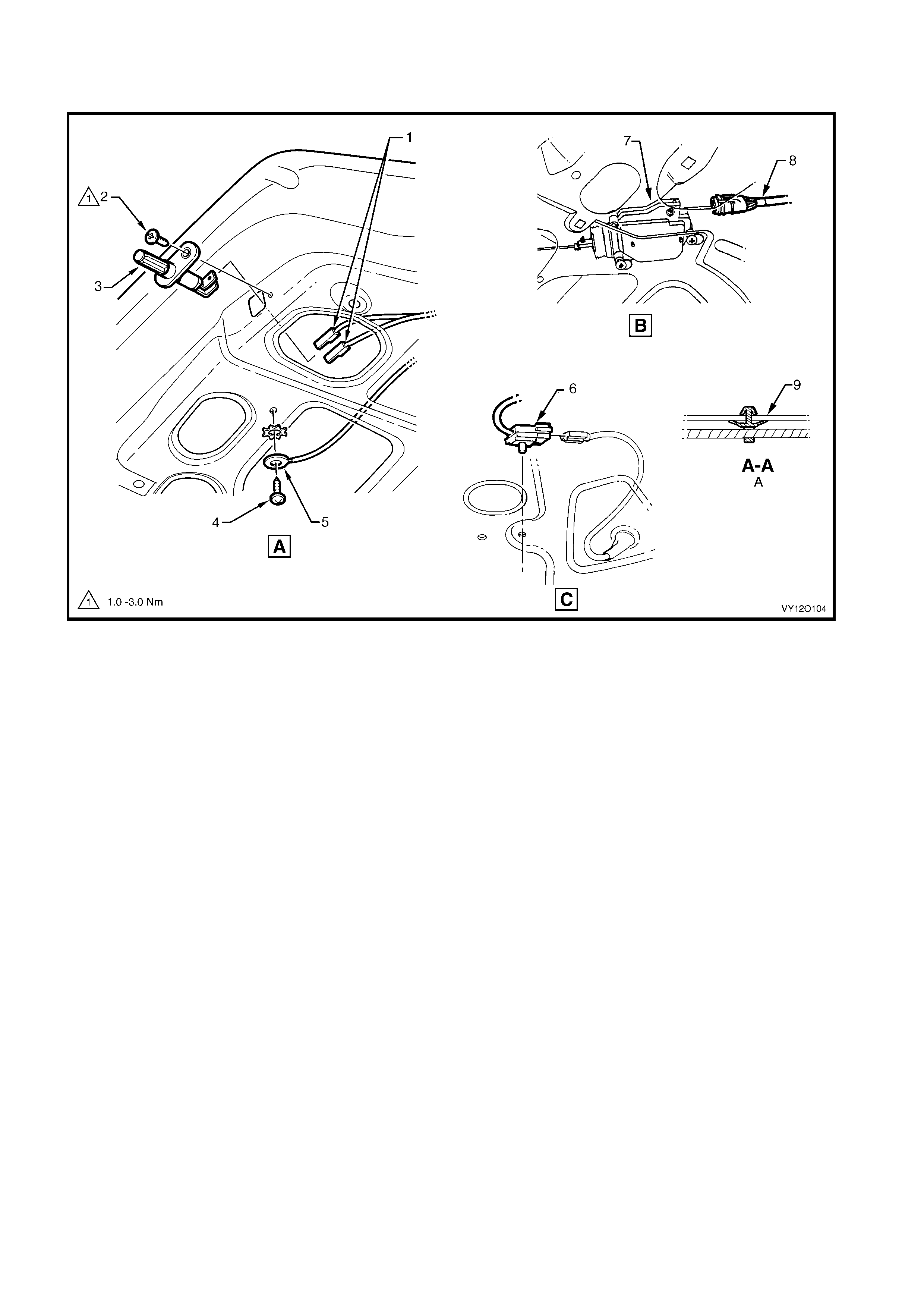
BODY & ROOF WIRING HARNESSES – 12
REAR COMPARTMENT LIFTGATE WIRING
Figure 12O-108
Legend
1. Rear Compartment Courtesy Lamp Connectors (S189)
2. Attaching Screw
3. Rear Compartment Courtesy Lamp Switch
4. Attaching Screw
5. Body Wiring Harness Ground Terminal (X118 – GP14)
6. Rear License Plate Lam p Connector (E44)
7. Lifgate Latc h Actuator
8. Lifgate Latc h Actuator Connect or (Y29)
9. Lifgate Hinge
A. Typical (4 places).
For location of views A, B, C, D & section A-A, refer to
BODY & ROOF WIRI NG HARNES SE S – 11 in this section.
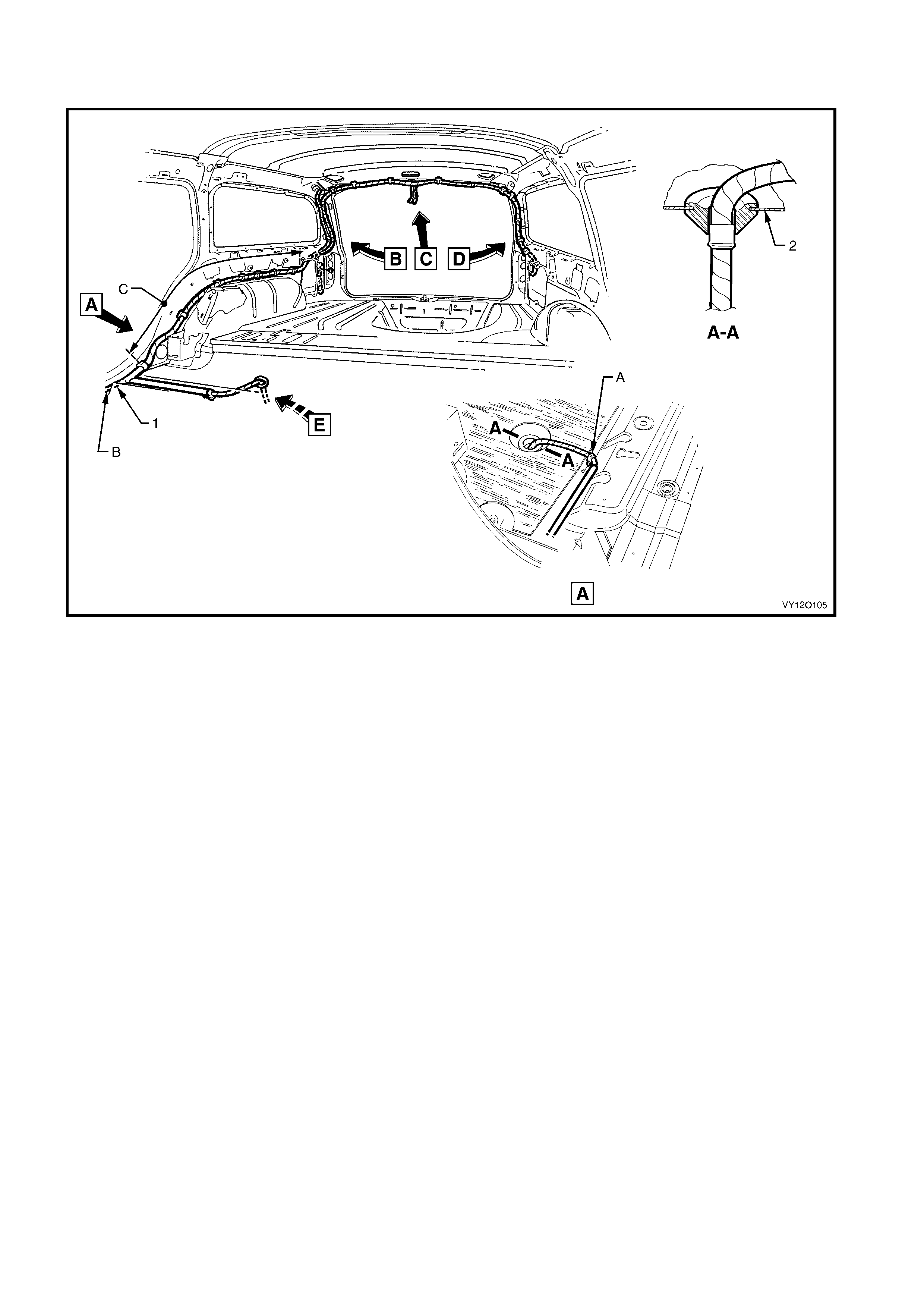
BODY & ROOF WIRING HARNESSES – 13
INTERIOR – STATION WAGON MODELS
Figure 12O-109
Legend
1. Body Wiring Harness
2. Rear Floor Panel Front A . Body wiring harnes s clipped to rear floor panel front.
B. For continuation refer t o
BODY & ROOF WIRI NG HARNES SE S – 1 in this sect io n .
C. Body wiring harness cli pped to i nner side panel – right -hand
side (8 places).
For views B & E, refer to
BODY AND LIFTGATE WIRI NG HARNE SSES – 1 in this section.
For views C & D, refer to
BODY AND LIFTGATE WIRI NG HARNE SSES – 5 in this section.
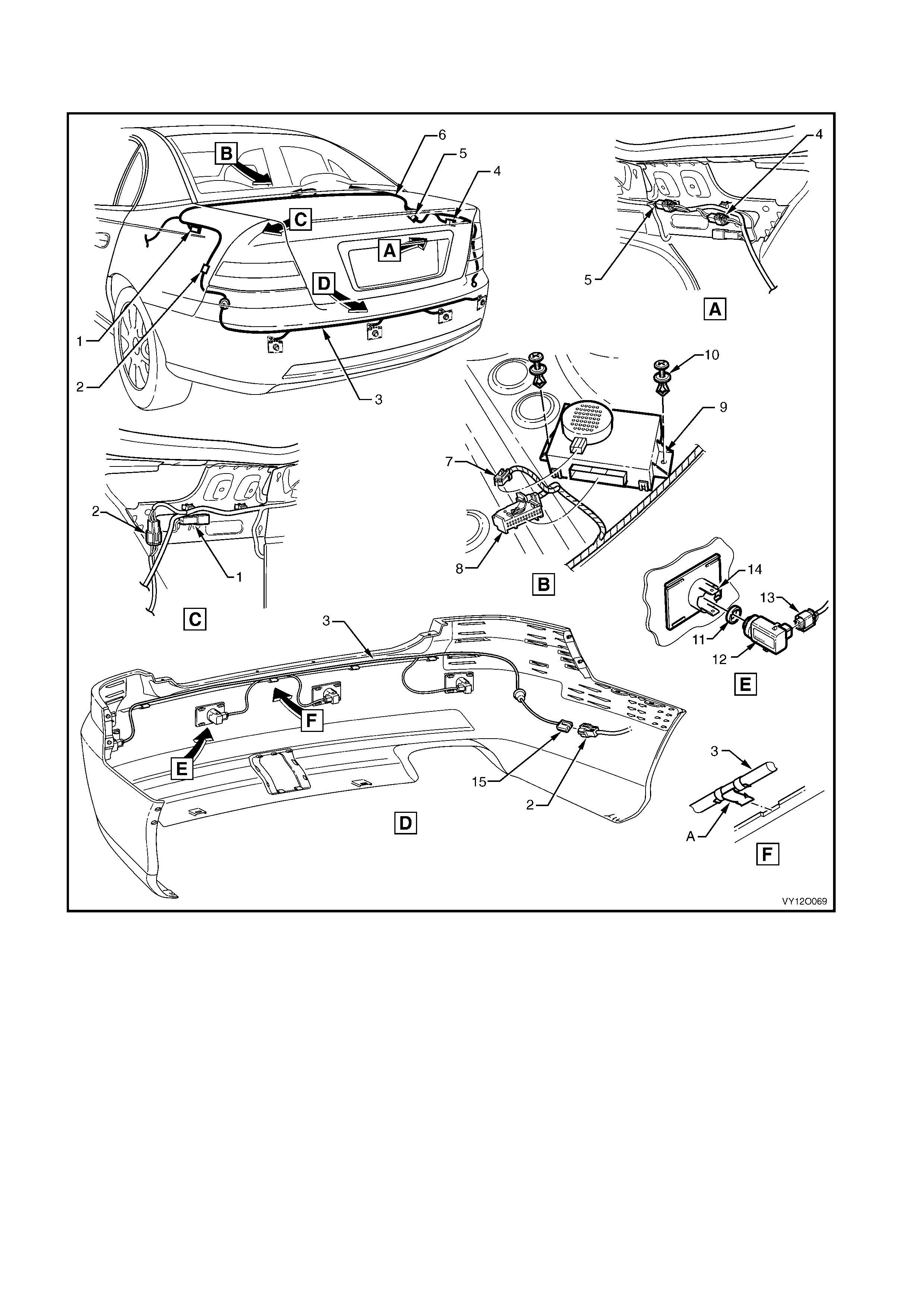
BODY & ROOF WIRING HARNESSES – 14
REVERSE PARKING AID
Figure 12O-110
Legend
1. Inline to Rear Object Sensor Harnes s Connector (X156)
2. Body Wiring Harness to Reverse Parking Aid Harness
Connector (X905)
3. Reverse Park i ng Aid Harness
4. Body Wiring Harness to Body Wiring Harness Trai l er A
Connector (X907)
5. Body Wiring Harness to Body Wiring Harness Tow Hook A
Connector (X906)
6. Body Wiring Harness
7. Rear Object Sensor Alarm Connect or (H31)
8. Rear Object Sensor Control Connec t or (A98)
9. Rear Object Sensor Control Module
10. Retaining Screw
11. Rear Object Sensor Ring
12. Rear Object Sensor Assembly
13. Rear Object Sensor Connector (B133)
14. Rear Object Sensor Housing
15. Reverse Parking Aid Harness t o Body Wi ri ng Harness
Connector (X905)
A. Reverse parking aid harness clipped as shown.
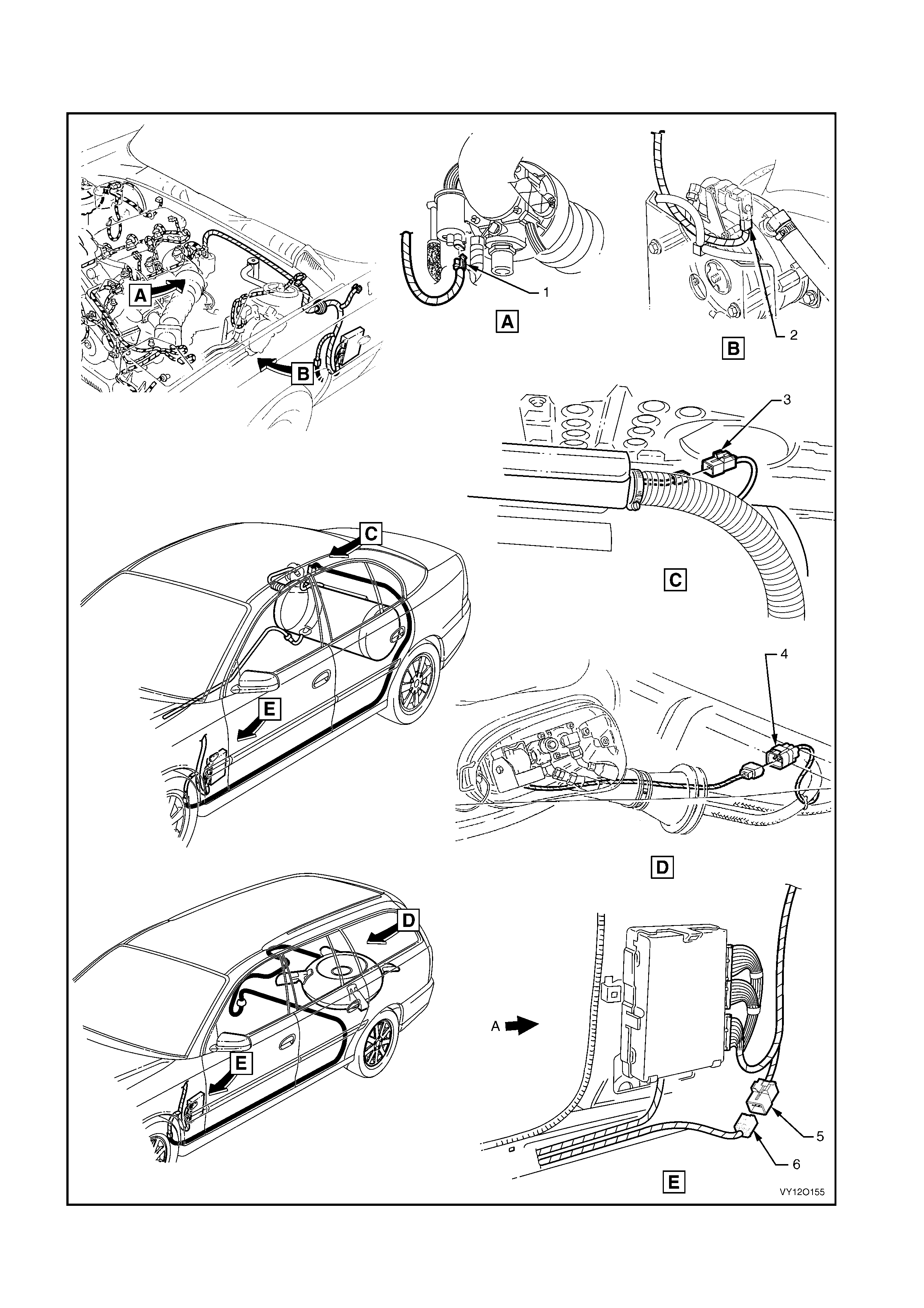
BODY WIRING HARNESS – LPG – RHD
SEDAN AND STATION WAGON MODELS
Figure 12O-111

Legend
1. Fuel Control Solenoid Valve Connector (Y143 – FCSV)
2. Lock-Off Solenoi d Val ve Connect or (Y143 – LOSV)
3. Sedan Fuel Sender & Pump Control Module Connector (A55)
4. Wagon Fuel Sender & Pump Control Module Connector (A55)
5. Powertrain Harness to LPG Harness Connector (X203)
6. LPG Harness to Powertrain Harness Connector (X203)
A. Front of vehicle.
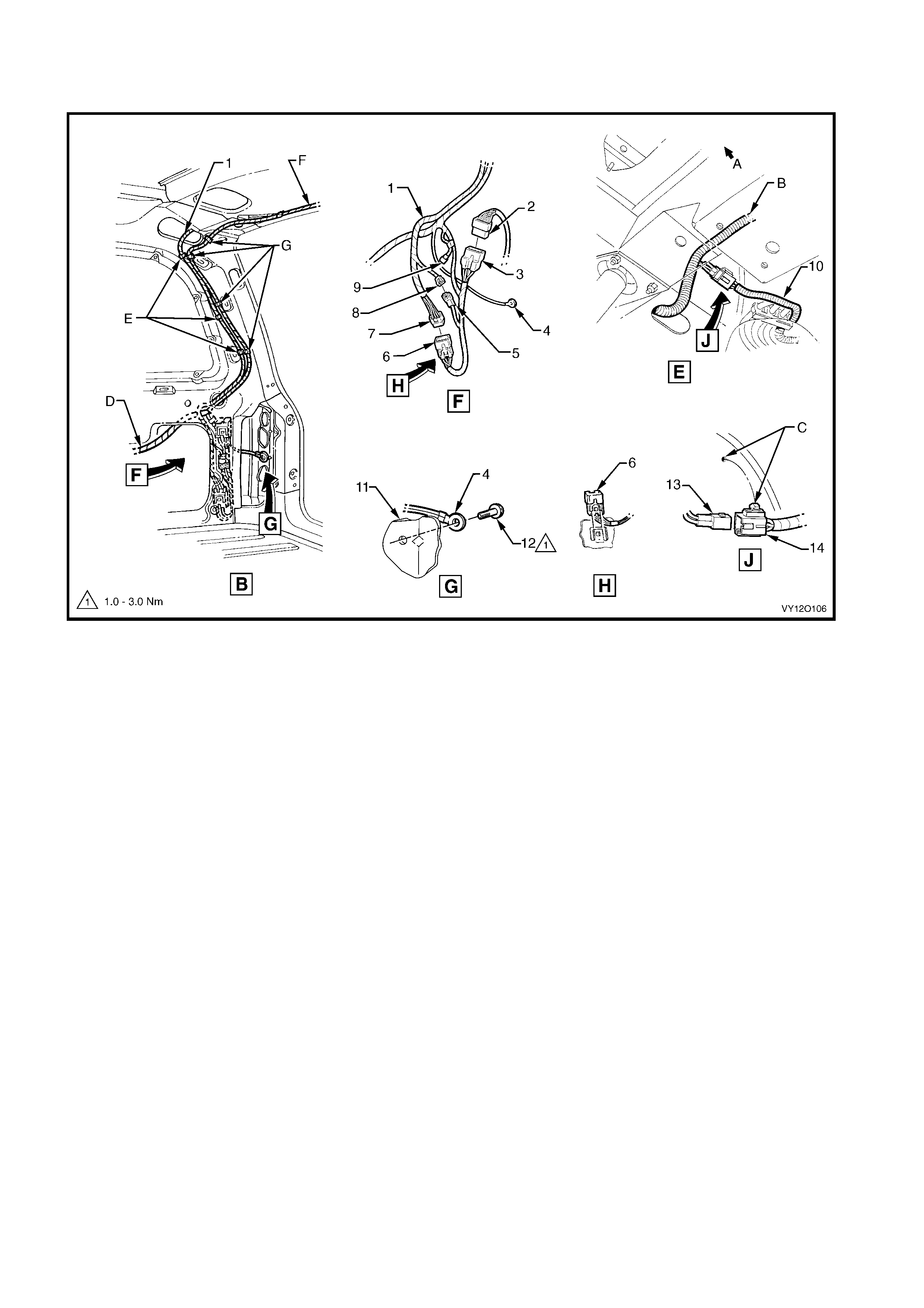
BODY & END GATE WIRING HA RNESSES – 1
STATION WAGON MODELS
Figure 12O-112
Legend
1. End Gate Harness
2. Tail Lamp Harness to Body Wiring Harnes s Connector (X903)
3. Body Wiring Harness to Tail Lamp Harness Connector (X903)
4. Body Wiring Harness Ground Tail Lam p Terminal
(X118 – GP13)
5. Body Wiring Harness to End Gate Harness Connect or (X902)
6. Body Wiring Harness to End Gate Harness Connect or (X901)
7. Liftgat e Harness to Body Wiring Harness Connector (X901)
8. Liftgat e Harness to Body Wiring Harness Connector (X902)
9. Body Wiring Harness to Trailer Harnes s Connector (X908)
10. Fuel Tank Harness
11. Quarter Inner Lower Rear Extension
12. Ground Terminal Attaching screw
13. Body Wiring Harness to Fuel Tank Harness Connect or
(X402)
14. Fuel Tank Harness to Body W i ri ng Harness Connector
(X402)
A. Front of vehicle.
B. ABS wiring, refer BODY & ROOF WIRING HARNESSES – 8 in
this section.
C. Fuel tank harness connect or cli pped to rear l ongitudi nal
extension panel.
D. For continuation, ref er to
BODY AND ROOF WIRI NG HARNESSES – 13 in this se c tio n .
E. Liftgate harness clipped to inner side panel (3 places).
F. For continuation, refer to
BODY & END GATE WIRING HARNESSES – 2 in this section.
G. Body wiring harness clipped to inner si de panel (4 places).
For location of views B & E, refer to to
BODY AND ROOF WIRI NG HARNESSES – 13 in this se c tio n .
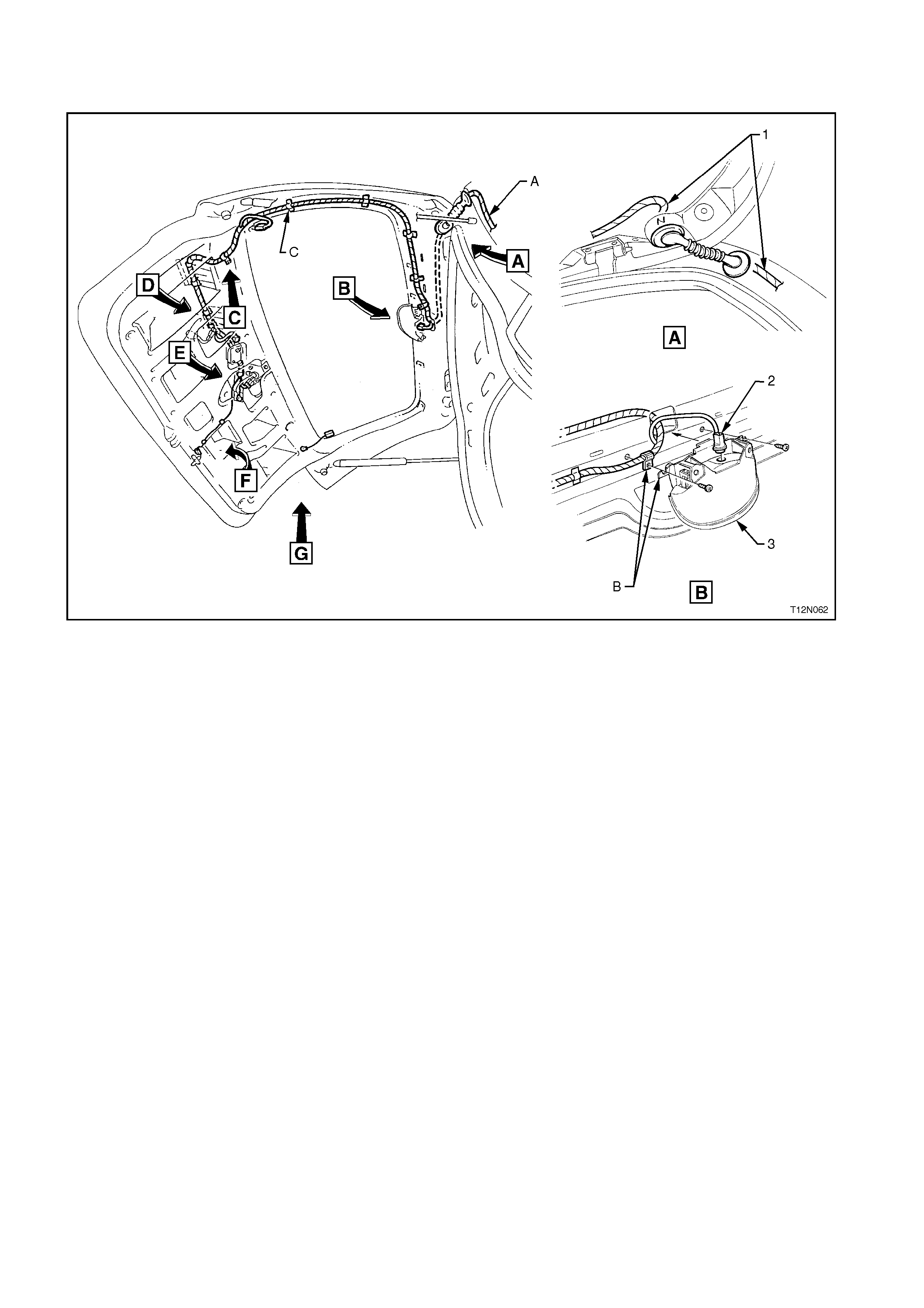
BODY & END GATE WIRING HA RNESSES – 2
STATION WAGON MODELS
Figure 12O-113
Legend
1. End Gate Harness
2. High Mounted Stop Lamp Connector (E79 – S/W)
3. High Mounted Stop Lamp
A. For continuation, refer to
BODY & END GATE WIRING HARNESSES – 1 in this section.
B. Harness ret ained between high mounted stop l amp and liftgat e
inner panel as shown.
C. End gate harness taped to liftgat e inner panel (4 places).
For views C through G, refer to
BODY & END GATE WIRING HARNESSES – 3 in this section.
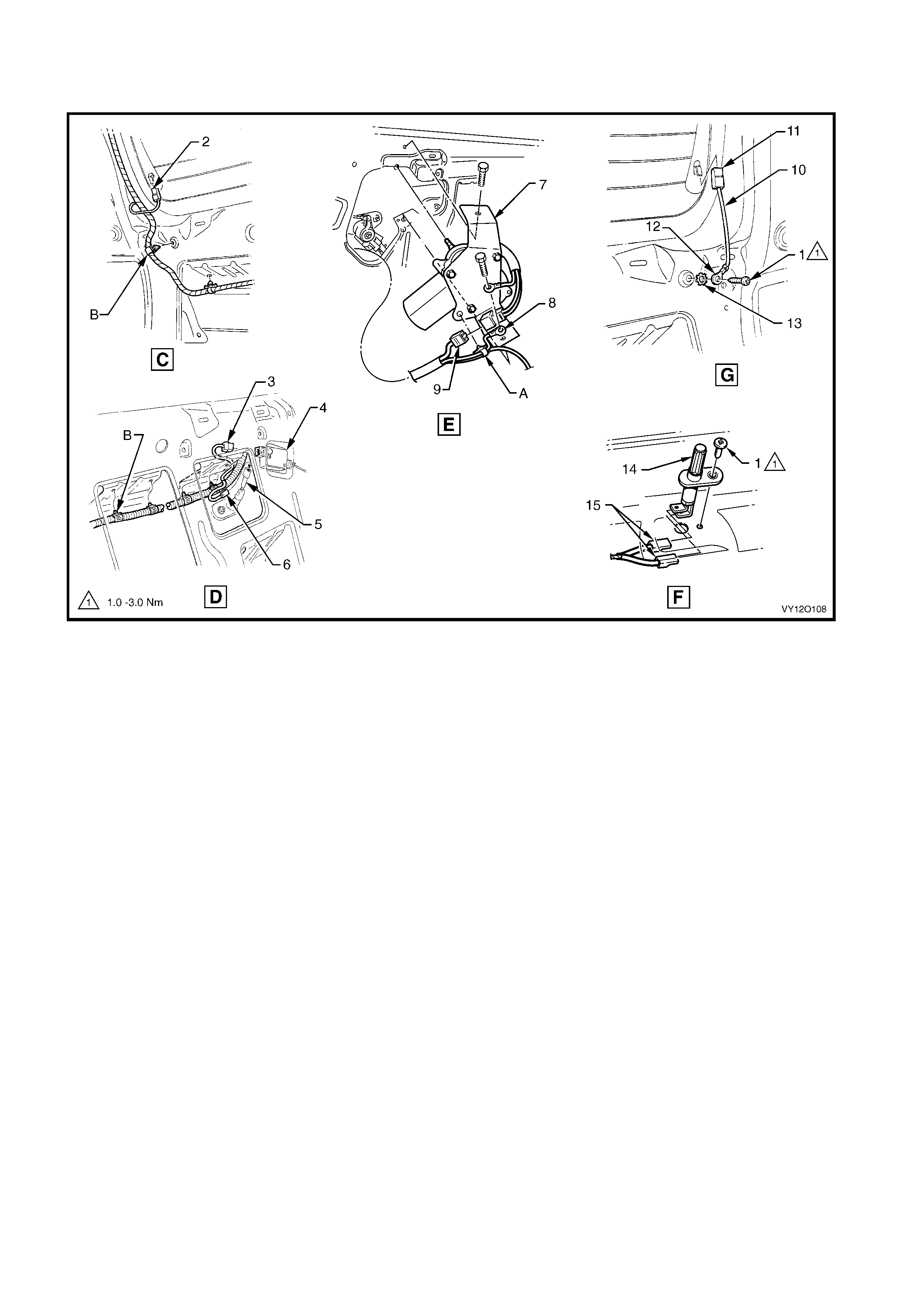
BODY & END GATE WIRING HA RNESSES – 3
STATION WAGON MODELS
Figure 12O-114
Legend
1. Attaching Screw
2. Defog Grid Connector (R22)
3. Liftgat e Latch Actuat or Connect or (Y29)
4. Liftgat e Lid Latch Actuator
5. Rear License Plate Lamp Switch
6. Rear License Plate Lam p Switch Connector (E 44)
7. Rear Window Wiper Motor Assembly
8. Rear Window Wiper Ground Terminal (X118 – GP7)
9. Rear Window Wiper Motor Connect or (M12)
10. Rear Window Defog Grid Ground Lead
11. Rear Window Defog Grid Connector (R22 – X2)
12. Ground Lead Term i nal (R22 – X1)
13. Ground Lead Attaching Washer
14. Rear Compartment Courtesy Lamp Switch
15. Rear Compartment Courtesy Lamp Connectors (S189)
A. End gate harness clipped to rear wiper motor as shown.
B. End gate harness clipped to liftgate inner panel as shown.
For location of views C through G, refer to
BODY & END GATE WIRING HARNESSES – 2 in this section.
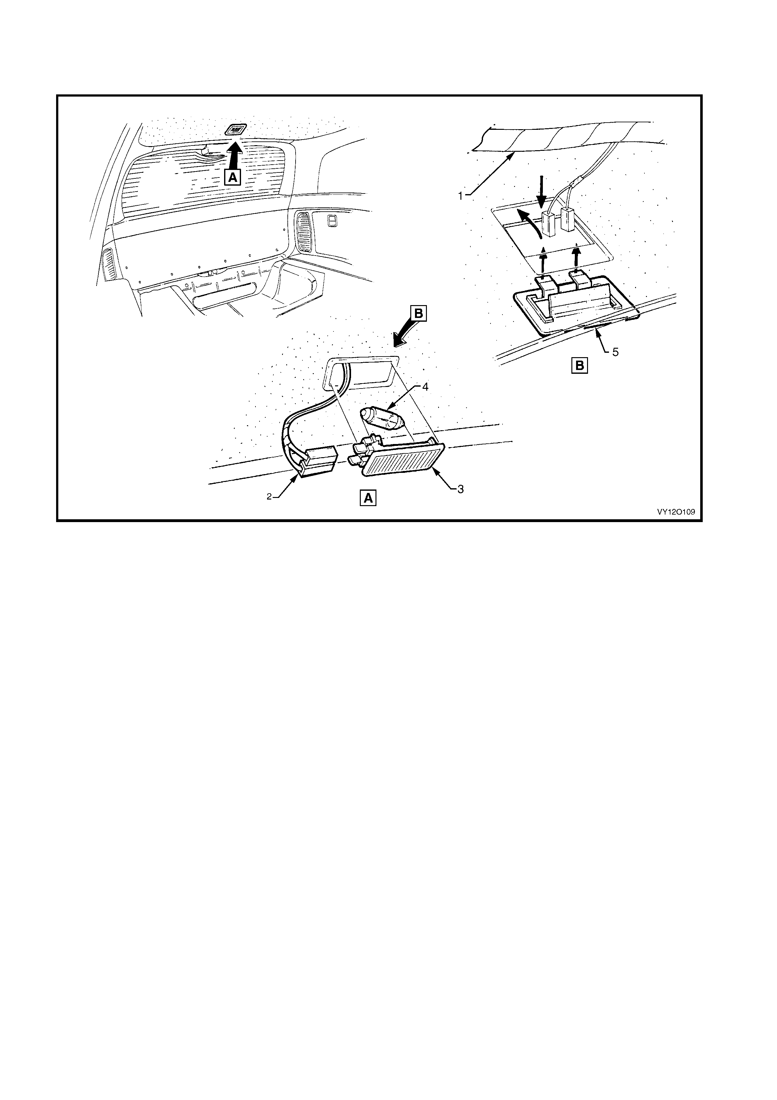
BODY & END GATE WIRING HA RNESSES – 4
REAR COMPARTMENT LAMP – STATION WAGON MODELS
Figure 12O-115
Legend
1. Body Wiring Harness
2. Rear Compartment Courtesy Lamp Connectors (S189)
3. Rear Compartment Courtesy Lamp
4. Rear Compartment Courtesy Lamp Bulb
5. Rear Compartment Courtesy Lamp Holder
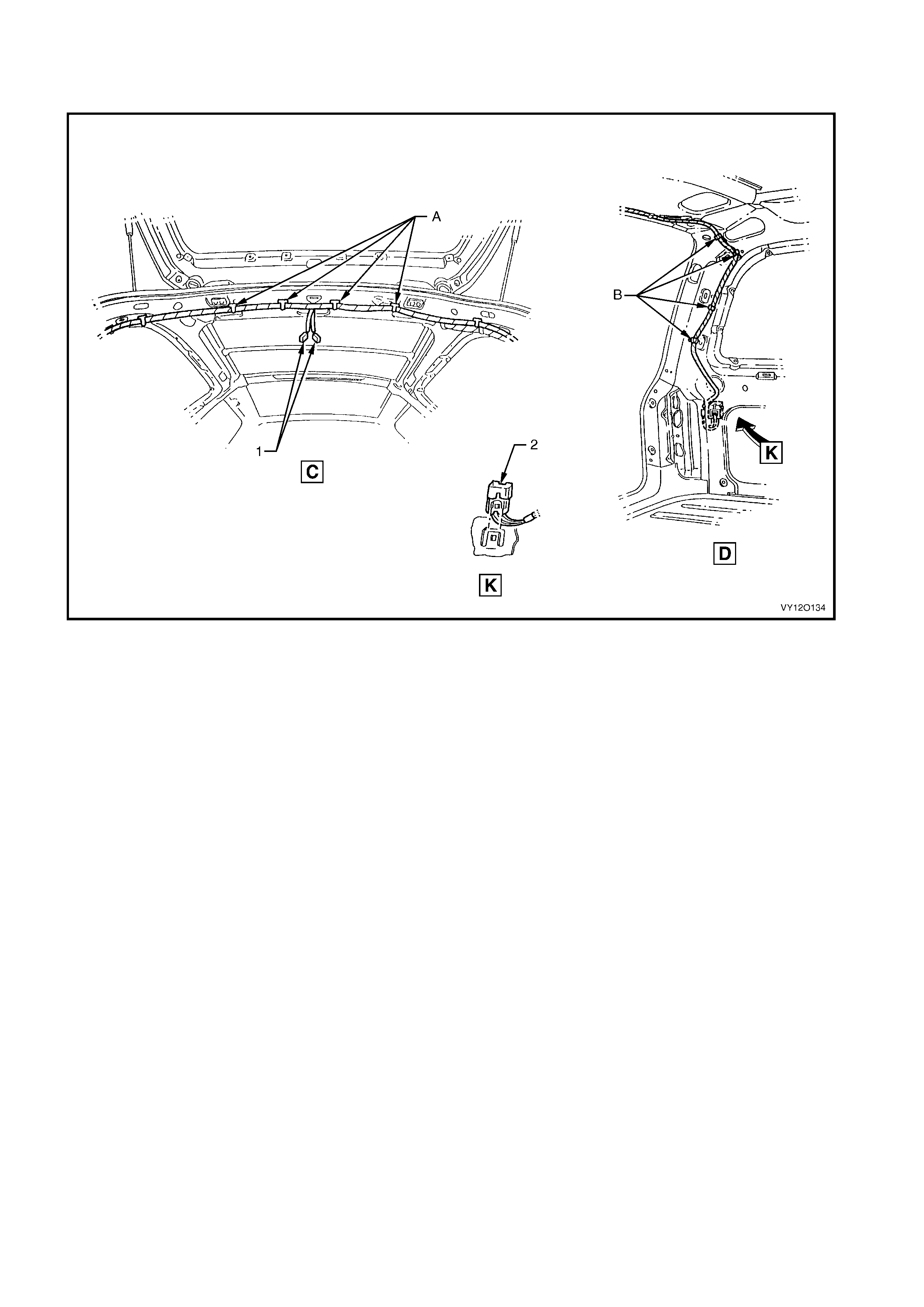
BODY & END GATE WIRING HA RNESSES – 5
REAR COMPARTMENT LAMP – STATION WAGON MODELS
Figure 12O-116
Legend
1. Rear Compartment Courtesy Lamp Connectors (S189)
2. Body Wiring Harness to Tail Lamp Harness Connector
(X904 – L)
A. Body wiring harness clipped to rear roof frame (4 places).
B. Body wiring harness cl i pped to inner si de panel clip (4 pl aces).
For location of views C & D, ref er to
BODY & ROOF WIRI NG HARNES SE S – 13 in this section.
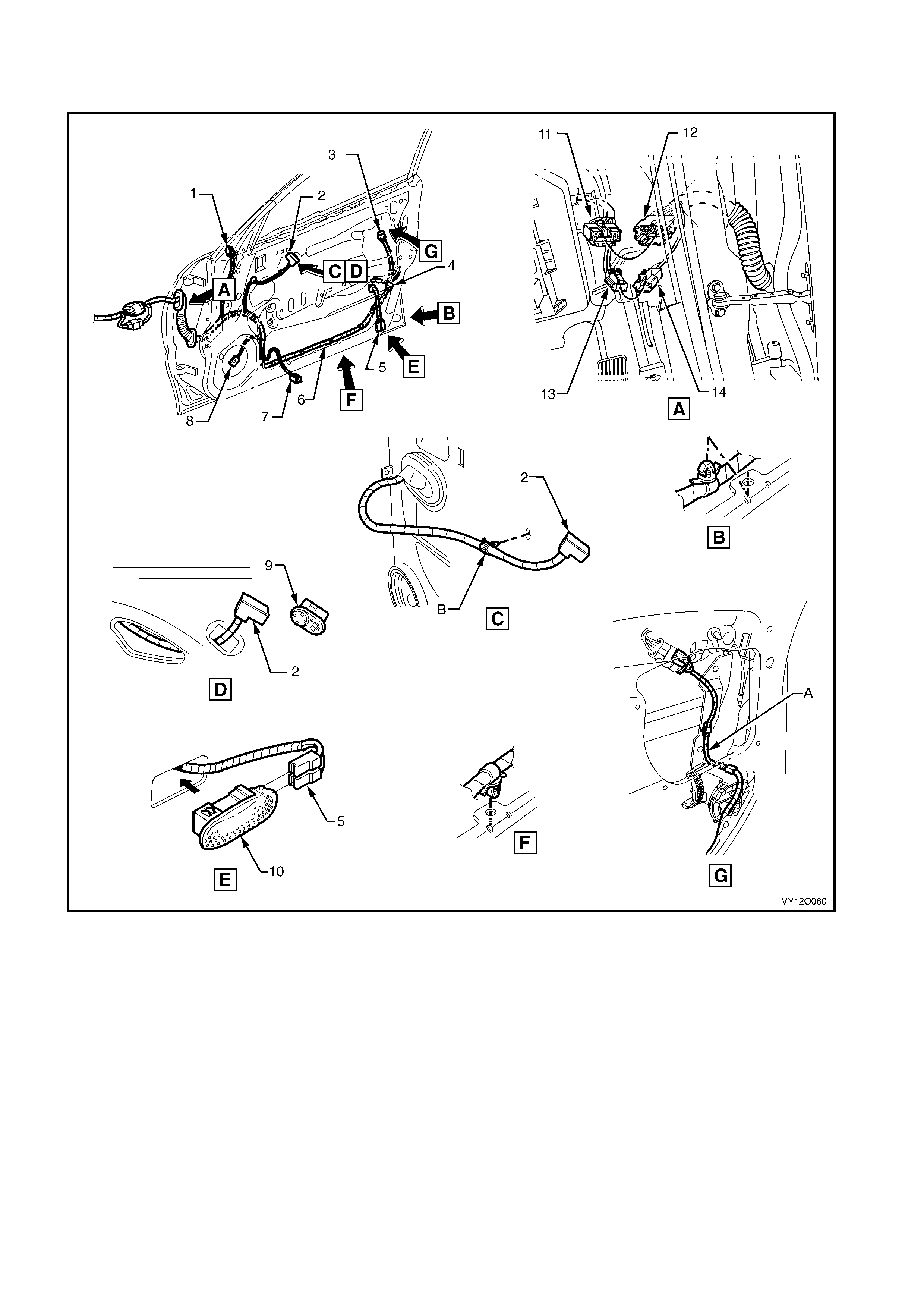
FRONT DOOR HARNESS
ALL MODELS
Figure 12O-117
Legend
1. Outside Rear View Mirror Motor Connect or (M11)
2. Outside Rear View Mirror Rem ote Control Switch Connector
(S169)
3. Door Lock Switc h Connect or (S63)
4. Front Door Lock Actuat or Connector (Y13)
5. Front Door Courtes y Lamp Connectors (E72)
6. Door Wiring Harness
7. Front Door Window Regulator Connect or (M10)
8. Door Radio Speaker Connect or (B108)
9. Outside Rear View Mirror Rem ote Control Switch
10. Front Door Courtesy Lamp
11. Body Wiring Harness to Right-hand Front Door Wi ri ng Harness
Connector (X600)
12. Right-hand Front Door Wiring Harness to Body Wiri ng Harness
Connector (X600)
13. Body Wiring Harness to Right-hand Front Door Wi ri ng Harness
Connector (X601)
14. Right-hand Front Door Wiring Harness to Body Wiri ng Harness
Connector (X601)
A. Harness rout ed as shown.
B. Harness clipped to door inner panel as shown.

REAR DOOR HARNESS
ALL MODELS
Figure 12O-118
Legend
1. Side Window Switch Connector (S221)
2. Rear Door Lock Actuator Connector (Y31)
3. Rear Door Courtesy Lamp Connect ors (E 99)
4. Rear Door Window Regulator Connec tor (M14)
5. Door Wiring Harness
6. Door Radio Speaker Connect or (B117)
7. Body Wiring Harness to Right-hand Rear Door Wiring
Harness Connect or (X800)
8. Right-hand Rear Door W i ri ng Harness t o Body Wi ri ng
Harness Connect or (X800)
9. Rear Door Courtesy Lamp
10. Rear Door Window Switch
A. Front of vehicle.
B. Typical (7 places).
C. Door wiring harness c lipped t o inner door inner panel as
shown.
D. Door wiring harness clipped to door inner panel.
E. Rear door inner seal pierced and then door harness clipped to
rear door inner panel (2 places).
F. Courtesy lamp connector taped back ed when courtesy lamp
not fitted.
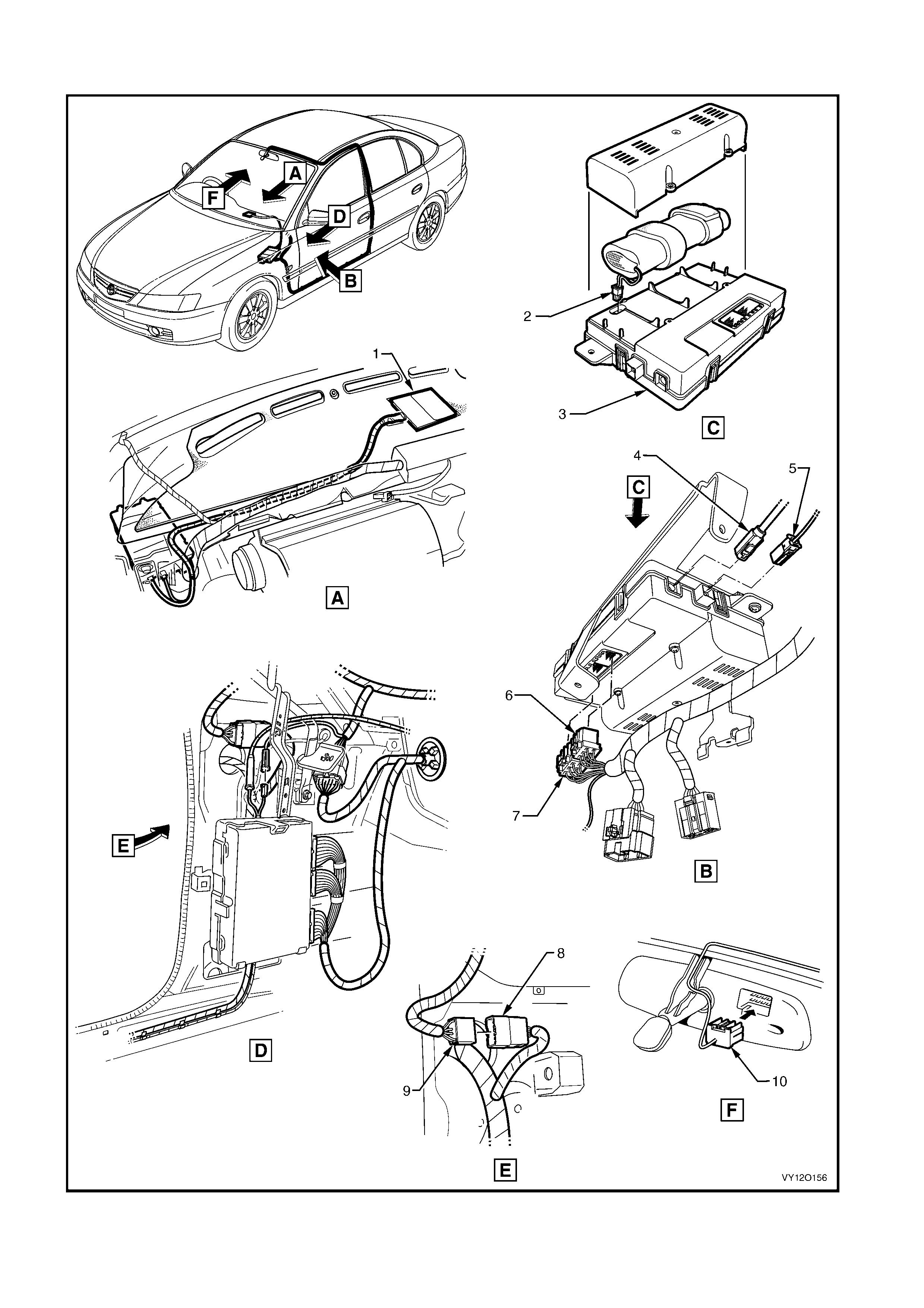
TELEMATICS SYSTEM HARNESS – ALL MODELS
Figure 12O-119

Legend
1. Telematics System Antenna
2. Communi cation Centre Call Connector (A158 – X5)
3. Communi cation Centre Call Module
4. Communication Centre Call Connect or (A158 – X4)
5. Communication Centre Call Connect or (A158 – X3)
6. Communication Centre Call Connect or (A158 – X2)
7. Communication Centre Call Connect or (A158 – X1)
8. Body Wiring Harness to Main Wiring Harness Connect or
(X312)
9. Main Wiring Harness to Body Wiring Harness Connector
(X312)
10. I nside Rearview Mirror Connector (E 124)
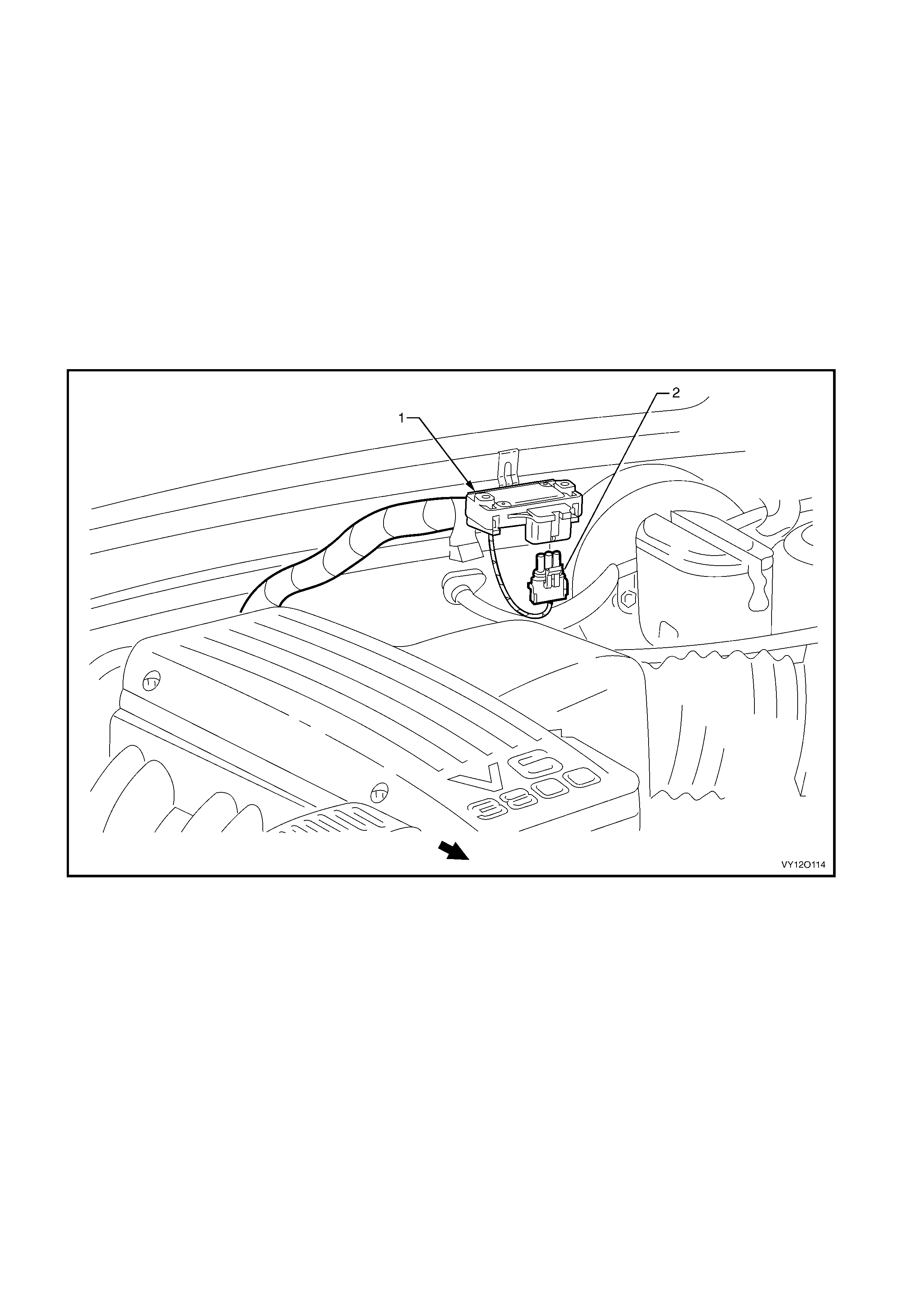
4. WIRING INSTALLATION DIAGRAMS – LEFT-HAND DRIVE
S E D AN AN D WAG O N
The f ollo wing f ig ur es illus trate t he veh icle wir ing install atio n d iagr ams for MY 200 3 V Y lef t -hand dr i ve se dan and
wagon.
All Battery Harness and Powertrain Harness for left-hand drive vehicles carry over from the right-hand drive
vehicles. For information relating to the wiring harness installation diagrams for the left-hand drive Sedan and
Wagon not provided in this section refer to 3. WIRING INSTALLATION DIAGRAMS – RIGHT-HAND DRIVE
SE DAN AN D WAG O N .
NOTE: Som e of the follo wing wiring i nstallation d iagrams illustrate the upp er level harnes ses which inc orporate
all necessary wiring harness connectors for all production options. Depending on equipment level and vehicle
model, some of the connectors may be taped back to the harness when a particular option is not fitted, or the
particular level of harness fitted to the vehicle may not incorporate some of the connectors illustrated.
MAIN WIRING HARNESS – 1
BAROMETRIC PRESSURE SENSOR
Figure 12O-120
Legend
1. Barometric Pressure Sensor Assembly 2. Barometric Pressure Sensor Connector (B26)
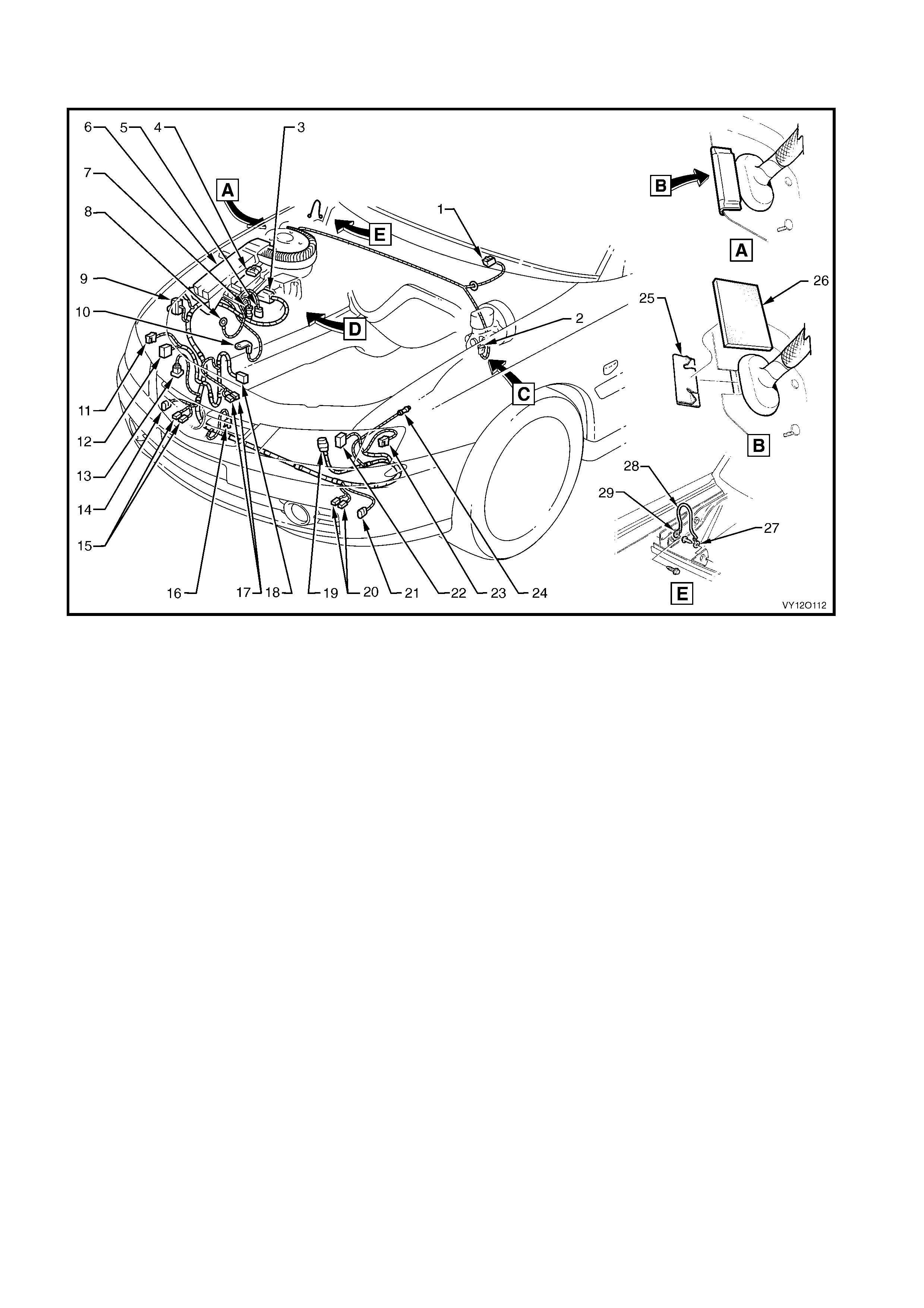
MAIN WIRING HARNESS – 2 – LHD
ENGINE COMPARTMENT
Figure 12O-121
Legend
1. Windshield Wiper Motor Connec t or (M17)
2. Brake Pressure Differential Connect or (S37)
3. Electronic Braking and Traction Control Module Connector
(A37)
4. Cruise Control Connect or (A18)
5. Main Wiring Harness to Battery Wiring Harness Connector
(X106)
6. Engine Wiring Harness J u nct i on Connector (X100)
7. Front Wheel Speed Sensor Connector (B52 – R)
8. A.B.S. Bracke t Connector (X119 – G3 – GP3)
9. Ground Connector (X157)
10. Fusible Link Supply Connector (X86 – A)
11. Turn Signal Lamp Connector (E76 – R)
12. Headlamp Connector (E83 – R)
13. Windshield Wiper and Windshield W asher Connect or (M19)
14. Front Fog Lamp Connector (E69 – R)
15. Horn Connector (B9)
16. Ambient Air Temperature Sensor Connector (B23)
17. Hood Theft Deterrent Connector (S135)
18. Engine Cooling Fan Connector (M7 – X1)
19. Main Wiring Harness t o Powertrain Harness Connector
(X101)
20. Horn Connector (B9)
21. Front Fog Lamp Connector (E69)
22. Headlamp Connector (E83 – L)
23. Turn Signal Lamp Connector (E76 – L)
24. Front Wheel Speed Sensor Connector (B52 – L)
25. Sealing Patch Grommet
26. Grommet Insert
27. Instrument Panel to Body Ground Strap Terminal
(X118 – GP9)
28. Body to Inst rument Panel Ground Strap
29. Body to Inst rum ent P anel Ground Strap Terminal
(X119 – GP10)
For views C & D, refer to
MAIN WIRING HARNESS – 9 – LHD in this section.
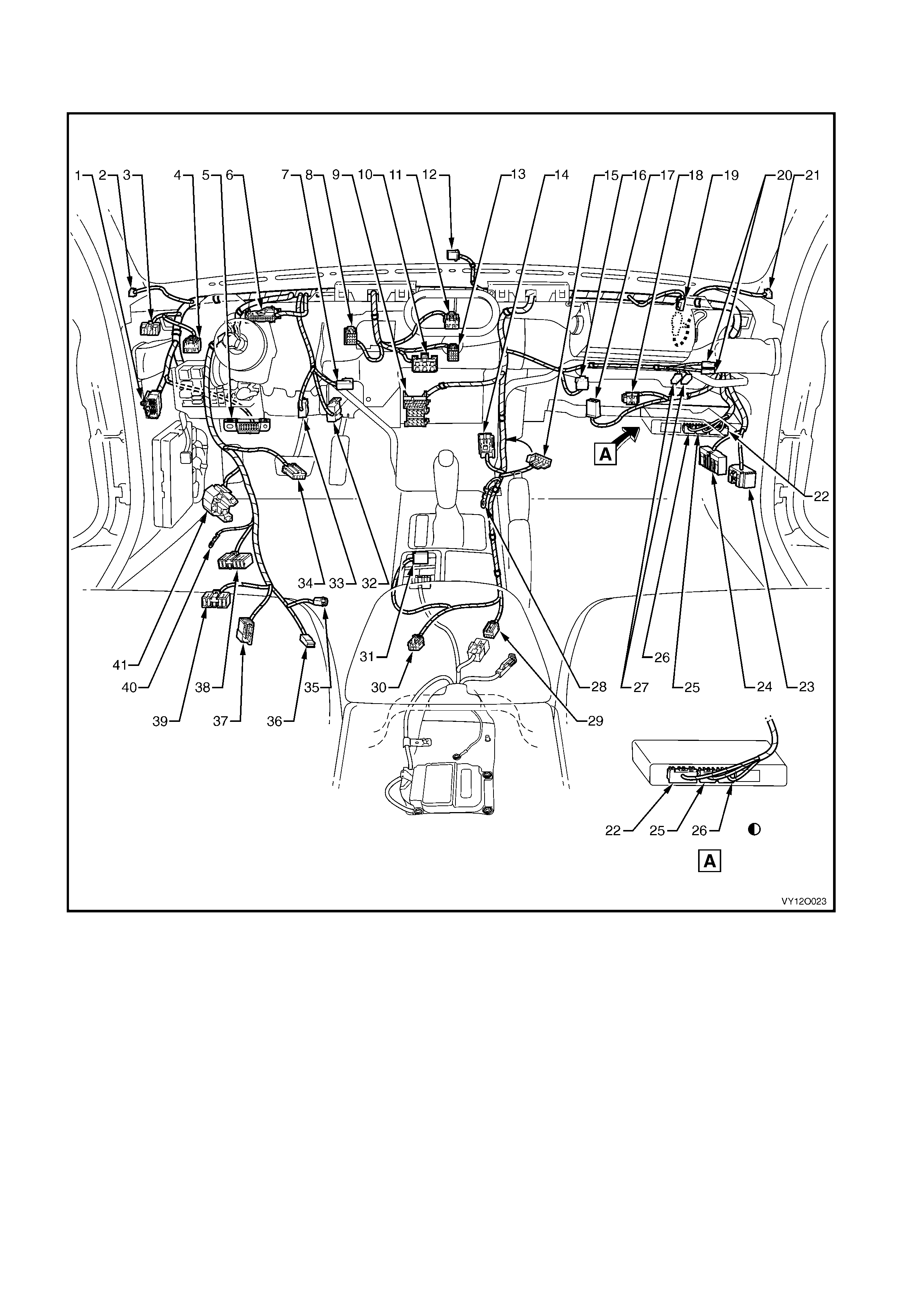
MAIN WIRING HARNESS – 3 – LHD
COCKPIT MODULE – MODELS WITHOUT CRUISE CONTROL
Figure 12O-122

Legend
1. Main Wiring Harness to Powertrain Harness Connector
(X206)
2. Radio Front Speaker Dash Upper Connector (B 112)
3. Headlamp Automatic Control Switch Connect or (S 125)
4. Fuel Filler Door Release Switch Connector (S191)
5. Wiring (Diagnostic) Connector (X40)
6. Instruments Connector (P3)
7. Stop Lamp, Traction and Cruise Control Release Switch
Connector (S 220 – X2)
8. Trip Odometer Reset Switch Connector (S237)
9. Radio, Clock and CD Player Connec tor (A133 – X1)
10. Heater and A/C Evaporator Module Connector (A60 – X1)
11. Hazard Warning Switch Connector (S120)
12. Ambient Light Sensor Connector (B55)
13. Heater and A/C Evaporator Module Connector (A60 – X2)
14. Front Cigar Lighter Connector (X113 – F)
15. Inline to Radio and Mobile Telephone Connector (X155)
16. Rear Compartment Lid Release Switch Connect or (S195)
17. Blower Motor Resistor Connect or (R6 – LHD)
18. Main Wiring Harness t o Body Wi ring Harness Connector
(X204)
19. Main Wiring Harness t o Pass enger Airbag Harness
Connector (X205)
20. Instrument Panel Compartment Lam p Switch Connect ors
(S142)
21. Radio Front Speaker Dash Upper Connector (B112)
22. B ody Control Module Connector (A15 – X1)
23. Main Wiring Harness t o Body Wiring Harnes s Connector
(X200)
24. Main Wiring Harness t o Body Wi ring Harness Connector
(X201)
25. Body Control Module Connector (A15 – X2)
26. Body Control Module Connector (A15 – X3)
27. Instrument Panel Compartment Lam p Connectors (E82)
28. Radio Ground Terminal (X118 – GP8)
29. Main Wiring Harness t o Body Wi ring Harness Connector
(X303)
30. Main Wiring Harness t o Consol e Wiring Harness Connector
(X309)
31. Main Wiring Harness t o Transmission Selector Harness
Connector (X301)
32. Stop Lamp, Traction and Cruise Control Release Switch
Connector (S 220 – X1)
33. Stop Lamp, Traction and Cruise Control Release Switch
Connector (S 220 – X3)
34. Cruise Control Switch Connector (S43)
35. Ignition Lock Cylinder Bulb Connect or (E30)
36. Ignition and Start Switch Connector (S149 – X2)
37. Steering Wheel Clock Spring Coil Connector (X116)
38. Turn Signal and Headlamp Switch Connector (S231)
39. Windshield Wiper and Washer Switch Connector (S247)
40. Ignition and Start Switch Terminal (S149 –GP15 – X3)
41. Ignition and Start Switch Connector (S149 – X1)
Late Producti on Vehicles
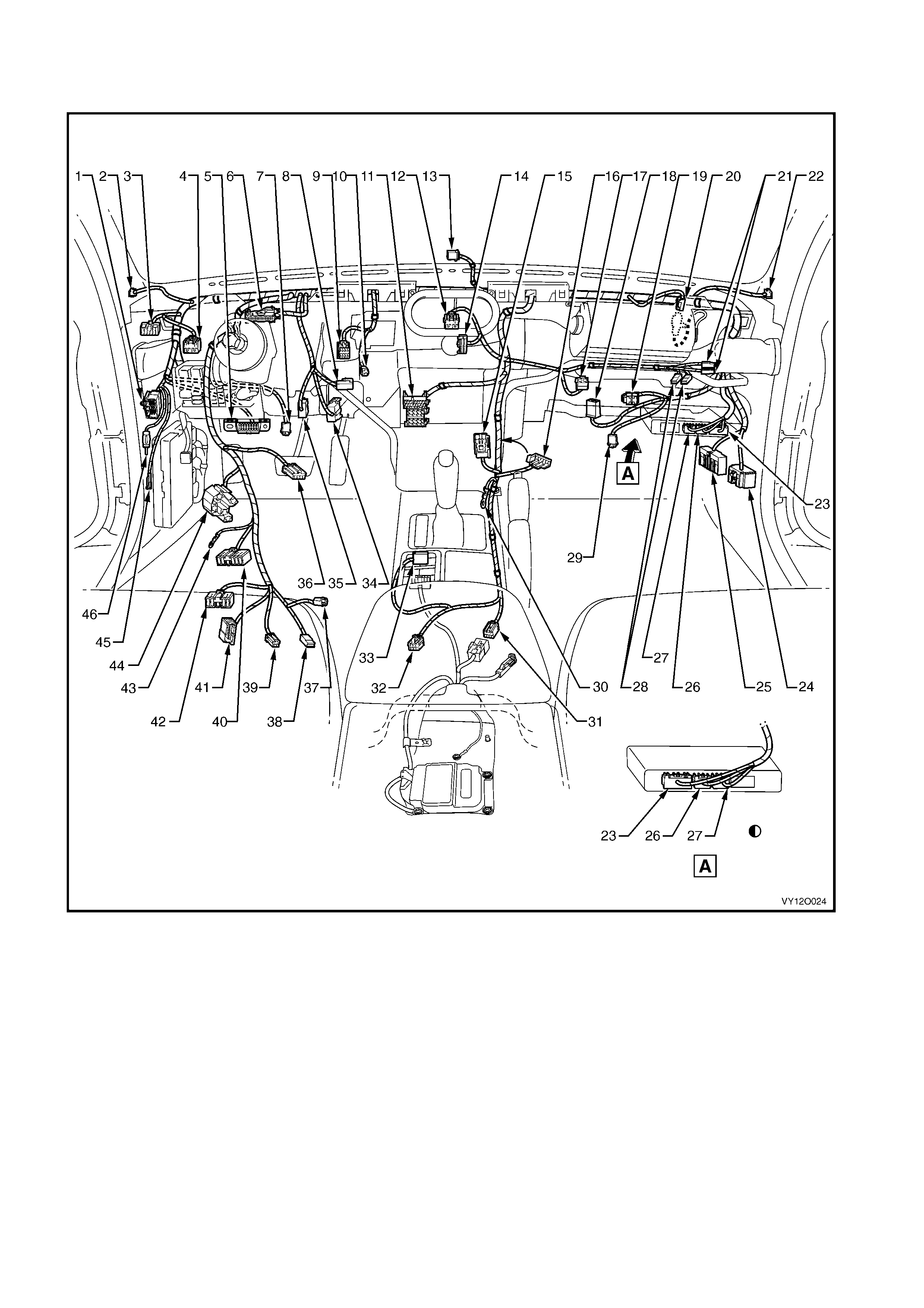
MAIN WIRING HARNESS – 4 – LHD
COCKPIT MODULE – MODELS WITH CRUISE CONTROL
Figure 12O-123

Legend
1. Main W i ri ng Harness t o Powertrain Harness Connector
(X206)
2. Radio Front Speak er Dash Upper Connect or (B 112)
3. Headlamp Automatic Control Switc h Connector (S125)
4. Fuel Filler Door Release Switch Connector (S191)
5. Wiring (Diagnostic) Connect or (X40)
6. Instruments Connector (P3)
7. St ep Well Lam p Connector (E 105)
8. St op Lamp, Traction and Cruis e Control Release Switch
Connector (S 220 – X2)
9. Trip Odomet er Reset Switch Connector (S237)
10. Inside Air Temperature Sensor Connector (B59)
11. Radio, Clock and CD Player Connec t or (A133 – X1)
12. Hazard Warning Switch Connector (S120)
13. Ambient Light Sensor Connector (B55)
14. Blower Motor and A/C Compressor Connec tor (A14 – X2)
15. Front Cigar Lighter Connector (X113 – F)
16. Inline to Radio and Mobile Telephone Connector (X155)
17. Rear Compartment Lid Release Switch Connector (S195)
18. Blower Motor Resistor Connector (R6 – LHD)
19. Main Wiring Harness t o Body Wiring Harnes s Connector
(X204)
20. Main Wiring Harness t o Passenger Ai rbag Harness
Connector (X205)
21. Instrument Panel Compartment Lamp Switch Connector
(S142)
22. Radio Front Speaker Dash Upper Connector (B112)
23. Body Control Module Connector (A15 – X1)
24. Main Wiring Harness t o Body Wiring Harnes s Connector
(X200)
25. Main Wiring Harness t o Body Wiring Harnes s Connector
(X201)
26. B ody Cont rol Module Connector (A15 – X2)
27. B ody Cont rol Module Connector (A15 – X3)
28. I nstrument Panel Compartm ent Lam p Connectors (E82)
29. S t ep W ell Lamp Connector (E 105)
30. Radio Ground Term i nal (X118 – GP8)
31. Main Wiring Harness to Body Wiring Harnes s Connector
(X303)
32. Main Wiring Harness to Console Wiring Harness Connector
(X309)
33. Main Wiring Harness to Transmission S el ector Harness
Connector (X301)
34. Stop Lamp, Traction and Cruise Control Release Switc h
Connector (S 220 – X1)
35. Stop Lamp, Traction and Cruise Control Release Switc h
Connector (S 220 – X3)
36. I gni tion Lock Cylinder Bulb Connector (E30)
37. Cruise Control Switch Connect or (S43)
38. I gni t i on and Start Switc h Connect or (S149 – X2)
39. Windshield Wiper Dwell Module Connector (R23)
40. Turn Si gnal and Headlam p Switc h Connect or (S231)
41. Steering Wheel Clock Spring Coil Connector (X116)
42. Windshield Wiper and Washer Switch Connect or (S247)
43. I gni t i on and Start Switc h Terminal (S149 – GP15 – X3)
44. I gni t i on and Start Switc h Connect or (S149 – X1)
45. Radio Antenna Amplifier Connect or (N3)
46. Radio Power Antenna Connector (W 6)
Late Producti on Vehicles
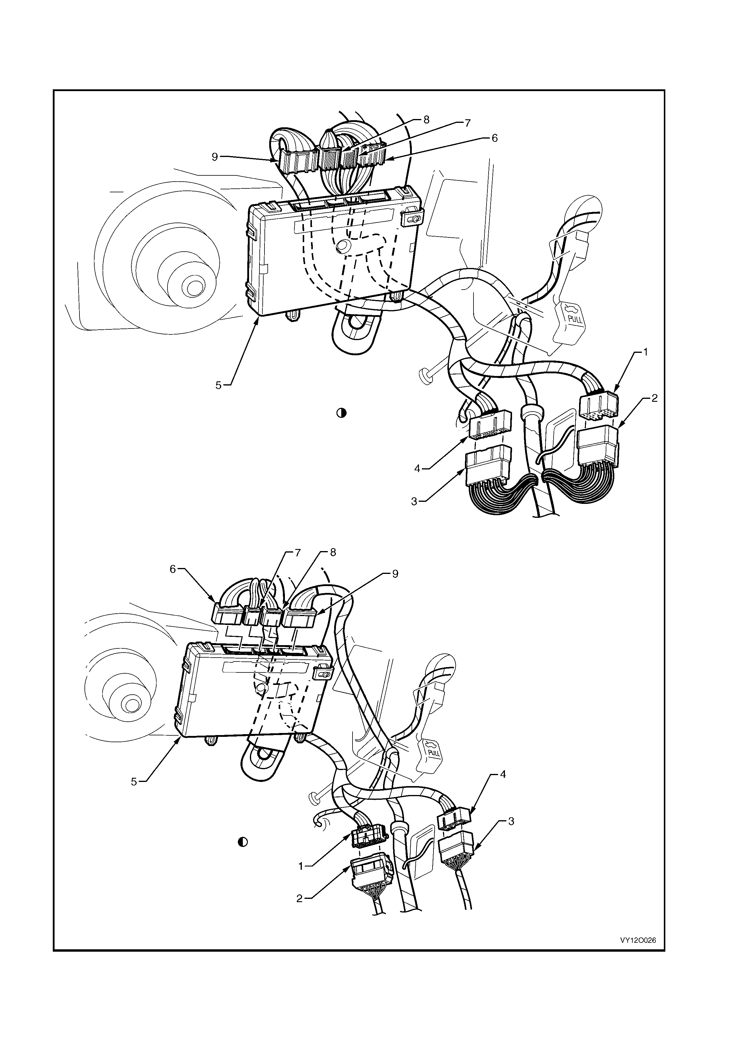
MAIN WIRING HARNESS – 5 – LHD
BODY CONTROL MODULE AND BODY HARNESS CONNECTORS
Figure 12O-124

Legend
1. Main W i ri ng Harness t o Body Wi ring Harness Connector
(X200)
2. Body Wi ri ng Harness to Main Wiring Harness Connect or
(X200)
3. Body Wi ri ng Harness to Main Wiring Harness Connect or
(X201)
4. Main W i ri ng Harness t o Body Wi ring Harness Connector
(X201)
5. Body Control Module
6. Body Control Module Connect or (A15 – X1)
7. Body Control Module Connect or (A15 – X2)
8. Body Control Module Connect or (A15 – X3)
9. Body Cont rol Module Connector (A15 – X4)
Early Product ion Vehicles
Late Production Vehicles
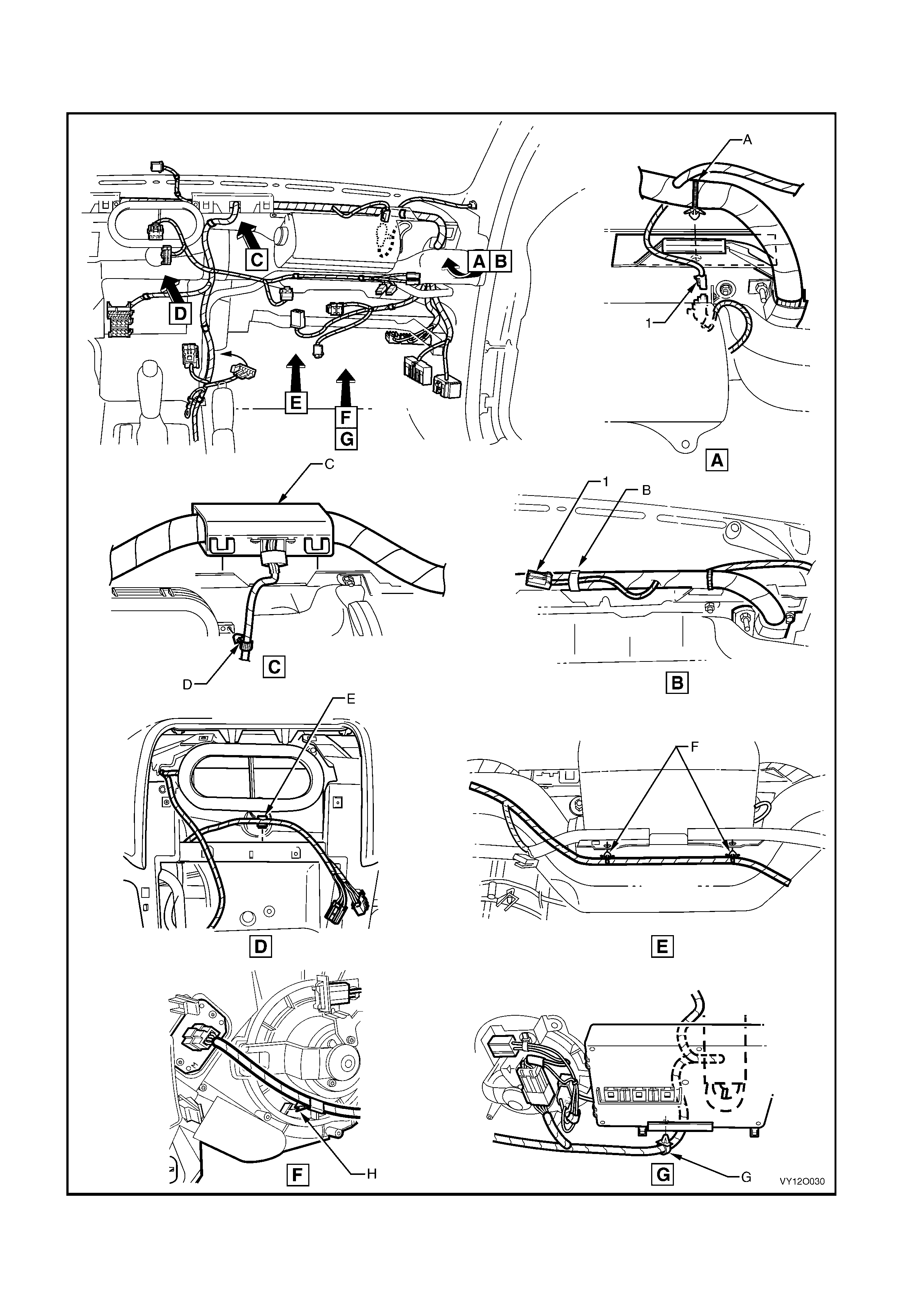
MAIN WIRING HARNESS – 6 – LHD
COCKPIT MODULE – ALL MODELS
Figure 12O-125

Legend
1. Main Wiring Harness to Passenger Air Bag Harness
Connector (X205) A. Harness ret ainer attached to instrument panel cover assembly
as shown – vehicles with passenger airbag.
B. Passengers side airbag c onnect or taped back as shown –
vehicles without passengers side airbag.
C. Harness former att ached t o inst rum ent panel co ver ass embly (2
places) as shown.
D. Harness attached t o heati ng, vent ilat i on & air conditioni ng unit
as shown.
E. W iring harness attac hed to heating, vent i l ation & air conditi oni ng
assembly.
F. Wiring harness attached to passenger side airbag support rail
assembly as shown.
G. Harness attached t o body control m odul e support bracket as
shown.
H. Harness attached t o heati ng, vent ilat i on & air conditioni ng
assembly as shown.
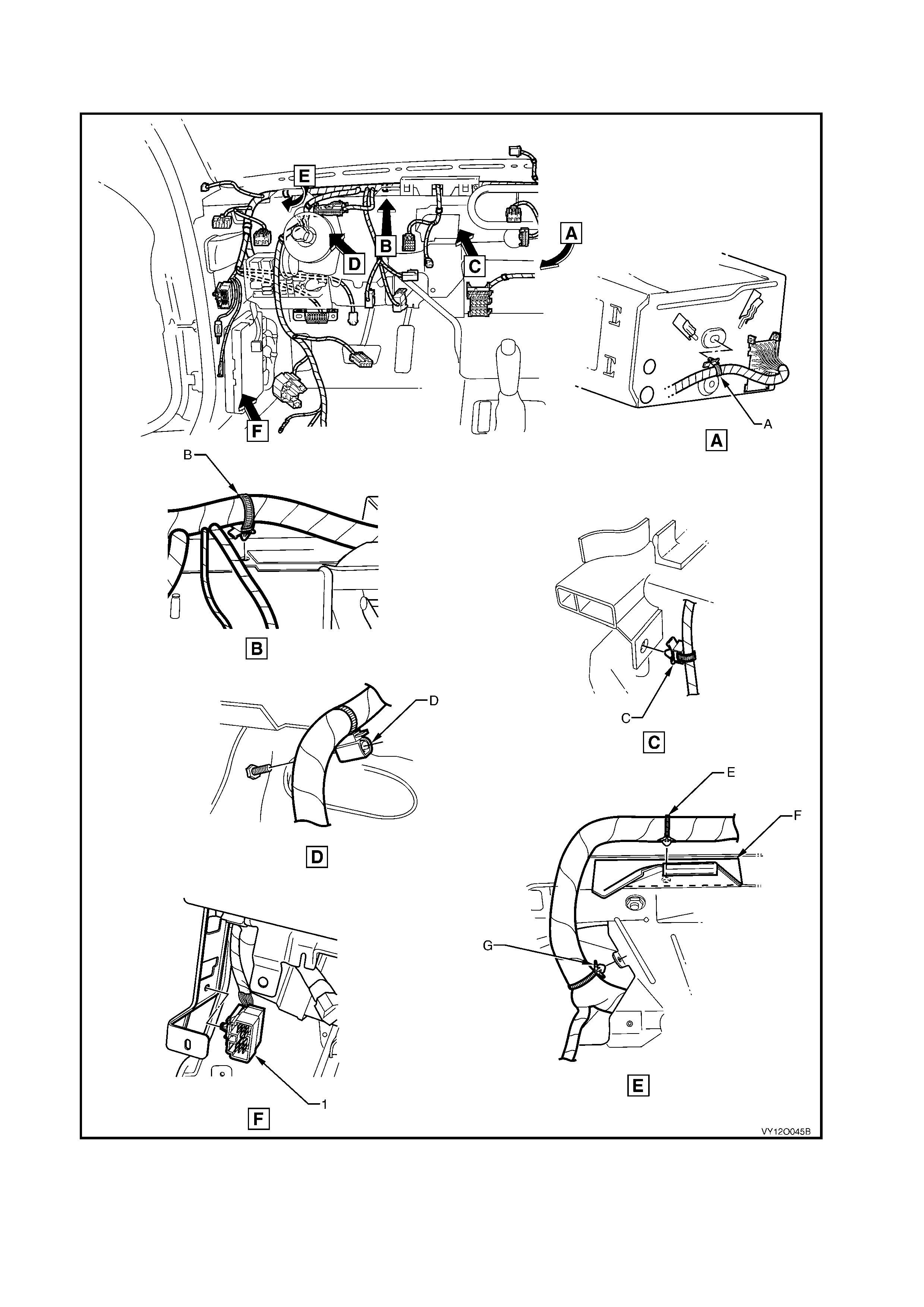
MAIN WIRING HARNESS – 7 – LHD
COCKPIT MODULE – ALL MODELS
Figure 12O-126

Legend
1. Main Wiring Harness to Powertrain Harness
Connector (X206) A. Main wiring harness attached to instrument panel cover
assembly as shown.
B. Harness attached to vehicle as shown.
C. Main wiring harness attached to instrument panel cover
assembly as shown.
D. Main wiring harness attached to instrument panel cover
assembly as shown.
E. Instrum ent panel cover assembly.
F. Main wiring harness att ached to instrum ent panel cover
assembly as shown.
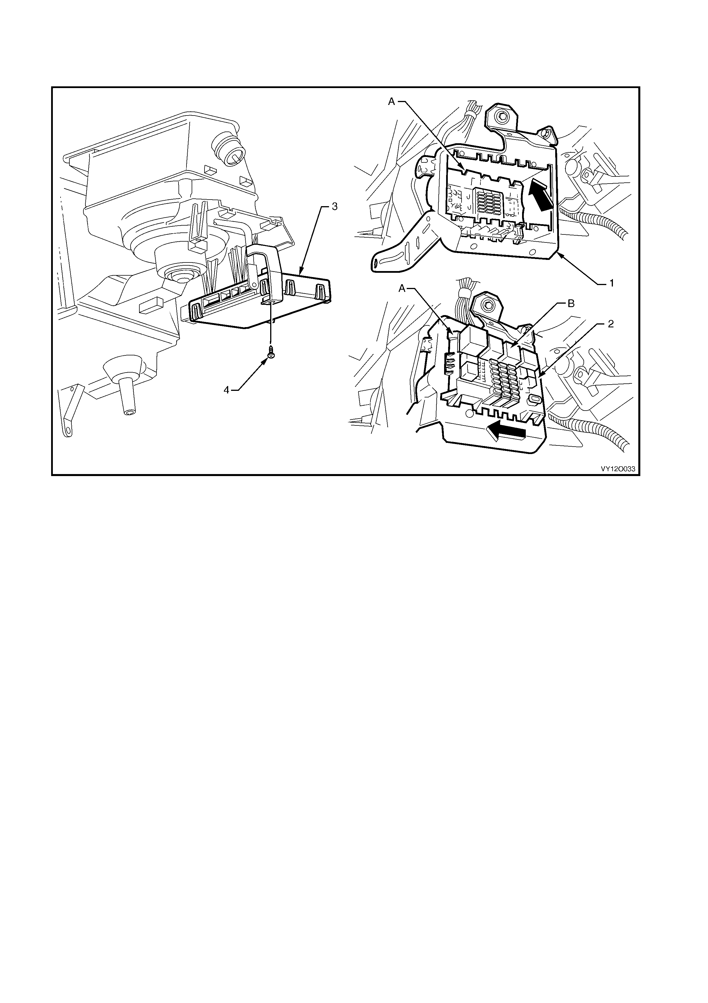
MAIN WIRING HARNESS – 8 – LHD
FUSE & RELAY PANEL AND BODY CONTROL MODULE – ALL MODELS
Figure 12O-127
Legend
1. Inst rument Panel Wiring Harness Fuse Block Mounting
Bracket
2. Inst rument Panel Wiring Harness Fuse Block (X129)
3. Body Cont rol Module
4. Attachi ng Screw, Body Control Module Mounting to Support
A. Instrument panel wiring harnes s fuse block installe d as shown.
B. For installa tion of relays, fuses and circuit breakers ref er to
1. GENERA L INF O RMAT ION in this section.
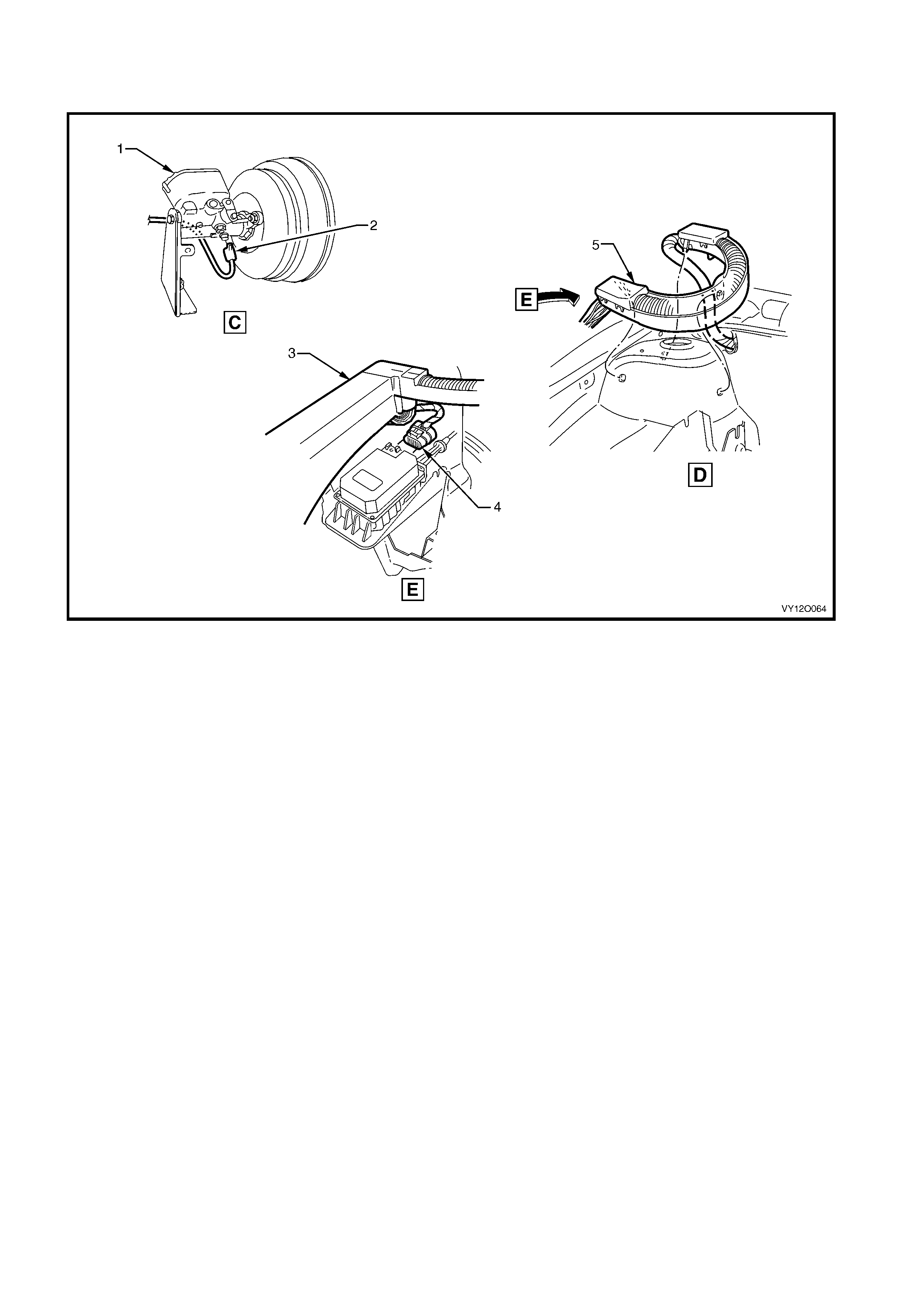
MAIN WIRING HARNESS – 9 – LHD
PROTECT O R ASSEMBLY, CRUISE CONTROL AND ENGINE HARNESS CONNECT O RS
Figure 12O-128
Legend
1. Brake Master Cyl i nder and Brak e Boost er
2. Brake Pressure Diff erential Connector (S37)
3. Engine Wiring Harness J unction Connecter Cover
4. Crui se Control Connect or (A18)
5. Harness Former
For location of views C & D, refer to
MAIN WIRING HARNESS – 2 –LHD in this section.
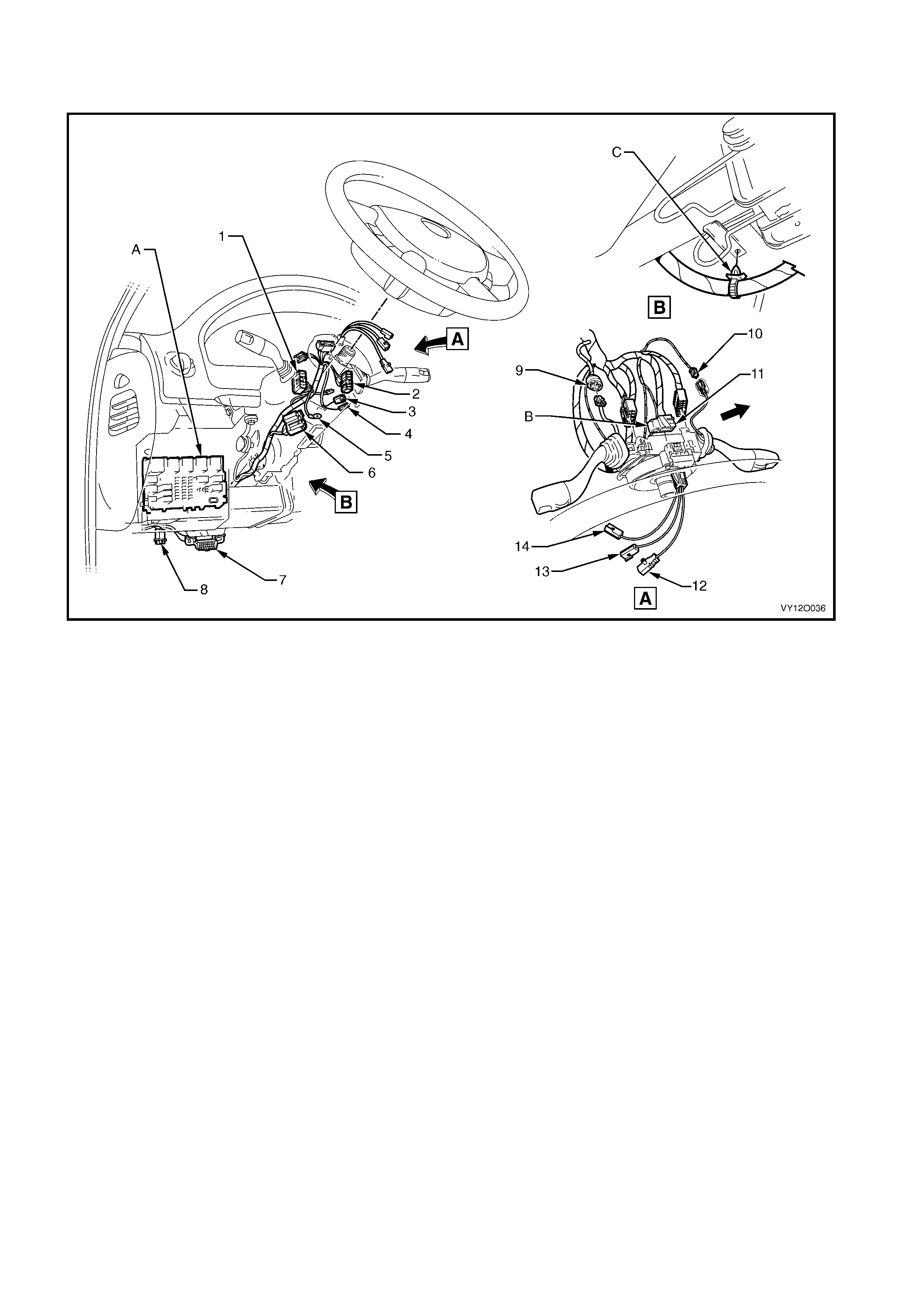
MAIN WIRING HARNESS – 10 – LHD
STEERING COLUMN
Figure 12O-129
Legend
1. Turn Signal Switch Connector (S231)
2. Windshield Wiper/Washer Switch Connector (S247)
3. Igni t i on Lock Cyl i nder Bulb Connector (E30)
4. Ignition and Start Switch Connector (S149 – X2)
5. Ignition and Start Switch Terminal (S149 – X3)
6. Ignition and Start Switch Connector (S149 – X1)
7. Wiring (Diagnostic) Connect or (X40)
8. St epwell Lam p Connect or (E105)
9. Cruis e Control Switch Connector (S43)
10. Windshield Wiper Dwell Module Connect or (R23)
11. Steering Wheel Lock Clock Spring Coi l Connect o r (X116)
12. Steering Wheel Inflat or Rest rai nt Module Connector (A106)
13. Steering Wheel Horn Connect or (S7)
14. Radio Control Switch Connect or (S208)
A. For installation of fuse and relay panel refer to
MAIN WIRING HARNESS – 8 – LHD in this section.
B. Clock s pri ng coil connect or i nst al l ed and secured by l ocking
retainer in direction of arrow shown.
C. Main wiring harness attached to steering column as shown.
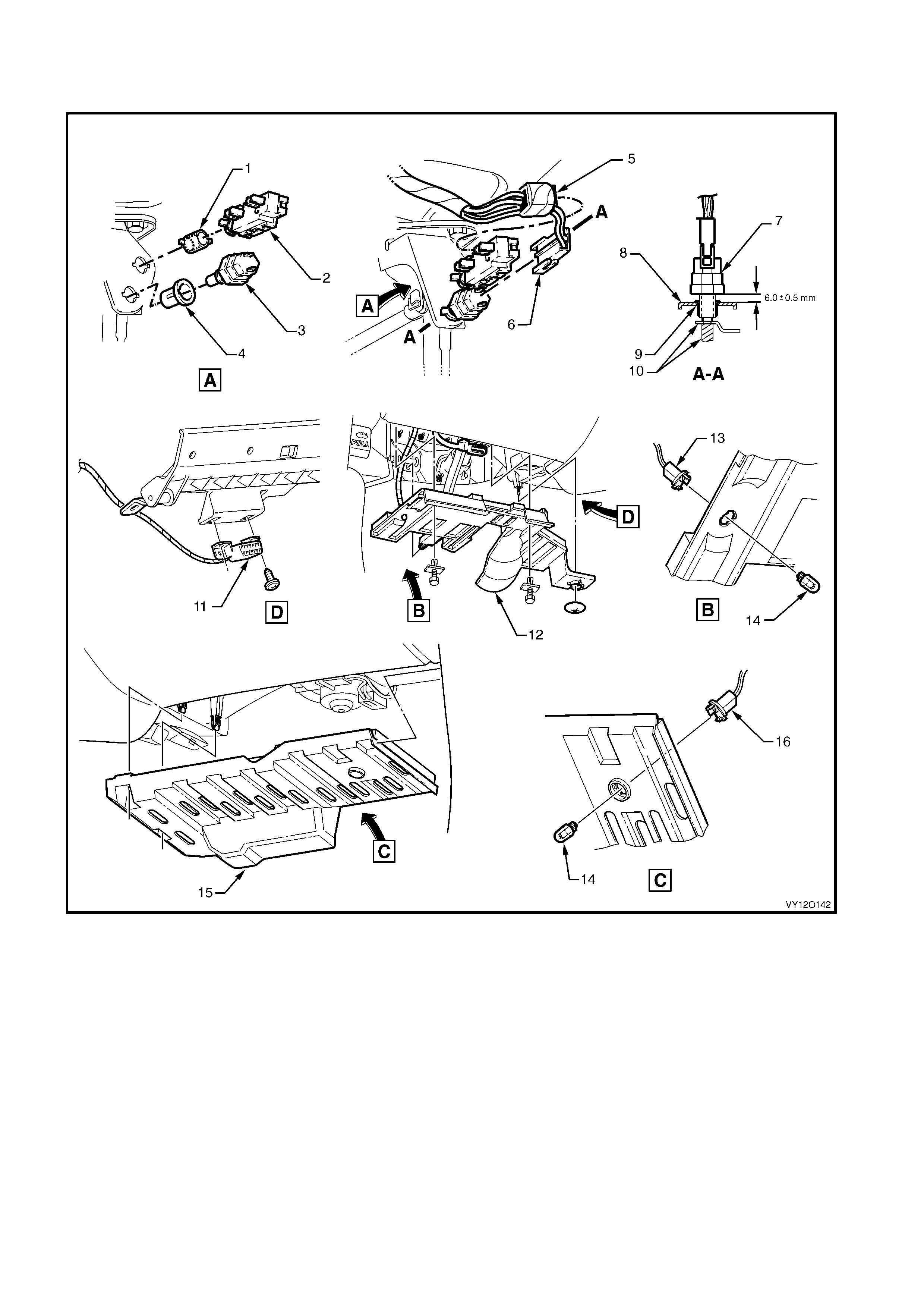
MAIN WIRING HARNESS – 11 – LHD
CRUISE CONTROL, STOP LAMP SWITCHES, DATA LINK CONNECTOR & STEPWELL LAMPS
Figure 12O-130
Legend
1. Nut
2 Cruis e Control Release Switch
3. Stepwell Lamp Switch
4. Nut
5. Stop Lamp, Traction & Cruise Control Releas e Switc h
Connector (S 220 – X2)
6. Stop Lamp, Traction & Cruise Control Releas e Switc h
Connector (S 220 – X1)
7. Stop Lamp Switch
8. Support Bracket
9. Nut
10. Pedal Assembly
11. Wiring (Diagnostic) Connect or (X40)
12. Instrument Panel Lower Cover – Left-hand Side
13. Stepwell Lamp Connector (E105 – L)
14. Stepwell Lamp
15. Instrument Panel Lower Cover – Right-hand Si de
16. Stepwell Lamp Connector (E105 – R)
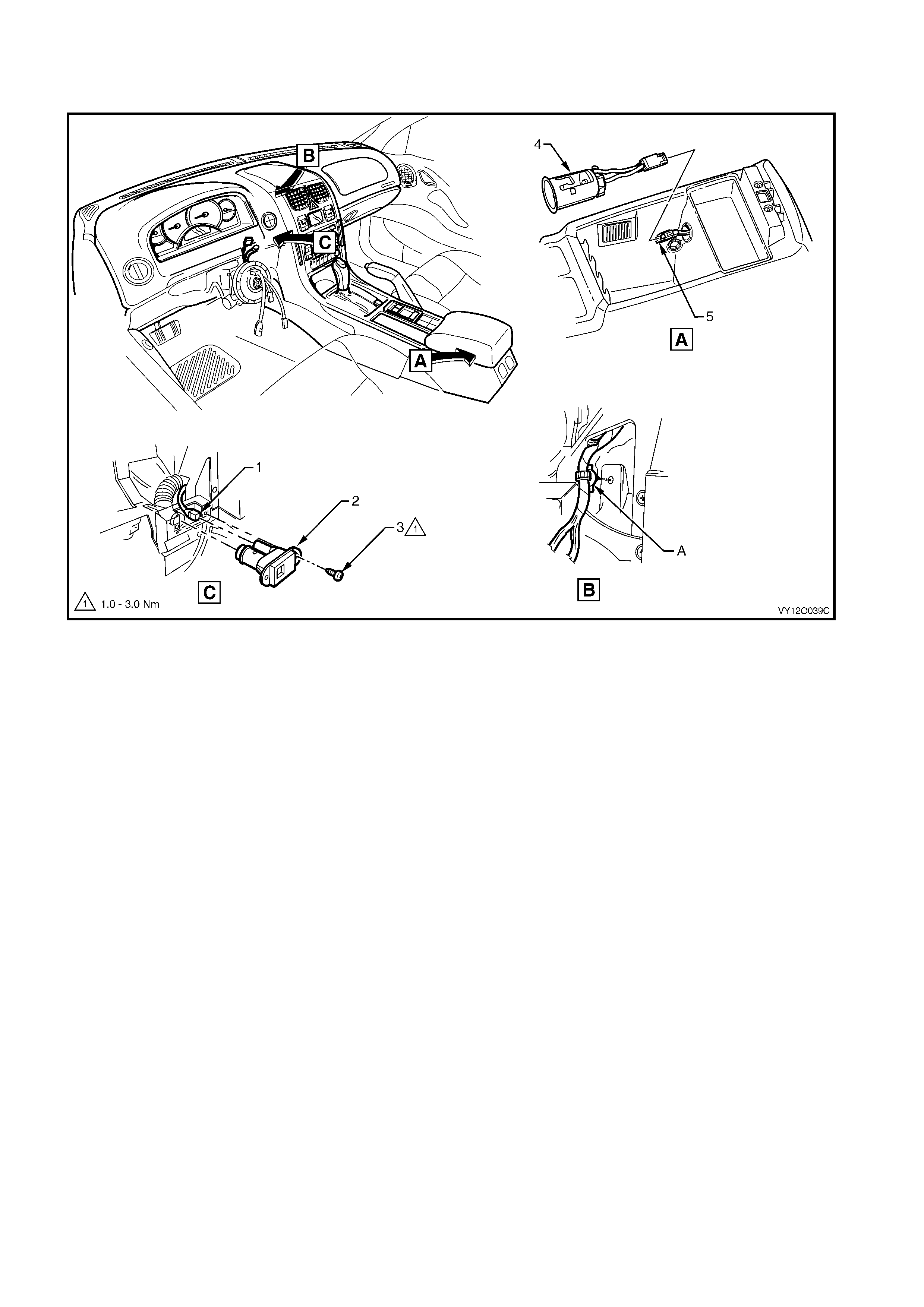
MAIN WIRING HARNESS – 12 – LHD
INSIDE AIR TEMPERATURE SENSOR & ACCESSORY JACK – ALL MODELS
Figure 12O-131
Legend
1. Inside Air Temperature Sensor Connect or (B59)
2 Ins i de Air Temperature Sensor
3. Inside Air Temperature Sensor Attaching Screw
4. Accessory Power Socket
5. Access ory P ower Connector (X112 – AUX)
A. W iring harness attached to instrument panel as shown.
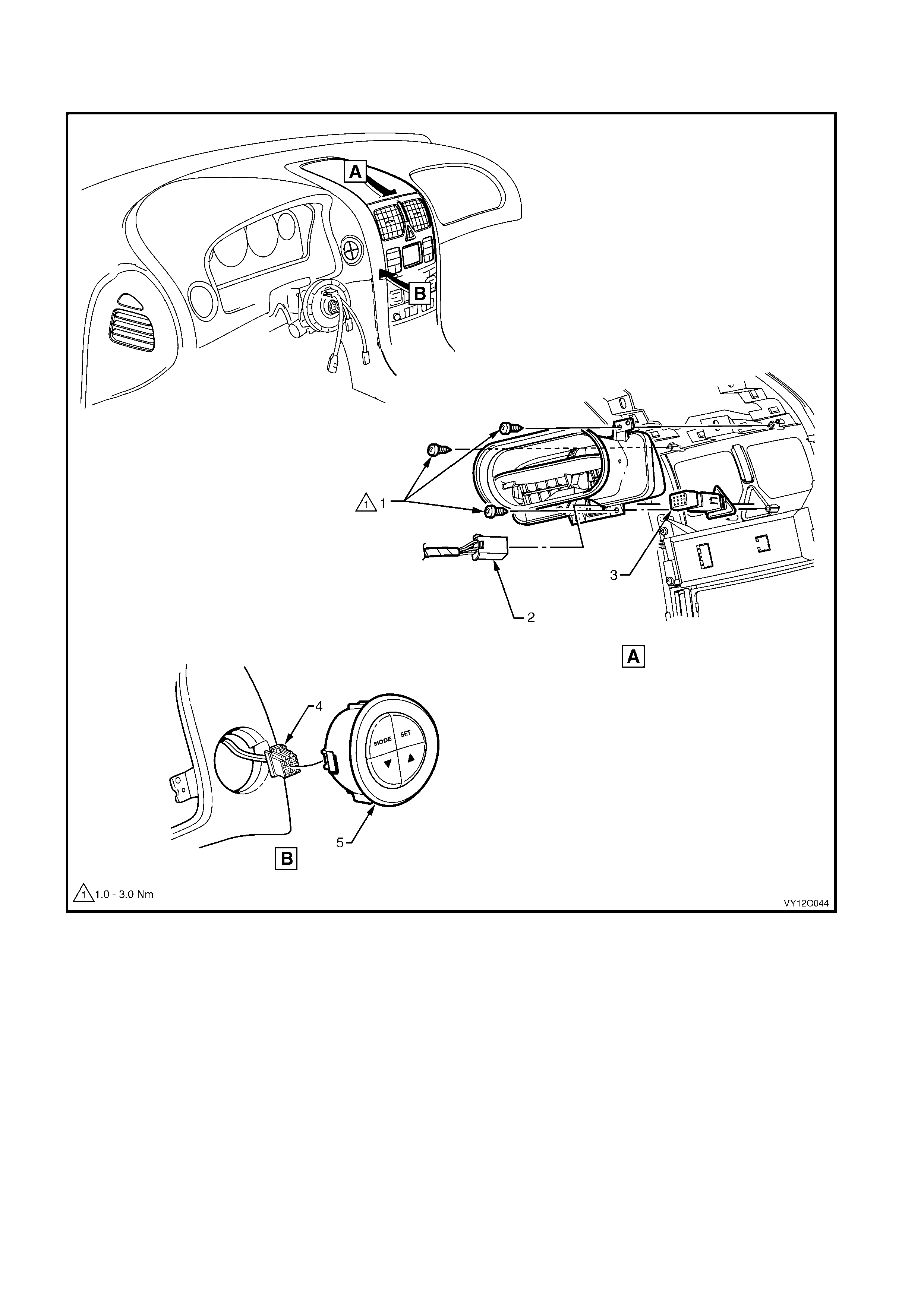
MAIN WIRING HARNESS – 13 – LHD
INSTRUMENT PANEL FACIA TRIM SWITCHES – ALL MODELS
Figure 12O-132
Legend
1. Attaching Screws
2. Hazard Warning S witch Connector (S120)
3. Hazard Warning Switch
4. Trip Odomet er Reset Switch Connector (S237)
5. Trip Odometer Reset Switch
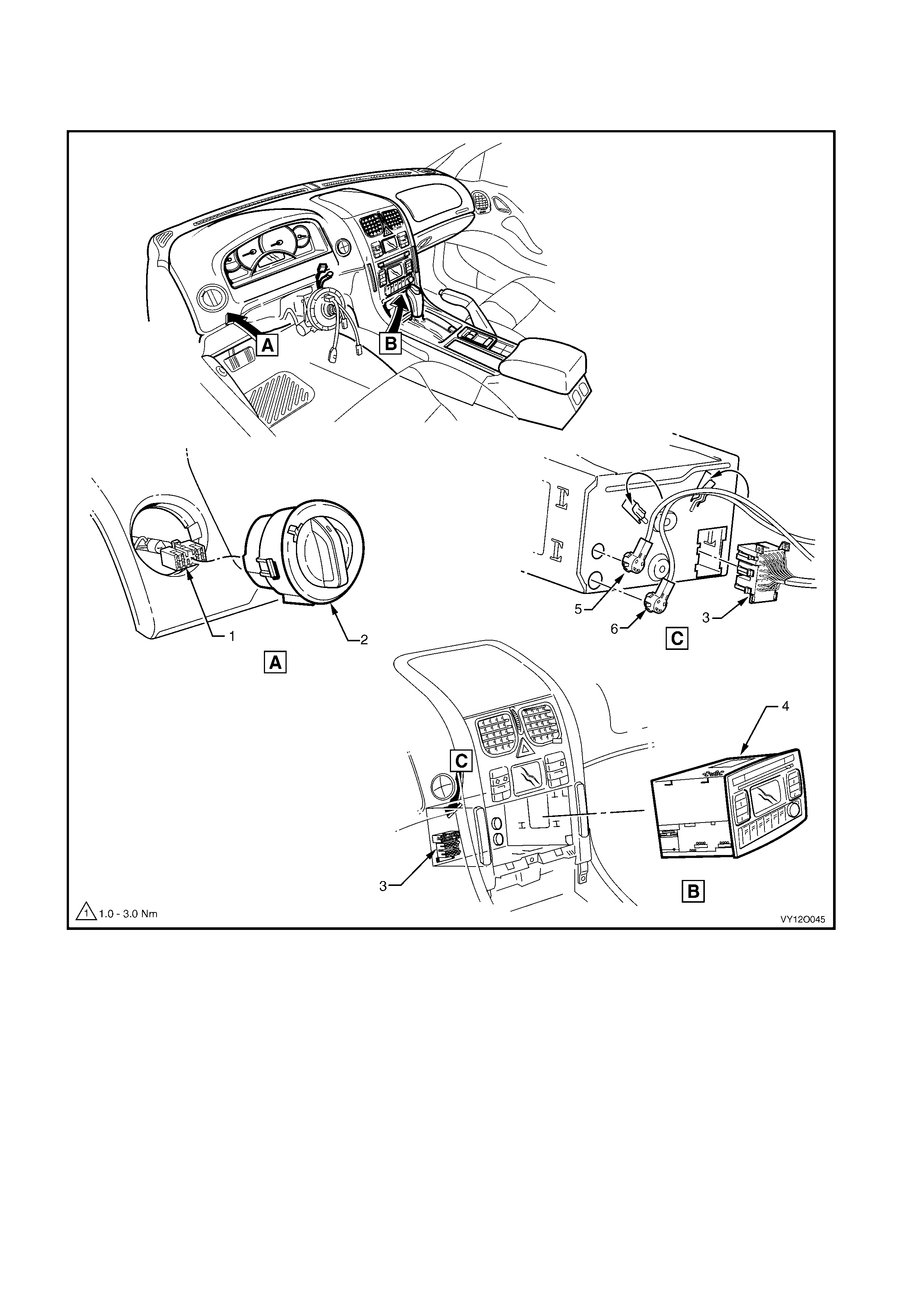
MAIN WIRING HARNESS – 14 – LHD
RADIO A SSEMBLY CONNECTORS & INSTRUMENT PANEL FACIA TRIM SWITCHES –
ALL MODELS
Figure 12O-133
Legend
1. Headlamp Automatic Control Switch Connect or (S 125)
2. Headlamp Automatic Control Switch
3. Radio, Clock and CD Player Connec tor (A133 – X1)
4. Radio, Clock and CD Player As sembly
5. Diversit y Antenna Connector (A133 – X3)
6. Power Antenna Connect or (A133 – X2)
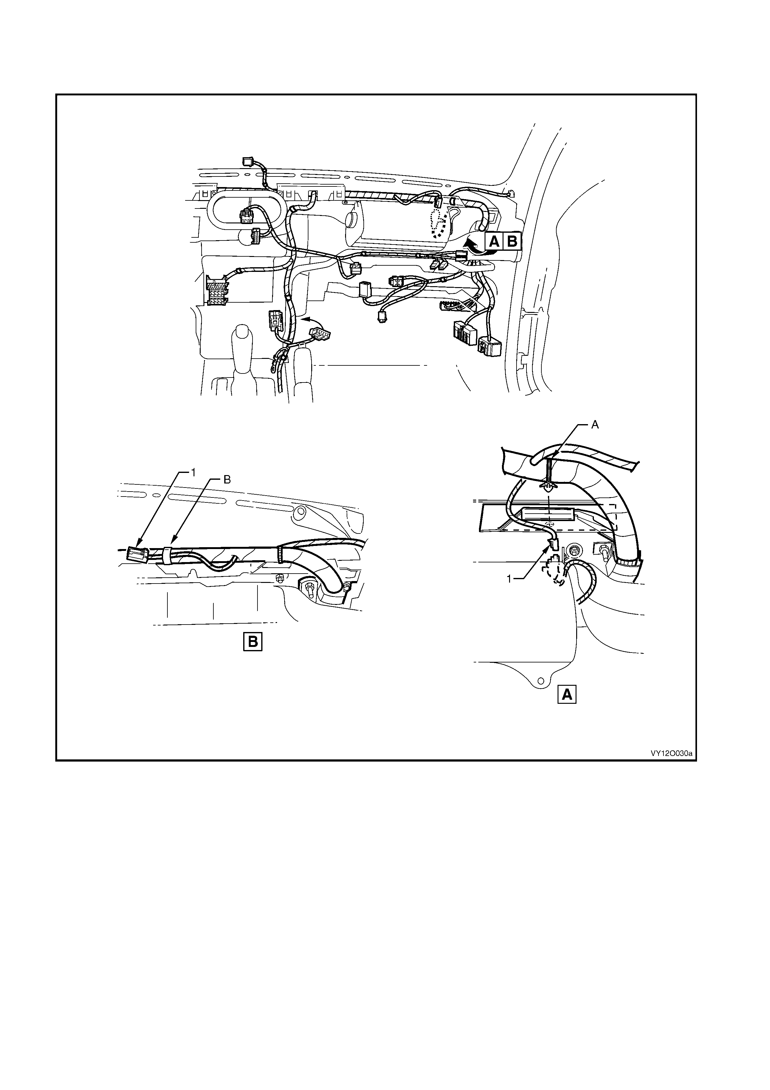
MAIN WIRING HARNESS – 15 – LHD
PASSENGER SIDE AIRBAG WIRING – ALL M ODELS
Figure 12O-134
Legend
1. Main Wiring Harness t o Pass enger Air Bag Harness
Connector (X205) A. Harness ret ainer attached to instrument panel cover assembly
as shown – vehicles with passenger airbag.
B. Passengers side airbag c onnect or taped back as shown –
vehicles without passengers side airbag.
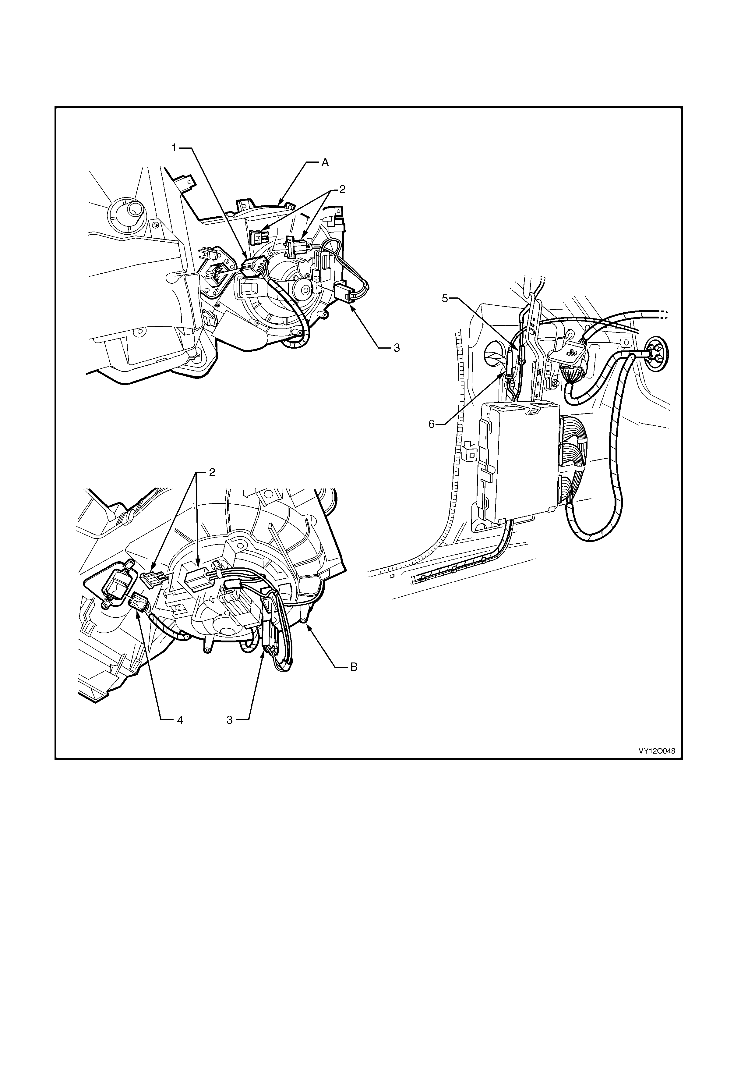
MAIN WIRING HARNESS – 16 – LHD
AMPLIFIER ASSEMBLY, HEATING, VENTILATION & AIR CONDITIONER CONNECTORS –
ALL MODELS
Figure 12O-135
Legend
1. Blower Motor Resist or Connector (R6 – LHD)
2. Fuseblock Connector (X126 – LHD)
3. Blower Motor Connector (M3 – LHD)
4. Blower & Air Inlet Connect or (A 13 – LHD)
5. Radio Antenna Connect or (W6)
6. Radio Antenna Amplif i er Connect or (N3)
A. Manual air conditi oni ng blower unit shown.
B. Auto climate control bl ower unit shown.
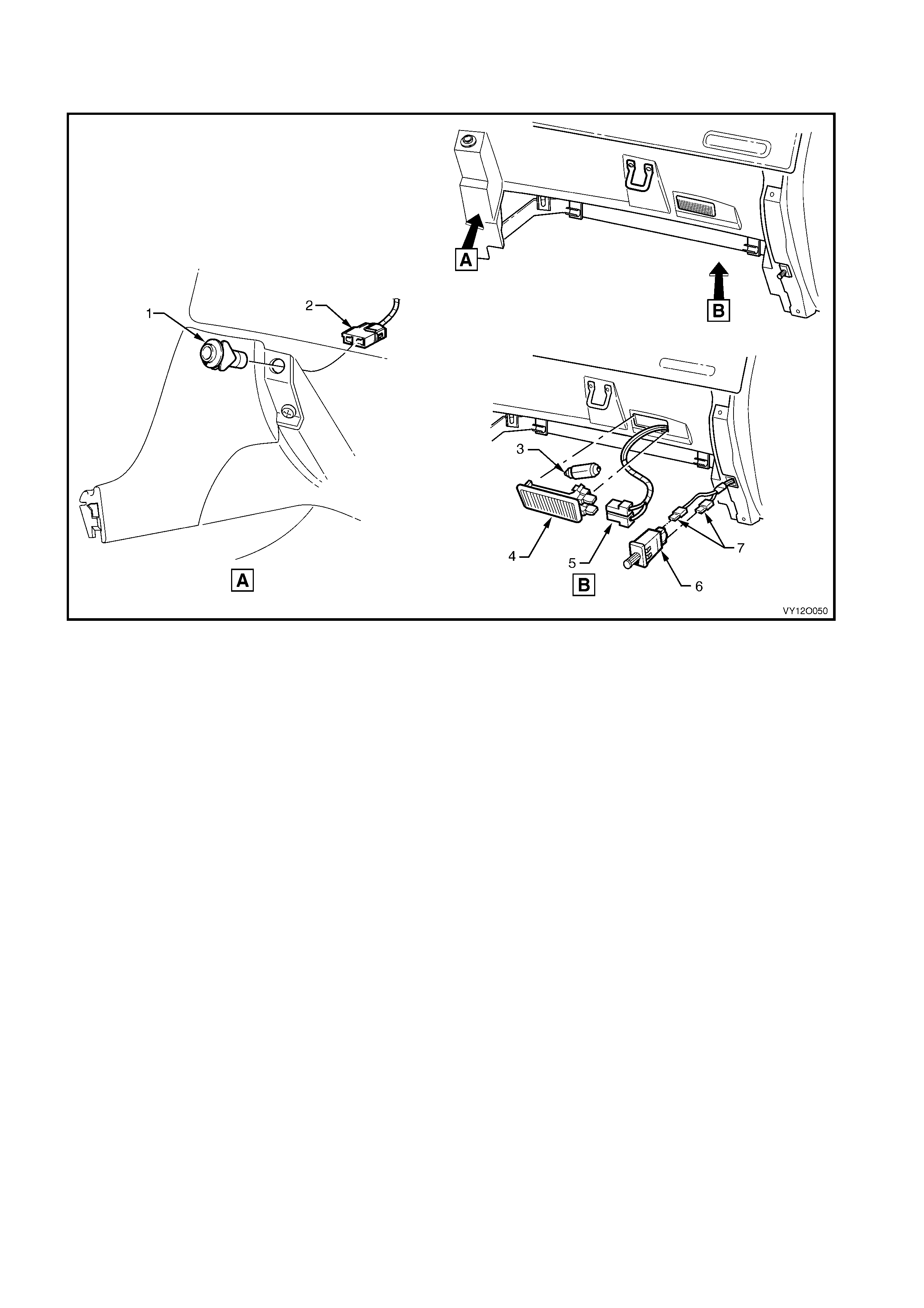
MAIN WIRING HARNESS – 17 – LHD
INSTRUMENT PANEL COMPARTMENT CONNECTORS – ALL MODELS
Figure 12O-136
Legend
1. Rear Compartment Lid Release Switc h
2. Rear Compartment Lid Release Connect or (S 195)
3. Instrument P anel Compartment Lamp Bulb
4. Instrument P anel Compartment Lamp
5. Instrument P anel Compartment Lamp Connectors (E82)
6. Instrument P anel Compartment Lamp Switch
7. Instrument Panel Compartment Lamp Switch Connectors
(S142)
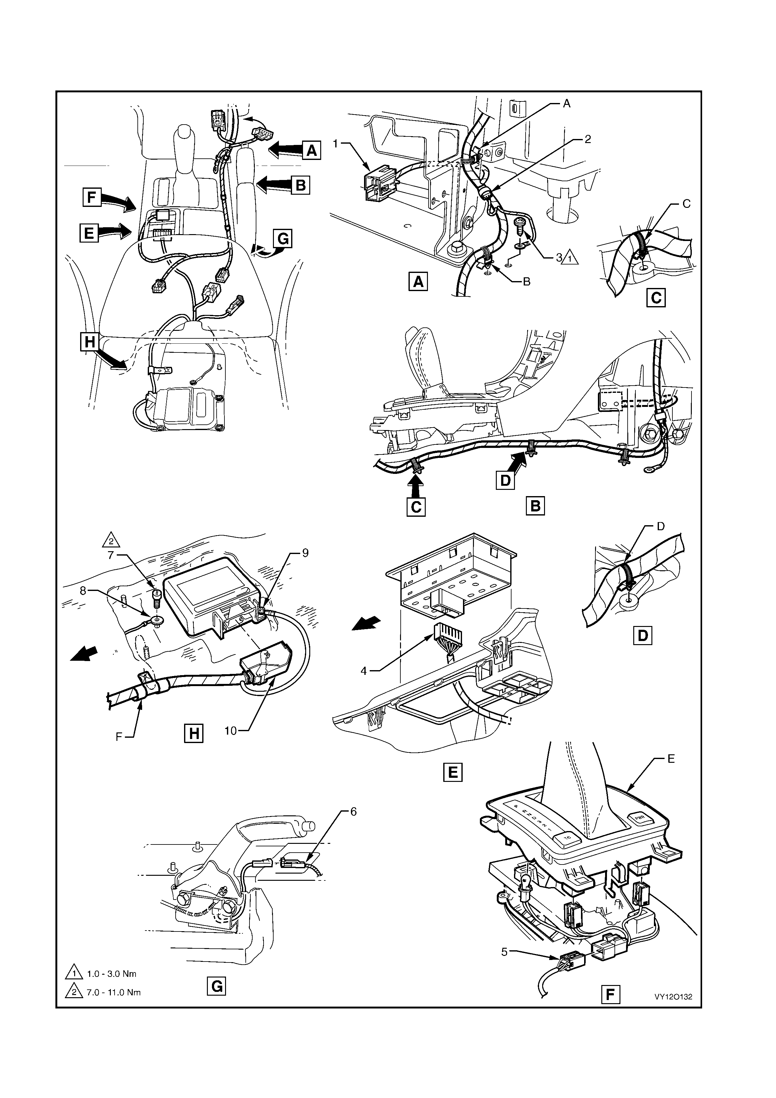
MAIN WIRING HARNESS – 18 – LHD
TRANSMISSION & SIR SENSING DIAGNOSTIC MODULE CONNECTORS – ALL MODELS
Figure 12O-137

Legend
1. Front Cigar Li ghter Connector (X113 – F)
2. Inli ne to Radio and Mobil e Telephone Connector (X155)
3. Radio Ground Terminal Att aching Sc rew
4. Side Wi ndow (Master) S witch Connector (S222)
5. Main W i ri ng Harness t o Transmission Selector Harness
Connector (X301)
6. Park Brak e Switc h Connect or (S181)
7. Body Harnes s Ground Term i nal Attac hi ng Screw
8. Ground Terminal (X118 – GP12)
9. Ground Terminal (X118 – GP11)
10. Inflation Rest rai nt S ensor Connector (A 65)
A. Harness attached t o lower radio brack et as shown.
B. Harness attached to vehicle as shown.
C. Main wiring harness att ached to tunnel as shown.
D. Main wiring harness att ached to tunnel as shown.
E. Automatic transmission selector as shown.
F. Harness attached t o stud as shown.
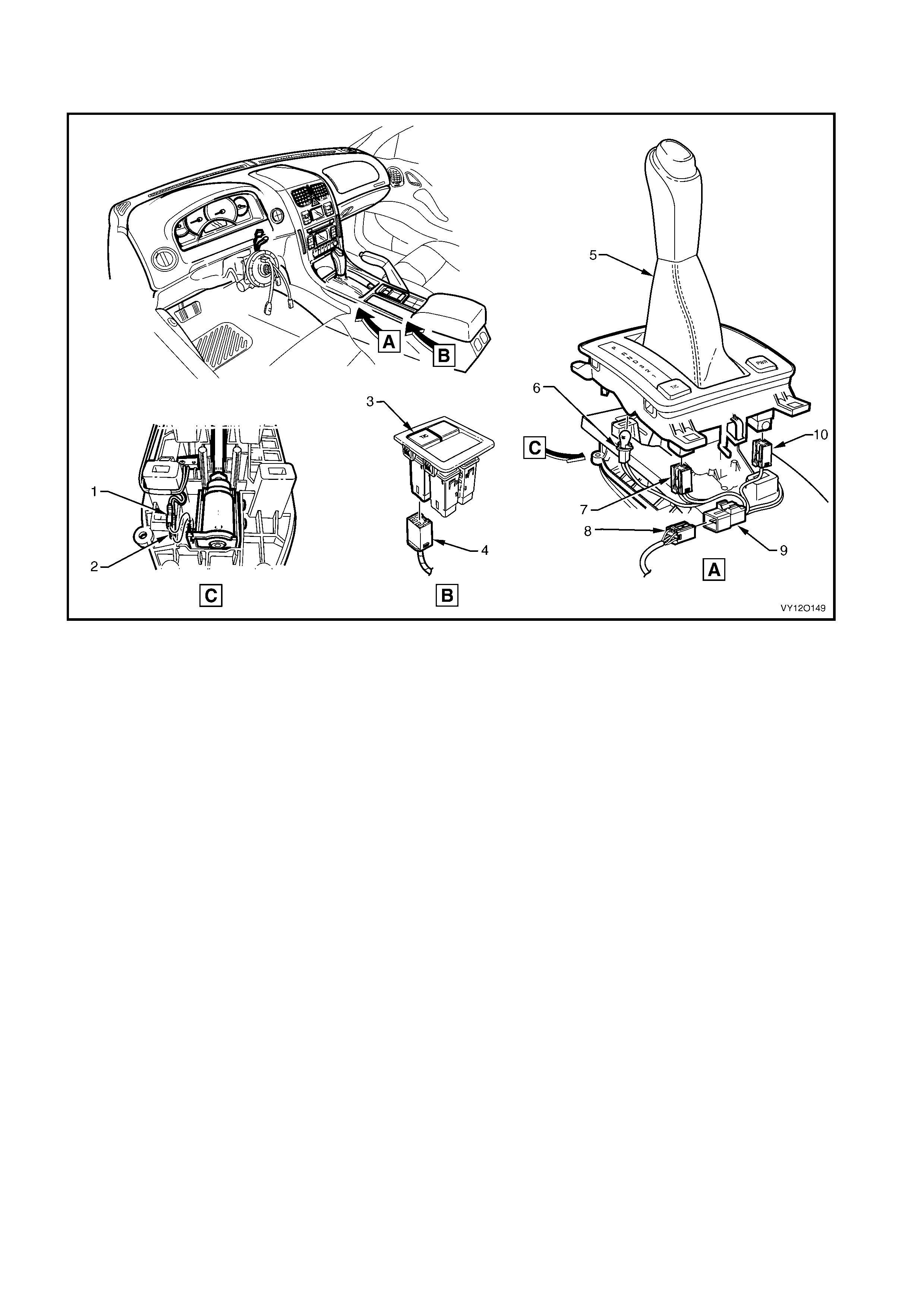
MAIN WIRING HARNESS – 19 – LHD
BREAK TRANSMISSION SHIFT INTERLOCK (BTSI) CONNECTORS
Figure 12O-138
Legend
1. Auto/Trans Shift Lock Park Terminal Connector (S21 – X2)
2. Auto/Trans Shift Lock Park Terminal Connector (S21 – X1)
3. Electroni c Tract i on Control S witch (Manual Transm i ssion)
4. Electroni c Tract i on Control S witch Connect or (S73)
5. PRNDL Selector
6. Aut o/Trans Control Position Indic ator Lamp Connector
(E125)
7. Electroni c Tract i on Control Connector (S73)
8. Main Wiring Harness to Transmission Selector Harness
Connector (X301)
9. Transmission Selector Harness to Main Wiring Harness
Connector (X301)
10. Auto/Trans Shift Program Connector (S22)
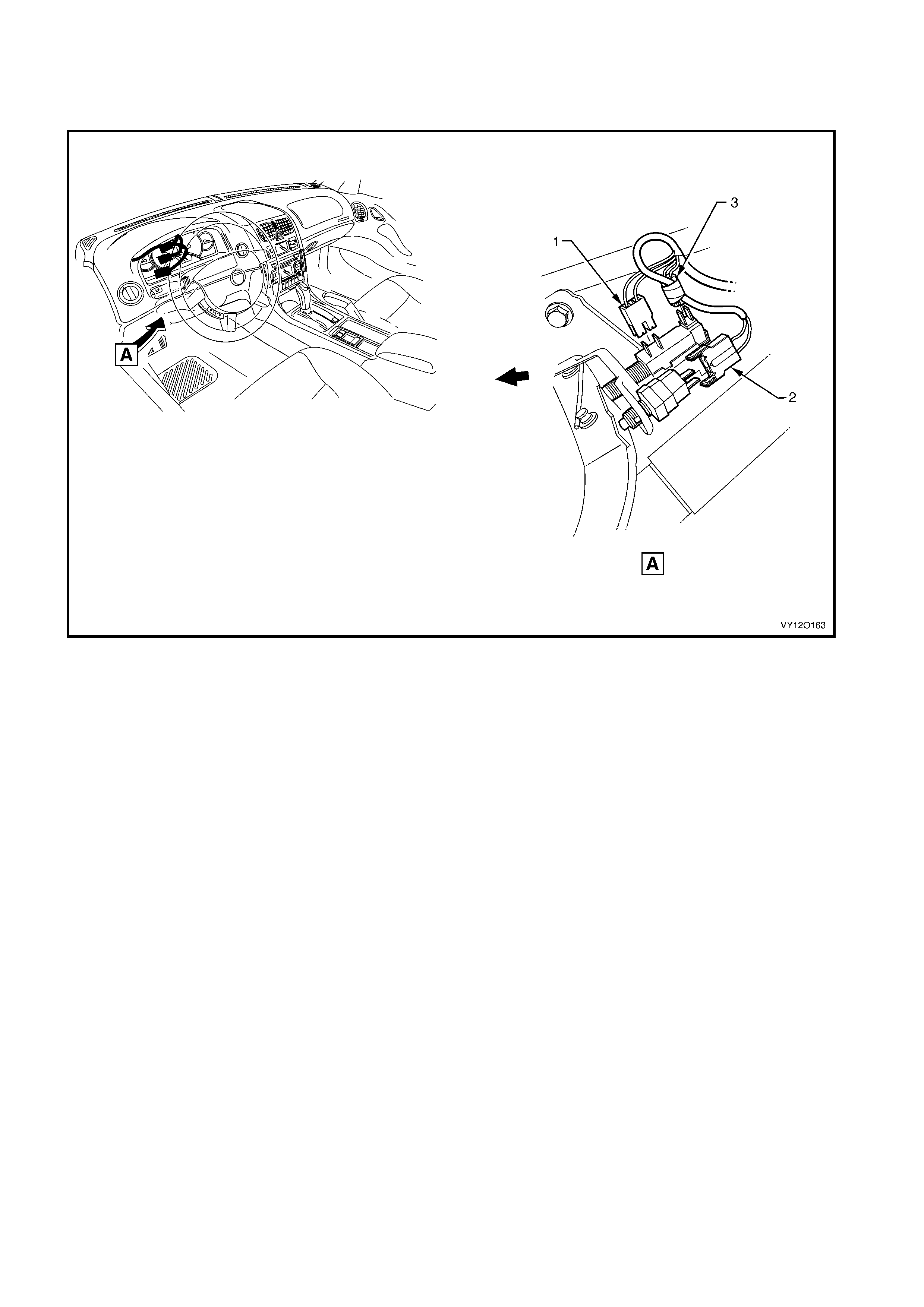
MAIN WIRING HARNESS – 20 – LHD
STOP LAMP, TRACTION & CRUISE CONTROL RELEASE SWITCH CONNECTORS –
AUTOMATIC TRANSMISSION
Figure 12O-139
Legend
1. S top Lamp, Tracti on & Cruise Control Releas e Switch Connector
(S220 - X3)
2. St op Lamp, Traction & Cruise Control Rel ease Switch Connector
(S220 - X1)
3. Stop Lamp, Traction & Cruise Control Releas e Switc h
Connector (S 220 - X2)
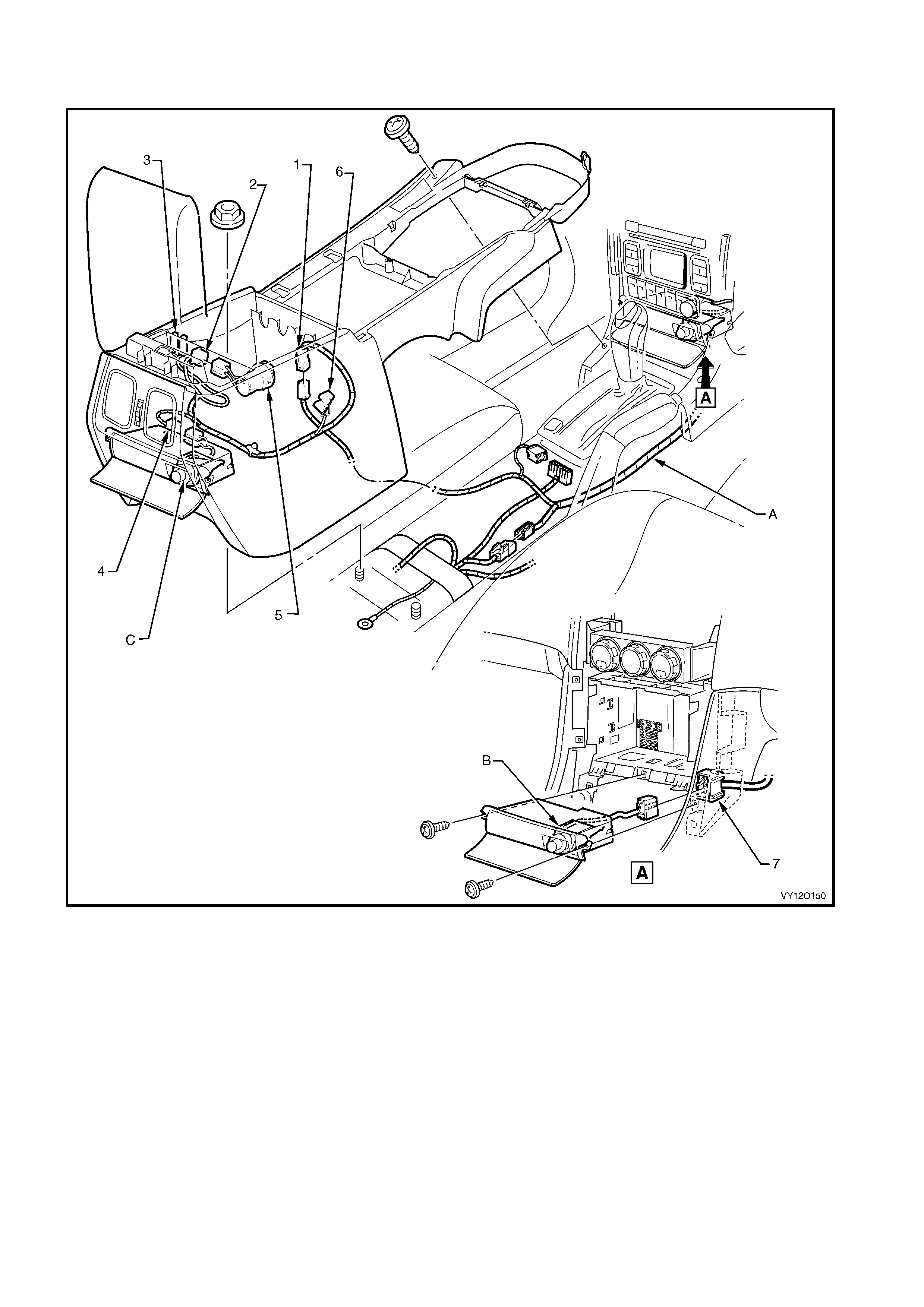
MAIN WIRING HARNESS AND CONSOLE WIRING HARNESS – LHD
FRONT & REAR CIGAR LIGHTER AND ACCESSORY POWER CONNECTOR
Figure 12O-140
Legend
1. Consol e Wi ri ng Harness to Main Wiring Harness
Connector (X309)
2. Acc essory Power Connector (X112 – AUX)
3. Front Floor Consol e Com partment Lamp Switc h Connect ors
(S94)
4. Rear Cigar Lighter Connector (X113 – R)
5. Accessory Power Socket
6. Front Floor Consol e Com partment Lamp Connectors (E16)
7. Front Cigar Li ghter Connector (X113 – F)
A. Main wiring harness att ached to inside of cons ol e (1 place).
B. Front cigar lighter installed.
C. Rear cigar lig hter inst al l e d.
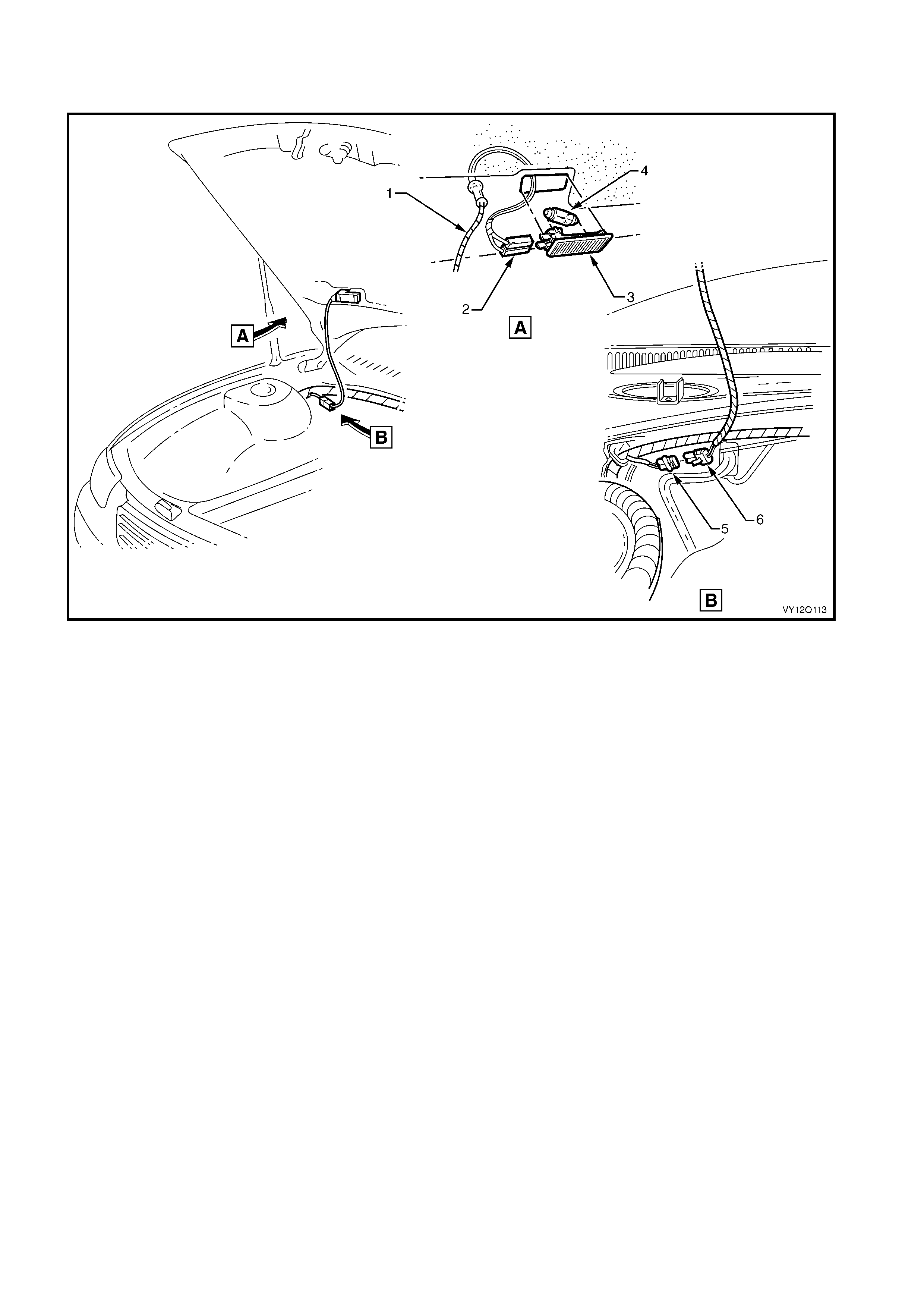
BODY WIRING HARNESS
UNDERHOOD COURTESY LAMP
Figure 12O-141
Legend
1. Underhood Courtesy Lamp Wi ri ng Harness
2. Underhood Courtesy Lamp Connectors (E107)
3. Underhood Courtes y Lam p
4. Underhood Courtes y Lam p Bulb
5. Main Wiring Harness t o Underhood Lamp Harness Connector
(X108)
6. Underhood Lamp Harness to Main Wiring Harness Connector
(X108)
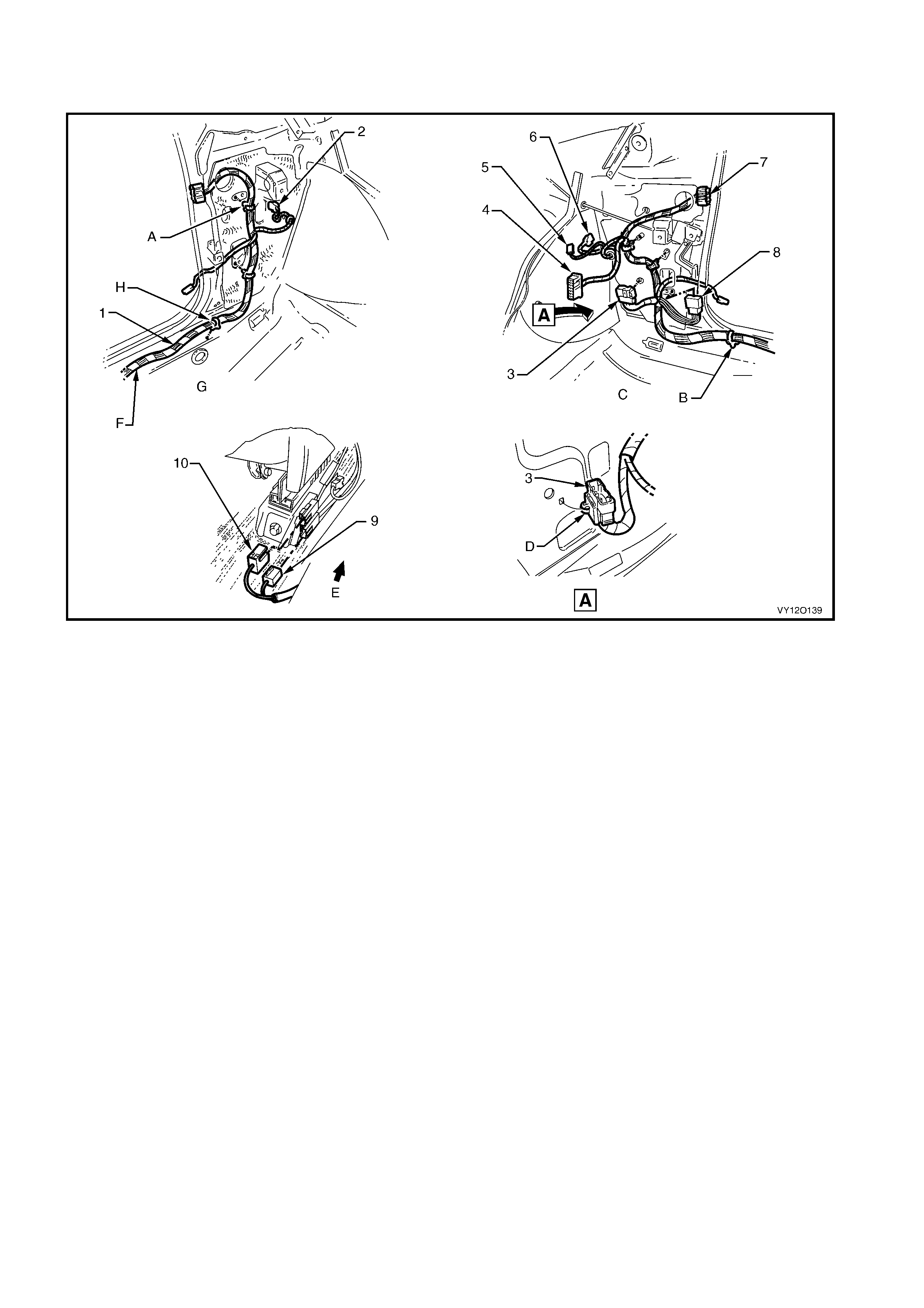
BODY & ROOF WIRING HARNESSES – 1
INTERIOR – LHD
Figure 12O-142
Legend
1. Body Wiring Harness
2. Front Side Turn Lamp Connector (E75)
3. Body Wiring Harness to Main Wiring Harness Connector
(X201)
4. Body Control Module Connect or (A15 – X4)
5. Radio Power Antenna Connector (W6 – X1)
6. Front Side Turn Lamp Connector (E75)
7. Body Wiring Harness to Right-hand Front Door Wiring
Harness Connect or (X600)
8. Body Wiring Harness to Main Wiring Harness Connector
(X200)
9. Seat Belt Connector (Y 128 – Driver), (Y129 – Passenger)
10. Body Wiring Harness to Side Airbag Harness Connector
(X306 – LH, X307 – RH)
A. Attach body wiring harness to shroud side panel (2 places).
B. Body wiring harness att ached t o underbody as shown
(9 places).
C. Right-hand side shown.
D. Main wiring harness connector clipped to shroud side panel as
shown.
E. Front of vehicle.
F. Left-hand side shown.
G. Body wiring harness attached t o underbody as shown
(6 places).
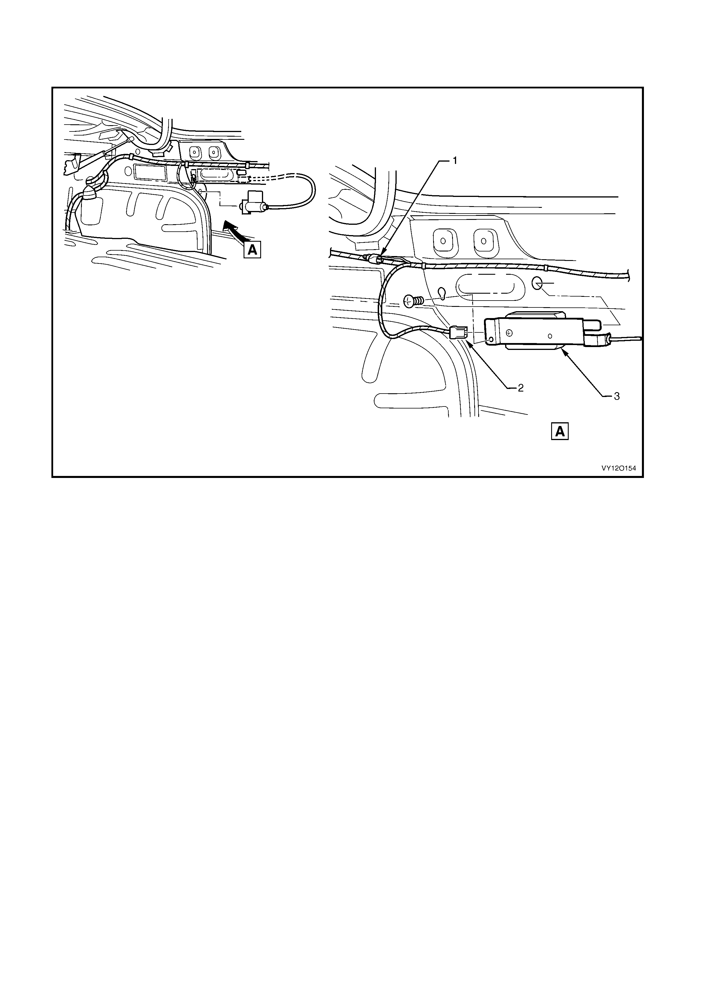
BODY & ROOF WIRING HARNESSES – 2
FUEL TA NK FILLER DOOR LOCK – LHD
Figure 12O-143
Legend
1. Suppression Di ode Fuel Tank Filler Door Lock Connecto r (V 7)
2. Fuel Tank Filler Door Lock Connector (Y10) 3. Fuel Tank Filler Door Lock
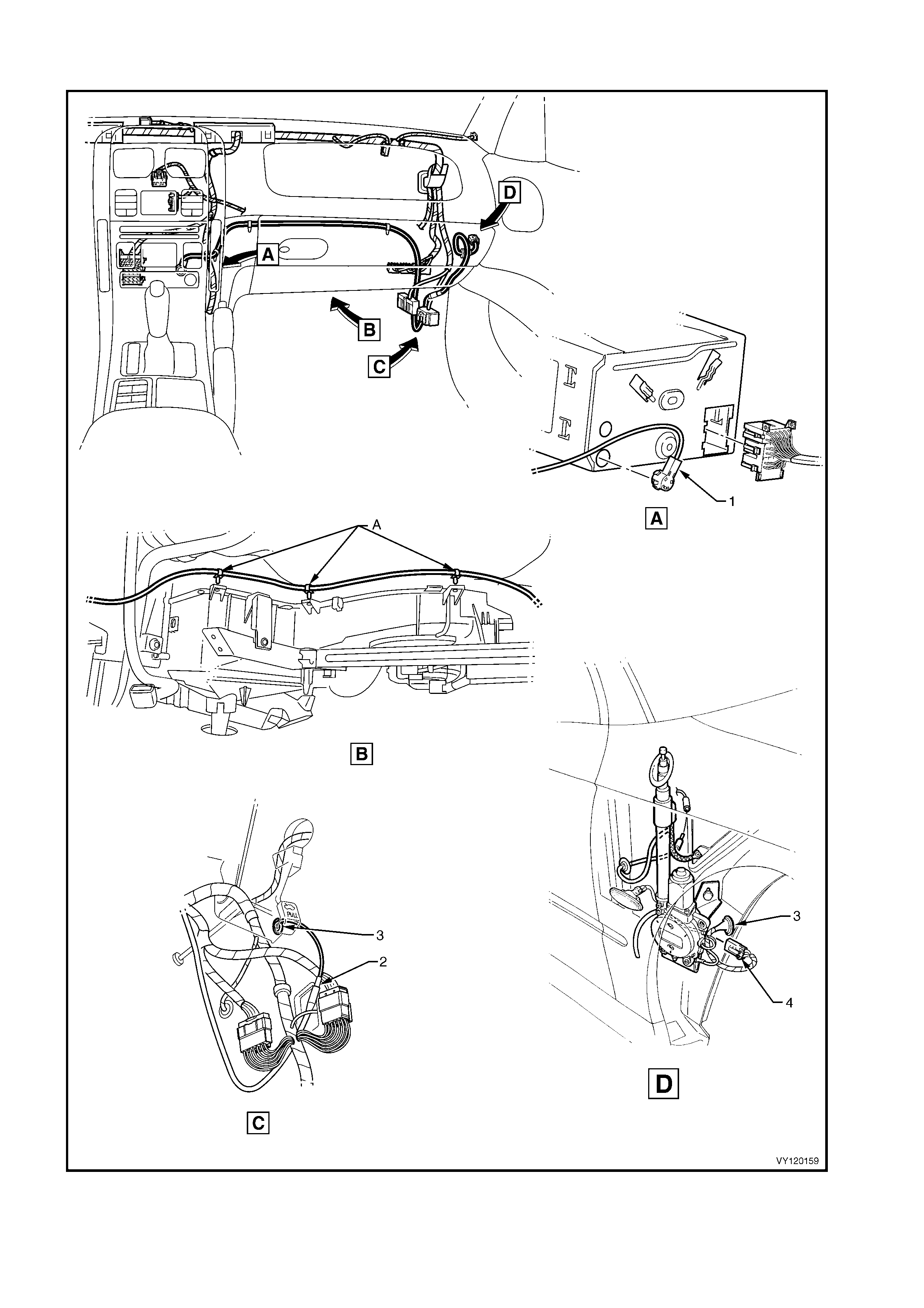
RADIO POWER ANTENNA WIRING – LHD
Figure 12O-144

Legend
1. Power Antenna Connect or (A133– X2)
2. Radio Power Antenna Connector (W6 – X2)
3. Antenna Lead Panel Blanking Grommet
4. Radio Power Antenna Connector (W6 – X1)
A. Lead attached along integral heating, ventilation and ai r
conditi oni ng unit as shown (3 places).
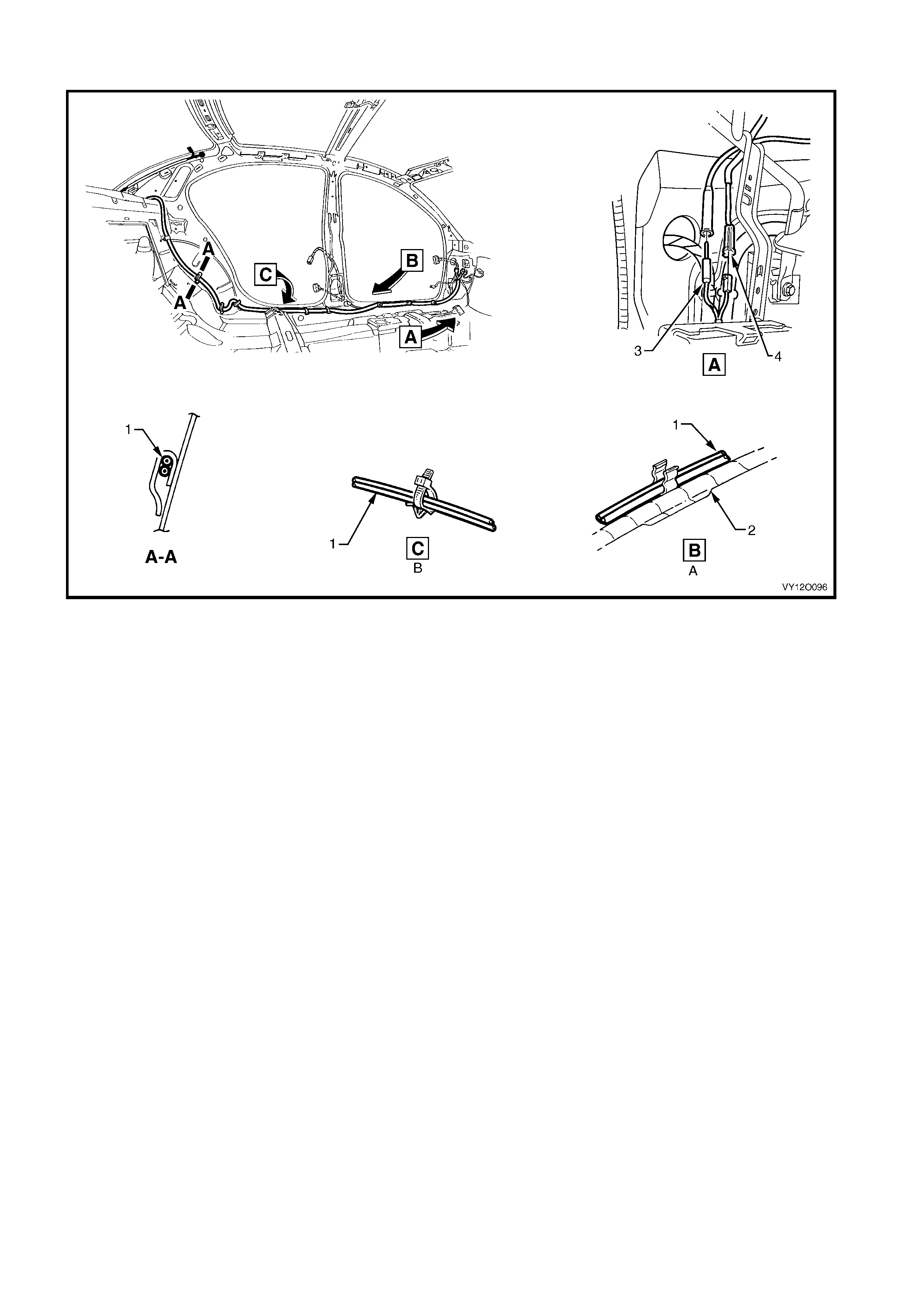
RADIO AMPLIFI ER ASSEMBLY WIRING – LHD
Figure 12O-145
Legend
1. Radio Amplifi er Harness
2. Body Wiring Harness
3. Radio Power Antenna Connector (W6 – X2)
4. Radio Antenna Amplif i er Connect or (N3)
A. Harness attached al ong sil l as shown (3 places)
B. Harness attached al ong sil l as shown (2 places)
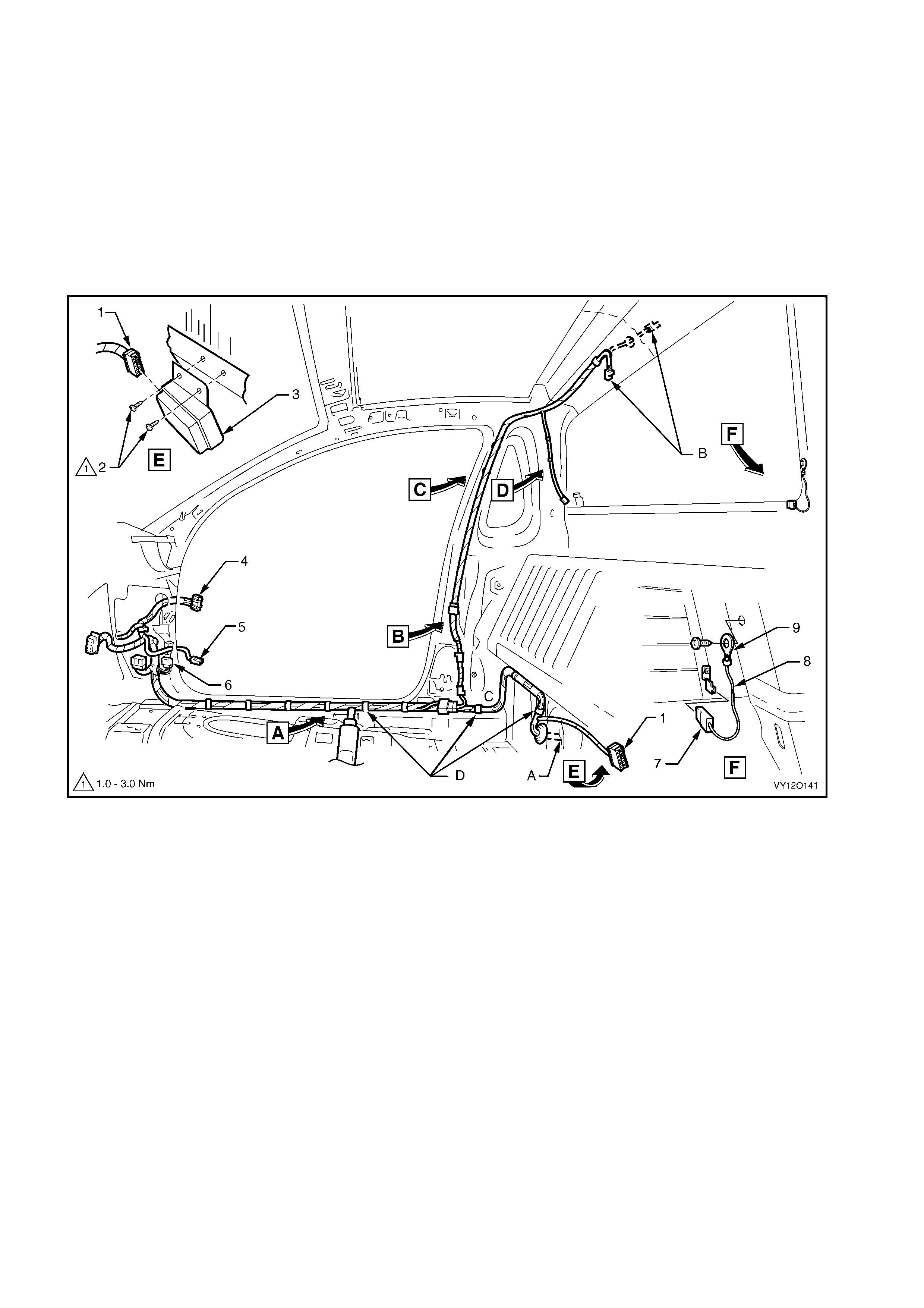
5. WIRING INSTALLATION DIAGRAMS – UTILITY
The following figures illustrate the vehicle wiring installation diagrams for MY 2003 VY Utility.
All the wiring harnesses forward of the A pillar in the Utility carryover from the right-hand drive Sedan and
Wagon. For information relating to the wiring harness installation diagrams for the Utility not provided in this
section refer to 3. WIRING INSTALLATION DIAGRAMS – RIGHT-HAND DRIVE SEDAN AND WAGON.
NOTE: Some of the following wiring installation diagrams illustrate the upper level harnesses which incorporate
all necessary wiring harnes s connectors f or all production options. Depending on equipm ent level and vehicle
model, s ome of the c onnectors ma y be tape d back to the h arness when a particular op tion is not f itted, or the
particular level of harness fitted to the vehicle may not incorporate some of the connectors illustrated.
INTERIOR BODY WIRING HARNESS – 1
Figure 12O-146
Legend
1. Body Wiring Harness to Fuel Module Connect or (A47)
2. Attaching Screws
3. Fuel Pump Module (V8 only)
4. Body Wiring Harness to Right-hand Front Door Wi ri ng
Harness Connect or (X600)
5. Door Ajar Indicator Switch Connector (S2)
6. Body Wiring Harness to Main Wi ring Harness Connector
(X200)
7. Rear Window Defog Grid Connector (R22 – X2)
8. Rear Window Defog Grid Ground Lead
9. Ground Lead Terminal (X118 – GP7)
A. For harness continuat i on, ref er to
BODY WI RING HARNESS – 2 in this section.
B. For harness continuat i on, ref er to
ROOF LAMP HARNESS – 2 in this sec tion .
C. For harness continuat i on, ref er to
INTERIOR BODY WIRING HARNESS – 2 in this sec tio n .
D. Harness clipped to underbody (10 places).
For views A, B, C & D, refer to
ROOF LAMP HARNESS – 1 in this section.
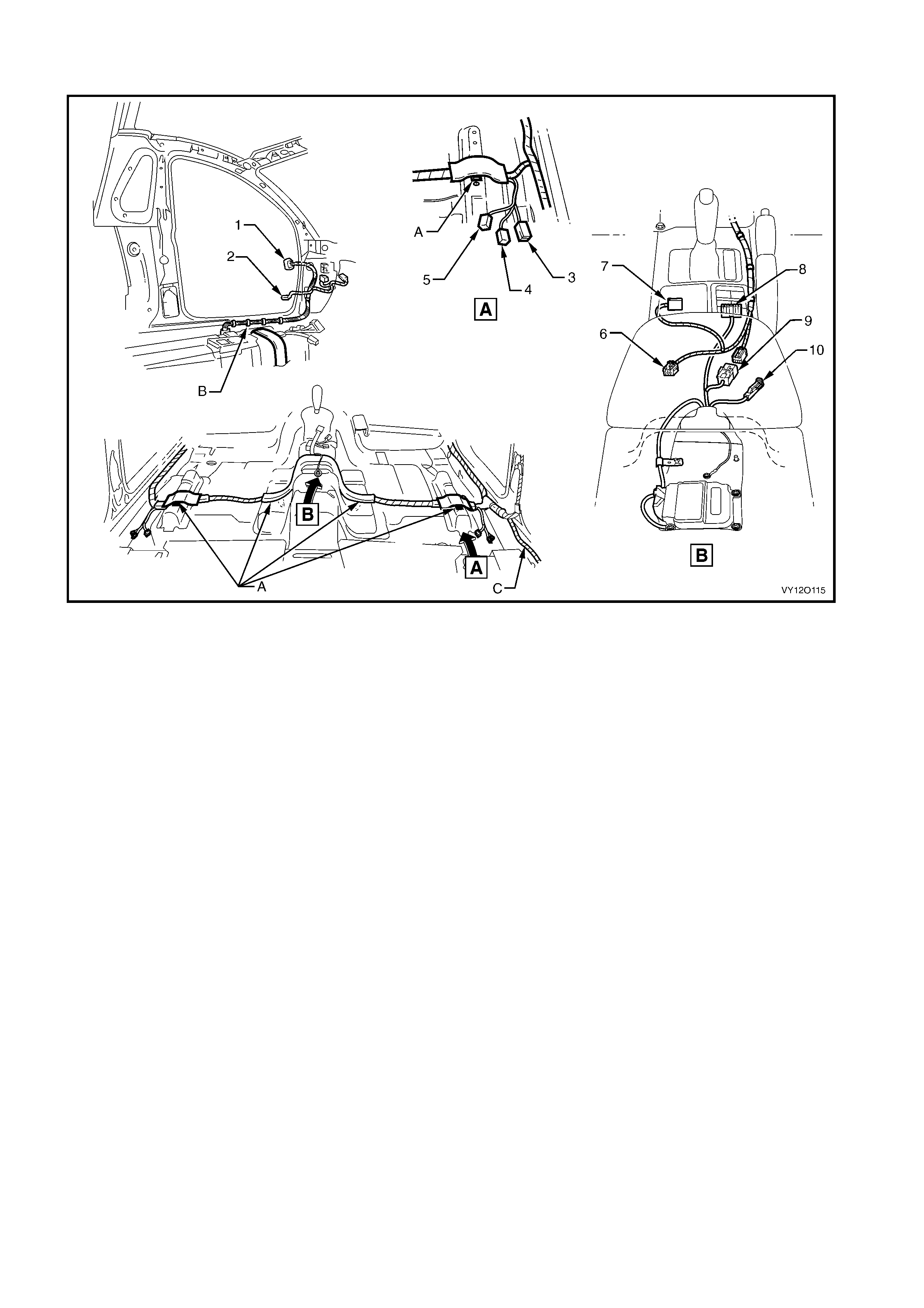
INTERIOR BODY WIRING HARNESS – 2
Figure 12O-147
Legend
1. Body Wiring Harness to Left-hand Front Door Wiring Harness
Connector (X500)
2. Door Ajar Indicator Switch Connector (S2)
3. Seat Belt Connector (Y 128 – D)(Y129 – P)
4. Body Wiring Harness to Side Airbag Harness Connector
(X306 – L) (X307 – R)
5. Body Wiring Harness to Power Seat Harness Connector
(X302)
6. Main Wiring Harness t o Consol e Wiring Harness Connector
(X309)
7. Main Wiring Harness to Transmission Selector Harness
Connector (X301)
8. Side Window (Master) Switch Connector (S222)
9. Body Wiring Harness to Main Wi ring Harnes s Connector
(X303)
10. Park Brake Switch Connector (S181)
A. Harness clipped to underbody (4 places).
B. Harness clipped to underbody (5 places).
C. For harness continuat ion refer to
INTERIOR BODY WIRING HARNESS – 1 in this sectio n .
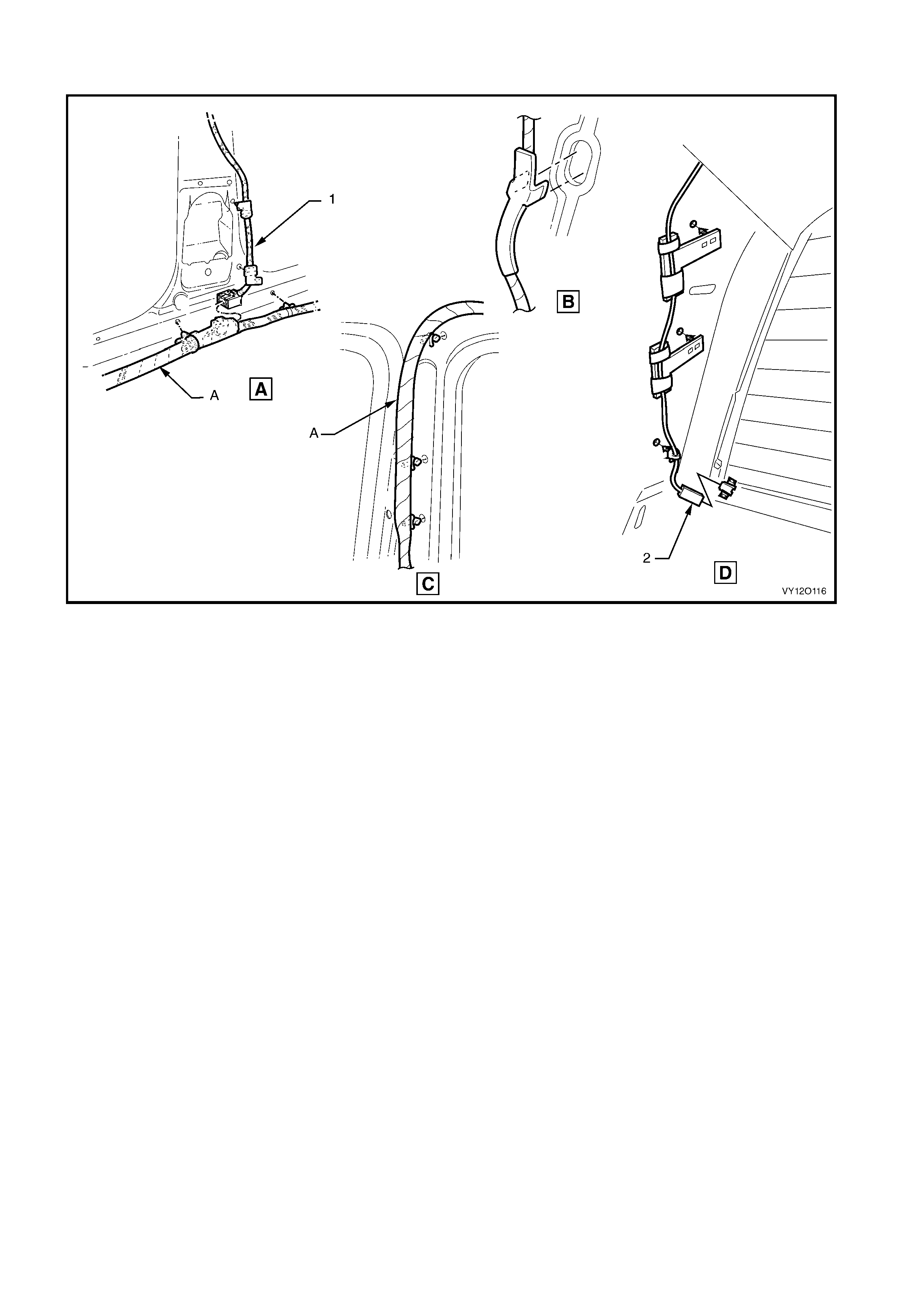
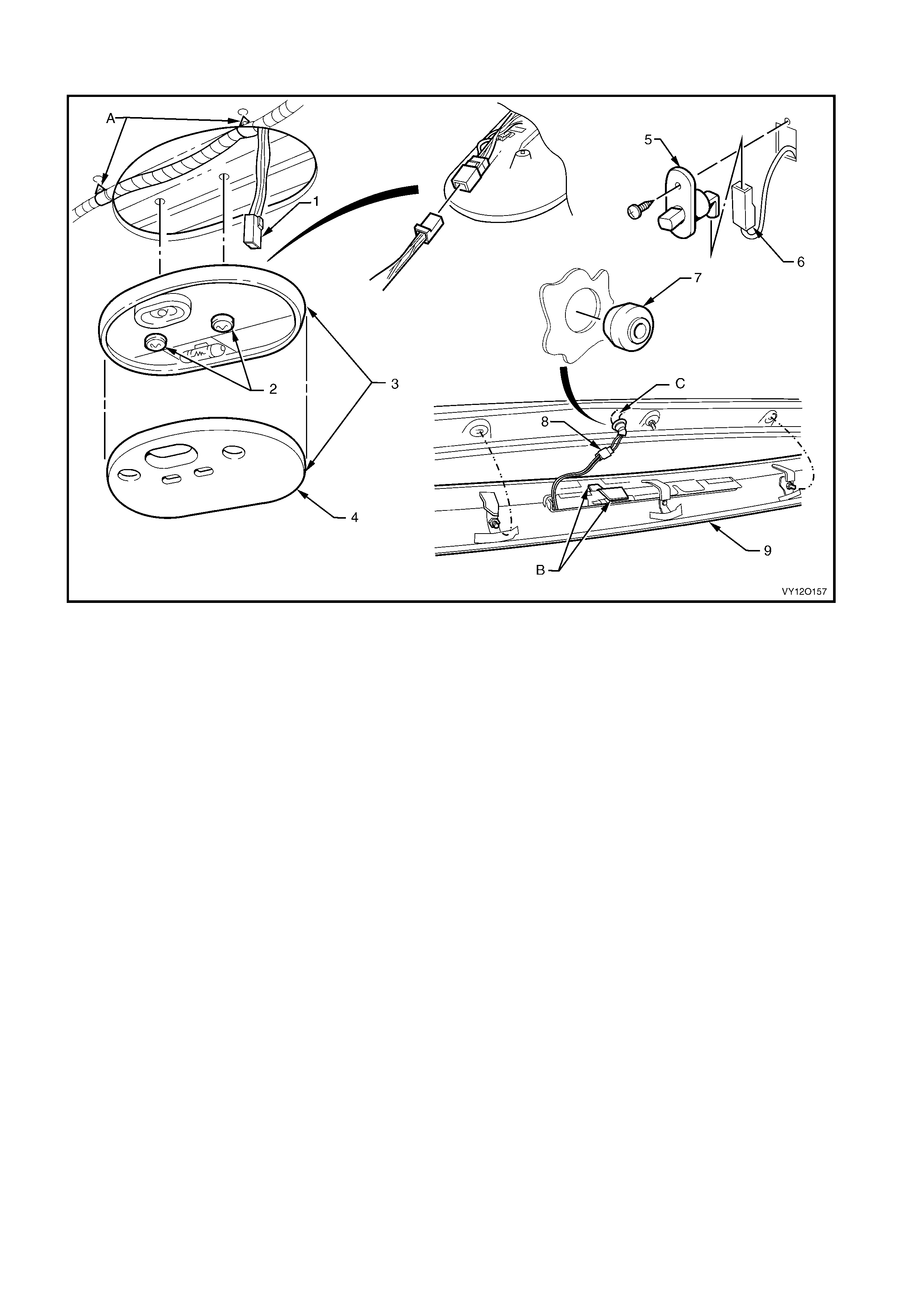
ROOF LAMP HARNESS – 2
Figure 12O-149
Legend
1. Dome Lamp Connector (E67)
2. Dome Lamp Screws
3. Dome Lamp Assembly
4. Dome Lamp Lens
5. Door Courtesy Lamp Switc h
6. Door Courtesy Lamp Connect or (E72)
7. Harness Blanking Plug (exc. SS)
8. High Mount Stop Lamp Connector (E79 – U)
9. Roof Rear Centre Capping
A. Harness cli pped to rear roof header reinf orcement (2 places).
B. High level st op l amp harness stowed into roof centre capping
rib.
C. For roof lamp harness conti nuation, ref er to
INTERIOR BODY WIRING HARNESS – 1 in this section.
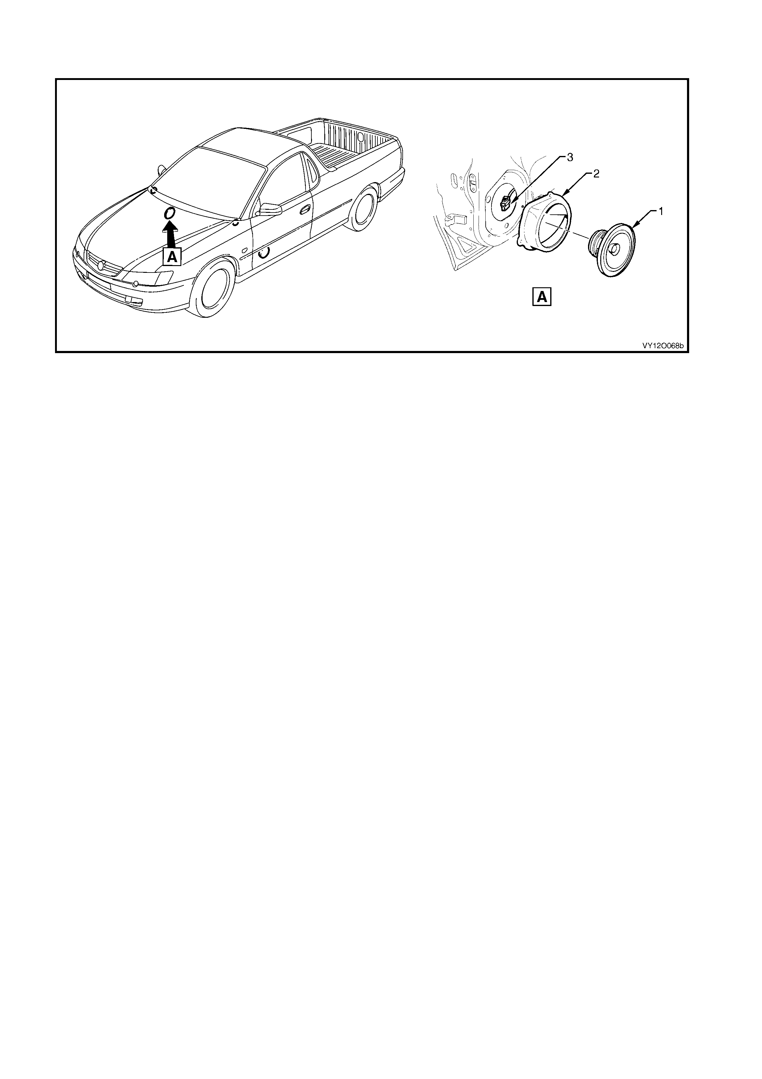
DOOR WIRING HARNESSES – SPEAKERS
Figure 12O-150
Legend
1. Front Door Radio Speaker Assembly
2. Front Door Radio Speaker Mounting Box Assembly
3. Right-hand and Left -hand Front Door Speaker Connector
(B108)
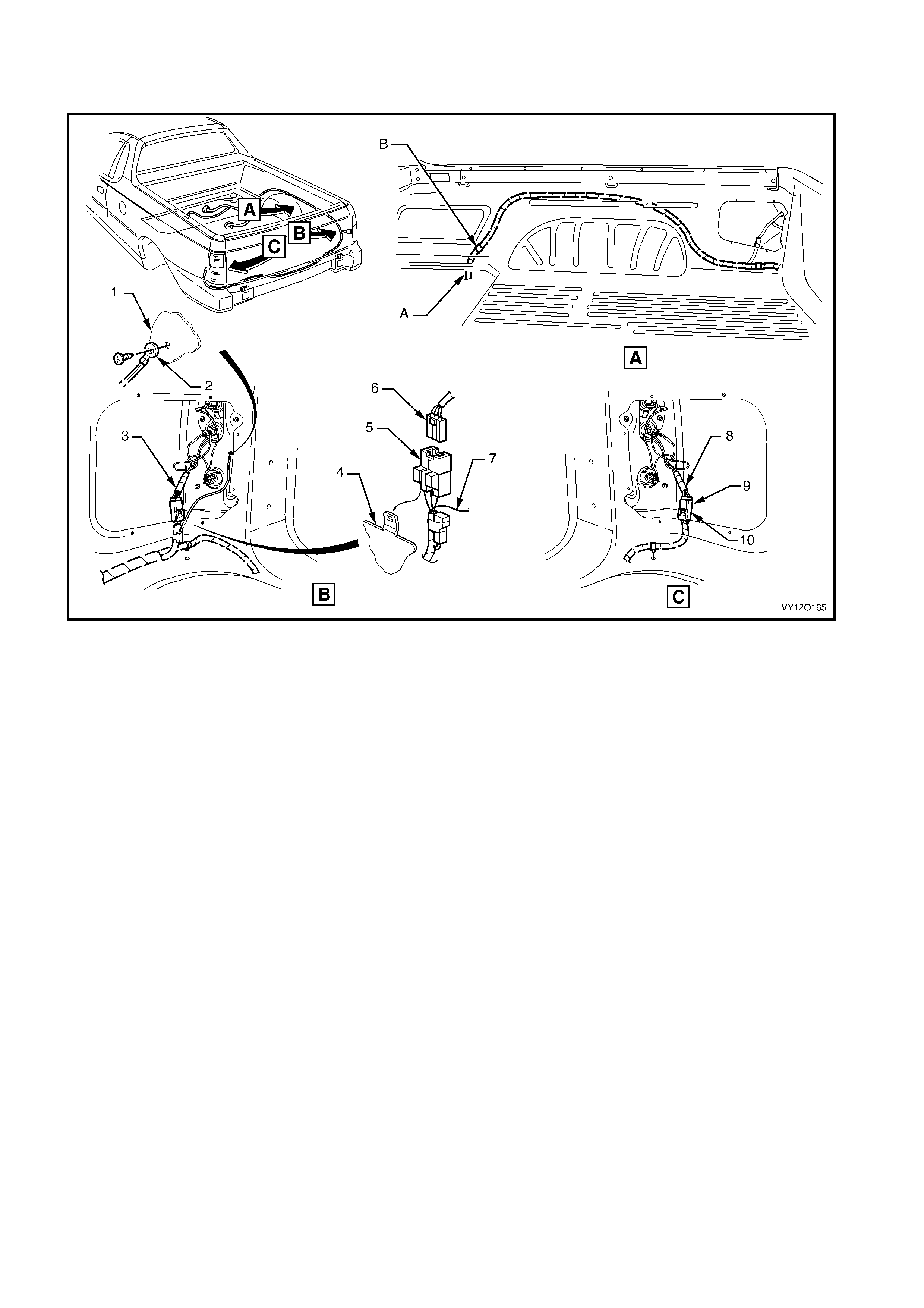
BODY WIRING HARNESS – 1
LOAD COMPARTMENT
Figure 12O-151
Legend
1. Side Panel Inner Extension
2. Body Ground Lead Terminal (X118 – GP14)
3. Right-hand Tail Lamp Harness
4. Side Inner Upper Panel
5. Body Wiring Harness to Tail Lamp Harness Connector (X903)
6. Tail Lamp Harness to Body Wiring Harnes s Connector (X903)
7. Body Ground Lead
8. Left-hand Tail Lamp Harness
9. Tail Lamp Harness to Body Wiring Harnes s Connector (X904)
10. Body Wiring Harness to Tail Lam p Harness Connec tor (X904)
A. For harness continuat i on refer to
BODY WI RING HARNESS – 2 in this section.
B. Harness clipped to side inner upper panel (1 place).
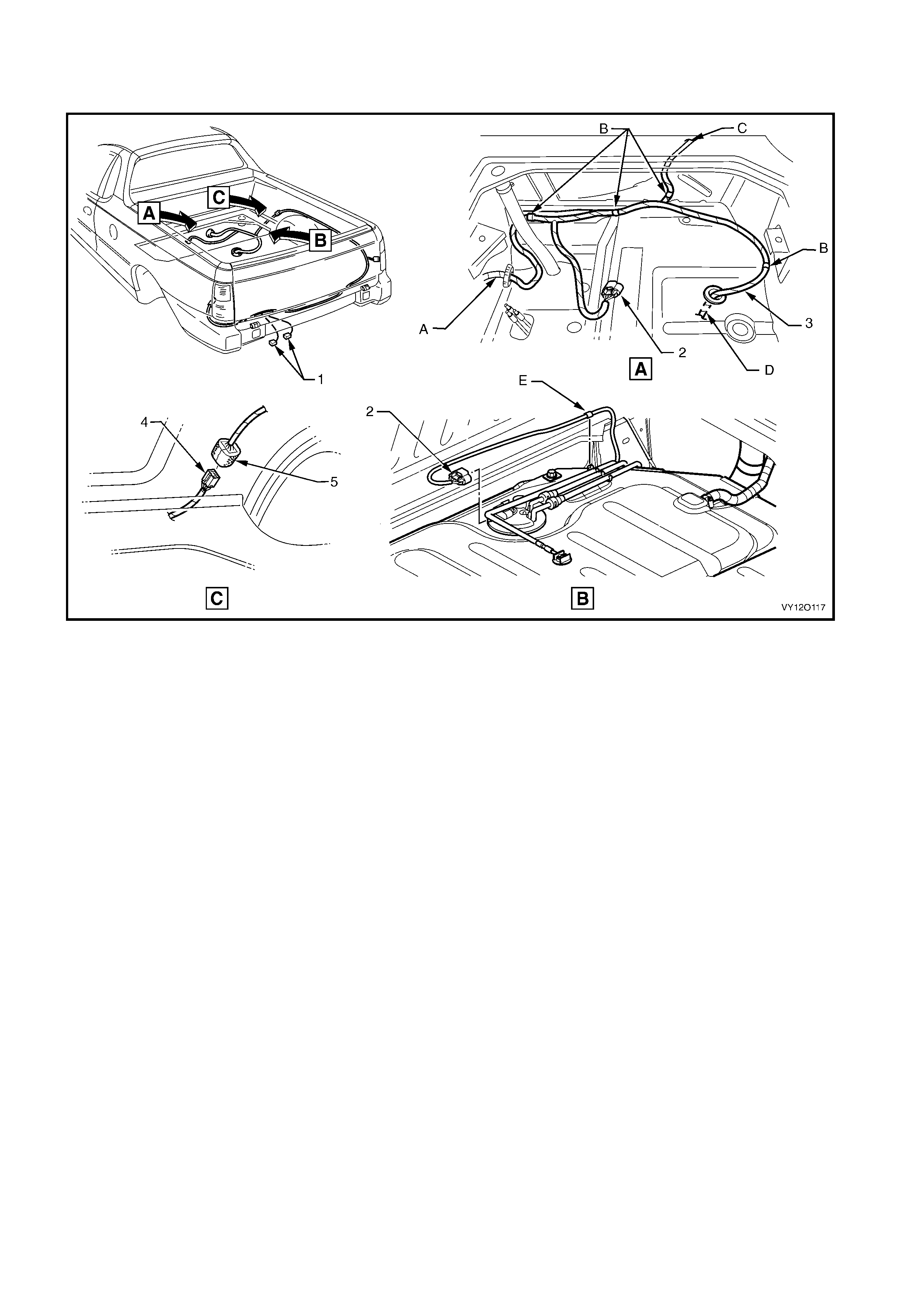
BODY WIRING HARNESS – 2
FUEL TANK
Figure 12O-152
Legend
1. Rear Licence Plate Lam p Connectors (E44 – U)
2. Fuel Pump Motor Connector (M8)
3. Body Wiring Harness
4. Body Wiring Harness to Rear Body Wiring Harness
Connector (X403)
5. Rear Body Wiring Harness to Body Wiring Harness
Connector (X403)
A. For harness continuat i on, ref er to
INTERIOR BODY WIRING HARNESS –1 in this sectio n.
B. Harness clipped to sheet metal (3 places).
C. For harness continuat ion refer to
BODY WI RING HARNESS –1 in this section.
D. For continuation, refer to BODY WIRING HARNESS – 3 in this
section.
E. Harness clipped to fuel tank.
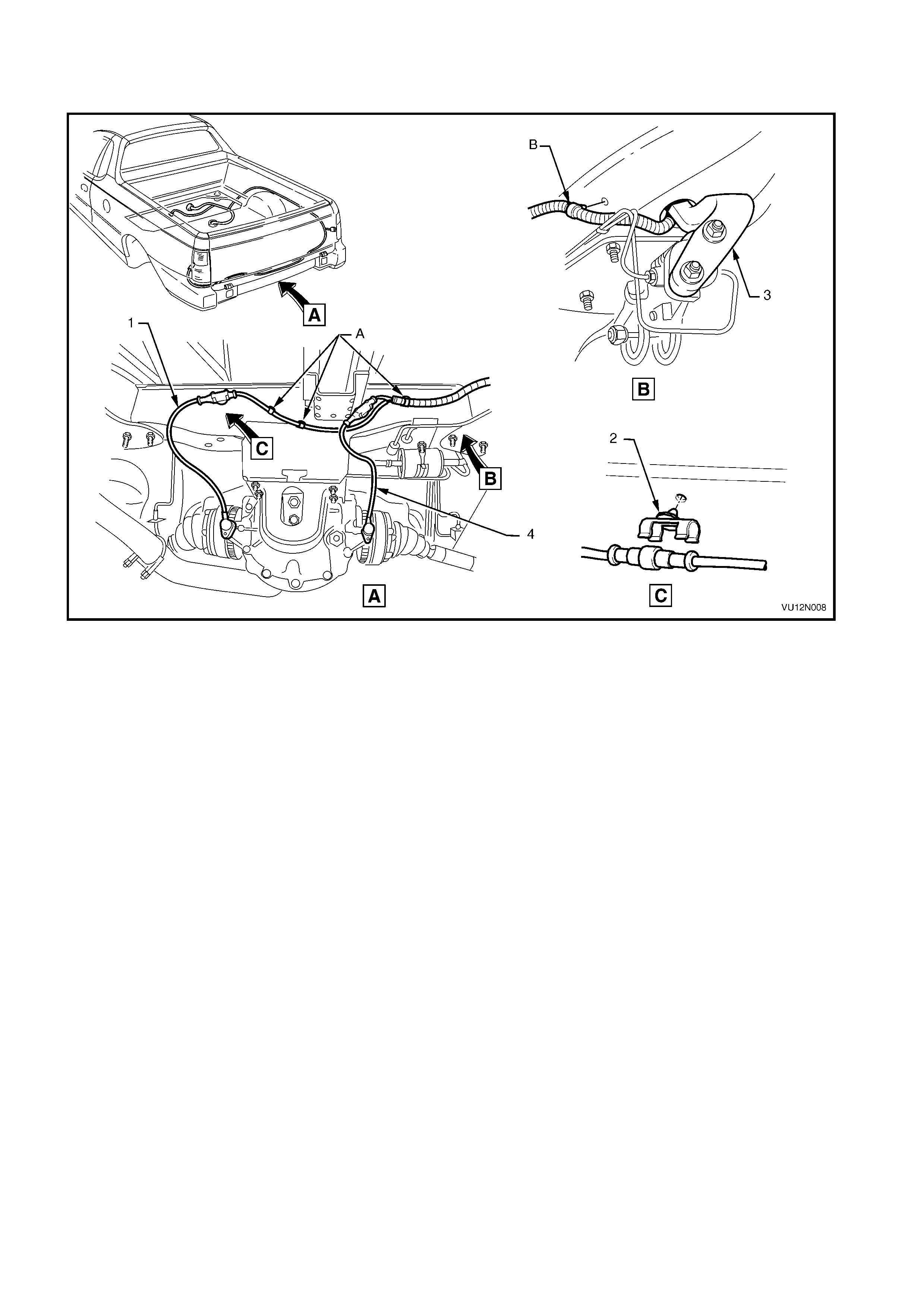
BODY WIRING HARNESS – 3
ABS
Figure 12O-153
Legend
1. Right-hand Rear ABS Speed Sensor
2. Speed Sensor Connector Cl i p (2 places)
3. Load Sensing Proporti on Valve
4. Left-hand Rear ABS Speed Sensor
A. Harness clipped to rear cross member (3 places).
B. Harness clipped to underbody (1 place).
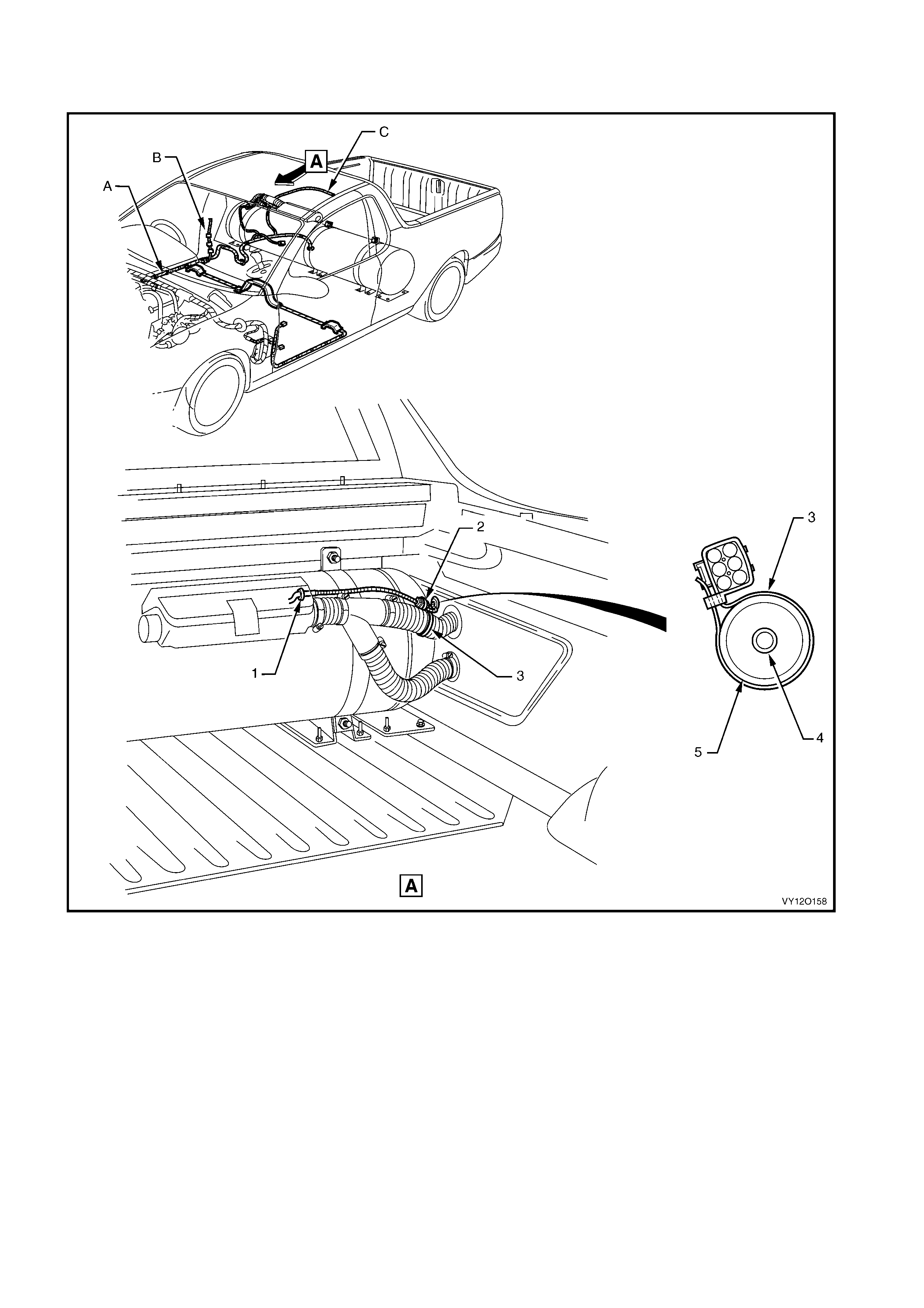
BODY WIRING HARNESS – 4
LPG
Figure 12O-154
Legend
1. LPG Control Valve Harness
2. LPG Control Valve Harness Connec tor (A55)
3. LPG Control Valve Harness Ret aining S trap
4. LPG Supply Hose
5. LPG Filler Vent Tube
A. For harness continuat i on and clipping refer t o
INTERIOR BODY WIRING HARNESS – 1 in this sec tio n .
B. For roof lamp harness conti nuation, ref er to
INTERIOR BODY WIRING HARNESS – 1 in this sec tio n .
C. For rear lamp harness continuation, refer to
BODY WI RING HARNESS – 1 in this section.
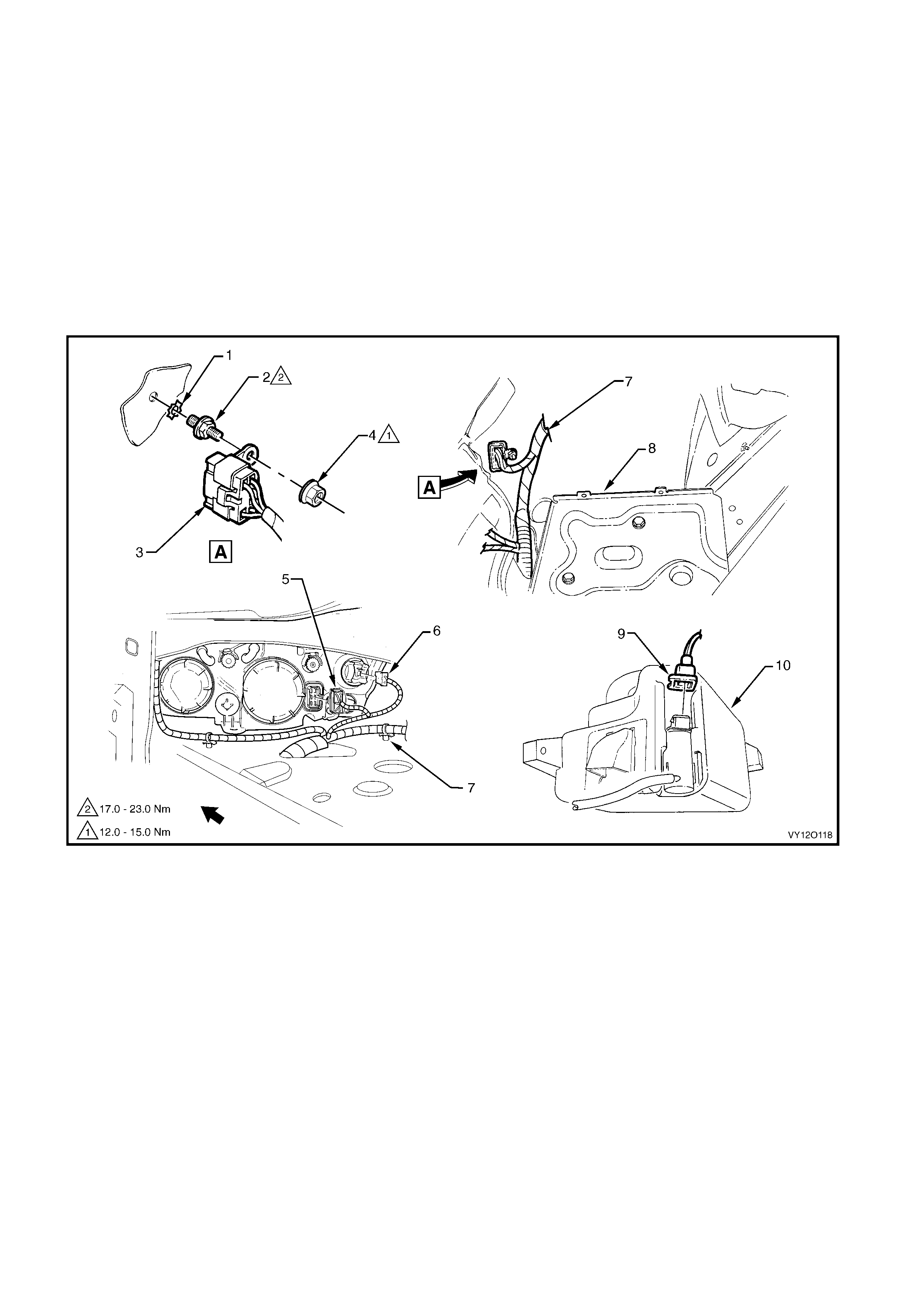
6. WIRING INSTALLATION DIAGRAMS – RIGHT-HAND DRI VE COUPE
The following figures illustrate the vehicle wiring installat ion diagrams for MY 2003 V2 series II right-hand drive
coupe.
For information relating to the wiring harness installation diagrams for the right-hand drive Coupe not provided in
this section refer to 3. WIRING INSTALLATION DIAGRAMS – RIGHT-HAND DRIVE SEDAN AND WAGON.
NOTE: Som e of the follo wing wiring i nstallation d iagrams illustrate the upp er level harnes ses which inc orporate
all necessary wiring harness connectors for all production options. Depending on equipment level and vehicle
model, some of the connectors may be taped back to the harness when a particular option is not fitted, or the
particular level of harness fitted to the vehicle may not incorporate some of the connectors illustrated.
MAIN WIRING HARNESS – 1
FRONT LAMP, BODY GROUND AND WASHER PUMP CONNECTORS
Figure 12O-155
Legend
1. Washer – Body Ground
2. Attaching Stud – Body Ground
3. Body Ground Connector (X157 – GP2)
4. Attachi ng Nut – Body Ground
5. Headlamp Connect or (E83)
6. Turn Signal Lamp Connector (E 76)
7. Main Wiring Harness
8. Battery Tray
9. Windshiel d Washer Connect or (M19)
10. Windshield Washer Reservoir
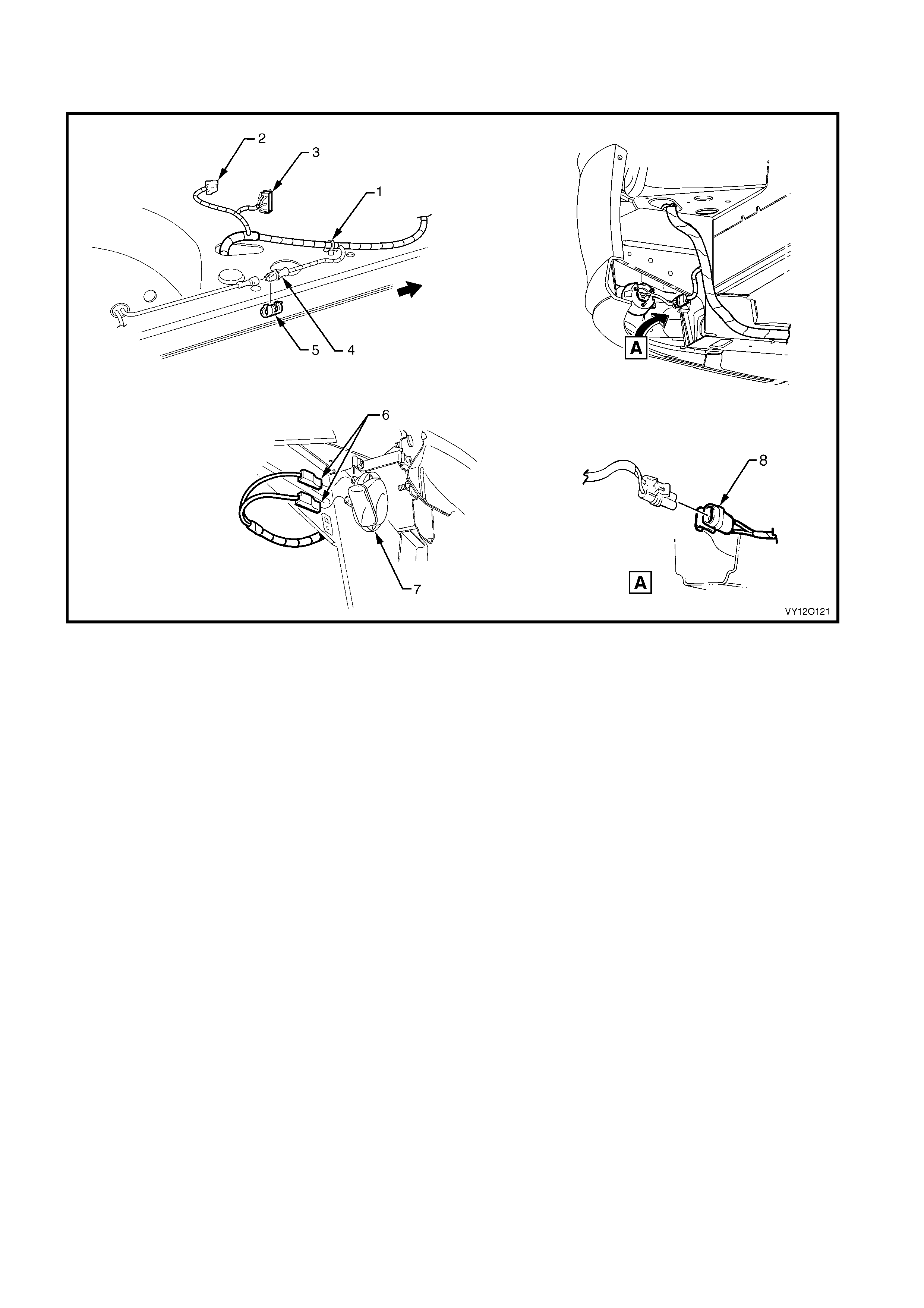
MAIN WIRING HARNESS – 2
HEADLAMP AN D HORN CONNECTORS
Figure 12O-156
Legend
1. Harness to Wheelhouse Att achi ng Clip (1 pl ace)
2. Left-hand Turn Signal Lamp Connector (E76)
3. Left-hand Headlam p Connect or (E83)
4. Left-hand Front ABS Wheel Sensor Harness Connect or (B52)
5. ABS Sensor Harness Connector Attaching Clip (2 places)
6. Horn Connector (B 9)
7. Right-hand Horn Ass embly (LH similar)
8. Fog Lamp Harness Connector (E69)
For harness continuat i on, ref er to MAI N WIRING HARNESS – 1 in
this section.
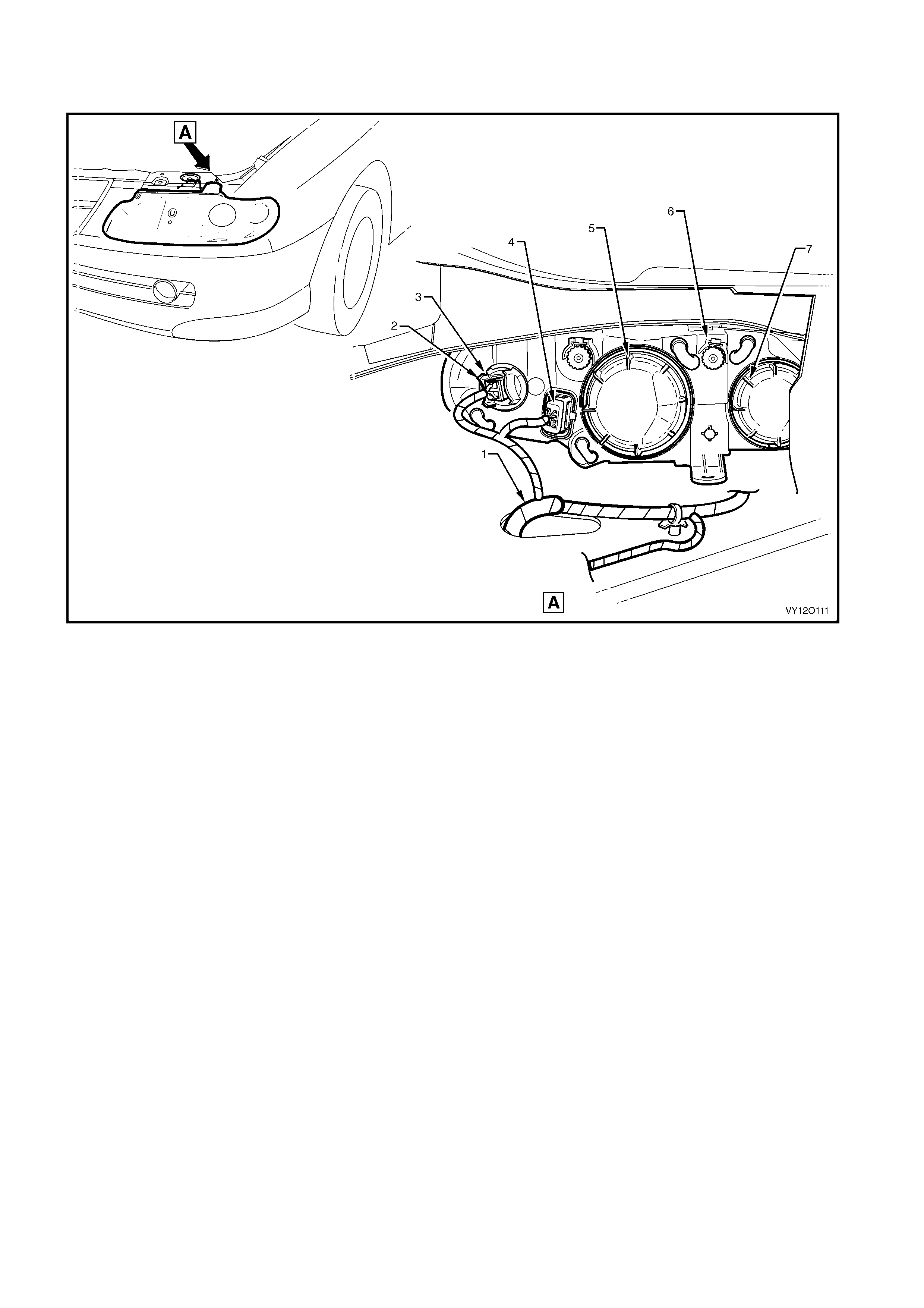
MAIN WIRING HARNESS – 3
HEADLAMPS
Figure 12O-157
Legend
1. Main Wiring Harness
2. Turn Signal Lamp Connector (E 76)
3. Turn Indicator Socket
4. Headlamp Connect or (E83)
5. Headlamp Low Beam Dust Cover
6. Headlamp Adjuster
7. Headlamp High Beam Dust Cover
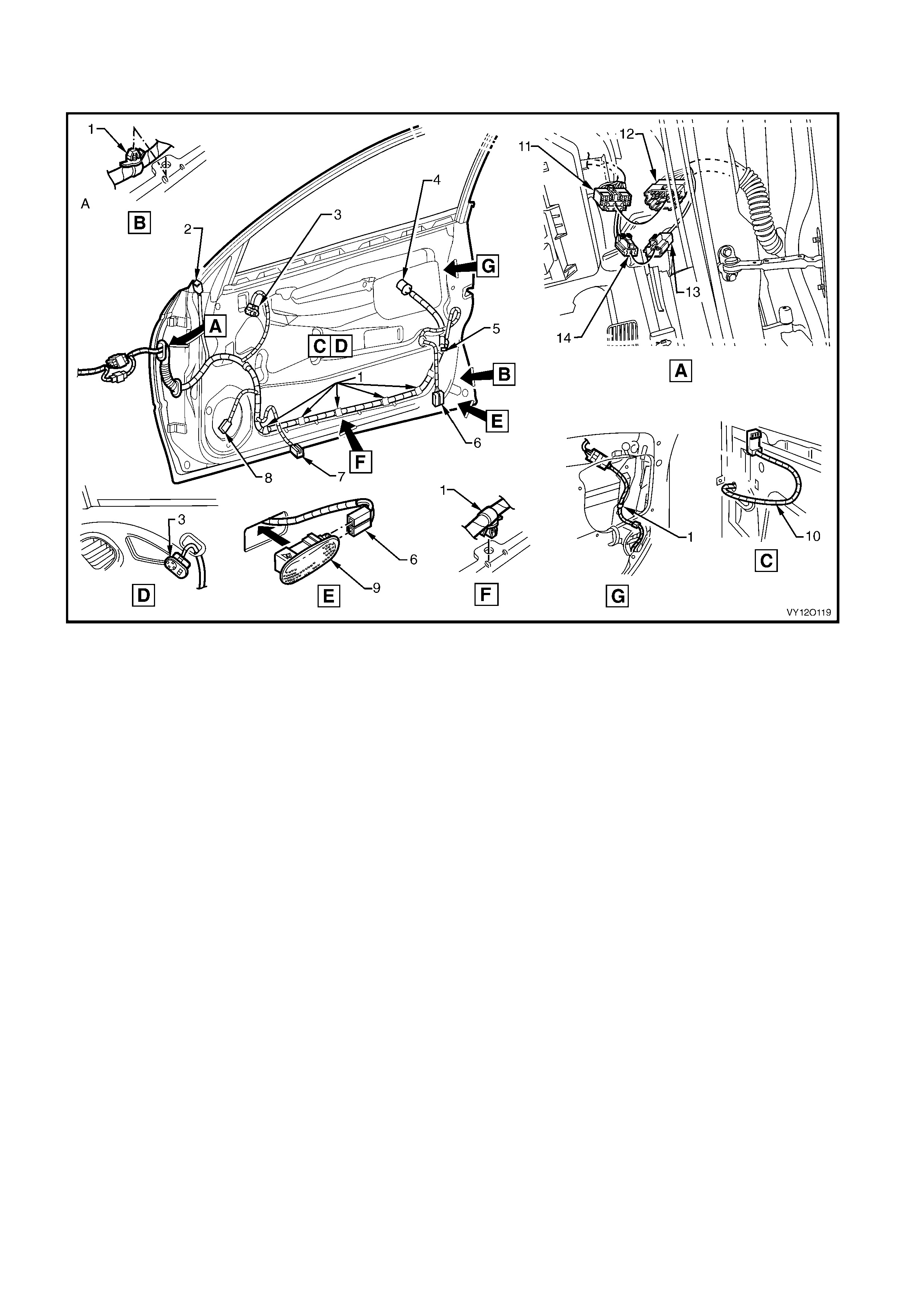
BODY WIRING HARNESS – 1
FRONT DOOR HARNESS
Figure 12O-158
Legend
1. Door Harness to Door Attaching Clip (9 pl aces )
2. Exterior Mirror Connector (M11)
3. Exterior Mirror Switch (RH only)
4. Door Lock Switch Connect or (RH only) (S63)
5. Door Lock Actuator Connector (Y13)
6. Door Courtesy Lamp Connector (E72)
7. Front Door Window Regulator Connec t or (M10)
8. Door Radio Speaker Connector (B108)
9. Door Courtesy Lamp
10. E xterior Mirror S witch Harness
11. Body Wiring Harness to Front Door Harness Connector
(X600 – Right-hand) (X500 – Left-hand)
12. Front Door Harness to Body Wiring Harness Connector
(X600 – Right-hand) (X500 – Left-hand)
13. Front Door Harness to Body Wiring Harness Connector
(X601 – Right-hand) (X501 – Left-hand)
14. Body Wiring Harness to Front Door Harness Connector
(X601 – Right-hand) (X501 – Left-hand)
A. Ensure harness is rout ed behi nd guide piece.
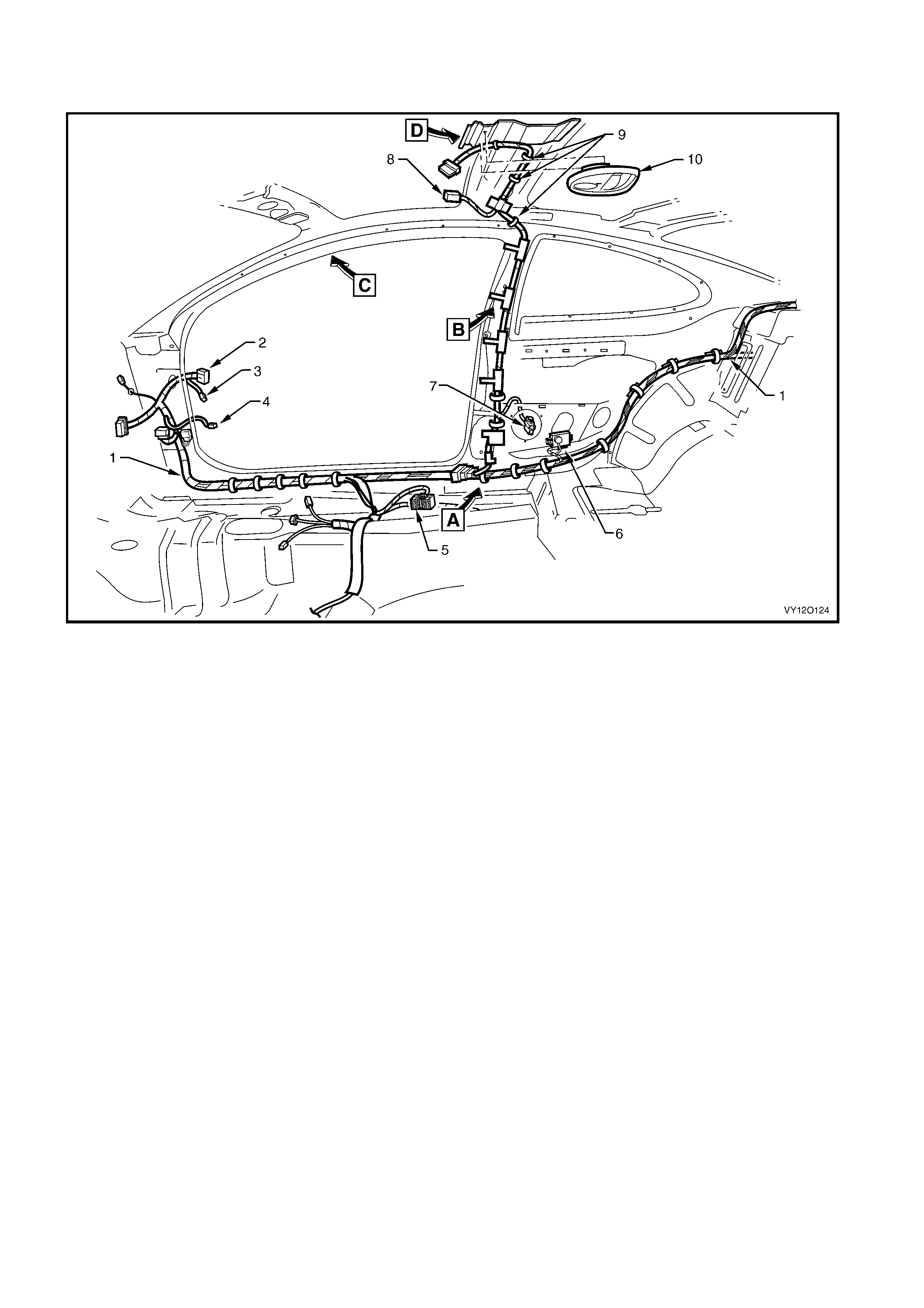
BODY WIRING HARNESS – 2
INTERIOR HARNESS – RIGHT-HAND
Figure 12O-159
Legend
1. Body Wiring Harness
2. Body Wiring Harness to Right-hand Front Door Wi ri ng
Harness Connect or (X600)
3. Body Wiring Harness to Right-hand Front Door Wi ri ng
Harness Connect or (X601)
4. Door Ajar Indicator Switch Connector (S2)
5. Body Wiring Harness to Power Seat Harness Connector
(X315)
6. Reverse Park i ng Aid Module & Speaker Assembly
7. Radio Rear Side Speaker Connector (B117)
8. Sun Shade Lamp Connector (E120)
9. Roof Lamp Harness Att achi ng Cl i ps
10. Dome Lamp
For views A, B, C & D, refer to BODY WIRING HARNE SS – 5 in this
section.
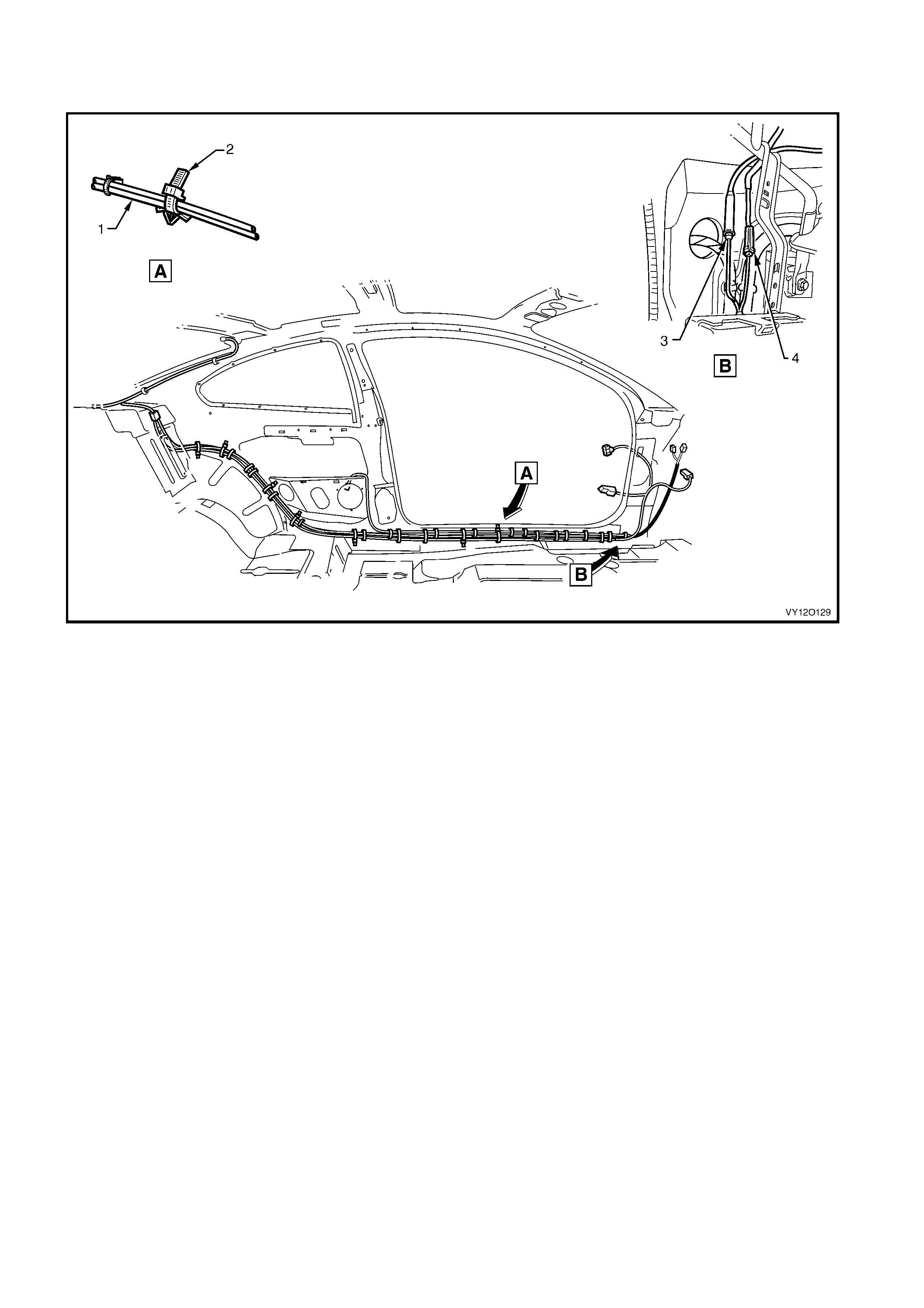
BODY WIRING HARNESS – 3
INTERIOR HARNESS – LEFT-HAND
Figure 12O-160
Legend
1. Diversit y Antenna Lead
2. Sill Attaching Clip 3. Radio Antenna Connect or (W6)
4. Radio Antenna Amplif i er Connect or (N3)
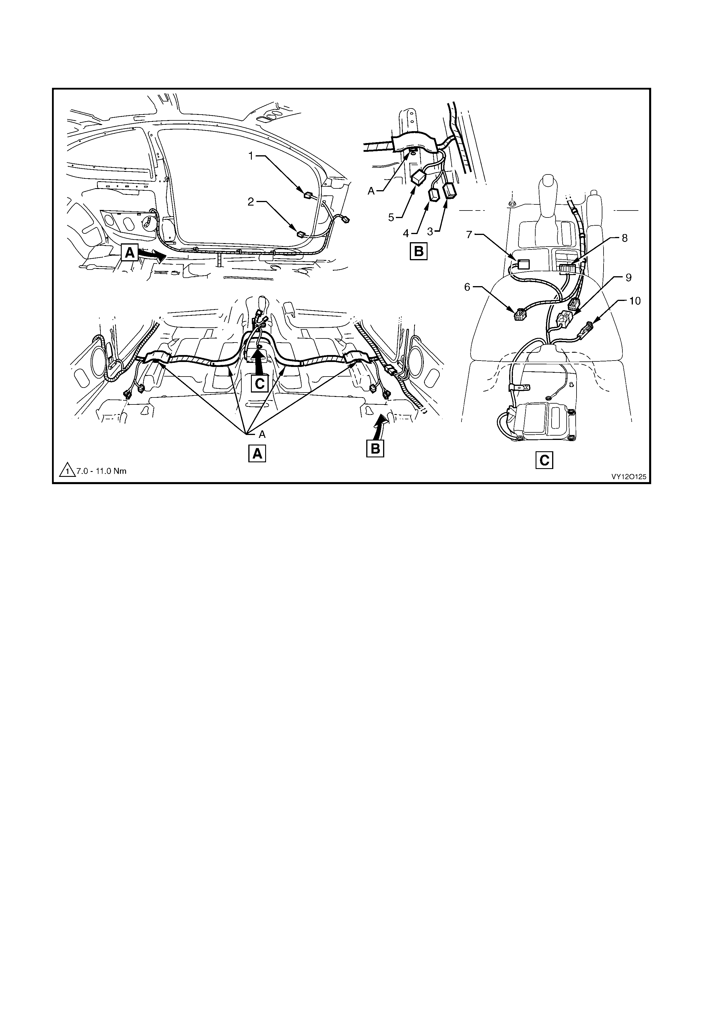
BODY WIRING HARNESS – 4
INTERIOR
Figure 12O-161
Legend
1. Body Wiring Harness to Front Door Wiring Harness
Connector (X500)
2. Door Ajar Indicator Switch Connector (S 2)
3. Seat Belt Connector (Y 128 – Driver)(Y129 – P assenger)
4. Body Wiring Harness to Side Airbag Harness Connector
(X306 – L) (X307 – R)
5. Body Wiring Harness to Power Seat Harness Connector
(X302 – Driver) (X308 – Passenger)
6. Main Wiring Harness t o Consol e Wiring Harness Connector
(X309)
7. Main Wiring Harness to Transmission Selector Harness
Connector (X301)
8. Side Window (Master) Switch Connector (S222)
9. Body Wiring Harness to Main Wi ring Harnes s Connector
(X303)
10. Park Brake Switch Connector (S181)
A. Harness clipped to underbody as shown (4 places).
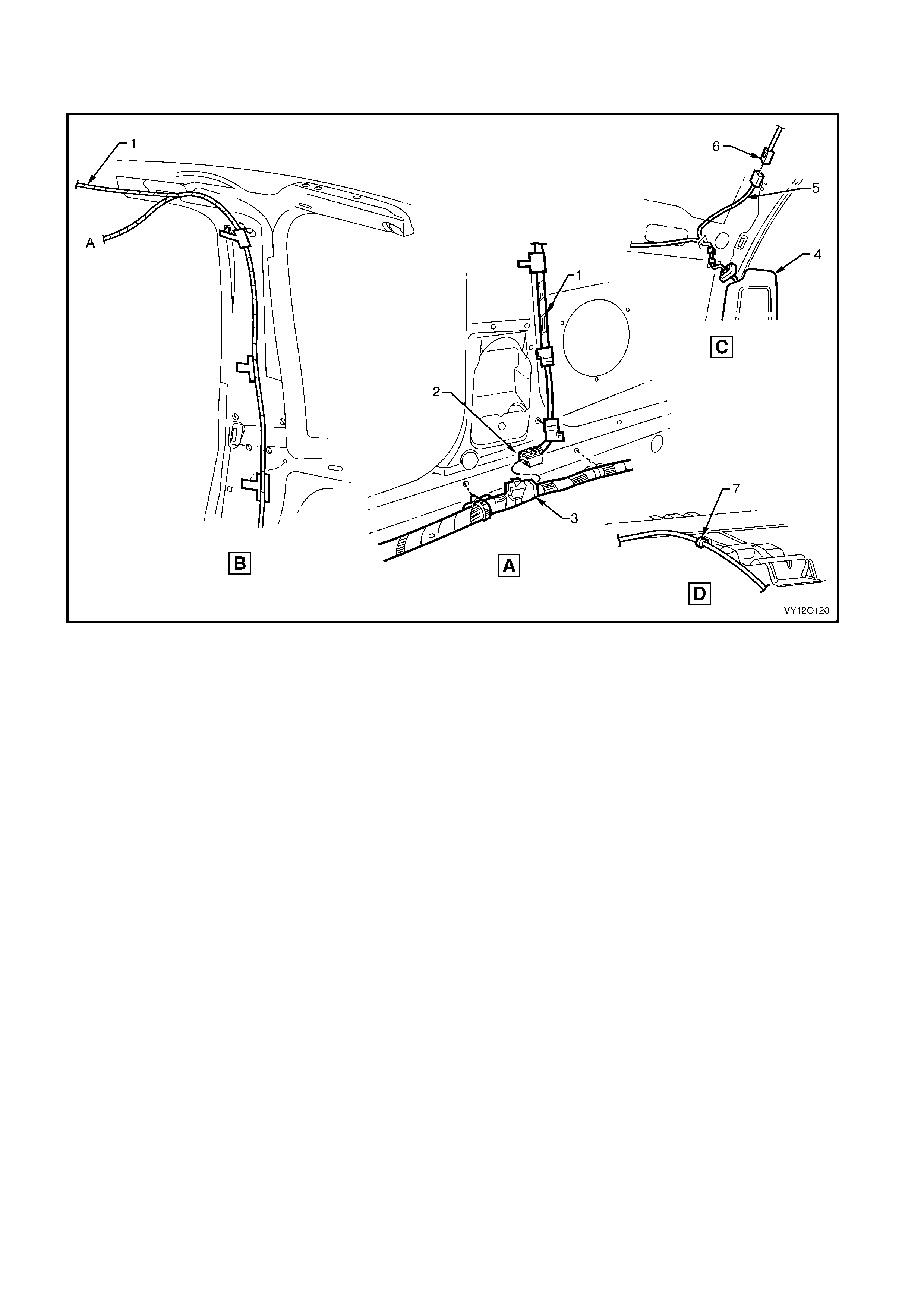
BODY WIRING HARNESS – 5
INTERIOR HARNESS - ROOF
Figure 12O-162
Legend
1. Roof Lamp Harness
2. Roof Lamp Harness to Body Wiri ng Harness Connector
(X300)
3. Body Wiring Harness
4. Sun Shade
5. Visor Lamp Harness
6. Sun Shade Lamp Connector (E120)
7. Visor Lamp Harness Clip
A. To dome lamp.
For location of views A, B, C, & D, refer to
BODY WI RING HARNESS – 2 in this section.

BODY WIRING HARNESS – 6
INTERIOR HARNESS - FRONT
Figure 12O-163
Legend
1. Body Wiring Harness
2. Front Side Turn Lamp Connector (E75)
3. Body Wiring Harness to Main Wi ring Harness Connector
(X201)
4. Body Control Module Connect or (A15 – X4)
5. Radio Power Antenna Connector (W6 – X1)
6. Front Side Turn Lamp Connector (E75)
7. Body Wiring Harness to Right-hand Front Door Wi ri ng
Harness Connect or (X600)
8. Body Wiring Harness to Main Wi ring Harness Connector
(X200)
9. Seat Belt Connector (Y 128 – Driver, Y129 – Passenger)
10. Body Wiring Harness to Side Airbag Harness Connector
(X306 – LH, X307 – RH)
A. Attach body wiring harness to shroud side panel (2 places).
B. Body wring harness attached to underbody as shown
(9 places).
C. Right-hand side shown.
D. Main wiring harness connector clipped to shroud side panel as
shown.
E. Front of vehicle.
F. For continuation, refer to BODY WIRI NG HARNE SS – 7 in this
section.
G. Left-hand side shown.
H. Body wiring harness att ached t o underbody as shown
(6 places).
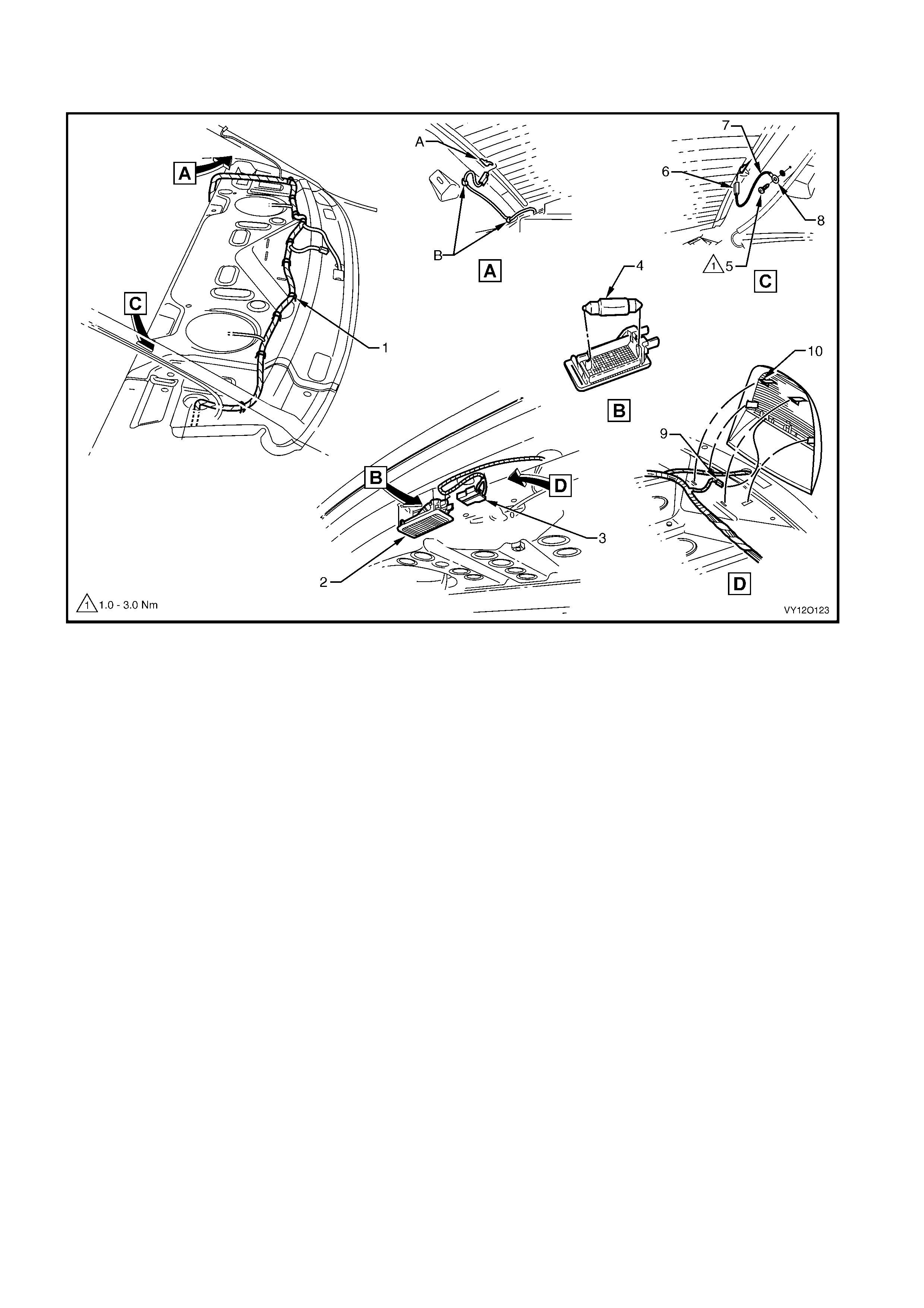
BODY WIRING HARNESS – 7
INTERIOR HARNESS - REAR
Figure 12O-164
Legend
1. Body Wiring Harness
2. Rear Compartment Courtesy Lamp
3. Rear Compartment Courtesy Lamp Connectors (E36)
4. Rear Compartment Lamp Bulb
5. Ground Lead Terminal Attaching Screw
6. Rear Window Defog Grid Connector (R22 – X2)
7. Rear Window Defog Grid Ground Lead
8. Ground Lead Terminal (X118 – GP7)
9. High Mounted Stop Lamp Connector (E79 – C)
10. High Mounted Stop Lamp
A. Tab bent once lead connector is installed.
B. Clip defog grid to side inner panel.
For harness continuat i on, ref er to BODY W IRING HARNESS – 2 in
this section.
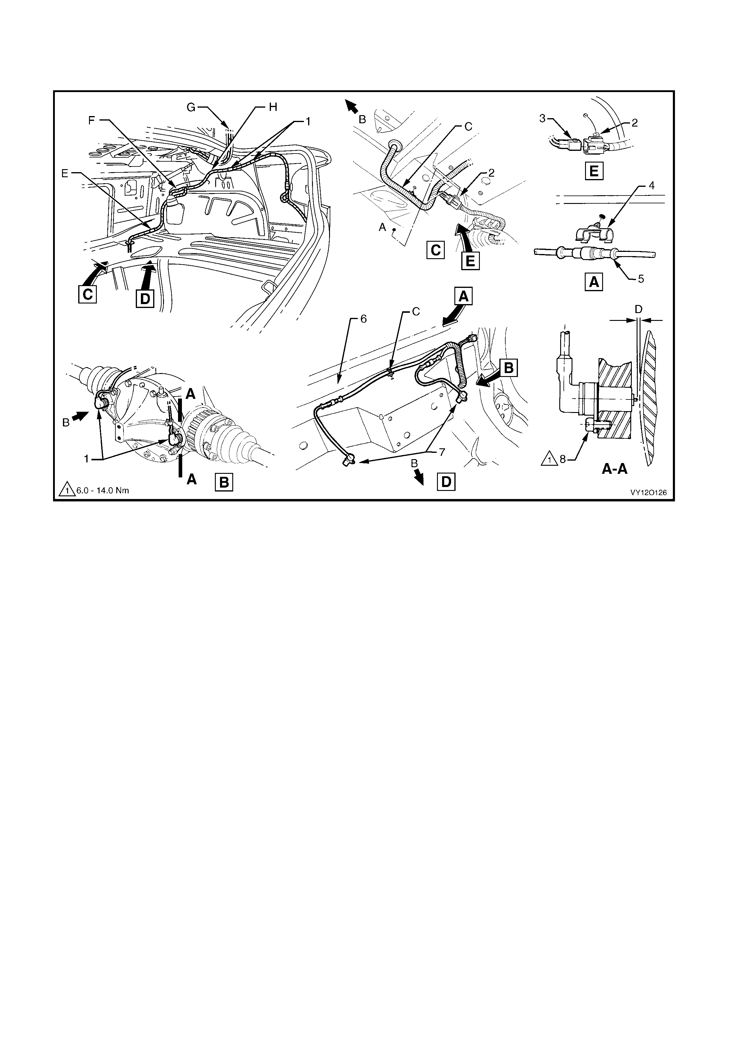
BODY WIRING HARNESS – 8
REAR COMPARTMENT HARNESS – ABS SENSORS AND FUEL TANK
Figure 12O-165
Legend
1. Differential Assembly with Rear Speed Sensors Installed
2. Fuel Tank Harness to Body Wiring Harness Connect or
(X402)
3. Body Wiring Harness to Fuel Tank Harness Connector
(X402)
4. Rear Wheel Speed Sensor Connector Retainer
5. Rear Wheel Speed Sensor Connector (B76)
6. Rear Axle Cross Member
7. Sensor Assembly Rear Wheel Speed
8. Attachi ng Screw Sensor Assembl y Rear Wheel Speed
A. Harness connector cl i ped to rear longitudi nal extens i on panel .
B. Front of vehicle.
C. Body wiring harness cl i pped to rear axle cross member
(2 places).
D. Shims used to achieve required clearanc e between tip of wheel
speed sensor and pulse ring of 0.3 to 1.1 mm.
E. Body wiring harness cli pped to lo wer wheelhouse brace – right
-hand side.
F. For continuation, refer to BODY WIRI NG HARNE SS – 2 in this
section.
G. For continuation, refer to BODY WIRING HARNESS – 10 in this
section.
H. Body wiring harness clipped to side inner panel.
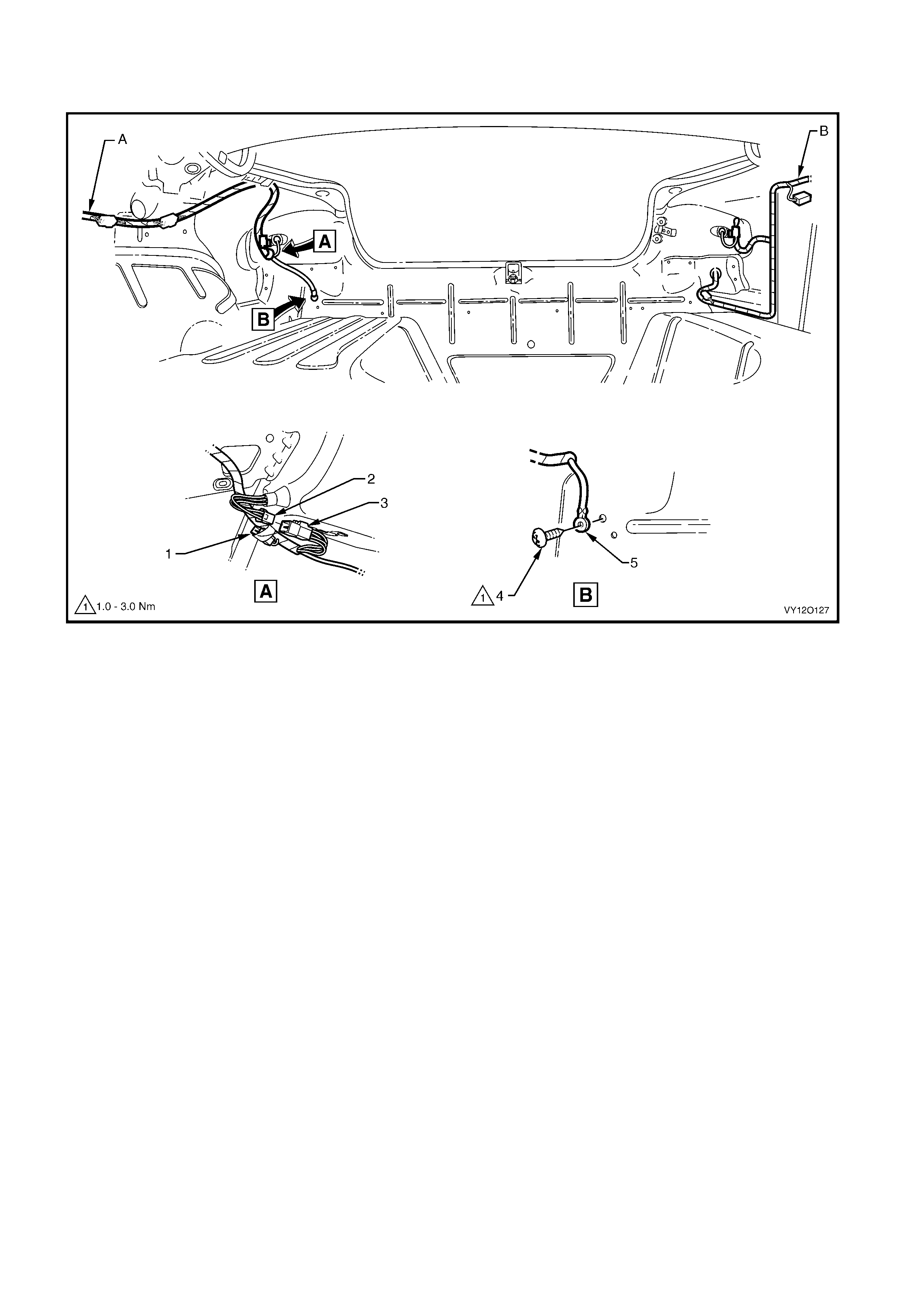
BODY WIRING HARNESS – 9
REAR COMPARTMENT HARNESS – REAR LAMPS
Figure 12O-166
Legend
1. Body Wiring Harness to Trailer Harnes s Connector (X908)
2. Tail Lamp Harness Connector to Body Wiring Harness
Connector (X903 – R)
3. Body Wiring Harness to Tail Lamp Harness Connector
(X903 – R)
4. Body Ground Attaching Screw
5. Body Wiring Harness Ground Tail Lamp Terminal
(X118 – GP13)
A. For continuation, refer to BODY WIRI NG HARNE SS – 8 in this
section.
B. For continuation, refer to BODY WIRING HARNE SS – 12 in this
section.
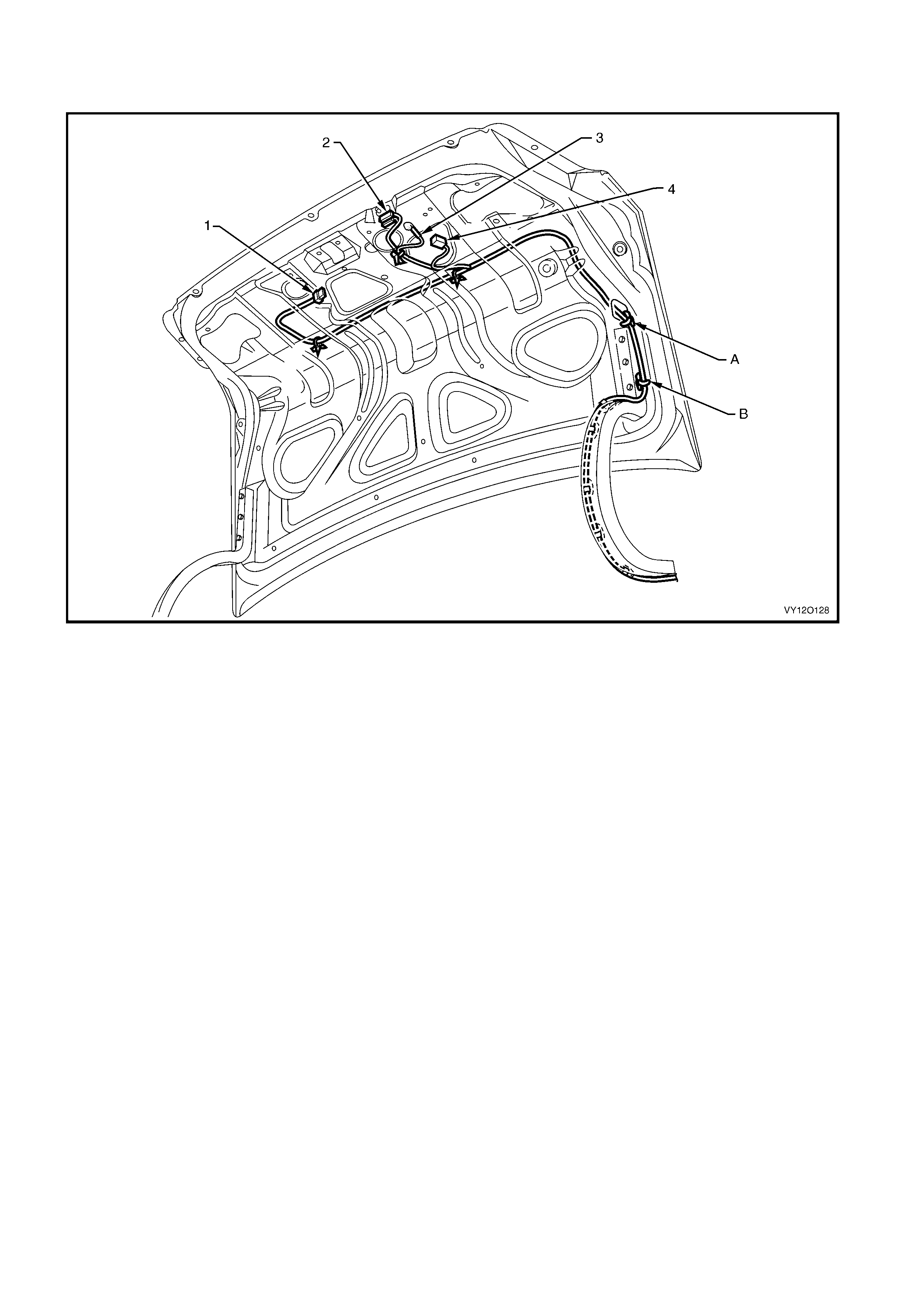
BODY WIRING HARNESS – 10
REAR COMPARTMENT LID WIRING
Figure 12O-167
Legend
1. Rear Licence Plate Lam p Connector (E44)
2. Rear Compartment Courtesy Lamp Switch Connectors (S189)
3. Body Wiring Harness Ground Rear Compartment Lid
Terminal (X118 – GP14)
4. Rear Compartment Lid Latc h Actuator Connec tor (Y29)
A. Body wiring harness cli pped to rear compartm ent li d inner
(5 places).
B. Body wiring harness cli pped to rear compartment li d hinge
(6 places).
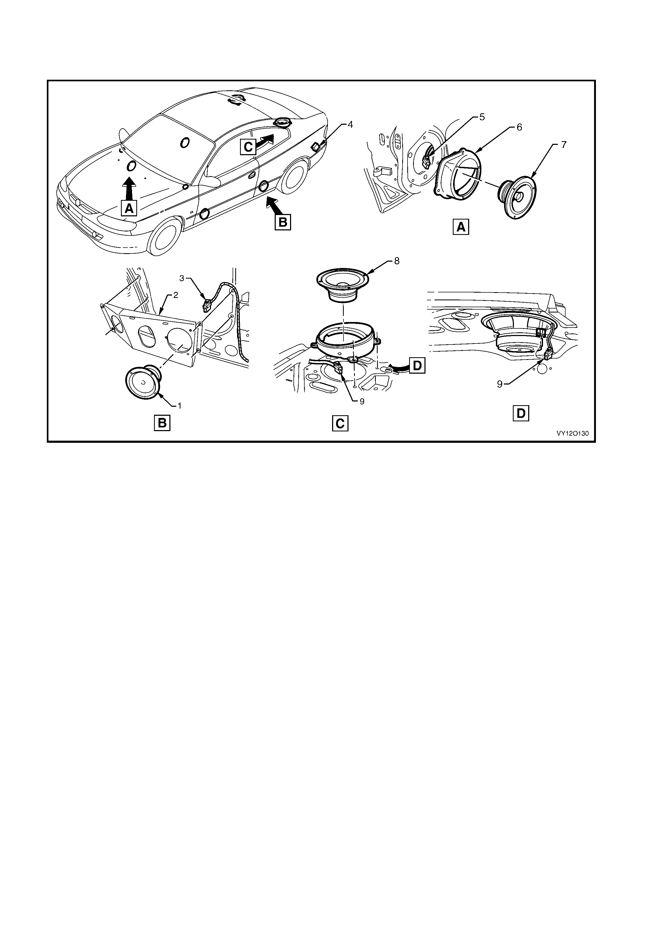
BODY WIRING HARNESS – 11
AUDIO SYSTEM
Figure 12O-168
Legend
1. Rear Quarter Trim Radio Speaker
2. Left-hand Rear Quarter Trim Radio Speak er Mounting
Bracket
3. Radio Right-hand and Left-hand Rear Quart er Trim S peaker
Connector (B 117)
4. Rear Speaker Amplifier
5. Radio Right-hand and Left-hand Door S peaker Connector
(B117)
6. Front Door Radio Speaker Mounting Box
7. Front Door Radio Speaker
8. Rear Shelf Radio Speaker
9. Rear Shelf Radi o Speaker Connector (B131)
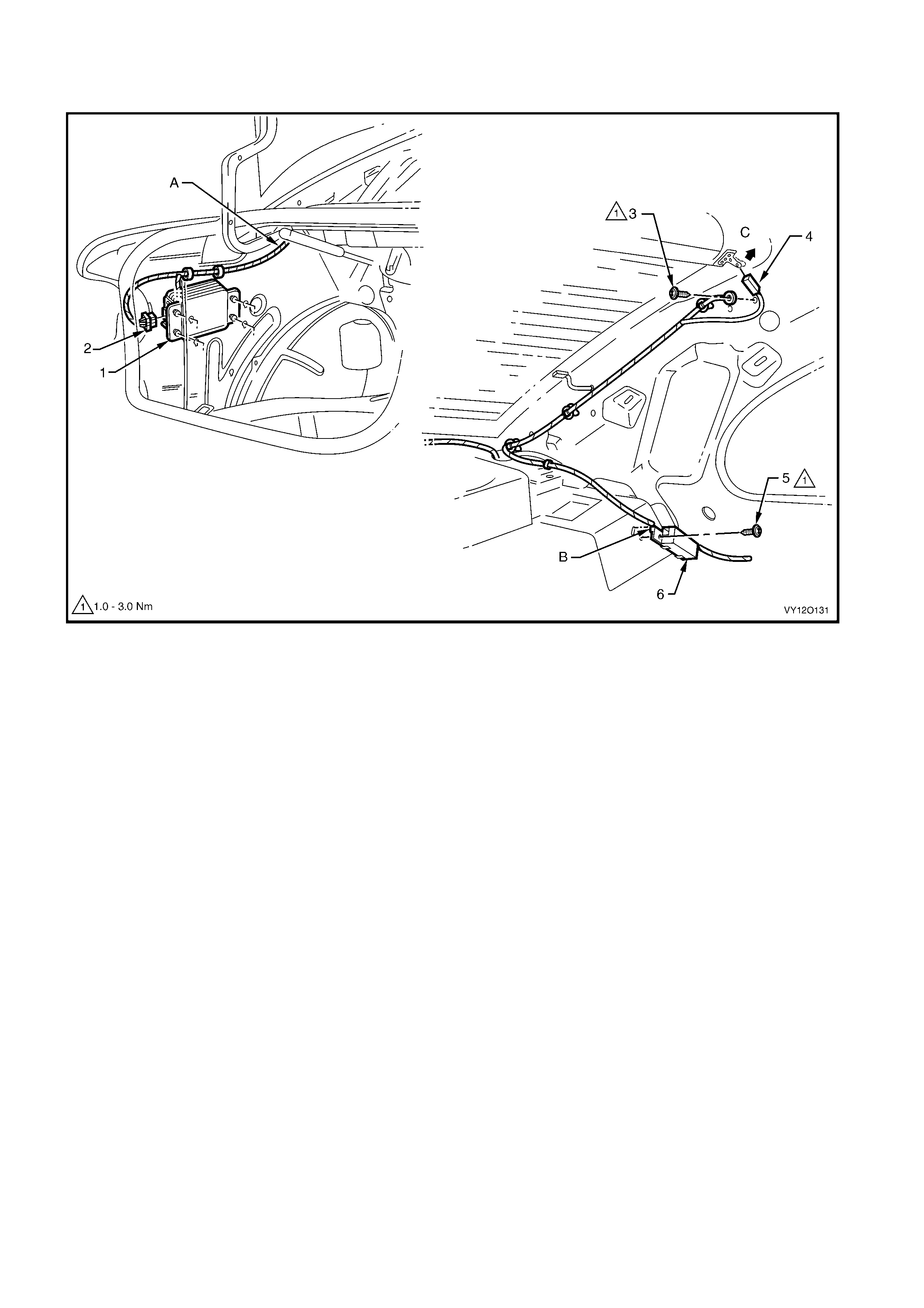
BODY WIRING HARNESS – 12
DIVERSITY ANTENN A
Figure 12O-169
Legend
1. Rear Speaker Amplifier Assembly
2. Radio Rear Speaker Amplif i er Connect or (N6)
3. Diversit y Antenna Ground Lead Attaching Screw
4. Radio Diversi t y Ant enna Connector (W4)
5. Diversity Antenna Amplifier Attaching Screw
6. Diversity Antenna Amplifier Assembly
A. For harness continuat i on, ref er to
BODY WI RING HARNESS – 9 in this section.
B. Locate tab in slot prior to installing screw.
C. Bend tab in directio n shown after connect or i nst allation.
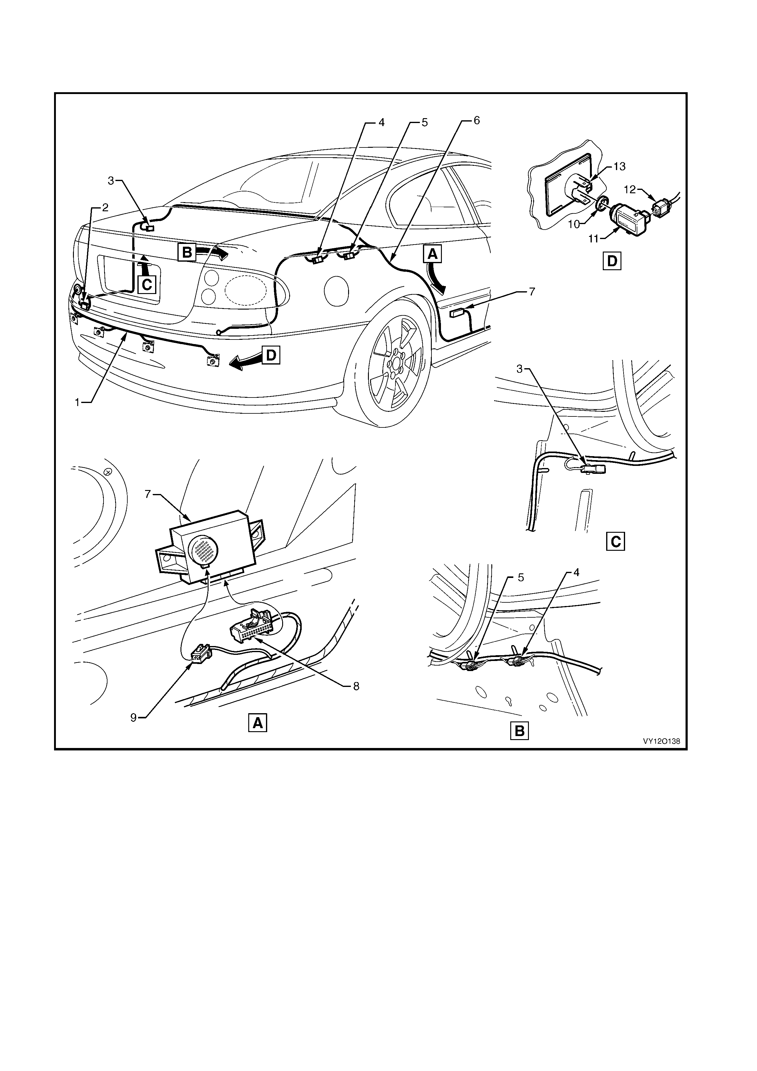
BODY & ROOF WIRING HA RNESSES
REVERSE PARKING AID
Figure 12O-170
Legend
1. Reverse Park i ng Aid Harness
2. Body Wiring Harness to Reverse Parking Aid Harness Connector
(X905)
3. Inline to Rear Object Sensor Harnes s Connector (X156)
4. Body Wiring Harness to Body Wiring Harnes s Trai l er A Connect or
(X907)
5. Body Wiring Harness to Body Wiring Harnes s t o w Hook A
Connector (X906)
6. Body Wiring Harness
7. Rear Object Sensor Control Module
8. Rear Object Sensor Control Connec t or (A98)
9. Rear Object Sensor Alarm Connect or (H31)
10. Rear Object Sensor Ring
11. Rear Object Sensor Assembly
12. Rear Object Sensor Connector (B133)
13. Rear Object Sensor Housing

NAVIG ATION SY ST EM ASSEM BLY AND WIRING – 1
Figure 12O-171
Legend
1. Speaker Assembly
2. Global Positioning System Harness
3. Display Assembly
4. Driver Informatio n Displ a y Connector (P6)
5. Driver Information Dis pl ay Control Connect or (A35)
6. Remote Control Cradle
7. Navigat i on S peaker Assembly Connector (B104)
8. Global P ositi oni ng Sys t em Harness Connectors (XO2)
9. Global P ositi oni ng Sys t em Harness Connectors (XO1)
10. Global Positioning System Harness to Main Wiring Harness
Connector (X207)
11. Main Wiring Harness t o Global Positioning S yst em Harness
Connector (X207)
A. Harness attached t o passenger side airbag s upport rail
assembly as shown.
For views D, H & J, refer to
NAVIGATION SYSTEM ASSEMBLY & WIRING – 2 in this section.
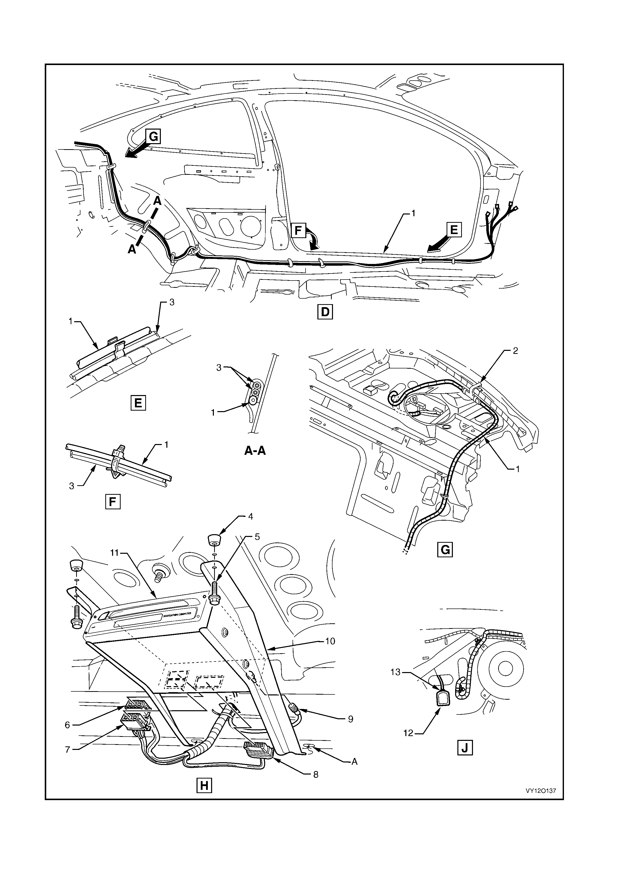
NAVIG ATION SY ST EM ASSEM BLY AND WIRING – 2
Figure 12O-172

Legend
1. Global Positioning System Harness
2. Global Positioni ng System Harness Vehicle Attachi ng Clip
3. Diversit y Antenna Lead
4. Processor Assembly Mounting Points
5. Processor Assembly Mounting Screws
6. Navigation Cont rol Proc essor Connector (A139 – X2)
7. Navigation Cont rol Proc essor Connector (A139 – X1)
8. Navigation Cont rol Proc essor Connector (A139 – X3)
9. Navigation Cont rol Proc essor Connector (A139 – X4)
10. Processor Assembly Mounting Brackets
11. Navigation Control Processor Assembly
12. Antenna
13. Antenna Connector (W2 – GPS – 2)
A. Process or assembl y brack et mounti ng hol es.
For location of views D, H & J, refer to
NAVIGATION SYSTEM ASSEMBLY & WIRING – 1 in this section.
