
SECTION 2A - HVA C CLIMATE CONT ROL
(MANUAL A/C) – DESCRIPTION AND OPERATION
IMPORTANT
Before performing any Service Operation or other procedure described in this Section, refer to Section 00
CAUTIONS AND NOTES for correct workshop practices with regard to safety and/or property damage.
CONTENTS
1. GENERAL INFORMATION
2. GENERAL DESCRIPTION
2.1 HVAC INLET, DUCTS AND OUTLETS
INLET
DUCTS
CABIN VENTILATION OUTLETS
BODY VENTILATION OUTLETS
2.2 MANUAL HVAC CONTROLLER
MANUAL CONTROLLER CONFIGURATIONS
MANUAL CONTROLLER FUNCTIONS
MANUAL MODE CONTROL SYMBOLS
MANUAL CONTROLLER COMPONENTS
AND CONSTRUCTION
MANUAL CONTROLLER ELECTRICAL
CONNECTIONS
2.3 HEATER
TEMPERATURE SWITCH
AIR MIX DOOR CONTROL MECHANISM
WATER VALVE
HEATER OPERATION
UNDER-HOOD HEATER COMPONENTS
AND COOLANT CIRCULATION
2.4 AIR CONDITIONING REFRIGERANT
CIRCUIT
2.5 HEATING, VENTILATION AND AIR
CONDITIONING (HVAC) UNIT
HVAC UNIT – LHD
HVAC UNIT – RHD
HVAC AIR MIX DOORS
VACUUM TANK
VACUUM TANK ONE WAY
CHECK VALVE
EVAPORATOR
HEATER CORE
BLOWER MOTOR AND FAN ASSEMBLY
BLOWER MOTOR RESISTOR
VACUUM ACTUATORS
2.6 HVAC UNIT AIRFLOW MODES
RECIRCULATION MODE – LHD
FACE MODE – LHD
BI-LEVEL MODE – LHD
FLOOR MODE – LHD
BLEND MODE – LHD
DEMIST MODE – LHD
DEFAULT MODE – LHD
RECIRCULATION MODE – RHD
FACE MODE – RHD
BI-LEVEL MODE – RHD
FLOOR MODE – RHD
BLEND MODE – RHD
DEMIST MODE – RHD
DEFAULT MODE – RHD
2.7 VACUUM CIRCUITS
VACUUM CIRCUIT SCHEMATIC – LHD
VACUUM CIRCUIT SCHEMATIC – RHD
2.8 UNDER-HOOD COMPONENTS
RADIATOR ASSEMBLY
CONDENSER
FILTER DRIER RECEIVER
A/C PRESSURE TRANSDUCER
THERMAL EXPANSION VALVE (TXV)
DELPHI V5 AND V7 COMPRESSOR
COMPRESSOR OPERATION
UNDER-HOOD A/C COMPONENTS:
V6 – LHD
UNDER-HOOD A/C COMPONENTS:
V6 – RHD
UNDER-HOOD A/C COMPONENTS:
GEN III V8 – LHD
UNDER-HOOD A/C COMPONENTS:
GEN III V8 – RHD
2.9 COOLING FANS
SYSTEM OVERVIEW
COOLING FAN ASSEMBLY
FAN MOTORS
FAN OPERATION: STANDARD COOLING
FAN SYSTEM – V6 (STAGE 1)
FAN OPERATION: STANDARD COOLING
FAN SYSTEM – V6 (STAGE 2)
FAN OPERATION: HIGH POWER COOLING
FAN SYSTEM – V6 (STAGE 1)
FAN OPERATION: HIGH POWER COOLING
FAN SYSTEM – V6 (STAGE 2)
FAN OPERATION: COOLING FAN
SYSTEM – GEN III V8 (STAGE 1)
FAN OPERATION: COOLING FAN
SYSTEM – GEN III V8 (STAGE 2)
3. SPECIFICATIONS
Techline
Techline

1. GENERAL INFORMAT ION
Two levels of air conditioning are fitted to the MY2003 VY and V2 Series vehicles and are described as follows:
• HVAC Climate Control (Manual A/C): This system uses a ‘rotary dial’ type controller to select the desired
operatin g modes and tem perature. It will be gen erally ref erred to as ‘manual’ a ir conditionin g in this Sectio n as
well as these following Sections:
Section 2B HVAC CLIMATE CONTROL (MANUAL A/C) – REMOVAL AND INSTALLATION
Section 2C HVAC CLIMATE CONTROL (MANUAL A/C) – SERVICING AND DIAGNOSIS
• HVAC Occupant Climate Control (Auto A/C): This system uses an elec tronic ‘pus h button’ type c ontroller to
select th e desired o peratin g modes and temperatur e. It will b e genera lly referr ed to as ‘auto ’ air cond itioning or
Occupant Climate Control (OCC).
For information relating specifically to the HVAC Occupant Climate Control ( Auto A/C) system refer to:
Section 2D HVAC OCCUPANT CLIMATE CONTROL (AUTO A/C) – DESCRIPTION AND OPERATION
Section 2E HVAC OCCUPANT CLIMATE CONTROL (AUTO A/C) – REMOVAL AND INSTALLATION
Section 2F HVAC OCCUPANT CLIMATE CONTROL (AUTO A/C) – DIAGNOSTICS
• For information relating to the HVAC Occupant Climate Control (Auto A/C) system not covered in Section
2D, 2E and 2F, refer to this Section as well as these following Sections:
Section 2B HVAC CLIMATE CONTROL (MANUAL A/C) – REMOVAL AND INSTALLATION
Section 2C HVAC CLIMATE CONTROL (MANUAL A/C) – SERVICING AND DIAGNOSIS
2. GENERAL DESCRIPTION
For the MY2003 VY and V2 Series, an integr ated air conditionin g sys tem is optiona l on RHD low-level m odels and
standard on mid-level m odels. This integrated s ystem combines bot h the heating and coo ling functions in a single
unit. The vehicle’s interior can be heated, cooled or vented (or a combination of these operations) depending on the
modes and switches activated on the HVAC controller. The controller is mounted below centre ventilation outlets,
behind the centr e ins trument beze l.
Air enters the heating , ventilation and air conditioning system (HVAC) from under the plenum chamber cover. The
air then passes through the blower motor/fan, evaporator and heater assemblies, to be cooled or heated as
required. Air leaves the HVAC unit and enters the vehicle interior through the centre, side, floor or demist outlets.
The cabin outlets through which the air is emitted is dependent upon the mode selected via the mode control.
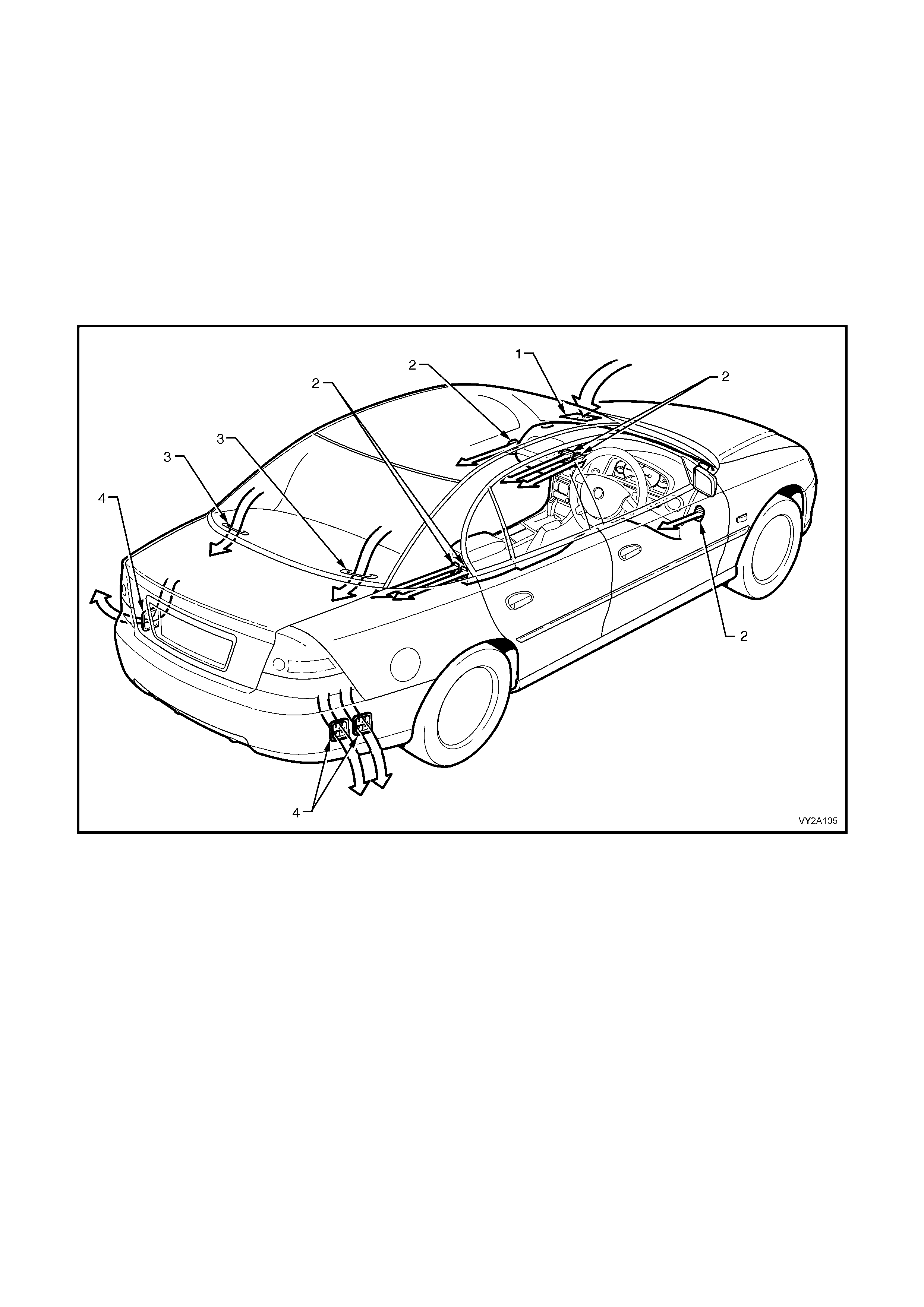
When the cabin is sealed, i.e. all movable windows are fully up, air exits the vehicle through three body mounted air
outlets located at the rear of the vehicle behind the rear bumper bar fascia. On utility models, the air outlets are
located on the floor panel extension behind the seat.
Figure 2A-1
Legend
1. HVAC Plenum Inlet 3. Parcel Shelf HVAC Grille
2. HVAC Cabin Air Outlet 4. HVAC Body Air Outlet

The blower fan is mounted within the HVAC unit and draws air from the plenum chamber forcing through the
evaporat or and h eater cas e as sem bly. Air is the n dire cted out thro ugh the v ario us outlets into th e vehic le in terior at
one of four speeds as selected on the fan switch.
The centre and side ventilation outlets can be turned on or off and are directionally adjustable. Turning off these
outlets will increase airflow to the rear outlets once suitable comfort levels are achieved by front occupants. The
rear outlets can also be turned on or off and are directionally adjustable.
The A/C s ystem is s witche d off or on by the A/ C switc h loc ated in the b lower f an switc h on the left- hand s ide of the
controller. A blower fan speed must be selected before the A/C system will function.
Outside air is used in all mode positions except when recirculate is selected. This mode can be selected via the
mode c ontrol switch and is us ed to close off the ve hicle inter ior from any outside air. When the recirculati on mode
is selected, air will flow from the centre and side ventilation outlets which are generally referred to as Face vents.
Recirculation mode is normally selected for:
• Quicker cooling down of the veh ic le interior es peci al l y af ter the veh ic le h as been park ed in dir ec t s unlight for an
extended period of time.
• Reducing heat up time as no cooler outside air can flow into the vehicle interior.
• Driving on unsealed roads to prevent dust entering the vehicle interior.
CAUTION: DO NOT drive a vehicle for extended periods in the recirculation mode as the lack of fresh air
into the vehicle will cause drowsiness and possibly impair driving performance.
While the functionality and performance characteristics of the HVAC system are common to LHD and RHD
vehicles, the LHD and RHD HVAC units and some of their associated components differ significantly in terms of
configuration and construction. Those differences are detailed in this Section as part of the overall description of
the HVAC system.
2.1 HVAC INLET, DUCTING AND OUTLETS
INLET
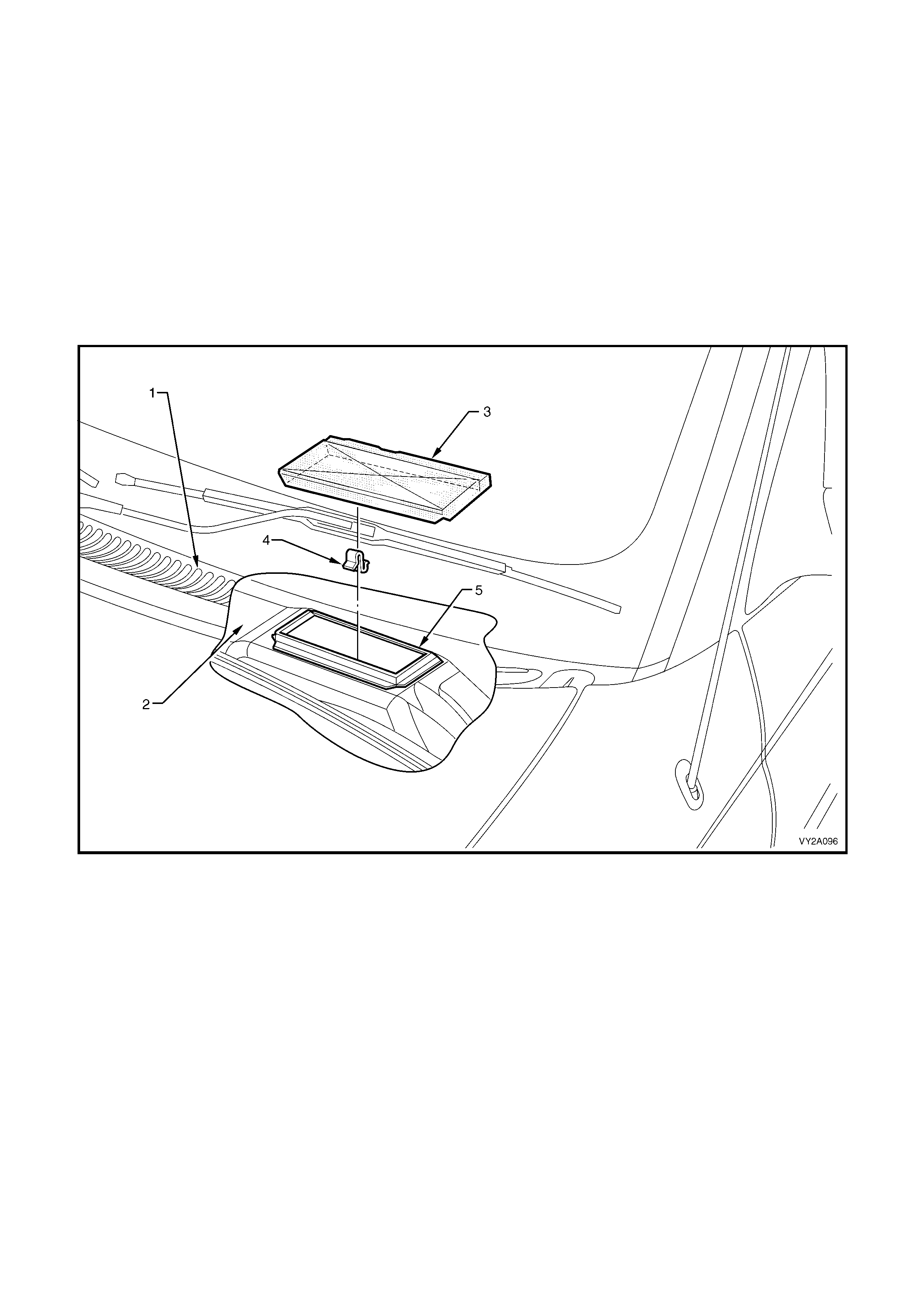
Air enters the vehicle at the plenum chamber located at the base of the windscreen under the plenum cover. The
rectangular HVAC inlet is located on a raised level within the plenum chamber. It is situated on the RHS on left-
hand drive vehicles and on the LHS on right-hand drive vehicles. To prevent the entry of foreign matter such as
leaves or twigs entering the HVAC unit, a rectangular piece of stainless steel mesh is installed around the inner
perimeter of the inlet. Although not a regular maintenance item, this mesh screen can be removed to clear away
any foreign matter that may have accumulated at the HVAC inlet.
Figure 2A-2 shows the HVAC inlet and associated components as applicable to right-hand drive vehicles. The
HVAC inlet on left-hand drive vehicles has identical components and dimensions but is located on the opposite side
of the plenum chamber.
Figure 2A-2
Legend
1. Plenum Cover 4. Mesh Screen Retaining Clip
2. Plenum Chamber 5. HVAC Inlet
3. Mesh Screen
DUCTS
Air that is directed to the sides and rear of the cabin is channelled through plastic ducts attached to the sides and
front of the HVAC case. Air leaving the side ducts is channelled through the left and right-hand side instrument
panel ou ter c o ver s an d ex i t s thr ough air out lets i ns ta lle d int o the fr ont do or trims . Air enter i ng t he f r ont d oor s is als o
directed into side window demisting outlets installed as part of the front door trim s and the window frame finishing
trims.
Air to the r ear outlets is channe lled thr ough a two- piece r ear duct inst alled ins ide of the centre floor c onsole on th e
LHS. Air le aving this d uct is divided into two paths b y the rear ventila tion outlet . On utilit y vehic les, the rear duct is
not installed and the outlet is blanked off the HVAC unit.
The c entre face out let is i n s tall ed d irec tly to th e H VAC uni t wh en centre i ns trument beze l is ins ta l led. A ir dire cted to
the floor (front occupant foot wells) is channelled through a detachable foot duct located on the underside of the
HVAC unit.
From the HVAC unit, air for demisting of the windscreen enters directly into a cavity formed by the dash panel
assembly under the instrument panel pad. This air is then directed through eight openings located in the upper
dash panel, and exits through the defroster grilles installed to the top of the instrument panel pad on the left and
right-hand sides.
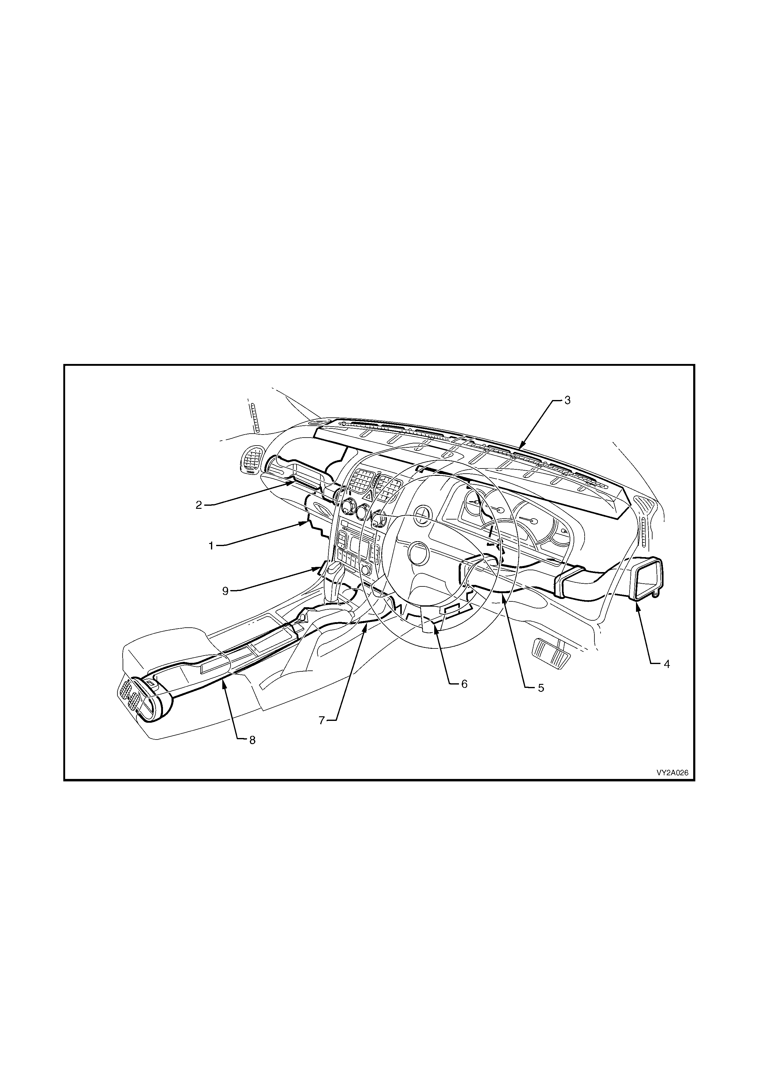
Figure 2A-3 shows the ducting as installed to right-hand drive vehicles. The ducting installation to left-hand drive
vehicles is similar.
Figure 2A-3
Legend
1. HVAC Unit 6. Foot Duct Outlet – RHS
2. Side Duct – LHS 7. Floor Console Duct – Front
3. Demister Cavity 8. Floor Console Duct – Rear
4. Driver’s Side Duct – Outer 9. Foot Duct Outlet – LHS
5. Driver’s Side Duct – Inner
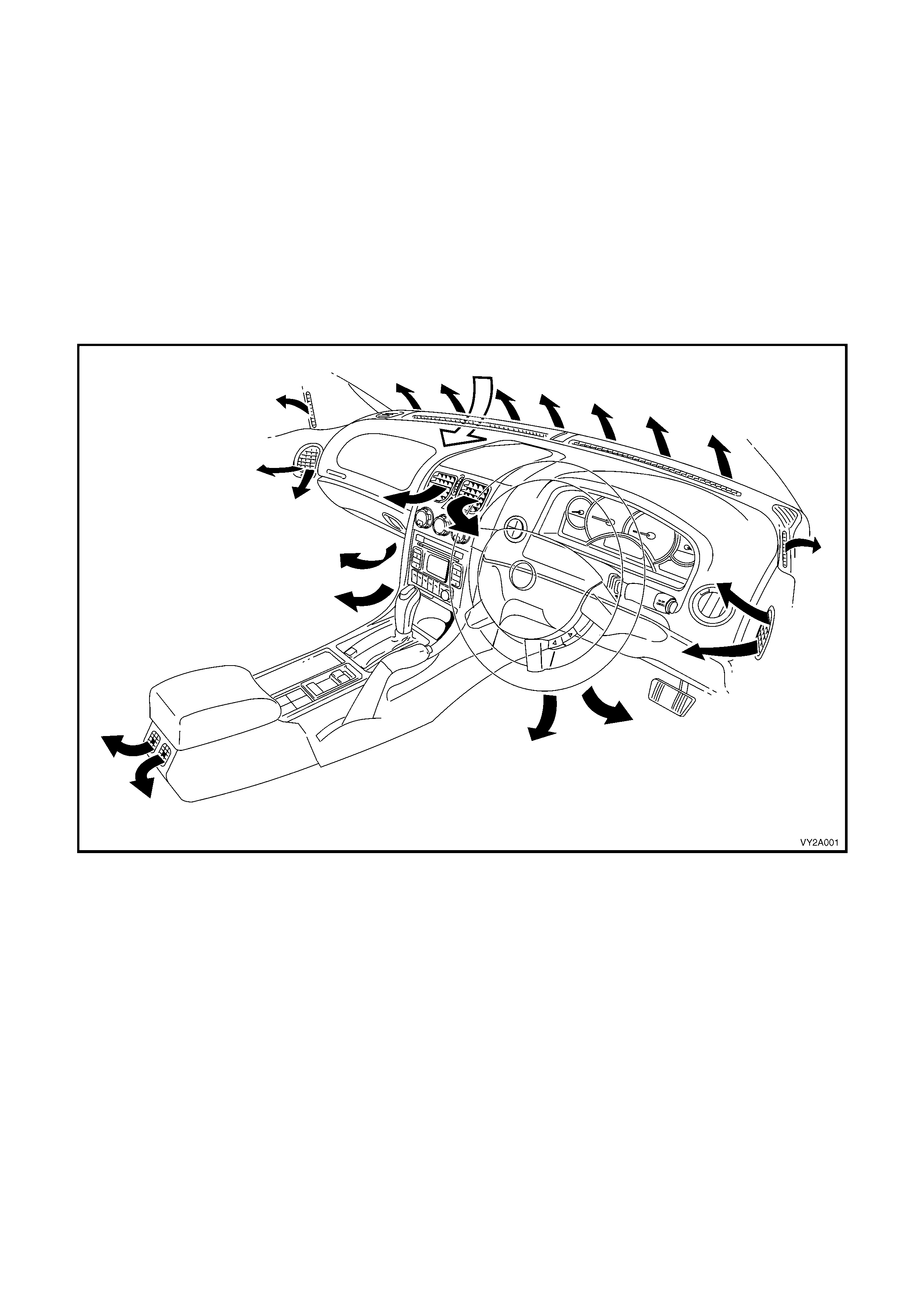
CABIN VENTILATION OUTLETS
Air entering the vehicle through the plenum chamber enters the cabin through ventilation outlets at twelve points:
• 2 windscreen (fixed, part of upper instrument panel assembly)
• 1 driver and 1 front passenger side foot outlet (fixed, part of HVAC unit underside)
• 1 driver and 1 front passenger side outlet (adjustable, installed into door trims)
• 1 driver and 1 front passenger side window demist outlet (fixed, installed into door trims)
• 1 driver and 1 front passenger side face level outlet (adjustable)
• 2 rear outlets (adjustable, installed to rear of floor console, excluding utility models)
On OCC system s with f itte d with Dua l Zo ne, th e tem perature of the air ex it in g t he front pass en ger ’s c e ntr e a nd f oot
vents can be set independently of the temperature of the air exiting the driver’s centre and foot vents. For further
information on Dual Zone air conditioning, refer to Section 2D HVAC OCCUPANT CLIMATE CONTROL (AUTO
A/C) – DESCRIPTION AND OPERATION.
Figure 2A-4
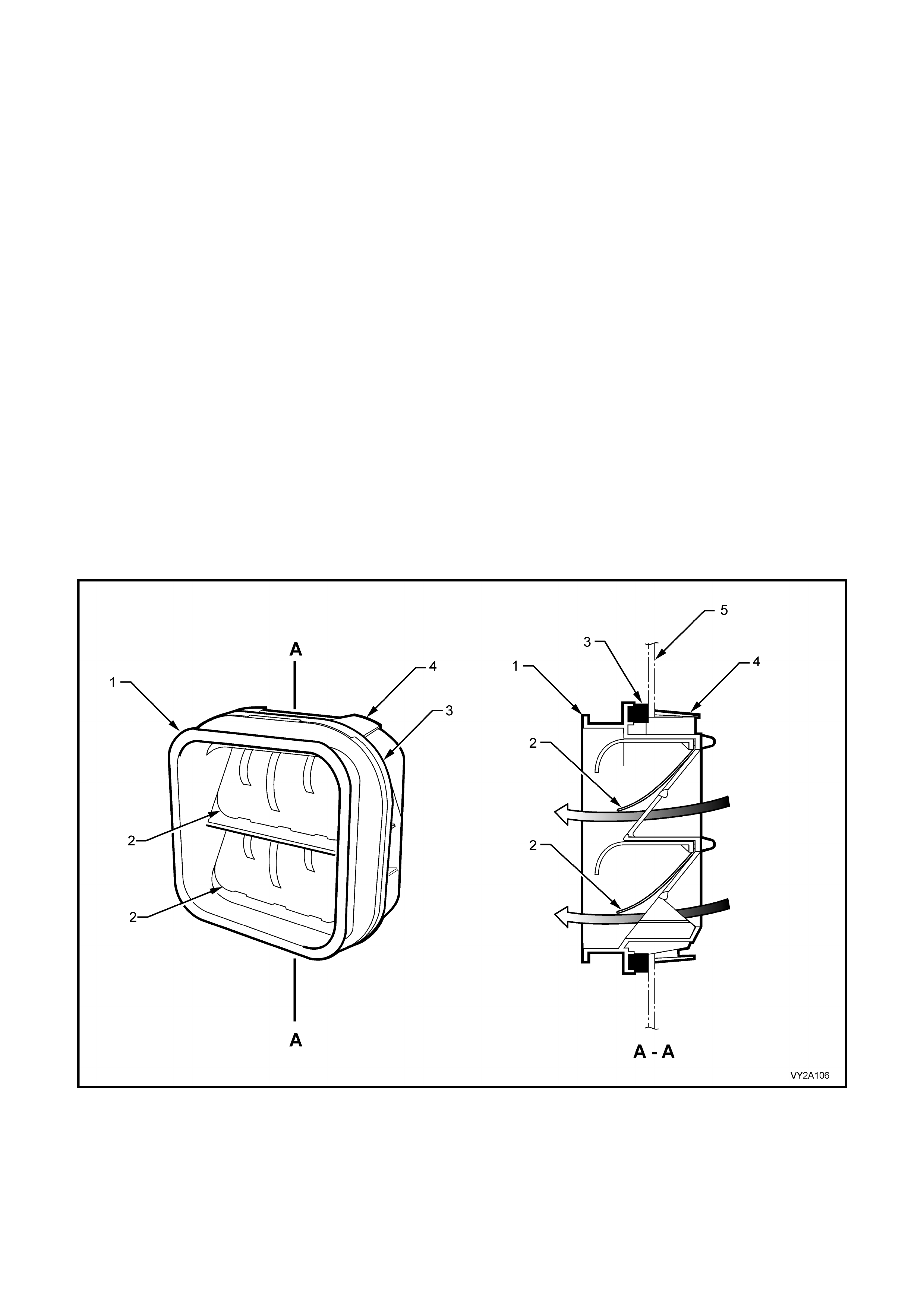
BODY VENTILATION OUTLETS
To allo w the HV AC system to oper ate effic iently air must be a llowed to enter and leave the veh icle even wh en the
cabin is sealed, i.e. al l movable windo ws are full y up. T his is achieve d by the inst allation bod y m ounted ventila tion
outlets. Eac h out let cons ists of a fluted p lastic ho using contai ning t wo flexi ble rub ber seals . W hen pos itive cabi n air
pressure acts upon the seals, they will deflect outward to allow air to exit the vehicle. Air may only exit and not
enter the vehic le via the bo d y ventilat ion outlets .
The ventilation outlet housing is retained to the body panel by four locking tabs located at each corner. Although
not a regu lar maintenanc e i tem, the body outlets c an b e r emoved to c lear a way any dust or f or eig n matter th at ma y
impede them from oper ating eff iciently. This is important f or reasons of dust exclus ion (outlets not s ealing) or over
pressurisation of the cabin (outlets obstructed) causing poor HVAC system performance.
The body ventil ati on out lets f ulf il an ad dit ion al f unc tion in a ll o wing the door s, tailg a te or d ec k lid to be cl osed without
exerting undue air pressure upon the windows and dust seals of the vehicle.
Althou gh bod y ventilat ion outle ts ar e identic al ac ross the m odel range, their locati on var ies acc ording to bod y st yle.
The body ventilation outlets are installed as follows:
• Sedan: 3 outlets installed behind the rear bumper bar – 1 on the left-hand side and 2 on the right-hand side
• Wagon: 3 outlets insta lled behind the rear bumper bar fascia – 1 on the left-hand side and 2 on the right-hand
side
• Coupe: 3 outlets installed behind the rear bum per bar fascia – 2 on the left-hand side and 1 on the right-hand
side
• Utility: 3 outlets installed on the floor panel extension behind the seat on the left-hand side
On sedan and c oup e models, air moves from the c abi n to t he rear c ompartment vi a air gr il les in the rear parcel tr ay
and then to the outlets.
On wagon m odels, air m oves from the cabin to the bod y cavity behind th e rear wheels via the rem ovable air gr illes
located in the rear compartment trim assembly near the rear pillars and then to the outlets.
On utilit y models, a ir exits the cab in through thre e rectangu lar apertures located in the back panel tr im adjacent to
the bod y ventilati on out lets .
Figure 2A-5
Legend
1. Outlet Housing 4. Locking Tab (4 places)
2. Rubber Seal 5. Body Panel
3. Foam Seal
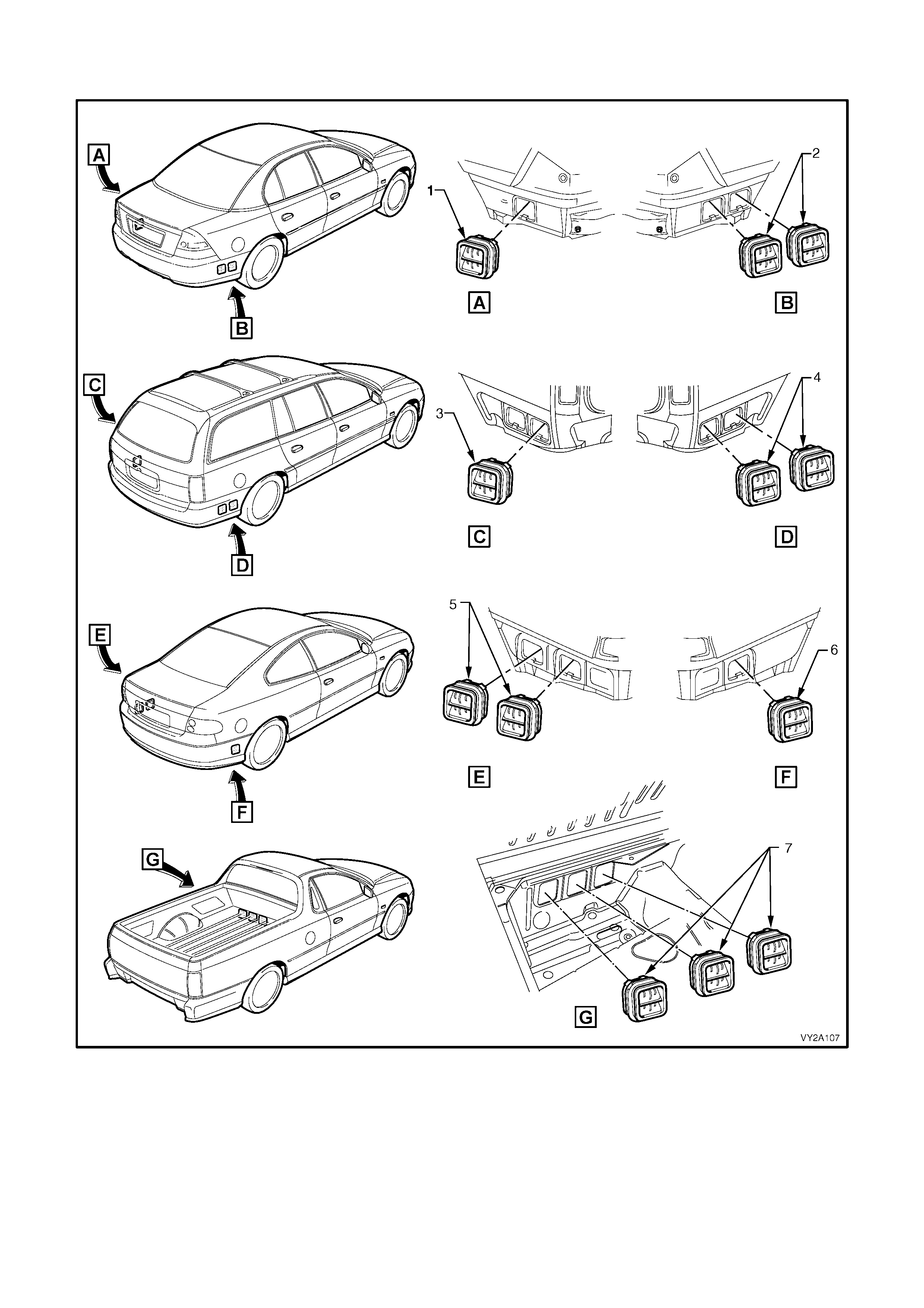
Figure 2A-6 shows the locations of body ventilation outlets across the MY2003 VY and V2 model range.
Figure 2A-6
Legend
1. Body Ventilation Outlet, Sedan – LHS 5. Body Ventilation Outlets, Coupe – LHS
2. Body Ventilation Outlets, Sedan – RHS 6. Body Ventilation Outlet, Coupe – RHS
3. Body Ventilation Outlet, Wagon – LHS 7. Body Ventilation Outlets, Utility
4. Body Ventilation Outlets, W agon – RHS
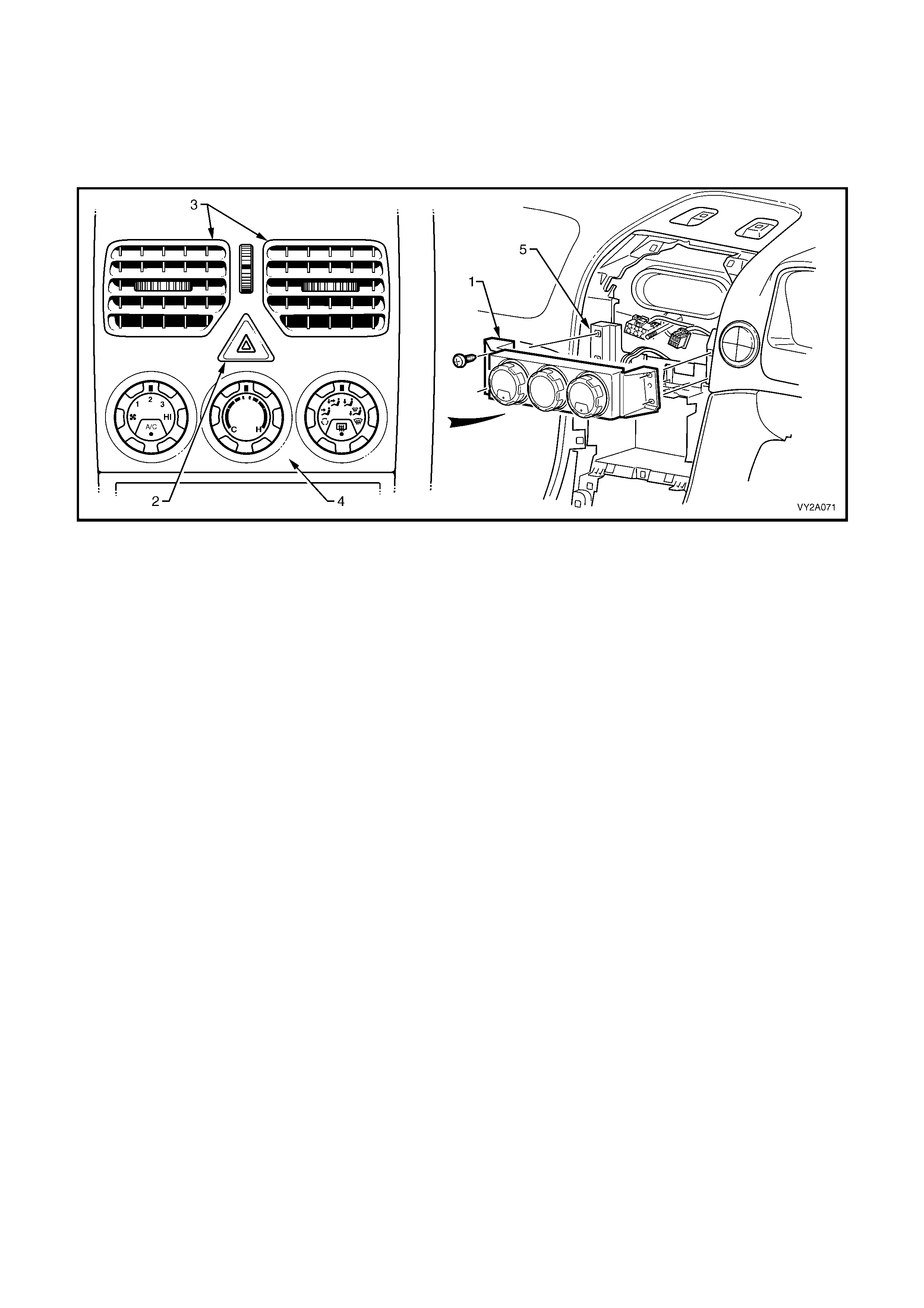
2.2 MANUAL HVAC CONTROLLER
The m anual t ype HV AC co ntr ol ler ( 1) on M Y200 3 V Y and V2 Ser ies veh ic les is l ocated belo w th e h a zar d s w itch ( 2)
and face level centre vents (3). It is of modular construction and has contained within or mounted to the rear, all
switchin g hardware requ ired to control t he HVAC syst em. Included in its functions are buttons for activa ting the air
conditioning and the heated rear window.
The controller is installed behind the instrument bezel (4) and is attached to the instrument panel (5) at four points.
Figure 2A-7
Three rotary switches are to mounted to the front housing of the controller. They are, from left to right:
• Blower fan switch (incorporating a push button A/C switch where A/C is fitted)
• Temperature control switch
• Mode control switch (incorporating a push button heated rear window switch).
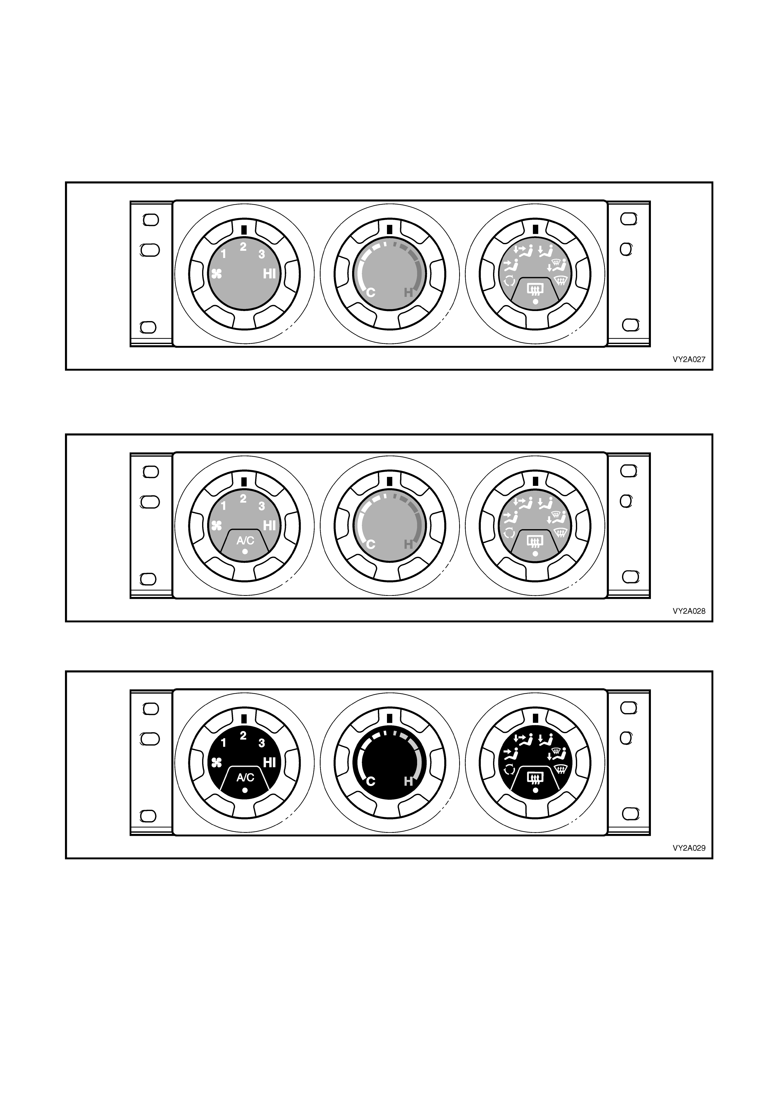
MANUA L CONTROLLER CONFIGURATIONS
Across the LHD and RHD MY2003 VY and V2 Series model range there are five different manual type HVAC
controllers. Two are applicable to LHD models and three are applicable to RHD models. The three configurations of
manual type HVAC controllers as fitted to MY2003 VY and V2 Series models are as follows:
Figure 2A-8 shows the controller as fitted to models witho ut air conditioning. The air conditioning switch is delet ed
from the fan speed switch. The centre bezels of the switches are grey.
Figure 2A-8
Figure 2A-9 shows the controller as fitted to all models with air conditioning, excluding SS models. The centre
bezels of the switches are grey.
Figure 2A-9
Figure 2A-10 shows the controller as fitted to SS models. The centre bezels of the switches are black.
Figure 2A-10
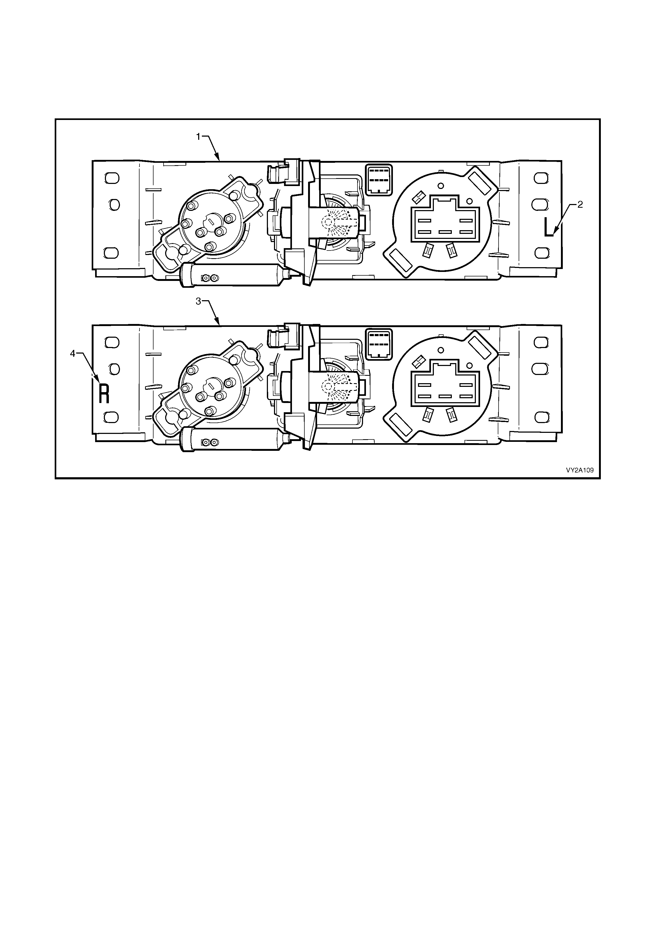
A design variatio n between equival ent conf iguration L HD and RH D control lers is a 3 ° facing angle, b iased towar ds
the driver, of the dials and front ho using. A c olouring d istinctio n is appl ied to the c ontroller’s rear housi ng. The rear
housing of LHD controllers are coloure d white, while th e rear housing of RHD c ontrollers are coloured bl ack. An ‘L’
for LHD controllers and an ‘R’ for RHD controllers is moulded to the mounting flange of the rear housing for
additional identification purposes. Refer to Figure 2A-11 for identification marking locations.
Figure 2A-11
Legend
1. Rear View, HVAC Controller – LHD 3. Rear View, HVAC Controller – RHD
2. Type Indication – LHD 4. Type Indication – RHD

MANUAL CONTROLLER FUNCTIONS
A/C Switch
The A/C switch is located at the bottom of the blower fan rotary switch.
ON: To turn on the blower fan, push the A/C button once – the indicator lamp will illuminate, and the A/C
compressor will engage.
OFF: To turn off the blower fan, push the A/C button again – the indicator lamp will extinguish, and the A/C
compressor will disengage.
Heated Rear Window Switch
The heated rear window switch is located at the bottom of the mode control switch.
ON: To turn on the rear window demist, push the heated rear window button once – the indicator lamp will
illuminate, and the heated rear window element will heat up.
OFF: After 15 minutes the heated rear window will automatically turn off. To reactivate the heated rear window,
push the button again. This will turn on the heated rear window circuit for a further 15 minutes.
Blower Fan Switch
Four blower fan speeds are available – a fan speed has to be selected before the A/C system can be engaged. The
fan is in the off position when the indicator light is aligned with the fan symbol.
Temperature Control
C = FULL COLD H = FULL HOT
This control is connec ted via a r od and lever s to the air mix doors at the HV AC case. T he air m ix doors control th e
amount of incoming air flowing through the heater core, in accordance with the selected cabin temperature. This
regulates the amount of heated air mixing with the unheated or air conditioned air.
NOTE: Both the left-hand drive and right-hand drive HVAC units are fitted with two air mix doors. However, while
the air mix doors on left and right-hand drive units fulfil the same function, their operation and configuration differ.
For f urther inf orm ation on air m ix door operatio n, refer to 2.5 HE ATING, VENTIL ATION AND AIR CONDITIONING
(HVAC) UNIT in this Sect io n.
The heat er water valve is held in the c losed position by vac uum gen erated b y the engin e. W hen the th ird detent is
selected from the full cold position via the tem perature control, the water valve vacuum switch located on the rear
of the HVAC contr oller is ac tivated an d the vac uum line to the water val ve is ve nted. T his allo ws hot wat er f low into
the heater core and subsequent heating of the vehicle cabin. Refer to 2.3 HEATER in this Section for further
information.
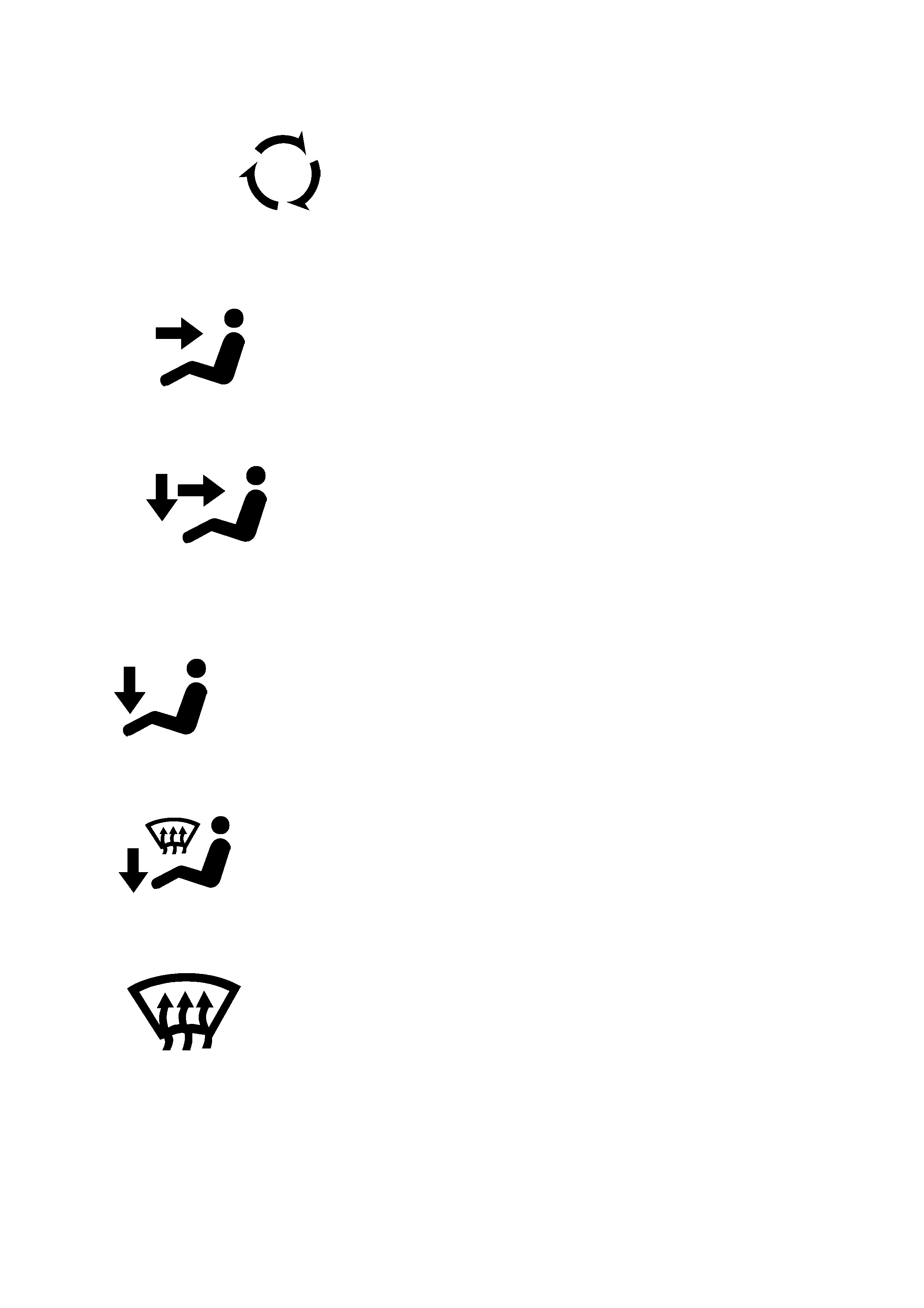
MANUAL MODE CONTROL SYMBOLS
100% Recirculated Air:
W ith the manual m ode contr ol switched to th is positio n there is no fresh air entry into the ve hicle. Air is directed to
the centre, side and rear passenger vents.
Face Mode:
In this position air is directed to the centre, side and rear passenger vents.
BI-LEVEL:
In this position the air is directed to the floor, centre and side vents. When using bi-level with the temperature
control in the central position, warm air will be directed to the feet and cooled air directed to the face and side
vents.
Floor:
In this position the main airflow is directed to the floor.
Blend:
In this position air is directed to the floor as well as to the demist ducts.
Demist:
In this position air is directed to front windscreen and front side windows only, through the demist ducts. It is
recommended that the A/C button and maximum heating be selected, as this will provide accelerated demisting
(dehumidification).
MANUAL CONTROLLER COMPONENTS AND CONSTRUCTION
The front housing and rear housing of the manual type HVAC controller are constructed of plastic. The complete
unit is assembled without the use of any fasteners. The front housing clips over the rear housing at six locations.
Contained within this assembly is a printed circuit board. The board is retained within the rear housing.
Attached to the back of the rear housing are the following components:
• Water valve vacuum switch – for water valve control/heater core flow
• Mode switch vacuum valve – for operation of the HVAC vacuum actuators/doors
• Pinion and crescent gear – for mechanical actuation of the water valve vacuum switch and HVAC air mix doors
• Electrical switch/connector – for blower fan operation
• Electrical connector – for illumination, A/C and heated rear window switching
All of these item s, except the LED, A/C and heated rear window electrical conn ector, are removable from the rear
housing. The illumination, A/C and heated rear window electrical connector is bonded to the printed circuit board.
There are no replaceable bulbs contain ed within the unit. Five LEDs provide the necessary illum ination. If an LED
fails to f unc ti on, the pr i nte d c irc uit board mus t be repl a c ed. O ther c omponents th a t ma y be ind ivid uall y ser vic ed ar e
the water valve vacuum switch, the mode switch vacuum valve and the air m ix door rod retainer. The three rotary
switches and the front housing are serviced as a unit.
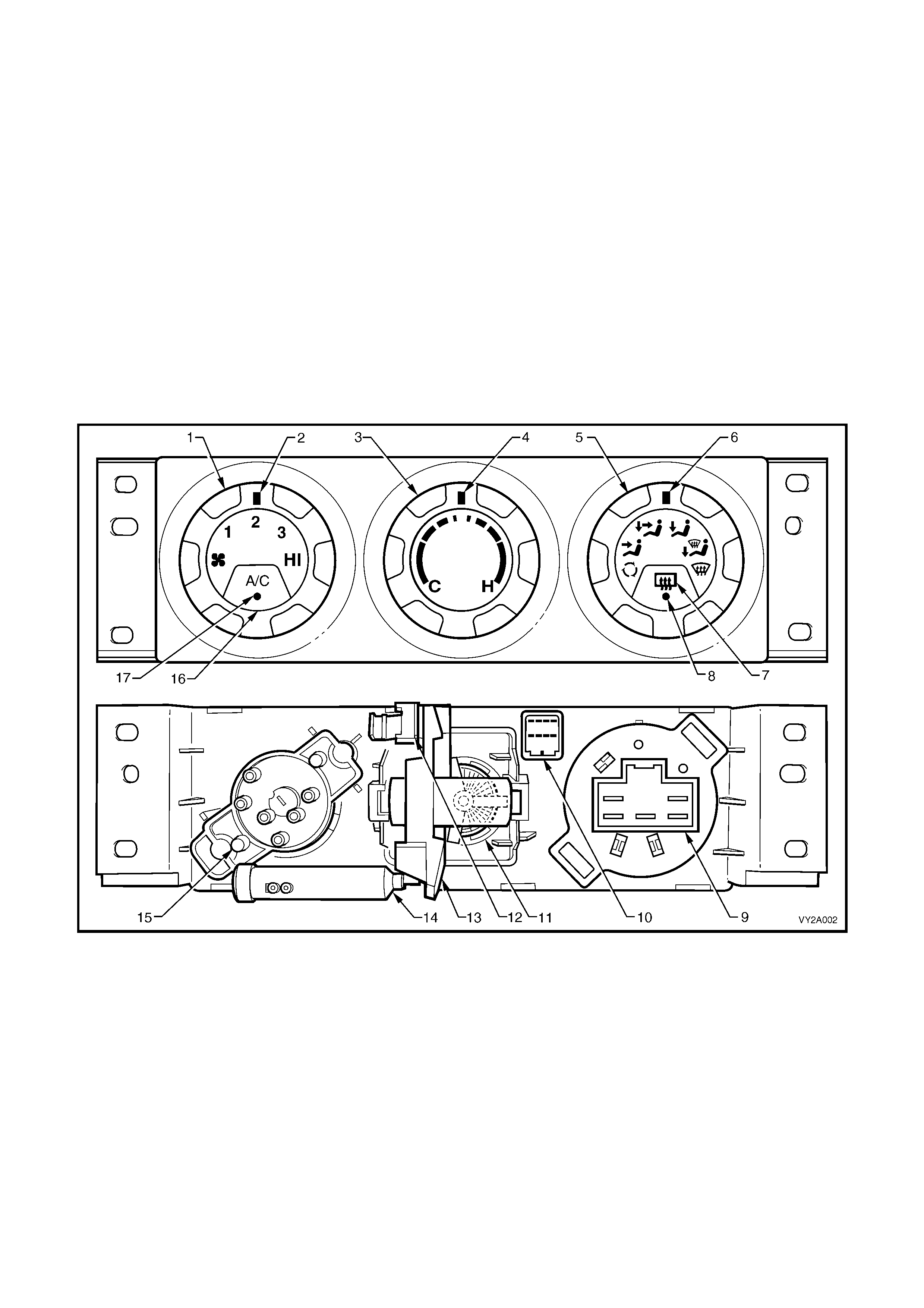
Figure 2A-12
Legend
1. Blower Fan Switch 10. Illumination, A/C Switch and Heated Rear Window Connector
2. Blower Fan Speed Position Indicator 11. Temperature Control Pinion
3. Temperature Control 12. Air Mix Door Rod Retainer
4. Temperature Control Position Indicator 13. Temperature Control Crescent Gear
5. Mode Position Switch 14. Water Valve Vacuum Switch
6. Mode Position Switch Position Indicator 15. Mode Switch Vacuum Valve
7. Heated Rear W indow Switch 16. A/C Switch
8. Heated Rear Window Switch ON Indicator LED 17. A/C ON Indicator LED
9. Blower Motor Connector
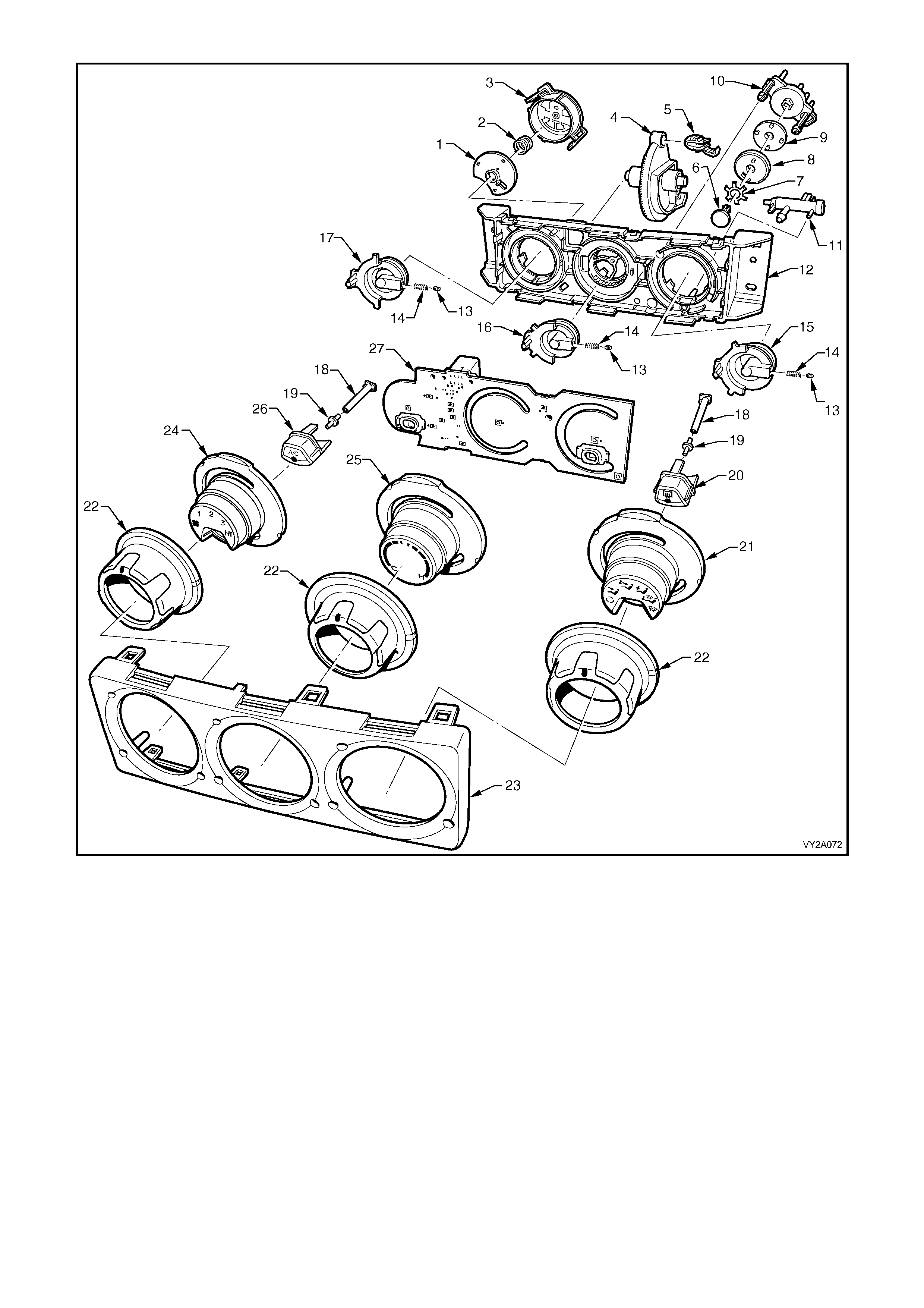
Figure 2A-13
Legend
1. Disc – Blower Fan Switch 15. Shaft – Mode Switch
2. Spring – Blower Fan Switch 16. Shaft – Temperature Switch
3. Housing – Blower Fan Switch 17. Shaft – Blower Fan Switch
4. Crescent Gear 18. Diode Illumination Tube (2 places)
5. Air Mix Door Rod Retainer 19. Diode Illumination Lens (2 places)
6. Retaining Pin – Vacuum Valve Mode Switch 20. Heated Rear Window Switch Button
7. Preload Spring – Vacuum Valve Mode Switch 21. Bezel – Mode Switch
8. Disc – Vacuum Valve Mode Switch 22. Dial (3 places)
9. Gasket – Vacuum Valve Mode Switch 23. Front Housing
10. Housing – Vacuum Valve Mode Switch 24. Bezel – Blower Fan Switch
11. Water Valve Vacuum Switch 25. Bezel – Temperature Switch
12. Rear Housing 26. A/C Switch Button
13. Detent Ball (3 places) 27. Printed Circuit Board
14. Detent Spring (3 places)
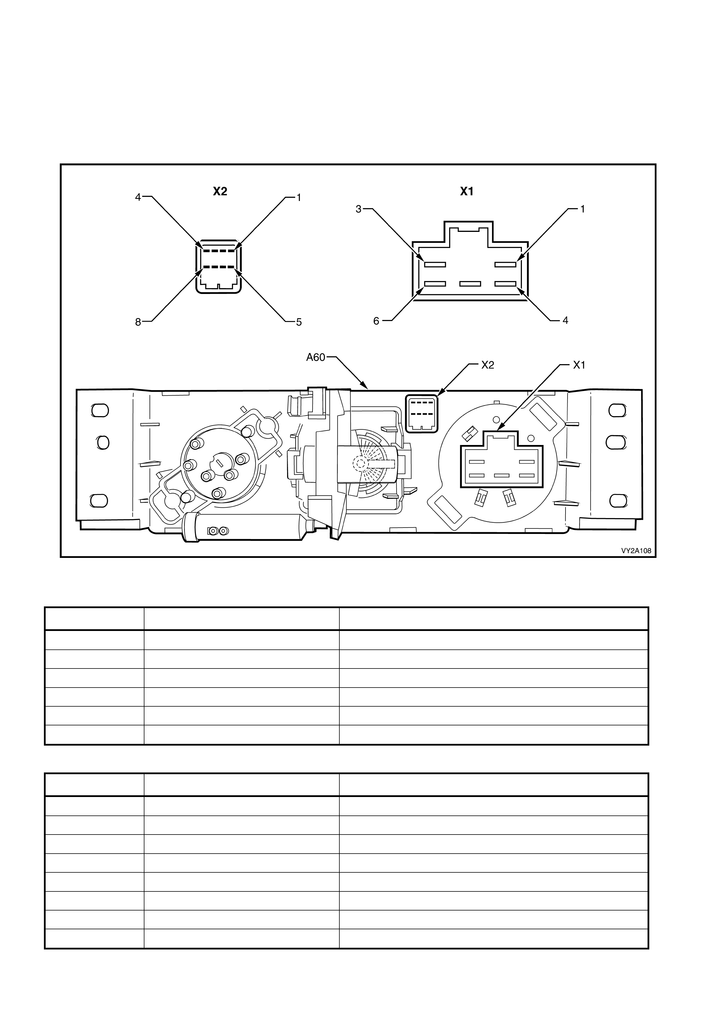
MANUAL CONTROLLER ELECTRICAL CONNECTIONS
Two electr ical connec tors ar e located to t he rear of the manual HV AC controll er. In acc ordance with t he Integr ated
Vehicle Electrical Design (IVED) standard as applied to MY2003 VY and V2 Series vehicles, the controller is
designated as A60 and the connectors are designated as Connector X1 and Connector X2.
Connector X1 is m oulded t o the rear of the b lower s witch. Connector X2 is b onded to the rear of the pr inted c ircuit
board. Figure 2A-14 provides a view of the connector terminal assignments and the tables following it provide
information on their function.
Figure 2A-14
Connector X1
PIN NUMBER WIRE COLOUR FUNCTION
X1-1 Orange / Green Ground via Blower Inhibit or Rel ay
X1-2 – Not Connected
X1-3 Dark green / Yellow Fan Speed 1 – Blower Resistor Assembly
X1-4 Yellow / Black Fan Speed HI – Blower Relay
X1-5 Red / Yellow Fan Speed 3 – Blower Resistor Assembly
X1-6 Red / Green Fan Speed 2 – Blower Resistor Assembly
Connector X2
PIN NUMBER WIRE COLOUR FUNCTION
X2-1 Orange Rear Window Demister Select to BCM
X2-2 Red / White Air Condit i oni ng Select t o BCM
X2-3 Red / Black Air Condit i oni ng ON LED Indication and Status to BCM
X2-4 Grey Instrument Dimming Control to BCM
X2-5 Pink / Blue Fuse F13 – Power for Switching and LED Indication
X2-6 – Not Connected
X2-7 Black / Red Demister ON LED Indication and Status to BCM
X2-8 Brown / White Fuse F11 – Power for Inst rum ent Ill um i nat i on
2.3 HEATER
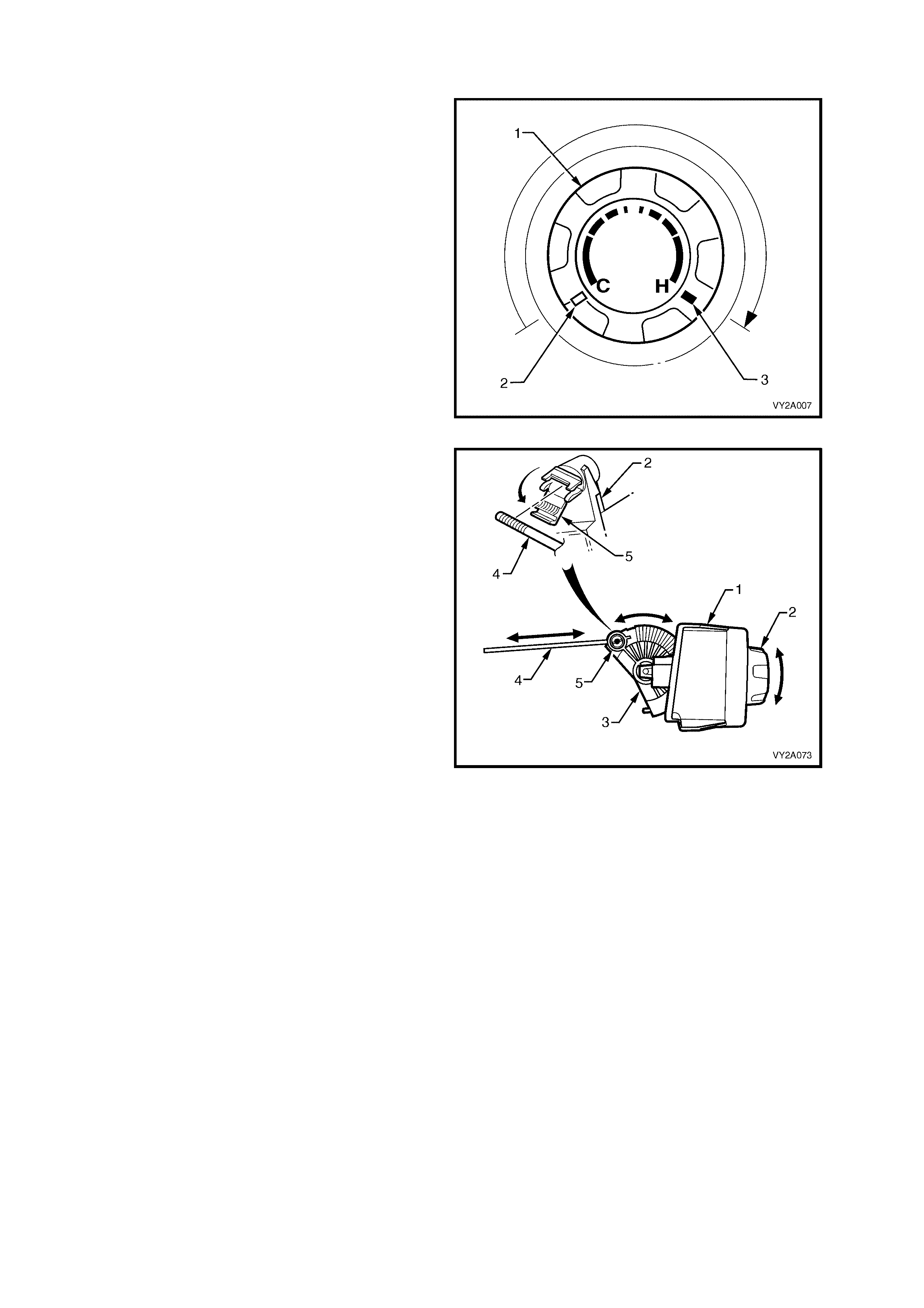
TEM PER ATURE SWITCH
When the temperature switch (1) is turned
clockwise from the full cold position (2) to the full
hot position (3), the pinion and crescent gear
mounted to the rear of the controller are rotated.
This action simultaneously opens HVAC airflow
through the he ater core and cuts off vacuum to the
water valve a llowing h eate d coola nt to flo w throu gh
the heater core.
Figure 2A-15
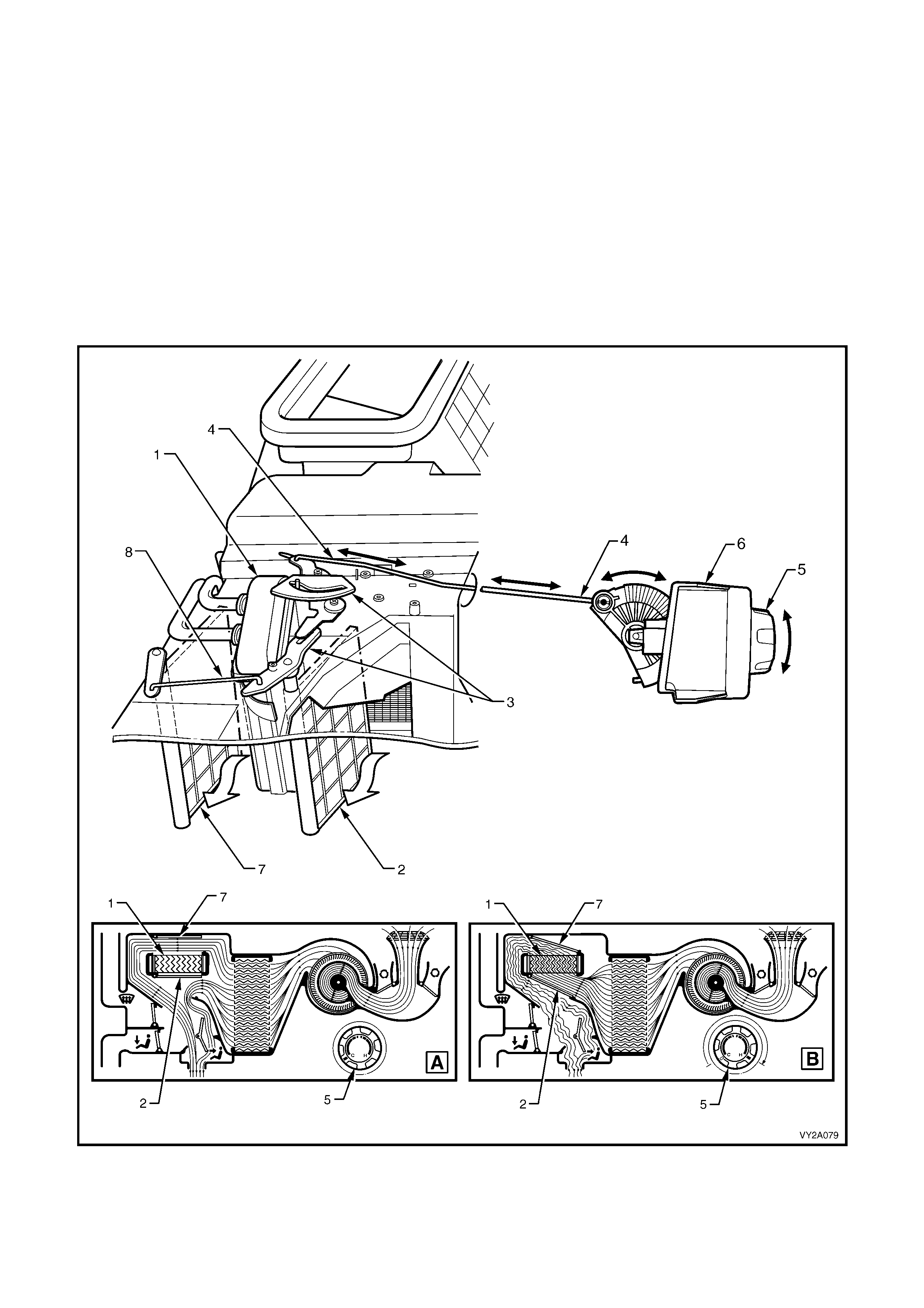
AIR MIX DOOR CONTROL MECHANISM
On all manual air conditioning systems the air mix
door function is the only HVAC airflow control not
to use a vacuum actuator.
An actuat ing r od pr ovides a m ec hanical c onnecti on
between the HVAC controller (1) and the HVAC
unit. The rod is installed between the temperature
switch m echanism and the air mix door levers. For
a schematic operation of the air mix door refer to
HEATER OPERATION in this Section. For
descriptions of the left and right-hand drive type
HVAC unit air m ix doors , r ef er to Figure 2A-32 and
Figure 2A-33.
The amount of airflow through the heater core is
determ ined by the degre e of opening at the air m ix
door. When the temperature switch (2) is rotated,
the air mix door is opened or closed by the
crescent gear (3) pushing or pulling the actuating
rod (4). T he rod is attached to the cresc ent gear by
a pivoting rod retainer (5).
The assembled position of the retainer on the
actuating rod is adjustable. The retainer must
clamp the actuating rod at a specific location if the
correct relative positions of the air mix door and
temperature switch are to be maintained.
For cor rect installat ion of the actuat ing rod, ref er to
Section 2B HV AC CLIMATE CONT ROL
(MANUAL A/C) – REMOVAL AND
INSTALLATION.
Figure 2A-16
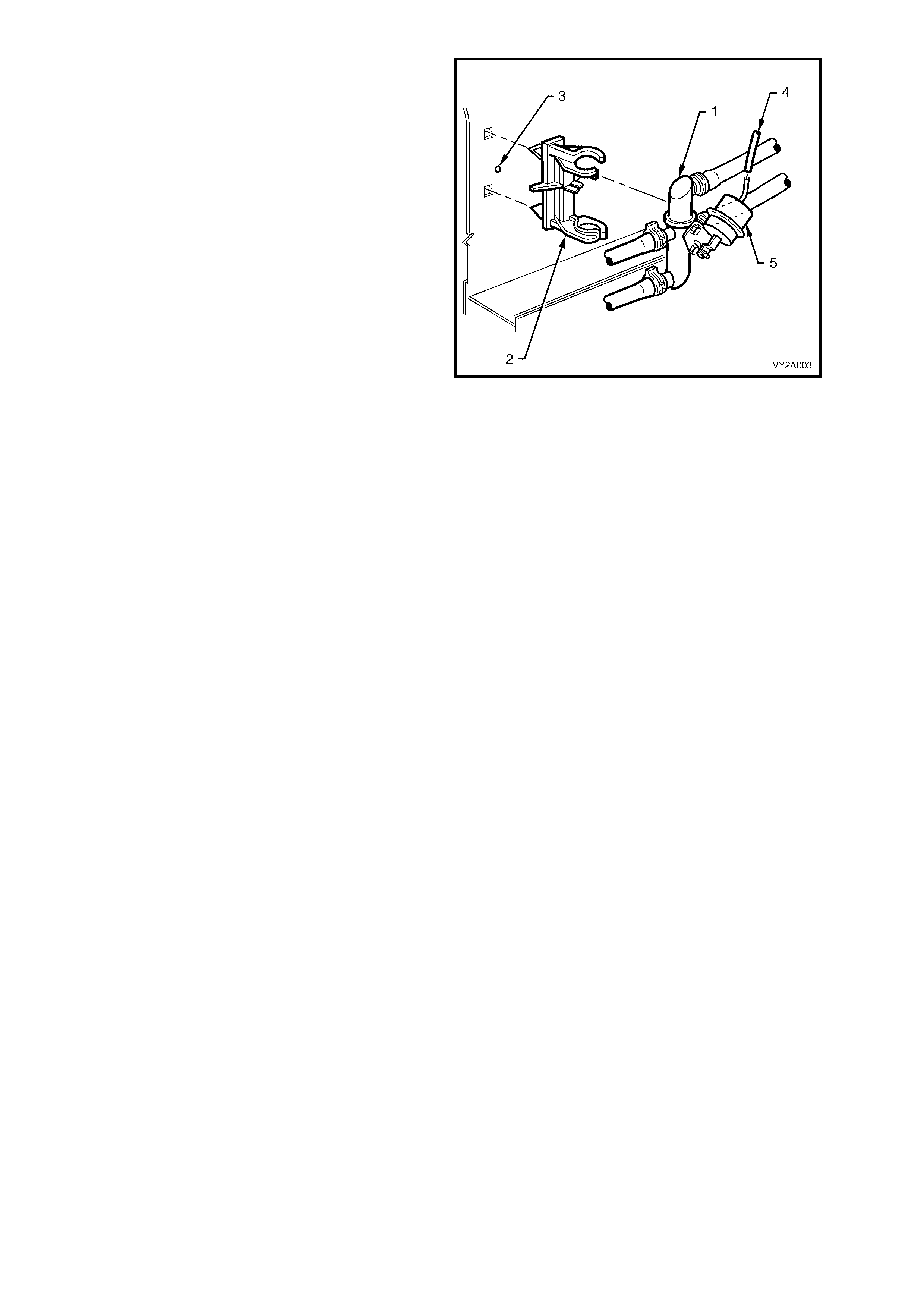
WATER VALV E
The heater water valve (1) is located in the engine
bay attached to a mounting clip (2), on the right-
hand side inner guard (3).
The vacuum line (4) attached to the water valve
vacuum actuator (5) is connected to the water
valve vacuum switch mounted on the HVAC
controller.
When full vacuum is applied to the water valve
actuator, full closure of the valve occurs and no
coolant will flow through the heater core.
Figure 2A-17
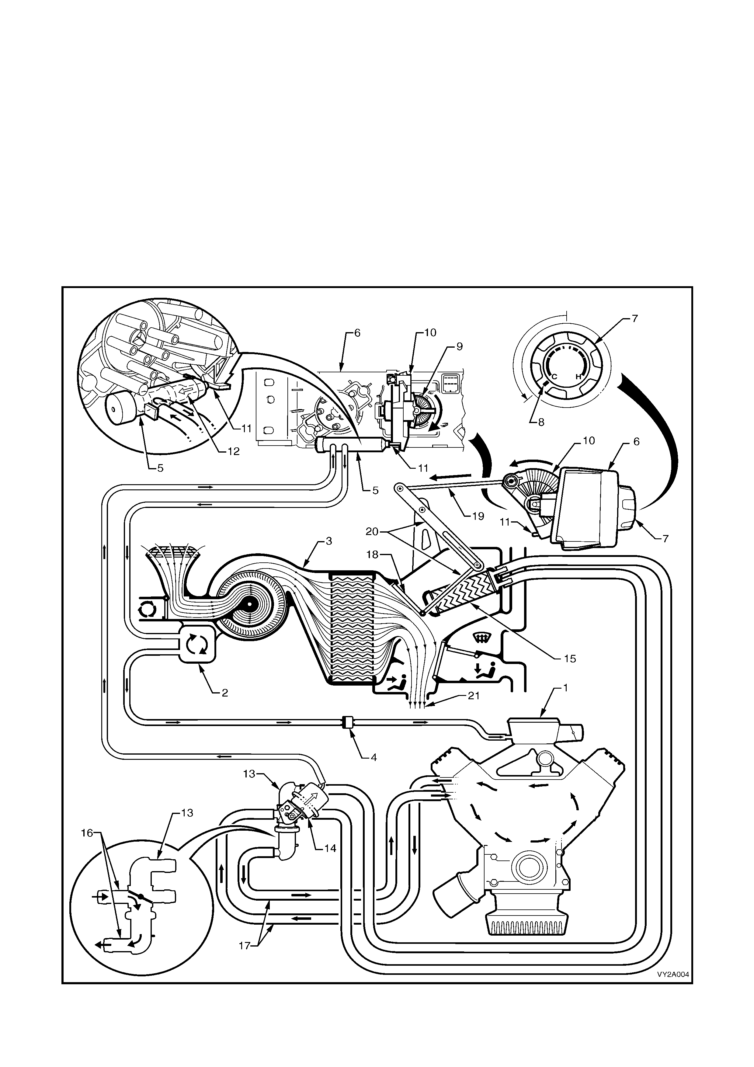
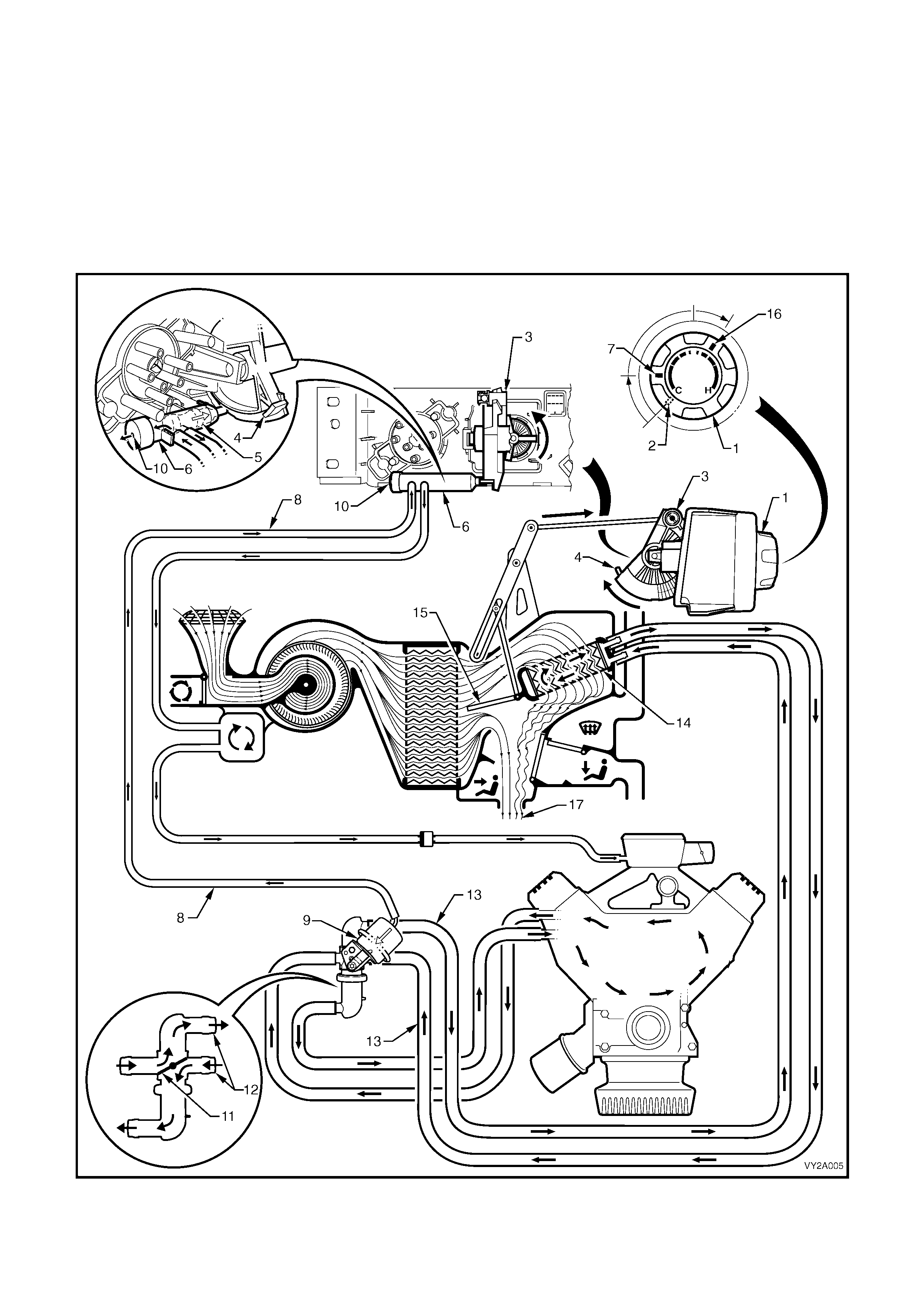
HEATER OPERATION
Full cold
Vacuum generated within the inlet m anifold (1) of the engine is stored within the vacuum tank (2) mounted on the
side the HV AC u nit (3) . Vacuum is retained within the HVA C system b y the one wa y check val ve (4) an d is di rec ted
to the water v alve vacuum switch (5) m ounted to the r ear of the HVAC c ontroller (6). W hen the temperatur e switch
(7) is tur ned to the Fu ll C old posit ion (8), the pin ion ge ar (9) rotates the c resc ent gear ( 10) so th at the ram p (11) on
the cresc ent gear pushes t he plunger (12) inside the water valve vac uum switch inward agains t spring pr essure. In
this posit ion, the water va lv e vacuum switch a llo ws va cuum to be directed t o the water val ve (13). When vacuum is
applied to the water valve vacuum actuator (14), no coolant can flow through the heater core (15). However,
coolant is still able to flow from the engine through the water valve via its engine side ports (16) and engine side
heater hoses (17).
The crescent gear is also mechanically connected to the HVAC air mix door (18) via the actuating rod (19) and
levers (20). As well as operating the plunger of the water valve vacuum switch, the crescent gear simultaneously
locates the air mix door in a position that does not allow any air to flow through the heater core in the Full Cold
mode. The result is that all air (21) entering the vehicle cabin will be cold air.
Figure 2A-18
Warm
W hen the temperature s witch (1) is turned from the Full Cold p osition (2), t he crescent ge ar (3) rotat es back wards
moving the ramp (4) away from the plunger (5) of the water valve vacuum switch (6). Spring pressure moves the
plunger outward and at the third detent position (7), the vacuum line (8) to the water valve actuator (9) is vented
through the ex haust port (10) of the water valve vac uum switch. W hen the actuator is r elieved of vacuum , the disc
(11) in t he water valve wil l rotate and all ow hot water t o flow through t he cabin side wat er valve ports (12) and the
cabin side heater hoses (13) into the heater core (14).
As the crescent gear rotates backward, it pulls the air mix door (15) open. When the temperature switch is turned to
a Warm position (16) , the a ir mix door will be part ially open . This wil l cause som e incom ing air to p ass throu gh the
heater core and some to air to bypass the heater core. The m ixture of heated and cool air (17) will result in warm
air entering the vehicle cabin.
Figure 2A-19

Full hot
W hen the temperatur e switch ( 1) is turned t o in the Fu ll Hot pos ition (2) the water valve vac uum s witch plunger ( 3)
remains in the same position. Therefore, the water valve (4) remains in the fully open position because the water
valve actuator (5) is devoid of vacuum.
In the Full Hot pos ition t he c resc ent gear (6) will b e rot ated full y rear ward. T his action will m ove the air m ix door (7)
to a positio n that dir ects al l inc om ing air thro ugh the h eater core ( 8). T heref ore, all air (9) enter ing t he veh icle c abin
will be heated air.
Figure 2A-20
UNDER-HOOD HEATER COMPONENTS AND COOLANT CIRCULATION
Figure 2A-21 shows the major under-hood heater related components and coolant flow for V6 left-hand drive
models fitted with an oil cooler.
Figure 2A-21
Legend
1. Water Valve 12. Vacuum Hose – To Water Valve Vacuum Switch
2. Water Valve Actuator 13. Hose Clamps – Heater Core (2 places)
3. Heater Hose – To Cabin 14. Vacuum Hose – To Water Valve Actuator
4. Heater Hose – From Cabin 15. Brake Lines
5. Vacuum Hose (2 piece) – HVAC Supply 16. Hose Clamps – Water Valve (4 places)
6. Check Valve 17. Wheel House – RHS
7. Vacuum Hose – To Inlet Manifold 18. Mounting Clip – Water Valve
8. Oil Cooler 19. Hose Clamps – Engine (2 places)
9. Heater Hose – To Engine 20. Oil Filter
10. Heater Hose – To Oil Cooler 21. Hose Clamps – Oil Cooler (2 places)
11. Heater Hose – From Engine NOTE: Heater hoses and vacuum hose to be routed
behind brake lines as shown in View B.
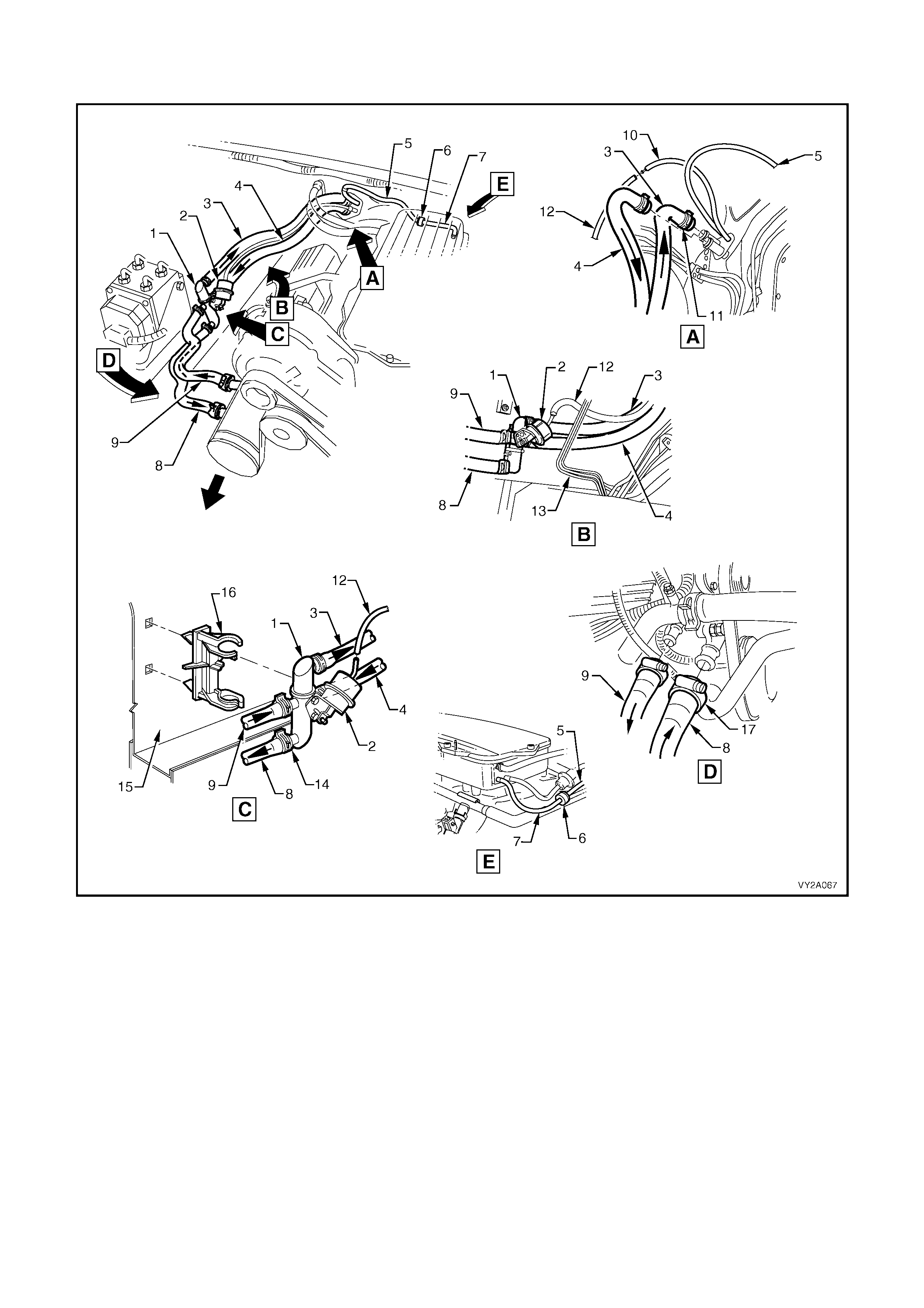
Figure 2A-22 shows the major under-hood heater related components and coolant flow for V6 left-hand drive
models without an oil cooler.
Figure 2A-22
Legend
1. Water Valve 10. Vacuum Hose – To Water Valve Vacuum Switch
2. Water Valve Actuator 11. Hose Clamps – Heater Core (2 places)
3. Heater Hose – To Cabin 12. Vacuum Hose – To Water Valve Actuator
4. Heater Hose – From Cabin 13. Brake Lines
5. Vacuum Hose (2 piece)– HVAC Supply 14. Hose Clamps – Water Valve (4 places)
6. Check Valve 15. Wheel House – RHS
7. Vacuum Hose – To Inlet Manifold 16. Mounting Clip – Water Valve
8. Heater Hose – To Engine 17. Hose Clamps – Engine (2 places)
9. Heater Hose – From Engine NOTE: Heater hoses and vacuum hose to be routed
behind brake lines as shown in View B.
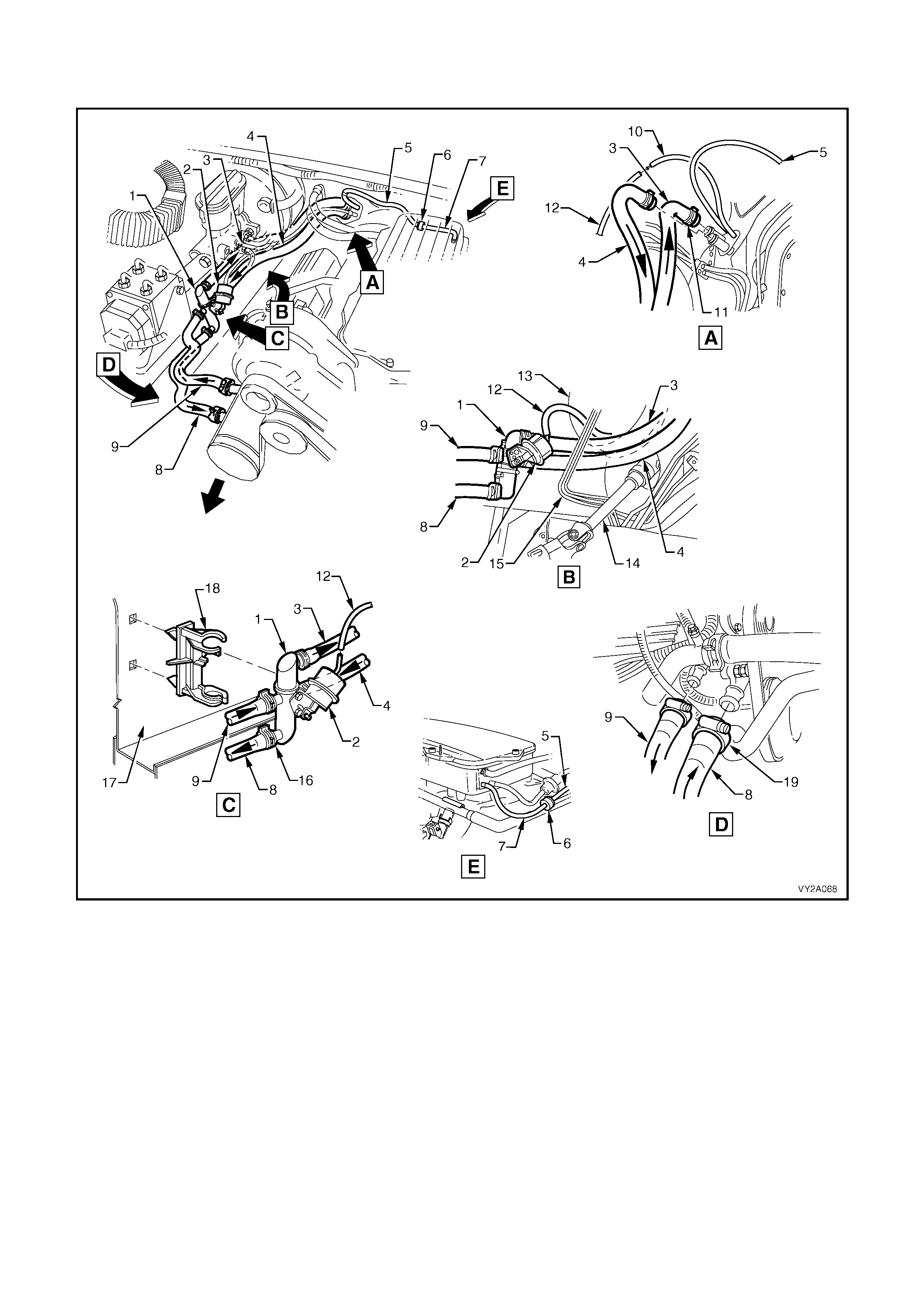
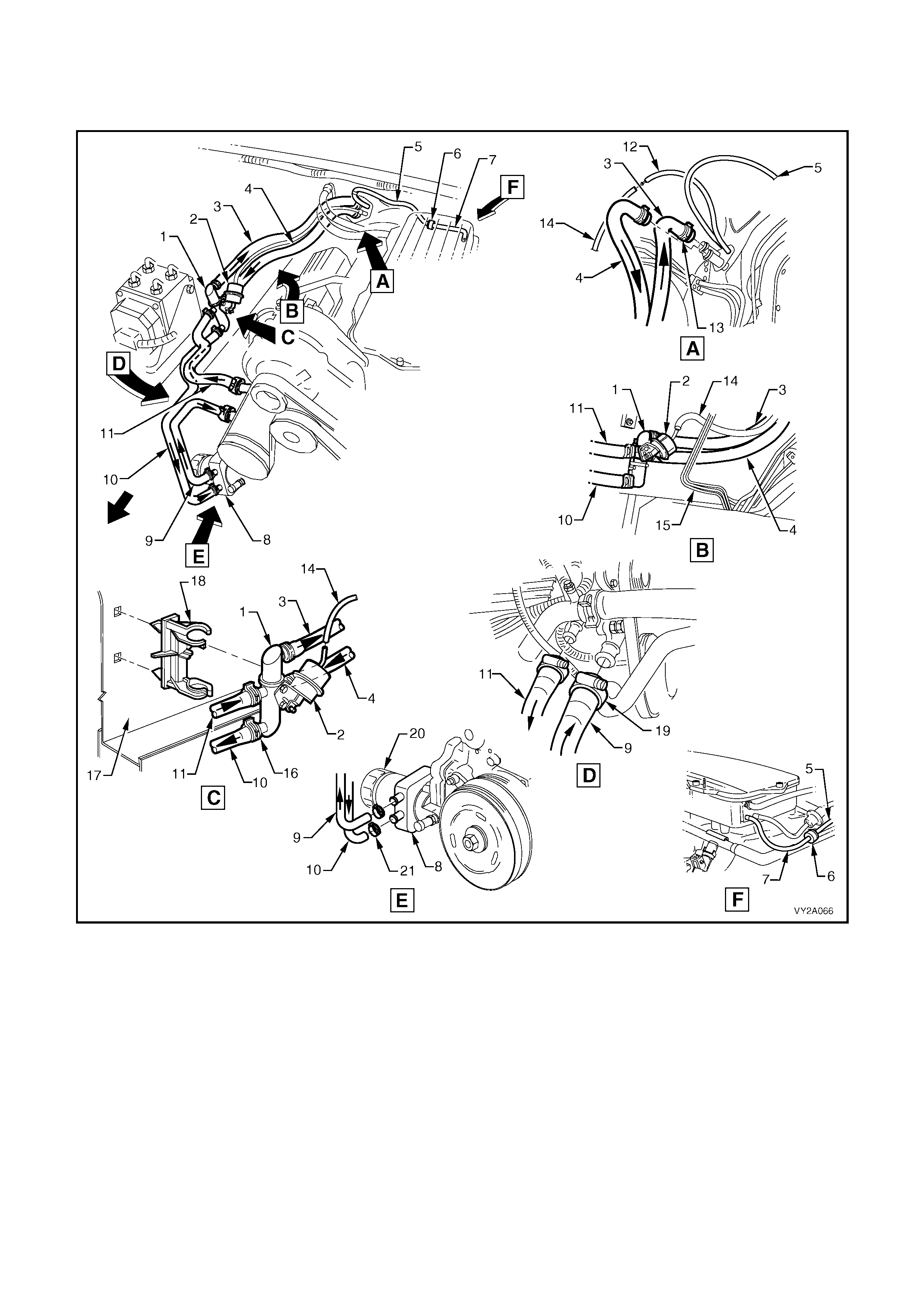
Figure 2A-23 shows t he maj or under- hood heater r elated c omponents and cool ant flo w for V6 right-hand dr ive and
V6 Superc harge d models.
Figure 2A-23
Legend
1. Water Valve 11. Hose Clamps – Heater Core (2 places)
2. Water Valve Actuator 12. Vacuum Hose – To Water Valve Actuator
3. Heater Hose – To Cabin 13. Brake Booster
4. Heater Hose – From Cabin 14. Steering Shaft
5. Vacuum Hose (2 piece) – HVAC Supply 15. Brake Lines
6. Check Valve 16. Hose Clamps – Water Valve (4 places)
7. Vacuum Hose – To Inlet Manifold 17. Wheel House – RHS
8. Heater Hose – To Engine 18. Mounting Clip – Water Valve
9. Heater Hose – From Engine 19. Hose Clamps – Engine (2 places)
10. Vacuum Hose – To Water Valve Vacuum Switch NOTE: Heater hoses and vacuum hose to be routed
behind brake lines as shown in View B.
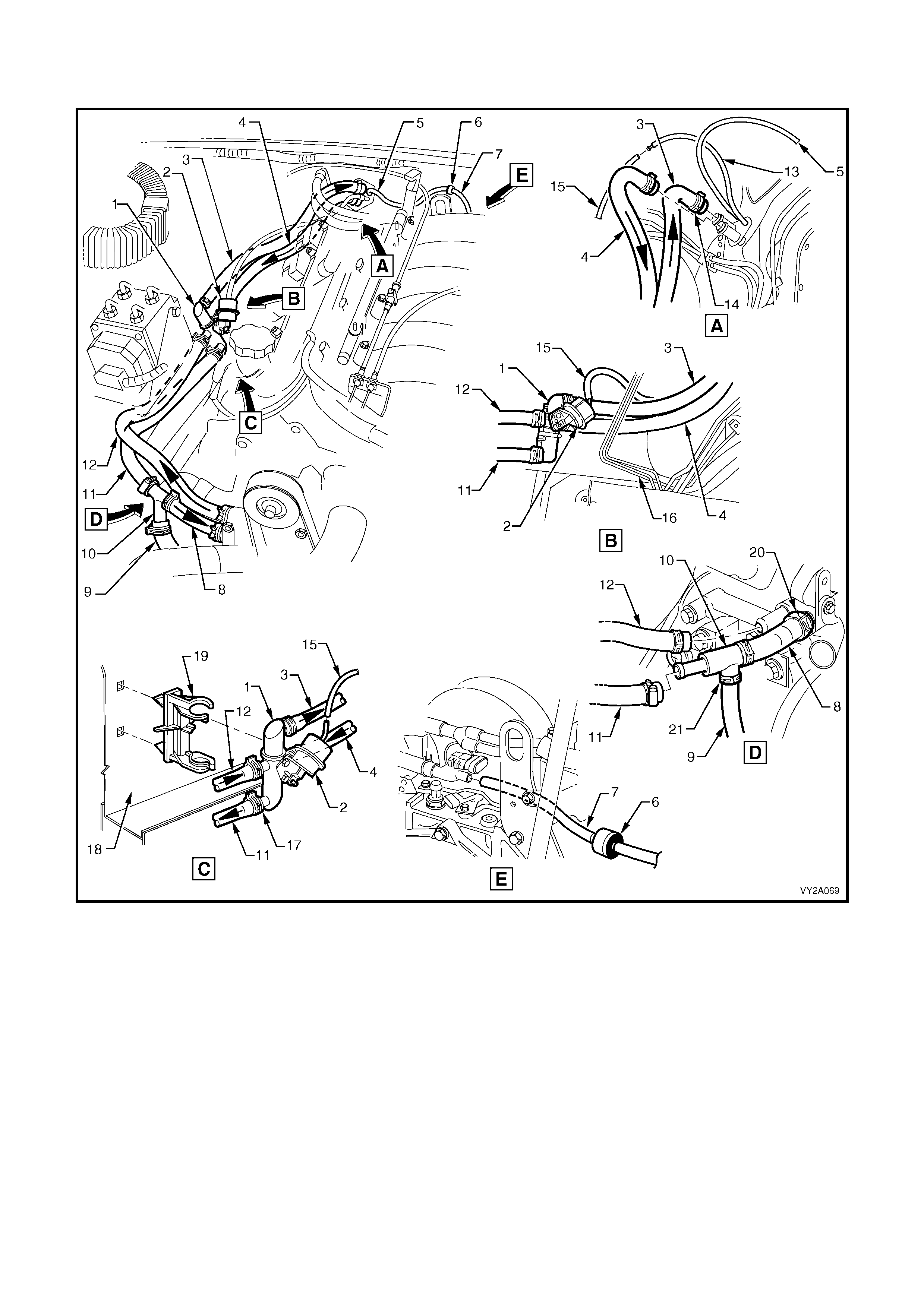
Figure 2A-24 shows the major under-hood heater related components and coolant flow for left-hand drive
GEN III V8 models.
Figure 2A-24
Legend
1. Water Valve 12. Heater Hose – From Engine
2. Water Valve Actuator 13. Vacuum Hose – To Water Valve Vacuum Switch
3. Heater Hose – To Cabin 14. Hose Clamps – Heater Core (2 places)
4. Heater Hose – From Cabin 15. Vacuum Hose – To Water Valve Actuator
5. Vacuum Hose (2 piece) – HVAC Supply 16. Brake Lines
6. Check Valve 17. Hose Clamps – Water Valve (4 places)
7. Vacuum Hose – To Inlet Manifold 18. Wheel House – RHS
8. Heater Hose – To Engine 19. Mounting Clip – Water Valve
9. Hose – To Coolant Surge Tank 20. Hose Clamps – Engine (2 places)
10. Heater Hose T-piece 21. Hose Clamps – T-piece (3 places)
11. Heater Hose – To T-piece NOTE: Heater hoses and vacuum hose to be routed
behind brake lines as shown in View B.
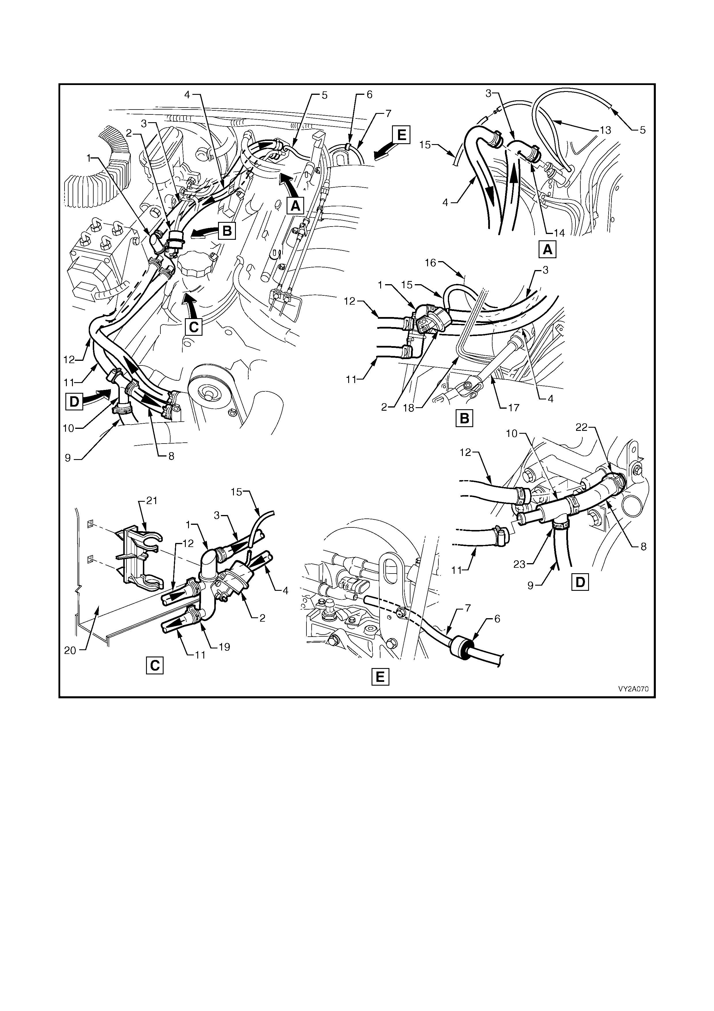
Figure 2A-25 shows the major under-hood heater related components and coolant flow for right-hand drive
GEN III V8 models.
Figure 2A-25
Legend
1. Water Valve 13. Vacuum Hose – To Water Valve Vacuum Switch
2. Water Valve Actuator 14. Hose Clamps – Heater Core (2 places)
3. Heater Hose – To Cabin 15. Vacuum Hose – To Water Valve Actuator
4. Heater Hose – From Cabin 16. Brake Booster
5. Vacuum Hose (2 piece) – HVAC Supply 17. Steering Shaft
6. Check Valve 18. Brake Lines
7. Vacuum Hose – To Inlet Manifold 19. Hose Clamps – Water Valve (4 places)
8. Heater Hose – To Engine 20. Wheel House – RHS
9. Hose – To Coolant Surge Tank 21. Mounting Clip – Water Valve
10. Heater Hose T-piece 22. Hose Clamps – Engine (2 places)
11. Heater Hose – To T-piece 23. Hose Clamps – T-piece (3 places)
12. Heater Hose – From Engine NOTE: Heater hoses and vacuum hose to be routed
behind brake lines as shown in View B.
2.4 AIR CONDITIONING REFRIGERANT CIRCUIT
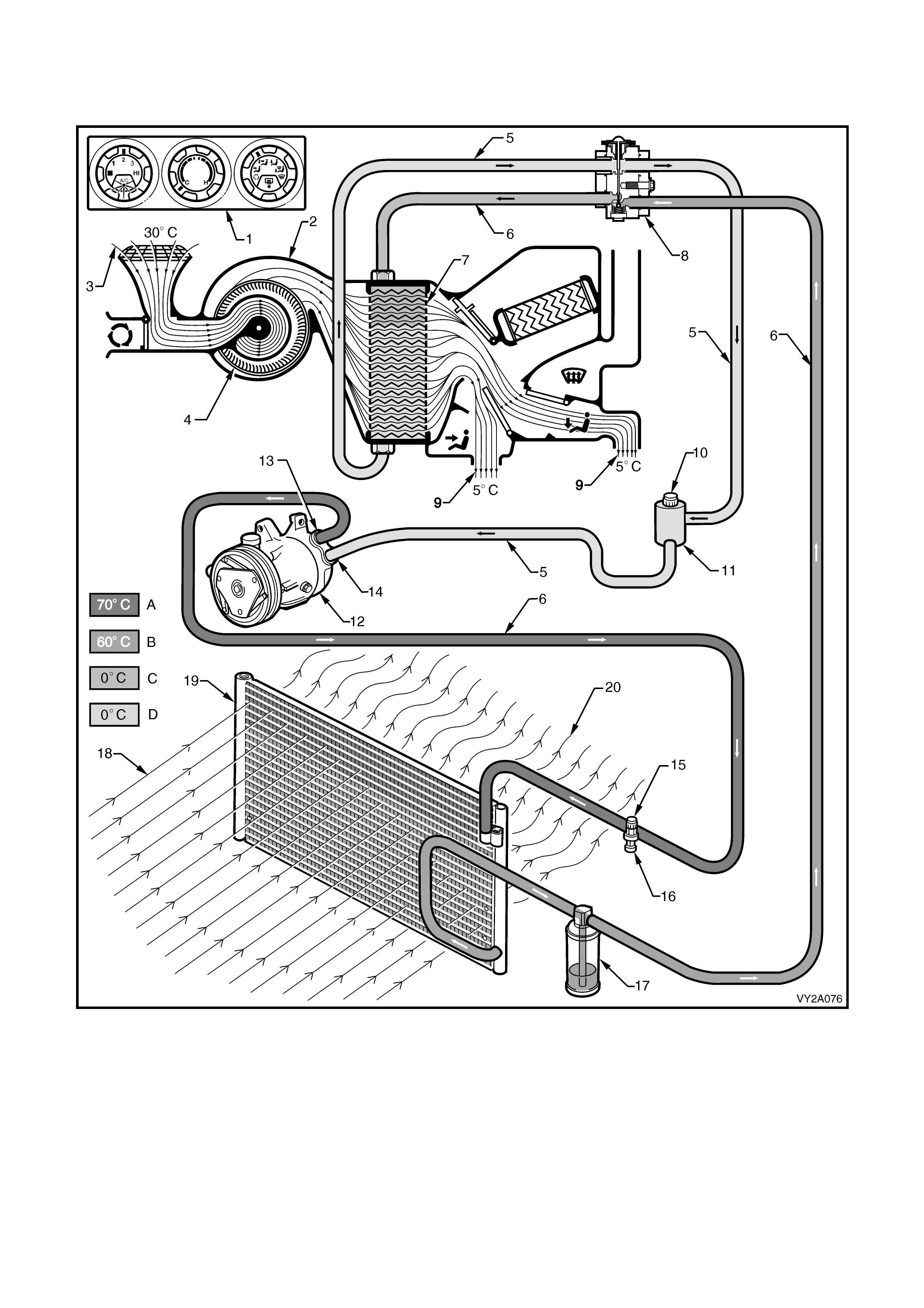
Figure 2A-26 shows the major components and refrigerant flow.
Figure 2A-26
A. High Pressure Vapour B. High Pressure Liquid C. Low Pressure Liquid D. Low Pressure Vapour
Legend
1. Controller (set to AC operational modes) 8. Thermal Expansion Valve 15. High Pressure Port
2. HVAC Unit 9. Air Conditioned Air 16. Pressure Transducer
3. Inlet Air 10. Low Pressure Port 17. Filter Drier Receiver
4. Blower Fan 11. Muffler 18. Cool Ram (Inlet) Air
5. Low Pressure Line 12. Compressor 19. Condenser
6. High Pressure Line 13. Compressor Pressure Port 20. Warm (Outlet) Air
7. Evaporator 14. Compressor Suction Port
2.5 HEATING, VENTILATION AND AIR CONDITIONING (HVAC) UNIT
There are six different types of HVAC units fitted across the MY2003 VY and V2 Series vehicle range:
• Left-hand drive manual system with A/C – HVAC Climate Control
• Left-hand drive automatic (Occupant Climate Control) single zone system – HVAC Occupant Climate Control
• Right-hand drive manual system without A/C
• Right-hand drive manual system with A/C – HVAC Climate Control
• Right-hand drive automatic (Occupant Climate Control) single zone system – HVAC Occupant Climate Control
• Right-hand drive automatic (Occupant Climate Control) dual zone system – HVAC Occupant Climate Control
For information relating specifically to OCC type HVAC units refer to:
• Section 2D HVAC OCCUPANT CLIMATE CONTROL (AUTO A/C) – DESCRIPTION AND OPERATION
• Section 2E HVAC OCCUPANT CLIMATE CONTROL (AUTO A/C) – REMOVAL AND INSTALLATION
• Section 2F HVAC OCCUPANT CLIMATE CONTROL (AUTO A/C) – DIAGNOSTICS
For inf orm ation r el ating to O CC t ype HVA C uni ts not cover ed in S ec tio n 2D, 2 E and 2F, r ef er to this Sec ti o n as well
as these following Sections:
• Section 2B HVAC CLIMATE CONTROL (MANUAL A/C) – REMOVAL AND INSTALLATION
• Section 2C HVAC CLIMATE CONTROL (MANUAL A/C) – SERVICING AND DIAGNOSIS
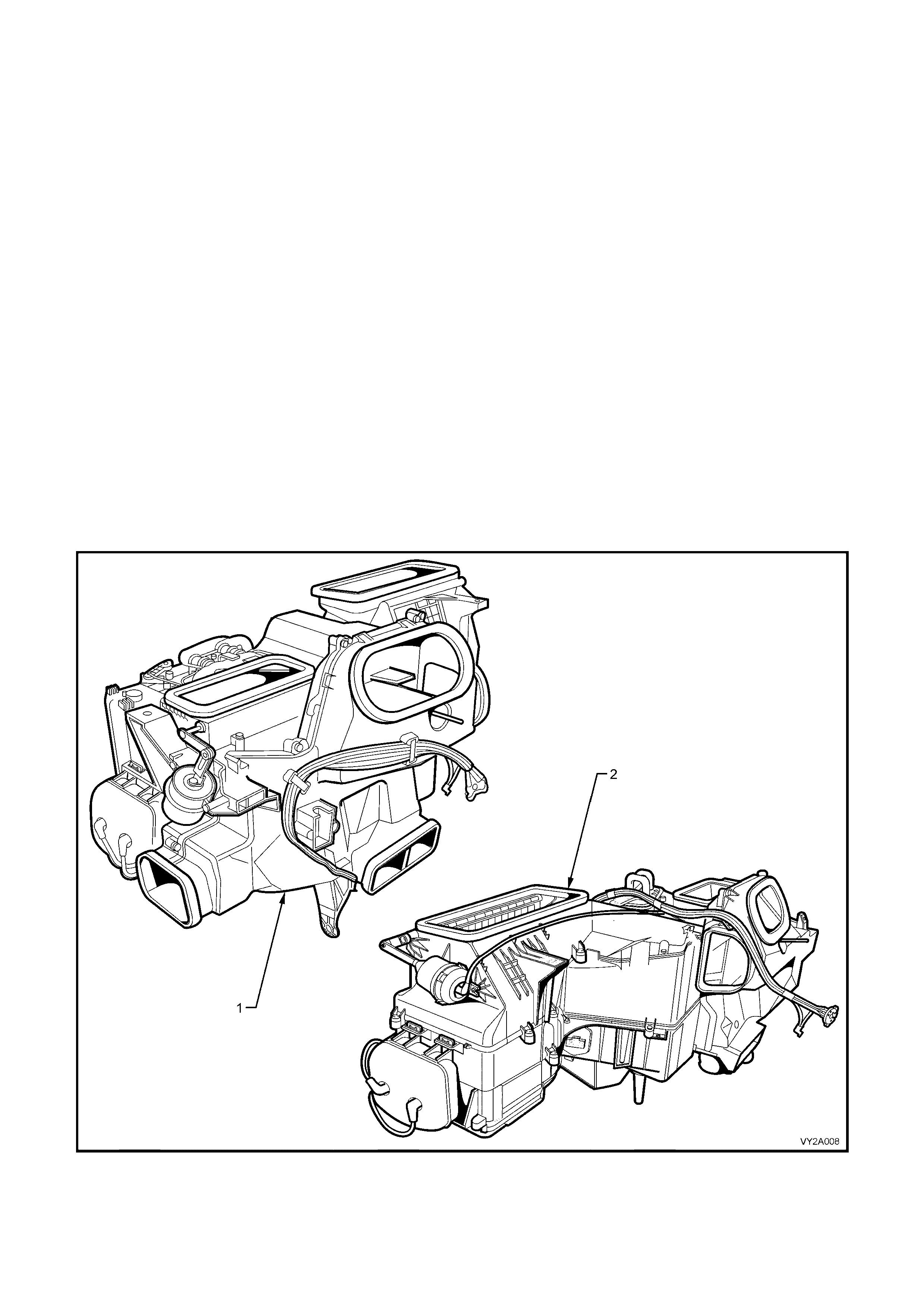
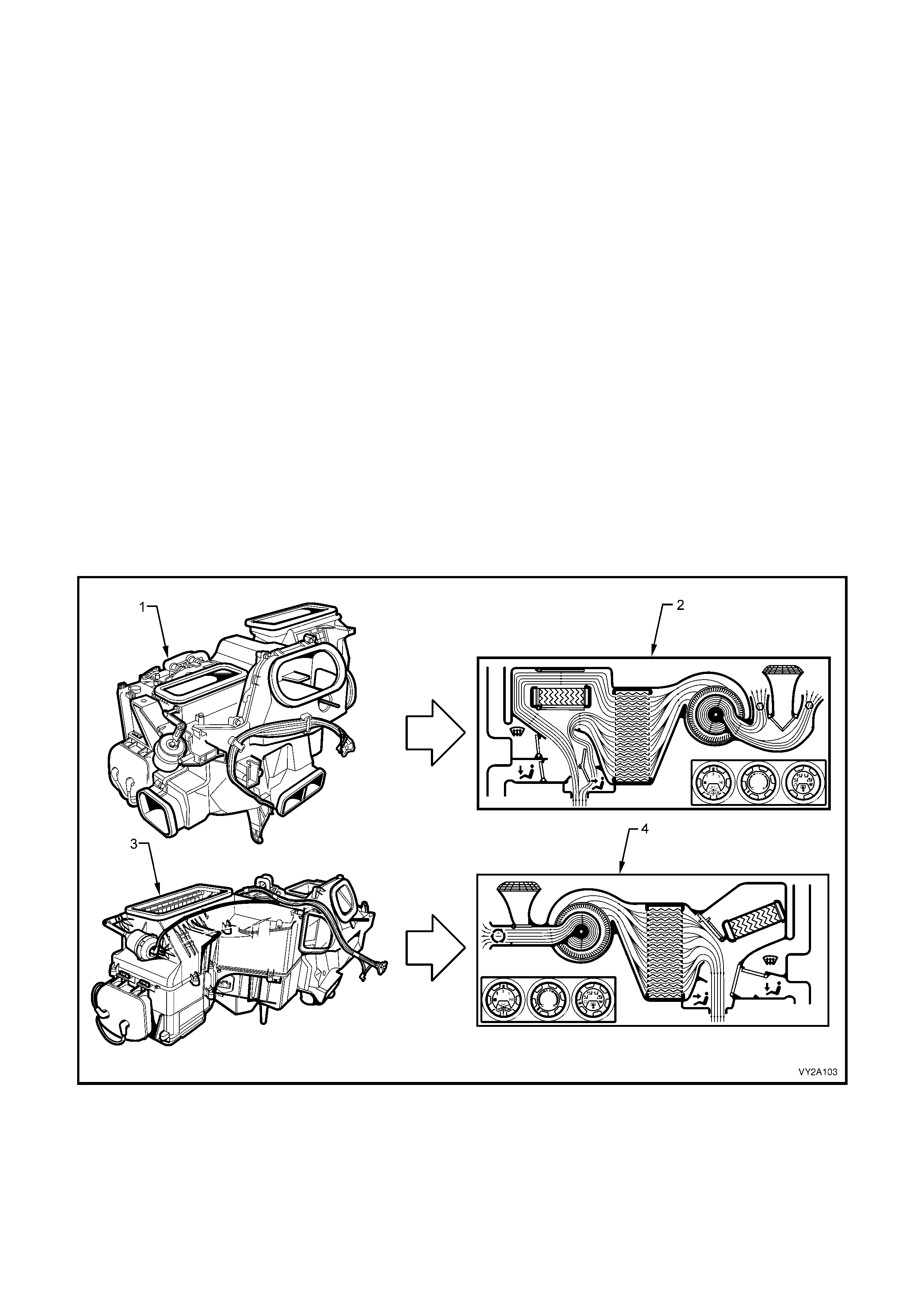
While similar in function and performance, the HVAC units fitted to left and right-hand drive vehicles differ
significantly in terms of their case construction as well as their internal and external components. Figure 2A-27
compares the left and right-hand drive HVAC units and shows them as viewed from a left-hand side of cabin
perspective.
Figure 2A-27
Legend
1. HVAC Unit – Left-hand Drive 2. HVAC Unit – Right-hand Drive
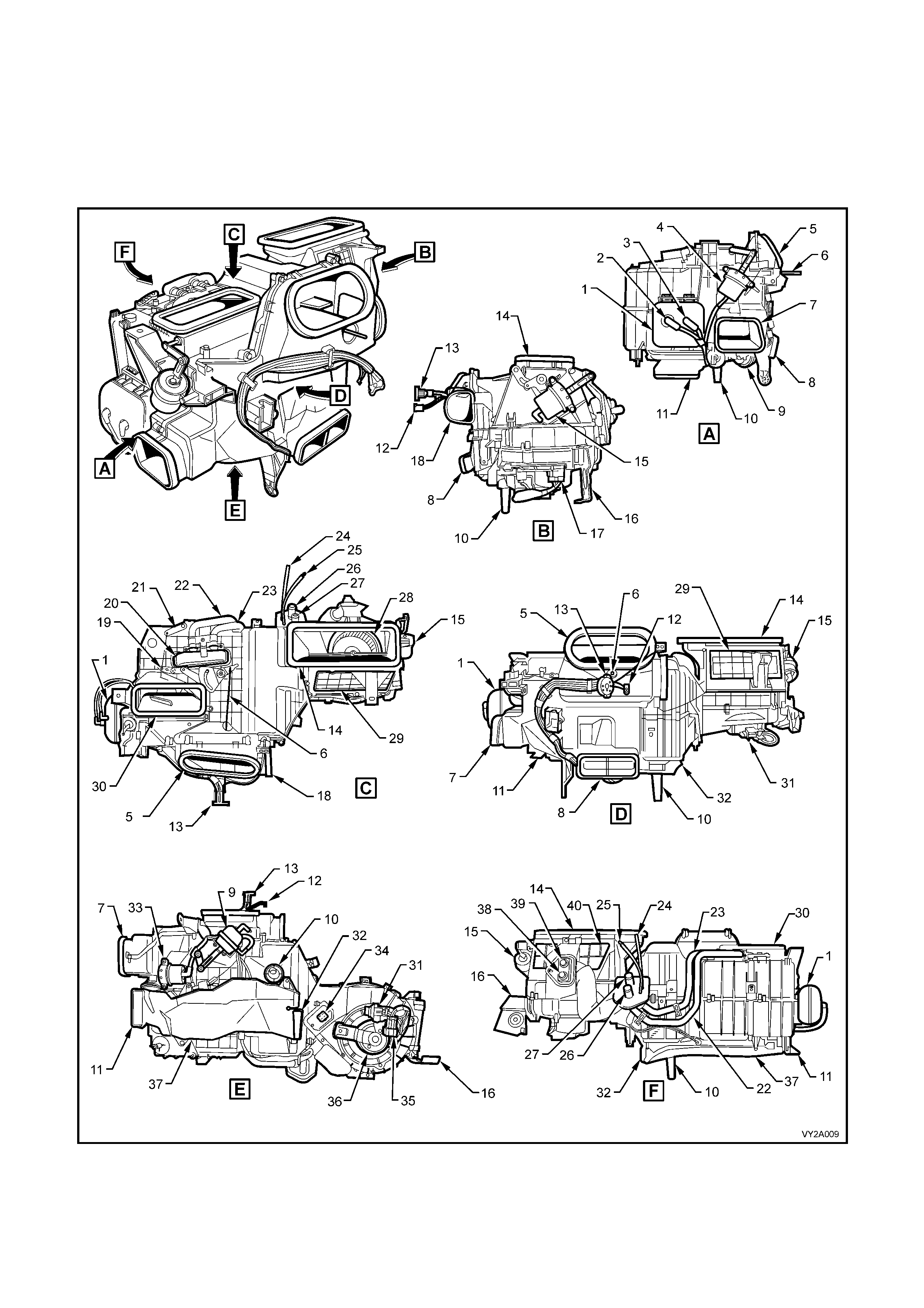
HVAC UNIT – LEFT-HAND DRIVE
The HVA C unit as f itted to unit as fitted t o left-hand drive veh icles is of a four p iece case c onstruction an d is fitted
with four externally mounted vacuum actuators to provide the selected ventilation modes.
Two equally sized recirculation doors are used to control airflow into the HVAC unit. Two air mix doors operating
simultaneously are used to control the airflow through the heater core.
Left-hand drive HVAC unit – assembled views
Figure 2A-28

Legend (for Figure 2A-28)
1. Vacuum Tank 21. Rear Air Mix Door Lever
2. Vacuum Connector (From inlet manifold) 22. Heater Core Pipe – Outlet
3. Vacuum Connector (From HVAC controller) 23. Heater Core Pipe – Inlet
4. Demist Actuator 24. Vacuum Line (To water valve)
5. Face Vent Outlet 25. Vacuum Line (To inlet manifold)
6. Air Mix Door Rod 26. Heater Core Outlet
7. Side Duct Outlet – LHS 27. Heater Core Inlet
8. Rear Duct Outlet 28. Blower Fan
9. Face Actuator 29. Front Recirculation Door
10. Drain Tube 30. Demist Outlet
11. Foot Vent Outlet – LHS 31. In-line Fuse Holder
12. Vacuum Connector (To water valve vacuum switch) 32. Foot Vent Outlet – RHS
13. Vacuum Manifold Connector (To mode switch) 33. Foot Actuator
14. HVAC Inlet 34. Blower Resistor Assembly
15. Intake Actuator 35. Blower Motor Harness Connector
16. BCM Bracket 36. Blower Motor
17. Blower Motor Connector 37. Foot Duct
18. Side Duct Outlet – RHS 38. A/C High Pressure Port
19. Front Air Mix Door Lever 39. A/C Low Pressure Port
20. Heater Core 40. Rear Recirculation Door
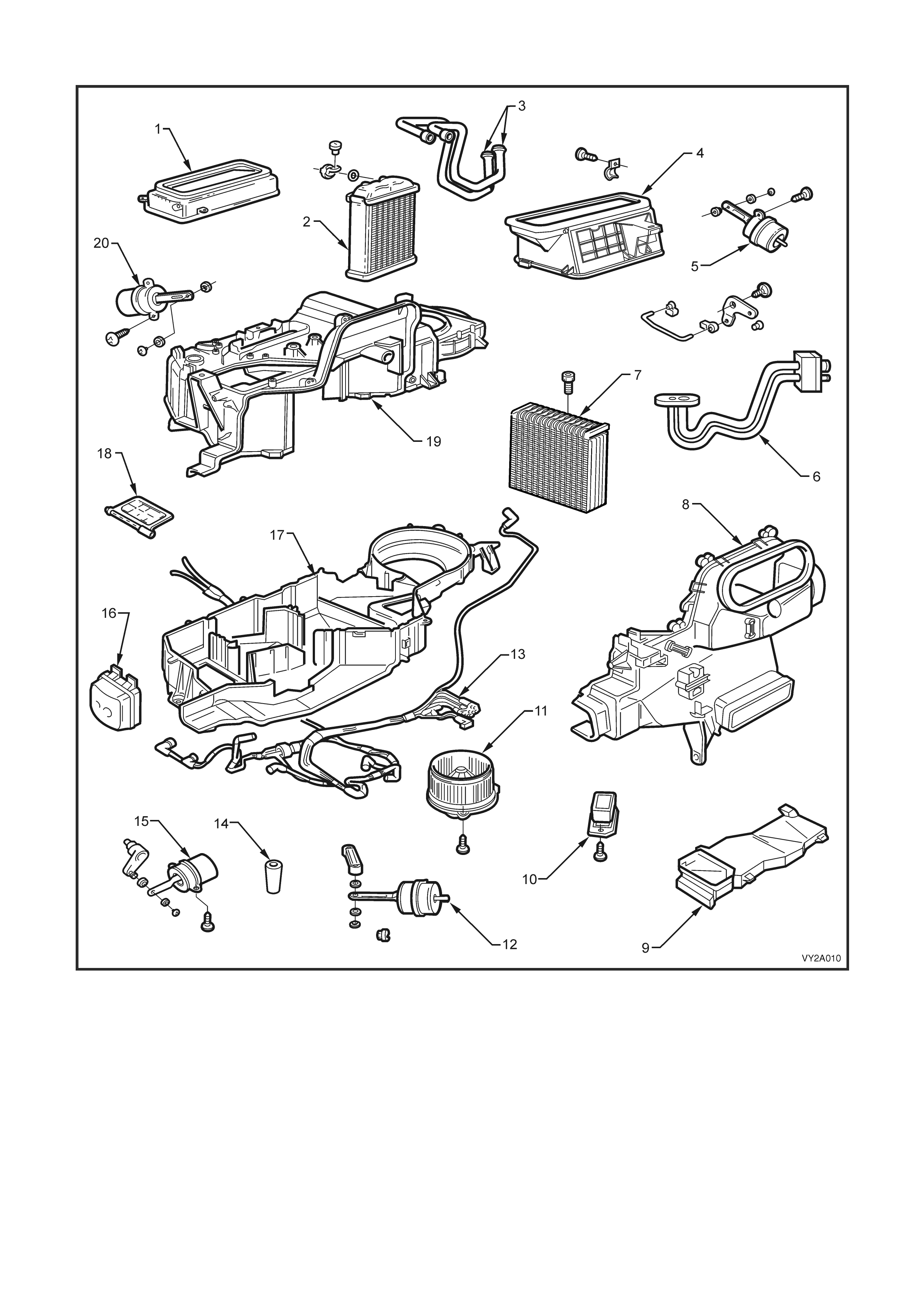
Left-hand drive HVAC unit – e xploded view
Figure 2A-29
Legend
1. Demist Air Duct 8. Front Case 15. Foot Actuator
2. Heater Core 9. Foot Duct 16. Vacuum Storage Tank
3. Heater Core Pipes 10. Blower Speed Resistor 17. HVAC Lower Case
4. Fresh/Recirculation Duct 11. Blower Motor and Fan 18. Foot Door
5. Fresh/Recirculation Mode Vacuum Actuator 12. Face Actuator 19. HVAC Upper Case
6. Evaporator Core Pipes 13. Vacuum Tube Harness 20. Demist Actuator
7. Evaporator 14. Drain Hose
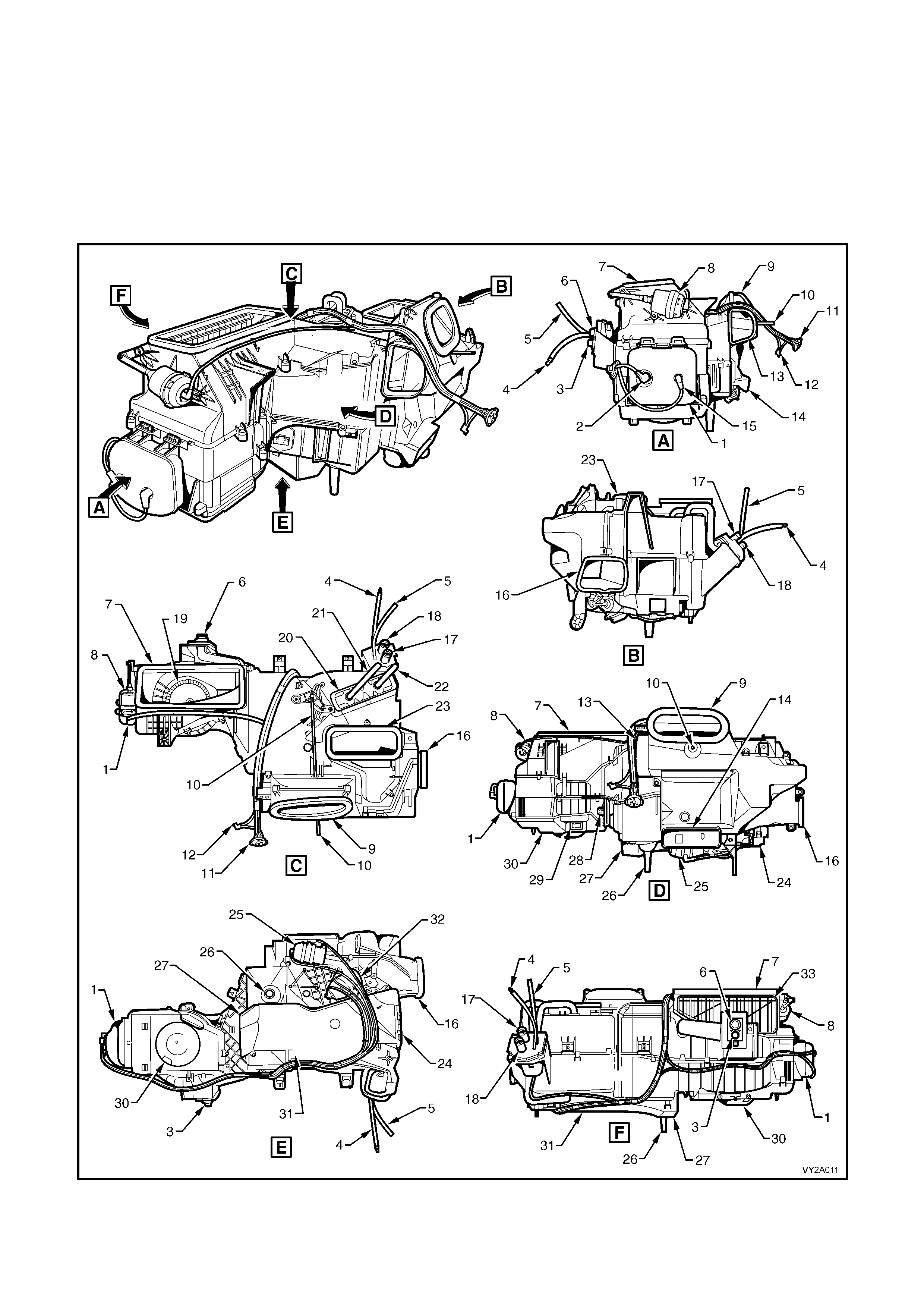
HVAC UNIT – RIGHT-HAND DRIVE
The HVAC unit as fitte d to unit as f itted to ri ght-hand dr ive ve hicl es is of a four pie ce cas e constr uction and is fitted
with three externally mounted vacuum actuators to provide the selected ventilation modes.
A single recirculation door is used to control airflow into the HVAC unit. A single two piece air m ix door is used to
control t he airf low throu gh the he ater c ore. W her e air cond itioning is not f itted, the evaporat or c ore is r eplaced by a
perforated baffle plate (refer to Figure 2A-31, item 19) to maintain airflow speeds to levels comparable with A/C type
units.
Right-hand drive HVAC unit – assembled views
Figure 2A-30

Legend (for Figure 2A-30)
1. Vacuum Tank 18. Heater Core Outlet
2. Vacuum Connector (From inlet manifold) 19. Blower Fan
3. A/C High Pressure Port 20. Heater Core
4. Vacuum Line (To water valve) 21. Heater Core Pipe – Outlet
5. Vacuum Line (To inlet manifold) 22. Heater Core Pipe – Inlet
6. A/C Low Pressure Port 23. Demist Outlet
7. HVAC Inlet 24. Foot Vent Outlet – RHS
8. Intake Actuator 25. Face Actuator
9. Face Vent Outlet 26. Drain Tube
10. Air Mix Door Rod 27. Foot Vent Outlet – LHS
11. Vacuum Manifold Connector (To mode switch) 28. Blower Resistor Assembly
12. Vacuum Connector (To water valve vacuum switch) 29. Blower Motor Connector
13. Side Duct Outlet – LHS 30. Blower Motor Cover
14. Rear Duct Outlet 31. Foot Duct
15. Vacuum Connector (From HVAC controller) 32. Demist/Foot Actuator
16. Side Duct Outlet – RHS 33. Recirculation Door
17. Heater Core Inlet
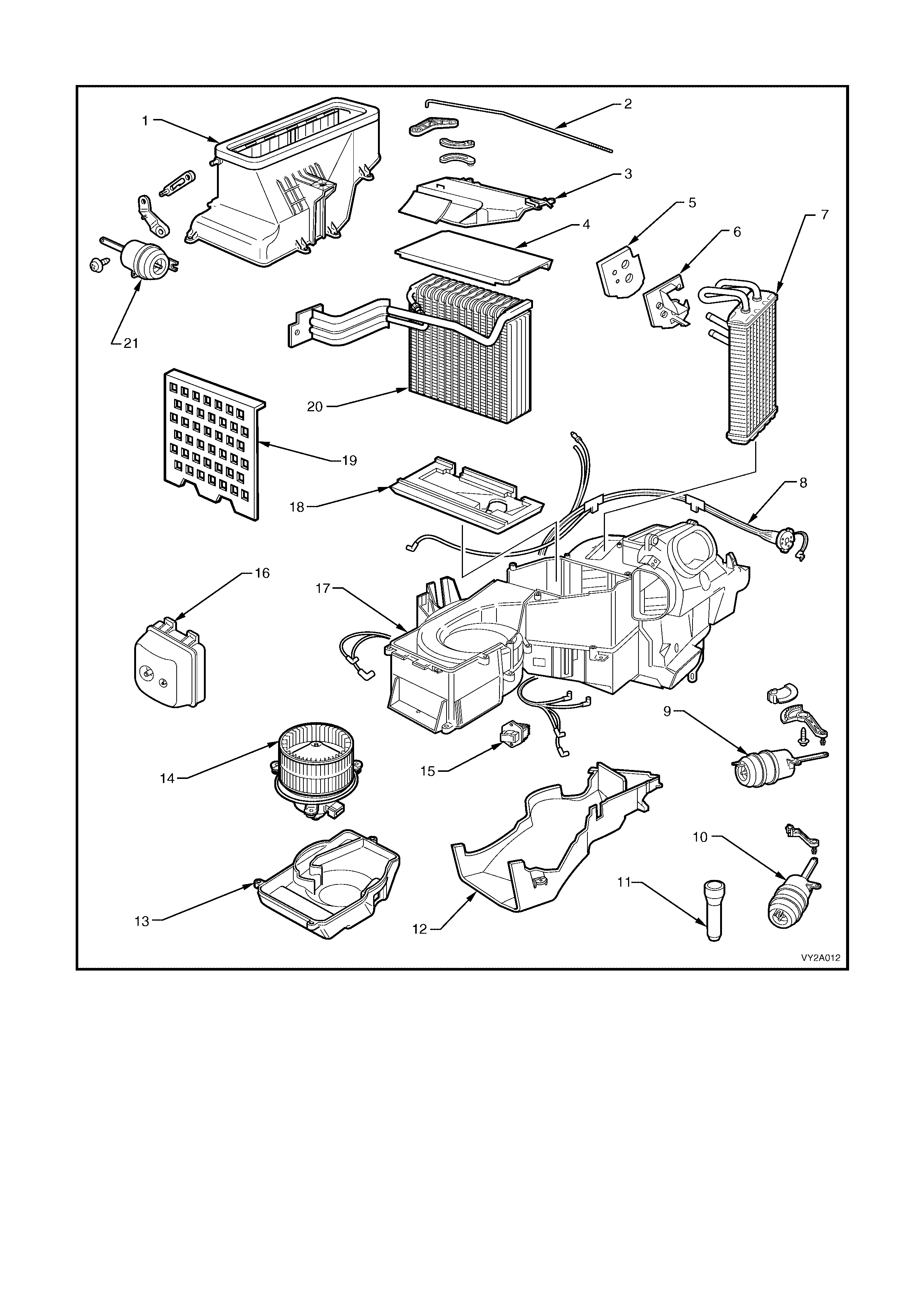
Right-hand drive HVAC unit – exploded view
Figure 2A-31
Legend
1. Fresh/Recirculation Housing 8. Vacuum Tube Harness 15. Blower Speed Resistor
2. Air Mix Door Actuator Rod 9. Demist/Foot Actuator 16. Vacuum Storage Tank
3. Evaporator Core Cover 10. Bi-level Centre Vent Actuator 17. HVAC Case
4. Upper Insulator 11. Drain Hose 18. Lower Insulator
5. Heater Pipe Seal 12. Foot Duct 19. Baffle Plate (non A/C HVAC units)
6. Heater Pipe Retainer 13. Blower Motor Cover 20. Evaporator
7. Heater Core 14. Blower Motor and Fan 21. Fresh/Recirculation Actuator
HVAC AIR MIX DOORS
The air mix doors control airflow through the heater core. On manual air conditioning HVAC units they are
mechanically connected to the temperature control dial at the HVAC controller via a rod, p inion and crescent gear
assembly, refer to Figure 2A-16. As the temperature control switch is rotated from Cold to Hot, the air mix doors
are moved to direct all or some of the air (depending on the position of the temperature control dial) within the
HVAC unit through the heater core.
Left-hand drive
On left-hand drive HVAC units there are two air mix doors that operate together to regulate airflow through the
heater core (1). The front air mix door (2) is connected through levers (3) to the actuating rod (4) which in turn is
connected to the temperature switch (5) on the HVAC controller (6). As the temperature switch is rotated t he front
air mix door is moved simultaneously with the rear air mix door (7) via the relay rod (8) connecting both air mix
doors together.
In Figure 2A- 32, the cutaway dra wing and airflow sc hematic A show air b ypass ing the heater core, i.e. c old mode.
Airflow schematic B shows air passing through the heater core, i.e. hot mode.
Figure 2A-32
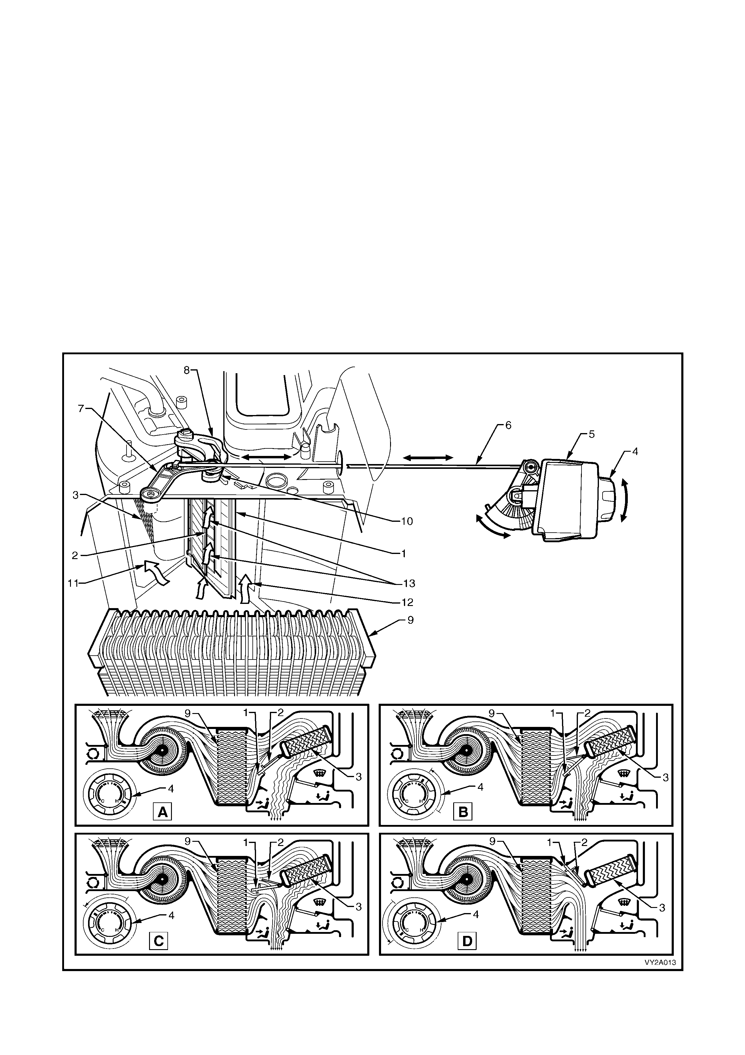
Right-hand drive
The air mix door assembly as fitted to the right-hand drive HVAC system incorporates a main door and a small
(inner) door to control airflow through the heater core. The two stage door opening strategy is used to over come
blower f an pr essur e imm ediate l y downstream of the evaporat or when al l air is pas s ing throu gh the heater cor e (f ull
hot position). This reduces door opening loads when a cooler or cold temperature is selected.
In the full hot position the main air mix door (1) and the small air mix door (2) are joined together and all air is
directed through the heater core (3). When the temperature switch (4) on the HVAC controller (5) is rotated to
select a c ooler tem perature , the actio n of actuat ing rod (6) and interm ediate le ver (7) m oves the s mall air mix door
lever (8) first, to depressurise the cavity between the heater core and the evaporator (9), followed by the large air
mix door lever (10). As the doors move toward to the full cold position, the y move closer together. In the full cold
position they will be joined together again, completely sealing off the heater core cavity. The reverse sequence
occurs when moving from the full cold to the full hot position.
In Figure 2A-33, the cutaway drawing shows the air mix doors in a warm position, i.e. the air moving left (11) is
headed for the heater core and the air moving to the right (1 2) is bypassing th e heater core. T he air in the m iddle
(13) is also bypassing the heater core via the holes in the main air mix door.
The airflow schematics A, B C and D in Figure 2A-33 represent air mix door movement from hot to cold and the resultant
airflow :
• A: Full hot • B: Warm
• C: Warm • D: Full cold
Figure 2A-33

VACUUM TANK
The vacuum tank (1) is located on the left side of
the HVAC un it (2) on both left and right-hand drive
HVAC units. Figure 2A-34 shows the vacuum tank
as fitted to right-hand drive units.
This tank is used to maintain a vacuum to the
vacuum actuators (which operate th e different vent
positions) during driving situations where the
vacuum s our ce is lo w su ch as f ull en gin e thro ttl e. A
one way valve is locat ed in the vacuum sour ce line
from the inlet manifold.
Two vacuum lines are attached to the vacuum
tank. The vacuum line (3) located towards the
front of the vehicle is the vacuum supply line from
the engine inlet manifold. The vacuum line (4)
located towards the rear of the vehicle is the
vacuum feed to the to the mode switch
vacuum valve and the water valve vacuum switch
mounted to the rear of the HVAC controller. On
Occupant Climate Control systems the
vacuum feed is directed to the solenoid
pack located on the underside of the of the HVAC
unit. For further information applicable to
OCC vacuum connections, refer to
Section 2D HVAC OCCUPANT CLIMATE
CONTROL (AUTO A/C) – DESCRIPTION AND
OPERATION.
Figure 2A-34
VACUUM TANK ONE WAY CHECK VALVE
A one way check valve (1) is fitted in the vacuum
source line from the inlet manifold.
It is loc ate d in t he en gin e ba y, to th e rear of th e in let
manifold. Refer to item 6 in Figure 2A-21 to
Figure 2A-25.
To maintain vacuum within the HVAC system, the
valve m ust be f itted cor rectl y with the black section
(2) of the valve installed towards the HVAC unit
side of the vacuum supply line .
Figure 2A-35
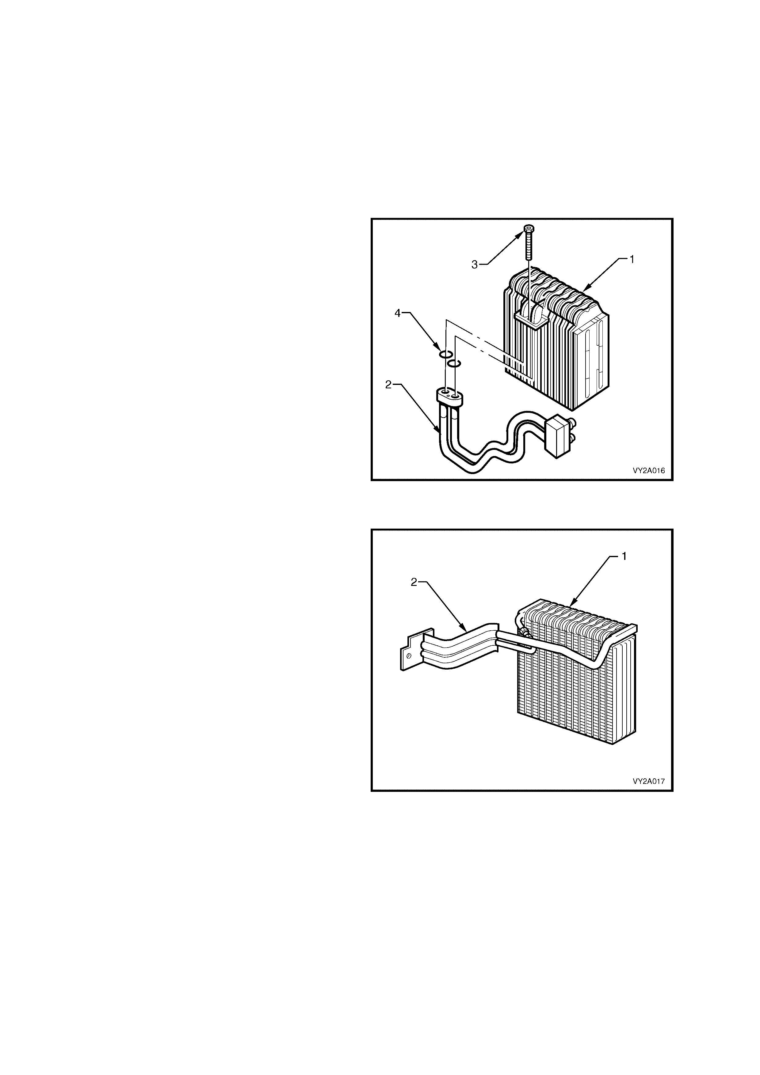
EVAPORATOR
The evaporator is located inside the vehicle housed behind the instrument panel fascia in the HVAC unit. It is
constructed of aluminium and is of a plate and fin design.
The evaporator core is the actual cooling unit of the A/C system. As the low pres sure, low temperature refrigerant
enters the evaporator, it begins to boil and evaporate. This evaporation process absorbs heat from the air being
circulated through the evaporator core by the blower fan.
Due to the evapor ator bein g so cold, conde nsation f orms on the s urface. T his condensatio n is m oisture tak en from
the air (humidity). Also any dust particles in the air passing through the evaporator become lodged in the
condensate water droplets, thus filtering the air from contaminants.
Left-hand drive
The evaporator (1) as fitted to left-hand drive
vehicles is constructed of aluminium and is fitted
with a detachable inlet and outlet pipe assembly
(2). It is att ac hed an d s ea le d to the e vapor ator b y a
single bolt (3) and O-rings (4).
Figure 2A-36
Right-hand drive
The evaporator (1) as fitted to right-hand drive
vehicles is also constructed of aluminium and has
an integral inlet and outlet pipe assembly (2).
Figure 2A-37
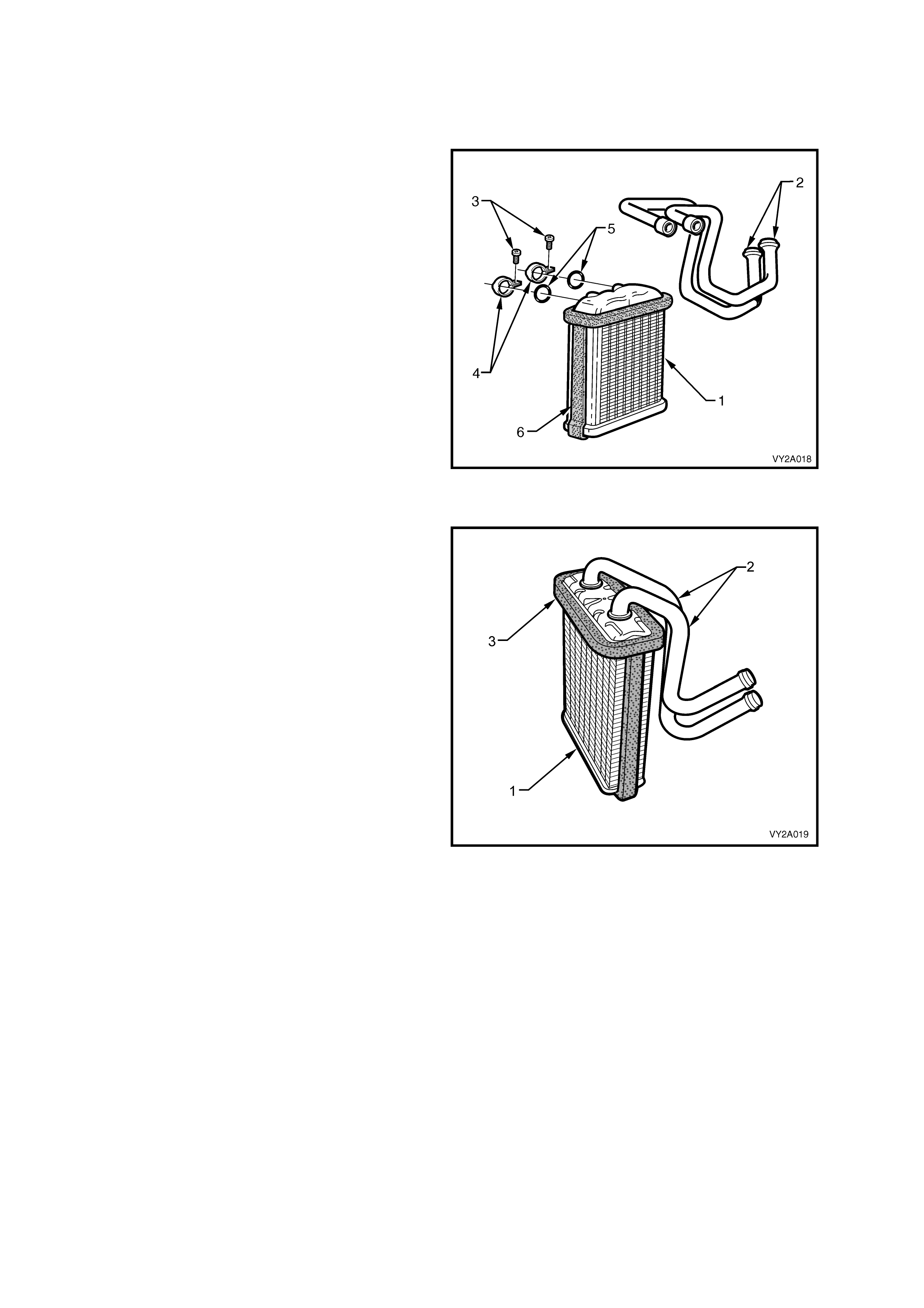
HEATER CORE
The heater c ore is located with in the HVAC unit. W hen the heater tap is i n the open position, en gine coolant f lows
through the heater core providing heat to warm the vehicle interior and to provide windscreen demisting.
Left-hand drive
The heater core (1) as fitted to left-hand drive
vehicles is of a tube and fin design and is
constructed of aluminium. It is fitted with a
detachabl e inlet an d outlet pip e assem bly (2). Each
pipe is attac hed and seal ed to the heater core b y a
single screw (3), retaining clip (4) and O-ring (5).
Sealing f oam (6) is bonded to the si des a nd ar o und
the top of the heater core to prevent air leakage
from the HVAC case and to ensure that all air
passes through the heater core in the full hot
mode.
Figure 2A-38
Right-hand drive
The heater core (1) as fitted to right-hand drive
vehicles is also of a tube and fin design and
constructed of aluminium. It has integral inlet and
outlet pipes (2). Similar to the left-hand drive unit,
sealing f oam (3) is bonde d to the sides and ar ound
the top of the heater core to maximise heating
efficiency.
Figure 2A-39
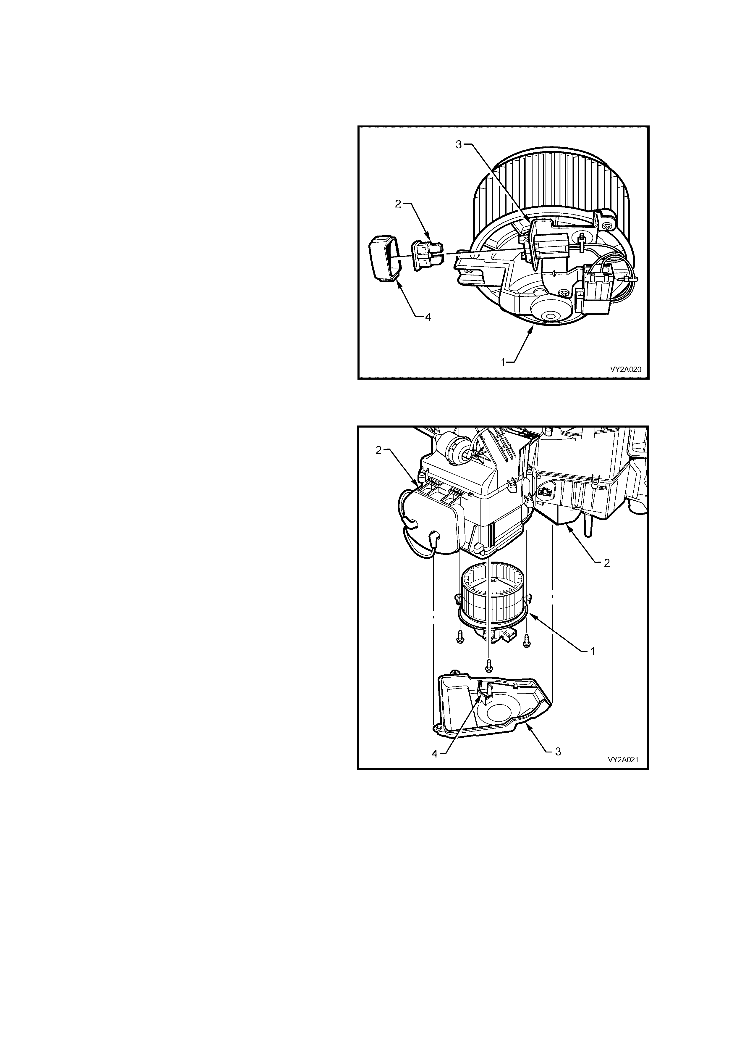
BLOWER MOTOR AND FAN ASSEMBLY
The blower motor draws air from the plenum chamber and into the HVAC unit. This air is then expelled from the
HVAC unit at a speed and temperature as selected on the HVAC controller.
Left-hand drive
The blower motor and fan assembly (1) as fitted to
left-hand drive vehic les is located on th e underside
of the HVAC unit on the right-hand side.
An add it ion al 30 Amp bla d e type f u se ( 2) is f itt ed t o
protect th e blower m otor circuitr y. It is l ocated on a
bracket (3) attached to the under side of the fan
motor. This fuse is accessible when the instrument
panel lower trim panel and the fuse cover (4) have
been removed.
Figure 2A-40
Right-hand drive
The blower motor and fan assembly (1) as fitted to
right-hand drive vehicles is located on the
underside of the HVAC unit (2) on the left-hand
side and is concealed within the HVAC case
The blower motor and fan assembly can be
accessed by removing the blower motor cover (3)
attached to the underside of the HVAC unit.
An internal circuit breaker is fitted to the motor at
the brush plate to protect the blower motor
circuitry.
The blo wer motor an d f an c over incor p or ates an air
channel ( 4) whic h r ed irec ts air f rom the press ur ised
HVAC unit cavity between the fan and the
evaporat or, to an open ing in the fan m otor housing
for motor cooling purposes.
Figure 2A-41
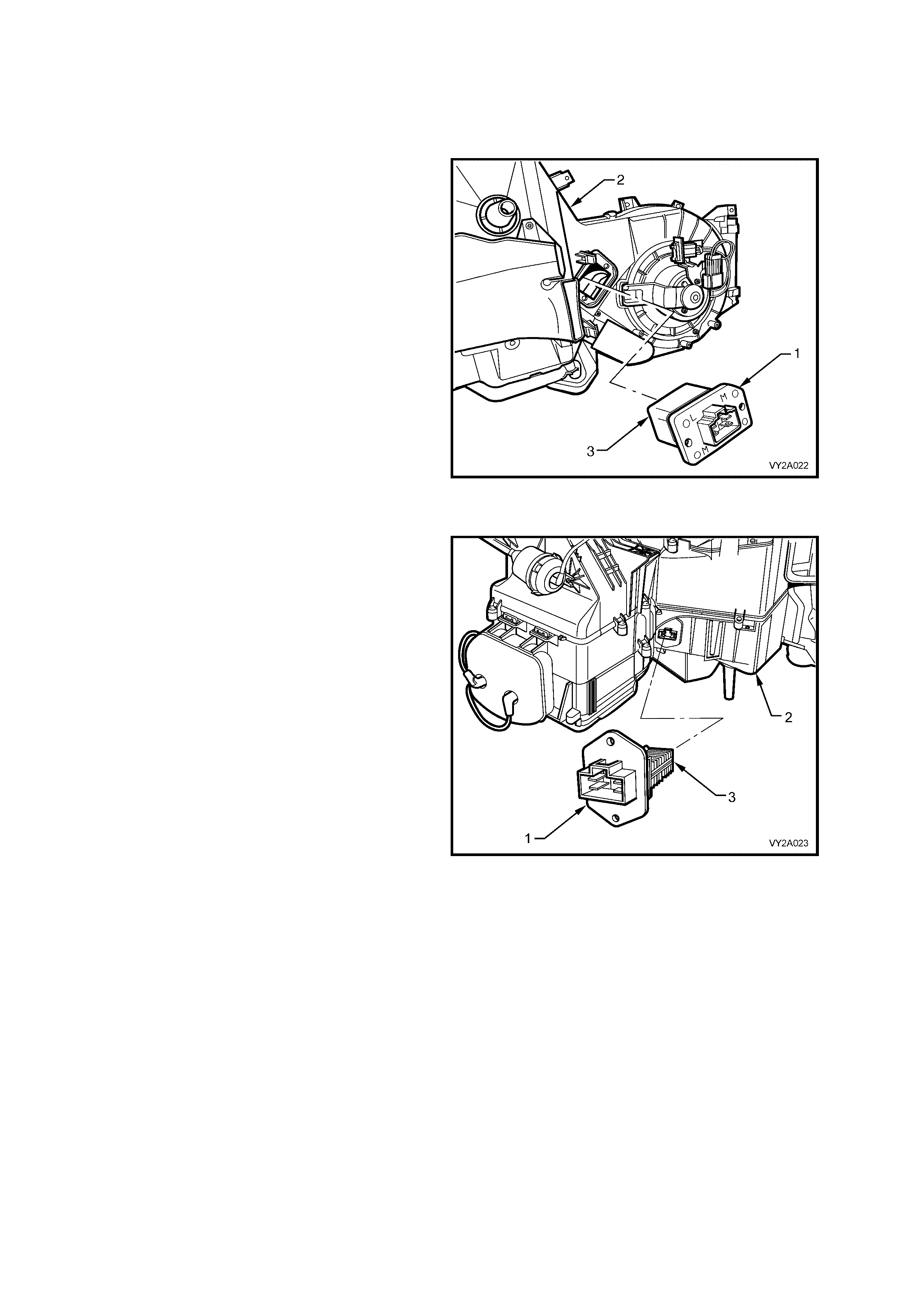
BLOWER MOTOR RESISTOR
To provide the different fan speeds a resistor block consisting of three resistors is wired into the blower motor
circuit. The resistor is located inside the HVAC unit exposed to the internal airflow.
Left-hand drive
The blower motor resistor (1) is located on the
under side of the HVAC unit (2) to the left-hand
side of the blower motor housing.
It uses three resistors contained within a ceramic
heat sink (3) to provide the required fan speeds.
Figure 2A-42
Right-hand drive
The blower motor resistor (1) is located to the
cabin side of the HVAC unit (2) beside the blower
motor housing.
It uses three resistors located in an aluminium
finned heat sink (3) to provide the required fan
speeds.
Figure 2A-43

VACUUM ACTUATORS
All doors on the manual air conditioning HVAC unit, apart from the air mix door(s), are opened and closed by
vacuum actuators. These may be single stage or two stage type actuators. The type, application and number of
actuators are not the same when left-hand drive units and right-hand drive HVAC units are compared:
Left-hand drive: Four actuators – three single stage and one, two stage.
Right-hand drive: Three actuators – one single stage and two, two stage.
On left-hand drive HVAC units all actuators, excluding the face actuator, have a composite metal and plastic
housing with metal ac tuating rods. T he face actuator is the onl y two st age actuator fitted to the lef t-hand drive unit
and has an all metal housing and metal actuating rod.
On right- hand driv e HVAC units al l actuator housings are cons tructed of plastic. The r ods of the ac tuators a re also
constructed of plastic and are colour keyed according to function. The intake actuator rod is blue, the demist/floor
actuator rod is black, and the actuator rod of the face door is white.
The following table is applicable to left and right-hand drive models. It indicates what type of actuator (single or
dual) is used to activate a particular ventilation door.
VACUUM ACTUATOR TYPE
VENTILATION DOOR LHD RHD
Intake (Fresh/Rec i rculat i on) Si ngl e (2 Doors) Single (1 Door)
Face Dual Dual
Demist Single —
Demist /Floor (Foot) — Dual
Foot Single —
NOTE: T he air mix door function (a irflo w through the heat er core) is not listed in the abov e table as its oper ation is
controlled mechanically by rod and temperature switch on manual HVAC systems, or electronically by air mix
motor(s) on auto (OCC) systems.
For left and right-hand drive HVAC system vacuum circuit schematics, refer to Figure 2A-71 and Figure 2A-72.
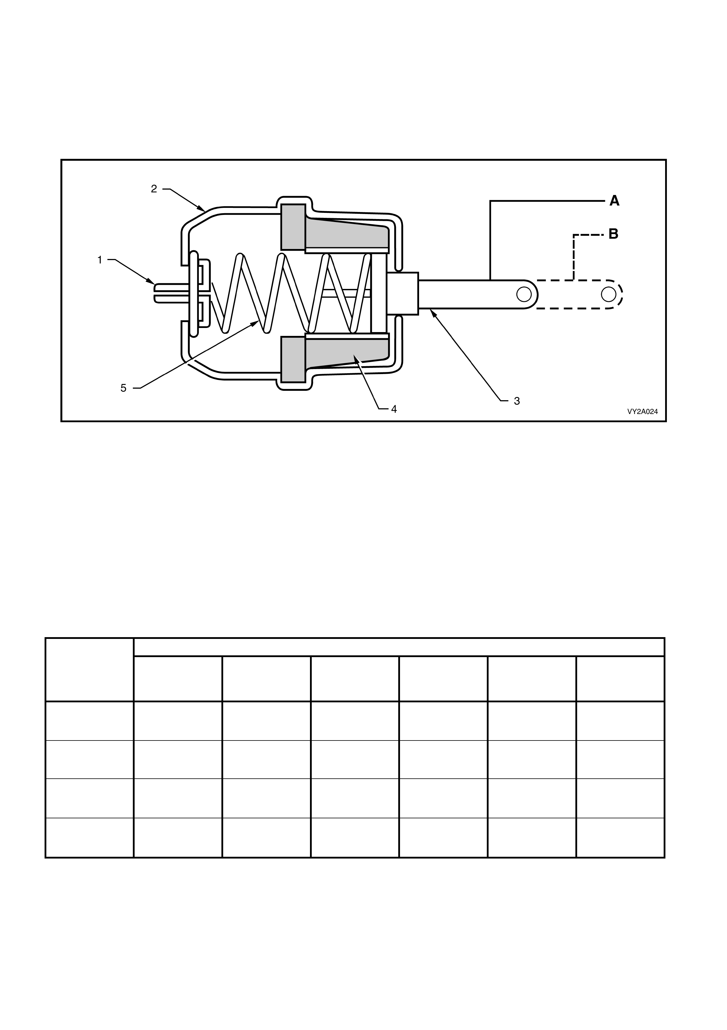
Single Stag e Va cuu m Actu ato r – Operatio n
Each sing le stage ac tuator cons ists of a vac uum housing c ontaining a s pring, rubber d iaphragm , and an actuating
rod.
When vacuum is applied to actuator the rubber diaphragm is pulled back, compressing the spring and retracting the
actuating rod which is connected via one or more levers to an air distribut ion door. When vacuum is removed, the
spring pushes the diaphragm and actuating rod back to its original position.
Figure 2A-44
Legend
A. Actuator rod retracted
B. Actuator rod extended
1. Vacuum Port 4. Diaphragm
2. Actuator Housing 5. Spring
3. Actuator Rod
The following table is applicable to left and right-hand drive models. It indicates what position (retracted or
extended) a single stage actuator will be in, when a particular ventilation function is selected.
SELECTED VENTILATION FUNCTION
ACTUATOR CENTRE AND
SIDES
(FACE)
BI-LEVEL
(FACE/FLOOR) FLOOR BLEND
(DEMIST/FLOOR) DEMIST RECIRCULATION
(FACE)
LHD:
Demist Retracted Retracted Retracted Extended Extended Extended
LHD:
Foot Extended Retracted Retracted Retracted Extended Extended
LHD:
Intake
(Fresh/recirc.) Extended Extended Extended Extended Extended Retracted
RHD:
Intake
(Fresh/recirc.) Extended Extended Extended Extended Extended Retracted
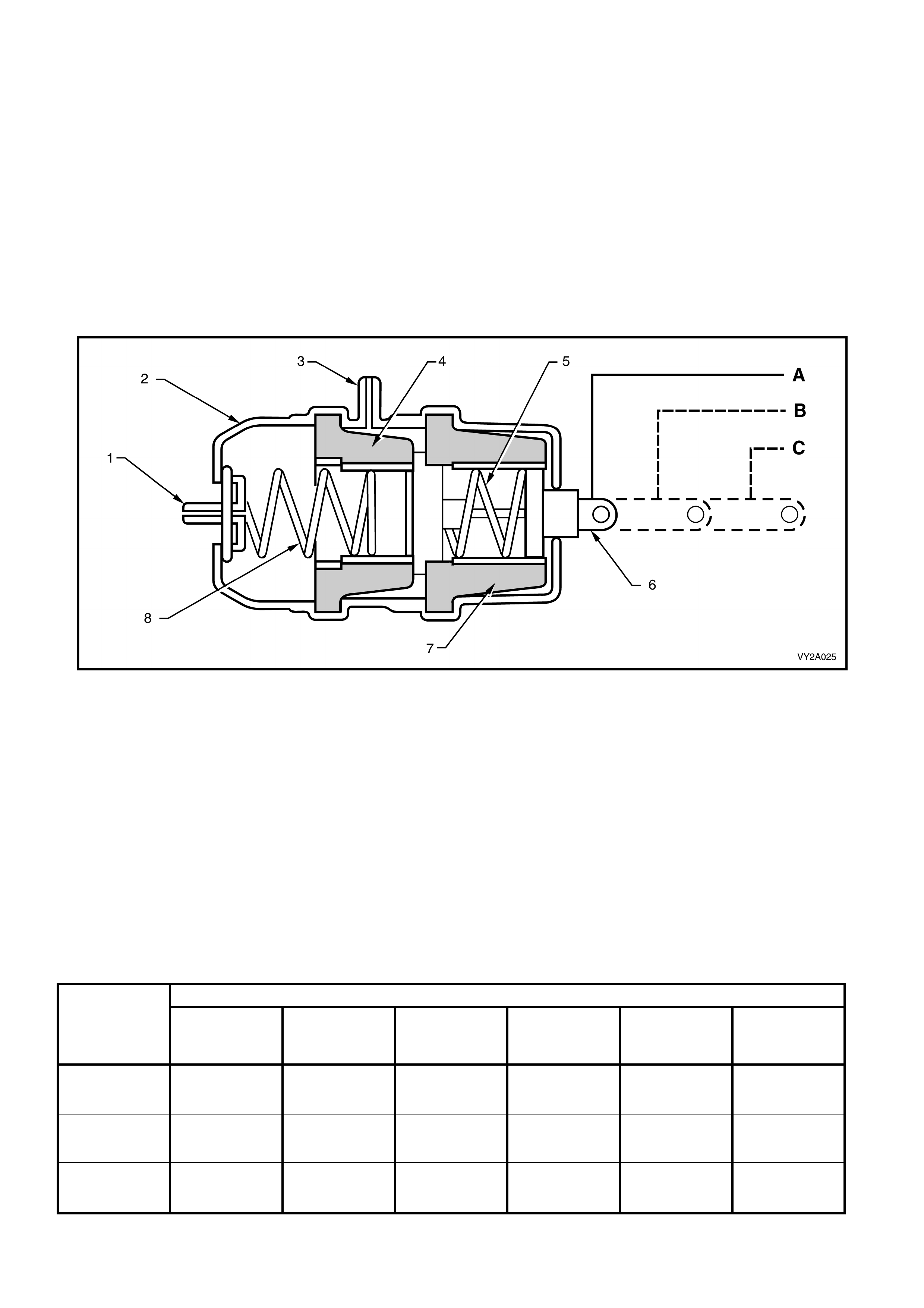
Two Stage Vacuum Actuator – Operation
The HVAC unit has doors that are required to open half way while another door closes fully. With normal single
stage vacuum actuators this would require a complicated linkage set-up and additional actuators.
To overcome this situation ‘two stage’ actuators are used. Through their design they can move the actuating rod
fully ( 2nd stage), half wa y (1st stage) and full y extended (no vacuum ). T his enables s ome doors housed within the
HVAC un it to be onl y half open when a ‘blend ’ m ode is selec ted, and ot her do ors to be c losed at the s am e tim e via
another actuator.
W hen vacuum is direc ted to the 1s t stage vacuum port onl y the 1st s tage rubber diaphragm is pulled (to wards the
rear of the housing), moving the actuator rod only half way. Once the 2nd and 1st stage ports have vacuum
applied, both diaphragms are pulled towards the rear of the housing moving the actuator rod fully inwards to the
2nd stage.
The extent of actuator rod travel in either 1st or 2nd stage is governed by compressing two springs on each
vacuum diaphragm. Both these springs are of differing tensions.
Figure 2A-45
Legend
A. Actuator rod at 2nd Stage
B. Actuator rod at 1st Stage
C. Actuator rod fully extended
1. Vacuum Port – 2nd Stage 5. Spring – 1st Stage
2. Actuator Housing 6. Actuator Rod
3. Vacuum Port – 1st Stage 7. Diaphragm – 1st Stage
4. Diaphragm – 2nd Stage 8. Spring – 2nd Stage
The f ollowing table is ap plic able to left an d ri ght-ha nd driv e m odels. It indic ates what p osition (1s t stag e, 2nd stage
or fully extended) a two stage actuator will be in, when a particular ventilation function is selected.
SELECTED VENTILATION FUNCTION
ACTUATOR CENTRE AND
SIDES
(FACE)
BI-LEVEL
(FACE/FLOOR) FLOOR BLEND
(DEMIST/FLOOR) DEMIST RECIRCULATION
(FACE)
LHD:
Face Actuator 2nd Stage 1st Stage Fully Extended Fully Extended Fully E xtended 2nd S t age
RHD:
Face Actuator 2nd Stage 1st Stage Fully Extended Fully Extended Fully E xtended 2nd S t age
RHD:
Demist /Floor
Actuator Full y E xtended 2nd Stage 2nd Stage 1st Stage Fully Extended Fully Extended
2.6 HVAC UNIT AIRFLOW MODES
The following airflow mode diagrams (Figure 2A-47 to Figure 2A-70) provide a schematic representation of how
cold and hea ted air f lows through the H VAC unit duri ng the seven differ ent possible m odes. Each sc hematic has a
graphic representation of the HVAC controller with switch settings matching the given mode.
Because of the diff erent design c haracter istics and co nfigurati ons of the left-hand dr ive and rig ht-hand dri ve HVAC
units, schematics are provided specific to left-hand drive and right-hand drive applications.
LEFT-HAND DRIVE
• Recirculation Mode Refer to Figure 2A-47 (Full cold) and Figure 2A-48 (Full heat)
• Face Mode Refer to Figure 2A-49 (Full cold) and Figure 2A-50 (Full heat)
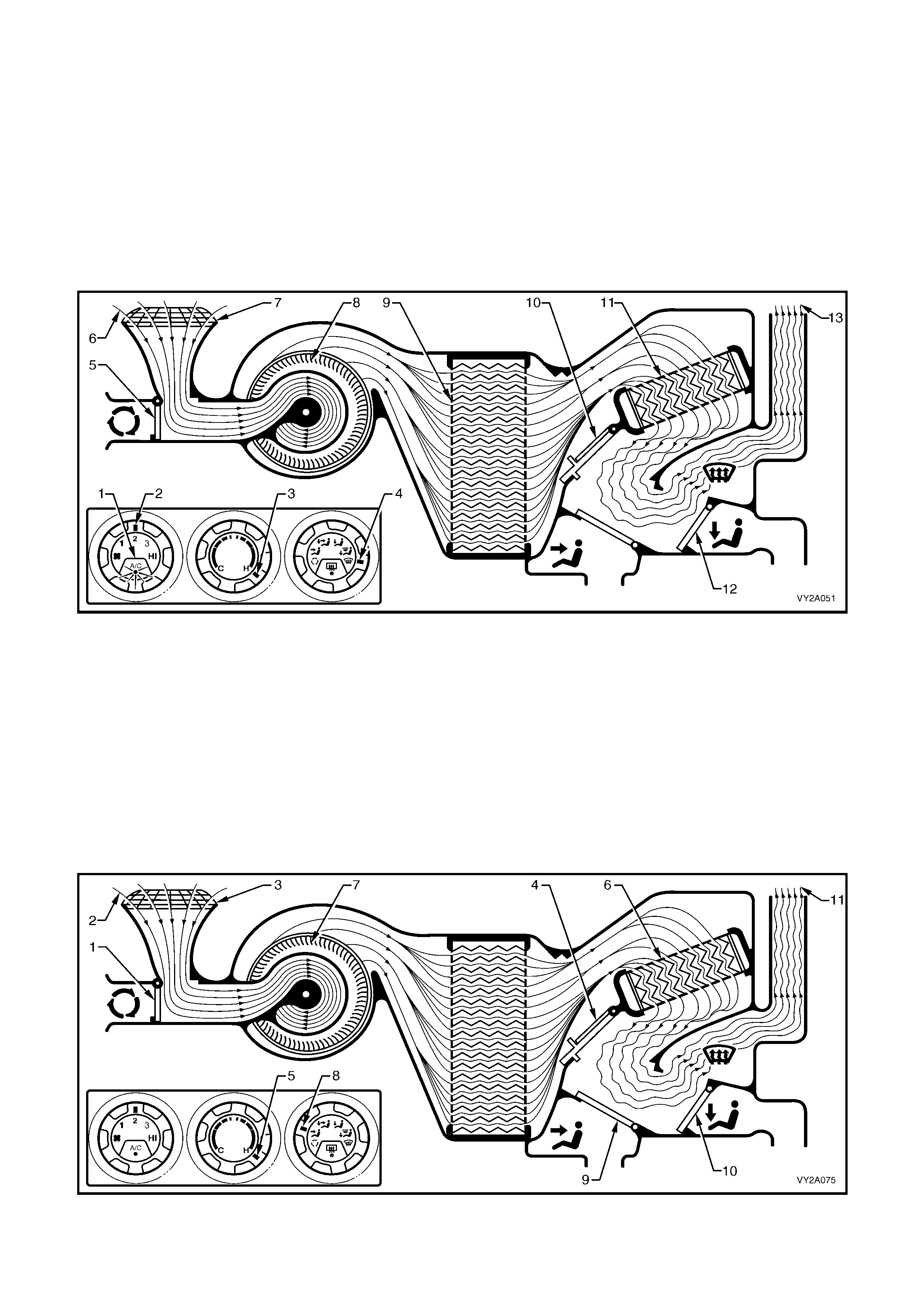
• Bi-level Mo de Refer to Figure 2A-51 (Full cold) and Figure 2A-52 (Full heat)
• Floor Mode Refer to Figure 2A-53 (Full cold) and Figure 2A-54 (Full heat)
• Blend Mode Refer to Figure 2A-55 (Full cold) and Figure 2A-56 (Full heat)
• Demist Mode Refer to Figure 2A-57
• Default Mode Refer to Figure 2A-58
RIGHT-HAND DRIVE
• Recirculation Mode Refer to Figure 2A-59 (Full cold) and Figure 2A-60 (Full heat)
• Face Mode Refer to Figure 2A-61 (Full cold) and Figure 2A-62 (Full heat)
• Bi-level Mo de Refer to Figure 2A-63 (Full cold) and Figure 2A-64 (Full heat)
• Floor Mode Refer to Figure 2A-65 (Full cold) and Figure 2A-66 (Full heat)
• Blend Mode Refer to Figure 2A-67 (Full cold) and Figure 2A-68 (Full heat)
• Demist Mode Refer to Figure 2A-69
• Default Mode Refer to Figure 2A-70
Figure 2A-46
Legend
1. HVAC Unit – LHD 3. HVAC Unit – RHD
2. HVAC Unit Airflow Schematic – LHD 4. HVAC Unit Airflow Schematic – RHD
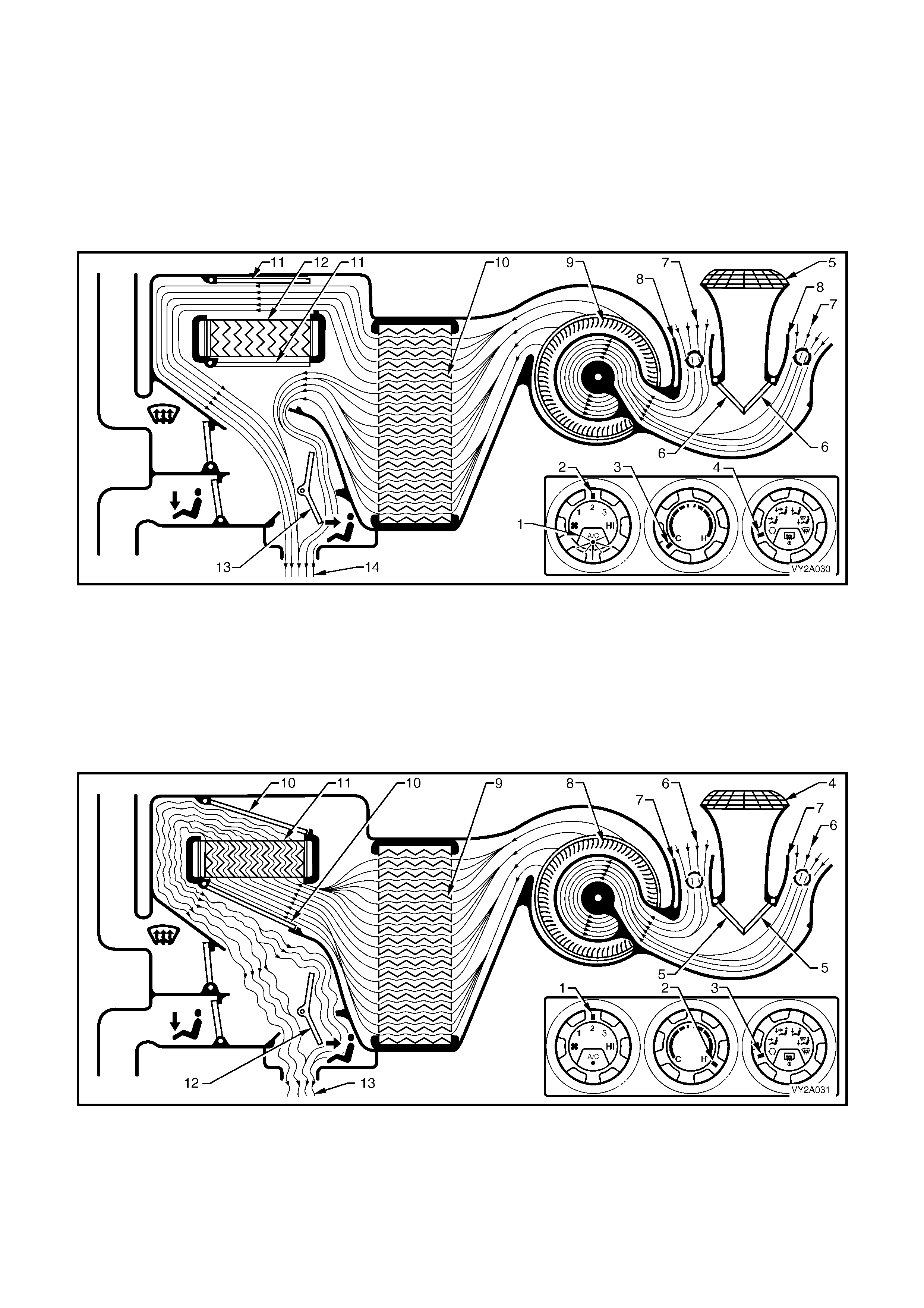
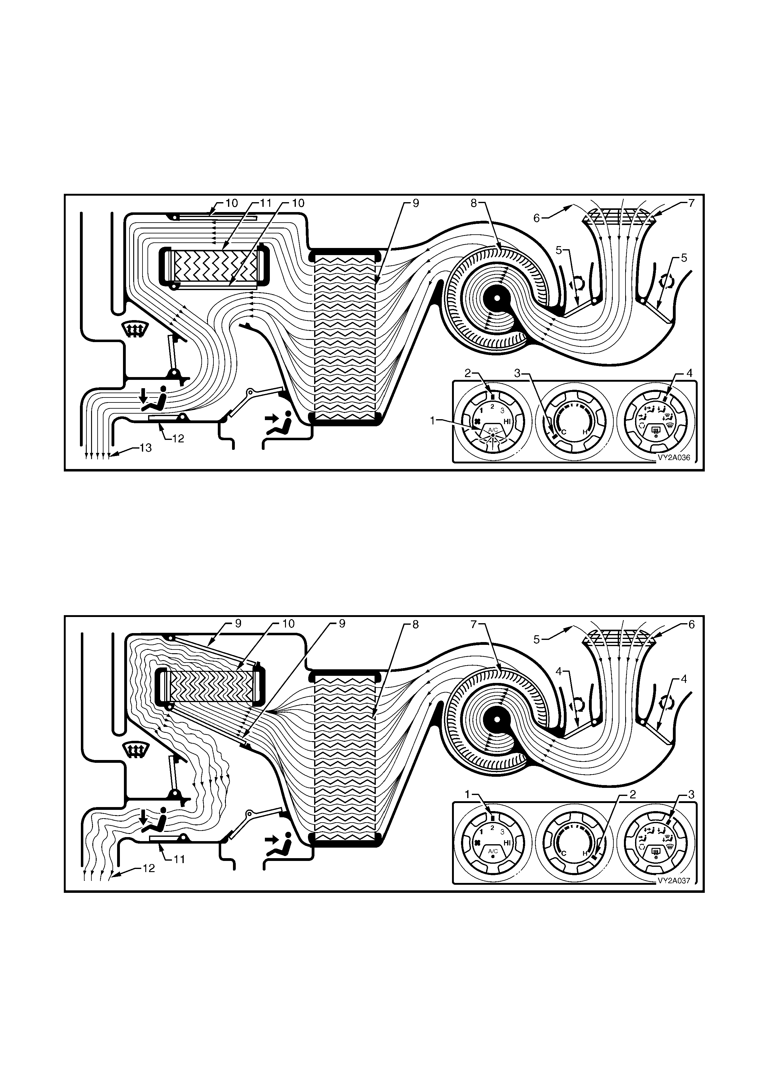
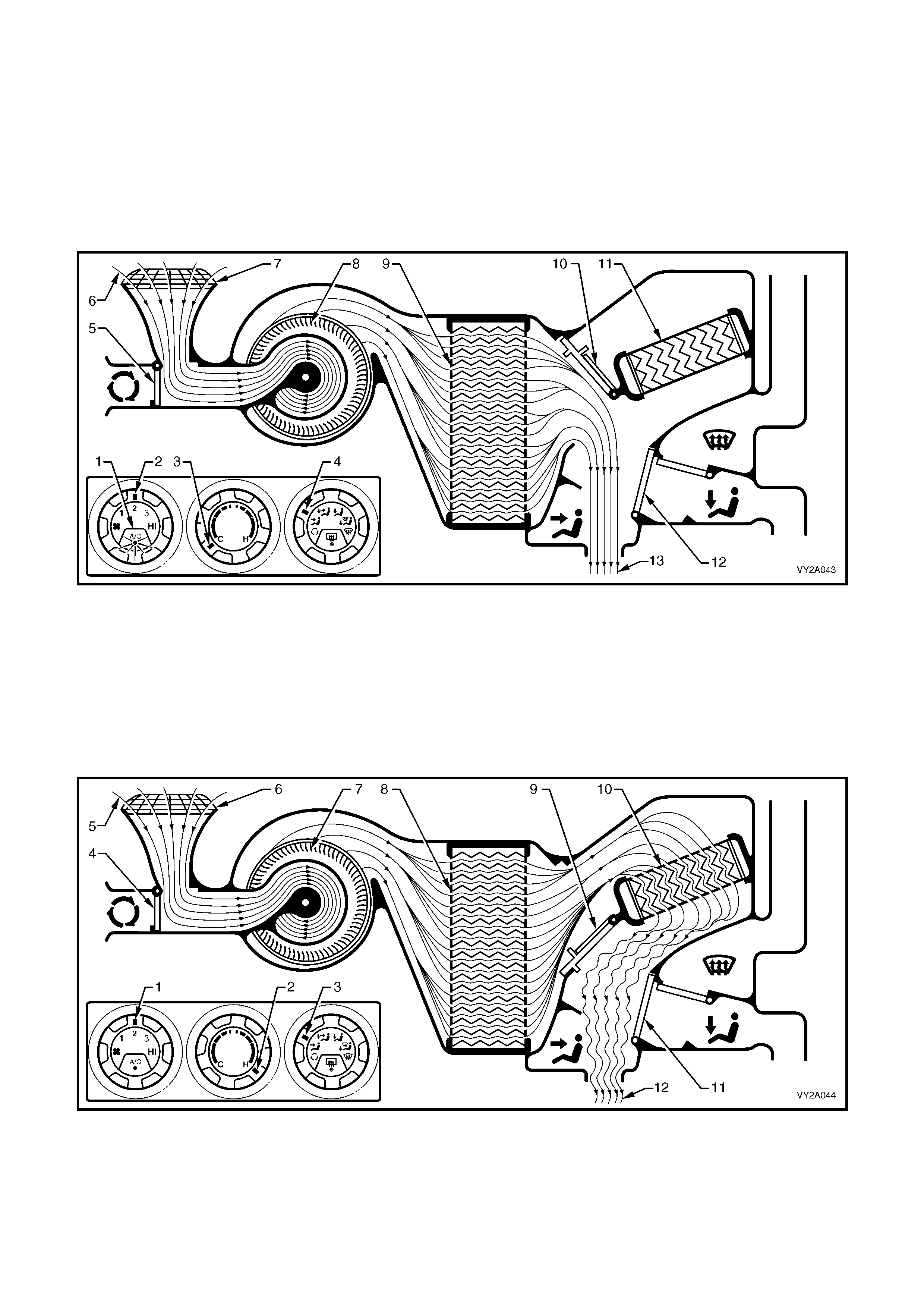
RECIRCULATION MODE – LEFT-HAND DRIVE
Full cold
The A/C switch is on (1). The f an switch is set to an y one of four speeds (2). The temperature switch is set to the
full cold position (3). The mode control switch is set to recirculation mode (4).
The plenum chamber (outside air) inlet (5) to the HVAC unit is closed off by the recirculation doors (6). Interior air
(7) is drawn into the HVAC unit through the recirculation inlets (8) by the blower motor fan (9), and is then forced
through the cold evaporator fins (10). In full cold mode the air mix doors (11) are positioned to allow all air to
bypass the heater core (12 ). The air tra vels throug h the open f ace door ( 13). The c old air (14) is then dir ected out
of the HVAC unit to the centre and side vents.
Figure 2A-47
Full heat
The fan switch is set to any one of four speeds (1). The temperature switch is set to the full hot position (2). The
mode control switch is set to recirculation mode (3).
The plenum chamber (outside air) inlet (4) to the HVAC unit is closed off by the recirculation doors (5). Interior air
(6) is drawn into the HVAC unit through the recirculation inlets (7) by the blower motor fan (8), and is then forced
through the evaporator fins (9). In full heat mode, the air mix doors (10) are positioned to direct all incoming air
through the heater core (11). The air travels through the open face do or (12). The heat ed air (13) is th en directed
out through the centre and side vents.
Figure 2A-48
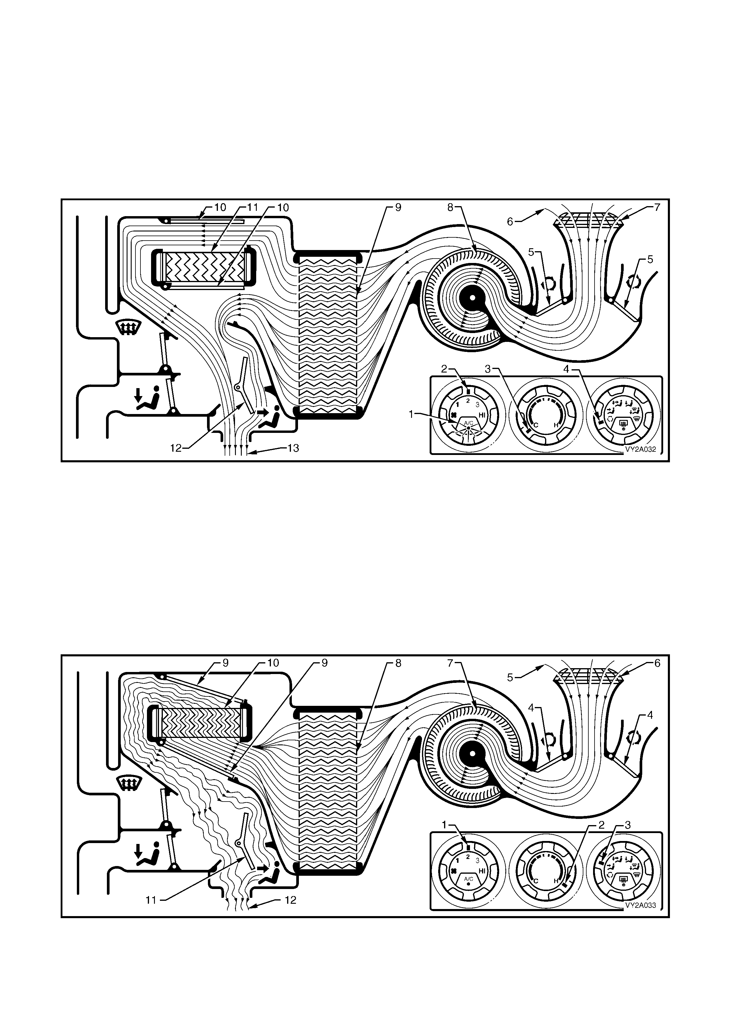
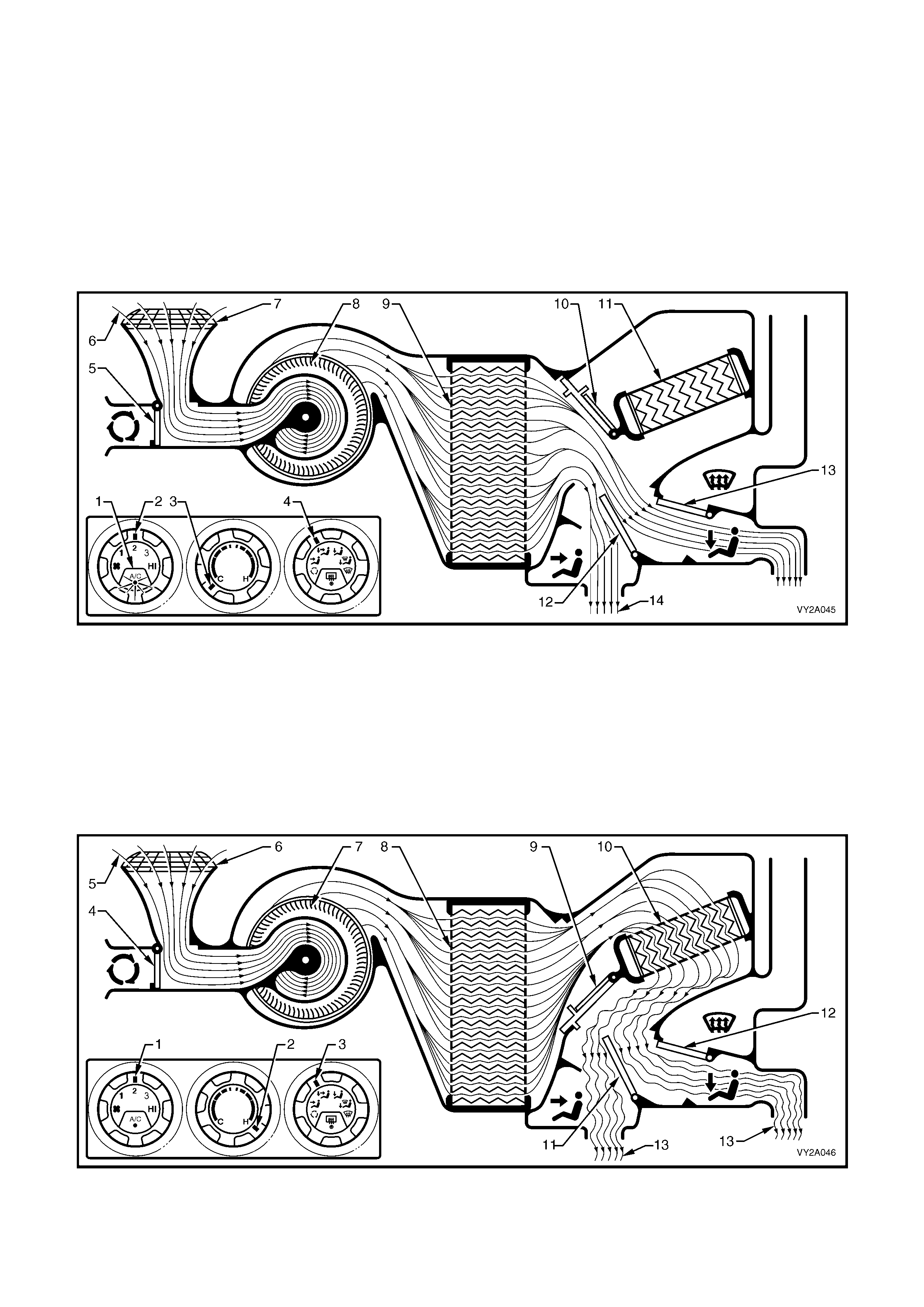
FACE MODE – LEFT-HAND DRIVE
Full cold
The A/C switch is on (1). The f an switch is set to an y one of four speeds (2). The temperature switch is set to the
full cold position (3). The mode control switch is set to face mode (4).
The recirculation doors (5) are closed allowing outside air (6) to enter and flow into the HVAC unit via the plenum
chamber inlet (7). Air is drawn into the HVAC unit by the blower motor (8), and is then forced through the cold
evaporat or fins ( 9). In full cold m ode, the air m ix doors (10) ar e positioned to a llow all air to b ypass the heat er core
(11). T he air travels thr ough the o pen face door ( 12). T he cold air (13) is then direc ted through t he centre a nd side
vents.
Figure 2A-49
Full heat
The fan switch is set to any one of four speeds (1). The temperature switch is set to the full hot position (2). The
mode control switch is set to face mode (3).
The recirculation doors (4) are closed allowing outside air (5) to enter and flow into the HVAC unit via the plenum
chamber inlet (6). Air is drawn into the HVAC unit by the blower motor (7). This air is then forced through the
evaporat or core f ins (8). In full heat m ode, the air mix doors (9) ar e positione d to direct all incom ing air thro ugh the
heater core (10). The air travels through the o pen face door (11). The heated air (12) is t hen directed out through
the centre and side vents.
Figure 2A-50
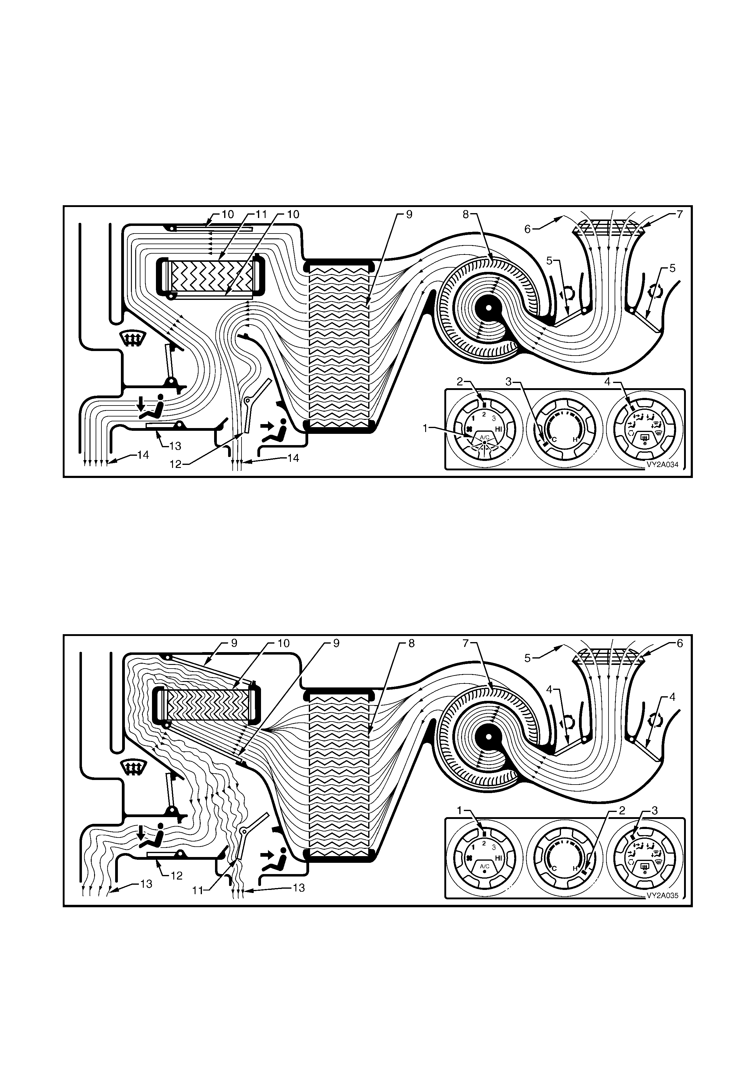
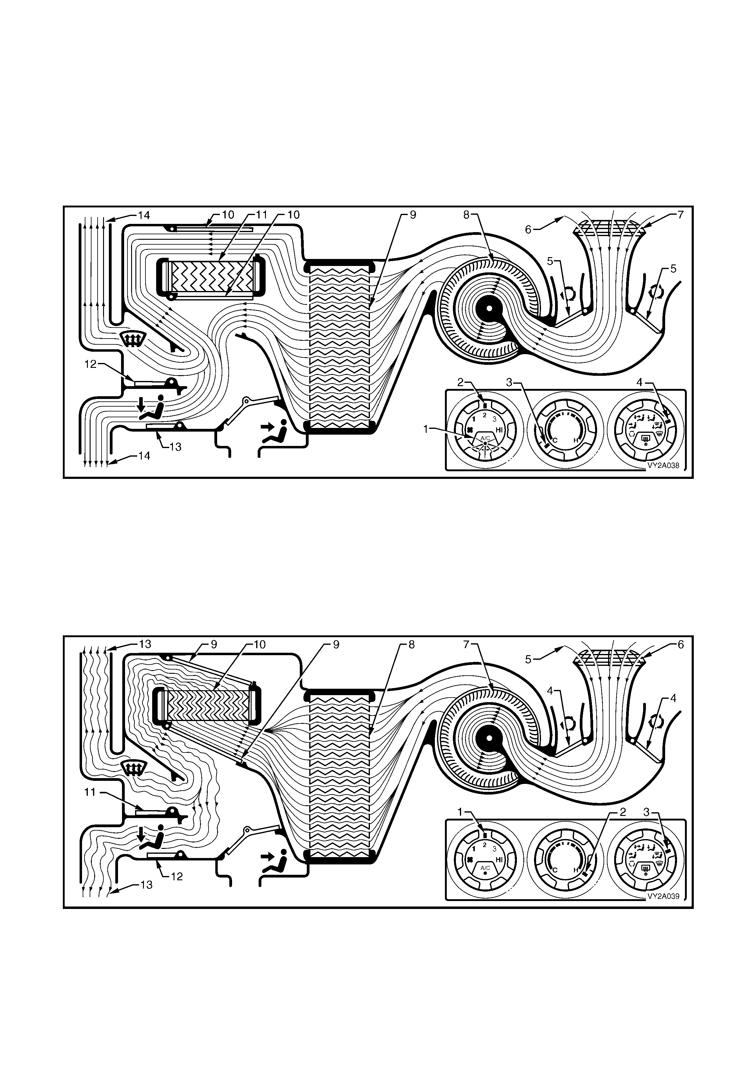
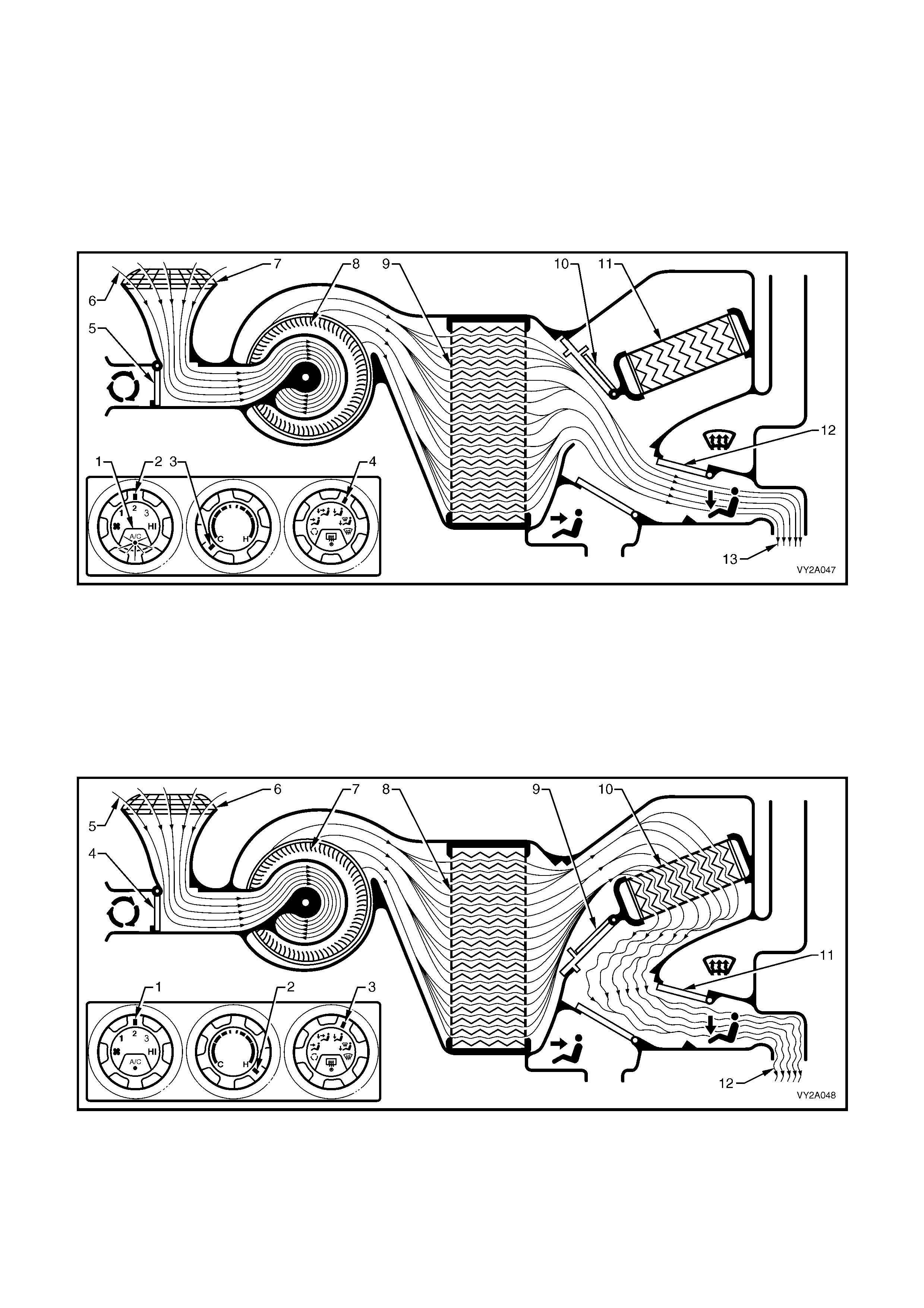
BI-LEVEL MODE – LEFT-HAND DRIVE
Full cold
The A/C switch is on (1). The f an switch is set to an y one of four speeds (2). The temperature switch is set to the
full cold position (3). The mode control switch is set to bi-level mode (4).
The recirculation doors (5) are closed allowing outside air (6) to enter and flow into the HVAC unit via the plenum
chamber inlet (7). Air is drawn into the HVAC unit by the blower motor (8), and is then forced through the cold
evaporat or fins ( 9). In full cold m ode, the air m ix doors (10) ar e positioned to a llow all air to b ypass the heat er core
(11). T he air tr avels thr ough th e half open ed f ace do or ( 12) and the full y opene d f oot door (13). T he cold a ir ( 14) is
then directed through the centre and side vents as well as to the floor ducts.
Figure 2A-51
Full heat
The fan switch is set to any one of four speeds (1). The temperature switch is set to the full hot position (2). The
mode control switch is set to bi-level mode (3).
The recirculation doors (4) are closed allowing outside air (5) to enter and flow into the HVAC unit via the plenum
chamber inlet (6). Air is drawn into the HVAC unit by the blower motor (7). This air is then forced through the
evaporat or core f ins (8). In full heat m ode, the air mix doors (9) ar e positione d to direct all incom ing air thro ugh the
heater core (10). The air travels through the half opened face door (11) and the fully opened foot door (12). The
heated air (13) is then directed through the centre and side vents as well as to the floor ducts.
Figure 2A-52
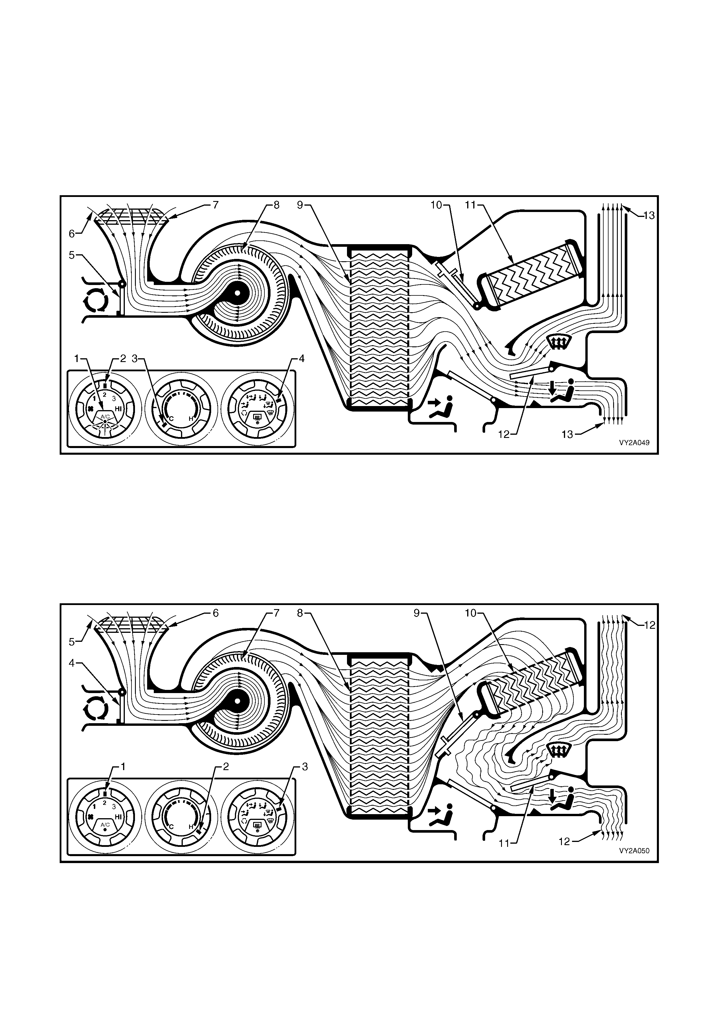
FLOOR MODE – LEFT-HAND DRIVE
Full cold
The A/C switch is on (1). The f an switch is set to an y one of four speeds (2). The temperature switch is set to the
full cold position (3). The mode control switch is set to floor mode (4).
The recirculation doors (5) are closed allowing outside air (6) to enter and flow into the HVAC unit via the plenum
chamber inlet (7). Air is drawn into the HVAC unit by the blower motor (8), and is then forced through the cold
evaporat or fins ( 9). In full cold m ode, the air m ix doors (10) ar e positioned to a llow all air to b ypass the heat er core
(11). The air travels through the foot door (12). The cold air (13) is then directed to the floor ducts.
Figure 2A-53
Full heat
The fan switch is set to any one of four speeds (1). The temperature switch is set to the full hot position (2). The
mode control switch is set to floor mode (3).
The recirculation doors (4) are closed allowing outside air (5) to enter and flow into the HVAC unit via the plenum
chamber inlet (6). Air is drawn into the HVAC unit by the blower motor (7). This air is then forced through the
evaporat or core f ins (8). In full heat m ode, the air mix doors (9) ar e positione d to direct all incom ing air thro ugh the
heater core (10). The air travels through the foot door (11). The heated air (12) is then directed to the floor ducts.
Figure 2A-54
BLEND MODE – LEFT-HAND DRIVE
Full cold
The A/C switch is on (1). The f an switch is set to an y one of four speeds (2). The temperature switch is set to the
full cold position (3). The mode control switch is set to blend mode (4).
The recirculation doors (5) are closed allowing outside air (6) to enter and flow into the HVAC unit via the plenum
chamber inlet (7). Air is drawn into the HVAC unit by the blower motor (8), and is then forced through the cold
evaporat or fins ( 9). In full cold m ode, the air m ix doors (10) ar e positioned to a llow all air to b ypass the heat er core
(11). T he air tra vels thr oug h the ope n dem ist door (12 ) and foot d oor (13) . The c old air (14) is then d irected to both
the front windscreen and the floor ducts.
Figure 2A-55
Full heat
The fan switch is set to any one of four speeds (1). The temperature switch is set to the full hot position (2). The
mode control switch is set to blend mode (3).
The recirculation doors (4) are closed allowing outside air (5) to enter and flow into the HVAC unit via the plenum
chamber inlet (6). Air is drawn into the HVAC unit by the blower motor (7). This air is then forced through the
evaporat or core f ins (8). In full heat m ode, the air mix doors (9) ar e positione d to direct all incom ing air thro ugh the
heater core (10). The air travels through the open dem ist door (11) and foot door (12). The heated a ir (13) is then
directed to both the front windscreen and the floor ducts.
Figure 2A-56
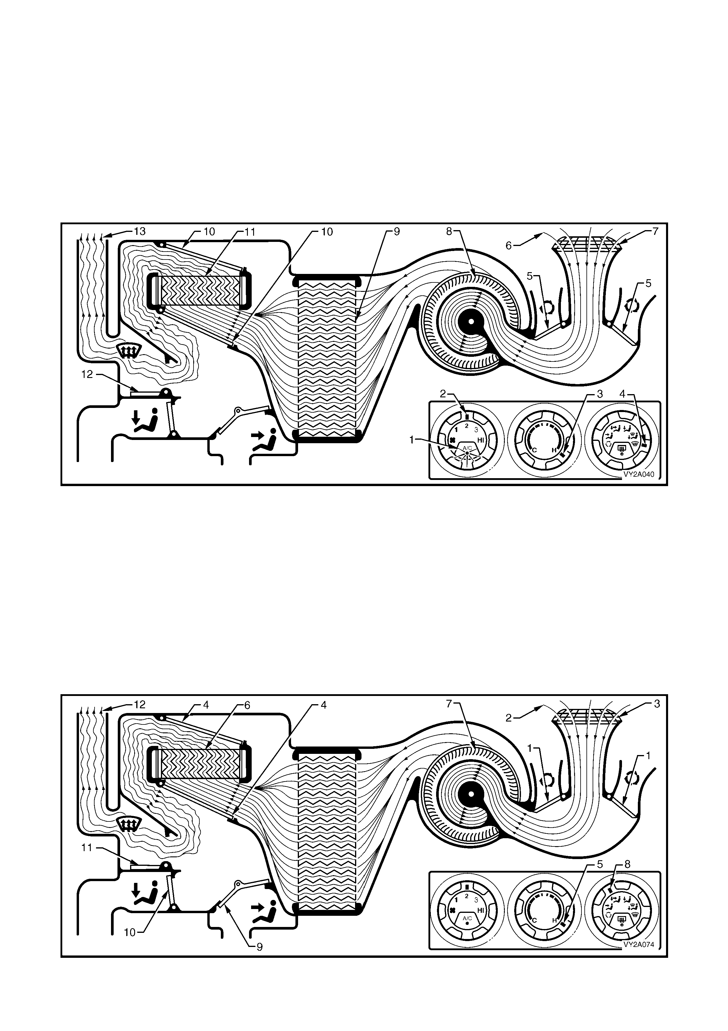
DEMIST MODE – LEFT-HAND DRIVE
Full heat and A/C activated
The A/C switch is on (1). The f an switch is set to an y one of four speeds (2). The temperature switch is set to the
full hot position (3). The mode control switch is set to demist mode (4).
The recirculation doors (5) are closed allowing outside air (6) to enter and flow into the HVAC unit via the plenum
chamber inlet (7). Air is drawn into the HVAC unit by the blower m otor (8). This air is then f orced through the cold
evaporator core fins (9) removing moisture from the air. In full heat mode, the air mix doors (10) are positioned to
direct this dehumidified incoming air through the heater core (11). The air travels through the open demist door
(12). The heated air (13) is then directed to the front windscreen via the demist outlets.
NOTE: By turning on the A/C system in this mode, dehumidification of incoming air will take place, demisting the
front windscreen and side windows in a shorter period.
Figure 2A-57
DEFAULT MODE – LEFT-HAND DRIVE
Loss of vacuum supply to HVAC unit
If a total loss of vacuum occurs within the system, the HVAC unit will default to the following settings. These
settings will be the same in any position of the mode control switch.
The recirculation doors (1) will remain closed allowing outside air (2) to enter and flow into the HVAC unit via the
plenum chamber inlet (3). As the air mix doors (4) are controlled by mechanical linkage, their position will still be
determined by the temperature switch setting (5). However, heated coolant will flow through the heater core (6)
regardless of the position of the temperature switch, as vacuum is required to maintain the water valve in the cold
(closed) position. The blower fan (7) will operate as normal. In any position of the mode switch (8), the face door (9)
and the floor door (10) will remain closed. The demist door (11) will be positioned so that all air (12) leaving the
HVAC unit will be directed to the demist outlets. Depending on the selected setting of temperature switch, this air
may be cold, warm or hot air.
Figure 2A-58
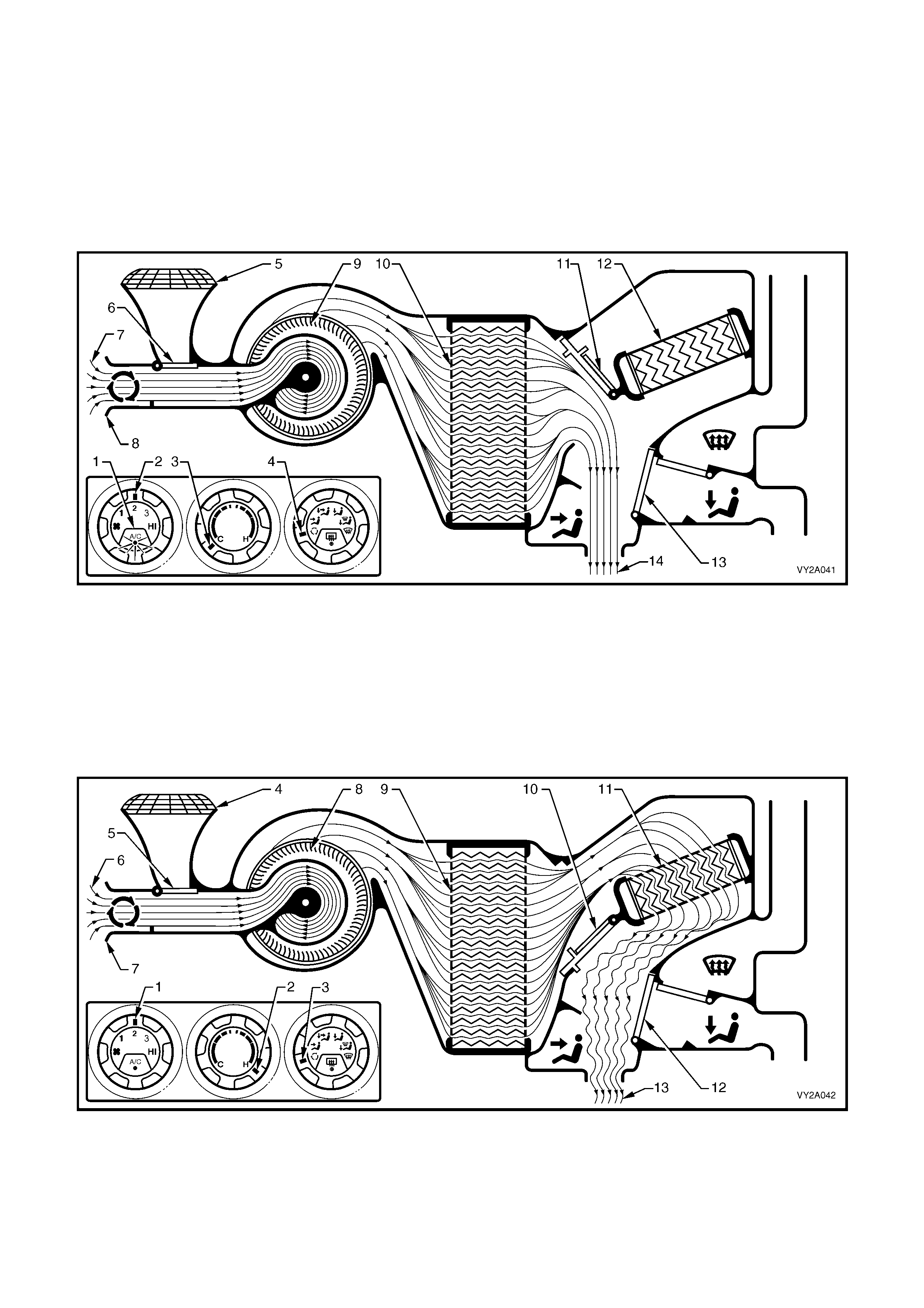
RECIRCULATION MODE – RIGHT-HAND DRIVE
Full cold
The A/C switch is on (1). The f an switch is set to an y one of four speeds (2). The temperature switch is set to the
full cold position (3). The mode control switch is set to recirculation (4).
The plenum chamber (outs ide air) in let ( 5) to the HVAC unit is c lose d off b y the recirculation door (6 ). Interior air (7)
is drawn into the HVAC unit through the recirculation inlet (8) by the blower motor fan (9), and is then forced
through the cold evaporator fins (10). In full cold mode the air mix doors (11) are fully closed sealing off the
passage through the heater core (12). The air travels through the open face door (13). The cold air (14) is then
directed out through the centre and side vents.
Figure 2A-59
Full heat
The fan switch is set to any one of four speeds (1). The temperature switch is set to the full hot position (2). The
mode control switch is set to recirculation (3).
The plenum chamber (outs ide air) in let ( 4) to the HVAC unit is c lose d of f by the recirculation door (5) . Interior air ( 6)
is drawn into the HVAC unit through the recirculation inlet (7) by the blower motor fan (8), and is then forced
through the evaporator fins (9). In full heat mode, the air mix doors (10) are fully open directing all incoming air
through the heater core (11). The air travels through the open face do or (12). The heat ed air (13) is th en directed
out through the centre and side vents.
Figure 2A-60
FACE MODE – RIGHT-HAND DRIVE
Full cold
The A/C switch is on (1). The f an switch is set to an y one of four speeds (2). The temperature switch is set to the
full cold position (3). The mode control switch is set to face mode (4).
The recirculation door (5) is closed allowing outside air (6) to enter and flow into the HVAC unit via the plenum
chamber inlet (7). Air is drawn into the HVAC unit by the blower motor (8), and is then forced through the cold
evaporator fins (9). In full cold mode, the air mix doors (10) are fully closed sealing off the passage through the
heater core (11). The air travels through the open face door (12). The cold air (13) is then directed through the
centre and side vents.
Figure 2A-61
Full heat
The fan switch is set to any one of four speeds (1). The temperature switch is set to the full hot position (2). The
mode control switch is set to face mode (3).
The recirculation door (4) is closed allowing outside air (5) to enter and flow into the HVAC unit via the plenum
chamber inlet (6). Air is drawn into the HVAC unit by the blower motor (7). This air is then forced through the
evaporat or core f ins (8). In f ull heat m ode, the air m ix doors (9) ar e full y open dir ecting all incom ing air thro ugh the
heater core (10). The air travels through the open face door (11). The heated air (12) is then directed out of the
HVAC unit to the centre and side vents.
Figure 2A-62
BI-LEVEL MODE – RIGHT-HAND DRIVE
Full cold
The A/C switch is on (1). The f an switch is set to an y one of four speeds (2). The temperature switch is set to the
full cold position (3). The mode control switch is set to bi-level mode (4).
The recirculation door (5) is closed allowing outside air (6) to enter and flow into the HVAC unit via the plenum
chamber inlet (7). Air is drawn into the HVAC unit by the blower motor (8), and is then forced through the cold
evaporator fins (9). In full cold mode, the air mix doors (10) are fully closed sealing off the passage through the
heater c ore (11). T he air trave ls thro ugh the half opened f ace door (12) and the thr ough the dem ist/floor do or (13)
which is full y open in th e floor m ode. The c old air (1 4) is then direc ted thr oug h the centr e and s ide vents as well as
the floor ducts.
Figure 2A-63
Full heat
The fan switch is set to any one of four speeds (1). The temperature switch is set to the full hot position (2). The
mode control switch is set to bi-level mode (3).
The recirculation door (4) is closed allowing outside air (5) to enter and flow into the HVAC unit via the plenum
chamber inlet (6). Air is drawn into the HVAC unit by the blower motor (7). This air is then forced through the
evaporat or core f ins (8). In f ull heat m ode, the air m ix doors (9) ar e full y open dir ecting all incom ing air thro ugh the
heater core (10). The air travels through the half opened face door (11) and through the demist/floor door (12)
which is f ully open in the f loor mode. T he heated air (13) is then dir ected throug h the centre and s ide vents as well
as to the floor ducts.
Figure 2A-64
FLOOR MODE – RIGHT-HAND DRIVE
Full cold
The A/C switch is on (1). The f an switch is set to an y one of four speeds (2). The temperature switch is set to the
full cold position (3). The mode control switch is set to floor mode (4).
The recirculation door (5) is closed allowing outside (6) air to enter and flow into the HVAC unit via the plenum
chamber inlet (7). Air is drawn into the HVAC unit by the blower motor (8), and is then forced through the cold
evaporator fins (9). In full cold mode, the air mix doors (10) are fully closed sealing off the passage through the
heater core (11). The air travels through the demist/floor door (12) which is fully open in the floor mode. The cold air
(13) is then directed to floor ducts.
Figure 2A-65
Full heat
The fan switch is set to any one of four speeds (1). The temperature switch is set to the full hot position (2). The
mode control switch is set to floor mode (3).
The recirculation door (4) is closed allowing outside air (5) to enter and flow into the HVAC unit via the plenum
chamber inlet (6). Air is drawn into the HVAC unit by the blower motor (7). This air is then forced through the
evaporat or core f ins (8). In f ull heat m ode, the air m ix doors (9) ar e full y open dir ecting all incom ing air thro ugh the
heater c ore ( 10) . T he air tra ve ls throug h the demis t/f loor door ( 11) which is f ully open in t he f loor mode. T he heate d
air (12) is then directed to the floor ducts.
Figure 2A-66
BLEND MODE – RIGHT-HAND DRIVE
Full cold
The A/C switch is on (1). The f an switch is set to an y one of four speeds (2). The temperature switch is set to the
full cold position (3). The mode control switch is set to blend mode (4).
The recirculation door (5) is closed allowing outside air (6) to enter and flow into the HVAC unit via the plenum
chamber inlet (7). Air is drawn into the HVAC unit by the blower motor (8), and is then forced through the cold
evaporator fins (9). In full cold mode, the air mix doors (10) are fully closed sealing off the passage through the
heater core (11). The air travels through the demist/floor door (12) which is positioned half way between demist and
floor modes. The cold air (13) is then directed to both the front windscreen and the floor ducts.
Figure 2A-67
Full heat
The fan switch is set to any one of four speeds (1). The temperature switch is set to the full hot position (2). The
mode control switch is set to blend mode (3).
The recirculation door (4) is closed allowing outside air (5) to enter and flow into the HVAC unit via the plenum
chamber inlet (6). Air is drawn into the HVAC unit by the blower motor (7). This air is then forced through the
evaporat or core f ins (8). In f ull heat m ode, the air m ix doors (9) ar e full y open dir ecting all incom ing air thro ugh the
heater core (10). The air travels through the demist/floor door (11) which is positioned half way between demist and
floor modes. The heated air (12) is then directed to both the front windscreen and the floor ducts.
Figure 2A-68
DEMIST MODE – RIGHT-HAND DRIVE
Full heat and A/C activated
The A/C switch is on (1). The f an switch is set to an y one of four speeds (2). The temperature switch is set to the
full hot position (3). The mode control switch is set to demist mode (4).
The recirculation door (5) is closed allowing outside air (6) to enter and flow into the HVAC unit via the plenum
chamber inlet (7). Air is drawn into the HVAC unit by the blower m otor (8). This air is then f orced through the cold
evaporator core fins (9) removing moisture from the air. In full heat mode, the air mix doors (10) are fully open
allowing dehumidified incoming air through the heater core (11). The air travels through the demist/floor door (12)
which is full y open in the dem ist mode. The heated air (13) is then directed t o the front windscreen via the dem ist
outlets.
NOTE: By turning on the A/C system in this mode, dehumidification of incoming air will take place, demisting the
front windscreen and side windows in a shorter period.
Figure 2A-69
DEFAULT MODE – RIGHT-HAND DRIVE
Loss of vacuum supply to HVAC unit
If a total loss of vacuum occurs within the system, the HVAC unit will default to the following settings. These
settings will be the same in any position of the mode control switch.
The recirculation door (1) will remain closed allowing outside air (2) to enter and flow into the HVAC unit via the
plenum chamber inlet (3). As the air mix doors (4) are controlled by mechanical linkage, their position will still be
determined by the temperature switch setting (5). However, heated coolant will flow through the heater core (6)
regardless of the position of the temperature switch as vacuum is required to maintain the water valve in the cold
(closed) posit ion. T he blo wer m otor (7) will o perat e as norm al. In an y position of the m ode s witch (8), t he f ace door
(9) will rem ain clos ed. The dem ist/floor door (10) will b e positioned s o that all air ( 11) leaving the H VAC unit wil l be
directed t o the dem ist outlets. Depen ding on the s elected setti ng of tem perature switc h, this air m ay be cold, war m
or hot air.
Figure 2A-70

2.7 VACUUM CIRCUITS
The vacuum generated within the engine inlet manifold is used to operate the HVAC vacuum actuators and the
water valve.
A vacuum tank located on the left-hand side of the HVAC unit is used to store vacuum for times when engine
vacuum is low such as at full engine throttle, refer to Figure 2A-34. A check valve is fitted on the vacuum supply
line between the inlet manifold and the vacuum tank to ensure that vacuum is maintained within the system at all
times.
The black plastic vacuum supply line on the HVAC unit supplies vacuum to the vacuum tank. The check valve is
used to join the supply line to the hose connected to the inlet manifold.
Vacuum from the vacuum tank is then direc ted through a sup ply hose (white f or LHD, black f or RHD) to the mode
switch (for HVAC door operation) and from the tee to the water valve vacuum switch (for water valve operation).
From the water va lve vacu um switch, vacuum m oves into a c oloured pl astic tu be (orange f or LHD, yellow fo r RHD)
and then c onnects to the black hose (inside t he cab in at the dash pa nel) which in turn is co nnected t o the vacuum
operated heater water valve. When vacuum is applied to the water valve, the valve remains closed and no water
will flow through the heater core. For further information on water valve vacuum switch and water valve operation,
refer to 2.3 HEATER in this Section.
As the m ode switch is turned, vacuum is directed through t he mode s witch and o nto the des ired vacuum actuators
through different coloured plastic tubing. This vacuum will activate the vacuum actuator rod which then moves a
vent position door.
Vacuum is vented from the vacuum actuator/plastic tube once the vacuum mode switch is turned to another
position.
NOTE: Left and right-hand drive HVAC units have different plastic tube colour coding. Refer to Figure 2A-71 and
Figure 2A-72. These diagrams also show which vacuum actuators are applied with vacuum in a certain mode.
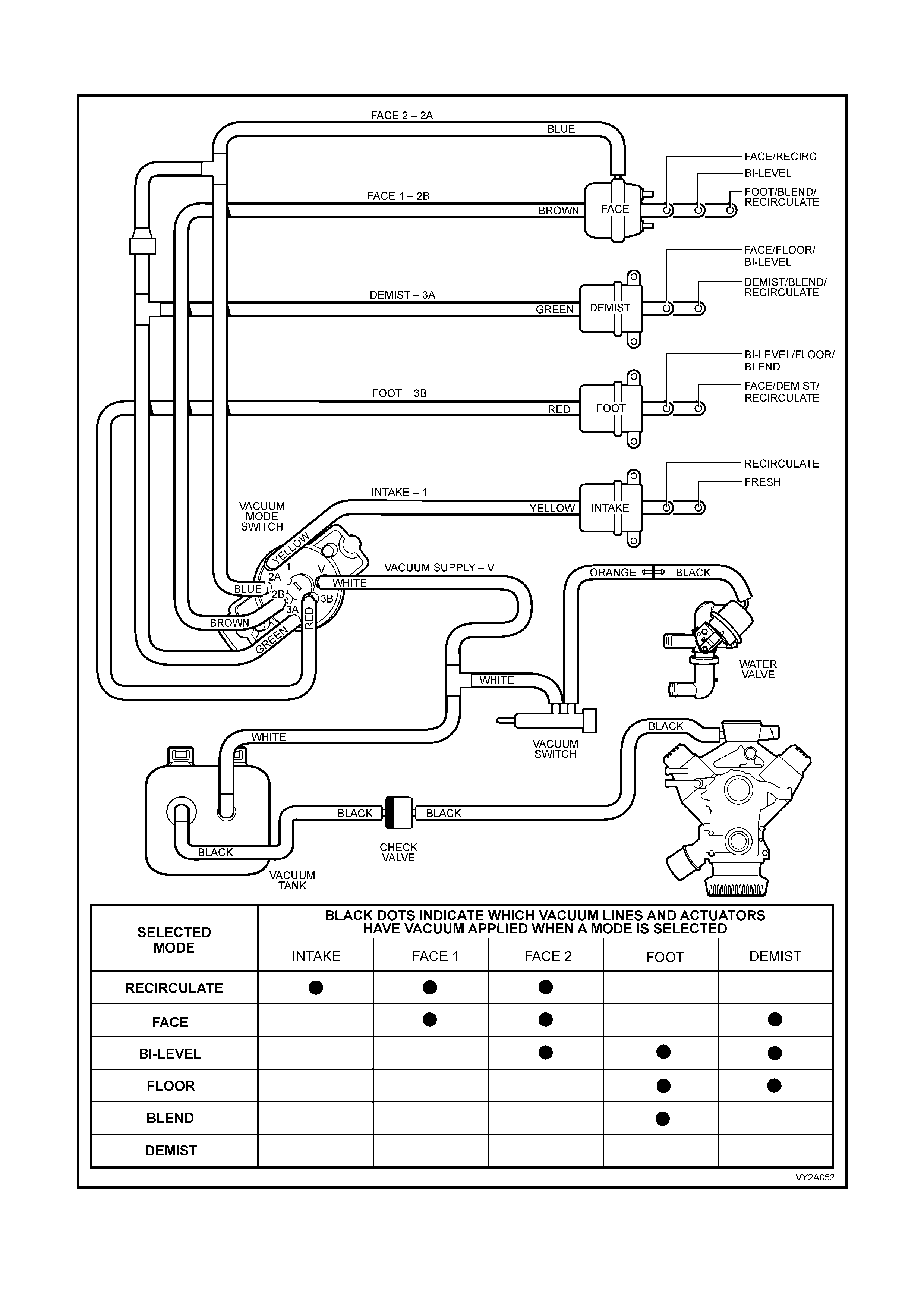
VACUUM CIRCUIT SCHEMATIC– LEFT HAND DRIVE
Figure 2A-71
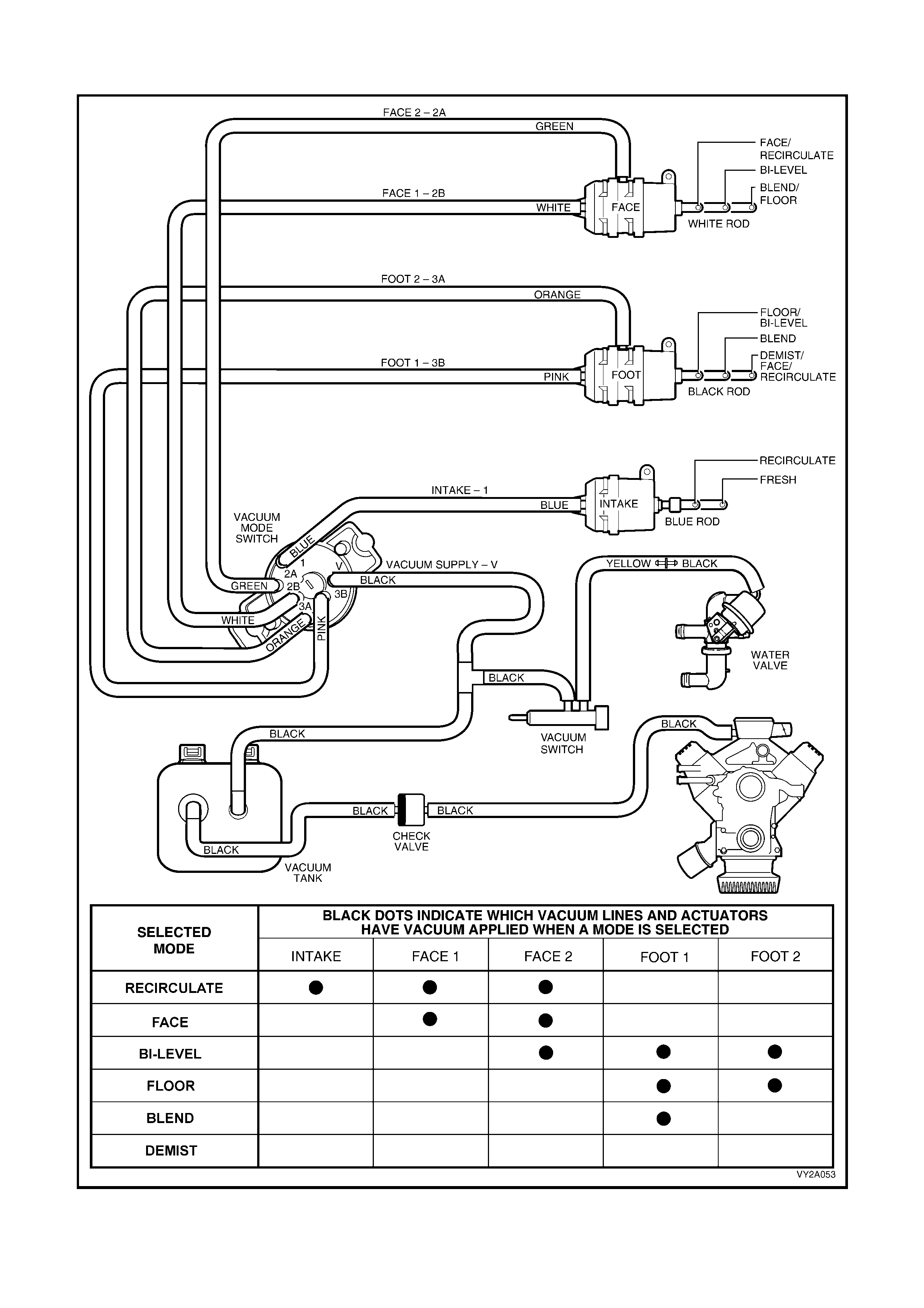
VACUUM CIRCUIT SCHEMATIC – RIGHT HAND DRIVE
Figure 2A-72

2.8 UNDER-HOOD COMPONENTS
RADIATOR ASSEMBLY
W hen the vehic le is built, the c ondens er, filter drier r ec eiver, c oolin g fans , fan s hroud and r adiator are insta lled into
the engine bay as an assembled unit. This unit is described as the radiator assembly or as the CRFM – Condenser,
Radiator and Fan Mod ule .
The condenser is mounted to the f ront of the radiator and is located an d supported by four clips moulde d into the
front of the plastic radiator tanks. The lower clips lock the condenser in place and can be released by hand to
facilitate condenser removal.
The c ooling fans m otors are each att ached b y thr ee screws to th e one piec e plastic f an shroud. T he fan shroud is
mounted to the rear of the radiator and is located and supported b y four clips moulded into the rear of the plastic
radiator tanks. The upper clips lock the fan shroud in place and can be released by hand to facilitate fan shroud
removal. The shroud must be removed to facilitate fan motor and blade assembly removal.
Two harness connectors are mounted to the upper section of the fan shroud allowing the fan motor and blade
assemblies to be removed individually from the shroud. The fan motor and blade is balanced as an assembly.
These two components are serviced only as a unit and must not be separated.
Two types of CRFM’s are fitted to V6 models. V6 cooling fan motors and operating strategies differ according to
mark et application. All other c om ponents apart fr om the fan m otors are comm on to both types of V6 CRFM’s. T he
CRFM as f itted to GEN III V8 m odels is id entical acr oss the model r ange. W hen air cond itioning is not f itted to the
vehicle, the condenser and filter drier receiver are deleted from the CRFM.
For further information relating to cooling fan operation refer to 2.9 COOLING FANS in this Section.
The condenser, filter drier receiver, radiator and the fan motors/blades/shroud assembly can be
removed and installed individually from the vehicle. For removal and installation procedures refer to
Section 2B HVAC CLIMATE CONTROL (MANUAL A/C) – REMOVAL AND INSTALLATION.
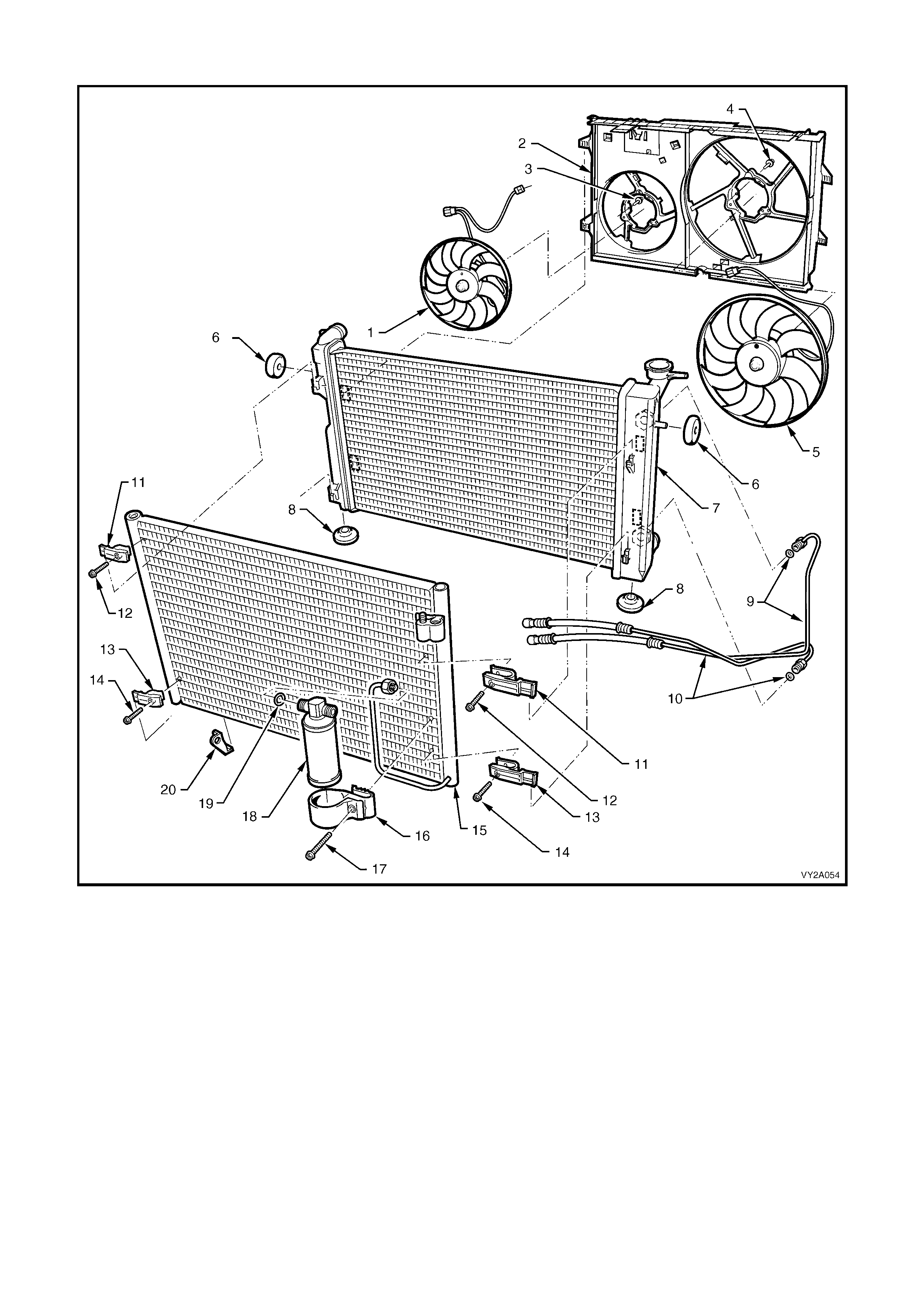
Condenser, Fan, and Radiator Module (CRFM) – V6 and V6 Supercharged
Figure 2A-73/
Legend
1. RHS Fan and Fan Motor Assembly 11. Upper Condenser Mounting Clips (2 places)
2. Fan Shroud 12. Upper Condenser Mounting Clip Screws (2 places)
3. RHS Fan Retaining Screw (3 places) 13. Lower Condenser Mounting Clips (2 places)
4. LHS Fan Retaining Screw (3 places) 14. Lower Condenser Mounting Clip Screws (2 places)
5. LHS Fan and Fan Motor Assembly 15. Condenser
6. Upper Radiator Insulators (2 places) 16. Filter Drier Receiver Mounting Bracket
7. Radiator 17. Filter Drier Receiver Mounting Bracket Screw
8. Lower Radiator Insulators (2 places) 18. Filter Drier Receiver
9. Inlet Transmission Cooling Line and O-ring 19. O-ring
10. Outlet Transmission Cooling Line and O-Ring 20. Ambient Air Temperature Mount
Note: Item 1 and 5, fans and fan motors are shown in Figure 2A-73 as assemblies. Fan and motor assemblies are not to be
disassembled.
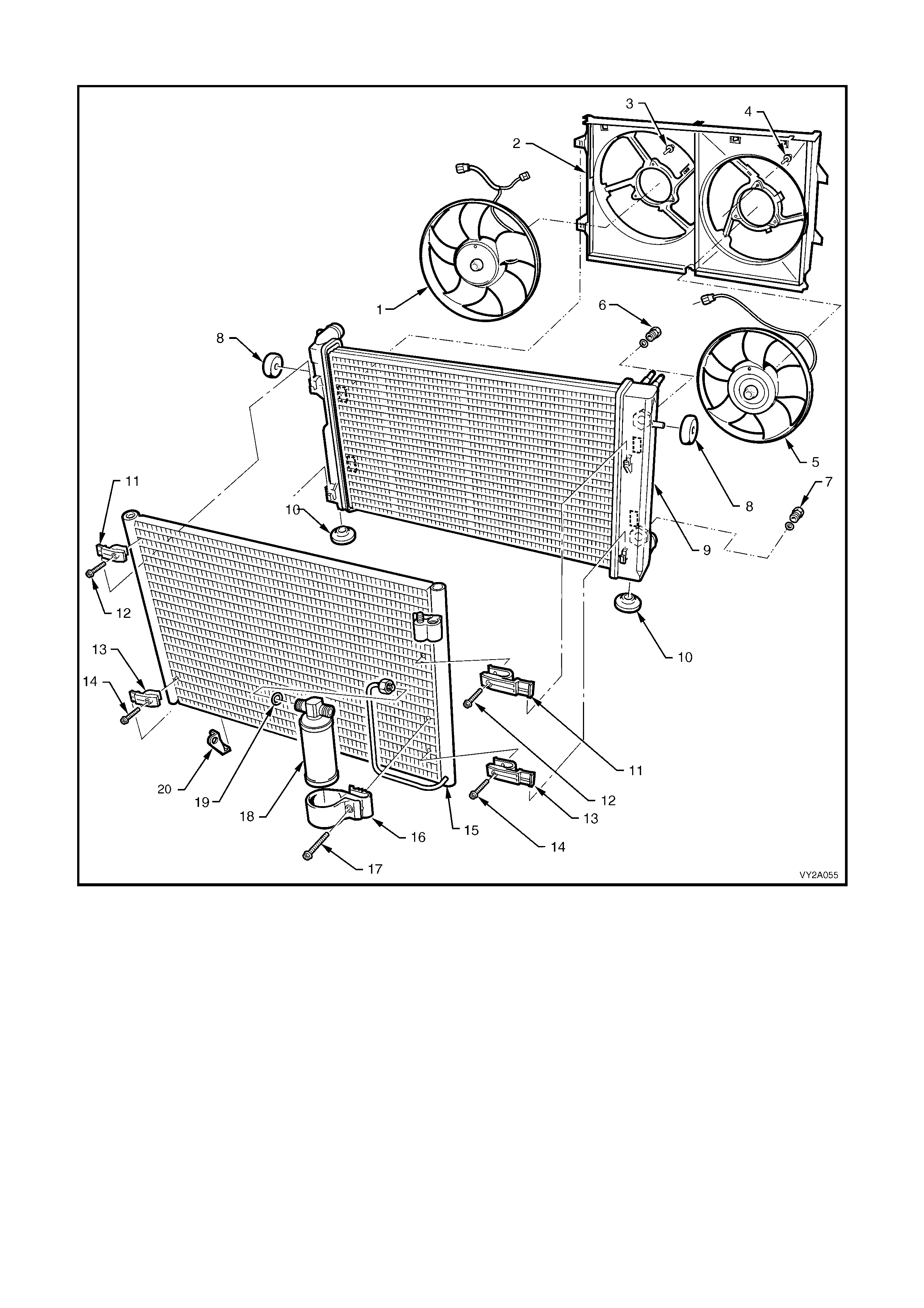
Condenser, Fan, and Radiator Module (CRFM) – GEN III V8
Figure 2A-74
Legend
1. RHS Fan And Fan Motor Assembly 11. Upper Condenser Mounting Clips (2 places)
2. Fan Shroud 12. Upper Condenser Mounting Clip Screws (2 places)
3. RHS Fan Retaining Screw (3 places) 13. Lower Condenser Mounting Clips (2 places)
4. LHS Fan Retaining Screw (3 places) 14. Lower Condenser Mounting Clip Screws (2 places)
5. LHS Fan And Fan Motor Assembly 15. Condenser
6. Inlet Transmission Cooling Line Connector / O-ring 16. Filter Drier Receiver Mounting Bracket
7. Outlet Transmission Cooling Line Connector / O-ring 17. Filter Drier Receiver Mounting Bracket Screw
8. Upper Radiator Insulators (2 places) 18. Filter Drier Receiver
9. Radiator 19. O-ring
10. Lower Radiator Insulators (2 places) 20. Ambient Air Temperature Mount
Note: 1 and 5, fans and fan motors are shown in Figure 2A-74 as assemblies. Fan and fan motor assemblies are not to be
disassembled.
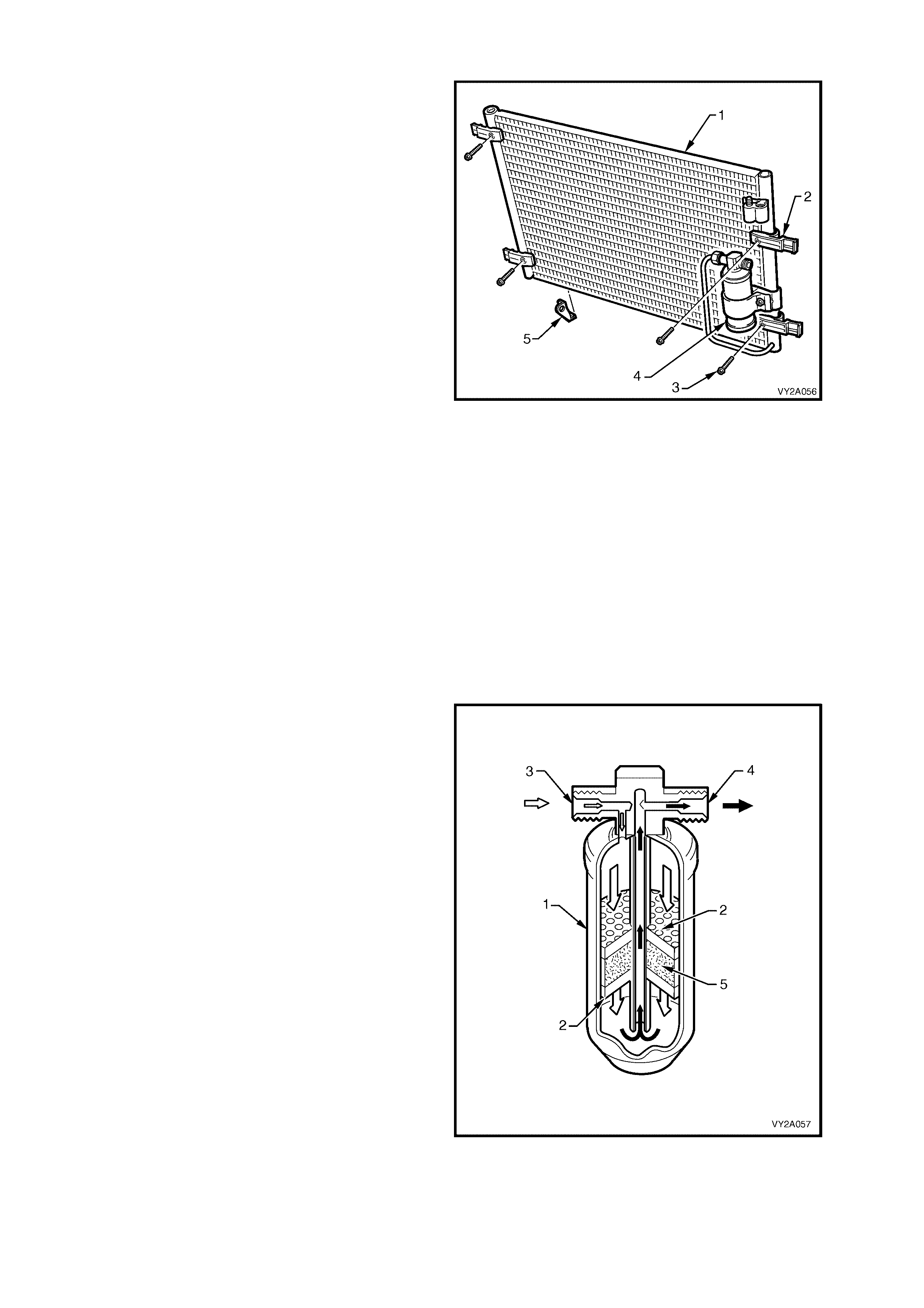
CONDENSER
The purpos e of the c on den s er (1) is the op posite of
the evaporator. The condenser receives high
pressure, high tem perature refrigerant vapour from
the compressor. It is exposed to a flow of ram air
from the movement of the vehicle and as the high
pressure high temperature vapour flows inside the
condenser tubes, heat is given off to the cooler
ambient air flowing past the condenser core. The
vapour then condenses into a high pressure, high
temperature liquid.
Two cooling fans fitted to the rear of the radiator
and are activated when required to assist in
drawing cool air through the condenser.
The condenser is of a parallel flow design. It has
38 horizontal, flat section tubes with side mounted
header tubes . All tubes an d finning are cons tructed
of aluminium.
It is mounted to the front of the radiator and is
attached to the radiator tanks by four identical
mounting clips (2) that are assembled with screws
(3) to the condenser sides.
The filter drier receiver (F DR) (4) is attached to the
front of the condenser on the left-hand side.
For vehic les f itted with O c cupan t Climate Contr o l, a
bracket (5) is fitted to the lower right-hand side of
the condenser to facilitate the installation of an
ambient air temperature sensor. This bracket
should not be removed from the condenser.
The condenser is identical across the
MY2003 VY and V2 Ser ies veh ic le rang e.
Figure 2A-75
FILTER DRIER RECEIVER
The filter drier receiver acts as a particle filter,
refrigerant storage container and most importantly
a moisture absorber.
Moisture, temperature and R134a causes
hydrofluoric and hydrochloric acid. The silica gel
beads (desiccant) located in the FDR absorb sm all
quantities of moisture thus preventing acid
establishment.
NOTE: Ensure the connection indicated with the
word ‘IN’ is connected to the condenser outlet
Legend
1. FDR Housing
2. Strainer
3. From Condenser (High pressure unfiltered liquid)
4. To Evaporator (High pressure filtered liquid)
5. Desiccant
The filter drier receiver is identical across the
MY2003 VY and V2 Ser ies veh ic le rang e.
Figure 2A-76
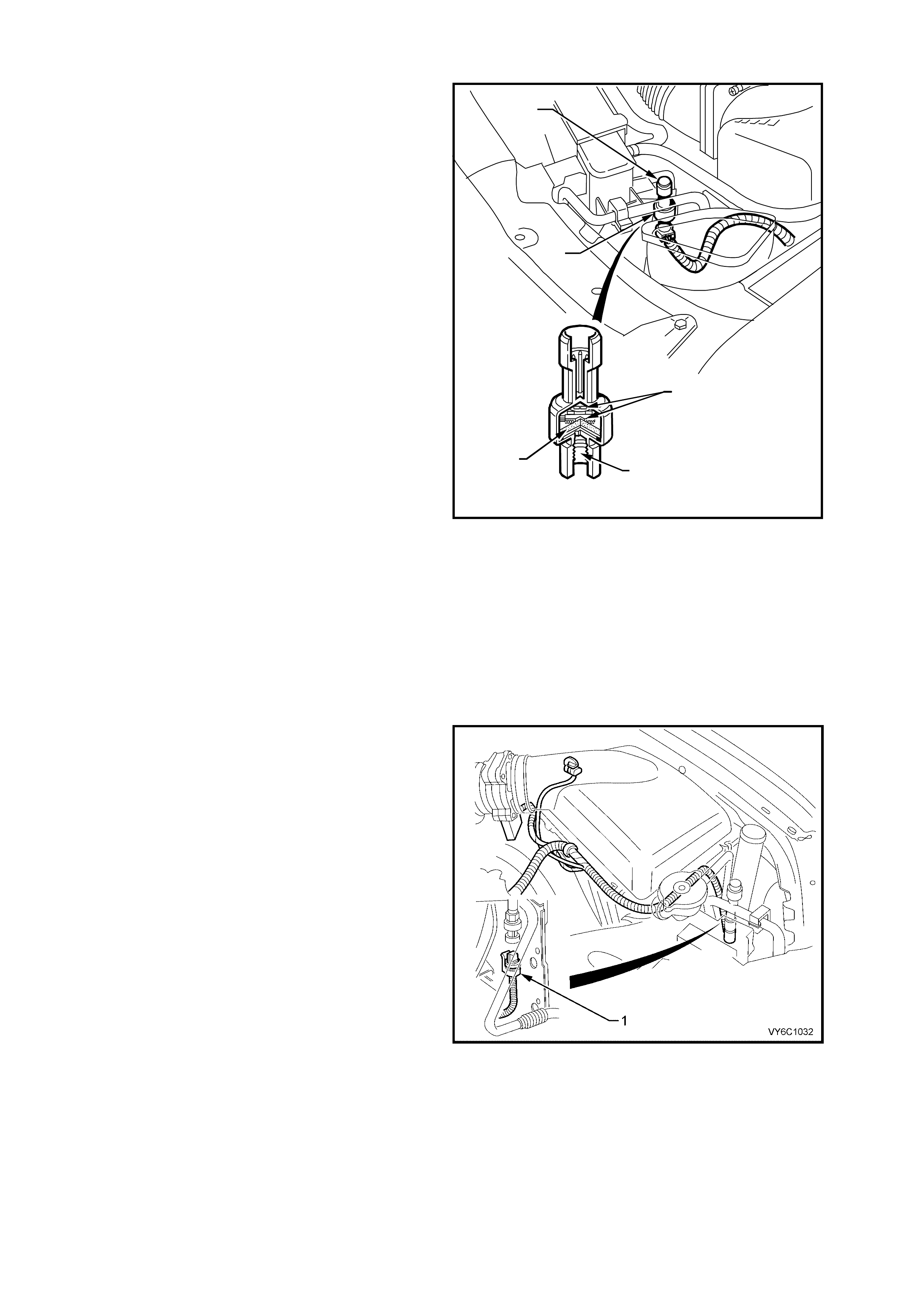
A/C PRESSURE TRANSDUCER
The pressure transducer is a sealed gauge
referenc e c apac iti ve pres s u re s ens or with on board
signal conditioning. It provides a 0 to 5 volt output
and requires a 5 volt regulated power supply.
In operation the transducer senses applied
pressure via the deflection of a two piece ceramic
diaphragm with one half being a parallel plate
capacitor. Changes in capacitance influenced by
the refrigerant pressure under the ceramic
diaphragm are converted to an analogue output by
the transducers integral signal electronics.
The pressure transducer’s electronics are on a
flexible c ircuit board c ontained in the upp er section
of the trans ducer. T hey pro vide lin ear cali bration of
the capacitance signal from the ceramic sensing
diaphragm.
Benefits of using the pressure transducer over a
normal type pressure switch is that the transducer
is constantly monitoring pressures and sending
signals to the Powertrain Control Module (PCM).
The normal t ype pr ess ur e s witc h o nly has an upp er
and lower cut out point. The PCM will disengage
the A/C compressor at low or high refrigerant
pressur es and electron ic diagnos tic equipm ent can
be used to extract system pressure information
making it easier when diagnosing problems.
Legend
1. Pressure Transducer
2. High Pressure Charge Port
3. Signal Electronics
4. Pressure Port
5. Ceramic Diaphr agm
T22A002
3
4
5
2
1
Figure 2A-77
Figure 2A-78 shows the location of the A/C
pressure transducer (1) for V6 and V6
Supercharged engines.
Figure 2A-78
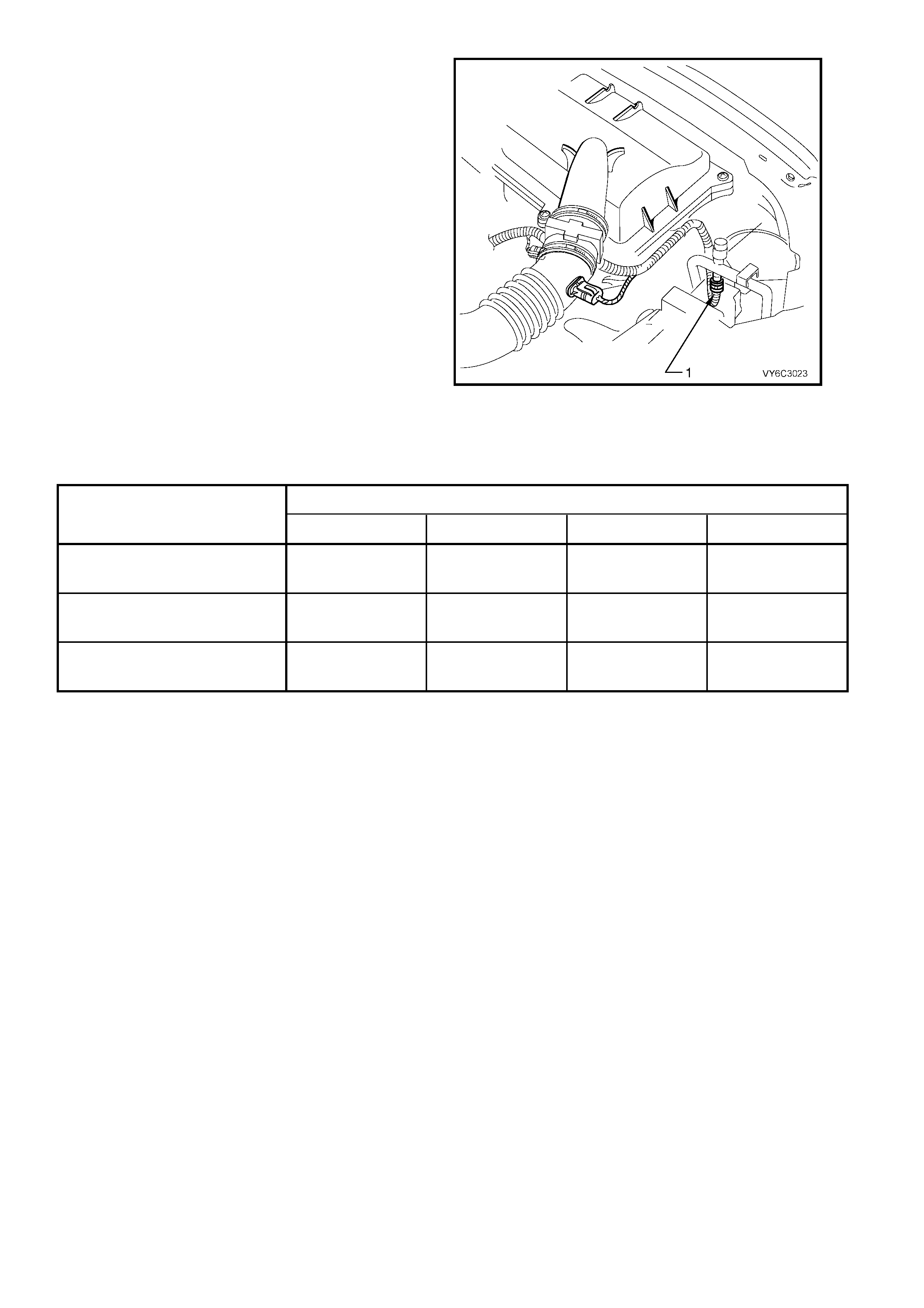
The A/C pressure transducer (1) on models fitted
with GEN III V8 engines is identical and in the
same location. However, removal of the upper
radiator shroud is required to gain access.
Figure 2A-79
As well as acting as an input to the PCM for A/C clutch operation, the PCM also uses the information provided by
the pressure transducer to determine when to turn on and off the 2nd Stage cooling fan operation. For further
information on cooling fan operation, refer to 2.9 COOLING FANS in this Sec ti on.
ENGINE
PRESSURE TRANSDUCER
OPERATION V6 LHD V6 RHD V6 Supercharged GEN III V8
Low Pressure Cut Out @ 180 kPa 180 kPa 180 kPa 180 kPa
Low Pressure Cut In @ 240 k Pa 240 kPa 240 kPa 240 kPa
High Pressure Cut Out @ 2900 kPa 2900 kPa 2900 kPa 2900 kPa
High Pressure Cut In @ 2000 kPa 2000 kPa 2400 kPa 2000 kPa
2nd Stage Fan Operation On @ 2400 kP a 2000 kPa 2600 kPa 2400 kP a
2nd Stage Fan Operation Off @ 2000 kP a 1500 kP a 2300 kPa 1900 kPa
NOTE: For pressure transducer diagnostics refer to the appropriate Section:
• Section 6C1 POWERTRAIN MANAGEMENT – V6 ENGINE
• Section 6C2 POWERTRAIN MANAGEMENT – V6 SUPERCHARGED ENGINE
• Section 6C3 POWERTRAIN MANAGEMENT – GEN III V8 ENGINE
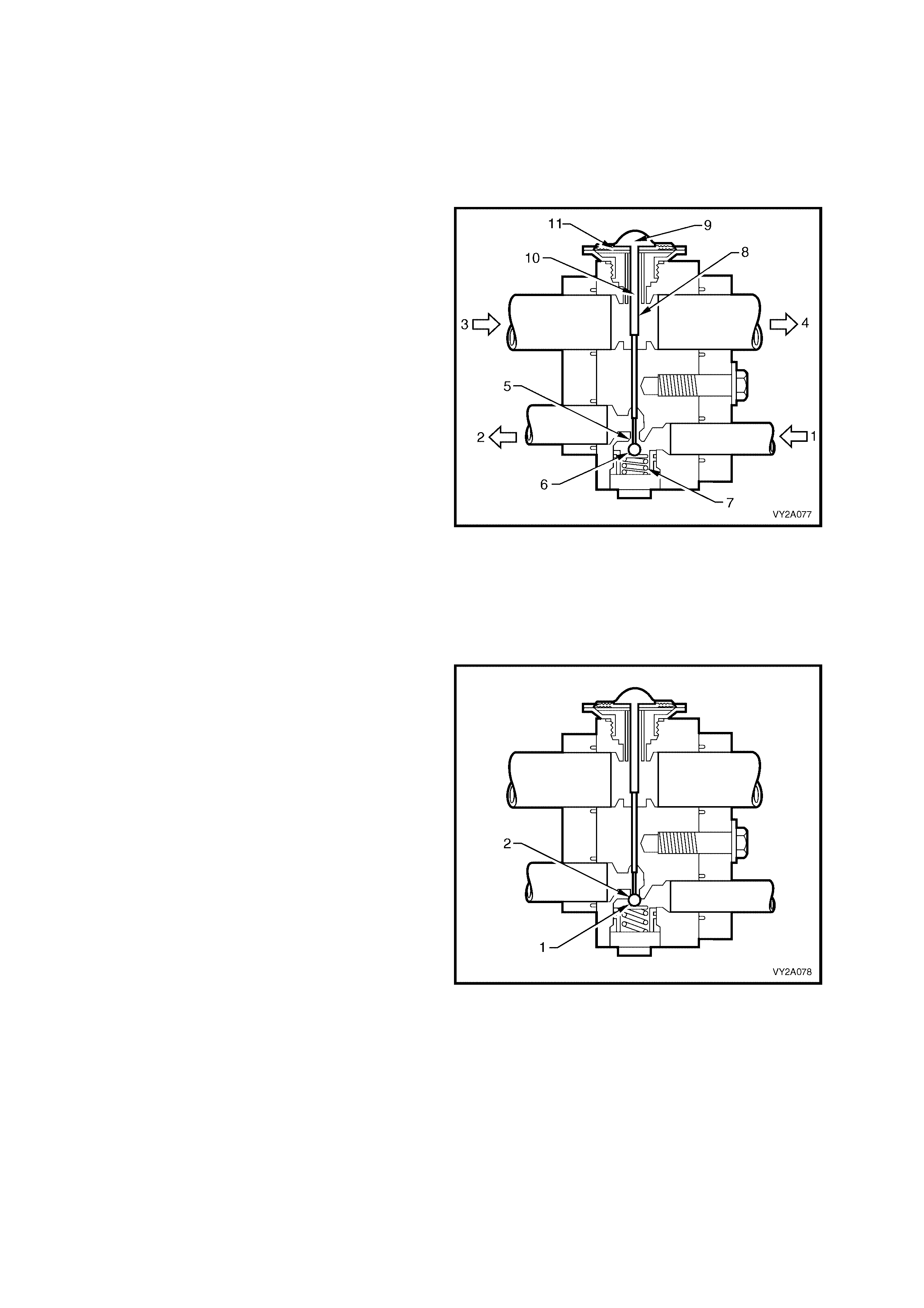
THERMAL EXPANSION VALVE (TXV)
The thermal expansion valve (TXV) controls refrigerant gas flow to the evaporator and ensures that complete
evaporat ion tak es place. I t has two refr igera nt pass ages . One is in the ref rigerant line from the con denser to the
evaporator and contains a ball and spring valve.
The other pas sage is in the refrigerant lin e from the ev aporator to the c ompres sor and contains the tem peratur e
sensing element.
Legend
1. From Filter Drier
2. To Evaporator Coil
3. From Evaporator
4. To Compressor
5. Metering Orifice
6. Ball
7. Spring
8. Activating Pin (hollow)
9. Refrigerant
10. Pressure Compensation Under Diaphragm
11. Metallic Diaphragm
Opening
Referring to Figure 2A-80: As the non-cooled
refrigerant from the evaporator coil flows through
the TXV outlet (suction), it makes contact with the
underside of the thin metallic diaphragm (11) and
reacts on the refrigerant contained above that
diaphragm. This refrigerant then expands forcing
the pin (8) downwards moving the ball (6) off its
seat (5), compressing the spring (7) and allowing
more refrigerant to enter the evaporator.
Figure 2A-80
Closing
Referring to Figure 2A-81: Operation is similar to
opening but now the refrigerant from the
evaporat or is c old. T he ref riger ant conta ined a bove
the diaphragm now contracts. The ball (1) moves
towards the seat (2) aided by the compressed
spring, reducing refrigerant flow.
NOTE: Low press ure liq uid R134 a pas sing thr ough
the evaporator should be completely vaporised by
the time it reaches the TXV outlet side.
Figure 2A-81
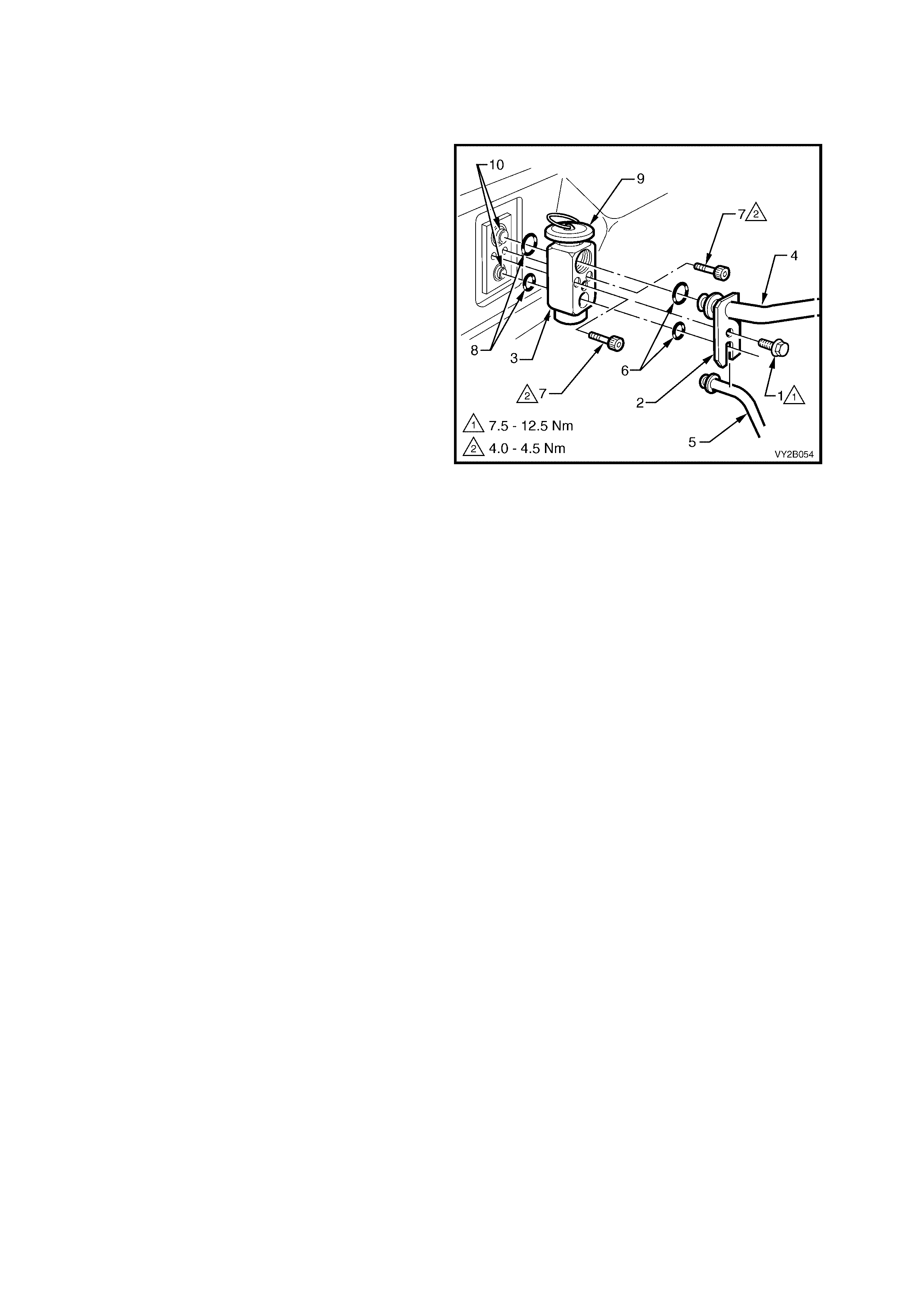
The TXV is installed in the engine bay to the dash panel as shown in Figure 2A-82.
NOTE: The TXV is located on the right-hand side of the dash panel on LHD models and on the left-hand side of
the dash panel on RHD models.
Legend
1. Retaining screw – Tubes to TXV
2. Tube Retaining Plate
3. Thermal Expansion Valve (TXV)
4. Suction Tube
5. Liquid Tube
6. O-rings – TXV to Suction and Liquid Tubes
7. Retaining screws – TXV to Evaporator Tubes
8. O-rings – TXV to Evaporator Tubes
9. TXV Diaphragm
10. Evaporator Tubes
Figure 2A-82
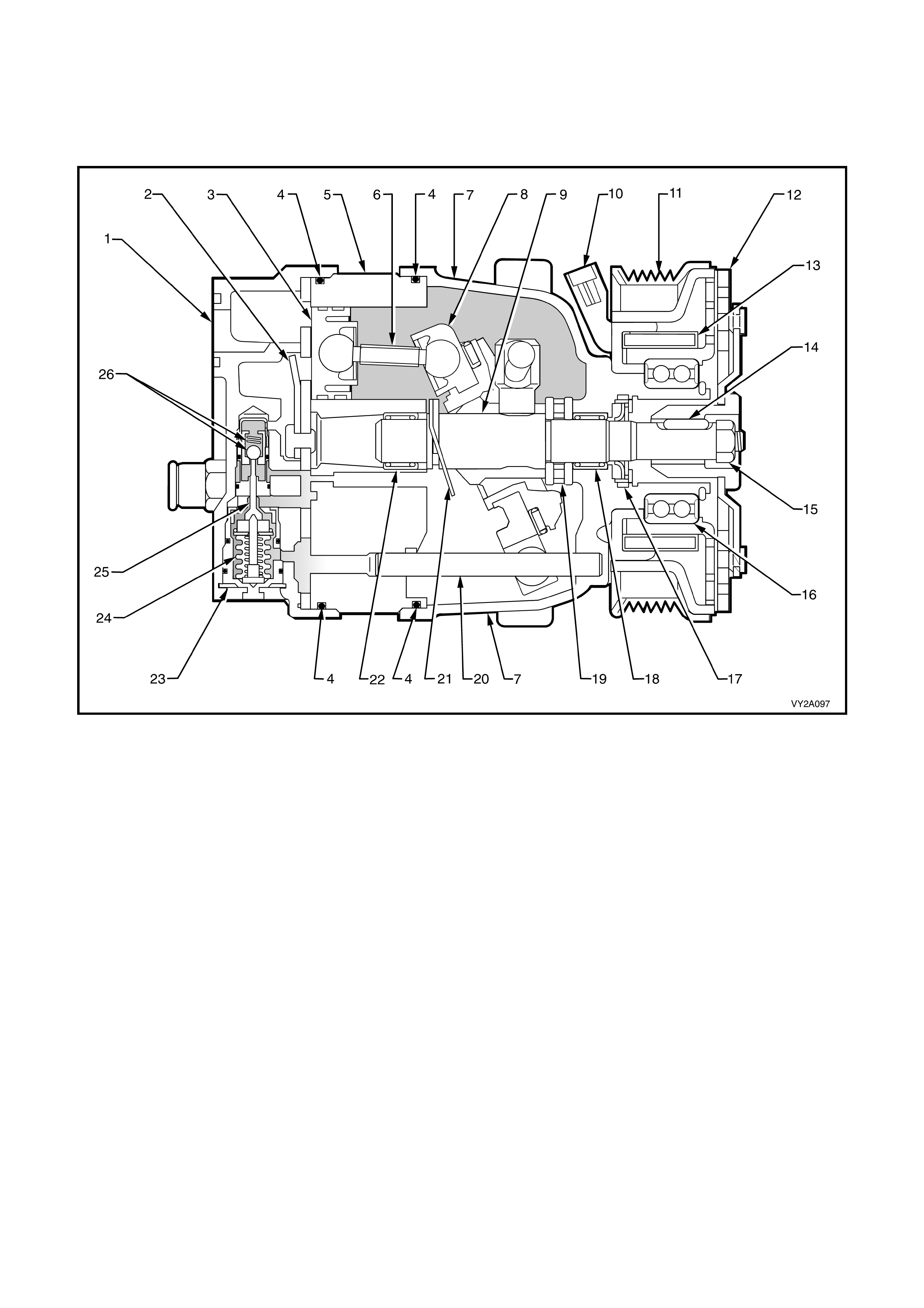
DELPHI V5 AND V7 COMPRESSOR
The Delph i V5 and V7 com press or can m atch the air c onditi oning de m and under all c ondi tions wit hout c yclin g. T he
basic compressor mechanism is a variable angle wobble-plate with five (V5) or seven (V7) axially oriented
cylinders.
The V5 compressor has a pumping capacity of 156 cc while the V7 has a pumping capacity of 179 cc.
Figure 2A-83
Legend
1. Rear Head 14. Shaft To Clutch Driver Key
2. Discharge pressure reed Valve 15. Clutch And Pulley Retaining Nut
3. Piston (5 for V5, 7 for V7) 16. Pulley Bearing
4. O-ring (2 places) 17. Shaft Seal
5. Cylinder 18. Shaft Bearing – Front
6. Piston Rod (5 for V5, 7 for V7) 19. Thrust Bearing Assembly
7. Front Head 20. Guide Pin
8. Wobble Plate 21. Return Spring
9. Shaft 22. Shaft Bearing – Rear
10. Clutch Coil Connector 23. Control Valve Retainer
11. Drive Pulley 24. Control Valve Bellows
12. Clutch Driver 25. Control Valve Shuttle Valve
13. Clutch Coil Assembly 26. Control Valve Discharge Pressure Ball And Spring
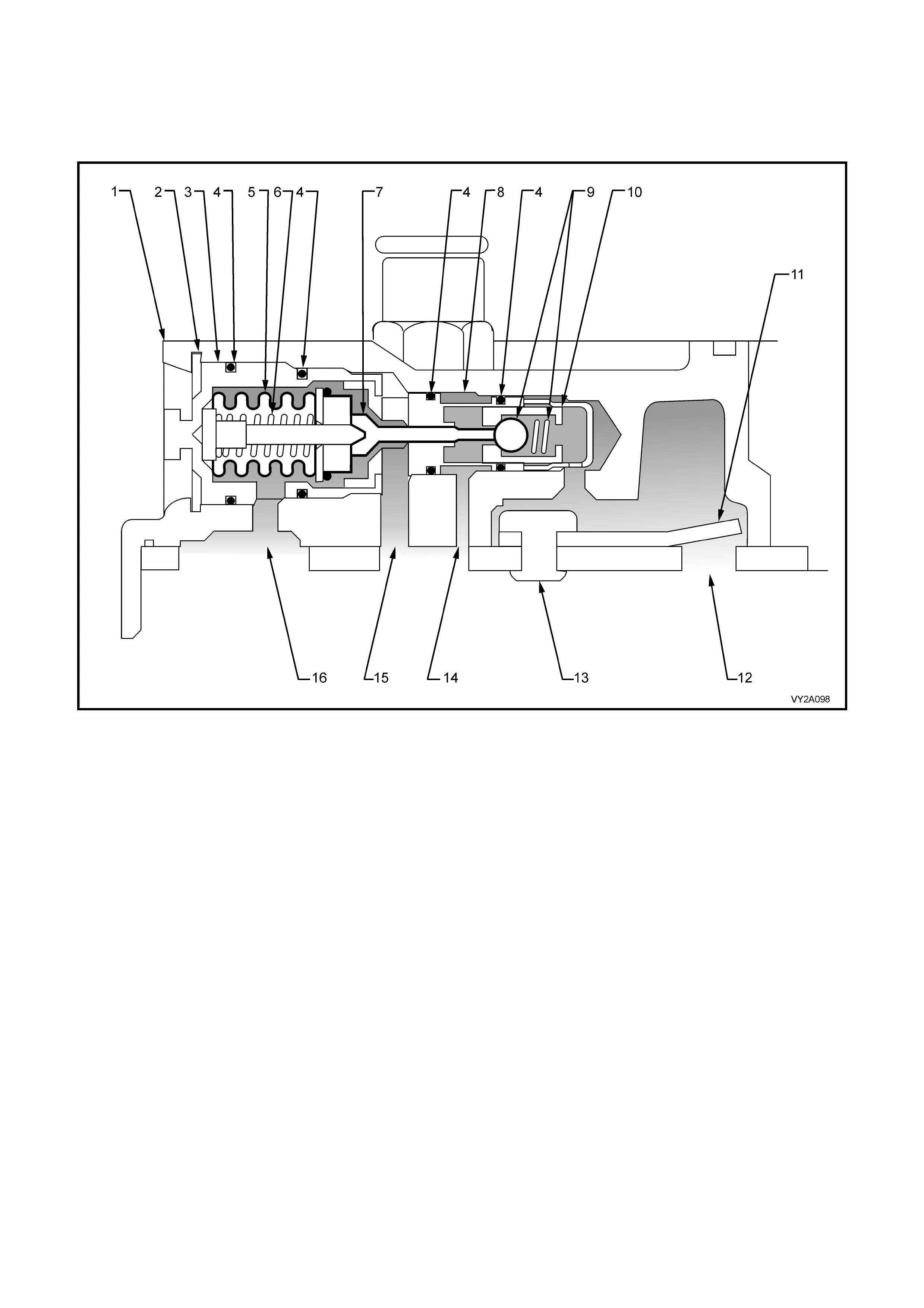
Control valve
Figure 2A- 8 4 s ho ws a cr oss s ec tion of the c on tr ol va l ve as i ns tal le d i n th e compr es sor rear head . The wo bble-plate
angle of the compressor, and the resultant compressor displacement, are determined by the compressor crankcase
to suction pressure differential which is governed by the control valve. For further information on the operation of
the control valve refer to Figure 2A-87 and Figure 2A-88.
Figure 2A-84
Legend
1. Compressor Rear Head 9. Discharge Pressure Ball and Spring
2. Control Valve Retainer 10. Discharge Pressure Ball and Spring Retainer
3. Control Valve Bellows Housing 11. Discharge Pressure Reed Valve
4. O-ring 12. Discharge Pressure Port (to discharge pressure ball and
spring)
5. Bellows 13. Discharge Pressure Reed Valve Rivet
6. Bellows Spring 14. Crankcase Pressure Port (from discharge pressure ball and
spring)
7. Shuttle Valve 15. Crankcase Pressure Port (to bellows)
8. Control Valve Discharge Pressure Valve Housing 16. Suction Port (from bellows)
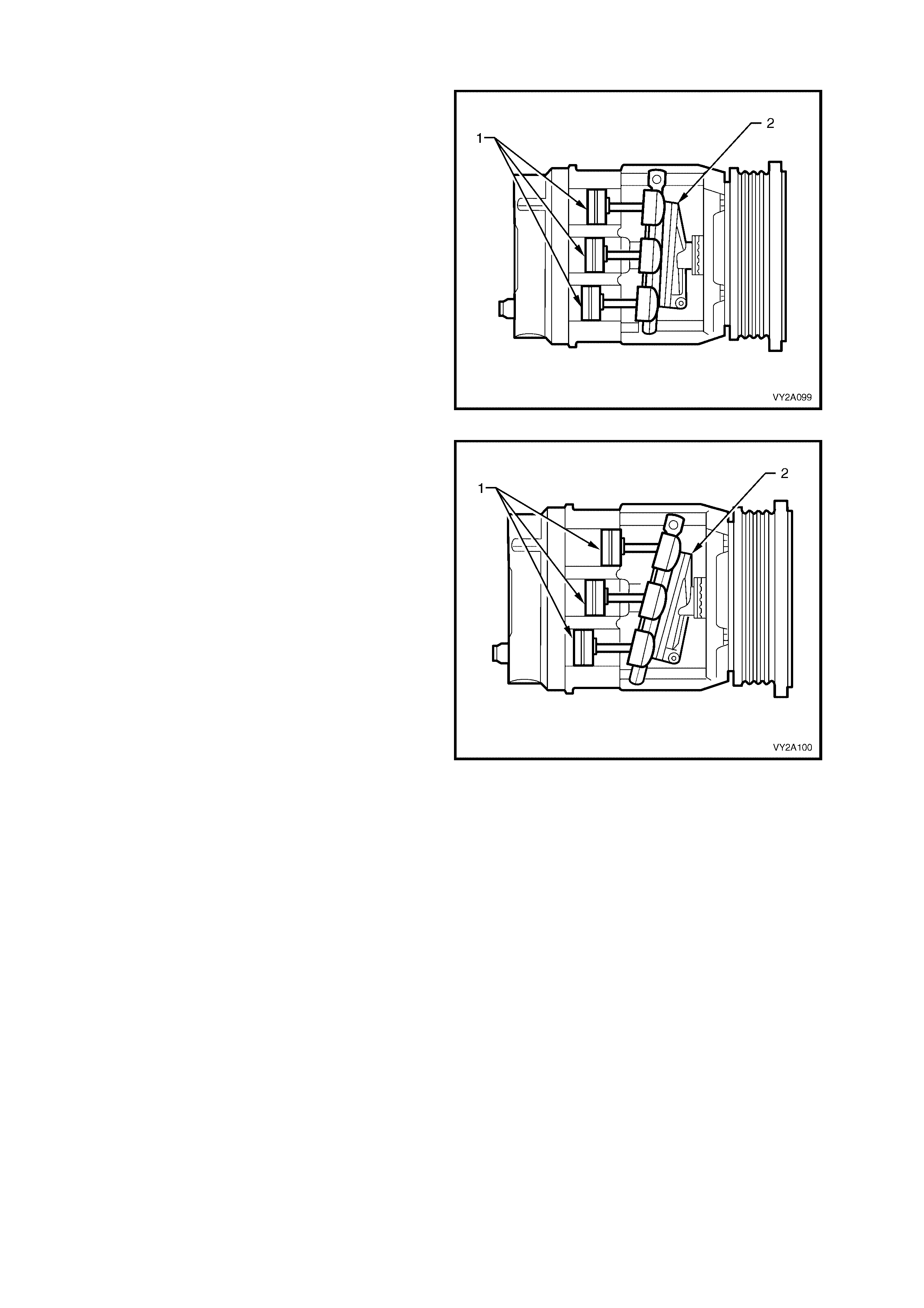
COMPRESSOR OPERATION
Compressor minimum stroke (destroked)
When the A/C capacity demand is low, the
crankcase pressure be hind the pisto ns (1) is equa l
to the pressure in front of the pistons. This forces
the wobble plat e (2) to change its angle to t owards
vertica l which r e duc es th e st roke of the pist ons an d
reduces the output of the compressor to
approximately 14.5 cc.
Figure 2A-85
Compressor maximum stroke
When the A/C capacity demand is high, the
crankcase pressure behind the pistons (1) is less
than the pressure in front of the pistons. This
forces the wobble plate (2) to change its angle
awa y from vertical whic h increas e the stroke of the
pistons and increases the output by approximately
141 cc for the V5 compressor and 164 cc for the
V7 compressor.
Figure 2A-86
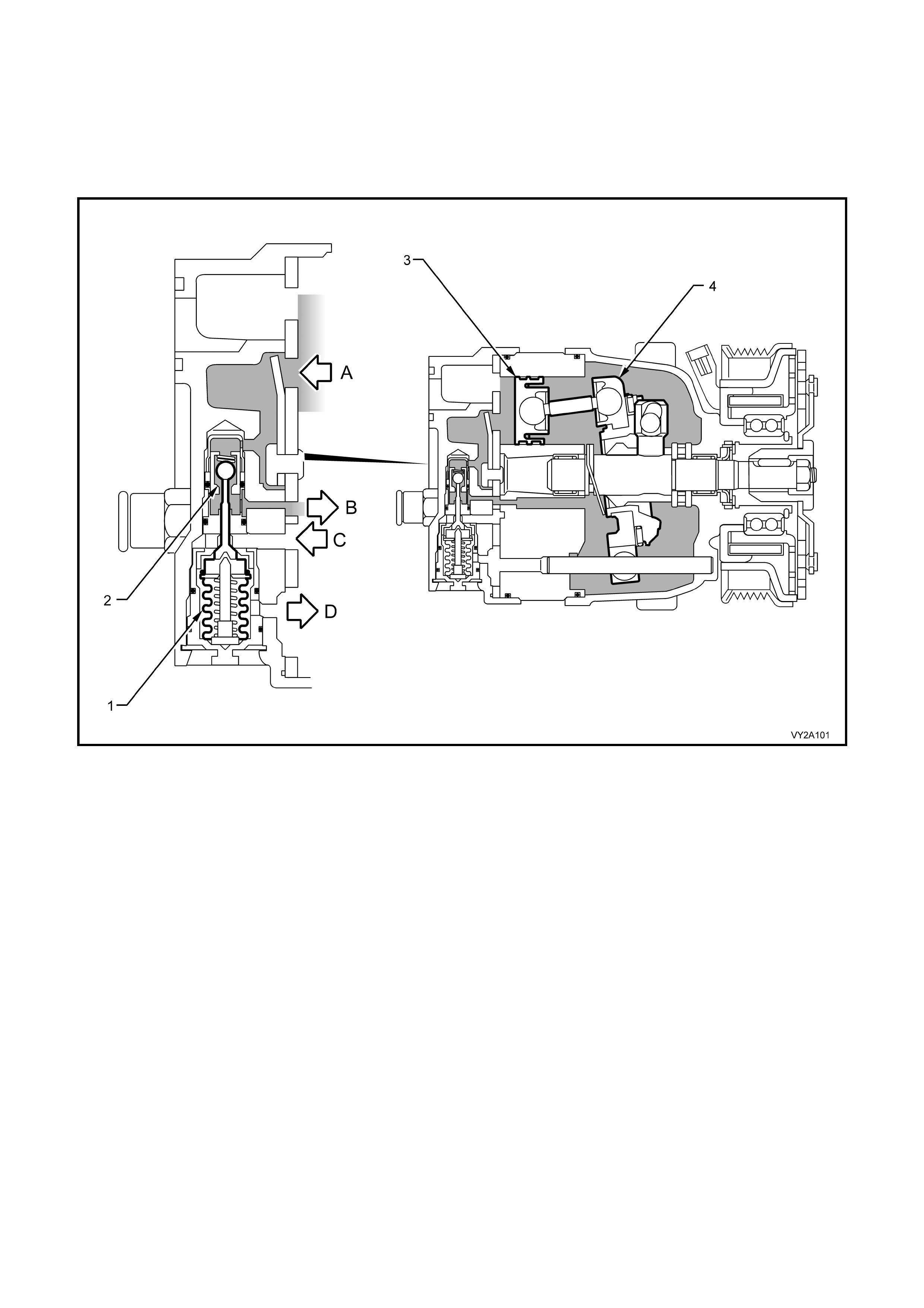
Low A/C Demand
The evaporator cooling load is reduced (ambient temperature or blower fan speed is reduced) and therefore the
suction pressure is reduced until it reaches the control point. To reach the control point, the bellows (1) in the
control val ve ass embly has ex pande d to a llo w dis c har ge pr es sur e ( A) to bl eed p a s t the c ontrol val ve bal l val v e s eat
(2) and into the compressor crankcase. This crankcase pressure (B) acts as an opposing force behind the
compressor pistons (3) to cause the wobble plate (4) to change its angle towards vertical and therefore, reduce
piston stroke.
Figure 2A-87
A. Discharge Pressure
B. Crankcase Pressure (from valve)
C. Crankcase Pressure (to valve)
D. Suction Pressure
LOW A/C DEMAND: A to B open, C to D closed, (bleed to crankcase)
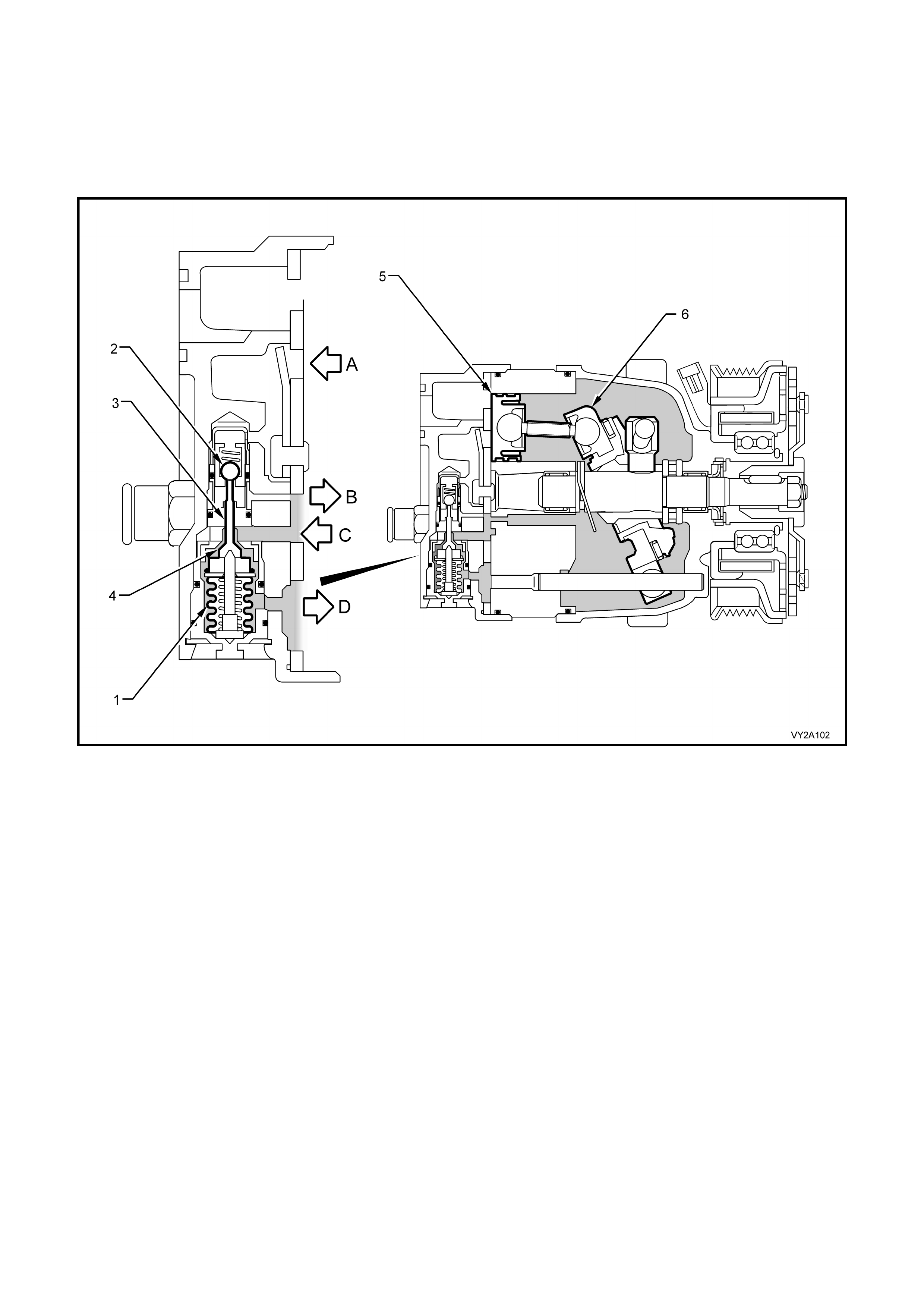
High A/C Demand
W hen suction pressure (D) is above the control point, it will compress the control valve bellows (1). T his will close
off the disc harge valve as t he ball v alve (2) is now on i ts s eat. The s huttle val ve (3) m oves towards the suc tion port
and opens the suction valve (4). Crankcase pressure (C) will then bleed from the compressor crankcase past the
suction val ve to t he suc tion port. As t he cra nk case pr essur e behind the p istons ( 5 ) is r educ ed, the wobbl e pl ate (6)
will tilt from vertical causing the pistons to move towards maximum stroke. The compressor will then have a
corres pondi ng inc reas e in it s displac ement.
Figure 2A-88
A. Discharge Pressure
B. Crankcase Pressure (from valve)
C. Crankcase Pressure (to valve)
D. Suction Pressure
HIGH A/C DEMAND: A to B closed, C to D open, (bleed from crankcase)
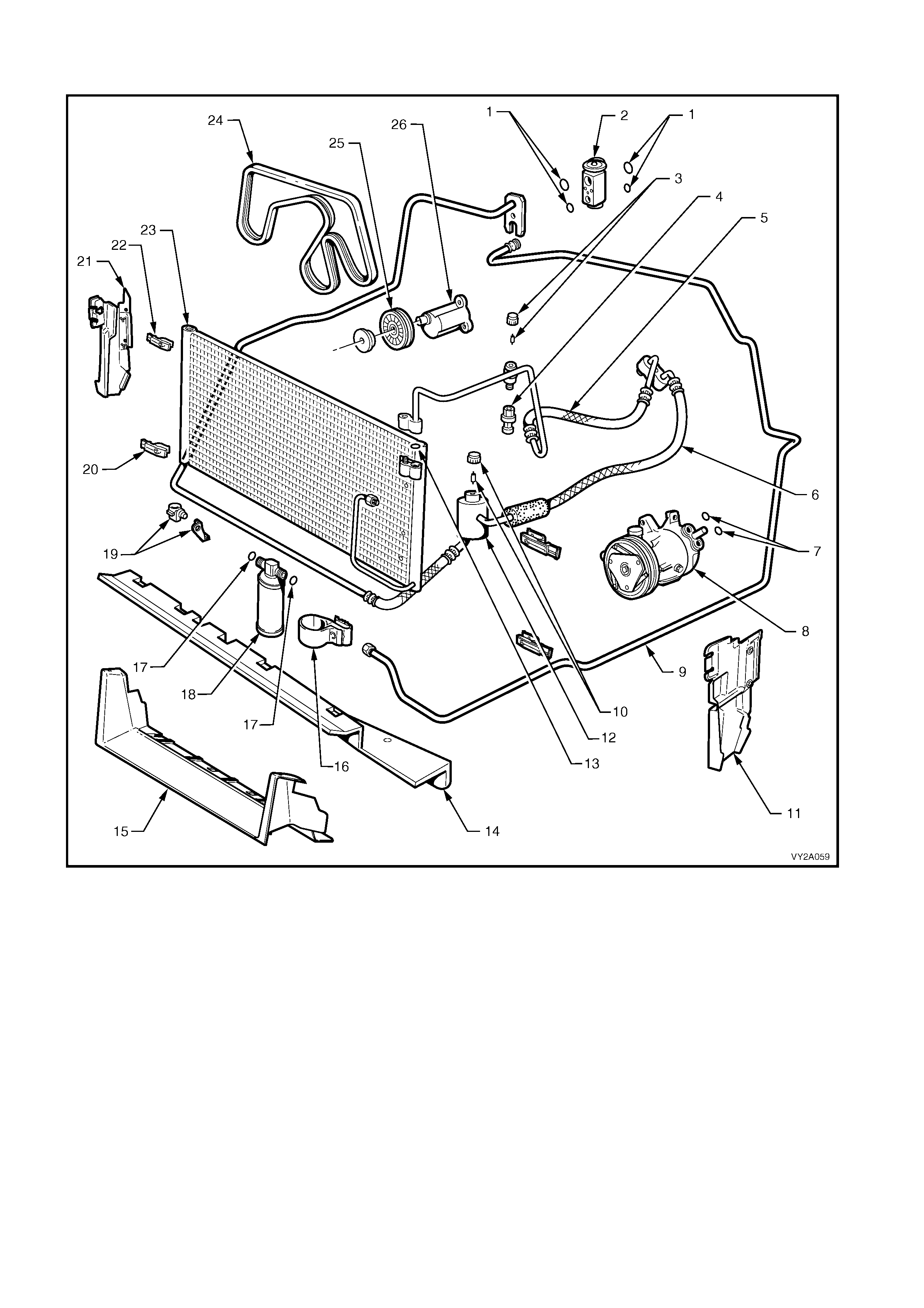
UNDER-HOOD A/C COMPONENTS: V6 – LEFT-HAND DRIVE
Figure 2A-89
Legend
1. O-rings – Thermal Expansion
Valve 10. Schraeder Valve And Cap – Low
Side 19. Ambient Air Temperature Sensor
And Bracket
2. Thermal Expansion Valve 11. Air Chute – LHS 20. Condenser Lower Mounting Clip
(2 places)
3. Schraeder Valve And Cap – High
Side 12. Muffler 21. Air Chute – RHS
4. Pressure Transducer 13. O-ring – Discharge Tube 22. Condenser Upper Mounting Clip
(2 places)
5. Discharge Hose/Tube 14. Air Chute – Lower Baffle 23. Condenser
6. Suction Hose/Tube 15. Lower Air Chute Extension
(S Models ) 24. Drive Belt
7. O-rings – Compressor 16. Filter Drier Receiver Bracket 25. Drive Belt Idler Pulley
8. Compressor 17. O-ring – Filter Drier Receiver 26. Mounting bracket – Drive Belt Idler
Pulley
9. Liquid Line 18. Filter Drier Receiver
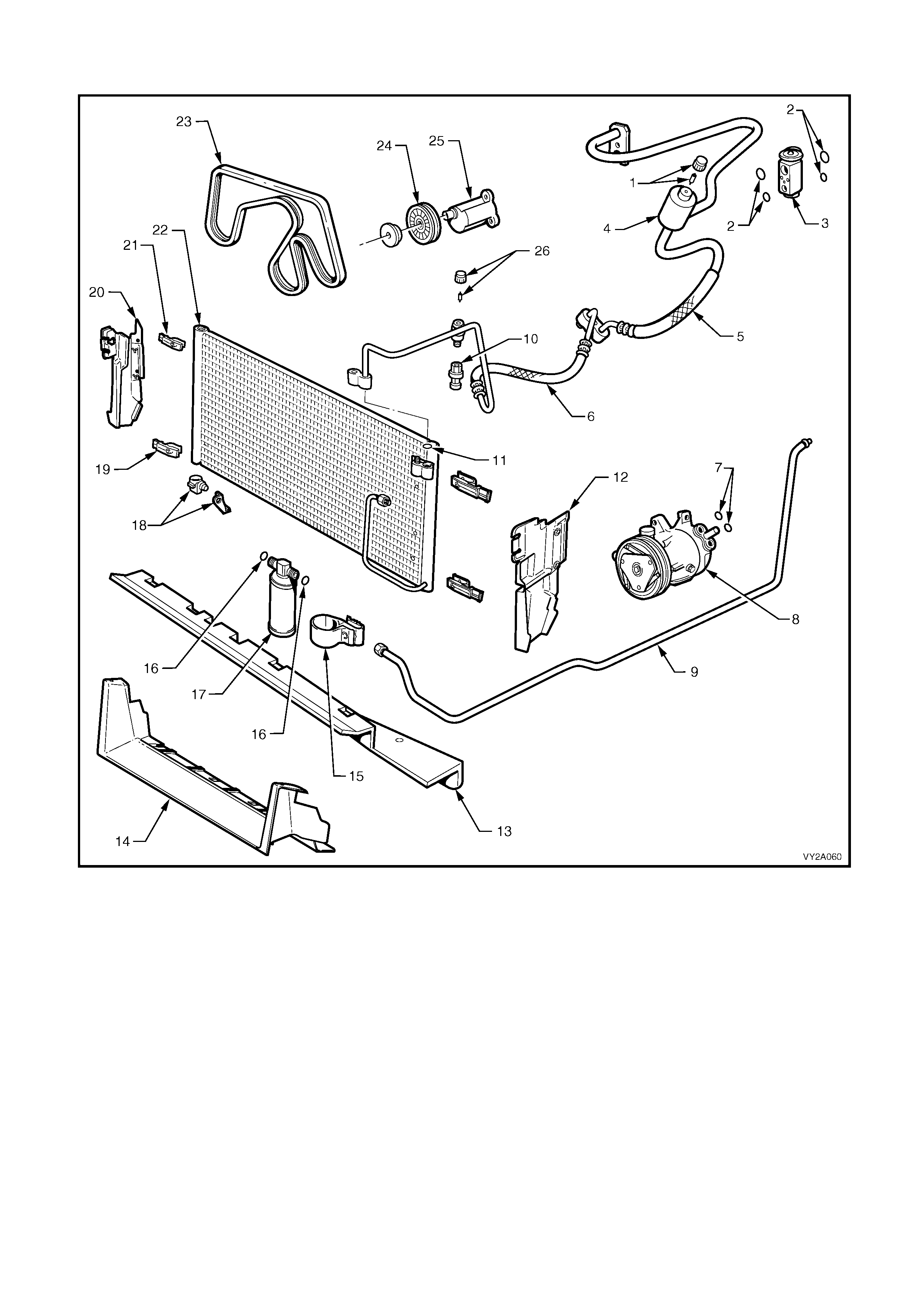
UNDER-HOOD A/C COMPONENTS: V6 – RIGHT-HAND DRIVE
Figure 2A-90
Legend
1. Schraeder Valve And Cap – Low
Side 10. Pressure Transducer 19. Condenser Lower Mounting Clip
(2 places)
2. O-rings – Thermal Expansion
Valve 11. O-ring – Discharge Tube 20. Air Chute – RHS
3. Thermal Expansion Valve 12. Air Chute – LHS 21. Condenser Upper Mounting Clip
(2 places)
4. Muffler 13. Air Chute – Lower Baffle 22. Condenser
5. Suction Hose/Tube 14. Lower Air Chute Extension
(S Models exc. utility) 23. Drive Belt
6. Discharge Hose/Tube 15. Filter Drier Receiver Bracket 24. Drive Belt Idler Pulley
7. O-rings – Compressor 16. O-ring – Filter Drier Receiver 25. Mounting bracket – Drive Belt Idler
Pulley
8. Compressor 17. Filter Drier Receiver 26. Schraeder Valve And Cap –
High Side
9. Liquid Line 18. Ambient Air Temperature Sensor
And Bracket
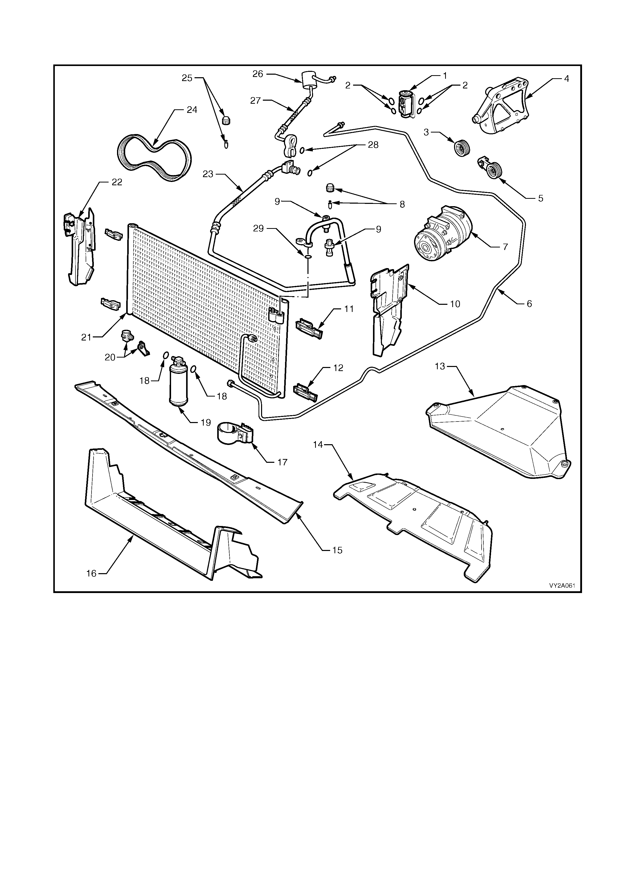
UNDER-HOOD A/C COMPONENTS: GEN III V8 – LEFT-HAND DRIVE
Figure 2A-91
Legend
1. Thermal Expansion Valve 11. Condenser Upper Mounting Clip
(2 places) 21. Condenser
2. O-rings – Thermal Expansion
Valve 12. Condenser Lower Mounting Clip
(2 places) 22. Air Chute – RHS
3. Drive Belt Idler Pulley 13. Oil Pan Guard 23. Discharge Hose/Tube
4. Compressor Mounting Bracket 14. Lower Air Chute Extension
(excluding SS Models) 24. Drive Belt
5. Drive Belt Tensioner 15. Air Chute – Lower Baffle 25. Schraeder Valve And Cap –
Low Side
6. Liquid Line 16. Lower Air Chute Extension
(SS Models) 26. Muffler
7. Compressor 17. Filter Drier Receiver Bracket 27. Suction Hose/Tube
8. Schraeder Valve And Cap – High
Side 18. O-ring – Filter Drier Receiver 28. O-rings – Compressor
9. Pressure Transducer 19. Filter Drier Receiver (FDR) 29. O-ring – Discharge Tube
10. Air Chute – LHS 20. Ambient Air Temperature Sensor
And Bracket

UNDER-HOOD A/C COMPONENTS: GEN III V8 – RIGHT-HAND DRIVE
Figure 2A-92
Legend
1. Thermal Expansion Valve 11. Lower Air Chute Extension
(excluding SS Models) 21. Discharge Hose/Tube
2. O-rings – Thermal Expansion
Valve 12. Air Chute – Lower Baffle 22. O-rings – Compressor
3. Schraeder Valve And Cap – Low
Side 13. Lower Air Chute Extension
(SS Models) 23. Compressor
4. Muffler 14. Filter Drier Receiver Bracket 24. Drive Belt Idler Pulley
5. Suction Hose/Tube 15. O-ring – Filter Drier Receiver 25. Schraeder Valve And Cap –
High Side
6. Liquid Line 16. Filter Drier Receiver (FDR) 26. Pressure Transducer
7. Oil Pan Guard 17. Ambient Air Temperature Sensor
And Bracket 27. O-ring – Discharge Tube
8. Air Chute – LHS 18. Condenser 28. Drive Belt Tensioner
9. Condenser Upper Mounting Clip
(2 places) 19. Air Chute – RHS 29. Compressor Mounting Bracket
10. Condenser Lower Mounting Clip
(2 places) 20. Drive Belt
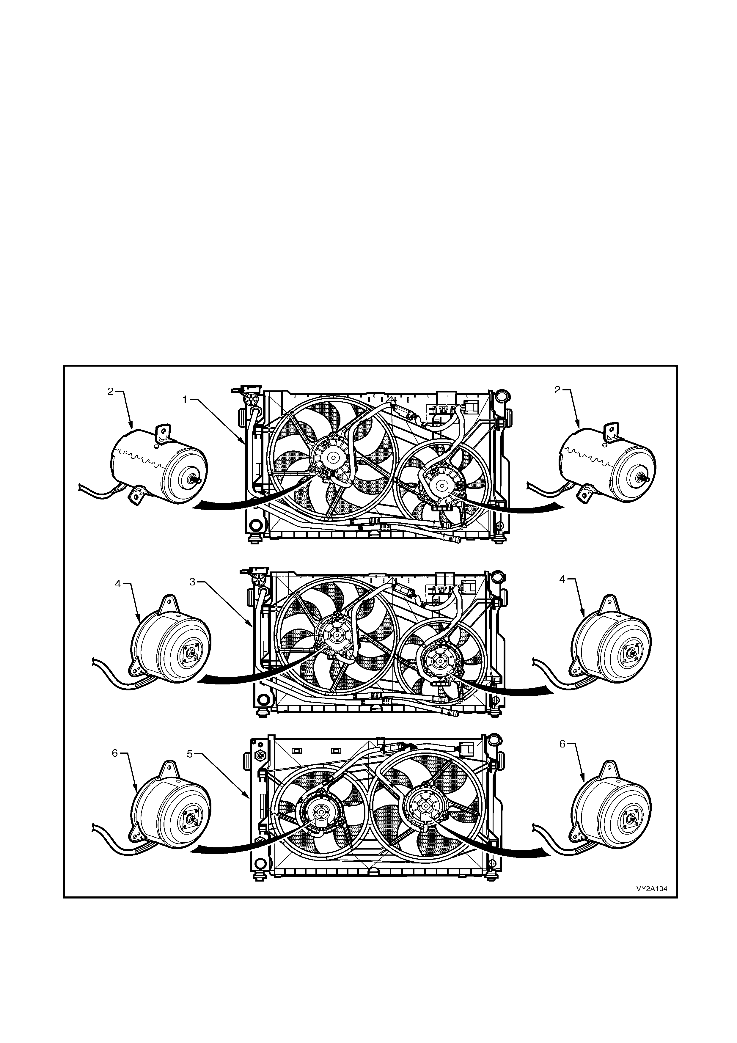
2.9 COOLING FANS
On all MY2003 VY and V2 Series v ehicles t wo electr ic eng ine coo ling fans are used t o cool engine c oolant f lowing
through the radiator and the refrigerant flowing through the A/C condenser.
The engine cooling fan assemblies provide the prim ary means of m oving air through the engine radiator. Both fan
and motor assemblies are mounted to a common shroud which in turn, is mounted to the engine side of the
radiator.
All of these components are part of the Condenser, Radiator and Fan Module (CRFM). For further information
relating to the CRFM, refer to 2.8 UNDER-HOOD COMPONENTS in this Section.
All MY2003 VY and V2 Series use a two stage fan operation strategy. However, two different strategies are
employed depending on engine type and/or market application.
All V6 RHD and V6 Superchar ged models are fitted with a stand ard cooling f an syst em (280 W att), which c onsists
of twin single speed fans. This cooling fan system operates as follows:
1st stage – large diameter fan operates at maximum speed
2nd stage – small and large diameter fans both operate at maximum speed
All V6 LHD and GEN III V8 models are fitted with a high power cooling fan system (400 Watt), which consists of
twin dual speed fans. This cooling fan sy stem operates as follows:
1st stage – both fans operate at low speed
2nd stage – both fans operate at high speed
Thes e fan c onfiguratio ns ar e us ed on a ll ve hicles even if not eq uippe d with a ir c onditio ning. T here is no f an in f ront
of the A/C condenser.
Figure 2A-93
Legend
1. V6 Radiator And Standard Cooli ng Fan System 4. V6 High Power Fan Motors – Dual Speed, 400 Watts Total
2. Standard Fan Motors – Single Speed, 280 Watts Total 5. GEN III V8 Radiator And Cooling Fan System
3. V6 Radiator And High Power Cooling Fan System 6. GEN III V 8 High Power Fan Motors – Dual Speed, 400 Watts Total
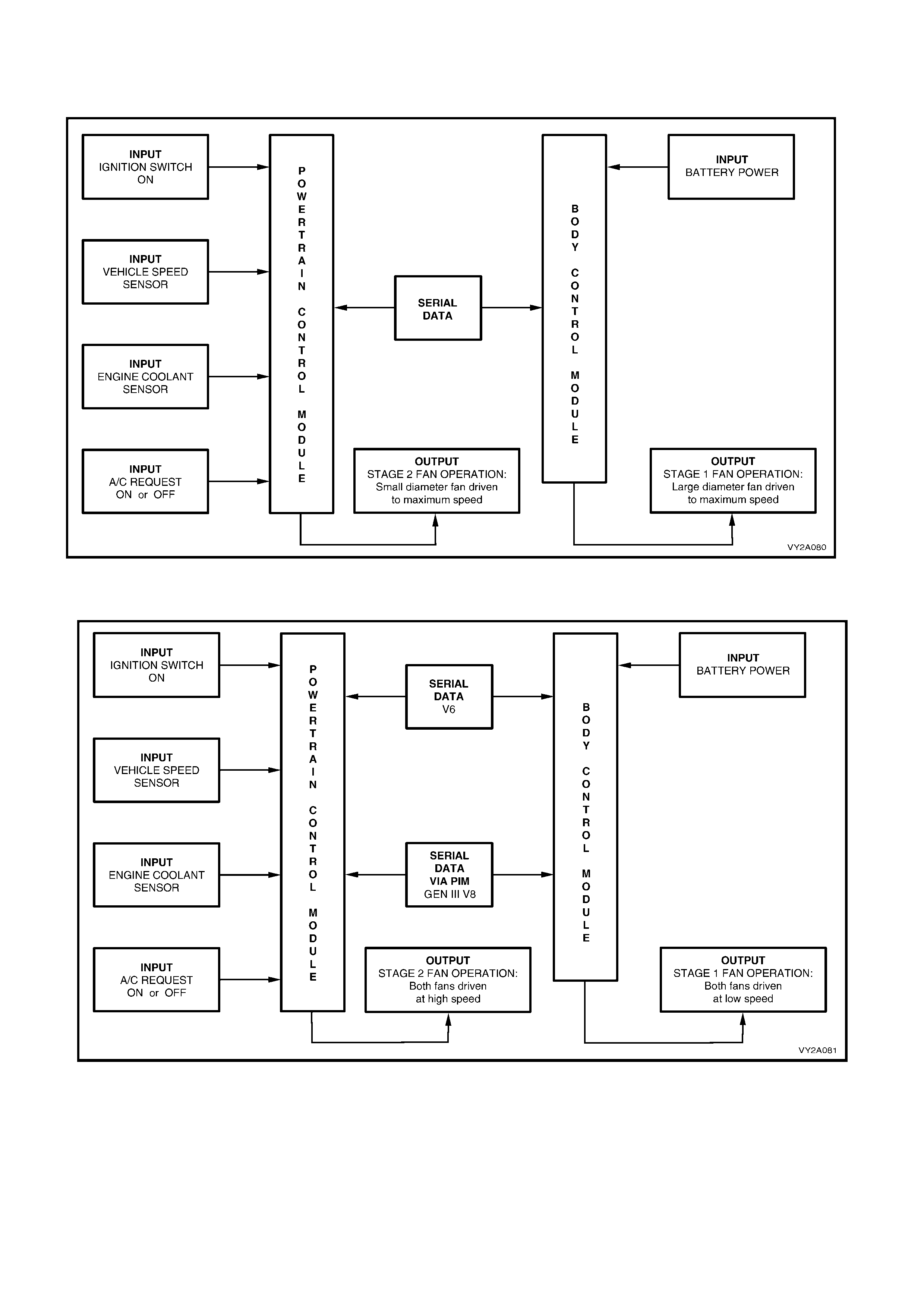
SYSTEM OVERVIEW
Standard Cooling Fan System – V6 models
Figure 2A-94
High Power Cooling Fan System – V6 and GEN III V8 models
Figure 2A-95
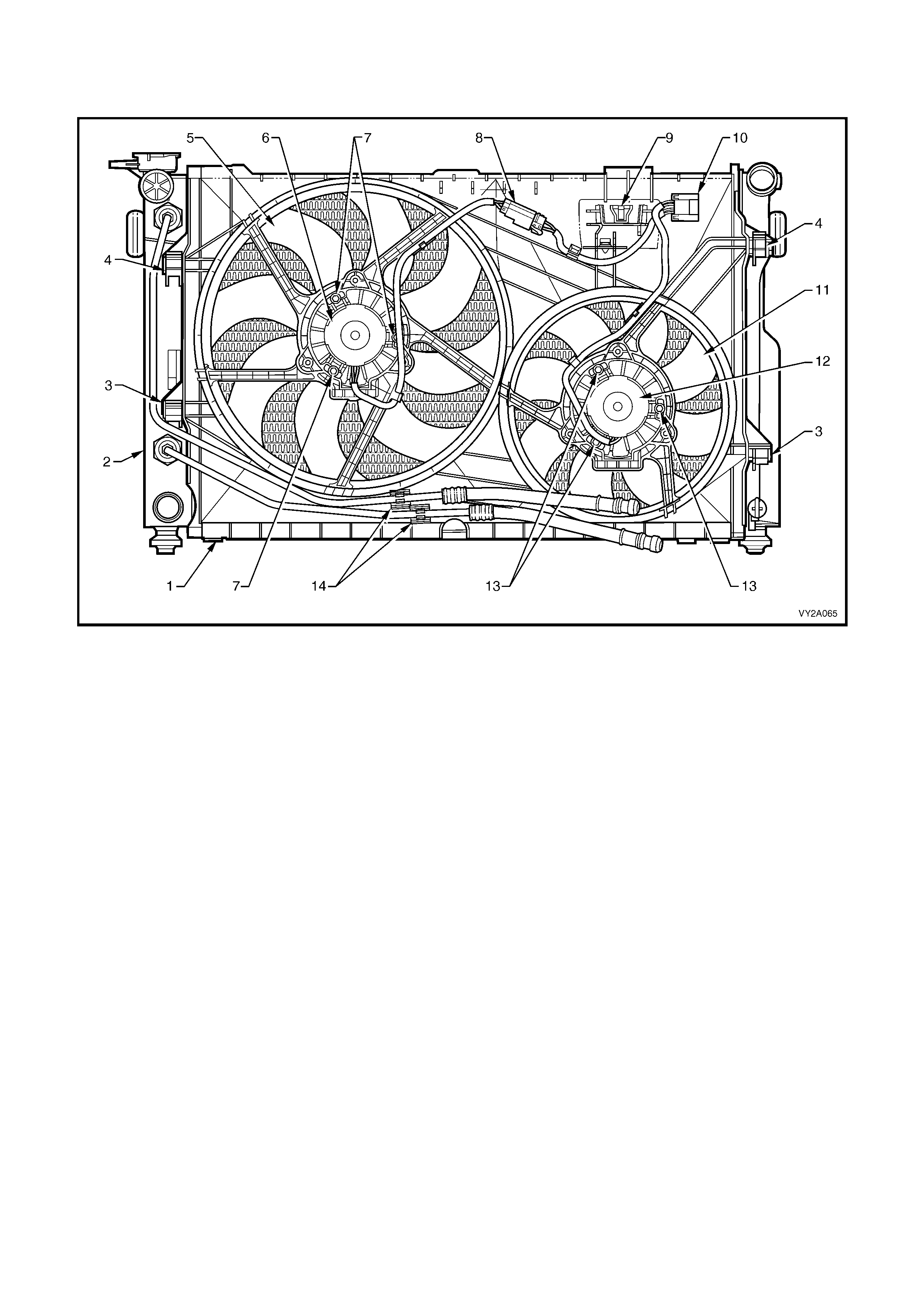
COOLING FAN ASSEMBLY
Standard Cooling Fans – V6 Models
Figure 2A-96
Legend
1. Fan Shroud 8. LHS Fan Motor Harness Connector (2 Terminal)
2. Radiator 9. Power Steering Reservoir Mount
3. Fan Shroud Lower Support 10. LHS and RHS Fan Motor Harness Connector (4 Terminal)
4. Fan Shroud Upper Support/Locking Retainer 11. RHS Fan – 8 Blade, 263 mm Blade Diameter
5. LHS Fan – 8 Blade, 365 mm Blade Diameter 12. RHS Fan Motor – 120 Watt, Single Speed
6. LHS Fan Motor – 160 Watt, Single Speed 13. RHS Fan Motor – Mounting Locations
7. LHS Fan Motor – Mounting Locations 14. Transmission Cooling Line Retaining Clips
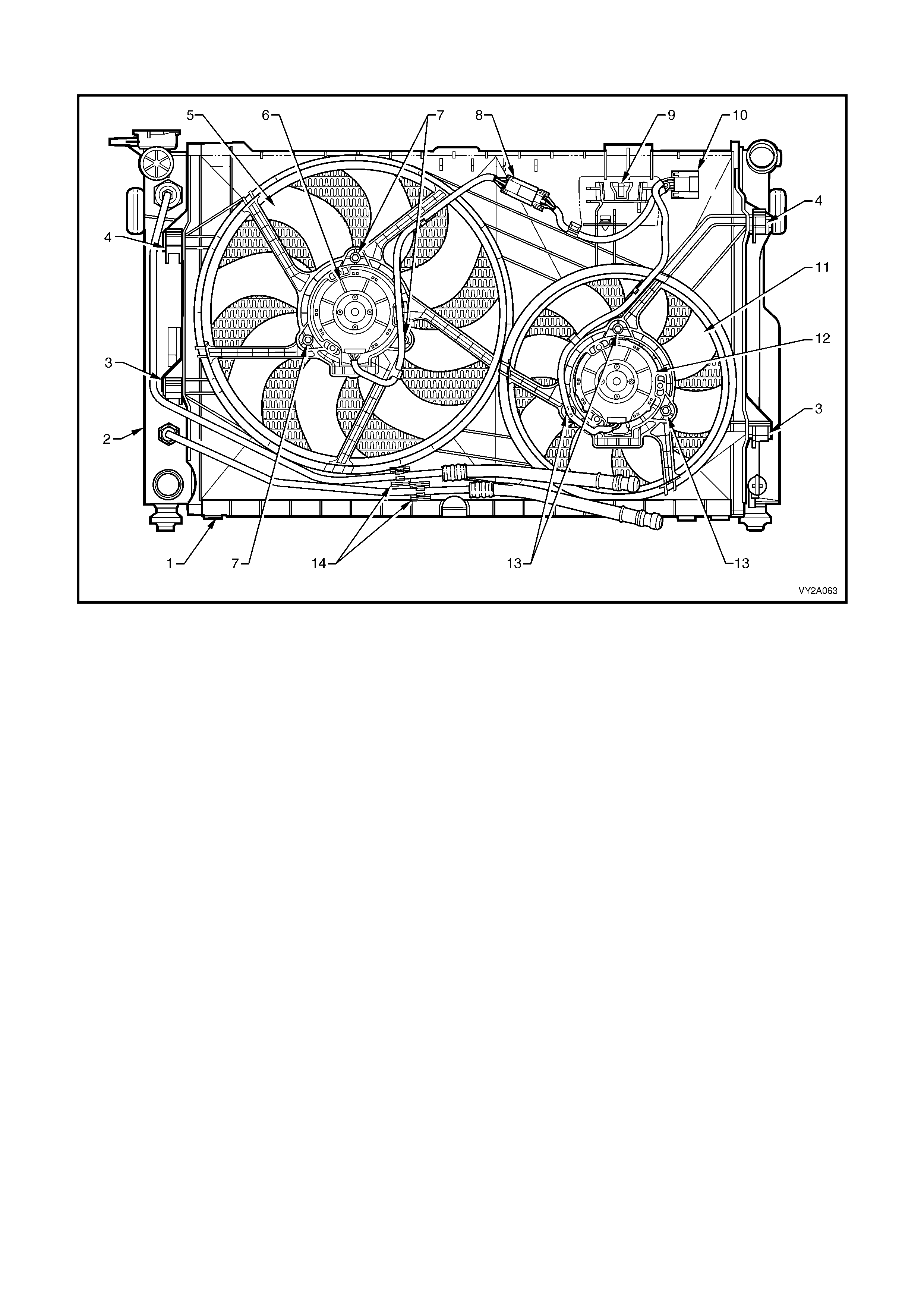
High Power Cooling Fans – V6 Models
Figure 2A-97
Legend
1. Fan Shroud 8. LHS Fan Motor Harness Connector (3 Terminal)
2. Radiator 9. Power Steering Reservoir Mount
3. Fan Shroud Lower Support 10. LHS and RHS Fan Motor Harness Connector (5 Terminal)
4. Fan Shroud Upper Support/Locking Retainer 11. RHS Fan – 8 Blade, 263 mm Blade Diameter
5. LHS Fan – 8 Blade, 365 mm Blade Diameter 12. RHS Fan Motor – 180 Watt, Dual Speed
6. LHS Fan Motor – 220 Watt, Dual Speed 13. RHS Fan Motor – Mounting Locations
7. LHS Fan Motor – Mounting Locations 14. Transmission Cooling Line Retaining Clips
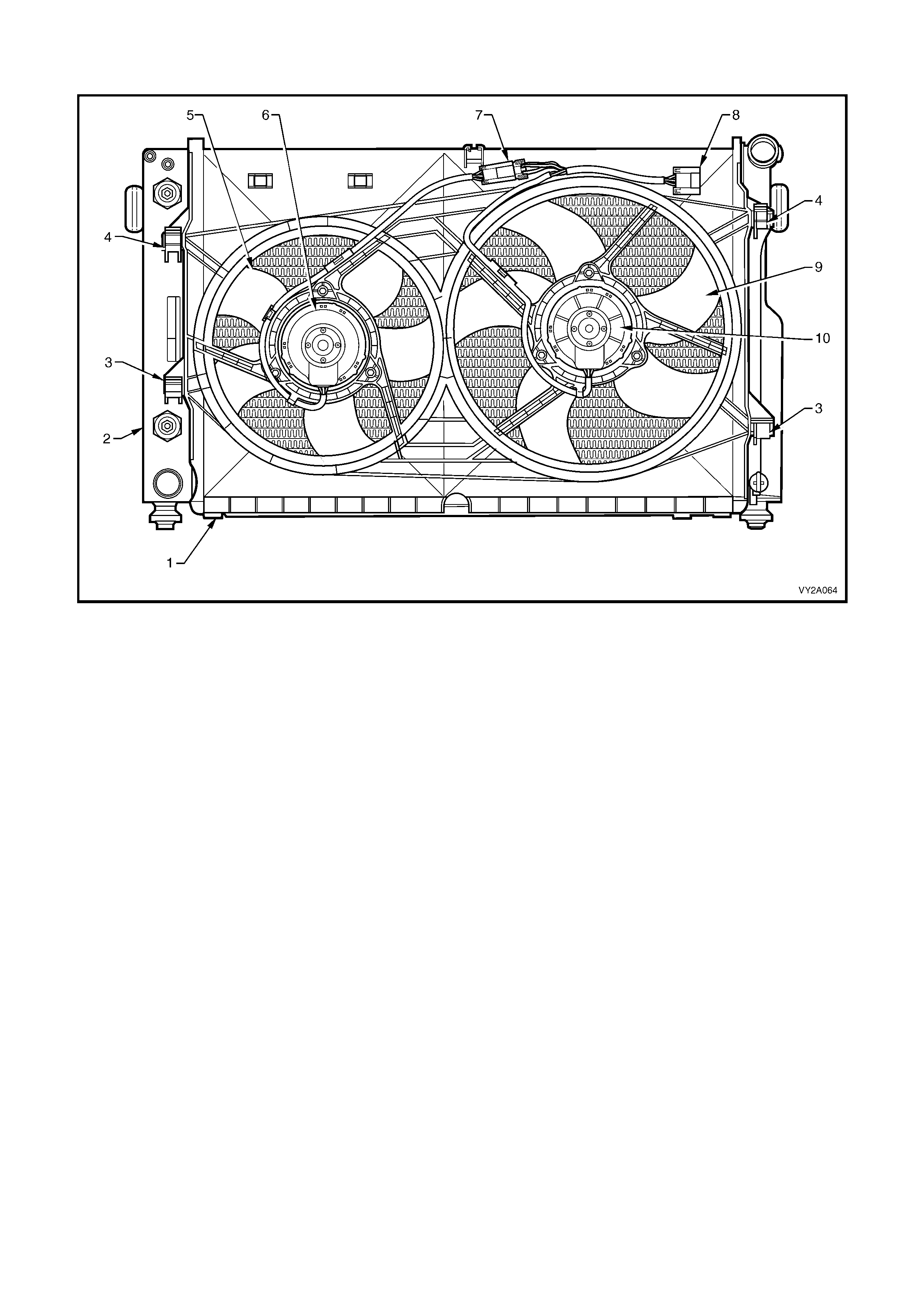
Cooling Fans – GEN III V8 Models
Figure 2A-98
Legend
1. Fan Shroud 6. LHS Fan Motor – 180 Watt, Dual Speed
2. Radiator 7. LHS Fan Motor Harness Connector (3 Terminal)
3. Fan Shroud Lower Support 8. LHS and RHS Fan Motor Harness Connector (5 Terminal)
4. Fan Shroud Upper Support/Locking Retainer 9. RHS Fan – 5 Blade, 336 mm Blade Diameter
5. LHS Fan – 5 Blade, 275 mm Blade Diameter 10. RHS Fan Motor – 220 Watt, Dual Speed
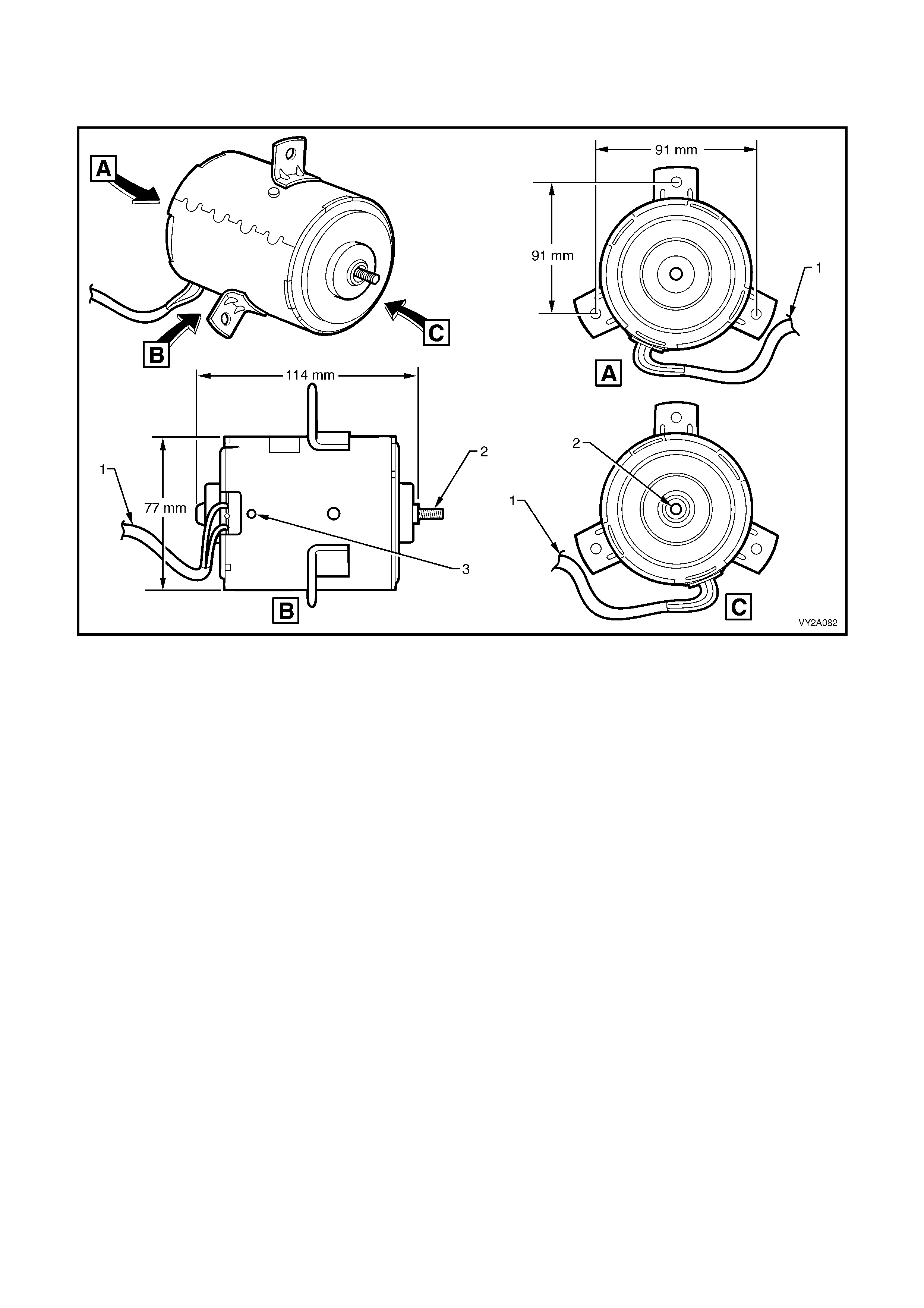
FAN MOTORS
Single Speed Motor, Standard Cooling Fan System – V6 Models
Figure 2A-99
Legend
1. Two Wire Harness 2. Armature Shaft 3. Drain Hole
When the Standard Cooling Fan System is fitted to a V6 engine, the fan motors are 12 Volt, single speed types.
The intern al construction of the fan m otor consists of two brushes and two perm anent m agnets. A two wire pigt ail
harness is perm anently co nnected to bot h m otors and is at tached to the polypr opylene f an shroud at two lo cations
by integral clips moulded as part of the fan shroud.
The RHS motor harness is directly connected to the engine harness through a 6 pin connector. It also carries an
additional 2 pin connector, which attaches to the LHS motor harness and enables individual removal of the LHS
and RHS fan and motor assemblies when necessary, refer to Figure 2A-96. The two associated electrical
connectors are attached to the shroud by way of slide lock clips. The motor is attached to the fan shroud by three
bolts at threaded mounting flanges spot-welded symmetrically around the fan housing, refer to Figure 2A-99.
The enc losed fan motor hous ing is constructe d of yellow zinc c oated steel. A drain ho le is located in the b ottom of
the housing to allow for breathing and draining of any moisture ingress.
Both fan motors rotate in an anti-clockwise direction when viewed from the fan motor side.
The LHS motor is rated at 160 Watts and drives the larger diam eter (384 mm) fan blade at approximately 1900 ±
150 rpm.
The RHS m otor is rat ed at 120 W atts and driv es th e sm aller diam eter (280 m m) fan bla de at a pproxim atel y 2350 ±
150 rpm.
Both LHS and RHS fan and motor are balanced as a unit and fan blades must not be separated from their
respectiv e motors . Fan motors and blades are s erv ic e d on l y as an as sembled un i t. Ho wever it s hou ld be n ot ed th at
the central nut attaching the fan blade to the motor shaft has a left-hand thread.
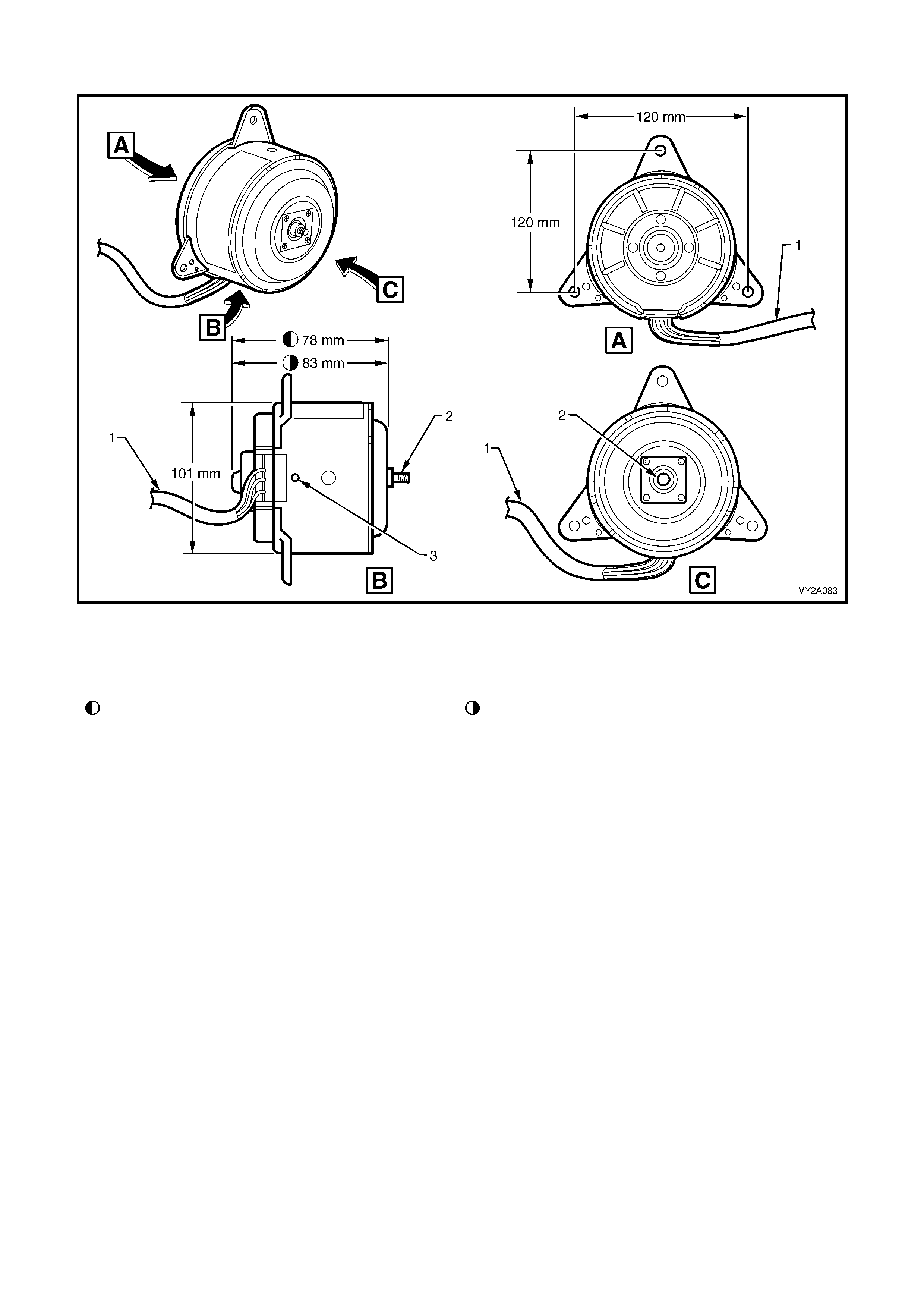
Dual Speed Motor, High Power Cooling Fan System – V6 and GEN III V8 Models
Figure 2A-100
Legend
1. Three Wire Harness 2. Armature Shaft 3. Drain Hole
Dimension applicable to small diameter fan blade Dimension applicable to large diameter fan blade
Vehicles f itted with V6 e ngines m ay have a Standar d Cooling Fan System or High Cooling Power Fan System . All
GEN III V8 models are fitted with a High Power Cooling Fan System.
Whenever a High Power Cooling Fan System is fitted, the fan motors are 12 Volt, dual speed types. Accordingly,
the intern al cons tructio n of the f an m otor c onsists of four brushes and f our perm anent m agnets. A three wire pigt ail
harness is permanently attached to both motors and is attached to the polypropylene fan shroud at two locations by
integral clips moulded as part of the shroud. The RHS motor harness is connected directly to the engine harness
through a 6 pin connector . It also carries an additional 4 pin connector which attaches to the LHS motor harness
and enables individual removal of the LHS and RHS fan and motor assemblies when necessary, refer to
Figure 2A-97 and Figure 2A-98. The two associated electrical connectors are attached to the shroud by way of
slide lock clips. The motor is attached to the polypropylene fan shroud by three bolts installed at the threaded
mounting flanges, which protrude symmetrically from the rear of the fan motor housing, refer to Figure 2A-100.
The enc losed fan motor hous ing is constructe d of yellow zinc c oated steel. A drain ho le is located in the b ottom of
the housing to allow for breathing and draining of any moisture ingress.
Both fan motors rotate in an anti-clockwise direction when viewed from the fan motor side.
On V6 engines:
The LHS motor is rated at 220 Watts and drives the larger diameter (384 mm) fan blade. During first stage
operation, the fan is driven at 2250 ± 150 rpm. During second stage operation, the fan is driven at 2500
± 150 rpm.
The RHS motor is rated at 180 Watts and drives the smaller diameter (280 mm) fan blade. During first stage
operation, the fan is driven at 2500 ± 150 rpm. During second stage operation, the fan is driven at approximately
2800 ± 150 rpm.

On GEN III V8 engines:
The LHS motor is rated at 180 Watts and drives the smaller diameter (298 mm) fan blade. During first stage
operation, the fan is driven at 2050 ± 150 rpm. During second stage operation, the fan is dr iven at 2300 ± 150
rpm.
The RHS motor is rated at 220 Watts and drives the larger diameter (355 mm) fan blade. During first stage
operation, the fan is driven at approximately 2350 ± 150 rpm. During second stage operation, the fan is driven at
2750 ± 150 rpm.
As with Standard Cooling Fan System, both LHS and RHS fan and motor fitted to the High Power Cooling Fan
System are b al anc ed as a unit an d fan bl ades must n ot b e s ep ar ate d f rom their res pecti ve motors . F an motors and
blades are serviced only as an assembled unit. However it should be noted that the central nut attaching the fan
blade to the motor shaft has a left-hand thread.
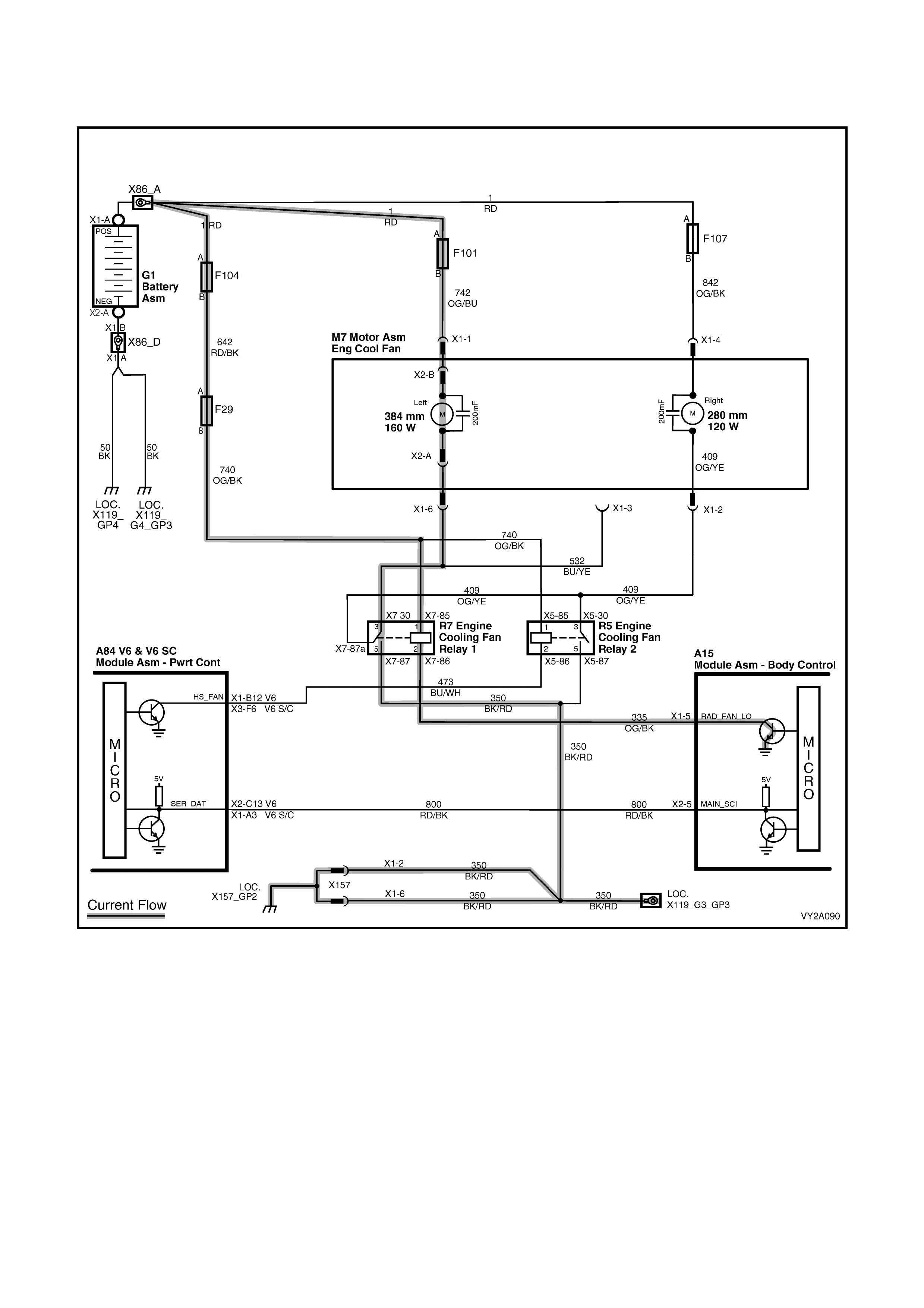
FAN OPERATION: STANDARD COOLING FAN SYSTEM – V6
1st Stage: Large diameter fan only driven at maximum speed
Figure 2A-101
On V6 m odels f itted with the standar d coo ling fan s ystem , the engine coo ling f an m otors are single spe ed an d both
motors have a two wire harness. Each harness has one positive wire connected to one positive brush and one
negative wire con nected to one ne gativ e brush. T he pos itive wire is per m anentl y connected to bat ter y voltage via a
fusible link.
When the negative wire of the large diameter cooling fan motor is grounded (via the relay located in the engine
compartment relay housing, labelled ‘ENGINE COOL FAN RELAY 1’), the fan will operate at maximum speed.
The large diameter cooling fan is grounded when this cooling fan relay is energised by the Body Control Module
(BCM) via a request from the Powertrain Control Module (PCM).
The PCM will request large diameter fan enable and disable via serial data communication to the BCM on circuit
800 (Red/B lack wire). Af ter the PCM requests a c han g e in the st at e of the ENGI N E COO L FAN RE LA Y 1 (i.e . off to
on or, on to off), the BCM will send a serial data response message back to the PCM confirming it received the
message.
The PCM det erm ines when to enabl e this rela y based on inputs f rom the A/C r equest sign al, Cooli ng Temper ature
Sensor (CTS) and the Vehicle Speed Sensor (VSS).

The ENGINE COOL FAN RELAY 1 cooling fan relay will be turned on when:
• Air conditioning request indicated (YES) and the vehicle speed is less than 30 km/h or
• Air conditioning pressure is greater than 1500 kPa or
• Coolant temperature is greater than 104°C or
• An engine coolant temperature sensor failure is detected by the PCM, (for additional information refer to
Section 6C1 POWERTRAIN MANAGEMENT – V6 ENGINE) or
• When the ignition switch is turned from ON to OFF and the engine coolant temperature is above 117°C. The
BCM will continue to energise the ENGINE COOL FAN RELAY 1 for four minutes.
The PCM will request the BCM to switch off the ENGINE COOL FAN RELAY 1 cooling fan relay when the following
conditions have been met:
• Air conditioning request not indicated (NO) and the coolant temperature is less than 99°C or
• Air conditioni ng r eques t ind icated ( YES) wit h pres sure less than 1170 kPa, ve hicl e s peed gre ater than 50 km/h
and coolant temperature less than 99°C.
Figure 2A-102
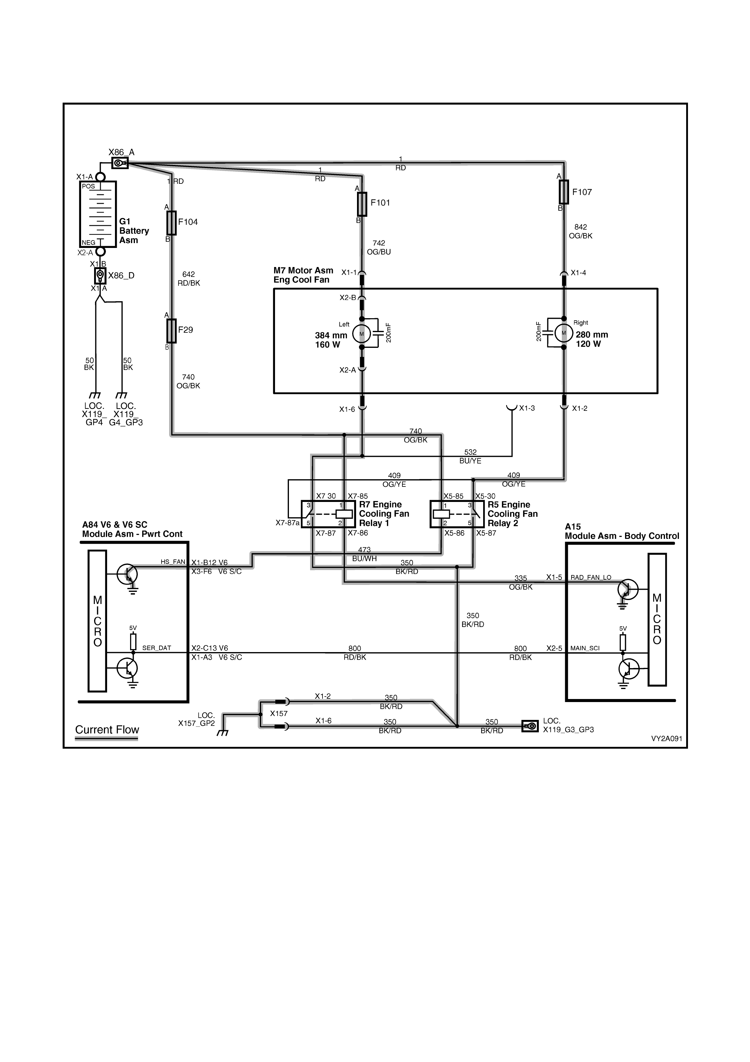
FAN OPERATION: STANDARD COOLING FAN SYSTEM – V6
2nd Stage: Large and small diameter fans driven at maximum speed
Figure 2A-103
At the 2nd stage the small diam eter fan will turn on and operate at m aximum speed along with the large diameter
fan.
To initiate this function the ENGINE COOL FAN RELAY 2 will be turned on if the ENGINE COOL FAN RELAY 1 has been
energised for one second and the following conditions have been met:
• If there is a BCM to PCM m ess age r espons e f ault, s ett i ng a DT C P1064 f or V6 or DTC 92 for V6 Super char g ed
or
• An engine coolant temperature sensor failure is detected by the PCM, (for additional information refer to
Section 6C1 POWERTRAIN MANAGEMENT – V6 ENGINE) or
• Engine coolant temperature is above 107°C or
• Air conditioning pressure is greater than 2000 kPa for V6 and 2600 kPa for V6 Supercharged.
NOTE: If the lar g e d iameter c ooli ng f an is of f when the c r iteria for turni ng t he s mall d iameter c ool ing f an o n are fir st
met, the small diameter cooling fan will turn on 5 seconds after the large diameter cooling fan is switched on.
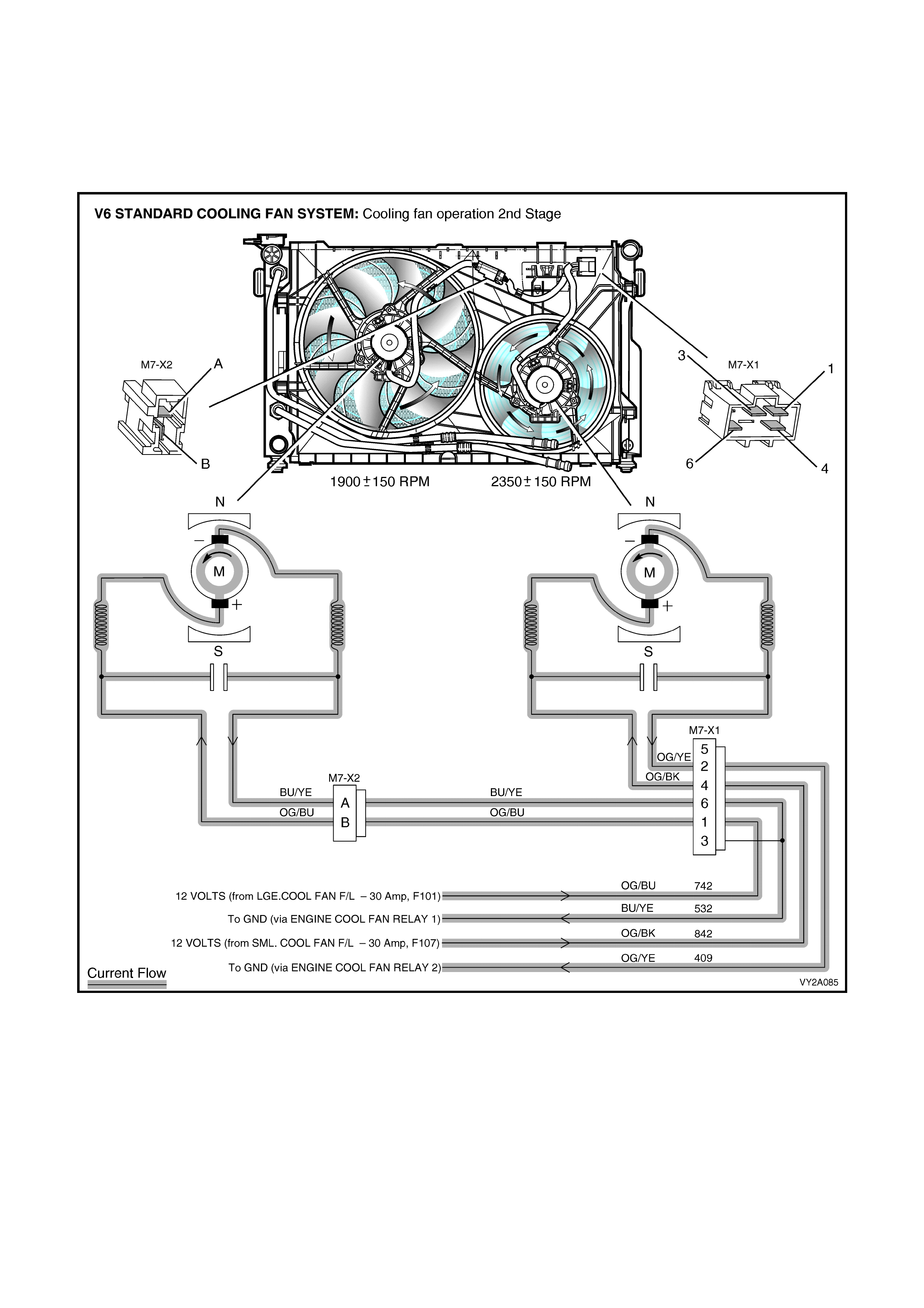
If both cooling fans are enabled, the PCM will turn the 2nd stage cooling function off (small diameter fan
off) when:
• The engine coolant temperature is less than 108°C and
• Air conditioning request is not indicated (NO) or
• Air conditioning request is indicated (YES) and the pressure is less than 1500 kPa for V6 and 2300 kPa for
V6 Superc harge d.
Figure 2A-104
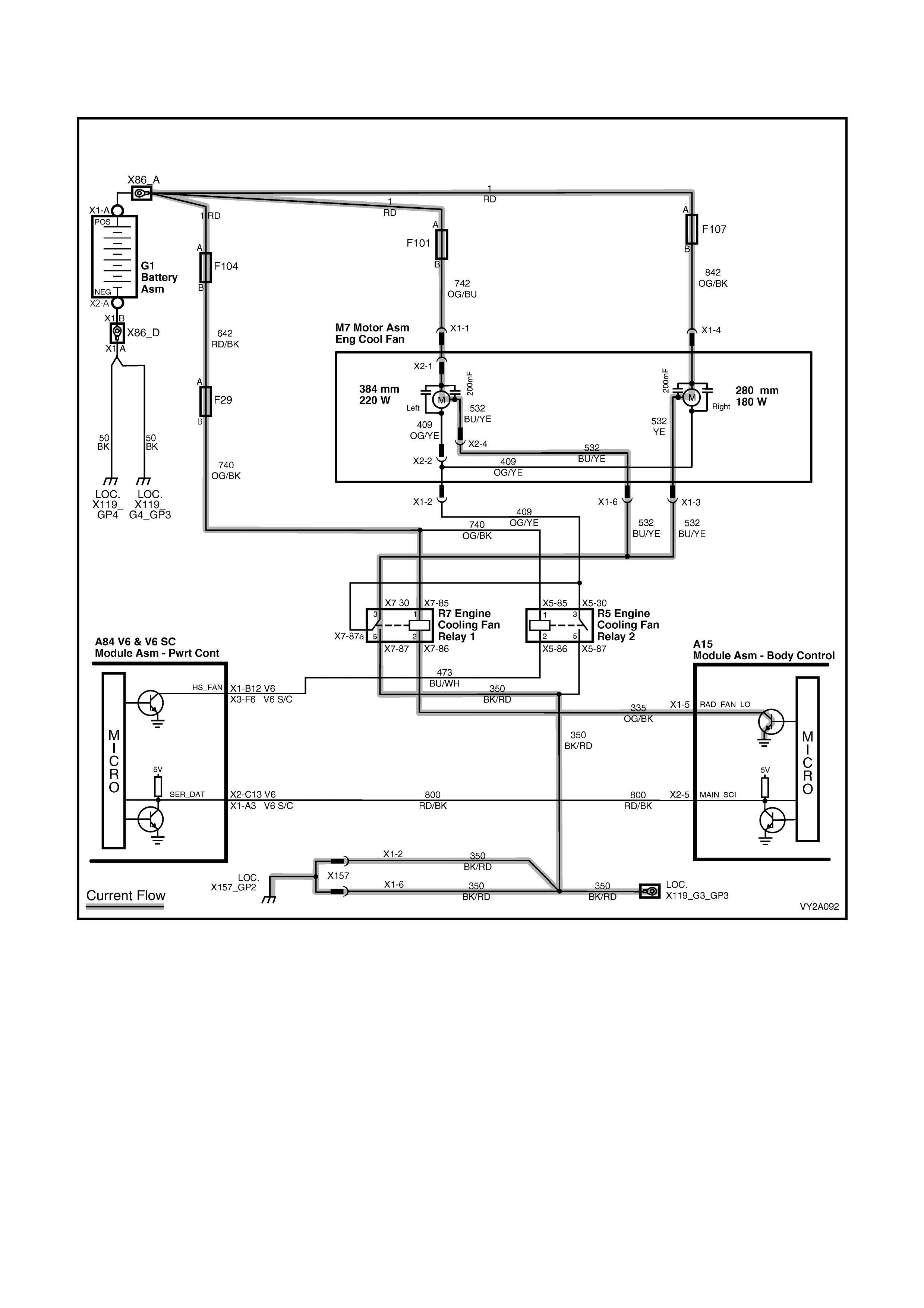
FAN OPERATION: HIGH POWER COOLING FAN SYSTEM – V6
1st Stage: Both fans driven at low speed
Figure 2A-105
On V6 models fitted with the high power cooling fan system, cooling fan motors are dual speed and have a three
wire harness attached. Each harness has one positive and two negative wires. The positive wire permanently
connects b attery voltag e to the t wo posit ive brushes of each f an motor. T he negative wires are each c onnected to
one negative brush. When one negative wire per motor is grounded (via the relay located in the engine
compartment relay housing, labelled ‘ENGINE COOL FAN RELAY 1’), both cooling fan motors will operate at low
speed.
The lo w speed coo ling fan oper ation is enable d when the ENGINE CO OL FAN R ELAY 1 is e nergised b y the Bod y
Control Module ( BCM) via a request from the Powertr ain Control Module (PC M). The PCM will request low speed
fan f unction enable an d d isable vi a s eri al da ta c om munication to th e BCM on c ircuit 80 0 ( Re d/B lac k wir e) . Af ter th e
PCM requests a change in the state of ENGINE COOL FAN RELAY 1 (i.e. off to on or, on to off), the BCM will send
a serial data response message back to the PCM confirming it received the message.
The PCM d etermines when to enabl e ENGINE COOL FAN RE LAY 1 base d on inputs from the A/C request signal,
Cooling Temperature Sensor (CTS) and the Vehicle Speed Sensor (VSS).
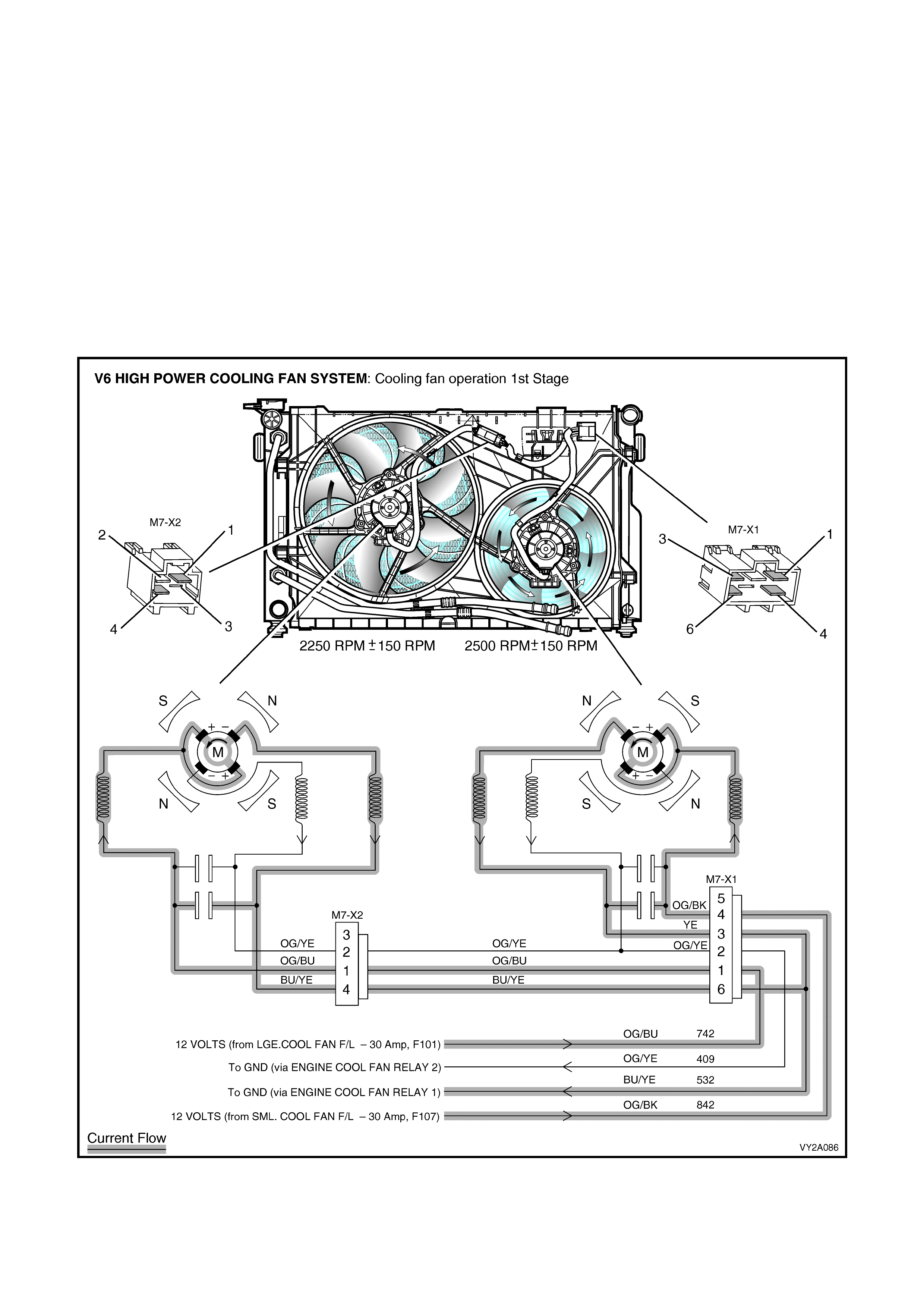
The ENGINE COOL FAN RELAY 1 will be turned on when:
• Air conditioning request indicated (YES) and the vehicle speed is less than 30 km/h or
• Air conditioning pressure is greater than 1500 kPa or
• Coolant temperature is greater than 104°C or
• An engine coolant temperature sensor failure is detected by the PCM (for additional information refer to
Section 6C1 POWERTRAIN MANAGEMENT – V6 ENGINE) or
• When the ignition switch is turned from ON to OFF and the engine coolant temperature is above 117°C. The
BCM will continue to energise ENGINE COOL FAN RELAY 1 for four minutes.
The PCM will request the BCM to switch off the ENGINE COOL FAN RELAY 1 when the following conditions have been
met:
• Air conditioning request not indicated (NO) and the coolant temperature is less than 99°C or
• Air conditioni ng r eques t ind icated ( YES) wit h pres sure less than 1170 kPa, ve hicl e s peed gre ater than 50 km/h
and coolant temperature less than 99°C.
Figure 2A-106

FAN OPERATION: HIGH POWER COOLING FAN SYSTEM – V6
2nd Stage: Both fans driven at high speed
Figure 2A-107
W hen the second nega tive wire ( internall y connected to the secon d negat ive brus h of each f an motor) is gr ounded
(via the rel a y loc ate d in t he eng ine c ompartm ent r elay housing, l abe lled ‘ ENG IN E CO OL F AN REL A Y 2’), b oth high
and low speed ne gative wir es will now be grou nded, allowing m ore current to flow through th e motor. Both cool ing
fans will then operate at high speed.
The ENGINE COOL FAN RELAY 2 cooling fan relay will be turned on if the ENGINE COOL FAN RELAY 1 has been
energised for one second and the following conditions have been met:
• If there is a BCM to PCM message response fault, setting a DTC P1064 or
• An engine coolant temperature sensor failure is detected by the PCM, (for additional information refer to
Section 6C1 POWERTRAIN MANAGEMENT – V6 ENGINE) or
• Engine coolant temperature is above 107°C or
• Air conditioning pressure is greater than 2400 kPa.
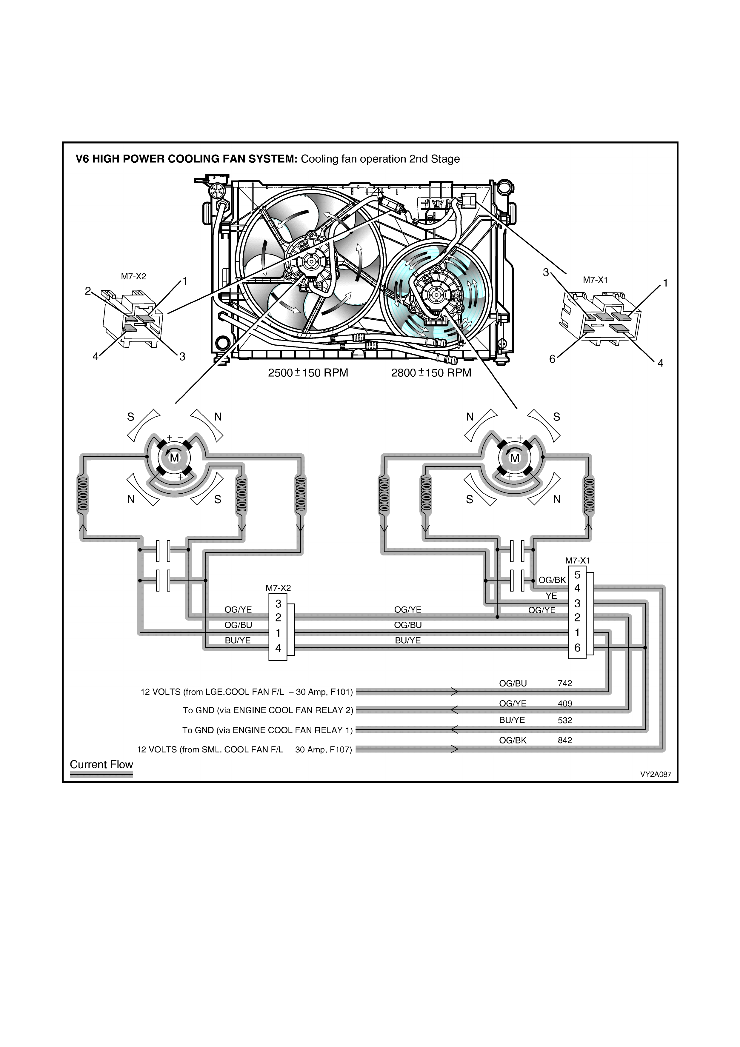
The PCM will turn the Stage 2 cooling fan function off when:
• The engine coolant temperature is less than 108°C and
• Air conditioning request is not indicated (NO) or
• Air conditioning request is indicated (YES) and the pressure is less than 2000 kPa.
Figure 2A-108
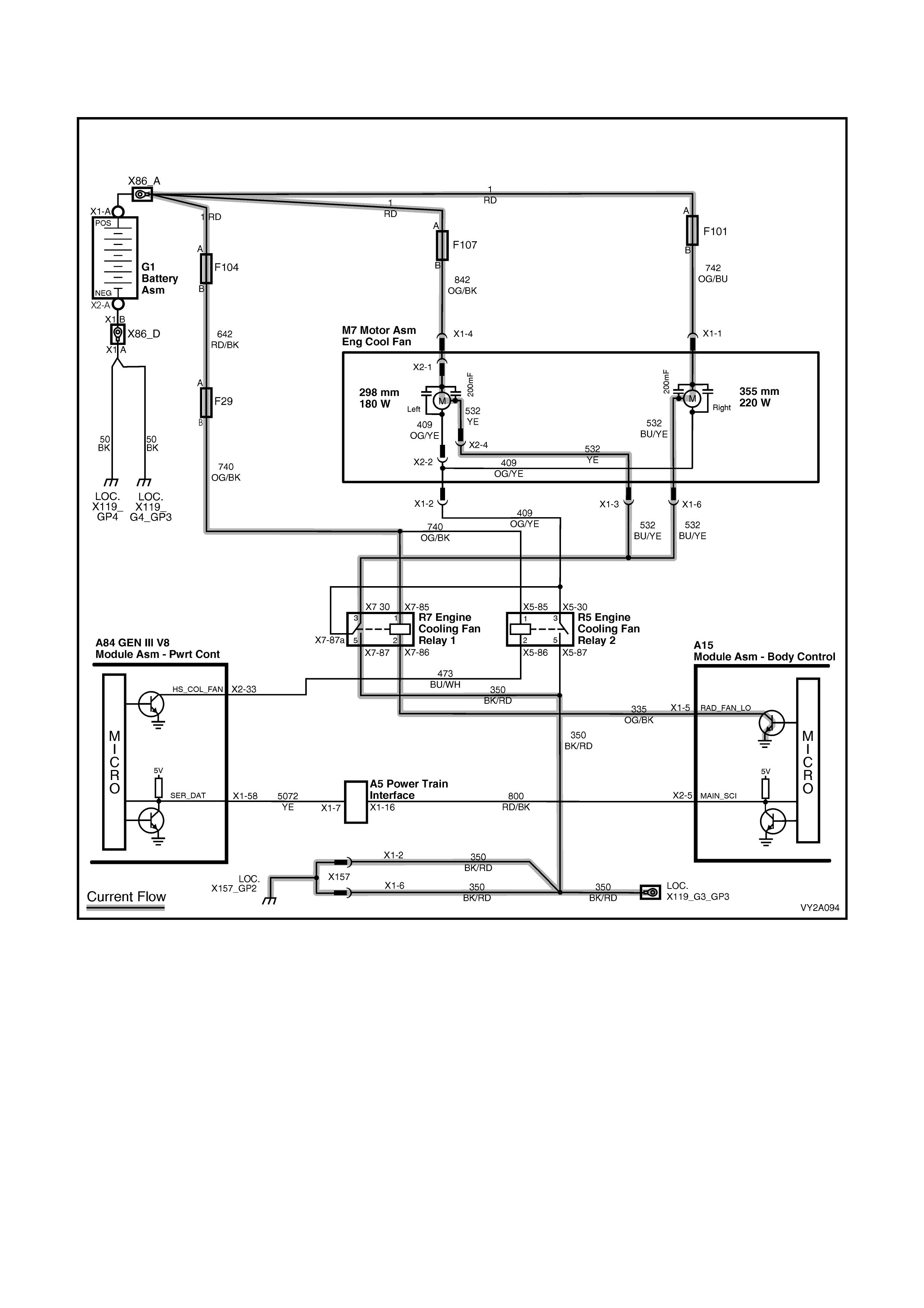
FAN OPERATION: COOLING FAN SYSTEM – GEN III V8
1st Stage: Both fans driven at low speed
Figure 2A-109
On all models fitted with GEN III V8 engines, cooling fan motors are dual speed and have a three wire harness
attached. Each harness has one positive and two negative wires. The positive wire perm anently connects battery
voltage to the two positive brushes of each fan motor. The negative wires are each connected to one negative
brush. When one negative wire per motor is grounded (via the relay located in the engine compartment relay
housing, labelled ‘ENGINE COOL FAN RELAY 1’), both cooling fan motors will operate at low speed.
The lo w speed coo ling fan oper ation is enable d when the ENGINE CO OL FAN R ELAY 1 is e nergised b y the Bod y
Control Module ( BCM) via a request from the Powertr ain Control Module (PC M). The PCM will request low speed
fan f unction enable an d d isable vi a s eri al da ta c om munication to th e BCM on c ircuit 80 0 ( Re d/B lac k wir e) . Af ter th e
PCM requests a change in the state of ENGINE COOL FAN RELAY 1 (i.e. off to on or, on to off), the BCM will send
a serial data response message back to the PCM confirming it received the message.
NOTE: Serial data communication between the PCM and BCM is via the Powertrain Interface Module (PIM).
The PCM d etermines when to enabl e ENGINE COOL FAN RE LAY 1 base d on inputs from the A/C request signal,
Cooling Temperature Sensor (CTS) and the Vehicle Speed Sensor (VSS).
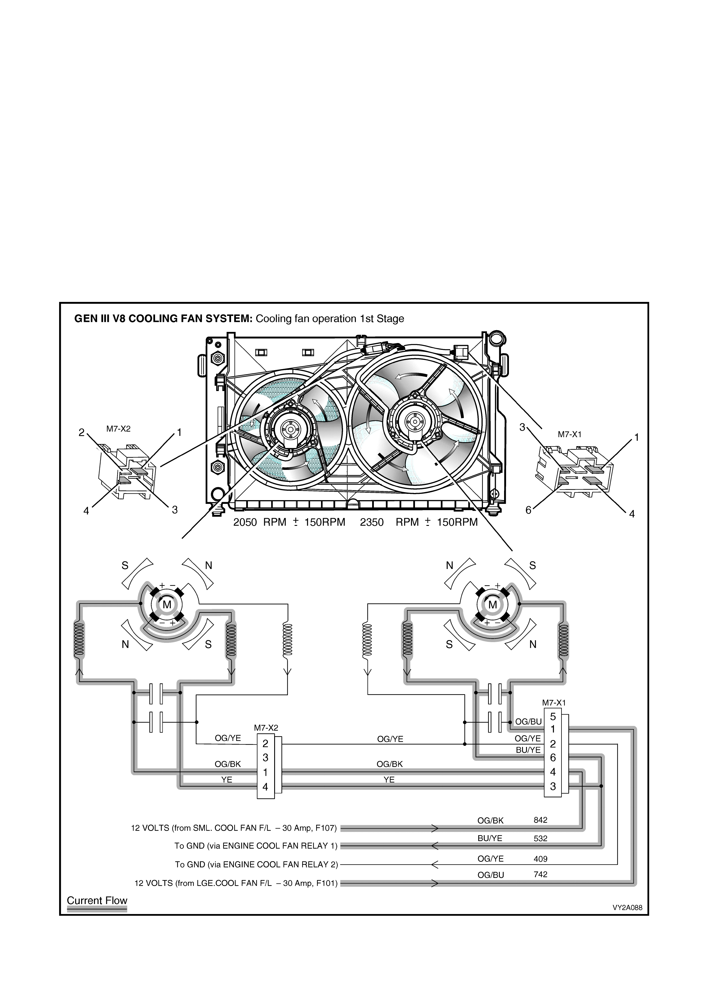
The ENGINE COOL FAN RELAY 1 will be turned on when:
• Air conditioning request indicated (YES) and the vehicle speed is less than 30 km/h or
• Air conditioning pressure is greater than 1500 kPa or
• Coolant temperature is greater than 98°C or
• When a coo lant temperature sens or f ai lure in c onj unction with an Int ake Air Temperature (I AT) s ensor f ailur e is
detected by the PCM (for additional information refer to Section 6C3 PO W E RT R AIN M ANAGEM ENT –
GEN III V8 ENGINE) or
• When the ignition switch is turned from ON to OFF and the engine coolant temperature is above 113°C. The
BCM will continue to energise ENGINE COOL FAN RELAY 1 for four minutes.
The PCM will request the BCM to switch off the ENGINE COOL FAN RELAY 1 when the following conditions have been
met:
• Air conditioning request not indicated (NO) and the coolant temperature is less than 95°C or
• Air conditioni ng r eques t ind icated ( YES) wit h pres sure less than 1170 kPa, ve hicl e s peed gre ater than 50 km/h
and coolant temperature less than 98°C.
NOTE: The Stage 1cooling fan operation has a minimum run on time function of 30 seconds.
Figure 2A-110
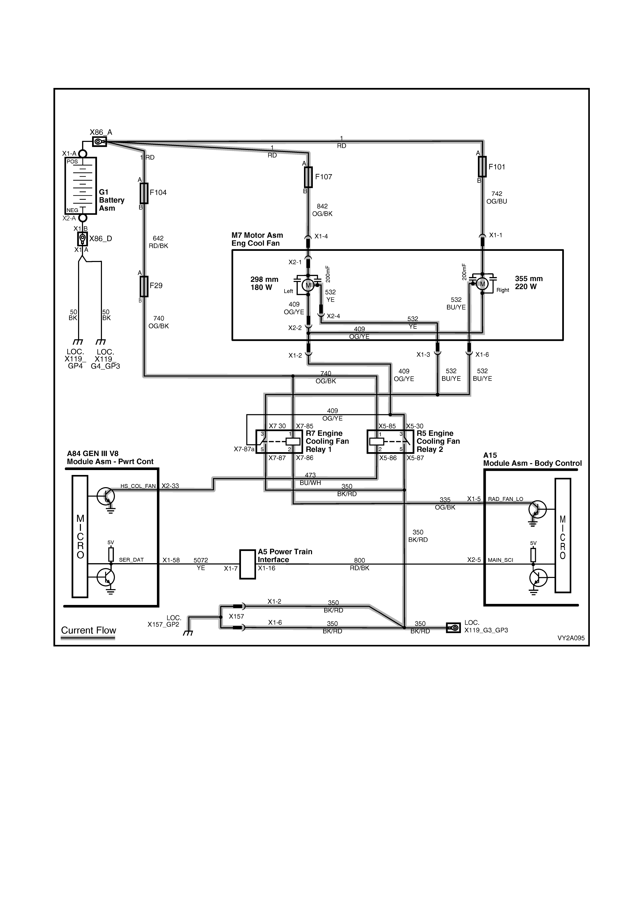
FAN OPERATION: COOLING FAN SYSTEM – GEN III V8
2nd Stage: Both fans driven at high speed
Figure 2A-111
W hen the second nega tive wire ( internall y connected to the secon d negat ive brus h of each f an motor) is gr ounded
(via the rel a y loc ate d in t he eng ine c ompartm ent r elay housing, l abe lled ‘ ENG IN E CO OL F AN REL A Y 2’), b oth high
and low speed negative wires will now be grounded, allowing current to flow through the motor. Both cooling f ans
will then operate at high speed.
The ENGINE COOL FAN RELAY 2 cooling fan relay will be turned on if the ENGINE COOL FAN RELAY 1 has been
energised for one second and the following conditions have been met:
• If there is a BCM to PIM message response fault, setting a DTC B2002 or
• Engine coolant temperature is above 108°C or
• Air conditioning pressure is greater than 2400 kPa.
NOTE: If the Stag e 1 c ooli ng fan func tion is of f when the crit eria for turn ing o n th e Stag e 2 c ooling f an functi on ar e
first met, the Stage 2 cooling fan function will begin to operate 1 second after the Stage 1 cooling fan function is
switched on.
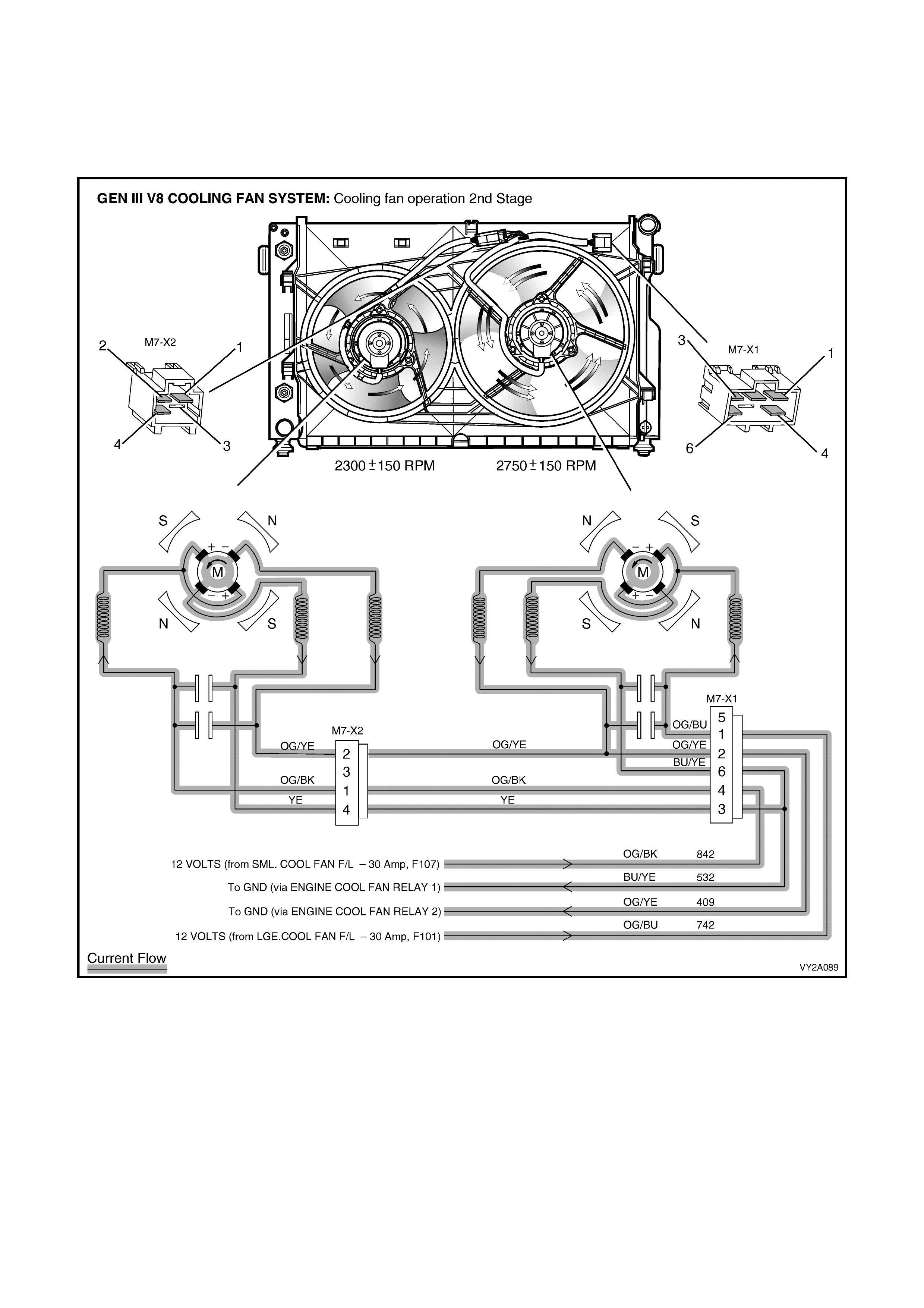
The PCM will turn the high speed cooling fan function off when:
• The engine coolant temperature is less than 102°C and
• Air conditioning request is not indicated (NO) or
• Air conditioning request is indicated (YES) and the pressure is less than 1900 kPa.
NOTE: The Stage 2 cooling fan operation has a minimum run on time function of 30 seconds.
Figure 2A-112

3. SPECIFICATIONS
GENERAL
Available modes...................................................... Recirculation, face, bi-level, floor, blend and demist
Blower fan speeds................................................... 4
HVAC door actuation
Air mix doors...................................................... Mechanical
Recirculation, face, foot, and demist doors........ Vacuum
Air conditioning system
Installation.......................................................... Integrated
Type................................................................... TXV (Thermostatic Expansion Valve) non-cycling
Cooling system capacity
V6 and V6 Su perc harged................................... 12.0 Litres
GEN III V8.......................................................... 14.3 Litres
Coolant specification
V6 and V6 Supercharged – RHD exc. S. Africa Conforming to HN2043
V6 – LHD and S. Africa...................................... Conforming to GM6277M
GEN III V8 – LHD and S. Africa......................... Dex-Cool (conforming to GM6277M)
GEN III V8 – RHD exc. S. Africa........................ Extended Life Anti-freeze Coolant (conforming
to GM6277M)
Coolant concentration
V6 and V6 Supercharged................................... 50% water and 50% coolant
GEN III V8.......................................................... 50% water and 50% coolant
WATER VALVE
Type ........................................................................ 4 port, constant flow
Actuation ................................................................. Vacuum
Construction
Porting................................................................ Plastic
Valve and vacuum actuator ............................... Metal
Operation
Vacuum applied ................................................. No coolant flow through heater core
Vacuum not applied ........................................... Coolant flow through heater core
HVAC UNIT – LEFT-HAND DRIVE MODELS
Manufacturer........................................................... Denso
Vacuum actuators
Housing material................................................
Face actuator ................................................ Metal
Demist actuator ............................................. Metal/plastic
Foot actuator ................................................. Metal/plastic
Intake actuator............................................... Metal/plastic
Rod material....................................................... Metal
No. of single stage actuators ............................. 3
No. of two stage actuators................................. 1
Air mix function (heater core air fl ow)
No. of doors........................................................ 2 (unequally sized)
Actuation............................................................ Pinion and crescent gear, and actuating rod
Recirculation mode (inlet/fresh)
No. of doors........................................................ 2 (equally sized)
Actuation............................................................ Vacuum, single stage actuator
Face mode
No. of doors........................................................ 1 (centre pivot)
Actuation............................................................ Vacuum, two stage actuator
Floor mode
No. of doors........................................................ 1
Actuation............................................................ Vacuum, single stage actuator

Demist mode
No. of doors........................................................ 1
Actuation............................................................ Vacuum, single stage actuator
Blower fan assembly
Fan motor wattage............................................. 290 Watts approximately
Fan motor current .............................................. 22.5 ± 2.3 Am ps
Fan drum height/diameter.................................. 75 mm X 150 mm
No. of fan blades................................................ 41
In-line fuse rating ............................................... 30 Amps
Blower fan resistor assembly
Fan speed 1 resistance...................................... 2.8 Ω
Fan speed 2 resistance...................................... 1.5 Ω
Fan speed 3 resistance...................................... 0.6 Ω
Fan speed 4 resistance...................................... 0 Ω
Heater core
Design................................................................ Vertical flow, plate and fin
Construction....................................................... Aluminium core and tanks with detachable pipes
No. of tubes........................................................ 22
Core width.......................................................... 150 mm
Core height......................................................... 200 mm
Core depth ......................................................... 30 mm
Evaporator
Design................................................................ Vertical flow, plate and fin
Construction....................................................... Aluminium core and tanks with detachable pipes
No. of tubes........................................................ 19
Core width.......................................................... 290 mm
Core height......................................................... 220 mm
Core depth ......................................................... 90 mm
HVAC UNIT – RIGHT-HAND DRIVE MODELS
Manufacturer........................................................... Air International
Vacuum actuators
Housing material................................................ Plastic
Rod material....................................................... Plastic
No. of single stage actuators ............................. 1
No. of two stage actuators................................. 2
Air mix function (heater core air fl ow)
No. of doors........................................................ 2 (unequally sized)
Actuation............................................................ Pinion and crescent gear, and actuating rod
Recirculation mode (inlet/fresh)
No. of doors........................................................ 1
Actuation............................................................ Vacuum, single stage actuator
Rod colour.......................................................... Blue
Face mode
No. of doors........................................................ 1
Actuation............................................................ Vacuum, two stage actuator
Rod colour.......................................................... White
Demist/Floor mode
No. of doors........................................................ 1
Actuation............................................................ Vacuum, two stage actuator
Rod colour.......................................................... Black
Blower fan assembly
Fan motor wattage............................................. 300 Watts approximately
Fan motor current .............................................. 25 Amps
Fan drum height/diameter.................................. 63 mm X 155 mm
No. of fan blades................................................ 59

Blower fan resistor assembly
Fan speed 1 resistance...................................... 2.2 Ω
Fan speed 2 resistance...................................... 1.2 Ω
Fan speed 3 resistance...................................... 0.5 Ω
Fan speed 4 resistance...................................... 0 Ω
Heater core
Design................................................................ Vertical flow, plate and fin
Construction....................................................... Aluminium core and tanks with integral pipes
No. of tubes........................................................ 18
Core width.......................................................... 160 mm
Core height......................................................... 195 mm
Core depth ......................................................... 35 mm
Evaporator
Design................................................................ Vertical flow, plate and fin
Construction....................................................... Aluminium core and tanks with integral pipes
No. of tubes........................................................ 24
Core width.......................................................... 270 mm
Core height......................................................... 215 mm
Core depth ......................................................... 70 mm
COMPRESSOR
Manufacturer........................................................... Delphi
Type ........................................................................ Non-cycling, variable stoke
Model – (V6 and V6 Supercharged) ....................... V5
Capacity............................................................. 156 cc
Model – (GEN III V8)............................................... V7
Capacity............................................................. 179 cc
Clutch coil resistance
V5....................................................................... 3.5 Ω
V7....................................................................... 3.2 Ω
Clutch plate to rotor clearance................................ 0.38 – 1.0 mm
Drive belt tension
V6 and V6 Su perc harg ed................................... Automatic
GEN III V8.......................................................... Automatic
REFRIGERANT
Type ........................................................................ R134a
Charge quantity....................................................... 775 – 825 g
AC LUBRICANT
Type ........................................................................ Poly Alkaline Glycol (PAG) conforming to HN2074
System quantity....................................................... 265 ml
Component replacement compensation quantities
Compressor........................................................ 220 ml
Filter drier receiver............................................. 15 ml
Condenser.......................................................... 40 ml
Evaporator.......................................................... 50 ml
Blown/ruptured pipe or hose.............................. 40 ml
CONDENSER
Manufacturer........................................................... Calsonic
Design..................................................................... Parallel flow, 4 pass
Construction............................................................ Aluminium
No. of tubes............................................................. 38
Core height.............................................................. 427 mm
Core width............................................................... 615 mm
Core depth .............................................................. 19 mm

PRESSURE TRANSDUCER
Low pressure cut out
V6....................................................................... 180 kPa
V6 Supercharged............................................... 180 kPa
GEN III V8.......................................................... 180 kPa
Low pressure cut in
V6....................................................................... 240 kPa
V6 Supercharged............................................... 240 kPa
GEN III V8.......................................................... 240 kPa
High pressure cut out
V6....................................................................... 2900 kPa
V6 Supercharged............................................... 2900 kPa
GEN III V8.......................................................... 2900 kPa
High pressure cut in
V6....................................................................... 2000 kPa
V6 Supercharged............................................... 2400 kPa
GEN III V8.......................................................... 2000 kPa
2nd stage cooling fan on
V6 Right-hand Drive........................................... 2000 kPa
V6 Left-hand Drive............................................. 2400 kPa
V6 Supercharged............................................... 2600 kPa
GEN III V8.......................................................... 2400 kPa
2nd stage cooling fan off
V6 Right-hand Drive........................................... 1500 kPa
V6 Left-hand Drive............................................. 2000 kPa
V6 Supercharged............................................... 2300 kPa
GEN III V8.......................................................... 1900 kPa
STANDARD COOLING FAN SYSTEM – V6 AND V6 SUPERCHARGED
Engine Cooling Fan 1 (LHS)
Fan
Design.............................................................. Symmetric, curved blades with outer ring
Material ............................................................ Polyamide, with zinc coated metal hub insert
Number of blades............................................. 8
Diameter of blades .......................................... 365 mm
Diameter of outer ring...................................... 384 mm
Fan motor
Manufacturer.................................................... Gate
Model ............................................................... MP5635
Type................................................................. Single speed, 2 brush and 2 permanent magnets
Housing............................................................ Semi-sealed, zinc coated steel with drain hole
Direction of rotation.......................................... Anti-clockwise (viewed from fan motor side)
Rotational speed.............................................. 1900 ± 150 RPM*
Power............................................................... 160 Watts (nominal)*
Current – constant ........................................... 10.5 – 11.5 Amps*
Engine Cooling Fan 2 (RHS)
Fan
Design.............................................................. Symmetric, curved blades, with outer ring
Material ............................................................ Polyamide, with zinc coated metal hub insert
Number of blades............................................. 8
Diameter of blades .......................................... 263 mm
Diameter of outer ring...................................... 280 mm
Fan motor
Manufacturer.................................................... Gate
Model ............................................................... MP5635
Type................................................................. Single speed, 2 brush and 2 permanent magnets

Housing............................................................ Semi-sealed, zinc coated steel with drain hole
Direction of rotation.......................................... Anti-clockwise (viewed from fan motor side)
Rotational speed.............................................. 2350 ± 150 RPM*
Power............................................................... 120 Watts (nominal)*
Current – constant ........................................... 20 – 22 Amps *
HIGH POWER COOLING FAN SYSTEM – V6
Engine Cooling Fan 1 (LHS)
Fan
Design.............................................................. Symmetric, curved blades with outer ring
Material ............................................................ Polyamide, with zinc coated metal hub insert
Number of blades............................................. 8
Diameter of blades .......................................... 365 mm
Diameter of outer ring...................................... 384 mm
Fan motor
Manufacturer.................................................... Gate
Model ............................................................... MP8125
Type................................................................. Dual speed, 4 brush and 4 permanent magnets
Housing............................................................ Semi-sealed, zinc coated steel with drain hole
Direction of rotation.......................................... Anti-clockwise (viewed from fan motor side)
Rotational speed – Stage 1.............................. 2250 ± 150 RPM*
Rotational speed – Stage 2.............................. 2500 ± 150 RPM*
Power............................................................... 220 Watts (nominal)*
Engine Cooling Fan 2 (RHS)
Fan
Design.............................................................. Symmetric, curved blades, with outer ring
Material ............................................................ Polyamide, with zinc coated metal hub insert
Number of blades............................................. 8
Diameter of blades .......................................... 263 mm
Diameter of outer ring...................................... 280 mm
Fan motor
Manufacturer.................................................... Gate
Model ............................................................... MP8120
Type................................................................. Dual speed, 4 brush and 4 permanent magnets
Housing............................................................ Semi-sealed, zinc coated steel with drain hole
Direction of rotation.......................................... Anti-clockwise (viewed from fan motor side)
Rotational speed – Stage 1.............................. 2500 ± 150 RPM*
Rotational speed – Stage 2.............................. 2800 ± 150 RPM*
Power............................................................... 180 Watts (nominal)*
Engine Cooling Fan Motors – Constant Current
Stage 1.................................................................... 25 – 27.5 Amps*
Stage 2.................................................................... 31 – 34 Amps*
COOLING FAN SYSTEM – GEN III V8
Engine Cooling Fan 1 (LHS)
Fan
Design.............................................................. Asymmetric, curved blades, with outer ring
Material ............................................................ Polyamide, with zinc coated metal hub insert
Number of blades............................................. 5
Diameter of blades .......................................... 275 mm
Diameter of outer ring...................................... 298 mm
Fan motor
Manufacturer.................................................... Gate
Model ............................................................... MP8120
Type................................................................. Dual speed, 4 brush and 4 permanent magnets
Housing............................................................ Semi-sealed, zinc coated steel with drain hole
Direction of rotation.......................................... Anti-clockwise (viewed from fan motor side)

Rotational speed – Stage 1.............................. 2050 ± 150 RPM*
Rotational speed – Stage 2.............................. 2300 ± 150 RPM*
Power............................................................... 180 Watts (nominal)*
Engine Cooling Fan 2 (RHS)
Fan
Design.............................................................. Asymmetric, curved blades, with outer ring
Material ............................................................ Polyamide, with zinc coated metal hub insert
Number of blades............................................. 5
Diameter of blades .......................................... 336 mm
Diameter of outer ring...................................... 355 mm
Fan motor
Manufacturer.................................................... Gate
Model ............................................................... MP8125
Type................................................................. Dual speed, 4 brush and 4 permanent magnets
Housing............................................................ Semi-sealed, zinc coated steel with drain hole
Direction of rotation.......................................... Anti-clockwise (viewed from fan motor side)
Rotational speed – Stage 1.............................. 2350 ± 150 RPM*
Rotational speed – Stage 2.............................. 2750 ± 150 RPM*
Power............................................................... 220 Watts (nominal)*
Engine Cooling Fan Motors – Constant Current
Stage 1.................................................................... 26 – 28.5 Amps*
Stage 2.................................................................... 33 – 36 Amps*
• NOTE: All cooling fan performance specifications are at 12 Volts with the fan and motor assemblies installed to
the radiator/condenser assembly.