
SECTION 2B - HVAC CLIMATE CONTROL
(MANUAL A/C) – REMOVAL AND INSTALLATION
IMPORTANT
Before performing any Service Operation or other procedure described in this Section, refer to Section 00
CAUTIONS AND NOTES for correct workshop practices with regard to safety and/or property damage.
CONTENTS
1. GENERAL INFORMATION
2. MANUAL HVAC CONTROLLER
REMOVE
REINSTALL
2.1 WATER VALVE VACUUM SWITCH
REMOVE
REINSTALL
2.2 AIR MIX DOOR ROD RETAINER
REMOVE
REINSTALL
2.3 FRONT HOUSING/SWITCH ASSEMBLY
AND PRINTED CIRCUIT BOARD
REMOVE
REINSTALL
2.4 MODE SWITCH VACUUM VALVE
REMOVE
REINSTALL
3. HEATING, VENTILATION AND AIR
CONDITIONING (HVAC) UNIT
REMOVE
REINSTALL
4. EVAPORATOR CORE
REMOVE – LHD
REINSTALL – LHD
REMOVE – RHD
REINSTALL – RHD
5. HEATER CORE
REMOVE – LHD
REINSTALL – LHD
REMOVE – RHD
REINSTALL – RHD
6. BLOWER MOTOR AND
FAN ASSEMBLY
REMOVE – LHD
REINSTALL – LHD
REMOVE – RHD
REINSTALL – RHD
7. BLOWER MOTOR RESISTOR
REMOVE – LHD
REINSTALL – LHD
REMOVE – RHD
REINSTALL – RHD
8. VACUUM TANK AND VACUUM
ACTUATORS
8.1 VACUUM TANK
REMOVE – LHD
REINSTALL – LHD
REMOVE – RHD
REINSTALL – RHD
8.2 FRESH/RECIRCULATION (INTAKE)
ACTUATOR
REMOVE – LHD
REINSTALL – LHD
REMOVE – RHD
REINSTALL – RHD
8.3 FACE ACTUATOR
REMOVE – LHD
REINSTALL – LHD
REMOVE – RHD
REINSTALL – RHD
8.4 FOOT ACTUATOR
REMOVE – LHD
REINSTALL – LHD
REMOVE – RHD
REINSTALL – RHD
8.5 DEMIST ACTUATOR – LHD ONLY
REMOVE
REINSTALL
9. A/C HOSE AND PIPE CONNECTIONS
AND RETAINERS
REMOVE AND REINSTALL
10. THERMAL EXPANSION VALVE (TXV)
REMOVE
REINSTALL
11. A/C PRESSURE TRANSDUCER
REMOVE AND REINSTALL
12. CONDENSER
12.1 V6 AND V6 SUPERCHARGED ENGINE
REMOVE
REINSTALL
12.2 GEN III V8 ENGINE
REMOVE
REINSTALL
13. FILTER DRIER RECEIVER
REMOVE
REINSTALL
14. A/C DRIVE BELT AND PULLEYS
14.1 V6 ENGINE
REMOVE
REINSTALL
14.2 V6 SUPERCHARGED ENGINE
REMOVE
REINSTALL
14.3 GEN III V8 ENGINE
REMOVE
REINSTALL
14.4 A/C DRIVE BELT IDLER PULLEY
ASSEMBLY – V6 AND V6 S/C ENGINE
REMOVE
REINSTALL
14.5 A/C DRIVE BELT IDLER PULLEY
ASSEMBLY – GEN III V8 ENGINE
REMOVE
REINSTALL
14.6 A/C DRIVE BELT TENSIONER PULLEY
ASSEMBLY – GEN III V8 ENGINE
REMOVE
REINSTALL
Techline
Techline
Techline

15. A/C COMPRESSOR
15.1 V6 AND V6 SUPERCHARGHED ENGINE
REMOVE
REINSTALL
15.2 GEN III V8 ENGINE
REMOVE
REINSTALL
16. MINOR A/C COMPRESSOR REPAIR
PROCEDURES
16.1 A/C COM PRESSOR CONTROL VALVE
REMOVE
REINSTALL
16.2 A/C CLUTCH DRIVE PLATE AND HUB
ASSEMBLY
REMOVE
REINSTALL
16.3 A/C CLUTCH PULLEY AND BEARING
ASSEMBLY
REMOVE
REINSTALL
17. UNDER HOOD HEATER COMPONENTS
17.1 WATER VALVE
REMOVE
REINSTALL
17.2 HEATER HOSES AND VACUUM LINES
REMOVE AND REINSTALL
18. HVAC INLET, DUCTS AND
VENTILATION OUTLETS
18.1 HVAC INLET SCREEN
REMOVE
REINSTALL
18.2 HVAC SYSTEM DUCTS
REMOVE – DRIVER’S SIDE OUTER DUCT
REINSTALL – DRIVER’S SIDE OUTER DUCT
REMOVE – DRIVER’S SIDE INNER DUCT
REINSTALL – DRIVER’S SIDE INNER DUCT
REMOVE – PASSENGER SIDE DUCT
REINSTALL – PASSENGER SIDE DUCT
REMOVE – FLOOR CONSOLE REAR DUCT
REINSTALL – FLOOR CONSOLE REAR DUCT
REMOVE – FLOOR CONSOLE FRONT DUCT
REINSTALL – FLOOR CONSOLE FRONT
DUCT
REMOVE – FOOT DUCT, LHD
REINSTALL – FOOT DUCT, LHD
REMOVE – FOOT DUCT, RHD
REINSTALL – FOOT DUCT, RHD
18.3 CABIN VENTILATION OUTLETS
REMOVE AND REINSTALL
18.4 BODY VENTILATION OUTLETS
REMOVE – SEDAN AND COUPE
REINSTALL – SEDAN AND COUPE
REMOVE – WAGON
REINSTALL – WAGON
REMOVE – UTILITY
REINSTALL – UTILITY
19. TORQUE WRENCH SPECIFICATIONS
20. SPECIAL TOOLS

1. GENERAL I NFORMATI O N
The inf or mation that is provided in this Sec tion is to be us ed f or both lef t and r ight-hand dr ive vehicles . Although the
information shown is primarily right-hand drive, it also applies to left-hand drive vehicles unless otherwise specified.
The instrument panel for left-hand drive vehicles is a mirror of the right-hand drive instrument panel, with a few
exceptions. The body control module r emains on the r ight-hand s ide of the vehic le, mounted vertically for right-hand
drive or horizontally for left-hand drive. A fuel filler door release switch is m ounted in the left-hand drive instrument
cluster trim.
While similar in function and performance, the HVAC units fitted to left and right-hand drive vehicles differ
significantly in terms of their case construction as well as their internal and external components. Accordingly,
certain Remove and Reinstall procedures in this area are specific to left and right-hand drive application and are
detailed in this Section.
The Remove and Reinstall procedures in this Section relating to the HVAC unit removal can be used for both the
HVAC Climate Control (Manual A/C) type system and the HVAC Occupant Climate Control (Auto A/C) type system.
The m anual HVAC controller Remove and Reins tall procedures in this Section relate only to HVAC Climate Control
(Manual A/C) type system. For Remove and Reinstall procedures of the OCC control module used to control the
HVAC Occupant Climate Control (Auto A/C) type system refer to Section 2E, 2. OCC CONTROL MODULE.
2. MANUAL HVAC CONTROLLER
LT Section – 08-155A
REMOVE
1. If fitted, remove the navigation remote control cradle. Refer to Section 12L, 3.2 NAVIGATION REMOTE
CONTROL ASSEMBLY.
2. If fitted, remove the navigation monitor escutcheon. Refer to Section 12L, 3.3 NAVIGATION DISPLAY
ASSEMBLY.
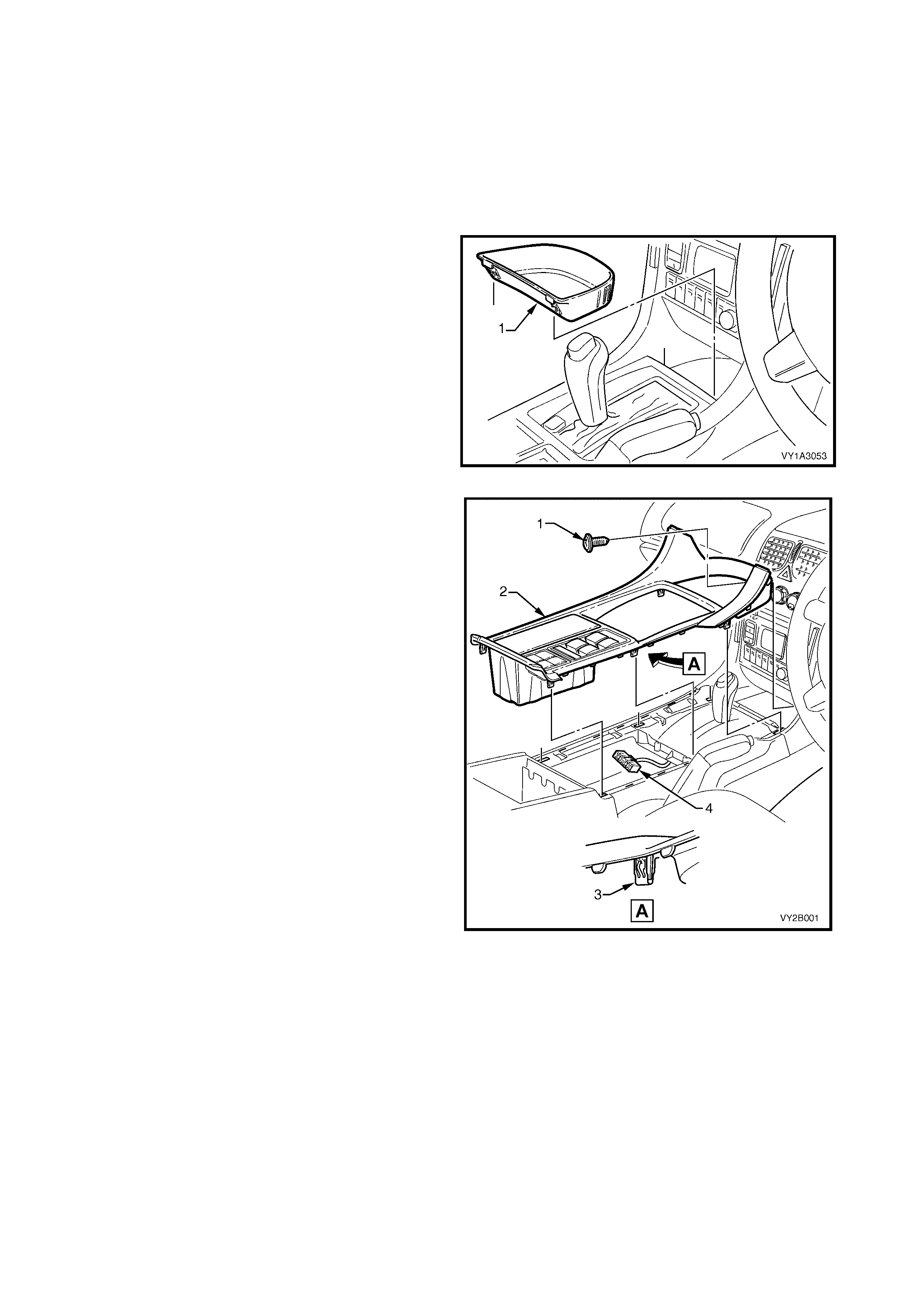
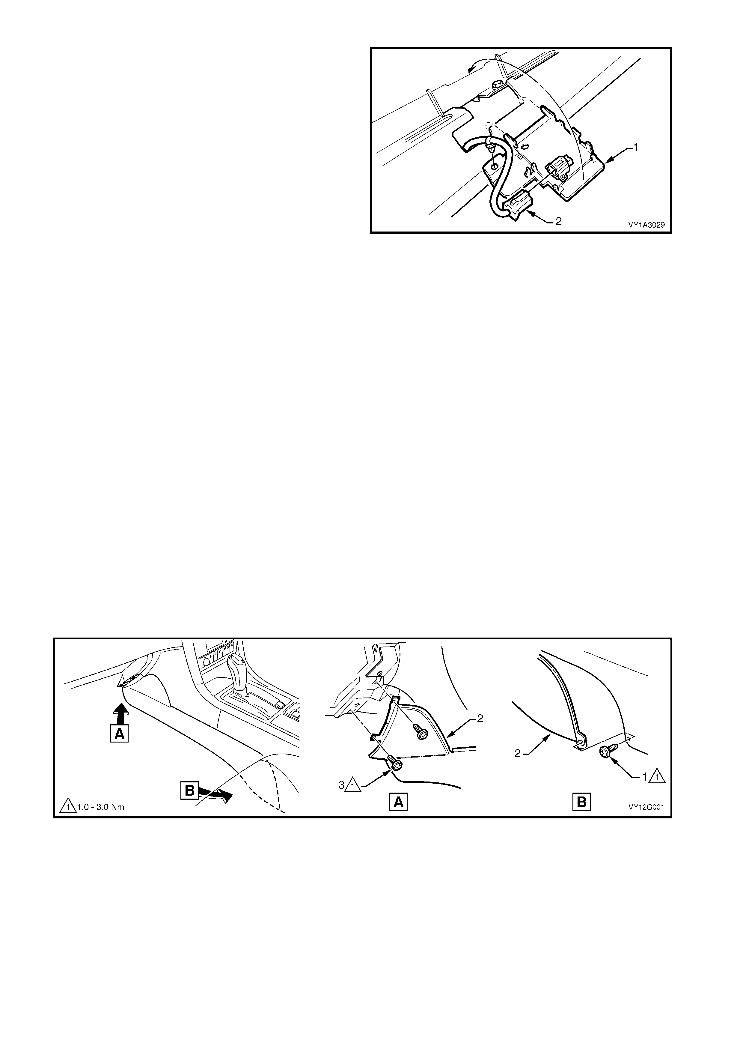
3. Remove the floor console front compartment liner
(1) by lifting upwards to disengage it from the
console cover.
Figure 2B-1
4. Remove the screw (1) slightly to the right of centre,
attaching the floor console cover assembly (2).
NOTE: Vehicles fitted with Navigation System do not
have this screw.
5. Prise the cover assembly from the floor console,
six places (3).
6. Lift the cover assembly up from the rear,
disconnect the wiring connector (4) from the side
window switch assembly and any auxiliary
switches if fitted, and remove the cover assembly.
Figure 2B-2
7. Insert Spec ial T ool KM6067 ( 1) into the holes eac h
side of the radio assembly.
8. While holding outward pressure on the tools
(toward each outer side of the vehicle), pull the
radio assembly from the radio housing.
NOTE: The wiring connectors remain attached to the
radio housing and will disconnect on removal of the
radio assembly.
Figure 2B-3
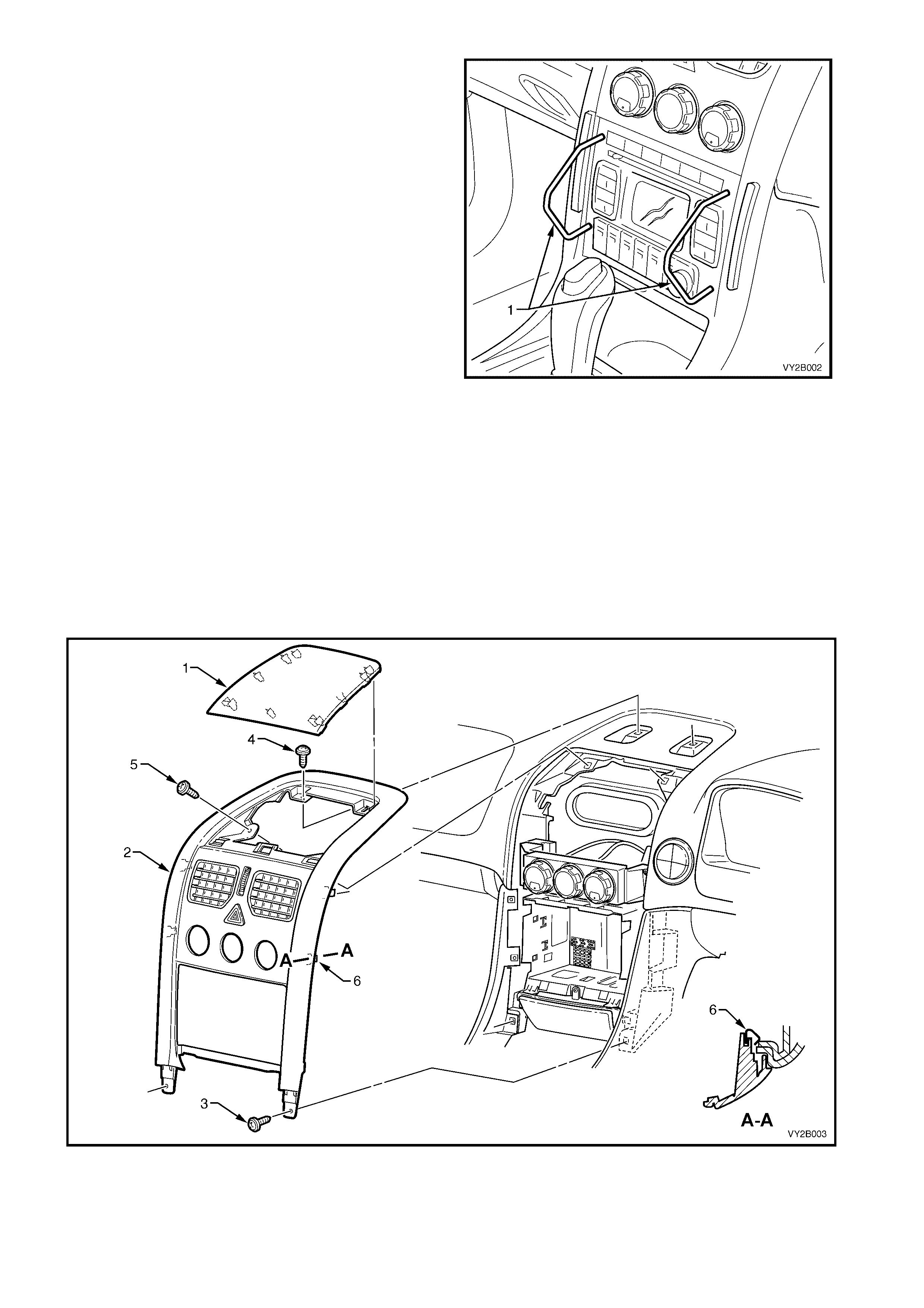
Referring to Figure 2B-4:
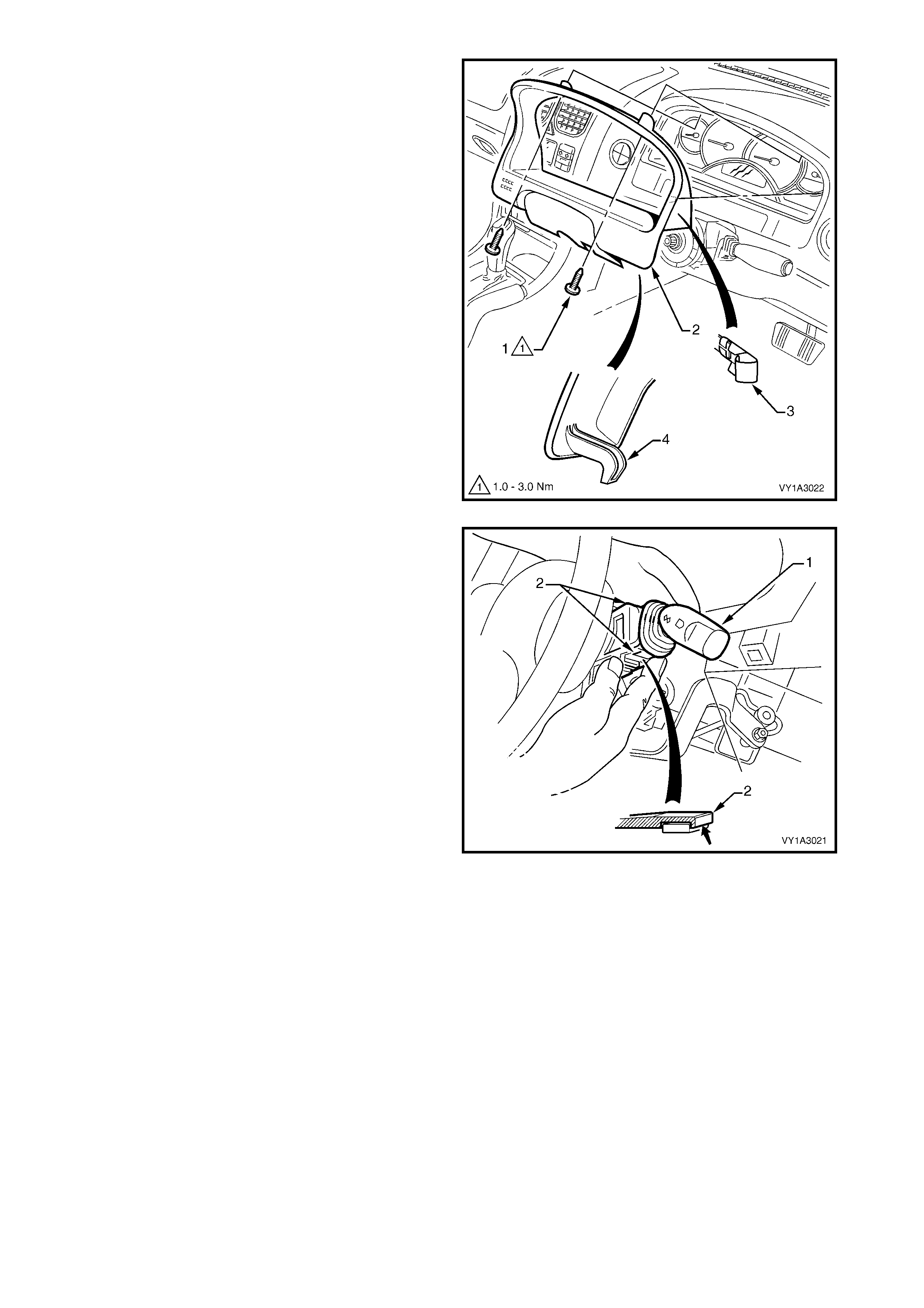
9. Carefully prise the front edge of the instrument panel upper centre trim panel (1), and pull upward to
disengage the retaining clips at each corner from the centre trim assembly (2).
NOTE: A fine flat blade screwdriver may be used; however take steps to ensure the trims are not marked or
damaged.
10. Remove the lower screw (3), two places, attaching the centre trim assembly to the instrument panel.
11. Remove the upper s crews (4 and 5), two places eac h, attaching the centre trim assem bly to the instrum ent
panel.
12. Remove the centre trim assembly, noting the four clips (6), far enough to disconnect the wiring connectors
from the rear of the hazard warning switch.
13. Remove the centre trim assembly.
Figure 2B-4
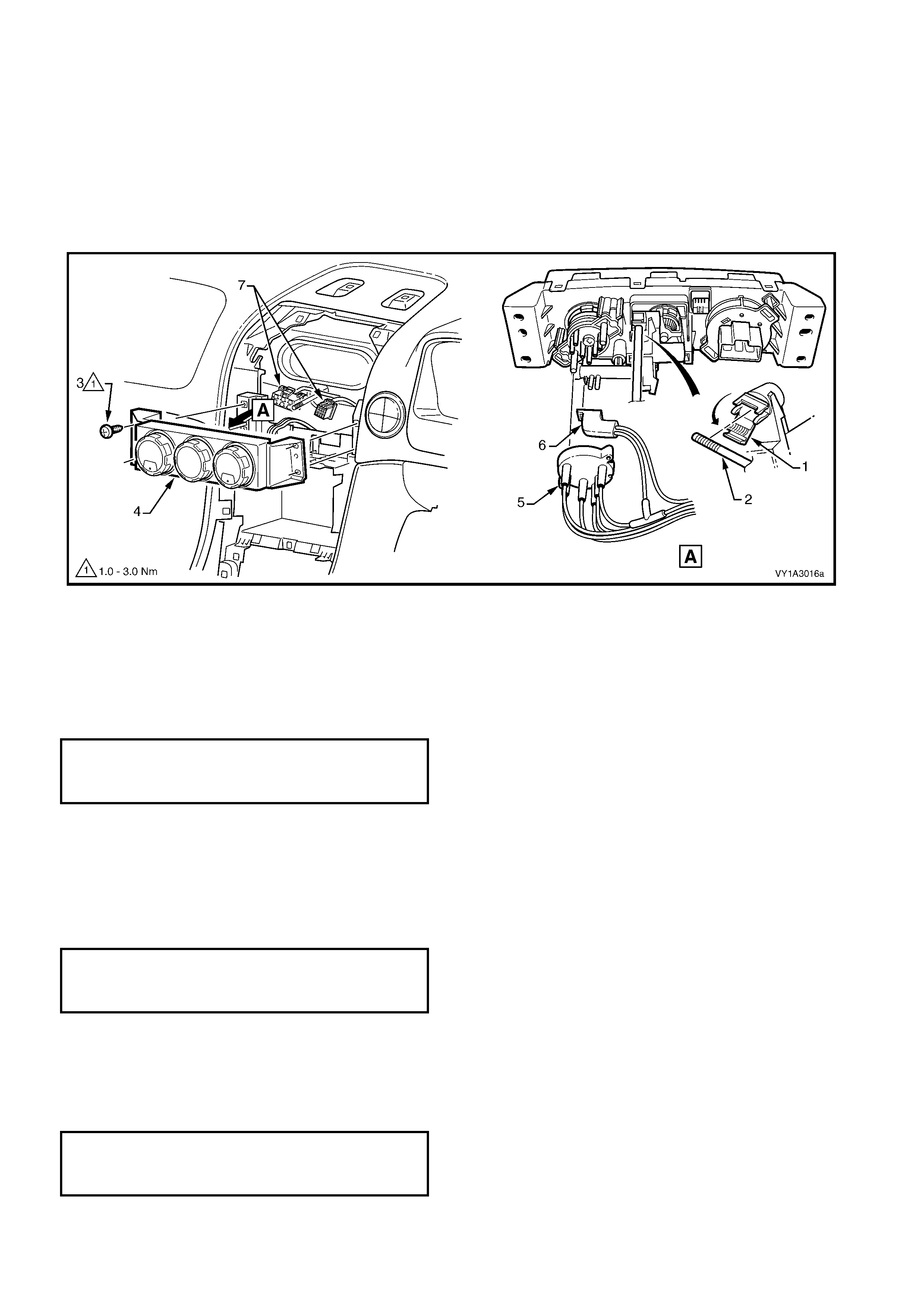
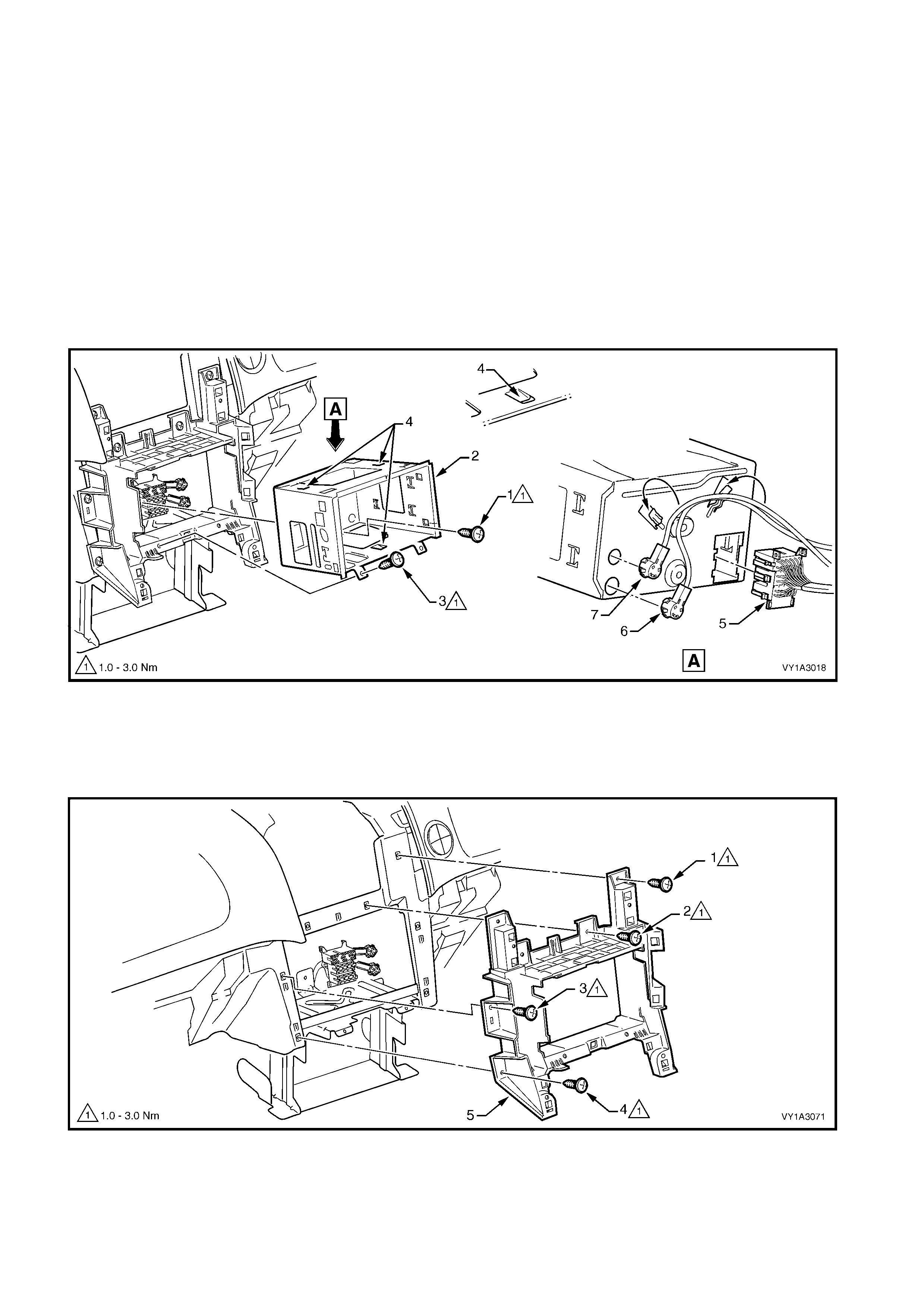
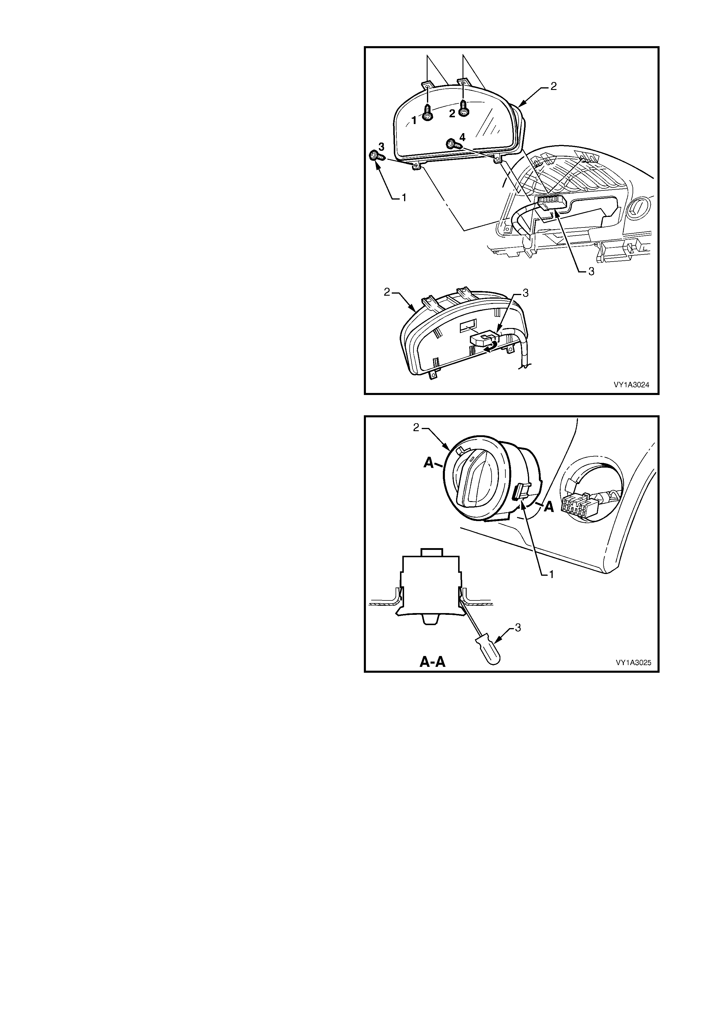
Referring to Figure 2B-5:
14. From the rear of the HVAC controller, open the air mix door rod retainer (1) and disconnect the rod (2).
15. Remove the screw (3), two places each side, attaching the HVAC controller (4) to the instrument panel.
16. Partially remove the HVAC c ontro ller as s embly outwards f rom the ins trument panel to ac ce ss the r ear of the
controller.
17. Disconnect the two vacuum hose connections (5 and 6) and two wiring connectors (7).
18. Remove the HVAC controller assembly.
NOTE: For service and diagnosis of the manual HVAC controller, refer to Section 2C, 7. ELECTRICAL
COMPONENT TESTS and Section 2C, 8. VACUUM RETENTION TESTS.
Figure 2B-5
REINSTALL
1. Install the two wiring connectors and the lower then upper vacuum hose connections.
2. Push the control rod toward the HVAC unit (front of vehicle) fully.
3. Seat the control assembly in position.
4. Install the four screws and tighten to the specified torque.
MANUAL HVAC CONTROLLER
ATTACHING SCREW TORQUE
TORQUE SPECIFICATION 1.0 – 3.0 Nm
5. Rotate the temperature switch to the full cold position.
6. Position the air mix door rod retainer so that it will close upward.
7. Connect the rod to the air mix door rod retainer.
8. Close and lock the rod retainer over the rod.
9. Check for correct operation of the temperature switch.
10. Install the instrument panel centre trim assembly. Tighten all screws to the specified torque.
INSTRUMENT PANEL CENTRE TRIM
ASSEMBLY ATTACHING SCREW
TORQUE SPECIFICATION 1.0 – 3.0 Nm
11. Insert the radio assembly into the housing.
12. Push the unit home to engage the retaining clips and wiring connectors.
NOTE: The Special Tool is not required.
10. Install the floor console cover assembly. Installation is the reverse of removal. Tighten the screw to the
specified torque.
FLOOR CONSOLE COVER ASSEMBLY
ATTACHING SCREW
TORQUE SPECIFICATION 1.0 – 3.0 Nm
2.1 WATER VALVE VACUUM SWITCH
LT Section – 08-155A
REMOVE
1. Remove the manual HVAC controller. Refer to 2. MANUAL HVAC CONTROLLER in this Section.
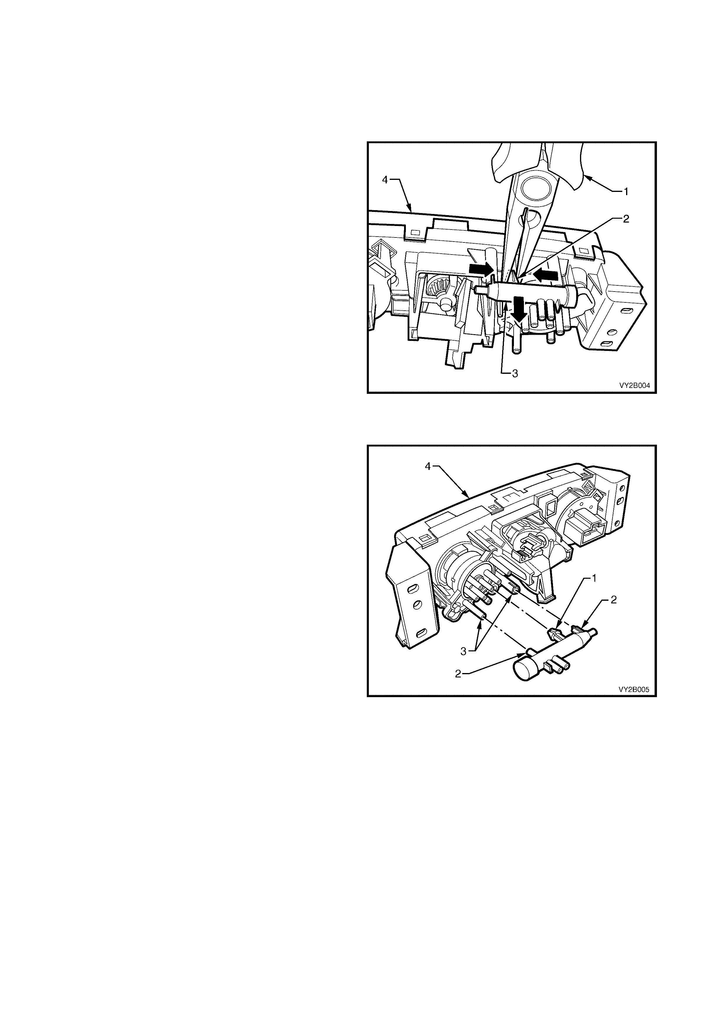
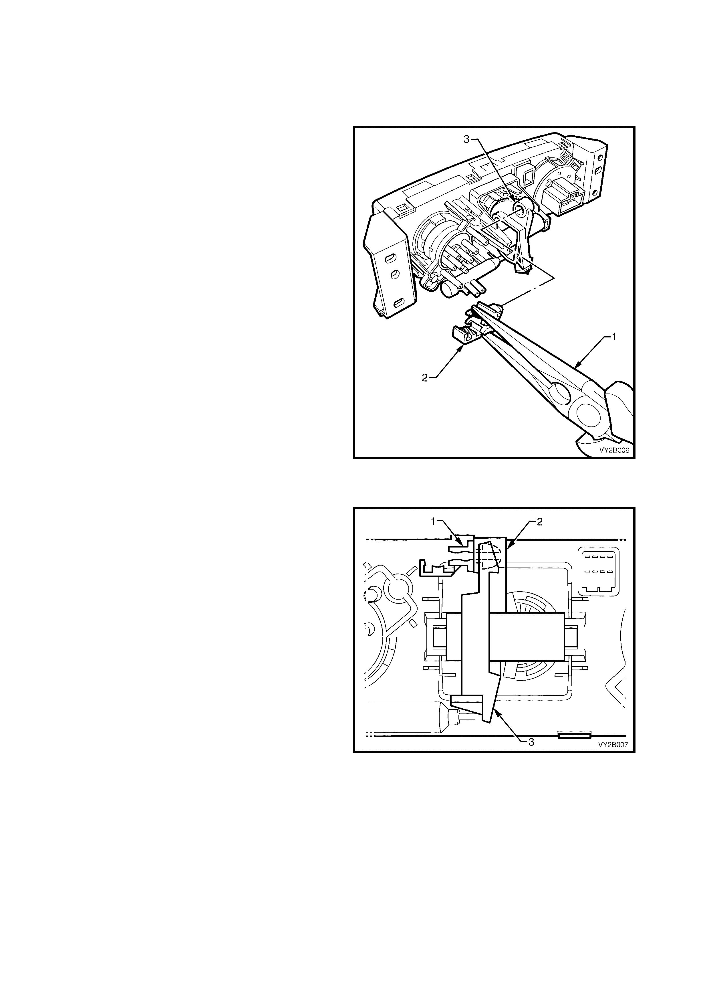
2. Turn the temper ature s witch to the f ull hot pos ition.
Using needle nose pliers (1), carefully compress
the locking legs (2) of the vacuum switch (3)
together and withdraw the switch from the rear
housing (4) of the controller.
Figure 2B-6
REINSTALL
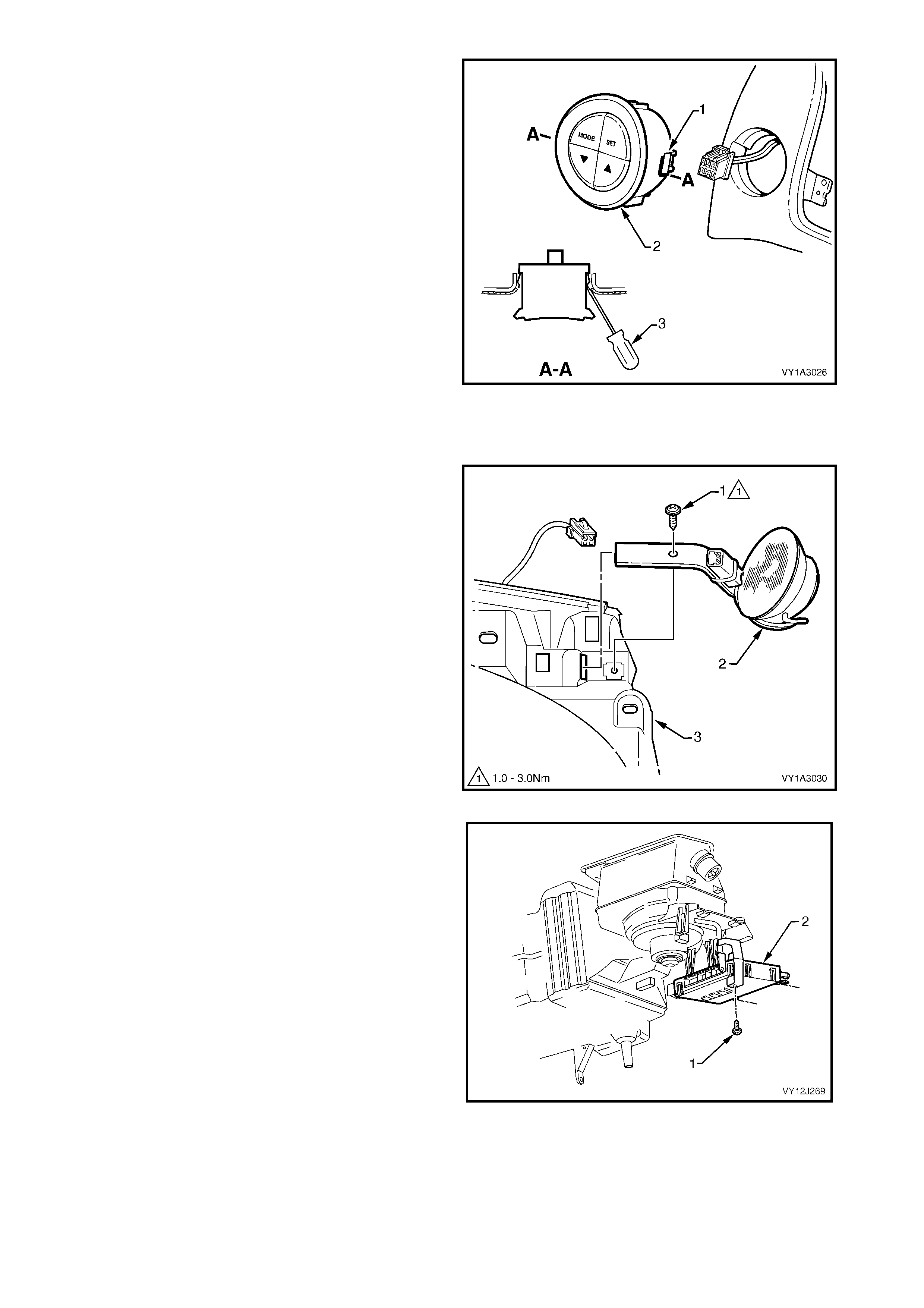
1. Insert the vacuum switch locking legs (1) through
the rear housing ensuring that the locating
dowels (2) are installed into the two dowel
locators (3) of the rear housing (4).
2. Push the vacuum switch into position ensuring the
lock ing legs lock into position and retain the switch
in the rear housing.
3. Install the controller to the instrument panel. Refer
to 2. MANUAL HVAC CONTROLLER in this
Section.
Figure 2B-7
2.2 AIR MIX DOOR ROD RETAINER
LT Section – 08-155A
REMOVE
1. Remove the manual HVAC controller. Refer to 2. MANUA L HVAC CONTROLLER in this Section.
2. Using needle nose pliers (1), carefully compress
the rod retainer ( 2) together and withdraw the rod
retainer from the crescent gear (3) of the
controller.
Figure 2B-8
REINSTALL
1. Insert the rod retainer (1) into the pivot hole ( 2) of
the crescent gear (3) ensuring it locks into
position.
2. Install the controller to the instrument panel.
Refer to 2. MANUAL HVAC CONTROLLER in
this Section.
Figure 2B-9
2.3 FRONT HOUSING/SWITCH ASSEMBLY
AND PRINTED CIRCUIT BOARD
LT Section – 08-155A
REMOVE
1. Remove the manual HVAC controller. Refer to 2. MANUA L HVAC CONTROLLER in this Section.
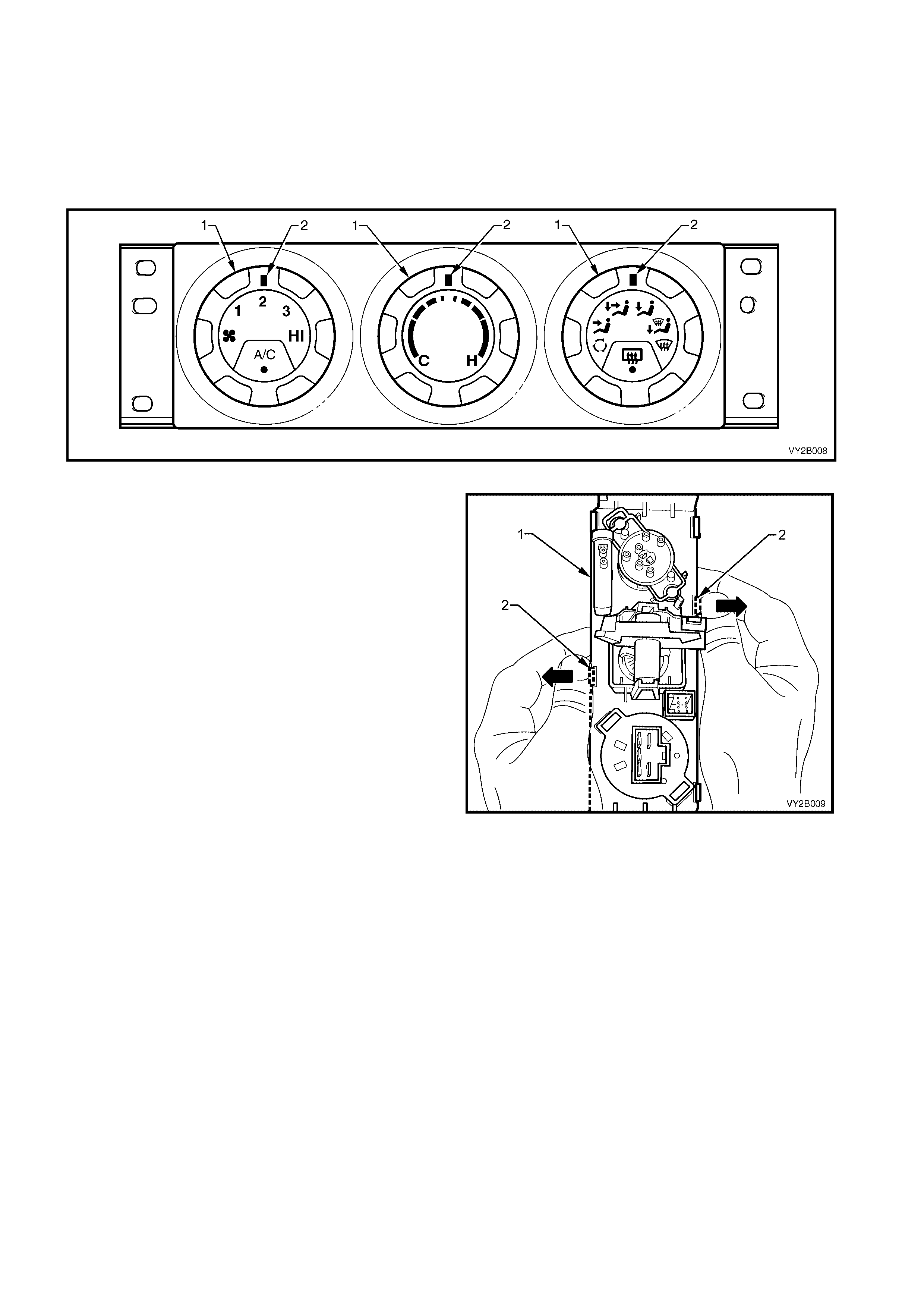
2. Rotate the switches (1) so that all switch position indicators (2) are at the 12 o’clock position.
Figure 2B-10
3. Holding the controller (1) as shown in Figure 2B-
11, disengage the middle retaining tangs of the
front housing/switch assembly from the rear
housing by caref ully m oving the retaining tangs (2)
of the front housing outwards with thumb pressure.
Figure 2B-11
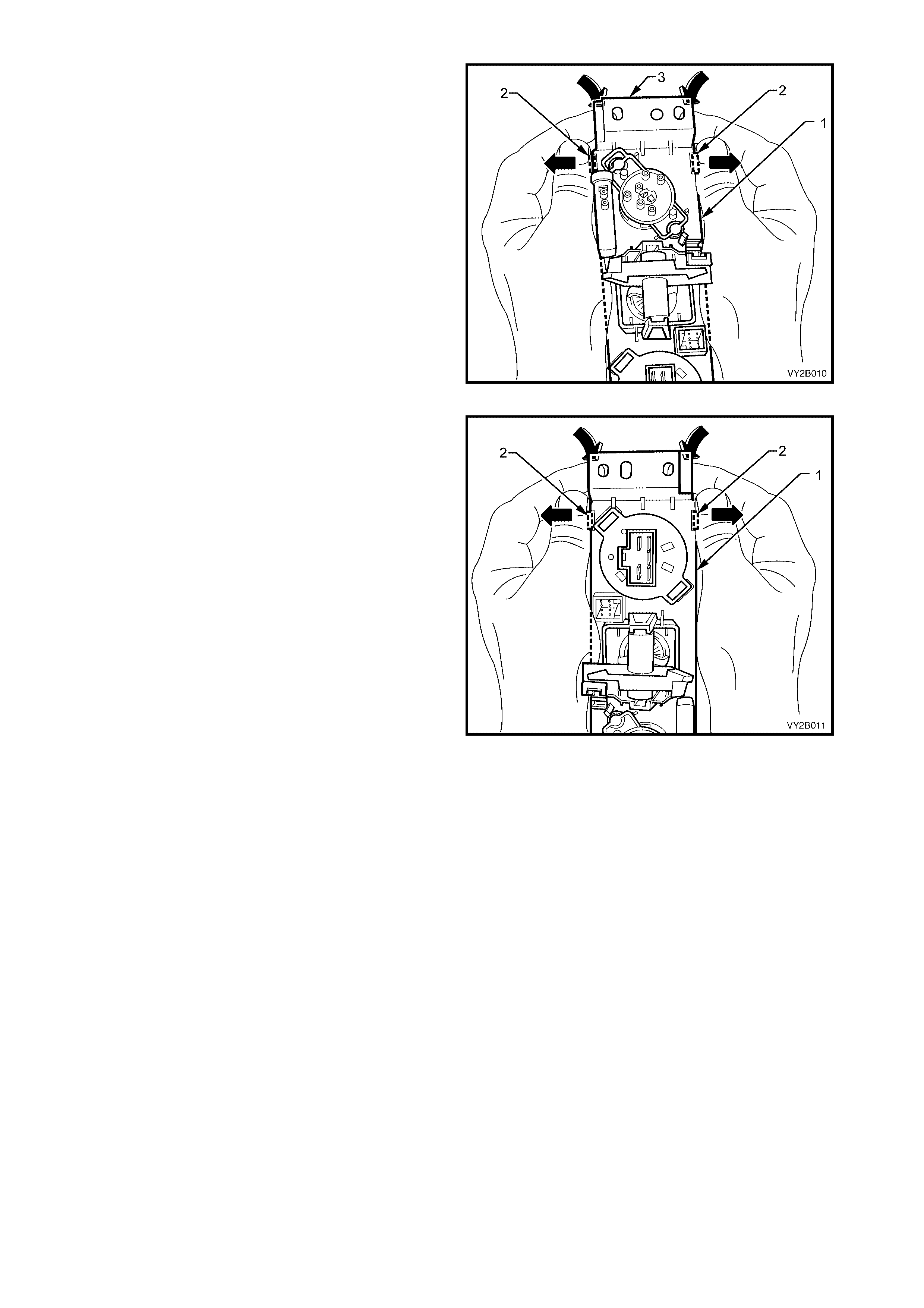
4. Holding the controller (1) as shown in Figure 2B-
12, continue to disengage the front housing/switch
assem bly from the rear housing by m oving the end
retaining tangs (2) of the front housing outwards
with thumb pressure while simultaneously
separating the rear housing from the front
housing/switch assembly using index finger
pressure at the mounting flange (3) of the
controller.
Figure 2B-12
5. Rotate the controller (1) through 180° and
disengage retaining tangs (2) at the other end of
the controller by using the same technique as
described in Step 4.
Figure 2B-13
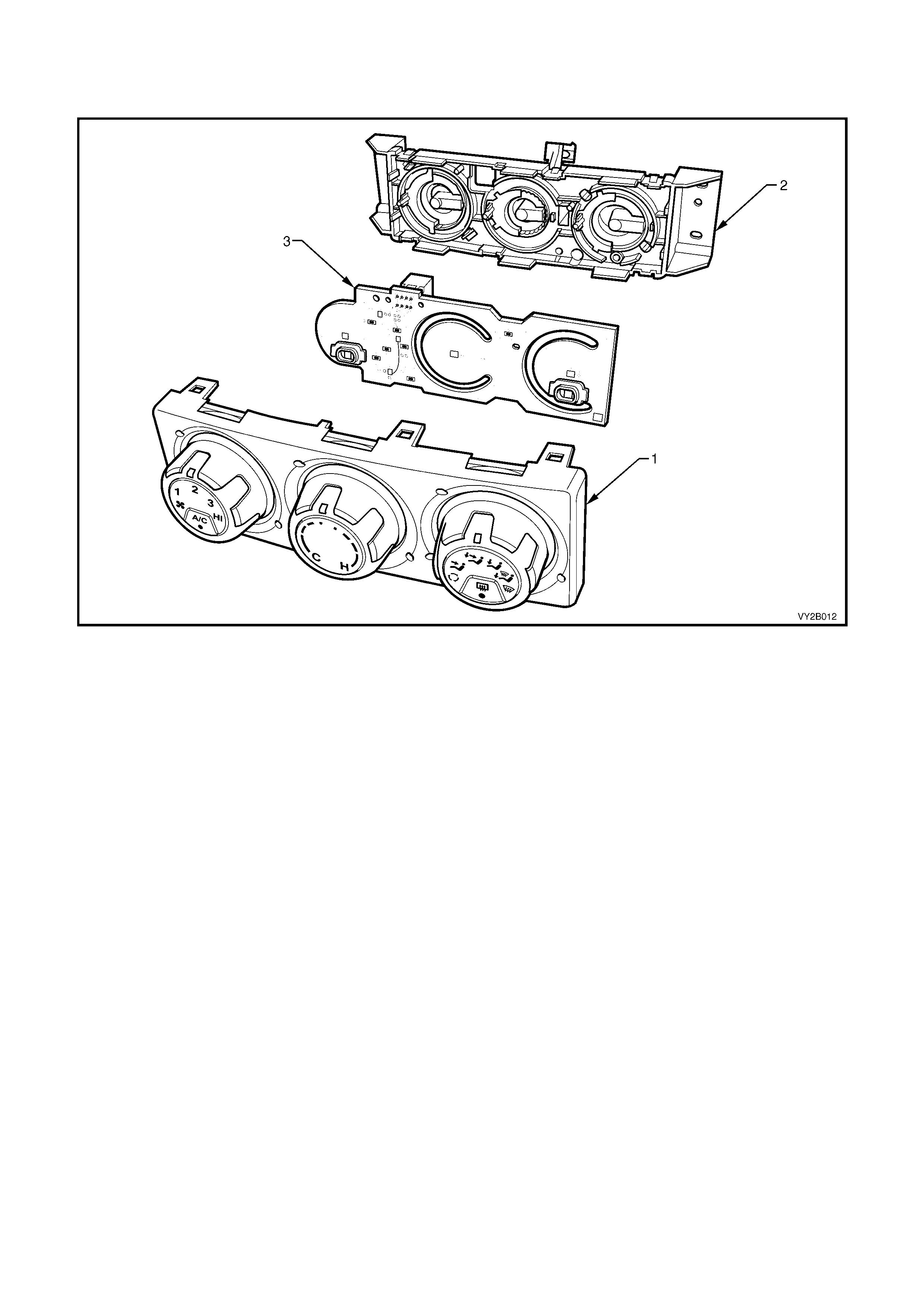
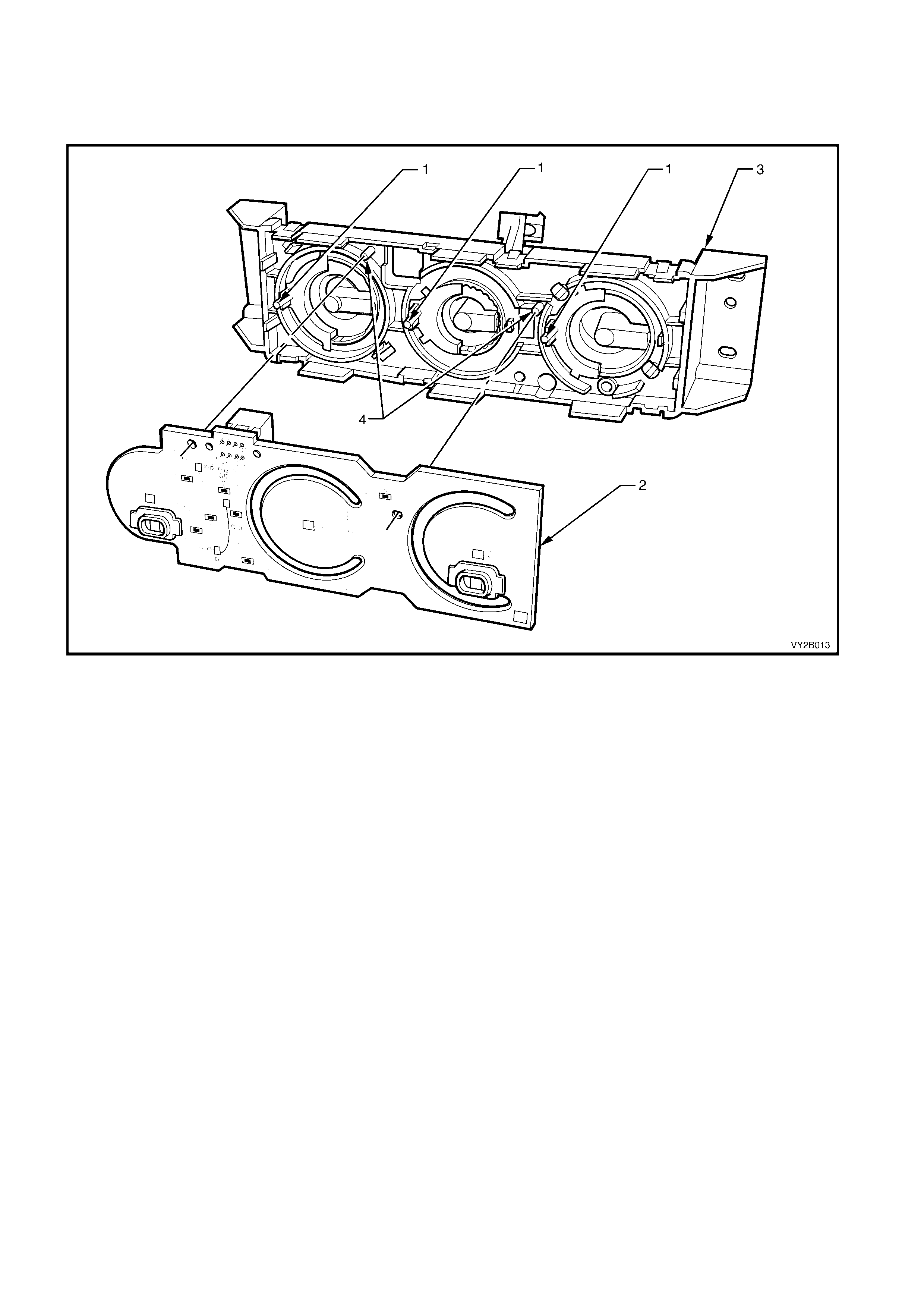
6. Remove the front housing/switch assembly (1) from the rear housing (2).
7. Remove the printed circuit board (3) from the rear housing.
Figure 2B-14
REINSTALL
1. Ensure that the switch shaft pins (1) are located at the 9 o’clock position.
2. Install the printed circuit board (2) to the rear housing (3). Ensure that the circuit board locating pins (4) are
aligned with the corresponding holes of the circuit board prior to installation.
Figure 2B-15
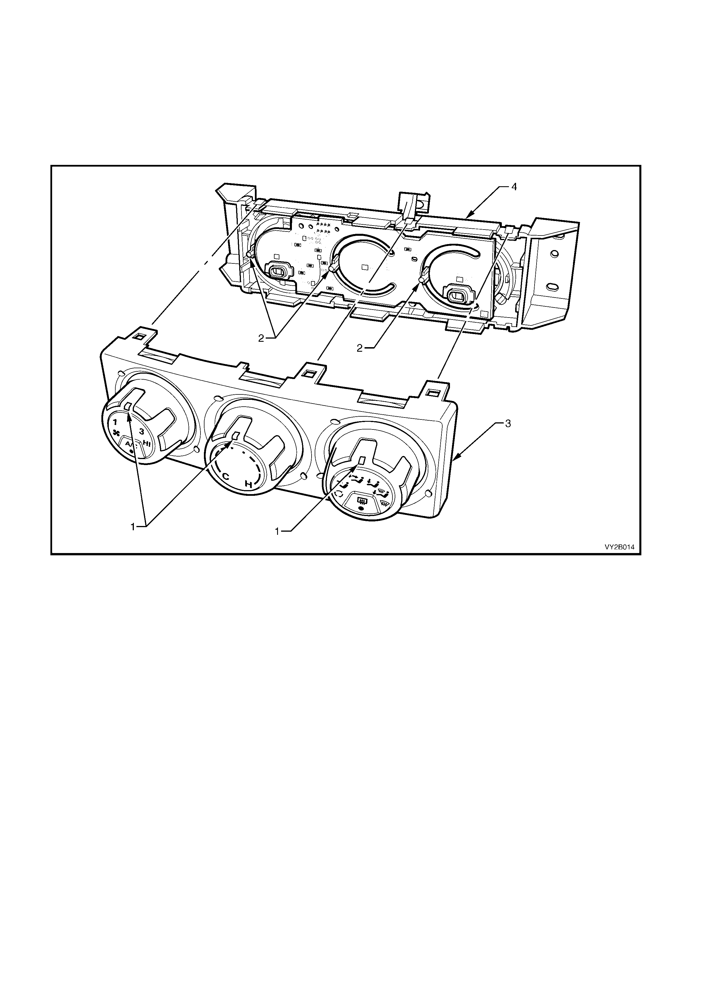
3. Rotate the switches so that all switch position indicators (1) are at the 12 o’clock position. Ensure that all
three of the shaft pins (2) are still located at exactly the 9 o’clock position.
4. Install the front housing/switch assembly (3) to the rear housing (4) ensuring that its six retaining tangs are
fully engaged over the rear housing tang protrusions.
5. Ensure that all the s witches rotate f reely and that the s witc h position indicators align cor rectly with all switch
positions. Ensure that all switches do not rotate past intended rotation limits.
6. Install the controller to the instrument panel. Refer to 2. MA NUAL HVAC CONTROLLER in this Section.
Figure 2B-16
2.4 MODE SWITCH VACUUM VALVE
LT Section – 08-155A
REMOVE
1. Remove the manual HVAC controller. Refer to 2. MANUAL HVAC CONTROLLER in this Section.
2. Remove the front housing/switch assembly and printed circuit from the rear housing. Refer to
2.3 FRONT HOUSING/SWITCH ASSEMBLY AND PRINTED CIRCUIT BOARD in this Section.
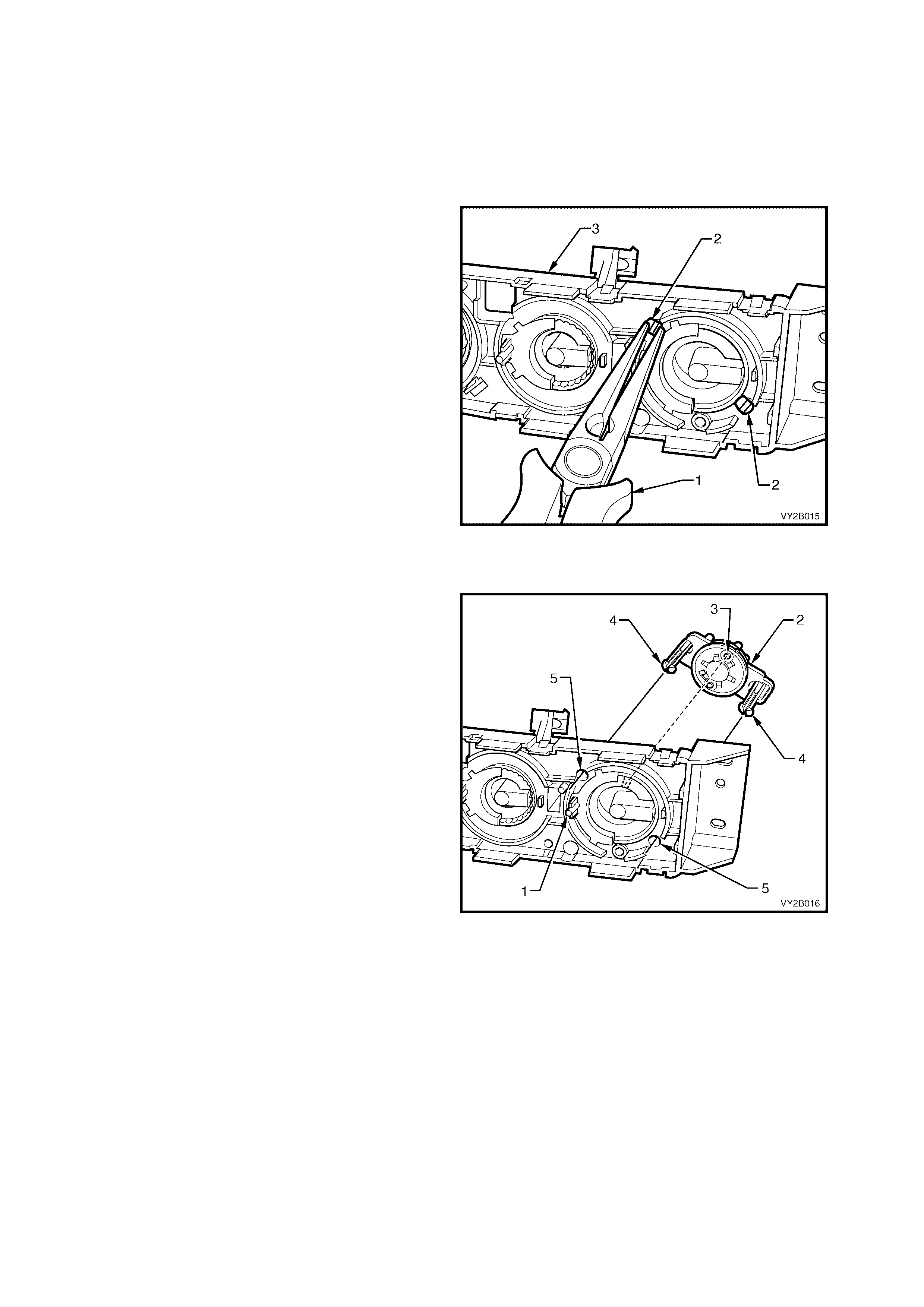
3. Using needle nose pliers (1), carefully compress
both pairs of locking tangs (2) on the mounting
dowels on the mode switch vacuum valve and
withdraw the switch assembly from the rear
housing (3) of the controller.
Figure 2B-17
REINSTALL
1. Ensure that the mode shaft pin (1) is located at
the 9 o’clock position. On the mode switch valve
assembly (2) ensure that the larger drive pin (3)
is positioned at the 12 o’clock position.
2. Align the mounting dowels (4) to the
corresponding holes (5) in the rear housing and
install the switch assembly ensuring that the
locking tangs of the mounting dowels engage
fully into the rear housing
3. Install the front housing/switch assembly and
printed circuit to the rear housing. Refer to
2.3 FRONT HOUSING/SWITCH ASSEMBLY
AND PRINTED CIRCUIT BOARD in this Section.
4. Ensure that all switches rotate freely and that all
the switch position indicators align correctly with
all switch positions. Ensure that all switches do
not rotate past intended rotation limits.
5. Install the controller to the instrument panel.
Refer to 2. MANUAL HVAC CONTROLLER in
this Section.
Figure 2B-18
3. HEATI NG, VENTILATION AND AIR CONDITIONING (HVAC) UNIT
LT Section – 08-150
REMOVE
NOTE: Disconnection of the battery affects certain vehicle electronic systems. Refer to Section 00, 5. BATTERY
DISCONNECTION PROCEDURES prior to disconnecting the battery.
1. Disconnect the battery ground lead. Refer to Section 00, 5. BATTERY DISCONNECTION PROCEDURES.
2. Disable the OPS, SRS system. Refer to Section 12M, 2.2 SYSTEM DISABLING AND ENABLING
PROCEDURE.
3. Discharge the A/C system. Refer to Section 2C, 2. DISCHARGING SYSTEM – REFRIGERANT
RECOVERY.
4. Drain engine coolant into a suitable, clean container. For GEN III V8 engines, refer to Section 6B-3, 2.3
DRAINING AND FILLING COOLING SYSTEM.
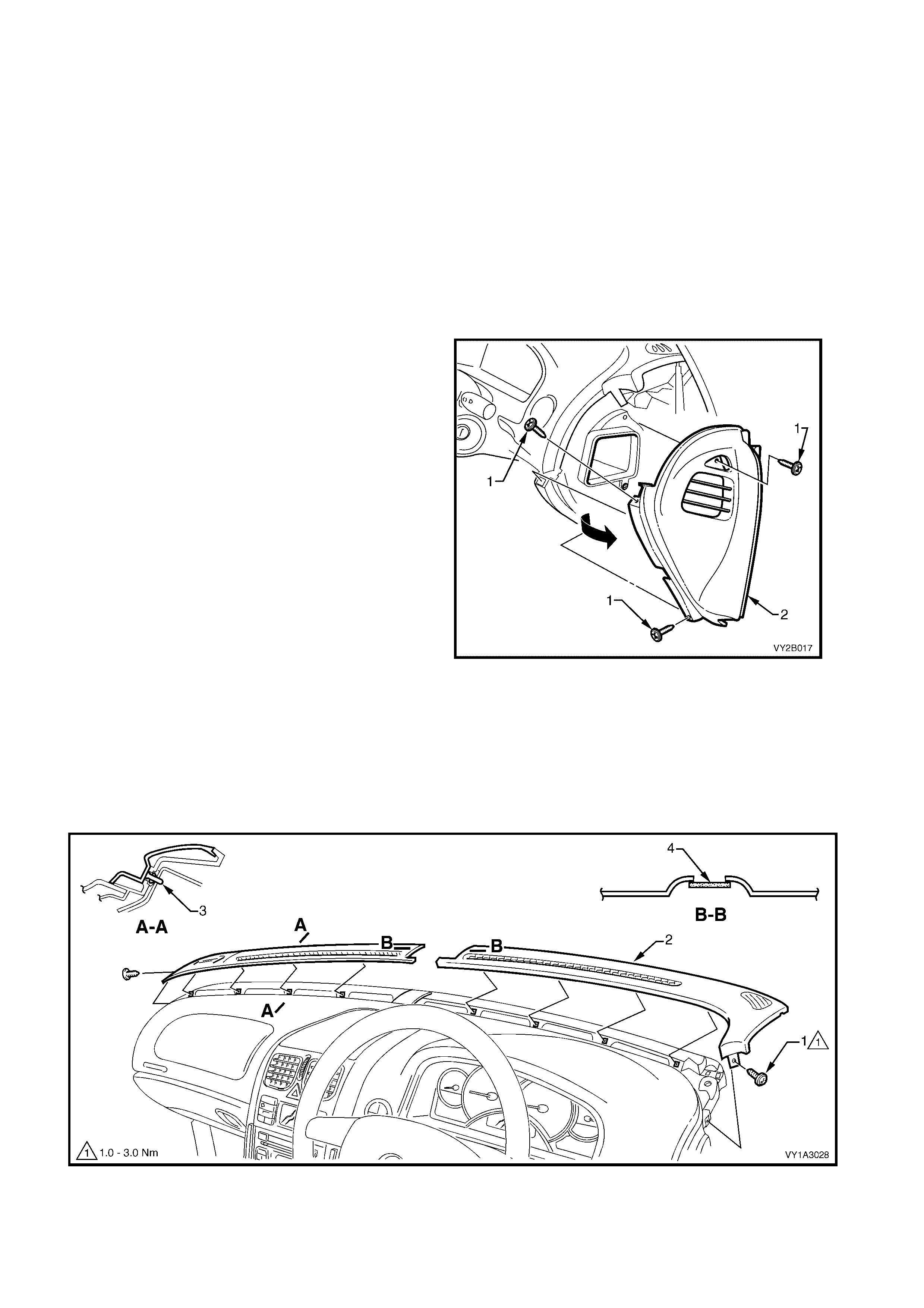
5. Remove the three screws (1) attaching the
right-hand side (shown) and left-hand side
instrument panel outer cover (2) to the
instrument panel.
6. Remove the cover by rotating outward to
disengage the ventilation duct.
Figure 2B-19
Referring to Figure 2B-20:
7. Remove the screw (1) attaching each windshield defroster grille (2) to the instrument panel.
8. Carefully remove the grille by unclipping (3), four places, at an angle equal to the windshield.
NOTE: As the grille is retained securely, removal may prove difficult. If required, a hook (such as an Allen key
held with vice- grips) can be used to assist in removal of the grille. Insert the hook at the inner then outer end of
the vent opening. Ensure it is hooked under the grille and not the sheetmetal below. Do not attempt to remove
the grilles by placing any removal tools between the grilles and the sun load sensor (4).
Figure 2B-20
9. Carefully unclip the sun load sensor (1) from the
instrument panel.
10. Disconnect the wiring connector (2), unclip the
wiring harness from the sensor assembly and
remove.
NOTE 1: The sun load sensor also functions as the
remote key receiver and provides data for headlamp
auto control.
NOTE 2: For diagnosis of the remote key receiver
and headlamp auto control functions, refer to
Section 12J, BODY CONTROL MODULE.
NOTE 3: For diagnosis of the sun load sensor
function, refer to Section 2F, HVAC OCCUPANT
CLIMATE CONTROL (AUTO A/C) – DIAGNOSTICS.
Figure 2B-21
11. Referr ing to information in 2. M ANUAL HVAC CONT ROLLER in this Section, rem ove in order, the f ollowing
items:
• Navigation remote control assembly (if fitted)
• Navigation display assembly (if fitted)
• Floor console front compartment liner
• Floor console cover assembly
• Radio assembly
• Instrument panel upper trim assembly
• Instrument panel centre trim assembly
• Manual HVAC controller (for manual A/C systems)
NOTE 1: If the HVAC unit to be removed is an Occupant Climate Control (Auto A/C) type, the OCC
control module will have been removed with the instrument panel centre trim assembly. If required, refer to
Section 2E, 2.1 OCC CONTROL MODULE for additional removal information.
NOTE 2: T he O CC c ontrol m odule does not have to be removed f r om the instr ument panel centr e trim ass embly
for HVAC unit removal purposes.
12. Referring to Figure 2B-22 for the left-hand side of the floor console:
a. Remove the screw (1) attaching the instrument panel lower extension side trim (2) to the floor console.
b. Open the instrum ent panel compartm ent (RHD) or instrument panel lower trim panel (LHD) and remove
the two screws (3) attaching the side trim to the instrument panel.
c. Remove the side trim.
Figure 2B-22
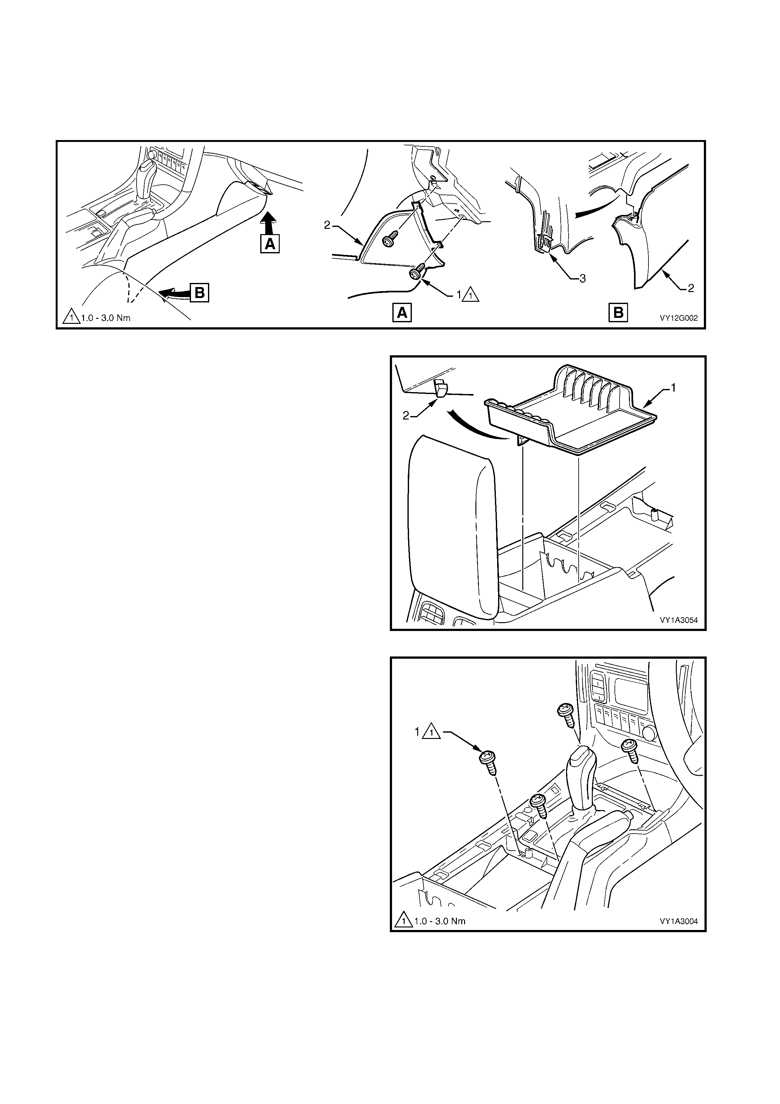
13. Referring to Figure 2B-23 for the right-hand side of the floor console:
a. Open the instrum ent panel lower trim panel (RHD) or instrum ent panel compartm ent (LHD) and remove
the two screws (1) attaching the instrument panel lower extension side trim (2) to the instrument panel.
b. Prise the rear of the trim panel downward to disengage it from the floor console retaining clip (3).
c. Remove the side trim.
Figure 2B-23
14. Remove the f loor c onsole c ompartment liner (1) by
carefully grasping the liner and disengaging the
two lugs (2).
Figure 2B-24
15. For automatic transmission models, remove the
screw (1), four places , attaching the console to the
automatic transmission selector assembly.
Figure 2B-25
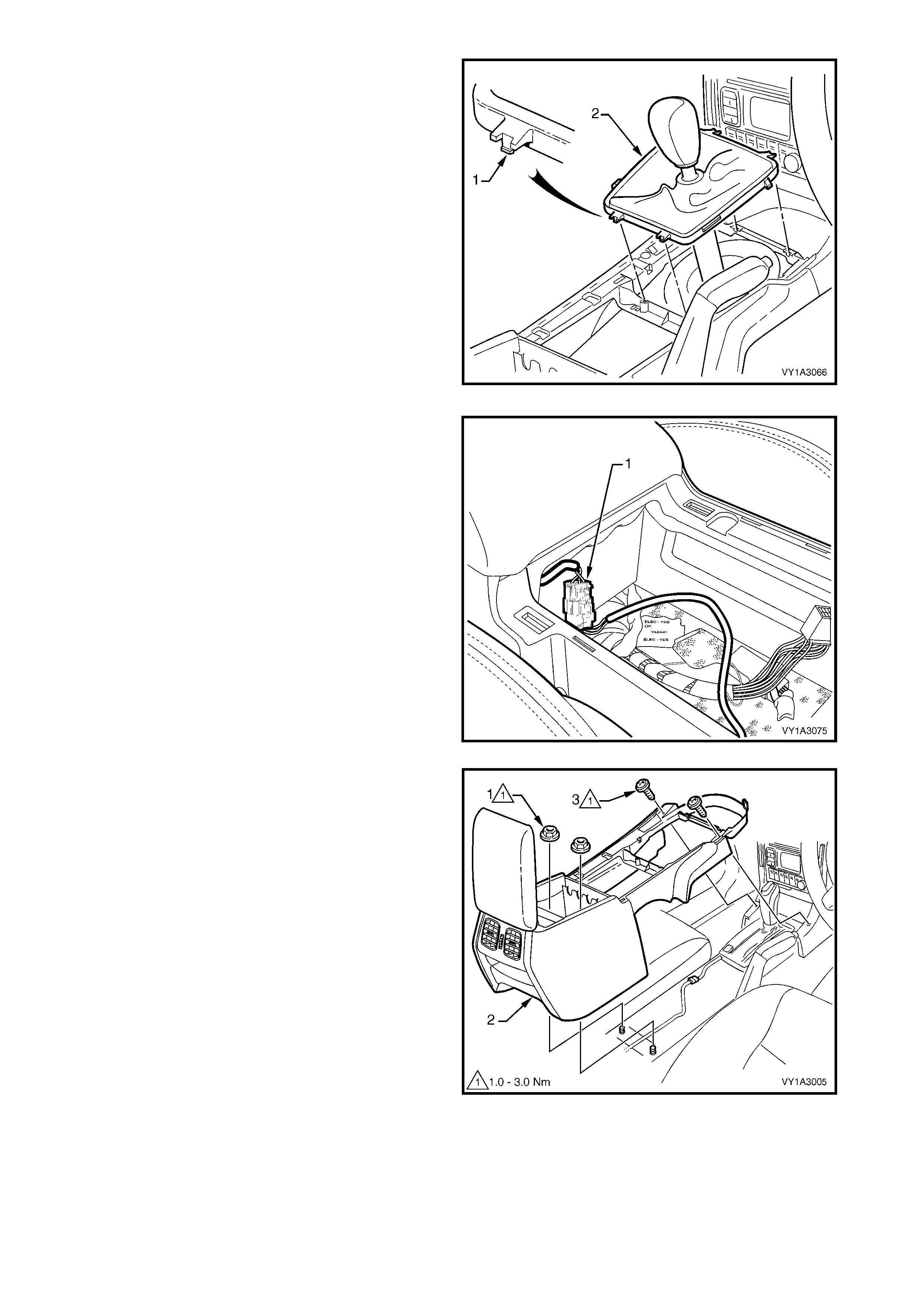
16. For manual transmission models, use a fine flat-
blade screwdriver to disengage the lug (1),
attaching the manual transmission gear lever boot
assembly (2) to the console, two places front and
rear.
17. Remove the boot assembly from the console and
raise it over the gear knob. Remove the console
over the boot assembly when the remaining
fasteners are removed.
IMPORTANT: Do not attem pt to r emove the gear knob
from the gear lever shaft as it is glued in place. The
gear knob, boot assembly and lever shaft can be
removed from the transmission if required, refer to
Section 7B, MANUAL TRANSMISSION.
Figure 2B-26
18. Disconnect the console wiring connector (1) from
the front of the console storage bin.
Figure 2B-27
19. Remove the two nuts (1) attaching the floor
console (2) to the vehicle floor.
20. Remove the two screws (3) attaching the front of
the console to the instrument panel assembly.
21. As required disconnect any console wiring
connectors.
22. Lift the rear of the console upward and remove.
NOTE: The console rear air duct will disconnect from
the console front air duct during removal. The rear air
duct will remain with the console.
Figure 2B-28
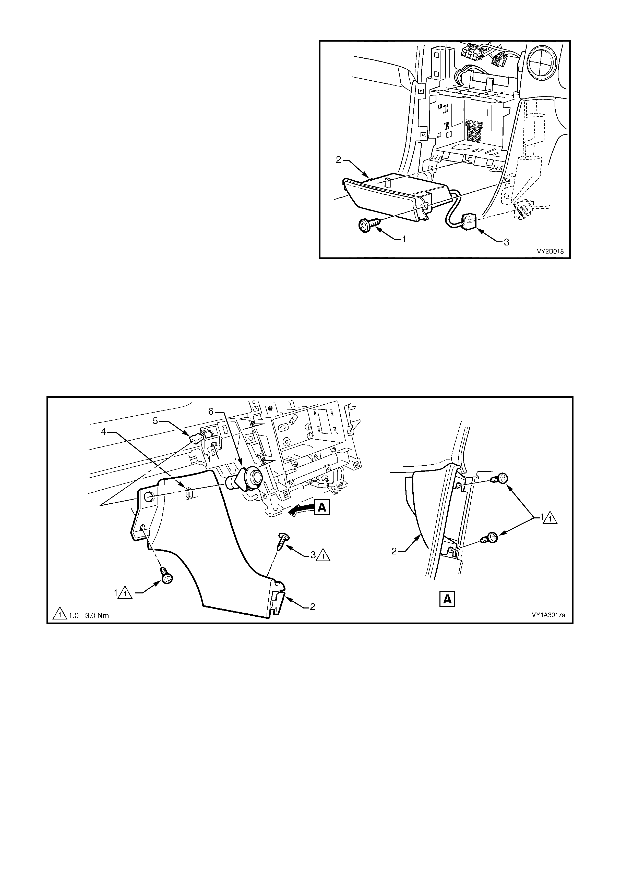
NOTE: Where fitted, an instrument panel ashtray
assembly replaces the instrument panel lower
compartment. Removal of both components is the
same.
23. Remove the screw (1), three places, attaching the
instrument panel lower compartment assembly or
ashtray assembly (2) to the instrument panel.
24. Slide the compartment or ashtray assembly
outward to remove.
NOTE: If an ashtray assembly is fitted, disconnect the
wiring connector (3).
Figure 2B-29
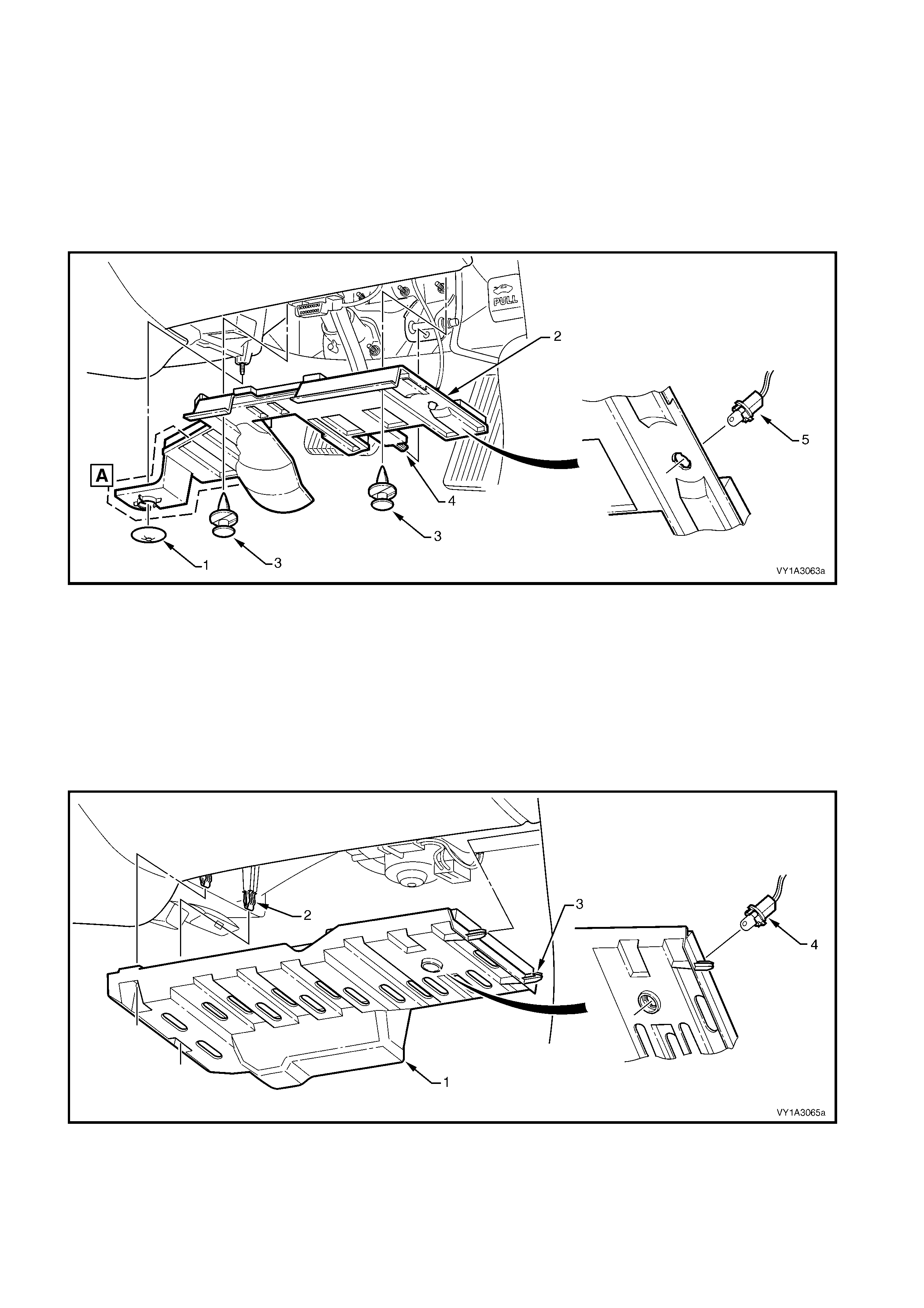
Referring to Figure 2B-30:
25. Remove the two screws (1) attaching the instrument panel lower extension (2) to the instrument panel.
26. For the left-hand side, remove the screw (3) attaching the floor console front duct.
27. Grasp the top of the extension and pull rearwards to release the clip (4).
28. Rem ove the floor console front duct from the HVAC unit. Refer to item 6 in Figure 2B-55 for left-hand drive
models or Figure 2B-56 for right-hand models.
29. If f itted, disconnect the wiring connec tor (5) f rom the r ear com par tm ent lid release switch (6) and rem ove the
panel.
Figure 2B-30
Referring to Figure 2B-31:
30. Remove the screw (1) from the rear face of the radio housing (2) attaching the housing to the instrument
panel.
31. Remove the screw (3), two places, attaching the front edge of the radio housing.
32. Lift the retaining tab (4), two places in the top of the housing and one place at the bottom.
33. Withdr aw the hous ing from the br ack et ass em bly far enough to allow access to the r adio and antenna wiring
connectors.
NOTE: If ther e is not s uff icient length in the radio harness , either unclip the c onnector f rom within the housing or
remove the passenger side instrument panel lower extension side trim and unclip the harness from the vehicle
floor.
34. From the rear of the housing, unclip the radio wiring connector (5), if not previously done, the antenna
connector (6) and if fitted, the diversity antenna connector (7) from the housing.
35. Disconnect the antenna lead(s) and remove the housing.
Figure 2B-31
Referring to Figure 2B-32:
36. Remove the screws (1, 2, 3 and 4), two places each side, attaching the radio bracket assembly (5) to the
instrument panel.
37. Remove the bracket assembly from its locating tabs.
Figure 2B-32
38. For automatic transmission models, remove the retainer (1) attaching the driver’s side instrument panel
lower trim plate assembly (2) to the HVAC unit, refer to Figure 2B-33.
NOTE: The area shown A is removed for manual transmission models.
39. Prise the insert and remove the retainer (3), two places, attaching the plate assembly to the instrument
panel.
40. Lower the plate assembly slightly and withdraw the lug (4) from the pedal bracket.
41. If fitted, remove the stepwell lamp (5) by rotating the socket and removing from the plate assembly.
42. Remove the driver’s side plate assembly.
Figure 2B-33
Left-Hand Drive Vehic les
43. Grasp the inner end of the passenger side instrum ent panel lower trim plate assembly (1) and carefully pull
downwards to disengage the retaining clip (2), two places, refer to Figure 2B-34.
44. Withdraw the plate assembly from the hinge pillar trim panel, disengaging the lug (3), two places.
NOTE: The rear lug has a hook that engages the hinge pillar trim panel.
45. Lower the passenger side plate assem bly slightly and, if f itted remove the stepwell lamp (4), by rotating the
socket and removing from the plate assembly.
46. Remove the passenger side plate assembly.
Figure 2B-34
Right-Hand Drive Vehicles
47. Grasp the passenger side instrument panel lower trim plate assembly (1).
48. Carefully pull downw ard to disengage the retaining clip (2), three places, refer to Figure 2B-35.
49. Lower the plate assembly slightly and, if fitted remove the stepwell lamp (3), by rotating the socket and
removing from the plate assembly.
50. Remove the passenger side plate assembly.
Figure 2B-35
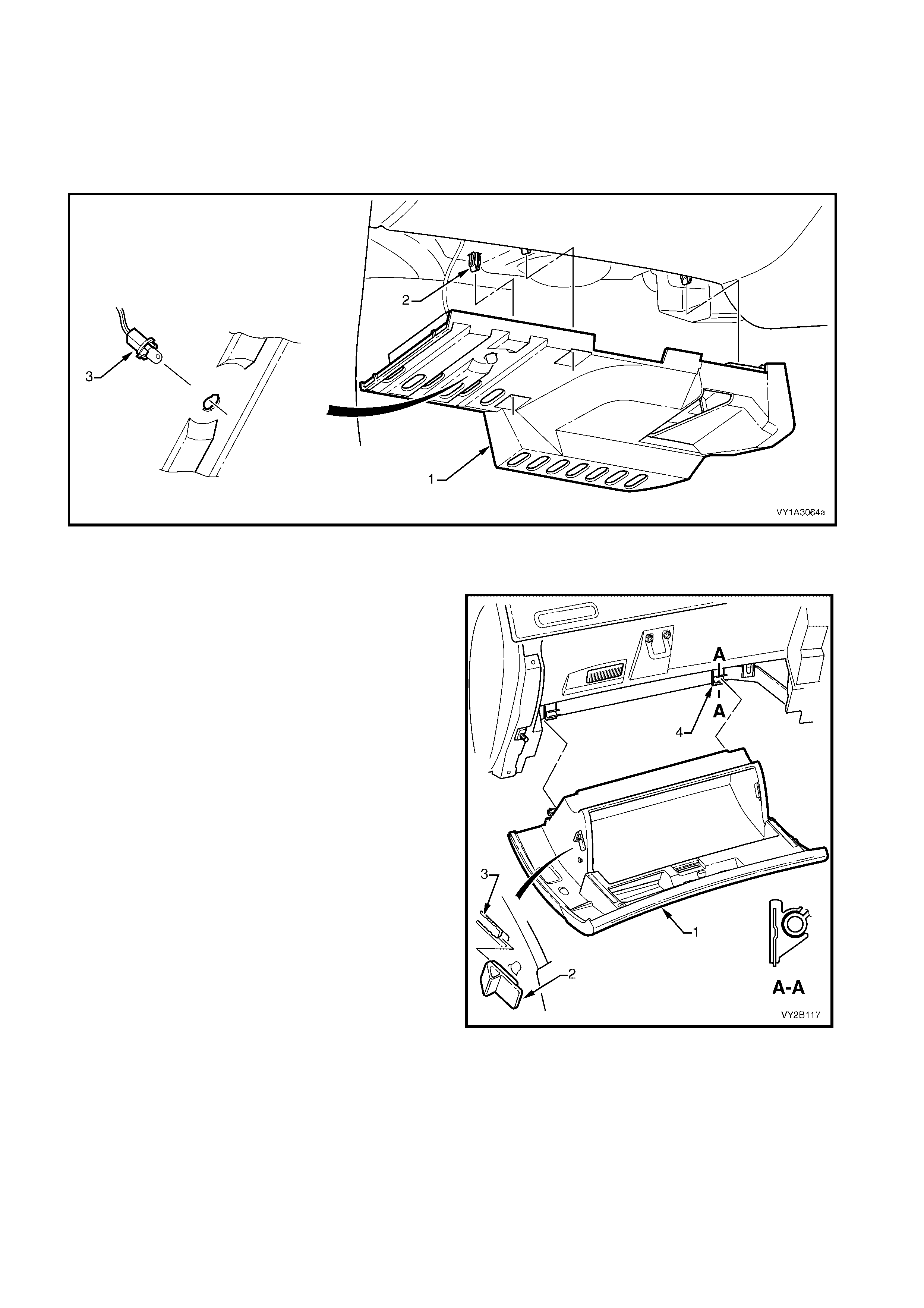
All Vehicles
51. O pen the instrument panel c om partm ent assem bly
(1).
52. Using a fine flat-blade screwdriver, flatten the
instrument panel compartment bumper stop (2)
each side, and carefully open the compartment
assembly fully.
53. From the inside of the compartment assembly,
push outwards on the bumper stop (2), and slide
the bumper from the lug (3). Repeat for the
opposite side.
54. Close the compartment assembly a third of the
way and grasping each side pull rearward to
disengage the compartment assembly from each
instrument panel compartment hinge (4).
IMPORTANT: T ake c are when disengaging the hinges
as removing the com partment assem bly on the wrong
angle may cause damage.
Figure 2B-36
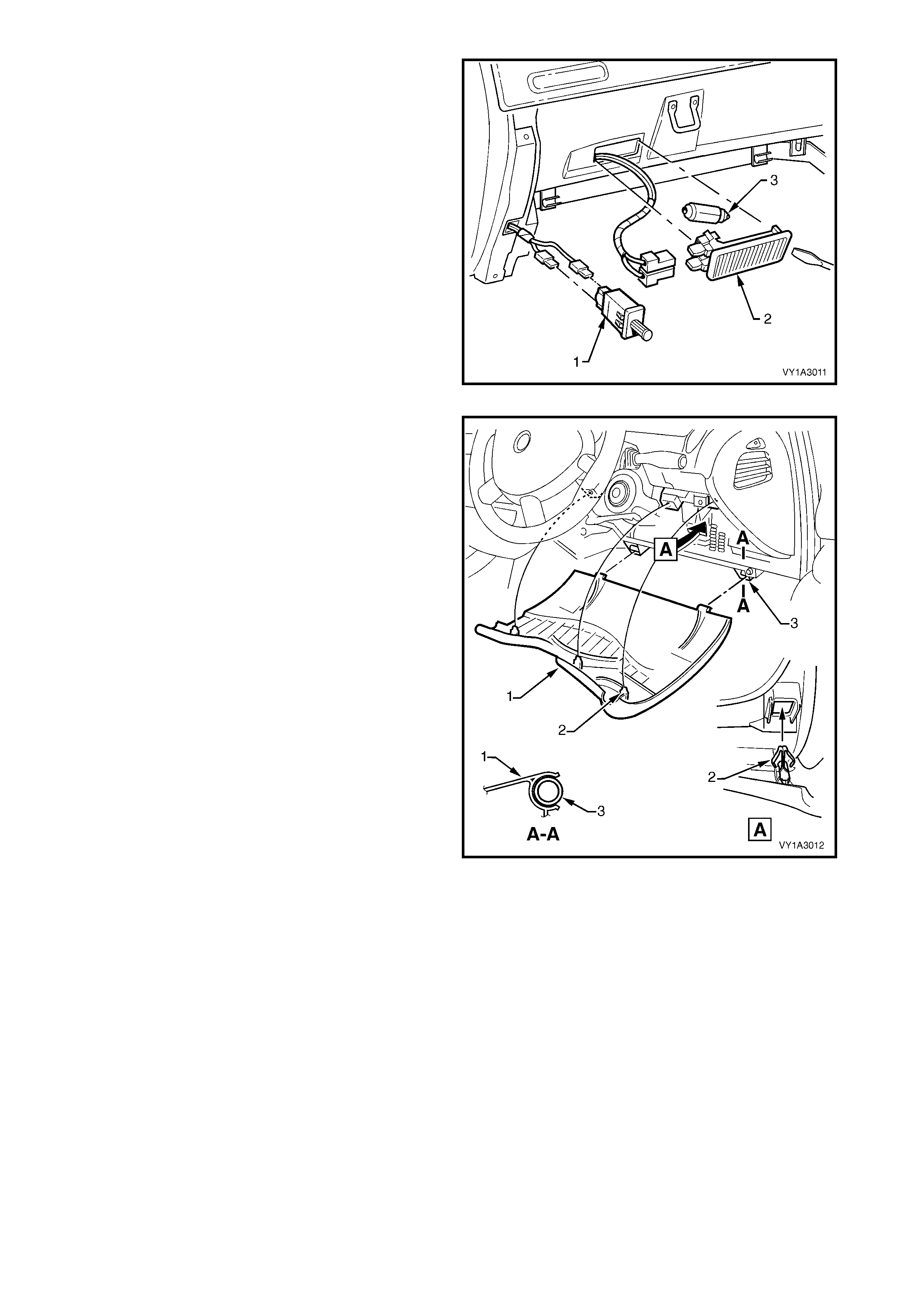
55. From either side of the instrument panel
compartment lamp switch (1), carefully insert a
fine flat blade screwdriver and prise the switch
from the instrument panel.
56. Disconnect the wiring harness connectors and
remove the switch.
57. From the right-hand side of the instrument panel
compartment lamp (2), carefully insert a fine flat
blade screwdriver.
58. Pr ise the lam p fr om the instrum ent panel and s lide
it out of its cavity.
59. Disconnect the wiring harness connectors.
60. Remove the lamp ensuring that the globe (3) is not
dislodged or damaged during the removal
procedure.
Figure 2B-37
61. Grasp the upper edge of the instrument panel
lower trim panel assem bly ( 1) and pull outward s to
disengage the three retaining clips (2).
62. Swing the panel assembly open.
63. Holding each side of the panel assembly, pull
rearwards to disengage it from the instrument
panel lower trim panel retainer (3), two places.
Figure 2B-38
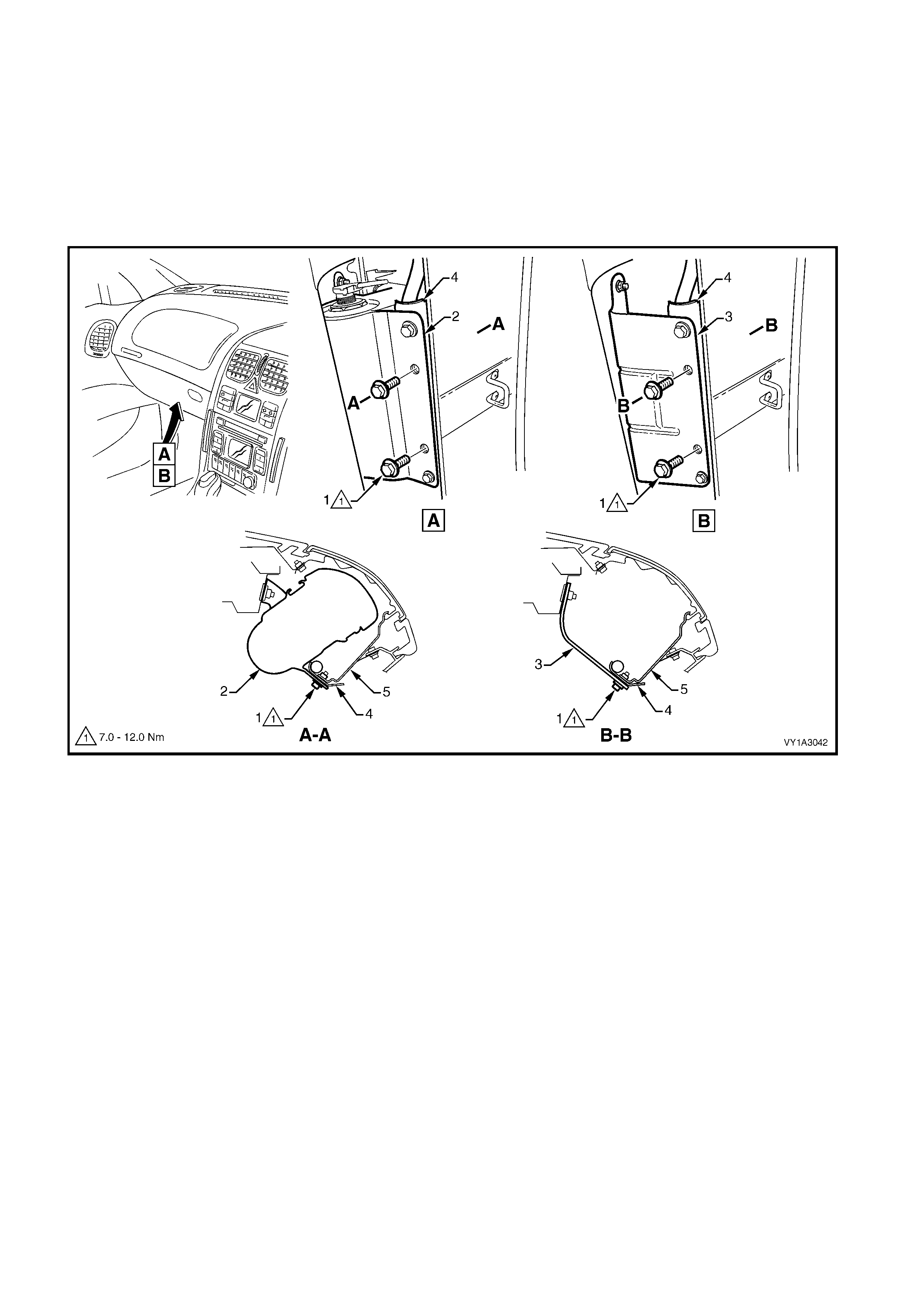
64. Remove the screw (1), two places, attaching the data link connector (2) to the instrument panel lower trim
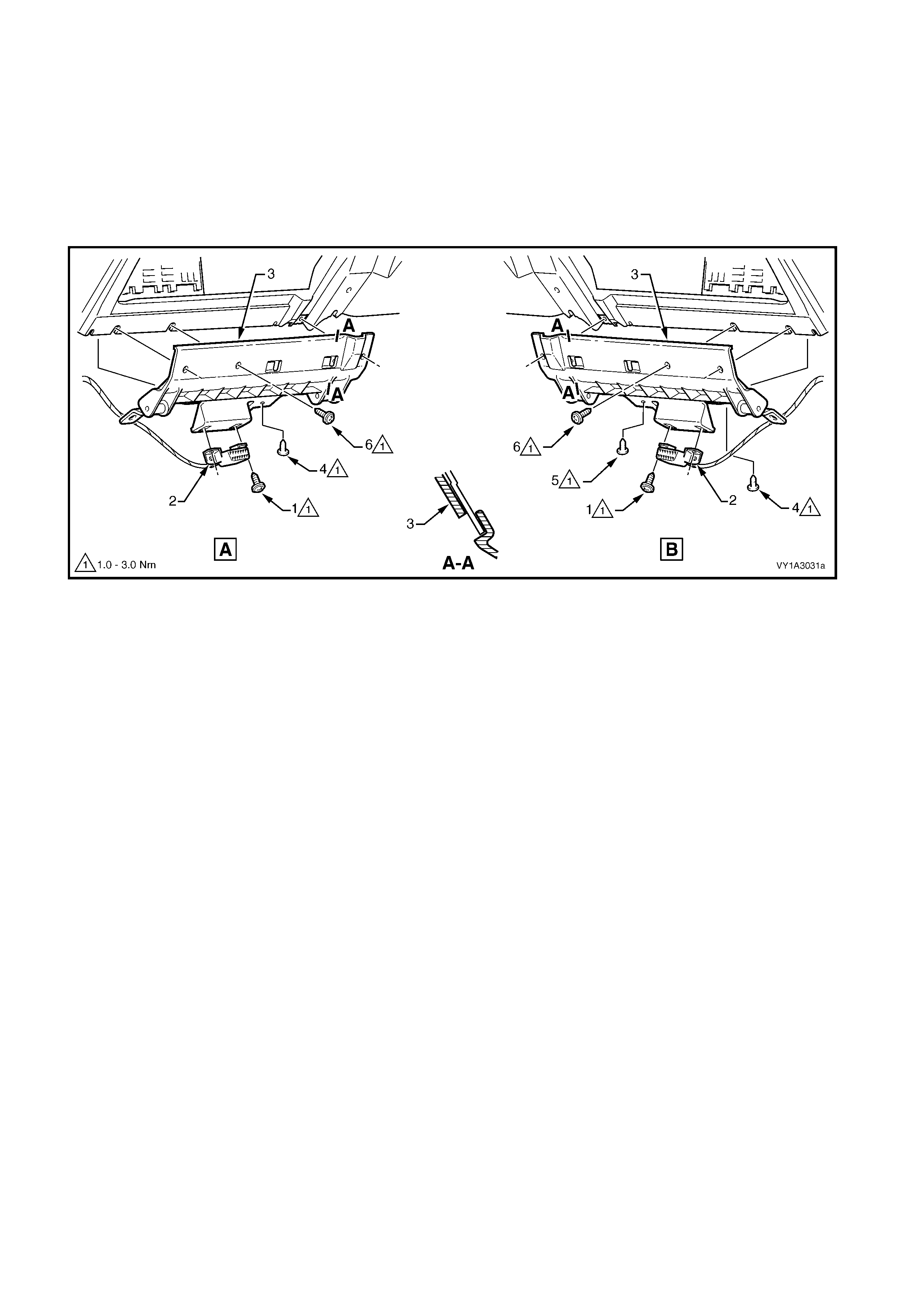
panel retainer (3), refer to Figure 2B-39, A – left-hand drive or B – right-hand drive.
65. For left-hand drive vehicles, remove the screw (4) attaching the retainer to the driver’s side inner air duct.
66. For r ight-hand drive vehicles, r emove the sc rew (4) attaching the retainer to the driver’s s ide inner and outer
air duct joint.
67. Remove the screw (5), attaching the driver’s side inner duct to the retainer.
68. Remove the screw (6), three places, attaching the retainer to the instrument panel.
69. Slide the retainer downward to disengage the two lugs from the instrument panel assembly as shown at
Section A-A and remove the retainer.
Figure 2B-39

70. Remove the screw (1) attaching the driver’s side outer duct (2) to the instrument panel.
NOTE: The lower retaining screw (3) and (4) are removed during removal of the instrument panel lower trim
panel retainer at Step 65 or Step 66. On left-hand drive models this screw retains only the inner duct (4) to the
instrum ent panel. On right-hand drive models, this screw retains both the inner and outer duct to the instrum ent
panel. For left-hand drive models refer to item 5 in Figure 2B-55. For right-hand drive m odels refer to item 5 in
Figure 2B-56.
71. Raise the steering column to its highest adjustment position.
72. Separate the dr iver’s side outer duc t and the driver’s side inner duct by partially withdrawing the driver’s side
outer duct through the end cavity of the instrument panel.
73. Remove the driver’s side inner duct through the instrument panel lower trim plate assembly cavity.
74. Remove the driver’s side outer duct through the instrument panel lower trim plate assembly cavity.
75. Remove the screw (6) attaching the passenger side duct (7) to the instrument panel.
NOTE 1: The floor console front duct retaining screw (8) is removed at Step 25 and duct (9), at Step 28.
NOTE 2: The floor console rear duct (10), is removed with the floor console at Step 22.
Figure 2B-40

76. Release the steering column adjustment lever (1)
and move the column to its lowest position.
77. From below the steering column, remove the
screw (2) attaching the lower cover (3).
NOTE: The covers can be removed with the steering
wheel installed; however, it is not shown for clarity.
78. Depress the face of the lower cover inwards to
disengage the tabs (4) and lift the steering column
upper cover (5).
79. Raise the upper cover as high as possible to
disengage the lugs (6) and remove the cover.
80. Slide the lower cover rearward to disengage it from
the lugs (7) and remove the cover.
81. Remove the steering wheel inflatable restraint
module, refer to Section 12M, OCCUPANT
PROTECTION SYSTEM.
NOTE: Special Tool required.
Figure 2B-41
82. Place the road wheels in the straight-ahead
position and lock the steering column.
83. Remove the screw (1).
84. Remove the steering wheel, disconnecting and
feeding the wires through the aperture as required.
NOTE: A puller should not be required, however if the
wheel assembly cannot be removed fairly easily, use
puller J1859-A and legs E1408.
85. Check that the green indicator (2) on the inflatable
restraint module coil assembly has engaged the
inner clock spring to lock it in the central position.
Figure 2B-42
86. Remove the two screws (1) attaching the
instrument cluster trim assembly (2) to the
instrument panel.
87. Depress the top of the trim assembly slightly and
tilt the top of the trim assembly out of the
instrument panel pad, disengaging the retaining
clips (3) each side.
88. Unhook each lug (4) from the instrument panel
pad.
89. For left-hand drive models, disconnect the fuel
tank filler door lock release switch wiring
connector.
90. Remove the trim assembly.
Figure 2B-43
91. Disconnect the wiring connectors from the rear of
the turn signal switch assembly (1) and windshield
wiper and washer switch assembly.
92. Depress the two tabs (2) securing the switch and
slide from the steering column assembly. Repeat
for the other switch.
Figure 2B-44
93. Remove the four screws (1) attaching the
instrument cluster (2) to the instrument panel.
94. Roll the top of the cluster from its cavity.
95. Using a f ine flat blade scr ewdriver, open the wiring
connector locking tab (3) on the back of the
cluster.
96. Remove the cluster assembly.
Figure 2B-45
IMPORTANT: Care m ust be exercis ed when removing
the headlamp switch as the retaining clip and locating
guide will catch and damage the instrument panel
outer material.
NOTE: Complete switch assembly removal is not
necessar y for HVAC unit rem oval. Figure 2B-46 shows
the switch assembly removed only for clarity of detail.
97. From behind the instrument panel pad, depress
the retaining clips (1). Use a fine, flat blade
screwdriver if required.
98. Carefully push the headlamp switch assembly (2)
part way from its cavity.
99. Insert a fine, flat-blade screwdriver (3) as shown
and hold the retaining clip depres sed, while slowly
manipulating the s witch from its cavity. Repeat for
the opposite side and for the locating guide
underneath as required.
100. Disconnect the wiring connector but do not
remove the switch assembly, as complete
removal is not necessary.
Figure 2B-46
IMPORTANT: Care m ust be exercis ed when removing
the trip computer switch as the retaining clip and
locating guide will catch and damage the instrument
panel outer material.
NOTE: Complete switch assembly removal is not
necessar y for HVAC unit rem oval. Figure 2B-47 shows
the switch assembly removed only for clarity of detail.
101. From behind the instrument panel pad, depress
the retaining clips (1). Use a fine, flat blade
screwdriver if required.
102. Carefully push the trip computer switch
assembly (2) part way from its cavity.
103. Insert a fine, flat-blade screwdriver (3) as shown
and hold the retaining clip depressed, while
manipulating the s witch from its cavity. Repeat for
the opposite side and for the locating guide
underneath as required.
104. Disconnect the wiring connector but do not
remove the switch assembly, as complete
removal is not necessary.
Figure 2B-47
105. Remove the screw (1) attaching the instrument
panel speaker (2) to the instrument panel (3).
106. Disconnect the wiring connector and remove the
speaker by withdrawing it from the slot in the
instrument panel.
Figure 2B-48
Left-Hand Drive Vehic les
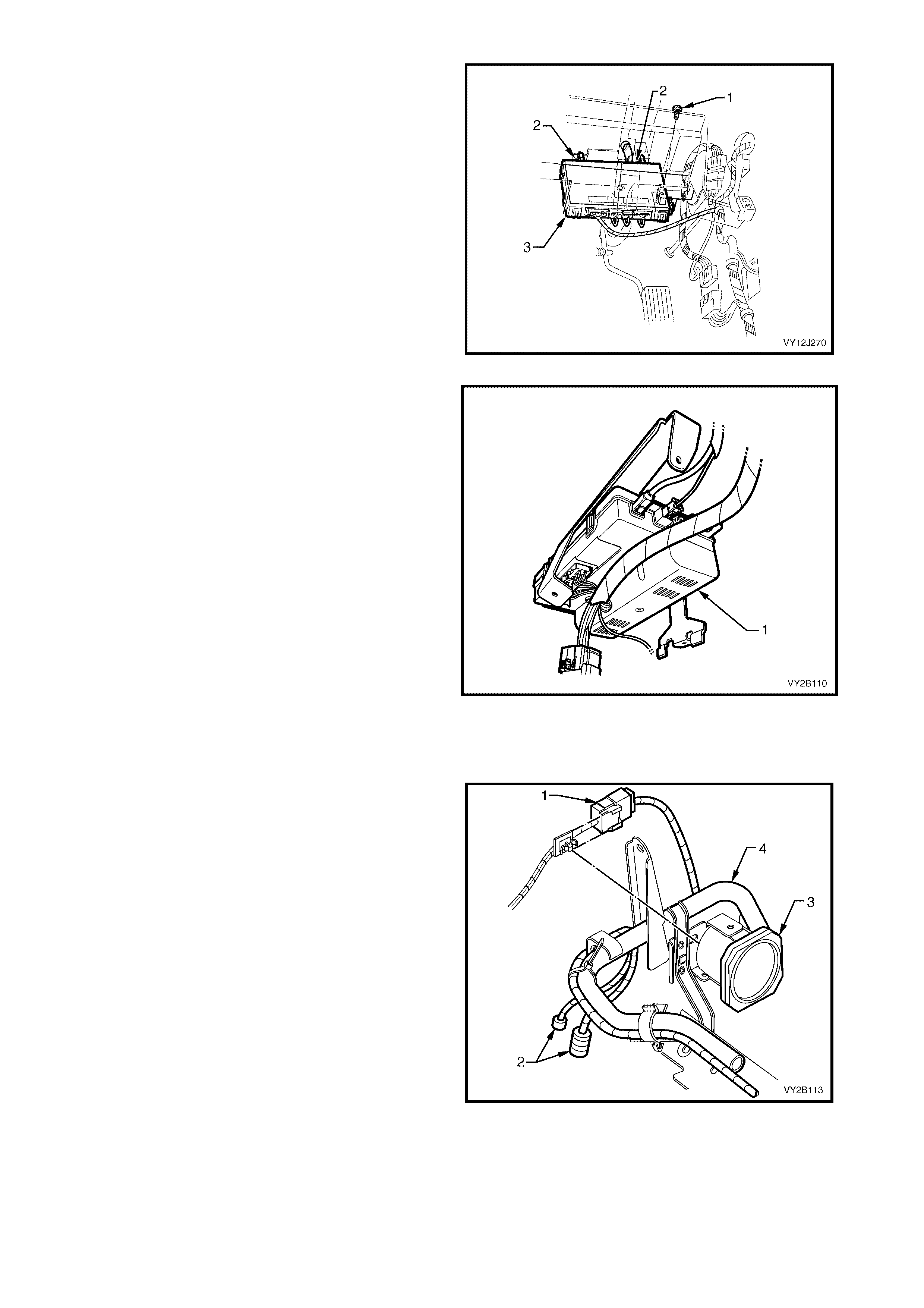
107. Remove the screw (1) attaching the BCM (2) to
the HVAC BCM bracket.
108. Release the rear retaining tang and gently
manoeuvre the BCM from the mounting bracket.
Figure 2B-49
Right-hand Drive Vehicles
109. Remove the screw (1) attaching the BCM (3) to
the instrument panel bracket outer brace.
110. Release the two rear retaining tangs (2) and
gently manoeuvre the BCM f r om the top mounting
bracket.
Figure 2B-50
111. If fitted, remove the telematics module (1). Refer
to Section 12K, TELEMATICS.
Figure 2B-51
112. If the vehicle is fitted with a satellite navigation
system, remove the passenger side hinge pillar
trim assembly. Refer to Section 1A8, 2.8 HINGE
PILLAR TRIM ASSEMBLY.
113. Disconnect the satellite navigation speaker
connector (1) and the satellite navigation system
connectors (2).
NOTE: Rem oval of the navigation s peaker (3) fr om the
instrument panel lower bracket (4) is not necessary.
The brac ket and s peaker are r emoved as an as s embly
at a latter stage.
Figure 2B-52
All Vehicles
114. Remove the four BCM wiring harness connectors from the module and remove the module.
115. Remove the antenna lead from the retaining clips loc ated on the underside of the RHD HVAC unit or at the
case join on the LHD HVAC unit.
116. Remove the two inner screws (1) attaching the instrument panel inflatable restraint (2) or instrument panel
outer upper bracket (3) and instrument panel lower bracket (4) to the instrument panel inflatable restraint
bracket (5), refer to Figure 2B-53.
NOTE: View A is for models with an instrument panel inflatable restraint. View B is for models without an
instrument panel inflatable restraint.
Figure 2B-53
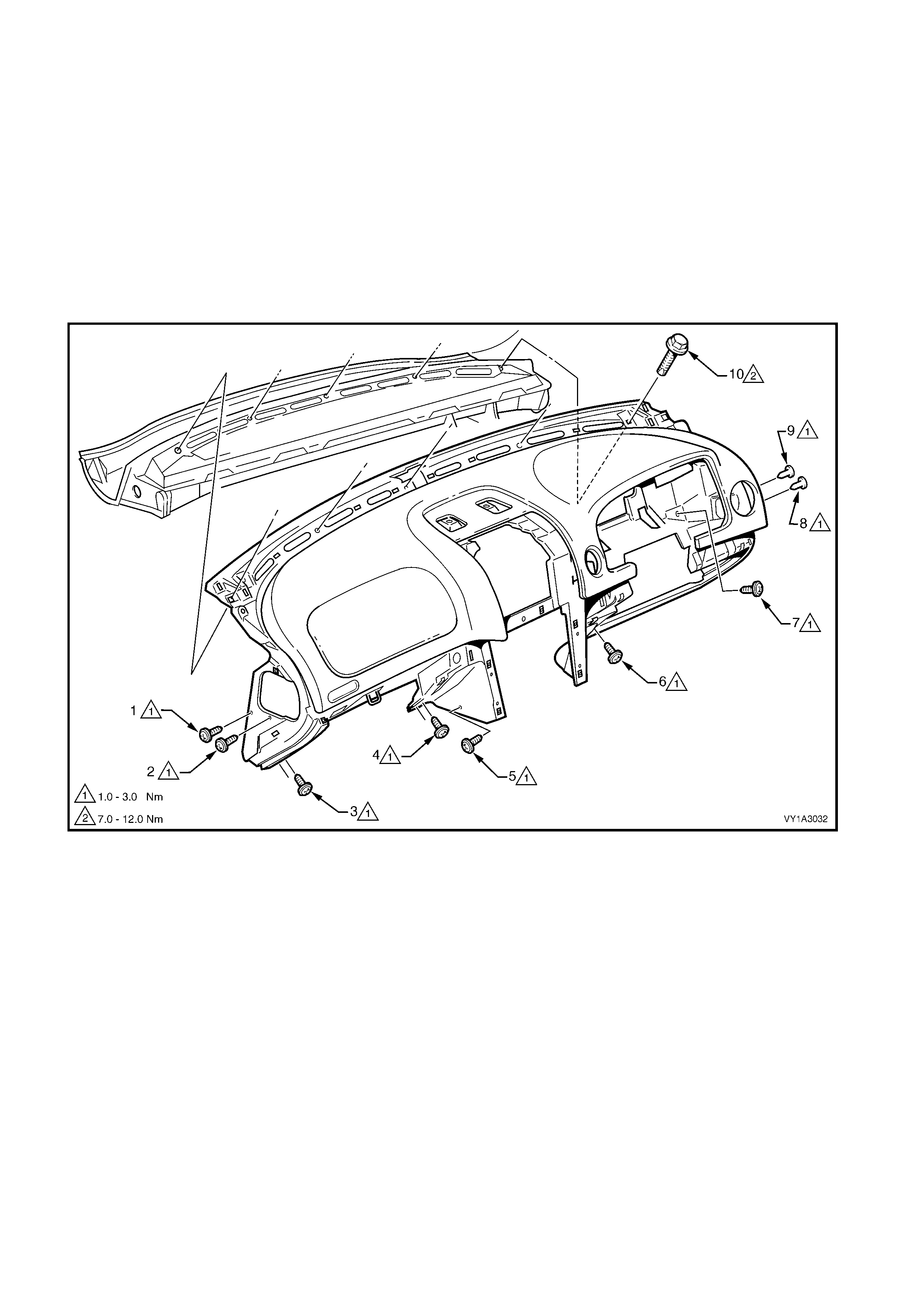
117. Prior to instrum ent panel pad rem oval, refe r to Figure 2B-54 and ensur e that the following screws attaching
the instrument pad assembly are removed:
a. left-hand end (1) one place,
b. to the passenger side air duct (2) one place, (removed previously at Step 75)
c. passenger side lower (3 and 4) two places each,
d. left of centre (5) one place,
e. driver side lower (6) one place,
f. behind instrument cluster (7) one place,
g. to the driver’s side outer air duct (8) one place, (removed previously at Step 70)
h. right-hand end (9) one place,
i. along the upper edge (10), five places.
With the aid of an assistant, carefully lift the pad assembly out of the vehicle and place on a soft surface.
Figure 2B-54
118. If fitted, remove the instrument panel inflatable restraint module assembly. Refer to Section 12M, 2.4
INSTRUMENT PANEL INFLATABLE RESTRAINT MODULE ASSEMBLY.
119. Remove the passenger side HVAC duct from the HVAC unit. Refer to item 9 in Figure 2B-55 for left-hand
drive models or Figure 2B-56 for right-hand models.
NOTE: At this stage, all ducting required for HVAC unit removal, should have been removed.
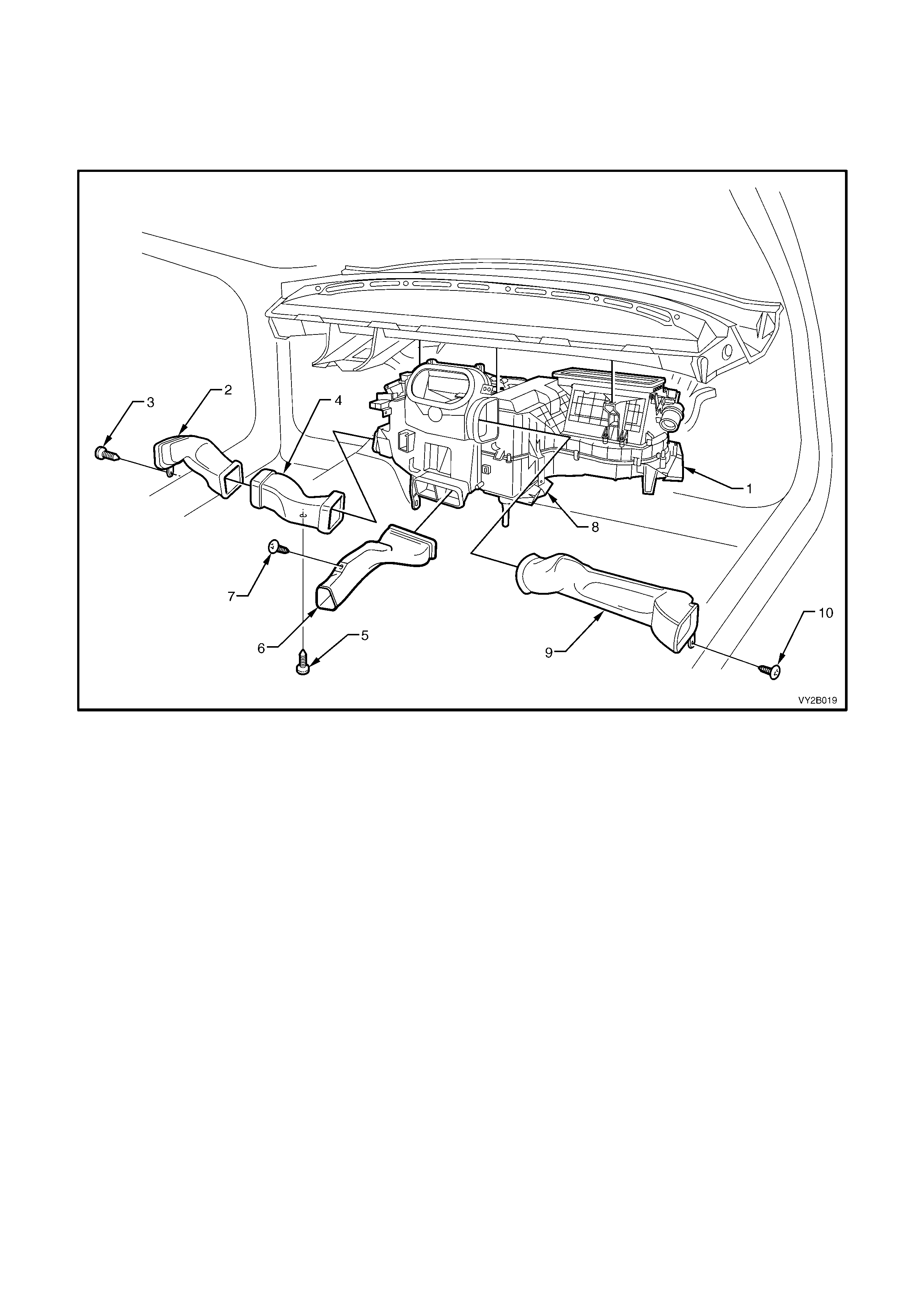
Figure 2B-55
Legend
1. HVAC Unit 6. Floor Console Front Duct, removed at Step 28
2. Driver’s Side Outer Duct, removed at Step 74 7. Screw (1 place), removed at Step 25
3. Screw (1 place), removed at Step 70 8. Foot Duct
4. Driver’s Side Inner Duct, removed at Step 73 9. Passenger’s Side Duct, removed at Step 118
5. Screw (1 place), removed at Step 65 10. Screw (1 place), removed at Step 75
NOTE 1: The foot duct remains attached when the HVAC unit is removed.
NOTE 2: The floor console rear duct (not shown) is removed and installed with the floor console assembly.
NOTE 3: The steering column (not shown) does not have to be removed for HVAC unit removal.
NOTE 4: The floor console front duct is not applicable to utility models.
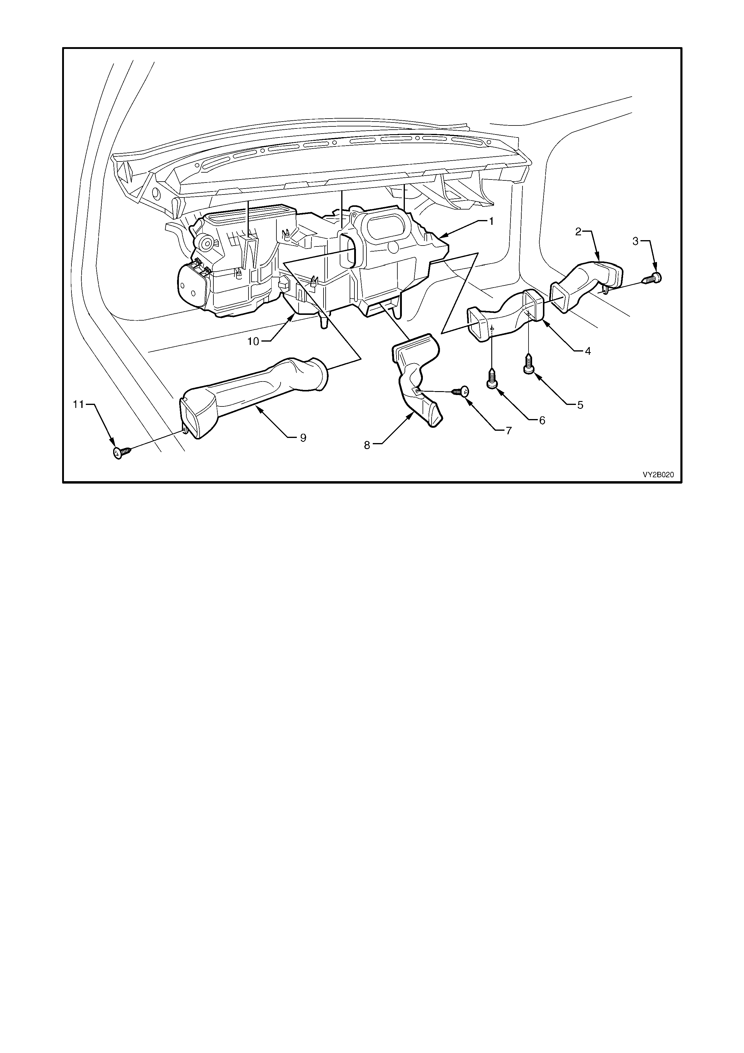
Figure 2B-56
Legend
1. HVAC Unit 7. Screw (1 place), removed at Step 25
2. Driver’s Side Outer Duct, removed at Step 74 8. Floor Console Front Duct, removed at Step 28
3. Screw (1 place), removed at Step 70 9. Passenger’s Side Duct, removed at Step 118
4. Driver’s Side Inner Duct, removed at Step 73 10. Foot Duct
5. Screw (1 place), removed at Step 66 11. Screw (1 place), removed at Step 75
6. Screw (1 place), removed at Step 67
NOTE 1: The foot duct remains attached when the HVAC unit is removed.
NOTE 2: The floor console rear duct (not shown) is removed and installed with the floor console assembly.
NOTE 3: The steering column (not shown) does not have to be removed for HVAC unit removal.
NOTE 4: The floor console front duct is not applicable to utility models.
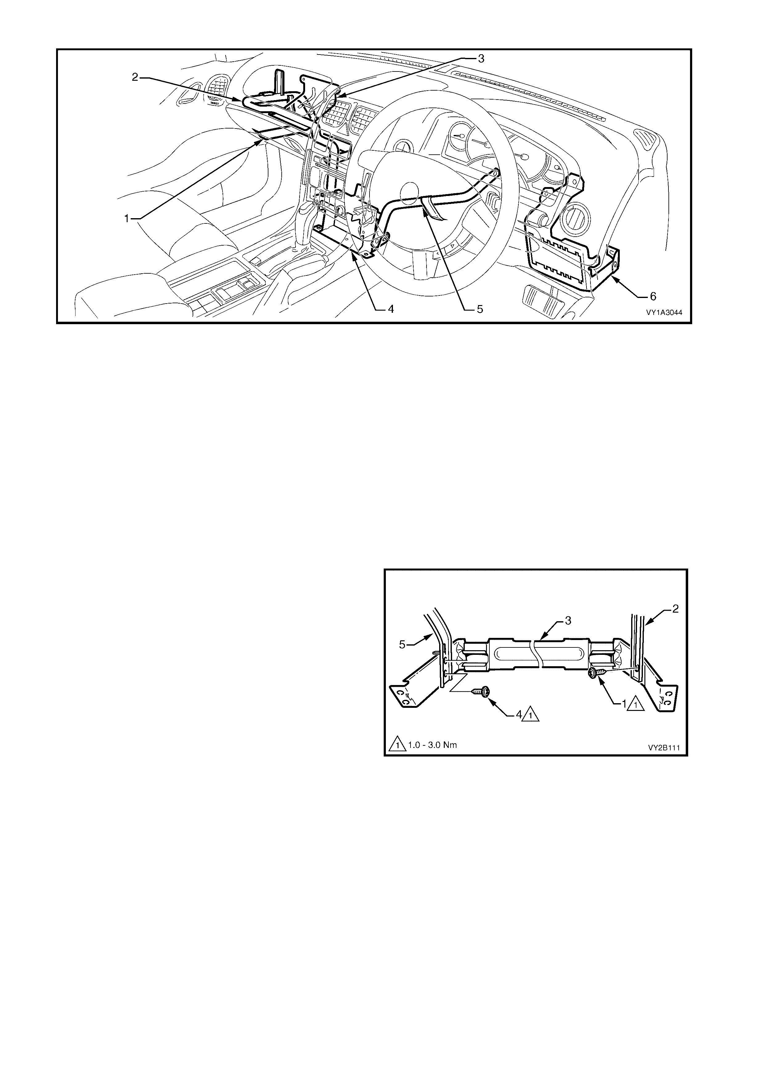
Figure 2B-57
Legend
1. Instrument Panel Compartment Bracket, refer to Step 117 c, and Step 120 through to Step 121
2. Instrument Panel Lower Bracket, refer to Step 122 through to Step 124
3. Instrument Panel Outer Upper Bracket, refer to Step 124 and Step 125
4. Lower Radio Bracket, refer to Step 122, Step 126, Step 127, Step 130 and Step 131
5. Steering Column Bracket Inner Brace, refer to Step 127 through to Step 129
6. Steering Column Bracket Outer Brace, do not remove
NOTE1: Item 3, the instrument panel outer upper bracket, is fitted only to models not fitted with an instrument panel
inflatable restraint module assembly.
NOTE 2: Item 2 and 3 are removed as an assembly.
NOTE 3: If the vehicle is fitted with a satellite navigation system, the navigation speaker will be attached to, and removed
with Item 2. Refer to Figure 2B-52.
120. Remove the screw (1) attaching the HVAC unit (2)
to the instrument panel compartment bracket (3).
121. Remove the screw (4), two places, attaching the
bracket to the instrument panel lower bracket (5)
and remove the bracket.
Figure 2B-58
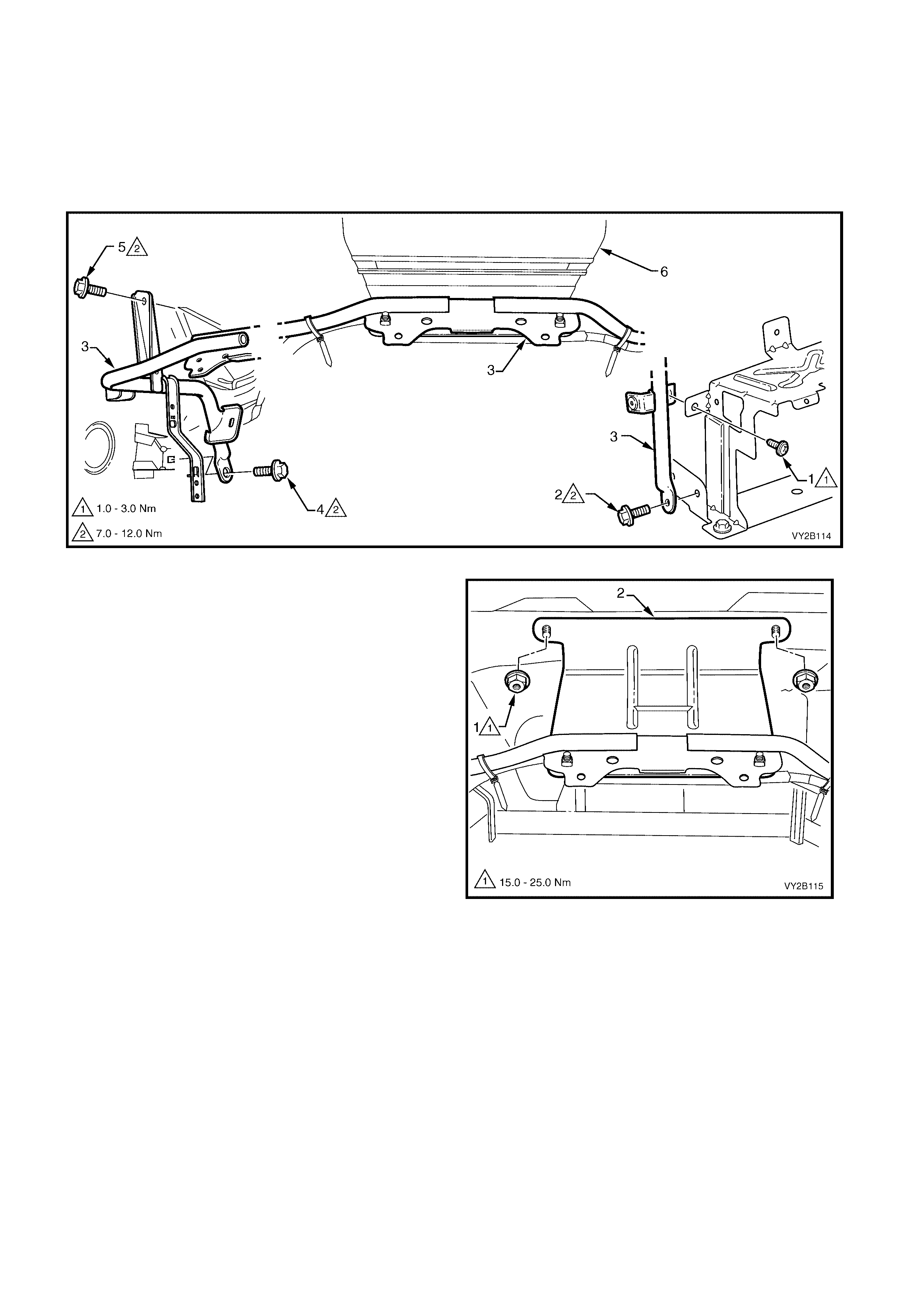
Referring to Figure 2B-59:
122. Remove the screws (1 and 2) attaching the instrument panel lower bracket (3) to the lower radio bracket.
123. Remove the screws (4 and 5) attaching the bracket to the vehicle.
IMPORTANT: If the vehicle is fitted with a satellite navigation system, exercise caution when removing the
instrument panel lower bracket to ensure that the attached satellite navigation speaker is not damaged.
124. Remove the outer upper bracket (6) and lower bracket as an assembly.
Figure 2B-59
125. Remove the nut (1), two places, attaching the
outer upper bracket to the dash panel assembly .
Figure 2B-60
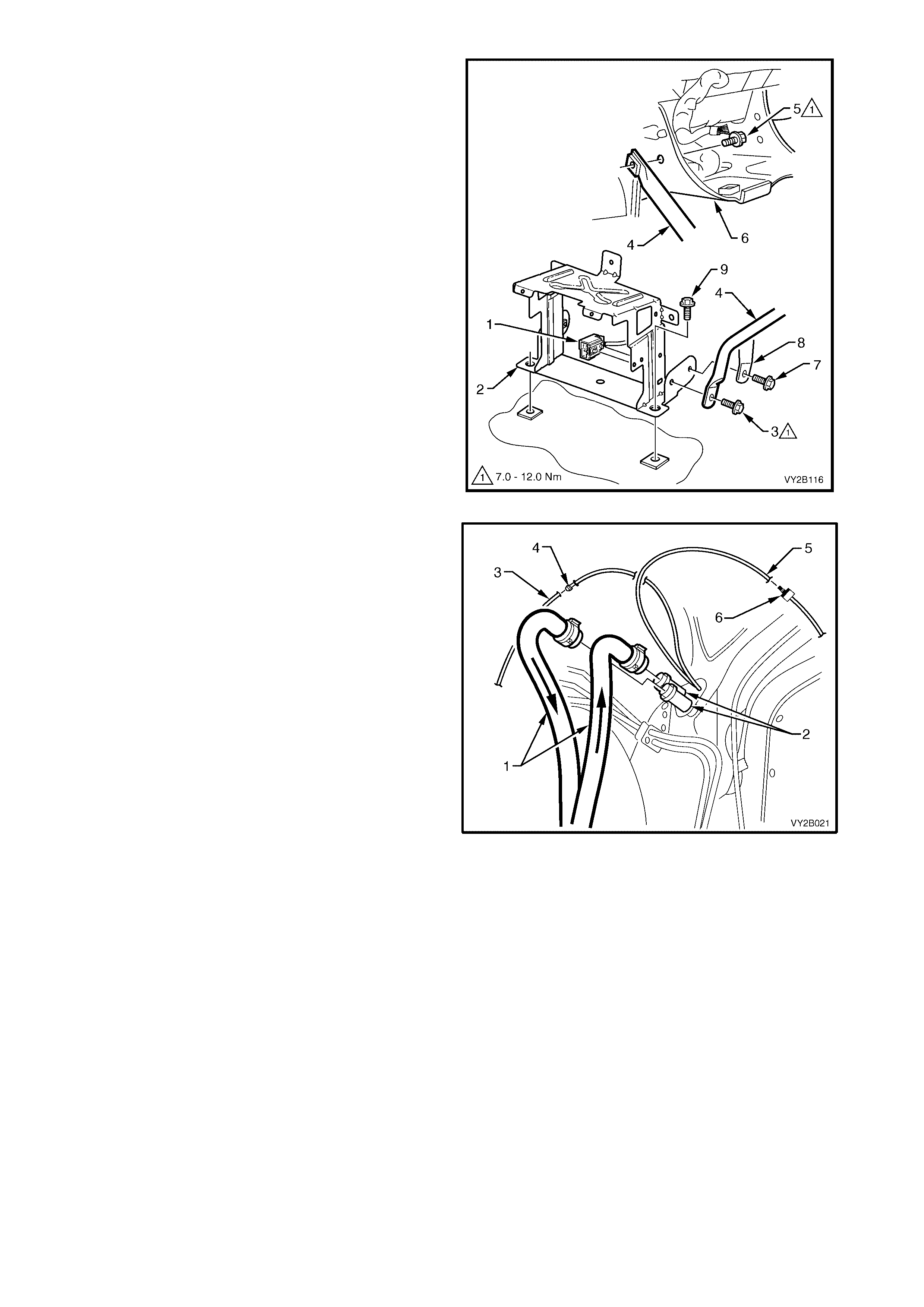
126. Unclip the wiring connector (1) from the lower
radio bracket (2).
127. Remove the screw (3) attaching the steering
column bracket inner brace (4) to the lower radio
bracket.
128. Remove the screw (5) attaching the brace to the
steering column bracket (6).
129. Remove the brace.
130. Remove the screw (7), attaching the HVAC
unit (8) to the radio bracket.
131. Remove the screw (9), two places, attaching the
radio bracket to the vehicle and remove the
bracket.
Figure 2B-61
132. Mark the heater hoses (1) in relation to the heater
core pipes (2) to maintain correct coolant flow.
Remove the heater hoses from the heater core
pipes.
133. Disconnect the water valve vacuum hose (3) at
the joiner (4).
134. Disconnect the vacuum supply hose (5) at the
check valve (6).
Figure 2B-62
135. Remove the suc tion and liquid tubes (one bolt) and the ther mal expans ion valve (two cap scr ews). Refer to
10.THERMAL EXPANSION VALVE (TXV) in this Section.
136. On GEN III V8 models, remove the fuel line retaining bracket attached to the HVAC mounting stud. For
location, refer to item 8 in Figure 2B-63 for left-hand drive models and Figure 2B-64 for right-hand drive
models.
137. Remove the screws retaining the HVAC unit to the dash panel. Refer to Figure 2B-63 for left-hand drive
models and Figure 2B-64 for right-hand drive models.
NOTE: Item 7 will have been removed during previous Steps.
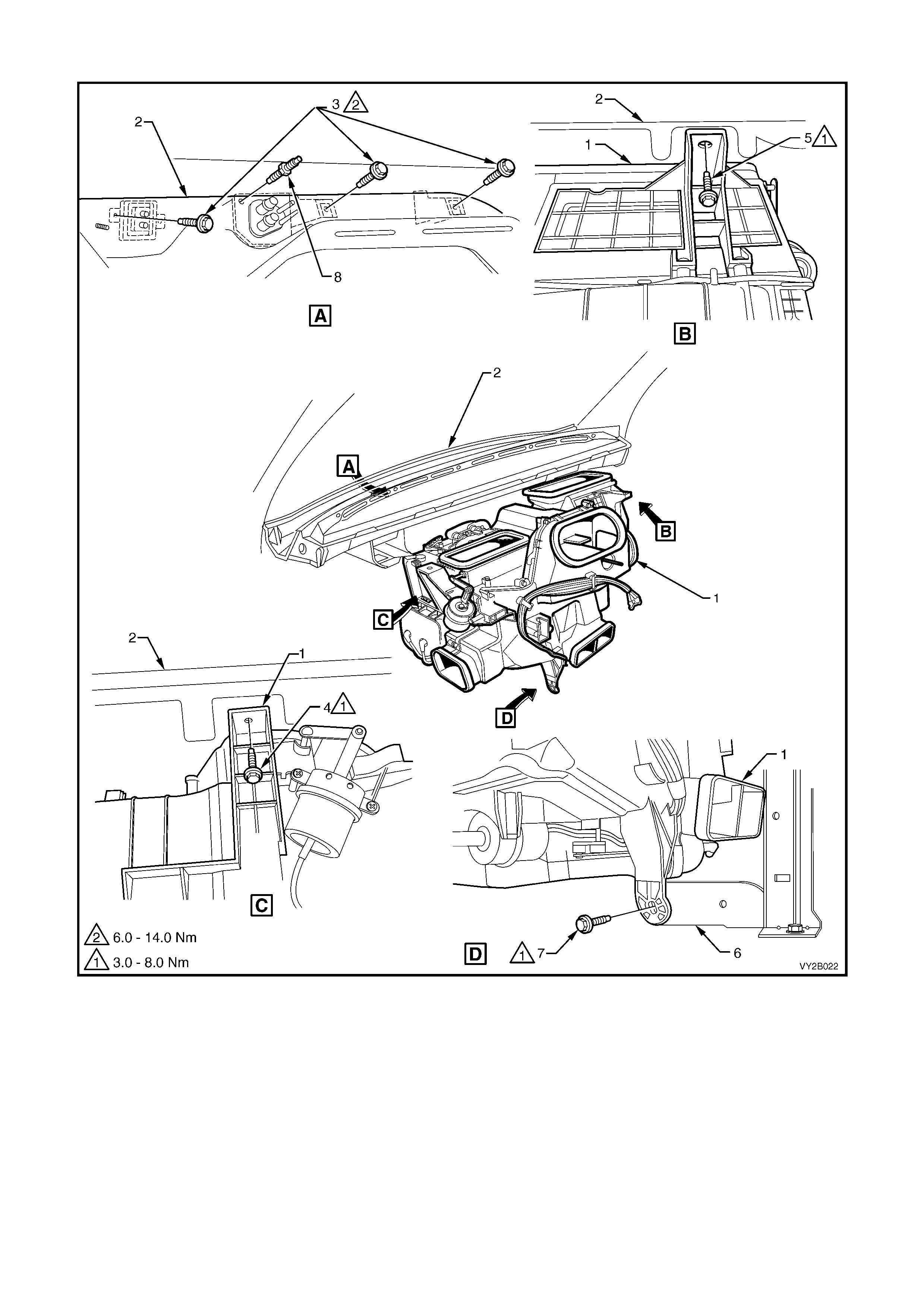
HVAC UNIT FASTENER LOCATION – LHD
Figure 2B-63
Legend
1. HVAC Unit 5. Screw – Dash Panel, Cabin on Passenger’s Side
2. Dash Panel 6. Lower Radio Bracket Assembly
3. Screw – Dash Panel, Engine Bay (3 places) 7. Screw – Lower Radio Bracket Assembly, removed at Step 130
4. Screw – Dash Panel, Cabin on Driver’s Side 8. Screw for V6, Stud for GEN III V8 – Dash Panel, Engine Bay
NOTE: The steering column (not shown) does not have to be removed for HVAC unit removal.
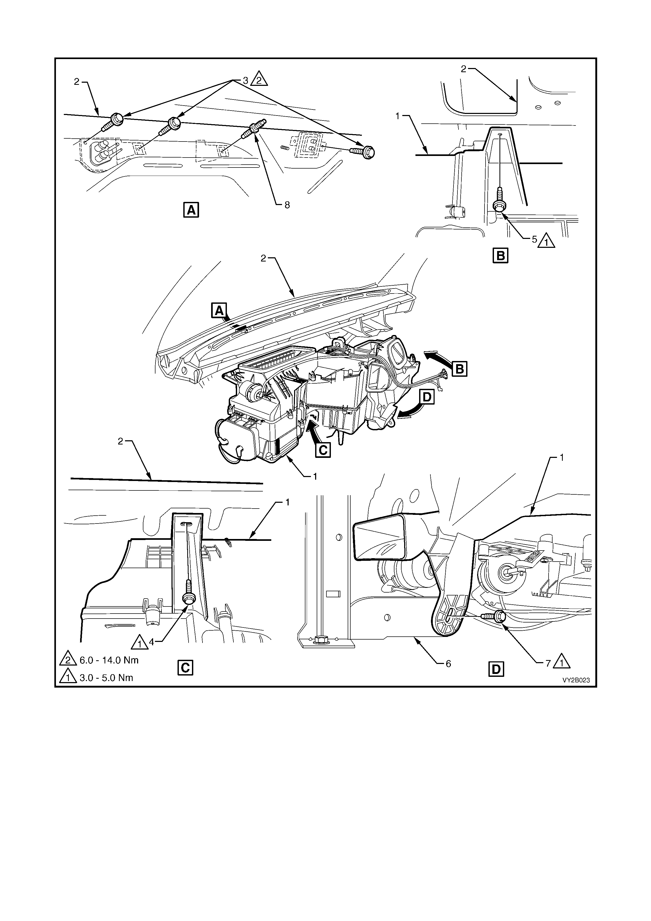
HVAC UNIT FASTENER LOCATION – RHD
Figure 2B-64
Legend
1. HVAC Unit 5. Screw – Dash Panel, Cabin Driver’s Side
2. Dash Panel 6. Lower Radio Bracket Assembly
3. Screw – Dash Panel, Engine Bay (3 places) 7. Screw – Lower Radio Bracket Assembly, removed at Step 130
4. Screw – Dash Panel, Cabin Passenger Side 8. Screw for V6, Stud for GEN III V8 – Dash Panel, Engine Bay
NOTE: The steering column (not shown) does not have to be removed for HVAC unit removal.
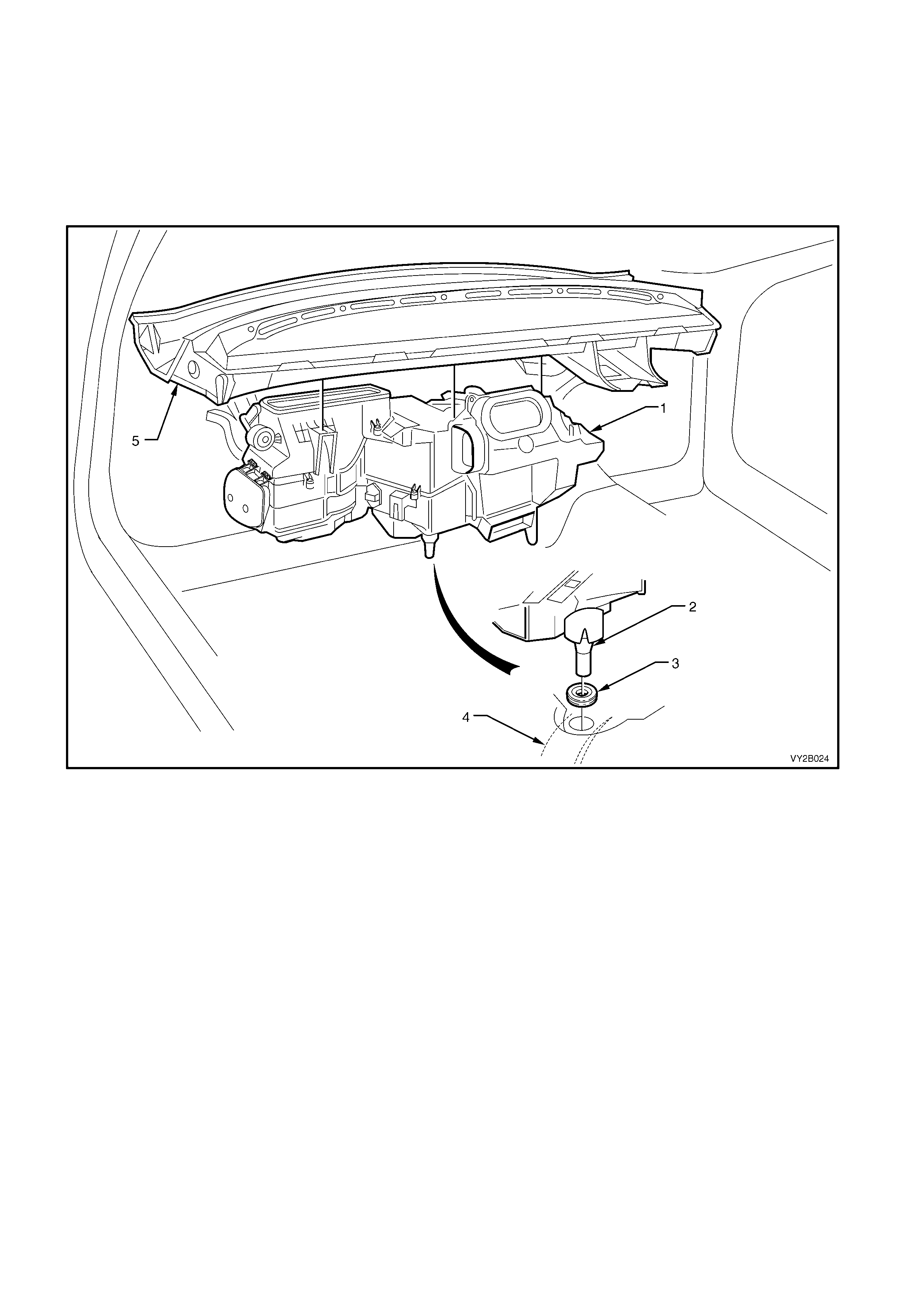
IMPORTANT: W hen r emoving the HVAC unit from the vehicle take c are not to strain the heater cor e tubes and
evaporator core tubes.
NOTE: Figure 2B-65 shows the right-hand drive HVAC unit and corresponding drain tube / hole location offset
towards the left of the transmission tunnel. The left-hand drive HVAC unit drain tube / hole location is offset
towards the right of the transmission tunnel.
138. Remove the HVAC unit (1) from the vehicle by disengaging the drain tube (2) from the body grommet (3)
installed in the transmission tunnel (4).
139. Carefully lift the HVAC unit away from the dash panel (5).
Figure 2B-65
REINSTALL
Installation of the heating, ventilation and air conditioning (HVAC) unit is in the reverse order of removal noting the
following points and references:
1. Tighten all fasteners to the specified torque. Refer to 19. TORQUE WRENCH SPECIFICATIONS in this
Section.
2. Enable the OPS, SRS in accordance to the correct procedure. Refer to Section 12M, 2.2 SYSTEM
DISABLING AND ENABLING PROCEDURE.
3. Fill the cooling system with the correct specification and quantity of coolant. Pressure test the cooling system.
As applicable refer to:
• Section 6B1, ENGINE COOLING – V6 ENGINE
• Section 6B2, ENGINE COOLING – V6 ENGINE SUPERCHARGED
• Section 6B3, ENGINE COOLING – GEN III V8 ENGINE
4. Evacuate and charge the system with 775 – 825 g of R134a refrigerant, refer to Section 2C, 2.1 SYSTEM
CHARGING AND EVACUATION.
4. EVAPORATOR CORE
REMOVE – LHD
1. Remove the floor console, instrument panel and HVAC assemblies, refer to 3. HEATING, VENTILATION
AND AIR CONDITIONING (HVAC) UNIT in this Section.
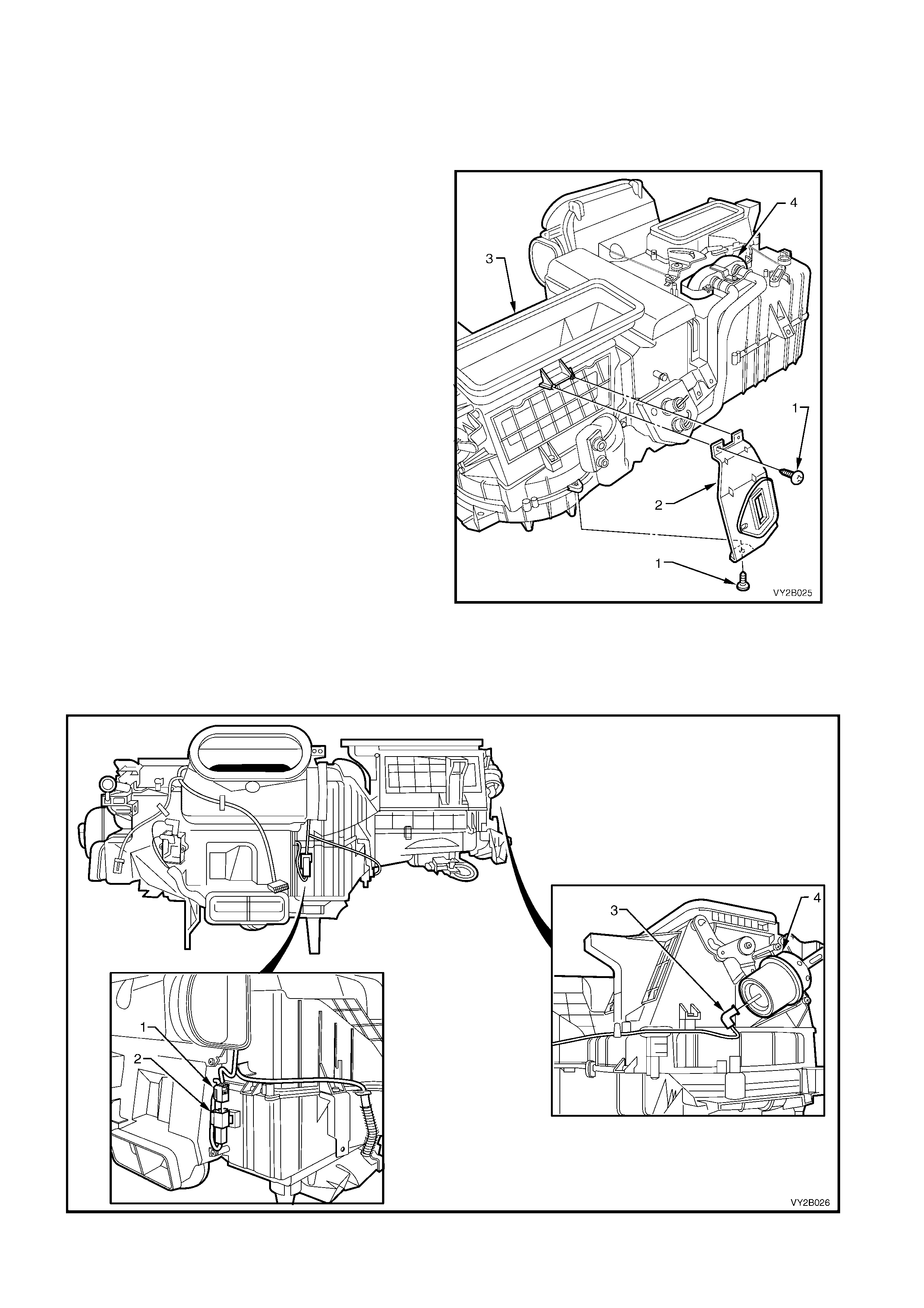
2. Remove TXV joint bracket screws (1) and
remove the bracket (2) from the HVAC unit (3).
3. Remove the heater core (4). Refer to
5. HEATER CORE in this Section.
Figure 2B-66
4. On O CC (Auto A/C) HVAC units rem ove the HVAC harness c onnector (1) f rom the evaporative temperatur e
sensor harness connector (2).
5. On both manual A/C and OCC (Auto A/C) type HVAC units, remove the vacuum line (3) to the intake
actuator (4).
Figure 2B-67
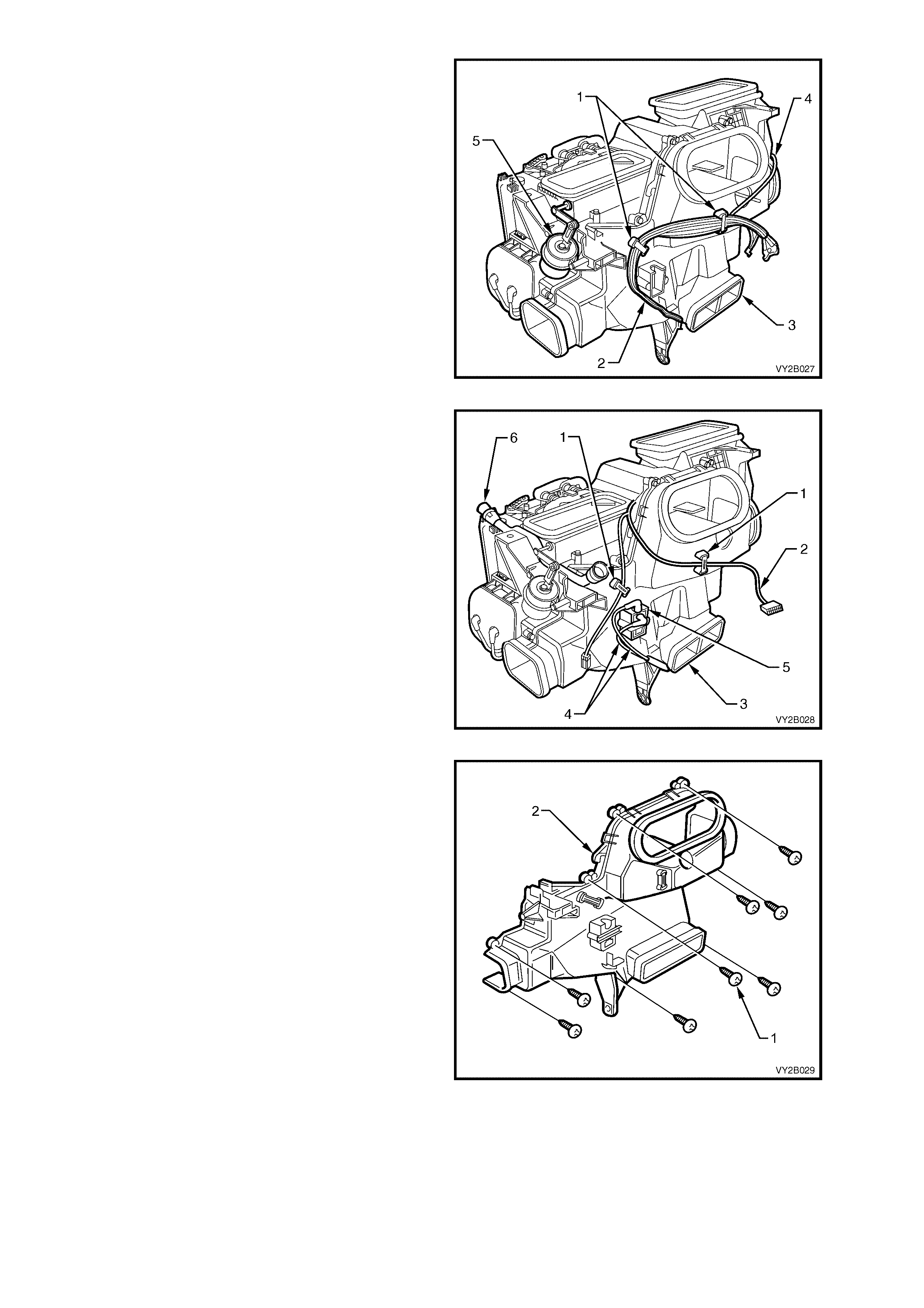
6. On manual HVAC units remove the vacuum
line retainers (1) and remove the vacuum lines
(2) from the front case (3). Remove the intake
actuator vacuum line (4) from the front and
upper case.
7. On both types of HVAC units remove
the demist actuator (5). Refer to
8.5 DEMIST ACTUATOR in this Section.
Figure 2B-68
8. On OCC (Auto A/C) HVAC units remove the
harness retainers (1) and remove the
harness (2) from the front case (3).
9. On OCC (Auto A/C) HVAC units remove the
vacuum lines (4) from the water valve VSV (5).
10. On OCC (Auto A/C) HVAC units remove the
aspirator tube and venturi assembly (6). Refer
to Section 2E, ASPIRATOR TUBE AND
VENTURI.
Figure 2B-69
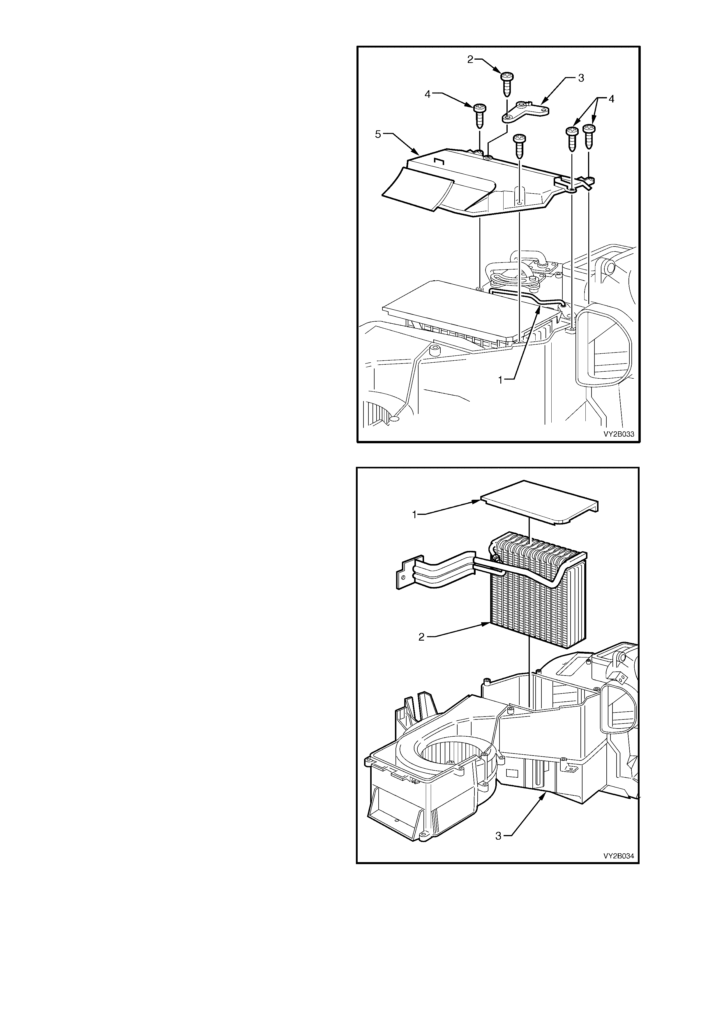
11. Remove the eight s cr ews (1) attaching the f ront
case (2) to the upper and lower case assembly.
Figure 2B-70
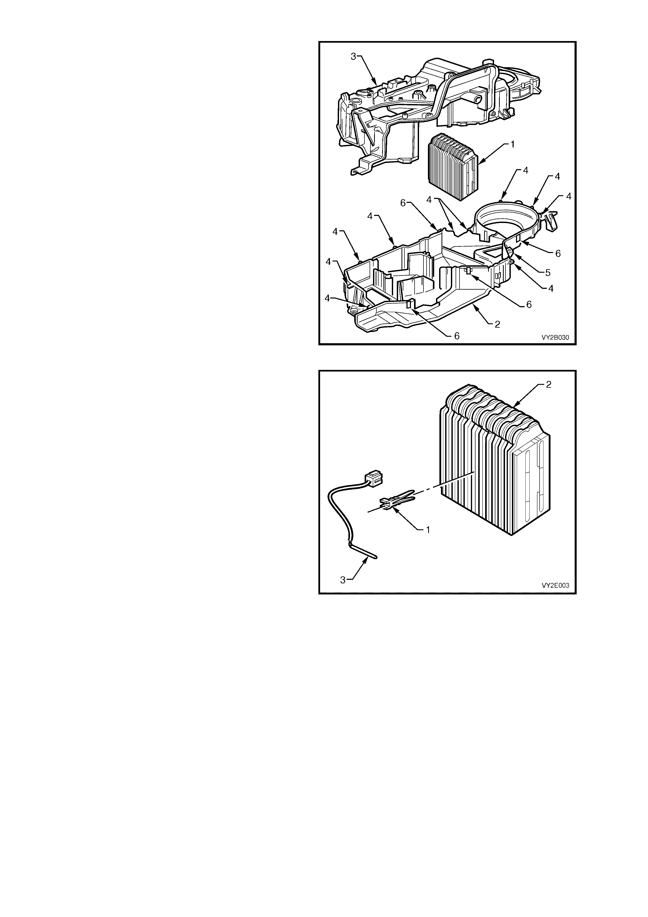
12. To access the evaporator (1) separate the
lower case (2) from the upper case (3) by
removing the ten screws (4) installed through
the upper case, one s crew (5) installed thr ough
the lower case, and four clips (6). Do not
remove air doors from either case.
NOTE: Two clips ar e located ins ide the HVAC case
and are accessible after the front case is removed.
Figure 2B-71
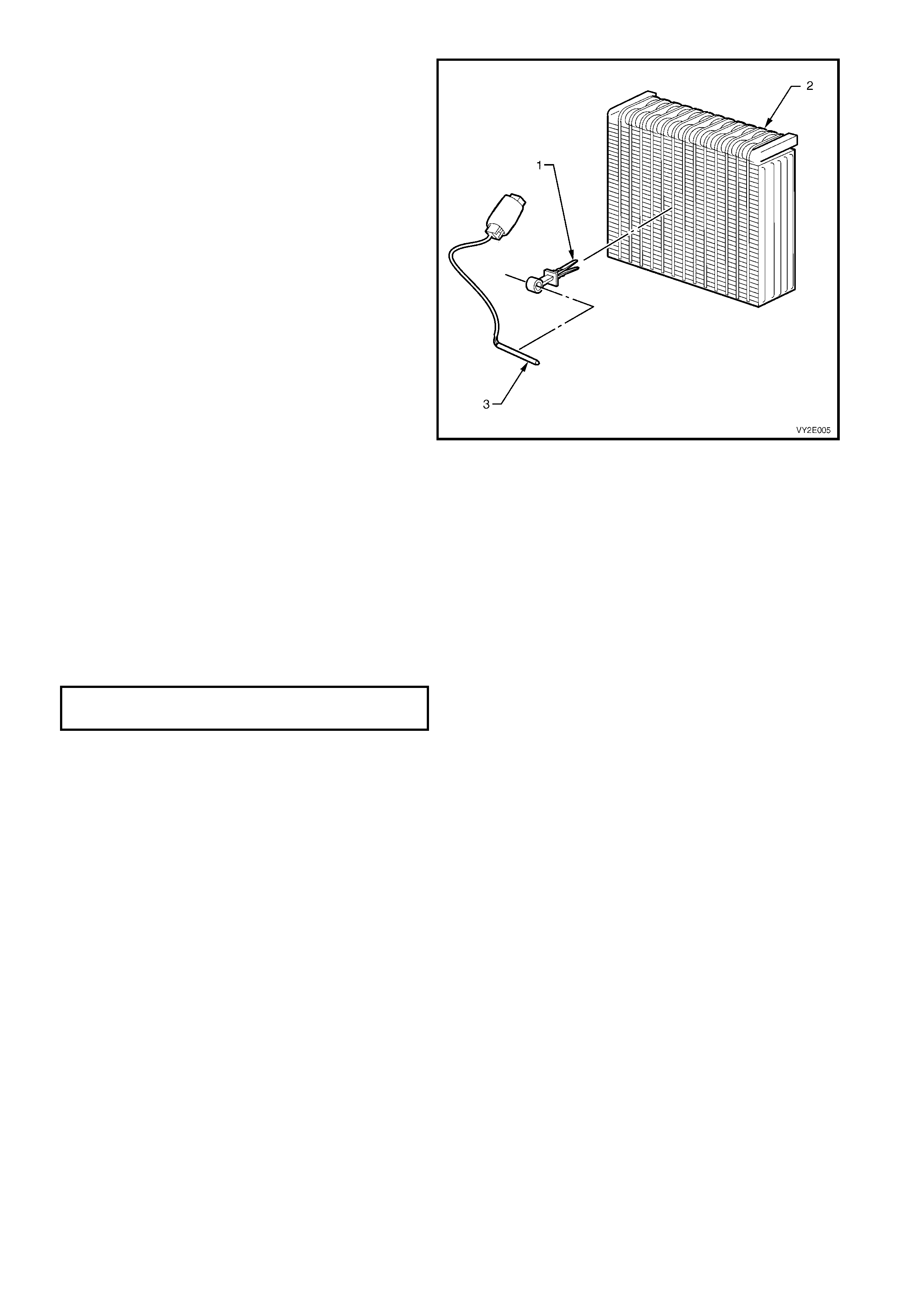
13. On OCC (Auto A/C) HVAC units, if the
evaporator is to be replaced, remove the
evaporative temperature sensor clip (1) from
the evaporator (2) and remove the sensor (3).
14. Carefully remove the evaporator core from the
upper case. Pull tubes away from the upper
case to facilitate removal.
Figure 2B-72
15. Rotate the evaporator core (1) and remove
evaporator pipes (2) after removing the
retaining scr ew (3). Remove and discar d the O-
rings (4) from the evaporator pipes.
Figure 2B-73
REINSTALL – LHD
Installation of the evaporator core is in the reverse order of removal procedures noting the following points:
IMPORTANT: The total quantity of lubricating oil in the air conditioning system must be maintained. If a
compressor, evaporator, condenser, filter drier receiver, hose or pipe is to be replaced, a specified quantity of
lubricating oil must be added to the system to compensate for oil removed with the original component. Refer to
Section 2C, 2.4 LUBRICATING OIL COMPENSATION.
NOTE 1: Install new O-rings at the evaporator to evaporator pipe joint.
NOTE 2: On OCC (Auto A/C) evaporator assemblies, install the evaporative temperature sensor in the correct
location on the evaporator core. Refer to Section 2E, 2.4 EVAPORATIVE TEMPERATURE SENSOR.
1. Tighten evaporator to evaporator pipe screw to the correct torque specification.
EVAPORATOR PIPE SCREW
TORQUE SPECIFICATION 5.0 Nm
2. Tighten the HVAC case screws to the correct torque specification.
HVAC CASE SCREW
TORQUE SPECIFICATION 1.0 – 3.0 Nm
3. Install the heating, ventilation and air conditioning (HVAC) unit, refer to 3. HEATING, VENTILATION AND AIR
CONDITIONING (HVAC) UNIT in this Section.
4. Evacuate and charge the system with 775 – 825 g of R134a refrigerant, refer to Section 2C, 2.1 SYSTEM
CHARGING AND EVACUATION.
LT Section – 08-150
REMOVE – RHD
1. Remove the floor console, instrument panel and HVAC assemblies, refer to 3. HEATING, VENTILATION
AND AIR CONDITIONING (HVAC) UNIT in this Section.
2. On OCC (Auto A/C) HVAC units, remove the
HVAC harness connector (1) from the
evaporative temperature sensor harness
connector (2). Remove the venturi (3) from the
evaporator cover (4).
Figure 2B-74
3. Remove the vacuum hose (1) from the fresh/
recirculation actuator (2).
4. Remove the five screws (3) from the
fresh/recirculation housing (4) and remove the
fresh/recirculation housing.
5. Disconnect the vacuum tube harness retaining
clips (5) above the evaporator core cover (6).
Figure 2B-75
6. On OCC (Auto A/C) HVAC units remove the
aspirator tube and venturi. Refer to
Section 2E, 2.5 ASPIRATOR TUBE AND
VENTURI.
7. On manual HVAC units disconnect the air mix
door actuator rod (1) and quadrant screw (2)
and remove the quadrant (3)
8. Remove the four screws from the evaporator
core cover (4) and remove the evaporator
cover (5).
Figure 2B-76
9. Remove the upper insulator (1) and carefully
rem ove the evapor ator c ore (2) f rom the m iddle
cavity of the HVAC case (3).
Figure 2B-77
10. On OCC (Auto A/C) HVAC units, disconnect
the evaporative tem perature sensor harness. If
the evaporator is to be replaced, remove the
evaporative temperature sensor clip (1) from
the evaporator (2) and remove the sensor (3).
Figure 2B-78
REINSTALL – RHD
Installation of the evaporator core is in the reverse order of removal procedures noting the following points:
IMPORTANT: The total quantity of lubricating oil in the air conditioning system must be maintained. If a
compressor, evaporator, condenser, filter drier receiver, hose or pipe is to be replaced, a specified quantity of
lubricating oil must be added to the system to compensate for oil removed with the original component. Refer to
Section 2C, 2.4 LUBRICATING OIL COMPENSATION.
NOTE: On OCC (Auto A/C) evaporator assemblies install the evaporative temperature sensor in the correct location
on the evaporator core. Refer to Section 2E, 2.4 EVAPORATIVE TEMPERATURE SENSOR.
1. Tighten the HVAC case screws to the correct torque specification.
HVAC CASE SCREW
TORQUE SPECIFICATION 1.0 – 3.0 Nm
2. Install the heating, ventilation and air conditioning (HVAC) unit, refer to 3. HEATING, VENTILATION AND AIR
CONDITIONING (HVAC) UNIT in this Section.
3. Evacuate and charge the system with 775 - 825 g of R134a refrigerant, refer to Section 2C, 2.1 SYSTEM
CHARGING AND EVACUATION.
5. HEATER CORE
REMOVE – LHD
1. Remove the floor console, instrument panel and HVAC assemblies, refer to 3. HEATING, VENTILATION
AND AIR CONDITIONING (HVAC) UNIT in this Section.
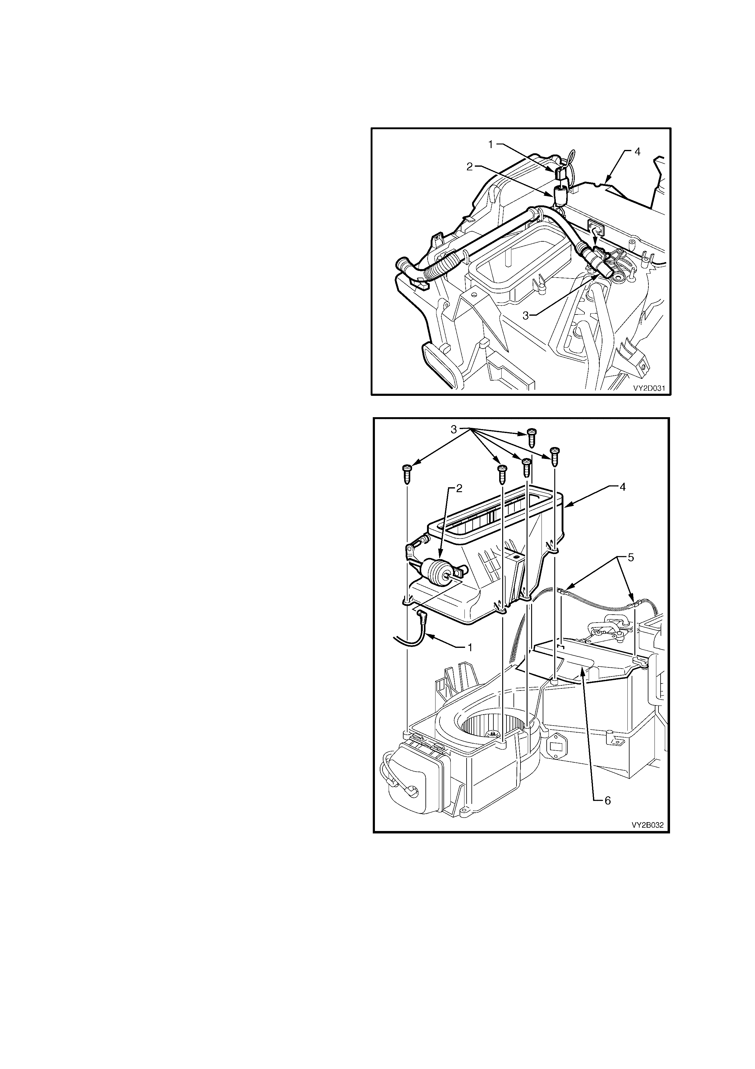
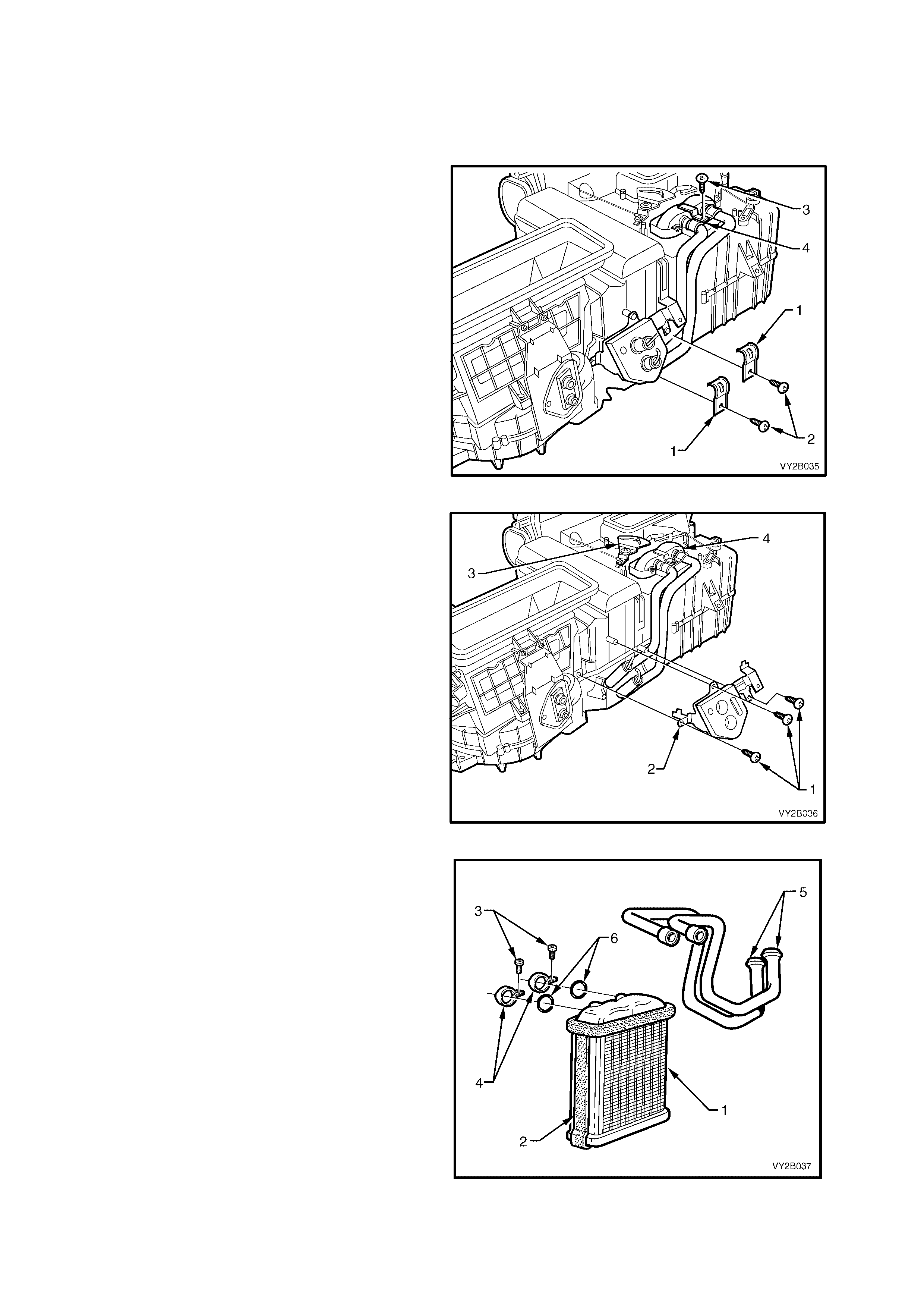
2. Remove heater the two heater core pipe
clamps (1) and screws (2).
3. Remove heater core retaining strap mounting
screw (3) and retaining strap (4).
Figure 2B-79
4. Remove heater pipe bracket mounting
screws (1) and the bracket (2).
5. Position the air mix door mechanism (3) clear
of the top of the heater core (4).
Figure 2B-80
6. Remove the heater core (1) from the HVAC
case without damaging the foam seal (2)
located on top and on both sides of the heater
core.
7. Remove the screw (3) and retainer clip (4)
retaining each heater pipe (5) to the heater
core and remove the pipes from the heater
core. Discard the O-rings (6).
Figure 2B-81
REINSTALL – LHD
Installation of the heater core is in the reverse order of removal procedures noting the following points:
NOTE 1: Install new O-rings at the heater core pipe joints.
NOTE 2: Ensure the foam seals are not damaged when installing heater core to the HVAC case.
1. Tighten all fasteners to the correct torque specification.
HEATER CORE PIPE
RETAINING SCREWS
TORQUE SPECIFICATION 3.0 – 5.0 Nm
HVAC CASE SCREW
TORQUE SPECIFICATION 1.0 – 3.0 Nm
2. Install the heating, ventilation and air conditioning (HVAC) unit, refer to 3. HEATING, VENTILATION AND AIR
CONDITIONING (HVAC) UNIT in this Section.
3. Evacuate and charge the system with 775 - 825 g of R134a refrigerant, refer to Section 2C, 2.1 SYSTEM
CHARGING AND EVACUATION.
LT Section – 08-150
REMOVE – RHD
1. Remove the floor console, instrument panel and HVAC assemblies, refer to 3. HEATING, VENTILATION
AND AIR CONDITIONING (HVAC) UNIT in this Section.
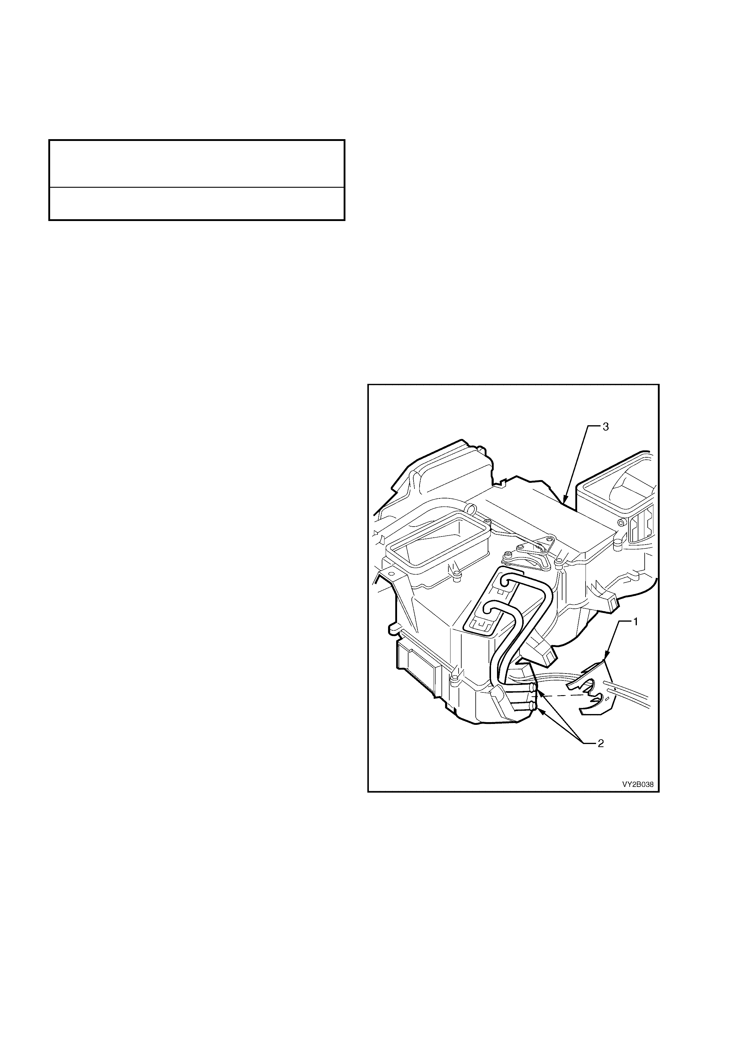
2. Unclip and remove plastic retainer (1) from the
heater pipes (2) at the rear of the HVAC unit
(3).
Figure 2B-82
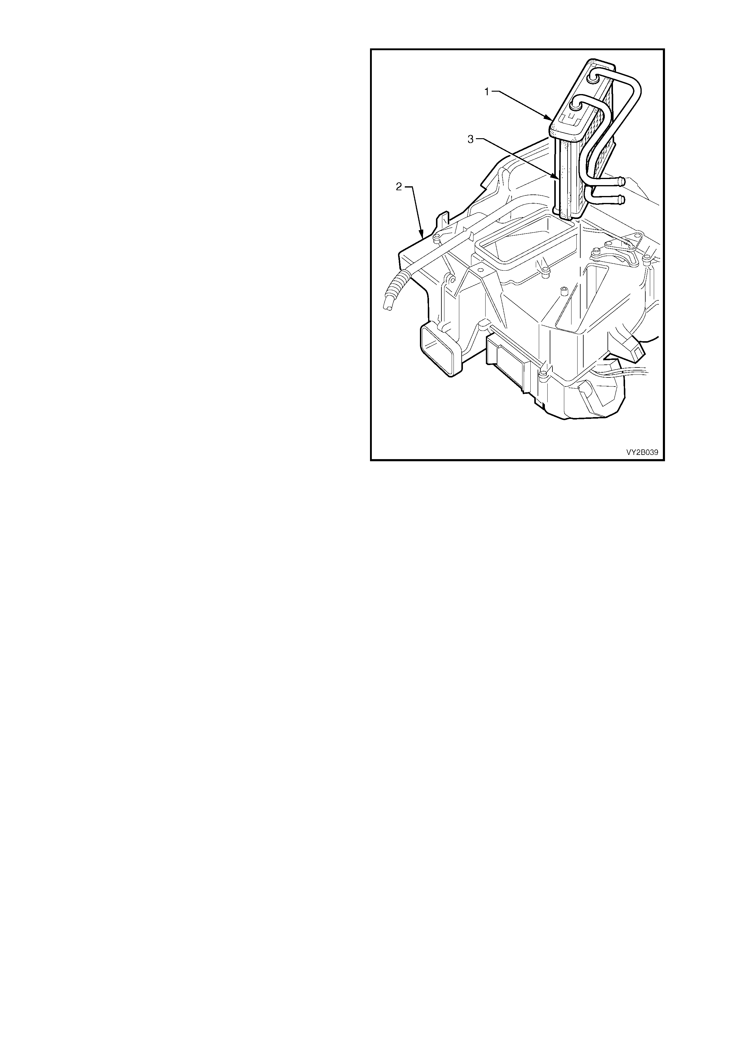
3. Remove the heater core (1) from the HVAC
case (2) without damaging the foam seal (3)
located on top and on both sides of the heater
core.
Figure 2B-83
REINSTALL – RHD
Installation of the heater core is in the reverse order of removal procedures noting the following points:
NOTE: Ensure the foam seals are not damaged when installing heater core to the HVAC case.
1. Install the heating, ventilation and air conditioning (HVAC) unit, refer to 3. HEATING, VENTILATION AND AIR
CONDITIONING (HVAC) UNIT in this Section.
2. Evacuate and charge the system with 775 – 825 g of R134a refrigerant, refer to Section 2C, 2.1 SYSTEM
CHARGING AND EVACUATION.
6. BLOWER MOTOR AND FAN ASSEMBLY
REMOVE – LHD
1. Remove the right-hand side instrument panel lower trim plate assembly, refer to Section 1A3,
3.1 INSTRUMENT PANEL LOWER TRIM PLATE ASSEMBLY.
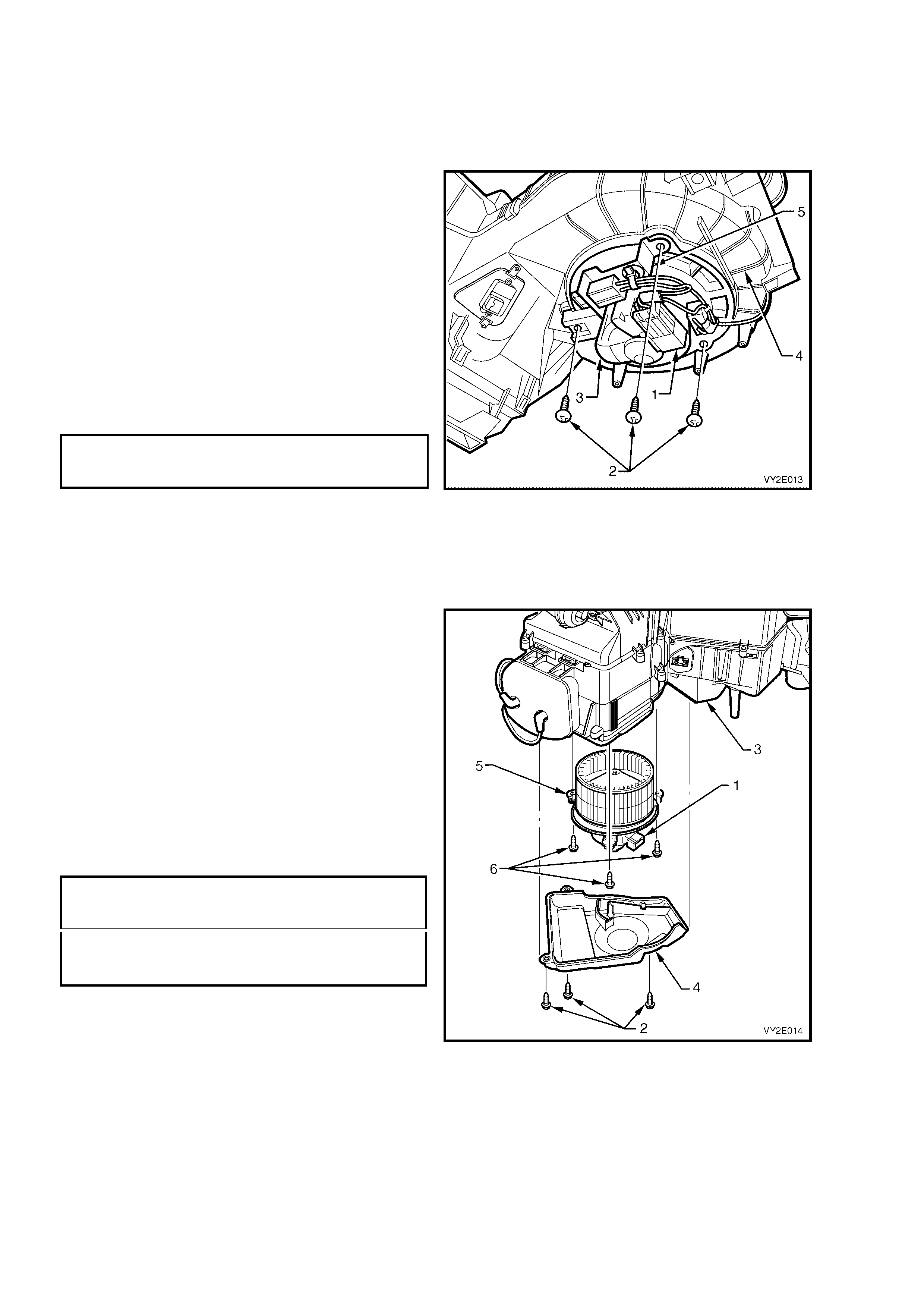
2. Disconnect the body harness connector to the
blower motor and fan assembly sub harness
connector (1).
3. Remove the three screws (2) and remove the
blower motor and fan assembly (3) from the
lower case housing (4)
4. Remove the blower motor and fan assembly
sub harness and bracket (5) from the blower
motor.
REINSTALL – LHD
Installation of the blower m otor and f an ass em bly is
the reverse order of removal procedures. Tighten
all screws to the specified torque.
BLOWER MOTOR AND FAN
ASSEMBLY ATTACHING SCREW
TORQUE SPECIFICATION 1.0 – 3.0 Nm
Figure 2B-84
LT Section – 08-150
REMOVE – RHD
1. Remove the left-hand side instrument panel lower trim plate assembly, refer to Section 1A3, 3.1
INSTRUMENT PANEL LOWER TRIM PLATE ASSEMBLY.
2. Disconnect the body harness connector to the
blower motor and fan assembly connector (1).
3. Remove the blower motor and fan assembly
cover screws (2) from the HVAC unit (3) and
move the cover (4) sufficiently to allow access
to the blower motor and fan assembly (5).
4. Remove the three blower motor and fan
assembly screws (6) and remove the blower
motor and fan assembly from the HVAC unit.
REINSTALL – RHD
Installation of the blower m otor and fan assem bly is
the reverse order of removal procedures. Tighten
all screws to the specified torque.
BLOWER MOTOR AND FAN ASSEMBLY
COVER ATTACHING SCREW
TORQUE SPECIFICATION 1.0 – 3.0 Nm
BLOWER MOTOR AND FAN ASSEMBLY
ATTACHING SCREW
TORQUE SPECIFICATION 1.0 – 3.0 Nm
Figure 2B-85
7. BLOWER MOTOR RESISTOR
REMOVE – LHD
1. Remove the right-hand side instrument panel lower trim plate assembly. Refer to
Section 1A3, 3.1 INSTRUMENT PANEL LOWER TRIM PLATE ASSEMBLY.
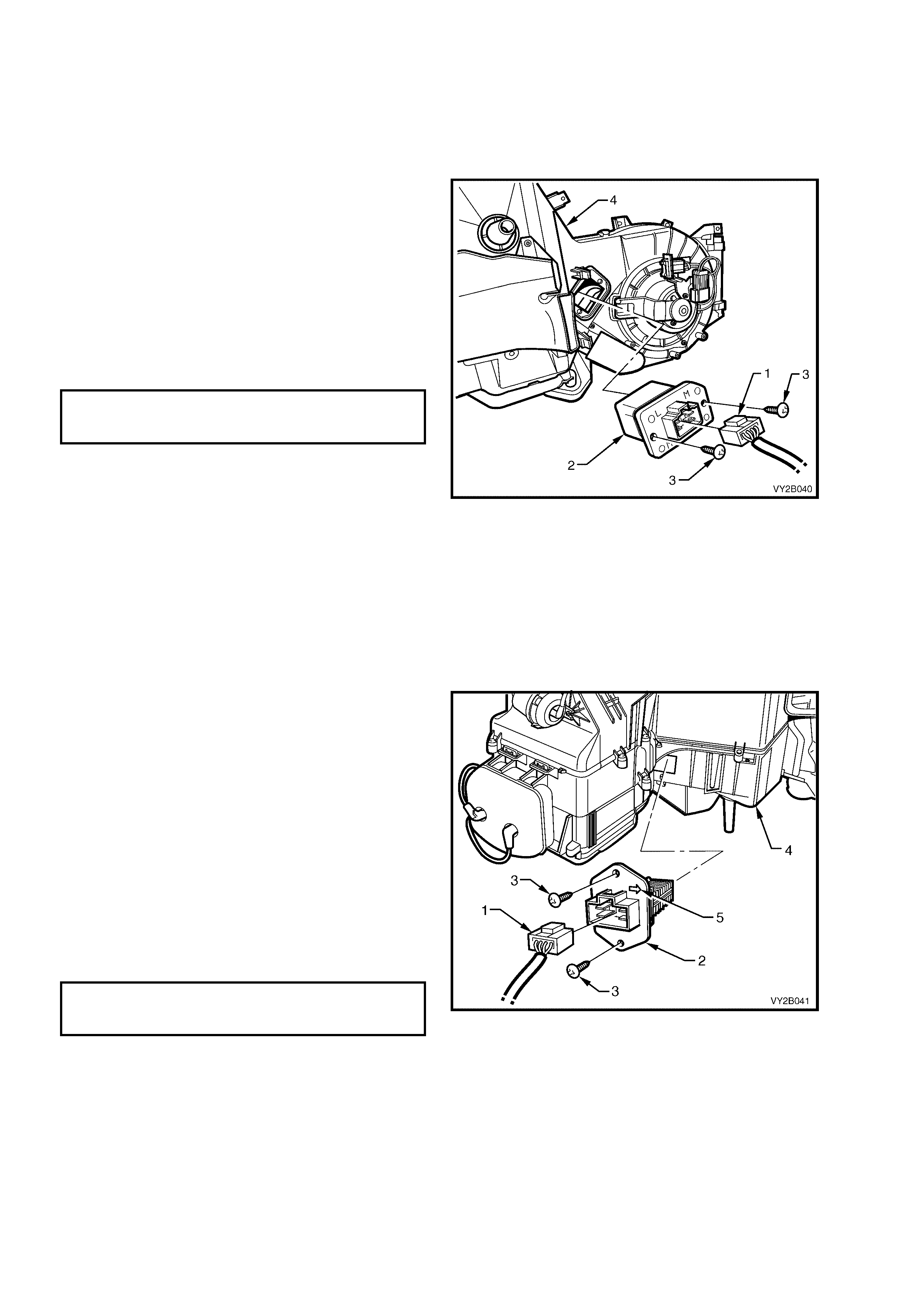
2. Remove the harness connector (1) from the
blower motor resistor (2).
3. Remove the two screws (3) retaining the
blower motor resistor to the HVAC unit (4).
4. Remove the blower motor resistor from below
the HVAC unit.
REINSTALL – LHD
Installation of the blower motor resistor is the
reverse order of removal procedures. Tighten all
screws to the specified torque.
BLOWER MOTOR RESISTOR
ATTACHING SCREW
TORQUE SPECIFICATION 1.0 – 3.0 Nm
Figure 2B-86
LT Section – 08-150
REMOVE – RHD
1. Remove the left-hand side instrument panel lower trim plate assembly. Refer to
Section 1A3, 3.1 INSTRUMENT PANEL LOWER TRIM PLATE ASSEMBLY.
2. Remove the instrument panel compartment assembly. Refer to Section 1A3, 3.2 INSTRUMENT PANEL
COMPARTMENT ASSEMBLY.
3. Remove the harness connector (1) from the
blower motor resistor (2).
4. Remove the two screws (3) attaching the
blower motor resistor to the side of the HVAC
unit (4).
5. Remove the blower motor resistor from the
HVAC unit.
REINSTALL – RHD
Installation of the blower motor resistor is the
reverse order of removal procedures noting the
following points:
1. Install the resistor with the arrow (5) pointing
towards the rear of the vehicle.
2. Tighten all screws to the specified torque.
BLOWER MOTOR RESISTOR
ATTACHING SCREW
TORQUE SPECIFICATION 1.0 – 3.0 Nm
Figure 2B-87
8. VACUUM TANK AND VACUUM ACTUATORS
8.1 VACUUM TANK
REMOVE – LHD
1. Remove the left-hand side instrument panel lower trim plate assembly. Refer to
Section 1A3, 3.1 INSTRUMENT PANEL LOWER TRIM PLATE ASSEMBLY.
2. Remove the two vacuum lines (1) from the
vacuum tank (2).
3. Remove the screw (3) located under the
vacuum tank.
4. Move the lower section of the vacuum tank
outwards and move the tank downwards to
disengage the retaining tangs (4) from the
locating slots (5) on the side of the HVAC
case (6).
5. Remove the vacuum tank.
REINSTALL – LHD
Installation of the vacuum tank is the reverse order
of removal procedures noting the following points:
NOTE: Ensure that the vacuum lines are installed
correctly. The black vacuum line (vacuum source)
is connected to tank port closer to the engine bay.
The white vacuum line is c onnected to the tank port
closer to the cabin.
1. Tighten all screws to the specified torque.
VACUUM TANK ATTACHING SCREW
TORQUE SPECIFICATION 1.0 – 3.0 Nm
Figure 2B-88
LT Section – 08-125
REMOVE – RHD
1. Remove the left-hand side instrument panel lower trim plate assembly. Refer to
Section 1A3, 3.1. INSTRUMENT PANEL LOWER TRIM PLATE ASSEMBLY
2. Remove the two vacuum lines (1) from the
vacuum tank (2).
3. Remove the screw (3) located under the
vacuum tank.
4. Move the lower section of the vacuum tank
outwards and move the tank downwards to
disengage the retaining tangs (4) from the
locating slots (5) on the side of the HVAC
case (6).
5. Remove the vacuum tank.
REINSTALL – RHD
Installation of the vacuum tank is the reverse order
of removal procedures noting the following points:
NOTE: Ensure that the vacuum lines are installed
correctly. The vacuum line with larger connecting
elbow (vacuum source) is connected to tank port
closer to the engine bay. The vacuum line with the
smaller connecting elbow is connected to the tank
port closer to the cabin.
1. Tighten all screws to the specified torque.
VACUUM TANK ATTACHING SCREW
TORQUE SPECIFICATION 1.0 – 3.0 Nm
Figure 2B-89
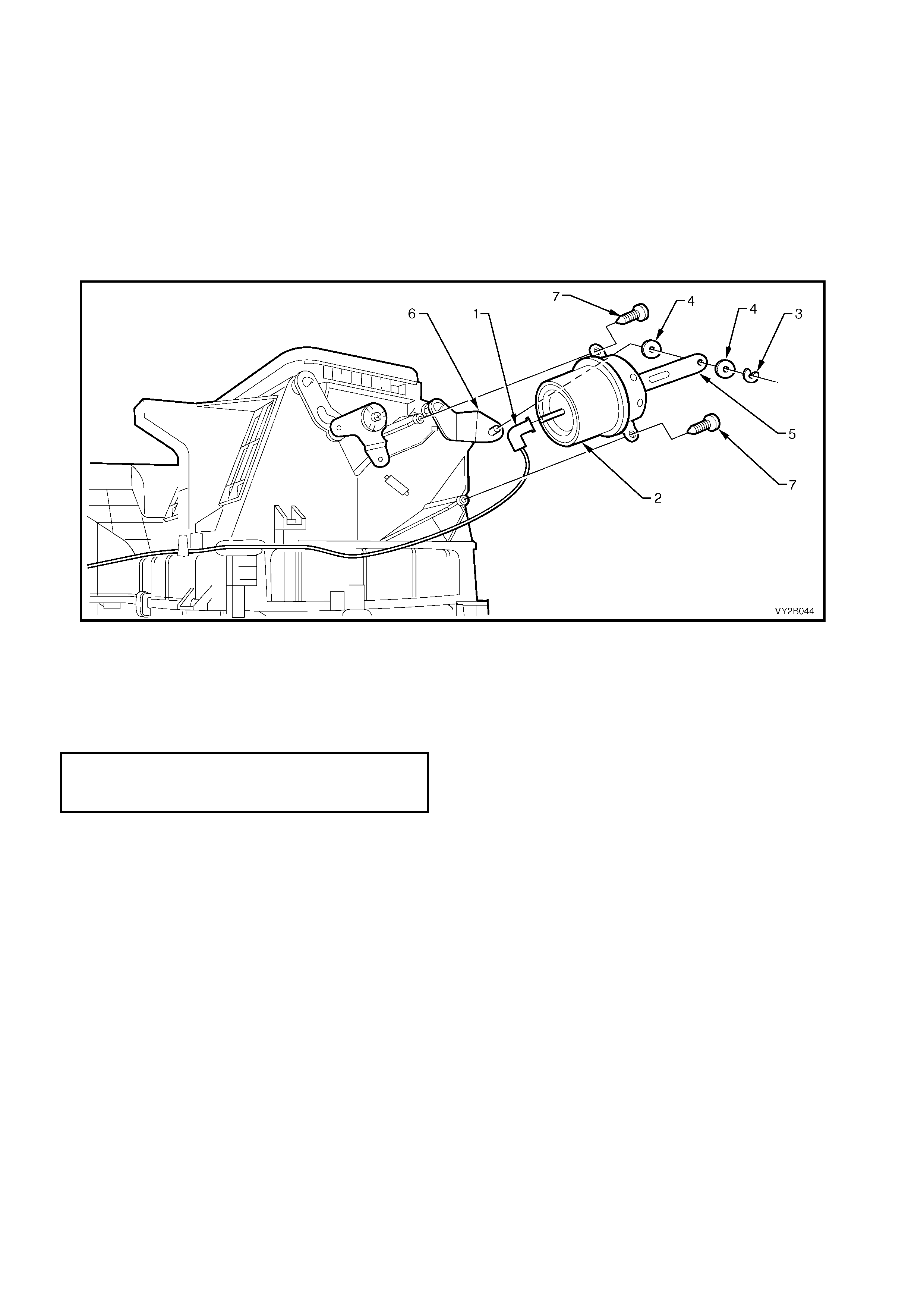
8.2 FRESH/RECIRCULATION (INTAKE) ACTUATOR
REMOVE – LHD
1. Remove the left-hand side instrument panel lower trim plate assembly. Refer to
Section 1A3, 3.1 INSTRUMENT PANEL LOWER TRIM PLATE ASSEMBLY.
2. Remove the BCM. Refer to Section 12J, 2.1 BODY CONTROL MODULE.
3. Remove the vacuum line (1) from the vacuum actuator (2).
4. Remove the e-clip (3), bushes (4) and actuator rod (5) from the lever (6).
5. Remove the vacuum actuator attaching screws (7).
6. Remove the vacuum actuator.
Figure 2B-90
REINSTALL – LHD
Installation of the fresh/recirculation (intake) vacuum actuator is in the reverse order of removal procedures noting
the following points:
1. Tighten all screws to the specified torque.
FRESH/RECIRCULATION
ACTUATOR ATTACHING SCREW
TORQUE SPECIFICATION 3.0 – 5.0 Nm
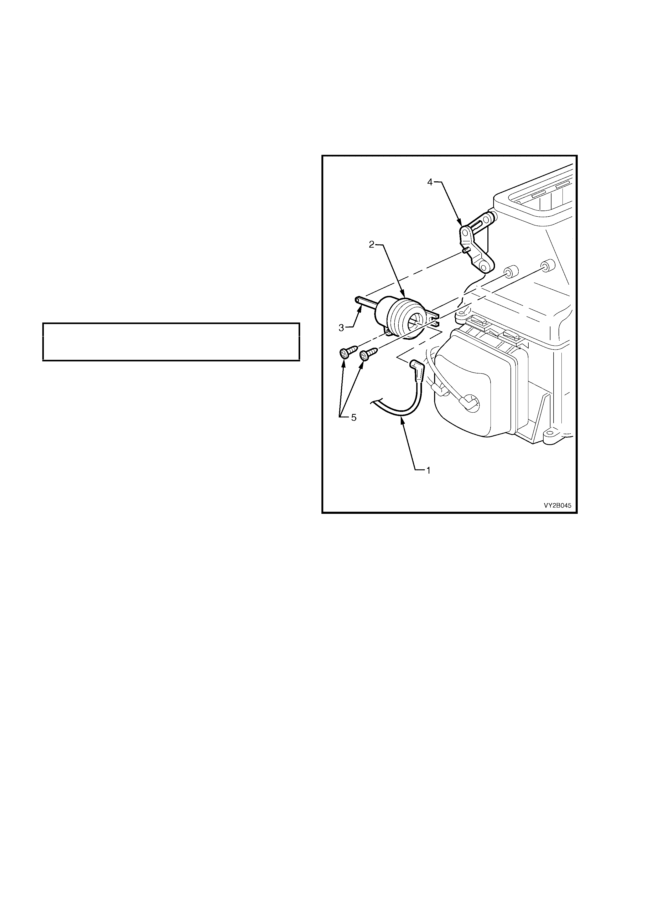
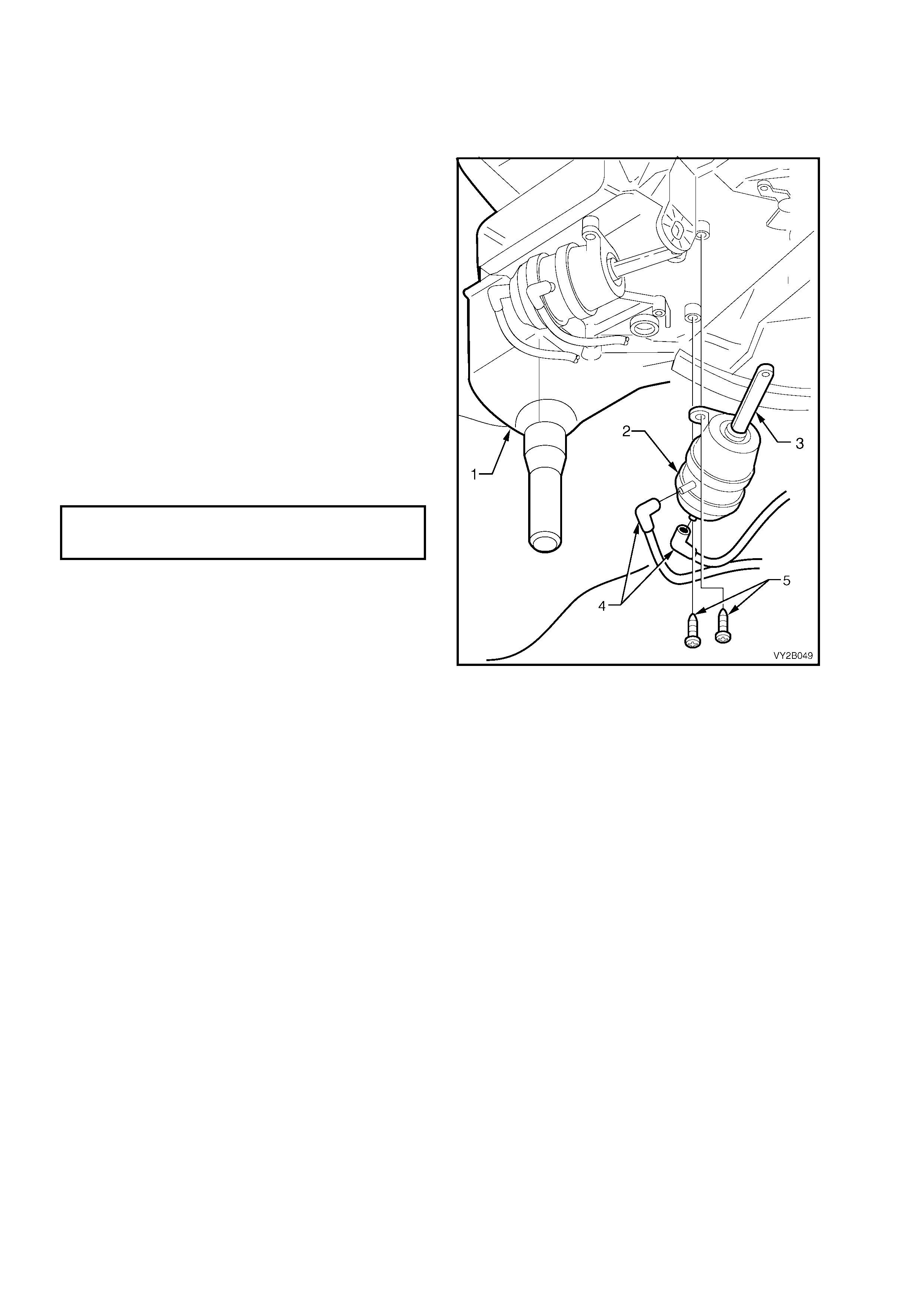
REMOVE – RHD
LT Section – 08-150
1. Remove the left-hand side instrument panel lower trim plate assembly. Refer to
Section 1A3, 3.1 INSTRUMENT PANEL LOWER TRIM PLATE ASSEMBLY.
2. Rem ove the left-hand s ide instrum ent panel outer cover. Ref er to Section 1A3, 3.17 INSTRUMENT PANEL
OUTER COVER.
3. Remove the vacuum tank. Refer to 8.1 VACUUM TANK in this Section.
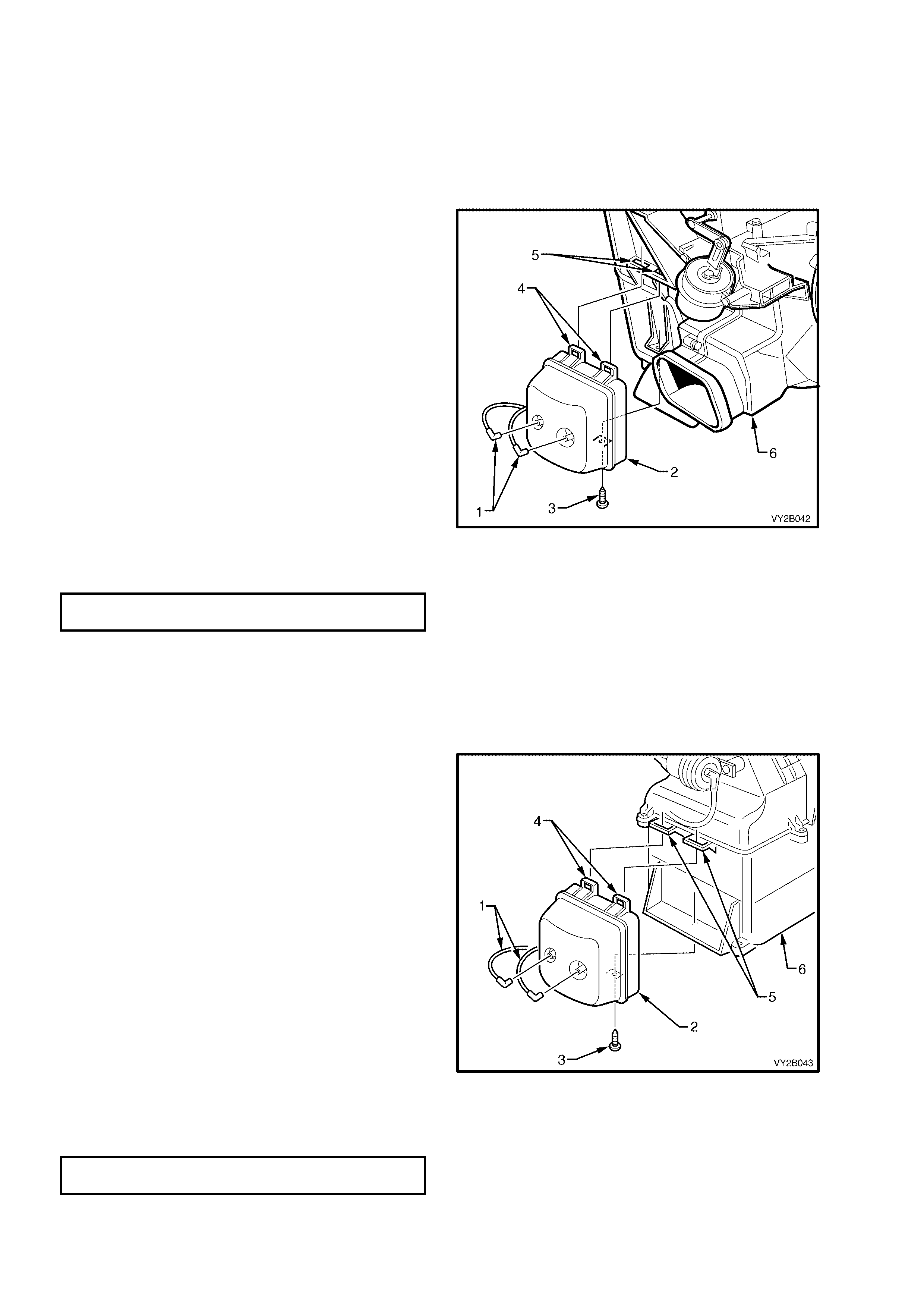
4. Remove the vacuum line (1) at the vacuum
actuator (2).
5. Remove the vacuum actuator rod (3) from the
vacuum actuator lever (4).
6. Remove the two screws (5).
7. Remove the vacuum actuator.
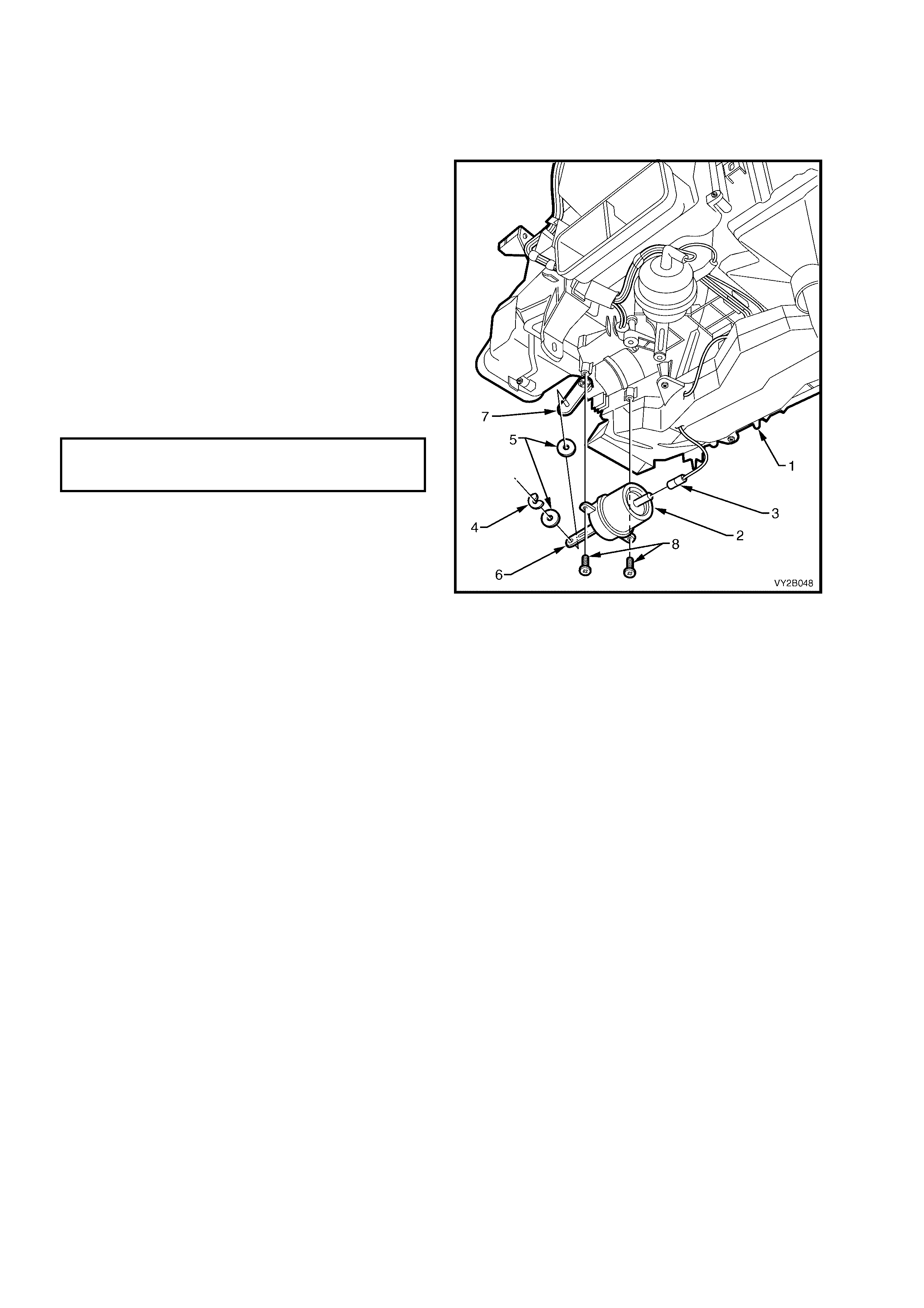
REINSTALL – RHD
Installation of the fresh/recirculation vacuum
actuator is the r ever se or der of re moval procedur es
noting the following:
1. Tighten all screws to the specified torque.
FRESH/RECIRCULATION
ACTUATOR ATTACHING SCREW
TORQUE SPECIFICATION 3.0 – 5.0 Nm
Figure 2B-91
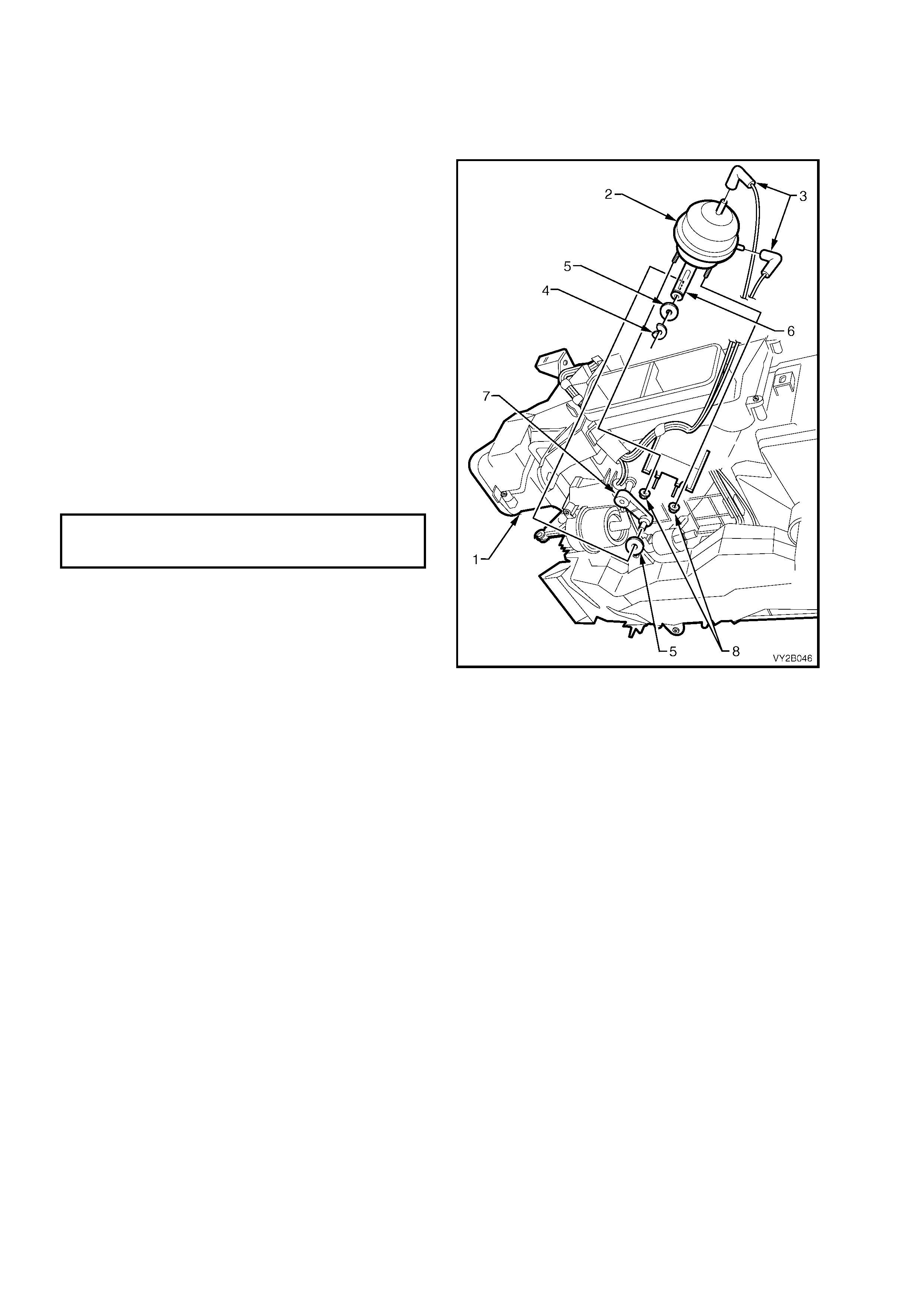
8.3 FACE ACTUATOR
REMOVE – LHD
1. Remove the floor console, instrument panel and HVAC assemblies, refer to 3. HEATING, VENTILATION
AND AIR CONDITIONING (HVAC) UNIT in this Section.
2. From the underside of the HVAC unit (1),
locate the face actuator (2).
3. Remove the vac uum lines (3) from the vacuum
actuator.
4. Remove the e-clip (4), rod bushes (5) and the
actuator rod (6) from the lever (7).
5. Remove the two vacuum actuator nuts (8).
6. Remove the vacuum actuator.
REINSTALL – LHD
Installation of the face vacuum actuator is the
reverse order of removal procedures noting the
following points:
NOTE: Ensure that the vacuum lines are installed
correc tly. The blue vac uum line is c onnected to the
side of the face actuator. The white vacuum line is
connected to the back of the face actuator.
1. Tighten the nuts to the specified torque.
FACE ACTUATOR
ATTACHING NUT
TORQUE SPECIFICATION 3.0 – 5.0 Nm
Figure 2B-92
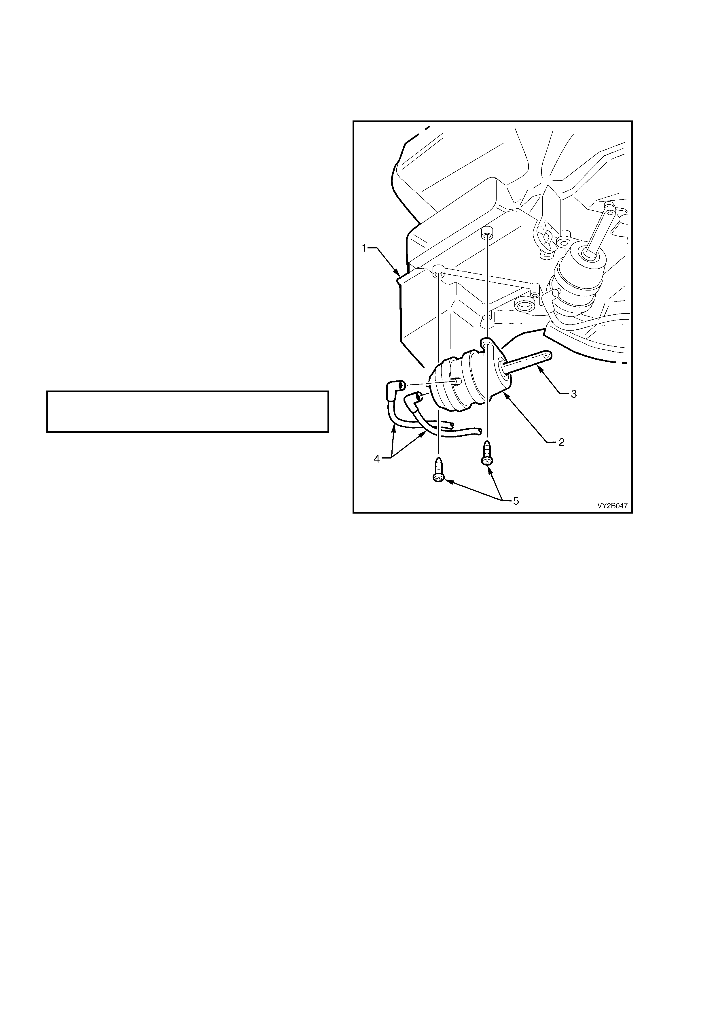
LT Section – 08-150
REMOVE – RHD
1. Remove the floor console, instrument panel and HVAC assemblies, refer to 3. HEATING, VENTILATION
AND AIR CONDITIONING (HVAC) UNIT in this Section.
2. From the underside of the HVAC unit (1),
locate the face actuator (2).
3. Remove the vacuum actuator rod (3) from the
door lever.
4. Remove the vac uum lines (4) from the vacuum
actuator.
5. Remove the two vacuum actuator attaching
screws (5).
REINSTALL – RHD
Installation of the face vacuum actuator is the
reverse order of removal procedures noting the
following points:
NOTE: Ensure that the vacuum lines are installed
correctly. The green vacuum line is connected to
the side of the face actuator. The white vacuum line
is connected to the back of the face actuator.
1. Tighten the screws to the specified torque.
FACE ACTUATOR
ATTACHING SCREW
TORQUE SPECIFICATION 3.0 – 5.0 Nm
Figure 2B-93
8.4 FOOT ACTUATOR
REMOVE – LHD
1. Remove the floor console, instrument panel and HVAC assemblies, refer to 3. HEATING, VENTILATION
AND AIR CONDITIONING (HVAC) UNIT in this Section.
2. From the underside of the HVAC unit (1),
locate the foot actuator (2).
3. Remove the vacuum line (3) from the vacuum
actuator.
4. Remove the e-clip (4), rod bushes (5) and the
actuator rod (6) from the lever (7).
5. Remove the vacuum actuator two screws (8).
5. Remove the vacuum actuator.
REINSTALL – LHD
Installation of the foot vacuum actuator is the
reverse order of removal procedures noting the
following:
1. Tighten the screws to the specified torque.
FOOT ACTUATOR
ATTACHING SCREW
TORQUE SPECIFICATION 3.0 – 5.0 Nm
Figure 2B-94
LT Section – 08-150
REMOVE – RHD
1. Remove the floor console, instrument panel and HVAC assemblies, refer to 3. HEATING, VENTILATION
AND AIR CONDITIONING (HVAC) UNIT in this Section.
2. From the underside of the HVAC unit (1),
locate the foot actuator (2).
3. Remove the vacuum actuator rod (3) from the
door lever.
4. Remove the vac uum lines (4) from the vacuum
actuator.
5. Remove the two vacuum actuator attaching
screws (5).
REINSTALL – RHD
Installation of the foot vacuum actuator is the
reverse order of removal procedures noting the
following points:
NOTE: Ensure that the vacuum lines are installed
correctly. The orange vacuum line is connected to
side of the foot actuator. The pink vacuum line is
connected to the back of the foot actuator.
1. Tighten all screws to the specified torque.
FOOT ACTUATOR
ATTACHING SCREW
TORQUE SPECIFICATION 3.0 – 5.0 Nm
Figure 2B-95
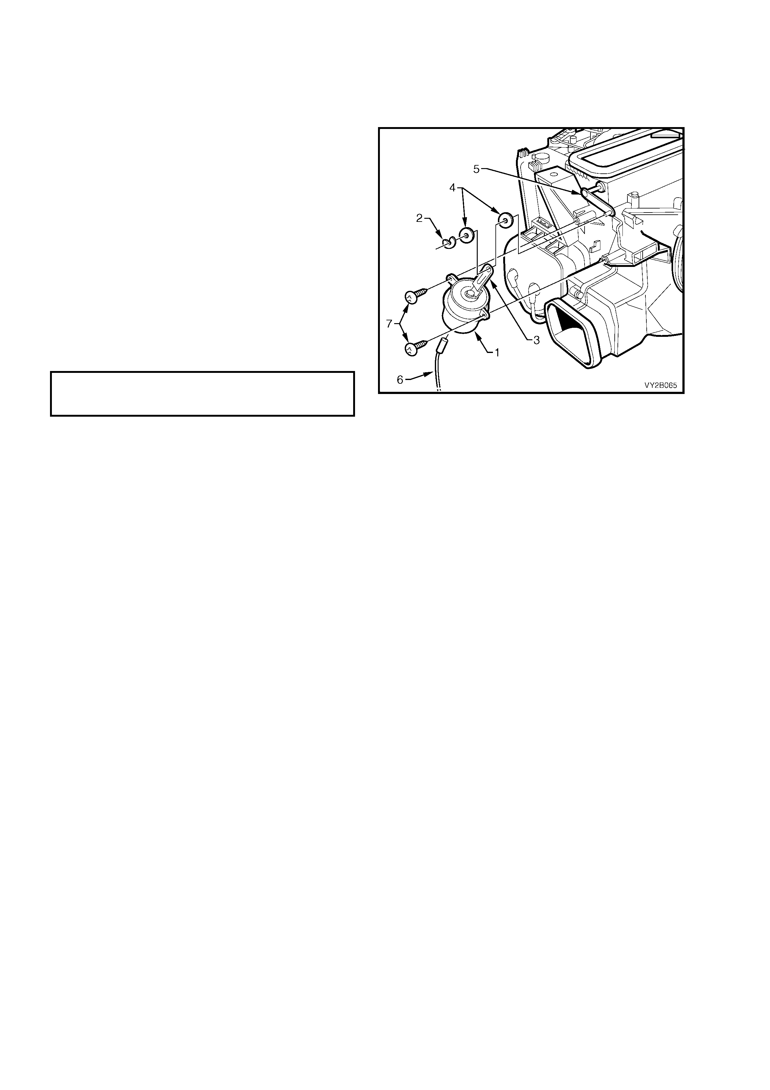
8.5 DEMIST ACTUATOR – LHD ONLY
REMOVE
1. Remove instrument cluster. Refer to Section 1A3, 3.14 INSTRUMENT CLUSTER.
2. Lower the instrument panel lower trim panel assembly.
3. Through the aperture in the instrument panel,
locate the vacuum actuator (1) and remove the
e-clip (2) and the actuator rod (3), rod
bushes (4) from the lever (5).
4. Remove the vacuum line (6) from the vacuum
actuator.
5. Remove the two vacuum actuator attaching
screws (7).
6. Remove the vacuum actuator.
REINSTALL
Installation of the demist vacuum actuator is the
reverse order of removal procedures noting the
following:
1. Tighten all screws to the specified torque.
DEMIST ACTUATOR
ATTACHING SCREW
TORQUE SPECIFICATION 3.0 – 5.0 Nm
Figure 2B-96

9. AI R CONDI TIONING HOSE AND PI PE CONNECTI O NS AND RETAI NERS
LT Section – 08-200
REMOVE AND REINSTALL
The following four Figures provide under hood views of the air conditioning hose and pipe connections, and
retainers. Refer to these Figures when removing and installing these components.
• For V6 left-hand drive models, refer to Figure 2B-62
• For V6 and V6 Supercharged right-hand drive models, refer to Figure 2B-63
• For GEN III V8 left-hand drive models, refer to Figure 2B-64
• For GEN III V8 right-hand drive models, refer to Figure 2B-6 5
IMPORTANT: The total quantity of lubricating oil in the air conditioning system must be maintained. If a
compressor, evaporator, condenser, filter drier receiver, hose or pipe is to be replaced, a specified quantity of
lubricating oil must be added to the system to compensate for oil removed with the original component. Refer to
Section 2C, 2.4 LUBRICATING OIL COMPENSATION.
Techline
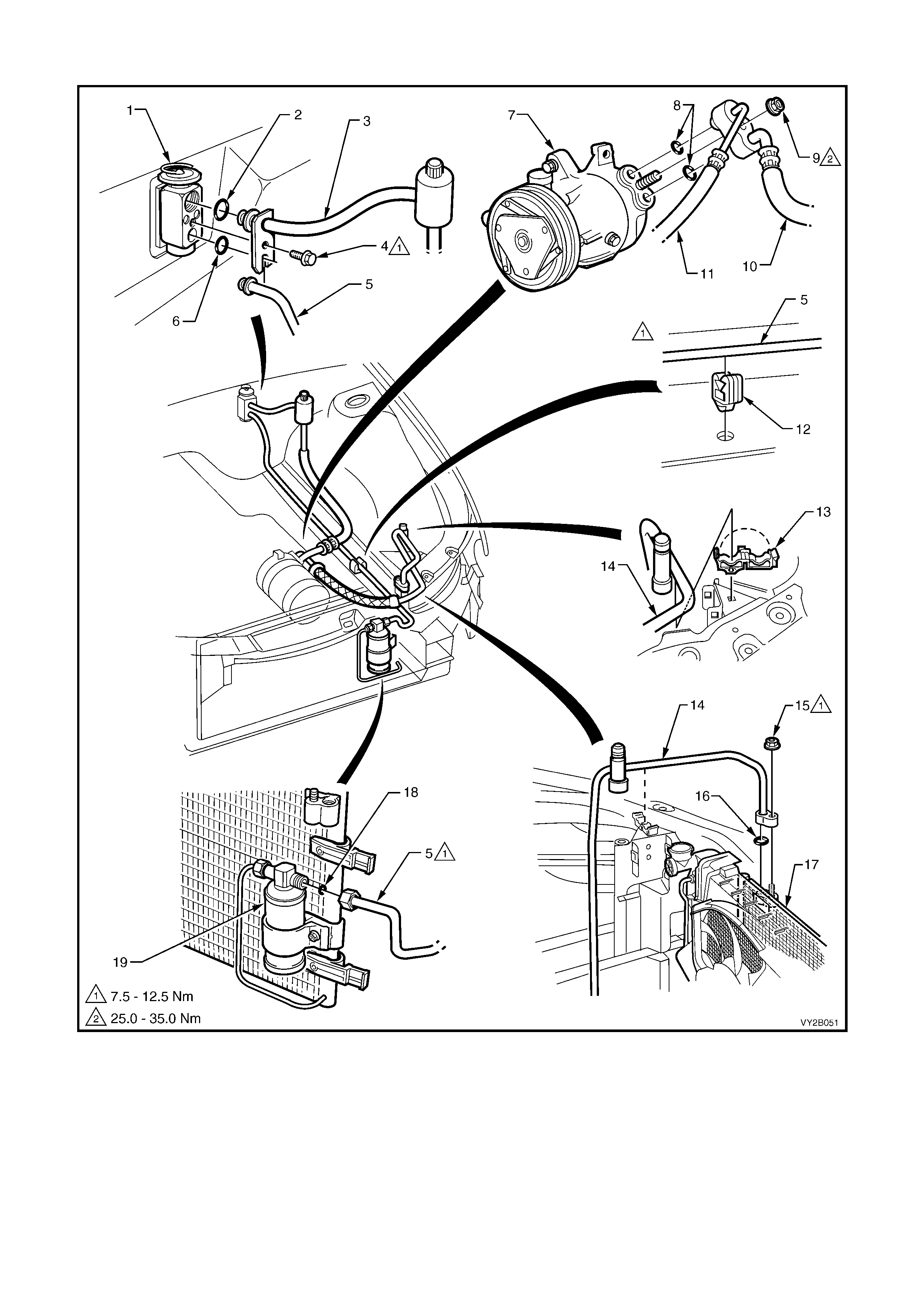
A/C HOSE AND PIPE CONNECTIONS, AND RETAINERS – V6 ENGINE LHD
Figure 2B-97
Legend
1. Thermal Expansion Valve
(TXV) 6. O-ring – TXV
Discharge 11. Discharge Hose/
Tube 16. O-ring – Condenser
2. O-ring – TXV Suction 7. Compressor 12. Liquid Tube Clip 17. Condenser
3. Suction Tube 8. O-ring – Compressor 13. Discharge Tube Clip 18. O-ring – FDR
4. Screw 9. Nut 14. Discharge Tube 19. Filter Drier Receiver
5. Liquid Tube 10. Suction Hose/Tube 15. Nut (FDR)
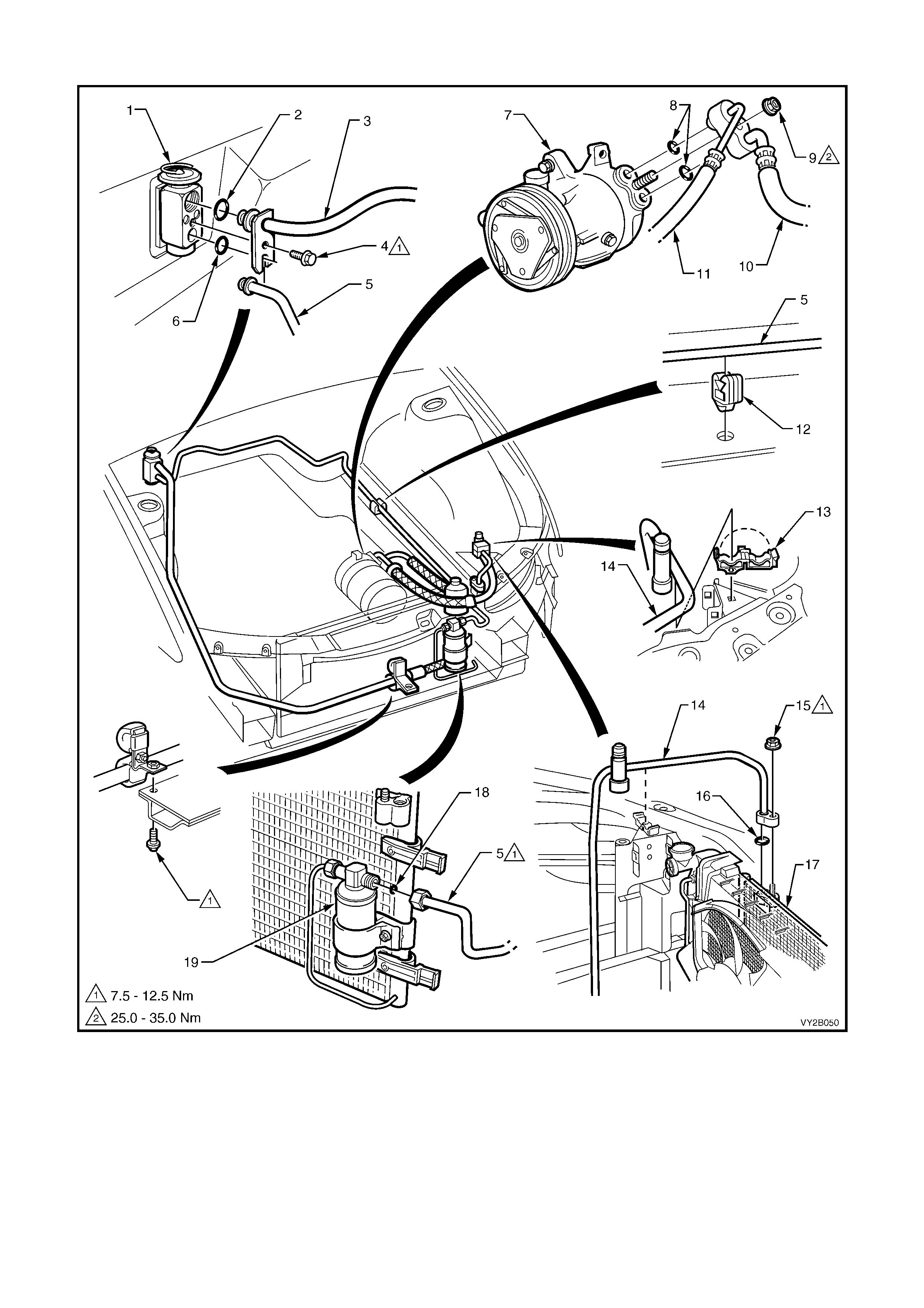
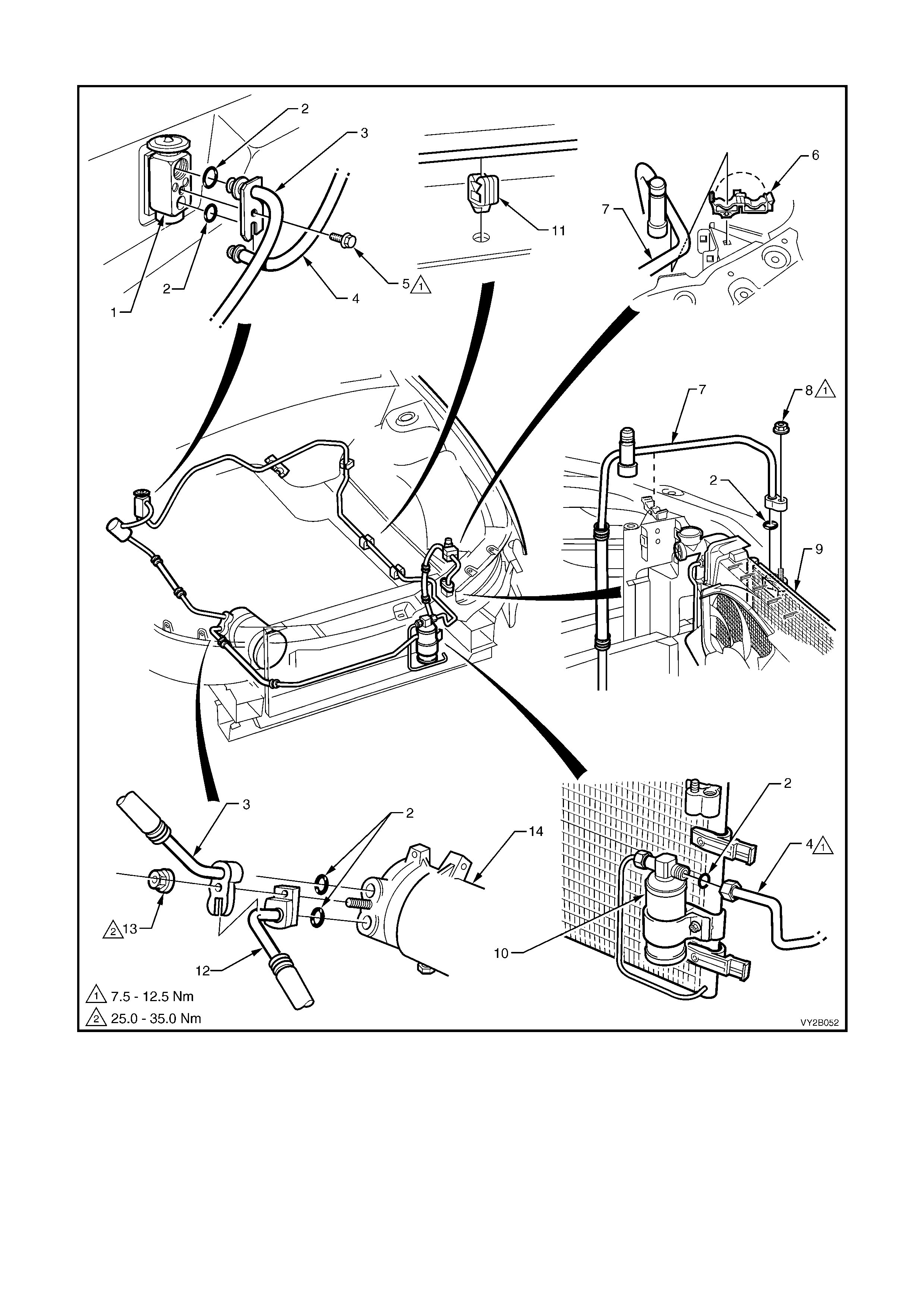
A/C HOSE AND PIPE CONNECTIONS, AND RETAINERS – V6 AND V6 SUPERCHARGED ENGINES RHD
Figure 2B-98
Legend
1. Thermal Expansion Valve
(TXV) 6. O-ring – TXV
Discharge 11. Discharge Hose/
Tube 16. O-ring – Condenser
2. O-ring – TXV Suction 7. Compressor 12. Liquid Tube Clip 17. Condenser
3. Suction Tube 8. O-ring – Compressor 13. Discharge Tube Clip 18. O-ring – FDR
4. Screw 9. Nut 14. Discharge Tube 19. Filter Drier Receiver
5. Liquid Tube 10. Suction Hose/Tube 15. Nut (FDR)
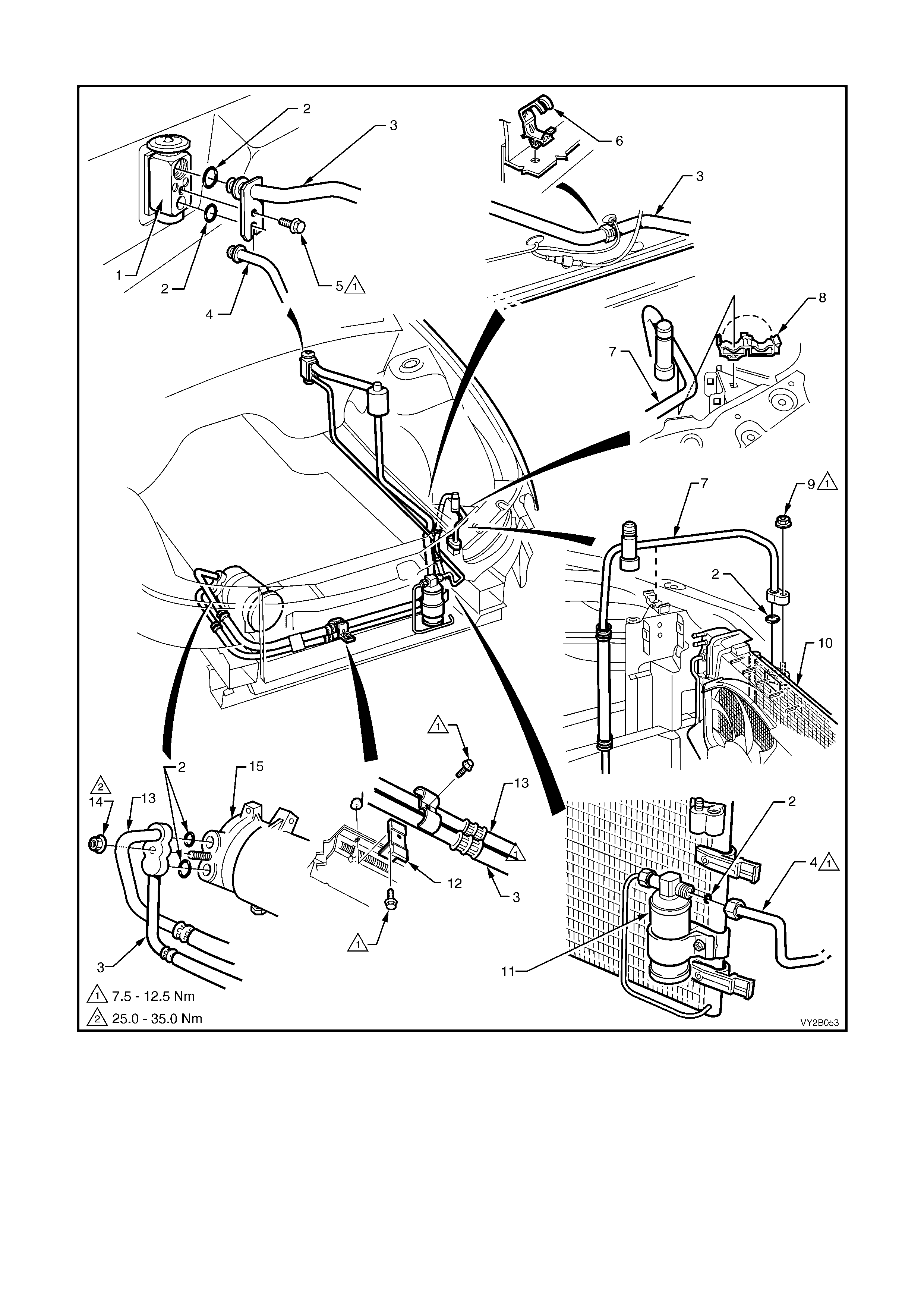
A/C HOSE AND PIPE CONNECTIONS, AND RETAINERS – GEN III V8 ENGINE LHD
Figure 2B-99
Legend
1. Thermal Expansion Valve (TXV) 6. Discharge Tube Retaining Clip 11. Retaining Clamp
2. O-Ring 7. Discharge Tube 12. Discharge Hose/Tube
3. Suction Hose/Tube 8. Discharge Tube Retaining Nut 13. Retaining Nut
4. Liquid Tube 9. Condenser 14. Compressor
5. Retaining Screw 10. Filter Drier Receiver (FDR)
A/C HOSE AND PIPE CONNECTIONS, AND RETAINERS – GEN III V8 ENGINE RHD
Figure 2B-100
Legend
1. Thermal Expansion Valve (TXV) 6. Suction Tube Retaining Clip 11. Filter Drier Receiver (FDR)
2. O-Ring 7. Discharge Tube 12. Retaining Clamp
3. Discharge Hose/Tube 8. Discharge Tube Retaining Clip 13. Suction Hose/Tube
4. Liquid Tube 9. Discharge Tube Retaining Nut 14. Retaining Nut
5. Retaining Screw 10. Condenser 15. Compressor
10. THERMAL EXPANSION VALVE (TXV)
LT Section – 08-200
REMOVE
1. Recover the refrigerant from the A/C system, refer to Section 2C, 2.1 SYSTEM CHARGING AND
EVACUATION.
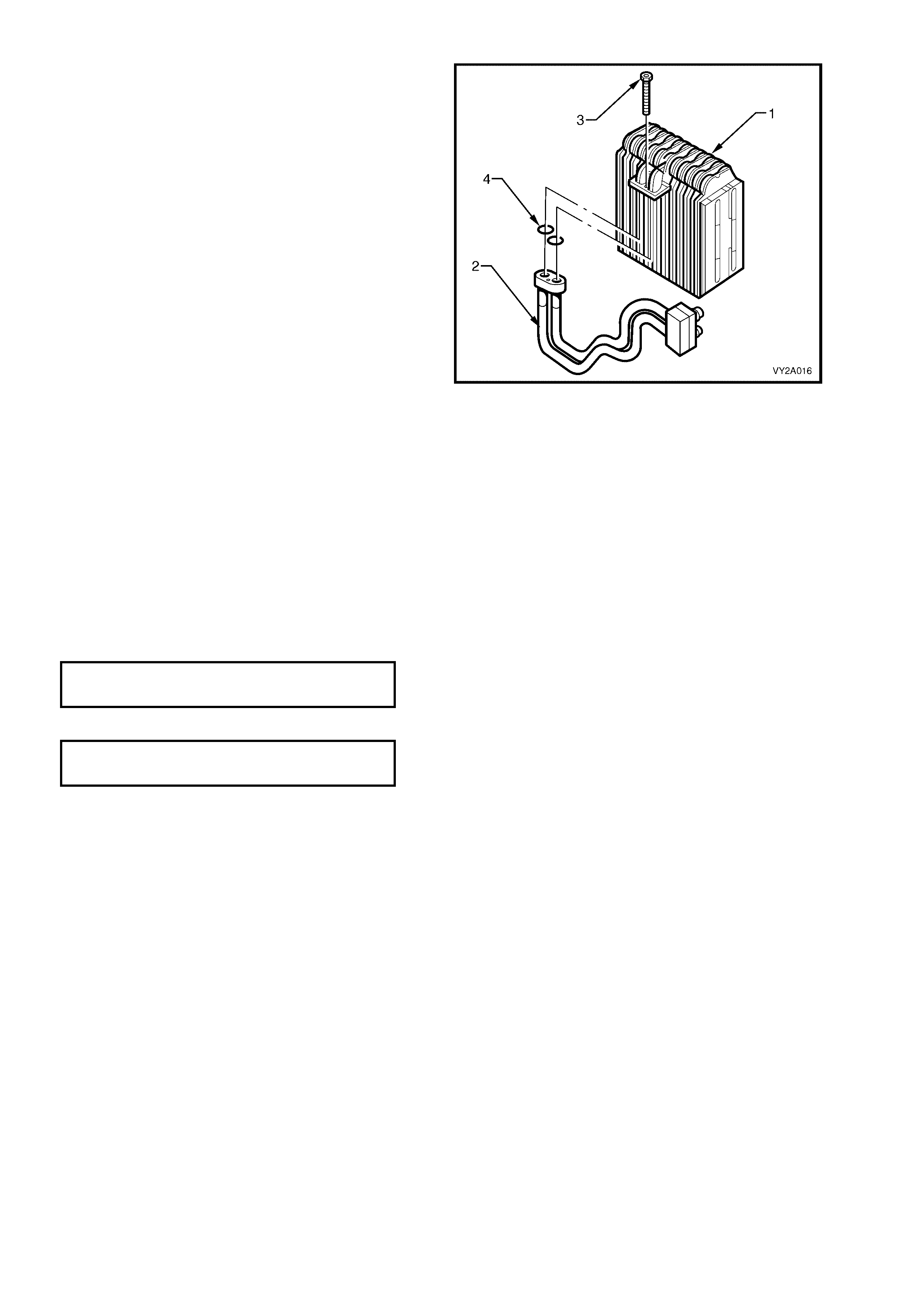
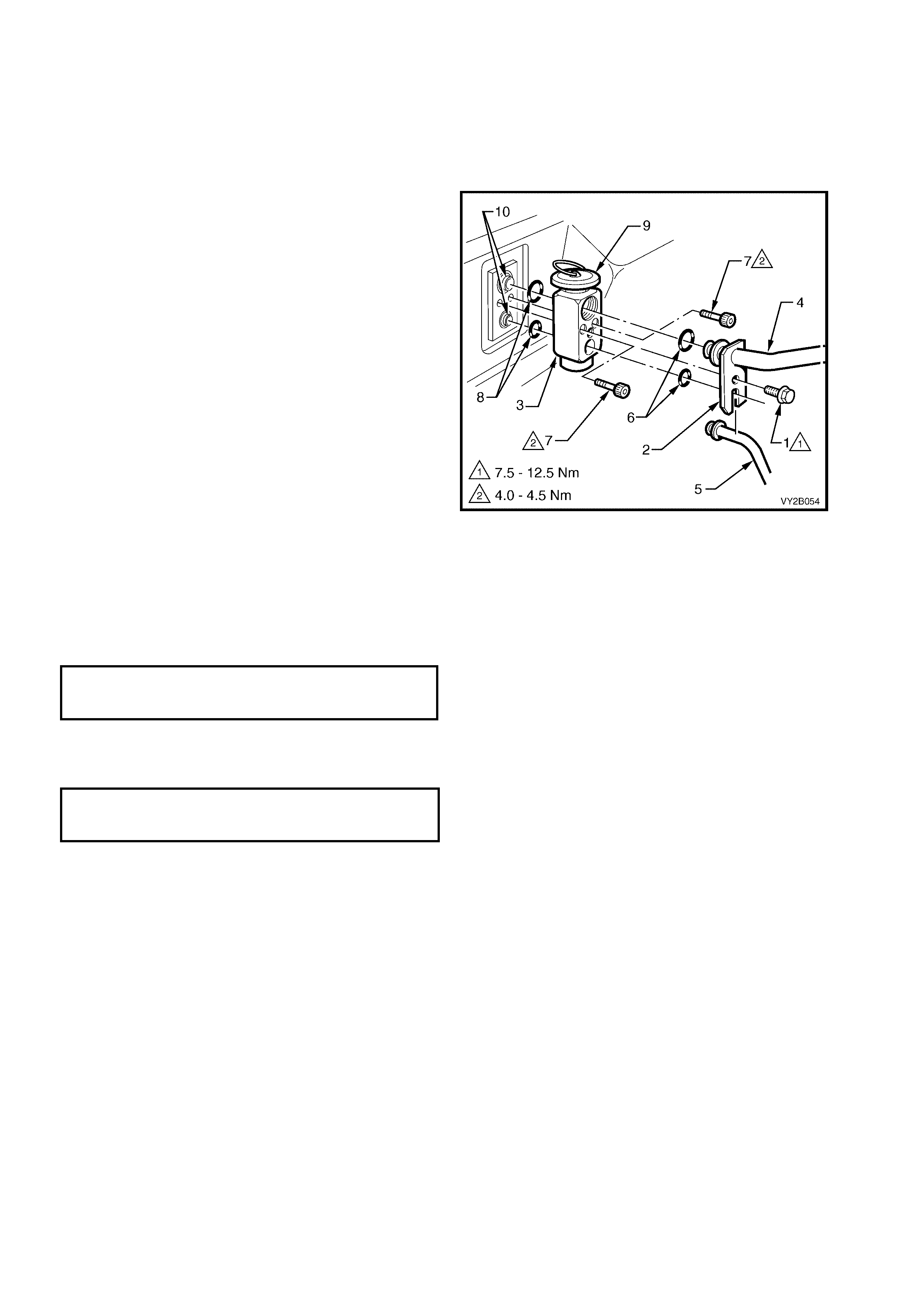
2. Remove the washer f ac ed sc r ew (1) retaining the
tube plate (2) to the Thermal Expansion
Valve (TXV) (3).
3. Remove the plate/suction tube (4) and the liquid
tube (5).
4. Remove and discard the liquid and suction line
O-rings (6).
5. Unscrew the two cap screws (7) and remove the
TXV.
6. Remove and discard the evaporator tube
O-rings (8).
REINSTALL
NOTE: The total quantity of lubricating oil in the air
conditioning system must be maintained. If
lubricating oil loss has occurred during TXV
replacement, oil must be added to the system to
compensate.
1. Lubricate and fit two new O-rings to the
evaporator tubes.
2. Install the TXV with the diaphragm (9) facing
upwards, onto the evaporator tubes (10).
3. Secure the TXV to the evaporator tube plate
using the two cap screws.
TXV TO EVAPORATOR TUBES
SECURING SCREWS
TORQUE SPECIFICATION 4.0 – 4.5 Nm
Figure 2B-101
4. Fit two new lubricated O-rings to the suction tube and liquid tube.
5. Install the liquid and suction tubes and retaining plate onto the TXV.
6. Secure using original washer faced screw.
LIQUID AND SUCTION TUBE
RETAINING PLATE TO TXV SCREW
TORQUE SPECIFICATION 7.5 – 12.5 Nm
7. Evacuate and charge the A/C system with 775 – 825 g of R134a refrigerant, refer to
Section 2C, 2.1 SYSTEM CHARGING AND EVACUATION.
11. A/ C PRESSURE TRANSDUCER
LT Section – 08-200
REMOVE AND REINSTALL
To remove and install the A/C pressure transducer, refer to the following:
• For V6 engines: Section 6C1-3, 6.4 A/C REFRIGERANT SENSOR.
• For V6 Supercharged engines: Section 6C2-3, 6.6 A/C REFRIGERANT SENSOR
• For GEN III V8 engines: Section 6C3-3, 5.3 A/C REFRIGERANT SENSOR
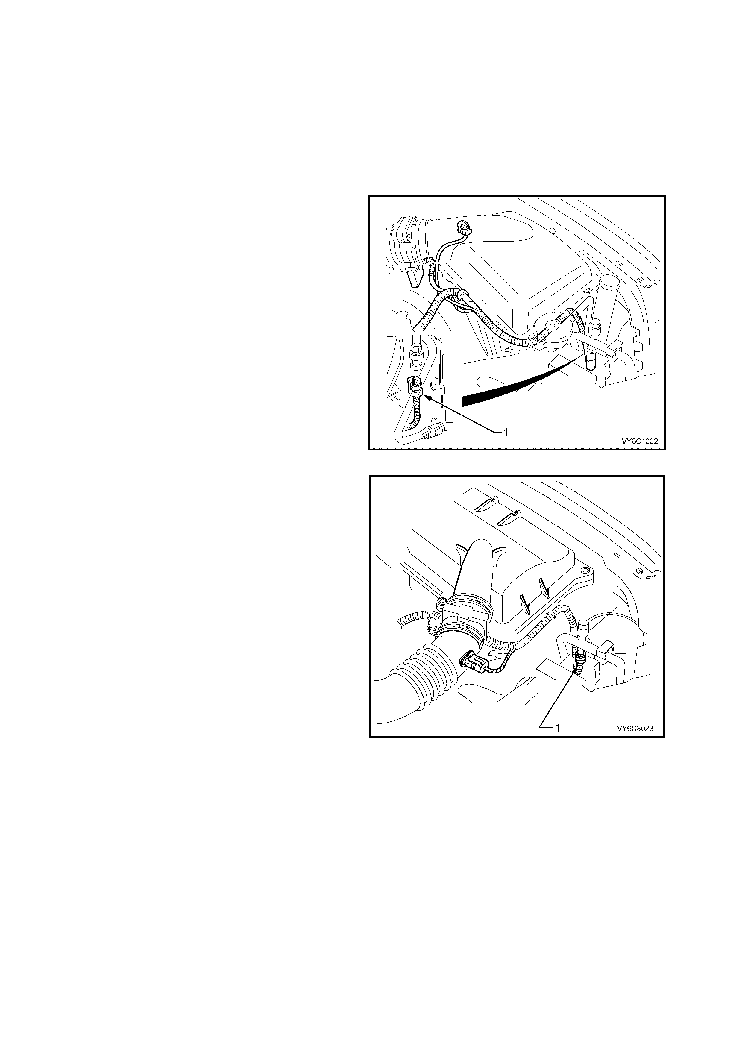
Figure 2B-102 shows the location of the A/C
pressur e transducer (1) f or V6 and V6 Superchar ged
engines.
Figure 2B-102
Figure 2B-103 shows the location of the A/C
pressure transducer (1) for GEN III V8 engines.
Figure 2B-103
12. CONDENSER
12.1 V6 AND V6 SUPERCHARGED ENGINE
LT Section – 08-200
REMOVE
1. Recover the refrigerant from the A/C system, refer to Section 2C, 2.1 SYSTEM CHARGING AND
EVACUATION.
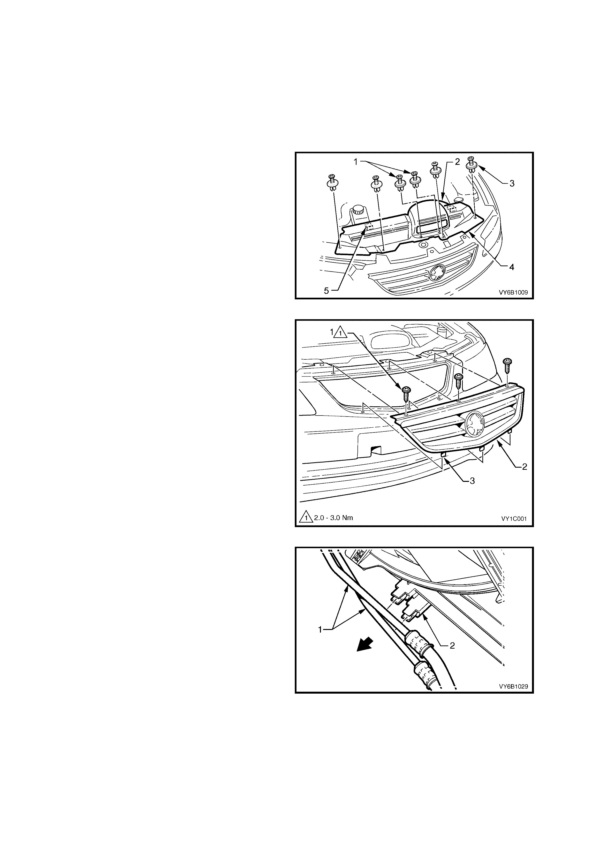
2. Remove the cold air intake duct and radiator
upper shroud retainers (1 and 2). Remove the
cold air intake duct (2), then disengage the
shroud locating tabs (5) by pulling the
shroud (4) towards front of vehicle, prior to
removal.
Figure 2B-104
3. On models with removable grille, remove the
three screws (1) securing the radiator grille
assembly (2) and raise that grille so that
locating tabs (3) disengage from the bumper
fascia and remove.
NOTE: To access air conditioning components in
front of the condenser on V2 Coupe models, it will
be necessary to raise the vehicle and remove the
under vehicle air baffles. Refer to
Section 0A, GENERAL INFORMATION for the
location of jacking and support points. Refer to
Section 6B-3, 2.13 AIR BAFFLES.
Figure 2B-105
4. If fitted, release each of the automatic
transm ission cooling pipes (1) from the integral
clips (2) on the fan shroud.
Figure 2B-106
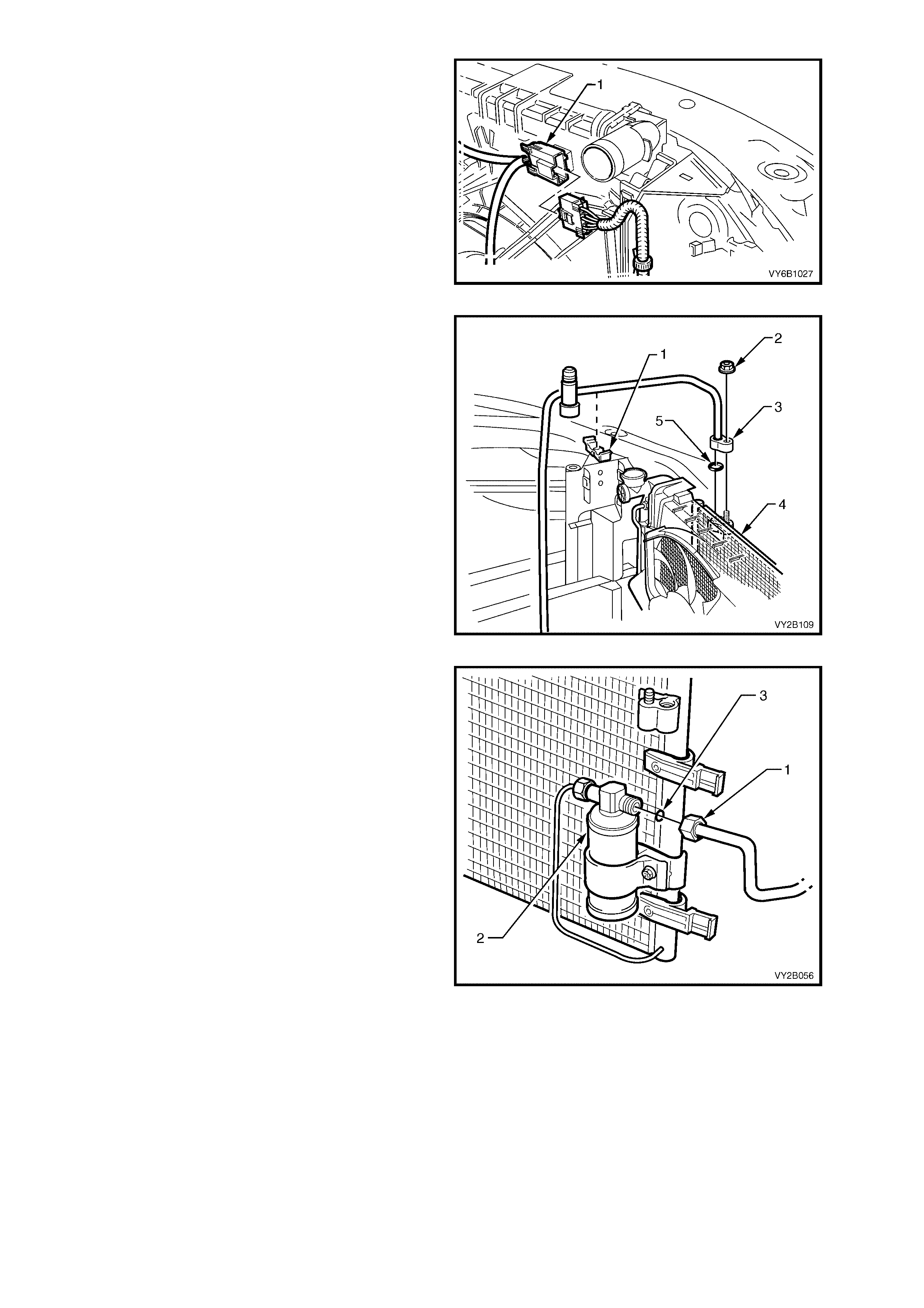
5. Depress tang on main wiring harness to cooling
fan motor wiring harness connector (1) and
separate the connector.
Figure 2B-107
6. Release the discharge tube retaining clip (1).
7. Remove the nut (2) retaining the discharge
hose pad fitting (3) to the condenser (4).
8. Cap all open tubes/hoses to avoid moisture
from entering the system.
9. Discard the O-ring (5).
Figure 2B-108
10. Remove the liquid tube union (1) from the
FDR (2) and discard the O-ring (3).
Figure 2B-109
11. On OCC (Auto A/C) equipped models
disconnect the harness connector (1) from the
ambient temperature sensor (2). Do not
attempt to remove the bracket (3) from the
condenser (4).
Figure 2B-110
12. Using a screwdriver, compress and lever out
radiator retaining clips (1) from radiator upper
mounting brackets.
IMPORTANT: Do not lift the radiator assembly by
lifting on the fan rings as this will bend the fan
motor shaft and create an unnecessary vibration.
13. Lift radiator assembly upwards out of lower
insulators. Slant the upper section of the
assembly behind the radiator support sheet
metal work and allow it to remain there.
Figure 2B-111
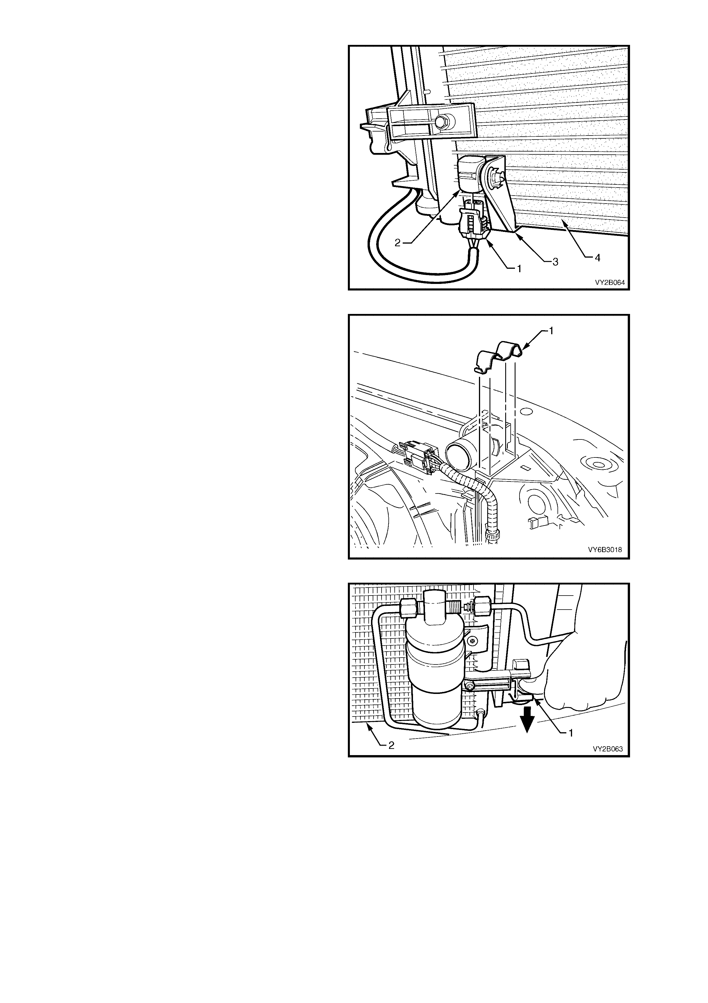
14. Release one of the clips securing the
condenser to the radiator Do this by pressing
down as indicated by the arrow, on the locking
retainer (1) with the fingers of one hand, while
lifting the condenser assembly (2) with the
other hand. Repeat for the other side.
Figure 2B-112
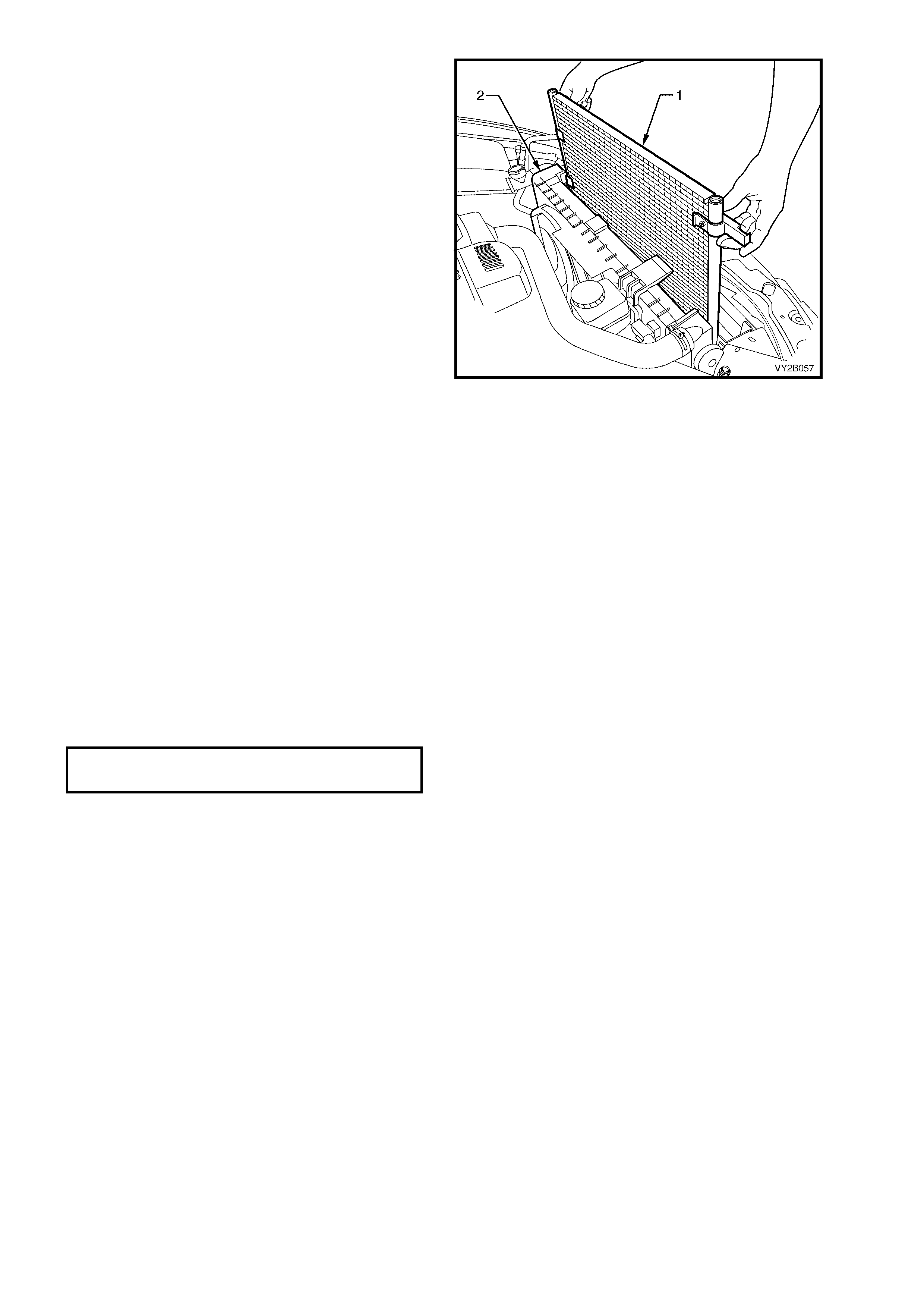
15. Lift the condenser assembly (1) upwards
suff ic iently to clear the mounts moulded to f r ont
of the radiator (2). Rem ove the condenser from
engine bay with the FDR attached.
NOTE: If the FDR is to be removed from the
condenser mark the mounting position of the FDR
in relation to the mounting bracket for correct
positioning when installing, and note the IN mar king
on the filter head for the correct flow direction. For
FDR installation information, refer to 13. FILTER
DRIER RECEIVER in this Section.
Figure 2B-113
REINSTALL
IMPORTANT: The total quantity of lubricating oil in the air conditioning system must be maintained. If a
compressor, evaporator, condenser, filter drier receiver, hose or pipe is to be replaced, a specified quantity of
lubricating oil must be added to the system to compensate for oil removed with the original component. Refer to
Section 2C, 2.4 LUBRICATING OIL COMPENSATION.
Installation of the condenser is the reverse of removal procedures, noting the following points:
1. Before installing radiator, inspect cor e to ensure that there is no for eign matter in cor e fins. Clean out between
core fins with compressed air, blowing from rear to front.
2. Ensure that radiator lower mounting insulators are correctly located in the radiator support panel.
3. Ensure that upper insulators are installed on each of the upper mounting pins and radiator retainers are
correctly installed on each side of the radiator by checking that the clips engage on both sides of the channel
support bracket.
4. If removed ins tall the FDR, ensuring that the union thread with the word IN is connected to the c ondenser side
of the FDR. Tighten the FDR unions and the FDR mounting bracket screw.
5. Ins tall the liquid tube and the dis charge hos e using new lubricated O -rings to the c ondenser. T orque the unions
to specification.
FDR TUBE UNION
TORQUE SPECIFICATION 7.5 – 12.5 Nm
6. Evacuate and charge the A/C system with 775 – 825 g of R134a refrigerant, refer to
Section 2C, 2.1 SYSTEM CHARGING AND EVACUATION.
7. Ensure that fan and shroud assembly to radiator attaching clips are all fully engaged and that the two locking
tangs on the upper clips are securing the shroud correctly.
8. Check cooling fan operation, refer to Section 6C1 POWERTRAIN MANAGEMENT – V6 ENGINE.
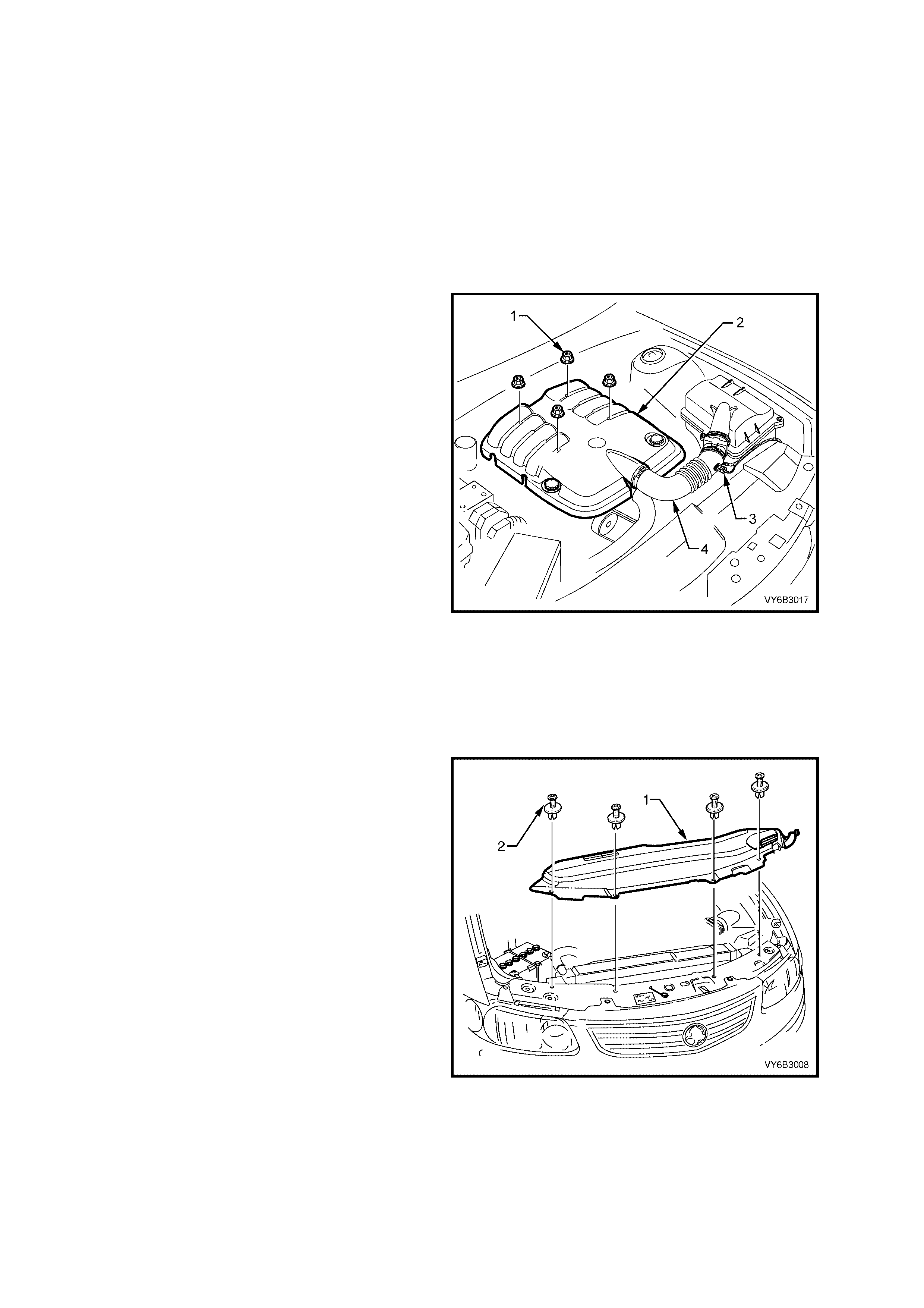
12.2 GEN III V8 ENGINE
LT Section – 08-200
REMOVE
1. Allow engine to cool to am bient temperature (less than 50° C) , slowly loos en the screw-on pressur e cap at the
coolant surge tank to relieve any residual coolant pressure, and then remove the cap.
CAUTION: Do not remo ve the screw-o n pressure cap while t he engine coolant temperature is above 50°
°°
° C,
as personal injury will most likely occur.
NOTE: Disconnection of the battery affects certain vehicle electronic systems. Refer to
Section 00, 5. BATTERY DISCONNECTION PROCEDURES before disconnecting the battery.
2. Disconnect the battery ground lead.
3. Remove engine dress cover decorative
nuts (1), then remove the cover (2).
4. Lift the locking lever on the Intake Air
Temperature (IAT) sensor wiring harness
connector (3), then remove the connector.
5. Lift the locking lever on the Mass Air Flow
(MAF) sensor and remove the connector.
6. Loosen the two intake duct clamps, one at the
throttle body and the other at the MAF to air
cleaner connection. Remove the duct (4) and
MAF as an assembly and carefully set to one
side.
7. Drain engine coolant into a suitable, clean
container. Refer to Section 6B-3, 2.3
DRAINING AND FILLING COOLING
SYSTEM.
8. Release the vapour hose from the radiator fan
shroud clips, remove the clamp securing the
hose to the radiator, remove the hose and
route to one side.
9. Remove the clamp sec uring the vapour hos e to
surge tank at the radiator end. Remove the
hose and route to one side.
Figure 2B-114
10. Remove the upper shroud (1) by removing the
4 radiator upper shroud retainers (2). Do not
rem ove the screw sec tions com pletely fr om the
retainers. Lift the upper shroud on the
right-hand side first, to allow release of the
locating tab on the left-hand side end.
11. Recover the refrigerant from the A/C system,
refer to Section 2C, 2.1 SYSTEM CHARGING
AND EVACUATION.
Figure 2B-115
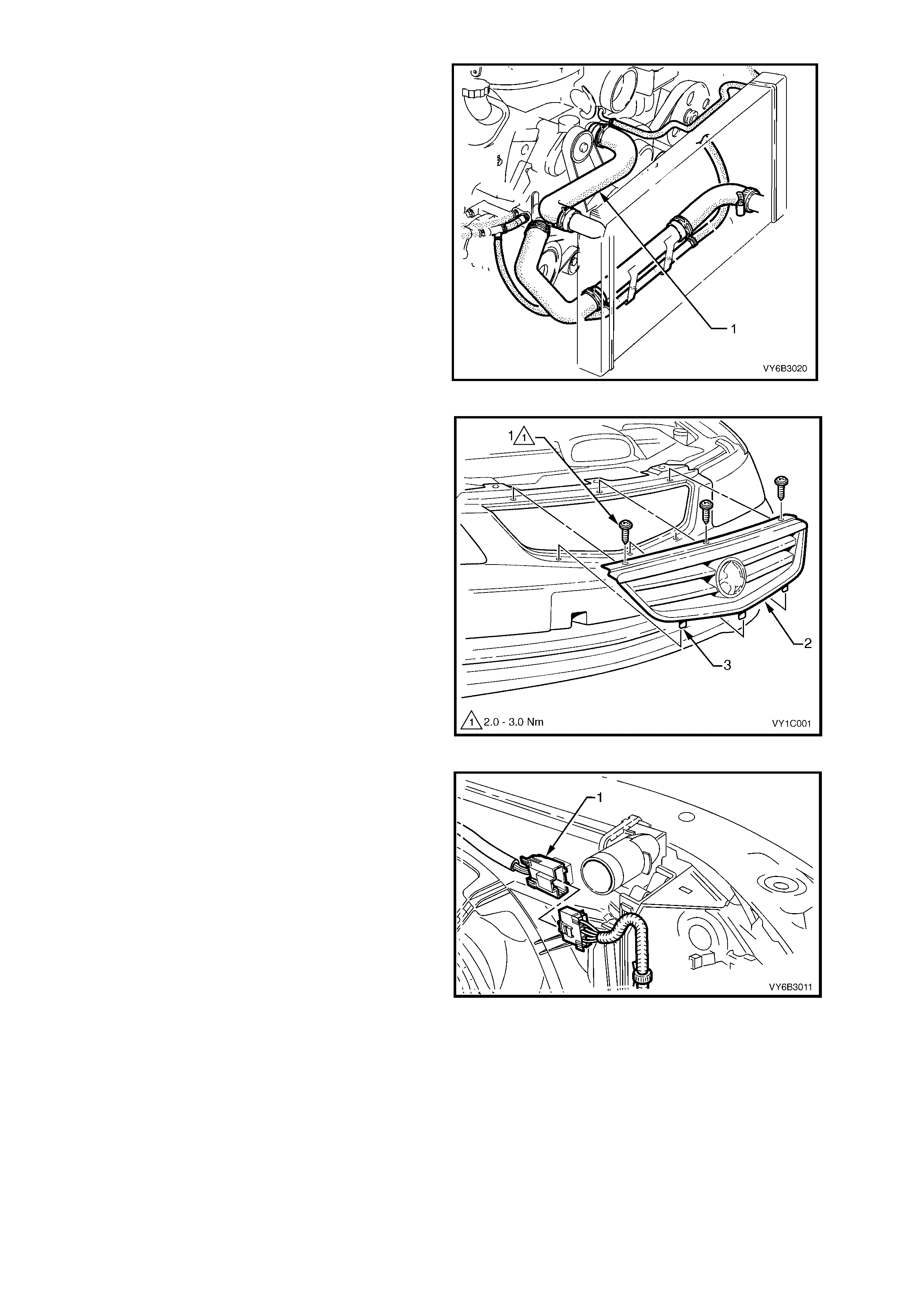
12. Remove the upper radiator hose clamps, then
remove the hose (1) and set to one side.
CAUTION: Wear eye protection when working
with spring type hose clamps.
Figure 2B-116
13. On models with removable grille, remove the
three screws (1) securing the radiator grille
assembly (2) and raise that grille so that
locating tabs (3) disengage from the bumper
fascia and remove.
NOTE: To access air conditioning components in
front of the condenser on V2 Coupe models, it will
be necessary to raise the vehicle and remove the
under vehicle air baffles. Refer to
Section 0A, GENERAL INFORMATION for the
location of jacking and support points. Refer to
Section 6B-3, 2.13 AIR BAFFLES.
Figure 2B-117
14. Press the retaining tang on wiring harness to
cooling fan m otor wiring harness connector (1),
then separate the connector halves.
Figure 2B-118
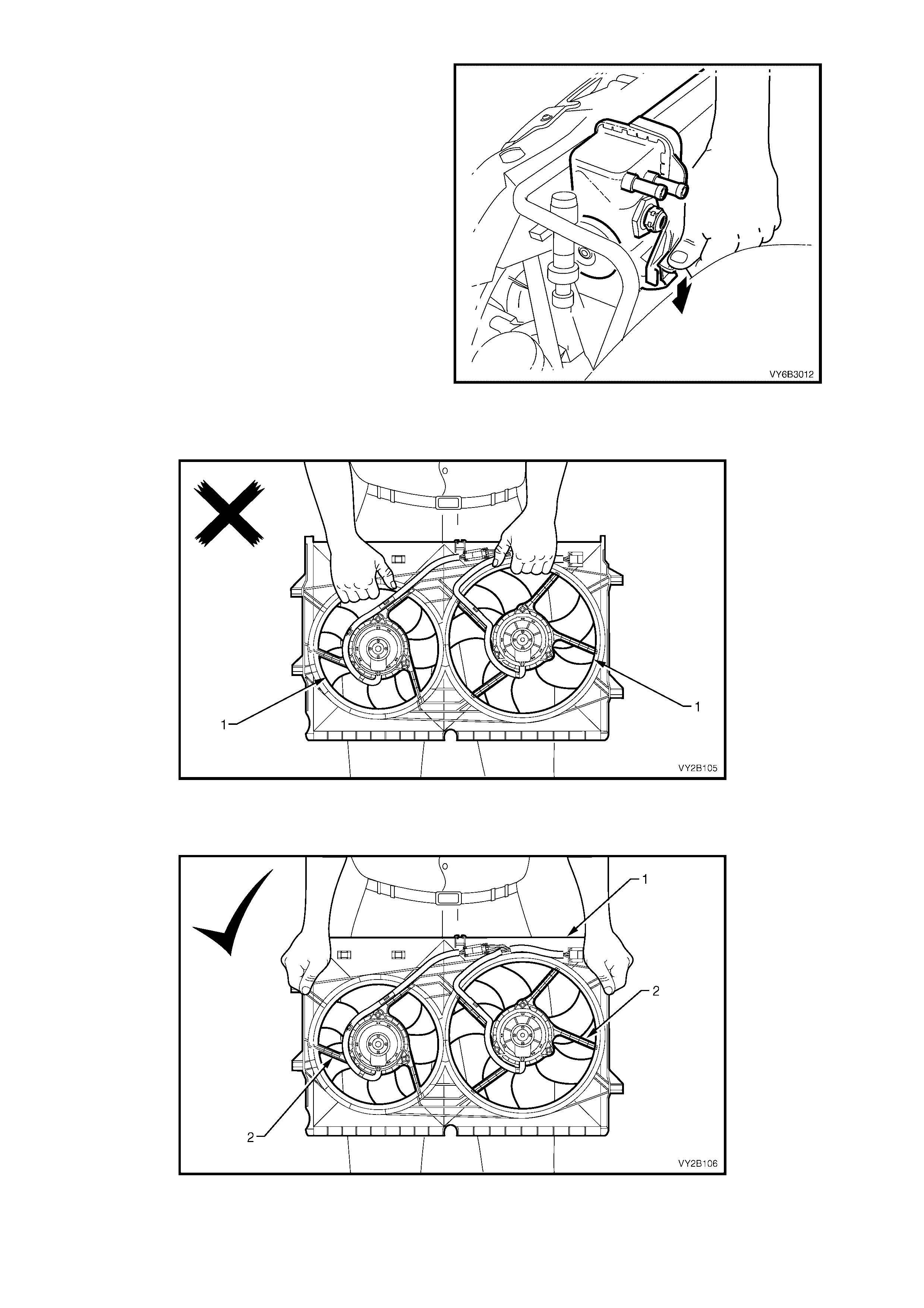
15. While holding the shroud locking tang in the
release position, lift the shroud and fan
assembly upwards. Repeat for the second side.
NOTE: While the automatic transmission fluid
cooling pipe is shown removed, this is not a
mandatory requirement for shroud removal. Pipe
has been shown rem oved to m ore clearly show the
shroud release method.
Figure 2B-119
IMPORTANT: When rem oving, transpor ting or installing the f an ass em bly, do not grasp the assem bly by the fan
rings (1) as this may bend the fan motor shafts and cause fan vibrations.
Figure 2B-120
When handling the fan assembly, always hold the assembly at the fan shroud (1) or fan motor mounting
struts (2).
Figure 2B-121

16. Lif t the shroud and f an assembly clear from the
engine bay, grasping the motor mounting
brackets.
Figure 2B-122
17. Release the discharge tube retaining clip (1).
18. Remove the nut (2) retaining the discharge
hose pad fitting (3) to the condenser (4).
19. Cap all open tubes/hoses to avoid moisture
from entering the system.
20. Discard the O-ring (5).
Figure 2B-123
21. Remove the liquid tube union (1) from the
FDR (2) and discard the O-ring (3).
Figure 2B-124

22. On OCC (Auto A/C) equipped models
disconnect the harness connector (1) from the
ambient temperature sensor (2).
NOTE: Do not attempt to remove the bracket (3)
from the condenser (4). If the ambient temperature
sensor is to be removed from the condenser, refer
to Section 2E, 2.6 AMBIENT TEMPERATURE
SENSOR.
Figure 2B-125
23. Using a screwdriver, compress and lever out
radiator retaining clips (1) from radiator upper
mounting brackets.
IMPORTANT: Do not lift the radiator assembly by
lifting on the fan rings as this will bend the fan
motor shaft and create an unnecessary vibration.
24. Lift radiator assembly upwards out of lower
insulators. Slant the upper section of the
assembly behind the radiator support sheet
metal work and allow it to remain there.
Figure 2B-126
25. Release one of the clips securing the
condenser to the radiator Do this by pressing
down as indicated by the arrow, on the locking
retainer (1) with the fingers of one hand, while
lifting the condenser assembly (2) with the
other hand. Repeat for the other side.
Figure 2B-127
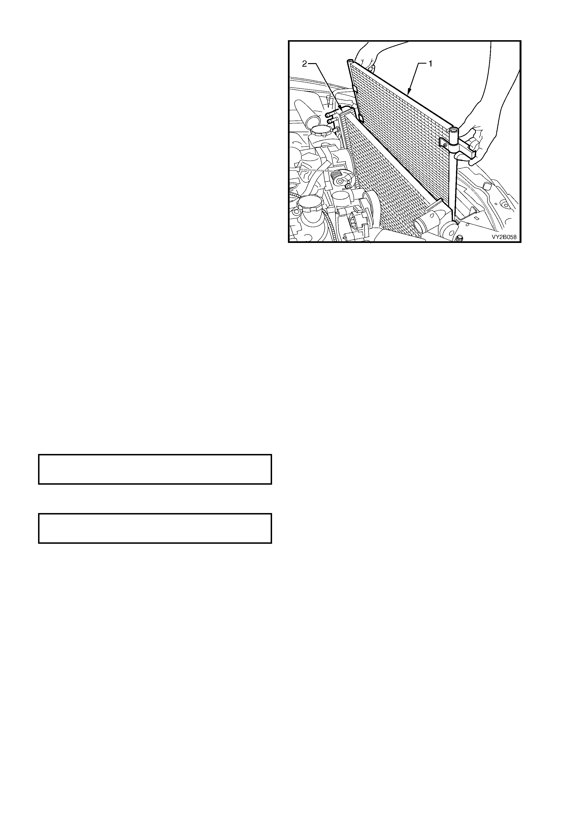
26. Lift the condenser assembly (1) upwards
suff ic iently to clear the mounts moulded to f r ont
of the radiator (2).
27. Remove the condenser from engine bay with
the FDR attached.
NOTE: If the FDR is to be removed from
the condenser mark the mounting position of the
FDR in relation to the mounting bracket for correct
positioning when installing, and note the IN mar king
on the filter head for the correct flow direction.
For FDR installation information, refer to
13. FILTER DRIER RECEIVER in this Section.
Figure 2B-128
REINSTALL
IMPORTANT: The total quantity of lubricating oil in the air conditioning system must be maintained. If a
compressor, evaporator, condenser, filter drier receiver, hose or pipe is to be replaced, a specified quantity of
lubricating oil must be added to the system to compensate for oil removed with the original component. Refer to
Section 2C, 2.4 LUBRICATING OIL COMPENSATION.
Installation of the condenser is the reverse of removal procedures, noting the following points:
1. Bef ore installing radiator , inspect c ore to ensur e that there is no for eign matter in cor e fins. Clean out between
core fins with compressed air, blowing from rear to front.
2. Ensure that radiator lower mounting insulators are correctly located in the radiator support panel.
3. Ensure that upper insulators are installed on each of the upper mounting pins and radiator retainers are
correctly installed on each side of the radiator by checking that the clips engage on both sides of the channel
support bracket.
4. If removed, ins tall the FDR, ensuring that the union thread with the word IN is directed to the condenser side of
the FDR. Install the FDR mounting bracket screw. Torque the screw to specification.
FDR MOUNTING BRACKET SCREW
TORQUE SPECIFICATION 7.5 – 12.5 Nm
5. Ins tall the liquid tube and the dis charge hos e using new lubricated O -rings to the c ondenser. T orque the unions
to specification.
FDR TUBE UNION
TORQUE SPECIFICATION 7.5 – 12.5 Nm
6. Evacuate and charge the A/C system with 775 – 825 g of R134a refrigerant, refer to
Section 2C, 2.1 SYSTEM CHARGING AND EVACUATION.
7. Ensure that fan and shroud assembly to radiator attaching clips are all fully engaged and that the two locking
tangs on the upper clips are securing the shroud correctly.
8. Fill the cooling system and test concentration levels. Refer to Section 6B-3, 2.3 DRAINING AND FILLING
COOLING SYSTEM and Testing Coolant Concentration, in Section 6B-3, 2.2 COOLANT MAINTENANCE.
9. Check cooling fan operation, refer to Section 6C3, POWERTRAIN MANAGEMENT – GEN III V8 ENGINE.
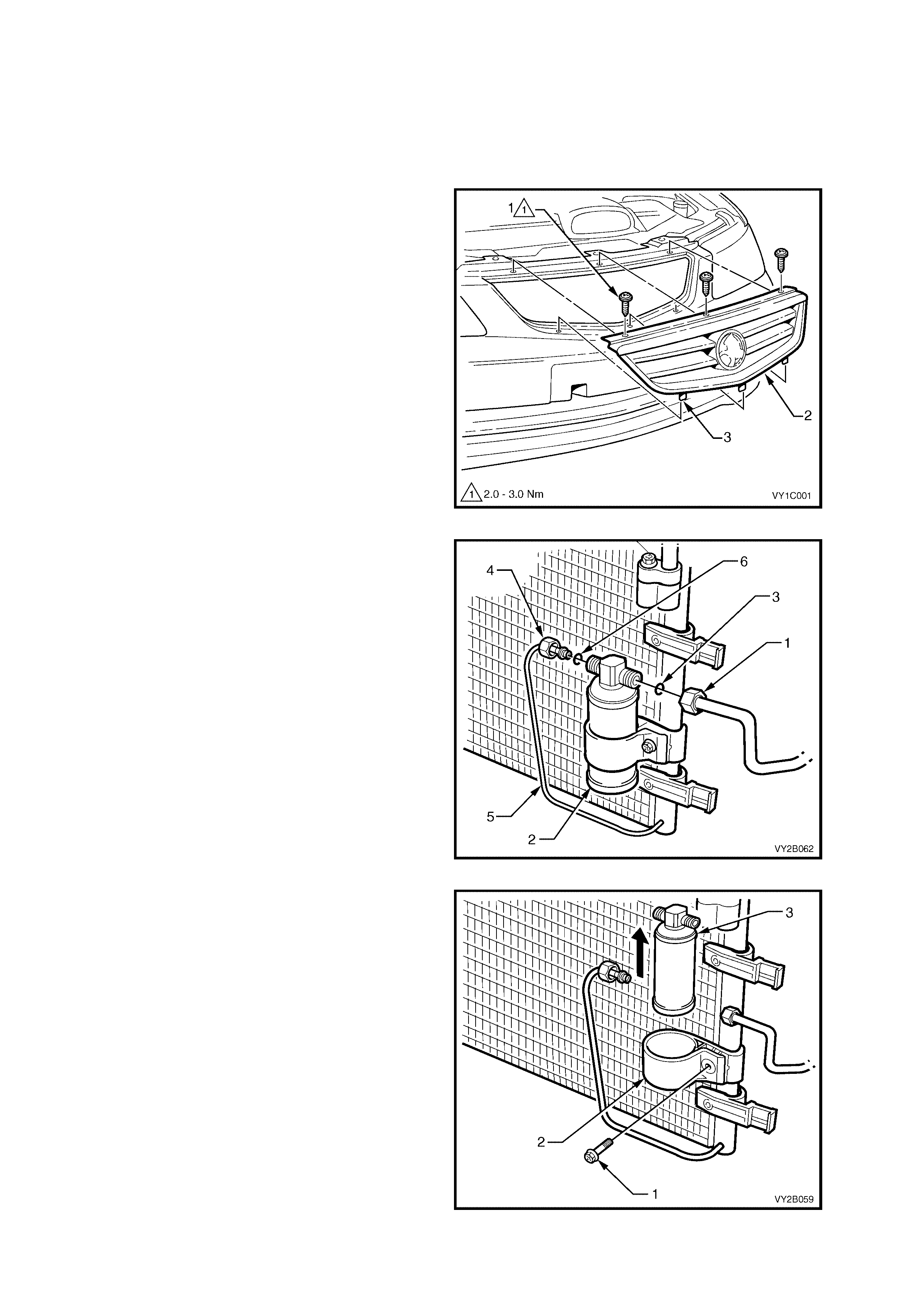
13. FILTER DRI ER RECEIVER
LT Section – 08-200
REMOVE
1. Recover the refrigerant from the A/C system, refer to Section 2C, 2.1 SYSTEM CHARGING AND
EVACUATION.
2. On models with removable grille, remove the
three screws (1) securing the radiator grille
assembly (2) and raise that grille so that
locating tabs (3) disengage from the bumper
fascia and remove.
NOTE: To access air conditioning components in
front of the condenser on V2 Coupe models, it will
be necessary to raise the vehicle and remove the
under vehicle air baffles. Refer to
Section 0A, GENERAL INFORMATION for the
location of jacking and support points. Refer to
Section 6B-3, 2.13 AIR BAFFLES.
Figure 2B-129
3. Remove the liquid tube union (1) from the
FDR (2) and discard the O-ring (3).
4. Remove the discharge pipe union (4) from the
FDR and caref ully flex the disc harge pipe (5) to
the left clear of the FDR. Discard the O-ring (6).
Figure 2B-130
5. Remove the screw (1) on the FDR mounting
bracket (2).
6. Cap all open tubes/hoses to avoid moisture
from entering the system.
7. Expand the bracket and remove the FDR (3) by
lifting it upwards clear of the bracket.
Figure 2B-131
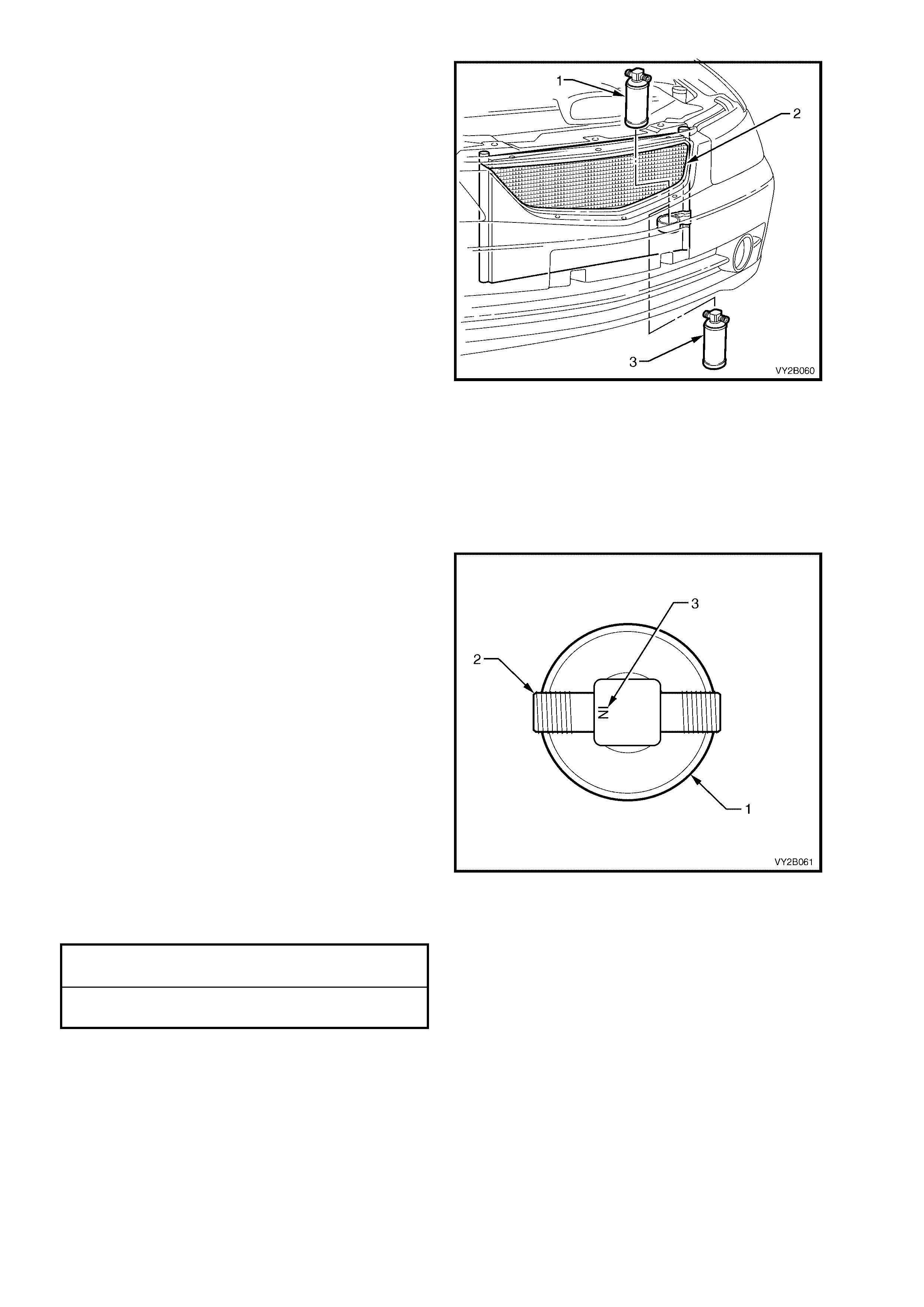
8. On models with removable grille, remove the
FDR (1) through the grille aperture (2). On
V2 Coupe models, remove the FDR (3) from
below the bumper bar fascia.
Figure 2B-132
REINSTALL
IMPORTANT: The total quantity of lubricating oil in the air conditioning system must be maintained. If a
compressor, evaporator, condenser, filter drier receiver, hose or pipe is to be replaced, a specified quantity of
lubricating oil must be added to the system to compensate for oil removed with the original component. Refer to
Section 2C, 2.4 LUBRICATING OIL COMPENSATION.
Installation of the filter drier receiver is the reverse of removal procedures, noting the following points:
1. Install the FDR (1), ensuring that the condenser
union is connected to the thread (2) adjacent to
the word IN (3) stamped on the head of the
FDR.
Figure 2B-133
2. Install the liquid tube and the discharge hose using new lubricated O-rings to the condenser. Torque the
mounting screw and unions to specification.
FDR MOUNTING BRACKET SCREW
TORQUE SPECIFICATION 7.5 – 12.5 Nm
FDR TUBE UNION
TORQUE SPECIFICATION 7.5 – 12.5 Nm
3. Evacuate and charge the A/C system with 775 – 825 g of R134a refrigerant, refer to
Section 2C, 2.1 SYSTEM CHARGING AND EVACUATION.
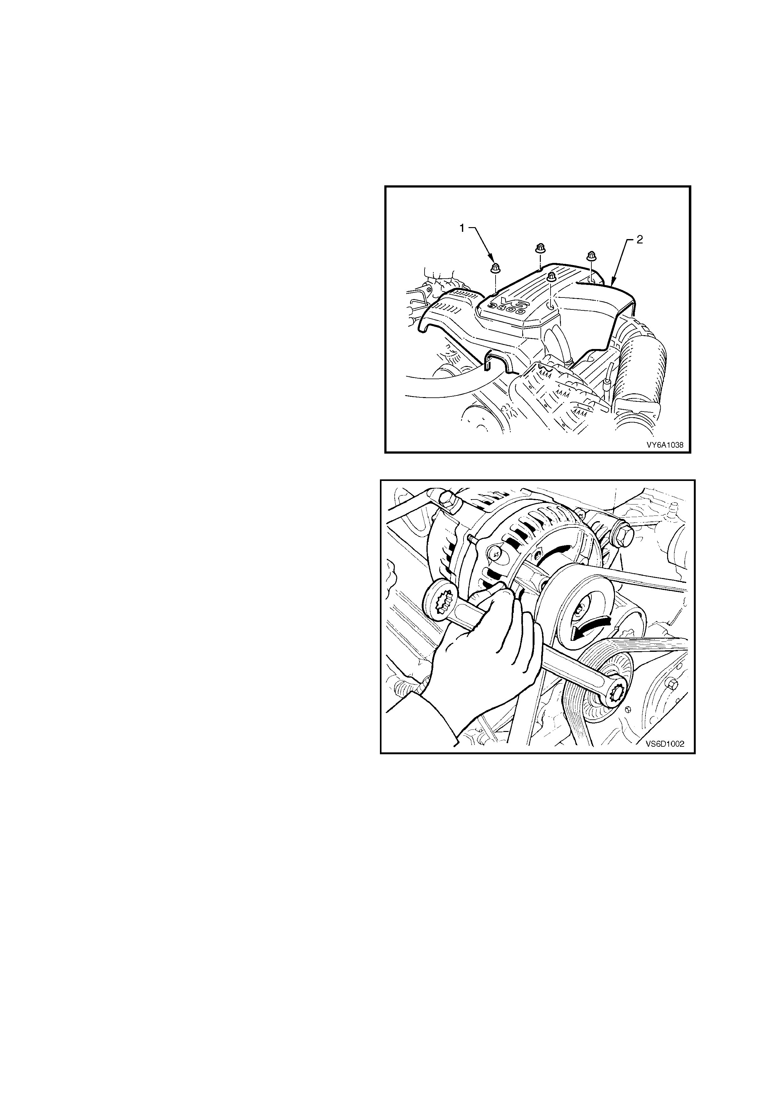
14. A/C DRIVE BELT AND PULLEYS
14.1 A/C DRIVE BELT – V6 ENGINE
LT Section – 01-003
REMOVE
1. Disconnect the battery ground lead. Refer to Section 00, 5. BATTERY DISCONNECTION PROCEDURES.
2. Remove four nuts (1) securing engine dress
cover (2).
Figure 2B-134
3. Using a 15 mm socket on the drive belt
tensioner pulley pivot bolt, release the belt
tension by turning the tensioner in an anti-
clockwise direction.
4. Starting at the water pump pulley remove the
drive belt.
Figure 2B-135
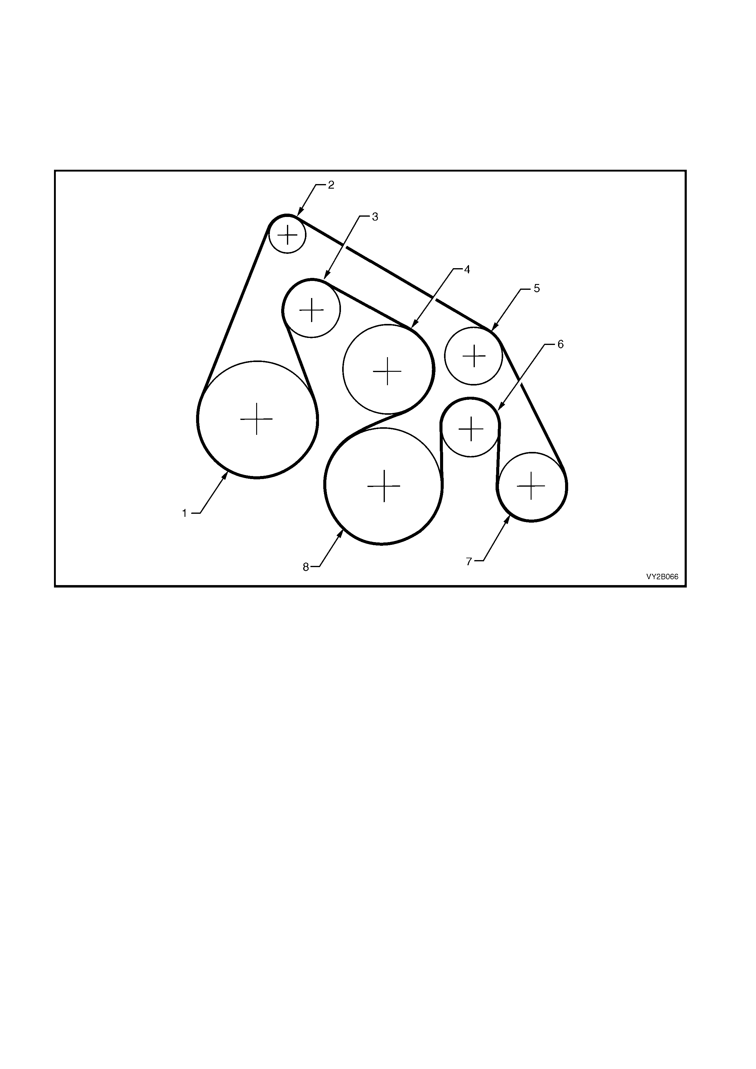
REINSTALL
1. Clean the engine accessory and air conditioning drive belt running surfaces.
2. Using Figure 2B-136 as a guide, fit the drive belt starting at the water pump pulley.
3. Inspect the installation to ensure that the belt is correctly aligned on all pulleys.
4. Start the engine to ensure correct operation.
5. Install the engine dress cover.
Figure 2B-136
Legend
1. Power Steering Pump 5. Idler
2. Generator 6. Idler
3. Tensioner 7. Air Conditioner Compressor
4. Water Pump 8. Crankshaft Pulley
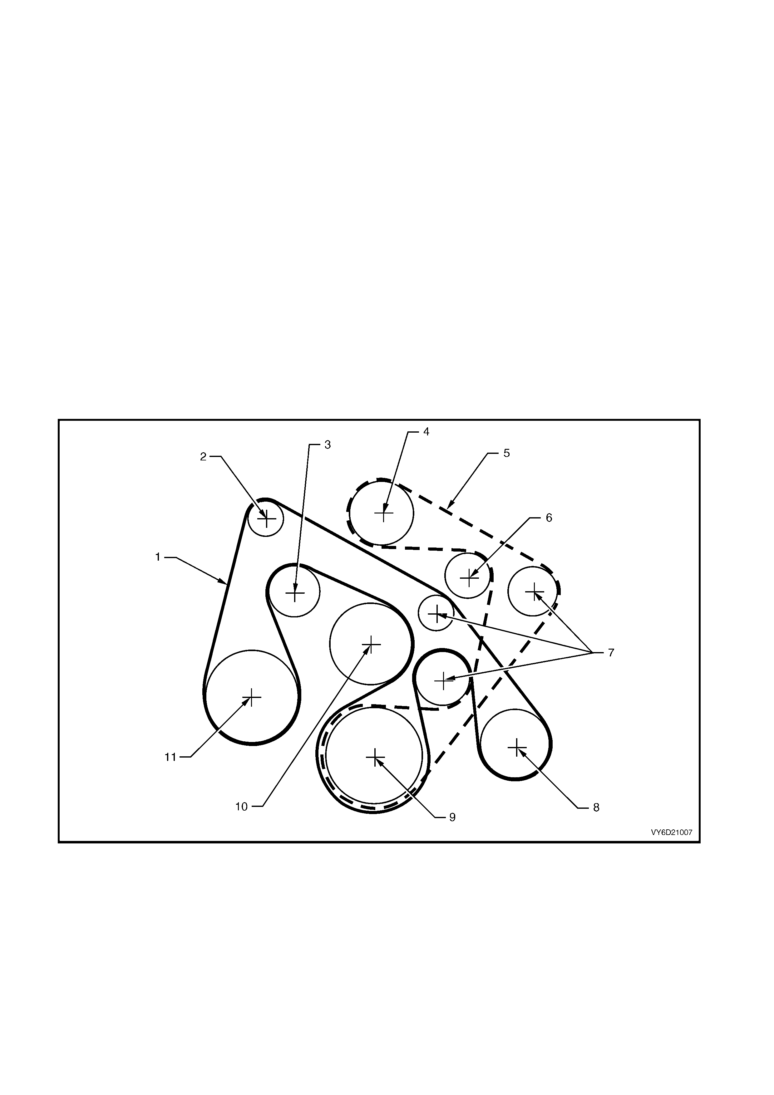
14.2 A/C DRIVE BELT – V6 SUPERCHARGED ENGINE
LT Section – 01-003
REMOVE
1. Disconnect the battery ground lead. Refer to Section 00, 5. BATTERY DISCONNECTION PROCEDURES.
2. Remove the four nuts securing engine dress cover.
3. Using a 15 m m sock et on the supercharger drive belt tensioner, release the supercharger drive belt tension
by turning the tensioner in an anti-clockwise direction.
4. Remove the supercharger drive belt starting at the double idler pulley.
5. Using a 15 mm socket on the main drive belt tensioner pulley retaining bolt, release the belt tension by
turning the tensioner in an anti-clockwise direction.
6. Starting at the water pump pulley remove the drive belt.
REINSTALL
1. Clean the engine accessory and air conditioning drive belt running surfaces.
2. Using Figure 2B-137 as a guide, fit the drive belt starting at the water pump pulley.
3. Inspect the installation to ensure that the belt is correctly aligned on all pulleys.
4. Install the supercharger drive belt starting at the double idler pulley.
5. Inspect the installation to ensure that the belt is correctly aligned on all pulleys.
6. Start the engine to ensure correct operation.
7. Install the engine dress cover.
Figure 2B-137
Legend
1. Accessory Drive Belt (Inner) 5. Accessory Drive Belt (Outer) 9 Crankshaft Pulley
2. Generator 6. Tensioner Pulley 10. Water Pump
3. Tensioner Pulley 7. Idler Pulleys 11. Power Steering Pump
4. Supercharger Pulley 8. Air Conditioning Compressor
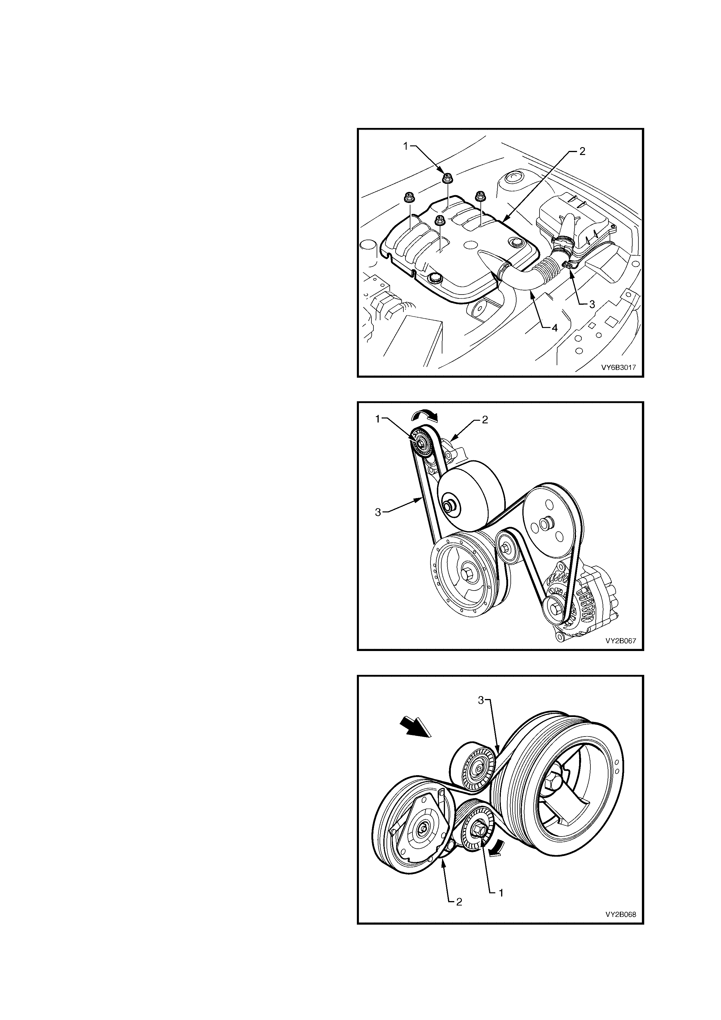
14.3 A/C DRIVE BELT – GEN III V8 ENGINE
LT Section – 01-003
REMOVE
1. Disconnect the battery ground lead. Refer to Section 00, 5. BATTERY DISCONNECTION PROCEDURES.
2. Remove the four engine dress cover decorative
nuts (1), then remove the dress cover (2) from
the engine.
3. Remove the air intake sensor wiring harness
connector (3), then loosen both hose clamps
securing the intake hose (4) to the MAF sensor
and the throttle body. Remove the hose from the
engine.
Figure 2B-138
4. Using a 15 mm socket attached to the centre
bolt (1) of the engine accessory drive belt
tensioner (2) , rotate the tensioner in a clockwise
direction, to reduce belt tension.
5. Remove the engine drive belt (3) from the
pulleys, taking note of the belt routing.
Figure 2B-139
6. Using a 15 mm socket attached to the centre
bolt (1) of the air conditioning drive belt
tensioner (2) , rotate the tensioner in a clockwise
direction to relieve belt tension.
7. Remove the air conditioning drive belt (3) from
the pulleys.
8. Inspect belts for wear or damage and replace if
necessary.
Figure 2B-140
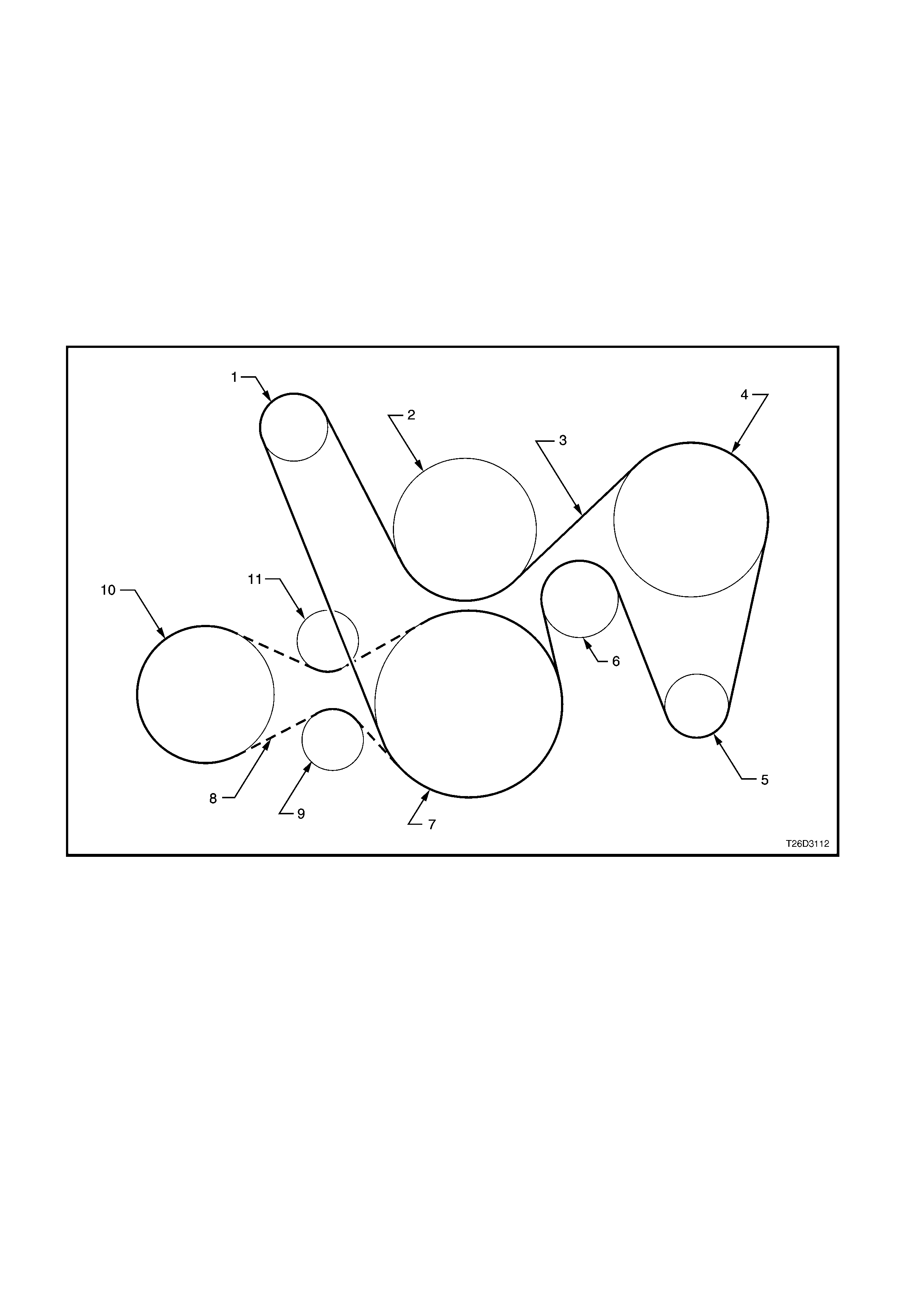
REINSTALL
1. Clean the engine accessory and air conditioning drive belt running surfaces.
2. Using a 15 mm socket attached to the centre bolt of the tensioner, rotate the air conditioning drive belt
tensioner in a clockwise direction, and install the drive belt over the pulleys, routing the belt correctly as
shown in Figure 2B-141.
3. Inspect the installation to ensure that the belt is correctly aligned on all pulleys.
4. Using a 15 mm socket attached to the centre bolt of the tensioner, rotate the engine accessory drive belt
tensioner in a clockwise direction, install the engine accessory drive belt over the pulleys, routing the belt
correctly, as shown in Figure 2B-141.
5. Inspect the installation to ensure that the belt is correctly aligned on all pulleys.
6. Start the engine to ensure correct operation.
7. Install the air intake sensor wiring harness connector and the intake hose.
8. Install the engine dress cover.
Figure 2B-141
Legend
1. Tensioner 7. Crankshaft
2. Water Pump 8. Drive Belt (Air Conditioning Compressor)
3. Drive Belt 9. Tensioner (Air Conditioning Compressor Drive Belt)
4. Power Steering Pump 10. Air Conditioner Compressor
5. Generator 11. Idler (Air Conditioning Compressor Drive Belt)
6. Idler
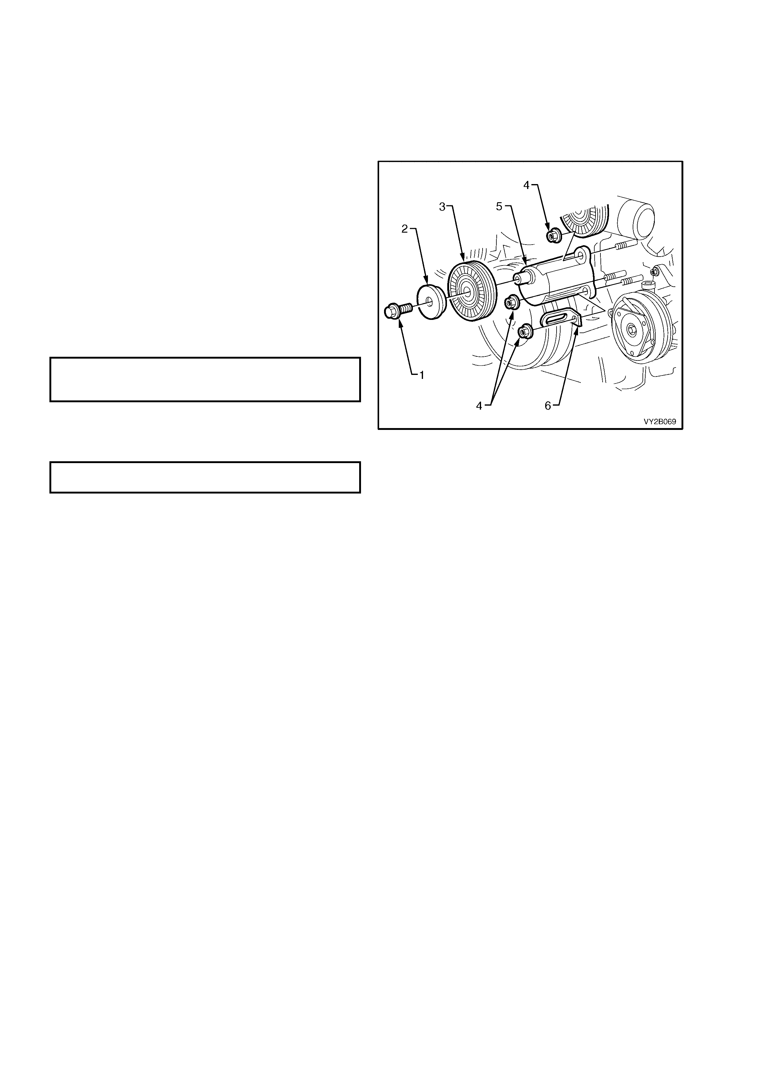
14.4 A/C DRIVE BELT IDLER PULLEY ASSEMBLY –
V6 AND V6 SUPERCHARGED ENGINE
LT Section – 01-020
REMOVE
1. Remove the dr ive belt. F or V6 engines , refer to 14.1 A/C DRIVE BELT – V6 ENGINE in this Sec tion. F or V6
Supercharged engines, refer to 14.2 A/C DRIVE BELT – V6 SUPERCHARGED ENGINE in this Section.
2. Remove the idler pulley retaining bolt (1),
washer (2) and idler pulley (3).
3. Remove the three mounting bracket nuts (4).
4. Remove the idler pulley mounting brack et (5), the
together with the harness clip (6) from the
engine.
REINSTALL
1. Fit the idler pulley mounting bracket to the
engine.
2. Install the harness clip as shown.
3. Install the three nuts.
IDLER PULLEY MOUNTING
BRACKET RETAINING NUTS
TORQUE SPECIFICATION 20.0 – 30.0 Nm
4. Replace the pulley, washer and bolt onto the idler
pulley bracket.
5. Tighten the idler pulley retaining bolt.
IDLER PULLEY RETAINING BOLT
TORQUE SPECIFICATION 45.0 – 50.0 Nm
6. Install the drive belt. For V6 engines, refer to
14.1 A/C DRIVE BELT – V6 ENGINE in this
Section. For V6 Supercharged engines, refer to
14.2 A/C DRIVE BELT – V6 SUPERCHARGED
ENGINE in this Section.
Figure 2B-142
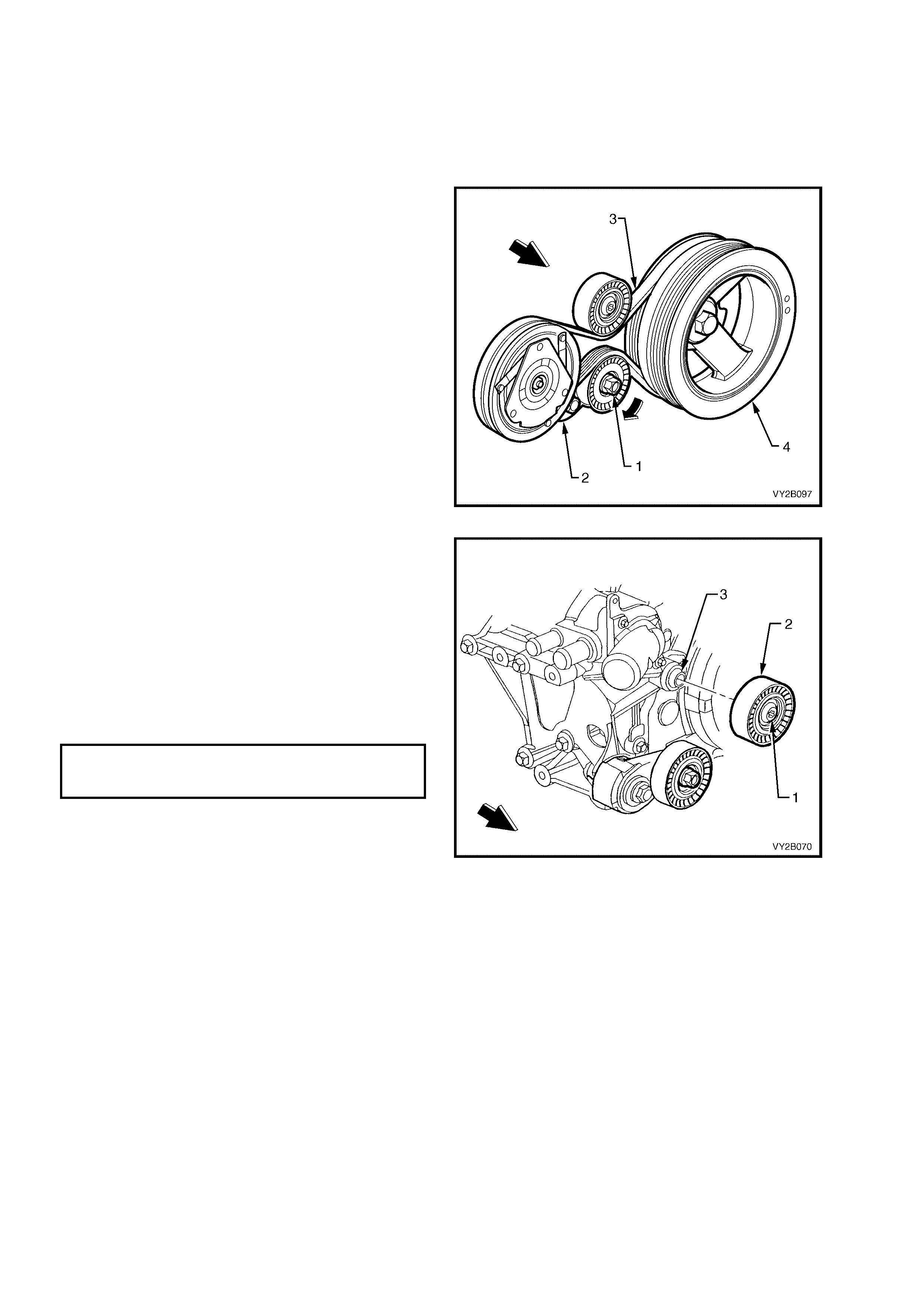
14.5 A/C DRIVE BELT IDLER PULLEY ASSEMBLY – GEN III V8 ENGINE
LT Section – 01-020
REMOVE
1. Remove the air conditioning com pr essor drive belt. Refe r to 14.3 A/C DRIVE BELT – GEN III V8 ENGINE in
this Section.
2. Using a 15 mm socket attached to the centre
bolt (1) of the air conditioning drive belt
tensioner (2), rotate the tensioner in the
direction shown to relieve the tension on the
A/C belt (3).
3. Remove the air conditioning drive belt from all
pulleys except the crankshaft pulley (4). Allow
the A/C belt to remain on the crankshaft pulley.
Figure 2B-143
4. Using a commercially available, Torx bit T50,
remove the bolt (1) securing the air
conditioning compressor drive belt idler
pulley (2) to its mounting boss (3) on the water
pump housing, then remove the pulley
assembly.
REINSTALL
1 Install the idler pulley to its mounting boss.
2. Install the idler pulley retaining bolt and tighten
to the correct torque specification.
AIR CONDITIONING COMPRESSOR
DRIVE BELT IDLER PULLEY BOLT
TORQUE SPECIFICATION 50.0 Nm
3. Install the air conditioning compressor drive
belt. Refer to 14.3 A/C DRIVE BELT – GEN III
V8 ENGINE in this Section.
Figure 2B-144

14.6 A/C DRIVE BELT TENSIONER PULLEY ASSEMBLY – GEN III V8 ENGINE
LT Section – 01-020
REMOVE
1. Remove the air conditioning com pr essor drive belt. Refe r to 14.3 A/C DRIVE BELT – GEN III V8 ENGINE in
this Section.
2. Using a 15 mm socket attached to the centre
bolt (1) of the air conditioning drive belt
tensioner (2), rotate the tensioner in the
direction shown to relieve the tension on the
A/C belt (3).
3. Remove the air conditioning drive belt from all
pulleys except the crankshaft pulley (4). Allow
the A/C belt to remain on the crankshaft pulley.
Figure 2B-145
4. Remove the bolt (1) securing the air
conditioning compressor drive belt tensioner (2)
and remove the assembly.
REINSTALL
1 Install the tensioner assembly and the
mounting bolt.
2. Tighten the tensioner mounting bolt to the
correct torque specification.
AIR CONDITIONING DRIVE BELT
TENSIONER BOLT
TORQUE SPECIFICATION 25.0 Nm
3. Install the air conditioning compressor drive
belt. Refer to 14.3 A/C DRIVE BELT – GEN III
V8 ENGINE in this Section.
Figure 2B-146

15. A/C COMPRESSOR
15.1 V6 AND V6 SUP ERCHARGHED ENGINE
LT Section – 08-200
REMOVE
1. Disconnect the battery ground lead. Refer to Section 00, 5. BATTERY DISCONNECTION PROCEDURES.
2. Discharge the A/C system. Refer to Section 2C, 2. DISCHARGING SYSTEM – REFRIGERANT
RECOVERY.
3. Remove the nut (1) securing the
suction/discharge hose pad (2) to the
compressor (3).
4. Remove and discard the port sealing O-
rings (4).
5. Cap or plug the disconnected hoses and ports
immediately to prevent absorption of moisture
from the atmosphere.
6. Remove the A/C drive belt.
7. Disconnect the compressor clutch electrical
connector.
8. Raise the vehic le and place the vehicle on jac k
stands. Refer to Section 0A, GENERAL
INFORMATION for the location of jacking and
support points.
Figure 2B-147
9. Remove the bolt (1) and two nuts (2) retaining
the compressor (3) to the engine block (4).
Figure 2B-148

REINSTALL
IMPORTANT: The total quantity of lubricating oil in the air conditioning system must be maintained. If a
compressor, evaporator, condenser, filter drier receiver, hose or pipe is to be replaced, a specified quantity of
lubricating oil must be added to the system to compensate for oil removed with the original component. Refer to
Section 2C, 2.4 LUBRICATING OIL COMPENSATION.
1. Install the compressor to the engine using the original two nuts and bolt. Torque to specifications.
COMPRESSOR RETAINING
BOLT AND NUT
TORQUE SPECIFICATION 40.0 – 60.0 Nm
2. Install the A/C drive belt. Inst all the drive belt. For V6 engines, refer to 14.1 A/C DRIVE BELT – V6 ENGINE in
this Section. For V6 Super char ged engines, refer to 14.2 A/C DRIVE BELT – V6 SUPERCHARGED ENGINE in
this Section.
3. Remove the compressor port protection caps.
4. Install two new port sealing washers.
5. Secure the suction/discharge hose assembly to the compressor with original nut.
SUCTION/DISCHARGE HOSE
PAD RETAINING NUT
TORQUE SPECIFICATION 25.0 – 35.0 Nm
6. Evacuate and charge the A/C system with 775 – 825 g of R134a refrigerant, refer to
Section 2C, 2. DISCHARGING SYSTEM – REFRIGERANT RECOVERY.
IMPORTANT: If replacing with a new compressor, refer to Section 2C, HVAC CLIMATE CONTROL (MANUAL
A/C) – SERVICING & DIAGNOSIS for lubrication requirements.
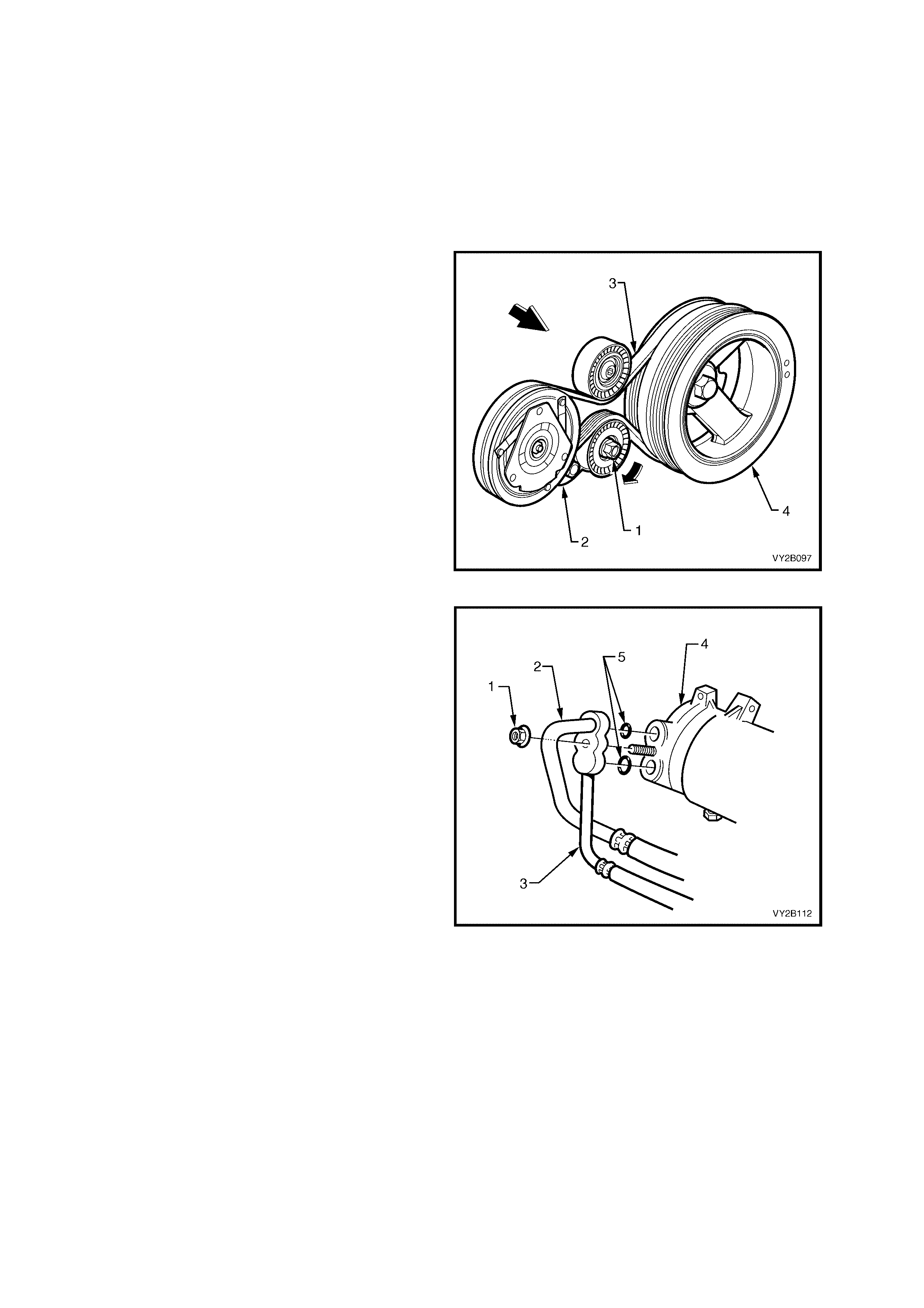
15.2 GEN III V8 ENGINE
LT Section – 08-200
REMOVE
1. Disconnect the battery ground lead. Refer to Section 00, 5. BATTERY DISCONNECTION PROCEDURES.
2. Drain coolant and rem ove the heater hoses and lower radiator coolant hose from the cylinder block, ref er to
Section 6B3, 2.3 DRAINING AND FILLING COOLING SYSTEM.
3. Discharge the A/C system. Refer to Section 2C, 2. DISCHARGING SYSTEM – REFRIGERANT
RECOVERY.
4. Using a 15 mm socket attached to the centre
bolt (1) of the air conditioning drive belt
tensioner (2), rotate the tensioner in the
direction shown to relieve the tension on the
A/C belt (3).
5. Remove the air conditioning drive belt from all
pulleys except the crankshaft pulley (4). Allow
the A/C belt to remain on the crankshaft pulley.
Figure 2B-149
6. Loosen and remove the nut (1) retaining the
suction (2) and discharge (3) hoses to the
compressor (4). Remove the hoses (2 and 3)
from the compressor.
7. Discard O-rings (5).
8. Cap or plug the ports immediately to prevent
entry of moisture from the atmosphere.
9. Disconnect the compressor clutch electrical
connector.
NOTE: Figure 2B-150 shows the hose
configuration applicable to RHD models with the
suction and discharge hoses connected to a
common pad. On LHD models the pad is a two
piece design, i.e. the suction and discharge hoses
are separate. Refer to the compressor installation
view in Figure 2B-99.
Figure 2B-150
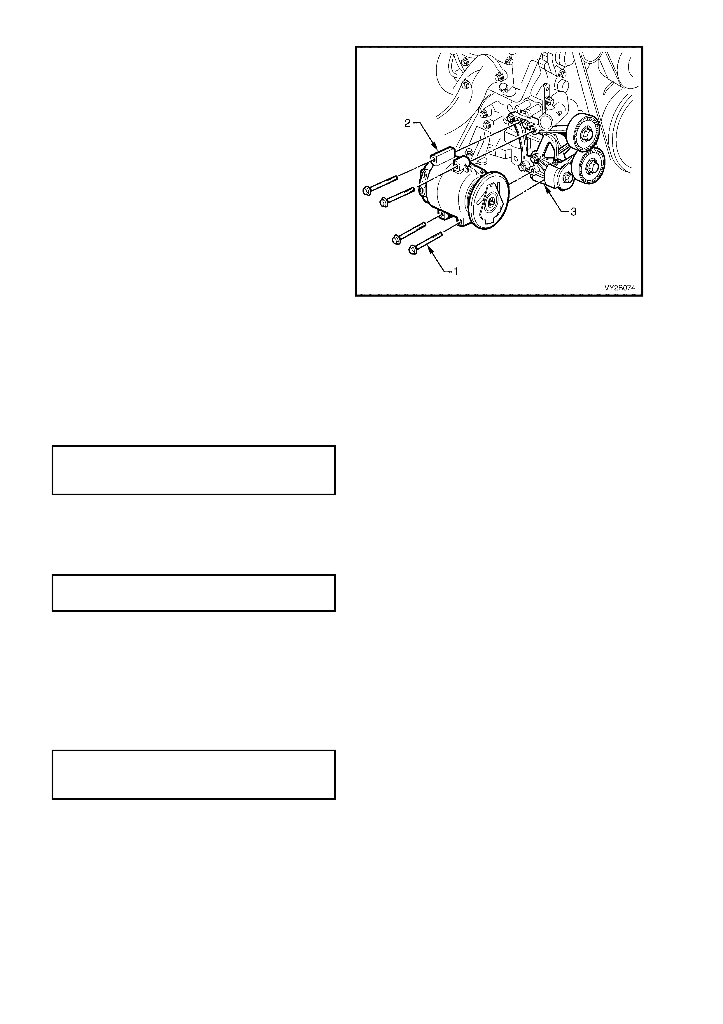
10. Remove the four bolts (1) retaining the
compressor (2) to the mounting bracket (3).
NOTE: Figure 2B-151 shows several components
removed for clarity only (i.e. heater hoses and
coolant hoses ). To remove the compres s or , it is not
necessary to remove these components.
11. Remove the compressor.
12. If necessary, remove the four bolts retaining
the compressor mounting bracket to the
cylinder block and remove the mounting
bracket.
Figure 2B-151
REINSTALL
IMPORTANT: The total quantity of lubricating oil in the air conditioning system must be maintained. If a
compressor, evaporator, condenser, filter drier receiver, hose or pipe is to be replaced, a specified quantity of
lubricating oil must be added to the system to compensate for oil removed with the original component. Refer to
Section 2C, 2.4 LUBRICATING OIL COMPENSATION.
1. If removed, reinstall the compressor mounting bracket and tighten the four retaining bolts to the correct torque
specification.
COMPRESSOR MOUNTING BRACKET
RETAINING BOLT
TORQUE SPECIFICATION 40.0 – 60.0 Nm
IMPORTANT: If replacing with a new compressor refer to Section 2C, AIR CONDITIONING – SERVICING AND
DIAGNOSIS for lubrication requirements/specifications.
2. Fit the com pr es sor to the c ompres sor mounting brac k et, ins tall the f our r etaining bolts and tighten to the c or rec t
torque specification.
COMPRESSOR RETAINING BOLT
TORQUE SPECIFICATION 40.0 – 60.0 Nm
3. Install the air conditioning com pressor drive belt. Refer to 14.3 A/C DRIVE BELT – GEN III V8 ENGINE in this
Section.
4. Remove caps from compressor ports and install new sealing washers.
5. Using new O-rings lubric ated with PAG re f riger ant oil ins tall the air c onditioning s uc tion and dis char ge hos e pad
fitting onto the compressor.
CAUTION: Do not allow PAG refrigerant oil to contact bare skin or vehicle paint work. If contact occurs to either,
wash PAG refrigerant oil off immediately.
6. Install the suction and discharge hose pad retaining nut and tighten to the correct torque specification.
SUCTION AND DISCHARGE HOSE
PAD RETAINING NUT
TORQUE SPECIFICATION 25.0 – 35.0 Nm
7. Install the compressor clutch electrical connector.
8. Install the heater and lower radiator coolant hoses, fill coolant system with correct coolant and pressure test
cooling system, refer to Section 6B3, ENGINE COOLING – GEN III V8 ENGINE.
9. Recharge air conditioner system, refer to Section 2C, AIR CONDITIONING – SERVICING & DIAGNOSIS.
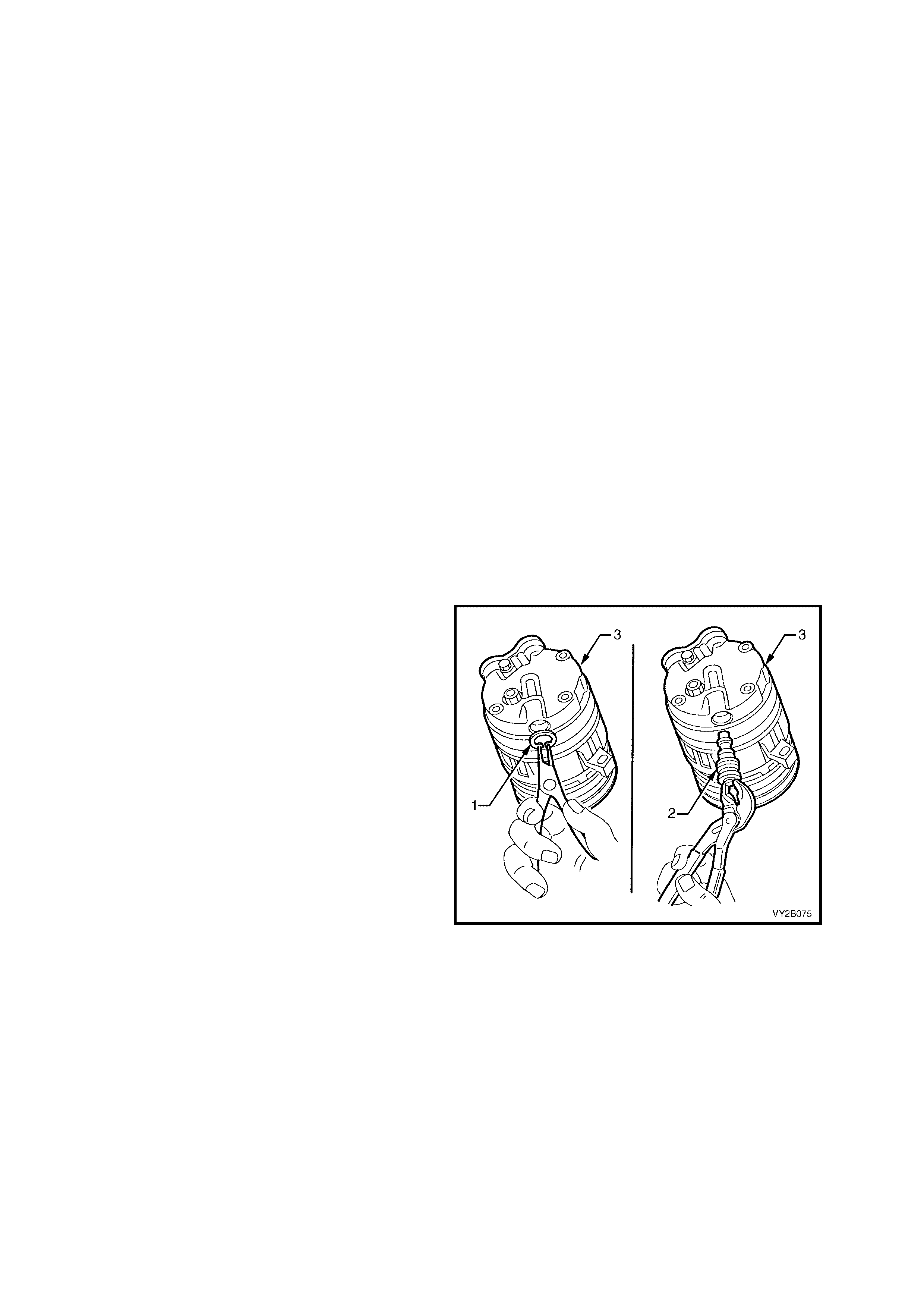
16. M INOR A/C COMPRESSOR REPAI R PROCEDURES
Illustrations used in the following procedures show the compressor removed from the vehicle for easier viewing.
When servicing the compressor, remove only the parts that preliminary diagnosis shows are in need of service.
Removal and installation of external parts of the compressor and disassembly/assembly of internal parts must be
performed on a clean workbench. The work area, tools and parts must be clean at all times.
NOTE: The only components that can be serviced are:
• Control Valve
• Port Sealing Washers
• Clutch Drive Plate and Hub Assembly
IMPORTANT: The total quantity of lubricating oil in the air conditioning system must be maintained. If a
compressor, evaporator, condenser, filter drier receiver, hose or pipe is to be replaced, a specified quantity of
lubricating oil must be added to the system to compensate for oil removed with the original component. Refer to
Section 2C, 2.4 LUBRICATING OIL COMPENSATION.
16.1 A/C COMPRESSOR CONTROL VALVE
LT Section – 08-200
REMOVE
1. Discharge the A/C system. Refer to Section 2C, 2. DISCHARGING SYSTEM – REFRIGERANT
RECOVERY.
2. Rais e fr ont of vehic le and support on saf ety stands. Refer to Section 0A, GENERAL INFORMAT ION for the
location of jacking and support points.
3. On GEN III V8 models remove the four bolts securing the under-tray to the crossmember and remove tray
from vehicle. Refer to Section 6B-3, 2.12 OIL PAN UNDER-TRAY.
4. From beneath the vehicle remove the lower air baffle / shute as required. Refer to
Section 6B-3, 2.13 AIR BAFFLES.
5. F rom beneath the vehicle r em ove the circ lip (1)
securing the control valve (2) to the
compressor (3).
6. Using a pair of s uitable cir c lip pliers r emove the
control valve from the compressor by pulling
downwards. Quickly insert the replacement
control valve (this will avoid any minor oil loss).
REINSTALL
1. Lubricate the control valve O-rings and
carefully push the control valve into the
compressor.
NOTE: V6 and GEN III V8 control valves have
different control settings. Ensure that the correct
control valve is installed.
2. Inspect the control valve retaining circlip. If it is
undamaged, reuse it to secure the control
valve. If it is not serviceable, replace it with a
new circlip. Ensure that the circlip is fully
seated in the circlip groove.
3. If A/C lubricating oil has been lost during
control valve removal procedure, add new
lubricating oil as required, through the suction
port of the A/C compressor. Refer to
Section 2C, 2.4 LUBRICATING OIL
COMPENSATION.
4. Install the lower air baffle / shute and under-tray
where fitted.
5. Evacuate and charge the A/C system with
775 – 825 g of R134a refrigerant, Refer to
Section 2C, 2. DISCHARGING SYSTEM –
REFRIGERANT RECOVERY.
Figure 2B-152
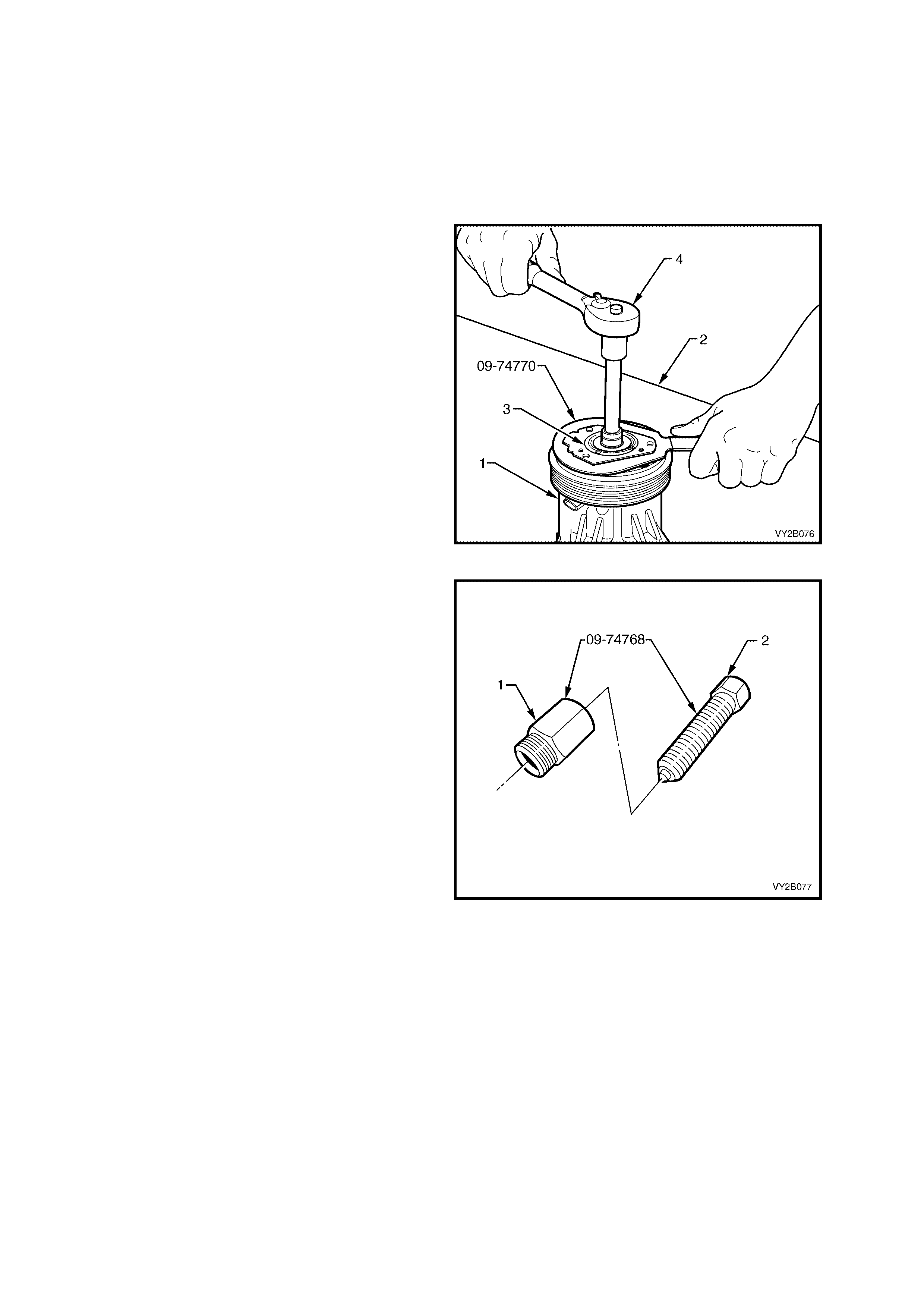
16.2 A/C CLUTCH DRIVE PLATE AND HUB ASSEMBLY
LT Section – 08-200
REMOVE
1. Discharge the A/C system. Refer to Section 2C, 2. DISCHARGING SYSTEM – REFRIGERANT
RECOVERY.
2. Remove the compressor from the vehicle. Refer to 15.1 V6 AND V6 SUPERCHARGED ENGINE or
15.2 GEN III V8 ENGINE as applicable in this Section.
3. Place the compressor (1) on a clean work
bench (2).
4. Use the clutch hub holding tool 09-74770 to
keep the hub assembly (3) from turning and
remove the compressor shaft nut using suitable
hand tools (4).
Figure 2B-153
5. Assemble the nut (1) and centre screw (2) of
the A/C clutch hub and drive plate rem over tool
09-74768 as shown in Figure 2B-154. Install
the centre screw no more than 2 cm into the
nut.
Figure 2B-154
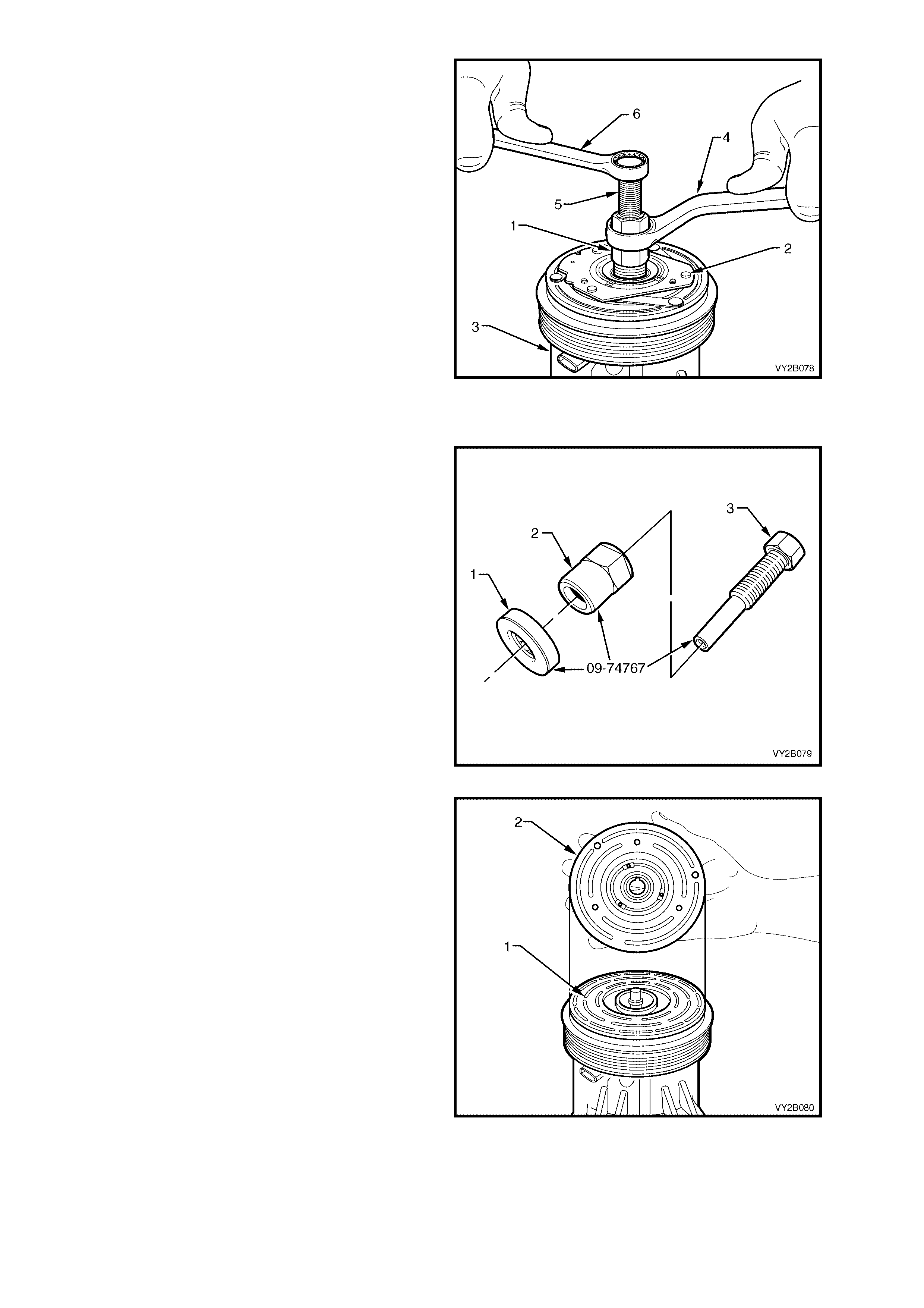
6. Install the nut (1) of the tool 09-74768 fully into
the clutch hub (2) of the compressor (3).
7. Hold the nut of tool 09-74768 with a suitable
hand tool (4) and turn the centre screw (5) of
the tool using a s ec ond suitable hand tool (6) to
remove the clutch drive plate and hub
assembly as shown in Figure 2B-155.
8. Remove the shaft key.
Figure 2B-155
REINSTALL
1. Assemble the bearing (1), nut (2) and centre
screw (3) of the A/C clutch hub and drive plate
installer tool 09-74767 as shown in Figure 2B-
156. Install the nut up to the hexagonal section
of the centre screw.
Figure 2B-156
2. Ensure that the clutch contact surfaces of the
clutch pulley (1) and clutch plate (2) are clean
before installing the clutch plate and hub
assembly to the A/C compressor. If necessary,
remove any oil or grease from the clutch
surfaces with a clean, lint free cloth dampened
with methylated spirits and allow the surfaces
to dry.
Figure 2B-157
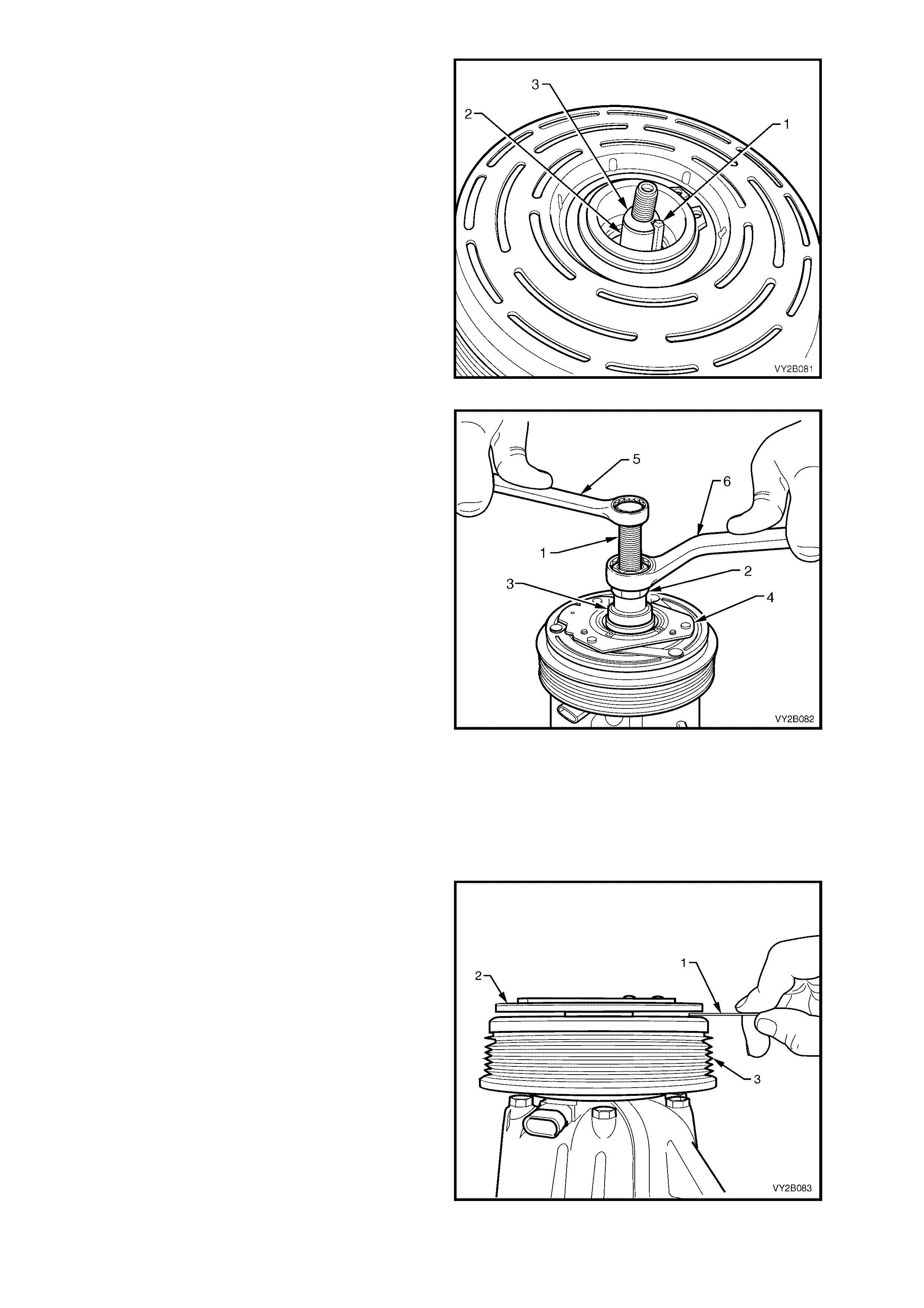
3. Place a small amount of assembly grease on
the key (1) to locate it in the keyway of the
compressor shaft (2). Install the key level with
the top of the tapered section (3) of the
compressor shaft as shown in Figure 2B-158.
Align the clutch hub keyway with the key and
install the clutch plate and hub assembly onto
the compressor shaft. Push as far as possible
by hand, the clutch plate and hub assembly
onto the compressor shaft ensuring that the
key has remained in the position as shown in
Figure 2B-158.
Figure 2B-158
4. Install the c entre screw (1) f ully onto the end of
the com pressor s haft and turn the nut (2) down
the centre screw until the bearing (3) of installer
tool 09-74767 contacts the A/C clutch hub (4).
5. Hold the centre screw with a suitable hand
tool (5) and continue to tur n the nut down using
a second a suitable hand tool (6) to press the
A/C clutch hub and drive plate onto the
compressor shaft.
IMPORTANT: Excessive force is not required to
install the A/C clutch hub and drive plate onto the
compressor shaft. If excessive force is required,
remove the special tool 09-74767 and inspect
com ponents. If the k ey has fallen down the keyway
causing it to protrude ex cessively f rom the k eyway,
continuing the installation procedure will damage
components.
6. Turn the nut several turns and remove the
installer tool 09-74767 from the compressor.
7. Check that the shaft key is located correctly in
the keyway before installing the A/C clutch
plate and hub assembly to its final position.
8. Install tool 09-74767 onto the compressor
again and press the A/C clutch hub and drive
plate fully onto the compressor shaft.
Figure 2B-159
9. Using a non-magnetic feeler strip (1) measure
the air gap between the frictional surfaces of
the clutch plate (2) and the clutch pulley (3).
Figure 2B-160
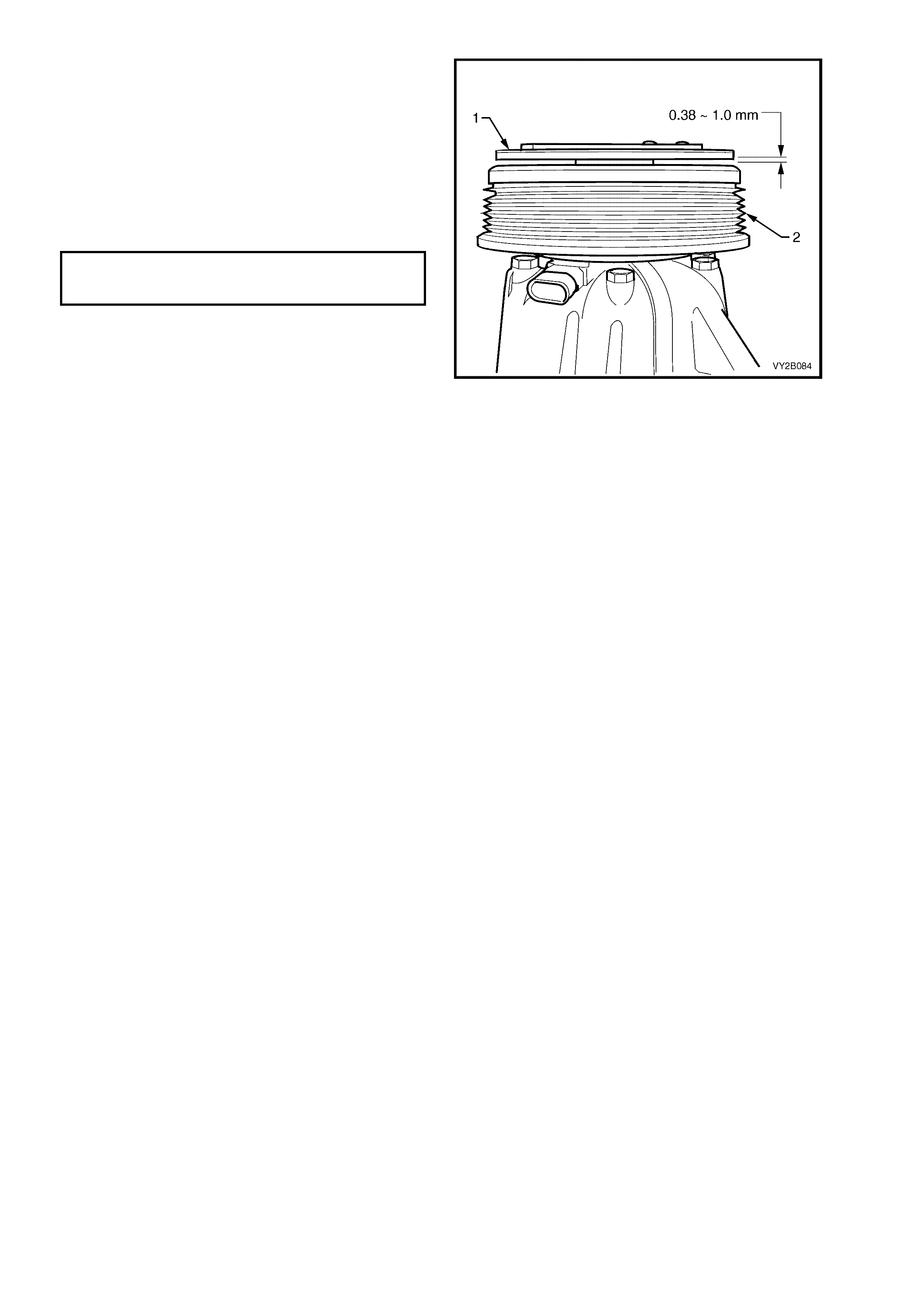
NOTE: The air gap between the frictional surfaces
of the clutch plate (1) and the clutch pulley (2)
should be 0.38 – 1.0 mm.
10. Remove tool 09-74767 and check for proper
positioning of the shaft key. The key should be
level with, or slightly above the clutch hub.
11. Install the shaft nut, and holding the A/C clutch
plate and hub assembly with the clutch hub
holding tool 09-74770, torque the nut to
specification.
CLUTCH DRIVE PLATE AND HUB
ASSEMBLY RETAINING NUT
TORQUE SPECIFICATION 11.0 – 22.0 Nm
12. Re-check the air gap and spin the pulley by
hand, checking that the pulley is not touching
the drive plate.
13. Install the compressor to the vehicle. Refer to
15.1 V6 AND V6 SUPERCHARGED ENGINE
or 15.2 GEN III V8 ENGINE as applicable in
this Section.
14. Evacuate and charge the A/C system with
775 – 825 g of R134a refrigerant. Refer to
Section 2C, 2. DISCHARGING SYSTEM –
REFRIGERANT RECOVERY.
Figure 2B-161
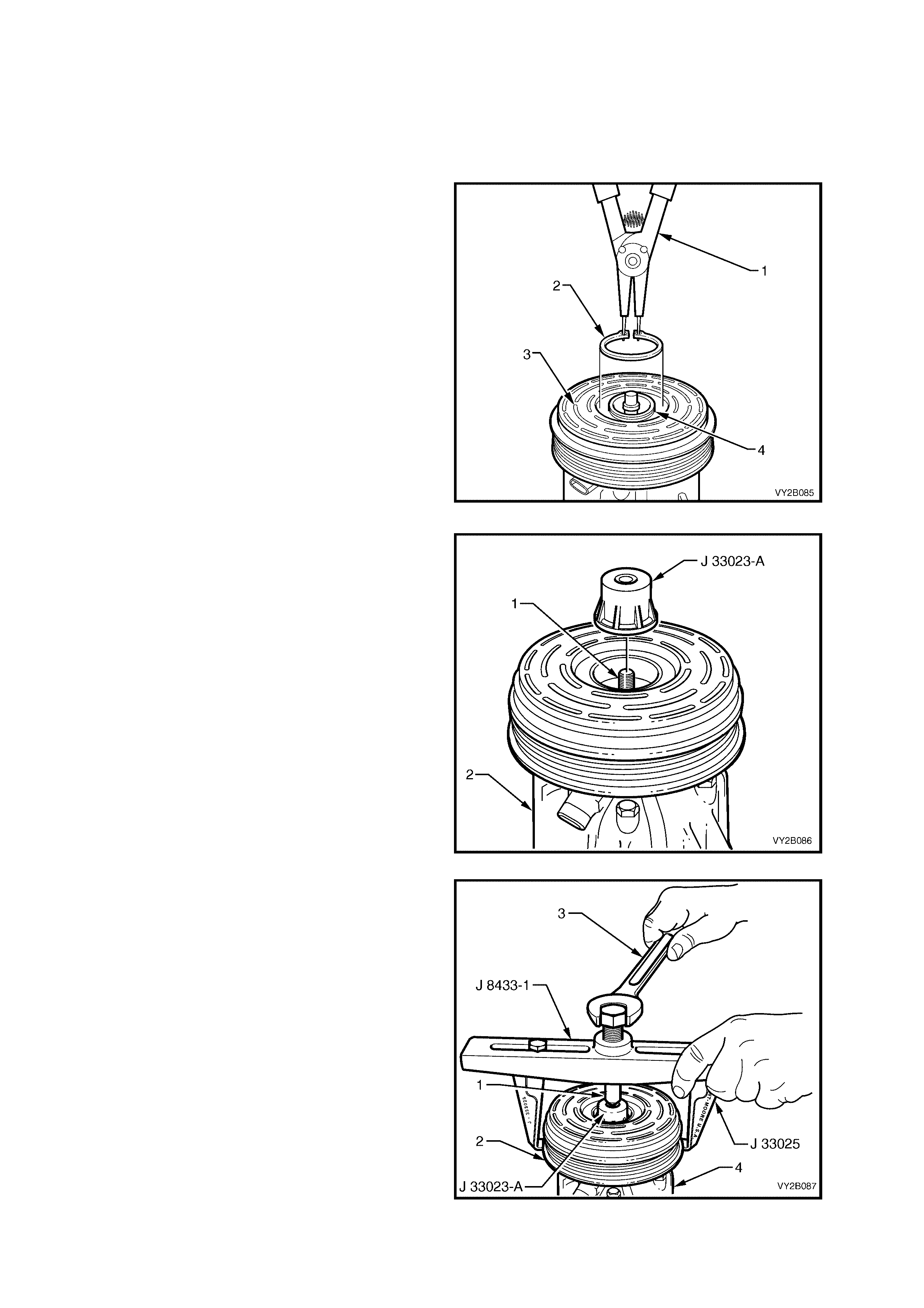
16.3 A/C CLUTCH PULLEY AND BEARING ASSEMBLY
LT Section – 08-200
REMOVE
1. Remove the A/C clutch drive plate and hub assem bly. Refer to 16.2 A/C CLUT CH DRIVE PLATE AND HUB
ASSEMBLY in this Section.
2. Using suitable external c irc lip plier s (1) , remove
the circlip (2) the retaining the clutch pulley and
bearing assembly (3) to the compressor
housing (4).
Figure 2B-162
3. Install the puller pilot tool J-33023-A onto the
end of the shaft (1) of the compressor (2).
Figure 2B-163
4. Attach puller legs J-33025 to the puller bar
J-8433-1. Locate the centre screw (1) of the
puller bar in the countersink hole of the puller
pilot J-33023-A. Engage the puller leg tangs
under the clutch pulley (2) as shown in Figure
2B-164.
5. Turn the centre screw of the J-8433-1 puller
bar us ing a s uitable hand tool (3) to remove the
clutch pulley and bearing assembly from the
compressor (4).
Figure 2B-164

REINSTALL
1. Assemble the bearing (1), nut (2) and centre
screw (3) of the A/C clutch hub and drive plate
installer tool 09-74767 as shown in Figure 2B-
156. Install the nut up to the hexagonal of the
centre screw.
Figure 2B-165
2. Position the clutch pulley and bearing
assembly (1) on the compressor housing (2).
3. Position special tool J-33017 with the larger
diameter facing down, between the pulley
bearing (3) and the bearing (4) of the installer
tool 09-74767 as shown in Figure 2B-166.
Install the centre screw (5) of special tool 09-
74767 fully onto the end of the compressor
shaft. Rotate the nut (6) down the screw until
the assembly is hand tensioned.
Figure 2B-166
4. Hold the centre screw (1) with a suitable hand
tool (2) and turn the nut (3) with a second
suitable hand tool (4) to press the pulley and
bearing assembly (5) onto the compressor
housing (6).
5. Install the circlip retaining the clutch pulley and
bearing assembly to the compressor housing.
6. Install the clutch drive plate and hub assembly,
refer to 16.2 A/C CLUTCH DRIVE PLATE AND
HUB ASSEMBLY in this Section.
Figure 2B-167
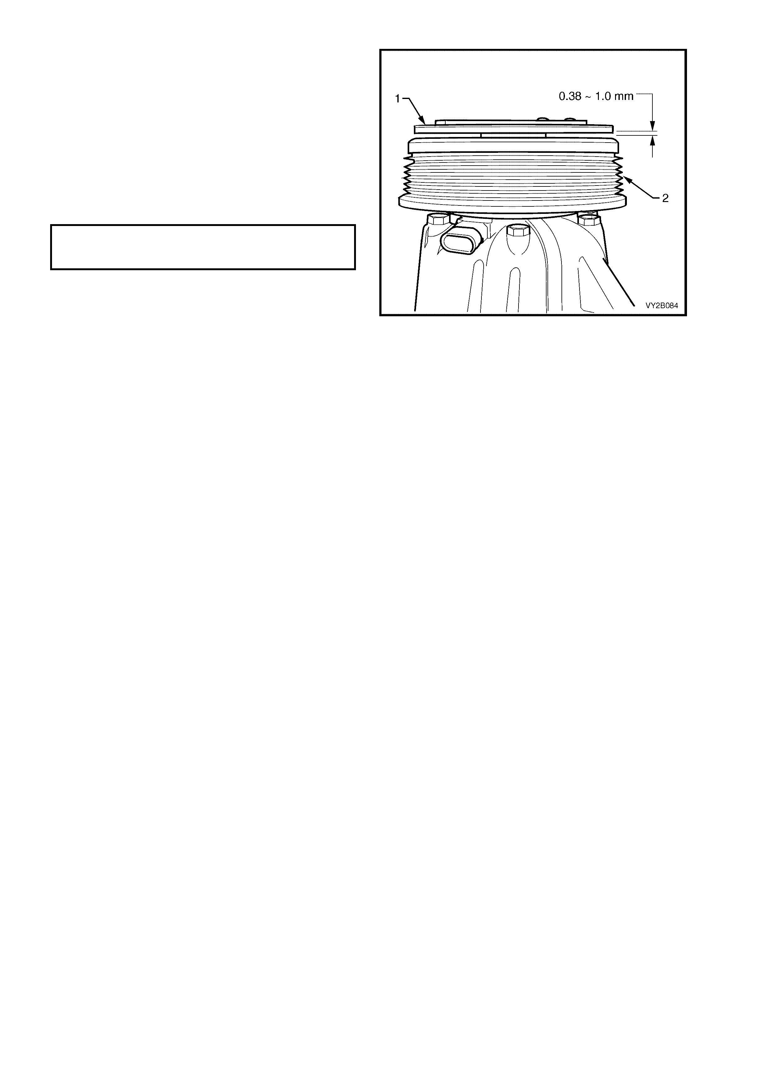
NOTE: The air gap between the frictional surfaces
of the clutch plate (1) and the clutch pulley (2)
should be 0.38 – 1.0 m m . This clearance should be
checked using a non-magnetic feeler strip.
7. Remove tool 09-74767 and check for proper
positioning of the shaft key. The key should be
level with, or slightly above the clutch hub.
8. Install the shaft nut, and holding the A/C clutch
plate and hub assembly with the clutch hub
holding tool 09-74770, torque the nut to
specification.
CLUTCH DRIVE PLATE AND HUB
ASSEMBLY RETAINING NUT
TORQUE SPECIFICATION 11.0 – 22.0 Nm
9. Re-check the air gap and spin the pulley by
hand, checking that the pulley is not touching
the drive plate.
10. Install the compressor to the vehicle. Refer to
15.1 V6 AND V6 SUPERCHARGED ENGINE
or 15.2 GEN III V8 ENGINE as applicable in
this Section.
11. Evacuate and charge the A/C system with
775 – 825 g of R134a refrigerant, Refer to
Section 2C, 2. DISCHARGING SYSTEM –
REFRIGERANT RECOVERY.
Figure 2B-168
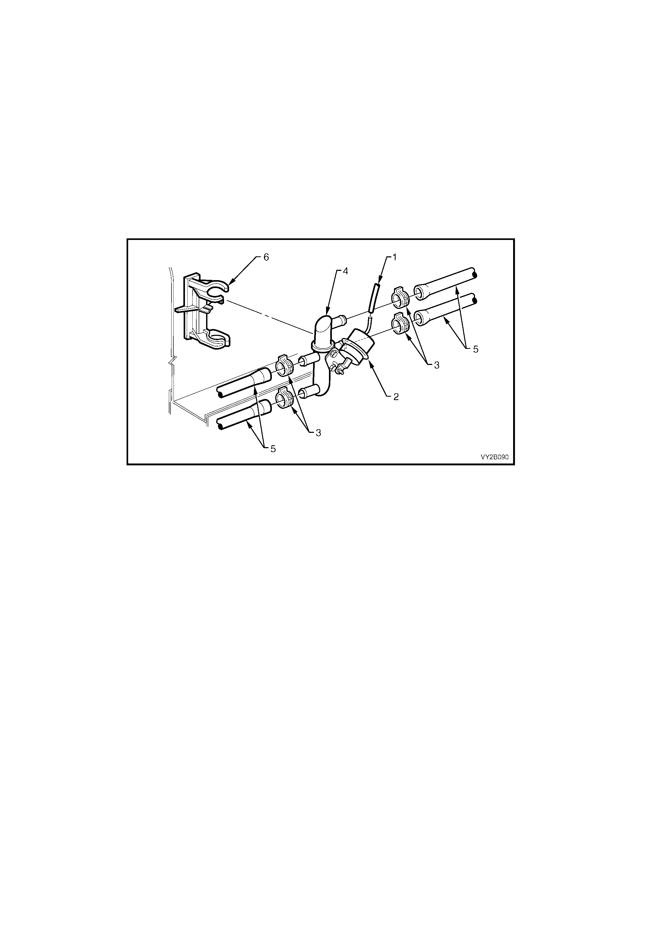
17. UNDER HOOD HEATER COMPONENTS
17.1 WATER VALVE
LT Section – 08-075
REMOVE
1. Drain engine coolant into a suitable, clean container. For GEN III V8 engines, refer to
Section 6B-3, 2.3 DRAINING AND FILLING COOLING SYSTEM.
2. Remove the vacuum hose (1) from the water valve actuator (2).
3. Remove the four hose clips (3) from the water valve (4) ports.
4. Remove the four heater hoses (5) from the water valve.
5. Remove the water valve assembly from the water valve bracket (6).
Figure 2B-169
REINSTALL
Installation of the water valve is the reverse of removal procedures, noting the following points:
1. Install the hoses to the correct ports of the water valve to maintain correct coolant flow. As applicable, refer
to the following Figures:
• For V6 left-hand drive models fitted with an oil cooler, refer to Figure 2B-170.
• For V6 left-hand drive models not fitted with an oil cooler, refer to Figure 2B-171.
• For V6 and V6 Supercharged right-hand drive models, refer to Figure 2B-172.
• For GEN III V8 left-hand drive models, refer to Figure 2B-173.
• For GEN III V8 right-hand drive models, refer to Figure 2B-174.
• For V6 right-hand drive models fitted with LPG, refer to Section 8A2, 3.23 COOLANT HOSES.
2. Fill the cooling system with the correct specification and quantity of coolant. Pressure test the cooling
system. As applicable refer to:
• Section 6B1, ENGINE COOLING – V6 ENGINE
• Section 6B2, ENGINE COOLING – V6 ENGINE SUPERCHARGED
• Section 6B3, ENGINE COOLING – GEN III V8 ENGINE

17.2 HEATER HOSES AND VACUUM LINES
LT Section – 08-075
REMOVE AND REINSTALL
The following five Figures provide under hood views of heater hose and HVAC vacuum line installations. Refer to
these Figures when removing and installing these components.
• For V6 left-hand drive models fitted with an oil cooler, refer to Figure 2B-170.
• For V6 left-hand drive models not fitted with an oil cooler, refer to Figure 2B-171.
• For V6 and V6 Supercharged right-hand drive models, refer to Figure 2B-172.
• For GEN III V8 left-hand drive models, refer to Figure 2B-173.
• For GEN III V8 right-hand drive models, refer to Figure 2B-174.
• For V6 right-hand drive models fitted with LPG, refer to Section 8A2, 3.23 COOLANT HOSES.
NOTE 1: Install all heater hoses to the ports indicated to maintain correct coolant flow.
NOTE 2: After the heater hoses are installed, fill the cooling system with the correct specification and quantity of
coolant. Pressure test the cooling system. As applicable refer to:
• Section 6B1, ENGINE COOLING – V6 ENGINE
• Section 6B2, ENGINE COOLING – V6 ENGINE SUPERCHARGED
• Section 6B3, ENGINE COOLING – GEN III V8 ENGINE
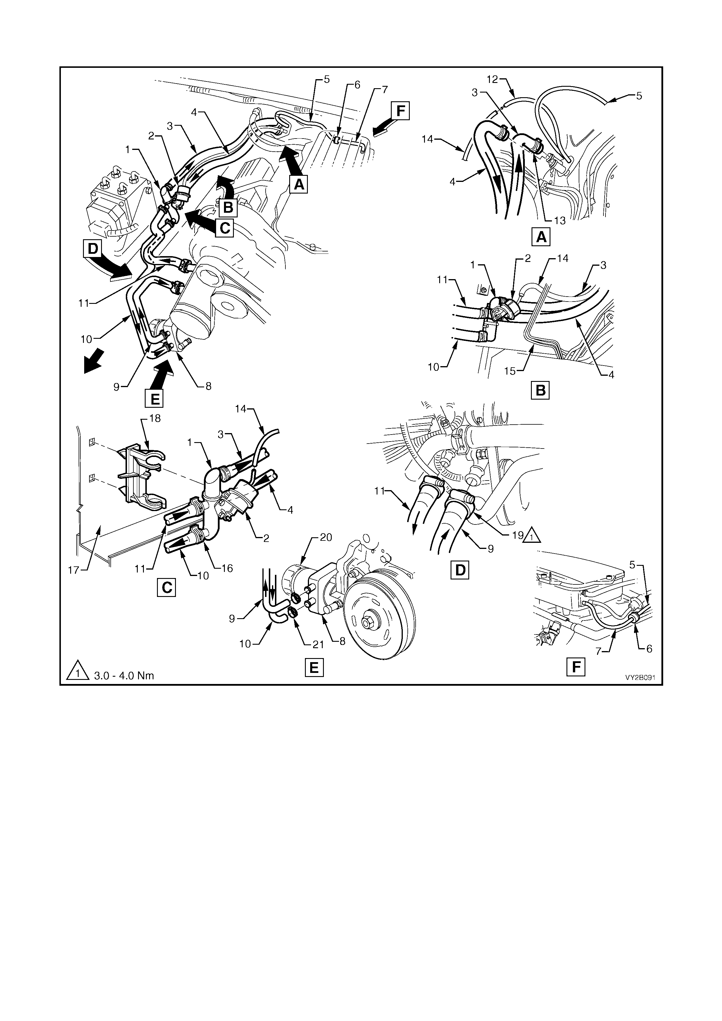
HEATER HOSES AND VACUUM LINES – V6 ENGINE LHD WITH OIL COOLER
Figure 2B-170
Legend
1. Water Valve 12. Vacuum Hose – To Vacuum Switch
2. Water Valve Actuator 13. Hose Clamps – Heater Core (2 places)
3. Heater Hose – To Cabin 14. Vacuum Hose – To Water Valve Actuator
4. Heater Hose – From Cabin 15. Brake Lines
5. Vacuum Hose (2 piece) – HVAC Supply 16. Hose Clamps – Water Valve (4 places)
6. Check Valve 17. Wheel House – RHS
7. Vacuum Hose – To Inlet Manifold 18. Mounting Clip – Water Valve
8. Oil Cooler 19. Hose Clamps – Engine (2 places)
9. Heater Hose – To Engine 20. Oil Filter
10. Heater Hose – To Oil Cooler 21. Hose Clamps – Oil Cooler (2 places)
11. Heater Hose – From Engine NOTE: Heater hoses and vacuum hose to be routed
behind brake lines as shown in View B.
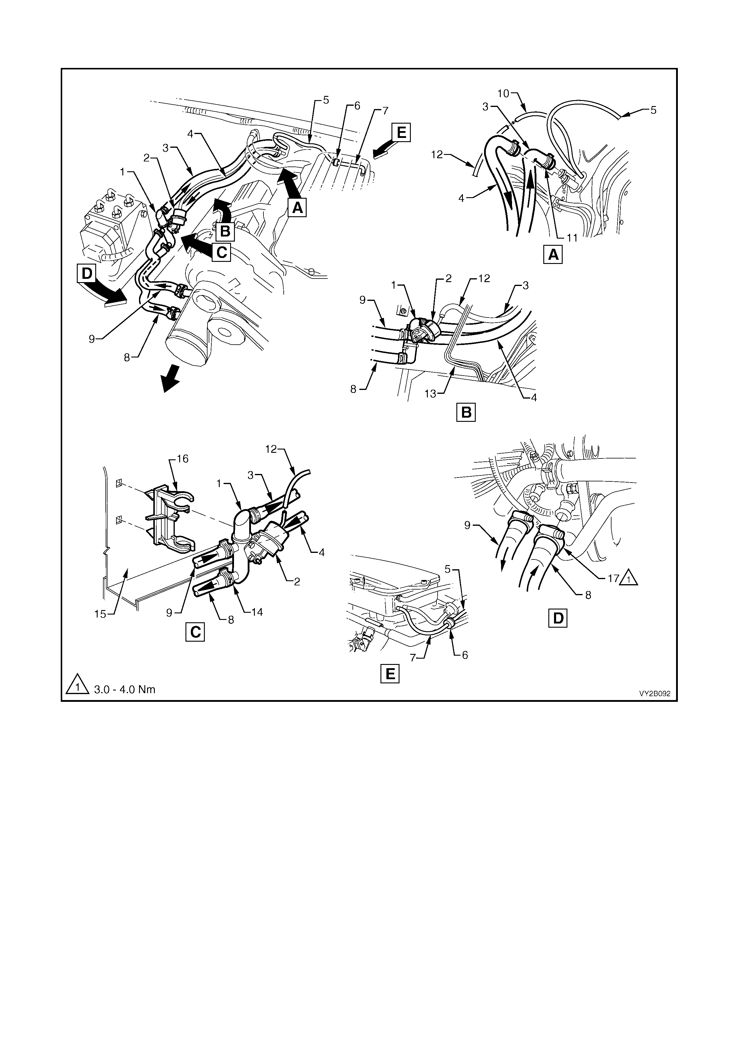
HEATER HOSES AND VACUUM LINES – V6 ENGINE LHD WITHOUT OIL COOLER
Figure 2B-171
Legend
1. Water Valve 10. Vacuum Hose – To Vacuum Switch
2. Water Valve Actuator 11. Hose Clamps – Heater Core (2 places)
3. Heater Hose – To Cabin 12. Vacuum Hose – To Water Valve Actuator
4. Heater Hose – From Cabin 13. Brake Lines
5. Vacuum Hose (2 piece) – HVAC Supply 14. Hose Clamps – Water Valve (4 places)
6. Check Valve 15. Wheel House – RHS
7. Vacuum Hose – To Inlet Manifold 16. Mounting Clip – Water Valve
8. Heater Hose – To Engine 17. Hose Clamps – Engine (2 places)
9. Heater Hose – From Engine NOTE: Heater hoses and vacuum hose to be routed
behind brake lines as shown in View B.
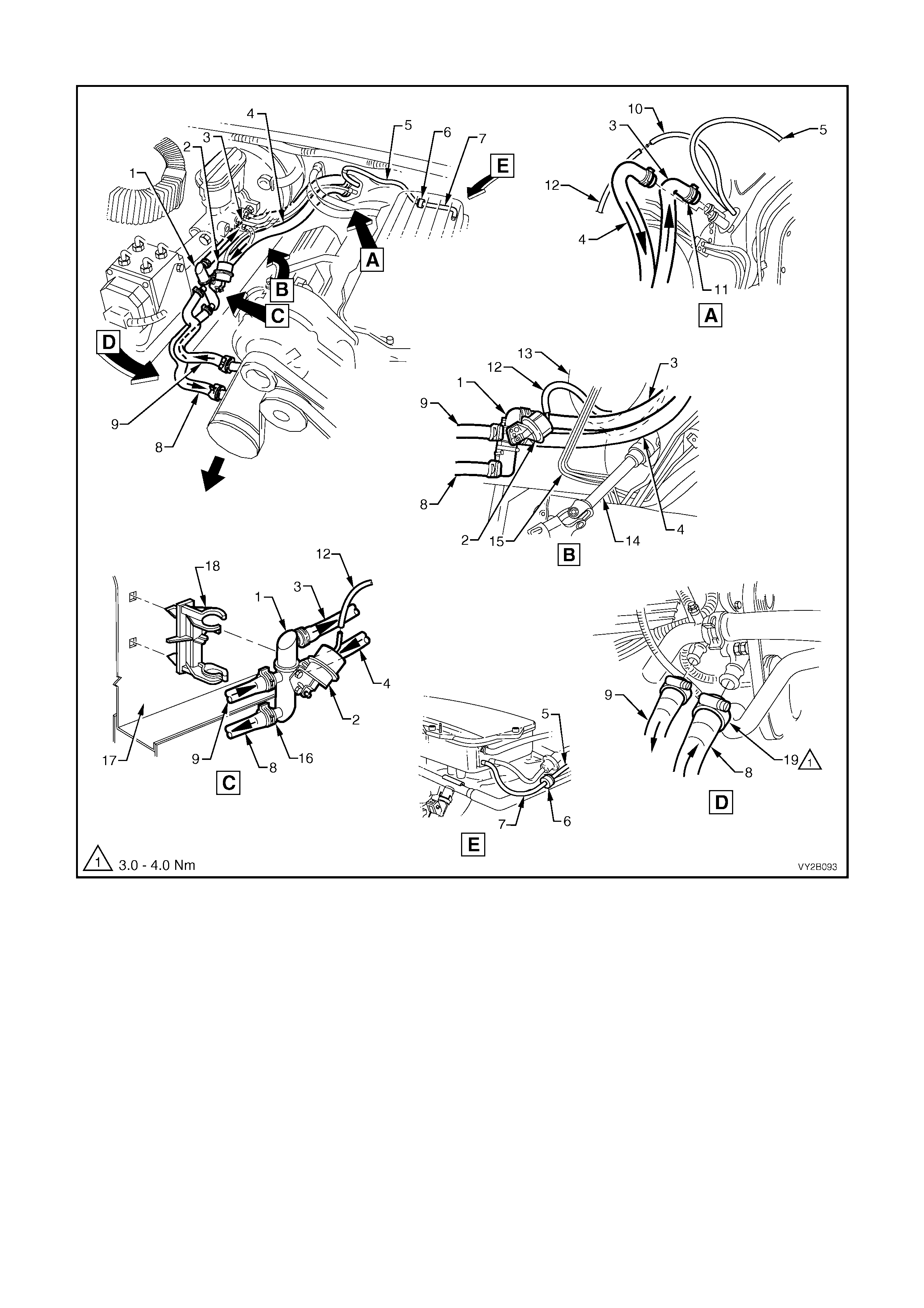
HEATER HOSES AND VACUUM LINES – V6 AND V6 SUPERCHARGED ENGINE RHD
Figure 2B-172
Legend
1. Water Valve 11. Hose Clamps – Heater Core (2 places)
2. Water Valve Actuator 12. Vacuum Hose – To Water Valve Actuator
3. Heater Hose – To Cabin 13. Brake Booster
4. Heater Hose – From Cabin 14. Steering Shaft
5. Vacuum Hose (2 piece) – HVAC Supply 15. Brake Lines
6. Check Valve 16. Hose Clamps – Water Valve (4 places)
7. Vacuum Hose – To Inlet Manifold 17. Wheel House – RHS
8. Heater Hose – To Engine 18. Mounting Clip – Water Valve
9. Heater Hose – From Engine 19. Hose Clamps – Engine (2 places)
10. Vacuum Hose – To Vacuum Switch NOTE: Heater hoses and vacuum hose to be routed
behind brake lines as shown in View B.
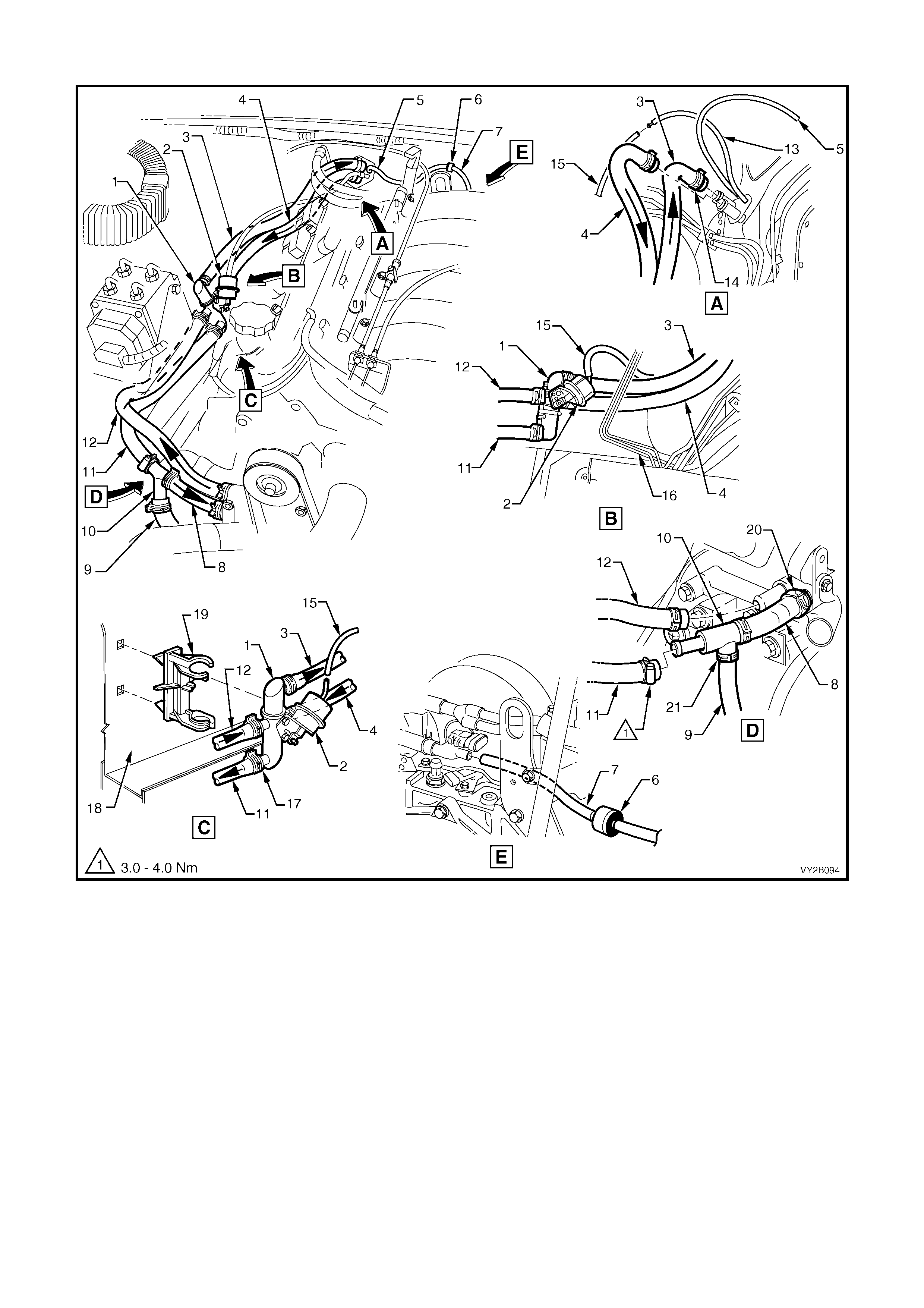
HEATER HOSES AND VACUUM LINES – GEN III V8 ENGINE LHD
Figure 2B-173
Legend
1. Water Valve 12. Heater Hose – From Engine
2. Water Valve Actuator 13. Vacuum Hose – To Vacuum Switch
3. Heater Hose – To Cabin 14. Hose Clamps – Heater Core (2 places)
4. Heater Hose – From Cabin 15. Vacuum Hose – To Water Valve Actuator
5. Vacuum Hose (2 piece) – HVAC Supply 16. Brake Lines
6. Check Valve 17. Hose Clamps – Water Valve (4 places)
7. Vacuum Hose – To Inlet Manifold 18. Wheel House – RHS
8. Heater Hose – To Engine 19. Mounting Clip – Water Valve
9. Hose – To Coolant Surge Tank 20. Hose Clamps – Engine (2 places)
10. Heater Hose T-piece 21. Hose Clamps – T-piece (3 places)
11. Heater Hose – To T-piece NOTE: Heater hoses and vacuum hose to be routed
behind brake lines as shown in View B.
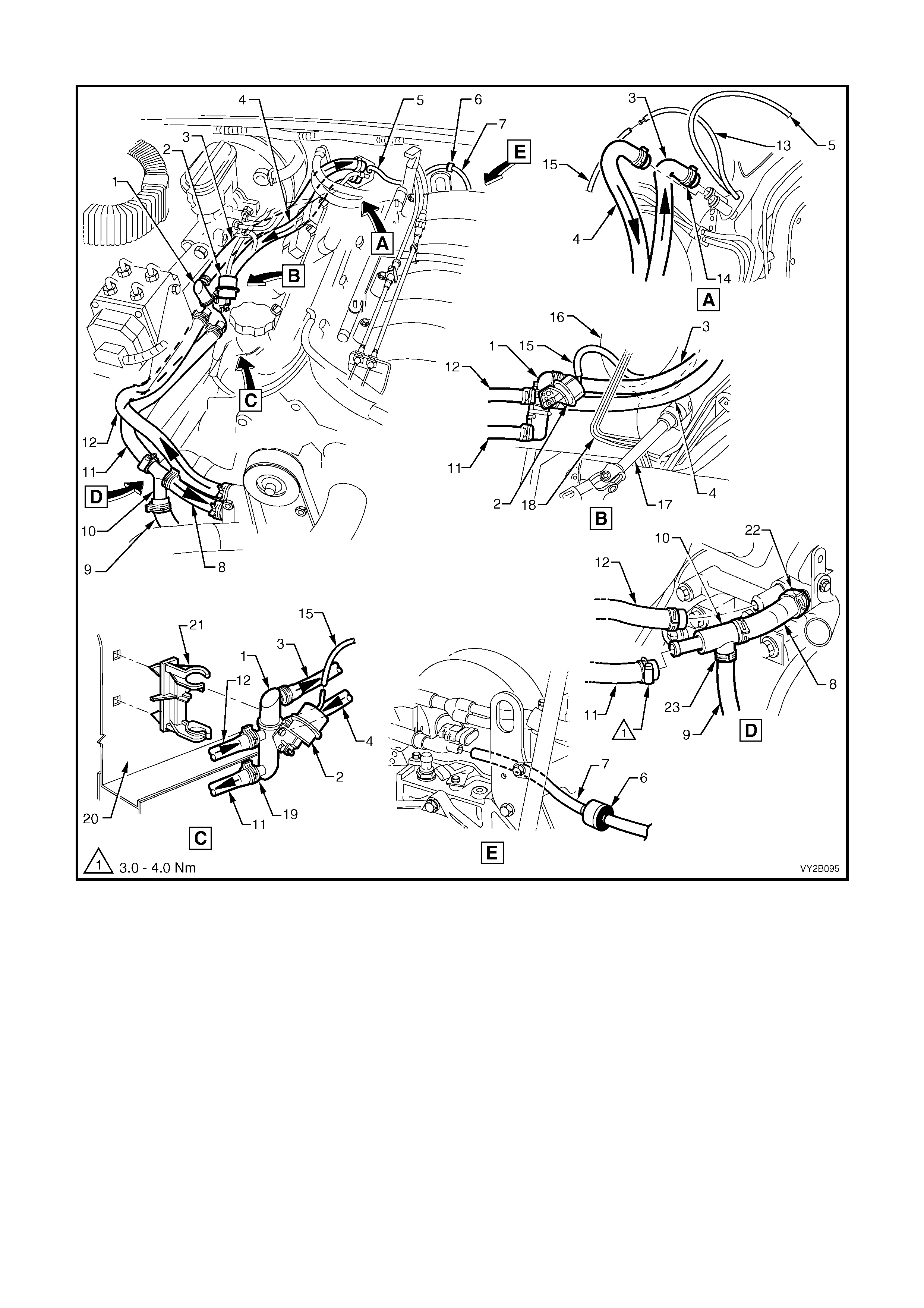
HEATER HOSES AND VACUUM LINES – GEN III V8 ENGINE RHD
Figure 2B-174
Legend
1. Water Valve 13. Vacuum Hose – To Vacuum Switch
2. Water Valve Actuator 14. Hose Clamps – Heater Core (2 places)
3. Heater Hose – To Cabin 15. Vacuum Hose – To Water Valve Actuator
4. Heater Hose – From Cabin 16. Brake Booster
5. Vacuum Hose (2 piece) – HVAC Supply 17. Steering Shaft
6. Check Valve 18. Brake Lines
7. Vacuum Hose – To Inlet Manifold 19. Hose Clamps – Water Valve (4 places)
8. Heater Hose – To Engine 20. Wheel House – RHS
9. Hose – To Coolant Surge Tank 21. Mounting Clip – Water Valve
10. Heater Hose T-piece 22. Hose Clamps – Engine (2 places)
11. Heater Hose – To T-piece 23. Hose Clamps – T-piece (3 places)
12. Heater Hose – From Engine NOTE: Heater hoses and vacuum hose to be routed
behind brake lines as shown in View B.
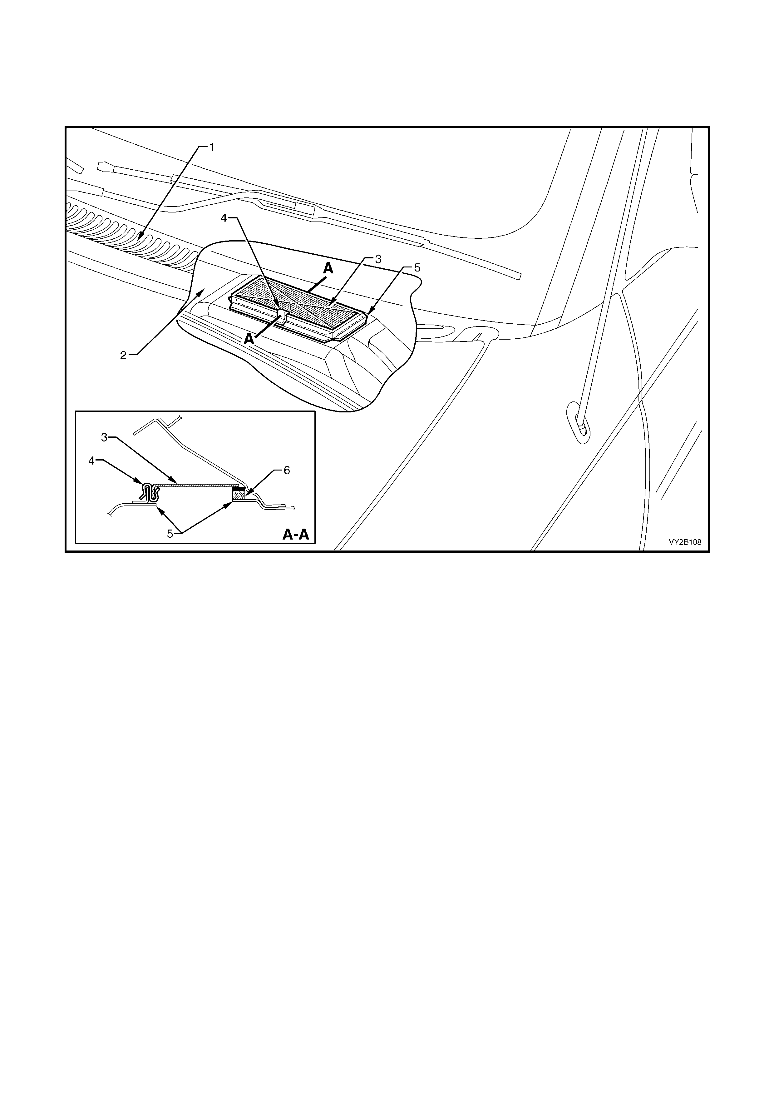
18. HVAC I NLET, DUCTS AND VENTILATION OUTLETS
18.1 HVAC INLET SCREEN
Figure 2B-175
Legend
1. Plenum Cover 4. HVAC Inlet Screen Retaining Clip
2. Plenum Chamber 5. HVAC Inlet
3. HVAC Inlet Screen 6. Foam seal
LT Section – 10-510
REMOVE
1. Remove the plenum cover and water deflector assembly. For all models except V2 Coupe, refer to
Section 12N, 2.5 PLENUM COVER ASSEMBLY, EXCEPT COUPE. For V2 Coupe models refer to
Section 12N, 2.6 PLENUM COVER ASSEMBLY – COUPE.
NOTE 1: Prior to removing the HVAC inlet mesh screen and clip assembly, clear away any foreign matter
such as leaves or twigs that m ay have accum ulated on or near the HVAC inlet m esh scr een. Failure to do so
may allow foreign matter to fall into the HVAC inlet causing noisy blower fan operation.
NOTE 2: Exercise c are when rem oving the m esh scr een and clip assem bly. Im proper rem oval technique will
distort the screen and may cause unsatisfactory screen fitting at HVAC inlet.
2. Remove the mesh screen from the HVAC inlet by grasping the mesh screen retaining clip and lifting the
mesh screen retaining clip and screen assembly upward clear of the HVAC inlet rim.
REINSTALL
Installation of the mesh screen and clip assembly is the reverse of removal procedures, noting the following
points:
1. Install the mesh screen and clip assem bly in the c orrect orientation, i.e. with the retaining clip to the f ront
of the vehicle and the foam seal to the rear of the vehicle, as shown in Figure 2B-175.
2. Install the m esh screen and clip assembly by applying light hand pressure to the outer edges only of the
upper face of the screen.
3. Ensure that the front and sides of the screen are installed within the rim of the HVAC inlet.
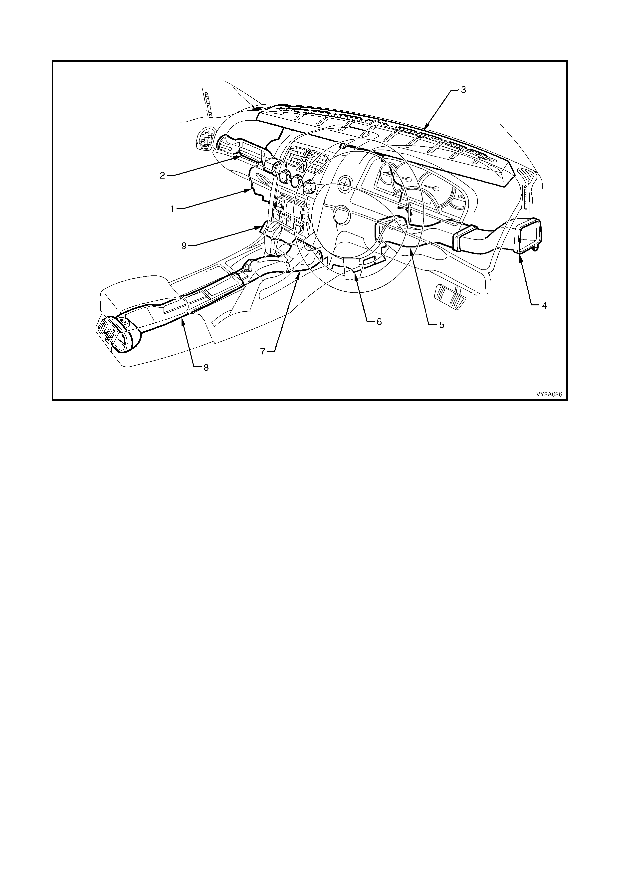
18.2 HVAC SYSTEM DUCTS
Figure 2B-176
Legend
1. HVAC Unit 6. Foot Duct Outlet – RHS
2. Passenger Side Duct 7. Floor Console Front Duct
3. Demister Cavity 8. Floor Console Rear Duct
4. Driver’s Side Outer Duct 9. Foot Duct Outlet – LHS
5. Driver’s Side Inner Duct
NOTE 1: Figure 2B-176 shows the HVAC ducting configuration as applicable to RHD models. Ducting configuration is
mirrored for LHD models.
NOTE 2: Items 7 and 8 are not fitted to utility models.
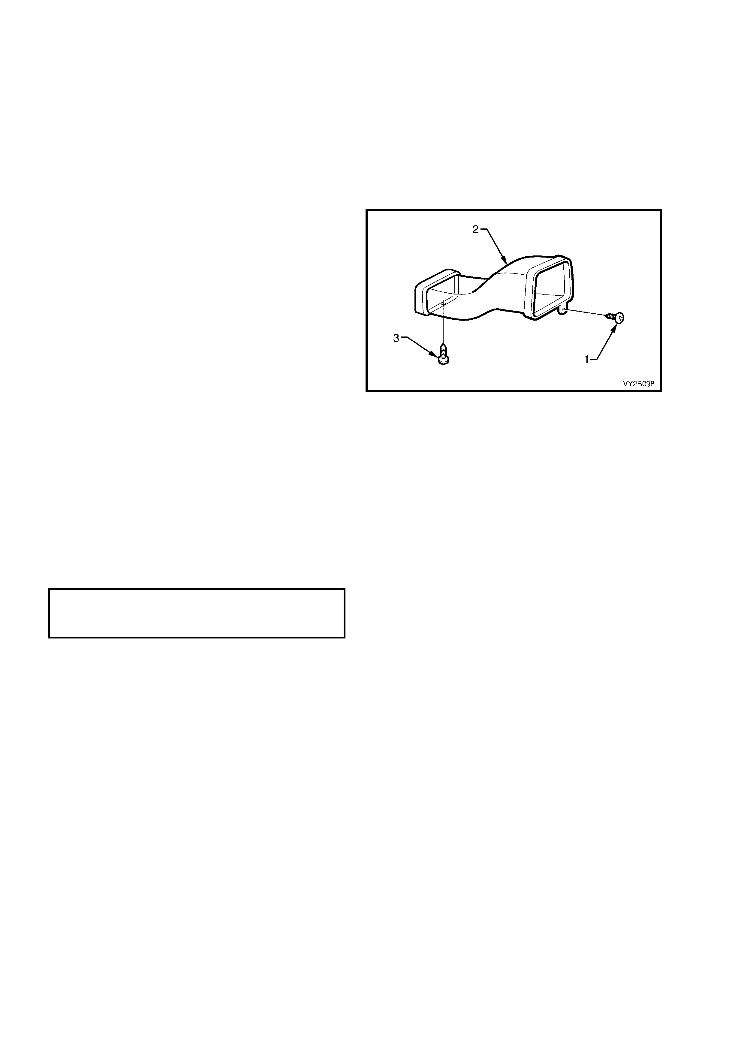
LT Section – 08-175
REMOVE – DRIVER’S SIDE OUTER DUCT
1. Remove the driver’s side instrument panel outer cover. Refer to Section 1A3, 3.17 INSTRUMENT PANEL
OUTER COVER.
2. Remove the driver’s side instrument panel lower trim plate assembly. Refer to
Section 1A3, 3.1 INSTRUMENT PANEL LOWER TRIM PLATE ASSEMBLY.
3. Remove the driver’s side instrument panel lower trim panel assembly. Refer to
Section 1A3, 3.4 INSTRUMENT PANEL LOWER TRIM PANEL ASSEMBLY.
4. Raise the steering column to its highest adjustment level.
5. Remove the screw (1) attaching the driver’s
side outer duct (2) to the instrument panel.
NOTE: The lower retaining screw (3) is removed
from the duct when the instrum ent panel lower trim
panel assembly is removed. On left-hand drive
models this screw retains only the inner duct to
the instrument panel lower trim panel assembly.
On right-hand dr ive models, this s crew retains both
the inner and outer duct to the instrument panel
lower trim panel assembly. Refer to item 4 in
Figure 2B-39.
6. Separate the inner duct from the outer duct by
partially withdrawing the outer duct through the
instrument panel side cavity.
7. Remove the inner duct from the HVAC unit
outlet.
8. Remove the inner duct through the instrument
panel lower trim panel cavity.
9. Remove the outer duct through the instrument
panel lower trim panel cavity.
Figure 2B-177
REINSTALL – DRIVER’S SIDE OUTER DUCT
Installation of the driver’s side outer duct is the reverse order of removal procedures noting the following:
1. Tighten all screws to the specified torque.
DRIVER SIDE OUTER DUCT
ATTACHING SCREW
TORQUE SPECIFICATION 1.0 – 3.0 Nm
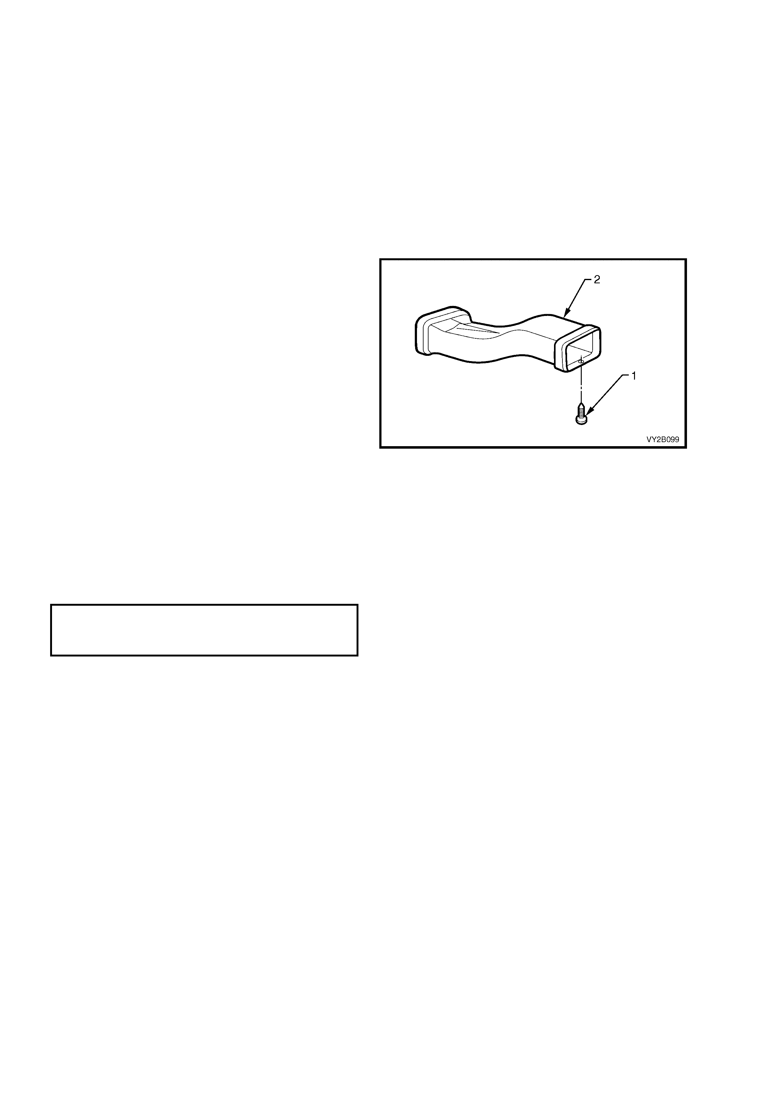
LT Section – 08-175
REMOVE – DRIVER’S SIDE INNER DUCT
1. Remove the driver’s side instrument panel outer cover. Refer to Section 1A3, 3.17 INSTRUMENT PANEL
OUTER COVER.
2. Remove the driver’s side instrument panel lower trim plate assembly. Refer to
Section 1A3, 3.1 INSTRUMENT PANEL LOWER TRIM PLATE ASSEMBLY.
3. Remove the driver’s side instrument panel lower trim panel assembly. Refer to
Section 1A3, 3.4 INSTRUMENT PANEL LOWER TRIM PANEL ASSEMBLY.
4. Raise the steering column to its highest adjustment level.
5. Remove the screw attaching the driver’s side outer duct to the instrument panel. Refer to item 1 in Figure
2B-177.
NOTE: T he retaining s c r ew (1) is removed fr om the
duct (2) when the instrument panel lower trim
panel assembly is removed. On left-hand drive
models this s crew retains only the inner duc t to the
instrument panel lower trim panel assembly.
On right-hand dr ive models, this s crew retains both
the inner and outer duct to the instrument panel
lower trim panel assembly. Refer to item 4 in
Figure 2B-39.
6. Separate the inner duct from the outer duct by
partially withdrawing the outer duct through the
instrument panel side cavity.
7. Remove the inner duct from the HVAC unit
outlet.
8. Remove the inner duct through the instrument
panel lower trim panel cavity.
Figure 2B-178
REINSTALL – DRIVER’S SIDE INNER DUCT
Installation of the driver’s side inner duct is the reverse order of removal procedures noting the following:
1. Tighten all screws to the specified torque.
DRIVER SIDE INNER DUCT
ATTACHING SCREW
TORQUE SPECIFICATION 1.0 – 3.0 Nm
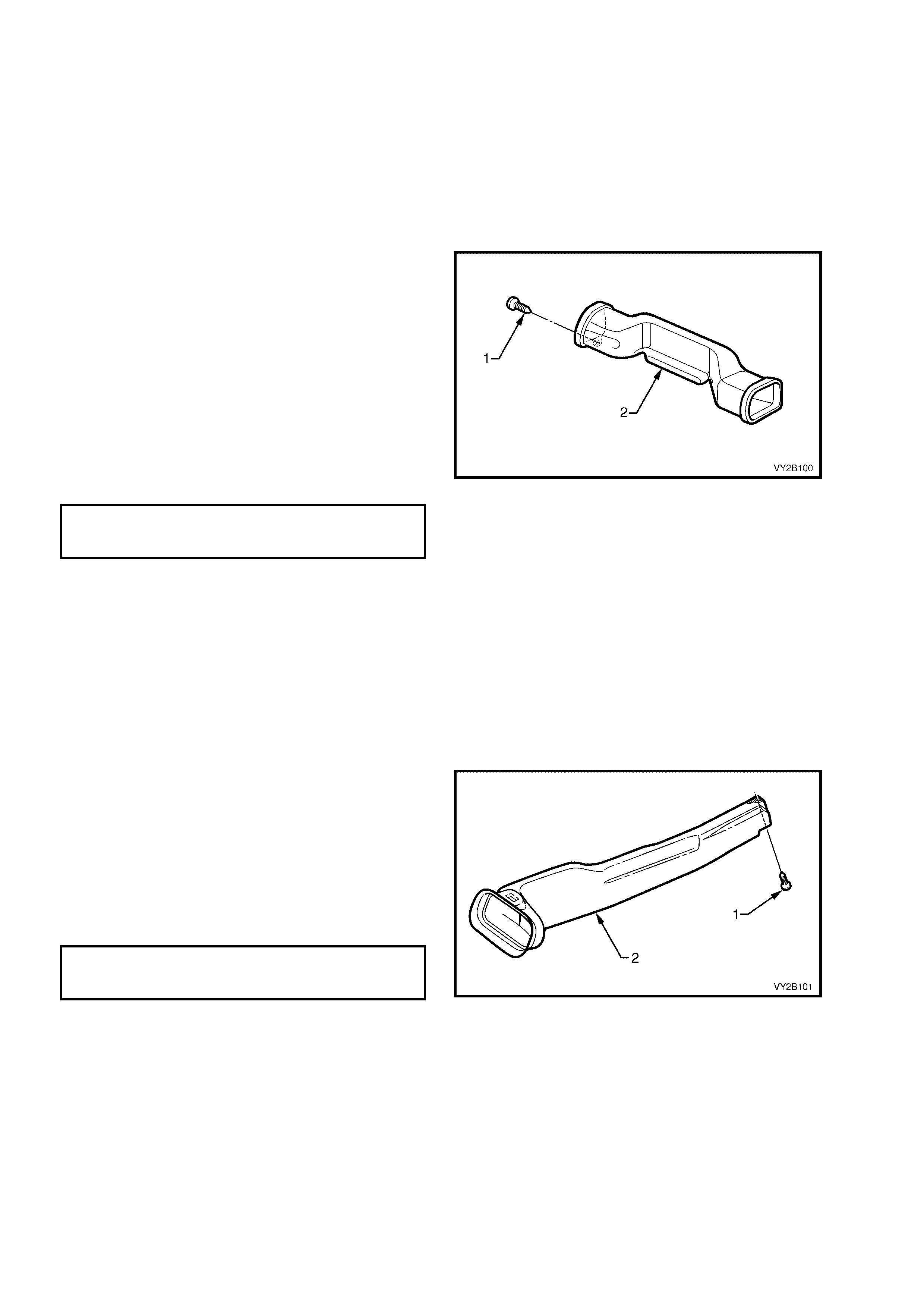
LT Section – 08-175
REMOVE – PASSENGER SIDE DUCT
1. Remove the instrument panel pad assembly. Refer to Section 1A3, 3.21 INSTRUMENT PANEL PAD
ASSEMBLY.
2. If fitted, remove the instrument panel inflatable restraint module assembly. Refer to
Section 12M, 2.4 INSTRUMENT PANEL INFLATABLE RESTRAINT MODULE ASSEMBLY. For models
not fitted with an instrument panel inflatable restraint module assembly, remove the instrument panel outer
upper bracket. Refer to Figure 2B-60.
NOTE: The s crew (1) attaching the passenger side
duct (2) to the instrum ent panel is removed as part
of the instrument panel pad assembly removal
procedure. Refer to item 2 in Figure 2B-32.
3. Remove the passenger side duct from the
HVAC unit outlet.
4. Remove the passenger side duct.
REINSTALL – PASSENGER SIDE DUCT
Installation of the passenger side duct is the
reverse order of removal procedures noting the
following:
1. Tighten all screws to the specified torque.
PASSENGER SIDE DUCT
ATTACHING SCREW
TORQUE SPECIFICATION 1.0 – 3.0 Nm
Figure 2B-179
LT Section – 08-175
REMOVE – FLOOR CONSOLE REAR DUCT
1. Remove the floor console assembly. Refer to the removal procedures in Section 1A3, 2.3 FLOOR
CONSOLE ASSEMBLY.
2. Remove the rear outlet housing from the floor console assembly. Refer to the floor console disassembly
procedures in Section 1A3, 2.3 FLOOR CONSOLE ASSEMBLY.
3. Remove the screw (1) attaching the rear
duct (2) to the floor console.
4. Remove the rear duct from the floor console.
REINSTALL – FLOOR CONSOLE REAR DUCT
Installation of the floor console rear duct is the
reverse order of removal procedures noting the
following:
1. Tighten all screws to the specified torque.
FLOOR CONSOLE REAR DUCT
ATTACHING SCREW
TORQUE SPECIFICATION 1.0 – 3.0 Nm
Figure 2B-180
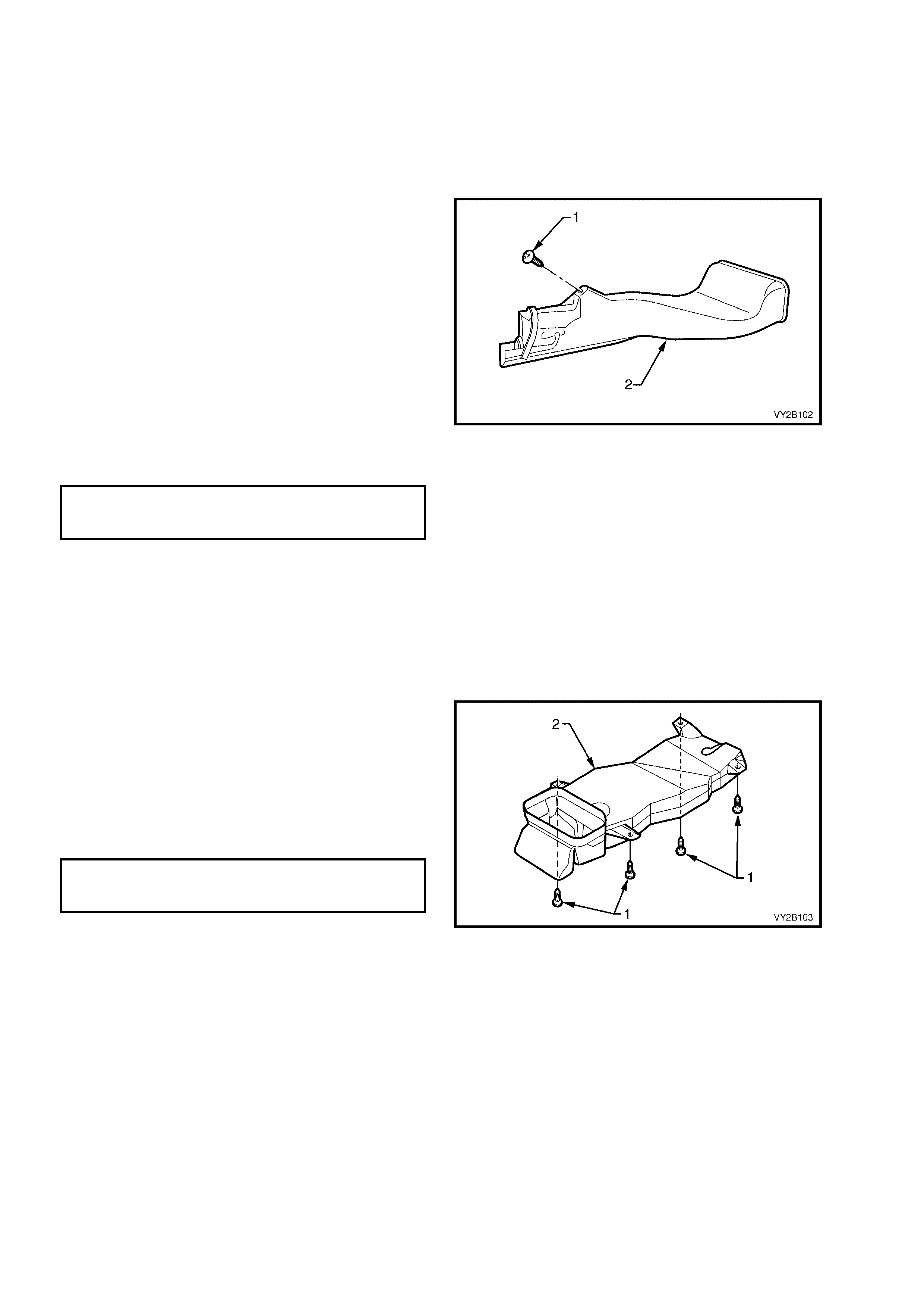
LT Section – 08-175
REMOVE – FLOOR CONSOLE FRONT DUCT
1. Remove the floor console assembly, refer to Section 1A3, 2.3 FLOOR CONSOLE ASSEMBLY.
2. Remove the left-hand side instrument panel lower extension side trim. Refer to Section 1A3,
2.2 INSTRUMENT PANEL LOWER EXTENSION SIDE TRIM.
3. Remove the screw (1) attaching the floor
console front duct (2) to the left-hand side
instrum ent panel lower extension. Refer also to
item 3 in Figure 2B-19.
4. Remove the duct away f rom the HVAC unit and
towards the rear of the vehicle.
5. Rem ove the duc t through the apertur e between
the left-hand side instrument panel lower
extension and the transmission tunnel.
REINSTALL – FLOOR CONSOLE FRONT DUCT
Installation of the floor console front duct is the
reverse order of removal procedures noting the
following:
1. Tighten all screws to the specified torque.
FLOOR CONSOLE FRONT DUCT
ATTACHING SCREW
TORQUE SPECIFICATION 1.0 – 3.0 Nm
Figure 2B-181
LT Section – 08-175
REMOVE – FOOT DUCT, LHD
1. Remove the HVAC unit. Refer to 3. HEATING, VENTILATION AND AIR CONDITIONING (HVAC) UNIT in
this Section.
2. Remove the four screws (1) attaching the foot
duct (2) to the underside of the HVAC unit.
3. Remove the foot duct from the HVAC unit.
REINSTALL – FOOT DUCT, LHD
Installation of the foot duct is the reverse order of
removal procedures noting the following:
1. Tighten all screws to the specified torque.
FOOT DUCT
ATTACHING SCREW
TORQUE SPECIFICATION 1.0 – 3.0 Nm
Figure 2B-182
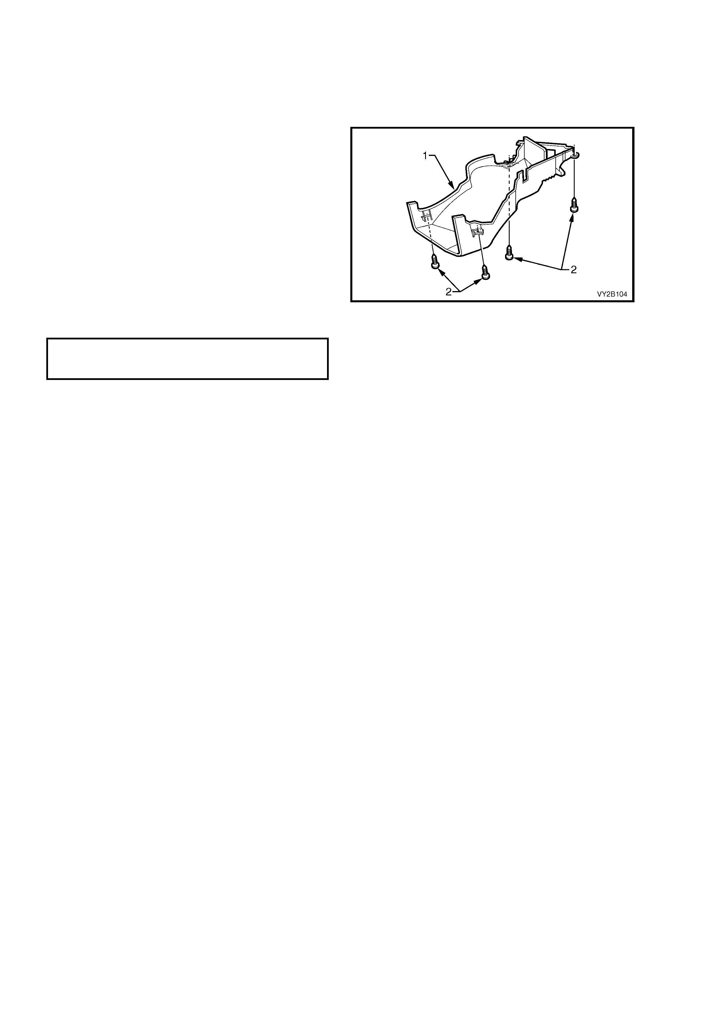
LT Section – 08-175
REMOVE – FOOT DUCT, RHD
1. Remove the HVAC unit. Refer to 3. HEATING, VENTILATION AND AIR CONDITIONING (HVAC) UNIT in
this Section.
2. Remove the vac uum lines f or the face and foot
actuators from the retaining clips on the
underside of the foot duct (1).
3. On OCC (Auto A/C) HVAC units, remove the
harness for the air mix motor/s from the foot
duct.
4. Remove the four screws (2) attaching the foot
duct to the underside of the HVAC unit.
5. Remove the foot duct from the HVAC unit.
REINSTALL – FOOT DUCT, RHD
Installation of the foot duct is the reverse order of
removal procedures noting the following:
1. Tighten all screws to the specified torque.
FOOT DUCT
ATTACHING SCREW
TORQUE SPECIFICATION 1.0 – 3.0 Nm
Figure 2B-183
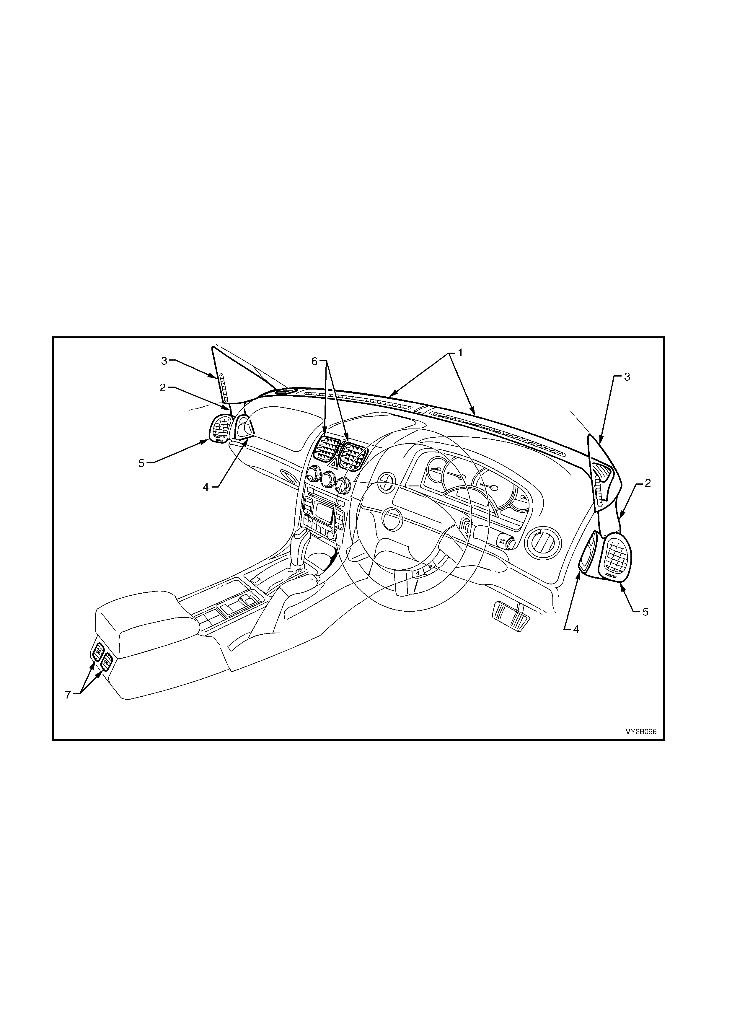
18.3 CABIN VENTILATION OUTLETS
LT Section – 08-175
REMOVE AND REINSTALL
Referring to Figure 2B-184:
• To remove and install the windshield defroster grilles (1), refer to Section 1A3, 3.18 WINDSHIELD
DEFROSTER GRILLE.
• To remove and install the side window defogger duct (2) and side window defogger outlet (3), refer to
Section 1A5, 2.6 FRONT DOOR TRIM PANEL ASSEMBLY.
• To remove and install the front door air duct assembly (4) and front door air outlet assembly (5), refer to
Section 1A5, 2.6 FRONT DOOR TRIM PANEL ASSEMBLY.
• To remove and install the centre air outlet assembly (6), refer to Section 1A3, 3.7 INSTRUMENT PANEL
CENTRE TRIM ASSEMBLY.
• To remove and install the rear outlet housing assembly (7), refer to Section 1A3, 2.3 FLOOR CONSOLE
ASSEMBLY.
Figure 2B-184
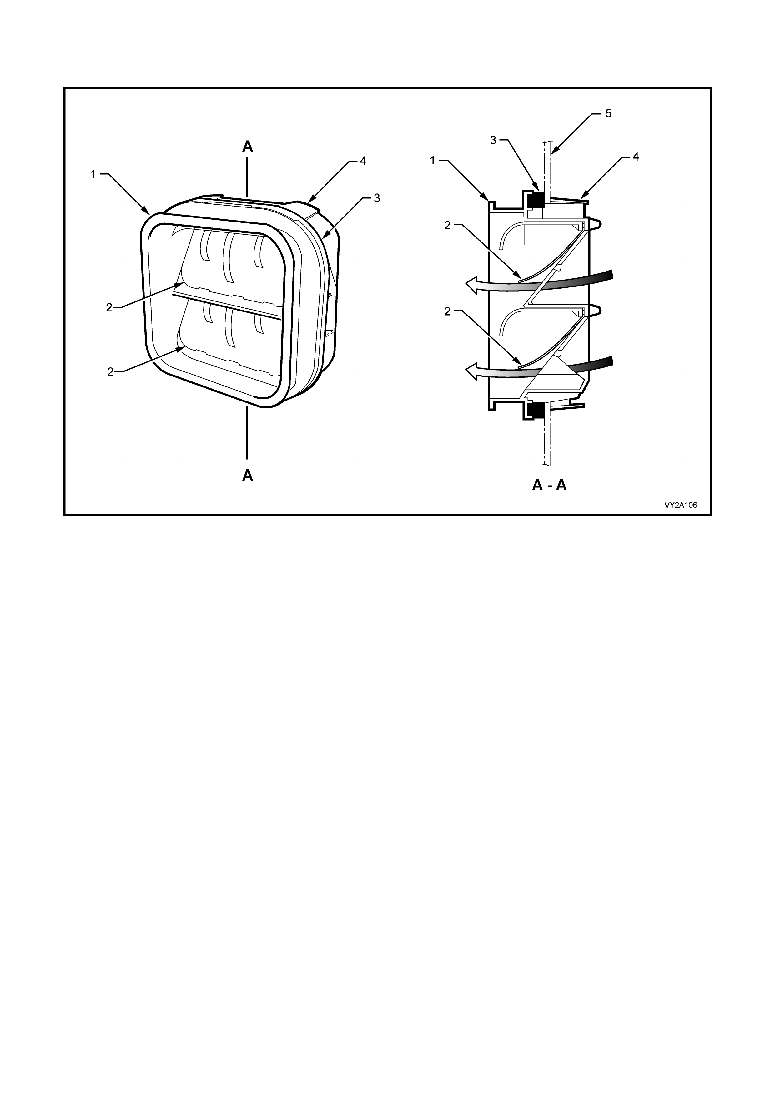
18.4 BODY VENTILATION OUTLETS
Figure 2B-185
Legend
1. Outlet Housing 4. Locking Tab (4 places)
2. Rubber Seal 5. Body Panel
3. Foam Seal
NOTE: For body ventilation outlet locations, refer to Figure 2B-186.
LT Section – 08-700
REMOVE – SEDAN AND COUPE
1. Rem ove the rear bum per fas cia assem bly. Refer to Section 1D, 2.5 REAR BUMPER FASCIA ASSEM BLY,
SEDAN AND COUPE.
2. As required, remove the left-hand side or right-hand side quarter inner rear side carpet. Refer to
Section 1A8, 2.17 QUARTER INNER REAR SIDE CARPET.
3. From inside the rear compartment, press the locking tabs at each corner of the ventilation outlet housing
while simultaneously moving it partially outward of the vehicle.
4. From outside the vehicle, remove the body ventilation outlet from the quarter panel.
REINSTALL – SEDAN AND COUPE
Installation of the body ventilation outlet is the reverse of removal procedures, noting the following points:
1. Install the body ventilation outlet in the correct vertical orientation, i.e. as shown in Figure 2B-185.
2. Ensure all four locking tabs are fully engaged on the inner side of the body panel.

REMOVE – WAGON
1. Rem ove the rear bum per fas cia assem bly. Refer to Section 1D, 2.6 REAR BUMPER FASCIA ASSEM BLY,
WAGON.
2. Carefully insert a flat bladed implement between the body panel and the foam seal at the corners on the
bottom of the ventilation outlet housing.
3. Use the implement to press the two locking tabs at the bottom of the ventilation outlet housing. W hile doing
so, allow the ventilation outlet housing to move upward within the body aperture.
4. Partially remove the ventilation outlet housing by withdrawing the lower section from the body aperture.
5. Move the body ventilation outlet downward within the body aperture and remove it the from the quarter panel.
REINSTALL – WAGON
Installation of the body ventilation outlet is the reverse of removal procedures, noting the following points:
1. Install the body ventilation outlet in the correct vertical orientation, i.e. as shown in Figure 2B-185.
2. Ensure all four locking tabs are fully engaged on the inner side of the body panel.
REMOVE – UTILITY
1. If fitted, remove the LPG tank. Refer to Section 8A2, 3.6 LPG TANK – UTILITY.
2. Remove the load floor front panel assembly. Refer to Section 1B, 2.7 LOAD FLOOR FRONT PANEL
ASSEMBLY, UTILITY.
3. Remove the seat back body panel trim assembly. Refer to Section 1A8, 5.11 SEAT BACK BODY PANEL
TRIM.
4. From inside the passenger compartment, press the locking tabs at each corner of the ventilation outlet
housing while simultaneously moving it partially outward of the passenger compartment.
5. From within the body cavity below the load floor front panel assembly, remove the body ventilation outlet from
the floor panel extension.
REINSTALL – UTILITY
Installation of the body ventilation outlet is the reverse of removal procedures, noting the following points:
1. Install the body ventilation outlet in the correct vertical orientation, i.e. as shown in Figure 2B-185.
2. Ensure all four locking tabs are fully engaged on the inner side of the body panel.
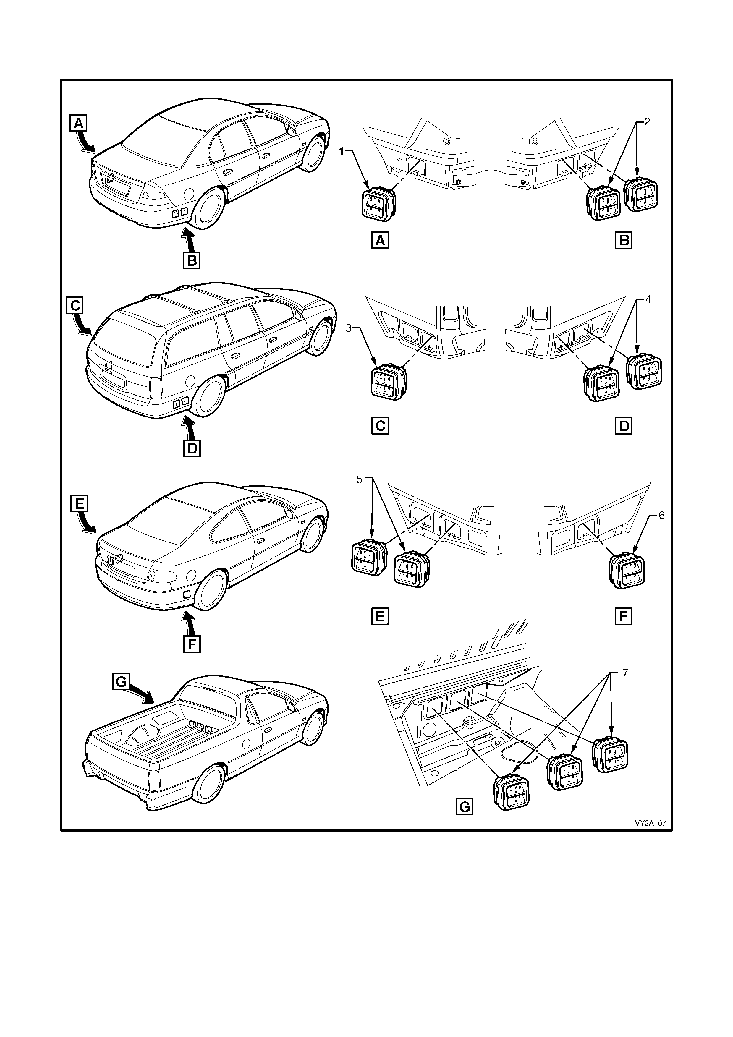
Figure 2B-186 shows the locations of body ventilation outlets across the MY2003 VY and V2 Coupe model range.
Figure 2B-186
Legend
1. Body Ventilation Outlet, Sedan – LHS 5. Body Ventilation Outlets, Coupe – LHS
2. Body Ventilation Outlets, Sedan – RHS 6. Body Ventilation Outlet, Coupe – RHS
3. Body Ventilation Outlet, Wagon – LHS 7. Body Ventilation Outlets, Utility
4. Body Ventilation Outlets, Wagon – RHS

19. TORQUE WRENCH SPECIFICATIONS
Nm
Floor console screw.................................................................................................1.0 – 3.0
Instrument panel centre trim assembly screw..........................................................1.0 – 3.0
Blower motor and fan assembly attaching screw.....................................................5.0 – 8.0
HVAC unit case screw .............................................................................................1.0 – 3.0
HVAC Manual controller securing screw..................................................................1.0 – 3.0
Evaporator tube plate securing screws....................................................................4.0 – 4.5
Liquid and suction tube retaining plate to TXV screw............................................7.5 – 12.5
TXV to evaporator tubes securing screw.................................................................4.0 – 4.5
Suction and discharge hose assembly retaining nut............................................25.0 – 35.0
FDR tube unions....................................................................................................7.5 – 12.5
Compressor retaining bolts (GEN III V8) .............................................................40.0 – 60.0
Idler pulley locking bolt.........................................................................................40.0 – 50.0
Idler pulley mounting bracket retaining nut (V6)...................................................20.0 – 30.0
Idler pulley retaining bolt ......................................................................................40.0 – 50.0
Clutch drive plate and hub assembly retaining nut ..............................................11.0 – 22.0
Evaporator pipe screw ......................................................................................................5.0
Heater core pipe retaining screw .............................................................................3.0 – 5.0
Blower motor resistor attaching screw.....................................................................1.0 – 3.0
Vacuum tank attaching screw..................................................................................1.0 – 3.0
Fresh / Recirculation actuator attaching screw........................................................3.0 – 5.0
Face actuator attaching nut (LHD)...........................................................................3.0 – 5.0
Face actuator attaching screw (RHD)......................................................................3.0 – 5.0
Foot actuator attaching screw..................................................................................3.0 – 5.0
Demist actuator attaching screw (LHD)...................................................................3.0 – 5.0
FDR mounting bracket screw.................................................................................7.5 – 12.5
Air conditioning compressor drive belt idler pulley bolt...................................................50.0
Air conditioning compressor drive belt tensioner bolt .....................................................25.0
Air conditioning compressor mounting bracket retaining bolt ..............................40.0 – 60.0
Suction and discharge hose pad retaining nut.....................................................28.0 – 42.0
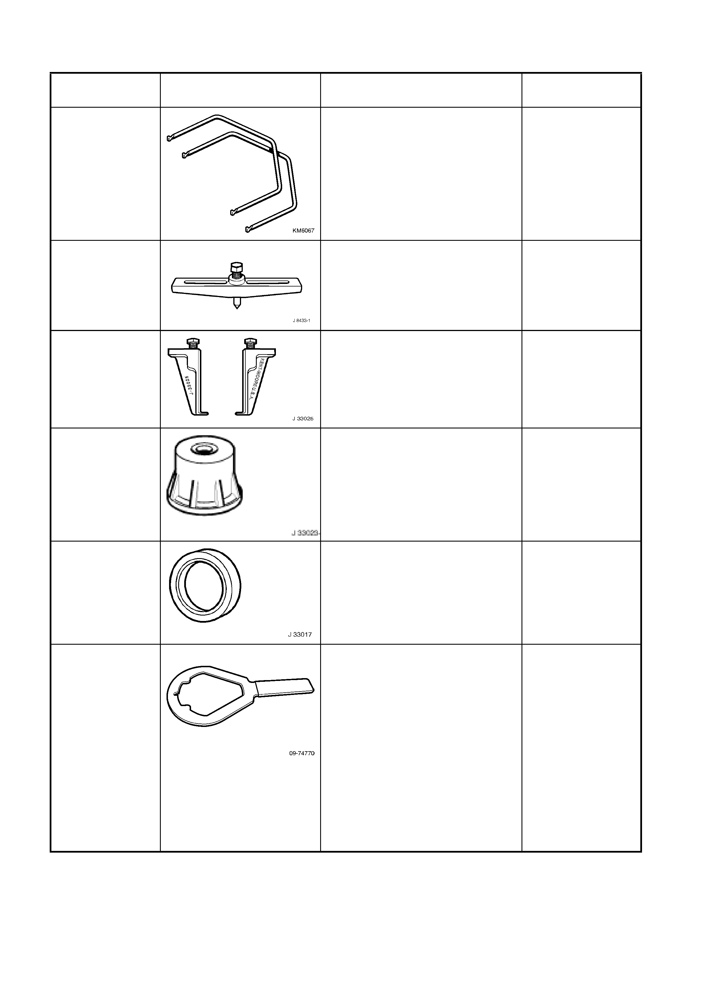
20. SPECIAL TOOLS
TOOL NUMBER ILLUSTRATION DESCRIPTION TOOL
CLASIFICATION
KM6067 RADIO REMOVAL TOOL
Used for removing VY audio unit
from its mounting location.
New tool for VY.
Mandatory
J-8433-1
PULLER BAR
Used for removing clutch pulley and
bearing assembly from A/C
compressor shaft.
Desirable
J-33025
CLUTCH COIL PULLER LEGS
Used for removing clutch pulley and
bearing assembly from A/C
compressor shaft.
Desirable
J-33023-A PULLER PILOT
Used for removing clutch pulley and
bearing assembly from A/C
compressor shaft.
Desirable
J-33017
A/C COMPRESSOR PULLEY AND
BEARING ASSEMBLY TOOL
Used in conjunction with installer
tool 09-74767 for installing A/C
clutch pulley and bearing assembly
to A/C compressor housing.
Desirable
09-74770 A/C CLUTCH HUB HOLDER
Used for holding A/C clutch
hub/drive plate during A/C clutch
drive plate and hub assembly
removal and installation.
Available from:
The Aftermarket Department
Air International P/L
80 Turner Street
Port Melbourne
Victoria, 3207
Desirable
TOOL NUMBER ILLUSTRATION DESCRIPTION TOOL
CLASIFICATION
09-74767 A/C CLUTCH HUB AND DRIVE
PLATE INSTALLER
Used for installing A/C clutch drive
plate and hub assembly.
Available from:
The Aftermarket Department
Air International P/L
80 Turner Street
Port Melbourne
Victoria, 3207
Desirable
09-74768 A/C CLUTCH HUB AND DRIVE
PLATE REMOVER
Used for removing A/C clutch drive
plate and hub assembly.
Available from:
The Aftermarket Department
Air International P/L
80 Turner Street
Port Melbourne
Victoria, 3207
Desirable
AU435 COOLANT TESTER Mandatory
AU425 COOLING SYSTEM FILLER TUBE Mandatory