
SECTION 2C - HVAC CLIMATE CONTROL
(MANUAL A/C) – SERVICING AND DIAGNOSIS
IMPORTANT:
Before performing any Service Operation or other procedure described in this Section, refer to Section 00
CAUTIONS AND NOTES for correct workshop practices with regard to safety and/or property damage.
CONTENTS
1. PRECAUTIONS IN HANDLING REFRIGERANT
2. DISCHARGING SYSTEM – REFRIGERANT
RECOVERY
2.1 SYSTEM CHARGING AND EVACUATION
FILLING A DIAL-A-CHARGE CYLINDER
EVACUATION AND LEAK TEST
CHARGING SYSTEM
2.2 CHECKING SYSTEM OIL CHARGE
2.3 FLUSHING THE A/C SYSTEM FOR
CONTAMINATION OR LUBRICATING OIL
REMOVAL
2.4 LUBRICATING OIL COMPENSATION
REINSTALLING THE ORIGINAL
COMPRESSOR
INSTALLING A NEW COM PRESSOR
EVAPORATOR OR CONDENSER
FILTER DRIER RECEIVER (FDR)
BLOWN OR RUPTURED PIPE/HOSE
3. DIAGNOSIS
3.1 THERMAL EXPANSION VALVE (TXV)
REMAINS OPEN
CONDITION
CAUSE
3.2 THERMAL EXPANSION VALVE (TXV)
REMAINS CLOSED
CONDITION
CAUSE
3.3 RESTRICTION IN HIGH SIDE OF SYSTEM
CONDITION
CAUSE
3.4 EXCESSIVE MOISTURE
CONDITION
CAUSE
3.5 CONDENSER MALFUNCTION OR OVERCHARGE
CONDITION
CAUSE
3.6 EXCESSIVE AIR (NON CONDENSABLES)
CONDITION
CAUSE
3.7 COMPRESSOR MALFUNCTION
CONDITION
CAUSE
3.8 COMPRESSOR CONTROL VALVE
MALFUNCTION
CONDITION
CAUSE
4. DELPHI V5 AND V7COMPRESSOR
TXV SYSTEM DIAGNOSTICS
DIAGNOSTIC FLOW CHART
PRELIMINARY CHECKS
VEHICLE SET UP AND PERFORMANCE TEST
GENERAL AND SPECIFIC SYSTEM
CONDITION CHARTS
COMPRESSOR CONTROL TEST
STEP 1 – PRELIMINARY CHECKS
STEP 2 – CHECKING REFRIGERANT
CHARGE
STEP 3 – CHECKING COMPRESSOR
CLUTCH ENGAGEMENT
STEP 4 – CHECKING SYSTEM
PERFORMANCE
STEP 5 – DIAGNOSTIC CHART
STEP 6 – DIAGNOSTIC CODE
PROCEDURES
A: REFRIGERANT OVERCHARGE OR
RESTRICTED RECEIVER/DRIER.
B: TXV BLOCKED. OUTLET TEMPERATURE
COOL TO WARM.
C: TXV STUCK OPEN.
D: COMPRESSOR NOT PUMPING, OUTLET
TEMPERATURE IS AMBIENT.
STEP 7 – CHECKING FOR NO STROKE
COMPRESSOR
STEP 8 – CONTROL VALVE DIAGNOSIS
5. NOISE DIAGNOSIS
6. PERFORMANCE TESTING
STEP 1
STEP 2
STEP 3
STEP 4
STEP 5
STEP 6
STEP 7
STEP 8
7. ELECTRICAL COMPONENT TESTS
7.1 BLOWER MOTOR RESISTOR
LHD
RHD
7.2 BLOWER FAN SWITCH
8. VACUUM RETENTION TESTS
VACUUM CIRCUIT SCHEMATICS
VACUUM LOSS DEFAULT SETTINGS
8.1 HVAC SYSTEM CHECK VALVE
8.2 VACUUM TANK
8.3 VACUUM MODE VALVE
8.4 WATER VALVE VACUUM SWITCH
8.5 VACUUM ACTUATORS AND LINES
ACCESS – LHD
TEST – LHD
REINSTALL – LHD
ACCESS – RHD
TEST – RHD
REINSTALL – RHD
8.6 VACUUM ACTUATORS
8.7 WATER VALVE
Techline
Techline
Techline

9. WIRING DIAGRAMS
CONNECTORS: MANUAL A/C
HVAC SYSTEM
CONNECTORS: MANUAL A/C
HVAC SYSTEM CONTINUED
CONNECTORS: MANUAL A/C
HVAC SYSTEM CONTINUED
WIRING DIAGRAM: MANUAL A/C
HVAC SYSTEM – V6 LHD
WIRING DIAGRAM: MANUAL A/C
HVAC SYSTEM – V6 RHD
WIRING DIAGRAM: MANUAL A/C
HVAC SYSTEM – GEN III V8 LHD
WIRING DIAGRAM: MANUAL A/C
HVAC SYSTEM –GEN III V8 RHD
10. SPECIAL TOOLS

1. PRECAUTIONS IN HANDLING REFRIGERANT
In any vocation or trade, there are established procedures and practices, which have been developed after many
years of experience. In addition, occupational hazards may be present that require the observation of certain
precautions, or use of special tools and equipment. Observing the procedures, practices and precautions of
servicing refrigeration equipment will greatly reduce the possibility of damage to the vehicle, as well as virtually
eliminating the element of hazard to the service technician.
Care should be tak en when discharging the air conditioning system to ensure that the refriger ant is not released to
the atmosphere but captured for recycling. Environmentally friendly refrigerant R134a is not an ozone depleting
substance but its release would add to the green house warming effect.
Refrigerant R134a is transparent and colourless in both the gaseous and liquid states. At all normal temperatures
and pressures it will be a vapour. The vapour is heavier than air and is non-flammable, non-explosive, non-
poisonous and non-corrosive (except when in contact with moisture).
The following precautions in handling R134a should be observed at all times:
NOTE: R134a and R12 are not compatible and must never be mixed.
1. Always use saf ety glasses and gloves when handling or s ervicing air c onditioning systems . If R134a does enter
the eye, f reezing of the eye can occur and could r esult in blindness . T he procedur e outlined below is suggested
if R134a enters the eyes.
a. Keep calm.
b. Do not rub eyes.
c. Splash large quantities of cool water into the eyes to raise the temperature.
d. Tape a sterile eye patch in place to prevent dirt from entering the eye.
e. Go immediately to a doctor or hospital for professional treatment.
DO NOT ATTEMPT TO TREAT YOURSELF
2. Always use proper workshop practices. Skylarking is dangerous!
3. Always work in a well ventilated area.
4. Avoid skin contact, as R134a will cause frostbite on contact with bare skin.
5. Do not abuse the refrigerant cylinder, or any other tools you may need to use.
6. Do not weld or steam clean on or near any air conditioning components when pressurised. This may cause a
dangerous pressure build up in the system.
7. Do not discharge refrigerant into an enclosed area.
8. When purging a system, discharge the refrigerant slowly.
9. If it is necessary to transport or carry a cylinder of refrigerant in a car, keep it in the luggage compartment.
10. Refrigerant cylinders should always be protected from the radiant heat of the sun.
11. When filling a refrigerant cylinder, never completely fill it. Always leave space for expansion. If the cylinder is
com pletely f illed and the ambient tem perature increases , hydraulic pr essure within the cylinder will elevate to a
dangerous level.
REMEMBER: Prevention is better than cure.
2. DISCHARGING SYSTEM – REFRIGERANT RECOVERY
NOTE: Care should be tak en when disc harging the air c onditioning system to ensur e the ref rigerant is not released
to the atm osphere but captured for recycling. R134a is not an ozone depleting substance but its cost and the fact
that it does contribute to the greenhouse effect, make it essential that it is recovered.
Various Refr igerant Recovery Units (RRU) are now available. T he following procedure is typical for the use of these
units when recovering refrigerant from a vehicle air conditioning system.
1. Connect the RRU outlet to an R134a recovery cylinder with a refrigerant hose and open the valve on the
cylinder. Ensure that the cylinder has sufficient capacity to hold the refrigerant in the system to be serviced. This
can be confirmed by weighing the cylinder or by referring to the volume gauge if fitted.
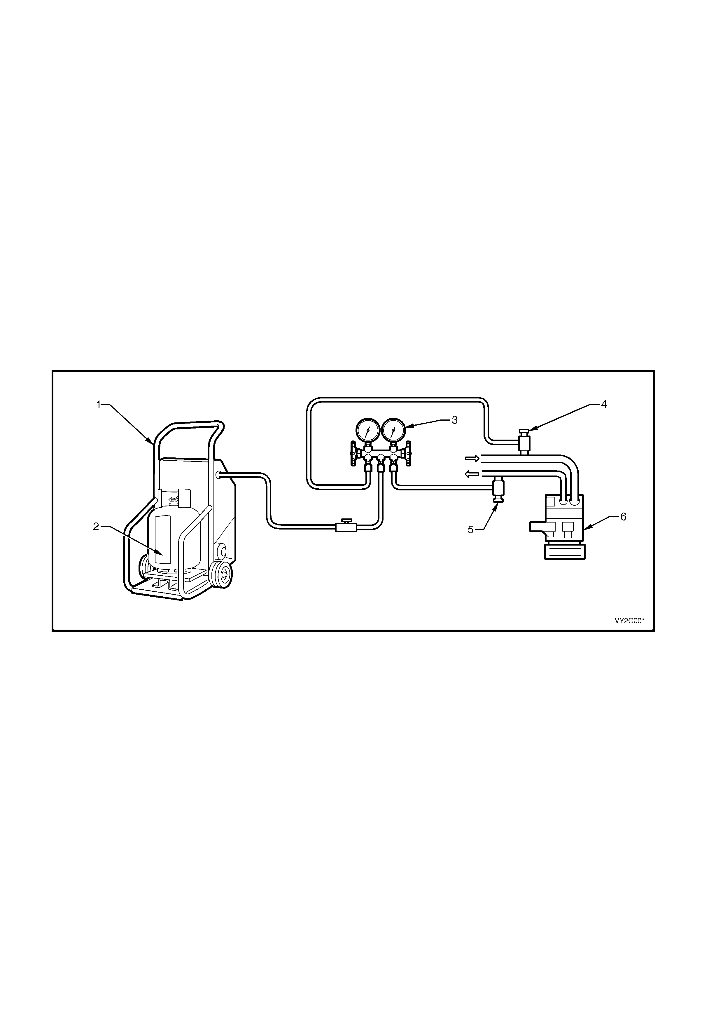
2. Connect a gauge m anifold s et to the vehicle air c onditioning system. Connect to both the suc tion and discharge
sides of the system. Connect the centre hose of the gauge set to the inlet of the recovery unit. Connect the
RRU to an electrical supply.
3. Open the gauge set and quickly connect the stop taps to allow the refrigerant to enter the RRU via the centre
hose. At this point, depending on which unit is being used, the RRU will switch on. If the RRU is not an
automated type, switch the unit on.
4. The autom atic recover y unit will operate until the air conditioning system has been emptied of refrigerant down
to atmospheric pressure. The cylinder can now be closed.
5. Measur e the amount of PAG oil r emoved f rom the A/C s ystem. This oil is normally separated fr om the incom ing
refrigerant into the RRU. New clean PAG oil must be added into the system before recharging it with refrigerant.
Figure 2C-1
Legend
1. Refrigerant Recovery Unit (RRU) 4. Low Side Charging Adaptor
2. Refrigerant Recovery Cylinder 5. High Side Charging Adaptor
3. Manifold/Gauge Set 6. Compressor
2.1 SYSTEM CHARGING AND EVACUATION
The following equipment is required for system charging and evacuation procedures:
1. Refrigerant calibration charging cylinder or weighing device.
2. Pressure gauges and hoses.
3. Vacuum pump.
4. Refrigerant Recovery Unit (including compressor and oil collector).
5. Electronic leak detector.
CAUTION: The wearing of safety goggles and gloves is mandatory during system charging or discharging.
NOTE: All hoses at point of connection to the system must have isolation valves fitted.
Charging the system includes the following steps:
1. Filling charging cylinder.
2. Evacuation and leak test.
3. Charging system.
4. Performance test.
FILLING A DIAL-A-CHARGE CYLINDER
1. Open the liquid valve on the R134a supply cylinder, allowing refrigerant to enter the ‘dial-a-charge’ cylinder.
2. Bleed the ‘dial-a-charge’ cylinder via the bleed valve on top (behind pressure gauge) as required to allow the
refrigerant to enter. This valve should be connected via a hose to a Refrigerant Recovery Unit (RRU) and
recovery cylinder. When the refrigerant reaches the desired level, close the supply valve at the bottom of the
‘dial-a-char ge’ cylinder and be certain that the bleed valve is als o securely closed. Close the liquid valve on the
R134a supply cylinder.
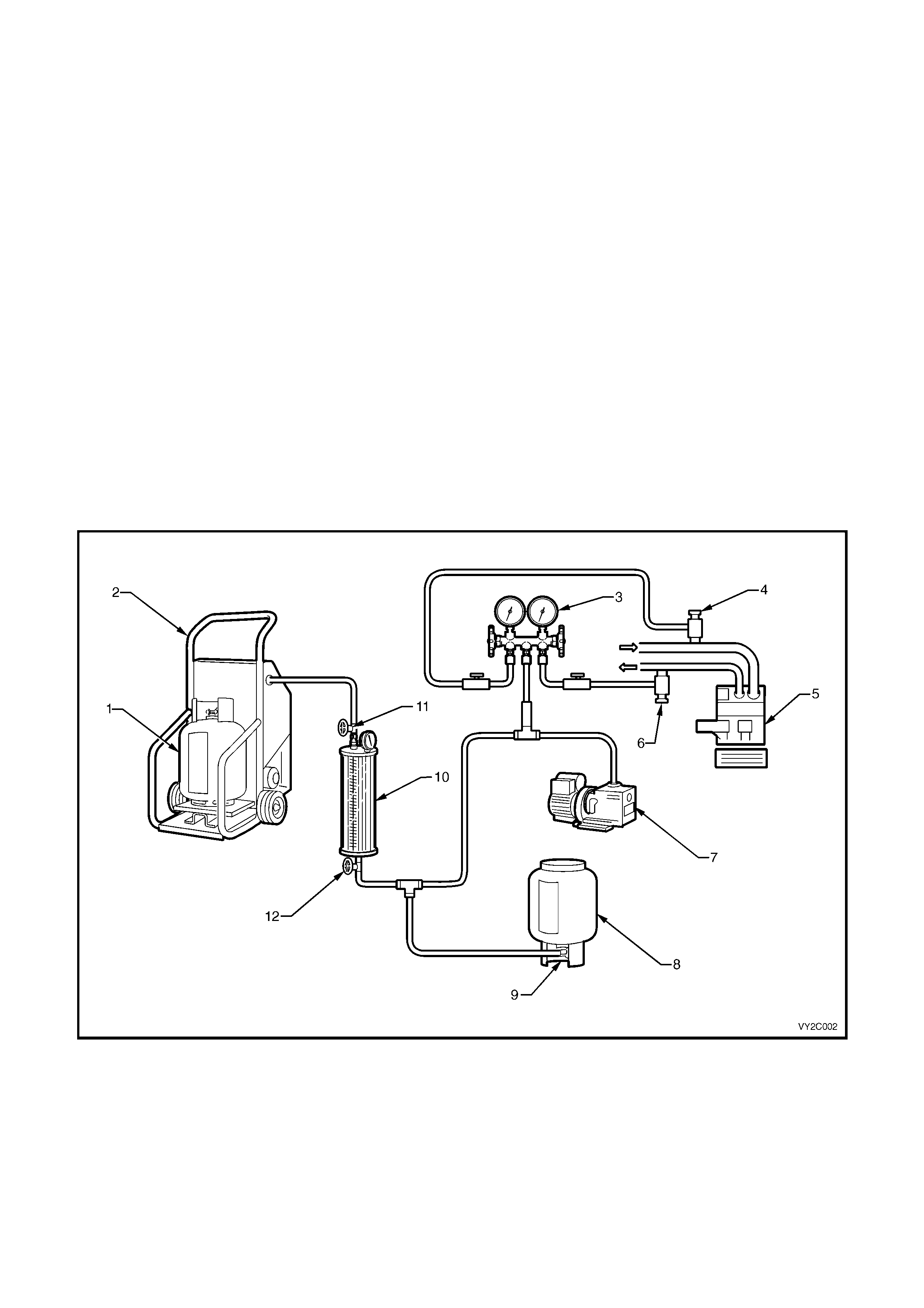
Figure 2C-2
Legend
1. Refrigerant Recovery Cylinder 7. Vacuum Pump
2. Refrigerant Recovery Unit (RRU) 8. R134a Supply Cylinder
3. Manifold Gauge Set 9. Liquid Valve
4. Low Side Charging Adaptor 10. ‘Dial -A-Charge’ Charging Cylinder
5. Compressor 11. Bleed Valve
6. High Side Charging Adaptor 12. Supply Valve

EVACUATION AND LEAK TEST
1. Check that both manifold hand valves of the gauge set are closed and turn the RRU off.
2. Connect the charging hoses onto the suction (low) and discharge (high) service valves in the system.
NOTE: DO NOT USE SPANNERS.
3. Connect the centre manifold charging hose to the vacuum pump inlet.
4. Start the vacuum pump and slowly open LOW SIDE manifold hand valve. Low side gauge reading should
decrease to 98 – 102 k Pa vacuum and the high side gauge should read s lightly below the zero index of gauge.
If high side gauge reading does not register, check system for a blockage or leak.
NOTE: When high side gauge is slightly below the zero index of the gauge, open the high side manifold hand valve.
5. After evacuating the system for 15 minutes to a vacuum of –100 kPa, close both the low and high side hand
valves, then stop the vac uum pum p. The system mus t hold a vacuum of –100kPa for a m inim um of 15 minutes .
If the specified vacuum is held then the system has no leaks and may continue to be evacuated for a further
15 minutes.
6. Wear safety goggles.
7. Connect the centre charging hose to the charging cylinder hand valve on the bottom of the cylinder. Open the
bottom charging cylinder hand valve. Do not open the low or high side valves on the manifold gauge at this
time.
8. Loosen the centre charging hose nut connected to the centre fitting of the manifold gauge set until a hiss can be
heard. Allow the air to escape for a few seconds, then re-tighten the nut.
NOTE: DO NOT START ENGINE.
9. Partially charge the system with 200 g of R134a by slowly opening the high side manifold hand valve; low side
gauge should register a pressure, if not, check for blockage. Close the high side manifold hand valve as soon
as 200 g of R134a has entered the system.
10. Check sys tem f or leaks with an electronic detector. If a leak is detected, rem ove refrigerant f rom system using
the RRU and repair the faulty component or connection. Repeat Steps 4 to 10 after repair of leak.
NOTE: Various types and makes of leak detectors are currently in use. Whichever leak detector is used, it is
important to follow the manufacturer’s instructions in regard to adjustment and setting the instrument prior to
conducting the test. Inspect for leaks by slowly moving the probe of the detector around all hose connections and
points of possible leakage. Refrigerant R134a is heavier than air and will be more apparent at the bottom of a fitting.
CHARGING SYSTEM
After a leak check has proven the system to be leak free, charge the proper amount of refrigerant into the system
as follows:
1 Open the HIGH SIDE manifold hand valve slowly. Fill the system with as much of the specified charge as
possible, then close the high side manifold hand valve.
2. Rotate the c ompres s or by hand for 12 revolutions to ens ure no liquid r ef r igerant is tr apped in the suc tion s ide of
the compressor. Failure to comply with this Step may result in damage to the compressor.
3. Start the engine and engage the compressor clutch and evaporator fan on high speed.
4. Set engine speed to 1500 – 1700 rpm.
5. If the system has been charged with the specified amount (775 – 825 g), go to Step 7.
6. To complete the charging of the system, slowly open the LOW side manifold hand valve until the specified
amount has been charged into the system.
CAUTION: Do not allow more than 275 kPa to be registered on the LOW pressure gauge.
7. Perform Cooling System Pressure Test, refer to COOLING SYSTEM PRESSURE TEST in the following
Sections:
Section 6B1 ENGINE COOLING – V6
Section 6B1-2 ENGINE COOLING – V6 SUPERCHARGED
Section 6B3 ENGINE COOLING – GEN III V8
If the unit operates satisfactorily, stop the engine, shut the stop valves at the hose connections to the system
and disconnect the hoses taking extreme caution, as the discharge hose can have up to 2070 kPa stored in it.
Install service valve caps as required.
WARNING: NEVER RUN THE COMPRESSOR WITHOUT REFRIGERANT IN SYSTEM AS COMPRESSOR
LUBRICANT RELIES ON REFRIGERANT FLOW.
No sight glass is fitted to the system due to PAG oil’s foaming properties, which may be confused with a low gas
charge. Topping up of the system is not recommended.

Accurate system refrigerant charge may only be determined by charging the system with the correct amount of
R134a.
Pressur e gauge readings together with face air outlet temperatur es ar e the only method of checking and diagnosing
the system cooling capacity (comparing results with the appropriate graph).
If in doubt as to the gas charge as a result of one the following conditions:
Suction pressure low,
Discharge pressure low,
Air outlet temperature (face) above graph range,
recover the refrigerant from the system using R134a specific equipment.
Evacuate the system. Charge with 775 – 825 g of R134a.
Carry out cooling system pressure test and suction (low side) pressure readings comparisons.

2.2 CHECKING SYSTEM OIL CHARGE
The compressor is charged at the factory with 265 ml of Delphi PAG refrigerant oil (Part No. 12345923), which
circulates within the entire A/C system. Only this type of oil (which is blue in colour) must be used when adding or
changing oil. This oil is not compatible with any other PAG oil.
Although it is not necessary to regularly check the oil level within the system, all the A/C system components will
hold a quantity of the oil circulated. Therefore whenever an A/C system component is replaced, a quantity of new
refrigerant (PAG) oil must be added to the system. Where a major loss of system oil has occurred, due to:
* A broken hose or severed leak,
* Collision damage to the refrigerant system components, or
* If excess oil is suspected to be in the system, then
1. Recover refrigerant from the system, then remove the compressor.
2. Carefully drain the refrigerant oil.
3. Flush remaining oil from the rest of the system using R134a refrigerant.
CAUTION: A Refrigerant Recovery Unit (RRU) should be used to flush the system, ensuring that the R134a
is not vented to the atmosphere. The R134a must be reclaimed via the RRU into a separate bottle.
4. Add 265 ml of new refrigerant oil to the compressor.
5. Install the c ompres s or, r eplac ing the suc tion and dis c harge O -r ings. Ens ur e that the O- rings are not twisted and
that the seals and O–rings are clean.
6. Evacuate then recharge the system.
PAG OIL PRECAUTIONS: DO NOT allow PAG oil to contact either bare skin or vehicle paintwork. IF CONTACT
OCCURS, WASH PAG OIL OFF IMMEDIATELY.
2.3 FLUSHING THE A/C SYSTEM FOR CONTAMINATION OR LUBRICATING OIL
REMOVAL
Some oil is lost whenever air conditioning system components are replaced.
Where the system has been ruptured, contaminated, or a compressor has to be removed and reinstalled or
replaced, the system should be checked for contamination and, if so, the entire system must be flushed.
Currently the only method recommended when flushing is with refrigerant R134a.
CAUTION: A Refrigerant Recovery Unit (RRU) should be used to capture the R134a used for flushing. The
R134a must be reclaimed via the RRU into a separate bottle. Use only a dedicated R134a RRU.
IMPORTANT: The complete air conditioning system must contain 265 ml (PAG refrigerant oil.
1. Flush the individual components.
2. Self m ade f lushing fittings will be r equired as A/C system com ponent f ittings all differ in size, shape and thread
size.
3. Invert decanting cylinder to use refrigerant in liquid form.
4. Reverse flush components.
5. Do not flush through a compressor otherwise possible internal damage could occur.
6. Recover/recycle flushing refrigerant, the recovery device will remove contaminants through its filtration system.
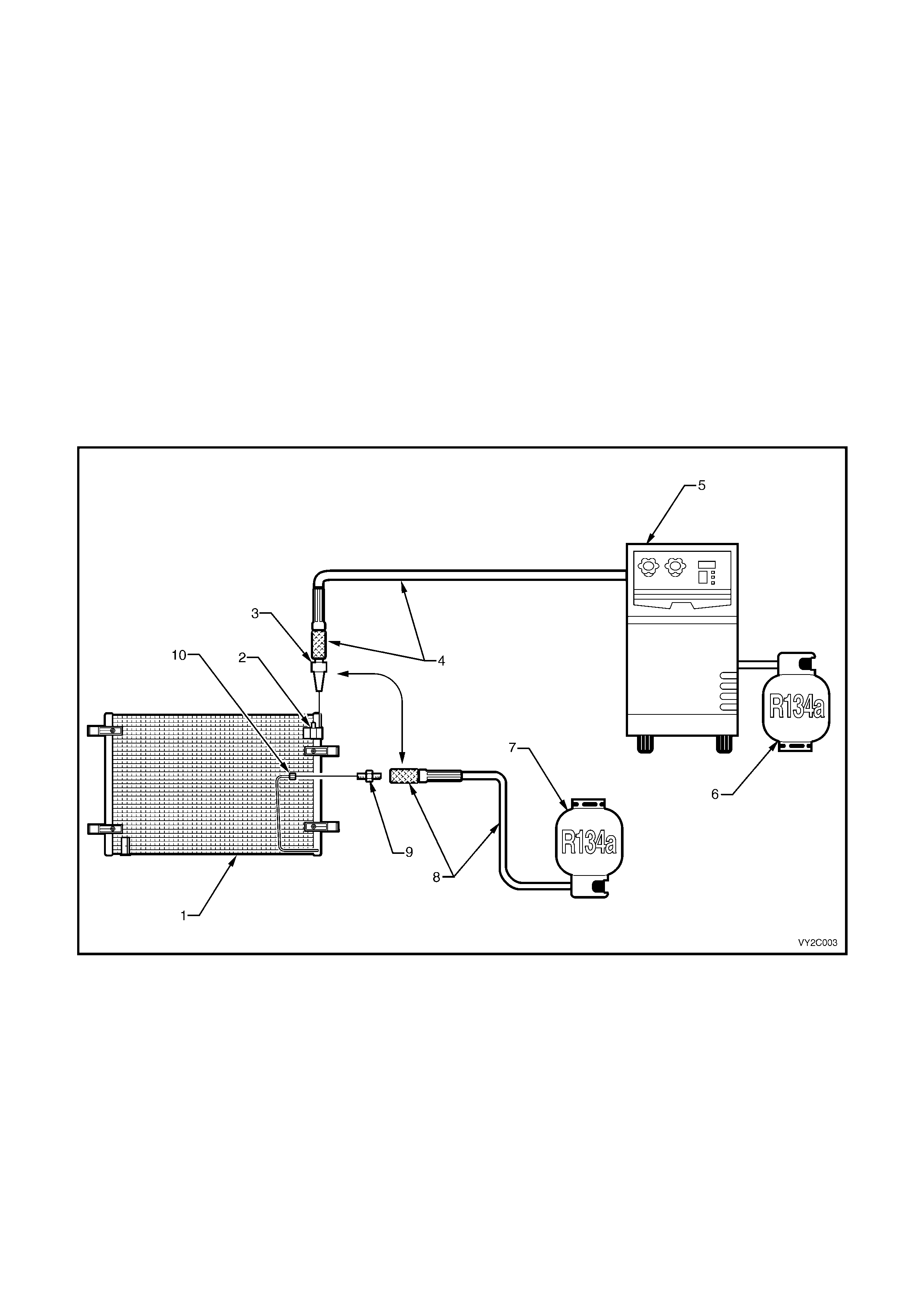
Figure 2C-3
Legend
1. Condenser 6. Refrigerant Recovery Cylinder
2. Condenser Inlet 7. R134a Supply Cylinder
3. Flush Gun 8. Flushing Hose And End Fitting
4. Recovery Hose And End Fitting 9. Adaptor
5. Refrigerant Recovery Unit (RRU) 10. Condenser Outlet
Note: To carry out reverse flush procedure the positions
of items 3 and 4 will be swapped with items 8 and 9.
2.4 LUBRICATING OIL COMPE NSATION
The total amount of lubricating oil in the air conditioning system must be m aintained. If a compressor, evaporator,
condenser, filter drier rec eiver , hose or pipe is to be replac ed, a s pec if ied amount of lubric ating oil mus t be added to
the system to compensate for oil removed with the original component.
REINSTALLING THE ORIGINAL COMPRESSOR
1. Drain and measure the refrigerant oil contained in the compressor.
2. Charge the oil through the discharge port of the compressor with the same amount of new refrigerant oil.
NOTE: If the amount of oil in the original c ompres s or was not chec ked, then approximately 150 cc of new oil should
be added to the compressor being installed. (This is assuming the compressor being installed has first been
drained).
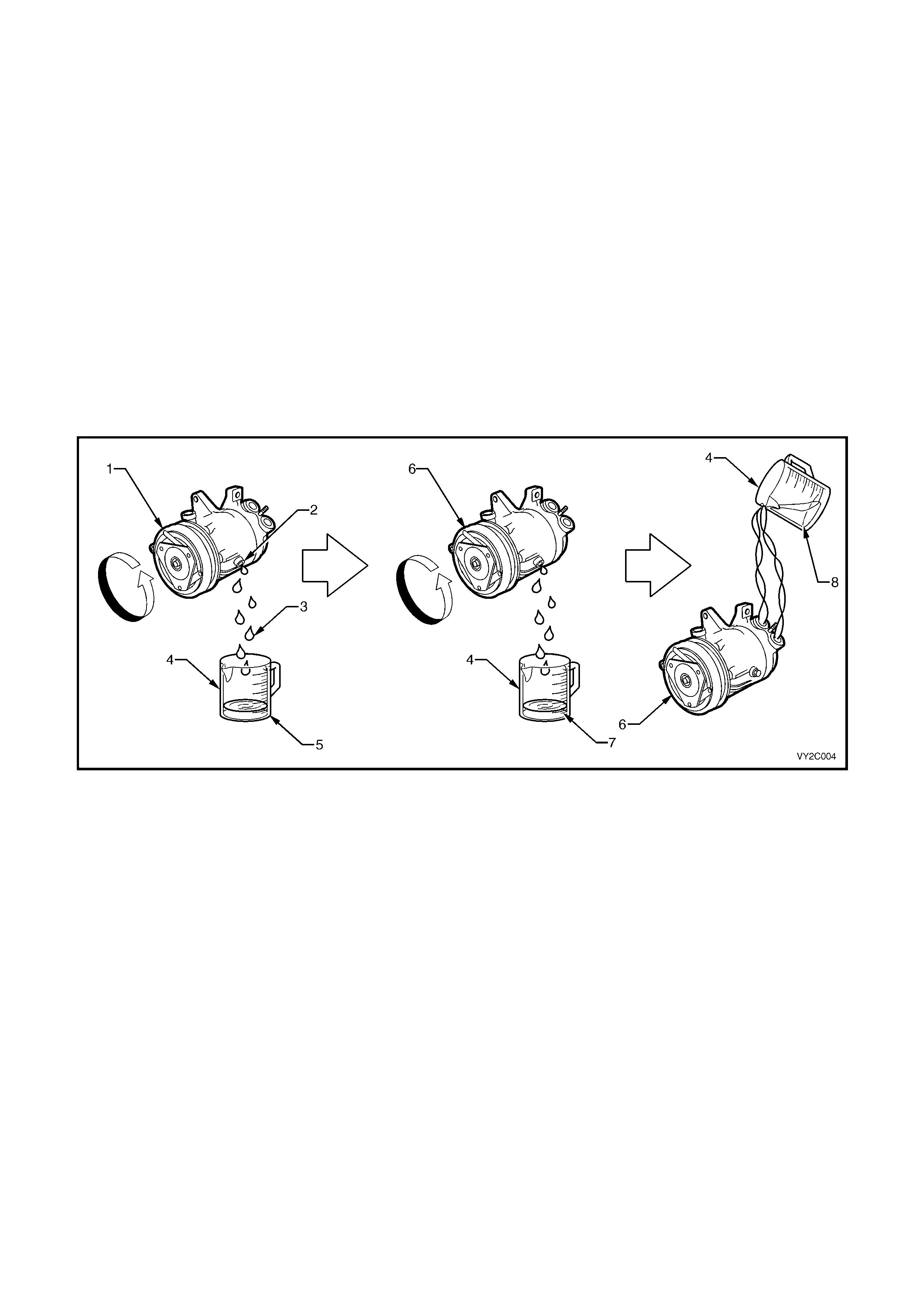
INSTALLING A NEW COMPRESSOR
1. Drain and measure refrigerant oil from the original compressor drain plug.
2. Drain factory installed refrigerant oil from new compressor drain plug (total lubricant quantity 220 ml).
3. Measure the same amount of new refrigerant oil that was drained from the original compressor. Install this
amount of oil into the new compressor through the suction/discharge port whilst turning the com pressor clutch
pulley front face.
Figure 2C-4
Legend
1. Faulty Compressor 5. Refrigerant Oil – Total Amount Removed: e.g. 100 cc
2. Drain Plug Location 6. New Compressor
3. Drained Refrigerant Oil From Faulty Compressor 7. Drained Refrigerant Oil From New Compressor
4. Graduated Container 8. Refrigerant Oil – Total Amount To Be Installed: 100 cc
EVAPORATOR OR CONDENSER
Drain as much of the original oil as possible from the evaporator or condenser. Add the same amount of new
refrigerant oil, either to the original or new evaporator or condenser.
If replacing condenser – add approximately 40 ml.
If replacing evaporator – add approximately 50 ml.
FILTER DRIER RECEIVER (FDR)
If replacing the FDR – add approximately 15 ml.
The FDR must be replaced whenever the system has been opened to the atmosphere for repair.
BLOWN OR RUPTURED PIPE/HOSE
When replacement is required add approximately 40 ml.
3. DIAGNOSIS
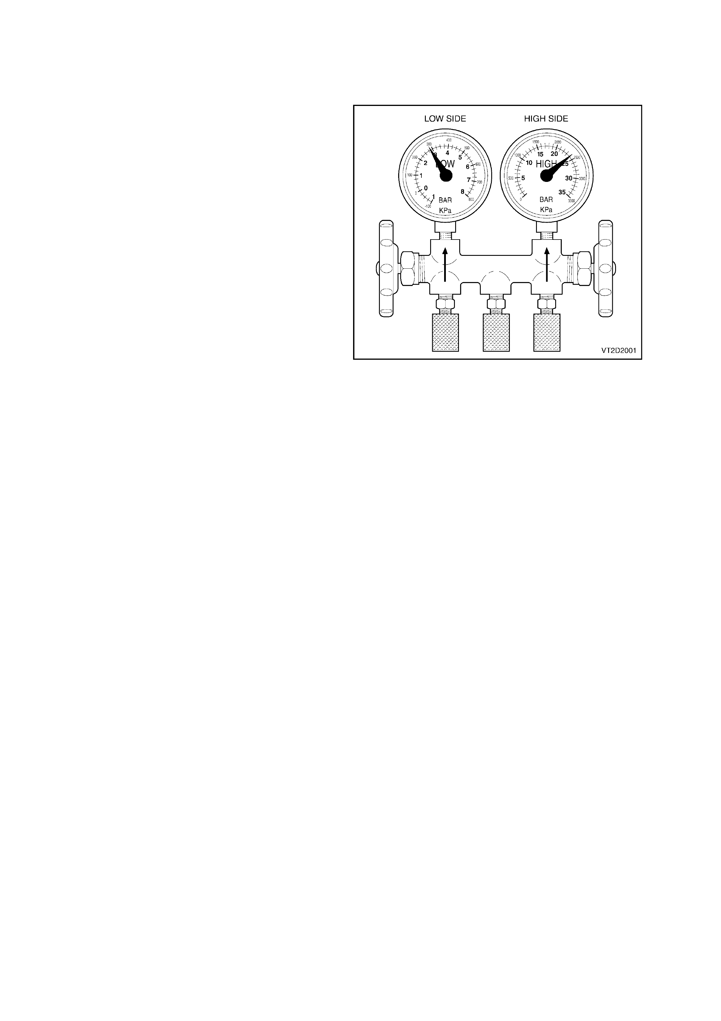
3.1 THERMAL EXPANSION VALVE (TXV) REMAINS OPEN
CONDITION
Low Side Gauge: High
High Side Gauge: High
Discharge Air: Warm
CAUSE
Thermal expansion valve (TXV) jammed open and
not modulating, causing flooding of the evaporator
with refriger ant. This is normally related to inco rrect
positioning of the temperature sensing bulb or
foreign material and moisture entry causing rust
formations.
Figure 2C-5
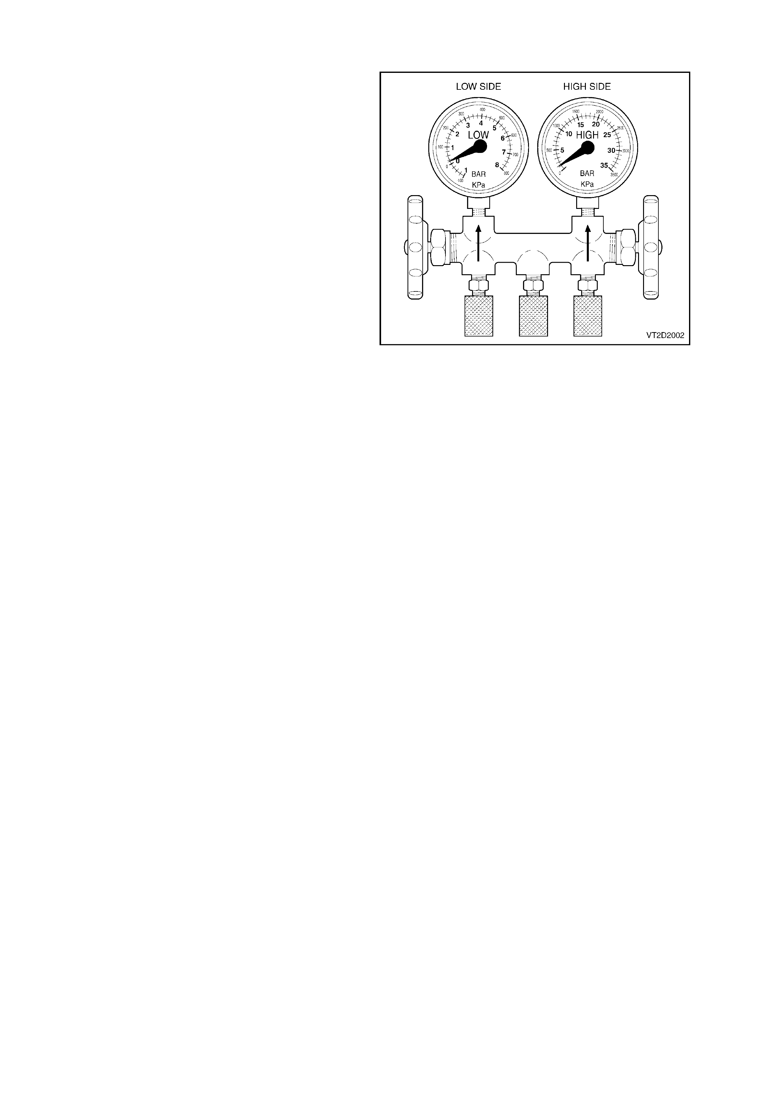
3.2 THERMAL EXPANSION VALVE (TXV) REMAINS CLOSED
CONDITION
Low Side Gauge: Low to vacuum
High Side Gauge: Low
Discharge Air: Slightly cool.
Expansion Valve: Sweating or frost build up.
CAUSE
Thermal expansion valve (TXV) jammed closed.
Insuff ic ient ref r igerant f low to the suc tion side of the
compressor. This is normally related to the TXV
sensing bulb malfunction, disconnected from tube,
foreign material in TXV or moisture entry causing
rust formations.
Figure 2C-6
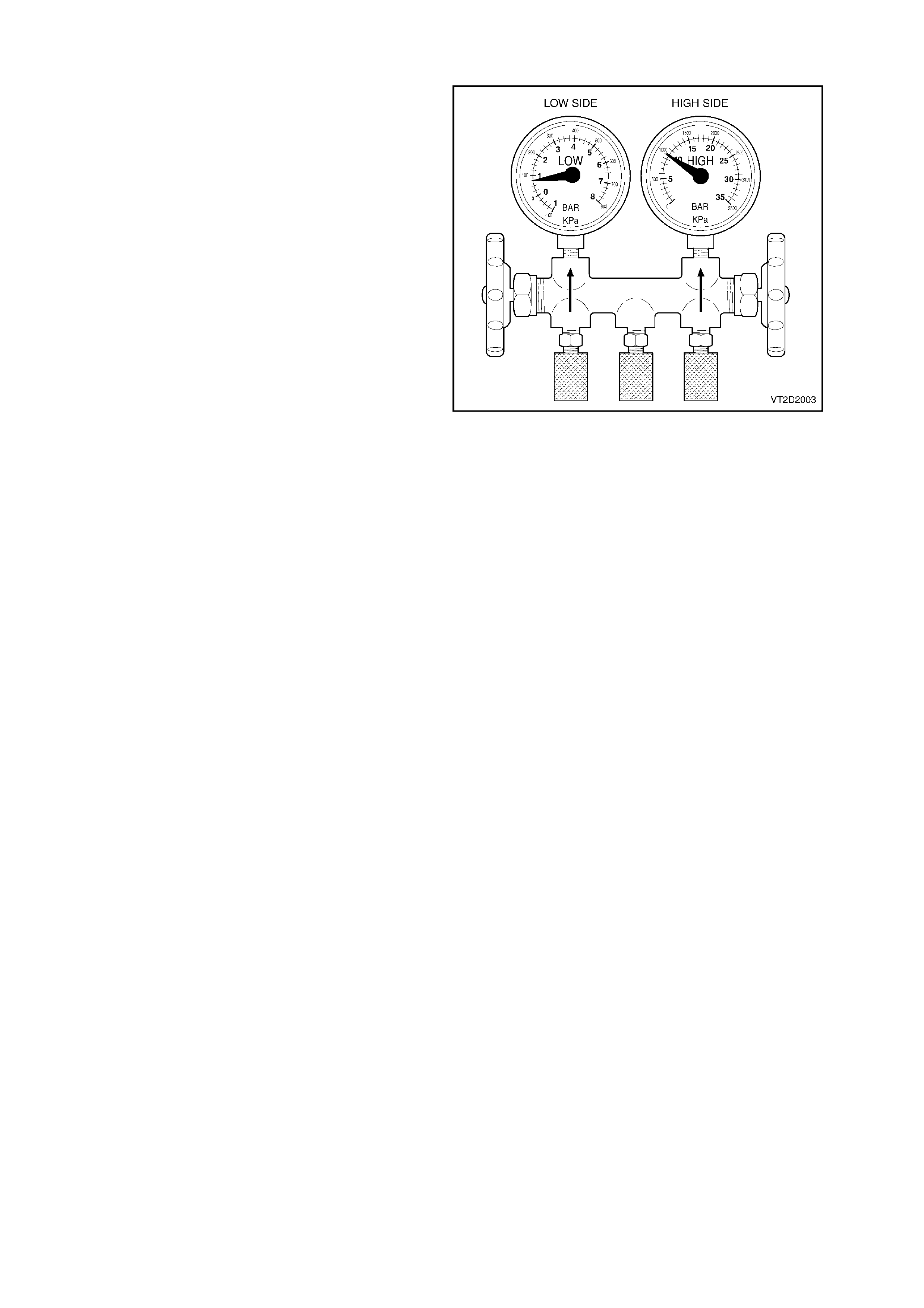
3.3 RESTRICTION IN HIGH SIDE OF SYSTEM
CONDITION
Low Side Gauge: Low
High Side Gauge: Low
Discharge Air: Slightly cool
High Side Tubes: Cool and showing signs of
sweating or moisture build up at the position after
the point of restriction.
CAUSE
Foreign material causing blockage between the
compressor outlet and evaporator inlet (high side).
Very little or no ref rigerant f low to suction (low) s ide
of compressor.
Figure 2C-7

3.4 EXCESSIVE MOISTURE
CONDITION
Low Side Gauge: Normal to vacuum.
High Side Gauge: Normal.
Discharge Air: Becomes warmer as the low side
cycles to a vacuum.
CAUSE
Moisture can freeze within the expansion valve and
cause blockages through rust formation.
Figure 2C-8

3.5 CONDENSE R MALFUNCTION OR OVERCHARGE
CONDITION
Low Side Gauge: Low to normal.
High Side Gauge: High.
Discharge Air: Warm.
High Side Tubes: Very hot.
Compressor Clutch: Could continually cycle on the
high pressure switch.
CAUSE
Refrigerant overcharge.
Engine or condenser fan not operating.
Condenser fins clogged with debris.
No sealing foam between the condenser eg. bull
bar, insect screen.
Radiator overheating.
Figure 2C-9

3.6 EXCESSIVE AIR (NON CONDENSABLES)
CONDITION
Low Side Gauge: High.
High Side Gauge: High.
Discharge Air: Slightly cool.
NOTE: Low side pressure gauge needle does not
fluctuate when compressor cycles ON and OFF.
CAUSE
Large amounts of air and moisture in the system
caused by insufficient evacuation time or no
evacuation after repairing or servicing the system.
Leaking components within the system allowing
moisture and air to enter.
Figure 2C-10

3.7 COMPRESSOR MALFUNCTION
CONDITION
Low Side Gauge: High.
High Side Gauge: Low.
Compressor: Noisy.
Discharge Air: Warm.
Discharge Hose: Cool.
CAUSE
Compressor faulty, internal failure.
Blockage in suction hose after the low side filling
port.
Figure 2C-11

3.8 COMPRESSOR CONTROL VALVE MALFUNCTION
CONDITION
Low Side Gauge: Higher or lower than control point
pressure.
High Side Gauge: Normal.
Discharge Air: Cool only if above control point.
Evaporator: Frozen up if too far below control point.
CAUSE
Compressor control valve faulty or incorrect valve
rating used. T hese valves are s tamped with a letter
code on the valve body indicating the pressure
control point for the low side of the system.
Figure 2C-12

4. DELPHI V5 AND V7 COMP RESSOR TXV SYSTEM DIAGNOSTICS
DIAGNOSTIC FLOW CHART
This flow chart is the starting point for verifying and diagnosing all air conditioning and HVAC control related
complaints. It represents the correct path to follow from a customer complaint or condition through delivery of the
vehicle back to the customer.
PRELIMINARY CHECKS
This step covers all physic al and visual inspections of interior and under- hood com ponents. Many pr oblems c an be
detected by a thorough inspection. Failure to perf orm this step could r esult in wasted time proc eeding f urther down
the flow chart.
VEHICLE SET UP AND PERFORMANCE TEST
To run the air conditioning performance test, the vehicle must be set up according to the instructions in
6. PERFORMANCE TESTING in this Sec tion. The instruc tions inc lude manifo ld gauge set installation and c ontro ller
settings. Improper vehicle set up will result in inaccurate pressure and temperature readings.
GENERAL AND SPECIFIC SYSTEM CONDITION CHARTS
These charts were developed in a wind tunnel by producing known system problems and recording pressures at
various ambient temperatures. The tests were then validated using the same vehicle set up in a service
environment. To find your problem, compare the performance test readings to the readings on the charts for your
ambient temperature and humidity. When all pressure and temperature readings fall within the limits of a given
chart, use that c har t to repair the vehicle. There is s ome variance in readings between s ystems of diff er ent vehicles;
however the target areas have been developed to accommodate these changes.
COMPRESSOR CONTROL TEST
This is designed to evaluate the compressor’s ability to change displacement with varying heat loads.
STEP 1 – PRELIMINARY CHECKS
1. A/C fuse.
2. A/C blower operation.
3. Air mix door. Move door rapidly from cold to hot.
Ensure air mix door fully opens and closes. Adjust rod (manual system) or re-calibrate air mix motor /door
movement (OCC Auto A/C system).
4. Clutch coil connection.
5. Pressure switch connection.
6. Compressor belt. Replace if damaged or missing.
7. Engine cooling fan operation – at idle, the cooling fan must be on at any A/C mode and must be rotate in the
correct direction (drawing ambient air through the condenser towards the engine).
8. Condenser – Check for restricted air flow.
9. Dealer technical bulletins for updates on A/C system.
STEP 2 – CHECKING REFRIGERANT CHARGE
This procedure is designed for use with gauges that have been properly calibrated.
Ambient air temperature at least 15°C, and ignition key in the OFF position.
STEP ACTION RESULT YES NO
A. • Connect high and low side pressure gauges.
• Read high side pressure.
High pressure
above
400 kPa
Carry out
Step 3 Go to
Step B
B. • If high pressure below 400 kPa, perform
EVACUATION AND LEAK TEST (refer to
2.1 SYSTEM CHARGING AND EVACUATION in this
Section).
Leak found Go to Step C Carry out
Step 3
C. • Recover refrigerant and repair leak.
• Evacuate and charge system.
Carry out
Step 3

STEP 3 – CHECKING COMPRESSOR CLUTCH ENGAGEMENT
STEP ACTION RESULT YES NO
A. • Run engine at idle. Set A/C controls to: NORMAL
A/C mode, high blower speed and temperature to full
cold.
Does clutch
engage? Go to Step B Go to Step H
B. • Observe for loud knocking noise coming from
compressor and/or a belt slippage condition (cycle
compressor on and off to verify source of noise).
Compressor
noise or belt
slippage
Go to Step C Go to Step D
C. • Check for compressor noise. Longer than
30 seconds Go to Step D Go to Step E
D. • Recover refrigerant.
• Replace compressor.
• Evacuate and charge system.
Carry out
Step 4 Go to Step F
E. • Possible TXV stuck open.
• Carry out Step 6 – DIAGNOSTIC CODE
PROCEDURES, E: TXV STUCK OPEN.
• TXV replaced.
F. • Check for noise. Belt slippage Go to Step G
G. • Correct condition.
• Refer to relevant service information.
Carry out
Step 4
H. • Turn OFF the ignition switch.
• Disconnect clutch wires at compressor.
• Connect a jumper lead from ground to one
compressor clutch terminal.
• Connect a fused jumper wire from the positive
battery terminal to the other compressor clutch
terminal.
Does clutch
engage? Go to Step I Go to Step J
I. • Repair electrical circuit to the compressor clutch.
Refer to Sec tion 12P WIRING DIAGRAMS for further
information.
J. • Replace clutch coil.
• Repeat Step 3.

STEP 4 – CHECKING SYSTEM PERFORMANCE
This test is designed for typical garage condition: 21°
°°
°C – 37.5°
°°
°C, various humidities and no sun load. Follow the
chart exactly. It is designed to create enough cooling load to cause the compressor to operate at full stroke. It is
absolutely essential for accurate results.
Neutralise internal vehicle temperature to workshop ambient conditions. Insert thermometer into centre duct.
STEP ACTION RESULT YES NO
A. • Hood up, open doors and windows.
• Temperature control at full cold, normal A/C mode
high blower speed.
• Engine at fast idle (1500 rpm) vehicle interior
temperature at ambient.
Does engine
cooling fan
run at highest
speed?
Go to Step B Go to Step C
B. • Close doors and windows set A/C controls to:
normal A/C mode high blower speed, temperature
control at full cold run engine at idle for 5 minutes.
• Record low and high side pressure after A/C system
has been run for 5 minutes, also record centre
outlet duct temperature.
• Carry out Step 5.
C. • Reference relevant engine cooling fan information.
Refer to:
Section 6B1 ENGINE COOLING – V6
Section 6B2 ENGINE COOLING – V6
SUPERCHARGED
Section 6B3 ENGINE COOLING – GEN III V8.
• Correct and return to Step 4.
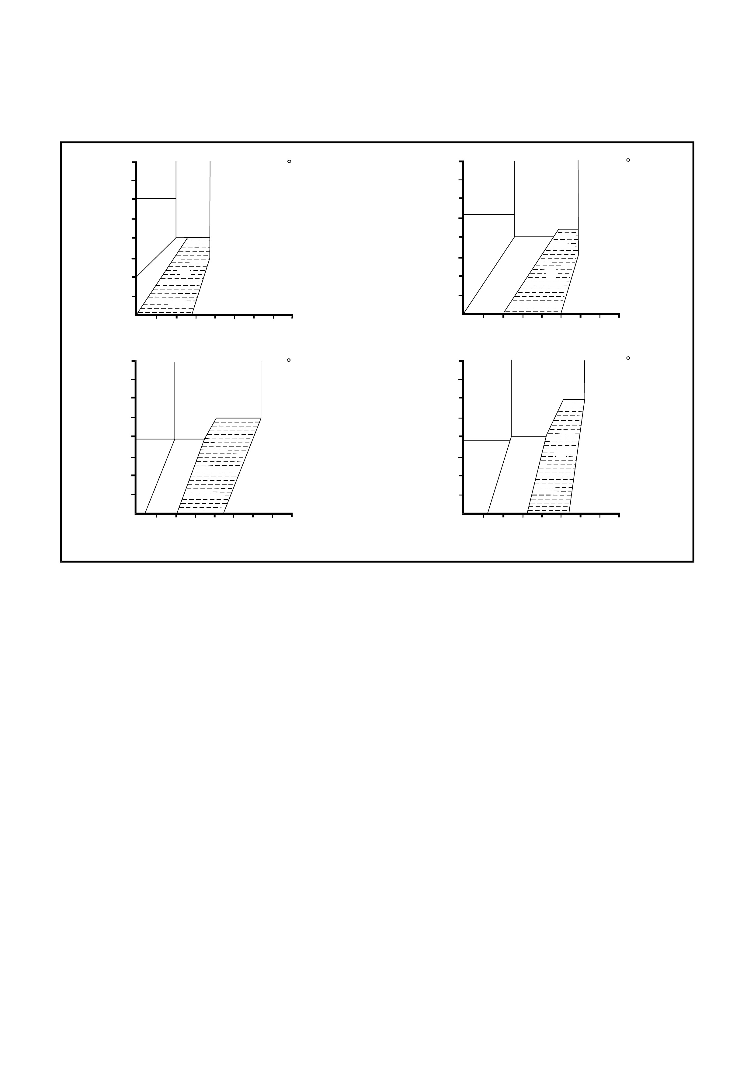
STEP 5 – DIAGNOSTIC CHART
1. Select the graph in Figure 2C-13 which corresponds closest to the present ambient temperature.
2. Read the high side and low side pressures and note the letter area in which they intersect.
3. Match that letter code with the corres ponding letter codes below Figure 2C-13 and c ontinue with the diagnostic
code procedures.
D
F
B
E
C
A
21 C
560
490
420
350
280
210
140
1400 2100 2800
700
70
HI GH SIDE PR ESSURE
LOW SIDE PRESSURE
(kpa)
(kpa)
D
F
B
E
C
A
26.5 C
560
490
420
350
280
210
140
1400 2100 2800700
70
HI GH SIDE PRESSUR E
LOW SIDE PRESSURE
(kpa)
(kpa)
D
F
B
E
C
A
32 C
560
490
420
350
280
210
140
1400 2100 2800
700
70
HI GH SIDE PR ESSURE
LOW SIDE PRESSURE
(kpa)
(kpa)
D
F
B
E
C
A
37.5 C
560
490
420
350
280
210
140
1400 2100 2800700
70
HI GH SIDE PRESSUR E
LOW SIDE PRESSURE
(kpa)
(kpa)
T22C001
Figure 2C-13
LETTER CODES
A = NORMAL SYSTEM
B = LOW REFRIGERANT CHARGE
C = REFRIGERANT OVERCHARGE OR FILTER DRIER RESTRICTED (GO TO STEP 6)
D = TXV BLOCKED (GO TO STEP 6)
E = TXV STUCK OPEN (GO TO STEP 6)
F = COMPRESSOR NOT PUMPING (GO TO STEP 6)

STEP 6 – DIAGNOSTIC CODE PROCEDURES
A: REFRIGERANT OVERCHARGE OR RESTRICTED RECEIVER/DRIER.
Confirm by touching filter dr ier inlet/outlet. If there is a tem perature and diff erence between inlet and outlet, replace
filter/drier and return to Step 4.
Complaint will be poor or intermediate cooling at high ambient temperature (pressure switch shuts system down
because of excessive high side system pressure).
Confirm by touching compressor suction tube – it will be cool and discharge tube will be hot.
B: TXV BLOCKED. OUTLET TEMPERATURE COOL TO WARM.
Confirm by thorough physical inspection of all tubes, hoses and components. In normal operation, the evaporator
inlet tem perature is hot. If the inlet pipe is c ool, check for high side r estriction. If the inlet pipe is room temper ature,
confir m TX V is blocked by running engine at 2000 rpm – neither pressure s hould c hange by m ore than 140 k Pa. If
TXV is blocked replace it.
C: TXV STUCK OPEN.
System appears to perform normally, but may go warm temporarily on extended journeys and recorrect itself
after vehicle shut down. May also cause compressor ‘slugging’ noise.
Run high blower speed, normal A/C, fast idle for 2 minutes, engine off for 3 minutes. Restart engine with A/C off.
Let engine speed stabilis e. On low blower r un A/C and listen for a ‘slugging’ noise (engine hood should be lowered
for this procedure). Replace TXV if stuck open.
D: COMPRESSOR NOT PUMPING, OUTLET TEMPERATURE IS AMBIENT.
Confirm by completing Step 7.
NOTE: If none of the above conditions can be verified, recover, evacuate and recharge with correct charge and
perform Step 4 again.

STEP 7 – CHECKING FOR NO STROKE COMPRESSOR
Run engine at 3000 rpm.
Set A/C controls to: high blower speed, temperature to full cold and close vehicle windows and doors. Cycle
mode lever from vent to A/C every 20 seconds for 3 minutes.
STEP ACTION RESULT YES NO
A. • Check compressor high and low side pressure. Within
210 kPa of
each other
Go to Step B Go to Step D
B. • Engine OFF, with compressor clutch disengaged,
• Check compressor clutch front plate (not pulley).
Turns freely
by hand Go to Step C Go to Step E
C. • Replace compressor.
• Recover refrigerant.
• Evacuate and charge system.
Go to Step D
D. • Leak test. Leak found Carry out Step 4
E. • Perform control valve diagnosis.
• Carry out Step 8
STEP 8 – CONTROL VALVE DIAGNOSIS
IMPORTANT: Follow this test procedure exactly. It is designed to create a low cooling load to cause the
compressor to operate at less than full stroke. This is absolutely necessary for accurate results.
STEP ACTION RESULT YES NO
A. • Run engine for 5 minutes at 1500 rpm.
• Set A/C controls to: maximum A/C mode low
blower speed, temperature to full cold, close
vehicle windows and doors open hood.
Is low side
pressure refer
to Step 5
diagnostic
chart.
Carry out STEP 4 Go to Step B
B. • Recover refrigerant.
• Replace control valve.
• Recover and charge system.
• Carry out leak test.
Leak found Carry out Step 4

5. NOISE DIAGNOSIS
Observe for loud knocking noise from compressor and/or a belt slippage condition.
STEP ACTION RESULT YES NO
A. • Is there belt slippage noise? Go to Step B Go to Step E
B. • Check for belt damage. Damaged Replace belt Go to Step C
C. • Check idler pulleys individually for bearing
roughness or damage. Roughness or
damage Replace bearing. Go to Step D
D. • Check belt tensioner for correct operation. Incorrect
operation Repair tensioner
refer to
Section 6A1
ENGINE
MECHANICAL–V6
or
6A2 ENGINE
MECHANICAL–
V6 S/C
or
6A3 ENGINE
MECHANICAL–
GEN III V8
Go to Step E
E. • Possible compressor noise.
• Does noise last longer than 30 seconds?
Go to Step G Go to Step F
F. • Is noise repeatable? Go to Step H It is normal to
observe a liquid
slugging
condition. This
may occur after
extended system
shutdown at
warmer ambient,
followed by an
overnight
ambient drop.
G. • Possible low charge or block valve stuck closed. Valve closed Go to Step I Go to Step J
H. • Possible block valve stuck open. Valve open Carry out block
valve diagnosis.
Replace if
confirmed to be
fully open.
Go to Step I
I. • Check for loose compressor bolts and/or A/C
plumbing contacting body work. Tighten bolts
and/or relocate
plumbing.
Go to Step J
J. • Recover refrigerant and replace compressor,
recharge system.
Techline

6. PERFORMANCE TESTING
STEP 1
Park the vehicle in a shaded area. Take note of the ambient temperature.
STEP 2
Open both front window s and engine hood.
STEP 3
Connect both high and low pressure service hose coupling valves to the system filling ports.
STEP 4
Open all ventilation outlets louvres and adjust to the straight-ahead position.
STEP 5
Insert a thermometer probe approximately 50 mm into the centre vent louvre.
NOTE: If the vehicle is fitted with an OCC (Auto A/C) dual zone system, both sides of the centre vent must be
checked to ensure that the temperature differential performance is correct.
STEP 6
Set controls to:
a. Fresh air position (i.e. recirculate is off)
b. Face vent mode
c. Maximum cooling
• manual A/C: temperature switch set to C
• OCC (Auto A/C) single zone: G MIN selected
• OCC (Auto A/C) dual zone: Gon temperature switch selected to lowest temperature setting
d. A/C on
e. Highest blower speed
f. Hood open
STEP 7
Start the engine and bring engine speed to 1700 rpm. Allow the pressure gauge needles to stabilise.

STEP 8
Take pressure and centre vent temperature readings. Compare these figures taken to the performance charts
(Figures 2C-14 and 2C-15).
NOTE: Only take pressure and temperature readings when the compressor is engaged.
NOTE: As you can see from the above typical performance test, the A/C system is put under an increased load,
such as doors and engine hood open and high blower speed. If an A/C system can perform to the m anufacturers
specifications under these loads, in normal driving situations with the engine hood down, windows closed and
possibly a lower blow er speed, centre vent temperatures will be lower.
Figure 2C-14
Figure 2C-15
7. ELECTRICAL COMPONENT TESTS
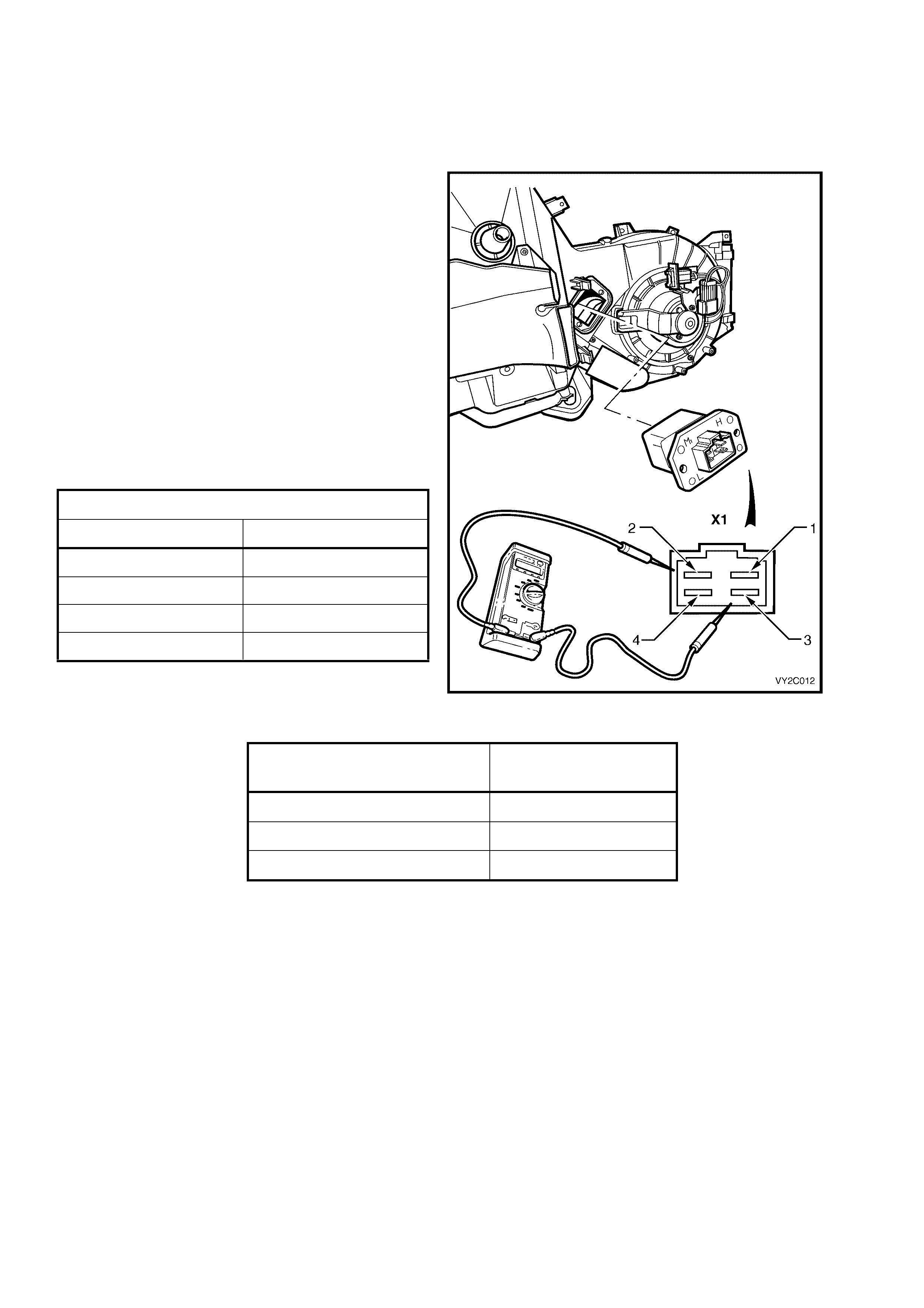
7.1 BLOWER MOTOR RESISTOR
LEFT-HAND DRIVE
To tes t the blower motor res istor , use an ohmmeter
to check for resistance across the different
terminals.
Refer to Figure 2C-16 in conjunction with the
following tables for details of the pin numbers and
resistances.
Perform the test as follows:
1. Remove the blower motor resistor. Refer to
Section 2B, 7. BLOWER MOTOR RESISTOR.
2. Position the contacts of the ohmmeter on the
terminals and take the reading. Compare the
reading with the table.
3. If blower motor resistor fails any part of the test,
replace the resistor with a serviceable item.
4. Install the blower motor resistor.
R6 CONNECTOR DETAILS
PIN NUMBER FUNCTION
X1-1 Ground
X1-2 Fan Speed 2
X1-3 Fan Speed 3
X1-4 Fan Speed 1
Figure 2C-16
BLOWER RESISTOR
CONTACTS RESISTANCE
READING
X1-1 and X1-2 1.5 Ω
X1-1 and X1-3 0.6 Ω
X1-1 and X1-4 2.8 Ω
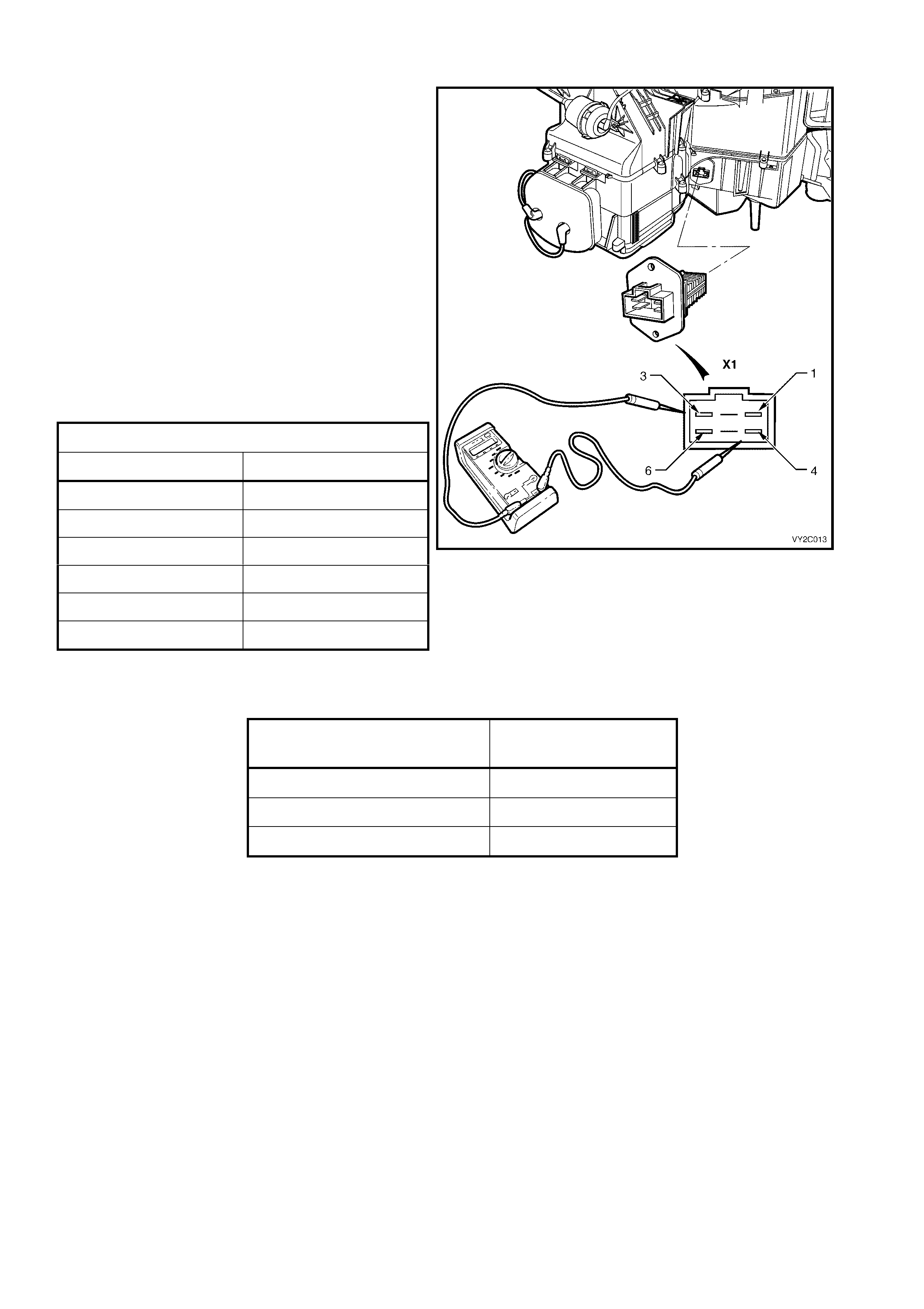
RIGHT-HAND DRIVE
To tes t the blower motor res istor , use an ohmmeter
to check for resistance across the different
terminals.
Refer to Figure 2C-17 in conjunction with the
following tables for details of the pin numbers and
resistances.
Perform the test as follows:
1. Remove the blower motor resistor. Refer to
Section 2B, 7. BLOWER MOTOR RESISTOR.
2. Position the contacts of the ohmmeter on the
terminals and take the reading. Compare the
reading with the table.
3. If the blower motor resistor fails any part of the
test, replace the resistor with a serviceable
item.
4. Install the blower motor resistor.
R6 CONNECTOR DETAILS
PIN NUMBER FUNCTION
X1-1 Fan Speed 1
X1-2 Not Connected
X1-3 Fan Speed 2
X1-4 Ground
X1-5 Not Connected
X1-6 Fan Speed 3
Figure 2C-17
BLOWER RESISTOR
CONTACTS RESISTANCE
READING
X1-4 and X1-1 2.2 Ω
X1-4 and X1-3 1.2 Ω
X1-4 and X1-6 0.5 Ω
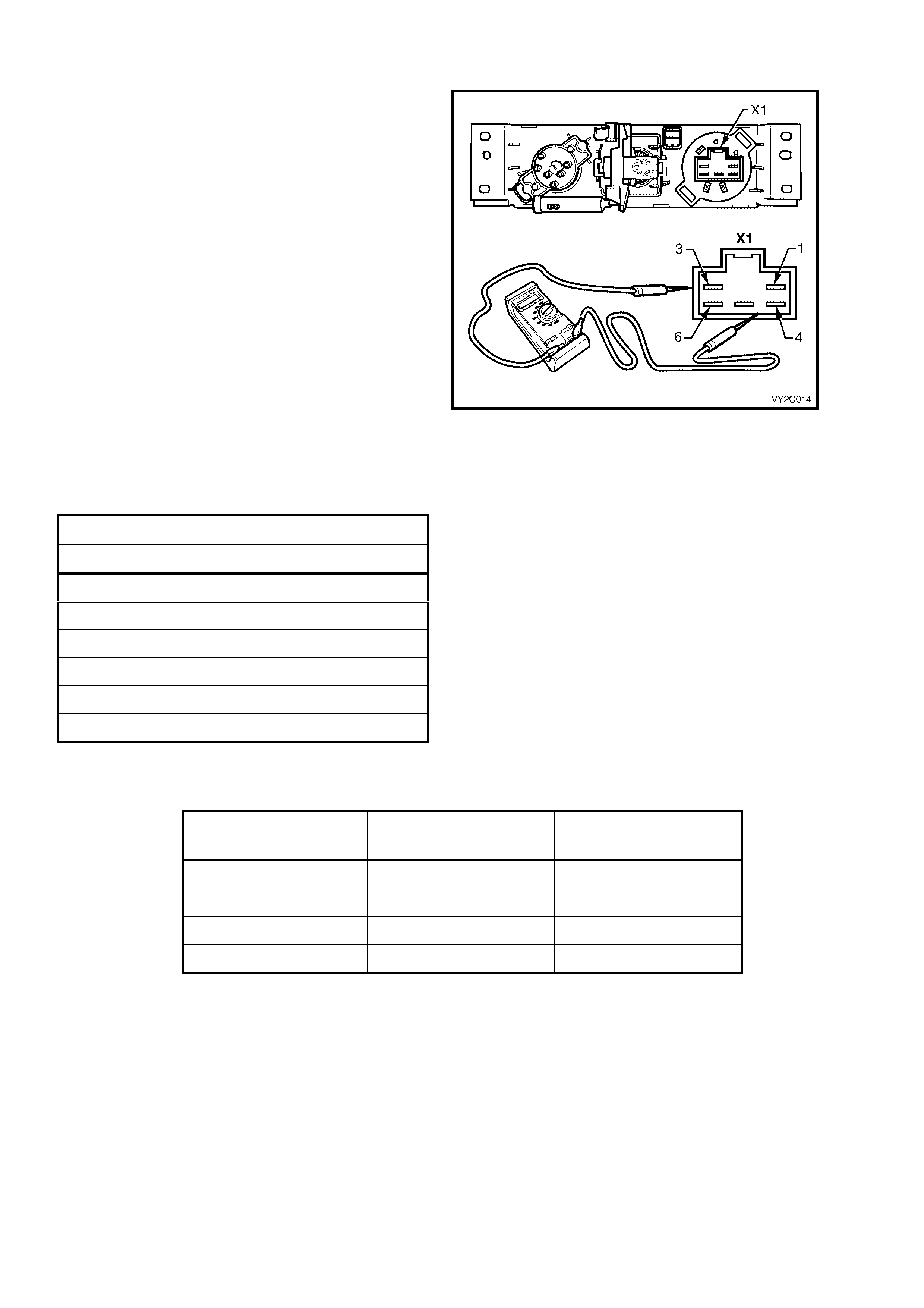
7.2 BLOWE R FAN SWITCH
To test the blower switch assembly, use an
ohmmeter to check for continuity when the fan
speeds of the switch are selected.
Refer to Figure 2C-18 in conjunction with the
following tables to fo r details of the s witch positions
and connector functions.
Perform the test as follows:
1. Remove the manual HVAC controller, refer to
Section 2B, 2. MANUAL HVAC
CONTROLLER.
2. Select the switch positions as detailed in the
lower table. Position the contacts of the
ohmmeter on the terminals and take the
reading. Compare the reading with the table.
3. If there is there is an open circuit between the
listed s witch contacts or continuity between any
contacts other than those listed, the switch
assem bly is faulty. If the switch fails any part of
the test, replace the HVAC controller assembly
with a serviceable item.
4. Install the manual HVAC controller.
A60 X1 CONNECTOR DETAILS
PIN NUMBER FUNCTION
X1-1 Ground
X1-2 Not Connected
X1-3 Fan Speed 1
X1-4 Fan Speed HI
X1-5 Fan Speed 3
X1-6 Fan Speed 2
Figure 2C-18
SWITCH SETTING SWITCH CONTACTS RESISTANCE
READING
1 X1-1 and X1-3 Continuity
2 X1-1 and X1-3 Continuity
3 X1-1 and X1-5 Continuity
HI X1-1 and X1-4 Continuity

8. VACUUM RETENTION TESTS
To operate efficiently, the HVAC system requires a constant vacuum source and all HVAC system vacuum
com ponents must have no vac uum leaks. Vac uum is s upplied by the engine induction system and is retained within
the HVAC system by the action of the one-way check valve located in the engine bay. A vacuum reserve is stored
within the vehicle cabin in the vacuum tank located on the left-hand side of the HVAC unit. Any of the following
components may cause or contribute to a vacuum leak within the HVAC system:
• Check valve
• Vacuum tank
• Water valve vacuum switch
• Vacuum mode valve (for HVAC mode selection)
• Vacuum actuators (including the water valve)
• Vacuum lines and connectors
Symptoms of a vacuum leak may be as follows:
• Constant coolant flow through the heater core
• Air always directed to windscreen
• Air directed to ventilation outlets that are not selected
• Dust and/or smog ingress into the cabin despite the selection of the recirculation mode
• Constant ‘hissing’ noise emanating from a leaking or disconnected vacuum component/s
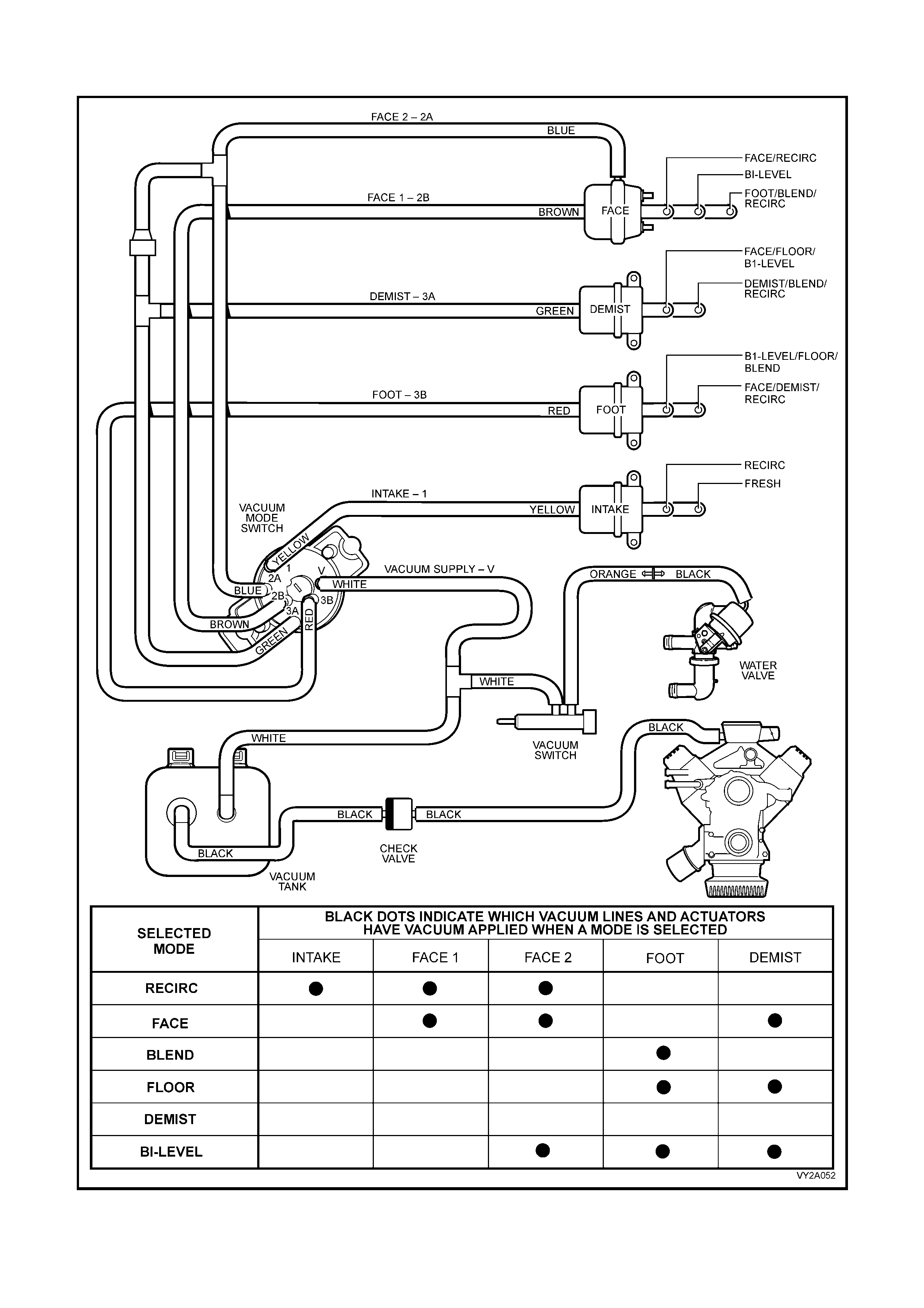
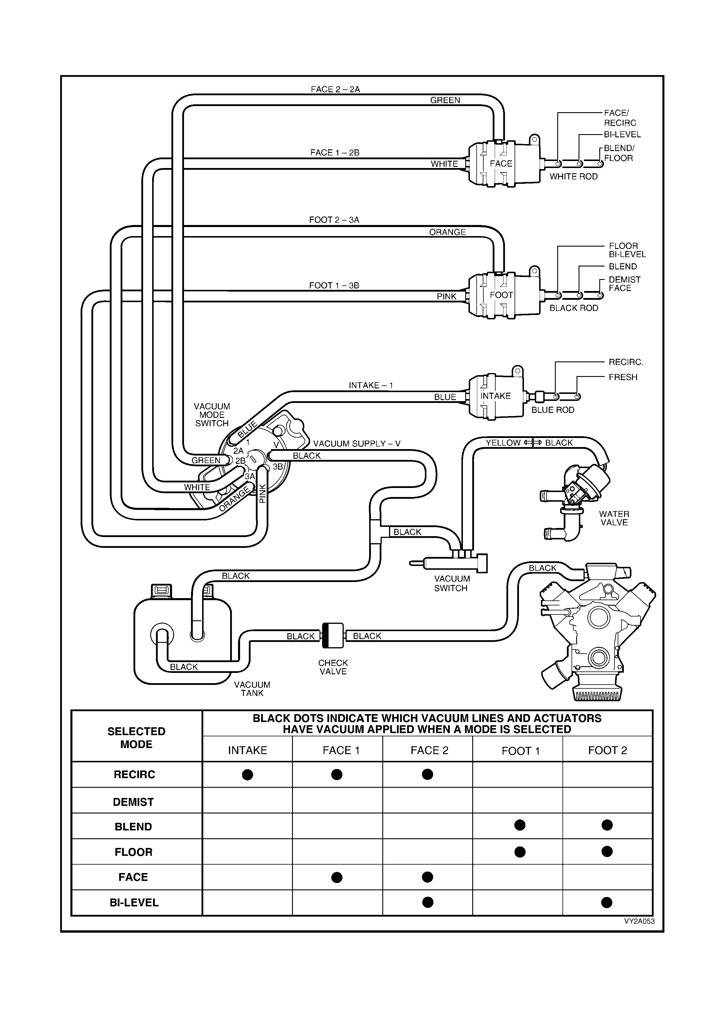
VACUUM CIRCUIT SCHEMATICS
The following two Figures represent a schematic layout of the vacuum components associated with the manual
HVAC system. T hese schem atics will serve as an aid in isolating and diagnos ing vacuum related f aults. Use these
schem atic s to view the interconnection of vacuum c om ponents and to understand which com ponents are subject to
vacuum in a certain ventilation mode.
For left-hand drive vehicles, refer to Figure 2C-19. For right-hand drive vehicles, refer to Figure 2C-20.
Vacuum Circuit Schematic– LHD
Figure 2C-19
Vacuum Circuit Schematic – RHD
Figure 2C-20
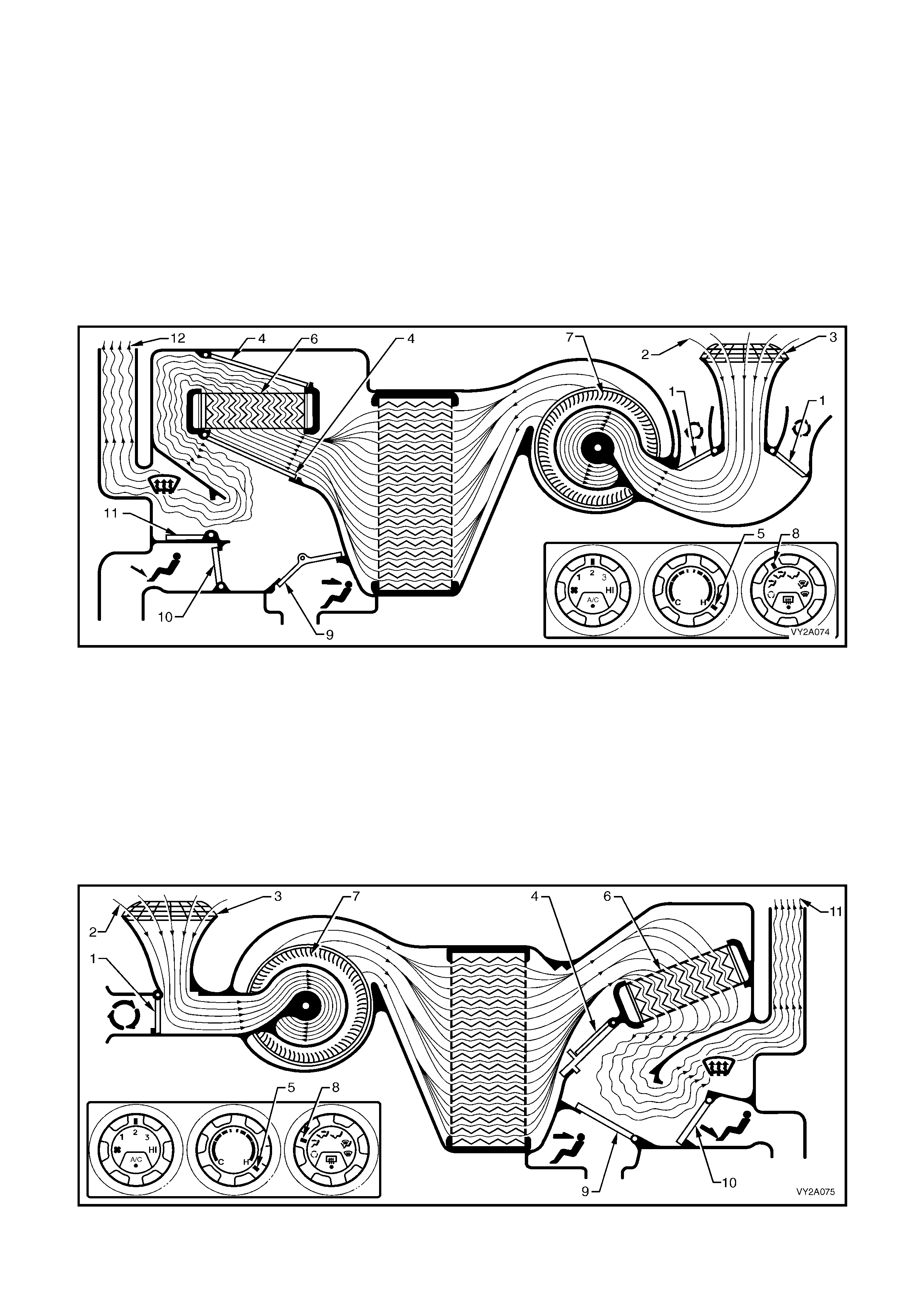
VACUUM LOSS DEFAULT SETTINGS
In the event of a vacuum loss, the manual HVAC unit will revert to a set of predetermined ‘safe to drive’ default
settings to allow continued operation of the vehicle until the fault is rectified.
Loss of vacuum supply to HVAC unit – LHD
If a total loss of vacuum occurs within the system, the left-hand drive type manual HVAC unit will default to the
following settings. These settings will be the same in any position of the mode control switch.
The recirculation doors (1) will remain closed allowing outside air (2) to enter and flow into the HVAC unit via the
plenum chamber inlet (3). As the air mix doors (4) are controlled by mechanical linkage, their position will still be
determined by the temperature switch setting (5). However, heated coolant will flow through the heater core (6)
regardless of the position of the temperature switch, as vacuum is required to m aintain the water valve in the cold
(closed) pos ition. T he blower fan ( 7) will operate as normal. In any position of the m ode s witch ( 8), the f ace door ( 9)
and the floor door (10) will remain closed. The demist door (11) will be positioned so that all air (12) leaving the
HVAC unit will be directed to the demist outlets. Depending on the selected setting of temperature switch, this air
may be cold, warm or hot air.
Figure 2C-21
Loss of vacuum supply to HVAC unit – RHD
If a total loss of vacuum occurs within the system, the right-hand drive type manual HVAC unit will default to the
following settings. These settings will be the same in any position of the mode control switch.
The recirculation door (1) will remain closed allowing outside air (2) to enter and flow into the HVAC unit via the
plenum chamber inlet (3). As the air mix doors (4) are controlled by mechanical linkage, their position will still be
determined by the temperature switch setting (5). However, heated coolant will flow through the heater core (6)
regardless of the position of the temperature switch as vacuum is required to maintain the water valve in the cold
(closed) position. The blower m otor (7) will operate as norm al. In any position of the mode switch (8), the face door
(9) will rem ain closed. T he demist/f loor door (10) will be positioned so that all air ( 11) leaving the HVAC unit will be
directed to the dem ist outlets. Depending on the selec ted setting of tem perature switch, this air may be cold, warm
or hot air.
Figure 2C-22
NOTE: The following vacuum tests should be conducted to the HAVC system to isolate a vacuum loss problem
leading to poor HVAC system performance. Perform each test in order until the problem is identified and corrected.
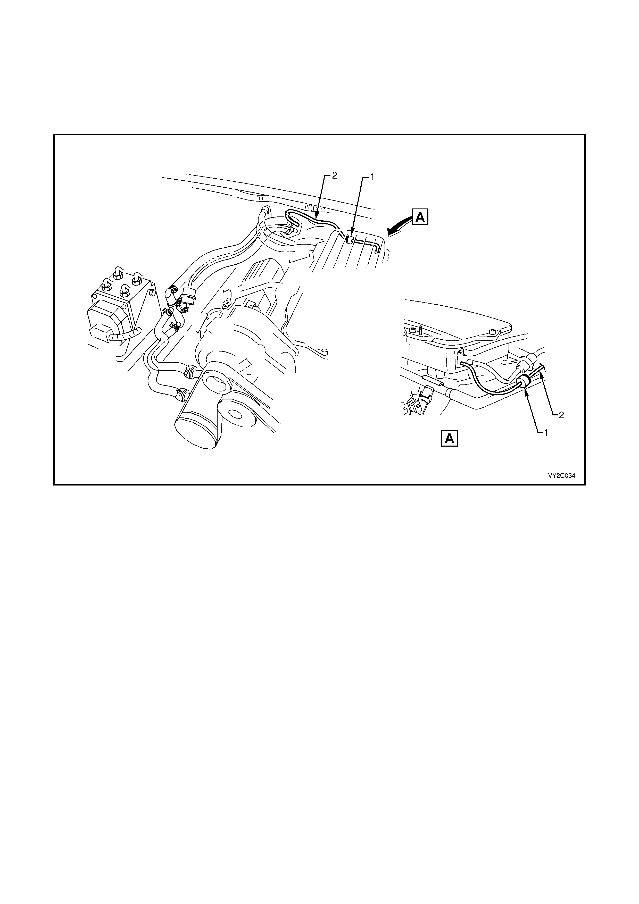
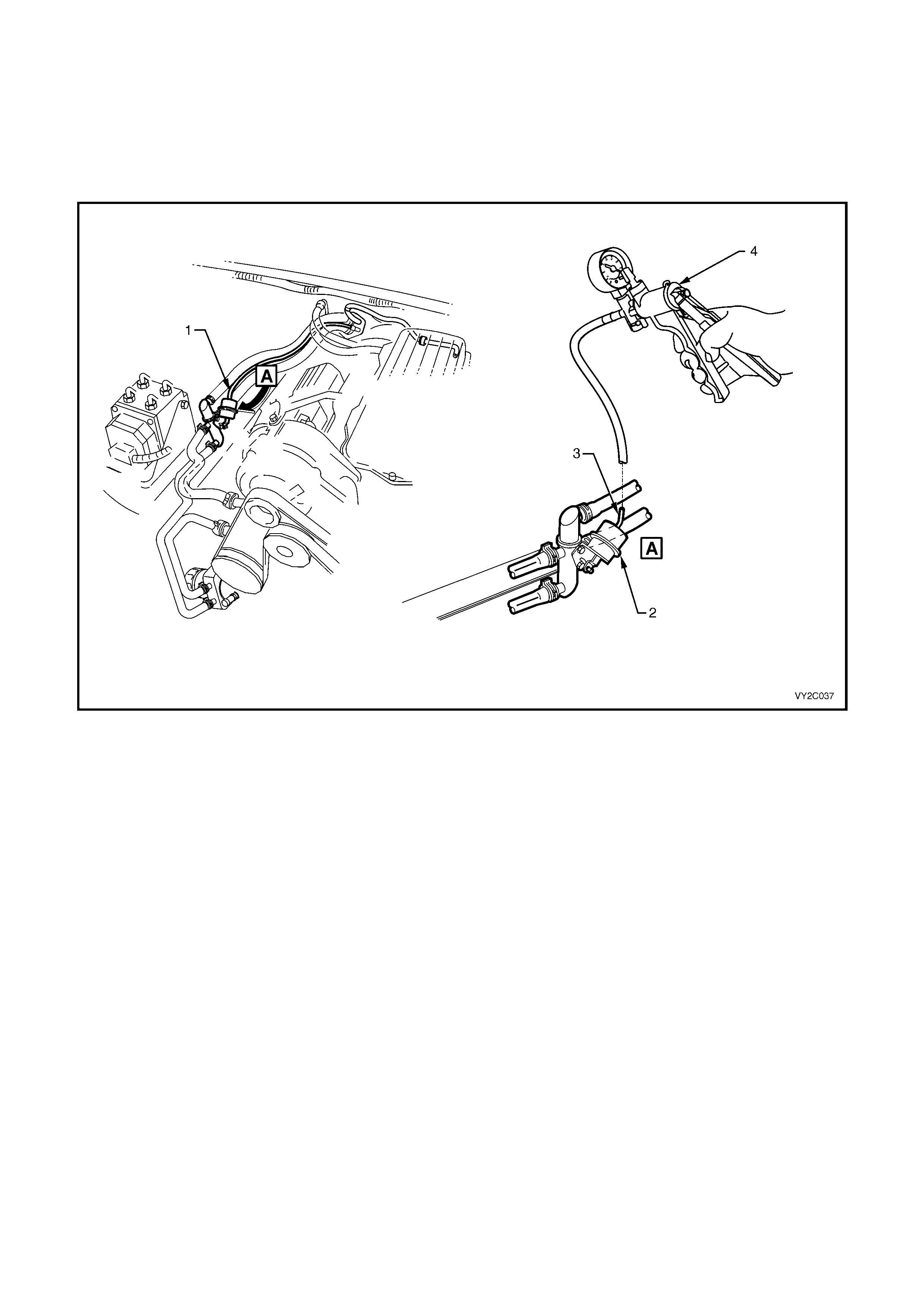
8.1 HVAC SYSTEM CHECK VALVE
VACUUM CHECK VALVE LOCATION
Refer to Figure 2C-23 for the location of the check valve (1) onV6 and V6 Supercharged engines.
Figure 2C-23
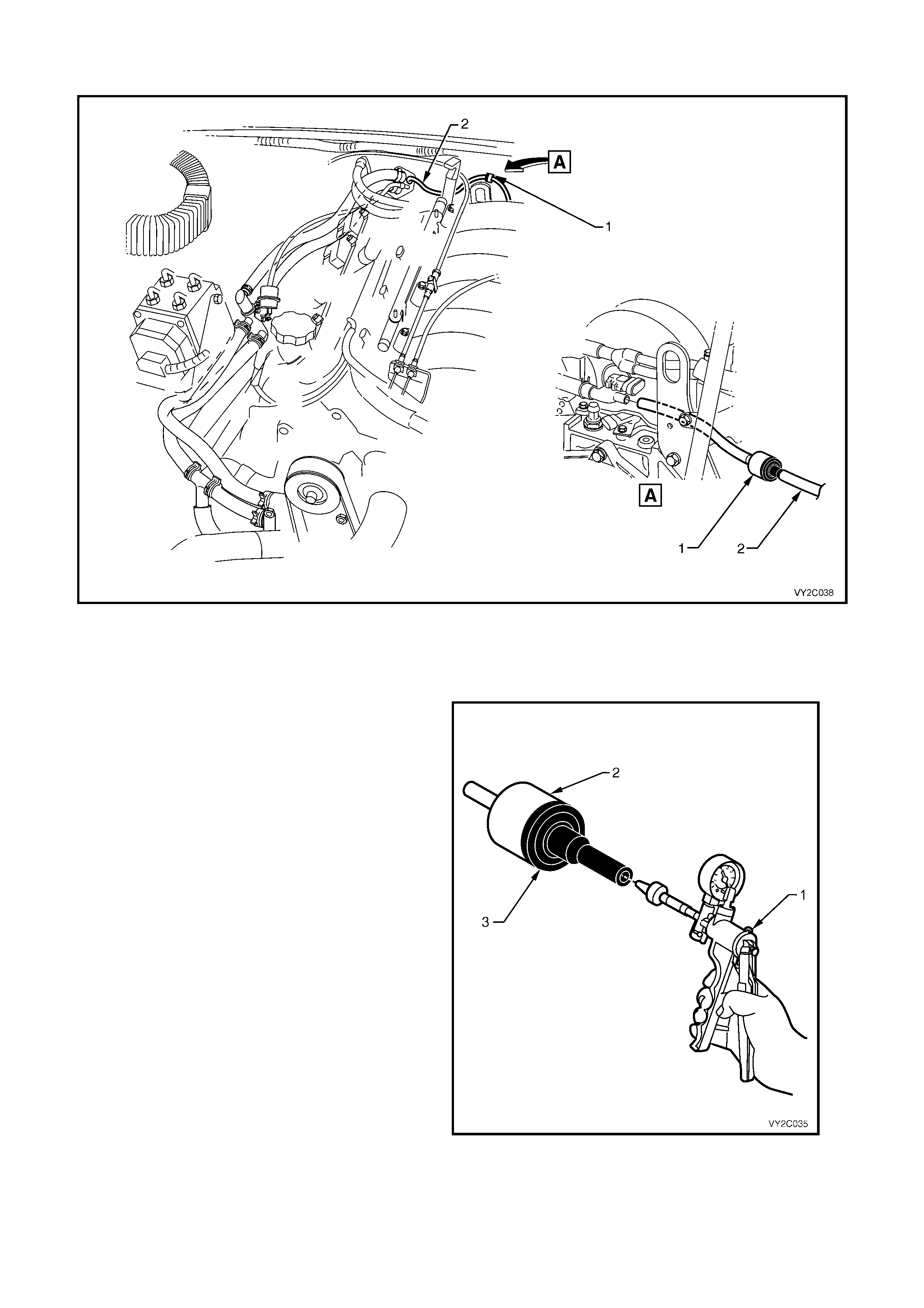
Refer to Figure 2C-24 for the location of the check valve (1) on GEN III V8 engines.
Figure 2C-24
To test the vacuum check valve perform the following:
1. Remove the vacuum line supply line (item 2 in Figure 2C-23 and Figure 2C-24) from the check valve.
2. Connect the vacuum pump (1) to the check
valve (2) at the port of the black section (3) of
the check valve.
3. Using the vacuum pump, create a vacuum and
observe the vacuum pump gauge needle.
4. If the needle remains steady it indicates that the
check valve is retaining vacuum . If the vacuum
reading decreases, it indicates a vacuum leak
in the check valve.
5. If a vacuum leak is indicated, replac e the check
valve.
Figure 2C-25
8.2 VACUUM TANK
To vacuum test the vacuum supply tank perform the following:
1. Remove the left-hand side instrument panel lower trim plate assembly. Refer to
Section 1A3, 3.1 INSTRUMENT PANEL LOWER TRIM PLATE ASSEMBLY.
2. Disconnect both vacuum lines (1) from the vacuum tank (2).
3. Connect the vacuum pum p (3) to the vacuum supply port (4) and cover the vacuum feed port (5) with a plug (6)
or finger.
4. Using the vacuum pump, create a vacuum and observe the vacuum pump gauge needle.
5. If the needle remains steady it indicates that the vacuum tank is retaining vacuum. If the vacuum reading
decreases, it indicates a vacuum leak in the vacuum tank.
6. If a vacuum leak is indicated, replace the vacuum tank.
Figure 2C-26
8.3 VACUUM MODE VALVE
Remove the manual HVAC controller, refer to Section 2B, 2.0 MANUAL HVAC CONTROLLER.
RECIRCULATION MODE
To vacuum test the vacuum mode valve in the recirculation mode perform the following:
1. Set the vacuum control to recirculation mode.
2. Block the intak e, face 1 and face 2 ports (1, 2A and 2B) of the vacuum m ode valve. Connect a vacuum pump
(4) to the vacuum supply port (V) of the vacuum mode valve.
3. Using the vacuum pump, create a vacuum and observe the vacuum pump gauge needle.
4. If the needle remains steady or decreases slowly, it indicates that the mode valve is retaining vacuum in the
recirculation position. If the vacuum reading decreases quickly, it indicates a vacuum leak in the mode valve.
5. If a vacuum leak is indicated, replace the vacuum mode valve.
Figure 2C-27
FACE MODE
To vacuum test the vacuum mode valve in the Face mode perform the following:
1. Set the vacuum control to Face mode.
2. Block the f ace 1 and face 2 ports (2A and 2B) of the vacuum m ode valve. Connect a vacuum pump (4) to the
vacuum supply port (V) of the vacuum mode valve.
3. Using the vacuum pump, create a vacuum and observe the vacuum pump gauge needle.
4. If the needle remains steady or decreases slowly, it indicates that the mode valve is retaining vacuum in the
Face position. If the vacuum reading decreases quickly, it indicates a vacuum leak in the mode valve.
5. If a vacuum leak is indicated, replace the vacuum mode valve.
Figure 2C-28
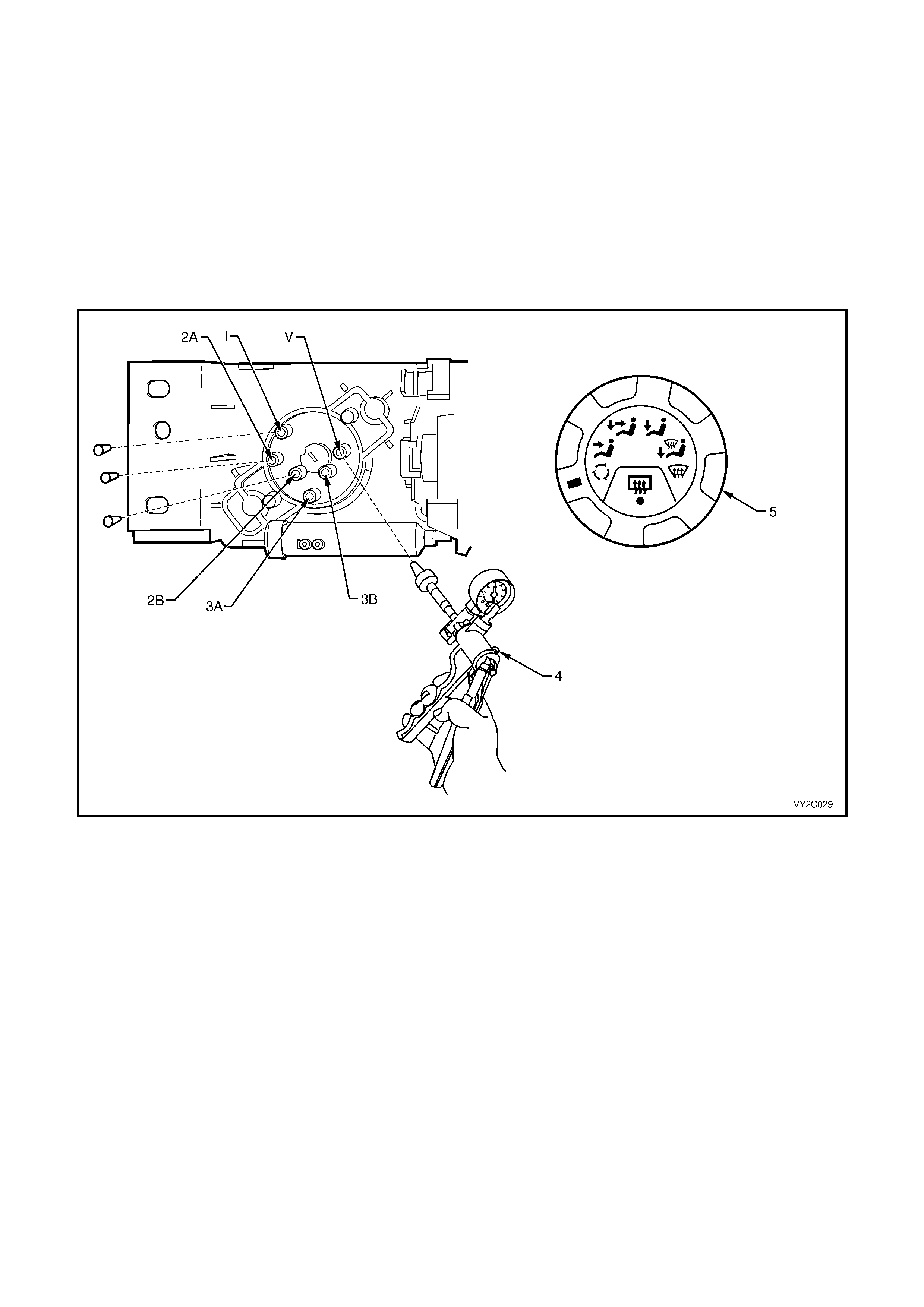
BI-LEVEL MODE
To vacuum test the vacuum mode valve in the Bi-level mode perform the following:
1. Set the vacuum control to Bi-level mode.
2. Block the fac e 1, foot 1 and foot 2 ports ( 2B, 3A and 3B) of the vacuum m ode valve. Connec t a vacuum pum p
(4) to the vacuum supply port (V) of the vacuum mode valve.
3. Using the vacuum pump, create a vacuum and observe the vacuum pump gauge needle.
4. If the needle remains steady or decreases slowly, it indicates that the mode valve is retaining vacuum in the
Bi-level position. If the vacuum reading decreases quickly, it indicates a vacuum leak in the mode valve.
5. If a vacuum leak is indicated, replace the vacuum mode valve.
Figure 2C-29
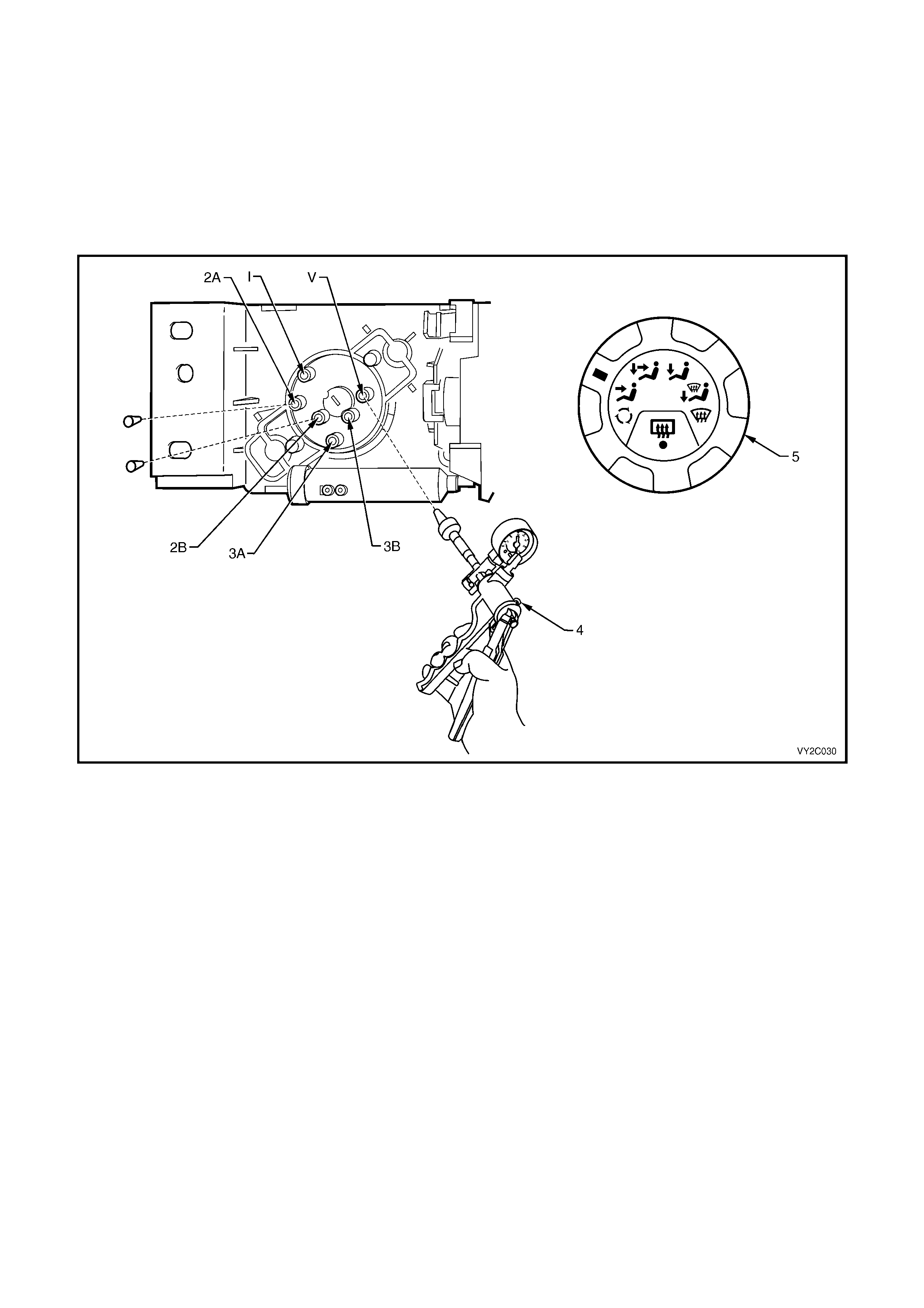
FLOOR MODE
To vacuum test the vacuum mode valve in the Floor mode perform the following:
1. Set the vacuum control to Floor mode.
2. Block the foot 1 and foot 2 ports (3A and 3B) of the vacuum mode valve. Connect a vacuum pump (4) to the
vacuum supply port (V) of the vacuum mode valve.
3. Using the vacuum pump, create a vacuum and observe the vacuum pump gauge needle.
4. If the needle remains steady or decreases slowly, it indicates that the mode valve is retaining vacuum in the
Floor position. If the vacuum reading decreases quickly, it indicates a vacuum leak in the mode valve.
5. If a vacuum leak is indicated, replace the vacuum mode valve.
Figure 2C-30
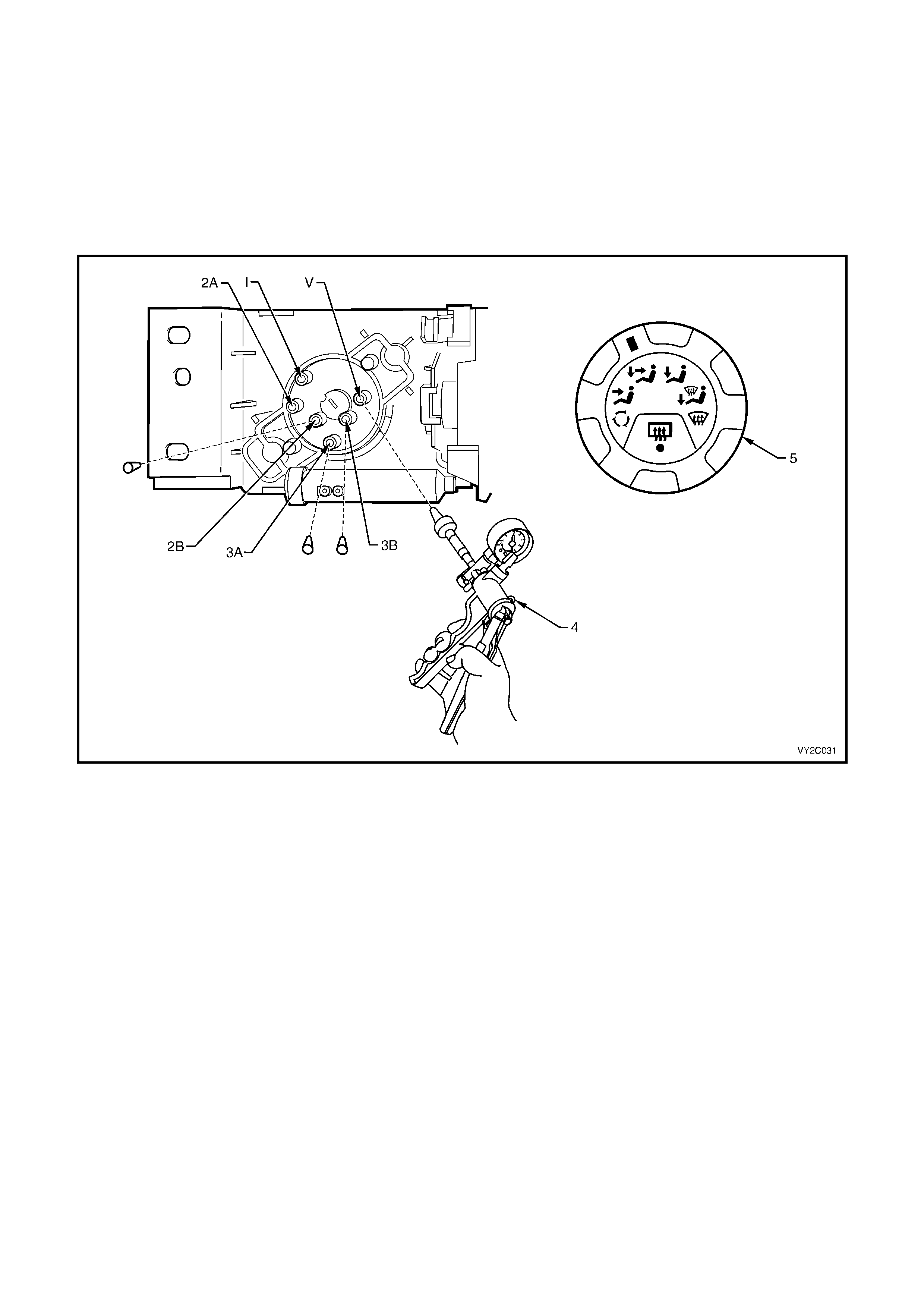
BLEND MODE
To vacuum test the vacuum mode valve in the Blend mode perform the following:
1. Set the vacuum control to Blend mode.
2. Block the foot 1 and foot 2 ports (3A and 3B) of the vacuum mode valve. Connect a vacuum pump (4) to the
vacuum supply port (V) of the vacuum mode valve.
3. Using the vacuum pump, create a vacuum and observe the vacuum pump gauge needle.
4. If the needle remains steady or decreases slowly, it indicates that the mode valve is retaining vacuum in the
Blend position. If the vacuum reading decreases quickly, it indicates a vacuum leak in the mode valve.
5. If a vacuum leak is indicated, replace the vacuum mode valve.
Figure 2C-31
REINSTALL MANUA L HVAC CONTROLLER
To reinstall the manual HVAC controller refer to Section 2B, 2.0 MANUAL HVAC CONTROLLER.
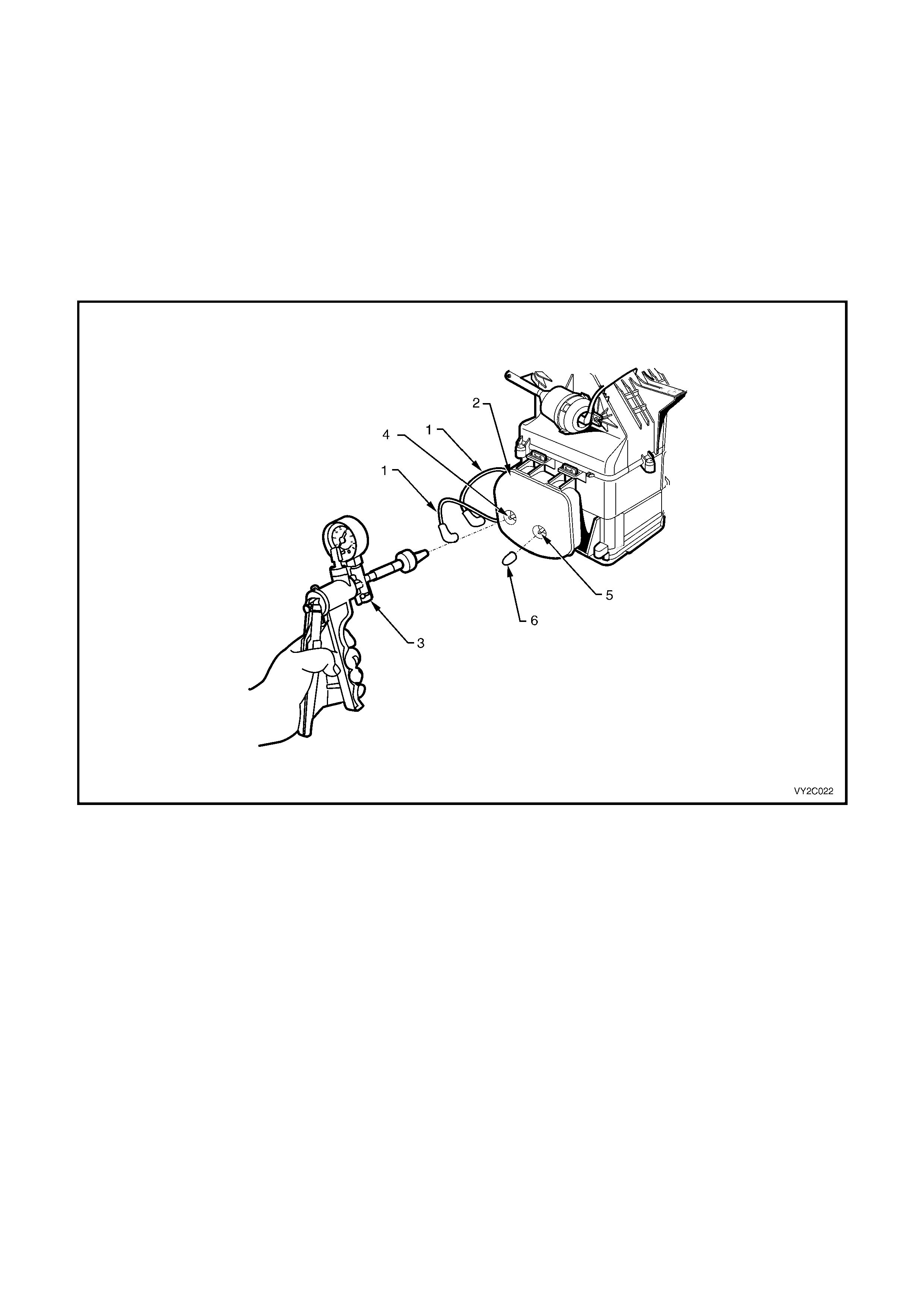
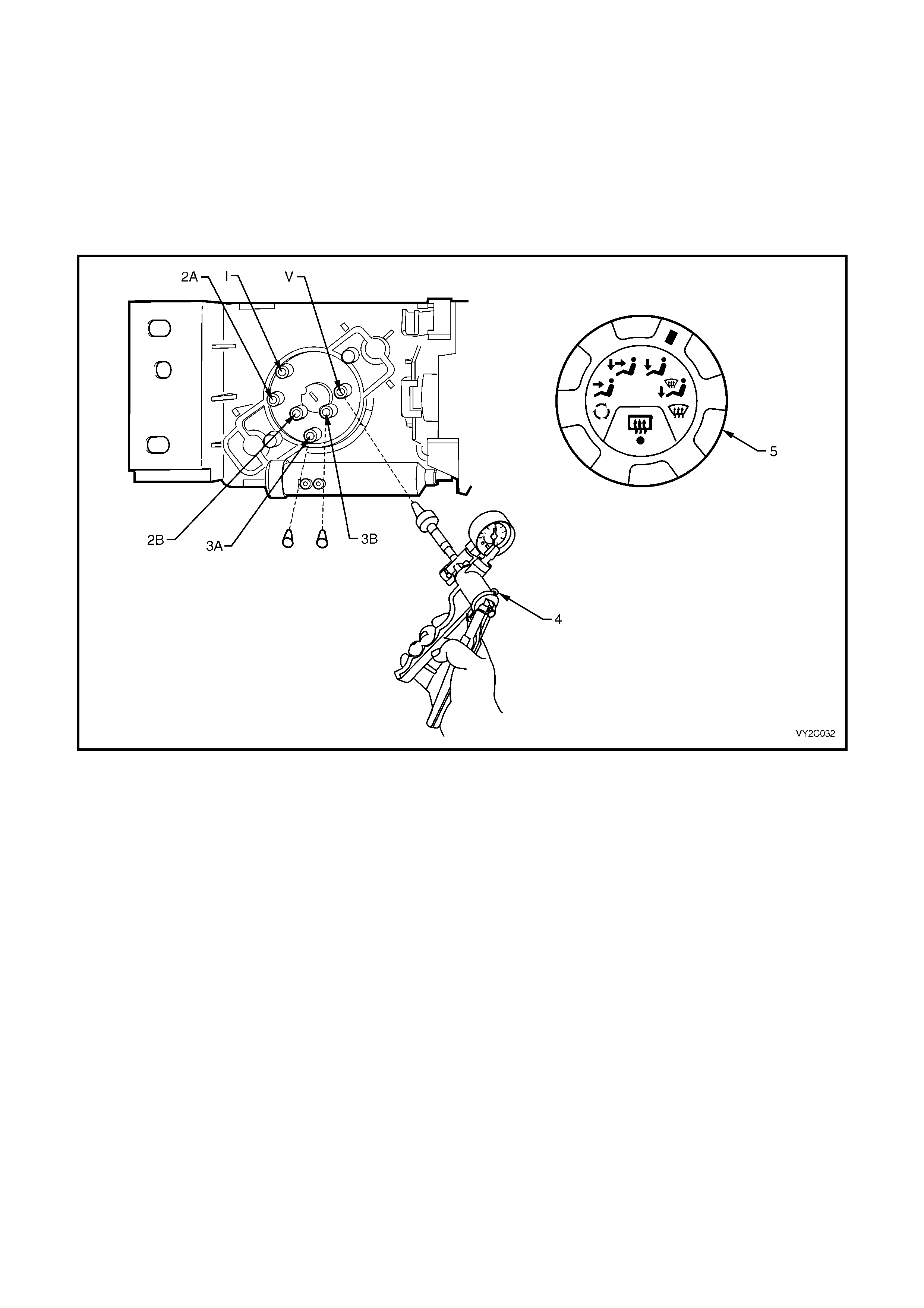
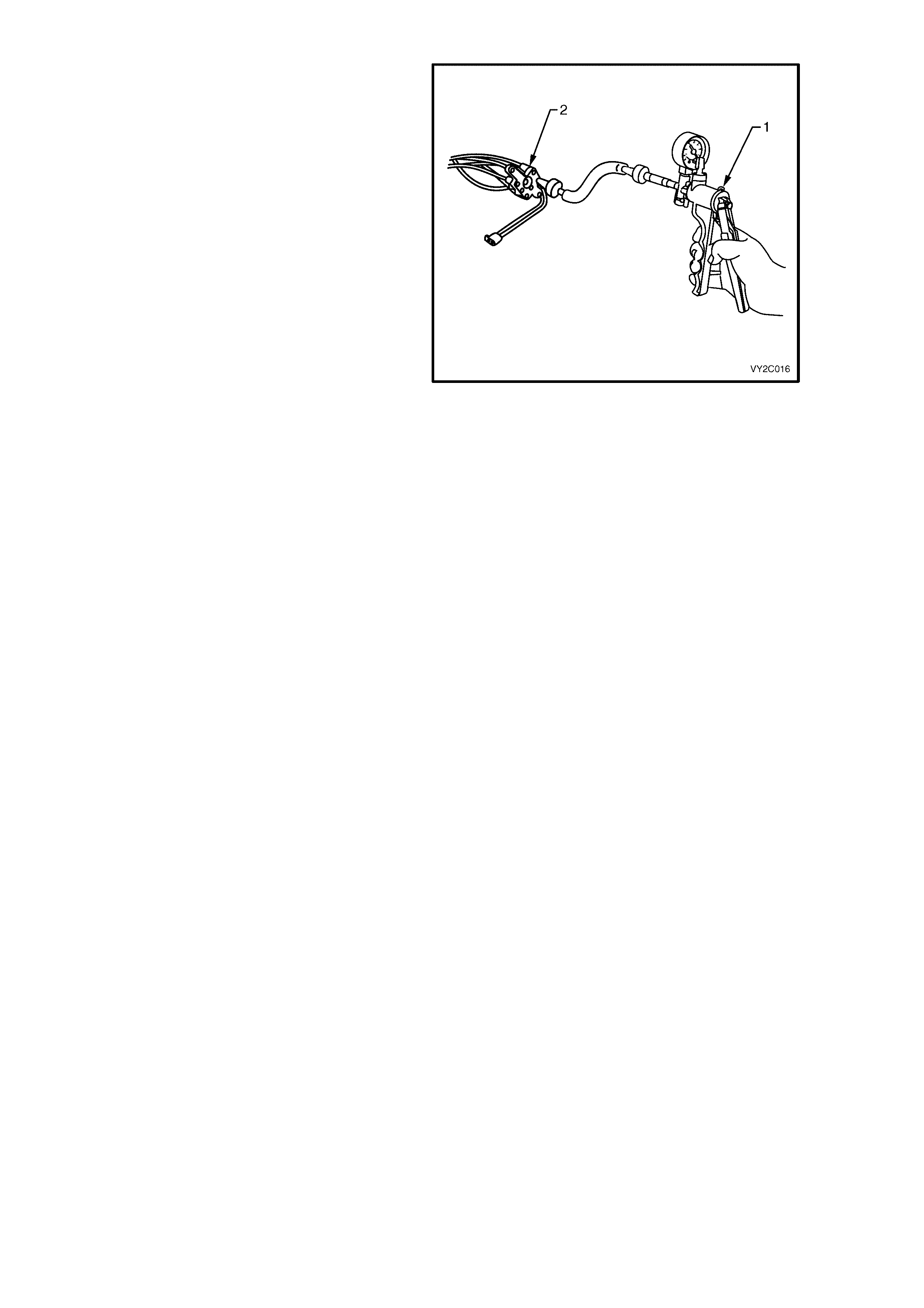
8.4 WATER VALVE VACUUM SWITCH
1. Remove the manual HVAC controller, refer to Section 2B, 2.0 MANUAL HVAC CONTROLLER.
2. Set the temperature control switch (1) to the full cold position.
3. On the water valve vacuum switch (2), block the water valve port (3) with a suitable plug.
4. Connect a vacuum pump (4) to the vacuum supply port (5) of the vacuum switch.
5. Using the vacuum pump, create a vacuum and observe the vacuum pump gauge needle.
6. If the needle remains steady it indicates that the vacuum switch is retaining vacuum. If the vacuum reading
decreases, it indicates a vacuum leak in the vacuum switch.
7. If a vacuum leak is indicated, replace the water valve vacuum switch.
Figure 2C-32

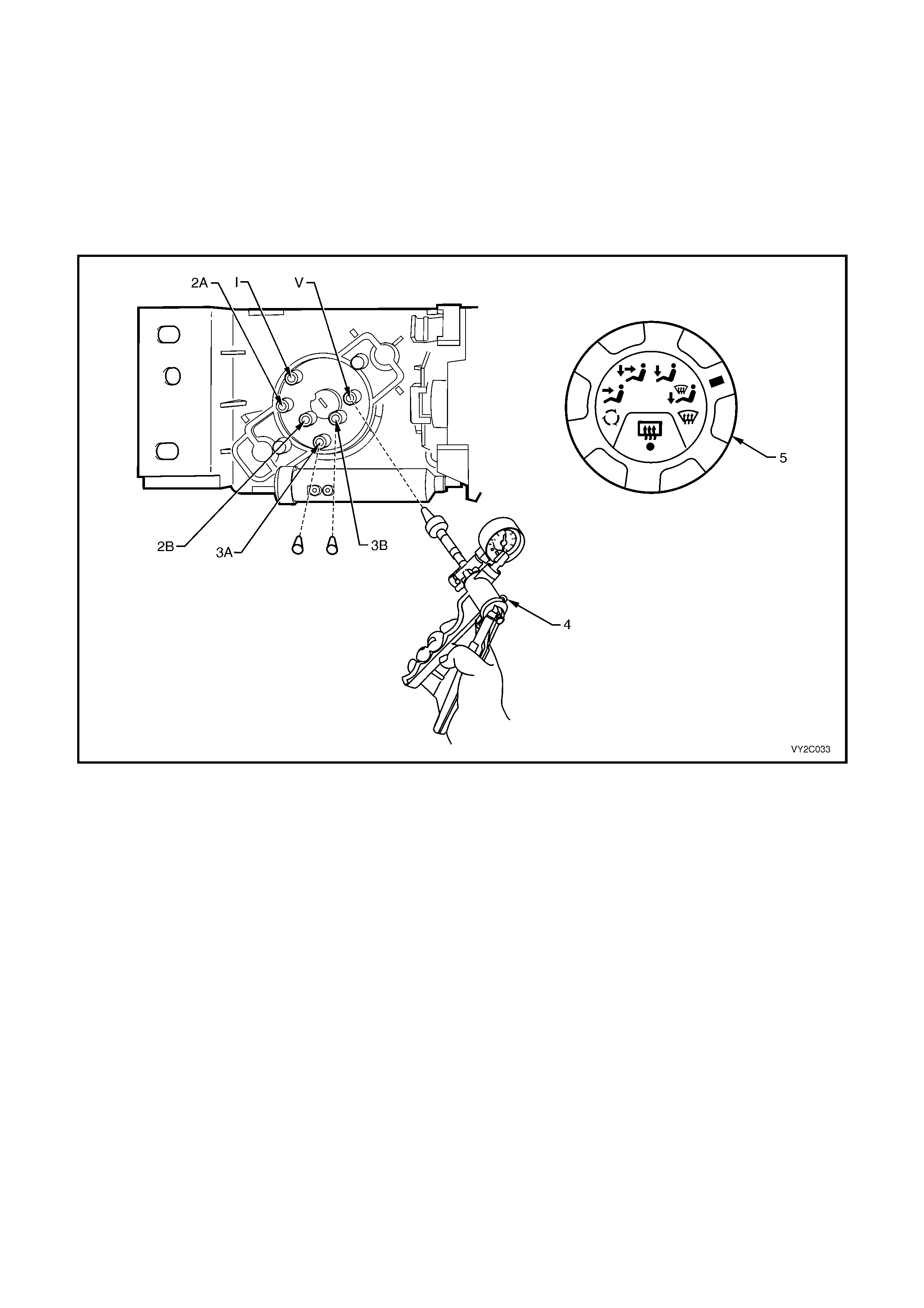
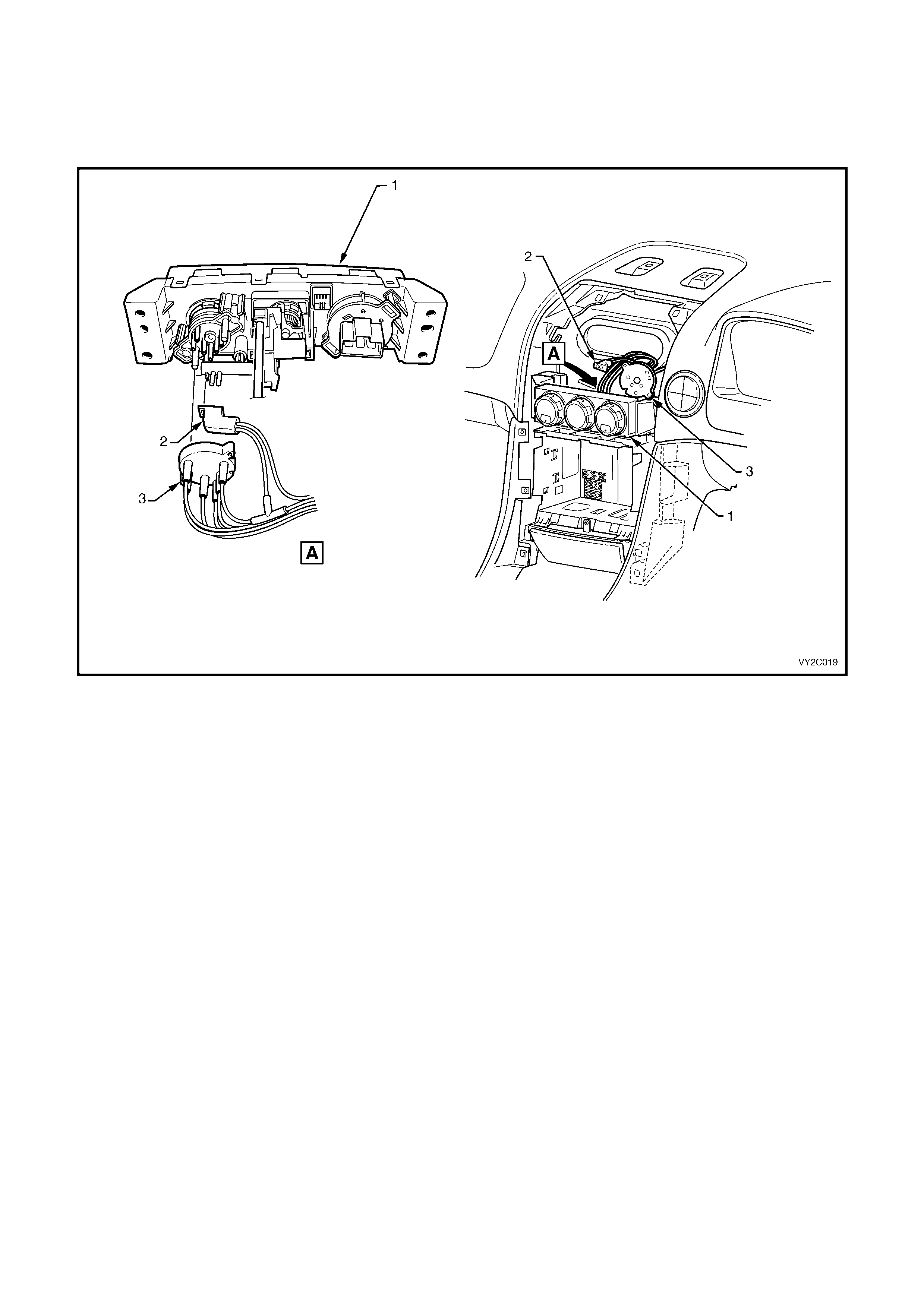
8.5 VACUUM ACTUATORS AND LINES
ACCESS – LHD
1. To access the rear of the manual HVAC controller (1), remove the instrument panel centre trim assembly. Refer
to Section 1A3, 3.7 INSTRUMENT PANEL CENTRE TRIM ASSEMBLY.
2. Remove the water valve vacuum switch valve connector (2) and the mode valve plastic manifold (3) from the
back of the HVAC controller.
Figure 2C-33
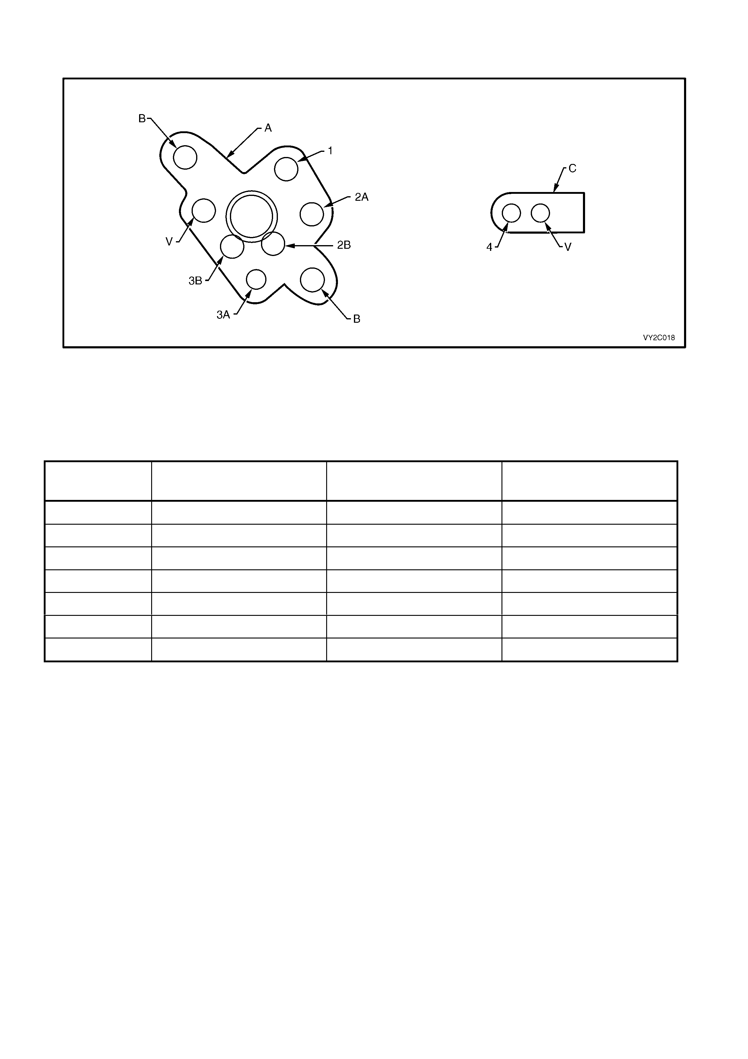
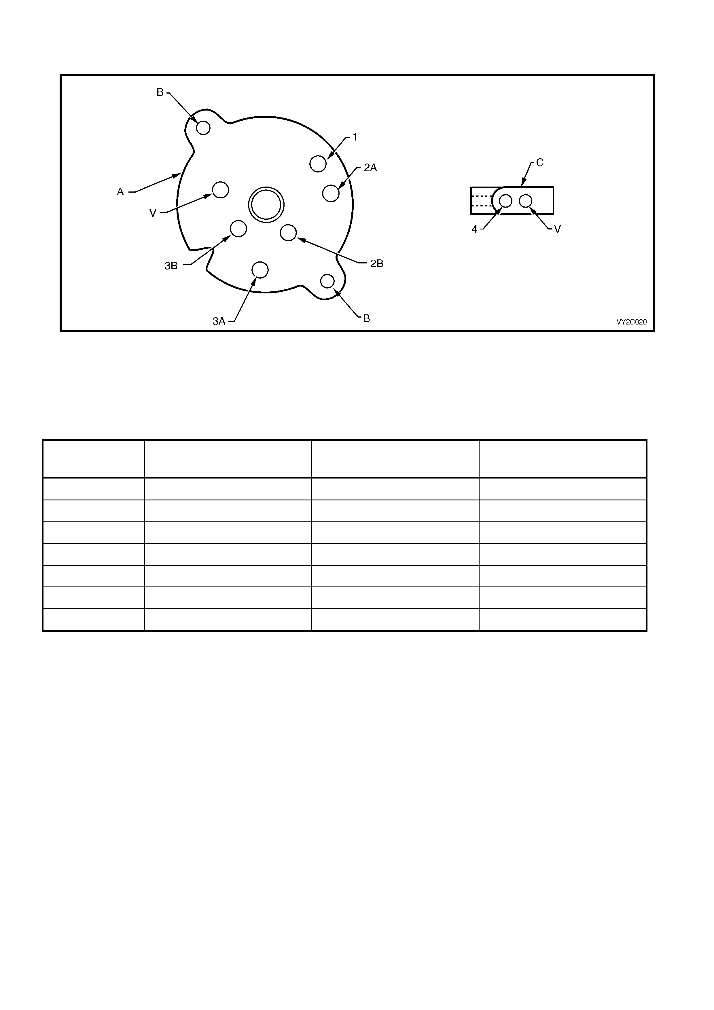
TEST – LHD
Figure 2C-34
Legend
A. Plastic Manifold
B. Manifold Mounting Hole
C. Water Valve Vacuum Switch Valve Connector
Vacuum ports, lines and functions
PORT ACTUATOR VACUUM LINE COLOUR FUNCTION WHEN
VACUUM APPLIED
V — White Vacuum Supply
1 Intake Yellow Recirculation
2A Face Blue Bi-level
2B Face Brown Face
3A Demist Green Demist / Face
3B Foot Red Demist / Face
4 Water valve Orange Full cold
To test the vacuum actuators and lines
perform the following (refer to Figure 2C-35
and the table above to determine the correct
port):
1. Test the Intake and Foot actuators and
lines by connecting a vacuum pump (1) to
the appropriate port of the plastic vacuum
manifold (2).
2. Using the vacuum pum p, c reate a vacuum
and observe the vacuum pump gauge
needle.
3. If the vacuum reading decreases, it
indicates a vacuum leak in the line or
actuator.
4. If a vacuum leak is indicated check the
vacuum tubing for damage or loose
connection to the plastic manifold and
vacuum actuator. If there is no damage or
loose connection, perform a vacuum test
on the connecting vacuum actuator.
5. To test the Demist actuator and lines,
connect a vacuum pump to the Demist
port (3A) of the plastic vacuum manifold
and block the Face 1 (2B) and Face 2 (2A)
ports.
6. Using the vacuum pum p, c reate a vacuum
and observe the vacuum pump gauge
needle.
Figure 2C-35
7. If the vacuum reading decreases, it indicates a vacuum leak in the line or actuator.
8. If a vacuum leak is indicated check the vacuum tubing for damage or loose connection to the plastic
manifold and vacuum actuator. If there is no damage or loose connection, perform a vacuum test on the
connecting vacuum actuator.
9. To test the Face actuator and lines connect a vacuum pump to the Face 1 (2B) and Face 2 (2A) ports of
the plastic vacuum manifold by using a tee piece. Block the Demist port (3A) of the plastic vacuum
manifold.
10. Using the vacuum pump, create a vacuum and observe the vacuum pump gauge needle.
11. If a vacuum leak is indicated check the vacuum tubing for damage or loose connection to the plastic
manifold and vacuum actuator. If there is no damage or loose connection, perform a vacuum test on the
connecting vacuum actuator.
12. To test the water valve and line connect a vacuum pump to the water valve port (4) of the vacuum switch
connector (C).
13. Using the vacuum pump, create a vacuum and observe the vacuum pump gauge needle.
14. If a vacuum leak is indicated check the vacuum tubing for damage or loose connection to the water valve. If
there is no damage or loose connection, perform a vacuum test on the water valve.
REINSTALL – LHD
1. Install the water valve vacuum switch valve connector to the switch.
2. Install the mode valve plastic manifold to the vacuum mode valve.
3. Install the instrument panel centre trim assembly, refer to Section 1A3, 3.7 INSTRUMENT PANEL CENTRE
TRIM ASSEMBLY.
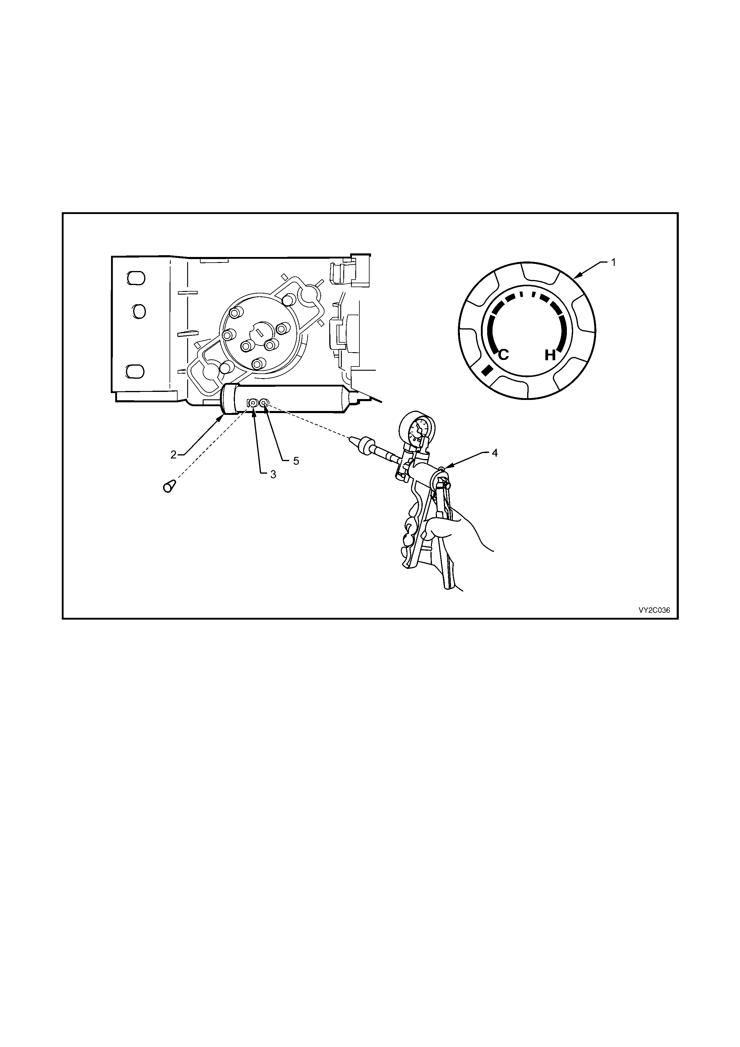
ACCESS – RHD
1. To access the rear of the manual HVAC controller (1), remove the instrument panel centre trim assembly. Refer
to Section 1A3, 3.7 INSTRUMENT PANEL CENTRE TRIM ASSEMBLY.
2. Remove the water valve vacuum switch valve connector (2) and the mode valve plastic manifold (3) from the
back of the HVAC controller.
Figure 2C-36
TEST – RHD
Figure 2C-37
Legend
A. Plastic Manifold
B. Manifold Mounting Hole
C. Water Valve Vacuum Switch Valve Connector
Vacuum ports, lines and functions
PORT ACTUATOR VACUUM LINE COLOUR FUNCTION WHEN
VACUUM APPLIED
V — Black Vacuum Supply
1 Intake Blue Recirculation
2A Face Green Bi-level
2B Face White Face
3A Foot Orange Blend
3B Foot Pink Foot / Bi-level
4 Water valve Yellow Full cold

To tes t the vacuum ac tuators and lines perform the
following (refer to Figure 2C-38 and table above to
determine the correct port):
1. Test the intake actuator and lines by
connecting a vacuum pump (1) to the intake
port of the plastic vacuum manifold (2).
2. Using the vacuum pump, cr eate a vacuum and
observe the vacuum pump gauge needle.
3. If a vacuum leak is indic ated chec k the vacuum
tubing for damage or loose connection to the
plastic manifold and vacuum actuator. If there
is no damage or loose connection, perform a
vacuum test on the connecting vacuum
actuator.
4. To test the Foot actuator and lines, connect a
vacuum pump to the Foot 1(3B) and Foot 2
(3A) ports of the plastic vacuum manifold by
using a tee piece.
5. Using the vacuum pump, cr eate a vacuum and
observe the vacuum pump gauge needle.
6. If a vacuum leak is indic ated chec k the vacuum
tubing for damage or loose connection to the
plastic manifold and vacuum actuator. If there
is no damage or loose connection, perform a
vacuum test on the connecting vacuum
actuator.
Figure 2C-38
7. T o tes t the Fac e ac tuator and lines c onnect a vac uum pump to the Face 1 ( 2B) and F ace 2 (2A) ports of the
plastic vacuum manifold by using a tee piece.
8. Using the vacuum pump, create a vacuum and observe the vacuum pump gauge needle.
9. If a vacuum leak is indicated check the vacuum tubing for damage or loose connection to the plastic
manifold and vacuum actuator. If there is no damage or loose connection, perform a vacuum test on the
connecting vacuum actuator.
10. To test the water valve and line connect a vacuum pump to the water valve port (4) of the vacuum switch
connector (C).
11. Using the vacuum pump, create a vacuum and observe the vacuum pump gauge needle.
12. If a vacuum leak is indicated chec k the vacuum tubing f or dam age or loos e connection to the water valve. If
there is no damage or loose connection, perform a vacuum test on the water valve.
REINSTALL – RHD
1. Install the water valve vacuum switch valve connector to the switch.
2. Install the mode valve plastic manifold to the vacuum mode valve.
3. Install the instrument panel centre trim assembly, refer to Section 1A3, 3.7 INSTRUMENT PANEL CENTRE
TRIM ASSEMBLY.
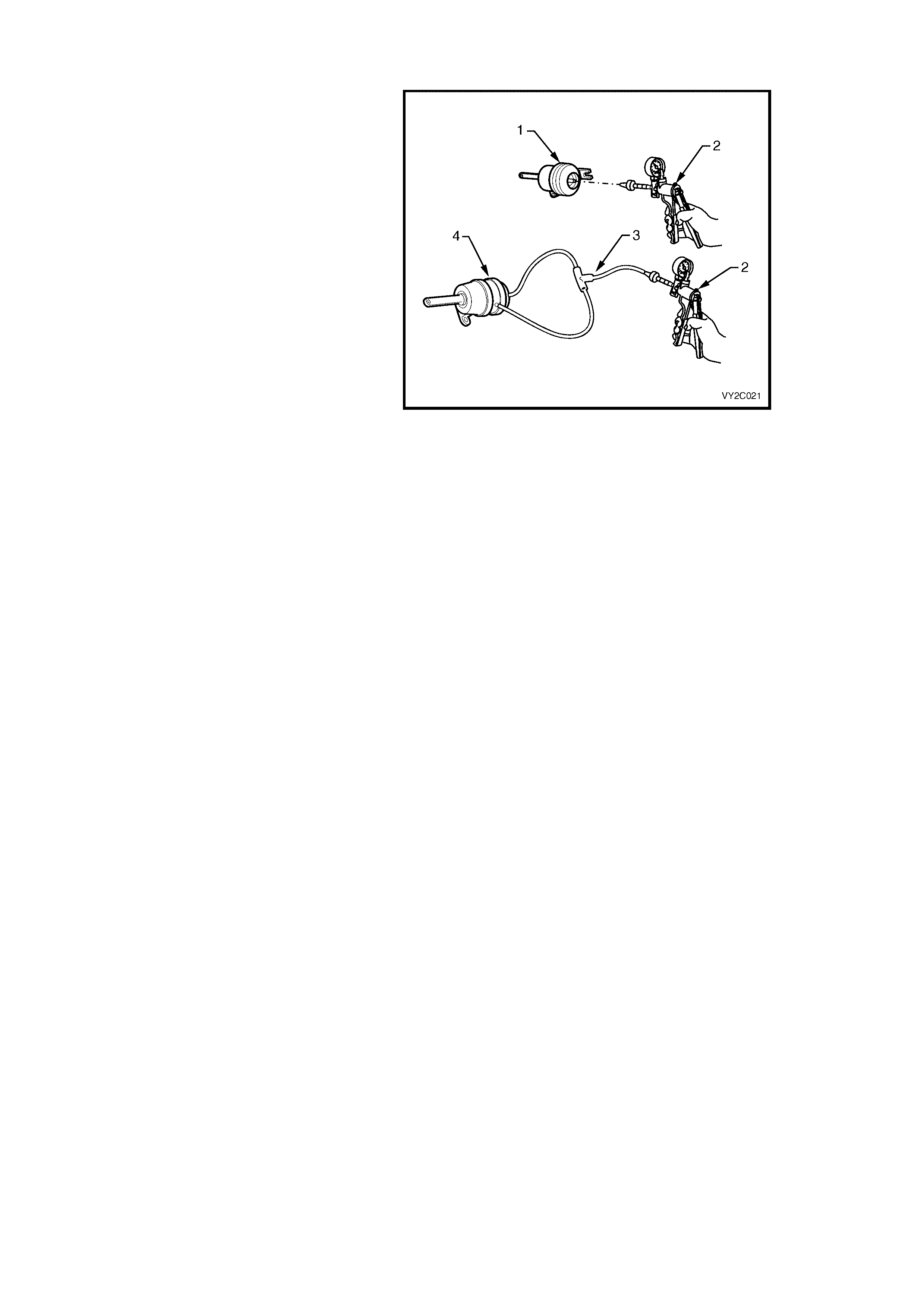
8.6 VACUUM ACTUATORS
To test the vacuum actuators, perform the
following:
1. Remove the vacuum actuator, refer to
Section 2B, 8. VACUUM TANK AND
VACUUM ACTUATORS.
2. For a single stage vacuum actuator
(demist, foot and intake actuators)
connect the vacuum pump to the rear
port of the vacuum actuator. For a two
stage vacuum actuator (face actuator)
connect the vacuum pump to the rear
and side ports with a vacuum tee piece.
3. Using the vacuum pump, create a
vacuum and observe the vacuum pump
gauge needle.
4. If a vacuum leak is indicated, replace the
vacuum actuator.
Legend
1. Single Stage Vacuum Actuator
2. Vacuum Pump
3. Vacuum Tee Piece
4. Two Stage Vacuum Actuator
Figure 2C-39
8.7 WATER VALVE
To vacuum test the water valve perform the following:
1. Remove the vacuum supply line (1) to the water valve actuator (2) vacuum port (3).
2. Connect a vacuum pump (4) to the vacuum port.
3. Using the vacuum pump, create a vacuum and observe the vacuum pump gauge needle.
4. If a vacuum leak is indicated replace the water valve assembly.
Figure 2C-40

9. WIRING DIAGRAMS
The following figures provide electrical connector diagrams and wiring diagrams applicable to HVAC Climate
Control (M anual A/C) systems as fitted to MY2003 VY and V2 Series vehic les. These diagram s should be used as
an aid to diagnosing circuit faults. The content of these Figures is as follows:
• Electrical connectors – refer to Figure 2C-41
• Electrical connectors continued – refer to Figure 2C-42
• Electrical connectors continued – refer to Figure 2C-43
• V6 LHD wiring diagram – refer to Figure 2C-44
• V6 RHD wiring diagram – refer to Figure 2C-45
• GEN III V8 LHD wiring diagram – refer to Figure 2C-46
• GEN III V8 RHD wiring diagram – refer to Figure 2C-47
For wiring diagrams related to the Occupant Climate Control (Auto A/C) system, refer to Section 2F, 5.WIRING
DIAGRAMS.
In the following wiring diagrams (Figure 2C-44 to Figure 2C-47) all components are described and displayed in
accordance to the Integrated Vehicle Electrical Design (IVED) standard as applied to MY2003 VY and V2 Series
vehicles. To assist in wiring diagram interpretation, refer to the following table:
IVED DESCRIP T ION IVED COMP ONE NT IDENTIF ICATION COMMON DESCRIPT ION
Switch Asm – I gn & Start S149 Ignition Switch
V6 Module Asm Pwrt Cont A84 V6 Powertrain Control Module
V8 Module Asm Pwrt Cont A84 GEN III V8 Powertrain Control Module
Module Asm Body Cont A15 Body Control Module
Motor Asm Blo M3 Blower Motor
Resistor Asm Blo Mot R6 Blower Motor Resis t or
Module Asm Htr & A / c Evpr A60 Manual HVAC Controller
Coil A/ c Clu L7 Compres sor Clutc h
Sensor Asm A /C Refrig Press B 18 A/C Press ure Transducer
Motor Asm Eng Cool Fan M7_Std V6 Standard Cool i ng Fan S ys tem
Motor Asm Eng Cool Fan M7_HP V6 High Power Cooling Fan System
Motor Asm Eng Cool Fan M7_V8 GEN III V8 Cooling Fan System
Window Rear R22 Heated Rear Window
The following table lists the IVED standard wire colour abbreviations:
BK Black D-GN Dark green L-GN Light green RD Red
BU Blue GN Green OG Orange TN Tan
BN Brown GY Grey PK Pink WH White
D-BU Dark blue L-BU Light blue PU Purple YE Yellow
NOTE 1: Electrical connectors specific to left-hand drive or right-hand drive applications are identified in the
connector view diagrams by a LHD or RHD notation after the connector description.
NOTE 2: For electrical connector locations and additional wiring diagram information refer to
Section 12P WIRING DIAGRAMS.
NOTE 3: V6 RHD domestic models are fitted with standard cooling fan system type fan motors. V6 RHD export
models may be fitted with high power cooling f an system type fan m otors. W here this applies , refer to the V6 RHD
wiring diagram Figure 2C-45, in conjunction with the cooling fan wiring details in the V6 LHD wiring diagram
Figure 2C-44.
NOTE 4: For visual identification of Standard (STD) and High Power (HP) cooling fan motors refer to
Section 2A, 2.9 COOLING FA NS.
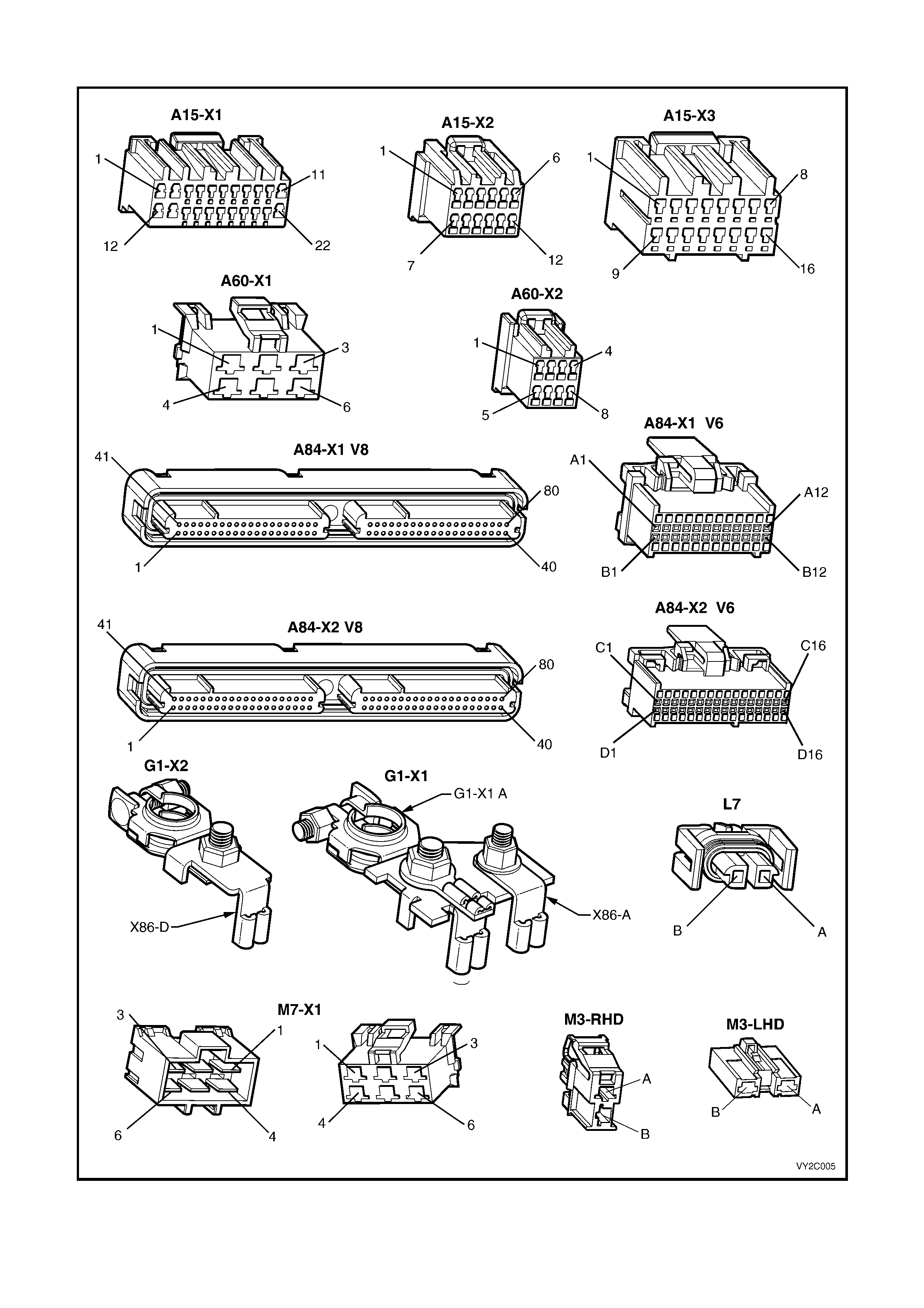
CONNECTORS: MANUAL A/C HVAC SYSTEM
Figure 2C-41
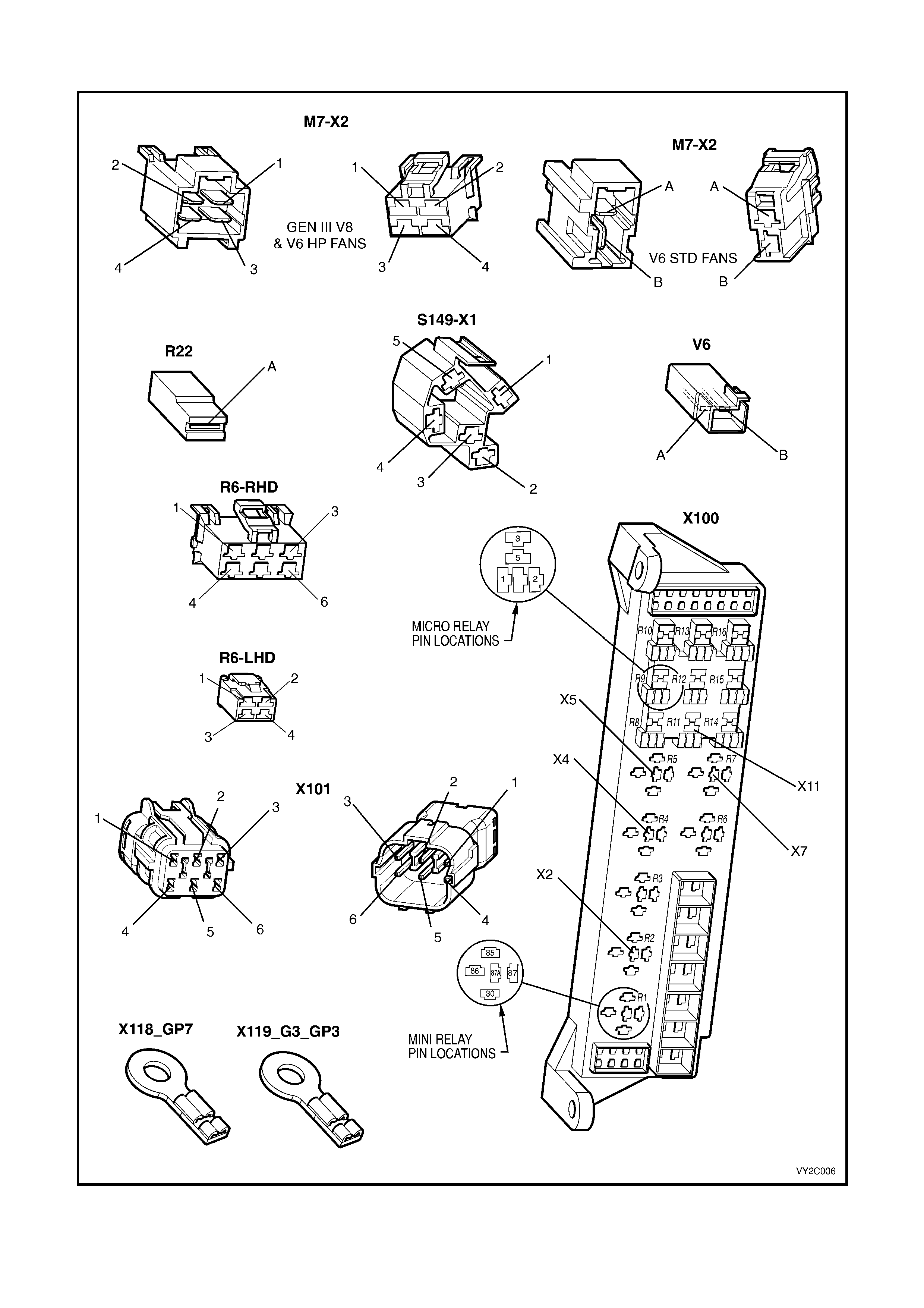
CONNECTORS: MANUAL A/C HVAC SYSTEM CONTINUED
Figure 2C-42
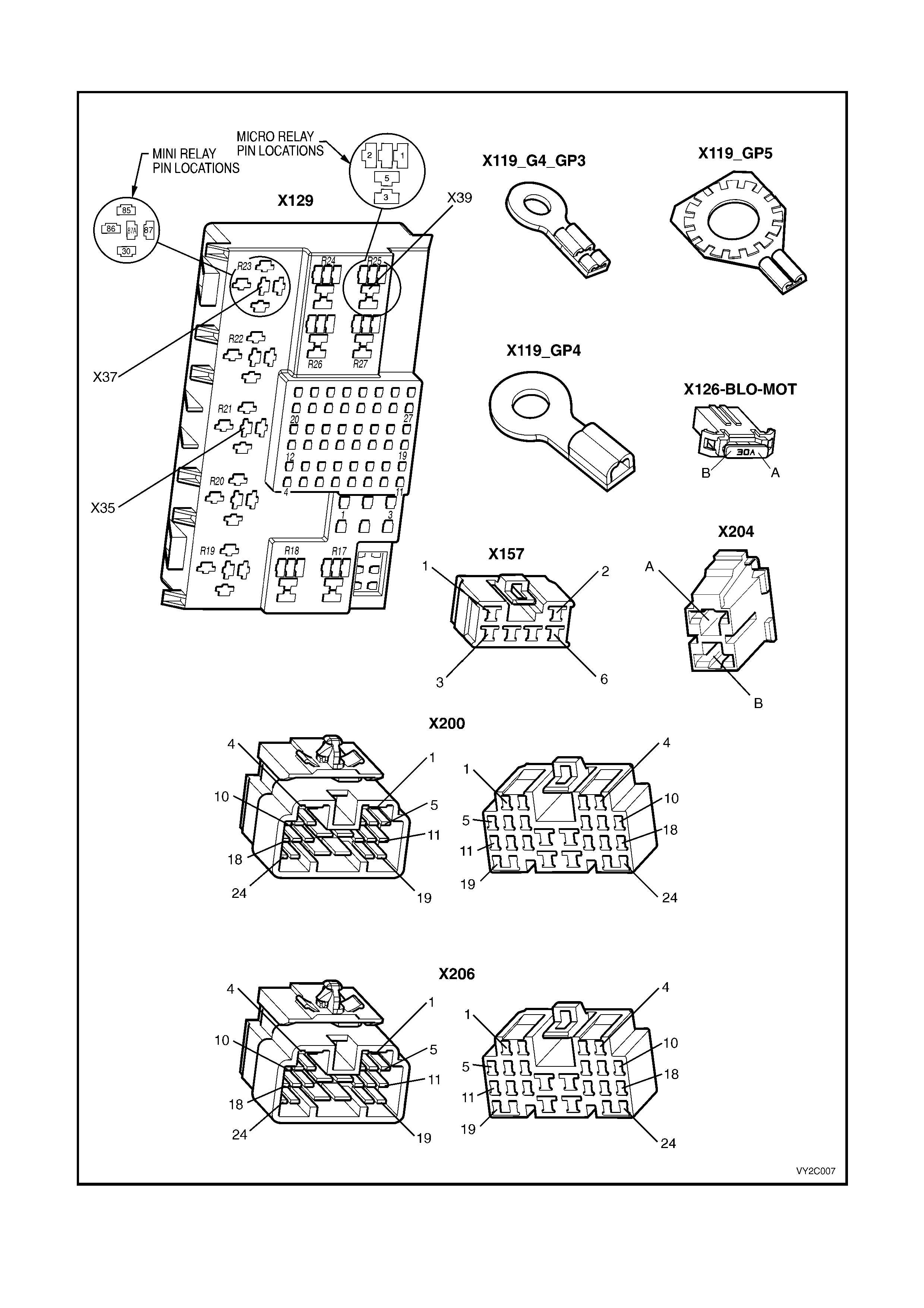
CONNECTORS: MANUAL A/C HVAC SYSTEM CONTINUED
Figure 2C-43
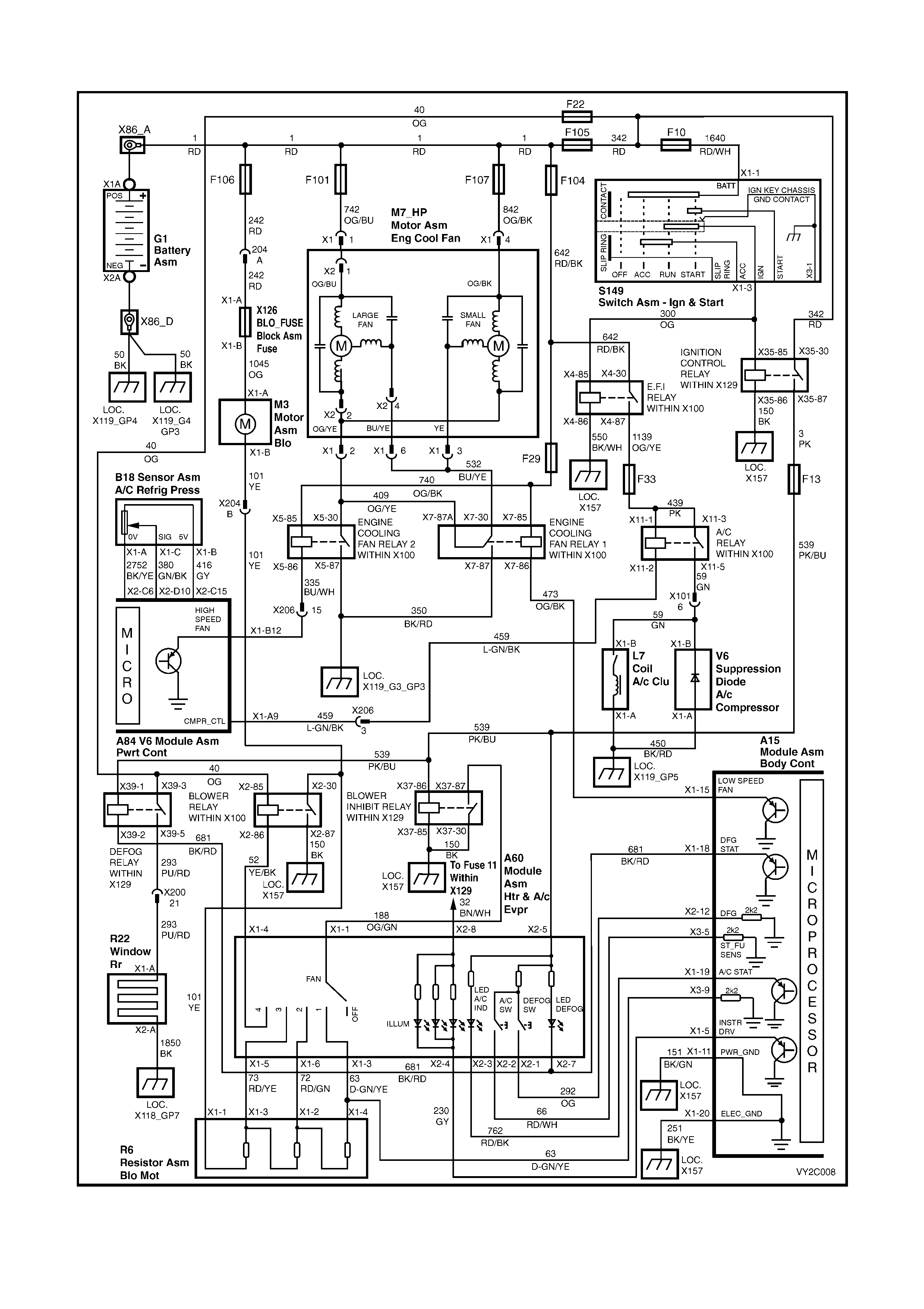
WIRING DIAGRAM: MANUA L A/C HVAC SYSTEM – V6 LHD
Figure 2C-44
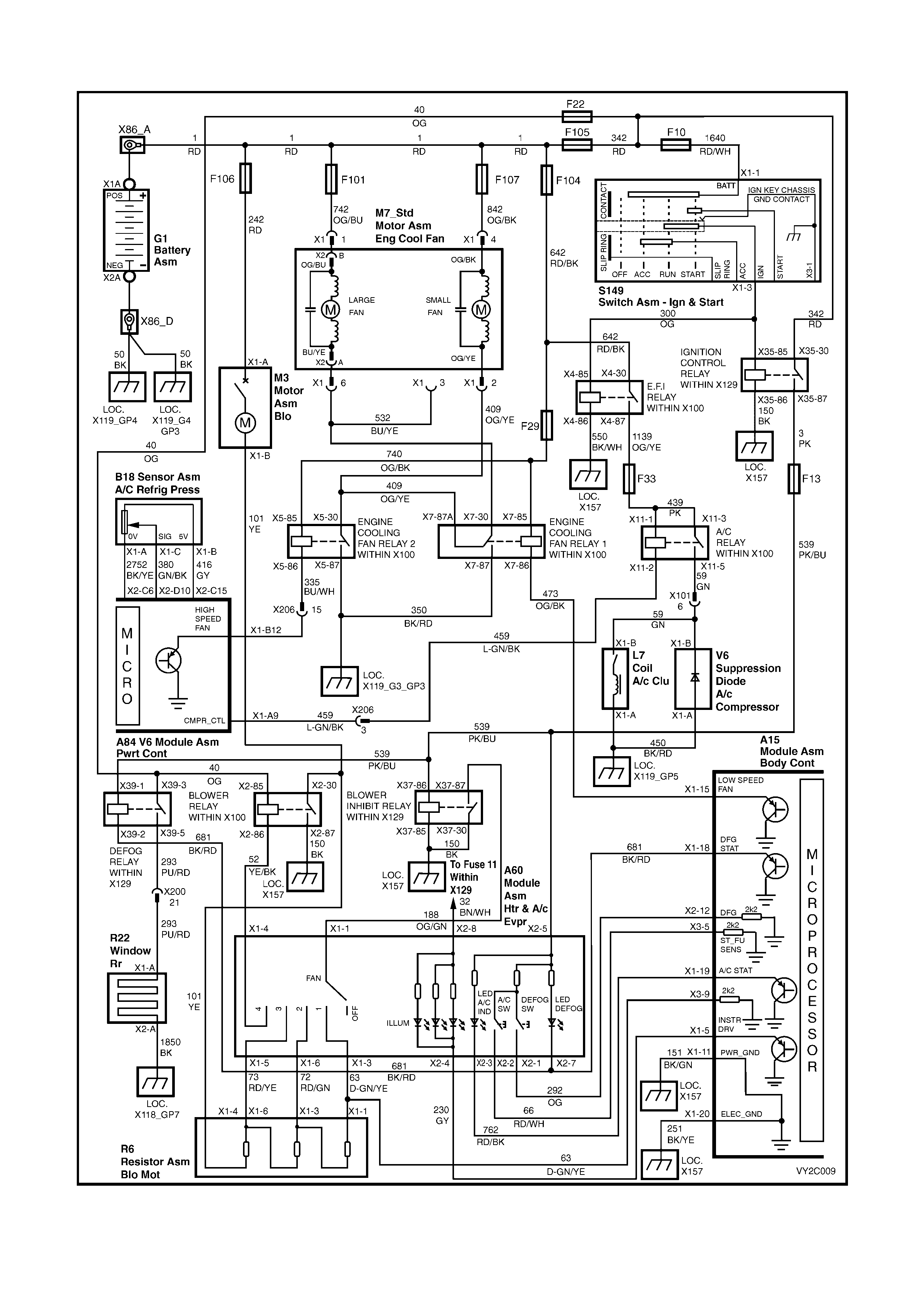
WIRING DIAGRAM: MANUAL A/C HVAC SYSTEM – V6 RHD
Figure 2C-45
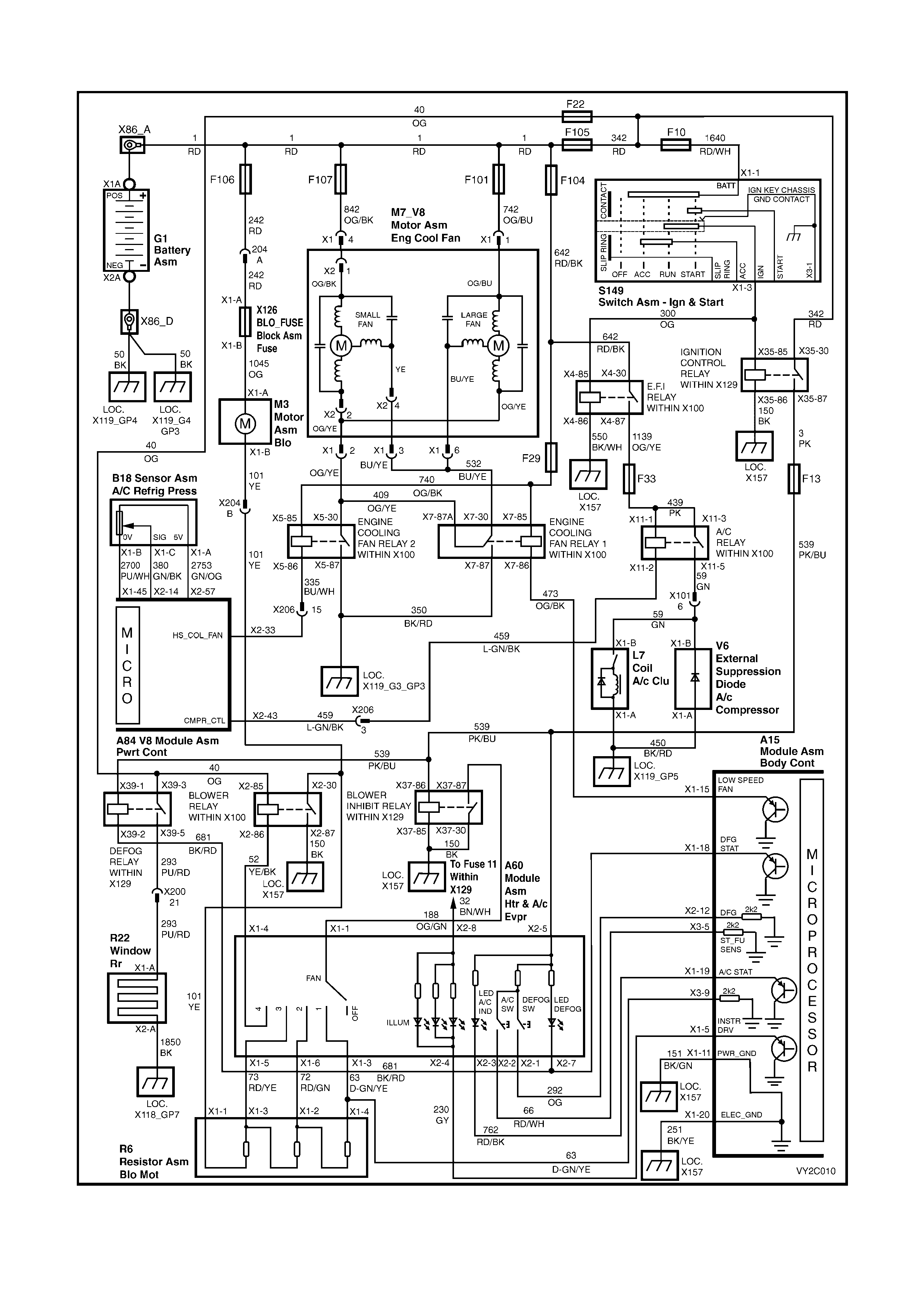
WIRING DIAGRAM: MANUAL A/C HVAC SYSTEM – GEN III V8 LHD
Figure 2C-46
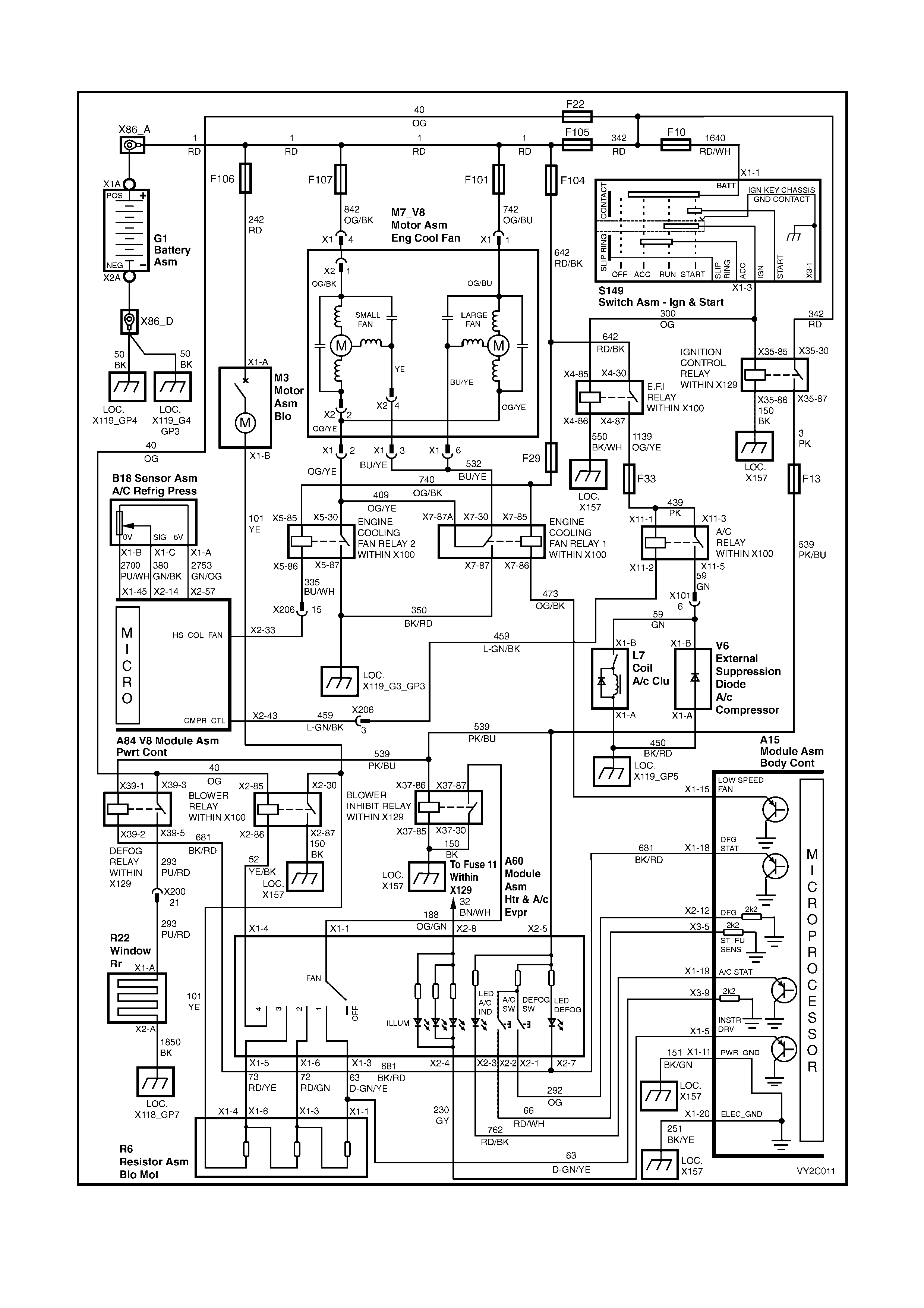
WIRING DIAGRAM: MANUAL A/C HVAC SYSTEM – GEN III V8 RHD
Figure 2C-47
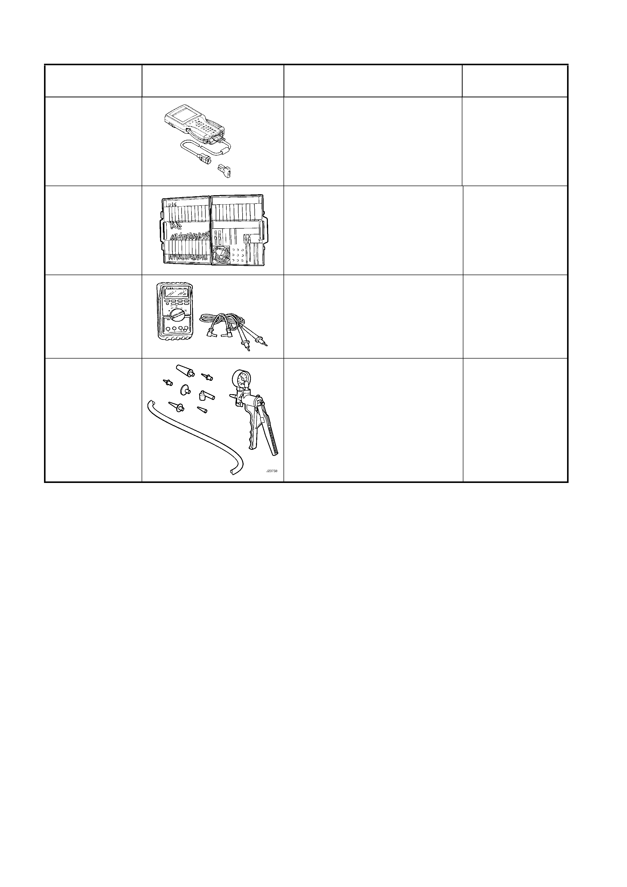
10. SPECIAL TOOLS
TOOL NUMBER ILLUSTRATION DESCRIPTION TOOL
CLASSIFICATION
7000086I
TECH 2
DIAGNOSTIC SCAN TOOL
Used for diagnosis of vehicle
electrical system.
Previously released.
Mandatory
J35616-A
(KM609)
CONNECTOR TEST ADAPTOR
KIT
Used when carrying out electrical
diagnostic circuit checks.
Previously released.
Desirable
3588
(J39200)
DIGITAL MULTIMETER
Must have at least 10 MΩ input
impedance and be capable of
reading frequencies.
Previously released.
Available
J23738 VACUUM PUMP
Used for testing HVAC system
components, i.e. check valve,
HVAC controller, HVAC unit
vacuum tank, lines and actuators.
Previously released.
Desirable