
SECTION 2D - HVAC OCCUPANT CLIMATE CONTROL
(AUTO A/C) – DESCRIPTION AND OPERATION
IMPORTANT
Before performing any Service Operation or other procedure described in this Section, refer to Section 00
CAUTIONS AND NOTES for correct workshop practices with regard to safety and/or property damage.
CONTENTS
1. GENERAL INFORMATION
2. GENERAL DESCRIPTION
3. DESCRIPTION
3.1 OCC CONTROL MODULE
OCC CONTROL MODULE CONFIGURATIONS
SWITCHES – SINGLE ZONE
SWITCHES – DUAL ZONE
LIQUID CRYSTAL DISPLAY SCREEN
OCC CONTROL MODULE COMPONENTS
OCC CONTROL MODULE ELECTRICAL
CONNECTION
3.2 HEATING, VENTILATION AND AIR
CONDITIONING (HVAC) UNIT:
CONSTRUCTION, COMPONENTS AND
ASSOCIATED SENSORS
HVAC UNIT – LEFT-HAND DRIVE
HVAC UNIT – RIGHT-HAND DRIVE
AIR MIX DOORS AND AIR MIX MOTORS
BLOWER MOTOR RESISTOR
VACUUM SOLENOID PACK
WATER VALVE VACUUM SWITCHING
VALVE
ASPIRATOR TUBE AND VENTURI
IN-CAR TEMPERATURE SENSOR
EVAPORATIVE TEMPERATURE SENSOR
AMBIENT TEMPERATURE SENSOR
SUN LOAD SENSOR
3.3 HVAC UNIT AIRFLOW MODES
RECIRCULATION MODE – LHD
FACE MODE – LHD
BI-LEVEL MODE – LHD
FLOOR MODE – LHD
BLEND MODE – LHD
DEMIST MODE – LHD
DEFAULT MODE – LHD
RECIRCULATION MODE – RHD
FACE MODE – RHD
BI-LEVEL MODE – RHD
FLOOR MODE – RHD
BLEND MODE – RHD
DEMIST MODE – RHD
DEFAULT MODE – RHD
3.4 VACUUM CIRCUIT
SOLENOID PACK AND VACUUM
LINES – LHD
VACUUM CIRCUIT SCHEMATIC – LHD
SOLENOID PACK AND VACUUM
LINES – RHD
VACUUM CIRCUIT SCHEMATIC – RHD
4. OPERATION
RECOMMENDED SETTINGS
EVAPORATOR TEMPERATURE CONTROL
BLOWER FAN CONTROL
AIR DISTRIBUTION CONTROL
AIR INLET CONTROL
VENT AIR TEMPERATURE CONTROL
OCC COLD START-UP ROUTINES
SENSOR MALFUNCTION INDICATOR
DEFAULT MODE: VACUUM LEAK
AUTOMATIC OPERATION
OCC SYSTEM ACTIVATION
OCC SINGLE ZONE OPERATION
OCC DUAL ZONE OPERATION
5. SPECIFICATIONS
Techline
Techline
Techline

1. GENERAL I NFORMATI O N
HVAC Occupant Climate Control (Auto A/C) is fitted to m id and high level MY2003 VY and V2 Series vehicles . It
will be generally referred to as ‘O cc upant Climate Control ( O CC)’ or ‘OCC (Auto A/C)’ air conditioning in this Section
and the following Sections:
• Section 2E HVAC OCCUPA NT CLIMATE CONTROL (AUTO A/C) – REMOVAL AND INSTALLATION
• Section 2F HVAC OCCUPANT CLIMATE CONTROL (AUTO A/C) – DIA GNOSTICS
Inform ation in this Sec tion, Section 2E and Section 2F is relevant to HVAC Occupant Climate Control (Auto A/C)
only. For information relating to the HVAC Occupant Climate Control (Auto A/C) system not covered in this
Section, Section 2E or Section 2F, refer to the following Sections:
• Section 2A HVAC CLIMATE CONTROL (MANUAL A/C) – DESCRIPTION AND OPERATION
• Section 2B HVAC CLIMATE CONTROL (MANUAL A/C) – REMOVAL AND INSTALLATION
• Section 2C HVAC CLIMATE CONTROL (MANUAL A/C) – SERVICING AND DIAGNOSIS

2. GENERAL DESCRIPTION
The Occupant Climate Control system as fitted to MY2003 VY and V2 Series uses the same basic components as
fitted to models equipped with manual air conditioning. Major components such as the condenser, filter drier
receiver, compressor, evaporator, heater core, blower fan, cooling fans and water valve are common to both
manual and OCC (Auto A/C) air conditioning systems.
Sensors and components, which are fitted to the auto air conditioning system and not the manual air conditioning
system, include the following:
• Push button Occupant Climate Control module
• In-car temperature sensor
• Sun load sensor
• Ambient temperature sensor
• Evaporative temperature sensor
• Vacuum solenoid pack
• Water valve vacuum switch valve (LHD models only)
• Air mix door motor/s
NOTE: Sun load sensing is an additional function of the ambient light sensor / remote receiver. Accordingly this
sensor is still fitted to vehicles with manual type air conditioning.
The major operational difference between the manual and OCC (Auto A/C) air conditioning systems is that the OCC
(Auto A/C)) system can maintain a preset level of cooling or heating regardless of inside or outside temperature
fluctuations. The electronic sensing devices listed above allow the system to respond to various changes in ambient
temperature, evaporator temperature, interior cabin temperature and sun load. Another key difference is that unlike
the manual system, the OCC (Auto A/C) system has the capability to use recirculated air in conjunction with all
other ventilation modes. The OCC (Auto A/C) system will adjust automatically to any climate and temperature
changes to maintain the vehicle cabin interior within the selected temperature range. This is achieved by
automatically controlling:
• Heater water valve opening and closing
• Air mix door movement
• Fresh/recirculation door position
• Blower fan speeds
• Ventilation mode selection
Similar to manual A/C system, the A/C compressor cycling is controlled by the PCM in accordance to the pressure
signal sent to it by the A/C pressure transducer and serial data communication with the BCM. Also similar to the
manual A/C system, engine cooling/condenser fan operation is controlled by the BCM and PCM.
Where an OCC (Auto A/C) system is fitted to MY2003 VY and V2 Series vehicles, it may be either single zone or
dual zone. Dual zone is available on right-hand drive models only.
Single zone OCC control modules are fitted with one temperature control button, refer to Figure 2D-8 and
Figure 2D-9. Dual zone OCC control modules are fitted with two temperature control buttons, refer to
Figure 2D-10. This allows both the driver and the front seat passenger to individually select their desired comfort
level of temperature setting. When dual zone mode is operating, the temperature of the air flowing from the
passenger’s floor, face and side vents will be different to that of the driver’s floor, face and side vents. For
information on the operation of single zone and dual zone OCC control modules refer to 4. OPERATION in this
Section.
OCC SYSTEM SENSORS
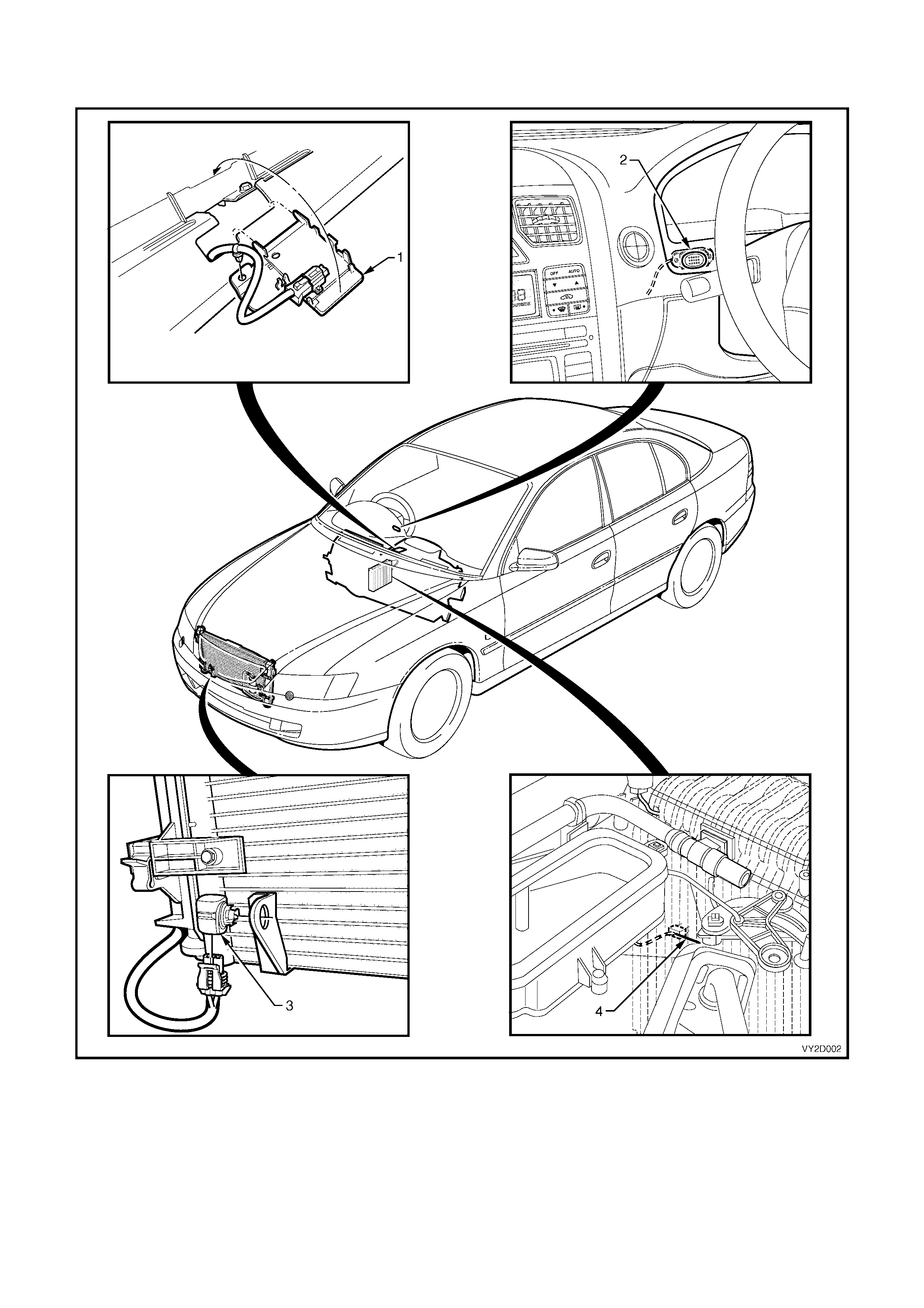
Figure 2D-1 shows the four sensors that the OCC control module uses to automatically control cabin temperature.
Figure 2D-1
Legend
1. Sun Load Sensor – located between defroster grilles and installed to top of instrument panel.
2. In-car Temperature Sensor – attached to instrument panel behind instrument cluster trim assembly.
3. Ambient Temperature Sensor – mounted to lower right-hand side front of condenser.
4. Evaporative Temperature Sensor – located inside HVAC unit and attached to downstream side of evaporator core.
3. DESCRIPTI O N
3.1 OCC CONTROL MODULE
The Occupant Climate Control system as fitted to MY2003 VY and V2 Series vehicles uses an electronic ‘soft
touch’, push button type control module to select the desired HVAC functions, operating modes and cabin
temperature. Included in its functions are switches for activating the Outside Temperature indicator, windscreen
demisting mode and the heated rear window. LED switch illumination is provided when the windscreen demister
and heated rear window are activated. All wording and icons on the soft touch buttons are illuminated when the park
lights are activated. Their illumination level is adjusted by the same means and to the same level as the
instrumentation illumination.
A Liquid Crystal Display (LCD) screen is located between the two switch clusters and provides information regarding
the current HVAC settings as well as the Outside Temperature when selected. In the event that the OCC system
develops a fault, an X symbol for OCC system Self Diagnosis can also be displayed on the LCD. The illumination
level of the LCD is also adjusted by the same means and to the same level as the instrumentation illumination.
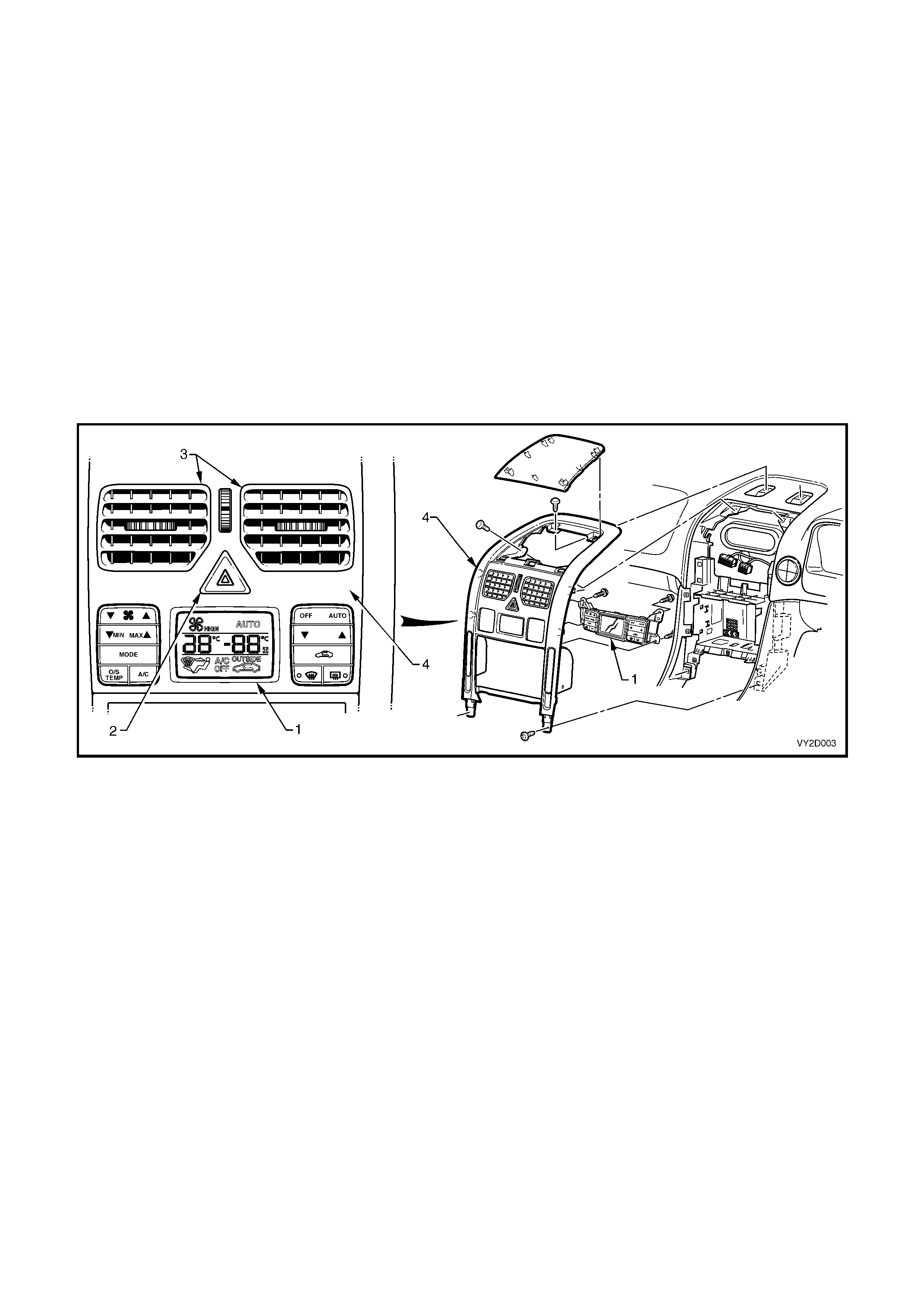
The O CC contr ol module (1) is loc ated below the hazard switch (2) and face level c entre vents (3). Contained within
the module is all s of tware and s witching hardware r equired to c ontr ol the HVAC sys tem in conjunction with the Body
Control Module (BCM) and Powertrain Control Module (PCM).
The module is installed behind the instrument bezel (4) and is attached to the bezel at four points.
Figure 2D-2
Four types of OCC control modules are fitted across the MY2003 VY and V2 Series vehicle range:
• a single zone module specific to left-hand drive models
• a single zone module specific to right-hand drive models
• a dual zone module for all dual zone systems excluding V2 Coupe models
• a dual zone module for all dual zone systems for V2 Coupe models
OCC CONTROL MODULE CONFIGURATIONS
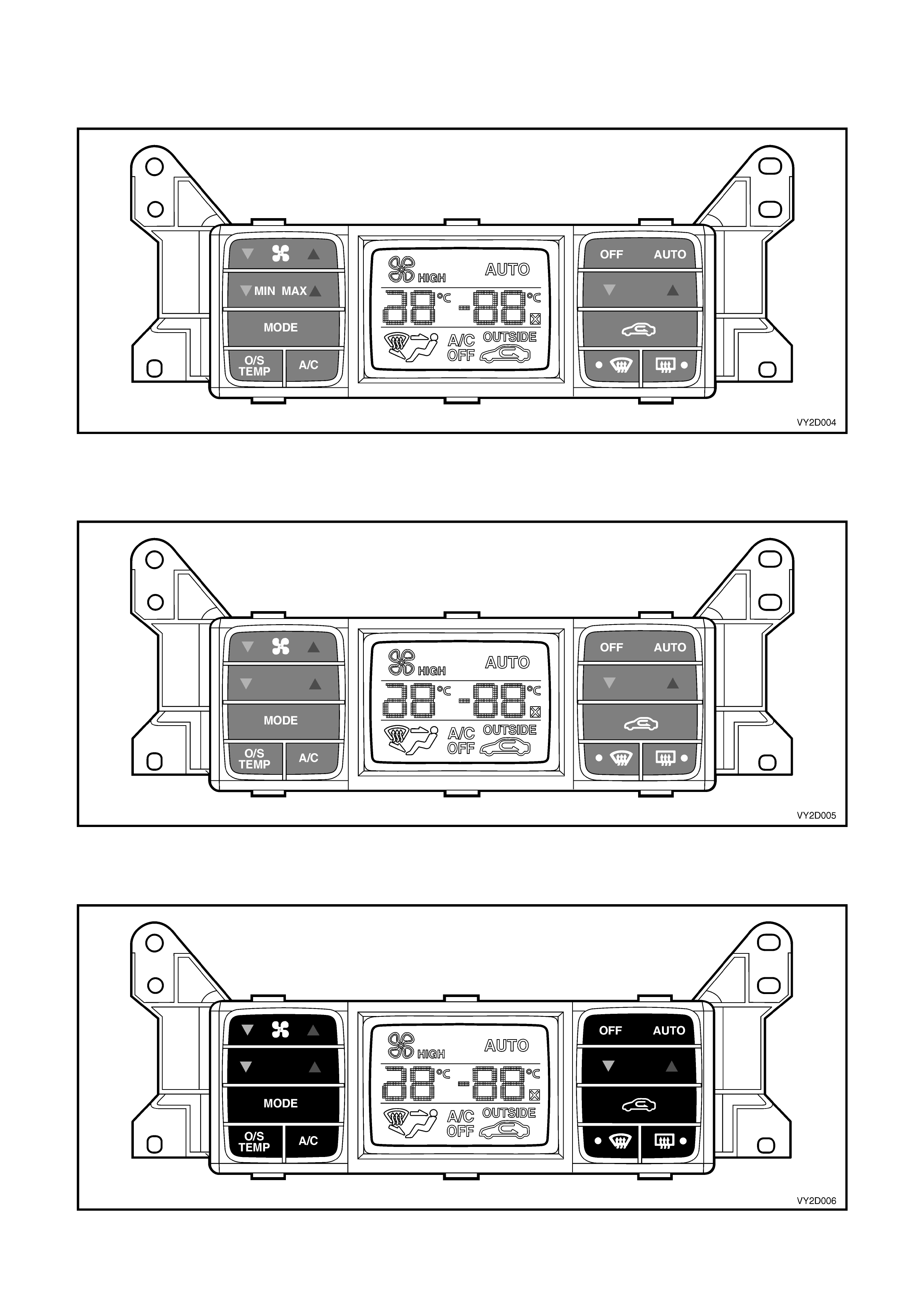
Figure 2D-3 shows the OCC control module for all single zone systems. All switches are grey.
Figure 2D-3
Figure 2D-4 shows the O CC control m odule f or all dual zone systems excluding V2 Coupe m odels. All switches are
grey.
Figure 2D-4
Figure 2D-5 shows the OCC control module for all dual zone systems as fitted to V2 Coupe models. All switches
are black.
Figure 2D-5
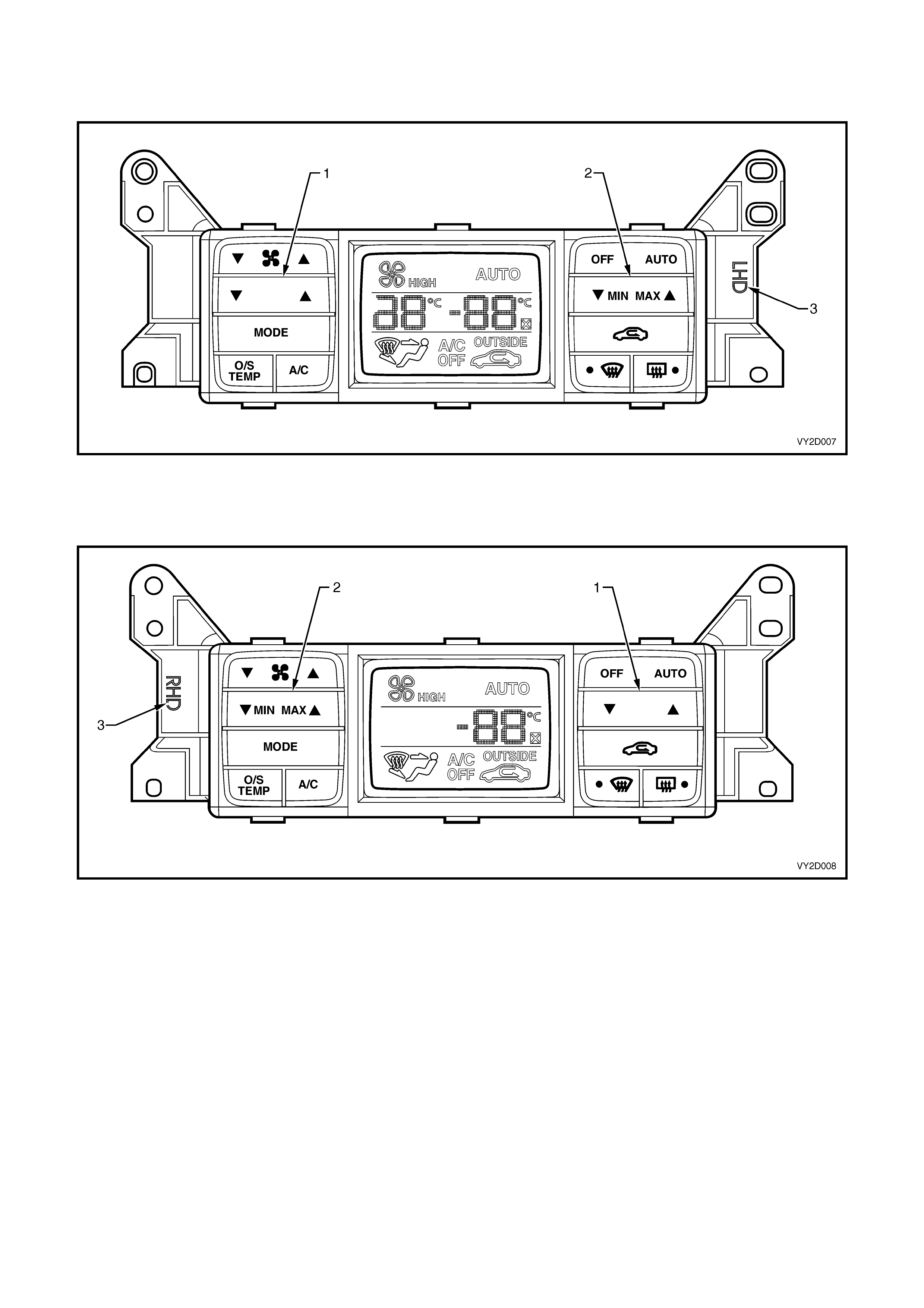
Figure 2D-6 shows the single zone OCC control module as fitted to left-hand drive models. The set temperature
switch (1) is on the left- hand side and the MIN/MAX unc ontrolled tem perature s witch (2) is on the right-hand side. A
‘LHD’ marking (3) is moulded to the facia to indicate that the module is for LHD application.
Figure 2D-6
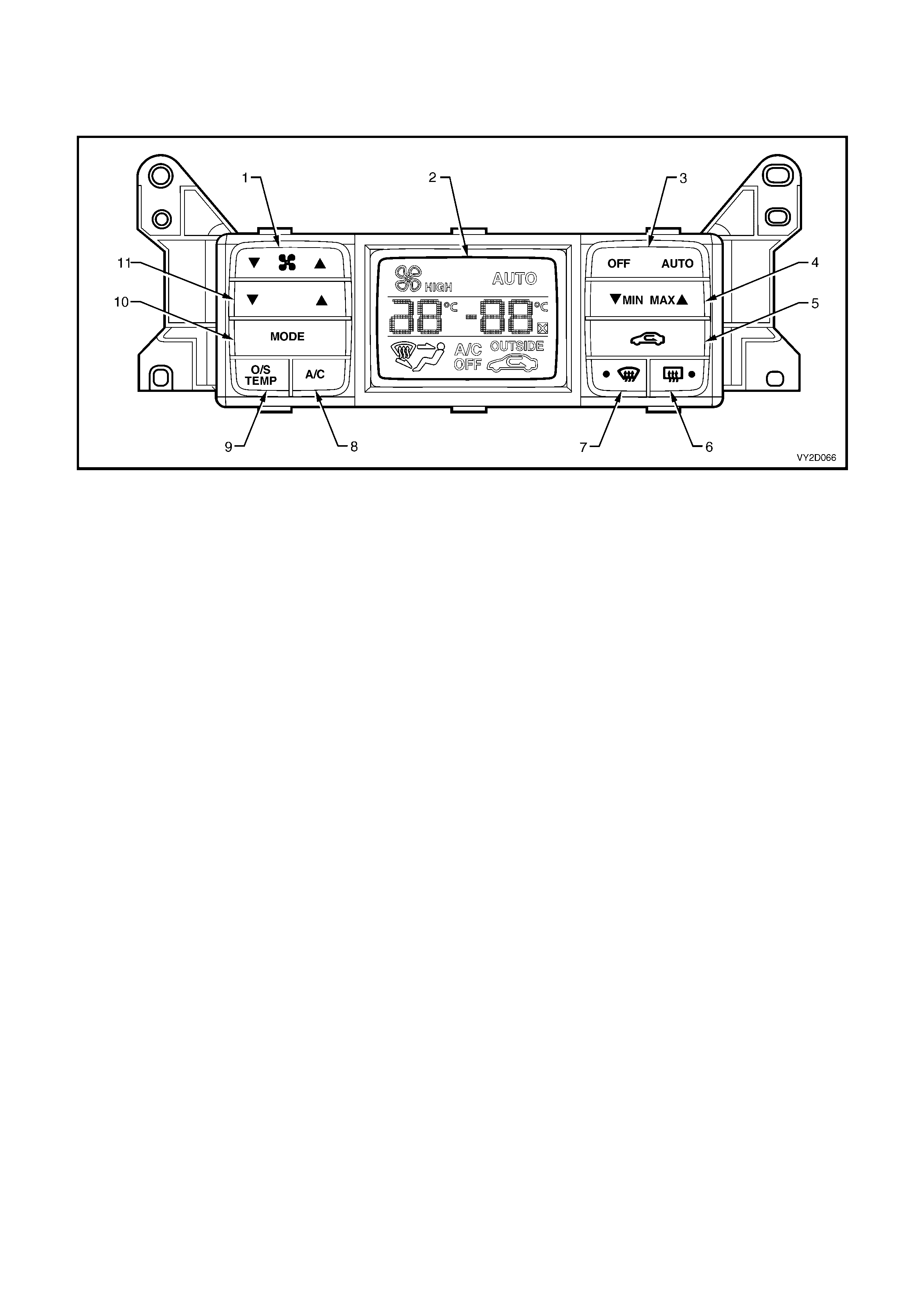
Figure 2D-7 shows the single zone OCC control module as fitted to right-hand drive models. The set temperature
switch (1) is on the right-hand side and the MIN/MAX uncontrolled tem per ature switch ( 2) is on the lef t-hand side. A
‘RHD’ marking (3) is moulded to the facia to indicate that the module is for RHD application.
Figure 2D-7
SWITCHES – SINGLE ZONE
Figure 2D-8 shows the single zone OCC control module switch configuration as applicable to left-hand drive
models.
Figure 2D-8
Legend
1. Blower Fan Speed Switch 7. Windscreen Demist Mode Switch And Indicator LED
2. Liquid Crystal Display (LCD) Screen 8. Air Conditioning ON/OFF Switch
3. OCC ON/OFF, Auto Function ON Switch 9. Outside Temperature Indicator Select Switch
4. Min (Cold), Max (Hot), Uncontrolled Temperature Setting 10. Ventilation Mode Selection Switch
5. Fresh/Recirculation Mode Position Switch 11. Set Temperature Switch
6. Heated Rear Window Switch And Indicator LED
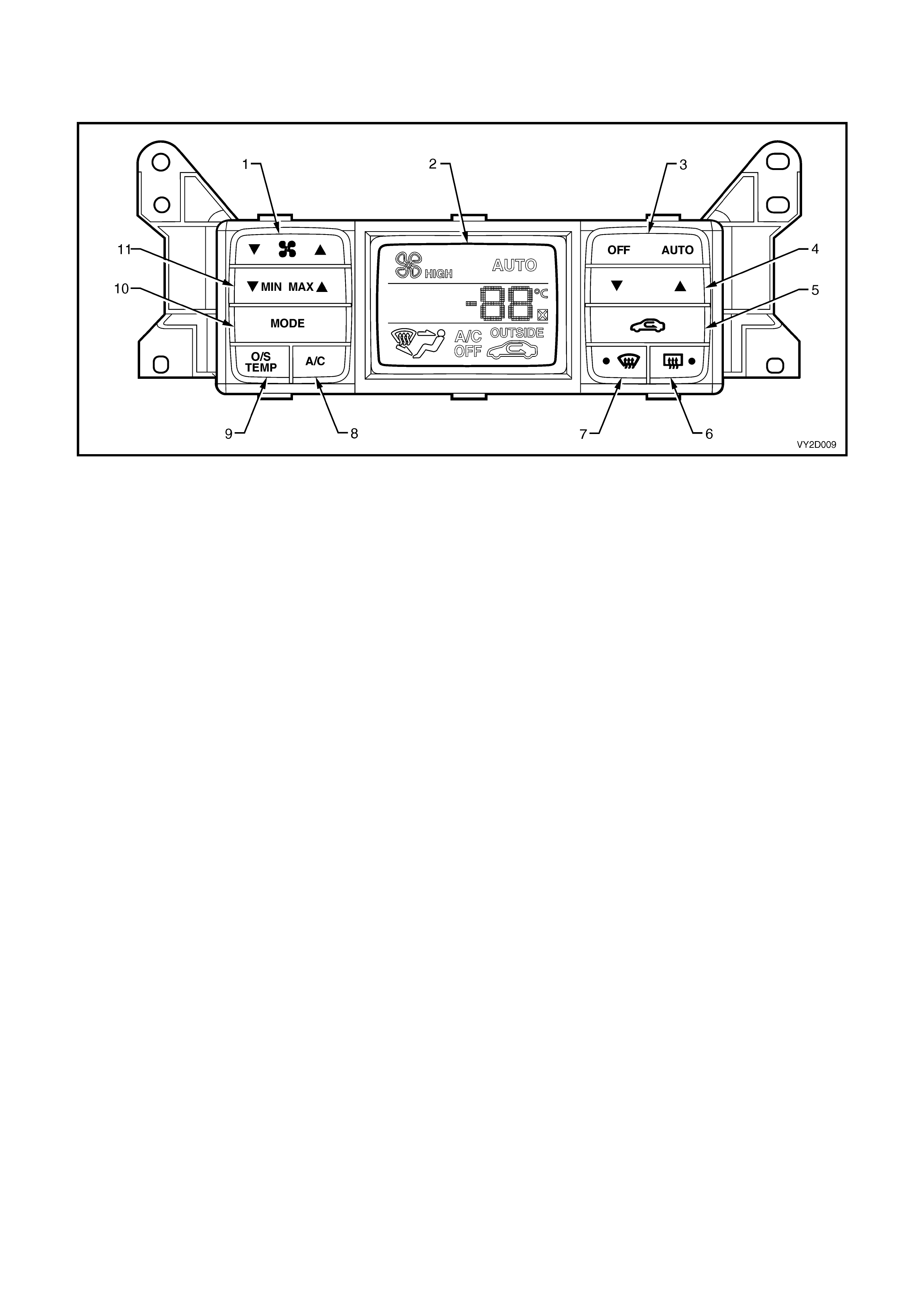
Figure 2D-9 shows the single zone OCC control module switch configuration as applicable to right-hand drive
models.
Figure 2D-9
Legend
1. Blower Fan Speed Switch 7. Windscreen Demist Mode Switch And Indicator LED
2. Liquid Crystal Display (LCD) Screen 8. Air Conditioning ON/OFF Switch
3. OCC ON/OFF, Auto Function ON Switch 9. Outside Temperature Indicator Select Switch
4. Set Temperature Switch 10. Ventilation Mode Selection Switch
5. Fresh/Recirculation Mode Position Switch 11. Min (Cold), Max (Hot), Uncontrolled Temperature Setting
6. Heated Rear Window Switch And Indicator LED
SWITCHES – DUAL ZONE
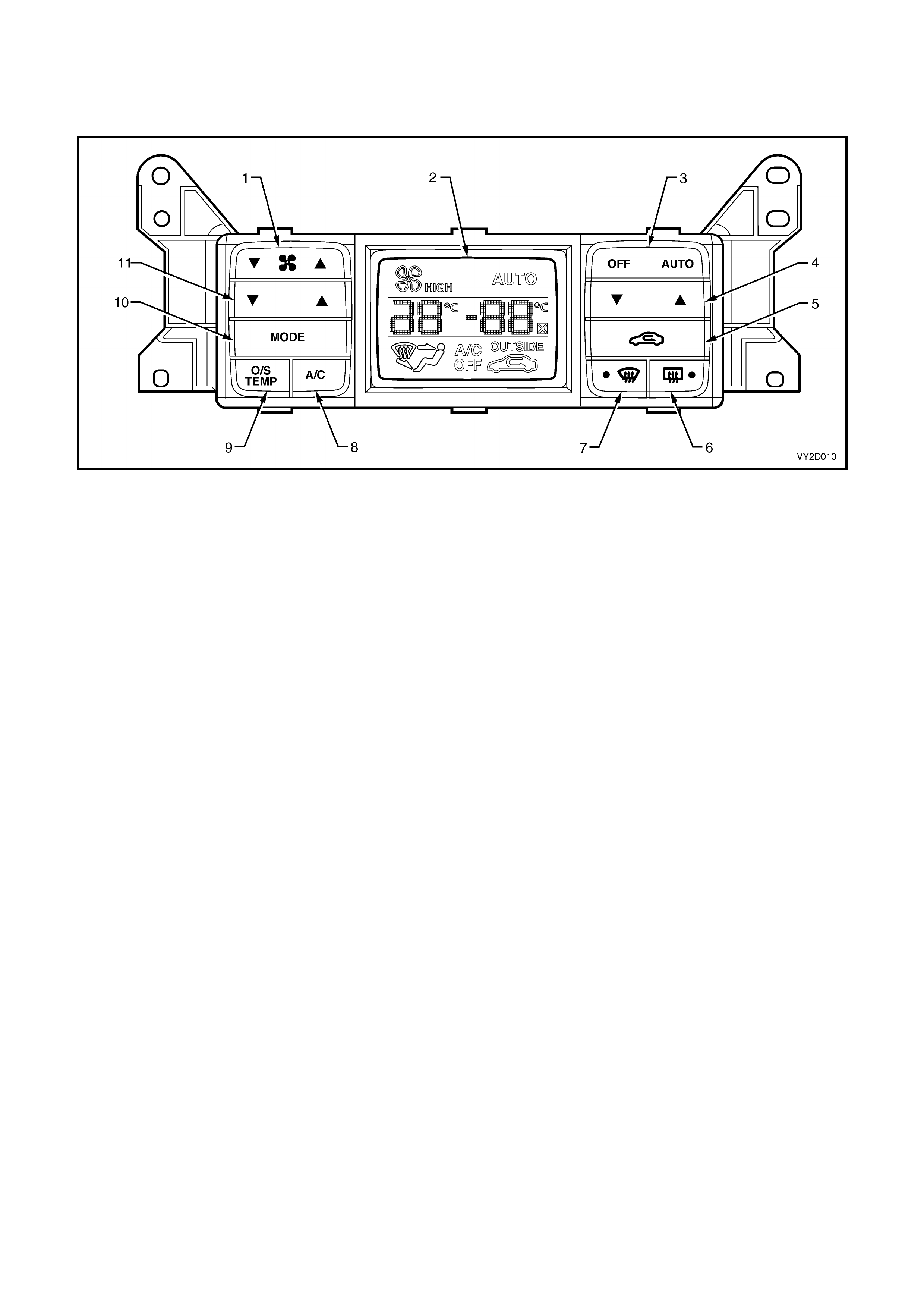
Figure 2D-10 shows the dual zone OCC control module switch configuration. Dual zone is applicable to right-hand
drive models only.
Figure 2D-10
Legend
1. Blower Fan Speed Switch 7. Windscreen Demist Mode Switch And Indicator LED
2. Liquid Crystal Display (LCD) Screen 8. Air Conditioning ON/OFF Switch
3. OCC ON/OFF, Auto Function ON Switch 9. Outside Temperature Indicator Select Switch
4. Set Temperature Switch – Driver’s Side 10. Ventilation Mode Selection Switch
5. Fresh/Recirculation Mode Position Switch 11. Set Temperature Switch – Passenger’s Side
6. Heated Rear Window Switch And Indicator LED
LIQUID CRYSTAL DISPLAY SCREEN
In the centre of the OCC control module is a Liquid Crystal Display (LCD) screen to indicate which modes and
functions have been selected. Depending on the mode chosen, the LCD will also display the vehicle cabin
temperature as selected by the driver, the vehicle cabin temperature as selected by the front passenger on a dual
zone system , or the tem perature as s et by the OCC s ystem when in Auto mode. An Outside Tem perature indicator
will be displayed when the O/S T EMP button is held on. T his f unction will operate whether the OCC s ystem is on or
off . When selected, the Rec irculation m ode s ymbol will be displayed on the LCD even if the OCC system is off . For
further information on the LCD screen and to view typical screen displays, refer to 4. OPERATION in this Section.
The illumination level of the LCD is controlled by the BCM via the auxiliary serial bus. The LCD brightness is
maintained at a similar level to the instruments (dials and Multi Function Display) and audio system displays. It is
adjusted simultaneously with these systems when the driver adjusts the brightness up or down, at the headlight
switch. Along with these systems, the illumination level will be dependant upon Priority 1 or Priority 2 remote key
usage. For further information, refer to Section 12J, BODY CONTROL MODULE.
The LCD is also capable of displaying a self-diagnostic message if the OCC system develops a fault. When an
OCC sensor input is not received due to an open circuit or damaged wiring, an X symbol will appear on the LCD
screen beside the right-hand side tem perature numerals. This X symbol will rem ain displayed on the LCD whether
the OCC system is on or of f . It will disappear once the pr oblem has been r ec tif ied. Fo r f ur ther inf ormation relating to
OCC self-diagnosis, refer to Section 2F, HVAC OCCUPANT CLIMATE CONTROL (AUTO A/C) – DIAGNOSTICS.
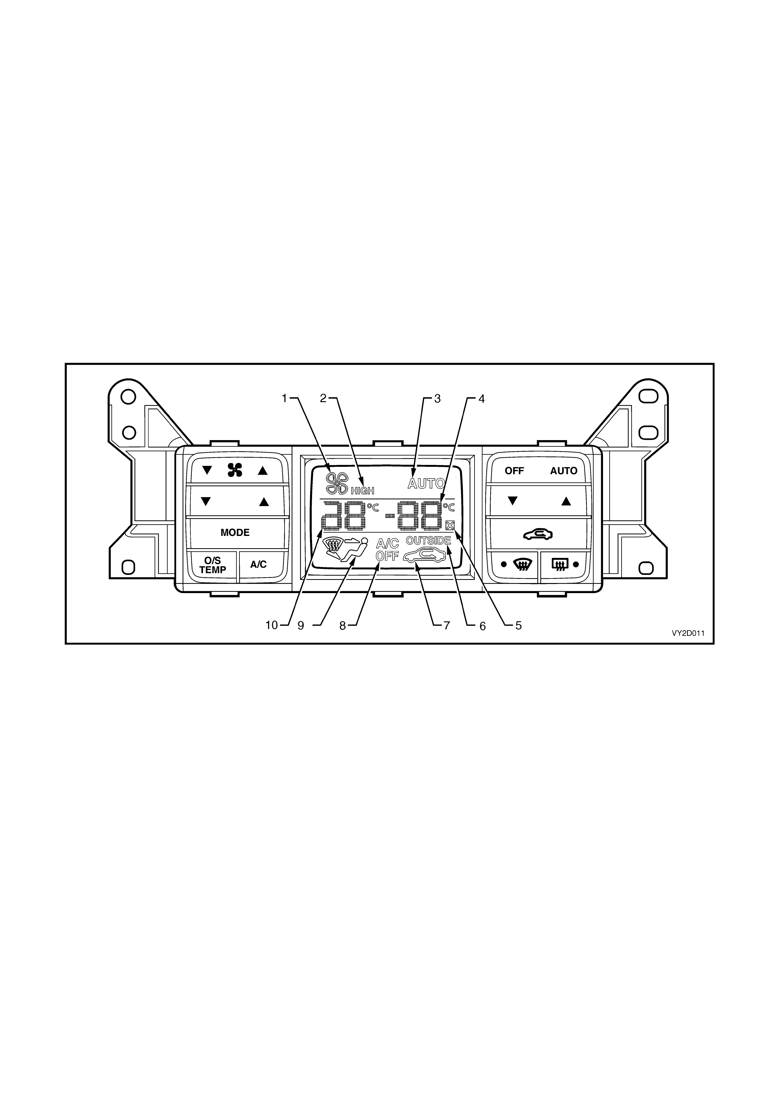
Figure 2D-11
Legend
1. Blower Fan Active 6. Outside Temperature Indicator
2. Blower Fan High Speed 7. Recirculation Mode Position Indicator
3. OCC System In Auto Mode 8. Air Conditioning OFF Indicator
4. Temperature Setting And Outside Temperature 9. Ventilation Mode Indicator
5. Self Diagnostic Symbol 10. Temperature Setting
Note 1: Item 4 – Temperature setting will be for the cabin on RHD single zone models or for the driver only on RHD
dual zone models.
Note 2: Item 10 – Temperature setting will be for the cabin on LHD vehicles or for the passenger only on RHD dual
zone models.
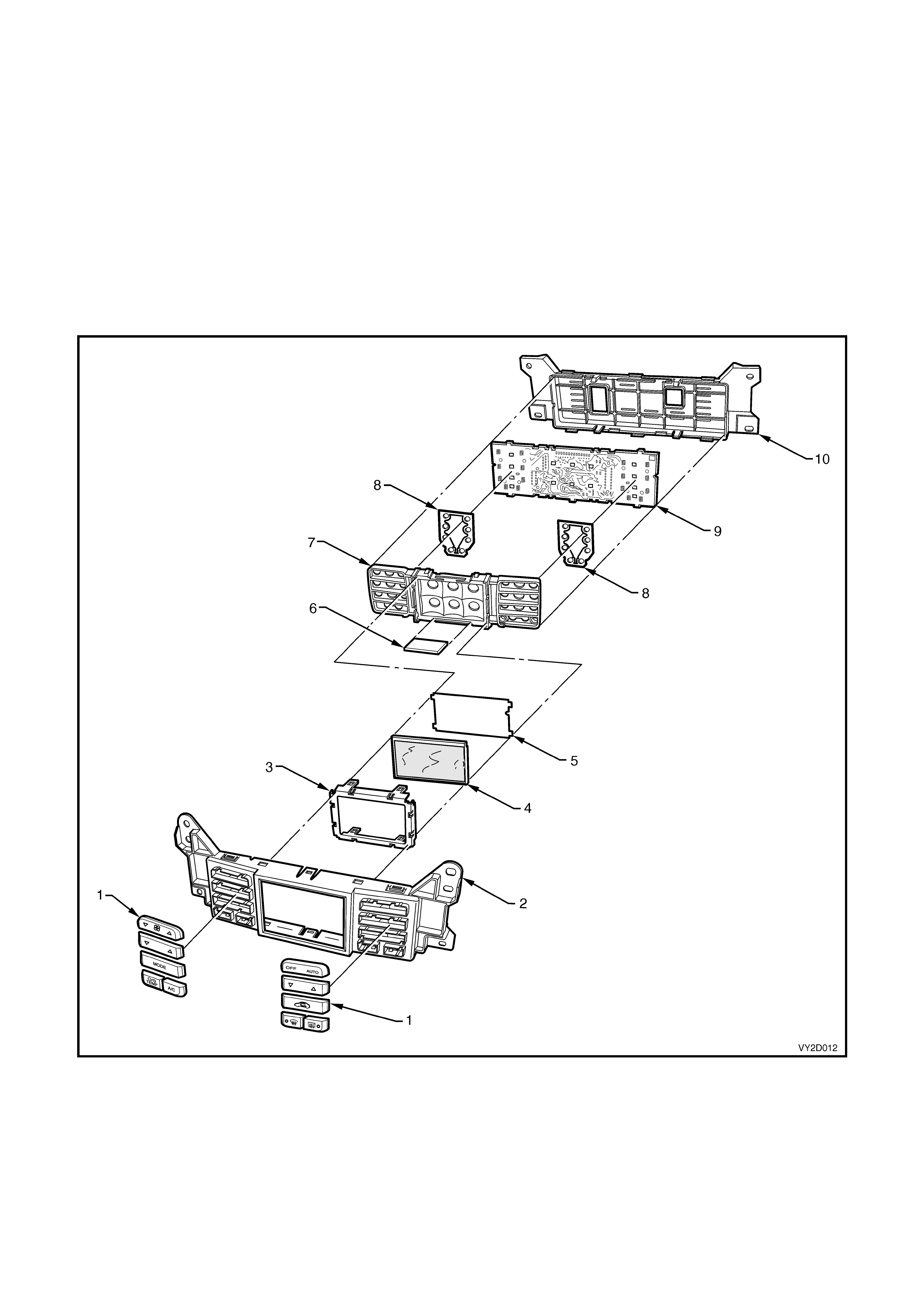
OCC CONTROL MODULE COMPONENTS
The module is designed for ease of assembly and no screws are used in its construction. The f ront facia and rear
housing of the module are constructed of plastic. The ten control buttons are also plastic and clip into and are
retained by the f ront f acia. The f ront f acia clips over the rear hous ing at four loc ations. Contained within the m odule
is a printed circuit board with the LCD screen clipped to it in four locations. Information from the circuit board is
transf erred to the LCD scr een through a carbon ‘zebra strip’. A 12 pin and a 20 pin electric al connector are bonded
directly to rear of the circuit board and protrude through apertures of the module’s rear housing. The circuit board
and LCD as sembly is c lipped to the front facia in s ix locations. At each cor ner, the complete m odule is attached to
the rear of the instrum ent bezel by four screws. T he installation of these s crews als o serves to clam p the front facia
and the rear housing of the module together, ensuring that the module remains in an assembled state when
installed to the instrument panel.
There are no replaceable bulbs contained within the OCC control module. LEDs are used to provide illumination
where necessary. The module has no serviceable items. If any component fails to function, including LCD, the
module must be replaced.
Figure 2D-12
Legend
1. Control Buttons 6. Carbon Zebra Strip
2. Front Facia 7. LCD and Silicone Switch Carrier
3. LCD Frame 8. Silicone Switches
4. LCD Screen 9. Circuit Board
5. LCD Diffuser 10. Rear Housing
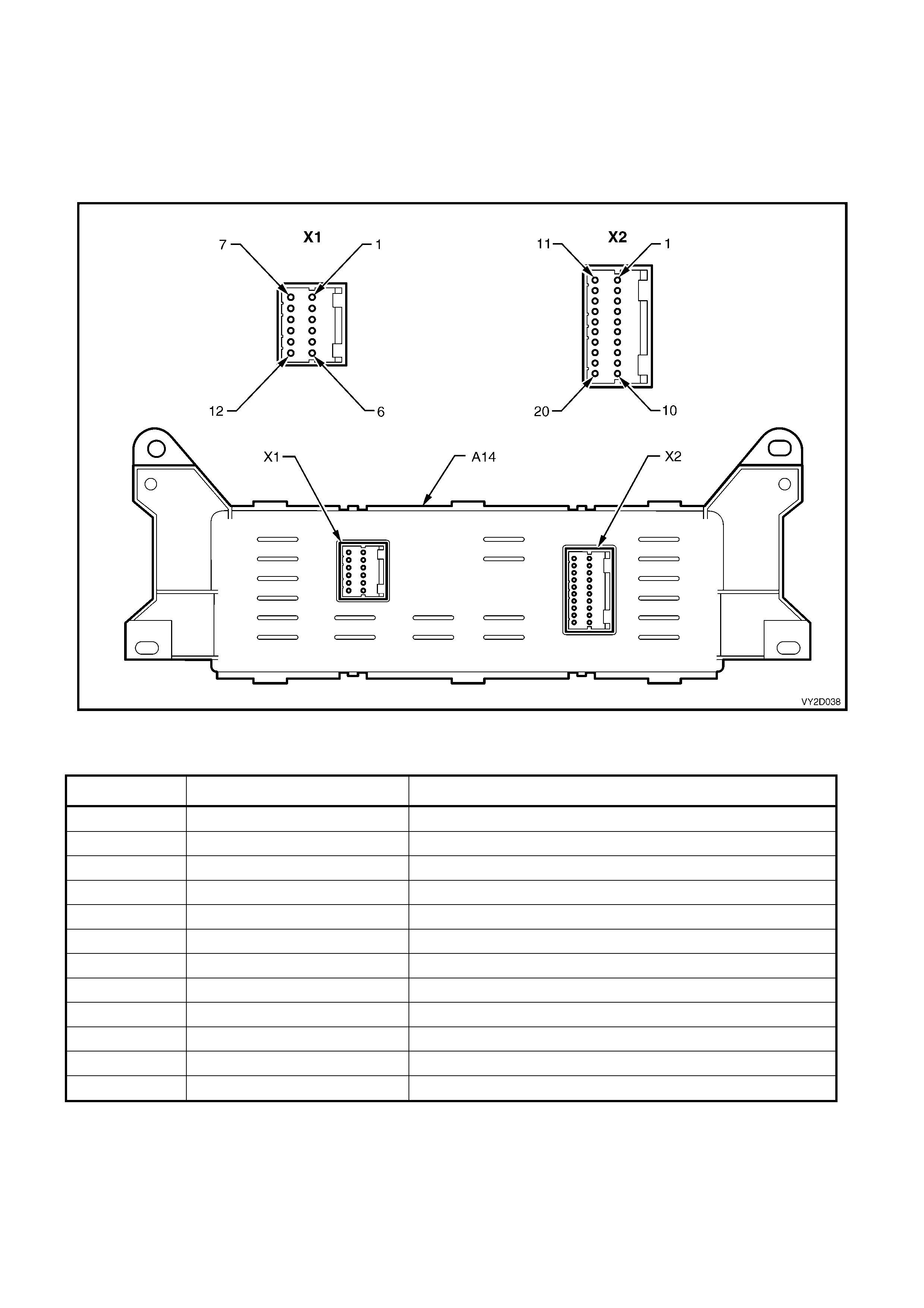
OCC CONTROL MODULE ELECTRICAL CONNECTION
Two electric al connectors are loc ated to the rear of the m anual HVAC controller. In accor dance with the Integrated
Vehicle Electrical Design (IVED) standard as applied to MY 2003 VY and V2 Series vehicles, the controller is
designated as A14 and the connectors are designated as Connector X1 and Connector X2. Both connectors are
bonded to the rear of the printed circuit board.
Figure 2D- 13 provides a view of the connector term inal assignm ents and the tables following it provide inf ormation
on their function.
Figure 2D-13
Connector X1 – RHD and LHD
PIN NUMBER WIRE COLOUR FUNCTION
X1-1 Black / Red Rear window demister select to HRW relay
X1-2 Black / Yellow Ground (X157)
X1-3 Orange / Yellow Fuse F21 – Power for OCC Switc hi ng and LE D i ndi cation
X1-4 Pink / B l ue Fuse F13 – Power for solenoid pack switching and LED illumi nation
X1-5 Yellow / Black Fan speed high – Bl ower Relay
X1-6 Green / White Serial data line
X1-7 Yellow Fan speed feedback
X1-8 Black / Red Fan speed cont rol
X1-9 Brown / White Fuse F11 – Power for instrument illumination
X1-10 Blue / Blac k In-car air temperat ure sensor signal
X1-11 – Not connected
X1-12 Light Green / B l ack Ambi ent air temperature sens or signal

Connector X2 – LHD
PIN NUMBER WIRE COLOUR FUNCTION
X2-1 Red Air m ix door motor + ve
X2-2 Black Air mix door motor – ve
X2-3 – Not connected
X2-4 – Not connected
X2-5 Red / White Power for sol enoi d pack sol enoi ds and water VSV
X2-6 Dark Green Foot 1 select – No.1 s ol enoi d, solenoid pack
X2-7 Black / Whit e Defog select – No.2 s ol enoi d, solenoid pac k
X2-8 Pink Fresh / rec i rc select – No.5 solenoi d, solenoid pac k
X2-9 Yellow Face 1 select – No.4 s ol enoi d, solenoid pack
X2-10 Blue / Red Face 2 select – No.3 s ol enoi d, solenoid pac k
X2-11 Brown Power for air m i x motor positi on signal
X2-12 – Not connected
X2-13 – Not connected
X2-14 – Not connected
X2-15 White Ground for sens ors and air mi x m ot or signal
X2-16 – Not connected
X2-17 – Not connected
X2-18 Green / Whit e Air mi x motor positi on signal
X2-19 Whit e / Black Evaporative temperat ure sensor signal
X2-20 Red / Black Water valve – Vac uum switch valve
Connector X2 – RHD (Single Zone)
PIN NUMBER WIRE COLOUR FUNCTION
X2-1 Red Air m ix door motor + ve
X2-2 Black Air mix door motor – ve
X2-3 – Not connected
X2-4 – Not connected
X2-5 Red / Whit e Power for sol enoi d pack sol enoi ds
X2-6 Dark Green Foot 1 select – No.4 s ol enoi d, solenoid pack
X2-7 Black / White Foot 2 select – No.5 solenoid, solenoid pack
X2-8 Pink Fres h/recircul ation selec t – No.1 solenoi d, solenoid pac k
X2-9 Yellow Fac e 1 select – No.2 solenoid, solenoid pack
X2-10 Blue / Red Fac e 2 select – No.3 solenoid, solenoid pack
X2-11 White P ower for air mix mot or position s i gnal
X2-12 – Not connected
X2-13 – Not connected
X2-14 – Not connected
X2-15 Tan Ground for sensors and ai r mix mot or signal
X2-16 – Not connected
X2-17 – Not connected
X2-18 Green / White Ai r mix motor position signal
X2-19 White / Black Evaporative temperature s i gnal
X2-20 Purple Water val ve – No. 6 solenoid, s o l enoi d pack

Connector X2 – RHD (Dual Zone)
PIN NUMBER WIRE COLOUR FUNCTION
X2-1 Red Driver’s s i de ai r mix door moto r + ve
X2-2 Black Driver’s si de ai r mix door mot or – ve
X2-3 Brown Passenger side air mix door motor + ve
X2-4 Blue Passenger s i de ai r mix door mot or – ve
X2-5 Red / White Power for solenoid pack solenoi ds
X2-6 Dark Green Foot 1 select – No. 4 solenoid, s ol enoi d pack
X2-7 Black / White Foot 2 select – No.5 sol enoi d, solenoid pac k
X2-8 Pink Fresh/recirculat i on select – No.1 solenoid, solenoid pack
X2-9 Yellow Face 1 select – No.2 s ol enoi d, solenoid pack
X2-10 Blue / Red Face 2 select – No.3 s ol enoi d, solenoid pac k
X2-11 White Power for air mix m otor positi on signal
X2-12 – Not connected
X2-13 – Not connected
X2-14 – Not connected
X2-15 Tan Ground for sens ors and air mi x motor signals
X2-16 – Not connected
X2-17 Yellow / Blue Passenger si de ai r mix motor position s i gnal
X2-18 Green / White Driver’s s i de ai r mix motor position signal
X2-19 White / B l ack Evaporative temperature s i gnal
X2-20 Purple Water valve – No.6 solenoid, solenoid pack
3.2 HEATING, VENTILATION AND AIR CONDITIONING (HVAC) UNIT:
CONSTRUCTION, COMPONENTS AND ASSOCIATED SENSORS
There are three different types of Occupant Climate Control (OCC) HVAC units fitted across the MY2003 VY and
V2 Series vehicle range:
• Left-hand drive single zone system – HVAC Occupant Climate Control
• Right-hand drive single zone system – HVAC Occupant Climate Control
• Right-hand drive dual zone system – HVAC Occupant Climate Control
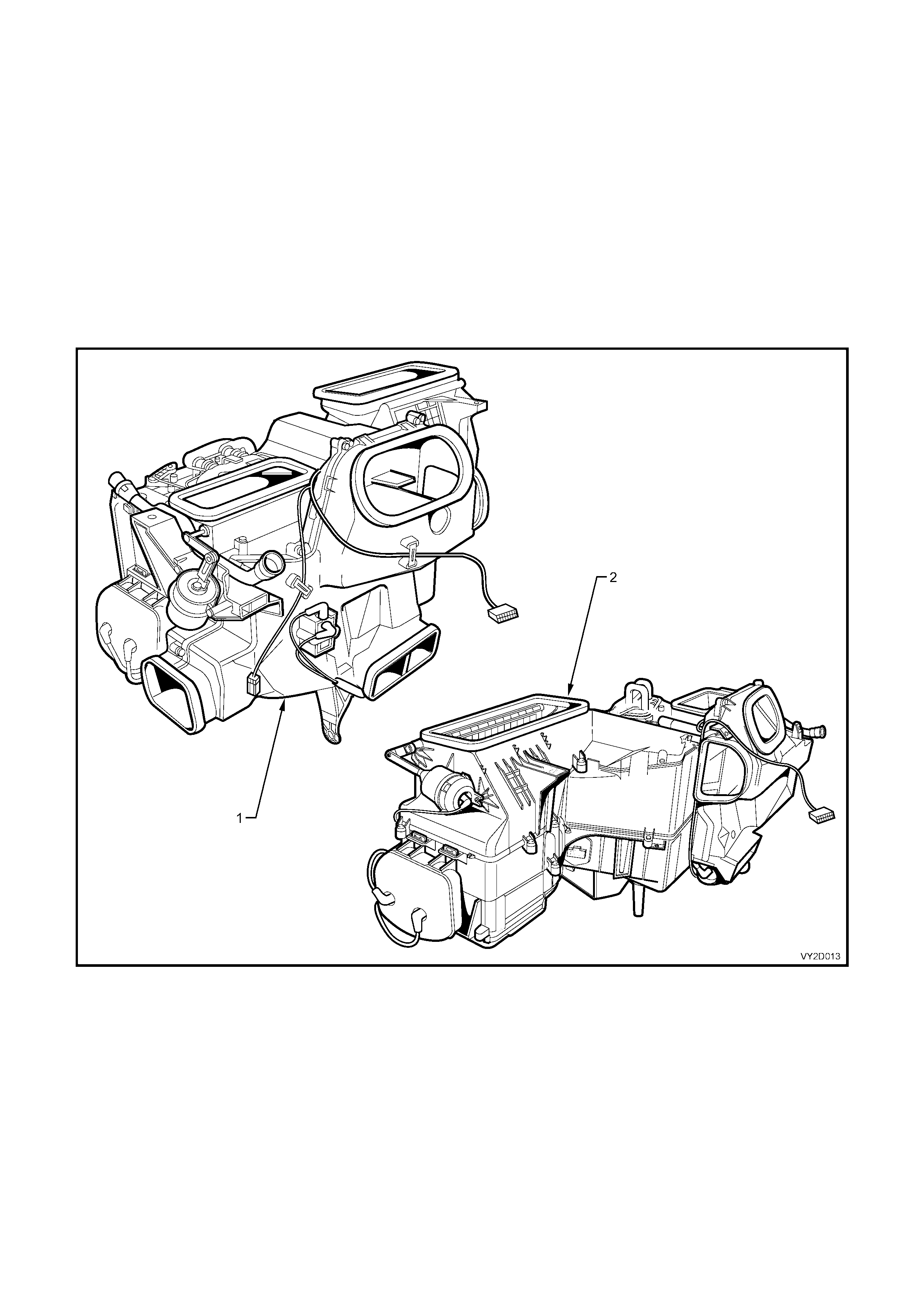
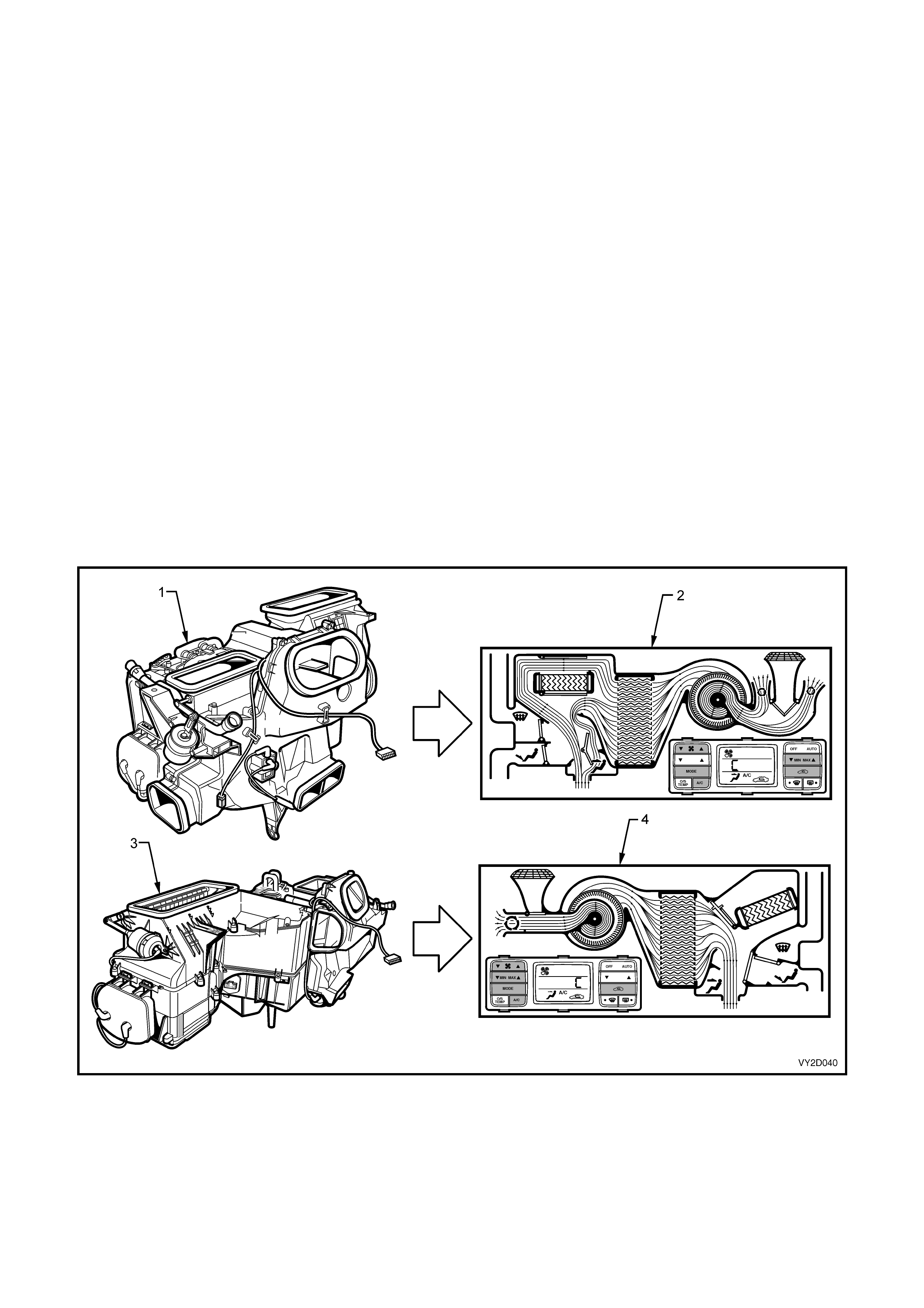
While similar in function and performance, the OCC HVAC units fitted to left and right-hand drive vehicles differ
significantly in ter ms of their case constr uction as well as their internal and external c omponents. Dual zone HVAC
units differ from the single zone units in that two air mix motors (not visible in the following diagram) are fitted to
provide independent operation of the passenger and driver side air m ix doors. Figure 2D-14 compares the left and
right-hand drive OCC HVAC units, Views are shown as viewed from a left-hand side of cabin perspective.
Figure 2D-14
Legend
1. OCC HVAC Unit – Left-hand Drive 2. OCC HVAC Unit – Right-hand Drive
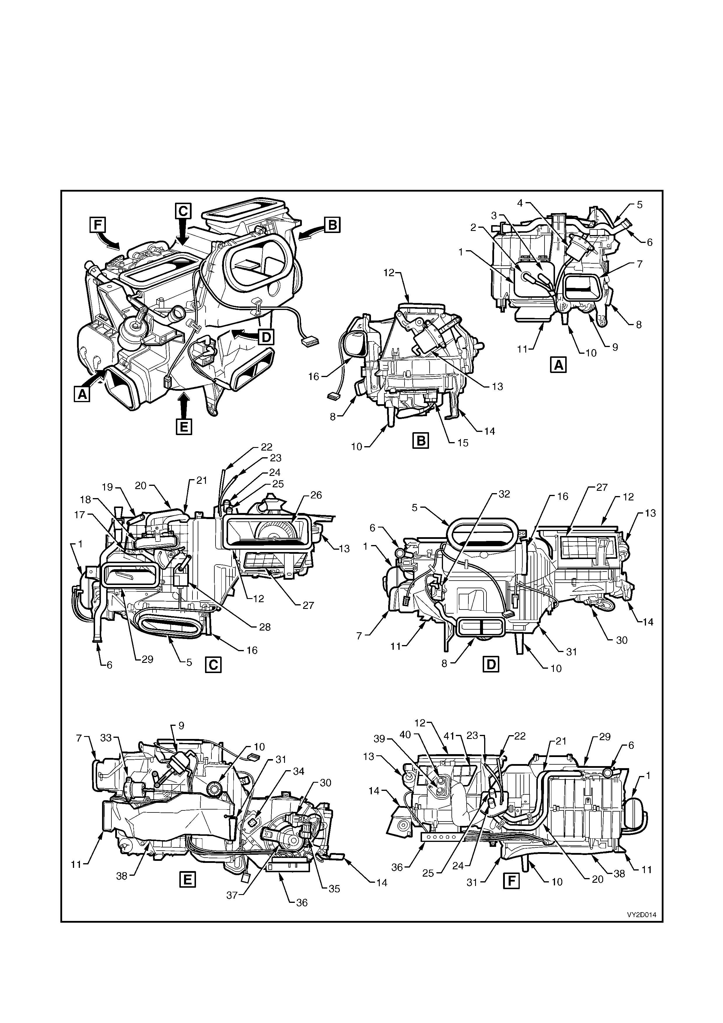
HVAC UNIT – LEFT-HAND DRIVE
The HVAC unit as fitted to left-hand drive vehicles is of a four piece case construction and is fitted with four
externally mounted vacuum actuators to provide the selected operating modes. A five-solenoid vacuum solenoid
pack , controlling vacuum to the actuators, is fitted under the RHS of the HVAC unit to the r ear of the blower m otor.
An additional solenoid for water valve control is mounted to the front of the HVAC unit.
Two recirculation doors are used to control airflow into the HVAC unit. Two individual air mix doors are used to
control the airflow through the heater core. A single air mix motor is fitted above the HVAC unit to operate the air
mix doors.
Left-hand drive HVAC unit – assembled views
Figure 2D-15

Legend (for Figure 2D-15)
1. Vacuum Tank 22. Vacuum Line (To water valve)
2. Vacuum Connector (From inlet manifold) 23. Vacuum Line (To inlet manifold)
3. Vacuum Connector (To solenoid pack) 24. Heater Core Outlet
4. Demist Vacuum Actuator 25. Heater Core Inlet
5. Face Vent Outlet 26. Blower Fan
6. Aspirator Tube 27. Front Recirculation Door
7. Side Duct Outlet – LHS 28. Air Mix Motor
8. Rear Duct Outlet 29. Demist Outlet
9. Face Vacuum Actuator 30. In-line Fuse Holder
10. Drain Tube 31. Foot Vent Outlet – RHS
11. Foot Vent Outlet – LHS 32. Water Valve Vacuum Switch Solenoid Valve
12. HVAC Inlet 33. Foot Vacuum Actuator
13. Intake Vacuum Actuator 34. Blower Resistor Assembly
14. BCM Bracket 35. Blower Motor Harness Connector
15. Blower Motor Connector 36. Solenoid Pack
16. Side Duct Outlet – RHS 37. Blower Motor
17. Front Air Mix Door Lever 38. Foot Duct
18. Heater Core 39. A/C High Pressure Port
19. Rear Air Mix Door Lever 40. A/C Low Pressure Port
20. Heater Core Pipe – Outlet 41. Rear Recirculation Door
21. Heater Core Pipe – Inlet
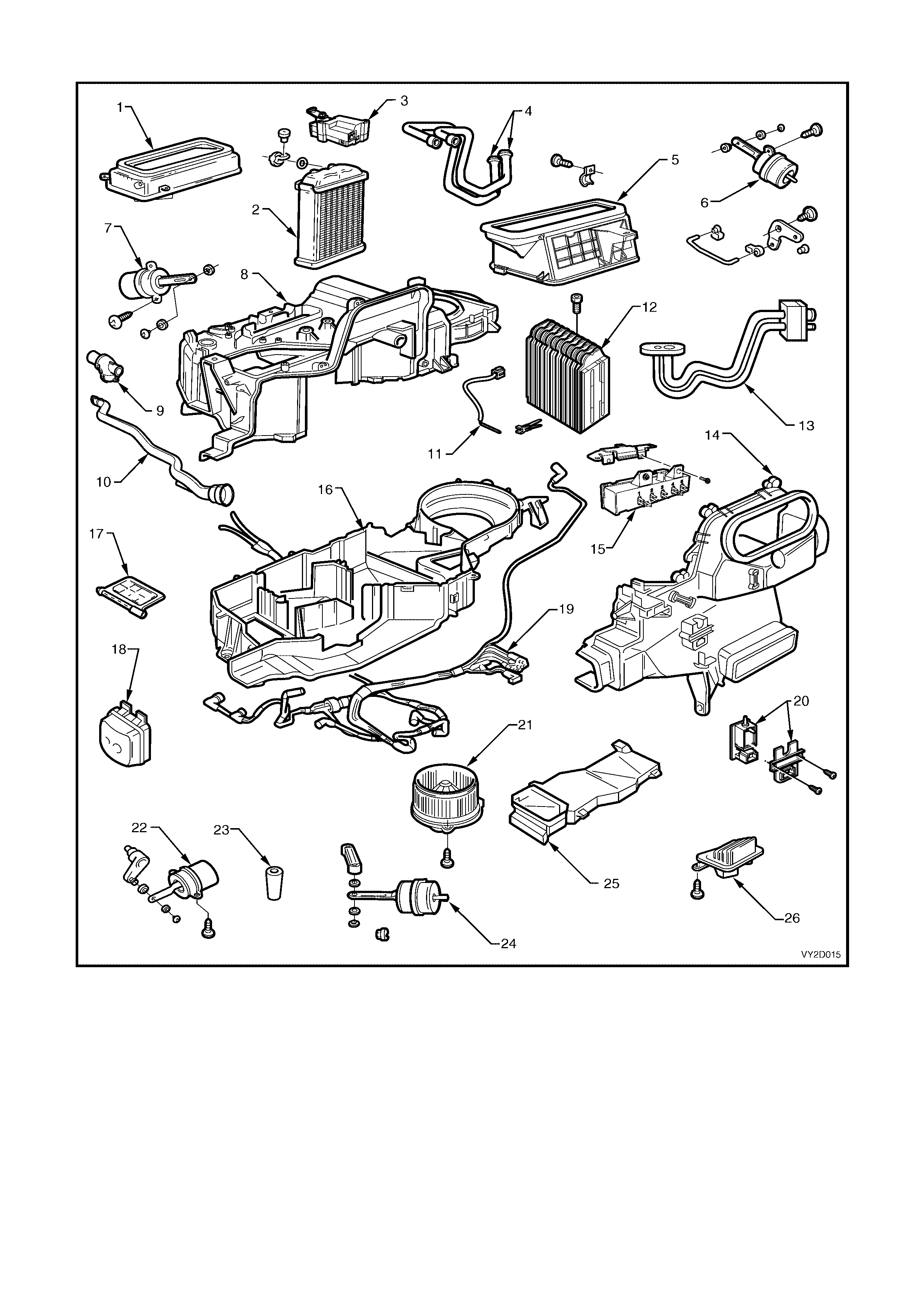
Left-hand drive HVAC unit – exploded view
Figure 2D-16
Legend
1. Demister Housing 10. Aspirator Tube 19. Vacuum Tube Harness
2. Heater Core 11. Evaporative Temperature Sensor 20. Water Valve VSV
3. Air Mix Motor 12. Evaporator Core 21. Blower Fan And Motor
4. Heater Core Pipes 13. Evaporator Core Pipes 22. Foot Vacuum Actuator
5. Fresh/Recirculation Housing 14. HVAC Case – Front 23. Drain Hose
6. Fresh/Recirculation Vacuum Actuator 15. Vacuum Solenoid Pack 24. Face Vacuum Actuator
7. Demist Vacuum Actuator 16. HVAC Case – Lower 25. Foot Duct
8. HVAC Case – Upper 17. Foot Door 26. Blower Motor Resistor
9. Aspirator Venturi 18. Vacuum Tank
HVAC UNIT – RIGHT-HAND DRIVE
The HVAC unit as fitted to right-hand drive vehicles is of a four piece case construction and is fitted with three
externally mounted vacuum actuators to provide the selected operating modes. A six-solenoid vacuum solenoid
pack, controlling vacuum to the actuators, is fitted under the LHS of the HVAC unit to the rear of the blower m otor
cover.
A single recirculation door is used to control airflow into the HVAC unit. A single two piece air mix door is used to
control the airflow through the heater core. On Single Zone units, a single air mix motor is fitted below the HVAC
unit to operate the air m ix door. On Dual Zone units, two air mix motors are f itted below the HVAC unit to operate
the two independent air mix doors.
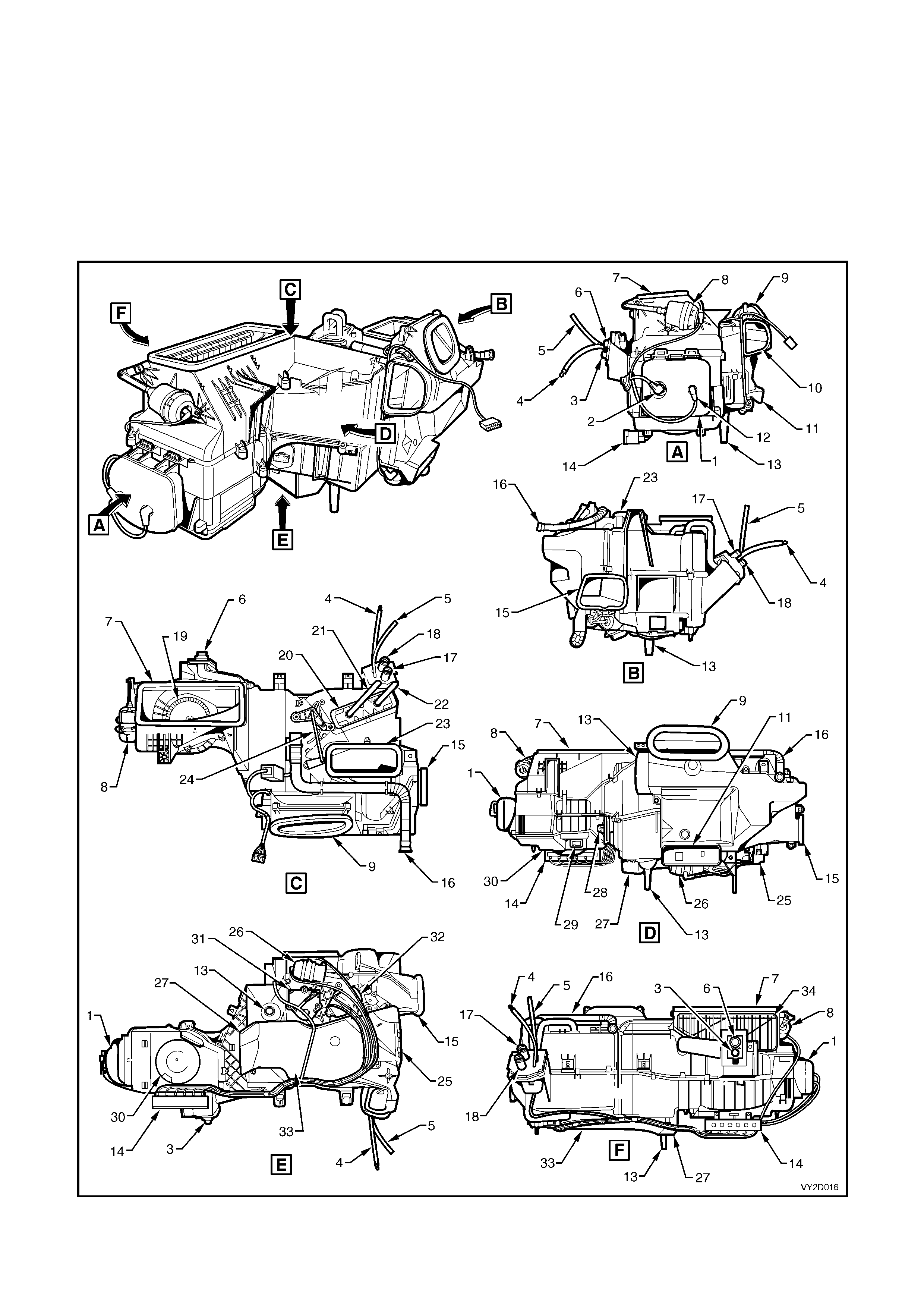
Right-hand drive HVAC unit – assembled views
Figure 2D-17

Legend (for Figure 2D-17)
1. Vacuum Tank 18. Heater Core Outlet
2. Vacuum Connector (From inlet manifold) 19. Blower Fan
3. A/C High Pressure Port 20. Heater Core
4. Vacuum Line (To water valve) 21. Heater Core Pipe – Outlet
5. Vacuum Line (To inlet manifold) 22. Heater Core Pipe – Inlet
6. A/C Low Pressure Port 23. Demist Outlet
7. HVAC Inlet 24. Air Mix Door Rod
8. Intake Vacuum Actuator 25. Foot Vent Outlet – RHS
9. Face Vent Outlet 26. Face/Bi-level Vacuum Actuator
10. Side Duct Outlet – LHS 27. Foot Vent Outlet – LHS
11. Rear Duct Outlet 28. Blower Resistor Assembly
12. Vacuum Connector (From Solenoid Pack) 29. Blower Motor Connector
13. Drain Tube 30. Blower Motor Cover
14. Solenoid Pack 31. Air Mix Motor
15. Side Duct Outlet – RHS 32. Demist/Foot Actuator
16. Aspirator Tube 33. Foot Duct
17. Heater Core Inlet 34. Recirculation Door
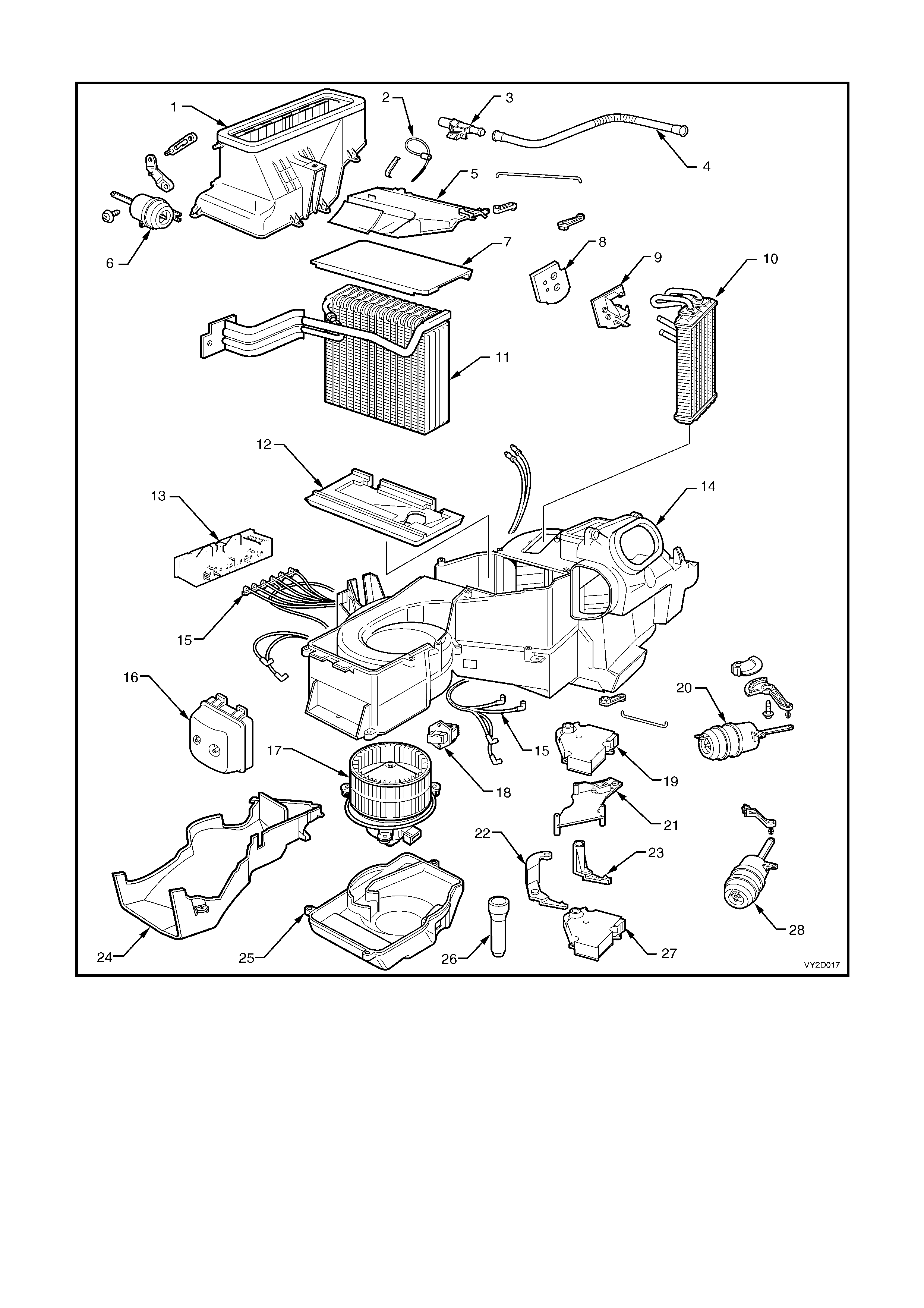
Right-hand drive HVAC unit, single zone and dual zone – exploded view
Figure 2D-18
Legend
1. Fresh/Recirculation Housing 11. Evaporator Core 21. Air Mix Motor Mounting Bracket
2. Evaporative Temperature Sensor 12. Lower Insulator – Evaporator 22. Lever – Dual Zone
3. Aspirator Venturi 13. Vacuum Solenoid Pack 23. Lever – Single Zone
4. Aspirator Tube 14. HVAC Case 24. Foot Duct
5. Evaporator Cover 15. Vacuum Tube Harness 25. Cover – Blower Fan And Motor
6. Fresh/Recirculation Vacuum
Actuator 16. Vacuum Tank 26. Drain Hose
7. Upper Insulator – Evaporator 17. Blower Fan And Motor 27. Air Mix Motor – Passenger
8. Heater Pipe Seal 18. Blower Motor Resistor 28. Face/Bi-level Vacuum Actuator
9. Heater Pipe Retainer 19. Air Mix Motor – Single Zone,
Driver – Dual Zone
10. Heater Core 20. Demist/Foot Vacuum Actuator
AIR MIX DOORS AND AIR MIX MOTORS
AIR MIX DOORS
Air mix doors control airflow through the heater core and thereby raising or lowering the vehicle’s cabin temperature.
Two air mix doors are fitted to all OCC HVAC units across the MY2003 VY and V2 Series vehicle range. However
three different configurations are across the MY2003 VY and V2 model range.
AIR MIX MOTORS
The air mix motor is a small electric stepper motor used to operate air mix doors which control airflow through the
heater core and thereby raising or lowering the vehicle’s cabin temperature.
Air mix motor movement is achieved by sending a 12 volt signal between the OCC control module to the air mix
motor causing the motor to turn and open the air mix doors. The motor’s direction can be changed to close the
doors by the OCC reversing the polarity of the voltage signal.
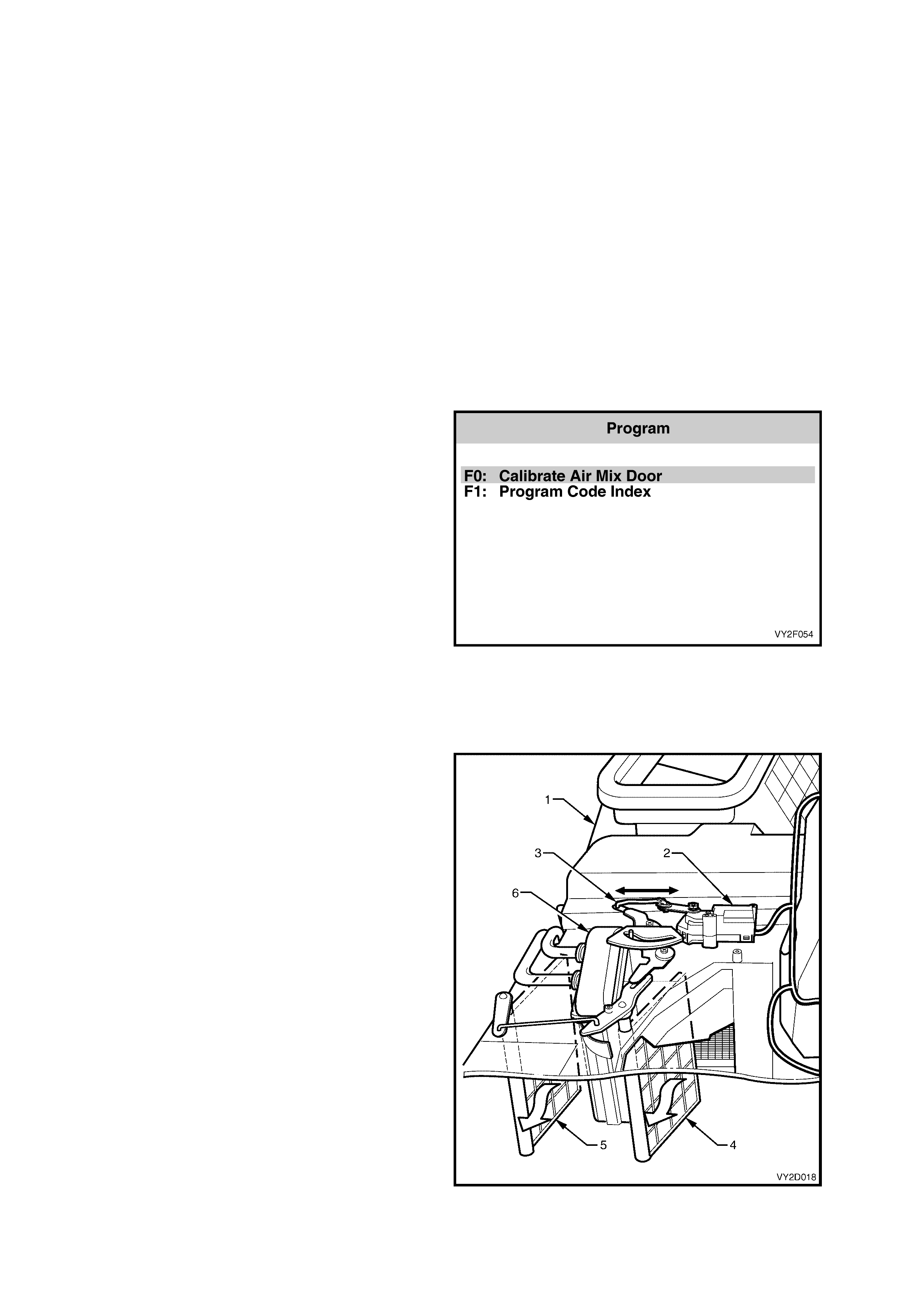
AIR MIX MOTOR/DOOR CALIBRATION
The air m ix m otor is als o fitted with a potentiom eter to send a 3.6 ± 0.2 volt ‘f eedbac k’ signal f rom the air mix motor
to the OCC control module as to the location of the air mix doors in relation to air mix motor drive location. To
maintain the correct working relationship between the OCC control module and the air mix motor/s, the air mix
motor and door f unc tion must be ‘c alibr ated’ to the OCC c ontr ol module. A variation of more than 5% f r om the base
calibration value may cause customer complaints e.g. cabin slow to heat, poor demist performance, etc.
Air mix door calibration can be carried out with
TECH 2 and is part of the ‘Program’ function
contained within the ‘2003 VY Commodore
Occupant Climate Control’ software. This can be
accessed by selecting ‘Occupant Climate Control’
from the Body menu on Tech 2.
For further information on air mix door calibrating,
refer to Section 2F, F5: PROGRAM.
Figure 2D-19
AIR MIX MOTOR/DOOR CONFIGURATIONS
Left-hand drive
All left-hand drive OCC HVAC units have two
unequally s ized air mix door s fitted. An air mix door
is located in front of, and behind the heater core.
A single air mix motor is located on top of the
HVAC unit. It opens and closes the two air mix
doors through a series of rods and levers in
response to OCC control module output signals.
Legend
1. HVAC Case
2. Air Mix Motor
3. Air Mix Motor Actuating Rod
4. Air Mix Door – Front
5. Air Mix Door – Rear
6. Heater Core
Figure 2D-20
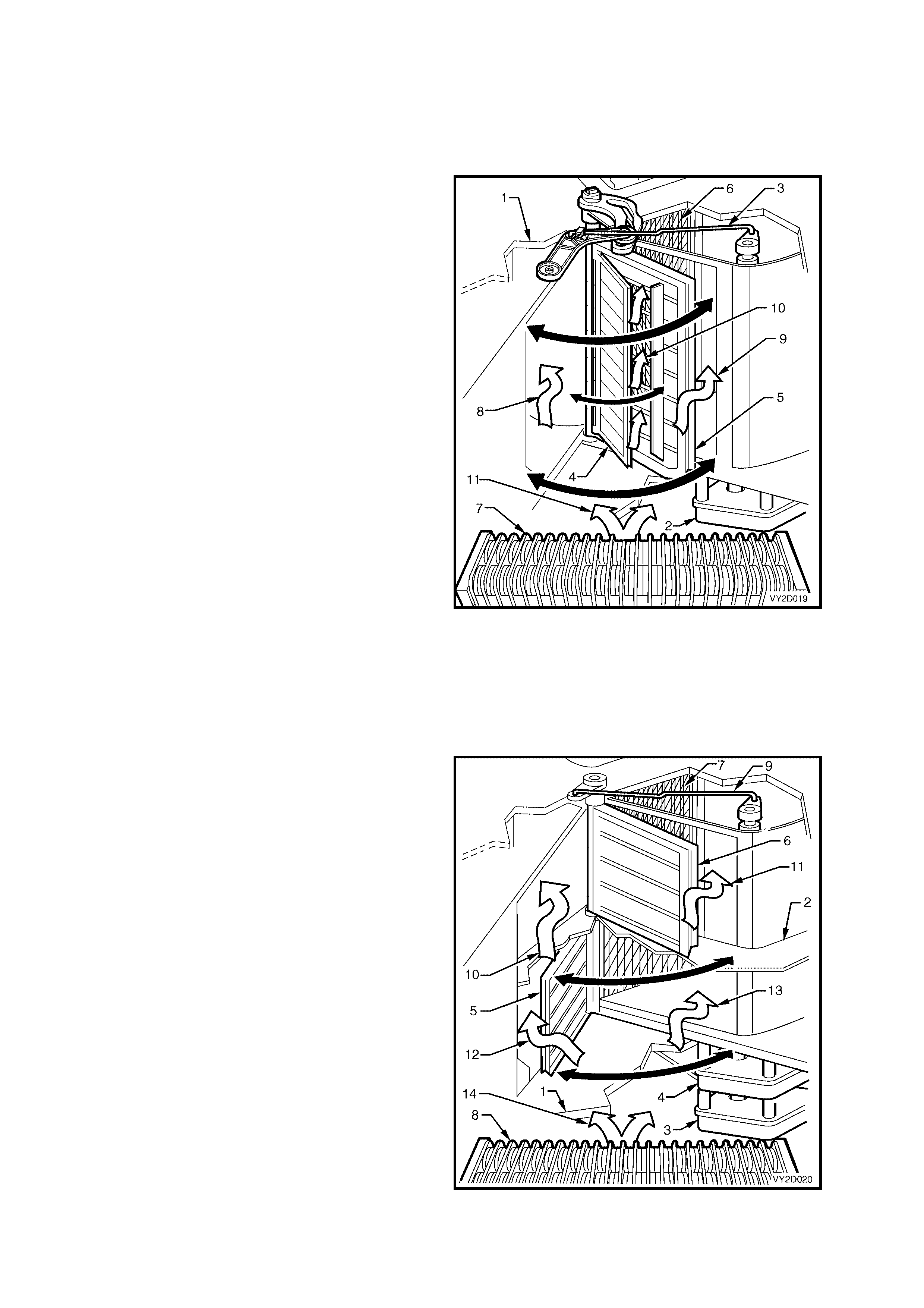
Right-hand drive – Single zone
All right-hand drive single zone HVAC units use a
large and small air mix door on one side of the
heater core.
One air mix motor is fitted to operate the air mix
door assem bly in response to OCC control module
output signals. The air mix motor is located under
the HVAC unit and is connected to the air mix door
lever via a relay lever and rod.
Legend
1. HVAC Case
2. Air Mix Motor
3. Air Mix Motor Actuating Rod
4. Air Mix Door – Small
5. Air Mix Door – Large
6. Heater Core
7. Evaporator
8. Air To Heater Core
9. Air Bypassing Heater Core
10. Air Bypassing Heater Core Through
Large Air Mix Door
11. Air Leaving Evaporator
Figure 2D-21
Right-hand drive – Dual zone
All right-hand drive dual zone HVAC units use an
equally sized upper and lower air mix door on one
side of the heater core to provide the temperature
differentiation between the driver’s side and front
passenger’s side of the cabin
Two air mix motors located under the HVAC unit
are fitted to operate the two air mix doors in
response to OCC control module output signals.
The air mix motors function independently during
dual zone operation. Their operating state is
identical during single zone operation.
Legend
1. HVAC Case
2. Dual Zone Partition
3. Air Mix Motor – Driver
4. Air Mix Motor – Passenger
5. Air Mix Door – Driver
6. Air Mix Door – Passenger
7. Heater Core
8. Evaporator
9. Air Mix Motor Actuating Rod – Passenger
10. Air To Heater Core – Passenger
11. Air Bypassing Heater Core – Passenger
12. Air To Heater Core – Driver
13. Air Bypassing Heater Core – Driver
14. Air Leaving Evaporator
Figure 2D-22
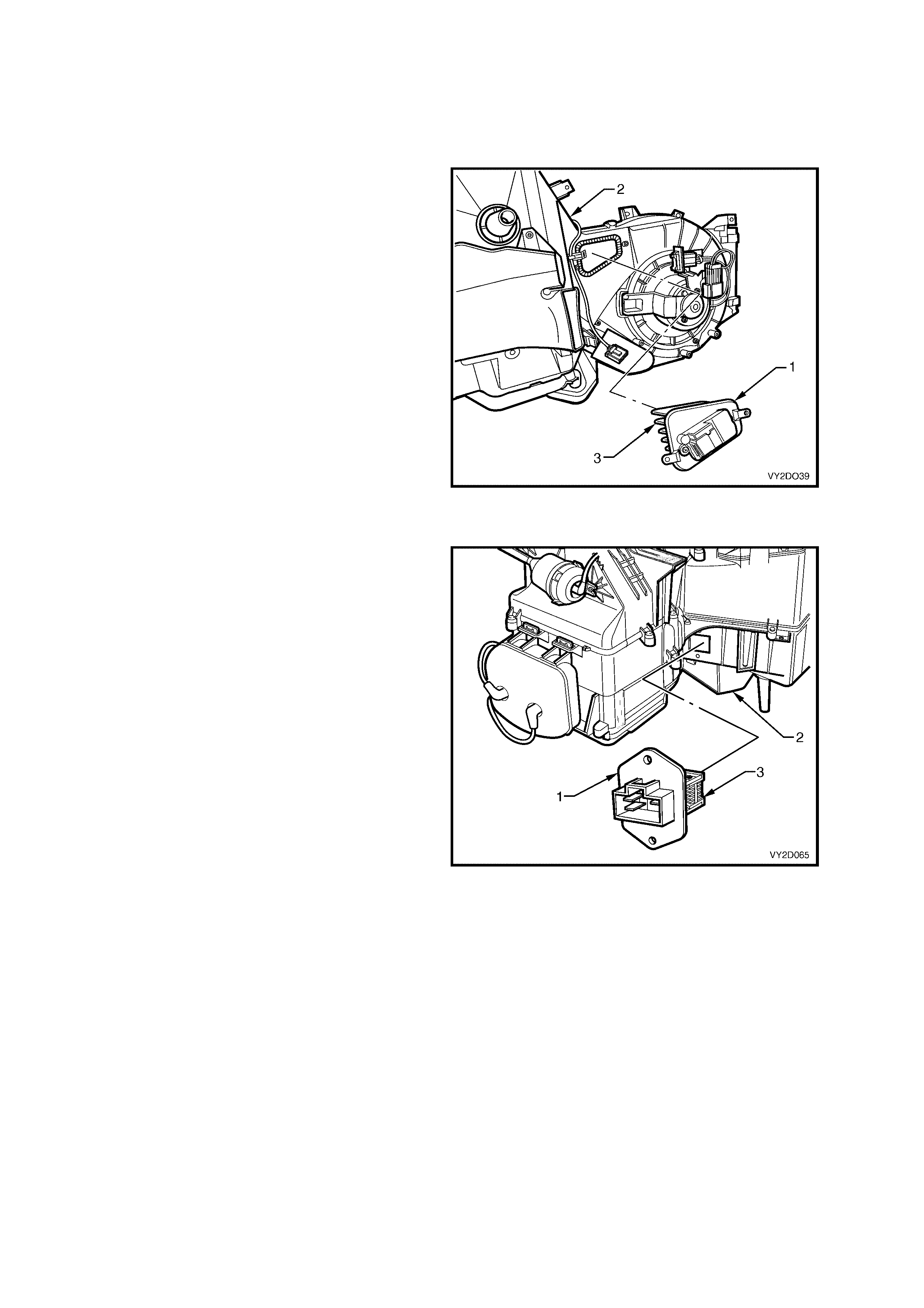
BLOWER MOTOR RESISTOR
To provide the different fan speeds a variable resistor using a large scale power transistor is wired into the blower
motor circuit. T he resistor is located inside the HVAC unit and is exposed to the internal airf low between the blower
fan and the evaporator.
Left-hand drive
The blower motor resistor (1) is located on the
underside of the HVAC unit ( 2) to the lef t-hand side
of the blower motor housing.
It uses a large s cale power transistor to provide the
fixed and var iable fan speeds. An alum inium finned
heat sink (3) is used to dissipate the heat from the
power transistor.
Figure 2A-23
Right-hand drive
The blower motor res is tor ( 1) is loc ated to the cabin
side of the HVAC unit (2) beside the blower motor
housing.
It uses large scale power transistor to provide the
fixed and variable fan speeds. An aluminium heat
sink (3) is used to dissipate the heat from the
power transistor.
Figure 2A-24
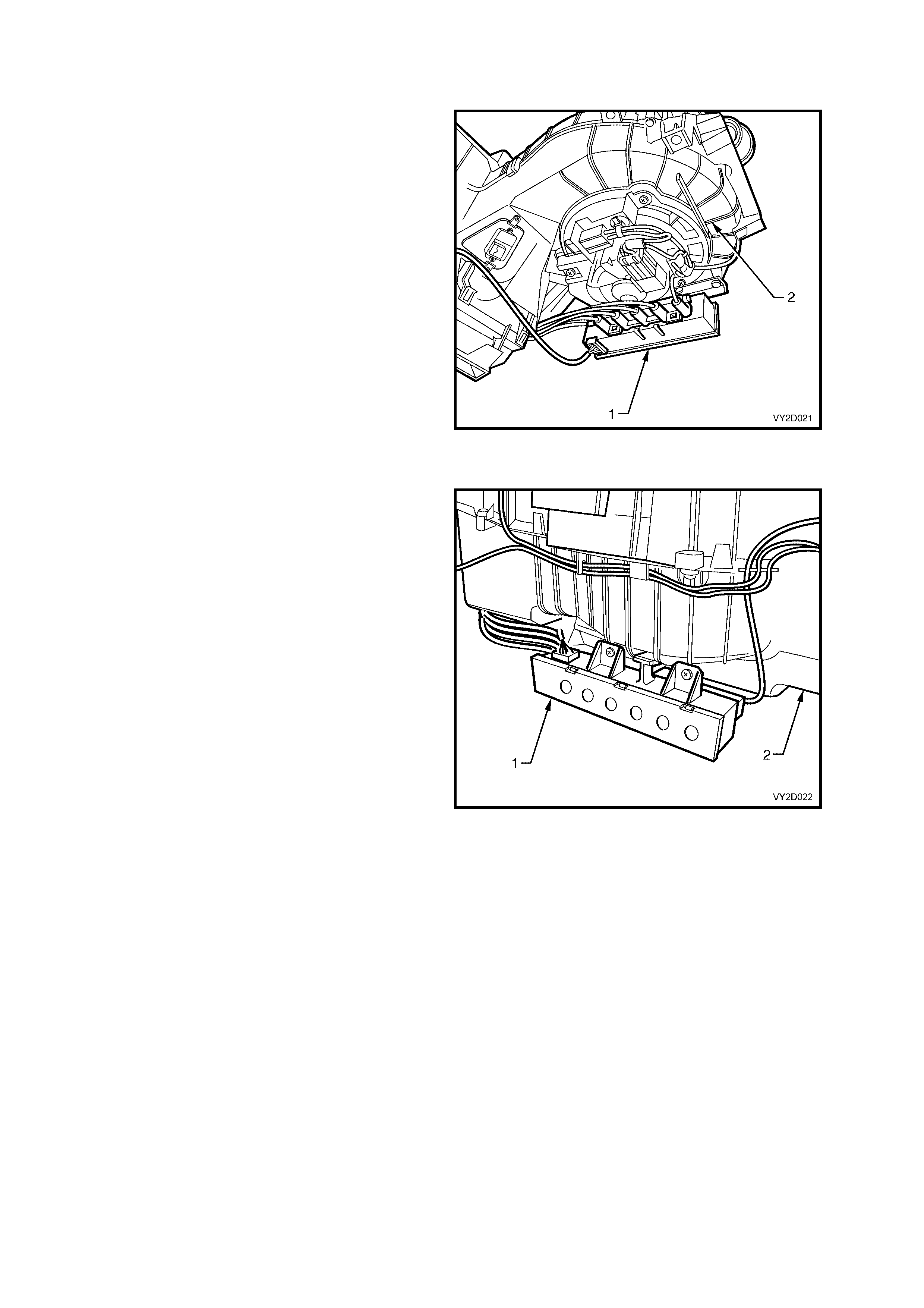
VACUUM SOLENOID PACK
Left-hand drive
On left-hand drive HVAC units, the vacuum
solenoid pack (1) is located on the lower rear of
blower motor housing (2). It consists of a band of
five electronically activated vacuum solenoids used
to apply or remove vacuum to the vacuum
actuators and alter air distribution positions.
Power is us ed to engage these solenoids and allow
vacuum to flow to an actuator. Removing this
power de-energises the solenoid and allows any
vacuum contained in the actuator and line to vent
through the front section of the solenoid.
Figure 2D-25
Right-hand drive
On right-hand drive HVAC units, the vacuum
solenoid pack (1) is located on the lower rear of
blower motor housing (2). It consists of a band of
six electronically activated vacuum solenoids. Five
are used to apply or remove vac uum to the vacuum
actuators altering the air distribution positions. The
remaining solenoid is used to actuate the heater
water valve.
Power is supplied to these solenoids through the
OCC control module. When a mode switch is
selected on the OCC control module, current flows
through appropriate solenoids and allows vacuum
to flow to the actuators. Rem oving this current flow
de-energises the solenoids and allows any vacuum
contained in the actuator and line to vent through
the front section of the solenoid.
Figure 2D-26
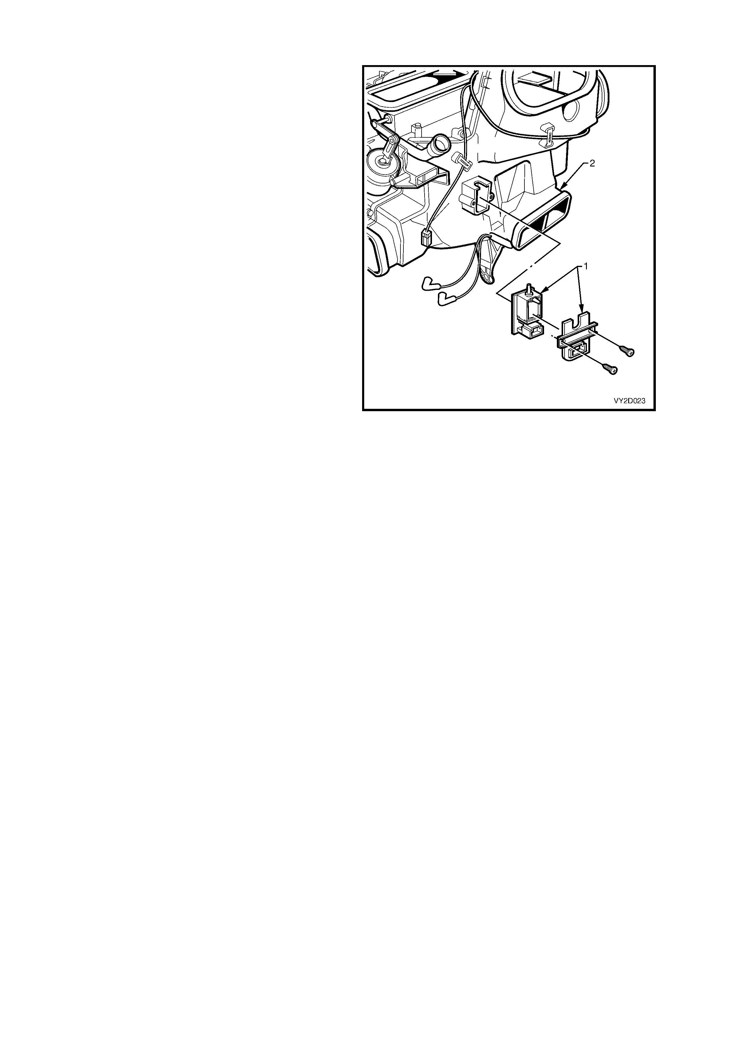
WATER VALVE VACUUM SWITCHING VALVE
Left-hand drive only
On left-hand drive HVAC units, an electrically
operated vacuum switching valve (1) for heater
water valve control is fitted and is located on the
front of the HVAC unit (2). The OCC control module
activates the vacuum switching valve in accordance
to a manually selected, or an automatically
controlled temperature setting.
The water valve is held in the off position by
vacuum. When a cold setting is selected either
manually or automatically, the vacuum switching
solenoid valve will maintain vacuum to the heater
water valve so that no hot water enters the heater
core.
Figure 2D-27
ASPIRATOR TUBE AND VENTURI
The aspirator tube is a formed plastic tube and is installed between the in-car temperature sensor (located behind
the instrument trim assembly) and a venturi, which is fitted to the top of the HVAC case. When the blower fan is
operating, positive air pressure is forced through the venturi. This causes air to be drawn from the vehicle interior
through the in-car tem perature s ensor to the venturi via the as pirator tube. T he induc ted air is used to aid the in- car
temperature sensor to react quickly to any temperature changes taking place within the vehicle interior.
Refer to IN-CAR TEMPERATURE SENSOR in this Section for further information.
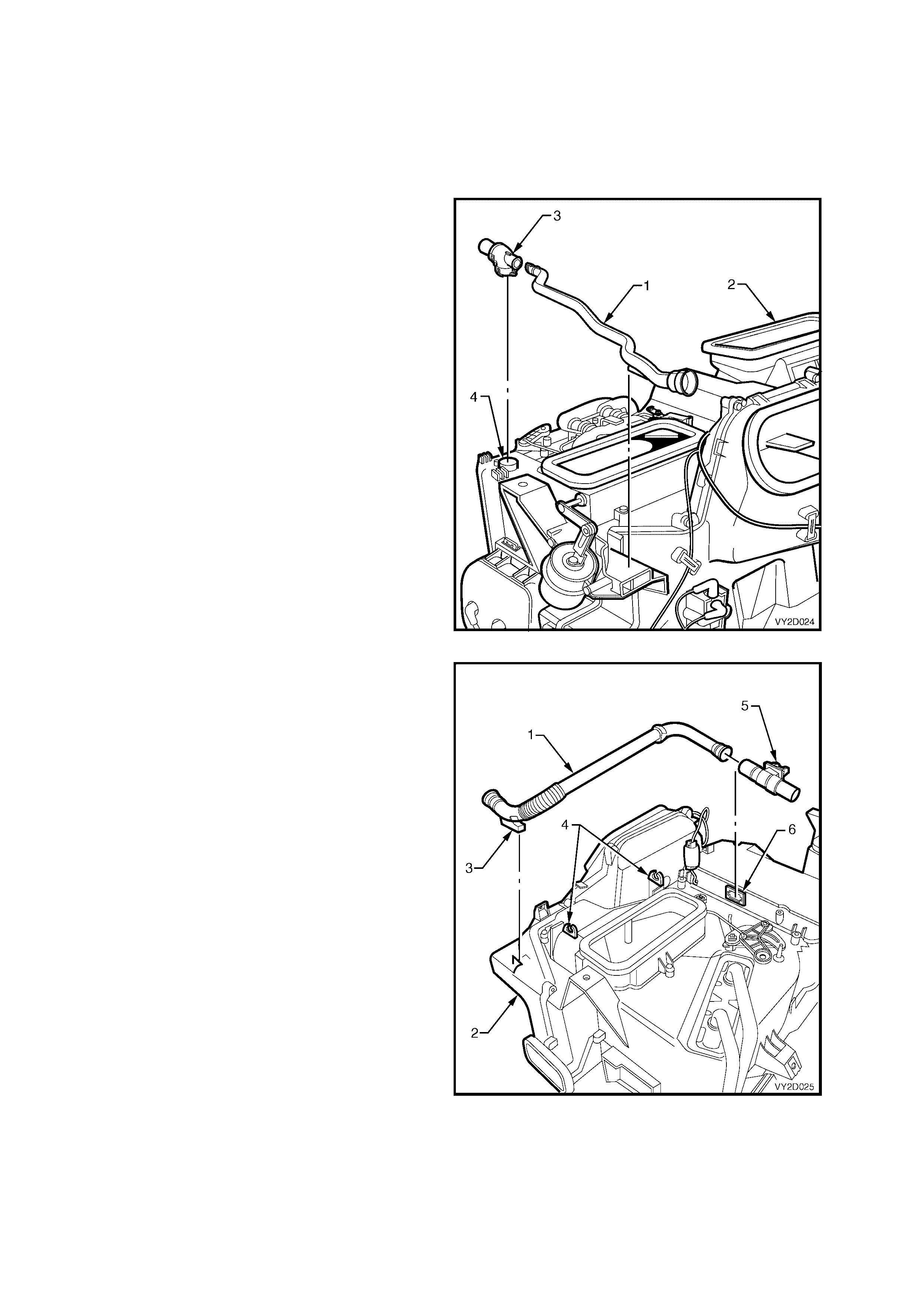
Left-hand drive
On left-hand drive HVAC units, the aspirator tube
(1) is located on the top of the HVAC case (2) on
the left-hand side. The front section of the tube is
retained to the case within a moulded recess. The
rear of the tube is fitted into the induction port of the
venturi (3) The base of the venturi (inlet port) is
installed to the HVAC unit at the venturi air hole (4)
located at the left rear corner of the HVAC case.
Figure 2D-28
Right-hand drive
On right-hand drive HVAC units, the aspirator tube
(1) is located on the top of the HVAC c ase (2). T he
front s ection of the tube is retained to the case by a
locating lug (3), which locks into the HVAC case.
Two retaining clips (4) moulded to the case retain
the centre section of the tube.
The rear of the tube is fitted into the induction port
of the venturi ( 5) The base of the venturi ( inlet port)
is installed to the venturi air hole (6) located in the
evaporator cover of the HVAC case.
Figure 2D-29
IN-CA R TEMPERATURE SENSOR
The in-c ar temperature s ens or is a ther mistor type (NTC ) r esis tor used to monitor the vehic le’s inter ior temperatur e.
Resistance s ignals are c onstantly monitored by the OCC control m odule and are used f or subsequent control of the
OCC system.
It is essential that the ventur i and aspirator tube assem b ly be properly connected to the in-car temper ature sensor if
the sensor is to provide correct information to the OCC control module.
Refer to ASPIRATOR TUBE AND VENTURI in this Section for further information.
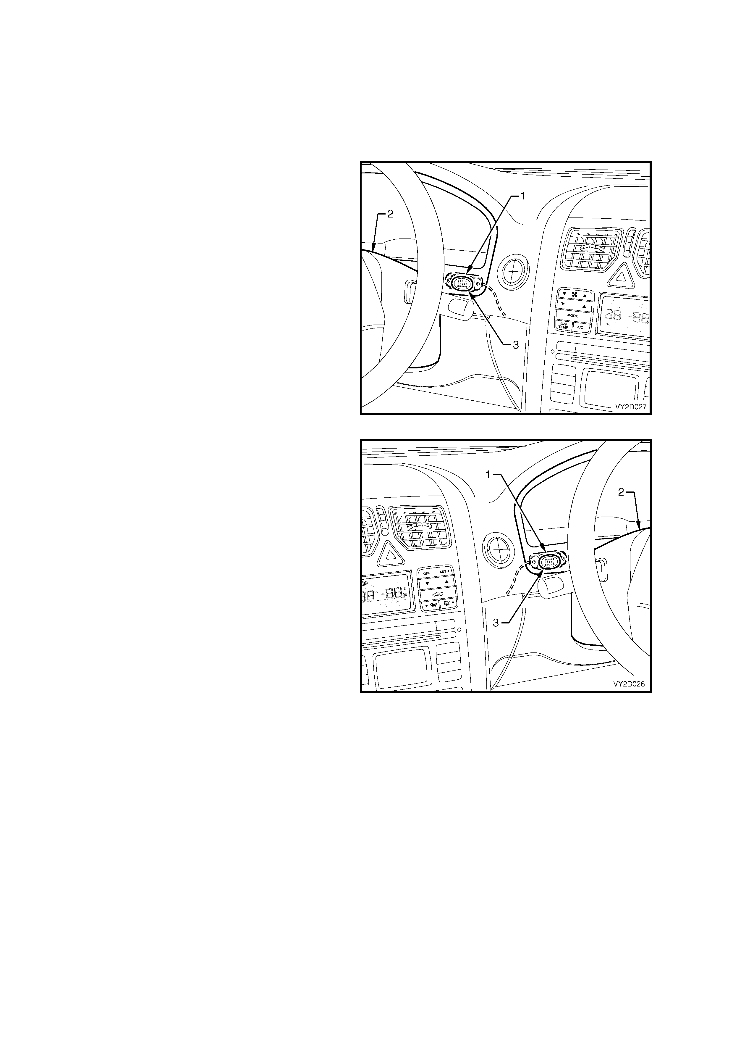
Left-hand drive
On left-hand drive vehicles, the in-car temperature
sensor (1) is located on the right-hand side of the
steering column (2) behind the sensor inlet air
holes (3) on the instrument cluster trim assembly.
Figure 2D-30
Right-hand drive
On right-hand drive vehic les , the in-car temper ature
sensor (1) is located on the left-hand side of the
steering column (2) behind the sensor inlet air
holes (3) on the instrument cluster trim assembly.
Figure 2D-31
EVAPORATIVE TEMPERATURE SENSOR
The Evaporative T em per ature Sens or is a therm istor type (NTC) resistor used to m onitor the tem per ature of the air
into the HVAC unit after it has passed through the evaporator cor e. Resistance values are c onstantly m onitored by
the OCC control module and are used for subsequent control of the OCC system.
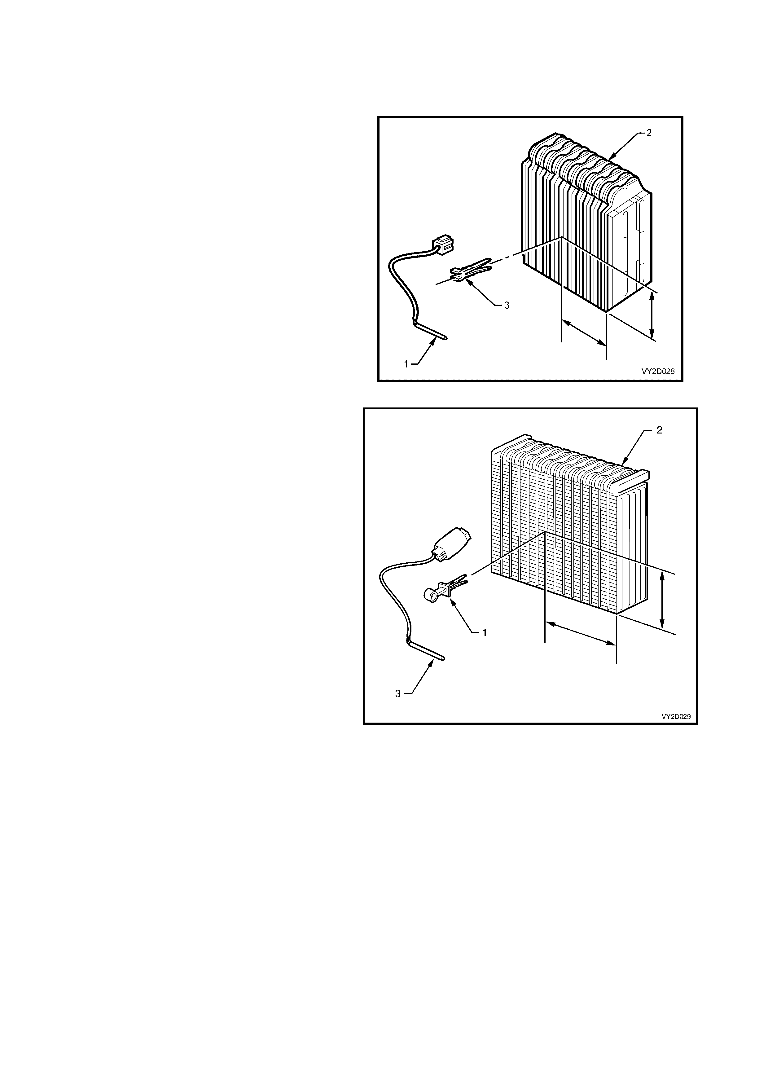
Left-hand drive
On left-hand drive HVAC units, the evaporative
temperature sensor (1) is located on evaporator
core (2) by a plastic retaining clip (3). The
installation point of the sensor to the evaporator is
critical f or correct OCC system performance. Refer
to Section 2E, 2.4 EVAPORATIVE
TEMPERATURE SENSOR for the specified
installation dimensions of the LHD evaporator
temperature sensor.
Figure 2D-32
Right-hand drive
On right-hand drive HVAC units, the evaporative
temperature sensor (1) is located on evaporator
core (2) by a plastic retaining clip (3). The
installation point of the sensor to the evaporator is
critical f or correct OCC system performance. Refer
to Section 2E, 2.4 EVAPORATIVE
TEMPERATURE SENSOR for the specified
installation dimensions of the RHD evaporative
temperature sensor.
Figure 2D-33
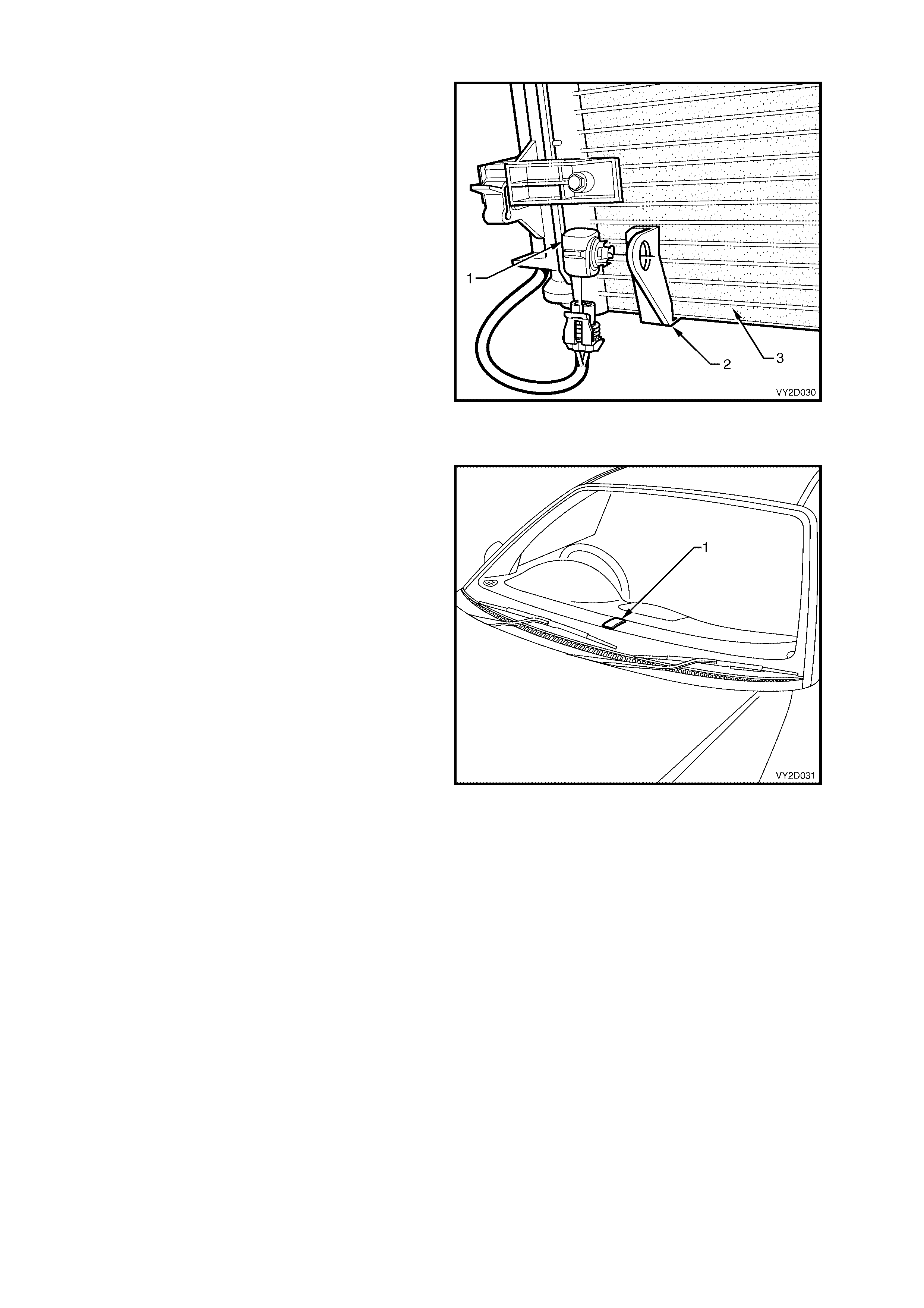
AMBIENT TEMPERATURE SENSOR
The Am bient T em peratur e Sensor ( 1) is ins talled to
a bracket (2) that is permanently attached to the
front of the A/C condenser (3) on the lower right-
hand side.
It is a thermistor type (NTC) resistor used to
monitor the ambient (outside) temperature. This
sensor is slow reacting due to the dense plastic
housing surrounding it. The OCC takes into
account road speed before updating the
temperature display to avoid false readings in
heavy traffic or extended idle conditions.
Resistance signals are sent directly from the
ambient temperature sensor to the OCC control
module for interpretation.
Figure 2D-34
SUN LOAD SENSOR
The Sun Load Sensor (1) incorporates the remote
receiver module and is located in the centre of the
demis t panel. F or the pur poses of the OCC sys tem,
it is used to monitor the sun load upon the vehicle.
It is a photochemical type sensor, meaning that a
small electrical current will be created depending
on the sun load (strength) over it. When the sun
load is high, the OCC control module will select a
higher blower fan speed and increased cooling
automatically. Likewise, when the sun load is low,
such as going into an underground car park, the
OCC control module will automatically reduce the
fan speeds and increase heating slightly.
Signals are sent from the sun load sensor directly
to the BCM then to the OCC control m odule via the
serial data line input.
Figure 2D-35
3.3 HVAC UNIT AIRFLOW MODES
The following airflow mode diagrams (Figure 2D-37 to Figure 2D-60) provide a schematic representation of how
cold and heated air f lows thr ough the HVAC unit during the seven differ ent pos sible m odes. Each schem atic has a
graphic representation of the OCC control module with the LCD screen matching the given mode.
Because of the differ ent design characteristic s and configurations of the left-hand drive and r ight-hand drive HVAC
units, schematics are provided specific to left-hand drive and right-hand drive applications.
LEFT-HAND DRIVE
• Recirculation Mode Refer to Figure 2D-37 (Full cold) and Figure 2D-38 (Full heat)
• Face Mode Refer to Figure 2D-39 (Full cold) and Figure 2D-40 (Full heat)
• Bi-level Mode Refer to Figure 2D-41 (Full cold) and Figure 2D-42 (Full heat)
• Floor Mode Refer to Figure 2D-43 (Full cold) and Figure 2D-44 (Full heat)
• Blend Mode Refer to Figure 2D-45 (Full cold) and Figure 2D-46 (Full heat)
• Demist Mode Refer to Figure 2D-47
• Default Mode Refer to Figure 2D-48
RIGHT-HAND DRIVE
• Recirculation Mode Refer to Figure 2D-49 (Full cold) and Figure 2D-50 (Full heat)
• Face Mode Refer to Figure 2D-51 (Full cold) and Figure 2D-52 (Full heat)
• Bi-level Mode Refer to Figure 2D-53 (Full cold) and Figure 2D-54 (Full heat)
• Floor Mode Refer to Figure 2D-55 (Full cold) and Figure 2D-56 (Full heat)
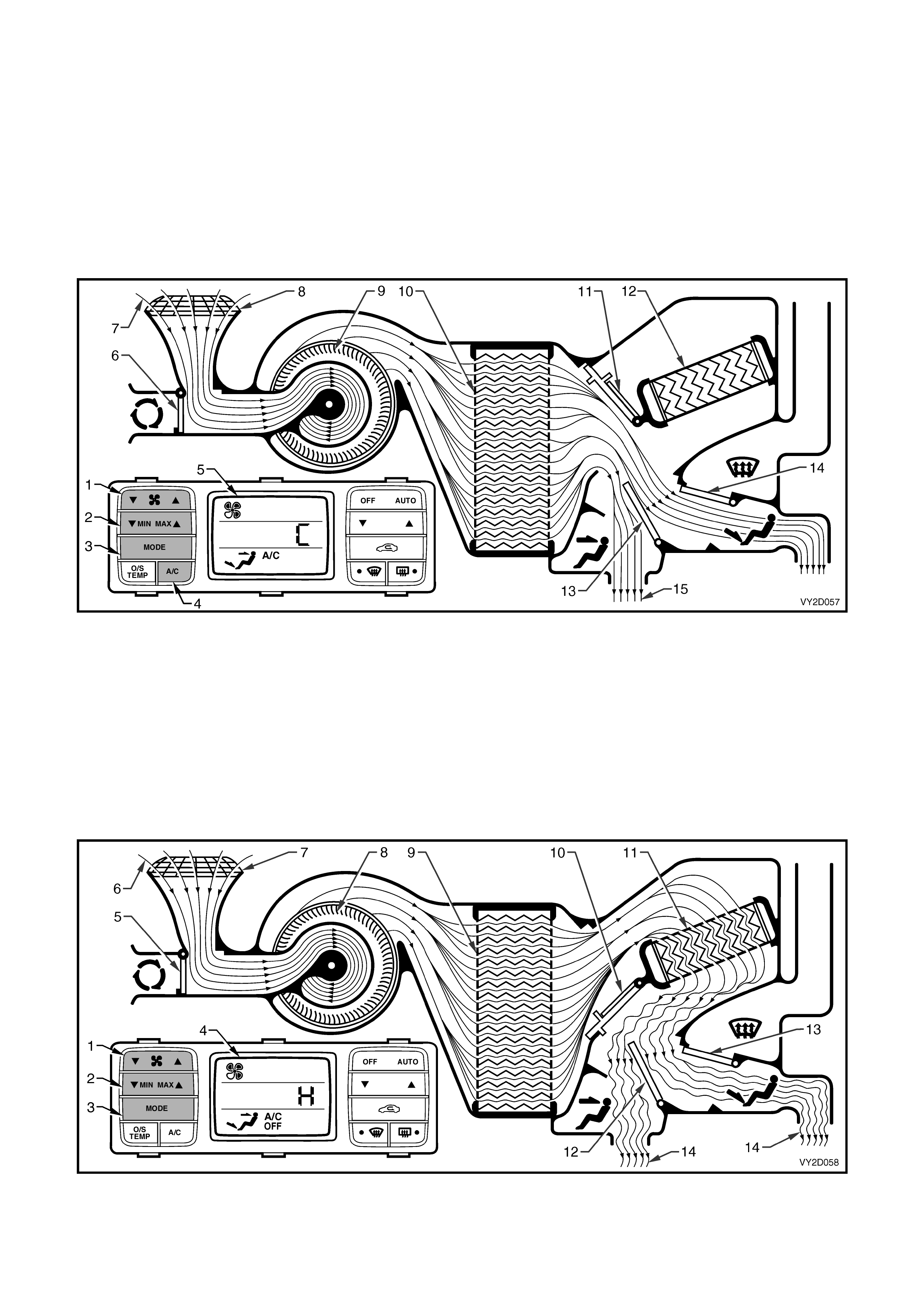
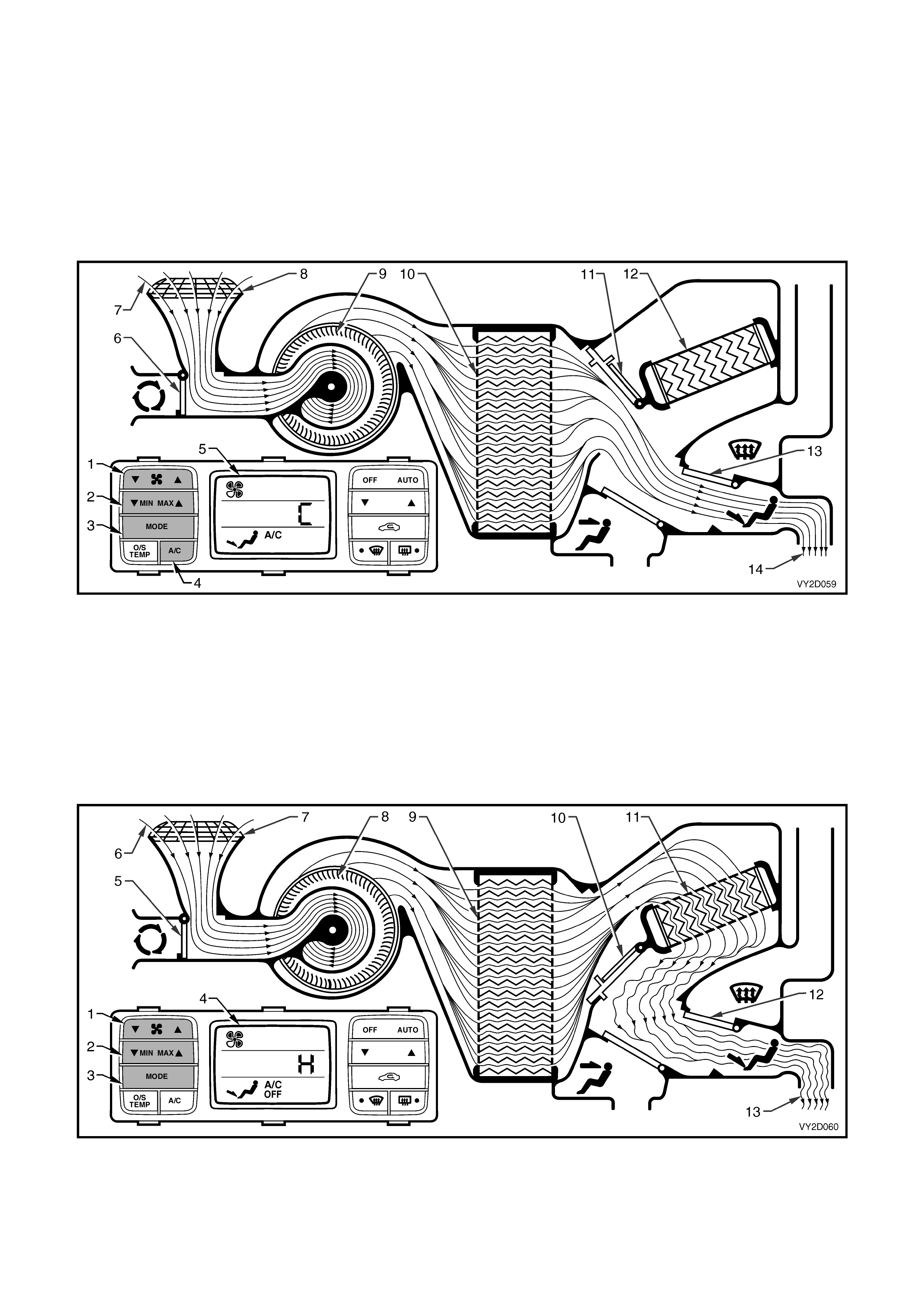
• Blend Mode Refer to Figure 2D-57 (Full cold) and Figure 2D-58 (Full heat)
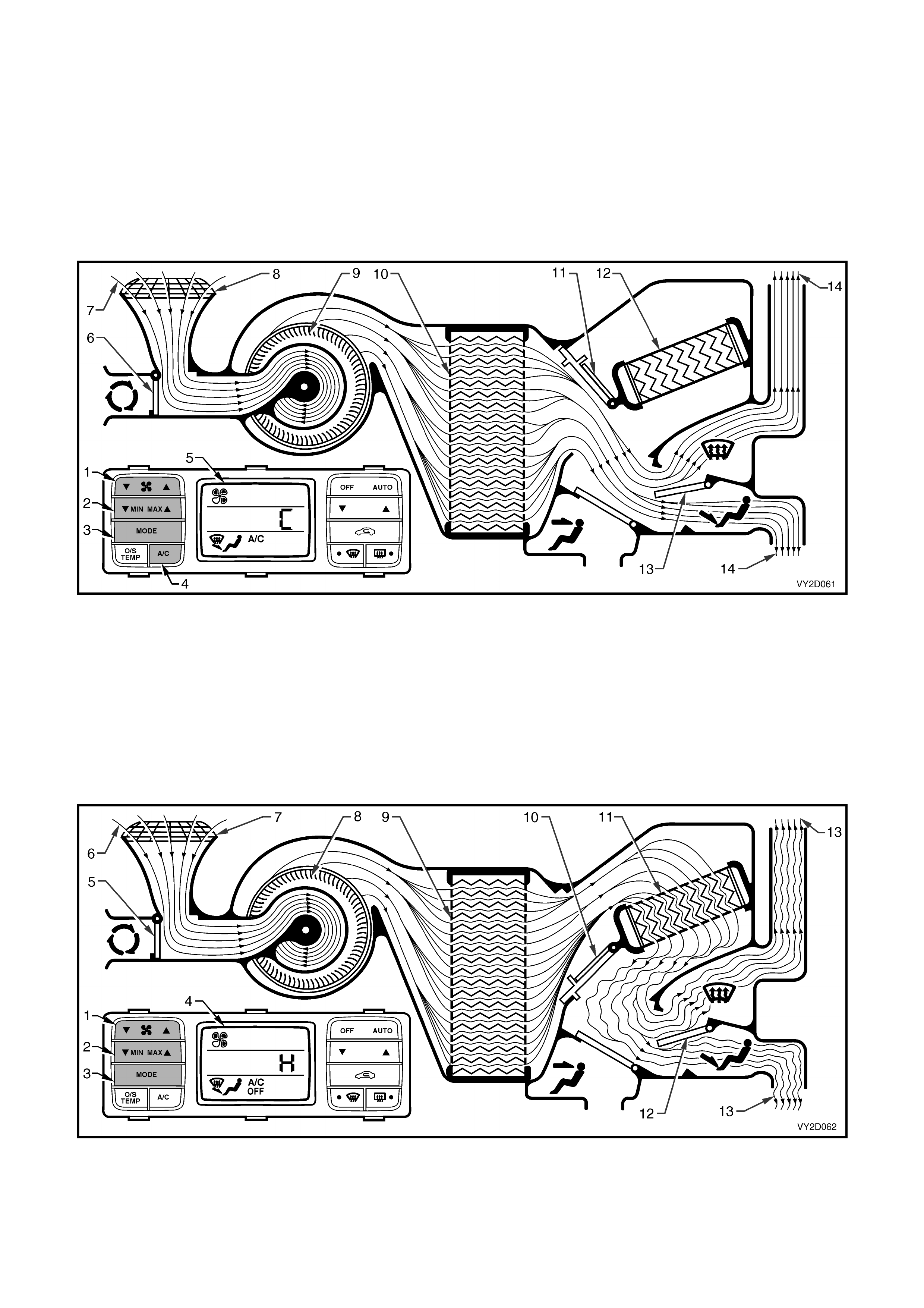
• Demist Mode Refer to Figure 2D-59
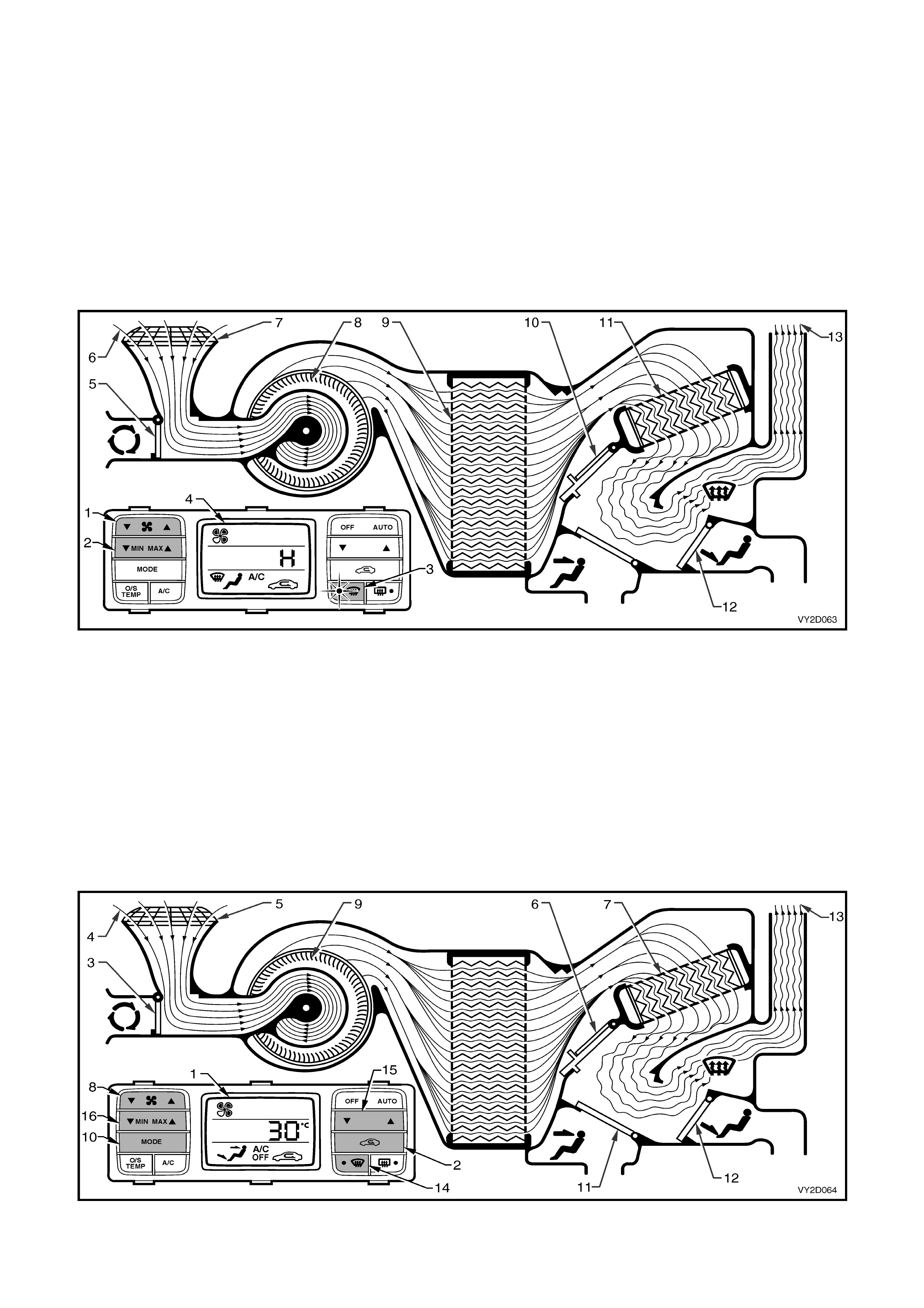
• Default Mode Refer to Figure 2D-60
Figure 2D-36
Legend
1. HVAC Unit – LHD 3. HVAC Unit – RHD
2. HVAC Unit Airfl ow Schematic – LHD 4. HVAC Unit Airfl ow Schematic – RHD
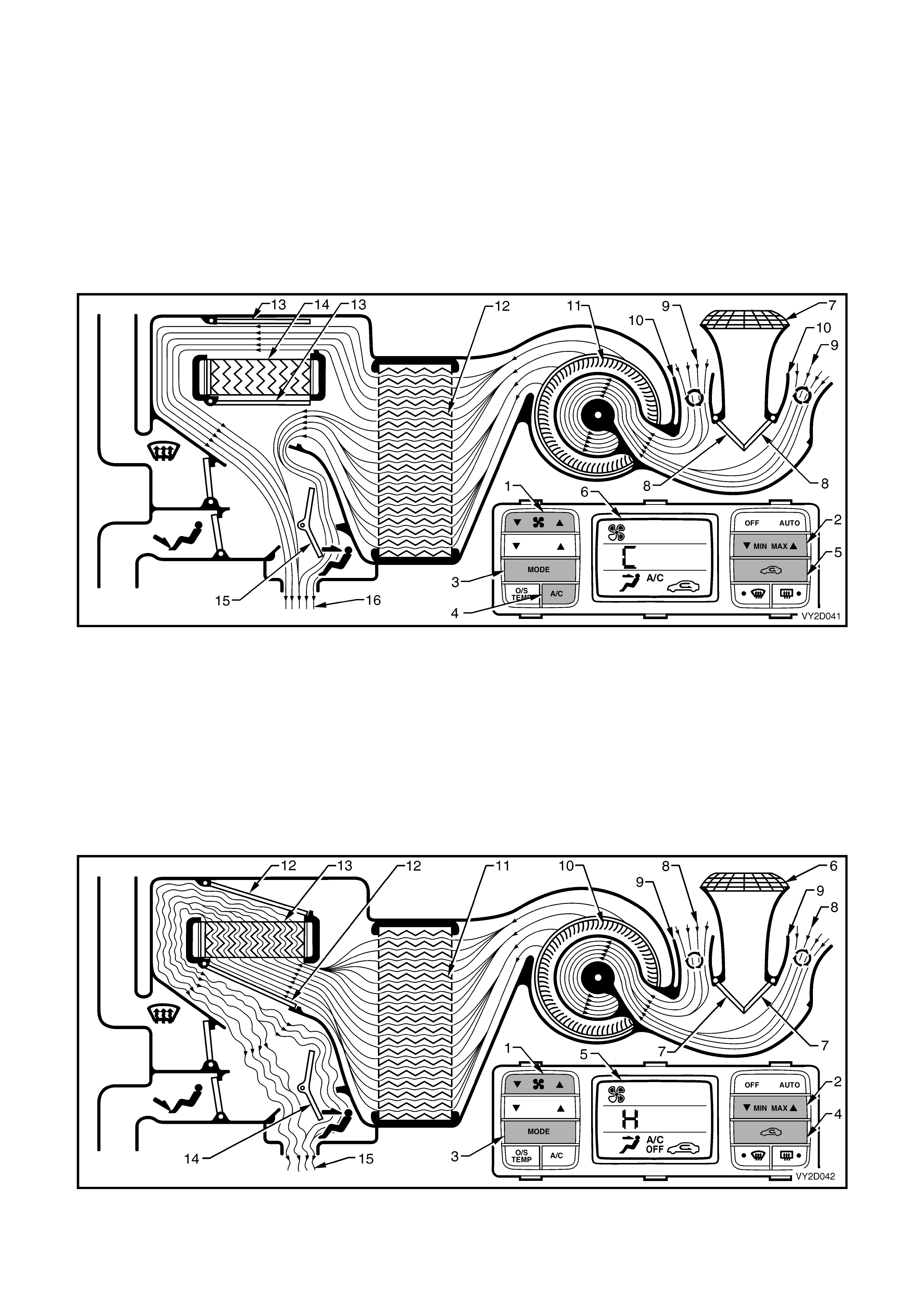
RECIRCULATION MODE – LEFT-HA ND DRIVE
Full cold
The fan switch (1) is used to select any one of five speeds. The side G of the MIN MAX switch (2) has been
selected resulting in full, uncontrolled cooling. The mode control switch (3) is set to face mode. The A/C switch (4) is
on and the recirculation switch (5) has also been selected. All of these settings are displayed on the LCD screen (6).
NOTE: Recirculation mode can be selected independently of all other air distribution modes excluding demist mode.
The plenum chamber (outside air) inlet (7) to the HVAC unit is closed off by the recirculation doors (8). Interior air
(9) is dr awn into the HVAC unit through the recirculation inlets ( 10) by the blower motor fan (11), and is then f orced
through the cold evaporator f ins (12) . In f ull c old mode the air mix doors ( 13) ar e positioned to allow all air to bypass
the heater core (14). The air travels through the open face door (15). The cold air (16) is then directed out of the
HVAC unit to the centre and side vents.
Figure 2D-37
Full heat
The fan switch (1) is used to select any one of five speeds. The side F of the MIN MAX switch (2) has been
selected resulting in full, uncontrolled heating. The mode control switch (3) has been switched to face mode. The
recirculation switch (4) has been selected. All of these settings are displayed on the LCD screen (5).
NOTE: Recirculation mode can be selected independently of all other air distribution modes excluding demist mode.
The plenum chamber (outside air) inlet (6) to the HVAC unit is closed off by the recirculation doors (7). Interior air
(8) is drawn into the HVAC unit through the recirculation inlets (9) by the blower motor fan (10), and is then forced
through the evaporator f ins (11) . In f ull heat mode, the air mix door s (12) will be positioned s o that all incoming air is
directed through the heater core (13). The air travels through the open face door (14). The heated air (15) is then
directed out through the centre and side vents.
Figure 2D-38
FACE MODE – LEFT-HAND DRIVE
Full cold
The fan switch (1) is used to select any one of five speeds. The side G of the MIN MAX switch (2) has been
selected r esulting in f ull, unc ontr olled cooling. The m ode c ontrol s witch ( 3) has been s witched to f ac e mode and the
A/C switch (4) is on. All of these settings are displayed on the LCD screen (5).
The recirculation doors (6) are closed allowing outside air (7) to enter and flow into the HVAC unit via the plenum
chamber inlet (8). Air is drawn into the HVAC unit by the blower motor (9), and is then forced through the cold
evaporator f ins ( 10). In full c old mode, the air mix door s ( 11) are pos itioned to allow all air to bypass the heater cor e
(12). T he air travels through the open fac e door (13). The c old air (14) is then directed through the centre and side
vents.
Figure 2D-39
Full heat
The fan switch (1) is used to select any one of five speeds. The side F of the MIN MAX switch (2) has been
selected resulting in full, uncontrolled heating. The m ode control switch (3) has been switched to face mode. All of
these settings are displayed on the LCD screen (4).
The recirculation doors (5) are closed allowing outside air (6) to enter and flow into the HVAC unit via the plenum
chamber inlet (7). Air is drawn into the HVAC unit by the blower motor (8). This air is then forced through the
evaporator core fins (9). In full heat mode, the air mix doors (10) will be positioned so that all incoming air is directed
through the heater core (11). The air travels through the open face door (12). The heated air (13) is then directed
out through the centre and side vents.
Figure 2D-40
BI-LEVEL MODE – LEFT-HAND DRIVE
Full cold
The fan switch (1) is used to select any one of five speeds. The side G of the MIN MAX switch (2) has been
selected r esulting in full, uncontrolled c ooling. The mode c ontrol switch (3) has been s witc hed to bi-level mode and
the A/C switch (4) is on. All of these settings are displayed on the LCD screen (5).
The recirculation doors (6) are closed allowing outside air (7) to enter and flow into the HVAC unit via the plenum
chamber inlet (8). Air is drawn into the HVAC unit by the blower motor (9), and is then forced through the cold
evaporator f ins ( 10). In full c old mode, the air mix door s ( 11) are pos itioned to allow all air to bypass the heater cor e
(12). T he air travels through the half opened face door (13) and the fully opened foot door (14) . The cold air (15) is
then directed through the centre and side vents as well as to the floor ducts.
Figure 2D-41
Full heat
The fan switch (1) is used to select any one of five speeds. The side F of the MIN MAX switch (2) has been
selected resulting in full, uncontrolled heating. The mode control s witc h (3) has been switched to bi-level m ode. All
of these settings are displayed on the LCD screen (4).
The recirculation doors (5) are closed allowing outside air (6) to enter and flow into the HVAC unit via the plenum
chamber inlet (7). Air is drawn into the HVAC unit by the blower motor (8). This air is then forced through the
evaporator core fins (9). In full heat mode, the air mix doors (10) will be positioned so that all incoming air is directed
through the heater core (11). The air travels through the half opened face door (12) and the fully opened foot door
(13). The heated air (14) is then directed through the centre and side vents as well as to the floor ducts.
Figure 2D-42

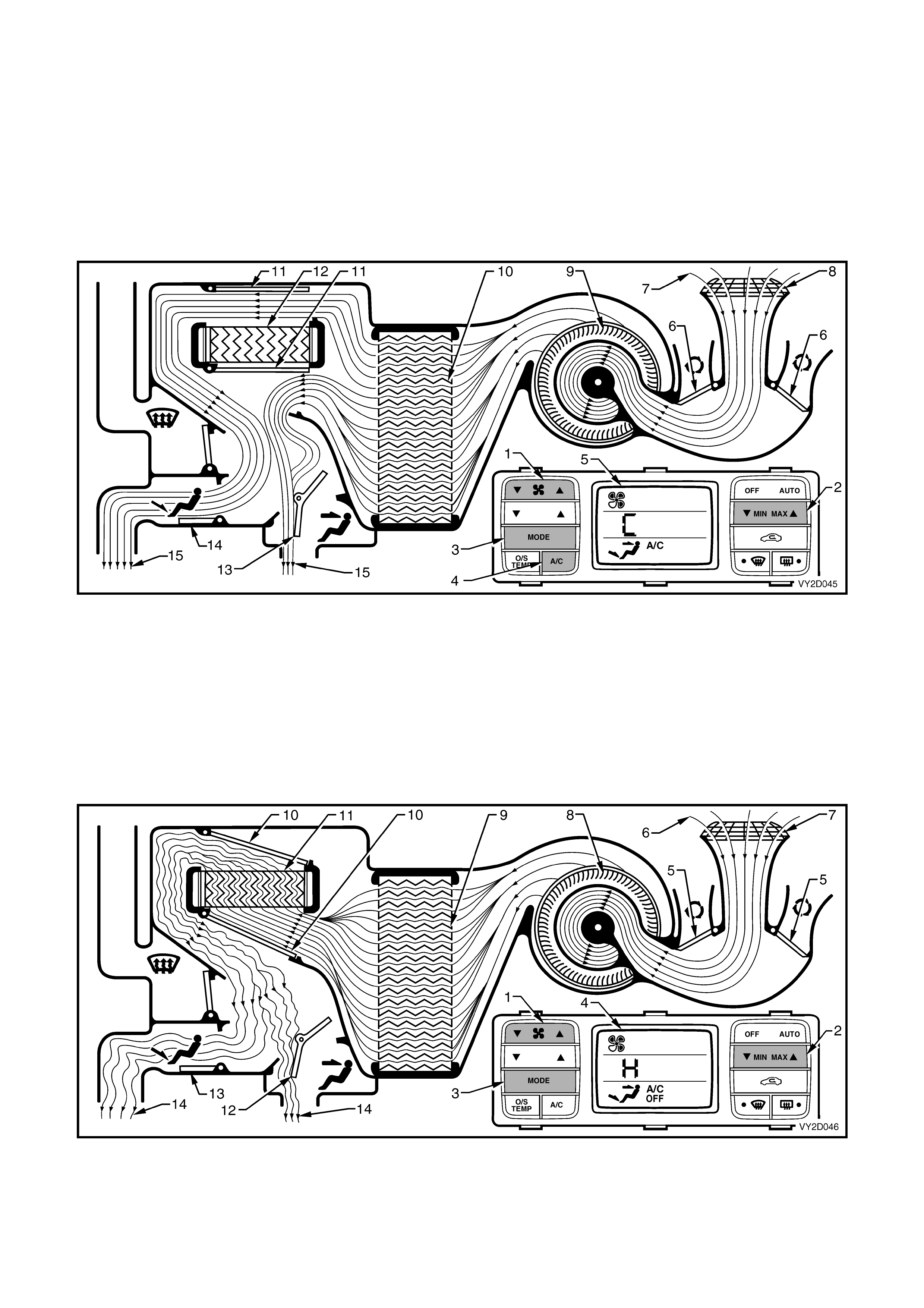
FLOOR MODE – LEFT-HAND DRIVE
Full cold
The fan switch (1) is used to select any one of five speeds. The side G of the MIN MAX switch (2) has been
selected r esulting in f ull, unc ontr olled cooling. The m ode c ontr ol s witch (3) has been switched to f loor mode and the
A/C switch (4) is on. All of these settings are displayed on the LCD screen (5).
The recirculation doors (6) are closed allowing outside air (7) to enter and flow into the HVAC unit via the plenum
chamber inlet (8). Air is drawn into the HVAC unit by the blower motor (9), and is then forced through the cold
evaporator f ins ( 10). In full c old mode, the air mix door s ( 11) are pos itioned to allow all air to bypass the heater cor e
(12). The air travels through the foot door (13). The cold air (14) is then directed to the floor ducts.
Figure 2D-43
Full heat
The fan switch (1) is used to select any one of five speeds. The side F of the MIN MAX switch (2) has been
selected resulting in full, uncontrolled heating. The m ode control switch (3) has been switched to floor mode. All of
these settings are displayed on the LCD screen (4).
The recirculation doors (5) are closed allowing outside air (6) to enter and flow into the HVAC unit via the plenum
chamber inlet (7). Air is drawn into the HVAC unit by the blower motor (8). This air is then forced through the
evaporator core fins (9). In full heat mode, the air mix doors (10) will be positioned so that all incoming air is directed
through the heater core (11). The air travels through the foot door (12). The heated air (13) is then directed to the
floor ducts.
Figure 2D-44
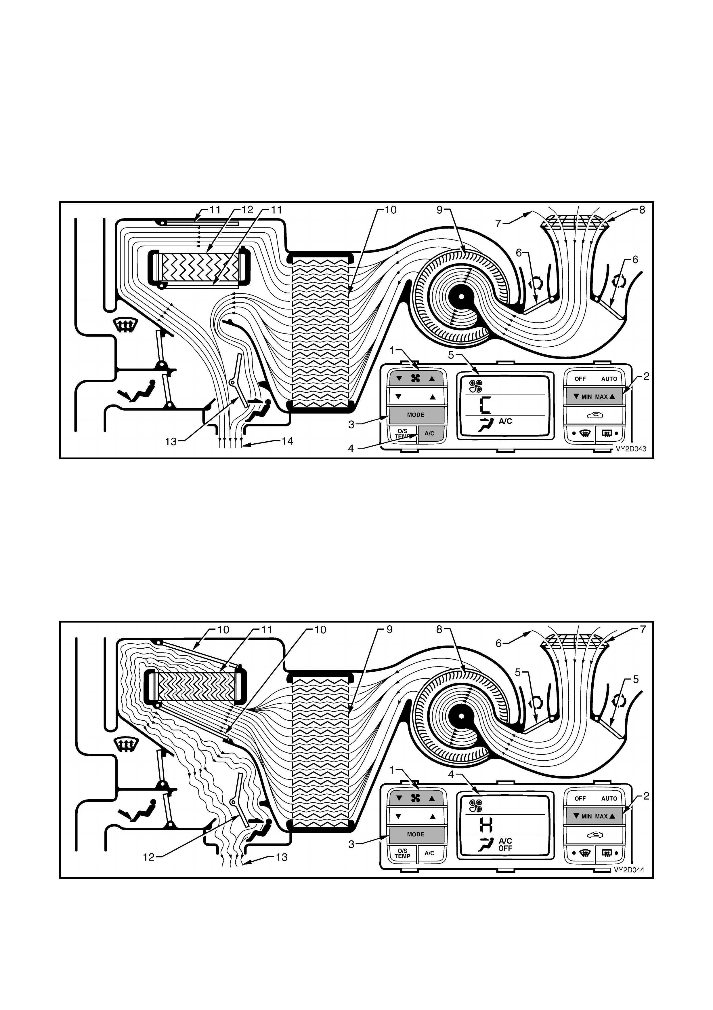
BLEND MODE – LEFT-HAND DRIVE
Full cold
The fan switch (1) is used to select any one of five speeds. The side G of the MIN MAX switch (2) has been
selected resulting in full, uncontrolled cooling. The mode control switch (3) has been switched to blend mode and
the A/C switch (4) is on. All of these settings are displayed on the LCD screen (5).
The recirculation doors (6) are closed allowing outside air (7) to enter and flow into the HVAC unit via the plenum
chamber inlet (8). Air is drawn into the HVAC unit by the blower motor (9), and is then forced through the cold
evaporator f ins ( 10). In full c old mode, the air mix door s ( 11) are pos itioned to allow all air to bypass the heater cor e
(12). T he air travels through the open dem ist door (13) and foot door ( 14). The c old air (15) is then direc ted to both
the front windscreen and the floor ducts.
Figure 2D-45
Full heat
The fan switch (1) is used to select any one of five speeds. The side F of the MIN MAX switch (2) has been
selected resulting in f ull, uncontrolled heating. T he m ode control s witch (3) has been switched to blend m ode. All of
these settings are displayed on the LCD screen (4).
The recirculation doors (5) are closed allowing outside air (6) to enter and flow into the HVAC unit via the plenum
chamber inlet (7). Air is drawn into the HVAC unit by the blower motor (8). This air is then forced through the
evaporator core fins (9). In full heat mode, the air mix doors (10) will be positioned so that all incoming air is directed
through the heater core (11). The air travels through the open demist door (12) and foot door (13). The heated air
(14) is then directed to both the front windscreen and the floor ducts.
Figure 2D-46
DEMIST MODE – LEFT-HAND DRIVE
Full heat and A/C activated
The fan switch (1) is used to select any one of five speeds. The side F of the MIN MAX switch (2) has been
selected resulting in f ull, uncontr olled heating. The dem is t switch (3) has been switched on and the A/C s ystem has
been switched on automatically. All of these settings are displayed on the LCD screen (4).
The recirculation doors (5) are closed allowing outside air (6) to enter and flow into the HVAC unit via the plenum
chamber inlet (7). Air is drawn into the HVAC unit by the blower motor (8). This air is then forced through the cold
evaporator core fins (9) removing moisture from the air. In full heat m ode, the air mix doors (10) are positioned to
direct this dehumidified incoming air through the heater core (11). The air travels through the open demist door (12).
The heated air (13) is then directed to the front windscreen via the demist vents.
NOTE: By turning on the A/C system in this mode, dehumidification of incoming air will take place, demisting the
front windscreen and side windows in a shorter period.
Figure 2D-47
DEFAULT MODE – LEFT-HA ND DRIVE
Loss of vacuum supply to HVAC unit
If a loss of vacuum occurs within the OCC (Auto A/C) system, the HVAC unit will default to the following settings.
The ventilation mode settings will remain constant regardless of what is displayed on the LCD screen (1).
Regardless of rec irculation s witch (2) s election, the rec irculation door s (3) will rem ain closed allowing outside air ( 4)
to enter and flow into the HVAC unit via the plenum chamber inlet (5). The position of the air mix doors (6) will
remain controllable as their function is electrically operated by the air mix motor. Heated coolant will flow through the
heater core (7), as vacuum is required to m aintain the water valve in the cold (closed) position. The f an switch (8)
will operate the blower fan (9) as normal. In any position of the mode switch (10), the face door (11) and the floor
door ( 12) will remain c losed. The dem is t door (13) will be positioned s o that all air (14) leaving the HVAC unit will be
directed to the demist ducts. Depending on the selected setting of temperature switch (15) and/or the MIN MAX
switch (16), this air may be cold, warm or hot air.
Figure 2D-48
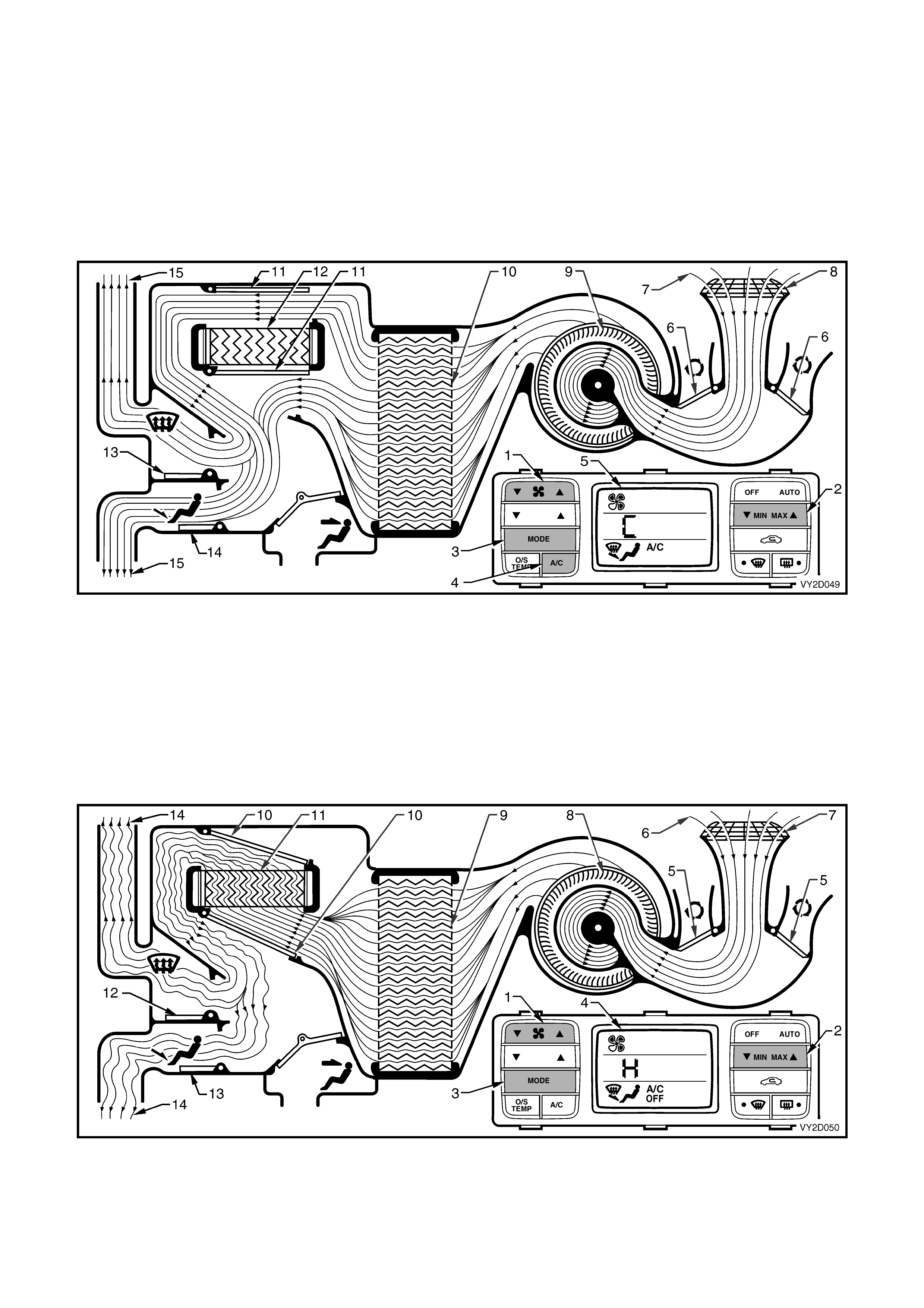
RECIRCULATION MODE – RIGHT-HAND DRIVE
Full cold
The fan switch (1) is used to select any one of five speeds. The side G of the MIN MAX switch (2) has been
selected resulting in full, uncontrolled cooling. The mode control switch (3) is set to face mode. The A/C switch (4) is
on and the recirculation switch (5) has also been selected. All of these settings are displayed on the LCD screen (6).
NOTE: Recirculation mode can be selected independently of all other air distribution modes excluding demist mode.
The plenum chamber ( outs ide air ) inlet (7) to the HVAC unit is c losed of f by the recirculation door (8) . Inter ior air (9)
is drawn into the HVAC unit through the recirculation inlet (10) by the blower motor fan (11), and is then forced
through the cold evaporator f ins (12) . In f ull c old mode the air mix doors ( 13) ar e positioned to allow all air to bypass
the heater core (14). The air travels through the open face door (15). The cold air (16) is then directed out of the
HVAC unit to the centre and side vents.
Figure 2D-49
Full heat
The fan switch (1) is used to select any one of five speeds. The side F of the MIN MAX switch (2) has been
selected resulting in full, uncontrolled heating. The mode control switch (3) has been switched to face mode. The
recirculation switch (4) has been selected. All of these settings are displayed on the LCD screen (5).
NOTE: Recirculation mode can be selected independently of all other air distribution modes excluding demist mode.
The plenum chamber ( outs ide air ) inlet (6) to the HVAC unit is c losed of f by the recirculation door (7) . Inter ior air (8)
is drawn into the HVAC unit through the recirculation inlet (9) by the blower motor fan (10), and is then forced
through the evaporator f ins (11) . In f ull heat mode, the air mix door s (12) will be positioned s o that all incoming air is
directed through the heater core (13). The air travels through the open face door (14). The heated air (15) is then
directed out through the centre and side vents.
Figure 2D-50
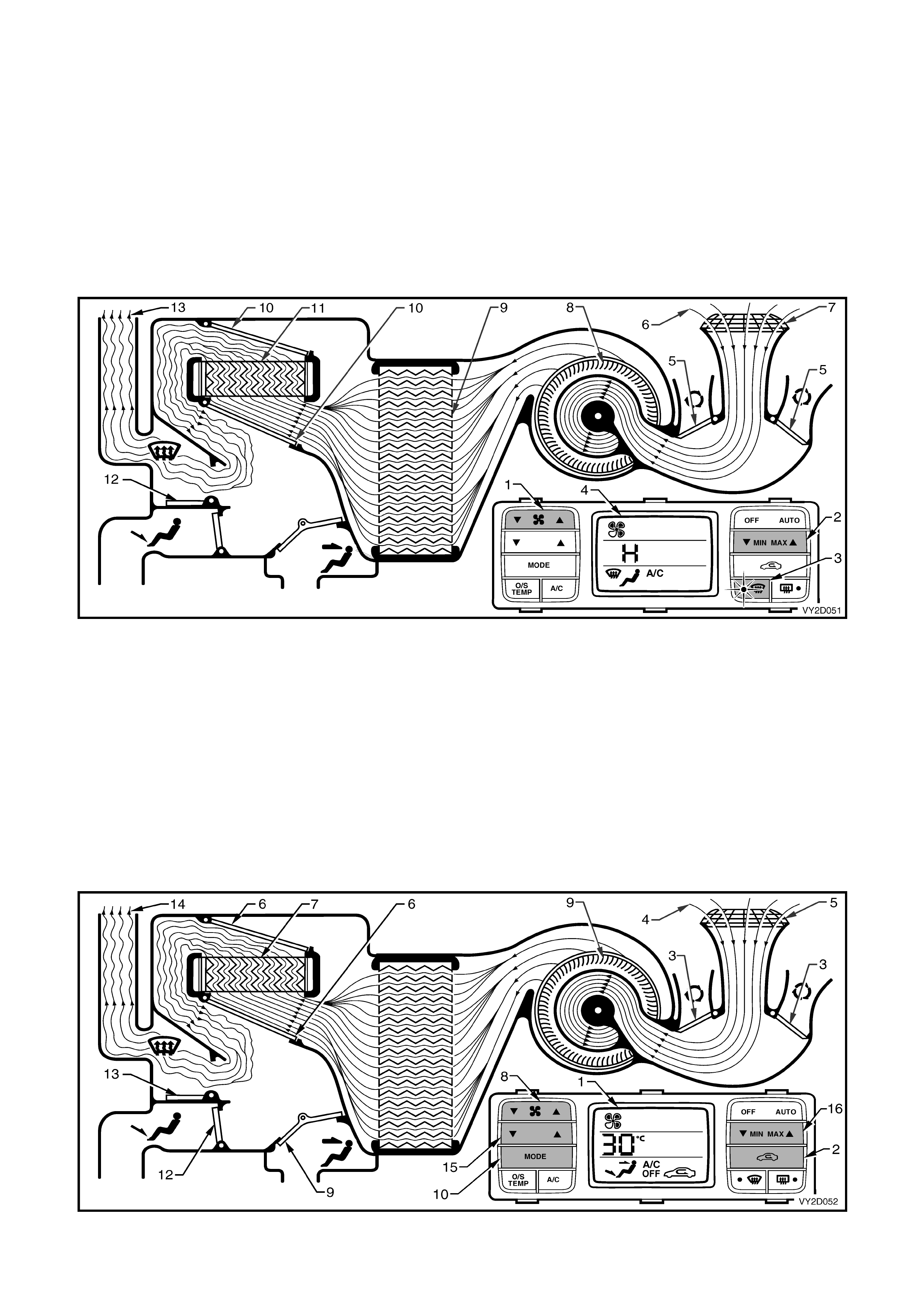
FACE MODE – RIGHT-HAND DRIVE
Full cold
The fan switch (1) is used to select any one of five speeds. The side G of the MIN MAX switch (2) has been
selected r esulting in f ull, unc ontr olled cooling. The m ode c ontrol s witch ( 3) has been s witched to f ac e mode and the
A/C switch (4) is on. All of these settings are displayed on the LCD screen (5).
The recirculation door (6) is closed allowing outside air (7) to enter and flow into the HVAC unit via the plenum
chamber inlet (8). Air is drawn into the HVAC unit by the blower motor (9), and is then forced through the cold
evaporator f ins ( 10). In full c old mode, the air mix door s ( 11) are pos itioned to allow all air to bypass the heater cor e
(12). T he air travels through the open fac e door (13). The c old air (14) is then directed through the centre and side
vents.
Figure 2D-51
Full heat
The fan switch (1) is used to select any one of five speeds. The side F of the MIN MAX switch (2) has been
selected resulting in full, uncontrolled heating. The m ode control switch (3) has been switched to face mode. All of
these settings are displayed on the LCD screen (4).
The recirculation door (5) is closed allowing outside air (6) to enter and flow into the HVAC unit via the plenum
chamber inlet (7). Air is drawn into the HVAC unit by the blower motor (8). This air is then forced through the
evaporator core fins (9). In full heat mode, the air mix doors (10) will be positioned so that all incoming air is directed
through the heater core (11). The air travels through the open face door (12). The heated air (13) is then directed
out through the centre and side vents.
Figure 2D-52
BI-LEVEL MODE – RIGHT-HAND DRIVE
Full cold
The fan switch (1) is used to select any one of five speeds. The side G of the MIN MAX switch (2) has been
selected r esulting in full, uncontrolled c ooling. The mode c ontrol switch (3) has been s witc hed to bi-level mode and
the A/C switch (4) is on. All of these settings are displayed on the LCD screen (5).
The recirculation door (6) is closed allowing outside air (7) to enter and flow into the HVAC unit via the plenum
chamber inlet (8). Air is drawn into the HVAC unit by the blower motor (9), and is then forced through the cold
evaporator f ins ( 10). In full c old mode, the air mix door s ( 11) are pos itioned to allow all air to bypass the heater cor e
(12). T he air travels through the half opened face door (13) and the through the dem ist/floor door (14) which is fully
open in the floor mode. The cold air (15) is then directed through the centre and side vents as well as to the floor
ducts.
Figure 2D-53
Full heat
The fan switch (1) is used to select any one of five speeds. The side F of the MIN MAX switch (2) has been
selected resulting in full, uncontrolled heating. The mode control s witc h (3) has been switched to bi-level m ode. All
of these settings are displayed on the LCD screen (4).
The recirculation door (5) is closed allowing outside air (6) to enter and flow into the HVAC unit via the plenum
chamber inlet (7). Air is drawn into the HVAC unit by the blower motor (8). This air is then forced through the
evaporator core fins (9). In full heat mode, the air mix doors (10) will be positioned so that all incoming air is directed
through the heater core (11). The air travels through the half opened face door (12) and through the demist/floor
door (13), which is fully open in the floor mode. The heated air (14) is then directed through the centre and side
vents as well as to the floor ducts.
Figure 2D-54
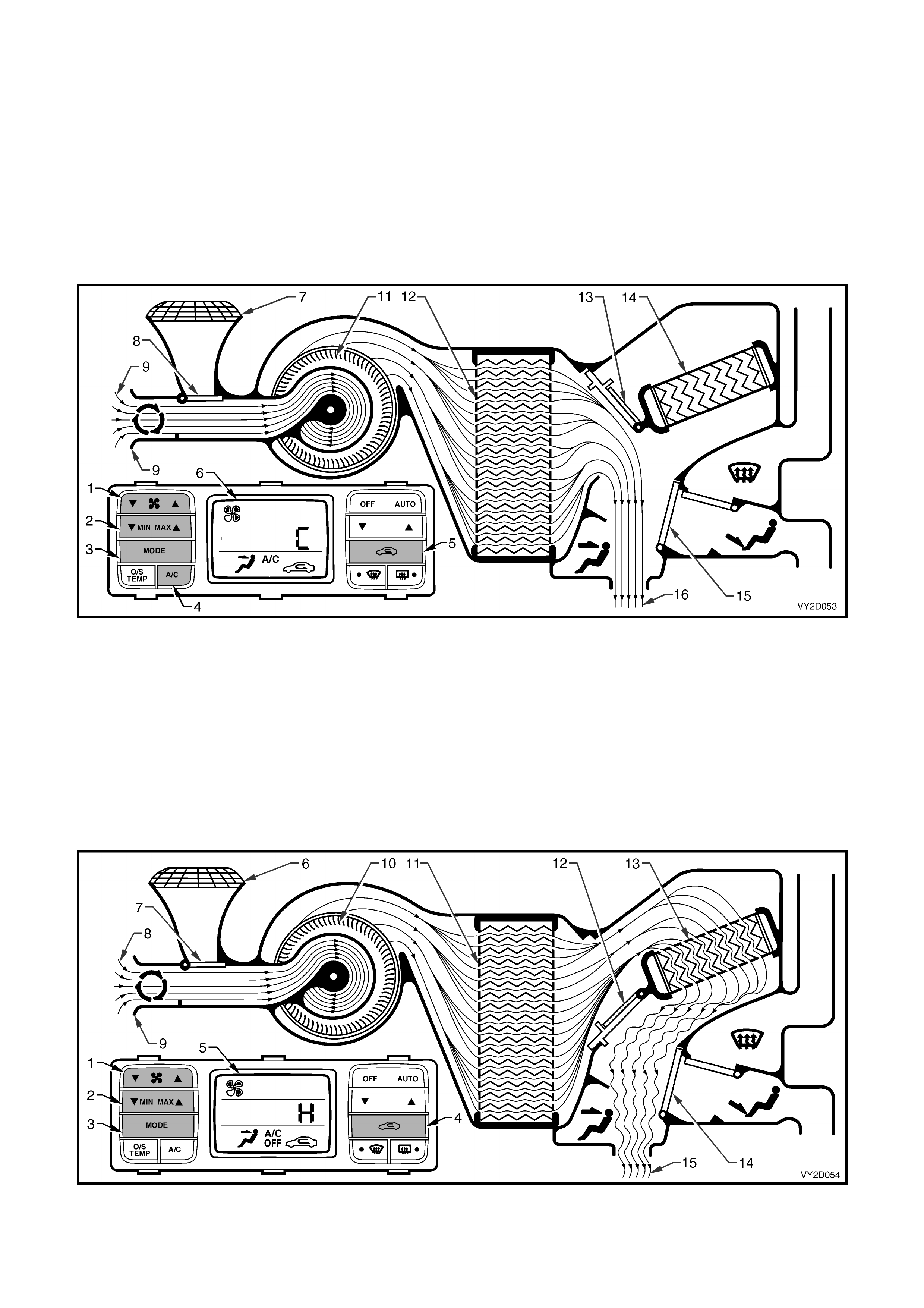
FLOOR MODE – RIGHT-HAND DRIVE
Full cold
The fan switch (1) is used to select any one of five speeds. The side G of the MIN MAX switch (2) has been
selected r esulting in f ull, unc ontr olled cooling. The m ode c ontr ol s witch (3) has been switched to f loor mode and the
A/C switch (4) is on. All of these settings are displayed on the LCD screen (5).
The recirculation door (6) is closed allowing outside air (7) to enter and flow into the HVAC unit via the plenum
chamber inlet (8). Air is drawn into the HVAC unit by the blower motor (9), and is then forced through the cold
evaporator f ins ( 10). In full c old mode, the air mix door s ( 11) are pos itioned to allow all air to bypass the heater cor e
(12). The air travels through the demist/floor door (13), which is fully open in the floor mode. The cold air (14) is then
directed to the floor ducts.
Figure 2D-55
Full heat
The fan switch (1) is used to select any one of five speeds. The side F of the MIN MAX switch (2) has been
selected resulting in full, uncontrolled heating. The m ode control switch (3) has been switched to floor mode. All of
these settings are displayed on the LCD screen (4).
The recirculation door (5) is closed allowing outside air (6) to enter and flow into the HVAC unit via the plenum
chamber inlet (7). Air is drawn into the HVAC unit by the blower motor (8). This air is then forced through the
evaporator core fins (9). In full heat mode, the air mix doors (10) will be positioned so that all incoming air is directed
through the heater cor e (11). T he air tr avels through the dem is t/floor door (12) which is fully open in the floor mode.
The heated air (13) is then directed to the floor ducts.
Figure 2D-56
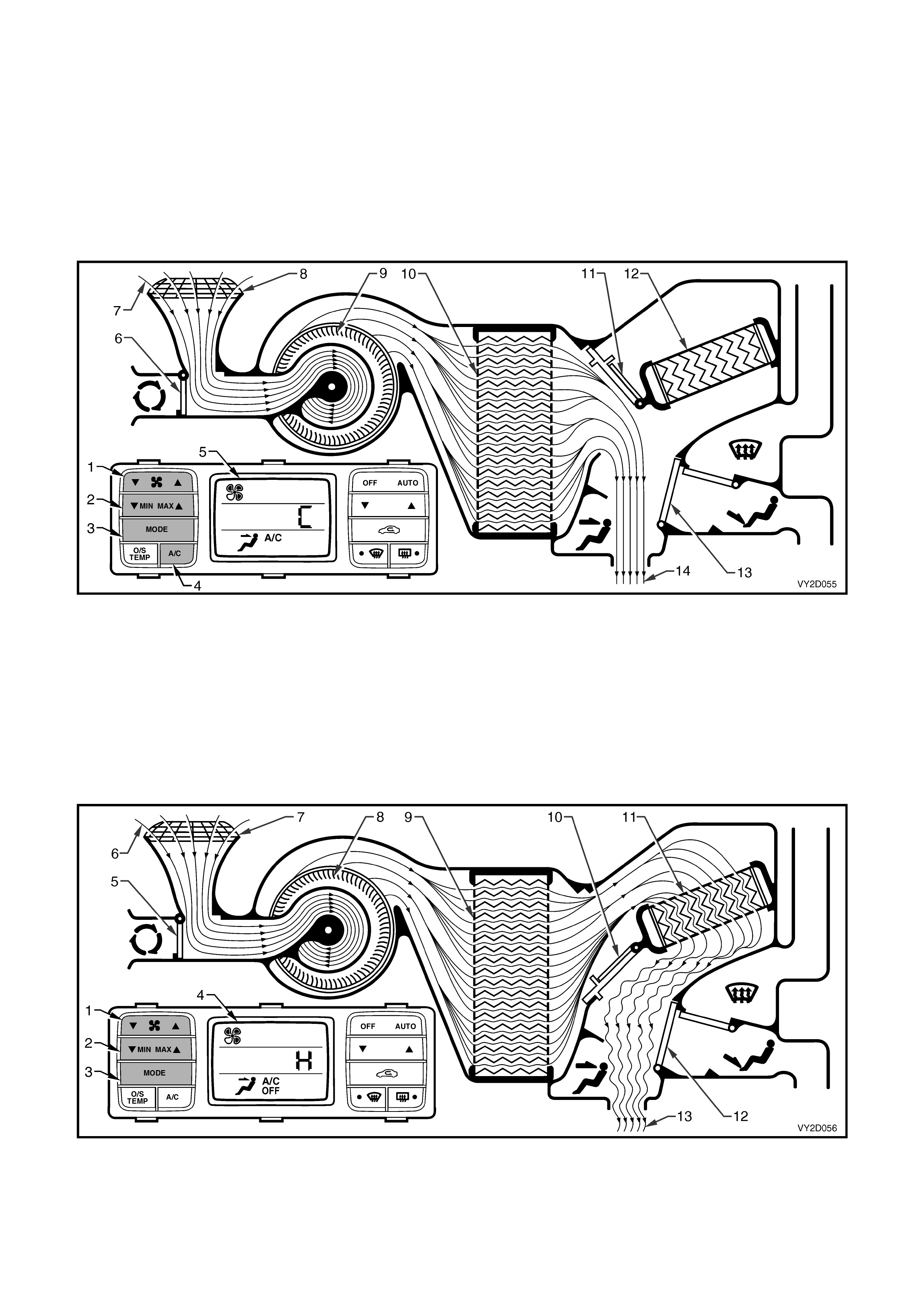
BLEND MODE – RIGHT-HAND DRIVE
Full cold
The fan switch (1) is used to select any one of five speeds. The side G of the MIN MAX switch (2) has been
selected resulting in full, uncontrolled cooling. The mode control switch (3) has been switched to blend mode and
the A/C switch (4) is on. All of these settings are displayed on the LCD screen (5).
The recirculation door (6) is closed allowing outside air (7) to enter and flow into the HVAC unit via the plenum
chamber inlet (8). Air is drawn into the HVAC unit by the blower motor (9), and is then forced through the cold
evaporator f ins ( 10). In full c old mode, the air mix door s ( 11) are pos itioned to allow all air to bypass the heater cor e
(12). The air travels through the demist/floor door (13) which is positioned half way between demist and floor
modes. The cold air (14) is then directed to both the front windscreen and the floor ducts.
Figure 2D-57
Full heat
The fan switch (1) is used to select any one of five speeds. The side F of the MIN MAX switch (2) has been
selected resulting in f ull, uncontrolled heating. T he m ode control s witch (3) has been switched to blend m ode. All of
these settings are displayed on the LCD screen (4).
The recirculation door (5) is closed allowing outside air (6) to enter and flow into the HVAC unit via the plenum
chamber inlet (7). Air is drawn into the HVAC unit by the blower motor (8). This air is then forced through the
evaporator core fins (9). In full heat mode, the air mix doors (10) will be positioned so that all incoming air is directed
through the heater cor e (11) . The air travels through the demis t/f loor door (12) which is positioned half way between
demist and floor modes. The heated air (13) is then directed to both the front windscreen and the floor ducts.
Figure 2D-58
DEMIST MODE – RIGHT-HAND DRIVE
Full heat and A/C activated
The fan switch (1) is used to select any one of five speeds. The side F of the MIN MAX switch (2) has been
selected resulting in f ull, uncontr olled heating. The dem is t switch (3) has been switched on and the A/C s ystem has
been switched on automatically. All of these settings are displayed on the LCD screen (4).
The recirculation door (5) is closed allowing outside air (6) to enter and flow into the HVAC unit via the plenum
chamber inlet (7). Air is drawn into the HVAC unit by the blower motor (8). This air is then forced through the cold
evaporator core fins (9) removing moisture from the air. In full heat m ode, the air mix doors (10) are positioned to
direct this dehumidif ied incom ing air through the heater core ( 11). The air travels through the dem ist/floor door (12)
which is fully open in the demist mode. The heated air (13) is then directed to the front windscreen via the demist
vents.
NOTE: By turning on the A/C system in this mode, dehumidification of incoming air will take place, demisting the
front windscreen and side windows in a shorter period.
Figure 2D-59
DEFAULT MODE – RIGHT-HAND DRIVE
Loss of vacuum supply to HVAC unit
If a loss of vacuum occurs within the OCC (Auto A/C) system, the HVAC unit will default to the following settings.
The ventilation mode settings will remain constant regardless of what is displayed on the LCD screen (1).
Regardless of rec irculation switch (2) selec tion, the recirculation door (3) will remain c losed allowing outside air (4)
to enter and flow into the HVAC unit via the plenum chamber inlet (5). The position of the air mix doors (6) will
remain controllable as their function is electrically operated by the air mix motor. Heated coolant will flow through the
heater core (7), as vacuum is required to maintain the water valve in the cold (closed) position. The fan switch (8)
will operate the blower fan (9) as normal. In any position of the mode switch (10), the face door (11) will remain
closed. The dem ist/f loor door (12) will be positioned so that all air (13) leaving the HVAC unit will be directed to the
demist ducts whether or not the demist switch (14) is selected. Depending on the selected setting of temperature
switch (15) and/or the MIN MAX switch (16), this air may be cold, warm or hot air.
Figure 2D-60
3.4 VACUUM CIRCUIT
SOLENOID PACK AND VACUUM LINES - LEFT-HAND DRIVE
The vacuum generated within the engine inlet manifold is used to operate the HVAC vacuum actuators and the
water valve.
A vacuum tank located on the left-hand side of the HVAC unit is used to store vacuum for times when engine
vacuum is low such as at full engine throttle. A check valve is fitted on the supply line between the inlet manifold and
the vacuum tank to ensure that vacuum is maintained within the system at all times.
A five solenoid vacuum solenoid pack is used to direct vacuum to the vacuum actuators. The solenoid pack is
connected to the vac uum tank through a white plastic vacuum hos e. An additional rem ote solenoid/ vacuum switch
valve is used to operate the water valve. T he OCC control module turns the solenoids on and off to direct vacuum
to the vac uum ac tuators and water valve when r equired. This alters the position of the water valve and the various
doors within the HVAC unit to bring about the desired heating, demisting or cooling affect.
Vacuum is vented f r om the vacuum actuator /plast ic hos e onc e an OCC c ontr ol module m ode s witch or temperature
switch is used to select a different setting. When vacuum is applied to the water valve, the valve remains closed and
no water will flow through the heater core.
This white plastic hose is also teed off to the heater water valve vacuum switching solenoid valve. From the
switching valve, vacuum moves into an orange coloured plastic hose and then that is connected to a black hose
(inside the cabin at the das h panel), which in turn is connected to the vac uum operated heater water valve. Refer to
Figure2D-63.
The five vacuum hoses between the solenoid pack and the vacuum actuators are also colour keyed.
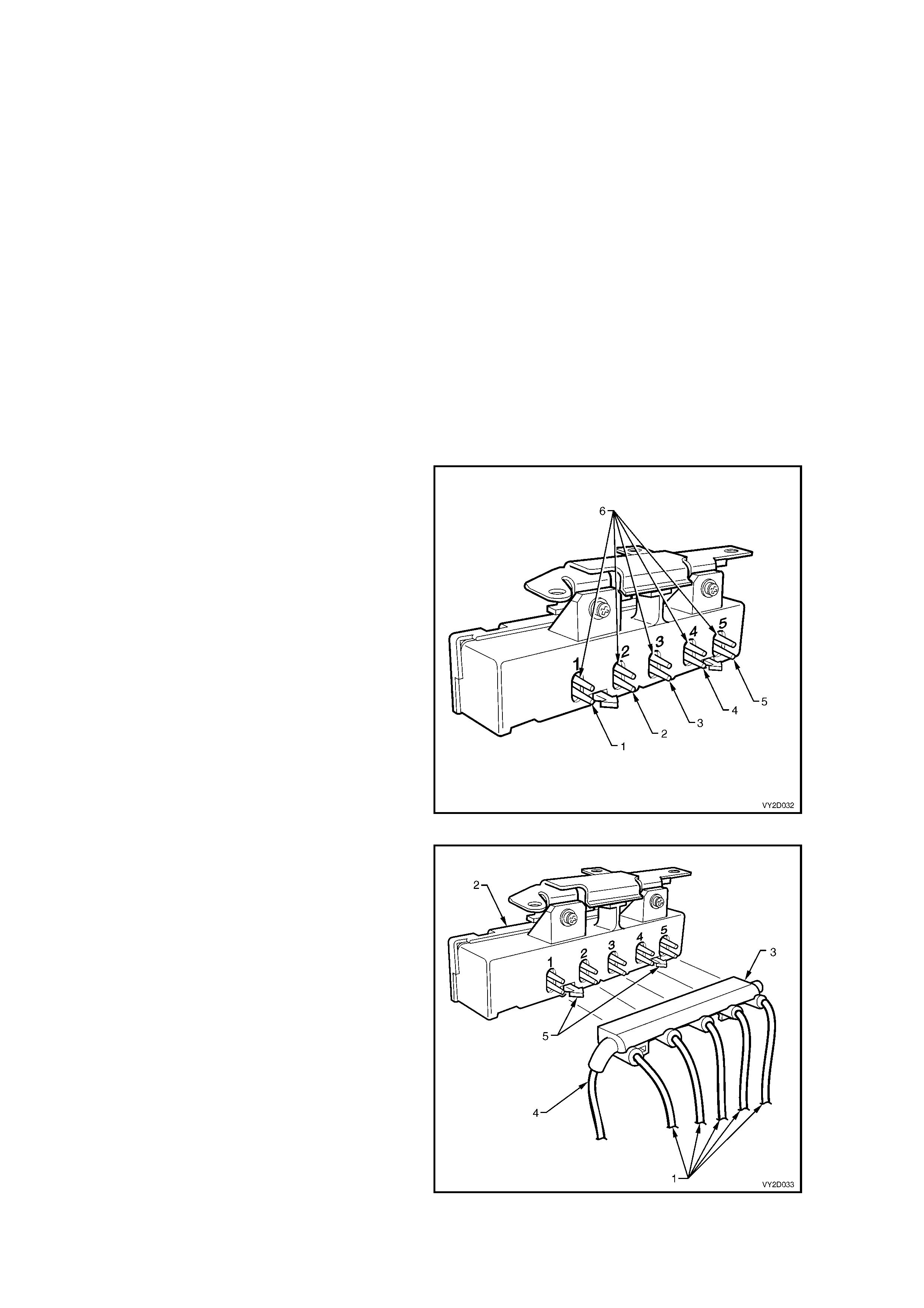
Figure 2D-61 shows the solenoid outlets from the
left-hand drive HVAC vacuum solenoid pack. The
function of the s olenoid connections and the colour
of the attached vacuum lines are listed below:
Legend
1. Foot (Red)
2. Demist (Green)
3. Face 2 (Brown)
4. Face 1 (Blue)
5. Fresh/Recirculation (Yellow)
6. Vacuum Supply (White)
Figure 2D-61
All actuator vacuum hoses (1) at the solenoid pack
(2) are permanently connected to a common, soft
plastic m anifold (3) , which is installed to the f ront of
the solenoid pack.
The white hose (4) at the left-hand side of the
manifold is the vacuum supply line from the
vacuum tank and is also permanently connected.
The manifold is locked into its installed position by
two retaining tangs (5) protruding fr om the so lenoid
pack housing.
Figure 2D-62
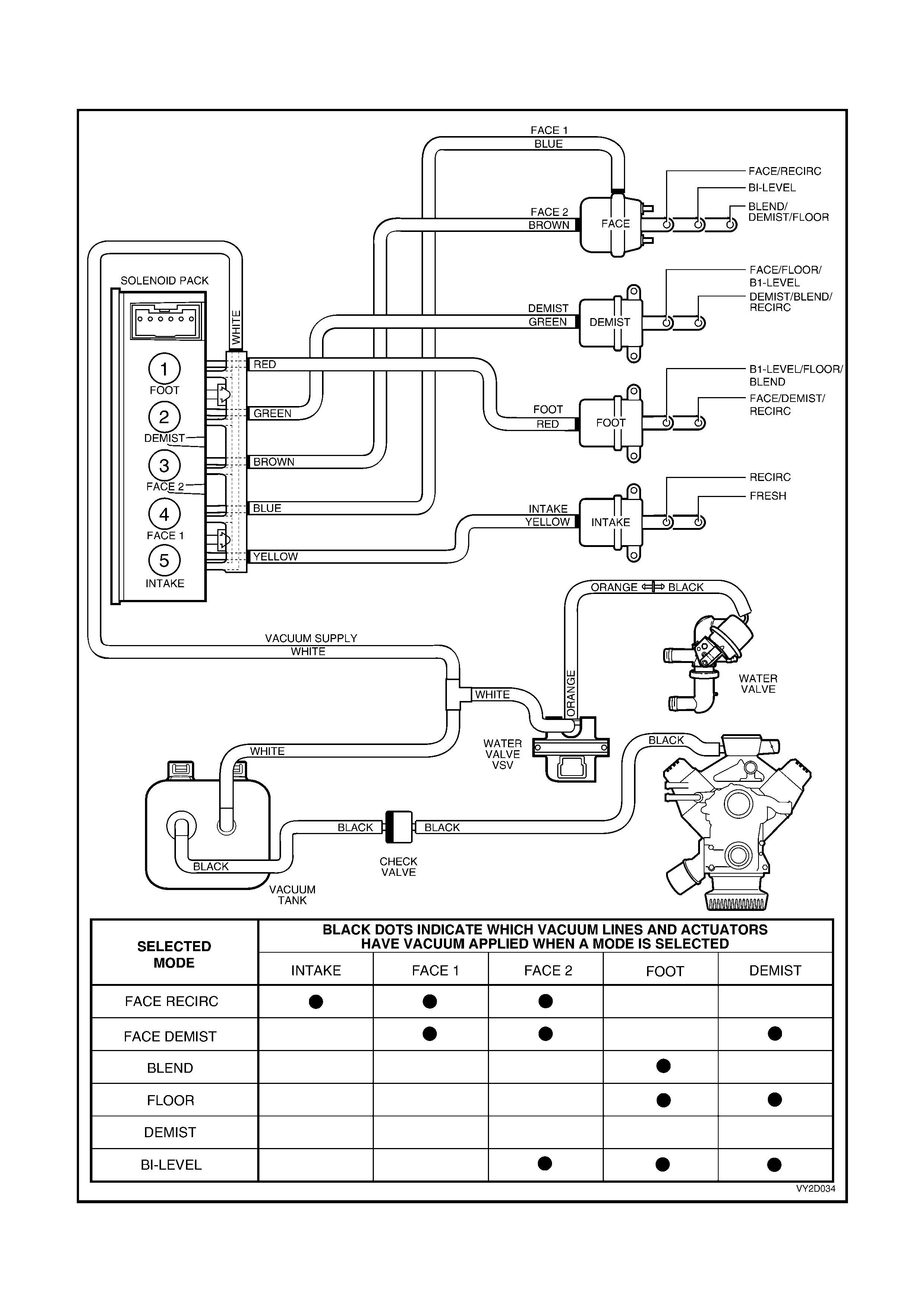
VACUUM CIRCUIT SCHEMATIC – LEFT-HAND DRIVE
Figure 2D-63 shows, which vacuum actuators are applied with vacuum in a certain mode.
Figure 2D-63
SOLENOID PACK AND VACUUM LINES - RIGHT-HAND DRIVE
The vacuum generated within the engine inlet manifold is used to operate the HVAC vacuum actuators and the
water valve.
A vacuum tank located on the left-hand side of the HVAC unit is used to store vacuum for times when engine
vacuum is low such as at full engine throttle. A check valve is fitted on the supply line between the inlet manifold and
the vacuum tank to ensure that vacuum is maintained within the system at all times.
A six solenoid vacuum solenoid pack is used to direct vacuum to the vacuum actuators and the water valve The
solenoid pack is connected to the vacuum tank through a black plastic vacuum hose. The OCC control module
turns the solenoids on and of f to direct vac uum to the vacuum actuator s and water valve when required. T his alter s
the position of the water valve and the various doors within the HVAC unit to bring about the desired heating,
demisting or cooling affect.
Vacuum is vented f r om the vacuum actuator /plast ic hos e onc e an OCC c ontr ol module m ode s witch or temperature
switch is used to select a different setting. When vacuum is applied to the water valve, the valve remains closed and
no water will flow through the heater core.
For water valve control, vacuum is directed to the yellow coloured plastic hose that is connected to a black hose
(inside the cabin at the das h panel), which in turn is connected to the vac uum operated heater water valve. Refer to
Figure 2D-66.
The six vacuum hoses between the solenoid pack and the vacuum actuators are also colour keyed.
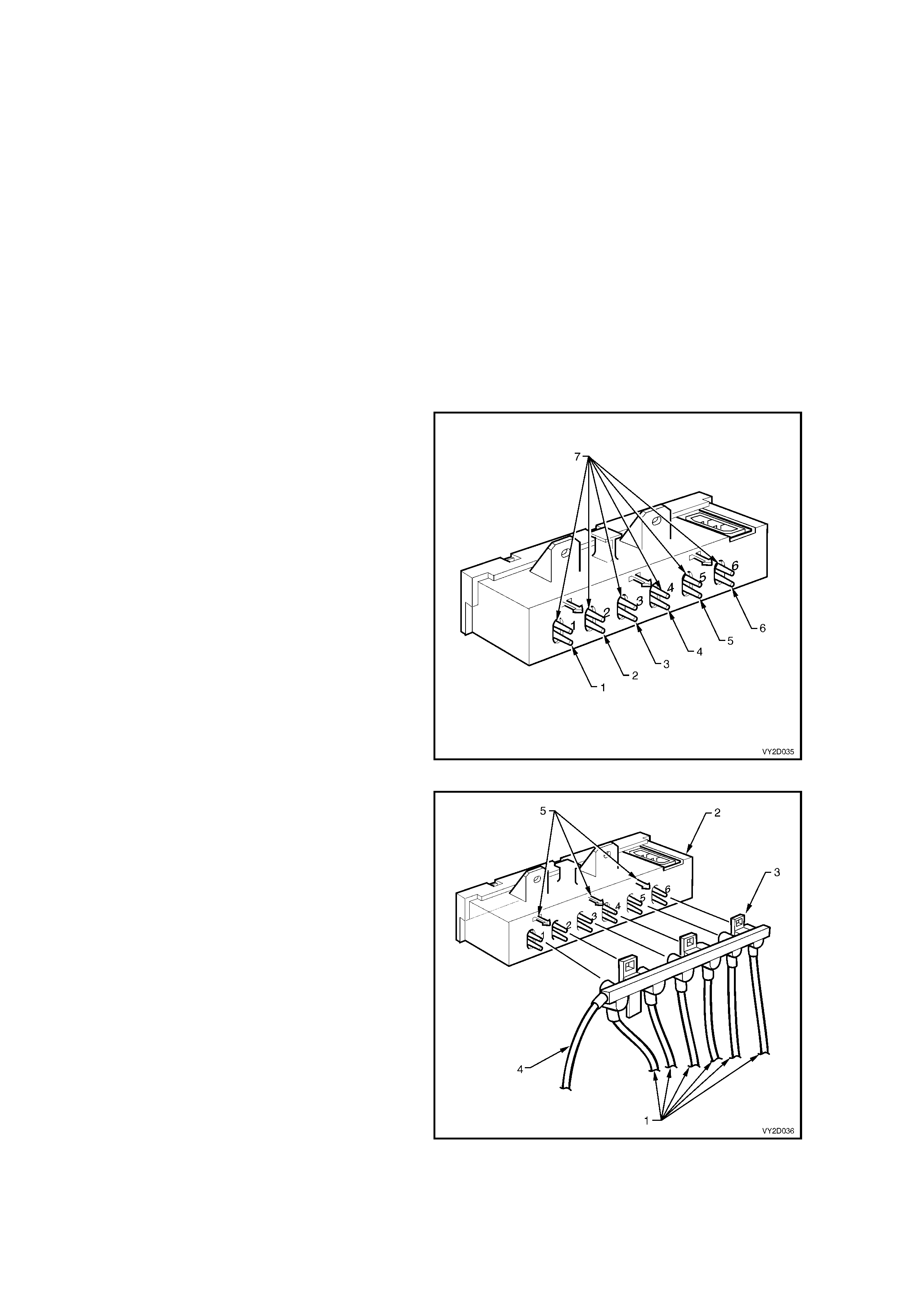
Figure 2D-64 shows the solenoid outlets from the
right-hand drive HVAC vacuum solenoid pack. The
function of the s olenoid connections and the colour
of the attached vacuum lines are listed below:
Legend
1. Fresh/Recirculation (Blue)
2. Face 1 (White)
3. Face 2 (Green)
4. Foot 1 (Pink)
5. Foot 2 (Orange)
6. Water valve (Yellow)
7. Vacuum supply (Black)
Figure 2D-64
All actuator vacuum hoses (1) at the solenoid pack
(2) are permanently connected to a common, soft
plastic m anifold (3) , which is installed to the f ront of
the solenoid pack.
The black hose (4) at the left-hand side of the
manifold is the vacuum supply line from the
vacuum tank and is also permanently connected.
The manifold is locked into its installed position by
three retaining tangs (5) protruding from the
solenoid pack housing.
Figure 2D-65
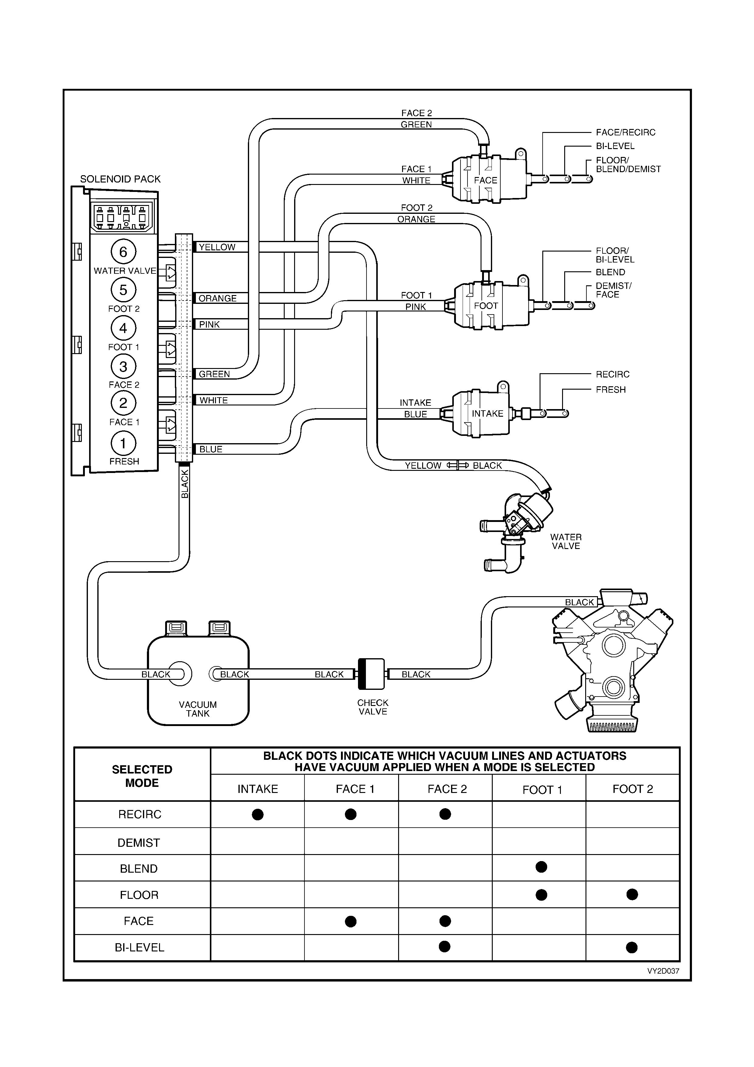
VACUUM CIRCUIT SCHEMATIC – RIGHT-HAND DRIVE
Figure 2D-66 shows, which vacuum actuators are applied with vacuum in a certain mode.
Figure 2D-66

4. OPERATION
The OCC control module uses a microprocessor to monitor inputs, process data and thus control outputs.
The inputs used by the OCC are as follows:
• Serial Data information:
Sunlight level, Priority Key user and Ignition Off time f rom BCM, Engine RPM, c oolant temperature, road speed
and A/C pressure from PCM.
• In-car temperature sensor.
• Ambient temperature sensor.
• Evaporative temperature sensor.
• Air mix potentiometer (PBR) (2 for dual zone systems).
• Ignition Voltage.
• Blower Fan Voltage.
• Customer settings by way of the OCC buttons.
The outputs controlled by the OCC control module controls are as follows:
• Serial Data information:
Sunlight level for Instrument dimming of cruise and Power indicators, A/C request to the PCM.
• Air Distribution Mode – demist, foot, foot and face (bi level), face – by controlling the logic of 4 vacuum
solenoids.
• Vent Air Temperature by controlling the position of the Air mix doors (2 independent doors for dual zone
systems) (between approx. 5°C (with A/C on) and approx. 70°C (with warm engine).
• Air Inlet Mode (i.e. Fresh or Recirculated) by controlling a vacuum solenoid.
• Water valve operation by controlling a vacuum solenoid.
• Blower fan s peed by an analogue signal s ent to the Blower speed controller which am plif ies this signal and thus
controls the blower voltage.
• Maximum Blower relay.
• Rear Window Demist relay.
• OCC LCD screen and LEDs to indicate OCC status.
RECOMMENDED SETTINGS
The customer should be encouraged to use the OCC in full Auto mode (orange Auto LED ON) and a set
temperature of 23°C.
Changing the set temperature to suit dif ferent conditions could cause the OCC to behave differently from what the
custom er expects (eg. setting to 17°C on a hot day could cause the customer to com plain the blower speed is too
high on hot days). This should be discouraged.
EVAPORATOR TEMPERATURE CONTROL
As the A/C system us es a Delphi V5 variable strok e compres sor, there is NO need f or an evaporative tem perature
sensor in the manual A/C system. In the OCC system an evaporator air off sensor does not exist, but is only used to
sense A/C temperature for OCC software calculations, not to cycle the compressor on or off. Anti ice-up is
governed by the evaporator pressure control valve located within the compressor.
BLOWER FAN CONTROL
There ar e s teples s var ying blower fan speeds available in the automatic mode and five speeds in the manual mode.
Manual fifth speed is the same as highest automatic blower fan speed.
When the engine is not running, the actual blower s peed will not be higher than approxim ately fan speed 3, in order
to improve battery life.
AUTOMATIC MODE
The blower speed will vary according to:
• In-car Temperature
• Ambient Temperature
• Sun load
• Driver Set Temperature
• Coolant Temperature
• Air Distribution Mode

If the cabin is at the required temperature, the blower will be at a minimum. An increase in sun load in these
conditions would cause the blower to increase.
If heating of the cabin is required (eg. After a cold night), the blower would gradually increase as the coolant
temperature increased to approximately 70°C. Then, as the In-car temperature increased, the blower would
decrease.
If extreme cooling of the cabin were required, the blower would increase to maximum speed (over about 15
seconds). Then, as the In-car temperature decreased, the blower would also decrease.
If cooling of the cabin is required, an increase in sun load will cause the blower speed to increase. If heating up of
the cabin is required, an increase in sun load will normally cause the blower speed to decrease.
If the air distribution mode changes, (eg. From Face to Face/Floor) the fan speed may also change.
In order to maintain a constant airflow, the blower voltage compensated for:
• Road Speed
• Air Inlet mode
• Ignition Voltage
AIR DISTRIBUTION CONTROL
There are 5 distribution modes that can be selected either automatically or manually. These are:
• Demist
• Blend (Foot/Demist)
• Foot
• Bi-level (Foot/Face)
• Face
AUTOMATIC MODE
The air distribution mode selected will vary according to:
• In-car Temperature
• Ambient Temperature
• Sun load
• Driver’s Set Temperature
• Start Up conditions
If the cabin is at the desired temperature, the OCC will select either Foot/Face of Face (depending on if the cabin
needed to be warmed up or cooled down).
If cooling of the cabin were required, Foot mode may be selected for a short time (A/C purge), followed by Face
mode.
If heating of the cabin is r equired, dem ist m ode would be selec ted until the coolant is warm enough (Demis t Delay),
followed by Foot/Demist. Then, as the In-car temperature increased, the mode should change to Foot/Face.
If heating is requires and the coolant is warm, Foot mode may be selected for a short time (Purge), followed by
Foot/Face mode (or Foot/Demist mode depending on conditions).
AIR INLET CONTROL
W hen recirculate is selected either Manually or Automatically, the OCC will return the Inlet to Fresh Air mode after
approxim ately 40 minutes. T his is to avoid ‘stuf finess ’ in the car. T he c ustom er c an return to r ecirculate by pressing
the recirculate button.
AUTOMATIC MODE
The Air Inlet mode selected will vary according to:
• In-car Temperature
• Ambient Temperature
• Sun load
• Driver’s Set Temperature
• Start Up conditions
• Evaporator Temperature
• A/C Pressure
• Coolant Temperature
If the cabin does not require cooling or A/C is Off, Fresh air will be selected.

If extreme cooling of the cabin were required, Fresh maybe selected for a short time (Fresh Delay), then
Recirculation mode will be selected until the cabin has cooled down sufficiently. Then, Fresh air mode will be
selected.
If the cabin needs cooling down, the air mix is at full cold, the evapor ator tem perature is high and the A/C pres sure
is high, Recirculation mode may be selected (ie. heavy traffic on a hot day). Then, as the In-car temperature
decreases to a suitable level, Fresh air mode will be selected.
If the coolant temperature gets very high, Recirculation may be selected to increase the cooling capacity of the
radiator.
VENT AIR TEMPERATURE CONTROL
The vent temperature will vary between approximately 5°C (with A/C on and Air mix door at minimum) and
approximately 70°C (with 90°C coolant and Air mix door at maximum).
MANUAL MODE
If the Set temperature is set to C, the air mix door will be set to minimum.
If the Set temperature is set to H, the air mix door will be set to maximum.
AUTOMATIC MODE
When a Set temperature of between 17°C and 30°C is selected, the Vent Air Temperature will be controlled
automatically.
The Vent Air Temperature will vary according to:
• In-car Temperature
• Ambient Temperature
• Sun load
• Driver’s or Passenger’s Set Temperature
W hen the cabin is at the desired temper ature, the average vent air tem perature should be appr oxim ately the sam e
as the set temperature.
If the cabin r equires cooling, the OCC will try to control the Vent tem perature to less than the Set tem perature. T he
more cooling required, the lower the vent temperature should be.
If the cabin r equires heating, the OCC will try to control the Vent temper ature to be mor e than the Set temperatur e.
The more cooling required, the higher the vent temperature should be.
Generally, the Automatic blower will be at a fairly low level (less than 50%) before the OCC starts to control the
temperature. (eg. W hen extreme cooling is required, the blower will start on maximum and the Air mix will start at
minim um . As the cabin cools down the blower will decrease gr adually, while the Air m ix will stay at m inimum , then,
when the blower is approximately 40%, the air mix door maybe opened to turn the water valve on. Then as the
cabin keeps cooling down, the blower is gradually decreased as the vent temperature is increased).
Increasing the Set temperature will increase the vent temperature (provided air mix is not at maximum).
Decreasing the Set temperature will decrease the vent temperature (provided air mix is not at minimum).
As the In-car temperature increases the vent temperature will decrease.
As the In-car temperature decreases the vent temperature will increase.
As the Sun load increases the vent temperature will decrease.
As the Sun load decreases the vent temperature will increase.
As the Ambient temperature increases the vent temperature will decrease.
As the Ambient temperature decreases the vent temperature will increase.
The OCC controls the Air mix position to achieve the required vent temperature, compensating for:
• Evaporator Temperature
• Coolant Temperature
• Inlet Mode
• Air Distribution Mode
OCC COLD START-UP ROUTINES
There are four cold start-up routines incorporated in the OCC system logic to cater for various conditions on first
starting the vehicle, typically at low ambient temperatures.
Each routine has its own respective set or criteria to satisfy before the routine is executed:
Recirculation delay: Automatically defaults to recirculation mode to prevent cold air from entering the vehicle
interior.
Demist delay: To eliminate cold air at floor during warm-up and prevents the driver’s breath from fogging front
windscreen.

Purge: Allows coolant to heat-up the heater core and avoid humidity to face/windscreen when the blower fan is
activated.
A/C Purge: To avoid hot air blowing on face when the blower fan is activated.
Fresh delay: Uses cooler outside air to purge hot air from the vehicle.
SENSOR MALFUNCTION INDICATOR
If a sensor open circuits due to an electrical connector disconnection or damaged wiring, an X symbol will appear on
the right-hand side of the OCC control module LCD display. This X symbol will disappear once the problem has
been rectified.
DEFAULT MODE: VACUUM LEAK
W hen a leak is apparent in the vacuum system, the air direction will automatically default to demist and fresh air.
Refer to DEFAULT MODE – LEFT-HAND DRIVE or DEFAULT MODE – RIGHT-HAND DRIVE as applicable, in
this Section for further information.
AUTOMATIC OPERATION
In f ully automatic mode, the micropr oc ess or uses the s unlight, in-c ar temperature, ambient temperature, evapor ator
temperature and customer set temperature to decide and control the amount of blower voltage, and the air inlet
mode.
• The Auto button contains an Orange LED.
Auto LED ON: indicates the OCC is in full Auto mode
(i.e. all functions are controlled automatically).
• The Auto LED OFF: indicates the OCC is in par t Manual mode (i.e. at leas t one function is not being controlled
automatically).
Any or the Auto functions can be manually overridden by pressing the appropriate button.
NOTE: If one function has been selected manually, other functions still operate automatically.
The OCC uses the in-car temperature sensor, the ambient temperature sensor, the sun load input from the BCM
and the ‘s et’ tem perature to determ ine if the c abin needs to be warmed, c ooled or maintained. T he following tables
provide examples of what the OCC system will attempt under various conditions:
If the cabin is ‘Just Right’, the OCC will try to maintain the cabin temp in the following situations:
SET TEMP IN-CAR
TEMP AMBIENT
TEMP SUN LOAD TYPICAL SITUATION
23°C 25°C 23°C Low Driving for a while on a warm night
23°C 27°C 12°C Low Driving for a while on a cold night
23°C 23°C 23°C Medium Driving for a while on a spring afternoon
The OCC will try Cooling Down the cabin in the following situations:
SET TEMP IN-CAR
TEMP AMBIENT
TEMP SUN LOAD TYPICAL SITUATION
23°C 40°C 23°C Low Dusk, car has been sitting in the sun
23°C 23°C 23°C High Been driving for a while in early afternoon
sun
23°C 23°C 30°C Low Been driving for a while on a hot night
23°C 55°C 30°C High Car has been sitting in sun on a hot
summers day. Extreme cooling is required
17°C 23°C 23°C Low Driver wants to cool down quickly.
The OCC will try Heating Up the cabin in the following situations:
SET TEMP IN-CAR
TEMP AMBIENT
TEMP SUN LOAD TYPICAL SITUATION
23°C 15°C 15°C Medium Morning drive after a cool night
23°C 20°C 20°C Low Early morning drive after a mild night
23°C 23°C 10°C Low Been driving for a while on a cold night
23°C 5°C 5°C Low Morning drive after a cold night.
Extreme heating is required
30°C 25°C 20°C Low Driver wants to warm up quickly.
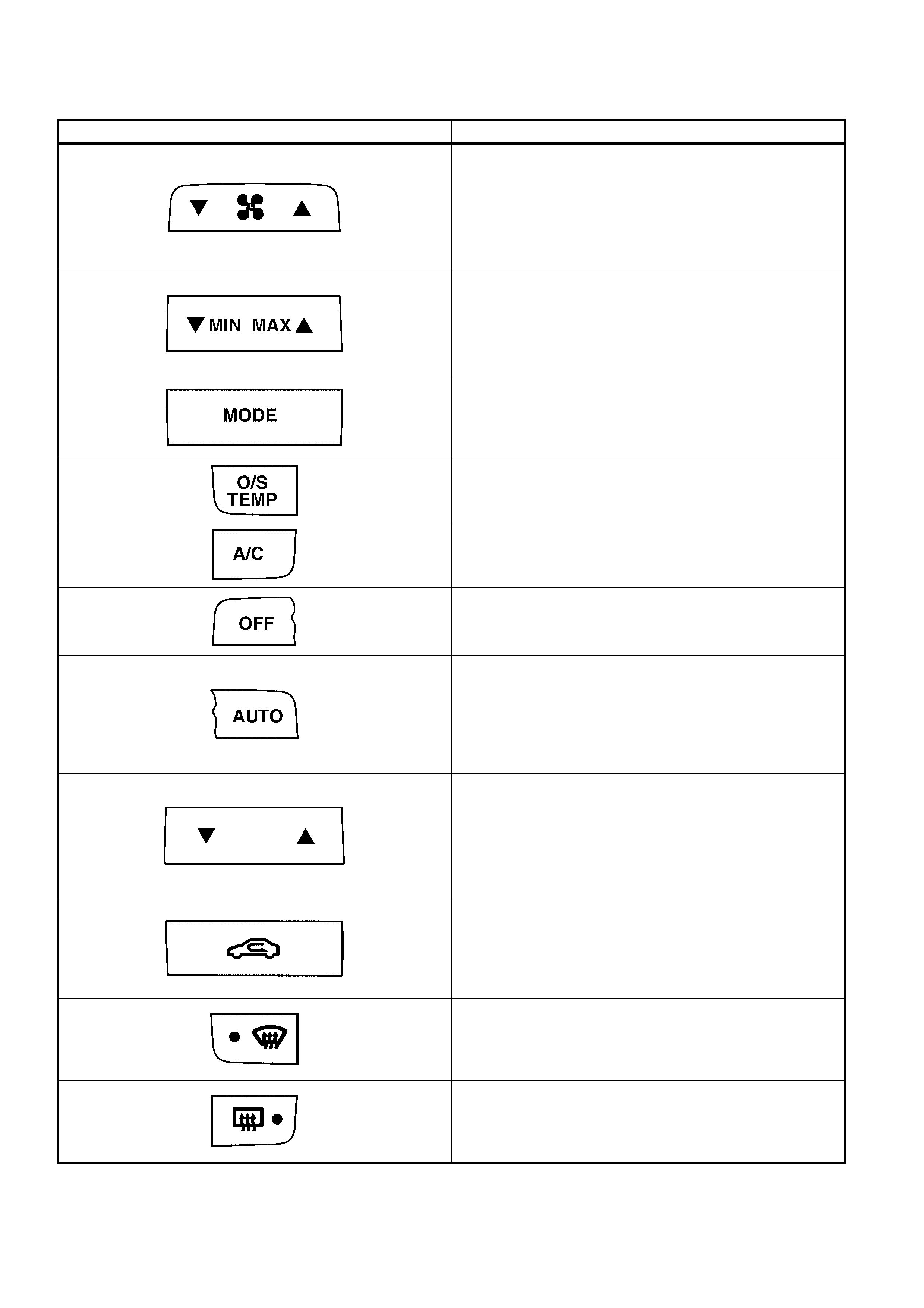
OCC SYSTEM ACTIVATION
The following table provides a summary of button functions:
BUTTON FUNCTION
BLOWER FAN
Manual operation – 5 speed
Automatic operation – Stepless
G = Speed decrease
F = Speed increase
Will turn on the OCC system when selected.
UNCONTROLLED TEMPERATURE SETTING
Applicable to Single Zone systems only.
G MIN = Uncontrolled cooling
F MAX = Uncontrolled heating
Will turn on the OCC system when selected.
AIR DISTRIBUTION
When selected the OCC system will scroll through
Face, Bi-level, Floor or Blend mode settings.
Will turn on the OCC system when selected.
OUTSIDE TEMPERATURE
Displays Outside Temperature on LCD when held on.
Will NOT turn on the OCC system when selected.
AIR CONDITIONING
Turns A/C system ON or OFF.
Will turn on the OCC system when selected.
OCC SYSTEM OFF
Will turn the OCC system on or off when selected.
AUTOMATIC OPERATION
The OCC system will operate in the AUTOMATIC
mode, automatically controlling the blower fan speed,
air distribution, air inlet function and air outlet
temperature.
Will turn on the OCC system when selected.
SET TEMPERATURE BUTTON
Allows cabin temperature selection between 17° and
30°C.
G = Set temperature decrease
F = Set temperature increase
Will turn on the OCC system when selected.
RECIRCULAT ION
Prevents outside air entering the vehicle cabin when
activated. Function can be selected whether OCC
system is on or off when ignition is on.
Will NOT turn on the OCC system when selected.
WINDSCREEN DEMIST
Directs air to the windscreen. Orange LED illuminates
when activated.
Will turn on the OCC system when selected.
REAR WINDOW DEMIST
Provides rear window heating. O range LED illum inates
when activated.
Will NOT turn on the OCC system when selected.
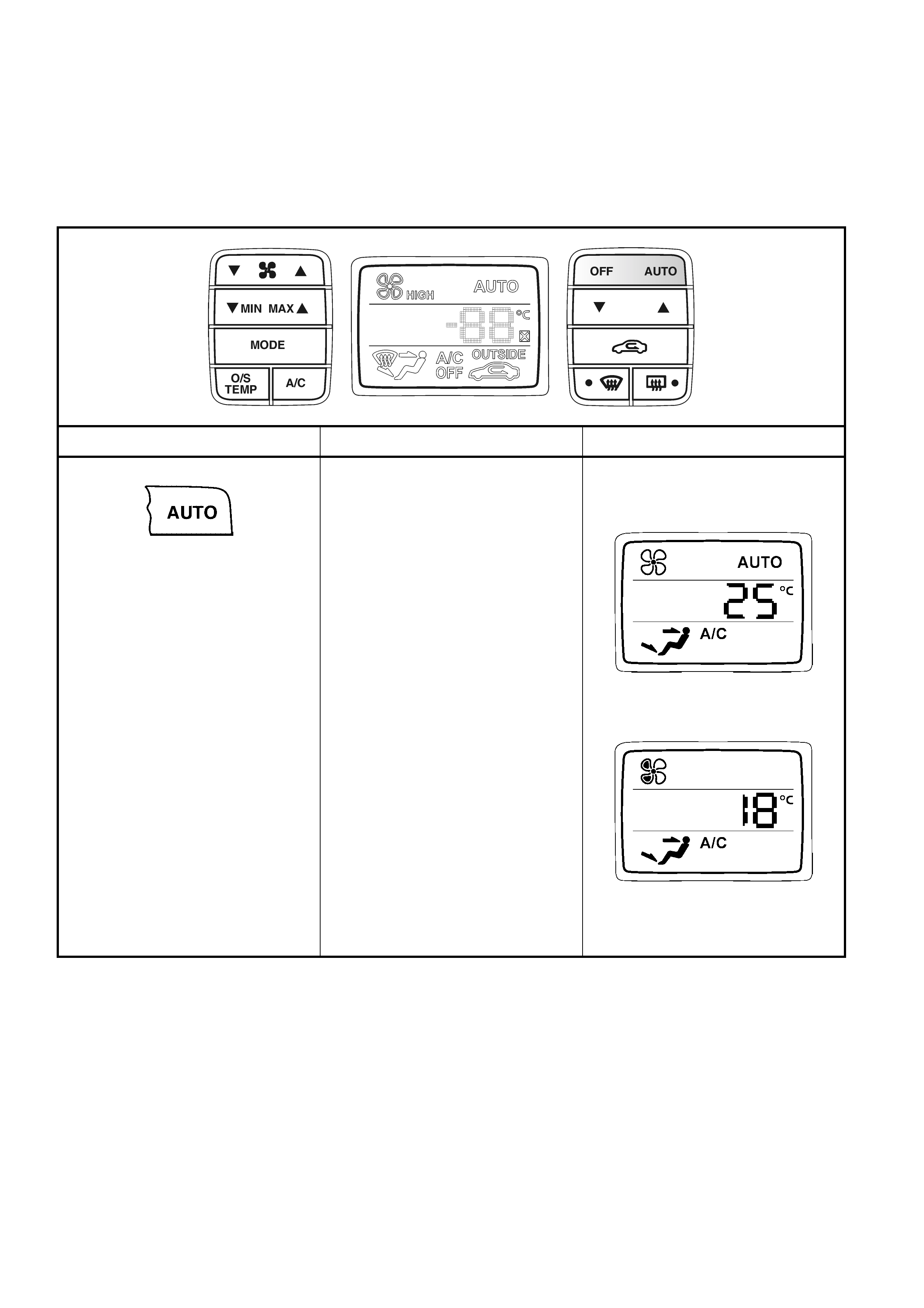
OCC SINGLE ZONE OPERATION
The OCC Single Zone system will function in accordance to the following tables.
Note: On single zone OCC systems the cabin temperature setting will appear on the left-hand side of the LCD on
LHD models and on the right-hand side of the LCD on RHD m odels. All icon and wording locations on the LCD are
common to LHD and RHD models. The graphics in these tables are based on RHD vehicles, i.e. the cabin
temperature setting is shown on the right-hand side of the LCD.
The AUTO and function will operate and provide displays as follows:
BUTTON OPERATION DISPLAY
SELE CTS F ULL AUTOMATIC
CLIMATE CONTROL
AUTOMATIC MODE
• Vehicle interior comfort is
controlled entirely and
automatically by the operation of
the OCC system including blower
fan speeds, heater or A/C
system, air intake and air
distribution. Automatic operation
is indicated by the appearance of
AUTO on the LCD screen.
MANUAL MODE
• This indicates that at least one of
the functions normally controlled
automatically has been
overridden. In this case the
temperature has been manually
reduced with the G side of the
Set Temperature switch. The
OCC processor may increase or
decrease another function to
compensate for the change from
Automatic Mode.
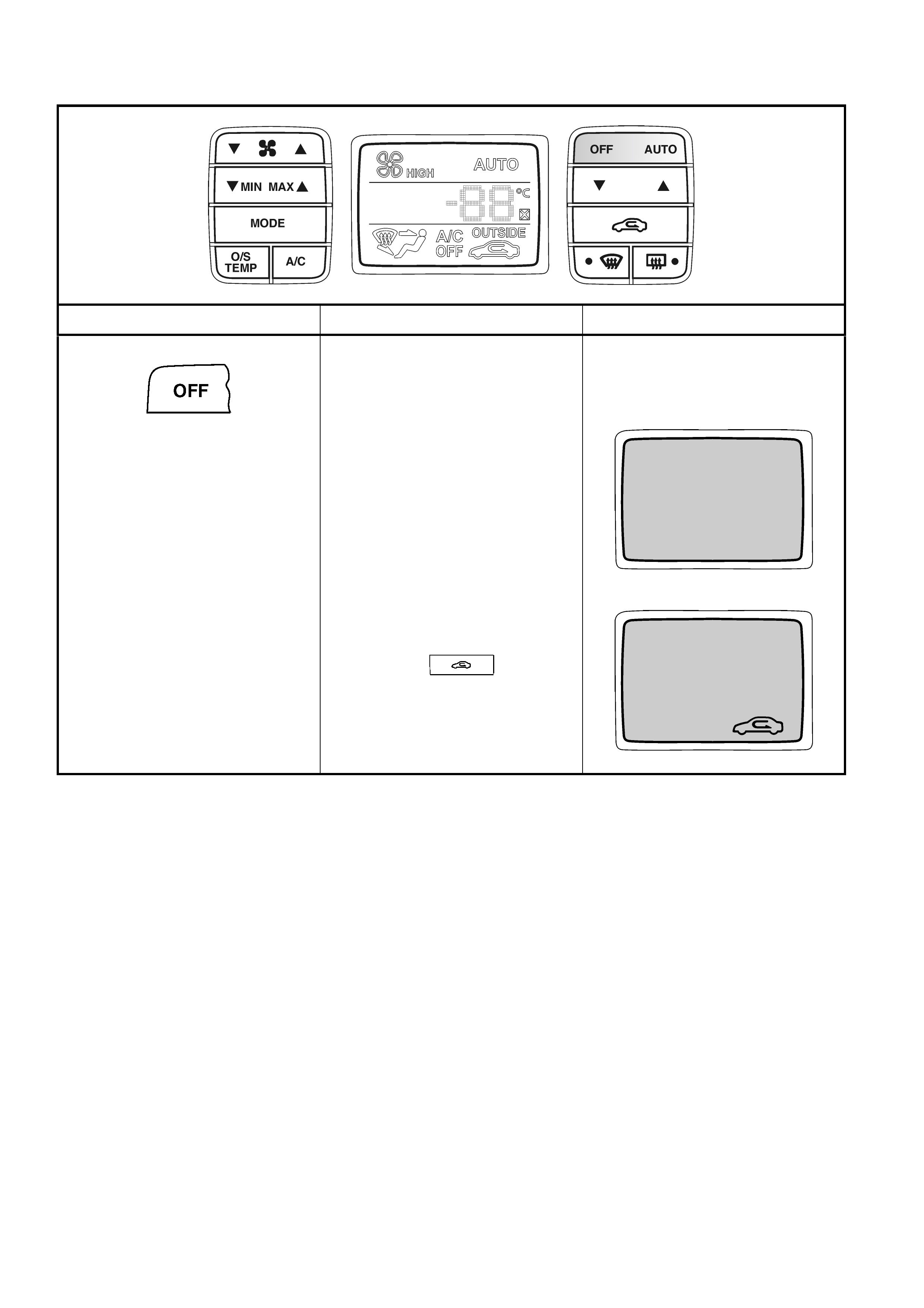
The OFF function will operate and provide displays as follows:
BUTTON OPERATION DISPLAY
TURNS OCC ON and OFF
OFF mode
No LCD screen display
Blower and A/C are off
• Temperature and air distribution
are still controlled automatically
unless manually selected prior to
pressing OCC. System is in
Fresh air mode.
• Recirculated air may still be
selected while the OCC system is
off and the ignition is on, by
pressing the button.
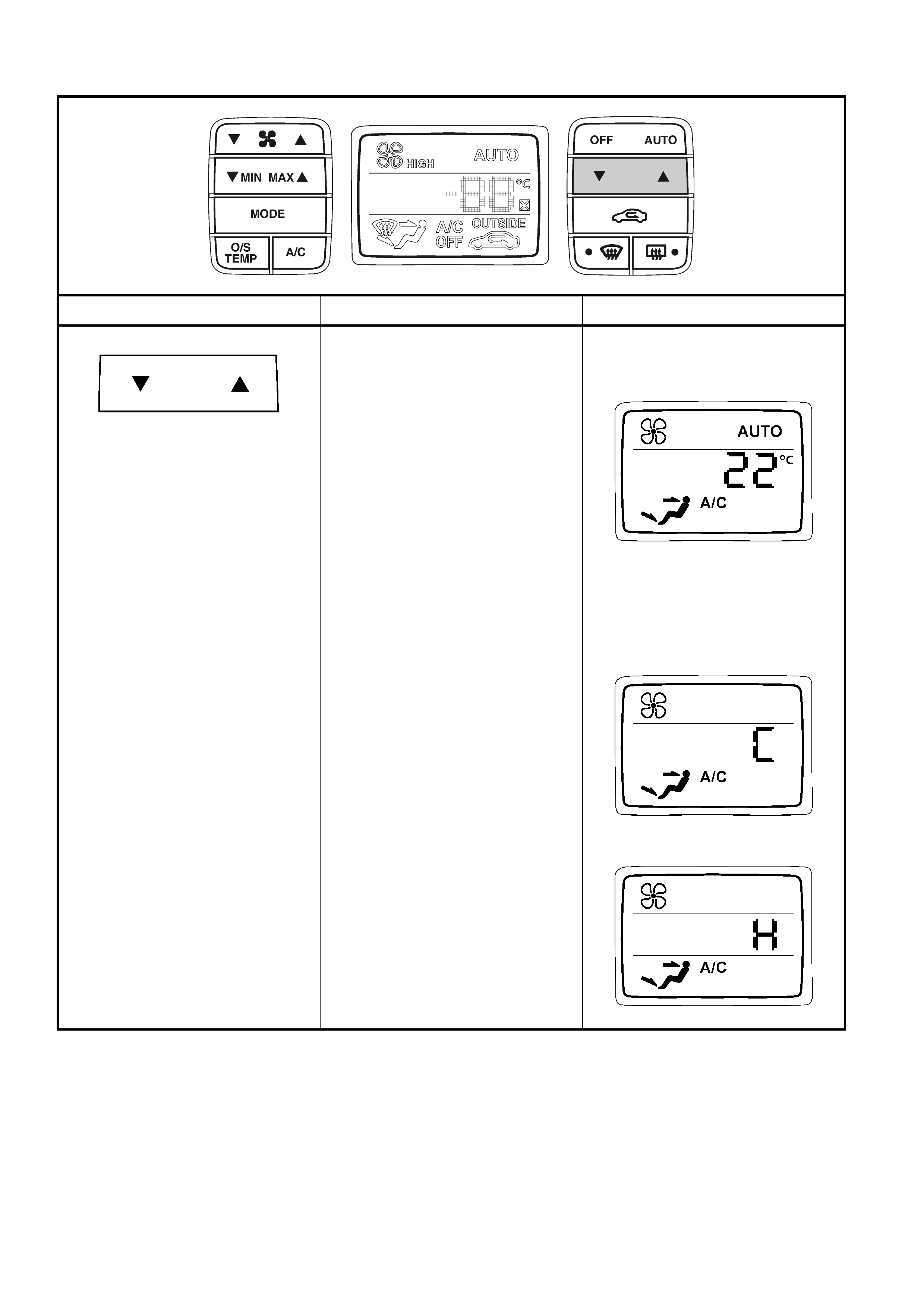
The SET TEMPERATURE functions will operate and provide displays as follows:
BUTTON OPERATION DISPLAY
SELECTS DESIRED INTERIOR
TEMPERATURE
AUTOMATIC MODE
• Use the blue G (cold) side of the
button to decrease the
temperature and the red F (hot)
side of the button to increase the
temperature.
• The set temperature range is
between 17°C and 30°C.
• By tapping the button the set
temperature will increase or
decrease in 1°C increments.
Holding down the button will scroll
the set temperatures.
MANUAL MODE
• When the set temperature is
scrolled lower than 17°C set
temperature, the OCC system
changes to Manual Mode with
full, uncontrolled cooling.
• When the set temperature is
scrolled higher than 30°C set
temperature, the OCC system
changes to Manual Mode with
full, uncontrolled heating.
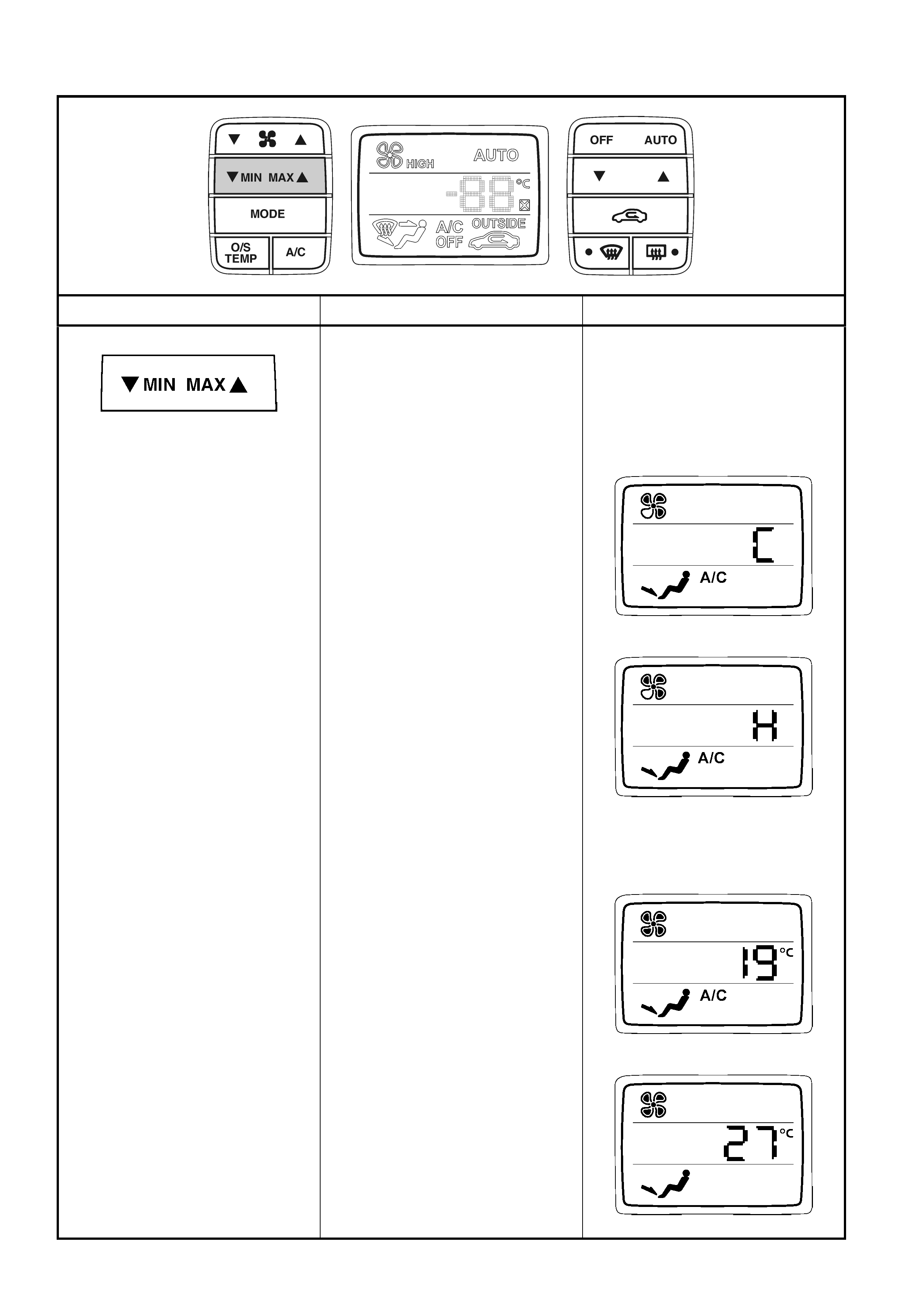
The UNCONTROLLED TEMPERATURE SETTING functions will operate and provide displays as follows:
BUTTON OPERATION DISPLAY
SEL ECTS MINIMUM or
MAXIMUM UNCONTROLLED
TEMPERATURE
• If either side of this button is
pressed the OCC will revert to
Manual Mode.
GMIN = Maximum, uncontrolled
cooling indicated by C (less than
17°C) on the LCD.
MAXF = Maximum, uncontrolled
heating indicated by H (m or e than
30°C) on the LCD
• When the Set Temperature
button is reactivated, the
MIN/MAX letters C or H will
disappear from the LCD screen.
When C is displayed on the LCD
screen, pressing MINF again will
change the OCC system to
previous set temperature.
When H is displayed on the LCD
screen, pressing MAXF again
will change the OCC system to
previous set temperature.
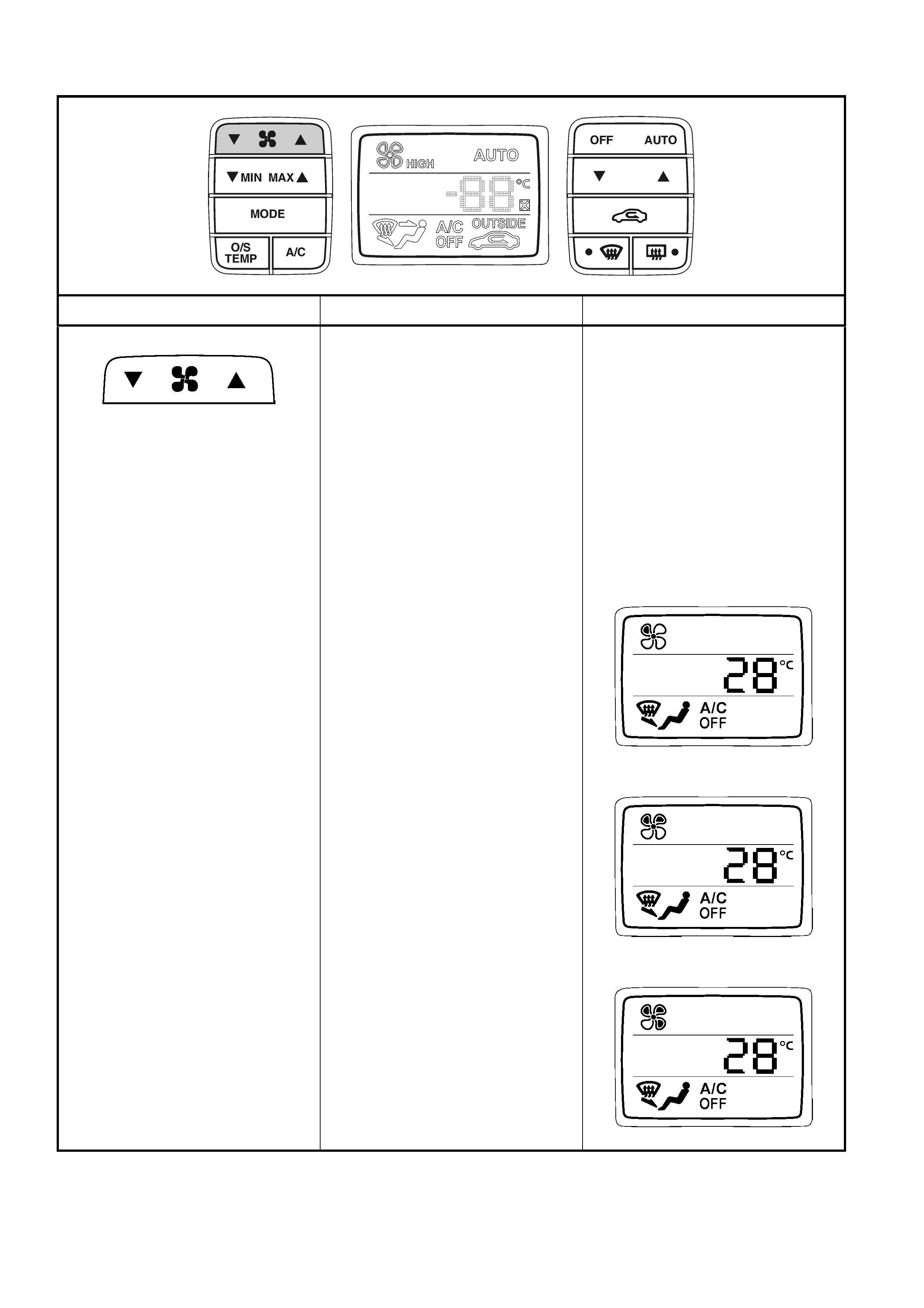
The BLOWER FAN function will operate and provide display s in MANUAL MODE as follows:
BUTTON OPERATION DISPLAY
SELECTS BLOWER FAN SPEED
MANUAL MODE
• Five blower fan speeds are
available.
• The F side of the button
increases blower fan speeds, the
G side of the button decreases
blower fan speeds.
• As the blower fan speeds are
increased the fan blades on the
fan icon darken sequentially.
• The fan cannot be turned off with
this button.
Fan Speed 1
Fan Speed 2
Fan Speed 3
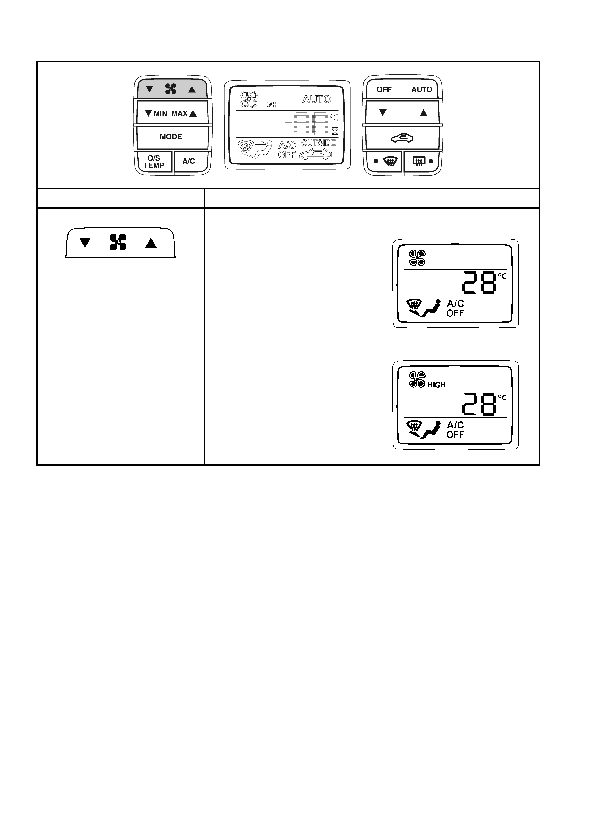
The BLOWER FAN function in MANUAL MODE continued:
BUTTON OPERATION DISPLAY
SELECTS BLOWER FAN SPEED
MANUAL MODE
Fan Speed 4
Fan Speed 5 (HIGH)
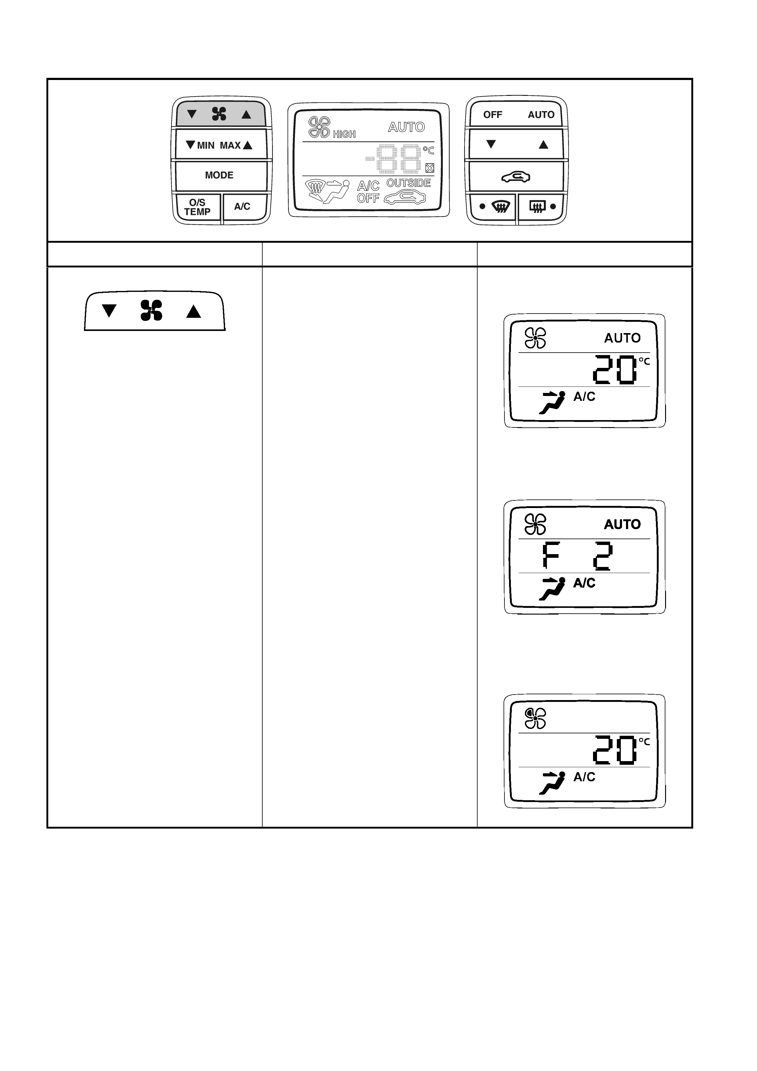
The BLOWER FAN function will operate and provide display s in AUTO MODE as follows:
BUTTON OPERATION DISPLAY
SELECTS BLOWER FAN SPEED
AUTOMATIC MODE
• Blower fan speeds are
automatic ally select ed and infinite
stepless blower speeds are
available
• The highest blower fan speed is
the same as the manual mode
highest blower speed.
• The fan icon on the LCD remains
unchanged during speed
changes.
• While the OCC system is in
Automatic Mode, fan speed can
be altered up or down between
the Fan Speed 1 (F1) and Fan
Speed 3 (F3) inclusive. The LCD
will m omentarily display an F1, F2
or F3 signal with an unfilled fan
icon flashing three times. The
OCC system will then return to
the previous LCD screen display
and will remain in Automatic
Mode.
• When fan speed is selected
beyond Fan Speed 1 (F1) or Fan
Speed 3 (F3), the OCC system
will revert to Manual Mode.
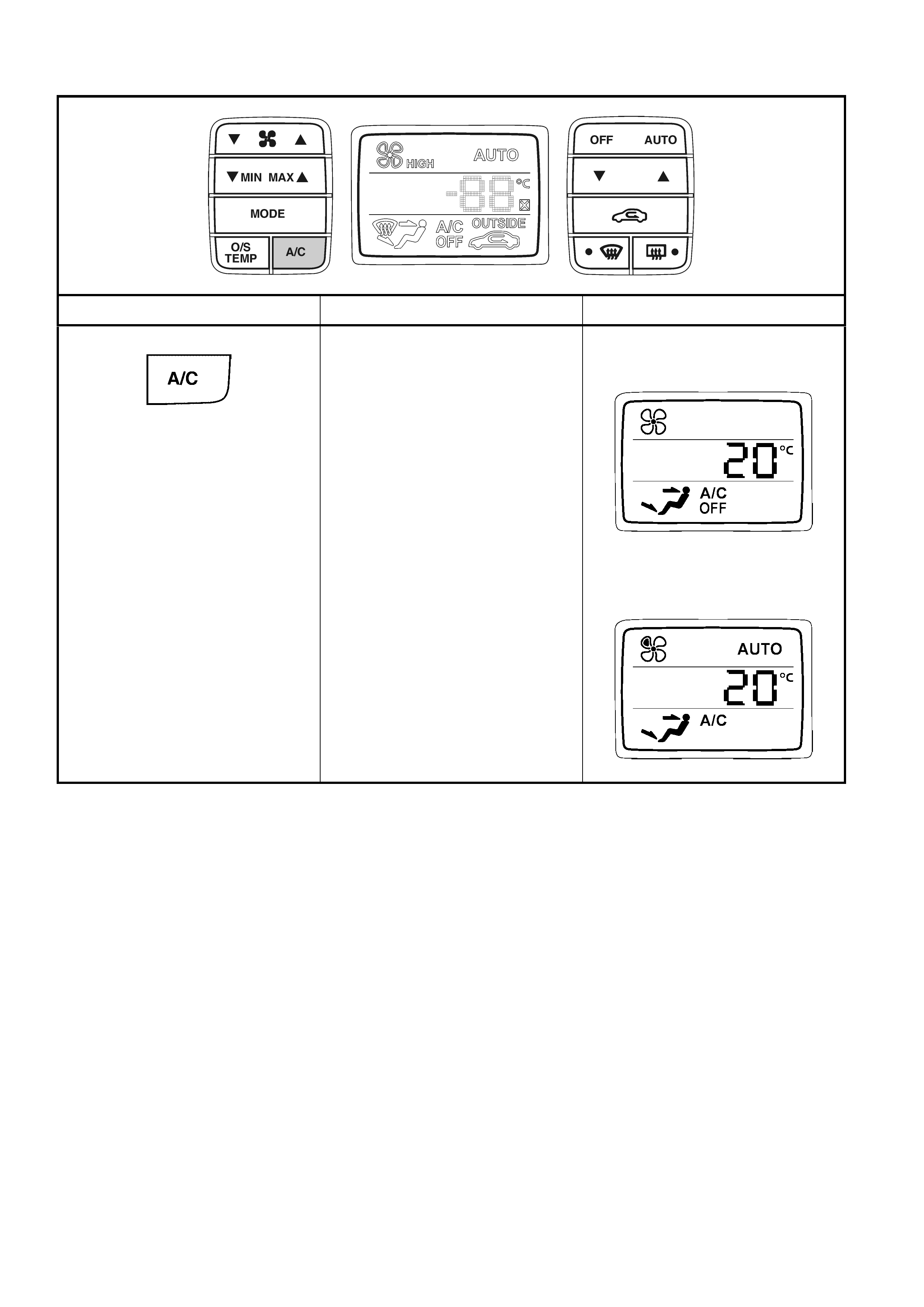
The A/C function will operate and provide displays as follows:
BUTTON OPERATION DISPLAY
SELECTS AIR CONDITIONING
ON or OFF
MANUAL MODE
• A/C OFF – Air conditioning
system disengaged.
AUTOMATIC MODE
• A/C ON – Compressor requested
continually in all set temperature
ranges, provided blower fan is
running.
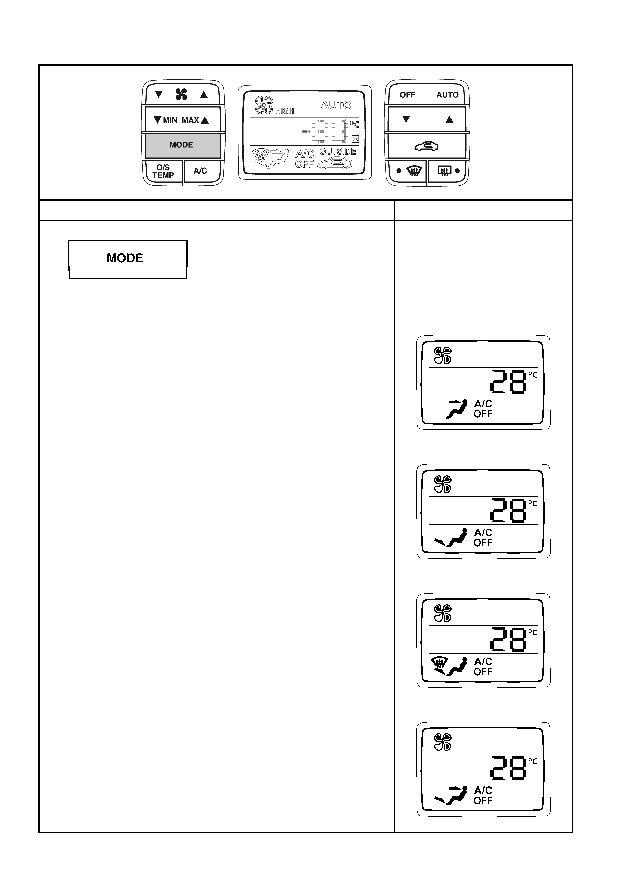
The MODE function will operate and provide displays in Manual Mode as follows:
BUTTON OPERATION DISPLAY
SELECTS AIR DISTRIBUTION
MANUAL MODE
• Pressing the button will select
Manual Mode
• The air direction can be selected
in four different directions in the
following order:
Face – From centre vents and
side vents.
Floor – To floor.
Blend – To windscreen and floor.
Bi-level – From centre vents, side
vents and floor.
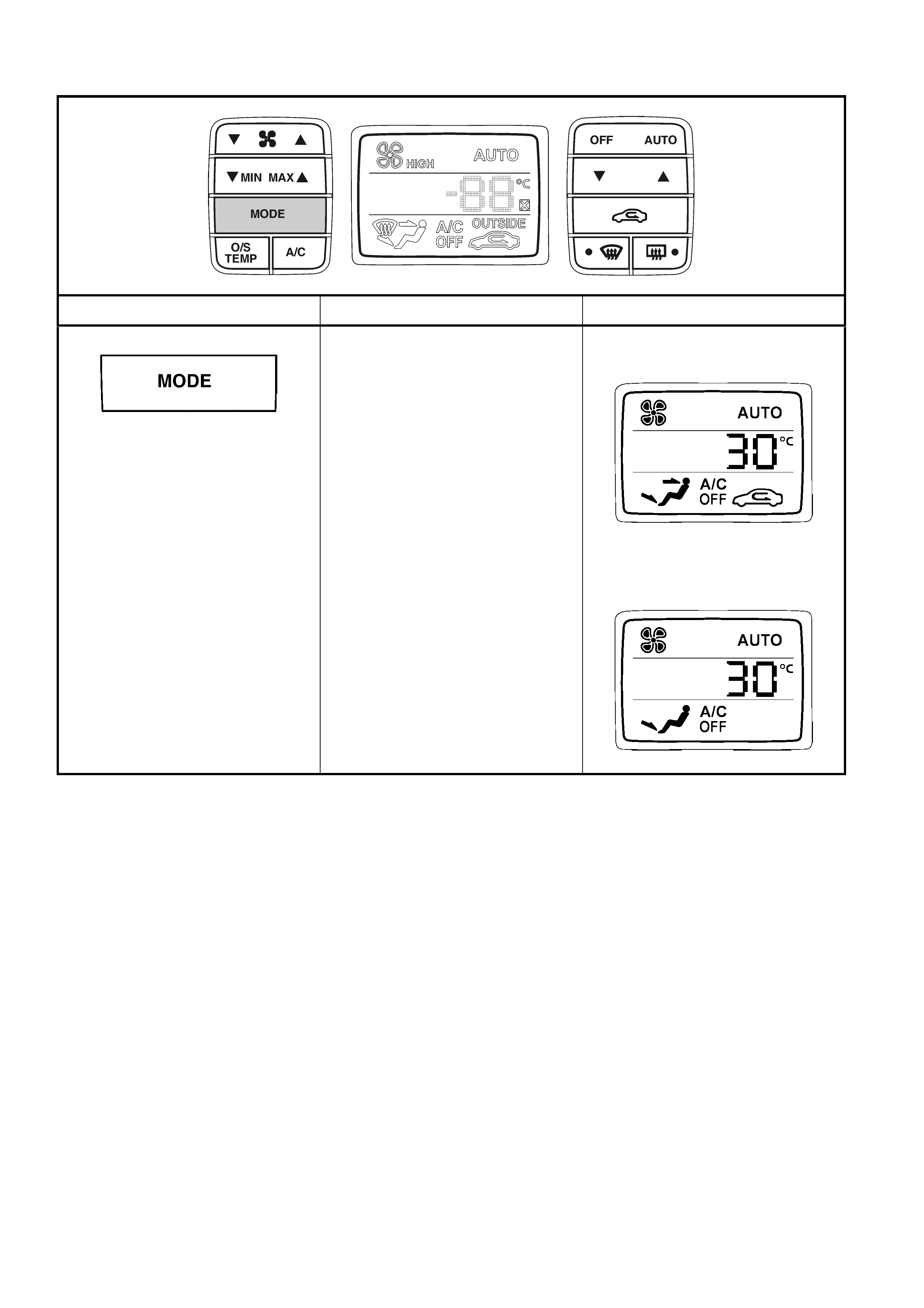
The MODE function will operate and provide displays in Automatic Mode as follows:
BUTTON OPERATION DISPLAY
SELECTS AIR DISTRIBUTION
AUTOMATIC MODE
• In Automatic Mode the outlet air
direction is automatically adj usted
depending on input signals into
the OCC control processor. In
this case the OCC has increased
the fan speed and temperature,
as well as closing off outside air
to bring about a rapid c abin warm
up condition.
• The air distribution icons on the
LCD screen will change when a
different mode is selected.
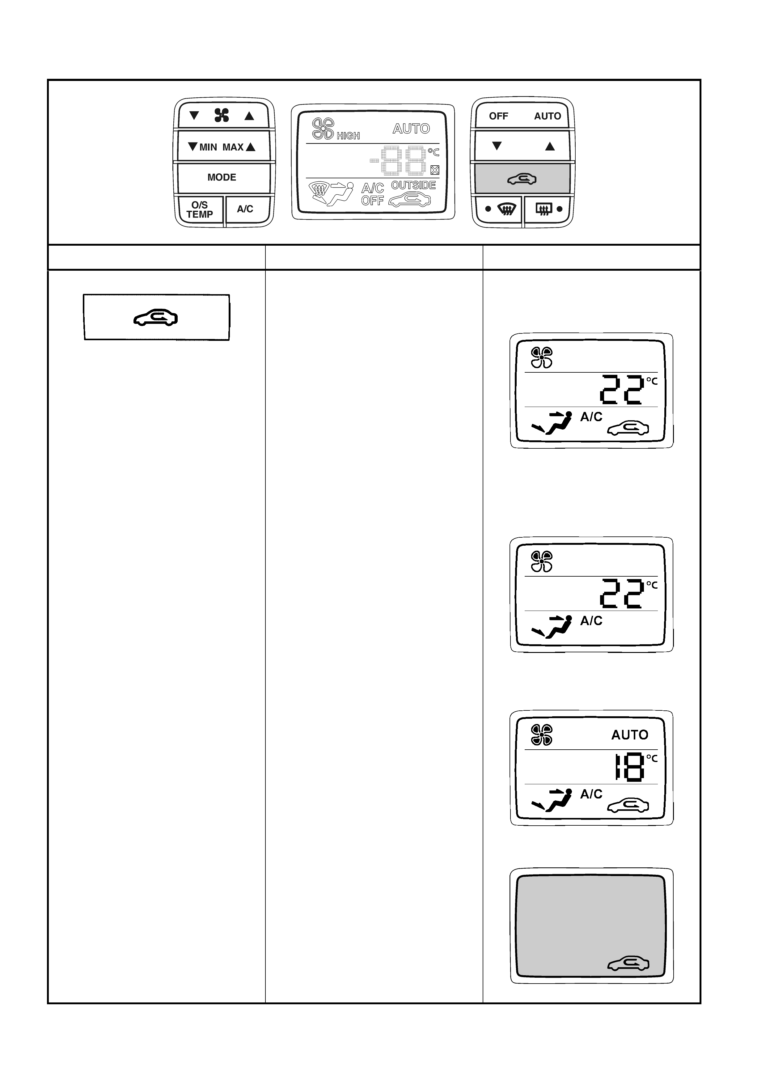
The RECIRCULATION function will operate and provide displays as follows:
BUTTON OPERATION DISPLAY
SELECTS FRESH OR
RECIRCULATED INTAKE AIR
MANUAL MODE
• Pressing the button will select
Manual Mode.
• The recirculation icon will appear
on the LCD screen.
No fresh air enters the cabin.
Note: T his mode is not to be us ed
for extended periods, as the
carbon dioxide level within the
cabin will rise causing
drowsiness.
• Press the button again and
recirc ulation icon is remo ved from
the LCD screen.
Fresh Air mode is operative, and
100% fresh air enters the cabin.
AUTOMATIC MODE
• At extremely high in-car
temperatures or in heavy traffic
on a hot day the OCC control
module will automatically select
recirculation mode to ensure fast
cool down of the vehicle interior,
Normally fresh air mode will be
operative.
OCC System off
• Recirculation mode may still be
selected while the OCC system is
off and the ignition is on. The
LCD will not be illuminated but
the recirculation icon will be
visible on the darkened LCD
when selected.

The WINDSCREEN DEMIST and REAR WINDOW DEMIST functions will operate and provide displays as follows:
BUTTON OPERATION DISPLAY
DIRECTS AIR TO FRONT
WINDSCREEN
• ON – The orange LED is
illuminated and the demist icon
appears on the LCD screen.
• A/C is engaged and Fresh air is
automatically selected.
• OCC is in Manual Mode.
• OFF – Push windscreen demist
button again. The LED is not
illuminated and the dem ist icon is
not displayed on the LCD screen
(unless the distribution mode
operating prior to Demist was
Blend).
• OCC returns to Automatic Mode if
Automatic Mode was operating
prior to Demist,
• or to the last selected air
distribution mode in Manual
Mode.
• The A/C will remain on when the
demist function is turned off.
TURNS ON REAR WINDOW
DEMISTER
• ON – The orange LED is
illuminated. Circuit is
automatically turned off after 15
minutes by the BCM. The button
must be pressed to re-activate
rear window demister, but will
now only remain on for five
minutes before automatically
turning off again. This five m inute
cycle will continue until vehicle is
restarted.
• OFF – The LED not illuminated.
The rear window demist is not
operating.
• This function is not displayed on
the LCD screen and the button will
not turn ON the OCC sy stem.
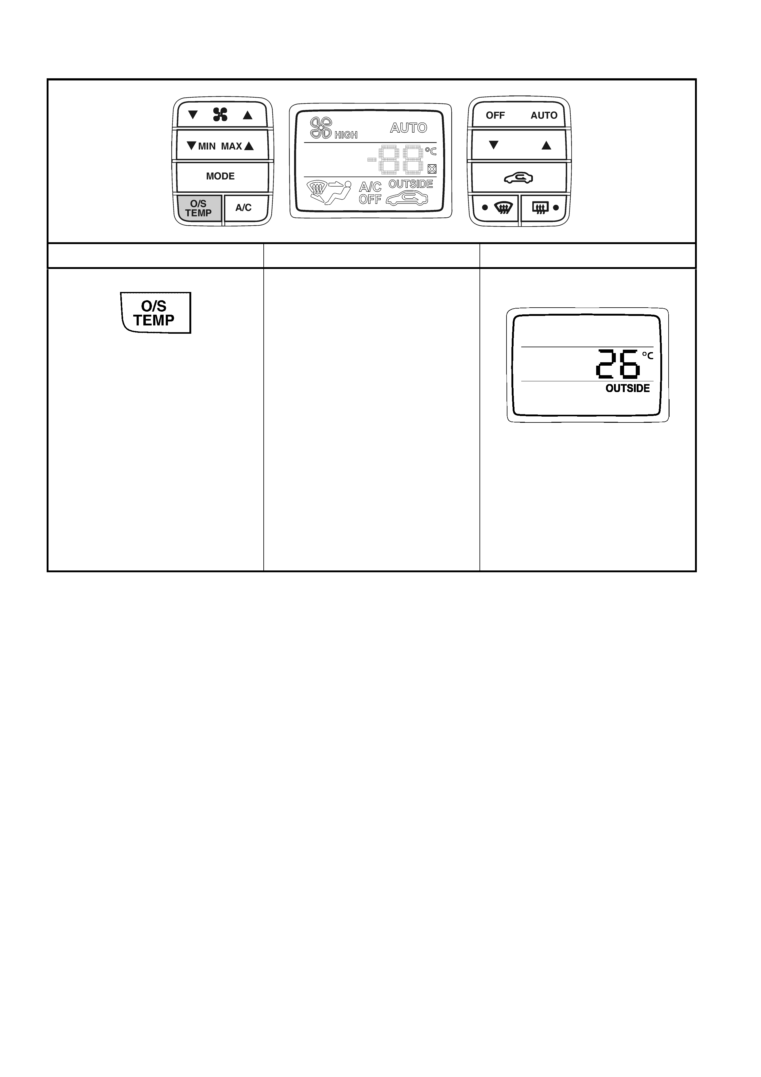
The OUTSIDE TEMPERATURE function will operate and provide a display as follows:
BUTTON OPERATION DISPLAY
DISPLAYS OUTSIDE
TEMPERATURE
• The O/S TEMP is the Outside
(ambient) Temperature.
• The Outside Temperature is
displayed on the right-hand side
of the LCD screen.
• The outside temperature display
can also be activated any time
the OCC is functioning. The LCD
will illuminate and the Outside
Temperature will be displayed on
the LCD until the ignition is tur ned
off or another button is selected
on the OCC control module.
• The outside temperature display
can also be activated with the
OCC turned off and the ignition
turned on.
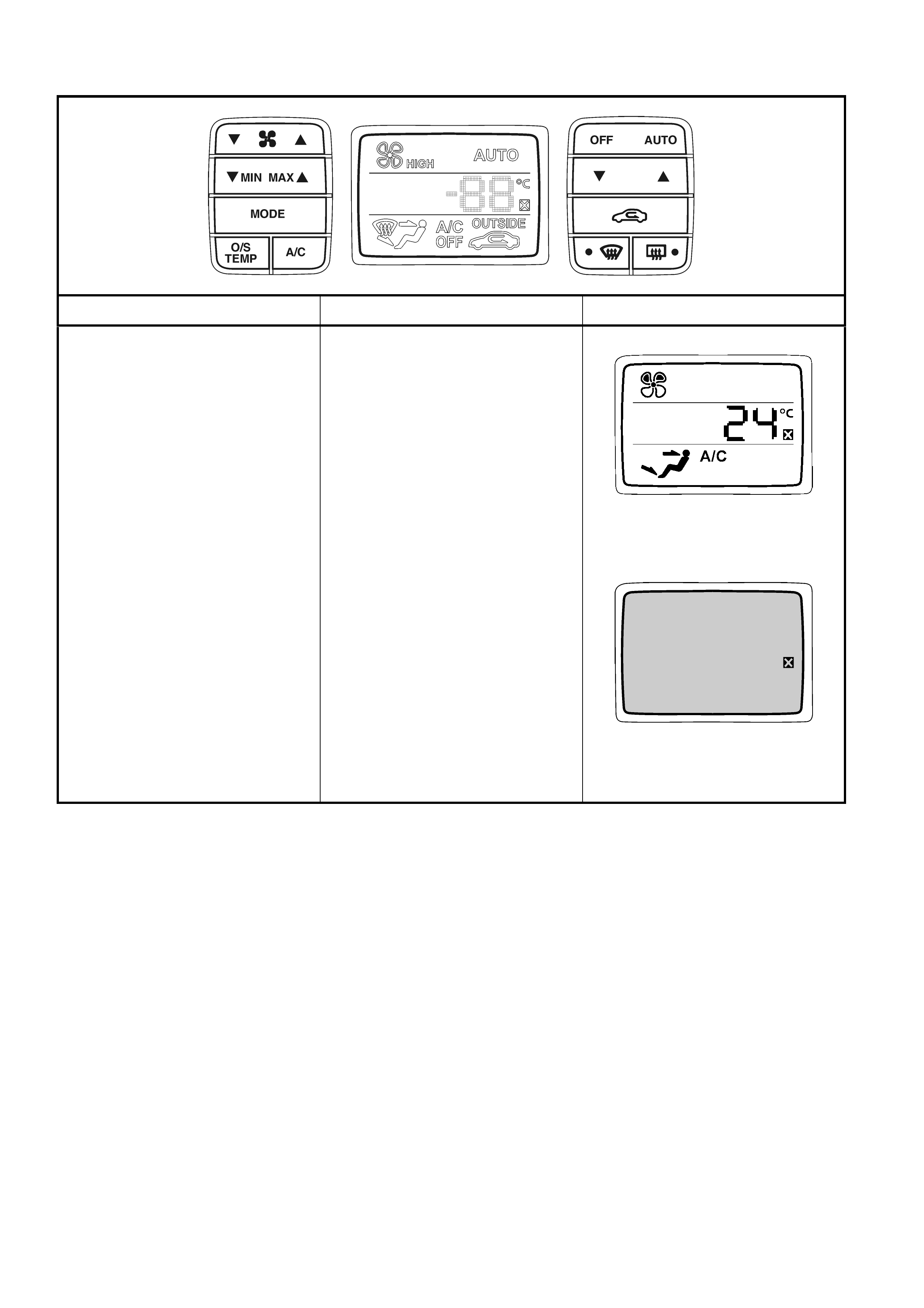
The SELF DIAGNOSTIC function will operate and provide displays as follows:
BUTTON OPERATION DISPLAY
SYSTEM FAULT ICON
• When the X is displayed on the
right-hand side of the LCD
screen, it is an indication that a
fault is present in the OCC
system. The OCC system may
continue to operate.
• Depending on the nature of the
fault, the X fault icon may still be
displayed on the LCD screen
when the OCC system is off and
the ignition is on.
Tech 2 is required for diagnosis of
the OCC system.

OCC DUAL ZONE OPERATION
General Information
The operation of the Dual Zone OCC system is the same as the Single Zone OCC system noting the following:
Link mode
The link mode refers to the mode when the operation of both the passenger and driver air mix motors are
synchronised.
When the driver ‘set’ temperature is changed, likewise the passenger ‘set’ temperature changes to the same value.
To access the ‘link’ mode press and hold the ‘AUTO’ button for more than two seconds.
Unlink mode
This mode is when the passenger sets their desired temperature independent of the driver.
To access the unlink mode press the passenger side temperature button.
NOTE: If the OCC was in link mode this will alter to unlink mode.
Mode control
It is NOT possible for the passenger to alter the m ode positions s uch as Floor, Dem ist, and Centre Vent etc. There
is no individual control. Mode positions will be the same for both passenger and driver.
Fan speed control
As with the mode control it is NOT possible for the passenger to alter the blower fan speeds as an individual
function. O nce the blower speeds have been selected, blower s peeds for both the pass enger and driver will be the
same.

The OCC Dual Zone system will function in accordance to the following tables.
Note: The graphics in these tables are based on RHD vehicles, i.e. the driver’s SET temperature button is on the
right-hand s ide of the m odule and the SET tem perature setting for the driver is shown on the right- hand side of the
LCD.
The driver and the passenger SET TEMPERATURE can be linked as follows:
BUTTON OPERATION DISPLAY
LINKING DRIVER AND
PASSENGER TEMPERATURES
• When the driver and passenger
temperatures are unlinked, the
two different Set Temperatures
will be displayed on the LCD
screen.
• If the driver holds down the AUTO
button for more than 2 seconds,
this will res et the passenger’s Set
Temperature to the same as the
driver’s Set Temperature.
• The A/C state and air distribution
mode may change as well, i.e.
the OCC module assumes full
control of temperature and air
distribution.
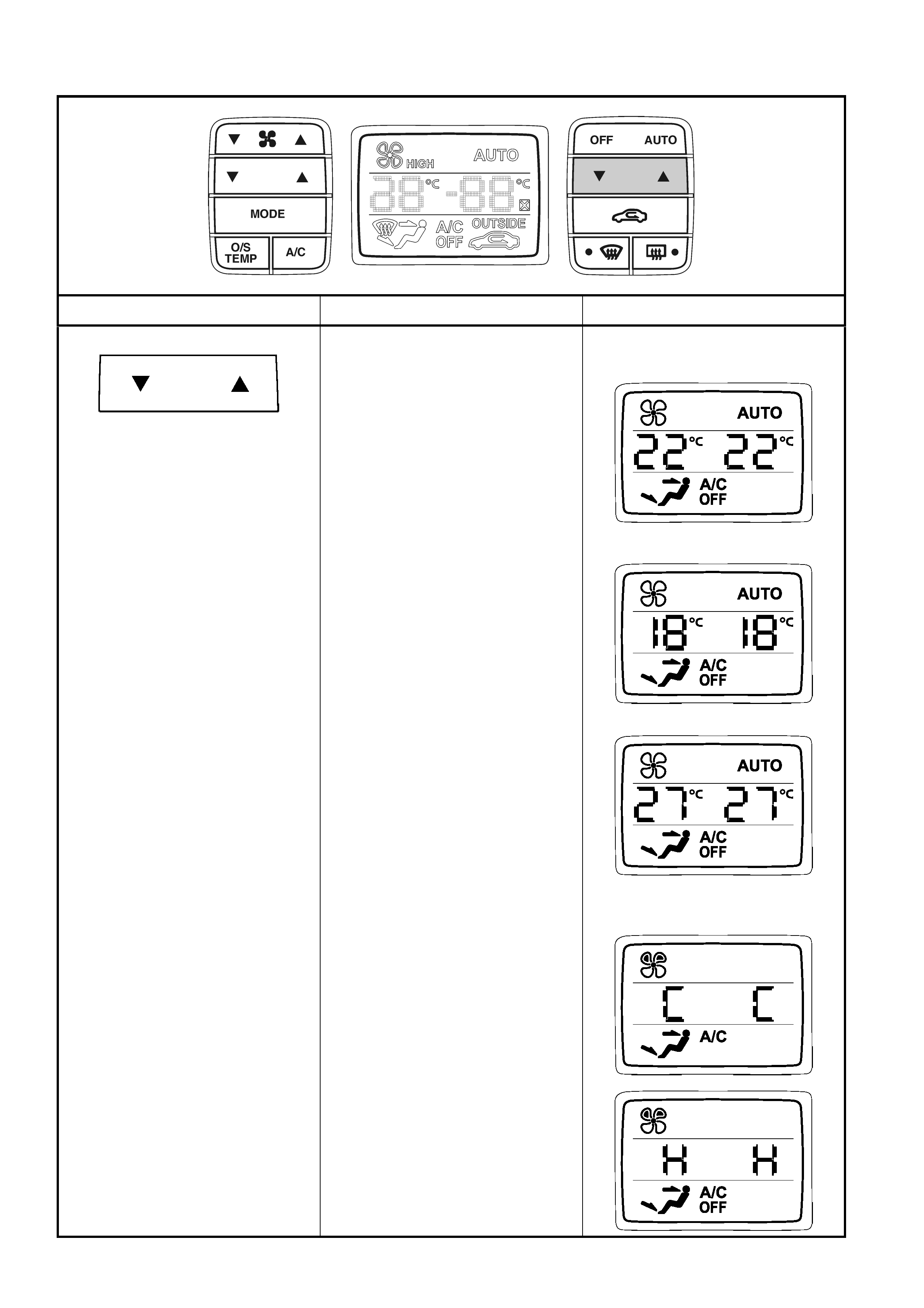
The driver SET TEMPERATURE functions will operate and provide displays in LINK MODE as follows:
BUTTON OPERATION DISPLAY
SET DRIVER AND PASSENGER
TEMPERATURES
AUTOMATIC MODE
• The Set Temperature range is
between 17°C and 30°C.
• Use the blue G (cold) side of the
button to decrease the
temperature.
• Use the red F (hot) side of the
button to increase the
temperature.
• By tapping the button the set
temperature will increase or
decrease in 1°C increments.
Holding down one or other side of
the button will scroll the set
temperatures.
MANUAL MODE
• When the set temperature is
scrolled lower than 17°C set
temperature, the OCC system
changes to Manual Mode with
full, uncontrolled cooling for the
driver and passenger sides.
• When the set temperature is
scrolled higher than 30°C set
temperature, the OCC system
changes to Manual Mode with
full, uncontrolled heating for the
driver and passenger sides.
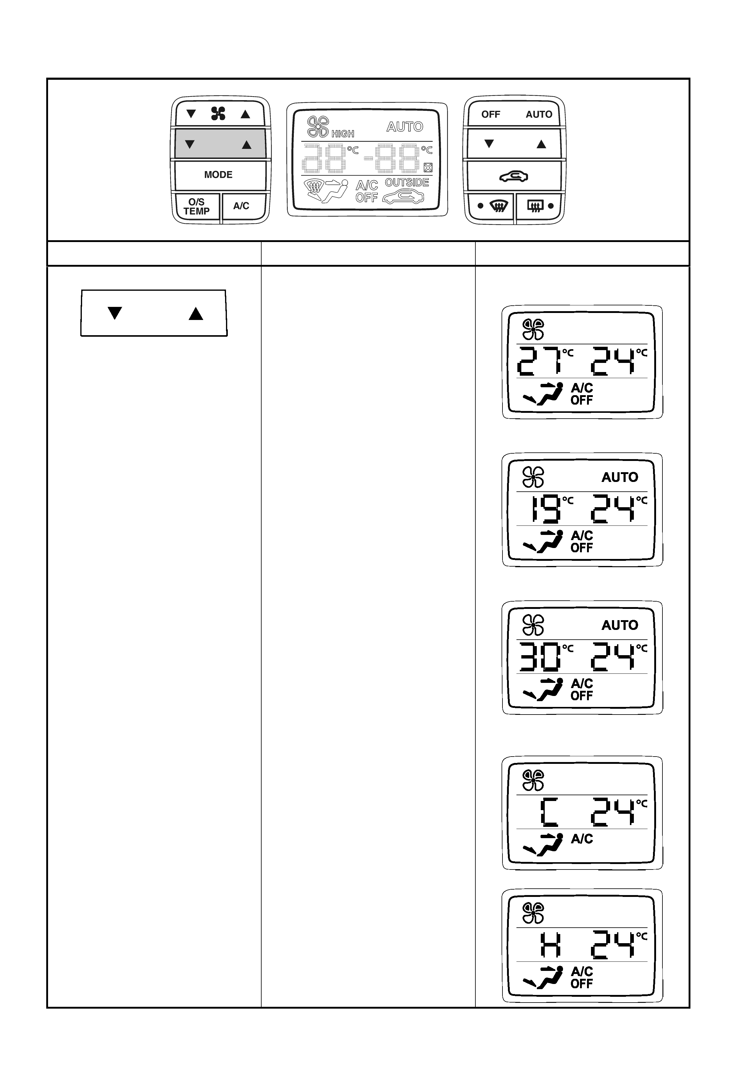
The passenger SET TEMPERATURE functions will operate and provide displays in UNLINK MODE as follows:
BUTTON OPERATION DISPLAY
UNLINKING DRIVER AND
PASSENGER TEMPERATURES
• Any press of the passenger’s
Set Temperature button will
unlink the passenger Set
Temperature from the driver Set
Temperature.
SETTING PASSENGER SIDE
INTERIOR TEMPERATURE
AUTOMATIC MODE
• The set temperature range is
between 17°C and 30°C.
• Use the blue G (cold) side of the
button to decrease the
temperature.
• Use the red F (hot) side of the
button to increase the
temperature.
• By tapping the button, the set
temperature will increase or
decrease in 1°C increments.
Holding down the button will scroll
the passenger’s set temperature.
MANUAL MODE
• When the set temperature is
scrolled lower than 17°C, the
OCC system changes to Manual
Mode with full, uncontrolled
cooling for the passenger’s side.
• When the set temperature is
scrolled higher than 30°C, the
OCC system changes to Manual
Mode with full, uncontrolled
heating for the passenger’s sides.

5. SPECIFICATIONS
GENERAL
Available modes...................................................... Recirculation, face, bi-level, floor, blend and demist
Blower fan speeds
Manual mode ..................................................... 5
Automatic mode................................................. Stepless
HVAC door actuation
Air mix doors...................................................... Electronic/mechanical
Recirculation, face, foot, and demist doors........ Electronic/vacuum
Air conditioning system
Installation.......................................................... Integrated
Type................................................................... TXV (Thermostatic Expansion Valve) non-cycling
Cooling system capacity
V6 and V6 Supercharged................................... 12.0 Litres
GEN III V8.......................................................... 14.3 Litres
Coolant specification
V6 and V6 Supercharged – RHD exc. S. Africa. Conforming to HN2043
V6 – LHD and S. Africa...................................... Conforming to GM6277M
GEN III V8 – LHD and S. Africa......................... Dex-Cool (conforming to GM6277M)
GEN III V8 – RHD exc. S. Africa........................ Extended Life Anti-freeze Coolant (conforming
to GM6277M)
Coolant concentration
V6 and V6 Supercharged................................... 50% water and 50% coolant
GEN III V8.......................................................... 50% water and 50% coolant
WATER VALVE
Type ........................................................................ 4 port, constant flow
Actuation ................................................................. Vacuum
Construction
Porting................................................................ Plastic
Valve and vacuum actuator................................ Metal
Operation
Vacuum applied ................................................. No coolant flow through heater core
Vacuum not applied ........................................... Coolant flow through heater core
HVAC UNIT – LEFT-HAND DRIVE MODELS
Manufacturer........................................................... Denso
Vacuum actuators
Housing material................................................
Face actuator................................................. Metal
Demist actuator ............................................. Metal/plastic
Foot actuator ................................................. Metal/plastic
Intake actuator............................................... Metal/plastic
Rod material....................................................... Metal
No. of single stage actuators.............................. 3
No. of two stage actuators ................................. 1
Air mix function (heater core airflow)
No. of doors........................................................ 2 (unequally sized)
Actuation............................................................ Electronic/mechanical (Air mix motor)
Recirculation mode (inlet/fresh)
No. of doors........................................................ 2 (equally sized)
Actuation............................................................ Vacuum, single stage actuator
Face mode
No. of doors........................................................ 1 (centre pivot)
Actuation............................................................ Vacuum, two stage actuator

Floor mode
No. of doors........................................................ 1
Actuation............................................................ Vacuum, single stage actuator
Demist mode
No. of doors........................................................ 1
Actuation............................................................ Vacuum, single stage actuator
Blower fan assembly
Fan motor wattage............................................. 290 Watts approximately
Fan motor current .............................................. 22.5 ± 2.3 Amps
Fan drum height/diameter.................................. 75 mm X 150 mm
No. of fan blades................................................ 41
In-line fuse rating................................................ 30 Amps
Blower fan resistor assembly resistance
Terminal 1 and 6................................................ 2.9 Ω
Terminal 1 +ve and 3 –ve .................................. 1.5 Ω
Terminal 1 –ve and 3 +ve .................................. 1.5 Ω
Terminal 3 +ve and 6 –ve .................................. 1.5 Ω
Terminal 3 –ve and 6 +ve .................................. 1.5 Ω
Heater core
Design................................................................ Vertical flow, plate and fin
Construction....................................................... Aluminium core and tanks with detachable pipes
No. of tubes........................................................ 22
Core width.......................................................... 150 mm
Core height......................................................... 200 mm
Core depth ......................................................... 30 mm
Evaporator
Design................................................................ Vertical flow, plate and fin
Construction....................................................... Aluminium core and tanks with detachable pipes
No. of tubes........................................................ 19
Core width.......................................................... 290 mm
Core height......................................................... 220 mm
Core depth ......................................................... 90 mm
Vacuum solenoid pack
No. of solenoids ................................................. 5
Solenoid resistance............................................ 89 – 91 Ω
Heater switch valve resistance................................ 93.5 Ω
HVAC UNIT – RIGHT-HAND DRIVE MODELS
Manufacturer........................................................... Air International
Vacuum actuators
Housing material................................................ Plastic
Rod material....................................................... Plastic
No. of single stage actuators.............................. 1
No. of two stage actuators ................................. 2
Air mix function (heater core airflow)
No. of doors........................................................ 2 (unequally sized)
Actuation............................................................ Pinion and crescent gear, and actuating rod
Recirculation mode (inlet/fresh)
No. of doors........................................................ 1
Actuation............................................................ Vacuum, single stage actuator
Rod colour.......................................................... Blue
Face mode
No. of doors........................................................ 1
Actuation............................................................ Vacuum, two stage actuator
Rod colour.......................................................... White

Demist/Floor mode
No. of doors........................................................ 1
Actuation............................................................ Vacuum, two stage actuator
Rod colour.......................................................... Black
Blower fan assembly
Fan motor wattage............................................. 300 Watts approximately
Fan motor current .............................................. 25 Amps
Fan drum height/diameter.................................. 63 mm X 155 mm
No. of fan blades................................................ 59
Blower fan resistor assembly resistance
Terminal 1 and 6................................................ 2.0 Ω
Terminal 1 +ve and 3 –ve .................................. 1.3 Ω
Terminal 1 –ve and 3 +ve .................................. 1.3 Ω
Terminal 3 +ve and 6 -ve................................... 1.0 Ω
Terminal 3 –ve and 6 +ve .................................. 0.9 Ω
Heater core
Design................................................................ Vertical flow, plate and fin
Construction....................................................... Aluminium core and tanks with integral pipes
No. of tubes........................................................ 18
Core width.......................................................... 160 mm
Core height......................................................... 195 mm
Core depth ......................................................... 35 mm
Evaporator
Design................................................................ Vertical flow, plate and fin
Construction....................................................... Aluminium core and tanks with integral pipes
No. of tubes........................................................ 24
Core width.......................................................... 270 mm
Core height......................................................... 215 mm
Core depth ......................................................... 70 mm
Vacuum solenoid pack
No. of solenoids ................................................. 6
Solenoid resistance............................................ 109 – 111 Ω
COMPRESSOR
Manufacturer........................................................... Delphi
Type ........................................................................ Non-cycling, variable stoke
Model – (V6 and V6 Supercharged)........................ V5
Capacity............................................................. 156 cc
Model – (GEN III V8)............................................... V7
Capacity............................................................. 179 cc
Clutch coil resistance
V5....................................................................... 3.5 Ω
V7....................................................................... 3.2 Ω
Clutch plate to rotor clearance ................................ 0.38 – 1.0 mm
Drive belt tension
V6 and V6 Supercharged................................... Automatic
GEN III V8.......................................................... Automatic
REFRIGERANT
Type ........................................................................ R134a
Charge quantity....................................................... 775 – 825 g

AC LUBRICA NT
Type ........................................................................ Poly Alkaline Glycol (PAG) conforming to HN2074
System quantity....................................................... 265 ml
Component replacement compensation quantities
Compressor ....................................................... 220 ml
Filter drier receiver............................................. 15 ml
Condenser.......................................................... 40 ml
Evaporator.......................................................... 50 ml
Blown/ruptured pipe or hose.............................. 40 ml
CONDENSER
Manufacturer........................................................... Calsonic
Design..................................................................... Parallel flow, 4 pass
Construction............................................................ Aluminium
No. of tubes............................................................. 38
Core height.............................................................. 427 mm
Core width............................................................... 615 mm
Core depth............................................................... 19 mm
PRESSURE TRANSDUCER
Low pressure cut out
V6....................................................................... 180 kPa
V6 Supercharged............................................... 180 kPa
GEN III V8.......................................................... 180 kPa
Low pressure cut in
V6....................................................................... 240 kPa
V6 Supercharged............................................... 240 kPa
GEN III V8.......................................................... 240 kPa
High pressure cut out
V6....................................................................... 2900 kPa
V6 Supercharged............................................... 2900 kPa
GEN III V8.......................................................... 2900 kPa
High pressure cut in
V6....................................................................... 2000 kPa
V6 Supercharged............................................... 2400 kPa
GEN III V8.......................................................... 2000 kPa
2nd stage cooling fan on
V6 Right-hand Drive........................................... 2000 kPa
V6 Left-hand Drive............................................. 2400 kPa
V6 Supercharged............................................... 2600 kPa
GEN III V8.......................................................... 2400 kPa
2nd stage cooling fan off
V6 Right-hand Drive........................................... 1500 kPa
V6 Left-hand Drive............................................. 2000 kPa
V6 Supercharged............................................... 2300 kPa
GEN III V8.......................................................... 1900 kPa
STANDARD COOLING FAN SYSTEM – V6 AND V6 SUPERCHARGED
Engine Cooling Fan 1 (LHS)
Fan
Design.............................................................. Symmetric, curved blades with outer ring
Material ............................................................ Polyamide, with zinc coated metal hub insert
Number of blades............................................. 8
Diameter of blades .......................................... 365 mm
Diameter of outer ring ...................................... 384 mm

Fan motor
Manufacturer.................................................... Gate
Model ............................................................... MP5635
Type................................................................. Single speed, 2 brush and 2 permanent magnets
Housing............................................................ Semi-sealed, zinc coated steel with drain hole
Direction of rotation.......................................... Anti-clockwise (viewed from fan motor side)
Rotational speed.............................................. 1900 ± 150 RPM*
Power............................................................... 160 Watts (nominal)*
Current - constant ............................................ 10.5 – 11.5 Amps*
Engine Cooling Fan 2 (RHS)
Fan
Design.............................................................. Symmetric, curved blades, with outer ring
Material ............................................................ Polyamide, with zinc coated metal hub insert
Number of blades............................................. 8
Diameter of blades .......................................... 263 mm
Diameter of outer ring ...................................... 280 mm
Fan motor
Manufacturer.................................................... Gate
Model ............................................................... MP5635
Type................................................................. Single speed, 2 brush and 2 permanent magnets
Housing............................................................ Semi-sealed, zinc coated steel with drain hole
Direction of rotation.......................................... Anti-clockwise (viewed from fan motor side)
Rotational speed.............................................. 2350 ± 150 RPM*
Power............................................................... 120 Watts (nominal)*
Current - constant ............................................ 20 – 22 Amps*
HIGH POWER COOLING FAN SYSTEM – V6
Engine Cooling Fan 1 (LHS)
Fan
Design.............................................................. Symmetric, curved blades with outer ring
Material ............................................................ Polyamide, with zinc coated metal hub insert
Number of blades............................................. 8
Diameter of blades .......................................... 365 mm
Diameter of outer ring ...................................... 384 mm
Fan motor
Manufacturer.................................................... Gate
Model ............................................................... MP8125
Type................................................................. Dual speed, 4 brush and 4 permanent magnets
Housing............................................................ Semi-sealed, zinc coated steel with drain hole
Direction of rotation.......................................... Anti-clockwise (viewed from fan motor side)
Rotational speed – Stage 1.............................. 2250 ± 150 RPM*
Rotational speed – Stage 2.............................. 2500 ± 150 RPM*
Power............................................................... 220 Watts (nominal)*
Engine Cooling Fan 2 (RHS)
Fan
Design.............................................................. Symmetric, curved blades, with outer ring
Material ............................................................ Polyamide, with zinc coated metal hub insert
Number of blades............................................. 8
Diameter of blades .......................................... 263 mm
Diameter of outer ring ...................................... 280 mm
Fan motor
Manufacturer.................................................... Gate
Model ............................................................... MP8120
Type................................................................. Dual speed, 4 brush and 4 permanent magnets
Housing............................................................ Semi-sealed, zinc coated steel with drain hole
Direction of rotation.......................................... Anti-clockwise (viewed from fan motor side)

Rotational speed – Stage 1.............................. 2500 ± 150 RPM*
Rotational speed – Stage 2.............................. 2800 ± 150 RPM*
Power............................................................... 180 Watts (nominal)*
Engine Cooling Fan Motors – Constant Current
Stage 1.................................................................... 25 – 27.5 Amps*
Stage 2.................................................................... 31 – 34 Amps*
COOLING FAN SYSTEM – GEN III V8
Engine Cooling Fan 1 (LHS)
Fan
Design.............................................................. Asymmetric, curved blades, with outer ring
Material ............................................................ Polyamide, with zinc coated metal hub insert
Number of blades............................................. 5
Diameter of blades .......................................... 275 mm
Diameter of outer ring ...................................... 298 mm
Fan motor
Manufacturer.................................................... Gate
Model ............................................................... MP8120
Type................................................................. Dual speed, 4 brush and 4 permanent magnets
Housing............................................................ Semi-sealed, zinc coated steel with drain hole
Direction of rotation.......................................... Anti-clockwise (viewed from fan motor side)
Rotational speed – Stage 1.............................. 2050 ± 150 RPM*
Rotational speed – Stage 2.............................. 2300 ± 150 RPM*
Power............................................................... 180 Watts (nominal)*
Engine Cooling Fan 2 (RHS)
Fan
Design.............................................................. Asymmetric, curved blades, with outer ring
Material ............................................................ Polyamide, with zinc coated metal hub insert
Number of blades............................................. 5
Diameter of blades .......................................... 336 mm
Diameter of outer ring ...................................... 355 mm
Fan motor
Manufacturer.................................................... Gate
Model ............................................................... MP8125
Type................................................................. Dual speed, 4 brush and 4 permanent magnets
Housing............................................................ Semi-sealed, zinc coated steel with drain hole
Direction of rotation.......................................... Anti-clockwise (viewed from fan motor side)
Rotational speed – Stage 1.............................. 2350 ± 150 RPM*
Rotational speed – Stage 2.............................. 2750 ± 150 RPM*
Power............................................................... 220 Watts (nominal)*
Engine Cooling Fan Motors – Constant Current
Stage 1.................................................................... 26 – 28.5 Amps*
Stage 2.................................................................... 33 – 36 Amps*
* NOTE: All cooling fan performance specifications are at 12 Volts with the fan and motor assemblies installed to
the radiator/condenser assembly.