
SECTION 2E - HVAC OCCUPANT CLIMATE CONTROL
(AUTO A/C) – REMOVAL AND INSTALLATION
IMPORTANT
Before performing any Service Operation or other procedure described in this Section, refer to Section 00
CAUTIONS AND NOTES for correct workshop practices with regard to safety and/or property damage.
CONTENTS
1. GENERAL INFORMATION
2. SERVICE OPERATIONS
2.1 OCC CONTROL MODULE
REMOVE
REINSTALL
2.2 SUN LOAD SENSOR
REMOVE
REINSTALL
2.3 IN-CAR TEMPERATURE SENSOR
REMOVE
REINSTALL
2.4 EVAPORATIVE TEMPERATURE SENSOR
REMOVE – LHD
REINSTALL – LHD
REMOVE – RHD
REINSTALL – RHD
2.5 ASPIRATOR TUBE AND VENTURI
REMOVE – LHD
REINSTALL – LHD
REMOVE – RHD
REINSTALL – RHD
2.6 AM BIENT TEMPERATURE SENSOR
REMOVE
REINSTALL
2.7 VACUUM SOLENOID PACK
REMOVE – LHD
REINSTALL – LHD
REMOVE – RHD
REINSTALL – RHD
2.8 WATER VALVE VACUUM SWITCH VALVE
REMOVE
REINSTALL
2.9 BLOWER MOTOR AND FAN
REMOVE – LHD
REINSTALL – LHD
REMOVE – RHD
REINSTALL – RHD
2.10 AIR MIX MOTOR
REMOVE – LHD
REINSTALL – LHD
REMOVE – RHD (SINGLE ZONE)
REINSTALL – RHD (SINGLE ZONE)
REMOVE – RHD (DUAL ZONE)
REINSTALL – RHD (DUAL ZONE)
3. TORQUE WRENCH SPECIFICATIONS
4. SPECIAL TOOLS
Techline
Techline
Techline
Techline
Techline

1. GENERAL I NFORMATI O N
The inf or mation that is provided in this Sec tion is to be us ed f or both lef t and r ight-hand dr ive vehicles . Although the
information shown is primarily right-hand drive, it is also applicable to left-hand drive vehicles unless otherwise
specified.
Removal and Installation procedures of the HVAC Occupant Climate Control (Auto A/C) type HVAC unit are not
included in this Section. For this information, refer to Section 2B, 3. HEATING, VENTILATION AND AIR
CONDITIONING (HVAC) UNIT.
2. SERVICE OPERATIONS
2.1 OCC CONTROL MODULE
LT Section – 08-155A
If required, first remove the following components:
1. Navigation remote control cradle, refer to Section 12L, 3.2 NAVIGATION REMOTE CONTROL ASSEMBLY.
2. Navigation monitor escutcheon, refer to Section 12L, 3.3 NAVIGATION DISPLAY ASSEMBLY.
REMOVE
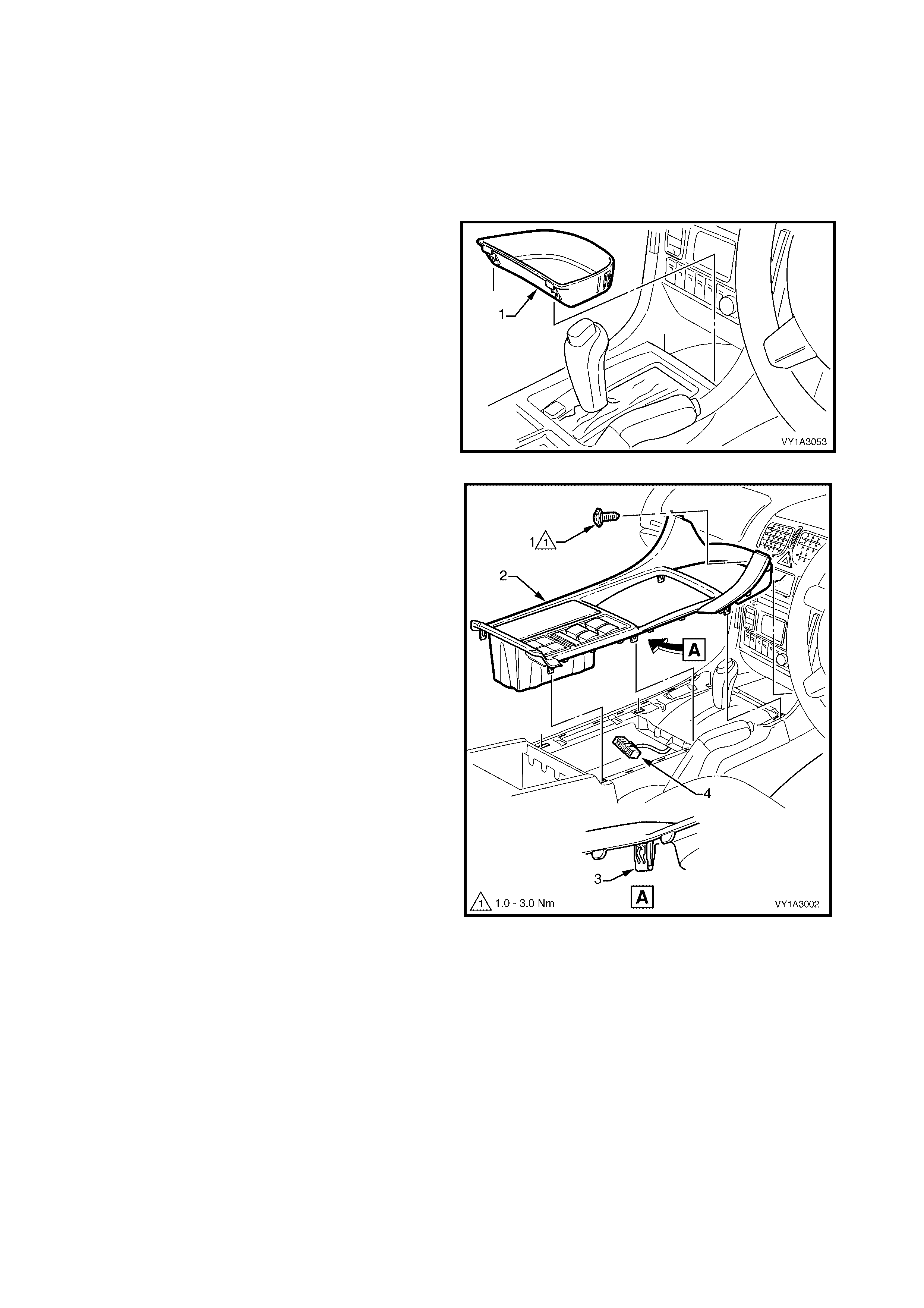
1. Remove the floor console front compartment liner
(1) by lifting upwards to disengage the retaining
lugs.
Figure 2E-1
2. Remove the screw (1) attaching the floor console
cover assembly (2).
3. Prise the cover assembly from the floor console,
six places (3).
4. Lift the cover assembly up from the rear,
disconnect the wiring connector (4) from the side
window switch assembly and any auxiliary
switches if fitted, and remove the cover assembly.
Figure 2E-2
5. Insert Spec ial T ool KM6067 ( 1) into the holes eac h
side of the radio assembly.
6. While holding outward pressure on the tools
(toward each outer side of the vehicle), pull the
radio assembly from the radio housing.
NOTE: The wiring connectors remain attached to the
radio housing and will disconnect on removal of the
radio assembly.
Figure 2E-3
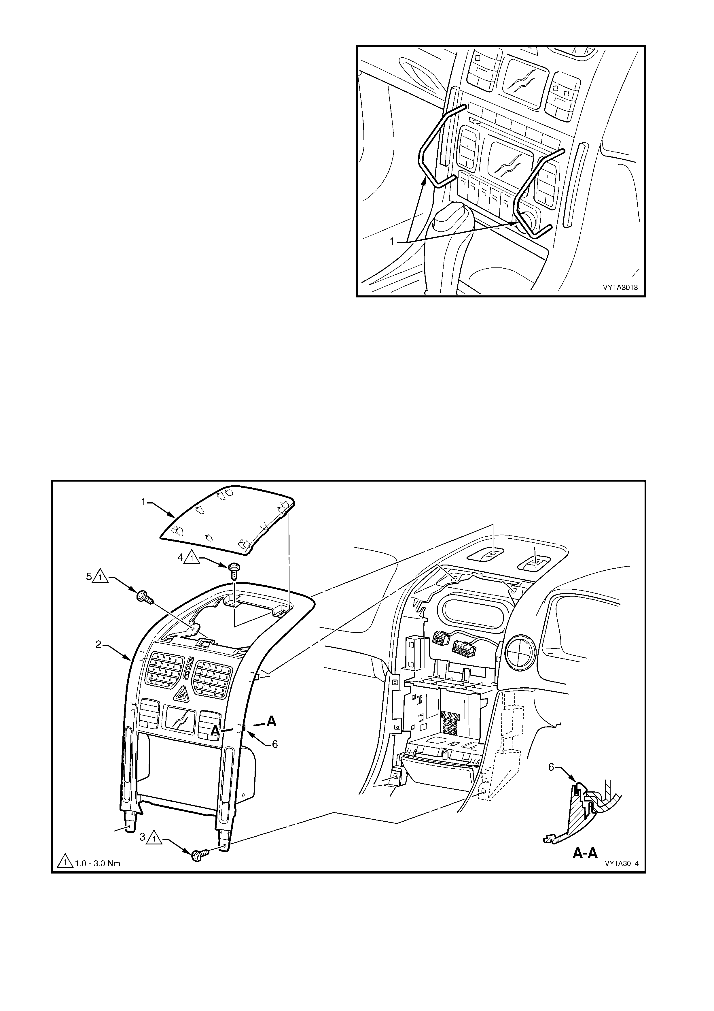
7. Carefully prise the front edge of the instrument panel upper centre trim panel (1) refer to Figure 2E-4, and pull
upward to disengage the retaining clips at each corner from the centre trim assembly (2).
NOTE: A fine flat blade screwdriver may be used; however take steps to ensure the trims are not marked or
damaged.
8. Remove the lower screw (3), two places, attaching the centre trim assembly to the instrument panel.
9. Remove the upper screws (4 and 5), two places each, attaching the centre trim assembly to the instrument
panel.
10. Remove the c entre tr im as s embly, noting the four clips ( 6), far enough to disc onnec t the wiring connector s f rom
the rear of the hazard warning switch.
11. Remove the centre trim assembly.
Figure 2E-4
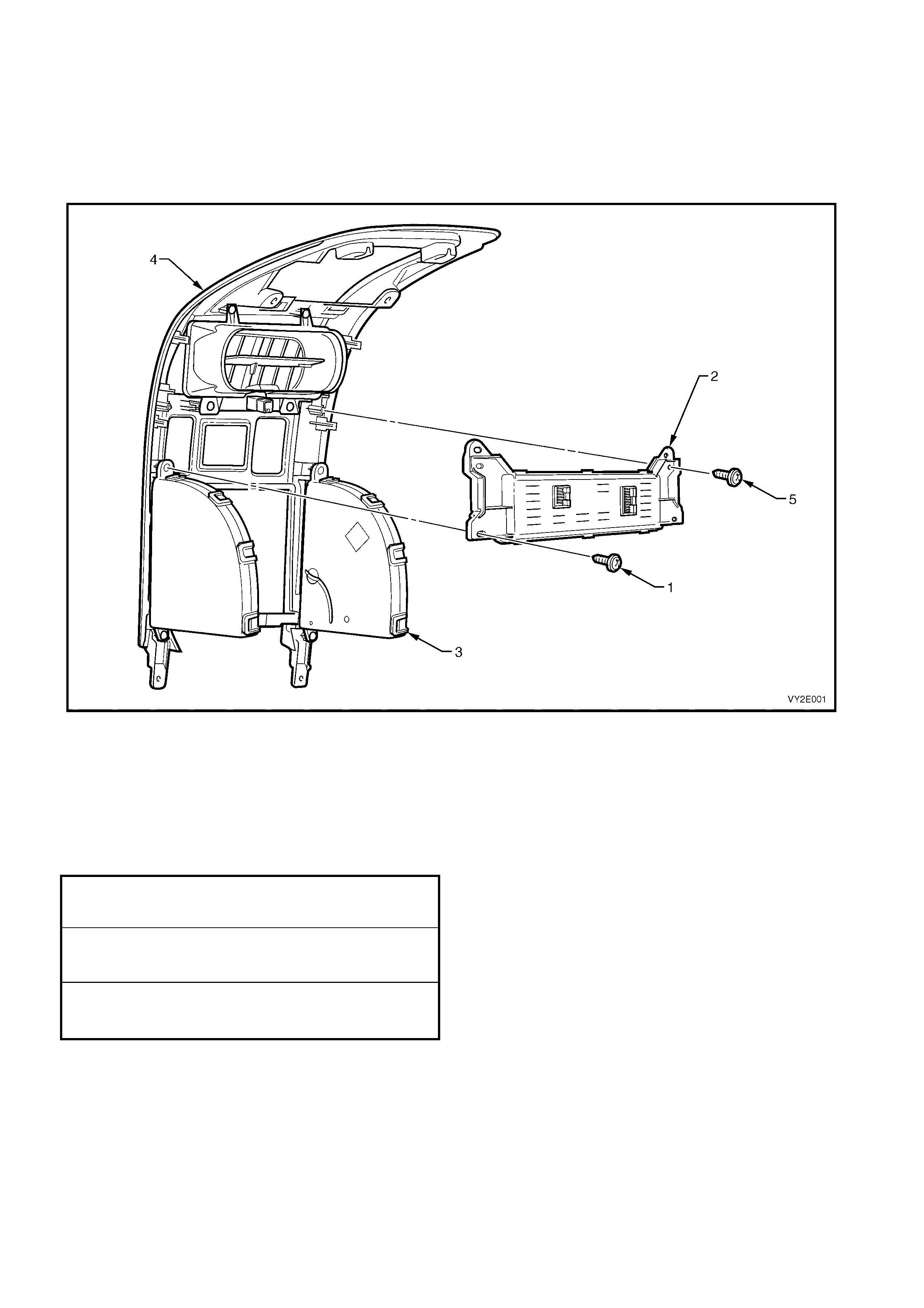
NOTE: Depending on model not all of the following components will be fitted.
12. Remove the scr ew ( 1) r ef er to Figure 2E- 5, one plac e each s ide, attaching the O CC c ontrol module (2) and c up
holder assembly (3) to the centre trim (4).
13. Remove the screw (5), one place each side, attaching the OCC control module to the centre trim and remove
the control module.
NOTE: For service and diagnosis of the OCC control module refer to Section 2F, HVAC OCCUPANT CLIMATE
CONTROL (AUTO A/C) – DIAGNOSTICS.
Figure 2E-5
REINSTALL
IMPORTANT: If the OCC control m odule has been replaced, the air mix door/motor function must be calibrated to
the new OCC control m odule. Failure to do so may cause poor HVAC system perform ance and result in customer
complaints. Refer to Section 2F, F5: PROGRAM.
Installation of the OCC control module is the reverse of removal procedures. Tighten all screws to the specified
torque.
OCC CONTROL MODULE
ATTACHING SCREW
TORQUE SPECIFICATION 1.0 – 3.0 Nm
INSTRUMENT PANEL CENTRE TRIM
ASSEMBLY ATTACHING SCREW
TORQUE SPECIFICATION 1.0 – 3.0 Nm
FLOOR CONSOLE COVER
ASSEMBLY ATTACHING SCREW
TORQUE SPECIFICATION 1.0 – 3.0 Nm
2.2 SUN LOAD SENSOR
LT Section – 08-155A
REMOVE
1. Remove the instrument panel outer cover from both sides, refer to Section 1A3, 3.17 INSTRUMENT PANEL
OUTER COVER.
2. Remove the windshield defroster grille assembly from both sides, refer to Section 1A3, 3.18 WINDSHIELD
DEFROSTER GRILLE ASSEMBLY.
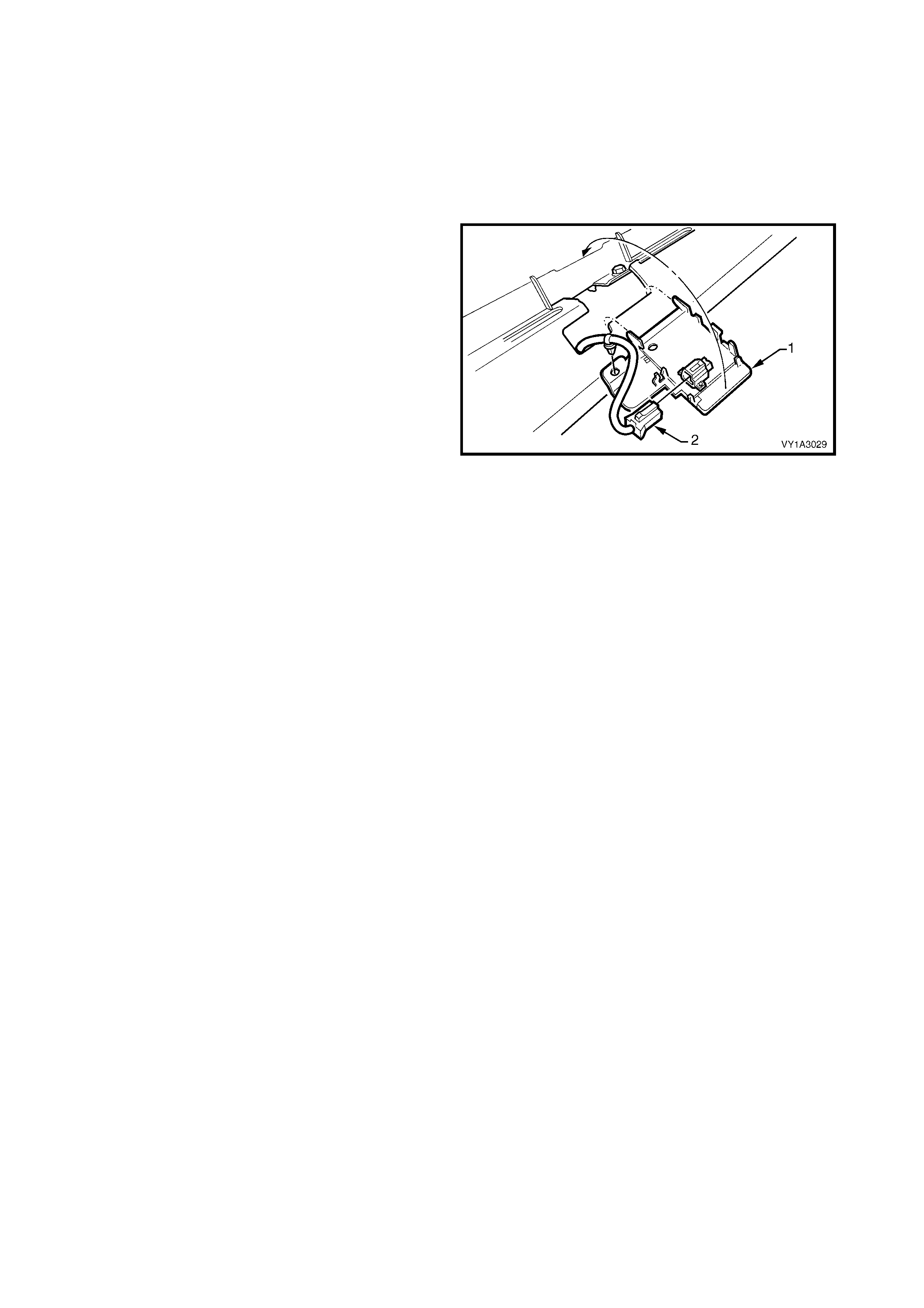
3. Carefully unclip the receiver and sun load sensor
(1) from the instrument panel.
4. Disconnect the wiring connector (2), unclip the
wiring harness f rom the sun load sensor as sembly
and remove.
NOTE: For service and diagnosis of the sun load
sensor, refer to Section 2F, HVAC OCCUPANT
CLIMATE CONTROL (AUTO A/C) – DIAGNOSTICS.
Figure 2E-6
REINSTALL
Installation of the receiver and sun load sensor assembly is the reverse of removal procedures.
2.3 IN-CAR TEMPERATURE SENSOR
LT Section – 08-200
REMOVE
1. Remove the instrument cluster trim assembly, refer to Section 1A3, 3.12 INSTRUMENT CLUSTER TRIM
ASSEMBLY.
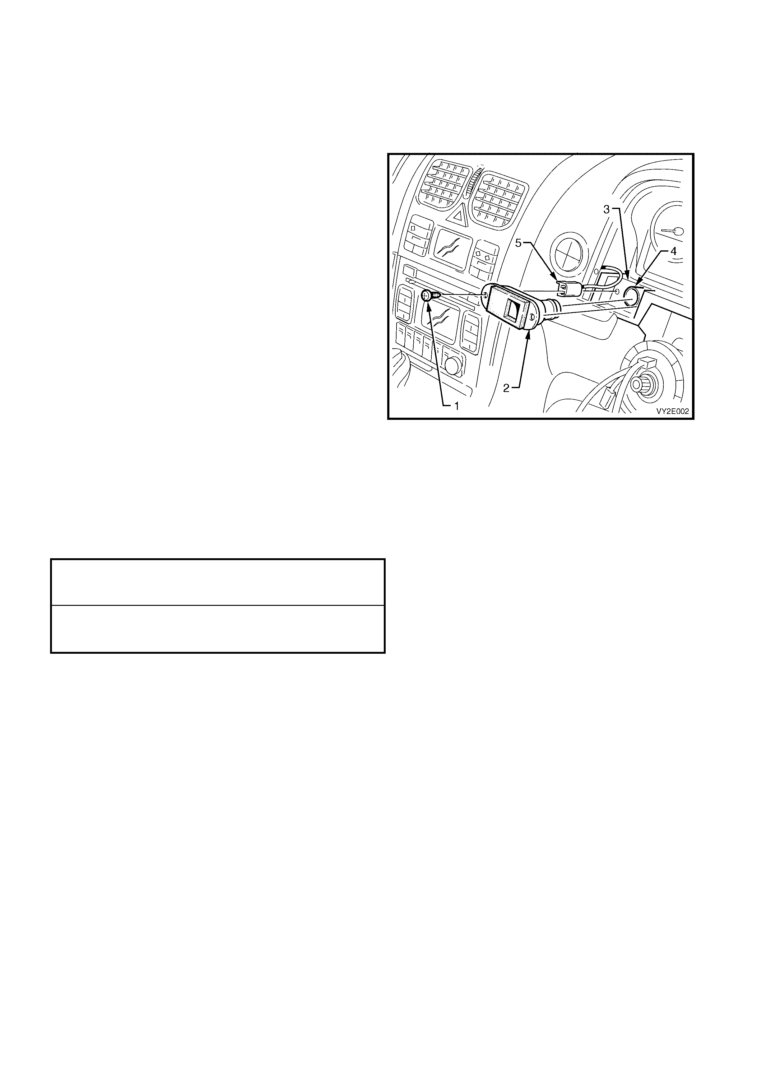
1. Remove the screw (1) attaching the in-car
temperature sensor (2) to the instrument panel (3).
2. Extract the sensor assembly from the cavity and
disconnect the aspirator tube (4) and wiring
connector (5).
3. Remove the sensor assembly.
NOTE 1: Steering wheel is shown removed only for
clarity of detail. Do not remove the steering wheel for
in-car temperature sensor removal.
NOTE 2: For service and diagnosis of the in-car
temperature sensor refer to Section 2F, HVAC
OCCUPANT CLIMATE CONTROL (AUTO A/C) –
DIAGNOSTICS.
Figure 2E-7
REINSTALL
1. Ins tall the in- car tem perature s ensor into the instr ument panel ensur ing that the aspirator tube is f itted correc tly
to the sensor.
2. Install the screw attaching the in-car temperature sensor to the instrument panel. Tighten the screw to the
specified torque.
3. Install the instrument cluster trim assembly. Tighten the screws to the specified torque.
INSTRUMENT CLUSTER TRIM ASSEMBLY
ATTACHING SCREW
TORQUE SPECIFICATION 1.0 – 3.0 Nm
IN-CAR TEMPERATURE SENSOR
ATTACHING SCREW
TORQUE SPECIFICATION 1.0 – 3.0 Nm
2.4 EVAPORATIVE TEMPERATURE SENSOR
REMOVE – LHD
1. Remove the floor console, instrument panel and HVAC assemblies, refer to Section 2B, 3. HEATING,
VENTILATION, AND AIR CONDITIONING UNIT – REMOVAL AND INSTALLATION.
2. Access the evaporator core, refer to Section 2B, 4. EVAPORATOR.
Disconnect the evaporative sensor harness connector at the front of the HVAC case.
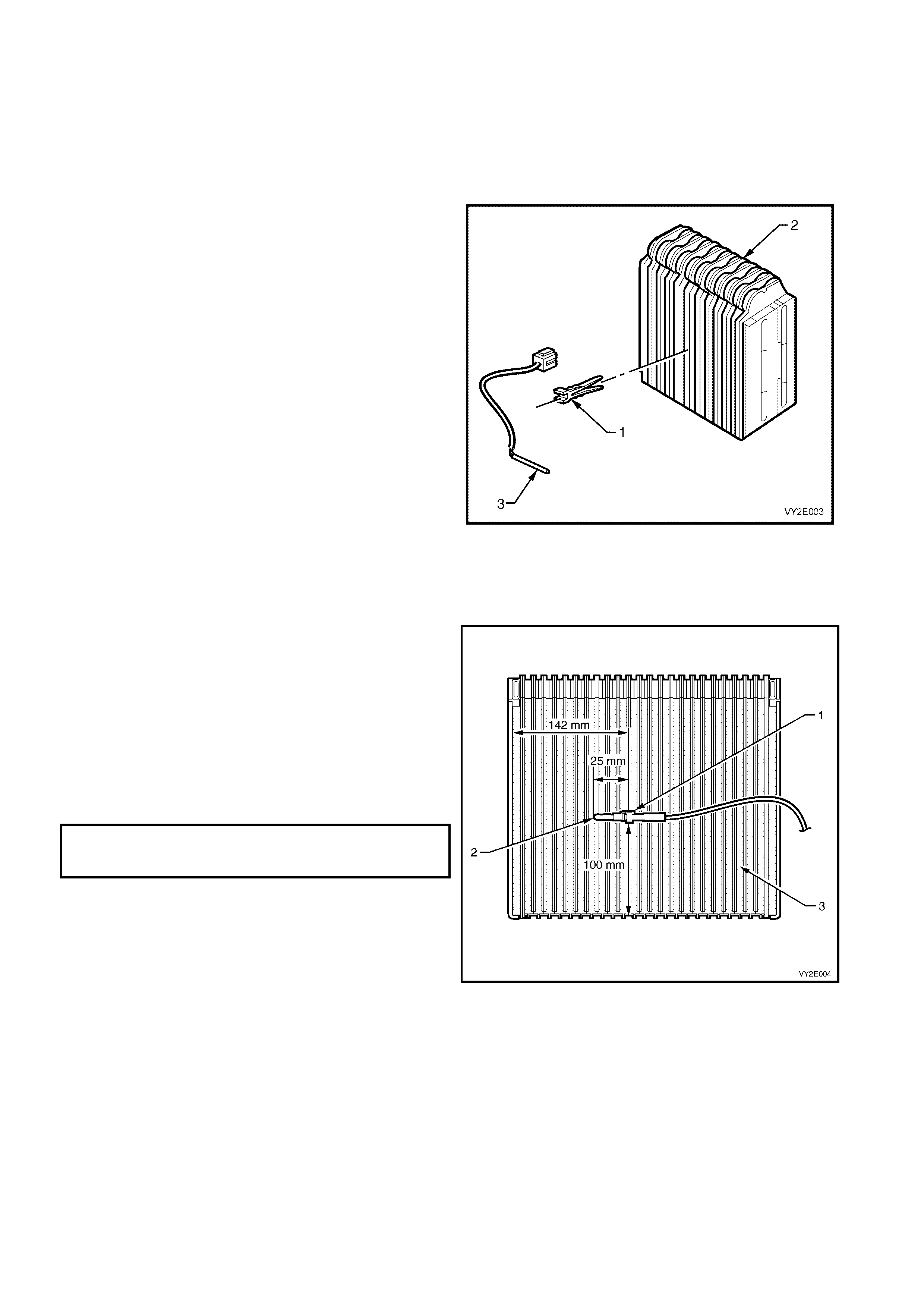
3. Remove the clamp (1) from the evaporator core (2)
and remove the thermistor (3).
NOTE: For service and diagnosis of the evaporator
temperature sensor assembly refer to
Section 2F, HVAC OCCUPANT CLIMATE CONTROL
(AUTO A/C) – DIAGNOSTICS.
Figure 2E-8
REINSTALL – LHD
Install the evaporator temperature in the reverse order
of removal procedures noting the following:
1. When installing the evaporative temperature
sensor, ensure that the clamp (1) is fitted over the
thermistor (2) at 25 mm from the end of the
thermistor. The clamp is firmly inserted into the
core fins (3) at a height and width as shown in
Figure 2E-9.
2. Ensure that the sensor harness is installed
correctly in the hole provided in the HVAC case
when the upper and lower cases are assembled.
3. Tighten all screws to the specified torque.
HVAC CASE
ATTACHING SCREW
TORQUE SPECIFICATION 1.0 – 3.0 Nm
Figure 2E-9
LT Section – 08-025
REMOVE – RHD
1. Remove the floor console, instrument panel and HVAC assemblies, refer to Section 2B, 3. HEATING,
VENTILATION, AND AIR CONDITIONING UNIT – REMOVAL AND INSTALLATION.
2. Access the evaporator core, refer to Section 2B, 4. EVAPORATOR.
3. Disconnect the evaporative temperature sensor harness connector at the front of the HVAC case.
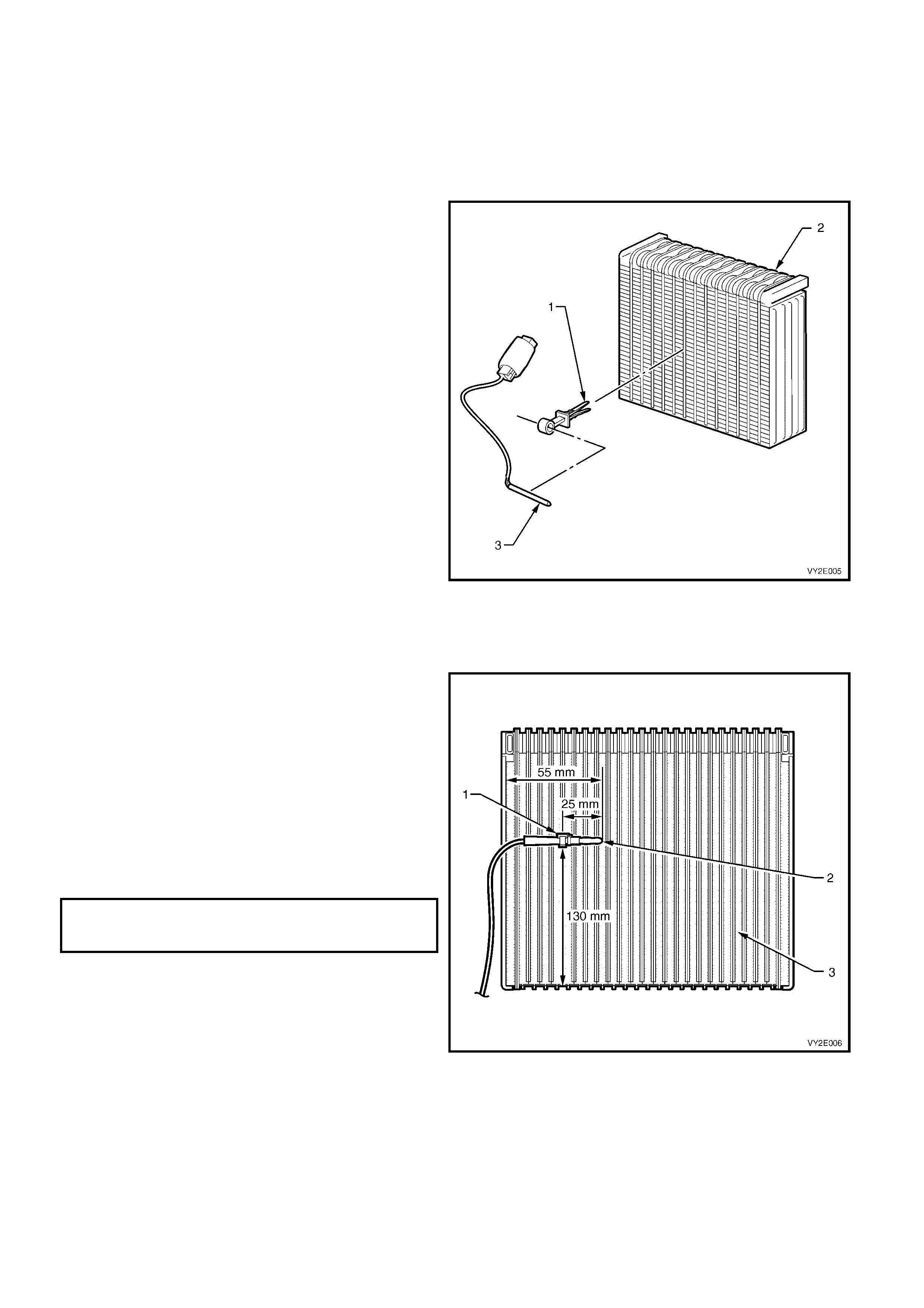
4. Remove the clamp (1) from the evaporator core
(2) and remove the thermistor (3).
NOTE: For service and diagnosis of the sensor
assembly refer to Section 2F, HVAC OCCUPANT
CLIMATE CONTROL (AUTO A/C) –
DIAGNOSTICS.
Figure 2E-10
REINSTALL – RHD
Install the evaporator temperature sensor in the
reverse order of removal procedures noting the
following:
1. When installing the evaporative temperature
sensor, ensure that the clamp (1) is fitted over
the thermistor (2) at 25 mm from the end of the
thermistor. The clamp is firmly inserted into the
core fins (3) at a height and width as shown in
Figure 2E-11.
2. Ensure that the sensor harness is correctly
installed in the recess provided in the evaporator
cover when the cover is assembled to the case.
3. Tighten all screws to the specified torque.
EVAPORATOR COVER
ATTACHING SCREW
TORQUE SPECIFICATION 1.0 – 3.0 Nm
Figure 2E-11
2.5 ASPIRATOR TUBE AND VE NTURI
REMOVE – LHD
1. Remove the floor console, instrument panel and HVAC assemblies, refer to Section 2B, 3. HEATING,
VENTILATION, AND AIR CONDITIONING UNIT – REMOVAL AND INSTALLATION.
2. Remove the venturi (1) and aspirator tube (2) as
an assembly from the HVAC case (3).
3. Remove the aspirator tube from the venturi.
REINSTALL – LHD
Install the aspirator tube and venturi in the reverse
order of removal procedures noting the following:
1. When inst alling the venturi on to the as pir ator tube,
ensure that the tube is fully engaged into the
venturi.
2. When installing the venturi and aspirator tube
assembly, ensure that the venturi is fully seated to
the HVAC case venturi hole (4) and that aspirator
tube is correctly installed in the aspirator tube
locating recess (5) moulded in the HVAC case.
Figure 2E-12
LT Section – 08-150
REMOVE – RHD
1. Remove the floor console, instrument panel and HVAC assemblies, refer to Section 2B, 3. HEATING,
VENTILATION, AND AIR CONDITIONING UNIT – REMOVAL AND INSTALLATION.
2. Note the location then remove any adhesive tape
retaining the aspirator tube (1) to the HVAC case
(2).
3. Remove the aspirator tube and the venturi (3) as
an assembly from the HVAC case.
4. Remove the aspirator tube from the venturi.
REINSTALL – RHD
Install the aspirator tube and the venturi in the reverse
order of removal procedures noting the following:
1. W hen installing the venturi into the aspirator tube,
ensure that the tube is fully engaged into the
venturi.
2. When installing the venturi and aspirator tube
assembly, ensure that the venturi is fully seated
into the venturi hole (4) of the HVAC case. Ensure
that aspirator tube is correctly installed into the
retaining clips (5) and the retaining lug (6) is
correctly installed into the recess (7) moulded in
the HVAC case.
3. Install adhesive tape to the original locations as
noted.
Figure 2E-13

2.6 AMBIENT TEMPERATURE SENSOR
LT Section – 08-200
REMOVE
1. Raise front of vehicle and support on safety stands. Refer to Section 0A, GENERAL INFORMATION for the
location of jacking and support points.
2. Remove the ambient temperature sensor harness
connector (1) from the sensor (2).
3. Using a flat blade screwdriver carefully lever the
sensor away from the retaining bracket (3).
NOTE 1: The retaining bracket is not to be removed
from the condenser (4).
NOTE 2: For service and diagnosis of the sensor
assembly refer to Section 2F, HVAC OCCUPANT
CLIMATE CONTROL (AUTO A/C) – DIAGNOSTICS.
REINSTALL
Installation of the ambient temperature sensor is the
reverse order of removal procedures.
Figure 2E-14
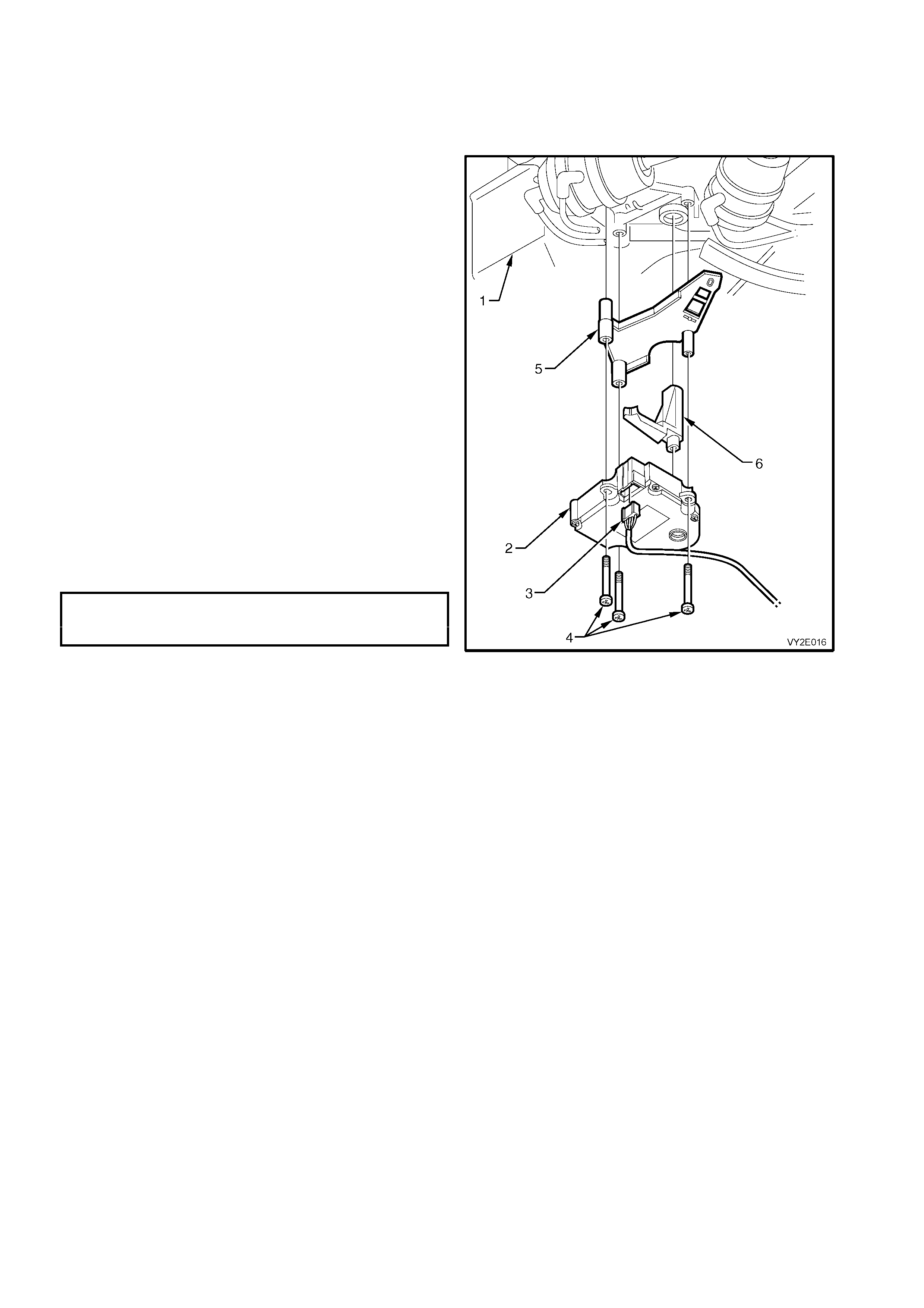
2.7 VACUUM SOLENOID PACK
REMOVE – LHD
1. Remove the right-hand side instrument panel lower trim plate assembly, refer to
Section 1A3, 3.1 INSTRUMENT PANEL LOWER TRIM PLATE ASSEMBLY.
2. Disconnect the vacuum solenoid pack vacuum
manifold (1) from the solenoid pack (2).
3. Disconnect the harness connector (3) from the
solenoid pack.
4. Remove the two screws (4) and detach the
vacuum s olenoid pac k and bracket fr om the HVAC
lower case housing (5).
NOTE: Fo r service and diagnosis of the solenoid pack
assembly refer to Section 2F, HVAC OCCUPANT
CLIMATE CONTROL (AUTO A/C) – DIAGNOSTICS.
REINSTALL – LHD
Installation of the vac uum solenoid pac k is the reverse
order of removal procedures. Tighten all screws to the
specified torque.
VACUUM SOLENOID PACK
ATTACHING SCREW
TORQUE SPECIFICATION 1.0 – 3.0 Nm
Figure 2E-15
LT Section – 08-150
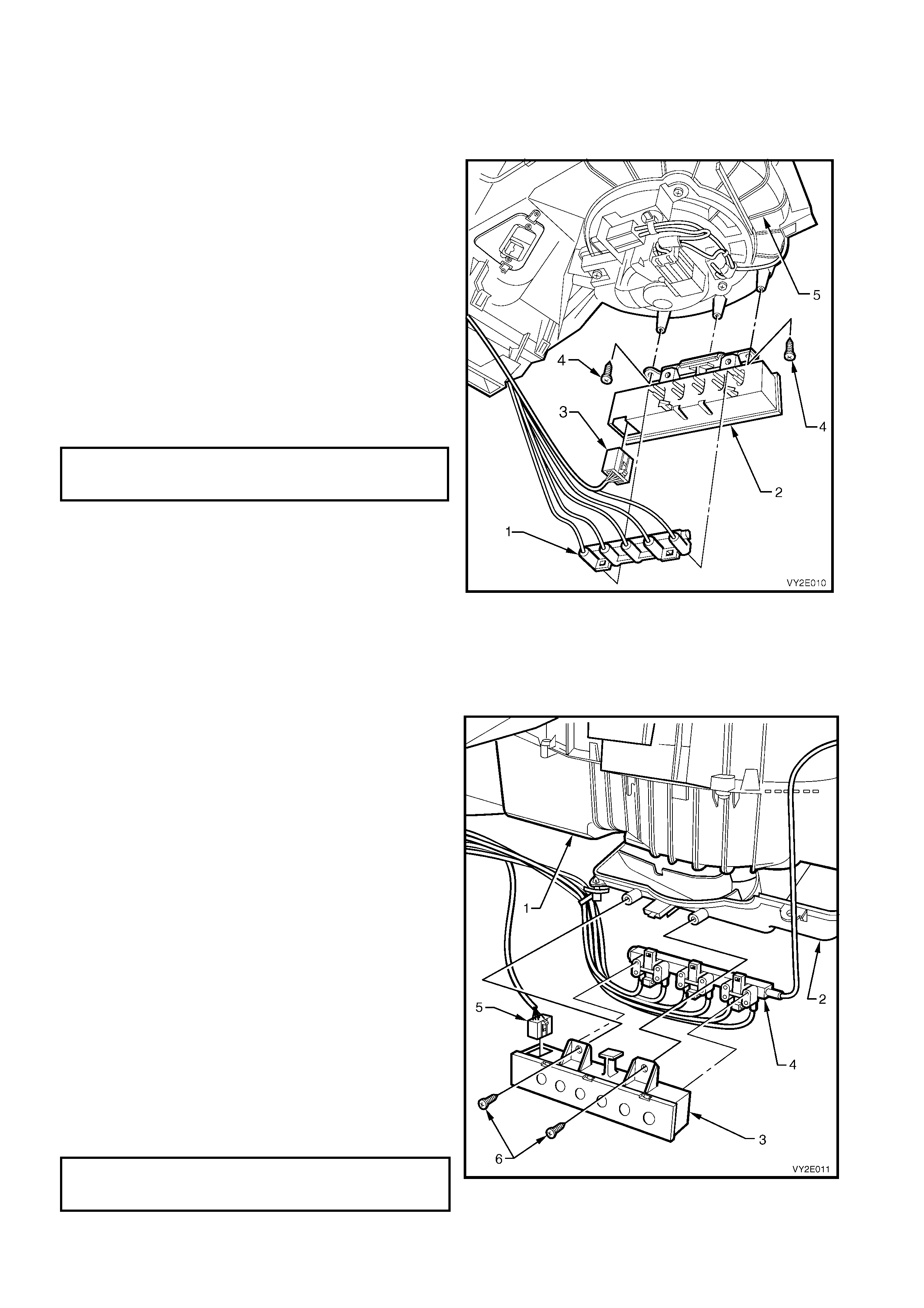
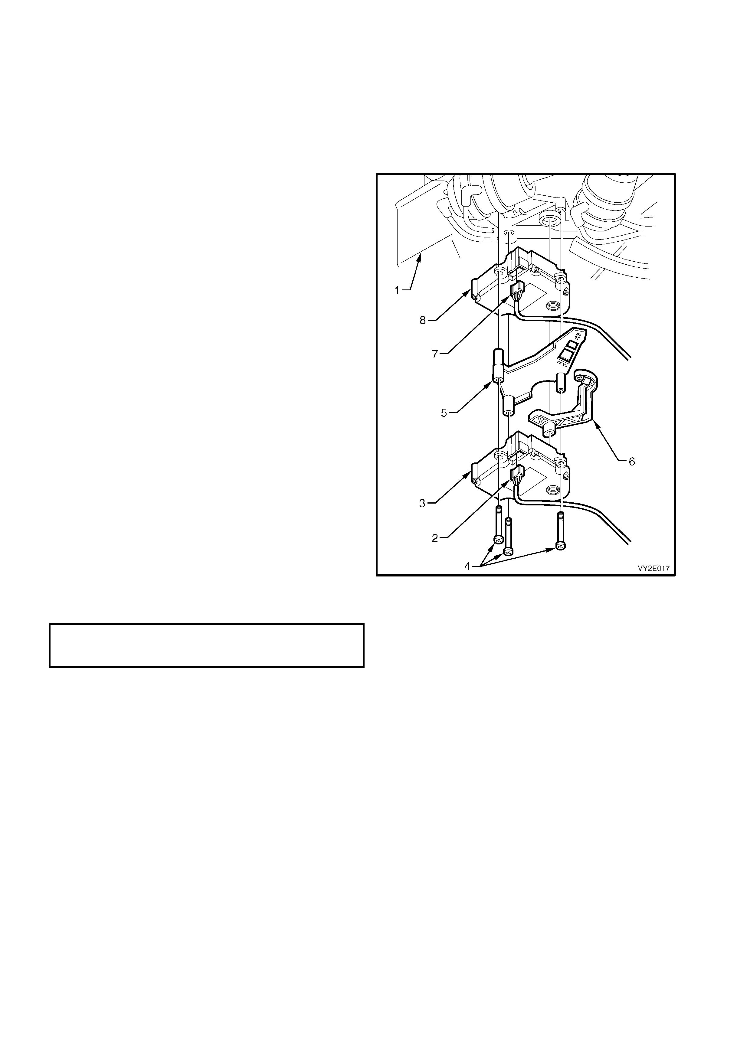
REMOVE – RHD
1. Remove the right-hand side instrument panel lower trim plate assembly, refer to Section 1A3, 3.1
INSTRUMENT PANEL LOWER TRIM PLATE ASSEMBLY.
2. Remove the blower motor and fan harness
connector from the blower motor connector (refer
to item 1 in Figure 2E-19) below the HVAC unit (1).
3. Remove the three screws from the blower motor
and fan assembly access cover (refer to item 2 in
Figure 2E-19) and remove the blower motor and
fan assembly access cover (2) with the solenoid
pack (3) attached to the cover.
4. Disconnect the vacuum manifold (4) from the
vacuum solenoid pack.
5. Disconnect the harness connector (5) from the
solenoid pack.
6. Remove the two screws (6) and remove the
vacuum solenoid pack from the blower motor and
fan access cover.
NOTE: For service and diagnosis of the solenoid pack
assembly refer to Section 2F, HVAC OCCUPANT
CLIMATE CONTROL (AUTO A/C) – DIAGNOSTICS.
REINSTALL – RHD
Installation of the vacuum solenoid pack is the reverse
order of removal procedures. Tighten all screws to the
specified torque.
VACUUM SOLENOID PACK
ATTACHING SCREW
TORQUE SPECIFICATION 1.0 – 3.0 Nm
Figure 2E-16
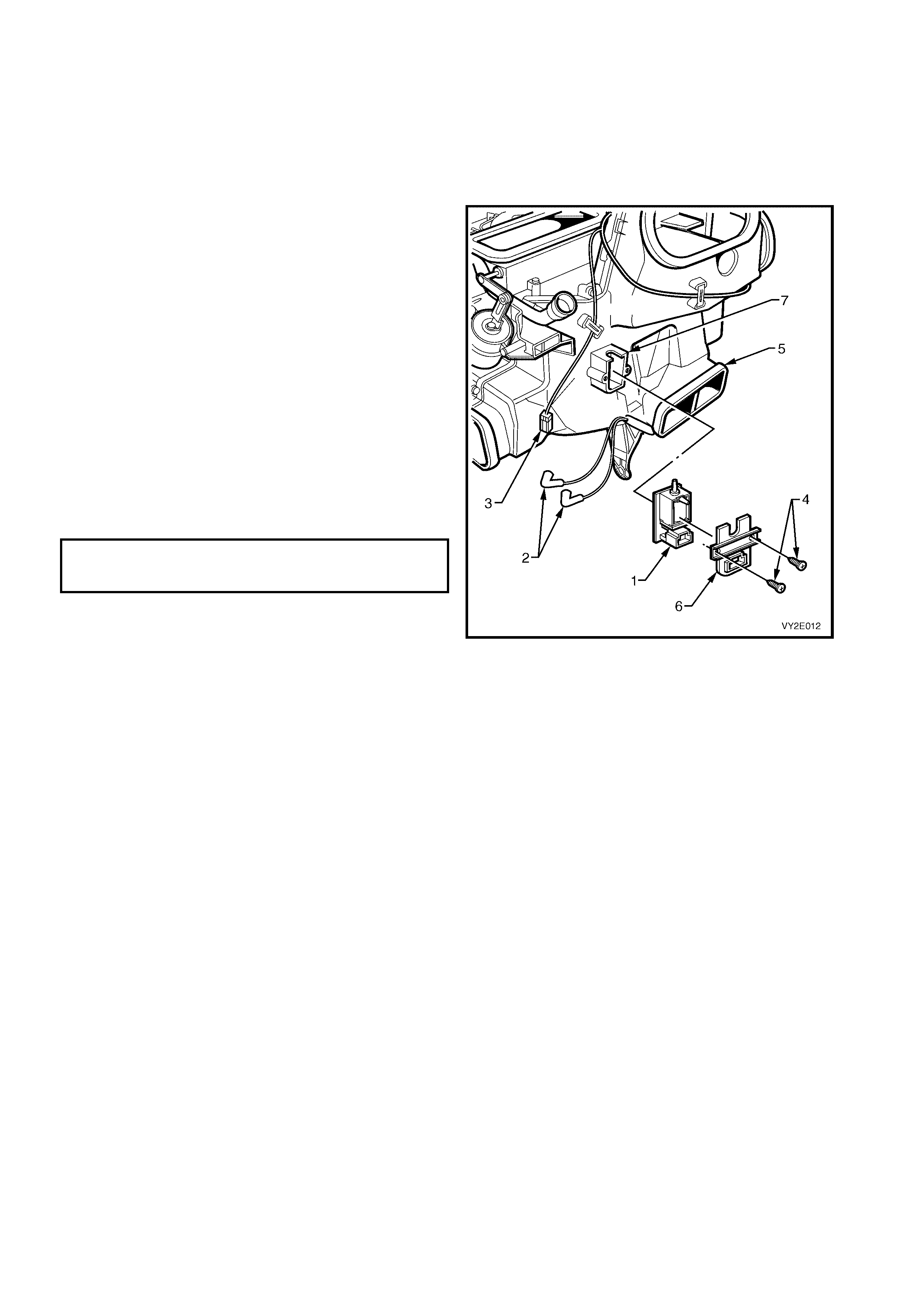
2.8 W ATER VALVE VACUUM SWITCH VALVE
REMOVE
NOTE: The water valve vacuum switch valve is fitted to LHD OCC (Auto A/C) HVAC units only.
1. Remove the radio assembly, refer to Section 1A3, 3.6 RADIO ASSEMBLY.
2. Remove the radio housing and radio bracket assembly, refer to Section 1A3, 3.11 RADIO HOUSING AND
RADIO BRACKET ASSEMBLY.
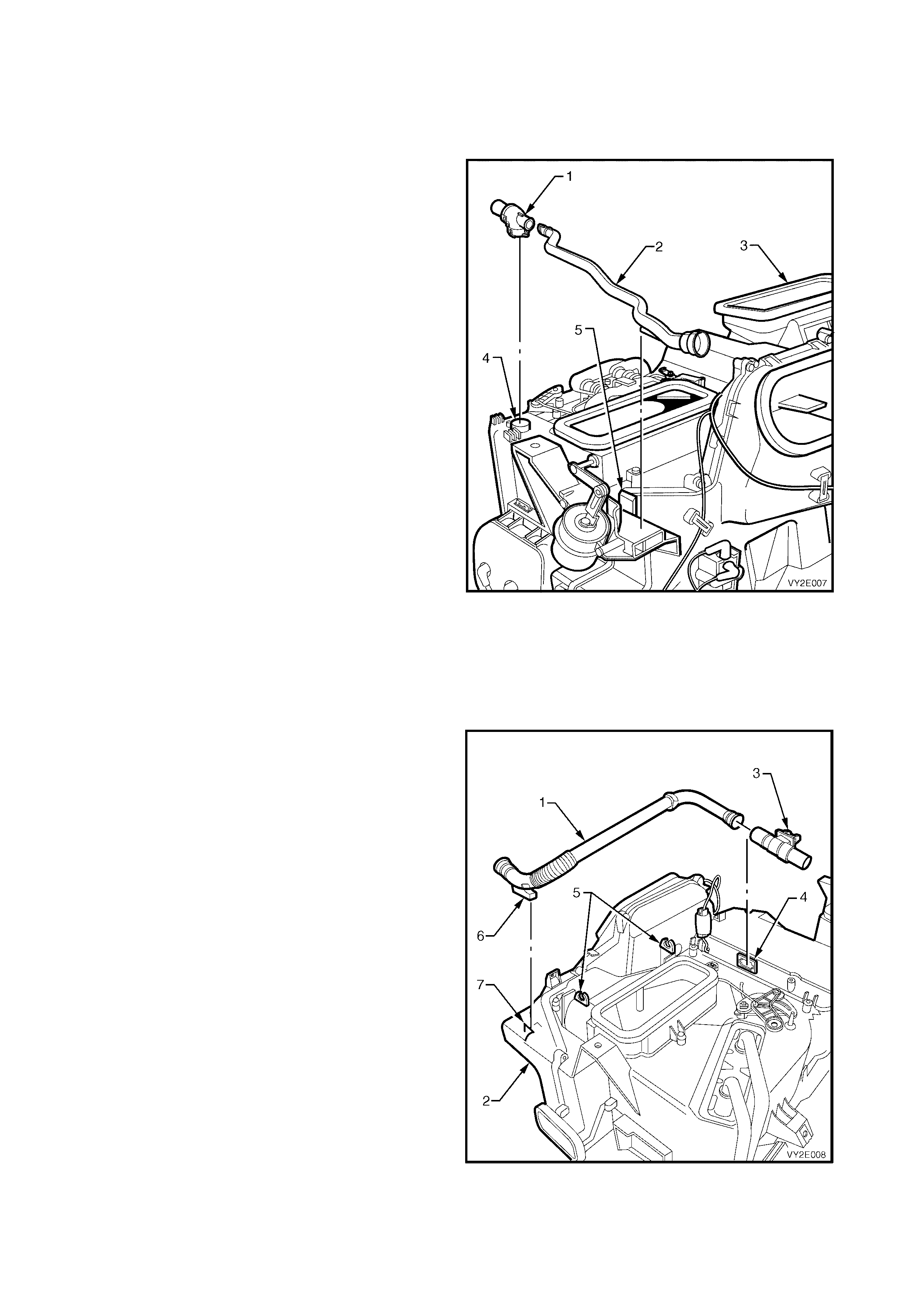
3. Locate the vacuum switch valve (1) and remove
the vacuum hoses (2) noting their installation to
the valve.
4. Remove the harness connector (3) from the valve.
5. Remove the two screws (4) attaching the valve to
the front of the HVAC unit (5).
6. Remove the valve cover (6).
7. Rem ove the vacuum s witc h valve from the front of
the HVAC unit vacuum switch housing (7).
NOTE: For service and diagnosis of the water valve
VSV refer to Section 2F, HVAC OCCUPANT
CLIMATE CONTROL (AUTO A/C) – DIAGNOSTICS.
REINSTALL
1. Ins ert the vacuum switch and c over into the HVAC
unit vacuum s witch hous ing and tighten the sc r ews
to the specified torque.
WATER VALVE VACUUM SWITCH
VALVE ATTACHING SCREW
TORQUE SPECIFICATION 1.0 – 3.0 Nm
2. Install the vacuum hoses to their original vacuum
outlets.
3. Install the harness connector to the valve.
4. Install the radio housing and radio bracket
assembly.
Figure 2E-17
2.9 BLOWE R MOTOR AND FAN
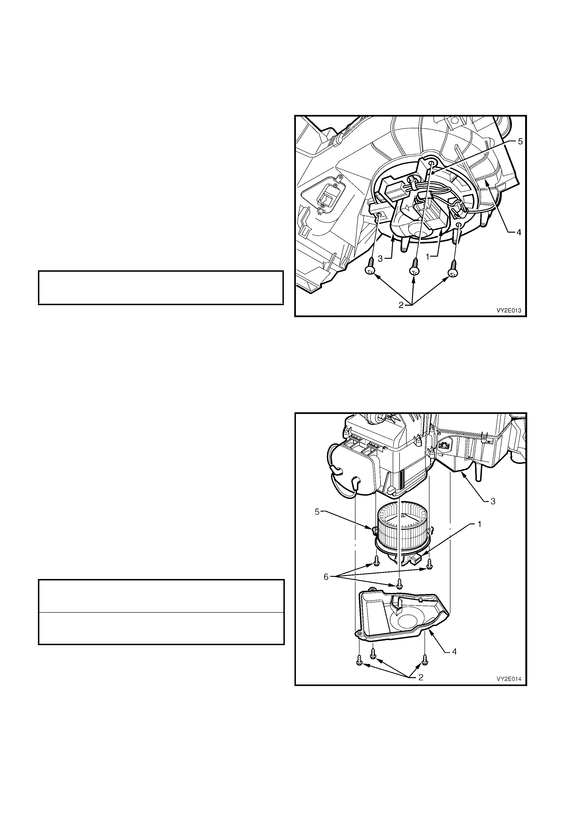
REMOVE – LHD
1. Remove the right-hand side instrument panel lower trim plate assembly, refer to Section 1A3, 3.1
INSTRUMENT PANEL LOWER TRIM PLATE ASSEMBLY.
2. Remove the solenoid pack from the HVAC unit, refer to 2.7 VACUUM SOLENOID PA CK in this Section.
3. Disconnect the body harness connector from the
blower motor and fan assembly sub harness
connector (1).
4. Remove the three screws (2) and remove the
blower motor and fan assembly (3) from the lower
case housing (4).
5. Remove the blower motor and fan assembly sub
harness and bracket (5) from the blower motor.
REINSTALL – LHD
Installation of the blower motor and fan assembly is the
reverse order of removal procedures. Tighten all
screws to the specified torque.
BLOWER MOTOR AND FAN ASSEMBLY
ATTACHING SCREW
TORQUE SPECIFICATION 1.0 – 3.0 Nm
Figure 2E-18
LT Section – 08-150
REMOVE – RHD
1. Remove the left-hand side instrument panel lower trim plate assembly, refer to Section 1A3, 3.1 INSTRUMENT
PANEL LOWER TRIM PLATE ASSEMBLY.
2. Disconnect the body harness connector from the
blower motor and fan assembly connector (1).
3. Remove the blower motor and fan cover screws
(2) f rom the HVAC unit (3) and m ove the cover (4)
suff iciently to allow access to the blower m otor and
fan assembly (5).
4. Remove the three blower m otor and f an s cr ews (6)
and remove the blower motor and fan assembly
from the HVAC unit.
REINSTALL – RHD
Installation of the blower motor and f an as s embly is the
reverse order of removal procedures. Tighten all
screws to the specified torque.
BLOWER MOTOR AND FAN ASSEMBLY
COVER ATTACHING SCREW
TORQUE SPECIFICATION 1.0 – 3.0 Nm
BLOWER MOTOR AND FAN ASSEMBLY
ATTACHING SCREW
TORQUE SPECIFICATION 1.0 – 3.0 Nm
Figure 2E-19
2.10 AIR MIX MOTOR
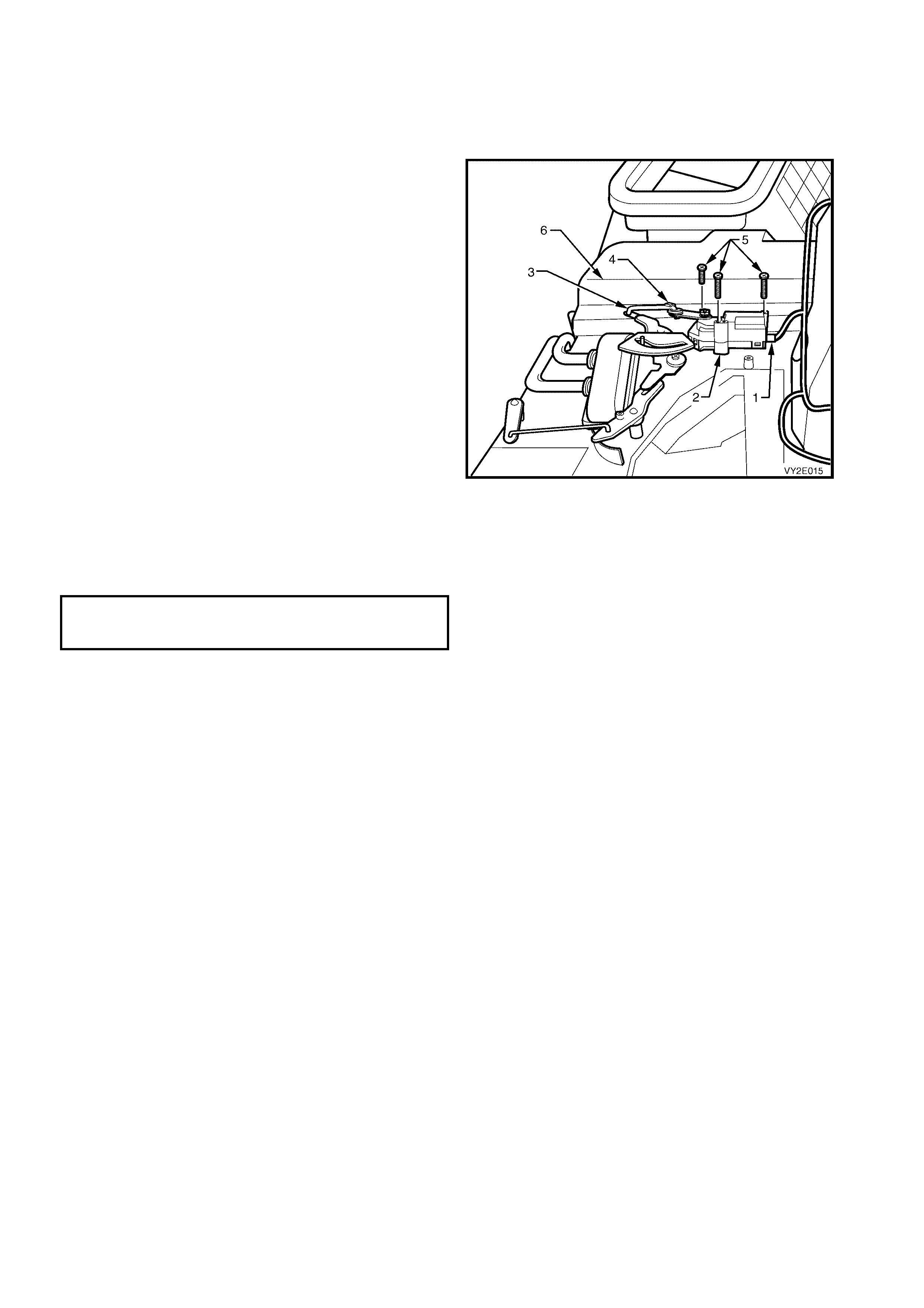
REMOVE – LHD
1. Remove the floor console, instrument panel and HVAC assemblies, refer to Section 2B, 3. HEATING,
VENTILATION, AND AIR CONDITIONING UNIT – REMOVAL AND INSTALLATION.
2. Disc onnect the wiring harness (1) from the air m ix
motor (2).
3. Remove the actuating rod (3) from the air mix
motor by unfastening but not removing the
actuating rod from the air mix motor retaining clip
(4).
4. Rem ove the three screws (5) securing the air mix
motor to the HVAC unit ( 6) and r emove the air mix
motor.
NOTE: Fo r s ervice and diagnos is of the air m ix m otor ,
refer to Section 2F, HVAC OCCUPANT CLIMATE
CONTROL (AUTO A/C) – DIAGNOSTICS.
REINSTALL – LHD
IMPORTANT: If the air mix motor has been replaced,
the air mix door/motor function must be calibrated to
the OCC control module. Failure to do so may cause
poor HVAC system performance and result in
customer complaints. Refer to
Section 2F, F5: PROGRAM.
1. Install the air mix motor and air mix motor screws
onto the HVAC unit and tighten the screws to the
specified torque.
AIR MIX MOTOR ATTACHING
SCREW ATTACHING SCREW
TORQUE SPECIFICATION 1.0 – 3.0 Nm
2. Ins tall the actuating rod and retaining clip to the air
mix motor.
3. Install the floor console, instrument panel and
HVAC assemblies, refer to Section 2B,
3. HEATING, VENTILATION, AND AIR
CONDITIONING UNIT – REMOVAL AND
INSTALLATION.
4. If required, carry out the air mix door calibration
procedure. Refer to Section 2F, F5: PROGRAM.
Figure 2E-20
LT Section – 08-150
REMOVE – RHD (SINGLE ZONE)
1. Remove the floor console, instrument panel and HVAC assemblies, refer to Section 2B, 3. HEATING,
VENTILATION, AND AIR CONDITIONING UNIT – REMOVAL AND INSTALLATION.
2. From the underside of the HVAC unit (1), locate
the air mix motor (2) and remove the harness
connector (3) from the air mix motor.
3. Remove the three screws (4) retaining the air mix
motor to the HVAC unit and remove the motor
along with intermediate mounting plate (5) and
activating lever (6).
NOTE: For service and diagnosis of the air mix
motors, refer to Section 2F, HVAC OCCUPANT
CLIMATE CONTROL (AUTO A/C) – DIAGNOSTICS.
REINSTALL – RHD (SINGLE ZONE)
IMPORTANT: If the air mix motor has been
replaced, the air mix door/motor function must be
calibrated to the OCC control module. Failure to
do so may cause poor HVAC system performance
and result in customer complaints. Refer to
Section 2F, F5: PROGRAM.
1. Install the activating lever into the HVAC case.
2. Assemble the intermediate mounting plate,
activating the lever and air mix motor as shown
and secure with the three screws to the specified
torque.
AIR MIX MOTOR ATTACHING SCREW
ATTACHING SCREW
TORQUE SPECIFICATION 1.0 – 3.0 Nm
3. Connect the harness connector to air mix motor.
4. Install the floor console, instrument panel and
HVAC assemblies, refer to Section 2B,
3. HEATING, VENTILATION, AND AIR
CONDITIONING UNIT – REMOVAL AND
INSTALLATION.
5. If required, carry out the air mix door calibration
procedure. Refer to Section 2F, F5: PROGRAM.
Figure 2E-21
LT Section – 08-150
REMOVE – RHD (DUAL ZONE)
1. Remove the floor console, instrument panel and HVAC assemblies, refer to Section 2B, 3. HEATING,
VENTILATION, AND AIR CONDITIONING UNIT – REMOVAL AND INSTALLATION.
IMPORTANT: Prior to removal of the air mix motor harness connectors, note which connector is installed to the
driver’s side air mix motor and which connector is installed to the passenger’s side air mix motor, i.e. do not
transpose air mix motor harness connectors.
2. From the underside of the HVAC unit (1), locate
the driver’s air mix motor harness connector (2).
Remove the harness connector from the driver’s
side air mix motor (3).
3. Remove the three screws (4) retaining the air mix
motors to the HVAC unit and remove the driver’s
side air mix motor along with intermediate
mounting plate (5) and activating lever (6).
4. Remove the harness connector (7) from the
passenger side air mix motor (8).
5. Remove the passenger side air mix motor from
the HVAC unit.
REINSTALL – RHD (DUAL ZONE)
IMPORTANT: If an air mix motor has been
replaced, the air mix door/motor function must be
calibrated to the OCC control module. Failure to
do so may cause poor HVAC system performance
and result in customer complaints. Refer to
Section 2F, F5: PROGRAM.
1. Install the passenger side air mix motor to the
HVAC case and install passenger side air mix
motor harness.
2. Install intermediate mounting plate and activating
lever to the passenger side air mix motor.
3. Install the driver’s side air mix motor to the
mounting plate.
4. Secure the air mix motors with the three scr ews to
the specified torque.
AIR MIX MOTOR ATTACHING SCREW
ATTACHING SCREW
TORQUE SPECIFICATION 1.0 – 3.0 Nm
5. Connect the harness connector to driver’s air mix
motor.
6. Install the floor console, instrument panel and
HVAC assemblies, refer to Section 2B,
3. HEATING, VENTILATION, AND AIR
CONDITIONING UNIT – REMOVAL AND
INSTALLATION.
7. If required, carry out the air mix door calibration
procedure. Refer to Section 2F, F5: PROGRAM.
Figure 2E-22

3. TORQUE WRENCH SPECIFICATIONS
Floor console cover assembly attaching screw .......................................................... 1.0 – 3.0 Nm
OCC control module attaching screw ......................................................................... 1.0 – 3.0 Nm
Instrument panel centre trim assembly attaching screw............................................. 1.0 – 3.0 Nm
In-car temperature sensor attaching screw................................................................. 1.0 – 3.0 Nm
Instrument cluster trim assembly attaching screw...................................................... 1.0 – 3.0 Nm
Solenoid pack attaching screw.................................................................................... 1.0 – 3.0 Nm
Water valve vacuum switch valve attaching screw..................................................... 1.0 – 3.0 Nm
Air mix motor attaching screw..................................................................................... 1.0 – 3.0 Nm
Blower motor and fan assembly cover attaching screw.............................................. 1.0 – 3.0 Nm
Blower motor and fan assembly attaching screw........................................................ 1.0 – 3.0 Nm
HVAC case attaching screws...................................................................................... 1.0 – 3.0 Nm
Evaporator cover attaching screws............................................................................. 1.0 – 3.0 Nm

4. SPECIAL TOOLS
TOOL NUMBER ILLUSTRATION DESCRIPTION TOOL
CLASIFICATION
KM6067 RADIO REMOVAL TOOL
Used for removing VY audio unit
from its mounting location.
New tool for VY.
Mandatory