
SECTION 2F HVAC OCCUPANT CLIMATE CONTROL
(AUTO A/C) – DIAGNOSTICS
IMPORTANT
Before performing any Service Operation or other procedure described in this Section, refer to
Section 00, CAUTIONS AND NOTES for correct workshop practices with regard to safety and/or
property damage.
CONTENTS
1. DIAGNOSTICS
1.1 TECH 2 DIAGNOSTICS
1.2 TECH 2 TEST MODES AND DISPLAYS FOR OCC
DIAGNOSIS
2. DIAGNOSTIC CHARTS
CHART A – DIAGNOSTIC CIRCUIT CHECK
CHART B – OCC SYSTEM DOES NOT POWER
UP
DTC 13 – AMBIENT TEMPERATURE SENSOR
VOLTAGE TOO HIGH
DTC 14 – AMBIENT TEMPERATURE SENSOR
VOLTAGE TOO LOW
DTC 15 – IN-CAR TEMPERATURE SENSOR
VOLTAGE TOO HIGH
DTC 16 – IN-CAR TEMPERATURE SENSOR
VOLTAGE TOO LOW
DTC 17 – EVAPORATIVE TEMPERATURE
SENSOR VOLTAGE TOO HIGH (LHD)
DTC 17 – EVAPORATIVE TEMPERATURE
SENSOR VOLTAGE TOO HIGH (RHD)
DTC 18 – EVAPORATIVE TEMPERATURE
SENSOR VOLTAGE TOO LOW (LHD)
DTC 18 – EVAPORATIVE TEMPERATURE
SENSOR VOLTAGE TOO LOW (RHD)
DTC 19 – SUN LOAD SENSOR ERROR
DTC 35 – NO SERIAL DATA FROM PCM
DTC 36 – NO SERIAL DATA FROM BCM
DTC 37 – ROM CHECKSUM ERROR
DTC 38 – EEPROM CHECKSUM ERROR
DTC 39 – RAM ERROR
DTC 40 – AIR MIX DOOR MOTOR DRIVER
ERROR (LHD)
DTC 40 – AIR MIX DOOR MOTOR DRIVER
ERROR (RHD DRIVERS SIDE MOTOR)
DTC 40 – AIR MIX DOOR MOTOR DRIVER
ERROR (RHD PASSENGERS SIDE MOTOR)
DTC 41 – SOLENOID DRIVER ERROR – LHD
DTC 41 – SOLENOID DRIVER ERROR – RHD
DTC 43 – DRIVER’S AIR MIX DOOR MOTOR
FEEDBACK CIRCUIT VOLTAGE TOO LOW
(LHD)
DTC 43 – DRIVERS AIR MIX DOOR MOTOR
FEEDBACK CIRCUIT VOLTAGE TOO LOW
(RHD)
DTC 44 – DRIVERS AIR MIX DOOR MOTOR
FEEDBACK CIRCUIT VOLTAGE TOO HIGH
(LHD)
DTC 44 – DRIVERS AIR MIX DOOR MOTOR
FEEDBACK CIRCUIT VOLTAGE TOO HIGH
(RHD)
DTC 45 – PASSENGERS AIR MIX DOOR
MOTOR FEEDBACK CIRCUIT VOLTAGE TOO
LOW
DTC 46 – PASSENGERS AIR MIX DOOR
MOTOR FEEDBACK CIRCUIT ZOLTAGE TOO
HIGH
DTC 47 – DRIVER AIR MIX MIN. CALIBRATION
ERROR (LHD)
DTC 47 – DRIVER AIR MIX MIN. CALIBRATION
ERROR (RHD)
DTC 48 – DRIVER AIR MIX MAX. CALIBRATION
ERROR (LHD)
DTC 48 – DRIVER AIR MIX MAX. CALIBRATION
ERROR (RHD)
DTC 49 – PASS AIR MIX MIN. CALIBRATION
ERROR
DTC 50 – PASS AIR MIX MAX. CALIBRATION
ERROR
3. ELECTRICAL COMPONENT TESTS
3.1 IN CAR TEMPERATURE SENSOR
3.2 EVAPORATIVE TEMPERATURE SENSOR TEST
LEFT-HAND DRIVE
RIGHT-HAND DRIVE
3.3 AMBIENT TEMPERATURE SENSOR
3.4 OCC BLOWER MOTOR RESISTOR
LEFT-HAND DRIVE
RIGHT-HAND DRIVE
3.5 VACUUM SOLENOID PACK
LEFT-HAND DRIVE
RIGHT-HAND DRIVE
3.6 WATER VALVE VACUUM SWITCH VALVE
4. VACUUM RETENTION TESTS
VACUUM LOSS DEFAULT SETTINGS
4.1 VACUUM SOLENOID PACK
4.2 VACUUM ACTUATOR LINES
LEFT- HAND DRIVE
RIGHT- HAND DRIVE
4.3 VACUUM MANIFOLD LINE
LEFT-HAND DRIVE
RIGHT-HAND DRIVE
4.4 WATER VALVE VACUUM SWITCH
5. WIRING DIAGRAMS
CONNECTORS: OCC SYSTEM
CONNECTORS: OCC SYSTEM CONTINUED
CONNECTORS: OCC SYSTEM CONTINUED
WIRING DIAGRAM: OCC SYSTEM – V6 LHD
WIRING DIAGRAM: OCC SYSTEM – V6 RHD
WIRING DIAGRAM: OCC SYSTEM – GEN III V8
LHD
WIRING DIAGRAM: OCC SYSTEM – GEN III V8
RHD
6. SPECIAL TOOLS
Techline
Techline
Techline
1. DIAGNOSTICS
1.1 TECH 2 DIAGNOSTICS
TECH 2 is a hand-held diagnostic computer
designed specifically to help Holden Retailer
technicians to diagnose and repair electronic
systems used on Holden vehicles.
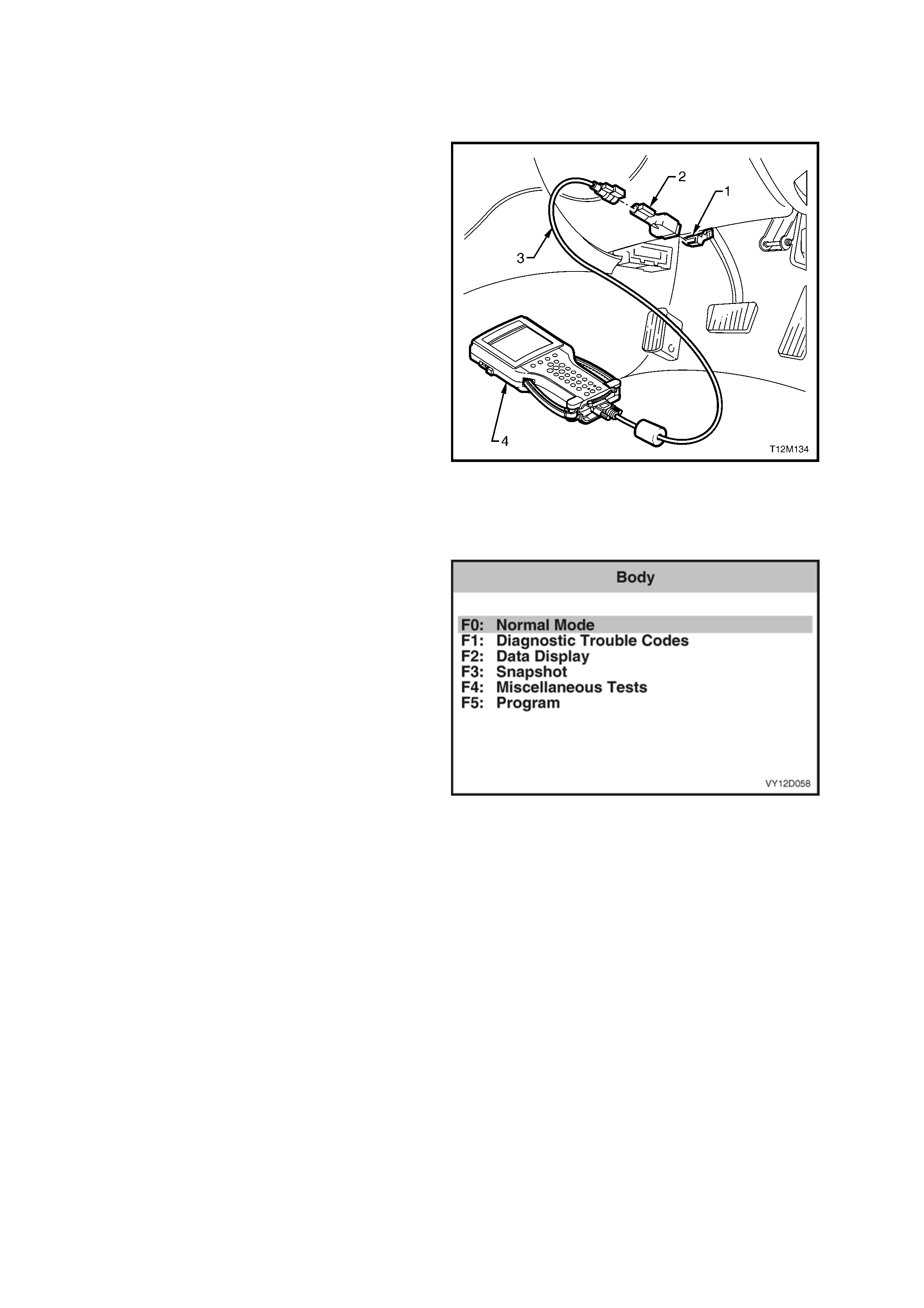
TECH 2, with the appropriate software, cables and
adaptors, is capable of reading serial d ata when
connected to the Data Link Connecto r (DLC). The
DLC is located in the instrument panel lower right-
hand trim, to the right of the steering column.
Legend
1. Data Link Connector (DLC)
2. DLC Adaptor
3. DLC Cable
4. TECH 2 diagnostic tool.
For additional general information on connecting
and operating TECH 2, refer to Section 0C,
TECH 2.
Figure 2F-1
TECH 2 has six test modes for diagnosing the
Occupant Climate Control (OCC system. The six
test modes are as follows:
Mode F0: Normal Mode
In this mode, the TECH 2 monitors the
communication between control modules on the
serial data line. The information displayed on the
TECH 2 screen in this mode is what the OCC is
communicating to the othe r modules via the serial
data line.
Mode F1: Diagnostic Tro uble Codes (DTC)
In this test mode, the operator of TECH 2 has the
option of reading current and history DTC’s or
clearing stored DTC’s from the control module’s
memory.
Mode F2: Data Display
In this test mode, TECH 2 displays the status of
inputs and outputs of the OCC.
Mode F3: Snapshot
In this test mode, TECH 2 captures OCC data
before and after a forced manual tri gger.
Mode F4: Miscellaneous Tests
In this test mode, the TECH 2 performs system
functional tests to assist in problem isolat ion during
troubleshooting.
Each test mode has specific diag nosis capabilities
that depend upon various function key entry on
TECH 2.
Mode F5: Program
In this test mode, TECH 2 allows the programming
of various OCC features (e.g. calibration of driver’s
air mix door).
Figure 2F-2
1.2 TECH 2 TEST MODES AND DISPLAYS FOR OCC DIAGNOSIS
A prerequisite to this diagnostic section is for the user to be familiar with the proper use of TECH 2. The following
pages illustrate only the major TECH 2 scree n displays and provide a brief explanation of their function for
diagnosing the OCC. If additional information is required on the operation of TECH 2, reference should be made to
either Section 0C TECH 2 or the TECH 2 OPERATOR’S MANUAL.
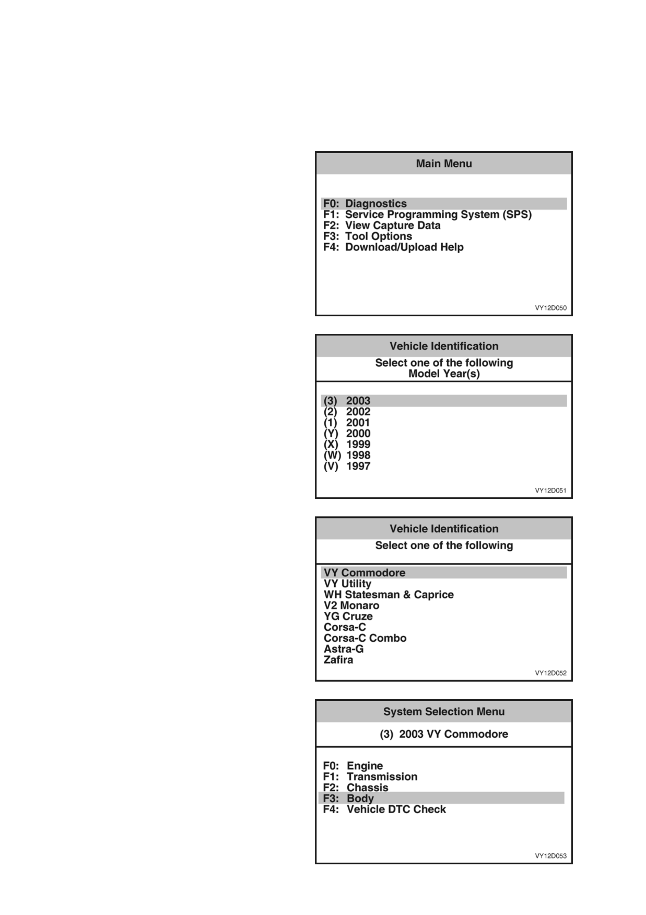
System Selection Menu
With TECH 2 connected to the DLC, select
F0: Diagnostics selected from the Main Menu, the
correct Model Year and Vehicle Type must be
selected for access to the System Selection Menu.
Select F3: Body.
This mode contains all functions to test, diagnose,
monitor and program the vehicle’s body systems
including the OCC as well as providing the
opportunity to check all DTC’s that may be set in
the vehicle.
Figure 2F-3
The correct Model Year is then selected.
Figure 2F-4
The Vehicle Type is then selected.
Figure 2F-5
Select F3: Body.
This mode contains all functions to test, diagnose,
monitor and program the vehicle’s body systems
including the OCC as well as providing the means
to check all DTC’s that may be set in the vehicle.
Figure 2F-6
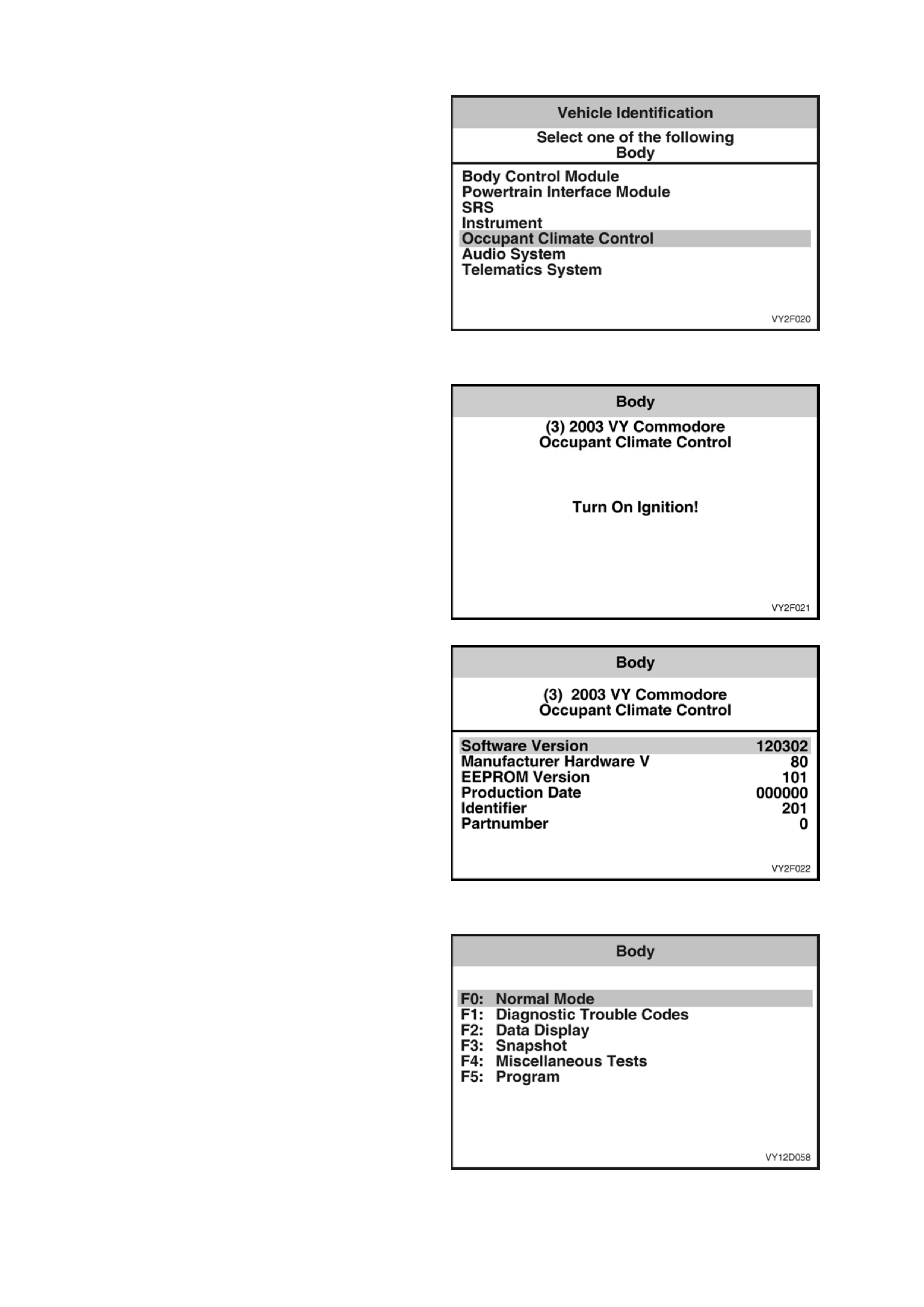
Body Application Menu
Once F3: Body has been selected from the System
Select Menu, Occupant Climate Cont rol can be
selected.
Select Occupant Climate Control.
NOTE: If information regarding DTC’s set for the
vehicle is required, select DTC Check and press
enter to continue. To return to the OCC mode
option from the DTC Check mode option screen
display, simply press the EXIT key on TECH 2.
Once the OCC has been selected, the following
two System Identification screens will appear which
require action.
Figure 2F-7
System Identification
Turn the ignition ON (as requested) and press
CONFIRM soft key to continue.
Figure 2F-8
The System Identification screen will then display
OCC system control module identification data.
Press the CONFIRM soft key to continue to the
OCC Application Menu.
Figure 2F-9
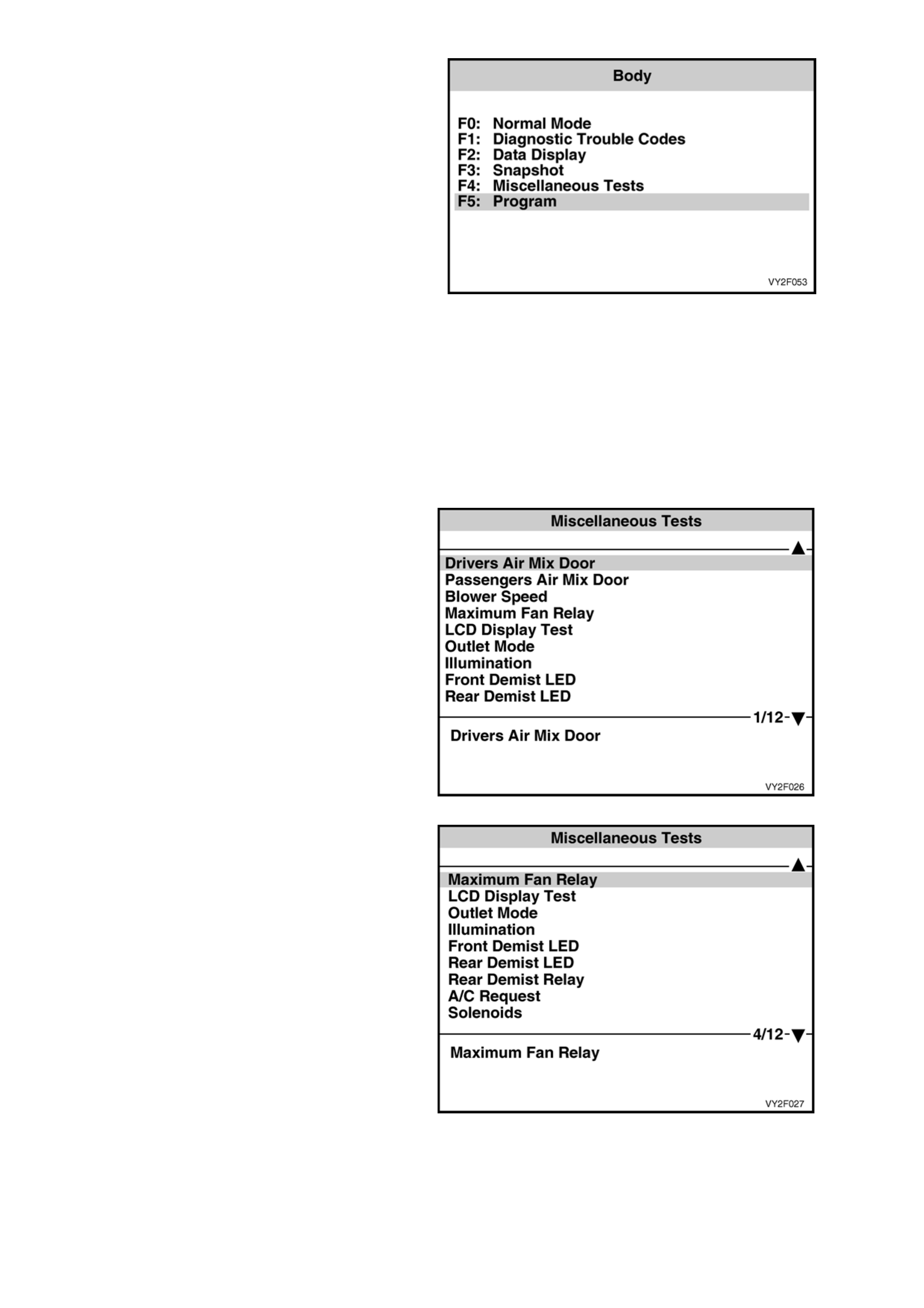
Body Menu
The following functions will now be available:
F0: Normal Mode
F1: Diagnostic Trouble Codes
F2: Data Display
F3: Snapshot
F4: Miscellaneous Tests
F5: Program
Figure 2F-10
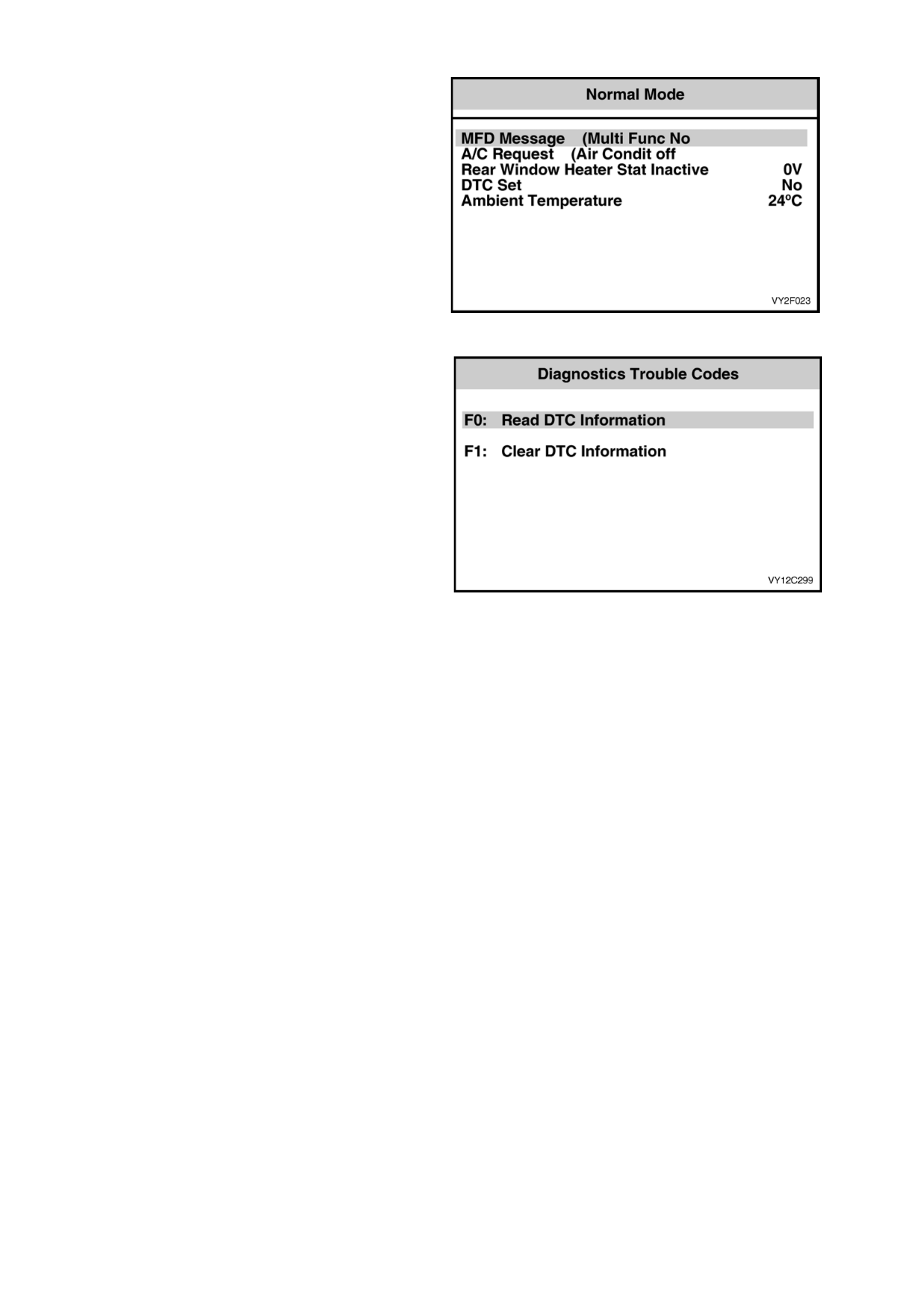
F0: NORMAL MODE
In the F0: Normal Mode, information that the OCC
control module is communicating to other control
modules, via the serial data line, is displayed.
For example: As displayed opposite, the A/C
request status is ‘(Air Condit off’. This means the
OCC control module is communicating with the
BCM, informing that the air conditioning
compressor is currently turned off.
Figure 2F-11
F1: DIAGNOSTIC TRO UBLE CODES (DTC)
If F1: Diagnostic Trouble Codes is selected, a
selection list is displayed which contains:
F0: Read DTC Informa tion: In this mode, a listing
of all (if any) current DTC numbers, together with a
brief description of the DTC, will be displayed. A
listing of the last two stored DTC’s will be
displayed, together with a brief description of the
DTC and the number of ignition cycles since the
DTC occurre d.
NOTE: If any DTC’s are set, reference sh ould be
made to the relevant diagnostic charts in this
Section.
F2: Clear DTC Informatio n: In this mode, DTC’s
can be cleared by simply selecting F2: Clea r DTC
Information and pressing the enter key on TECH 2.
The following table sets out all the possible
diagnostic trouble codes as indicated by TECH 2.
Figure 2F-12

The following table lists all OCC system DTCs applica ble to MY2003 VY and V2 Series vehicles.
DTC CODE DESCRIPTION
13 Ambient temperature sensor voltage too high
14 Ambient temperature sensor voltage too low
15 In car temperature sensor voltage too high
16 In car temperature sensor voltage too low
17 Evaporative temperature sensor voltage too high
18 Evaporative temperature sensor voltage too low
19 Sun load sensor error
35 No serial data from PCM
36 No serial data from BCM
37 ROM checksum error
38 EEPROM checksum error
39 RAM error
40 Air mix door motor driver error
41 Solenoid driver error
43 Driver’s air mix door motor feedback circuit voltage
too low
44 Driver’s air mix door motor feedback circuit voltage
too high
45 Passenger’s air mix door motor feedback circuit
voltage too low
46 Passenger’s air mix door motor feedback circuit
voltage too high
47 Driver Airmix Min. Calibration Erro r
48 Driver Airmix Max. Calibration Error
49 Pass Airmix Min. Calibration Error
50 Pass Airmix Max. Calibration Erro r
NOTE: for diagnosis of the pressure transducer, refer to the following Sections in the MY2003 VY and V2 Series
Service Information:
• Section 6C1 POWERTRAIN CONTROL MODULE – V6 ENGINE.
• Section 6C2 POWERTRAIN CO NTROL MODULE – V6 SUPERCHARGED ENGINE.
• Section 6C3 POWERTRAIN CONTROL MODULE – GEN III V8.
F2: DATA DISPLAY
If the F2: Data Display mode is selected, an additional menu will appear giving the operator th e option of selecting:
• F1: OCC Data List,
• F2: OCC Switch Data,
• F3: System Identification or,
• Air Mix Door Calibration Position s.
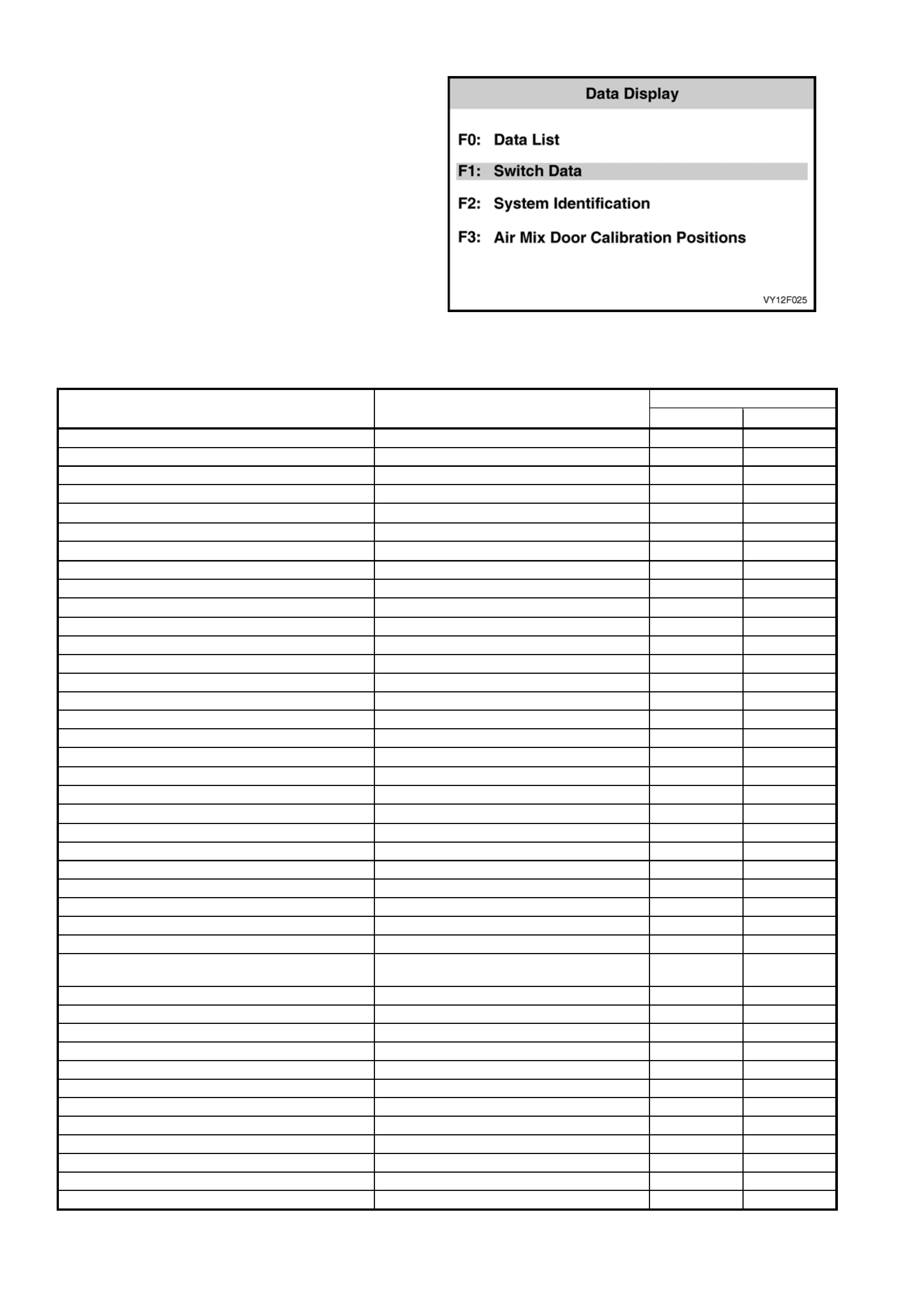
F0: Data List
The data list displays inputs and o utputs of the
OCC system. When F2: DATA DISPLAY is
selected followed by F0: DATA LIST, the Switch
Data Table will be displayed.
Figure 2F-13
The following table shows all items in the DATA LIST, together with their expected readings:
OCC TYPE
DATA LIST READING Single Zone Dual Zone
System Status On/Off X X
Battery Voltage Approx 13.5 V X X
Ignition Status OFF/ON X X
Air Conditioning Request NO/YES X X
Evaporative Temperature Sensor 0 to 5.0 ± 0.2 V X X
Evaporative Temperature °C X X
Ambient Temperature Sensor 0 to 5.0 ± 0.2 V X X
Ambient Temperature Degrees °C X X
Dampened Ambient Temperature Degrees °C X X
In Car Temperature Sensor 0 to 5.0 ± 0.2 V X X
In Car Temperature Degrees °C X X
Blower Fan Speed Manual: 1234 and HIGH, Auto: Low, Mid and High X X
Desired Blower Fan Speed % X X
Blower Fan Speed Control % X X
Blower Fan Speed Feedback Voltage V X X
Drivers Air Mix Motor Position Desired % X X
Drivers Air Mix Motor Position Feedback % X X
Drivers Air Mix Motor Position Feedback Voltage 0 to 5.0 ± 0.2 V X X
Passengers Air Mix Motor Position Desired % X
Passengers Air Mix Motor Position Feedback % X
Passengers Air Mix Motor Position Feedback Voltage 0 to 5.0 ± 0.2 V X
Engine Coolant Temperature Degrees °C X X
Sun Load Steps: 0 – 255 X X
Driver Set Temperature Degrees °C X X
Passengers Set Temperature Degrees °C X
Operating Mode Manual/auto X X
Outlet Mode Face / floor / blend / foot X X
Inlet Mode Fresh / Recirc X X
Startup Strategy None, Recirc / Delay, Demist / Delay, Purge,
A/C Purge, Fresh / Delay X X
Fresh / Recirculation Solenoid Off/On X X
Water Valve Solenoid Off/On X X
Water Valve Closed/Open X X
Face 2 Solenoid Off/On X X
Face 1 Solenoid Off/On X X
Foot 2 Solenoid Off/On X X
Foot 1 Solenoid Off/On X X
High Fan Relay Inactive: 12 V Active: 0 V X X
Rear Demist Relay Off/On X X
Park Lamp Input Off/On X X
Front Demist LED Off/On X X
Rear Demist LED Off/On X X

F1: Switch Data
In this mode, the operator is able to test the
function of each switch on the OCC control module.
When F2: DATA DISPLAY is selected followed by
F1: SWITCH DATA, the Switch Data Table will be
displayed.
NOTE: The OCC control module buttons will need
to be held on when carrying out this test due to a
normal delay in information transfer.
To test the OCC control module switches in this
mode, turn on the ignition and the OCC system.
Activate each switch on the OCC cont rol module
and observe the TECH 2 screen to see if the
TECH 2 display changes the switch status from Off
to On.
Figure 2F-14
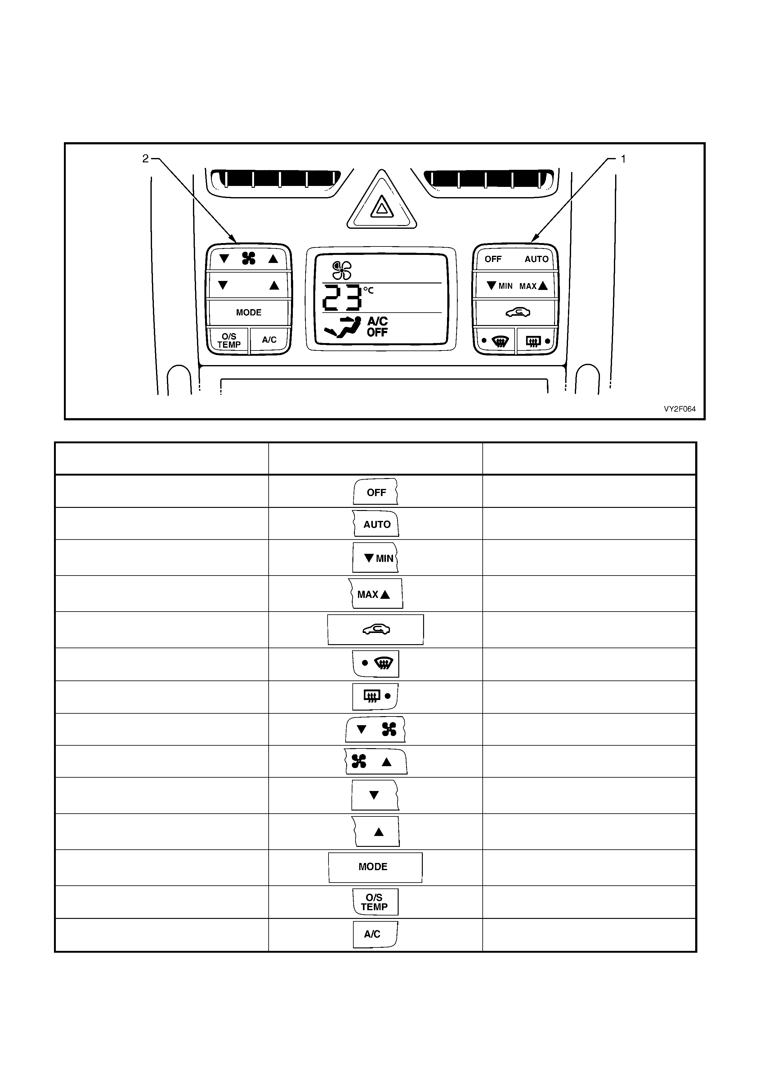
Figure 2F-15 shows the OCC switch configuration applicable to LHD models. The table following shows all items in
the SWITCH DATA, the switch graphics and their expected test readings. Switch progression of the table follows
the switch layout of the LHD OCC control module. Turn each switch on and off beginning at the OFF side of the
OFF/AUTO switch (1) and progre ss down through the right-hand side switch cluster. Move to the left-hand side
switch cluster and begi nning at the T side of the blower fan switch (2), turn each switch on and off.
Figure 2F-15
SWITCH DATA SWITCH READING
Off Switch Off/On
Auto Switch Off/On
Minimum Temperature Switch Off/On
Maximum Temperature Switch Off/On
Recirculation Switch Off/On
Front Demist Switch Off/On
Rear Demist Switch Off/On
Fan Down Switch Off/On
Fan Up Switch Off/On
Driver Temp. Down Switch (Temperature) Off/On
Driver Temp. Up Switch (Temperature) Off/On
Mode Switch Off/On
Outside Temperature Switch Off/On
Air Conditioning Switch Off/On
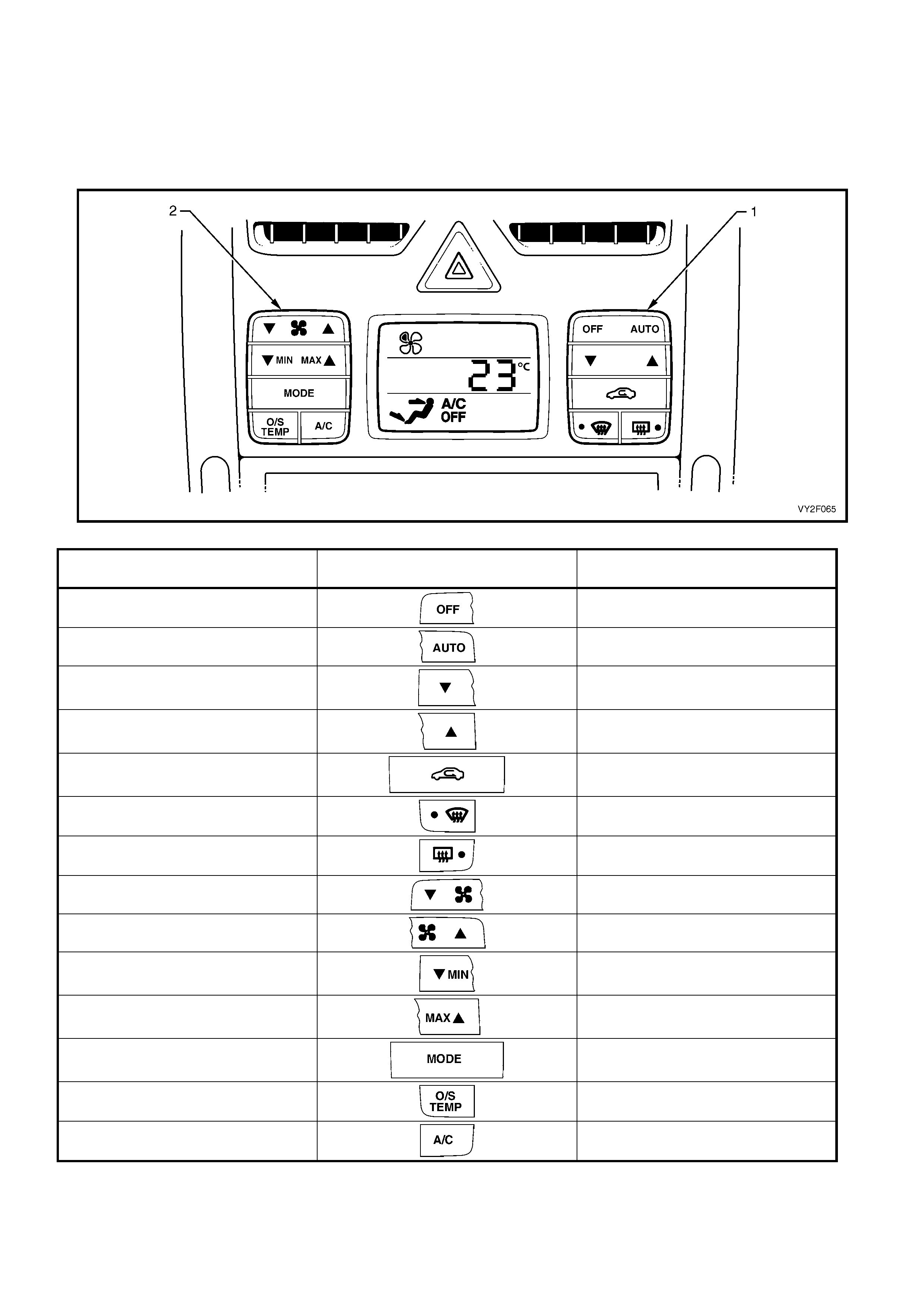
Figure 2F-16 shows the OCC switch configuration applicable to RHD single zone models. The table following
shows all items in the SWITCH DATA, the switch graphics and their expected test readings. Switch prog ression of
the table follows the switch layout of the RHD single zone OCC control module. Turn ea ch switch on and off
beginning at the OFF side of the OFF/AUTO switch (1) and progress down through the right-hand side switch
cluster. Move to the left-hand side switch cluster and beginning at the T side of the blower fa n switch (2), turn each
switch on and off.
Figure 2F-16
SWITCH DATA SWITCH READING
Off Switch Off/On
Auto Switch Off/On
Driver Temp. Down Switch (Temperature) Off/On
Driver Temp. Up Switch (Temperature) Off/On
Recirculation Switch Off/On
Front Demist Switch Off/On
Rear Demist Switch Off/On
Fan Down Switch Off/On
Fan Up Switch Off/On
Minimum Temperature Switch Off/On
Maximum Temperature Switch Off/On
Mode Switch Off/On
Outside Temperature Switch Off/On
Air Conditioning Switch Off/On
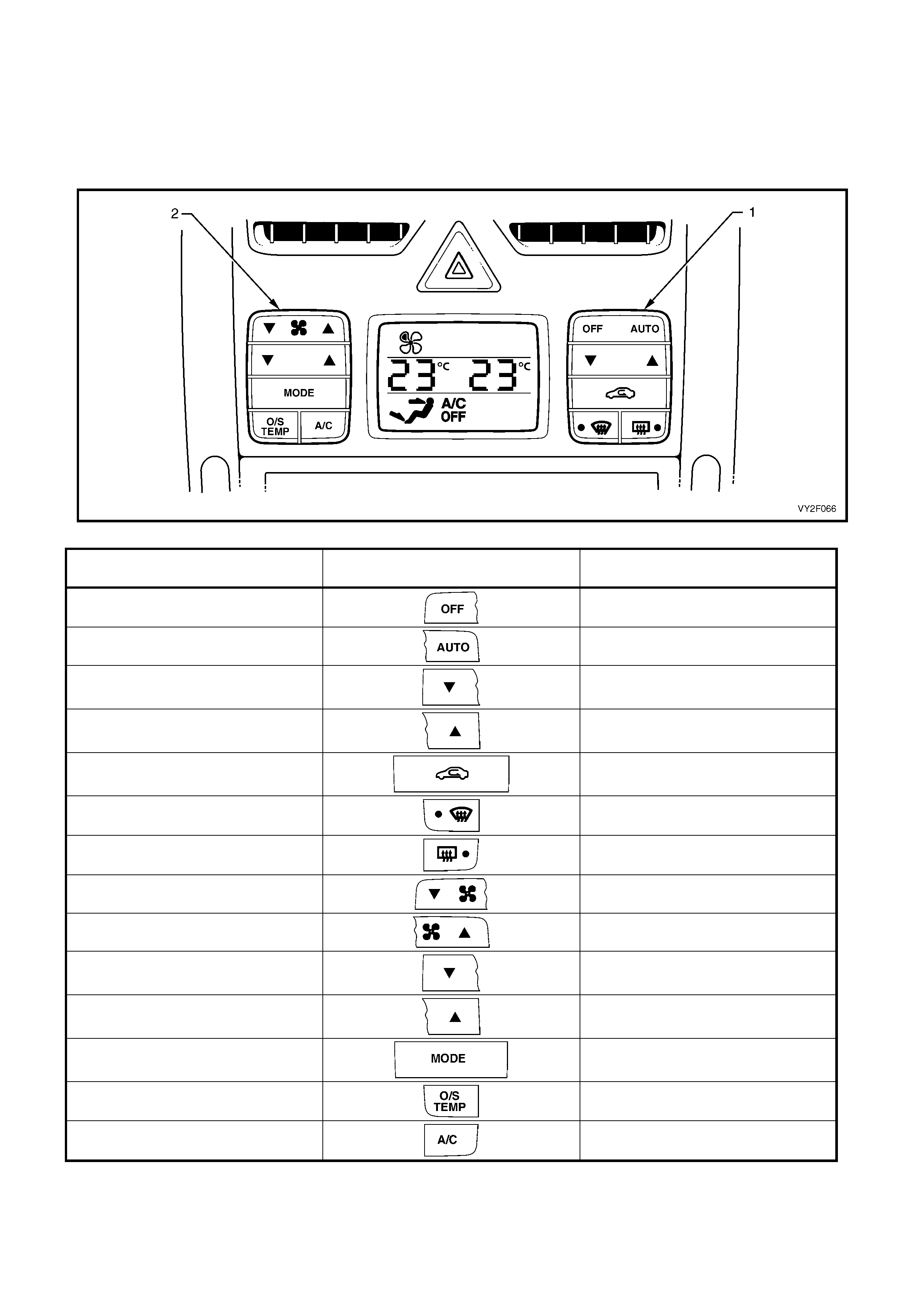
Figure 2F-17 shows the OCC switch configuration applicable to RHD dual zone models. The table following shows
all items in the SWITCH DATA, the switch graphics and their expected test readings. Switch progre ssion of the
table follows the switch layout of the RHD dual zone OCC control module. Turn each switch on and off beginning at
the OFF side of the OFF/AUTO switch (1) and p ro gress down through the right-hand side switch cluster. Move to
the left-hand side switch cluster and beginning at the T side of the blower fan switch (2), turn each switch on and
off.
Figure 2F-17
SWITCH DATA SWITCH READING
Off Switch Off/On
Auto Switch Off/On
Driver Temp. Down Switch (Temperature) Off/On
Driver Temp. Up Switch (Temperature) Off/On
Recirculation Switch Off/On
Front Demist Switch Off/On
Rear Demist Switch Off/On
Fan Down Switch Off/On
Fan Up Switch Off/On
Passenger Temp. Down Switch
(Temperature) Off/On
Passenger Temp. Up Switch
(Temperature) Off/On
Mode Switch Off/On
Outside Temperature Switch Off/On
Air Conditioning Switch Off/On
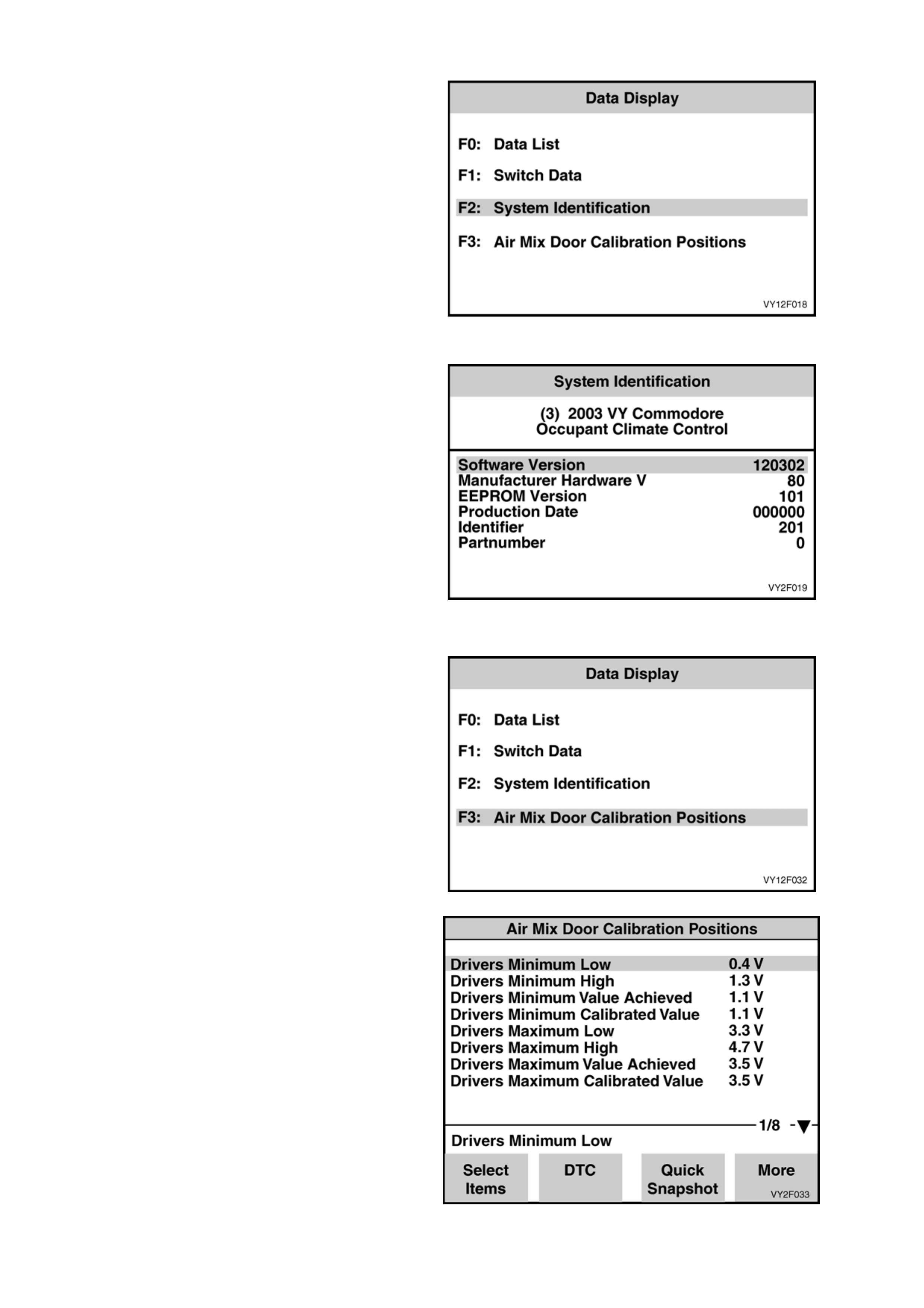
F2: System Identification
When F2: DATA DISPLAY is selected followed by
F2: SYSTEM IDENTIFICATION, the System
Identification will be displayed.
Figure 2F-18
In this mode, the operator is able to view the
System Identification screen, which will display
OCC system control module identification data.
Figure 2F-19
F3: Air Mix Door Calibration Positions
When F2: DATA DISPLAY is selected followed by
F3: AIR MIX DOOR CALIBRATION POSITIONS,
the System Identification will be displayed.
Figure 2F-20
In this mode, the operator is able to view the results
of the last air mix door calibration.
Figure 2F-21
The air mix doors can be calibrated by selecting
F5: Program in the Body menu. To carry out an air
mix door calibration, refer to F5: PROGRAM in this
Section.
Figure 2F-22
F3: SNAPSHOT
In this test mode, the TECH 2 captures OCC data before and after a forced manual trigger.
F4: MISCELLANEOUS TESTs
In the Miscellaneous Test mode, tests can be carried out to the OCC system that will test for proper operation of
the various OCC functions. In this mode, testing and observing the results can confirm correct operation or identify
error conditions.
NOTE: During the Miscellaneous Tests, the blower fan will be driven at approximately 60% for all tests excluding
the Blower Speed test.
When Miscellaneous Tests is sele cted, the first
nine tests will be displayed.
Figure 2F-23
When the menu is scrolled downward with the
down soft key, the remaining test options are
displayed.
Figure 2F-24
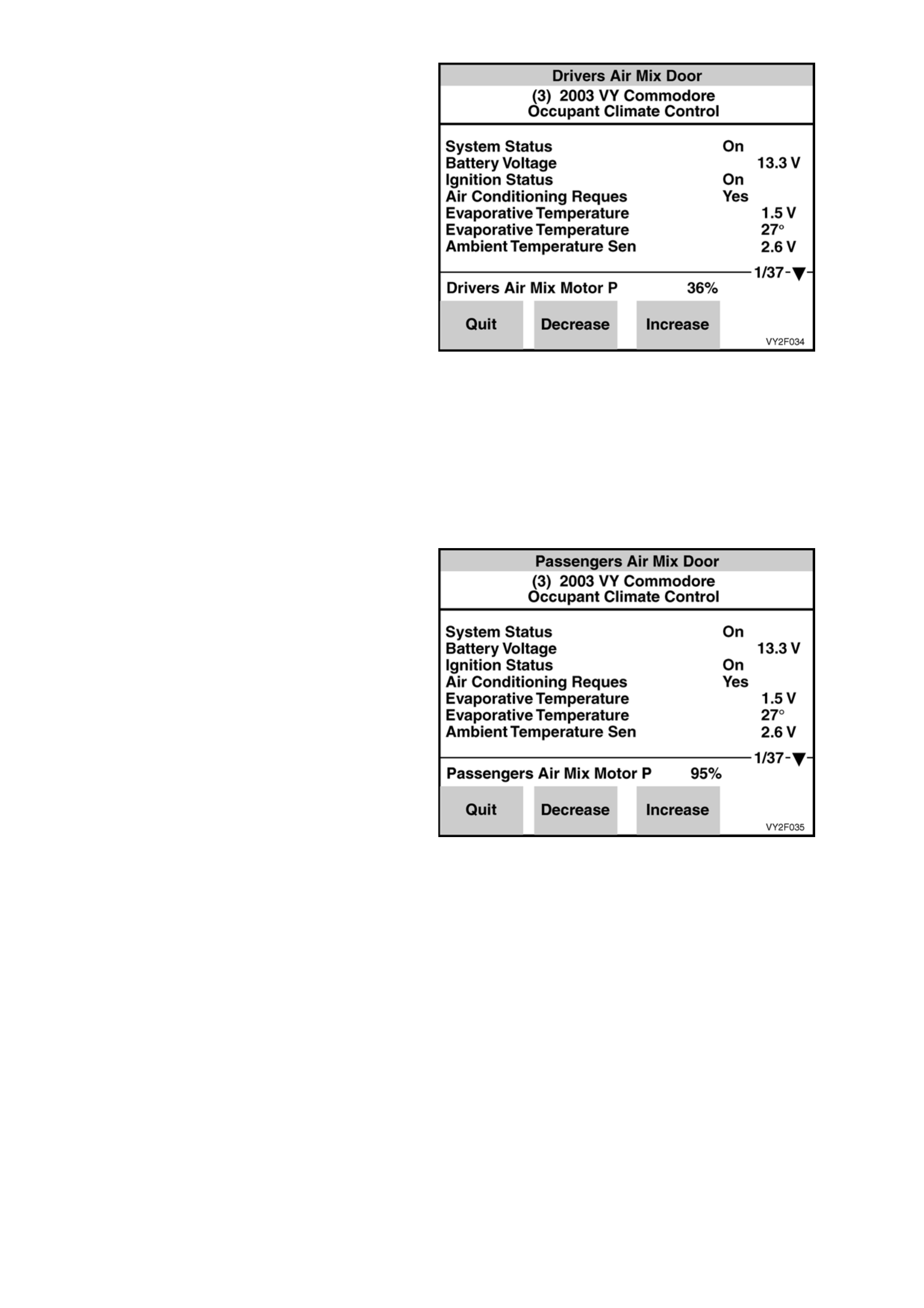
Driver’s Air Mix Door
PURPOSE OF TEST:
Monitor the face vent to verify that a temperature
change takes place when opening and closing the
air mix door, indicating both air mix motor and door
movement.
PRE-CONDITIONS:
Engine running at operating temperature.
PROCEDURE:
Insert a thermometer into the centre face vent
(right-hand side centre vent for dual zone). With
TECH 2 connected to the DLC select:
Body /
Occupant Climate Control /
Miscellaneous Tests /
Driver’s Side Air Mix Door.
Conduct the Drivers Side Air Mix Door test by
using the increase/decrease soft keys on TECH 2
open and close the air mix door. The range is
variable from 9% closed to 100% open.
When the door is open (increase % opening), the
temperature at the centre vent should increase.
When the door is closed (decrease % opening), the
temperature at the centre vent should decrease.
Figure 2F-25
Passenger’s Air Mix Door
PURPOSE OF TEST:
Monitor the face vent to verify that a temperature
change takes place when opening and closing the
air mix door, indicating both air mix motor and door
movement.
PRE-CONDITIONS:
Engine running at operating temperature.
PROCEDURE:
Insert a thermometer into the left side of the centre
face vent. With TECH 2 connected to the DLC
select:
Body /
Occupant Climate Control /
Miscellaneous Tests /
Passenger’s Side Air Mix Door.
Conduct the Passenger Side Air Mix Door test by
using the increase/decrease soft keys on TECH 2
open and close the air mix door. The range is
variable from 9% closed to 100% open.
When the door is open (increase % opening), the
temperature at the centre vent should increase.
When the door is closed (decrease % opening), the
temperature at the centre vent should decrease.
Figure 2F-26
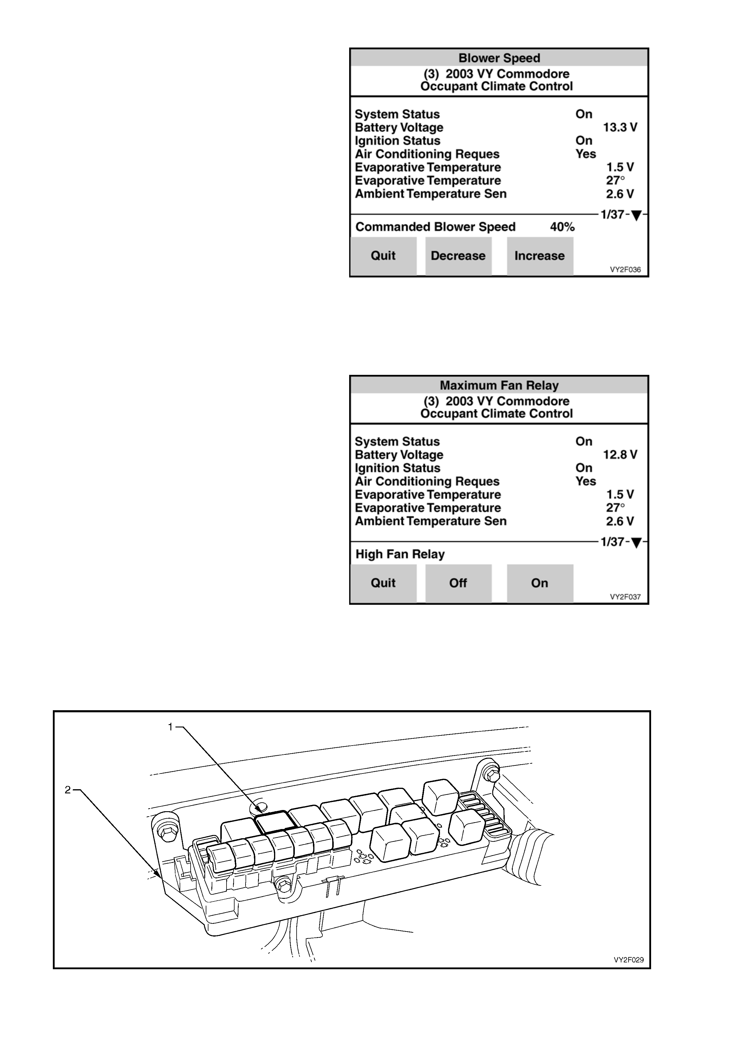
Blower Speed
PURPOSE OF TEST:
To ensure that all blower speeds are preset and
the blower motor circuit is functional.
PRE-CONDITION:
Engine running
PROCEDURE:
With TECH 2 connected to the DLC select:
Body /
Occupant Climate Control /
Miscellaneous Tests /
Blower Speed.
Using the increase soft key on TECH 2, command
the blower fan to maximum – 100%.
Using the decrease soft key on TECH 2, command
the blower fan to minimum – 0%.
Each soft key increase or decrease will alter fan
speed by a 10% increment.
NOTE: Blower fan speeds are dependant on
vehicle battery voltage.
Figure 2F-27
Maximum Fan Relay
PURPOSE OF TEST:
To ensure a circuit exists between the OCC control
module, the relay and the blower fan.
PRE-CONDITION:
Engine off.
PROCEDURE:
With TECH 2 connected to the DLC select:
Body /
Occupant Climate Control /
Miscellaneous Tests /
Maximum Fan Relay.
Figure 2F-28
Conduct the Maximum Fan Relay test by using the On soft key to activate the relay and maximum fan sp eed.
Use the Off soft key to deactivate relay and turn blower speed off. The maximum fan relay (1) is labelled
BLOWER FAN RELAY and is located in the engine compa rtment fuse and relay housing (2). Listen or feel for
the relay activating (clickin g) wh en the On and Off soft keys are activated on TECH 2. If the relay does not
activate, temporarily substitute with a serviceable relay from an adjacent installation. If the substitute relay
does not activate, refer to Chart A in 2. DIAGNOSTIC CHARTS in this Section.
Figure 2F-29
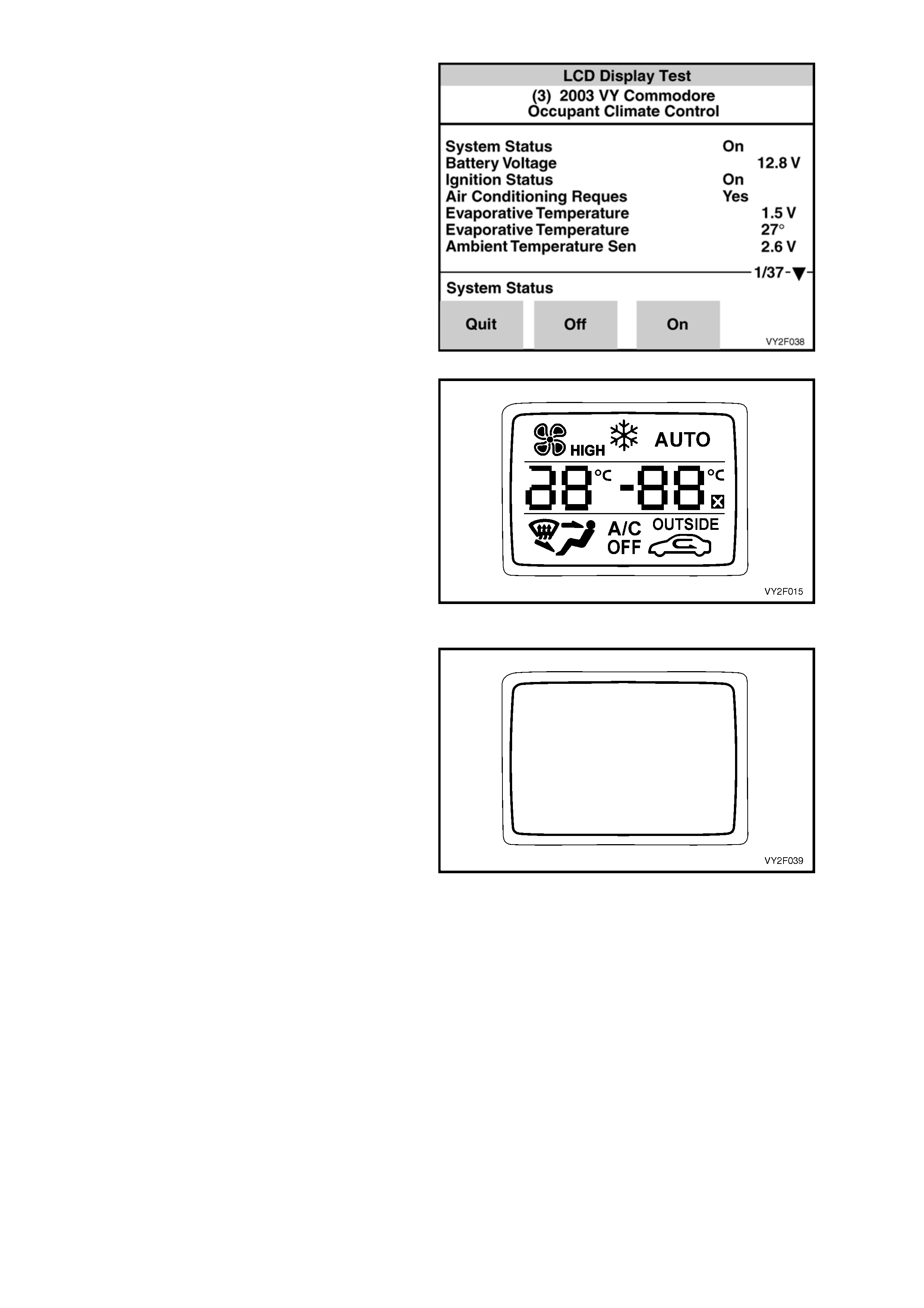
LCD Display Test
PURPOSE OF TEST:
To ensure that all segments are functioning an d
can be displayed on the OCC control module LCD
screen.
PRE-CONDITION:
Engine not running.
PROCEDURE:
With TECH 2 connected to the DLC select:
Body /
Occupant Climate Control /
Miscellaneous Tests /
LCD Display Test.
Using the On/Off soft keys on TECH 2, activate
and deactivate the LCD. An LCD screen displaying
all segments should appear for approximately
5 seconds after the On soft key is activated.
Pressing the Off key will turn all segments off for
approximately 5 seconds but the LCD screen will
remain illuminated during this procedure.
Figure 2F-30
Figure 2F-31
Figure 2F-32
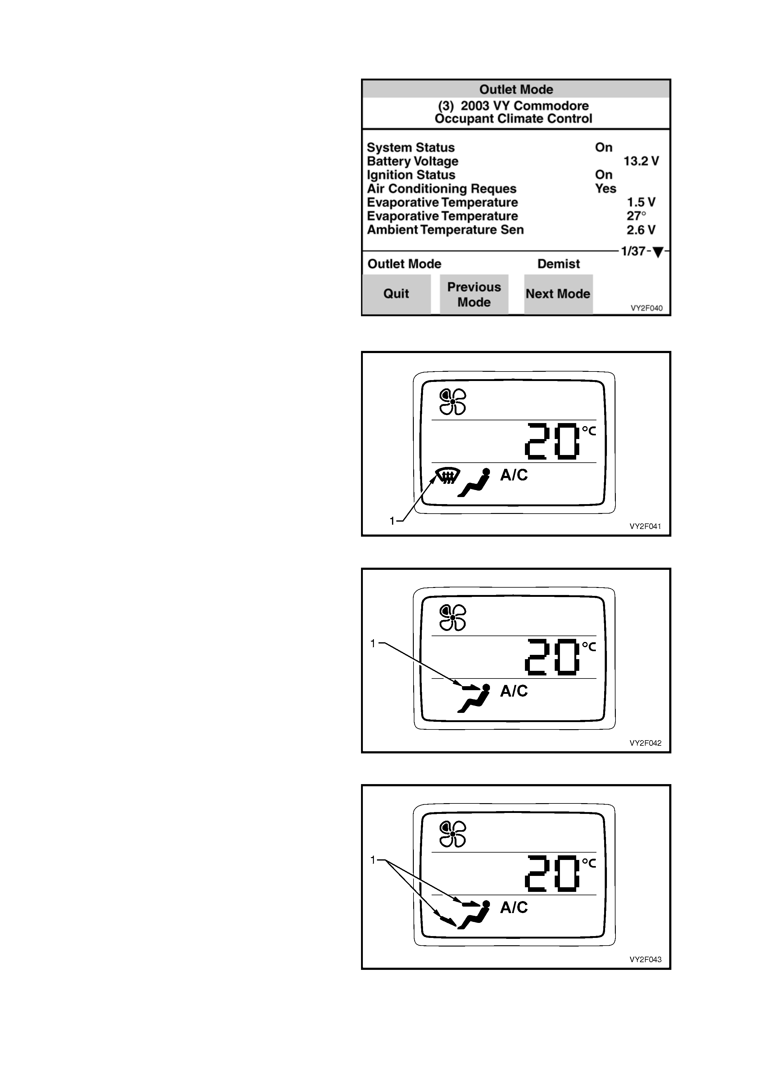
Outlet Mode
PURPOSE OF TEST:
To ensure that the vacuum solenoids, vacuum
supply and mode doors are functional.
PRE-CONDITION:
Engine running.
PROCEDURE:
With TECH 2 connected to the DLC select:
Body /
Occupant Climate Control /
Miscellaneous Tests /
Outlet Mode.
Conduct Outlet Mode test by using the up/down
soft keys on TECH 2 and scrolling through each
mode position; Demist, Face, Foot/Face (Bi-level),
Demist/Foot (Blend) and Foot.
The OCC control module LCD indicates the
position that the air will be directed to. During this
test the blower fan will be driven at approximately
60%.
Feel for air movement at the direction indicated by
the mode graphic on the OCC control module LCD
screen.
When the Demist Mode is selected, air i s
distributed from demist ducts only. The demist ico n
(1) will be displayed on the LCD screen.
When Face Vent Mode is selected air is distributed
from the centre and side vents. The fa ce icon (1)
will be displayed on the LCD screen.
NOTE: On dual zon e sy stems, when the Face Vent
Mode is selected, air will be distributed from left
and right or the centre face vent.
When the Face/Foot (Bi-Level) Mode is sele cted,
air is distributed from face, side and floor ducts.
The bi-level icon (1) will be displayed on the LCD
screen.
Figure 2F-33
Figure 2F-34
Figure 2F-35
Figure 2F-36
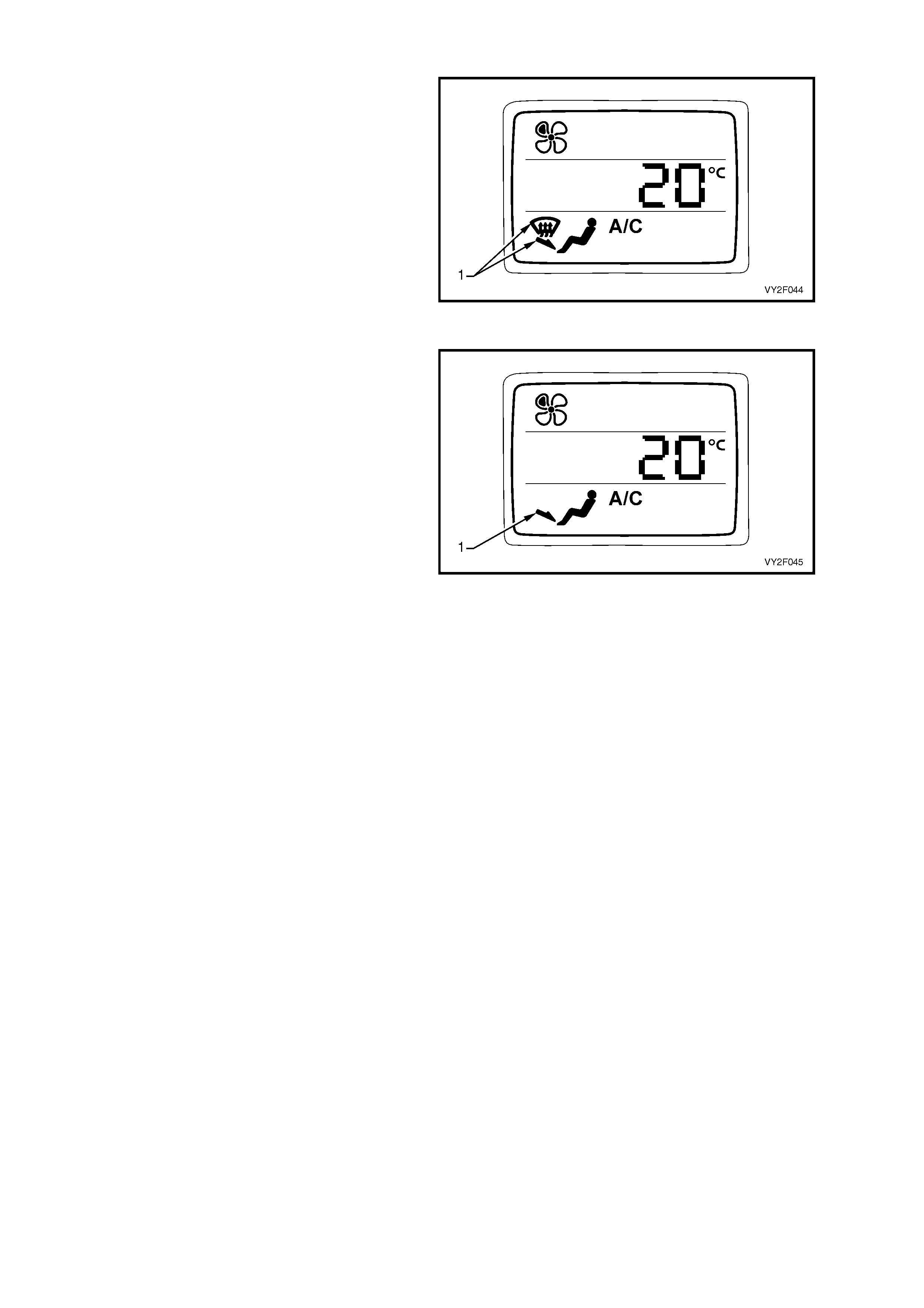
When the Demist/Foot (Blend) Mode is selected,
air is distributed from demist ducts and the floor.
The demist and foot icons (1) will be displayed on
the LCD screen.
When the Foot (Floor) Mode is sele cted, air is
distributed to the floor. The foot icon (1) will be
displayed on the LCD screen.
Figure 2F-37
Figure 2F-38
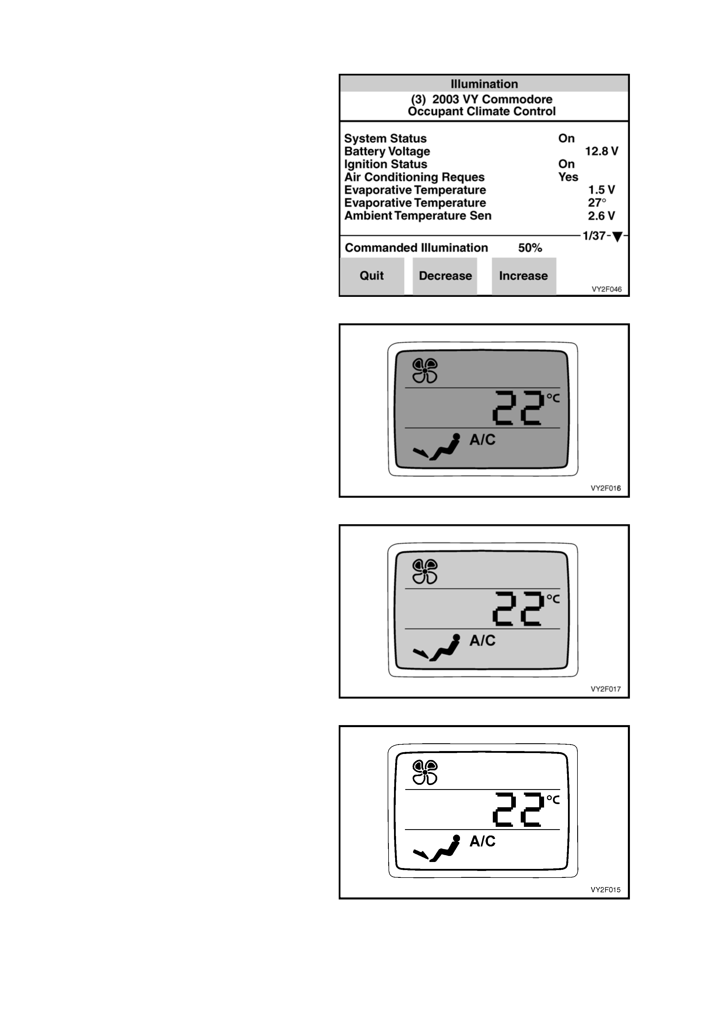
Illumination
PURPOSE OF TEST:
To check the illumination function of the LCD
screen.
PRE-CONDITION:
Engine not running.
PROCEDURE:
With TECH 2 connected to the DLC select:
Body /
Occupant Climate Control /
Miscellaneous Tests /
Illumination.
Conduct the Illumination test by pressing the soft
keys on TECH 2 to adjust the illumination level of
the LCD screen. Press the increase soft key on
TECH 2 to increase the illumination level of the
LCD screen. Each press of the soft keys adjusts
the illumination level between 0% and 100% in
10% increments.
Press the decrease soft key on TECH 2 to reduce
the illumination level of the LCD screen.
Press the increase soft key on TECH 2 to raise the
illumination level of the LCD screen.
Continue to press the increase soft key on TECH 2
to maximum illumination level of the LCD screen.
The illumination across the complete LCD screen
should be uniform at any given illumination level.
Figure 2F-39
Figure 2F-40
Figure 2F-41
Figure 2F-42
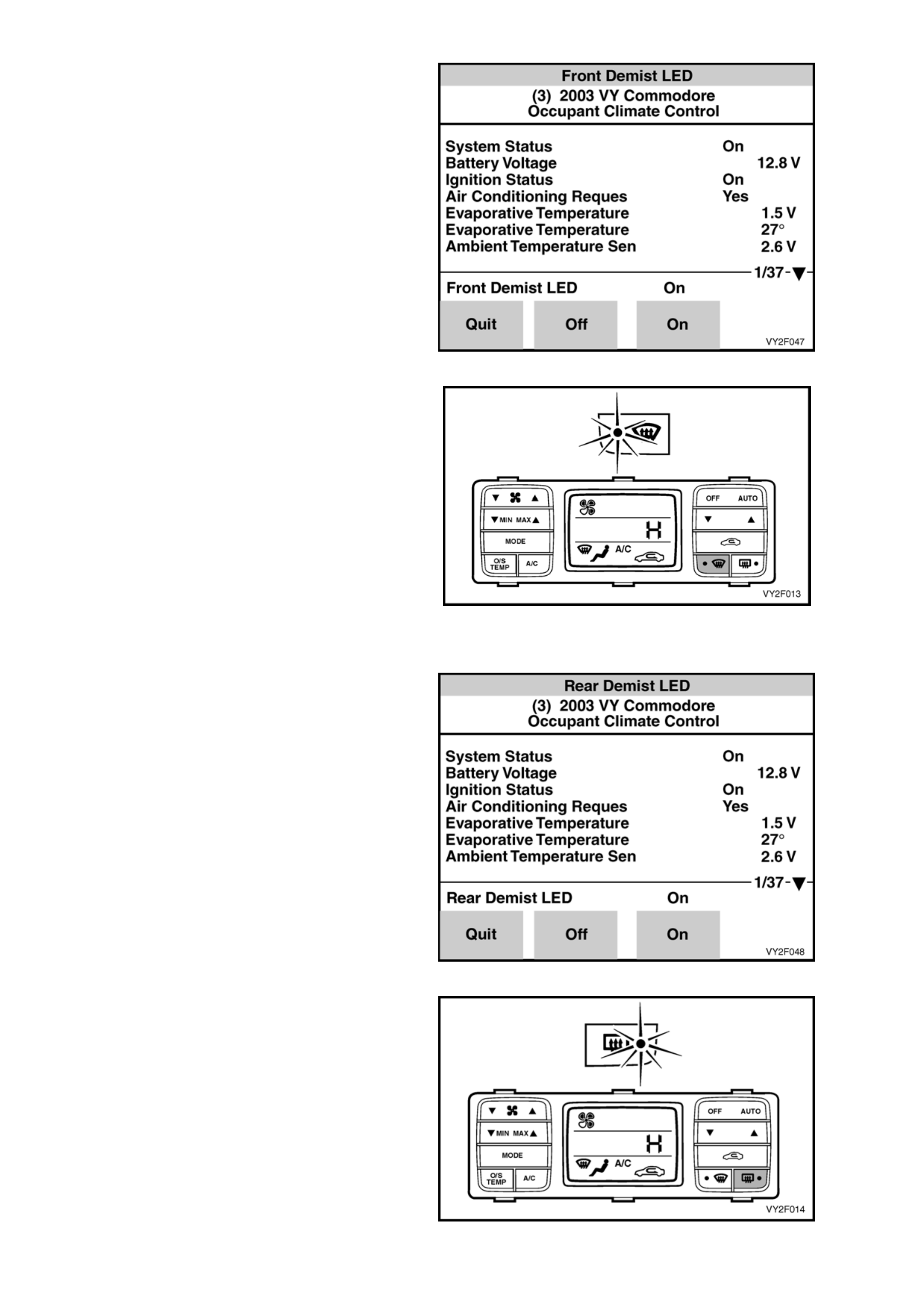
Front Demist led
PURPOSE OF TEST:
To check the operation of the front demist LED.
PRE-CONDITION:
Engine not running.
PROCEDURE:
With TECH 2 connected to the DLC select:
Body /
Occupant Climate Control /
Miscellaneous Tests /
Front Demist LED.
Conduct the Front Demist LED test by pressing the
On soft key to activate the orange LED on the front
demist button. The front demist LED will illuminate.
Use the Off soft key to deactivate the LED.
Figure 2F-43
Figure 2F-44
Rear Demist LED
PURPOSE OF TEST:
To check the operation of the rear demis t LED.
PRE-CONDITION:
Engine not running.
PROCEDURE:
With TECH 2 connected to the DLC select:
Body /
Occupant Climate Control /
Miscellaneous Tests /
Rear Demist LED.
Conduct the Rear Demist LED test by p ressin g the
On soft key to activate the orange LED on the rear
demist button. The rear demist LED will illuminate.
Use the Off soft key to deactivate the LED.
Figure 2F-45
Figure 2F-46
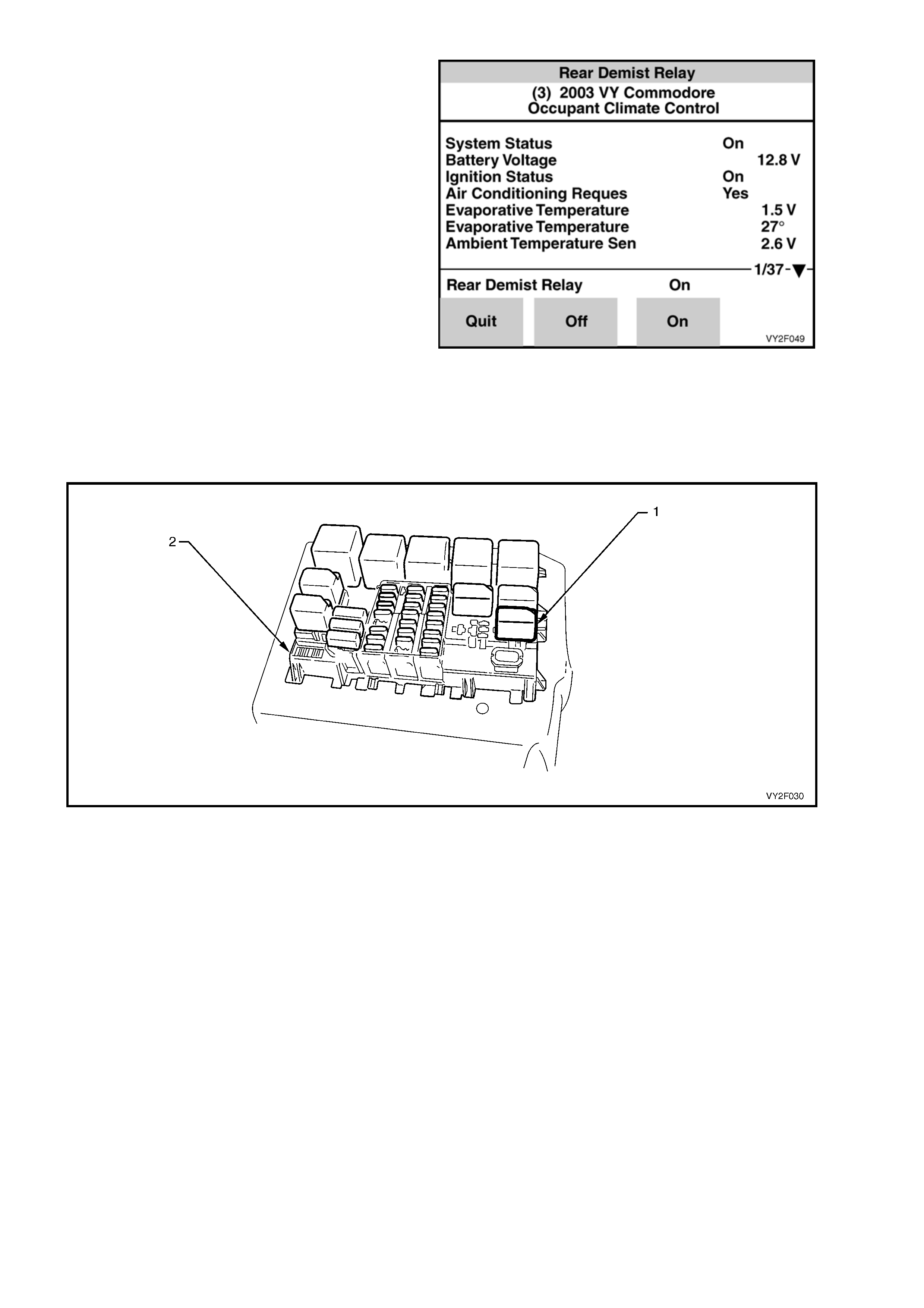
Rear Demist Relay
PURPOSE OF TEST:
To check operation of circu i t from OCC control
module to relay.
PRE-CONDITION:
Engine not running.
PROCEDURE:
With TECH 2 connected to the DLC select:
Body /
Occupant Climate Control /
Miscellaneous Tests /
Rear Demist Relay.
Figure 2F-47
Conduct the Rear Demist Relay test by pressing the On soft key to activate heated rear window relay. Use
the Off soft key to deactivate relay. The rear demist relay (1) is labelled HEATED REAR WINDOW and is
located in the instrument panel fuse and relay panel (2). Listen or feel for the relay activating (clicking) when
the On and Off soft keys are activated on TECH 2. If the relay does not activate, temporarily substitute with a
serviceable relay from an adjacent installation. If the substitute relay does not activate, refer to Chart A in
2. DIAGNOSTIC CHARTS in this Section.
Figure 2F-48
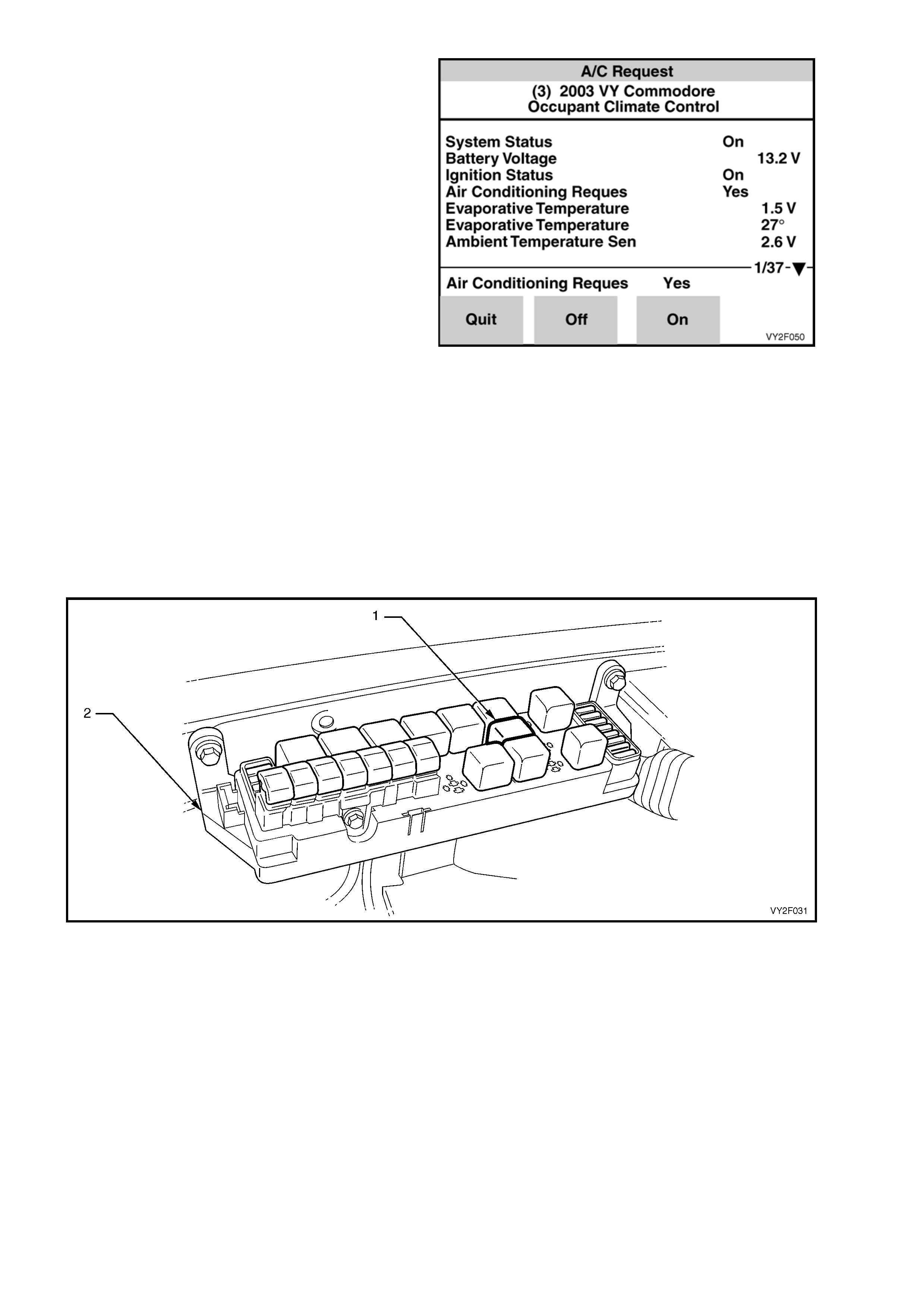
A/C Request
NOTE 1: In this test a blower fan speed is
automatically selected.
NOTE 2: A three second delay until compressor
clutch engagement will occur. This is a normal
condition.
PURPOSE OF TEST:
To ensure OCC control module, wi ring,
compressor relay and compressor clutch are
functional.
PRE-CONDITION:
Engine running.
PROCEDURE:
With TECH 2 connected to the DLC select:
Body /
Occupant Climate Control /
Miscellaneous Tests /
A/C Request.
Figure 2F-49
Conduct the A/C Request test by using the On soft key to engage the compressor clutch and the Off soft key
to disengage the compressor. Listen fo r clutch engagement noise. If the clutch does not engage, inspect the
A/C compressor relay. The A/C compressor relay (1) is labelled A/C COMPR RELAY and is located in the
engine compartment fuse and relay hou sing (2). Listen or feel for the relay activating (clicking) when the On
and Off soft keys are activated on TECH 2 If the relay does not activate, temporarily substitute with a
serviceable relay from an adjacent installation. If the substitute relay does not activate, refer to Chart A in
2. DIAGNOSTIC CHARTS in this Section.
Figure 2F-50
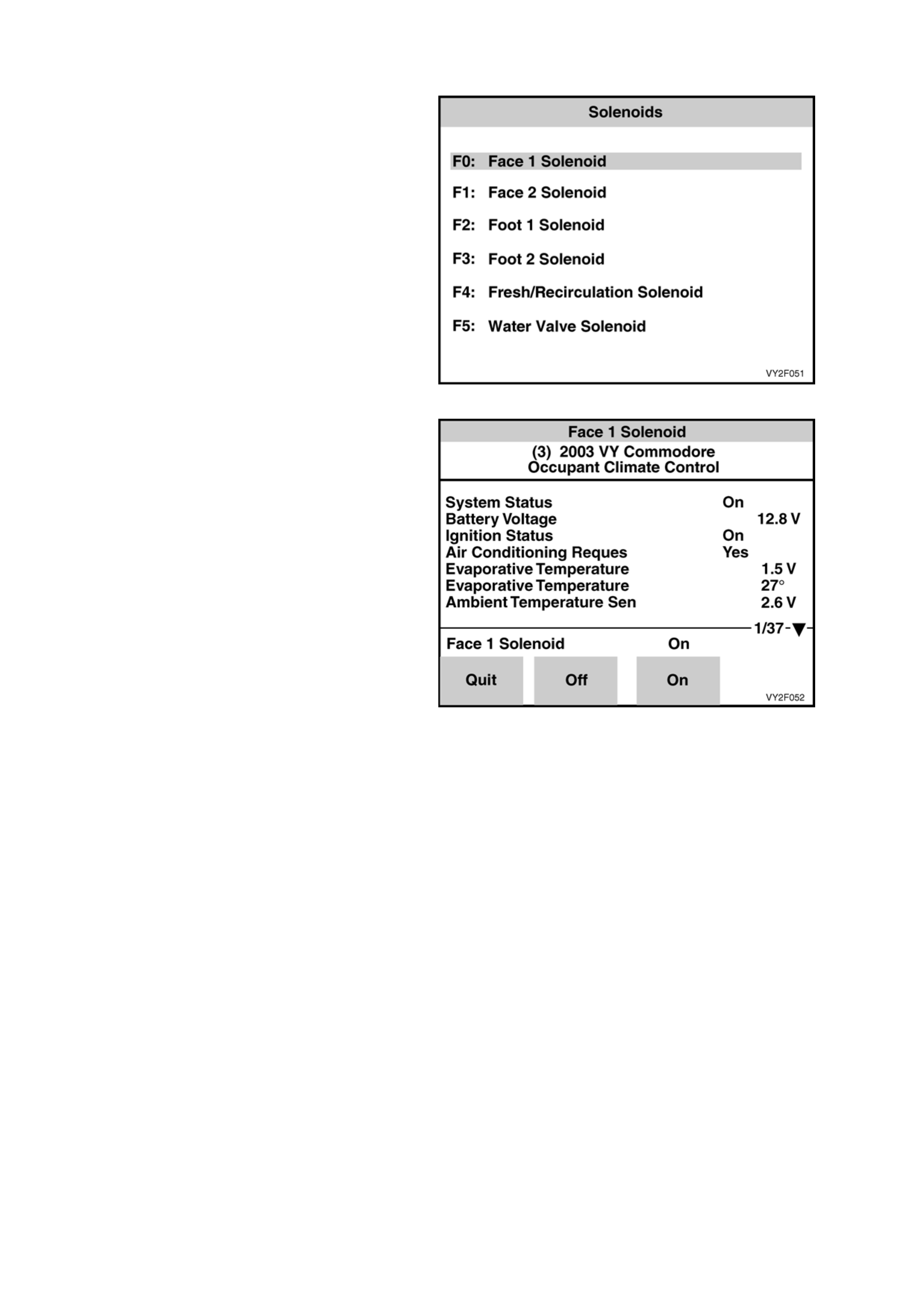
Solenoids
NOTE: If the TECH 2 Outlet Mode test was carried
out and passed, testing of the mode solenoids
need not be carried out. However, the water valve
solenoid circuit should be tested regardless of
Outlet Mode test results.
PURPOSE OF TEST:
To ensure the OCC control module and the
electrical circuit to the solenoid is OK.
PRE-CONDITION:
Engine not running.
PROCEDURE:
On RHD models remove the left-hand side
instrument panel lower trim plate assembly. On
LHD models remove the right-hand side instrument
panel lower trim plate assembly. Refer to
Section 1A3, 3.1 INSTRUMENT PANEL LOWER
TRIM PLATE ASSEMBLY. Locate the vacuum
solenoid pack (rear of blower motor and fan
housing).
With TECH 2 connected to the DLC select:
Body /
Occupant Climate Control /
Miscellaneous Tests /
Solenoids.
Conduct the Solenoids test by using the On soft
key to activate one solenoid at a time.
Listen or feel for the solenoids activating (clicking).
Use the Off soft key to deactivate solenoids and
likewise listen or feel for solenoids activating
(clicking). If a solenoid or solenoids do not activate,
refer to DTC 41 in 2. DIAGNOSTIC CHARTS in
this Section.
Figure 2F-51
Figure 2F-52
NOTE: The solenoid pack config urations for LHD
and RHD models are not the same. LHD models
use a solenoid pack fitted with five solenoids, refer
to Figure 2F-53. LHD models are also fitted with an
additional remote solenoid for water valve
activation, refer to Figure 2F-54. RHD models use
a solenoid pack fitted with six solenoids that
incorporates the solenoid f or water valve activation,
refer to Figure 2F-55.
Refer to Figure 2F-53, Figure 2F-54 and
Figure 2F-55 to understand which solenoid should
be activated in each mode.

Figure 2F-53 shows the sol enoid outlets from the
LHD HVAC unit vacuum solenoid pack. The
function of the solenoid connections and the colour
of the attached vacuum lines are listed below:
Legend
1. Foot 1 (Red)
2. Defrost (Green)
3. Face 2 (Brown)
4. Face 1 (Blue)
5. Fresh/Recirculation (Yellow)
6. Vacuum Supply (White)
Figure 2F-53
Figure 2F-54 shows the location of the sixth
solenoid for water valve activation on LHD HVAC
units. This electrically operated vacuum switching
valve (1) is located on the front of the HVAC unit
(2). The OCC control module activates the vacuum
switching valve in accordance to a manually
selected, or an automatically controlled
temperature setting.
The water valve is held in the off position by
vacuum. When the a cold setting is selected either
manually or automatically, the vacuum switching
solenoid valve will maintain vacuum to the heater
water valve so that no hot water enters the heater
core.
The integrity of vacuum switching solenoid valve
and its associated circuitry can be asse ssed by
observing the opening and closing action of the
water valve. The water valve is located in the
engine bay on the right-hand side inner guard.
If required, access to the vacuum switching
solenoid valve can achieved by removing the radio
assembly, radio housing and radio bracket
assembly.
Refer to:
• Section 1A3, 3.6 RADIO ASSEMBLY.
• Section 1A3, 3.11 RADIO HOUSING AND
RADIO BRACKET ASSEMBLY.
Figure 2F-54
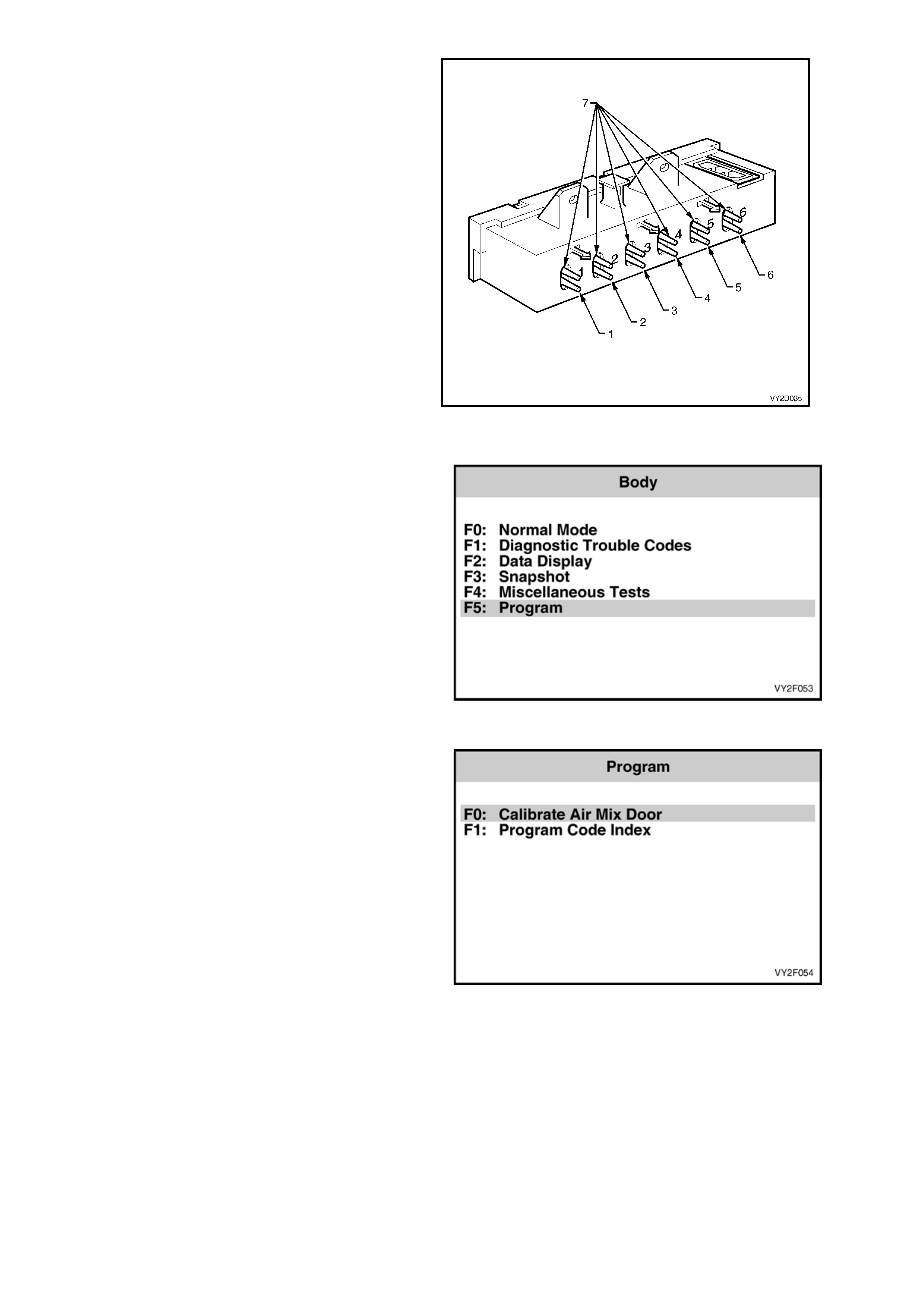
Figure 2F-55 shows the sol enoid outlets from the
RHD HVAC unit vacuum solenoid pack. The
function of the solenoid connections and the colour
of the attached vacuum lines are listed below:
Legend
1. Fresh/recirculation (Blue)
2. Face 1 (White)
3. Face 2 (Green)
4. Foot 1 (Pink)
5. Foot 2 (Orange)
6. Water valve (Yellow)
7. Vacuum supply (Black)
Figure 2F-55
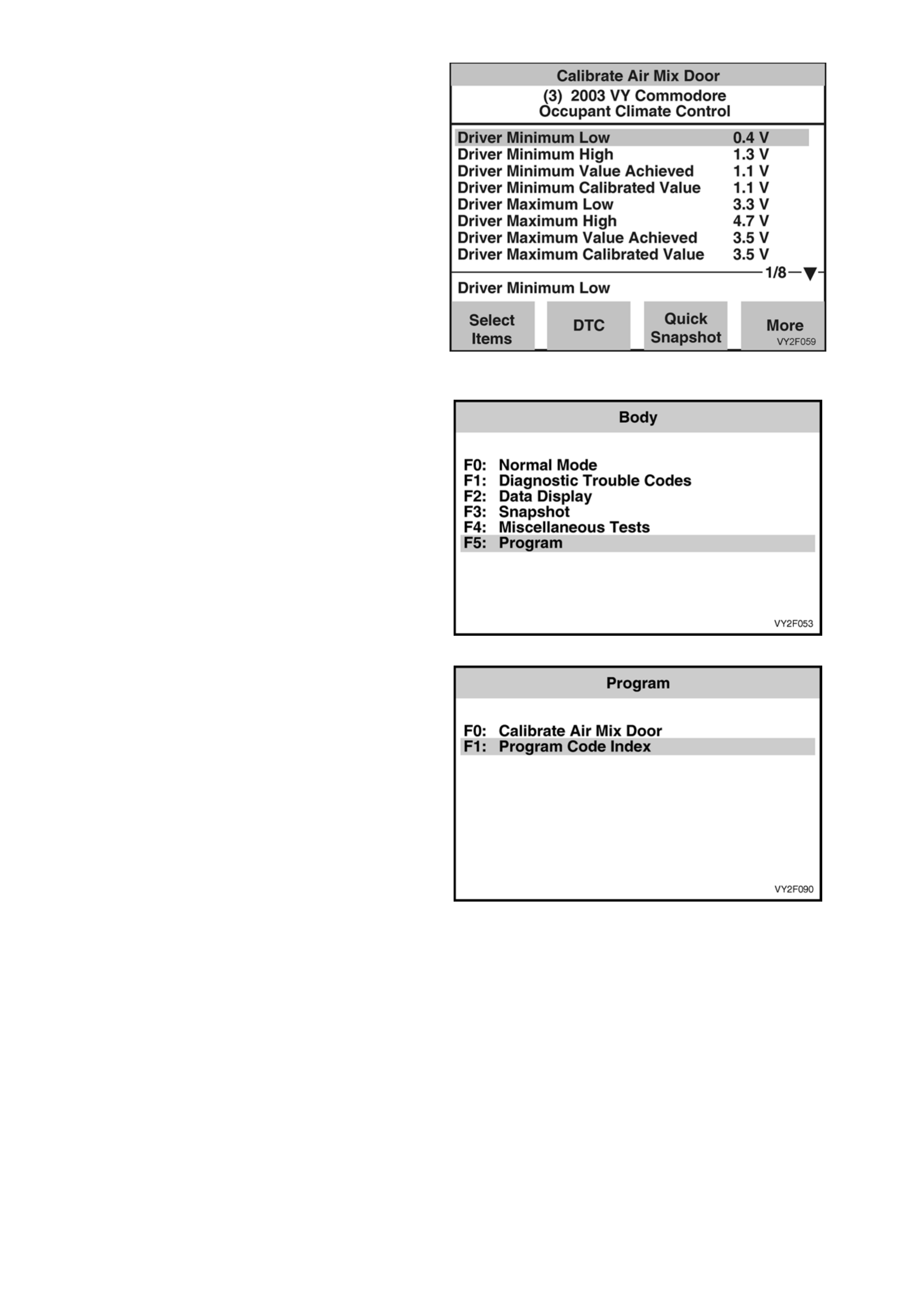
F5: PROGRAM
In this mode, TECH 2 allows the programming of
the OCC control module.
When the Program option is selected, the following
two choices will be available:
F0: Calibrate Air Mix Door.
F1: Program Code Index.
Figure 2F-56
F0: Calibrate Air Mix Door
In this mode, the air mix doors may be
recalibrated/programmed so they drive to the full
hot and full cold stops.
NOTE: All HVAC units have two air mix doors.
However, their configuration differs according to
application:
• LHD Single Zone – two equally sized doors
operating in unison.
• RHD Single Zone – a large and a small d oor
operating sequentially.
• RHD Dual Zone – two equally sized doors
operating in unison during link mode and
independently during unlink mode.
To understand these configurations refer to
Section 2A, HVAC AIR MIX DOORS and
Section 2D, AIR MIX DOORS AND AIR MIX
MOTORS.
Figure 2F-57
NOTE: During the calibration procedure on singl e zone HVAC units, TECH 2 describes the single air mix door
function as ‘Drivers Air Mix Door’ and not as ‘Air Mix Door’.
The calibration mode looks at the full movement in both directions (open and closed) of the air mix doors/motors
and compares the actual voltage values to known base values. If they are different, the OCC softwa re will
compensate.
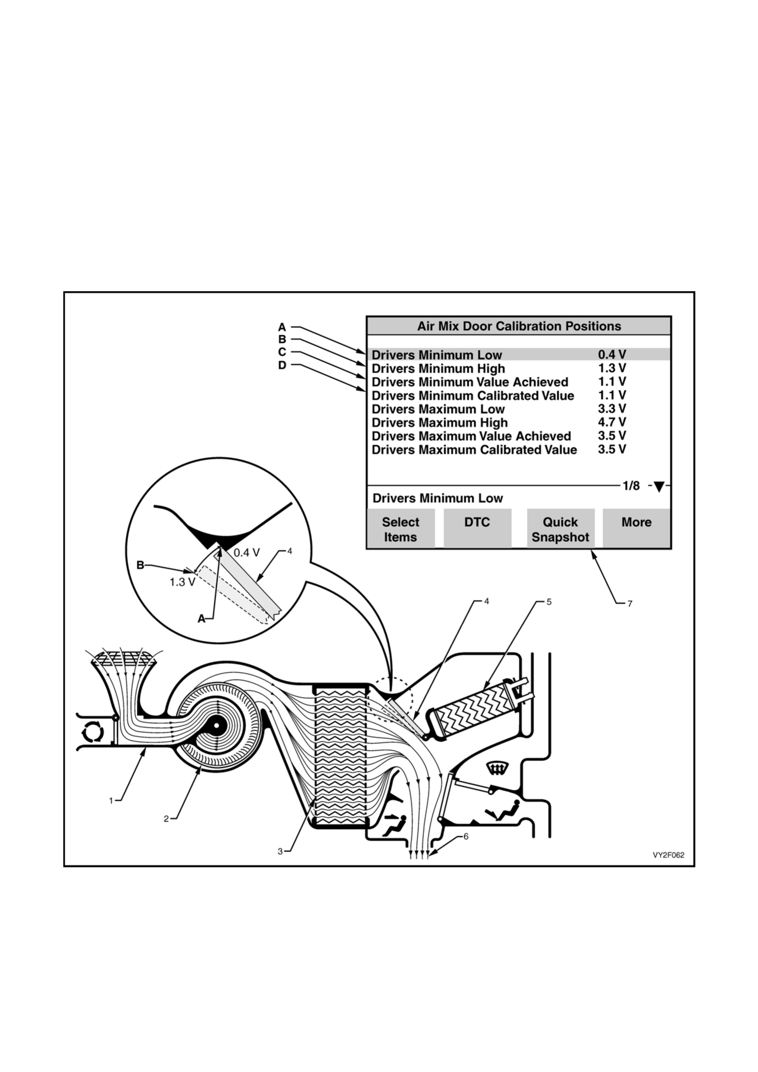
Figure 2F-58 shows the air mix door in the closed sta t e. When the air mix door i s clo se d, all air moving through the
HVAC unit has bypassed the heater core, therefore all air entering the cabin is cold.
In this state, the feedback voltage sent back to the OCC control module (by the potentiometer built into the air mix
motor) may be anywhere in the acceptable closed range of 0.4 – 1.3 Volts. This closed range is shown
exaggerated in the magnified view in Figure 2F-58 between points A and B of air mix door movement.
The following summarises the air mix door positions in the closed state:
A: Air mix door fully closed = Cold air ,0.4 Volts = Drivers Minimum Low
B: Air mix door almost fully closed = Cold air ,1.3 Volts = Drivers Minimum Hi gh
Figure 2F-58
Legend
A. Drivers Minimum Low
B. Drivers Minimum High
C. Drivers Minimum Value Achieved (resu lt of previous calibration, i.e. voltage value anywher e between A and B)
D. Drivers Minimum Calibrated Value (result of new calibration, i.e. voltage value anywher e between A and B)
1. HVAC unit 5. Heater Core (Cold – no coolant flow)
2. Blower Fan 6. Cold Air To Cabin
3. Evaporator 7. TECH 2 Calibration Result Screen
4. Air Mix Door
NOTE: During the calibration procedure on singl e zone HVAC units, TECH 2 describes the single air mix door
function as ‘Drivers Air Mix Door’ and not as ‘Air Mix Door’.
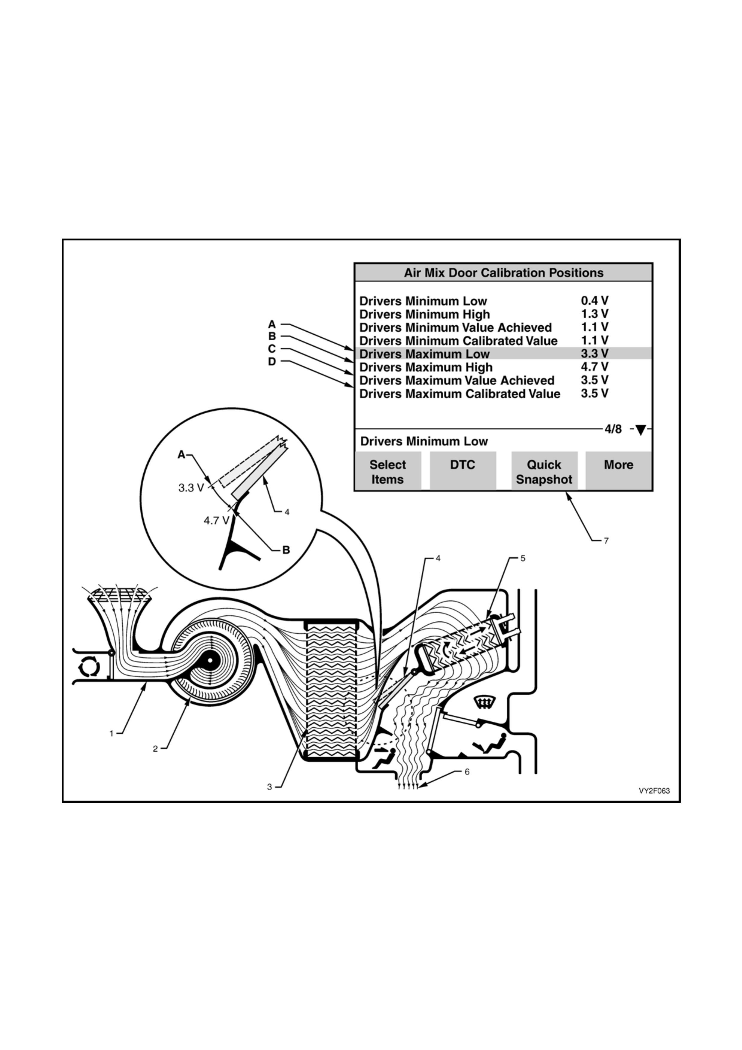
Figure 2F-59 shows the air mix door in the open state. When the air mix door is open, all air moving through the
HVAC unit has passed through the heater core, therefore all air entering the cabin will heated air.
In this state, the feedback voltage sent back to the OCC control module (by the potentiometer built into the air mix
motor) may be anywhere in the acceptable open range of 3.3 – 4.7 Volts. This open range is shown exaggerated in
the magnified view in Figure 2F-59 between points A and B of air mix door movement.
The following summarises the air mix door positions in the open state:
A: Air mix door almost fully open = Heated air, 3.3 Volts = Drivers Maximum Low
B: Air mix door fully open = Heated air, 4.7 Volts = Drivers Maximu m High
Figure 2F-59
Legend
A. Drivers Maximum Low
B. Drivers Maximum High
C. Drivers Maximum Value Achieved (result of previous cali brat ion, i.e. voltage value anywhere between A and B)
D. Drivers Maximum Calibrated Value (result of new calibration, i.e. voltage value anywhere between A and B)
1. HVAC unit 5. Heater Core (Hot – coolant flow)
2. Blower Fan 6. Heated Air To Cabin
3. Evaporator 7. TECH 2 Calibration Result Screen
4. Air Mix Door
To calibrate the air mix door, connect TECH 2 to
the DLC and with the engine running, select:
Body /
Occupant Climate Control /
Program /
Calibrate Air Mix Door
Press the Calibrate soft key on TECH 2.
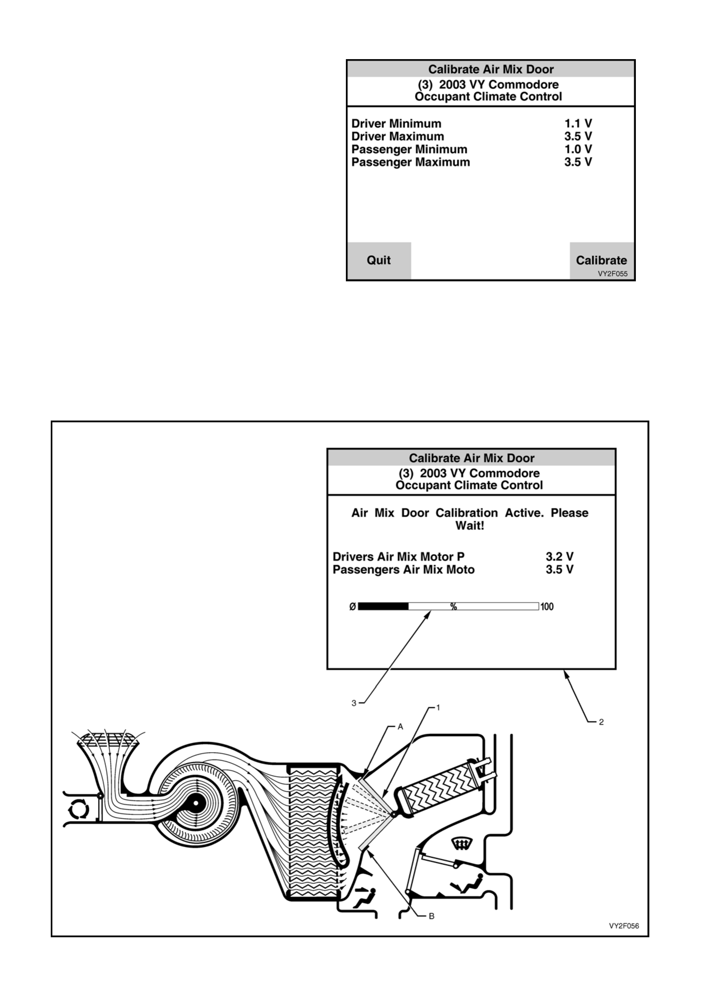
NOTE: Figure 2F-60 shows the calibration screen
applicable to a dual zone system, i.e. specifications
are displayed for the passenger side air mix door
also.
Figure 2F-60
While an air mix door (1) is re calibrating, TECH 2 will display a momentary Calibration Active screen (2) showing
a percentage bar (3) filling from left to right. This symbolises the air mix door being driven from closed (A) to
open (B) and back to closed again.
NOTE: Figure 2F-61 shows the Calibration Active screen applicable to a dual zone system, i.e. specifications
are displayed for the passenger side air mix door also. On a dual zone system, both the driver’s and
passenger’s side air mix door will be calibrated at the same time.
Figure 2F-61

When the air mix doors have been successfully
recalibrated, TECH 2 will display the percentage of
variation between the base value and t he pre-
calibration value. If this variation is greater than
5%, a noticeable difference should be fel t and
could have contributed to a customer complaint.
NOTE 1: If the recalibration programming is
unsuccessful, repeat the program agai n, as the
system may have ‘crashed’ during this pro ce ss.
NOTE 2: During programming, a DTC 47, 48, 49 or
50 could be set. If any of these codes are set, with
TECH 2 connected to the DLC select:
Body /
Occupant Climate /
Diagnostic Trouble Codes /
Clear DTC Information and clear DTC’s.
Figure 2F-62
If the recalibration programming of the air mix door (1) continue s to be unsuccessful, TECH 2 will display a
‘Programming Failed!’ screen (2) as shown in Figure 2F-63. The messag e ‘Driver Error in Maximum Position’ (3 )
defines the problem sector of air mix door movement. This example means that the air mix door (the driver’s
side air mix door on a dual zone system) had difficulty in the maximum (fully open) sector of door movement –
area A.
This may caused by a variety of reasons such as the air mix door fouling within the HVAC case, damaged or
sticking external linkages between the air mix door and air mix motor.
Figure 2F-63
Press the confirm key to view the results of the air
mix door calibration
Figure 2F-64
F1: Program Code Index
In this mode, the Code Index and programmed
Code Version are displayed, as well as providing
the operator the option of reprogramming the code
version of the OCC system to the latest level.
To access the program code index option, select
Body /
Occupant Climate Control /
Program
Figure 2F-65
After the Program option is selected from the Body
menu, the following two choices will be available:
F0: Calibrate Air Mix Door.
F1: Program Code Index.
Select Program Code Index
Figure 2F-66
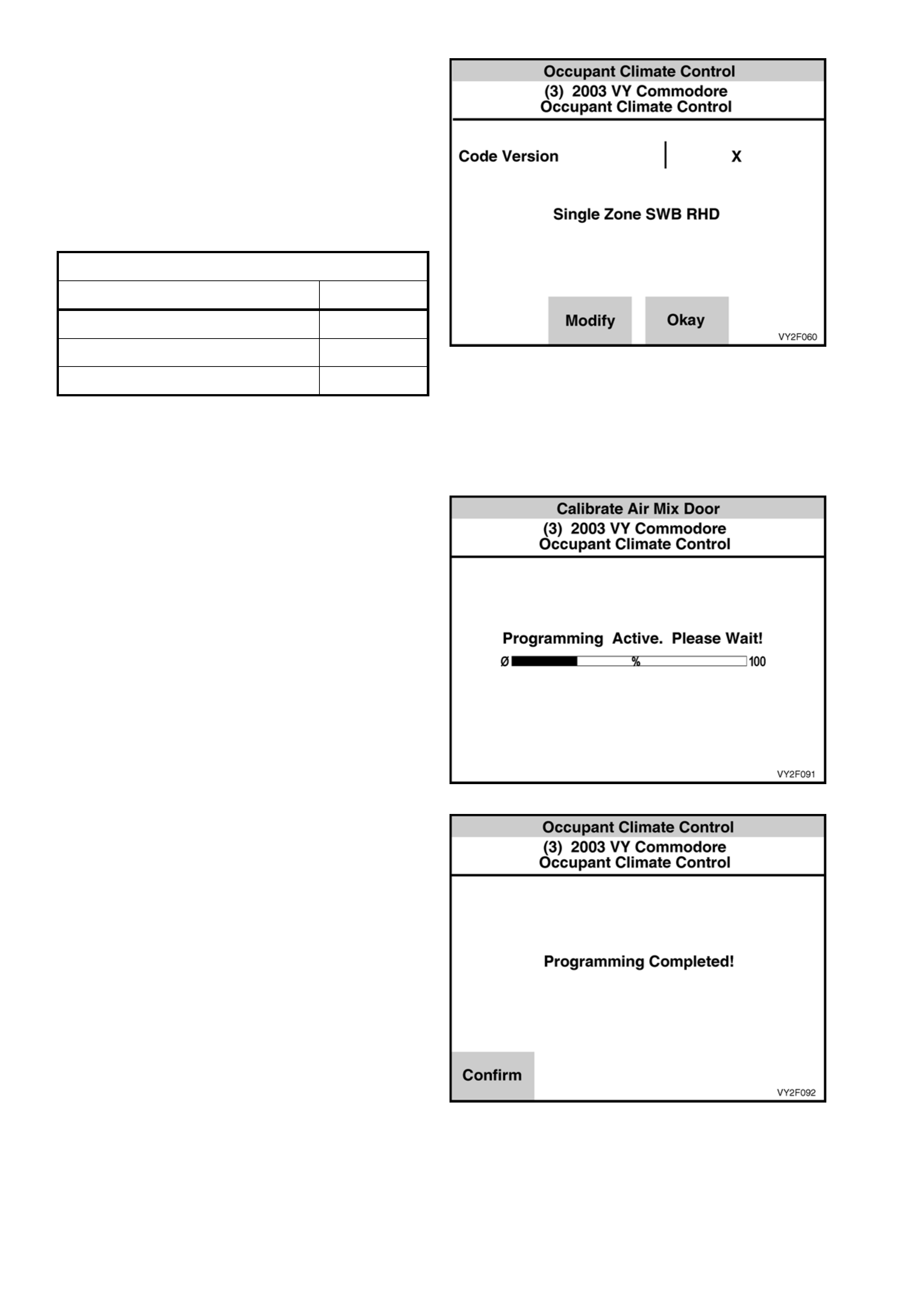
The Code Index screen will display the current
Code Version (software calibration) loaded into the
OCC module. The Code Version identifies the
programmed level of OCC calibration. A higher
number indicates a later version of calibration
loaded into the OCC module. This calibration can
be updated, if necessary, by using TECH 2.
CODE INDEX DETAILS
Application Index
Single Zone SWB RHD 1
Dual Zone SWB RHD 2
Single Zone SWB LHD 3
The Code Index must match the vehicle type and
OCC system configuration.
To update the calibration press the Modify Soft key
on TECH 2.
A momentary Calibration Active screen will be
displayed on TECH 2 sho wing a p ercentage bar
filling from left to right. This symbolises that
recalibrating of the OCC module is takin g place.
NOTE: If programming is unsuccessful, repeat the
program again, as the reprogramming procedure
may have ‘crashed’ during this proce ss.
Figure 2F-68
After the OCC module has been successfully
reprogrammed, TECH 2 will display a
Programming Completed screen.
Follow any TECH 2 screen prompts when
programming is completed.
Figure 2F-69

2. DIAGNOSTIC CHARTS
INTRODUCTION
The following diagnostic charts are designed to provide fast and efficient fault location of the OCC system. Each
diagnostic chart consists of a diagnostic chart and pertinent information including Diagnostic Trouble Code (DTC)
setting parameters and, in most charts, a circuit diag ram.
At the end of this Section electrical connector diagrams and wiring diagrams applicable to OCC systems as fitted to
MY2003 VY and V2 Series vehicles are provided and can be used in conjunction with the diagnostic chart
circuit diagrams when diagnosing circuit faults. Refer to 5. WIRING DIAGRAMS in this Section. For electrical
connector locations and additional wiring diagram information, refer to Section 12P WIRING DIAGRAMS.
When carrying out wiring checks as directed to by the diagnostic charts, rather than probe terminals and
connectors with incorrect sized multimeter connections, use the adaptors contained in connector test adaptor kit
KM-609. This will prevent any possibility of spreading or damaging wiring harness terminals.
Ensure that at the completion of any diagnostic procedure, all diagnostic tools are removed and all OCC
components are correctly connected.
INTERMITTENTS
Definition: Problems may or may not turn on the X symbol on the OCC module LCD screen or store a DTC,
indicating an intermittent problem. DO NOT use the diagnostic code charts for intermittent problems. When using
the code charts the fault must be present to locate the problem. If a fault is intermittent, use of diagnostic trouble
code charts may result in replacem ent of good parts.
• Most intermittent problems are caused by faulty electrical connections or wiring. Perform careful visual/physical
checks of the applicable circuit.
Check for:
a. Poor mating of the connector halves or a terminal n ot fully seated in the connector body (backed out).
Improperly formed or damaged terminal. All connector terminals in the suspect circuit should be carefully
reformed or replaced to insure proper contact ten sio n.
Poor terminal to wire connection. This requires removing the terminal from the connector body to check as
outlined in service operations.
Loose OCC ground circuit terminals.
• If a visual/physical check does not find the cause of the problem, the car can be driven with a voltmeter
connected to a suspected circuit. A scan tool (TECH 2) can also be used to help detect intermittent conditions.
An abnormal voltage, or scan tool reading, when the problem occurs, indicates the problem may be in that
circuit. If the wiring and connectors check OK, and a diagnostic trouble code was stored for a circuit having a
sensor, substitute a kno wn good sensor and recheck.
• Loss of diagnostic code memory. To check, disconnect Ambient Air Temperature sensor and turn the ignition
on until the X symbol is displayed on LCD screen. DTC 13 should be stored and kept in memory when ignition
is turned off. If not, the OCC module is faulty.
• Check for electrical system interference caused by a defective relay, OCC driven solenoid, or switch. They can
cause a sharp electri cal surge. Normally, the problem will occu r when the faulty component is operated.
• Check for improper in stallation of non-factory installed electrical options such as lights, 2 way radios, etc.
• If problem has not been found, refer to the prope r symptom and perform all checks listed there.

CHART A – DIAGNOSTI C CIR C UIT C HEC K
Circuit Description
When investigating any complaint of an OCC problem or malfunction, always begin diagnosis with the following
diagnostic circuit check. This check is a preliminary procedure that checks to ensure the OCC is communicating on
the serial data line as well as helping to identify a problem or malfunction and directing the reader to the
appropriate diagnostic chart in this Section.
With TECH 2 connected to the DLC and the ignition switched on, TECH 2 should display serial data
communication. If TECH 2 does not display serial data, the serial data circuit may be open or shorted.
In addition to the OCC module there are several other control modules that are connected to the serial data line
(PCM, BCM, ABS/TCS, instruments and SDM). Any one of these control modules could cause a fault on the serial
data line. This fault could result in TECH 2 not being able to displ ay serial d ata.
Test Description:
The numbers below refer to Step numbers in diagnostic chart A.
1. This test checks if the OCC module is being powered up.
2. This test checks if the OCC module has detected and stored a current Diagnostic Trouble Code.
3. This test determines if TECH 2 is being powered up.
4. This test checks if TECH 2 can communicate with the OCC control module. If TECH 2 cannot communicate
with the OCC control module, you will not be able to determine which DTC has been stored in the OCC control
modules memory.
5. Determines which DTC has been stored in the OCC control modules memory. This test determines if a
DTC was current and has been rectified. An intermittent problem will cau se a DT C to be stored.
6. During this test the OCC module recalibrates the air mix doors. An incorrectly calibrated air mix door will cause
incorrect operation of the OCC system.
7. Checks accuracy of OCC sensors.
8. During this test, the operation of the air conditioning section of the OC C system is checked.
Notes On Diagnostic Chart:
1. Refer to 1.1 TECH 2 DIAGNOSTICS in this Sectio n for connecting and using TECH 2.
2. Refer to 1.2 TECH 2 TEST MODES AND DISPLAYS FOR OCC DIAGNOSIS in this Section for further
information on programming of the OCC module.
3. OCC sensors can be checked usin g the following procedure and should also be checked in the order listed:
• In-car Temperature Sensor – connect TECH 2 to the DLC, sele ct Body / Occupant Climate Control / Data
Display / Data List / In Car Temperature Sensor.
• Ambient Temperature Sensor – connect TECH 2 to the DLC, select Body / Occupant Climate Control /
Data Display / Data List / Ambient Temperature Sens or.
• Sun Load Sensor (Sun Sensor/Remote Receiver) – refer to DTC 19 diagnostic chart in this Section for a
procedure on checki ng this sensor.
• Evaporative Sensor – connect TECH 2 to the DLC, select Body / Occupant Climate Control / Data Display /
Data List / Evap Temperature Sen sor.

CHART A – DIAGNOSTI C CIR C UIT C HEC K
STEP ACTION VALUE YES NO
1 1. Turn the ignition on.
2. Turn on OCC system.
Does OCC module LCD screen activate?
– Go to Step 2. Go to Chart B –
OCC SYSTEM
DOES NOT
POWER UP in
this Section.
2 Is there an X on the right-hand side of the OCC
module LCD screen? – Go to Step 3. Go to Step 6.
3 1. Connect TECH 2 to the DLC. (Refer to Notes
on Diagnostic Chart for this chart, Note 1.)
2. Turn the ignition on.
3. Push power button on TECH 2.
Does TECH 2 power up?
– Go to Step 4. Go to TECH 2
diagnosis. Refer
to Section 0C,
TECH 2.
4 1. With TECH 2 connected, select Diagnostics /
Model Year / Vehicle Model / Body / Occupant
Climate Control.
Does TECH 2 display OCC System Identification
Screen information (i.e. part number etc.)?
– Go to Step 5. Go to BCM
Serial Data
Communication
diagnostics.
Refer to Section
12J, 4.2 SERIAL
DATA
COMMUNICN
(BUS MASTER).
5 1. With TECH 2 connected and the ignition on,
select Diagnostic Trouble Codes / Read
DTC Information.
Does TECH 2 display any DTCs?
– Go to applicable
DTC Chart in
this Section.
Go to Step 6.
6 1. With TECH 2 connected, the ignition on and
OCC system selected, select Program /
Calibrate Air Mix Door / Calibrate.
Does TECH 2 display a value greater than 5%?
– OCC air mix
doors have
been
recalibrated.
Refer to DTC
48 to DTC 50
as applicable, in
this Section.
7 1. Check the accuracy of the OCC sensors.
(Refer to 3. ELECTRICAL COMPONENT
TESTS in this Section.)
Are the OCC sensors OK?
– Go to Step 8. Replace the
faulty OCC
sensor, refer to
Section 2E,
HVAC
OCCUPANT
CLIMATE
CONTROL
(AUTO A/C) –
REMOVAL &
INSTALLATION
.
8 1. Perform the DELPHI V5 and V7 compressor
and TXV system diagnosis. Refer to
Section 2C, 4. DELPHI V5 AND V7
COMPRESSOR AND TXV SYSTEM
DIAGNOSTICS.
Does the system pass the diagnosis test?
– No fault found
with OCC
system. Syst em
Code Index
may need to be
Programmed.
Refer to
F1:PROGRAM
CODE INDEX
in this Section.
Carry out repair
procedure as
detailed in
Delphi V5 and
V7 Compressor
TXV System
Diagnosis.
Refer to
Section 2C,
HVAC
CLIMATE
CONTROL
(MANUAL A/C)
– SERVICING
& DIAGNOSIS.
WHEN ALL DIAGNOSIS AND REPAIRS ARE COMPLETE, VERIFY CORRECT OPERATION
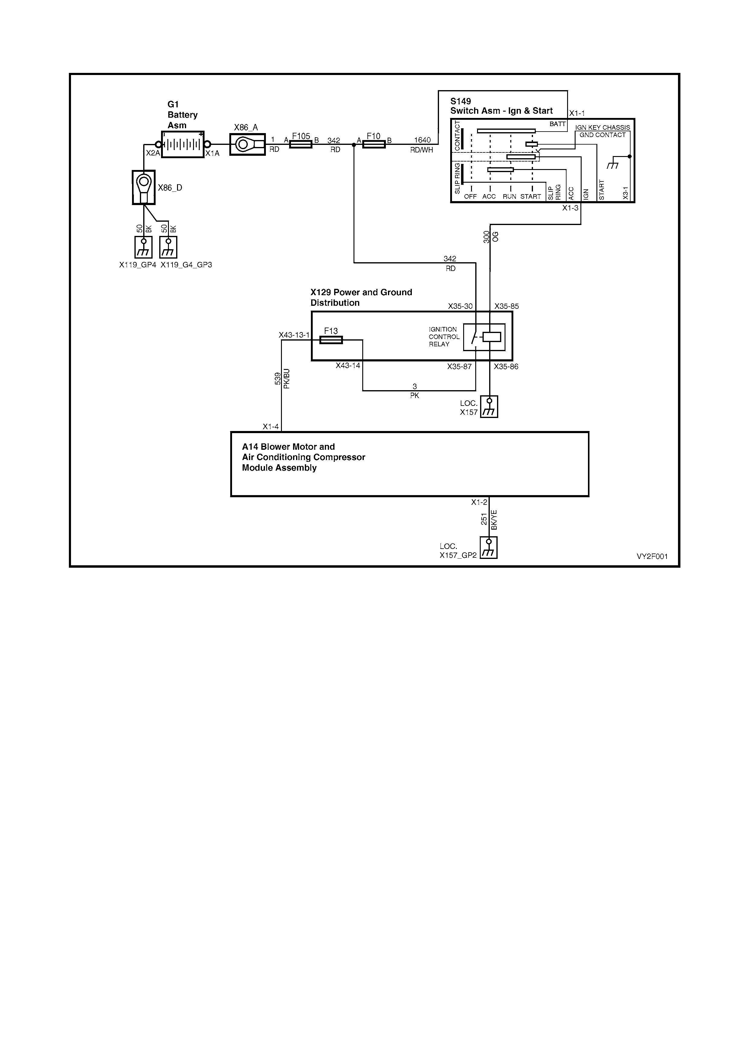
CHART B – OCC SYSTEM DOES NOT POWER UP
Figure 2F-70
Circuit Description
Battery power is supplied to the OCC control module, terminal X1-4, with the ignition switch in the ignition or start
positions through fuse F13 (located in the passe nger compartment fuse panel).
Test Description:
The numbers below refer to Step numbers in diagnostic chart B:
1. The diagnostic circuit test is the beginning of all diagnostics and should be performed whenever diagnosing an
OCC system complaint.
2. This test checks if the fuse F13 is OK.
3. This test determines if power is being supplied to fuse F13.
4. This test determines if the OCC module has a power supply and a ground. If the OCC module has power and
ground and the module is not being activated when the ignition and the OCC system is turned on.
5. If battery voltage was not available during Step 4, this test determines if the power supply circuit 539 to the OCC
module has continuity.
6. If battery voltage was not available during Step 4, this test determines if the ground circuit 251 to the OCC
module has continuity.
Notes on Diagnostic Chart:
1. Refer to 5. WIRING DIAGRAMS in this Section for views of OCC system related electrical connectors and
complete OCC system wiring diag rams.
2. For electrical connector locations and additional wiring diagram information, refer to
Section 12P WIRING DIAGRAMS.

CHART B – OCC SYSTEM DOES NOT POWER UP
STEP ACTION VALUE YES NO
1 Has the Diagnostic Circuit Check been performed? – Go to Step 2. Go to Chart A –
DIAGNOSTIC
CIRCUIT
CHECK in this
Section.
2 1. Check f use F13.
Is the fuse OK? – Go to Step 3. Check for cause
of blown fuse
and replace the
fuse.
3 1. Turn the ignition on.
2. Back-probe fuse F13, circuit 3 (Pink wire) with
a voltmeter to ground. (Refer to Notes on
Diagnostic Chart for this chart, Note 1.)
Is the value as specified?
Battery
voltage Go to Step 4. Repair faulty
circuit 3.
4 1. Remove the OCC control module. (Refer to
Section 2E, OCCUPANT CLIMATE CONTROL
(AUTO A/C) REMOVAL AND INSTALLATION.)
2. Turn the ignition on.
3. Probe between OCC module (A14) connector
terminal X1-4, circuit 539 (Pink / Blue wire) and
terminal X1-2, circuit 251 (Black / Yellow wire)
with a voltmeter to ground.
Is the value as specified?
Battery
voltage Replace the
OCC control
module, refer to
Section 2E,
HVAC
OCCUPANT
CLIMATE
CONTROL
(AUTO A/C) –
REMOVAL &
INSTALLATION
.
Install the OCC
module (Refer
to Section 2E,
OCCUPANT
CLIMATE
CONTROL
(AUTO A/C)
REMOVAL
AND
INSTALLATION
.) and go to
Step 5.
5 1. Turn the ignition off.
2. Back-probe between OCC module
terminal X1-4, circuit 539 (Pink / Blue wire) and
fuse F13 with an ohmmeter to ground.
Is the value as specified?
Less than
1 ohm Go to Step 6. Repair faulty
circuit 539.
6 1. Turn the ignition off.
2. Back-probe OCC module terminal X1-2,
circuit 251 (Black / Yellow wire) with an
ohmmeter to a known good ground.
Is the value as specified?
Less than
1 ohm Check for
intermittent
connection at
OCC module
connector
A14 X1. Check
sizing of
connector
A14 X1
terminals.
Repair faulty
circuit 251.
WHEN ALL DIAGNOSIS AND REPAIRS ARE COMPLETE, VERIFY CORRECT OPERATION
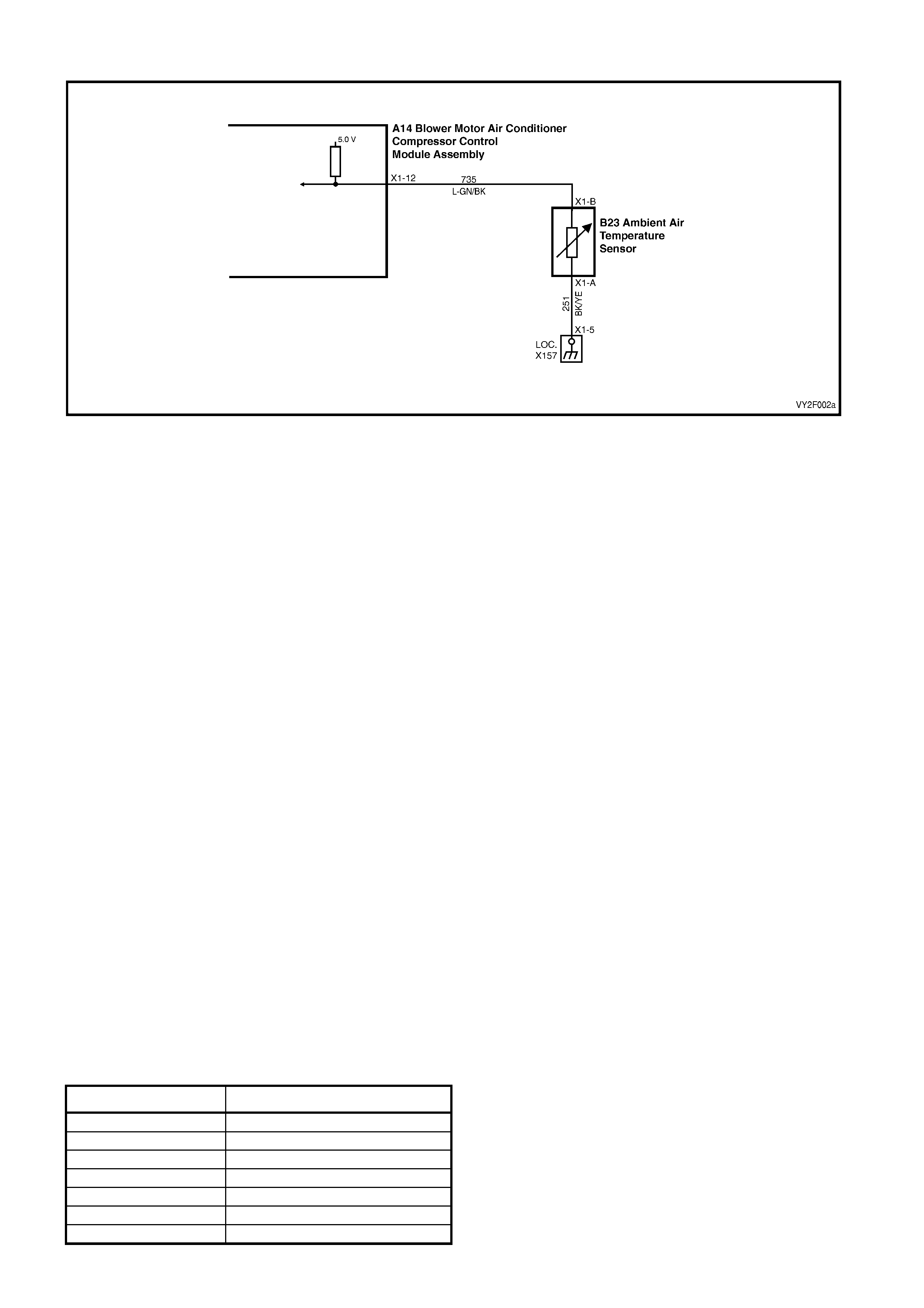
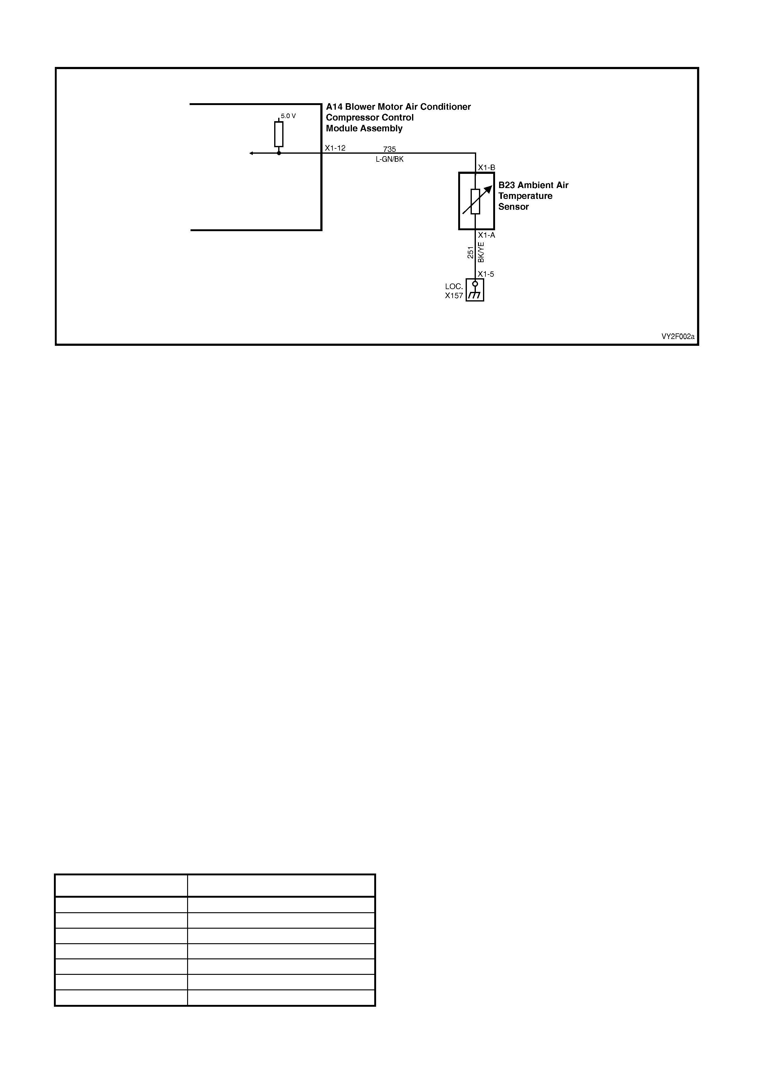
DTC 13 – AMBIENT TEMPERAT URE SENSOR VOLTAGE TOO HIGH
Figure 2F-71
Circuit Description:
The Ambient Temperature Sensor (ATS) uses a thermistor to control the signal voltage to the OCC control module.
The OCC module applies a voltage of 5.0 volts to the sensor. When the air is cold, the ATS resistance is high,
therefore the OCC module will sense a high signal voltage. If the ambient air is warm, the ATS resistance is low
therefore the OCC module will sense a low signal voltage.
DTC 13 will set if: the ATS sensor signal voltage is more than 5.0 volts or if the ATS sensor wiring harness
(circuit 735) or connectors are op en circuited for a period of 10 seconds.
Test Description:
Number(s) below refer to Step numbers in the followin g Diagnostic Chart:
1. Ensures the Diagnostic Circuit Check has been performed.
2. Checks that the conditions for setting the DTC are present or if fault is intermittent.
3. Checks integrity of circuit 735.
4. Checks if sensor is service able by t e st ing resistance across ATS.
5. Checks for an intermittent connection at ATS.
6. Checks for an open in circuit 251.
7. Checks for an open in circuit 735.
8. Checks for short to voltage in circuit 735.
Diagnostic Aids:
The default temperature for an open circuit is 22.5°C.
If the vehicle is left idling for an extended period, the ambient temperature readings will rise owing to heat radiated
by the A/C condenser and lack of airflow.
When using the temperature/resistance chart, place a thermometer as close as possible to the sensor being tested,
then compare this temperature figure to the resistance value.
Notes on Diagnostic Chart:
1. Refer to 5. WIRING DIAGRAMS in this Section for views of OCC system related electrical connectors and
complete OCC system wiring diag rams.
2. For electrical connector locations and additional wiring diagram information, refer to
Section 12P WIRING DIAGRAMS.
3. Refer to 1.1 TECH 2 DIAGNOSTICS in this Sectio n for connecting and using TECH 2.
Temperature Resistance Chart
AMBIENT°C RESISTANCE Ω
0 15920 – 16750
10 9715 – 10193
20 6107 – 6389
30 3943 – 4115
40 2610 – 2717
50 1767 – 1836
60 1201 – 1291

DTC 13 – AMBIENT TEMPERATURE SENSOR VOLTAGE TOO HIGH DIAGN OSTIC CHART
STEP ACTION VALUE YES NO
1 Was the Diagnostic Circuit Check performed? – Go to Step 2. Go to Chart A –
DIAGNOSTIC
CIRCUIT
CHECK in this
Section.
2 1. Connect TECH 2 to the DLC.
2. Select Diagnostics / Model Year / Vehicle
Model / Body / Occupant Climate Control /
Data Display / Data List / Ambient Air
Temperature Sensor.
Does TECH 2 display a value above 4.8 volts?
– Go to Step 3. DTC 13
intermittent. If
no additional
DTCs were
stored. Refer to
2. DIAGNOSTI
C CHARTS in
this Section.
3 1. With TECH 2 connected and Ambient Air
Temperature Sensor displayed, disconnect the
ambient air temperature sensor wiring harness
connector B23 X1.
2. Place a jumper wire between the two terminals
of connector B23 X1.
Does TECH 2 display a value less than 0.4 volt?
– Go to Step 4. Go to Step 6
4 1. With the ambient air temperature sensor wiring
harness connector disconnected, probe
between the ambient air sensor terminals with
an ohmmeter to ground.
Is the value as specified?
Refer to
DTC 13
Temp.
Resistance
Chart
outlined
previously.
Go to Step 5. Replace faulty
ambient air
temperature
sensor. Refer to
Section 2E,
HVAC
OCCUPANT
CLIMATE
CONTROL
(AUTO A/C)–
REMOVAL &
INSTALLATION
.
5 1. Inspect the ambient air temperature sensor
wiring harness connector for an intermittent or
loose terminal.
Is connector OK?
– Go to Step 8 Repair faulty
connector.
6 1. With TECH 2 connected and Ambient Air
Temperature Sensor displayed, back-probe
between OCC module connector
terminal X1-12, circuit 735 (Light-green / Black
wire) and chassis ground with a jumper lead.
Does TECH 2 display a value less than 0.4 volt?
– Repair faulty
circuit 251
(Black / Yellow
wire).
Go to Step 7
7 1. Check the integrity of circuit 735 (Light-green /
Black wire) between ambient air temperature
sensor connector terminal X1-B and OCC
module connector terminal X1-12.
Is the circuit OK?
– Go to Step 8 Repair faulty
circuit 735.
8 1. Turn the ignition off.
2. Disconnect OCC wiring harness connectors
A14 X1 and A14 X2.
3. Remove the jumper lead from the ambient air
temperature sensor connector.
4. Turn the ignition on.
5. Back-probe ambient air temperature sensor
wiring harness connector terminal X1-B
circuit 735 (Light-green / Black wire) with a
voltmeter to chassis ground.
Is the value as specified?
0.4 volt Replace the
faulty OCC
control module.
Refer to
Section 2E,
HVAC
OCCUPANT
CLIMATE
CONTROL
(AUTO A/C) –
REMOVAL &
INSTALLATION
Repair faulty
circuit 735.
WHEN ALL DIAGNOSIS AND REPAIRS ARE COMPLETE, VERIFY CORRECT OPERATION
DTC 14 – AMBIENT TEMPERAT URE SENSOR VOLTAGE TOO LOW
Figure 2F-72
Circuit Description:
The ambient air temperature sensor (ATS) uses a thermistor to control the signal voltage to the OCC control
module. The OCC module applies a voltage of 5.0 volts to the sensor. When the air is cold, the ATS resistance is
high therefore the OCC module will sense a high signal voltage. If the air is warm, the ATS resistance is low
therefore the OCC module will sense a low signal voltage.
DTC 14 will set: if the ATS sensor signal voltage is less than 0.3 volt or if the ATS sensor wiring harness
(circuit 735) or connectors are op en for a period of 10 seconds.
Test Description:
Number(s) below refer to Step numbers in the followin g Diagnostic Chart:
1. Ensures the Diagnostic Circuit Check has been performed.
2. This test checks that the conditions that would set the DTC, are p resent.
3. This test checks if the sensor is causing the sho rt circuit.
4. This test checks if sensor is functioning correctly.
5. Checks for intermittent connection at sensor.
6. Checks for a short circuit of sensor signal wire to ground.
Diagnostic Aids:
The default temperature for a short circuit is 22.5° C.
If the vehicle is left idling for an extended period, the ambient temperature readings will rise owing to heat radiated
by the A/C condenser and lack of airflow.
When using the temperature/resistance chart, place a thermometer as close as possible to the sensor being tested,
then compare this temperature figure to the resistance value.
Notes on Diagnostic Chart:
1. Refer to 5. WIRING DIAGRAMS in this Section for views of OCC system related electrical connectors and
complete OCC system wiring diag rams.
2. For electrical connector locations and additional wiring diagram information, refer to
Section 12P WIRING DIAGRAMS.
3. Refer to 1.1 TECH 2 DIAGNOSTICS in this Sectio n for connecting and using TECH 2.
Temperature Resistance Chart
AMBIENT°C RESISTANCE Ω
0 15920 – 16750
10 9715 – 10193
20 6107 – 6389
30 3943 – 4115
40 2610 – 2717
50 1767 – 1836
60 1201 – 1291

DTC 14 – AMBIENT TEMPERATURE SENSOR VOLTAGE TOO LOW DI AGNOSTIC CHART
STEP ACTION VALUE YES NO
1 Was the Diagnostic Circuit Check performed? – Go to Step 2. Go to Chart A –
DIAGNOSTIC
CIRCUIT
CHECK in this
Section.
2 1. Connect TECH 2 to the DLC.
2. Select Diagnostics / Model Year / Vehicle
Model / Body / Occupant Climate Control /
Data Display / Data List / Ambient Air
Temperature Sensor.
Does TECH 2 display a value less than 0.4 volt?
– Go to Step 3. DTC 14
intermittent. If
no additional
DTCs were
stored, refer to
2. DIAGNOSTI
C CHARTS in
this Section.
3 1. With TECH 2 connected and Ambient Air
Temperature Sensor displayed, disconnect
ambient air temperature sensor wiring harness
connector B23 X1.
Does TECH 2 display a value more than 4.8 volts?
– Go to Step 4. Go to Step 6.
4 1. With the ambient air temperature sensor wiring
harness connector disconnected, back-probe
between the ambient air sensor terminals.
Is the value as specified?
Refer to
DTC 14
Temp.
Resistance
Chart.
Go to Step 5. Replace the
faulty ambient air
temperature
sensor. Refer to
Section 2E,
HVAC
OCCUPANT
CLIMATE
CONTROL
(AUTO A/C) –
REMOVAL &
INSTALLATION
.
5 1. Check for an intermittent short to ground in
circuit 735 (Light-green / Black wire) between
OCC module connector terminal X1-12 and
ambient air sensor connector terminal X1-B.
Is the circuit OK?
– Repair faulty
connector. Replace the
faulty OCC
control module.
Refer to
Section 2E,
HVAC
OCCUPANT
CLIMATE
CONTROL
(AUTO A/C) –
REMOVAL &
INSTALLATION
.
6 1. Check circuit 735 (Light-green / Black wire) for
a short circuit to ground.
Is the circuit OK?
– Replace the
faulty OCC
control module.
Refer to
Section 2E,
HVAC
OCCUPANT
CLIMATE
CONTROL
(AUTO A/C) –
REMOVAL &
INSTALLATION
.
Repair faulty
circuit 735.
WHEN ALL DIAGNOSIS AND REPAIRS ARE COMPLETE, VERIFY CORRECT OPERATION
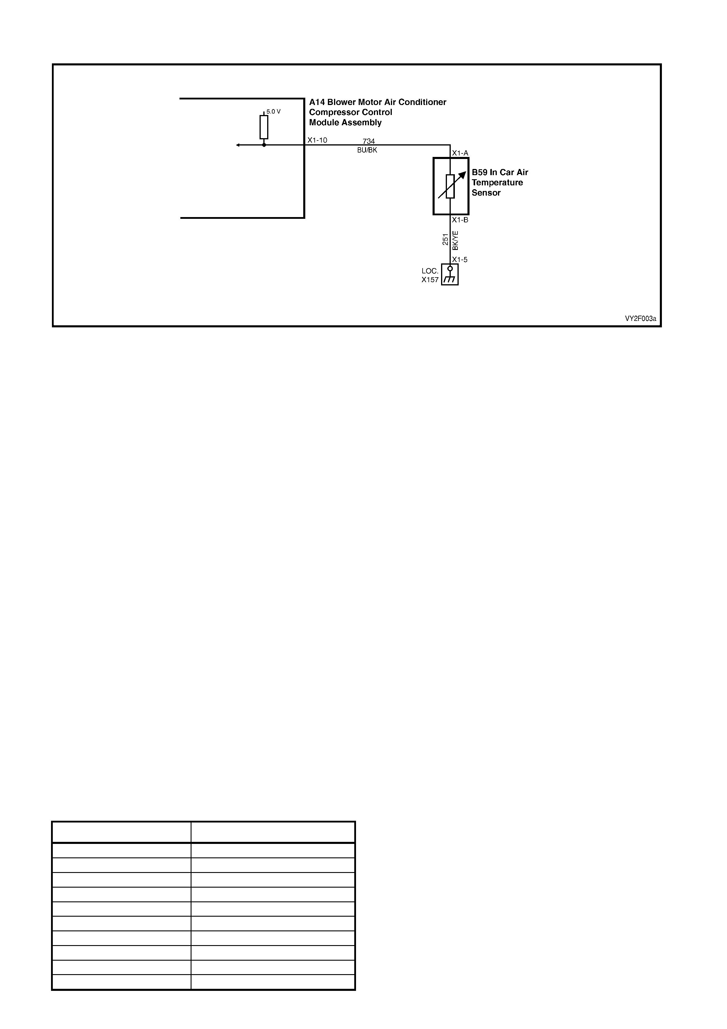
DTC 15 – IN-CAR TEMPERATU RE SENSOR VO LTAGE TOO HIGH
Figure 2F-73
Circuit Description:
The In-car Temperature Sensor (ITS) is a thermistor used to vary voltage signals to control the signal voltage to the
OCC control module. The OCC module applies a voltage of 5.0 volts to the sensor, via circuit 734. When the
vehicle interior air is cold, the ITS resistance is high therefore the OCC module will sense a high signal voltage. If
the air is warm, the ITS resistance is low, therefore the OCC module will sense a low signal voltage.
DTC 15 will set: if the ITS signal voltage is more than 4.8 volts or if the ITS sensor wiring harness (circuit 734) or
connectors are open circuited for 10 seconds.
Test Description:
Number(s) below refer to Step numbers in the followin g Diagnostic Chart:
1. Ensures the Diagnostic Circuit Check has been performed.
2. Checks that the conditions for setting the DTC are present or if fault is intermittent.
3. Checks integrity of circuit 734.
4. Checks if sensor is service able by t e st ing resistance across ITS.
5. Checks for an intermittent connection at ITS.
6. Checks for an open in circuit 251.
7. Checks for an open in circuit 734.
8. Checks for short to voltage in circuit 734.
Diagnostic Aids:
The default temperature for an open circuit is 22.5°C.
When using the temperature/resistance chart, place a thermometer as close as possible to the sensor being tested,
then compare this temperature figure to the resistance value.
Notes on Diagnostic Chart:
1. Refer to 5. WIRING DIAGRAMS in this Section for views of OCC system related electrical connectors and
complete OCC system wiring diag rams.
2. For electrical connector locations and additional wiring diagram information, refer to
Section 12P WIRING DIAGRAMS.
3. Refer to 1.1 TECH 2 DIAGNOSTICS in this Sectio n for connecting and using TECH 2.
Temperature Resistance Chart
AMBIENT°C RESISTANCE Ω
5 7009 – 7536
10 5477 – 5856
15 4310 – 4583
20 3416 – 3612
25 2725 – 2865
30 2175 – 2299
35 1746 – 1857
40 1410 – 1508
45 1145 – 1231
50 935 – 1010

DTC 15 – IN-CAR TEMPERATURE SENSOR VOLTAGE TOO HIGH DIAGNOSTIC CHART
STEP ACTION VALUE YES NO
1 Was the Diagnostic Circuit Check perfo rmed? – Go to Step 2. Go to Chart A –
DIAGNOSTIC
CIRCUIT
CHECK in this
Section.
2 1. Connect TECH 2 to the DLC (refer to Note 2
on previous page).
2. Select Diagnostics / Model Year / Vehicle
Model / Body / Occupant Climate Control /
Data Display / Data List / In-car Temperature
Sensor.
Does TECH 2 display a value above 4.8 volts?
– Go to Step 3. DTC 15
intermittent. If
no additional
DTCs were
stored, refer to
2. DAGNOSTIC
CHARTS in this
Section.
3 1. With TECH 2 connected and In-car
Temperature Sensor displayed, disconnect the
in-car temperature sensor wiring harness
connector B59 X1.
2. Probe between the two terminals of the
connector with a jumper wire.
Does TECH 2 display a value less than 0.4 volt?
– Go to Step 4. Go to Step 6.
4 1. With the in-car temperature sensor wiring
harness connector disconnected, probe
between the two terminals of the connector
with an ohmmeter. (Refer to Notes on
Diagnostic Chart for this chart, Note 1).
Is the value as specified?
Refer to
DTC 15
Temp.
Resistance
Chart.
Go to Step 5. Replace faulty
in-car
temperature
sensor. Refer to
Section 2E,
HVAC
OCCUPANT
CLIMATE
CONTROL
(AUTO A/C) –
REMOVAL &
INSTALLATION
.
5 1. Inspect the in-car temperature sensor wiring
harness connector for an intermittent or loose
terminal.
Is the connector OK?
– Go to Step 8. Repair faulty
connector.
6 1. With TECH 2 connected and In-car
Temperature Sensor displayed, back-probe
OCC connector terminal X1-10, circuit 734
(Blue/Black wire) with a jumper lead to chassis
ground.
Does TECH 2 display a value less than 0.4 volt?
– Go to Step 7. Repair faulty
circuit 251.
7 1. Check the integrity of circuit 734 (Blue/Black
wire) between the OCC module connector and
in car temperature sensor connector. (Refer to
Notes on Diagnostic Chart for this chart, Note
1.)
Is the circuit OK?
– Go to Step 8. Repair faulty
circuit 734.
8 1. Turn the ignition OFF.
2. Disconnect the OCC module wiring harness
connectors A14 X1 and A14 X2.
3. Remove jumper lead from the in-car
temperature sensor connector.
4. Turn the ignition on.
5. Back-probe in-car temperature sensor wiring
harness connector terminal X1-A, circuit 734
(Blue/Black wire) with a voltmeter to chassis
ground.
Is the value as specified?
Less than
0.4 volt Replace the
faulty OCC
control module.
Refer to
Section 2E,
HVAC
OCCUPANT
CLIMATE
CONTROL
(AUTO A/C) –
REMOVAL &
INSTALLATION
.
Repair faulty
circuit 734.
WHEN ALL DIAGNOSIS AND REPAIRS ARE COMPLETE, VERIFY CORRECT OPERATION
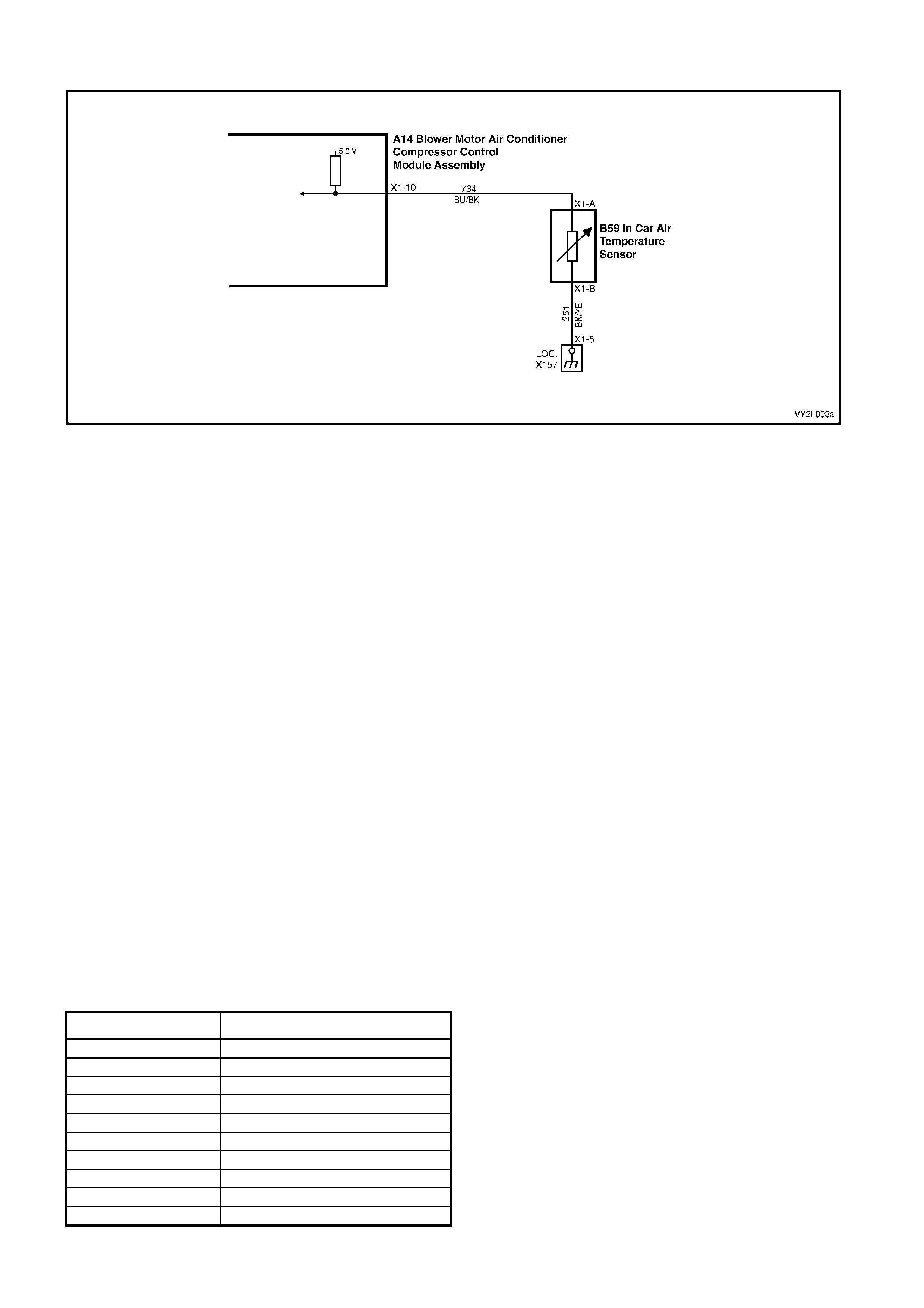
DTC 16 – IN-CAR TEMPERATU RE SENSOR VO LTAGE TOO LOW
Figure 2F-74
Circuit Description:
The in-car temperature sensor (ITS) is a thermistor used to vary voltage signals to the OCC control module. The
OCC module applies a voltage of 5.0 volts to the sensor. When the vehicle interior air is cold, the ITS resistance is
high, therefore the OCC module will sense a high signal voltage. If the air is warm, the ITS resistance is low,
therefore the OCC module will sense a low signal voltage.
DTC 16 will set: if the ITS signal voltage is less than 0.3 volt or if the ITS sensor wiring harness (circuit 734) or
connectors are open circuited for 10 seconds.
Test Description:
Number(s) below refer to Step numbers in the followin g Diagnostic Chart:
1. Ensures the Diagnostic Circuit Check has been performed.
2. This test checks that the conditions that would set the DTC, are p resent.
3. This test checks if the sensor is causing the sho rt circuit.
4. This test checks if sensor is functioning correctly.
5. Checks for intermittent connection at sensor.
6. Checks for a short circuit of sensor signal wire to ground.
Diagnostic Aids:
The default temperature for a short circuit is 22.5°C.
When using the temperature/resistance chart, place a thermometer as close as possible to the sensor being tested,
then compare this temperature figure to the resistance value.
Notes on Diagnostic Chart:
1. Refer to 5. WIRING DIAGRAMS in this Section for views of OCC system related electrical connectors and
complete OCC system wiring diag rams.
2. For electrical connector locations and additional wiring diagram information, refer to
Section 12P WIRING DIAGRAMS.
3. Refer to 1.1 TECH 2 DIAGNOSTICS in this Sectio n for connecting and using TECH 2.
Temperature Resistance Chart
AMBIENT°C RESISTANCE Ω
5 7009 – 7536
10 5477 – 5856
15 4310 – 4583
20 3416 – 3612
25 2725 – 2865
30 2175 – 2299
35 1746 – 1857
40 1410 – 1508
45 1145 – 1231
50 935 – 1010

DTC 16 – IN-CAR TEMPERATURE SENSOR VOLTAGE TOO LOW DIAG NOSTIC CHART
STEP ACTION VALUE YES NO
1 Was the Diagnostic Circuit Check perfo rmed? – Go to Step 2. Go to Chart A –
DIAGNOSTIC
CIRCUIT
CHECK in this
Section.
2 1. Connect TECH 2 to the DLC.
2. Select Diagnostics / Model Year / Vehicle
Model / Body / Occupant Climate Control /
Data Display / Data List / In-car Temperature
Sensor.
Does TECH 2 display a value less than 0.4 volt?
– Go to Step 3. DTC 16
intermittent. If
no additional
DTCs were
stored, refer to
2. DIAGNOSTI
C CHARTS in
this Section.
3 1. With TECH 2 connected and In-car
Temperature Sensor displayed, disconnect the
in-car temperature sensor wiring harness
connector B59 X1.
Does TECH 2 display a value above 4.8 volts?
– Go to Step 4. Go to Step 6.
4 1. With the in-car temperature sensor wiring
harness connector disconnected, probe
between the in-car sensor terminals with an
ohmmeter. (Refer to Notes on Diagnostic Chart
for this chart, Note 1.)
Is the value as specified?
Refer to
DTC 16
Temp.
Resistance
Chart.
Go to Step 5. Replace the
faulty in-car
temperature
sensor. Refer to
Section 2E,
HVAC
OCCUPANT
CLIMATE
CONTROL
(AUTO A/C) –
REMOVAL &
INSTALLATION
.
5 1. Check the in-car temperature sensor
connectors B59 X1 and A14 X1, circuit 734
(Blue / Black wire) for an intermittent short to
ground. (Refer to Notes on Diagnostic Chart
for this chart, Note 1.).
– Replace the
faulty OCC
control module.
Refer to
Section 2E,
HVAC
OCCUPANT
CLIMATE
CONTROL
(AUTO A/C) –
REMOVAL &
INSTALLATION
.
Repair faulty
connector.
6 1. Check the integrity of circuit 734 (Blue / Black
wire). (Refer to Notes on Diagnostic Chart for
this chart, Note 1.).
Is the circuit OK?
– Replace the
faulty OCC
control module.
Refer to
Section 2E,
HVAC
OCCUPANT
CLIMATE
CONTROL
(AUTO A/C) –
REMOVAL &
INSTALLATION
.
Repair faulty
circuit 734.
WHEN ALL DIAGNOSIS AND REPAIRS ARE COMPLETE, VERIFY CORRECT OPERATION
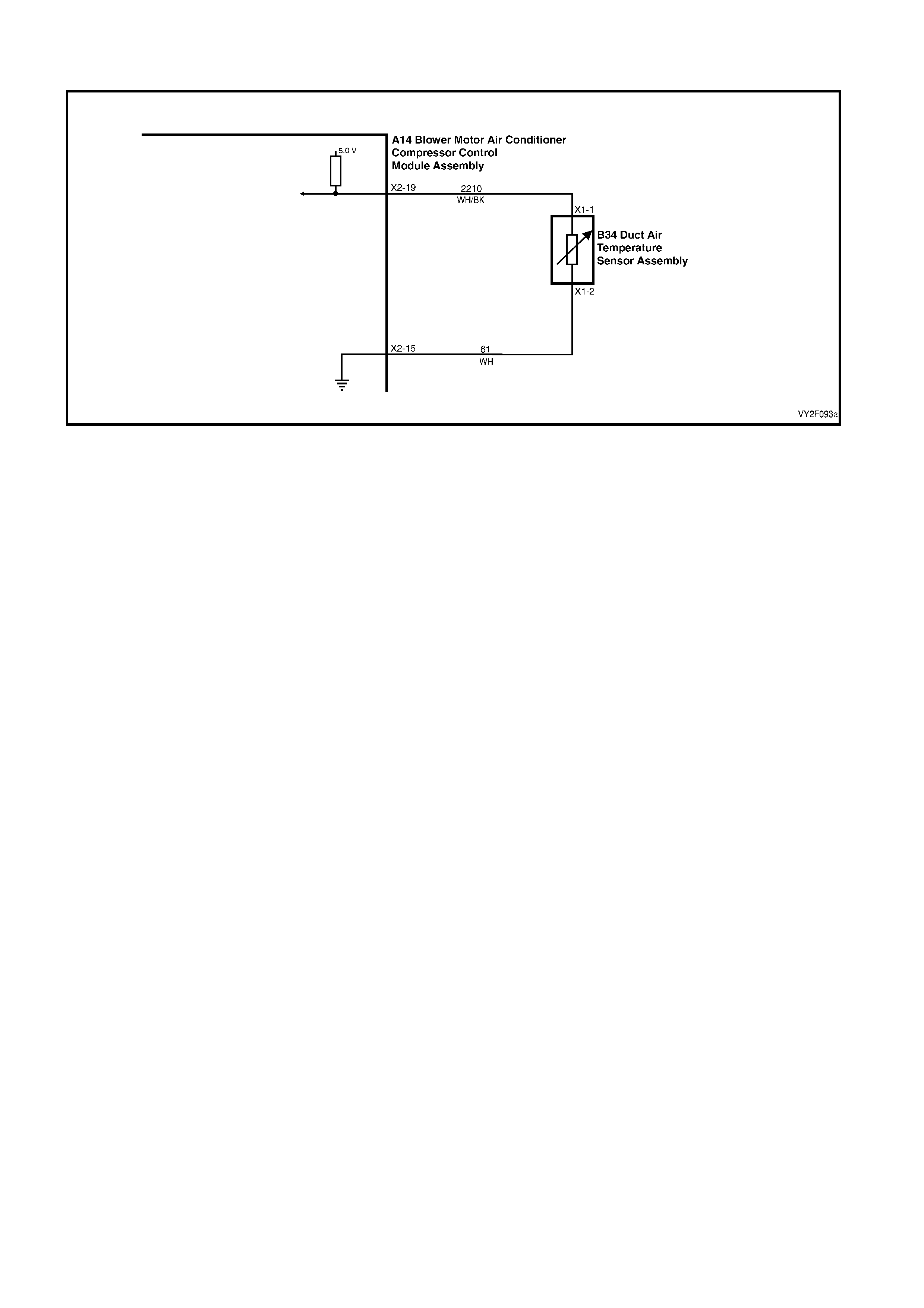
DTC 17 – EVAPORATIVE TEMPERATURE SENSOR VOLTAGE TOO HIGH (LHD)
Figure 2F-75
Circuit Description:
The Evaporative Temperature Sensor (ETS) uses a thermistor to vary voltage signals to the OCC control module.
The OCC module applies a voltage of 5.0 volts to the sensor. When the air is cold, the ETS resistance is high,
therefore the OCC module will sense a high signal voltage. If the air is warm the resistance is low, therefore the
OCC module will sense a low signal voltage.
DTC 17 will set if the ETS signal voltage is more than 4.8 volts or if the ETS sensor wiring harness (circuit 2210) or
connectors are open circuited for 10 seconds.
Test Description:
Number(s) below refer to Step numbers in the followin g Diagnostic Chart:
1. Ensures the Diagnostic Circuit Check has been performed.
2. This test checks that the conditions that would set the DTC, are p resent.
3. This test checks if the wiring or sensor is open circuit.
4. This test checks if wiring is shorted to the ignition feed in the OCC harness.
5. This test checks if wiring is shorted to the 5.0 V feed in the OCC harness.
6. This test checks if wiring is shorted to a voltage in the main wiring harne ss.
7. Check for intermittent connection at OCC.
8. This test checks if sensor is functioning correctly.
9. Check for intermittent connection at sensor.
10. This test checks for an open circuit sensor g ro und wire.
11. This test checks for an open circuit sensor signal wire.
Diagnostic Aids:
The default temperature for an open circuit is 5°C.
When using the temperature/resistance chart, place a thermometer in the centre vent, set temperature to full cold
and manual fan speed to 2. This will give an approximate evaporative air temperature. Compare this temperature
to the chart.
Notes on Diagnostic Chart:
1. Refer to 5. WIRING DIAGRAMS in this Section for views of OCC system related electrical connectors and
complete OCC system wiring diag rams.
2. For electrical connector locations and additional wiring diagram information, refer to
Section 12P WIRING DIAGRAMS.
3. Refer to 1.1 TECH 2 DIAGNOSTICS in this Sectio n for connecting and using TECH 2.

Temperature Resistance Chart
AMBIENT°C RESISTANCE Ω
5 4300 – 4850
10 3600 – 4050
15 2950 – 3250
20 2320 – 2625
25 1990 – 2200
30 1675 – 1850
35 1330 –1470
40 1140 – 1260
45 950 – 1050
50 850 - 950
DTC 17 – EVAPORATIVE TEMPERATURE SENSOR VOLTAGE TOO HIGH DIAGNOSTIC CHART (LHD)
STEP ACTION VALUE YES NO
1 Was the Diagnostic Circuit Check perfo rmed? – Go to Step 2. Go to Chart A –
DIAGNOSTIC
CIRCUIT
CHECK in this
Section.
2 1. Connect TECH 2 to the DLC.
2. Select Diagnostics / Model Year / Vehicle
Model / Body / Occupant Climate Control /
Data Display / Data List / Evap Temperature
Sensor.
Does TECH 2 display a value above 4.8 volts?
– Go to Step 3. DTC 17 is
intermittent. If
no other DTCs
are stored, refer
to
2. DIAGNOSTI
C CHARTS in
this Section.
3 1. Disconnect OCC connector A14 X2.
2. Probe between OCC evaporative air
temperature sensor (ETS) terminals X2-19 and
X2-15 with an ohmmeter. (Refer to Notes on
Diagnostic Chart for this chart, Note 1).
Is the value as specified?
Refer to
Temp.
Resistance
Chart.
Go to Step 4. Go to Step 8.
4 1. With the OCC connector A14 X2 disconnected,
probe between OCC harness connector
terminals X2-5, circuit 274 (Red / White wire)
and X2-19, circuit 2210 (White / Black wire)
with an ohmmeter.
Does a short exist?
NOTE: Any resistance measured here qualifies as
a short
– Repair faulty
circuits 274 and
/ or 2210.
Verify repair.
Go to Step 5.
5 1. With the OCC connector A14 X2 disconnected,
probe between OCC harness connector
terminal X2-11, circuit 705 (White wire) and
connector terminal X2-19, circuit 2210 (White /
Black wire).
Is the value as specified?
Less than
4,000 Ω Repair faulty
circuits 705 and
2210.
Verify repair.
Go to Step 6.
6 1. Turn the ignition on.
2. Back-probe OCC harness connector
terminal X2-19, circuit 2210 (White / Black
wire) with a voltmeter to chassis g round.
Is the value as specified?
Less than
0.4 volt Go to Step 7. Repair faulty
circuit 2210.
7 1. Inspect the OCC harness connector A14 X2 for
an intermittent or loose terminal.
Is the connector OK?
– Replace the
faulty OCC
control module.
Refer to
Section 2E,
HVAC
OCCUPANT
CLIMATE
CONTROL
(AUTO A/C) –
REMOVAL &
INSTALLATION
.
Repair faulty
connector
A14 X2.

STEP ACTION VALUE YES NO
8 1. Disconnect ETS connector B34 X1. Refer to
Temp.
Resistance
Chart.
Go to Step 9. Replace the
faulty
evaporative
temperature
sensor. Refer to
Section 2E,
HVAC
OCCUPANT
CLIMATE
CONTROL
(AUTO A/C) –
REMOVAL &
INSTALLATION
.
9 1. Inspect the evaporative air temperature sensor
harness connector B34 X1 for an intermittent
or loose terminal.
Is the connector OK?
– Go to Step 10. Repair faulty
connector
B34 X1.
10 1. Check the integrity of circuit 61 (White wire)
between (B34) connector terminal X1-2 and
(A14) connector terminal X2-15. (Refer to
Notes on Diagnostic Chart for this chart, Note
1.)
Is the circuit OK?
– Go to Step 11. Repair faulty
circuit 61.
11 1. Check the integrity of circuit 2210 (White /
Black wire) between (B34) connector
terminal X1-1 and (A14) connector
terminal X2-19.
Is the circuit OK?
– Reconnect
evaporative air
temp sensor
harness
connector
B34 X1 and go
to Step 4.
Repair faulty
circuit 2210.
WHEN ALL DIAGNOSIS AND REPAIRS ARE COMPLETE, VERIFY CORRECT OPERATION

DTC 17 – EVAPORATIVE TEMPERATURE SENSOR VOLTAGE TOO HIGH (RHD)
Figure 2F-76
Circuit Description:
The Evaporative Temperature Sensor (ETS) uses a thermistor to vary voltage signals to the OCC control module.
The OCC module applies a voltage of 5.0 volts to the sensor. When the air is cold, the ETS resistance is high,
therefore the OCC module will sense a high signal voltage. If the air is warm the resistance is low, therefore the
OCC module will sense a low signal voltage.
DTC 17 will set: if the ETS signal voltage is more than 4.8 volts or if the ETS sensor wiring harness (circuit 2210) or
connectors are open circuited for 10 seconds.
Test Description:
Number(s) below refer to Step numbers in the followin g Diagnostic Chart:
1. Ensures the Diagnostic Circuit Check has been performed.
2. This test checks that the conditions that would set the DTC, are p resent.
3. This test checks if the wiring or sensor is open circuit.
4. This test checks if wiring is shorted to the ignition feed in the OCC harness.
5. This test checks if wiring is shorted to the 5.0 V feed in the OCC harness.
6. This test checks if wiring is shorted to a voltage in the main wiring harne ss.
7. Check for intermittent connection at OCC.
8. This test checks if sensor is functioning correctly.
9. Check for intermittent connection at sensor.
10. This test checks for an open circuit sensor g ro und wire.
11. This test checks for an open circuit sensor signal wire.
Diagnostic Aids:
The default temperature for an open circuit is 5°C.
When using the temperature/resistance chart, place a thermometer in the centre vent, set temperature to full cold
and manual fan speed to 2. This will give an approximate evaporative air temperature figure. Compare this to the
chart.
Notes on Diagnostic Chart:
1. Refer to 5. WIRING DIAGRAMS in this Section for views of OCC system related electrical connectors and
complete OCC system wiring diag rams.
2. For electrical connector locations and additional wiring diagram information, refer to
Section 12P WIRING DIAGRAMS.
3. Refer to 1.1 TECH 2 DIAGNOSTICS in this Sectio n for connecting and using TECH 2.

Temperature Resistance Chart
AMBIENT°C RESISTANCE Ω
5 4300 – 4850
10 3600 – 4050
15 2950 – 3250
20 2320 – 2625
25 1990 – 2200
30 1675 – 1850
35 1330 –1470
40 1140 – 1260
45 950 – 1050
50 850 - 950
DTC 17 – EVAPORATIVE TEMPERATURE SENSOR VOLTAGE TOO HIGH DIAGNOSTIC CHART (RHD)
STEP ACTION VALUE YES NO
1 Was the Diagnostic Circuit Check perfo rmed? – Go to Step 2. Go to Chart A –
DIAGNOSTIC
CIRCUIT
CHECK in this
Section.
2 1. Connect TECH 2 to the DLC.
2. Select Diagnostics / Model Year / Vehicle Model
/ Body / Occupant Climate Control / Data
Display / Data List / Evap Temperature Sensor.
Does TECH 2 display a value above 4.8 volts?
– Go to Step 3. DTC 17 is
intermittent. If
no other DTCs
are stored, refer
to
2. DIAGNOSTI
C CHARTS in
this Section.
3 1. Disconnect O CC connector A14 X2.
2. Probe between OCC evaporative air
temperature sensor (ETS) terminals X2-19 and
X2-15 with an ohmmeter. (Refer to Notes on
Diagnostic Chart for this chart, Note 1.)
Is the value as specified?
Refer to
Temp.
Resistance
Chart.
Go to Step 4. Go to Step 8.
4 1. With the OCC connector A14 X2 disconnected,
probe between OCC harness connector
terminals X2-5, circuit 274 (Red / White wire)
and X2-19, circuit 2210 (White / Black wire) with
an ohmmeter.
Does a short exist?
NOTE: Any resistance measured here qualifies as a
short
– Repair faulty
circuits 274 and
/ or 2210.
Go to Step 5.
5 1. With the OCC connector A14 X2 disconnected,
probe between OCC harness connector
terminal X2-11, circuit 705 (White wire) and
connector terminal X2-19, circuit 2210 (White /
Black wire).
Is the value as specified?
Less than
4,000 Ω Repair faulty
circuits 705 and
2210.
Go to Step 6.
6 1. Turn the ignition on.
2. Back-probe OCC harness connector
terminal X2-19, circuit 2210 (White / Black wire)
with a voltmeter to chassis ground.
Is the value as specified?
Less than
0.4 volt Go to Step 7. Repair faulty
circuit 2210.

STEP ACTION VALUE YES NO
7 1. Inspect the OCC harness connector A14 X2 for
an intermittent or loose terminal. – Replace the
faulty OCC
control module.
Refer to
Section 2E,
HVAC
OCCUPANT
CLIMATE
CONTROL
(AUTO A/C) –
REMOVAL &
INSTALLATION
.
Repair faulty
connector
A14 X2.
8 1. Disconnect ETS connector B34 X1.
2. Probe between the evaporative air temperature
sensor terminals with an ohmmeter. (Refer to
Notes on Diagnostic Chart for this chart, Note
1).
Is the value as specified?
Refer to
Temp.
Resistance
Chart.
Go to Step 9. Replace the
faulty
evaporative
temperature
sensor. Refer to
Section 2E,
HVAC
OCCUPANT
CLIMATE
CONTROL
(AUTO A/C) –
REMOVAL &
INSTALLATION
.
9 1. Inspect the evaporative air temperature sensor
harness connector B34 X1 for an intermittent or
loose terminal.
Is the connector OK?
– Go to Step 10. Repair faulty
connector
B34 X1.
10 1. Check the integrity of circuit 61 (Tan wire)
between (B34) connector terminal X1-B and
(A14) connector terminal X2-15. (Refer to Notes
on Diagnostic Chart for this chart, Note 1.)
Is the circuit OK?
– Go to Step 11. Repair faulty
circuit 61.
11 1. Check the integrity of circuit 2210 (White / Black
wire) between (B34) connector terminal X1-A
and (A14) connector terminal X2-19.
Is the circuit OK?
– Reconnect
evaporative air
temp sensor
harness
connector
B34 X1 and go
to Step 4.
Repair faulty
circuit 2210.
WHEN ALL DIAGNOSIS AND REPAIRS ARE COMPLETE, VERIFY CORRECT OPERATION
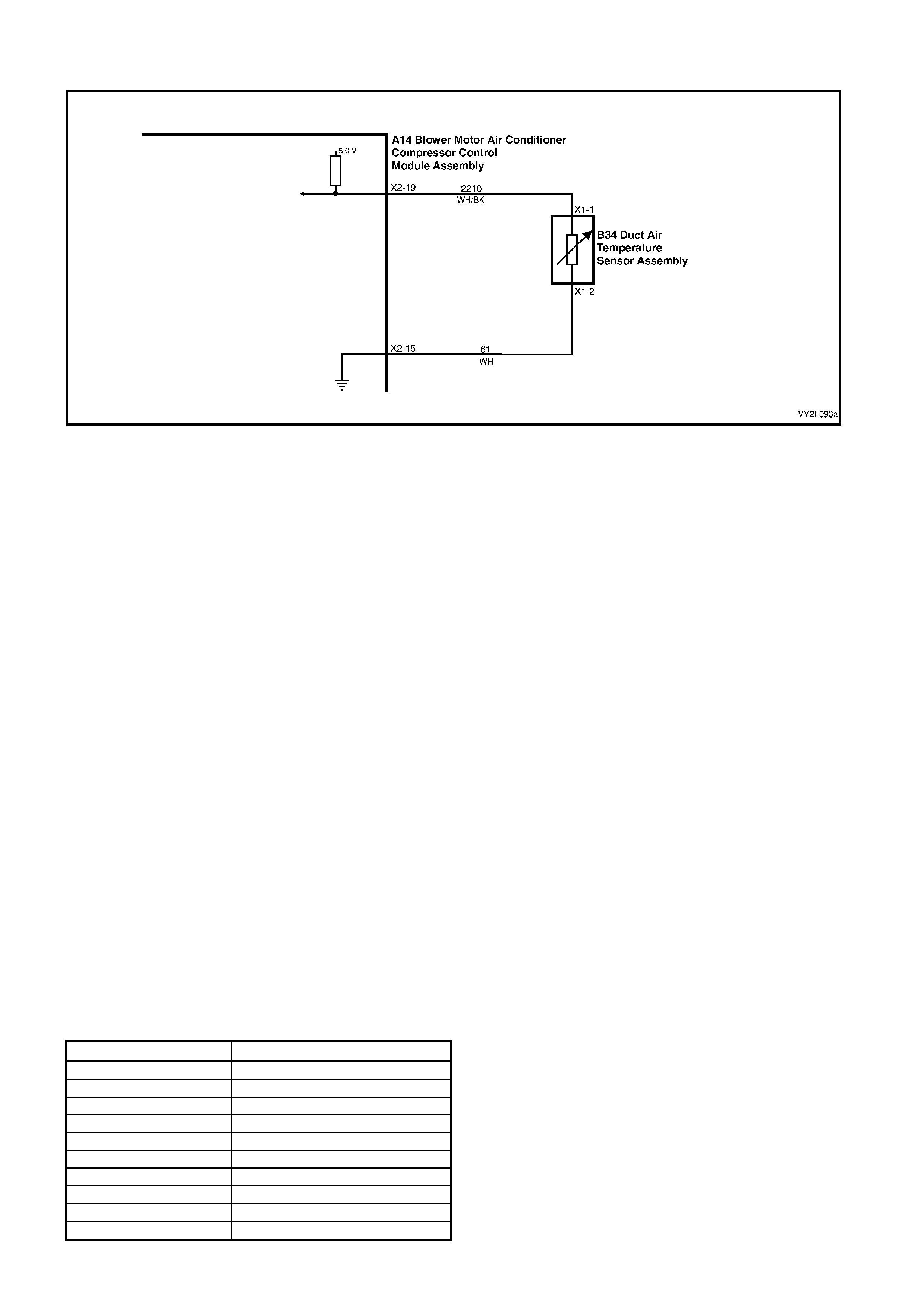
DTC 18 – EVAPORATIVE TEMPERATURE SENSOR VOLTAGE TOO LOW (LHD)
Figure 2F-77
Circuit Description:
The evaporative temperature sensor (ETS) uses a thermistor to control the signal voltage to the OCC control
module. The OCC module applies a voltage of 5.0 volts to the sensor. When the air off the evaporator core is cold,
the ETS resistance is high, therefore the OCC module will sense a high signal voltage. If the air is warm, the ETS
resistance is low, therefore the OCC mod ule will sense a low signal voltage.
DTC 18 will set if the ETS signal voltage is less than 0.3 volt or if the ETS sensor wiring harness (circuit 2210) or
connectors are open circuited for 10 seconds.
Test Description:
Number(s) below refer to Step numbers in the followin g Diagnostic Chart:
1. Ensures the Diagnostic Circuit Check has been performed.
2. This test checks that the conditions that would set the DTC, are p resent.
3. This test checks if the sensor or wiring is causing the short circuit.
4. This test checks if sensor and wi ring is functioning correctly.
5. Check for intermittent connectio n at sensor
6. This test checks for a short circuit of the sen sor signal wire to ground.
7. This test determines if the sensor is shorted or the wire is sh orted.
Diagnostic Aids:
The default temperature for a short circuit is 5°C.
When using the temperature/resistance chart, place a thermometer in the centre vent, set temperature to full cold
and manual fan speed to 2. This will give an approximate evaporative air temperature figure. Compare this to the
chart.
Notes on Diagnostic Chart:
1. Refer to 5. WIRING DIAGRAMS in this Section for views of OCC system related electrical connectors and
complete OCC system wiring diag rams.
2. For electrical connector locations and additional wiring diagram information, refer to
Section 12P WIRING DIAGRAMS.
3. Refer to 1.1 TECH 2 DIAGNOSTICS in this Sectio n for connecting and using TECH 2.
Temperature Resistance Chart
AMBIENT°C RESISTANCE Ω
5 4300 – 4850
10 3600 – 4050
15 2950 – 3250
20 2320 – 2625
25 1990 – 2200
30 1675 – 1850
35 1330 – 1470
40 1140 – 1260
45 950 – 1050
50 850 – 950

DTC 18 – EVAPORATIVE TEMPERATURE SENSOR VOLTAGE TOO LOW DIAGNOSTIC CHART
STEP ACTION VALUE YES NO
1 Was the Diagnostic Circuit Check performed? – Go to Step 2. Go to Chart A –
DIAGNOSTIC
CIRCUIT
CHECK in this
Section.
2 1. Connect TECH 2 to the DLC (Refer to Notes
on Diagnostic Chart for this chart, Note 2.)
2. Select Diagnostics / Model Year / Vehicle
Model / Body / Occupant Climate Control /
Data Display / Data List / Evap Temperature
Sensor.
Does TECH 2 display a value less than 0.4 volt?
– Go to Step 3. DTC 18
intermittent. If
no other DTCs
are stored, refer
to
2. DIAGNOSTI
C CHARTS in
this Section
3 1. With TECH 2 connected and Evap
Temperature Sensor displayed, disconnect the
OCC wiring harness A14 X2.
Does TECH 2 display a value above 4.8 volts?
– Go to Step 4. Replace the
faulty OCC
control module.
Refer to
Section 2E,
HVAC
OCCUPANT
CLIMATE
CONTROL
(AUTO A/C) –
REMOVAL &
INSTALLATION
.
4 1. With the OCC connector A14 X2 disconnected,
probe between the OCC connector terminals
X2-19 and X2-15 with an ohmmeter. (Refer to
Notes on Diagnostic Chart for this chart, Note
1.)
Is the value as specified?
Refer to
Temp.
Resistance
Chart.
Go to Step 5. Go to Step 7
5 1. With the OCC connector A14 X2 disconnected,
probe OCC harness connector terminal X2-19,
circuit 2210 (White/ Black wire) with an
ohmmeter to ground.
Is the value as specified?
More than
0 ohm Repair faulty
circuit 2210. Go to Step 6
6 1. Inspect the OCC and evaporative air
temperature sensor wiring harness and
connectors B34 X1 and A14 X2 for an
intermittent short.
Are the circuits OK?
– Replace the
faulty OCC
control module.
Refer to
Section 2E,
HVAC
OCCUPANT
CLIMATE
CONTROL
(AUTO A/C) –
REMOVAL &
INSTALLATION
.
Repair faulty
circuits /
connectors as
necessary.
7 1. Disconnect the evaporative temperature
sensor connector B24 X1.
2. Install OCC connectors A14 X1 and A14 X2.
3. With TECH 2 connected, select Body /
Occupant Climate Control / Data Display / Data
List / Evap Temperature Sensor.
Does TECH 2 display a value above 3.4 volts?
– Replace the
faulty
evaporative
temperature
sensor. Refer to
Section 2E,
HVAC
OCCUPANT
CLIMATE
CONTROL
(AUTO A/C) –
REMOVAL &
INSTALLATION
.
Repair faulty
circuit 2210.
WHEN ALL DIAGNOSIS AND REPAIRS ARE COMPLETE, VERIFY CORRECT OPERATION

DTC 18 – EVAPORATIVE TEMPERATURE SENSOR VOLTAGE TOO LOW (RHD )
Figure 2F-78
Circuit Description:
The evaporative temperature sensor (ETS) uses a thermistor to control the signal voltage to the OCC control
module. The OCC module applies a voltage of 5.0 volts to the sensor. When the air off the evaporator core is cold,
the ETS resistance is high, therefore the OCC module will sense a high signal voltage. If the air is warm, the ETS
resistance is low, therefore the OCC mod ule will sense a low signal voltage.
DTC 18 will set: if the ETS signal voltage is less than 0.3 volt or if the ETS sensor wiring harness (circuit 2210) or
connectors are open circuited for 10 seconds.
Test Description:
Number(s) below refer to Step numbers in the followin g Diagnostic Chart:
1. Ensures the Diagnostic Circuit Check has been performed.
2. This test checks that the conditions that would set the DTC, are p resent.
3. This test checks if the sensor or wiring is causing the short circuit.
4. This test checks if sensor and wi ring is functioning correctly.
5. Check for intermittent connection at sensor.
6. This test checks for a short circuit of the sen sor signal wire to ground.
7. This test determines if the sensor is shorted or the wire is shorted.
Diagnostic Aids:
The default temperature for a short circuit is 5°C.
When using the temperature/resistance chart, place a thermometer in the centre vent, set temperature to full cold
and manual fan speed to 2. This will give an approximate evaporative air temperature figure. Compare this to the
chart.
Notes on Diagnostic Chart:
1. Refer to 5. WIRING DIAGRAMS in this Section for views of OCC system related electrical connectors and
complete OCC system wiring diag rams.
2. For electrical connector locations and additional wiring diagram information, refer to
Section 12P WIRING DIAGRAMS.
3. Refer to 1.1 TECH 2 DIAGNOSTICS in this Sectio n for connecting and using TECH 2.
Temperature Resistance Chart
AMBIENT°C RESISTANCE Ω
5 4300 – 4850
10 3600 – 4050
15 2950 – 3250
20 2320 – 2625
25 1990 – 2200
30 1675 – 1850
35 1330 – 1470
40 1140 – 1260
45 950 – 1050
50 850 – 950

DTC 18 – EVAPORATIVE TEMPERATURE SENSOR VOLTAGE TOO LOW DIAG NOSTIC CHART (RHD)
STEP ACTION VALUE YES NO
1 Was the Diagnostic Circuit Check performed? – Go to Step 2. Go to Chart A –
DIAGNOSTIC
CIRCUIT
CHECK in this
Section.
2 1. Connect TECH 2 to the DLC (Refer to Notes
on Diagnostic Chart for this chart, Note 2.)
2. Select Diagnostics / Model Year / Vehicle
Model / Body / Occupant Climate Control /
Data Display / Data List / Evap Temperature
Sensor.
Does TECH 2 display a value less than 0.4 volt?
– Go to Step 3. DTC 18
intermittent. If
no other DTCs
are stored, refer
to
2. DIAGNOSTI
C CHARTS in
this Section
3 1. With TECH 2 connected and Evap
Temperature Sensor displayed, disconnect the
OCC wiring harness A14 X2.
Does TECH 2 display a value above 4.8 volts?
– Go to Step 4. Replace the
faulty OCC
control module.
Refer to
Section 2E,
HVAC
OCCUPANT
CLIMATE
CONTROL
(AUTO A/C) –
REMOVAL &
INSTALLATION
.
4 1. With the OCC connector A14 X2 disconnected,
probe between the OCC connector terminals
X2-19 and X2-15 with an ohmmeter. (Refer to
Notes on Diagnostic Chart for this chart, Note
1.)
Is the value as specified?
Refer to
Temp.
Resistance
Chart.
Go to Step 5. Go to Step 7
5 1. With the OCC connector A14 X2 disconnected,
probe OCC harness connector terminal X2-19,
circuit 2210 (White/ Black wire) with an
ohmmeter to ground.
Is the value as specified?
More than
0 ohm Repair faulty
circuit 2210. Go to Step 6
6 1. Inspect the OCC and evaporative air
temperature sensor wiring harness and
connectors B34 X1 and A14 X2 for an
intermittent short.
Are the circuits OK?
– Replace the
faulty OCC
control module.
Refer to
Section 2E,
HVAC
OCCUPANT
CLIMATE
CONTROL
(AUTO A/C) –
REMOVAL &
INSTALLATION
.
Repair faulty
circuits /
connectors as
necessary.
7 1. Disconnect the evaporative temperature
sensor connector B24 X1.
2. Install OCC connectors A14 X1 and A14 X2.
3. With TECH 2 connected, select Body /
Occupant Climate Control / Data Display / Data
List / Evap Temperature Sensor.
Does TECH 2 display a value above 3.4 volts?
– Replace the
faulty
evaporative
temperature
sensor. Refer to
Section 2E,
HVAC
OCCUPANT
CLIMATE
CONTROL
(AUTO A/C) –
REMOVAL &
INSTALLATION
.
Repair faulty
circuit 2210.
WHEN ALL DIAGNOSIS AND REPAIRS ARE COMPLETE, VERIFY CORRECT OPERATION
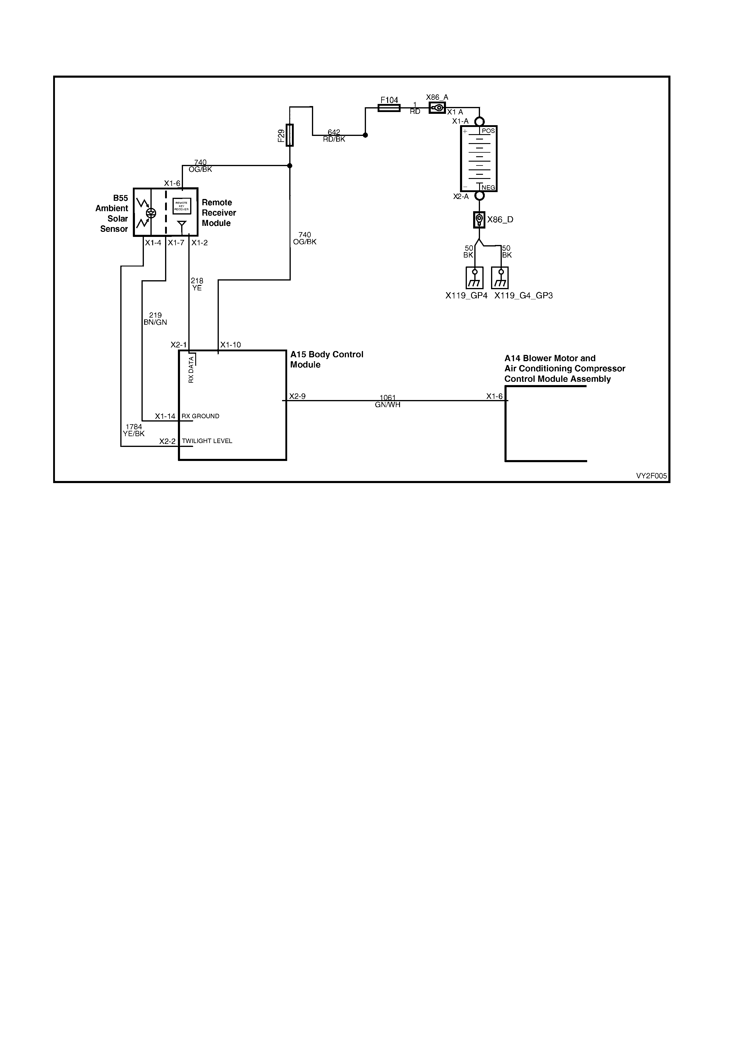
DTC 19 – SUN LOAD SENSOR ERROR
Figure 2F-79
Circuit Description:
The sun load sensor is mounted in the instrument panel pad between the demist ducts to monitor the amount of
sun load and ambient light in front of the vehicle. The ambient light monitored is used by the BCM for Auto Lights
On operation (twilight sentinel) and the sun load monitored is used by the OCC control module. The BCM monitors
the voltage from this sensor via circuit 1784 and converts this voltage signal into Steps which it sends to the OCC
module via the auxiliary serial data line, circuit 1061. The message sent will vary between 0 and 254 Steps,
depending on the amount of sun load (0 = no sun load, 254 = maximum sun load).
DTC 19 will set if the BCM sends a sun load sensor value of 255 Steps to the OCC module for 10 seconds. The
BCM will send this value if it detects a high sun load and a low twilight level.
NOTE: This trouble code is for information only; under no circumstances should the OCC module be replaced due
to this trouble code.
Test Description:
Number(s) below refer to Step numbers in the followin g Diagnostic Chart:
1. Ensures the Diagnostic Circuit Check has been performed.
2 & 3. Uses TECH 2 to check ambient light level data on the auxiliary serial data bus.
4 & 5. Uses TECH 2 to check ambient light level signal at microprocessor of BCM.
6. Determines if the sun sensor / remote receiver module has power and ground by checking operation of the
remote coded key reader.
7 & 8. Checks ambient light level signal at input to BCM.
9. Checks integrity of circuit 1784 (open, sh ort to ground or short to Battery voltage).
10. Checks battery voltage supply at sun sensor / remote receiver module.
11. Checks integrity of circuit 219 (open, sh ort to ground or short to Battery voltage).
Notes on Diagnostic Chart:
1. Refer to 5. WIRING DIAGRAMS in this Section for views of OCC system related electrical connectors and
complete OCC system wiring diag rams.
2. For electrical connector locations and additional wiring diagram information, refer to
Section 12P WIRING DIAGRAMS.
3. Refer to 1.1 TECH 2 DIAG NOSTICS in this Section for connecting and u sing TECH 2.

DTC 19 – SUN LOAD SENSOR ERROR DIAGNOS TIC C HA RT
STEP ACTION VALUE YES NO
1 Was the Diagnostic Circuit Check perfo rmed? – Go to Step 2. Go to Chart A –
DIAGNOSTIC
CIRCUIT
CHECK in this
Section.
2 1. Connect TECH 2 to the DLC.
2. Select Diagnostics / Model Year / Vehicle
Model / Body / Body Control Module / Normal
Mode / Ambient Light Level.
3. Cover the sun load sensor / remote receiver
module assembly.
Does TECH 2 display 1 Step?
– Uncover the
sun load sensor
/ remote
receiver module
assembly and
go to Step 3.
Go to Step 4.
3 1. With TECH 2 connected and the Ambient Light
Level displayed, shine a torch directly on the
sun load sensor / remote receiver module
assembly.
Does TECH 2 display 254 Step?
– Fault not found,
if no other
DTCs are
stored, refer to
2. DIAGNOSTI
C CHARTS in
this Section.
Go to Step 4.
4 1. With the sun load sensor / remote receiver
module assembly covered and TECH 2
connected, select Body / Body Control Module
/ Data Display / Data List / Ambient Light
Sensor display.
Does TECH 2 display less than 0.5 volts?
– Replace the
BCM. Refer to
Section 12J, 2.1
BODY
CONTROL
MODULE.
Go to Step 5.
5 1. With TECH 2 connected and the Ambient Light
Sensor displayed, shine a torch on the sun
load sensor / remote receiver module
assembly.
Does TECH 2 display approximately 5 volts?
– Replace the
BCM. Refer to
Section 12J, 2.1
BODY
CONTROL
MODULE.
Go to Step 6.
6 1. Check the operation of the remote coded key
receiver by locking and unlocking the doors
using the remote coded key (Lock and Unlock
buttons).
Does remote coded key re ceiver operate?
– Go to Step 7. Go to Step 10.
7 1. Back-probe BCM connector terminal X2-2,
circuit 1784 (Yellow / Black wire) with a
voltmeter to ground. (Refer to Notes on
Diagnostic Chart for this chart, Note 1.)
2. Turn the ignition on.
3. Cover the sun load sensor / remote receiver
module assembly.
Is the value as specified?
Less than
0.5 volt Replace BCM.
Refer to Section
12J, 2.1 BODY
CONTROL
MODULE.
Go to Step 8.
8 1. Back-probe BCM connector terminal X2-2,
circuit 1784 (Yellow / Black wire) with a
voltmeter to ground.
2. Turn the ignition on.
3. Shine a torch on the sun load sensor / remote
receiver module assembly.
Is the value as specified?
Approx.
5 volts Replace the
BCM. Refer to
Section 12J, 2.1
BODY
CONTROL
MODULE.
Go to Step 9.

STEP ACTION VALUE YES NO
9 1. Check the integrity of circuit 1784 (Yellow /
Black wire). – Replace the sun
sensor / remote
receiver
module. Refer
to Section 12J,
2.1 BODY
CONTROL
MODULE.
Repair faulty
circuit 1784.
10 1. Back-probe sun sensor / remote receiver
module connector terminal X1-6, circuit 740
(Orange / Black wire) with a voltmeter to
ground.
Is the value as specified?
12 volts Go to Step 11. Repair faulty
circuit 740.
11 1. Check the integrity of circuit 219
(Brown/Green wire).
Is the circuit OK?
– Go to Step 7. Repair faulty
circuit 219.
WHEN ALL DIAGNOSIS AND REPAIRS ARE COMPLETE, VERIFY CORRECT OPERATION
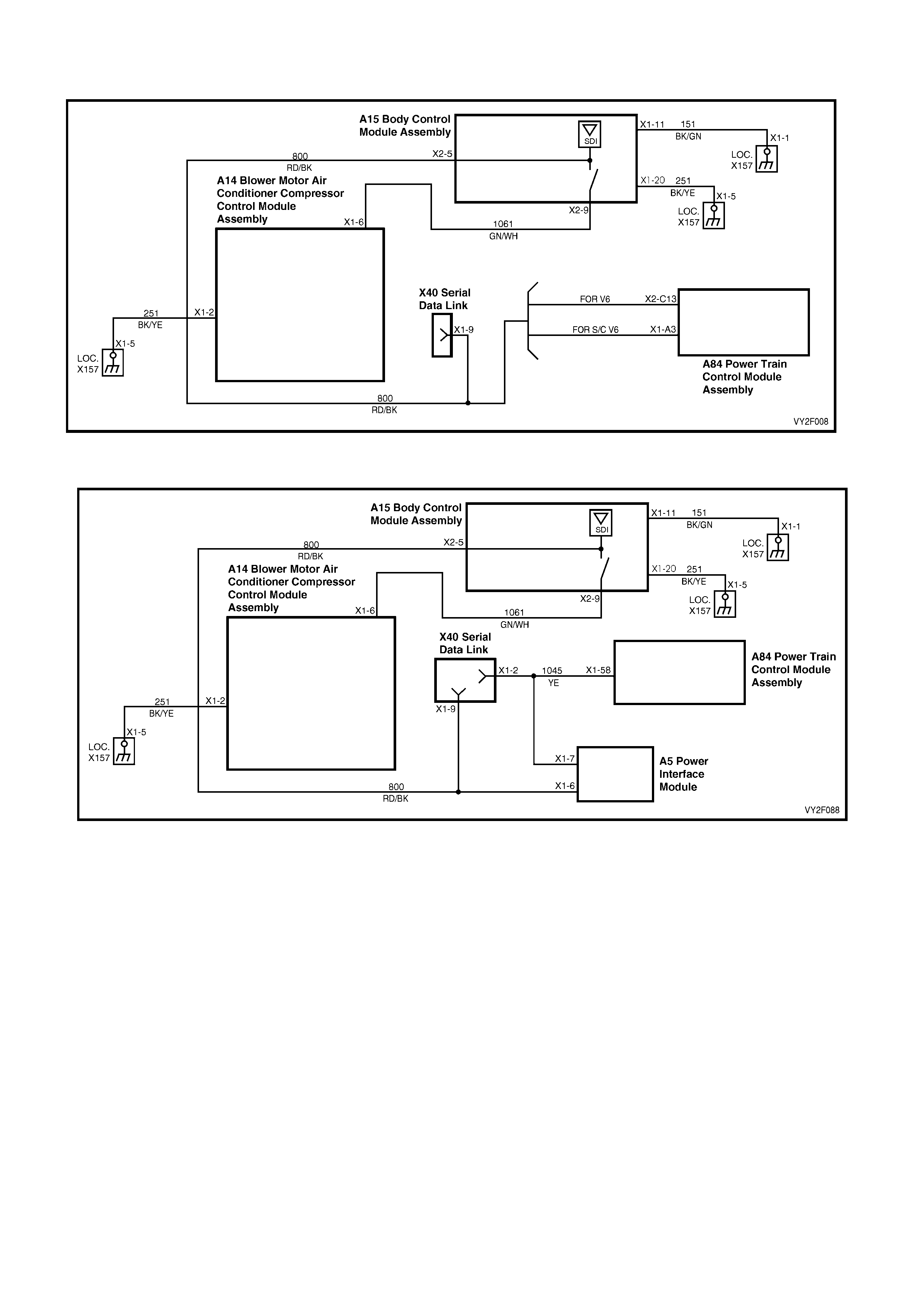
DTC 35 – NO SERIAL DATA FR OM PCM
Figure 2F-80 (V6 and S/C V6)
Figure 2F-81 (GEN III V8)
Circuit Description:
When investigating any complaint of an OCC problem or malfunction, always begin diagnosis with the following
diagnostic circuit check. This check is a preliminary procedure that checks to ensure the OCC module is
communicating on the serial data line as well as helping to identify a problem or malfunction and directing the
reader to the appropriate diagnostic chart in this Section.
With TECH 2 connected to the DLC and ignition switched on, TECH 2 should display serial data communication.
If TECH 2 does not display serial d ata, the serial data circuit may be open or shorted.
There are several other control modules that are connected to the serial data line (PCM, BCM, ABS/TCS,
instruments and SDM. Any of these control modules could cause a fault on the serial data line. This fault could
result in TECH 2 not being able to display serial data.
DTC will set if the serial data line (circuits 1061 or 800) are interrupted and the OCC does not receive data from the
PCM or BCM fo r 10 seconds.

Test Description:
Number(s) below refer to Step numbers in the followin g Diagnostic Chart
1. Ensures the Diagnostic Circuit Check has been performed.
2. Determines if there is a fault in the serial data circuit (800) between the BCM and PCM by starting the engine.
If serial data was lost while the engine was running, the engine will restart but there will b e a one second delay.
3. Checks if fault is common with other control modules connected to the serial data circuit.
4. Checks internal switch in BCM for open circuit.
5. Checks circuit 1061 and determine if fault is in wiring or a control module.
6. Checks circuit 1061 for open circuit.
7. Checks integrity of ground circuits for the BCM, PCM, PIM and OCC control module.
Diagnostic Aids:
A fault with the serial data circuit could be caused by one or more of the several control modules connected to this
serial data circuit. Isolate the fault by disconnecting each control module, one at a time until serial data
communication is re stored.
Notes on Diagnostic Chart:
1. Refer to Section 12P, WIRING DIAGRAMS for procedures on checking wiring faults.
2. Refer to 1.1 TECH 2 DIAG NOSTICS in this Section for connecting and using TECH 2.
3. To check the integrity of the OCC module ground circuit; turn ignition and OCC system ON and check for a
voltage drop across circuit 251 (Black / Yellow wire), between OCC module connector A14 X1, terminal X1-2,
and ground point X157.
4. To check the integrity of the PCM ground circuit, refer to Ground Credibility Check in the following Sections:
• Section 6C1, POWERTRAIN – V6
• Section 6C2, POWERTRAIN – V6 S/C
• Section 6C3, POWERTRAIN – GEN III V8
DTC 35 – NO SERIAL DAT A FR OM PCM DIAGNOSTIC CHART
STEP ACTION VALUE YES NO
1 Was the Diagnostic Circuit Check perfo rmed? – Go to Step 2. Go to Chart A –
DIAGNOSTIC
CIRCUIT
CHECK in this
Section.
2 1. Connect TECH 2 to the DLC.
2. Select Diagnostics / Model Year / Vehicle
Model / Body / DTC Check / DTC Check.
Can TECH 2 communicate with the BCM and
PCM?
NOTE: If No Data displays next to a module, then
there is no communication between TECH 2 and
that module.
– Go to Step 3. G o to Sectio n
12J, 4.2 SERIAL
DATA
COMMUNICATI
ON (BUS
MASTER).
3 In Step 2, did TECH 2 communicate with all control
modules except the OCC control module? – Go to Step 7. Go to Step 4.
4 1. Back-probe between BCM connector
terminal X2-9, circuit 1061 (Green / White
wire) and X2-5, circuit 800 (Red / Black wire)
with an ohmmeter. (Refer to Notes on
Diagnostic Chart for this chart, Note 1.)
Is the value as specified?
Less than
1 ohm Go to Step 5. Replace the
BCM. Refer to
Section 12J, 2.1
BODY
CONTROL
MODULE.
5 1. Check the integrity of circuit 1061 (Green /
White wire) between BCM connector
terminal X2-9 and the individual control
modules.
Is the circuit OK?
– Go to Step 6. Repair faulty
circuit 1061.

STEP ACTION VALUE YES NO
6 1. Disconnect each control module in
circuit 1061 one at a time to isolate the fault
in the circuit or to identify the control module
causing the fault.
– Verify repair. Go to Step 7.
7 1. Back-probe between BCM connector
terminal X2-9 and OCC module connector
terminal X1-6, circuit 1061 (Green/White
wire) with an ohmmeter.
Is the value as specified?
Less than
1 ohm. Go to Step 8. Repair faulty
circuit 1061.
8 1. Check the integrity of the ground circuits to
the OCC control module, BCM, PCM and
PIM (GEN III V8) using a voltmeter to a
known good ground. (Refer to Notes on
Diagnostic Chart for this chart, Notes 3
and 4.)
Are the values as specified?
Less than
0.15 volt. Replace the
OCC control
module. Refer
to Section 2E,
HVAC
OCCUPANT
CLIMATE
CONTROL
(AUTO A/C) –
REMOVAL &
INSTALLATIO
N.
Repair faulty
ground circuit/ s.
WHEN ALL DIAGNOSIS AND REPAIRS ARE COMPLETE, VERIFY CORRECT OPERATION

DTC 36 – NO SERIAL DATA FROM BCM
Figure 2F-82 (V6 and S/C V6)
Figure 2F-83 (GEN III V8)
Circuit Description:
When investigating any complaint of an OCC problem or malfunction, always begin diagnosis with the following
diagnostic circuit check. This check is a preliminary procedure that checks to ensure the OCC module is
communicating on the serial data line as well as helping to identify a problem or malfunction and directing the
reader to the appropriate diagnostic chart in this section.
With TECH 2 connected to the DLC and ignition switched on, TECH 2 should display serial data communication.
If TECH 2 does not display serial d ata, the serial data circuit may be open or shorted.
There are several other control modules that are connected to the serial data line (PCM, BCM, ABS/TCS,
instruments and SDM. Any of these control modules could cause a fault on the serial data line. This fault could
result in TECH 2 not being able to display serial data.
DTC will set if set if the serial data line (circuits 1061 or 800) are interrupted and the OCC module does not receive
data from the PCM or BCM for 10 seconds.

Test Description:
Number(s) below refer to Step numbers in the followin g Diagnostic Chart
1. Ensures the Diagnostic Circuit Che ck has been performed.
2. Determines if there is a fault in the serial data circuit (800) between the BCM and PCM by starting the engine.
If serial data was lost while the engine was running, the engine will restart but there will b e a one second delay.
3. Checks if fault is common with other control modules connected to the serial data circuit.
4. Checks internal switch in BCM for open circuit.
5. Checks circuit 1061 and determines if fault is in wiring or a control module.
6. Checks circuit 1061 for open circuit.
7. Checks integrity of ground circuits for the BCM, PCM, PIM and OCC control module.
Diagnostic Aids:
A fault with the serial data circuit could be caused by one or more of the several control modules connected to this
serial data circuit. Isolate the fault by disconnecting each control module, one at a time until serial data
communication is re stored.
Notes on Diagnostic Chart:
1. Refer to Section 12P, WIRING DIAGRAMS for procedures on checking wiring faults.
Refer to 1.1 TECH 2 DIAGNOSTICS in this Section for connecting and using TECH 2.
To check the integrity of the OCC module ground circuit; turn ignition and OCC system ON and check for a voltage
drop across circuit 251 (Black / Yellow wire), between OCC module connector A14 X1, terminal X1-2, and
ground point X157.
To check the integrity of the BCM ground circuit turn the ignition on and check for a voltage drop across circuit 251
(Black / Yellow wire), between BCM connector A15 X1, terminal X1-20 and ground point X157.
To check the integrity of the PCM ground circuit, refer to Ground Credibility Check in the following Sections:
• Section 6C1, POWERTRAIN – V6
• Section 6C2, POWERTRAIN – V6 S/C
• Section 6C3, POWERTRAIN – GEN III V8.
DTC 36 – SERIAL DATA COMMUNICATION ERROR DI AGNOSTIC CHART
STEP ACTION VALUE YES NO
1 Was the Diagnostic Circuit Check perfo rmed? – Go to Step 2. Go to Chart A –
DIAGNOSTIC
CIRCUIT
CHECK in this
Section.
2 1. Connect TECH 2 to the DLC.
2. Select Diagnostics / Model Year / Vehicle
Model / Body / DTC Check / DTC Check.
Can TECH 2 communicate with the BCM and
PCM?
NOTE: If No Data displays next to a module, then
there is no communication between TECH 2 and
that module.
– Go to Step 3. G o to Sectio n
12J, 4.2 SERIAL
DATA
COMMUNICATI
ON (BUS
MASTER).
3 In Step 2, did TECH 2 communicate with all the
control modules, except the OCC module (ABS,
instruments, SRS)?
– Go to Step 7. Go to Step 4.
4 1. Check the integrity of circuit 1061 (Green /
White wire) and circuit 800 (Red / Black wire)
between BCM connector terminals X2-5 and
X2-9. (Refer to Notes on Diagnostic Chart for
this chart, Note 1.)
Are the circuits OK?
– Go to Step 5. Repair faulty
circuit 800

STEP ACTION VALUE YES NO
5 1. Check the integrity of circuit 1061 (Green /
White wire) between BCM and the individual
control modules.
– Go to Step 6. Repair faulty
circuit 1061.
6 1. Disconnect each control module in
circuit 1220 one at a time to isolate the fault
in the circuit or to identify the control module
causing the fault.
Was a fault located and rectified?
– Verify repair. Go to Step 7.
7 1. Back-probe between BCM connector
terminal X2-9 and OCC module connector
terminal X1-6, circuit 1061 (Green / White
wire) with an ohmmeter.
Is the value as specified?
Less than
1 ohm Go to Step 8. Repair faulty
circuit 1061.
8 1. Check the integrity of the ground circuits to
the OCC module, BCM, PCM and PIM
(GEN III V8) with a voltmeter to a known
good ground.
Is the value as specified?
Less than
0.15 volts Replace the
OCC control
module. Refer
to Section 2E,
HVAC
OCCUPANT
CLIMATE
CONTROL
(AUTO A/C) –
REMOVAL &
INSTALLATIO
N.
Repair faulty
ground circuit/ s.
WHEN ALL DIAGNOSIS AND REPAIRS ARE COMPLETE, VERIFY CORRECT OPERATION

DTC 37 – ROM CHECKSUM ERROR
Figure 2F-84
Circuit Description:
When this diagnostic trouble code (DTC) is set, it indicates a failure attributed to the processor. The processor is
part of the printed circuit board (1) installed within the rear housing (2) of the OCC modul e (3).
DTC 37 will set: if the ROM checksum is incorrect. The testing of the ROM checksum occurs every time the OCC
system is reset due to battery disconnection or lo w power conditions.
If DTC 37 sets and reprogramming is unsuccessful, replace the OCC control module.
Refer to Section 2E, 2.1 OCC CONTROL MODULE.
Test Description:
Number(s) below refer to Step numbers in the followin g Diagnostic Chart.
1. Ensures the Diagnostic Circuit Che ck has been performed.
2. Determines if OCC module is faulty by re-programming the OCC control module.
3. Determines if OCC module is faulty.
Notes on Diagnostic Chart:
Refer to 1.1 TECH 2 DIAGNOSTICS in this Section for connecting and using TECH 2.
Diagnostic Aids:
If the OCC system programming is corrupted, recalibration can be carried out via TECH 2. To calibrate the system
refer to 1.2 TECH 2 TEST MODES AND DISPLAYS FOR OCC DIAGNOSIS in this Section.

DTC 37 – ROM CHECKSUM ERROR
Step Action Yes No
1 1 Has the Diagnostic Circuit Check been performed? Go to Step 2. Go to Chart A –
DIAGNOSTIC
CIRCUIT CHECK
in this Section.
2
1. Reprogram the OCC module Code Version using TECH 2.
Refer to 1.2 TECH 2 TEST MODES AND SCREEN
DISPLAYS FOR OCC DIAGNOSIS in this Section.
Was programming successful?
Go to Step 4. Go to Step 3.
3 1. Repeat Step 2 at least twice, as the system may have
crashed during the prog ramming process.
Was programming successful?
Go to Step 4. Go to Step 5.
4
1. Connect TECH 2 to the DLC.
2 Select Diagnostics / Model Year / Vehicle Model / Body /
Occupant Control Module / Diagnostic Trouble Codes / Clear
DTC Information and clea r DTCs.
Were all DTCs cleared?
System OK. Go to Step 5.
5
1. Replace the OCC control module. Refer to Section 2E,
HVAC OCCUPANT CLIMATE CONTROL (AUTO A/C) –
REMOVAL & INSTALLATION.
Is the replacement completed?
Verify system –
WHEN ALL DIAGNOSIS AND REPAIRS ARE COMPLETED, CLEAR ALL D TC AND VERIFY CORRECT
OPERATION

DTC 38 – EEPROM CHECKSUM ERROR
Figure 2F-85
Circuit Description:
The EEPROM (Expandable, Erasable Program, Read Only, Memory) is part of the printed circuit board (1) installed
within the rear housing (2) of the OCC module (3).
The function of the EEPROM is to store data used to control operating parameters of the OCC system.
When this DTC is set, and the EEPROM checksum is incorrect. The OCC system calibration is corrupted or the
EEPROM in the OCC module has failed.
DTC 38 will set when the EEPROM checksum is incorrect. The testing of the EEPROM occurs whenever the
ignition is turned on.
If DTC 38 sets and reprogramming is unsuccessful, replace the OCC control module.
Refer to Section 2E, 2.1 OCC CONTROL MODULE.
Test Description:
Number(s) below refer to Step numbers in the followin g Diagnostic Chart:
1. Ensures the Diagnostic Circuit Che ck has been performed.
2. Determines if OCC module is faulty by re-programming the OCC control module.
3. Determines if OCC module is faulty.
Notes on Diagnostic Chart:
Refer to 1.1 TECH 2 DIAGNOSTICS in this Section for connecting and using TECH 2.
Diagnostic Aids:
If the OCC system programming is corrupted, recalibration can be carried out via TECH 2. To calibrate the system
refer to 1.2 TECH 2 TEST MODES AND DISPLAYS FOR OCC DIAGNOSIS in this Section.

DTC 38 – EEPROM CHECKSUM ERROR DIAGNOSTIC CHART
Step Action Yes No
1 1 Has the Diagnostic Circuit Check been performed? Go to Step 2. Go to Chart A –
DIAGNOSTIC
CIRCUIT CHECK
in this Section.
2
1. Reprogram the OCC module Code Version using TECH 2.
Refer to 1.2 TECH 2 TEST MODES AND SCREEN
DISPLAYS FOR OCC DIAGNOSIS in this Section.
Was programming successful?
Go to Step 4. Go to Step 3.
3 1. Repeat Step 2 at least twice, as the system may have
crashed during the prog ramming process.
Was programming successful?
Go to Step 4. Go to Step 5.
4
1. Connect TECH 2 to the DLC.
2 Select Diagnostics / Model Year / Vehicle Model / Body /
Occupant Control Module / Diagnostic Trouble Codes / Clear
DTC Information and clea r DTCs.
Were all DTCs cleared?
System OK. Go to Step 5.
5
1. Replace the OCC control module. Refer to Section 2E,
HVAC OCCUPANT CLIMATE CONTROL (AUTO A/C) –
REMOVAL & INSTALLATION.
Is the replacement completed?
Verify system –
WHEN ALL DIAGNOSIS AND REPAIRS ARE COMPLETED, CLEAR ALL D TC AND VERIFY CORRECT
OPERATION
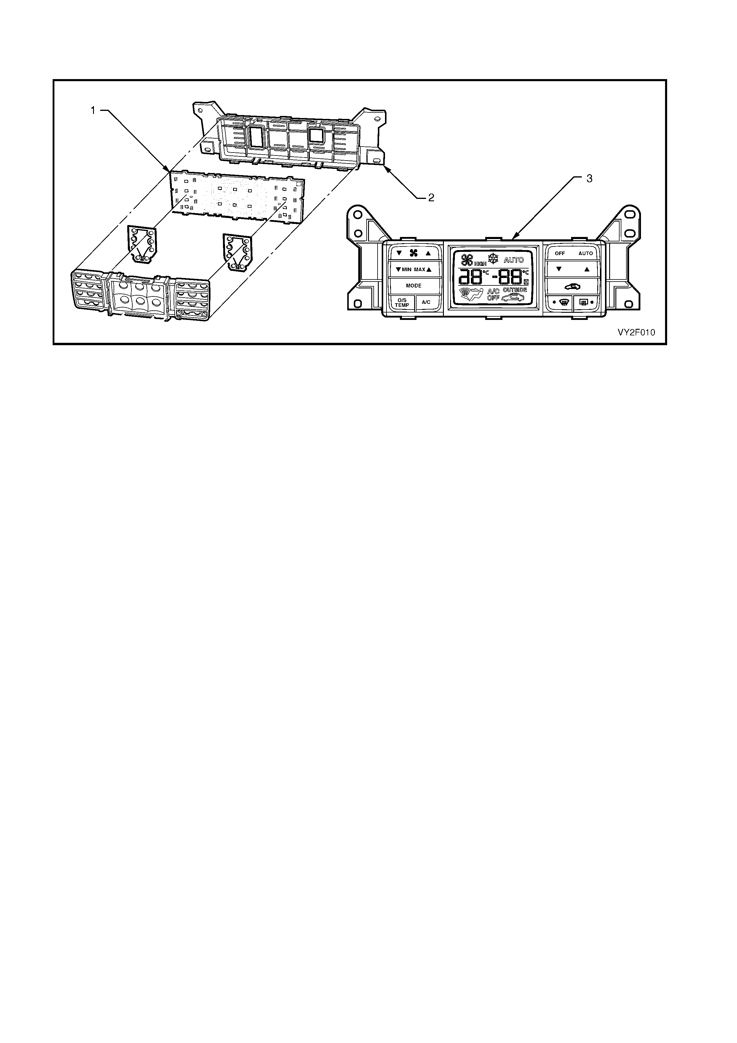
DTC 39 – RAM ERROR
Figure 2F-86
Circuit Description:
The RAM (Random Access Memory) is part of the printed circuit board (1) installed within the rear housing (2) of
the OCC module (3).
The function of the RAM is to store data used to control operating parameters of the OCC system.
When this DTC is set, it indicates that the RAM has been corrupted or failed.
DTC 39 will set when the microprocessor RAM test fails. The RAM is tested every time the cluster performs a cold
reset due to battery disconnection.
If DTC 39 sets and reprogramming is unsuccessful, replace the OCC control module.
Refer to Section 2E, 2.1 OCC CONTROL MODULE.
Test Description:
Number(s) below refer to Step numbers in the followin g Diagnostic Chart:
1. Ensures the Diagnostic Circuit Che ck has been performed.
2. Determines if OCC module is faulty by re-programming the OCC control module.
3. Determines if OCC module is faulty.
Notes on Diagnostic Chart:
1. Refer to 1.1 TECH 2 DIAGNOSTICS in this Section for connecting and using TECH 2..
Diagnostic Aids:
If the OCC system programming is corrupted, recalibration can be carried out via TECH 2. To calibrate the system
refer to 1.2 TECH 2 TEST MODES AND DISPLAYS FOR OCC DIAGNOSIS in this Section.

DTC 39 – RAM ERROR DIAGNOSTIC CHART
Step Action Yes No
1 1 Has the Diagnostic Circuit Check been performed? Go to Step 2. Go to Chart A –
DIAGNOSTIC
CIRCUIT CHECK
in this Section.
2
1. Reprogram the OCC module Code Version using TECH 2.
Refer to 1.2 TECH 2 TEST MODES AND SCREEN
DISPLAYS FOR OCC DIAGNOSIS in this Section.
Was programming successful?
Go to Step 4. Go to Step 3.
3 1. Repeat Step 2 at least twice, as the system may have
crashed during the prog ramming process.
Was programming successful?
Go to Step 4. Go to Step 5.
4
1. Connect TECH 2 to the DLC.
2 Select Diagnostics / Model Year / Vehicle Model / Body /
Occupant Control Module / Diagnostic Trouble Codes / Clear
DTC Information and clea r DTCs.
Were all DTCs cleared?
System OK. Go to Step 5.
5
1. Replace the OCC control module. Refer to Section 2E,
HVAC OCCUPANT CLIMATE CONTROL (AUTO A/C) –
REMOVAL & INSTALLATION.
Is the replacement completed?
Verify system –
WHEN ALL DIAGNOSIS AND REPAIRS ARE COMPLETED, CLEAR ALL D TC AND VERIFY CORRECT
OPERATION
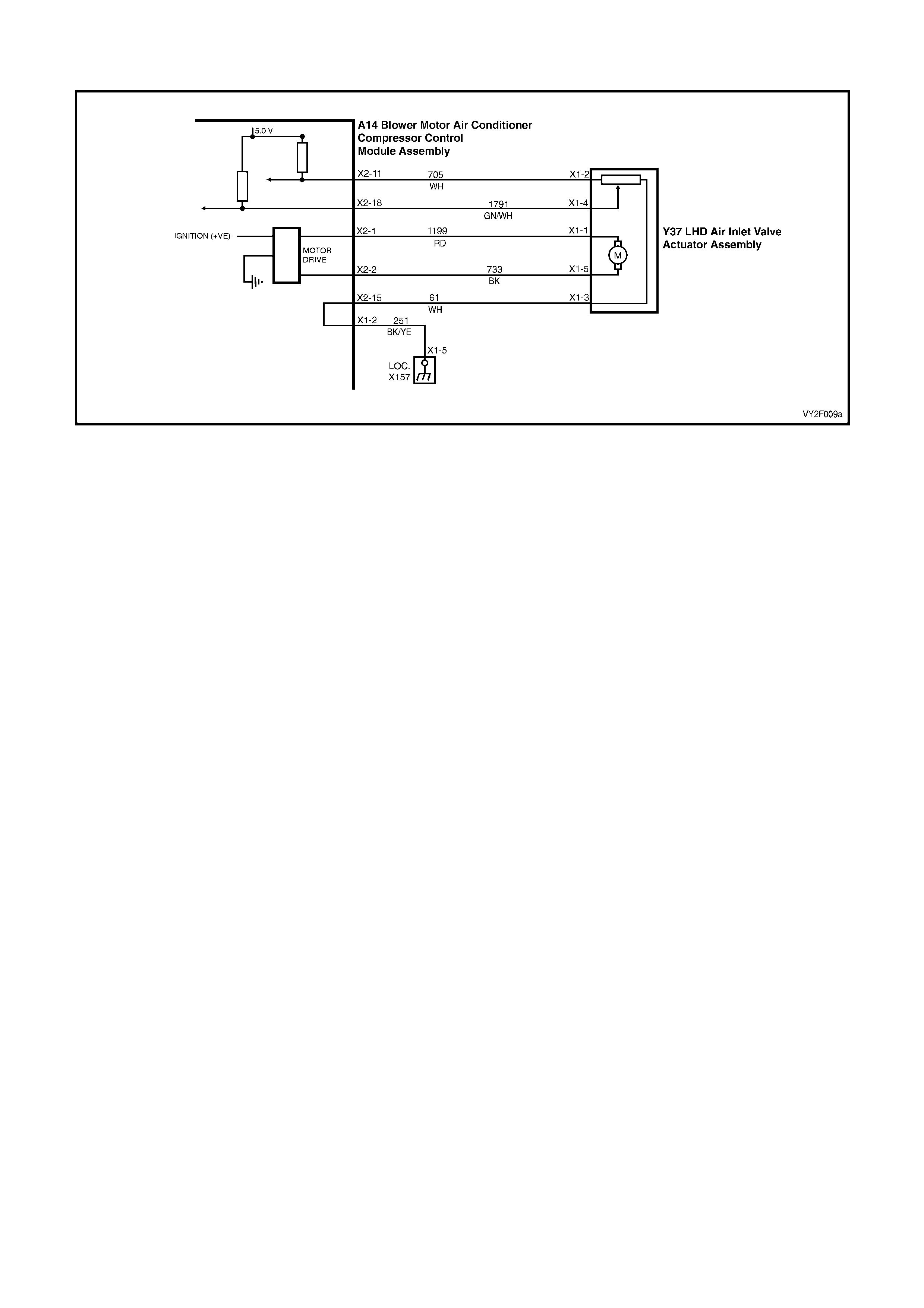
DTC 40 – AIR MIX DOOR MOTOR DRIVER ERROR (LHD)
Figure 2F-87
Circuit Description:
The air mix motor is an electric motor used to operate the air mix door. The electric motor is sent a voltage signal of
12.5 volts from the OCC module which causes the motor to turn, and in turn moves the air mix door towards or
away from the heater core. The direction change takes place by reversing the polarity of this motor.
A potentiometer (PBR) is housed in the air mix motor circuit which, feeds signals (5.0 volts) back to the OCC
module as to the positioning of the motor and consequently the air mix door.
NOTE 1: Refer to Figure 2F-87 for LHD vehicles.
NOTE 2: Refer to Figure 2F-88 a nd Figure 2F-89 for RHD drive vehicles.
DTC 40 will set when the Air Mix Motor Driver detects an error condition for a period of 1 second. An error condition
occurs when the Air Mix Motor Outputs are dra wing e xcessive current or operating with an excessive voltage.
Test Description:
1. Ensures the Diagnostic Circuit Check has been performed.
This test checks to see whether the OCC is faulty.
This test checks whether the resistance across terminals X2-1 and X2-2 indicat es a faulty connector or open circuit.
This test checks whether the resistance across terminals X2-1 and X2-2 indicates a faulty circuit or air mix door
motor.
This test checks for a short to ground in circuit 1199.
This test checks for a short in circuit 1199 or 61.
This test checks for a short in circuit 1199 or 27 4.
This test checks for a short in circuit 1199 or 73 3.
This test checks for intermittent or loose terminals.
This test checks for open in circuits 1199 or 733.
This test checks for faulty connectors.
Ensures that DTC 43 has been cleared if present.
Ensures that DTC 44 has been cleared if present.
This test checks for physical fault in drivers air mix door motor.
This test determines if the drivers air mix door motor is faulty.

Diagnostic Aids:
An air mix motor or door problem will always be associated with non-regulated or incorrect temperatures from
mode positions.
The OCC control module, during calibration, sets a minimum and a maximum PBR value for the air mix motor in its
memory. It is these values which determine the operating range of the air mix motor and against which all
movements of the air mix adjustment are scaled. Any PBR signal value outside the minimum or maximum value
are considered a motor fault.
The OCC module monitors the rate of change of PBR signal during air mix motor movement. If this rate of change
falls to 0 (such as a broken air mix motor wire or physical jamb), the OCC module will recognise the stoppage and
set the fault code.
If DTC 40 was present before turning the ignition off, when the ignition is turned on again, the OCC module will
automatically try to recalibrate the air mix door. This takes approximately 15 seconds. If the recalibration fails, then
DTC 40 will be set again.
Notes on Diagnostic Chart:
1. Refer to Section 12P, WIRING DIAGRAMS for procedures on checking wiring faults.
2. Refer to 1.1 TECH 2 DIAGNOSTICS in this Section for conne cting and using TECH 2.
DTC 40 – AIR MIX DOOR MOTOR DRIVER ERROR (LHD) DIAGNOSTIC CHART
STEP ACTION VALUE YES NO
1 Has the Diagnostic Circuit Check been performed? – Go to Step 2. Go to Chart A –
DIAGNOSTIC
CIRCUIT
CHECK in this
Section.
2 1. Disconnect the OCC wiring harness
connector A14 X2.
Connect TECH 2 to the DLC.
Select Diagnostics / Model Year / Vehicle Model /
Body / Occupant Climate Control / Data
Display / Data List / Drivers Air Mix Door
Feedback.
Does TECH 2 display a value more than 4.8 volts?
– Go to Step 3. Replace the
OCC control
module. Refer to
Section 2E,
HVAC
OCCUPANT
CLIMATE
CONTROL
(AUTO A/C) –
REMOVAL &
INSTALLATION
.
3 1. With the OCC connector A14 X2
disconnected, probe between OCC
connector terminal X2-1, circuit 1199 (Red
wire) and connector terminal X2-2, circuit 733
(Black wire) with an ohmmeter.
Is the value as specified?
Less than
80 ohms Go to Step 4. Go to Step 9.
4 In Step 3, was the value specified? Less than
70 ohms Go to Step 8. Go to Step 5.
5 1. With the OCC connector A14 X2
disconnected, probe terminal X2-1,
circuit 1199 (Red wire) with an ohmmeter to
chassis ground.
Is the value as specified?
NOTE: Any resistance measured here qualifies as
a short.
– Repair faulty
circuit 1199. Go to Step 6.
6 1. With the OCC connector A14 X2
disconnected, probe between OCC
connector terminal X2-1, circuit 1199 (Red
wire) and connector terminal X2-15, circuit 61
(White wire) with an ohmmeter.
Is the value as specified?
NOTE: Any resistance measured here qualifies as
a short.
– Repair faulty
circuit 1199
and/or 61.
Go to Step 7.

STEP ACTION VALUE YES NO
7 1. With the OCC connector A14 X2
disconnected, probe between OCC
connector terminal X2-1, circuit 199 (Red
wire) and connector terminal X2-5, circuit 274
(Red / White wire) with an ohmmete r.
– Repair faulty
circuits 1199
and/or 274.
Go to Step 11.
8 1. Disconnect the driver’s air mix door motor
connector Y37 LHD X1.
With the OCC connector A14 X2 disconnected,
probe between OCC connector terminal X2-1,
circuit 1199 (Red wire) and connector
terminal X2-2, circuit 733 (Black wire) with an
ohmmeter.
Does the meter indicate a short?
NOTE: Any resistance measured here qualifies as
a short.
– Repair faulty
circuit1199
and/or 733.
Replace the
drivers air mix
door motor.
Refer to
Section 2E,
HVAC
OCCUPANT
CLIMATE
CONTROL
(AUTO A/C) –
REMOVAL &
INSTALLATION
.
9 1. Inspect wiring harness connectors A14 X2
and Y37 LHD X1 for an intermittent or loose
terminal.
Are the connectors OK?
– Go to Step 10. Repair faulty
connector/s.
10 1. Check the integrity of circuit 1199 and
circuit 733.
Are the circuits OK?
– Replace air mix
door motor.
Refer to
Section 2E,
HVAC
OCCUPANT
CLIMATE
CONTROL
(AUTO A/C) –
REMOVAL &
INSTALLATION
.
Repair faulty
circuit 1199
and/or 733.
11 1. Inspect wiring harness connectors A14 X2
and Y37 LHD X1 for an intermittent or loose
terminal and for a short circuit between
terminals.
Are the connectors OK?
– Go to Step 12. Repair faulty
connector/ s.
12 Does DTC 43 set as a curr ent DTC? – Go to Chart
DTC 43 –
DRIVERS AIR
MIX DOOR
MOTOR
FEEDBACK
CIRCUIT VOLT
AGE TOO LOW
(LHD) in this
Section.
Go to Step 13.

STEP ACTION VALUE YES NO
13 Does DTC 44 set as a curr ent DTC? – Go to Chart
DTC 44 –
DRIVERS AIR
MIX DOOR
MOTOR
FEEDBACK
CIRCUIT VOLT
AGE TOO
HIGH (LHD) in
this Section.
Go to Step 14.
14 1. Remove the driver’s air mix motor assembly.
Refer to Section 2E, HVAC OCCUPANT
CLIMATE CONTROL (AUTO A/C) –
REMOVAL & INSTALLATION.
Move the air mix door by hand.
Is the door physically jammed or bro ken ?
– Repair faulty air
mix door. Go to Step 15.
15 1. Replace the air mix motor assembly. Refer to
Section 2E, HVAC OCCUPANT CLIMATE
CONTROL (AUTO A/C) – REMOVAL &
INSTALLATION.
Is the problem resolved?
– System OK. Replace the
OCC control
module. Refer to
Section 2E,
HVAC
OCCUPANT
CLIMATE
CONTROL
(AUTO A/C) –
REMOVAL &
INSTALLATION
.
WHEN ALL DIAGNOSIS AND REPAIRS ARE COMPLETE, VERIFY CORRECT OPERATION
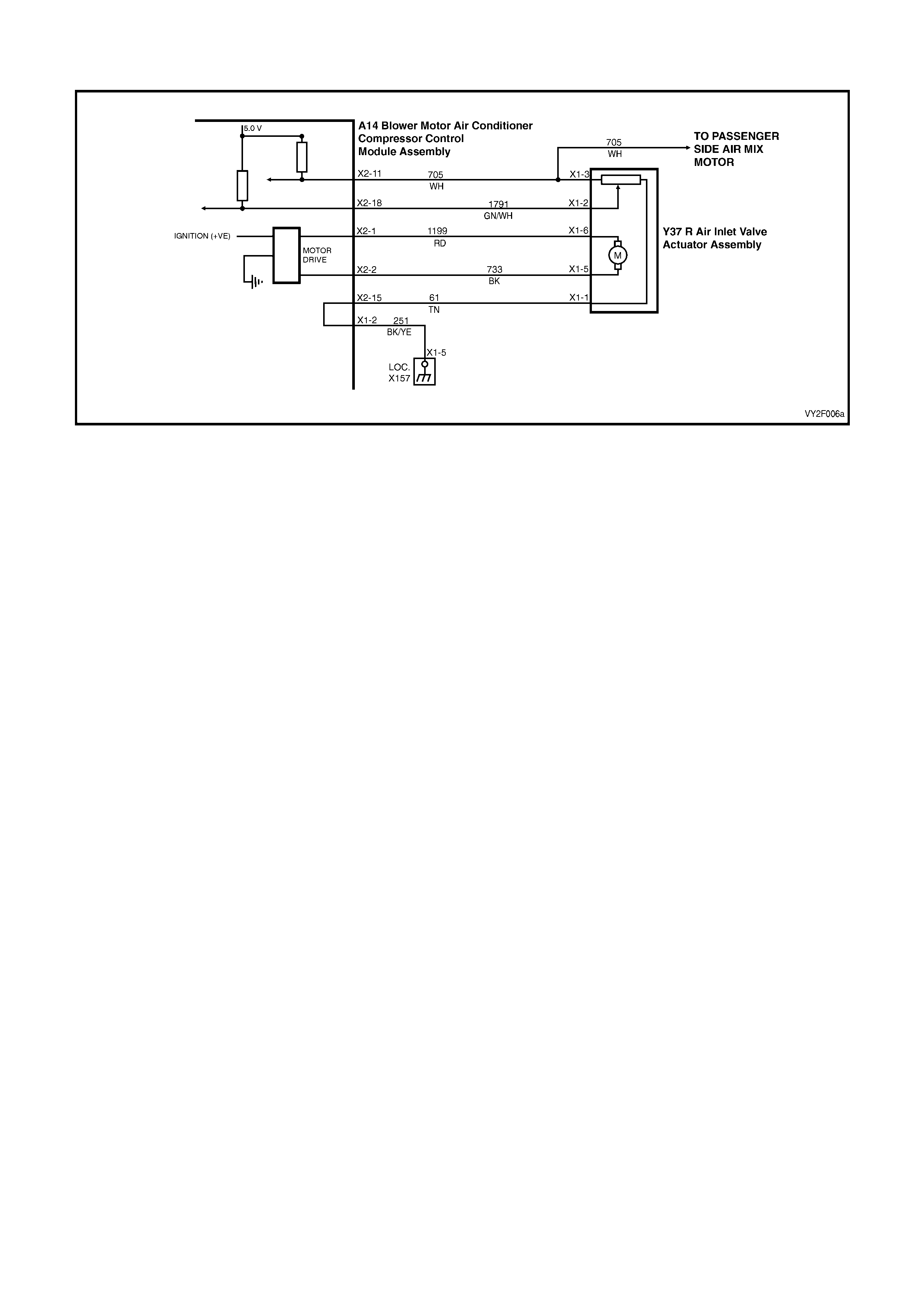
DTC 40 – AIR MIX DOOR MOTOR DRIVER ERROR (RHD DRIVERS SIDE MOTOR)
Figure 2F-88
Circuit Description:
DTC 40 will set when the Air Mix Motor Driver detects an error condition for a period of 1 second. An error condition
occurs when the Air Mix Motor Outputs are dra wing e xcessive current or operating with an excessive voltage.
Test Description:
1. Ensures the Diagnostic Circuit Check has been performed.
This test checks to see whether the OCC is faulty.
This test checks whether the resistance across terminals X2-1 and X2-2 indicat es a faulty connector or open circuit.
This test checks whether the resistance across terminals X2-1 and X2-2 indicates a faulty circuit or air mix door
motor.
This test checks for a short to ground in circuit 1199.
This test checks for a short in circuit 1199 or 61.
This test checks for a short in circuit 1199 or 27 4.
This test checks for a short in circuit 1199 or 73 3.
This test checks for intermittent or loose terminals.
This test checks for open in circuits 1199 or 733.
This test checks for faulty connectors.
Ensures that DTC 43 has been cleared if present.
Ensures that DTC 44 has been cleared if present.
This test checks for physical fault in drivers air mix door motor.
This test determines if the drivers air mix door motor is faulty.
Diagnostic Aids:
An air mix motor or door problem will always be associated with non-regulated or incorrect temperatures from
mode positions.
The OCC control module, during calibration, sets a minimum and a maximum PBR value for the air mix motor in its
memory. It is these values which determine the operating range of the air mix motor and against which all
movements of the air mix adjustment are scaled. Any PBR signal value outside the minimum or maximum value
are considered a motor fault.
The OCC module monitors the rate of change of PBR signal during air mix motor movement. If this rate of change
falls to 0 (such as a broken air mix motor wire or physical jamb), the OCC module will recognise the stoppage and
set the fault code.
If DTC 40 was present before turning the ignition off, when the ignition is turned on again, the OCC module will
automatically try to recalibrate the air mix door. This takes approximately 15 seconds. If the recalibration fails, then
DTC 40 will be set again.
Notes on Diagnostic Chart:
1. Refer to Section 12P, WIRING DIAGRAMS for procedures on checking wiring faults.
2. Refer to 1.1 TECH 2 DIAGNOSTICS in this Section for conne cting and using TECH 2.

DTC 40 – AIR MIX DOOR MOTOR DRIVER ERROR (RHD DRIVERS SIDE MOTOR) DIAGNOSTIC CHART
STEP ACTION VALUE YES NO
1 Has the Diagnostic Circuit Check been performed? – Go to Step 2. Go to Chart A –
DIAGNOSTIC
CIRCUIT
CHECK in this
Section.
2 1. Disconnect the OCC wiring harness
connector A14 X2.
Connect TECH 2 to the DLC.
Select Diagnostics / Model Year / Vehicle Model /
Body / Occupant Climate Control / Data
Display / Data List / Drivers Air Mix Door
Feedback.
Does TECH 2 display a value more than4.8 volts?
– Go to Step 3. Replace the
OCC control
module. Refer to
Section 2E,
HVAC
OCCUPANT
CLIMATE
CONTROL
(AUTO A/C) –
REMOVAL &
INSTALLATION
.
3 1. With the OCC connector A14 X2
disconnected, probe between OCC
connector terminal X2-1, circuit 1199 (Red
wire) and connector terminal X2-2, circuit 733
(Black wire) with an ohmmeter.
Is the value as specified?
Less than
80 ohms Go to Step 4. Go to Step 9.
4 In Step 3, was the value as specified? Less than
70 ohms Go to Step 8. Go to Step 5.
5 1. With the OCC connector A14 X2
disconnected, probe terminal X2-1,
circuit 1199 (Red wire) with an ohmmeter to
chassis ground.
Is the value as specified?
NOTE: Any resistance measured here qualifies as
a short.
– Repair faulty
circuit 1199. Go to Step 6.
6 1. With the OCC connector A14 X2
disconnected, probe between OCC
connector terminal X2-1, circuit 1199 (Red
wire) and connector terminal X2-15, circuit 61
(Tan wire) with an ohmmeter.
Is the value as specified?
NOTE: Any resistance measured here qualifies as
a short.
– Repair faulty
circuit 1199
and/or 61.
Go to Step 7.
7 1. With the OCC connector A14 X2
disconnected, probe between OCC
connector terminal X2-1, circuit 199 (Red
wire) and connector terminal X2-5, circuit 274
(Red / White wire) with an ohmmete r.
Is the value as specified?
NOTE: Any resistance measured here qualifies as
a short.
– Repair faulty
circuits 1199
and/or 274.
Go to Step 11.
8 1. Disconnect the driver’s air mix door motor
connector Y37 R X1.
With the OCC connector A14 X2 disconnected,
probe between OCC connector terminal X2-1,
circuit 1199 (Red wire) and connector
terminal X2-2, circuit 733 (Black wire) with an
ohmmeter.
Does the meter indicate a short?
NOTE: Any resistance measured here qualifies as
a short.
– Repair faulty
circuit1199
and/or 733.
Replace the
drivers air mix
door motor.
Refer to
Section 2E,
HVAC
OCCUPANT
CLIMATE
CONTROL
(AUTO A/C) –
REMOVAL &
INSTALLATION
.

STEP ACTION VALUE YES NO
9 1. Inspect wiring harness connectors A14 X2
and Y37 R X1 for an intermittent or loose
terminal.
– Go to Step 10. Repair faulty
connector/s.
10 1. Check the integrity of circuit 1199 and
circuit 733.
Are the circuits OK?
– Replace air mix
door motor.
Refer to
Section 2E,
HVAC
OCCUPANT
CLIMATE
CONTROL
(AUTO A/C) –
REMOVAL &
INSTALLATION
.
Repair faulty
circuit 1199
and/or 733.
11 1. Inspect wiring harness connectors A14 X2
and Y37 R X1 for an intermittent or loose
terminal and for a short circuit between
terminals.
Are the connectors OK?
– Go to Step 12. Repair faulty
connector/ s.
12 Does DTC 43 set as a curr ent DTC? – Go to Chart
DTC 43 –
DRIVERS AIR
MIX DOOR
MOTOR
FEEDBACK
CIRCUIT VOLT
AGE TOO LOW
(LHD) in this
Section.
Go to Step 13.
13 Does DTC 44 set as a curr ent DTC? – Go to Chart
DTC 44 –
DRIVERS AIR
MIX DOOR
MOTOR
FEEDBACK
CIRCUIT VOLT
AGE TOO
HIGH (LHD) in
this Section.
Go to Step 14.
14 1. Remove the driver’s air mix motor assembly.
Refer to Section 2E, HVAC OCCUPANT
CLIMATE CONTROL (AUTO A/C) –
REMOVAL & INSTALLATION.
Move the air mix door by hand.
Is the door physically jammed or bro ken ?
– Repair faulty air
mix door. Go to Step 15.
15 1. Replace the air mix motor assembly. Refer to
Section 2E, HVAC OCCUPANT CLIMATE
CONTROL (AUTO A/C) – REMOVAL &
INSTALLATION.
Is the problem fixed?
– System OK. Replace the
OCC control
module. Refer to
Section 2E,
HVAC
OCCUPANT
CLIMATE
CONTROL
(AUTO A/C) –
REMOVAL &
INSTALLATION
.
WHEN ALL DIAGNOSIS AND REPAIRS ARE COMPLETE, VERIFY CORRECT OPERATION
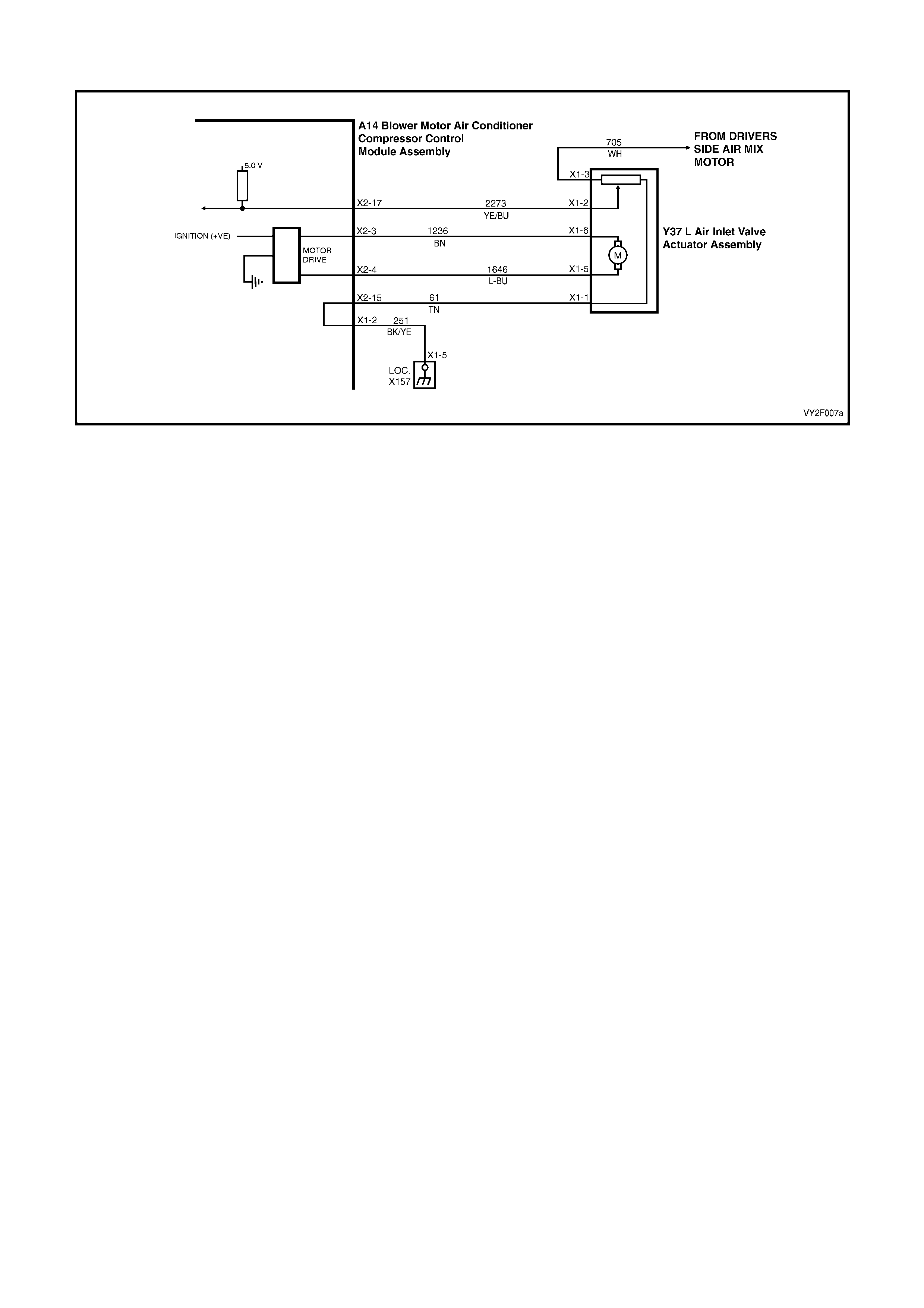
DTC 40 – AIR MIX DOOR MOTOR DRIVER ERROR (RHD PASSENGERS SIDE MOTOR)
Figure 2F-89
Circuit Description:
The air mix motor is an electric motor used to operate the air mix door. The electric motor is sent a voltage signal of
12.5 volts from the OCC module which causes the motor to turn, and in turn moves the air mix door towards or
away from the heater core. The direction change takes place by reversing the polarity of this motor.
A potentiometer (PBR) is housed in the air mix motor circuit which, feeds signals (5.0 volts) back to the OCC
module as to the positioning of the motor and consequently the air mix door.
DTC 40 will set when the Air Mix Motor Driver detects an error condition for a period of 1 second. An error condition
occurs when the Air Mix Motor Outputs are dra wing e xcessive current or operating with an excessive voltage.
Test Description:
1. Ensures the Diagnostic Circuit Check has been performed.
This test checks to see whether the OCC is faulty.
This test checks whether the resistance across terminals X2-3 and X2-4 indicat es a faulty connector or open circuit.
This test checks whether the resistance across terminals X2-3 and X2-4 indicates a faulty circuit or air mix door
motor.
This test checks for a short to ground in circuit 1236.
This test checks for a short in circuit 1236 or 61.
This test checks for a short in circuit 1236 or 27 4.
This test checks for a short in circuit 1236 or 1646.
This test checks for intermittent or loose terminals.
This test checks for open in circuits 1236 or 1646.
This test checks for faulty connectors.
Ensures that DTC 45 has been cleared if present.
Ensures that DTC 46 has been cleared if present.
This test checks for physical fault in drivers air mix door motor.
This test determines if the drivers air mix door motor is faulty.

Diagnostic Aids:
An air mix motor or door problem will always be associated with non-regulated or incorrect temperatures from
mode positions.
The OCC control module, during calibration, sets a minimum and a maximum PBR value for the air mix motor in its
memory. It is these values which determine the operating range of the air mix motor and against which all
movements of the air mix adjustment are scaled. Any PBR signal value outside the minimum or maximum value
are considered a motor fault.
The OCC module monitors the rate of change of PBR signal during air mix motor movement. If this rate of change
falls to 0 (such as a broken air mix motor wire or physical jamb), the OCC module will recognise the stoppage and
set the fault code.
If DTC 40 was present before turning the ignition off, when the ignition is turned on again, the OCC module will
automatically try to recalibrate the air mix door. This takes approximately 15 seconds. If the recalibration fails, then
DTC 40 will be set again.
Notes on Diagnostic Chart:
1. Refer to Section 12P, WIRING DIAGRAMS for procedures on checking wiring faults.
2. Refer to 1.1 TECH 2 DIAGNOSTICS in this Section for conne cting and using TECH 2.
DTC 40 – AIR MIX DOOR MOTOR DRIVER ERROR (RHD PASS ENGERS SIDE MOTOR)
STEP ACTION VALUE YES NO
1 Has the Diagnostic Circuit Check been performed? – Go to Step 2. Go to Chart A –
DIAGNOSTIC
CIRCUIT
CHECK in this
Section.
2 1. Disconnect the OCC wiring harness
connector A14 X2.
Connect TECH 2 to the DLC.
Select Diagnostics / Model Year / Vehicle Model /
Body / Occupant Climate Control / Data
Display / Data List / Drivers Air Mix Door
Feedback.
Does TECH 2 display a value above 4.8 volts?
– Go to Step 3. Replace the
OCC control
module, refer to
Section 2E,
HVAC
OCCUPANT
CLIMATE
CONTROL
(AUTO A/C) –
REMOVAL &
INSTALLATION
.
3 1. With the OCC connector A14 X2
disconnected, probe between OCC
connector terminal X2-3, circuit 1236 (Brown
wire) and connector terminal X2-4,
circuit 1646 (Light-Blue wire) with an
ohmmeter.
Is the value as specified?
Less than
80 ohms Go to Step 4. Go to Step 9.
4 In Step 3, was the value as specified? Less than
70 ohms Go to Step 8. Go to Step 5.
5 1. With the OCC connector A14 X2
disconnected, probe connector terminal X2-3,
circuit 1236 (Brown wire) with an ohmmeter
to chassis ground.
Is the value as specified?
NOTE: Any resistance measured here qualifies as
a short.
– Repair faulty
circuit 1236. Go to Step 6.

STEP ACTION VALUE YES NO
6 1. With the OCC connector A14 X2
disconnected, probe between OCC
connector terminal X2-3, circuit 1236 (Brown
wire) and connector terminal X2-15, circuit 61
(Tan wire) with an ohmmeter.
– Repair faulty
circuit 1236
and/or 61.
Go to Step 7.
7 1. With the OCC connector A14 X2
disconnected, probe between OCC
connector terminal X2-3, circuit 1236 (Brown
wire) and connector terminal X2-5, circuit 274
(Red / White wire) with an ohmmete r.
Is the value as specified?
NOTE: Any resistance measured here qualifies as
a short.
– Repair faulty
circuit 1236
and/or 274.
Go to Step 11.
8 1. Disconnect air mix door motor connector
Y37 L X1.
With the OCC connector A14 X2 disconnected,
probe between terminals X2-3, circuit 1236
(Brown wire) and X2-4, circuit 1646 (Light-Blue
wire) with an ohmmeter.
Is the value as specified?
NOTE: Any resistance measured here qualifies as
a short.
– Repair faulty
circuits 1236
and/or 1646.
Replace the air
mix door motor.
Refer to
Section 2E,
HVAC
OCCUPANT
CLIMATE
CONTROL
(AUTO A/C) –
REMOVAL &
INSTALLATION
.
9 1. Inspect wiring harness connectors A14 X2
and Y37 L X1 for an intermittent or loose
terminal.
Are the connectors OK?
– Go to Step 10. Repair faulty
connector/s.
10 1. Check the integrity of circuits 1236 and 1646.
Are the circuits OK? – Repair faulty
circuit 1236
and/or 1646.
Replace the air
mix door motor.
Refer to
Section 2E,
HVAC
OCCUPANT
CLIMATE
CONTROL
(AUTO A/C) –
REMOVAL &
INSTALLATION
.
11 1. Inspect the wiring harness connectors
A14 X2 and Y37 L X1 for an intermittent or
loose terminal and for a short circuit between
terminals.
Are the connectors OK?
– Go to Step 12. Repair faulty
connector/ s.

STEP ACTION VALUE YES NO
12 Does DTC 45 set as a curr ent DTC? – Go to Chart
DTC 45 –
PASSENGERS
AIR MIX DOOR
MOTOR
FEEDBACK
CIRCUIT VOLT
AGE TOO LOW
in this Section.
Go to Step 13.
13 Does DTC 46 set as a curr ent DTC? – Go to Chart
DTC 46 –
PASSENGERS
AIR MIX DOOR
MOTOR
FEEDBACK
CIRCUIT VOLT
AGE TOO
HIGH in this
Section.
Go to Step 14.
14 1. Remove the air mix motor assembly. Refer to
Section 2E, HVAC OCCUPANT CLIMATE
CONTROL (AUTO A/C) – REMOVAL &
INSTALLATION.
Move the air mix door by hand.
Is the door physically jammed or bro ken ?
– Repair faulty air
mix door. Go to Step 15.
15 1. Replace the air mix motor assembly. Refer to
Section 2E, HVAC OCCUPANT CLIMATE
CONTROL (AUTO A/C) – REMOVAL &
INSTALLATION.
Is the problem fixed?
– System OK. Replace the
OCC control
module. Refer to
Section 2E,
HVAC
OCCUPANT
CLIMATE
CONTROL
(AUTO A/C) –
REMOVAL &
INSTALLATION
.
WHEN ALL DIAGNOSIS AND REPAIRS ARE COMPLETE, VERIFY CORRECT OPERATION
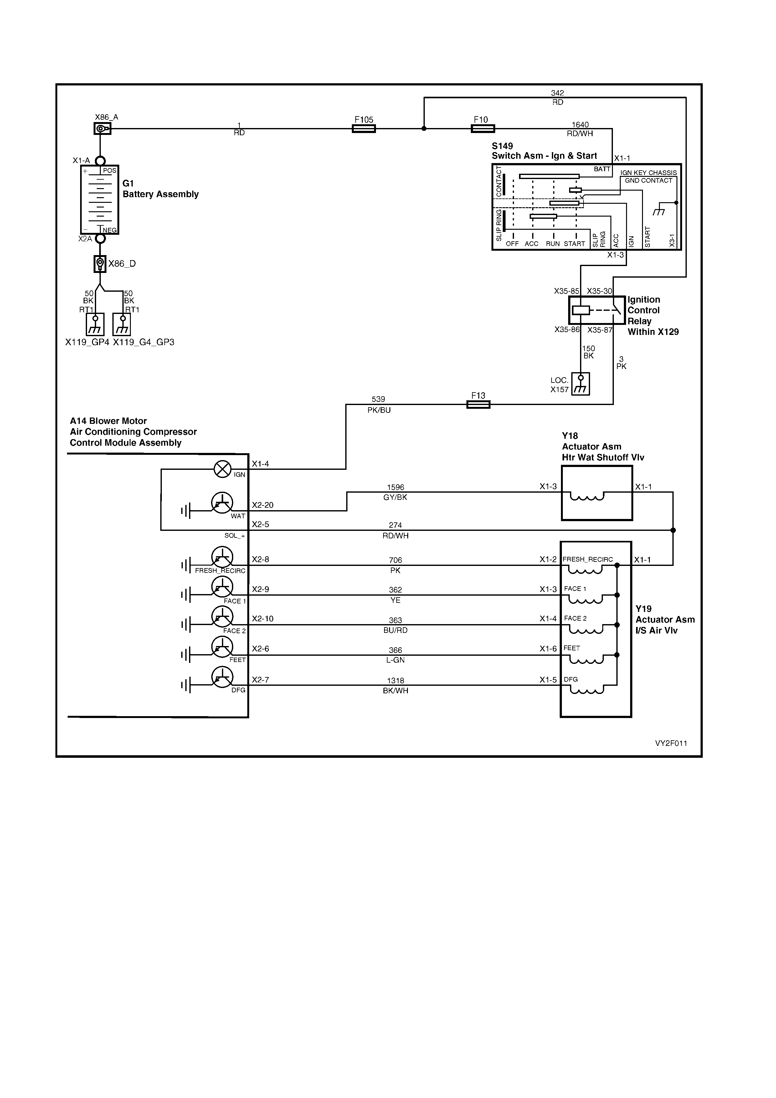
DTC 41 – SOLENOID DRI VER ERROR – LHD
Figure 2F-90
Circuit Description:
The solenoid pack is activated when the OCC system is turned on. Individual solenoids are grounded by via the
OCC control module. In accordance to switching signals generated manually or automatically at the OCC control
module, the solenoid pack directs vacuum to the various vacuum actuators to achieve the desired ventilation mode.
It also activates the water valve for heating and demisting purposes.
DTC 41 will set when the Solenoid Driver detects an error condition for a period of 1 second. An error condition
occurs when the Solenoid Outputs are drawing excessive current and / or have reached an over temperature
condition.

Test Description:
1. Ensures the Diagnostic Circuit Check has been performed.
This test checks the power supply to the solenoid pack.
This test checks for open in circuit 274 between the solenoid pack and the OCC control modu le.
This test checks power supply to heater water shut off valve.
This test checks for open in circuit 274 between heater water shut off valve and OCC control module.
This test checks the functioning of the Face 1 sole noid.
This test checks the functioning of the Face 2 sole noid.
This test checks the functioning of the Feet solenoid.
This test checks the functioning of the DFG solen oid.
This test checks the functioning of the Fresh / Recirc solenoid.
This test checks the functioning of the WAT solenoid.
Notes on Diagnostic Chart:
1. Refer to Section 12P, WIRING DIAGRAMS for procedures on checking wiring faults.
Refer to 1.1 TECH 2 DIAGNOSTICS in this Section for connecting and using TECH 2.
DTC 41 – SOLENOID DRIVER ERROR – LHD DIAGNOSTIC CHART
STEP ACTION VALUE YES
NO
1 Has the Diagnostic Circuit Check been performed? – Go to Step 2. Go to Chart A –
DIAGNOSTIC
CIRCUIT
CHECK in this
Section.
2 1. Turn the ignition on.
2. Back-probe connector Y19 LHD terminal X1-1,
circuit 274 (Red / White wire) with a voltmeter to
ground.
Is the value as specified?
4.5 volts Go to Step 3. Repair faulty
circuit 274.
3 1. Turn the ignition off.
Back-probe between OCC module connector
terminal X2-5, circuit 274 (Red / White wire) and
the solenoid pack connector Y19 LHD
terminal X1-1 circuit 274 (Red / White wire) with
an ohmmeter.
Is the value as specified?
Less than
1 ohm Go to Step 4. Repair faulty
circuit 274.
4 1. Turn the ignition on.
Back-probe connector Y18 LHD terminal X1-1,
circuit 274 (Red / White wire) with a voltmeter to
ground.
Is the value as specified?
12 volts Go to Step 5. Repair faulty
circuit 274.
5 1. Turn the ignition off.
Back-probe between OCC module connector
terminal X2-5 and solenoid pack connector
Y18 LHD terminal X1-1, circuit 274 (Red / White
wire) with an ohmmeter.
Is the value as specified?
– Go to Step 6. Repair faulty
circuit 274.
6 1. Turn the ignition on
Connect TECH 2 to the DLC.
Select Diagnostics / Model Year / Vehicle Model /
Body / Occupant Climate Control /
Miscellaneous Tests / Solenoids.
Activate the Face 1 solenoid.
Does the Face 1 solenoid Activate?
– Go to Step 7. Go to OCC
Solenoid Pack
(LHD) test in
this Section.

STEP ACTION VALUE YES
NO
7 1. With TECH 2 connected, activate the Face 2
solenoid. – Go to Step 8. Go to OCC
Solenoid Pack
(LHD) test in
this Section.
8 1. With TECH 2 connected, activate the Feet
solenoid.
Does the Feet solenoid activate?
– Go to Step 9. Go to OCC
Solenoid Pack
(LHD) test in
this Section.
9 1. With TECH 2 connected, activate the DFG
solenoid.
Does the DFG solenoid activate?
– Go to Step 10. Go to OCC
Solenoid Pack
(LHD) test in
this Section.
10 1. With TECH 2 connected, activate the
FRESH_RECIRC.
Does the FRESH_RECIRC solenoid activate?
– Go to Step 11. Go to OCC
Solenoid Pack
(LHD) test in
this Section.
11 1. With TECH 2 connected, activate the WAT
solenoid.
Does the WAT solenoid activate?
– System OK. Go to Water
Vacuum, Valve
Switch (LHD)
test in this
Section.
WHEN ALL DIAGNOSIS AND REPAIRS ARE COMPLETE, VERIFY CORRECT OPERATION
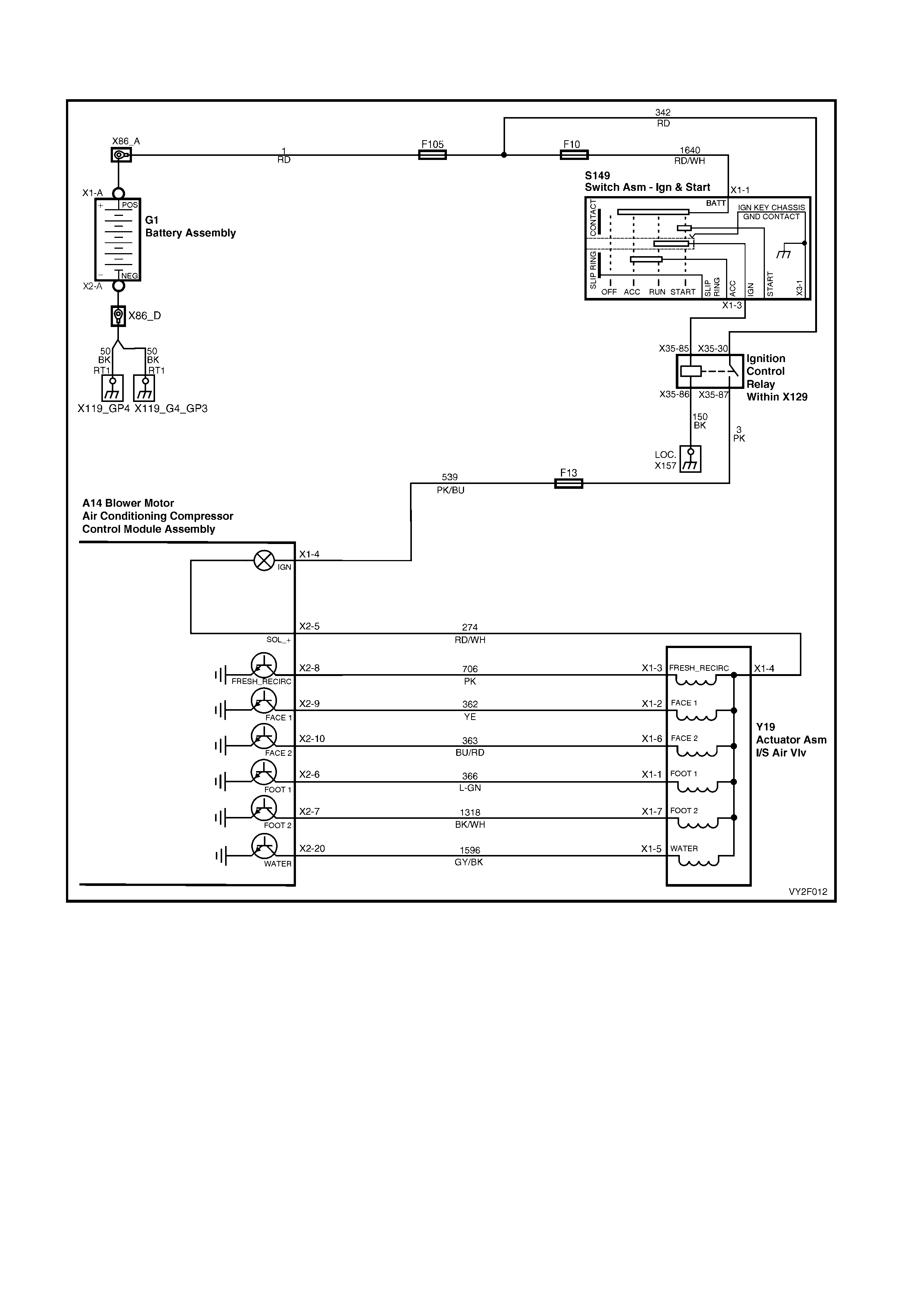
DTC 41 – SOLENOID DRI VER ERROR – RHD
Figure 2F-91
Circuit Description:
The solenoid pack is activated when the OCC system is turned on. Individual solenoids are grounded by via the
OCC control module. In accordance to switching signals generated manually or automatically at the OCC control
module, the solenoid pack directs vacuum to the various vacuum actuators to achieve the desired ventilation mode.
It also activates the water valve for heating and demisting purposes.
DTC 41 will set when the Solenoid Driver detects an error condition for a period of 1 second. An error condition
occurs when the Solenoid Outputs are drawing excessive current and / or has reached an over temperature
condition.

Test Description:
1. Ensures the Diagnostic Circuit Check has been performed.
This test checks the power supply to the solenoid pack.
This test checks for open in circuit 274 between the solenoid pack and the OCC control modu le.
This test checks the functioning of the Fresh / Recirc solenoid.
This test checks the functioning of the Face 1 sole noid.
This test checks the functioning of the Face 2 sole noid.
This test checks the functioning of the Foot 1 solenoi d.
This test checks the functioning of the Foot 2 solenoi d.
This test checks the functioning of the Water sole noid
Notes on Diagnostic Chart:
1. Refer to Section 12P, WIRING DIAGRAMS for procedures on checking wiring faults.
Refer to 1.1 TECH 2 DIAGNOSTICS in this Section for connecting and using TECH 2.
DTC 41 – SOLENOID DRIVER ERROR – RHD DIAGNOSTIC CHART
STEP ACTION VALUE YES NO
1 Has the Diagnostic Circuit Check been performed? – Go to Step 2. Go to Chart A –
DIAGNOSTIC
CIRCUIT
CHECK in this
Section.
2 1. Turn the ignition on.
Back-probe connector Y19 L terminal X1-4,
circuit 274(Red / White wire).
Is the value as specified?
4.5 volts Go to Step 3. Repair faulty
circuit 274.
3 1. Turn the ignition off.
Back-probe between the OCC module connector
terminal X2-5 and the solenoid pack connector
Y19 L terminal X1-4 circuit 274 (Red / White
wire).
Is the value as specified?
– Go to Step 4. Repair faulty
circuit 274.
4 1. Turn the ignition on
Connect TECH 2 to the DLC.
Select Diagnostics / Model Year / Vehicle Model /
Body / Occupant Climate Control /
Miscellaneous Tests / Solenoids.
Activate the Fresh / Recirc solenoid.
Does the Fresh / Recirc solenoid Activate?
– Go to Step 5. Go to OCC
Solenoid Pack
(RHD) test in
this Section.
5 1. With TECH 2 connected, activate the Face 1
solenoid.
Does the Face 1 solenoid activate?
– Go to Step 6. Go to OCC
Solenoid Pack
(RHD) test in
this Section.
6 1. With TECH 2 connected, activate the Face 2
solenoid.
Does the Face 2 solenoid activate?
– Go to Step 7. Go to OCC
Solenoid Pack
(RHD) test in
this Section.
7 1. With TECH 2 connected, activate the Foot 1
solenoid.
Does the Foot 1 solenoid activate?
– Go to Step 8. Go to OCC
Solenoid Pack
(RHD) test in
this Section.
8 1. With TECH 2 connected, activate the Foot 2
solenoid.
Does the Foot 2 solenoid activate?
– Go to Step 9. Go to OCC
Solenoid Pack
(RHD) test in
this Section.
9 1. With TECH 2 connected, activate the Water
solenoid.
Does the Water solenoid activate?
– System OK. Go to OCC
Solenoid Pack
(RHD) test in
this Section.
WHEN ALL DIAGNOSIS AND REPAIRS ARE COMPLETE, VERIFY CORRECT OPERATION

DTC 43 – DRIVER’S AIR MIX DOOR MOTOR FEEDBACK CIRCUIT VOLTAGE TOO LOW (LHD)
Figure 2F-92
Circuit Description:
The air mix motor is an electric motor used to operate the air mix door. The electric motor is sent a voltage signal of
12.5 volts from the OCC module which causes the motor to turn, and in turn moves the air mix door towards or
away from the heater core. The direction change takes place by reversing the polarity of this motor.
A potentiometer (PBR) is housed in the air mix motor circuit which, feeds signals (5.0 volts) back to the OCC
module as to the positioning of the motor and consequently the air mix door.
DTC 43 will set when the feedback si gnal from the Driver’s Air Mix Motor is open circuit for a period of 10 secon ds.
Test Description:
1. Ensures the Diagnostic Circuit Check has been performed.
This test checks for faulty OCC.
This test checks for short to ground in circuit 705.
This test checks for a short in circuits 705 and 1199.
This test checks for a short in circuits 705 and 274.
This test checks that the resistance value of the potentiometer does not exceed maximum acceptable tolerance.
This test checks that the resistance value of the potentiometer is not less than the minimum acceptable tolerance.
This test checks that the signal from the potentiometer does not exceed maximum acceptable tolerance.
This test checks that the signal from the potentiometer is not less than minimum acceptable to lerance.
This test checks for intermittent or loose terminals in the OCC an d air mix door motor connectors.
This test checks for sufficient power supply for the potentiometer from the OCC.
This test checks for short in circuits 705 or 61.
This test checks for short in circuits 61 or 1791.
This test checks for short in circuits 705 or 1791.
This test checks for intermittent or loose terminals in the OCC an d air mix door motor connectors.
This test checks for open in circuits 61, 1791 and 705.
Ensures that DTC 40 has been cleared if present.
This test checks to see if the air mix door is physically jammed or bro ken.
This test determines whether the air mix motor a ssem bly is faulty.

Diagnostic Aids:
An air mix motor or door problem will always be associated with non-regulated or incorrect temperatures from
mode positions.
The OCC control module, during calibration, sets a minimum and a maximum PBR value for the air mix motor in its
memory. It is these values which determine the operating range of the air mix motor and against which all
movements of the air mix adjustment are scaled. Any PBR signal value outside the minimum or maximum value
are considered a motor fault.
The OCC module monitors the rate of change of PBR signal during air mix motor movement. If this rate of change
falls to 0 (such as a broken air mix motor wire or physical jamb), the OCC module will recognise the stoppage and
set the fault code.
If DTC 43 was present before turning the ignition off, when the ignition is turned on again, the OCC module will
automatically try to recalibrate the air mix door. This takes approximately 15 seconds. If the recalibration fails, then
DTC 43 will be set again.
Notes on Diagnostic Chart:
1. Refer to Section 12P, WIRING DIAGRAMS for procedures on checking wiring faults.
2. Refer to 1.1 TECH 2 DIAGNOSTICS in this Section for conne cting and using TECH 2.
DTC 43 – DRIVERS AIR MIX DOOR MOTOR FEEDBACK CIRCUIT VOLTAGE TOO LOW (LHD)
STEP ACTION VALUE YES NO
1 Has the Diagnostic Circuit Check been performed? – Go to Step 2. Go to Chart A –
DIAGNOSTIC
CIRCUIT
CHECK in this
Section.
2 1. Disconnect the OCC wiring harness connector
A14 X2.
Connect TECH 2 to the DLC.
Select Diagnostics / Model Year / Vehicle Model /
Body / Occupant Climate Control / Data Display
/ Data List / Drivers Air Mix Door Feedback.
Does TECH 2 display a value more than 4.8 volts?
– Go to Step 3. Replace the
OCC control
module. Refer to
Section 2E,
HVAC
OCCUPANT
CLIMATE
CONTROL
(AUTO A/C) –
REMOVAL &
INSTALLATION
.
3 1. Install the driver’s air mix motor (if
disconnected).
With the OCC connector A14 X2 disconnected,
probe OCC connector terminal X2-11,
circuit 705 (White wire) with an ohmmeter to
chassis ground.
Is the value as specified?
NOTE: Any resistance measured here qualifies as a
short.
0 Ohm Repair faulty
circuit 705. Go to Step 4.
4 1. With the OCC A14 X2 disconnected, probe
between OCC connector terminal X2-1,
circuit 1199 (Red wire) and connector
terminal X2-11, circuit 705 (White wire) with an
ohmmeter.
Is the value as specified?
NOTE: Any resistance measured here qualifies as a
short.
0 Ohm Repair faulty
circuit 705
and/or 1199.
Go to Step 5.

STEP ACTION VALUE YES NO
5 1. With the OCC connector A14 X2
disconnected, probe between OCC connector
terminal X2-5, circuit 274 (Red / White wire)
and connector terminal X2-11, circuit 705
(White wire) with an ohmmeter.
0 Ohm Repair faulty
circuit 274
and/or 705.
Go to Step 6.
6 1. With the OCC connector A14 X2
disconnected, probe between OCC connector
terminal X2-11, circuit 705 (White wire) and
connector terminal X2-15, circuit 61 (White
wire) with an ohmmeter.
Is the value as specified?
Less than
12 kilohm Go to Step 7. Go to Step 15.
7 In Step 6, was the value as specified? More than
8 kilohms Go to Step 8. Go to Step 12.
8 1. With the OCC connector A14 X2
disconnected, probe between OCC connector
terminal X2-11, circuit 705 (White wire) and
connector terminal X2-18, circuit 1791 (Green /
White wire) with an ohmmeter.
Is the value as specified?
Less than
8.5 kilohms Go to Step 9. Go to Step 15.
9 In Step 8, was the value as specified? More than
1.5 kilohms Go to Step 10. Go to Step 12.
10 1. Inspect the OCC wiring harness connector
A14 X2 and air mix motor connector Y37 L X1
for an intermittent or loose terminal.
Are the connectors OK?
– Repair faulty
connector/s. Go to Step11.
11 1. Install the OCC connectors A14 X2 and
A14 X1 to OCC module.
Disconnect the driver’s air mix motor connector
Y37 LHD X1.
Turn the ignition on.
Back-probe between the driver’s air mix motor
connector Y37 LHD X1 terminal X1-3, circuit 61
(White wire) and terminal X1-2 circuit 705 (White
wire).
Is the value as specified?
4.8 – 5.0
volts Go to Step 17. Replace the
OCC control
module. Refer to
Section 2E,
HVAC
OCCUPANT
CLIMATE
CONTROL
(AUTO A/C)–
REMOVAL &
INSTALLATION
.
12 1. Disconnect the air mix motor connector
Y37 LHD.
With the OCC connector A14 X2 disconnected,
probe between OCC connector terminal X2-11,
circuit 705 (White wire) and connector
terminal X2-15, circuit 61 (White wire) with an
ohmmeter.
Is the value as specified?
NOTE: Any resistance measured here qualifies as a
short.
– Repair faulty
circuit 705
and/or 61.
Go to Step 13.
13 1. With OCC connectors A14 X2 and
Y37 LHD X1 disconnected, probe between
OCC connector terminal X2-15, circuit 61
(White wire) and connector terminal X2-18,
circuit 1791 (Green / White wire) with an
ohmmeter.
Is the value as specified?
NOTE: Any resistance measured here qualifies as a
short.
– Repair faulty
circuit 61 and/or
1791.
Go to Step 14.

STEP ACTION VALUE YES NO
14 1. With OCC connectors A14 X2 and
Y37 LHD X1 disconnected, probe between
OCC connector terminal X2-11, circuit 705
(White wire) and connector terminal X2-18,
circuit 1791 (Green / White wire) with an
ohmmeter.
– Repair faulty
circuit 705
and/or 1791.
Replace the air
mix door motor.
Refer to
Section 2E,
HVAC
OCCUPANT
CLIMATE
CONTROL
(AUTO A/C) –
REMOVAL &
INSTALLATION
.
15 1. Inspect the wiring harness connectors A14 X2
and Y37 LHD X1 for an intermittent or loose
terminal.
Are the connectors OK?
– Go to Step 16. Repair faulty
connector/s.
16 1. Check the integrity of circuits 61, 1791 and
705.
Are the circuits OK?
– Replace the air
mix door motor.
Refer to
Section 2E,
HVAC
OCCUPANT
CLIMATE
CONTROL
(AUTO A/C) –
REMOVAL &
INSTALLATION
.
Repair faulty
circuit/s.
17 Is DTC 40 currently recorded in TECH 2? – Go to DTC 40 in
this Section and
clear DTC.
Go to Step 18.
18 1. Remove the driver’s air mix motor assembly.
Refer to Section 2E, HVAC OCCUPANT
CLIMATE CONTROL (AUTO A/C) –
REMOVAL & INSTALLATION.
Move the air mix door by hand.
Is the door physically jammed or bro ken ?
– Repair faulty air
mix door. Go to Step 19.
19 1. Replace the air mix motor assembly. Refer to
Section 2E, HVAC OCCUPANT CLIMATE
CONTROL (AUTO A/C) – REMOVAL &
INSTALLATION.
Is the problem fixed?
– System OK. Replace the
OCC control
module. Refer to
Section 2E,
HVAC
OCCUPANT
CLIMATE
CONTROL
(AUTO A/C) –
REMOVAL &
INSTALLATION
.
WHEN ALL DIAGNOSIS AND REPAIRS ARE COMPLETE, VERIFY CORRECT OPERATION

DTC 43 – DRIVERS AIR MIX DOOR MOTOR FEED B AC K CIRCUIT VOLTAGE TOO LOW ( R HD)
Figure 2F-93
Circuit Description:
The air mix motor is an electric motor used to operate the air mix door. The electric motor is sent a voltage signal of
12.5 volts from the OCC module which causes the motor to turn, and in turn moves the air mix door towards or
away from the heater core. The direction change takes place by reversing the polarity of this motor.
A potentiometer (PBR) is housed in the air mix motor circuit which, feeds signals (5.0 volts) back to the OCC
module as to the positioning of the motor and consequently the air mix door.
DTC 43 will set when the feedback si gnal from the Driver’s air mix motor is open circuit for a period of 10 seconds.
Test Description:
1. Ensures the Diagnostic Circuit Check has been performed.
This test checks for faulty OCC.
This test checks for short to ground in circuit 705.
This test checks for a short in circuits 705 and 1199.
This test checks for a short in circuits 705 and 274.
This test checks that the resistance value of the potentiometer does not exceed maximum acceptable tolerance.
This test checks that the resistance value of the potentiometer is not less than the minimum acceptable tolerance.
This test checks that the signal from the potentiometer does not exceed maximum acceptable tolerance.
This test checks that the signal from the potentiometer is not less than minimum acceptable to lerance.
This test checks for intermittent or loose terminals in the OCC an d air mix door motor connectors.
This test checks for sufficient power supply for the potentiometer from the OCC.
This test checks for short in circuits 705 or 61.
This test checks for short in circuits 61 or 1791.
This test checks for short in circuits 705 or 1791.
This test checks for intermittent or loose terminals in the OCC an d air mix door motor connectors.
This test checks for open in circuits 61, 1791 and 705.
Ensures that DTC 40 has been cleared if present.
This test checks to see if the air mix door is physically jammed or bro ken.
This test determines whether the air mix motor a ssem bly is faulty.

Diagnostic Aids:
An air mix motor or door problem will always be associated with non-regulated or incorrect temperatures from
mode positions.
The OCC control module, during calibration, sets a minimum and a maximum PBR value for the air mix motor in its
memory. It is these values which determine the operating range of the air mix motor and against which all
movements of the air mix adjustment are scaled. Any PBR signal value outside the minimum or maximum value
are considered a motor fault.
The OCC module monitors the rate of change of PBR signal during air mix motor movement. If this rate of change
falls to 0 (such as a broken air mix motor wire or physical jamb), the OCC module will recognise the stoppage and
set the fault code.
If DTC 43 was present before turning the ignition off, when the ignition is turned on again, the OCC module will
automatically try to recalibrate the air mix door. This takes approximately 15 seconds. If the recalibration fails, then
DTC 43 will be set again.
Notes on Diagnostic Chart:
1. Refer to Section 12P, WIRING DIAGRAMS for procedures on checking wiring faults.
2. Refer to 1.1 TECH 2 DIAGNOSTICS in this Section for conne cting and using TECH 2.
DTC 43 – DRIVERS AIR MIX DOOR MOTOR FEEDBACK CIRCUIT VOLTAGE TOO LOW (RHD) DI AGNOSTIC
CHART
STEP ACTION VALUE YES NO
1 Has the Diagnostic Circuit Check been performed? – Go to Step 2. Go to Chart A –
DIAGNOSTIC
CIRCUIT
CHECK in this
Section.
2 1. Disconnect the OCC wiring harness
connector A14 X2.
Connect TECH 2 to the DLC.
Select Diagnostics / Model Year / Vehicle Model /
Body / Occupant Climate Control / Data
Display / Data List / Drivers Air Mix Door
Feedback.
Does TECH 2 display a value above 3.4 volts?
– Go to Step 3. Replace the
OCC control
module. Refer to
Section 2E,
HVAC
OCCUPANT
CLIMATE
CONTROL
(AUTO A/C) –
REMOVAL &
INSTALLATION
.
3 1. Install the driver’s air mix motor (if
disconnected).
With the OCC connector A14 X2 disconnected,
probe OCC connector terminal X2-11,
circuit 705 (White wire) with an ohmmeter to
chassis ground.
Is the value as specified?
NOTE: Any resistance measured here qualifies as
a short.
0 Ohms Repair faulty
circuit 705. Go to Step 4.
4 1. With the OCC connector A14 X2
disconnected, probe between OCC
connector terminal X2-1, circuit 1199 (Red
wire) and connector terminal X2-11,
circuit 705 (White wire) with an ohmmeter.
Is the value as specified?
NOTE: Any resistance measured here qualifies as
a short.
0 Ohm Repair faulty
circuit 705
and/or 1199.
Go to Step 5.
5 1. With the OCC connector A14 X2
disconnected, probe between OCC
connector terminal X2-5, circuit 274 (Red /
White wire) and connector terminal X2-11,
circuit 705 (White wire) with an ohmmeter.
Is the value as specified?
NOTE: Any resistance measured here qualifies as
a short.
0 Ohm Repair faulty
circuit 274
and/or 705.
Go to Step 6.

STEP ACTION VALUE YES NO
6 1. Disconnect the passenger’s air mix motor
connector Y37 L X1 (if fitted). Less than
12 kilohms
Go to Step 7. Go to Step 15.
7 In Step 6, was the value as specified? More than
8 kilohms Go to Step 8. Go to Step 12.
8 1. With the OCC connector A14 X2
disconnected, probe between OCC
connector terminal X2-11, circuit 705 (White
wire) and connector terminal X2-18,
circuit 1791 (Green / White wire) with an
ohmmeter.
Is the value as specified?
Less than
8.5 kilohms Go to Step 9. Go to Step 15.
9 In Step 8, was the value as specified? More than
1.5 kilohms Go to Step 10. Go to Step 12.
10 1. Inspect the OCC wiring harness connector
A14 X2 and the air mix motor connector
Y37 L X1 for an intermittent or loose terminal.
Are the connectors OK?
– Go to Step11. Repair faulty
connector/s.
11 1. Install OCC connectors A14 X2 and A14 X1.
Disconnect the driver’s air mix motor
connector Y37 R X1.
Turn the ignition on.
Back-probe between the driver’s air mix motor
connector Y37 R X1 terminal X1-1, circuit 61
(Tan wire) and terminal X1-3, circuit 705
(White wire).
Is the value as specified?
4.8 – 5.0
volts Go to Step 17. Replace the
OCC control
module. Refer to
Section 2E,
HVAC
OCCUPANT
CLIMATE
CONTROL
(AUTO A/C)–
REMOVAL &
INSTALLATION
.
12 1. Disconnect the air mix motor connectors
Y37 R X1 and Y37 L X1 (if fitted).
With the OCC connector A14 X2 disconnected,
probe between OCC connector terminal X2-11,
circuit 705 (White wire) and connector
terminal X2-15, circuit 61 (Tan wire) with an
ohmmeter.
Is the value as specified?
NOTE: Any resistance measured here qualifies as
a short.
0 Ohm Repair faulty
circuit 705
and/or 61.
Go to Step 13.
13 1. With OCC connectors A14 X2 and Y37 R X1
disconnected, probe between OCC
connector terminal X2-15, circuit 61 (Tan
wire) and connector terminal X2-18,
circuit 1791 (Green / White wire) with an
ohmmeter.
Is the value as specified?
NOTE: Any resistance measured here qualifies as
a short.
0 Ohm Repair faulty
circuit 61 and/or
1791.
Go to Step 14.

STEP ACTION VALUE YES NO
14 1. With OCC connectors A14 X2 and Y37 R X1
disconnected, probe between OCC
connector terminal X2-11, circuit 705 (White
wire) and connector terminal X2-18,
circuit 1791 (Green / White wire) with an
ohmmeter.
0 Ohm Repair faulty
circuit 705
and/or 1791.
Replace the air
mix door motor.
Refer to
Section 2E,
HVAC
OCCUPANT
CLIMATE
CONTROL
(AUTO A/C) –
REMOVAL &
INSTALLATION
.
15 1. Inspect the wiring harness connectors
A14 X2 and Y37 R X1 for an intermittent or
loose terminal.
Are the connectors OK?
– Go to Step 16. Repair faulty
connector/s.
16 1. Check the integrity of circuits 61, 1791 and
705.
Are the circuits OK?
– Replace the air
mix door motor.
Refer to
Section 2E,
HVAC
OCCUPANT
CLIMATE
CONTROL
(AUTO A/C) –
REMOVAL &
INSTALLATION
.
Repair faulty
circuit/s.
17 Is DTC 40 currently recorded in TECH 2? – Go to DTC 40 in
this Section and
clear DTC.
Go to Step 18.
18 1. Remove the driver’s air mix motor assembly.
Refer to Section 2E, HVAC OCCUPANT
CLIMATE CONTROL (AUTO A/C) –
REMOVAL & INSTALLATION.
Move the air mix door by hand.
Is the door physically jammed or bro ken ?
– Repair faulty air
mix door. Go to Step 19.
19 1. Replace the air mix motor assembly. Refer to
Section 2E, HVAC OCCUPANT CLIMATE
CONTROL (AUTO A/C) – REMOVAL &
INSTALLATION.
Is the problem fixed?
– System OK. Replace the
OCC control
module. Refer to
Section 2E,
HVAC
OCCUPANT
CLIMATE
CONTROL
(AUTO A/C) –
REMOVAL &
INSTALLATION
.
WHEN ALL DIAGNOSIS AND REPAIRS ARE COMPLETE, VERIFY CORRECT OPERATION

DTC 44 – DRIVERS AIR MIX DOOR MOTOR FEEDBACK CIRCUIT VOLTAGE TOO HIG H ( LHD)
Figure 2F-94
Circuit Description:
The air mix motor is actually an electric motor used to operate the air mix door. The electric motor is sent a voltage
signal of 12.5 volts from the OCC module which causes the motor to turn, which moves the air mix door towards or
away from the heater core, the direction change takes place by reversing the polarity of this motor.
A potentiometer (PBR) is housed in the air mix motor circuit, which feeds signals (5.0 volts) back to the OCC
module as to the positioning of the motor and consequently the air mix door.
DTC 44 will set when the feedback si gnal from the driver's air mix motor is short circuit for a period of 10 seconds.
Test Description:
1. Ensures the Diagnostic Circuit Check has been performed.
This test checks for faulty OCC.
This test checks for short to ground in circuit 705.
This test checks for a short in circuits 705 and 1199.
This test checks for a short in circuits 705 and 274.
This test checks that the resistance value of the potentiometer does not exceed maximum acceptable tolerance.
This test checks that the resistance value of the potentiometer is not less than the minimum acceptable tolerance.
This test checks that the signal from the potentiometer does not exceed maximum acceptable tolerance.
This test checks that the signal from the potentiometer is not less than minimum acceptable to lerance.
This test checks for intermittent or loose terminals in the OCC an d air mix door motor connectors.
This test checks for sufficient power supply for the potentiometer from the OCC.
This test checks for short in circuits 705 or 61.
This test checks for short in circuits 61 or 1791.
This test checks for short in circuits 705 or 1791.
This test checks for intermittent or loose terminals in the OCC an d air mix door motor connectors.
This test checks for open in circuits 61, 1791 and 705.
Ensures that DTC 40 has been cleared if present.
This test checks to see if the air mix door is physically jammed or bro ken.
This test determines whether the air mix motor assembly is faulty

Diagnostic Aids:
An air mix motor or door problem will always be associated with non-regulated or incorrect temperatures from
mode positions.
The OCC control module, during calibration, sets a minimum and a maximum PBR value for the air mix motor in its
memory. It is these values which determine the operating range of the air mix motor and against which all
movements of the air mix adjustment are scaled. Any PBR signal value outside the minimum or maximum value
are considered a motor fault.
The OCC module monitors the rate of change of PBR signal during air mix motor movement. If this rate of change
falls to 0 (such as a broken air mix motor wire or physical jamb), the OCC module will recognise the stoppage and
set the fault code.
If DTC 44 was present before turning the ignition off, when the ignition is turned on again, the OCC module will
automatically try to recalibrate the air mix door. This takes approximately 15 seconds. If the recalibration fails, then
DTC 44 will be set again.
Notes on Diagnostic Chart:
1. Refer to Section 12P, WIRING DIAGRAMS for procedures on checking wiring faults.
2. Refer to 1.1 TECH 2 DIAGNOSTICS in this Section for conne cting and using TECH 2.
DTC 44 – DRIVERS AIR MIX DOOR MOTOR FEED BACK CIRCUIT VOLTAGE TOO HIGH (LHD) DIAGNOSTIC
CHART
STEP ACTION VALUE
YES NO
1 Has the Diagnostic Circuit Check been performed? – Go to Step 2. Go to Chart A –
DIAGNOSTIC
CIRCUIT
CHECK in this
Section.
2 1. Disconnect the OCC wiring harness connector
A14 X2.
Connect TECH 2 to the DLC.
Select Diagnostics / Model Year / Vehicle Model /
Body / Occupant Climate Control / Data Display
/ Data List / Drivers Air Mix Door Feedback.
Does TECH 2 a value more than 4.8 volts?
– Go to Step 3. Replace the
OCC control
module. Refer to
Section 2E,
HVAC
OCCUPANT
CLIMATE
CONTROL
(AUTO A/C) –
REMOVAL &
INSTALLATION
.
3 1. Install the driver’s air mix motor (if
disconnected).
With the OCC connector A14 X2 disconnected,
probe OCC connector terminal X2-11,
circuit 705 (White wire) with an ohmmeter to
chassis ground.
Is the value as specified?
NOTE: Any resistance measured here qualifies as a
short.
0 Ohm Repair faulty
circuit 705. Go to Step 4.
4 1. With the OCC connector A14 X2
disconnected, probe between OCC connector
terminal X2-1, circuit 1199 (Red wire) and
connector terminal X2-11, circuit 705 (White
wire) with an ohmmeter.
Is the value as specified?
NOTE: Any resistance measured here qualifies as a
short.
0 Ohm Repair faulty
circuit 705
and/or 1199.
Go to Step 5.
5 1. With the OCC connector A14 X2
disconnected, probe between OCC connector
terminal X2-5, circuit 274 (Red / White wire)
and connector terminal X2-11, circuit 705
(White wire) with an ohmmeter.
Is the value as specified?
NOTE: Any resistance measured here qualifies as a
short.
0 Ohm Repair faulty
circuit 274
and/or 705.
Go to Step 6.

STEP ACTION VALUE
YES NO
6 1. With the OCC connector A14 X2
disconnected, probe between OCC connector
terminal X2-11, circuit 705 (White wire) and
connector terminal X2-15, circuit 61 (White
wire) with an ohmmeter.
Less than
12 kilohms Go to Step 7. Go to Step 15.
7 In Step 6, was the value as specified? More than
8 kilohms Go to Step 8. Go to Step 12.
8 1. With the OCC connector A14 X2
disconnected, probe between OCC connector
terminal X2-11, circuit 705 (White wire) and
connector terminal X2-18, circuit 1791 (Green /
White wire) with an ohmmeter.
Is the value as specified?
Less than
8.5 kilohms Go to Step 9. Go to Step 15.
9 In Step 8, was the value as specified? More than
1.5 kilohms Go to Step 10. Go to Step 12.
10 1. Inspect the OCC wiring harness connector
A14 X2 for an intermittent or loose terminal.
Are the connectors OK?
– Repair faulty
connector/s. Go to Step11.
11 1. Install the OCC connectors A14 X2 and
A14 X1.
Disconnect the driver’s air mix motor connector
Y37 LHD X1.
Turn the ignition on
Probe the driver’s air mix motor connector
Y37 LHD X1 between OCC connector
terminal X1-3 circuit 61 (White wire) and
terminal X1-2 circuit 705 (White wire) with a
voltmeter.
Is the value as specified?
4.8 – 5.0
volts Go to Step 17. Replace the
OCC control
module. Refer to
Section 2E,
HVAC
OCCUPANT
CLIMATE
CONTROL
(AUTO A/C)–
REMOVAL &
INSTALLATION
.
12 1. Disconnect the air mix motor connector
Y37 LHD X1.
With the OCC connector A14 X2 disconnected,
probe between OCC connector terminal X2-11,
circuit 705 (White wire) and connector
terminal X2-15, circuit 61 (White wire) with an
ohmmeter.
Is the value as specified?
NOTE: Any resistance measured here qualifies as a
short.
0 Ohm Repair faulty
circuit 705
and/or 61.
Go to Step 13.
13 1. With OCC connectors A14 X2 and
Y37 LHD X1 disconnected, probe between
OCC connector terminal X2-15, circuit 61
(White wire) and connector terminal X2-18,
circuit 1791 (Green / White wire) with an
ohmmeter.
Is the value as specified?
NOTE: Any resistance measured here qualifies as a
short.
0 Ohm Repair faulty
circuit 61 and/or
1791.
Go to Step 14.
14 1. With OCC connectors A14 X2 and
Y37 LHD X1 disconnected, probe between
OCC connector terminal X2-11, circuit 705
(White wire) and connector terminal X2-18,
circuit 1791 (Green / White wire) with an
ohmmeter.
Is the value as specified?
NOTE: Any resistance measured here qualifies as a
short.
0 Ohm Repair faulty
circuit 705
and/or 1791.
Replace the air
mix door motor.
Refer to
Section 2E,
HVAC
OCCUPANT
CLIMATE
CONTROL
(AUTO A/C) –
REMOVAL &
INSTALLATION
.

STEP ACTION VALUE
YES NO
15 1. Inspect wiring harness connectors A14 X2 and
Y37 LHD X1 for an intermittent or loose
terminal.
– Go to Step 16. Repair faulty
connector/s.
16 1. Check the integrity of circuits 61, 1791 and
705.
Are the circuits OK?
– Replace the air
mix door motor.
Refer to
Section 2E,
HVAC
OCCUPANT
CLIMATE
CONTROL
(AUTO A/C) –
REMOVAL &
INSTALLATION
.
Repair faulty
circuits.
17 Is DTC 40 currently recorded in TECH 2? – Go to DTC 40 in
this Section and
clear DTC.
Go to Step 18.
18 1. Remove the driver’s air mix motor assembly.
Refer to Section 2E, HVAC OCCUPANT
CLIMATE CONTROL (AUTO A/C) –
REMOVAL & INSTALLATION.
Move the air mix door by hand.
Is the door physically jammed or bro ken ?
– Repair faulty air
mix door. Go to Step 19.
19 1. Replace the air mix motor assembly. Refer to
Section 2E, HVAC OCCUPANT CLIMATE
CONTROL (AUTO A/C) – REMOVAL &
INSTALLATION.
Is the problem fixed?
– System OK. Replace the
OCC control
module. Refer to
Section 2E,
HVAC
OCCUPANT
CLIMATE
CONTROL
(AUTO A/C) –
REMOVAL &
INSTALLATION
.
WHEN ALL DIAGNOSIS AND REPAIRS ARE COMPLETE, VERIFY CORRECT OPERATION

DTC 44 – DRIVERS AIR MIX DOOR MOTOR FEEDBACK CIRCUIT VOLTAGE TOO HIG H (RH D)
Figure 2F-95
Circuit Description:
The air mix motor is actually an electric motor used to operate the air mix door. The electric motor is sent a voltage
signal of 12.5 volts from the OCC module which causes the motor to turn, which moves the air mix door towards or
away from the heater core, the direction change takes place by reversing the polarity of this motor.
A potentiometer (PBR) is housed in the air mix motor circuit, which feeds signals (5.0 volts) back to the OCC
module as to the positioning of the motor and consequently the air mix door.
DTC 44 will set when the feedback signal from the driver’s air mix motor is short circuited for a period of 10
seconds.
Test Description:
1. Ensures the Diagnostic Circuit Check has been performed.
This test checks for faulty OCC.
This test checks for short to ground in circuit 705.
This test checks for a short in circuits 705 and 1199.
This test checks for a short in circuits 705 and 274.
This test checks that the resistance value of the potentiometer does not exceed maximum acceptable tolerance.
This test checks that the resistance value of the potentiometer is not less than the minimum acceptable tolerance.
This test checks that the signal from the potentiometer does not exceed maximum acceptable tolerance.
This test checks that the signal from the potentiometer is not less than minimum acceptable to lerance.
This test checks for intermittent or loose terminals in the OCC an d air mix door motor connectors.
This test checks for sufficient power supply for the potentiometer from the OCC.
This test checks for short in circuits 705 or 61.
This test checks for short in circuits 61 or 1791.
This test checks for short in circuits 705 or 1791.
This test checks for intermittent or loose terminals in the OCC an d air mix door motor connectors.
This test checks for open in circuits 61, 1791 and 705.
Ensures that DTC 40 has been cleared if present.
This test checks to see if the air mix door is physically jammed or bro ken.
This test determines whether the air mix motor a ssem bly is faulty.

Diagnostic Aids:
An air mix motor or door problem will always be associated with non-regulated or incorrect temperatures from
mode positions.
The OCC control module, during calibration, sets a minimum and a maximum PBR value for the air mix motor in its
memory. It is these values which determine the operating range of the air mix motor and against which all
movements of the air mix adjustment are scaled. Any PBR signal value outside the minimum or maximum value
are considered a motor fault.
The OCC module monitors the rate of change of PBR signal during air mix motor movement. If this rate of change
falls to 0 (such as a broken air mix motor wire or physical jamb), the OCC module will recognise the stoppage and
set the fault code.
If DTC 44 was present before turning the ignition off, when the ignition is turned on again, the OCC module will
automatically try to recalibrate the air mix door. This takes approximately 15 seconds. If the recalibration fails, then
DTC 44 will be set again.
Notes on Diagnostic Chart:
1. Refer to Section 12P, WIRING DIAGRAMS for procedures on checking wiring faults.
2. Refer to 1.1 TECH 2 DIAGNOSTICS in this Section for conne cting and using TECH 2.
DTC 44 – DRIVERS AIR MIX DOOR MOTOR FEED B AC K CIRCUIT VOLTAGE TOO HIGH (RH D) DIAGNOSTIC
CHART
STEP ACTION VALUE YES NO
1 Has the Diagnostic Circuit Check been performed? – Go to Step 2. Go to Chart A –
DIAGNOSTIC
CIRCUIT
CHECK in this
Section.
2 1. Disconnect the OCC wiring harness
connector A14 X2.
Connect TECH 2 to the DLC.
Select Diagnostics / Model Year / Vehicle Model /
Body / Occupant Climate Control / Data
Display / Data List / Drivers Air Mix Door
Feedback.
Does TECH 2 display a value above 3.4 volts?
– Go to Step 3. Replace the
OCC control
module. Refer to
Section 2E,
HVAC
OCCUPANT
CLIMATE
CONTROL
(AUTO A/C) –
REMOVAL &
INSTALLATION
.
3 1. Install the driver’s air mix motor (if
disconnected).
With the OCC connector A14 X2 disconnected,
probe OCC connector terminal X2-11,
circuit 705 (White wire) with an ohmmeter to
chassis ground.
Is the value as specified?
NOTE: Any resistance measured here qualifies as
a short.
0 Ohm Repair faulty
circuit 705. Go to Step 4.
4 1. With the OCC connector A14 X2
disconnected, probe between OCC
connector terminal X2-1, circuit 1199 (Red
wire) and connector terminal X2-11,
circuit 705 (White wire) with an ohmmeter.
Is the value as specified?
NOTE: Any resistance measured here qualifies as
a short.
0 Ohm Repair faulty
circuit 705
and/or 1199.
Go to Step 5.
5 1. With the OCC connector A14 X2
disconnected, probe between OCC
connector terminal X2-5, circuit 274 (Red /
White wire) and connector terminal X2-11,
circuit 705 (White wire) with an ohmmeter.
Is the value as specified?
NOTE: Any resistance measured here qualifies as
a short.
0 Ohm Repair faulty
circuit 274
and/or 705.
Go to Step 6.

STEP ACTION VALUE YES NO
6 1. Disconnect the passengers air mix motor
connector Y37 L X1 (if fitted). Less than
12 kilohms
Go to Step 7. Go to Step 15.
7 In Step 6, was the value as specified? More than
8 kilohms Go to Step 8. Go to Step 12.
8 1. With the OCC connector A14 X2
disconnected, probe between OCC
connector terminal X2-11, circuit 705 (White
wire) and connector terminal X2-18,
circuit 1791 (Green / White wire) with an
ohmmeter.
Is the value as specified?
Less than
8.5 kilohms Go to Step 9. Go to Step 15.
9 In Step 8, was the value as specified? More than
1.5 kilohms Go to Step 10. Go to Step 12.
10 1. Inspect the OCC wiring harness connector
A14 X2 or air mix motor connector Y37 L X1
for an intermittent or loose terminal.
Are the connectors OK?
– Repair faulty
connector/s. Go to Step11.
11 1. Install the OCC connectors A14 X2 and
A14 X1.
Disconnect the driver’s air mix motor
connector Y37 R X1.
Turn the ignition on.
Probe the driver’s air mix motor connector
Y37 R X1 between terminals X1-1 circuit 61
(Tan wire) and X1-3 circuit 705 (White wire)
with a voltmeter.
Is the value as specified?
4.8 – 5.0
volts Go to Step 17. Replace the
OCC control
module. Refer to
Section 2E,
HVAC
OCCUPANT
CLIMATE
CONTROL
(AUTO A/C)–
REMOVAL &
INSTALLATION
.
12 1. Disconnect the air mix motor connectors
Y37 R X1 and Y37 L X1 (if fitted).
With the OCC connector A14 X2 disconnected,
probe between OCC connector terminal X2-11,
circuit 705 (White wire) and connector
terminal X2-15, circuit 61 (Tan wire) with an
ohmmeter.
Is the value as specified?
NOTE: Any resistance measured here qualifies as
a short.
0 Ohm Repair faulty
circuit 705
and/or 61.
Go to Step 13.
13 1. With OCC connectors A14 X2 and Y37 R X1
disconnected, probe between OCC
connector terminal X2-15, circuit 61 (Tan
wire) and connector terminal X2-18,
circuit 1791 (Green / White wire) with an
ohmmeter.
Is the value as specified?
NOTE: Any resistance measured here qualifies as
a short.
0 Ohm Repair short in
circuit 61 and/or
1791.
Go to Step 14.

STEP ACTION VALUE YES NO
14 1. With OCC connectors A14 X2 and Y37 R X1
disconnected, probe between OCC
connector terminal X2-11, circuit 705 (White
wire) and connector terminal X2-18,
circuit 1791 (Green / White wire) with an
ohmmeter.
0 Ohm Repair faulty
circuit 705
and/or 1791.
Replace the air
mix door motor.
Refer to
Section 2E,
HVAC
OCCUPANT
CLIMATE
CONTROL
(AUTO A/C) –
REMOVAL &
INSTALLATION
.
15 1. Inspect wiring harness connectors A14 X2
and Y37 R X1 for an intermittent or loose
terminal.
Are the connectors OK?
– Go to Step 16. Repair faulty
connector/s.
16 1. Check the integrity of circuits 61, 1791 and
705.
Are the circuits OK?
– Repair faulty
circuits. Replace the air
mix door motor.
Refer to
Section 2E,
HVAC
OCCUPANT
CLIMATE
CONTROL
(AUTO A/C) –
REMOVAL &
INSTALLATION
.
17 Is DTC 40 currently recorded in TECH 2? – Go to DTC 40 in
this Section and
clear DTC.
Go to Step 18.
18 1. Remove the driver’s air mix motor assembly.
Refer to Section 2E, HVAC OCCUPANT
CLIMATE CONTROL (AUTO A/C) –
REMOVAL & INSTALLATION.
Move the air mix door by hand.
Is the door physically jammed or bro ken ?
– Repair faulty air
mix door. Go to Step 19.
19 1. Replace the air mix motor assembly. Refer to
Section 2E, HVAC OCCUPANT CLIMATE
CONTROL (AUTO A/C) – REMOVAL &
INSTALLATION.
Is the problem fixed?
– System OK. Replace the
OCC control
module. Refer to
Section 2E,
HVAC
OCCUPANT
CLIMATE
CONTROL
(AUTO A/C) –
REMOVAL &
INSTALLATION
.
WHEN ALL DIAGNOSIS AND REPAIRS ARE COMPLETE, VERIFY CORRECT OPERATION
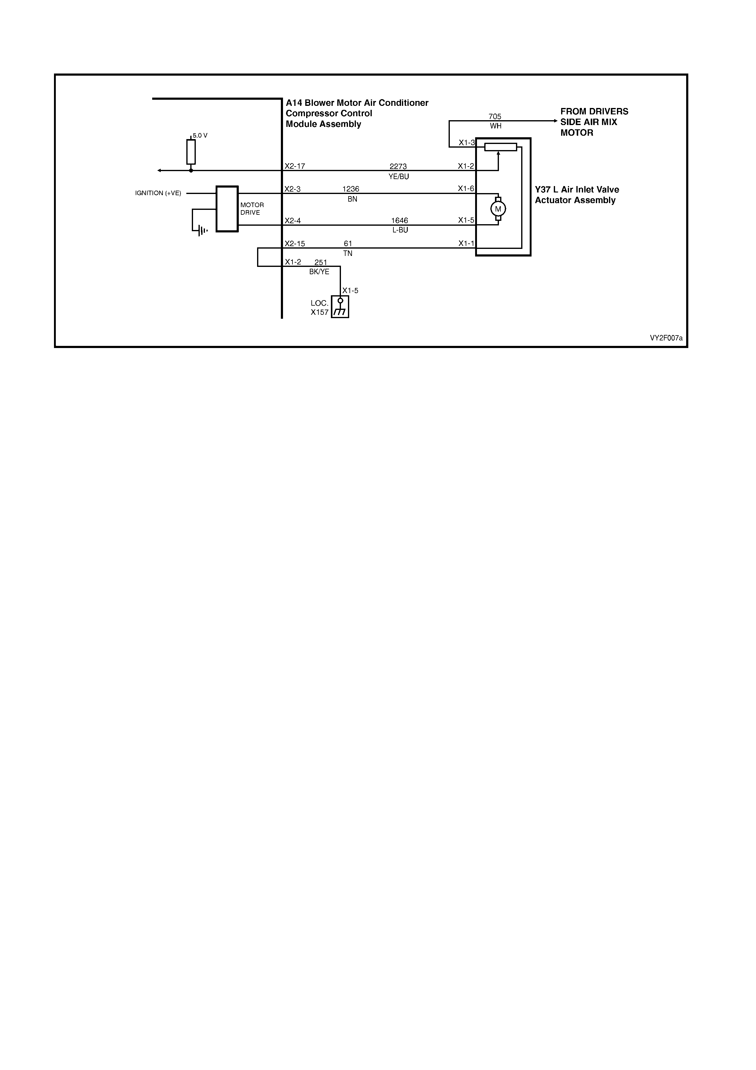
DTC 45 – PASSENGERS AIR MIX DOOR MOTOR FEEDBACK CIRCUIT VOLTAGE TOO LOW
Figure 2F-96
Circuit Description:
The air mix motor is an electric motor used to operate the air mix door. The electric motor is sent a voltage signal of
12.5 volts from the OCC module which causes the motor to turn, which moves the air mix door towards or away
from the heater core, the direction change takes place by reversi ng the polarity of this motor.
A potentiometer (PBR) is housed in the air mix motor circuit, which feeds signals (5.0 volts) back to the OCC
module as to the positioning of the motor and consequently the air mix door.
DTC 45 will set when the feedback signal from the passenger air mix motor is short circuited for a period of 10
seconds.
Test Description:
1. Ensures the Diagnostic Circuit Check has been performed.
This test checks for faulty OCC.
This test checks for short to ground in circuit 705.
This test checks for a short in circuits 705 and 1236.
This test checks for a short in circuits 705 and 274.
This test checks that the resistance value of the potentiometer does not exceed maximum acceptable tolerance.
This test checks that the resistance value of the potentiometer is not less than the minimum acceptable tolerance.
This test checks that the signal from the potentiometer does not exceed maximum acceptable tolerance.
This test checks that the signal from the potentiometer is not less than minimum acceptable to lerance.
This test checks for intermittent or loose terminals in the OCC an d air mix door motor connectors.
This test checks for sufficient power supply for the potentiometer from the OCC.
This test checks for short in circuits 705 or 61.
This test checks for short in circuits 61 or 2273.
This test checks for short in circuits 705 or 2273.
This test checks for intermittent or loose terminals in the OCC an d air mix door motor connectors.
This test checks for open in circuits 61, 2273 and 705.
Ensures that DTC 40 has been cleared if present.
This test checks to see if the air mix door is physically jammed or bro ken.
This test determines whether the air mix motor a ssem bly is faulty.

Diagnostic Aids:
An air mix motor or door problem will always be associated with non-regulated or incorrect temperatures from
mode positions.
The OCC control module, during calibration, sets a minimum and a maximum PBR value for the air mix motor in its
memory. It is these values which determine the operating range of the air mix motor and against which all
movements of the air mix adjustment are scaled. Any PBR signal value outside the minimum or maximum value
are considered a motor fault.
The OCC module monitors the rate of change of PBR signal during air mix motor movement. If this rate of change
falls to 0 (such as a broken air mix motor wire or physical jamb), the OCC module will recognise the stoppage and
set the fault code.
If DTC 45 was present before turning the ignition off, when the ignition is turned on again, the OCC module will
automatically try to recalibrate the air mix door. This takes approximately 15 seconds. If the recalibration fails, then
DTC 45 will be set again.
Notes on Diagnostic Chart:
1. Refer to Section 12P, WIRING DIAGRAMS for procedures on checking wiring faults.
2. Refer to 1.1 TECH 2 DIAGNOSTICS in this Section for conne cting and using TECH 2.
DTC 45 – PASSENGERS AIR MIX DOOR MOTOR FEEDBACK CIRCUIT VOLTAGE TOO LOW DIAGNOSTIC
CHART
STEP ACTION VALUE YES
NO
1 Has the Diagnostic Circuit Check been performed? – Go to Step 2. Go to Chart A –
DIAGNOSTIC
CIRCUIT
CHECK in this
Section.
2 1. Disconnect the OCC wiring harness connector
A14 X2.
Connect TECH 2 to the DLC.
Select Diagnostics / Model Year / Vehicle Model /
Body / Occupant Climate Control / Data Display
/ Data List / Drivers Air Mix Door Feedback.
Does TECH 2 display a value above 3.4 volts?
– Go to Step 3. Replace the
OCC control
module. Refer to
Section 2E,
HVAC
OCCUPANT
CLIMATE
CONTROL
(AUTO A/C) –
REMOVAL &
INSTALLATION
.
3 1. Install the passenger’s air mix motor (if
disconnected).
With the OCC connector A14 X2 disconnected,
probe OCC connector terminal X2-11,
circuit 705 (White wire) with an ohmmeter and
chassis ground.
Is the value as specified?
NOTE: Any resistance measured here qualifies as a
short.
0 Ohm Repair faulty
circuit 705. Go to Step 4.
4 1. With the OCC connector A14 X2
disconnected, probe between OCC connector
terminal X2-3, circuit 1236 (Brown wire) and
connector terminal X2-11, circuit 705 (White
wire) with an ohmmeter.
Is the value as specified?
NOTE: Any resistance measured here qualifies as a
short.
0 Ohm Repair faulty
circuit 705
and/or 1236.
Go to Step 5.
5 1. With the OCC connector A14 X2
disconnected, probe between OCC connector
terminal X2-5, circuit 274 (Red / White wire)
and connector terminal X2-11, circuit 705
(White wire) with an ohmmeter.
Is the value as specified?
NOTE: Any resistance measured here qualifies as a
short.
0 Ohm Repair faulty
circuit 274
and/or 705.
Go to Step 6.

STEP ACTION VALUE YES
NO
6 1. Disconnect the driver’s air mix motor
connector Y37 R X1. Less than
12 kilohms Go to Step 7. Go to Step 15.
7 In Step 6, was the value as specified? More than
8 kilohms Go to Step 8. Go to Step 12.
8 1. With the OCC connector A14 X2
disconnected, probe between OCC connector
terminal X2-11, circuit 705 (White wire) and
connector terminal X2-17, circuit 2273 (Yellow
/ Blue wire) with an ohmmeter.
Is the value as specified?
Less than
8.5 kilohms Go to Step 9. Go to Step 15.
9 In Step 8, was the value as specified? More than
1.5 kilohms Go to Step 10. Go to Step 12.
10 1. Inspect the OCC wiring harness connector
A14 X2 or air mix motor connector Y37 L X1
for an intermittent or loose terminal.
Are the connectors OK?
– Repair faulty
connector/s. Go to Step11.
11 1. Install the OCC connectors A14 X2 and
A14 X1.
Disconnect the passenger’s air mix motor
connector Y37 L X1.
Turn the ignition on
Probe the driver’s air mix motor connector Y37 R X1
between connector terminal X1-3 circuit 61 (Tan
wire) and connector terminal X1-1 circuit 705
(White wire) with a voltmeter.
Is the value as specified?
4.8 – 5.0
volts Go to Step 17. Replace the
OCC control
module. Refer to
Section 2E,
HVAC
OCCUPANT
CLIMATE
CONTROL
(AUTO A/C)–
REMOVAL &
INSTALLATION
.
12 1. Disconnect the air mix motor connectors
Y37 R X1 and Y37 L X1.
With the OCC connector A14 X2 disconnected,
probe between OCC connector terminal X2-11,
circuit 705 (White wire) and connector
terminal X2-15, circuit 61 (Tan wire) with an
ohmmeter.
Is the value as specified?
NOTE: Any resistance measured here qualifies as a
short.
0 Ohm Repair faulty
circuit 705
and/or 61.
Go to Step 13.
13 1. With OCC connectors A14 X2 and Y37 L X1
disconnected, probe between OCC connector
terminal X2-15, circuit 61 (Tan wire) and
connector terminal X2-17, circuit 2273 (Yellow
/ Blue wire) with an ohmmeter.
Is the value as specified?
NOTE: Any resistance measured here qualifies as a
short.
0 Ohm Repair faulty
circuit 61
and/or 2273.
Go to Step 14.
14 1. With OCC connectors A14 X2 and Y37 L X1
disconnected, probe between OCC connector
terminal X2-11, circuit 705 (White wire) and
connector terminal X2-17, circuit 2273 (Yellow
/ Blue wire) with an ohmmeter.
Is the value as specified?
NOTE: Any resistance measured here qualifies as a
short.
0 Ohm Repair faulty
circuit 705
and/or 2273.
Replace the air
mix door motor.
Refer to
Section 2E,
HVAC
OCCUPANT
CLIMATE
CONTROL
(AUTO A/C) –
REMOVAL &
INSTALLATION
.

STEP ACTION VALUE YES
NO
15 1. Inspect the wiring harness connectors A14 X2
and Y37 L X1 for an intermittent or loose
terminal.
– Go to Step 16. Repair faulty
connector/s.
16 1. Check the integrity of circuits 61, 2273 and
705.
Are the circuits OK?
– Replace the air
mix door motor.
Refer to
Section 2E,
HVAC
OCCUPANT
CLIMATE
CONTROL
(AUTO A/C) –
REMOVAL &
INSTALLATION
.
Repair faulty
circuits.
17 Is DTC 40 currently recorded in TECH 2? – Go to DTC 40 in
this Section and
clear DTC.
Go to Step 18.
18 1. Remove passenger’s air mix motor assembly.
Refer to Section 2E, HVAC OCCUPANT
CLIMATE CONTROL (AUTO A/C) –
REMOVAL & INSTALLATION.
Move the air mix door by hand.
Is the door physically jammed or bro ken ?
– Repair faulty air
mix door. Go to Step 19.
19 1. Replace the air mix motor assembly. Refer to
Section 2E, HVAC OCCUPANT CLIMATE
CONTROL (AUTO A/C) – REMOVAL &
INSTALLATION.
Is the problem fixed?
– System OK. Replace the
OCC control
module. Refer to
Section 2E,
HVAC
OCCUPANT
CLIMATE
CONTROL
(AUTO A/C) –
REMOVAL &
INSTALLATION
.
WHEN ALL DIAGNOSIS AND REPAIRS ARE COMPLETE, VERIFY CORRECT OPERATION

DTC 46 – PASSENGERS AIR MIX DOOR MOTOR FEEDBACK CIRCUIT ZOLTAGE TOO HIGH
Figure 2F-97
Circuit Description:
The air mix motor is an electric motor used to operate the air mix door. The electric motor is sent a voltage signal of
12.5 volts from the OCC module which causes the motor to turn, which moves the air mix door towards or away
from the heater core, the direction change takes place by reversi ng the polarity of this motor.
A potentiometer (PBR) is housed in the air mix motor circuit, which feeds signals (5.0 volts) back to the OCC
module as to the positioning of the motor and consequently the air mix door.
DTC 46 will set when the feedback signal from the passenger air mix motor is short circuited for a period of 10
seconds.
Test Description:
1. Ensures the Diagnostic Circuit Check has been performed.
This test checks for faulty OCC.
This test checks for short to ground in circuit 705.
This test checks for a short in circuits 705 and 1236.
This test checks for a short in circuits 705 and 274.
This test checks that the resistance value of the potentiometer does not exceed maximum acceptable tolerance.
This test checks that the resistance value of the potentiometer is not less than the minimum acceptable tolerance.
This test checks that the signal from the potentiometer does not exceed maximum acceptable tolerance.
This test checks that the signal from the potentiometer is not less than minimum acceptable to lerance.
This test checks for intermittent or loose terminals in the OCC an d air mix door motor connectors.
This test checks for sufficient power supply for the potentiometer from the OCC.
This test checks for short in circuits 705 or 61.
This test checks for short in circuits 61 or 2273.
This test checks for short in circuits 705 or 2273.
This test checks for intermittent or loose terminals in the OCC an d air mix door motor connectors.
This test checks for open in circuits 61, 2273 and 705.
Ensures that DTC 40 has been cleared if present.
This test checks to see if the air mix door is physically jammed or bro ken.
This test determines whether the air mix motor a ssem bly is faulty.

Diagnostic Aids:
An air mix motor or door problem will always be associated with non-regulated or incorrect temperatures from
mode positions.
The OCC control module, during calibration, sets a minimum and a maximum PBR value for the air mix motor in its
memory. It is these values which determine the operating range of the air mix motor and against which all
movements of the air mix adjustment are scaled. Any PBR signal value outside the minimum or maximum value
are considered a motor fault.
The OCC module monitors the rate of change of PBR signal during air mix motor movement. If this rate of change
falls to 0 (such as a broken air mix motor wire or physical jamb), the OCC module will recognise the stoppage and
set the fault code.
If DTC 46 was present before turning the ignition off, when the ignition is turned on again, the OCC module will
automatically try to recalibrate the air mix door. This takes approximately 15 seconds. If the recalibration fails, then
DTC 46 will be set again..
Notes on Diagnostic Chart:
1. Refer to Section 12P, WIRING DIAGRAMS for procedures on checking wiring faults.
2. Refer to 1.1 TECH 2 DIAGNOSTICS in this Section for conne cting and using TECH 2.
DTC 46 – PASSENGERS AIR MIX DOOR MOTOR FEEDBACK CIRCUIT VOLTAGE TOO HIGH DIAGNOSTIC
CHART
STEP ACTION VALUE YES
NO
1 Has the Diagnostic Circuit Check been performed? – Go to Step 2. Go to Chart A –
DIAGNOSTIC
CIRCUIT
CHECK in this
Section.
2 1. Disconnect the OCC wiring harness
connector A14 X2.
Connect TECH 2 to the DLC.
Select Diagnostics / Model Year / Vehicle Model /
Body / Occupant Climate Control / Data
Display / Data List / Drivers Air Mix Door
Feedback.
Does TECH 2 display a value above 3.4 volts?
– Go to Step 3. Replace the
OCC control
module. Refer to
Section 2E,
HVAC
OCCUPANT
CLIMATE
CONTROL
(AUTO A/C) –
REMOVAL &
INSTALLATION
.
3 1. Install the passenger’s air mix motor (if
disconnected).
With the OCC connector A14 X2 disconnected,
probe OCC connector terminal X2-11,
circuit 705 (White wire) with an ohmmeter to
chassis ground.
Is the value as specified?
NOTE: Any resistance measured here qualifies as
a short.
0 Ohm Repair faulty
circuit 705. Go to Step 4.
4 1. With the OCC connector A14 X2
disconnected, probe between OCC
connector terminal X2-3, circuit 1236 (Brown
wire) and connector terminal X2-11,
circuit 705 (White wire) with an ohmmeter.
Is the value as specified?
NOTE: Any resistance measured here qualifies as
a short.
0 Ohm Repair faulty
circuit 705
and/or 1236.
Go to Step 5.
5 1. With the OCC connector A14 X2
disconnected, probe between OCC
connector terminal X2-5, circuit 274 (Red /
White wire) and connector terminal X2-11,
circuit 705 (White wire) with an ohmmeter.
Is the value as specified?
NOTE: Any resistance measured here qualifies as
a short.
0 Ohm Repair faulty
circuit 274
and/or 705.
Go to Step 6.

STEP ACTION VALUE YES
NO
6 1. Disconnect the driver’s air mix motor
connector Y37 R X1. Less than
12 kilohms Go to Step 7. Go to Step 15.
7 In Step 6, was the value as specified? More than
8 kilohms Go to Step 8. Go to Step 12.
8 1. With the OCC connector A14 X2
disconnected, probe between OCC
connector terminal X2-11, circuit 705 (White
wire) and connector terminal X2-17,
circuit 2273 (Yellow / Blue wire) with an
ohmmeter.
Is the value as specified?
Less than
8.5 kilohms Go to Step 9. Go to Step 15.
9 In Step 8, was the value as specified? More than
1.5 kilohms Go to Step 10. Go to Step 12.
10 1. Inspect the OCC wiring harness connector
A14 X2 or air mix motor connector Y37 L X1
for an intermittent or loose terminal.
Are the connectors OK?
– Repair faulty
connector/s. Go to Step11.
11 1. Install the OCC connectors A14 X2 and
A14 X1 to OCC control module.
Disconnect passenger’s air mix motor connector
Y37 L X1.
Turn the ignition on
Measure voltage at driver’s air mix motor
connector Y37 R X1 between OCC connector
terminal X1-3 circuit 61 (Tan wire) and
connector terminal X1-1 circuit 705 (White
wire).
Is the value as specified?
4.8 – 5.0
volts Go to Step 17. Replace the
OCC control
module. Refer to
Section 2E,
HVAC
OCCUPANT
CLIMATE
CONTROL
(AUTO A/C)–
REMOVAL &
INSTALLATION
.
12 1. Disconnect the air mix motor connectors
Y37 R X1 and Y37 L X1.
With the OCC connector A14 X2 disconnected,
probe between OCC connector terminal X2-11,
circuit 705 (White wire) and connector terminal
X2-15, circuit 61 (Tan wire) with an ohmmeter.
Is the value as specified?
NOTE: Any resistance measured here qualifies as
a short.
0 Ohm Repair faulty
circuit 705
and/or 61.
Go to Step 13.
13 1. With OCC connectors A14 X2 and Y37 L X1
disconnected, probe between OCC
connector terminal X2-15, circuit 61 (Tan
wire) and connector terminal X2-17,
circuit 2273 (Yellow / Blue wire) with an
ohmmeter.
Is the value as specified?
NOTE: Any resistance measured here qualifies as
a short.
0 Ohm Repair faulty
circuit 61
and/or 2273.
Go to Step 14.

STEP ACTION VALUE YES
NO
14 1. With OCC connectors A14 X2 and Y37 L X1
disconnected, probe between OCC
connector terminal X2-11, circuit 705 (White
wire) and connector terminal X2-17,
circuit 2273 (Yellow / Blue wire) with an
ohmmeter.
0 Ohm Repair faulty
circuit 705
and/or 2273.
Replace the air
mix door motor.
Refer to
Section 2E,
HVAC
OCCUPANT
CLIMATE
CONTROL
(AUTO A/C) –
REMOVAL &
INSTALLATION
.
15 1. Inspect wiring harness connectors A14 X2
and Y37 L X1 for an intermittent or loose terminal.
Are the connectors OK?
– Go to Step 16. Repair faulty
connector/s.
16 1. Check the integrity of circuits 61, 2273 and
705.
Are the circuits OK?
– Repair faulty
circuits. Replace the air
mix door motor.
Refer to
Section 2E,
HVAC
OCCUPANT
CLIMATE
CONTROL
(AUTO A/C) –
REMOVAL &
INSTALLATION
.
17 Is DTC 40 currently recorded in TECH 2? – Go to DTC 40 in
this Section and
clear DTC.
Go to Step 18.
18 1. Remove the passenger’s air mix motor
assembly, refer to Section 2E, HVAC
OCCUPANT CLIMATE CONTROL (AUTO
A/C) – REMOVAL & INSTALLATION.
Move the air mix door by hand.
Is the door physically jammed or bro ken ?
– Repair faulty air
mix door. Go to Step 19.
19 1. Replace the air mix motor assembly. Refer to
Section 2E, HVAC OCCUPANT CLIMATE
CONTROL (AUTO A/C) – REMOVAL &
INSTALLATION.
Is the problem fixed?
– System OK. Replace the
OCC control
module. Refer to
Section 2E,
HVAC
OCCUPANT
CLIMATE
CONTROL
(AUTO A/C) –
REMOVAL &
INSTALLATION
.
WHEN ALL DIAGNOSIS AND REPAIRS ARE COMPLETE, VERIFY CORRECT OPERATION
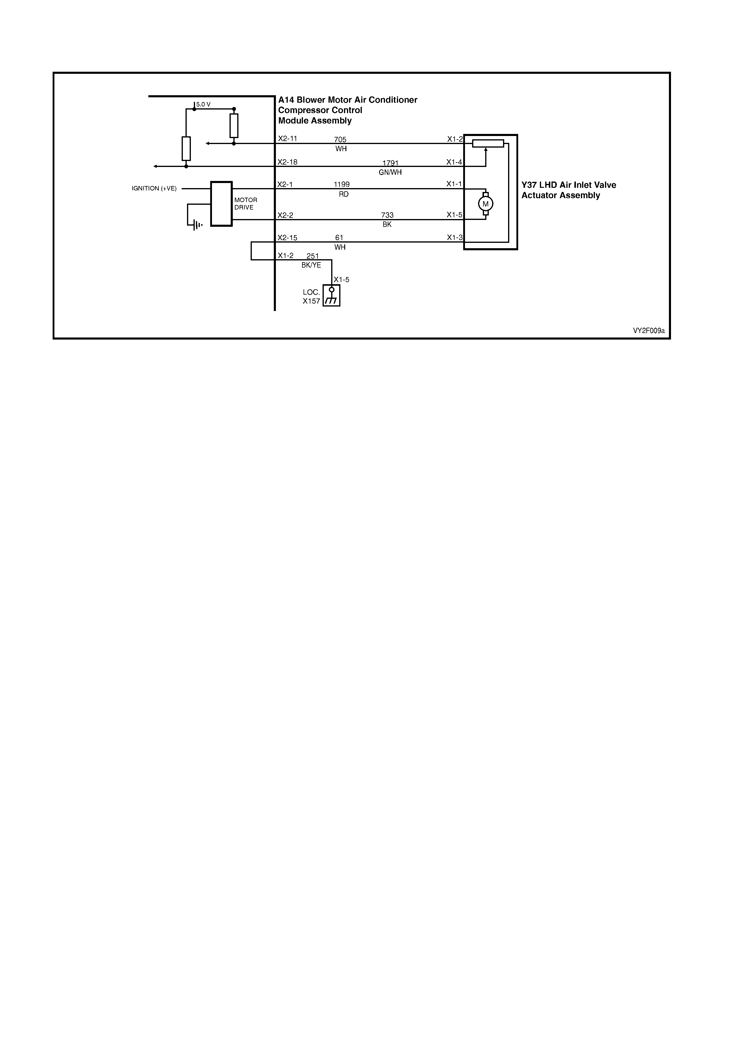
DTC 47 – DRIVER AIR MIX MIN. CALIBRATIO N ERROR ( LHD)
Figure 2F-98
Circuit Description:
The air mix motor is an electric motor used to operate the air mix doors. The electric motor is sent a voltage signal
of 12.5 volts from the OCC module which causes the motor to turn, which moves the air mix doors towards or away
from the heater core, the direction change takes place by reversi ng the polarity of this motor.
A potentiometer (PBR) is housed in the air mix motor circuit, which feeds signals (5.0 volts) back to the OCC
module as to the positioning of the motor and consequently the air mix door.
DTC 47 will set: if the PBR feedback signal fails to reach the requested value. This will occur if the PBR or motor is
open or short circuited, or an air mix door is jammed or sticking.
Test Description:
Number(s) below refer to Step numbers in the followin g Diagnostic Chart:
1. Ensures the Diagnostic Circuit Check has been performed.
2. This test checks that the DTC is current.
3. This test checks if the motor is moving.
4. This test checks that the motor is stopping within the correct range at full cold.
5. This test checks that the motor is stopping within the correct range at full hot.
6. Attempts to recalibrate and check DTC is still current.
7. Determines if a PBR fault is the likely cause of the problem.
8. Determines if a motor fault is more likely than a PBR fault to be the cause of the problem.
9. Checks fault has been rectified.
Notes on Diagnostic Chart:
1. Refer to Section 12P, WIRING DIAGRAMS for procedures on checking wiring faults.
Refer to 1.1 TECH 2 DIAGNOSTICS in this Section for connecting and using TECH 2.
Diagnostic Aids:
An air mix motor or door problem will always be associated with non-regulated or incorrect temperatures from
mode positions.
The OCC control module, during calibration, sets a minimum and a maximum PBR value for the air mix motor in its
memory. It is these values which determine the operating range of the air mix motor and against which all
movements of the air mix adjustment are scaled. Any PBR signal value outside the minimum or maximum value
are considered a motor fault.
The OCC module monitors the rate of change of PBR signal during air mix motor movement. If this rate of change
falls to 0 (such as a broken air mix motor wire or physical jamb), the OCC module will recognise the stoppage and
set the fault code.
If DTC 47 was present before turning the ignition off, when the ignition is turned on again, the OCC module will
automatically try to recalibrate the air mix door. This takes approximately 15 seconds. If the recalibration fails, then
DTC 47 will be set again.

DTC 47 – DRIVER AIR MIX MIN. CALIBRATIO N ERR OR ( LHD) DIAGNOSTIC CHART
STEP ACTION VALUE YES
NO
1 Has the Diagnostic Circuit Check been performed? – Go to Step 2. Go to Chart A –
DIAGNOSTIC
CIRCUIT
CHECK in this
Section.
2 1. Turn the ignition off.
Connect TECH 2 to the DLC.
Select Diagnostics / Model Year / Vehicle Model /
Body / Occupant Climate Control / Diagnostic
Trouble Codes / Read Current DTC Information.
Does DTC 47 display a s the cur re nt DTC?
– Go to Step 3. Go to Step 9.
3 1. With TECH 2 connected, select Body /
Occupant Climate Control / Miscellaneous
Tests / Drivers Side Air Mix Motor – Door
Movement.
Move the air mix door maximum then decrease to
minimum.
Does the TECH 2 value change accordingly?
– Go to Step 4. Go to Step 7.
4 1. With the Drivers Side Air Mix Motor – Door
Movement test selected, decrease the air mix
door to minimum.
Does TECH 2 display a value within 0.6 – 0.9 volt?
– Go to Step 5. Go to chart
DTC 40 – AIR
MIX DOOR
MOTOR
DRIVER
ERROR (LHD)
in this Section.
5 1. With the Drivers Side Air Mix Motor – Door
Movement test selected, increase the air mix
door to maximum.
Does TECH 2 display a value within 2.6 – 2.9 volts?
– Go to Step 6. Go to chart
DTC 40 – AIR
MIX DOOR
MOTOR
DRIVER
ERROR (LHD)
in this Section.
6 1. With TECH 2 connected, select Body /
Occupant Climate Control / Program /
Calibrate Air Mix Door.
Reprogram the air mix door.
Turn the ignition off.
Turn the ignition on.
Does DTC 47 set as the cu rrent DTC?
– Go to chart
DTC 40 – AIR
MIX DOOR
MOTOR
DRIVER
ERROR (LHD)
in this Section.
Go to Step 9.
7 In Step 3, did TECH 2 display less than 0.3 volt? – Go to chart
DTC 43 –
DRIVERS AIR
MIX DOOR
MOTOR
FEEDBACK
CIRCUIT VOLT
AGE TOO LOW
(LHD) in this
Section.
Go to Step 8.

STEP ACTION VALUE YES
NO
8 In Step 3, did TECH 2 display more than 3.4 volts? 3.4 volts Go to chart
DTC 44 –
DRIVERS AIR
MIX DOOR
MOTOR
FEEDBACK
CIRCUIT VOLT
AGE TOO
HIGH (LHD) in
this Section.
Go to chart
DTC 40 – AIR
MIX DOOR
MOTOR
DRIVER
ERROR (LHD)
in this Section.
9 1. With TECH 2 connected, select Body /
Occupant Climate Control / Miscellaneous
Tests / Drivers Side Air Mix Motor– Door
Movement.
Increase to maximum then decrease to minimum.
Does DTC 47 set as a current DTC?
– Go to Step 3. Recalibration of
Air mix door
may have
corrected fault
or DTC 47 is
intermittent.
(Carry out air
mix door
calibration if not
already done
so. Refer to 1.2
TECH 2 TEST
MODES AND
DISPLAYS
FOR OCC
DIAGNOSIS
and/or refer to
2 DIAGNOSTIC
CHARTS in this
Section.
WHEN ALL DIAGNOSIS AND REPAIRS ARE COMPLETE, VERIFY CORRECT OPERATION

DTC 47 – DRIVER AIR MIX MIN. CALIBRATION ERROR (RHD)
Figure 2F-99
Circuit Description:
The air mix motor is an electric motor used to operate the air mix door. The electric motor is sent a voltage signal of
12.5 volts from the OCC module which causes the motor to turn, which moves the air mix door towards or away
from the heater core, the direction change takes place by reversi ng the polarity of this motor.
A potentiometer (PBR) is housed in the air mix motor circuit, which feeds signals (5.0 volts) back to the OCC
module as to the positioning of the motor and consequently the air mix door.
DTC 47 will set: if the drivers PBR feedback signal fails to reach the requested value. This will occur if the PBR or
motor is open or short circu ited, or if the air mix door is jammed or sticking.
Test Description:
Number(s) below refer to Step numbers in the followin g Diagnostic Chart:
1. Ensures the Diagnostic Circuit Check has been performed.
2. This test checks that the DTC is current.
3. This test checks if the motor is moving.
4. This test checks that the motor is stopping within the correct range at full cold.
5. This test checks that the motor is stopping within the correct range at full hot.
6. Attempts to recalibrate and check DTC is still current.
7. Determines if a PBR fault is the likely cause of the problem.
8. Determines if a motor fault is more likely than a PBR fault to be the cause of the problem.
9. Checks fault has been rectified.
Notes on Diagnostic Chart:
1. Refer to 5. WIRING DIAGRAMS in this Section for views of OCC system related electrical connectors and
complete OCC system wiring diag rams.
For electrical connector locations and additional wiring diagram information, refer to
Section 12P WIRING DIAGRAMS
Refer to 1.1 TECH 2 DIAGNOSTICS in this Section for connecting and using TECH 2.
Diagnostic Aids:
An air mix motor or door problem will always be associated with non-regulated or incorrect temperatures from
mode positions.
The OCC control module, during calibration, sets a minimum and a maximum PBR value for the air mix motor in its
memory. It is these values which determine the operating range of the air mix motor and against which all
movements of the air mix adjustment are scaled. Any PBR signal value outside the minimum or maximum value
are considered a motor fault.
The OCC module monitors the rate of change of PBR signal during air mix motor movement. If this rate of change
falls to 0 (such as a broken air mix motor wire or physical jamb), the OCC module will recognise the stoppage and
set the fault code.
If DTC 47 was present before turning the ignition off, when the ignition is turned on again, the OCC module will
automatically try to recalibrate the air mix door. This takes approximately 15 seconds. If the recalibration fails, then
DTC 47 will be set again.

DTC 47 – DRIVER AIR MIX MIN. CALI BRATION ERROR (RHD) DIAGNOSTI C C HA RT
STEP ACTION VALUE YES NO
1 Was the Diagnostic Circuit Check performed? – Go to Step 2. Go to Chart A –
DIAGNOSTIC
CIRCUIT
CHECK in this
Section.
2 1. Turn the ignition off.
Connect TECH 2 to the DLC.
Select Diagnostics / Model Year / Vehicle Model /
Body / Occupant Climate Control / Diagnostic
Trouble Codes / Read Current DTC Information.
Does DTC 47 display a s the cur re nt DTC?
– Go to Step 3. Go to Step 9.
3 1. With TECH 2 connected, select Body /
Occupant Climate Control / Miscellaneous
Tests / Drivers Side Air Mix Motor – Door
Movement.
Increase to maximum then decrease to minimum.
Does the TECH 2 value change accordingly?
– Go to Step 4. Go to Step 7.
4 1. With Drivers Side Air Mix Motor – Door
Movement test selected, decrease the air mix
door to minimum.
Does TECH 2 display a value within 0.6 – 0.9 volt?
– Go to Step 5. Go to chart
DTC 40 – AIR
MIX DOOR
MOTOR
DRIVER
ERROR (RHD
DRIVERS SIDE
MOTOR) in this
Section.
5 1. With Drivers Side Air Mix Motor – Door
Movement test selected increase the air mix
door to maximum.
Does TECH 2 display a value within 2.6 to 2.9 volts?
– Go to Step 6. Go to chart
DTC 40 – AIR
MIX DOOR
MOTOR
DRIVER
ERROR (RHD
DRIVERS SIDE
MOTOR) in this
Section.
6 1. With TECH 2 connected, select Body /
Occupant Climate Control / Program /
Calibrate Air Mix Door.
Reprogram the air mix doors.
Turn the ignition off.
Turn the ignition on.
Does DTC 47 set as a current DTC?
– Go to chart
DTC 40 – AIR
MIX DOOR
MOTOR
DRIVER
ERROR (RHD
DRIVERS SIDE
MOTOR) in this
Section.
Go to Step 9.

STEP ACTION VALUE YES NO
7 In Step 3, did TECH 2 display less than 0.3 volt? – Go to chart
DTC 43 –
DRIVERS AIR
MIX DOOR
MOTOR
FEEDBACK
CIRCUIT VOLT
AGE TOO LOW
in this Section .
Go to Step 8
8 In Step 3, did TECH 2 display more than 3.4 volts? – Go to chart
DTC 44 –
DRIVERS AIR
MIX DOOR
MOTOR
FEEDBACK
CIRCUIT VOLT
AGE TOO
HIGH in this
Section .
Go to chart
DTC 40 – AIR
MIX DOOR
MOTOR
DRIVER
ERROR (RHD
DRIVERS SIDE
MOTOR) in this
Section.
9 1. With TECH 2 connected, select Body /
Occupant Climate Control / Miscellaneous
Tests / Drivers Side Air Mix Motor– Door
Movement.
Increase to maximum then decrease to minimum.
Does DTC 47 set as a current DTC?
– Go to Step 3. Recalibration of
Air mix door
may have
corrected fault
or DTC 47 is
intermittent.
(Carry out air
mix door
calibration if not
already done
so. Refer to 1.2
TECH 2 TEST
MODES AND
DISPLAYS
FOR OCC
DIAGNOSIS
and/or refer to
2 DIAGNOSTIC
CHARTS in this
Section.
WHEN ALL DIAGNOSIS AND REPAIRS ARE COMPLETE, VERIFY CORRECT OPERATION

DTC 48 – DRIVER AIR MIX MAX. CALIBRATIO N ERROR ( LHD)
Figure 2F-100
Circuit Description:
The air mix motor is an electric motor used to operate the air mix doors. The electric motor is sent a voltage signal
of 12.5 volts from the OCC module which causes the motor to turn, which moves the air mix doors towards or away
from the heater core, the direction change takes place by reversi ng the polarity of this motor.
A potentiometer (PBR) is housed in the air mix motor circuit, which feeds signals (5.0 volts) back to the OCC
module as to the positioning of the motor and consequently the air mix door.
DTC 48 will set: if the PBR feedback signal fails to reach the requested value. This will occur if the PBR or motor is
open or short circuited, or an air mix door is jammed or sticking.
Test Description:
Number(s) below refer to Step numbers in the followin g Diagnostic Chart:
1. Ensures the Diagnostic Circuit Check has been performed.
2. This test checks that the DTC is current.
3. This test checks if the motor is moving.
4. This test checks that the motor is stopping within the correct range at full cold.
5. This test checks that the motor is stopping within the correct range at full hot.
6. Attempts to recalibrate and check DTC is still current.
7. Determines if a PBR fault is the likely cause of the problem.
8. Determines if a motor fault is more likely than a PBR fault to be the cause of the problem.
9. Checks fault has been rectified.
Notes on Diagnostic Chart:
1. Refer to Section 12P, WIRING DIAGRAMS for procedures on checking wiring faults.
2. Refer to 1.1 TECH 2 DIAGNOSTICS in this Section for connecting and using TECH 2.
Diagnostic Aids:
An air mix motor or door problem will always be associated with non-regulated or incorrect temperatures from
mode positions.
The OCC control module, during calibration, sets a minimum and a maximum PBR value for the air mix motor in its
memory. It is these values which determine the operating range of the air mix motor and against which all
movements of the air mix adjustment are scaled. Any PBR signal value outside the minimum or maximum value
are considered a motor fault.
The OCC module monitors the rate of change of PBR signal during air mix motor movement. If this rate of change
falls to 0 (such as a broken air mix motor wire or physical jamb), the OCC module will recognise the stoppage and
set the fault code.
If DTC 48 was present before turning the ignition off, when the ignition is turned on again, the OCC module will
automatically try to recalibrate the air mix door. This takes approximately 15 seconds. If the recalibration fails, then
DTC 48 will be set again.

DTC 48 – DRIVER AIR MIX MAX. CALI BRATION ERROR (LHD) DIAGNOSTIC CHART
STEP ACTION VALUE YES
NO
1 Was the Diagnostic Circuit Check performed? – Go to Step 2. Go to Chart A –
DIAGNOSTIC
CIRCUIT
CHECK in this
Section.
2 1. Turn the ignition off.
Connect TECH 2 to the DLC.
Select Diagnostics / Model Year / Vehicle Model /
Body / Occupant Climate Control / Diagnostic
Trouble Codes / Read Current
DTC Information.
Does DTC 48 display a s a current DTC?
– Go to Step 3. Go to Step 9.
3 1. With TECH 2 connected, select Body /
Occupant Climate Control / Miscellaneous
Tests / Drivers Side Air Mix Motor – Door
Movement
Increase to maximum then decrease to minimum.
Does the TECH 2 value change accordingly?
– Go to Step 4. Go to Step 7.
4 With Drivers Side Air Mix Motor – Door Movement
test still selected, decrease air mix door to
minimum.
Does TECH 2 display a value within 0.6 – 0.9 volt?
– Go to Step 5. Go to chart
DTC 40 – AIR
MIX DOOR
MOTOR
DRIVER
ERROR (LHD)
in this Section.
5 1. With Drivers Side Air Mix Motor – Door
Movement test still selected increase air mix
door to maximum.
Does TECH 2 display a value within 2.6 to 2.9
volts?
– Go to Step 6. Go to chart
DTC 40 – AIR
MIX DOOR
MOTOR
DRIVER
ERROR (LHD)
in this Section.
6 1. With TECH 2 connected, select Body /
Occupant Climate Control / Program /
Calibrate Air Mix Door.
Reprogram the air mix door.
Turn the ignition off.
Turn the ignition on.
Does DTC 48 set as a current DTC?
– Go to chart
DTC 40 – AIR
MIX DOOR
MOTOR
DRIVER
ERROR (LHD)
in this Section.
Go to Step 9.
7 In Step 3, did TECH 2 display less than 0.3 volt? – Go to chart
DTC 43 –
DRIVERS AIR
MIX DOOR
MOTOR
FEEDBACK
CIRCUIT VOLT
AGE TOO LOW
(LHD) in this
Section .
Go to Step 8.

STEP ACTION VALUE YES
NO
8 In Step 3, did TECH 2 display more than 3.4 volts? – Go to chart
DTC 44 –
DRIVERS AIR
MIX DOOR
MOTOR
FEEDBACK
CIRCUIT VOLT
AGE TOO
HIGH (LHD) in
this Section .
Go to chart
DTC 40 – AIR
MIX DOOR
MOTOR
DRIVER
ERROR (LHD)
in this Section.
9 1. With TECH 2 connected, select Body /
Occupant Climate Control / Miscellaneous
Tests / Drivers Side Air Mix Motor– Door
Movement.
Increase to maximum then decrease to minimum.
Does DTC 48 set as a current DTC?
– Go to Step 3. Recalibration of
Air mix door
may have
corrected fault
or DTC 48 is
intermittent.
(Carry out air
mix door
calibration if not
already done
so. Refer to 1.2
TECH 2 TEST
MODES AND
DISPLAYS
FOR OCC
DIAGNOSIS
and/or refer to
2 DIAGNOSTIC
CHARTS in this
Section.
WHEN ALL DIAGNOSIS AND REPAIRS ARE COMPLETE, VERIFY CORRECT OPERATION
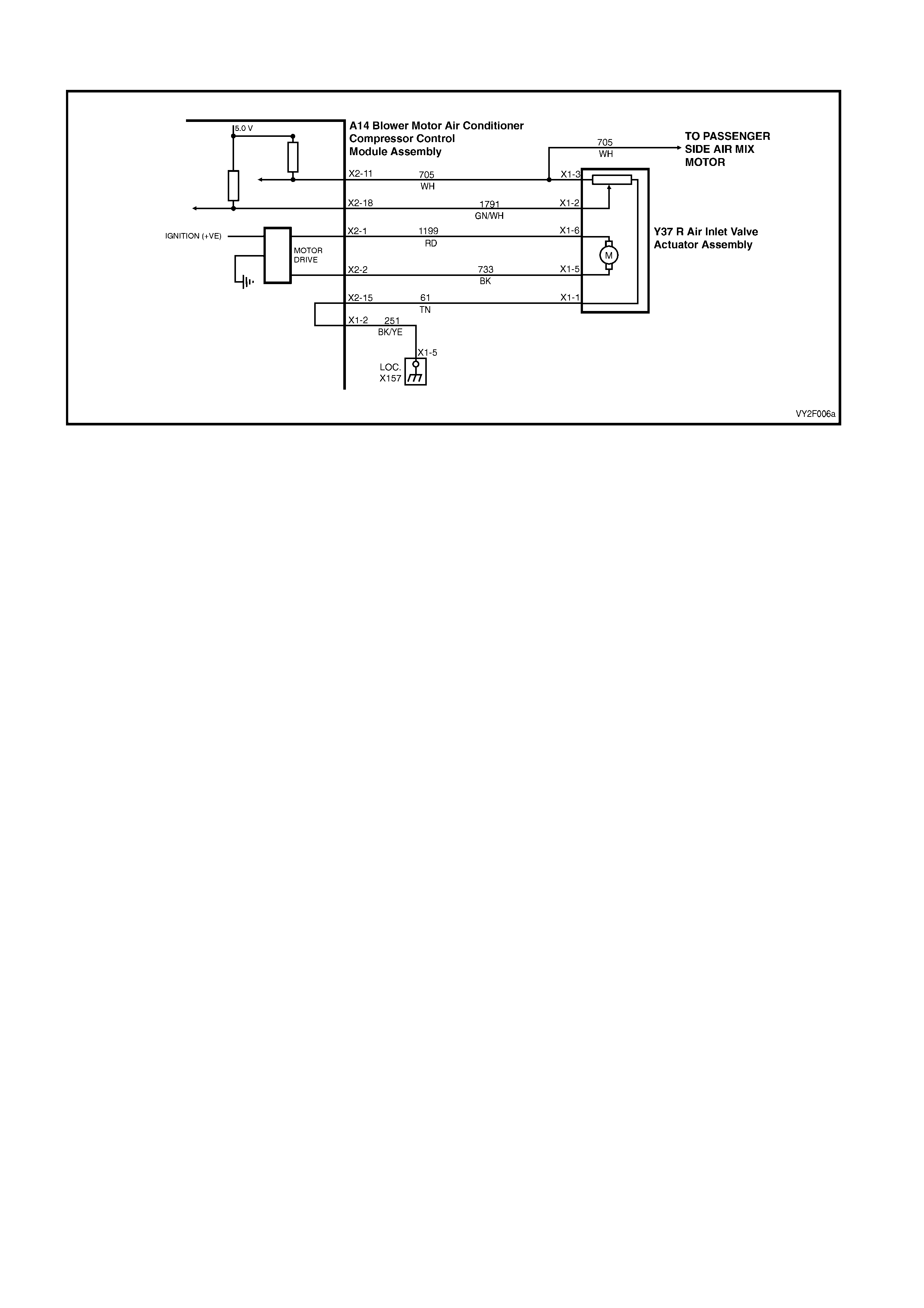
DTC 48 – DRIVER AIR MIX MAX. CALIBRATION ERROR (RHD)
Figure 2F-101
Circuit Description:
The air mix motor is an electric motor used to operate the air mix door. The electric motor is sent a voltage signal of
12.5 volts from the OCC module which causes the motor to turn, which moves the air mix door towards or away
from the heater core, the direction change takes place by reversi ng the polarity of this motor.
A potentiometer (PBR) is housed in the air mix motor circuit, which feeds signals (5.0 volts) back to the OCC
module as to the positioning of the motor and consequently the air mix door.
DTC 48 will set: if the drivers PBR feedback signal fails to reach the requested value. This will occur if the PBR or
motor is open or short circu ited, or if the air mix door is jammed or sticking.
Test Description:
Number(s) below refer to Step numbers in the followin g Diagnostic Chart:
1. Ensures the Diagnostic Circuit Check has been performed.
2. This test checks that the DTC is current.
3. This test checks if the motor is moving.
4. This test checks that the motor is stopping within the correct range at full cold.
5. This test checks that the motor is stopping within the correct range at full hot.
6. Attempts to recalibrate and check DTC is still current.
7. Determines if a PBR fault is the likely cause of the problem.
8. Determines if a motor fault is more likely than a PBR fault to be the cause of the problem.
9. Checks fault has been rectified.
Notes on Diagnostic Chart:
1. Refer to 5. WIRING DIAGRAMS in this Section for views of OCC system related electrical connectors and
complete OCC system wiring diag rams.
For electrical connector locations and additional wiring diagram information, refer to
Section 12P WIRING DIAGRAMS
Refer to 1.1 TECH 2 DIAGNOSTICS in this Section for connecting and using TECH 2.
Diagnostic Aids:
An air mix motor or door problem will always be associated with non-regulated or incorrect temperatures from
mode positions.
The OCC control module, during calibration, sets a minimum and a maximum PBR value for the air mix motor in its
memory. It is these values which determine the operating range of the air mix motor and against which all
movements of the air mix adjustment are scaled. Any PBR signal value outside the minimum or maximum value
are considered a motor fault.
The OCC module monitors the rate of change of PBR signal during air mix motor movement. If this rate of change
falls to 0 (such as a broken air mix motor wire or physical jamb), the OCC module will recognise the stoppage and
set the fault code.
If DTC 48 was present before turning the ignition off, when the ignition is turned on again, the OCC module will
automatically try to recalibrate the air mix door. This takes approximately 15 seconds. If the recalibration fails, then
DTC 48 will be set again.

DTC 48 – DRIVER AIR MIX MAX. CALI BRATION ERROR (RHD) DIAGNOSTI C C HA RT
STEP ACTION VALUE YES NO
1 Was the Diagnostic Circuit Check performed? – Go to Step 2. Go to Chart A –
DIAGNOSTIC
CIRCUIT
CHECK in this
Section.
2 1. Turn the ignition off.
Connect TECH 2 to the DLC.
Select Diagnostics / Model Year / Vehicle Model /
Body / Occupant Climate Control / Diagnostic
Trouble Codes / Read Current DTC Information.
Does DTC 48 display as a the current DTC?
– Go to Step 3. Go to Step 9.
3 1. With TECH 2 connected, select Diagnostics /
Model Year / Vehicle Model / Body / Occupant
Climate Control / Miscellaneous Tests / Drivers
Side Air Mix Motor – Door Movement.
Increase to maximum then decrease to minimum.
Does the TECH 2 value change accordingly?
– Go to Step 4. Go to Step 7.
4 1. With Drivers Side Air Mix Motor – Door
Movement test still selected, decrease air mix
door to minimum.
Does TECH 2 display a value within 0.6 – 0.9 volt?
– Go to Step 5. Go to chart
DTC 40 – AIR
MIX DOOR
MOTOR
DRIVER
ERROR (RHD
DRIVERS SIDE
MOTOR) in this
Section.
5 1. With Drivers Side Air Mix Motor – Door
Movement test still selected increase air mix
door to maximum.
Does TECH 2 display a value within 2.6 to 2.9 volts?
– Go to Step 6. Go to chart
DTC 40 – AIR
MIX DOOR
MOTOR
DRIVER
ERROR (RHD
DRIVERS SIDE
MOTOR) in this
Section.
6 1. With TECH 2 connected, select Body /
Occupant Climate Control / Program /
Calibrate Air Mix Door.
Reprogram the air mix doors.
Turn the ignition off.
Turn the ignition on.
Does DTC 48 set as a current DTC?
– Go to chart
DTC 40 – AIR
MIX DOOR
MOTOR
DRIVER
ERROR (RHD
DRIVERS SIDE
MOTOR) in this
Section.
Go to Step 9.
7 In Step 3, did TECH 2 display less than 0.3 volt? – Go to chart
DTC 43 –
DRIVERS AIR
MIX DOOR
MOTOR
FEEDBACK
CIRCUIT VOLT
AGE TOO LOW
in this Section .
Go to Step 8.

STEP ACTION VALUE YES NO
8 In Step 3, did TECH 2 display more than 3.4 volts? – Go to chart
DTC 44 –
DRIVERS AIR
MIX DOOR
MOTOR
FEEDBACK
CIRCUIT VOLT
AGE TOO
HIGH in this
Section.
Go to chart
DTC 40 – AIR
MIX DOOR
MOTOR
DRIVER
ERROR (RHD
DRIVERS SIDE
MOTOR) in this
Section.
9 1. With TECH 2 connected, select Body /
Occupant Climate Control / Miscellaneous
Tests / Drivers Side Air Mix Motor– Door
Movement.
Increase to maximum then decrease to minimum.
Does DTC 48 set as a current DTC?
– Go to Step 3. Recalibration of
Air mix door
may have
corrected fault
or DTC 48 is
intermittent.
(Carry out air
mix door
calibration if not
already done
so. Refer to 1.2
TECH 2 TEST
MODES AND
DISPLAYS
FOR OCC
DIAGNOSIS
and/or refer to
2. DIAGNOSTI
C CHARTS in
this Section.
WHEN ALL DIAGNOSIS AND REPAIRS ARE COMPLETE, VERIFY CORRECT OPERATION

DTC 49 – PASS AIR MIX MIN. CALIBRATION ER ROR
Figure 2F-102
Circuit Description:
The air mix motor is an electric motor used to operate the air mix door. The electric motor is sent a voltage signal of
12.5 volts from the OCC module which causes the motor to turn, which moves the air mix door towards or away
from the heater core, the direction change takes place by reversi ng the polarity of this motor.
A potentiometer (PBR) is housed in the air mix motor circuit, which feeds signals (5.0 volts) back to the OCC
module as to the positioning of the motor and consequently the air mix door.
DTC 49 will set: if the passengers PBR feedback signal fails to reach the requested value. This will occur if the
PBR or motor is open or short circuited, or it the air mix door is jammed or sticki ng.
Test Description:
Number(s) below refer to Step numbers in the followin g Diagnostic Chart:
1. Ensures the Diagnostic Circuit Check has been performed.
2. This test checks that the DTC is current.
3. This test checks if the motor is moving.
4. This test checks that the motor is stopping within the correct range at full cold.
5. This test checks that the motor is stopping within the correct range at full hot.
6. Attempts to recalibrate and check DTC is still current.
7. Determines if a PBR fault is the likely cause of the problem.
8. Determines if a motor fault is more likely than a PBR fault to be the cause of the problem.
9. Checks fault has been rectified.
Notes on Diagnostic Chart:
1. Refer to Section 12P, WIRING DIAGRAMS for procedures on checking wiring faults.
Refer to 1.1 TECH 2 DIAGNOSTICS in this Section for connecting and using TECH 2.
Diagnostic Aids:
An air mix motor or door problem will always be associated with non-regulated or incorrect temperatures from
mode positions.
The OCC control module, during calibration, sets a minimum and a maximum PBR value for the air mix motor in its
memory. It is these values which determine the operating range of the air mix motor and against which all
movements of the air mix adjustment are scaled. Any PBR signal value outside the minimum or maximum value
are considered a motor fault.
The OCC module monitors the rate of change of PBR signal during air mix motor movement. If this rate of change
falls to 0 (such as a broken air mix motor wire or physical jamb), the OCC module will recognise the stoppage and
set the fault code.
If DTC 49 was present before turning the ignition off, when the ignition is turned on again, the OCC module will
automatically try to recalibrate the air mix door. This takes approximately 15 seconds. If the recalibration fails, then
DTC 49 will be set again.

DTC 49 – PASS AIR MIX MIN. CALIBRATION ERROR DIAGNOSTIC CHART
STEP ACTION VALUE YES NO
1 Was the Diagnostic Circuit Check perfo rmed? – Go to Step 2. Go to Chart A –
DIAGNOSTIC
CIRCUIT
CHECK in this
Section.
2 1. Turn the ignition off.
Connect TECH 2 to the DLC.
Select Diagnostics / Model Year / Vehicle Model /
Body / Occupant Climate Control / Diagnostic
Trouble Codes / Read Current
DTC Information.
Does DTC 49 display a s the current DTC?
– Go to Step 3. Go to Step 9.
3 1. With TECH 2 connected, select Body /
Occupant Climate Control / Miscellaneous
Tests / Passenger Side Air Mix Motor – Door
Movement and increase to maximum then
decrease to minimum.
Does the TECH 2 value change accordingly?
– Go to Step 4. Go to Step 7.
4 1. With Passengers Side Air Mix Motor – Door
Movement test still selected, decrease air mix
door to minimum.
Does TECH 2 display a value within 0.6 – 0.9 volt?
– Go to Step 5. Go to chart
DTC 40 – AIR
MIX DOOR
MOTOR
DRIVER
ERROR (RHD
PASSENGERS
SIDE MOTOR)
in this Section.
5 1. With Passengers Side Air Mix Motor – Door
Movement test still selected increase air mix
door to maximum.
Does TECH 2 display a value within 2.6 to 2.9
volts?
– Go to Step 6. Go to chart
DTC 40 – AIR
MIX DOOR
MOTOR
DRIVER
ERROR (RHD
PASSENGERS
SIDE MOTOR)
in this Section.
6 1. With TECH 2 connected, select Body /
Occupant Climate Control / Program /
Calibrate Air Mix Door.
Reprogram the air mix doors.
Turn the ignition off.
Turn the ignition on.
Does DTC 24 set as a current DTC?
– Go to chart
DTC 40 – AIR
MIX DOOR
MOTOR
DRIVER
ERROR (RHD
PASSENGERS
SIDE MOTOR)
in this Section.
Go to Step 9.
7 In Step 3, did TECH 2 display less than 0.3 volt? – Go to chart
DTC – 45
PASSENGERS
AIR MIX DOOR
MOTOR
FEEDBACK
CIRCUIT VOLT
AGE TOO LOW
in this Section.
Go to Step 8.

STEP ACTION VALUE YES NO
8 In Step 3, did TECH 2 display more than 3.4 volts? – Go to chart
DTC – 46
PASSENGERS
AIR MIX DOOR
MOTOR
FEEDBACK
CIRCUIT VOLT
AGE TOO
HIGH in this
Section.
Go to chart
DTC 40 – AIR
MIX DOOR
MOTOR
DRIVER
ERROR (RHD
PASSENGERS
SIDE MOTOR)
in this Section.
9 1. With TECH 2 connected, select Body /
Occupant Climate Control / Miscellaneous
Tests / Passengers Side Air Mix Motor– Door
Movement.
Increase to maximum then decrease to minimum.
Does DTC 49 set as a current DTC?
– Go to Step 3. Recalibration of
Air mix door
may have
corrected the
fault or DTC 49
is intermittent.
(Carry out air
mix door
calibration if not
already done
so. Refer to 1.2
TECH 2 TEST
MODES AND
DISPLAYS
FOR OCC
DIAGNOSIS
and/or refer to
2. DIAGNOSTI
C CHARTS in
this Section.
WHEN ALL DIAGNOSIS AND REPAIRS ARE COMPLETED, CLEAR ALL D TC AND VERIFY CORRECT
OPERATION

DTC 50 – PASS AIR MIX MAX. CALIBRATION ERRO R
Figure 2F-103
Circuit Description:
The air mix motor is an electric motor used to operate the air mix door. The electric motor is sent a voltage signal of
12.5 volts from the OCC module which causes the motor to turn, which moves the air mix door towards or away
from the heater core, the direction change takes place by reversi ng the polarity of this motor.
A potentiometer (PBR) is housed in the air mix motor circuit, which feeds signals (3.6 ± 0.18 volts) back to the OCC
module as to the positioning of the motor and consequently the air mix door.
DTC 50 will set: if the passengers PBR feedback signal fails to reach the requested value. This will occur if the
PBR or motor is open or short circuited, or it the air mix door is jammed or sticki ng.
Test Description:
Number(s) below refer to Step numbers in the followin g Diagnostic Chart:
1. Ensures the Diagnostic Circuit Check has been performed.
2. This test checks that the DTC is current.
3. This test checks if the motor is moving.
4. This test checks that the motor is stopping within the correct range at full cold.
5. This test checks that the motor is stopping within the correct range at full hot.
6. Attempts to recalibrate and check DTC is still current.
7. Determines if a PBR fault is the likely cause of the problem.
8. Determines if a motor fault is more likely than a PBR fault to be the cause of the problem.
9. Checks fault has been rectified.
Notes on Diagnostic Chart:
1. Refer to Section 12P, WIRING DIAGRAMS for procedures on checking wiring faults.
Refer to 1.1 TECH 2 DIAGNOSTICS in this Section for connecting and using TECH 2.
Diagnostic Aids:
An air mix motor or door problem will always be associated with non-regulated or incorrect temperatures from
mode positions.
The OCC control module, during calibration, sets a minimum and a maximum PBR value for the air mix motor in its
memory. It is these values which determine the operating range of the air mix motor and against which all
movements of the air mix adjustment are scaled. Any PBR signal value outside the minimum or maximum vale are
considered a motor fault.
The OCC module monitors the rate of change of PBR signal during air mix motor movement. If this rate of change
falls to 0 (such as a broken air mix motor wire or physical jamb), the OCC module will recognise the stoppage and
set the fault code.
If DTC 50 was present before turning the ignition off, when the ignition is turned on again, the OCC module will
automatically try to recalibrate the air mix door. This takes approximately 15 seconds. If the recalibration fails, then
DTC 50 will be set again.

DTC 50 – PASS AIR MIX MAX. CALIBRATION ERROR DIAGNOSTIC CHART
STEP ACTION VALUE YES
NO
1 Was the Diagnostic Circuit Check perfo rmed? – Go to Step 2. Go to Chart A –
DIAGNOSTIC
CIRCUIT
CHECK in this
Section.
2 1. Turn the ignition off.
Connect TECH 2 to the DLC.
Turn the ignition on when instructed by TECH 2.
Select Diagnostics / Model Year / Vehicle Model /
Body / Occupant Climate Control / Diagnostic
Trouble Codes / Read Current
DTC Information.
Does DTC 50 display a s the current DTC?
– Go to Step 3. Go to Step 9.
3 1. With TECH 2 connected, select Body /
Occupant Climate Control / Miscellaneous
Tests / Passenger Side Air Mix Motor – Door
Movement.
Increase to maximum then decrease to minimum.
Does the TECH 2 value change accordingly?
– Go to Step 4. Go to Step 7.
4 1. With Passengers Side Air Mix Motor – Door
Movement test still selected, decrease air mix
door to minimum.
Does TECH 2 display a value within 0.6 – 0.9 volt?
– Go to Step 5. Go to chart
DTC 40 – AIR
MIX DOOR
MOTOR
DRIVER
ERROR (RHD
PASSENGERS
SIDE MOTOR)
in this Section.
5 1. With Passengers Side Air Mix Motor – Door
Movement test still selected increase air mix
door to maximum.
Does TECH 2 display a value within 2.6 to 2.9
volts?
– Go to Step 6. Go to chart
DTC 40 – AIR
MIX DOOR
MOTOR
DRIVER
ERROR (RHD
PASSENGERS
SIDE MOTOR)
in this Section.
6 1. With TECH 2 connected, select Body /
Occupant Climate Control / Program /
Calibrate Air Mix Door.
Reprogram the air mix doors.
Turn the ignition off.
Turn the ignition on.
Does DTC 24 set as a current DTC?
– Go to chart
DTC 40 – AIR
MIX DOOR
MOTOR
DRIVER
ERROR (RHD
PASSENGERS
SIDE MOTOR)
in this Section.
Go to Step 9.
7 In Step 3, did TECH 2 display less than 0.3 volt? – Go to chart
DTC – 45
PASSENGERS
AIR MIX DOOR
MOTOR
FEEDBACK
CIRCUIT VOLT
AGE TOO LOW
in this Section.
Go to Step 8.

STEP ACTION VALUE YES
NO
8 In Step 3, did TECH 2 display more than 3.4 volts? – Go to chart
DTC – 46
PASSENGERS
AIR MIX DOOR
MOTOR
FEEDBACK
CIRCUIT VOLT
AGE TOO
HIGH in this
Section.
Go to chart
DTC 40 – AIR
MIX DOOR
MOTOR
DRIVER
ERROR (RHD
PASSENGERS
SIDE MOTOR)
in this Section.
9 1. With TECH 2 connected, select Body /
Occupant Climate Control / Miscellaneous
Tests / Passengers Side Air Mix Motor– Door
Movement.
Increase to maximum then decrease to minimum.
Does DTC 50 set as a current DTC?
– Go to Step 3. Recalibration of
the Air mix door
may have
corrected fault
or DTC 50 is
intermittent.
(Carry out air
mix door
calibration if not
already done
so. Refer to 1.2
TECH 2 TEST
MODES AND
DISPLAYS
FOR OCC
DIAGNOSIS
and/or refer to
2. DIAGNOSTI
C CHARTS in
this Section.
WHEN ALL DIAGNOSIS AND REPAIRS ARE COMPLETED, CLEAR ALL D TC AND VERIFY CORRECT
OPERATION
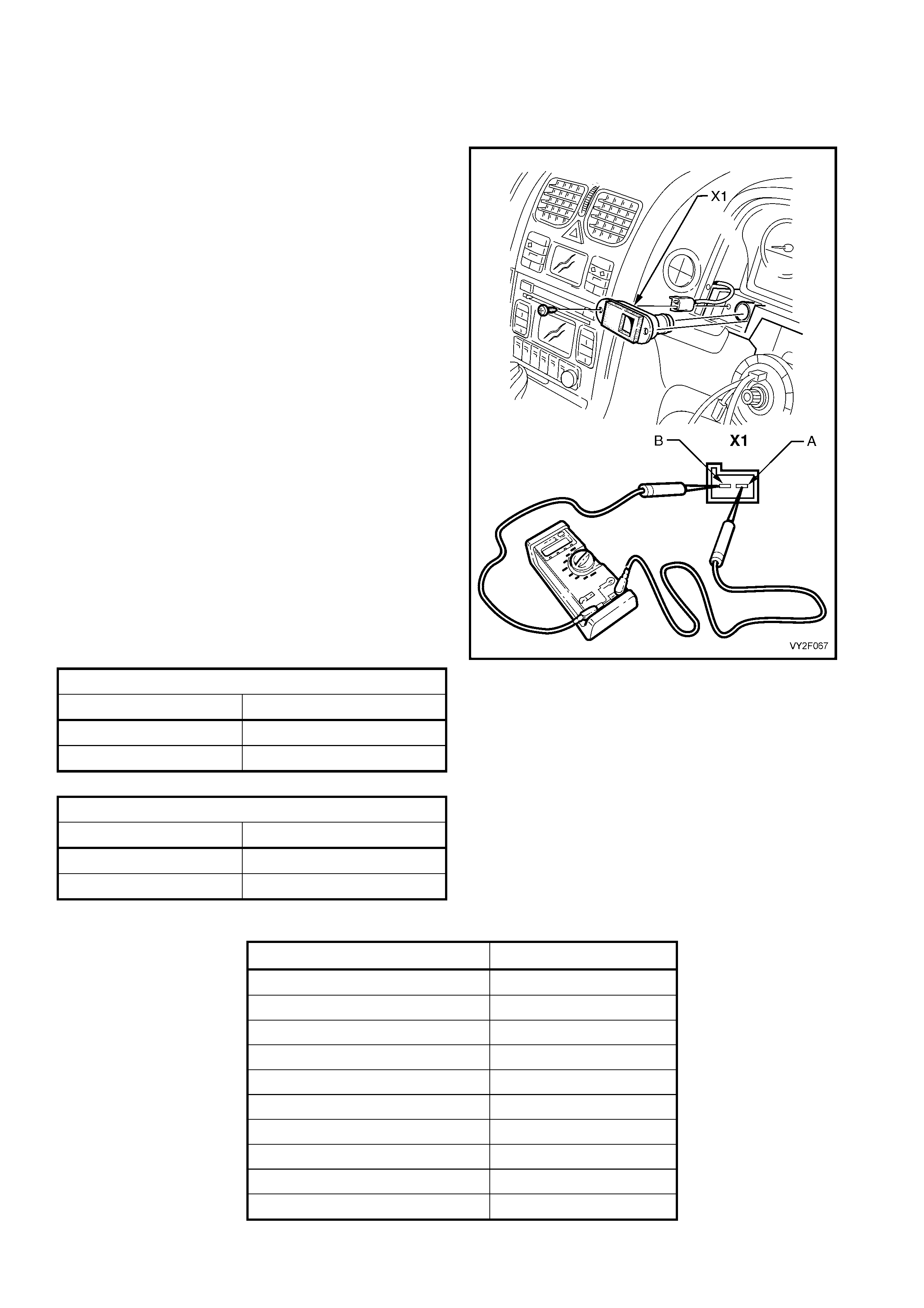
3. ELECTRICAL COMPONENT TESTS
3.1 IN CAR TEMPERATURE SENSOR
To test the in car temperature sensor, use an
ohmmeter to check for resistance across the
terminals on either the sensor or the O C C module
connector.
Refer to Figure 2F-104 in conjunction with the
following tables for details of the pin numbers an d
resistances.
Perform the test as follows:
1. Remove the in-car temperature sensor or OCC
connector. Refer to Section 2E, HVAC Occupant
Climate Control (Auto A/C) – Removal and
Installation.
2. Position the contacts of the ohmmeter on the
terminals and take the reading while noting the
temperature at the sensor.
3. Using a digital thermometer, placed as close to
the in car temperature sensor as possible,
compare thermometer reading with the ohmmeter
reading Compare the reading with the table
(should be within ± 3°C).
4. If the in car temperature sensor fails any part of
the test, replace the sensor with a serviceable
item.
5. Install the in-car temperature sensor, refer to
Section 2E, HVAC Occupant Climate Control
(Auto A/C) – Removal and Installation.
B59 CONNECTOR DETAI LS
PIN NUMBER FUNCTION
X1-A Ground
X1-B Power from OCC
A14 X1 CONNECTOR DETAILS
PIN NUMBER FUNCTION
X1-2 Ground
X1-10 2.5 V Power
Figure 2F-104
IN CAR AIR TEMPERATURE° C RESISTANCE Ω
5 7009 – 7536
10 5477 – 5856
15 4310 – 4583
20 3416 – 3612
25 2725 – 2865
30 2175 – 2299
35 1746 – 1857
40 1410 – 1508
45 1145 – 1231
50 935 – 1010
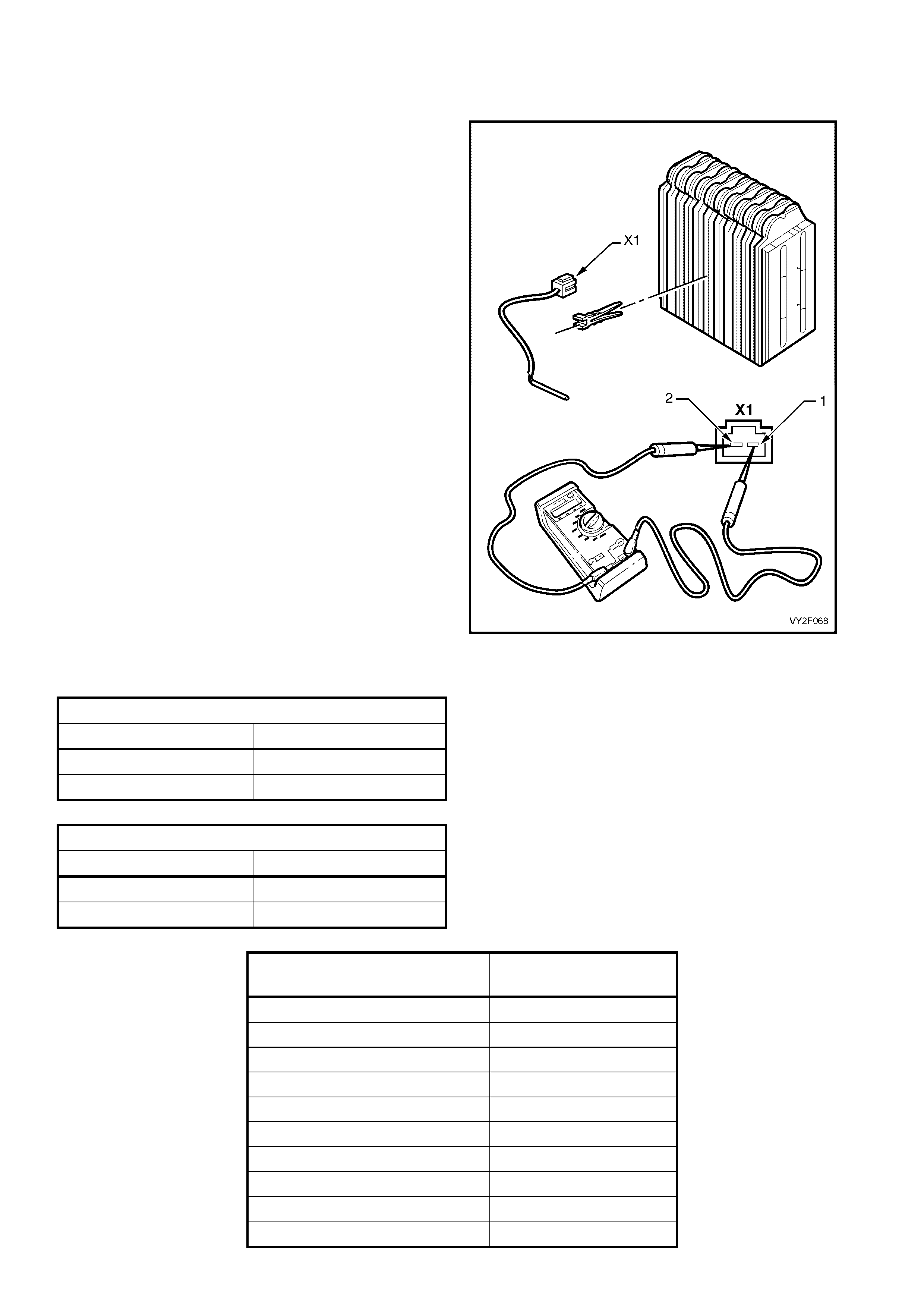
3.2 EVAPORATIVE TEMPERATURE SENSOR TEST
LEFT-HAND DRIVE
To test the evaporative temperature sensor, use an
ohmmeter to check for resistance across the
terminals on either the sensor or O CC module
connector.
Refer to Figure 2F-105 in conjunction with the
following tables for details of the pin numbers an d
resistances.
Perform the test as follows:
1. Remove the evaporative temperature sensor or
OCC connector. Refer to Section 2E, HVAC
Occupant Climate Control (Auto A/C) – Removal
and Installation.
2. Position the contacts of the ohmmeter on the
terminals and take the reading while noting the
temperature at the sensor.
3. Using a digital thermometer, placed as close to
the evaporative temperature sensor as possible,
compare thermometer reading with the ohmmeter
reading. Compare the reading with the table
(should be within ± 3°C). Temperature readings
should be about 2 – 8°C higher than TECH 2
readings.
4. If the evaporative temperature sensor fails any
part of the test, replace the sensor with a
serviceable item.
5. Install the evaporative temperature sensor or
OCC connector, refer to Section 2E, HVAC
Occupant Climate Control (Auto A/C) – Removal
and Installation.
B34 CONNECTOR DETAI LS
PIN NUMBER FUNCTION
X1-1 Power from OCC
X1-2 Ground
A14 X2 CONNECTOR DETAILS
PIN NUMBER FUNCTION
X2-15 Ground
X2-19 2.5 V Power
Figure 2F-105
EVAPORATIVE
AIR TEMPERATURE°C RESISTANCE Ω
5 4300 – 4850
10 3600 – 4050
15 2950 – 3250
20 2320 – 2625
25 1990 – 2200
30 1675 – 1850
35 1330 – 1470
40 1140 – 1260
45 950 – 1050
50 850 – 950
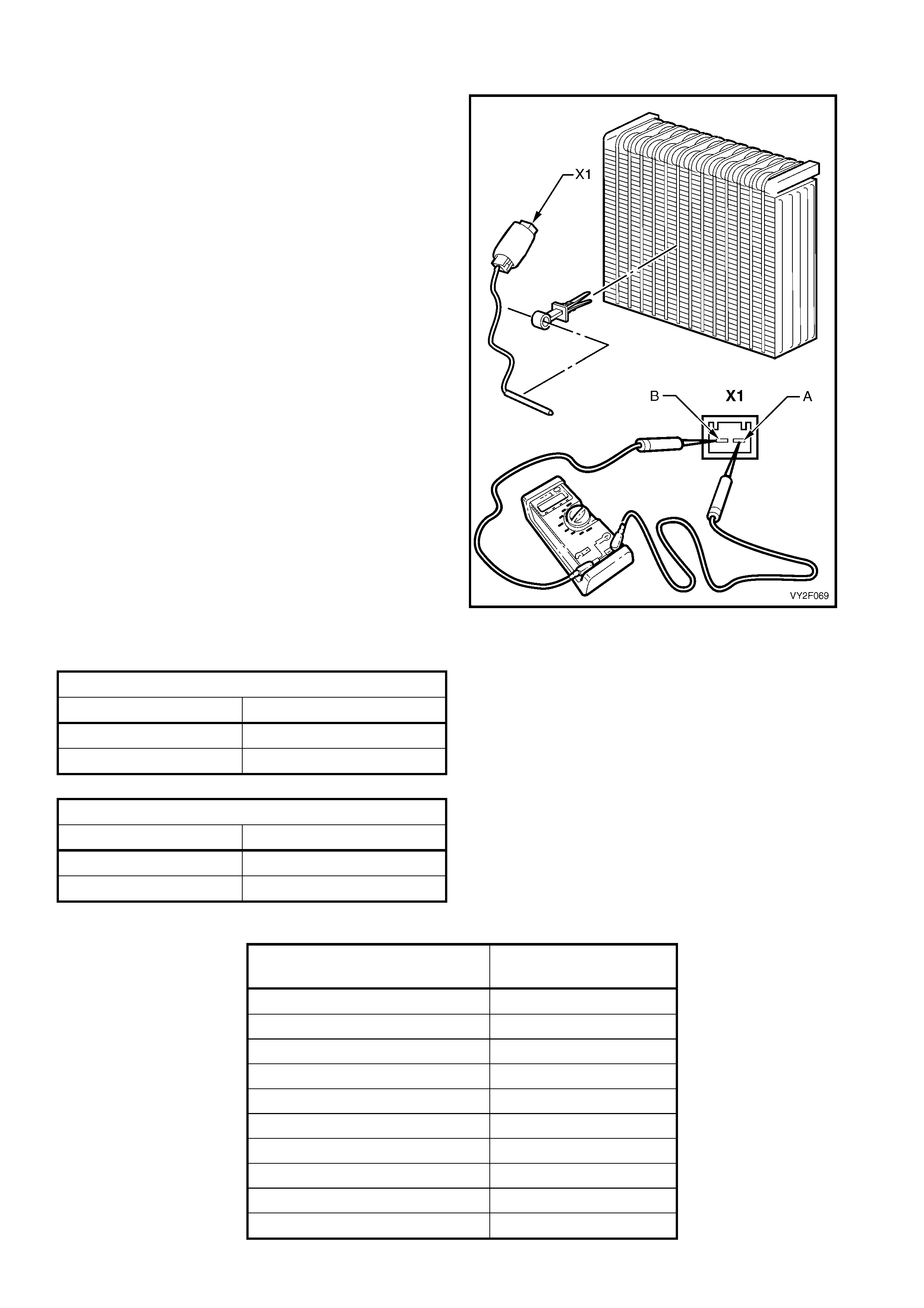
RIGHT-HAND DRIVE
To test the evaporative temperature sensor, use an
ohmmeter to check for resistance across the
terminals on either the sensor or O CC module
connector.
Refer to Figure 2F-106 in conjunction with the
following tables for details of the pin numbers an d
resistances.
Perform the test as follows:
1. Remove the evaporative temperature sensor or
OCC connector. Refer to Section 2E, HVAC
Occupant Climate Control (Auto A/C) – Removal
and Installation.
2. Position the contacts of the ohmmeter on the
terminals and take the reading while noting the
temperature at the sensor.
3. Using a digital thermometer, placed as close to
the evaporative temperature sensor as possible,
compare thermometer reading with the ohmmeter
reading. Compare the reading with the table
(should be within ± 3°C). Temperature readings
should be about 2 – 8°C higher than TECH 2
readings.
4. If the evaporative temperature sensor fails any
part of the test, replace the sensor with a
serviceable item.
5. Install the evaporative temperature sensor or
OCC connector. Refer to Section 2E, HVAC
Occupant Climate Control (Auto A/C) – Removal
and Installation.
B34 CONNECTOR DETAI LS
PIN NUMBER FUNCTION
X1-A Power from OCC
X1-B Ground
A14 X2 CONNECTOR DETAILS
PIN NUMBER FUNCTION
X2-15 Ground
X2-19 2.5 V Power
Figure 2F-106
EVAPORATIVE
AIR TEMPERATURE°C RESISTANCE Ω
5 4300 – 4850
10 3600 – 4050
15 2950 – 3250
20 2320 – 2625
25 1990 – 2200
30 1675 – 1850
35 1330 – 1470
40 1140 – 1260
45 950 – 1050
50 850 – 950
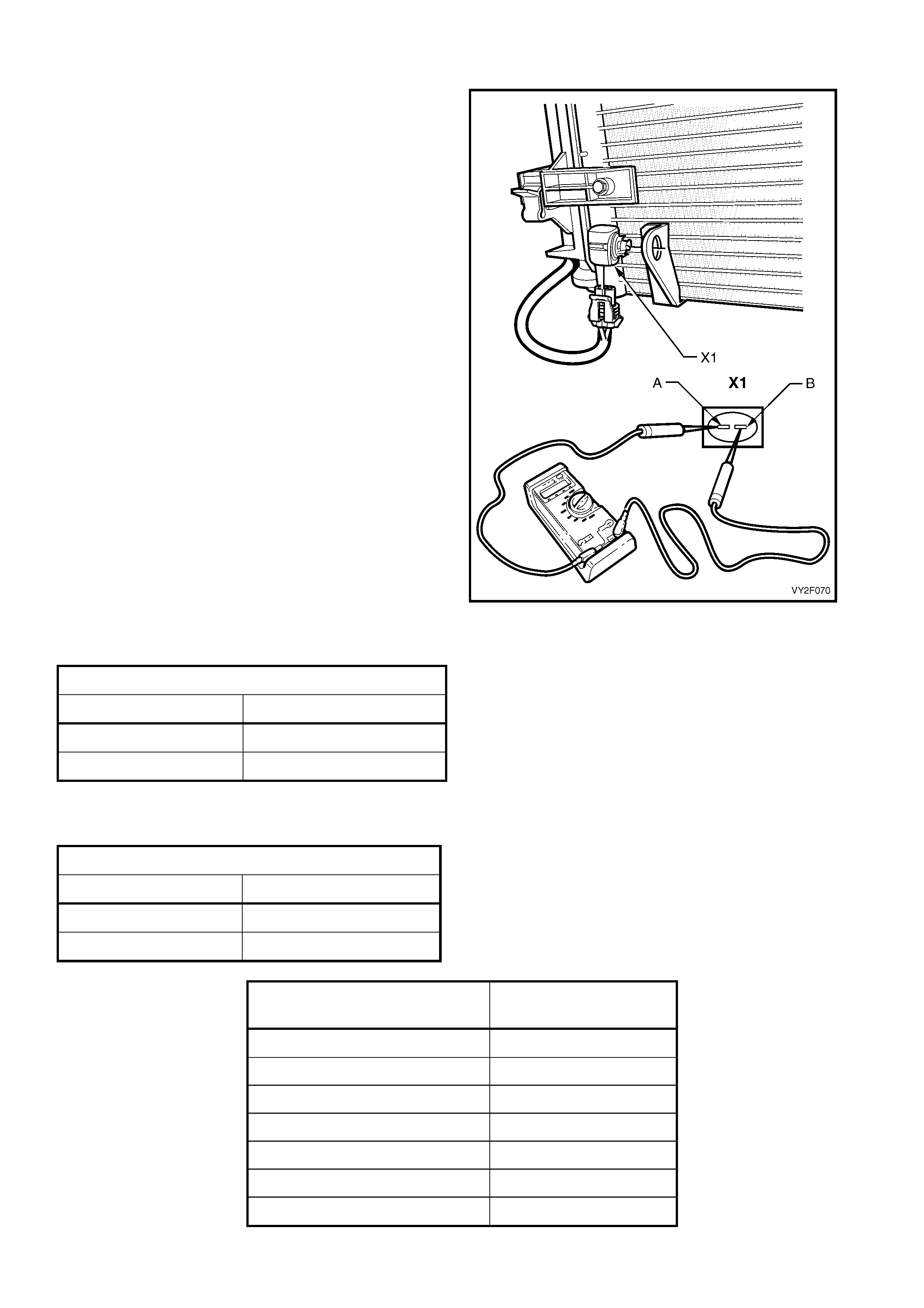
3.3 AMBIENT TEMPERATURE SENSOR
To test the ambient temperature sensor, use an
ohmmeter to check for resistance across the
terminals on either the sensor or O CC module
connector.
Refer to Figure 2F-107 in conjunction with the
following tables for details of the pin numbers an d
resistances.
Perform the test as follows:
1. Remove the ambient temperature sensor or OCC
connector. Refer to Section 2E, HVAC Occupant
Climate Control (Auto A/C) – Removal and
Installation.
2. Position the contacts of the ohmmeter on the
terminals and take the reading while noting the
temperature at the sensor. Compare the reading
with the table.
3. Using a digital thermometer, placed as close to
the ambient temperature sensor as possible,
compare thermometer reading with the ohmmeter
reading. Compare the reading with the table
(should be within ± 3°C). Temperature readings
should be within ± 3°C of TECH 2 readings.
4. If the ambient temperature sensor fails any part of
the test, replace the sensor with a serviceable
item.
5. Install the ambient temperature sensor or OCC
connector. Refer to Section 2E, HVAC Occupant
Climate Control (Auto A/C) – Removal and
Installation.
B23 CONNECTOR DETAI LS
PIN NUMBER FUNCTION
X1-A Ground
X1-B Power from OCC
Figure 2F-107
A14 X1 CONNECTOR DETAILS
PIN NUMBER FUNCTION
X1–2 Ground
X1–12 2.5 V Power
AMBIENT AIR
TEMPERATURE°C RESISTANCE Ω
0 15920 – 16750
10 9715 – 10193
20 6107 – 6389
30 3943 – 4115
40 2610 – 2717
50 1767 – 1836
60 1201 – 1291
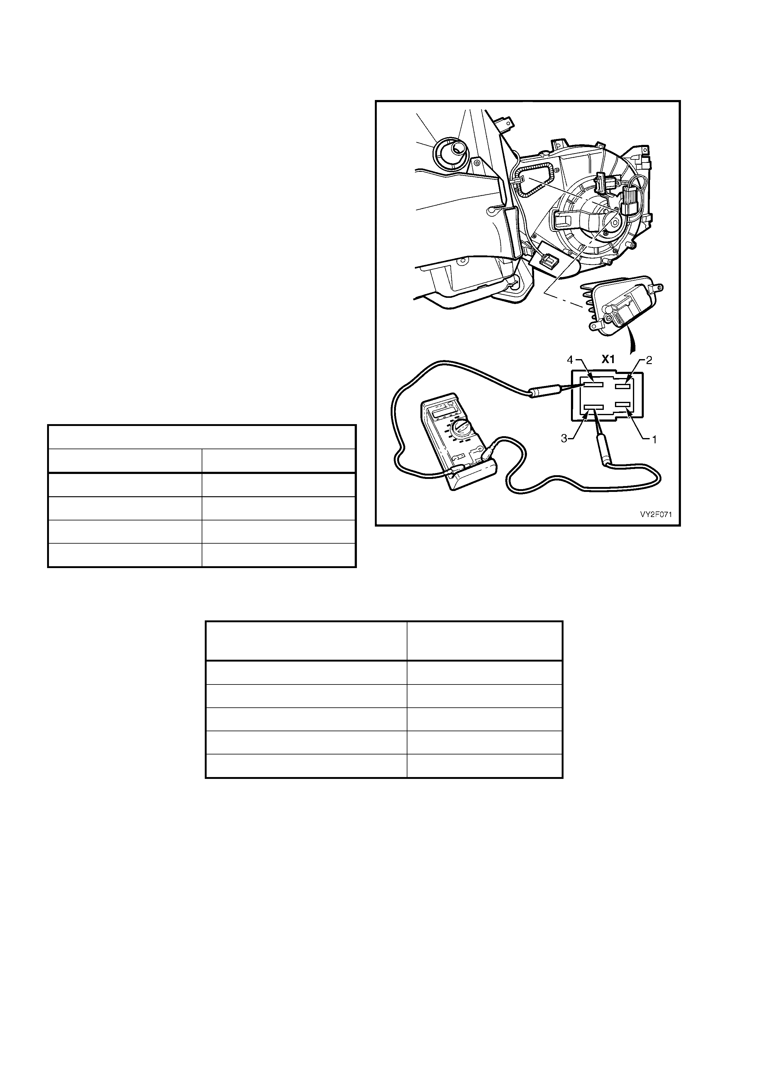
3.4 OCC BLOWER MOTOR RESISTOR
LEFT-HAND DRIVE
To test the blower motor resistor, use an ohmmeter
to check for resistance across the different
terminals.
Refer to Figure 2F-108 in conjunction with the
following tables for details of the pin numbers an d
resistances.
Perform the test as follows:
1. Remove the blower motor resistor. Refer to
Section 2B, 7 BLOWER MOTOR RESISTOR.
2. Position the contacts of the ohmmeter on the
terminals and take the reading. Compare the
reading with the table.
3. If there is continuity between any other
terminals other than those listed, the blower
motor resistor is faulty. If blower motor resistor
fails any part of the test, replace the resistor
with a serviceable item.
4. Install the blower motor resistor. Refer to
Section 2B, 7 BLOWER MOTOR RESISTOR.
A13_LHD CONNECTO R DETAILS
PIN NUMBER FUNCTION
X1-1 Fan Spd Cont
X1-2 Not Connected
X1-3 Ground
X1-4 Blower Motor
Figure 2F-108
CONTROLLER CONTACTS
AND METER POLARITIES RESISTANCE Ω
X1-1 and X1-3 2.9
X1-1 +ve and X1-4 –ve 1.5
X1-1 –ve and X1-4 +ve 1.5
X1-4 +ve and X1-3 -ve 1.5
X1-4 –ve and X1-3 +ve 1.5
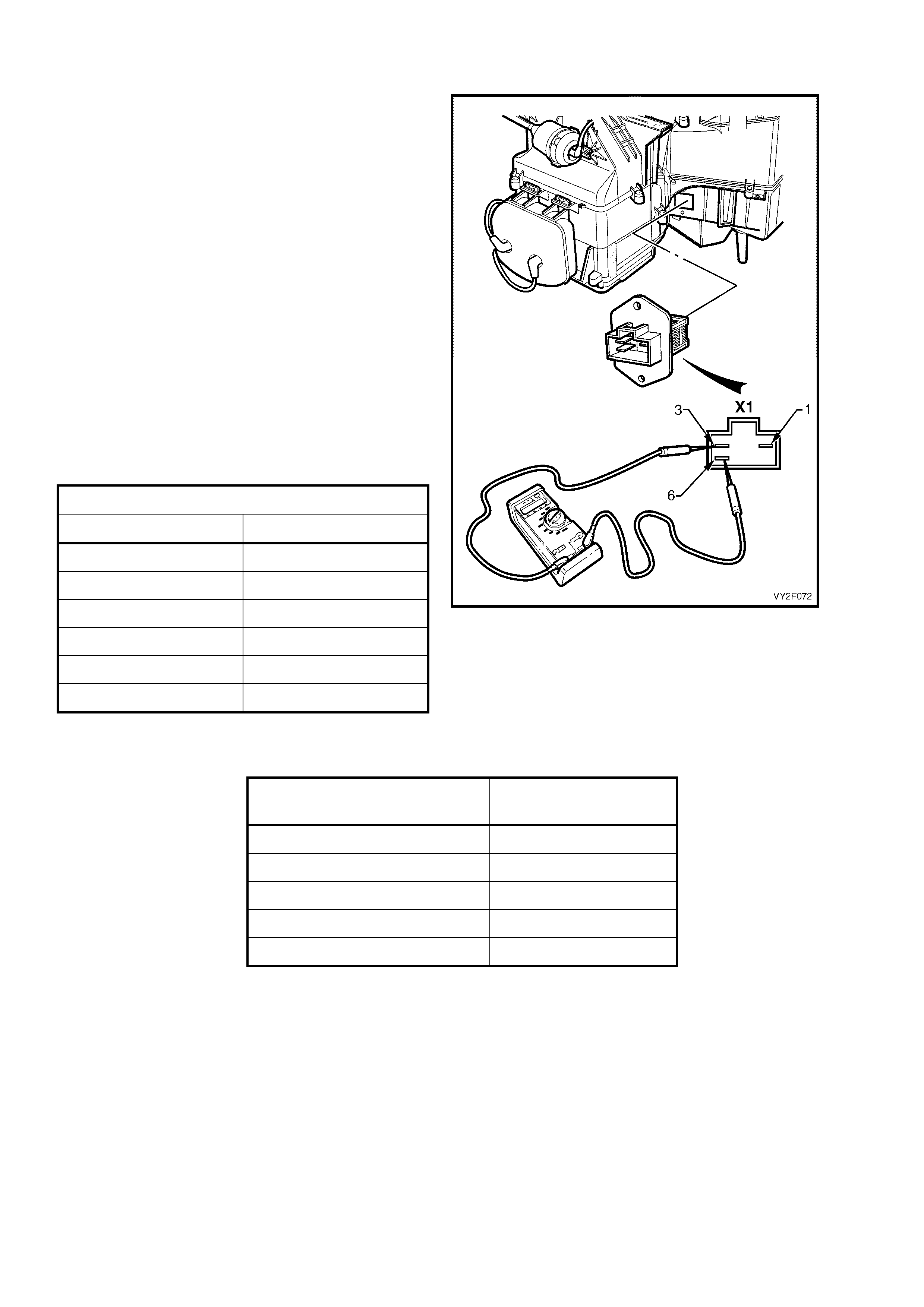
RIGHT-HAND DRIVE
To test the blower motor resistor, use an ohmmeter
to check for resistance across the different
terminals.
Refer to Figure 2F-109 in conjunction with the
following tables for details of the pin numbers an d
resistances.
Perform the test as follows:
1. Remove the blower motor resistor. Refer to
Section 2B, 7 BLOWER MOTOR RESISTOR.
2. Position the contacts of the ohmmeter on the
terminals and take the reading. Compare the
reading with the table.
3. If there is continuity between any other
terminals other than those listed, the blower
motor resistor is faulty. If the blower motor
resistor fails any part of the test, replace the
resistor with a servicea ble item.
4. Install the blower motor resistor. Refer to
Section 2B, 7 BLOWER MOTOR RESISTOR.
A13_RHD CONNECTOR DETAILS
PIN NUMBER FUNCTION
X1-1 Fan Spd Cont
X1-2 Not Connected
X1-3 Blower Motor
X1-4 Not Connected
X1-5 Not Connected
X1-6 Ground
Figure 2F-109
CONTROLLER CONTACTS
AND METER POLARITIES RESISTANCE Ω
X1-1 and X1-6 2.0
X1-1 +ve and X1-3 –ve 1.3
X1-1 –ve and X1-3 +ve 1.3
X1-3 +ve and X1-6 –ve 1.0
X1-3 –ve and X1-6 +ve 0.9
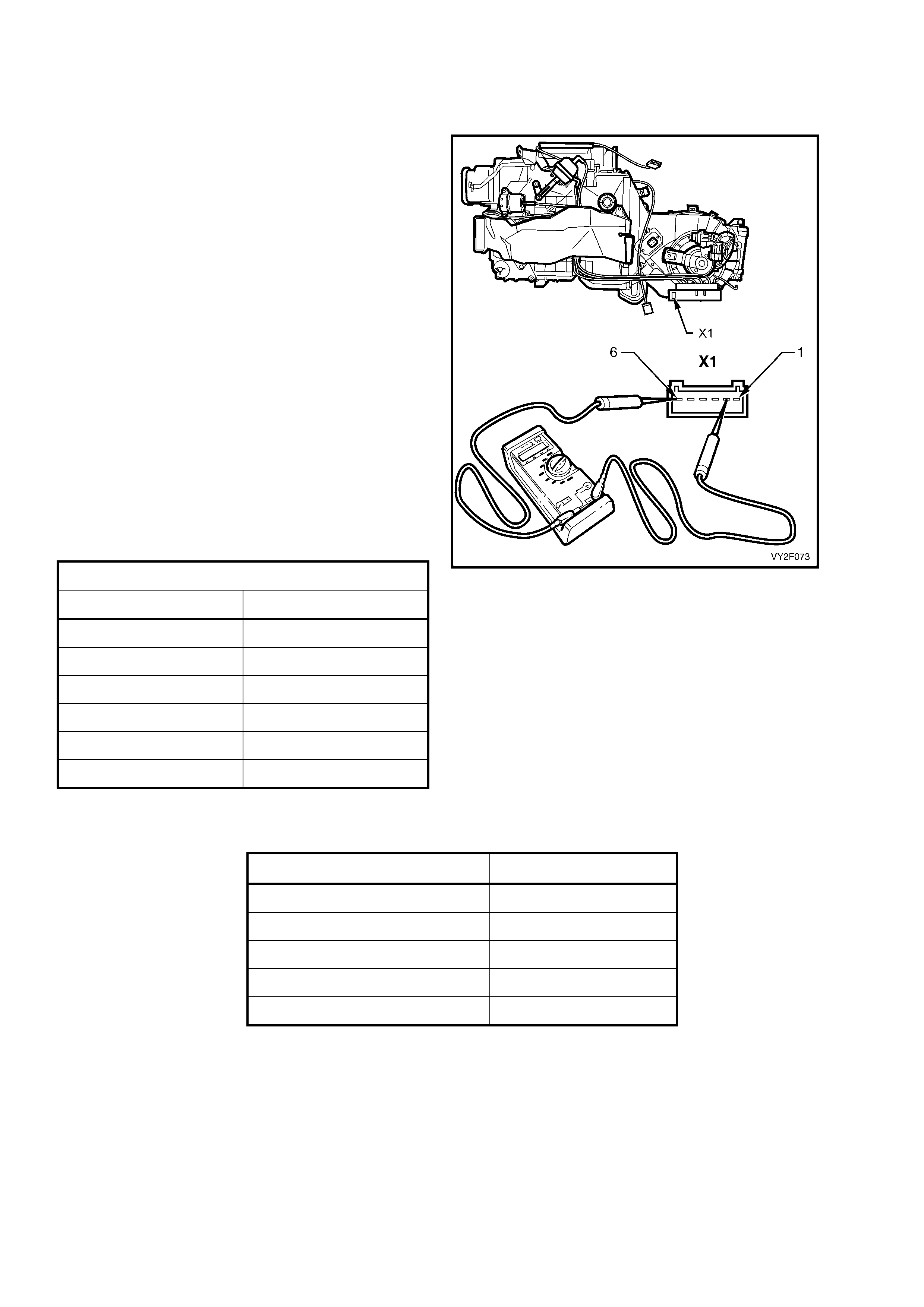
3.5 VACUUM SOLENOID PACK
LEFT-HAND DRIVE
To test the OCC solenoid pack, use an ohmmeter
to check for resistance across the different
terminals.
Refer to Figure 2F-left-hand drive in conjunctio n
with the following tables for details of the pin
numbers and resistan ces.
Perform the test as follows:
1. Remove the solenoid pack, refer to the LHD
information in Section 2E, 2.7 VACUUM
SOLENOID PACK.
2. Position the contacts of the ohmmeter on the
terminals and take the reading. Compare the
reading with the table.
3. If resistance reading are not to specification or
there is continuity between any other terminals
other than those listed, the solenoid pack is
faulty. If the solenoid pack fails any part of the
test, replace the complete solenoid pack.
4. Install the vacuum solenoid pack, refer to the
LHD information in Section 2E, 2.7 VACUUM
SOLENOID PACK.
Y19_LHD CONNECTOR DETAILS
PIN NUMBER FUNCTION
X1-1 12 V power
X1-2 Solenoid 5 – Intake
X1-3 Solenoid 4 – Face 1
X1-4 Solenoid 3 – Face 2
X1-5 Solenoid 2 – Defog
X1-6 Solenoid 1 – Foot
Figure 2F-110
SOLENOID PACK CONTACTS RESISTANCE Ω
X1-1 and X1-2 89 – 91
X1-1 and X1-3 89 – 91
X1-1 and X1-4 89 – 91
X1-1 and X1-5 89 – 91
X1-1 and X1-6 89 – 91
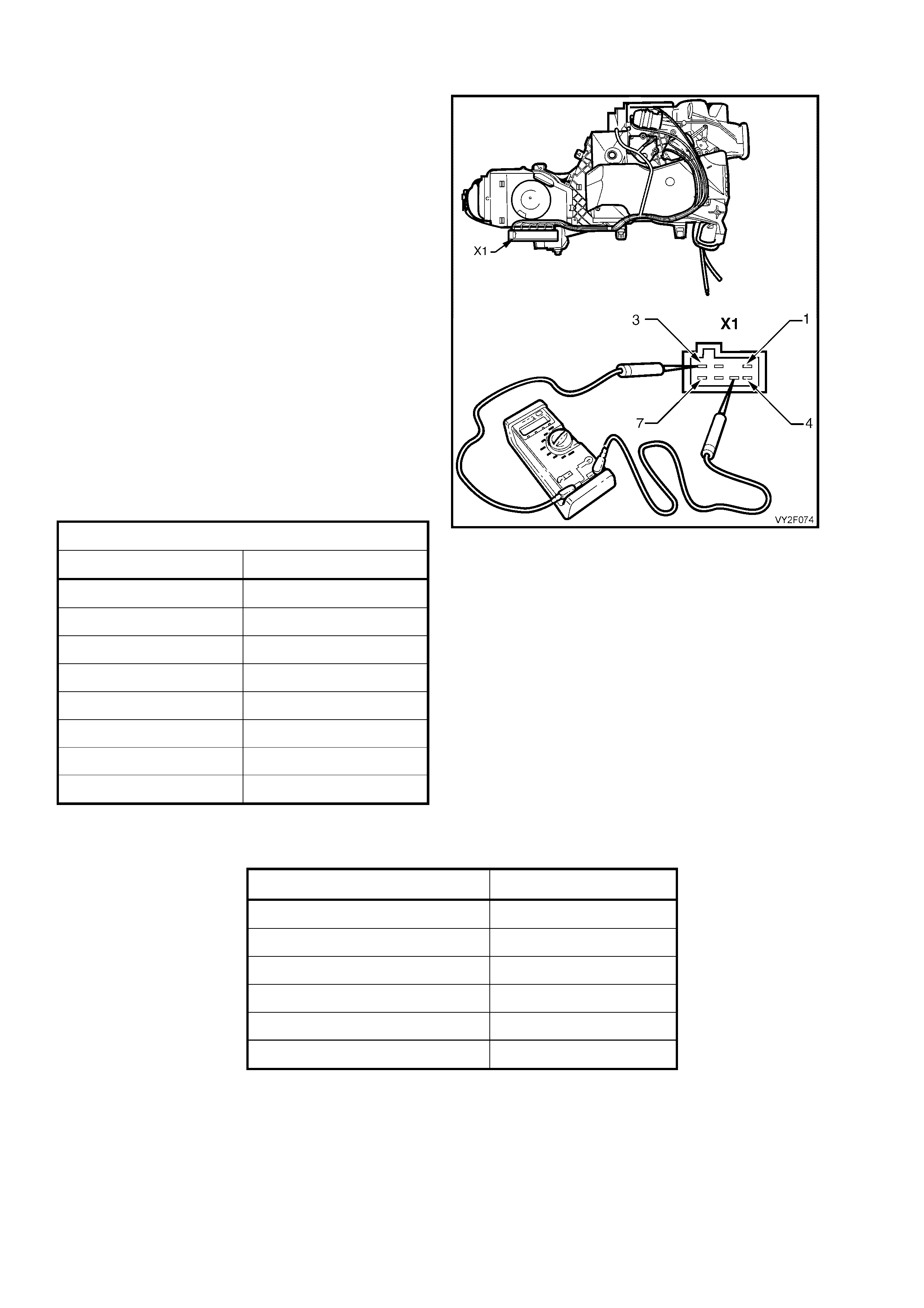
RIGHT-HAND DRIVE
To test the OCC solenoid pack, use an ohmmeter
to check for resistance across the different
terminals.
Refer to Figure 2F-111 in conjunction with the
following tables for details of the pin numbers an d
resistances.
Preform the test as follows:
1. Remove the solenoid pack, refer to the RHD
information in Section 2E, 2.7 VACUUM
SOLENOID PACK.
2. Position the contacts of the ohmmeter on the
terminals and take the reading. Compare the
reading with the table.
3. If resistance reading are not to specification or
there is continuity between any other terminals
other than those listed, the solenoid pack is
faulty. If the solenoid pack fails any part of the
test, replace the complete solenoid pack.
4. Install the vacuum solenoid pack, refer to the
RHD information in Section 2E, 2.7 VACUUM
SOLENOID PACK.
Y19_RHD CONNECTOR DETAILS
PIN NUMBER FUNCTION
X1-1 Solenoid 4 – Foot 1
X1-2 Solenoid 2 – Face 1
X1-3 Solenoid 1 – Intake
X1-4 12 V Power
X1-5 Solenoid 6 – Water
X1-6 Solenoid 2 – Face 2
X1-7 Solenoid 5 – Foot 2
X1-8 Not Connected
Figure 2F-111
SOLENOID PACK CONTACTS RESISTANCE Ω
X1-4 and X1-1 109 – 111
X1-4 and X1-2 109 – 111
X1-4 and X1-3 109 – 111
X1-4 and X1-5 109 – 111
X1-4 and X1-6 109 – 111
X1-4 and X1-7 109 – 111
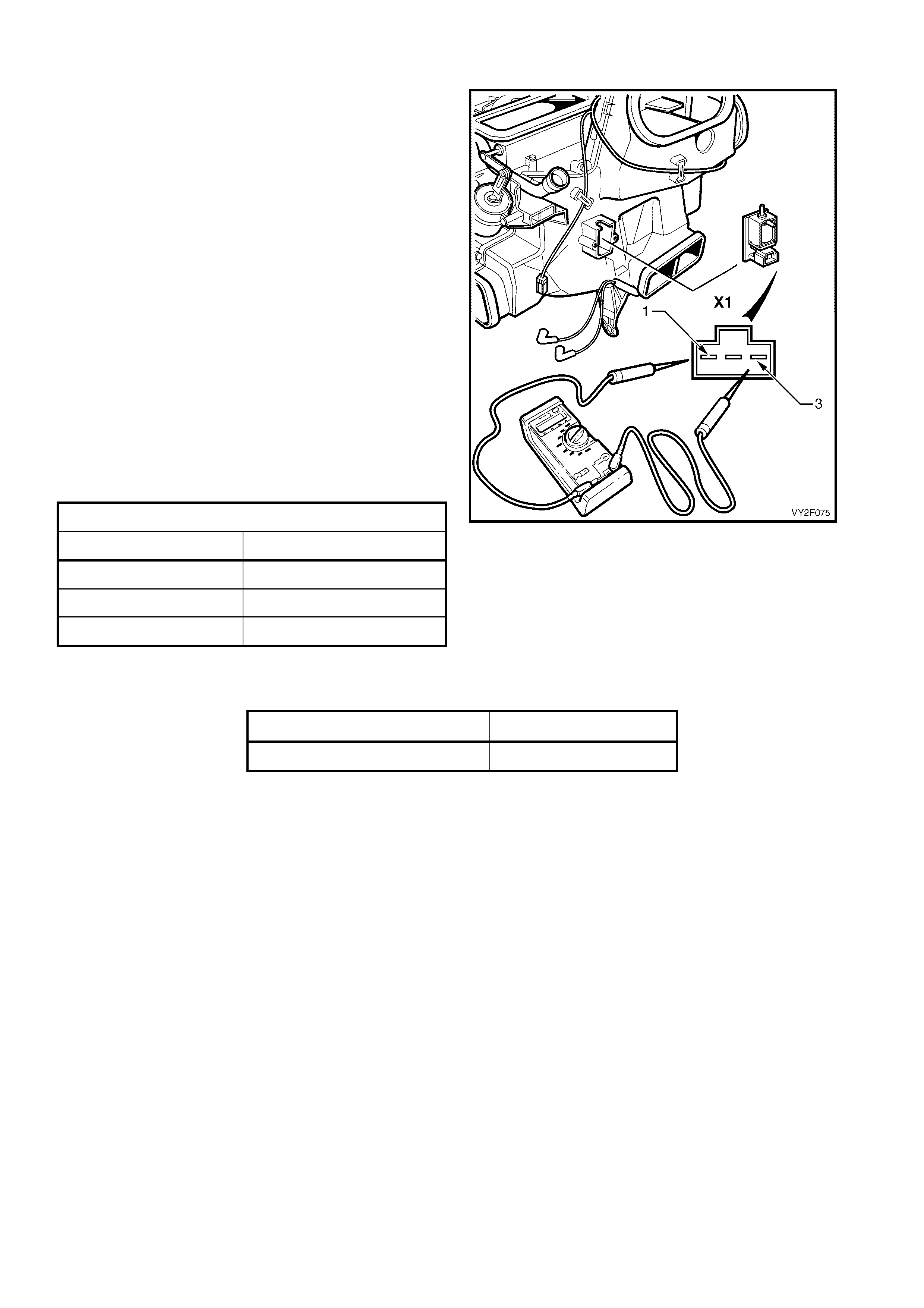
3.6 WATER VALVE VACUUM SWITCH VALVE
NOTE: The water valve vacuum switch valve is fitted
to LHD type OCC (Auto A/C) HVAC units only.
To test the water valve vacuum switch valve, use an
ohmmeter to check for resistance across the
terminals.
Refer to Figure 2F-112 in conjunction with the
following tables for details of the pin numbers an d
resistances.
Perform the test as follows:
1. Remove the water valve vacuum switch valve.
Refer to Section 2E, 2.8 WATER VALVE
VACUUM SWITCH VALVE.
2. Position the contacts of the ohmmeter on the
terminals and take the reading. Compare the
reading with the table.
3. If the switch valve fails any part of the test,
replace the switch with a serviceable item .
4. Install the water valve vacuum switch valve.
Refer to Section 2E, 2.8 WATER VALVE
VACUUM SWITCH VALVE.
Y18_LHD CONNECTOR DETAILS
PIN NUMBER FUNCTION
X1-1 12 V power
X1-2 Not Connected
X1-3 Water Valve
Figure 2F-112
TERMINALS RESISTANCE Ω
X1-1 and X1-3 93.5
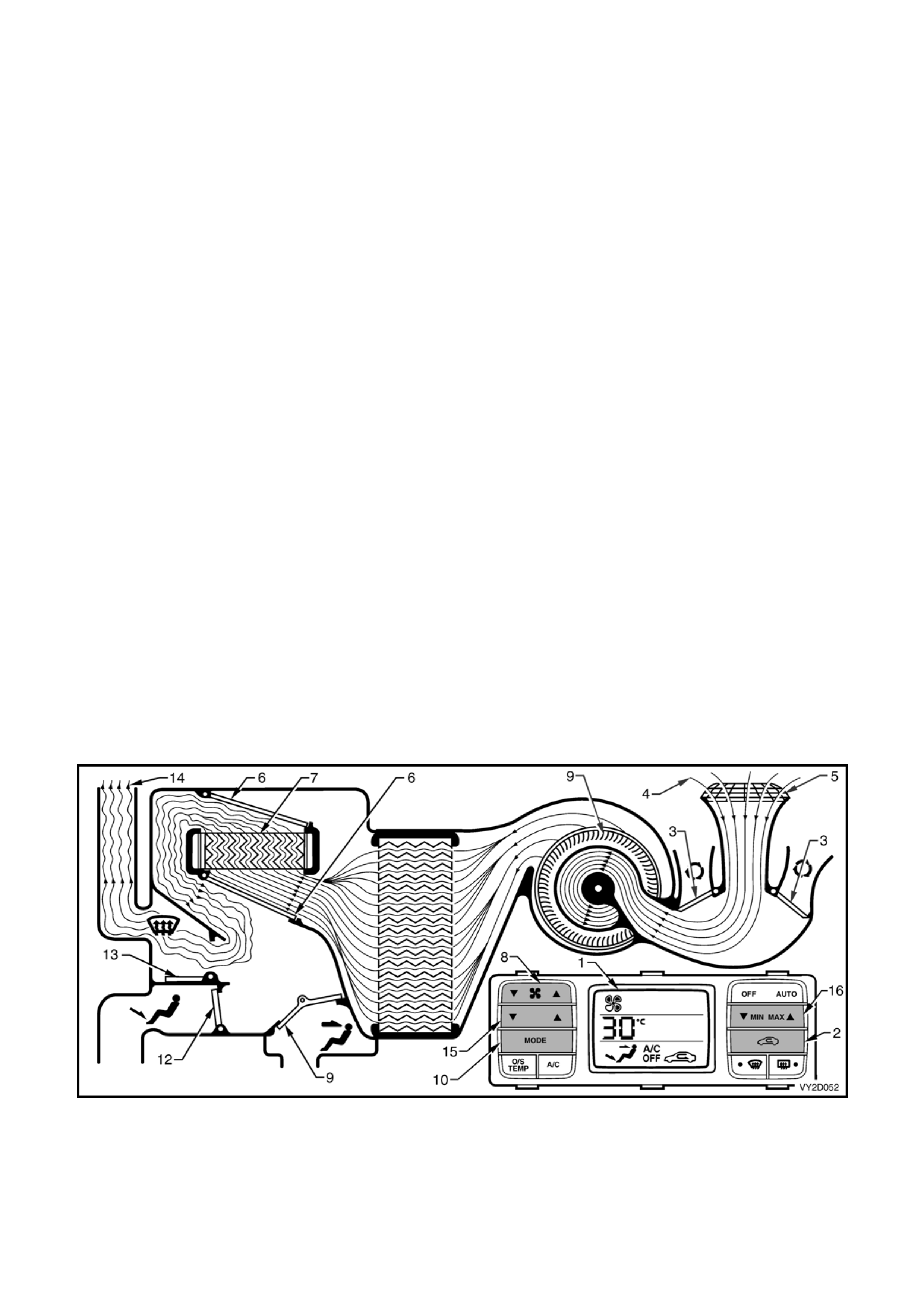
4. VACUUM RETENTION TESTS
To operate efficiently, the HVAC system requires a constant vacuum source and all HVAC system vacuum
components must have no vacuum leaks. Vacuum is supplied by the engine induction system and is retained
within the HVAC system by the action of the one-way check valve located in the engine bay. A vacuum reserve is
stored within the vehicle cabin in the vacuum tank located on the left-hand side of the HVAC unit. Any of the
following components may cause o r co ntribute to a vacuum leak within the HVAC system:
• Check valve
• Vacuum tank
• Vacuum solenoid pack
• Water valve vacuum switch valve (LHD only)
• Vacuum actuators (including the water valve)
• Vacuum lines and manifold
Symptoms of a vacuum leak may be as follows:
• Constant coolant flow through the heater core
• Air always directed to the windscreen
• Air directed to ventilation outlets that are not selected
• Dust and/or smog ingress into the cabin despite the selection of the recirculation mode
• Constant ‘hissing’ noise emanating fro m a leaking or disconnected vacuum co mponent/s.
VACUUM LOSS DEFAULT SETTINGS
In the event of a vacuum loss, the OCC (Auto A/C) type HVAC unit will revert to a set of predetermined ‘safe to
drive’ default settings to allow continued operatio n of the vehicle until the fault is rectified.
Loss of vacuum supply to HVAC unit – LHD
If a total loss of vacuum occurs within the LHD type OCC (Auto A/C) system, the HVAC unit will default to the
following settings. The ventilation mode setting s will remain con stant regardless of what is displayed on the LCD
screen (1).
Regardless of recirculation switch (2) selection, the recirculation doors (3) will remain closed allowing outsi de air (4)
to enter and flow into the HVAC unit via the plenum chamber inlet (5). The position of the air mix doors (6) will
remain controllable as their function is el ectrically operated by the air mix motor. Heated coolant will flow through
the heater core (7), as vacuum is required to maintain the water valve in the cold (closed) po sition. The fa n switch
(8) will operate the blower fan (9) as normal. In any position of the mode switch (10), the face door (11) and the
floor door (12) will remain close d. The demist door (13) will be positioned so that all air (14) leaving the HVAC unit
will be directed to the demist outlets. Depending on the selected setting of temperature switch (15) and/or the
MIN MAX switch (16), this air may be cold, warm or hot air.
Figure 2F-113
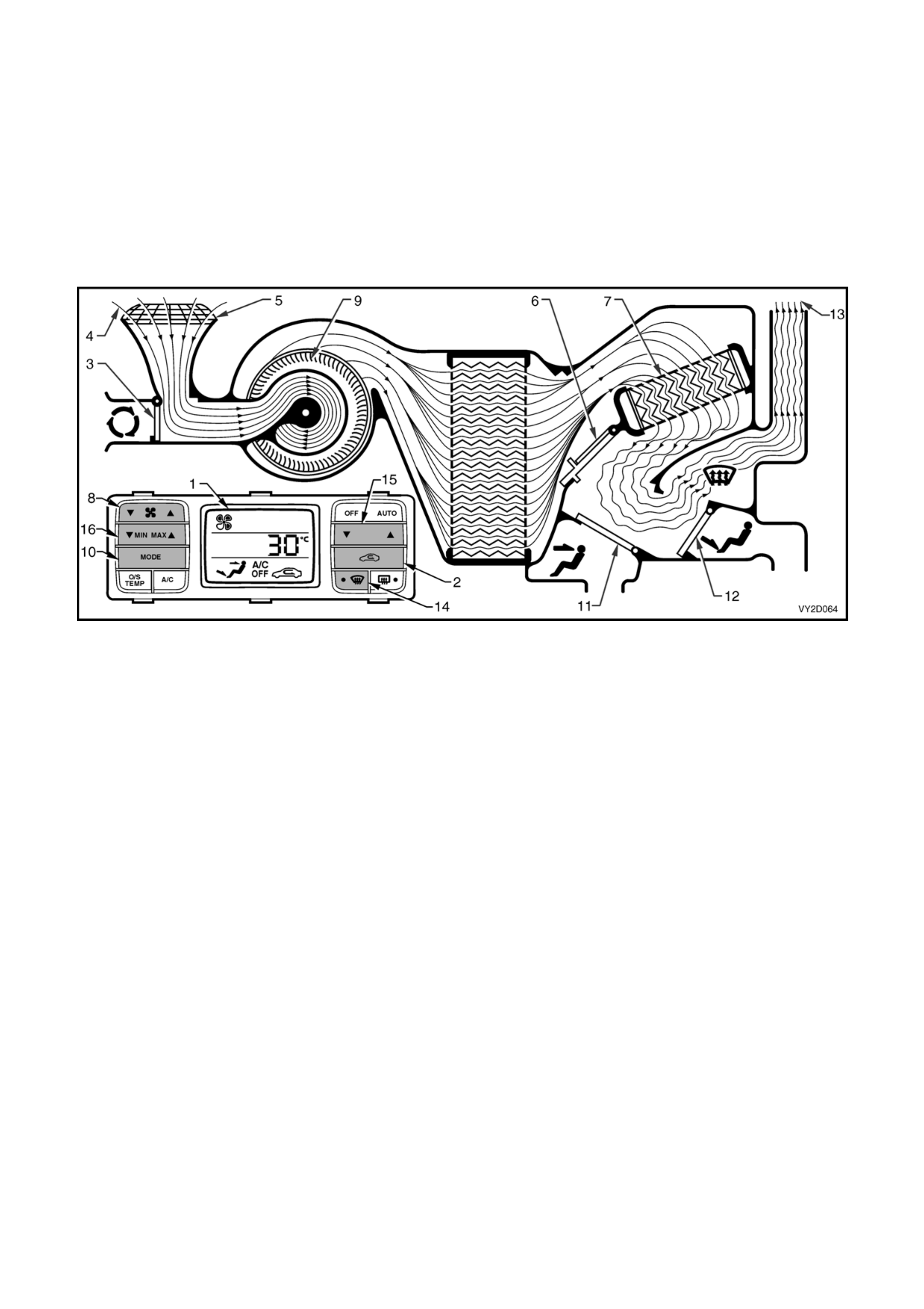
Loss of vacuum supply to HVAC unit – RHD
If a total loss of vacuum occurs within the RHD type OCC (Auto A/C) system, the HVAC unit will default to the
following settings. The ventilation mode setting s will remain con stant regardless of what is displayed on the LCD
screen (1).
Regardless of recirculation switch (2) selection, the recirculation door (3) will remain closed allowing outside air (4)
to enter and flow into the HVAC unit via the plenum chamber inlet (5). The position of the air mix doors (6) will
remain controllable as their function is el ectrically operated by the air mix motor. Heated coolant will flow through
the heater core (7), as vacuum is required to maintain the water valve in the cold (closed) po sition. The fa n switch
(8) will operate the blower fan (9) as normal. In any position of the mode switch (10), the face door (11) will remain
closed. The demist/floor door (12) will be positioned so that all air (13) leaving the HVAC unit will be directed to the
demist outlets whether or not the demist switch (14) is selected. Depending on the selected setting of temperature
switch (15) and/or the MIN MAX switch (16), this air may be cold, warm or hot air.
Figure 2F-114
The following vacuum tests should be conducted to the HAVC system to isolate vacuum loss problems leading to
poor HVAC system performance. Perform each test in order until the problem is identified and corrected. The
vacuum retention tests in this Section apply only to OCC (Auto A/C) HVAC systems
NOTE: The vacuum components listed below are common to both Manual A/C and OCC (Auto A/C) HVAC
systems. For testing of the these components, refer to Section 2C, 8 VACUUM RETENTION TESTS.
• Check valve
• Vacuum tank
• Vacuum actuators (including the water valve)
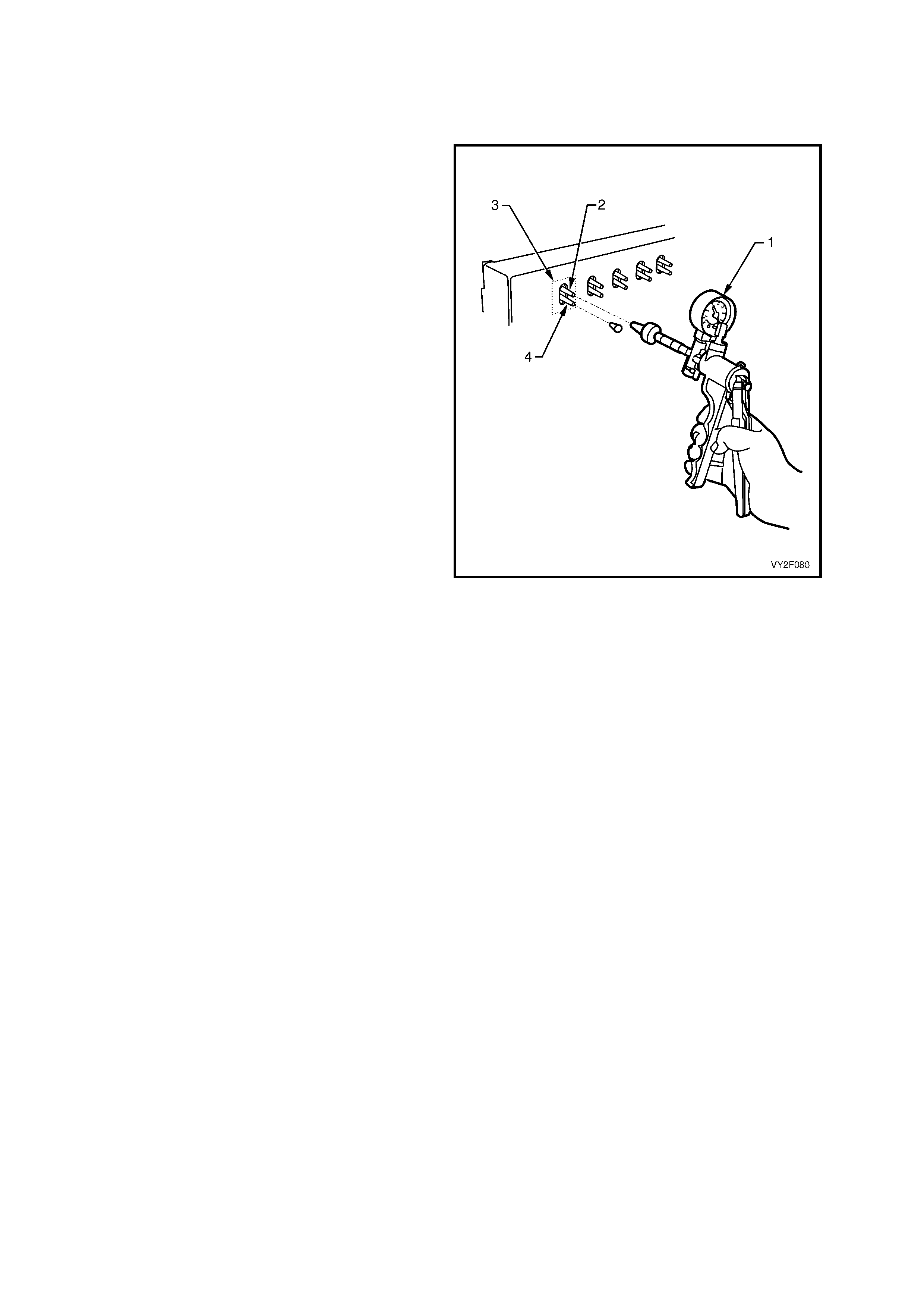
4.1 VACUUM SOLENOID PACK
To vacuum test the solenoid pack perform the following:
1. Remove the vacuum solenoid pack. Refer to Section 2E, 2.7 VACUUM SOLENOID PACK.
2. Connect a vacuum pump (1) to the vacuum
supply port (2) of solenoid (3) and plug the
actuator port (4) below it.
3. Using the vacuum pump, create a vacuum and
observe the vacuum pump gauge needle.
4. If the needle remains steady it indicates that
the solenoid is retaining vacuum. If the vacuum
reading decreases, it indicates a vacuum leak
with that solenoid.
5. Repeat steps 1 to 3 for each solenoid of the
solenoid pack.
6. Install the vacuum solenoid pack. Refer to
Section 2E, 2.7 VACUUM SOLENOID PACK.
Figure 2F-115

4.2 VACUUM ACTUATOR LINES
LEFT- HAND DRIVE
To vacuum test the vacuum actuator lines an d on LHD type OCC (Auto A/C) HVAC units perform the following:
1. Remove the right-hand side instrument panel lower trim plate assembly.
Refer to Section 1A3, 3.1 INSTRUMENT PANEL LOWER TRIM PLATE ASSEMBLY.
2. Remove the plastic manifold from the vacuum solenoid pack. If required,
refer to Section 2E, 2.7. VACUUM SOLENOID PACK.
3. Using a vacuum pump, connect to the appropriate port of the plastic vacuum manifold. Refer to Figure 2F-116
and table below.
4. Using the vacuum pump, create a vacuum and observe the vacuum pump gauge needle. If the needle remains
steady it indicates that vacuum circuit is retaining vacuum. If the vacuum reading decreases, it indicates a
vacuum leak in that vacuum circuit.
5. If a vacuum leak is indicated check the vacuum tubing for damage or loose connection to the plastic manifold
and/or vacuum actuator. If there is no damage or loose connection, perform a vacuum test on the connecting
vacuum actuator.
6. Connect the plastic vacuum manifold to the vacuum solenoid pack ensuring that the vacuum manifold is fully
engaged to the two locking tangs of the solenoid pack.
7. Install the left-hand side instrument panel lower trim plate assembly.
Refer to Section 1A3, 3.1 INSTRUMENT PANEL LOWER TRIM PLATE ASSEMBLY.
Figure 2F-116
Legend
1. Plastic Vacuum Manifold 4. Face 2 (Brown) 7. Vacuum Supply (White)
2. Foot 1 (Red) 5. Foot 1 (Blue) 8. Vacuum Pump
3. Defrost (Green) 6. Fresh / Recirculation (Yellow)
SOLENOID No. ACTUATOR VACUUM LINE COLOUR FUNCTION WHEN
VACUUM APPLIED
1 Foot Red Demist / Foot.
2 Demist Green Demist / Face
3 Face 2 Brown Bi-level
4 Face 1 Blue Face
5 Inlet Yellow Recirculation
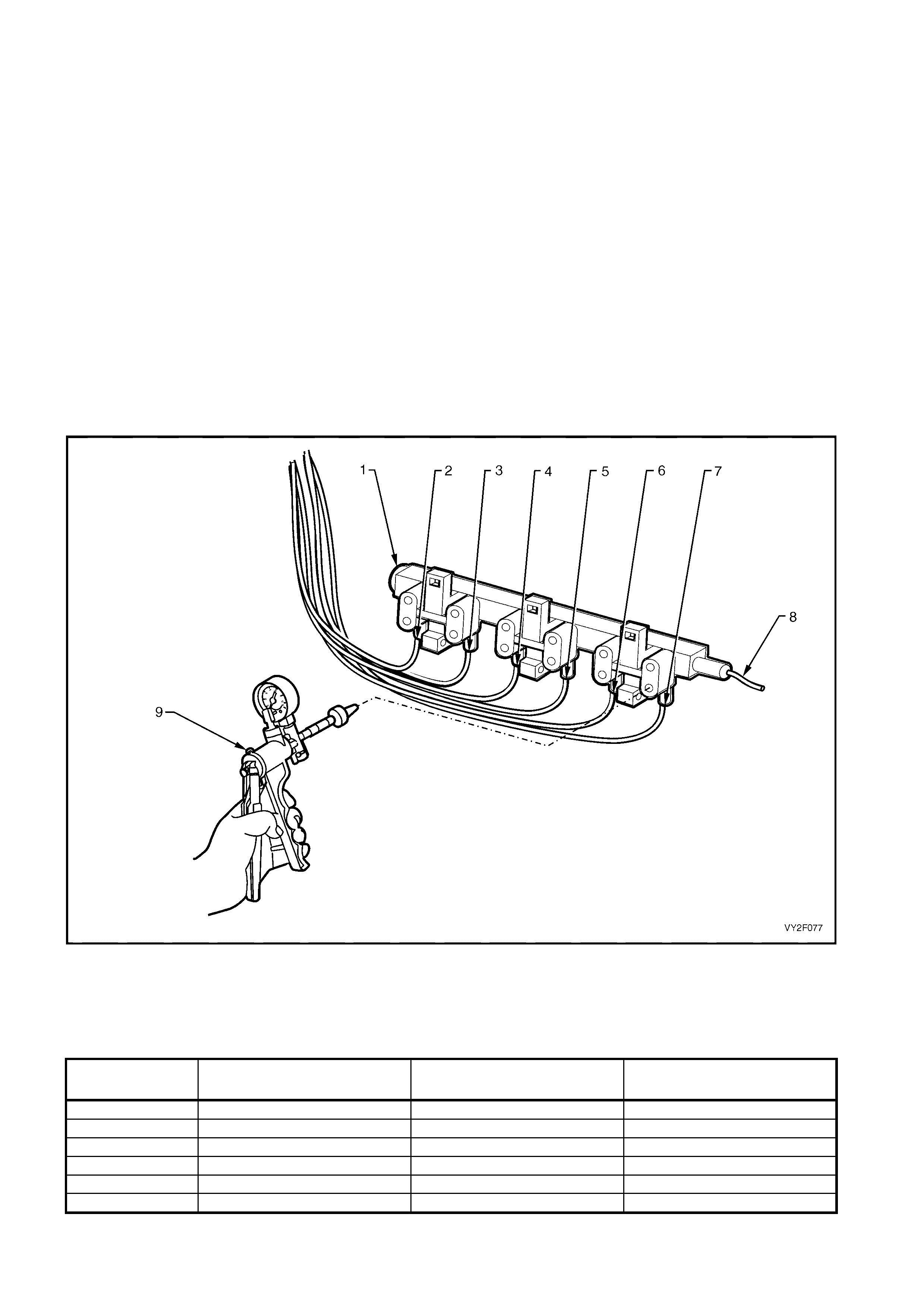
RIGHT- HAND DRIVE
To vacuum test the vacuum actuator lines on RHD type OCC (Auto A/C) HVAC units perform the following:
1. Remove the left-hand side instrument panel lower trim plate assembly.
Refer to Section 1A3, 3.1 INSTRUMENT PANEL LOWER TRIM PLATE ASSEMBLY.
2. Remove the plastic manifold from the vacuum solenoid pack. If required, refer to
Section 2E, 2.7 VACUUM SOLENOID PACK.
3. Using a vacuum pump, connect to the appropriate port of the plastic vacuum manifold Refer to Figure 2F-117
and table below.
4. Using the vacuum pump, create a vacuum and observe the vacuum pump gauge needle. If the needle remains
steady it indicates that vacuum circuit is retaining vacuum. If the vacuum reading decreases, it indicates a
vacuum leak in that vacuum circuit.
5. If a vacuum leak is indicated check the vacuum tubing for damage or loose connection to the plastic manifold
and/or vacuum actuator. If there is no damage or loose connection, perform a vacuum test on the connecting
vacuum actuator.
6. Connect the plastic vacuum manifold to the vacuum solenoid pack ensuring that vacuum manifold is fully
engaged to the three locking tangs of the solenoid pack.
7. Install the left-hand side instrument panel lower trim plate assembly.
Refer to Section 1A3, 3.1 INSTRUMENT PANEL LOWER TRIM PLATE ASSEMBLY.
Figure 2F-117
Legend
1. Plastic Vacuum Manifold 4. Foot 1 (Pink) 7. Fresh / Recirculation (Blue)
2. Water Valve (Yellow) 5. Face 2 (Green) 8. Vacuum Supply (Black)
3. Foot 2 (Orange) 6. Face 1 (White) 9. Vacuum Pump
SOLENOID No. ACTUATOR VACUUM LINE COLOUR FUNCTION WHEN
VACUUM APPLIED
1 Intake Blue Recirculation
2 Face 1 White Bi-level
3 Face 2 Green Face
4 Foot 1 Pink Blend
5 Foot 2 Orange Foot /Bi-level
6 Water valve Yellow Full cold
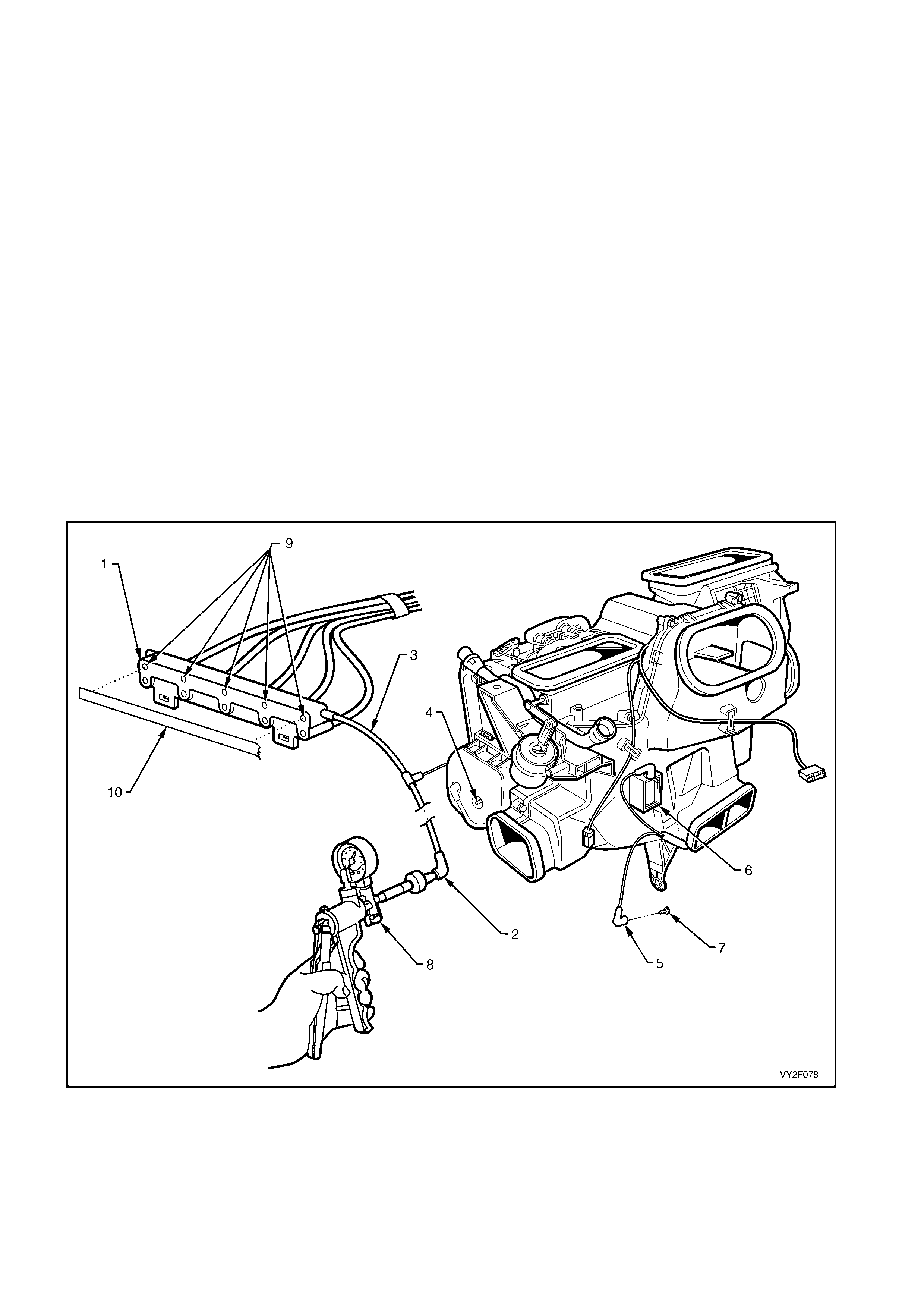
4.3 VACUUM MANIFOLD LINE
LEFT-HAND DRIVE
To vacuum test the vacuum manifold line on LHD type OCC (Auto A/C) HVAC units perform the following:
1. Remove the left-hand side lower trim plate assembly to access the vacuum tank, and right-hand side
instrument panel lower trim plate assembly to access the solenoid pack.
Refer to Section 1A3, 3.1 INSTRUMENT PANEL LOWER TRIM PLATE ASSEMBLY.
2. To access the water valve vacuum switch valve, remove the radio assembly,
refer to Section 1A3, 3.6 RADIO ASSEMBLY. Remove also the radio housing and radio bracket assembly,
refer to Section 1A3, 3.11 RADIO HOUSING AND RADIO BRACKET ASSEMBLY.
3. Remove the plastic vacuum manifold (1) from the solenoid pack.
4. Remove the connector (2) of white vacuum manifold line (3) from the vacu um tank manifold line port (4).
5. Remove the connector (5) of white vacuum manifold line from the water valve vacuum switch valve (6).
6. Seal off the water valve vacuum switch valve connector with a suitable plug (7).
7. Connect a vacuum pump (8) to the vacuum manifold line connector. Seal the vacuum supply ports (9) on the
plastic vacuum manifold using a suitable strip of electrical tape (10).
8. Using the vacuum pump, create a vacuum and observe the vacuum pump gauge needle.
9. If a vacuum leak is indicated, check the condition of the vacuum line for damage or loose connection to the
plastic manifold and vacuum tank.
10. Replace components a s n ecessary.
If there is no fault or loose connection detected, perform a vacuum test on the water valve vacuum switch valve
and vacuum tank (if not already tested).
Figure 2F-118
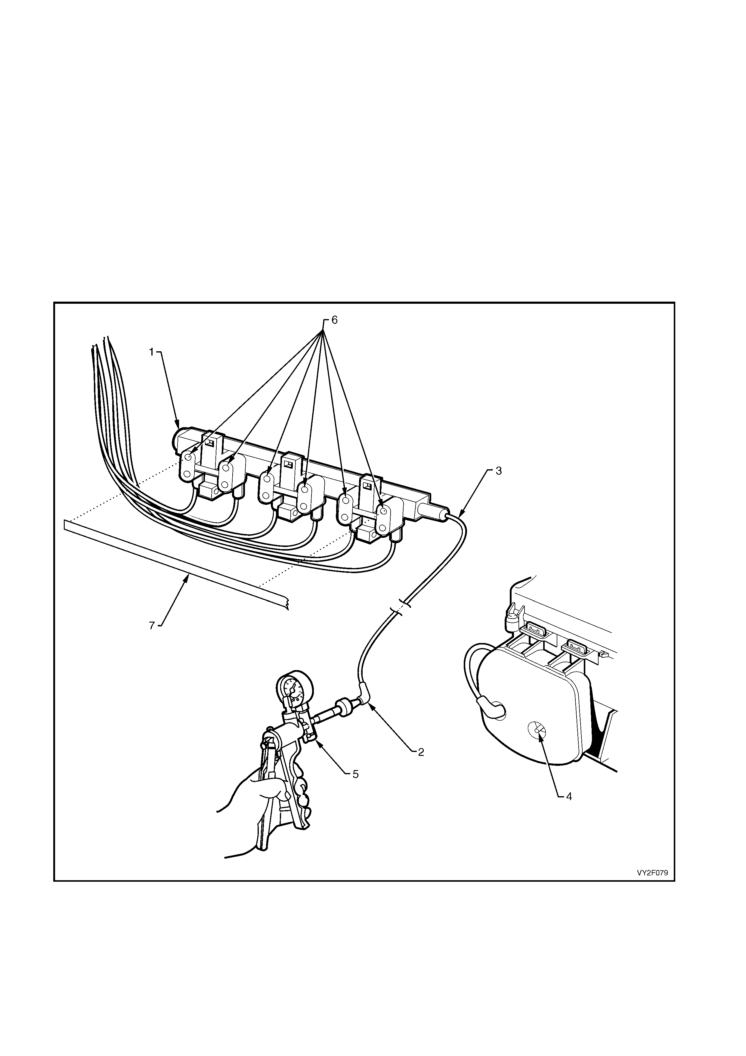
RIGHT-HAND DRIVE
To vacuum test the vacuum manifold line on RHD type OCC (Auto A/C) HVAC units perform the following:
1. Remove the right-hand side instrument panel lower trim plate assembly,
refer to Section 1A3, 3.1 INSTRUMENT PANEL LOWER TRIM PLATE ASSEMBLY.
2. Remove the plastic vacuum manifold (1) from the solenoid pack.
3. Remove the connector (2) of vacuum manifold line (3) from the vacuum tank ma nifold line port (4).
4. Connect a vacuum pump (5) to the vacuum manifold line connector. Seal the vacuum supply ports (6) on the
plastic vacuum manifold using a suitable strip of electrical tape (7).
5. Using the vacuum pump, create a vacuum and observe the vacuum pump gauge needle.
6. If a vacuum leak is indicated, check the condition of the vacuum line for damage or loose connection to the
plastic manifold and vacuum tank.
7. Replace components a s n ecessary.
If there is no fault or loose connection detected, perform a vacuum test on the water valve and vacuum tank (if not
already tested).
Figure 2F-119
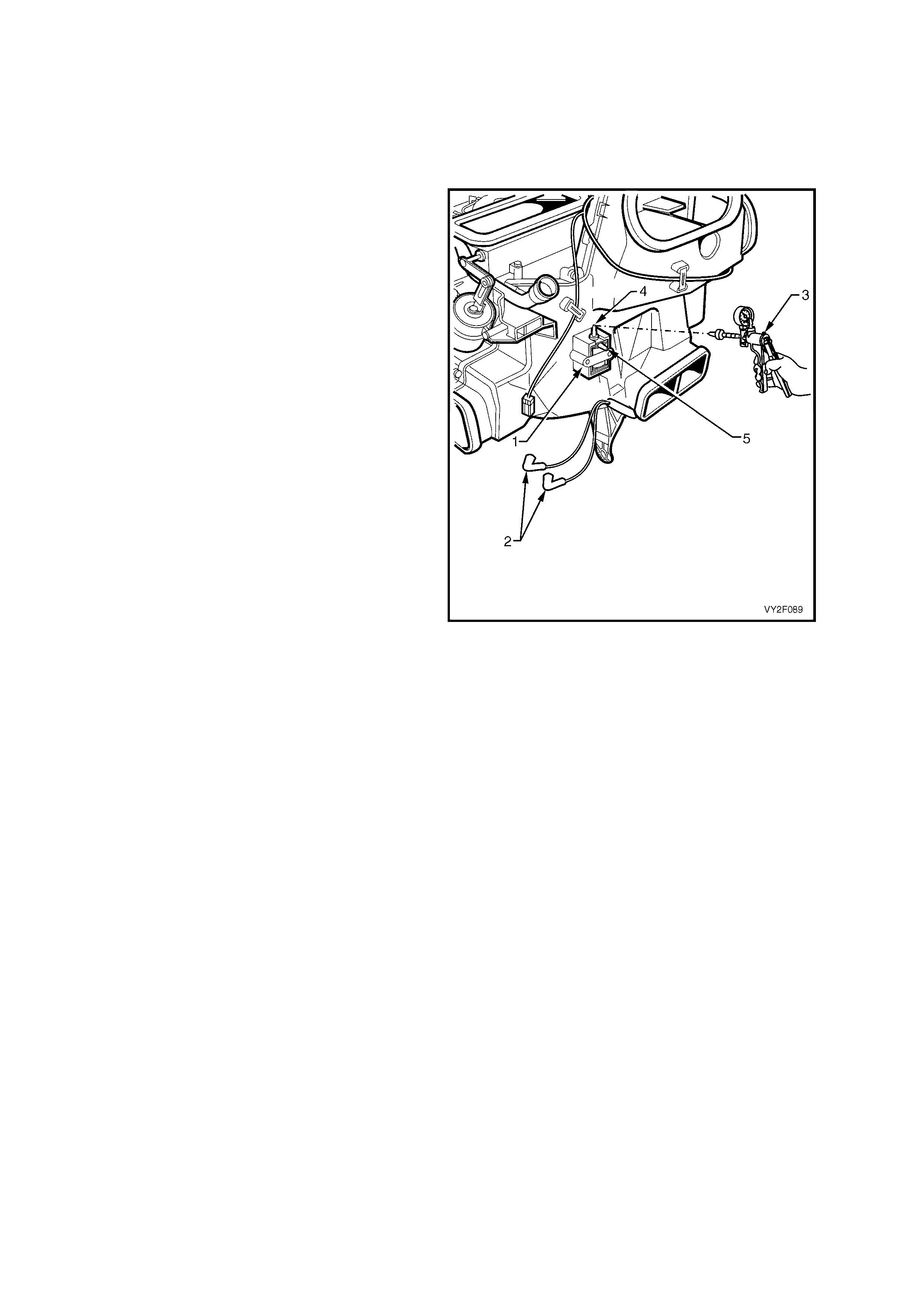
4.4 WATER VALVE VACUUM SWITCH
NOTE: The water valve vacuum switch valve is fitted to LHD type OCC (Auto A/C) HVAC units
1. Remove the radio assembly, refer to Section 1A3, 3.6 RADIO ASSEMBLY.
2. Remove the radio housing and radio bracket assembly,
refer to Section 1A3, 3.11 RADIO HOUSING AND RADIO BRACKET ASSEMBLY.
3. Locate the vacuum switch and valve (1) and
remove the vacuum hoses (2) noting their
installation to the valve.
4. Using a vacuum pump (3), connect to the
vacuum supply port (4) on the vacuum switch.
Vacuum seal the water valve vacuum port (5).
5. Using the vacuum pump, create a vacuum and
observe the vacuum pump gauge needle.
6. If a vacuum leak is indicated replace the water
valve vacuum switch valve.
Refer to Section 2E, 2.8 WATER VALVE
VACUUM SWITCH VALVE.
Figure 2F-120

5. WIRING DIAGRAMS
The following Figures provide electrical connector diagrams and wiring diagrams applicable to HVAC Occupant
Climate Control (Auto A/C) systems as fitted to MY2003 VY and V2 Serie s vehicles. These diagrams should be
used in conjunction with the diagn ostic chart circuit diagrams when diagnosing circuit faults. The content of these
figures is as follows:
• Electrical connectors – refer to Figure 2F-121
• Electrical connectors continued – refer to Figure 2F-122
• Electrical connectors continued – refer to Figure 2F-123
• V6 LHD wiring diagram – refer to Figure 2F-124
• V6 RHD wiring diagram – refer to Figure 2F-125
• GEN III V8 LHD wiring diagram – refer to Figure 2F-126
• GEN III V8 RHD wiring diagram – refer to Figure 2F-127
In the following wiring diagrams (Figure 2F-124 to Figure 2F-127) all compo nents are described and displayed in
accordance to the Integrated Vehicle Electrical Design (IVED) standard a s ap plied to MY2003 VY and V2 Series
vehicles. To assist in wiring diagram interpretation, refer to the following table:
IVED DESCRIPTION IVED COMPONENT IDENTIFICATION COMMON DESCRIPTION
Switch Asm – Ign & Start S149 Ignition Switch
V6 Module Asm Pwrt Cont A84 V6 Powertrain Control Module
V8 Module Asm Pwrt Cont A84 GEN III V8 Powertrain Control Module
Module Asm Body Cont A15 Body Control Module
Motor Asm Blo M3 Blower Motor
Module Asm Blo & Air Inl A13 Blower Motor Resistor
Module Asm Blo & A/C Cmpr A14_LHD OCC Control Module for LHD Models
Module Asm Blo & A/C Cmpr A14_RHD OCC Control Module for RHD Models
Actuator Asm Temp Vlv Y37 LHD Air Mix Motor for LHD Models
Actuator Asm Temp Vlv Y37 L Passenger’s Air Mix Motor for RHD Models
Actuator Asm Temp Vlv Y37 R Driver’s Air Mix Motor for RHD Models
Actuator Asm I/S Air Vlv Y19 Solenoid Pack
Actuator Asm Htr Wat Shutoff Vlv Y18_Lhd Water Valve VSV for LHD Models
Sensor Asm Amb Air Temp B23 Ambient Air Temperature Sensor
Sensor Asm I/S Air Temp B59 In-car Temperature Sensor
Sensor Asm Duct Air Temp B34 Evaporative Temperature Sensor
Coil A/c Clu L7 Compressor Clutch
Sensor Asm A/C Refrig Press B18 A/C Pressure Transducer
Motor Asm Eng Cool Fan M7_Std Standard Cooling Fan System
Motor Asm Eng Cool Fan M7_HP High Power Cooling Fan System
Window Rear R22 Heated Rear Window
The following table lists the IVED standard wire colour abbreviations:
BK Black D-GN Dark green L-GN Light green RD Red
BU Blue GN Green OG Orange TN Tan
BN Brown GY Grey PK Pink WH White
D-BU Dark blue L-BU Light blue PU Purple YE Yellow
NOTE 1: Electrical connectors specific to left-hand d rive or right-hand drive applications are identified in the
connector view diagram s b y a LHD or RHD notation after the connector description.
NOTE 2: For electrical connector locations and additional wiring di agram information
refer to Section 12P WIRING DIAGRAMS.
NOTE 3: V6 RHD domestic models are fitted with standard cooling fan system type fan motors. V6 RHD export
models may be fitted with high power cooling fan system ty pe fan motors. Where this applies, refer to the V6 RHD
wiring diagram Figure 2F-125, in conjunction with the cooling fan wiring details in the V6 LHD wiring diagram
Figure 2F-124.
NOTE 4: For visual identification of standard (STD) and high power (HP) cooling fan motors
refer to Section 2A, 2.9 COOLING FANS.
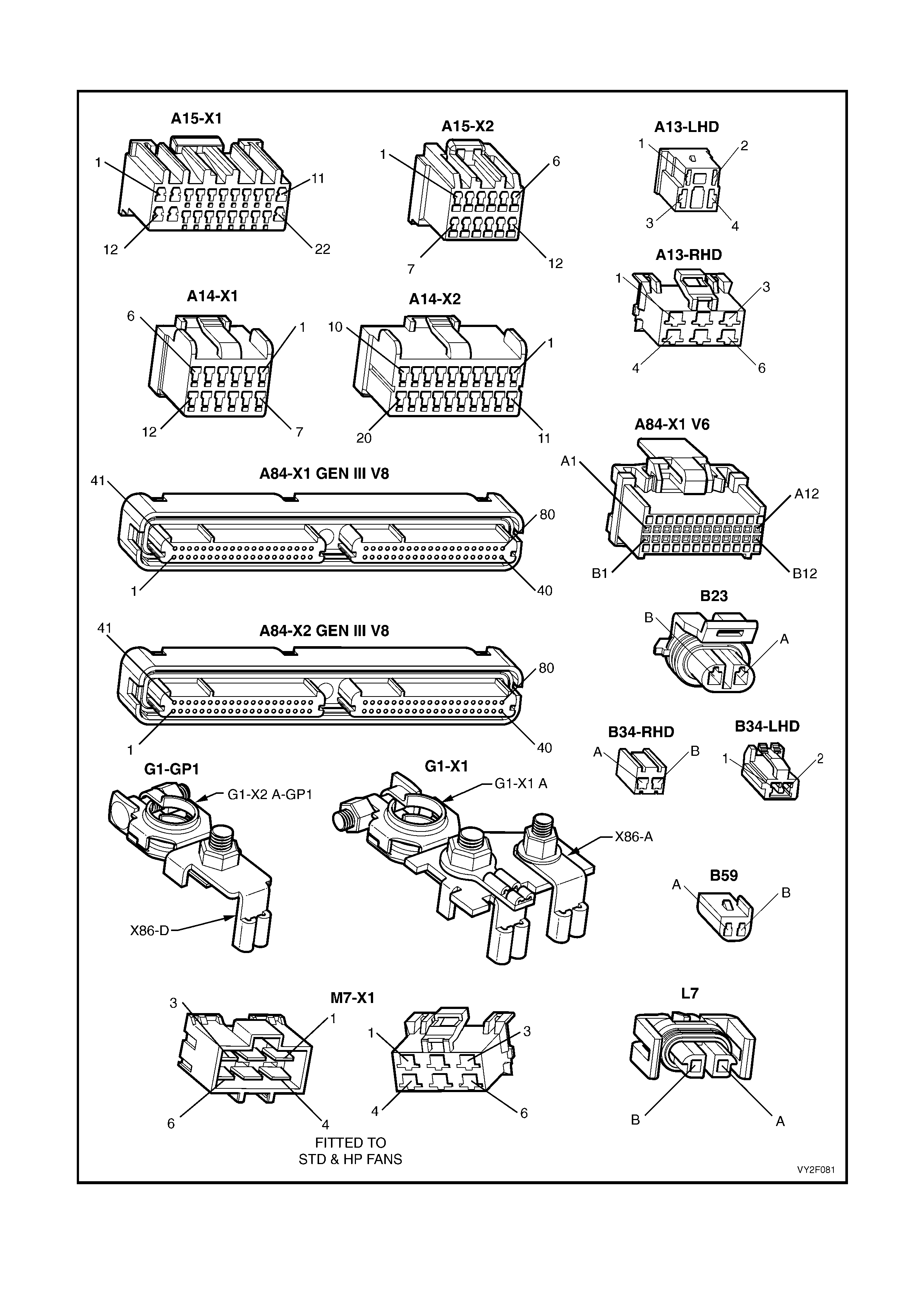
CONNECTORS: OCC SYSTEM
Figure 2F-121
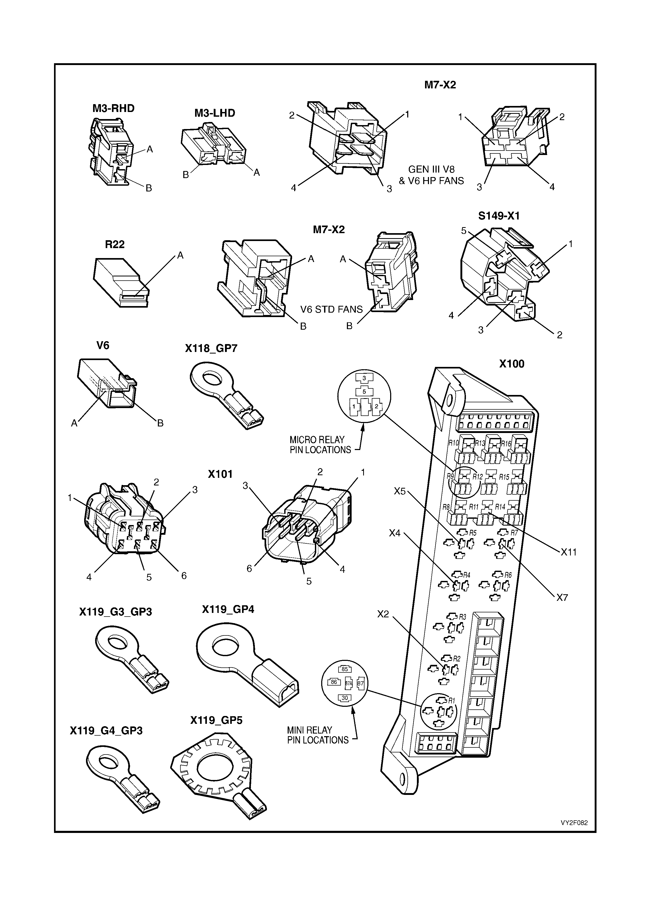
CONNECTORS: OCC SYSTEM CONTINUED
Figure 2F-122
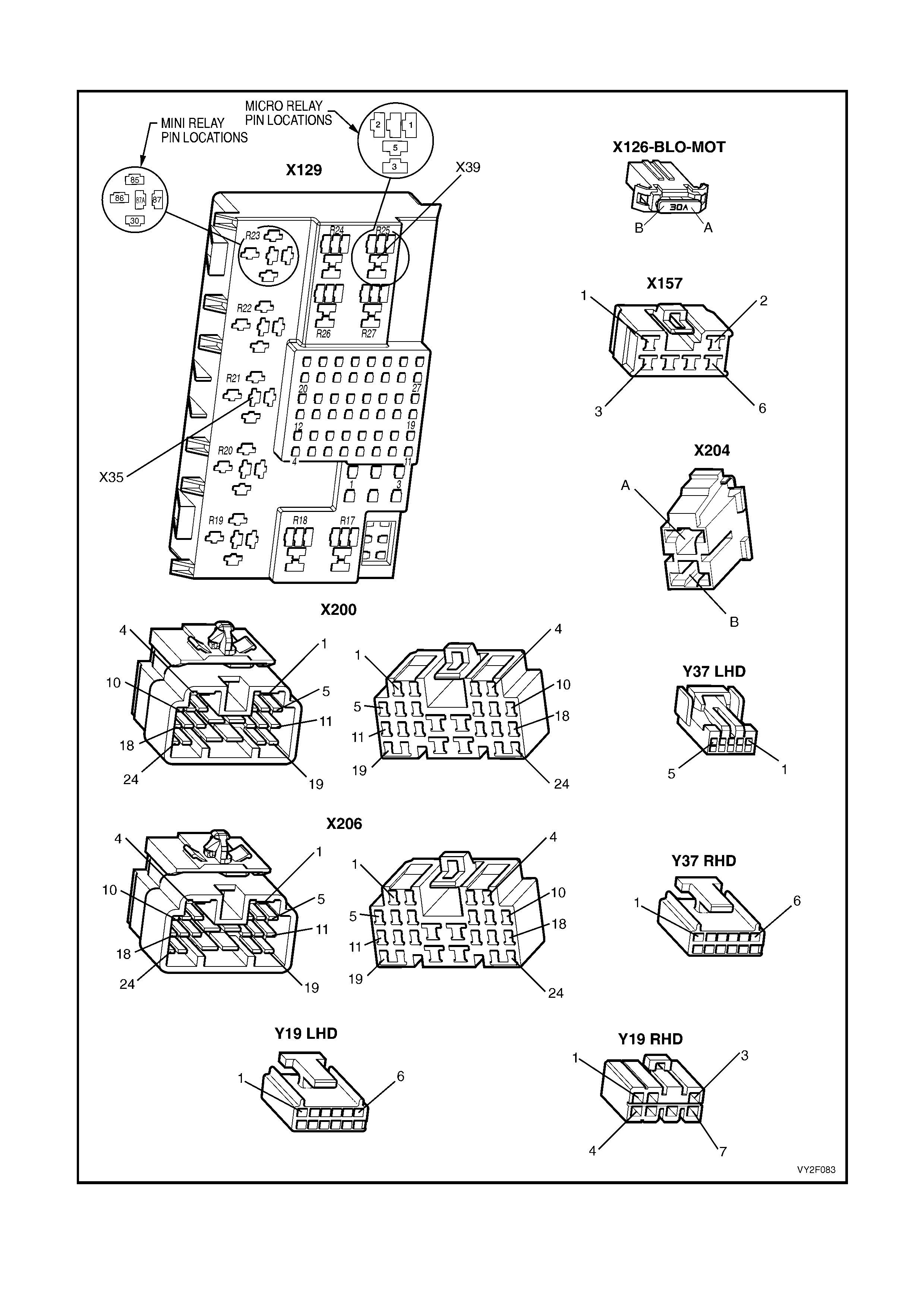
CONNECTORS: OCC SYSTEM CONTINUED
Figure 2F-123
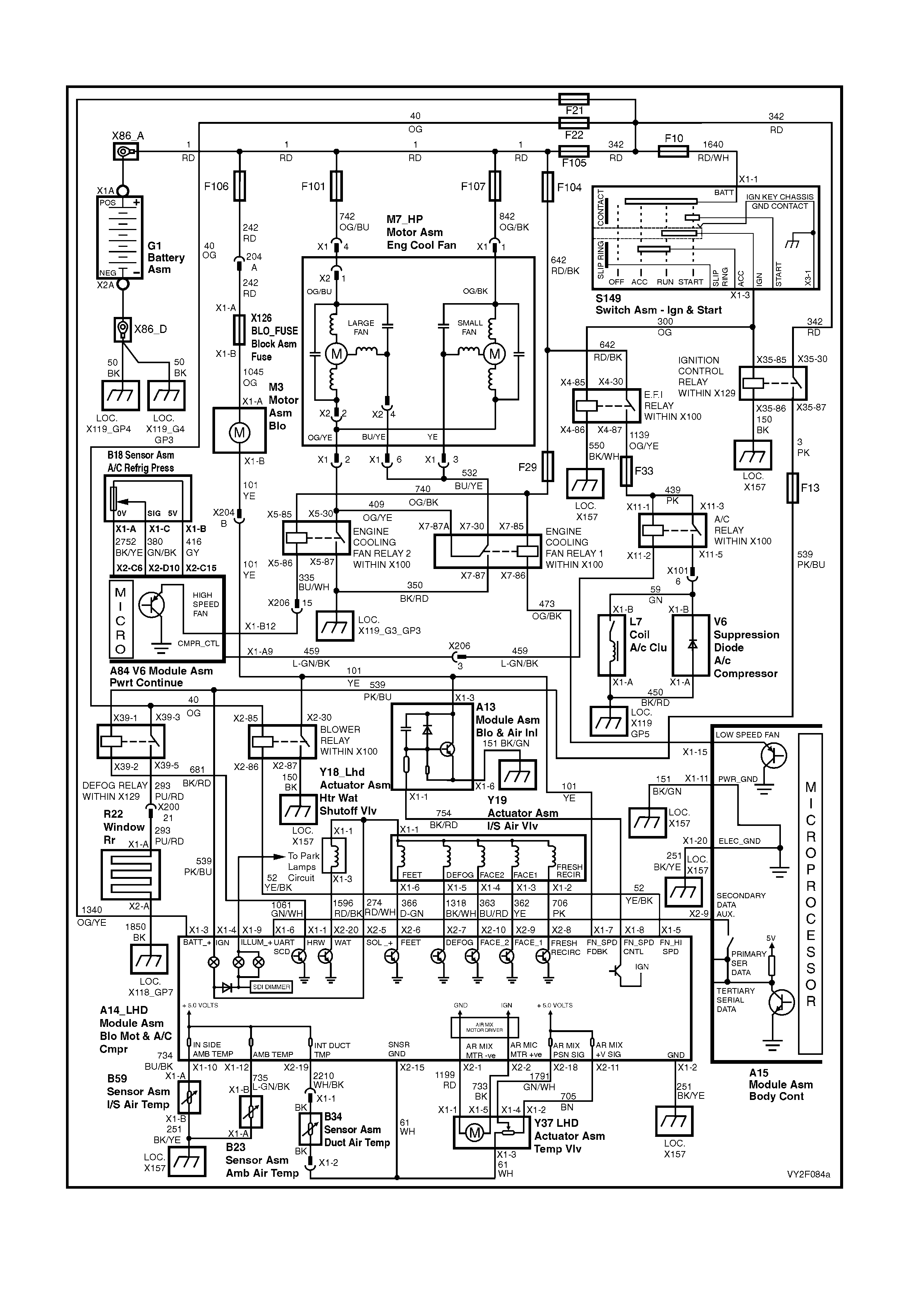
WIRING DIAGRAM: OCC SYSTEM – V6 LHD
Figure 2F-124
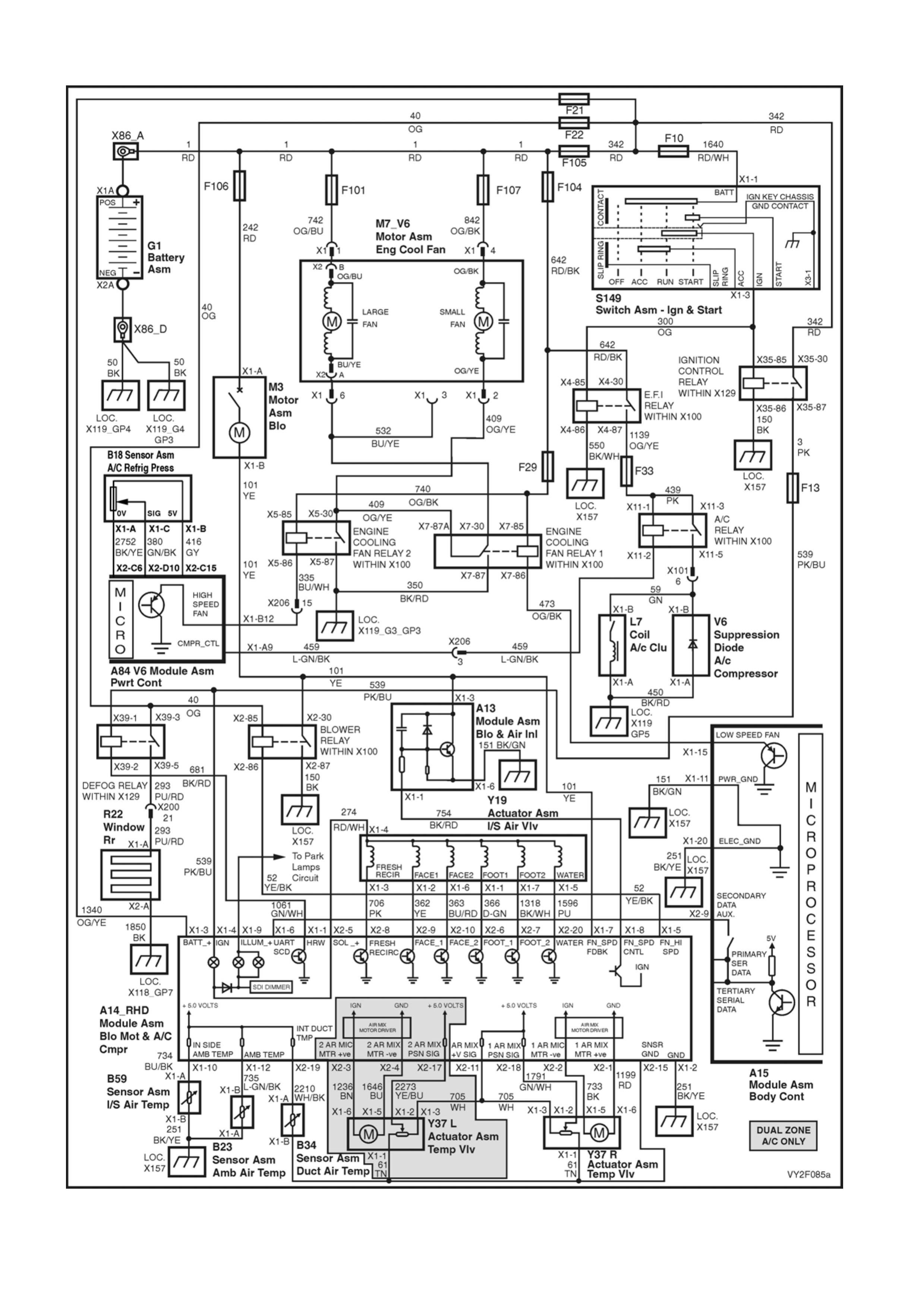
WIRING DIAGRAM: OCC SYSTEM – V6 RHD
Figure 2F-125
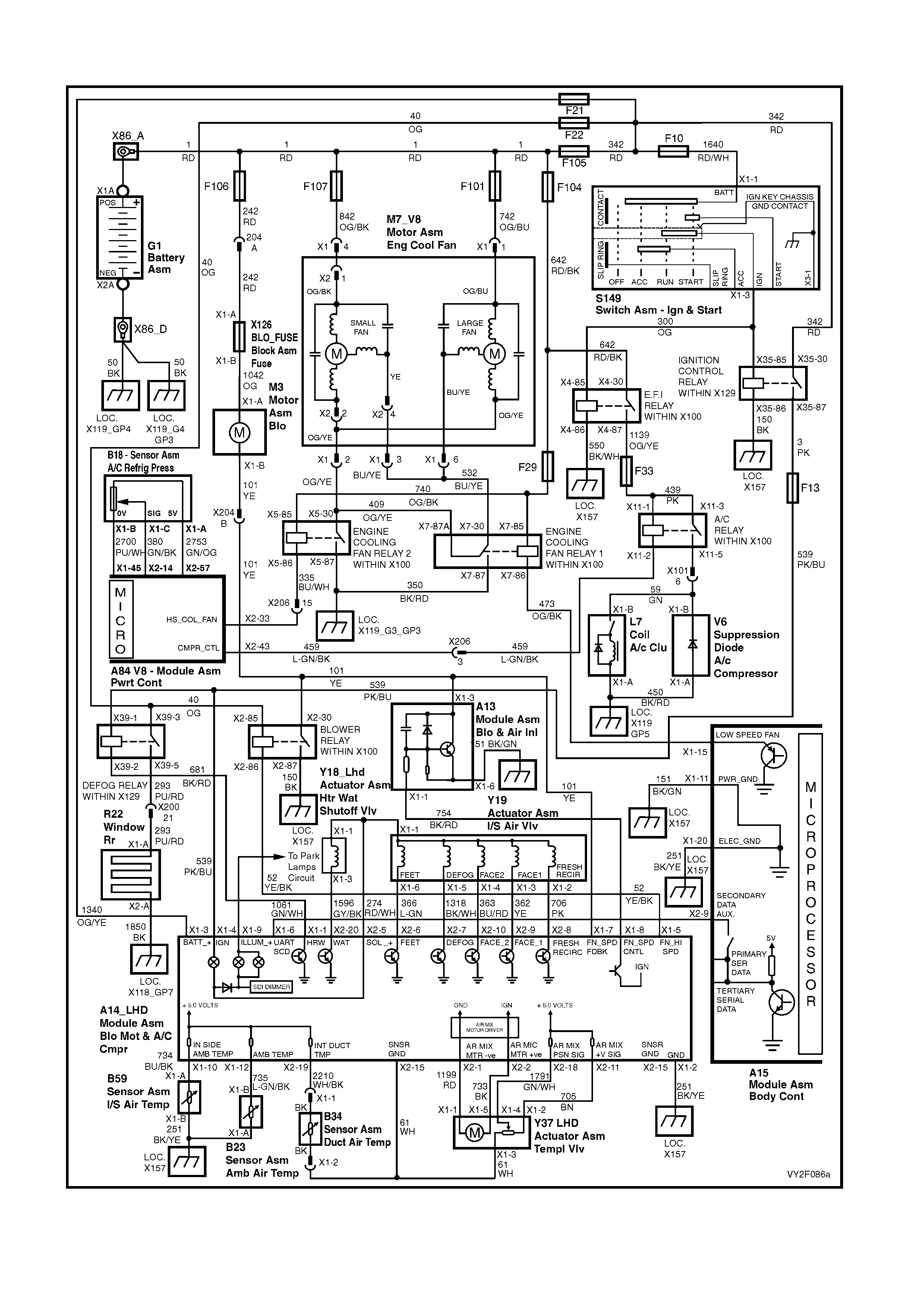
WIRING DIAGRAM: OCC SYSTEM – GEN III V8 LHD
Figure 2F-126
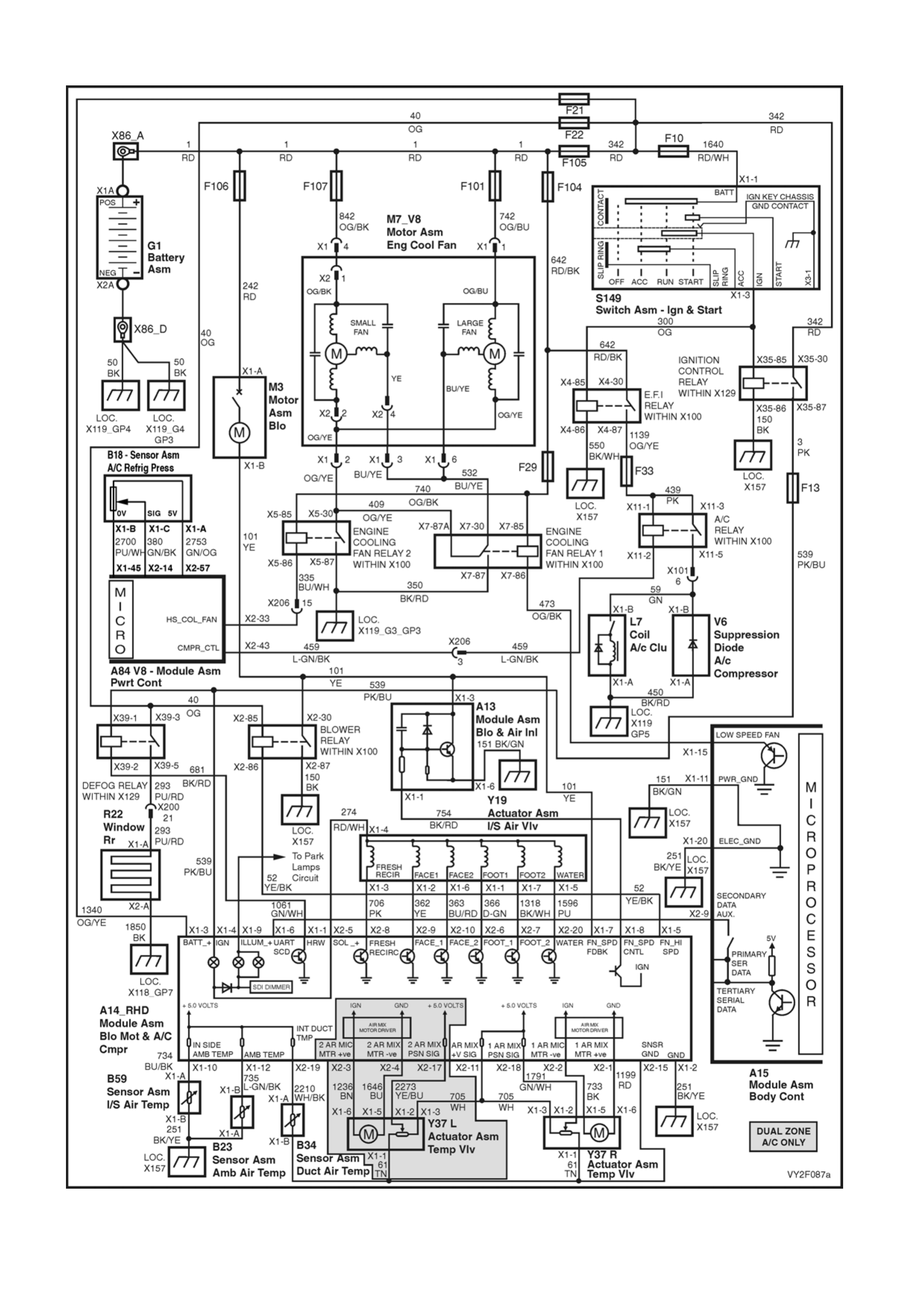
WIRING DIAGRAM: OCC SYSTEM – GEN III V8 RHD
Figure 2F-127
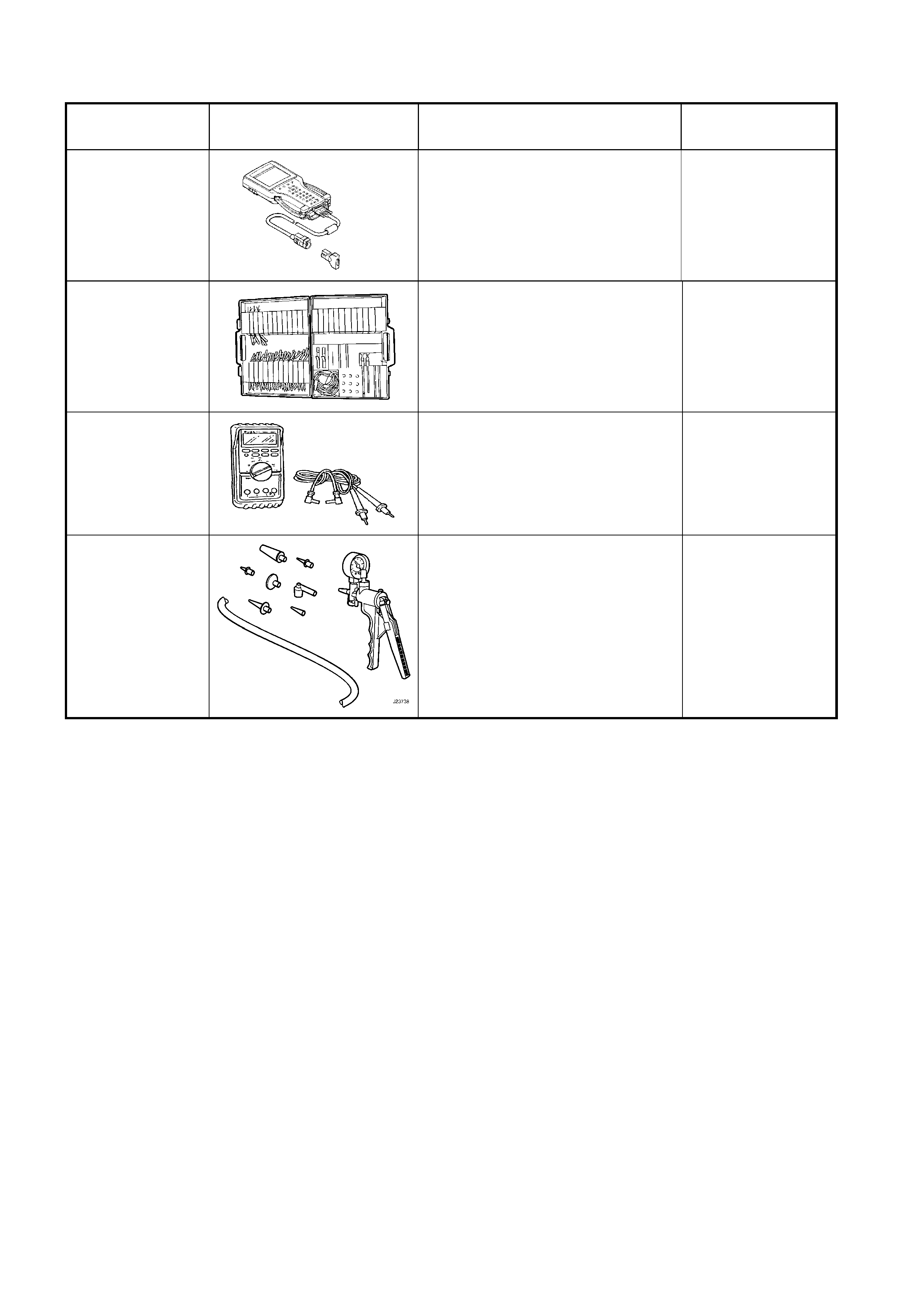
6. SPECIAL TOOLS
TOOL NUMBER ILLUSTRATION DESCRIPTION TOOL
CLASSIFICATION
7000086I
TECH 2
DIAGNOSTIC SCAN TOOL
Used for diagnosis of vehicle
electrical system.
Previously released.
Mandatory
J35616-A
(KM609)
CONNECTOR TEST ADAPTOR
KIT
Used when carrying out electrical
diagnostic circuit checks.
Previously released.
Desirable
3588
(J39200)
DIGITAL MULTIMETER
Must have at least 10 MΩ input
impedance and be capable of
reading frequenci es.
Previously released.
Available
J23738 VACUUM PUMP
Used for testing HVAC system
components, i.e. check valve,
HVAC unit vacuum tank, lines and
actuators.
Previously released.
Desirable