
SECTION 4A - REAR SUSPENSION
IMPORTANT
Before performing any Service Operation or other procedure described in this Section, refer to Section
00 CAUTIONS AND NOTES for correct workshop practices with regard to safety and/or property damage.
CONTENTS
1. GENERAL INFORMATION
2. SERVICE OPERATIONS
2.1 SERVICE NOTES AND CAUTIONS
2.2 REAR SUSPENSION CONTROL ARM
REMOVE
REAR SUSPENSION CONTROL ARM
PIVOT BUSHING, REPLACE
REINSTALL
2.3 OUTER REAR WHEEL DRIVE SHAFT,
FLANGE OR BEARING
REPLACE
2.4 REAR SUSPENSION CROSSM EMBER
REMOVE
REINSTALL
2.5 REAR SUSPENSION CROSSMEMBER
FRONT MOUNT BUSHING
OFF-CAR REPLACEMENT
ON-CAR REPLACEMENT
2.6 REAR SUSPENSION CROSSMEMBER
MASS DAMPER
REMOVE
REINSTALL
2.7 REAR SUSPENSION CROSSMEMBER
REAR MOUNT
REMOVE
REINSTALL
2.8 STABILISER SHAFT AND/OR MOUNTINGS
REMOVE
STABILISER SHAFT LINK INSULATORS,
REPLACE
REINSTALL
2.9 REAR SPRING AND INSULATORS
REMOVE
REINSTALL
2.10 REAR SHOCK ABSORBERS AND/OR BUSHING
REMOVE
LOWER BUSHING, REPLACE
REINSTALL
2.11 ADDITIONAL CONTROL ARM
INSPECT
REMOVE
DISASSSEMBLE
REASSSEMBLE
REINSTALL
2.12 REAR WHEEL ALIGNMENT CHECKING
CAMBER AND TOE CHECK
2.13 REAR WHEEL TOE ADJUSTMENT
3. DIAGNOSIS
CHECKING AND TESTING SHOCK
ABSORBERS
LEAKAGE CRITERIA
4. SPECIFICATIONS
REAR SUSPENSION SERVICE
ALIGNMENT DATA
REAR SPRING DETAILS
REAR SHOCK ABSORBER DETAILS
REAR STABILISER SHAFT DETAILS
5. TORQUE WRENCH SPECIFICATIONS
6. SPECIAL TOOLS
Techline

1. GENERAL I NFORMATI O N
Independent rear suspension is fitted as standard equipment on all MY 2003 VY and V2 Series Models, and is
equipped with variable rate minibloc coil rear springs and direct acting shock absorbers.
The r ear s us pension is contained within a rear sus pens ion c ros s mem ber as sembly that is attached by large volume
rubber bus hing at eac h f r ont c orner to the vehic le underbody. Rear location is provided by a rear m ounting bolted to
the differential carrier assembly that is in turn, attached to the crossmember.
W ith the exception of utility vehicles, vehicles that are fitted with a GEN III V8 and automatic transmission, have a
mass damper located on the rear suspension cross member, forward of each of the front mounts.
Two rear suspension control arms are attached to the crossm ember pivot points through rubber bushing. The rear
suspension control arms provide attachment of the additional control arms (where fitted), the rear brake
componentry, rear wheel drive shaft flanges and outer rear wheel drive shaft (rear wheel) bearings.
A decoupled type stabiliser shaf t is attac hed to the top of the c ross m em ber by two brackets and ins ulating bushing.
The outer ends of the stabiliser shaft are attached to each rear suspension control arm by a link via insulating
bushing.
All standard (Production Option FE1) suspension applications utilise twin tube hydraulic shock absorbers that are
double acting and are mounted between the vehicle underbody and each rear suspension control arm . The sports
suspension (Production Option FE2) and country pack (Production Option FR1) applications utilise twin tube, gas
pressurised shock absorbers. Pneumatic adjustable (Superlift) type rear shock absorbers are available as an
accessory or as part of a 2100 kg tow bar package for select MY 2003 VY Series Models.
Numerous specifications of variable rate minibloc rear springs are fitted to MY 2003 VY and V2 Series Models,
depending on body type and the suspension option. T he rear springs have insulating pads top and bottom , and are
maintained in the correct location by mounts on the vehicle underbody and the rear suspension control arms.
As part of the KL7 production LPG option, Sedan and Wagon vehicles gain, as par t of the option, an uprated spring
package to compensate for the extra weight of the LPG tank.
All vehicles fitted with the KL7 LPG option are identified by the installation of a Holden By Design (HBD)
identification plate attached to the upper front panel, refer to Section 8A2, 1.2 Identification Plates and Warning
Labels.
An additional control arm is also fitted as standard equipment to all MY 2003 VY and V2 Series Models except
utilities. T he inner ends of the additional control arms contain rubber bushing and are attached to brackets welded
to the rear sus pension cross mem ber. T he outer end of the additional control arm is secured to the rear sus pension
control arm by a sock et assem bly. The purpose of the additional control arm is to m aintain the rear wheel camber
and toe angles during suspension travel, whilst also providing a means of adjusting the rear wheel toe.
NOTE: For further information regarding how to identif y which suspension application (Production Option) is fitted to
a particular vehicle, refer to 9.3 BODY AND OPTION IDENTIFICATION PLATE in Section 0A, GENERAL
INFORMATION.
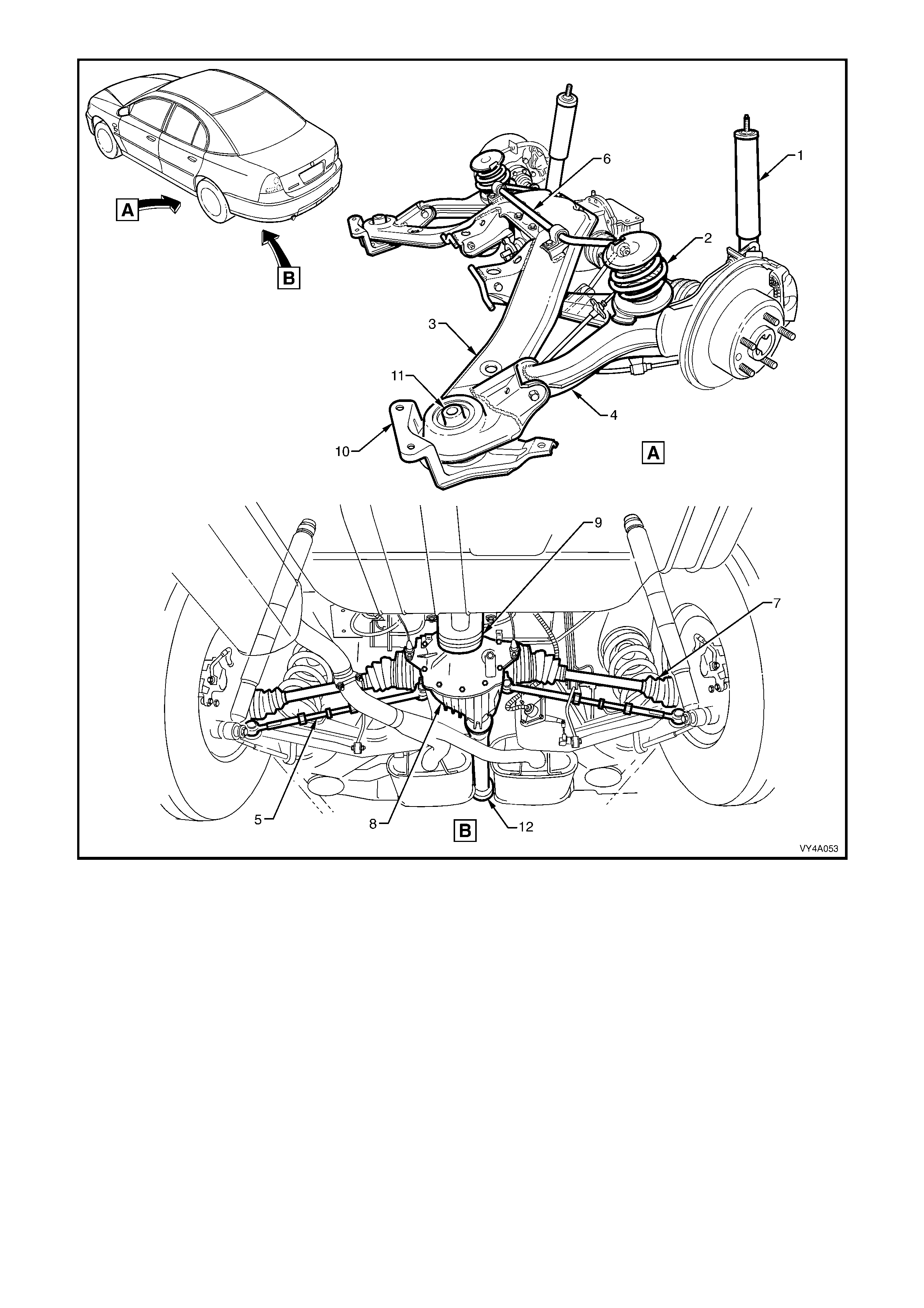
Figure 4A-1
Legend
1. Rear Shock Absorber 7. Driveshaft (2 Places)
2. Rear Spring 8. Rear Suspension Differential Assembly
3. Rear Suspension Crossmember Assembly 9. Rear Suspension Crossmember Rear Mount
4. Rear Suspension Control Arm Assembly 10. Rear Suspension Crossmember Front Mounting Brace
5. Additional Control Arm Assembly 11. Rear Suspension Crossmember Front Mount Bushing
6. Stabiliser Shaft 12. Propeller Shaft Assembly

2. SERVICE OPERATIONS
IMPORTANT
All rear suspension fasteners are important attaching parts as they affect the performance of vital
components and/or could result in major repair expense. Where specified in this Section, fasteners M UST
be replaced w ith part s of the same part nu mber or a GM appro ved equiv alent. Do no t use fasteners o f an
inferior qua lity or substitute des ign.
Torque values must be used as specified during reassembly to ensure proper retention of all rear
suspension components.
Throughout this Section, fastener torque wrench specifications may be accompanied with the following
identification marks:
!
!!
! Fasteners must be replaced after loosening.
"
""
" Vehicle must be at curb height before final tightening.
#
##
# Fasten ers either hav e micro encap sulated sealant app lied or incorporate a mechan ical thread lock and
should only be re-used once. If in doubt, replacement is recommended.
If one of these identification marks is present alongside a fastener torque wrench specification, the
recommendation regarding that fastener must be adhered to.
2.1 SERVICE NOTES AND CAUTIONS
NOTE 1: Whenever a road wheel and/or brake rotor is removed from or installed to a MY 2003 VY or V2 Series
vehicle, it MUST be done in accordance with the procedure provided in 2.3 WHEEL REMOVAL AND
INSTALLATION in Section 10, WHEELS AND TYRES.
NOTE 2: T o ensure proper retention of the additional contr ol arm, the sock et assem bly stud and the corresponding
tapered hole in the rear suspension control arm must be cleaned of dirt and foreign matter prior to installation.
CAUTION: Whenever any component that forms part of the ABS (if fitted) is disturbed during
Service Operat ions, it is v ital th at the co mplete ABS system b e checked, using the pro cedure as detailed in
4.4 ABS & T CS FUNCTION CHECK (V6 engines) or 5.4 ABS & TCS FUNCT ION CHECK (GEN III V8 engines),
in Section 5B ABS & TCS.

2.2 REAR SUSPENSION CONTROL ARM
LT Section No. – 06-212
NOTE 1: The following fasteners have either micro
encapsulation or incorporate a mechanical thread lock
and should only be used once. If in doubt, r eplacement
is recommended when performing this operation:
♦ Brake caliper anchor plate to rear suspension
control arm upper attaching bolt.
♦ Additional control arm socket assembly retaining
nut.
♦ Stabiliser shaft link to rear suspension control arm
attaching nut and bolt.
♦ Rear suspension control arm to rear suspension
crossmember attaching nut.
NOTE 2: The following fasteners MUST be replaced
when performing this operation:
!
!!
!$
$$
$Brake caliper anchor plate lower attaching bolt.
!
!!
!$
$$
$Rear suspension crossmember mount to under
body attaching bolt.
!
!!
!$
$$
$Drive shaft constant velocity joint to rear wheel
drive shaft flange attaching bolt.
NOTE 3: The following fasteners MUST be at curb
height before final tightening:
• Shock absorber lower mounting bolt.
• Stabiliser shaf t link to rear suspension control arm
attaching nut and bolt.
• Rear suspension control arm to rear suspension
crossmember attaching nut.
IMPORTANT: Before disturbing the crossmember rear mounting bolts, an alignment procedure is required on
installation and a spec ial tool is required for this purpose. If this tool is not available, then the crossm em ber c annot
be correctly aligned and steering and/or handling abnormalities will result.
REMOVE
1. Using a floor jack under the centre of the differential carrier, jack up the rear of the vehicle and place safety
stands under the body rear jacking points. Refer to Section 0A GENERAL INFORMATION for the location of
jacking points.
2. On the side of the vehicle where the rear suspens ion control ar m is to be rem oved, mar k the r elationship of the
road wheel to hub (eg. end of wheel stud), with a felt tipped pen or similar. Loosen, and then rem ove the road
wheel attaching nuts. Remove the road wheel.
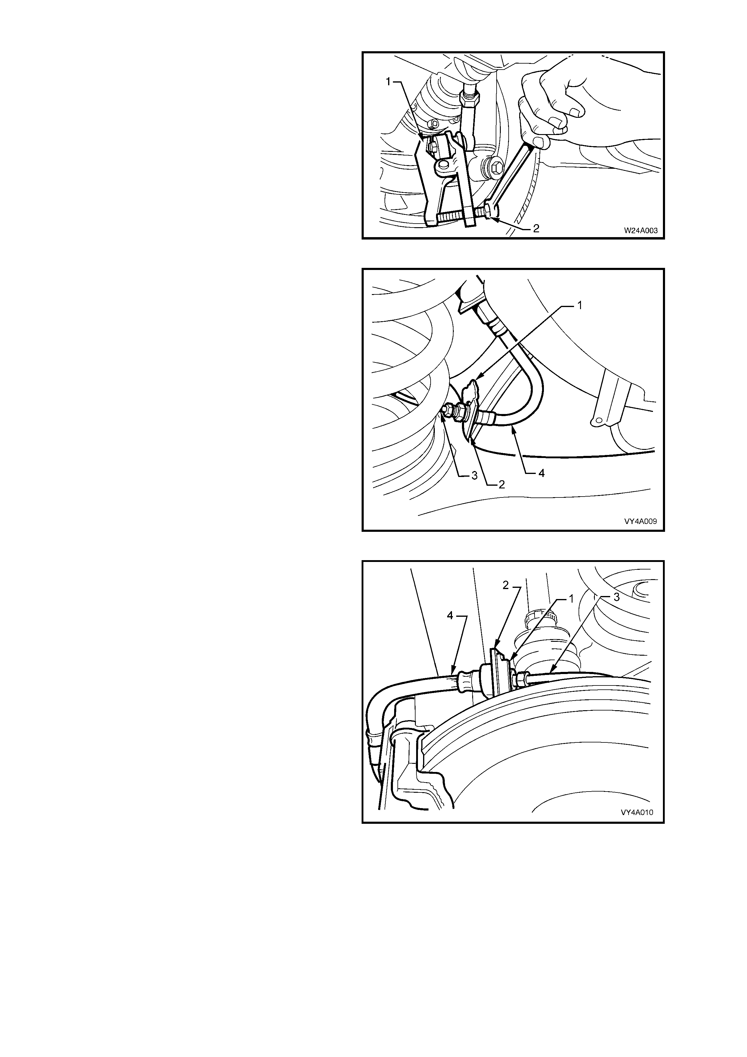
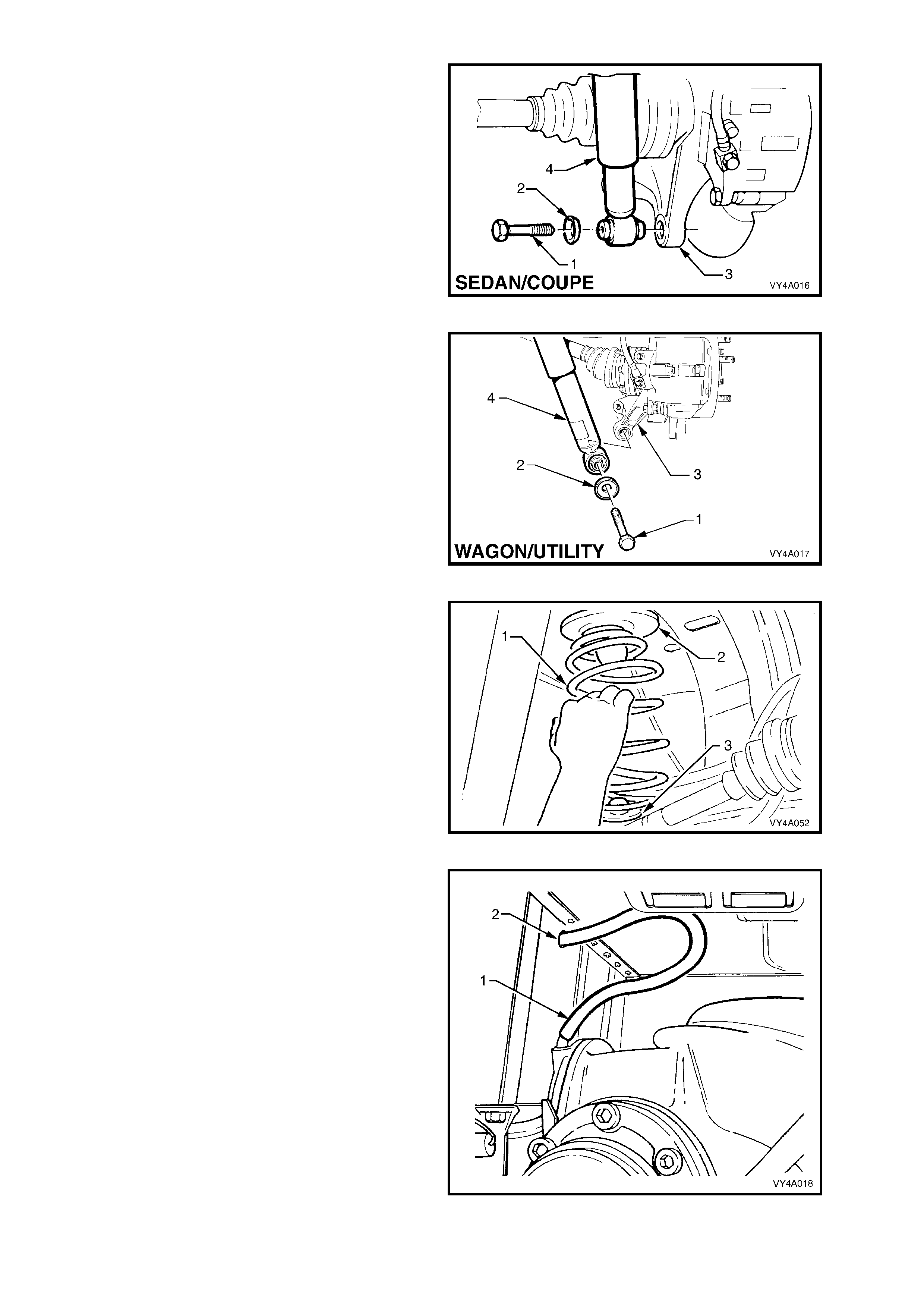
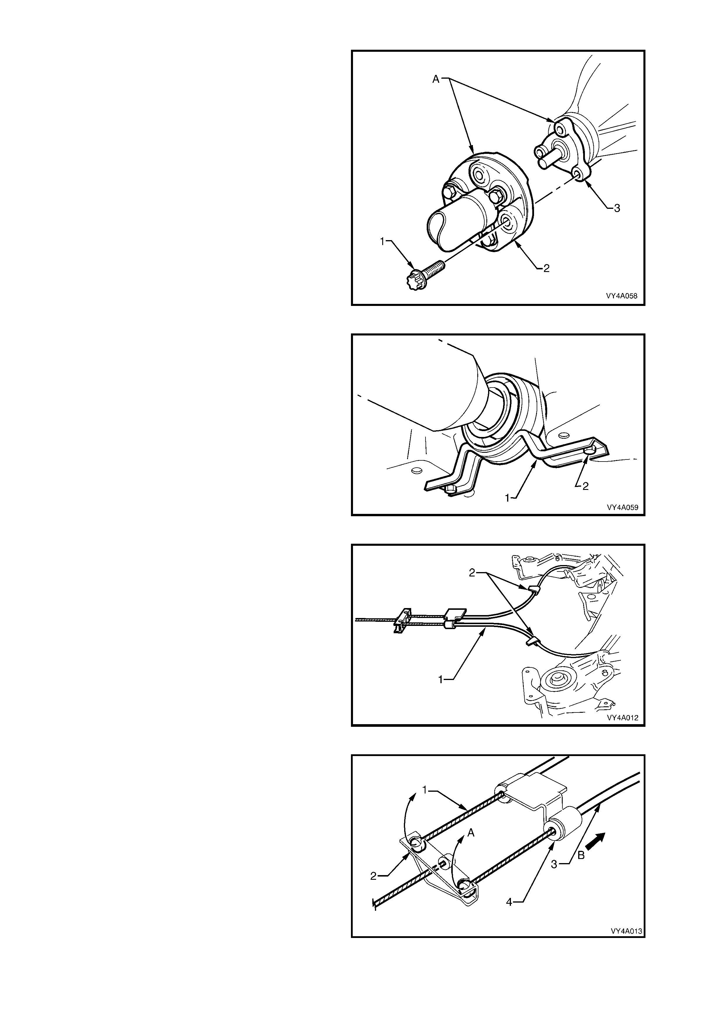
3. Loosen both stabiliser shaft link (1), attaching
bolts (2) and nuts, to reduce stress on the
insulator bushing.
4. Remove the stabiliser link to rear suspension
control arm attaching bolt and nut from side of
vehicle where the rear suspension control arm
is to be removed.
Figure 4A-2
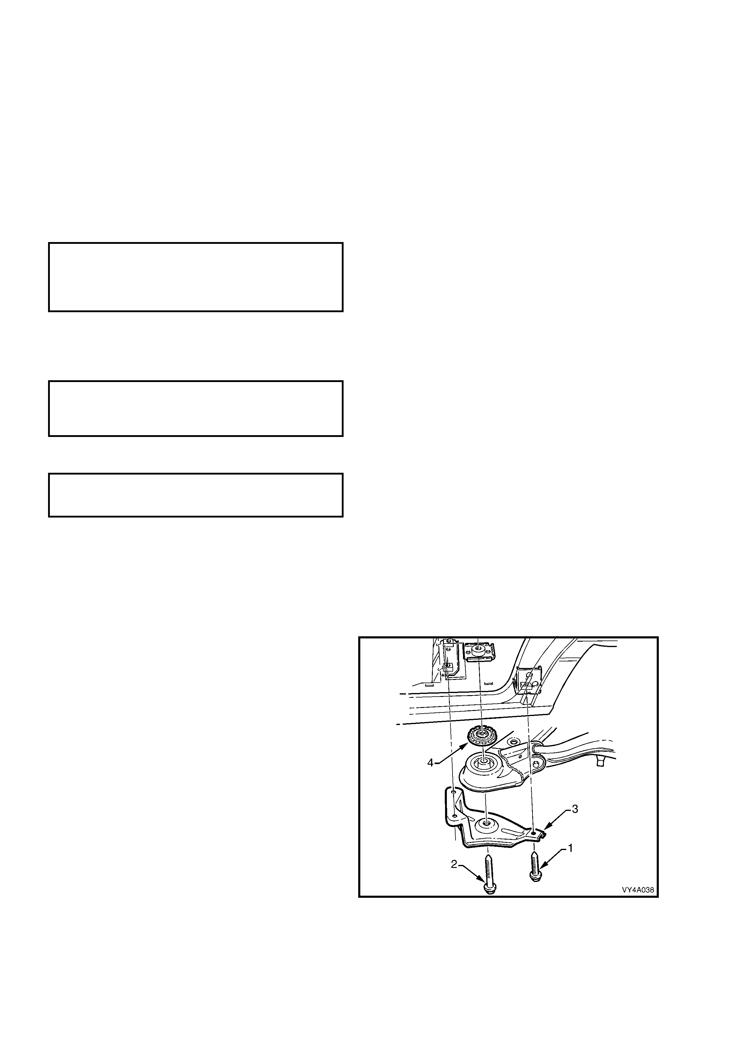
5. Loosen the additional control arm socket
assem bly retaining nut until level with the top of
the socket assembly stud.
6. Using s pecial tool No. E-9332- A (1), tighten the
lever forcing screw (2) to press the socket
assembly stud free from the taper in the rear
suspension control arm, remove socket
assembly retaining nut and discard.
7. Remove the additional control arm socket
assembly from the rear suspension control
arm.
Figure 4A-3
8. Remove the rear brake hose retaining clip (1)
from the rear suspension control arm bracket
(2) on the side to be removed. Pull the brake
pipe (3) and hose ( 4) f orward from the brack et,
and then disconnect from the rear suspension
control arm by lifting the brake pipe up through
the slot in the bracket.
Figure 4A-4
9. Remove the brake hose retaining clip (1) from
the brak e back ing plate brack et (2). Disconnec t
the rear caliper brake pipe (3) from the brake
hose (4) and disconnect the pipe from the
backing plate bracket.
Plug the open ends of the brak e pipe and hose
to prevent fluid loss and foreign matter entry.
Figure 4A-5
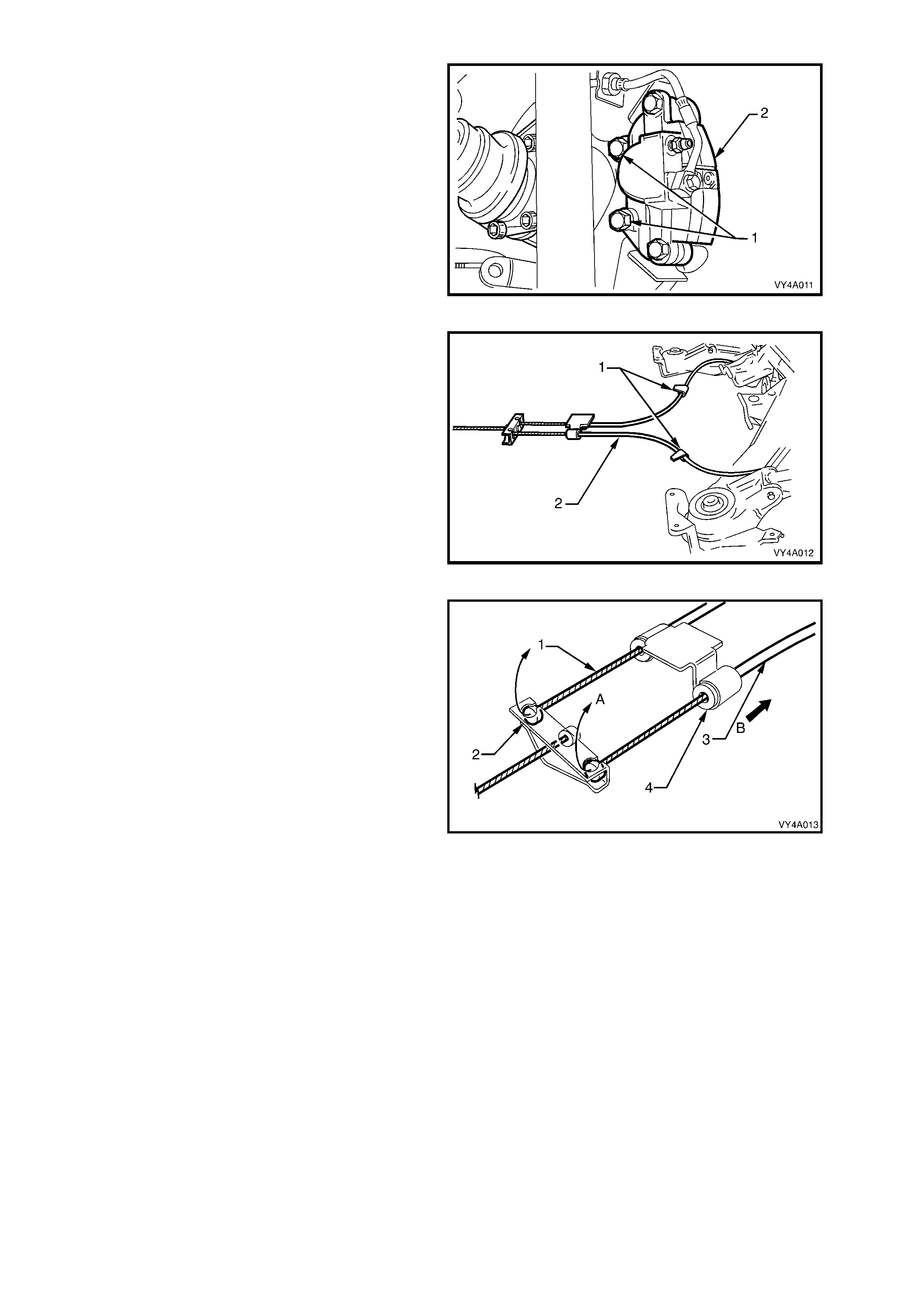
10. Remove the brake caliper anchor plate to rear
suspension control arm attaching bolts (1) and
remove the caliper (2) from the rotor. Set the
brake caliper to one side.
Important: If the brake pipe to hose is not
disconnected, the brake caliper must be supported
with tie wire secured to the vehicle underbody. THE
CALIPER IS NOT TO HANG BY THE BRAKE
HOSE.
Figure 4A-6
11. Set the park brake in the fully released position,
then release each of the underbody to park
brake cable (1) retaining clips (2) and free the
cables.
Figure 4A-7
12. Remove the park brake outer cable retaining
bracket bolt (underbody bracket and bolt are
not shown) from the vehicle underbody.
13. Pull each park brake inner cable (1) forward
and up (A), out of the cable retainer (2) to
release each cable.
14. Pull the outer cable (3) rearward (B) to remove
from the underbody retainer (4).
15. Remove the br ake rotor f r om the wheel bearing
hub.
NOTE 1: While the brake rotor to hub location is
marked in production, ensure that the rotor to hub
position is carefully marked (eg. rotor to end of
wheel stud), with a felt tipped pen or s im ilar. T his is
necess ary to overc ome the poss ibility of inducing a
brake shudder condition after reassembly.
NOTE 2: Should it be necessary to adjust the park
brake shoe to allow the brake rotor to be rem oved,
refer to Section 5A, SERVICE AND PARK
BRAKING SYSTEM for the necessary procedure.
Figure 4A-8
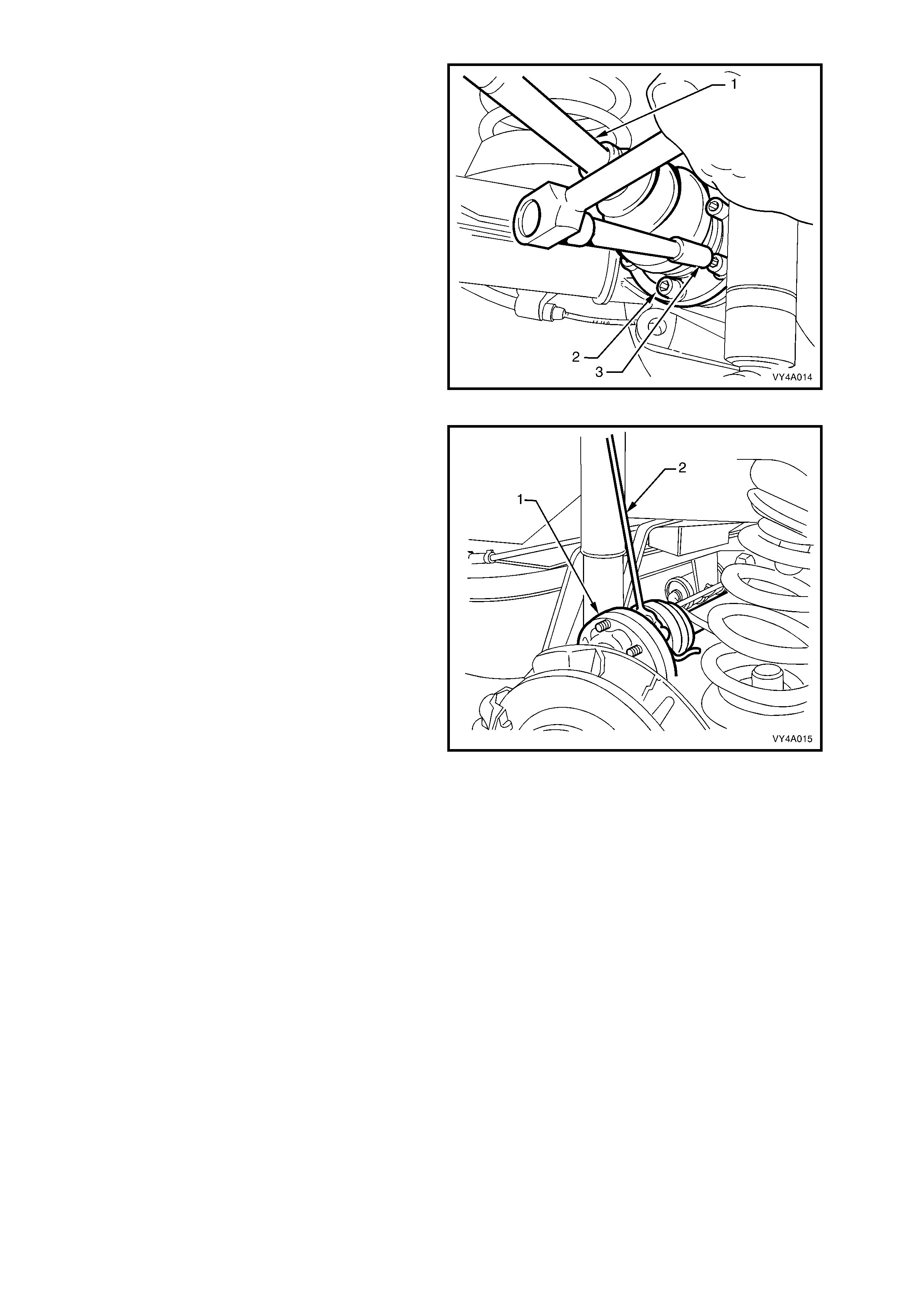
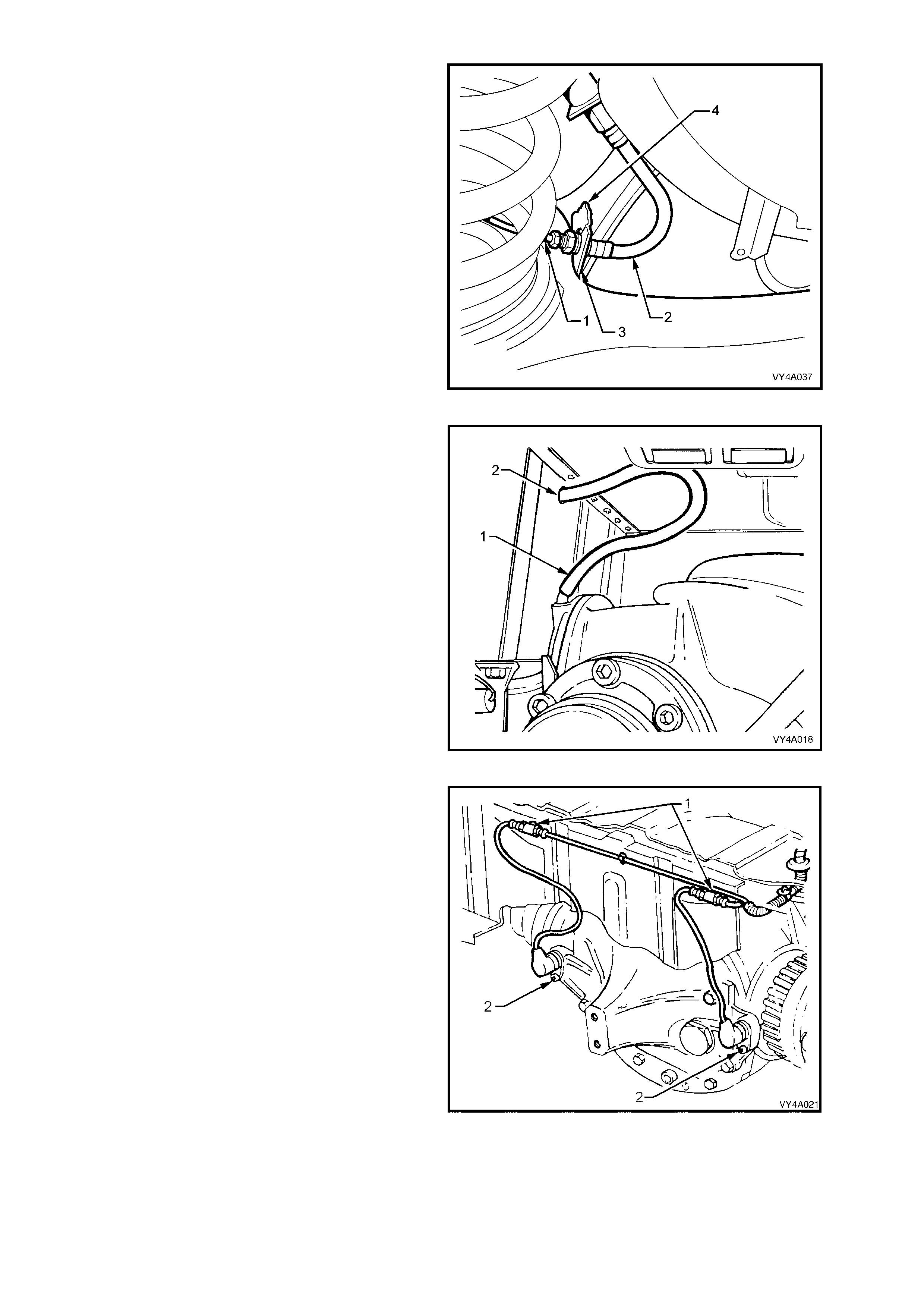
16. Using T ool No. KM468 over the wheel studs to
hold outer rear wheel drive shaft hub from
rotating, loosen the six drive shaft (1) outer
constant velocity joint to rear wheel drive shaft
flange attaching bolts (2), using an 8 mm Allen
key socket (3). Remove and discard the bolts.
Figure 4A-9
17. Disconnect the drive shaft (1) from the flange
and lift upward. While keeping the outer
constant velocity joint in the same plane as the
driveshaf t, use a length of wire (2), to tie up the
drive shaft to the lower end of the shock
absorber upper mounting.
NOTE: Bruising to the inside of the drive shaft
constant velocity joint boots will occur if the rear
suspens ion control arm is lowered. This will lead to
prem ature f ailure of the boot and eventual failure of
the joint.
This is why it is im portant that the constant velocity
joint be disconnected from the rear wheel drive
shaft flange before removing the shock absorber
lower mounting bolt.
Figure 4A-10
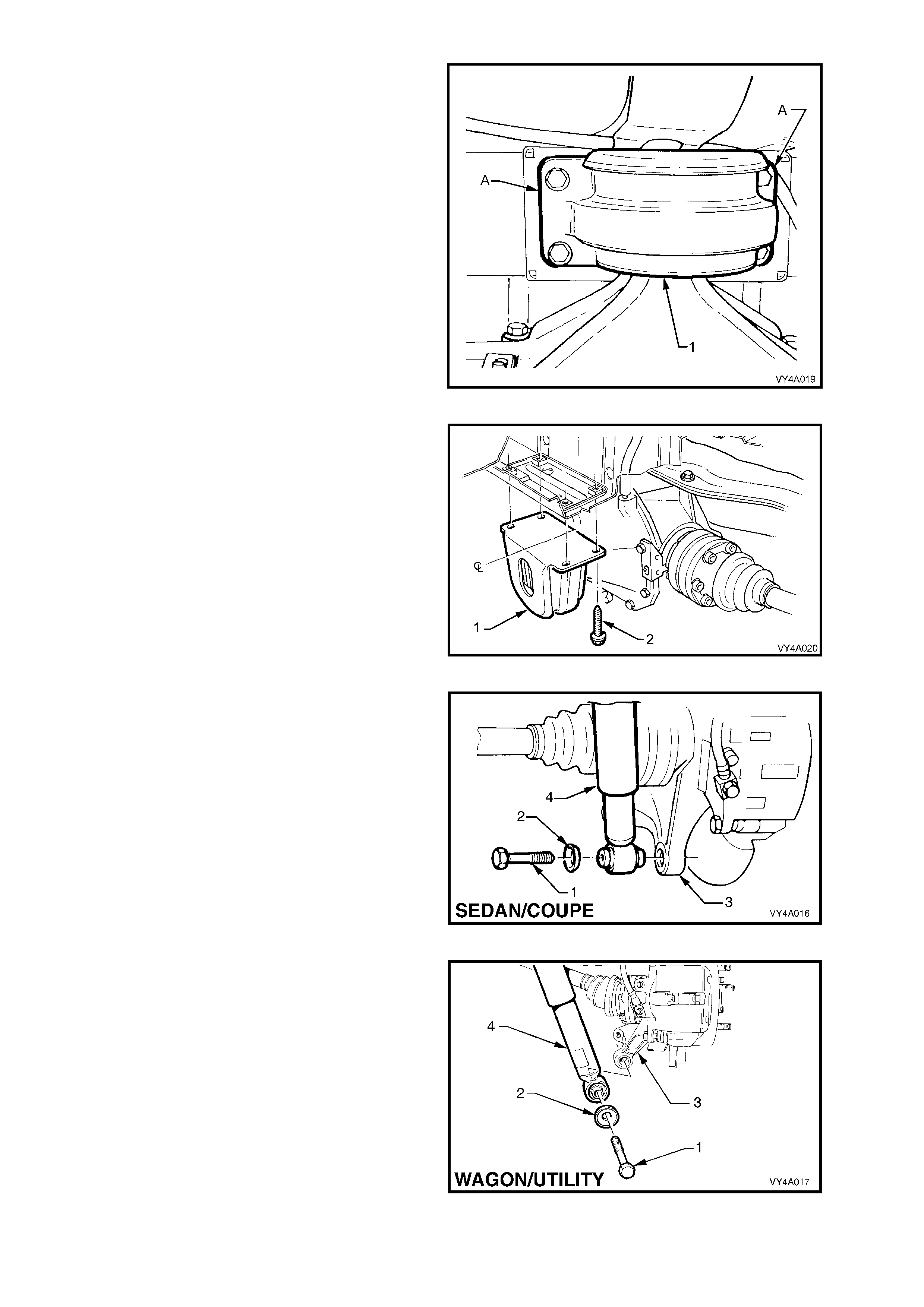
18. Position the floor jack with a block of wood
under the rear suspension control arm. Raise
the jack slightly to take the spring load off the
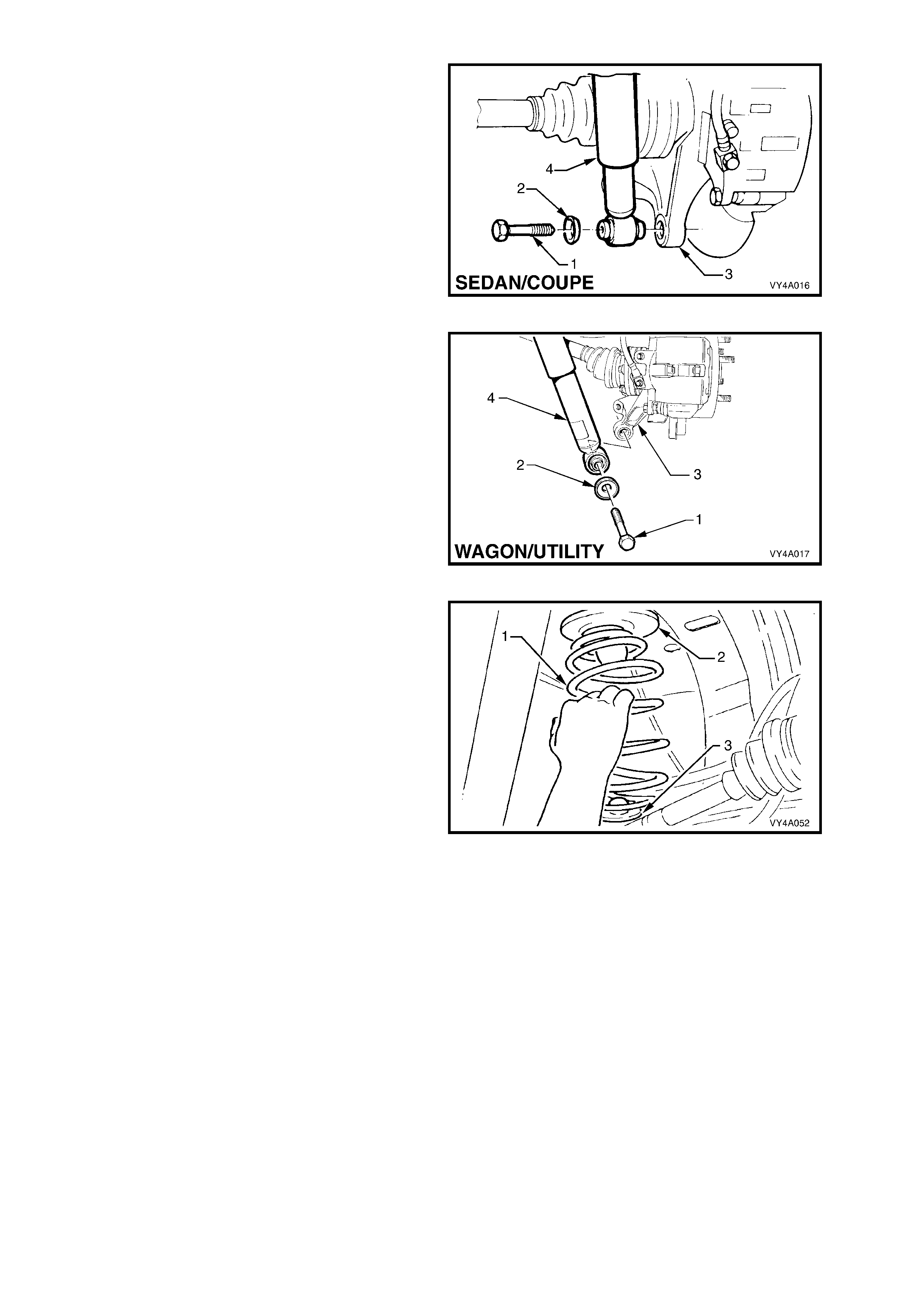
rear suspension control arm. Remove the rear
shock absorber lower mounting bolt (1) and
washer (2) from the rear suspension control
arm (3), then pull the lower end of the shock
absorber (4) from the rear suspension control
arm.
Figure 4A-11
Figure 4A-12
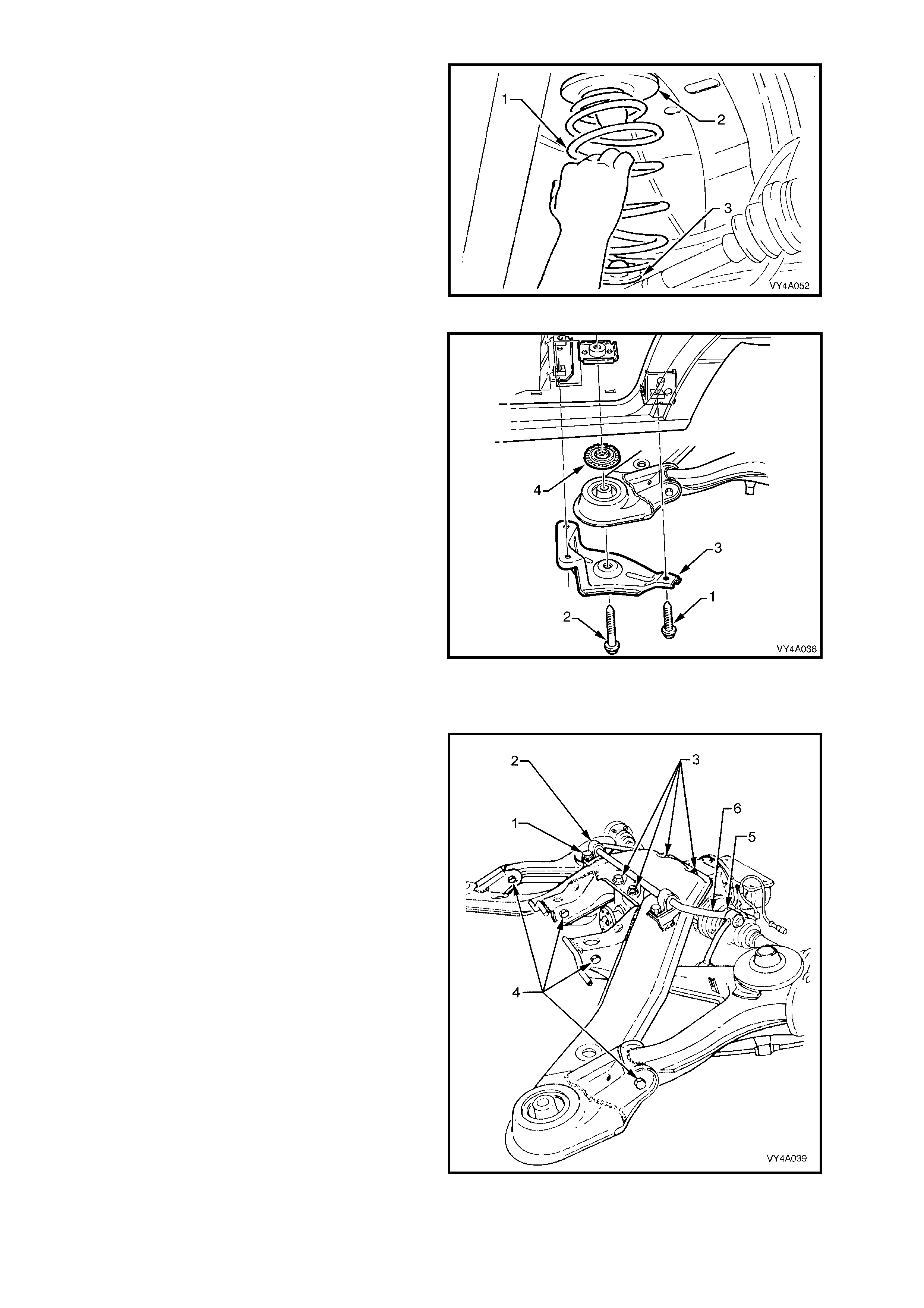
19. Lower the floor jack and if necessary, push
down on the rear suspension control arm and
remove the rear spring (1), upper insulator (2)
and lower insulator (3) from the vehicle
underbody and rear suspension control arm.
Figure 4A-13
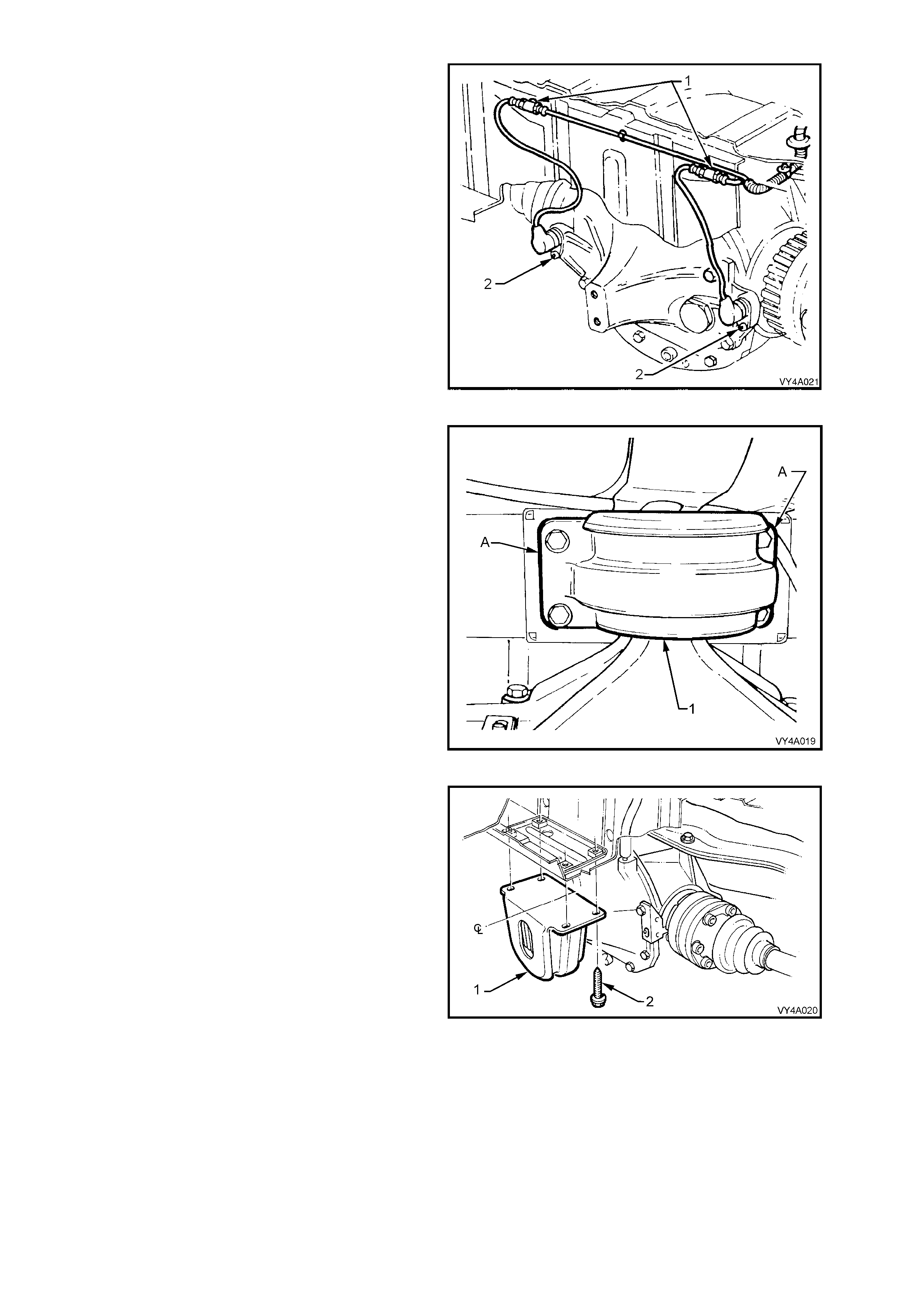
20. Pull out the differ ential c arr ier br eather hos e ( 1)
from the vehicle underbody crossmember hole
(2).
Figure 4A-14
21. If the vehicle is f itted with ABS, pull both sensor
lead connectors from the underbody retaining
clips (1). Separate the sensor connectors from
the body harnes s connectors by levering with a
screwdriver.
Figure 4A-15
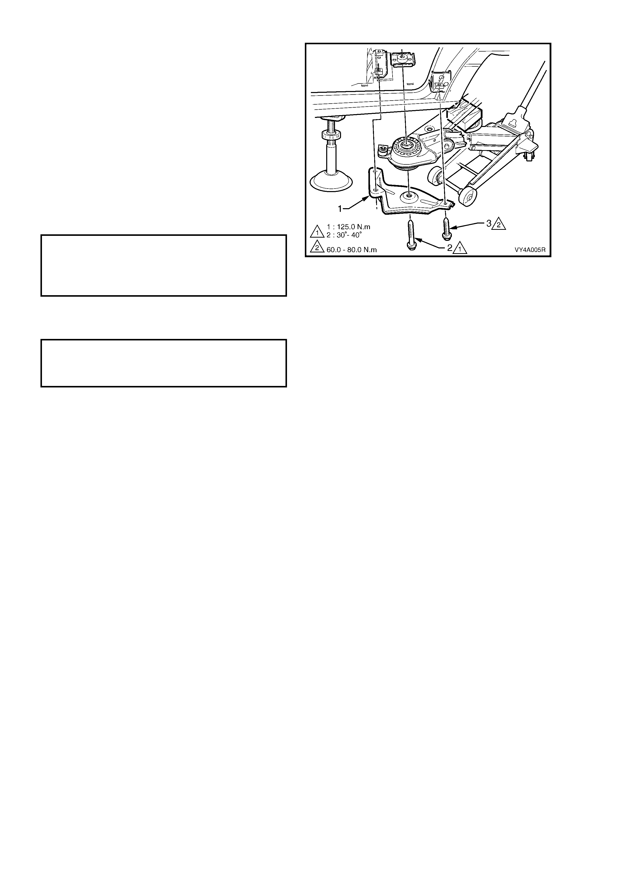
22. Using a scriber, mark the rear mount (1) to
vehicle under body location (A). T his will assist
in the rear sus pension crossm ember alignm ent
on installation.
23. Support the weight of the differential carrier
with a floor jack.
Figure 4A-16
24. Remove the rear mount (1) to vehicle
underbody attaching bolts (2) and discard.
Lower the differential carrier and rear
suspension crossmem ber assem bly suff iciently
to allow removal of the outboard rear
suspension control arm to front crossmember
attaching bolt and nut.
Figure 4A-17
25. Remove the rear suspension control arm to
rear suspension crossmember attaching bolts
and nuts, remove the rear suspension control
arm and discard the nuts.
Figure 4A-18
REAR SUSPENSION CONTROL ARM PIVOT BUSHING, REPLACE
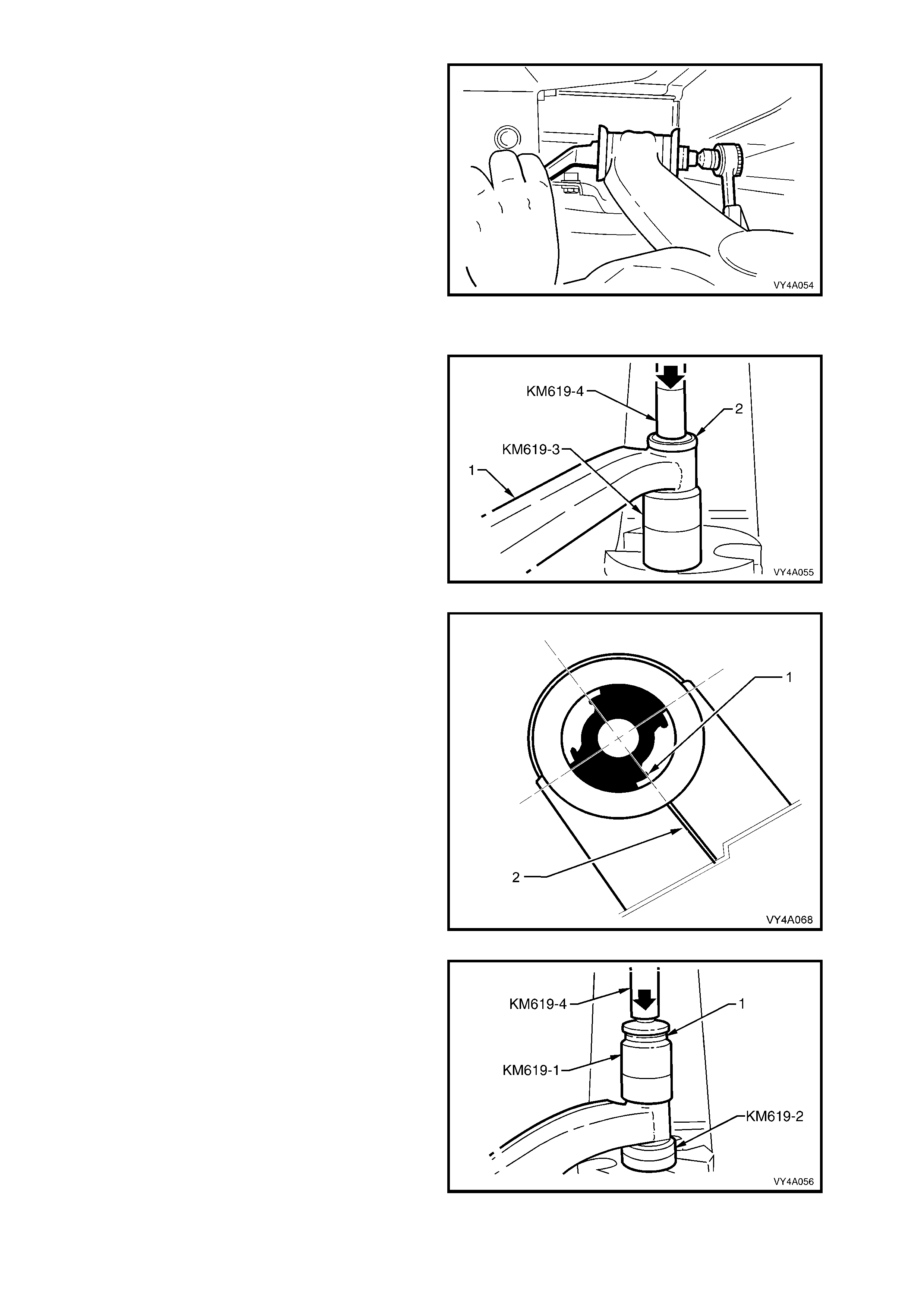
1. With the rear suspension control arm (1)
removed, press the bushing (2) from the rear
suspension control arm using Special tools
number KM619-3 and KM619-4.
Figure 4A-19
2. Lightly coat the outside surface of the new
bushing with a soapy water solution.
3. Position the new bush into the rear suspension
control arm.
NOTE: If replacing a voided type inner bush as
fitted to all MY 2003 VY Series Models with the
additional control arm, ensure to align the edge of
one of the voids (1), with the welded seam in the
trailing arm (2) as shown in Figure 4A-20.
Figure 4A-20
4. Press the new bushing into rear suspension
control arm (2) using Special tools number
KM619-1, KM619-2 and KM619-4.
Figure 4A-21
REINSTALL
The re installation of the rear sus pension control arm is the reverse of the removal pr ocedure, with the exception of
the following steps:
1. Install the rear suspension c ontrol arm to the r ear suspension cros smem ber, using bolts and NEW nuts but do
not fully tighten at this stage.
2. Install the brake rotor, aligning the marks made before removal.
NOTE: If the r ear wheel drive s haf t f lange or outer rear wheel drive shaf t was r eplac ed, then runout chec k s m us t be
carried out on the installed brake rotor. Refer to Section 5A, SERVICE AND PARK BRAKING SYSTEM for
important information regarding these checks.
3. Ins tall the br ake caliper anc hor plate to the rear s uspens ion c ontrol ar m, install the attaching bolts and tighten to
the correct torque specification.
( # ) BRAKE CALIPER ANCHOR
PLATE TO REAR SUSPENSION
CONTROL ARM UPPER ATTACHING
BOLT TORQUE SPECIFICATION......... 70 – 100 Nm
( ! ) BRAKE CALIPER ANCHOR
PLATE TO REAR SUSPENSION
CONTROL ARM LOWER ATTACHING
BOLT TORQUE SPECIFICATION......... 85 – 90 Nm
4. Support rear suspension control arm with a floor jack and wooden block and raise sufficiently to enable the
shock absorber to be reinstalled.
5. Install the shock absorber and stabiliser shaft link attaching bolts and nuts but do not fully tighten at this stage.
6. Install the additional control arm socket assembly and a NEW nut and tighten to the correct torque wrench
specification.
( # ) ADDITIONAL CONTROL ARM BALL
JOINT RETAINING NUT
TORQUE SPECIFICATION ................... 55 – 70 Nm
7. Install new drive shaft outer constant velocity joint to rear wheel drive shaft flange attaching bolts and plates,
then tighten to the correct torque specification.
( ! ) DRIVE SHAFT CONSTANT
VELOCITY JOINT TO REAR WHEEL
DRIVE SHAFT FLANGE BOLT
TORQUE SPECIFICATION ...................... 50 Nm, then
60° - 75°
turn angle
8. After reconnec ting all brak e line connec tions, bleed the rear brak es and chec k for leaks . For the r ecom m ended
procedure, refer to Section 5A, SERVICE AND PARK BRAKING SYSTEM.
9. Raise the differential carrier and rear suspension crossmember assembly until the rear mount contacts the
vehicle underbody.
10. Align rear suspension crossmember mount with the scribed alignment mark (refer to step 1 in
2.7 REAR SUSPENSION CROSSMEMBER REAR MOUNT, REMOVE in this Section), fit the new rear
suspension crossmember mount to vehicle underbody mounting bolts and tighten to the correct torque
specification.
( ! ) REAR SUSPENSION CROSSMEMBER
MOUNT TO UNDERBODY ATTACHING
BOLT TORQUE SPECIFICATION...... 30 – 40 Nm,
Plus 55° – 65°
turn angle
11. Install the road wheel/s, aligning the marks made prior to removal and secure with the attaching nuts.
12. Lower the vehicle to the ground and bounce the rear of the vehicle several times to settle the suspension
components.

13. W ith the weight of the vehicle on the four wheels and at curb weight, tighten the f ollowing bolts and nuts to the
respective, correct torque specifications.
( " ) SHOCK ABSORBER LOWER
MOUNTING BOL T
TORQUE SPECIFICATION ................ 105 – 125 Nm
( " # ) STABILISER SHAFT LINK
TO REAR SUSPENSION CONTROL
ARM ATTACHING BOLT
TORQUE SPECIFICATION ................... 90 – 105 Nm
( " # ) REAR SUSPENSION CONTROL ARM
TO REAR CROSSMEMBER ATTACHING
NUT TORQUE SPECIFICATION........... 95 – 105 Nm
14. Tighten the road wheel attaching nuts to the correct torque specification, working in a ‘star’ pattern. Refer to
Section 10 WHEELS AND TYRES for detailed information regarding the installation procedure for the road
wheels.
ROAD WHEEL ATTACHING NUT
TORQUE SPECIFICATION ................ 100 – 125 Nm
15. Install the wheel cover/centre cap.
2.3 OUTER REAR WHEEL DRIVE SHAFT, FLANGE OR BEARING
LT Section No. – 05-290
NOTE: The following fasteners MUST be replaced
when performing this operation:
!
!!
!$
$$
$Outer rear wheel drive shaft collar nut.
REPLACE
Important: The rear wheel bearing s hould only be rem oved if it is faulty, or the outer rear wheel drive shaft is to be
removed.
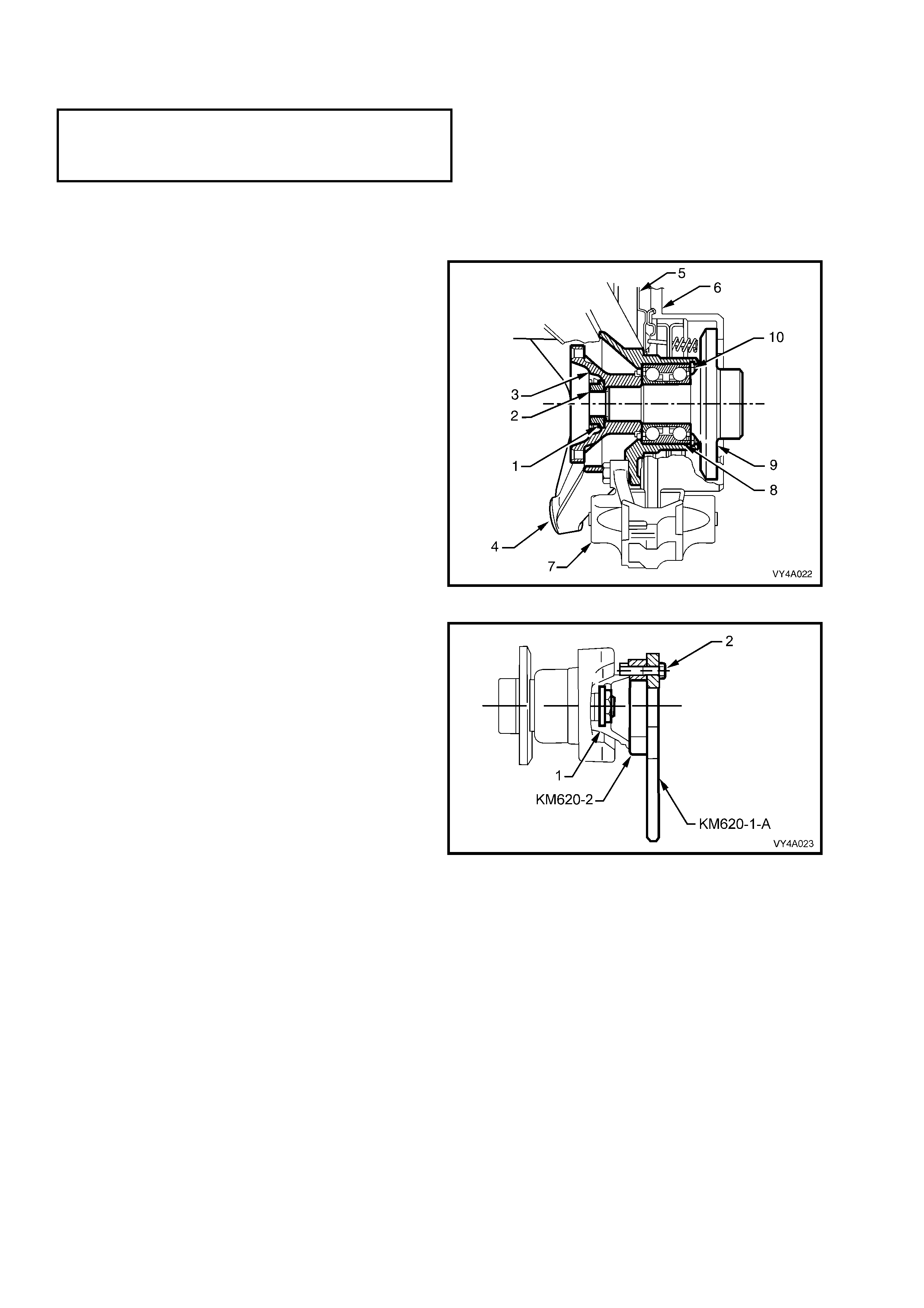
Trunnion Assembly – Sectioned View
Legend:
1. Collar Nut Lock Plate
2. Collar Nut
3. Rear Wheel Drive Shaft Flange
4. Rear Suspension Control Arm
5. Brake Backing Plate
6. Brake Rotor
7. Brake Caliper
8. Rear Wheel Bearing
9. Outer Rear Wheel Drive Shaft
10. Rear Wheel Bearing Retaining Ring
Figure 4A-22
1. Remove the rear suspension control arm.
Refer 2.2 REAR SUSPENSION CONTROL
ARM in this Section for details.
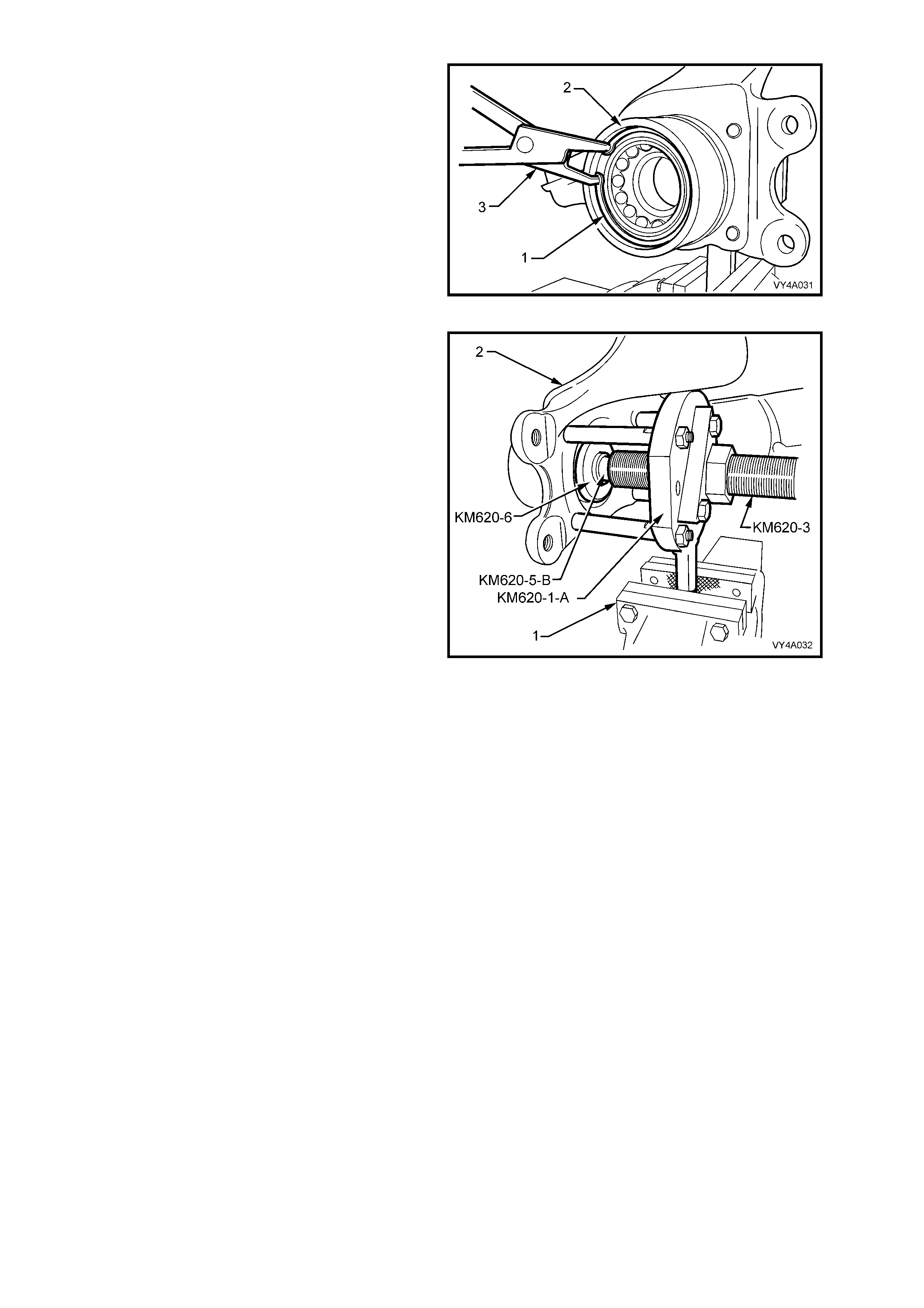
2. Secure the flange holding tool, KM620-1-A and
rear wheel drive shaft f lange ring tool KM620-2
to the rear wheel drive shaft flange (1) with
three of the removed drive shaft constant
velocity joint to rear wheel drive shaft flange
attaching bolts (2).
NOTE: Align holes marked ‘B’ on the flange holding
tool KM620-1-A and KM620-2 with holes in the rear
wheel drive shaft flange before installing and
tightening bolts.
Figure 4A-23
3. Distort the rear wheel drive shaft flange collar
nut lock plate, using a suitable size pin punch
and hamm er , then remove and dis car d the loc k
plate.
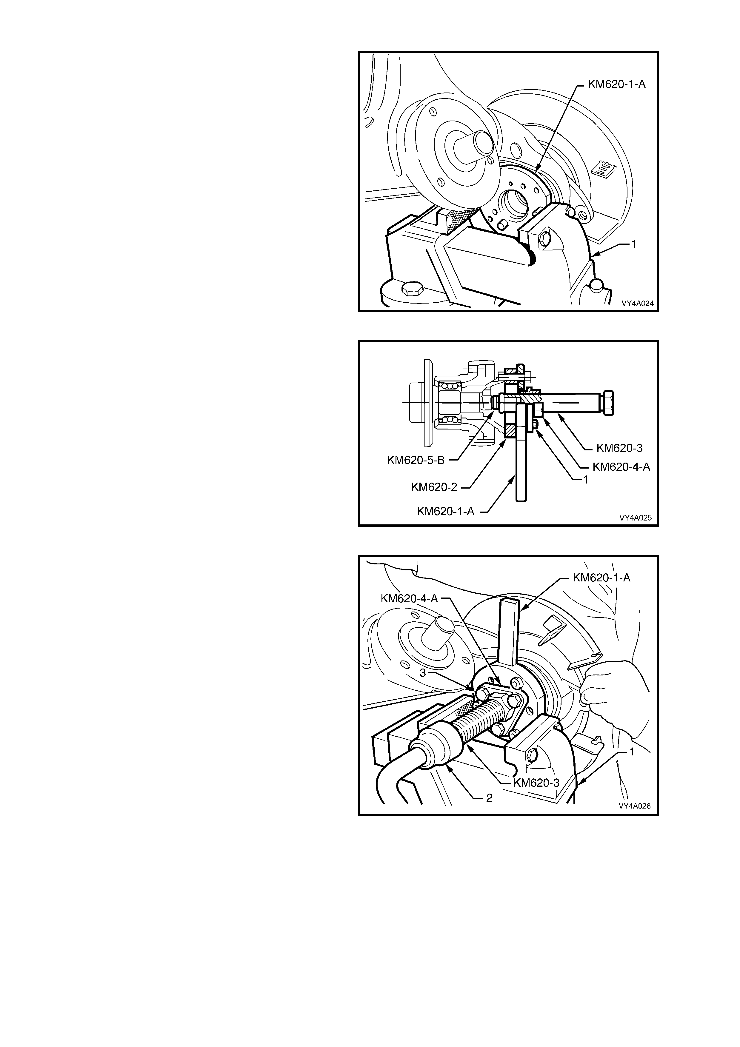
4. Mount the assembly in a vice (1), gripping the
handle or the flats of the flange holding tool
KM620-1-A. Loosen, then remove and discard
the rear wheel drive shaft flange to outer rear
wheel drive shaft collar nut and lock plate.
NOTE: The collar nut and the lock plate must be
replaced on reassembly.
5. Leave the holding tool KM620-1-A and the rear
wheel drive shaft flange ring tool KM620-2
assembled to the rear wheel drive shaft flange.
Figure 4A-24
6. Lubricate the threads of the forcing screw
KM620-3, then install the screw to adaptor
KM620-4-A. Apply grease to the ball end of the
plunger, Tool No. KM620-5-B, then install that,
into the end of the forcing screw KM620-3.
7. Install the whole sub-assembly through the
central opening of the flange holding tool
KM620-1-A. Secure the adaptor KM620-4-A to
the flange holding tool KM620-1-A, using three
suitable bolts (1).
NOTE: Adjust the position of the forcing screw
KM620-3 in the adaptor KM620-4-A, to allow the
adaptor to be in full contact with the flange holding
tool KM620-1-A.
Figure 4A-25
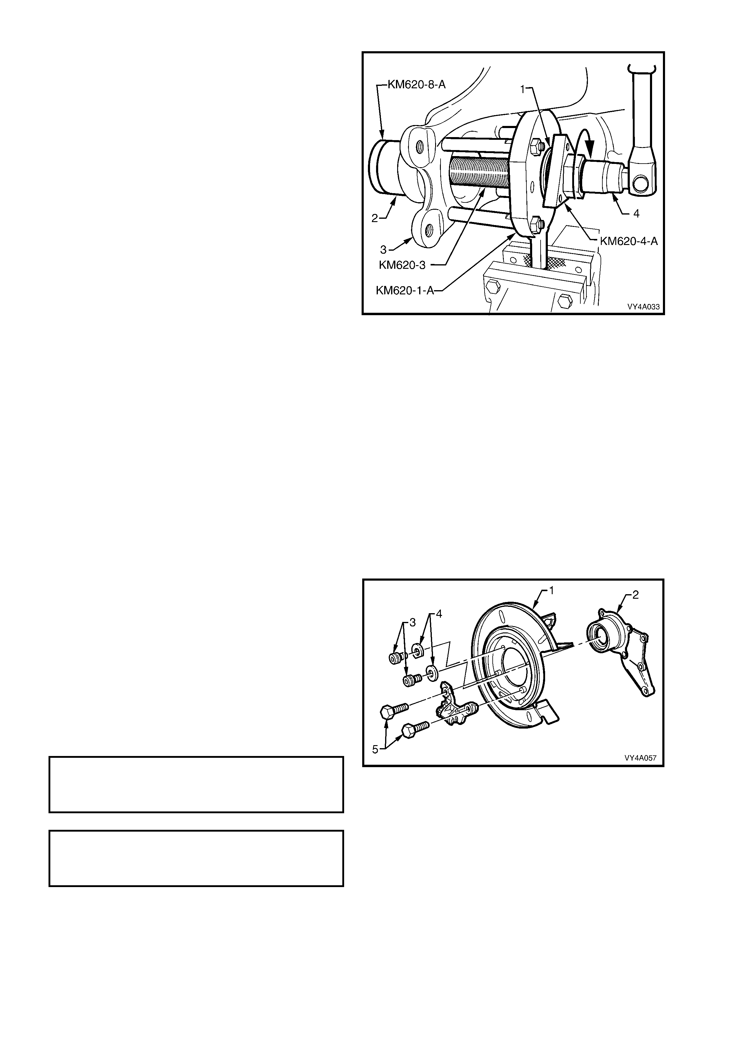
8. W ith the flange holding tool KM620-1-A held in
a vice (1) and, with an assistant holding and
supporting the weight of the rear suspension
control arm assembly, turn the forcing screw
(KM620-3) us ing suitable s oc ket equipment (2),
until the flange is f r ee f r om the outer rear wheel
drive shaft, then remove and separate the
special tool components from the rear wheel
drive shaft flange.
Figure 4A-26
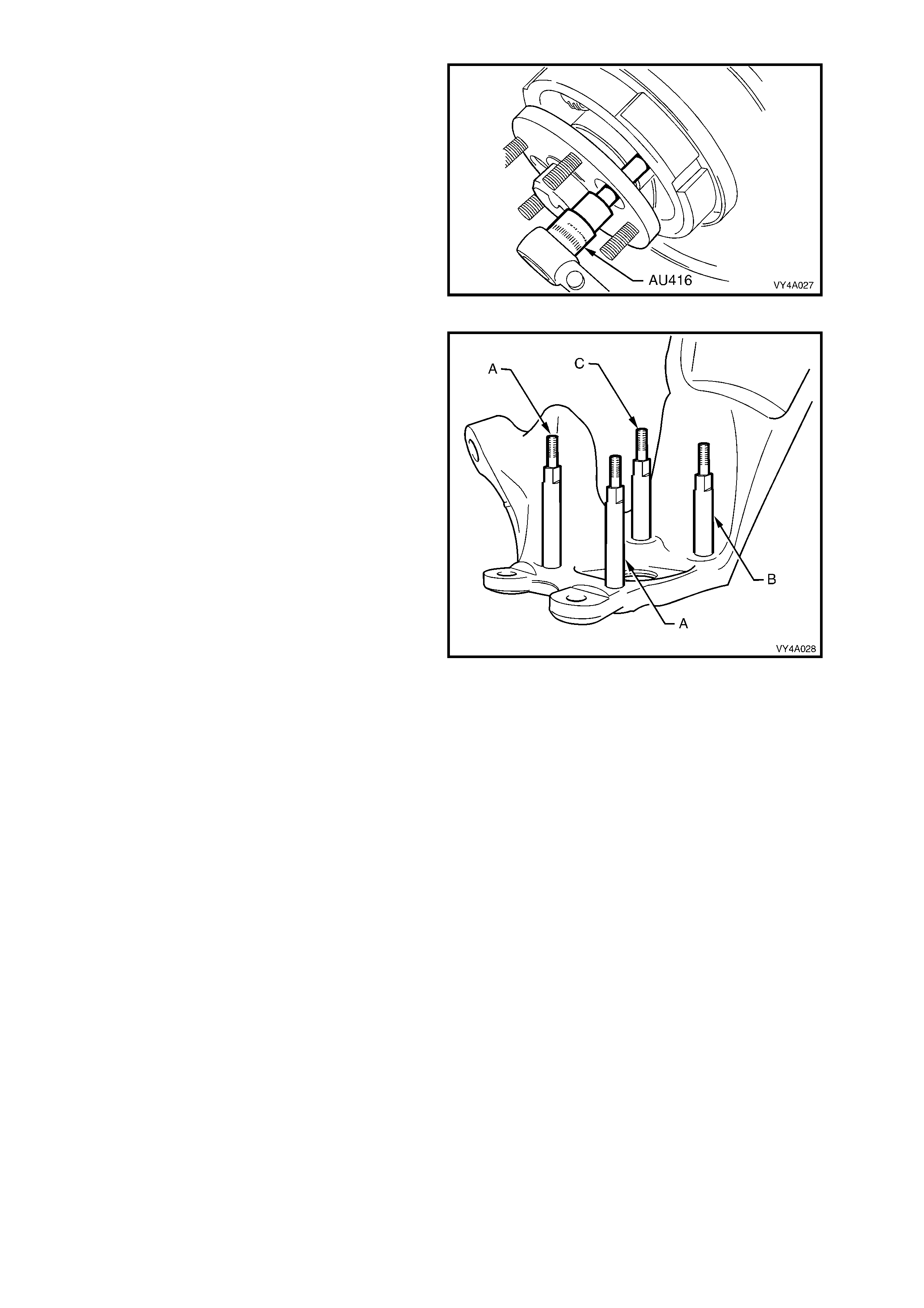
9. Using Torx bit s oc k et, Tool No. AU416, remove
the two upper bolts attaching the brake backing
plate to the rear suspension control arm, then,
using suitable socket equipment, remove the
two longer, hexagonal headed, lower bolts.
Figure 4A-27
10. Prior to removing the outer rear wheel drive
shaft and rear wheel bearing from the rear
suspension control arm, use a commercially
available M10 x 1.25 bottoming tap and a
suitable lubricant, clean the four backing plate
to rear suspension control arm bolt threads
working from the outer rear wheel drive shaft
side.
NOTE: This step is necessary to clear any dried
mud, dirt etc, from the exposed portion of the
threads on the inboard side of the rear suspension
control arm. Also, the deepest thread (position ‘C’)
may not be completely formed through to the
inboard side.
11. Install two supports KM620-7-A in positions ‘A’
and two KM620-7- AUS to ‘B’ and ‘C’ in the rear
suspension control arm, as indicated.
As a guide, the two longest supports (KM620-
7-A) are to be installed at the brake caliper
mounting side (position ‘A’). The longer of
KM620-7-AUS supports is installed at position
‘B’ and the shorter is installed at position ‘C’.
12. After installing all four supports in the correct
positions, tighten with a set spanner.
Figure 4A-28
13. Install the flange holding tool KM620-1-A over
the four supports, KM620-7-A (2 places) and
KM620-7-AUS (2 places), install four suitable
nuts (1) and tighten to secure.
14. Pre-assemble the lubricated forcing screw
KM620-3 to the adaptor KM620-4-A. Apply
grease to the ball end of the plunger KM620- 5-
B, then install that, into the end of the forcing
screw KM620-3.
15. Install this sub-assembly through the central
opening of holding tool KM620-1-A. Secure the
adaptor KM620-4-A to the flange holding tool
KM620-1-A, using three suitable bolts (2).
NOTE: Adjust the position of the forcing screw
KM620-3 into the adaptor KM620-4-A, to allow full
contact of the adaptor to the flange holding tool
KM620-1-A.
16. Tighten the three bolts securing adaptor
KM620-4-A to the flange holding Tool KM620-
1-A.
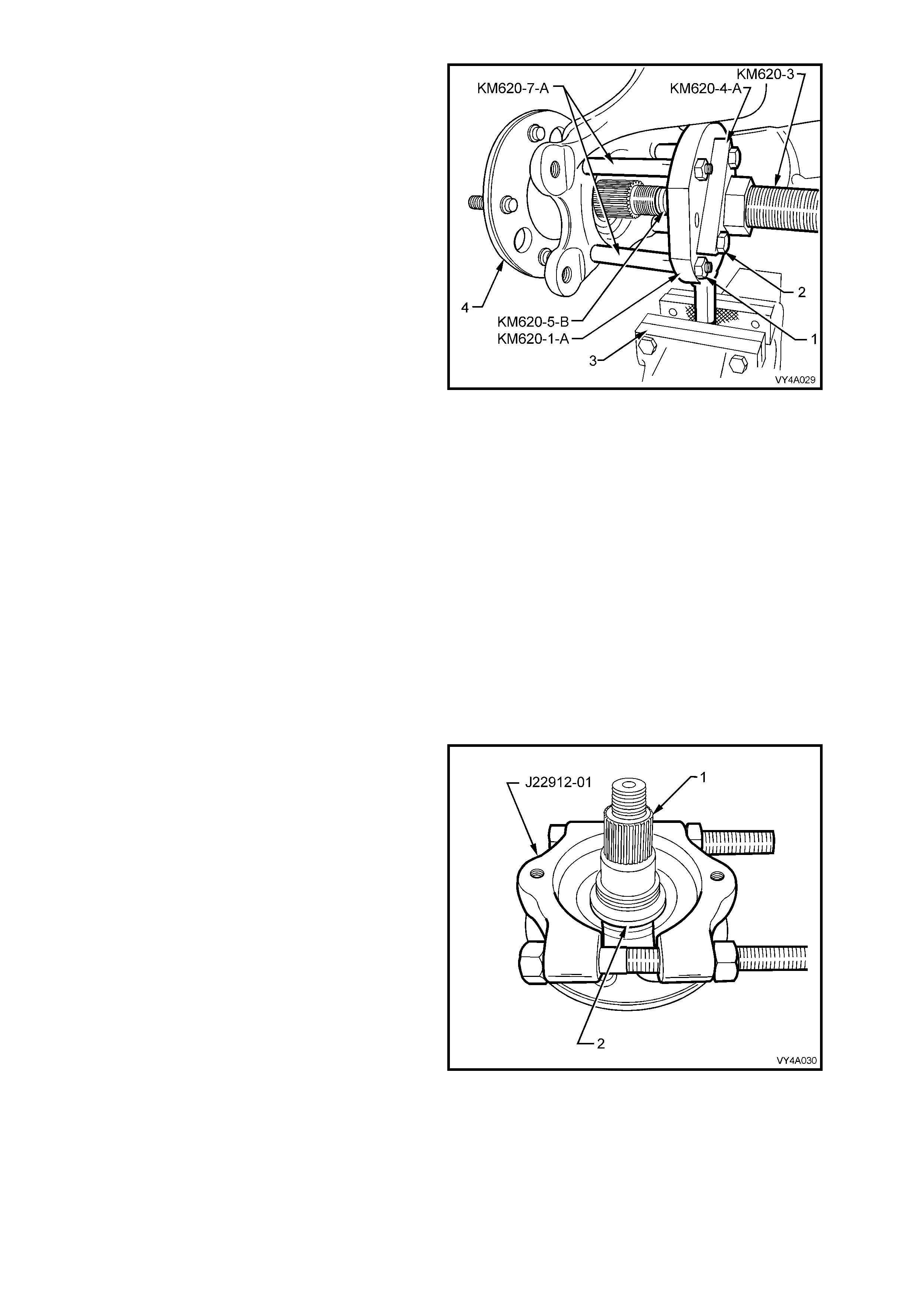
17. Mount the assem bly in a vice (3) by the handle
of the f lange holding tool KM620-1- A as s hown,
then turn the forcing s crew KM620-3 and press
the outer rear wheel drive shaft (4) from the
rear wheel bearing.
18. When the outer rear wheel drive shaft has
been removed, unscrew the forcing screw, as
this same arrangement is used to press the
rear wheel bearing from the rear suspension
control arm.
NOTE: The inner rear wheel bearing cone will
separate from the bearing assembly and be
retained on the outer rear wheel drive shaft.
19. Remove the brake backing plate and park
brake assembly from the rear suspension
control arm and set to one side.
Figure 4A-29
20. If the outer rear wheel drive shaft (1) is to be
re-used, then the outer half of the inner rear
wheel bearing cone ( 2) will need to be removed
from the outer rear wheel drive shaft.
a. Install the press plates J22912-01 over the
bearing cone and tighten the press plate
bolts to grip the bearing cone.
b. Pres s the outer rear wheel drive shaft from
the bearing cone and discard bearing cone.
NOTE 1: If the outer rear wheel drive shaft is to be
replaced, then step 20, is not required.
NOTE 2: A new outer rear wheel drive shaft is
supplied with wheel studs already installed.
Figure 4A-30
21. Remove the wheel bearing retaining ring (1)
from the rear s uspension contr ol arm (2), using
suitable circlip pliers (3).
Figure 4A-31
22. With the tool components set up as shown in
Figure 4A-29, install the rear axle bearing
removing plate KM620-6 into the rear of the
axle bearing. Reposition the forcing screw
KM620-3 and the adaptor KM620-5-B to retain
the removing plate KM620-6 in place.
23. With KM620-1-A mounted in the vice jaws (1),
turn the forcing screw KM620-3 clockwise to
press the wheel bearing from the rear
suspension control arm (2).
24. If installing a replacement rear suspension
control arm without bushing, install new
bushing. Refer to 2.2 REAR SUSPENSION
CONTROL ARM in this Section.
25. Ensure that the bearing bore of the rear
suspens ion contr ol ar m is c lean and f ree of any
foreign matter.
26. Coat the outside diameter of a new wheel
bearing and the bore of the rear suspension
control arm with lubricant such as Molybond
HB50 (or a commercially available equivalent).
Figure 4A-32
27. Rem ove the bolts secur ing adaptor KM620- 4-A
to the holding tool KM620-1-A, then r emove the
adaptor and forcing screw KM620-3.
28. Lubricate the thrust ball bearing race (1) (part
of KM620-A) with lubricant such as Molybond
HB50 (or commercially available equivalent),
then assemble the bearing onto the flanged
end of adaptor KM620-4-A.
29. Install the forcing screw and adaptor/bearing
assem bly to the flange holding tool KM620-1- A.
Do not install the adaptor (KM620-4-A) to
holding tool (KM620-1-A) attaching bolts.
30. Install the bearing installer KM620-8-A into a
new bearing (2) and install both into the rear
suspension control arm (3).
31. Join the forcing screw (KM620-3), and the
bearing installer (KM620-8-A) by engaging the
screw thread of the forcing screw (KM620-3)
with the installer (KM620-8-B) and tightening
the forcing screw to engage at least 8 full
threads.
32. While holding the forcing screw (KM620-3)
from turning by using suitable socket
equipment ( 4) , rotate the adaptor KM620-4- A in
the direction shown, with a suitable 40 mm
wrench to draw the new bearing (2) fully into
position.
33. Remove the installer KM620-8-A once the
bearing is fully installed, then install the
retaining ring into the rear suspension control
arm using suitable circlip pliers, ensuring that
the ring is seated correctly.
34. Separate all special tool components from the
rear wheel drive shaft flange, after the bearing
has been fully installed.
Figure 4A-33
NOTE 1: T he two upper bolts (3) have washer s (4)
that are installed with the cut-out edge facing
around the rear suspension control arm hub outer
surface.
NOTE 2: Apply Loctite 242 (or a commercially
available equivalent) to the threads of the two
longer, lower hexagon headed bolts (5), before
installation.
35. Install the rear brake shield (1) to rear
suspension control arm (2) bolts and tighten to
the correct torque specification.
REAR BRAKE SHIELD TO REAR
SUSPENSION CONTROL ARM
UPPER ATTACHING BOLT
TORQUE SPECIFICATION ................... 70 – 80 Nm
REAR BRAKE SHIELD TO REAR
SUSPENSION CONTROL ARM
LOWE R ATTACHING BOLT
TORQUE SPECIFICATION ................... 85 – 90 Nm
Figure 4A-34
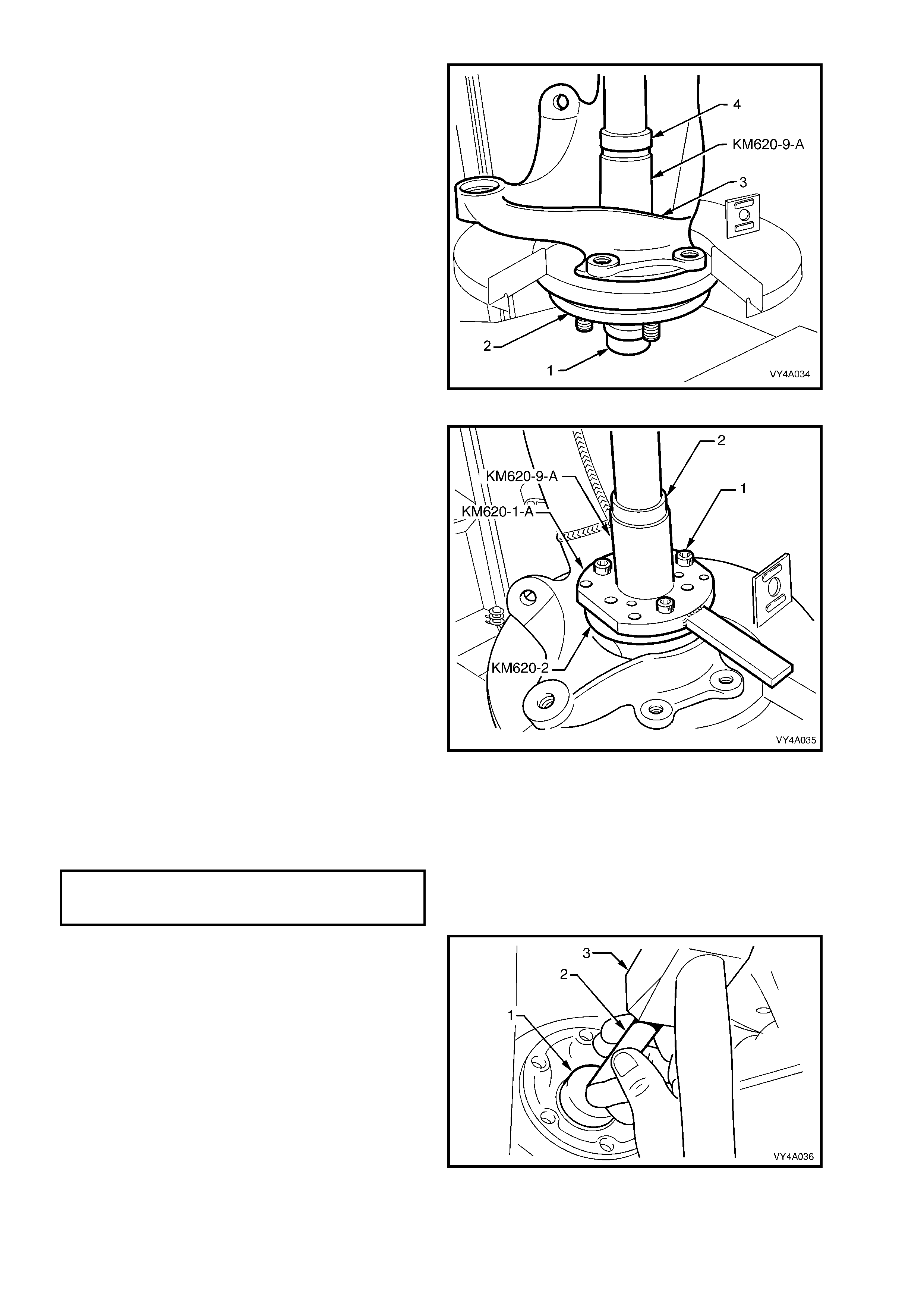
36. Position the outer rear wheel drive shaft (2)
with the centre hub section resting on a
suitable support (1) and press plates, checking
to make sure that the outer rear wheel drive
shaft wheel studs do not contact press plates.
37. Position the rear suspension control arm (3)
with the wheel bearing onto the outer rear
wheel drive shaft. W ith an assistant supporting
the rear suspension control arm assembly in
this position, us e installer KM620-9-A and steel
pipe (4) of suitable length and diameter, press
wheel bearing onto the outer rear wheel drive
shaft.
Figure 4A-35
38. Remove the installer KM620-9-A and steel
pipe. Assemble the flange holding tool KM620-
1-A and rear wheel drive shaft flange ring
KM620-2 to the rear wheel drive shaft flange
using three drive shaft attaching bolts (1).
39. Lubricate the rear wheel drive shaft flange
splines and the outer rear wheel drive shaft
threads with a suitable lubricant such as
Molybond HB50 (or a commercially available
equivalent), then install the rear wheel drive
shaft flange onto the outer rear wheel drive
shaft, aligning the splines on each.
40. W ith the outer rear wheel drive shaf t supported
on press plates, as in step 36, press the rear
wheel drive shaft flange onto the outer rear
wheel drive shaft using installer KM620-9-A
and a suitable steel pipe (2).
41. Remove the rear suspension control arm
assembly from the press and support the
assembly in a vice by the flats on flange
holding tool KM620-1-A.
42. Install a new collar nut to the outer rear wheel
drive shaft and tighten to the correct torque
specification.
( ! ) COLLAR NUT TO OUTER REAR
WHEEL DRIVE SHAFT
TORQUE SPECIFICATION ................ 295 – 305 Nm
Figure 4A-36
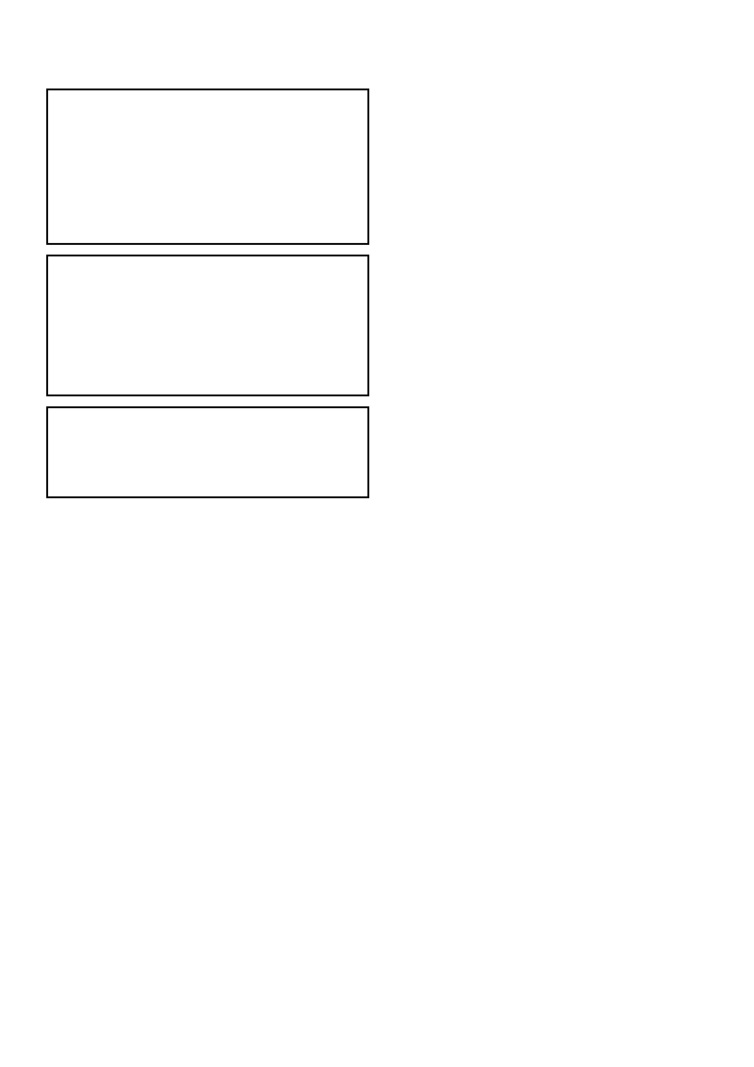
43. Remove the rear suspension control arm
assembly from the vice and remove all the
special tools from the rear wheel drive shaft
flange. Using a suitable diameter socket (1),
150 mm socket shaft (2) and hammer (3),
install a new lock plate over the collar nut.
Figure 4A-37
2.4 REAR SUSPENSION CROSSMEMBER
LT Section No. – 07-150
NOTE 1: The following fasteners have either micro
encapsulation or incorporate a mechanical thread lock
and should only be used once. If in doubt, r eplacement
is recommended when performing this operation:
♦ Rear suspension crossmember front mounting
brace to under body attaching bolts.
♦ Additional control arm inner shaft attaching nut.
♦ Rear suspension control arm to rear suspension
crossmember attaching nut.
NOTE 2: The following fasteners MUST be replaced
when performing this operation:
!!!!$
$$
$ Rear suspension crossmember rear mount to
under body attaching bolt.
!!!!$
$$
$ Rear suspension crossmember front mounting
bolt.
!
!!
!$
$$
$ Differential carrier to rear suspension
crossmember attaching bolts.
NOTE 3: The following fasteners MUST be at curb
height before final tightening:
• Rear suspension control arm to rear suspension
crossmember attaching nut.
• Shock absorber lower mounting bolt.
CAUTION: Whenever any component that forms part of the ABS (if fitted) is disturbed during
Service Operat ions, it is v ital th at the co mplete ABS system b e checked, using the pro cedure as detailed in
4.4 ABS & T CS FUNCTION CHECK (V6 engines) or 5.4 ABS & TCS FUNCT ION CHECK (GEN III V8 engines),
in Section 5B ABS & TCS.
Important: Before dis tur bing the rear s uspens ion c r oss member mounting bolts, an alignment proc edure is r equired
on installation and a special tool is required for this purpose. If this tool is not available, then the crossmember
cannot be correctly aligned and steering and/or handling abnormalities will result.
REMOVE
1. Using a floor jack under the centre of the differential carrier, jack up the rear of the vehicle and place safety
stands under the body rear jacking points. Refer to Section 0A, GENERAL INFORMATION for location of
jacking points.
2. Remove the wheel covers (steel wheels) or centre caps (alloy wheels).
3. Mark the relationship of the road wheels to the hubs (eg. end of wheel stud), with a felt tipped pen or similar.
Loosen then remove the road wheel attaching nuts. Remove the road wheel.
4. Disconnect and remove the exhaust system from the rear of the catalytic converter/s.
5. Remove the intermediate muffler heatshield from the vehicle underbody.
NOTE: For information regarding the removal and installation of the exhaust components (including heatshields),
refer to Section 8B, EXHAUST SYSTEM.
6. To enable the propeller shaft to be installed in
the original position relative to the pinion flange,
use a felt tipped pen or similar to identify the
relationship (‘A’) between the two components.
7. With the transmission in the ‘Park’ position
(automatic transmission) or in first gear
(m anual transm ission and the park brak e firm ly
applied, use Torx socket K04425E20 or a
commercially available E20 Torx socket to
loosen the three T or x headed bolts (1) secur ing
the propeller shaft rear rubber coupling (2) to
the pinion flange (3).
8. Release the park brake to relieve any torque
loading on the rubber coupling, then remove
the three Torx headed bolts.
Figure 4C-38
9. W hile supporting the centre bearing carrier (1),
remove the two bolts (2) securing the centre
bearing carrier to the underbody reinforcement.
10. While supporting the centre bearing section,
slide the propeller shaft assembly forward to
disengage f rom the rear sus pension diff erential
assembly pinion support pin.
11. Install the centre bearing support bolts (do not
tighten) and use a suitable length of wire to tie
the rear of the pr opeller s haf t to a s uitable point
on the vehicle underbody.
Figure 4C-39
12. Set the park brake in the fully released position,
then release each of the underbody to park
brake cable (1) retaining clips (2) and free the
cables.
Figure 4A-40
13. Remove the park brake outer cable retaining
bracket bolt (underbody bracket and bolt are
not shown) from the vehicle underbody.
14. Pull each park brake inner cable (1) forward
and up in the direction of the arrow (A) and out
of the cable retainer (2) to release each cable.
15. Pull the outer cable (3) rearward (B) to remove
from the underbody retainer (4).
Figure 4A-41
16. Disconnect the brake pipe (1) from the brake
hose (2) at the rear suspension control arm
bracket (3) and remove the brake hose
retaining clip (4).
Plug the open ends of both pipes and hoses to
prevent unnecessary fluid loss and/or foreign
matter entry.
17. Repeat for the other side.
Figure 4A-42
18. Pull the differ ential c arr ier br eather hos e ( 1) out
of the hole (2) in the vehicle underbody rear
suspension crossmember.
Figure 4A-43
19. If the vehicle is f itted with ABS, pull both sensor
lead connectors from the underbody retaining
clips (1). Separate the sensor connectors from
the body harnes s connectors by levering with a
screwdriver.
Figure 4A-44
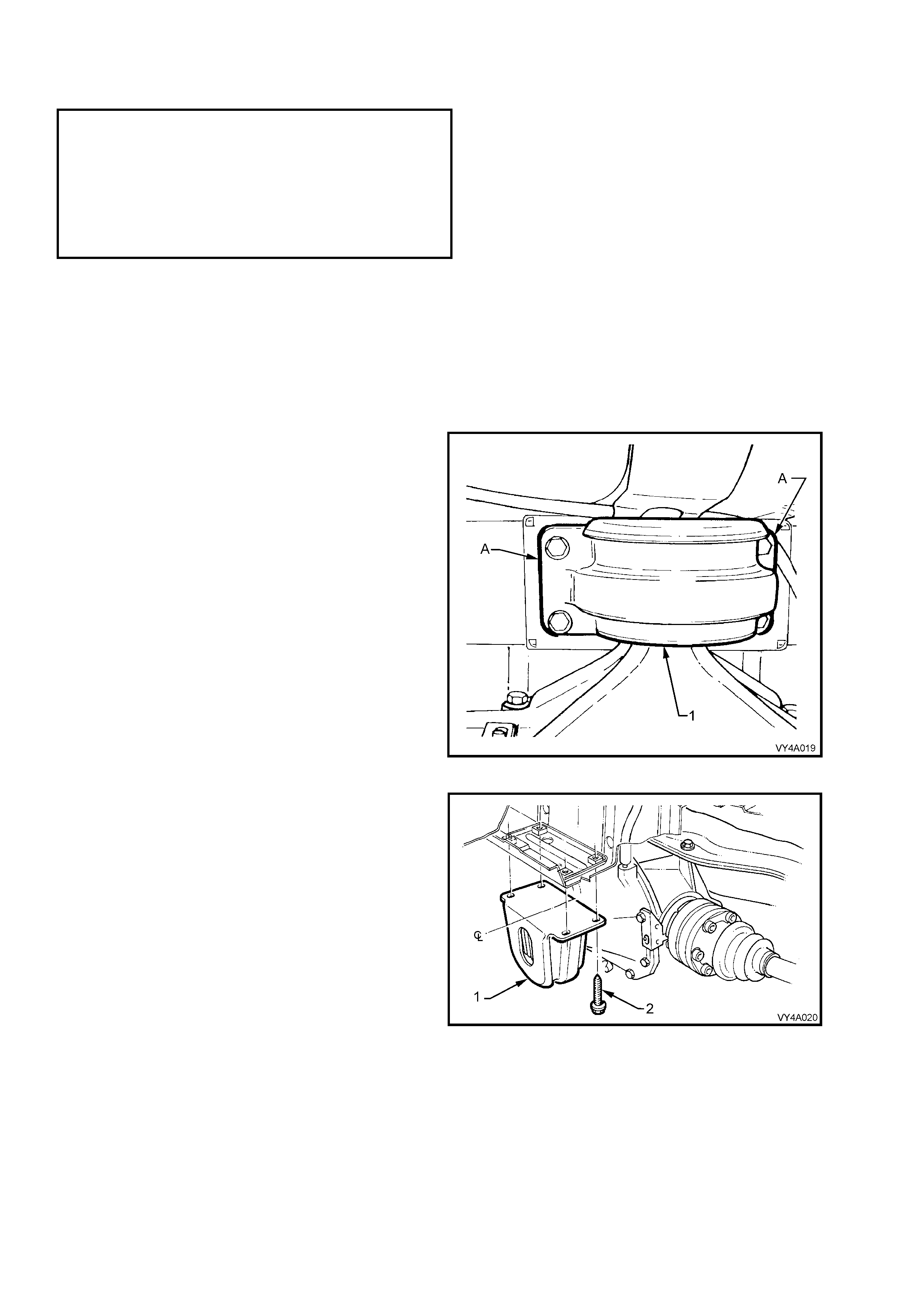
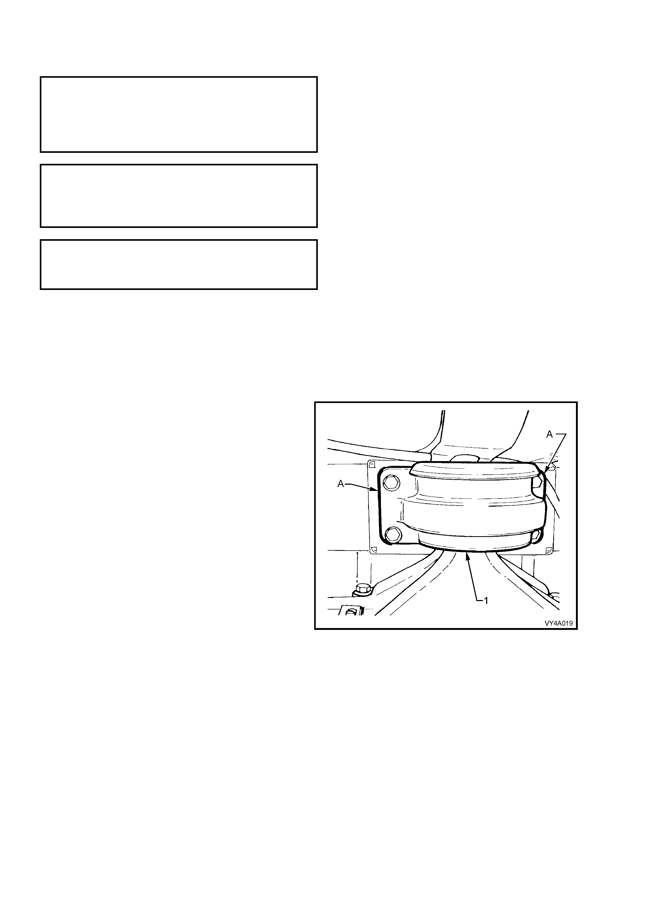
20. Using a scriber, mark the location (A) of the
rear mount (1) to vehicle under body location.
This will assist in rear suspension
crossmember alignment on installation.
21. Support the weight of the differential carrier
with a floor jack.
Figure 4A-45
22. Remove and discard the rear mount (1) to
vehicle underbody attaching bolts (2), the lower
differential carrier and rear suspension
crossmember assembly by at least 60 mm.
Figure 4A-46
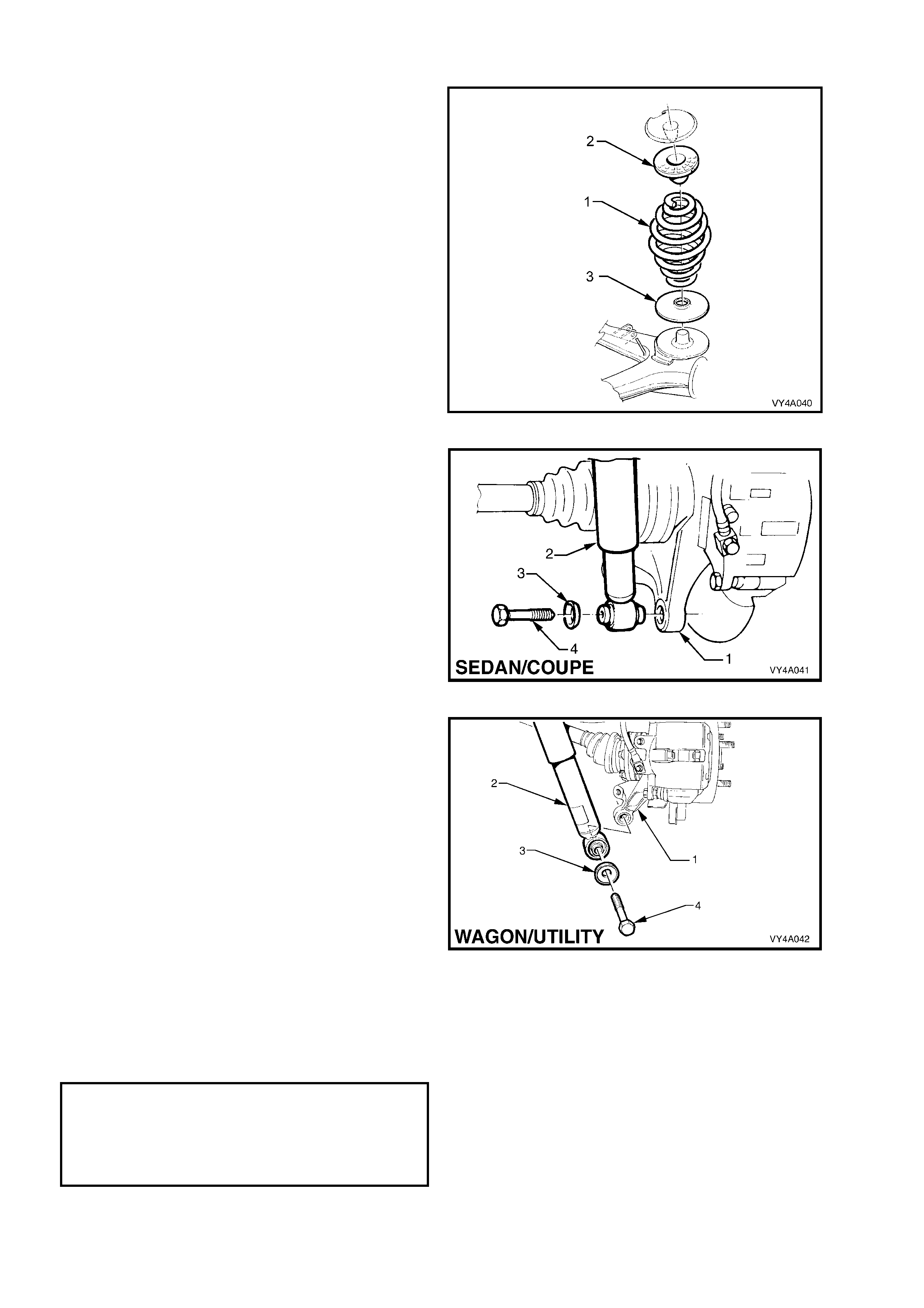
23. Position the floor jack with a block of wood
under the rear suspension control arm. Raise
the jack slightly to take the spring load off the
rear suspension control arm. Remove the rear
shock absorber lower mounting bolt (1) and
washer (2) from the rear suspension control
arm (3), then pull the lower end of the shock
absorber (4) from the rear suspension control
arm.
NOTE: Bruising to the inside of the drive shaft
constant velocity joint boots will occur if the shock
absorber is disconnected f rom the rear suspension
control arm bef ore the r ear of the dif f erential car rier
and crossmember assembly has been lowered by
at least 60 mm. Bruising of the boot will lead to
prem ature f ailure of the boot and eventual failure of
the joint if left unchecked.
Figure 4A-47
Figure 4A-48
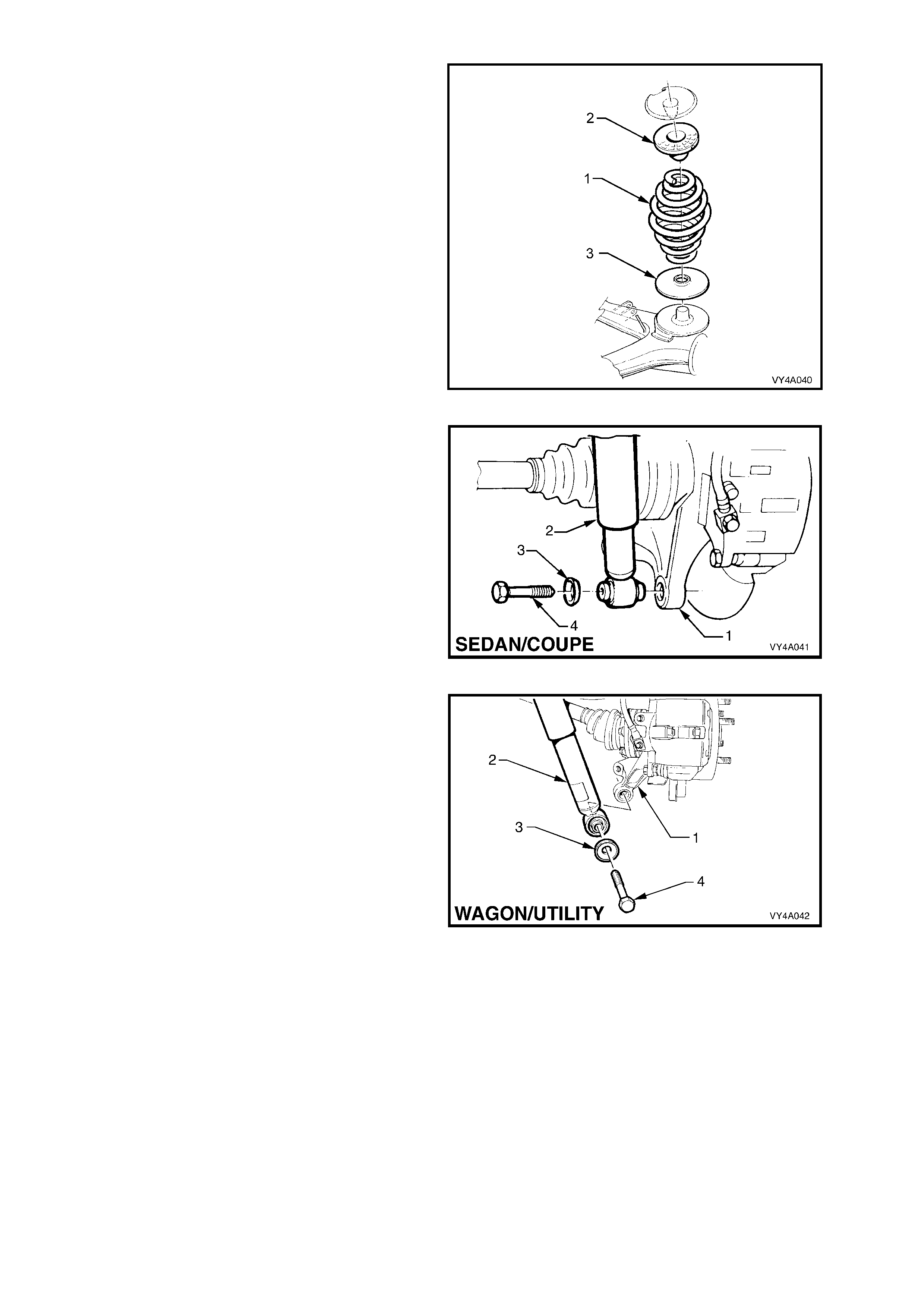
24. Remove the rear springs (1), the upper
insulators (2) and the lower insulators (3) from
the vehicle underbody and rear suspension
control arms.
25. Raise the differential carrier and rear
suspension crossmember on a floor jack until
the rear mount contacts the vehicle underbody.
Figure 4A-49
26. Use a floor jac k and a bloc k of wood to support
the differential carrier and crossmember
assembly.
27. Remove the brace to underbody bolts (1)
(3 places) and crossmember to vehicle
underbody attaching bolt (2) from each side.
28. Remove the braces (3) from the vehicle.
29. With an assistant supporting the front end of
the rear suspension crossmember, lower the
assembly on the jack and remove from
beneath the vehicle.
NOTE: If the vehicle is fitted with the GEN III V8
engine and manual transmission, take care not to
lose the is olating r ubbers (4 ) loc ated on top of eac h
rear suspension crossmember front mount
bushing.
30. Remove the differential carrier and
crossmember assembly from the jack and
support the rear suspens ion control ar m s, drive
shafts and differential carrier on wooden
blocks.
Figure 4A-50
31. Remove the stabiliser shaft mounting bracket
attaching bolts (1). Use a screwdriver to lever
up the brackets (2) from the mounting points
and remove the brackets.
32. Remove and discard the differential carrier to
crossmember attaching bolts (3).
33. Remove the rear suspension control arm to
crossmember attaching bolts and nuts (4).
Discard the nuts, as new ones must be used
on reassem bly. Disengage the rear suspens ion
control arms from the crossmember.
34. After loosening the stabiliser link attaching nuts
(5) at each end and on each side to avoid
stres s on the bus hing, s wing the stabilis er s haf t
(6) back from the crossmember.
35. Remove the additional control arm inner shaft
to rear suspension crossmember retaining nut
and bolt and manoeuvre the additional control
arm free from the crossmember.
36. Lift up and remove the crossmember.
Figure 4A- 51
REINSTALL
Installation of the rear suspension crossmember is the reverse of the rem oval procedures, except for the following
steps:
1. If replacing a crossmember that does not have front mount bushing, install new bushing. Refer to
2.5 REAR SUSPENSION CROSSMEMBER FRONT MOUNT BUSHING in this Section, for the required
procedure.
2. Install the crossmember over the differential carrier and rear suspension control arms.
3. Assemble the rear suspension control arms into the crossm ember brackets and install the attaching bolts and
new self-locking nuts.
Do not fully tighten nuts at this stage.
4. Align the crossmember and differential carrier mounting holes, install new attaching bolts and tighten to the
correct torque specification.
( ! ) DIFFERENTIAL ASSEMBLY TO
REAR CROSSMEMBER ATTACHING
BOLT TORQUE SPECIFICATION......... 90 Nm, plus
30° - 45°
turn angle
5. Position the stabilis er shaft onto the cros smem ber, with the insulators located over the cross mem ber m ounting
points.
6. Engage the brackets into the mounting points and install over the insulators, install attaching bolts and tighten to
the correct torque specification.
Stabiliser shaft mounting
bracket TO CROSSMEMBER
ATTACHING BOLT
TORQUE SPECIFICATION ................... 18 – 26 Nm
7. Install the additional control arm into the rear suspension crossmember, install attaching bolt and a NEW nut
and tighten to the correct torque specification.
( # ) ADDITIONAL CONTROL ARM
INNER SHAFT ATTACHING NUT
TORQUE SPECIFICATION ................... 55 – 70 Nm
8. With the aid of two ass istants, place the dif ferential c arrier and rear s uspension cros sm ember assem bly onto a
floor jack.
9. Position the assembly under the vehicle, raise with the jack and, with the aid of the assistants, guide the
crossmember front mounting points into position.
NOTE: During this operation, ensure that rear suspension control arms are also supported on safety stands, to
keep the drive shafts as near to horizontal as possible. Otherwise, bruising to the insides of the constant velocity
joint boots will result, leading to boots splitting and eventually joint failure, if left unchecked.
10. If the vehicle is fitted with the GEN III V8 engine
and manual transmission, an isolating rubber
(4) must be fitted at the top of each
crossmember front mount bushing as shown,
before raising the assembly into place.
11. Install both crossmember front mounting
braces (3), the six mounting brace attaching
bolts (1) and the two rear suspension
crossmember front mounting bolts (2) but do
not fully tighten any of these bolts at this
stage.
Figure 4A-52
12. Lower the differential carrier and rear
suspension crossmember assembly on the
floor jack and s afety stands. Install rear springs
(1) and the upper (2) and lower (3) spring
insulators between the rear suspension control
arm and the vehicle underbody.
Figure 4A-53
13. With both springs and insulators installed, use
a second floor jack to raise each rear
suspension control arm (1) up sufficiently to
allow shock absorber (2) lower mounting to be
installed to the rear suspension control arm.
14. Install washers (3) and bolts (4) into the shock
absorber lower mounts but do not fully
tighten at this stage. Repeat for the other
side.
NOTE 1: T he torque s pecific ation for Sedan/Coupe
and Station Wagon/Utility are the same.
NOTE 2: Vehicle m ust be at curb weight and on all
four wheels before this the shock absorber lower
mounting bolts are tightened to the correct torque
specification.
Figure 4A-54
Figure 4A-55
15. Raise the assembly until the rear mount
contacts the vehicle underbody.
16. Align the rear mount (1) with the marks (A) on
the underbody, made on disassembly, then
loosely install new attaching bolts but do not
fully tighten at this stage.
17. The rear suspension crossm ember MUST now
be aligned to the vehicle centreline, using the
special tool and procedure as detailed in
Section 1A2, BODY DIMENSIONS.
CAUTION: Failure to correctly align the rear
suspension crossmember to the centreline of
the vehicle will result in steering abnormalities
and uneven tyre wear!
18. Tighten all cros sm em ber m ounting f astener s to
the correct torque specification.
( ! ) CROSSMEMBER REAR MOUNT TO
VEHICLE UNDERBODY ATTACHING
BOLT TORQUE SPECIFICATION...... 30 – 40 Nm,
Plus 55° – 65°
turn angle
( ! ) REAR SUSPENSION CROSSMEMBER
FRONT MOUNTING BOLT
TORQUE SPECIFICATION ................ 125 Nm, plus
30° – 40°
turn angle
( ! ) REAR SUSPENSION CROSSMEMBER
FRONT MOUNTING BRACE BOLT
TORQUE SPECIFICATION ...................... 70 Nm
Figure 4A-56
19. Install the differential carrier breather hose into the hole in the vehicle underbody rear suspension
crossmember, ensuring that the end of the hose is pushed into the hole approximately 25 mm.
20. If equipped with ABS, reconnect the wheel sensor wiring harness connectors and install into the retaining clips.
21. Check the park brake adjustment and bleed the brake hydraulic system, refer to Section 5A, SERVICE AND
PARK BRAKING SYSTEM.
22. Reinstall the exhaust system, using new gasket/seal at the flanges on the catalytic converters.
23. Tighten the intermediate exhaust pipe to catalytic converter bolts to the correct torque specification.
INTERMEDIATE EXHAUST PIPE TO
CATALYTIC CONVERTER BOLT
TORQUE SPECIFICATION ................... 40 – 50 Nm
(All Engines)
24. Check the exhaust clearances as detailed in Section 8B, EXHAUST SYSTEM.
25. Install the road wheel/s, aligning the marks made prior to removal and secure with the attaching nuts but do not
fully tighten at this stage.
26. Remove the safety stands and lower the vehicle.
27. Bounce the rear of the vehicle several times to settle the suspension then, with vehicle in the curb height
position, tighten rear suspension control arm to crossmember attaching nuts, stabiliser shaft link nuts and the
shock absorber lower mounting bolts to the correct torque specifications.
( " # ) REAR SUSPENSION CONTROL
ARM TO REAR CROSSMEMBER
ATTACHING NUT
TORQUE SPECIFICATION ................... 95 – 105 Nm
STABILISER SHAFT LINK, UPPER
AND LOWER MOUNTING NUT
TORQUE SPECIFICATION ...................90 – 105 Nm
( " ) SHOCK ABSORBER
LOWER MOUNTING BOLT
TORQUE SPECIFICATION ................ 105 – 125 Nm
28. Tighten the road wheel attaching nuts to the correct torque specification, working in a ‘star’ pattern. Refer to
Section 10, WHEELS AND TYRES for detailed information regarding installation procedure for the road
wheels.
ROAD WHEEL ATTACHING NUT
TORQUE SPECIFICATION ................ 100 – 125 Nm
29. Install the wheel cover/centre cap.
30. Start the vehicle and check the exhaust system for leaks. Repair as necessary.
2.5 REAR SUSPENSION CROSSMEMBER FRONT MOUNT BUSHING
LT Section No. – 07-150A
NOTE 1: The following fasteners have either micro
encapsulation or incorporate a mechanical thread lock
and should only be used once. If in doubt, replacement
is recommended when performing this operation:
♦ Rear suspension crossmember front mounting
brace to under body attaching bolts.
NOTE: The following fasteners MUST be replaced
when performing this operation:
!!!!$
$$
$ Rear suspension crossmember front mounting
bolt.
CAUTION: Whenever any component that forms part of the ABS (if fitted) is disturbed during
Service Operat ions, it is v ital th at the co mplete ABS system b e checked, using the pro cedure as detailed in
4.4 ABS & T CS FUNCTION CHECK (V6 engines) or 5.4 ABS & TCS FUNCT ION CHECK (GEN III V8 engines),
in Section 5B ABS & TCS.
Important: Before removing the rear suspension crossmember, front mounting bolts, an alignment procedure is
required on installation and a special tool is required for this purpose. If this tool is not available, then the
crossmember cannot be correctly aligned and steering and/or handling abnormalities will result.
OFF-CAR REPLACEMENT
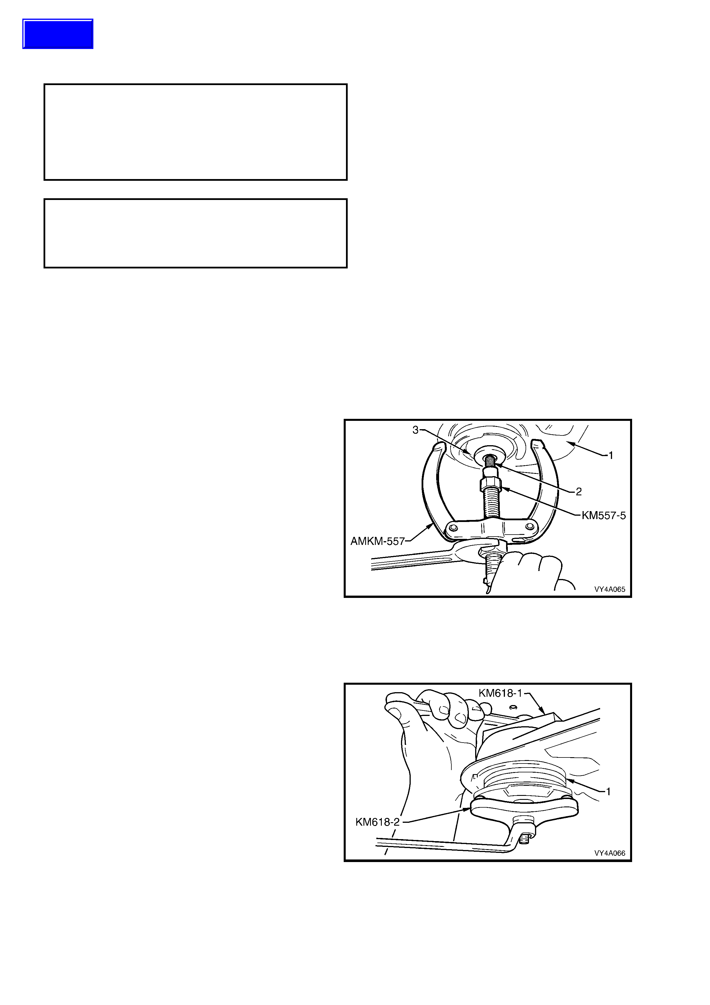
1. With the rear suspension crossmember (1)
removed, install the crossmember to
underbody attaching bolt (2) into the bushing
(3) from above.
NOTE: For information regarding the removal
and installation procedure for the rear
suspension crossmember assembly, refer to
2.4 REAR SUSPENSION CROSSMEMBER in this
Section.
2. Screw the underbody attaching bolt into puller,
Tool No. AMKM-557 and adaptor, Tool No.
KM-557-5 (part of Tool No. AMKM-557).
3. Tighten the forcing nut while holding the
threaded shaft of Tool No. AMKM-557 until the
bushing is removed from the crossmember.
4. Remove the crossmember to underbody
attaching bolt from the puller and adaptor
assembly and discard the bush.
Figure 4A-57
5. Draw the new bushing (1) into the
crossmem ber (2) using Tool No. KM618-1 and
KM618-2.
Figure 4A-58
Techline

ON-CAR REPLACEMENT
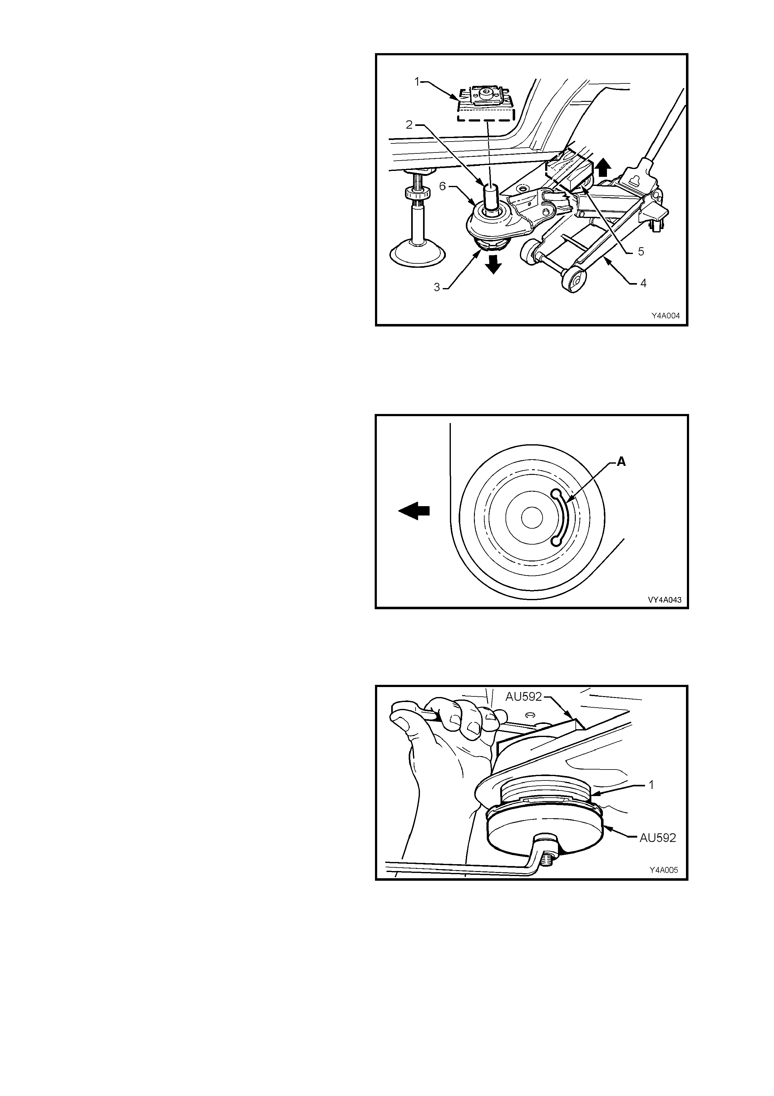
1. Using a floor jack (2) with a suitable wood block
(1) mounted on top of the floor jack to support
and protect the underside of the centre
differential carrier, jack up the rear of the
vehicle.
Figure 4A-59
2. Position s af ety stands (2) to s upport the vehic le
weight at both the LH side and RH side under
body rear jacking points (1). Refer to
Section 0A, GENERAL INFORMATION, for
the detailed information regarding the location
of the vehicle jacking points.
Figure 4A-60
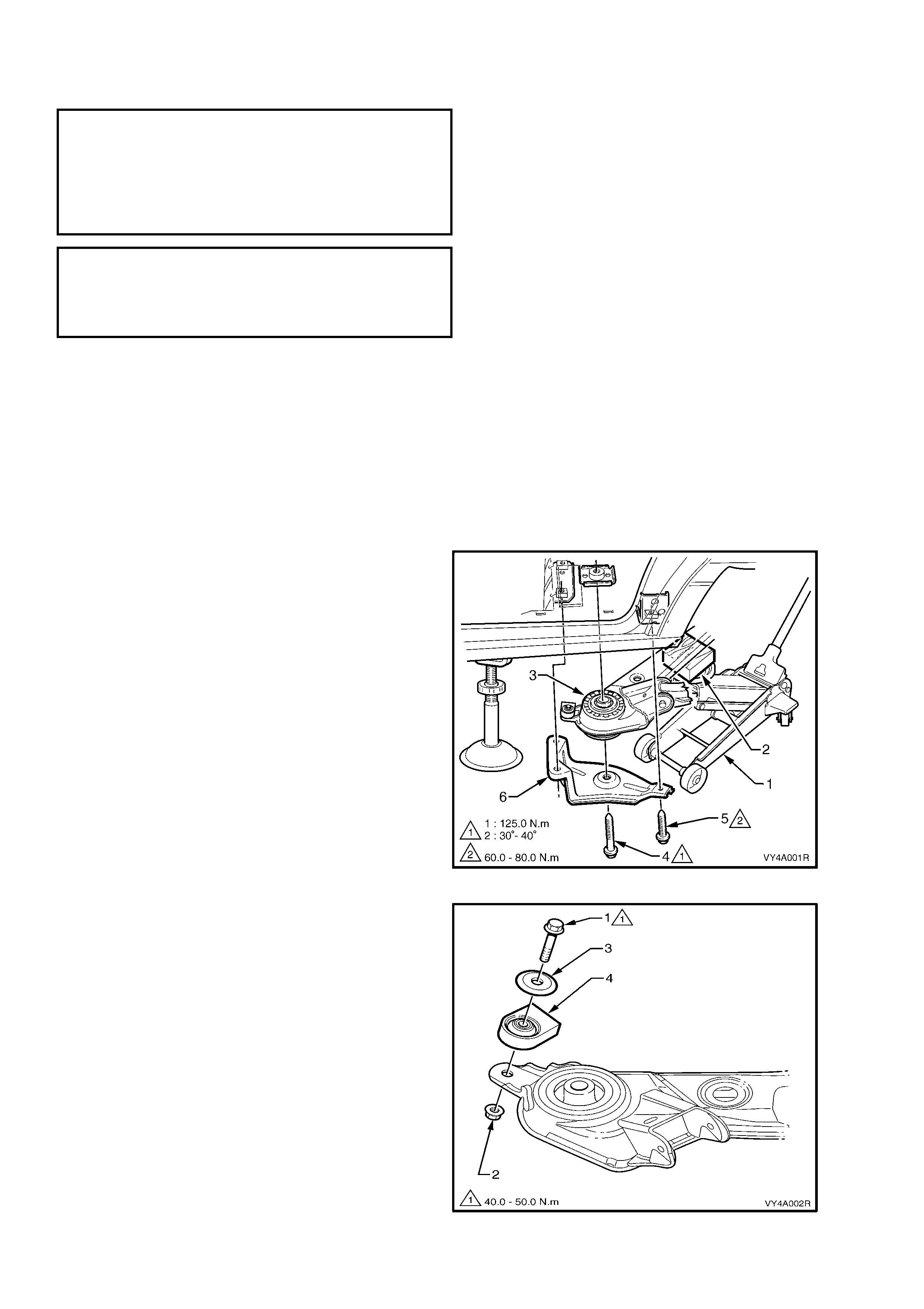
3. Position a floor jack (2) with a suitable block of
wood (1) mounted on top of the jacks’ lifting
pad to support and protec t the rear suspension
cross member as sembly (3) dur ing the f ollowing
procedure.
4. Take up the weight of the crossmember by
raising the floor jack to make contact with the
cross mem ber, nearest to the side on which the
bushing is to be replaced.
5. Rem ove the brac e (6) and the cros smem ber to
vehicle underbody attaching bolts (4 & 5) from
the same side of the vehicle.
6. Lower the floor jack slightly to allow clearance
between the crossmember and the vehicle
underbody.
Figure 4A-61
7. Place a suitable block of wood (1),
approxim ately 50m m in width x 50m m in length
x 25mm in depth, along with a suitable metal
distance piece (2), approximately 50mm in
length x 30mm in diameter, between the
bushing (3) to be removed and the underbody.
8. Raise the floor jack (4) slowly with a suitable
block of wood (5) m ounted on top, allowing the
clearance to reduc e between the crossm em ber
(6) bush, distance piece and the underbody to
apply force in a downward direction on the
bush.
9. Incr ease the pr ess ur e applied by the floor jack ,
gradually pressing the bushing downward and
free of the crossmember. The vehicle weight
and the up-ward movement of the jack will
apply adequate force in a downward direction
to facilitate removal of the bush.
10. Remove and discard the bushing together with
the crossmember front mounting to underbody
bolt.
11. Lower the floor jack to allow clearance for
installation of the new bush.
Figure 4A-62
12. Apply a small amount of petroleum jelly to the
outer diameter area of the new bush, to assist
the installation of the bushing into the
crossmember bushing aperture.
13. For all MY 2003 VY and V2 Series Models
except left-hand drive Lumina, align the new
bushing with the voided section facing the rear
of the vehicle, as shown in Figure 4A-63.
14. For all MY 2003 VY and V2 Series left-hand
drive Lumina Models, position the location
identification mark (Blue) toward the front of the
vehicle, in a 30° inboard direction (toward the
centre line of the vehicle) and apply hand
pressur e to initially start the leading edge of the
bushing into crossmember bushing aperture.
NOTE: Th is installation s tep applies to both LH and
RH side applications respectively.
Figure 4A-63
15. Offer the new bushing (1) up to the
crossmember.
16. Apply the installation Tool No. AU592 to the
bushing and crossmember.
17. Draw the remaining exposed section of the new
bushing into the crossmember using Tool No.
AU592.
Figure 4A-64

18. Position the upper insulator pad (1), between
the underbody and the upper part of the
bushing and crossmember (3).
19. With the floor jack still in position to support
and protect the rear suspension crossmember
assembly, raise the crossmember using the
floor jack.
20. Position the lower insulator pad (2), between
the lower part of the bushing and the brace.
Figure 4A-65
21. Install the brace (6), a new crossmember front
mounting to underbody bolt (5), and the three
smaller original brace attaching bolts (4), but do
not tighten the bolts at this stage.
22. If necessary, repeat steps 1 to 21 for the
opposite side.
23. The rear suspension crossm ember MUST now
be chec ked f or correct alignm ent to the vehicle
centreline. Using the special tool and
procedure, as detailed in Section 1A2, BODY
DIMENSIONS.
CAUTION: Failure to correctly align the rear
suspension crossmember to the centreline of
the vehicle will result in steering abnormalities
and or uneven tyre wear.
24. Tighten bolts (4 and 5) to the correct torque
specification.
( ! ) REAR SUSPENSION CROSSMEMBER
TO UNDERBODY FRONT MOUNTING
BOLT TORQUE SPECIFICATION......... 125 Nm, plus
30° - 40°
turn angle
( 6 ) REAR SUSPENSION CROSSMEMBER
BRACE MOUNTING BOLT
TORQUE SPECIFICATION ................... 70 Nm
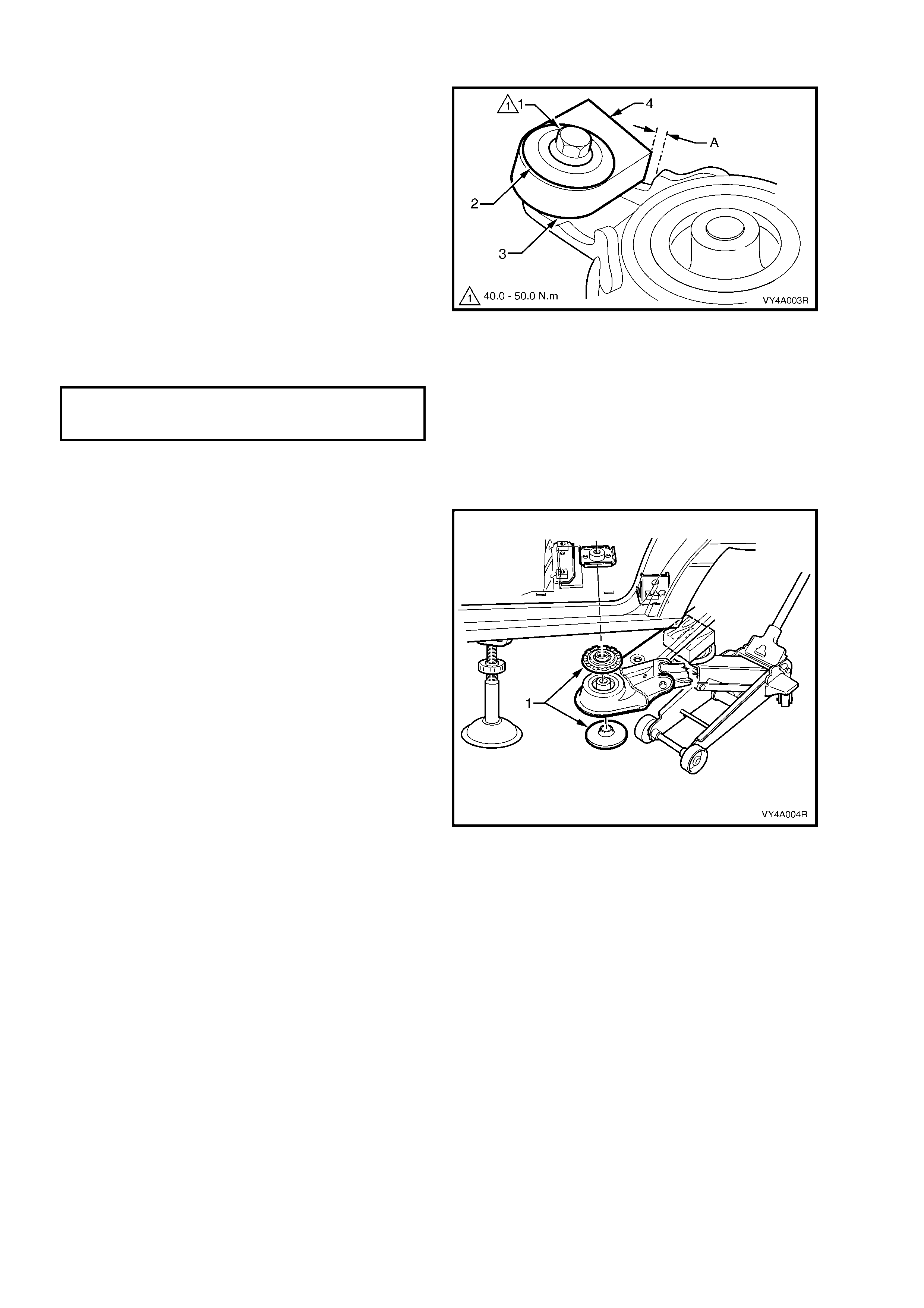
25. Using a floor jack (2) with a suitable block of
wood (1) mounted on top of the jack lifting pad
to support and protect under the centre of the
differential carrier, raise the rear of the vehicle
from the safety stands.
26. Remove the safety stands, carefully lower the
vehicle to the floor and remove the jack.
Figure 4A-66
2.6 REAR SUSPENSION CROSSMEMBER MASS DAMPER
LT Section No. – 07-150A
NOTE 1: The following fasteners have either micro
encapsulation or incorporate a mechanical thread lock
and should only be used once. If in doubt, replacement
is recommended when performing this operation:
♦ Rear suspension crossmember front mounting
brace to under body attaching bolts.
NOTE: The following fasteners MUST be replaced
when performing this operation:
!!!!$
$$
$ Rear suspension crossmember front mounting
bolt.
CAUTION: Whenever any component that forms part of the ABS (if fitted) is disturbed during
Service Operat ions, it is v ital th at the co mplete ABS system b e checked, using the pro cedure as detailed in
4.4 ABS & T CS FUNCTION CHECK (V6 engines) or 5.4 ABS & TCS FUNCT ION CHECK (GEN III V8 engines),
in Section 5B ABS & TCS.
IMPORTANT: It is necessary to perform an alignment procedure when the front mounting bolts have been loosened
or removed. A special tool is required for this procedure, and if this tool is not available, then the crossmember
cannot be correctly aligned and steering and/or handling abnormalities will result.
REMOVE
1. Raise the vehicle and place on saf ety st ands. Refer to Section 0A, GENERAL INFORM ATION f or the location
of jacking and support points.
2. Position a floor jack (1) with a suitable block of
wood (2) mounted on top of the jacks’ lifting
pad to support and protec t the rear suspension
cross member as sembly (3) dur ing the f ollowing
procedure.
3. Take up the weight of the crossmember by
raising the floor jack to make contact with the
cross mem ber, nearest to the side on whic h the
rear sus pension cros smem ber m ass damper is
to be replaced.
4. Remove the rear suspension crossmember
front mounting attaching bolt (4). Discard the
removed bolt.
5. Remove the bolt (5), three places, and rem ove
the rear suspension crossmember front
mounting brace (6). Discard the removed bolts.
6. Lower the floor jack slightly to allow clearance
between the crossmember and the vehicle
underbody.
Figure 4A-67
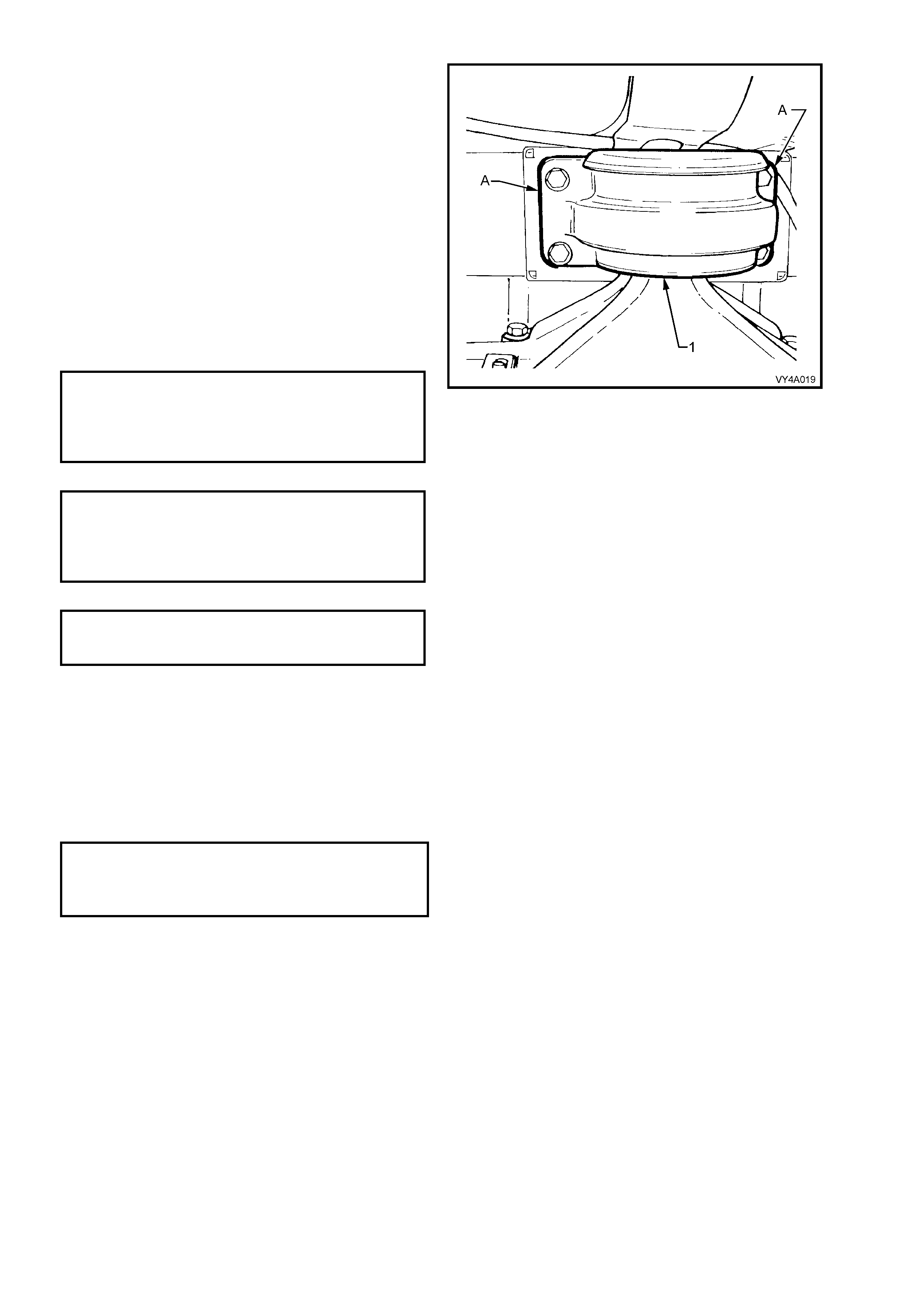
7. Using a back-up spanner on the rear
suspension crossmember mass damper bolt
(1), remove the nut (2).
8. Remove the bolt, washer (3) and rear
suspension crossmember mass damper (4)
from the crossmember.
Figure 4A-68
REINSTALL
1. Install the bolt (1), washer (2), rear suspension
crossmember mass damper (3) and nut to the
crossmember. Check that there is a 4 mm
clearance (A) from the rear suspension
crossmember mass damper to the bracket
edge. Do not tighten the retaining nut and bolt
at this stage.
CAUTION: Failure to achieve the correct
clearance may result in driveline vibration.
NOTE: The squared edge (4) of the rear
suspension crossmember mass damper, faces
towards the centre of the vehicle.
2. Using a back-up spanner on the rear
suspension crossmember mass damper bolt,
tighten the nut to the correct torque
specification.
REAR SUSPENSION CROSSMEMBER
MASS DAMPER BOLT
TORQUE SPECIFICATION 40.0 - 50.0 Nm
NOTE: Care must be taken when tightening the
retaining nut to prevent the mass damper from
rotating.
Figure 4A-69
3. Check that the upper and lower insulator pads
(1) are correctly positioned on the
crossmember front mounting bush.
4. With the floor jack still in position to support
and protect the rear suspension crossmember
assembly, raise the crossmember using the
floor jack.
Figure 4A-70
5. Install the brace (1), a new rear suspension
crossmember front mounting bolt (2), and the
rear suspension crossmember front mounting
brace attaching bolt (3), three places. Do not
tighten the bolts at this stage.
6. Check the rear suspension crossmember
alignment. Refer to Section 1A2, BODY
DIMENSIONS for this procedure.
CAUTION: Failure to correctly align the rear
suspension crossmember to the centreline of
the vehicle will result in steering abnormalities
and or uneven tyre wear.
7. Tighten the rear suspension crossmember
front mounting bolt to the correct torque
specification.
( ! ) REAR SUSPENSION
CROSSMEMBER FRONT MOUNTING
TO UNDERBODY BOLT
TORQUE SPECIFICATION 125 N.m, plus
30° - 40° turn angle
8. Tighten the rear suspension crossmember
front mounting brace attaching bolts to the
correct torque specification.
( 6 ) REAR SUSPENSION
CROSSMEMBER BRACE
MOUNTING BOL T
TORQUE SPECIFICATION 70 Nm
9. Remove the safety stands and lower the
vehicle.
Figure 4A-71
2.7 REAR SUSPENSION CROSSMEMBER REAR MOUNT
LT Section No. – 07-150A
NOTE: The following fasteners MUST be replaced
when performing this operation:
!
!!
!$
$$
$Rear suspension crossmember rear mount to
under body attaching bolt.
!
!!
!$
$$
$Rear suspension crossmem ber rear mount to rear
suspension differential assembly rear cover
attaching bolts.
CAUTION: Whenever any component that forms part of the ABS (if fitted) is disturbed during
Service Operat ions, it is v ital th at the co mplete ABS system b e checked, using the pro cedure as detailed in
4.4 ABS & T CS FUNCTION CHECK (V6 engines) or 5.4 ABS & TCS FUNCT ION CHECK (GEN III V8 engines),
in Section 5B ABS & TCS.
Important: Before disturbing the crossmember rear mounting bolts, an alignment procedure is required on
installation and a spec ial tool is required for this purpose. If this tool is not available, then the crossm em ber c annot
be correctly aligned and steering and/or handling abnormalities will result.
REMOVE
1. Using a scriber, mark the rear mount (1) to the
vehicle under body location (A). This will aid
with the rear suspension crossmember
alignment on installation.
2. Support the weight of the differential carrier
with a floor jack.
Figure 4A-72
3. Remove and discard the rear mount (1) to
vehicle underbody attaching bolts (2). Lower
the differential carrier and rear suspension
crossmember assembly by at least 60 mm.
Figure 4A-73
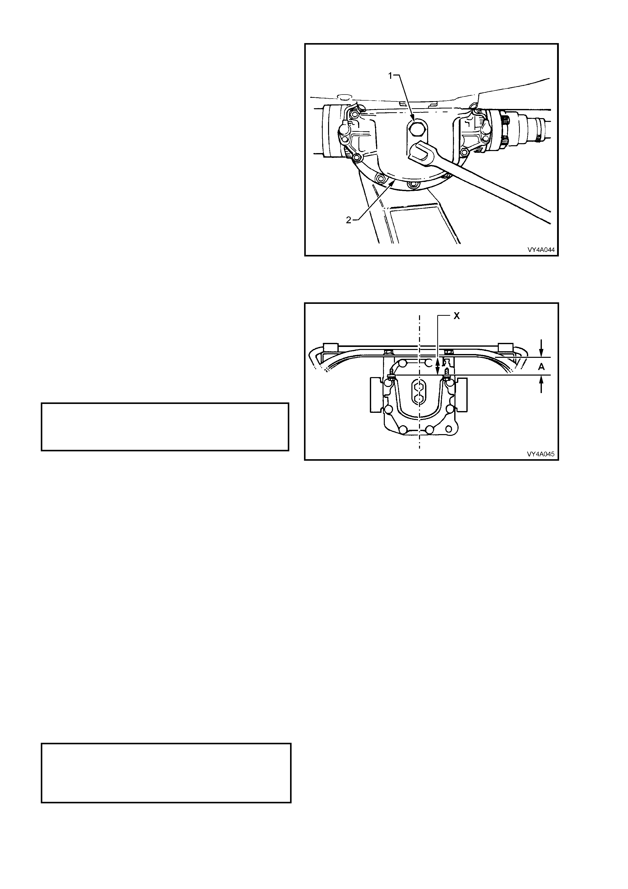
4. Remove and discard the rear mount to
differential carrier attaching bolts (1) and
remove the rear mount (2).
Figure 4A-74
REINSTALL
1. Install the rear mount and new attaching bolts
to differential carrier rear cover.
2. Tighten the attac hing bolts to the c or rec t tor que
specification, and at same time ensure that
mount does not twist, as the mount to vehicle
underbody mating su rface should be parallel to
within 1 mm (‘X’) of the rear suspension
crossmember,.
( ! )REAR MOUNT TO REAR SUPENSION
DIFFEREENTIAL ASSEMBLY
REAR COVER ATTACHING BOLT
TORQUE SPECIFICATION ................... 85 – 105 Nm
NOTE: Use a spirit level on the rear mount to
underbody surface and the top surface of the
crossmember to ensure that both surfaces are
parallel. Dimension ‘A’ is to be 56.7 mm.
3. Raise the differential carrier and rear
suspension crossmember assembly until the
rear mount contacts vehicle underbody.
4. Align the mount with the marks made on the
underbody during disassembly and install new
attaching bolts but do not tighten at this
stage.
5. The rear suspension crossmem ber MUST now
be aligned to the vehicle centreline, using the
special tool and procedure as detailed in
Section 1A2, BODY DIMENSIONS.
CAUTION: Failure to correctly align the rear
suspension crossmember to the centreline of
the vehicle will result in steering abnormalities
and uneven tyre wear!
Figure 4A-75
6. T ighten the rear sus pension cr ossm em ber rear
mount to underbody bolts to the correct torque
specification.
( ! )REAR SUSPENSION CROSSMEMBER REAR
MOUNT TO VEHICLE UNDERBODY ATTACHING
BOLT TORQUE SPECIFICATION......... 30 – 40 Nm,
then 55° - 65°
turn angle
7. Remove the safety stands and lower the vehicle.
2.8 STABILISER SHAFT AND/OR MOUNTINGS
LT Section No. – 07-150A
NOTE 1: The following fasteners have either micro
encapsulation or incorporate a mechanical thread lock
and should only be used once. If in doubt, r eplacement
is recommended when performing this operation:
♦ Stabiliser shaft link attaching nuts and bolts.
NOTE 2: The following fasteners MUST be replaced
when performing this operation:
!
!!
!$
$$
$Rear suspension crossmember rear mount to
under body attaching bolt.
NOTE 3: The following fasteners MUST be at curb
height before final tightening:
• Stabiliser shaft link attaching nuts and bolts.
CAUTION: Before disturbing the crossmember rear mount to underbody bolts, an alignment procedure is
required on installation and a special tool is required for this purpose. If this tool is not available, then the
crossmember cannot be correctly aligned and steering and/or handling abnormalities will result.
REMOVE
1. Using a floor jack under the centre of the differential carrier, jack up the rear of the vehicle then place safety
stands under the body rear jack ing points. Refer to Section 0A, GENERAL INFORMATION for the location of
the jacking points.
2. Using a scriber, mark the rear mount (1) to
vehicle under body location (A). T his will assist
in the rear sus pension crossm ember alignm ent
on installation.
3. Support the weight of the differential carrier
with a floor jack.
4. Remove and discard the rear mount to vehicle
underbody attaching bolts (2).
5. Lower the differential carrier and rear
suspension crossmem ber assem bly suff iciently
to gain access to the brackets securing the
stabiliser shaft to the rear suspension
crossmember.
NOTE: Do not allow the propeller s haft or left-hand
side drive shaft to rest on the exhaust system.
Figure 4A-76
6. Remove both stabiliser shaft link to rear
suspension control arm attaching nuts (1) and
bolts (2).
7. Rotate links (3) until clear of the rear
suspension control arms (4).
8. Remove the stabiliser shaft to the
crossmember bracket attaching bolts (5).
9. Using a screwdriver, lever the brackets (6) up
and out of the crossmember (7).
10. Remove the stabiliser shaft (8) from the
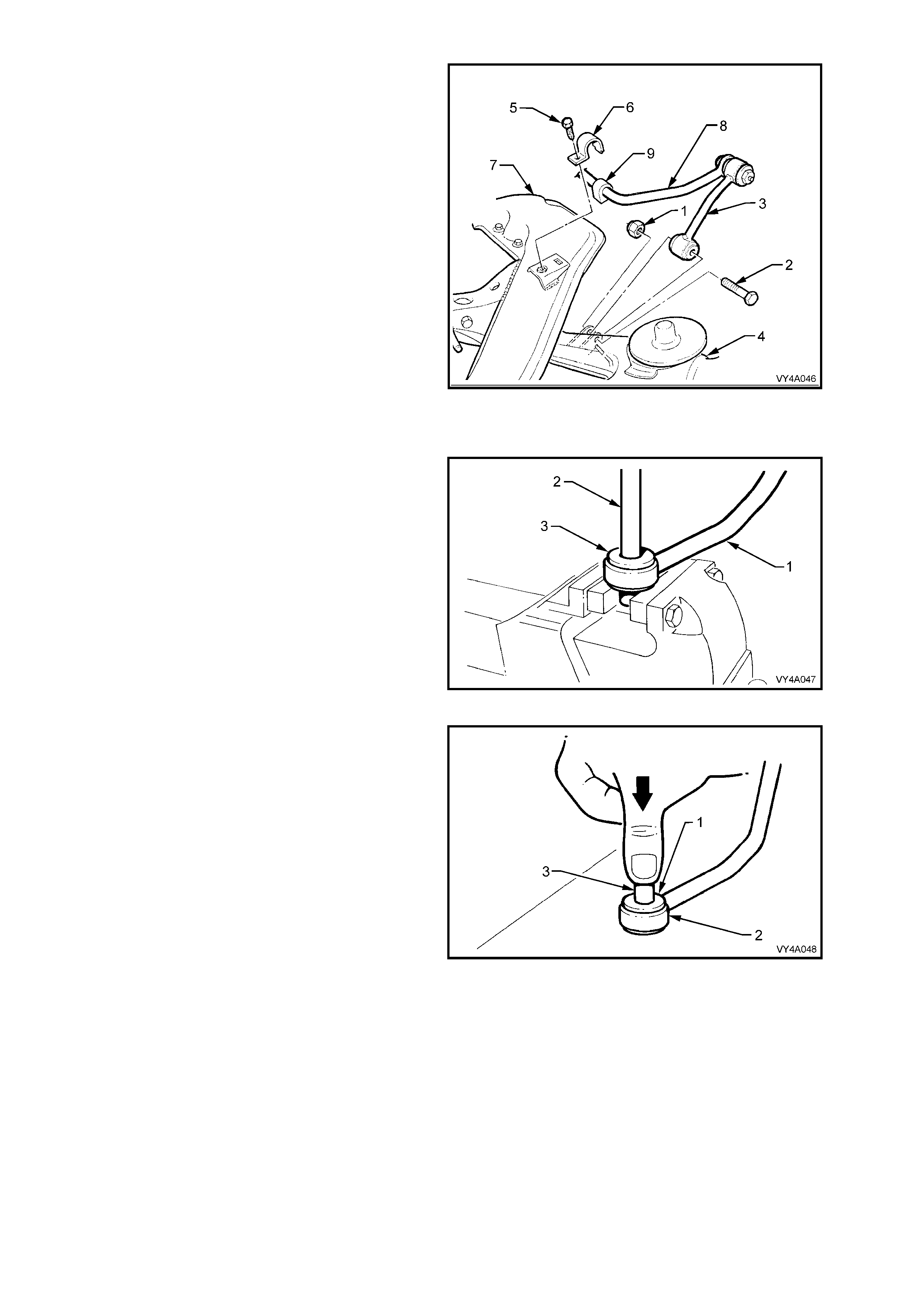
vehicle.
11. Remove the insulators (9) from the stabiliser
shaft.
12. Remove the stabiliser shaft to link mounting
bolts and nuts.
13. Separate the links from the stabiliser shaft.
Figure 4A-77
STABILISER SHAFT LINK INSULATORS, REPLACE
NOTE: The same procedure is used to replace
both the upper and lower insulator.
1. While supporting link (1) on open vice
jaws, use a suitable drift (2) and hammer to
remove the steel sleeve from the centre of the
insulator (3).
2. Distort the flanged edge of the insulator and
remove from the link.
Repeat the procedure for the remaining
insulator if required.
Figure 4A-78
3. To ease installation, apply petroleum jelly such
as Vaseline or equivalent, to insulator (1), then
install into the eye of the link (2).
4. Apply a smear of petroleum jelly to the steel
inner sleeve (3), then insert into the insulator
until the sleeve is centralised.
Figure 4A-79
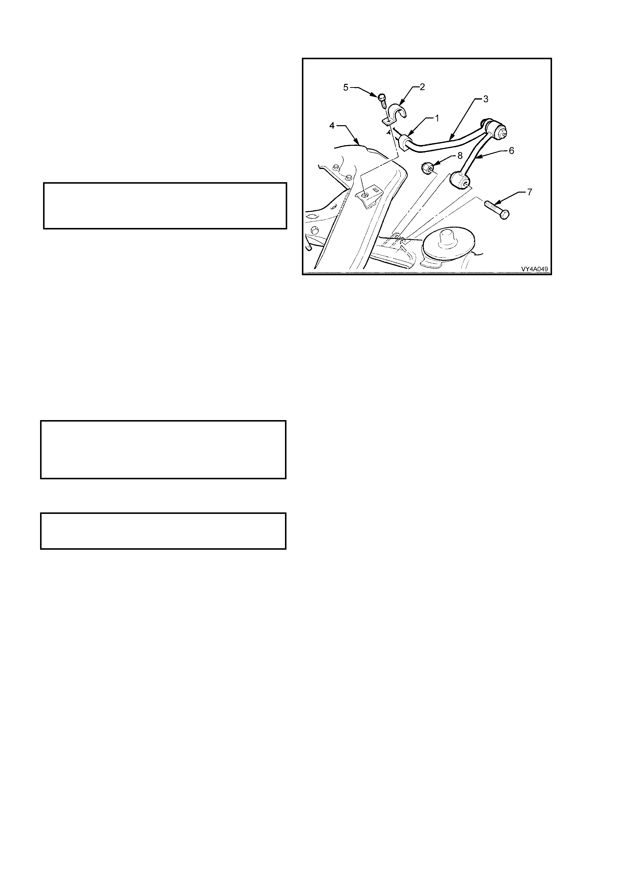
REINSTALL
1. Loosely install the stabiliser shaft link to
stabiliser shaft bolts and nuts but do not fully
tighten at this stage.
2. Install the insulators (1) and brackets (2) to the
stabiliser shaft (3). Position the stabiliser shaft
onto the crossmember (4), engaging the tangs
on the brackets with the slots in the mounting
points on the rear suspension crossmember.
3. Install and tighten the bracket attaching bolts
(5) to the correct torque specification.
STABILISER SHAFT MOUNTING
BRACKET TO CROSSMEMBER
ATTACHING BOLT
TORQUE SPECIFICATION.................. 18 – 26 Nm
4. Install the links (6) into position between the
rear suspension control arm brackets and
loosely install the attaching bolts (7) and nuts
(8), but do not fully tighten at this stage.
Figure 4A-80
5. Raise the differential carrier and rear suspension crossmember assembly until the rear mount contacts the
vehicle underbody.
6. Align the mount with the m ar ks m ade on the under body during disassem bly, and install new attaching bolts but
do not tighten at this stage.
7. The rear suspension crossmember MUST now be aligned to the vehicle centreline, using the special tool and
procedure as detailed in Section 1A2, BODY DIMENSIONS.
CAUTION: Failure to correctly align the rear suspension crossmember to the centreline of the vehicle will
result in steering abnormalities and uneven tyre wear!
8. Tighten the rear suspension crossmember, rear mount to underbody bolts to the correct torque specification.
( ! ) REAR SUSPENSION CROSSMEMBER
MOUNT TO UNDERBODY ATTACHING
BOLT TORQUE SPECIFICATION......... 30 – 40 Nm,
then 55° - 65°
turn angle
9. Lower the vehicle, then bounce the rear of the vehicle several times to settle the suspension.
10. Tighten the stabiliser shaft link mounting bolts and nuts to the correct torque specification.
( " # ) STABILISER SHAFT LINK
ATTACHING BOLTS AND NUTS
TORQUE SPECIFICATION ................... 90 – 105 Nm
2.9 REAR SPRING AND INSULATORS
LT Section No. – 07-150
NOTE 1: The following fasteners have either micro
encapsulation or incorporate a mechanical thread lock
and should only be used once. If in doubt, r eplacement
is recommended when performing this operation:
♦ Additional control arm socket assembly retaining
nut.
♦ Stabiliser shaft link to rear suspension control arm
attaching nut and bolt.
NOTE 2: The following fasteners MUST be replaced
when performing this operation:
!
!!
!$
$$
$Drive shaft constant velocity joint to rear wheel
drive shaft flange attaching bolt.
NOTE 3: The following fasteners MUST be at curb
height before final tightening:
• Shock absorber lower mounting bolt.
• Stabiliser shaf t link to rear suspension control arm
attaching nut and bolt.
REMOVE
1. Using a floor jack under the centre of the differential carrier, jack up the rear of the vehicle and place safety
stands under the body rear jack ing points. Refer to Section 0A, GENERAL INFORMATION for the location of
the jacking points.
2. Remove the wheel cover (steel wheels) or centre cap (alloy wheels) from the rear wheel on the side of the
vehicle where the spring is to be removed.
3. Mark the relationship of the wheel to the mounting flange. Remove the road wheel attaching nuts and rem ove
the wheel.
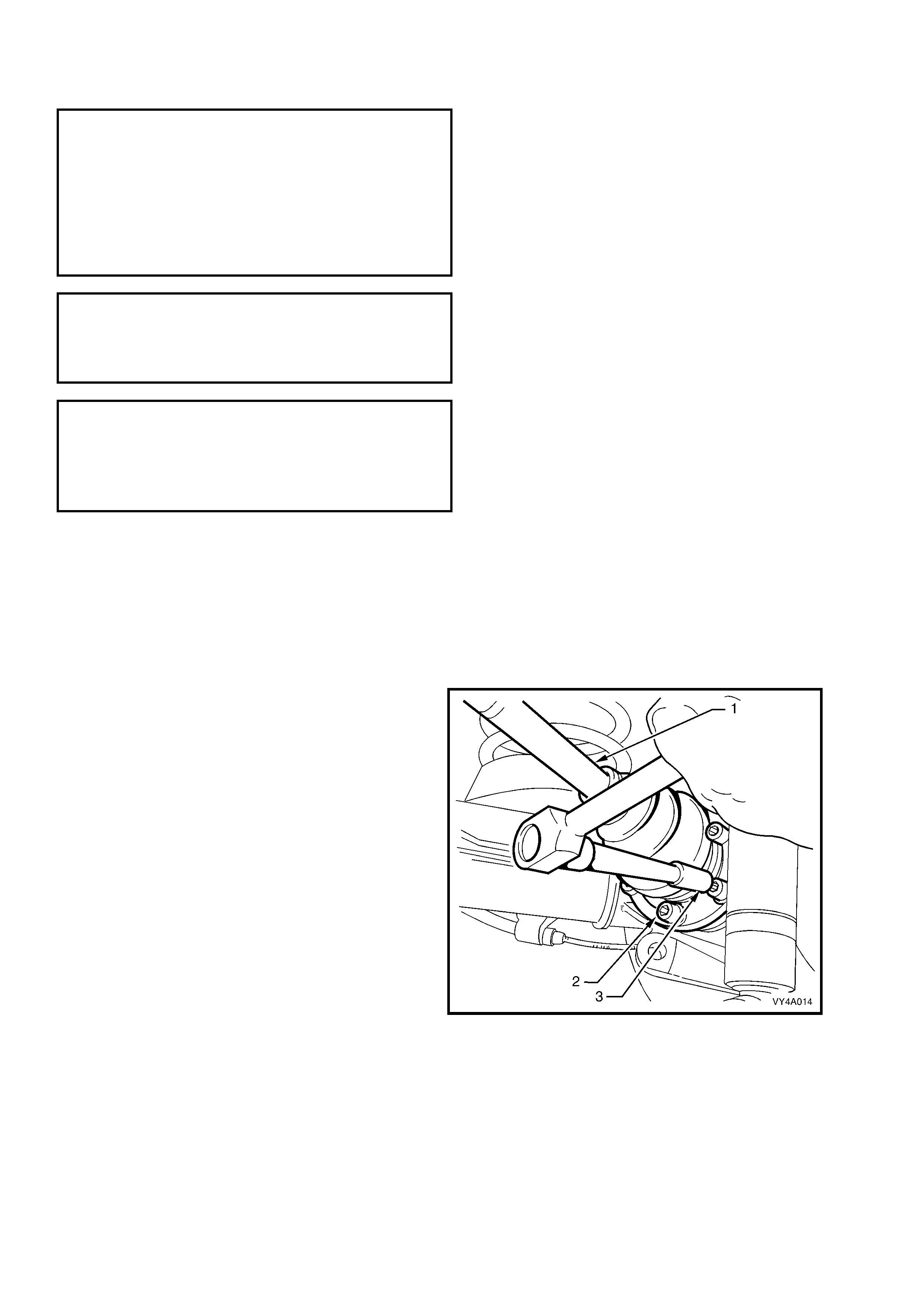
4. Using Tool No. KM468 to hold the outer rear
wheel drive shaft hub from rotating, loosen the
six drive shaft (1) outer constant velocity joint to
rear wheel drive shaf t flange attaching bolts (2)
with an 8 mm Allen key socket (3). Remove
and discard the bolts.
Figure 4A-81
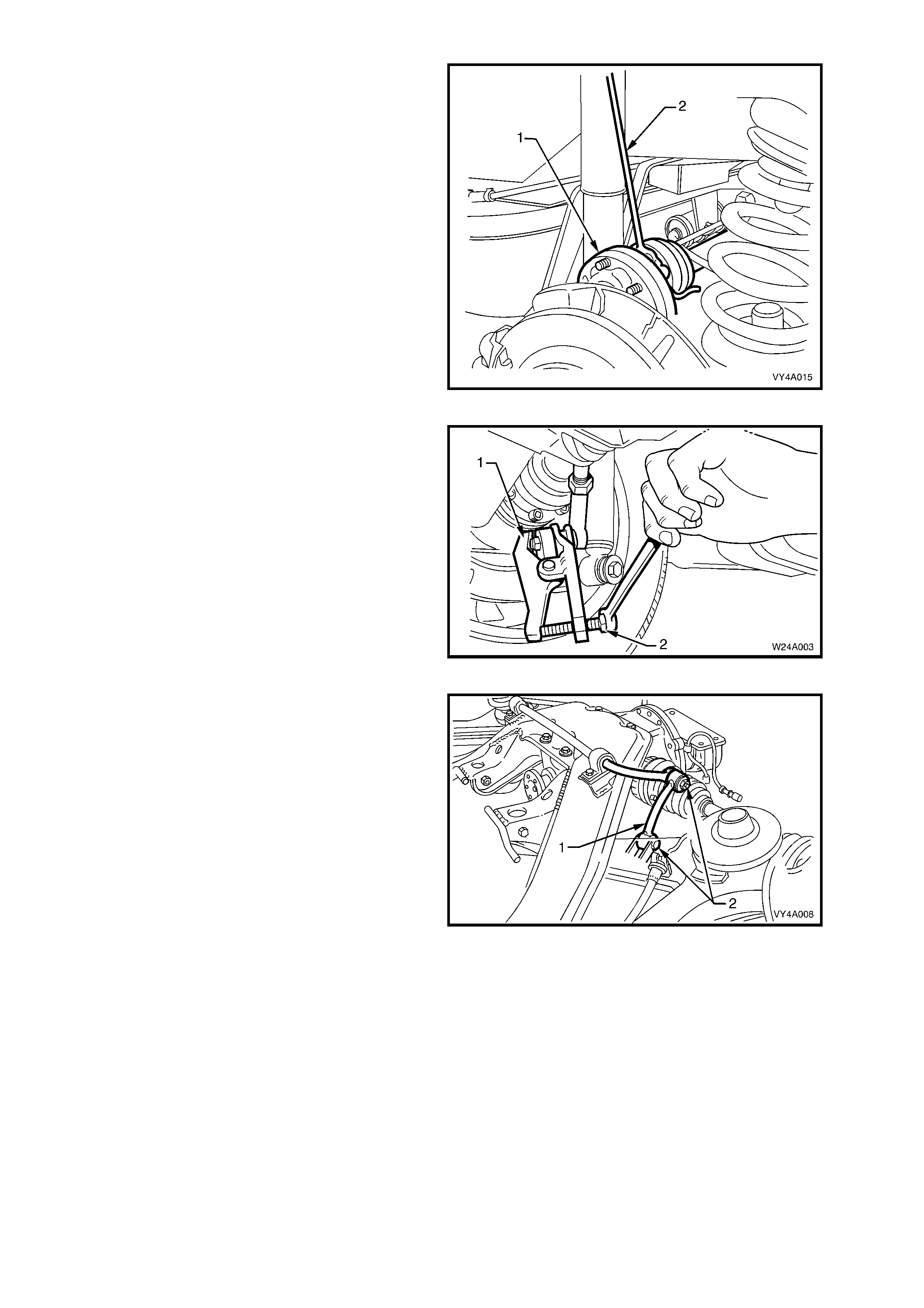
5. Disconnect the drive shaft (1) from the flange
and lift upward. Keeping the drive shaft vertical
and, using a length of wire (2), tie up the drive
shaft to the lower end of the shock absorber
upper mounting.
NOTE: Bruising to the inside of the drive shaft
constant velocity joint boots will occur if the rear
suspens ion control arm is lowered any further. This
will lead to premature failure of the boot and
eventual failure of the joint if left unchecked.
For this reason, it is important that the constant
velocity joint is disconnected from the rear wheel
drive shaft flange before removing the shock
absorber lower mounting bolt.
Figure 4A-82
6. Loosen the additional control arm socket
assem bly retaining nut until level with the top of
the socket assembly stud.
7. Using s pecial tool No. E-9332- A (1), tighten the
lever forcing screw (2) until the socket
assembly stud breaks f r ee f r om the taper in the
rear suspension control arm, then remove and
discard the socket assembly retaining nut.
8. Remove the additional control arm socket
assembly from the rear suspension control
arm.
Figure 4A-83
9. Remove the stabiliser shaft link (1) to rear
suspension control arm attaching bolt (2) and
nut from the side of the vehicle where the
spring is being removed.
Figure 4A-84
10. Position a floor jack under the rear suspension
control arm. Raise the jack slightly to take the
spring load of f the rear suspension control arm .
Disconnect rear shock absorber lower
mounting bolt (1) and washer (2) from rear
suspension control arm (3), then remove the
lower end of the shock absorber (4) from the
rear suspension control arm.
Figure 4A-85
Figure 4A-86
11. Lower the jack and remove the rear spring (1),
upper insulator (2) and lower insulator (3) from
between the vehicle underbody and the rear
suspension control arm.
NOTE 1: It may be necessary to push the rear
suspension control arm downward by hand slightly
to provide sufficient space for the spring to be
removed.
NOTE 2: Ensure that the rear brake hose is not
pulled tight while pushing down on the rear
suspension control arm.
Figure 4A-87
REINSTALL
1. Install the lower insulator (3) onto the rear
suspension control arm. Assemble the upper
insulator (2) into the spr ing (1) then push down
on the rear suspension control arm and install
the spring and upper insulator.
Figure 4A-88
2. Position the jack under the rear suspension
control arm (1) and raise it sufficiently to allow
the shock absorber (2) lower mounting washer
(3) and bolt (4) to be installed.
3. Install the washer and bolt on to the shock
absorber lower mount and into the rear
suspension control arm, but do not tighten at
this stage.
Figure 4A-89
Figure 4A-90
4. Remove the wire from the drive shaft and shock absorber upper mount. Lower the drive shaft and align the
drive shaft constant velocity joint to rear wheel drive shaft flange, then fit new attaching bolts into the
corresponding holes in the rear wheel drive shaft flange
5. Tighten the drive shaft constant velocity joint to rear wheel drive shaft flange attaching bolts to the correct
torque specification.
( ! ) DRIVE SHAFT CONSTANT VELOCITY
JOINT TO REAR WHEEL DRIVE SHAFT
FLANGE ATTACHING BOLT
TORQUE SPECIFICATION ................... 50 Nm, then
60° - 75°
turn angle
7. Rotate the stabiliser shaft link into position over the rear suspension control arm bracket. Install the attaching
bolt and nut.
8. Install the additional control arm socket assembly and a new nut and tighten to the correct torque wrench
specification.
( # ) ADDITIONAL CONTROL ARM
SOCKET ASSEMBLY RETAINING NUT
TORQUE SPECIFICATION ................... 55 – 70 Nm
9. Install the road wheel, aligning the previously made marks and secure with the attaching nuts but do not
tighten at this stage.
10. Remove the safety stands and lower the vehicle.
11. Tighten the road wheel attaching nuts to the correct torque specification, working in a ‘star’ pattern. Refer to
Section 10, WHEELS AND TYRES for detailed information regarding the installation procedure for the road
wheels.
ROAD WHEEL ATTACHING NUT
TORQUE SPECIFICATION ................ 100 – 125 Nm
12. Tighten the stabiliser shaft link to rear suspension control arm nut to the correct torque specification.
( " # ) STABILISER SHAFT LINK TO
REAR SUSPENSION CONTROL ARM
ATTACHING NUT
TORQUE SPECIFICATION ................... 95 – 105 Nm
13. Tighten the shock absorber lower mount to rear suspension control arm attaching bolt to the correct
specification.
( " ) SHOCK ABSORBER LOWER
MOUNTING BOL T
TORQUE SPECIFICATION ................ 105 – 125 Nm
14. Install the wheel cover/centre cap.
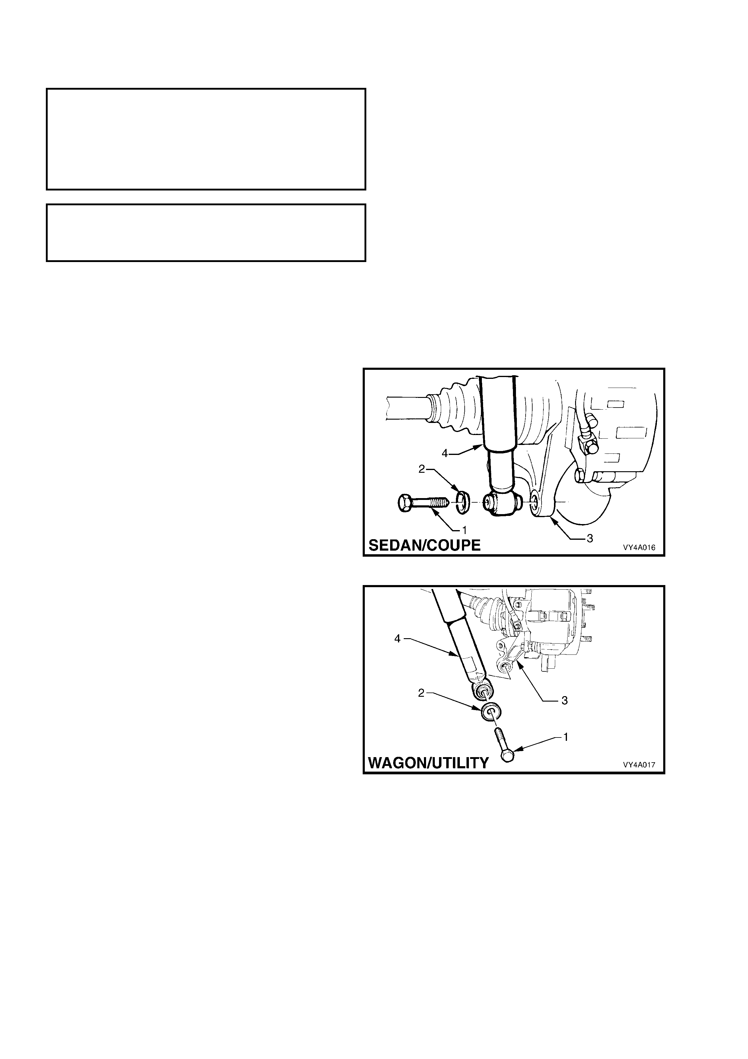
2.10 REAR SHOCK ABSORBERS AND/OR BUSHING
LT Section No. – 07-150
NOTE 1: The following fasteners have either micro
encapsulation or incorporate a mechanical thread lock
and should only be used once. If in doubt, r eplacement
is recommended when performing this operation:
♦ Upper shock abs orber mounting plate retaining nut
(Wagon and Utility only).
NOTE 2: The following fasteners MUST be at curb
height before final tightening:
• Shock absorber lower mounting bolt.
REMOVE
1. Using a floor jack under the centre of the
differential carrier, jack up the rear of the
vehicle then place saf ety s tands under the rear
suspension control arms to support weight of
the vehicle.
2. Loosen and remove the shock absorber lower
mounting bolt (1) and washer (2) and remove
the shock absorber (4) from the rear
suspension control arm (3).
Figure 4A-91
Figure 4A-92
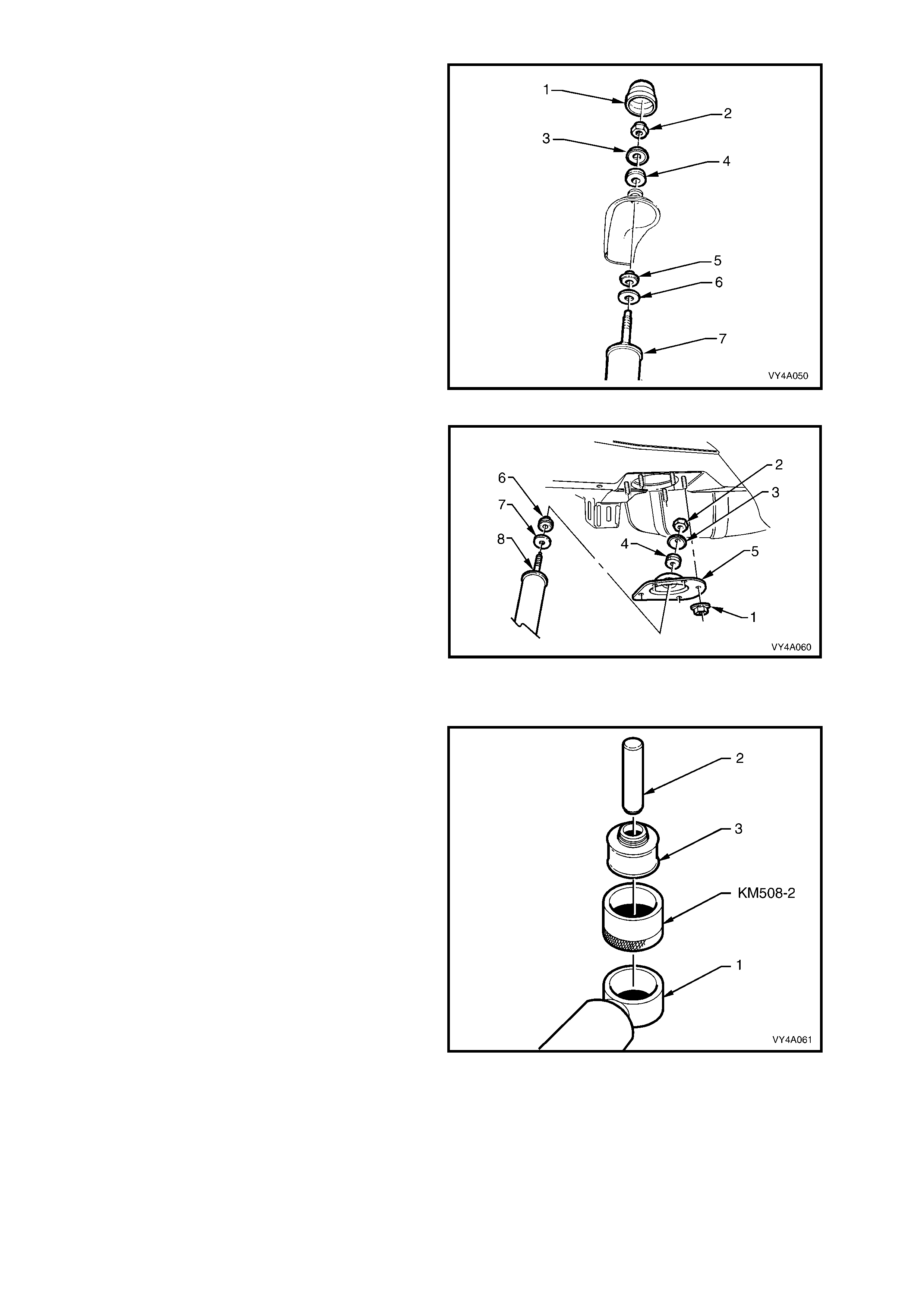
For MY 2003 VY Series Sedan and V2 Series
Coupe Models:
3a. Open the rear compartment lid and prise off the
shock absorber upper mounting cap cover (1).
4a. Remove the shock absorber upper mounting
nut (2), upper plate (3) and upper bushing (4).
5a. Remove the upper mounting lower bushing (5)
and lower plate (6) from the shock
absorber (7).
Figure 4A-93
For MY 2003 VY Series Wagon and Utility
Models:
3b. Remove the five upper m ounting plate r etaining
nuts (1).
4b. Remove the shock absorber upper mounting
nut (2), upper plate (3), upper bushing (4) and
upper mounting plate (5).
5b. Remove the upper mounting lower bushing (6)
and lower plate (7) from the shock
absorber (8).
Figure 4A-94
LOWER BUSHING, REPLACE
1. To replace the shock absorber lower bushing:
a. With the shock absorber (1) lower mount
supported on suitable press plates, use a
suitable press tool (2) suc h as Tool No. KM619
to press the bushing (3) from the mount.
b. Lubricate the new bushing with soapy water
and place in sleeve, Tool No. KM508-2.
c. With the shock absorber lower mount
supported on press plates, position KM508-2
onto the lower mount. Press the new bushing
into the lower mount us ing a suitable press tool
such as Tool No. KM619.
Figure 4A-95
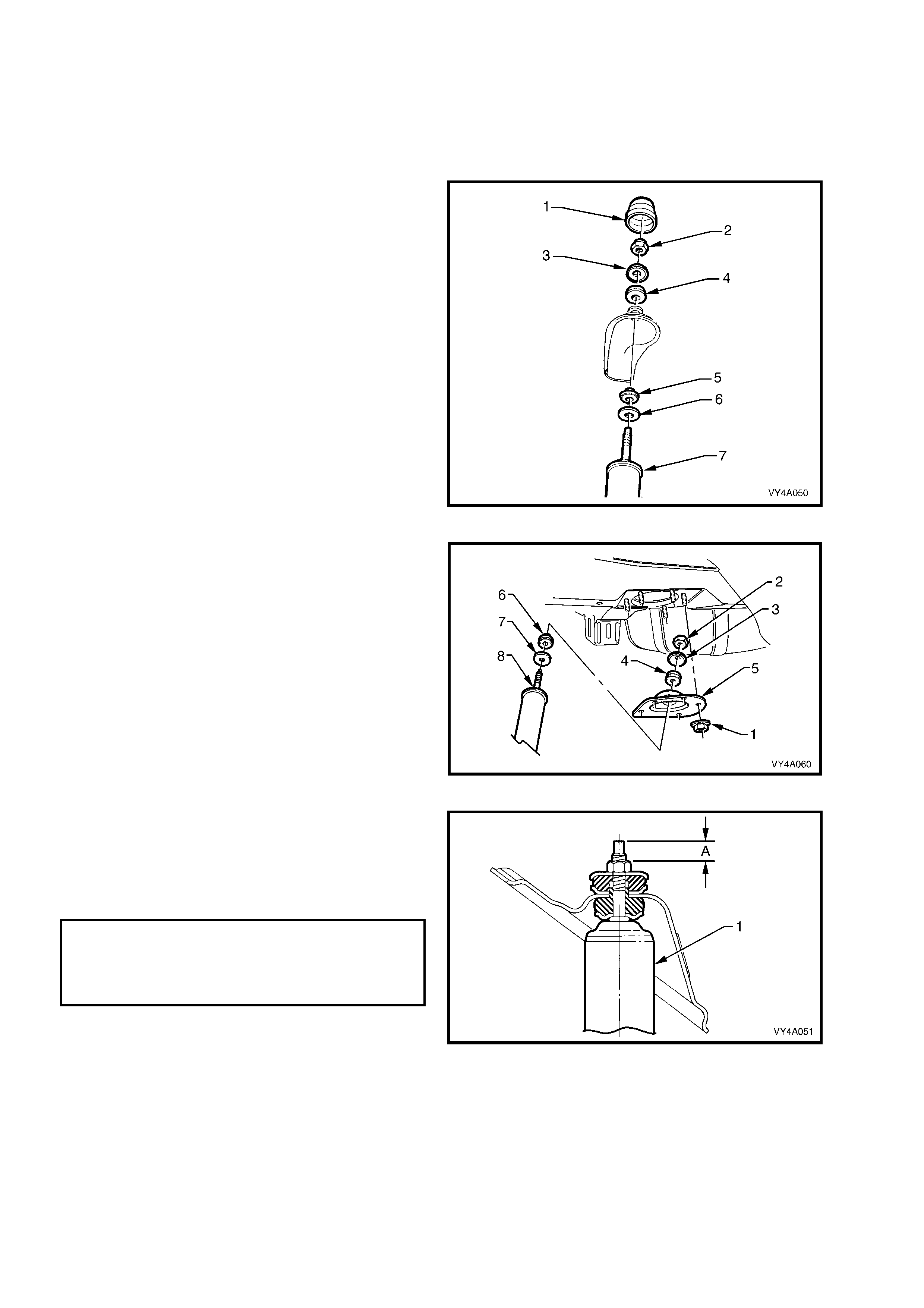
REINSTALL
1. Before installation, check shock the absorber
action and ins pec t the rubber bushing. Replac e
components as required. Refer to
3. DIAGNOSIS in this Section for testing
details.
For MY 2003 VY Series Sedan and V2 Coupe
Models:
2a. Assemble the upper mounting lower plate (6)
and bushing (5) to the shock absorber (7).
3a. Position the shock absorber into the upper
mounting hole. Install the upper mounting
upper bushing (4), upper plate (3) and
mounting nut ( 2) , then hand tighten until the nut
is fully installed onto the threaded section of the
shaft.
NOTE: Do not use power operated tools for this
operation, as thread damage will result.
4a. Install the upper mounting cap cover (1)
Figure 4A-96
For MY 2003 VY Series Wagon and Utility
Models:
2b. Assemble the upper mounting lower plate (7),
lower bushing (6), the upper mounting plate (5),
upper bus hing (4) and upper plate (3) on to the
shock absorber (8).
Figure 4A-97
3b. Install the retaining nut (item 2 in Figure
4A-96), tightening until the distance ‘A’,
between the top of the threaded shaft and the
nut is from 15.5 - 16.0 mm.
4b. Install the five retaining plate nuts and tighten
nuts to the correct torque specification.
( # ) UPPER SHOCK ABSORBER
MOUNTING PLATE RETAINING
NUT TORQUE SPECIFICATION........... 42 – 50 Nm
(Wagon and
Utility only)
Figure 4A-98
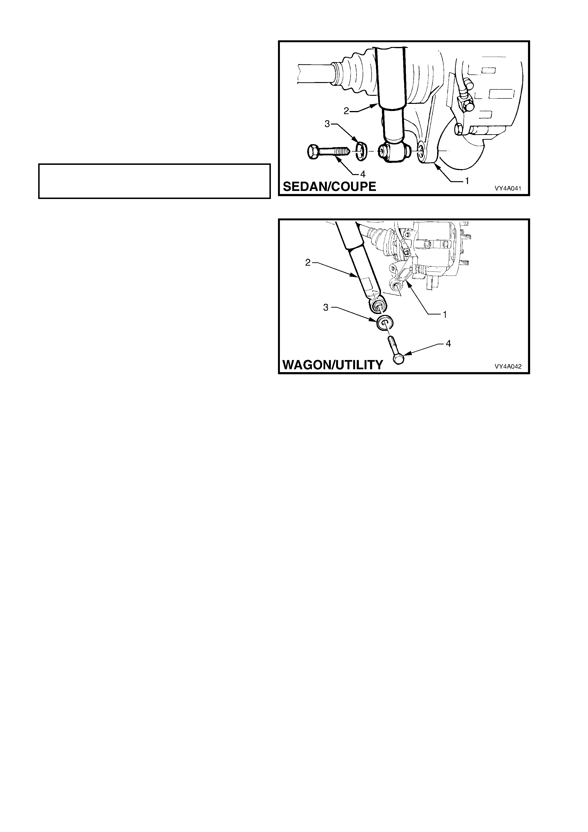
For all MY 2003 VY and V2 Series Models:
5. Install the shock absorber (2) lower mount into
the rear suspension control arm (1) and install
the washer (3) and bolt (4) but do not fully
tighten at this stage.
6. Lower the vehicle to the ground, then bounce
the rear of the vehicle several times to settle
the suspension.
7. Tighten the shock absorber lower mounting
bolt to the correct torque specification.
( " ) SHOCK ABSORBER LOWER
MOUNTING BOLT TORQUE
SPECIFICATION (All Models)............. 105 – 125Nm
Figure 4A-99
Figure 4A-100
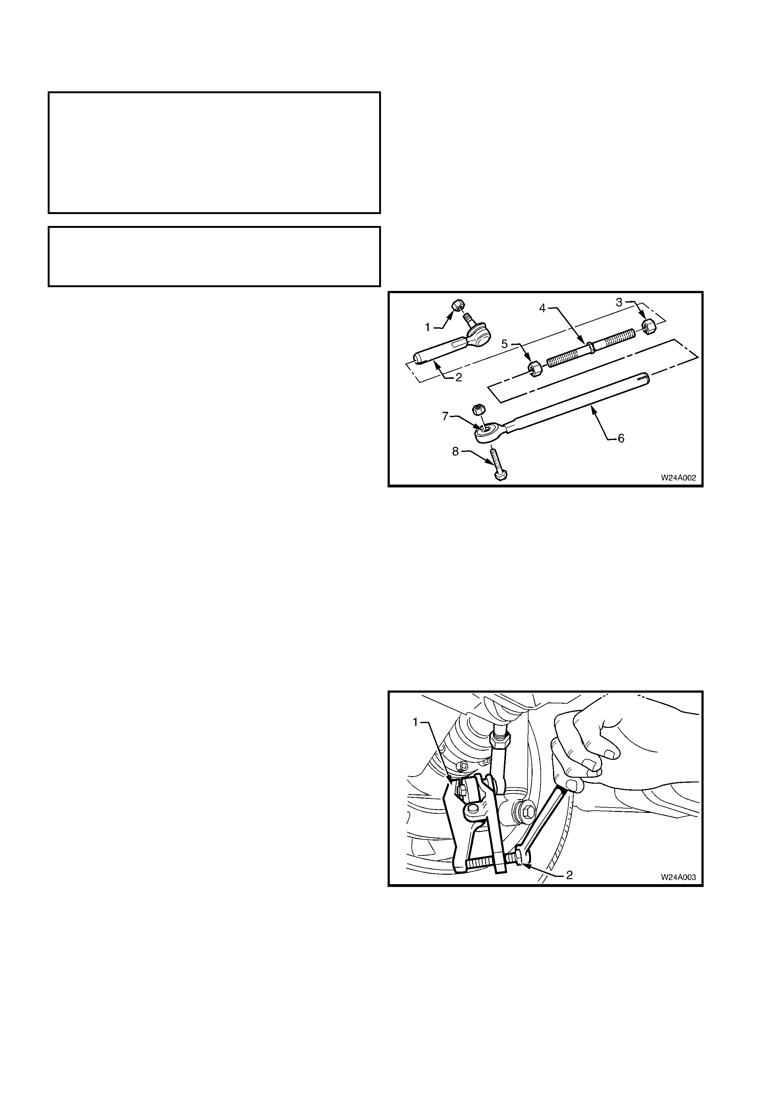
2.11 ADDITIONAL CONTROL ARM
LT Section No. – 07-150A
NOTE 1: The following fasteners have either micro
encapsulation or incorporate a mechanical thread lock
and should only be used once. If in doubt, r eplacement
is recommended when performing this operation:
♦ Additional control arm inner shaft attaching nut.
♦ Additional control arm socket assembly retaining
nut.
NOTE 2: The following fasteners MUST be at curb
height before final tightening:
• Additional control arm adjusting shaft lock nut.
Figure 4A-101
INSPECT
Inspection of the additional control arm may be
required in the following circumstances:
• Poor handling.
• Uneven tyre wear.
A visual inspec tion of the additional control ar m should
be perfor med with the arm installed to the vehicle. The
following conditions would require replacement of the
additional control arm or some of its components:
• Bent or damaged shafts.
• Bent or damaged adjusting shaft.
• Excessive play in the socket assembly.
• Excessive play in the inner bushing.
• Damaged socket assembly boot. Legend
1. Socket Assembly Retaining Nut
2. Additional Control Arm Outer Shaft
3. Outer Adjuster Lock Nut
4. Adjusting Shaft
5. Inner Adjuster Lock Nut
6. Additional Control Arm Inner Shaft
7. Additional Control Arm Inner Bushing
8. Additional Control Arm to Rear Suspension
Crossmember Retaining Bolt
REMOVE
1. Using a floor jack under the centre of the
differential carrier, jack up the rear of vehicle then
place safety stands under the rear suspension
control arms to support the weight of the vehicle.
2. If the additional contr ol ar m is being dis as sembled,
measure and record the length of the adjusting
shaft between the lock nuts.
3. Loosen the additional control arm soc ket ass em bly
retaining nut until level with the top of the socket
assembly stud.
4. Using special tool No. E-9332-A (1), tighten the
lever forcing screw (2) to press the socket
assembly stud free from the taper in the rear
suspension control arm then remove the socket
assembly retaining nut.
5. Remove the additional control arm to rear
suspension crossmember retaining nut and bolt.
6. Carefully manoeuvre the additional control arm
from the vehicle.
Figure 4A-102
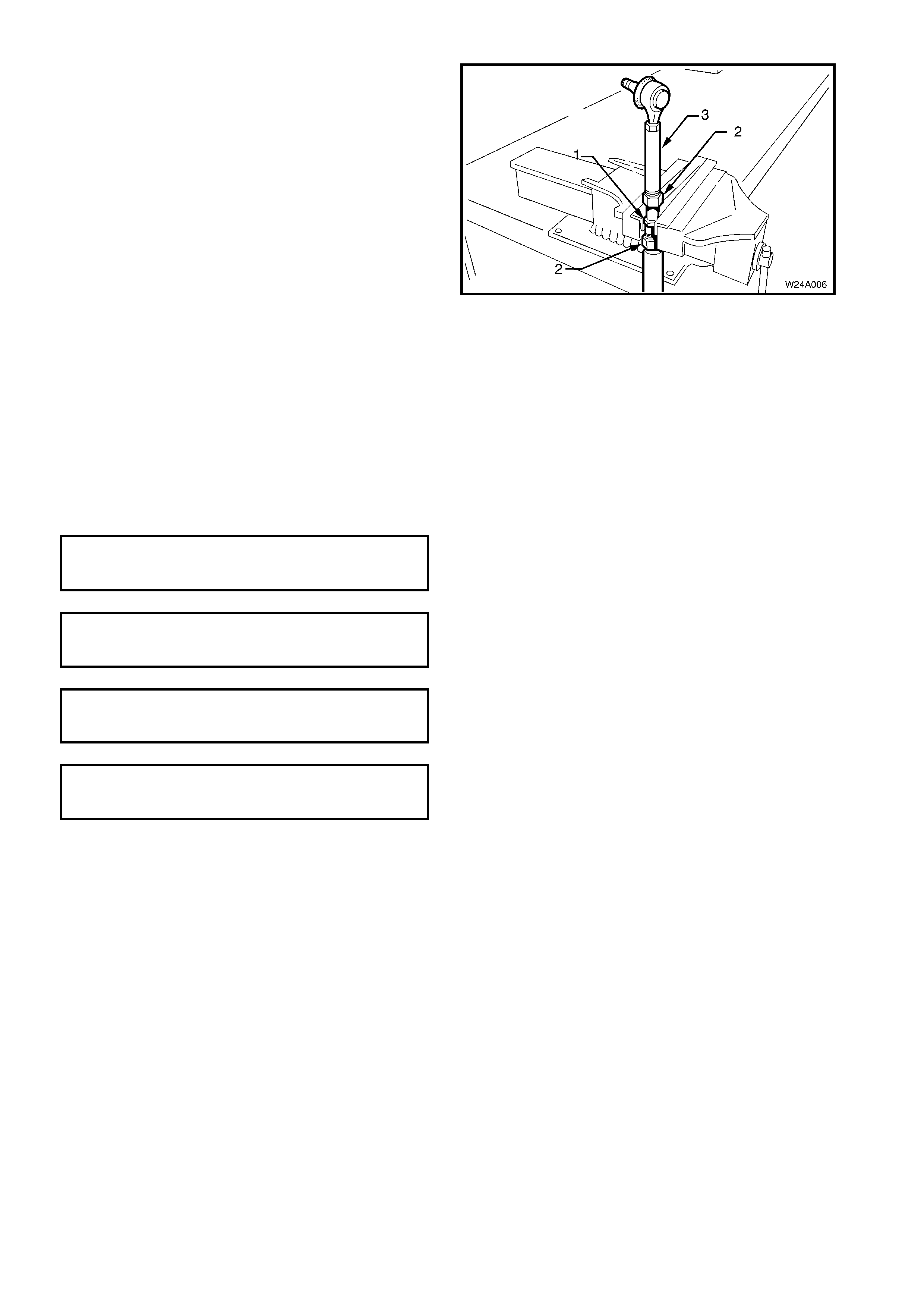
DISASSEMBLE
1. Using a suitable vice with soft jaws, retain the
centre adjusting shaft (1) and loosen the two lock
nuts (2).
2. Rotate the inner shaft (3) clockwise (noting the
number of tur ns ) until the inner shaf t is disengaged
from the threaded area of the adjusting shaft.
NOTE: The inner additional control arm shaft, the
inner lock nut and the corresponding end of the
adjuster shaft have left-hand threads.
3. Rotate the outer shaft counter clockwise (noting
the number of turns) until the outer shaft is
disengaged from the threaded area of the
adjusting shaft.
4. Remove the lock nuts from the adjusting shaft.
Figure 4A-103
REASSEMBLE
The reassembly procedure for the additional control arm is the reverse of the disassembly procedure. Ensure that
the inner and outer shafts are installed onto the adjusting shaft with the correct number of turns and that the arm,
when assembled, is set to the correct length.
NOTE 1: The inner additional control arm shaft, the inner lock nut and the corresponding end of the adjuster contain
left-hand threads.
NOTE 2: The additional control arm lock nuts should only be tightened when the arm is installed into the vehicle and
the suspension is under load.
( # ) ADDITIONAL CONTROL ARM BALL
JOINT RETAINING NUT
TORQUE SPECIFICATION ................... 55 – 70 Nm
( # ) ADDITIONAL CONTROL ARM INNER
SHAFT ATTACHING NUT
TORQUE SPECIFICATION ................... 55 – 70 Nm
ADDITIONAL CONTROL ARM INNER
SHAFT ATTACHING BOLT
TORQUE SPECIFICATION ................... 55 – 70 Nm
( " ) ADDITIONAL CONTROL ARM
ADJUSTING SHAFT LOCK NUT
TORQUE SPECIFICATION ................... 50 Nm
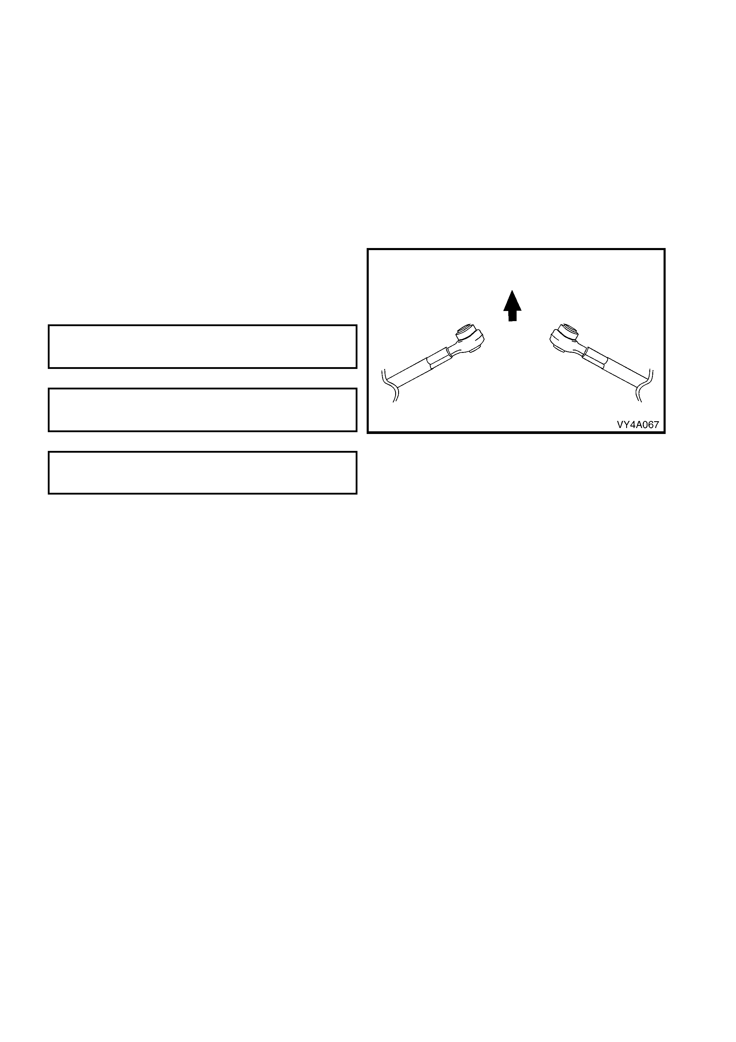
REINSTALL
The installation procedure for the additional control arm is the reverse of the removal procedure, ensuring that the
inner and outer shafts are installed with the correct number of turns and that the arm, when installed, is set to the
correct length.
NOTE 1: The additional control arm lock nuts should only be tightened when the arm is installed into the vehicle and
the suspension is under load.
NOTE 2: The socket assembly may be over extended if allowed to move during the tightening of the lock nut,
resulting in possible damage to socket assembly internals. When tightening the additional control arm lock nuts, use
a suitable spanner on the hexagonal crimped section near the socket assembly to prevent the socket assembly
from being deflected.
NOTE 3: T o ensure proper retention of the additional contr ol arm, the sock et assem bly stud and the corresponding
tapered hole in the rear suspension control arm must be cleaned of dirt and foreign matter prior to installation.
NOTE 4: The inner additional control arm shaft, MUST
be installed into the vehicle with the protruding side of
the bushing towards the front of the vehicle.
NOTE 5: Check the rear wheel toe-in setting, refer to
2.13 REAR WHEEL TOE ADJUSTMENT.
( # ) ADDITIONAL CONTROL ARM BALL
JOINT RETAINING NUT
TORQUE SPECIFICATION.......................... 55 – 70 Nm
( # ) ADDITIONAL CONTROL ARM INNER
SHAFT ATTACHING NUT
TORQUE SPECIFICATION.......................... 55 – 70 Nm
ADDITIONAL CONTROL ARM INNER
SHAFT ATTACHING BOLT
TORQUE SPECIFICATION.......................... 55 – 70 Nm
Figure 4A-104
2.12 REAR WHEEL ALIGNMENT CHECKING
LT Section No. – 06-212
NOTE 1: The following fasteners have either micro
encapsulation or incorporate a mechanical thread lock
and should only be used once. If in doubt, replacement
is recommended when performing this operation:
♦ Rear suspension control arm to rear suspension
crossmember attaching nut.
♦ Rear suspension crossmember mounting brace to
underbody attaching bolts.
NOTE 2: The following fasteners MUST be replaced
when performing this operation:
!!!!$
$$
$ Rear suspension crossmember front mounting
bolt.
!!!!$
$$
$ Rear suspension crossmember mount to under
body attaching bolt.
NOTE 3: The following fasteners MUST be at curb height
before final tightening:
• Rear suspension control arm to rear suspension
crossmember attaching nut.
CAMBER AND TOE CHECK
The following conditions must be checked to ensure accurate measurement of rear wheel alignment.
1. Tread on rear tyres must be uniform and in a roadworthy condition.
2. Tyre pressures must be equal on both sides and to the correct pressure. Refer to the tyre placard on the vehicle
for correct tyre pressure s.
3. Wheel rim flange lateral run-out should be checked and to specification, refer to Section 10, WHEELS AND
TYRES.
4. T he vehic le must be at c urb height, ie. vehic le ready to drive with all fluids at r ec omm ended levels, fuel tank full,
without driver, passengers or luggage.
5. Stabilise vehicle springs by bouncing the rear of vehicle several times.
This step is very important, particularly if the vehicle was raised before checking. In that instance, the camber
angle m easur ed will be inc orrec t, because the r ear sus pension contr ol arm s will not have res um ed their norm a l
position.
NOTE 1: Camber is not adjustable. If there is any deviation from specification, the condition and alignment of the
crossmember, rear suspension control arms and bushing should be checked.
NOTE 2: W hen checking wheel toe, if one side has excessive toe-in and the opposite side has excessive toe-out,
this may be due to:
a. The rear suspension control arm attaching nuts being tightened when the vehicle was not at curb height.
b. The rear suspension crossmember not correctly aligned to the vehicle centreline.
To correct such a condition, check the rear suspension crossmember alignment, as detailed in
Section 1A2, BODY DIMENSIONS. Following the alignment procedure, tighten fastenings to the following torque
specifications.
( ! ) REAR SUSPENSION CROSSMEMBER
FRONT MOUNTING BOLT
TORQUE SPECIFICATION ................... 125 Nm, plus
30° – 40°
turn angle
( ! ) REAR SUSPENSION CROSSMEMBER
REAR MOUNT TO VEHICLE BODY
ATTACHING BOLT
TORQUE SPECIFICATION ................... 30 – 40Nm
( ! ) REAR SUSPENSION CONTROL
ARM TO REAR SUSPENSION
CROSSMEMBER ATTACHING NUT
TORQUE SPECIFICATION ................... 95 – 105Nm
Important: Alignment of the rear suspension crossmember requires the use of a special tool. Attempting to align
the rear suspension crossmember without it will not prove to be successful.
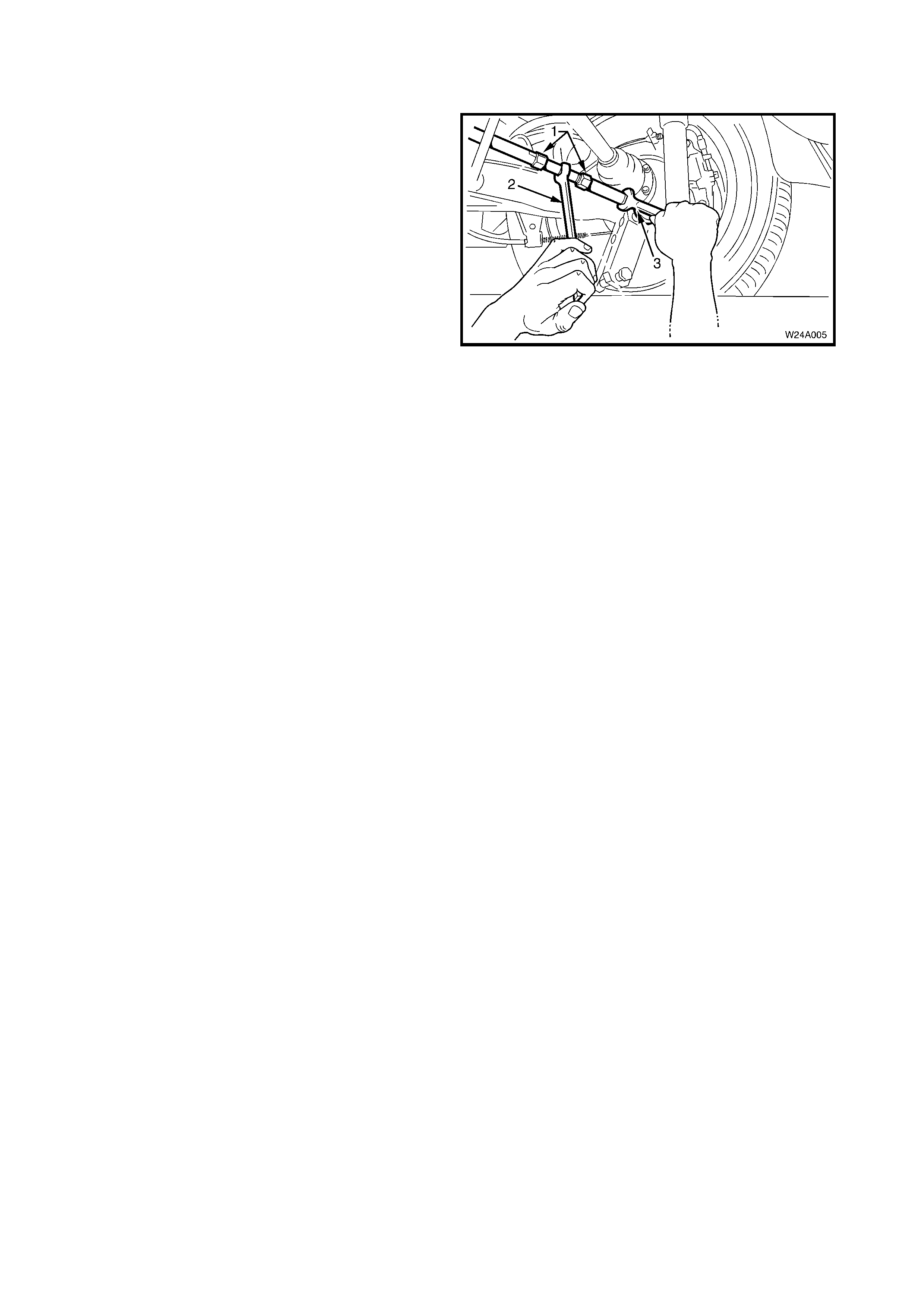
2. 13 REAR WHEEL TOE ADJUSTMENT
LT Section No. – 06-212
The rear suspension toe setting is adjustable in
vehicles equipped with the additional control arm by
varying the length of the additional control arm. To
adjust toe setting:
1. Loosen the two lock nuts (1).
2. Using a suitable spanner (2), rotate the centre
adjusting shaft.
3. Tighten the two lock nuts.
NOTE 1: The inner additional control arm shaft, the
inner lock nut and the corresponding end of the
adjuster have left-hand threads.
NOTE 2: Increasing the additional control arm length
will increase rear wheel toe in and vice versa.
NOTE 3: The socket assembly may be over extended
if allowed to move during the tightening of the lock
nuts, causing damage to socket assembly internals.
During the toe adjustment procedure, use a suitable
spanner (3) on the hexagonal c r imped sec tion near the
socket assembly to prevent the socket assembly from
being deflected.
Figure 4A-105
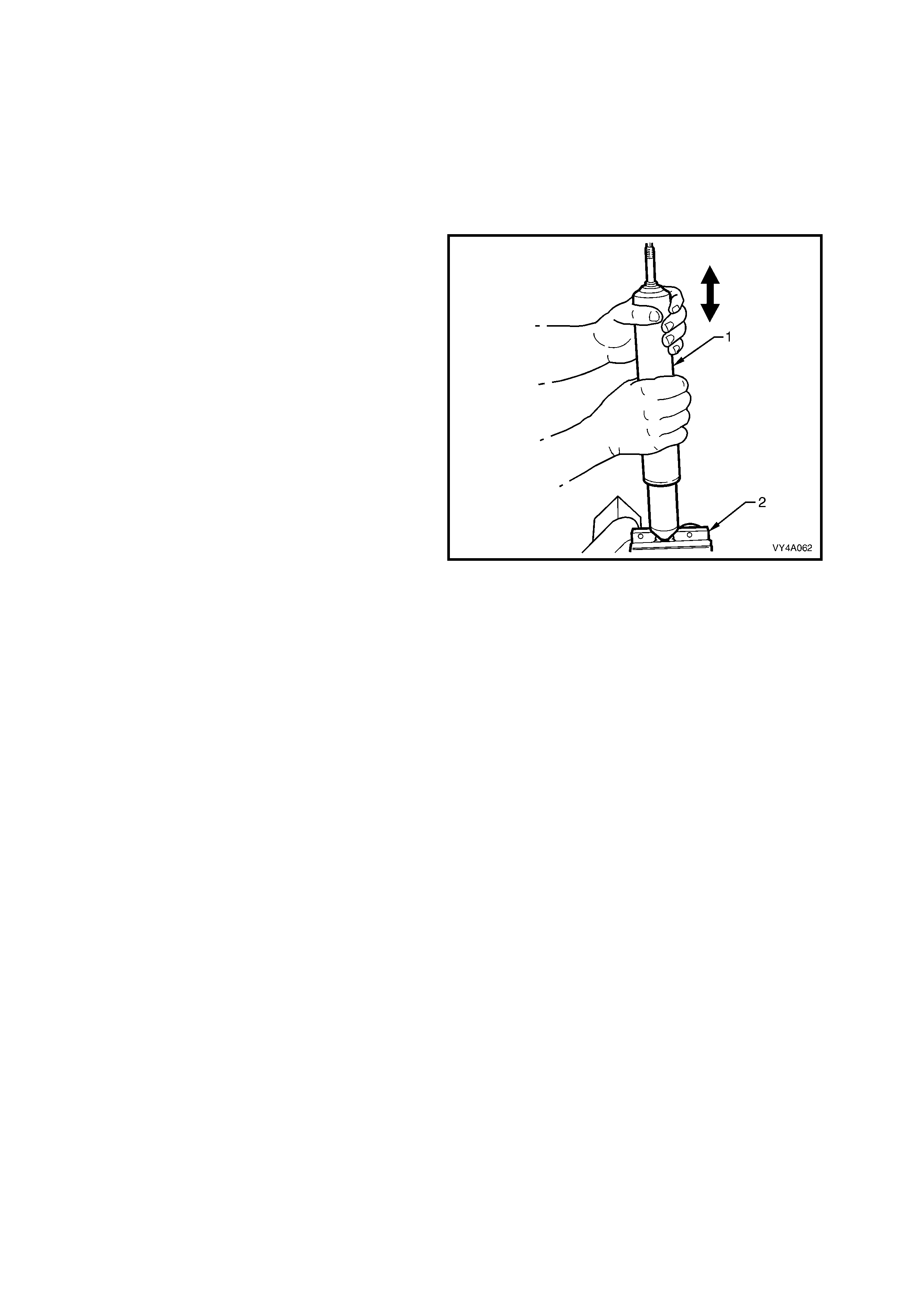
3. DIAGNOSIS
CHECKING AND TESTING SHOCK ABSORBERS
For a positive chec k of shoc k absorber operation it is advisable to rem ove them fr om the vehicle. However, bef ore
proceeding with the removal, it is good practice to ensure that the noise causing concern, is not coming from
another source.
Check the shock absorber mountings for tightness; check the rubber mount bushing and replace if worn.
Test shock absorber action as follows:
Important: This test procedure is not for gas
pressurised shock absorbers.
1. Clamp the shock absorber (1) by its lower
mount in a vice (2).
2. Slowly pump the shock absorber up and down
the full str oke at least six tim es befor e checking
its resistance.
3. Pump the shock absorber by hand at various
rates of speed and observe the resistance.
When extending the shock absorber, the resistance
should be marginally greater than when collapsing
the unit. The resistance should be consistent
throughout both strokes and there should be no
‘sla ck' spots.
‘Slack' spots indicate either loss of oil - which is
usually visible on the outside - or the inter nal valves
not seating.
4. It is normal to detect a hissing noise (orifice
swish).
5. The following conditions are considered
abnormal and replacement is recommended:
a. A skip or lag at reversal near mid-stroke.
b. A seize (except at either extreme end of travel).
c. A noise such as a grunt or squeal after
completing one full stroke in both directions.
d. A clicking noise at fast reversal.
e. Fluid leakage. Refer to LEAKAGE CRITERIA
for guidelines.
Figure 4A-106
LEAKAGE CRITERIA
A shock absorber DOES NOT require replacement if any or a combination of the following are present:
• An oily build-up at the end of the piston rod, up to 1 cm wide.
• Oily ‘sludge’ accumulated from normal operating conditions to 4 cm from the top of the shock absorber body.
• Road grease, oil, s and and dust discolouration on the body, does not constitute a leak ing shock abs orber. If this
condition is evident, the shock absorber should be wiped clean and checked at a later service.
NOTE: Should one shock absorber prove to be leaking and require replacement, providing the remaining shock
absorber is serviceable, it does not also need to be replaced.
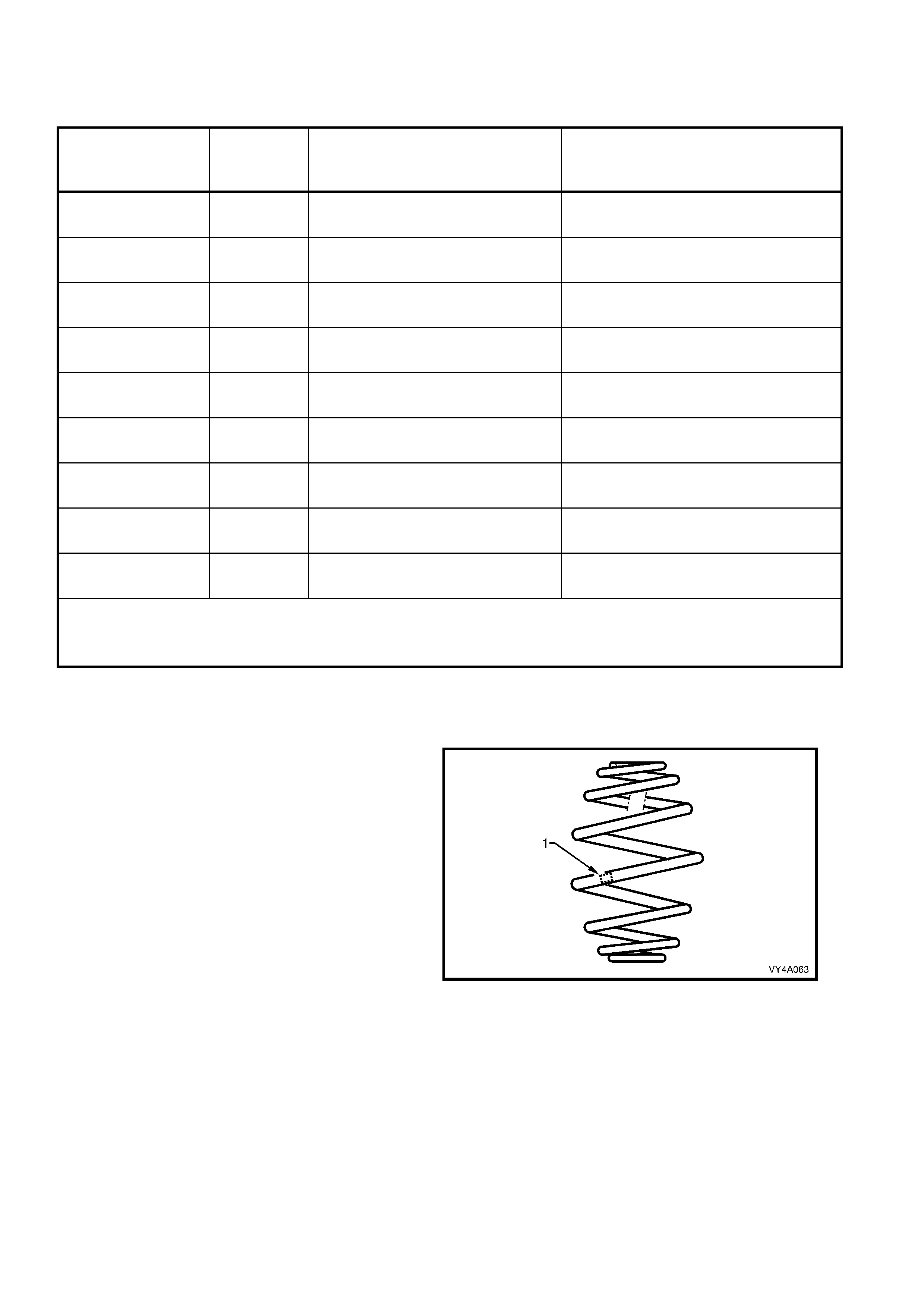
4. SPECIFICATIONS
REAR SUSPENSION SERVICE ALIGNMENT DATA
SUSPENSION
CONFIGURATION REAR
TRACK
(mm)
REAR WHEEL CAMBER
(VARIATION SIDE TO SIDE) TOE DEGREES PER WHEEL
(VARIATION SIDE TO SIDE)
Coupe 1577
-0°25’ to -1°41’
(0°35’ Maximum) +0°02’ to +0°22’
(0°20’ Maximum)
Sedan FE1 1587 -1°23’ to -0°07’
(0°35’ Maximum) 0°00’ to +0°20’
(0°20’ Maximum)
Sedan FR1 1587 -1°13’ to +0°03’
(0°35’ Maximum) -0°01’ to +0°19’
(0°20’ Maximum)
Sedan FE2 1577 -1°41’ to -0°25’
(0°35’ Maximum) +0°02’ to +0°22’
(0°20’ Maximum)
Wagon FE1 1587 -1°07’ to +0°09’
(0°35’ Maximum) -0°01’ to +0°19’
(0°20’ Maximum)
Wagon FR1 1587 -0°43’ to +0°33’
(0°35’ Maximum) -0°01’ to +0°19’
(0°20’ Maximum)
Wagon FE2 1587 -1°37’ to -0°21’
(0°35’ Maximum) 0°00’ to +0°20’
(0°20’ Maximum)
Utility FE1 1587 -0°28’ to +0°33’
(0°35’ Maximum) -0°14’ to +0°11’
(0°20’ Maximum)
Utility FE2 1577 -0°52’ to +0°09’
(0°35’ Maximum) -0°05’ to +0°20’
(0°20’ Maximum)
Dimens ions shown are for a vehic le at curb height, ie. vehicle ready to drive with all fluids at the rec omm ended
levels, the fuel tank full and without the driver, passenger/s or luggage.
Refer to 2.12 REAR WHEEL ALIGNMENT CHECKING in this Section for specific details.
REAR SPRING DETAILS
Type....................................... Variable rate 'Minibloc'
Identification of the rear spring fitted to a particular
vehicle can be achieved by cross-referencing the
two digit code, which is provided on the
production identification tag (1) with the table
below.
Figure 4A-107
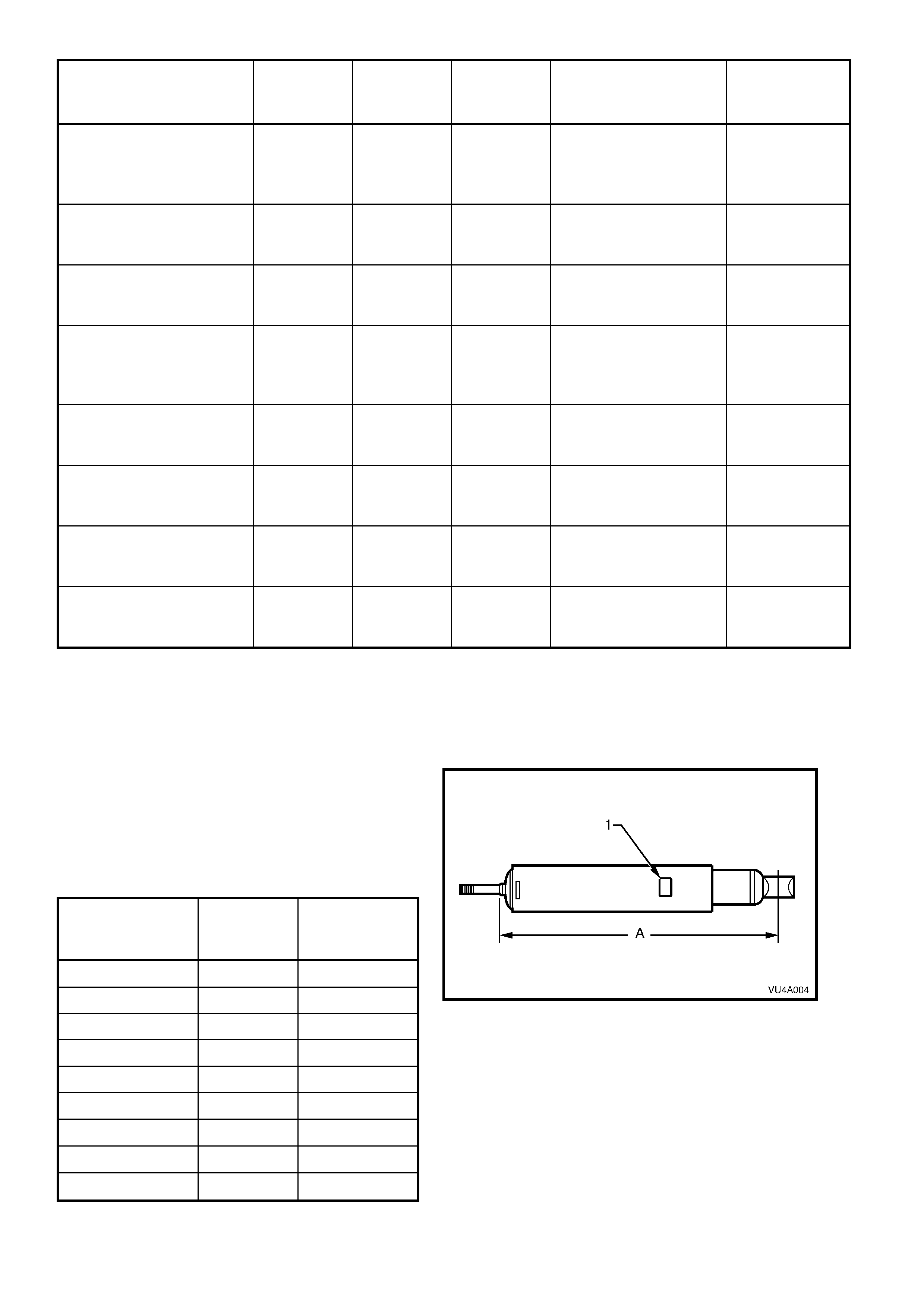
SUSPENSION
CONFIGURATION NUMBER
OF COILS FREE
LENGTH
(mm)
OUTSIDE
DIAMETER
(mm)
SPRING TYPE AND
RAT E PRODUCTION
ID CODE
Coupe 7.5 256 158 Variable
43 N/mm – 90 N/mm
(3860 ± 150N @
168mm)
TF
Sedan FE1 Exc LPG 7.8 275 158 Variable
45 N/mm – 82 N/mm
(4400 N @ 177mm)
EJ
Sedan FE1 and LPG
or
Sedan FR1
7.8 285 158 Variable
47 N/mm – 84 N/mm
(4400 N @ 188mm)
EP
Sedan FE2
7.5 250 158 Variable
51 N/mm – 90 N/mm
(4400 ± 150N @
168mm)
EM
Wagon FE1 Exc LPG 7.8 279 158 Variable
51 N/mm – 90 N/mm
(5200 N @ 180mm)
EK
Wagon FE1 and LPG 7.8 294 158 Variable
51 N/mm – 90 N/mm
(4418 N @ 207mm)
ET
Wagon FR1
or
Utility FE1
7.6 265 165 Variable
51 N/mm – 90 N/mm
(4420 N @ 188mm)
EW
Wagon FE2
or
Utility FE2
7.8 272 158 Variable
68 N/mm – 108 N/mm
(3660 N @ 200mm)
EL
REAR SHOCK ABSORBER DETAILS
Type
Production Option FE1 (Standard).................... Twin tube hydraulic
Production Option FE2 (Sports)........................ Twin tube hydraulic, gas pressurised
Production Option FR1 (Country Pack)............. Twin tube hydraulic, gas pressurised
Identification of the rear shoc k absor ber fitted to a
particular vehicle can be achieved by cross-
referencing the two digit code which is provided
on the production identification tag (1) with the
table below.
The table also provides nominal ex tended lengths
(A).
SUSPENSION
CONFIGURATION NOMINAL
EXTENDED
LENGTH
PRODUCTION
ID CODE
Coupe 670 SB
Sedan FE1 670 TF
Sedan FR1 672 HM
Sedan FE2 670 HJ
Wagon FE1 536 HK/HL
Wagon FR1 508 TP/TS
Wagon FE2 536 HT/HV
Utility FE1 508 TP/TS
Utility FE2 536 HT/HV
Figure 4A-108
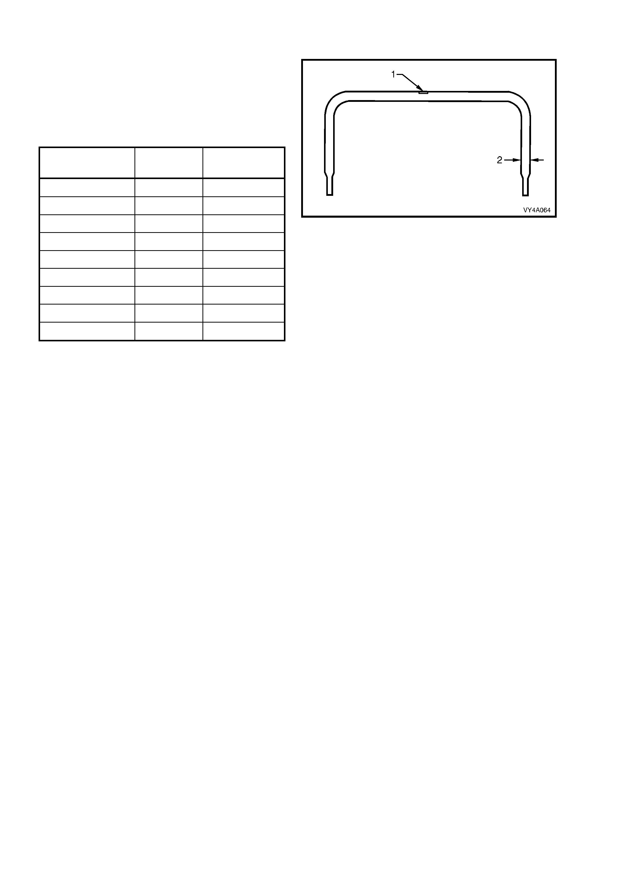
REAR STABILISER SHAFT DETAILS
Identification of the rear stabiliser shaft fitted to a
particular vehicle can be achieved by cross-
referencing the two digit code which is provided
on the production identification tag (1) with the
table below.
The table also provides stabiliser shaft diameters
(2).
SUSPENSION
CONFIGURATION DIAMETER
(mm) PRODUCTION
ID CODE
Coupe 16 FK
Sedan FE1 12 AC
Sedan FR1 12 AC
Sedan FE2 13 FL
Wagon FE1 13 FL
Wagon FR1 13 FL
Wagon FE2 15 FJ
Utility FE1 13 FL
Utility FE2 15 FJ
Figure 4A-109

5.TORQUE WRENCH SPECIFICATIONS
Nm
# Additional Control Arm Socket Assembly to Trailing
Arm Retaining Nut.................................................... 55 – 70
# Additional Control Inner Shaft to Rear Suspension
Crossmember Retaining Nut ................................... 55 – 70
Additional Control Inner Shaft to Rear Suspension
Crossmember Retaining Bolt................................... 55 – 70
" Additional Control Adjusting Shaft Lock Nut............ 50
! Front Rear Suspension Control Arm Mounting
Brace Bolt to Underbody.......................................... 60 – 85
! Rear Suspension Crossmember Front
Mounting Bolt........................................................... 125, then 30° - 40° turn angle
! Crossmember Rear Mount to Underbody
Attaching Bolt........................................................... 30, then 60° turn angle
! Crossmember Rear Mount to Differential Carrier
Rear Cover Attaching Bolt ....................................... 85 - 105
" # Rear Suspension Control Arm to Rear Suspension
Crossmember Attaching Nut.................................... 95 - 105
! Drive Shaft Constant Velocity Joint to Rear Wheel
Flange Attaching Bolt............................................... 50, then 60° - 75° turn angle
Road Wheel Attaching Nut ...................................... 100 - 125
Rear Brake Shield to Rear Suspension Control
Arm Attaching Bolt................................................... 70 - 80
#$ Brake Caliper Anchor Plate To Rear Suspension
Control Arm
Upper bolt ..... 70 - 100
Lower bolt ..... 85 - 90
# Collar Nut to Outer Rear Wheel Drive Shaft............ 295 - 305
! Differential Carrier to Rear Suspension
Crossmember Attaching Bolt................................... 90, then 30° - 45° turn angle
" # Stabiliser shaft Link to Rear Suspension Control
Arm Attaching Nut.................................................... 90 - 105
Stabiliser shaft Mounting Bracket to Rear
SuspensionCrossmember Attaching Bolt ............... 18 - 26
Intermediate Exhaust Pipe to Catalytic Converter
Attaching Bolt........................................................... 40 - 50
Shock Absorber Upper Mounting Nut.
Sedan/Coupe Hand tighten to end of thread
Wagon/Utility. Shaft protrusion above nut, from
15.5 - 16.0 mm.
#$ Shock Absorber Upper Mounting Plate Nut
(Wagon/Utility) ......................................................... 42 - 50
" Shock Absorber Lower Mounting Bolt...................... 105 – 125
Rear Suspension Crossmember Mass Damper Bolt 40 - 50
!
Fasteners must be replaced after loosening.
• Vehicle must be at cur b height before final tightening.
♦ Fasteners either have micro encapsulated sealant applied or incorporate a mechanical
thread lock and should only be re-used once. If in doubt, replacement is recommended.
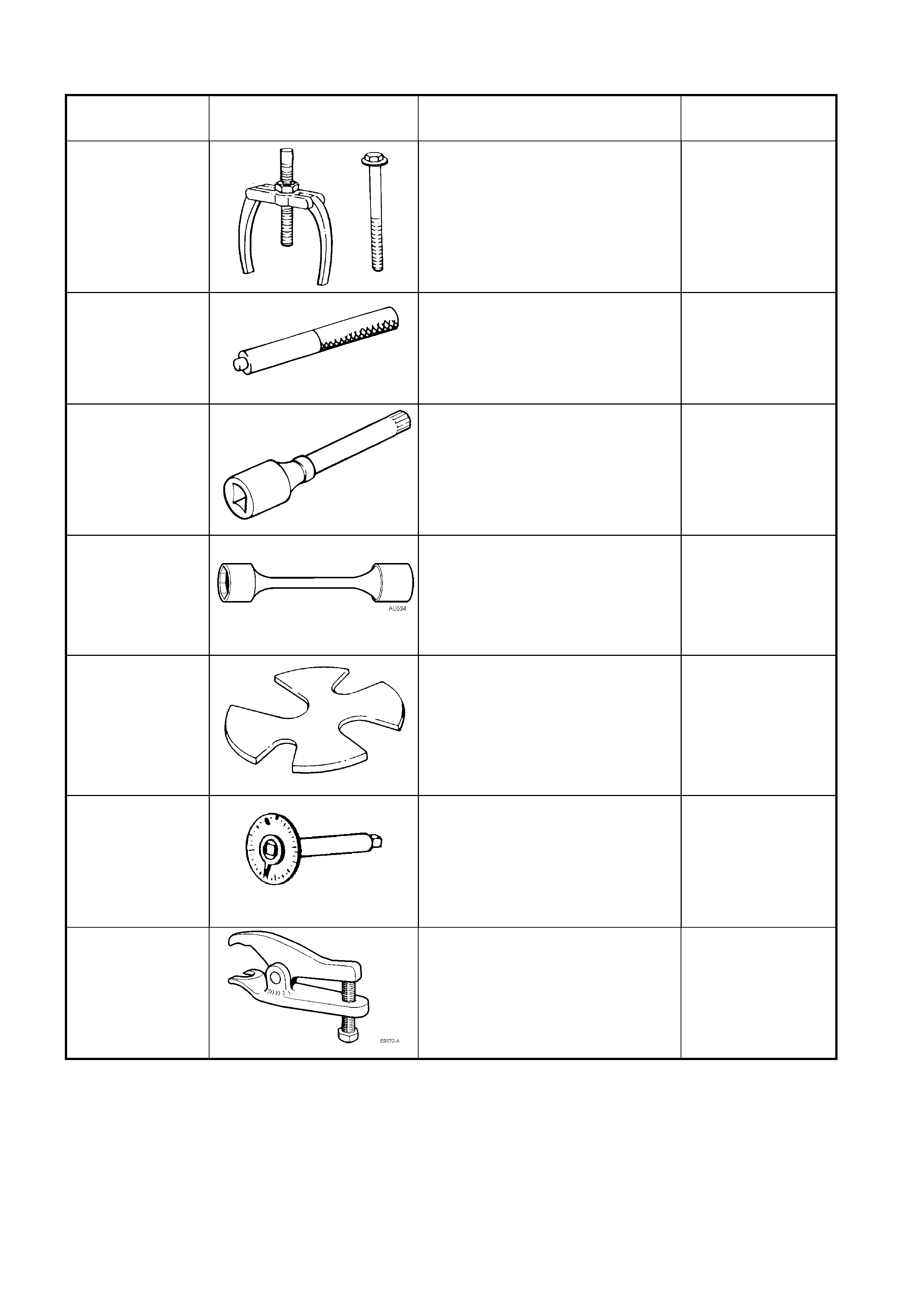
6. SPECIAL TOOLS
TOOL NUMBER ILLUSTRATION DESCRIPTION TOOL
CLASSIFICATION
AMKM-557
PULLER
Previously released.
Used for removing bushing from
crossmember front mounting.
AU385-4
REMOVER/INSTALLER
Previously released.
Used to remove and install bushing
into stabiliser shaft.
AU416
TOR X BIT
Previously released.
Used to remove and install brake
backing plate to rear suspension
control arm attaching bolts.
AU534
TORQUE LIMITING SOCKET
Previously released.
Used in conjunction with an impact
gun to tighten wheel nuts.
This is a mandatory tool.
E7110
PRESS PLATE
Previously released.
Used for supporting stabiliser shaft
link while pressing out or installing
bushing.
E7115
ANGLE WRENCH
Previously released.
Used to tighten various
components where a turn angle is
specified in addition to an initial
torque setting.
E 9332-A
SOCKET ASSEMBLY RELEASE
TOOL
Previously released.
Used to release the additional
control arm socket assembly from
the rear suspension control arm.
Desirable
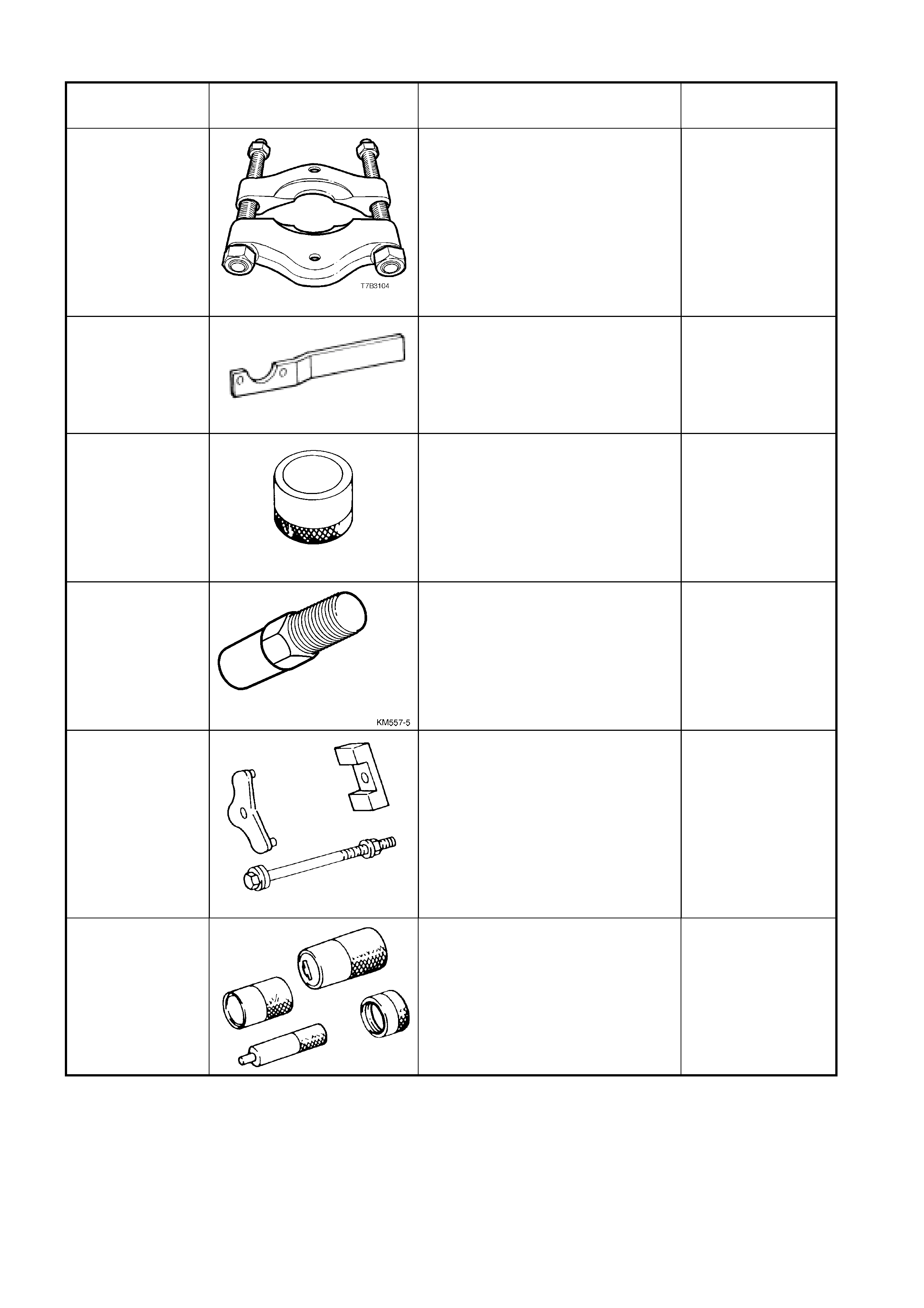
TOOL NUMBER ILLUSTRATION DESCRIPTION TOOL
CLASSIFICATION
J22912-01
PRESS PLATES
Previously released.
Used for various press support
operations.
KM468 HOLDING BAR
Previously released.
Used to hold outer rear wheel drive
shaft hub from rotating.
KM508-2
INSTALLING SLEEVE
Previously released.
Used to install new bushing in
shock absorber lower mount.
KM557-5
ADAPTOR
Previously released.
Used with puller AMKM-557 for
removing bushing from
crossmember front mounting.
KM618
INSTALLER
Previously released.
Used for installing new bushing into
crossmember front mounting
KM619
REMOVER/INSTALLER
Previously released.
Used to press bushing from and
into rear suspension control arms.
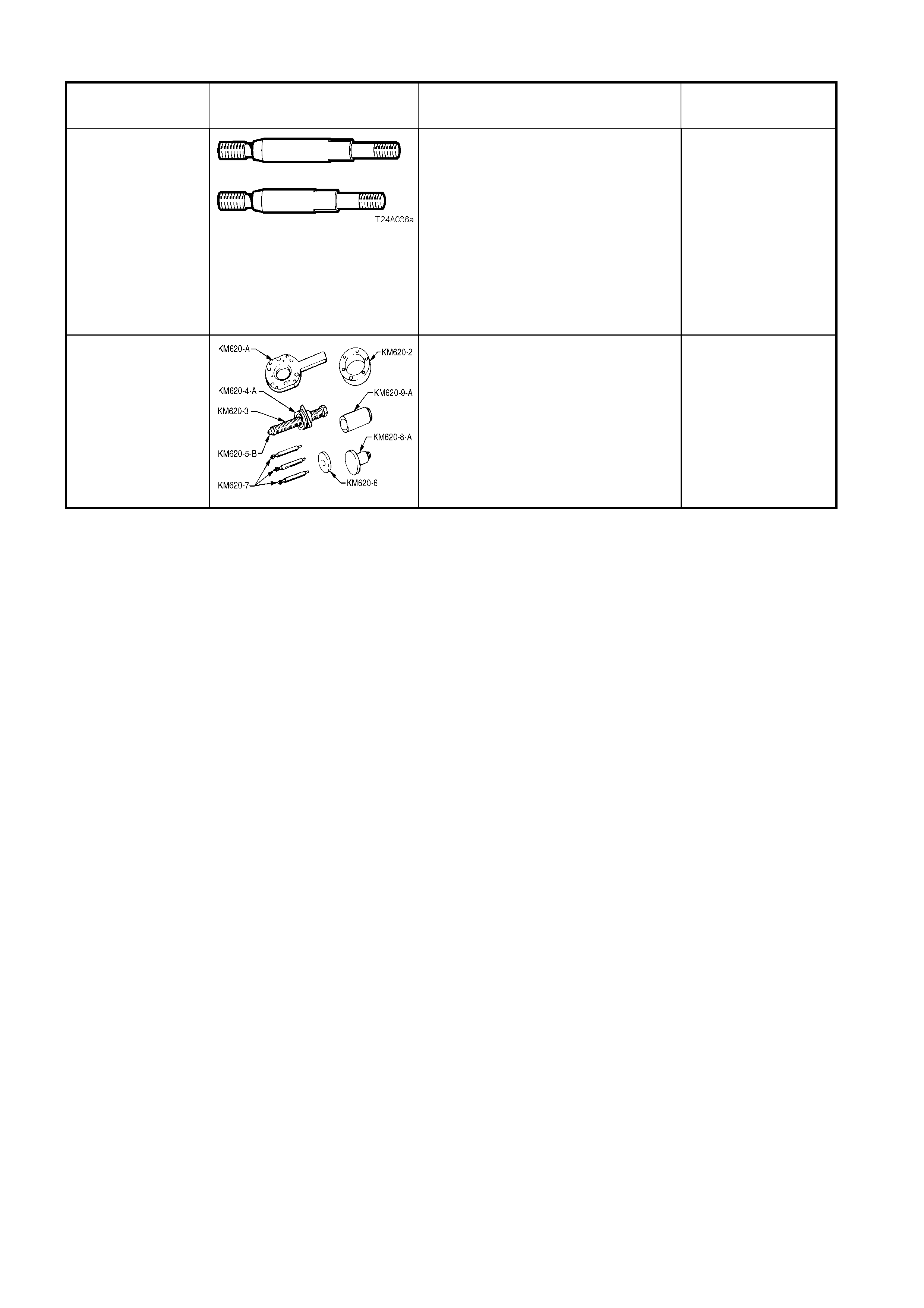
TOOL NUMBER ILLUSTRATION DESCRIPTION TOOL
CLASSIFICATION
KM620-7-AUS
SUPPORTS
Previously released.
The two revised length supports are
required when undertaking any of
the following service operations on
the rear suspension control arm
assembly:
• Rear wheel drive shaft flange
• Rear wheel bearing
•
Rear outer rear wheel drive
KM620-A
REMOVER/INSTALLER
Previously released.
Used to remove and install rear
wheel drive shaft flange, rear wheel
bearing and outer rear wheel drive
shaft