
SECTION 4B - FINAL DRIVE AND DRIVE SHAFTS
IMPORTANT
Before performing any Service Operation or other procedure described in this Section, refer to Section 00
CAUTIONS AND NOTES for correct workshop practices with regard to safety and/or property damage.
CONTENTS
1. GENERAL DESCRIPTION
1.1 FINAL DRIVE ASSEMBLY IDENTIFICATION
1.2 FINAL DRIVE ASSEMBLY MAINTENANCE
MAINTENANCE
LIMITED SLIP DIFFERENTIAL
PRECAUTIONS
LUBRICATION
2. MINOR SERVICE OPERATIONS
2.1 GENERAL
IMPORTANT SERVICE REQUIREMENTS
2.2 CHECKING DIFFERENTIAL CARRIER
LUBRICANT LEVEL
2.3 CHANGING/FLUSHING REAR AXLE
LUBRICANT LEVEL
2.4 TRAILING ARM TRUNNION ASSEMBLY HUB
CHECK FOR RUN-OUT
2.5 TRAILING ARM TRUNNION ASSEMBLY
HUB STUDS
REPLACE
2.6 LIMITED SLIP DIFFERENTIAL
TORQUE CHECK
2.7 DRIVE SHAFT ASSEMBLY
REMOVE
REINSTALL
2.8 DRIVE SHAFT AND/OR CONSTANT
VELOCITY JOINTS
DISASSEMBLE
INSPECT
REASSEMBLE
2.9 INNER AXLE SHAFT SEAL
REPLACE
2.10 PINION OIL SEAL
REPLACE
2.11 PINION FLANGE
REPLACE [USING OLD OIL SEAL]
REPLACE [USING NEW OIL SEAL]
3. MAJOR SERVICE OPERATIONS
3.1 TRAILING ARM TRUNNION FLANGE,
TRUNNION ASSEMBLY AND/OR
WHEEL BEARING
REMOVE
REINSTALL
3.2 FINAL DRIVE ASSEMBLY
REMOVE
REINSTALL
3.3 REMOVED FINAL DRIVE ASSEMBLY
DISASSEMBLE
INSPECT
REASSEMBLE
3.4 LIMITED SLIP DIFFERENTIAL
DISASSEMBLE
INSPECT
REASSEMBLE
3.5 REAR AXLE
REASSEMBLE
4. DIAGNOSIS
4.1 GENERAL INFORMATION
4.2 FINAL DRIVE ASSEMBLY NOISE
GEAR RELATED NOISE
BEARING RELATED NOISE
4.3 LSD NOISE
4.4 FINAL DRIVE BEARING DIAGNOSIS
5. SPECIFICATIONS
6. TORQUE WRENCH SPECIFICATIONS
7. SPECIAL TOOLS
Techline
Techline
Techline
Techline
Techline
Techline
Techline
Techline

1. GENERAL DESCRIPTION
Independent rear suspension is fitted as standard equipment on all MY2003 VY Series vehicles and all are fitted
with a f inal dr i ve ass embly that h as a f our -pin ion type rear dif f er entia l as sembl y. The rin g ge ar di ameter varie s f r om
190.5 m m to 203.2 mm and 205 mm . Applicat ion of each r atio is pro vided in a s ummar y of usage in table form on
page 4B-5.
Production option G80, Limited Slip Differential (LSD), (also referred to as Spin Resistant Differential - SRD) is
availab le on a ll models. While the m aj orit y of illust rations shown in th is Sec ti on rel ate to v eh ic les f itted with th e AB S
braking system, service procedures are the same for vehicles equipped with standard brakes, unless otherwise
noted.
The final dr ive assem bly is mounted directl y to a crossm em ber which is rubber mounted to th e vehicle un derbod y.
The differential case and drive p inion are m ounted in opposed taper roller bearings in the carrier. Differentia l case
side beari ng pre- load adj us tm ent is provi ded b y screw adjusters in the s ides of the cas e. Pinion b earing pr e- load is
provided by a collapsible spacer. Torque is transferred from the propeller shaft to the final drive assem bly via the
pinion flange which is splined to the hypoid pinion. The torque is then transferred from the pinion through the ring
gear, differential case, differential pinion cross shafts, differential pinions, side gears and then via splines, to the
inner axle shafts and drive shafts.
The Limited Slip Differential performs the same functions as the conventional type differential but in addition,
transfers driving force to the wheel with traction, should the opposite wheel begin to spin. The differential case
houses t wo co ne t ype clutc hes b ehind the s ide gears t hat, wit h V6 m odels, ar e sp lined to the inner axl e shaf ts and
their tapered faces contact corresponding faces in the differential case.
The cones for V8 and V6 supercharged models however, form an integral part of the side gears. The four pinion
type Limited Slip Differential has three pre-load springs enclosed in the centre of the pinion cross shaft. The Limited
Slip Diff erential dir ects the m ajor drivin g forc e to the wheel with the gr eater am ount of trac tion, but will not inter fere
with steer ing char acteristic s or dif ferentia l action. T he partia l lock ing action, due t o the sprin g load on th e cones , is
automatic ally incr eased by the i nherent separa ting f orces bet ween the side gear s and pinions , which pro gressive ly
increases the resistance in the differential as applied torque is increased.
W hen the rear wh eels are under ex trem ely unbalanc ed condit ions, s uch as a wheel on a dr y road and t he other in
mud or ice, with the standa rd differential, wheel spin eas ily occ urs if over-ac celeration is attem pted. Howeve r, with
a Limited Slip Differential, when the tendency for wheel spin occurs, the friction generated inside the case, transfers
drivin g force to the non-s pinning wheel. In the event o f continu ed spin ning, a whirring so und fr om the ov er-runnin g
cones is produced but this condition/sound does not indicate failure of the unit.
The f inal dri ve as sembl y shoul d be r emoved f rom the vehicl e f or all s ervice oper at i ons other than for the remova l of
the inner axle shafts, inner axle shaft oil seals, pinion oil seal or the rear cover. Two drive shaft assemblies are
used, each consisting of a shaft which is splined at each end into a ball type constant velocity joint. The inner
constant velocit y joint is bolted to the inner axle shaft flange at the differential ca rrier, with the outer joint bolted to
the trunnion flange at the rear trailing arm.
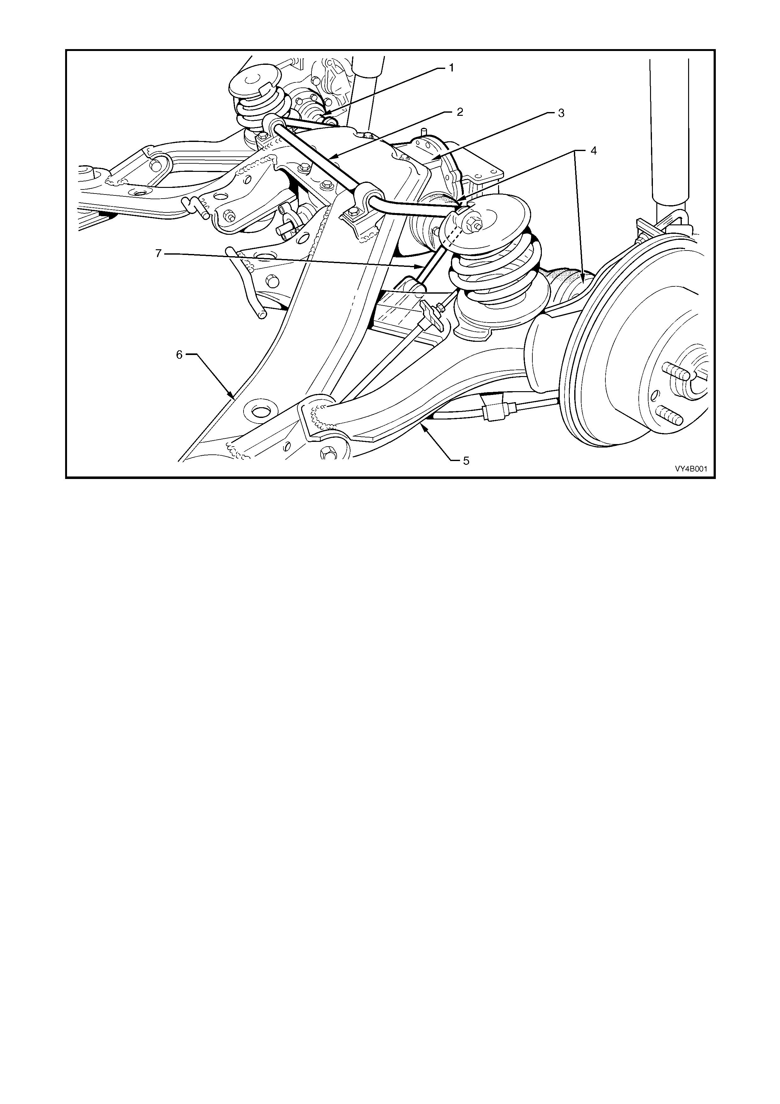
Figure 4B-1
Legend
1. Drive Shaft
2. Rear Suspension Stabiliser Bar
3. Final Drive Assembly
4. Constant Velocity Joints
5. Trailing Arm
6. Rear Suspension Crossmember
7. Rear Stabiliser Bar to Trailing Arm Link
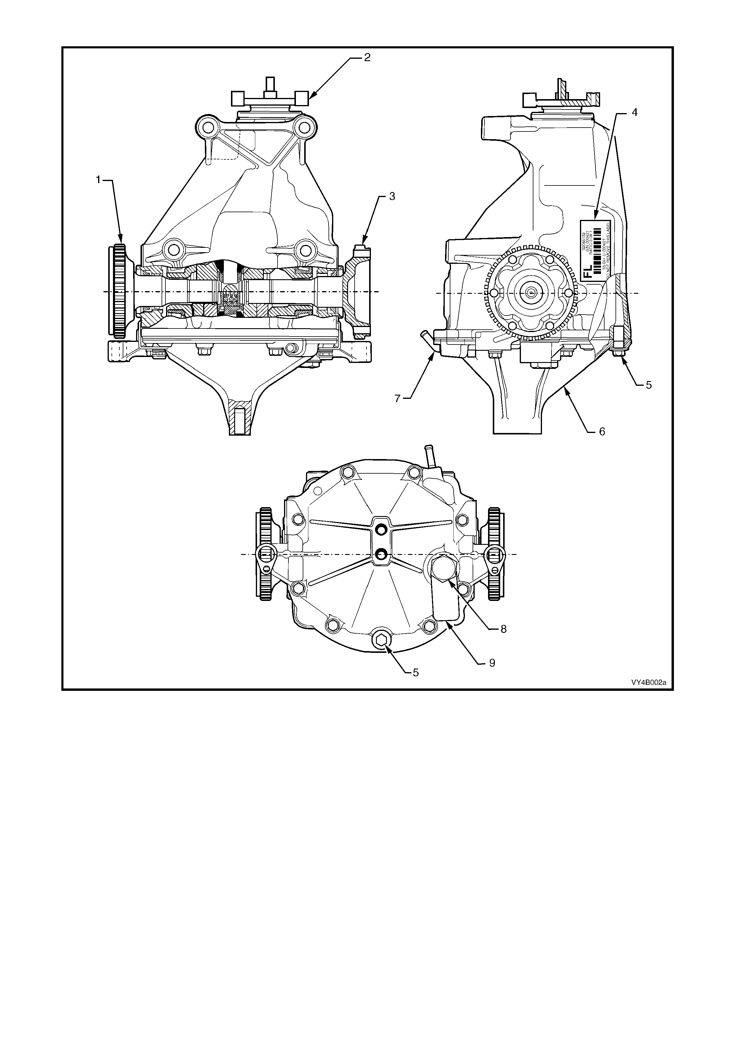
Legend
1. LH Inner Axle Shaft
2. Pinion Flange
3. RH Inner Axle Shaft
4. Identification Label
5. Drain Plug
6. Rear Cover
7. Breather
8. Filler Plug
9. Lubrication Tag
Figure 4B-2
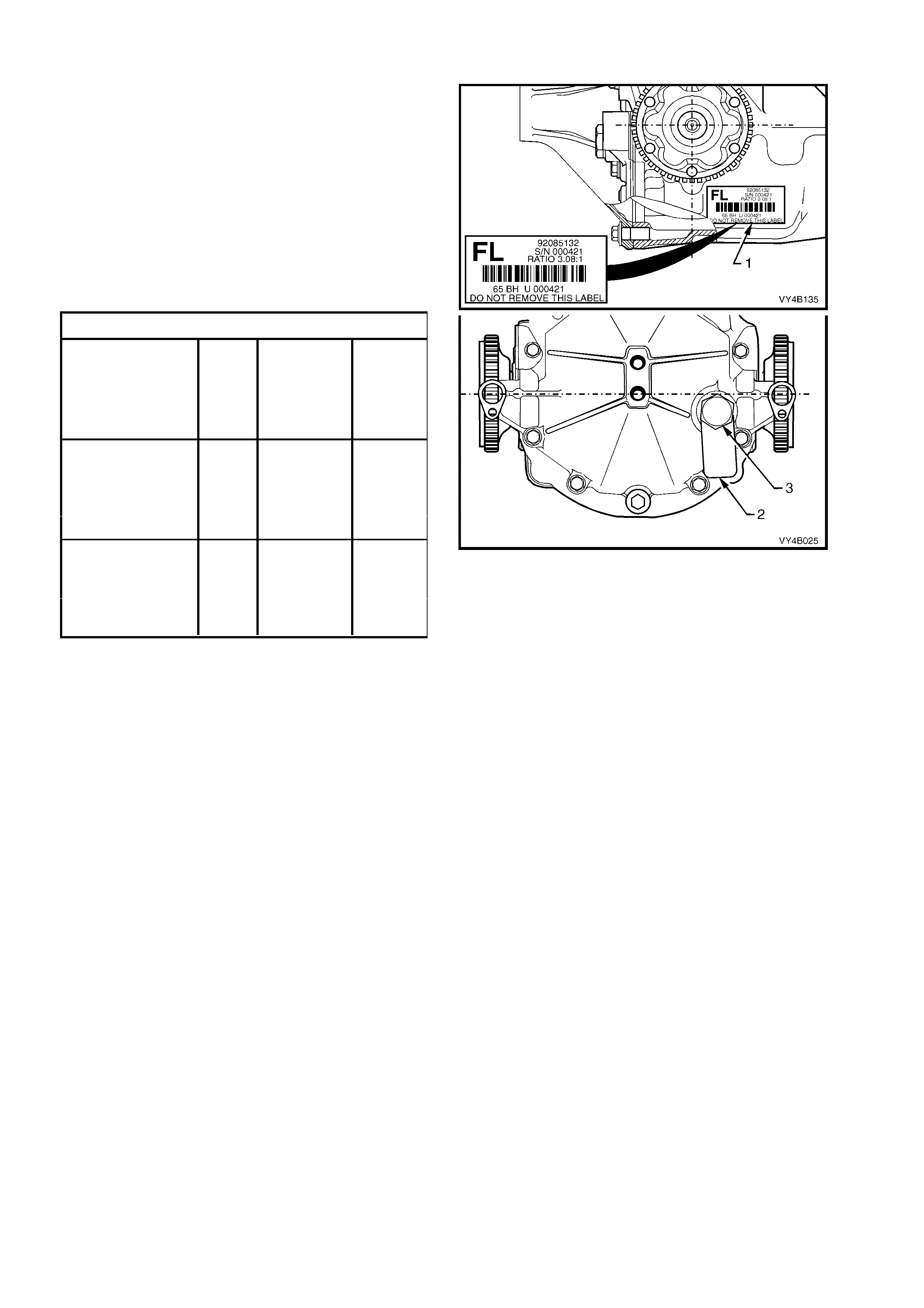
1. 1 FINAL DRIVE ASSEMBLY IDENTIFICATION
The type of differential fitted to this final drive
assembly can be identified by referring to the
identification label (1) attached to the RHS of the
carrier housing and the lubrication tag (2) under the
filler plug (3) on the rear cover.
The locations of the identification label and
lubrication tag are as shown in Figure 4B-3.
The identification label (1) carries the final drive
assembly part number for the final drive ratio and
the serial number of the assembly.
The code number and bar code is used for
production identification of the final drive assembly.
Usage Ratio Type I.D. Code
GEN III V8 or Standard FB
V6 Engined Ut il ity LSD FA
with 3.46:1 ABS (Std) FT
Manual LSD & ABS FC
Transmission
GEN III V8 &V6 Standard FD
Superc harge d with LSD FE
Automatic Trans. / 3.07:1 ABS (Std) FF
V6 Statio n Wagon LSD & ABS FH
with Manual Tr ans .
All V6 Engined Standard FJ
Sedans, Utility and LSD FK
Station Wagon 3.08:1 ABS (Std) FL
with Aut omatic LSD & ABS FM
Transmission
When fitted, the information on the lubrication tag
(2) under the filler plug (‘3’ in Figure 4B-3), will be:
Figure 4B-3
• With V6 and LSD; “SPIN RESISTANT DIFF. USE APPROVED LUBRICANT ONLY”
• With GEN III V8, V6 Supercharged (with Automatic Transmission), V6 Station Wagon and V6 Utility (with
Manual Transmission), fitted with the conventional differential; “HIGH PERFORMANCE. USE APPROVED
LUBRICANT ONLY”
• With GEN III V8, V6 Supercharged (with Automatic Transmission), V6 Station Wagon and V6 Utility (with
Manual Transmission), fitted with LSD; “LSD - HIGH PERFORMANCE. USE APPROVED LUBRICANT AND
FRICTION MODIFIER”
1.2 FIN AL DRIVE ASSEMBLY MAINTENANCE
MAINTENANCE
Drive Shaft Bearings and Constant Velocity Joints
The drive shaft outer bearings and constant
velocity joints are lubricated for life and therefore
require no periodic maintenance.
The constant velocity joint boots are to be
inspected at every maintenance service. If there is
any evidence of damage to boots, remove drive
shaft and inspect constant velocity joints, refer to
2.7 DRIVE SHAFT ASSEMBLY and to
2.8 DRIVE SHAFT AND/OR CONSTANT
VELOCITY JOINTS in this Section.
Differential Carrier Assembly
Check for lubricant leaks at every maintenance
service. If there is evidence of leakage, c orrect the
leak and add lubricant as necessary. (Refer to
2 MINOR SERVICE OPERATIONS in this
Section).
At the tim e or distance interval specified in the MY
2003 VY and V2 Ser ies Owner's Handbook , check
to ensur e that the lubr icant le vel is to the bottom of
the filler plug hole when the differential carrier
assembly is COLD.
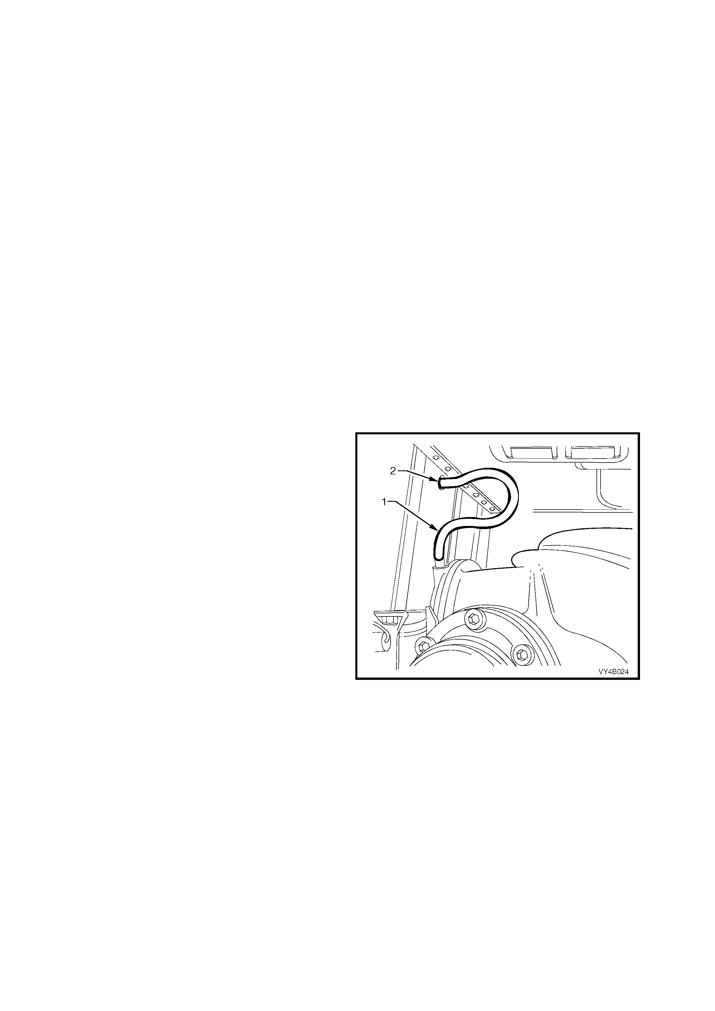
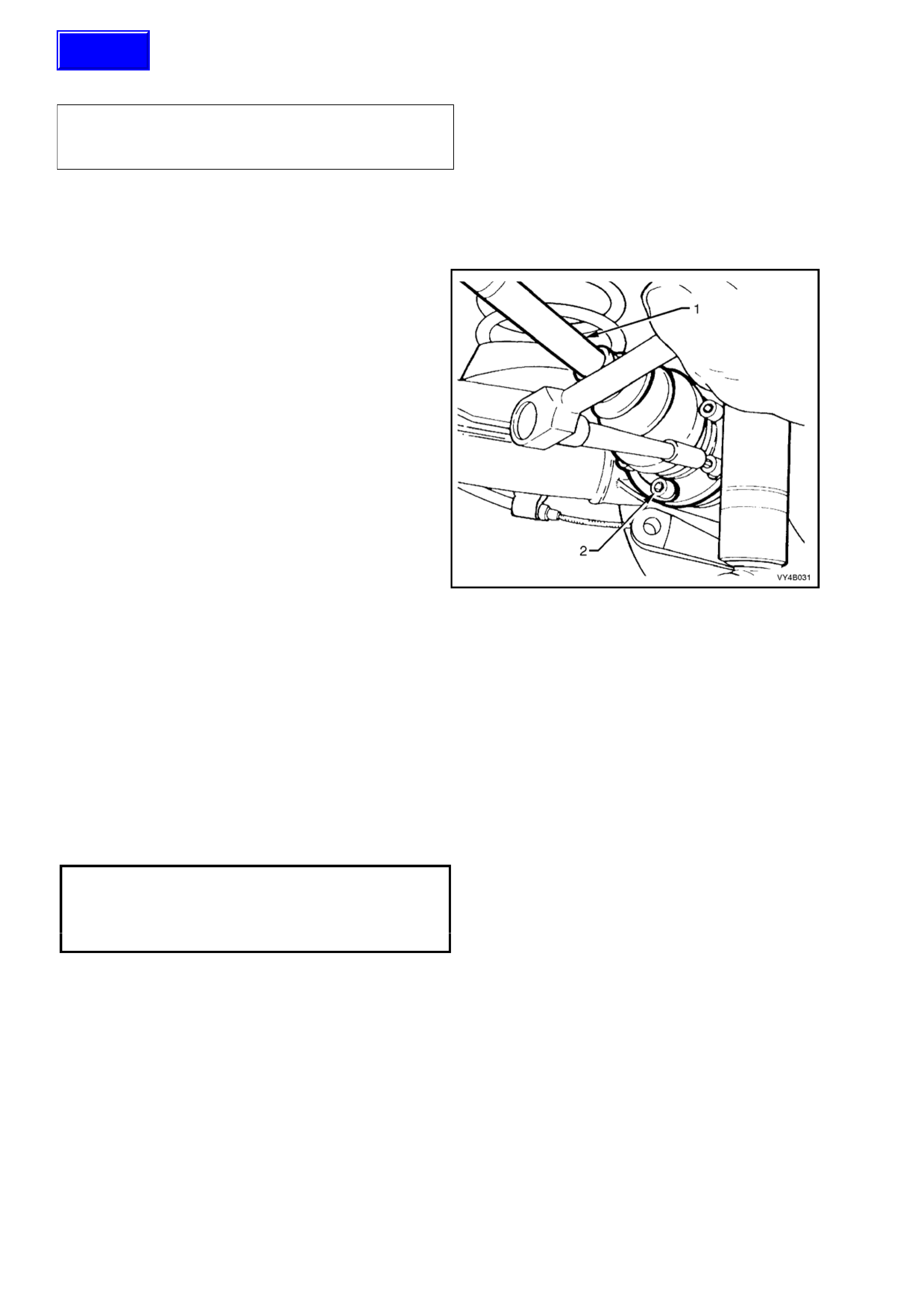
Final Drive Assembly Breather
The breath er hose ( 1) shou ld be check ed regular ly
to ensure that it is correctly routed and not kinked.
The top end of the breather hose should be
inserted at least 25 mm into the vehicle underbody
crossmember hole (2).
Figure 4B-4

LIMITED SLIP DIFFERENTIAL PRECAUTIONS
CAUTION: When servicing a vehicle fitted with a Limited Slip Differential, never run the engine with the
transmission in gear and one wheel raised. The driving force to the wheel on the ground may cause the
vehicle to move.
NOTE: 'On Car' type wheel balancers are not recommended for use on the rear wheels of cars equipped with a
Limited Slip Differential. One rear wheel will drive if in contact with the ground when the opposite wheel is raised
and rotated.
This type of bal ancer ma y be used b y rem oving the road wheel opposit e to the one bein g spun, the veh icle raised
and supported on safety stands. Refit wheel nuts, reversed, to retain brake disc.
LUBRICATION
The lubricant level should be checked and topped up (if required), at the time or distance intervals outlined in the
MY2003 V Y Series Owner' s Handbook with the differ ential carr ier COLD ; refer to 2.2 C HECKING DIFF ERENT IAL
CARRIER LUBRICANT LEVEL in this Sec t ion . At th is temperatur e, th e l ubr ica n t s hould be le ve l with the bott om of
the filler plug hole. Operation 2.2 also details the recommended lubricants for all final drives fitted to MY2003 VY
Series vehicles.
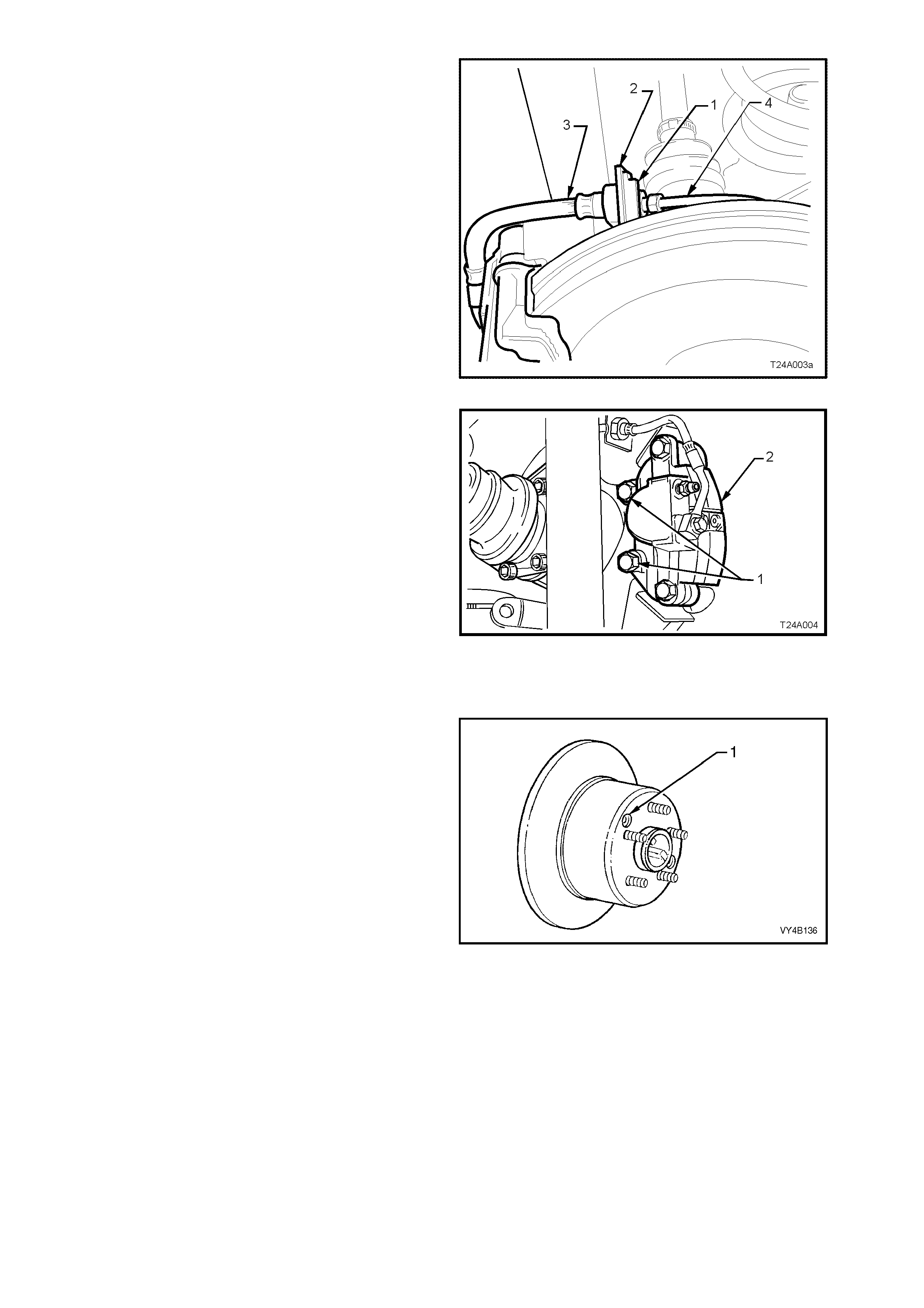
NEVER USE ANY OTHER THAN THE STATED AND RECOMMENDED LUBRICANT.
NOTE 1: The lubricant for vehicles with the 3.08:1 ratio assembly, with either the standard or Limited Slip
Differential (LSD) differential, is an approved mineral, LSD compatible lubricant and MUST be used. Using a
straight run mineral oil in an LSD final drive assembly, will cause ‘stick-slip’ chatter to occur when turning corners.
Alternatively, if a synthetic type lubricant is used in any rear axle of a 3.08:1 ratio assembly, oil seal deterioration
with the possibility of lubricant leakage may occur.
NOTE 2: T he lubr icant used i n the r ear ax les of al l 3.0 7 and 3.46:1 rat io as sem bli es, is a s ynthetic pr oduc t. The oil
seals of the 3.07 and 3.46 :1 ratio as semblies ha ve been speci ally form ulated to tolerat e this lubr icant. It mus t also
be noted that, using a m ineral t ype lubricant in any final drive f itted to a 3.07 or 3.46:1 ratio assem bly, may cause
gear set and/or bearing damage under high load driving conditions.
NOTE 3: With rear axles of 3.07 and 3.46:1 ratio assemblies, with LSD, an approved additive such as Sturaco
7098 MUST also be used, in conjunction with a synthetic hypoid gear oil.
NOTE 4: If the incorrect lubricant is accidentally used in the rear axle of any MY2003 VY Series vehicle, then the
rear axle should be drained, flushed (with the recommended lubricant) and then refilled with the correct lubricant.
The procedure for this operation is detailed in 2.3 CHANGING/FLUSHING REAR AXLE LUBRICANT, in this
Section.
2. MINOR SERVICE OPERATIONS
2.1 GENERAL
IMPORTANT SERVICE REQUIREMENTS
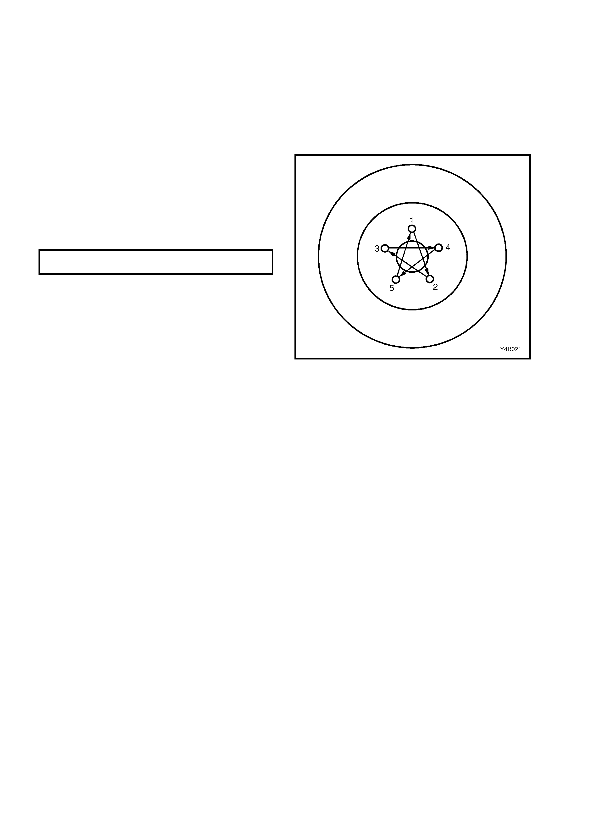
1. Whenever a road wheel and/or brak e disc is removed from the vehicle, the relationship of the road wheel and
the disc to th e hub MUST be mark ed with a felt ti ppe d pen or similar, in or d er f or those parts to be re ins ta ll ed in
their original positions. This is critical to maintain the brake disc and road wheel runout dimension to a
minimum.
2. When reinstalling road wheels, do not use an
impact gun to tighten wheel nuts unless the
impact gun is fitted with a torque limiter socket
(Tool No. AU534 or a commercial equivalent).
Failure to correctly tighten wheel nuts to the
correct torque specification and in the correct
order, may result in a distorted brake disc,
leading to the development of brake shudder.
ROAD WHEEL ATTACHING NUT
TORQUE SPECIFICATION 110 – 140 Nm
For a complete description of the method
used to measure both brake disc and
trunnion assembly runout and correction, refer to
3.5 REAR BRAKE DISC, Brake Disc and Hub
Indexing Procedure, in Section 5A SERVICE AND
PARK BRAKING SYSTEMS in the MY 2003 VY
and V2 Series Ser v ice Infor mation
Figure 4B-5
3. All rear suspension fasteners are important
attaching parts because they affect the
performance of vital components and/or could
result in major repair expense. Where
specified in this Section, fasteners MUST be
replace d with ones of the s am e par t num ber or
with an equivalent part. Do not use a
replacement part of inf erior qua lity or substitute
design.
4. Torque values must be used as specified
during reassembly to ensure proper retention
of all rear suspension components.
2.2 CHECKING DIFFERENTIAL CARRIER LUBRICANT LEVEL
1. Ensure ve hic l e is le vel.
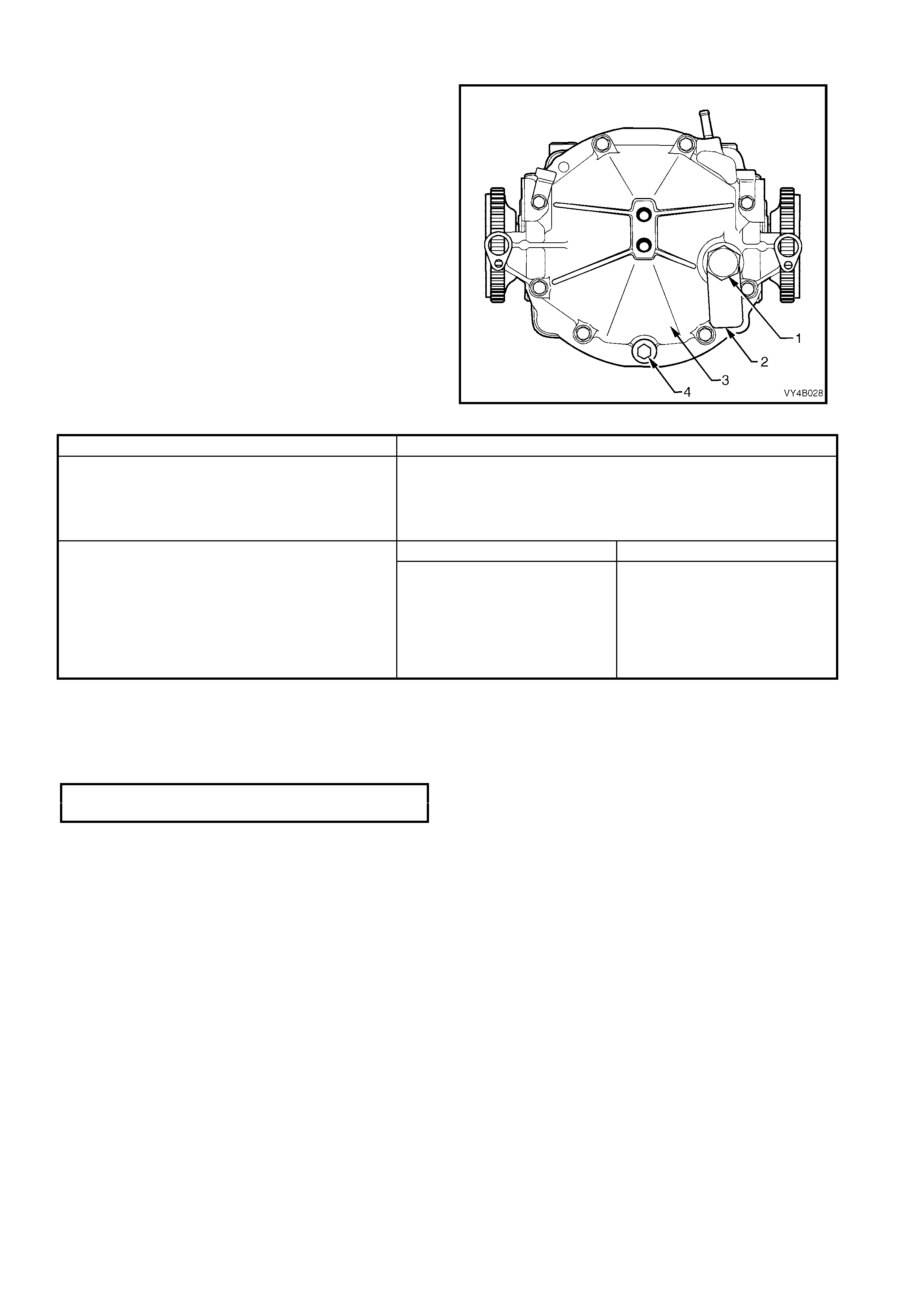
2. Clean area around filler plug (1).
3. Remove filler plug (1) from rear cover (3) (do
not lose the lubrication tag (2) from the plug, if
fitted).
4. The lubricant level is to be maintained at the
bottom edge of the filler plug hole, WHEN
COLD. Use only the recommended lubricant,
detailed as follows:
Figure 4B-6
ENGINE & AXLE TYPE RECOMMENDED LUBRICANT
ALL V6 Sedan with Manual or Automatic
Transmission,
V6 Station Wagon or Utility with Automatic
Transmission
Mineral Hypoid Gear Oil SAE 90 LSD such as;
AMPOL Gear Lube LSD 90,
CASTROL LSX90,
SHELL Helix Limited Slip Diff. Oil
VALVOLINE HP Gear Oil LS90
ALL NON-LSD AXLES ALL LSD AXLES
ALL GEN III V8 V6 Supercharged and V6 Station
Wagon or Utility with Manual Transmission Synthetic Hypoid Gear Oil, SAE
80W-140 such as;
MOBIL Mobilube SHC ID or
CASTROL SAF-XA Only
Synthetic Hypoid Gear Oil, SAE
80W-140 such as;
MOBIL Mobilube SHC ID,
CASTROL SAF-XA
With LSD (G80), also add;
0.1 litre of Sturaco 7098 Oil
Additive
5. Inspect filler plug (1) for damage, if OK,
reinstall to the rear cover (3) (including the
lubrication tag (2). If damaged, replace plug.
6. Tighten filler plug (1) to the correct torque
specification.
FILLER PLUG
TORQUE SPECIFICATION 23 - 31 Nm

2.3 CHANGING/FLUSHING REAR AXLE LUBRICANT
1. To drain lubrican t from diff er entia l c arr ier as s embly, re move filler ( 1) and dr ai n p lu gs (4 ) ( refer Figur e 4B-6) a nd
allow (preferably warm) lubricant to drain into a suitable container.
2. If flushing is required, use an undiluted quantity of the recommended lubricant for the operation.
3. When the draining and flushing (if required), operation is completed, apply thread sealing tape to rear cover
drain plug (4) thread. Install and tighten drain plug (4) to the correct torque specification.
REAR AXLE DRAIN PLUG
TORQUE SPECIFICATION 23 - 31 Nm
4. Fill the f in al dr iv e as sembl y with eith er 1.6 litr es of the r ec om m ended l ubric an t or 1.5 litr es of the r ec om mended
lubricant plus 0.1 litre of Sturaco 7098 oil additive. Install the filler plug (1) and lubrication tag (2) (if fitted) and
tighten to the correct torque specification.
REAR AXLE FILLER PLUG
TORQUE SPECIFICATION 23 - 31 Nm
2.4 TRAILING ARM TRUNNION ASSEMBLY HUB
CHECK FOR RUN-OUT
1. Using a floor jack under centre of differential carrier, jack up rear of vehicle, then place safety stands under
trailing arms to support weight of vehicle.
2. Remove rear wheel cover (steel wheels) or wheel nut covers (alloy wheels) on that side of the vehicle where
the trunnion is to be checked.
3. Mark relationship of wheel to mounting flange. Remove road wheel attaching nuts and remove wheel.
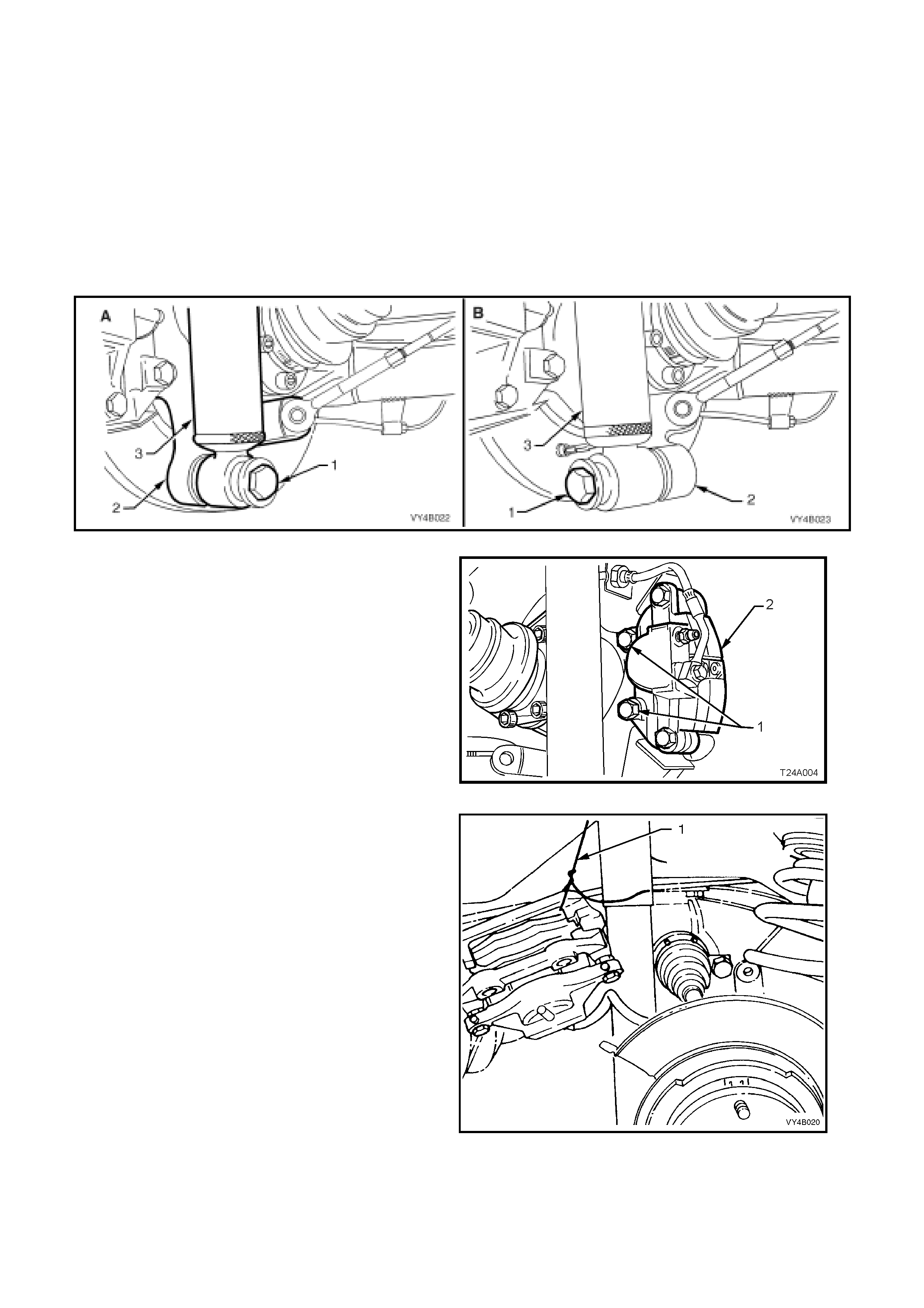
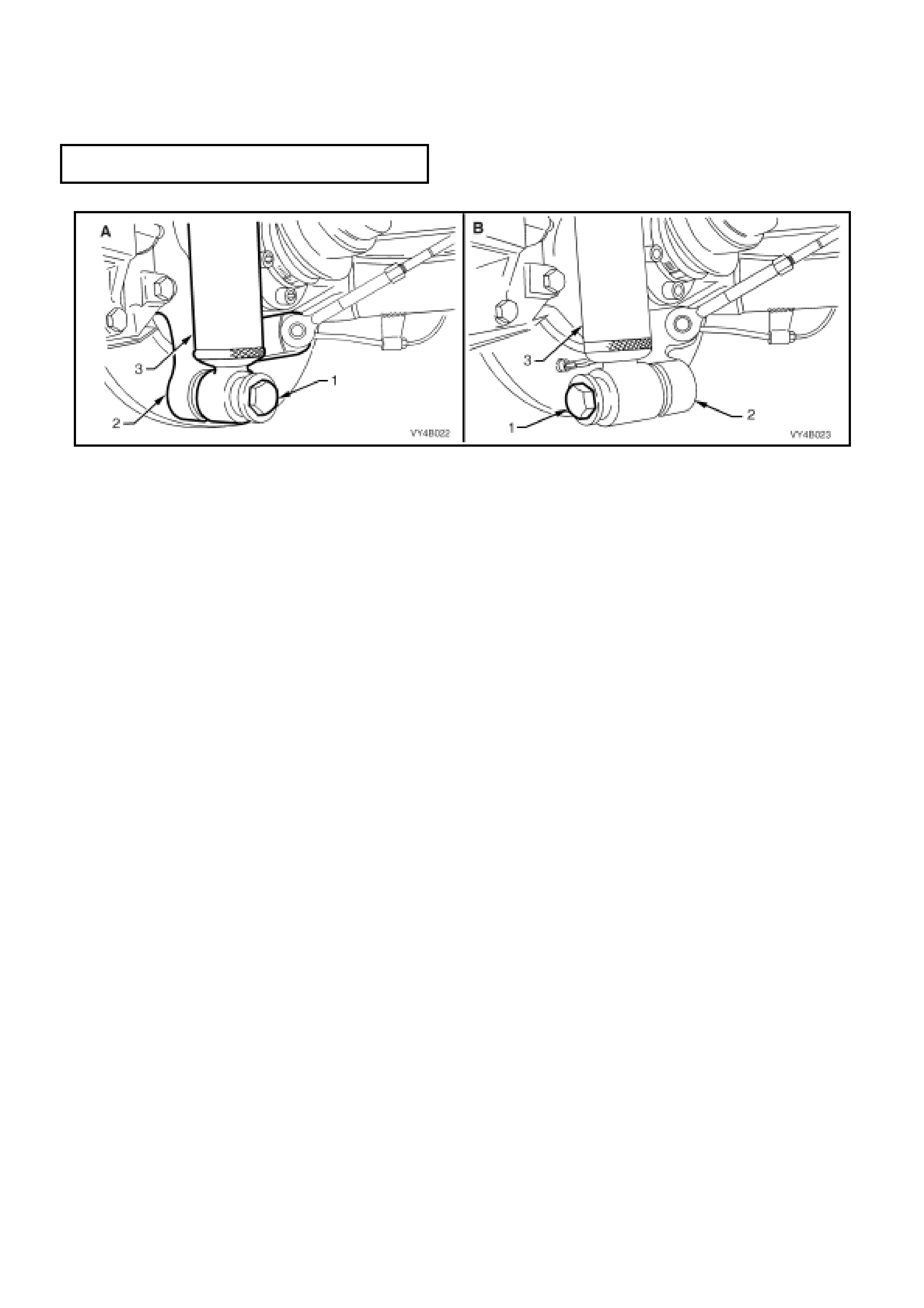
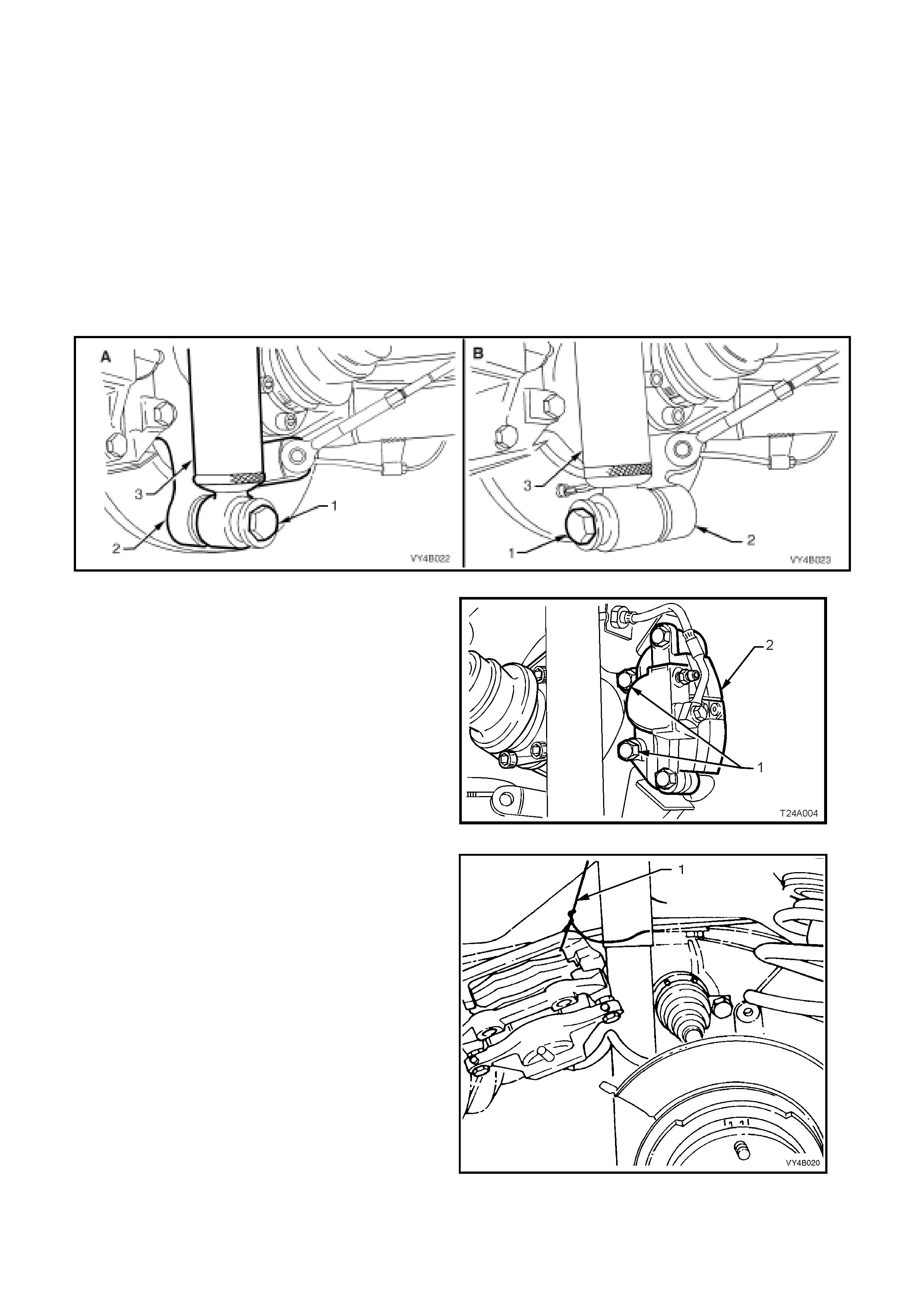
4. Disconnect rear shock absorber lower mounting bolt (1) from trailing arm (2), and pull lower end of shock
absorber (3) from trailing arm.
NOTE: View ‘A’ i n Figure 4B-7 s hows the sedan, lower s hock absorber m ounting, whil e view ‘B’ sho ws the station
wagon arrangement.
Figure 4B-7
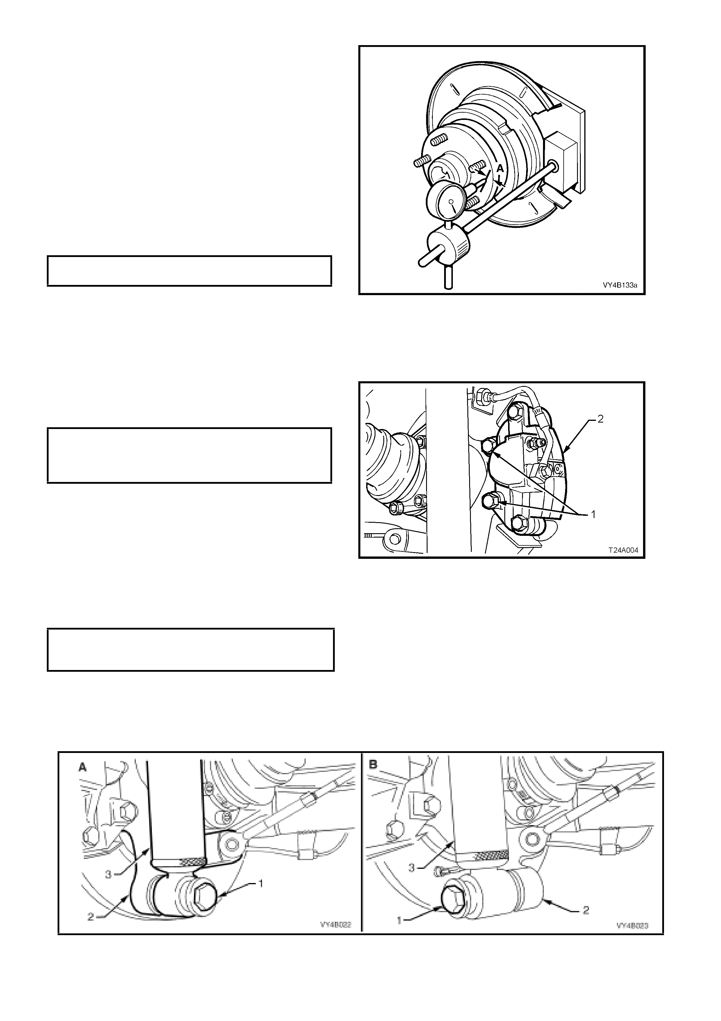
5. Remove brake caliper anchor plate to trailing
arm attac hing bo lts ( 1), rem ove c aliper (2) fr om
disc.
Figure 4B-8
6. Using tie wire (1), secure caliper to lower end
of shock absorber upper mounting. DO NOT
ALLOW CALIPER TO HANG BY BRAKE
HOSE.
7. Mark the brake disc position to trunnion
assembly, using a felt tipped pen or similar,
then remove the brake disc from the trunnion
assembly (Shown already removed in
Figure 4B-9).
Figure 4B-9
8. Clean the rear trunnion face by rubbing lightly
with fine emery paper.
9. Mount the pre-fabricated mounting plate (refer
7. SPECI AL TOOLS in th is Section f or details )
to the brake caliper mounting points on the rear
trailing arm, using the caliper mounting bolts.
10. Mount a magnetic based dial indicator stand,
install a dial in dicat or, posit ioning the pointer at
a distance of 5 mm in from the outer edge (‘A’).
11. Using the wheel studs , carefull y rotate trunn ion
assembly hub, noting the points of maximum
and minimum lateral run-out. The difference
between these two dimensions is the total
indicated runout.
MAXIMUM TRUNNION ASSEMBLY HUB,
TOTAL INDICATED RUN-OUT 0.060 mm
Figure 4B-10
If Run-out is Within Specification:
12. Reinstall brake disc over the trunnion wheel
studs, ensur ing that th e ali gnm ent marks made
prior to disassembly, are aligned.
13. Reinstall brake caliper (2) anchor plate to
trailing arm attaching bolts (1) and tighten to
the correct torque specification.
BRAKE CALIPER ANCHOR
PLATE TO TRAILING
ARM ATTACHING BOLT
TORQUE SPECIFICATION 70 – 100 Nm
Figure 4B-11
14. Install shock absorber to trailing arm, fit
washer to the lower mounting bolt, install bolt
and tighten to the correct torque specification.
SHOCK ABSORBER LOWER
MOUNTING BOLT
TORQUE SPECIFICATION 105 - 125 Nm
NOTE 1: Vehic le m ust be at c urb we ight an d on al l
four wheels before this torque is applied.
NOTE 2: View ‘A’ in Figure 4B-12 shows the
sedan, lower shock absorber mounting, while view
‘B’ shows the station wagon arrangement.
Figure 4B-12

15. Reinstall road wheel, aligning marks made
prior to removal, install and tighten attaching
nuts.
16. Remove safety stand and lower vehicle.
17. Tighten road wheel attaching nuts to the
correct torque specification and in the correct
sequence (refer ‘IMPORTANT SERVICE
REQUIREMENTS’ in 2.1 GENERAL, in this
Section).
ROAD WHEEL ATTACHING NUT
TORQUE SPECIFICATION 110 - 140 Nm
18. Refit wheel cover/ whe el nut caps.
If the Run-out Check, Exceeds Specification:
19. The tr unnion assem bly mus t be replace d, refer
to 3.1 TRAILING ARM TRUNNION FLANGE,
TRUNNION ASSEMBLY AND/OR WHEEL
BEARING in this Sect ion.

2.5 TRAILING ARM TRUNNION ASSEMBLY HUB STUDS
LT Section No: E006500 / E006600
REPLACE
1. Using a floor jack under centre of differential carrier, jack up rear of vehicle, then place safety stands under
trailing arms to support weight of vehicle.
2. Rem ove rear wheel cover (steel whee ls) or whee l nut caps (alloy whee ls) on that side of the veh icle where th e
stud/s are to be replaced.
3. Mark relationship of wheel to mounting flange. Loosen then remove road wheel attaching nuts. Remove the
road wheel.
4. Loosen and disconnec t rear shock absorber lo wer mounting bolt ( 1) from trailing arm (2) and pull lo wer end of
shock absorber (3) from trailing arm (2).
NOTE: View ‘A ’ in Figure 4 B-13 s h o ws th e s eda n, lower shoc k absor ber mountin g, whil e vie w ‘ B’ s ho ws t he s tatio n
wagon arrangement.
Figure 4B-13
5. Loosen and remove brake caliper anchor plate
to trailing arm attaching bolts (1) and remove
caliper (2) from disc.
Figure 4B-14
6. Using tie wire (1), secure the brake caliper to
lower end of shock absorber upper mounting.
DO NOT ALLOW CALIPER TO HANG BY
BRAKE HOSE.
7. Mark the brake disc position to trunnion
assembly, using a felt tipped pen or similar,
then remove the brake disc from the trunnion
assembly (Shown already removed in Figure
4B-15).
Figure 4B-15
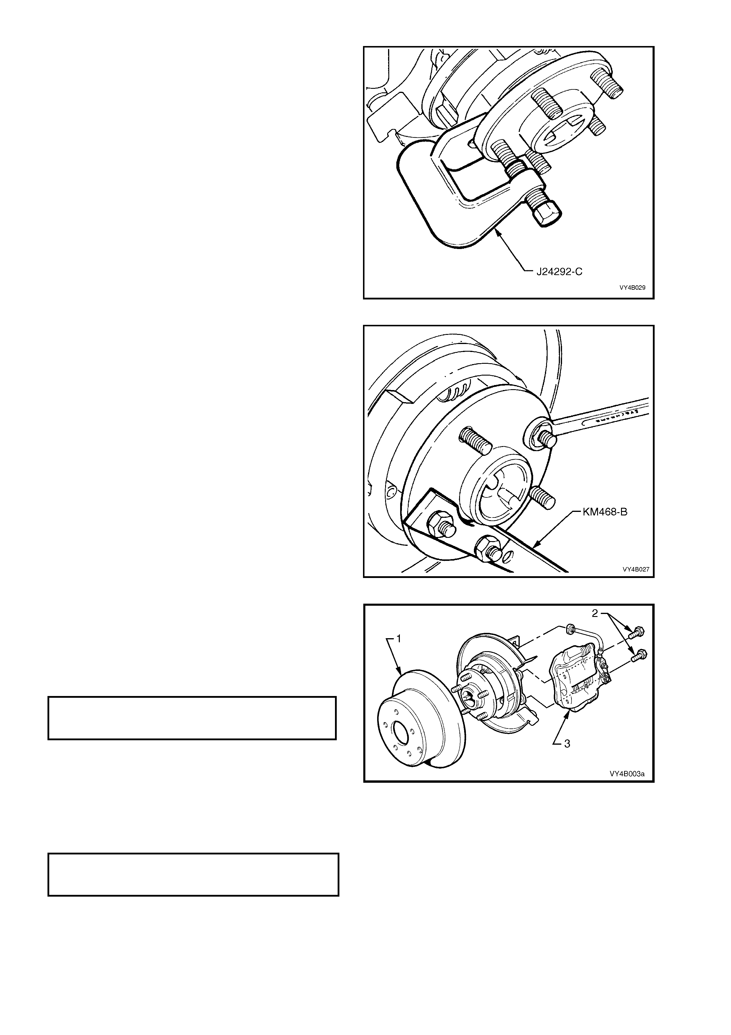
8. Using Tool No. J24292-C or equivalent, press
stud/s from hub.
Figure 4B-16
9. Install Tool No. K M-46 8-B hol ding bar, with tw o
wheel nuts to t he trun nion assem bly hub studs .
Install new stud into hub. Assemble some
suitable size washers and a reversed wheel
nut, onto stud. Tighten wheel nut to draw in
stud. When stud is fully installed, remove
wheel nut and washers.
10. Install any remaining studs in the same
manner.
11. Remove Tool No. KM468-B.
Figure 4B-17
12. Reinst all br ak e disc ( 1) over the trunnion wheel
studs, ensuring that the marks made prior to
disassembly, are aligned.
Reinstall brake caliper (3) anchor plate to
trailing arm attaching bolts (2) and tighten to
the correct torque specification.
BRAKE CALIPER ANCHOR PLATE
TO TRAILING ARM ATTACHING
BOLT TORQUE SPECIFICATION 70 – 100 Nm
Figure 4B-18
13. Reinstall shock absorber to trailing arm, fit
washer to the lower mounting bolt, install bolt
and tighten to the correct torque specification.
SHOCK ABSORBER LOWER
MOUNTING BOLT
TORQUE SPECIFICATION 105 - 125 Nm
NOTE 1: Vehic le m ust be at c urb we ight an d on al l
four wheels before this torque is applied.
NOTE 2: View ‘A’ in Figure 4B-19 shows the
sedan, lower shock absorber mounting, while view
‘B’ shows the station wagon arrangement.
14. Install road wheel, aligning marks made prior to removal, install and tighten attaching nuts.
15. Remove safety stand and lower vehicle.
16. Tighten road wheel attaching nuts to the correct torque specification and in the correct sequence (refer
‘IMPORTANT SERVICE REQUIREMENTS’ in 2.1 GENERAL, in this Sec ti on).
ROAD WHEEL ATTACHING NUT
TORQUE SPECIFICATION 110 - 140 Nm
17. Refit wheel cover/wheel nut caps.
Figure 4B-19
2.6 LIMITED SLIP DIFFERENTIAL
TORQUE CHECK
1. Place transmission in neutral with engine turned OFF.
2. Jack up one rear wheel and support trailing arm on a safety stand. Release park brake lever to fully OFF
position.
3. Rem ove rear wheel cover (steel whee ls) or whee l nut caps (alloy whee ls) on that side of the veh icle where th e
stud/s are to be replaced.
4. Mark relationship of wheel to mounting flange. Loosen then remove road wheel attaching nuts. Remove the
road wheel.
5. Loosen and disconnect rear shock absorber lower mounting bolt from trailing ar m and pull lower end of shock
absorber from trailing arm.
NOTE: View ‘A ’ in Figure 4 B-20 s h o ws th e s eda n, lower shoc k absor ber mountin g, whil e vie w ‘ B’ s ho ws t he s tatio n
wagon arrangement.
Figure 4B-20
6. Loosen and remove brake caliper anchor plate
to trailing arm attaching bolts (1) and remove
caliper (2) from disc.
Figure 4B-21
7. Using tie wire (1), secure the brake caliper to
lower end of shock absorber upper mounting.
DO NOT ALLOW CALIPER TO HANG BY
BRAKE HOSE.
8. Mark the brake disc position to trunnion
assembly, using a felt tipped pen or similar,
then remove the brake disc from the trunnion
assembly (Shown already removed in
Figure 4B-2 2).
Figure 4B-22
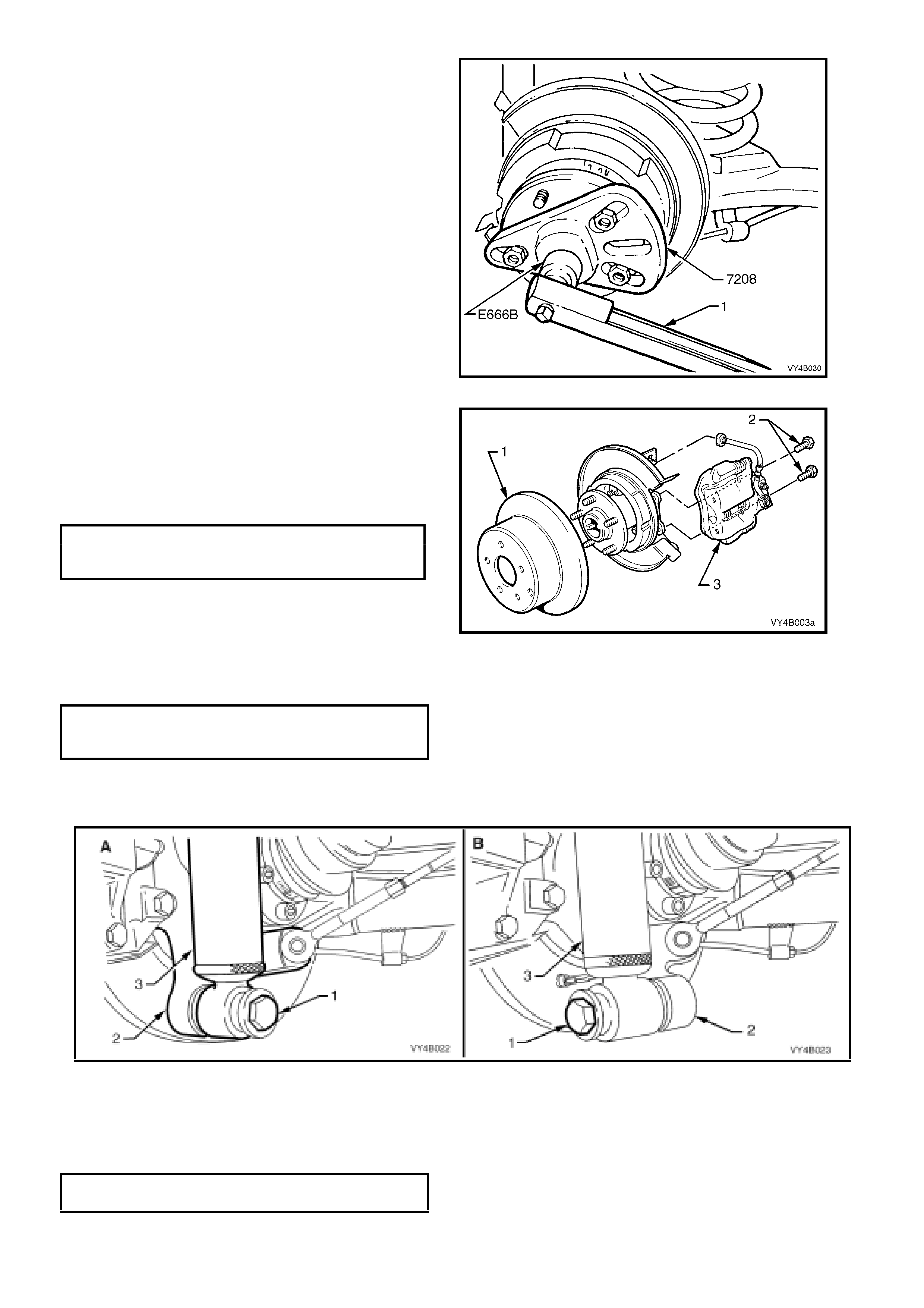
9. Using a torque wrench in conjunction with
adaptor, Tool No. 7208, and torque wrench
adaptor E6662B, rotate trunnion assem bly in a
forward direction. If the unit is operating
satisf ac toril y, a torque rea di ng of appr ox imately
70 Nm should be obtained while turning the
trunnion assembly, with the opposite wheel
remaining stationary.
If a torque reading of less than 45 Nm
is obtained, remove differential case
and inspect case internal components
and repair as necessary, refer to
3.4 LIMITED SLIP DIFFERENTIAL in this
Section.
Figure 4B-23
10. Reinst all br ak e disc ( 1) over the trunnion wheel
studs, ensuring that the marks made prior to
disassembly, are aligned.
Reinstall brake caliper (3) anchor plate to
trailing arm attaching bolts (2) and tighten to
the correct torque specification.
BRAKE CALIPER ANCHOR PLATE
TO TRAILING ARM ATTACHING
BOLT TORQUE SPECIFICATION 70 – 100 Nm
Figure 4B-24
11. Reinstall shock absorber to trailing arm, fit washer to the lower mounting bolt, install bolt and tighten to the
correct torque specification.
SHOCK ABSORBER LOWER
MOUNTING BOLT
TORQUE SPECIFICATION 105 - 125 Nm
NOTE 1: Vehicle must be at curb weight and on all four wheels before this torque is applied.
NOTE 2: View ‘A’ in Figure 4B-25 shows the sedan, lower shock absorber mounting, while view ‘B’ shows the
station wagon ar rangem ent.
Figure 4B-25
12. Install road wheel, aligning marks made prior to removal, install and tighten attaching nuts.
13. Remove safety stand and lower vehicle.
14. Tighten road wheel attaching nuts to the correct torque specification and in the correct sequence (refer
‘IMPORTANT SERVICE REQUIREMENTS’ in 2.1 GENERAL, in this Sec ti on).
ROAD WHEEL ATTACHING NUT
TORQUE SPECIFICATION 110 - 140 Nm
15. Refit wheel cover/wheel nut caps.
2.7 DRIVE SHAFT ASSEMBLY
LT Reference No: F50400 / F504100 / F504200
NOTE: The following fasteners MUST be replaced when
performing this operation:
Drive shaft constant velocity joint to trunnion flange and
inner axle shaft attaching bolt.
REMOVE
1. Using a floor jack under centre of differential
carrier, jack up rear of vehicle then place safety
stands under trailing arms.
2. Using an 8 mm Allen key socket, remove drive
shaft inner constant velocity joint to inner axle
shaft and outer constant velocity joint to
trunnion flange attaching bolts (2) (six places)
and plates, remove drive shaft (1).
NOTE 1: As it is only the inner, constant velocity
joint that is a plunge joint, it is important that the
drive shaft orientation is remembered for correct
installation.
NOTE 2: During drive shaft removal and
installation, keep drive shaft supported so that it
does not hang on one end because drive shaft joint
deflection must be kept to within the angular
movement of an installed drive shaft.
Figure 4B-26
REINSTALL
Reinstallation of the drive shaft is reversal of the
removal procedure, noting the following points.
NOTE: A label is attached to each drive shaft, to
indicate which joint faces outward. The outer CV joint
is also marked with a groove, while the inner, plunge
joint has none. It is important that the drive shaft is
installed correctly.
1. Tighten drive shaft to trunnion flange and inner
axle shaft attaching bolts to the correct torque
specification.
DRIVE SHAFT CONSTANT VELOCITY
JOINT TO TRUNNION FLANGE AND
INNER AXLE SHAFT ATTACHING
BOLT TORQUE SPECIFICATION 50 Nm, then
90° turn angle
Techline
2.8 DRIVE SHAFT AND/OR CONSTANT VELOCITY JOINTS
There are four repair kits available for drive shaft constant velocity joint repairs.
1. A ‘BOOT KIT’, which consists of a boot, boot clamps, snap ring and two tubes of grease.
2. A ‘CONSTANT VELOCITY JOINT KIT’, which contains the same items as the BOOT KIT plus the inner,
constant ve locity joint.
3. A ‘CONSTANT VELOCITY JOINT KIT’, which contains the same items as the BOOT KIT plus the outer,
constant ve locity joint.
4. A ‘DUST CAP REPAIR KIT’, which is common to both the inner and outer constant velocity joints.
DISASSEMBLE
1. Remove drive shaft assembly, refer to
2.7 DRIVE SHAFT ASSEMBLY in this Section.
2. Clean outside of assembly with a suitable
solvent before disassembling.
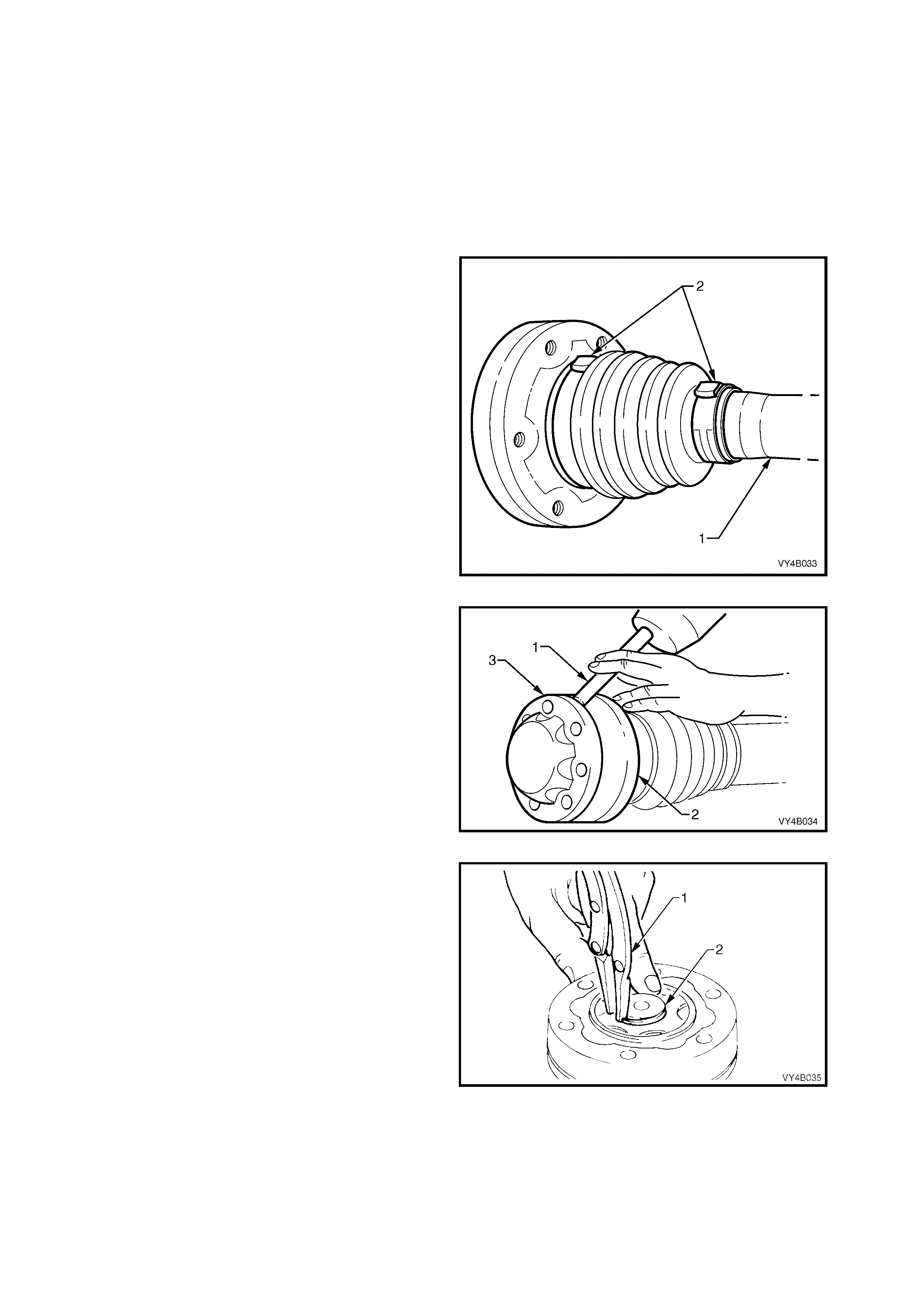
3. Clamp assembly, by drive shaft (1), in a vice
fitted with soft metal jaws.
4. Using tin snips or other suitable cutting tool, cut
boot clamps (2) in raised crimped area and
remove clamps.
Figure 4B-27
5. Using a suitable dr ift (1) a nd hamm er, tap dust
shields (2) and caps (3) from both sides of
constant velocity joints.
Figure 4B-28
6. Using suitable snap ring pliers (1), remove the
snap ring (2) from each end of drive shaft and
discard.
NOTE: Do not use s na p rin gs once they have be en
removed. Always use new snap rings on
reassembly.
7. Remove assembly from vice. Slide dust shield
and boots towards centre of shaft.
Figure 4B-29
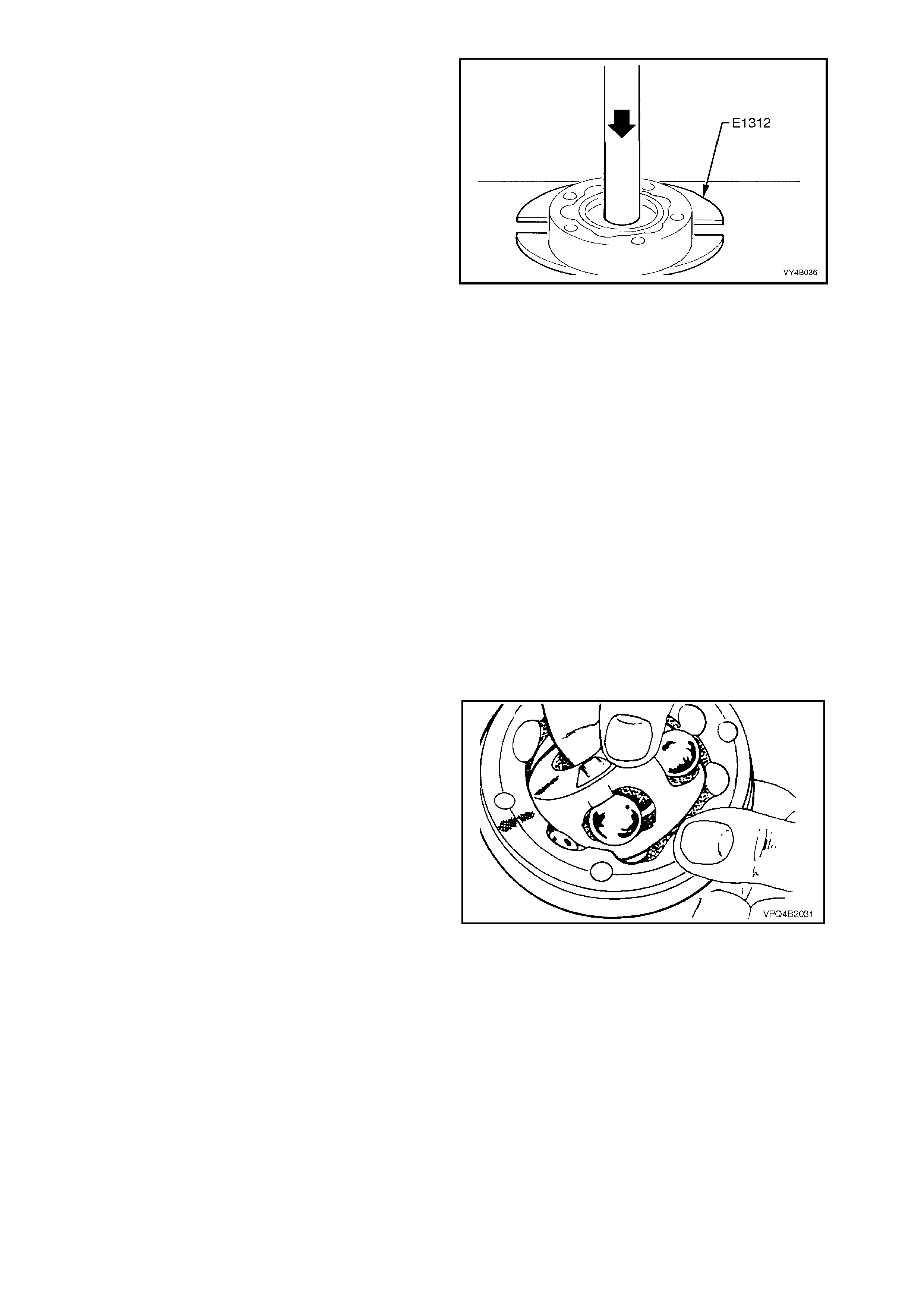
8. Using suitable press plates (such as Tool No.
E1312), supporting inner race, press drive
shaft from constant velocity joint.
9. Repeat process to remove remaining constant
velocity joint.
10. Remove boots and dust shields from drive
shaft, ensuring boots are not damaged on
edges of shaft.
Figure 4B-30
INSPECT
Drive Shaft and Boots
1. Clean shaft and boots in a suitable cleaning
solvent.
2. Inspect drive shaft for twisting, cracking or
excessive spline wear.
NOTE: As the interc onnecting shaft is not serv iced
separately, if the interconnecting shaft is found to
be defective, then the driveshaft must be replaced
as an assembly.
3. Inspect boots and replace if split, fatigued,
cracked or worn.
Constant Velocity Joints
NOTE: Complete disassembly of the constant
velocity joints is not recommended. The internal
components are a precision fit and develop their
own characteristic wear patterns. Intermixing
components could result in looseness, binding
and/or premature failure of the joint.
1. Inspect grease in joint, and if obviously
contaminated with and/or been subjected to
dirt ingress, the joint has in all likelihood
suffered damage and should be replaced.
2. If ins pection reveals that the joint h as not been
contaminated, clean joint by soaking in a
suitable cleaning solvent.
3. Once grease has been removed, inspect
internal c ompone nts by tilti ng inner race to one
side to expose each ball.
4. Replace joint assembly if there is severe
pitting, galling, play between balls and the cage
windows, any cracking or damage to cage,
pitting or galling or chips in raceways.
Figure 4B-31
REASSEMBLE
Constant Velocity Joints
NOTE 1: During the removal, cleaning, inspection
or replacement of a constant velocity joint, it is
possible for the joint to become disassembled.
Should an inadvertent disassembly of a constant
velocity (CV) joint occur, and notwithstanding the
earlier recommendation, it is possible to
reassemble the CV joint, provided the following
procedure is followed EXACTLY.
NOTE 2: Ideally, the inner race (1) and cage (2),
together with the individual balls (3), should be
maintained in their original locations to minimise
the creation of a noisy joint.
NOTE 3: Und er no circum stances are components
from one constant velocity joint to be mixed with
components from another CV joint.
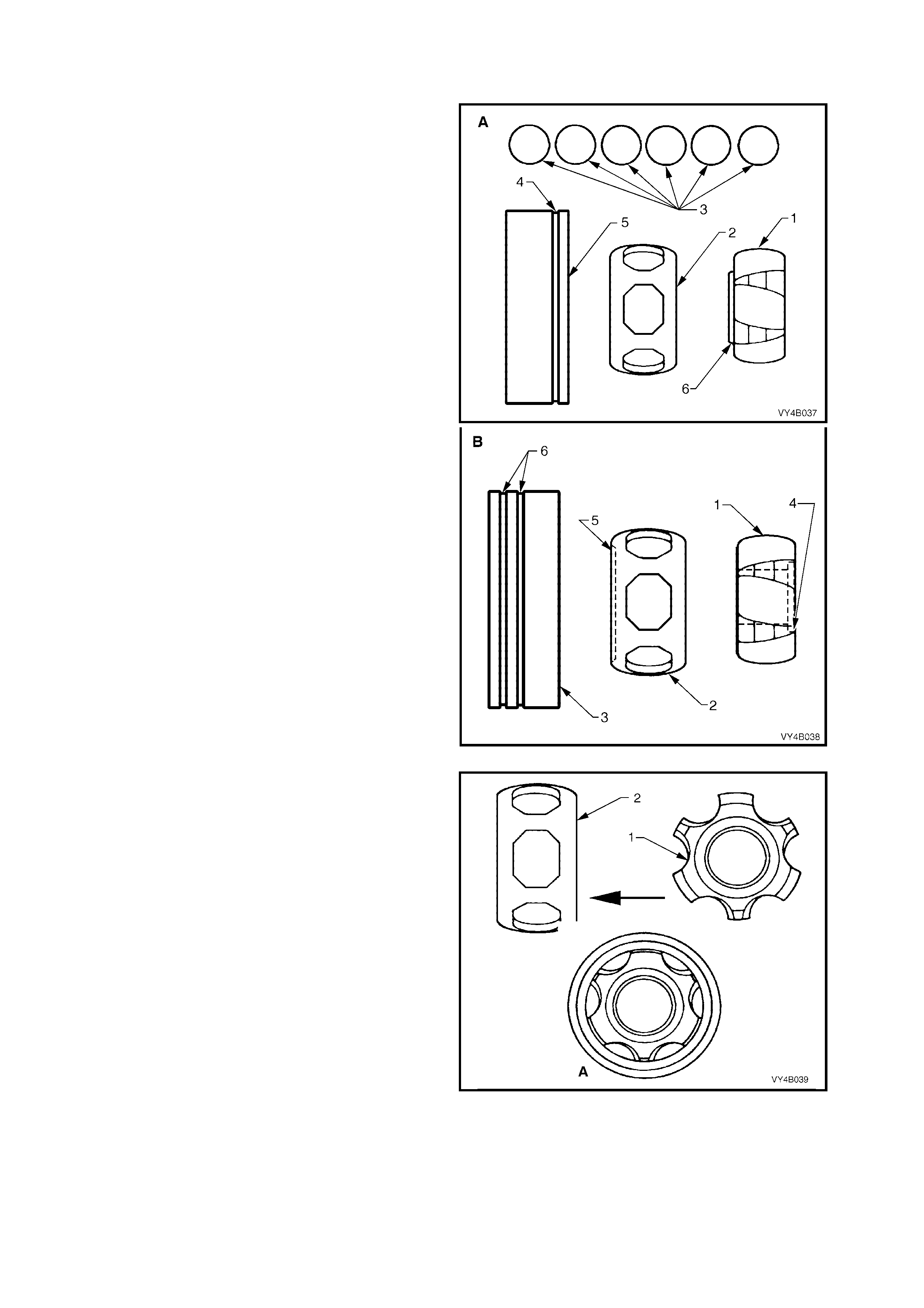
Shown are exploded views of each constant
velocity joint; view “A” is the inner joint, while view
“B” shows the outer.
With the inner joint, note the single identification
groove (4) on the outer race (5) and the
identification step (6) on the inner race.
Conversely, the outer joint has two grooves (6) on
the outer race, a chamfer (5) on the cage and a
recess (4) on the inner race (1).
Figure 4B-32
1. Place the inner race (1) into the cage (2) and
position centrally.
Figure 4B-33
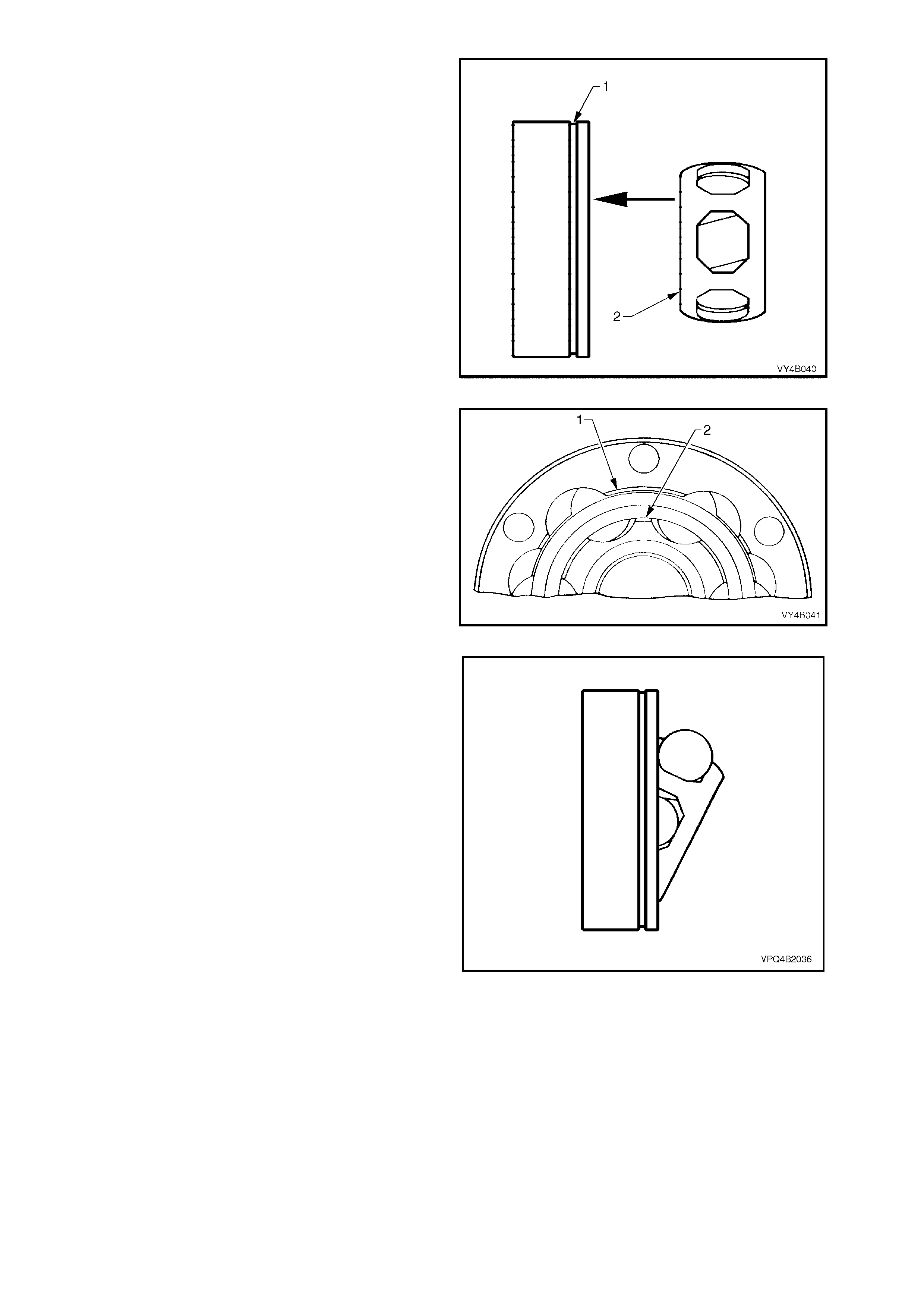
2. Place the inner race and cage assembly (2)
into the outer race (1). Make sure that the
identification groove (1) and step (2) are on
opposite sides of the assembly, as shown.
Figure 4B-34
3. Align the thick sections (1) on the outer race,
with the narrow ones (2) on the inner race.
Figure 4B-35
4. Tilt the cage and inner race, as shown and fit
one ball.
Repeat this process for the remaining five
balls.
Figure 4B-36
5. When assembly of the CV joint is complete,
check for plunge movement of the inner
members, as indicated by ‘A’. If NO plunge
movement can be achieved, then the
constant velocity joint has been incorrectly
assembled.
If suc h a situation occurs, t he CV joint m ust be
disassembled and the assembly process
repeated until such time that the required
plunge movement is achieved.
NOTE: This check only applies to the inner plunge
joint. The outer CV joint should have no plunge
movement.
Figure 4B-37
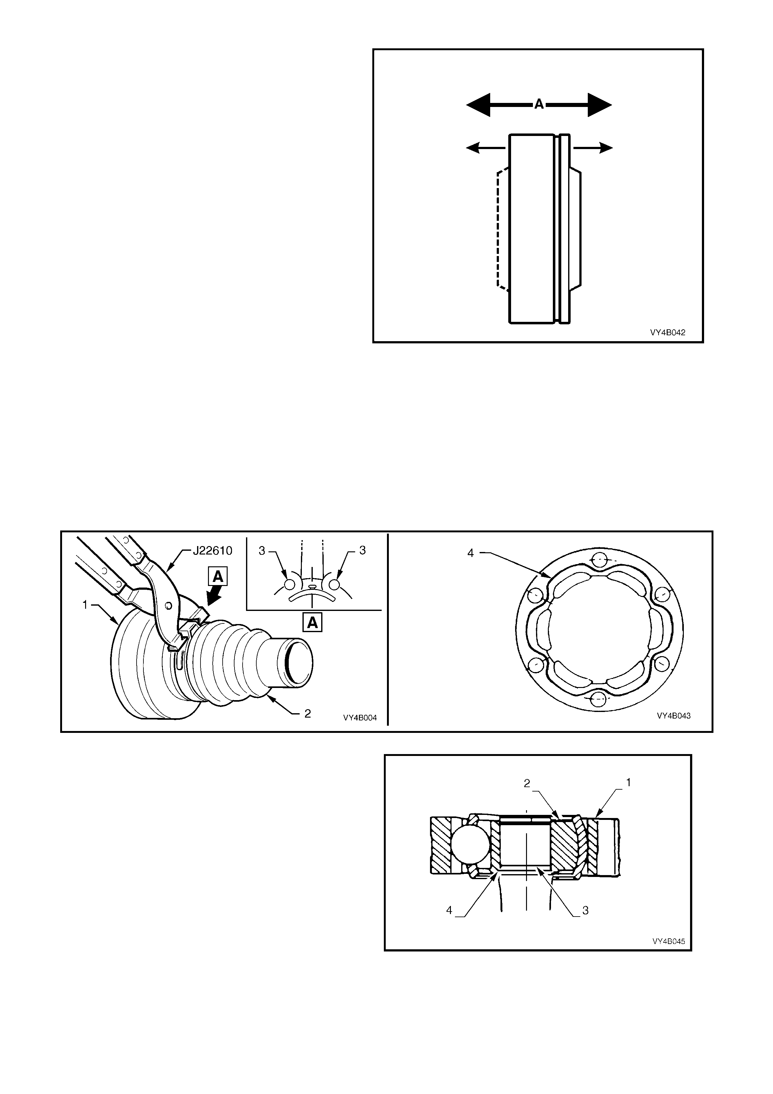
Drive Shaft And Boots
1. Remove old sealing bead of silicon from dust shields, dust caps and constant velocity joints.
2. Position new large boot clamp over boot (2) and place boot over dust shield (1). Using Tool No. J22610,
securely crimp boot clamp, ensuring the crimp is positioned mid-way between two bolt holes (3, in view ‘A’).
3. Apply a 2 mm diameter bead (4) of commercially available RTV 732 sealant to dust caps/shields and allow
approximately one hour to cure.
4. Place new small boot clamps onto drive shaft.
5. Place both dust shield and boot assemblies onto drive shafts, ensuring that boots are not damaged by sharp
edges on each end of shaft.
Figure 4B-38
6. Only for the inner constant velocity joint (1),
reinsta ll the joi nt (1) onto s haft with step (3) on
the inner race (2) facing toward the shoulder
(4) on the shaft.
NOTE: The recess on the inner race of the outer
CV joint, also faces the drive shaft.
7. Press constant velocity joints onto shaft and
install a NEW circlip at each end.
NOTE: When pressing joints onto shaft, ensure
that the joint inner races (2) take the press load.
Figure 4B-39
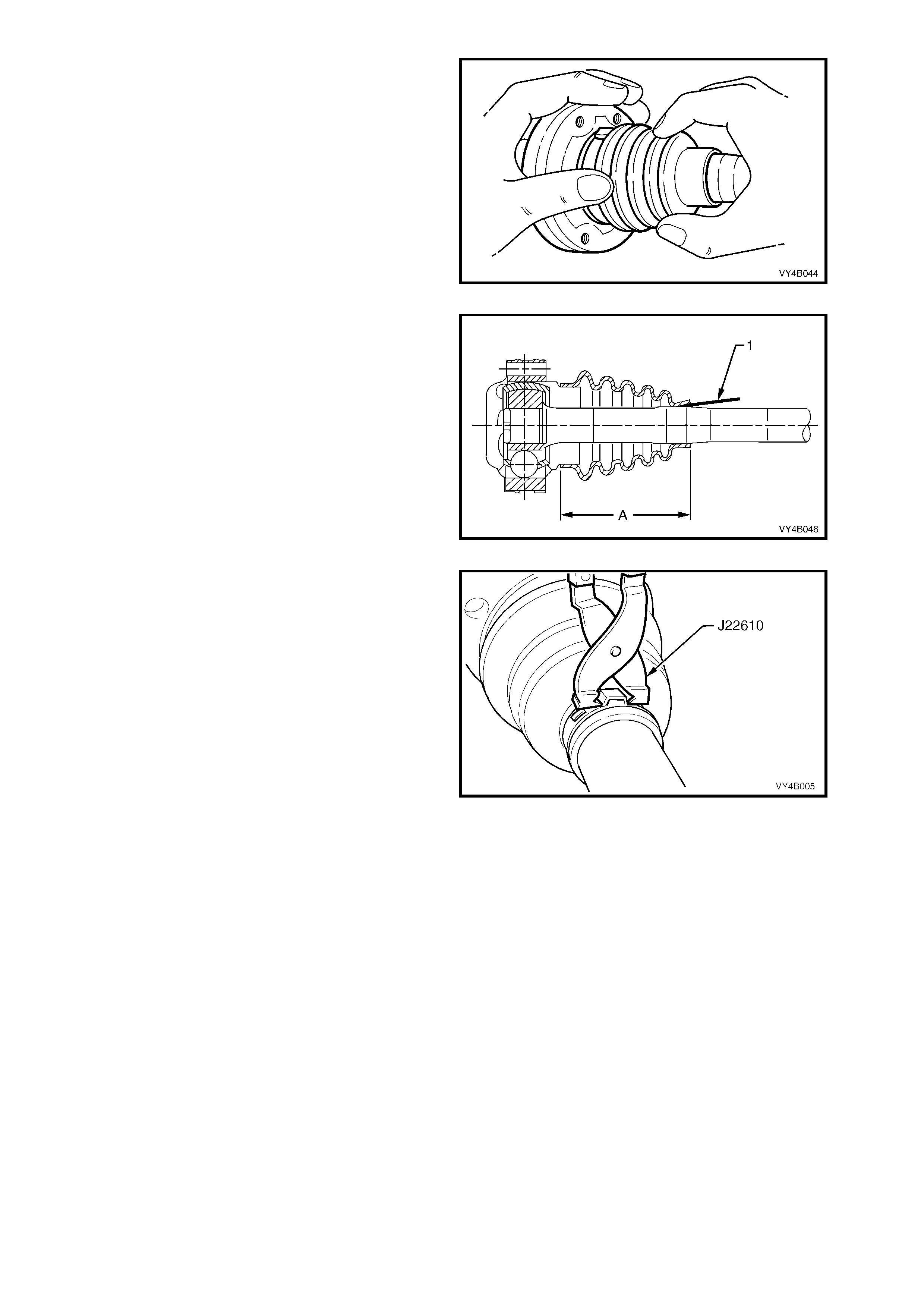
8. Pack inside section of joint and boot with one
tube of grease (40 grams) and pack half tube
(20 grams) to outside section of joint.
9. Position dust caps and dust shields onto
constant velocity joints, ensuring that all bolt
holes align.
10. Using a suitable punch and hammer, tap caps
and shields into place.
Figure 4B-40
11. Locate small ends of boots into boot grooves
on drive shafts, ensuring that boots are not
twisted.
W ith both j oin t, pr y up s mall ends of b oots f rom
shaft (1) to equalise air pressure inside and
outside of boots and work out any dimples
before applying new small clamps.
IMPORTANT: The location distance ’A’, ONLY
applies to the inner, plunge joint and should be set
at 81 mm before applying the small clamp.
Figure 4B-41
12. Position small clamps over ends of boots and
using Tool No. J22610, crimp ends of clamps.
13. Reinstall drive shaft, refer 2.7 DRIVE SHAFT
ASSEMBLY - REINSTALL in this Section.
Figure 4B-42
2.9 INNER AXLE SHAFT SEAL
REPLACE
1. Using a floor jack under centre of differential
carrier, jack up rear of vehicle then place
safety stands under body rear jacking points.
Refer to Section 0A GENERAL
INFORMATION for location of jacking points.
2. Remove drive shaft from side of vehicle
which seal is to be replaced, refer to
2.7 DRIVE SHAFT ASSEMBLY – REMOVE,
in this Section.
NOTE 1: During drive shaft removal, keep drive
shaft supported so that it does not hang on one
end.
NOTE 2: Drive s haft j oint def lection sho uld be k ept
to a minimum.
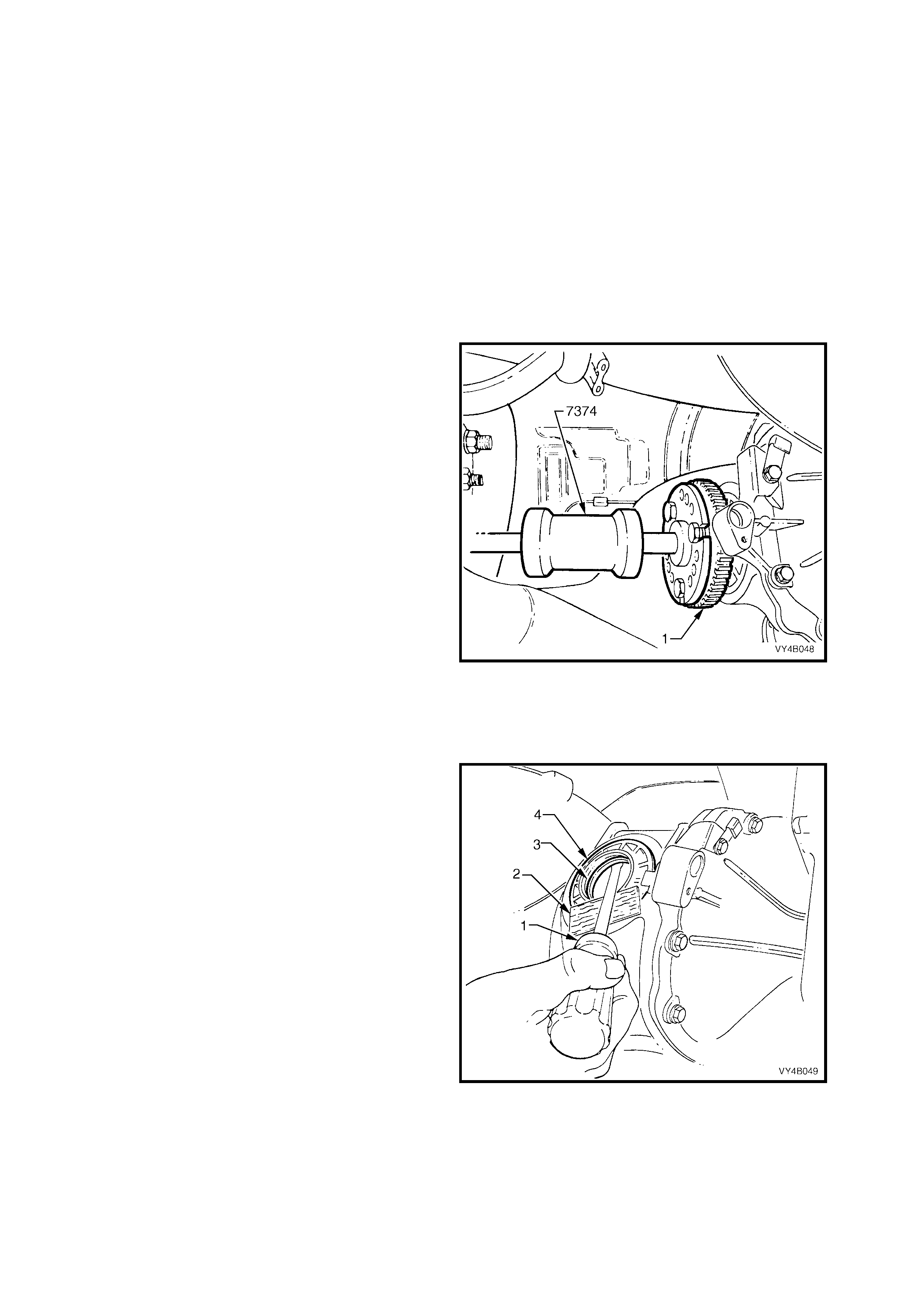
3. Remove inner axle shaft (1) by installing a slide
hammer, Tool No. 7 374 with three suit abl e s i ze
bolts to axle flange. Use slide hammer to
release axle shaft spring clip.
As the axle shaft is removed, a small amount
of lubricant may leak from differential carrier.
CAUTION: If a 3.08:1 ratio final drive is fitted
with LSD, do not rotate the opposite axle shaft,
as side gear and clutch cone splines will
become misaligned. Then the axle shaft cannot
be reinstalled without removing differential
case, dismant ling and realigning g ear and cone
splines.
NOTE: The above ‘Caution’ does not apply to
either the 3.07:1 or 3.46:1 ratio final drives,
because the side gear and LSD cone is an
integrated component.
4. Clean around seal bore and housing area to
make sure that no foreign matter enters axle
shaft needle bearing in the scr ew adjust er.
Figure 4B-43
5. Using a suitable screwdriver (1) and a block of
wood (2), lever seal (3) from screw adjuster
bore (4).
NOTE: Take care not to damage the screw
adjuster's aluminium housing (4) with the
screwdriver blade (1), as this could cause oil leaks
to occur, after a new oil seal was fitted.
Figure 4B-44
6. Before installation of new seal, examine seal
surface of inner axle shaft and remove any
nick s or bur rs. Shoul d th is i ns pection sho w that
the surface is marked, a new inner axle shaft
should be fitted.

NOTE 1: The left hand in n er ax le sh aft is shor ter in
length than the right hand shaft.
NOTE 2: If veh icle is e quipped with AB S, the inner
axle shafts are unique for this application.
NOTE 3: Check spring clip in end of axle shaft to
ensure that it is not damaged and moves freely in
groove. Replace spring clip if necessary, by
expanding ends of clip and removing from shaft.
Only expand the ends of a new clip sufficiently to
allow installation into shaft groove.
7. Examine seal bore in screw adjuster and
remove any nicks or burrs.
8. Lubricate seal lips and outside diameter with
lithium soap grease. Insta ll seal usin g Tool No.
AU410, until seal bottoms in bore.
Figure 4B-45
9. Reinstall inner axle shaft (1), aligning splines
with clutch cone (if fitted with a Limited Slip
Diff erential) and side ge ar .
NOTE: To avoid premature seal failure, ensure
axle shaft splines or securing clip do not score or
damage the seal lips during installation.
10. Lightl y hit on end of axle shaf t flange (1) with a
soft faced hammer (2) to compress spring clip
on shaft in to cl utch con e and s ide g ear splin es.
Fully engage shaft (1) until clip snaps in to side
gear groove.
Figure 4B-46
11. Reinstall drive shaft, refer to
2.7 DRIVE SHAFT ASSEMBLY in this
Section.
12. Remove safety stands and lower vehicle.
13. Check and f il l dif f er entia l carrier to c orr ec t le vel
with specified lubricant. Refer to
2.2 CHECKING DIFFERENTIAL CARRIER
LUBRICANT LEVEL in this Section.
2.10 PINION OIL SEAL
LT Reference No: F502100
REPLACE
1. Using a floor jack under centre of differential carrier, jack
up rear of vehicle, then place safety stands under trailing
arms.
2. Mark the position of the propeller shaft rear coupling to
pinion flange, using a felt tipped pen or similar.
3. Remove propeller shaft, refer to 4C PROPELLER
SHAFT AND UNIVERSAL JOINTS in the MY 2003 VY
and V2 Series Service Information. This operation may
also require partial exhaust system removal.
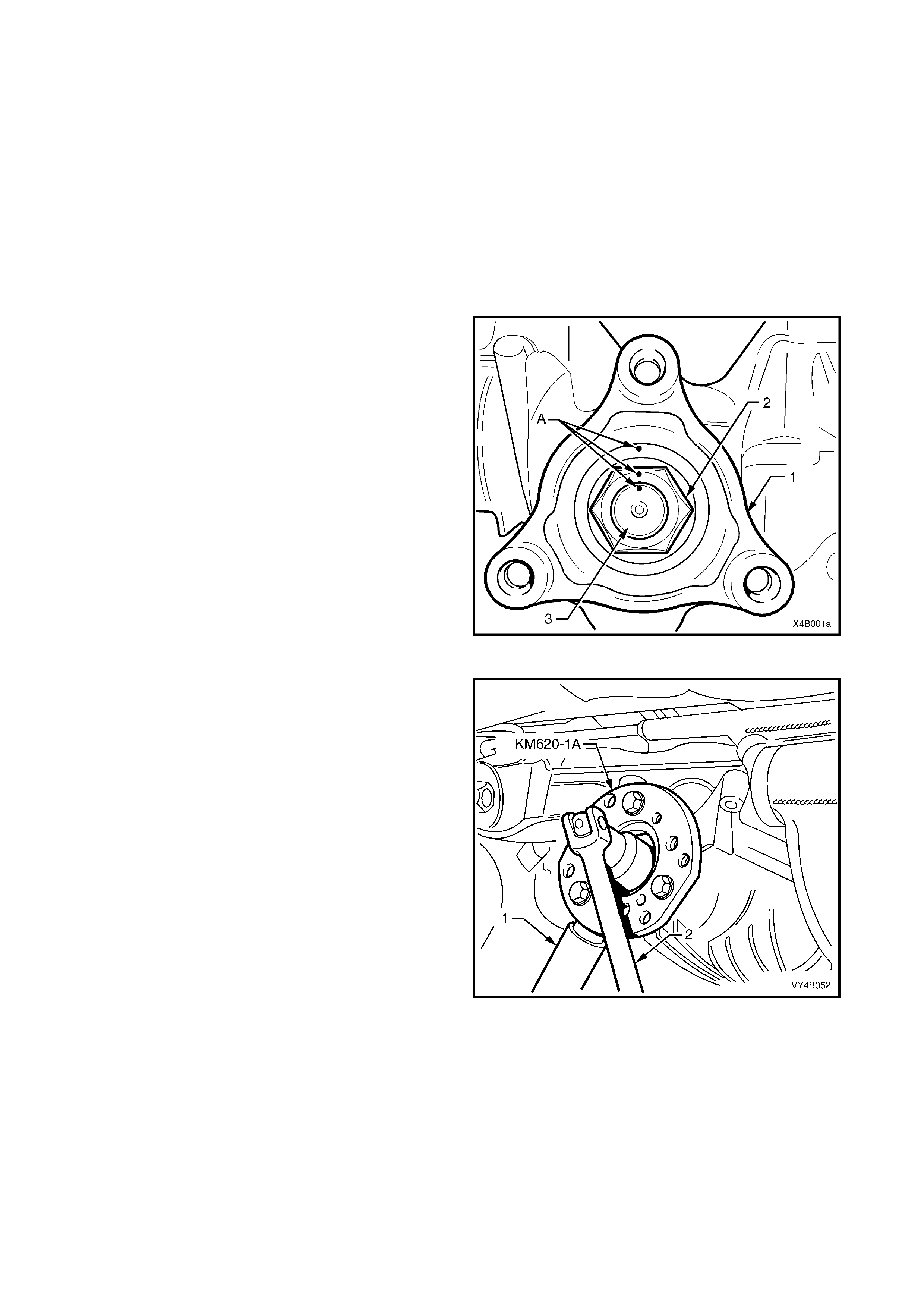
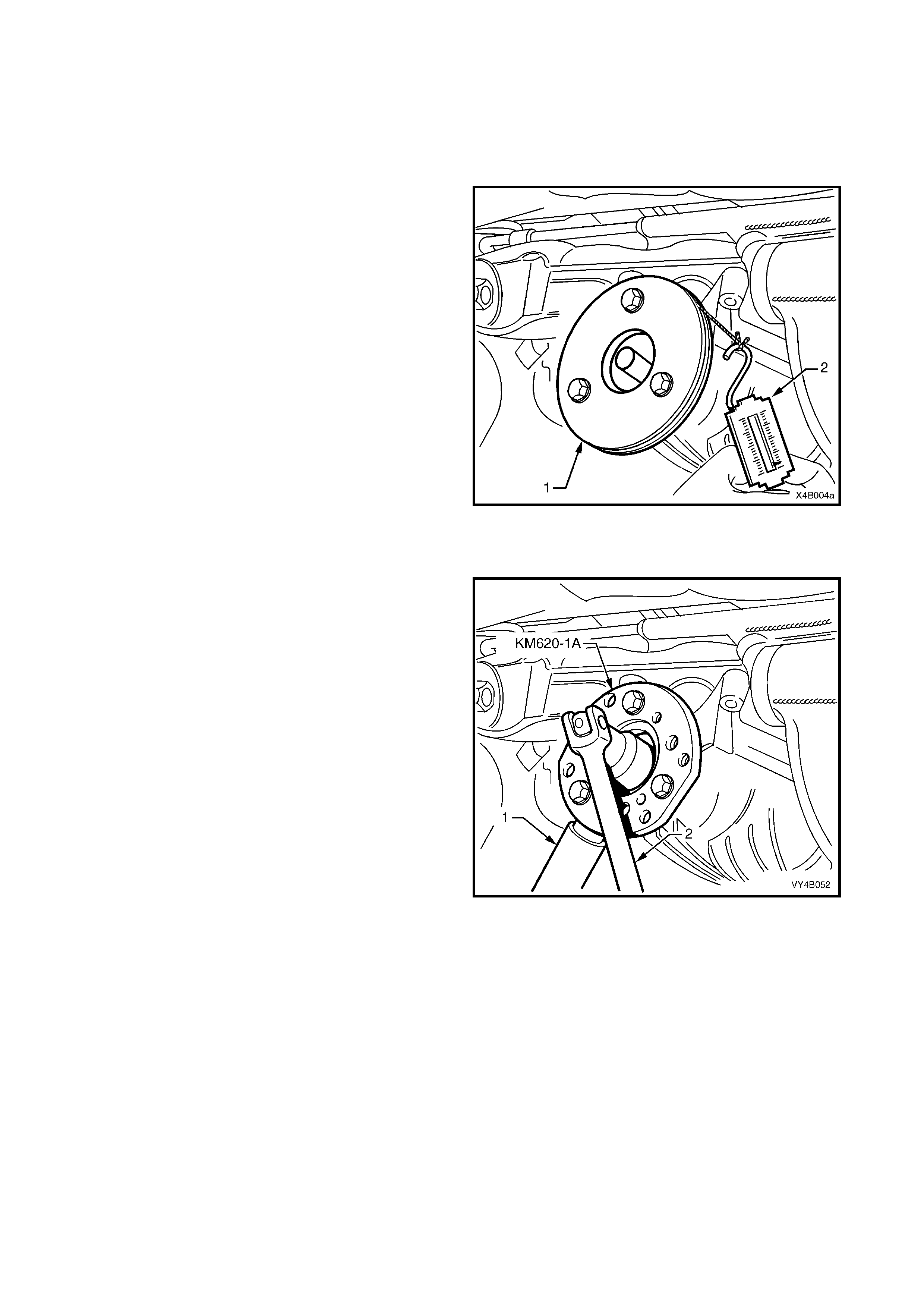
4. Lightly centre-punch alignment marks (A) on the
pinion flange (1), flange nut (2) and pinion end (3) as
an aid for reassembly.
By reassembling to the original position, the flange
run-out will be minimised and the pinion bearing
preload will be maintained.
Figure 4B-47
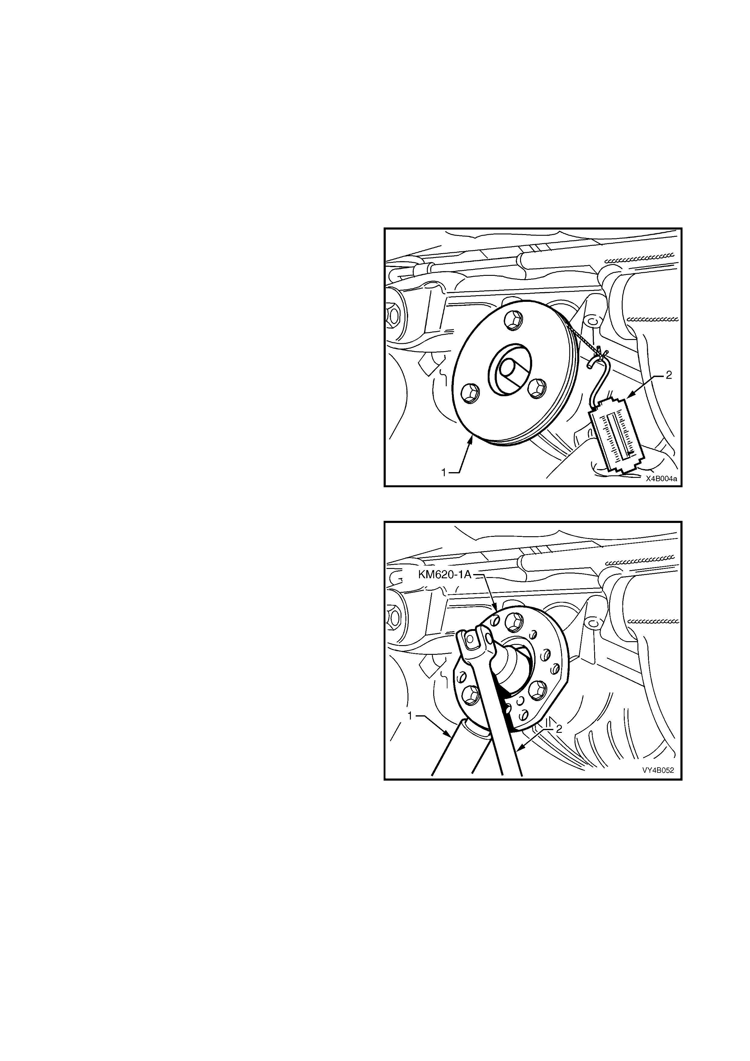
5. Attach Tool No. KM620-1A to the pinion flange,
using three suitable bolts to hold pinion flange.
NOTE 1: If not previously done so, drill out holes
stamped ‘B’ on Tool No. KM620-1A to 12.5 mm.
NOTE 2: Use either the rear coupling to pinion flange
retaining bolts with a 25 mm spacer (e.g. flat washers)
installed first or use three bolts M12 x 1.5 x 40, with the
thread extending to w ithin 12 mm of the head.
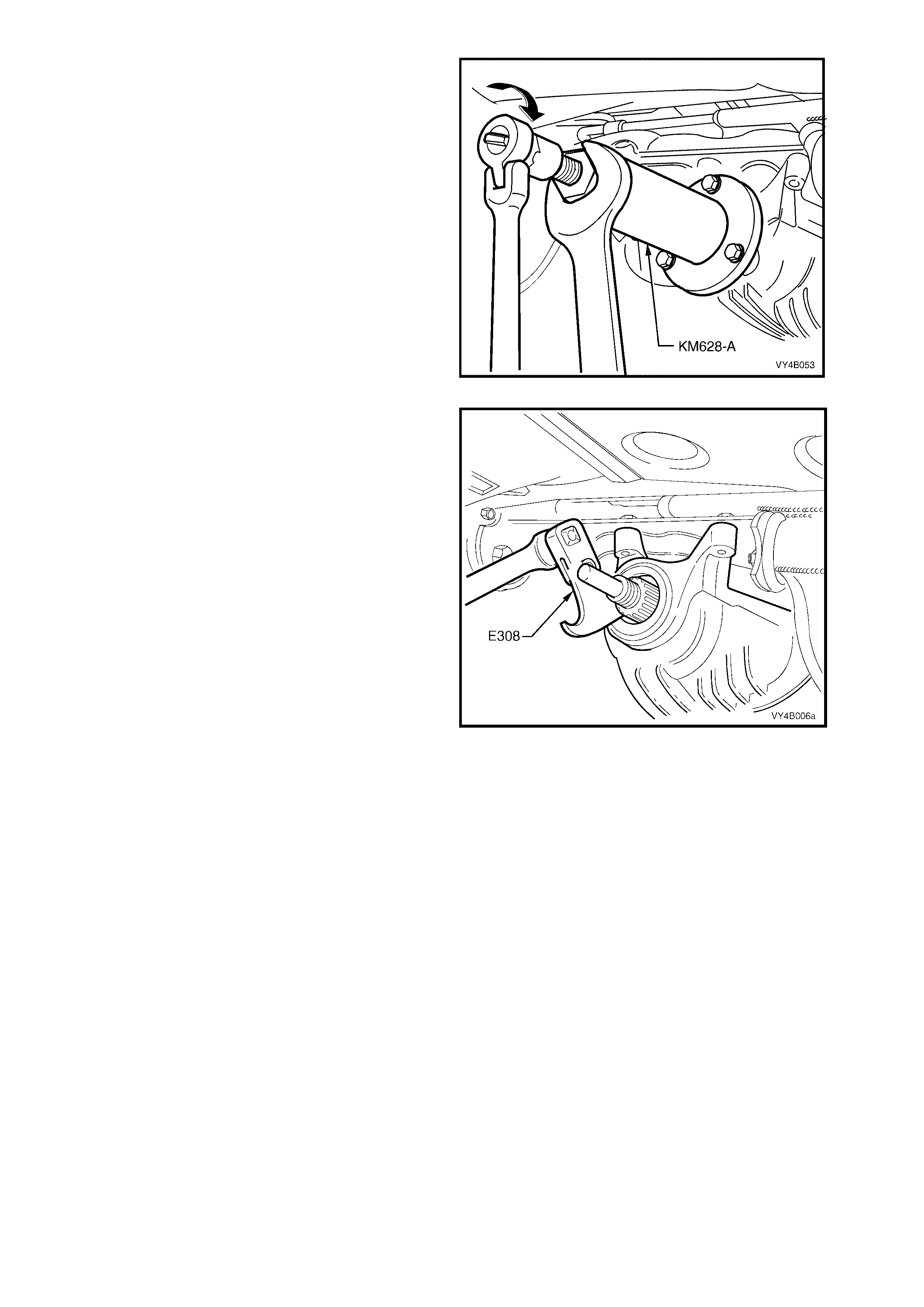
6. Insert a suitable length of pipe (1) over the tang of
the installed tool for leverage, then remove the
pinion flange retaining nut, using a commercially
available, 30 mm deep socket and socket bar (2).
7. Remove Tool No. KM620-1A from the pinion flange.
Figure 4B-48
8. Place drain tray beneath differential carrier.
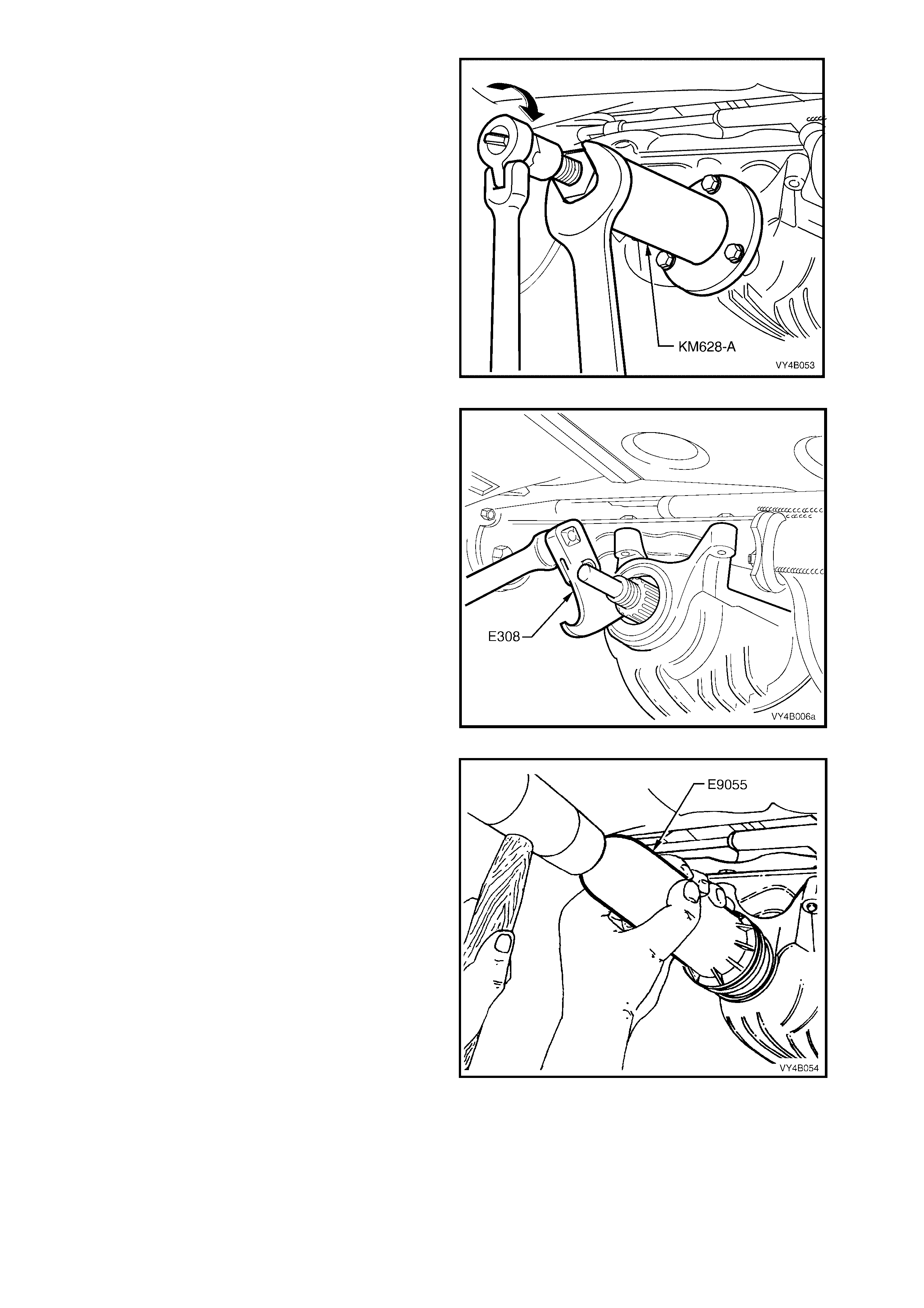
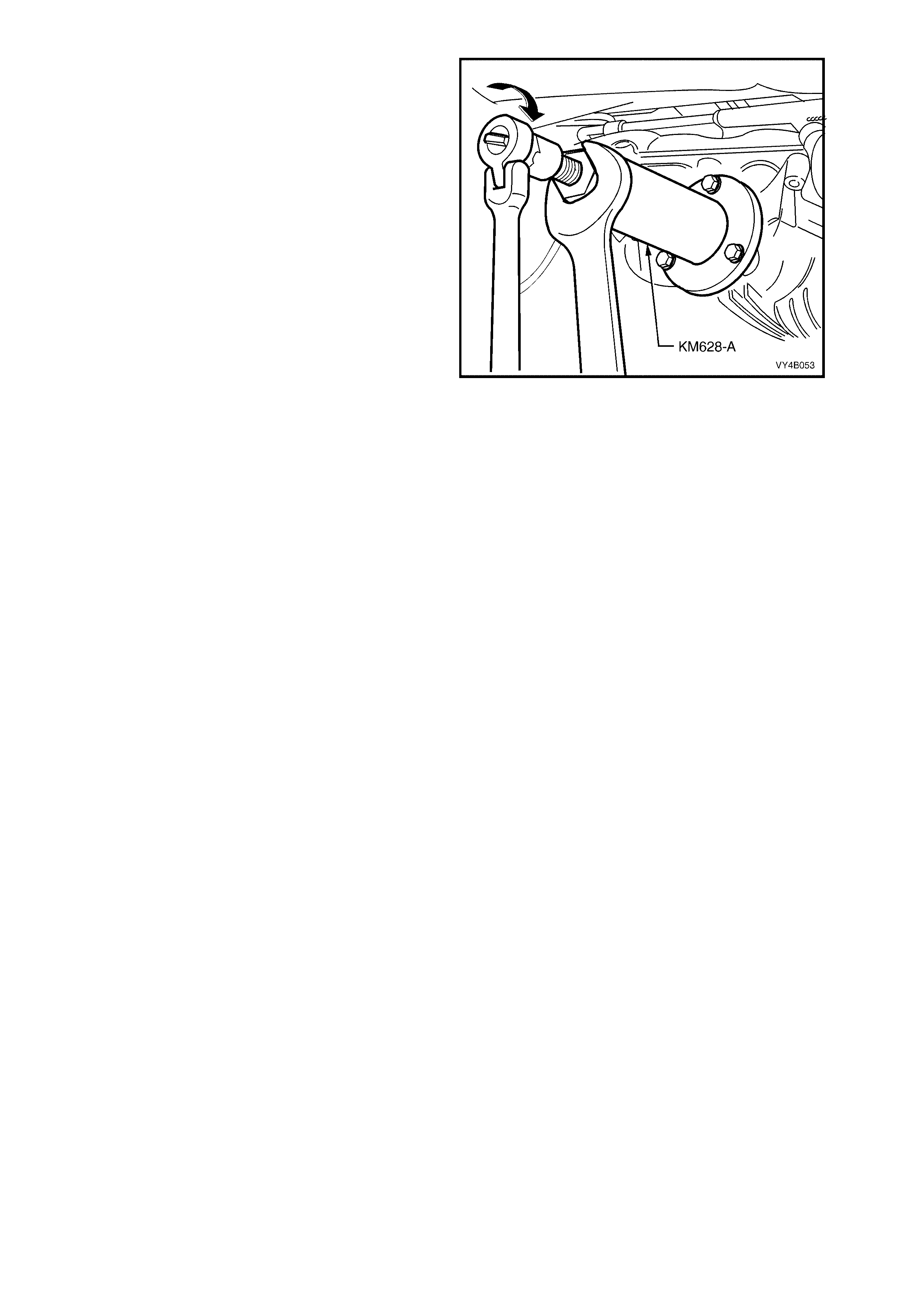
9. Install extractor, Tool No. KM628-A to the
pinion flange using the same three bolts used
to secure the flange holding tool, KM620-1A
(refer Figure 4B-48).
NOTE: If not previo us l y done s o, dr ill out the flan ge
holes on Tool No. KM628-A to 12.5 mm.
IMPORTANT: If using the original propeller shaft
coupling bolts, they must have a 25 mm spacer
fitted to each, so the tool is clamped to the pinion
flange. If this is not done, the screw thread on the
extractor Tool No. KM628-A will not be long
enough to fully remove the pinion flange.
10. While holding the extractor tool with a suitable
spanner, withdraw pinion flange by tightening
the forcing screw in the direction indicated.
Figure 4B-49
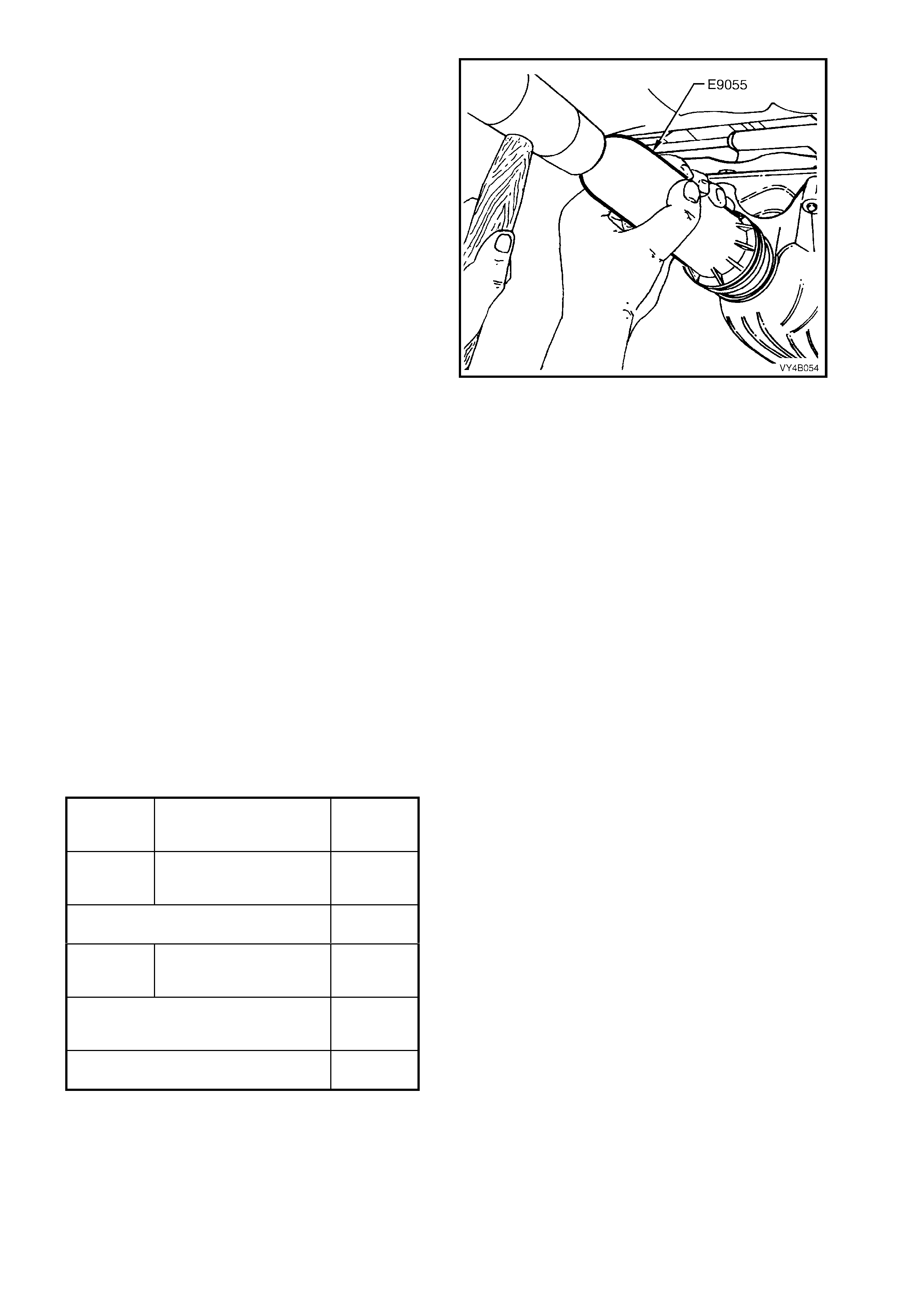
11. Prise pinion oil seal from carrier bore using
Tool No. E308 or a universal seal removing
tool.
Figure 4B-50
12. Lubricate a new pinion oil seal lips and the
outer diameter with the recommended rear
axle lubr ic ant.
13. Start oil seal into differential carrier housing
and dri ve seal squ arel y into pos ition usin g T ool
No. E9055. Seal fits flush to 0.25 mm below
carrier housing surface.
14. Ensure that pinion shaft is free from burrs and
that flange oil seal surface is free from
damage.
Figure 4B-51
15. Clean the threads of the pinion shaft and the flange retaining nut, removing any oil, dirt or grease.
16. Coat splines and s eal s urface of pinion f lan ge with dif f er enti al g ear lubricant , and ins ta ll flange ont o pi nio n shaft
splines. Ensure that centre-punch marks are aligned.
17. Reinstall holding tool KM620-1A to the pinion flange.

18. Apply a thread locking compound such as Loctite 243 or equivalent, to the threads of the pinion flange retaining
nut, then reinstall the nut.
19. Tighten the flange retaining nut until all centre-punch marks align. Then carefully tighten the nut to a position
not more than 5° past the aligned setting.
NOTE: The pinion flange is an interference fit on pinion shaft splines and should only be pulled into place by
tightening the retaining nut. DO NOT, UNDER ANY CIRCUMSTANCES, USE FORCE OR HAMMER THE
FLANGE DURING INSTALLATION ONTO PINION FLANGE.
CAUTION: Should the retaining nut be over-tightened and pre-load exceeded, it will be necessary to
remove the pinion from the carrier and install a new collapsible spacer. Under no circumstances must the
retaining nut be backed off to decrease the pre-load reading.
20. Reinstall propeller shaft rear coupling to the pinion flange, refer Section 4C PROPELLER SHAFT AND
UNIVERSAL JOINTS in the MY 2003 VY and V2 Series Service Information.
21. If removed previously, reconnect exhaust system, in the reverse to the removal procedure. Refer to
3.2 FINAL DRIVE ASSEMBLY, in this Section, for details.
22. Remove safety stands and lower vehicle.
23. Check lubricant le vel and t op up as necessar y. Refer 2.2 CH ECKING D IFFER ENTIAL CARRIER LUBRICANT
LEVEL in this Section
24. Start vehicle and check for exhaust leaks.
2.11 PINION FLANGE
LT Reference No: F501100
REPLACE (USING OLD OIL SEAL)
NOTE: Due to production tolerances in the length of the pinion flange, it is essential that the following method be used when
installing a new pinion flange. .
1. Using a floor jack under centre of differential carrier, jack up rear of vehicle then place safety stands under trailing arms.
2. Remove propeller shaft, refer 2.1 PROPELLER SHAFT in 4C PROPELLER SHAFT AND UNIVERSAL JOINTS in the
MY 2003 VY and V2 Series Service Information.
3. Remove both drive shafts, refer 2.7 DRIVE SHAFTS in this Section.
4. Check and record pre-load at pinion flange as follows:
a. Fit a pulley (1) to pinion flange, using three
suitable bolts and attach a cord around pulley
and to a spring scale (2).
NOTE 1: Use either the rear coupling to pinion
flange retaining bolts with a 25 mm spacer (e.g.
flat washers) installed first or use three bolts
M12 x 1.5 x 40, with the thread extending to
within 12 mm of the head.
NOTE 2: For details of the fabricated pulley,
refer 7 Special Tools at end of this Section.
b. Start rotation of pulley and whilst in motion
(approximately 50-60 rpm) note and record
reading of spring balance.
This pre-load reading includes pinion bearings,
side bearings, meshing effect of gear set and
pinion oil seal.
To determine pre-load, multiply reading on
spring balance by radius of pulley.
EXAMPLE: With a pulley diameter of 152 mm, the radius
is 76 mm, which equals 0.076 m. With a spring balance
reading of 25 N, the pre-load equals 0.076 m x 25 N =
1.9 Nm.
5. Remove pulley from pinion flange.
Figure 4B-52
6. Attach Tool No. KM620-1A to the pinion flange,
using three suitable bolts to hold pinion flange.
NOTE 1: If not previously done so, drill out holes
stamped ‘B’ on Tool No. KM620-1A to 12.5 mm.
NOTE 2: Use either the rear coupling to pinion
flange retaining bolts with a 25 mm spacer (e.g. flat
washers) installed first or use three bolts M12 x 1.5
x 40, with the thread extending to within 12 mm of
the head.
7. Insert a suitable length of pipe (1) over the tang of
the installed tool for leverage, then remove the
pinion flange retaining nut, using a commercially
available, 30 mm deep socket and socket bar (2).
8. Remove Tool No. KM620-1A from the pinion flange.
Figure 4B-53
9. Place drain tray beneath differential carrier.
10. Install extractor, Tool No. KM628-A to the
pinion flange using the same three bolts used
in step 6.
NOTE: If not previo us l y done s o, dr ill out the flan ge
holes on Tool No. KM628-A to 12.5 mm.
IMPORTANT: If using the original bolts, they must
have the 25 mm spacers fitted so the tool is
clam ped to the pinion f lang e. If this is not don e, the
screw thread on the extractor Tool No. KM628-A
will not be long enough to fully remove the pinion
flange.
11. While holding the extractor tool with a suitable
spanner, withdraw pinion flange by tightening
the forcing screw in the direction shown.
Figure 4B-54
12. Ensure that pinion shaft thread is free from burrs, oil, dirt or grease, then coat splines and seal surface of a new
pinion flange with the recommended rear axle lubricant.
13. Install the new pinion flange and a new retaining nut.
NOTE: The new flange will be an interference fit on pinion shaft splines and should only be pulled into place by
tightening retaining nut. DO NOT, UNDER ANY CIRCUMSTANCES, USE FORCE OR HAMMER FLANGE
DURING INSTALLATION ONTO PINION FLANGE.
14. Tighten flange retaining nut gradually until pinion shaft end play is reduced to approximately 0.50 mm.
15. Attach pull ey to the ne w pi nion flange and using sprin g balance, chec k pre-load . Continue ti ghtening nut while
alternatively turning pinion to seat bearings, until the pre-load figure recorded previousl y (Step 4b) is reached.
Further increase this original pre-load reading by 0.5 Nm.
ROTATE PINION AN EXTRA 30-40 TURNS AND RE-CHECK THE PRE-LOAD TO ENSURE THAT NO
CHANGE HAS OCCURRED.
CAUTION: Should the retaining nut be over-tightened and the pre-load exceeded, it will be necessary to
remove the differential carrier assembly and install a new collapsible spacer. Under no circumstances
must the retaining nut be backed off to decrease the pre-load setting.
16. Reinstall drive shafts, refer to 2.7 DRIVE SHAFTS in this Section.
17. Reinstall pro peller s haf t, ref er to Se ction 4C P ROP EL LER SHAFT AND UNIVERS AL JOINT S in th e M Y 20 03
VY and V2 Series Service Information.
18. If removed previously, reconnect exhaust system, in reverse to the removal procedure. Refer to
3.2 FINAL DRIVE ASSEMBLY, in this Section, for details.
19. Remove safety stands and lower vehicle.
20. Check lubricant level and top up as necessary with the recommended lubricant, refer to
2.2 CHECKING DIFFERENTIAL CARRIER LUBRICANT LEVEL in this Section.
21. Start vehicle and check for exhaust leaks.
REPLACE (USING NEW OIL SEAL)
1. Using a floor jack under centre of differential carrier, jack up rear of vehicle then place safety stands under trailing arms.
2. Remove propeller shaft, refer to 4C PROPELLER SHAFT AND UNIVERSAL JOINTS in the MY 2003 VY and V2
Series Service Information.
3. Remove both drive shafts, refer to 2.7 DRIVE SHAFTS in this Section.
4. Check and record pre-load at pinion flange as
follows:
a. Fit a pulley (1) to pinion flange, using three
suitable bolts and attach a cord around pulley
and to a spring balance (2).
NOTE 1: Use either the rear coupling to pinion
flange retaining bolts with a 25 mm spacer (e.g.
flat washers) installed first or use three bolts
M12 x 1.5 x 40, with the thread extending to
within 12 mm of the head.
NOTE 2: For fabricated pulley details, refer to
7. Special Tools at the end of this Section.
b. Start rotation of pulley and whilst in motion
(approximately 50-60 rpm), note and record the
spring balance reading.
This pre-load reading includes pinion bearings,
side bearings, meshing effect of gear set and
pinion oil seal.
To determine pre-load, multiply reading on
spring balance by radius of pulley.
EXAMPLE: With a pulley diameter of 152 mm, the radius
is 76 mm which equals 0.076 m. With a spring balance
reading of 25 N, the pre-load equals 0.076 m x 26 N =
1.9 Nm.
5. Remove pulley from pinion flange.
Figure 4B-55
6. Attach Tool No. KM620-1A to the pinion flange,
using three suitable bolts to hold pinion flange.
NOTE 1: If not previously done so, drill out holes
stamped ‘B’ on Tool No. KM620-1A to 12.5 mm.
NOTE 2: Use either the rear coupling to pinion flange
retaining bolts with a 25 mm spacer (e.g. flat washers)
installed first or use three bolts M12 x 1.5 x 40, with the
thread extending to w ithin 12 mm of the head.
7. Insert a suitable length of pipe (1) over the tang of
the installed tool for leverage, then loosen the pinion
flange retaining nut, using a commercially available,
30 mm deep socket and socket bar (2) until end play
can be felt in the pinion shaft.
8. Check the oil seal and differential side bearing pre-
load using the spring scale and pulley, as detailed in
steps 4a and 4b, Record oil seal and side bearing
pre-load for later use.
9. Remove Tool No. KM620-1A from the pinion flange.
Figure 4B-56
10. Place drain tray beneath differential carrier.
11. Install extractor, Tool No. KM628-A to the
pinion flange using the same three bolts used
previously.
NOTE: If not previo us l y done s o, dr ill out the flan ge
holes on Tool No. KM628-A to 12.5 mm.
IMPORTANT: If using the original bolts, they must
have the 25 mm spacers fitted so the tool is
clam ped to the pinion f lang e. If this is not don e, the
screw thread on the extractor Tool No. KM628-A
will not be long enough to fully remove the pinion
flange.
12. While holding the extractor tool with a suitable
spanner, withdraw pinion flange by tightening
the forcing screw in the direction shown.
Figure 4B-57
13. Prise pinion oil seal from carrier bore using
Tool No. E308 or a universal seal removing
tool.
Figure 4B-58
14. Lubricate a new pinion oil seal lips and the
outer diameter with the recommended rear
axle lubr ic ant.
15. Start oil seal into differential carrier housing
and dri ve seal squ arel y into pos ition usin g T ool
No. E9055. Seal fits flush to 0.25 mm below
carrier housing surface.
16. Ensur e that pin ion shaf t is free f rom burrs , then
clean the threads of the pinion shaft, removing
any oil, dirt or grease.
17. Coat splines and seal surface of pinion flange
with differential gear lubricant, then reinstall
flange to the pinion shaft splines.
18. Install a new flange retaining nut, then tighten
to draw the pinion flange onto the pinion shaft
splines.
NOTE: The ne w flang e will be an int er f er enc e f it on
pinion shaft splines and should only be pulled into
place by tightening the retaining nut. DO NOT,
UNDER ANY CIRCUMSTANCES, USE FORCE
OR HAMMER FLANGE DURING INSTALLATION
ONTO PINION FLANGE.
19. Continue to tighten the flange retaining nut
gradually until pinion shaft end play is reduced
to approximately 0.5 mm.
20. Check new oil seal and differential assembly
pre-load using spring balance as previously
outlined in steps 4a and 4b. Record pre-load
for reassembly reference.
Figure 4B-59
21. The pre-load reading for differential assembly
obtained in step 8, is subtracted from pre-load
reading obtained in step 20. The difference
between these figures represents extra lip
tension of new seal expressed as a Nm pre-
load figure. The difference between the pre-
load readings obtained in steps 8 and 20 must
be added to pre-load reading obtained in step
4b to obtain a total pre-load reading.
THEORETI CAL EXAMPLE
STEP 20 NEW OIL SEAL AND SIDE
BEARIN G PR E- L OAD
SETTING
1.47 Nm
STEP 8 OLD OIL SE AL AND SIDE
BEARING
PRE-LOAD READING
1.02 Nm
SUBTR AC T STEP 8
FROM STEP 20
0.45 Nm
STEP 4b COMPLETE
DIFFER EN TIAL ASSEM BLY
PRE-LOAD READING
1.47 Nm
THE PRE-L O AD READIN G
COMBINATION WILL BE
THE SUM OF:-
1.47 Nm
plus
0.45 Nm
WHICH GI VE S A TO TAL
PRE-LOAD READING OF:-
1.92 Nm
22. Continue tightening retaining nut while
alternately turning pinion to seat bearings until
total pre-load figure obtained in step 21 is
achieved, then increase this pre-load reading
by 0.11 to 0.34 Nm. Further rotate pinion an
extra 30-40 turns and recheck pre-load to
ensure that no change has occurred.

CAUTION: Should the retaining nut be over-tightened and the pre-load exceeded, it will be necessary to
remove the differential carrier assembly and install a new collapsible spacer. Under no circumstances
must the retaining nut be backed off to decrease the pre-load setting.
NOTE: It must be realised that the pre-load readings in the example are only theoretical. In practice, the figures
could differ greatly, so the readings obtained when performing the actual operations, are the ones to use.
23. Reinstall drive shafts, refer to 2.7 DRIVE SHAFTS in this Section.
24. Reinstal l propeller shaf t, refer to Sect ion 4C PROPELL ER SH AFT AND UNIVER SAL JOINT S in the MY2003
VY and V2 Series Service Information.
25. If removed previously, reconnect exhaust system, in the reverse to the removal procedure. Refer to
3.2 FINAL DRIVE ASSEMBLY, in this Section, for details.
26. Remove safety stands and lower vehicle.
27. Check lubricant level and top up as necessary, refer to 2.2 CHECKING DIFFERENTIAL CARRIER
LUBRICANT LEVEL in this Section.
28. Start vehicle and check for exhaust leaks.
3. MAJOR SERVICE OPERATIONS
3.1 TRAILING ARM TRUNNION FLANGE, TRUNNION ASSEMBLY
AND/OR WHEEL BEARING
LT Reference No: F201350 / F201450 / F701100 / F701200 / F201300 / F21400
NOTE: The following fastener MUST be replaced when
performing this operation:
Collar nut to trunnion assembly.
Drive shaft constant velocity joint to trunnion flange and
inner axle shaft attaching bolt.
NOTE 1: The following procedure involves the removal of the trunnion flange, trunnion and/or wheel bearing with
the trailing arm installed in the vehicle. A similar procedure is included in Section 4A REAR SUSPENSION in
the MY2003 VY Series Service Information, when the trailing arm is rem oved from the vehicle.
NOTE 2: The rear wheel bearin g should only be removed if it is faulty, or if the trunnion assembly is to be removed.
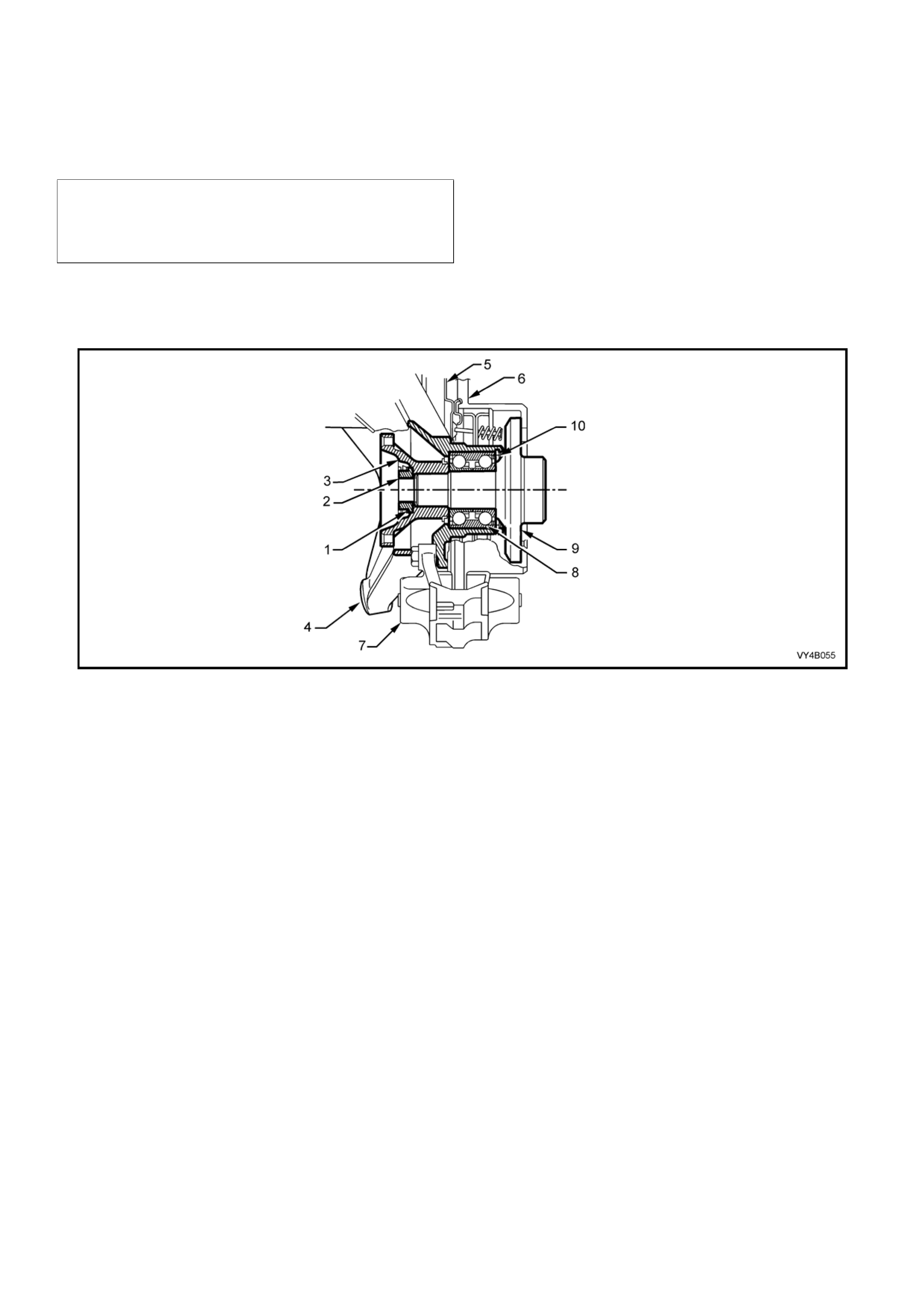
Legend
1. Collar Nut Lock Plate.
2. Collar Nut.
3. Trunnion Flange.
4. Trailing Arm.
5. Brake Backing Plate.
6. Brake Disc.
7. Brake Caliper.
8. Rear Wheel Bearing.
9. Trunnion Assembly.
10. Rear Wheel Bearing Retai ning Ring.
Figure 4B-60
REMOVE
1. Using a floor jack under centre of differential carrier, jack up rear of vehicle and place safety stands under body
rear jacking points. Refer to Section 0A GENERAL INFORMATION in the MY2003 VY Series Service
Information for location of jacking points.
2. On the side of the vehicle where the trailing arm is to be removed, remove the wheel trim or wheel nut covers,
mark relationship of road wheel to hub (e.g. end of wheel stud), with a felt tipped pen or similar. Loosen then
remove road wheel attaching nuts. Remove the road wheel.
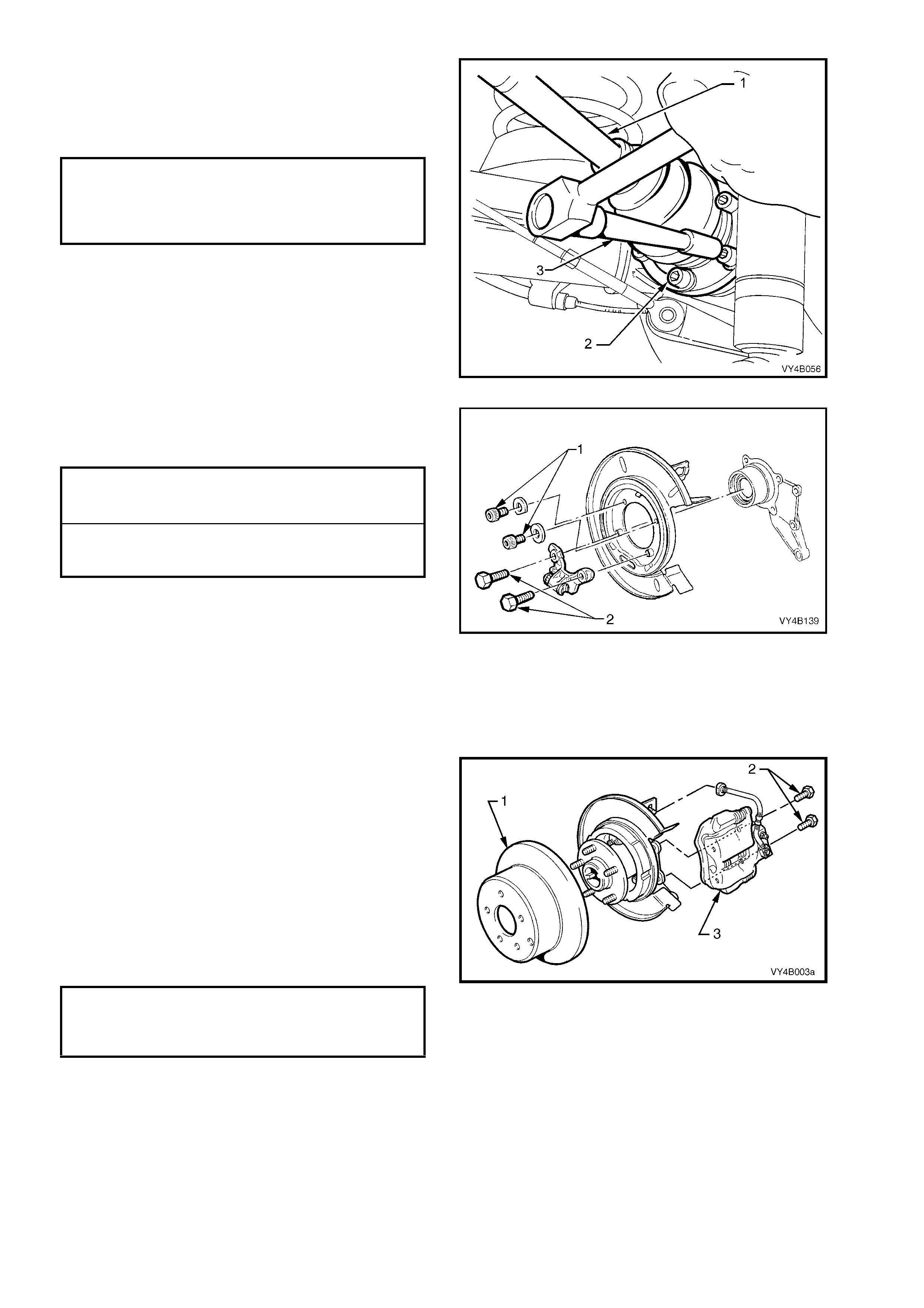
3. Remove brake hose retaining clip (1) from
brake backing plate bracket (2). Disconnect
rear caliper brake hose (3) from brake pipe (4)
and disc on nec t p ipe from bac king plate brack et
(2).
Plug open ends of brake pipe (4) and hose (3)
to prevent fluid loss and foreign matter entry.
Figure 4B-61
4. Remove brake caliper anchor plate to trailing
arm attaching bolts (1) and remove caliper (2)
from disc.
Important: If the brake pipe to hose is not
disconn ected, t he brak e caliper mus t be secur ed to
the vehicle underbody. THE CALIPER IS NOT TO
HANG BY THE BRAK E HOSE.
5. Remove brake disc from the wheel bearing
hub.
NOTE 1: While the brake disc to hub location is
marked in production, ensure that the disc to hub
position is carefully marked (e.g. disc to end of
wheel stud), with a f elt ti pp ed p en or similar. This is
necessar y to overcom e the possibil ity of inducin g a
brake shudder condition after reassembly.
Figure 4B-62
NOTE 2: Should it be necessar y to adjust the park
brake shoe to allow the brake disc to be removed,
the following method should be adopted.
6. Remove one of the access hole plugs (1) from
either of the two access holes provided in the
disc. Using a suitable lever such as a
screwdriver, loosen the par k brake shoe screw
adjuster, until the disc is freed.
7. After disc removal, reinstall the access hole
plug to prevent loss.
Figure 5A-63
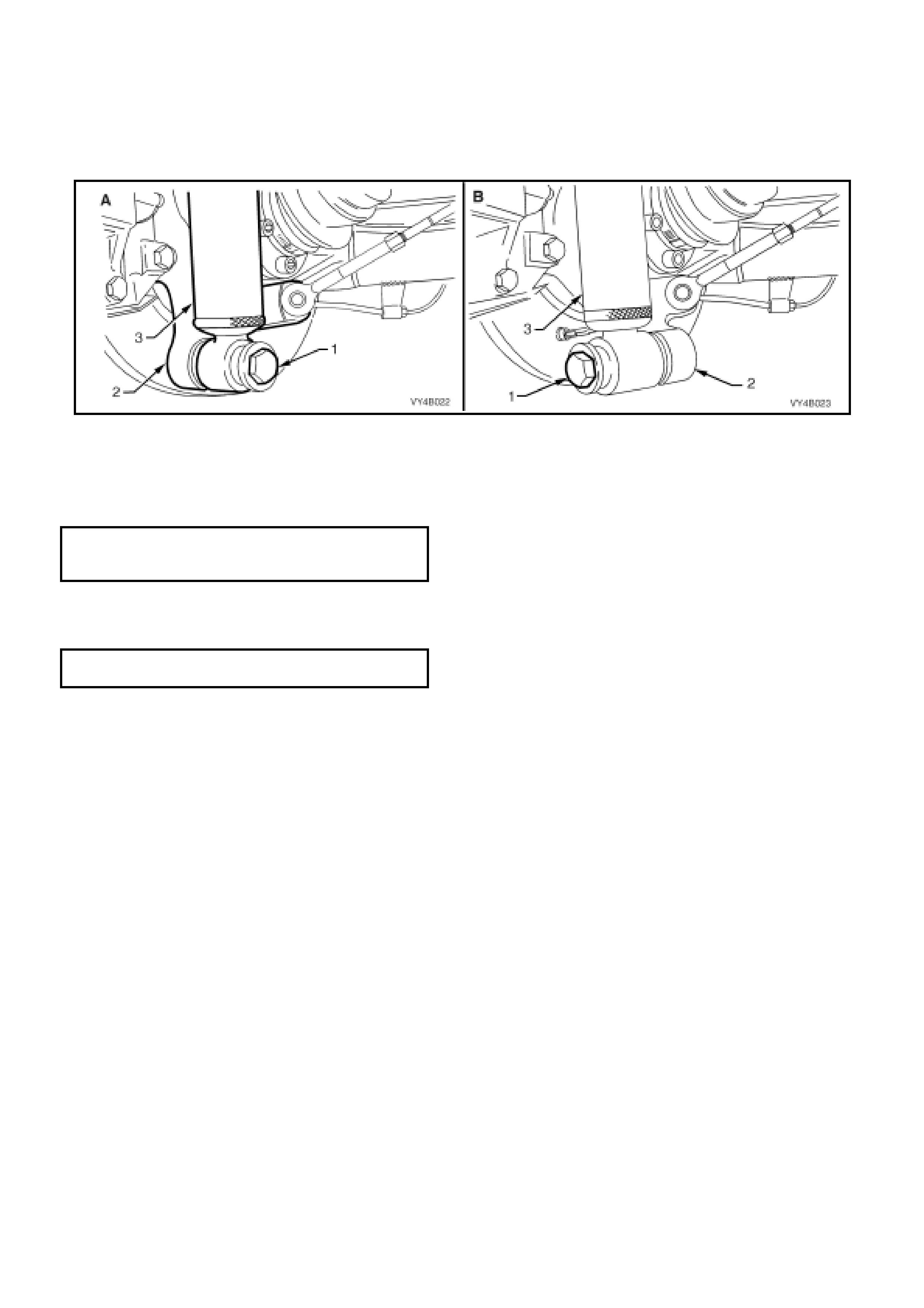
8. Position floor jack with a block of wood under the trailing arm (2). Raise jack slightly to take spring load off
trailing arm.
9. Disconnect rear shock absorber lower mounting bolt (1) from trailing arm (2), and pull lower end of shock
absorber (3) from trailing arm. Leave the supporting jack and wooden block in position.
NOTE: View ‘A ’ in Figure 4 B-65 s h o ws th e s eda n, lower shoc k absor ber mountin g, whil e vie w ‘ B’ s ho ws t he s tatio n
wagon arrangement.

Figure 4B-64
10. Using holding bar, Tool No. KM468 over the
wheel studs to hold trunnion assembly from
rotating, loosen and remove the six drive shaft
(1) constant velocity joint to trunnion flange
attaching bolts (2) and plates, using an 8 mm
Allen key socket and suitable socket
equipment (3).
Figure 4B-65
11. Separate drive shaft from flange and lift
upward. While keeping the outer constant
velocity joint (1) in the same plane as the
driveshaft, use a piece of wire (2) and tie up
the drive shaft assembly to lower end of shock
absorber upper mounting.
NOTE: Bruising to the inside of the drive shaft
constant velocit y joint boots will occur if the trailing
arm is lowered. This will lead to premature failure
of the boot and eventual failure of the joint if left
unchecked.
12. The supporting jack may now be lowered and
the wooden block removed.
Figure 4B-66
13. Remove park brake shoe by grasping each
end as shown. Push up on one end of the
shoe, dislodging the end from the actuator pin
and the shoe from the retaining clip.
Figure 5A-67
14. Using a scre wing motion, rotate t he park brak e
shoe around the trunnion flange to remove it
from the vehicle.
15. Rem ove the park brak e s hoe spring retai ner b y
prising from the rear disc shield, with a
screwdriver or similar lever.
16. Using suitable socket equipment, loosen then
remove the two lower bolts securing the park
brake adjuster and brake backing plate to the
trailing arm.
17. Using Tool No. AU416 and suitable socket
equipment, loosen then remove the two upper
brak e backing plate to the trail ing arm , Tor x bit
headed bolts
Figure 5A-68
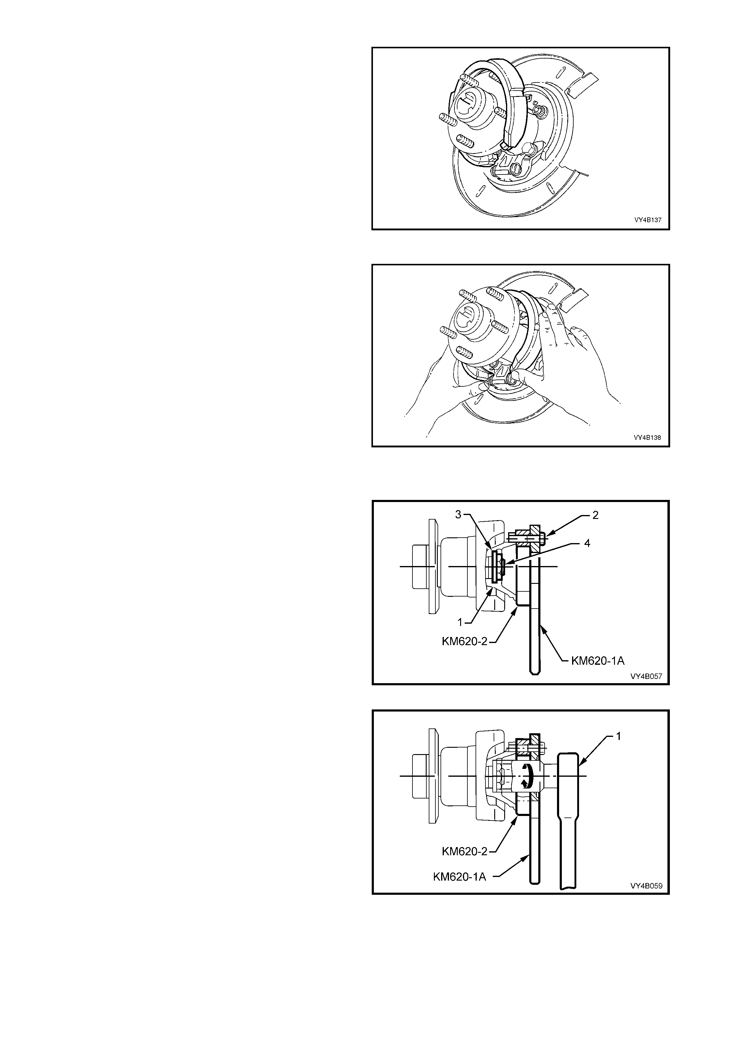
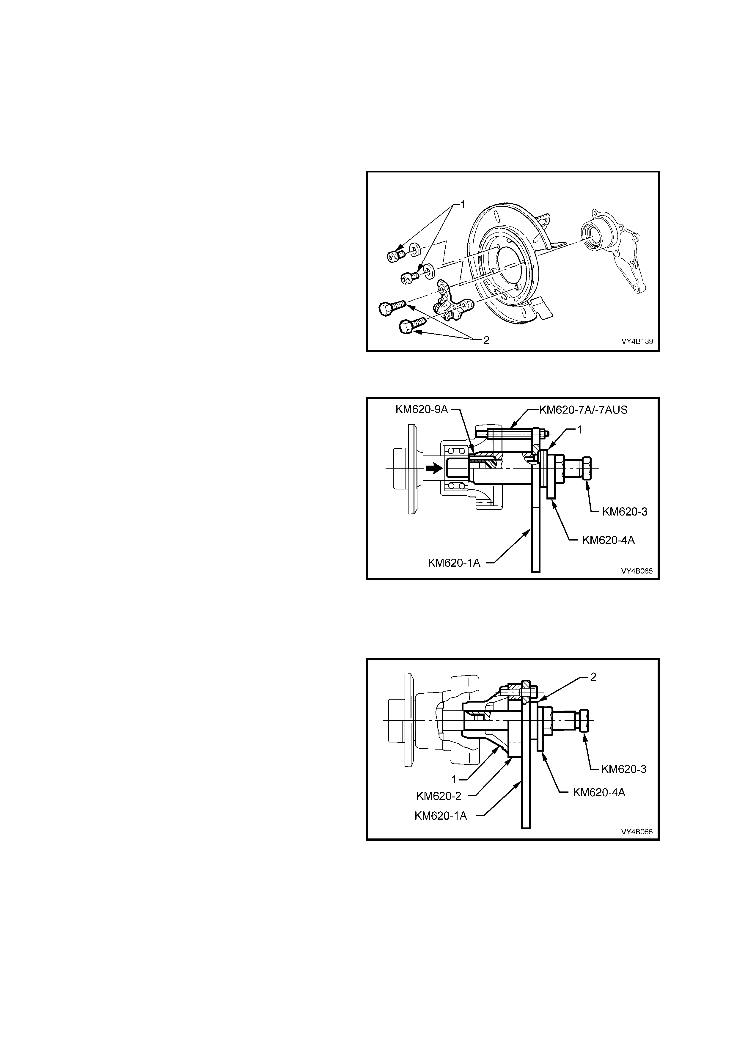
18. Secure flange holding tool, KM620-1A and
trunnion flange ring tool KM620-2 to trunnion
flange (1) with thr ee of the rem oved drive shaf t
constant velocity joint to trunnion flange
attaching bo lts (2).
NOTE: Align holes marked ‘B' on the flange
holding tool KM620-1A and KM620-2 with holes in
the trunnion flange before installing and tightening
bolts.
Figure 4B-69
19. Install a su ita ble le ngth and diameter s teel tub e
over handle of KM620-1A to stop it from
rotating, then use suitable socket equipment
(1) to loosen and remove the collar nut and
lock plate.
NOTE: Once collar nut and lock plate have been
removed, they must be discarded as they are only
to be used once.
Figure 4B-70

20. Lubricate the threads of forcing screw KM620-
3, then install to adaptor KM620-4-A. Apply
grease to ball end of plung er, T ool No. KM 620-
5B, then install that, into the end of forcing
screw KM620-3.
21. Install the whole sub-assembly through the
central opening of flange holding tool KM620-
1-A. Secure the adaptor KM620-4A to the
flange holding tool KM620-1A, using three
suitable bo lts (1) .
NOTE: Adjust the position of the forcing screw
KM620-3 in the adaptor KM620-4A, to allow
adaptor to be in full contact with the flange holding
tool KM620-1A.
Figure 4B-71
22. While hold ing KM 620-1A f rom r otating, tur n the
screw KM620-3, forcing the flange free from
the trunnion.
Separate tool components from flange once it
has been removed.
Figure 4B-72
23. Prepara tory to rem oving th e trunni on assem bly
and rear wheel bearing from the trailing arm,
use a commercially available M10 x 1.25
bottoming tap and clean the four backing plate
to trailing arm bolt threads, using a suitable
lubricant and working from the trunnion
assembly side.
NOTE: This step is necessary to clear any dried
mud, dirt etc, from the exposed portion of the
threads on the inboard side of the trailing arm.
Also, the deepest thread (position ‘C’) may not be
completely formed through to the inboard side.
24. Install two supports KM620-7A in positions ‘A’
and two KM620-7AUS to ‘B’ and ‘C’ in the
trailing arm, as indicated.
As a guide, the two longest supports (KM620-
7A) are to be installed at the brake caliper
mounting side (position ‘A’). The longer of
KM620-7AUS supports is installed at position
‘B’ and the shorter is installed at position ‘C’.
25. After installing all four supports in the correct
positions, tighten with a set spanner.
Figure 4B-73
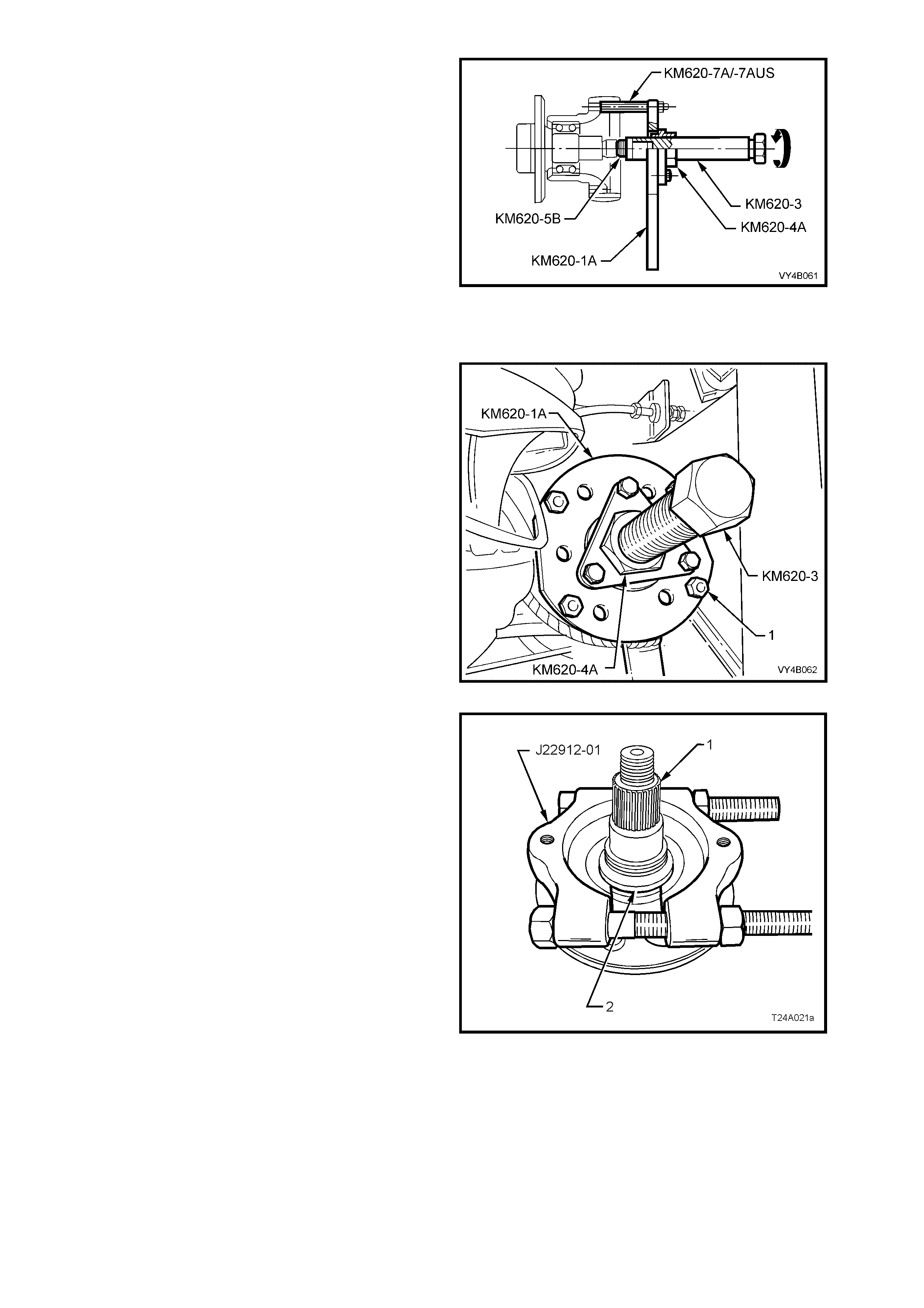
26. Install flange holding tool KM620-1A over the
four supports, KM620-7A (2 places) and
KM620-7AUS (2 places), install four suitable
nuts (1) and tighten to secure.
27. Pre-assem ble lubricated forcing screw KM620-
3 to adaptor KM620-4A. Apply grease to ball
end of plunger KM6 20-5B, then i nstall th at, into
the end of forcing screw KM620-3.
28. Install this sub-assembly through the central
opening of holding tool KM620-1A. Secure the
adaptor KM620-4A to the flange holding tool
KM620-1A, using three suitable bolts (2).
NOTE: Adjust the position of the forcing screw
KM620-3 into the adaptor KM620-4A, to allow full
contact of the adaptor to the flange holding tool
KM620-1A.
Figure 4B-74
29. Insert a s uitable le ngth of tube over the handle
of holding tool KM620-1A to stop it from
rotating and turn the forcin g screw KM620-3 to
press trunnion from rear wheel bearing.
30. W hen the trunnion has be en removed, rem ove
nuts (1) holding KM620-1A assembly to the
distance pieces, KM620-7A and KM620-7-
AUS. Rem ove KM620-1A, and r emove KM620-
5B from the end of KM620-3.
31. Unscrew the forcing screw (KM620-3), as this
same arrangement is used to press the rear
wheel bearing from the trailing arm.
NOTE: The rear wheel bearing inner cone will
separate from the bearing assembly and be
retained on the trunnion assembly.
32. Remove the brake backing plate and park
brak e assem bly from the trailin g arm and s et to
one side.
Figure 4B-75
33. If the trunnio n assem bly (1) is to be reins talled,
then the outer half of the inner rear wheel
bearing cone (2) will need to be removed from
the trunnion assembly (1).
a. Ins tall press plates J2291 2-01 over the b earing
cone (2) and tighten the press plate bolts to
grip the bearing cone.
b. Press the trunnion assembly (1) from the
bearing cone (2) and discard bearing cone.
NOTE 1: If the tru nn ion is t o be r ep laced , th en s t ep
27 will not be required.
NOTE 2: A new trunnio n assem bly is supplied with
wheel studs already installed.
Figure 4B-76
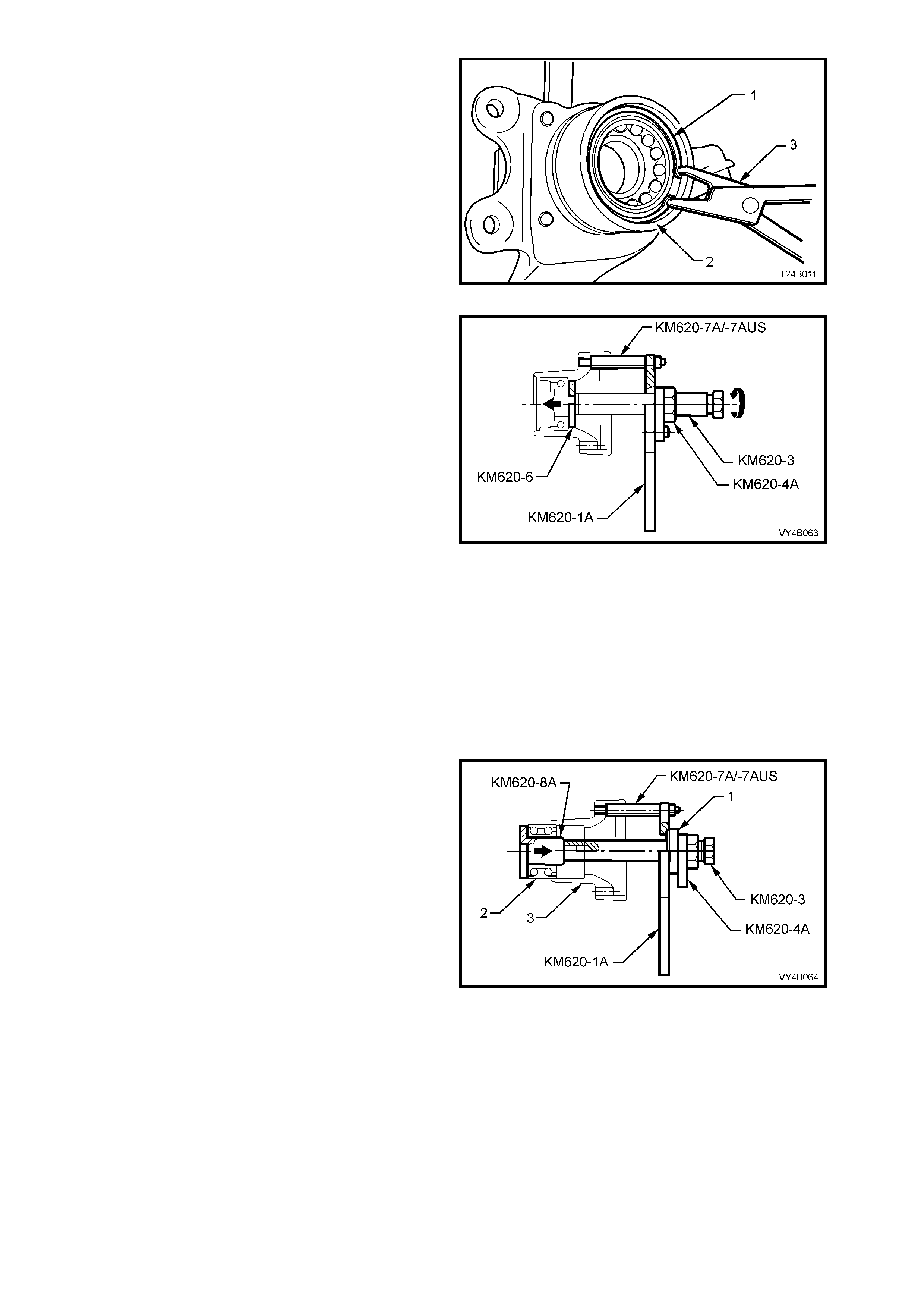
34. Remove wheel bearing retaining ring (1) from
trailing arm (2), using suitable circlip pliers (3).
Figure 4B-77
35. With the tool components set up in the same
arrangement as for step 20 (and as shown in
Figure 4B-73), install rear axle bearing
removing plate KM620-6 to rear of the axle
bearing. Reposition the for cing scre w KM620-3
to hold the removi ng pl ate KM6 20-6 in pl ac e.
36. Insert a s uitable le ngth of tube over the handle
of holding tool KM620-1A to stop it from
rotating, then turn the forcing screw KM620-3
to press the wheel bearing from the trailing
arm.
37. If installing a replacement trailing arm without
bushes, install new bushes. Refer to
2.7, TRAILING ARM BUSHES in Section 4A
REAR SUSPENSION in MY2003 VY and V2
Series Service Information.
Figure 4B-78
REINSTALL
To Install A New Bearing:
1. Ensure that bearing bore of trailing arm is clean and free of any foreign matter.
2. Coat outside diam eter of ne w wheel bear ing an d bor e of traili ng arm with lubric a nt such as M ol ybond HE50 , or
equivalent.
3. Remove bolts securing adaptor KM620-4-A to
the holding tool KM620-1A, then remove the
adaptor and forcing screw KM620-3 from the
holding tool KM620-1A.
4. Lubricate the thrust ball bearing race (1) (part
of KM620-A) with lubricant such as Molybond
HB50, or equivalent, then assemble the
bearing onto the flanged end of adaptor
KM620-4A.
5. Reinstal l t he f or c in g s cr e w and ad aptor / bearing
assem bly to t he flange ho lding tool KM620-1A.
Do not reinstall the adaptor (KM620-4A) to
holding tool (KM620-1A) attaching bolts.
6. Install bearing installer KM620-8A into a new
bearing (2) and install both into the trailing
arm (3).
7. Join the forcing screw (KM620-3), and bearing
installer (KM620-8A) by engaging the screw
thread of the forcing screw (KM620-3) with
installer (KM620-8A) and tightening the forcing
screw to engage at least eight full threads.
Figure 4B-79
8. While holding the forcing screw (KM620-3) from turning by using suitable socket equipment (4), rotate the
adaptor KM620-4A in a clockwise direction, using a suitable 40 mm wrench to draw the new bearing (2) fully
into position.
9. W hen the bearing is f ully installed, separ ate instal ler KM620-8A f rom the forcing s crew KM620-3, the n remove
the instal ler and f orc ing scre w (KM620- 3), adap tor (K M620- 4A) and be arin g, from the holdin g tool (KM 620- 1A).
Leave remaining tools installed.
10. Using s uitab le circ lip pl iers, ins tall a new bear ing ret ainin g ring into tra iling arm , ensuring t hat the r ing is s eat ed
correctly.
11. Install rear disc brake shield to trailing arm but
do not inst all fastener s (‘1’ and ‘2’) at this tim e,
as the s upports, K M620-7A and KM620- 7-AUS
could not be fully installed in the threaded
holes on the opposite side.
Figure 4B-80
To Reinstall Trunnion:
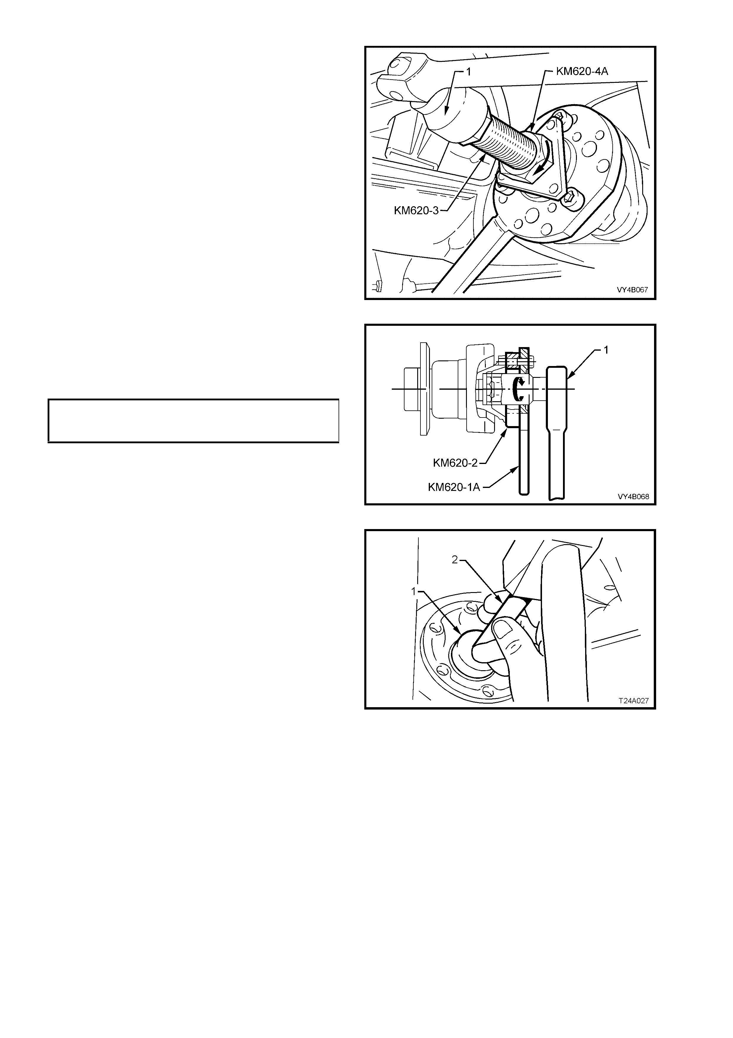
1. Remove KM620-1A from distance pieces,
KM620-7A and KM620-7AUS. Install sleeve
KM620-9A over KM620-3, with the stepped
shoulder facing away from the trunnion
bearing. Reinstall KM620- 1A to K M620-7A a nd
KM620-7AUS, tightening the attaching nuts.
2. Screw the threaded end of the trunnion into
KM620-3. W hile ho ld ing K M620-3 f rom tur ning,
rotate KM620-4A to draw trunnion into wheel
bearing.
3. Unscrew for cing sc rew KM620-3 fr om trunni on,
then rem ove t he nuts h old i ng to ol KM 620- 1 A t o
the distance pieces KM620-7A and KM620-
7AUS.
4. Remove the distance pieces KM620-7A and
KM620-7AUS from the trailing arm.
Figure 4B-81
5. Assem ble KM620-2 and KM620-1A to trunnion
flange using three drive shaft constant velocity
joint to flange bolts.
6. Lubricate trunnion flange splines and trunnion
threads with the recommended differential
carrier lubricant.
7. With KM620-4A, thrust ball bearing race (2)
and KM620-3 assembled to KM620-1A, screw
the internal thread of KM620-3 onto the
trunnion ass embly.
Figure 4B-82
8. While holding the forcing screw (KM620-3)
from turning with suitable socket equipment
(1), use a suitable 40 mm wrench to rotate the
adaptor KM620-4A in the direction shown, to
install the trunnion flange onto trunnion.
9. Unscrew KM620-3 from the trunnion, then
remove it and adaptor KM620-4A from the
holding tool KM620-1A. Leave the holding tool
KM620-1A and trunnion flange ring tool
KM620-2 installed to the trunnion flange.
Figure 4B-83
10. Install N EW c ollar nut to t he trunnio n assem bly
and, using a suitable length and sized pipe
over the handle of KM620-1A to hold trunnion
assembly from turning, tighten collar nut to the
correct torque specification.
COLLAR NUT TO
TRUNNION ASSEMBLY
TORQUE SPECIFICATION 295 – 305 Nm
11. Remove the holding tool KM620-1A and
trunnion flange ring tool KM620-2 from the
trunnion flange.
Figure 4B-84
12. Using a 1.25 inch socket (1), 150 mm socket
bar (2) and a soft faced hammer, install new lock
plate over collar nut.
Figure 4B2-85
13. Assem ble driveshaft ( 1) outer c onstant veloc ity
joint to trunnion flange, aligning bolt holes.
14. Reinstall six attaching bolts (2) with plates and
tighten bo lts to the c orrect torque specific ation,
using suitable socket equipment (3).
DRIVESHAFT CONSTANT
VEL O CI T Y JO I NT TO TRUNNIO N
FLANGE ATTACHING BOLT
TORQUE SPECIFICATION 50 Nm, then
90° turn angle
Figure 4B-86
15. Reinst all t he f our br ak e back ing plat e t o trail ing
arm bolts (‘1’ a nd ‘2’) and tighte n to the c orrect
torque specification.
REAR DISC BRAKE SHIELD TO
TRAILING ARM UPPER BOLT (‘1’)
TORQUE SPECIFICATION 70 - 80 Nm
REAR DISC BRAKE SHIELD TO
TRAILING ARM LOWER BOLT (‘2’)
TORQUE SPECIFICATION 85 - 90 Nm
NOTE 1: The upper Torx headed bolts have
washers with cut-outs that are to be installed with
the cut-o ut ed ge f ac ing ar o und t he trailing arm hub,
outer surface.
NOTE 2: Apply Loctite 242 thread sealant or
equivalent (to GM Specification 998 5283) to the
threads of the two longer, lower hexagon headed
bolts, befor e instal lat io n.
Figure 4B-87
16. Reinst all br ak e disc ( 1) to trunnion, align ing the
marks made before removal.
NOTE: If the trunnion has been replaced, then
runout checks must be carried out on the trunnion
flange and the installed brake disc (1). Refer to
2.4 TRAILING ARM TRUNNION ASSEMBLY, in
this Section for important information regarding
these checks.
17. Reinstall the brake caliper (3) to the trailing
arm, reinstall brake caliper anchor plate to
trailing ar m attac hing bolts (2 and tig hten to the
correct torque specification.
BRAKE CALIPER ANCHOR
PLATE TO TRAILING ARM
ATTACHING BOLT
TORQUE SPECIFICATION 70 – 100 Nm
18. After reconnecting the brake line to the caliper
hose and installing the brake hose retaining
clip, bl eed the rear brak es and ch eck f or leaks.
For the recommended procedure, refer to
Section 5A SERVICE AND PARK BRAKING
SYSTEMS, in the MY 2003 VY and V2 Series
Service Information.
Figure 4B-88
19. Support the trailing arm with a floor jack and wooden block, sufficient to enable the shock absorber to be
reinstalled.
20. Reinstall shock absorber (3) to trailing arm (2), install the lower mounting bolt (1) but do not torque to
specification at this stage.
NOTE 1: View ‘A’ in Figure 4B-89 shows the sedan, lower shock absorber mounting, while view ‘B’ shows the
station wagon ar r ang ement.
Figure 4B-89
21. Install road wheel, aligning marks made before removal and reinstall attaching nuts.
22. Remove safety stands and lower vehicle to the ground and bounce the rear of the vehicle several times to
settle the suspension components.
23. Tighten the lower shock absorber bolt to the correct torque specification.
SHOCK ABSORBER LOWER
MOUNTING BOL T
TORQUE SPECIFICATION 105 - 125 Nm
NOTE: Vehicle must be at curb weight and on all four wheels before this torque is applied.
24. Tighten road wheel attaching nuts to the correct torque specification, working in a ‘star’ pattern. Refer to
Service Notes in 2.1 GENERAL in this Section for more details.
ROAD WHEEL ATTACHING NUT
TORQUE SPECIFICATION 110 - 140 Nm
25. Refit wheel cover/wheel nut decorative caps.
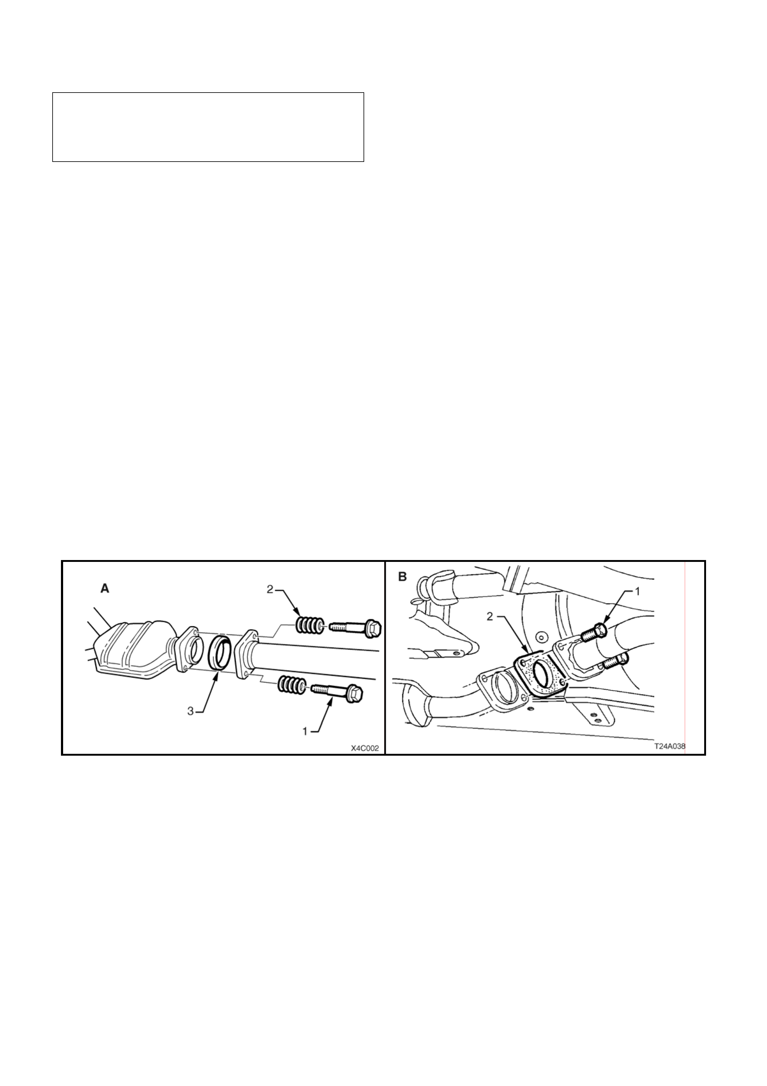
3.2 FINAL DRIVE ASSEMBLY
LT Reference No: F650100 / F504150
NOTE: The following fasteners MUST be replaced when
performing this operation:
Final drive assembly to crossmember attach ing bolts.
Drive shaft constant velocity joint to trunnion flange
and inner axle shaft attaching bolt.
CAUTION: Whenever any component that forms part of the ABS (if fitted) is disturbed during Service
Operations, it is vital that the complete ABS system be checked, using the procedure as detailed in
DIAGNOSIS, ABS FUNCTION CHECK, in Section 5B ABS & ABS/TCS, in the MY2003 VY and V2 Series
Service Information.
IMPORTANT: Before disturbing the rear suspension crossmember mounting bolts, an alignment procedure is
required on reinstallation and a special tool is required for this purpose. If this tool is not available, then the
crossmember cannot be correctly aligned and steering and/or han dling abnormalities will result.
NOTE: For this service ope ration, ne w intermediate muffler support retainers must be used on reassem bly.
REMOVE
1. Using a floor jack under centre of differential carrier, jack up rear of vehicle and place safety stands under body
rear jacking points. Refer to Section 0A GENERAL INFORMATION in MY2003 VY Series Service Information
for location of jacking points.
2. Remove wheel covers (steel wheels) or whe el nut caps (alloy wheels).
3. Mark relationship of road wheels to hubs (e.g. end of wheel stud), with a felt tipped pen or similar. Loosen then
remove road wheel attaching nuts. Remove the road wheel.
4. Disconnect exhaust system from rear of catalytic converter/s:
V6 Engined Vehicles (A ):
a. Remove both flange bolts (1) and springs (2). After separation remove the retaining ring (3).
V6 Supercharged and GEN III V8 Engined Vehicles (B):
b. Remove both flange bolts (1), then the sealing gasket (2).
NOTE 1: Only one side of the V6 Supercharged/GEN III V8 engine arrangement is shown.
NOTE 2: Both Views ‘A’ and ‘B’ (Figure 4B-91) show a catalytic converter fitted to the exhaust system, which may
not be applicable for all vehicle spe cifications.
Figure 4B-90
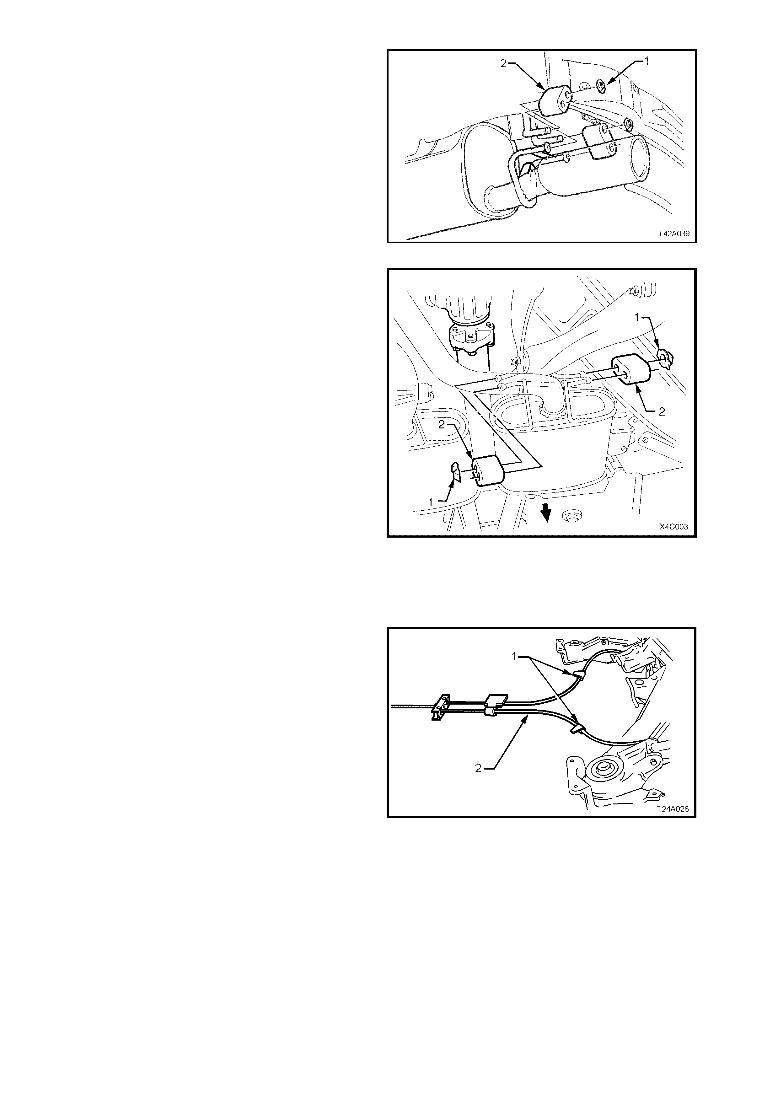
5. Remove the two retainers (1) from the top
posts and discard. Disconnect exhaust system
support rings (2) from rear hanger of rear
muffler assembly. Both V6 and GEN III V8/V6
Supercharged engine arrangements are
similar.
Figure 4B-91
6. Remove muffler support to rear crossmember
hanger retainers (1).
NOTE: There are two retainers for V6 engined
vehicles and four retainers for GEN III V8 and V6
Supercharged engine vehicles.
7. Support intermediate section of exhaust
system and remove support rings (2) from
muffler and crossmember hangers.
8. Remove intermediate and rear sections of
exhaust system from vehicle.
Figure 4B-92
9. Remove propeller shaft, refer to
Section 4C PROPELLER SHAFT AND
UNIVERSAL JOINTS in the MY2003 VY and
V2 Series Service Information.
10. Set park brake in fully released position, then
release each of the underbody to park brake
cable (1) retaining clips (2) and free cables (1).
Figure 4B-93
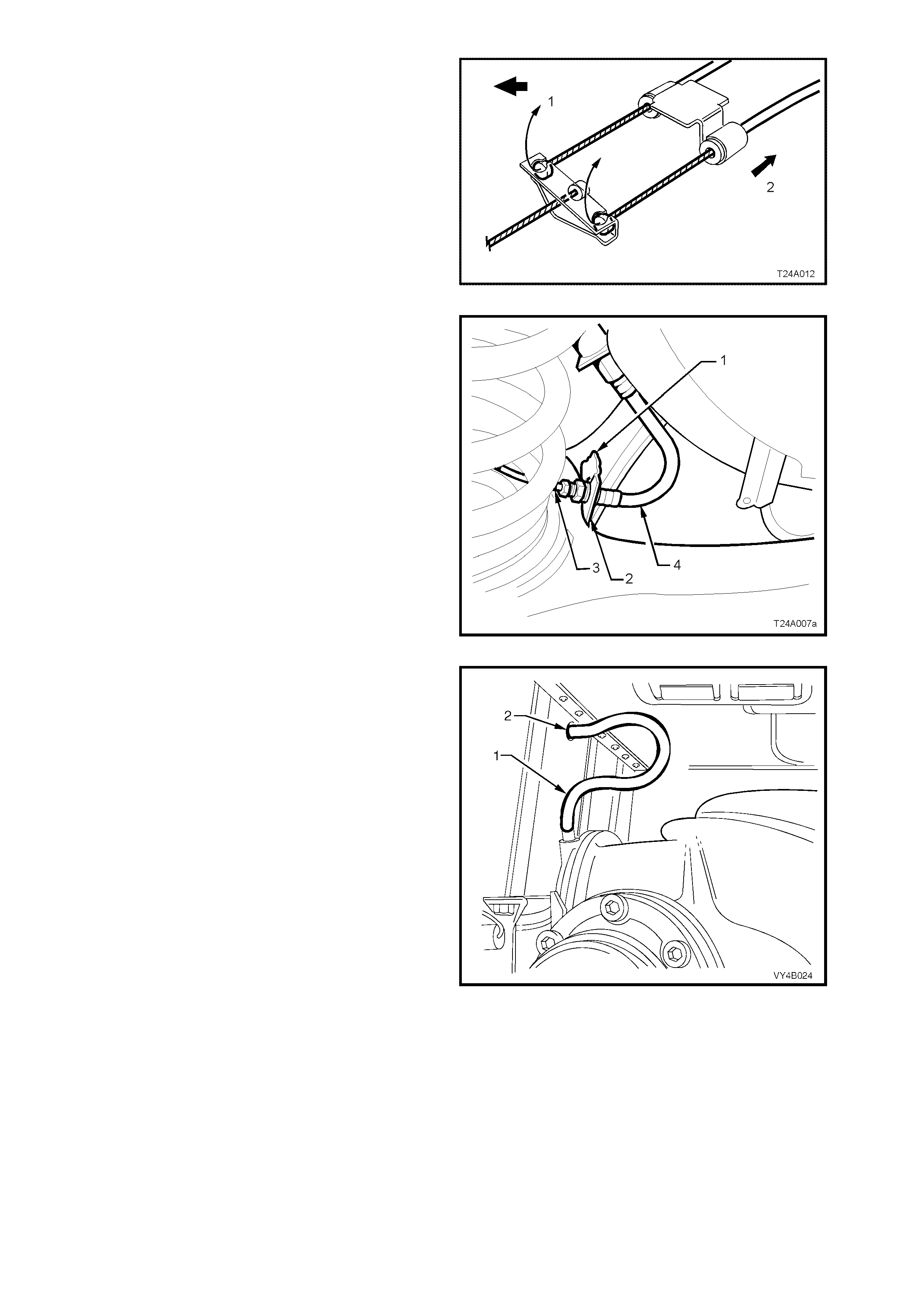
11. Remove park brake outer cable retaining
bracket bolt (underbody bracket and bolt are
not shown) from the vehicle underbody.
12. Pull each park brake inner cable forward and
up, (1) out of the cabl e reta iner to re lease eac h
cable.
13. Pull the outer cable rearward (2) to remove
from the underbody retainer.
Figure 4B-94
14. Disconnect brake pipe (3) from brake hose (4)
at trailing arm bracket (2) and remove the
brake hose retaining clip (1).
Plug t he op en ends of both pipes and hoses to
prevent unnecessary fluid loss and/or dirt
entry.
15. Repeat for the other side.
Figure 4B-95
16. Pull out differential carrier breather hose (1)
from vehicle underbody crossmember hole (2).
Figure 4B-96
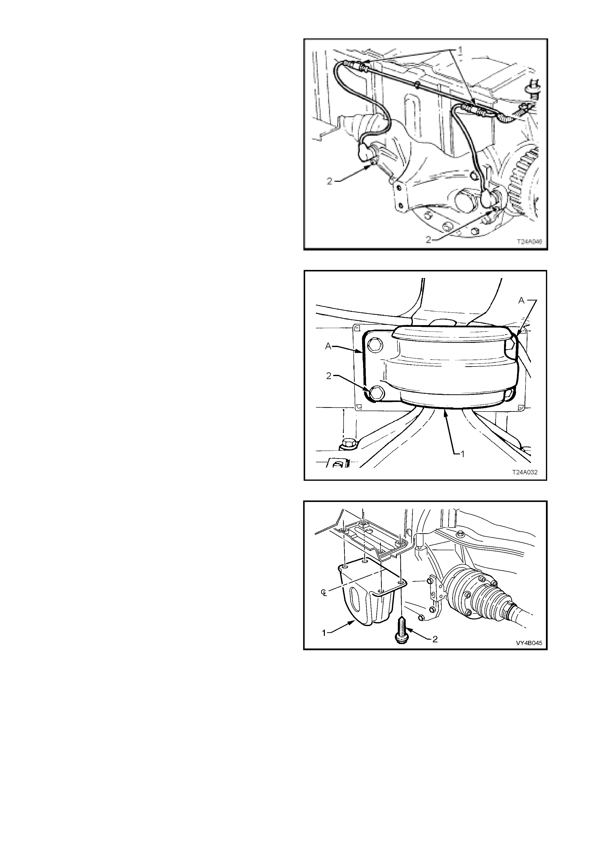
17. If vehicle is fitted with ABS, pull both sensor
lead connectors from the underbody retaining
clips (1). Separate the sensor connectors from
the body har ness c onnecto rs by levering with a
screwdriver.
Figure 4B-97
18. Using a scriber, m ark rear mount (1) to vehicle
under body location (A). This will assist in rear
crossmember alignment on reinstallation.
19. Support weight of differential carrier with floor
jack.
Figure 4B-98
20. Remove rear mount (1) to vehicle underbody
attaching bolts (2) and discard removed bolts.
Lower differential carrier and rear
crossmember assembly by at least 60 mm.
Figure 4B-99
21. Position floor jack with a block of wood under
trailing arm. Raise jack slightly to take spring
load off trailing arm.
22. Disconnect rear shock absorber lower
mounting bo lt (1) from trailing arm (2) , and pull
lower end of shock absorber (3) from trailing
arm.
NOTE 1: View ‘A’ in Figure 4B-98 shows the
sedan, lower shock absorber mounting, while view
‘B’ shows the station wagon arrangement.
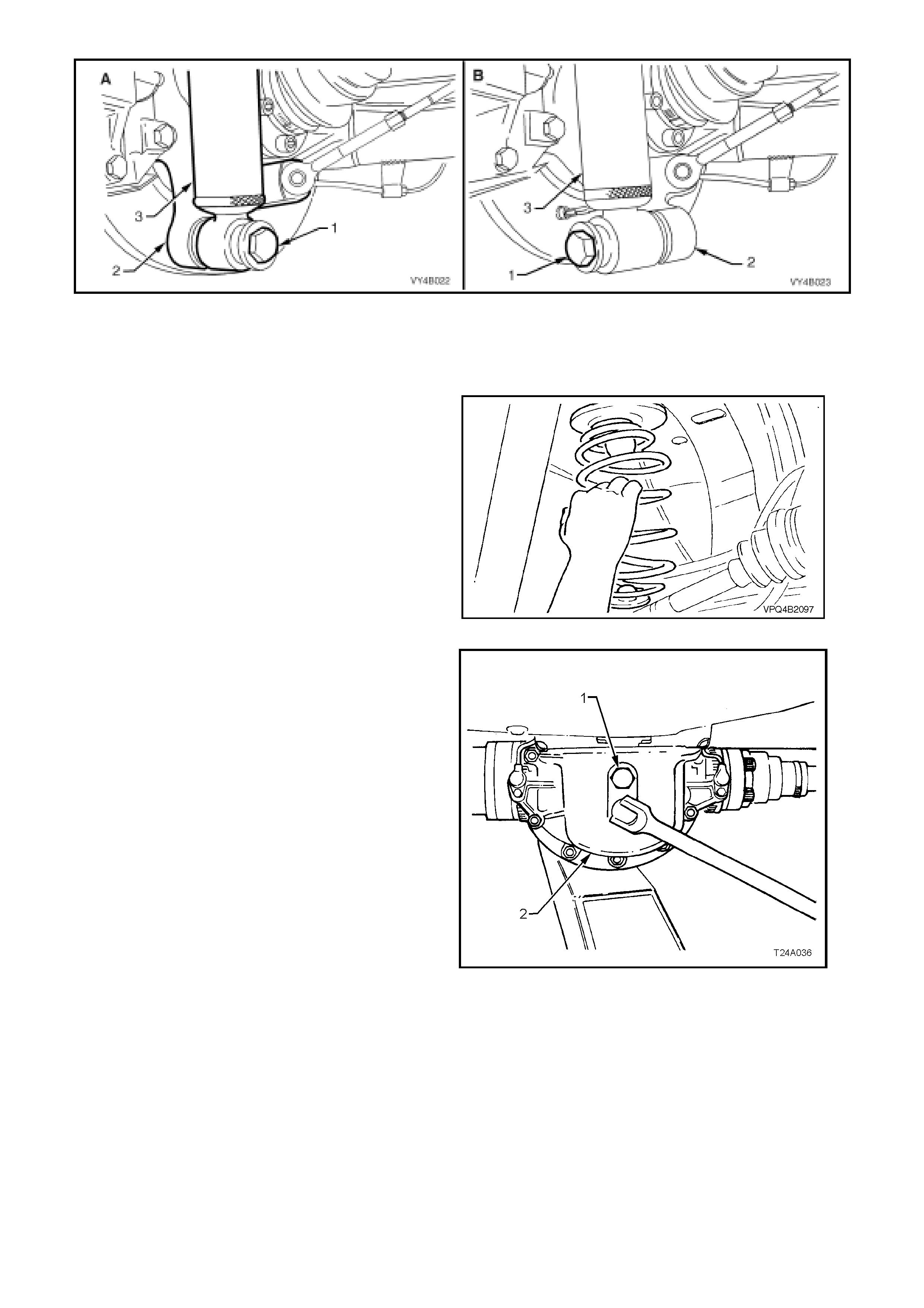
Figure 4B-100
NOTE 2: Bruising to the inside of the drive shaft constant velocity joint boots will occur if the shock absorber is
disconnected from the trailing arm before the rear of the differential carrier and crossmember assembly has been
lowered by at leas t 60 m m . Bruisin g of t he boo t wil l le ad to pr em ature f ailure of t he boot and event ual f ailur e of the
joint, if left unchecked.
23. Remove rear springs and insulators from
vehicle underbody and trailing arms.
24. Raise dif f erential c arrier and rear cros sm ember
on floor jack until rear mount contacts
underbody.
Figure 4B-101
25. If replacing differential carrier assembly, rear
cover or rear mount, loosen and remove rear
mount to r ear cover attachi ng bol ts (1) , rem ove
rear mount (2) and discard attaching bolts (1).
Figure 4B-102
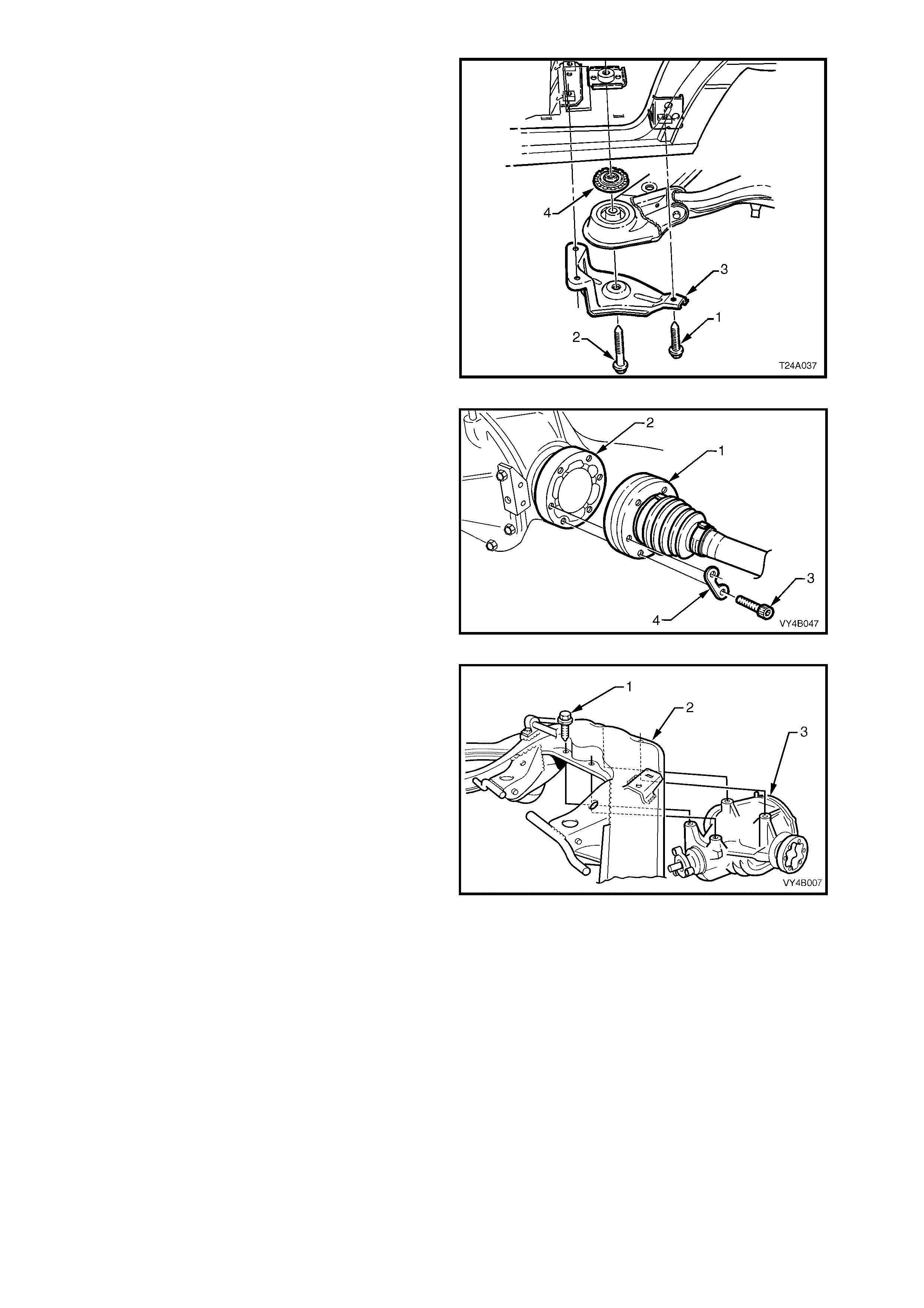
26. Use a floor jack and block of wood to support
differential carrier and crossmember assembly.
27. Remove brace to underbody bolts (1) (3
places) and crossmember to vehicle
underbody attaching bolt (2) from each side.
28. Remove the braces (3) from the vehicle.
29. With an assistant supporting front end of rear
crossmember, lower assembly on jack and
remove from beneath vehicle.
NOTE: If the vehicle is fitted with isolating rubbers
(4) locate d on top of each f ront c r ossmem ber bus h,
remove and set to one side.
Figure 4B-103
30. Using an 8 mm Allen key s ocket, rem ove drive
shaft inner constant velocity joint (1) to inner
axle shaft (2) attaching bolts (3) and plates (4).
Disconnect joints from inner axle shafts.
NOTE: Support drive shafts with suitable tie wire
so that they do not hang on one end. Drive shaft
joint def lection shou ld be kept to within t he angular
movement of an installed drive shaft.
Figure 4B-104
31. Remove differential carrier (3) to rear
crossmember (2) attaching bolts (1), remove
rear crossmember assembly from differential
carrier and discard attaching bolts(1).
32. If not carrie d out in s tep 25, r emove rear mount
to rear cover attaching bolts, remove mount
and discard attac h ing bo lts .
Figure 4B-105
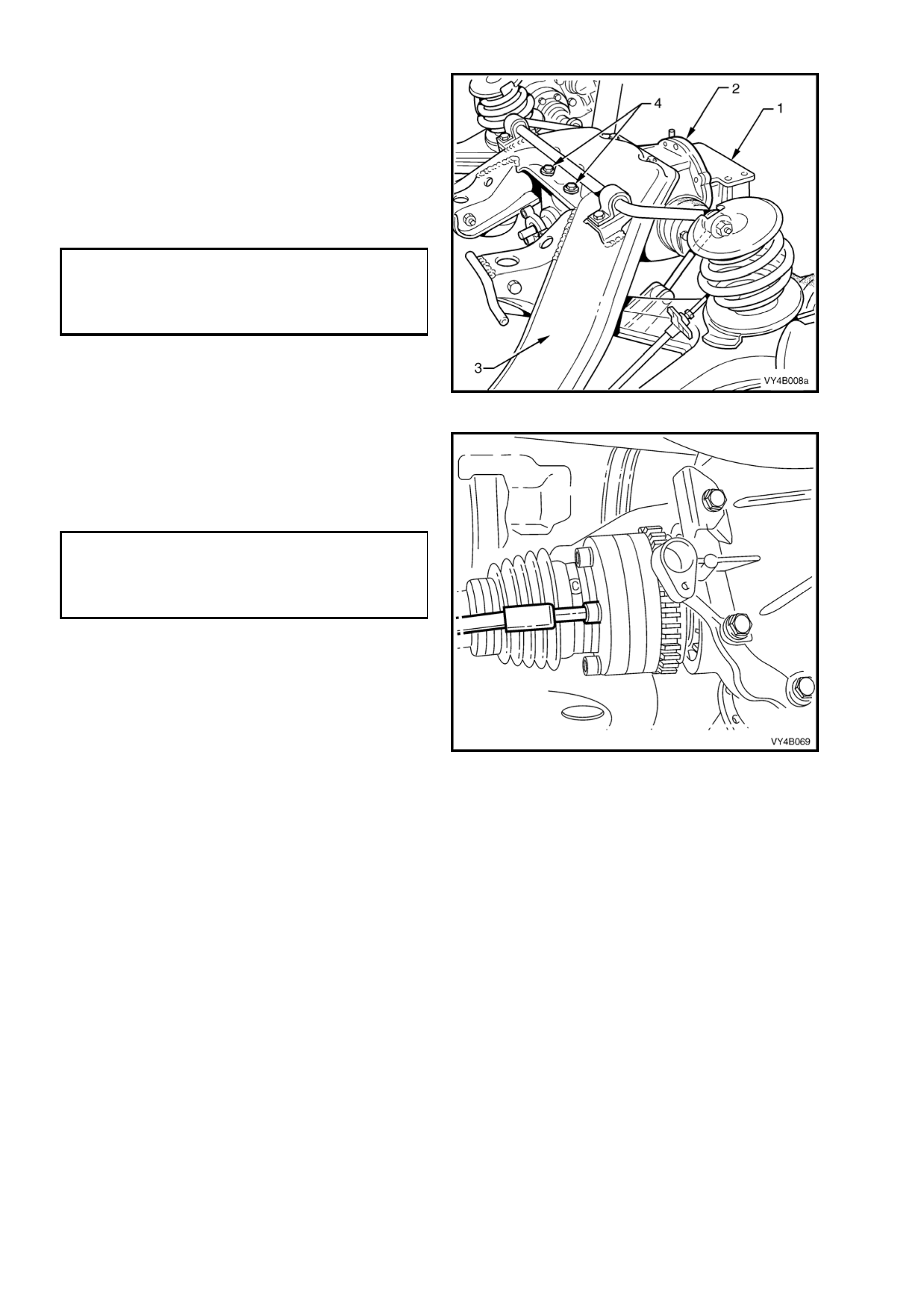
REINSTALL
Installation is the reverse of removal procedure
except for the following items:
1. If necessary, reinstall rear mount (1) to rear
cover using NEW bolts but leave bolts finger
tight at this stage.
2. Line up mounting holes in differential carrier (2)
and rear crossmember (3). Install NEW
attaching bolts (4) (four places) and tighten to
the correct torque specification.
DIFFERENTIAL CARRIER TO REAR
CROSSMEMBER ATTACHING BOLT
TORQUE SPECIFICATION 90 Nm, then
30° - 45°
turn angle
Figure 4B-106
3. Inspect drive shaft constant velocity joint boots
for damage, replace as necessary.
4. Tighten drive shaft inner constant velocity joint
to inner axle shaft attaching bolts to the correct
torque specification.
DRIVE SHAFT CONSTANT VELOCITY
JOINT TO TRUNNION FLANGE
ATTACHING BOLT
TORQUE SPECIFICATION 50 Nm, then
90° turn angle
Figure 4B-107
5. With the aid of two assistants, place the
differential carrier and rear crossmember
assembly onto a floor jack.
6. Position assembly under vehicle, raise with the
jack and, with the aid of the assistants, guide
the crossmember front mounting points into
position.
NOTE 1: When raising the assembly, take care
that the rear mount does not foul on the fuel tank
or fuel hoses.
NOTE 2: During this operation, ensure that trailing
arms are also supported on safety stands, to keep
the drive shafts as near to horizontal as possible.
Otherwise, bruising to the insides of the constant
velocity joint boots will result, leading to boots
splitting and eventually joint failure, if left
unchecked.
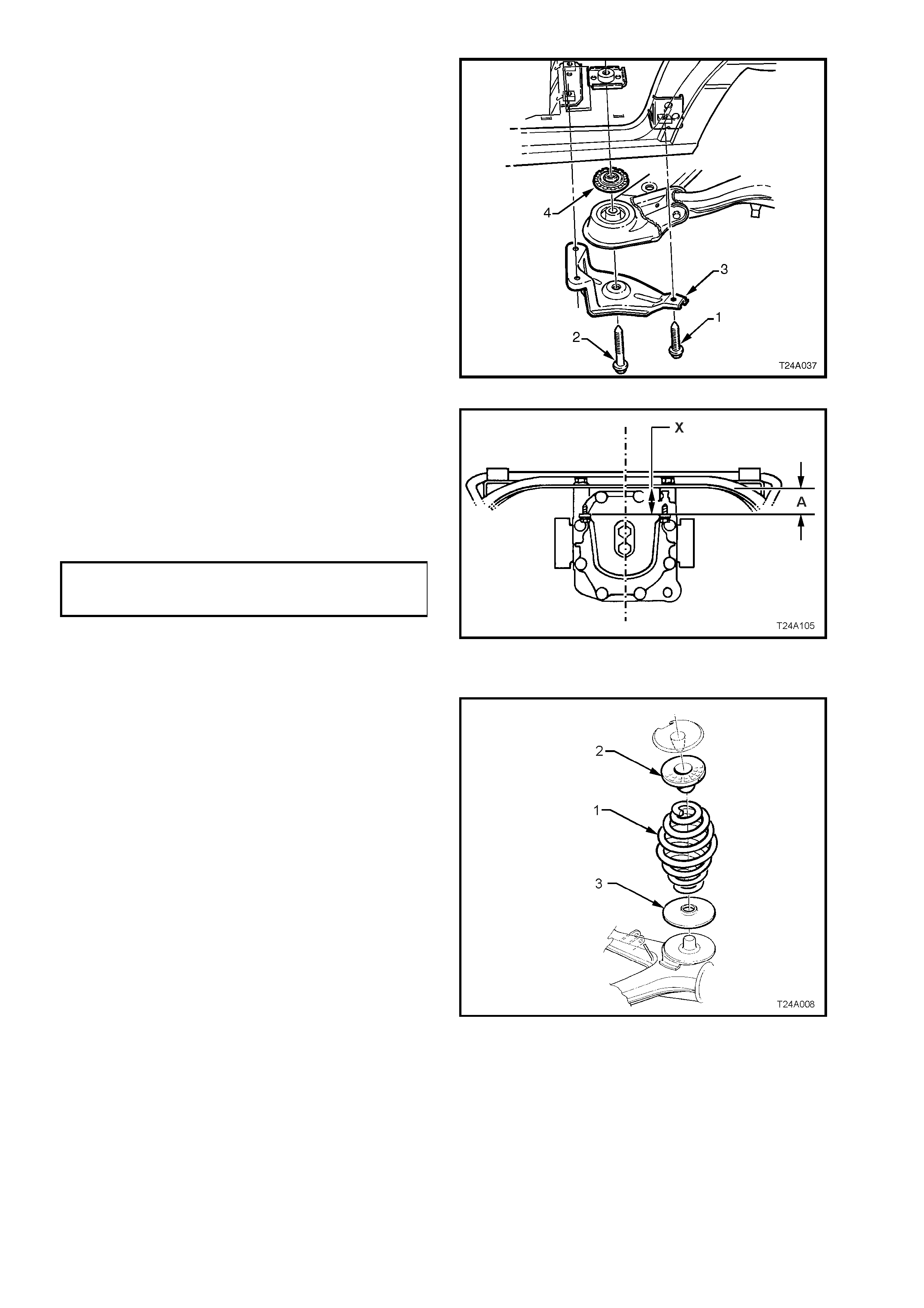
7. If the vehicle is fitted with an isolating rubber
(4) on each side, it must be fitted at the top of
each crossmember front bush as shown,
before raising the assembly into place.
8. Install crossm ember front m ounting braces (3),
attaching bolts (‘1’ – three places) and rear
crossmember, front mounting bolt (4) but do
not fully tighten any of these bolts at this
stage.
Figure 4B-108
9. Lower rear of the final drive assembly to gain
access to the rear mount to cover attaching
bolts. Tighten attaching bolts to the correct
torque specification.
IMPORTANT: At t he s ame tim e, ens ure that m ount
does not twist, as the mount to vehicle underbody
mating surface should be parallel to the rear
crossmember, to within 1 mm (‘X’).
REAR MOUNT TO REAR COVER
ATTACHING BOLT
TORQUE SPECIFICATION 85 – 105 Nm
NOTE: Use a spirit level on rear mount to
underbody surface and top surface of
crossmember to ensure that both surfaces are
parallel. Dimension ‘A’ is to be 56.7 mm.
Figure 4B-109
10. Lower differential carrier and rear
crossmember assembly on floor jack and
safety stands. Install rear springs (1) and the
two insulators, (2 and 3).
NOTE: During this operatio n, the diff erential c arrier
and rear crossmember assembly rear mount must
be lowered at least 60 mm from the vehicle
underbody. Otherwise damage to the drive shaft
constant velocity joint boots will occur.
Figure 4B-110
11. Reinstall shock absorber to trailing arm, fit
washer to the lower mounting bolt, install bolt
but do not fully tighten at this time, as the
vehicle must be at curb weight before final
tightening is undertaken.
NOTE: View ‘A’ in Figure 4B-109 shows the sedan,
lower shock absorber mounting, while view ‘B’
shows the station wagon arrangement.
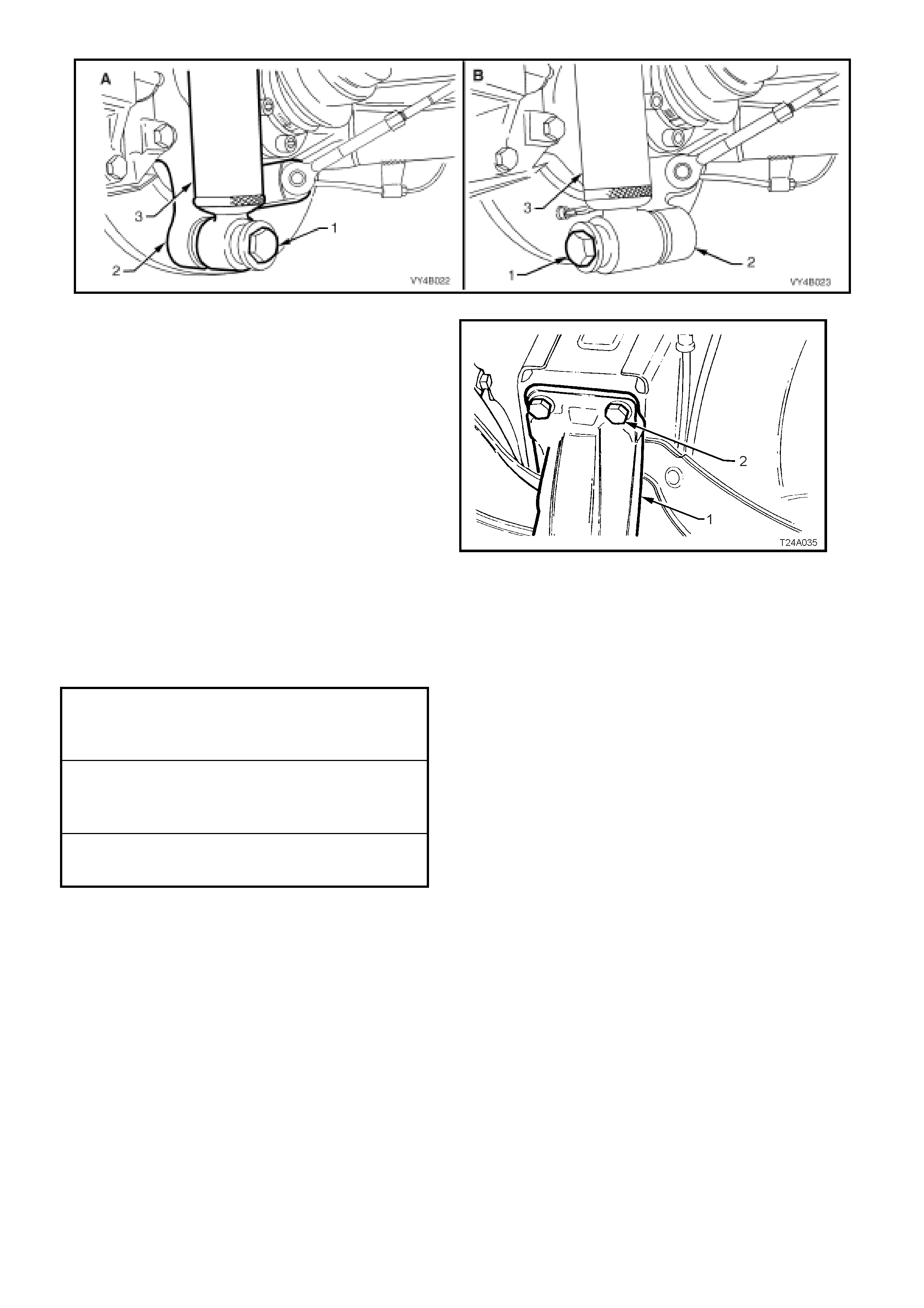
Figure 4B-111
12. Raise assembly until rear mount contacts
vehicle underbody.
13. Align r ear mount (1) with m arks on underbod y,
made on disassem bly, then loosely install new
attaching bolts (2) but do not fully tighten at
this stage.
14. The rear crossmember MUST now be
aligned to the vehicle centreline, using the
special tool and procedure as detailed in
Section 1A2 BODY DIMENSIONS in the
MY2003 VY and V2 Series Service
Information.
CAUTION: Failure to correctly align the rear
crossmember to the centreline of the vehicle
will result in steering abn ormalities and unev en
tyre wear!
Figure 4B-112
15. Tighten all cr os smem ber mount ing f as ten er s to
the correct torque specification.
REAR MOUNT TO VEHICLE
UNDERBODY ATTACHING BOLT
TORQUE SPECIFICATION 30 – 40 Nm, plus
55° – 65° turn angle
REAR CROSSMEMBER FRONT
MOUNTING BOLT
TORQUE SPECIFICATION 125 Nm, plus
30° – 40° turn angle
REAR CROSSMEMBER FRONT
MOUNTING BRACE BOLT
TORQUE SPECIFICATION 60 – 85 Nm
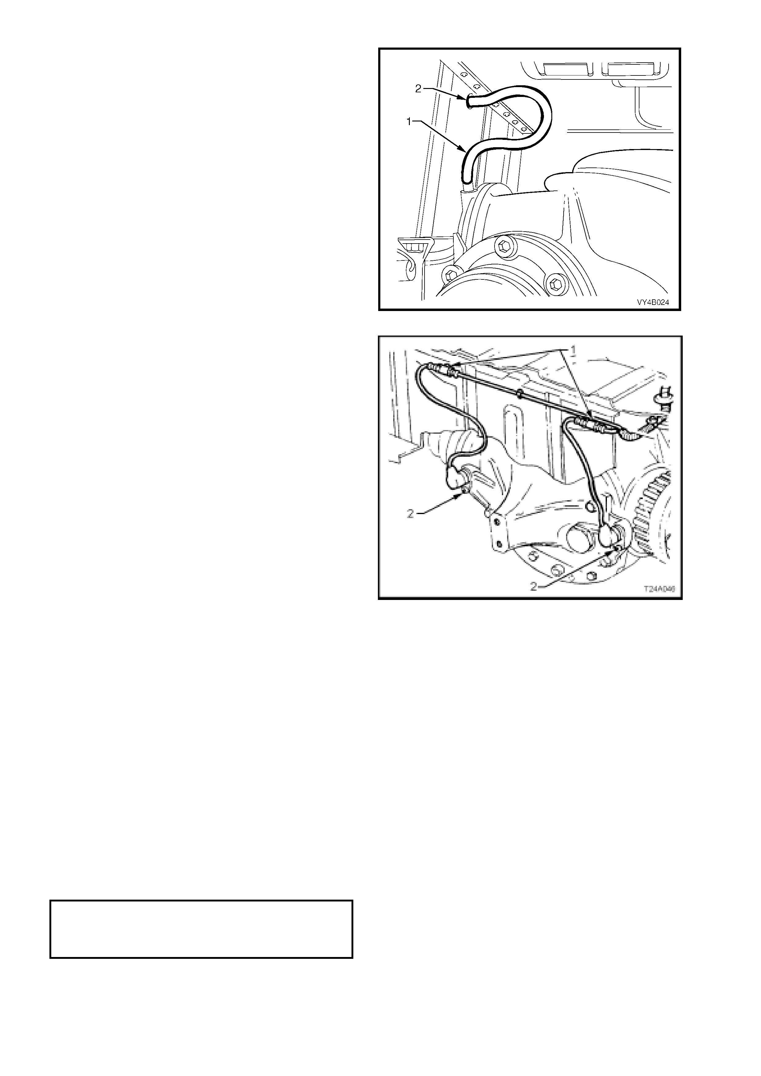
16. Install differential carrier breather hose into
vehicle underbody crossmember hole. Ensure
that end of hose is pushed into hole
approximately 25 mm.
Figure 4B-113
17. If equipped with ABS, reconnect wheel sensor
wiring harness connectors. Reinstall into the
retaining clips (1).
18. Reinstall park brake inner cables to the front
retainer, install and secure outer cables in the
underbody retainers, then install the outer
cable retaining bracket bolt to the vehicle
underbody.
19. Check and f ill diff erentia l c arrier to cor rect le vel
with specified lubricant, refer to
2.2 CHECKING DIFFERENTIAL CARRIER
LUBRICANT LEVEL in this Section.
20. Check park brake adjustment and bleed
brake hydraulic system, refer to
Section 5A SERVICE AND PARK BRAKING
SYSTEMS in the MY 2003 VY and V2 Series
Service Information.
21. Reinstall propeller shaft. Refer to
Section 4C PROPELLER SHAFT AND
UNIVERSAL JOINTS in the MY2003 VY and
V2 Series Service Information.
22. Reinstall exhaust system, by first installing the
front of the intermediate pipe to the catalytic
converter (V6 engine) or converters (V6
Supercharged and GEN III V8 engines). Use
new gaskets at the flanges on V6
Supercharged and GEN III V8 converters.
23. While supporting the exhaust system, install
the exhaust hanger rubbers to the rear of the
intermediate muffler/s and secure with new
retainers.
Figure 4B-114
24. Install rear muffler support rings to the rear of
the rear muffler and secure with new retainers.
25. Tighten intermediate exhaust pipe to catalytic
converter bolts to the correct torque
specification.
INTERMEDIATE EXHAUST PIPE TO
CATALYTIC CONVERTER B OL T
TORQUE SPECIFICATION 40 – 50 Nm
(All Engines)

26. Check exhaust clearances, Refer to Section 8B EXHA UST SYSTEM in the MY2003 VY and V2 Series Service
Information.
27. Reinstall road wheel/s, aligning the marks made prior to removal and secure with attaching nuts.
28. Remove safety stands and lower vehicle.
29. Bounce the rear of the vehicle several times to settle suspension then, tighten road wheel attaching nuts to
correct torque specification, working in a ‘star’ pattern, as indicated in Fig. 4B-5, in this Section.
ROAD WHEEL ATTACHING NUT
TORQUE SPECIFICATION 100 – 125 Nm
30. Refit wheel cover/wheel nut decorative caps.
31. Tighten lower shock absorber lower mounting bolts to the correct toque specification.
SHOCK ABSORBER LOWER
MOUNTING BOLT
TORQUE SPECIFICATION 105 - 125 Nm
32. Start vehicle and check for exhaust leaks. Repair as necessary.
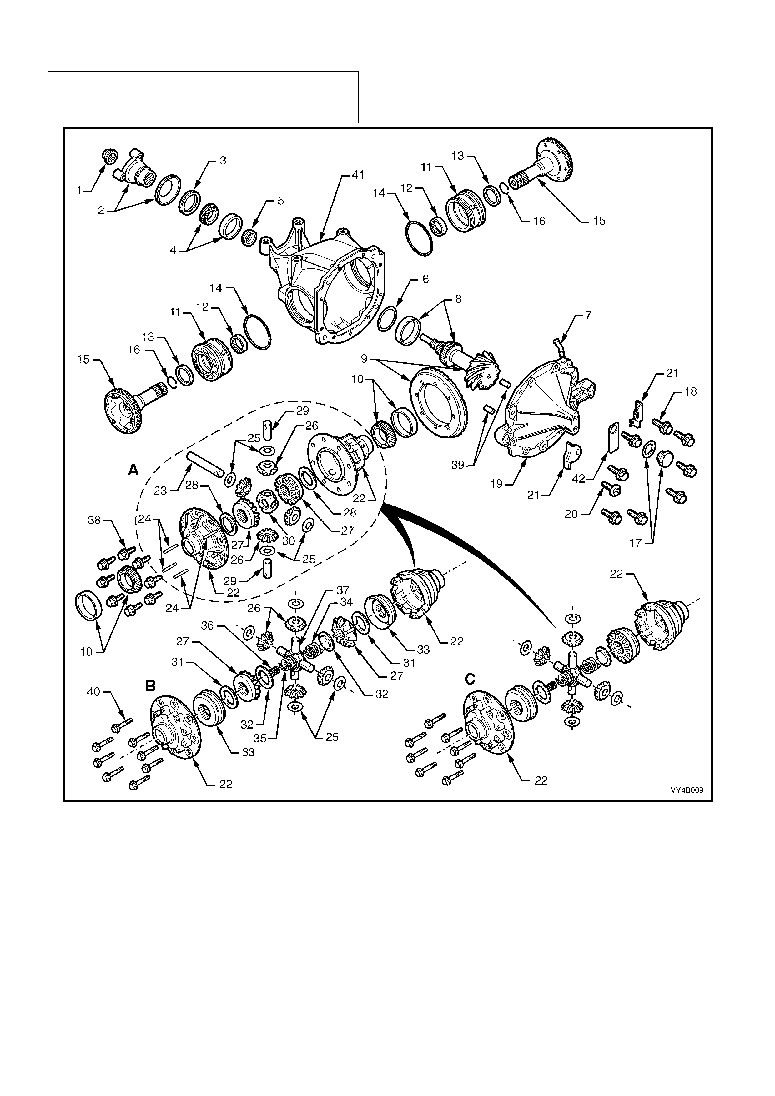
3.3 REMOVED FINAL DRIVE ASSEMBLY
NOTE: The following fasteners MUST be replaced
when performing this operation:
n Final drive ring gear bolts.
Figure 4B-115

Legend
1. NUT – Pinion flange retaining
2. FLANGE ASSEMBLY – Differential pinion
3. SEAL – Rear axle pinion oil
4. BEARING ASSEMBLY – Pinion front
5. SPACER – Pinion bearing
6. SHIM – Pinion position adjusting
7. BREATHER ASSEMBLY – Rear axle
8. BEARING ASSEMBLY – Pinion Rear
9. RING GEAR AND PINION
10. BEARING ASSEMBLY – Differential side
11. SCREW – Differential side bearing adjusting
12. BEARING ASSE MBLY – Inner axle shaft
13. SEAL – Inner axle shaft
14. 'O' RING – Screw adjuster
15. SHAFT – Inner axle
16. CLIP – Inner axle shaft
17. SCREW PLUG & WASHER – Rear axle filler
18. BOLT – Rear cover attaching
19. COVER – Rear axle housing
20. PLUG – Drain
21. PLATE – Lock
22. CASE – Differential
23. SHAFT – Differential pinion gear - long
24. LOCK PIN – Differential pinion shaft
25. WASHER – Differential pinion gear thrust
26. GEAR – Differential pinion
27. GEAR – Differential side
28. WASHER – Differential side gear thrust
29. SHAFT – Differential pinion gear - short
30. BLOCK – Thrust
31. SHIM – Differential side gear (LSD, V6 only)
32. PLATE – Thrust spring (LSD only)
33. CONE – Clutch (LSD, V6 only)
34. SPRING – Differential pre-load - outer (LSD only)
35. SPRING – Differential pre-load -middle (LSD only)
36. SPRING – Differential pre-load -inner (LSD only)
37. SHAFT – Cross (LSD only)
38. BOLT – Ring gear to case
39. PIN – Dowel
44. BOLT – Case cap to cover
41. CARRIER
42. TAG – Lubrication
‘A’ V6 Engine – Non-Limited Slip Differential
‘B’ V6 Engine – Limited Slip Differential
‘C’ V6 Supercharged and GEN III V8 Engine – Limited
Slip Differential
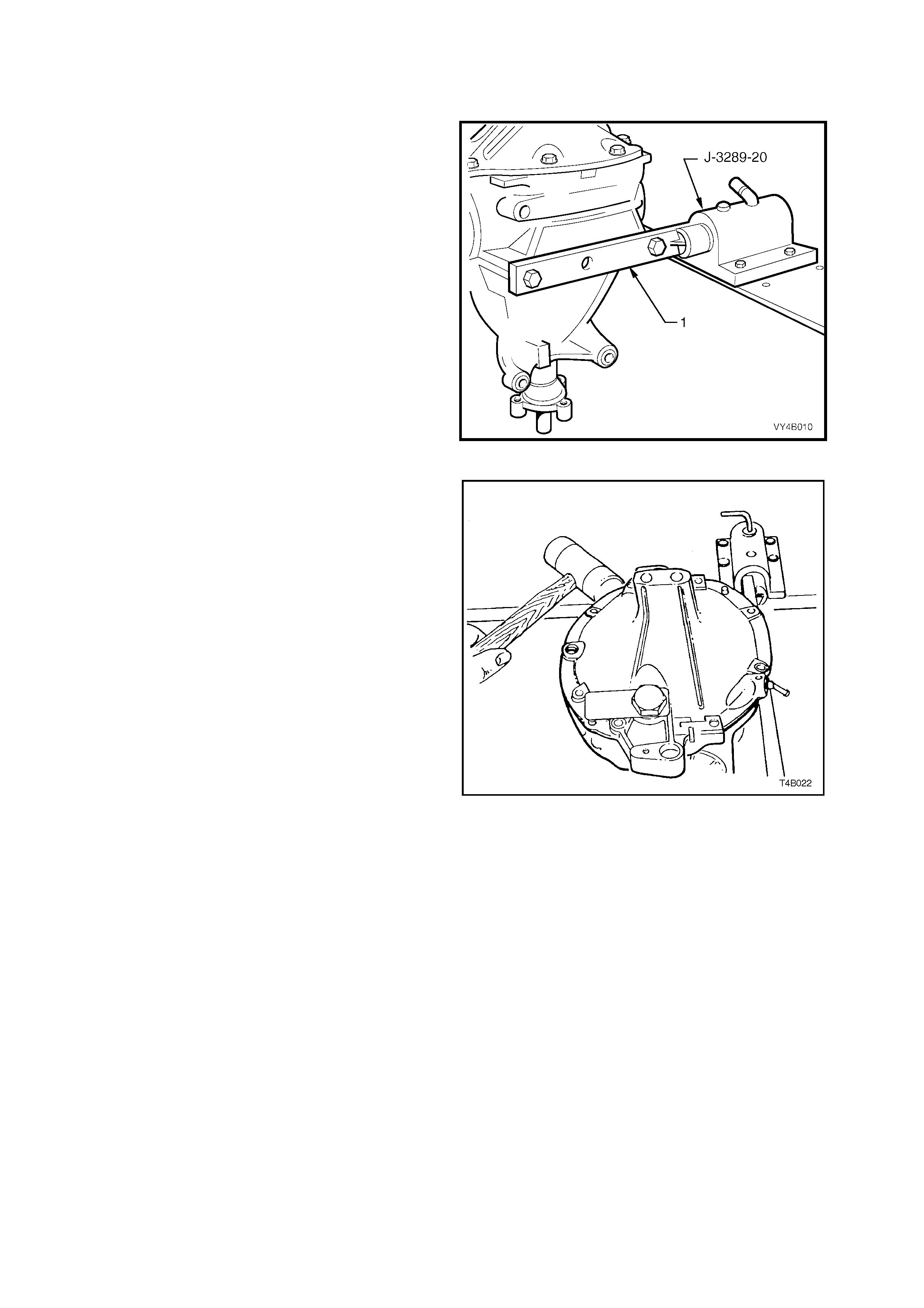
DISASSEMBLE
1. Remove differential carrier assembly. Refer to
3.2 FINAL DRIVE ASSEMBLY in this Section.
2. Secure holding tool (1) that is either fabricated
or Tool No. KM480, to the differential carrier
using tw o of the d iscarded differ ential carrier to
rear crossmember attaching bolts.
For details of holding tool, refer to
7. SPECIAL TOOLS at the end of this Section.
3. Install holding tool into bench mounted fixture
base, Tool No. J-3289-20.
Figure 4B-116
4. Remove rear cover to differential carrier
attaching bolts and screw adjuster lock plates.
Using a soft faced hammer, tap rear cover at
rear mount area to break rear cover to
differential carrier seal. Remove rear cover,
rotate the assembly and drain residual
differential lubricant into a suitable container.
Figure 4B-117
5. Before removing differential case assembly
and drive pinion from differential carrier, the
following inspection procedures should be
adopted. These inspections can help find the
cause of final drive assembly noise and
determine corrections needed.
a. Visually inspect the moving parts for chipped
or scuffed surfaces.
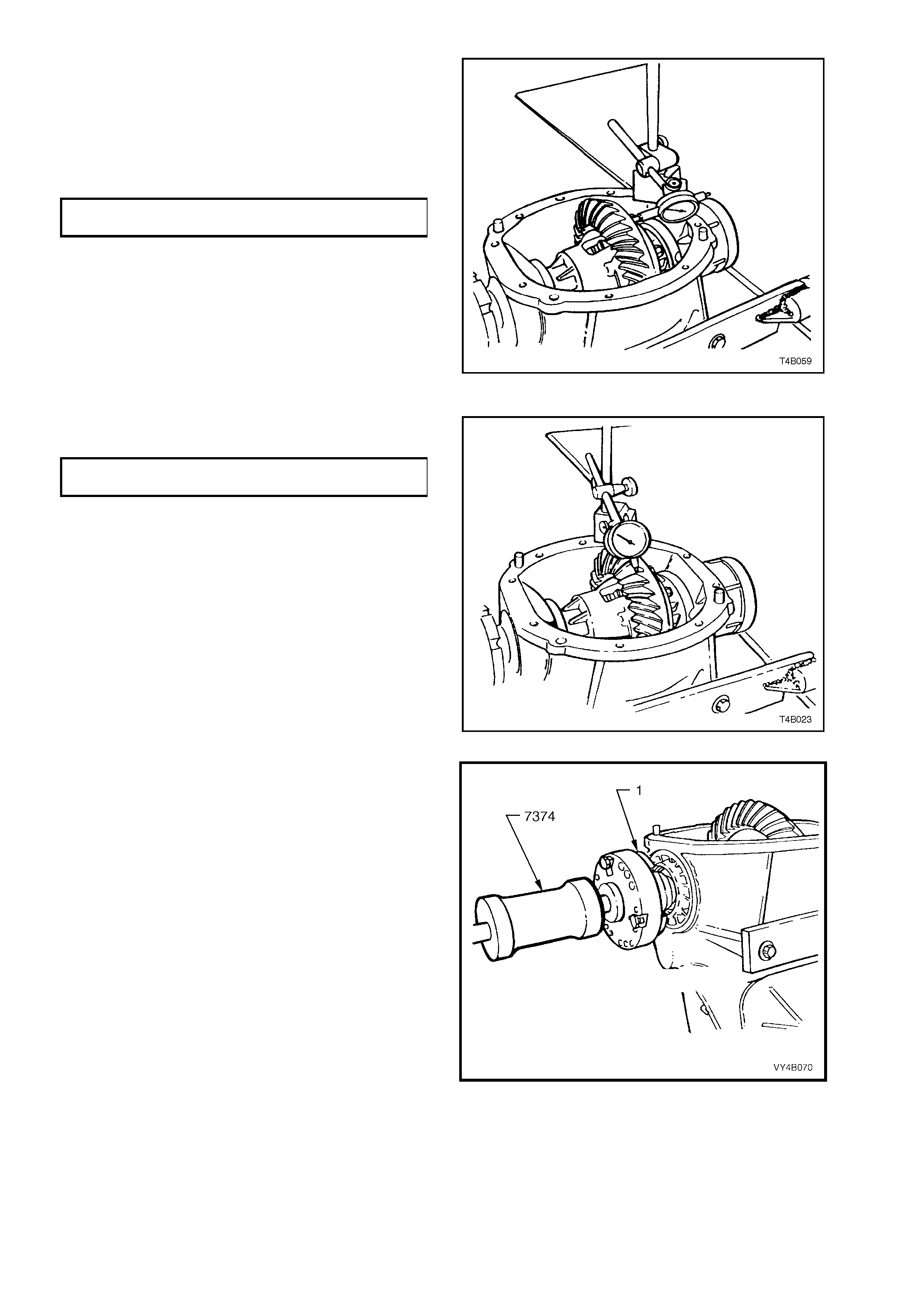
b. Chec k the tor que of th e rin g gear bolts and t he
pinion flange nut.
NOTE: Ring gear bolts have a left hand thread.
c. Mount a dial indicator to read from the rear
face of the ring gear, the n r otate the diff erentia l
case through several turns to measure ring
gear run-out.
RING GEAR FACE
RUN-OUT SPECIFICATION 0.13 mm maximum
d. Leave the dial indicator set up and push the
ring gear har d one wa y, then hard the oppos ite
way to measure side play. There should be no
side play present.
Check to ensure that there is no pinion end
play.
If end play is evident, then special attention
should be made to the bearing inspection
process, after disassembly.
Figure 4B-118
e. Set up the dial indicator to measure ring gear
backlash at three equally spaced positions.
BACKLASH SPECIFICATION 0.10 - 0.18 mm, at
the tightest point
f. If no obvious faults are found, check the gear
tooth contact pattern. Refer to Ring Gear and
Pinion Contact Pattern in this Sectio n.
Figure 4B-119
6. Remove inner axle shafts (1) by installing a
slide hammer, Tool No. 7374 and three
suitable size bo lts to each axle flange . Use the
slide hammer to release axle shaft spring clips.
NOTE: The left hand inner axle shaft is shorter in
length than the right hand shaft.
Figure 4B-120

7. If new screw adjuster seals are to be installed,
use a suita ble scre wdriver and a b lock of wood
to lever out seals from screw adjusters.
NOTE: Take care not to damage the screw
adjuster's aluminium housing with the screwdriver
blade, as th is c ou ld ca us e oil l eaks to occ ur , af ter a
new oil seal is fitted.
Figure 4B-121
8. Remove screw adjusters from housing using
Tool No. 205-463 (also released as AU407).
9. Remove dif ferential c ase a ss embl y from car rier
housing.
Figure 4B-122
10. To remove side bearing cups from screw
adjusters, install screw adjusters, reversed,
into dif ferential c arrier. Inst all ada ptor, Tool No.
AU412 onto screw adjuster. Using puller, Tool
No. 1150, a nd forc ing screw T ool No. E6 661S,
pull side bearing cups from screw adjusters
and discard.
NOTE: Side bear i ng cups a r e only to be removed if
side bearing assemblies are to be replaced.
Figure 4B-123
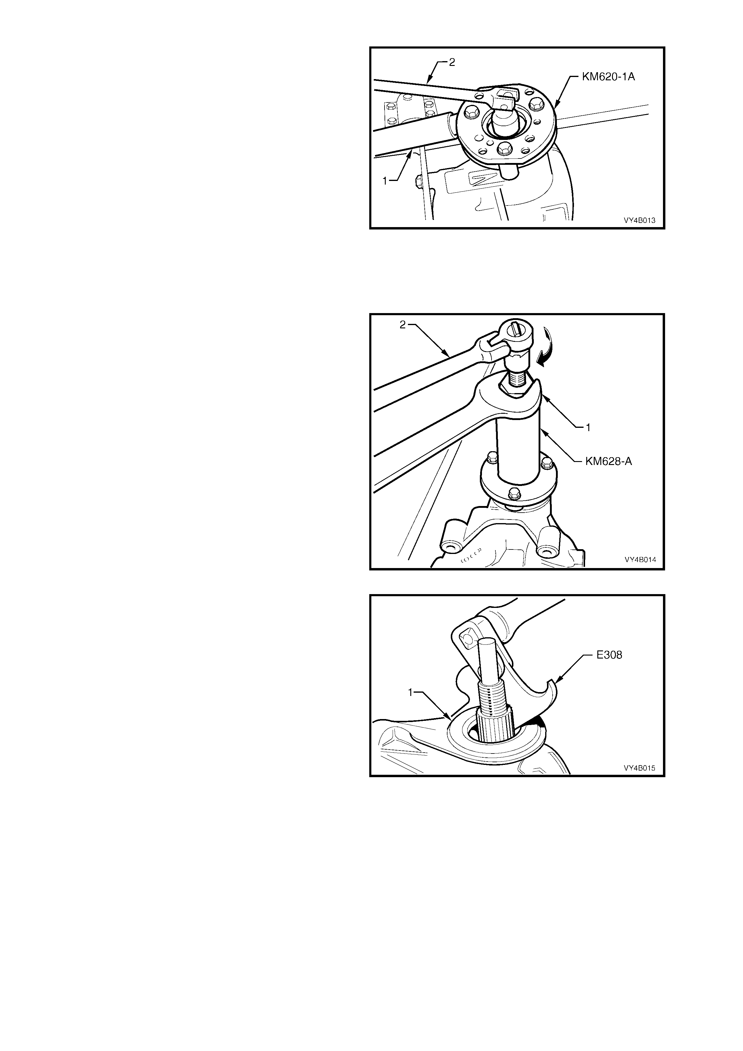
11. Install Tool No. KM620-1A to the pinion flange
using three suitable bolts.
NOTE 1: Use either the rear coupling to pinion
flange r eta in ing bo lts with a 25 m m spac er (e.g. f lat
washers) insta lled firs t or u se three b olts M 12 x 1.5
x 40,with the thread extending to within 12 mm of
the head.
NOTE 2: If not previously done so, drill out holes
stamped ‘B’ on Tool No. KM620-1A, to 12.5 mm.
12. W hile holding KM620- 1A with a suitable length
of pipe (1) over the tang, loosen and remove
pinion flange retaining nut, using a
commercially available deep socket and
bar (2).
Remove flange holding tool KM620-1A from
pinion flange.
Figure 4B-124
13. Install extractor, Tool No. nut KM628-A to the
pinion flange, using the same three bolts used
in step 11.
NOTE: If not previously done so, dr ill out the three
flange holes on Tool No. KM628-A, to 12.5 mm.
14. W hile holding KM6 28-A with a set spann er (1),
use suitable socket equipment (2) to withdraw
the pinion flange by tightening the forcing
screw in the direction indicated.
Figure 4B-125
15. Pry pinion oi l s eal out of c arr ier bor e us ing Tool
No. E308 or a suitable seal extraction tool.
Figure 4B-126
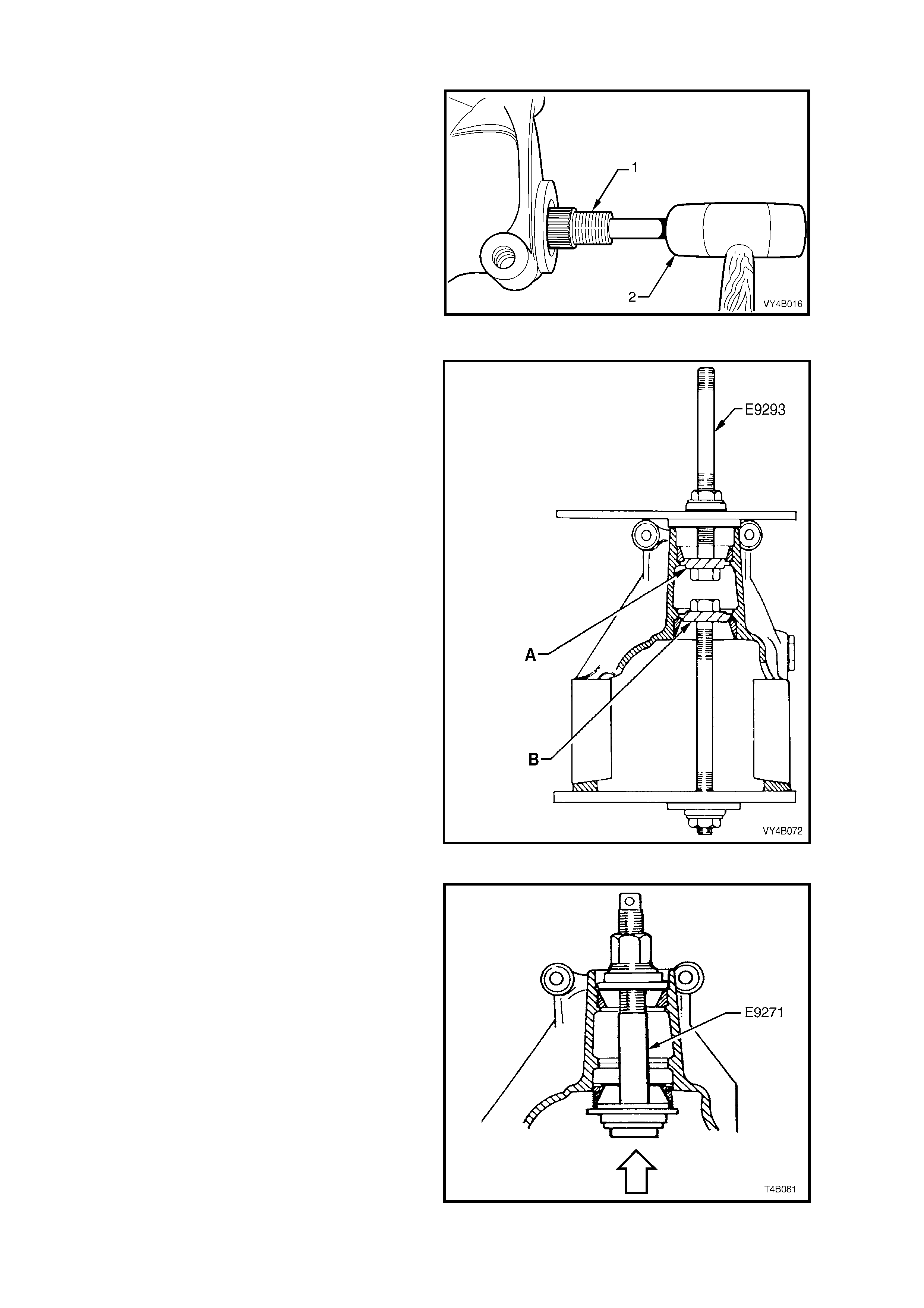
16. Remove pinion (1) by tapping on front end with a
soft faced hammer (2) to withdraw it through rear of
carrier. Remove pinion front bearing from carrier
bore. Remove and discard pinion bearing spacer.
Figure 4B-127
17. If pinion bearings are to be replaced, remove
bearing cups using Tool No. E9293.
NOTE 1: View ‘A’ shows the tool arrangement to
remove the front (outer) pinion bearing cup, while view
‘B’ shows the arrangement to remove the rear (inner)
bearing cup.
NOTE 2: When removing the rear (inner) pinion bearing
cup from 3.07 and 3.46 assemblies, the adaptor 'B' to
be used with E9293, is DT-47695.
NOTE 3: As the installation tool (E9271) relies on an
installed bearing cup for alignment, it is essential that
only one bearing cup is replaced at the one time. Use of
installer E9271 is shown in Fig. 4B-129.
Figure 4B-128
18. To install a new, rear (inner) pinion bearing cup,
use installer Tool No. E9271 with adaptor E9271/B,
as shown. The same arrangement is used to install
a new front (outer) pinion bearing cup, using
adaptor E9271/A (or 205-552-1).
NOTE: When installing the rear (inner) pinion bearing
cup to 3.07 and 3.46 assemblies, the adaptor to be
used with E9271, is 205-552-2.
Figure 4B-129
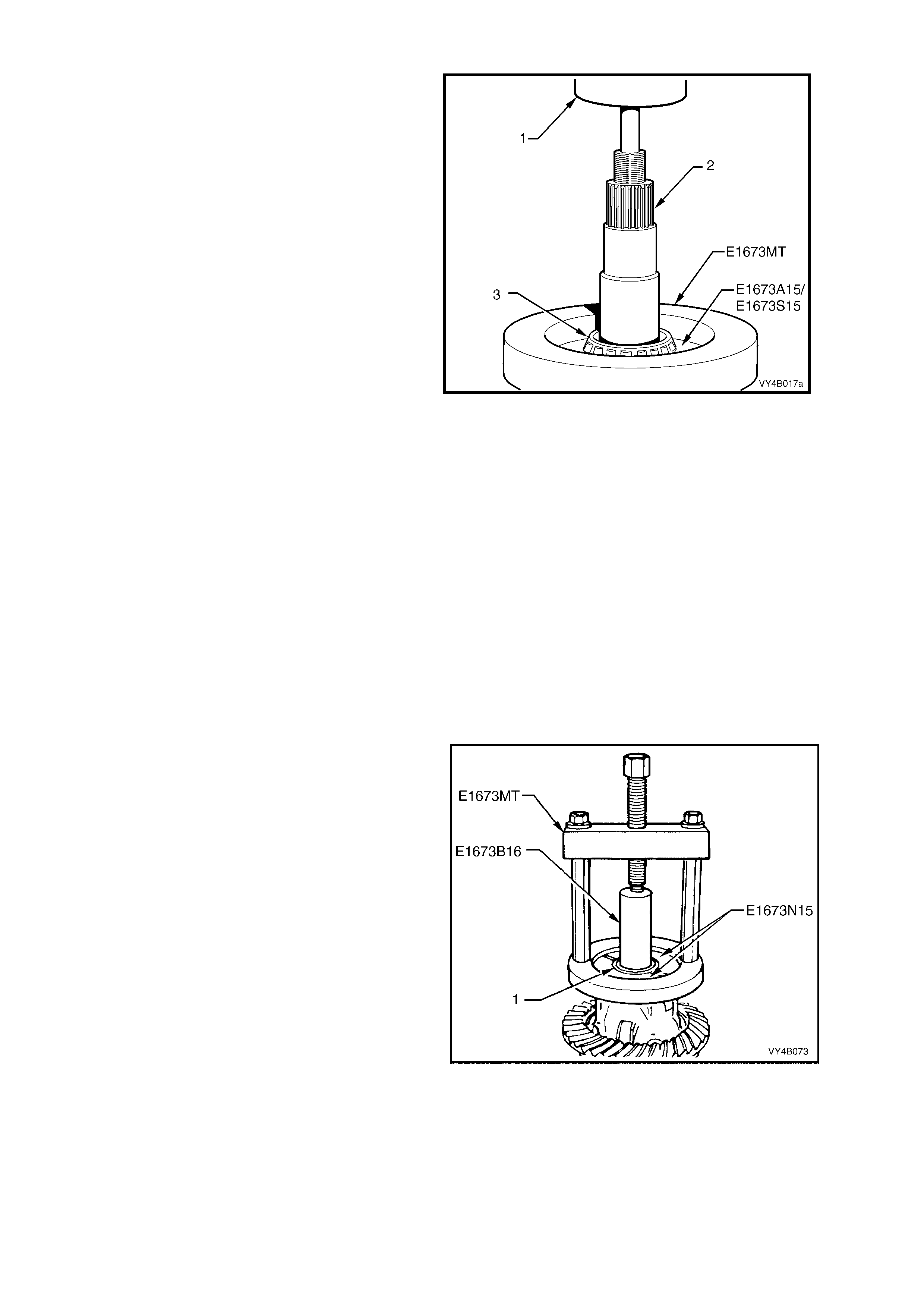
19. To remove rear (inner) bearing from pinion, remove
legs from the ring of Tool No. E1673MT.
20. Place ring on suitable press plates. Install pinion
and adaptors E1673A15 (3.08:1 assembly) or
E1673S15 (3.07/3.46:1 assembly) into the ring.
Press pinion from bearing .
NOTE: With the larger pinion head size on the
3.07/3.46:1 assemblies, the ring must be placed over
the bearing first, then the adaptors manoeuvred into
place under the bearing cone.
21. Discard the removed bearing.
Figure 4B-130
Differential Case
The following procedures describe the standard type differential
case assembly. For Limited Slip Differential case assembly, refer
to 3.4 LIMITED SLIP DIFFERENTIAL in this Section.
NOTE: The 3.07:1 and 3.46:1 ratio differentials are unique and
parts are not interchangeable with the 3.08:1 ratio unit. The
general overhaul procedures however, remain the same for both
types. The unique components for the 3.07:1 and 3.46:1 ratio
differentials are; differential case, differential pinions, side gears
and thrust block.
1. Before disassembling the differential case, inspect differential
side bearings for any signs of damage.
IMPORTANT: The side bearings can be manufactured by either
one of two manufacturers; Timken or Koyo. When replacing the
differential side bearings, the two bearings and cups must be of
the same brand. The pinion bearings may be of a different
manufacture but again, they must be a matched pair. The reason
for matched pairs of bearings is that a different preload
specification is required for each brand.
2. If necessary, use Tool No. E1673MT, adaptors
E1673N15 and stepped plug E1673B16 to remove
side bearings from differential case, as shown.
Discard side bearings once they are removed.
To remove side bearing cups, refer to FINAL DRIVE
ASSEMBLY – Disassemble, step 10.
Figure 4B-131
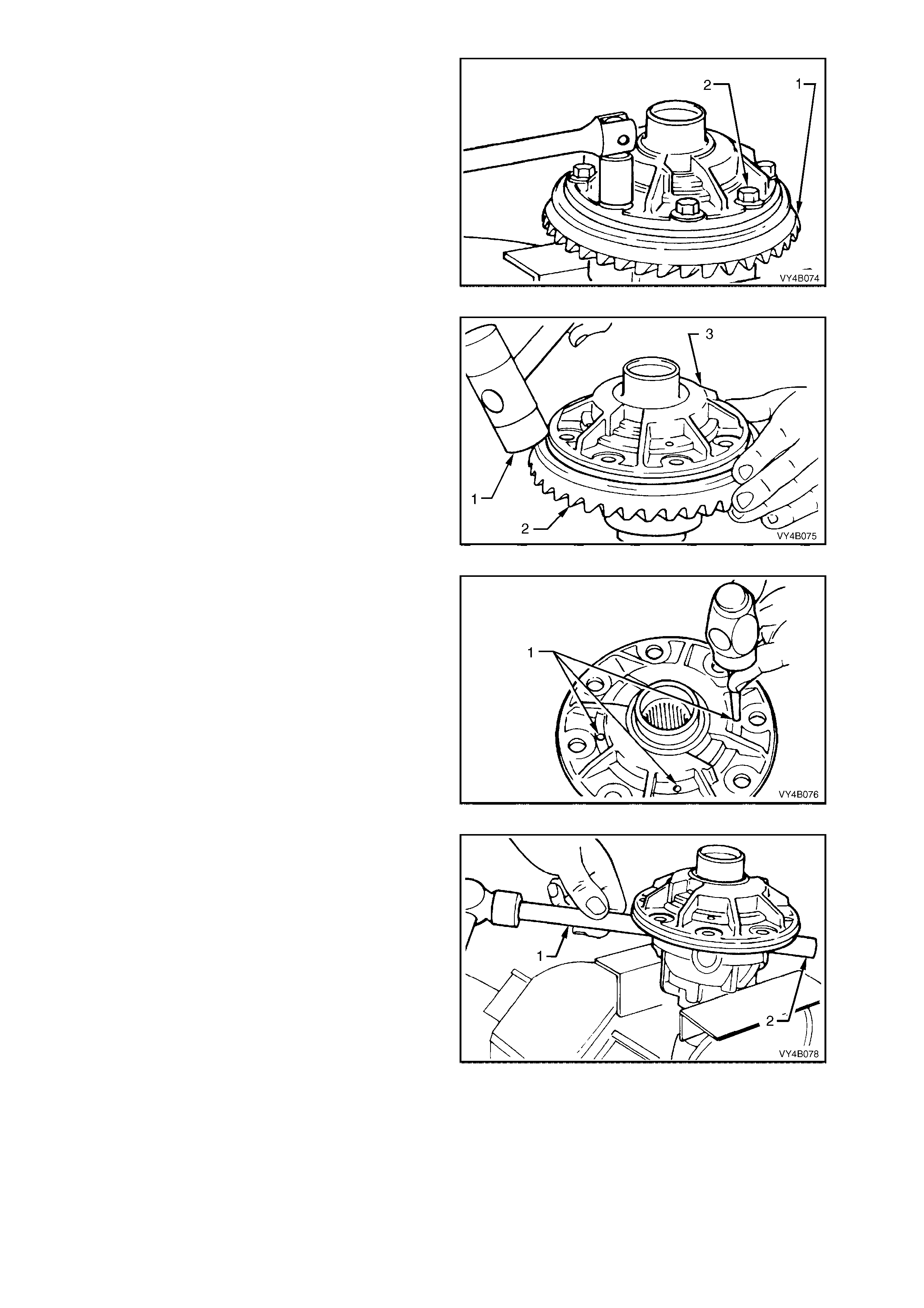
3. Grip the differential case in a vice with soft
jaws.
4. Remove ring gear (1) attaching bolts (2).
NOTE: Ring gear attaching bolts (2) use a left
hand thread and are identified by an 'L' on the bolt
head.
5. Remove differential case from vice.
Figure 4B-132
6. Using a soft faced hammer (1), remove ring
gear (2) from differential case (3) by hitting
down on ring gear. Support ring gear during
this operation so that it does not strike bench
top as it comes free of case.
NOTE: Do not use a screwdriver to prise between
ring gear and case.
Figure 4B-133
7. Drive out differ ential pinion gear lon g shaft and
short shafts retaining pins (1) from differential
case, using a suitable size pin punch and
hammer.
Figure 4B-134
8. Re-mount the differential case in vice with soft
jaws. Usin g a brass drif t (1) and ham mer, dr ive
out pinion long shaft (2) from differential case.
Figure 4B-135

9. Remove differential case (3) from vice. Using a
brass drift (1) and hammer (2), separate two
differential case halves by driving against
thrust block.
NOTE: Do not use a screwdriver to prise the
differential case halves apart.
Figure 4B-136
10. Using a brass drift (1) and hammer, drive out
pinion gear short shafts (2) from differential
case.
Figure 4B-137
11. Lift out pinion gears (1), thrust washers and
thrust block (2) from differential case.
Remove differential side gears and thrust
washers from differential case halves.
NOTE 1: When removing the thrust block from
either th e 3.07:1 or 3.46: ra tio dif ferential, note that
the pinion shafts are angled at 96° and not 90° as
is usual.
NOTE 2: Keep the gears with their respective
thrust washers in pairs so they can be reinstalled in
their original position.
Figure 4B-138
INSPECT
All components should be thoroughly cleaned and dried, then inspected.
Differential Case
Check case for general soundness and pay particular attention to the following points;
1. If diff erential cas e side bear ings have be en rem oved, chec k case j ournals f or dam age and th at bear ing sea ting
surfaces are free from dirt and burrs.
2. The ring gear spigot and mounting face should be clean and free from dirt and burrs.
3. The mating surfaces for differential case halves should be clean and free from burrs.
4. The thrust surfaces for differential side gears and pinions should be examined for excessive wear.
5. The differential side gear journal bores should be clean and free from scoring.
6. The case bores for differential pinion gear shafts should be checked for ovality.
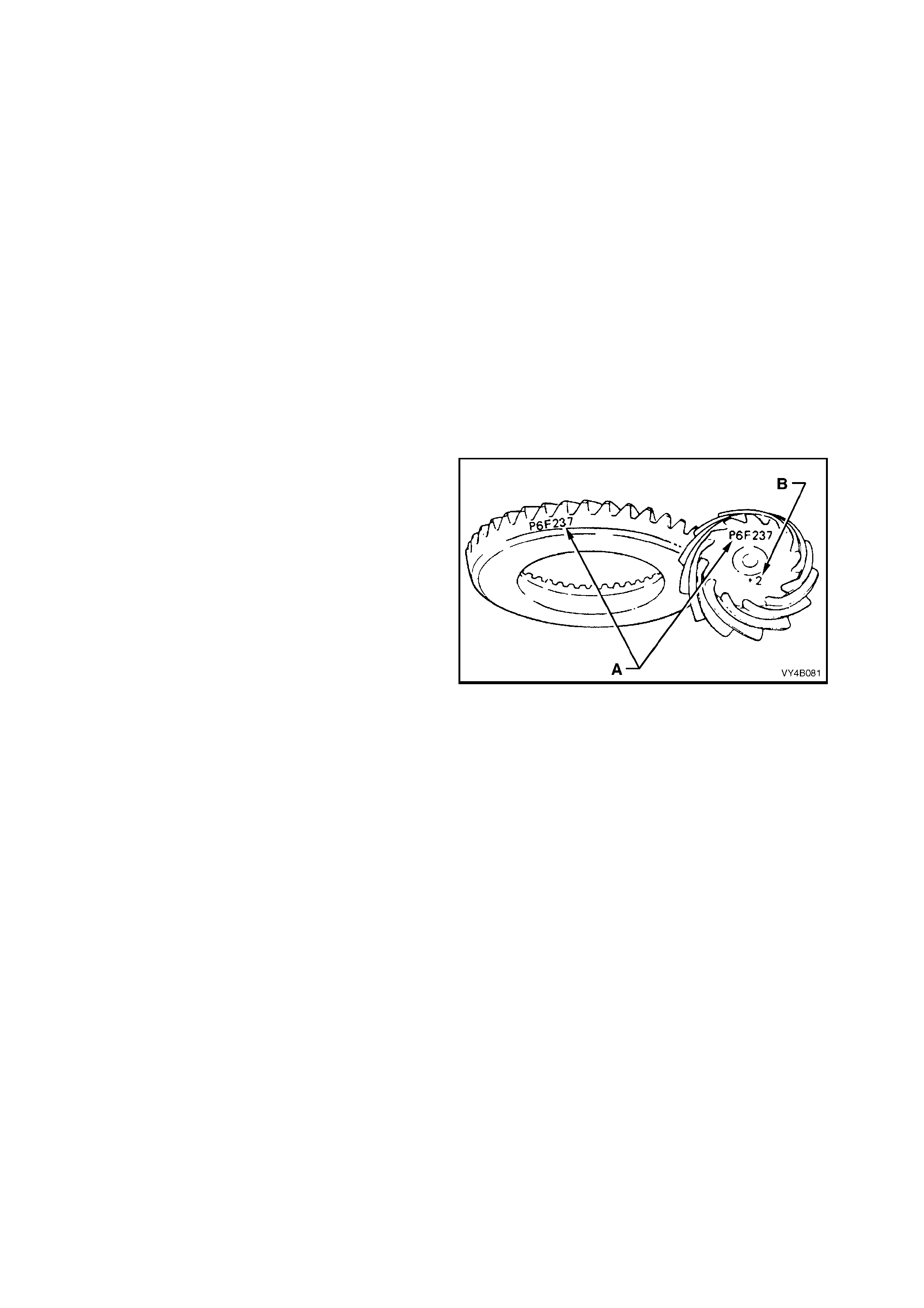
Differential Side Gears and Pinion Ge ars
1. Examine all gear teeth for cracks and hard contact marks.
2. The differential side gear splines should be checked for excessive wear. Wear on splines can contribute to
excessive driveline backlash.
3. Check differential side gear journals and back faces for scoring.
4. Check fit of differential side gears in differential case cap and cover. Wear on side gear hubs or in the case
bores can cause a "clunking" noise in rear axle assembly when vehicle is driven at low speeds.
5. Inspect differential pinion bores and thrust surfaces for scoring. Also check differential pinion gear shafts are
not bent and that surfaces where pinions run are not worn or scored.
6. Check thrust washers. They should be f ree from cracks, nicks and burrs. Excessive wear of thrust washers or
pinion gear thrust surfaces can also contribute to excessive driveline backlash.
7. Check thrust block pinion gear shaft bores for ovality.
Ring Gear and Pinion
1. Inspec t gear teeth f or scoring or damage. Scor ing of gear t eeth is usu ally caused b y excessive s hock loadi ng,
use of inc orrect lubr icant or ins uffic ient "run in" befor e towing a heav y load. (Refer MY2003 VY Seri es Owner' s
Handbook). Scored gears must be replaced.
2. The ring gear bore and back face should be clean and free from burrs.
3. The rear bearing seating surface on the pinion should be clean and free from burrs.
4. Inspect pinion splines and flange splines for evidence of wear.
5. Inspect thread and bearing journals of pinion
for damage.
6. If on reassembly, a new gear set is to be
installed, ensure that the same matching
number appears on both the pinion and ring
gear, as shown by ‘A’. The pinion installation
marking figure is indicated by ‘B’.
7. On ring gear bolts, clean the serrations under
each bolt flange.
Figure 4B-139
Bearings
1. Bearing cups should have an even wear pattern and must be free from flaking or pitting. Ensure that seating
surfaces are clean and free from burrs or raised metal.
2. The bearing assemblies should feel smooth when turned in their cups.
3. The assembly should be free from loose particles.
4. No cracks should be present in roller cages, and bores should show no evidence of flaking or pitting.
Refer to 4.4 FINAL DRIVE BEARING DIAGNOSIS in this Section, for identification of bearing failures.
Differential Carrier
1. Check casting all over for general soundness.
2. Examine oil passages and ensure they are free from obstructions and loose particles.
3. The bore for the pinion oil seal should be free from burrs.
4. Inspect rear cover face and bolt holes for damage.
5. Check rear cover seating surface for scoring or other damage.
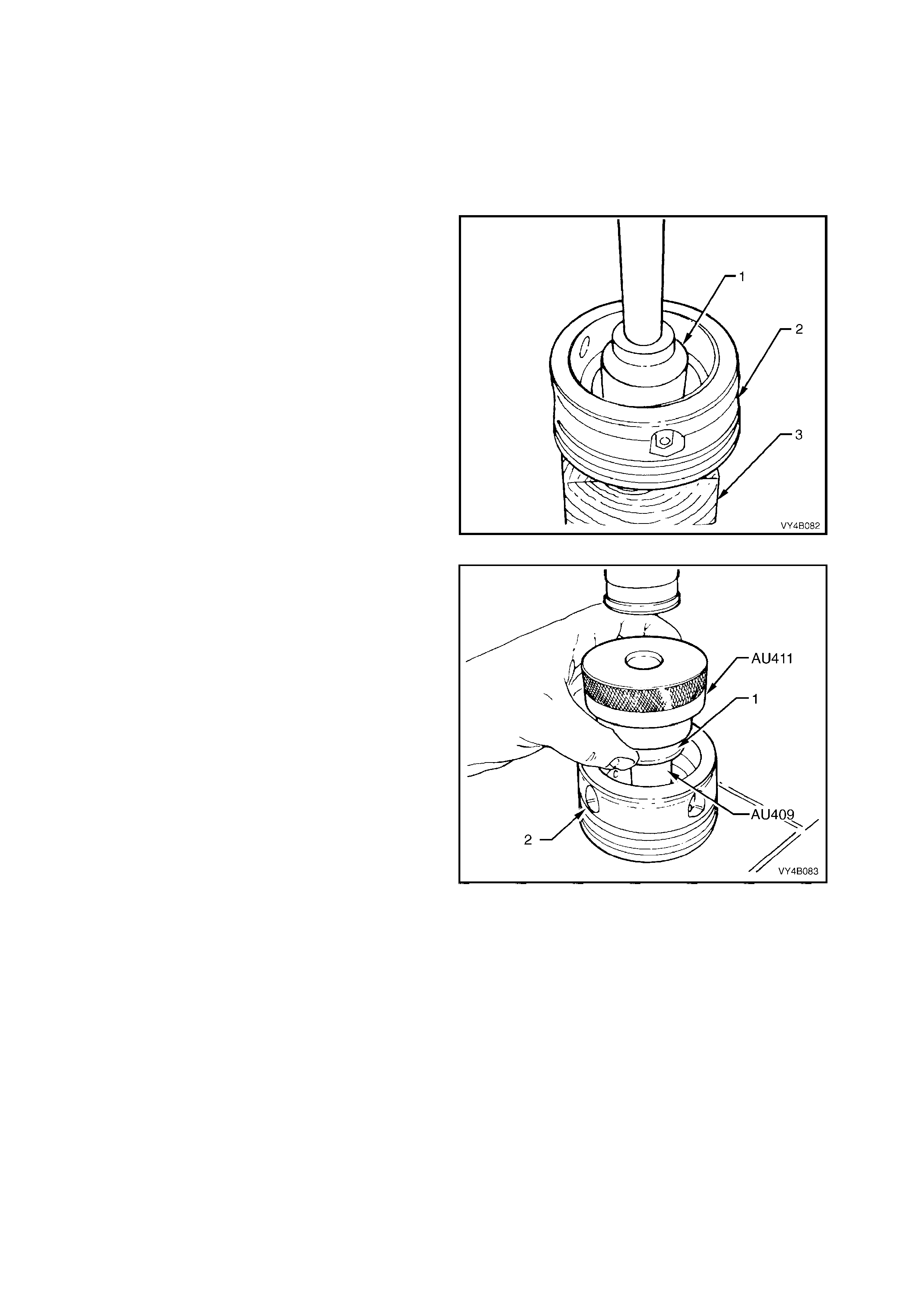
Screw Adjusters and Inner Axle Shafts
1. Inspect inner axle shaft needle bear ings inside
screw adjusters for wear or damage.
2. If inner axle shaft needle bearings are to be
replaced, reinstall screw adjusters into
differential carrier and remove inner axle shaft
seals. Refer to Step 7 of FINAL DRIVE
ASSEMBLY – Disassemble.
Remove screw adjusters (2) from carrier and
position each onto a block of wood (3). Then,
using a 1.25 inch socket (1) and bar or a 73
mm diameter tube, press the bearing from
each of the screw adjusters (2).
3. Remove and discard O-rings from screw
adjusters.
4. Exam ine adjuster seal bore s for burr s, nicks or
other damage. Examine oil passages and
ensure they are free from obstructions and
loose part icles .
Adjuster thread and bearing bores should be
clean and free from burrs or other damage.
Figure 4B-140
5. To install new screw adjuster needle bearings,
place screw adjuster (2) over fixture, Tool No.
AU409 and press needle bearing (1) into
adjuster (2) using Tool No. AU411. Repeat
procedure for the remaining screw adjuster.
NOTE 1: Side bearing cups must be installed into
screw adjusters before installing needle bearings.
This is to ensure that needle bearings are located
correctly into screw adjuster bores.
NOTE 2: To install side bearing cups, refer to
step 1, Differential Case Side Bearing Pre-Load
Setting, in this Section.
Figure 4B-141
6. Examine seal surface of inner axle shafts and
carefully remove any nicks or burrs.
Should this surface be irreparable on either
axle shaft, a new axle shaft must be fitted.
7. Check spring clip in end of inner axle shafts to
ensure that they are not damaged and move
freely in grooves. Replace spring clips if
necessary, by expa nd ing ends of each c li p and
removing from inner axle shafts. Expand ends
of new cli ps suf fic iently to allo w ins tallat ion in to
axle shaft grooves.
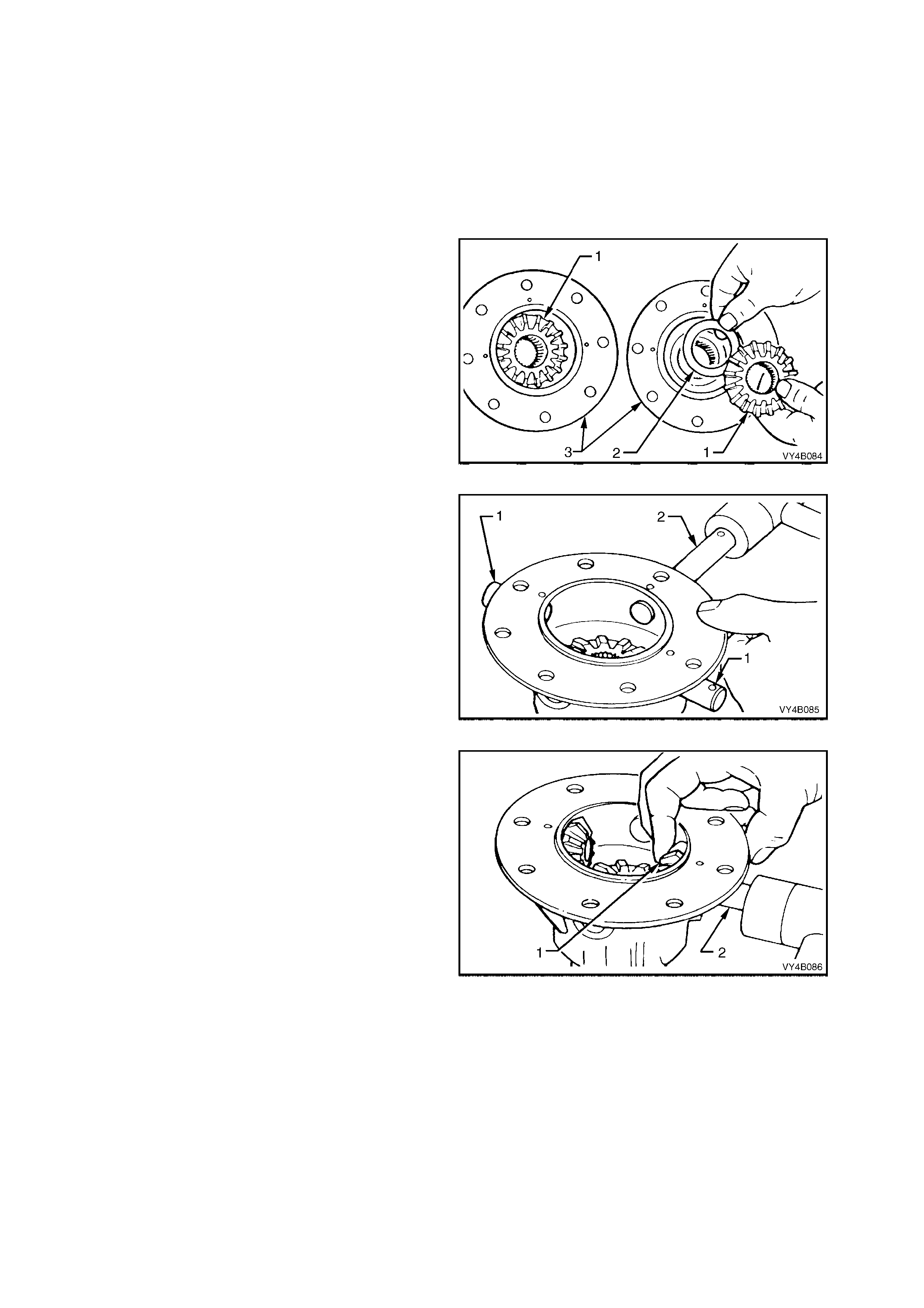
Rear Cover
1. Clean sealant from rear cover sealing surface.
2. Inspect rear cover for cracks or damaged
sealing surface.
3. Ensure breather passage is clean and free of
obstructions.
REASSEMBLE
Differential Case
1. Lubricate all differential gears, bearings, thrust
washers and d iffer ential pin ion gear shaf ts with
the recommended rear axle lubricant before
assembly.
2. Position differential side gears (1) with their
thrust washers (2) into differential case halves
(3).
Figure 4B-142
3. Using a soft faced hammer, reinstall pinion
gear short shafts (1) and long shaft (2) into
differential case, just enough to allow a pinion
gear thrust washer to sit on the end of each
shaft.
NOTE: Ensure that the retaining pin holes in the
differential case and pinion gear shafts are in
alignment and with the chamfered edge of the
holes in each shaft facing up.
Figure 4B-143
4. Install one of the pinion gear thrust washers
over inside end of one of the short shafts.
5. Position appropriate pinion gear (1) next to
thrust washer and tap in short shaft (2) until it
comes through centre of the gear (1).
6. Carr y out steps 4 and 5 for second pinion gear
short shaft.
Figure 4B-144
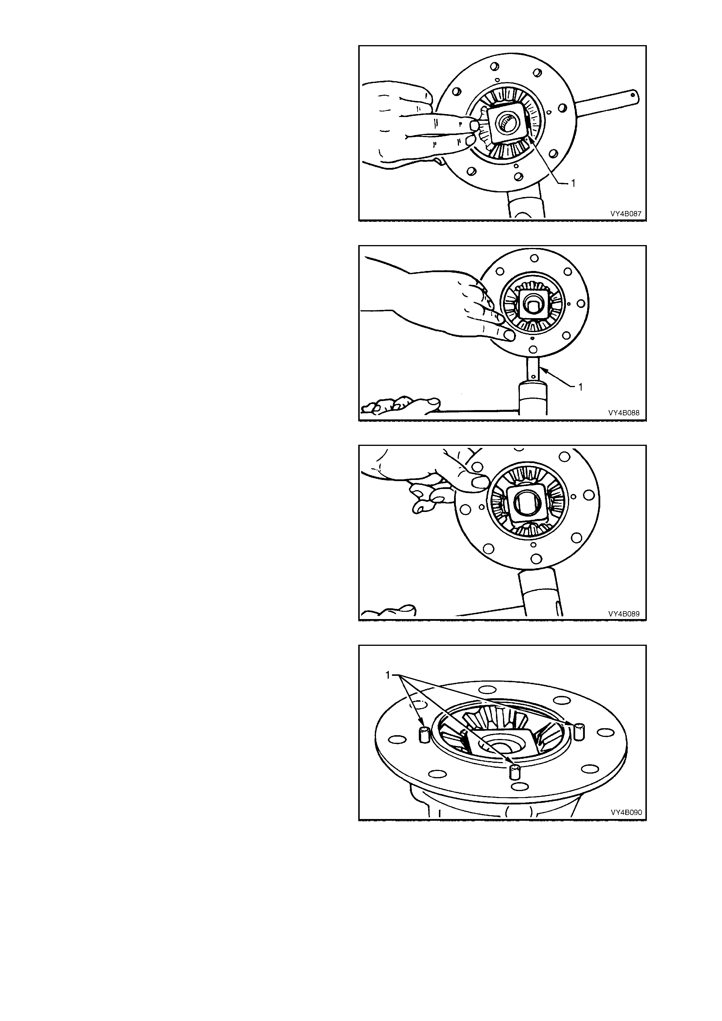
7. Reinstall thrust block (1) between two installed
pinion gears. Knock the two pinion gear short
shafts into position, ensuring that retaining pin
holes in the shafts line up with holes in
differential case.
Figure 4B-145
8. Install pinion gear thrust washer and gear to
long shaft (1). Tap long shaft (1) through gear
and thrust block.
Figure 4B-146
9. Reinstall remaining pinion gear and thrust
washer. Tap long shaft through pinion gear,
ensuring that thrust washer aligns with cross
shaft and the retaining pin hole in the shaft
aligns with hole in differential case.
Figure 4B-147
10. Install pinion gear long shaft and short shaft
retaining pins. Ensure that ends of retaining
pins (1) protrude 6 mm from differential case
cap to cover mating surface. This is necessary
to prov ide a posit ive locatio n for the d ifferential
case cover to case cap.
Figure 4B-148
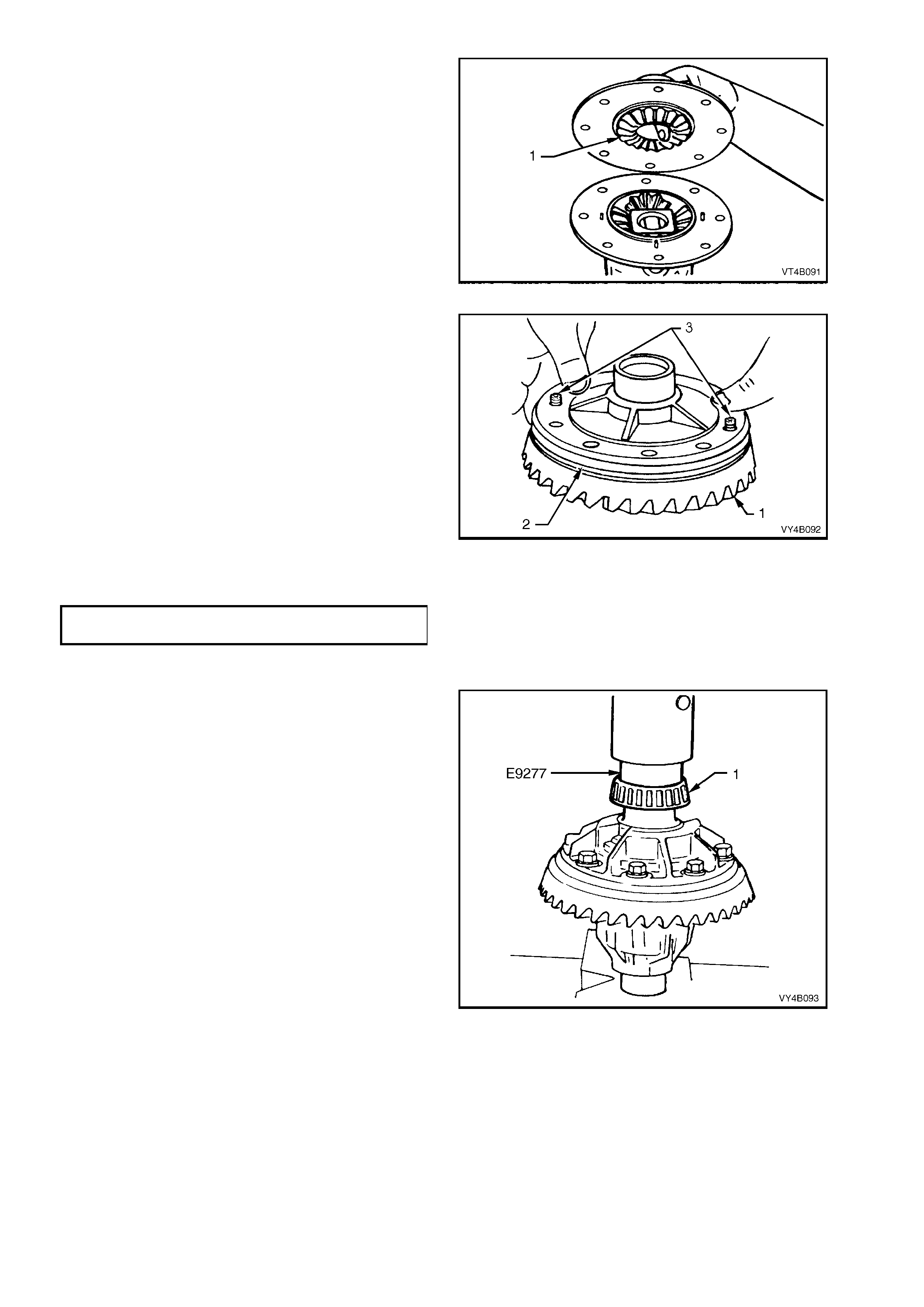
11. Holding differential side gear (1) in position
with a finger through differential case cover
bore as shown, push the two differential case
halves together, locating on the protruding
retaining pins.
Figure 4B-149
12. Place ring gear (1) into position on differential
case cap (2) and install ring gear attaching
bolts.
NOTE 1: For ease of assembly, it may be
necessar y to heat the ring gear on a hot plate until
it is hot to the hand, prior to installing onto the
differential case cap.
NOTE 2: On no account must a flame be used to
heat the ring gear.
NOTE 3: Use left hand threaded guide pins (3) to
pilot the ring gear over the differential case spigot.
13. Install and gradually tighten NEW ring gear
attaching bolts evenly, until gear face is flush
with diff erential case sp igot. Tighten a ll bolts to
the correct torque specification.
FINAL DRIVE RING GEAR
BOLT TORQUE SPECIFICATION 125 - 150 Nm
NOTE: Ring gear attaching bolts use a left hand
thread and are identified by an 'L' on the bolt head.
Figure 4B-150
14. If installin g n ew side b eari ngs (1), us e Tool N o.
E9277 to press on side bearings to differential
case journals.
NOTE: Check that both nearing assemblies are of
the same manufacture – Timken or Koyo.
Figure 4B-151
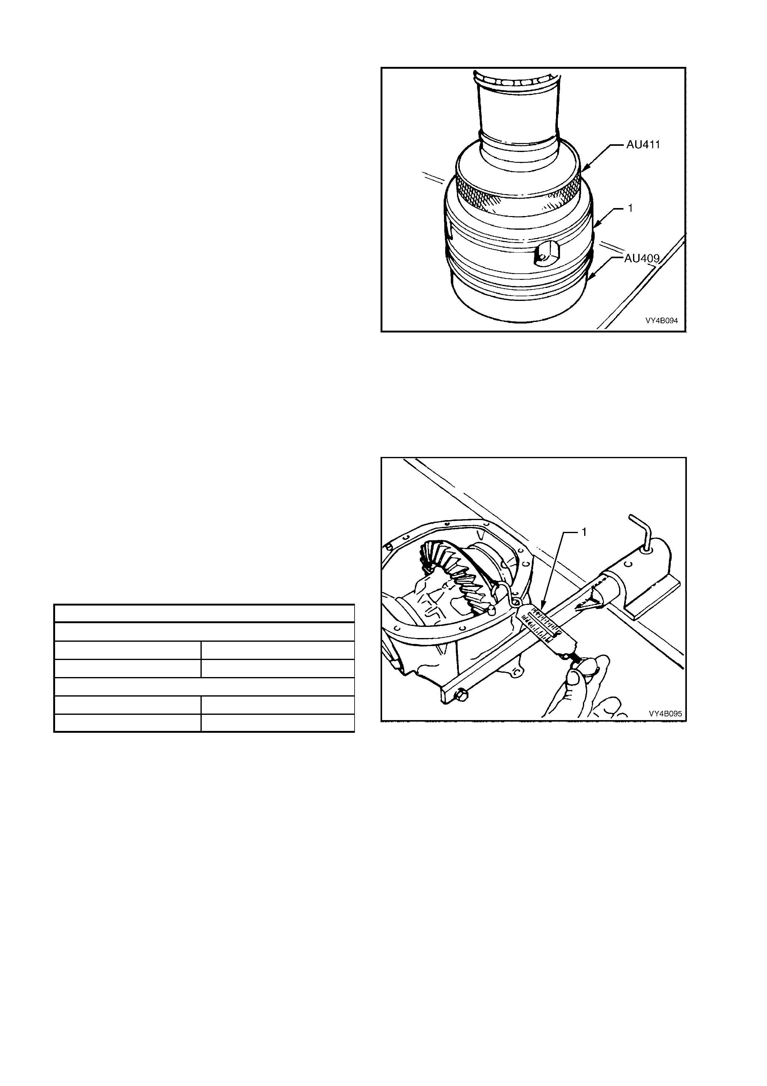
Differential Case Side Bearing Pre-Load Setting
1. If removed during disassembly, press new
bearing cups into screw adjusters firmly to the
shoulder by positioning screw adjuster onto
Tool No. AU409 and using Tool No. AU411 to
press new cup into place. Repeat procedure
for remaining screw adjuster.
NOTE 1: Ensure that bearing side and cup
ma tching is m aintained a nd that t he pair of bear ing
assemblies are of the same manufacture – either
Timken or Koyo.
NOTE 2: The screw adjuster used on either the
3.07 or 3.46:1 ratio final drives is 1.9 mm deeper
than the one used for 3.08:1 ration unit. The
deeper screw adjuster can be identified by a
groove on the inner edge.
This depth change is necessary to accommodate
the greater s ide be arin g span us ed wit h the 3.0 7 or
3.46:1 ratio final drives assemblies.
2. Install new O-rings to screw adjusters and
apply a lubricant such as rubber grease to
each.
3. While s upportin g the dif fer ential c ase in carr ier,
fit screw adjusters to both sides of carrier.
Continue tightening adjusters until case
assem bl y is supported b y side bear ings .
Figure 4B-152
4. Rotate diff erential c ase se ver al tim es to ensure
that side bearings are correctly seated.
5. Wrap a piece of string around differential case
flange and check side bearing pre-load by
pulling on end of string with a spring balance
(1). Spring balance reading must be within
specification.
Tighten or loosen one of the screw adjusters
until the correct pre-load is obtained.
SIDE BEARING PRE LOAD SPECIFICATION
New Bearings
Timken Koyo
15 – 35 N 8 – 24 N
Used Bearings
Timken Koyo
8 – 18 N 5 – 13 N
Figure 4B-153
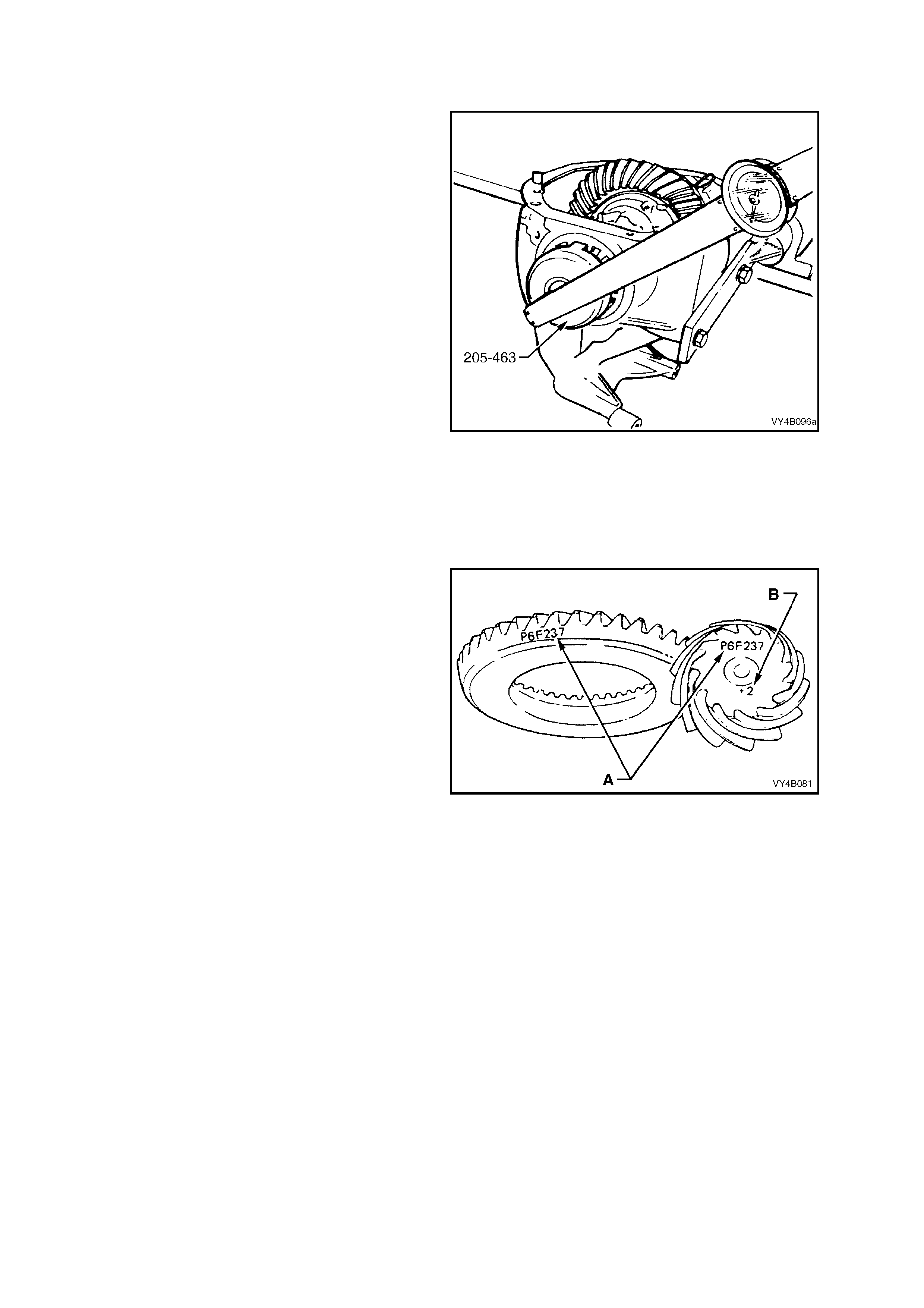
6. Using Tool No. 205-463 (or AU407) and a torque
wrench, measure tightening torque of each screw
adjuster (usually within the range of 50-60 Nm) and
record.
These torque readings will be used to set bearing
pre-load on final assembly.
7. Using Tool No. AU407, loosen and remove screw
adjusters, remove differential case assembly.
Figure 4B-154
Hypoid Pinion Positioning Shim Selection
The pinion positioning shim is located between pinion rear bearing cup and carrier housing.
If the ring gear and pinion or the pinion rear bearing assembly are replaced, pinion depth must be rechecked with pinion
setting gauge, Tool No. E9300A (previously released as E9300), dummy pinion spacer, Tool No. DT-47696 and dummy
arbour Tool No. AU408.
The gauge and arbour provide a nominal or 'zero' pinion
as a gauging reference.
NOTE 1: If a new gear set is to be installed, ensure that
the same matching number (‘A’) appears on both the
pinion and the ring gear, in either white or yellow marker.
NOTE 2: The pinion installation marking figure is
indicated by ‘B’, in either white or yellow marker.
NOTE 3: The final drive pinion fitted to the 3.07:1 and
3.46:1 ratio assemblies, has a different mounting
distance to the 3.08:1 pinion (102.50 mm and 94.49 mm
respectively). Also, as the 3.07:1 and 3.46:1 ratio, final
drive assemblies have a different rear pinion bearing,
gear set sizes, differential case assemblies and screw
adjusters, none of these parts are to be mixed.
Figure 4B-155
8. Inspect pinion bearing cups/cones for nicks and burrs.
Replace if damaged.
9. Lubricate pinion front and rear bearings with the
recommended differential carrier lubricant. Do not use
engine or other oils, as a misleading rotating torque can
be obtained.
NOTE: Ensure that both pinion bearings used on the dummy
pinion to determine the pinion positioning shim thickness, are
those that will be used on the final reassembly.
MY2003 VY Series Vehicles with the 3.08:1 Ratio Axle
Assembly:
10. Install the rear bearing onto dummy pinion, Tool No.
E9300A.
MY2003 VY Series Vehicles with the 3.07:1/3.46:1 Ratio
Axle Assembly:
11. Install the spacer, Tool No. DT-47696, to the dummy
pinion, supplied as part of E9300A, then install the rear
(inner) pinion bear ing onto the dummy pinion.
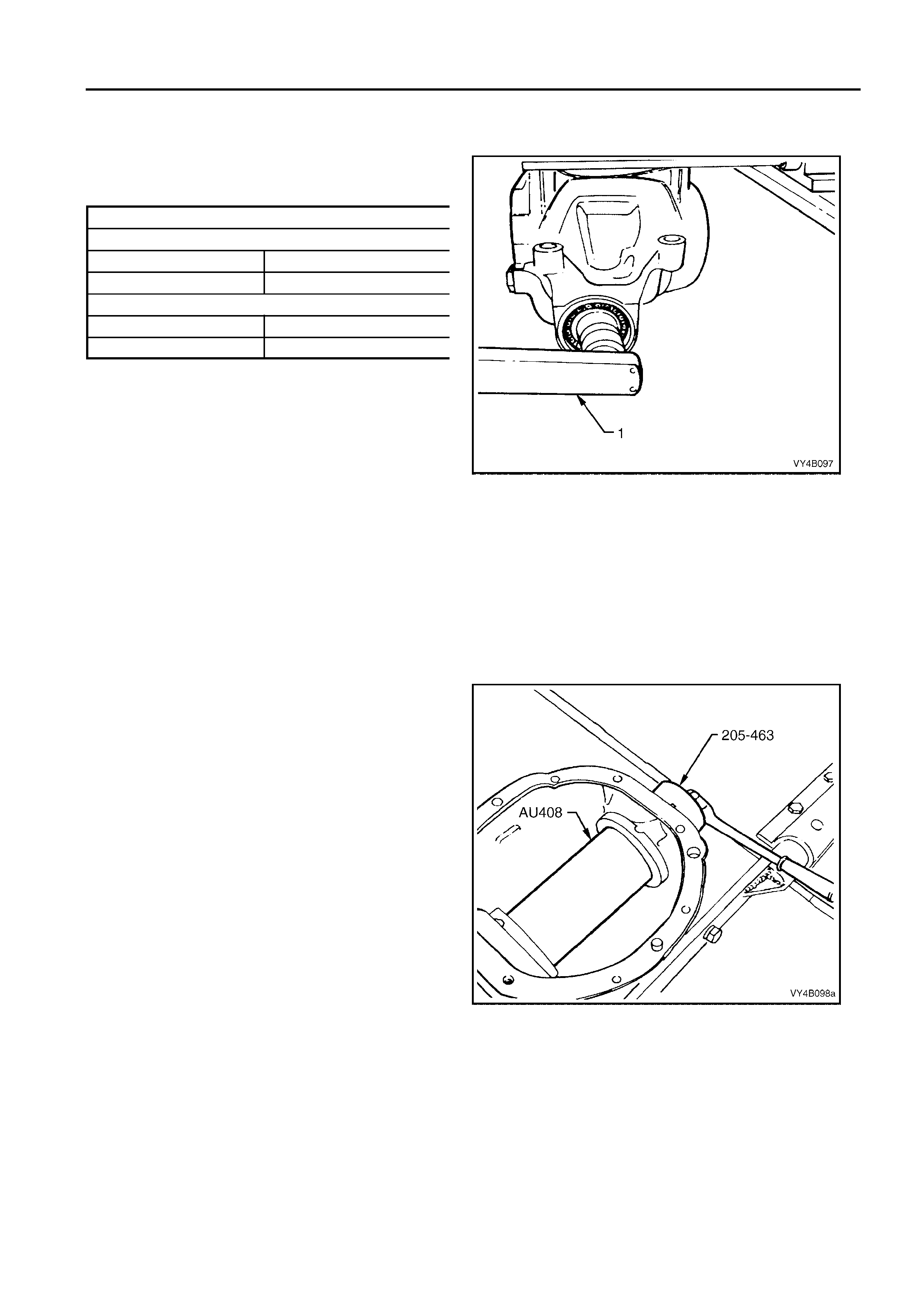
FINAL DRIVE AND DRIVE SHAFTS 4B - 65
12. Install dummy pinion and rear (inner) bearing into
carrier housing. Fit front (outer) bearing to dummy
pinion, then install the dummy pinion thrust collar and
nut.
13. Tighten nut on end of dummy pinion, using a
commercially available, dial type torque wrench (1),
until the specified rotational torque is obtained.
DUMM Y PINION ROT ATIONAL TORQUE SPECI FI CATION
New Bearings, No Pinion Oil Seal Installed
Timken Koyo
1. 4 – 2.0 Nm 1.5 – 1.9 Nm
Used Bearings, No Pinion Oil Seal Install ed
Timken Koyo
0. 7 – 1.2 Nm 0.7 – 1.2 Nm
14. Rotate dummy pinion back and forth during
tightening to ensure that bearings settle in their
cups.
NOTE 1: W hen the specified preload is reached, remove
the block from the rear of the dummy pinion (to allow
continuous rotation of the pinion during the preload
tightening process). Rotate the pinion approximately 50
turns in each direction, then re-check the bearing
preload, readjusting as required, to achieve the specified
figure.
NOTE 2: Pinion bearing pre-load is very important
because it retains pinion in its correct relationship to ring
gear.
NOTE 3: Bearings that are installed with insufficient or
no pre-load, will, after a comparatively short period of
running, develop end play, causing noisy operation on
overrun and could be responsible for scuffing of ring gear
and pinion teeth.
Figure 4B-156
NOTE 4: Bearings that have too much pre-load, may
become pitted or flaked and result in premature failure. It
is therefore essential to ensure that bearings are pre-
loaded to specified torque specification.
15. Position arbour Tool No. AU408 in carrier assembly
and install screw adjusters with side bearing cups.
Adjust screw adjusters to lightly clamp arbour, using
Tool No. 205-463 (or AU407).
NOTE: Ensure that arbour is free of burrs that may
damage bearing cups.
Figure 4B-157
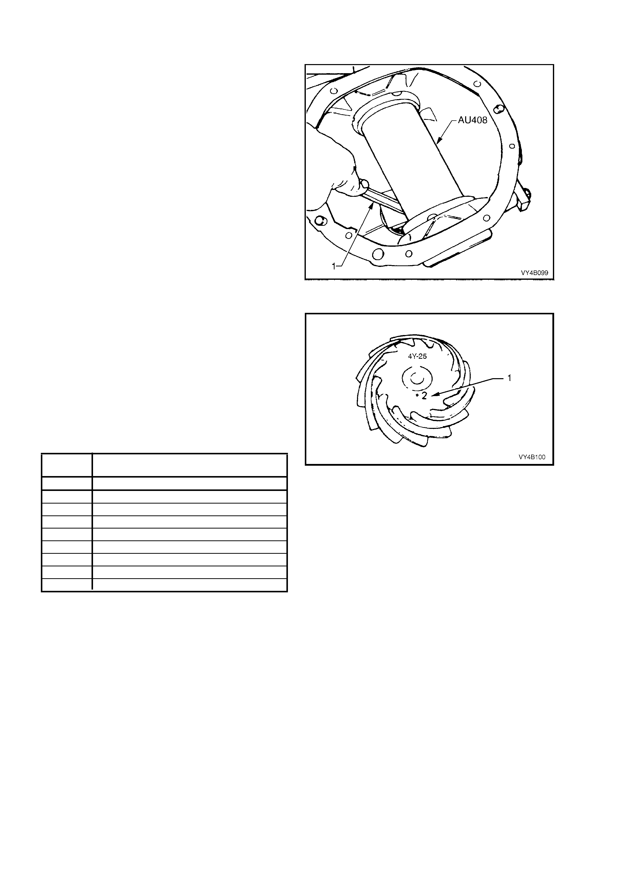
16. Check clearance between arbour (Tool No. AU408)
and head of dummy pinion with a feeler gauge (1).
Record this dimension.
Figure 4B-158
17. On the end of the pinion, a drive pinion installation
marking figure (1) is applied with either a white or
yellow marker. A zero marking ('0') indicates that
shim size equal to the dimension measured in Step
16 is the correct size for this carrier/pinion
combination.
A positive marking, e.g. +3, means that a thickness
measurement equivalent to this numerical marking
must be subtracted from shim size measured in
Step 16, refer to the following chart.
A negative marking, e.g. –3, means that a thickness
measurement equivalent to this numerical marking
must be added to the shim size measured in Step
16. Refer to the following chart for specific details.
PINION SHIM THICKNESS
MARKING
REQUIRED
–4 Add 0.10 mm to measurement of step 16.
–3 Add 0.075 mm to measurement of step 16.
–2 Add 0.050 mm to measurement of step 16.
–1 Add 0.025 mm to measurement of step 16.
0 Size as measured in step 16.
+1 Subtract 0.025 mm from measurement of step 16.
+2 Subtract 0.050 mm from measurement of step 16.
+3 Subtract 0.075 mm from measurement of step 16.
+4 Subtract 0.10 mm from measurement of step 16.
NOTE: Pinion positioning shims are serviced in
thicknesses of 0.2 – to 0.75 mm in 0.025 mm
increments. They are also dimensioned differently,
depending on the pinion bearing used.
Figure 4B-159
18. Remove dummy pinion and arbour from carrier assembly.
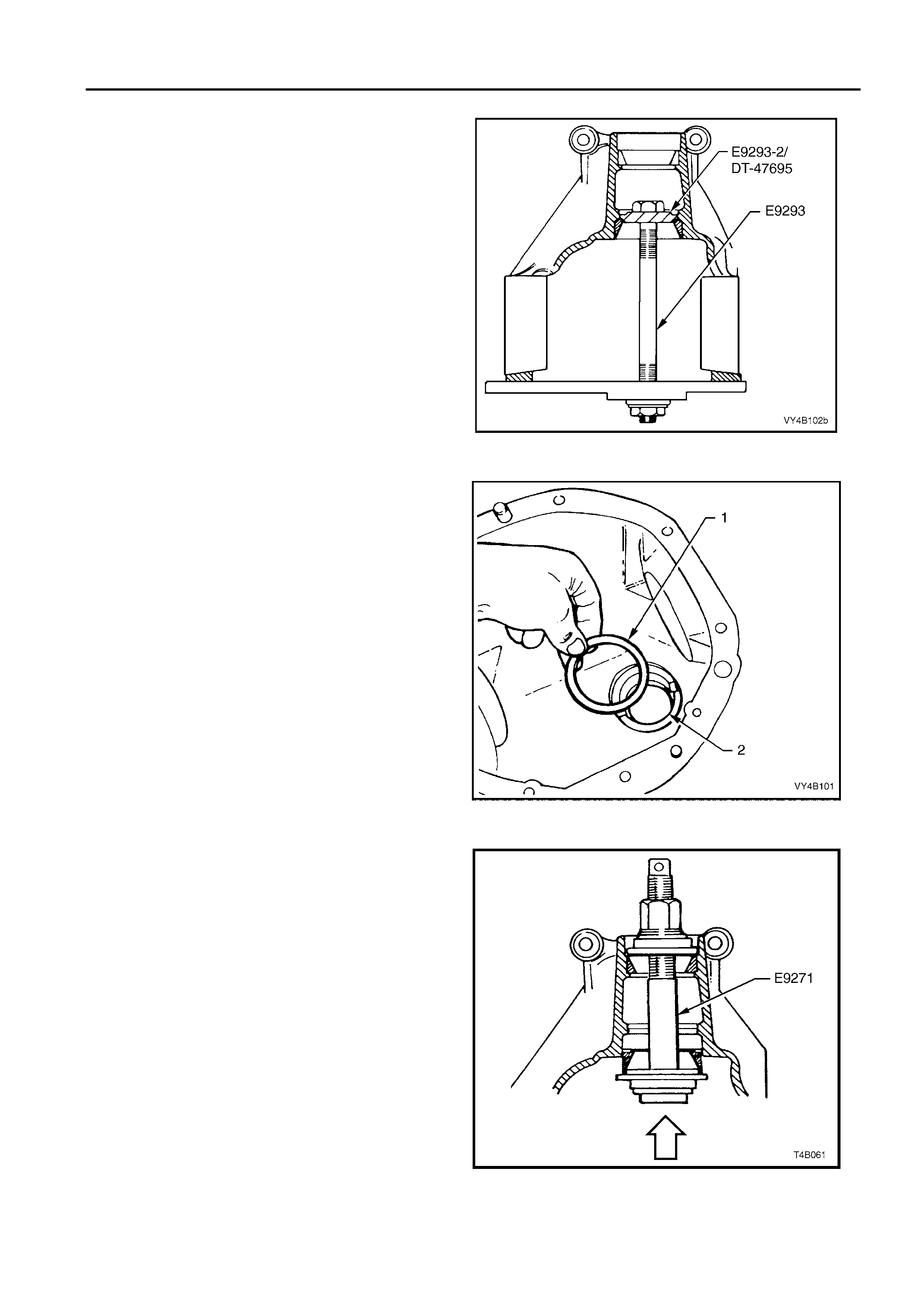
FINAL DRIVE AND DRIVE SHAFTS 4B - 67
Pinion Installation
1. Select pinion positioning shim stack as determined
in the Hypoid Pinion Positioning Shim Selection
procedure, in this Section.
2. Remove pinion rear (inner) bearing cup, using Tool
No. E9293, using adaptor Tool No. E9293-2.
NOTE: When removing the inner pinion bearing cup from
3.07 and 3.46 assemblies, the adaptor to be used with
E9293, is
DT-47695
.
Figure 4B-160
3. Install pinion positioning shim/s (1) into pinion rear
bearing cup bore (2).
Figure 4B-161
4. Reinstall pinion rear bearing cup using Tool No.
E9271. Ensure that cup is seated squarely in bore.
NOTE: When installing the inner pinion bearing cup to
3.07 and 3.46 assemblies, the adaptor to be used with
E9271, is 205-552-2 .
Figure 4B-162

5. Press rear bearing inner race against the
shoulder of the pinion, using Tool No.
E3C10AER.
NOTE 1: To avoid possible damage to the pinion
gear teeth when pressing the bearing on, ensure
that the pres s plates are p erfectly flat, fr ee of burrs
and foreign matter prior to installing the rear
bearing.
NOTE 2: Locate b eari ng in ner rac e s quare ly on the
pinion and press only on inner race surface.
NOTE 3: Only lubricate the bearing with the
recommended differential carrier lubricant.
Figure 4B-163
6. Place the pinion in the carrier.
7. Lubricate pinion front bearing with the
recommended differential carrier lubricant and
assem ble the coll apsible pinion bear ing spac er
and front bearing onto pinion, while supporting
pinion head.
8. Install pinion flange and the original pinion
flange retaining nut.
9. Install Tool No. KM620-1A and, using a
suitable l ength of pipe ( 1) to hold pi nion flange ,
tighten re taining n ut until p inion f ront bearing is
squarely engaged on the pinion shaft and not
cocked.
NOTE 1: If not previously done so, drill out holes
stamped ‘B’ on Tool No. KM620-1A to 12.5 mm.
NOTE 2: Use either the rear coupling to pinion
flange r eta in ing bo lts with a 25 m m spac er (e.g. f lat
washers) insta lled firs t or u se three b olts M 12 x 1.5
x 40, with the thread extending to within 12 mm of
the head.
10. Insert a suitable length of pipe (1) over the tang
of the installed tool for leverage, then remove
the pinion flange retaining nut, using a
comm erc ially ava ilabl e dee p soc ket and soc k et
bar (2).
Figure 4B-164
11. Install extractor, Tool No. KM628-A to the
pinion flange using the same three bolts used
to secure the flange holding tool, KM620-1A
(refer step 9).
NOTE: If not previo us l y done s o, dr i ll out t he f lan ge
holes on Tool No. KM628-A to 12.5 mm.
IMPORTANT: If using the original bolts, they must
have the 25 mm spacers fitted so the tool is
clam ped to the pinion f lang e. If this is not don e, the
screw thread on the extractor Tool No. KM628-A
will not be long enough to fully remove the pinion
flange.
12. While holding the extractor tool with a suitable
spanner, withdraw pinion flange by tightening
the forcing screw in the direction indicated.
Figure 4B-165
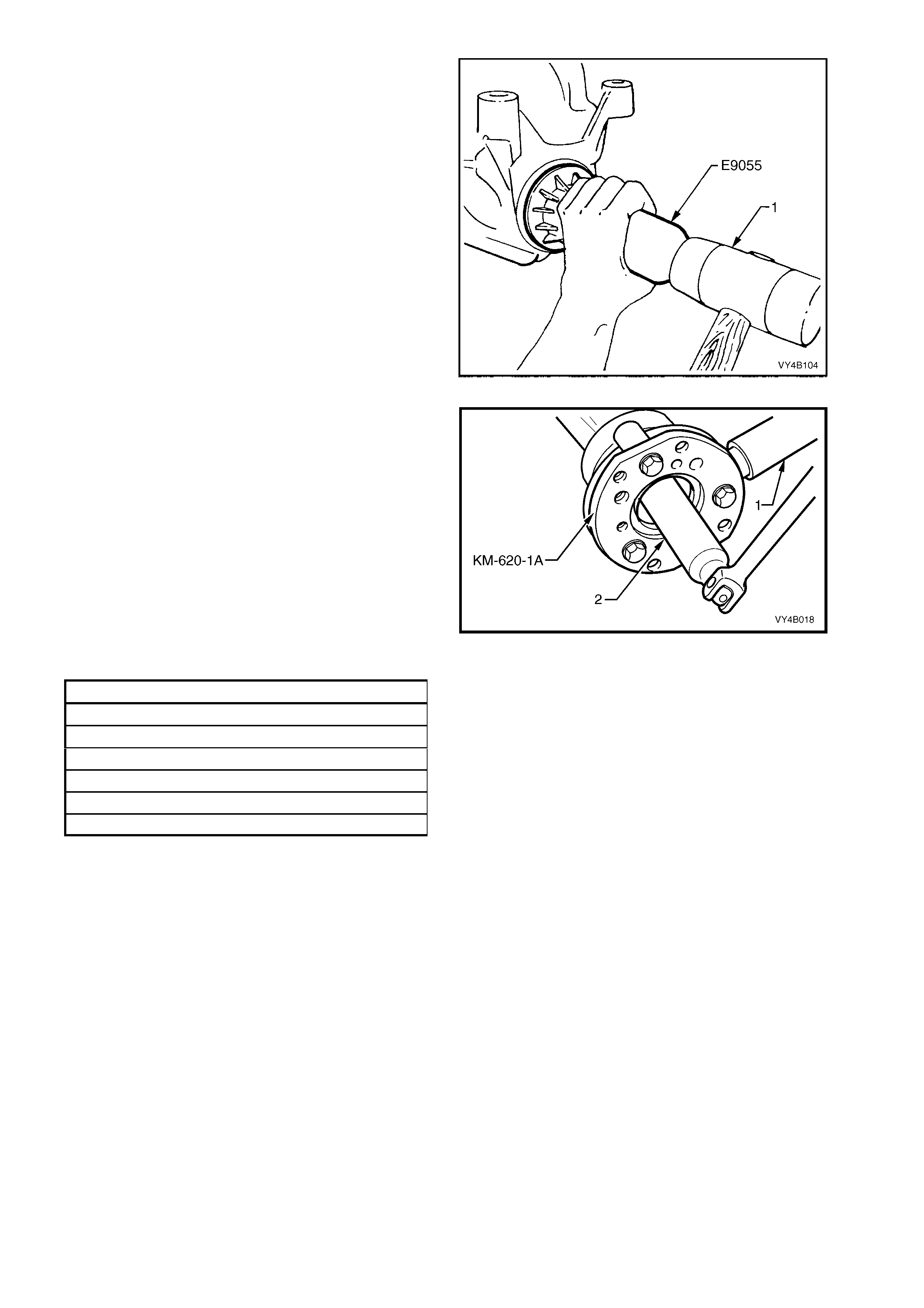
13. Lubricate pinion oil seal lips and the pinion oil
seal bore in the carrier hou sing with diffe rential
carrier lubricant.
14. Install oil seal into carrier bore using Tool No.
E9055 and a pl astic f aced hamm er (1) until the
seal fits flush to 0.25 mm below car rier ho usin g
surface.
Figure 4B-166
15. Reinstall pinion flange and fit a NEW retaining
nut. Hold pinion flange using Tool No. KM620-
1A and a suitable length of pipe (1). Gradually
tighten the retaining n ut while rota ting pinio n in
both directions to seat bearings.
16. Check bearing pre- load f requentl y by rem oving
flange hold ing tool (KM62 0-1A) and inst alling a
pulley and string to the pinion flange. Refer to
7. SPECIAL TOOLS at the end of this Section
for pulley details.
17. Using a spring scale, measure rotational
torque.
18. Continue to tighten the nut until specified
torque is achieved.
PINION ROTATIONAL TORQUE SPECIFICATION
New Bearings, With Pinion Oil Seal Installed
Timken Koyo
1. 4 – 2.4 Nm 1.5 – 2.1 Nm
Used Bearings, With Pinion Oil Seal Installed
Timken Koyo
0. 7 – 1.2 Nm 0.7 – 1.2 Nm
The torque figure is calculated by multiplying the
radius of the pulley by the spring balance reading.
EXAMPLE: If the pulley diameter is 152 mm, the
radius is 76 m m which equals 0.076 m. The spring
balance reading is 25 N. Therefore, the pre-load
equals 0.076 m x 25 N = 1.9 Nm.
CAUTION: Should the retaining nut be over-
tightened and pre-load exceeded, it will be
necessar y to r emov e th e pi nio n f rom t he c arr ier
and install a new collapsible spacer. Under no
circumstances must the retaining nut be
backed off to decrease the pre-load reading.
Figure 4B-167
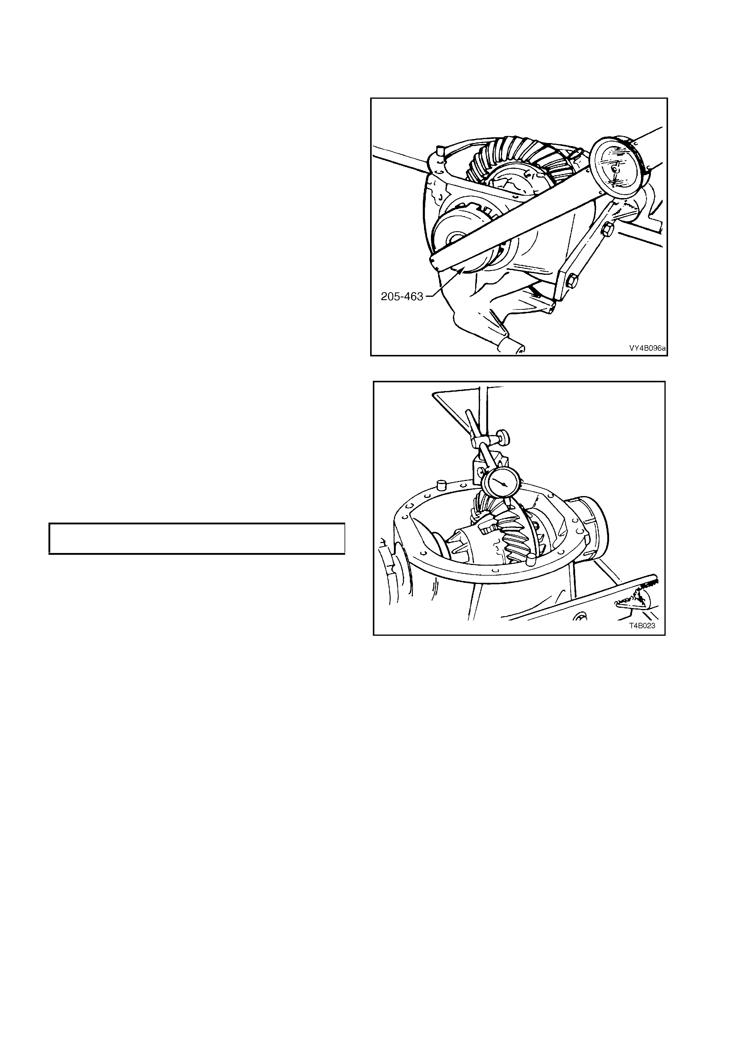
Differential Backlash Setting
1. Check threads of screw adjusters and ensure
that they are free of damage.
2. Holding differential case in carrier, with ring
gear in mesh with pinion, fit screw adjusters
and side bearing cup assemblies to both sides
of carrier. Using Tool No. 205-463 (or AU407),
continue tightening adjusters until case
assem bl y is supported b y side bear ings .
3. Rotate differential case several times, to
ensure that side bearings are correctly seated.
4. Tighten screw adjusters to the torque setting
recorded in step 6, ‘Differential Case Side
Bearing - Pre-lo ad Set ti ng ’ in this Section.
Figure 4B-168
5. Mount a dial indicator on carrier and check
gear backlash between the ring gear and
pinion. Backlash should be within the following
specification.
Check readings at four equally spaced
positions around ring gear.
NOTE: Position the dial indicator so that the
indicator stylus is perpendicular to the ring gear
tooth and in line with gear rotation.
BACKLASH SPECIFICATION 0.10 - 0.18 mm at
the tightest point.
6. If backlash is excessive or insufficient, adjust
by slackening off screw adjuster on the side
that the ring gear (differential case) needs to
move towards. Re-tighten opposite screw
adjuster the s ame amount, then t ig hte n bot h as
detailed in step 4.
7. With back lash corr ectly set, check gear c ontact
pattern as detailed in the following instructions.
Figure 4B-169
Ring Gear and Pinion Contact Patter n
1. Thoroughly clean ring gear and pinion teeth.
2. Paint ring gear teeth lightly and evenly with gear marking compound of a suitable consistency to produce a
contact pattern.
3. Rotate pinion through several revolutions in both directions while lightly loading gear set.
To load gear set, use a suitable bar to lever between ring gear outer diameter and differential carrier.
NOTE: W hen rotating pinion, ensure that no metal swarf from contact with rotating ring gear and bar is allowed to
enter gear teeth.
4. Inspect contact pattern produced by above procedure.
5. After a satisfactory contact pattern is produced, clean the ring gear and pinion gear teeth and pour a liberal
quantity of the correct rear axle lubricant onto the gears and bearings. Turn the gear set to work the lubricant
into all surfaces.

Tooth Marking Nomenclature
The large end of th e t ooth i s c alle d t he 'H E EL' and th e small end the 'TOE', also t he top of the toot h whic h is abo ve
the pitch li ne is called the ' FACE' while the are a below the pitch line is called th e 'FLANK'. The clear ance between
the pinion and ring gear teeth is referred to as 'BACKLASH'.
Figure 4B-1 68 illus tr at es corr ect and incor rec t cont ac t patterns .
Contact pattern 'A' provides the ideal marking for quietness and long life. If the pattern shows a toe contact 'B', it
indicates not enough backlash. To correct, move the ring gear away from the pinion by increasing the size of the
shim on the pinion side of the ring gear and decreasing the ring gear side shim by an equal amount.
If the pattern shows a heel contact 'C', it indicates too much back lash. To correct, move the ring gear towards the
pinion by increasing the size of the shim on the ring gear side and decreasing the size of the shim on the pinion
side of the ring gear by an equal amount.
NOTE: Make adj ustment, incr eas ing a nd d ec reas in g s him thick nes s b y 0.04 mm at a tim e. Chec k contact wit h gear
marking compound and continue adjustment until tooth contact appears as in 'A'. Backlash must remain within
specif ied limits .
To correct a pattern such as 'D', it will be necessar y to install a thicker pinion positioning shim as described unde r
HYPOID PINION PO SITIO NING SHIM SELECT ION in th is Sect ion. A 0.0 25 mm thick er shim is recomm ended as
a starting point. Continued changes may be necessary to obtain the correct setting. If the pattern shows a flank
contact 'E', it ind icates t hat the p in ion is in too f ar . T o c or rec t, repl ac e the pi ni on s him with a 0. 02 5 m m thinn e r s him
and recheck contact pattern.
In mak ing pinion pos itio n adj ustm ents, be sur e back lash is corre ct bef ore testing c ontact patt ern. Movi ng the pinion
'IN' reduces backlash and moving pinion 'OUT' increases backlash.
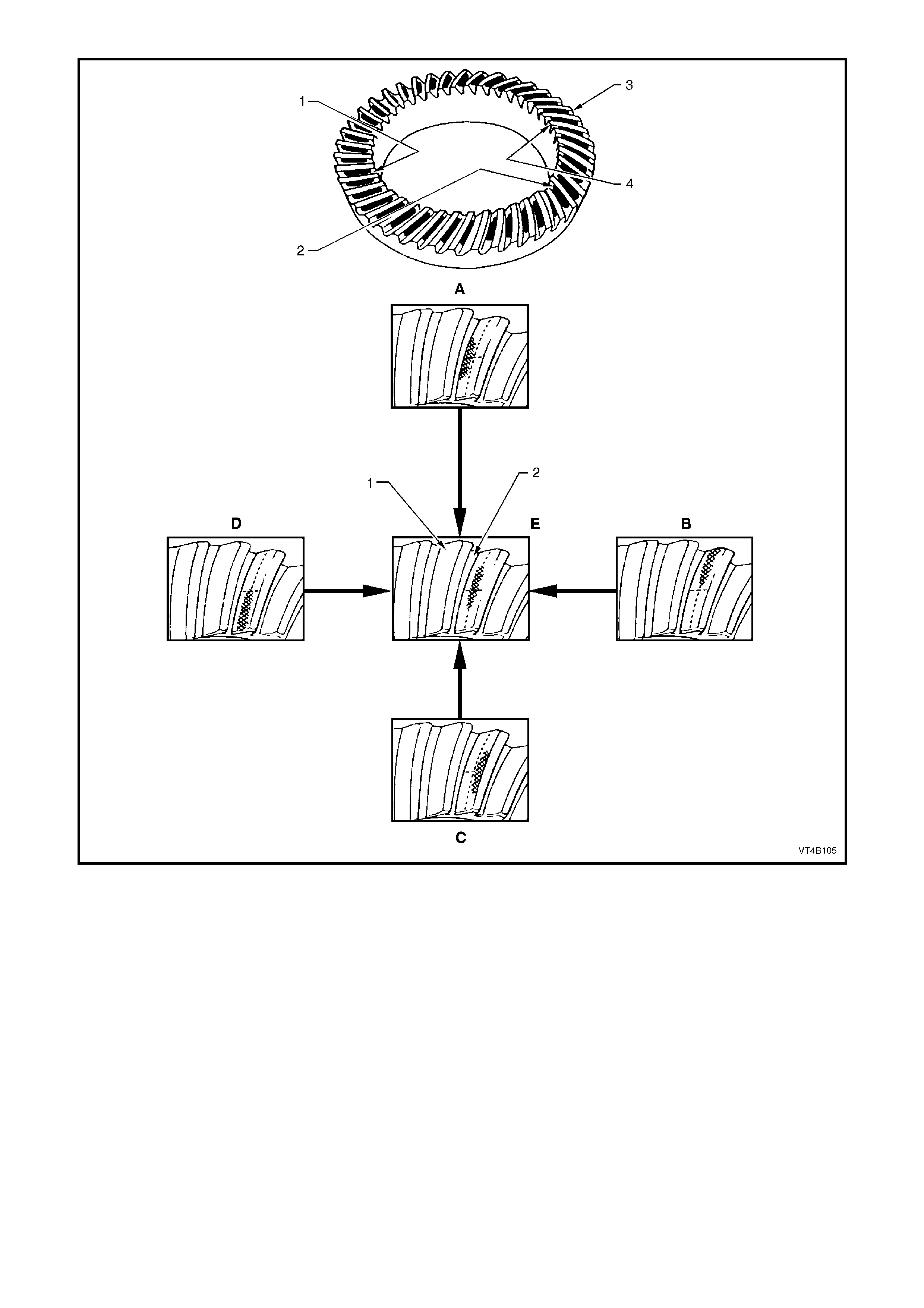
Figure 4B-170
Legend
1. Convex Side (Drive)
2. Concave Side (Coast)
3. Heel
4. Toe
A. Low Flank Contact – Decrease Pinion Shim Thickness
B. Heel Contact – Decrease Backlash
C. High Face Contact – Increase Pinion Shim Thickness
D. Toe Contact – Increase Backlash
E. Ideal Contact
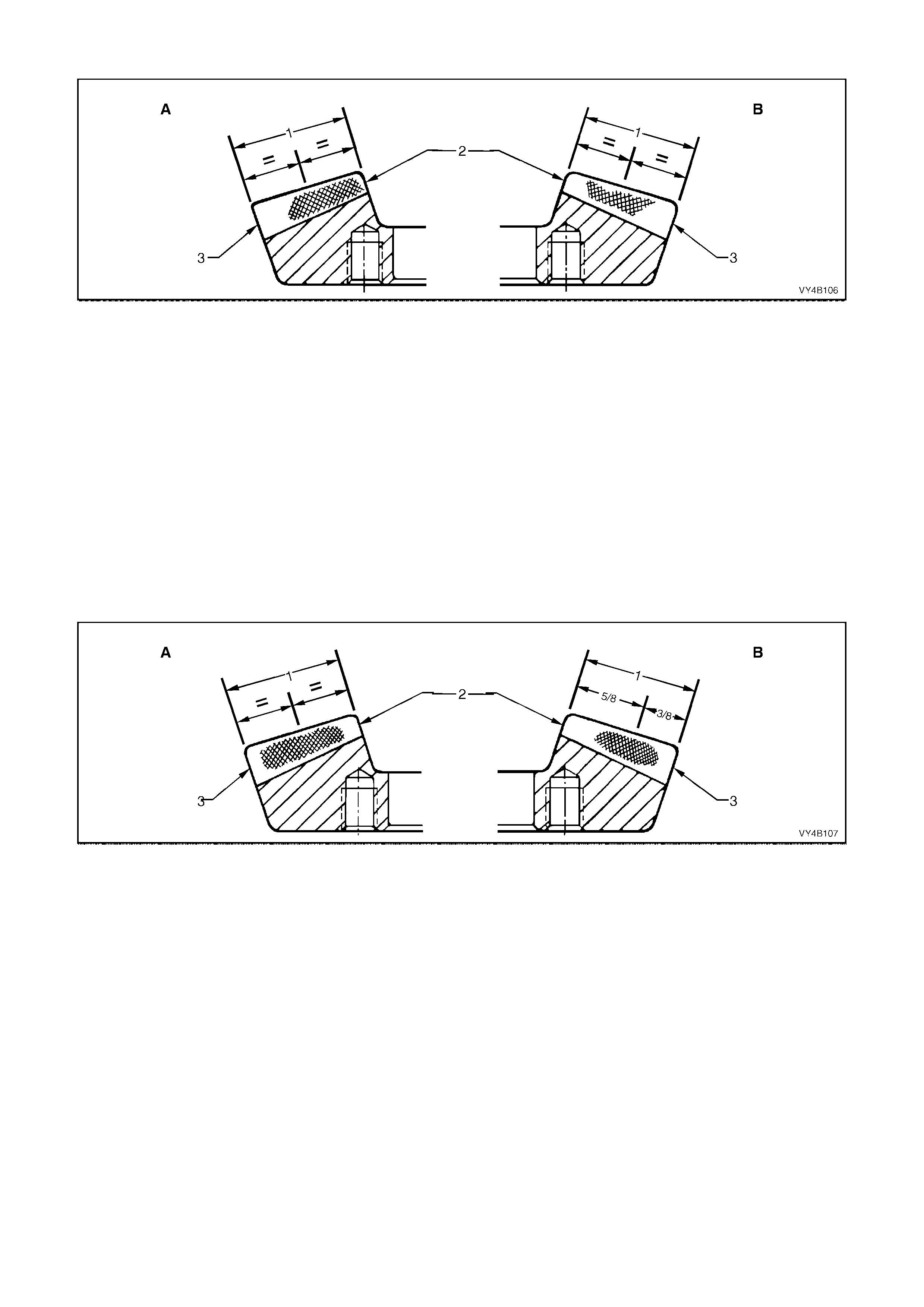
Ideal Contact
Figure 4B-171
Legend
A. Drive Side
B. Coast Side 1. Face Width
2. Toe
3. Heel
Drive Side
A central toe contact marking, lengthwise in position and slightly low contact in the profile position.
Total length approximately 5/8th of the gear face width.
There should be c learance of about 1 m m between the contact marking and the toe and along the top f ace angle
line.
Coast Side
A centrally located marking, lengthwise in position and slightly high in the profile position.
Total length approximately 5/8th of the gear face width.
There should be clearance between the contact and the face angle line of the gear.
Acceptable Heel Contacts
Figure 4B-172
Legend
A. Drive Side
B. Coast Side 1. Face Width
2. Toe
3. Heel
Drive Side
A central face contact marking, lengthwise in position, is shown in Figure 4B-172. This represents the limit of
acceptability of the contact marking towards the heel.
The marking should fade out at least 5 mm before the heel end.
A central profile marking position is shown and is acceptable, although low contact marking is preferred.
Coast Side
The centre of the contact marking is located at 5/8th of the face width from the toe and it does not approach the
heel end by less than 5 mm.
A high contact marking, as shown in Figure 4B-172, is preferred for coast side contacts which tend to be toward the
heel.
A centra l profile m ar k ing pos itio n is ac c epta ble , pro vi di ng the pinion fac e ang le ed ge l ines d o not app ear lo w on th e
gear.
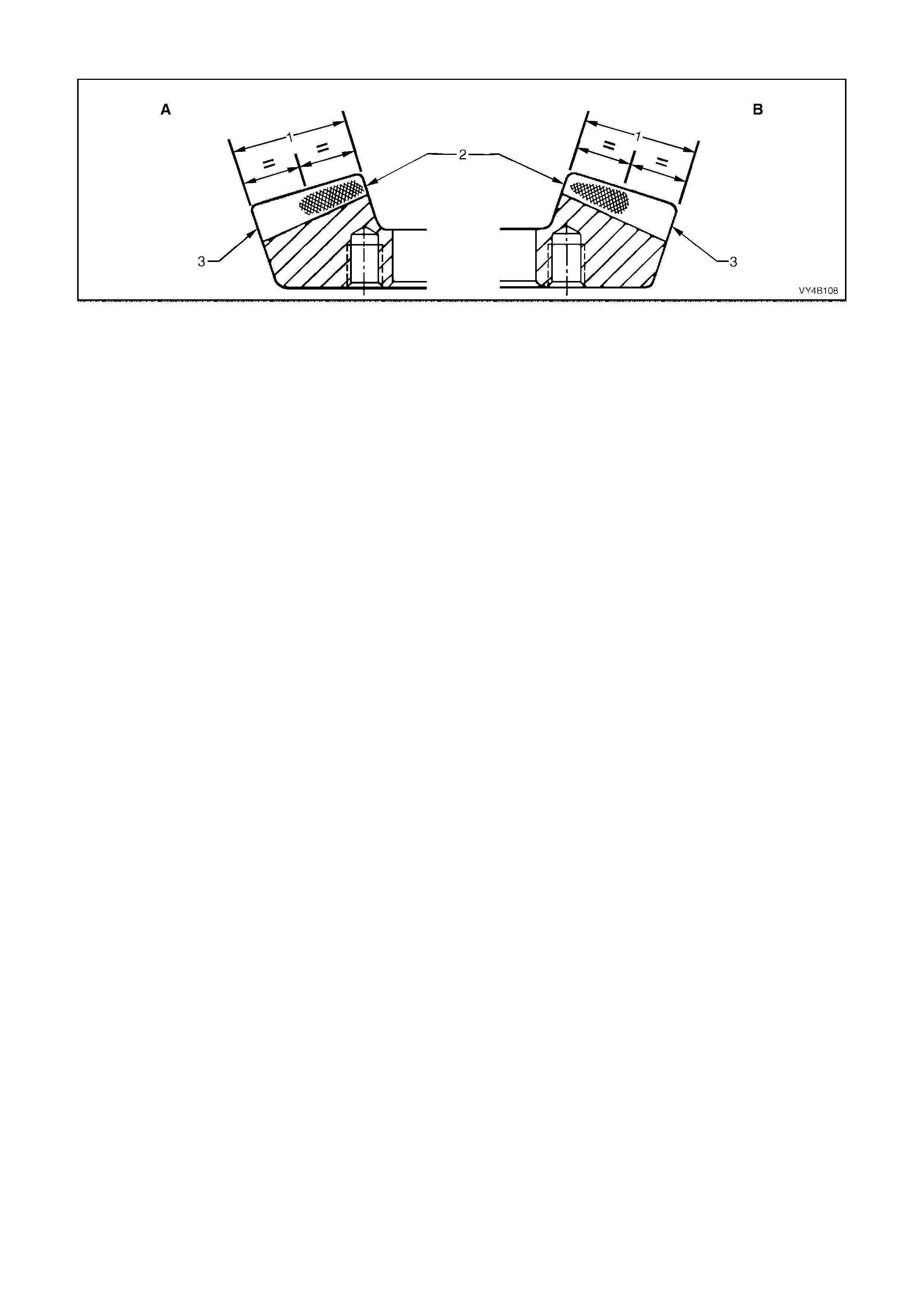
Acceptable Toe Contacts
Figure 4B-173
Legend
A. Drive Side
B. Coast Side 1. Face Width
2. Toe
3. Heel
Drive Side
The contact markings begin almost at the toe end face and extend in length by approximately half the face width.
A slightly low contact marking is shown in Figure 4B-173. This is preferable although a centrally located profile
position is acceptable.
Coast Side
The contact marking being almost at the toe end face and may appear pointed as shown in Figure 4B-173. A
square end is equally acceptable.
The total length of the contact marking is approximately 1/2 of the face width.
A high profile marking position is desirable, although a central profile is acceptable.
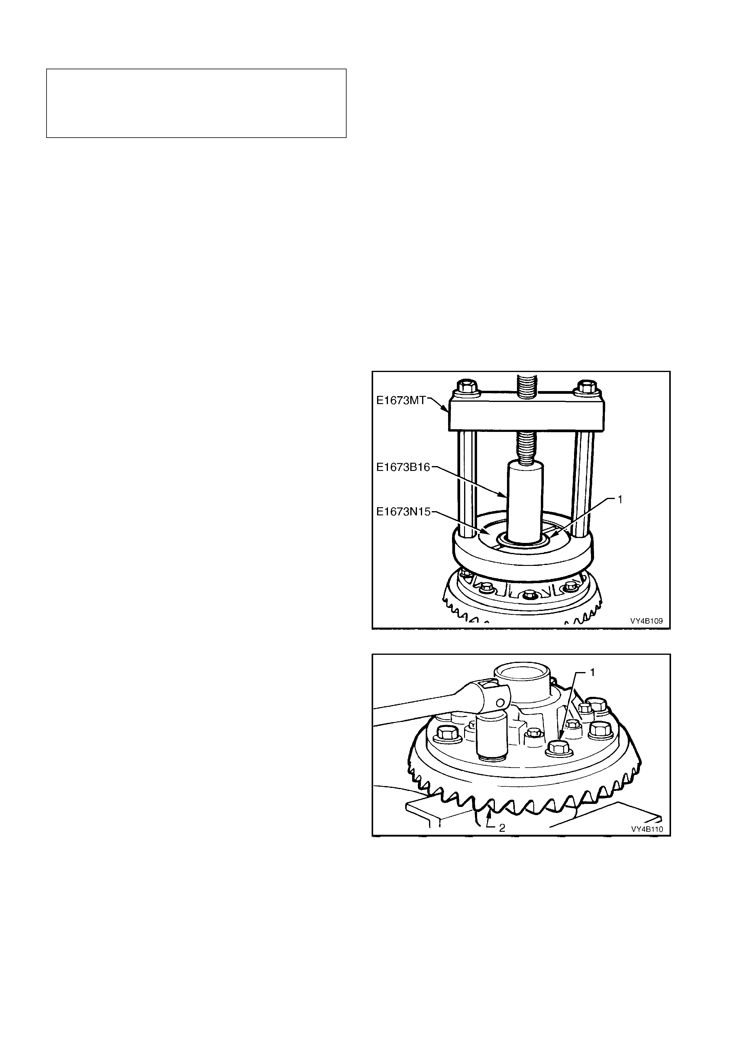
3.4 LIMITED SLIP DIFFERENTIAL
NOTE: The following fasteners MUST be replaced
when performing this operation:
n Final drive ring gear bolts.
n LSD case cap to cover attaching bolts.
The overha ul proc edures , r ing gear an d pini on positi onin g and t ooth m ark ings for the lim ited sl ip dif fer ential are the
same as for the standard type of rear axle assembly, except for the servicing of the internal components of the
limited slip differential assembly.
NOTE: The 3.07:1 and the 3.46:1 r atio diff erentials ha ve unique parts and are no t interchangea ble with the 3.08:1
ratio un it. The genera l overhaul pr ocedures ho wever, rem ain the same f or both types. T he unique c omponents f or
the 3.07:1 and the 3.46:1 ratio differentials are; differential case, differential pinions, side gears and thrust block.
DISASSEMBLE
1. Before disassembling differential case, inspect differential side bearings for any signs of damage.
NOTE: Both side bearings and their cups are matched parts. If either bearing is to be replaced, its matching cup
must also be replaced.
IMPORTANT: T he side bearings c an be manuf actured by either one of two m anufacturers; T imken or Ko yo. W hen
replac ing the diff erentia l sid e bear ings , the t wo bear ing s and cu ps m us t be of the sam e brand. The pi nion b ear ings
may be of a different manufacture but again, they must be a matched pair. The reason for matched pairs of
bearings is that a different preload specification is required for each brand.
2. If replacing side bearings, use Tool No.
E1673MT, adaptors E1673N15 and stepped
plug E1673B16 to remove side bearings from
differential case.
Discard side bearings once they are removed.
To remove side bearing cups, refer to
3.3 REMOVED FINAL DRIVE ASSEMBLY -
Disassemble, step 10 in this Sect ion.
Figure 4B-174
3. Grip differential case in a vice with soft jaws.
4. Remove ring gear attaching bolts (1).
NOTE: Ring gear attaching bolts use a left
hand thread and are identified by an 'L' on the
bolt head.
5. Remove differential case from vice.
Figure 4B-175
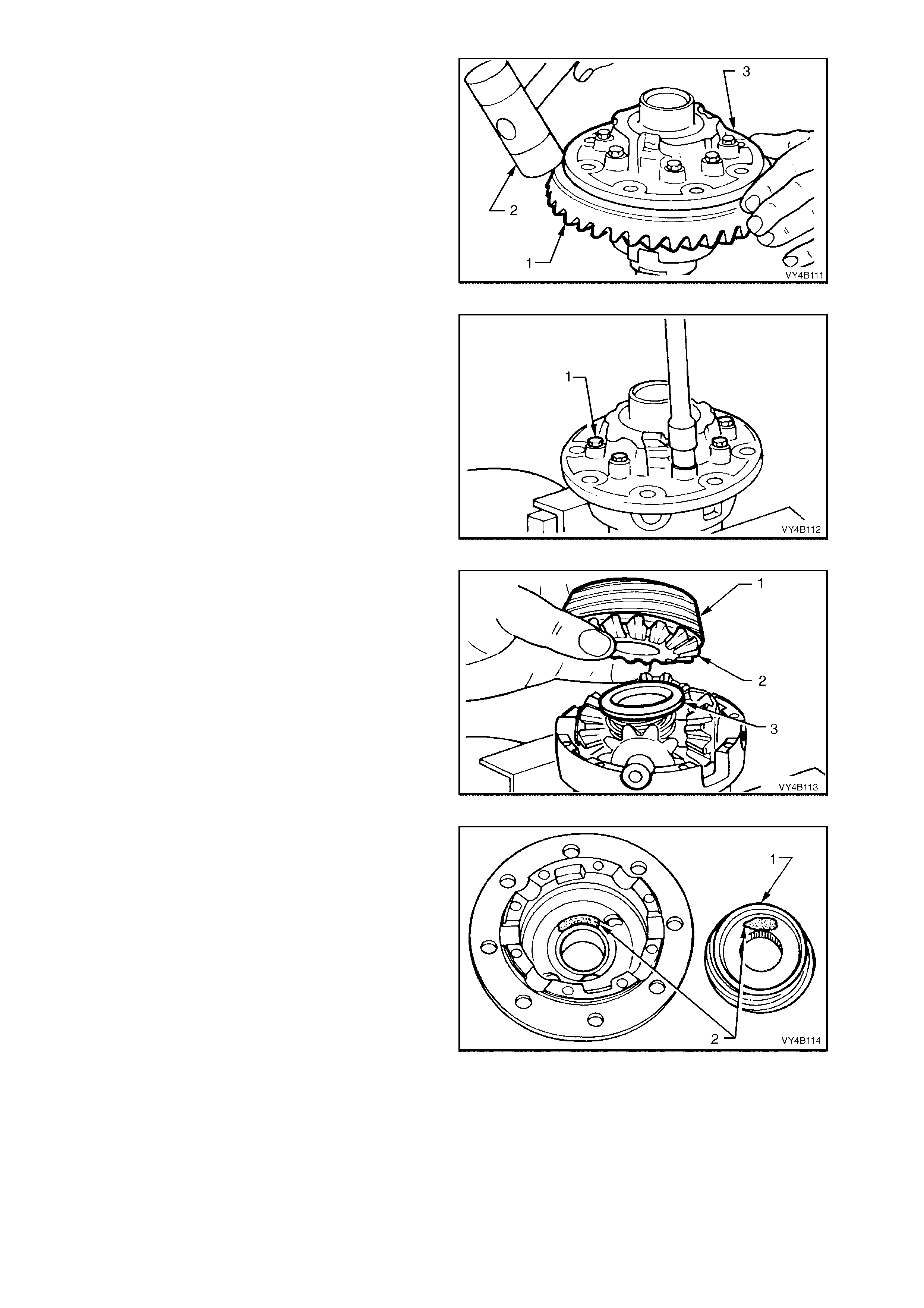
6. Using a soft faced hammer (2), remove ring
gear (1) from differential case (3) by hitting
down on ring gear. Support ring gear during
this operation so that it does not strike bench
top as it comes free of case.
NOTE: Do not use a screwdriver to prise
between ring gear and case.
7. Place differential case in a vice equipped with
soft jaws.
Figure 4B-176
8. Loosen and remove differential case cap to
cover attaching bolts (1) evenly. Lift off
differential case cover. If necessary, remove
clutch cup f rom cover (s ometimes the c one will
remain inside the cover).
Figure 4B-177
9. Remove clutch cone (1), shim (if fitted), side
gear (2) and thrust spring plate (3) from pinion
cross shaft.
NOTE: The 3.07:1 and the 3.46:1 ratio clutch
cones and s ide gears ar e an int egral un it and m ust
stay assembled to each other.
Figure 4B-178
NOTE: T o ensure that the c lutch cones ( 1) (are not
interchanged during reassembly, mark the cone
and corresponding side of the differential case (2)
with a felt tipped pen or similar. If shims are
present, t hey must als o be mark ed so that the y ca n
be reassembled into the correct case half.
Figure 4B-179
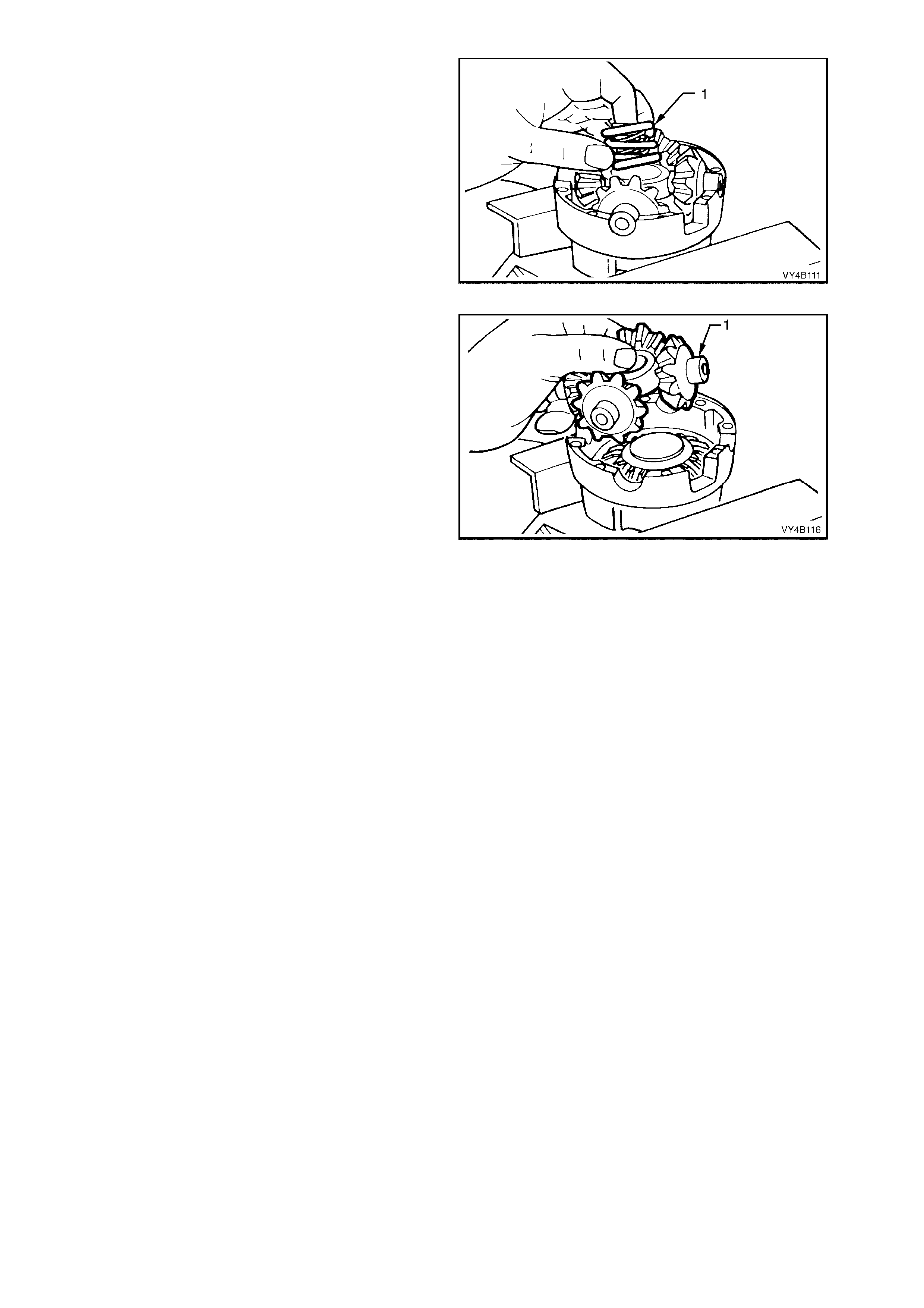
10. Remove three concentric differential pre-load
springs (1) from centre of pinion cross shaft.
Figure 4B-180
11. Lift pinion cross shaft (1), pinion gears and
thrust washers from case. Remove pinion
gears and thrust washers from cross shaft.
NOTE: Keep the pinion gears with their
respective thrust washers in sets so they can
be reinstalled in their original position.
12. Remove remaining thrust spring plate, side
gear, shim (if fitted) and clutch cone from
differential case cap.
Figure 4B-181
INSPECT
All components should be thoroughly cleaned and dried, then inspected.
Differential Case
Check the case for general soundness and pay particular attention to the following points:
1. If differential case side bearings have been removed, check case journals for damage and that seating
surfaces are free from dirt and burrs.
2. The ring gear spigot and mounting face should be clean and free from dirt and burrs.
3. The mating surfaces for differential case halves should be clean and free from burrs.
4. The thrust surfaces for the differential pinions should be examined for excessive wear.
5. The clutch cone seats in two housing halves should be smooth and free from any excessive scoring. Slight
grooves and scratches are permissible and normal.
The land surface of the heavy spirals on clutch cones will duplicate the housing surface condition. Excessive
wear or dam age on the clutch cone surface will requir e renewal of bot h clutch cones (3.08:1 ra tio only) or the
clutch cone/side gear assemblies (3.07:1 and the 3.46:1 ratio differentials) and the housing
6. Inspect axle splines of the clutch cones for excessive wear.
7. Check thrust spring plates for excessive wear or damage.
8. If fitted, inspect side gear shims for damage.
9. Inspect pinion gear cross shaft bores for ovality.
Differential Side Gears and Pinion Ge ars
1. Examine all gear teeth for cracks or hard contact marks.
2. The differential side gear splines should be checked for excessive wear. Wear on splines can contribute to
excessive driveline backlash.
3. The differential pinion bores and thrust surfaces should be smooth and free from scores. Inspect all thrust
washers for cracks, nicks or burrs. Wear of thrust washers or thrust surfaces on gears can contribute to
excessive driveline backlash.
4. Check that pinion gear cross shaft is not bent and that surfaces on which pinions run, are not scored or worn.
Ring Gear and Pinion
1. Inspect gear teeth for scoring or damage. Scoring of the gear teeth is usually caused by excessive shock
loading, use of the incorrect lubricant or insufficient "run in" before towing a heavy load. (Refer MY2003 VY
Series Owner's Handbook). Scored gears must be replaced.
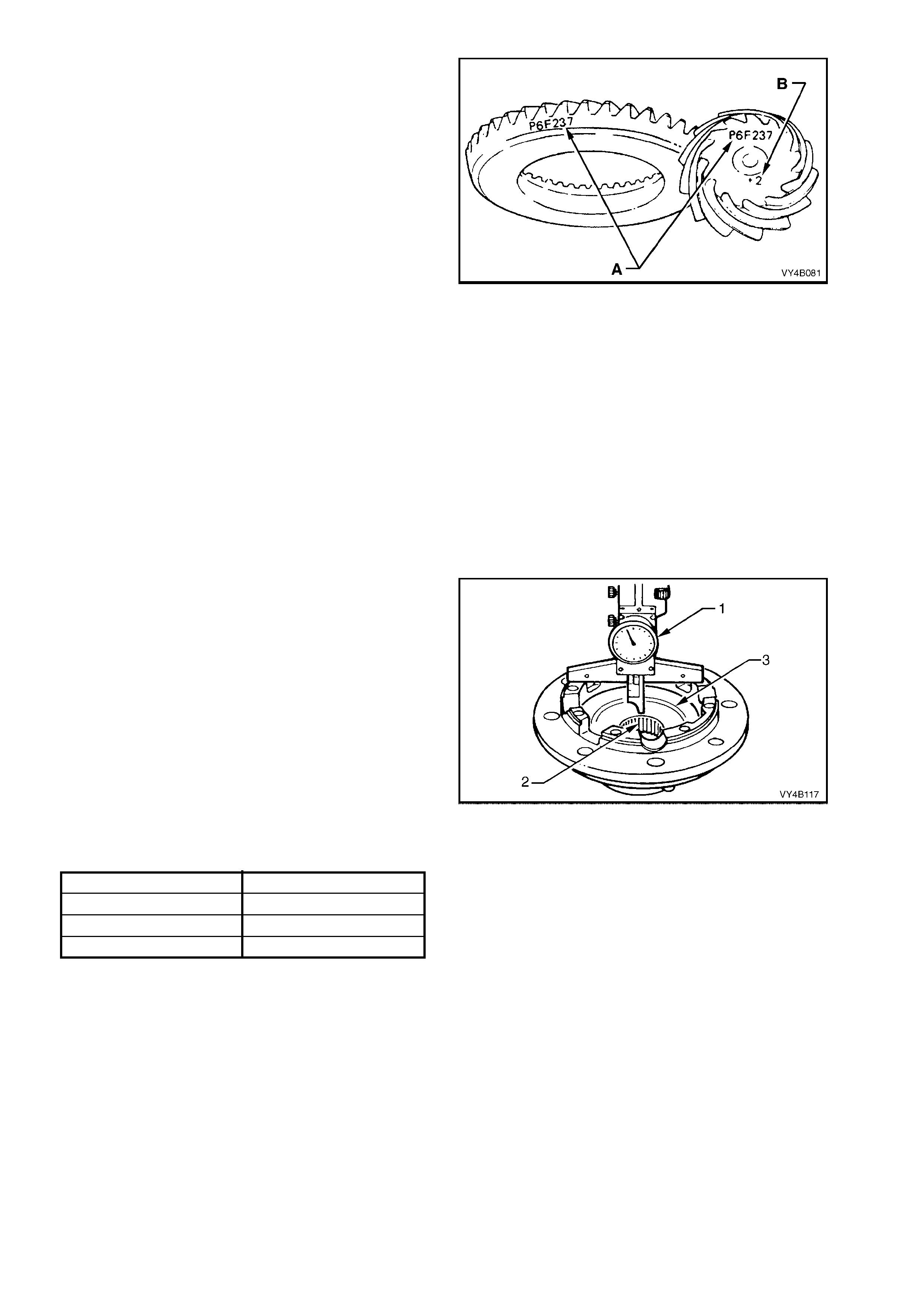
2. If on reassembly, a new gear set is to be
installed, ensure that the same matching
number (A) appears on both the pinion and
ring gear.
T he ide ntific ation number ( B) on th e pin ion e nd
is used when setting the pinion depth, on
reassembly.
3. On ring gear bolts, clean serrations under bolt
flanges.
Figure 4B-182
Bearings
1. Bearing c u ps s hou ld ha ve an even wear pat tern a nd be f r ee f rom flak ing or pit t in g . Ens ure the s eat ing s ur f ac es
are clean and free from burrs or raised metal.
2. The bearing assemblies should feel smooth when turned in the cups.
3. The assembly should be free from loose particles.
4. There should be no cracks present in the roller cages and the bores should show no evidence of flaking or
pitting.
Refer to 4.4 FINAL DRIVE BEARING DIAGNOSIS in this Section, for identification of bearing failures.
REASSEMBLE
1. Lubricate all gears, bearings, thrust washers
and pinion gear cross shaft with rear axle
lubric ant bef ore ass embly.
2. With the 3.08:1 ratio unit, reinstall respective
clutch cones (2) and shims (3)(if fitted) into
differential case halves.
To check if shims are required:
a. Using a depth gauge (1), measure the
distance from the case mating surface to
the flat surface of the tightly seated clutch
cone. Record this dimension.
b. This measurement will indicate what size side
gear positioning shim is required. Each case
half and clutch cone must be measured for its
own respective shim.
c. With the measurement from "a", above, select
the correct shim size as indicated by the
following chart.
DISTANCE MEASURED SHIM SIZE REQUIRED
32.0 - 31.84 mm No shim required
32.14 - 32.04 mm 0.13 mm shim required
32.27 - 32.17 mm 0.25 mm shim required
Figure 4B-183
3. Remove clutch cones and shims from
differential case halves.
NOTE: With the 3.07:1 and the 3.46:1 ratio
assemblies, shimming is not required, as the side
gear and cone are an integrated, single assembly.
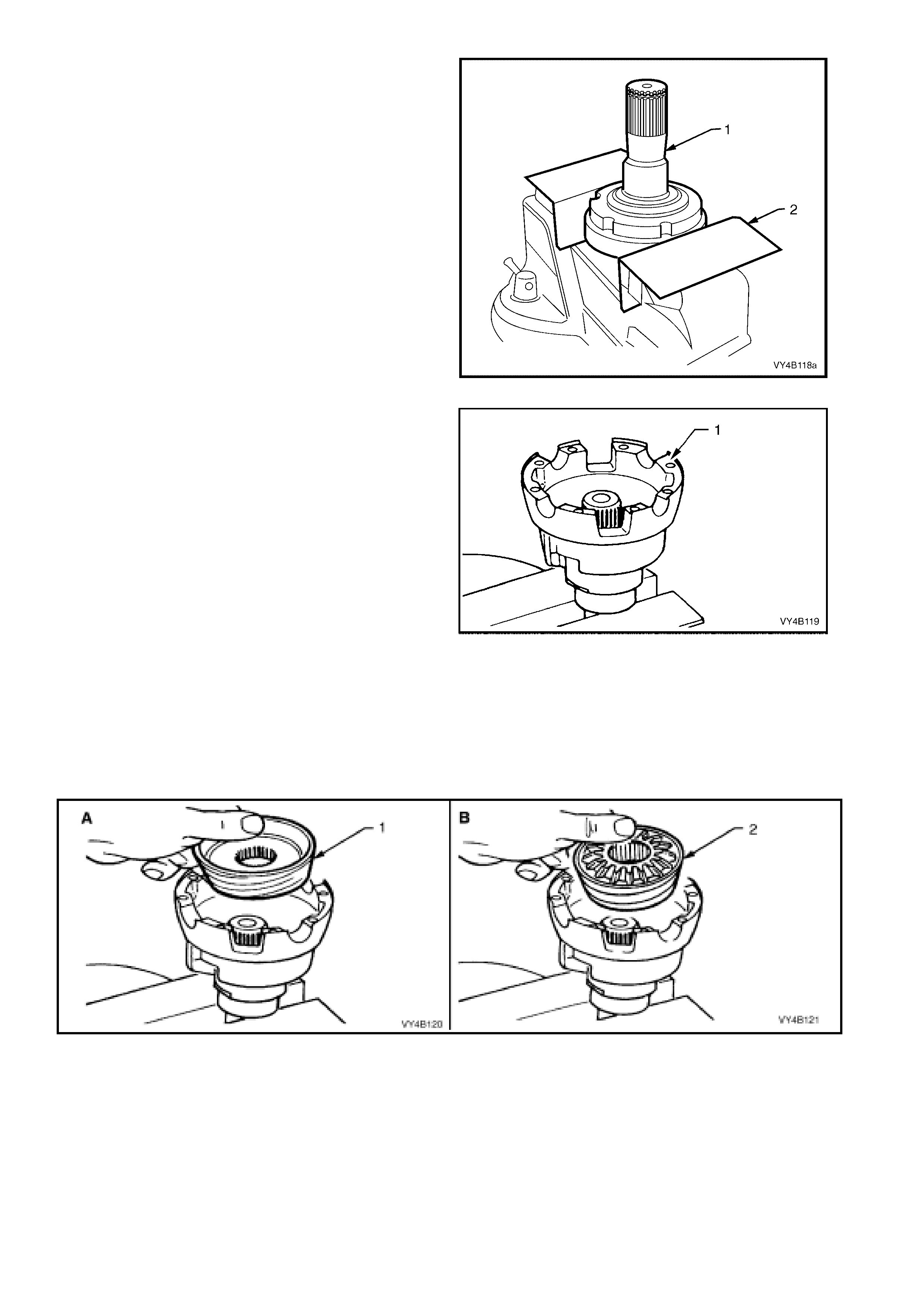
4. Clamp the left hand inner axle shaft (1) in a
vice equ ipped with sof t jaws (2), af ter rem oving
the snap ring from the end of the shaft.
NOTE: The axle shaft (or inner axle shaft) is used
as a mounting tool with 3.08:1 ratio differentials, to
ensure correct side gear and clutch cone spline
alignment. Failure to follow this procedure will
prevent installation of the inner axle shafts at final
assembly.
Figure 4B-184
5. Place differential case cap (1) over axle shaft
mounted in vice with interior of the housing
facing upwards.
6. Paint a mixture of Molybdenum Disulphide
grease and the recommended differential
carrier lubricant onto faces of side gears and
clutch cone surfaces.
Figure 4B-185
7. For 3.08:1 ratio differentials (view ‘A’), install
clutch cone over axle splines, seating it in
position in housing followed by a shim (if
required, refer Step 2) and side gear.
With 3.07:1 and the 3.46:1 ratio differentials
(view ‘B’), install the clutch cone/side gear
assembly (2) to the housing.
Figure 4B-186
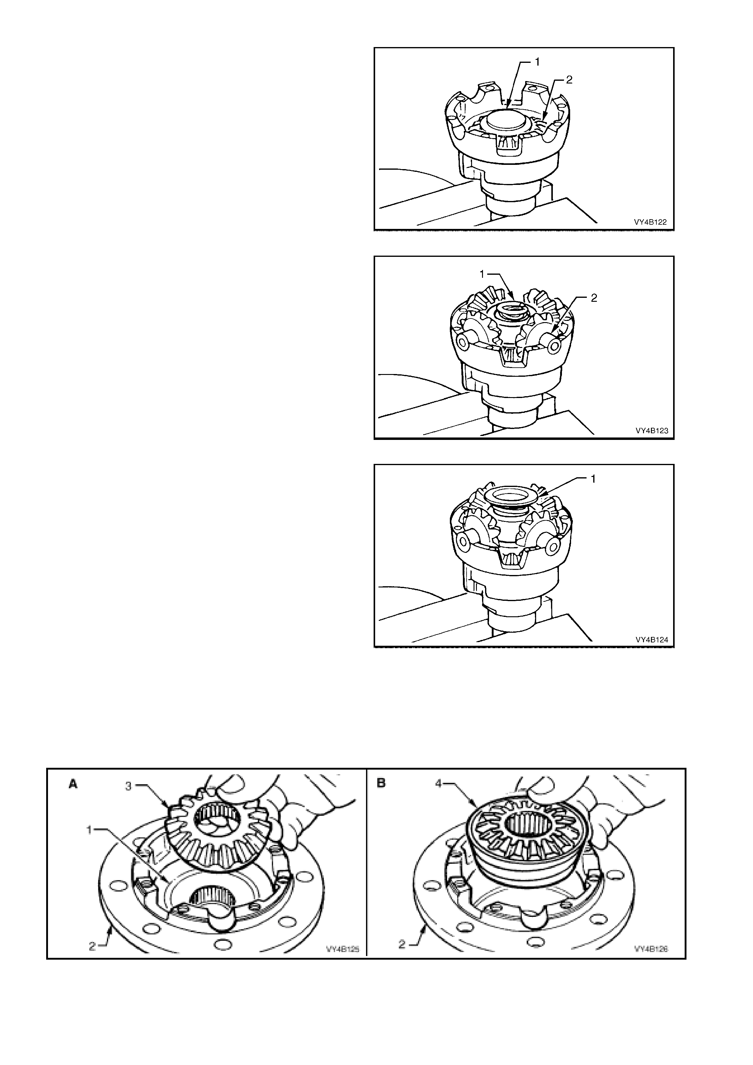
8. Plac e a thr ust spring plate ( 1), stepped s ide up
on side gear (2).
9. Assemble the four pinions and thrust washers
onto pinion cross shaft.
10. Install pinions and cross shaft assembly to
case c ap, ensuring that pin ions mesh with si de
gear.
Figure 4B-187
11. Install three ne w co ncentr ic diff er ential pre- l oad
springs (1) into cen tre of the pinion cross shaft
(2).
NOTE: NEW pre-load springs (1) must always be
installed on reassembly, DO NOT RE-USE OLD
SPRINGS.
Figure 4B-188
12. Assemble second thrust spring plate (1),
stepped side down, onto pre-load springs.
Figure 4B-189
13. For 3.08:1 ratio differentials (view ‘A’), install
clutch cone (1), shim (if required) and side
gear (3) to case cover (2).
With 3.07:1 and the 3.46:1 ratio differentials
(view ‘B’), install the clutch cone/side gear
assembly (4) into the case cover (2).
Figure 4B-190
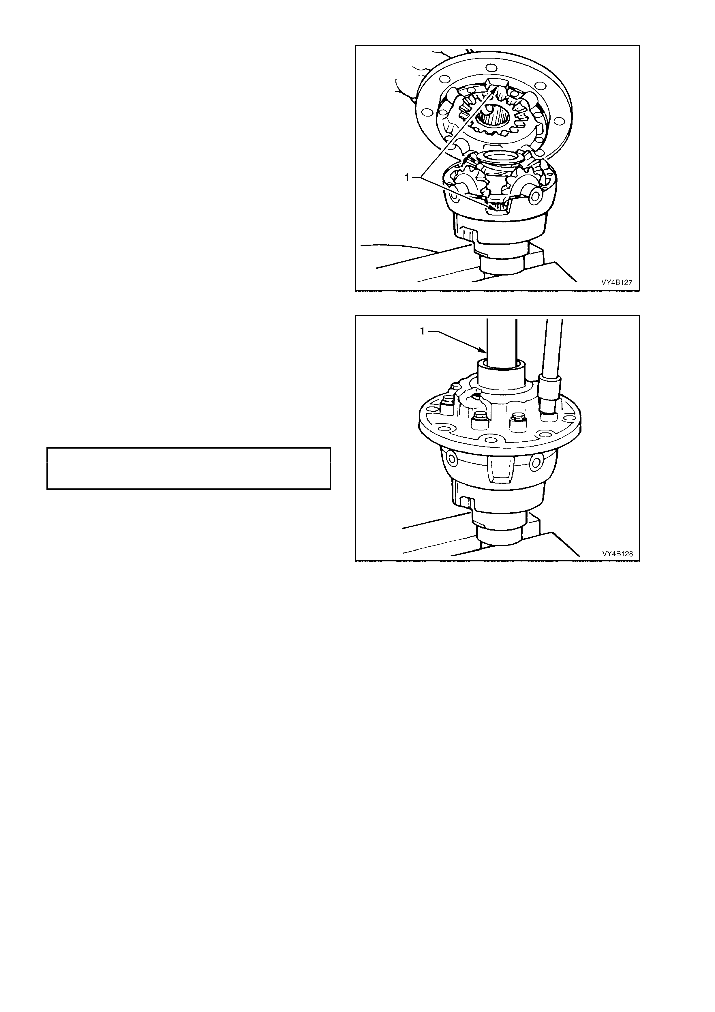
14. Install case cover onto case cap.
NOTE: Ensure that the cut out (1) on each side of
the case cover and cap align.
Figure 4B-191
15. Install two NEW differential case cap-to-cover
attaching b olts i n opposite bolt hol es and f inger
tighten.
16. Install other inner axle shaft (1) through case
cover, rotating axle shaft to engage clutch cone
splines and then side gear splines. Leave axle
shaft in this position. Install remaining, NEW,
cap-to-cover attaching bolts and t ighten evenly
to the correct torque specification.
DIFFERENTIAL CASE CAP TO
TO COVER ATTACHING BOLT
TORQUE SPECIFICATION 35 – 45 Nm
17. With 3.08:1 ratio assemblies, remove axle
shafts from differential case assembly.
NOTE 1: If the shafts bind on the clutch cone and
side gear splines, a light tap with a soft metal
hammer may be necessary to remove the axle
shafts.
NOTE 2: At no tim e mus t the side gears and clutc h
cones be rot ated until t he i nner axl e shaf ts are f ull y
installed. Failur e to obs er ve this c ondit ion wil l res ult
in side gear and clutch cone spline misalignment,
thus preventing inner axle shaft installation.
Figure 4B-192
Should splines become misaligned, loosen case
cap to c over b olts and rep e at s teps 4, 5, 15 and 1 6
of REASSEMBLE procedure.
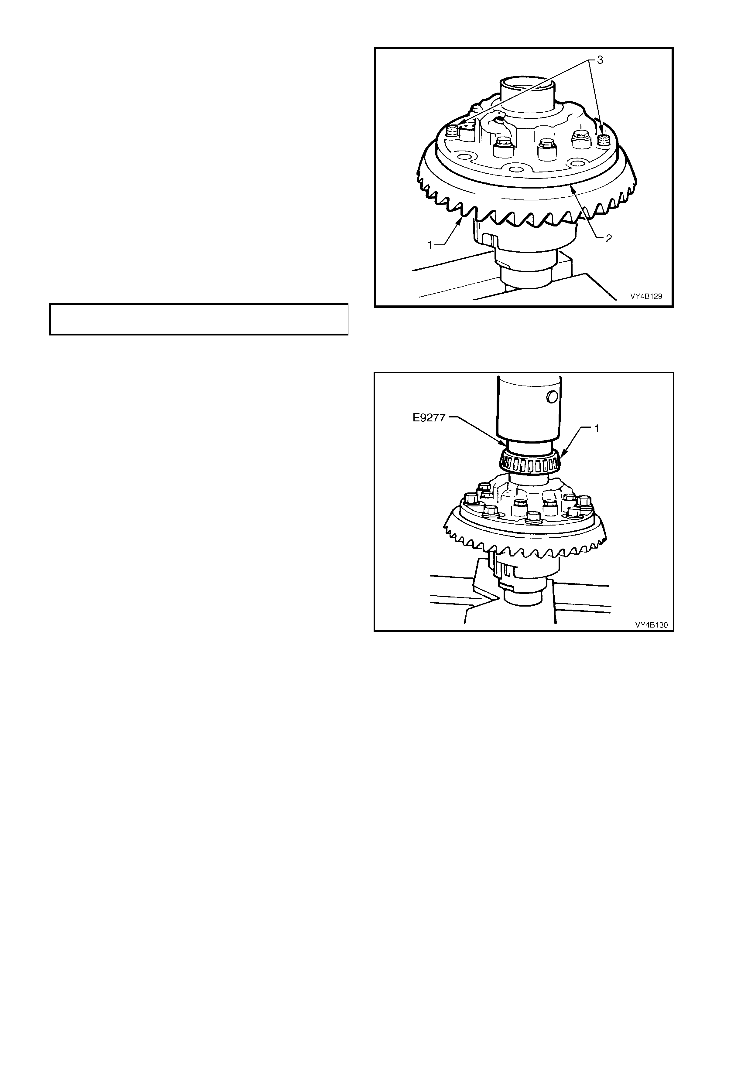
18. Place ring gear (1) into position on differential
case cap (2) and install ring gear attaching
bolts.
NOTE 1: For ease of assembly, it may be
necessar y to heat the ring gear on a hot plate until
it is hot to the hand, prior to installing onto the
differential case cap.
NOTE 2: On no account must a flame be used to
heat the ring gear.
NOTE 3: Use left hand threaded guide pins (3) to
pilot ring gear over differential case spigot.
19. Install NEW ring gear attaching bolts evenly
until gear face is flush with differential case
spigot.
Tighten bolts to the correct torque
specification.
FINAL DRIVE RING GEAR
TORQUE SPECIFICATION 125 - 150 Nm
NOTE: Ring gear attaching bolts use a left hand
thread and are identified by an 'L' on the bolt head.
Figure 4B-193
20. If installin g n ew side b eari ngs (1), us e Tool N o.
E9277 to press on side bearings (1) to
differential case journals.
Figure 4B-194
21. Continue rear axle assembly, proceeding from
'Differential Case Side Bearing Pre-Load
Setting', in this Section.
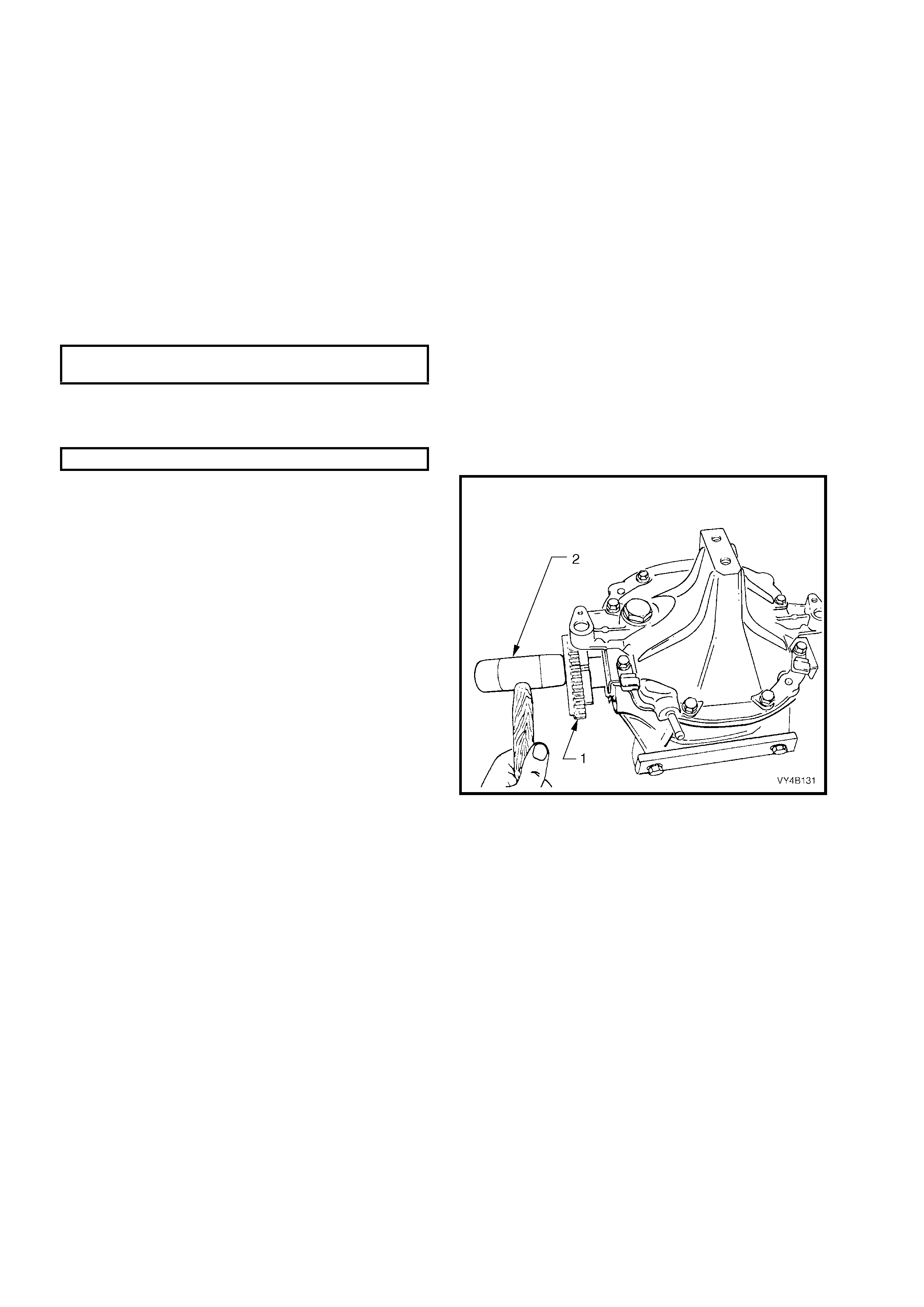
3.5 REAR AXLE
REASSEMBLE
1. Apply a 1.5 – 2.0 mm diameter continuous
bead of sealant, such as Loctite 587 (‘Ultra
Blue’) or equivalent to inside edge of rear
cover and bolt holes and completely around
drain plug hole.
2. Install rear cover to differential carrier housing.
Fit screw adjuster lock plates to rear cover,
ensuring that lock plates fit over ribs or
between ribs on the screw adjusters.
If equipped with ABS, i nstall both sensor s, and
tighten rear c over attach ing bolts to the correc t
torque specification.
REAR COVER ATTACHING
TORQUE SPECIFICATION 23 - 31 Nm
3. If equipped with ABS, check that sensor to
toothed inner axle shafts air gap is to
specification.
ABS SENSOR AIR GAP 0.4 - 1.5 mm
4. If removed, reinstall a spring clip to the end of
each inner axle shaft (1), then reinstall, aligning
splines with clutch cones (if a 3.08:1 ratio unit
is equipped with an LSD) and side gears.
NOTE: To avoid premature seal failure, ensure
axle shaft splines or spring clip do not score or
damage the seal lips during installation.
5. Lig htly tap on end of each shaft flange (1) with
a soft faced hammer (2) to compress spring
clip on shaft into clutch cup and side gear
splines. Fully engage both shafts until clips
snap into side gear grooves.
IMPORTANT: With 3.08:1 ratio, LSD type
differential assemblies, ensure that both inner axle
shafts are instal led ful ly befor e rotating e ither s haft.
If rotation of one shaft occurs before both are fully
installed, misalignment of opposite side gear and
clutch cone will occur, thus preventing ass embly of
remaining shaft.
NOTE: For vehicles equipped with ABS, the inner
axle shafts are unique for this application.
Figure 4B-195
6. Reinstall differential carrier assembly. Refer to
3.2 FINAL DRIVE ASSEMBLY in this Section.

4. DIAGNOSIS
4.1 GENERAL INFORMATION
Very of ten, fin al dr ive as sem blies ar e consi dered as n ois y, when in re ality, th e no ise is em anating fr om s ome other
source, such as tyres, front wheel bearings, rear wheel bearings, manual transmission rear bearings, engine
noises, muffler roar, automatic transmission or power steering pumps.
All final drive assemblies have some slight humming noise. This will vary with the type of body construction, load
and tyre pressure.
Noise which emanates from any one of these can quite easily be confused with a final drive assembly noise and
unless a series of elimination tests are carried out to definitely confirm the real source of the noise, differential
assemblies may be, and often are, dismantled unnecessarily.
Although not infallible, the following diagn osis guide will assist in locating and definin g the different characteristics
of the components which could be responsible for a noise.
Road Test
Ensure th at the final dr ive ass embly lubric ant is cor rect and at the cor rect le vel. Drive at lo w speed unt il thor oughly
familiar with vehicle noises by which time the final drive assembly should have warmed up. Accelerate gradually
from the lowes t pr actica l sp eed in a d irect r atio gear (1:1) to 100 k m /h, noting any nois es and t he sp eeds at which
they occur. Release the accelerator and without using the brakes, allow the vehicle to lose speed. Next, allow the
vehicle t o coast to res t from 100 km /h with the trans mission in ne utral pos ition. An y noises comm on to earlier tes ts
may be eliminated as final drive assembly gear noise, as the final drive assembly is not under load under these
conditions. Engine noise is gauged by gradually accelerating the engine with the vehicle at rest.
NOTE: Only drive at high speeds when it is legal and safe to do so.
Tyre Noise
T yr e noise can easily be mis taken for final drive asse mbly noise ev en though th e noisy t yres m ay be operating on
the front wheels. Tyre noise changes with different road conditions, but final drive assembly noise does not. Final
drive ass em bly noise us ual ly ceases when coas ting with the tra nsm iss ion in neutral at s peeds under 50 k m /h. T yre
noise continues, but with a lower tone as vehicle speed is reduced.
T yre noise nat urally shou ld be first elim inated; drivin g on a grass s urface is idea l to check against this condit ion. It
should be noted though, that dry grass can impose a fire hazard with the heat emanating from the catalytic
converter and wet grass can cause excessive wheel spin. Inflating tyres temporarily to high pressures will change
the contact with the road and assist in reducing tyre noise. Pressures up to 276 kPa may be used temporarily.
Tyres which have the surface of the non-skid divisions worn with one end higher than the other (saw-tooth wear)
are usually noisy. Interchanging tyres can prove effective in reducing noise.
Front Wheel Bearings
W orn, brinelled, c hipp ed or incorrec tly adj usted fr ont whee l bear ings wi ll caus e a noise, ver y similar to t yre n oise. It
is a constant noise, does not vary on 'drive' or 'coast' and still persists when coasting with the transmission in
neutral. This noise does not noticeably change on differing road surfaces to the same degree as does tyre noise.
Although not so pronounced, front wheel bearing noise can also be compared to a road surface noise, which is
produced when the vehicle is travelling over a surface such as penetrated bitumen type road.
Transmission Rear Bearing (Manual Transmission)
A rough or pitted rear transmission bearing, usually produces a very definite bearing noise and sets up a distinct
'whirring' condition, which is most audible when accelerating from slow speed under a high throttle opening and
tends to diminish as vehicle speed increases.
This noise is also prominent un der a consta nt throttle opening, but dis appears o n over-run when coasting with the
transmission in neutral.
When driven in second gear, noise can be amplified by lightly accelerating.
Backlash Clunk
Excessive clunk with acceleration and deceleration may be caused by worn differential pinion shafts, excessive
clearance between inner axle shaft and side gear splines, drive shaft companion flange and wheel spindle flange
splines, excessive clearance between side gear hub and counterbore in case, worn pinion and side gear teeth,
worn thrust washers and excessive drive pinion and ring gear backlash. Remove worn parts and replace as
required, selecting close fitting parts when possible. Adjust pinion and ring gear backlash.
Drive-Line Snap
A snap on s udden st art, either forward or reverse, m ay be caused by a loose p inion f lange. If lo ose, replac e nut or
flange as outli ned un der 2.9 PINION FLANGE in this Section.
This condition may also be caused by incorrect lubricant in an LSD Drain and refill with correct lubricant.
Techline

Engine And Other Contributing Factors
Noises whic h emanate fr o m the engin e, tra ns miss ion or muffler ar e oc cas io nal ly confus ed with final dri ve as sem bl y
noises.
To is olate t hese nois es, fir st car efull y not e the appr oxim ate veh icle s peed and c ondit ions wher e the supp ose d fina l
drive assembly noise is m ost pronounced, then with the vehicle stationary and in a quiet place to avoid interfering
noises (depress the clutch pedal on vehicles with manual transmission), run the engine up and down slowly
through the engine speeds that correspond to the vehicle speeds at which the noise was prominent and observe
whether there is any similarity to a final drive assembly noise.
For vehicles with manual transmission: With transmission still in neutral, again run the engine at similar speed while
slowly letting the clutch engage, and listen for noises from the transmission.
Muffler noises are usually readily identified, possibly an exception being when a muffler emits a high-pitched
periodic whistling noise, which could be confused with a bearing noise.

4.2 FINAL DRIVE ASSEMBLY NOISE
Final drive assembly noises fall into two categories:
a. Gear related noises.
b. Bearing related noises.
Before testing for final drive assembly noise, ensure that the lubricant is the correct type and at the correct level.
GEAR RELATED NOISE
Ring Gear And Pinion Noise
Noise produced by the ring gear and pinion set is of a cyclic nature and generally shows up as a 'drive noise',
'coast noise', or 'float noise'.
1. Drive noise is most pronounced on constant acceleration through the speed range of 50 to 90 km/h.
2. Coast noise is most pronounced when the vehicle is allowed to coast through the speed range from 90 to 50
km/h.
3. Float noise is most pronounced while the vehicle is kept at constant speed for periods between 50 to 90 km/h.
Final drive assembly noise will always change when comparing 'drive' and 'coast' and will usually cease when
coasting with transmission in neutral at speeds under 50 km/h.
Differential Side Gear and Pinion Noise
Noise produced by these gears occurs when there is excessive wear between the side gear hubs and the
differential case bores. This can cause a 'clunking' noise when the vehicle is driven at low speeds.
Noise produced due to excessive wear between the gear teeth will be most pronounced on turns.
Common Causes of Gear Related Noises
1. Low lubric ant le ve l or inc or rec t lubr ic ant us ed.
2. Incorrect meshing of gear teeth (i.e. incorrect pinion positioning shim or backlash setting shims).
3. Scored gear teeth:- usually the result of incorrect lubricant type or level.
4. End play in bearin gs .
5. Bruised or chipped teeth.
6. Excessive runout of pinion head or ring gear backlash.
7. Ring gear creep ing on d ifferentia l case r esulting f rom ring g ear bolts l oosening - n oise fr om this s ource usual ly
appears as a sharp metallic sound when shifting from reverse to first gear.

BEARING RELATED NOISE
Differential Pinion Gear Bearings
W orn, rough or lo ose beari ngs will tend to a ggravate and magnif y drive, float an d coast noise, and r esult in heav y,
irregular drive noise on constant acceleration and float, and also an irregular noise on deceleration.
Pinion bearings, if rough or brinelled, will produce a continuous whine, which will persist when coasting with
transmission in neutral even to a low speed.
End play in the pinion bearings, even from natural wear, which permits the pinion to feed back into the ring gear,
will cause a noise on ov er- run.
Drive Shaft Bearings
Drive s haf t bear ings t hat are roug h or p itt ed can be res pons ib le f or a gro wlin g no i s e which on first impres sion c oul d
be likened to a final drive noise.
The noise, however, does not vary on 'drive' or 'coast' and still persists when coasting with transmission in neutral.
Frequently this noise can be readily identified by the sound being conveyed in an eccentric form. It can also be
intermittent as the noise may fade for a short period.
To confirm the diagnosis of a drive shaft bearing noise:
1. Support the rear of the vehicle on safety stands and remove both rear wheels and brake discs.
2. Start the engine and, with top gear engaged, speed engine up to a fast idle.
3. If a stethoscope is available, it is ideal to compare the noise of one bearing against the other. To obtain the
best results with a stethoscope, keep the volume adjustment down low.
4. A difference in the noise of the drive shaft bearings can also be discerned by placing a steel-shafted
screwdriver to the ear and in close proximity to each bearing in turn.
With practice, a noticeable difference in noise can, at most times, be observed between a good and not so good
bearing.
Differential Side Bearings
Side bearings will produce a constant grinding noise of a slower nature than pinion bearings (side bearing noise
cannot be det ermined by the diagn osis procedure for drive shaft bearing noise), but will be in t he same frequenc y
as drive shaft bearings.
Common Causes of Bearing Related Noises
1. Low lubric ant le ve l or inc or rec t lubr ic ant us ed.
2. Foreign matter in the lubricant.
3. Incorrect pre-load setting.
4. Bearings incorrectly mounted e.g. dirt trapped behind abutment faces during assembly.

4.3 LSD NOISE
If LSD stick-slip chatter is diagnosed, the differential carrier lubricant should be drained immediately after a run to
warm up the lubricant. This is to remove as much old lubricant and wear debris as possible. Refill carrier with the
specif ied l ubric a nt a nd r e- e va luat e L SD o per at ion f or a m inimum of 20 k m . Chatte r will us ua lly disapp ear with in th is
time.
Should chatter still occur, remove carrier and overhaul LSD. Refer to 3.4 LIMITED SLIP DIFFERENTIAL in this
Section.
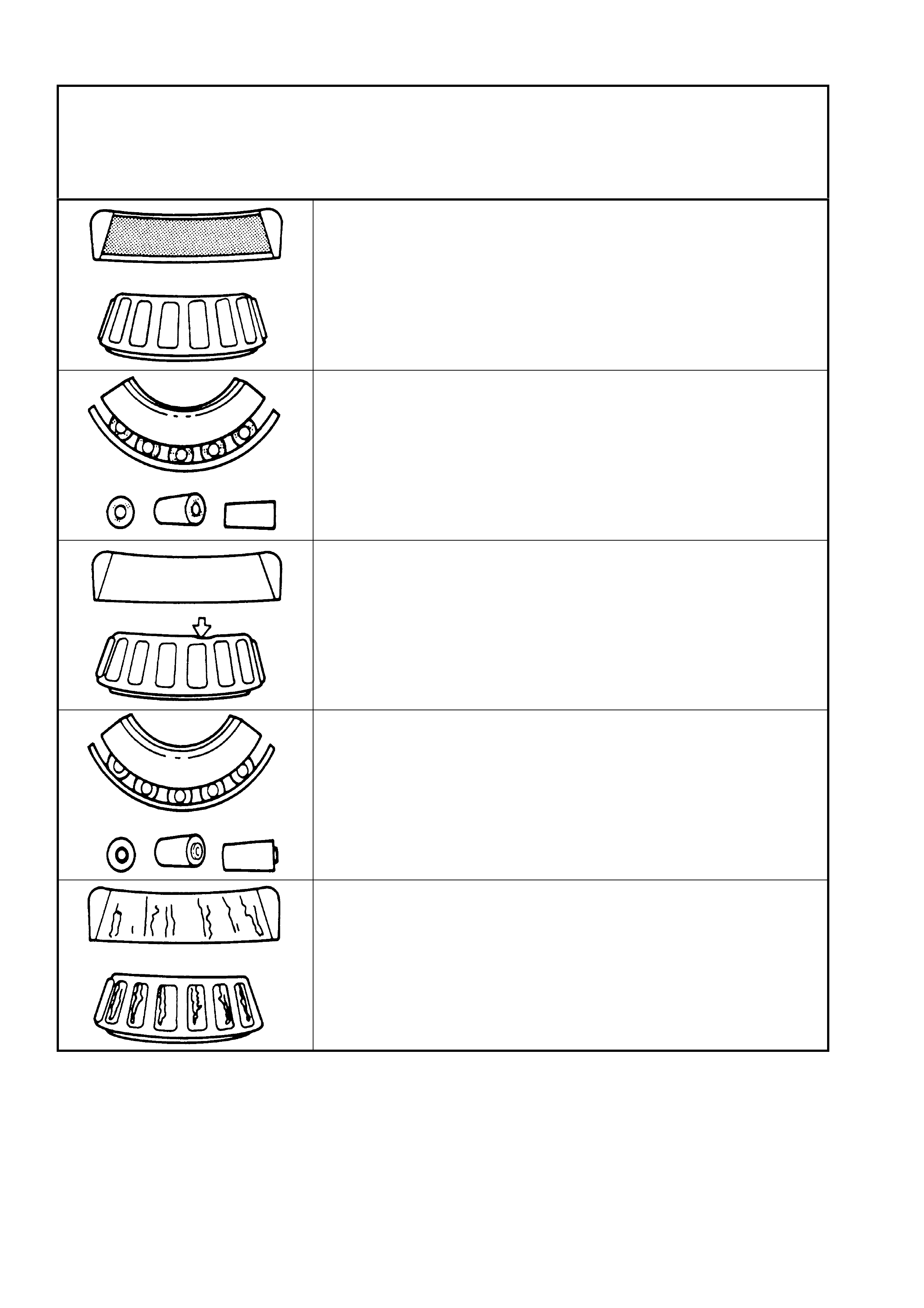
4.4 FINAL DRIVE BEARING DIAGNOSIS
CONSIDER THE FOLLOWING FACTORS WHEN DIAGNOSING BEARING CONDITION:
1. GENERAL CONDITION OF ALL PARTS DURING DISASSEMBLY AND INSPECTION.
2. CLASSIFY THE FAILURE WITH THE AID OF THE FOLLOWING ILLUSTRATIONS.
3. DETERMINE THE CAUSE.
4. MAKE ALL REPAIRS FOLLOWING RECOMMENDED PROCEDURES.
ABRASIVE ROLLER WEAR
DESCRIPTION:
Pattern on races and rollers caused by fine abrasives.
CORRECTION:
Clean all parts and housings
Check seals and bearings, replacing if leaking, rough or noisy.
GALLING
DESCRIPTION:
Metal smears on roller ends due to overheating, lubricant failure or
overload.
CORRECTION:
Replace bearing, check seals and check for proper lubrication.
BENT CAGE
DESCRIPTION:
Cage damage due to improper handling or tool use.
CORRECTION:
Replace bearing.
ABRASIVE STEP WEAR
DESCRIPTION:
Pattern on bearing ends caused by fine abrasives.
CORRECTION:
Clean all parts and housing. Check seals and bearings, replacing if
leaking, rough or noisy.
ETCHING
DESCRIPTION:
Bearing surfaces appear grey or greyish-black in colour with related
etching away or material, usually at the roller spacing.
CORRECTION:
Replace bearings. Check seals and check for proper lubrication.
Figure 4B-196
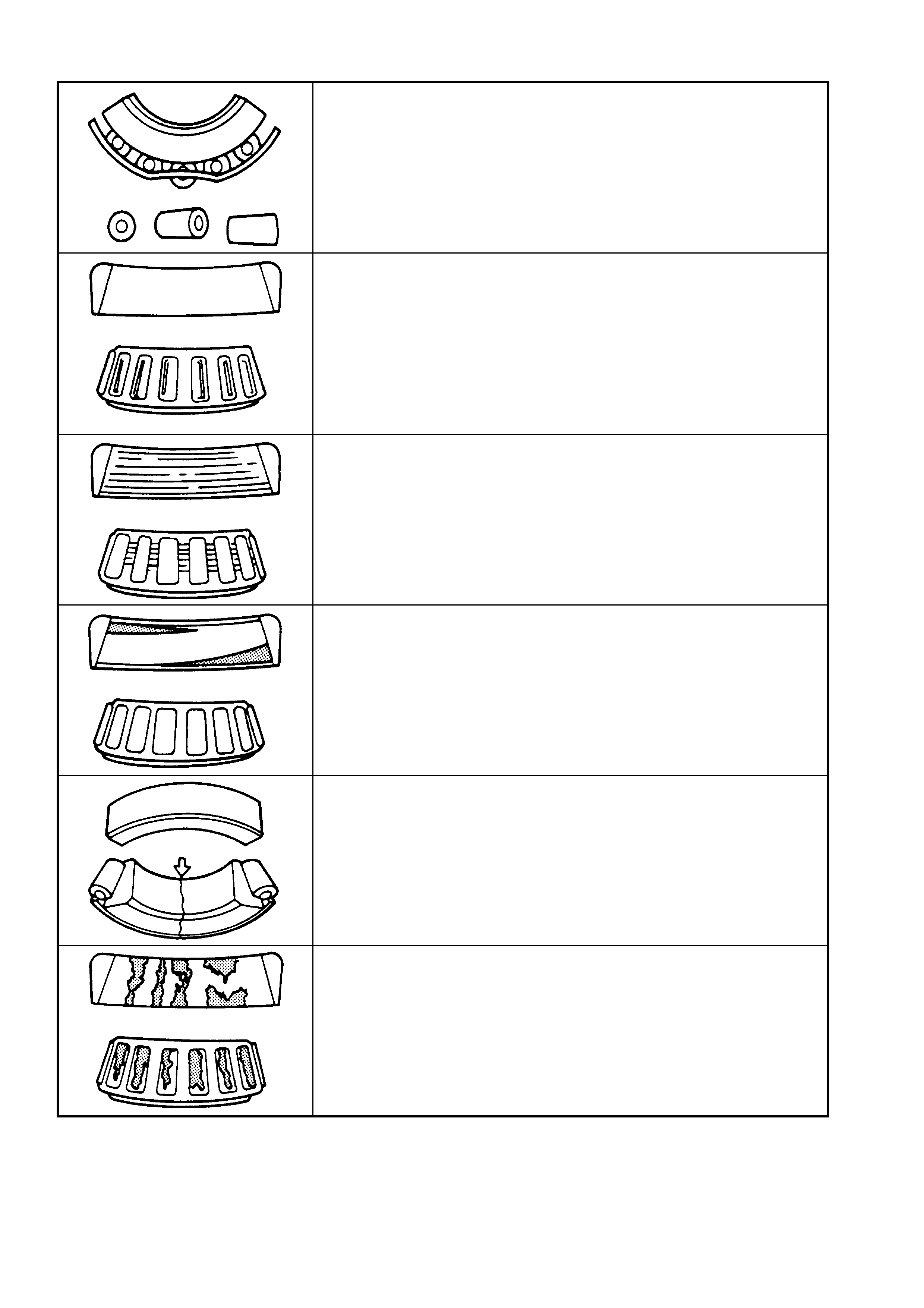
Final Drive Bearing Diagnosis – Continued
BENT CAGE
DESCRIPTION:
Cage damage due to improper handling or use of tools.
CORRECTION:
Replace bearing.
INDENTATIONS
DESCRIPTION:
Surface depressions on race and rollers caused by hard particles of
foreign material.
CORRECTION:
Clean all parts and housing. Check seals and replace bearings if rough
and nois y.
CAGE WEAR
DESCRIPTION:
Wear around outside diameter of cage and roller pockets caused by
abrasive materials and inefficient lubrication.
CORRECTION:
Replace bearings. Check seals and check for proper lubrication.
MISALIGNMENT
DESCRIPTION:
Outer race misalignment due to foreign object.
CORRECTION:
Clean related parts and replace bearing. Make sure races are properly
seated.
CRACKED INNER RACE
DESCRIPTION:
Race cracked due to improper fit, cocking or poor bearing seats.
CORRECTION:
Replace bearings and correct bearing seats.
FATIGUE SPALLING
DESCRIPTION:
Flaking of surface metal resulting from fatigue.
CORRECTION:
Replace bearings and clean all related parts.
Figure 4B-197
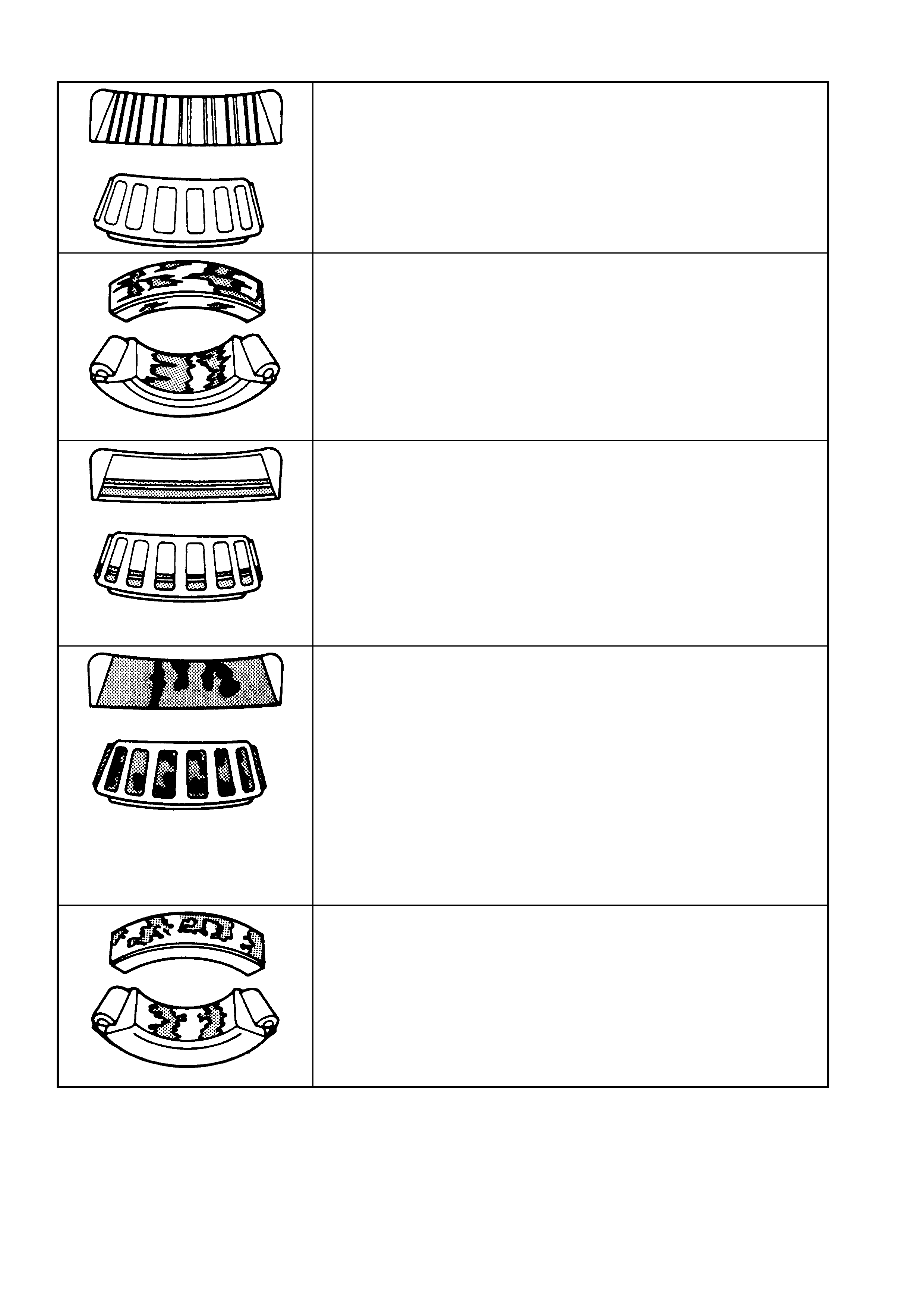
Final Drive Bearing Diagnosis – Continued
BRINELLING
DESCRIPTION:
Surface indentations in raceway caused by rollers either under impact,
loading or vibration while the bearing is not rotating.
CORRECTION:
Replace bearing if rough or noisy.
FRETTAGE
DESCRIPTION:
Corrosion set up by relative movement of parts with no lubrication.
CORRECTION:
Replace bearing. Clean related parts. Check seals and check for proper
lubrication.
STAIN DISCOLOURATION
DESCRIPTION:
Discolouration can range from light brown to black, caused by incorrect
lubrication or moisture.
Re-use bearing if stains can be removed by light polishing or if no
evidence of overheating is observed.
CORRECTION:
Check seals and related parts for damage.
HEAT DISCOLOURA TION
DESCRIPTION:
Heat discolouration can range from faint yellow to dark blue, resulting
from overload or improper lubricant.
Excessive heat can cause softening of races or rollers.
To check for loss of temper on races or rollers, a simple file test may be
made. A file drawn over a tempered part will grab and cut metal,
whereas a file drawn over a hard part will glide readily with no metal
cutting action.
CORRECTION:
Replace bearings if overheating damage is indicated. Check seals and
other parts.
SMEARS
DESCRIPTION:
Smearing of metal due to slippage that can be caused by poor fits,
lubrication, overheating, overloads or handling damage.
CORRECTION:
Replace bearings. Clean related parts and check for proper fit and
lubrication.
Figure 4B-198

5. SPECIFICATIONS
GENERAL
Rear Axle Assembly
V6 Engine
(Except Manual Transmission Station Wagon)... SAA – 76 Series
GEN III V8/V6 Supercharged Engines (and
Manual Transmission Station Wagon)................ SAA – 80 Series
Axle Type ................................................................... Independent Housing
ST ANDARD AND L SD AXLES
Gear Type .................................................................. Hypoid
Gear Ratio (See I.D. tag attached to the carrier)
V6 Engine
(Except Manual Transmission Station Wagon)... 3.08:1
GEN III V8/V6 Supercharged Engines (and
Manual Transmission Station Wagon)................ 3.07:1
GEN III V8/V6 Utility and Manual Transmission... 3.46:1
No. of Teeth: .............................................................. 3.08:1 3.07:1 3.46:1
Ring Gear.............................................................. 37 43 45
Drive Pinion Gear.................................................. 12 14 13
LUBRICANT
Capacity..................................................................... 1.6 litres
Type ........................................................................... Refer Lubrication in this Section.
DIFFERENTIAL GEARS
Type ........................................................................... Straight Bevel
No. of Teeth: .............................................................. 3.08:1 3.07:1 3.46:1
Pinion Gears ......................................................... 10 10 10
Side Gears............................................................ 16 15 15
FINAL DRIVE PINION GEAR BEARINGS
Bearing Type.............................................................. Adjustable Tapered Roller
Bearing Adjustment.................................................... Collapsible Spacer
Bearing Pre- L oad:...................................................... Timk en Koyo
Dummy pinion - New bearings.............................. 1.4 – 2.0 1.5 – 1.9 Nm
Dummy pinion - Used bearings............................. 0.7 – 1.2 0.7 – 1.2 Nm
New with oil seal................................................... 1.4 – 2.4 1.5 – 2.1 Nm
New without oil seal.............................................. 1.4 – 2.0 1.5 – 1.9 Nm
Used with oil seal.................................................. 0.7 – 1.2 0.7 – 1.2 Nm
Used without oil seal............................................. 0.7 – 1.2 0.7 – 1.2 Nm
DIFFERENTIAL CARRIER SIDE BEARINGS
Type ........................................................................... Adjustable Tapered Roller
Adjustment ................................................................. Screw adjusters on each side of the carrier.
Bearing Pre-Load
(Refer to text for measurement conditions) .......... Timken Koyo
New Bearings........................................................ 15 – 35 N 8 – 24 N
Used Bearings ...................................................... 8 – 18 N 5 – 13 N
RUN-OUT SPECIFICA TIONS
Trunnion Assembly Hub............................................. 0.06 mm Total Indicated Run-out
Case Assembly (without ring gear attached)............. 0.05 mm (maximum)
Ring Gear Rear Face (assembled to case flange) .... 0.13 mm (maximum)
BACKLASH SPECIFICA TIONS
Ring Gear to Drive Pinion .......................................... 0.10 – 0.18 mm (at the tightest point)
LSD TORQUE CHECK
Torque Check Specification....................................... 45 Nm (minimum)

ABS SEN SO R
Air Gap (non-adjustable)............................................ 0.4 – 1.5 mm
SEALANTS
Drive Shaft Dust Caps/Shield........................................ RTV 732 Sealant, or commercial equivalent
Rear Cover to Carrier Housing .................................. Loctite 587 (‘Ultra Blue’) or equivalent
As Required ............................................................... Loctite 242 or commercial equivalent, to
GM Specification 9985283.
LUBRICANTS
As Specified in Text ...................................................... Molybond HE50
As Specified in Text ...................................................... Commercially available Lithium Soap Based Grease.

6. TORQUE WRENCH SPECIFICATIONS
Nm
Brake caliper anchor plate to trailing arm bolts....................... 70 – 100
Collar nut to trunnion assembly .............................................. 295 – 305
Crossmember front mounting bolt........................................... 125 Nm, plus 30° – 40°
turn angle
Crossmember front mounting brace to underbody bolts ........ 60 – 85
Drain plug................................................................................ 23 – 31
Drive shaft constant velocity joint to trunnion flange/inner
axle shaft flange bolts............................................................. 50 Nm, plus 90°
turn angle
Filler plug................................................................................. 23 – 31
Final drive assembly to crossmember attaching bolts............ 90 Nm, plus 30° – 45°
turn angle
Final drive ring gear bolts........................................................ 125 – 150
Intermediate exhaust pipe to catalytic converter
attaching bolts – All engines.............................................. 40 – 50
LSD case cap to cover attaching bolts ................................... 35 – 45
Rear cover attaching bolts...................................................... 23 – 31
Rear disc brake shield to trailing arm. Upper bolts................ 70 – 80
Lower bolt s................ 85 – 90
....Rear mount to vehicle underbody attaching bolts................... 30 – 40 Nm, plus 55° – 65°
turn angle.
Rear mount to differential carrier rear cover attaching bolts... 85 – 105
Road wheel attaching nut ....................................................... 100 – 125
z Shock absorber lower mounting bolt ...................................... 105 – 125
New bolts/nuts and washers MUST be used on reassembly.
z Vehicle MUST be at curb weight before tightening to specifica tion
7. SPECIAL TOOLS
TOOL
NUMBER ILLUSTRATION DESCRIPTION CLASSIFICATION
1150
PULLER
Used in conjunction with forcing
screw E6661S and adaptor AU412 to
remove side bearing cups from the
screw adjusters
Previously released.
Unique
205-463
SCREW ADJUSTER SOCKET
Used for checking and adjusting final
drive side bearings.
Previously released.
(Also released as AU407
Unique
205-551
ADAPTORS
Used to remove the pini on beari ng
cups, in conjunction with
Remover /Ins tal ler E92 93.
205-551-1 is required for 3.07:1 and
3.46:1 assemblies.
New release.
Unique
205-552
ADAPTORS
Used to install the pinion bearing
cups, in conjunction with
Remover /Ins tal ler E92 71.
205-552-2 is required for 3.07:1 and
3.46:1 assemblies.
New release.
Unique
7208 REAR AXLE REMOVAL ADAPTOR
Used with E6662B for LSD torque
check.
Previously released.
Unique
7374 SLIDE HAMMER & PLATE
Used to remove inner axle shafts
from the rear axle assembly.
Previously released.
Available
AU408
DUMMY ARBOU R
Used with dummy pinion from
E9300A.
Previously released.
Unique
TOOL NUMBER ILLUSTRATION DESCRIPTION CLASSIFICATION
AU409 PRESS FIXTURE
Used for installing needle bearings into
screw adjusters. Used with AU411.
Previously released.
Unique
AU410 SEAL INSTALLER
Used to install inner axle seals to screw
adjuster.
Previously released.
Unique
AU411 BEARING & CUP REMOVER
Used in conjunction with AU409.
Previously released.
Unique
AU412
ADAPTOR
Used with forcing screw E6661S and
puller 1150 to remove side bearing cups
from screw adjust ers.
Previously released.
Unique
AU416
TOR X BIT
Used to remove and reinstall upper rear
brake backing plate to trailing arm bolts
Previously released.
Unique
DT-47695
REAR PINION BEARING CUP
REMOVER
Used in conjunction with remover E9293
to remove the rear (inner) pinion bearing
cup on 3.07/3.46:1 assemblies.
New release
Unique
DT-47696
SPACER
Used in conjunction with the dummy
pinion from E9300A when checking pinion
depth on 3.07/3.46:1 assemblies
New release.
Unique
E1673A15 BASIC PULLER
Used with adaptors to remove bearings
from the final drive assembly.
Previously released.
Unique
E1673A15
ADAPTOR
Used with puller E1673MT and stepped
plug E1673B16 to remove the rear pinion
bearing on 3.08:1 assemblies.
Previously released.
Unique
E1673B16
STEPPED PLUG
Used with puller E1673MT and adaptor
E1673N15 to remove bearings from the
differenti al cas e.
Previously released.
Unique
TOOL
NUMBER ILLUSTRATION DESCRIPTION CLASSIFICATION
E1673N15 ADAPTOR
Used with puller E16 73MT and
stepped plug E1673B16 to remove
the side bearings from the differential
case.
Previously released.
Unique
E1673S15 ADAPTOR
Used with puller E16 73MT to remove
the rear pinion bearing on 3.07:1 and
3.46:1 assemblies.
Previously released.
Unique
E3C10AER PINION REAR BEARING
REPLACER
Used to install the rear pinion bearing
during final drive overhaul.
Previously released.
Unique
E308
SEAL REMOVER
Used as a universal seal remover.
Also released as 56750.
Previously released.
Available
E6661S
FORCING SCREW
Used in conjunction with puller 1150
and adaptor AU41 2.
Previously released.
Unique
E6662B
TORQUE WRENCH ADAPTOR
Used in conjunction with 7208 to
check breakaway torque of LSD
differential.
Previously released.
Unique
E7115
ANGLE WRENCH
Used to tighten fas teners when an
angle torque is specified.
Also released as BT8653-A
Previously released.
Unique
TOOL
NUMBER ILLUSTRATION DESCRIPTION CLASSIFICATION
E9055
PINION OIL SEAL INSTALLER
Used to install the pinion oil seal.
Also released as 17-010A.
Previously released.
Unique
E9271
PINION BEARING CUP INSTALLER
Previously released.
Unique
E9277 SIDE BEARING INSTALLER
Used to install bearings to the
differential case.
Previously released.
Unique
E9293 PINION BEARING CUP REMOVER
Previously released.
Unique
E9300A
PINION HEIGHT SETTING GAUGE
Previously released as E9300, this
set now has an additional spacer to
be used on the 3.07:1 and 3,46:1
ratio, final dr i ve ass emblies.
Previously released.
Unique
J3289-20
HOLDING FIXTURE BASE
Used with either KM480 or dealer
fabricated bracket to hold the final
drive assembly.
Previously released.
Unique
J22610 CLAMP PLI ER S
Used to crimp the drive shaft boot
clamps. Also released as E1896.
Previously released.
Available
J22912-01
PRESS PLATES
Used in a number of different
applicat ions in removing be ar ings and
other transmission components when
pressing operations are required.
Previously released.
Unique
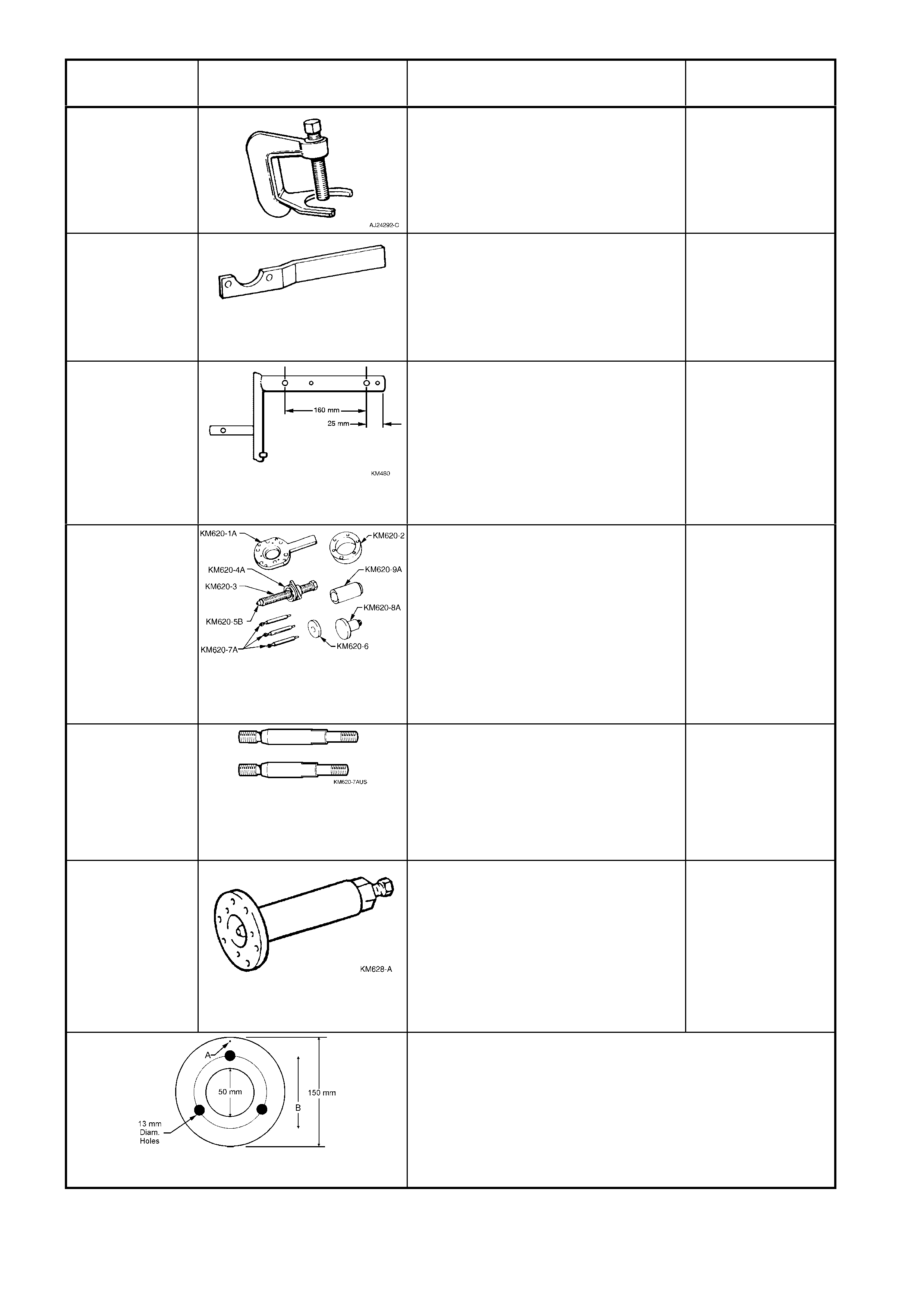
TOOL
NUMBER ILLUSTRATION DESCRIPTION CLASSIFICATION
J24292-C PRESS TOOL
Used to remove rear wheel studs
from the trunnion flange.
Previously released.
Unique
KM468 HOLDING BAR
Used to stop the rear trunnion from
rotating.
Previously released.
Available
KM480 HOLDING FIXTURE
Modify by drilling two 14 mm holes as
shown. Fixture originally released for
THM 125 automatic transaxle (’J’’
car).
Previously released.
Unique
KM620-B REMOVER/INSTALLER
Used for removing and installing
trunnion flange and rear wheel
bearing. KM 620-1 A is also us ed to
hold the pinion flange.
NOTE: Holes in KM620-1A, stamped
with a ‘B’ must be enlarged to 12.5
mm.
Previously released.
Unique
KM620-7AUS
SUPPORTS
The two revised length supports are
require d when us in g KM62 0- B for
service operations on the rear
trunnion and /or bear in g.
Previously released.
Unique
KM628-A EX TR A CTOR TO O L
Used to remove the final drive pinion
flange. Also used for several
disassembly operations on the V6
manual transmission. Each of the
three mounting holes must be
enlarged to 12.5 mm.
Previously released.
Unique
PINION FLANGE PULLEY
Dealer fabricated:
1. Made from a 13 mm thick piece of wood.
2. Drill a sm all hol e at 'A' and attach a o ne m etre len gth of
string at this point.
3. Drill two 10 mm holes as shown in the figure.
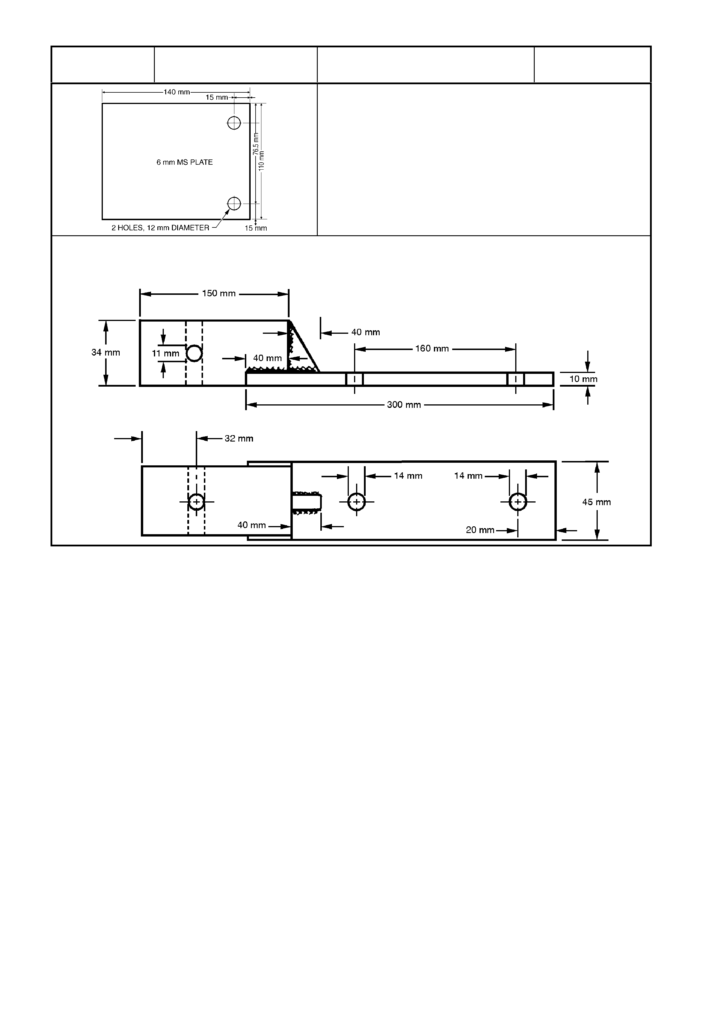
TOOL
NUMBER ILLUSTRATION DESCRIPTION CLASSIFICATION
DIAL INDICAT O R PLATE
Dealer fabricated:
1. Fabricated from 6 mm Mild Steel Plate
2. If using the brake caliper bolts to fasten, then 17 mm
spacer swill need to be installed on each bolt, prior to
installing.
DIFFERENTIAL CARRIER HOLDING FIXTURE
If KM480 is not available, fabricate
a holding fixture as shown.