
SECTION 4C - PROPELLER SHAFT AND
UNIVERSAL JOINTS
IMPORTANT
Before performing any Service Operation or other procedure described in this Section, refer to
Section 00 CAUTIONS AND NOTES for correct workshop practices with regard to safety and/or property
damage.
CONTENTS
1. GENERAL DESCRIPTION
1.1 SERVICE NOTES
2. SERVICE OPERATIONS
2.1 PROPELLER SHAFT
REMOVE
REINSTALL
2.2 RUBBER COUPLING
REPLACE
2.3 CENTRE BEARING ASSEMBLY
REMOVE
REINSTALL
3. SPECIFICATIONS
4. TORQUE WRENCH SPECIFICATIONS
5. SPECIAL TOOLS

1. GENERAL DESCRI PTI O N
The propeller shaft assembly as fitted to all MY 2003 VY and V2 Series Models is a two piece tubular design that
incorporates a centre support bearing, a conventional cross type universal joint (Hooke’s joint) and two rubber
couplings, one at the front and one at the rear.
The centre support bearing is a fully sealed ball bearing, mounted in a reinforced rubber cup. This centre bearing
rubber cup is supported in a cup guide and attached to a carrier, which in turn, is bolted to the vehicle underbody
brace.
Drive is trans m itted between the two halves of the propeller s haft through a centre universal joint directly behind the
centre bearing. T he centre univer sal joint is of the c onventional cros s design, and is located and s ecured in eac h of
the two propeller shaft yolks by staking.
The centre universal joint and centre bearing are lubricated for life and do not require any periodic lubrication.
For MY 2003 VY and V2 Series Models, excluding those fitted with a V6 engine and manual transmission, the
rubber coupling fitted to the front of the propeller shaft is bolted to a slip yoke at the transmission.
For MY 2003 VY Series Models f itted with a V6 engine and manual trans m ission, the rubber coupling at the f ront of
the propeller shaft is bolted to a flange that is fixed to the transmission mainshaft.
The rubber coupling at the rear of the propeller shaft is bolted to the pinion drive flange at the front of the rear
suspension differential assembly, and is common to all MY 2003 VY Series Models regardless of
engine/transmission combination.
1.1 SERVICE NOTES
1. By us ing two rubber couplings and having an interf erence fit between the two propeller shaft halves, meas uring
the driveline angles and propeller shaft phasing is not required.
2. The only serviceable components in the propeller shaft assembly as fitted to MY 2003 VY and V2 Series
Models (except those fitted with a V6 engine and manual transm ission) are the two rubber couplings, the front
slip yoke and associated fasteners. For MY 2003 VY Series Models fitted with the V6 engine and manual
transmission, in addition to the above components, the centre bearing assembly in the unit can also be
serviced, along with the slip joint boot and clamp. The reasons for this situation can be summarised as:
a. The centre univer sal joint bearing cups ar e set and retained by staking which requir es sophistic ated equipment
to ensure concentric reassembly of the universal joint. Should the centre universal joint require servicing, then
the propeller shaft assembly must be replaced.
b. In or der to separ ate the two propeller shaf t halves in MY 2003 VY and V2 Series Models (exc luding those fitted
with the V6 engine and manual transmission), the interference fit of the splined joint requires the use of a
hydr aulic pr ess and ex pensive tools. As this oper ation would also require the r e-balancing of the propeller s haft
assembly, the centre bearing assembly and/or slinger are also non-serviceable.
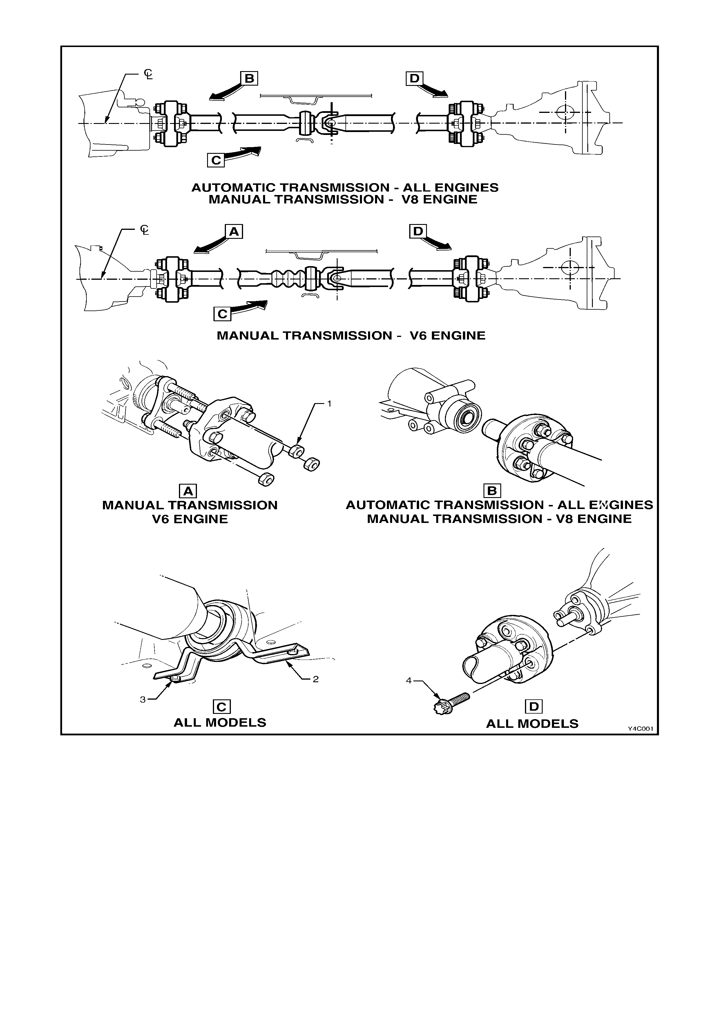
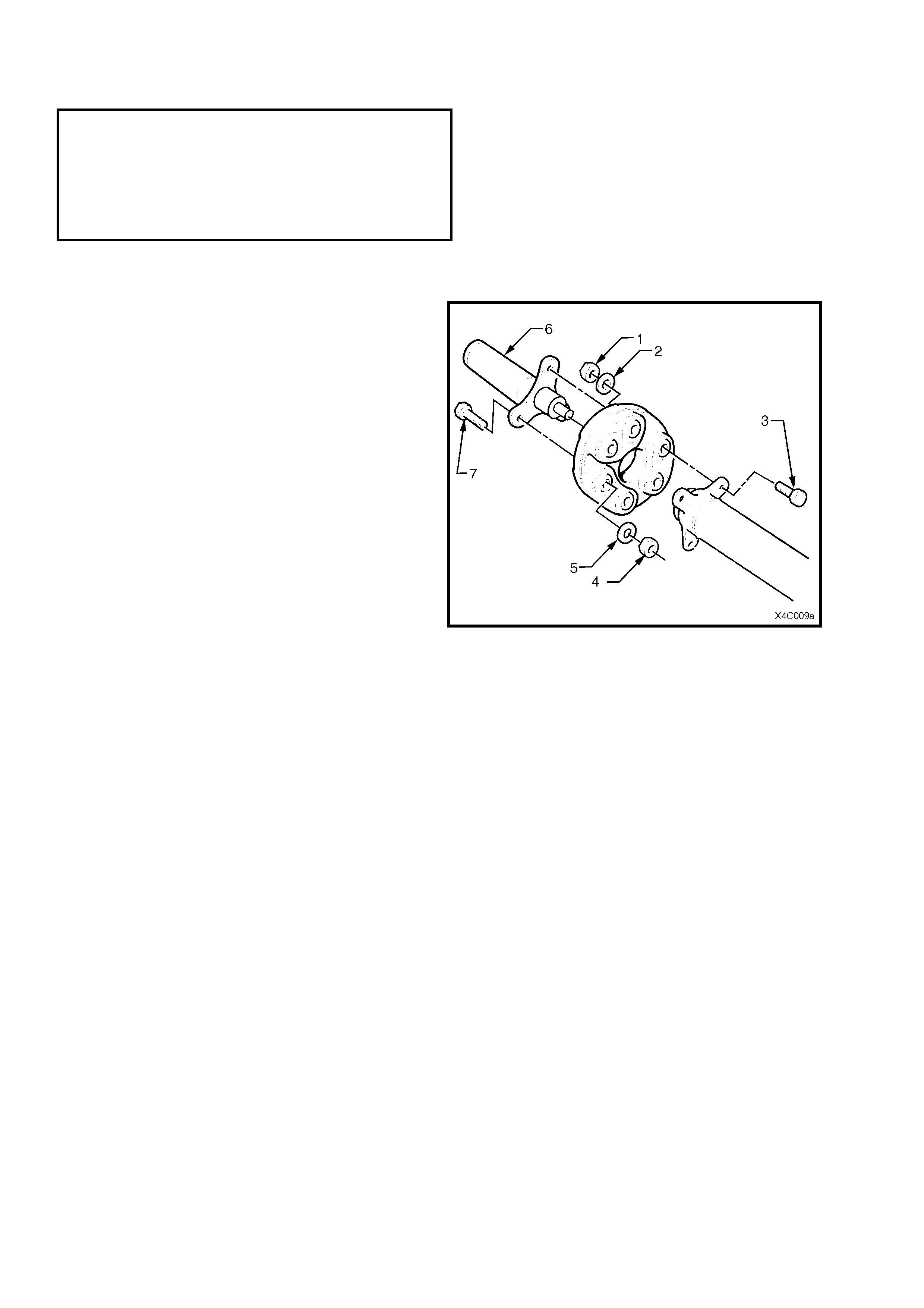
Figure 4C-1
Legend
1. Front Coupling to Transmi ssion Flange Nut (3 Places) 4. Rear Coupling to Rear Suspension Dif ferential A ssem bl y P i ni on
2. Centre Bearing Cup Guide Flange Torx Bolt (3 Plac es)
3. Centre Bearing Cup Guide to Underfloor Brace Bolt (2 P l aces)
2. SERVICE OPERATIONS
IMPORTANT
All propeller shaft fasteners are important attaching parts as they affect the performance of vital
powertrain components and/or could result in major repair expense. Where specified in this section,
fasteners MUST be replaced with parts of the same part number or a GM approved equivalent. Do not
use fasteners of an inferior quality or substitute design.
Torque values must be used as specified during reassembly or installation of the propeller shaft to
ensure pr oper retention.
Throughout this Section, fastener torque wrench specifications may be accompanied with the follow ing
identification marks:
!
!!
! Fasteners must be replaced after loosening.
"
""
" Vehicle must be at curb height before final tightening.
#
##
# Fasteners either have micro encapsulated sealant applied or incorporate a mechanical thread lock
and
should only be re-used once. If in doubt, replacement is recommended.
If one of these identification marks is present alongside a fastener torque wrench specification, the
recommendation regarding that fastener must be adhered to.
2.1 PROPELLER SHAFT
LT Section No. – 05-050
NOTE 1: The following fastener must be replaced
when performing this operation:
!
!!
! Rubber coupling to V6 manual transmission
output shaft flange retaining nut.
NOTE 2: The following fastener may have micro
encapsulation and should only be re-used once. If in
doubt, replacement is recommended when performing
this operation:
♦ Centre bearing carrier to underbody
reinforcement bolts.
REMOVE
1. Using a floor jack under the centre of the rear suspension differential assembly housing, jack up the
rear of the vehicle and place safety stands under the body rear jacking points. Refer to
Section 0A GENERAL INFORMATION for location of jacking points.
CAUTION: After raising the rear of the vehicle, release the park brake (if applied) to relax any ‘wind-up’ in the
flexible rubber couplings. Otherwise, when the propeller shaft bolts are released from the rear suspension
differential assembly pinion flange, personal injury may result.
2. To provide access to the propeller shaft fasteners, it is recommended that (at least) the following exhaust
system components be removed. For information regarding the removal and installation procedures for these
components, refer to Section 8B EXHAUST SYSTEM.
For MY 2003 VY Series Models with the V6 Engine and Manual Transmission.
a. The dual front exhaust pipe and catalytic converter assembly.
For MY 2003 VY and V2 Series Models with the V6 Supercharged or GEN III V8 Engine.
a. The dual intermediate exhaust pipe and muffler assembly.
NOTE 1: For MY 2003 VY Series Models with a V6 engine and automatic transmission, removal of exhaust
components is not required.
NOTE 2: Carefully lower and remove the exhaust pipes from the vehicle, taking care not to damage the exhaust
gas oxygen sensors in the process.
3. For vehicles with the V6 engine and manual
transmission, r emove the propeller s haf t r ubber
coupling (4) to transmission output flange (1)
attaching nuts (3). Discard removed nuts.
Figure 4C-2
4. To enable the propeller shaft to be installed in
the original position relative to the pinion flange,
use a felt tipped pen or similar to identify the
relationship (‘A’) of the two components.
5. With the transmission in the ‘Park’ position
(automatic transmission) or in first gear
(manual transmission) and the park brake
firmly applied, use Torx soc ket K04425E20 or a
commercially available E20 Torx socket to
loosen the three T or x headed bolts (1) secur ing
the propeller shaft rear rubber coupling (2) to
the pinion flange (3).
6. Ensuring that the torque loading on the rubber
coupling has been relieved, remove the three
Torx headed bolts (1)
Figure 4C-3
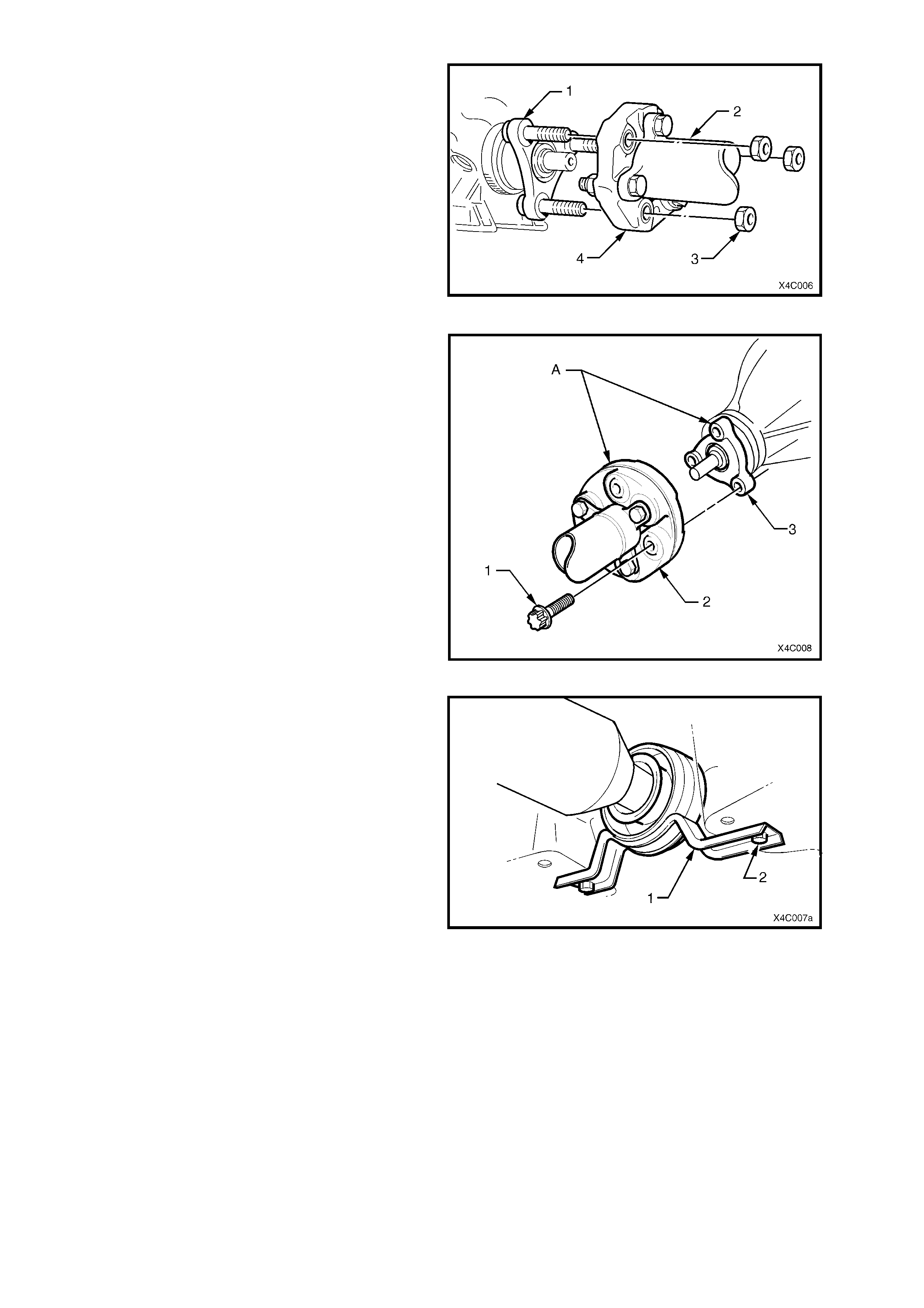
7. Remove the two centre bearing carrier (1) to
underbody reinforcement bolts (2).
8. While supporting the centre bearing section,
slide the propeller shaft assembly forward to
disengage f rom the rear sus pension diff erential
assembly pinion support pin, then lower the
assembly at the rear, sliding rearward to
remove from the vehicle.
For MY 2003 VY and V2 Series Models with a
sliding front yoke:
NOTE 1: Take car e to protec t the outer diameter of
the front yoke. Nicks or abrasions will damage the
transm ission extens ion seal during reas sembly and
result in subsequent lubricant leakage from this
area.
NOTE 2: Insert a suitable plug in the end of the
transmission rear extension to prevent loss of
transmission lubricant.
Figure 4C-4
REINSTALL
Installation is the reverse of removal procedures noting the following:
1. Lubricate both the transmission output shaft (V6 engine and manual transmission) and the rear suspension
differential assembly pinion spigots with a molybdenum disulphide grease such as Molybond GA10 or Shell
ML10.
2. For those MY 2003 VY and V2 Series Models with a sliding front yoke, remove any foreign matter that may
have adhered to the f r ont univer sal j oint yoke and lubric ate with transmiss ion lubric ant. Inser t the yoke on to the
transmission mainshaft, indexing the splines.
3. Clean the threads of the centre bearing carrier to underbody reinforcement bolts and underbody weld nuts.
4. Install the front of the propeller shaft assembly first, supporting the centre and rear sections.
5. While still supporting the centre bearing area, slide the propeller shaft assembly forward to allow engagement of
the rear spigot, then slide rearward to fully engage.
6. Raise the centre bear ing assem bly and ins tall the bolts and washers to secure to the underbody reinforcem ent.
Tighten both bolts to the correct torque specification.
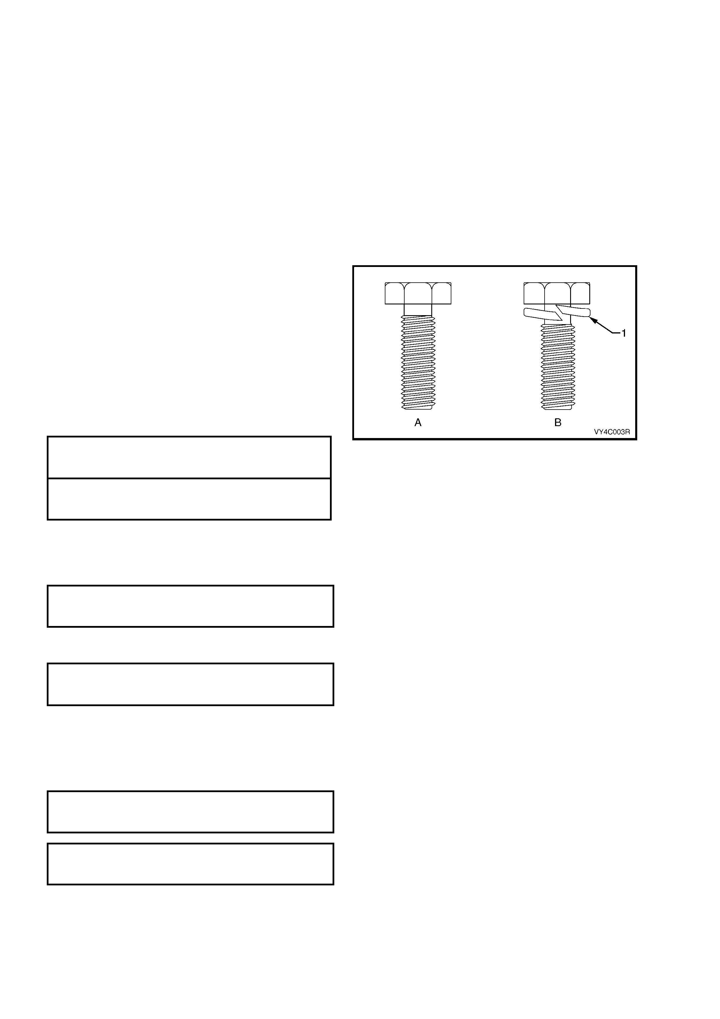
NOTE 1: There are two types of centre bearing
carrier to underbody reinforcement bolts. The first
type (A), is a micro encapsulated bolt and was used
at the start of production. T he sec ond type (B), was
introduced as a running change and is a zinc
coated bolt inc or porating a loc king washer (1) . The
mo st visible identification c an be determined by the
presence of, or lack of a locking washer.
NOTE 2: Micro encapsulated bolts should only be
re-used once. If in doubt, replacement is
recommended. If not replacing bolts, apply Loctite
242 or an equivalent to the cleaned threads.
( # ) TYPE 'A' CENTRE BEARING
CARRIER RETAINING BOLT
TORQUE SPECIFICATION 19 – 25 Nm
TYPE 'B' CENTRE BEARING
CARRIER RETAINING BOLT
TORQUE SPECIFICATION 20 – 35 Nm
Figure 4C-5
7. Before installing the attaching bolts and washers into the propeller shaft rear coupling and pinion flange, align
the marks made during removal of the pinion flange and rear coupling, refer to Figure 4C-3.
8. Provided no thread damage is evident, reinstall the original rear propeller shaft coupling to rear suspension
differential assembly pinion flange bolts, tightening to the correct torque specification.
PROPELLER SHAFT REAR
COUPLING TO PINION FLANGE
BOLT TORQUE SPECIFICATION 105 – 125 Nm
9. Vehicles with V6 Engine and Manual Transmission, install new rubber coupling to transmission output flange
retaining nuts before tightening to the correct torque specification.
( ! ) RUBBER COUPLING TO TRANSMISSION
OUTPUT SHAFT FLANGE RETAINING
NUT TORQUE SPECIFICATION 50 – 85 Nm
10. Install the exhaust system noting the following;
For vehicles fitted with a V6 engine and manual transmission:
a. Check that the catalytic converter to intermediate exhaust pipe bolts, springs and sealing ring are all in a
serviceable condition prior to installation.
b. Tighten all exhaust fasteners to the specified torque.
EXHAUST PIPE FLANGE TO
EXHAUST MANIFOLD NUT
TORQUE SPECIFICATION 18 – 35 Nm
INTERMEDIATE EXHAUST PIPE
TO CATALYTI C CONVERTER
BOLT TORQUE SPECIFICATION 40 – 50 Nm
c. Ensure that both wiring harnesses to the oxygen sensors are properly connected.

Vehicles fitted with a V6 Supercharged or GEN III V8 engines:
a. Ensure the catalytic converter flange is clean and free from any gasket material.
b. Install the exhaust system, using a new gasket at the catalytic converter and new hanger retainers for the
muffler supports to the rear crossmember.
c. Tighten all exhaust fasteners to the specified torque.
INTERMEDIATE EXHAUST PIPE
TO CATALYTI C CONVERTER
BOLT TORQUE SPECIFICATION............ 40 – 50 Nm
All MY 2003 VY and V2 Series Models:
a. Check exhaust clearances as detailed in Section 8B EXHAUST SYSTEM.
11. For all MY 2003 VY Series Models with a sliding yoke: if transmission lubricant leaked from the rear of the
transmission when the propeller shaft was removed, check the transmission lubricant level and top up as
necessary. Refer to Section 0B LUBRICATION AND SERVICE for transmission lubricant specifications and
replacement procedures.
2.2 RUBBER COUP LING
LT Section No. – 05-050
NOTE: The following fasteners MUST be replaced
when performing this operation:
!
!!
!$
$$
$Propeller shaf t to r ubber coupling attaching nut
and bolt.
!
!!
!$
$$
$Propeller shaft to sliding yoke attaching nut
and bolt.
REPLACE
NOTE: While the front coupling is shown for this operation, the replacement of either coupling is similar.
1. Remove the propeller shaft. Refer to
2.1 PROPELLER SHAFT in this Section.
2. Using a back-up spanner on each of the three
propeller shaft sliding yoke bolts (7), loosen
then remove the nuts (4) and washers (5).
Discard the removed bolts and nuts. Remove
the sliding yoke from the coupling.
3. Using a back-up spanner on each of the three
propeller shaft to coupling bolts (3), loosen then
remove the nuts (1) and washers (2). Discard
the removed bolts and washers. Remove the
coupling from the front of the propeller shaft.
Figure 4C-6
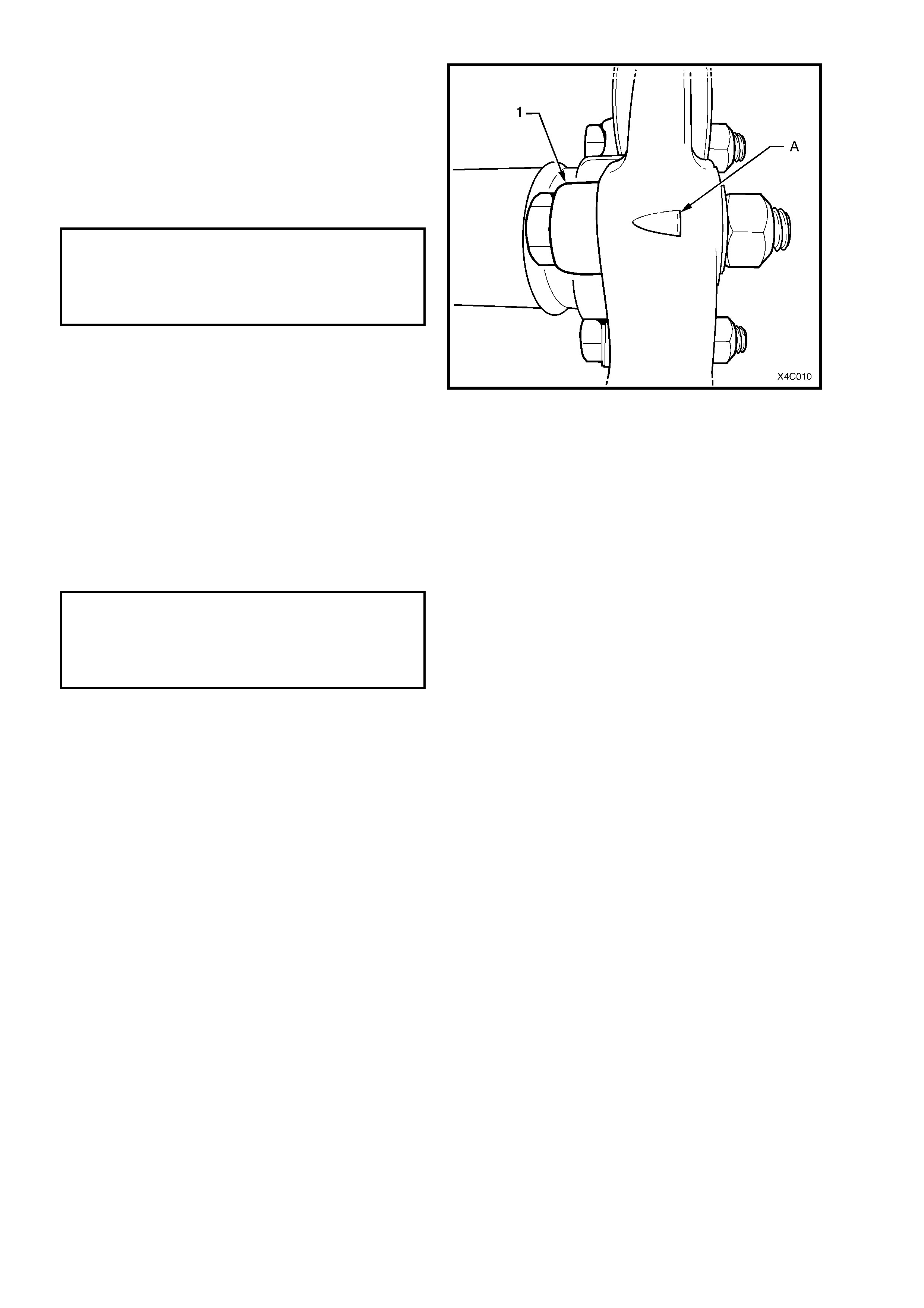
4. Install a replacement rubber coupling onto the
end of the propeller shaft, aligning the holes in
such a way that the triangular shape (‘A’) on
the coupling ‘points’ to the propeller shaft
flange (1), as shown.
5. Install NEW bolts, washers and nuts to secure
the coupling to the propeller shaft flange and
tighten to the correc t torque specif ication, using
a back-up spanner on the bolt head.
( ! ) PROPELLER SHAFT TO
RUBBER COUPLING NUT AND BOLT
TORQUE SPECIFICATION 18 Nm, then
50° - 60°
turn angle
6. Install 0.5 gm of molybdenum disulphide
grease (such as Molybond GA10 or Shell
ML10) to the spigot bush in the propeller shaft
end of the sliding yoke.
7. Install the sliding yoke spigot into the bush on
the f ront end of the propeller s haft, aligning the
bolt holes. If the rear bolts were placed
correctly (refer step 4), then the triangular
shape will ‘point’ to the sliding yoke flange bolt
holes.
8. Install new bolts, washers and nuts to secure
the coupling to the sliding yoke flange and
tighten to the correc t torque specif ication, using
a back-up spanner on the bolt head.
( ! ) PROPELLER SHAFT TO
SLIDING YOKE NUT AND BOLT
TORQUE SPECIFICATION 18 Nm, then
50° - 60°
turn angle
9. Install the propeller shaft, as detailed in
2.1 PROPELLER SHAFT in this Section.
Figure 4C-7
2.3 CENTRE BEARING ASSEMBLY
LT Section No. – 05-050
REMOVE
NOTE 1: T his oper ation is only to be carried out on propeller shaf ts f itted to those MY 2003 VY Ser ies Models fitted
with the V6 engine and manual transmission. The reasons for this are detailed in 1.1 SERVICE NOTES, in this
Section.
NOTE 2: During the removal process described, the rubber bearing support will be damaged, requiring the
complete centre bearing assembly to be replaced.
1. Remove the propeller shaft. Refer to 2.1 PROPELLER SHAFT in this Section.
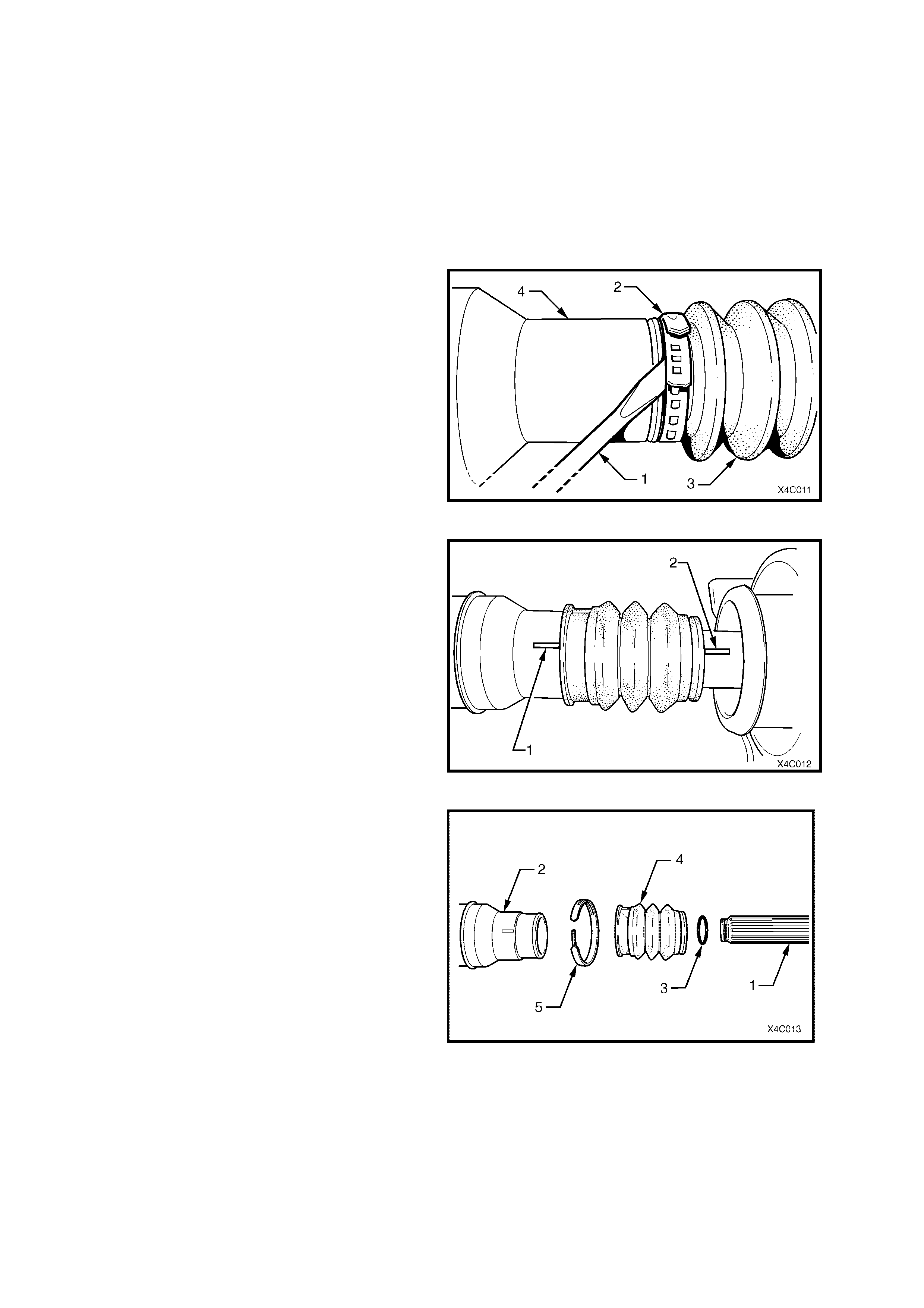
2. W ith the propeller shaft assembly (4) laying on
a bench, use a screwdriver (1) or similar and
lever up on the boot clamp (2) releasing the
tension.
Figure 4C-8
3. Extend the sliding joint until resistance is felt,
then use a felt tipped pen or similar to mark
alignment marks on the front propeller shaft
section (1) and the rear (2)
Important: This is a critical operation, as propeller
shaft phasing and balance will be affected if the two
propeller shaft halves are not aligned correctly on
reassembly.
Figure 4C-9
4. W ith the two propeller shaft halves extended, a
snap action is required to separate them,
because of the O-ring seal (3) mounted on the
end of the rear shaft (1).
5. Once separ ated, the ribbed boot (4) and O-ring
seal (3) are released.
NOTE: Once s eparated, the O- ring seal (3) may be
retained in the fr ont half (2). Retrieve by inserting a
hooked piece of wire.
Figure 4C-10
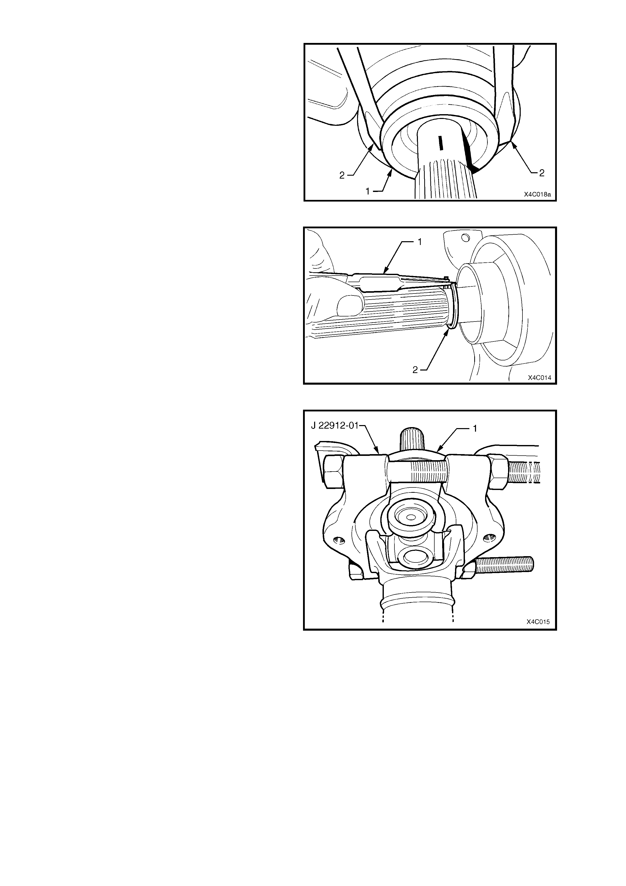
6. Remove the slinger (1), by levering off, using
two similar sized screwdrivers (2) or similar, as
shown.
NOTE: Removal of the slinger is required to gain
access to a circlip underneath.
Figure 4C-11
7. Using suitable, commercially available circlip
pliers (1), remove the circlip (2) securing the
centre bearing.
Figure 4C-12
8. Ins tall s uitable pr ess plates s uch as J 22912-01
under the centre bear ing, carrier (1) and rubber
support, with the flat face towards the bearing
and carrier (1).
9. Tighten the c lamp nuts on the pres s plates until
the two halves are firmly secure around the
bearing.
10. Support the press plates on the bed of an
hydraulic press and press the rear propeller
shaft, splined shaft from the centre bearing.
NOTE: This operation will damage the rubber
bearing support, requiring the centre bearing,
rubber and carrier assembly to be replaced.
Figure 4C-13
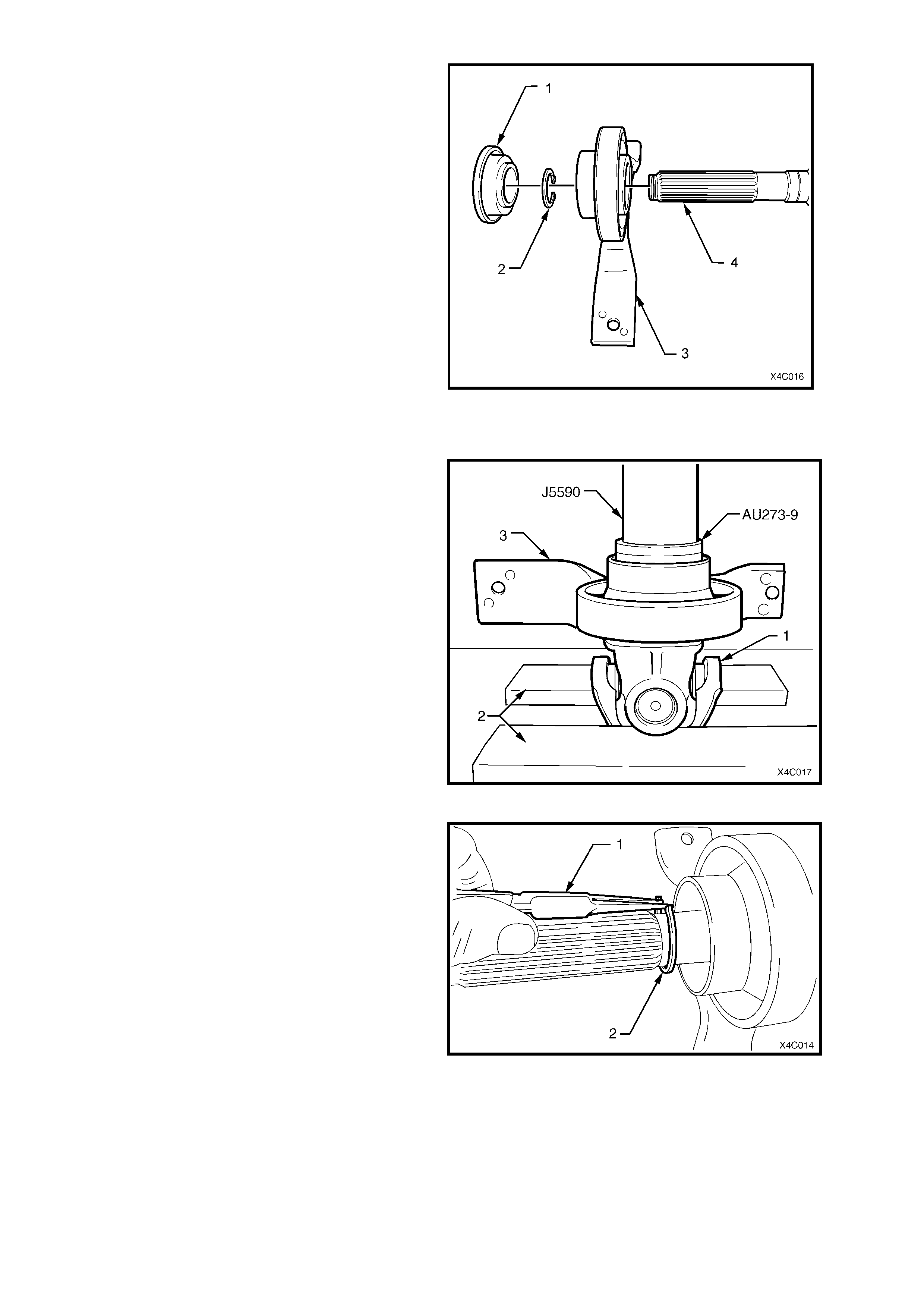
11. Figure 4C-14 shows the relationship of the
centre bearing assembly (3) to the rear
propeller shaft (4), together with the slinger (1)
and the retaining circlip (2).
Figure 4C-14
REINSTALL
1. With the front universal joint ‘ears’ (1)
supported on press plates (2), press a NEW
centre bearing assembly (3) onto the front
section of the rear propeller shaft, using press
tube J5590 and adaptor AU273-9.
NOTE: If these tools are not available, then a 150
mm length of pipe with an ID of 30 mm (and a wall
thickness of 5 mm), can be used as a substitute.
Figure 4C-15
2. Install a NEW centre bearing retaining circlip
(2), using commercially available circlip pliers
(1), taking care not to over-stretch the circlip.
3. Install a NEW slinger, using press tool J5590.
Figure 4C-16
4. Install a NEW boot and ring assem bly over the
splines of the rear propeller shaft.
5. Lubricate the splines of the rear propeller shaft
with approximately 1 – 2 gm of molybdenum
disulphide grease (such as Molybond GA10 or
Shell ML10).
6. Install a NEW O-ring seal onto the nose of the
rear propeller shaft.
7. Taking care to align the two propeller shaft
halves with the marks made before
disassembly (1 and 2), push the two halves
together until the O-ring seal clears the inner
splines of the front half.
NOTE: At this time it should be pos s ible to slide the
two halves back and forth with little resistance.
Figure 4C-17
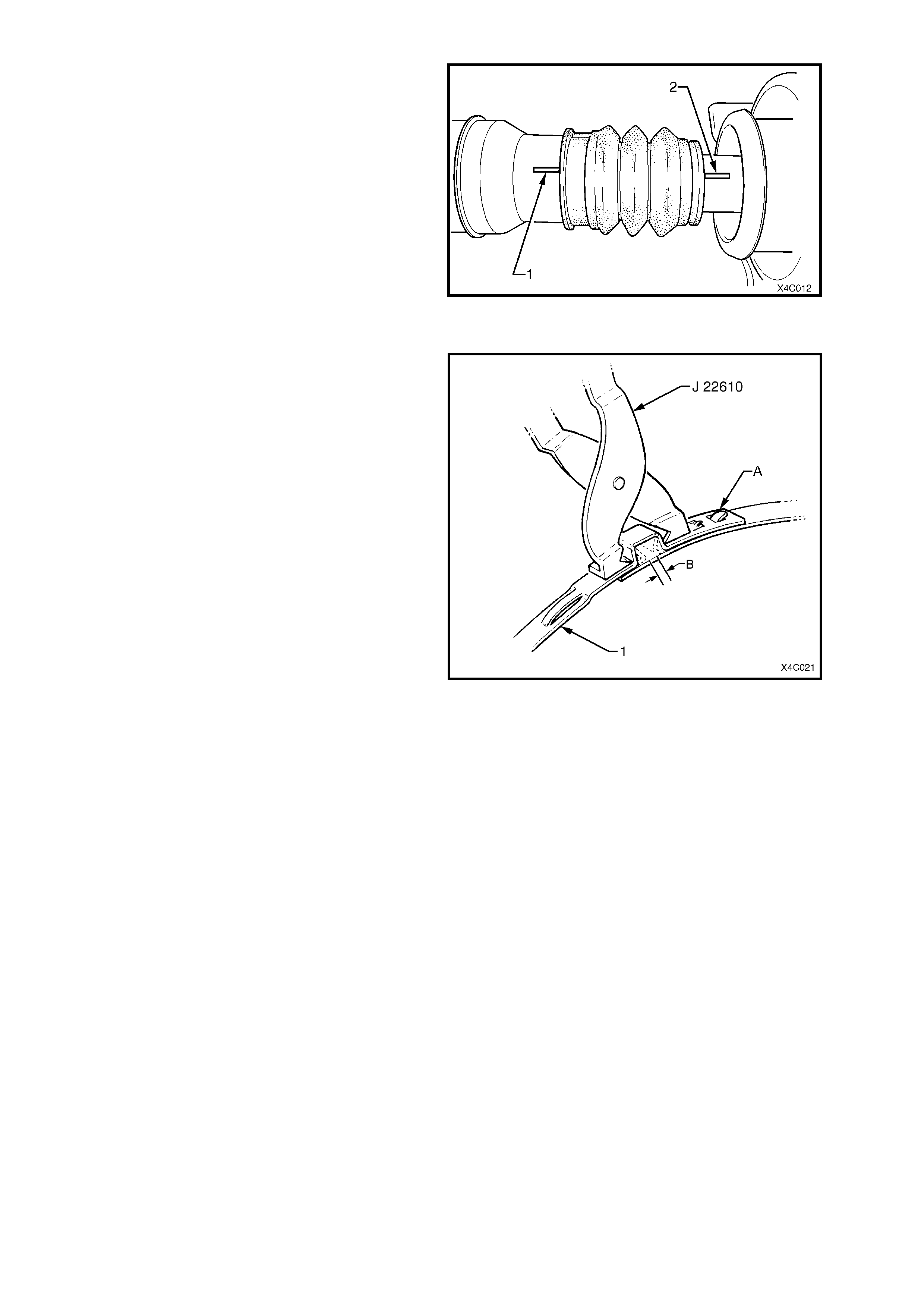
8. With the boot and ring assembly located
correctly in the grooved section of the front
propeller shaft, install a NEW retaining clamp
to secure.
9. After installing a new clamp around the boot
and ring assem bly bend the tab over as shown
by ‘A’ in Figure 4C-18.
10. Using keystone clamp pliers such as J 22610
(Also released as E1896 and 3A13) or
commercial equivalent, tighten the clamp (1)
until the gap ‘B’ is from 1 – 2 mm.
11. Install the propeller shaft assembly. Refer
2.1 PROPELLER SHAFT, in this Section.
Figure 4C-18
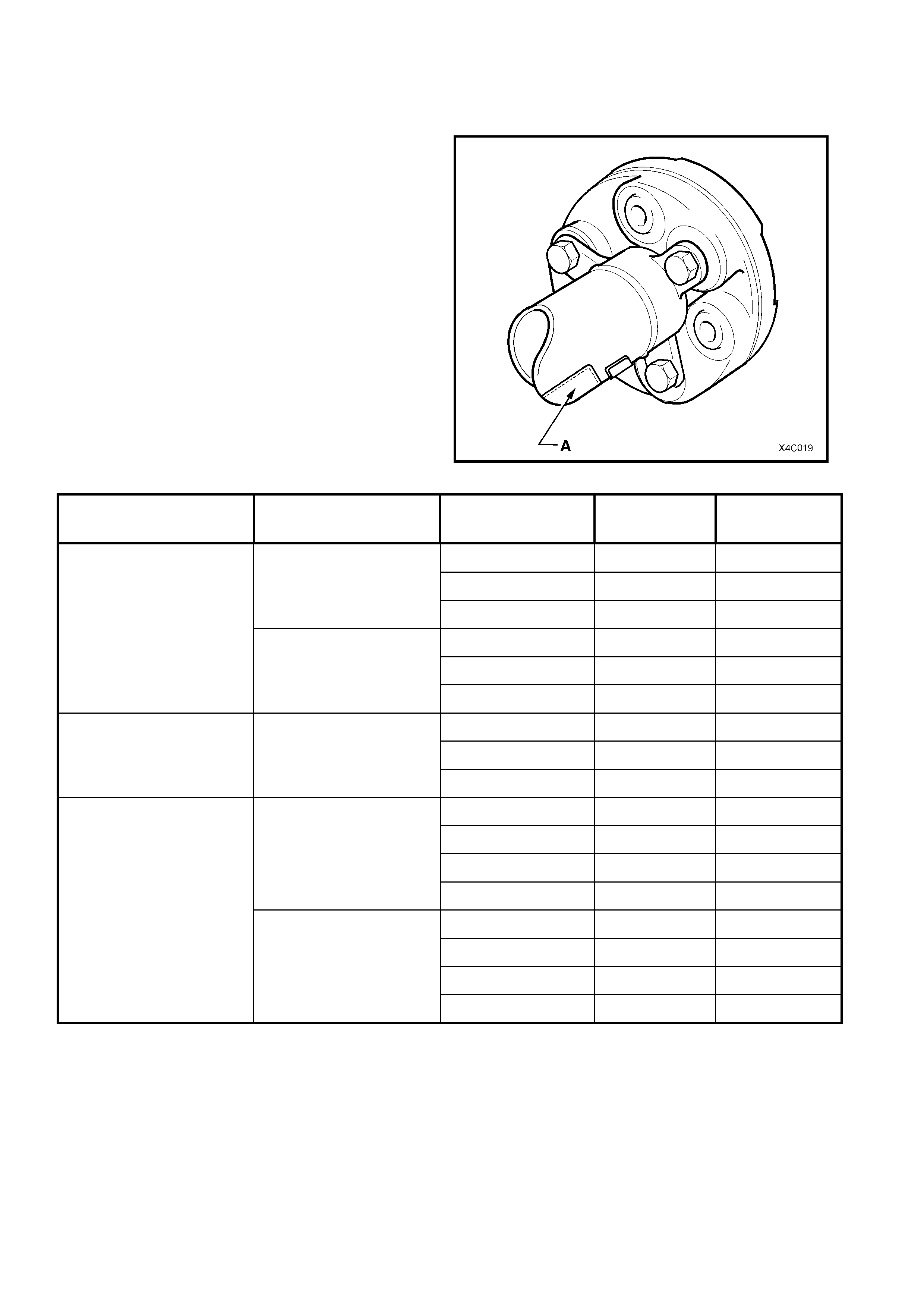
3. SPECIFICATIONS
PROPELLER SHAFT IDENTIFICATION
Identification of the propeller shaft assembly fitted to
a particular vehicle can be achieved by cross-
referencing the two digit code which is provided on
the production identification tag (A) with the table
below.
Figure 4C-19
ENGINE TYPE TRANSMISSION TYPE BODY STYLE MASS (kg) PRODUCTION
I.D CODE
Sedan 9.27 NC
Wagon 9.48 ND
Manual
Utility 9.48 ND
Sedan 9.71 NA
Wagon 9.90 NB
V6
Automatic
Utility 9.90 NB
Coupe 9.95 NK
Sedan 9.95 NK
V6 Supercharged Automatic
Wagon 10.10 NL
Coupe 9.95 NE
Sedan 9.95 NE
Wagon 10.10 NF
Manual
Utility 10.10 NF
Coupe 9.95 NE
Sedan 9.95 NE
Wagon 10.10 NF
GEN III V8
Automatic
Utility 10.10 NF

4. TORQUE WRENCH SPECIFICATIONS Nm
% Centre Bearing Carrier To Underbody Reinforcement Bolt
(early design)................................................................................ 19 - 25
Centre Bearing Carrier To Underbody Reinforcement Bolt
(late design).................................................................................. 20 - 35
Exhaust Pipe Flange To Engine Manifold (V6 Engine)................. 18 - 35
Intermediate Exhaust Pipe To Catalytic Converter Attaching
Bolt................................................................................................ 40 - 50
Propeller Shaft Rear Coupling To Pinion Flange Bolt................... 105 - 125
! Propeller Shaft To Rubber Coupling Nut And Bolt........................ 18, then 50° to
60° turn angle
! Propeller Shaft To Sliding Yoke Nut And Bolt............................... 18, then 50° to
60° turn angle
! Rubber Coupling To V6 Manual Transmission Output Flange
Nut ................................................................................................ 50 – 85
! Fasteners must be replaced after loosening.
• Vehicle must be at curb height before final tightening.
♦ Fasteners either have micro encapsulated sealant applied or incorporate a
mechanical thread lock and should only be re-used once. If in doubt, replacement is
recommended.
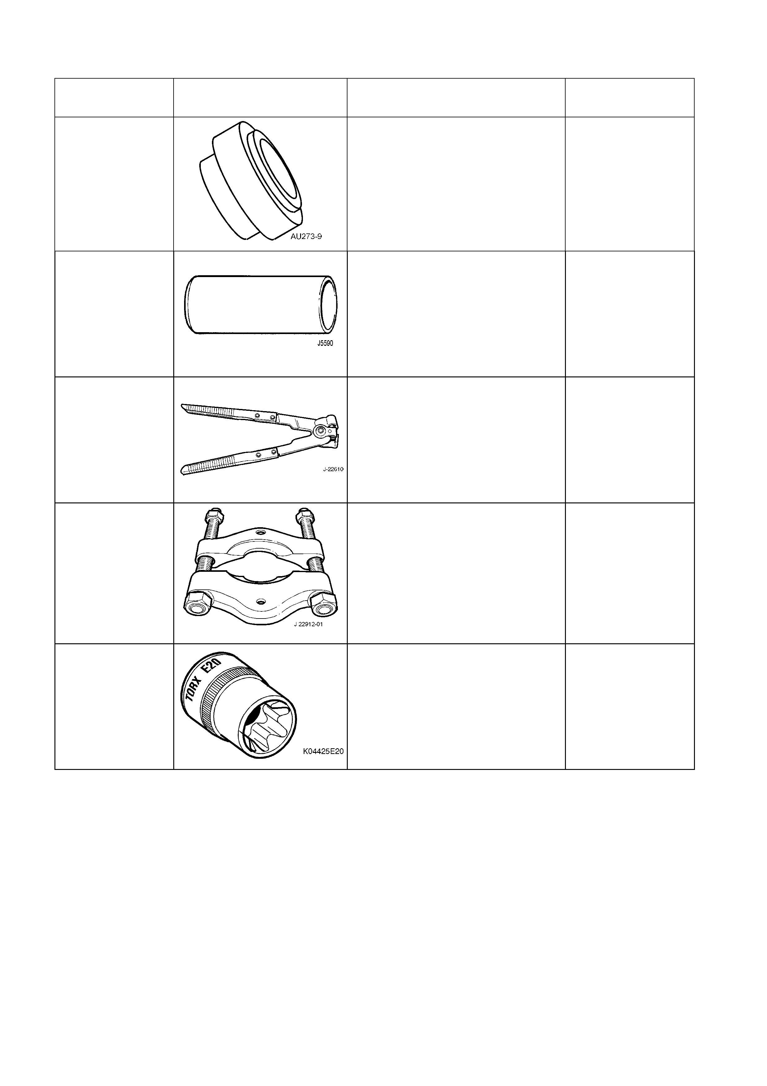
5. SPECIAL TOOLS
TOOL NUMBER ILLUSTRATION DESCRIPTION TOOL
CLASSIFICATION
AU273-9
ADAPTOR
Previously released.
J 5590 PRESS TUBE
Previously released.
J 22610
KEYSTONE CLAMP PLIERS
Previously released.
Used to tighten the sliding joint boot
clamp.
Also released as E 1896 and 3A13.
J 22912-01
PRESS PLATES
Previously released.
K04425E20 E 20 TORX SOCKET
Previously released or use
commercially available equivalent.