
SECTION 5A - SERVICE AND PARK
BRAKING SYSTEMS
IMPORTANT:
Before performing any Service Operation or other procedure described in this Section, refer to Section 00
Cautions And Notes for correct workshop practices with regard to safety and/or property damage.
CONTENTS
1. GENERAL INFORMATION
1.1 GENERAL DESCRIPTION
1.2 MASTER CYLINDER
DESCRIPTION
CONSTRUCTION
OPERATION
1.3 PROPORTIONIN G VALVE OPERATION
ALL EXCEPT UTILITY
UTILITY LOAD SENSING PROPORTIONING
VALVE
1.4 FRONT AND REAR BRAKES
2. MINOR SERVICE OPERATIONS
2.1 SERVICE NOTES AND CAUTIONS
2.2 PARK BRAKE CABLE, ADJUST
2.3 BRAKE FLUID LEVEL CHECK
2.4 BRAKE SYSTEM BLEED
2.5 BRAKE FLUID, CHANGE
2.6 BRAKE PAD WEAR, CHECK
2.7 BRAKE PADS, REPLACE
BRAKE PAD REMOVAL
FRONT BRAKE PAD INSTALLATION
REAR BRAKE PAD INSTALLATION
BRAKE PAD BEDDING-IN PROCEDURE
2.8 BRAKE PEDAL ASSEMBLY
REMOVE
DISASSEMBLE
REASSEMBLE
REINSTALL
2.9 PARK BRAKE LEVER
REMOVE
REINSTALL
2.10 PARK BRAKE WARNING LAMP
SWITCH
REMOVE
INSPECT
REINSTALL
2.11 FRONT PARK BRAKE CABLE
REMOVE
REINSTALL
2.12 REAR PARK BRAKE CABLE /S
REMOVE
REINSTALL
2.13 FRONT BRAKE HOSE
REMOVE
REINSTALL
2.14 REAR CALIPER BRAKE HOSE
REMOVE
REINSTALL
2.15 REAR BRAKE HOSE
REMOVE
REINSTALL
2.16 BRAKE BOOSTER HOSE & VALVE
ASSEMBLY – V6 ENGINE
REPLACE
2.17 BRAKE BOOSTER HOSE & VALVE
ASSEMBLY – GEN III V8 ENGINE
REPLACE
2.18 LOAD SENSING PROPORTIONING
VALVE – UTILITY
REMOVE
REINSTALL
2.19 BRAKE PRESSURE DIFFERENTIAL
WARNING SWITCH
REMOVE
INSPECT
REINSTALL
3. MAJOR SERVICE OPERATIONS
3.1 MASTER CYLINDER
REMOVE
DISASSEMBLE
CLEAN AND INSPECT
REASSEMBLE
REINSTALL
3.2 BRAKE BOOSTER
REMOVE
REINSTALL
3.3 BRAKE CALIPER (FRONT AND REAR)
REMOVE
DISASSEMBLE
CLEAN AND INSPECT
REASSEMBLE
REINSTALL
3.4 FRONT BRAKE DISC
REMOVE
INSPECT
BRAKE DISC AND HUB INDEXING
PROCEDURE
REINSTALL
3.5 REAR BRAKE DISC
REMOVE
INSPECT
BRAKE DISC AND HUB INDEXING
PROCEDURE
REINSTALL
3.6 PARK BRAKE LINING WEAR, CHECK
3.7 PARK BRAKE SHOE, ADJUST
3.8 PARK BRAKE SHOE
REMOVE
REINSTALL
3.9 FRONT DISC BRAKE SHIELD
REMOVE
REINSTALL
3.10 REAR DISC BRAKE SHIELD
REMOVE
REINSTALL
4. DIAGNOSIS
5. SPECIFICATIONS
6. TORQUE WRENCH SPECIFICATIONS
7. SPECIAL TOOLS
Techline
Techline
Techline

1. GENERAL INFORMATION
1.1 GENER AL DESCRIPTION
Some illustrations in this Section may show components that are not fitted to all vehicles. Where differences in
service procedures apply, then relevant information relating to those differences are made.
Except f or thos e v eh icles e qui ppe d with A BS as s tand ar d equ ipment, the f r ont an d rear disc br ak es on M Y20 03 V Y
and V2 Series vehicles, are served by separate brake circuits by means of a tandem master cylinder, working
through a vacuum booster. T he dual brake circuit arrangement is designed to provide adequate braking, should a
fault occur in either circuit.
All MY200 3 VY and V2 Series vehicles are f itted with a Steppe d Tandem , Vacuum Suspended t ype brak e booster
and a 25.4 mm bore master cylinder, regardless of the brake system used. The brake booster is not able to be
serviced and must be replaced if proven to have become defective.
All MY2003 VY and V2 Series vehicle are fitted with ventilated discs at the front and solid discs at the rear. The
brake calipers are the sliding, reaction type, with twin pistons in the front calipers and single in the rear.
The front disc brake caliper is attached to the steering knuckle support by two bolts, as is the front wheel bearing
hub, using three bolts. The front dust shield is also attached to the steering knuckle support by three pop rivets.
The rear brake backing plate assembly is bolted to the trailing arm, as is the disc brake caliper. The machined inner
surface of the disc hub acts as the brake drum for the park brake.
The single shoe, Banksia park brake is a drum type with a manual adjustment incorporated into the design. The
park brake is operated by two separate cables at the rear, connected to an equaliser bracket. Park brake
application force is applied to this equaliser bracket, via a single cable, connected to the floor mounted, button
release, park brake lever. Adjustment of the parking brake cables is provided for, by a threaded end on the front,
single cable, at the park brake lever end.
For servici ng deta ils of the ABS Br aking System , ref er to Section 5B in this Service Information.
1.2 MASTER CYLINDER
DESCRIPTION
A ma ster cylinder with a 25 .4 mm (1”) diameter bore is used on all MY2003 V Y and V2 Ser ies vehicl es, regar dless
of the braking system fitted. The only differences being:
a. The m aster cylinder used with ABS has a sc rew in blank ing plug i nstalled into the lower of the two front brake
outlets in the master cylinder.
b. The master cylinder fitted to MY2003 VY Series Utility vehicles does not have a brake proportioning valve
incorpora t ed in to t he master cylinder but us es a s eparate, lo ad sensing pr o porti o nin g val ve , c ou ple d t o the rear
suspension. This ensures that the front to rear braking balance, relative to vehicle load, is maintained.
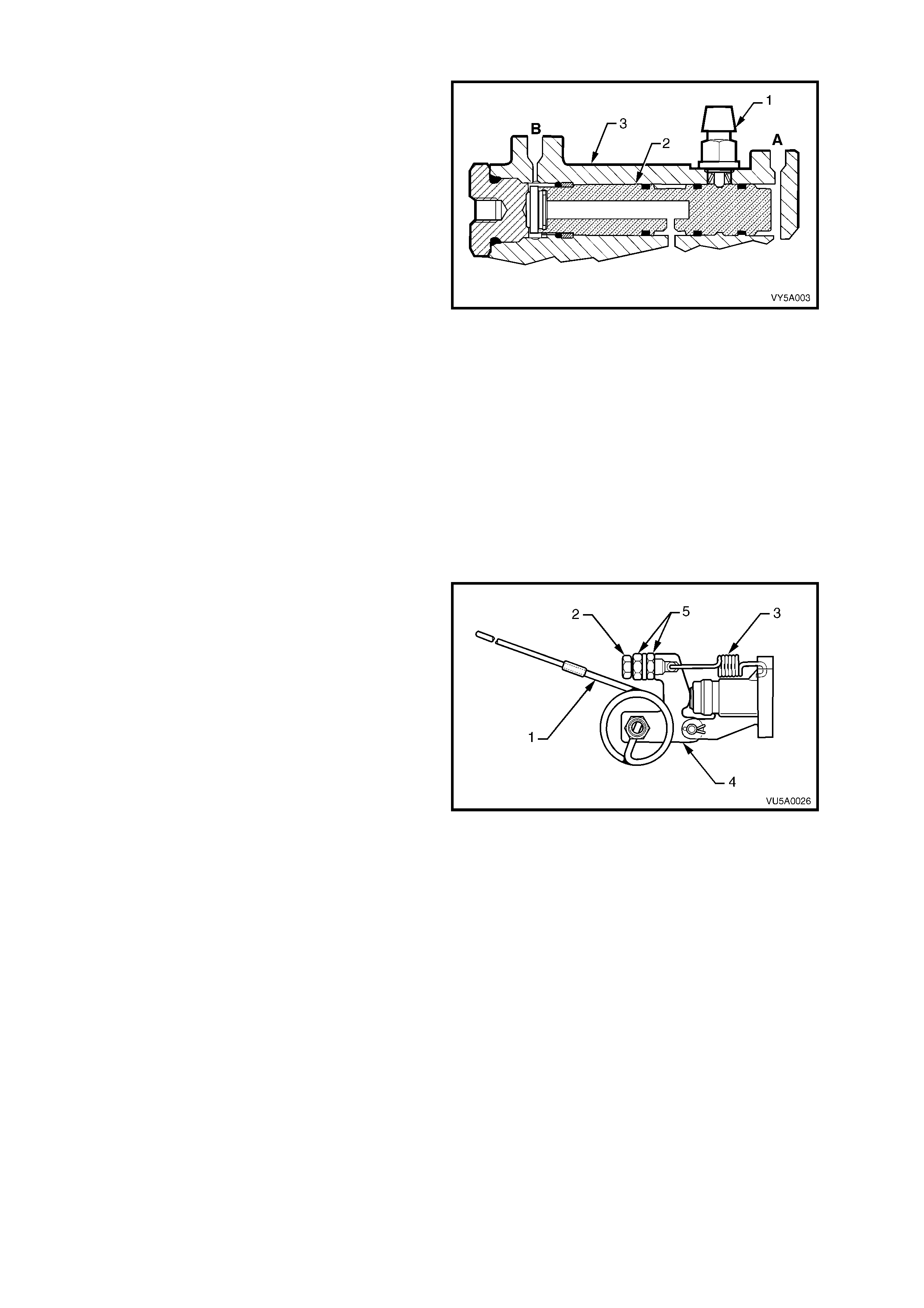
The master cylinder is a tandem, centre valve design, incorporating a fast fill valve that provides a reduced pedal
travel. T he m aster cylinder is m ounted to th e vacuum brak e booster whic h in turn, is m ounted to t he eng ine side of
the dash panel.
CONSTRUCTION
This tandem m aster cylinde r arr angement prov ides s e p arate hydraulic c irc u its f or the applic at io n of the brakes, in a
front to rear split arrangement.
Both of these circuits are fed by separate fluid feed and compensating ports, through a common fluid reservoir,
sealed by a diaphragm fitted inside the reservoir cover. This diaphragm provides an effective seal against any
atmospheric moisture coming into contact with the hygroscopic brake fluid. This provision maintains the brake
fluid's boiling point, for a maximum period of time.
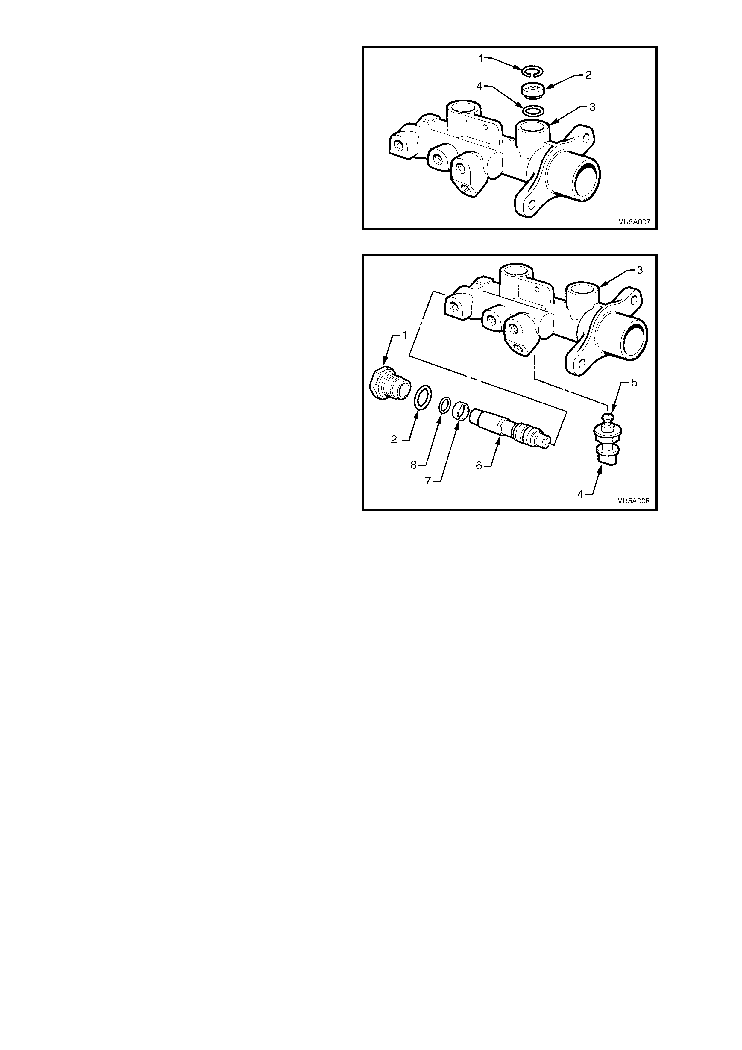
The internal parts of the master cylinder comprise a primary piston with an L type seal and an O-ring seal, a
secondary valve which incorporates a centre valve, a caged spring and two L type seals, a return spring, a
secondary piston stop pin, and a fast fill valve.
In all vehicles except MY2003 VY Series Utility, a proportioning valve is located in a parallel bore in the same
casting of the master cylinder. This valve is used to maintain the front to rear hydraulic pressure balance. Should
one of the two separate systems fail, a separate piston and brake pressure differential warning switch is
incorporated into the design so that the vehicle operator can be warned of a system malfunction.
The MY20 03 VY Series Ut ilit y has a load s ensing pro portioning valve locat ed at the rear of the veh icle. A pr essure
diff erential spool va l ve replaces the propor tioni ng va l v e, n or mally locat ed in the s ec ond bor e of the master cylind er .
This spool valve can move back and forth to operate the brake pressure differential warning switch, should a
pressure loss occur in either the front or rear brake circuits.
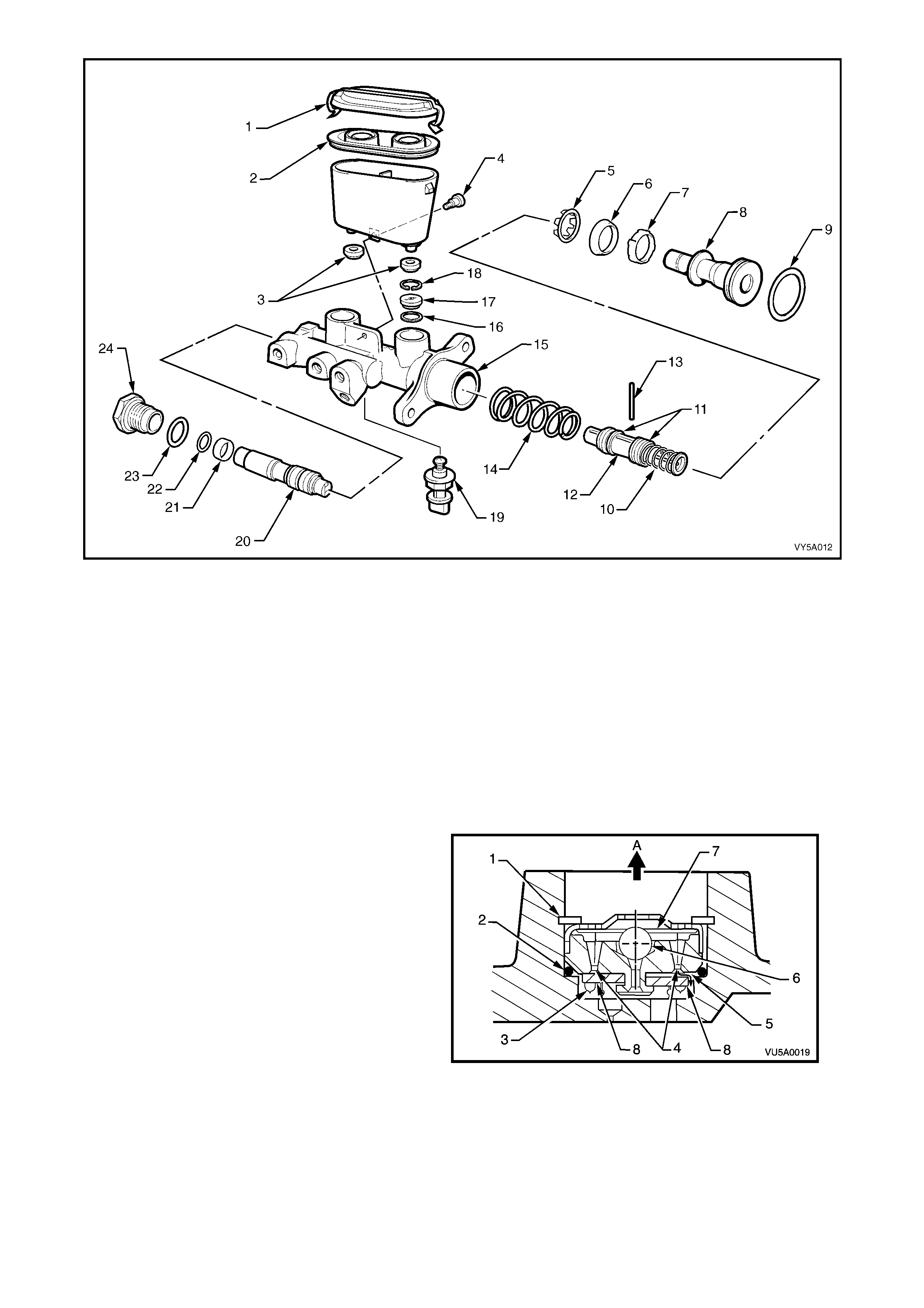
Figure 5A - 1
Legend
1. Reservoir Cap
2. Reservoir Cap Seal
3. Reservoir Sealing Grommets
4. Reservoir Retaining Screw
5. Primary Seal Retainer
6. Primary Seal (L type)
7. Recuperating Guide
8. Primary Piston
9. Primary Piston O-ring
10. Caged Spring
11. Secondary Seals (L type)
12. Secondary Piston
13. Secondary Piston Stop Pin
14. Return Spring
15. Master Cylinder Body
16. Fast Fill Valve O-ring
17. Fast Fill Valve
18. Fast Fill Valve Circlip
19. Brake Pressure Differential
Warning Switch
20. Proportioning Valve (Utility:
Differential Spool Valve)
21. Spool Valve Sleeve
22. Spool Valve Sleeve O-ring
23. End Plug O-ring
24. End Plug
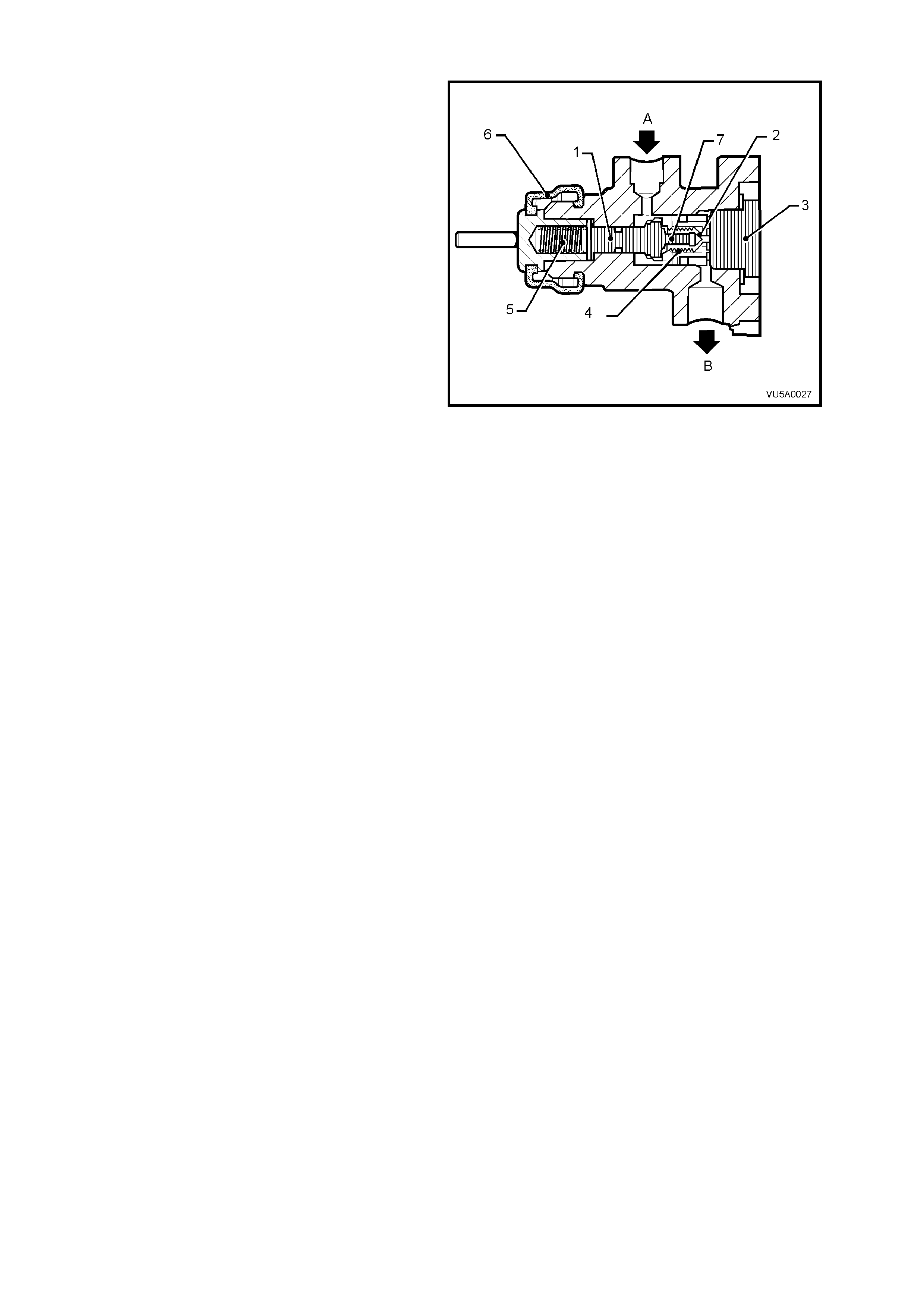
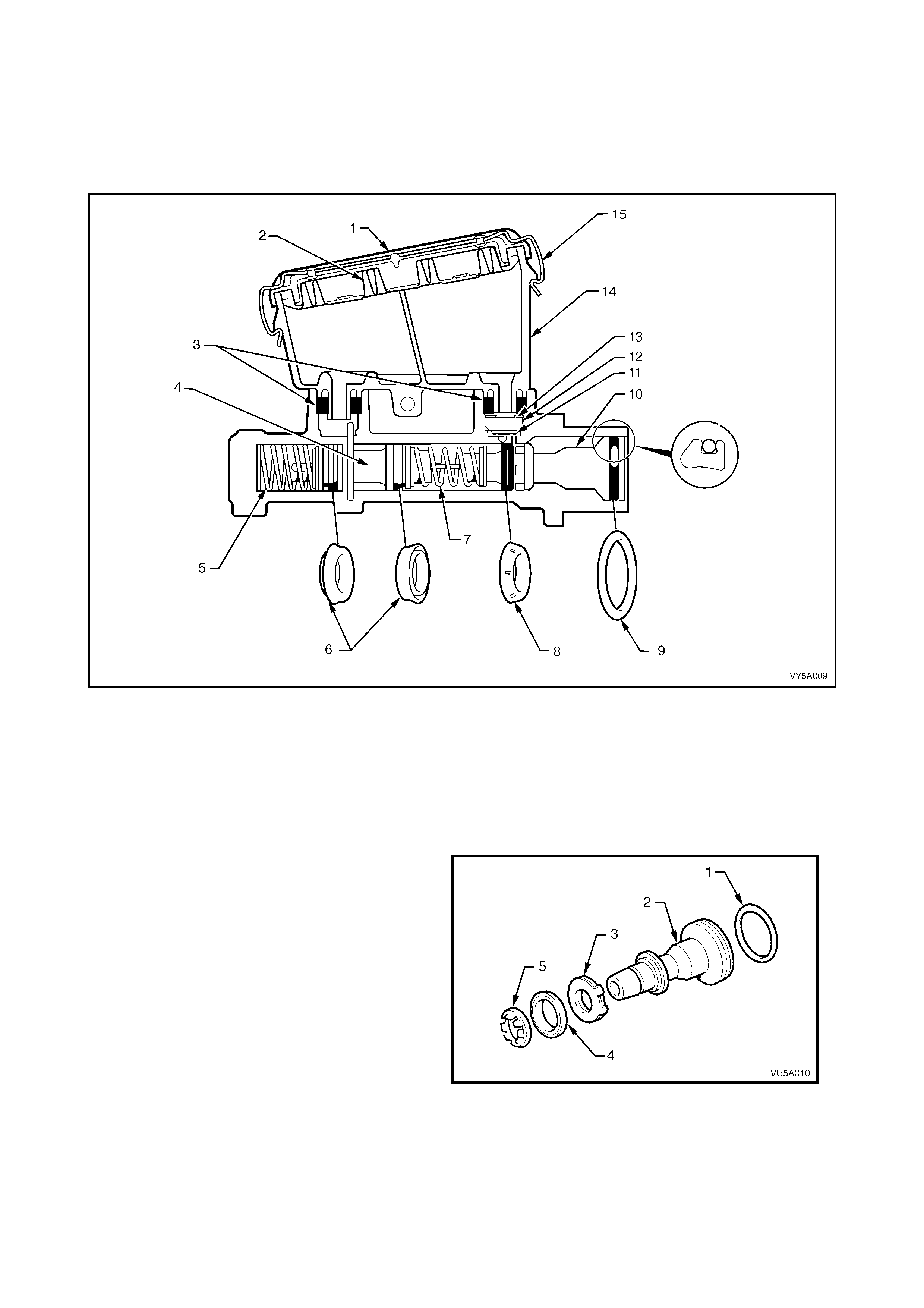
OPERATION
The fast fill (fast pressure build up) valve
incorporated into the master cylinder provides
reduced pedal travel by rapidly overcoming large
low pressure displacements, such as the
advancement of brake pads against the disc with
minimal primary piston travel.
Legend
1. Fast Fill Valve Retaining Circlip
2. Fast Fill Valve O-ring
3. One Way Flap Valve
4. Replenishing Holes
5. Compensating Passage
6. Bal l Va lv e and Seat
7. Ball Valve, Pre Load Disc Spring
8. Rubber Flaps
A To Reservoir
Figure 5A - 2
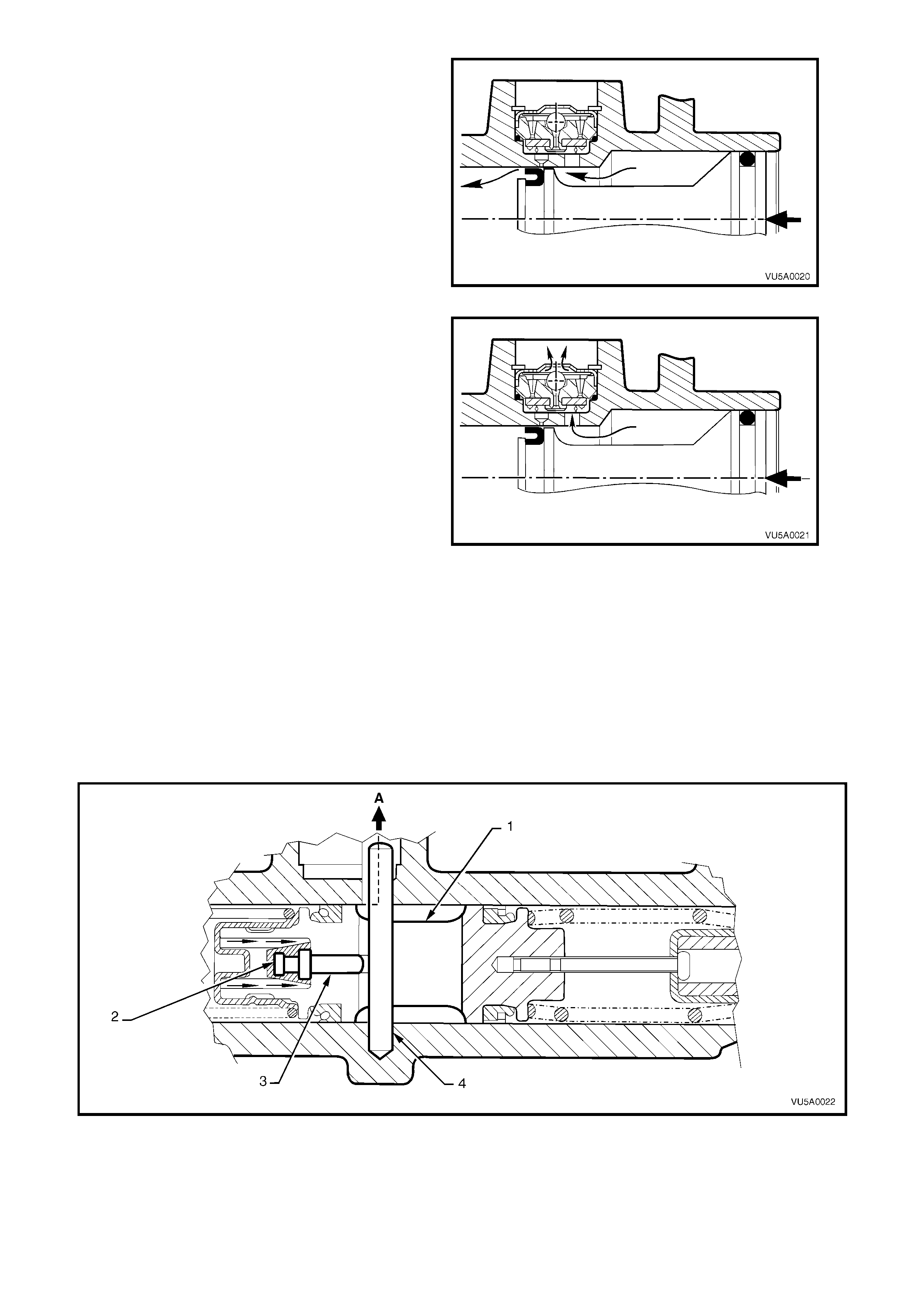
Initial primary piston movement produces pressure
in the larger bore of the master cylinder which
forces closed the flap on the fast fill valve and
prevents fluid from entering the reservoir port.
This high volum e, lo w pres sure f luid, f lows over th e
primary piston primary L type seal and into the
smaller bore and ou t to the brak e calipers , catering
for most of the low pressure brake system
displacement with minimal primary piston travel.
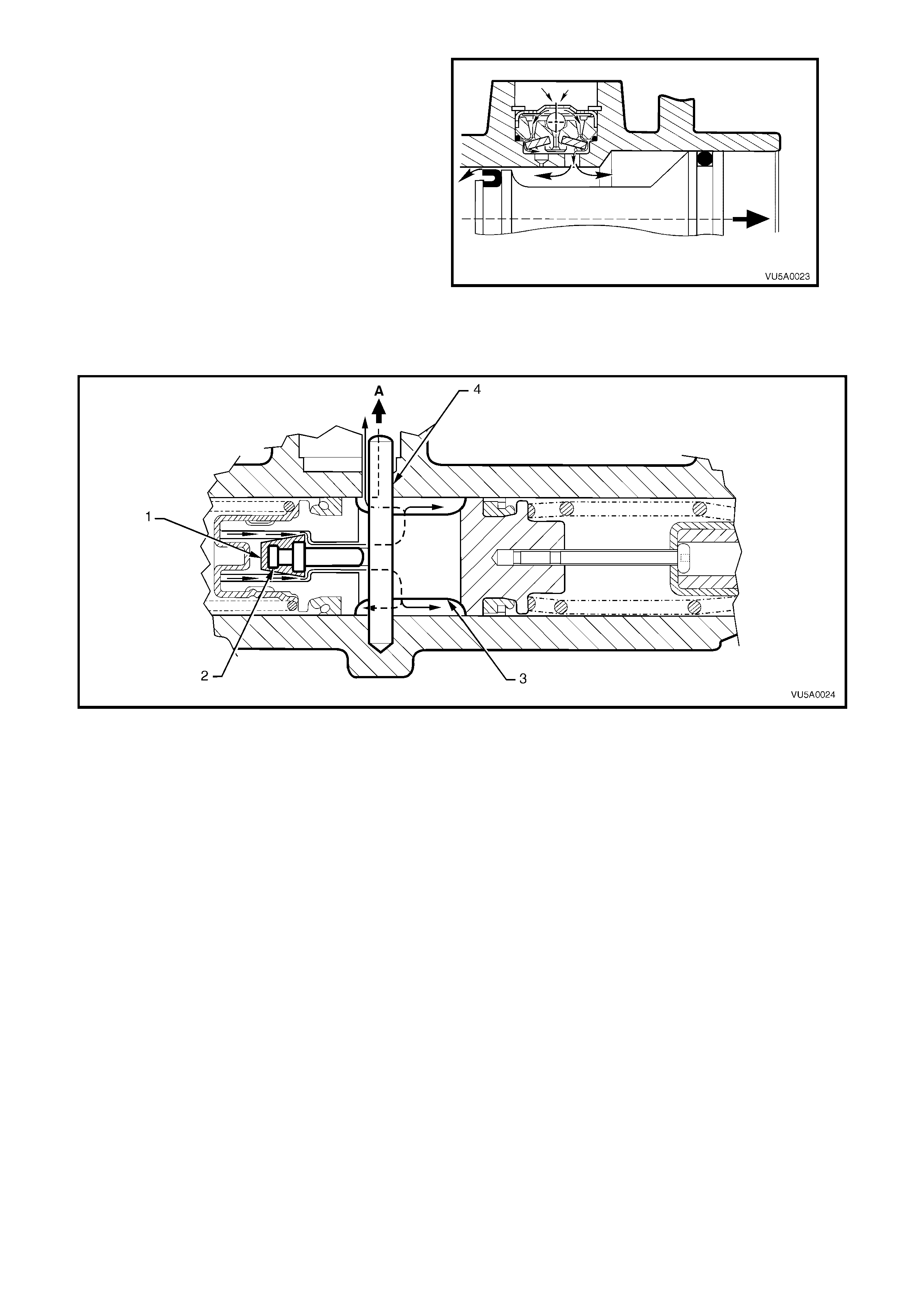
Figure 5A - 3
Further primary movement increases the pressure
in the larger bore and, at a pre-determined
pressure, the ball and seat feature incorporated in
the fast fill valve unloads, preventing additional
pressure rise and allowing fluid to flow from the
larger bore into the reservoir port.
At this point, the small bore section of the master
cylinder functions as a conventional master
cylinder, producing high operating line pressures,
with minimal primary piston travel.
Figure 5A - 4
The combination of hydraulic pressure and the force of the primary piston acting on the secondary piston spring
causes the secondary piston to move forward.
This action on the seco ndar y piston m oving forward r eleases th e centre va lve pin fr om contact with the seco ndary
piston st op pin. W ith the for ce of the centr e valve s pring, and th e releas e of the centre valve pin, the r ubber centre
valve seal is pushed against the front of the secondar y piston inner bore, effectively blocking off the fluid from the
rear brake system compensating port.
At the same time, the primary piston L type seal passes the front brake system compensating port, closing it off
from the reservoir and thus the high operating fluid pressure is produced.
The high operating f luid pressur e influence is t hen registered on the proport ioning valve, then to the fr ont and rear
brake calipers, where the brakes are applied.
Figure 5A - 5
Legend
1. Secondary Piston
2. Centre Valve Seal 3. Centre Valve Pin
4. Secondary Piston Stop Pin A To Reservoir
Front Brake System: When the brake pedal is
released and the secondary piston returns, fluid
recuperation will occur from the reservoir through
the reple nishing ho les in the f ast fill val ve, over the
rubber flap and into the larger and smaller piston
bores.
When the primary piston has fully returned, the
compensating hole in the master cylinder will be
uncovered, allowing fluid returning from the wheel
cylinders to flow into the reservoir via the fast fill
valve compensating passage, thus relieving all
pressur e in the brak e s ystem.
Figure 5A - 6
Rear Brake System: When the brake pedal is released and the secondary piston returns, fluid recuperation will
occur from the reservoir and through the centre valve when the centre valve rubber seal becom es unseated from
the secondary piston bore.
Figure 5A - 7
In all vehicles except the MY2003 VY Ser ies Utility vehicles, brake fluid pressure is equal in each system until the
proportioning valve reaches its designed crack point. If the master cylinder pressure then continues to rise, the
proportioning valve operation changes the front to rear braking pressures, to maintain the designed front to rear
braking balance.
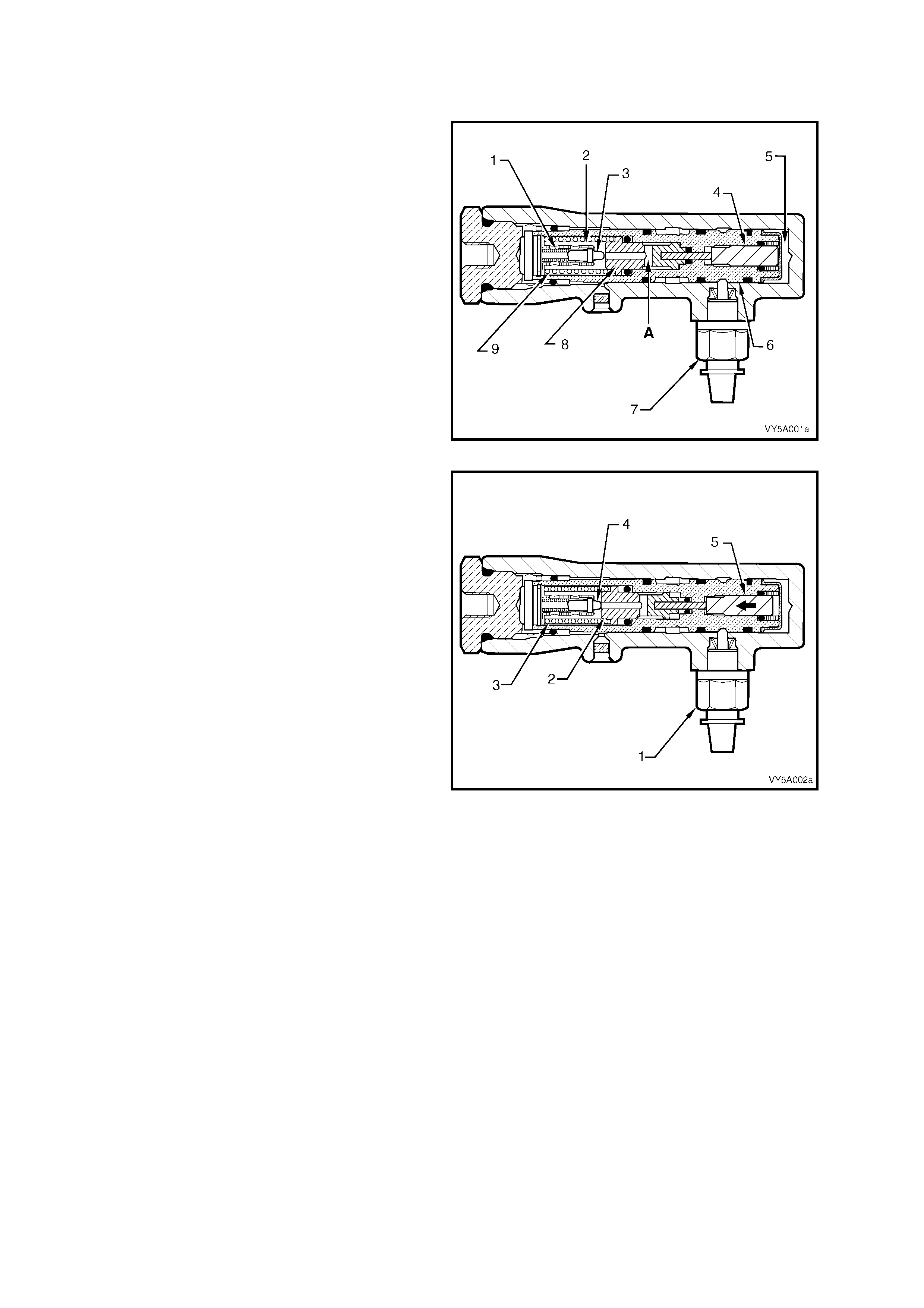
1.3 PROPORTIONING VALVE OPERATION
ALL EXCEPT UTILITY
In the relaxed position, the proportioning valve
piston (8) is held in the valve housing (6) by the
large proportioning spring (9).
The poppet valve (3) is held against the end of its
retainer (2) by a light return spring (1) and brake
fluid is free to pass from the master cylinder,
through the bore of the proportioning valve piston
(6) to the rear brakes at A.
Figure 5A - 8
When master cylinder pressure is increased to the
proportioning valve crack point, brake fluid
pressure from the primary section of the master
cylinder acting on the control piston (5), forces the
proportioning valve piston (2) to move to the plug
end, overcoming the large proportioning spring (3)
and seals against the poppet valve (4). This
prevents any further increase in pressure to the
rear brakes until master cylinder pressure is
increased.
Once seated, the proportioning valve piston (2)
now has a larger diameter than the control piston
(5). As a consequence of this differential area, the
output to t he rear brakes after c rack point has bee n
reached, is less than that applied to the front
brakes.
As master cylinder pressure is further increased
above crack point, the piston (2) oscillates against
the poppet va lve (4) a nd pr oportions the r ear br ak e
pressure to a value lower than the front brakes.
Figure 5A - 9
When the brake pedal is released and the fluid pressure from the master cylinder drops, the pressure of the rear
brake fluid unseats the poppet valve (3), allowing the fluid to return to the master cylinder, refer to Figure 5A - 8.
The large propor tioning s pring (9) then returns the propor tioning valve pis ton and control p iston (4) to the ir relaxe d
positions.
Should a loss of pressure occur in either the front or rear brake system, when the brake pedal is applied, the
proport ioning val ve hous ing (6) will m ove withi n the m aster c ylinder bod y, closi ng the sw itch contac ts on the brak e
pressur e diff er entia l war ni n g switch (7) and thus il luminating the brake fail warnin g light on the instrument panel.
After r epairs have been m ade, applicat ion of a reaso nable f orce to the brak e pedal will autom aticall y centralis e the
proport ioning valve h ousing, opening th e contacts in t he brake pres sure differ ential warning s witch and turning the
brake warning light off.
Utility Pressure Differential Spool Valve
As previously stated, the master cylinder fitted to
Utility vehicles is not fitted with a proportioning
valve. In al l other respec ts, it is similar to that f itted
to other MY2003 VY and V2 Series vehicles.
Instead of a proportioning valve, Utility vehicles
have a differential spool valve (2).
The brake pressure differential warning switch (1)
is m ounted in the mas ter cylinder bo dy (3) with the
spring loaded plunger located in a tapered groove
in the centre of the spool valve (2). With the spool
in a centralised position, the switch contacts
remain open.
Should there be a loss of pressure in either the
front (A) or rear (B) brake system when the brake
pedal is applied, the spool valve will move off
centre, closing the switch contacts and activating
the warning light on the instrument panel.
After repairs have been made and the brake
system has been bled, the pressure in the front
and rear brake systems will equalise (when the
brakes are applied), centralising the spool and
opening the contacts in the brake pressure
differential warning switch (1), turning the brake
warning lig ht off .
Figure 5A - 10
UTILITY LOAD SENSING PROPORTIONING VALVE
Construction
The loa d sens ing propor tio ning valv e is attac hed to
the right hand frame, above the final drive
assembly. The valve torsion spring lever (1) is
attached to the right hand trailing arm rod with a
bracket, cable and hook.
The load sensing proportioning valve senses load
by monitoring the rear suspension ride height, to
regulate the pressure applied to the rear brake
calipers. Maximum line pressure is supplied to the
rear brakes when the vehicle is fully laden, while
lightly loaded conditions provide minimum line
pressure; i.e. line pressure varies in relation to the
weight of the load.
The static spring (3) exerts a force on the end of
the spool valve by means of a lever (4), while a
torsion type sensing spring (1) is attached to the
right-hand trailing arm rod, modifying this applied
force, depending on the axle load.
IMPORTANT: Under no c ircum stances is the st atic
spring tens ion adjustin g sc rew (2) and lock nuts (5 )
to be disturbed nor adjusted, as this adjustment is
set in manufacture.
Figure 5A - 11
Operation
When the vehicle is unladen or lightly loaded, the
torsion spring has the maximum effect and,
together with the static spring f orce, the total apply
force on the plunger and load sensing valve spool
(1) is l o west. This app l y for c e is a ble to position t he
load sensing valve spool (1) to restrict the flow of
fluid through the outlet port (B) to the rear brakes.
However, when the vehicle is loaded, the load
sensing valve spool is positioned so that fluid can
flow unrestricted through the inlet port (A), through
the spool sub-assembly, around the poppet valve
(7) and out via the spool sub assembly sealing seat
(2) and outlet port (B) to the rear wheel brake
calipers.
When the brake pedal is released, inlet pressure
drops, allowing the higher pressure on the rear
wheel side of the sensing valve to force upon the
poppet valve (7), such that the brake fluid can flow
almost unrestricted, back to the master cylinder.
Eventually, the load sensing valve spool (1) is
forced into its released position by the external
spring set up, to fully open the passage between
the front and rear circuit.
Figure 5A - 12
Legend
1. Load sensing valve s pool
2. Load sensing valve s pool sealing seat
3. Load sensing valve end plug
4. Secondary spring
5. Primary spring
6. Load sensing valve boot
7. Load sensing valve poppet and valve
A. Brake fluid inlet
B. Brake fluid outlet
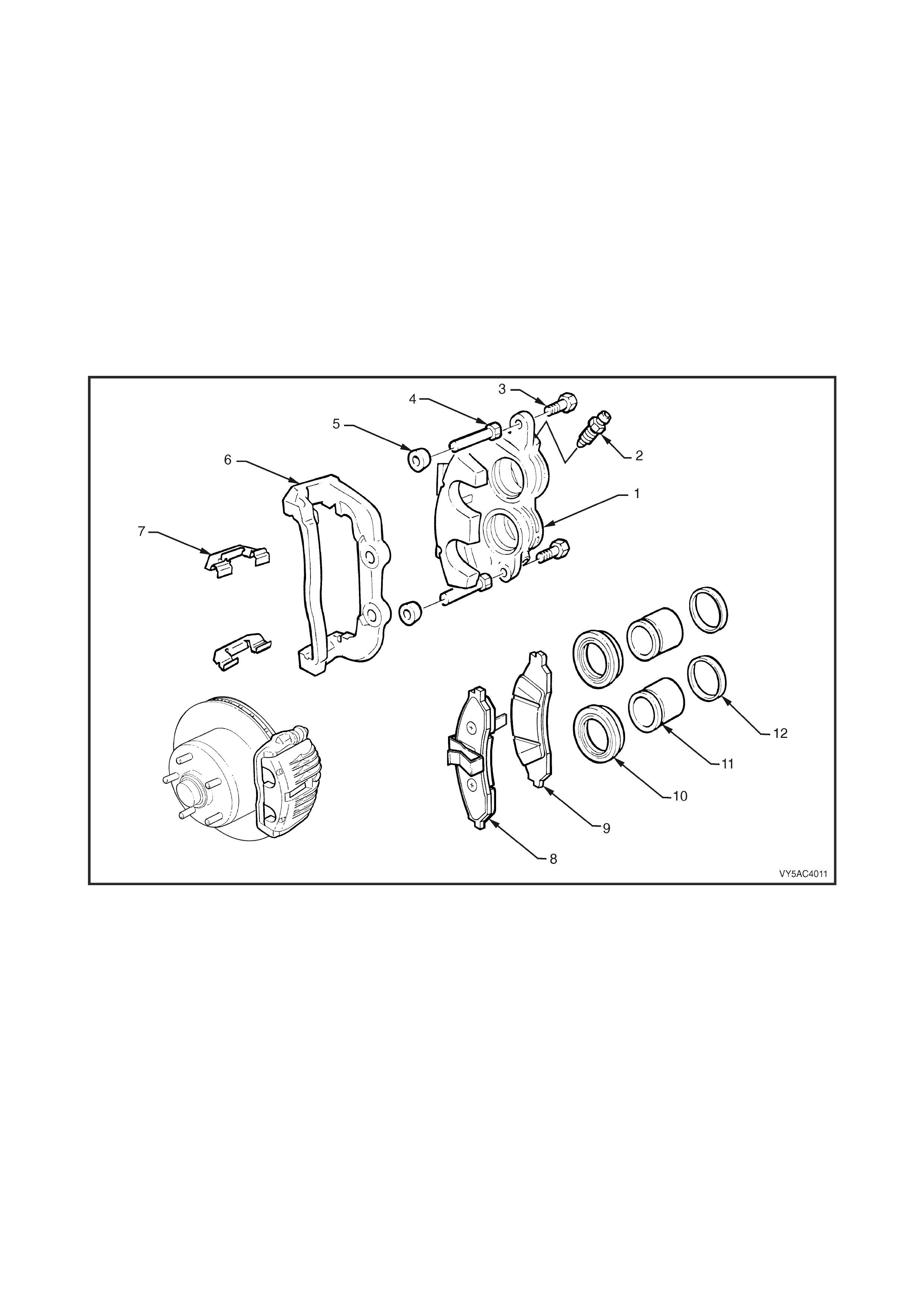
1.4 FRONT AND REAR BRAKES
Both front an d r ear br ake assem blies are c om mon for the stand ard an d AB S systems . An ex plod ed vie w of the twin
piston front caliper is shown in Figure 5A - 13.
For the front brakes, the anchor plate is rigidly fixed to the steering knuckle support arm, while the housing slides
within t he anchor p late b y m eans of two gu ide pins b olted to the housing. R ubber boots are f itted to the gu ide pins
to exclude moisture, dirt and foreign matter.
The rear br ak e c aliper anc h or plates are bo lte d to th e t r ailing ar m and also ha ve a f loatin g ho us ing , s lid in g o v er two
guide pins that are fitted with rubber dust boots.
The housing incorporates either twin (front) or a single hydraulic piston (rear), each with a seal. When hydraulic
pressur e is applied, the pis ton forces the inner pad against the dis c and the reaction of the housing pul ls the outer
pad against the disc. The forces of the pads on each side of the disc are therefore equal.
When the hydraulic pressure is released, the piston seal/s retracts the piston/s a small amount, allowing the moving
parts to re lax s uff icientl y for the pads to rem ain in clos e prox im ity to th e disc without dr agg ing. Adj ustm ent for wear
is automatic.
Refer to 2.7 BRAKE PADS, REPLACE, in this Section, for further information regarding brake pad application.
Figure 5A - 13
Legend
1. Caliper Housing
2. Bleed Screw
3. Self Locking Bolt (2 places)
4. Guide Pin (2 places)
5. Guide Pin Boot
6. Anchor Plate
7. Clip ( 2 places)
8. Outer Brake Pad
9. Inner Brake Pad
10. Piston Boot (2 plac es)
11. Piston (2 pl aces)
12. Cylinder Seal (2 pl aces )
2. MINOR SERVICE OPE RATIONS
2.1 SERVICE NOTES AND CAUTIONS
IMPORTANT ITEMS
a. While Holden's wheel brake parts are not asbestos based in their material composition, a danger exists that
non-genuine parts replacement may contain asbestos.
NOT ONLY IS IT IN THE INTERESTS OF PERSONAL SAFETY BUT ALSO THE SAFE AND RELIABLE
OPERATION OF T HE BRA KING S YSTEM, THAT ONLY GENUINE PARTS ARE USED F O R REPLACEM ENT
PURPOSES.
Even so, when s er vic ing whee l br ake parts, do not cr eate dus t by grin di ng or s an din g br ake linings, b y clean ing
wheel brak e parts with a dry brush or with com pressed air. Breathing in dust that may contain asbestos fibr es
can cause serious bodily harm over a protracted period of time.
A water dampened cloth or water based solution should be used to remove any dust on brake parts.
Equipment is commercially available to perform this washing function. These wet methods prevent brake
component fibres from becoming airborne.
b. The polyglycol brake fluid used in MY2003 VY and V2 Series vehicles is hygroscopic and absorbs moisture
from the air through the br ake hoses etc. The boilin g resistance of the f luid decreases as the moistur e content
increases and so the possibility of a vapour lock under heavy braking conditions increases with the age of the
fluid. Therefore, for maximum brake effectiveness, a two yearly change of brake fluid is mandatory, refer to
2.5 BRAKE FLUID, CHANGE, in this Section.
To prevent the absorption of moisture from the air or other contamination, it is recommended that the brake
fluid be stored in small (500 ml) containers and that any surplus fluid remaining in a container after use be
discarded.
NOTE: The only approved brake fluid is Super DOT 4 Plus and is available in 250 and 500 ml containers. If
pressure bleeding equipment is used, it m ust be of an approved type with a diaphragm separating the brake fluid
from the air.
CAUTION: Brake fluid is extremely damaging to paint. If fluid should accidentally come into contact with a
painted surface, immediately wash the fluid from the paint and clean the painted surface.
c. W henever an y component that forms part of the ABS (if fitted) is dis turbed d uring Ser vice Operat ions, it is vital
that the complete ABS system be checked, refer to 4.4 ABS & TCS FUNCTION CHECK (V6 engines) or
5.4 ABS & TCS FUNCTION CHECK (GEN III V8 engines), in Section 5B, ABS & TCS.
d. W henever a r oad whee l an d/or brake rotor is r em oved f r om or ins talled to a MY2003 V Y or V2 Ser ies ve hic le, it
MUST be done in accorda nce with the procedure provided in 2.3 WHEEL REMOVAL AND INSTALL ATION in
Section 10, WHEELS AND TYRES.
e. W henever a road wheel and/or brake disc is removed from the vehicle, the relat ionship of the road wheel and
the disc to th e hu b MU ST be m ark ed with a felt ti pp ed pen or s imilar, in ord er f or those par ts to b e r eins ta lled in
their original positions. This is critical to maintain the brake disc and road wheel runout dimension to a
minimum.
When reinstalling road wheels, do not use an
impact gun to tighten wheel nuts unless the
impact gun is fitted with a torque limiter socket
(Tool No. AU534 or a commercial equivalent).
Failure to correctly tighten wheel nuts to the
correct torque specification and in the correct
order, may result in a distorted brake disc,
leading to the development of brake shudder.
ROAD WHEEL ATTACHING NUT
TORQUE SPECIFICATION 100 – 125 Nm
For a com plete desc ription of the method used
to measure both brake disc and trunnion
assembly runout and correction, refer to
3.4 FRONT BRAKE DISC or 3.5 REAR
BR AKE DISC, in this Sec ti on.
Figure 5A - 14
2.2 PARK BRAKE CABLE, ADJUST
1. Raise rear of vehicle and support on jack
stands under each lower control arm, to
maintain the correct suspension attitude.
2. Loosen the park brake cable adjustment nut
several turns.
3. App ly the park brak e until the l ever is extende d
4 - 6 clicks.
4. Using a dial type torque wrench and a deep
socket, tighten the cable adjustment nut
(arrow) until a torque of 2 Nm is applied.
5. Check that this adjustment applies the park
brake shoes to a firm drag torque, by turning
each rear wheel.
NOTE 1: With a new park brake installation or one
that has the correct park brake shoe adjustment,
the thread on the front cable should protrude
through the adjustment nut by 15 - 20 mm.
NOTE 2: If the park brake cannot be satisfactorily
adjusted b y the above m ethod, it will be necessary
to refer to 3.7 PARK BRAKE SHOE, ADJUST in
this Section.
Figure 5A - 15

2.3 BRAKE FLUID LEVEL CHECK
Check that the fluid level is between the MIN and
MAX level markings on the translucent reservoir
housing.
NOTE: If the fluid is between the markings, do not
remove reservoir cap, as brake fluid exposed to the
atmosphere will quickly absorb moisture.
Should the addition of f luid be required, wipe clean
the sides of the reservoir cover, then unclip and
rem ove the res ervoir cap . T op up fluid using h eavy
duty brake fluid that complies with DOT 4 Plus
(SAE J1704).
T20B014
Figure 5A - 16
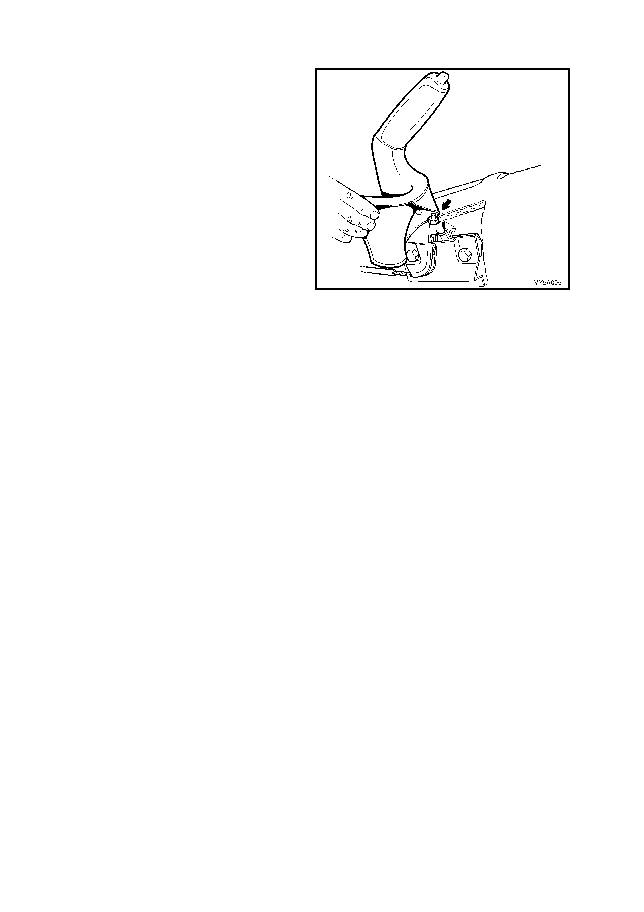
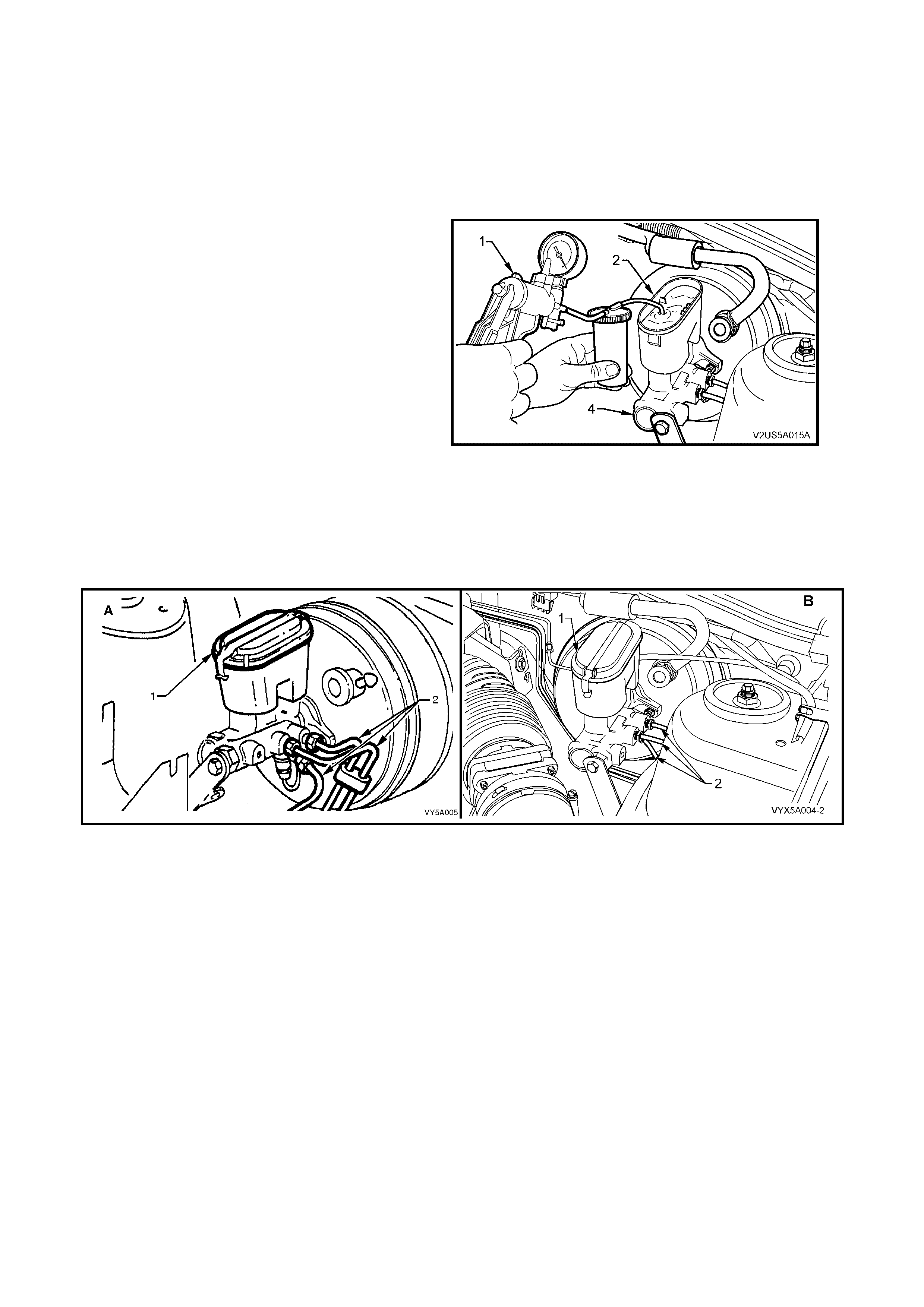
2.4 BRAKE SYSTEM BLEED
LT Section No. – 04-725
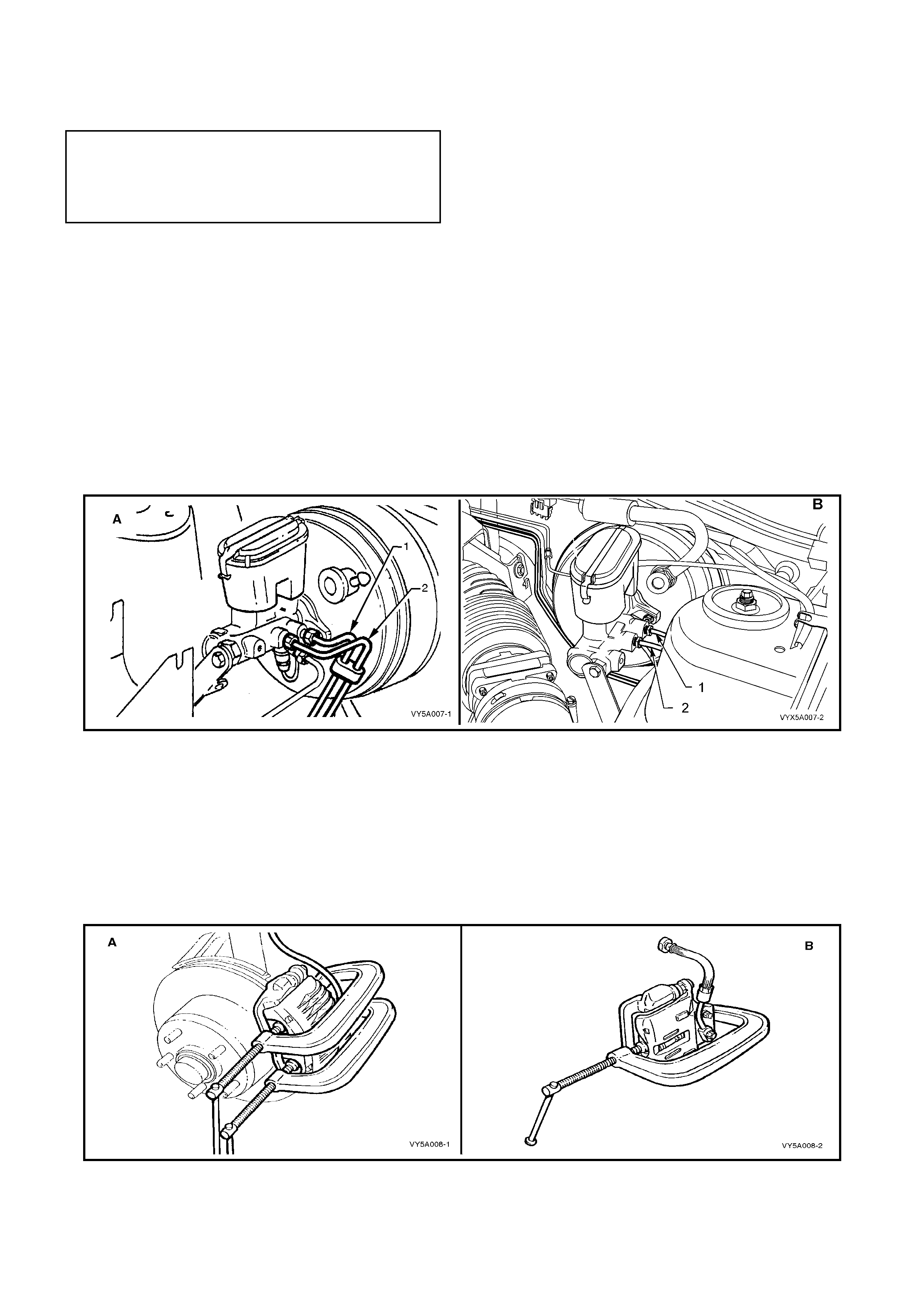
The f r ont chamber of the m as ter cylinder can be b led b y lo oseni ng the pi pe to t h e LHF br ak e at th e master c ylinder
(2) and allowing brake fluid to drip from the connection for approximately one minute, ensuring that spilled fluid
drips into a suitab le conta iner. Do not r e-use dra ined fluid and do not operate the brak e pedal or a pply press ure to
the master cylinder during this operation.
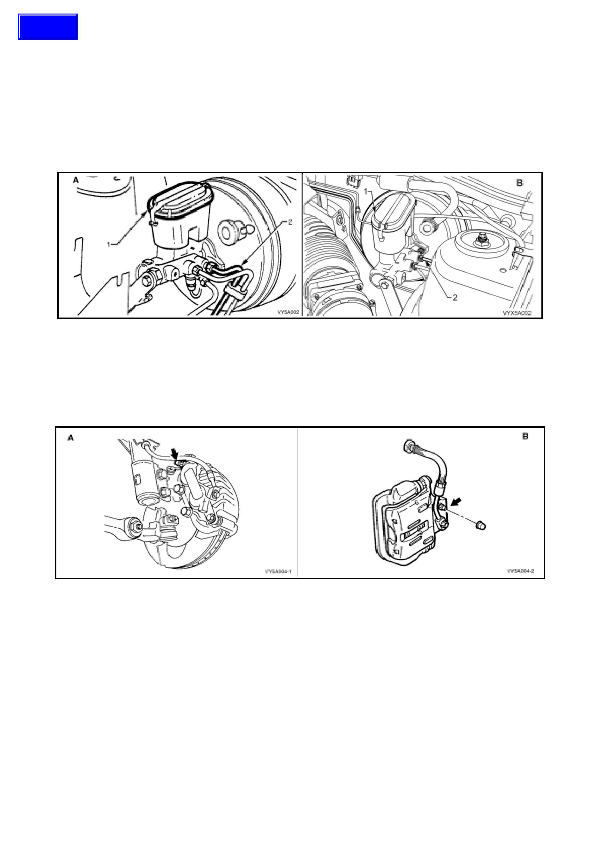
Remove air from other components of the brake system as follows:
1. Remove master cylinder reservoir cap (1) and fit a commercially available pressure bleed cap.
NOTE: View A is for RHD vehicles, while View B is for LHD vehicles.
Figure 5A - 17
2. Connect cap to pressure bleed pump and pressurise system to no more than 345 kPa.
3. Open brake bleeder of line to be bled and pump brake pedal one stroke/second for approxim ately 10 strokes,
then close ble eder . Dur ing t his oper a tio n the pres s ure bleeder to th e master c ylinder s hould not b e tur ne d of f. It
is essential that this volume and rate of flow is maintained to ensure air trapped in pipes is carried out of the
system with the flow of the fluid and not allowed to retreat between strokes of the brake pedal.
NOTE: View A shows the brake bleeder location for the front brake caliper, while View B is for the rear.
Figure 5A - 18
Techline
2.5 BRAKE FLUID, CHANGE
NOTE: The following fastener MUST be replaced
(!
!!
!) when performing this operation :
!
!!
!
Front brake caliper anchor plate to steering
knuckle attaching bolt
REMOVE
1. Thoroughly clean master cylinder, especially around wheel brake line connections.
2. Disconnect wheel brake lines from master cylinder (2) and remove reservoir cap (1).
3. Allow master cylinder to drain into a container until empty.
4. Fill master cylinder reservoir with fresh, specified brake fluid from a sealed 500 ml container and ensure
reservoir is maintained at least half full for remainder of procedure.
5. Allow fluid to flow from open connection ports until fluid is free of air. Collect discharged fluid in suitable
container and then discard. Do not allow fluid to contact paintwork.
6. Reconnect wheel brake lines to master cylinder and tighten to specified torque.
BRAKE PIPE TO MASTER CYLINDER
FLARE NUT TORQUE SPECIFICATION 8 - 11 Nm
NOTE: View A is for RHD vehicles, while View B is for LHD vehicles.
Figure 5A - 19
Drain brake calipers as follows:
7. Raise veh icle and plac e on safet y sta nds. Refer to Section 0A GENERAL INFORM AT ION in the MY2003 VY
and V2 Series Service Information for the locations of jacking and support points.
8. Mark position of wheels relative to hub and remove wheels.
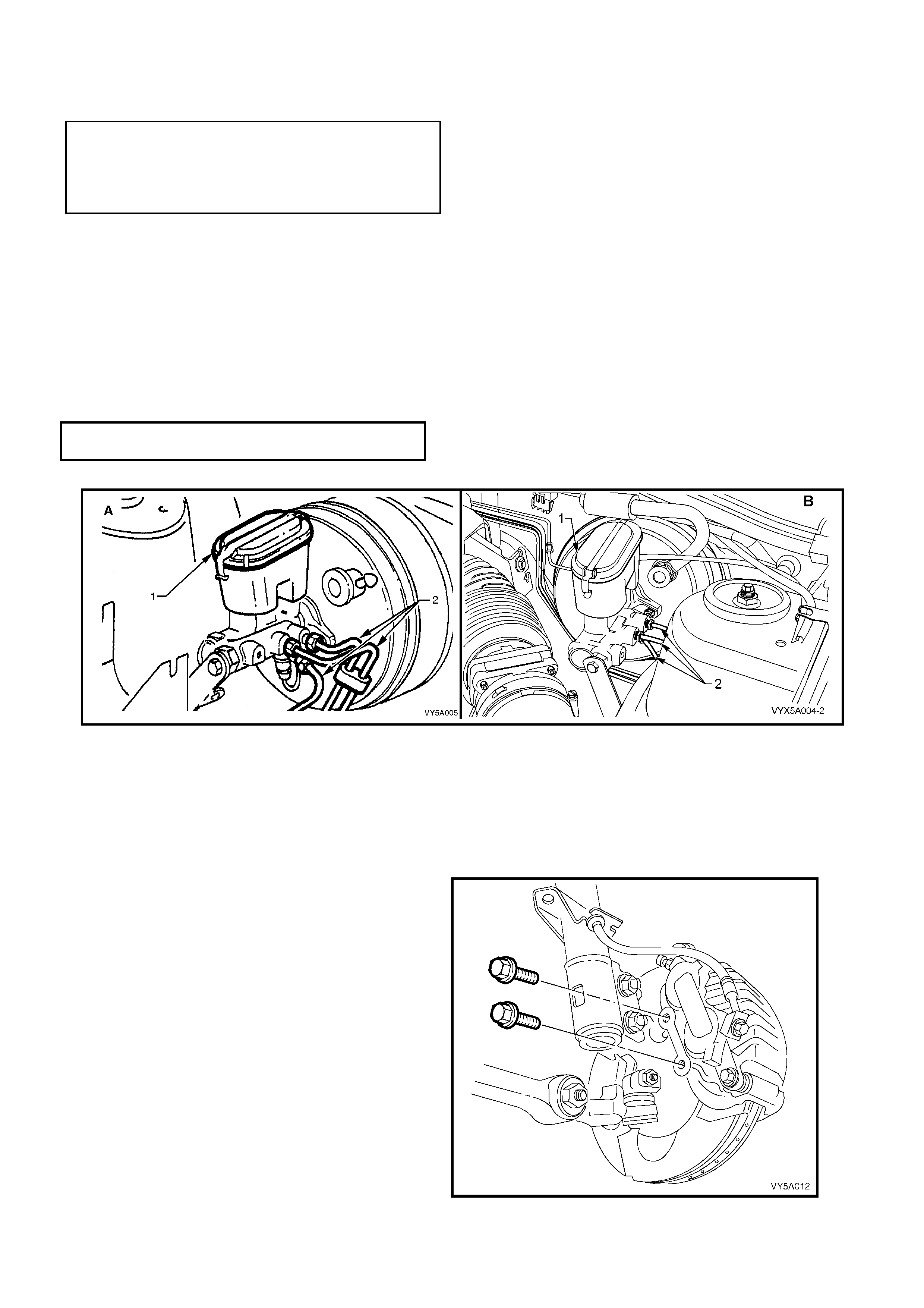
9. Loosen the left hand front caliper bleed screw (bold arrow, in Figure 5A - 18).
10. Remove front left hand caliper anchor plate
retaining bolts.
Figure 5A - 20

11. Hold caliper upside down and remove bleed screw to drain contents of caliper into suitable receptacle.
12. Hand tighten bleed screw and reinstall caliper assembly.
13. Tighten caliper anchor plate retaining bolts to specified torque.
(!
!!
!) FRONT BRAKE CALIPER
ANCHOR PLATE BOLT
TORQUE SPECIFICATION 80 - 90 Nm, then
40° - 50° turn angle
14. Repeat steps 8 to 13 for the rem aining cali per assem blies and tighten the r ear brak e caliper anc hor plate b olts
to the correct torque specification.
REAR BRAKE CALIPER ANCHOR
BOLT TORQUE SPECIFICATION 70 - 100 Nm
15. Bleed brake system, refer to 2.4 BRAKE SYSTEM BLEED in this Section.
16. Reinstall road wheel in original position and lower vehicle.
17. Tighten road wheel nuts to the specified torque.
ROAD WHEEL ATT ACHING
NUT TORQUE SPECIFICATION 100 - 125 Nm
2.6 BRAKE PAD WEAR, CHECK
FRONT OR REAR
NOTE: The procedure and minimum thickness specification is common to both f ront and rear brak e pads, despite
the fact that only the front brake caliper procedure is provided.
1. Raise the vehicle and support on safety stands. Refer to Section 0A GENERAL INFORMATION in the
MY2003 VY and V2 Series Service Information for the locations of jacking and support points.
2. Remove rear wheel covers (steel wheels) or wheel nut decorative caps (alloy wheels).
3. Mark position of road wheels relative to hub, remove road wheel attaching nuts, then the road wheels.
4. Remove the pads to be checked, from the
caliper ensuring that the original pad positions
are noted. Refer to 2.7 BRAKE PADS,
REPLACE, in this Section.
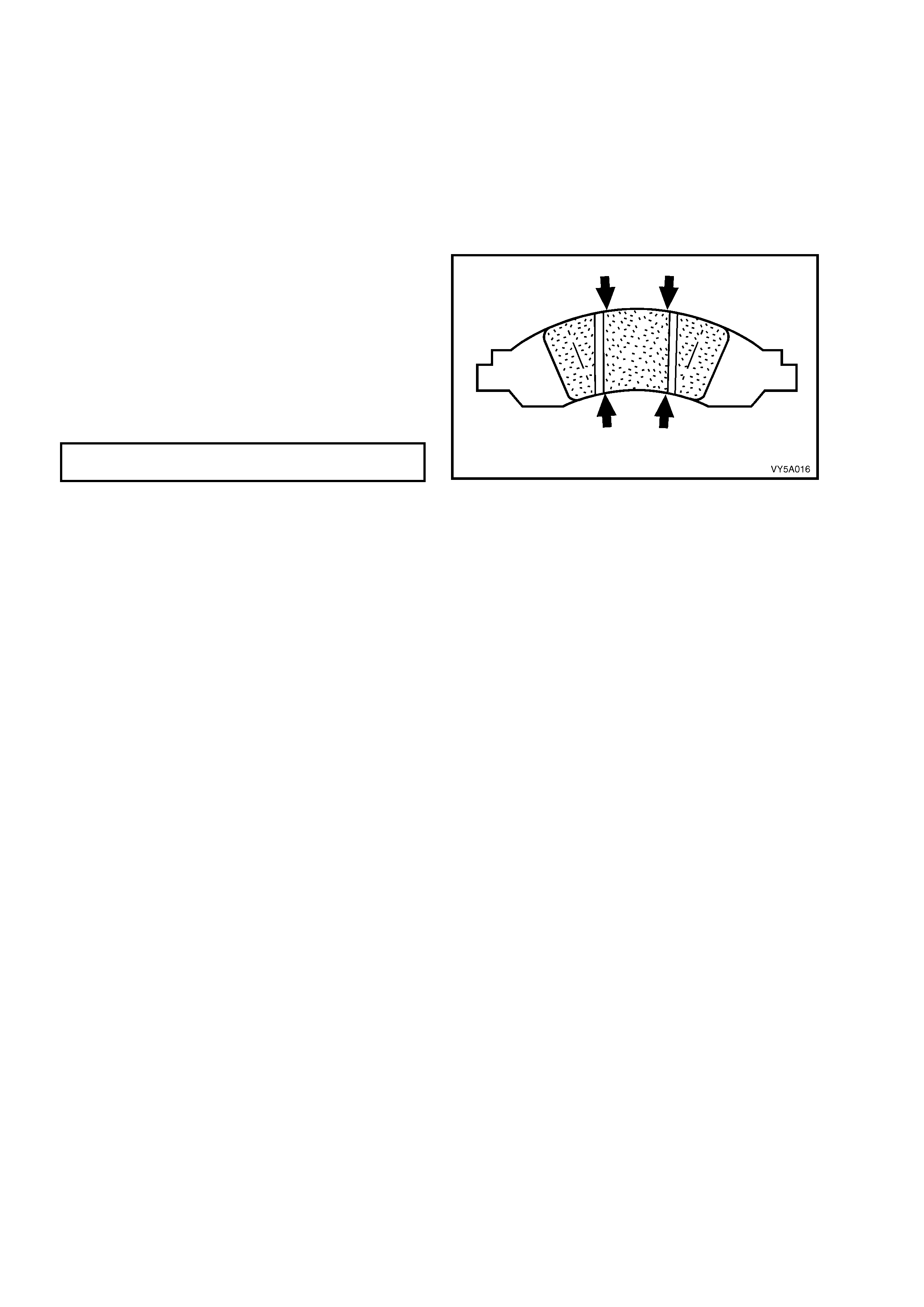
5. Using vernier calipers, check the brake [pad
thickness in the four locations shown. The
minimum lining thickness should be no less
that the thickness specified. Also, pad wear
should be even – if not, then the cause must
be established and corrected.
BRAKE PAD MINIMUM LINING
THICKNESS BEFORE REPLACEMENT 2 mm
6. If not being replaced, reinstall the brake pads
in the same locations, prior to removal. Refer
to 2.7 BRAKE PADS, REPLACE, in this
Section, for the required procedures for this
operation.
7. Reinstall wheel nuts but do not fully tighten at
this time.
Figure 5A - 21
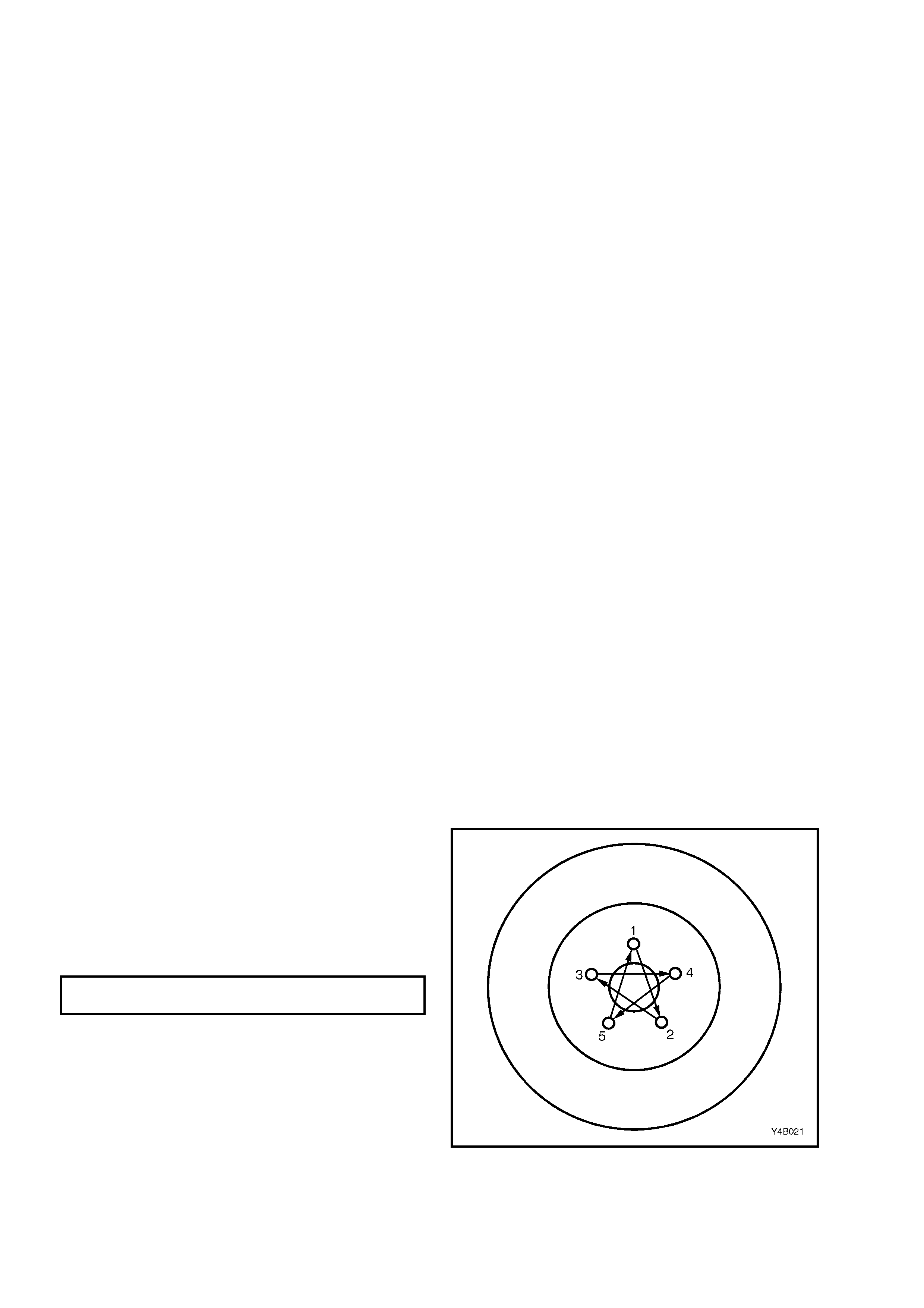
8. Lower the vehicle to the ground and tighten the wheel nuts to the specified torque, working in a star pattern,
refer to 2.1 SERVICE NOTES AND CAUTIONS, in this Section.
9. Reinstall wheel covers (steel wheels) or wheel nut decorative caps (alloy wheels).
10. Road test vehicle to check for correct brake operation.
2.7 BR AKE PADS, REPLACE
LT Section No. – 04-750 and 04-825
NOTE: The following fasteners have micro-
encapsulated sealant applied and should be
replaced (#
##
#) on reassembly:
# Brake caliper guide pin bolt
BR AKE PAD REMOV AL
NOTE: T his proc edure ref ers to f ront brak e pads. An y dif ferenc es relatin g to rear brak e pad repl acem ent are noted
in square brackets.
1. Remove m aster c ylinder re servoir cap. L oosen fr ont left (1) [or rear (2)] wheel brak e line connect ion at m aster
cylinder, allowing fluid to bleed into a container until master cylinder reservoir is approximately 1/2 full.
Re tighten line connection and install master cylinder cap.
NOTE 1: Do not completely remove the brake line or empty the reservoir or it will be necessary to bleed the braking
system.
NOTE 2: DO NOT ATTEMPT TO RE-USE the removed fluid.
NOTE 3: Removal of fluid from the reservoir is needed to stop reservoir overflow when caliper piston is pushed
back in its bore during pad replacement.
NOTE 4: Brake fluid will damage paint-work.
NOTE 5: View A is for RHD vehicles, while View B is for LHD vehicles.
Figure 5A - 22
2. Raise fr ont (or rear) of vehi cle and place on s afety stands. Ref er to Section 0A GENERAL INFORM ATION in
the MY2003 VY and V2 Series Service Information for the necessary procedures.
3. Mark relationship of wheel to hub. Remove front (or rear) wheels.
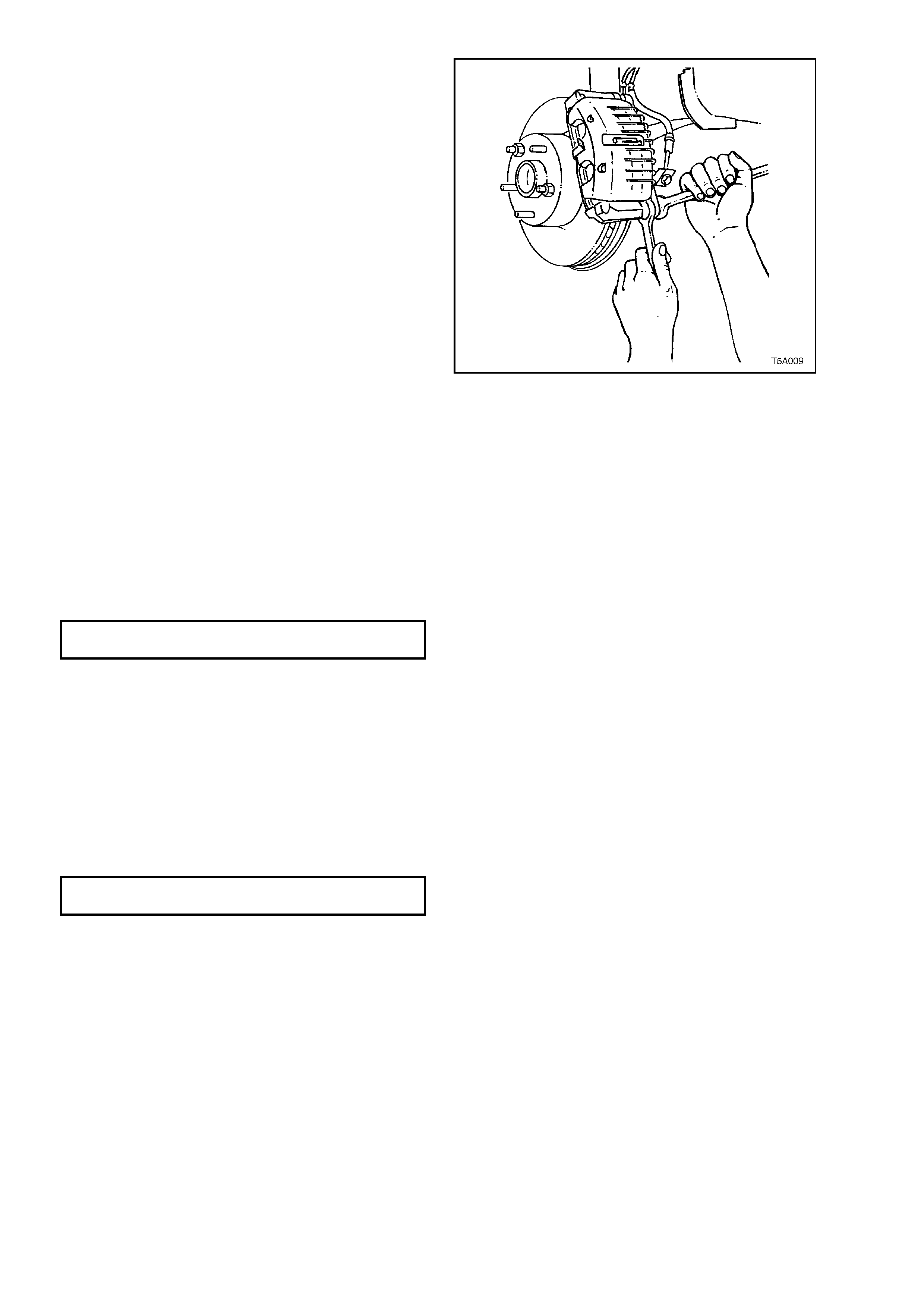
4. Using G-clamps as shown, tighten until the caliper pistons bottom in each bore.
NOTE 1: Ensure that one end of the G-clamp rests on (or is adjacent to) the brake hose attaching bolt head, and
the other against the outer pad.
NOTE 2: View A is for the front brake caliper, while View B is for the rear.
Figure 5A - 23
5. Us ing a s uitab le si ze ope n end sp anner to hol d
the lower guide pin, remove and discard the
guide pin bolt.
NOTE: Old bolts must not be re-used as they are
vital safety components which have a micro-
encapsulated adhesive on the bolt thread.
6. Swing caliper assembly up from the anchor
plate and disc and support caliper with a wire
hook.
7. Remove worn pads from anchor plate.
8. Inspect condition of brake disc.
9. Check guide pins for free movement in anchor
plate. If there is restriction of movement,
replace guide pins and/or guide pin boots.
Refer to 3.3 BRAKE CALIPER in this Section.
10. Clean an y dirt f rom both t he piston f ace, which
contacts the inner pad, and the caliper head
area which contacts the outer pad.
11. Install new brake pads as follows:
Figure 5A - 24
FRONT BRAKE PAD INSTALLATION
1. Thoroughly clean both piston contact faces, using a suitable solvent such as Prepsol, if required.
2. Peel the backing paper from the inner pad and install it to the anchor plate, against the brake disc.
NOTE: Do not handle the exposed, sticky surface of the pad, particularly in the piston contact areas.
3. Install the outer pad to the caliper, noting that a leg of the steel spring should sit on top of the inner pad.
4. Reinstall the brake caliper housing, ensuring that the outer spring clip engages with the middle finger of the
caliper housing.
5. Install and tighten a new guide pin, self locking bolt to the correct torque specification.
(#
##
#) GUIDE PIN BOLT
TORQUE SPECIFICATION 30 - 34 Nm
NOTE 1: Use a suitable open end spanner to prevent the guide pin from rotating when tightening the guide pin bolt.
NOTE 2: Do not wed ge a n yth ing bet ween the guid e p i n hex a nd t he c a lip er as it c ould c aus e inc orr ec t a lignm ent of
the pin which would then restrict the free sliding of the caliper relative to the anchor plate.
6. Fill master cylinder to correct level with fresh, specified brake fluid.
7. Depress an d hold the br ake peda l down in the applied pos ition for at least 5 s econds, to ens ure that the inner
pads stick to the pistons.
8. Refill master cylinder if necessary.
9. Reinstall wheels, aligning marks made prior to removal and lower vehicle to the ground.
10. Tighten road whee l att ac hi ng nuts to th e s pec if ied torque, work ing i n a star patte r n, as detai le d in 2.1 SERVICE
NOTES AND CAUTIONS, in this Section.
ROAD WHEEL ATT ACHING
NUT TORQUE SPECIFICATION 100 - 125 Nm
11. Reins t al l wheel caps (steel whee ls) or wheel nut dec or ati ve ca ps (al loy wheels) .
REAR BRAKE PAD INSTALLATION
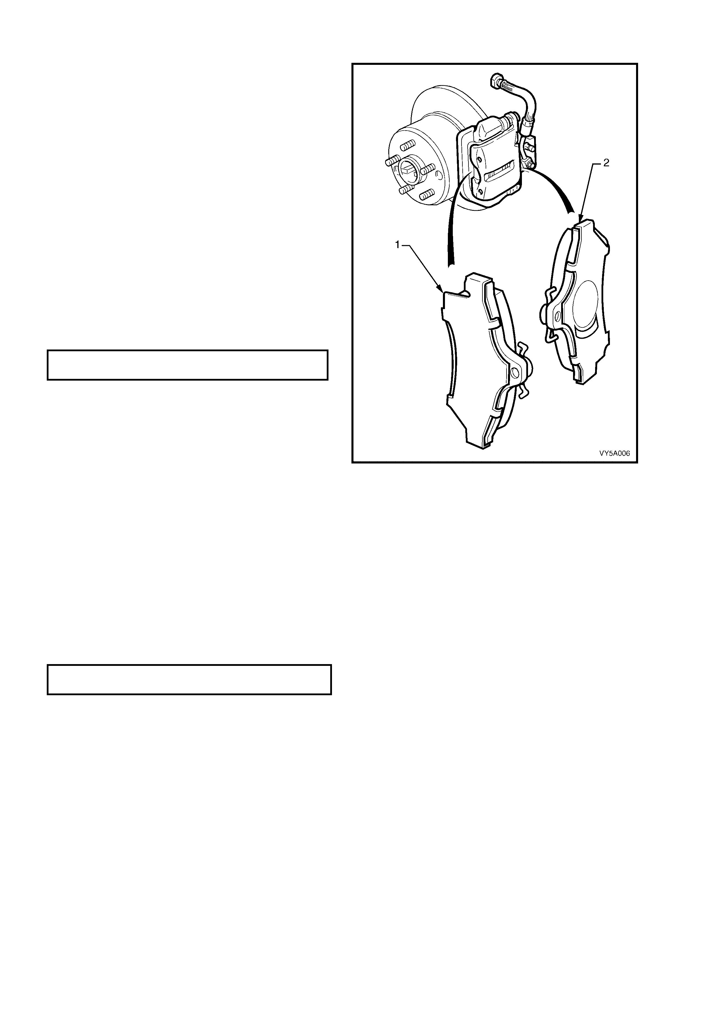
IMPORTANT: For noise damping effectiveness, it
is critical that the brake pad and shim assemblies
are installed in the correct locations. For example:
a. The outer pad (1) (which is retained by the
fingers of the brake caliper housing), has a full
shim.
b. The inner pad (2) has a shim that has an
asymmetrical cut-out above the caliper piston
and mus t be cor rectl y installed to the c aliper b y
having the cut-out on the lower half of the pad
when installed in the caliper (in-car position).
The brake pads illustrated, should only be fitted
to the left hand side, rear brake caliper, in the
attitude, as shown.
1. Reinstall caliper housing over brake pads.
Ensure spring clip is located correctly in the top
of the caliper body.
2. Install new guide pin, self locking bolt. Tighten
to the specified torque.
(#
##
#) GUIDE PIN BOLT
TORQUE SPECIFICATION 30 - 34 Nm
NOTE 1: Use a suitable open end spanner to
prevent t he guide p in from rotating when tig htening
the guide pin bolt.
NOTE 2: Do not wedge anything between the
guide pin hex and the caliper as it could cause
incorrect alignment of the pin which would then
restrict the free sliding of the caliper relative to the
anchor plate.
3. Fill master cylinder to correct level with fresh,
specified brake fluid.
4. Depress brake pedal several times to bring pad
assemblies into position against disc.
5. Refill master cylinder if necessary.
6. Reinstall wheels, aligning marks made prior to
removal and lower vehicle to the ground.
Figure 5A - 25
7. Tighten road wheel attaching nuts to the specified torque, working in a star pattern (refer to 2.1 SERVICE
NOTES AND CAUTIONS, in this Section.
ROAD WHEEL ATT ACHING
NUT TORQUE SPECIFICATION 100 - 125 Nm
8. Reinstal l whee l caps (stee l whee ls ) or wheel nut dec orative caps (alloy wheels).
BRAKE PAD BEDDING-IN PROCEDURE
Whenever brake pads are replaced, they should be burnished, by the following bedding-in procedure:
1. Perform a minimum of 10 moderate (0.3 to 0.4 g deceleration) brake applications from 70 km/h down to 40
km/h every 500 metres.
NOTE 1: A panic stop would be classif ied as being a 0.9 g deceler ation br aking effor t, so a moder ate deceler ation
rate of 0.4 g would be one that required approximately half the brake pedal effort needed for a panic stop.
NOTE 2: Do not perform this procedure at less than 500 metre intervals, as the excessive heat build-up, may
adversely affect the frictional characteristics of the new brake pad material.
2.8 BRAKE PEDAL ASSEMBLY
LT Section No. – 04-600
REMOVE
CAUTION: Disable the SRS (Air Bag). Refer to Section 12M, OCCUPANT PROTECTION SYSTEM.
NOTE: For vehicles with manual transmission, it is necessary to remove the clutch pedal assembly prior to
removing the brake pedal assembly. Ref er to Section 7 A1, 3.7 CLUT CH PEDAL ASSEMBLY in the MY2003 VY
and V2 Series Service Information for details.
1. As required, first remove the following components:
a. Driver side instrument panel lower trim plate assembly, refer to Section 1A3, 3.1 INSTRUMENT PANEL
LOWER TRIM PLATE A SSEMBLY.
b. Instrument panel lower trim panel assembly, refer to Section 1A3, 3.4 INSTRUMENT PANEL LOWER
TRIM PANEL ASSEMBLY.
c. Instrument panel lower trim panel retainer, refer to Section 1A3, 3.5 LOWE R TRIM PANEL RETAINER.
2. For left-hand drive vehicles, disconnect the left hand side ventilation ducting. Refer to Section 2B - HVAC
CLIMATE CONTROL (MANUAL AC) – REMOVAL AND INSTALLATION
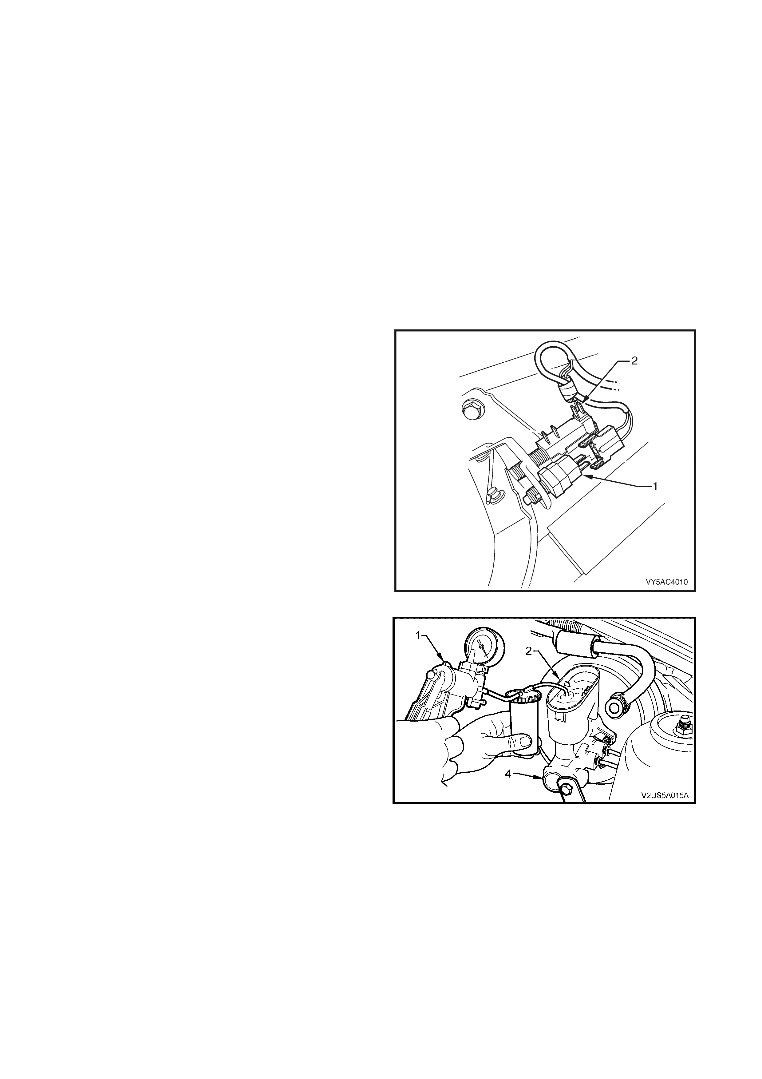
3. Disconnect t he wiring h arness connec tors from the
stop lamp switch (1) and the cruise control switch
(2).
NOTE: Refer to Section 12E, CRUISE CONTROL for
further information on the cruise control switch.
4. Thoroughly clean the master cylinder, especially
around the brake line connections.
Figure 5A - 26
5. Remove the m as ter c ylinder r eservoir cap. Using a
hand vacuum pum p (1), special tool J 23738- A or a
commercially available hand vacuum pump or
syringe, siphon as much brake fluid from the
master cylinder reservoir (2) as possible.
NOTE: Brak e fluid will c aus e dam age to the pa int work
if it comes into contact with it. In the event that this
happens, wash the brake fluid off with water.
Figure 5A - 27
6. Disconnect the brak e lines (2) f rom the m aster cylinde r (1) and allo w an y residu al brak e f luid from the m aster
cylinder t o drain int o a cont ainer. P lug the ope nings in both the m aster c ylinder and th e pipes to pr event f luid
loss and dirt ingress. Refer to Figure 5A - 28.
NOTE: View A is for RHD vehicles, while View B is for LHD vehicles.
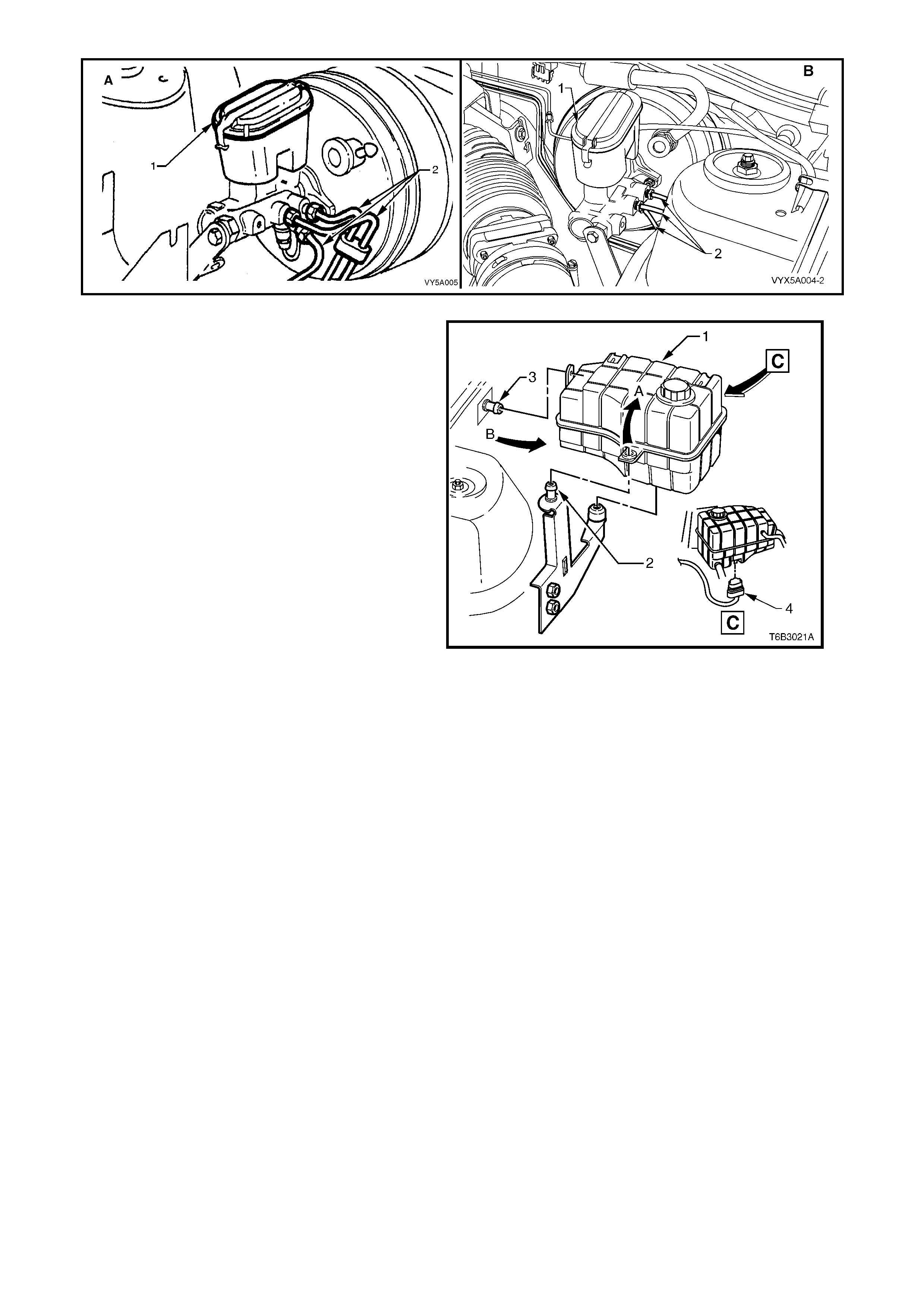
Figure 5A - 28
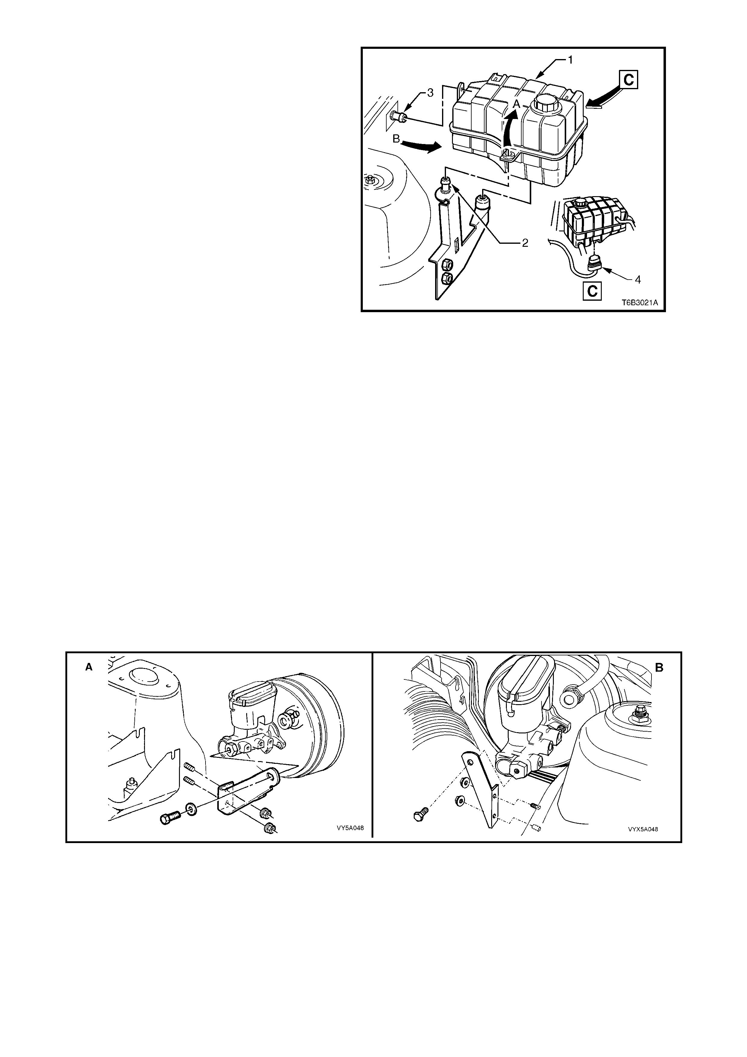
IMPORTANT: The engine surge tank may be hot.
Allow the coolant to cool before performing this
procedure.
7. For lef t-han d drive veh ic les fitted with th e GEN
III V8 engine, disengage the coolant surge
tank from its anchor points by:
A Grasping the surge tank (1) firmly with
both hands and pivoti ng in the direction of
arrow A to dislodge the surge tank from
the rear anchor po int (2).
B Pulling the surge tank inboard (arrow B)
toward the engine to dislodge the inner
fender skirt anchor point (3). Refer to
2.10 Coolant Recovery Surge Tank in
Section 6B3, ENGINE COOLING – GEN
III V8 ENGINE in the MY2003 VY and V2
Series Service Information for further
information.
8. For lef t-han d drive veh ic les fitted with th e GEN
III V8 engine, disconnect the harness
connector (4) from the coolant level sensor
and set the surge tank to one side.
NOTE: It is not necessary to remove the surge
tank from the vehicle. Leave all hoses and screw-
on-cap intact.
9. To provide access to the brake master
cylinder support bracket on left-hand drive
vehicles fitted with the GEN III V8 engine, it is
necessary to remove the Powertrain Control
Module. Refer to 2.1 Powertrain Control
Module (PCM) in Section 6C3-3, SERVICE
OPERATIONS – GEN III V8 ENGINE in the
MY2003 VY and V2 Series Service
Information.
Figure 5A - 29
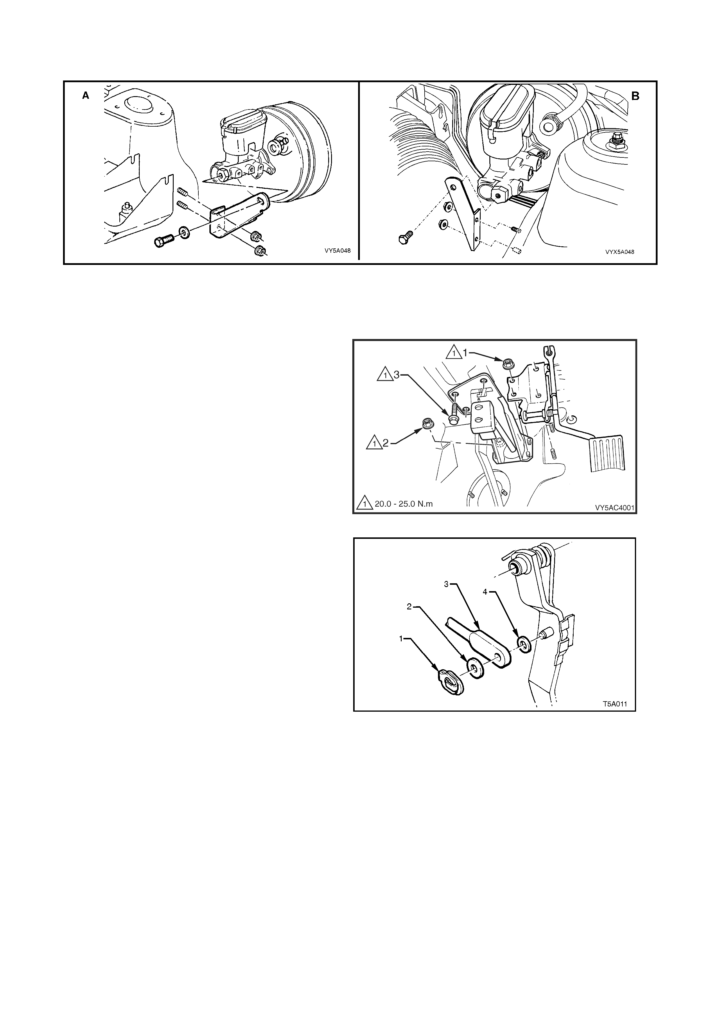
10. Remove the bracket securing the master cylinder to the adjacent strut tower. Refer to Figure 5A - 30.
NOTE: View A is for RHD vehicles, while View B is for LHD vehicles.
Figure 5A - 30
11. Disconnect the accelerator pedal cable from the accelerator pedal. Refer to Section:
• Section 6C3- 3 SERVICE OPER ATION S for vehicles fitted with the GEN III V8 engine.
• Section 6C1- 3 SERVICE OPERATION S for vehicles fitted with the V6 and V6 Supercharged engine.
12. Remove the nut (1), four places, securing the
accelerator pedal assembly to the dash panel.
Remove the accelerator pedal assembly.
13. Remove the remaining two nuts (2) securing
the brake booster to the dash panel.
Figure 5A - 31
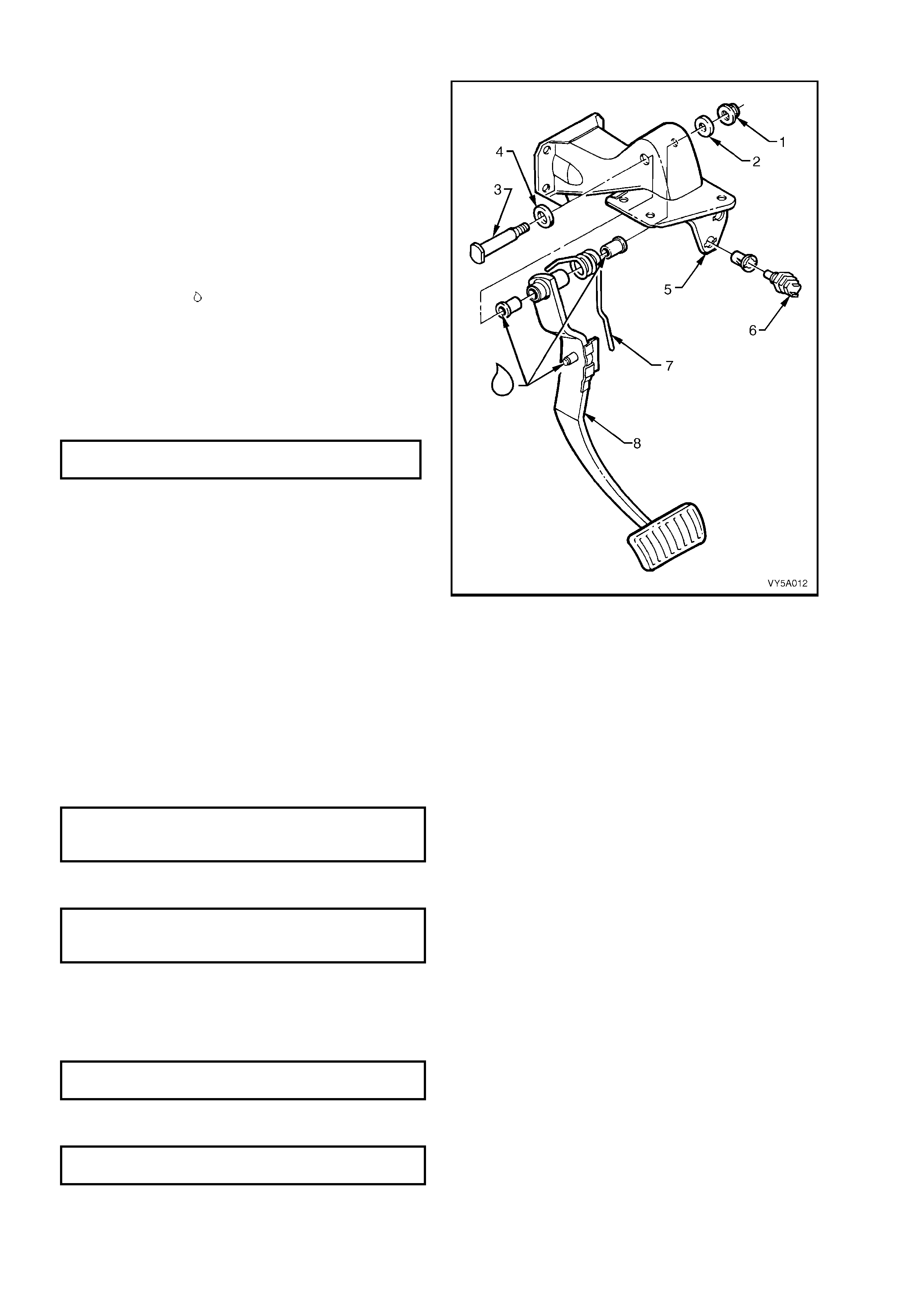
14. Remove the push rod retaining clip (1), push
rod (3) and washers (2 and 4) from the brake
pedal.
15. Remove the three bolts (3) securing the brake
pedal assembly to the steering column. Refer
to Figure 5A - 31.
16. From the engine compartment, pull the brake
booster forward, allowing the brake pedal
assembly to be lowered, rear end first from
under the instrument panel.
Figure 5A - 32
DISASSEMBLE
1. Remove the nut (1) and washer (2) securing
the brake pedal shaft (3) to the brake pedal
support (5).
2. Carefully remove t he s haf t and was her ( 4) f r om
the brake pedal support.
3. W ithdraw the brak e pedal (8) and retur n spring
(7) assembly.
REASSEMBLE
1. Lubricate all bearing surfaces with
Molybdenum Disulphide grease, as indicated
by the symbol .
2. Hold the brake pedal and return spring in
position and insert the brake pedal support
shaft and washer through the brake pedal
support.
3. Reinstall the brake pedal shaft retaining
washer and nut, then tighten to the specified
torque.
PEDAL SUPPORT SHAFT NUT
TORQUE SPECIFICATION 50 - 60 Nm
Figure 5A - 33
REINST ALL
1. Reinstall the brake pedal assembly into the vehicle and install the three bolts securing the brake pedal
assembly to the steering column, refer to Figure 5A - 31. DO NOT tighten the bolts at this time.
2. Push the brake booster rearward to engage the four studs with the brake pedal assembly.
3. Install the push rod (3), washers (2 and 4) and retaining clip (1). Refer to Figure 5A - 32.
4. Install the accelerator pedal assembly, refer to Figure 5A - 31.
5. Install and tighten the four brake pedal assembly to brake booster nuts to the specified torque. Refer to
Figure 5A - 31.
BRAKE PEDAL ASSEMBLY TO
BRAKE BOOSTER NUT
TORQUE SPECIFICATION 20 - 25 Nm
6. Install and tighten the two accelerator pedal assembly to dash panel nuts to the specified torque. Refer to
Figure 5A - 31.
ACCELERATOR PEDAL ASSEMBLY
TO DASH PANEL NUT
TORQUE SPECIFICATION 20 - 25 Nm
7. Reinstall the accelerator cable. Refer to Section:
• Section 6C3- 3 SERVICE OPERATION S for vehicles fitted with the GEN III V8 engine.
• Section 6C1- 3 SERVICE OPERATION S for vehicles fitted with the V6 and V6 Supercharged engine.
8. Tighten the three brake pedal assembly bolts to the specified torque, refer to Figure 5A - 31.
BRAKE PEDAL SUPPORT BOLT
TORQUE SPECIFICATION 20 - 25 Nm
9. Install the m aster c yl inder support brack et, tightening the fasteners to the s pecified torqu e, refer to Figure 5 A -
30.
MASTER CYLINDER BRACKET
NUT TORQUE SPECIFICATION 15 - 20 Nm
10. For lef t-han d dri ve vehicles f itted with the G EN III V8 e ngi ne, re insta ll th e PCM. Refer to 2.1 P o wertrain C ont rol
Module (PCM) in Section 6C3-3, SERVICE OPERATIONS – GEN III V8 ENGINE in the MY2003 VY and V2
Series Service Information.
11. For left-hand drive vehicles fitted with the GEN III V8 engine, reinstall the coolant surge tank. Refer to 2.10
Coolant Recovery Surge Tank in Section 6B3, ENGINE COOLING – GEN III V8 ENGINE in the MY2003 VY
and V2 Series Ser v ice Infor mation.
12. Place a clean container under the brake master cylinder, unplug the brake lines and master cylinder outlet
ports and reinstall the pipes to the master cylinder, refer to Figure 5A - 28.
13. Tighten the brake pipe nuts to their specified torque.
BRAKE PIPE TO MASTER
CYLINDER FLARED NUT
TORQUE SPECIFICATION 8 - 11 Nm
14. Bleed the brake system. Refer to 2.4 BRAKE SYSTEM BLEED.
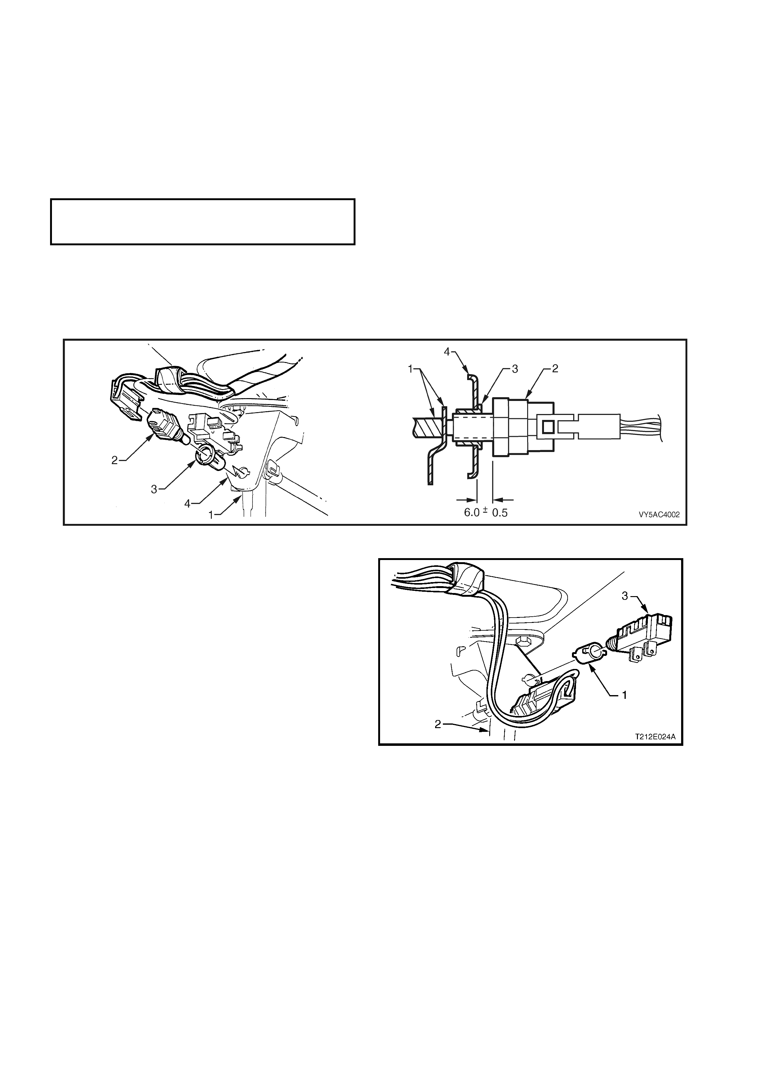
15. Adjust the stop lamp and/or cruise control switches as follows:
Stop Lamp Switch
W ith the pedal (1) held i n the at res t position, pus h or pull the s witch ( 2) through t he metal c lip (3) to ach ieve a
gap of 6 ± 0.5 mm, as shown, between the brake pedal support (4) and switch body. Refer to Figure 5A - 34.
Figure 5A - 34
Cruise Control Switch
Check that the tubular clip (1) is correctly
installed. With the brake pedal (2) held in the
depressed position (brakes applied), push the
cruise contro l s witch (3) for ward u ntil t he s witch
body contacts the tubular clip.
Pull the brake pedal fully up against the brake
pedal stop, until audible click sounds are no
longer heard.
Depress the brake pedal again and repeat the
above procedure until the audible click sounds
can no long er be he ard. At this point, t he switch
will be correctly adjusted.
Figure 5A - 35
16. For left-hand drive vehicles, reinstall the left-hand side ventilation duct.
17. Reinst all the instrum ent panel lower trim panel retainer, lower trim panel and driver side lower trim plate, refer
to Section 1A3, INSTRUMENT PANEL & CONSOLE.
CAUTION: Enable the SRS (Air Bag). Refer to Section 12M, OCCUPANT PROTECTION SYSTEM.
18. Road test the vehicle to check for correct brake operation.
2.9 PARK BRAKE LEVER
LT Section No. – 04-675
REMOVE
1. Remove the right hand front seat. Refer to Section 1A7 SEAT ASSEMBLIES in the MY2003 VY and V2
Series Service Information.
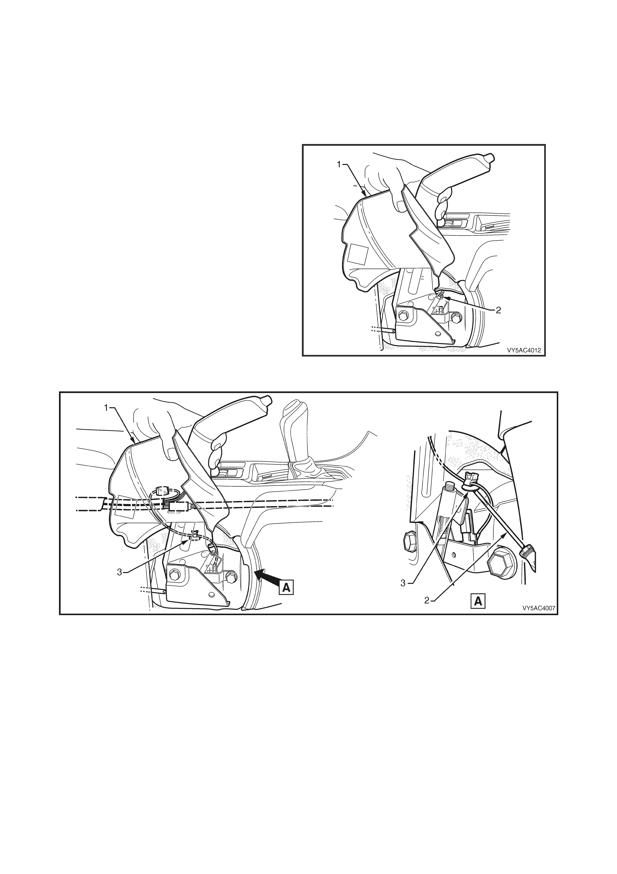
2. Set the park brake in the fully released position.
3. Slip the park brake lever boot (1) to one side,
then remove the park brake front cable
adjusting nut (2), using a deep socket.
4. Whilst holding the park brake lever boot (1) to
one side, use a screwdriver (2) to prise the
park brake warning lamp switch harness
retaining clip (3) from the transmission tunnel.
Refer to Figure 5A - 37.
Figure 5A - 36
Figure 5A - 37
5. Remove the floor console cover assembly. Refer to Section 1A3, INSTRUMENT PANEL and CONSOLE.
6. Disconnect the park brake warning lamp switch harness connector (1) from the main vehicle wiring harness
connector (2). Refer to Figure 5A - 38.
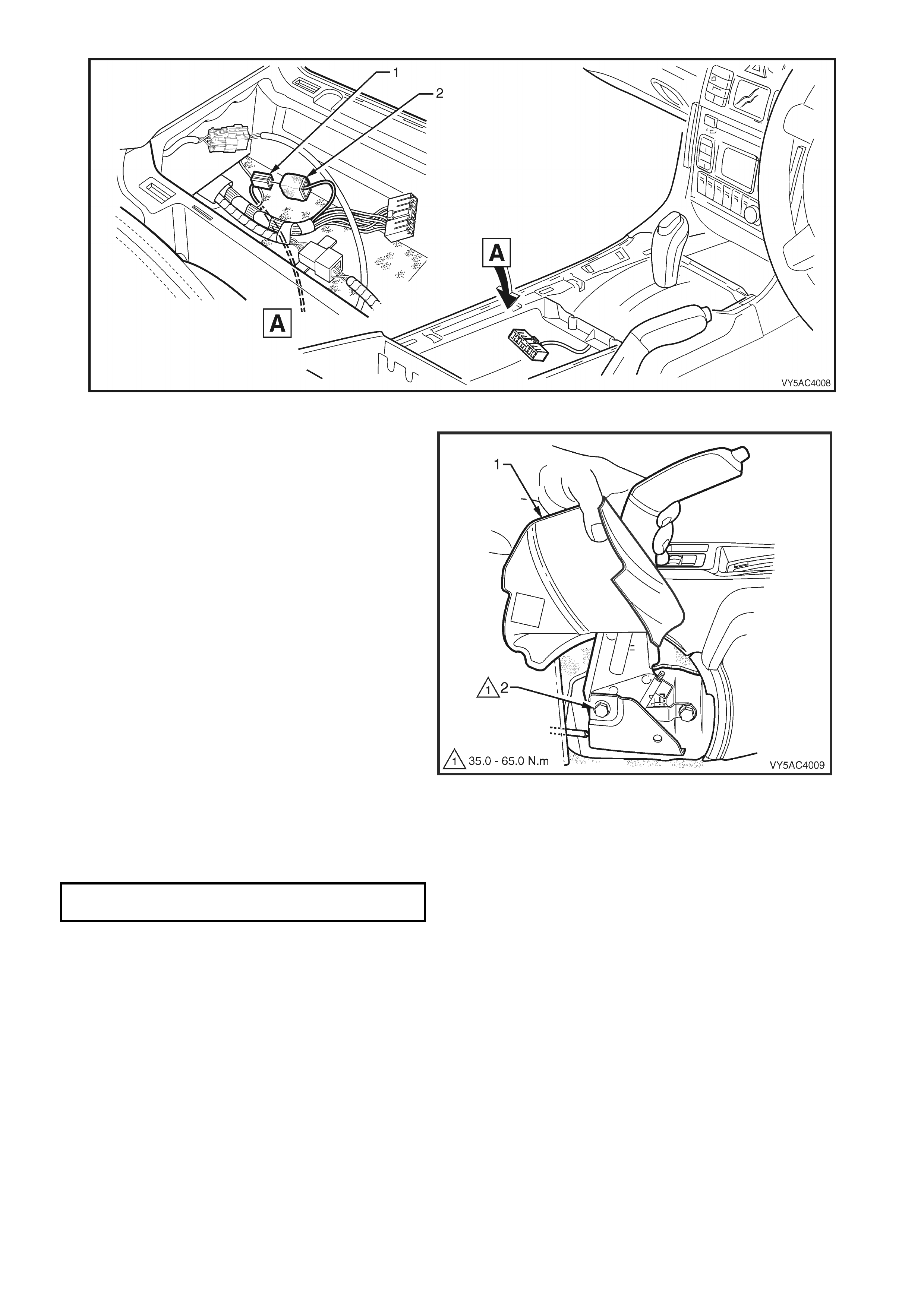
Figure 5A - 38
7. Whilst holding the park brake lever boot (1) to
one side, remove the par k brake lever r e tai ni ng
bolt (2), two places.
8. Carefully lift the park brake lever assembly
upwards to free the cable (2).
9. Remove the lever assembly from the vehicle.
Figure 5A - 39
REINST ALL
Installation is the reverse of the removal procedure, noting the following:
1. Tighten the park brake lever bolts to specified torque.
PARK BRAKE LEVER BOLT
TORQUE SPECIFICATION 35 – 65 Nm
2. Reinstal l the thread ed end of the front park brake c able and then inst all the adj usting lock nut. Adjust the park
brake cable. Refer to 2.2 PARK BRAKE CABLE, ADJUST in this Section.
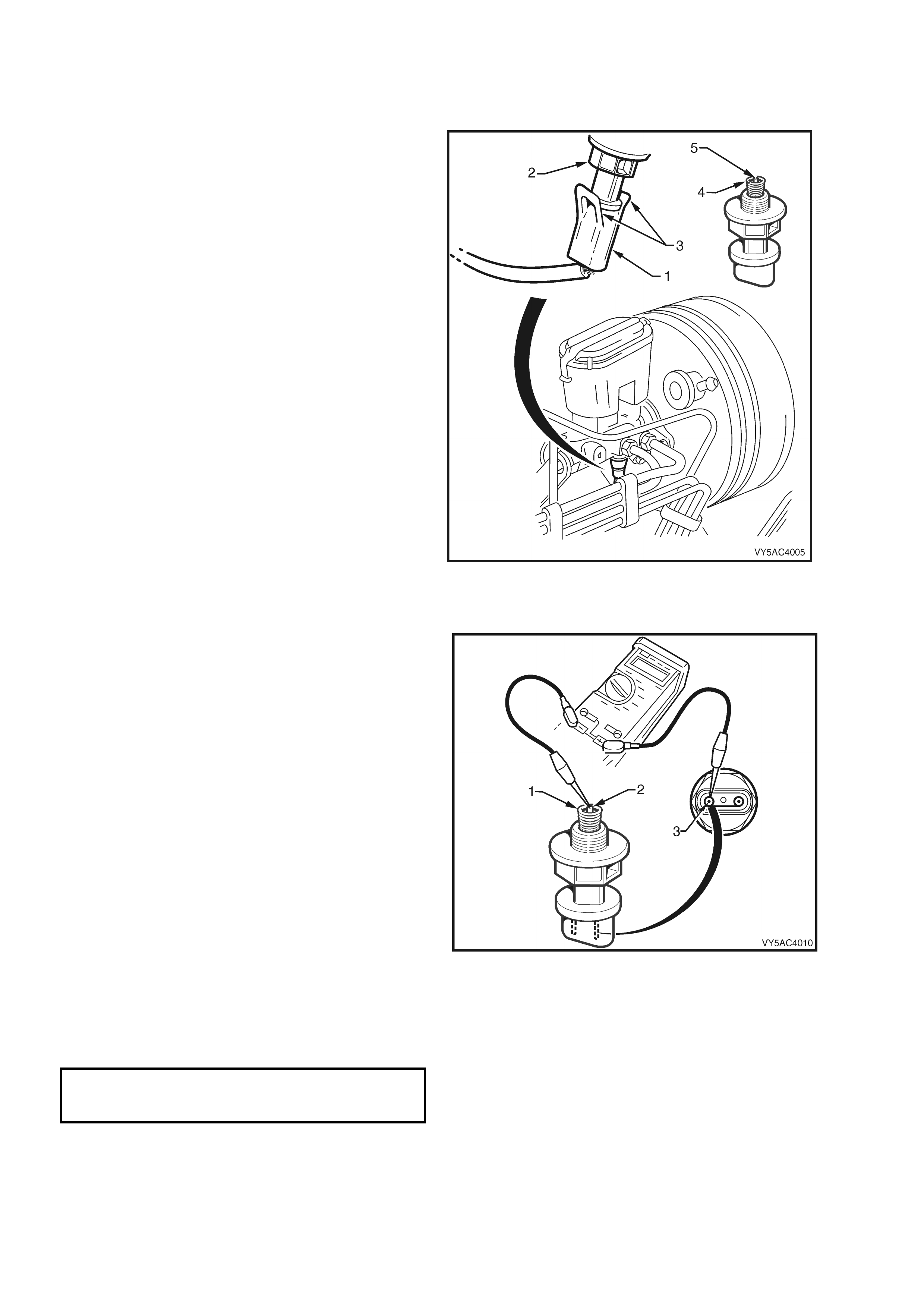
2.10 PARK BRAKE WARNING L AMP SWITCH
LT Section No. – 04-675
REMOVE
1. Remove the park brake lever. Refer to 2 .9 P ARK BR AKE LEVER, REM O VE in this Section.
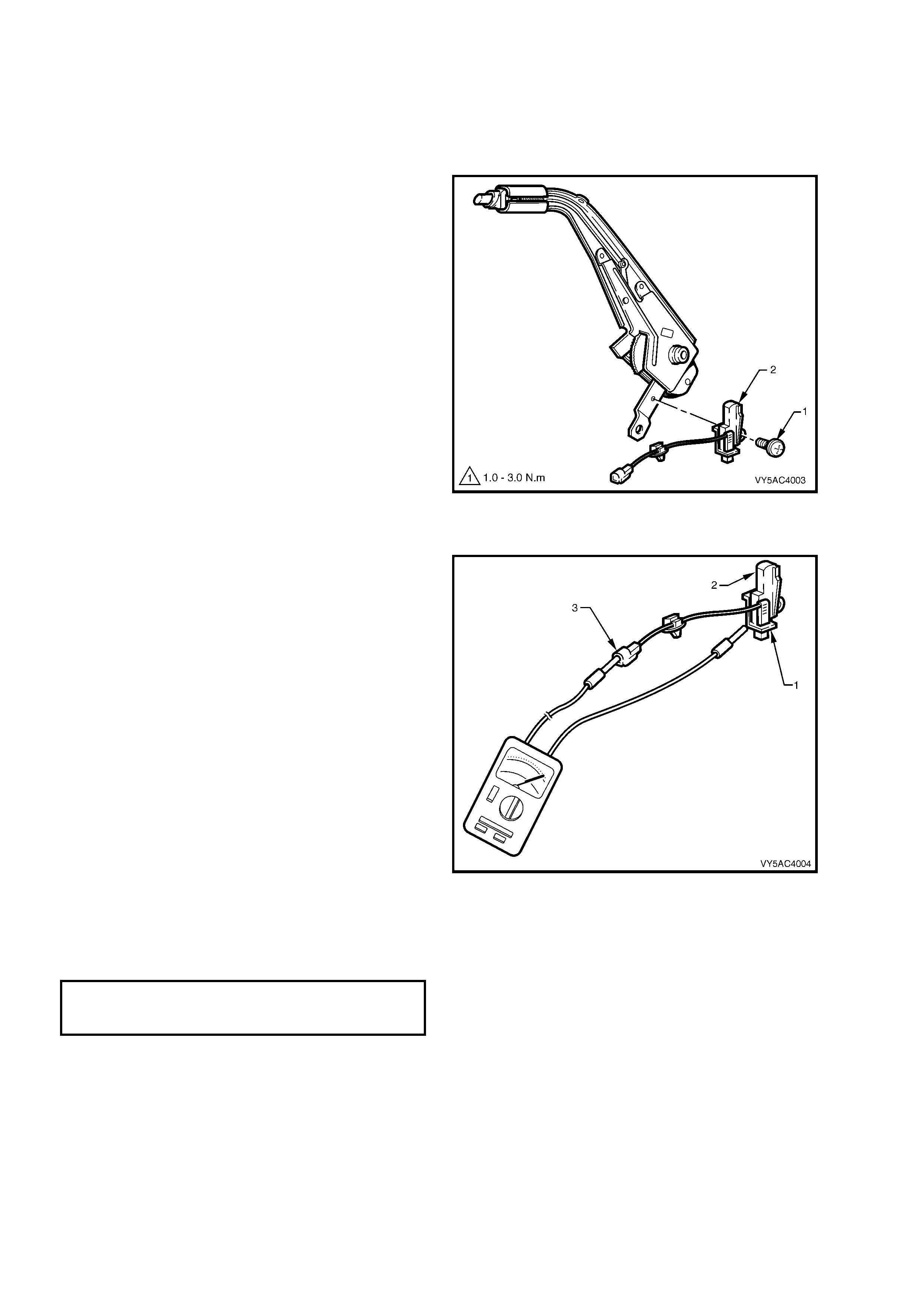
2. Remove the park brake warning lamp switch
retaining screw (1), and remove the switch (2).
Figure 5A - 40
INSPECT
1. Whilst holding the park brake warning lamp
switch (1), depress and release the plunger (2),
checking that the plunger moves freely.
2. Using a multimeter, check that there is
continuity between the terminal (3) and the
switch body.
3. With the multimeter still connected, check that
there is no continuity when the switch plunger
is depressed.
4. If any of the above tests fail, replace the park
brake warning lamp switch.
Figure 5A - 41
REINST ALL
Installation is the reverse of the removal procedure, noting the following:
1. Tighten the park brake warning lamp switch retaining screw to the specified torque.
PARK BRAKE WARNING LAMP
SWITCH RETAINING SCREW
TORQUE SPECIFICATION 1.0 – 3.0 Nm
NOTE: For further information on the park brake warning lamp operation, refer to Sect ion 12C, INST RUMENTS.
2.11 FRONT P ARK BRAKE CABLE
LT Section No. – 04-675
REMOVE
1. Set park brake in the fully released position.
2. Remove driver’s seat. Refer to Section 1A7
SEAT ASSEMBLIES in the MY2003 VY and
V2 Series Service Information for the
procedure.
3. Remove the park brake lever (1). Refer to
2.9 PARK BRAKE LEVER, in this Section.
4. Remove the centre console and lift the carpet
to gain access to the two front cable
escutcheon screws (3). Refer to Section 1A3
INSTRUMENT PANEL and CONSOLE, in the
MY2003 VY and V2 Series Service
Information, for details.
5. Remove the two screws (3).
Figure 5A - 42
6. Raise vehicle and place safety stands under
each of the rear trailing arms. Refer to
Section 0A, GENERAL INFORMATION, in the
MY2003 VY and V2 Series Service Infor mation
for the recommended support points.
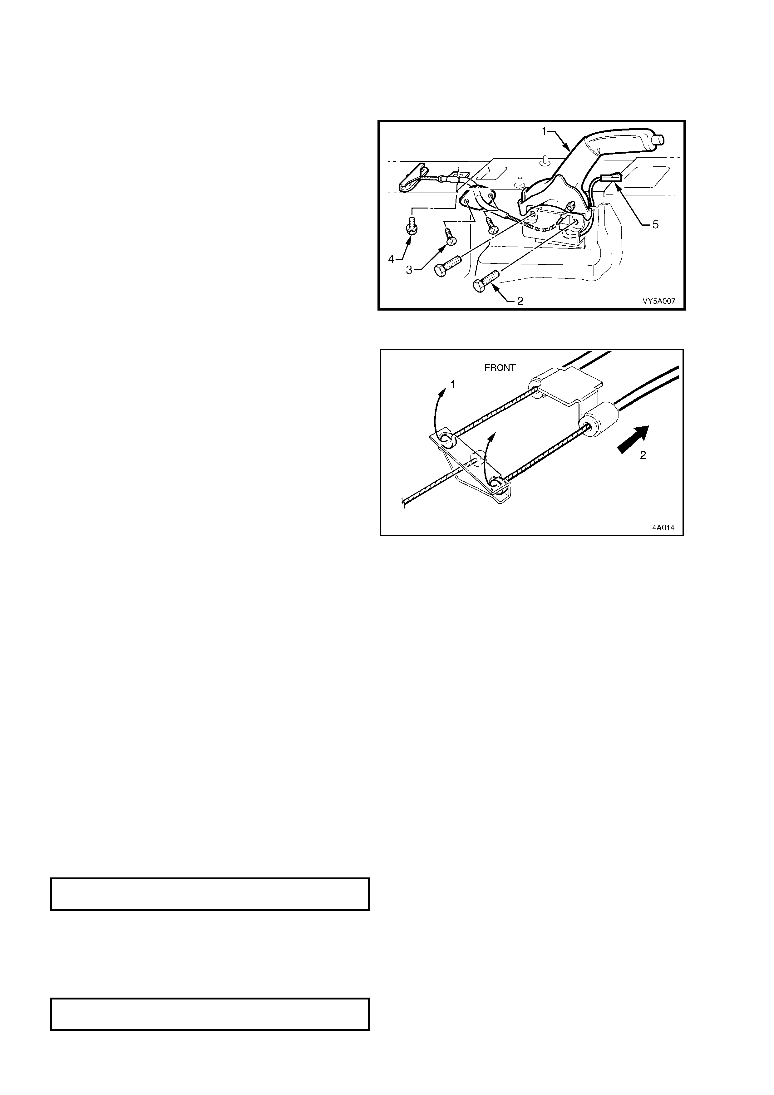
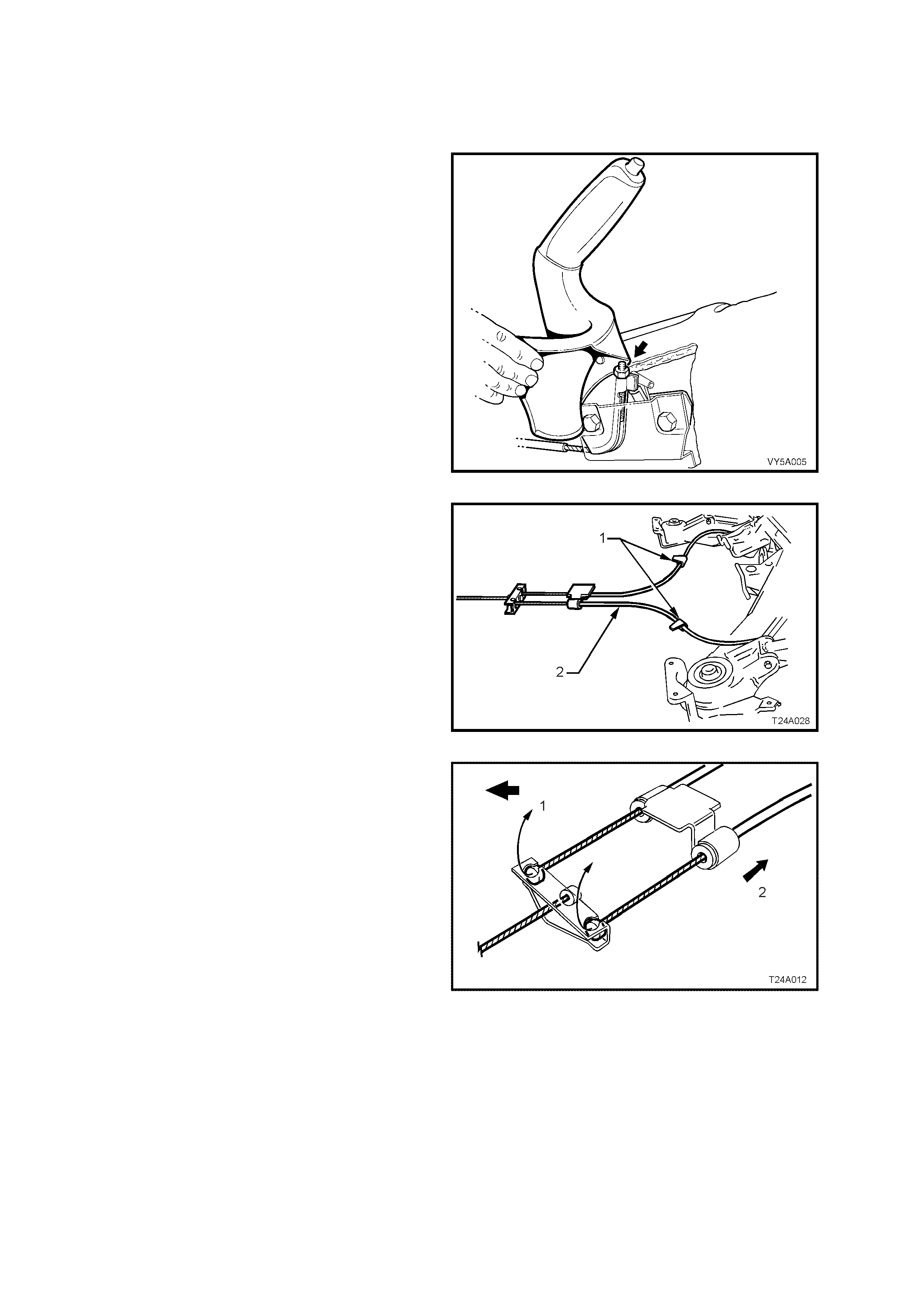
7. Pull each park brake inner rear cable forward
and up (1) to release it from the equaliser
bracket. Pull the outer cables to the rear (2) to
remove the cable from the retaining bracket.
8. Remove the front cable outer cable retaining
bracket bolt (4) from the vehicle underbody,
refer to Figure 5A - 42.
NOTE: Depending on the engine/transmission
fitted to the vehicle, it may be necessary to first
remove the propeller shaf t to enable access to this
bolt. Refer to Section 4C PROPELLER SHAFT
AND UNIVERSAL JOINTS, in the MY2003 V Y an d
V2 Series Service Information for the procedure.
9. Manoeuvre the front cable assembly and
equaliser bracket, through the aperture in the
floor pan, removing the cable assembly from
inside the vehicle.
Figure 5A - 43
REINST ALL
Installation is the reverse to the removal procedure,
apart from the following:
1. Manoeuvr e the front cable and equaliser bracket
assembly, through the hole in the floor pan,
ensuring that the rubber seal is correctly
positioned. Install the two self tapping screws
(3 in Figure 5A - 42), securing the plate to the
floor pan.
2. Reinstall the park brake lever and tighten bolts
(2 in Figure 5A - 42) to the specified torque.
PARK BRAKE LEVER BOLT
TORQUE SPECIFICATION 35 – 65 Nm
3. Reinstal l the park br ake f ront cable adj usting nut
a few threads to secure the cable.
4. Reinstall the outer front cable retaining bracket
bolt to the vehicle underbody, tightening to the
specified torque.
OUTER FRONT CABLE BRACKET
BOLT TORQUE SPECIFICATION 6 - 14 Nm

5. As required, reinstall the propeller shaft. Refer to Section 4C PROPELLER SHAFT AND UNIVERSAL
JOINTS, in the MY2003 VY and V2 Series Service Information for the procedure and the specified torque
specifications.
6. Reinstall the driver’s seat and centre console. Refer to Section 1A7 SEAT ASSEMBLIES and
Section 1A3 INSTRUMENT PANEL and CONSOLE, in t he M Y20 03 V Y a nd V 2 Ser i es S er v ic e I nf ormation f or
the necessary procedures.
7. Reinstall the two rear cables to the equaliser bracket.
8. Adjust the park brake. Refer to 2.2 PARK BRAKE CABLE, ADJUST in this Section.
9. Lower the vehic l e to the ground.
2.12 REAR PARK BRAKE CABLE/S
LT Section No. – 04-675
REMOVE
1. Release park brake.
2. Using a deep socket, loosen the front cable
adjusting nut (arrow) until the nut is almost
removed.
3. Using a floor jack under centre of differential
carrier, jack up and support rear of vehicle on
safety stands under rear trailing arms.
Figure 5A - 44
4. To provide sufficient access, it may be
necessary to remove the propeller shaft from
the vehic le. Refer to Section 4C PROPELLER
SHAFT AND UNIVERSAL JOINTS, in the
MY2003 VY and V2 Series Service Infor mation
for the necessary procedures.
5. Unclip each (or as required) of the cable
gromm ets from the underb ody clip/s (1), to f ree
the cable/s (2).
Figure 5A - 45
6. Remove the front of the rear inner cable/s, by
first wrapping rag around the inner cable to
protect it from damage, then use pliers to pull
the ball nipple forward and up (1), to free from
the equaliser bracket.
7. Pull the outer cable rearward (2) to release
from the vehicle underbody bracket.
Figure 5A - 46
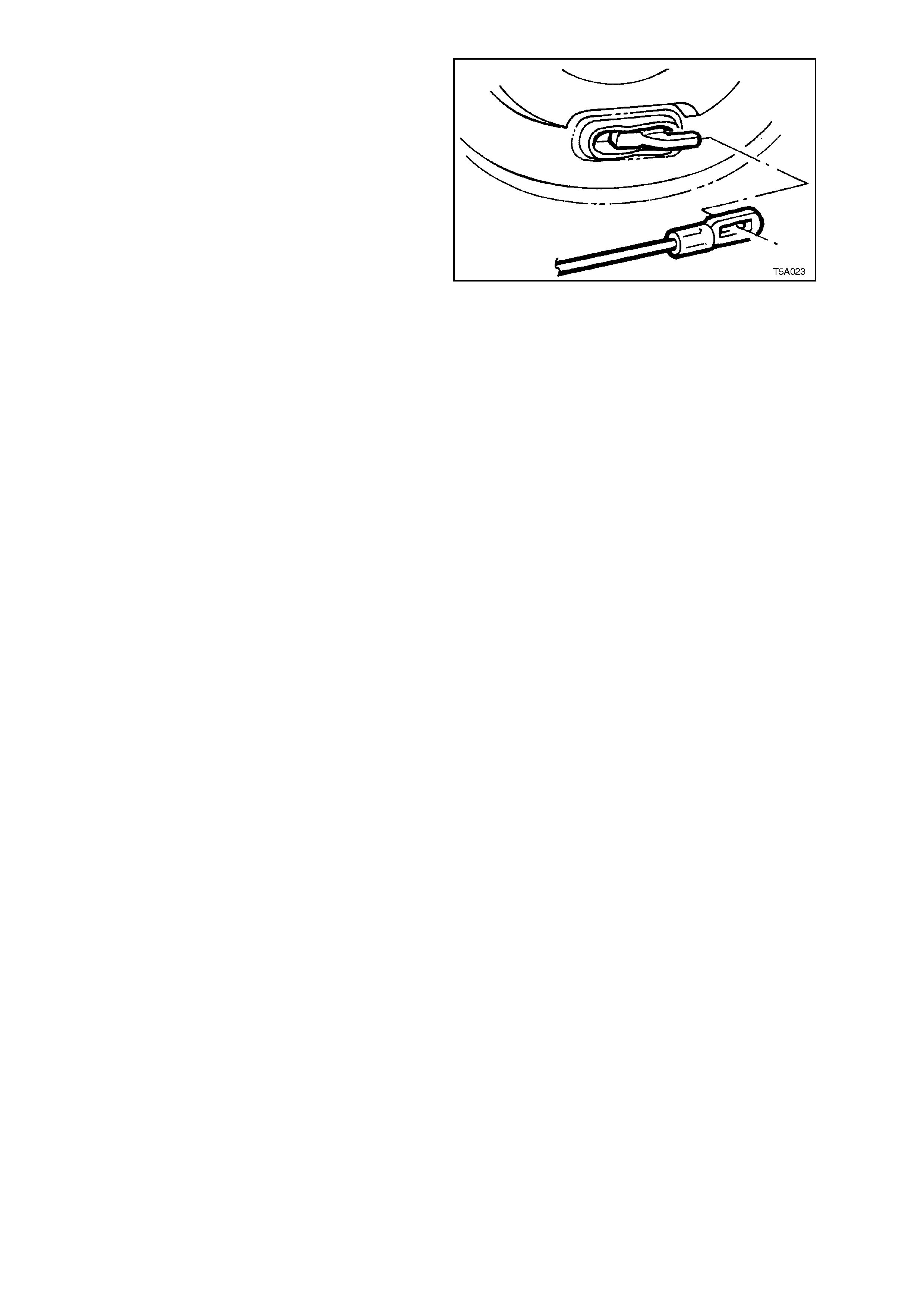
8. Disconnect the rear clevis from the rear park
brake actuating lever by gripping with pliers
and pivoting the cable rearwards.
9. Pull outer cable forward, out of trailing arm
retainer/s and remove the cable/s from the
vehicle.
Figure 5A - 47
REINST ALL
Reinstallation of the rear park brake cable/s is the reverse of removal procedure, except for the following points:
1. Install the cable through the trailing arm retainer, then fit the cable clevis to the park brake actuating lever.
2. Wrap rag around the inner cable to protect it from damage, then use pliers to pull the ball end on the inner
cable forward to engage into the equaliser bracket.
3. If removed, reinstall the propeller shaft. Refer to Section 4C PROPELLER SHAFT AND UNIVERSAL JOINTS,
in MY2003 VY and V2 Series Service Information for all details.
4. Adjust park brake cable, refer 2.2 PARK BRAKE CABLE, ADJUST, in this Section.
2.13 FRONT BRAKE HOSE
LT Section No. – 04-750
REMOVE
1. Raise fr ont of ve hic le and place o n j ack stands.
Refer to Section 0A, GENERAL
INFORMATION, in the MY2003 VY and V2
Series Service Information for the
recommended support points.
2. Mark position of wheel relative to hub and
remove road wheel.
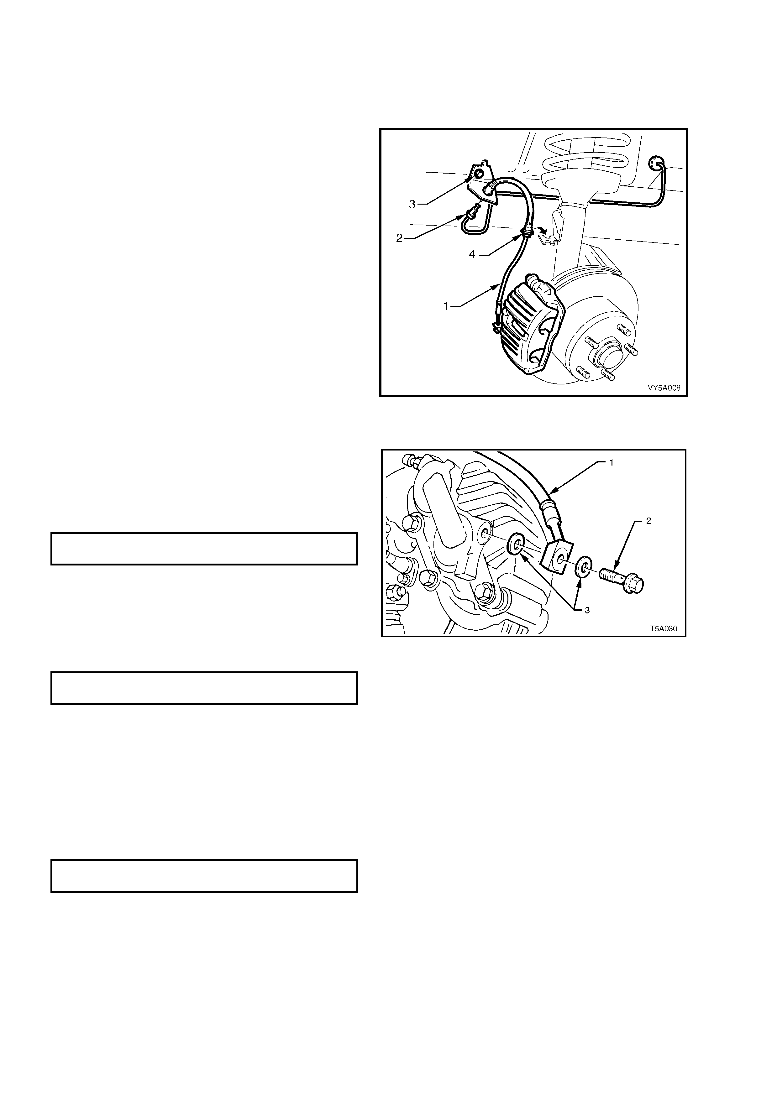
3. Thoroughly clean connections at each end of
brake hose (1).
4. Disconnect brake pipe (2) from hose (1) and
plug pipe.
5. Remove the screw (3) securing the hose
bracket to the inner skirt panel.
6. Unclip hose and grommet (4) from bracket on
suspension tower.
7. Unbolt and remove the brake hose from the
caliper, refer to Figure 5A - 49.
Figure 5A - 48
REINST ALL
1. Ensure brake hose and c a li per mating surf ac es
are clean and free from burrs.
2. Reconnect brake hose (1) to caliper, using
NEW copper sealing washers (3), then tighten
the banjo bolt (2) to specified torque.
BRAKE HOSE TO CALIPER
TORQUE SPECIFICATION 32 - 37 Nm
3. Clip hose and grommet into suspension strut
bracket.
4. Reinstall the screw to retain the hose bracket
to the inner skirt panel.
5. Remove plug f rom brake pipe an d rec onnect to
hose. Tighten to specified torque.
BRAKE PIPE TO BRAKE HOSE FLARE
NUT TORQUE SPECIFICATION 14 - 17 Nm
6. Check that hose is not twisted.
Figure 5A - 49
7. Bleed brake/s, refer 2.4 BRAKE SYSTEM
BLEED, in this Section.
8. Reinstall road wheel, aligning marks made on
removal and lower vehicle.
9. Tighten road wheel attaching nuts to the
specified torque, tightening in a star pattern,
refer to 2.1 SERVICE NOTES AND
CAUTIONS, in this Section.
ROAD WHEEL ATTACHING NUT
TORQUE SPECIFICATION 100 - 125 Nm

2.14 REAR CALIPER BRAKE HOSE
LT Section No. – 04-750
REMOVE
1. Raise the rear of the vehicl e and place o n jack
stands. Refer to Section 0A GENERAL
INFORMATION in the MY2003 VY and V2
Series Service Information, for the procedure.
2. Mark position of wheel relative to hub and
remove road wheel.
3. Thoroughly clean connections at each end of
brake hose (2).
4. While holding the hose (2) with a back-up
spanner, loosen then disconnect brake pipe
from brake hose. Plug the pipe open end.
5. Unclip retainer (1) from hose and withdraw
hose from bracket.
6. Unbolt and remove brake hose from caliper.
Figure 5A - 50
REINST ALL
1. Ensure brake hose and caliper mating surfaces are clean and free of burrs.
2. Rec onnec t brak e hos e to c ali per, ens uring that t he locatin g peg alig ns with the di m ple in the cal iper. Us e NEW
copper sealing washers, then tighten the banjo bolt to specified torque.
BRAKE HOSE TO CALIPER
TORQUE SPECIFICATION 32 - 37 Nm
3. Fit hose correctly into mounting plate bracket and reinstall retainer. Check that hose is not twisted.
4. Remove plug from brake pipe and reconnect to hose. While using a back-up spanner on the brake hose to
prevent twisting, tighten pipe to specified torque.
BRAKE PIPE TO HOSE FLARED
NUT TORQUE SPECIFICATION 14 -17 Nm
5. Bleed brake/s, see 2.4 BRAKE SYSTEM BLEED, in this Section.
6. Reinstall road wheel, aligning marks made on removal and lower vehicle.
7. Tighten road wheel attaching nuts to the specified torque, tightening in a star pattern, refer to 2.1 SERVICE
NOTES AND CAUTIONS, in this Section.
ROAD WHEEL ATTACHING NUT
TORQUE SPECIFICATION 100 - 125 Nm
2.15 REAR BRAKE HOSE
LT Section No. – 04-750
REMOVE
1. Raise rear of vehicle and place on jack stands. Refer to Section 0A GENERAL INFORMATION, in the
MY2003 VY and V2 Series Service Information, for the procedure.
2. Thoroughly clean connections at each end of the rear brake hose to be removed.
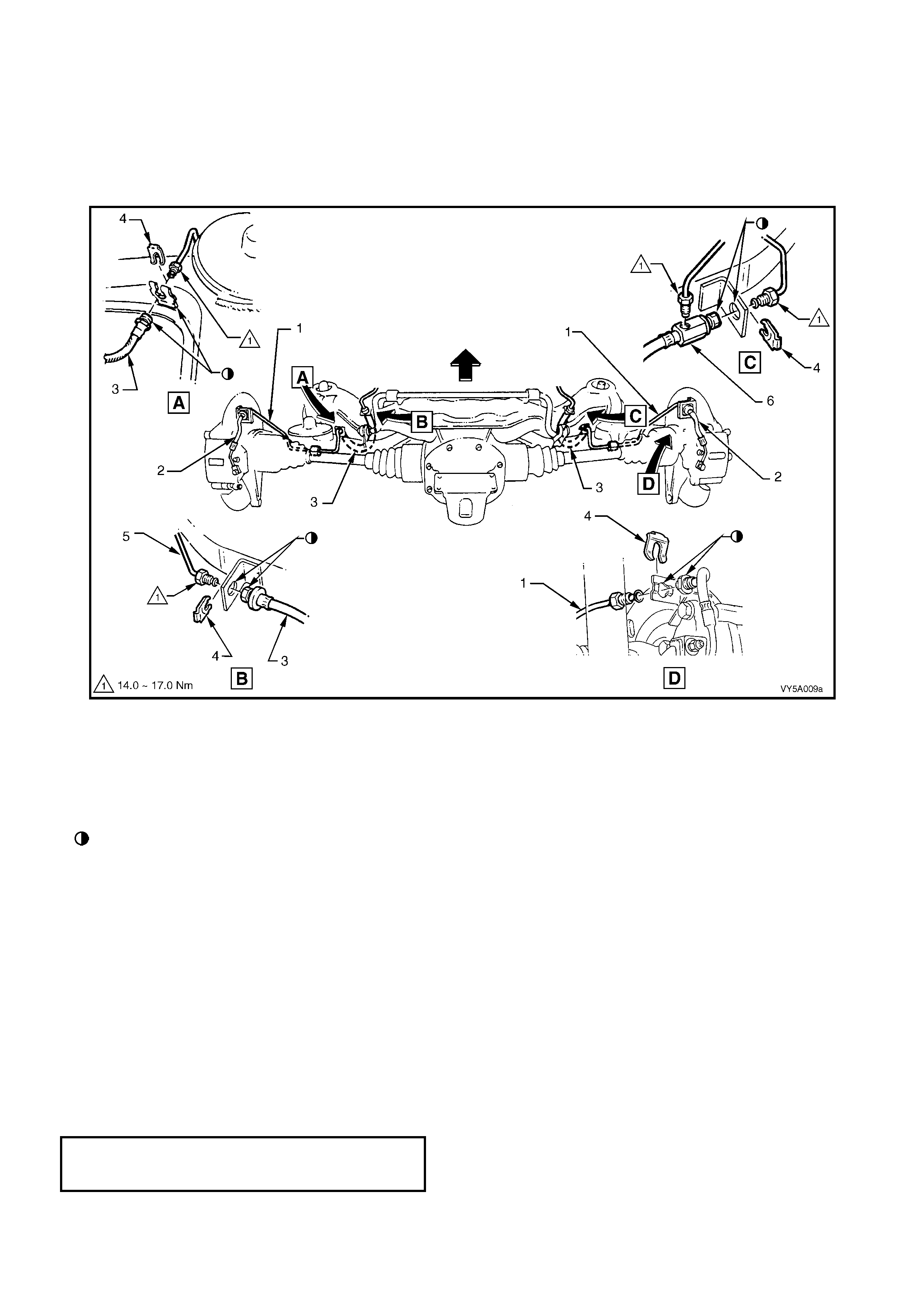
Figure 5A - 51
Legend
VIEW A: LH Shown – RH opposite
VIEW B: With Traction Control – LH shown, RH opposite
Without Traction Control – LH only
VIEW C: Without Traction Control – RH only
VIEW D: RH shown, LH opposite
Align Flats on Brack et and Hose
1. Rear Brake Pipe
2. Rear Brake Hose, Caliper t o Rear Brake Pipe
3. Rear Brake Hose
4. Retaining Clip
5. Brake Hose Connecti on Pipe
6. Junction Block – RH only (Vehicles without Traction Cont rol )
3. Disc onnect brak e pipe (5) fr om brake hos e (3) at trailing ar m brack ets (View B). Plu g open end of br ake pipe/s
to prevent foreign material entry.
4. Dis connect r ear brak e pipe (1) connectio n f rom br ake hose (3), while hol ding the hose with a back -up spann er.
For those v ehicles witho ut ABS/T CS, the RH sid e brak e hose ( View C), a lso has a junction block (6) to provide
for a connection from the master cylinder. Plug all pipe ends to prevent foreign material entry.
5. Unclip retaining clips (4) from the end of each hose end and withdraw hose/s fro m brackets.
NOTE: Refer to Operat ion 2.13 for procedure to remove the rear caliper hose (2).
REINST ALL
1. Ensure brake hose ends and pipe mating surfaces are clean and free of burrs.
2. Fit hose (3) into mounting plate brackets and reinstall retaining clips (4). Check that the hose (3) is not twisted.
3. Remove plugs from brake pipes (1 and 5), then reconnect to hose ends. Tighten all pipe nuts to specified
torque.
BRAKE PIPE FLARE NUT
TO BRAKE HOSE
TORQUE SPECIFICATION 14 - 17 Nm
4. Bleed brake/s, see 2.4 BRAKE SYSTEM BLEED, in this Section.
5. Raise vehicle, remove jack stands, then lower vehicle to the ground.
2.16 BRAKE BOOSTER HOSE & VALVE ASSEMBLY – V6 ENGINE
REPLA CE
1. Remove the four decorative nuts securing the engine dress cover, then remove the cover from the engine.
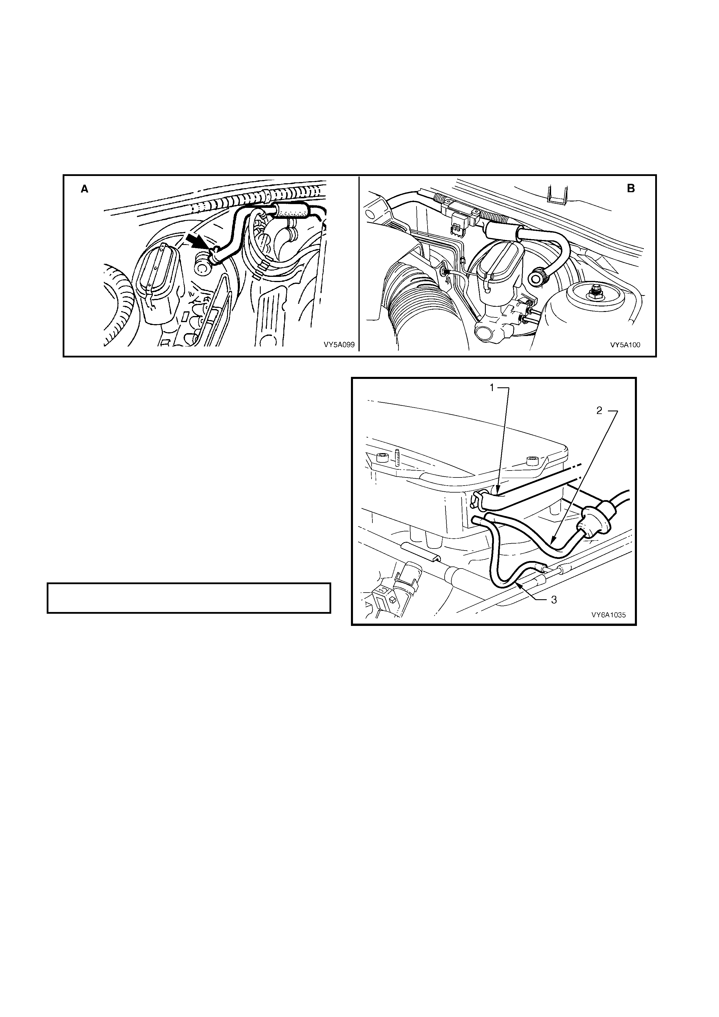
2. Using su itab le pl iers , c ompress the spring h os e c lamp at each end of the br ake booster vacu um hose and sli d e
both clamps back along the hose, refer to Figure 5A - 52 and Figure 5A - 53.
CAUTION: Wear safety glasses to avoid eye injury when working with spring wire hose clamps.
NOTE: View A is for RHD vehicles, while View B is for LHD vehicles.
Figure 5A - 52
3. While supporting the vacuum check valve at
the booster end, twist the hose to break the
seal, then remove by twisting back and forth
while maintaining a constant pulling force on
the hose. Repeat for the intake manifold fitting
at the rear of the engine.
4. Reinstallation is the reverse of the removal
process, except that each hose clip must be
reinsta lled over t he hose a nd behind t he nipple
at each end to prevent hose premature
disengagement.
5. Reinstall the engine dress cover and secure
with the four decorative nuts, tightening to the
correct torque specification.
ENGINE DRESS COVER NUT
TORQUE SPECIFICATION 5 Nm
Figure 5A - 53
2.17 BRAKE BOOSTER HOSE & VALVE ASSEMBLY – GEN III V8 ENGINE
REPLA CE
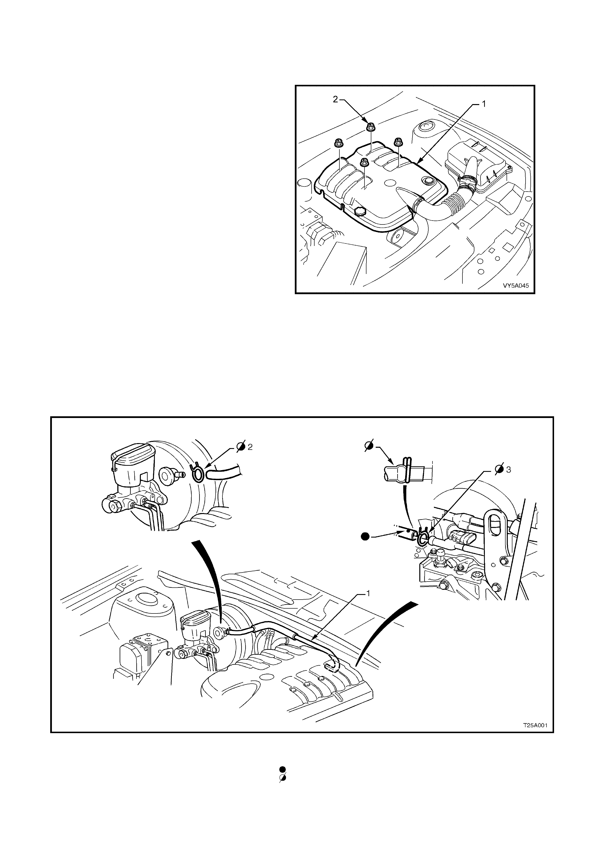
1. Remove the four engine dress cover
decorative nuts (2), then remove the dress
cover (1) from the engine.
Figure 5A - 54
2. Using su itab le pl iers , c ompress the spring h os e c lamp at each end of the br ake booster vacu um hose and sli d e
both clamps back along the hose, refer to Figure 5A - 55 and Figure 5A - 56.
3. W hile suppor ting the vac uum check valve at the boost er end, t wist the h ose to br eak the s eal, then remove by
twisting back and forth while maintaining a constant pulling force on the hose. Repeat for the intake manifold
fitting at the rear of the engine, supporting the fitting during the removal process.
4. Reinstallation is the reverse of the removal process, except that each hose clip must be reinstalled over the
hose and behind the nipple at each end to prevent hose premature disengagement. Also ensure that the b lue
alignment dot on the hose is facing upward
Figure 5A - 55 – Brake Vacuum Booster Hose – RHD with the GEN III V8 Engine
Legend
1. GEN III V8 brake booster vacuum hose.
2. Retaining cli p, brak e boost er end.
3. Retaining cli p, engine m anifol d end.
Blue spot to be on top.
Ens ure hose ends are clamped behind the ri dge on the nipple.

Figure 5A - 56 – Brake Vacuum Booster Hose – LHD with the GEN III V8 Engine
Legend
1. GEN III V8 brake booster vacuum hose.
2. Retaining cli p, brak e boost er end.
3. Retaining cli p, engine m anifol d end.
Blue spot to be on top.
Ens ure hose ends are clamped behind the ri dge on the nipple.
2.18 LOAD SENSING PROPORTIONING VALVE – UTILITY
REMOVE
1. Raise the rear wheels and place the vehicle on suitable safety stands.
2. Dis connec t the brak e li nes f rom the load sens ing pro por tionin g valve. Seal th e openi ngs and li nes with suit able
plugs.
3. Unhook the load sensing proportioning valve connector cable from the load-sensing arm by moving the arm
downward to relieve the tension. Slowly release the arm.
NOTE: The arm may spring up slightly when the hook is released.
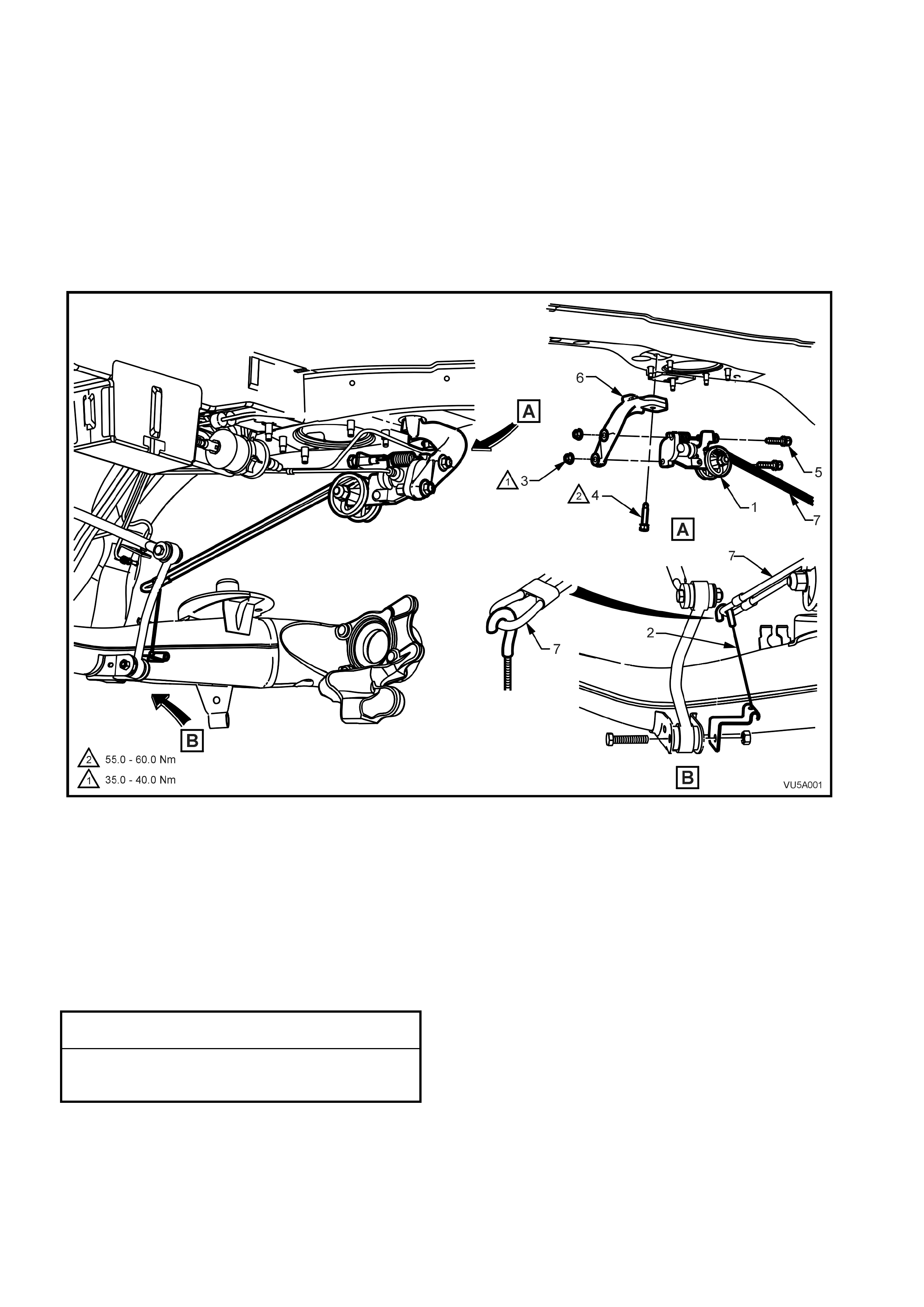
4. Support the load sensing proportioning valve, then remove the nuts from the two retaining bolts and remove
the bolts removing the valve assembly.
Figure 5A - 57
Legend
1. Load sensing proporti oni ng val ve
2. Connector cable assembly
3. Nut (2 places)
4. Mounting bracket bolt
5. Bolt (2 places) 6. Mounting bracket
7. Load sensing arm
REINSTALL
The installation procedure is the reverse of the removal procedure, noting the following:
1. Position valve on brack et, then install and secure the two bolts. Tighten the bo lts or nuts to th e correct torque
specification.
LOAD SENSING VALVE MOUNTING
NUT TORQUE SPECIFICATION 35 - 40 Nm
LOAD SENSING VALVE MOUNTING
BRACKET BOLT
TORQUE SPECIFICATION 55 - 60 Nm
2. Ensure all pipes are secured and routed correctly, refer to Figure 5A - 58.
3. Bleed the brake system refer to 2.4 BRAKE SYSTEM BLEED, in this Section.
NOTE 1:The load sensing proportioning valve setting is preset and should not be adjusted.
NOTE 2:The c able hook must be connec ted to the torsion s pring lever in t he correct or ientation, refer to View B in
Figure 5A - 57
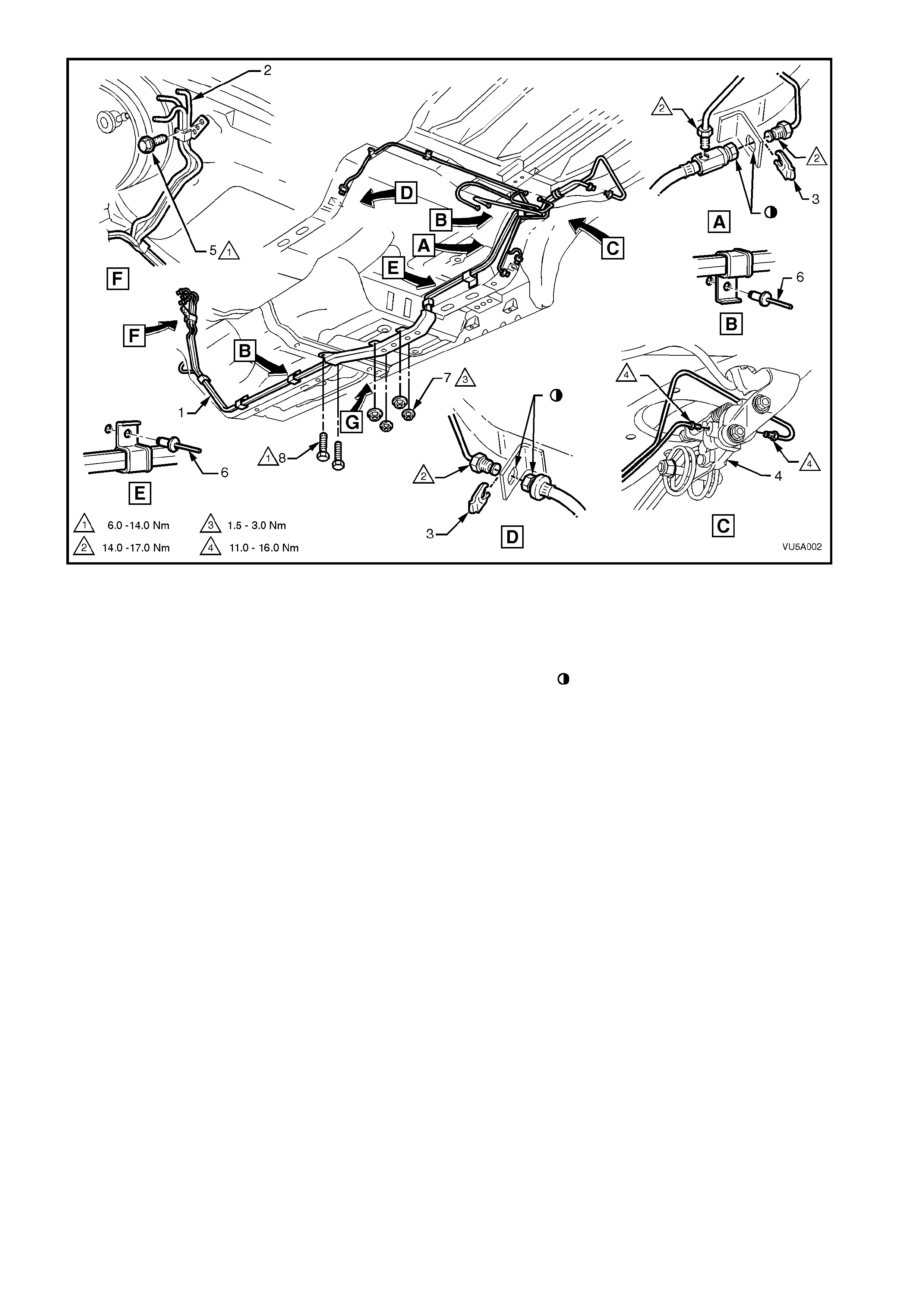
Figure 5A - 58
Legend
1. Brake and fuel line harness
2. Fuel feed and return line
3. Brake hose clip
4. Load sensing proporti oni ng val ve
5. Brake pipe clamp to dash panel bolt
6. Rivet (5 plac es)
7. Nut (4 places)
8. Screw (2 places)
Flats aligned on hose and bracket
2.19 BRAKE PRESSURE DIFFERENTIAL WARNING SWITCH
REMOVE
1. Dis connec t the brak e pres sure dif fer ential warnin g
switch harness connector (1) from the brake
pressure differential warning switch (2).
NOTE: To disconnect the harness connector, spread
the two locking tangs (3) whilst pulling the connector.
2. Unscrew the brake pressure differential warning
switch from the master cylinder.
NOTE: Ensure the earthing spring (4) is attached to
the plunger switch plunger (5).
Figure 5A - 59
INSPECT
1. Check that the earthing spring (1) is firmly
installed on the switch plunger (2).
NOTE: If necessary, the small end of the spring
may need to be closed down slightly to give the
required attachment.
2. Using a multimeter, check that there is no
continuit y between t he ear thing sprin g and the
switch terminal.
NOTE: Although there are two terminal
connections within the switch assembly, these
terminals are bridged together by a small bridging
wire.
3. With the multimeter still connected, check that
there is continuity when the switch plunger is
depressed.
4. If any of the above tests fail, replace the brake
pressure differential warning switch.
Figure 5A - 60
REINST ALL
1. Reinstall the brake pressure differential switch (1) to the master cylinder. Refer to Figure 5A - 59.
2. Tighten to the brake pressure differential switch to the specified torque – do not over tighten.
BRAKE PRESSURE DIFFERENTIAL
WARNING SWITCH
TORQUE SPECIFICATION 2 Nm
3. Reconnect the brake pressure differential warning switch harness connector to the brake pressure differential
warning switch.
3. MAJOR SERVICE OPERATIONS
3.1 MASTER CYLINDER
LT Section No. – 04-725
REMOVE
1. Thoroughly clean the master cylinder, especially around the brake line connections.
2. Remove the master cylinder reservoir cap.
Using a hand vacuum pump (1), special tool
J23738-A or a commercially available hand
vacuum pump or syringe, siphon as much
brake fluid from the master cylinder reservoir
(2) as possible.
NOTE: Brake fluid will cause damage to the paint
work if it comes into contact with it. In the event
that this happens, wash the brake fluid off with
water.
Figure 5A - 61
3. Disconnect the electrical connector from the brake pressure differential warning switch.
4. Disconnect the wheel brake lines (2) from the master cylinder (1) and allow any residual brake fluid from the
master cylinder to dr a in int o a c onta in er. Pl ug t he op e nin gs in b oth th e master cylinder and the p ipes to pr ev ent
fluid loss and dirt ingress.
NOTE: View A is for RHD vehicles, while View B is for LHD vehicles.
Figure 5A - 62
IMPORTANT: The engine surge tank may be hot.
Allow the coolant to cool before performing this
procedure.
4. For lef t-han d drive veh ic les fitted with th e GEN
III V8 engine, disengage the coolant surge
tank from its anchor points by:
A Grasping the surge tank (1) firmly with
both hands and pivoti ng in the direction of
arrow A to dislodge the surge tank from
the rear anchor po int (2).
B Pull the surge tank inboard (arrow B)
toward the engine to dislodge the inner
fender skirt anchor point (3). Refer to
2.10 Coolant Recovery Surge Tank in
Section 6B3, ENGINE COOLING – GEN
III V8 ENGINE in the MY2003 VY and V2
Series Service Information for further
information.
5. For lef t-han d drive veh ic les fitted with th e GEN
III V8 engine, disconnect the harness
connector (4) from the coolant level sensor
and set the surge tank to one side.
NOTE: It is not necessary to remove the surge
tank from the vehicle. Leave all hoses and screw
on cap intact.
6. To provide access to the brake master
cylinder support bracket on left-hand drive
vehicles fitted with the GEN III V8 engine, it is
necessary to remove the Powertrain Control
Module. Refer to 2.1 Powertrain Control
Module (PCM) in Section 6C3-3, SERVICE
OPERATIONS – GEN III V8 ENGINE in the
MY2003 VY and V2 Series Service
Information.
Figure 5A - 63
7. Remove the bracket securing the master cylinder to the adjacent strut tower.
8. Remove the nuts securing the master cylinder to the brake booster and remove the master cylinder.
IMPORTANT: DO NOT disturb th e brake boos ter push rod, a nd DO NOT depress the brake ped al with the master
cylinder removed or the internal reaction disc in the booster may become dislodged.
NOTE: View A is for RHD vehicles, while View B is for LHD vehicles.
Figure 5A - 64
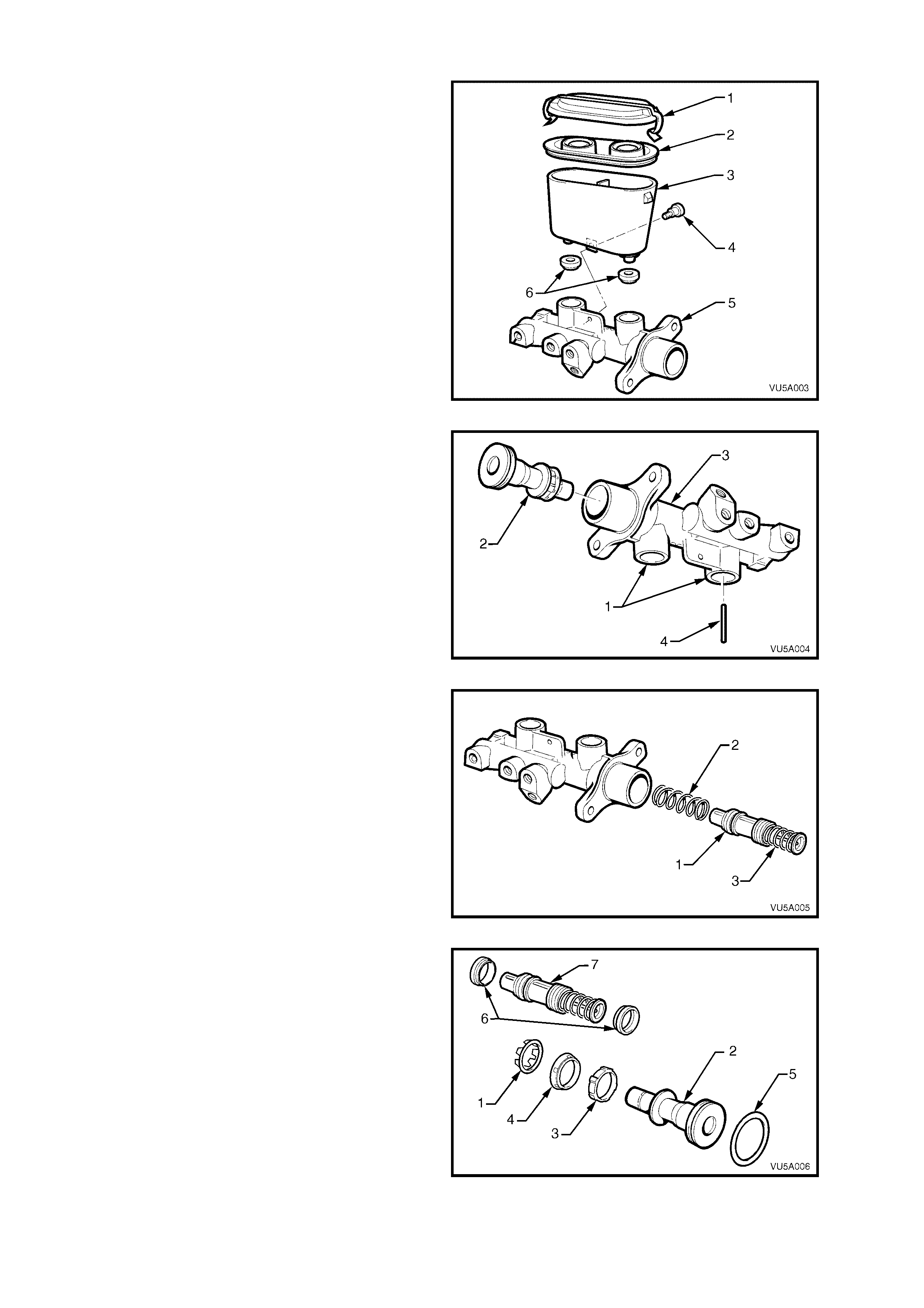
DISASSEMBLE
1. Clean the outside of the master cylinder.
2. Remove reservoir cap (1) and seal (2). Discard
any fluid left in reservoir
3. Unscrew the reservoir to body retaining screw
(4), located at the base of the reservoir.
4. Separate the plastic reservoir (3), by hand,
from the body (5).
5. Remove the two reservoir sealing grommets
(6) from the body (5).
Figure 5A - 65
6. Invert master cylinder body (3) so that the
reservoir ports (1) face downwards. Depress
the primary piston (2) with a wood dowel or
brass r od u nti l t he pis t on b ottoms in th e b ore of
the master cylinder body (3). The secondary
piston stop pin (4) should freely fall out.
7. Carefully remove primary piston (2) from the
main bore of the master cylinder (3).
Figure 5A - 66
8. Remove s ec ond ary piston ( 1) and r eturn s pr ing
(2) by lightly tapping the open end of the
master cylinder b ore squar ely onto a sof t piece
of wood.
NOTE 1: The caged spring (3) of the secondary
piston (1) has been set to a predetermined length.
Do not attempt to adjust or remove the caged
spring (3).
NOTE 2: The centre valve is part of the secondary
piston assembly and is not serviced as a separate
part.
Figure 5A - 67
9. Remove the seal retainer (1) from the primary
piston (2), using a small screwdriver to
caref ull y pry apart the seal retain er legs.
10. Remove the recuperating guide (3) and seal
(4) from the primary piston (2).
11. Remove the O-ring (5) seal from the primary
piston (2), taking EXTREME CARE not to
damage the piston in the process.
12. Remove both seals (6) from the secondary
piston (7), again taking EXTREME CARE not
to damage the piston (7).
Figure 5A - 68
13. Using suitable circlip pliers, remove the circlip
(1) retaining the fast fill valve (2) located in the
primary reservoir port of the master cylinder
(3).
14. Face the master cylinder reservoir ports
downwards to allow the fast fill valve (2) to fall
out. If the valve is stuck, lightly tap the master
cylinder on a piece of wood to assist removal.
15. Remove the valve sealing O-ring (4) from the
bottom of the reservoir port.
Figure 5A - 69
16. Unscrew an d rem ove the e nd plug (1) from the
master cylinder body (3).
17. Remove the brake pressure differential
warning switch (5) from the master cylinder,
ensuring that the electrical earthing spring
remains on the switch plunger.
18. Remove the proportioning valve assembly
(differential spool valve assembly – Utility) (6)
by lightly tapping the end plug end of the
cylinder bore squarely onto a soft piece of
wood to dislodge the proportioning valve
assembly.
IMPORTANT: Do not damage the proportioning
valve assembly by attempting to pull it out of the
bore with pliers .
NOTE: Do not disass emble the propor tioning va lve
assembly as this valve is only serviced as a
complete assembly.
Figure 5A - 70
CLEAN AND INSPECT
NOTE: Ensure work area is clean and free of dust or other contam inants. These can affect the performance of all
the seals in the master cylinder.
1. Wash master cylinder body, reservoir and cap in clean methylated spirits.
2. Wash all internal parts in brake fluid.
3. Check all recesses, openings and passages to ensure they are open and free of foreign matter.
4. Place all parts on a clean surface.
5. Inspect the master cylinder bores for signs of etching, pitting, scoring or rust. If in poor condition, replace the
master cylinder.
IMPORTANT: Do not hone the master cylinder bore.
6. Discard all rubber parts together with the secondary piston assembly (the secondary piston assembly
incorporates; the secondary piston, the centre valve and the caged spring). Only new parts from the genuine
service kit should be used to reassemble the master cylinder.
REASSEMBLE
NOTE 1: Bef ore assembl y, lubricate int ernal parts and m aster cylinder bor es with clean, recom mended brak e fluid
from a sealed container.
NOTE 2: Prior to assembly, ensure that the primary piston, without seals fitted to it, is free to m ove the full piston
stroke in the large bore.
NOTE 3: The three L type seals (6 and 8) must be assembled in the directions and positions as shown next.
Figure 5A - 71
Legend
1. Reservoir Cap
2. Reservoir Cap Seal
3. Reservoir Seal i ng Grommets
4. Secondary Piston
5. Return Spring
6. Secondary Seals (L Type)
7. Caged Spring
8. Primary S eal (L Type)
9. Primary Pist on O-ri ng
10. Primary Piston
11. Fast Fill Valve O-ring
12. Fast Fill Valve
13. Fast Fill Valve Circlip
14. Reservoir
15. Reservoir Cap Retai ning Clip
1. Install O -r ing sea l ( 1) in to the groove at th e end
of the primary piston (2).
2. Install the recuperating guide (3) followed by
the primary L type seal (4) onto the end of the
primary piston (2). The sealing face of the L
type seal must face away from the
recuperat ing guide.
NOTE: The primary L type seal for the primary
piston can be identified by the six shallow grooves
around the seals outer surface.
3. As sem ble the s eal ret ainer ( 5) onto the prim ar y
piston (2). Using a small screwdriver, clip the
retainin g legs of the r eta iner ( 5) into the groo ve
on the primary pisto n ( 2). Care shou ld b e taken
to avoid damage to the piston or seal.
Figure 5A - 72
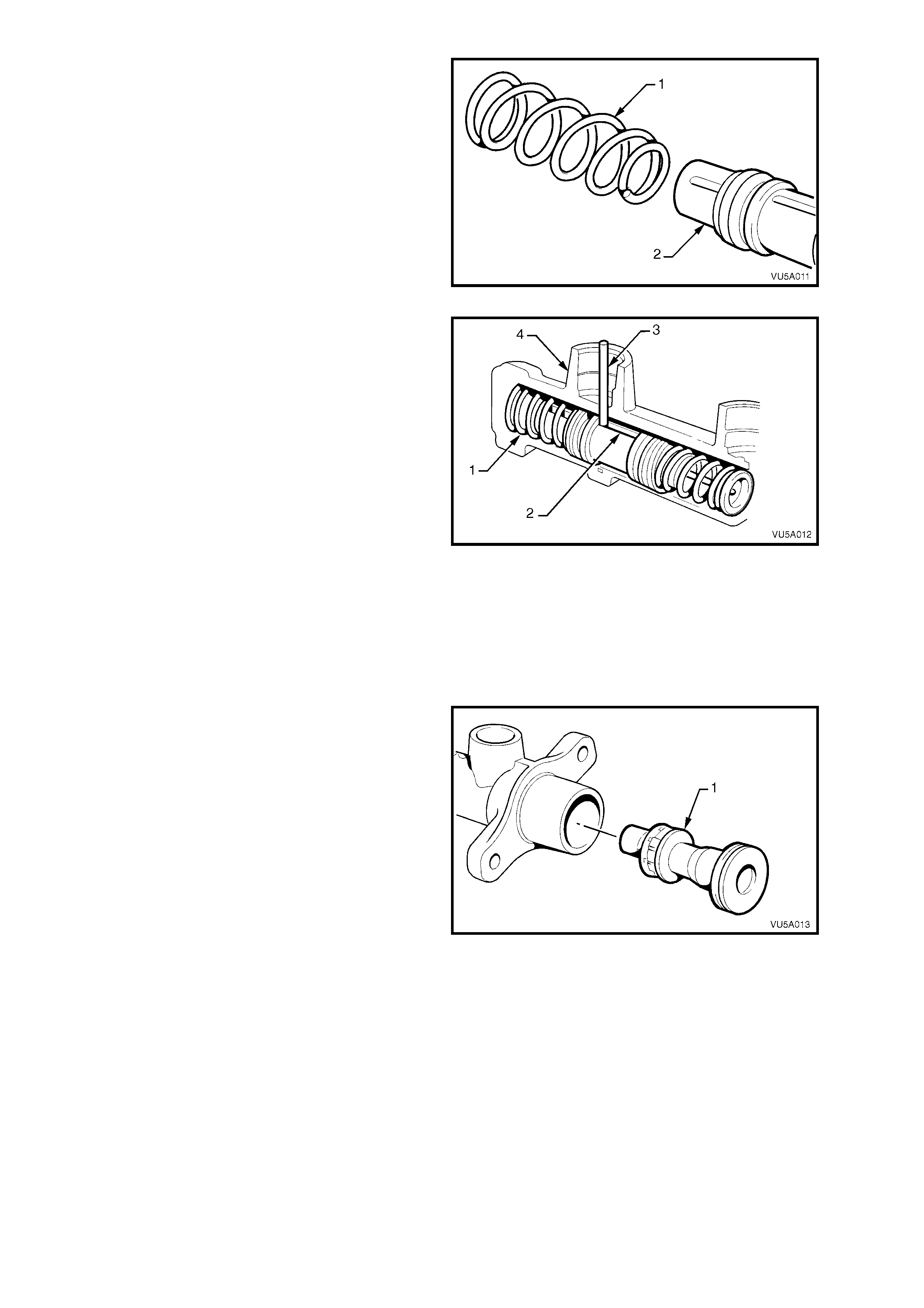
4. Assemble the small end of the return spring
over (1) the end of the secondary piston (2).
This should be a slight int er ference fit.
Figure 5A - 73
5. Carefully insert the secondary piston , caged
spring end las t, throug h the large bor e and into
the sm aller bor e of the master cylinder unti l the
return spring (1) bottoms. Ensure the
secondary spring does not dislodge from the
piston assembly during this operation.
NOTE: To assemble the secondary piston
assembly into the body, align the slot (2) in the
secondary piston with the hole in the reservoir
ports. This must be done so that the secondary
piston stop pin (3) can be inserted into secondary
reservoir port (4) in the master cylinder.
6. Fully stroke the secondary piston using a soft
dowel and, while held at the bottom of the
bore, install the secondary piston stop pin (2)
into the secondary reservoir port (4). The
piston stop pin (3) should easily fit through the
larger of the two holes loc at ed in the sec ond ar y
reservoir port. The top of the secondar y piston
stop pin should not protrude more than 6 mm
above the bottom of the reservoir port.
Figure 5A - 74
7. Ins ert the prim ar y piston (1 ) into the m ain bor e,
against t he secondar y piston a nd caged spr ing
assembly. Carefully push both pistons down
the bore until the primary piston is flush with
the bore opening.
8. Stroke pistons and check that the primary
piston re turns to the end of the bore after eac h
stroke. Ensure movement is not sticky.
Figure 5A - 75
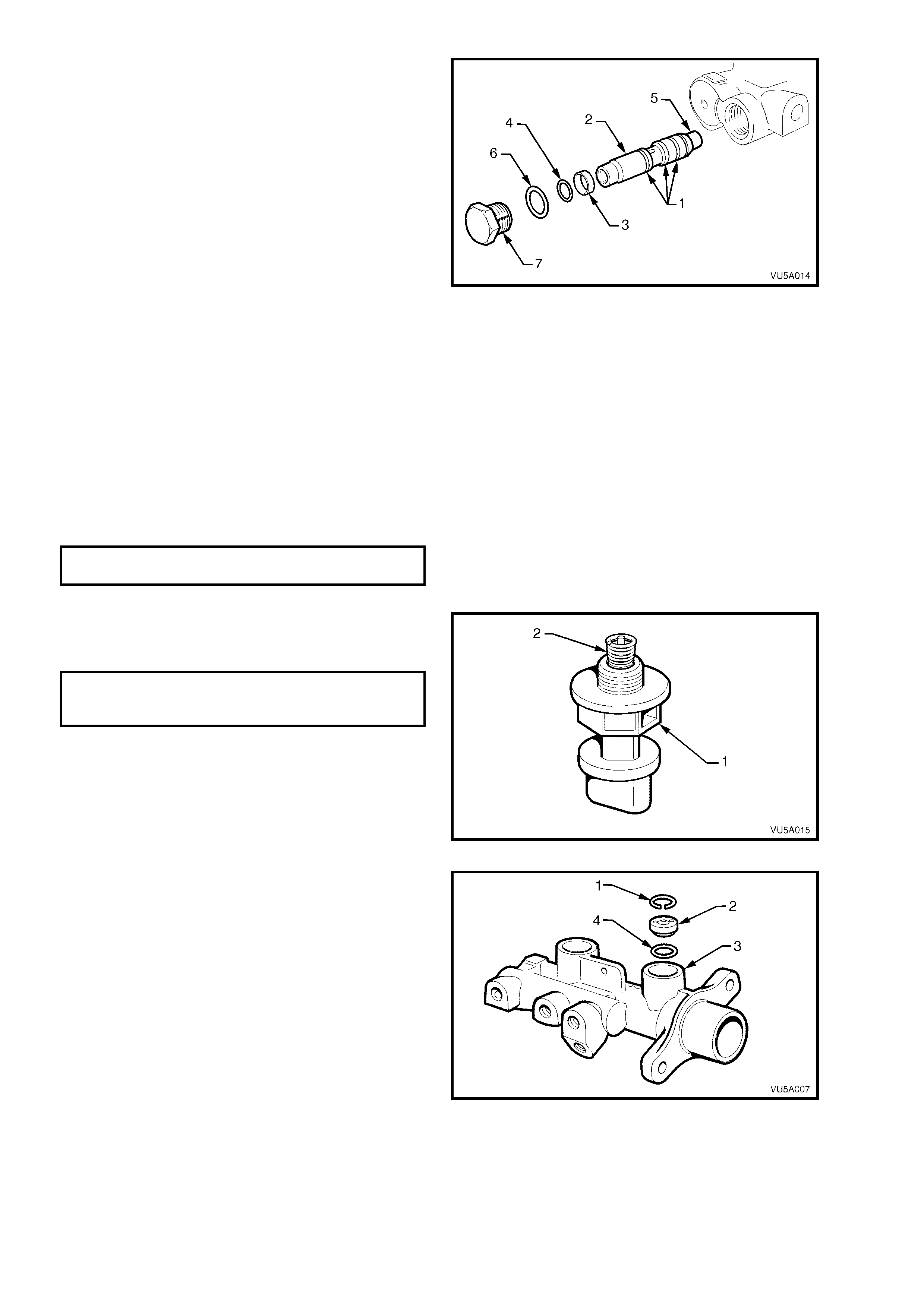
NOTE: While the proportioning valve (or pressure
differential spool valve on Utility) (2) are physically
similar in external appearance, the terminology for
the Utility reassembly is provided in square
brackets.
9. Fit new O-rings (1) onto proportioning valve
[pressure differential spool valve] (2).
10. Ensur e spacer (3) and O- ring (4) ar e fitted over
the proportioning valve spool [pressure
differential spool valve] and that they are
installed in the correct order (spacer first, then
the O-ring).
11. Insert proportioning valve [pressure differential
spool valve] into the bore, capped end [solid
end] A first. Extreme care should be taken
when inserting the valve to ensure that the O-
rings (1 an d 4) are not d amaged. If O-rings are
damaged, the master cylinder will not function
correctly and will leak brake fluid. The
proportioning valve [pressure differential spool
valve] assembly (2) must be bottomed in the
bore of the master cylinder.
12. Assemble a new O-ring (6) onto the end plug
(7), and screw the end plug into the master
cylinder body, tightening to the specified
torque.
END PLUG
TORQUE SPECIFICATION 25 - 30 Nm
Figure 5A - 76
13. Reinstall the brake differential warning switch
and spring. Tighten t o the specified t or qu e – do
not over tighten.
BRAKE PRESSURE DIFFERENTIAL
WARNING SWITCH
TORQUE SPECIFICATION 2 Nm
NOTE: Ensure the earthing spring on the brake
pressure differential warning switch is installed on
the plunger as shown. If necessary, the small end
of the spring may need to be closed down slightly
to give the required attachment.
Figure 5A - 77
14. Carefully install the fast fill valve O-ring (4) in
the bottom shoulder of the primary reservoir
port (3).
15. Fit the fast fill valve (2) into the primary
reservoir port (3), ensuring the rubber base
with six dimples is facing downward. Secure
valve with circlip (1).
Figure 5A - 78
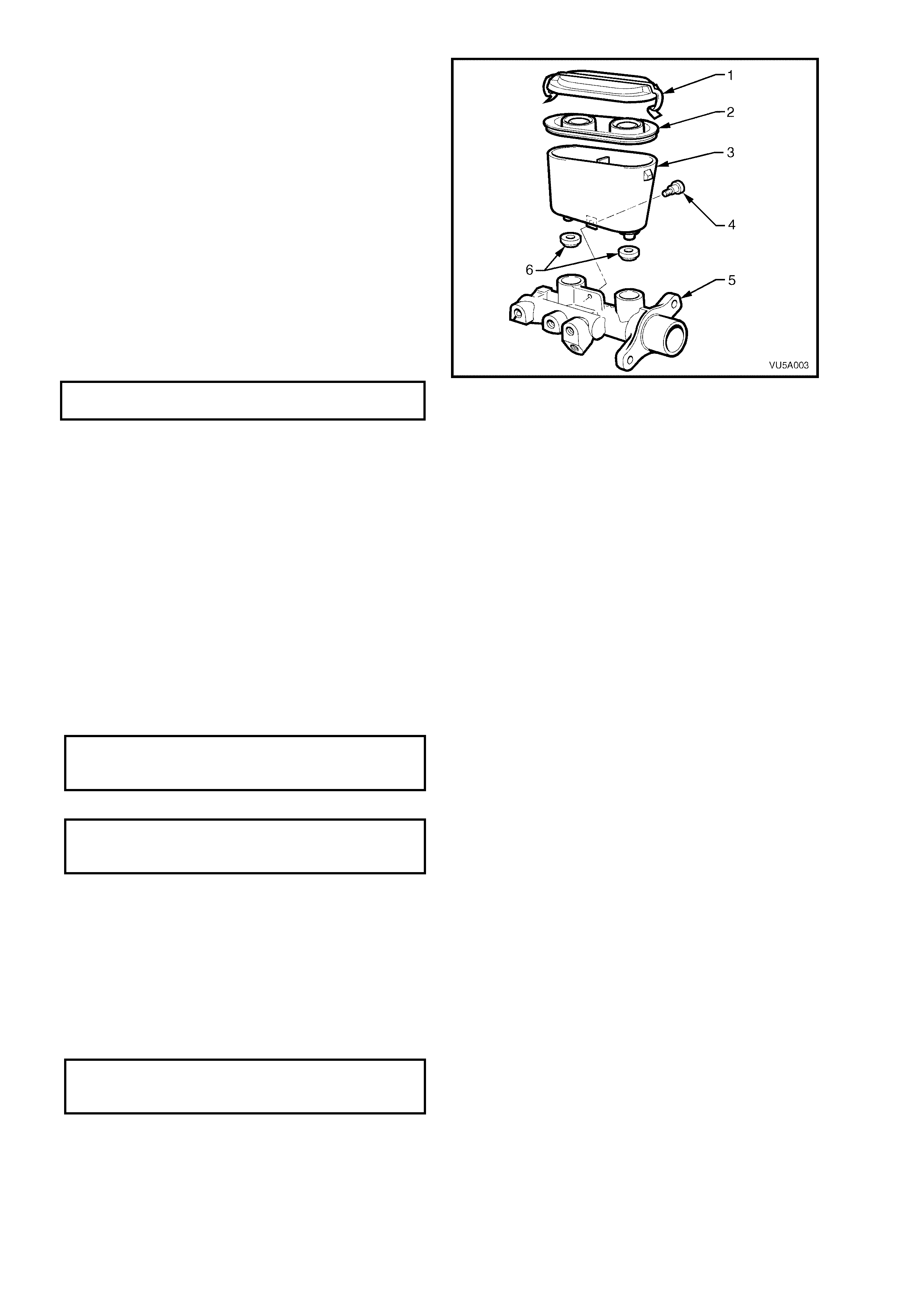
16. Lightly smear the bores of the reservoir ports
and sealing grommets (6) with clean brake
fluid.
17. Carefully assemble sealing grommets (6) into
the bores of the reservoir ports to locate them
against the shoulder in each bore.
18. Reins tall reser voir (3) by pus hing reser voir into
the sealing grommets (6) until the hole for the
retaining screw in the reservoir aligns with the
master cylinder bod y ( 5). In s tall r eta ini ng sc r ew
(4) and tighten to the specified torque. The
retaining screw (4) should just protrude from
the hole in the master cylinder body when
tightened.
NOTE: Both reservoir and master cylinder holes
must be aligned when installing the reservoir
retaining screw to avoid cross threading.
RESERVOIR SCREW
TORQUE SPECIFICATION 4.0 – 5.0 Nm
19. Fill the master cylinder with fresh,
recommended brake fluid and bleed on the
bench prior to replacing on the vehicle. After
bleeding, block master cylinder outlet ports to
prevent fluid escaping.
20. Assemble new reservoir seal (2) into reservoir
cap (1). Lubricate inside of the reservoir lips
with clean brake fluid to accept the reservoir
cap seal.
21. Reinstall cap seal (2) and cap (1).
Figure 5A - 79
REINST ALL
The reinstallation procedure for the master cylinder is the reverse of the removal procedure, noting the following:
1. Reinstal l the master cylinder as s em bly onto th e br ak e boos ter tak ing c are not to dis turb th e br ake booster p u sh
rod.
2. Tighten the master cylinder nuts to the specified torque.
MASTER CYLINDER
ATTACHING NUT
TORQUE SPECIFICATION 15 – 20 Nm
3. Reinstall the master cylinder support bracket and tighten the nuts and bolt to their specified torque.
MASTER CYLINDER TO
BRACKET FASTENER
TORQUE SPECIFICATION 15 – 22 Nm
4. For left-hand dri ve v ehicles f itted with the G EN III V8 e ngine, re ins ta ll th e PC M. Refer to 2.1 P o wertrain C ont rol
Module (PCM) in Section 6C3-3, SERVICE OPERATIONS – GEN III V8 ENGINE in the MY2003 VY and V2
Series Service Information.
5. For left-hand drive vehicles fitted with the GEN III V8 engine, reinstall the coolant surge tank. Refer to 2.10
Coolant Recovery Surge Tank in Section 6B3, ENGINE COOLING – GEN III V8 ENGINE in the MY2003 VY
and V2 Series Ser v ice Infor mation.
6. Place a clean contain er under the m aster c ylinder, un plug the brak e lines and m aster cylinder outlet ports a nd
reinstall the pipes to the master cylinder.
7. Tighten to their specified torque.
BRAKE PIPE TO MASTER
CYLINDER FLARED NUT
TORQUE SPECIFICATION 8 – 11 Nm
8. Reconnect the electrical connector to the brake pressure differential warning switch.
9. Bleed the brakes. Refer to 2.4 BRAKE SYSTEM BLEED, in this Sect ion.
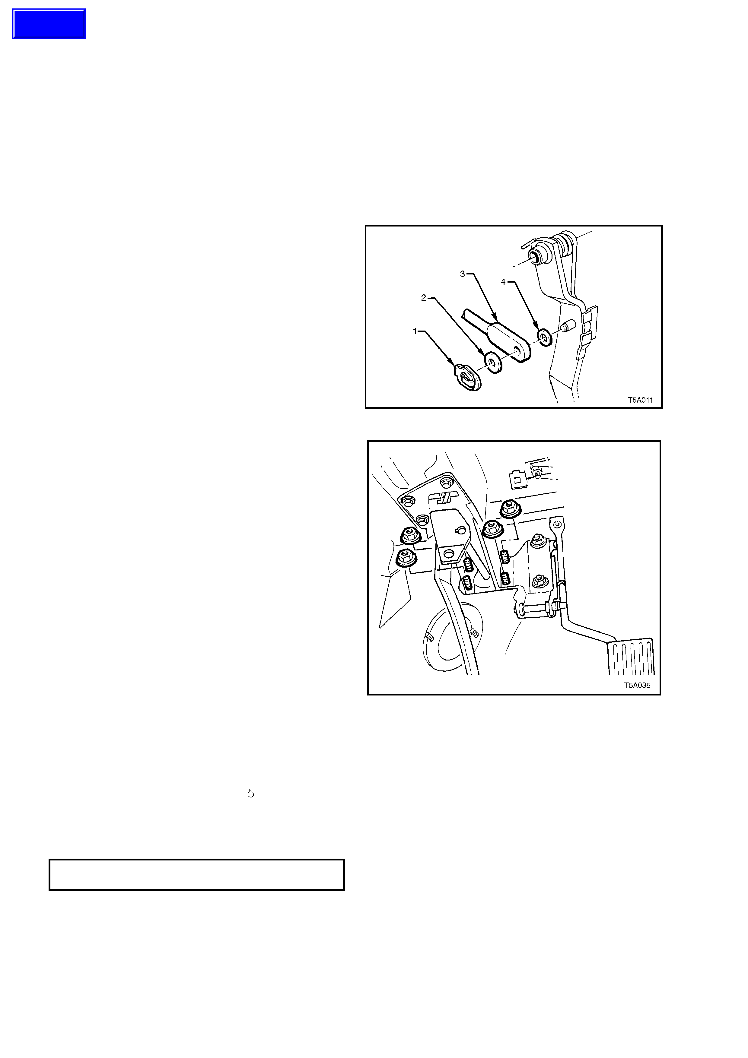
3.2 BR AKE BOOSTER
LT Section No. – 04-725
NOTE: The brake booster is not a serviceable item and if found to be faulty, must be replaced as a unit.
REMOVE
1. Remove master cylinder, refer to 3.1 MASTER CYLINDER in this Secti on.
IMPORTANT: W ith the mas ter cylinder rem oved, do not dist urb the brake boos ter push rod nor depr ess the brak e
pedal, as the reaction disc in the booster may become dislodged.
2. Remove vacuum hose from brake booster vacuum check valve. Refer to 2.16 BRAKE BOOSTER HOSE – V6
ENGINE or 2.17 BRAKE BOOSTER HOSE – GEN III V8 ENGINE, in this Section.
3. Remove instrument panel lower right
trim assembly. Refer to Section 1A3
INSTRUMENT PANEL and CONSOLE, in the
MY2003 VY and V2 Series Service
Information, for details.
4. Remove push rod retaining clip (1), push rod
(3) and washers (2 and 4) from brake pedal.
Figure 5A - 80
5. Remove br ake booster ass embly retain ing n uts
(4 places) at brake pedal support, from inside
vehicle.
6. Withdraw booster from engine compartment,
turning booster towards engine to clear spring
tower.
Figure 5A - 81
REINST ALL
Installation is the reverse of the removal procedure, except for the following:
1. Lubricat e brake peda l an d pus h rod c omponent b eari n g s ur f aces with M olybdenu m Disulphide gr e as e. R ef er to
Figure 5A - 33 and the symbol for the locations.
2. Ensure brake booster hose is routed correctly.
3. Reinstall master cylinder. Refer to 3.1 MASTER CYLINDER, in this Section.
4. Tighten brake booster retaining nuts to specified torque.
BRAKE BOOSTER RETAINING
NUT TORQUE SPECIFICATION 20 – 25 Nm
Techline

3.3 BR AKE CALIPER (FRONT & REAR)
LT Section No. – 04-750 and 04-825]
NOTE: The following fasteners MUST be replaced
(!
!!
!) when performing this operation or they have
micro-encapsulated sealant applied and should be
replaced on reassembly (#
##
#):
!
!!
!
Front brake caliper anchor plate to steering
knuckle attaching bolt
#
##
#
Brake caliper guide pin bolt
REMOVE
NOTE: W hile the serv ice oper ation descr ibed, re lates to the f ront brak e c aliper/s , the s am e procedur e can be used
for the rear brake caliper operation.
1. Raise vehic l e and place on j ack stands.
2. Mark position of road wheel relative to hub and remove wheel. Refer to 2.1 SERVICE NOTES AND
CAUTIONS, in this Section.
3. Place a drain tray beneath caliper assembly.
4. Loosen and remove brake hose to caliper
banjo bolt. Separate bolt from hose and
discard sealing washers.
5. Remove the brake caliper anchor plate
retaining bolts and lift the caliper assembly out
over disc .
NOTE: Discard the f ront brak e caliper anchor plate
retaining bolts as they must be replaced on
reassembly.
Figure 5A - 82
6. The removal procedure for the rear brake
caliper is similar to that for the front.
NOTE: The rear brake caliper anchor plate bolts
can be reused on assembly
Figure 5A - 83
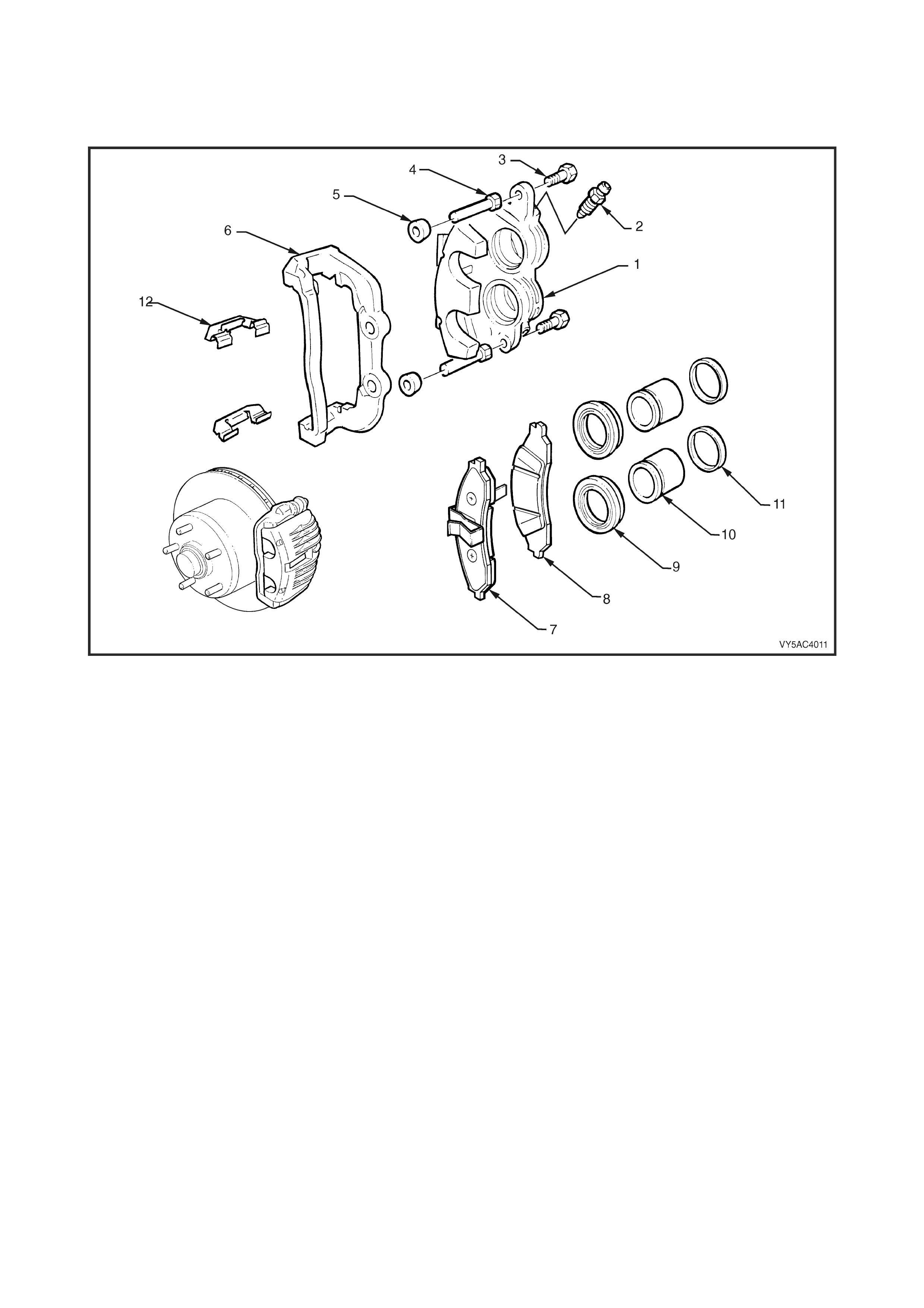
DISASSEMBLE
NOTE: Apart from the two spring clips (12) fitted to the front brake calipers (refer to Figure 5A - 84), both the
service operation description and part identification numbers are the same for the front and rear brake calipers.
Front Brake Caliper
Figure 5A - 84
Legend
1. Caliper Housing
2. Bleed Screw
3. Self Locking Bolt (2 places)
4. Guide Pin (2 places)
5. Guide Pin Boot
6. Anchor Plate
7. Outer Brake Pad
8. Inner Brake Pad
9. Piston Boot (2 plac es)
10. Piston (2 pl aces)
11. Cylinder Seal (2 pl aces )
12. Clip ( 2 places)
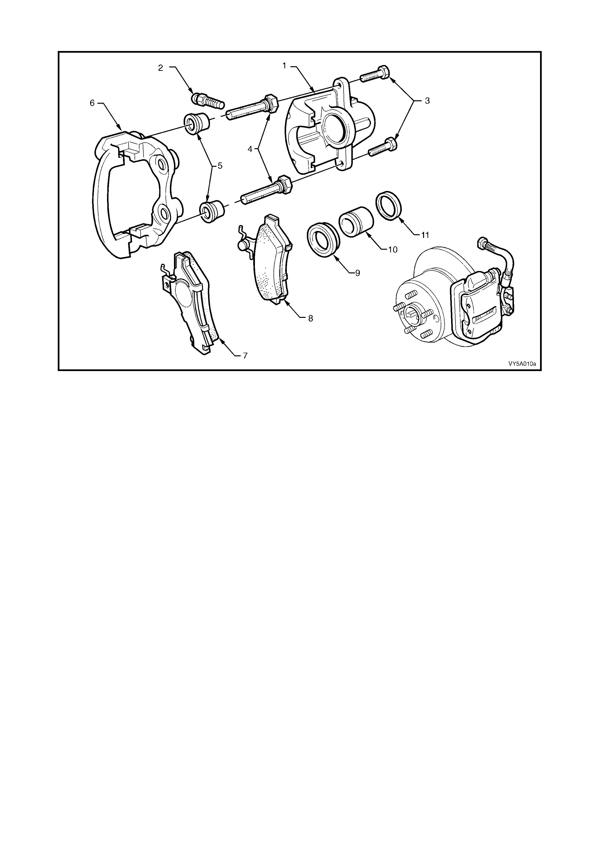
Rear Brake Calipe r
Figure 5A - 85
Legend
1. Caliper Housing
2. Bleed Screw
3. Self Locking Bolt (2 places)
4. Guide Pin (2 places)
5. Guide Pin Boot (2 places)
6. Anchor Plate
7. Outer Brake Pad
8. Inner Brake Pad
9. Piston Boot
10. Piston
11. Cylinder Seal
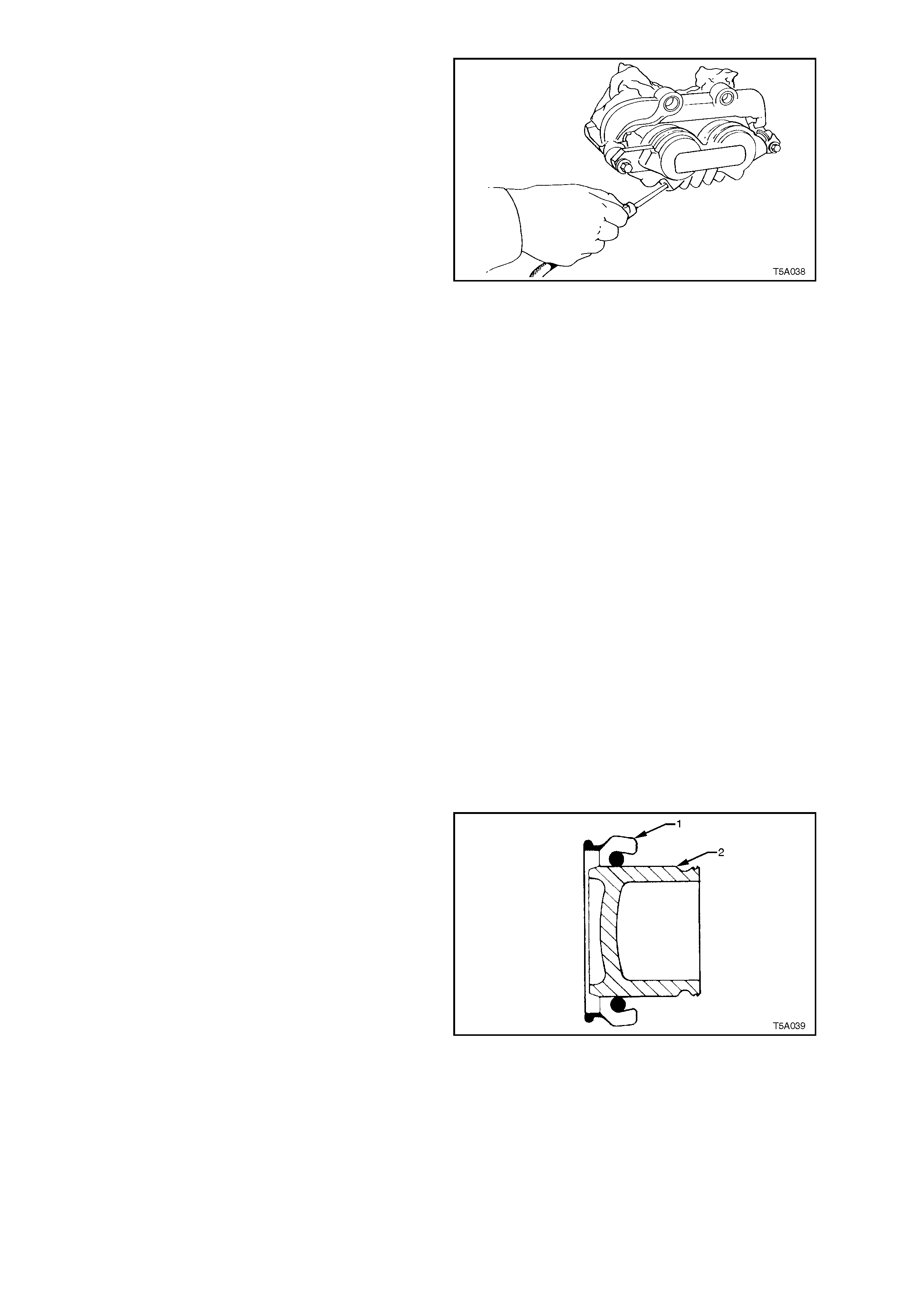
1. Remove guide pin, self locking bolts (3) and
discard.
2. Remove guide pin clips (12) (front brake
caliper only).
3. Separate caliper housing (1) from anchor plat e
(6) and remove brake pads (7 and 8).
4. Withdraw guide pins (4) and boots (5) from
anchor plate (6). Separate boots from pins.
5. Pack a clean piece of cloth between caliper
piston/s and opposite legs on housing and
apply air pressure at brake hose inlet port to
eject a piston.
CAUTION: Apply light air pressure initially and
progressiv el y incr ea se un til t he p isto n is f orced
out of the bore. This precaution is advisable to
avoid physical injury, as the piston may eject
with considerable force due to the air pressure.
NOTE: As only one piston in the front caliper will
be rem oved b y this m ethod, rem oval of the seco nd
will need to be done by using internal expanding
circlip pliers, to grasp the inner piston wall. Then,
while twisting the piston, apply a pulling force to
remove the piston from its bore.
6. Remove piston boot/s (9) from piston/s (10).
7. Remove cylinder seal (11) from bore, taking
care not to damage bore or seal locating
groove.
8. Remove bleeder screw (2).
Figure 5A - 86
CLEAN AND INSPECT
1. Clean all metal parts t hor o ugh l y with methylate d spirits . Clea n ru bber par ts with brake fluid onl y. Use c le an, dry
compressed air to dry parts.
2. Examine bore and piston carefully for signs of damage, abrasion, scuffing or corrosion. RENEW PISTON IF
ANY OF THESE F ACTO RS EXIST OR IF T HERE I S ANY DO UBT REG ARDING ITS CONDIT ION. If the bore
is unserviceable, a new housing must be fitted.
3. Inspect guide pins for corrosion. Replace pins if corroded.
4. Blow through bleed screw port with compressed air.
REASSEMBLE
1. Lubricate cylinder bore and piston (2) with the
recommended brake fluid
2. Fit new seal into inner groove of the cylinder
bore. Ensure seal is not twisted and is fully
seated in groo ve.
3. Install piston boot (1) over end of piston (2).
Figure 5A - 87
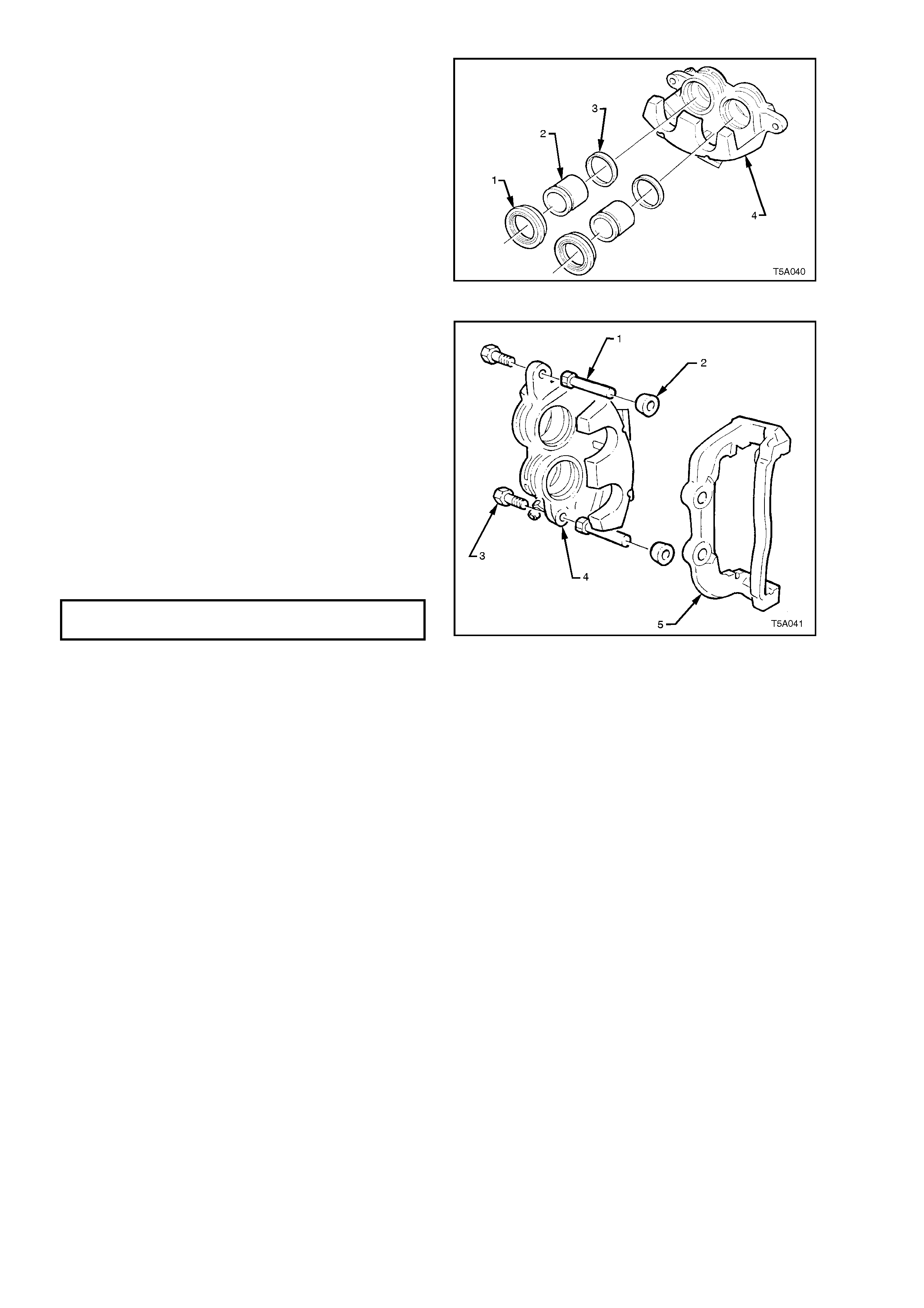
4. Position each piston (2) into caliper housing
(4), seati ng boot (1) int o gr oove in c aliper bore.
Ensure boot flange is squarely and firmly
seated in groo ve.
5. Push pis ton (2) s qu ar el y int o bor e by hand unt il
fully seated. Ensure piston boot (1) is fully
seated in piston (2) and caliper bore grooves.
Figure 5A - 88
IMPORTANT: To avoid uneven pad wear and/or
noisy brake operation, the assembly of the guide
pins to the caliper housing is critical and the
follo wing MU ST be followed.
6. Lubricate guide pins with silicone type grease
(Dow Corning No. 44 or equivalent).
7. Full y install gu ide pins ( 1) into the anch or plate
(5), without the two boots ( 2).
8. Reinstall the caliper housing (4) to the anchor
plate (5) and install NEW guide pin bolts (3).
CAUTION: Do not use the original bolts.
9. Us e an open e nd spa nner to hol d the gu ide pin
flat section, then tighten the guide pin bolts (3)
to the correct torque.
(#
##
#) GUIDE PIN BOLT
TORQUE SPECIFICATION 30 - 34 Nm
IMPORTANT: Check that the caliper housing (4)
and guide pins (1) slide out and in easily from the
anchor plate (5). If any binding is evident, then
steps 6 to 9 must be repeated.
10. Disengage the caliper housing (4) from the
anchor plate( 5) and instal l new guide pin boots
(2) to the guide pins (1).
11. Reassemble caliper housing (4) and anchor
plate (5) together. Squeeze each boot to
remove excess air, then ensure that each
guide pin boot (2) is correctly located in guide
pin and anchor plate grooves.
12. Reinstall bleed screw.
13. Reinstall the brake pads, refer to 2.7 BRAKE
PADS, REPLACE in this Section, for the
correct installation procedure.
Figure 5A - 89
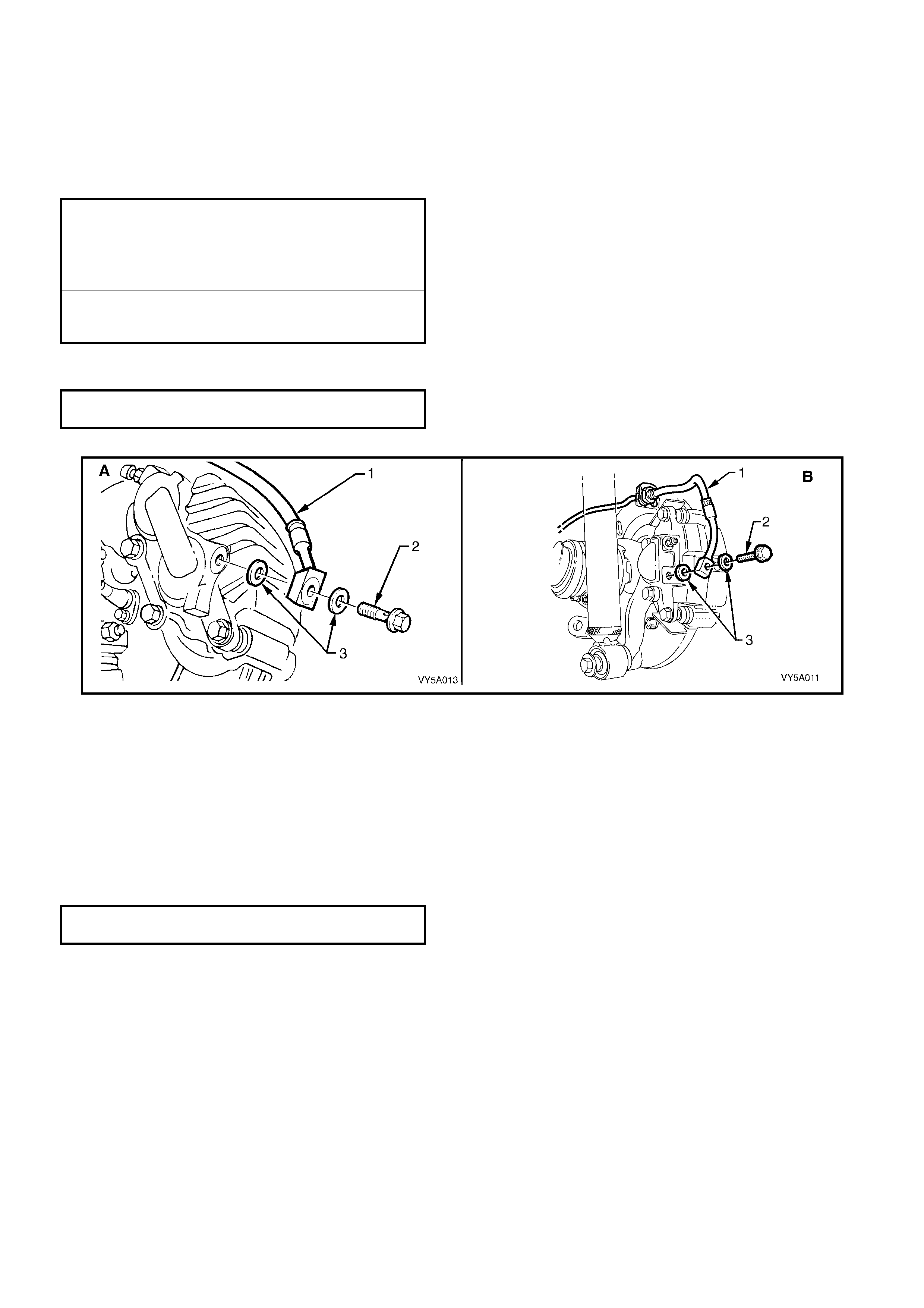
REINST ALL
1. Ensure anchor plate mounting surfaces are clean.
2. Press inner brake pad by hand to ensure piston is bottomed in bore.
3. Position the caliper assembly over the disc and insert the anchor plate reta ining bolts. Tighten the bolts to the
specified torque.
NOTE: New retaining bolts must be used when reinstalling the front brake caliper anchor plate.
(!
!!
!) FRONT BRAKE CALIPER
ANCHOR PLATE BOLT
TORQUE SPECIFICATION 80- 90 Nm, plus
40° - 50°
turn angle
REAR BRAKE CALIPER
ANCHOR PLATE BOLT
TORQUE SPECIFICATION 70 - 100 Nm
4. Reconnect brake hose (1) using NEW, dry, sealing washers (3). Tighten banjo bolt (2) to the correct torque
specification.
BRAKE HOSE TO CALIPER BOLT
TORQUE SPECIFICATION 32 - 37 Nm
NOTE: View A is for the front caliper, while View B is for the rear.
Figure 5A - 90
5. Bleed brake system, refer to 2.4 BRAKE SYSTEM, BLEED, in this Section.
6. Depress brake pedal several times to bring pads into position against disc.
7. Reinstall road wheel(s), aligning marks made prior to removal, then lower vehicle.
8. Tighten roa d wheel attachi ng nuts to the specif ied torque a nd in a star pattern. Ref er to 2.1 SERVICE NO TES
AND CAUTIONS, in this S ec tion .
NOTE: Do not use an im pact gun to tighten whee l nuts unless it is fitted with a torque lim iter bar such as T ool No.
AU534 or commercial equivalent. Failure to correctly tighten wheel nuts to the correct torque specification may
result in a warped brake disc, which may lead to development of brake shudder.
ROAD WHEEL ATTACHING NUT
TORQUE SPECIFICATION 100 - 125 Nm
9. Check level of fluid in master cylinder.
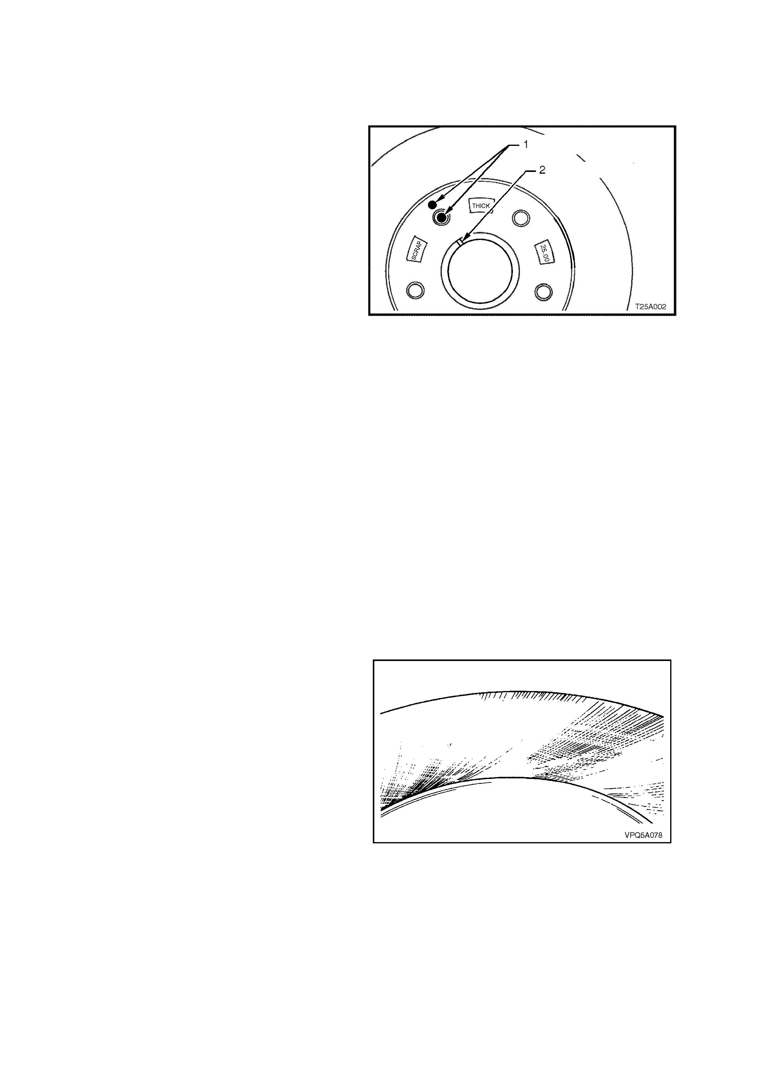
3.4 FRONT BRAKE DISC
LT Section No. – 04-805
REMOVE
IMPORTANT: T he brake disc to hub r elationship is
carefully matched during production (indexed), to
minimise the effect of a tolerance stack-up, that
could result in disc runout and subsequent brake
shudder.
Therefore, prior to removal of the front brake
disc/s, check to see wheth er a paint dau b mark ( 1)
is still visible on the brake disc hub surface,
adjacent to one of the wheel studs and in
alignment with the two marks (2) on the end of the
hub, as shown.
If the paint marks are no longer visible, then
carefully mark the relationship of the brake disc to
the hub for reinstallation, using a felt tipped pen or
similar. If this precaution is not taken, then a disc
runout condition could be induced that will cause
brake shudder.
NOTE: If the brak e disc is being rem oved to rectif y
brake shudder, if the brake disc is to be machined
or replaced, or if brake disc to hub matching is not
evident, then the brake disc to the hub must be
indexed. Refer procedure in this Section.
Figure 5A - 91
1. Remove the brake caliper assembly, refer to 3.3 BRAKE CALIPER (FRONT & REAR), in this Sectio n.
NOTE: It is not necess ary to disc onnect the brak e hose from caliper . However, the calip er must be suppor ted with
a wire hook to avoid strain on the brake hose.
2. If neces sary, jar the brak e disc loos e by carefull y tapp i ng the disc in t he c entr e be tween t he whee l s tuds , with a
soft faced hammer (or block of wood and a hard faced hammer), taking care not to damage the wheel stud
threads.
INSPECT
If the brake disc surface is rusted or lightly scored, resurface disc. Scores less than 0.4 mm deep will not affect
brake performance.
If scoring is deep or if brake disc parameters are out of specification, the disc must be machined.
NOTE 1: Machine or resurface BOTH sides of disc. Do not machine or resurface one side only.
NOTE 2: After m achining, the br ake dis c s houl d be
ground to achieve a non-circumferential finish of
0.4 to 2.0 microns.
Figure 5A - 92

NOTE 3: After machining, the chamfer on the
brake disc outer diameter must be 45 deg x 1 mm
maximum (dimension A) with a pad (1) to chamfer
clearance of 1.3 m m m inimum to 2.5 mm m axim um
(dimension B). This is to prevent thermal stress
cracking at the top of the disc (2).
Figure 5A - 93
NOTE 4: Replace disc if specifications cannot be
achieved above the minimum disc thickness.
CAUTION: Th e Number Cast Into Th e Hub (1) Is
The Minimum Safe Thickness. At This
Thickness The Disc Must Be Replaced
MINIMUM BRAKE DISC THIC KNESS
(REPLACEM ENT REQUIRED) 25. 0 0 mm
Figure 5A - 94
Inspect disc as follows:
1. Using a piece of chalk, mark the brake disc
every 30 deg (1).
2. Using a dial indicator (2), check that lateral run-
out of each braking surface does not exceed
0.04 mm T otal Indicated Runou t (TIR) and that
the rate of c hang e does no t exc eed 0.03 m m in
30 degrees.
MAXIMUM LATERAL RUNOUT (TIR) 0.04 mm
MAXIMUM LATERAL RUNOUT IN 30 DEG 0.03 mm
IMPORTANT: This specification is the lateral run-
out of a front brake disc that has been removed
from the vehicle (do not confuse this with brake
disc to hub assembled lateral run-out.
Figure 5A - 95
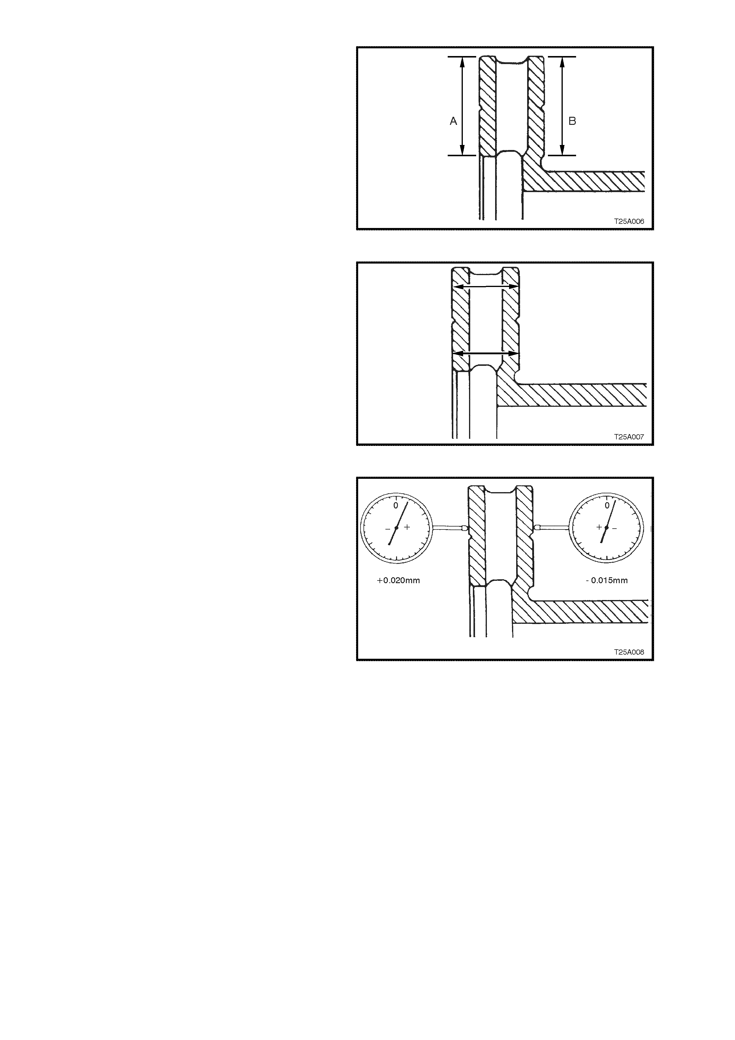
3. Check that both sur f ac es of the brak e disc (A &
B) are flat within 0.05 mm TIR.
Figure 5A - 96
4. Check that disc surf aces are paral lel with each
other to within 0.08 mm, when checked
radially.
NOTE: Taper variation must not exceed 0.08mm
Figure 5A - 97
5. Check that total circumferential thickness
variation, (also referred to as Disc Thickness
Variation) at any radius, does not exceed 0.005
mm in 360 degrees as the brake disc is
rotated.
NOTE: To measure the thickness variation,
measure both sides of the brake disc for runout
and add the two measur em ents togeth er.
Example:
Total runout on one side = +0.020 mm
Total runout on other side = - 0.015 mm
Therefore +0.020 +-0.015 = +0.005 mm
Figure 5A - 98
BRAKE DISC AND HUB INDEXING PROCEDURE
NOTE 1: Brake disc and hub indexing is required in order to obtain the minimum installed brake disc runout. Brake disc
and hub indexing involves aligning the point of max imum runout on the hub with the point of least runout on the brake
disc.
NOTE 2: This procedure is to be used when ever reinstalling brak e discs that have been rem oved f or machining off -
car. It must also be used when installing new brake discs or brake discs that have been removed for any reason
and where the brake disc to hub matching is not evident.
The procedure consists of three parts:
Part 1. Clean mating surfaces
Part 2. Meas ure an d Matc h brak e dis c high point t o hub low p oint. If these m eas urem ents ar e not O K, go to Part
3
Part 3. Checking hub mounting face runout
Part 1. Clean Mating Surfaces
Ensure tha t brak e disc and hub m ating s urf aces ar e free from dir t, corros ion, etc. If required, use f ine em er y paper
to clean surfaces.
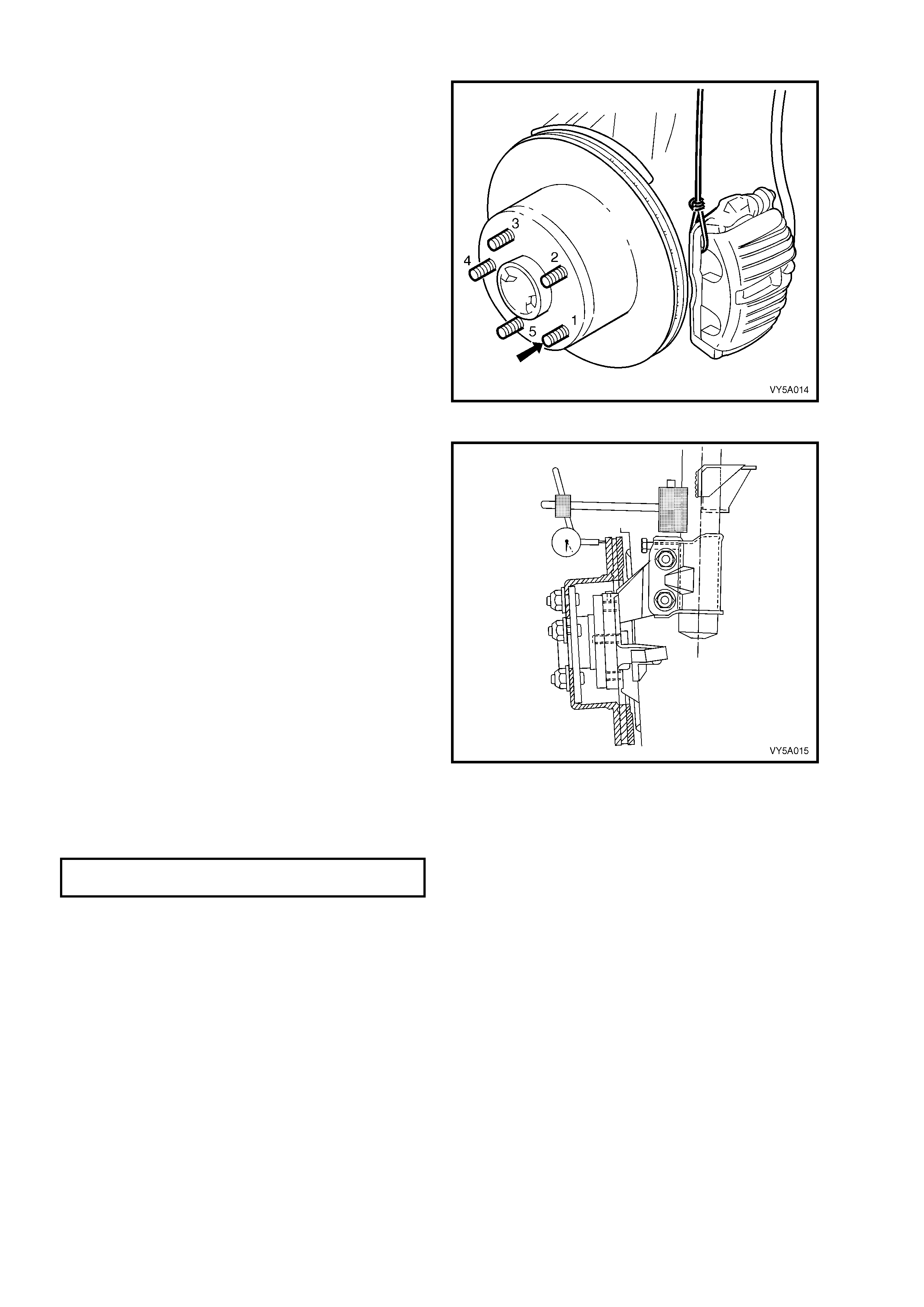
Part 2. Indexing Brake Disc to Hub
1. Install and secure the brake disc onto the hub
with wheel nuts reversed, to avoid damage to
the tapers, and nip up with a spanner.
2. Number each of the wheel stud holes on the
front surface of the brake disc from 1 to 5.
Place a chalk mark on the end of the wheel
stud adjacent to the number “1” hole (arrow).
NOTE: While the rear disc and caliper are
illustrated, the procedure for indexing the front
brake disc to the front hub, is the same.
Figure 5A - 99
3. Set up a dia l indicator on a magnetic b ase and
attach to the strut tube above the brake disc.
Position the pointer about 10 to 15mm inboard
from the outer diameter of the brake disc.
4. Carefully rotate the brake disc and note the
points of minim um and m axim um runout on th e
dial indic ator. T he num ber of divis ions bet ween
these two points is the total indicated runout.
Record this figure toget her with the num ber on
the brake disc aligned with the chalk-marked
stud.
5. Remove and reinstall the brake disc with hole
number “2” over the m arked stud. Rep eat Step
4. This procedure is to be repeated for all 5
hole positions.
6. Mount the brake disc to the hub in the stud
position which recorded the least amount of
runout.
IMPORTANT: If the lowest assembled disc runout
achieved is more than 0.050 mm (50 micron) then
the hub runout should be checked as detailed in
Part 3 of this procedure.
MAXIMUM ASSEMBLED DISC & HUB
RUNOUT AT DISC OUT ER DI AM ET ER 0.05 mm
Figure 5A - 100
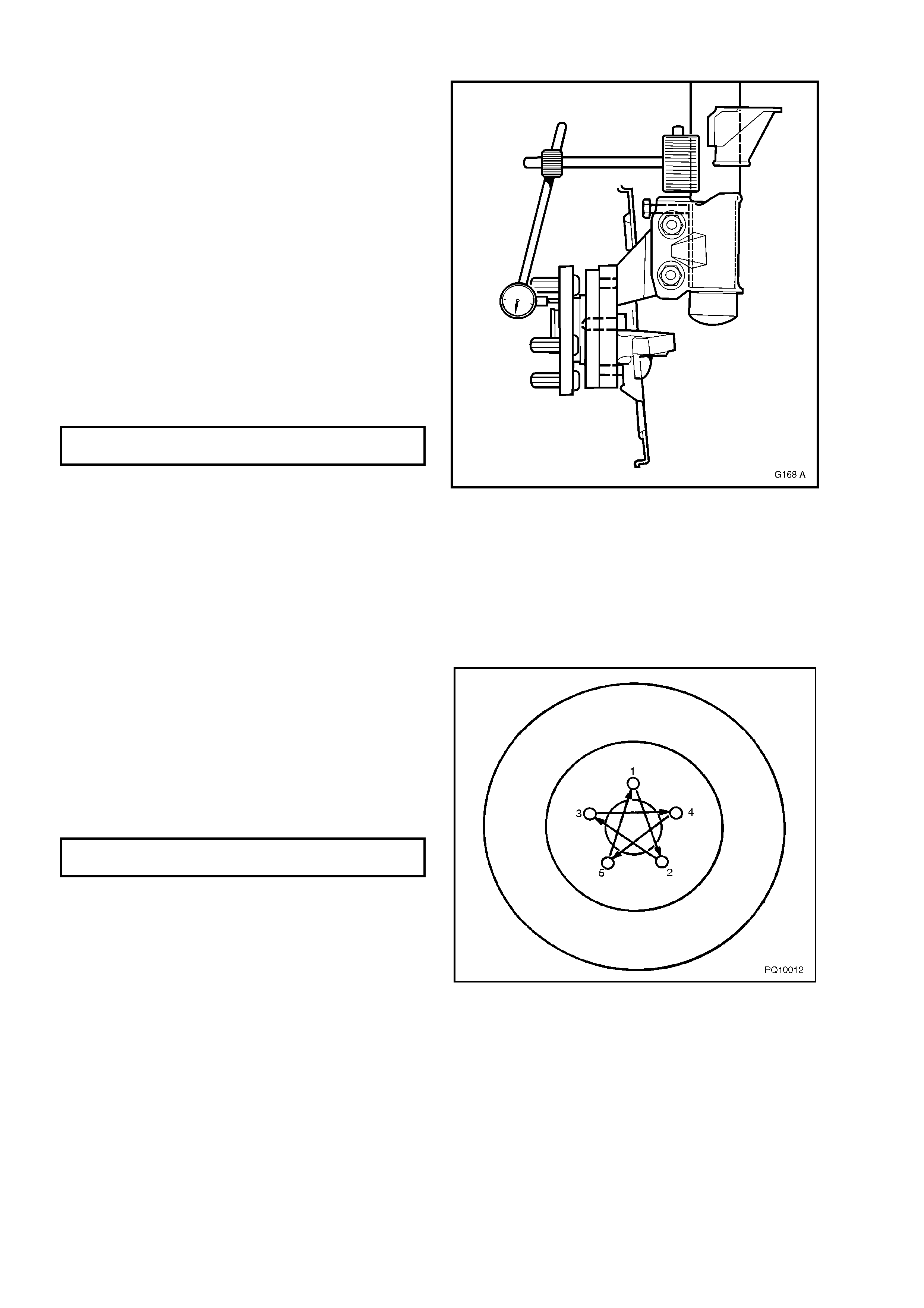
Part 3. Hub Runout Check
1. Clean the front hub face by rubbing lightly with
fine emery paper.
2. Locate the dial indicator on the strut tube and
position the pointer on the hub face about
midway between the spigot and the studs.
NOTE: For this check to be performed to 100 %
accurac y, a f lat para lleled surf ace plat e attac hed to
the hub should be used, however, measuring
runout between each of the wheel studs should
suffice.
3. Carefully rotate the hub by the hub spigot (to
avoid loading the bearing) and note the points
of minimum and maximum runout on the dial
indicator. The number of divisions between
these two points is the total indicated runout.
4. If the runout measured in Step 3 exceeds
0.025 mm (25 micron) then the hub unit s hould
be replaced.
MAXIMUM RUNOUT AT
HU B FAC E – FRONT HUB 0.025 mm
Figure 5A - 101
REINST ALL
1. Reinstall the brake disc over the wheel studs in either the pre-marked/indexed position or the newly indexed
position.
2. Reinstall the brake caliper assembly, refer to 3.3 BRAKE CALIPER (FRONT & REAR), in this Section.
3. Depress the brake pedal several times to bring pads into position against disc.
4. Reinstall road wheels aligning marks made prior to removal, loosely reinstall nuts, then lower vehicle.
5. Tighten road wheel attaching nuts to the
specified torque and in the order shown.
NOTE: Do not use an impact gun to tighten wheel
nuts unles s it is fitted with a tor que limiter bar such
as Tool No. AU534 or commercial equivalent.
Failure to c orr ec t l y tighte n whee l n uts to th e c orr ec t
torque specification may result in a warped brake
disc, which may lead to development of brake
shudder.
ROAD WHEEL ATTACHING NUT
TORQUE SPECIFICATION 100 - 125 Nm
Figure 5A - 102
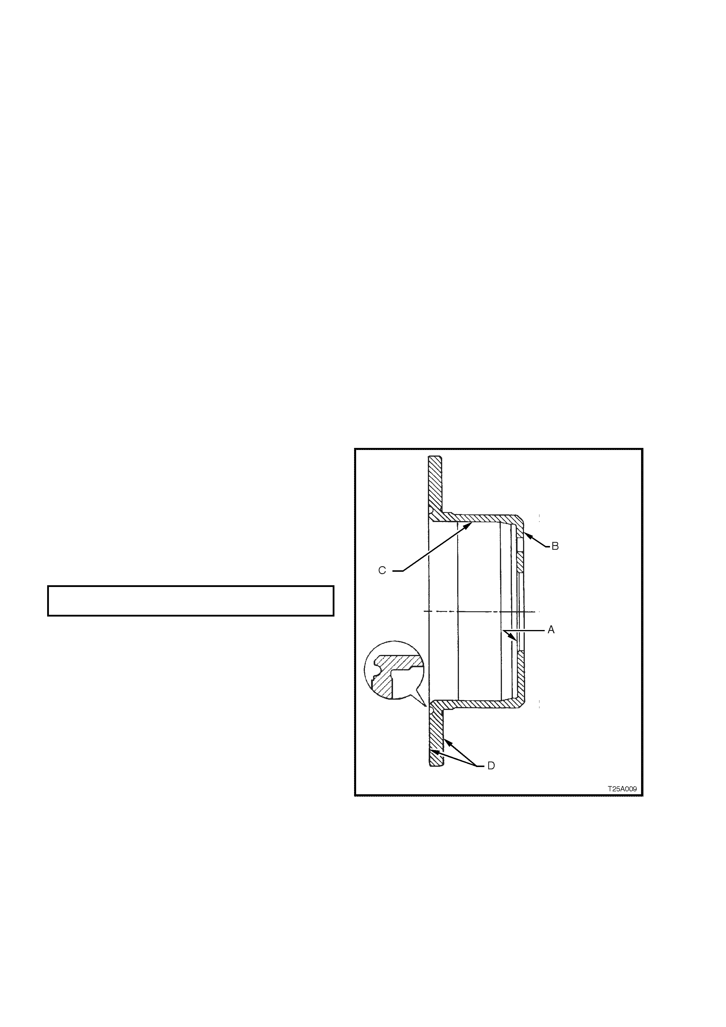
3.5 REAR BRAKE DISC
LT Section No. – 04-825
REMOVE
IMPORTANT: T he brake disc to hub relati onship is caref ully matched duri ng production (index ed), to m inimise the
effect of a tolerance stack-up, that could result in disc runout and subsequent brake shudder.
Carefully mark the relationship of the brake disc to the hub for installation. If this precaution is not taken, then a disc
runout condition could be induced that will cause brake shudder.
NOTE: If the br ake disc is being rem oved to r ectif y brake shudder , if the br ake dis c is to be m achined or replaced,
or if brake disc to hub matching is not evident, the brake disc to the hub must be indexed, as detailed in this
Section.
1. Ensure park brake is fully released.
2. Remove the brake caliper assembly, refer to 3.3 BRAKE CALIPER (FRONT & REAR), in this Section.
NOTE: It is not necessary to disconnect the brake hose from the caliper. However, the caliper must be supported
with a wire hook to avoid strain on brake hose.
3. If neces sary, jar the brak e disc loos e by careful ly tapp i ng the dis c in the centre between the wh ee l st uds, with a
soft faced hammer (or block of wood and a hard faced hammer), taking care not to damage the wheel stud
threads.
NOTE: It may be necessary to loosen the park brake shoe adjustment, to allow the disc to be removed over the
park brake shoes. Refer to Operation 3.7 PARK BR AKE SHOE, ADJUST, in this Section.
INSPECT
If the brake disc surface is rusted or lightly scored, resurface disc. Scores less than 0.4 mm deep will not affect
brake performance.
If scoring is deep or if disc parameters are out of specification, the disc must be machined or replaced.
NOTE 1: Machine or r es urfac e BO T H sides of dis c.
Do not machine or resurface one side only.
NOTE 2: After mac hining, disc f inish should be 0. 6
to 1.25 microns and should not be circumferential
i.e. disc finish should be non-directional. Park
brake surface finish should be 20 microns.
NOTE 3: Replace the brake disc if specifications
cannot be achieved above the minimum disc
thi ckness.
MINIMUM BRAKE DISC THIC KNESS
(REPLACEM ENT REQUIRED) 13.9 m m
WARNING: THE DISC MUST BE REPLACED AT
THIS THICKNESS!
Inspect brake disc as follows:
1. Check that sur f ac e B is flat with in 0.0 8 m m and
is parallel with surface A within 0.08 mm Total
Indicated Runout (TIR).
2. Check that surface C circular run-out is less
than 0.08 mm and that surface is square to
surface A within 0.05 mm TIR
3. Check that each brake disc surface is flat
within 0.05 mm and is parallel to surface A
within 0.085 mm TIR.
4. Check that lateral run-out of each braking
surface D is less than 0.05 mm when
measured from surface A as shown or when
bolted to the axl e and tha t rate of change d oes
not exceed 0.03 mm in 30°.
5. Check that maximum circumferential thickness
(also referred to as Disc Thickness Variation
(DT V) does not vary by more than 0 . 01 3 m m at
any radius when disc is rotated.
Figure 5A - 103
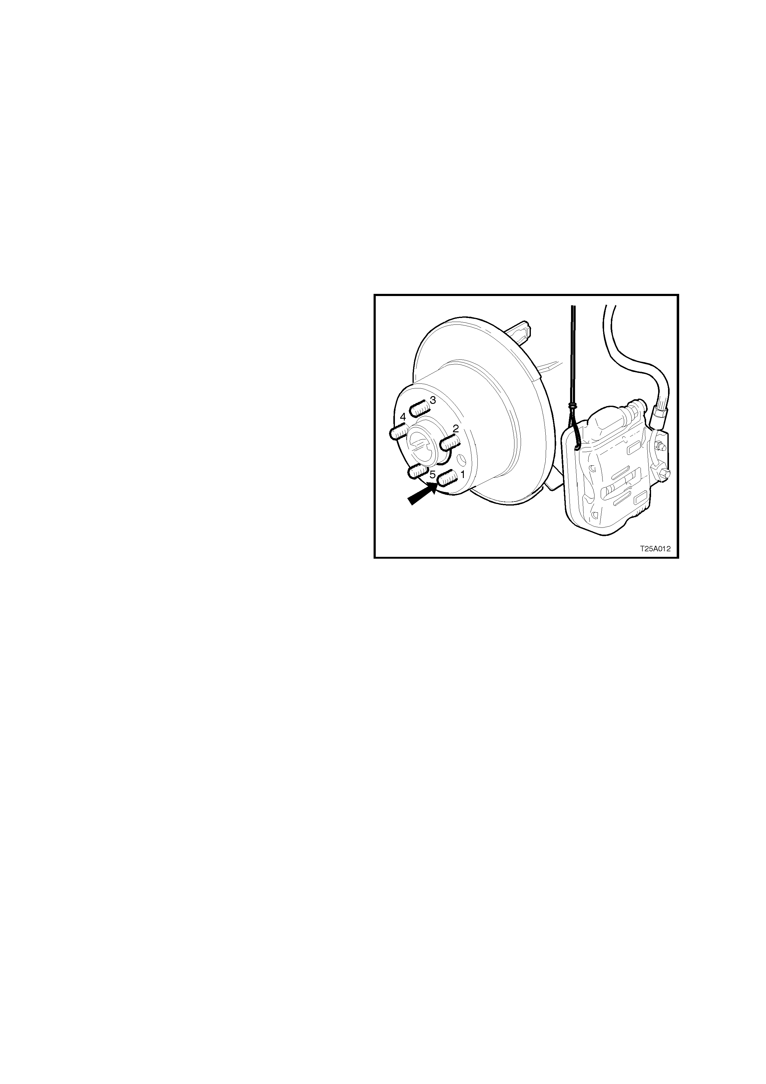
BRAKE DISC AND HUB INDEXING PROCEDURE
NOTE 1: Th e brake disc and hub indexing is required in or der to obtain the minimum installed disc runout. Brak e disc
and hub indexing involves aligning the point of maximum runout on the hub with the point of least runout on the disc
NOTE 2: T his procedure is to be used whenever reinstalling brak e discs that have be en rem oved for m achining off
car. It must also be used when installing new brake discs or brake discs that have been removed for any reason
and where the brake disc to hub matching is not evident.
The procedure consists of three parts as follows:
Part 1. Clean mating surfaces.
Part 2. Measure and Match brake disc high point to hub low point. If measurements are not OK, go to Part 3.
Part 3. Checking hub mounting face runout.
Part 1. Clean Mating Surfaces
Ensure tha t brak e disc and hub m ating s urf aces ar e free from dir t, corros ion, etc. If required, use f ine em er y paper
to clean surfaces.
Part 2. Indexing Brake Disc to Hub
1. Fasten the brake disc onto the hub with wheel
nuts reversed to avoid damage to the tapers,
and nip up with a spanner.
2. Number each of the wheel stud holes on the
front surface of the brake disc from 1 to 5.
Place a chalk mark on the end of the wheel
stud adjacent to the number “1” hole (bold
arrow).
Figure 5A - 104
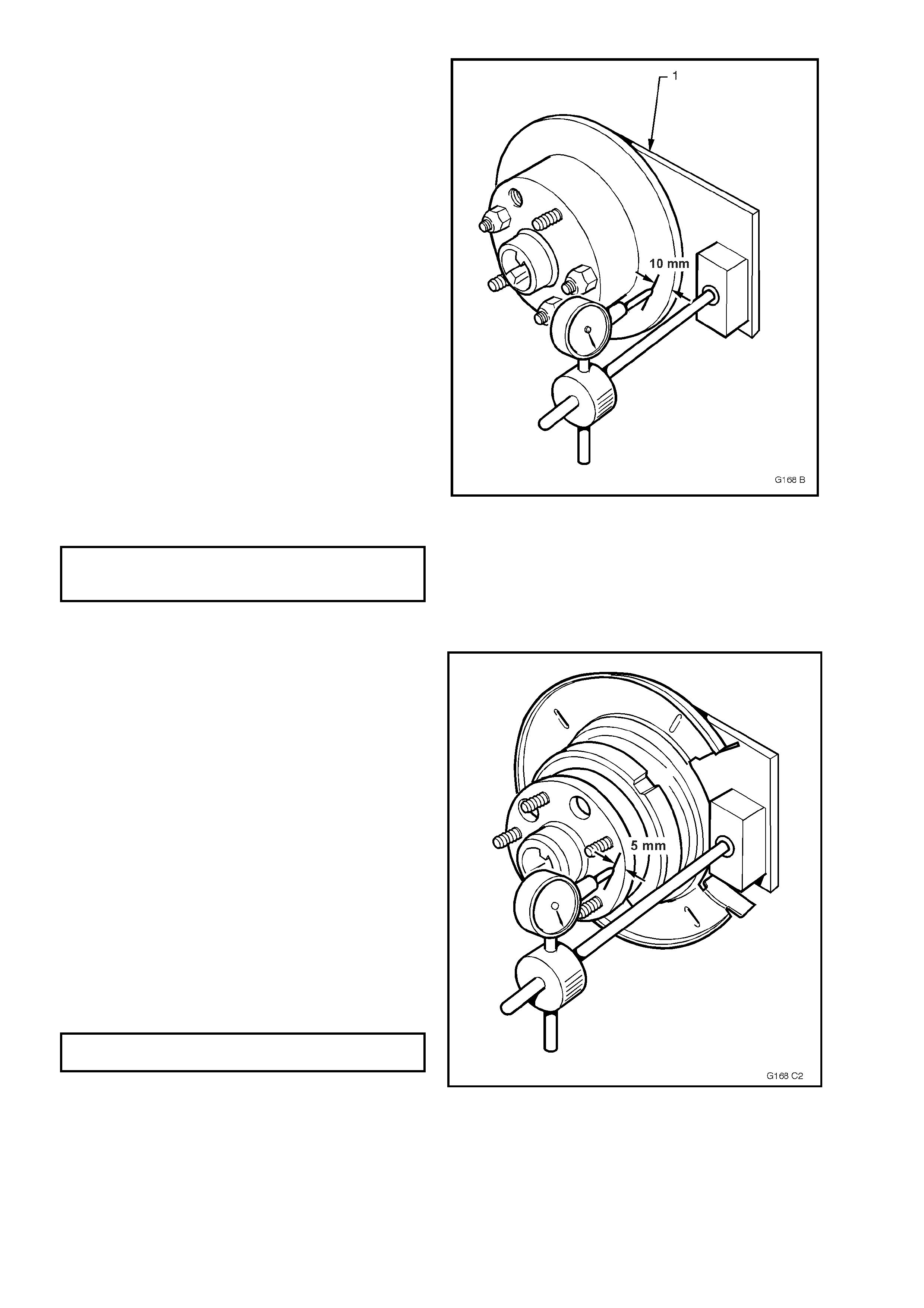
3. Set up a dia l indicator on a magnetic b ase and
attach to a pre-fabricated mounting plate (1)
(refer 7. SPECIAL TOOLS in this Section for
pre-fabricated mounting plate details) bolted to
the caliper attaching points. Position the
pointer of the dial indicator about 10 to 15mm
inboard from the outer diameter of the brake
disc.
4. Carefully rotate the brake disc and note the
points of minim um and m axim um runout on th e
dial indic ator. T he num ber of divis ions bet ween
these two points is the total indicated runout.
Record this figure toget her with the num ber on
the brake disc aligned with the chalk-marked
stud.
5. Remove and reinstall brake disc with hole
number “2” over the marked stud and repeat
Step 4. T his procedur e is to be repeat ed for all
5 hole positions.
6. Mount the disc to the trunnion hub in the stud
position which recorded the least amount of
runout.
NOTE: If the lowest assembled disc runout
achieved is more than 0.080 mm (80 micron) then
the trunnion hub runout should be checked as
shown in Part 3.
MAXIMUM ASSEM BLED BRAKE DISC &
TRUNNION HUB RUNOUT AT BRAKE DI SC
OUTER DIAM ET ER – REA R B R AKE D ISC 0.08 mm
Figure 5A - 105
Part 3 Trunnion Hub Runout Check
1. Clean the front hub face by rubbing lightly with
fine emery paper.
2. Mount a dial indicator on a pre-fabricated
mounting plate bolted to the caliper mounting
points and position th e pointer on the hub face
as sho wn. Refer to 7. SPECIAL TOOLS in this
Section f or dimens ional details of the mounting
plate.
NOTE: For this check to be 100% accurate, a flat
paralle led surfac e plate attached to the hub s hould
be used, howe ver , measuring runou t between each
of the wheel studs should suffice.
3. Carefully rotate the hu b by the wheel s tuds an d
note the points of minimum and maximum
runout on the dial indicator. The number of
divisions between these two points is the total
indicated runout.
4. If the runout measured in Step 3 exceeds
0.060 mm (60 micron) then the trunnion
assembly must be replaced.
MAXIMUM TRUNNION HUB TOTAL
INDICATED RUNOUT 0.06 mm
Figure 5A - 106
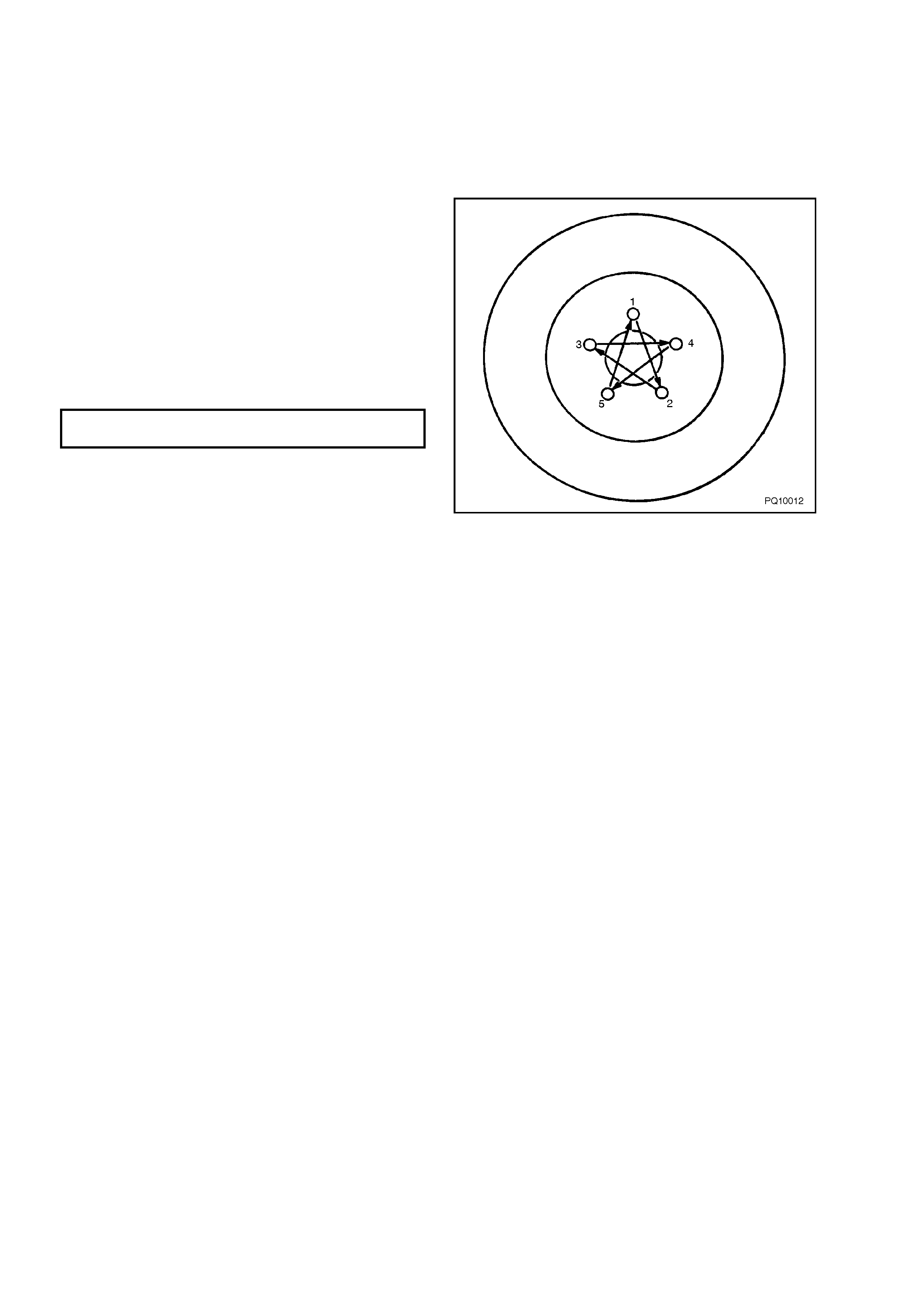
REINST ALL
1. Reinstall the brake disc over the wheel studs in either the pre-marked/indexed position or the newly indexed
position.
2. Reinstall the brake caliper assembly, refer to 3.3 BRAKE CALIPER (FRONT & REAR), in this Section.
3. Depress the brake pedal several times to bring pads into position against disc.
4. Adjust park brake shoe clearance. Refer to 3.7 PARK BRAKE SHOE, ADJUST , in this Section, for details.
5. Reinstall road wheels aligning marks made
prior to removal then lower vehicle.
6. Tighten road wheel attaching nuts to the
specified torque and in the order shown.
NOTE: Do not use an impact gun to tighten wheel
nuts unles s it is fitted with a tor que limiter bar such
as Tool No. AU534 or commercial equivalent.
Failure to c orr ec t l y tighte n whee l n uts to th e c orr ec t
torque specification may result in a warped brake
disc, which may lead to development of brake
shudder.
ROAD WHEEL ATTACHING NUT
TORQUE SPECIFICATION 100 - 125 Nm
Figure 5A - 107

3.6 PARK BRAKE LINING WEAR, CHECK
1. Remove both rear discs. Refer to 3.5 REAR BR AKE DISC, in this Sec t ion.
2. Check the park brake lining for even wear, both across the shoe and circumferentially around each shoe, for
each lining half, using a vernier caliper or similar.
3. W ear should be even and no thinner than the specified minimum thickness. If the minimum thickness is at or
less than specified, then the linings must be replaced. The drum section of the rear disc may also require
grinding. Re fer 3.5 REAR BR AKE DISC, in this Section for specific detail, regarding grinding operations.
MINIMUM PARKING BRAKE SHOE
LINING THICKNESS 1.5 mm
NOTE: If one park brake shoe requires replacement, then both must be replaced.
4. Reinstall rear discs and adjust the park brake shoe clearances, refer 3.5 REAR BRAKE DISC, REINSTALL
and 3.7 P ARK BR AKE SH OE, ADJUST, both in this Section.
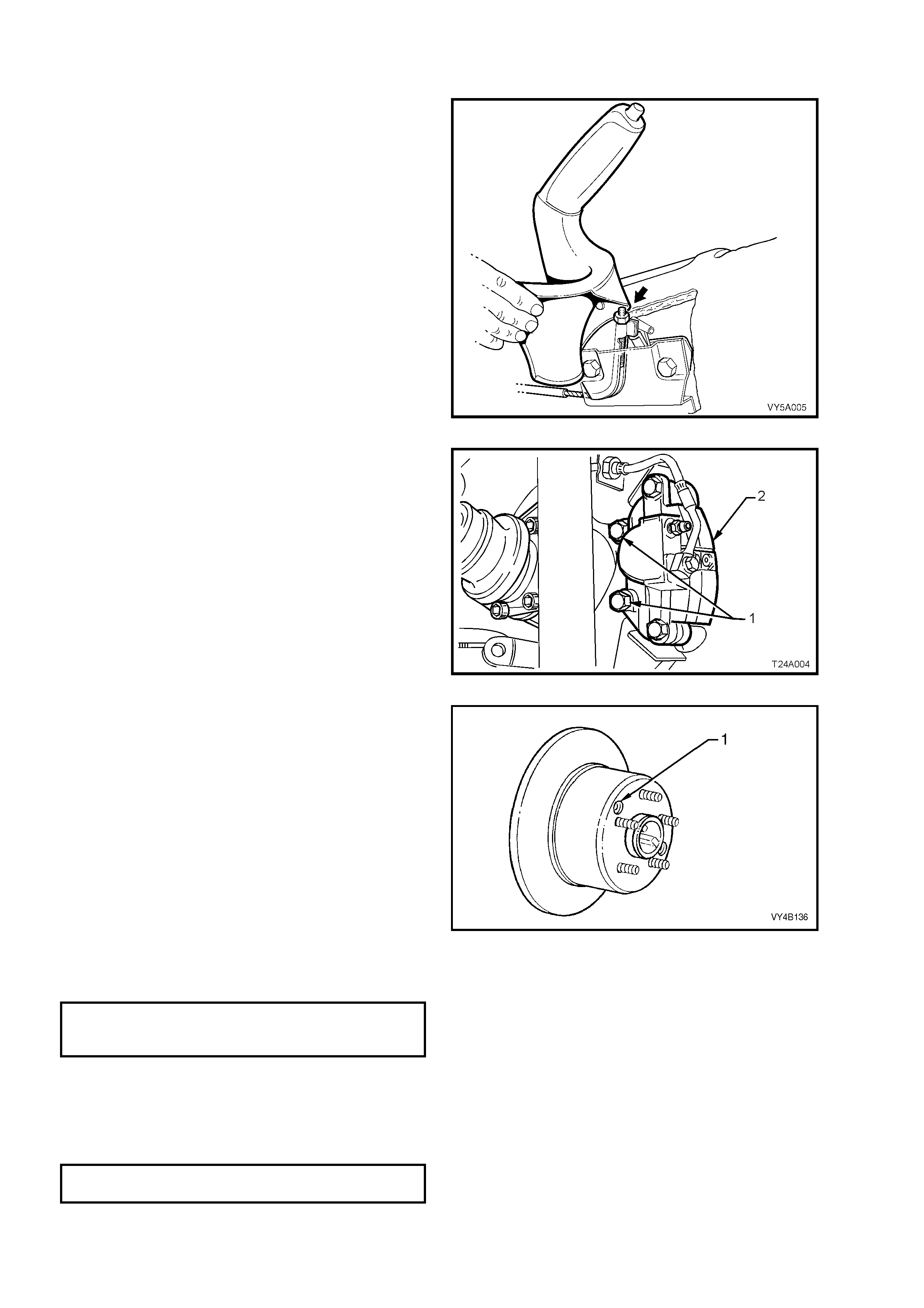
3.7 PARK BRAKE SHOE, ADJUST
1. Using a floor jack under centre of differential
carrier, jack up and support rear of vehicle on
safety stands under rear trailing arms.
2. Remove rear wheel covers (steel wheels) or
wheel nut decorative caps (alloy wheels).
3. Mark relationship of wheels to mounting
flanges.
4. Remove roa d whee l attac h i ng nuts and remove
wheels.
5. Release p ar k br ak e and en sur e that par k br ake
actuator arms have fully retracted.
If necessary, loosen the front park brake cable
adjustment nut (arrow) with a deep socket, to
ensure slack in the park brake rear cables.
Figure 5A - 108
6. Remove rear brake caliper anchor plate to
trailing arm attaching bolts (1) (both sides of
vehicle ), then remove calipers (2) from discs.
7. Using tie wire, secure calipers to lower end of
shock absorber upper mountings. DO NOT
ALLOW CALIPERS TO HANG BY BRAKE
HOSES!
8. Reinstall three wheel nuts, reversed to prevent
damage to the tapers and lightly tighten to
secure the disc in place.
Figure 5A - 109
9. Remove the access hole plug (1). Using a
suitable lever such as a screwdriver, tighten
the park brake shoe screw adjuster, until the
disc is locked. Access to the screw adjuster is
through either one of two holes (1) provided in
the disc.
10. Loosen the adjuster 3 – 5 clicks, then check
that the disc is free and does not drag. Replace
the access hole plug when the adjustment
procedure has been completed.
Figure 5A - 110
11. Reinstall brake caliper, install and tighten caliper anchor plate to trailing arm attaching bolts, to the correct
torque specification.
BRAKE CALIPER ANCHOR PLATE
TO TRAILING ARM ATTACHING
TORQUE SPECIFICATION 70 - 100 Nm
12. Reinstall rear wheels, aligning marks made prior to removal, and install attaching nuts.
13. Check park brake cable adjustment, refer to 2.2 PARK BRAKE CABLE, ADJUST, in this Section.
14. Remove safety stands and lower vehicle.
15. Tighten road wheel attaching nuts in a star pattern to the correct torque specification. Refer 2.1 SERVICE
NOTES AND CAUTIONS in this Section for more specific information.
ROAD WHEEL ATTACHING NUT
TORQUE SPECIFICATION 100 - 125 Nm
16. Refit wheel covers/wheel nut decorative caps.
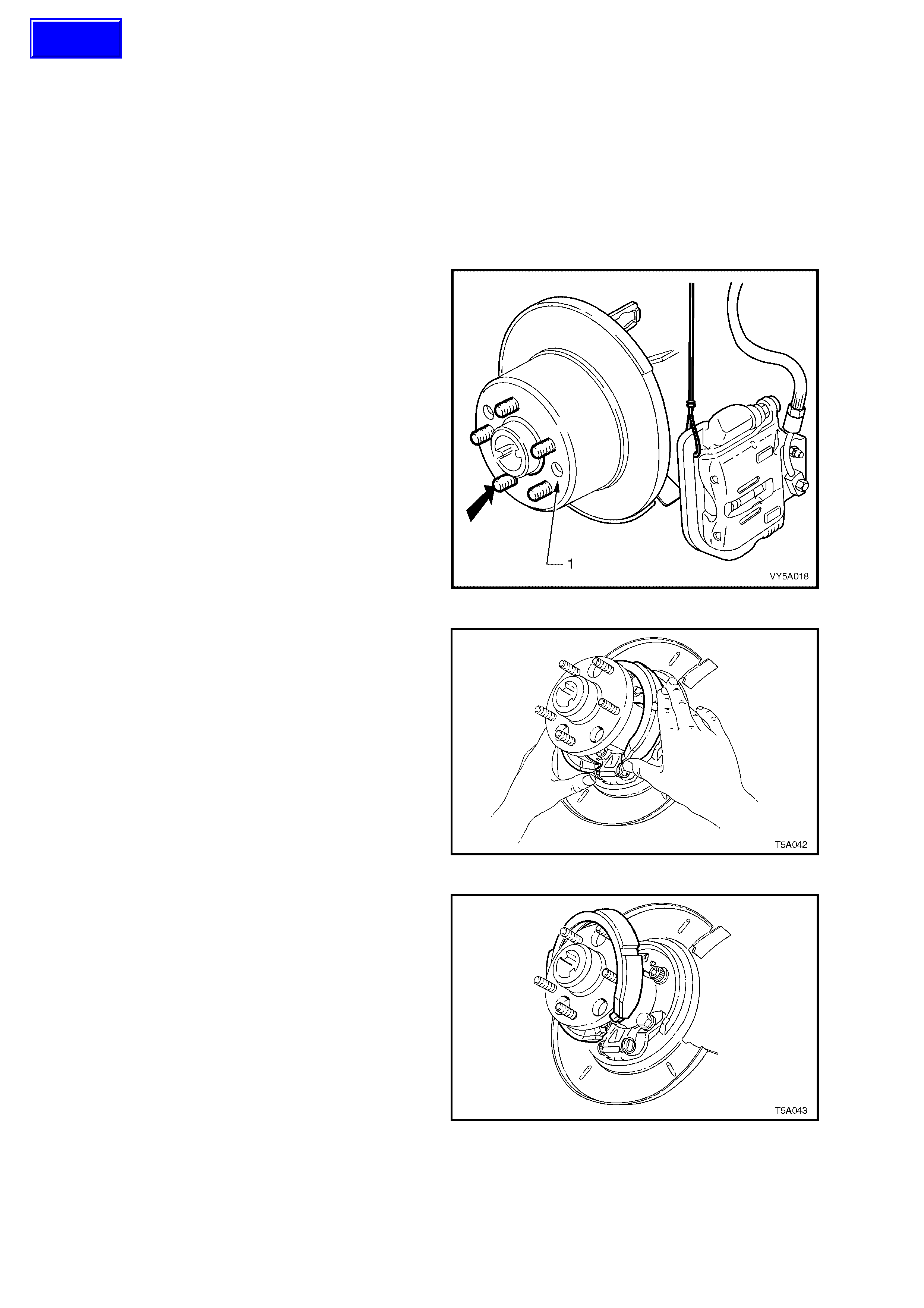
3.8 PARK BRAKE SHOE
LT Section No. – 04-825
REMOVE
1. Using a floor jack under centre of rear axle, jack up and support rear of vehicle on jack stands under rear
trailing arms (rear axle housing).
2. Remove rear wheel covers on steel wheels or decorative wheel nut caps on alloy wheels.
3. Mark relationship of wheels to mounting flanges. Remove road wheel attaching nuts and remove wheels.
4. Release park brake.
5. Remove brake caliper anchor plate to trailing arm attaching bolts and remove caliper/s from disc/s.
6. Using tie wir e, secure the caliper s to lo wer end
of shock absorber upper mount ings, as shown.
DO NOT ALLOW CALIPERS TO HANG BY
BRAKE HOSES.
7. Index each disc to a wheel stud using a felt
tipped pen or similar, as indicated by the bold
arrow.
8. Remove brake discs.
NOTE: It may be necessary to loosen the park
brake shoe adjustment, to enable disc removal.
Use a suitable size screwdriver, screw in the
adjuster, using one of the two access holes (1) in
the brake disc.
Figure 5A - 111
9. Remove park brake shoe by grasping each
end as shown. Push up on one end of the
shoe, dislodging the end from the actuator pin
and the shoe from the retaining clip.
Figure 5A - 112
10. Us ing a screwing m otion, rotate the park brake
shoe around the trunnion flange to remove it
from the vehicle.
11. Rem ove the park brak e s hoe spring retai ner b y
prising from the rear disc shield, with a
screwdriver or similar lever.
12. If required, the actuator screw adjuster and
pins ca n be rem oved at this point, but th e bod y
and remaining components are not able to be
removed without first removing the rear disc
shield. For this operation, refer to 3.10 REAR
DISC SHIELD, in this Sect ion.
Figure 5A - 113
Techline
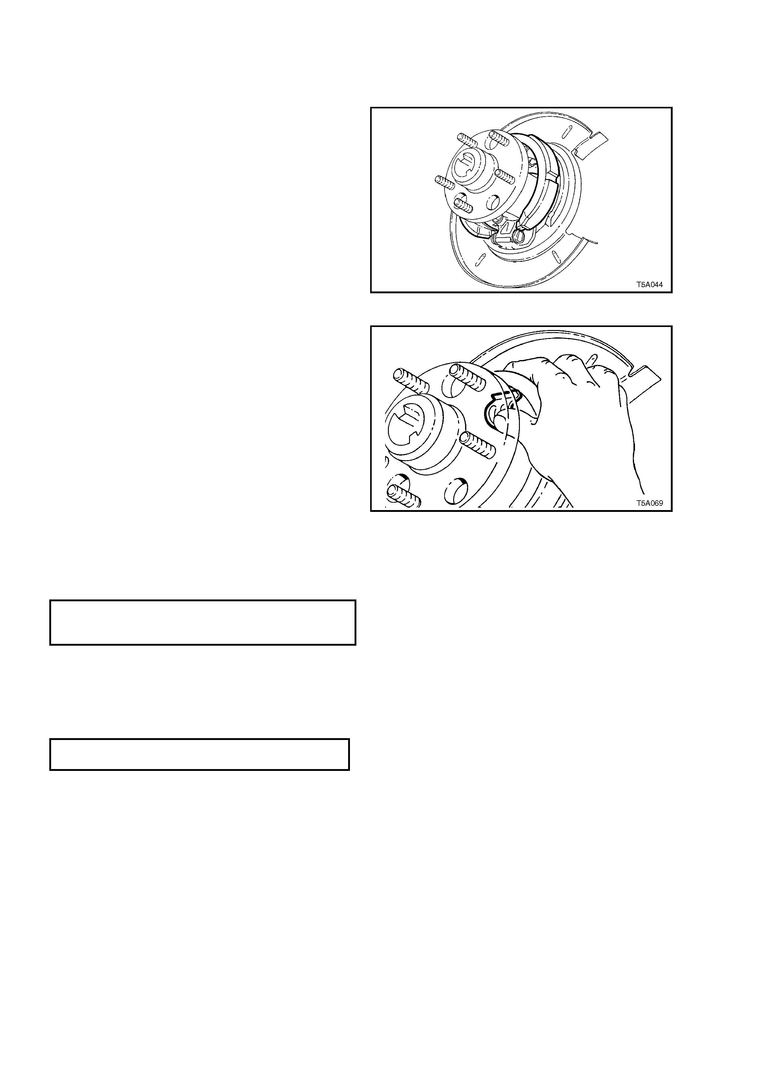
REINST ALL
1. Apply Mo lybdenum Disulphide grease to t he adjustin g screw an d pins. Fully win d screw into s leeve and ins tall
into the adjuster body.
2. Install the park brake shoe over the trunnion
flange.
3. W ith one shoe end l ocated on the adj uster pin,
roll the shoe to engage the other end onto the
other pin.
Figure 5A - 114
4. Reinstall park brake shoe retaining spring clip,
by sliding it into place, ensuring that the spring
clip is correctly loc ated by the ta ngs in the rear
brake shield.
Figure 5A - 115
5. Reinstall brake discs, aligning marks made on removal.
6. Adjust park brake shoe to disc clearance. Refer to 3.7 PARK BRAKE SHOE, A DJUST, in this Sec ti on.
7. Reinstall caliper anchor plate attaching bolts and tighten to the correct torque specification.
REAR BRAKE CALIPER
ANCHOR PLATE BOLT
TORQUE SPECIFICATION 70 - 100 Nm
8. Adjust park brake cable, refer to 2.2 PARK BRAKE CABLE, ADJUST in this Section.
9. Reinstall road wheels, aligning marks made prior to removal, install but do not tighten attaching nuts.
10. Remove safety stands and lower vehicle.
11. Tighten road wheel attaching nuts to the correct torque specification, working in a star pattern. Refer
2.1 SERVICE NOTES AND CAUTIONS, in this Section for more specific information.
ROAD WHEEL ATTACHING NUT
TORQUE SPECIFICATION 100 - 125 Nm
12. Refit wheel covers/wheel nut decorative caps.
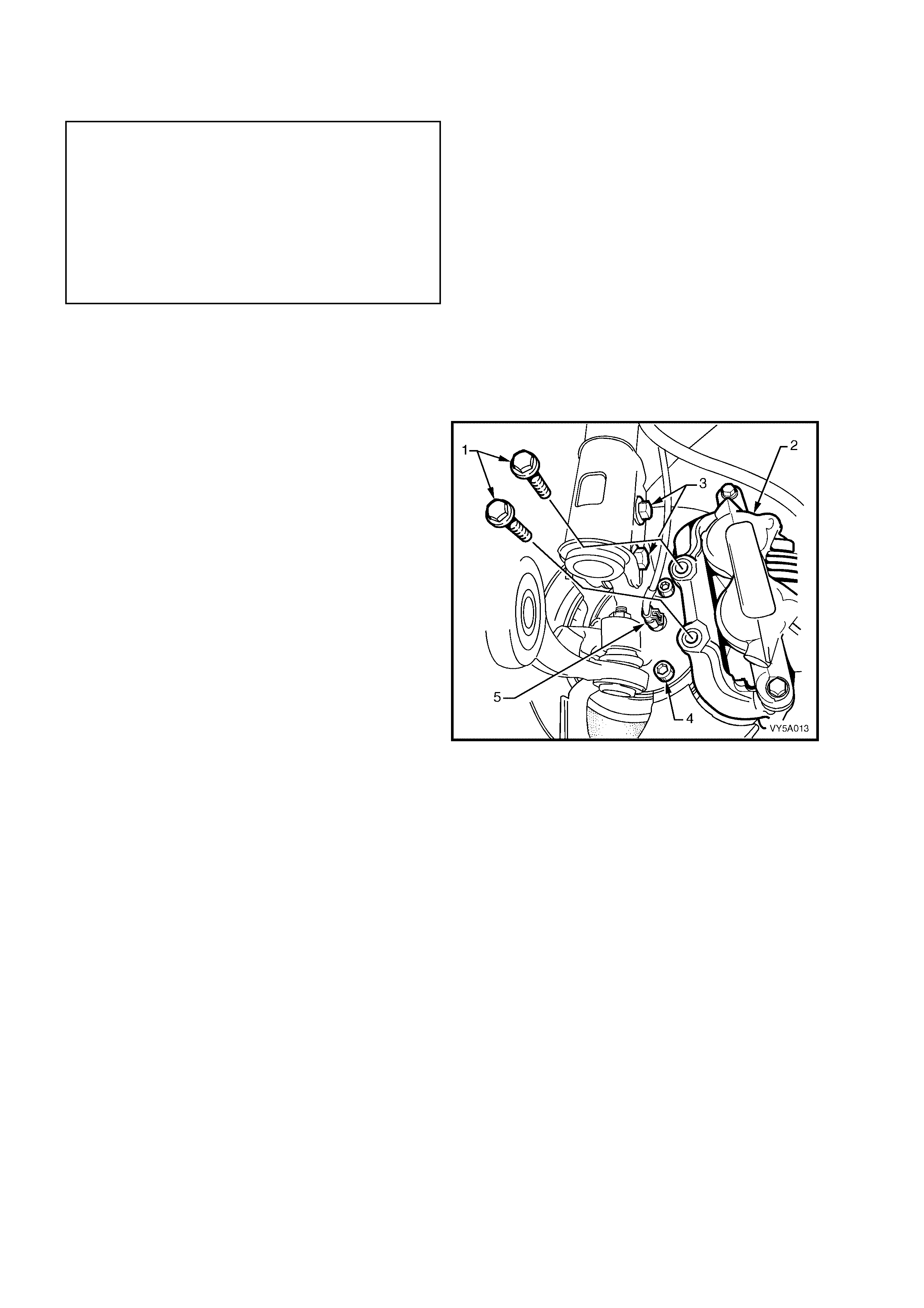
3.9 FRONT DISC BRAKE SHIELD
LT Section No. – 04-805
NOTE: The following fasteners MUST be replaced
(!
!!
!) when performing this operation or they have
micro-encapsulated sealant applied and should be
replaced on reassembly (#
##
#):
!
!!
!
Lower strut to steering knuckle bolts and nuts.
!
!!
!
Front brake caliper anchor plate to steering
knuckle attaching bolt
#
##
#
Hub to steering knuckle attaching bolts.
REMOVE
1. Raise front of vehicle and support on safety stands under the front crossmember.
2. Remove front wheel cover (steel wheels) or wheel nut decorative caps (alloy wheels) from side of vehicle
where the shield is to be removed.
3. Mark relationship of wheel to hub disc. Remove road wheel attaching nuts and remove wheel.
4. Rem ove the front brak e caliper anchor p late to
front strut knuckle attaching bolts (1), then
remove caliper (2) from disc.
NOTE: Discar d the front br ake c aliper anchor plate
retaining bolts as they must be replaced on
reassembly.
5. Using tie wire, secure the caliper to lower end
of front suspension coil spring. DO NOT
ALLOW CALIPER TO HANG BY BRAKE
HOSE.
6. For vehicles equipped with ABS or ABS/TCS,
disconnect the wheel speed sensor connector
(5) from the steering knuckle by lifting the
connector locking tab and pulling outward to
remove.
7. Remove front brake disc from the wheel
bearing hub.
IMPORTANT: Marking the relationship of the front
brake disc to the front hub is critical to minimising
the possibility of brake shudder. Refer to
3.4 FRONT BRAKE DISC in this Section, for
further information.
8. Using a commercially available 10 mm Allen
key socket and a suitable socket bar, loosen
each of the three bolts (4) holding the hub to
the steering knuckle support.
NOTE 1: If the Allen key socket is too long to fit
into the f ront, up per hu b bo lt, then the lower str ut to
steering knuckle nut (and bolt – 3) will need to be
loosened a nd r emoved. Discard t he remov ed bol t
and nut, as they must be replaced on
reassembly.
Figure 5A - 116
NOTE 2: For the front lower hub bolt (4), turn wheel outwards to provide sufficient clearance.
9. To remove hub from knuckle, it may first be necessary to tap the loosened bolts to break the seal. DO NOT
STRIKE THE HUB.
10. Remove the three bolts (4) and then the hub from steering knuckle.
11. Rem ove the three rivets (1) securing shiel d to knuck le, by drilli ng the head from each rivet. Rem ove the shiel d
from the knuckle support.
12. Carefully drill out the rivet remainder from the steering knuckle, using a suitable size drill.
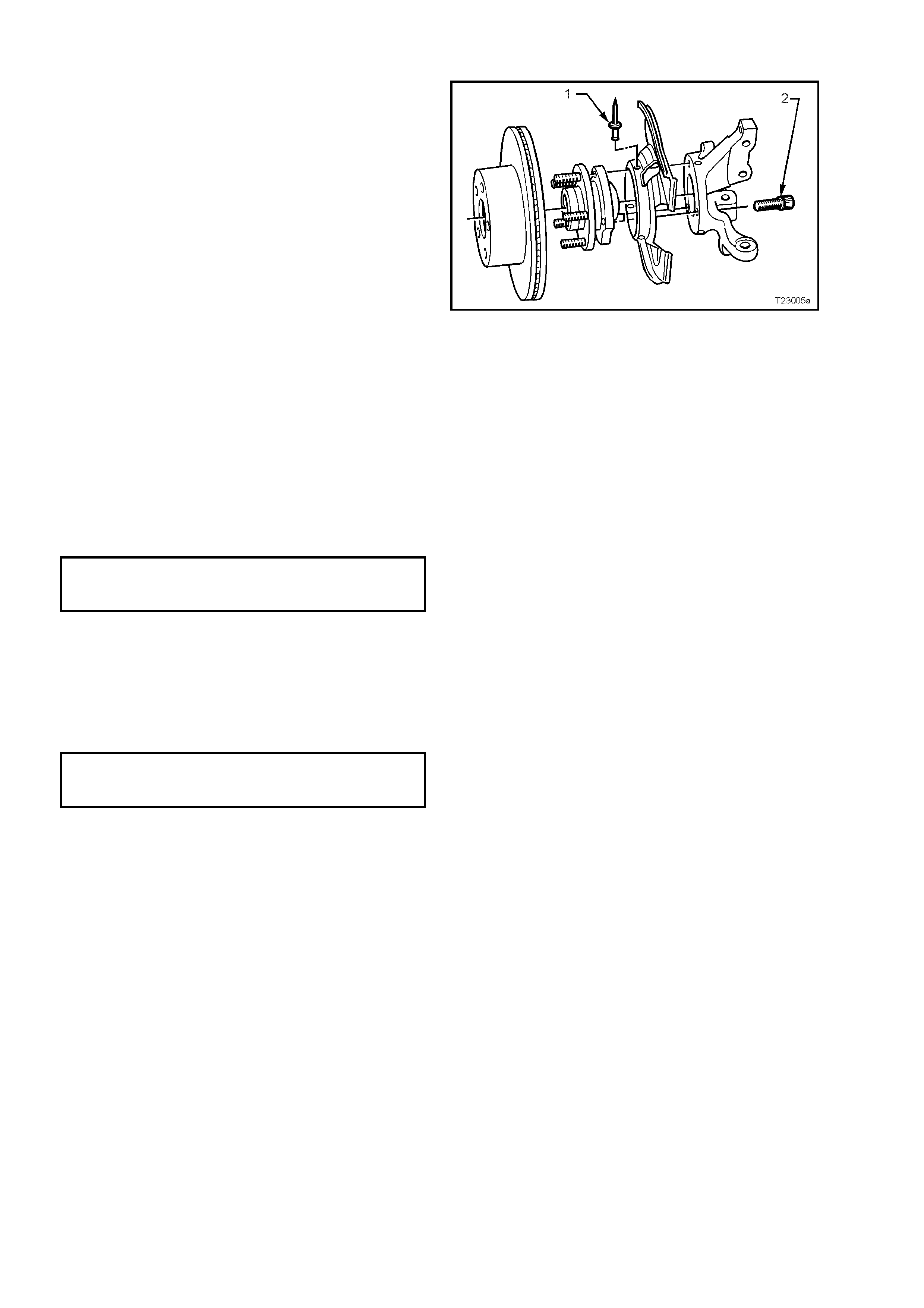
REINST ALL
Installat ion is th e rever s e of the r em oval proc e dur e,
except for the following points:
1. Reinstall the brake shield to the steering
knuckle support, securing with three, common
pop rivets (1), using a commercially available
pop rivet gun. Start with the round hole, to
ensure that the clearance to the brake caliper
is correct.
2. Before installing the hub, inspect both mating
surfaces to make sure that they are clean and
free from burrs that could prevent correct
alignment of both parts, once installed.
3. Prior to installation, it is also vital that the
sealing O-ring located around the mounting
flange, is checked to ensure its serviceability.
Failing to adequately seal the hub to steering
knuck le interface, will cause water t o be dra wn
into the cavity in the steering knuckle, during
the norm al heating and coo ling c ycle of vehic le
operation.
Figure 5A - 117
WITHOUT ABS:
4. Install the hub assembly to the steering knuckle.
5. Install the three attaching bolts and tighten to the correct torque specification.
FRONT HUB TO STEERING
KNUCKLE ATTACHING BOLT
TORQUE SPECIFICATION 120 – 140 Nm
NOTE: The three hub attaching bolts are micro-encapsulated with thread sealant and are not to be re-used more
than three times. If in doubt, the bolts should be replaced.
WITH ABS:
6. Carefully align the sensor connection on the hub, with the hole in the steering knuckle, then install the three
hub attaching bolts and tighten to the correct torque specification.
FRONT HUB TO STEERING
KNUCKLE ATTACHING BOLT
TORQUE SPECIFICATION 120 – 140 Nm
7. Reinstall the wheel speed sensor connector, pushing fully home. Check that the locking tang is secure.

ALL VEHICLES:
8. If the lower strut to steering knuckle bolt and nut were removed to gain access to the front, upper hub to
steering knuckle bolt, then both the removed bolt and nut must be replaced with new components and
tightened to the correct torque specification.
(!
!!
!) STEERING KNUCKLE TO STRUT
NUT TORQUE SPECIFICATION
Stage 1 85 Nm
Stage 2 100 Nm
Stage 3 turn through 90°
9. Reinstall the brake disc over the wheel studs in the pre-marked position.
10. Position the caliper assembly over the disc and insert the anchor plate retaining bolts. Tighten the bolts to the
specified torque.
NOTE: New retaining bolts must be used when reinstalling the front brake caliper anchor plate.
(!
!!
!) BRAKE CALIPER ANCHOR
PLATE RETAINING BOLTS
TORQUE SPECIFICATION 80 - 90 Nm,
then turn through
40° - 50°
11. Reinstall road wheel, aligning the marks made prior to removal and secure with the attaching nuts.
12. Remove jack stands and lower vehicle.
13. Tighten road wheel attaching nuts to correct torque specification, working in a star pattern (refer to
2.1 SERVICE NOTES AND CAUTIONS, in this Section).
ROAD WHEEL ATTACHING BOLT
TORQUE SPECIFICATION 100 - 125 Nm
14. Refit wheel cover/centre cap.
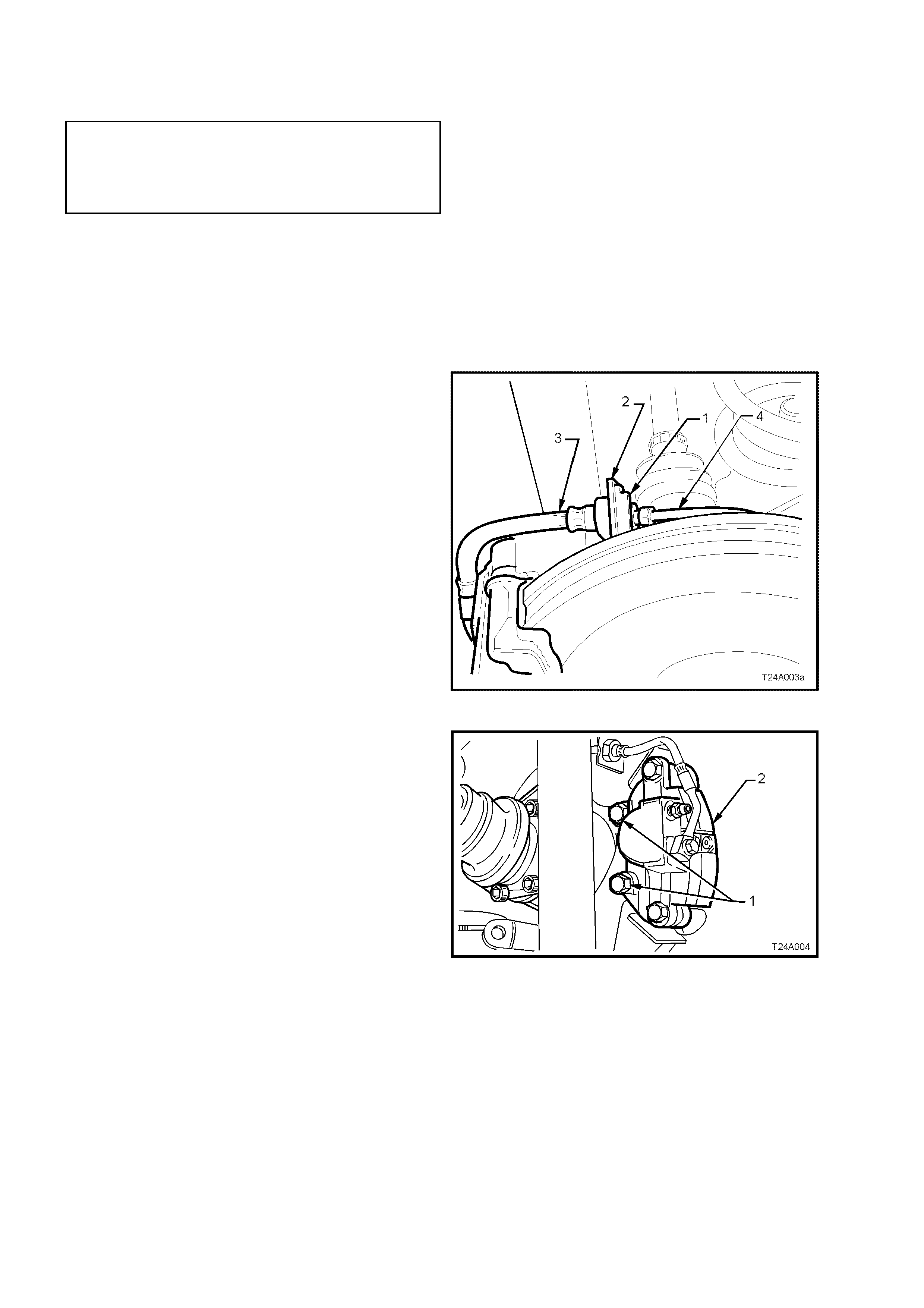
3.10 REAR DISC BRAKE SHIELD
LT Section No. – 04-825
NOTE: The following fasteners MUST be replaced
(!
!!
!) when performing this operation :
!
!!
!
Lower rear disc brake shield to trailing arm
attaching bo lt
REMOVE
1. Using a floor jack under centre of differential carrier, jack up rear of vehicle then place safety stands under
trailing arms.
2. Remove rear wheel cover (steel wheels) or wheel nut decorative caps (alloy wheels).
3. Mark relationship of wheel to wheel stud, using a felt tipped pen or similar.
4. Remove road wheel attaching nuts and remove wheel.
5. Release park brake.
6. Thoroughly clean around brake hose to pipe
connection at backing plate. Disconnect brake
pipe (4) from the brake hose (3) at backing
plate bracket (2) and remove brake hose
retaining clip (2).
Figure 5A - 118
7. Remove brake caliper anchor plate to trailing
arm attaching bolts and remove caliper from
disc.
8. Using wire, tie up caliper/s to the lower end of
the shock abs or ber upper mounting/s. DO NOT
ALLOW THE CALIPER/S TO HANG BY THE
BRAKE HOSE/S.
Figure 5A - 119
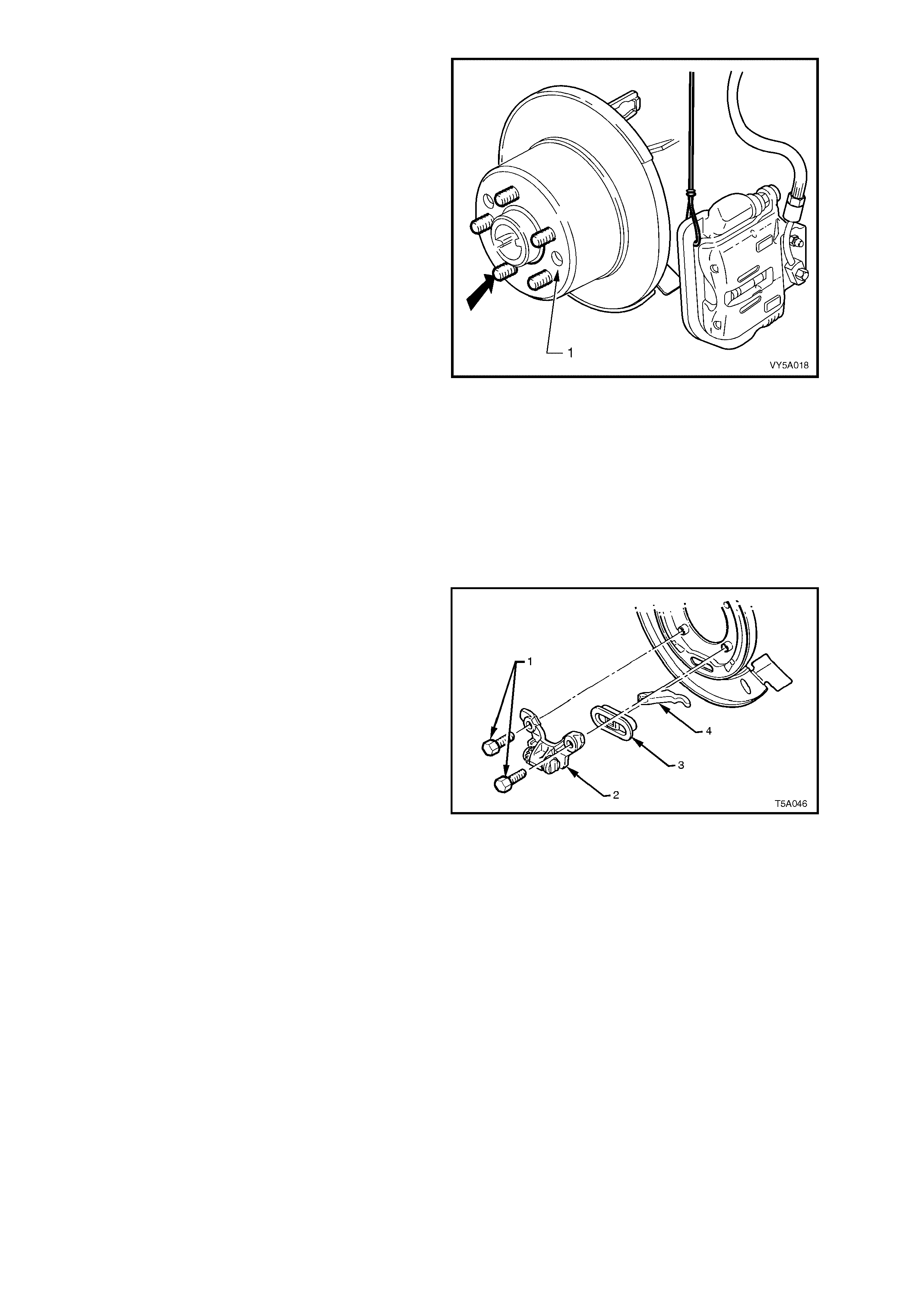
9. Index each disc to a wheel stud using a felt
tipped pen or similar, as indicated by the bold
arrow.
10. Remove brake disc/s.
NOTE: It may be necessary to loosen the park
brake shoe adjustment, to enable disc removal.
Use a suitable size screwdriver, screw in the
adjuster, using one of the two access holes (1) in
the brake disc.
11. Disconnect the park brake cable from the
actuator arm. See 2.11 REAR PARK BRAKE
CABLES in this Section, for details.
Figure 5A - 120
12. Remove trailing arm trunnion flange and trunnion as sembly, refer to 3.1 TRAILIN G ARM FLANGE, T RUNNI O N
ASSEMB LY AND/OR W HEEL BEARING , in Section 4B, FIN AL DR IVE AND DRIVE SHAFTS in the MY2003
VY and V2 Series Service Information, for the necessary procedure.
IMPORTANT: Beca use t he r em oval proc edure of th e tr unnion f lange will c ause th e be aring t o be br ine lled, it must
be replaced on reassembly. Also refer to Section 4B, FINAL DRIVE AND DRIVE SHAFTS for the necessary
procedure for this task.
13. Following the removal of the trunnion and bearing assembly, the backing plate will be free to be removed,
together with the parking brake show assembly.
14. Remove park brake shoe assembly. Refer to 3.8 PARK BRAKE SHOE, in t his S ec tion.
15. In order to disassemble the park brake actuator
assem bl y (2, 3 a nd 4) f r om the rear d isc shield,
it will be nec essar y to caref ull y support the dis c
shield to minimise distortion, then press the
actuator ass embl y from the lower ex truded b olt
hole sections of the disc plate.
Figure 5A - 121
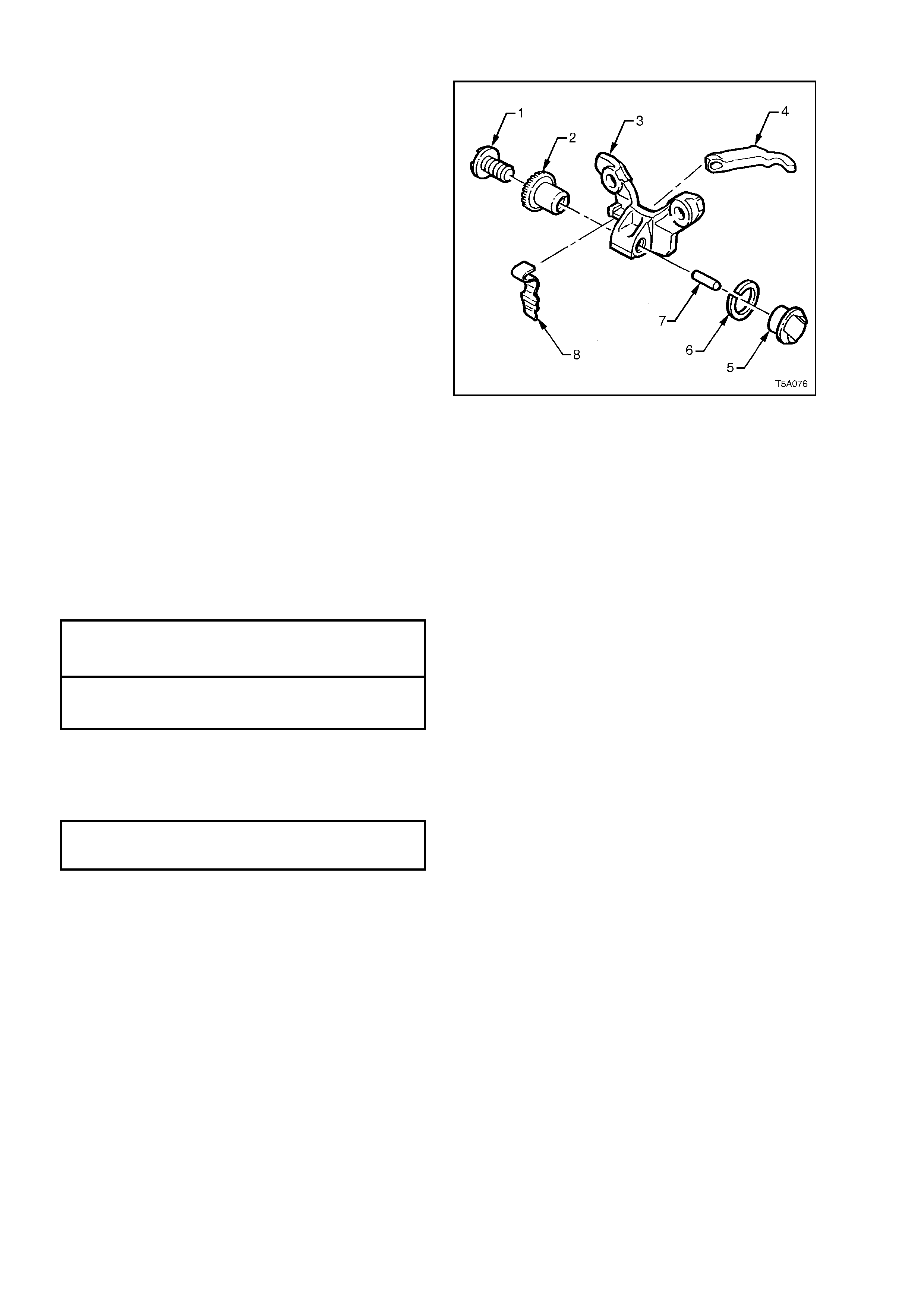
REINST ALL
Reinstallation of the rear disc shield is the reverse
to the rem oval pr ocedures, exc ept for the following
points:
1. As the removed actuator assembly can easily
be disassembled, the view shown, details the
relationships of each, in an exploded view.
2. While supporting the rear disc brake shield,
install the actuator assembly to the extruded
bolt hole sections, after ensuring that the
actuator mechanism is correctly assembled.
Legend:
1. Adjusting Screw
2. Adjusting Ratchet Wheel
3. Actuator Body
4. P arking Brake Actuator Lever
5. Brake Shoe Anchor
6. Washer
7. Pin
8. Ratchet Wheel Spring
Figure 5A - 122
3. Reinstall trunnion to the trailing arm, using a new wheel bearing. For the required procedures refer to
3.1 TRAILING ARM FLANGE, TRUNNION ASSEMBLY AND/OR WHEEL BEARING, in
Section 4B FINAL DRIVE AND DR IVE SH AFTS in th e MY2003 VY an d V2 Ser ies Ser vice Inf orm ation, fo r the
necessary procedure.
4. Reinstall the t wo upper rear disc brake shield t o trailing arm attaching Torx bit h eaded bolts. Do not tighten at
this stage.
5. Install two new lower rear disc brake shield to trailing arm bolts.
6. Tighten the four rear disc brake shield to trailing arm attaching bolts to the correct torque specification
UPPER REAR DISC BRAKE SHIELD
TO TRAILING ARM ATTACHING BOLT
TORQUE SPECIFICATION 70 - 80 Nm
(!)_LOWER REAR DISC BRAKE SHIELD
TO TRAILING ARM ATTACHING BOLT
TORQUE SPECIFICATION 70 - 80 Nm
7. Reinstall the park brake shoe. Refer to 3.8 PARK BRAKE SHOE, in this Section.
8. Reinstall the rear disc, aligning the marks made before removal and adjust the park brake shoe, following the
procedure det ai led in 3.7 PARK BRAKE SHOE, ADJUST, in this Section.
9. Install and tighten brake caliper anchor plate to trailing arm attaching bolts to the correct torque specification.
BRAKE CALIPER ANCHOR PLATE
TO TRAILI NG ARM ATTACHI NG
BOLT TORQUE SPECIFICATION 70 - 100 Nm
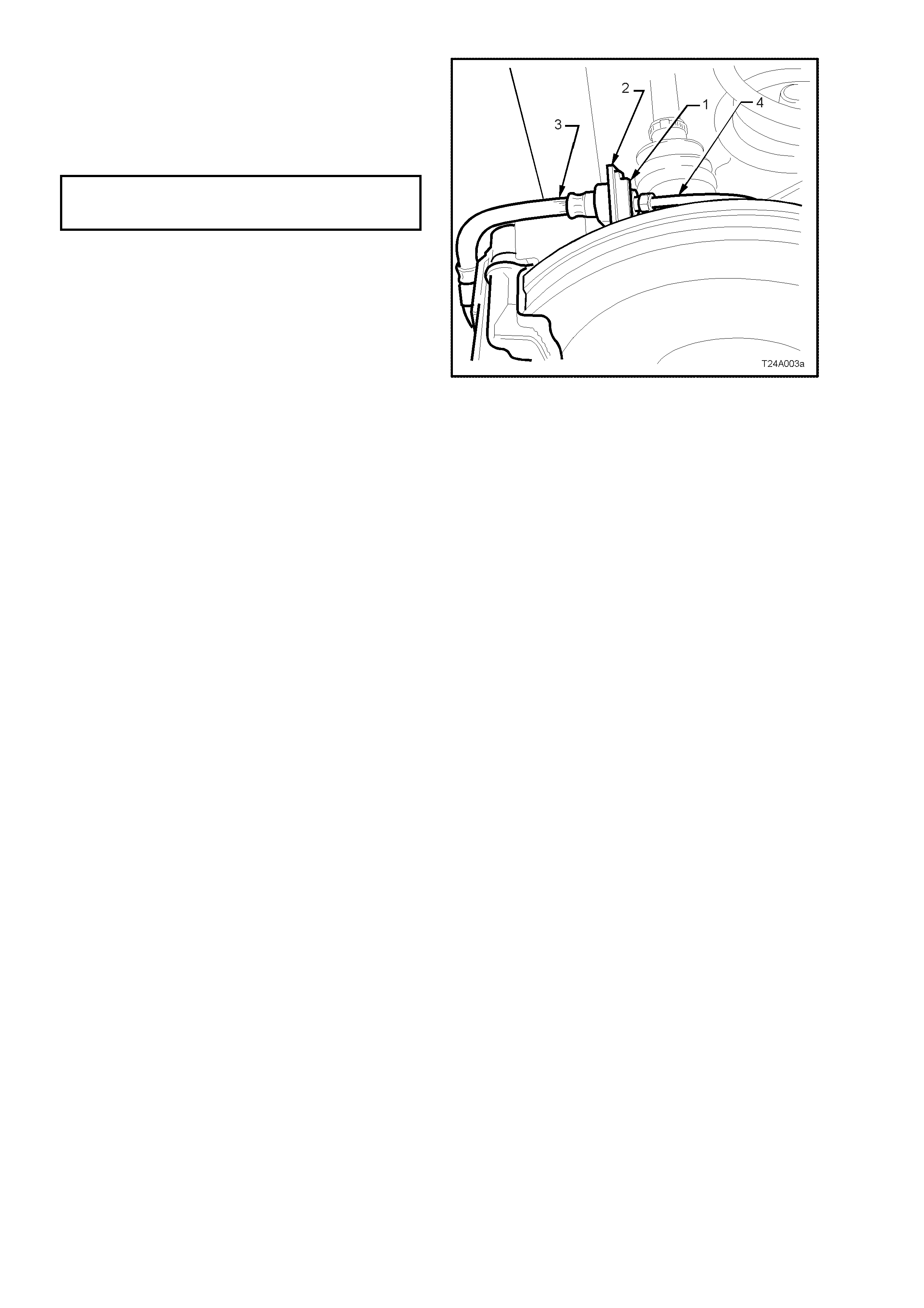
10. Reinstall the caliper hose (3) to the backing
plate bracket (2) and secure with the retaining
clip (1).
11. Reinstall the brake pipe (4) to the caliper hose
(3) and tighten to the correct torque
specifications.
BRAKE PIPE FLARE NUT TO
CALIPER BRAKE HOSE
TORQUE SPECIFICATION 14 – 17 Nm
12. Reinstall road wheel, aligning marks made
prior to removal and reinstall road wheel
attaching nuts .
13. Remove jack stands and lower vehicle to the
ground.
14. Tighten road wheel attaching nuts to the
specified torque, working in a star pattern.
Refer to 2.1 SERVICE NOTES AND
CAUTIONS, in this Section.
15. Check for brake fluid leaks, repair as
necessary.
Figure 5A - 123

4. DIAG NOSIS
SYMPTOM
X - Indicates Probable Cause
XX - Indicates a More Possible Cause
CAUSE
Excessive Brake Pedal Travel
Brake Pedal Travel Gradually Increases
Excessive Brake Pedal Effort
Excessive Braking Action
Brakes Slow t o Respond
Brakes Slow to Release
Brakes Drag
Uneven Braking Action (Side to Side)
Uneven Braking Action (Front t o Rear)
Scraping Noise from Brakes
Brakes Squeak During Application
Brakes Squeal During a Stop
Brakes Chatter
Brakes Groan at End of Stop
Brake Tell-tal e Lamp Glows During a Stop
Leaking Brake Line or Connection X X X
Leaking Caliper or Pist on Line X X X X X
Leaking Mast er Cylinder X XX X
Air in Brake System XX X X
Contaminated or Improper Brak e Fluid X X X X
Leaking Vacuum System XX X
Restricted Air Passage in Vacuum Booster X XXX
Damaged Vacuu m Booster X X X X XX
Improperly Assembled Vacuum Booster Valving X X X X XX
Worn Out Disc Pads - Replace X X X X X X X X
Uneven Disc Pad Wear - Replace or Correct X X X X X XX X
Contaminat ed Disc Pad - Replace XX XX XX X X X X
Heat Spotted or Scored Brake Discs X XX XX XXX
Out-of-Paral l el Brake Discs XX
Excessive Brake Disc Run-Out X
Brake Assem bly Attachm ents - Missing or Loos e X X X X X X X X
Restrict ed Brak e Fluid Passage or Sticki ng Caliper P iston X X X X X X X
Brake Pedal/Linkage Binding or Interference X X X XX
Improperly Adj usted Parking Brake X
Incorrect Front Wheel Ali gnment X XX
Incorrect Tyre Pressures XX
Wheel Bearing Clearance Excessive X X
Loose Front Suspension and/or Components X XX X X
Out-of-Balance Wheel Assemblies XX
Operator Riding Brake Pedal X X X X X X
Table 1

5. SPECIFICATIONS
BRAKE FLUID
Type ......................................................................... Super DOT 4 Plus
BRAKE BOOSTER
Make ......................................................................... PBR
Type ......................................................................... Tandem, Vacuum Suspended
MASTER CYLINDER
Make ......................................................................... PBR
Type ......................................................................... Tandem
Bore diameter (nominal)............................................. 25.4 mm
Crack point................................................................. 3.1 MPa (stamped on master cylinder end plug)
FRONT DISC
Type ......................................................................... Ventilated
Diameter (nominal)..................................................... 296 + 0.0 - 0.2 mm
Thickness................................................................ 28.0 ± 0.15 mm
Lateral Runout (maximu m) ..................................... 0.04 mm Total Indicated Run-out (TIR)
Minimum disc thickness, requiring replacement........ 25.0 mm
FRONT CALIPER
Make ......................................................................... PBR
Type ......................................................................... Twin piston, sliding caliper
Bore diameter (nominal)............................................. 42.0 mm (each)
Front Disc Pad
Material.................................................................... Organic, non-asbestos
Minimum Thickness before Replacement............... 2 mm
REAR DISC
Type ......................................................................... Solid
Diameter (nominal)..................................................... 286 + 0.0 - 0.2 mm
Thickness................................................................... 15.9 mm ± 0.2 mm
Lateral Runout (maximum)
(Rate of change 0.03 mm in 30O rotation max.)...... 0.05 mm
Minimum disc thickness, requiring replacement........ 13.9 mm
REAR CALIPER
Make ......................................................................... PBR
Type ......................................................................... Single piston, sliding caliper
Bore diameter (nominal)............................................. 40.5 mm
Rear Disc Pad
Material.................................................................... Organic, non-asbestos
Minimum Thickness before Replacement............... 2 mm
DRUM PARK BRAKE
Make ......................................................................... PBR
Type ......................................................................... Banksia, single shoe, cable and lever operated
Drum
Inside Diameter (nominal)....................................... 190 mm
Maximu m out of square (TIR with disc surface) ..... 0.05 mm
Maximum out of round ............................................ 0.08 mm
Linings
Type ........................................................................ Bonded
Width....................................................................... 25 mm
Thickness................................................................ 3.5 mm
Minimum Thickness before Replacement............... 1.5 mm

6. TORQUE WRENCH SPECIFI CATIONS
Brake booster retaining nut........................................................ 20 – 25
#
##
# Brake caliper guide pin bolt ....................................................... 30 – 34
Brake pressure differential warning switch................................ 2.0
Brake hose to caliper bolt (Front and Rear) .............................. 32 – 37
Brake pedal support shaft nut ................................................... 50 – 60
Brake pipe to brake hose flared nut (All positions).................... 14 – 17
Brake pipe to load sensing proportioning valve (Utility) ............ 11 – 16
Brake pipe to master cylinder flare nut...................................... 8 – 11
! Front brake caliper anchor bolt.................................................. 80 – 90 Nm, plus
40° – 50° turn angle
Front brake pipe clamp to dash panel bolt ................................ 6 - 14
Front hub to steering knuckle bolt.............................................. 120 – 140
Load sensing proportioning valve mounting bracket
Bolt (Utility) ........................................................................... 35 – 60
Load sensing proportioning valve mounting nut (Utility)............ 35 – 40
Lower brake pipe shield to floor bolt.......................................... 6 - 14
Lower brake pipe shield to floor nut........................................... 1.5 - 3
Master cylinder attaching nut..................................................... 15 – 20
Master cylinder to bracket bolt and bracket to tower nut........... 15 – 22
Master cylinder end pl ug............................................................ 25 – 30
Master cylinder reservoir retaining screw.................................. 4.0 – 5.0
Outer front park brake cable bracket retaining bolt ................... 20 – 25
Park brake lever bolt.................................................................. 35 – 65
Rear brake caliper anchor plate bolt.......................................... 70 – 100
Rear disc brake shield to trailing arm Upper bolt..................... 70 – 80
! Rear disc brake shield to trailing arm Lower bolt..................... 85 – 90
Road wheel attach in g nut.......................................................... 100 – 125
! Steering knuckle to strut attaching bolts and nuts Stage 1 .... 85
Stage 2 .... 100
Stage 3 .... Turn through 90°
Throttle pedal support attaching nut.......................................... 20 – 25
! Fastener/s must be replaced on reassembly.
#
##
# Fastener/s have micro-encapsulated sealant applied and should be replaced on
reassembly.
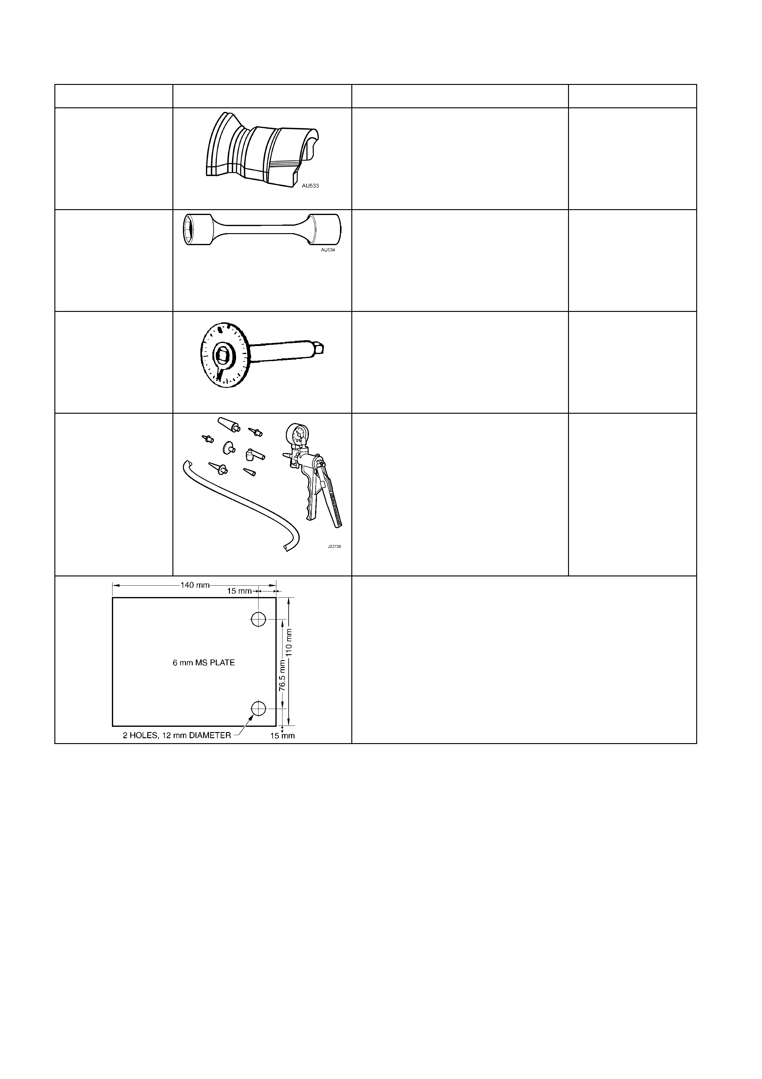
7. SPECIAL TOOLS
TOOL NUMBER ILLUSTRATION DESCRIPTION CLASSIFICATION
AU533
QUICK CONNECT FITTING
RELEASE TOOL
Released in two sizes;
Red for 5/16” fitti ngs and
Blue for 3/8” fittings.
Also available commercially under P/N
Essential
AU534
TORQUE LIMITING SOCKET
Used in conjunction with an impact
gun to tighten wheel nuts.
Essential
E7115
ANGLE WRENCH
1. Previously released for J and V
cars, as Tool No. 394.
2. Used to tighten component f ast eners
when angle torque is required.
Available
J23738-A
HAND VACUUM PUMP Mandatory
DIAL INDICAT OR PLAT E
Dealer fabric ated:
1. Fabricat ed from 6mm thick Mild Steel Plate.
2. If using the cali per bolts to attac h the plate to the trunnion, a 17mm
spacer will need to be installed on each bolt, prior to installing.