
SECTION 5B - ABS & ABS/TCS
IMPORTANT
Before performing any Service Operation or other procedure described in this Section, refer to Section 00
CAUTIONS AND NOTES for correct workshop practices with regard to safety and/or property damage.
CONTENTS
1. GENERAL INFORMATION
1.1 ANTILOCK BRAKING SYSTEM (ABS)
WHEEL SLIP
STEERING CONTROL
CORNERING FORCE
FACTORS AFFECTING BRAKING
1.2 TRACTION CONTROL SYSTEM (TCS)
BASE SYSTEM
1.3 SERVICE INFORMATION
2. GENERAL DESCRIPTION
2.1 ABS AND ABS/TCS SYSTEM
OVERVIEW
BASIC OPERATING PRINCIPLE
ABS CONTROL
2.2 NORMAL CONDITIONS DURING
ANTILOCK BRAKING AND TRACTION
CONTROL INTERVENTION
2.3 ABS AND ABS/TCS SYSTEM COMPONENTS
WHEEL SPEED SENSORS AND PULSE RINGS
ABS AND ABS/TCS CONTROL MODULE
HYDRAULIC MODULATOR
THROTTLE RELAXER
THROTTLE RELAXER CONTROL MODULE
ABS WARNING LAMP
ELECTRONIC TRACTION CONTROL (TCS)
WARNING DISPLAYS
ELECTRONIC TRACTION CONTROL (T/C)
SWITCH
BRAKE MASTER CYLINDER
ABS & TCS FUSES
STOP LAMP SWITCH
2.4 INSTALLATION POSITION OF ABS AND
ABS/TCS COMPONENTS
2.5 ABS PRINCIPLES OF OPERATION –
EXCLUDING ABS/TCS
NON-ANTILOCK BRAKING
ANTILOCK BRAKING
ABS CONTROL MODULE OPERATION
HYDRAULIC MODULATOR OPERATION
MASTER CYLINDER OPERATION
OPERATION AND TESTING OF THE
ABS WARNING LAMP
2.6. ABS/TCS PRINCIPLES OF
OPERATION - EXCLUDING ABS
NON-ANTILOCK BRAKING / NON
ELECTRONIC TRACTION CONTROL
ANTILOCK BRAKING
ELECTRONIC TRACTION CONTROL
ABS/TCS CONTROL MODULE OPERATION
HYDRAULIC MODULATOR OPERATION
MASTER CYLINDER OPERATION
OPERATION AND TESTING OF THE
ABS AND TRAC OFF WARNING LAMPS
3. SERVICE OPERATIONS
3.1 SAFETY AND PRECAUTIONARY MEASURES
3.2 BRAKE SYSTEM – BLEED
3.3 FRONT WHEEL SPEED SENSOR LEAD
REMOVE
TEST
REINSTALL
3.4 WHEEL SPEED SENSORS
FRONT WHEEL SPEED SENSOR
REAR WHEEL SPEED SENSOR
3.5 PULSE RINGS
REMOVE
REINSTALL
3.6 HYDRAULIC MODULATOR AND
CONTROL MODULE ASSEMBLY
REMOVE
REINSTALL
3.7 CONTROL MODULE
REMOVE
INSPECT
REINSTALL
3.8 MASTER CYLINDER
REMOVE AND REINSTALL
OVERHAUL
3.9 TRACTION CONTROL SWITCH
REMOVE
TEST
REINSTALL
3.10 THROTTLE RELAXER CONTROL
MODULE (GEN III V8 ONLY)
REMOVE
REINSTALL
3.11 THROTTLE RELAXER (GEN III V8 ONLY)
4. ABS AND ABS/TCS DIAGNOSIS
4.1 GENERAL DESCRIPTION
4.2 BASIC KNOWLEDGE REQUIRED
4.3 VISUAL INSPECTION
ABS, ABS/TCS VISUAL INSPECTION CHART
4.4 ABS & ABS/TCS FUNCTIONAL CHECK
ABS & ABS/TCS FUNCTIONAL CHECK CHART
4.5 INTERMITTENT FAILURES
4.6 ABS & ABS/TCS SELF DIAGNOSTICS
DIAGNOSTIC TROUBLE CODES
FLASH CODE DIAGNOSTICS DISPLAY
ABS DIAGNOSTIC TROUBLE CODES
ABS/TCS DIAGNOSTIC TROUBLE
CLEARING DTCs
4.7 TECH 2 DIAGNOSTICS
4.8 TECH 2 TEST MODES AND SCREEN
DISPLAYS FOR ABS & TCS DIAGNOSIS
SYSTEM SELECT MENU
VEHICLE IDENTIFICATION MENU
SYSTEM IDENTIFICATION
ABS/TCS APPLICATION MENU
F4: MISCELLANEOUS TESTS
4.9 DIAGNOSTIC CHARTS – V6 ENGINES
INTRODUCTION
CHART A1 – ABS WARNING DISPLAY
INOPERATIVE
CHART A2 – TRAC OFF WARNING DISPLAY
INOPERATIVE
CHART A3 – LOW TRAC WARNING DISPLAY
INOPERATIVE
CHART B – POWER SUPPLY TO CONTROL
MODULE (NO DTCS STORED)
Techline
Techline
Techline
Techline
Techline
Techline

CHART C1 – ABS OFF WARNING DISPLAY
ACTIVATED CONTINUOUSLY (NO DTCs
STORED)
CHART C2 – TRAC OFF WARNING DISPLAY
ACTIVATED CONTINUOUSLY (NO DTCs
STORED)
CHART C3 – LOW TRAC WARNING DISPLAY
ACTIVATED CONTINUOUSLY (NO DTCs
STORED)
DTC 21 – FRONT RIGHT WHEEL SPEED
SENSOR INCORRECT SIGNAL
DTC 23 – FRONT RIGHT WHEEL SPEED
SENSOR SHORT OR OPEN CIRCUIT
DTC 25 – FRONT LEFT WHEEL SPEED
SENSOR INCORRECT SIGNAL
DTC 27 – FRONT LEFT WHEEL SPEED
SENSOR SHORT OR OPEN CIRCUIT
DTC 28 – WHEEL SPEED SENSOR
FREQUENCY ERROR
DTC 31 – REAR RIGHT WHEEL SPEED
SENSOR INCORRECT SIGNAL
DTC 33 – REAR RIGHT WHEEL SPEED
SENSOR SHORT OR OPEN CIRCUIT
DTC 35 – REAR LEFT WHEEL SPEED
SENSOR INCORRECT SIGNAL
DTC 37 – REAR LEFT WHEEL SPEED
SENSOR SHORT OR OPEN CIRCUIT
DTCs 41, 42, 45, 46, 47, 48, 51, 52, 55 &
56 – SOLENOID VALVE CIRCUIT FAULTS
DTC 61 – PUMP MOTOR OR RELAY FAULT
DTC 62 – RPM SIGNAL FAULT
DTC 63 – VALVE SOLENOID RELAY CIRCUIT
FAULT
DTC 67 – STOP LAMP SWITCH CIRCUIT FAULT
DTC 71 – CONTROL MODULE INTERNAL FAULT
DTC 72 – SERIAL DATA FAULT
DTC 73 – REQUESTED TORQUE CIRCUIT FAULT
DTC 74 – ACTUAL TORQUE CIRCUIT FAULT
DTC 78 – INCORRECT OPTION CODING
DTC 85 – SYSTEM VOLTAGE TOO LOW
5. ABS/TCS DIAGNOSIS – GEN III V8 ENGINE ONLY
5.1 GENERAL DESCRIPTION
5.2 BASIC KNOWLEDGE REQUIRED
5.3 VISUAL INSPECTION
ABS/TCS VISUAL INSPECTION CHART
5.4 ABS/TCS FUNCTIONAL CHECK
ABS OR ABS/TCS FUNCTIONAL CHECK CHART
5.5 INTERMITTENT FAILURES
5.6 ABS/TCS SELF DIAGNOSTICS
5.7 TECH 2 DIAGNOSTICS
5.8 TECH 2 TEST MODES AND SCREEN
DISPLAYS FOR ABS/TCS DIAGNOSIS
5.9 DIAGNOSTIC CHARTS
INTRODUCTION
DTC 58 – THROTTLE RELAXER PWM
INTERFACE FAULT
DTC 62 – RPM SIGNAL FAULT
DTC 64 – THROTTLE RELAXER CONTROL
MODULE POSITION FAULT
DTC 65 – THROTTLE RELAXER MOTOR FAULT
DTC 66 – THROTTLE RELAXER CONTROL FAULT
DTC 68 – THROTTLE POSITION SENSOR
MONITORING FAULT
DTC 72 – SERIAL DATA FAULT
DTC 73 – SPARK RETARD MONITORING FAULT
6. SPECIFICATIONS
7. TORQUE WRENCH SPECIFICATIONS
8. SPECIAL TOOLS
1. GENERAL INFORMATION
Essentially, ther e can be two systems fitted to a M Y 2003 VY and V2 Series vehicle; the Antilock Braking System
only, (ABS) and an Antilock Braking System (ABS) combined with an Electronic Traction Control system (TCS).
The combined two systems are known as ABS/TCS
W hile the ABS a lone, h as c omm on elem ents, r egardle ss of the engin e fitted , the AB S/TC S has m ark ed diff erences
between the V6 and GEN III V8 engine applications. While the general information and servicing segments are
combined, the diagnostic sections have been separated between the V6 and GEN III V8 engines, where the
diagnostic procedure is different.
1.1 ANTILOCK BRAKING SYSTEM (ABS)
The pur pose of the Ant ilock Brak ing System (ABS) is to pre vent wheel lock-up during heavy brak ing conditi ons on
most road surfaces. A vehicle that is stopped without locking the wheels will normally stop in a shorter distance
than a vehicle with lock ed wheel/s, while m aintaining directional stabilit y and some steering capabilit y. This allows
the driver to retain greater control of the vehicle during heavy braking.
Therefore, the object of an Antilock Braking System (ABS) is to provide drivers with:
1. Enhanced braking performance by reducing vehicle speed in the shortest distance possible on most road
surfaces.
2. Enhanced steering control by enabling the vehicle to move in a driver-controlled direction during braking
manoeuvres.
WHEEL SL IP
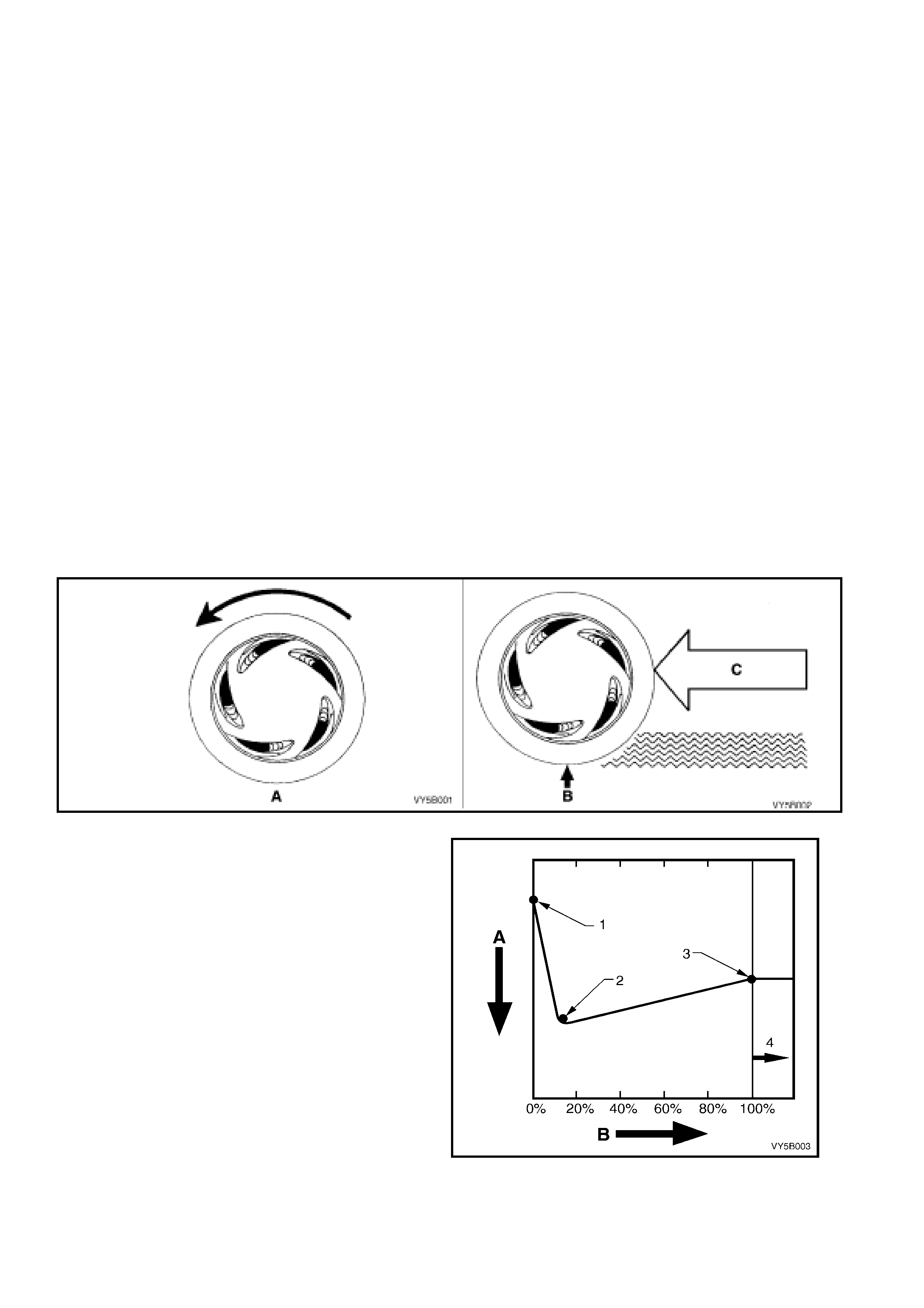
Maxim um br ak ing is ac hiev ed when whee l loc k-up is preven ted. M aximum br ak ing forc e is gen er ate d when the t yre
slip is approx imatel y 12%.
T yre slip ca n be anywhere between 0% and 1 00%. W ith reference to Fig. 5 B-1, with zero % s lip, the wheel r otates
freely as in case ‘A’. However, should the wheel lock, as in case ‘B’ but is still pushed along the road surface, by
the energy and inertia (‘C’) of the moving vehicle.
Figure 5B-1
At zero slip (0%) , a tyre rolls fr eely. At 100% slip, a
tyre locks up as the weight of the vehicle pushes
the non-rotating tyre along. At 100% slip, the
brakes stop the tyre but not the vehicle.
Legend:
A Decreasing Stopping Distance
B % of Tyre Slip
1 No Braking
2 Best Braking (approximately 12% Slip)
3 Least Effective Braking
4 Lack of vehicle Control (Slide) from This Point
Figure 5B-2
The braking system needs tyre traction to function: In operation, the brakes convert the vehicle's forward motion
into heat e nergy. The br akes cannot generate stop ping for ce unless the t yres have tractio n. Tyre tracti on provides
a counter force for the brakes to work against.
The forces involved in stopping a vehicle are extremely high. For example, stopping an 1800 kg vehicle from 100
km/h requires the brakes to generate approximately 8,100 kilojoule (kJ) of braking energy.
At 100% slip, the vehicle's forward energy is turned into braking energy between the tyre and the road surface.
However, the d isadvantag e here is that the tyres again st the road surf ace are a very poor high tem perature f riction
material when compared to that of the brake pads. Brake pad material can generate stopping force much more
efficiently than the road surface and a non-rotating tyre. The lack of traction at 100% slip explains why locked
wheels produce long vehicle stopping distances.
Professional dr ivers caref ully control lock up by limiting brake pressure, but even they cannot always prevent lock-
up on wet roa ds or in other reduced tr action con ditio ns. In theor y, drivers m ust lim it brake applic ations just shor t of
lock-up. In practice, drivers rapidly pump the brakes to reduce lock-up. They apply, release, reapply and release
the brakes until the vehicle stops.
However, the m o st skilled d r ivers c ann ot p ump the br a kes rapidl y or prec is ely enough f o r the b es t br aking under al l
conditions. Of course, pumping of the brake pedal applies and releases the brakes at all four wheels at the same
time. Ideally, automatic individual control over the braking at each wheel would enhance braking on most road
surfaces. This is precisely what ABS attempts to achieve.
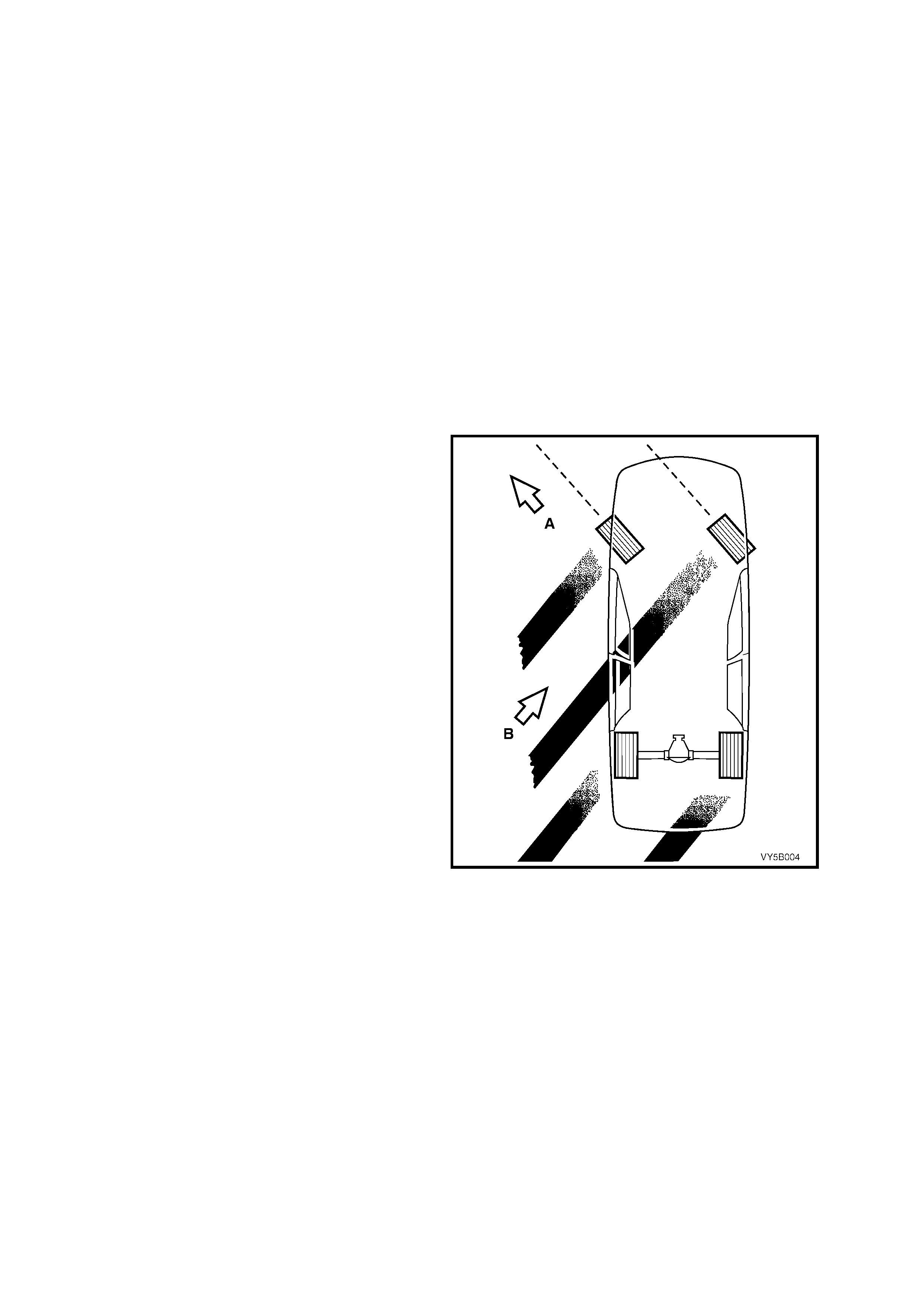
STEERING CONTROL
Steering control, like braking, also depends upon
tyre traction. A locked wheel/tyre in a 100% slip
condition (refer 5B-3) delivers poor braking and
directional control. Therefore, some tyre rotation is
also necessary for steering control.
In this example, the front tyre direction (A) has
minimal steering effect, with the vehicle sliding in
direction ‘B’. The tyres must regain their traction
before steering control is restored to the vehicle.
Figure 5B-3 – Minimal Steering Effect at 100% Slip
CORNERING FORCE
From view ‘A’, Centrifugal force (1) inevitability acts on a vehicle that is turning a corner. A balancing force (2)
(referred to as ‘cornering force’) is needed to overcome the centrifugal force so that the vehicle will stay on the
road. The cornering force (2) is produced when tyre distortion occurs during turns (while the wheels are rotating).
This distortion of the t yre tread chang es the direction t he tyre is pointing (4), relative to the direction the vehicle is
travellin g (3). T he an gle b etween the t wo (‘θ’) is ref erred to as a “s lip a ngle” a lthou gh no ac tual ‘sl ip’ occ urs, u nless
the t yre to road footprint is lost. If wheel/t yre lock -up does occur, the c ornering f orce will becom e zero). The graph
in view ‘B’ sh ows the rela tions hip betwee n th e percen tage of slip ( Z) and the cor nerin g for ce (X ), relati ve to the sl ip
angle (Y).
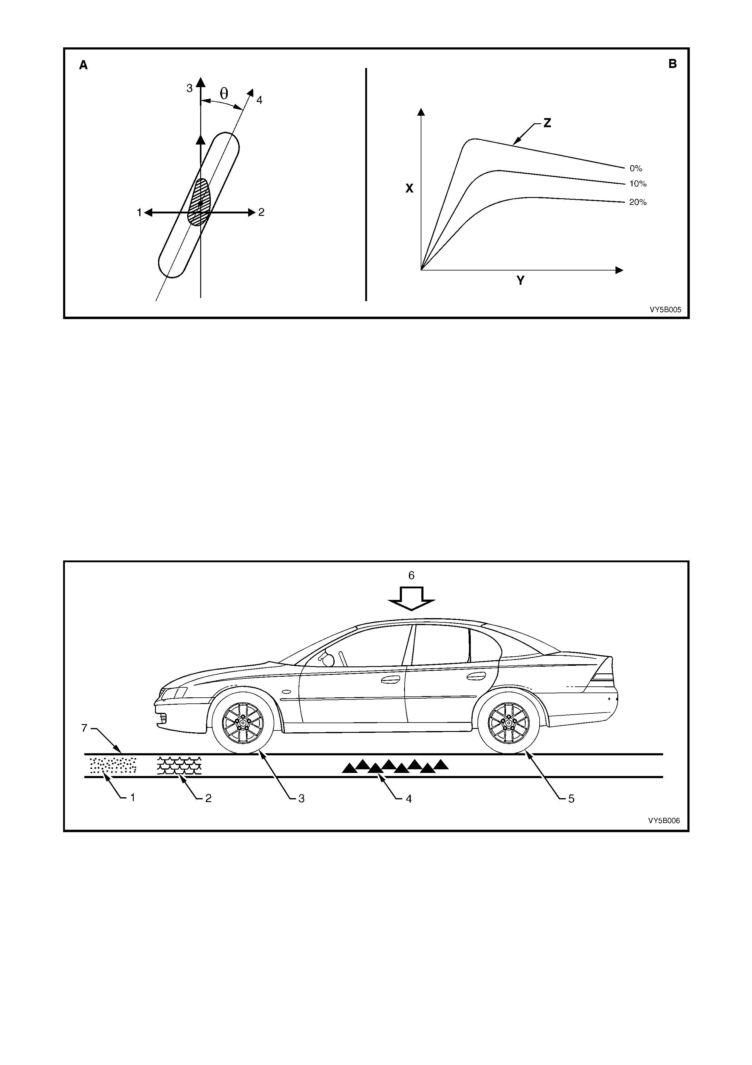
Figure 5B-4
FACTORS AFFECTING BRAKING
During vehicle braking, several conditions and forces are at work. These include those factors shown in the
follo wing il lus tr at io n:
1. Road surface (dirt, gravel, bitumen).
2. Sudden changes in the road surface (oil, puddles, ice spots).
3. Tyres.
4. Road conditions (smooth, rough, wet, dry).
5. Wheel loading when stopping.
6. Vehicle weight.
7. Steering manoeuvres.
The adv ent of solid s tate elec tronics enab les t hese fac tor s to be m onitored and al lo wed for during brak ing. W ithout
special electronics devices, the braking system could not account for these variables.
Figure 5B-5

1.2 TRACTION CONTROL SYSTEM (TCS)
Critical driving situations are not restricted to braking; they can also occur during standing start and moving
acceleration (especially on slippery gradients) and during cornering. These conditions can present drivers with
more than they can handle. The result: dangerous driving errors.
Electro nic Trac tion Contr ol (T CS) is des igned to solve these prob lems . The prim ary purpos e of T CS, an exp anded
version of ABS, is to reduce the demands placed on the vehicle by the driver by maintaining vehicle stability and
steering response under acceleration (provided that the physical limits are not exceeded). When fitted to V6
engined vehicles, TCS does this through the use of ABS (brake intervention) and adapting the engine torque (spark
timing retard) to levels corresponding to the traction available at the road surface, before the situation becomes
critical. When the GEN III V 8 eng ine is f itted to t he veh i cle, while both br ake and e ngine i ntervention are s till used a
throttle relaxer is also fitted, to control the throttle valve position in the throttle body. The throttle relaxer is controlled
by its own Throttle Relaxer Control Module, that in turn, receives information from the ABS/TCS Control Module.
The throttle relax er is pos it i oned part way along t he acce lerator cable in the engine c ompar tm ent. T he r eque s t f r om
the accelera tor pedal (ped al depress ed), is trans mitted via the c able to the thr ottle relax er. Under norm al operating
conditio ns , th e r eq ues t t he c ontin ues o n to th e t hrottle valve. H o we ver, in a s i tuat i on wher e a rear wheel is a bout to
lose tr action s a y, under to o intense an ac celer ation r equest f or th e ro ad condi tion s, the throttle rel axer will int err upt
the accelerator pedal request and control the throttle valve position in the throttle body, directly. In this way a
potential loss of traction condition is averted.
By combining TCS and ABS, it is possible to obtain higher levels of safety through dual purpose application of
system components.
BASE SYSTEM
The TCS system must be capable of inhibiting wheelspin during initial or moving acceleration under the following
conditions:
• When the lane surface is slippery on one or both sides.
• As the vehicle emerges from an ice covered road surface.
• During acceleration when cornering.
• When starting off on a gradient.
The TCS system must also intervene in the following situations:
• When a wheel spins (the same as when it locks), the lateral forces which it can transmit are limited; the
vehicle becomes unstable and the rear ‘fishtails’. TCS maintains vehicle stability for enhanced safety.
• Spin also leads to increased tyre tread wear and drivetrain stress, ie. rear axle. TCS avoids the drivetrain
loads that occur when a spinning wheel suddenly finds traction on a high adhesive surface.
• TCS must be ready to intervene automatically at all times. TCS employs the difference in slip rates at the
drive wheels to d is tin gu is h bet ween c or ner ing a nd ac celeration s lip pa ge. The t yres do not dr ag in tight r ad ius
corners, as can occur with a differential lock. Limited slip differentials can not always inhibit wheel spin
resulting from excess throttle applications. In contrast, TCS also regulates the engine output to ensure that
the wheels retain traction.
• T he system r esponds to condit ions in th e physical t hreshold r ange b y triggering a LOW TR AC warning lam p
in the instrument cluster to alert the driver.

1.3 SERVICE INFORMATION
Apart from the information contained within this Section, additional servicing details on the ABS and ABS/TCS,
reference can also be made to:
a. Section 3 FRONT SUSPENSION in the MY 2003 VY and V2 Series Service Information, for information
relating to front wheel bearing hub removal and/or reinstallation operations.
b. Section 4B FINAL DRIVE AND DRIVE SHAFTS in the MY 2003 VY and V2 Series Service Information, for
details of rear axle sensor removal and adjustment details.
c. General brake bleeding operations for the ABS and ABS/TCS are the same as for the standard braking system.
This operation is described in Section 5A SERVICE AND PARK BR AKING SY STEM S in the MY 2003 VY and
V2 Series Service Information.
IMPORTANT: When bleeding operations are carried out, that involve the ABS Hydraulic Control Module,
then specific procedures must be followed that require the use of Tech 2. Refer to Section 0C TECH 2, in
the MY2003 VY Series Service Information for details.

2. GENERAL DESCRIPTION
There can be two types of ABS fitted to MY 2003 VY and V2 Series vehicles; one without traction control, ABS
(production option JL9) and one with traction control ABS/TCS (production options JL9 and NW9). Depending on
individual vehicle specifications, either one of these options may be utilised or, neither of them. W here differences
in service procedures or routing (e.g. brake piping), between left and right hand drive vehicles are evident, then
illustrations will be used to reflect those changes.
NOTE: As the two systems are not compatible it is not possible to build a V6 engined vehicle with
Electronic Traction Control (TCS) and Liquefied Petroleum Gas (LPG.). If a vehicle with TCS is to be fitted
with an aftermarket LPG system, the TCS system must be permanently disabled.
The only recommended way of disabling the TCS system on a V6 engined vehicle, is to disconnect terminal
27 from the ABS/TCS control module connector A37 X1, circuit 27, Black/White wire (actual torque – MMI).
This is to be achieved by withdrawing terminal 27 from connector A37 X1 and taping the wire back to the
main wiring harness. This will disable the TCS system while maintaining normal ABS operation.
If the TCS system is disabled, the TC OFF warning display in the instrument cluster will be permanently
activated when the ignition is on and Diagnostic Trouble Code 74 will be logged. At no time must the ‘T/C
OFF’ warning lamp be disconnected as it’s function is to advise the driver that this safety feature is not
available.
On all MY 2003 VY and V2 Series vehicles, the conventional portion (non-ABS) of the braking system comprises
the conve ntional heav y dut y brak ing system , specific br ake pipe harnes s and lines and a comm on m aster cylinder
with the conve ntional no n- AB S braking system . W ith ABS or ABS/TCS ho we ver, the master c ylinder has a scr ew-i n
blanking plug installed into the lower of the two front brake outlets. Each front wheel hub also includes the wheel
speed sensor as p art of the assembly. The rear wheel speed sensors are toot hed pulse rings attached to each of
the inner axle flanges.
At road sp eeds a bove approximatel y 6 km /h, the A BS i s designed to co ntr ol brake f luid pres s ure s o th at th e whee ls
are pre vented from loc king-up d ur in g braking, ir res pec t ive of the r oa d c on dit ions a nd tyre gr ip. The s ystem s tarts to
regulate when one wheel is detected to be decelerating faster than the other wheels, tending to lock. The vehicle
remains steerable, even in the event of panic braking, for instance on bends or when swerving to avoid an
obstacle.
The ABS without traction control fitted to MY 2003 VY and V2 Series vehicles, modulates braking pressure
separate ly at each fr ont wheel, wit h the rear whee ls sharing a s ingle AB S modulated hydraulic c ircuit. T his ABS is
referred to as a three-channel s ystem , as three separate hydraulic brake circuits are used to the achieve anti-lock
braking function.
The ABS/TCS (ABS with electronic traction control) fitted to MY 2003 VY and V2 Series vehicles, modulates
brak ing press ure se paratel y at e ach f ront and rear wh eel. T he AB S/TCS is ref erred t o as a four c hann el s ystem as
each of the four wheels have a separate hydraulic brake circuits which are used to achieve anti-lock braking and
traction control functions. The term modulated refers to the ABS ability to 'Maintain', 'Reduce' or 'Increase' (Build-
up) the hydraulic pressure in the various brake circuits based on various inputs.
The Tech 2 diagnostic scan tool is programmed to assist with MY 2003 VY and V2 Series vehicle electrical
diagnosis and problem solving, including ABS and ABS/TCS Tech 2 connects to the ABS or ABS/TCS serial data
communication inform ation via the Dat a Link Connector (DLC), attached to the instrument panel lower trim, to the
right of the steering column. For additional information on DLC location and system diagnosis, refer to
4. AB S DI AG NO S IS in this Sectio n. For additio nal and m ore com prehensive inf ormation regar ding T ech 2, refer to
Section 0C TECH 2 in the M Y 2003 VY and V2 Ser ies Ser vice Inform ation.
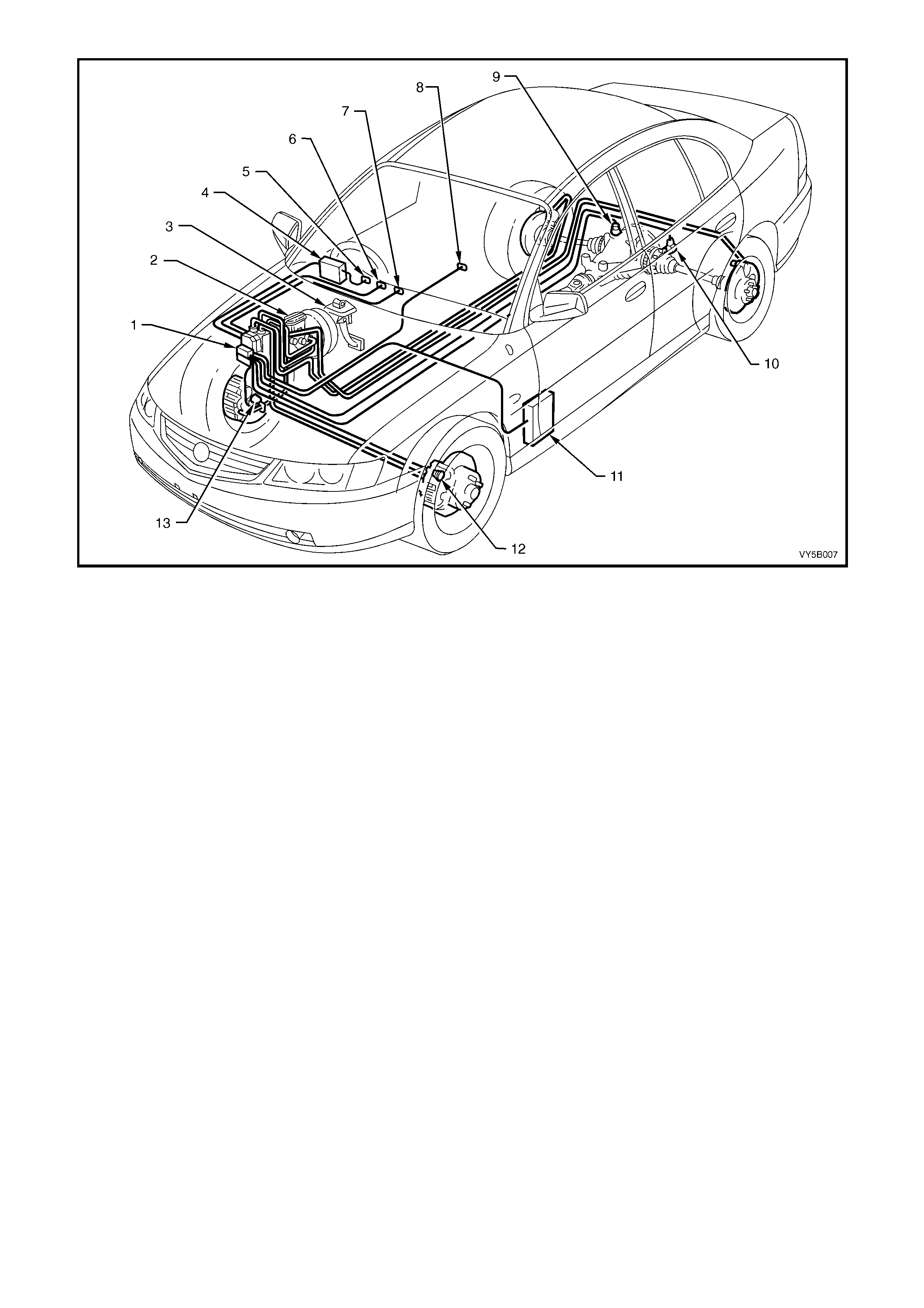
Figure 5B-6 – Typical Location for ABS/TCS Components Fitted to a RHD Vehicle with either V6 Engine
Legend
1. Hydraulic Modulator and Control Module Assembly
2. Brake Master Cylinder
3. Stop Lamp Switch
4. Body Control Module (BCM)
5. TRAC OFF W arning Lamp
6. TRAC LOW W arning Lamp
7. ABS OFF Warning Lamp
8. Traction Control Switch (in Console)
9. Right Hand Rear Wheel Speed Sensor
10. Left Hand Rear Wheel Speed Sensor
11. Powertrain Control Module (PCM) – For ABS/TCS Only
12. Left Hand Front Wheel Speed Sensor
13. Right Hand Front Wheel Speed Sensor
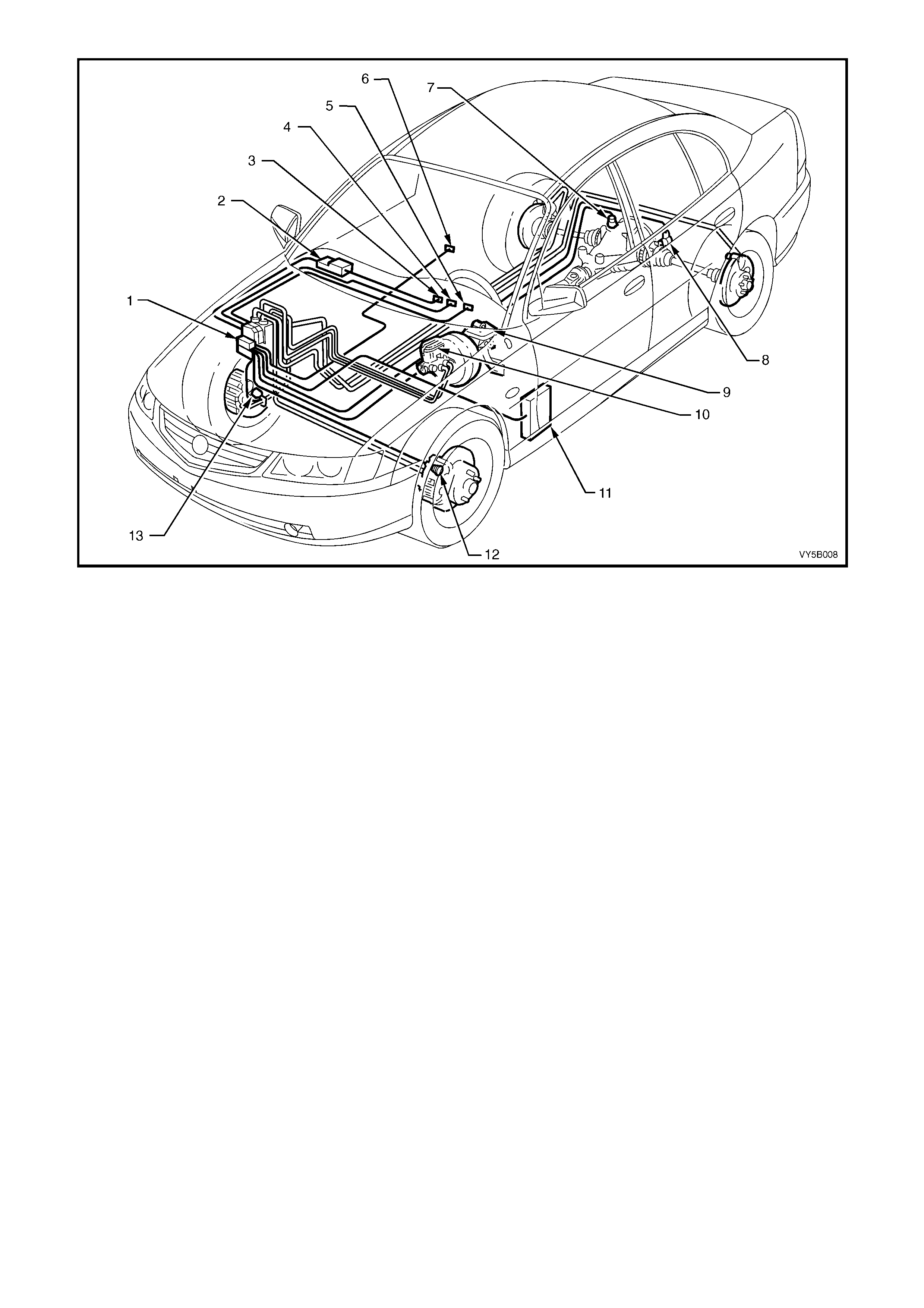
Figure 5B-7 Typical Location for ABS/TCS Components Fitted to a LHD Vehicle with the V6 Engine
Legend
1. Hydraulic Modulator and Control Module Assembly
2. Body Control Module (BCM)
3. TRAC OFF W arning Lamp
4. TRAC LOW Warning Lamp
5. ABS OFF Warning Lamp
6. Traction Control On/Off Switch (in Console)
7. Right Hand Rear Wheel Speed Sensor
8. Left Hand Rear Wheel Speed Sensor
9. Stop Lamp Switch
10. Brake Master Cylinder
11. Powertrain Control Module (PCM) – For ABS/TCS Only
12. Left Hand Front Wheel Speed Sensor
13. Right Hand Front Wheel Speed Sensor
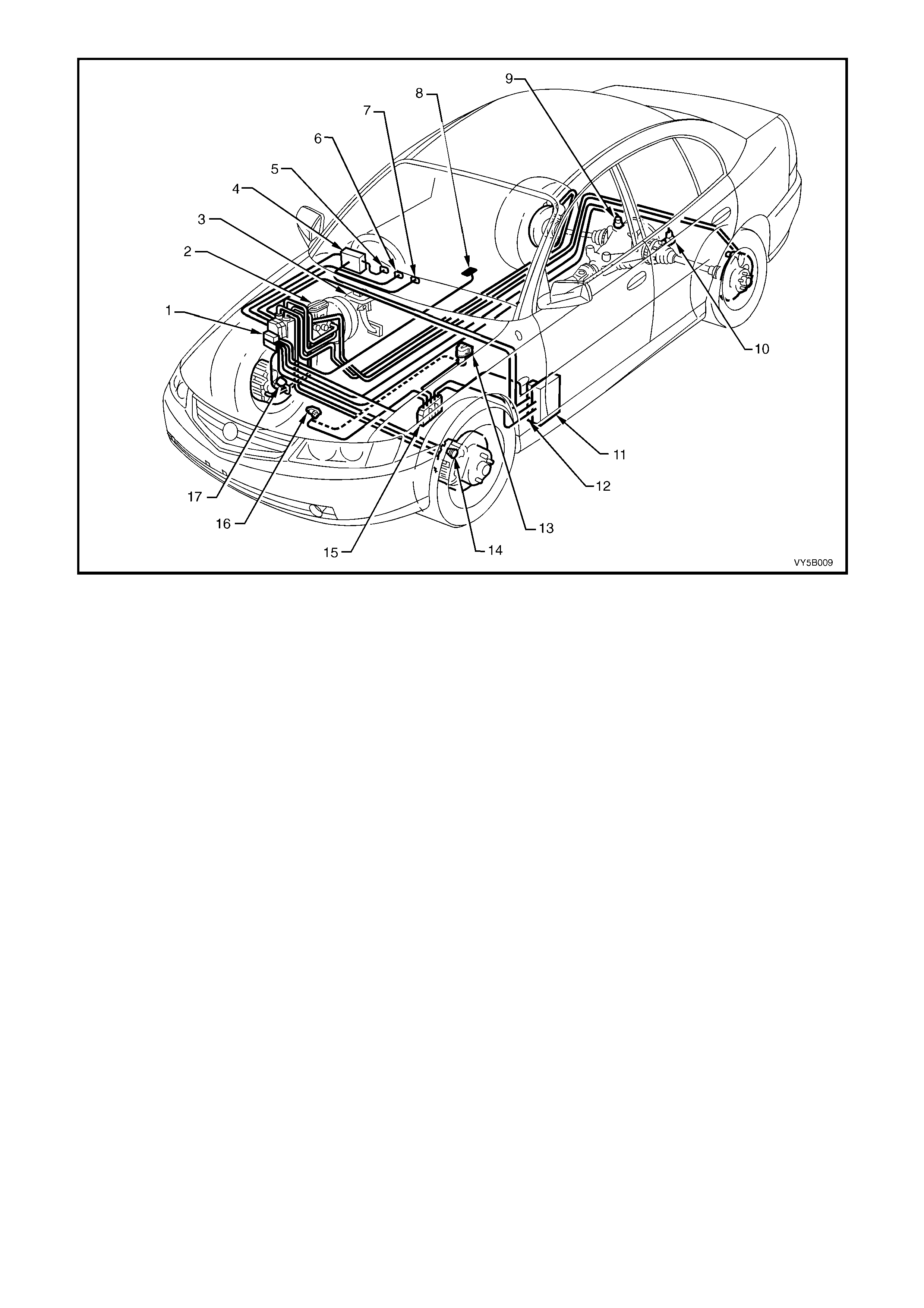
Figure 5B-8– Typical Location for ABS/TCS Components fitted to a RHD Vehicle with the GEN III V8 Engine
Legend
1. Hydraulic Modulator and Control Module Assembly
2. Brake Master Cylinder
3. Stop Lamp Switch
4. Body Control Module (BCM)
5. TRAC OFF W arning Display
6. TRAC LOW W arning Display
7. ABS OFF Warning Display
8. Traction Control On/Off Switch (in Console)
9. Right Hand Rear Wheel Speed Sensor
10. Left Hand Rear Wheel Speed Sensor
11. Powertrain Interface Module (PIM)
12. Throttle Relaxer (Actuator) Control Module
13. Throttle Relaxer (Actuator) Assembly
14. Left Hand Front Wheel Speed Sensor
15. Powertrain Control Module (PCM) – For ABS/TCS Only
16. Throttle Position Sensor (TP Sensor)
17. Right Hand Front Wheel Speed Sensor
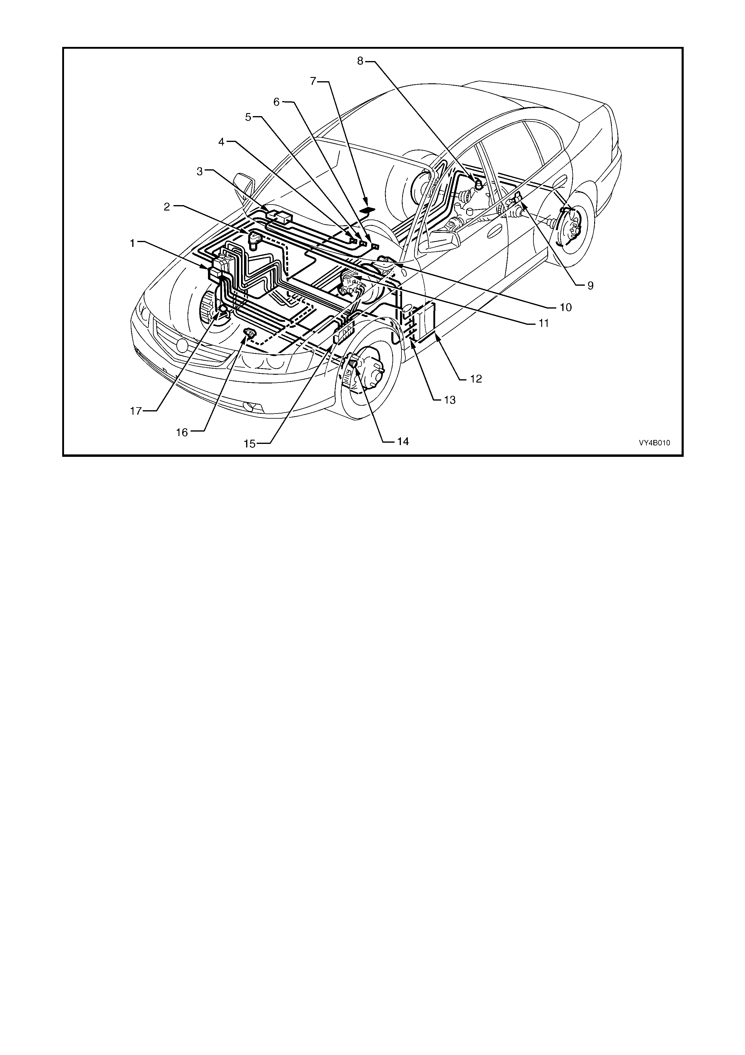
Figure 5B-9 – Typical Location for ABS/TCS Components fitted to a LHD Vehicle with the GEN III V8 Engine
Legend
1. Hydraulic Modulator and Control Module Assembly
2. Throttle Relaxer (Actuator) Assembly
3. Body Control Module (BCM)
4. TRAC OFF W arning Display
5. TRAC LOW W arning Display
6. ABS OFF Warning Display
7. Traction Control On/Off Switch (in Console)
8. Right Hand Rear Wheel Speed Sensor
9. Left Hand Rear Wheel Speed Sensor
10. Stop Lamp Switch
11. Brake Master Cylinder
12. Powertrain Interface Module (PIM)
13. Throttle Relaxer (Actuator) Module
14. Left Hand Front Wheel Speed Sensor
15. Powertrain Control Module (PCM) – For ABS/TCS Only
16. Throttle Position Sensor (TP Sensor)
17. Right Hand Front Wheel Speed Sensor
2 1 ABS AND ABS/TCS SYSTEM OVERVIEW
BASIC OPERATING PRINCIPLE
The rotational speed of each wheel is m easured by inductive wheel speed sens ors. W hen the brakes are applied,
the change in rotational speed is used by the processor in the ABS or ABS/TCS control module to determine the
deceleration, acceleration and slip of the wheels.
On vehic les with ABS ( excluding AB S/TCS), the fr ont wheels are i ndividuall y c ontroll ed with the rear wheels bei ng
controlled jointly (three channel system). If one side of the road surface is slippery, the rear wheel braking on this
surf ace determ ines the brak ing press ure of both rear whee ls. On ve hicl es with A BS/T CS, the f ront and r ear whee ls
are individually controlled (four channel system).
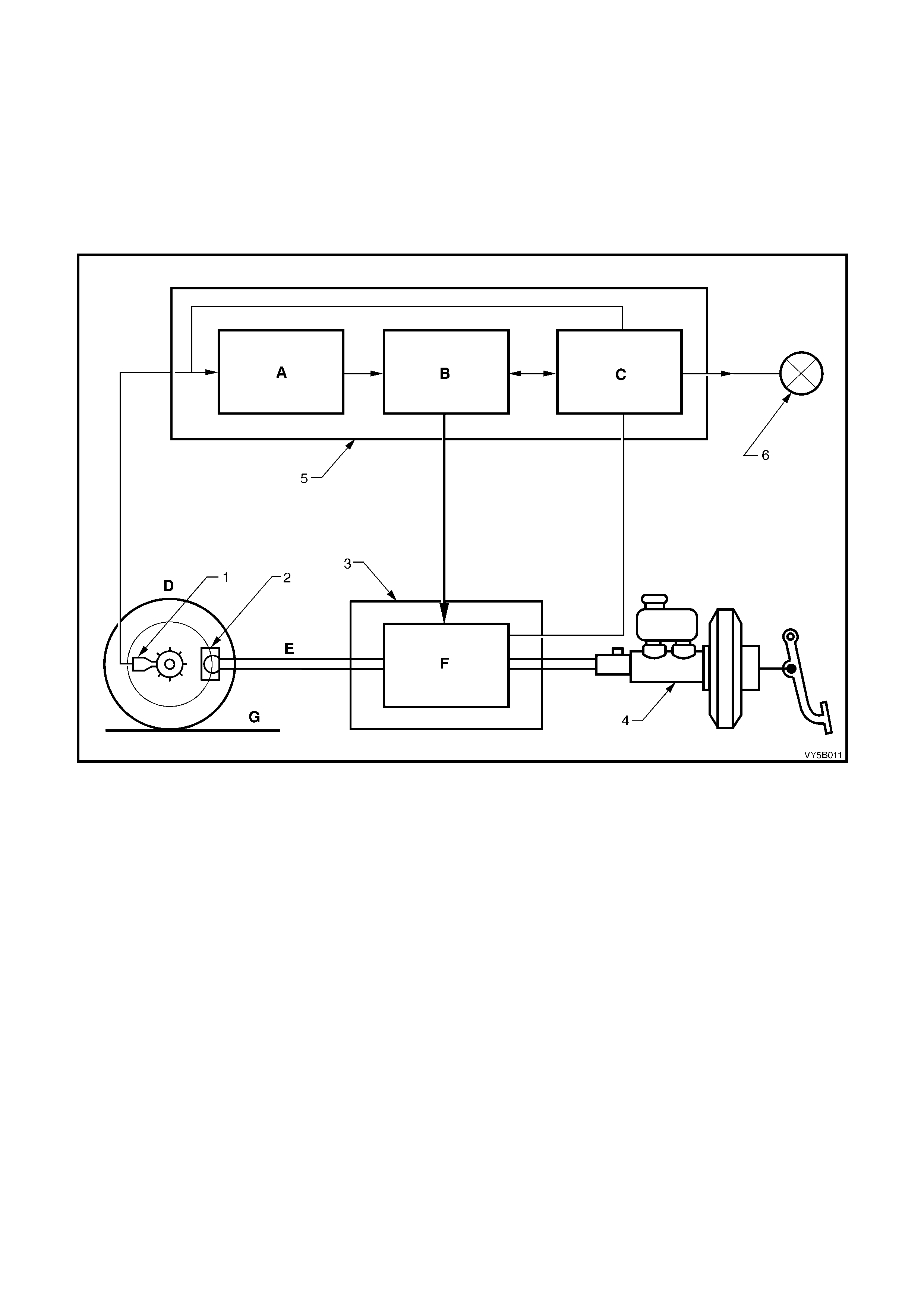
Figure 5B-10
Legend
A Calculate
B Control
C Test Monitor Warn
D Wheel Speed
E Brake Pressure
F Influence on Brake Pressure
G Road Surface Condition
1. Wheel Speed Sensor
2. Brake caliper
3. Hydraulic Modulator
4. Brake Master Cylinder
5. Electronic Control Module
6. Instrument Warning Display
Three Chann el ABS (R efer Figur e 5B-1 1)
The braking force for each of the front wheels is regulated using individual inlet and outlet solenoid valves within
the hydraulic modulator, and the rear wheels are controlled by a common set of inlet and outlet solenoid valves
within the hydraulic modulator. Four sensors measure the individual speed of each wheel.
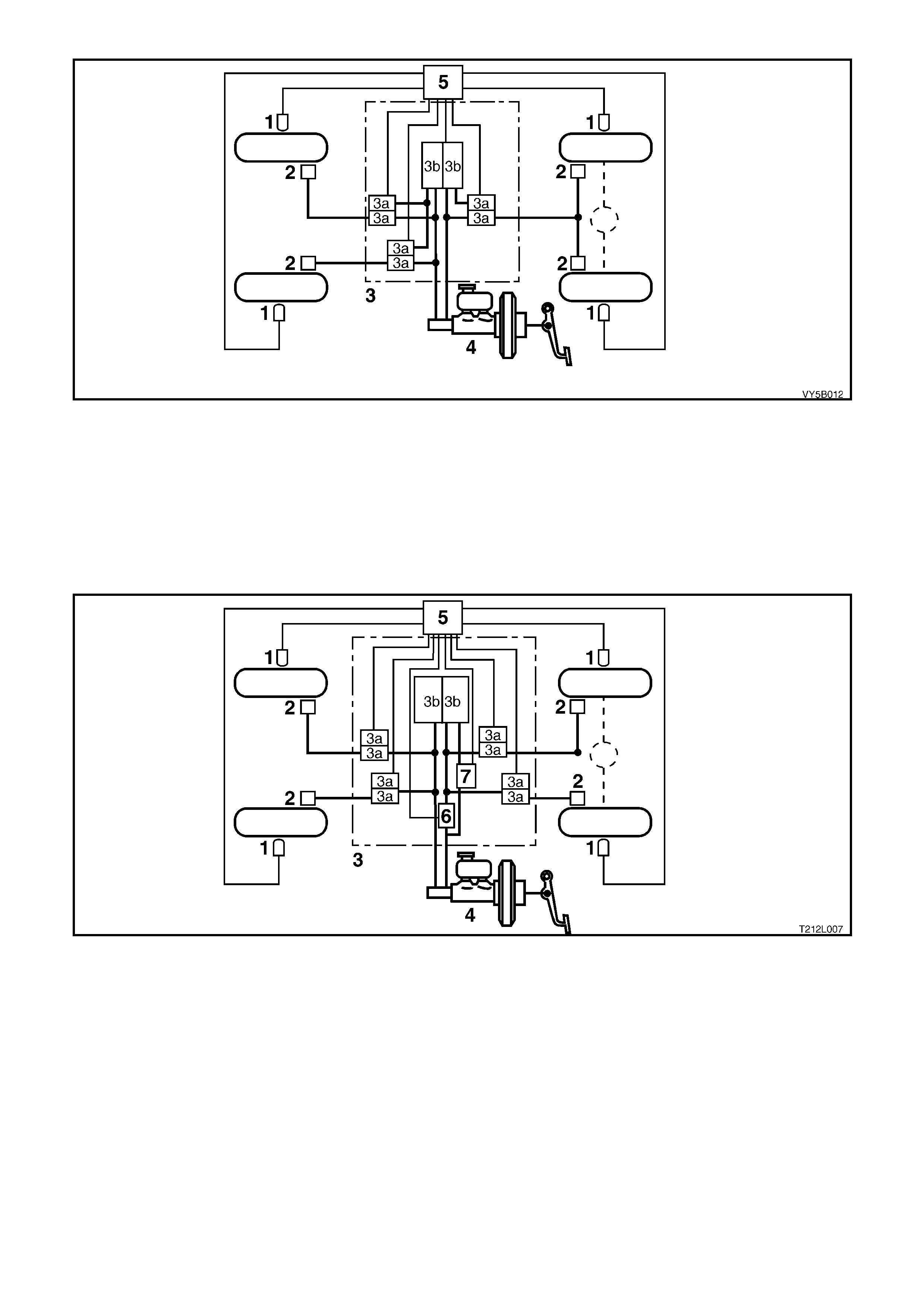
Figure 5B-11
Legend
1. Wheel speed sensors
2. Brake calipers
3. Hydraulic modulator
3a. Solenoid valve
3b. Return pump
4. Brake master cylinder
5. Electronic control module
Four Channel ABS/TCS (Refer Figure 5B-12)
The braking force for each wheel (front and back) is regulated using individual inlet and outlet solenoid valves
within the hydraulic modulator. Four sensors measure the individual speed of each wheel.
Figure 5B-12 Four Channel ABS/TCS
Legend
1. Wheel speed sensors
2. Brake calipers
3. Hydraulic modulator
3a. Solenoid valve
3b. Return pump
4. Brake master cylinder
5. Electronic control module
6. Switching valve
7. Priming valve
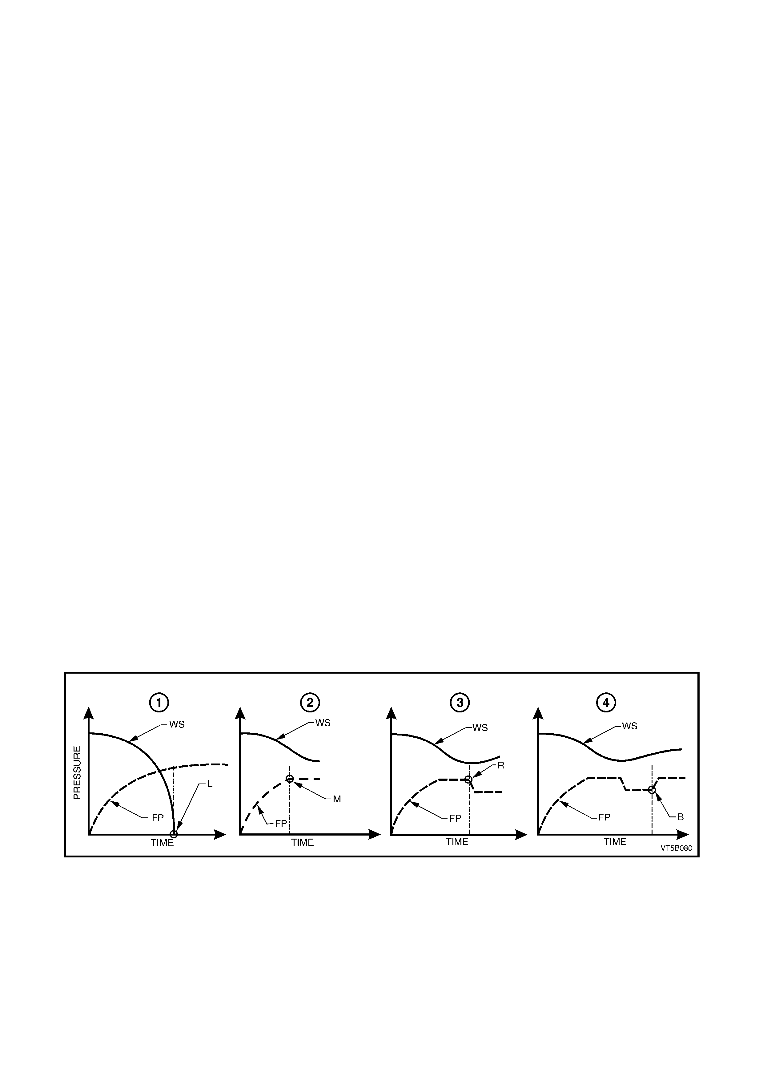
ABS CONTROL
Lock-up (Refer Q in Figu re 5B-13)
During full braking, the driver usually applies braking pressure (FP) to such an extent that the wheel speed (WS)
rapidly decreases causing wheel lock-up (L). This results in a loss of steering control, and the maximum possible
braking effect is not attained. During ABS-controlled full braking, the braking pressure is automatically adjusted to
prevent wheel lock-up, regardless of brake pedal force.
The processes involved are:
• m aintain ing pr es su re
• reducing pressure
• increasing (building-up) pressure.
Maintain ing Pr es s ure (Ref e r R in Figure 5B-13)
If a wheel speed sensor signals severe wheel deceleration to the ABS control module, ie. the wheels are likely to
lock-up, the braking pressure at the wheel involved is initially maintained (kept constant) as opposed to being
further increased (point M).
Reducing Pres s ure (Ref er S in Figure 5B-13)
If the wheel still continues to decelerate rapidly, the pressure in the brake caliper circuit is reduced so that the
wheel is braked less heavily (point R).
Increasing (Building-up) Pressure (Refer T in Figure 5B-13)
The wheel accelerates again (WS) as a result of the reduced braking pressure. Upon reaching a spec ific limit, the
ABS or A BS/TCS c ontro l modu le reg isters the fac t that the wheel is no w not bei ng br ak ed suff iciently. The f orm erl y
reduced pressure is then incr eased, prov ided peda l press ure is m aintained, s o that th e wheel is agai n decel erated
(point B) . The c ontro l cyc le beg ins agai n. T here are approx im ately four t o six con trol c ycles per s econ d, dep ending
on the state of the road surface. This rate is made possible by rapid electronic signal processing and the short
response times of the solenoid valves.
Self-Monitoring
At the start of a journey, the system automatically carries out an operational check in accordance with a stored
program in the ABS or ABS/TCS control module. The signals generated during a braking process are simulated
and the signals transmitted to the hydraulic modulator are checked for their correctness.
During the journey the system monitors itself by comparing the logical sequence of input and output signals with
memorised limit values, in addition to monitoring the voltage supply.
If a system defect is detected, the ABS switches itself off and the driver can still use the conventional, non ABS
controlled braking system. This changeover is indicated by the illumination of an ABS warning lamp in the
instrument cluster.
Performance
When full braking power is applied, the vehicle is optimally braked while retaining its full directional stability and
control. T he AB S pr events wheel l ock -up abov e a m inim um speed of approx im ately 6 k m /h, whether on ice o r on a
dry road surface.
Figure 5B-13
Legend
Q
QQ
Q No ABS Control
R
RR
R With ABS – Maintaining Pressure
S
SS
S With ABS – Reducing Pressure
T
TT
T With ABS – Increasing Pressure
WS Wheel Speed
FP Brake Fluid Pressure
L Wheel Lock-Up
M Pressure Maintained
R Pressure Reducing
B Pressure Increasing

2.2 NORMAL CONDITIONS DURING ANTI-LOCK BRAKING AND
TRACTION CONTROL INTERVENTION
During anti-lock braking, a series of rapid pulsations are felt through the brake pedal. These pulsations occur as
solenoid valves within the underhood hydraulic modulator assembly change position to modulate brake hydraulic
pressure. Brake pedal pulsation continues until the vehicle is stopped or the ABS mode disengages.
The operation of the pump, also within the hydraulic modulator assembly, is characterised by rapid brake pedal
pulsation that is accompanied by some electric motor and pump noise. Pump operation may be perceived during
regular vehicle operation or during initial ABS or ABS/TCS control module self-test. While these functions sometime
cause driver concern, they are normal functions of ABS operation.
During trac tion control on V6 engined vehic les fitted with nor mal operatio n is less notic eable. Pum p operation ma y
still be heard, together with a power sag from the engine as the ABS/TCS control module requests the PCM to
bring engine torque into a specific range.
Traction control intervention on GEN III V8 engine vehicle fitted with ABS/TCS, operates in three stages; engine
spark retard, throttle angle reduction, and rear brake application.
The first is less noticeable; with only a power sag from the engine being felt as the ABS/TCS control module
requests the PCM to retard the engine spark as appropriate.
If the ABS/TCS contro l module continues to detect the rear wheels are rotating faster than the front, it will request
the throttle relaxer control module to reduce the throttle angle.
The final step taken to control the rear wheel is for the ABS/TCS control module to apply the rear brakes, thus
reducing the torque to the rear wheels.
W hen the vehic le re ac hes approx imately 6 km /h and pr ovided the AB S or A BS/T C S contr o l module do es no t s ense
a stop lam p switch input, after initial engine start-up and driving away, the ABS or ABS/TCS control module tests
the solenoid valves and pump. This self test can be heard by the driver and is a normal operating function of the
ABS. If the ABS or ABS/T CS control module does sense a stop lamp switch input, the self test will not occur until
the vehicle is travelling at approximately 18 km/h.
Normal function of the ABS, TC OFF and LOW TC warning lamps in the instrument cluster are as follows:
ABS lamp: should illuminate when the ignition is switched on and will go out approximately two seconds later.
Should the lamp not go out, the ABS or ABS/TCS control module has detected a system fault.
TC OFF lamp: should illuminate when the ignition is switched on and will go out approximately five seconds later
(or two seconds latter with engine running). If the lamp does not go out, either the ABS/TCS control module has
detected a system fault, or the system has been manually switched off.
LOW TC lam p: should illu minate when the ignition is switched on a nd will go ou t approxim ately two secon ds later.
This lamp will illuminate whenever the TCS system is engaged.
Techline
2.3 ABS AND ABS/TCS SYSTEM COMPONENTS
WHEEL SPEED SENSORS AND PULSE RINGS
Front Wheel Speed Sensors
Inductive wheel speed sensors (1) are used to
detect the rotational speed of each wheel. There
are specific wheel sensor assemblies for front and
rear wheels.
Signals generated by the wheel speed sensor are
transmitted to the ABS control module via a wheel
speed sensor lead, that has a ‘push-on’ type
connector with a locking tang, at the wheel speed
sensor end.
The front wheel speed sensors (1) are incorporated
as part of the front suspension front wheel hub
assembly.
Figure 5B-14
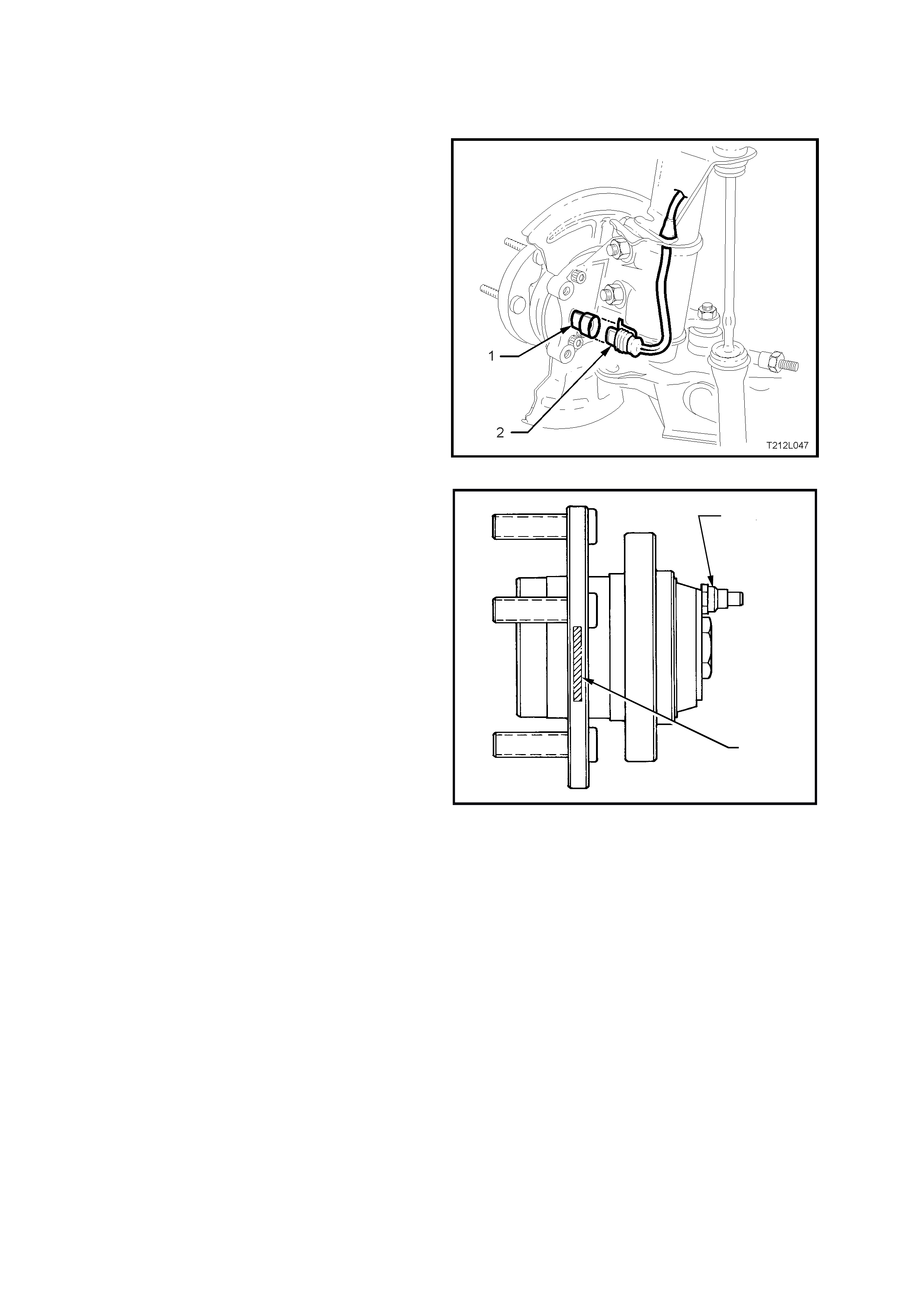
There are three specific front wheel hub
assemblies available. For vehicles with ABS or
ABS/TCS, there is a right and left, which
incorporates the wheel speed sensor and a 48
tooth magnet impulse ring. For non ABS vehicles,
a common hub is used for both sides.
Identification of the front wheel hub assemblies is
by the assembly part number etched on the outer
surface (1) of the hub wheel flange or by simply
noting whether a wheel speed sensor cap is fitted
to the hub (2).
CAUTION: During any service operation that
requires the replacement of the front hub
assembly on a vehicle equipped with ABS/TCS,
ensure that the correct replacement hub
assembly is installed, otherwise malfunctioning
of the ABS or ABS/TCS will occur.
NOTE 1: Always refer to the latest spare parts
information (PartFinder®) for the correct front
wheel hub assembly part numbers.
NOTE 2: Apart fr om wheel stud replac ement, ther e
are no serviceable items in the front wheel hub
assembly. With the unit being a ‘sealed for life’
assembly, there are no requirements for wheel
speed sensor and/or bearing adjustments. Should
a non-standard condition develop, then the hub
assembly must be replaced as complete unit.
T212L004
2
1
Figure 5B-15
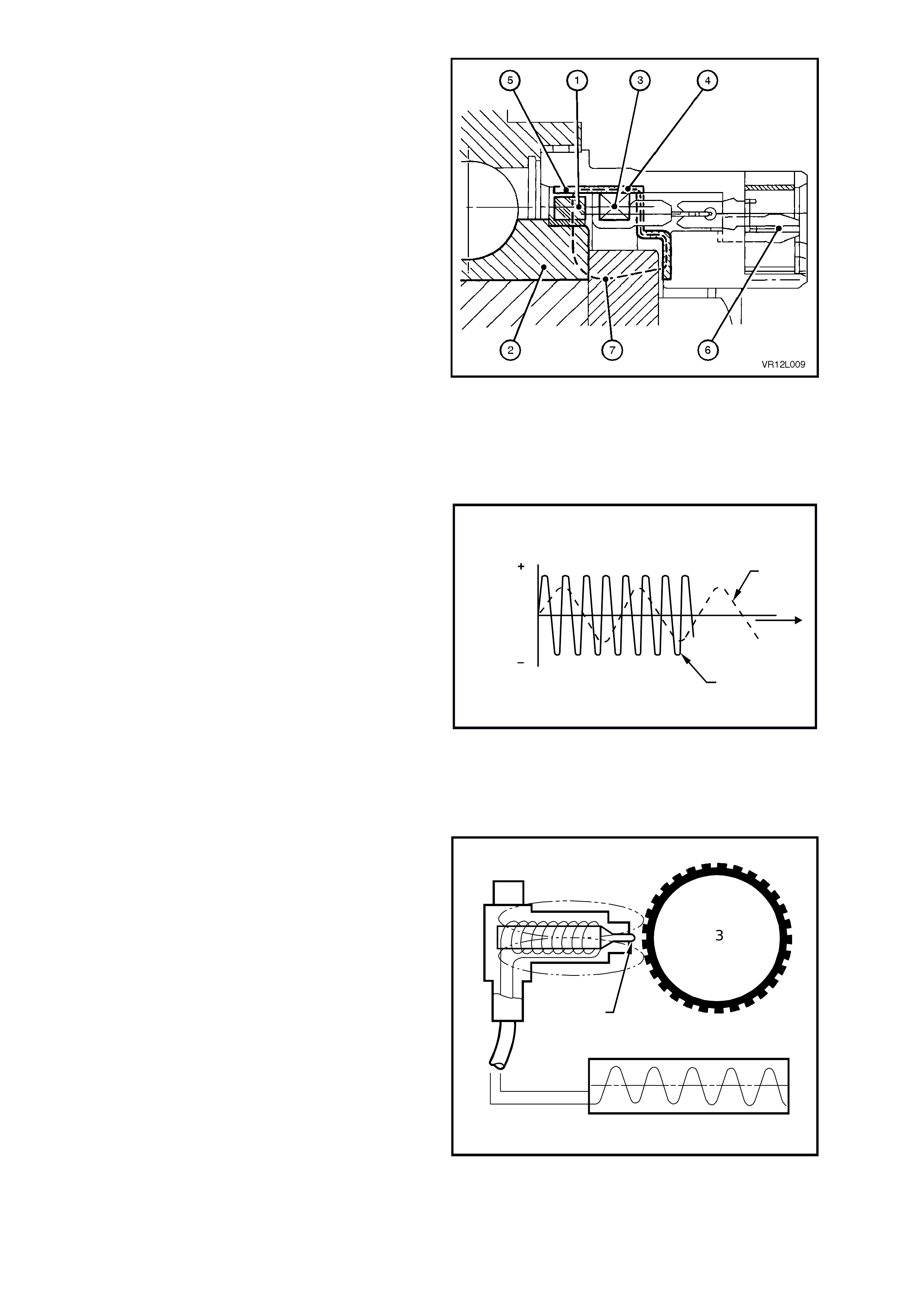
Figure 5B-16 illustrates a sectioned view of the
front wheel sensor in the front hub assembly.
The components of the sensor are:
• magnetic impulse ring (1)
• coil (3)
• flux concentrator (4)
• coaxial connector (6)
The m agnetic impulse r i ng (1 ), attac he d to the f r ont
hub rotating member (2), is magnetised and
contains 48 individual magnets evenly spaced
around the ring.
On the flux concentrator (4) there are a
corresponding 48 evenly spaced teeth (5).
Magnetic flux (7), generated from the impulse
ring (1), is induced into the coil (3) via the flux
concentrator (4).
As the road wheel is rotated, the front hub inner
member and magnetic impulse ring rotate as one,
causing a variation of the magnetic flux generated
in the flux concentrator. This change in the
magnetic flux causes an alternating voltage to be
induced in the coil of the sensor.
Figure 5B-16
The frequency and amplitude of the induced
voltage are dependent on wheel RPM, the number
of turns of the coil, the magnetisation level of the
impulse ring and the number teeth of the flux
concentrator. Of all these factors, the only variable
is the wheel RPM, so the frequency and am plitude
of the output signal depend on the speed of wheel
rotation.
The dotted line (1) in Figure 5B-17 represents the
voltage generated by the wheel speed sensor
versus time (T) at low wheel speed.
The continuous line (2) in Figure 5B-17 represents
the voltage generated by the wheel speed sensor
versus time (T) at high wheel speed.
1
2
T
V
V
T212L005
Figure 5B-17
Rear Wheel Spe ed Se ns ors
The rear wheel speed sens or (1) basic ally consists
of a magnetic core and a coil. The pole tip (2) is
surrounded by a magnetic field. As the wheel turns,
the teeth of the p ulse r i ng ( 3) c ause c hang es in th is
magnetic field. The magnetic flux thereby changes
and an alternating voltage is induced in the coil of
the wheel speed sensor.
The pole piece on the outer surface of the sensor
is of a pl as tic cons tr uct ion and ther ef or e there is no
requirement to coat the outer surface with high
temperature grease when reinstalling sensor
assemblies (as on previous models).
The rear wheel speed se nsors have a hi gh voltage
output and therefore, there is no need to install
shim s between the s ensor and its m ating mounti ng
bracket.
Legend:
1. Wheel speed sensor
2. Pole tip
3. Pulse ring
4. Sensor output
T212L006
1
3
2
4
Figure 5B-18
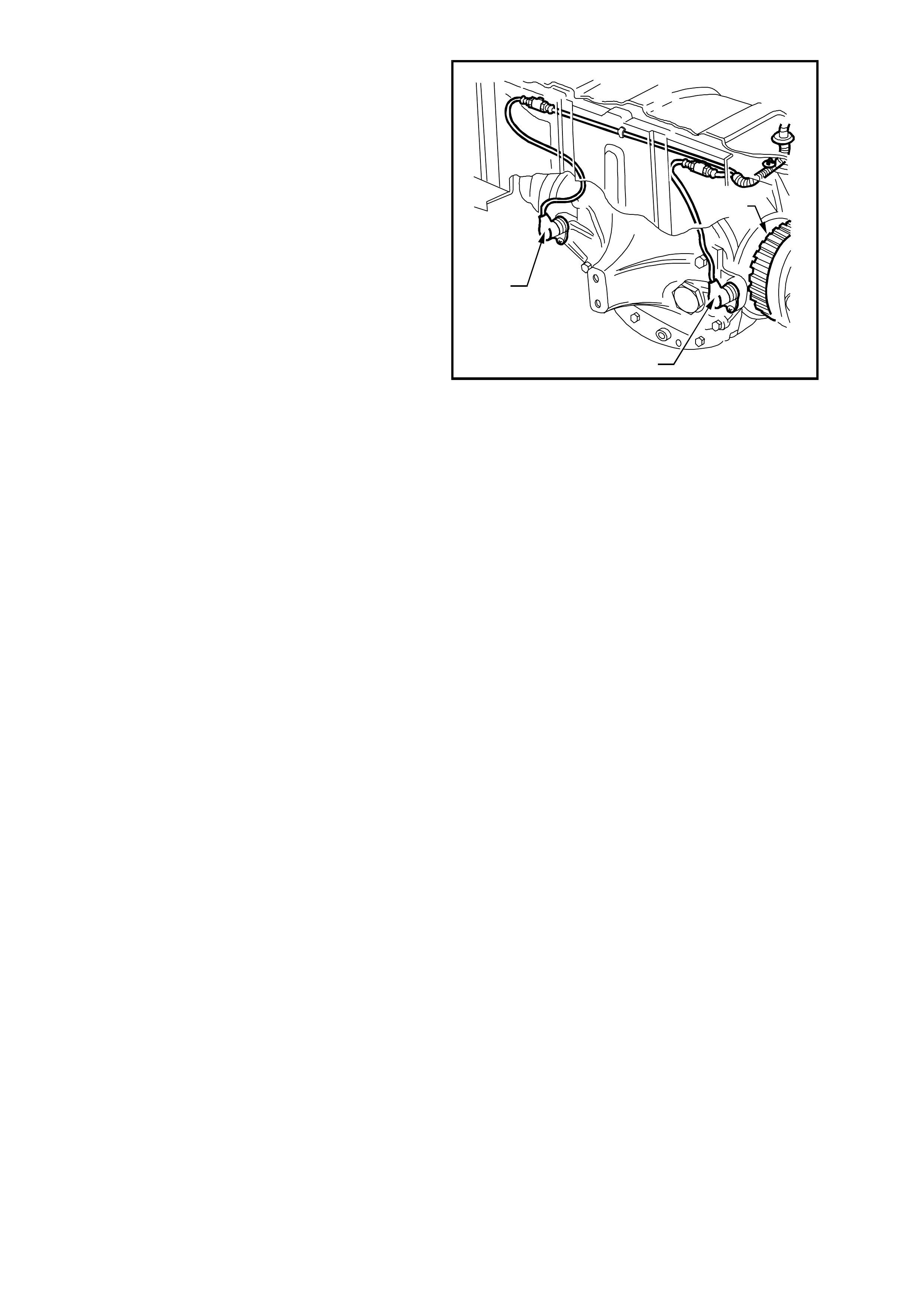
The rear wheel speed sensors (1) are located in a
bracket which is part of the final drive rear cover.
Each pulse ring (2) is a toothed ring made of a
ferrous metal that rotates to allow the wheel speed
sensor to read the rotational speed of each rear
wheel.
The rear wheel pulse rings are part of the final
drive inner axle flanges and are not serviced
separately.
As the road wheels rotate, the wheel speed
sensors generate an AC electrical signal
proportional (in frequency and amplitude) to the
wheel speed . The ABS or AB S/TCS c ontrol module
uses wheel speed signals to determine when anti-
lock control or traction control is required.
Specifically, the module uses wheel speed sensor
signals to find out whether any of the wheels are
decelerating rapidly (locking) or accelerating
rapidly (slipping).
The ABS and ABS/TCS systems are calibrated to
use tyres of a known rolling radius and pulse rings
with a specific number of teeth. The number of
teeth on the pulse rings correspond directly to tyre
size. If one of the tyres f itted to t he veh icle is l arger
or smaller (not to original equipment size) than the
remainder of the tyres on the vehicle, the ABS or
ABS/TCS control module will not modulate brake
system hydraulic pressure properly.
T212L008
2
1
1
Figure 5B-19
Improper system operation occurs because the wheel speed signal from the off-size tyre makes the module think
that one wheel is accelerating or decelerating faster than the others.
NOTE: IT IS IMPORTANT THAT THE VEHICLE ONLY BE EQUIPPED WITH THE ORIGINAL EQUIPMENT
TYRE SIZE AS NOMINATED ON THE VEHICLES TYRE PL ACARD. CHANGING TYRE SIZE COULD AFFECT
SYSTEM FUNCTION.
ABS AND ABS/TCS CONTROL MODULE (Refer Figure 5B-20)
The ABS or ABS/TCS control module (1) evaluates the signals from the wheel speed sensors and computes the
permissible wheel slip for optimum braking and traction.
During ABS, it regulates the necessary braking pressure in the brake calipers by means of solenoid valves within
the hydr aulic m odulator as semb ly (2). The ABS or A BS/TCS c ontrol m odule test s the s ystem in accordance with a
defined program and monitors it during driving.
The ABS/T CS contr ol m odule a lso m onitor s both fr ont and r ear wh eel sp eeds thr ough the whee l speed s ensors for
wheel slip. If at any time during acceleration the ABS/TCS control module detects drive wheel slip, it will act to bring
excess engine torque into a specific range. How this is achieved, depends on the engine fitted to the vehicle.
V6 Engined Veh ic les
• Engine Control: This is ac complishe d via t wo high sp eed Puls e W idth Modulate d (PW M) circuits between t he
ABS/TCS control module and the PCM. The PCM will then adjust spark firing and air/fuel ratio, altering the
boost duty cycle (Supercharged engine only), and shutting OFF up to five (5) injectors (if necessary), and
report the modified torque value (on the Torque Achieved circuit) back to the ABS/TCS control module.
• Brak e Application : Simultaneously with engine torque management, the ABS/TCS control module will activate
the ABS isolator valves, turn on the ABS pump motor and supply brake pressure to the over-spinning wheel/s.
GEN III V8 Engine Veh icles
• Spark adv ance: Re qu esting the PCM to r etard the amount of spark adva nce, v ia the spar k r etard circ uit, circ uit
1687 (Grey/Black wire).
• Throttle angle reduction: Sending a message to the throttle relaxer control module, via the requested throttle
position line (DKR), circuit 463 (Orange/White wire), to reduce the throttle angle. The throttle relaxer control
module achieves this by driving the throttle relaxer motor, which in turn pulls back the throttle cable, reducing
the throttle body opening.
The throttle relaxer control module sends a signal back to the ABS/TCS control module via the actual throttle
position line (DKI), circuit 464 (Black/White), reporting on the actual throttle position.
• Brake application: The ABS/TCS control module will activate the ABS isolator valves, turn on the ABS pump
motor and supply brake pressure to the over-spinning wheel/s.
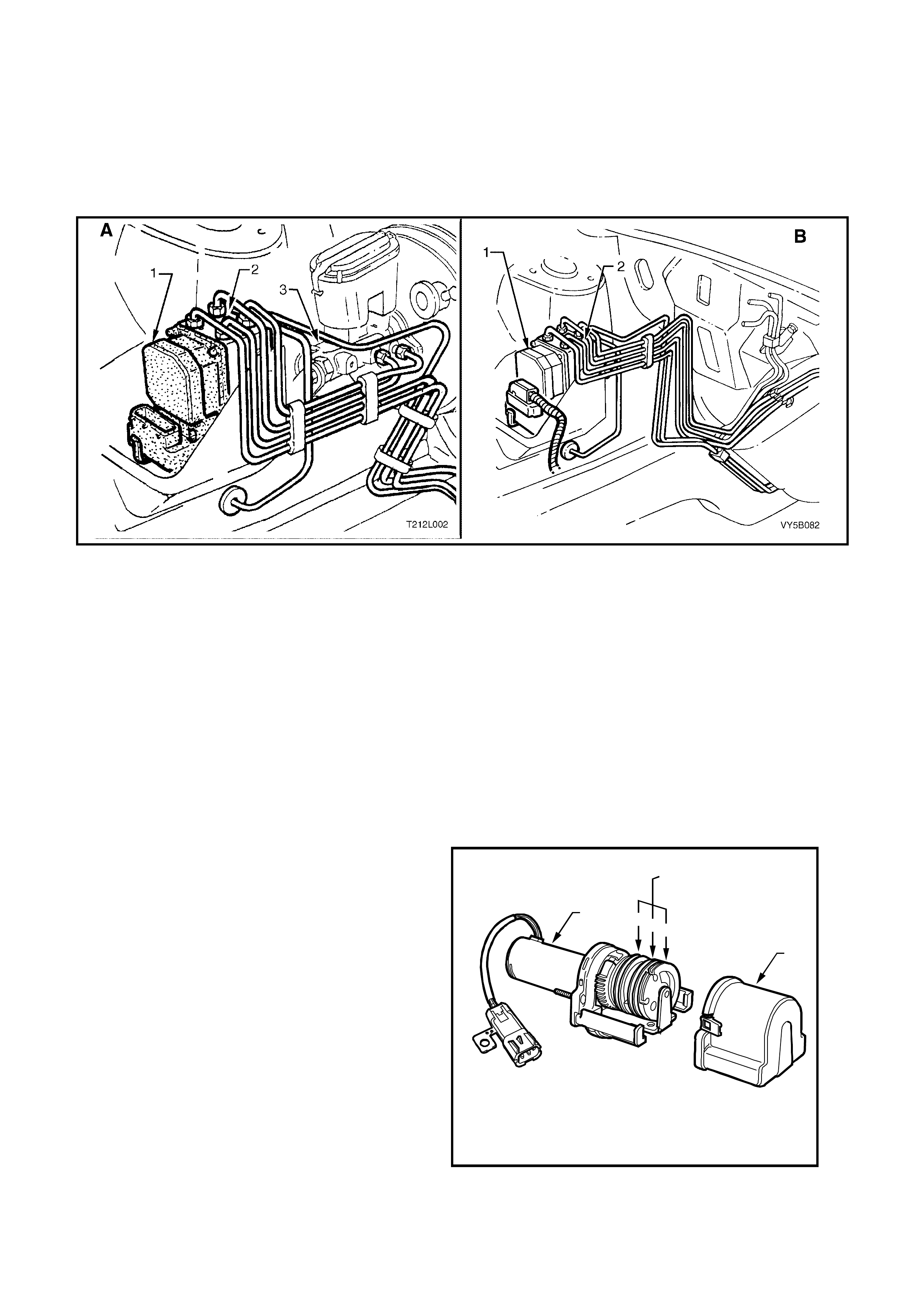
The ABS/TCS control module (1) is integrated with the hydraulic modulator (2) and there are different control
modules used in MY 2003 VY and V2 Series vehicles for ABS and ABS/TCS systems. It is physically impossible to
fit an ABS control module to an ABS/TCS hydraulic modulator or an ABS/TCS control module to a ABS hydraulic
modulator. However, if replacing an ABS or ABS/TCS control module, always refer to the latest PartFinder® Parts
Information for the correct control module part numbers.
NOTE: View ‘A’ is for RHD vehicles, while view ‘B’ is for LHD vehicles.
Figure 5B-20
HYDRAULIC MODULATOR (Refer Figure 5B-20)
The hydraulic modulator (2) for the ABS consists of six solenoid valves (three inlet and three outlet), two
accumulators, one for the front brake circuits and the other for the rear brake circuit and a brake fluid return pump.
The h ydraulic m odulator ( 2) for the ABS/T CS system consists of ten so lenoid valves ( four inle t, four o utlet and t wo
TCS s olenoi d valves ), t wo accum ulators , one for the f ront brak e circ uits a nd the other for th e rear brak e c ircuit a nd
a brake fluid return pump.
The solenoid valves are actuated by the ABS/TCS control module (1). Depending on the switching stage, they
connect the wheel brake calipers either with the brake master cylinder (3) or with the pump assembly, or
disconnect the wheel brake caliper from both the circuit and pump. When pressure is reduced, the return pump
conveys the brake fluid flowing out of the wheel brake cylinders back into the brake master cylinder via the
corresponding accumulator. The accumulators serve to temporarily accommodate the brake fluid 'surplus' which
suddenly occurs following a drop in pressure.
THROTTLE RELAXER
Only utilis e d when the GEN III V8 e ng ine is f itted to
a vehicle with ABS/TCS, the throttle relaxer is
mounted on the cockpit module, in the engine
compartm ent. The thrott le r elaxer co nsists of: three
pulleys (2), a dust cover (1) and a motor (3).
The accelerator pedal cable is connected to the
centre (B) of the three pulleys. The throttle cable
(throttle relaxer to throttle body cable) attaches to
the bottom (A) of the three pulleys. If the vehicle is
fitted with cruise control, the cruise control cable
attaches to the top pulley (C).
Via a raised lug on pulley B, through an elongated
slot in pulley C, pulleys B and C are connected to
each other. This allows for the operation of the
cruise control, and interruption free movement of
pulley B (accelerator pedal position) when the
cruise control is not in operation.
T212L009
2
ABC1
3
Figure 5B-21
Pulle ys A and B ar e c on ne c ted to e ac h oth er v ia an in ter nal spring . Und er nor mal operating co nd iti ons , th e lo ad
applied to pulleys B and C (accelerator pedal and cruise control actuator load) is transferred through the
internal spring to pulley A and onto the throttle body.
During TCS intervention, the throttle relaxer motor controls pulley A regardless of the accelerator pedal position.
The internal s pri ng betwee n pulle y A and B is com pr essed and theref ore, the acc elerat or pedal is overr idden . A
slight sensation on the accelerator pedal can be felt during this stage.
If the cruise control is engaged and the TCS intervenes, the cruise control will automatically be disengaged.
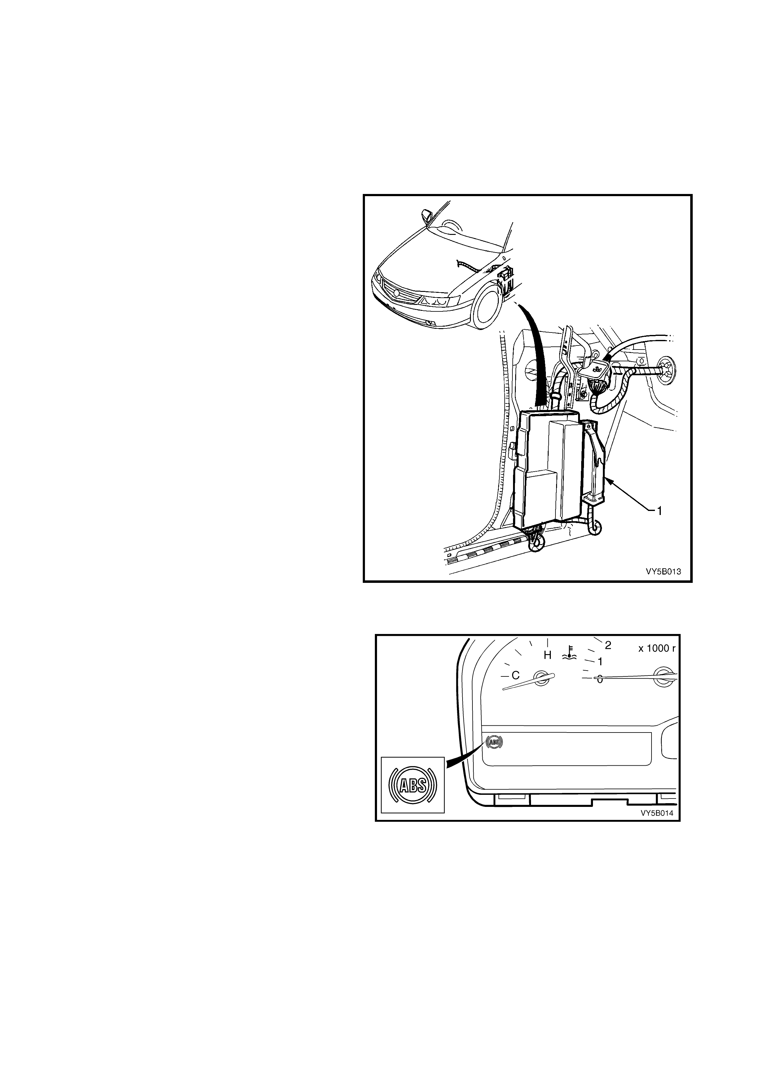
THROTTLE RELAXER CONTROL MODULE
Only required when the GEN III V8 engine is fitted
to a vehicle with ABS/TCS, the throttle relaxer
control m odule (1) is loc ated behind the p assenger
side shroud lower trim assembly, next to the
Powertrain Interface Module (PIM).
NOTE: The locat ion of the Throttle Re laxer C ontrol
Module is the same in all vehicles fitted with the
GEN III V8 engine.
The throttle relaxer control module uses input
information received from both the throttle position
sensor and the ABS/TCS control module.
The ABS/TCS control module communicates with
the throttle relaxer control module via Pulse Width
Modulated (PWM) signals sent and received on
two circuits; DKR circuit 463 (Orange/White wire)
and DKI circuit 464 Black/White wire). “DKR”
translates to the requested throttle position; “DKI”
translates to the actual throttle position.
Diagnostic Trouble Codes DTCs for the throttle
relaxer are incorporated into the ABS/TCS control
module.
Figure 5B-22
ABS WARNING LAMP
Located in t he instrum ent cluster, the A BS warning
lamp is part of the driver warning system.
The ABS warning lamp is controlled by the ABS or
ABS/T CS c ontr o l module a nd is il luminate d to warn
the driver that a utomatic an ti- lock brak ing c apab il ity
is totally inhibited. This does not affect the
operation of the vehicle's conventional braking
system.
The ABS warning lamp will illuminate when:
1. The ignition is turned on. The lamp will go out
after a stationary 'Self Check' is completed
(two to five seconds).
2. The ABS or ABS/TCS control module detects
an ABS electrical wiring or component
problem.
3. T he ABS or AB S/TCS control module det ects a
problem within itself.
These conditions are part of the ABS self-
check.
Figure 5B-23
4. When using Tech 2 in certain diagnostic modes for ABS/TCS diagnosis, the ABS/TCS system is disabled by
the ABS/TCS control module while it is communicating with Tech 2.
Should the ABS warning lamp lose power (from fuse F13 ignition fuse) or the ABS control module lose earth
(terminals A37, X1 16 and X1 16), the ABS warning lamp will not illuminate at any time.
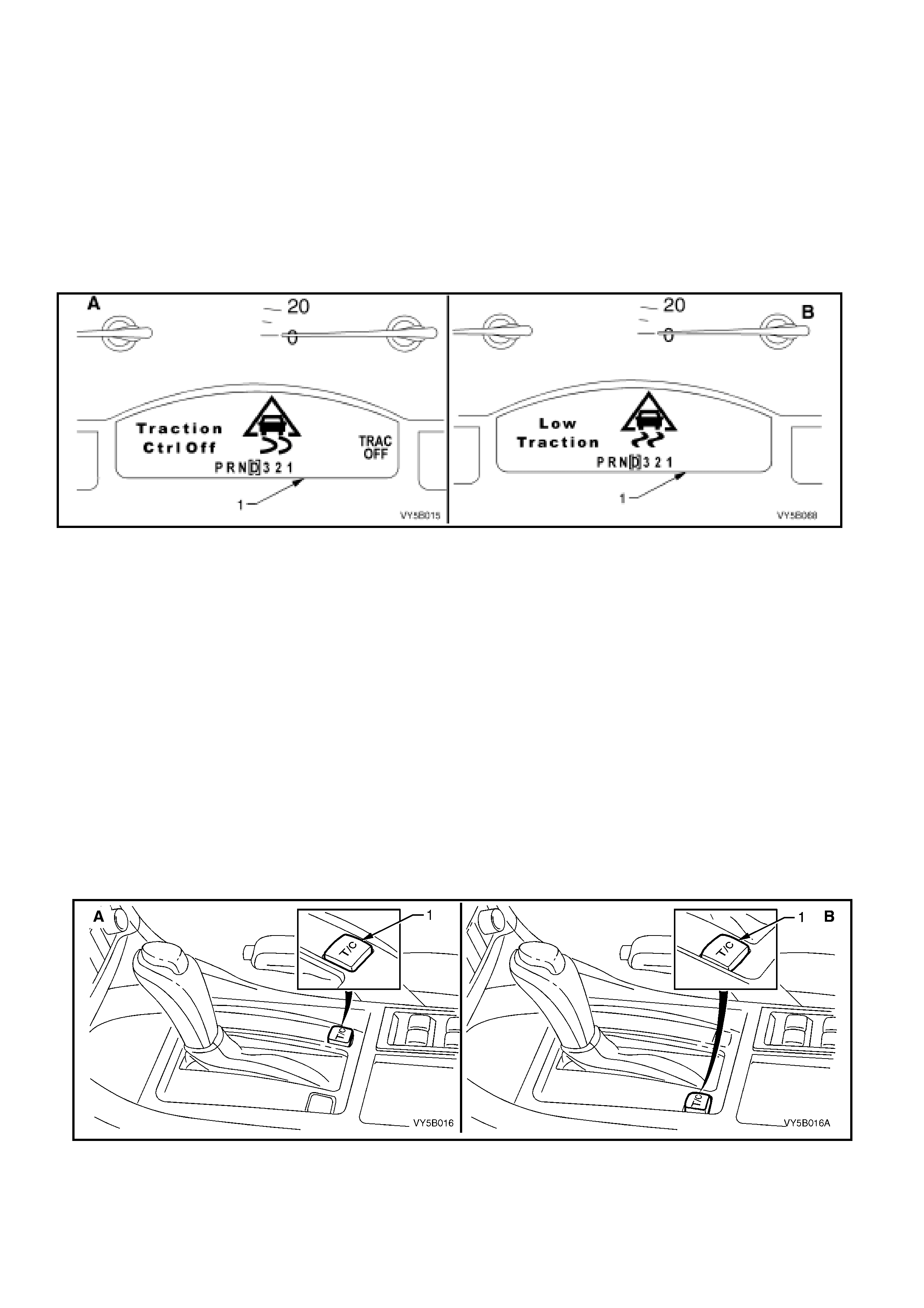
ELECTRONIC TRACTION CONTROL (TCS) WARNING DISPLAYS
There ar e two electronic tr action contr ol warning d ispla ys in the instrum ent panel Multi Functio n Displa y (MFD) (1);
‘TRAC OFF’ (‘A’) and ‘LOW TRAC’ (‘B’).
The ‘T RAC OFF’ warn ing displa y (‘A’) is c ontrolled b y the ABS/T CS control module, v ia the seria l data bus c ircuit,
and will be activated to warn the driver that the TCS system has been disabled.
The ‘TRAC OFF’ warning display will be activated when:
1. The ignition is turned on. The display will de-activate after a stationary 'Self Check' is completed (two to five
seconds).
2. When the TCS system is manually switched off, via the traction control switch.
3. The ABS/TCS control module detects an TCS electrical wiring or component problem.
4. The ABS/TCS control module detects a problem within itself.
Figure 5B-24
5. W hen using Tech 2 in certain diagnostic modes for ABS/TCS diagnosis. The ABS/TCS system is disabled by
the ABS/TCS control module while it is communicating with the Tech 2.
Should th e ‘TRAC OFF’ or ‘LOW TR AC’ warning displa ys lose power (fr om fus e F13 igniti on fuse) neither of these
lamps will activate. Also, if the ABS/TCS control module loses earth (terminals A37, X1-16 and X1-19), the ‘LOW
TRAC’ warn ing disp lay will not activ ate.
The ‘LOW TRAC’ warning display is also controlled by the ABS/TCS control module and will be activated for two
seconds when the ignition is switched on and then go out, or when the ABS/TCS control module is controlling
wheel spin, indicating that the vehicle is in a critical situation.
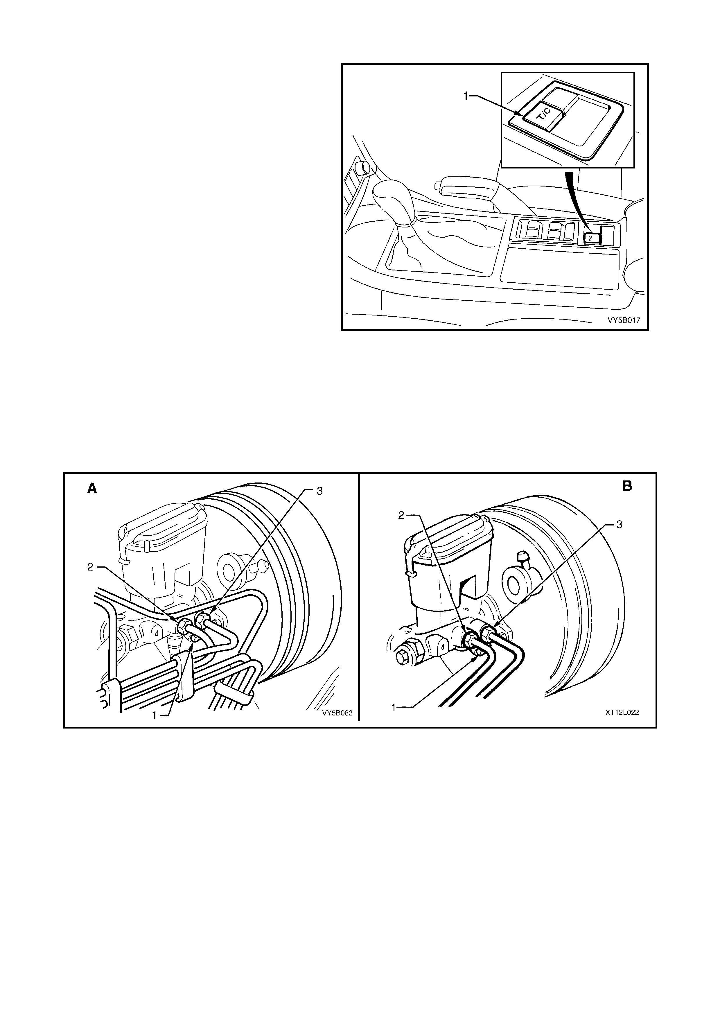
ELECTRONIC TRACTION CONTROL (T/C) SWITCH
Automatic Transmission
In certain circumstances (i.e. if the vehicle became bogged but could be ‘rocked out’) it may be necessary to
disable th e electronic traction c ontrol s ystem (TCS) . This is achie ved by pressi ng the ‘T/C’ butto n, located n ear the
transmission selector, as shown. If the traction control system is switched off, the ‘T/C’ displa y will be activated in
the Multi Function Display (MFD) in the Instrument (refer Figure 5B-25, view ‘A’). The system can be switched on
again by either pressing the ‘T/C’ button again or when the ignition is next cycled (off to on).
View ‘A’ that follows shows the ‘T/C’ off button (1) location for Right Hand drive models, while view ‘B’ shows the
Left Hand drive arrangement.
Figure 5B-25
Manual Transmission
On vehicles with manual transmission, the
electronic traction control disabling s witch (‘T/C’) is
located in the rear of the centre console in the
position shown (1).
If the traction control system is switched off, the
‘TRAC OFF’ display will be activated in the Multi
Function Display (MFD) in the Instrument (refer
Figure 5B-26). The system can be switched on
again by either pressing the ‘T/C’ button again or
when the ignition is next cycled (off to on).
NOTE 1: If the electronic traction control system is
commanded off, the ABS will still function normally.
NOTE 2: If the button is depress ed and held for 10
or mor e seconds, the ABS/ TCS control m odule will
see this as a short circuit and the TCS will be
permanently enabled (for that ignition cycle) until
the ignition is switched off and the engine
restarted. Additionally, the TRAC OFF warning
display (if activated) will be turned off until the
ignition is switched off and the engine restarted.
Figure 5B-26
BRAKE MASTER CYLINDER
On MY 2003 VY and V2 Series vehicles, regardless of the engine f itted, a com mon brake master cylinder is used
on vehicles with standard, ABS and ABS/TCS brake systems. The only difference being that the master cylinder
used with AB S and A BS/TCS s ystems has a s c rew- in bla nking p lug ( 1) installed and t ig hten ed into th e lo we r of two
front brake outlets in the master cylinder. Pipe (2) is the rear brake outlet and pipe (3) is for the front outlet.
NOTE: View ‘A’ is for RHD vehicles, while view ‘B’ is for LHD vehicles.
Figure 5B-27
ABS & TCS FUSES
An ABS 60 Amp fusible link, X18_F103, is incorporated in the underhood electrical centre.
The thro ttle relax er and th rottle re laxer c ontrol m odule (G EN III V8 onl y) are supp lied vo ltage via f use X17_F 36 ( 15
Amp) , also locat ed in the u nderh ood el ec tr ical ce ntr e.
An additional 10 Amp fuse, X42_F27 is used for the ABS and is located in the interior electrical centre.
The ABS OFF, TRAC OFF & LOW TRAC warning displays are supplied voltage via fuse X44_F11 (7.5 Amp)
located in the interior electrical centre.
View ‘A’ shows the Right Hand drive locations while view ‘B’ shows them for the Left Hand drive models.
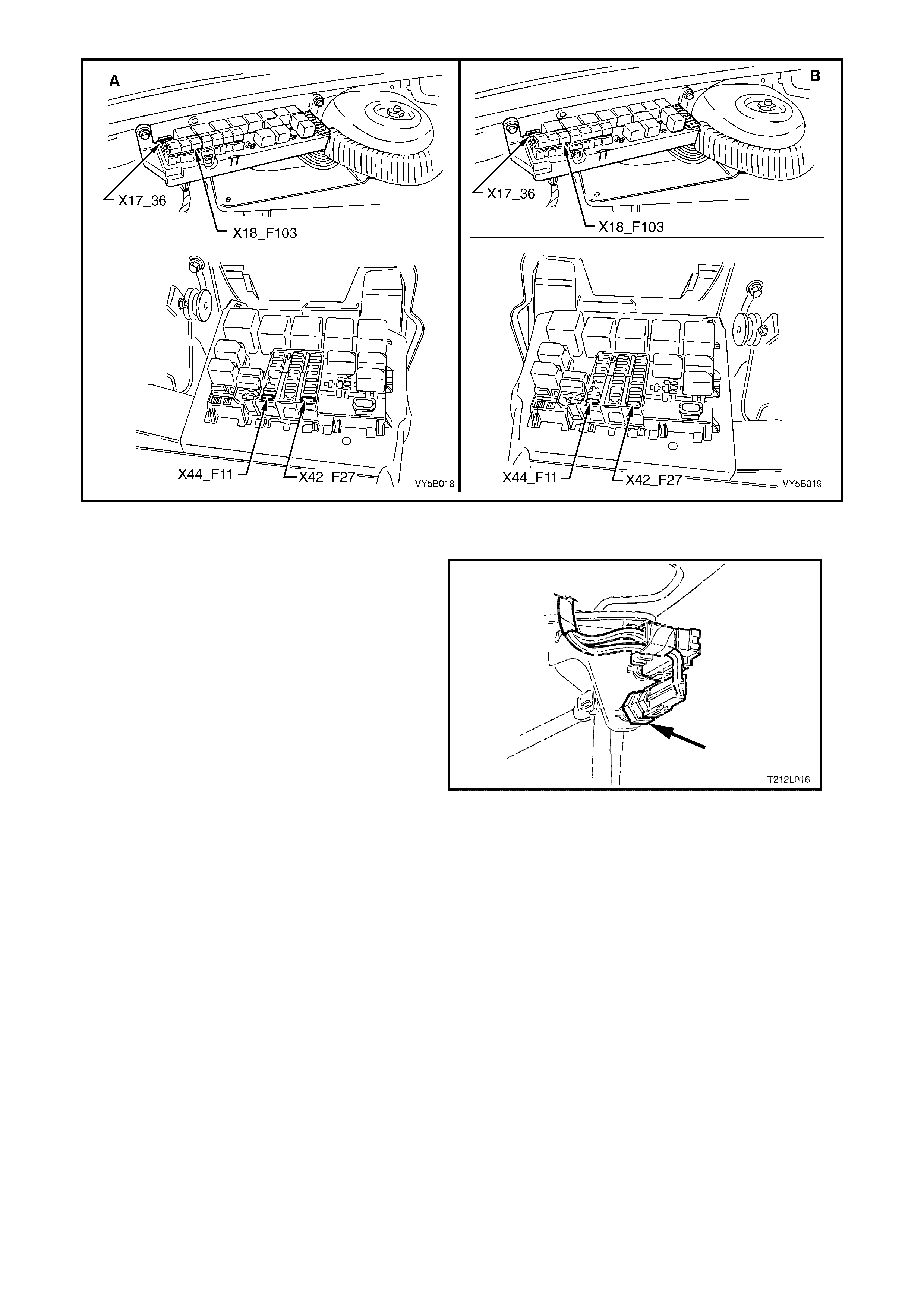
Figure 5B-28
STOP LAMP SWITCH
Located in the brake pedal support, the stop lamp
switch provides a BRAKES APPLIED 12 volt input
signal to terminal X1-14 of the ABS or ABS/TCS
control module connector A37. W henever the ABS
or ABS/TCS co n tr ol modul e rec ei ves t his s i gna l th e
ABS control cycle will begin. If the driver pumps the
brake pedal during the ABS operation, the control
cycle will be reset.
The stop lamp switch is a normally ‘open’ switch
that supplies batter y voltage to the stop lam ps and
terminal X1-14 of the ABS or ABS/TCS control
module, when closed. When the switch is open
(brakes not applied), terminal X1-14 of the ABS or
ABS/TCS control module is earthed through the
stop lamps, causing the voltage at terminal X1-14
to be pulled low (less than 0.2 volts)
Also, if the ABS or ABS/TCS control module
senses a stop lamp switch input, the self test will
not occur until the vehicle is travelling at
approximately 18 km/h.
Figure 5B-29
For all service operations on the stop lam p switch,
refer to Section 12B LIGHTING SYSTEM in the
MY 2003 VY and V2 Series Service Information.
2.4 INSTALLATION POSITION OF ABS AND ABS/TCS COMPONENTS
The following figures illustrate the installed positions of the various ABS and ABS/TCS components fitted to MY
2003 VY and V2 Series vehicles. The series of illustrations are arranged with the RHD version presented first,
followed by the equivalent for the LHD. Where an arrangement is common to both Right and Left drive vehicles,
notation is made to that effect.
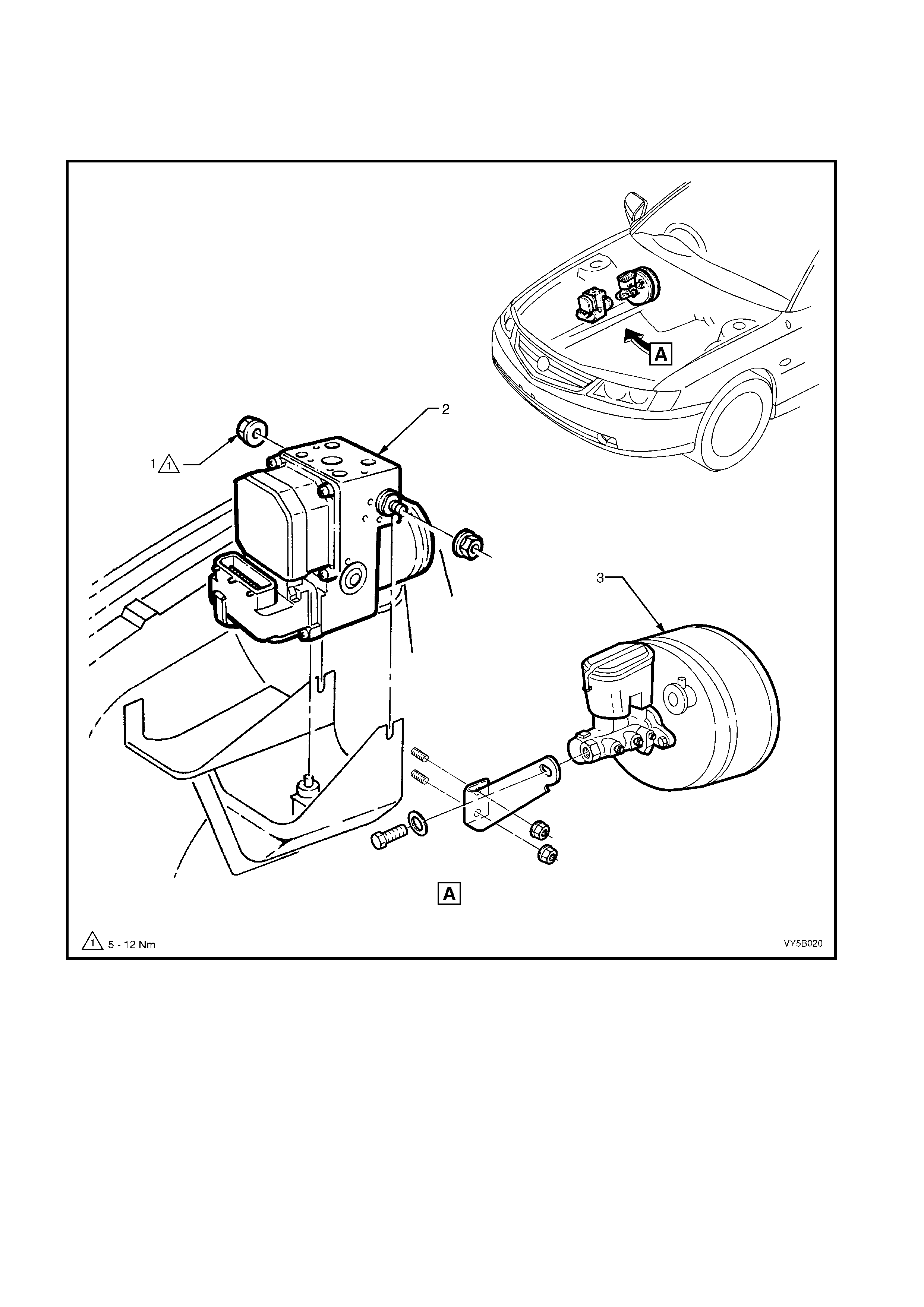
Figure 5B-30
RHD Brake Master Cylinder and Hydraulic Modulator Locations – ABS or ABS/TCS With V6 Engines
Legend
1. Nut – Hydraulic Modulator/Control
Module Retaining 2. Hydraulic Modulator/Control
Module Assembly 3. Brake Master Cylinder/Vacuum
Booster Assembly
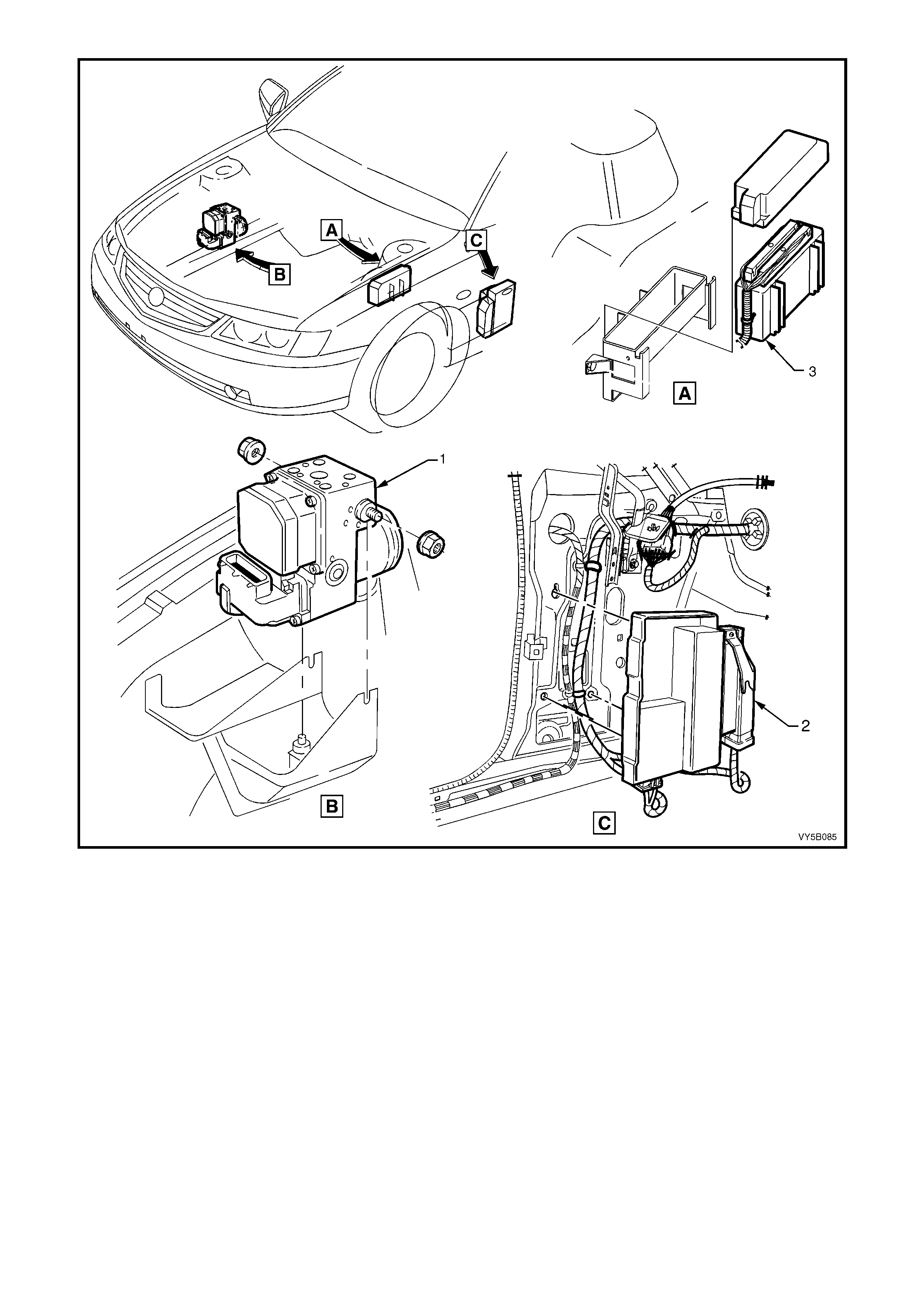
Figure 5B-31 – RHD & LHD – ABS/TCS Hydraulic Modulator, Throttle Relaxer Module and PCM Locations –
GEN III V8 Engine
Legend
1. ABS/TCS Hydraulic Modulator
– All Engines 2. Throttle Relaxer Module
– GEN III V8 Only 3. Powertrain Control Module (PCM)
– GEN III V8 Engine Only
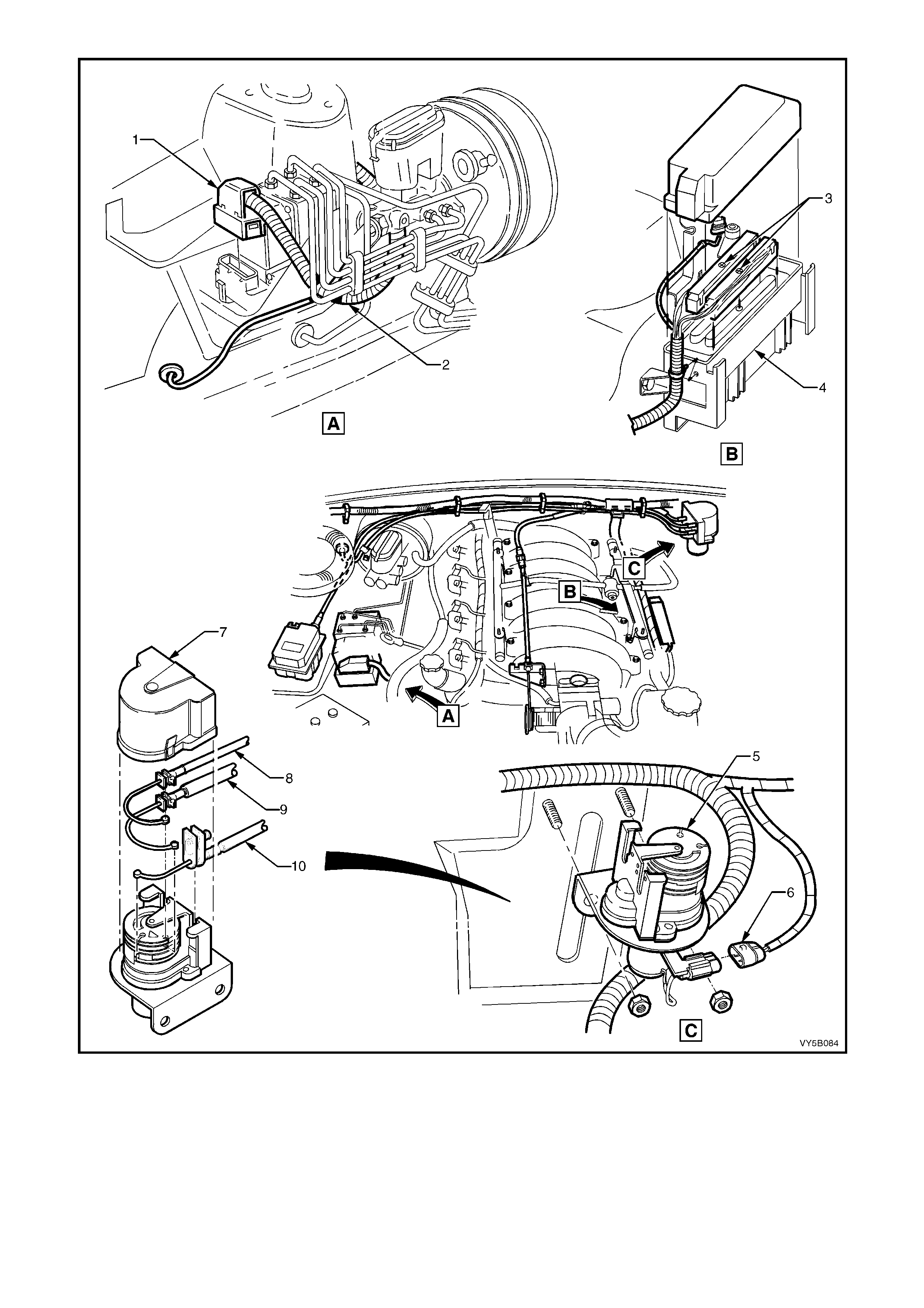
Figure 5B-32 – RHD Wiring Harness and Relaxer Cable Installation for ABS/TCS – GEN III V8 Engine
Legend
1. ABS/TCS Control Module Connector
2. Main Wiring Harness
3. Powertrain Harness Connector to PCM
4. Powertrain Control Module (PCM)
5. Throttle Relaxer
6. Powertrain Harness to Throttle Relaxer
7. Throttle Relaxer Cover
8. Cruise Control Cable
9. Accelerator Cable
10. Throttle Cable
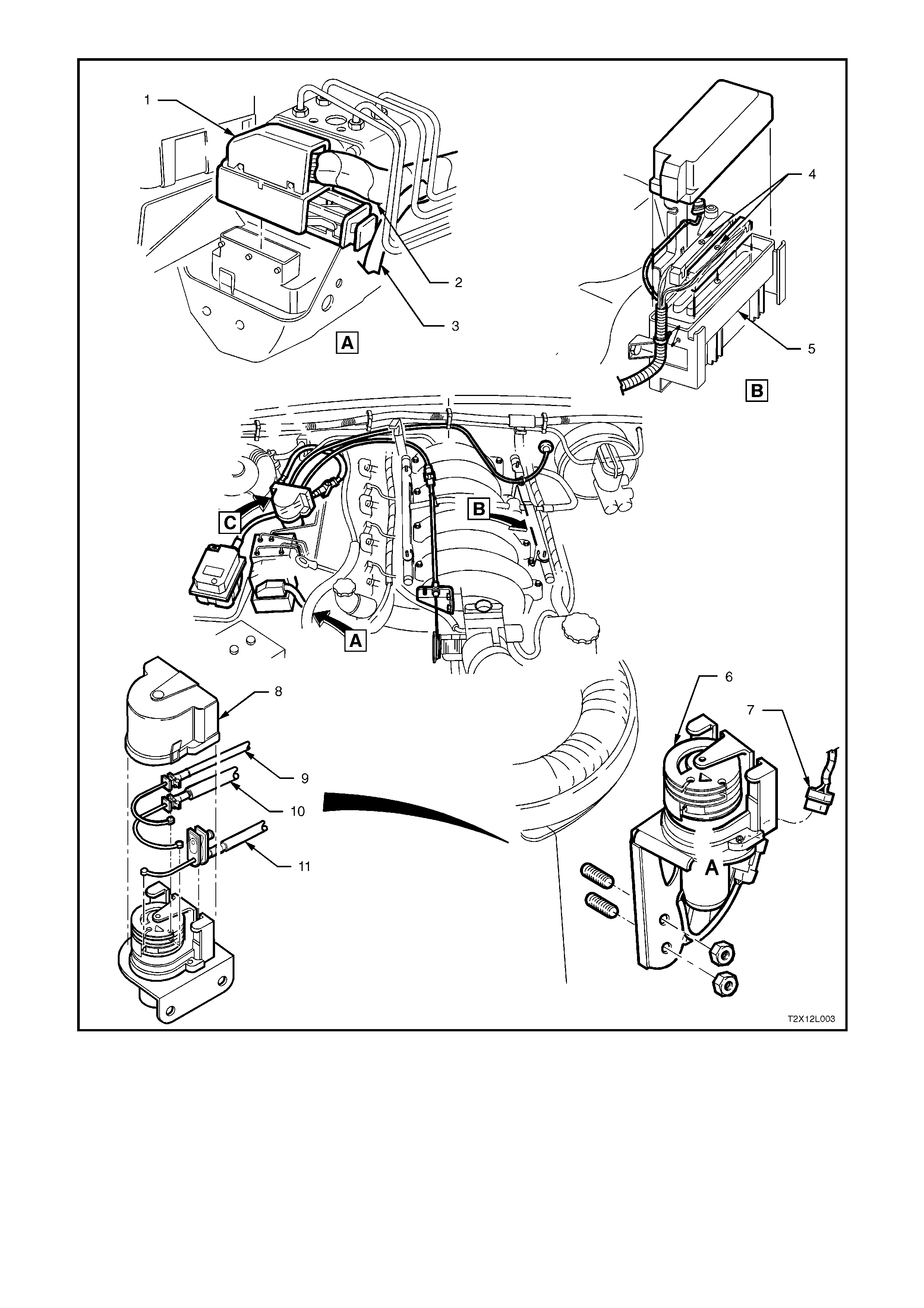
Figure 5B-33 – LHD Wiring Harness and Throttle Relaxer Cable Installation for ABS/TCS – GEN III V8 Engine
Legend
1. ABS/TCS Control Module Connector
2. Main Wiring Harness
3. Powertrain Harness Connector to PCM
4. Powertrain Control Module (PCM)
5. Throttle Relaxer
6. Powertrain Harness to Throttle Relaxer
7. Throttle Relaxer Cover
8. Cruise Control Cable
9. Accelerator Cable
10. Throttle Cable

Figure 5B-34 – RHD & LHD – Front Wheel Speed Sensor Lead Routing – All Engines
Legend
1. Front Wheel Speed Sensor and Lead Assembly 2. Main Wiring Harness 3. Retaining Clip
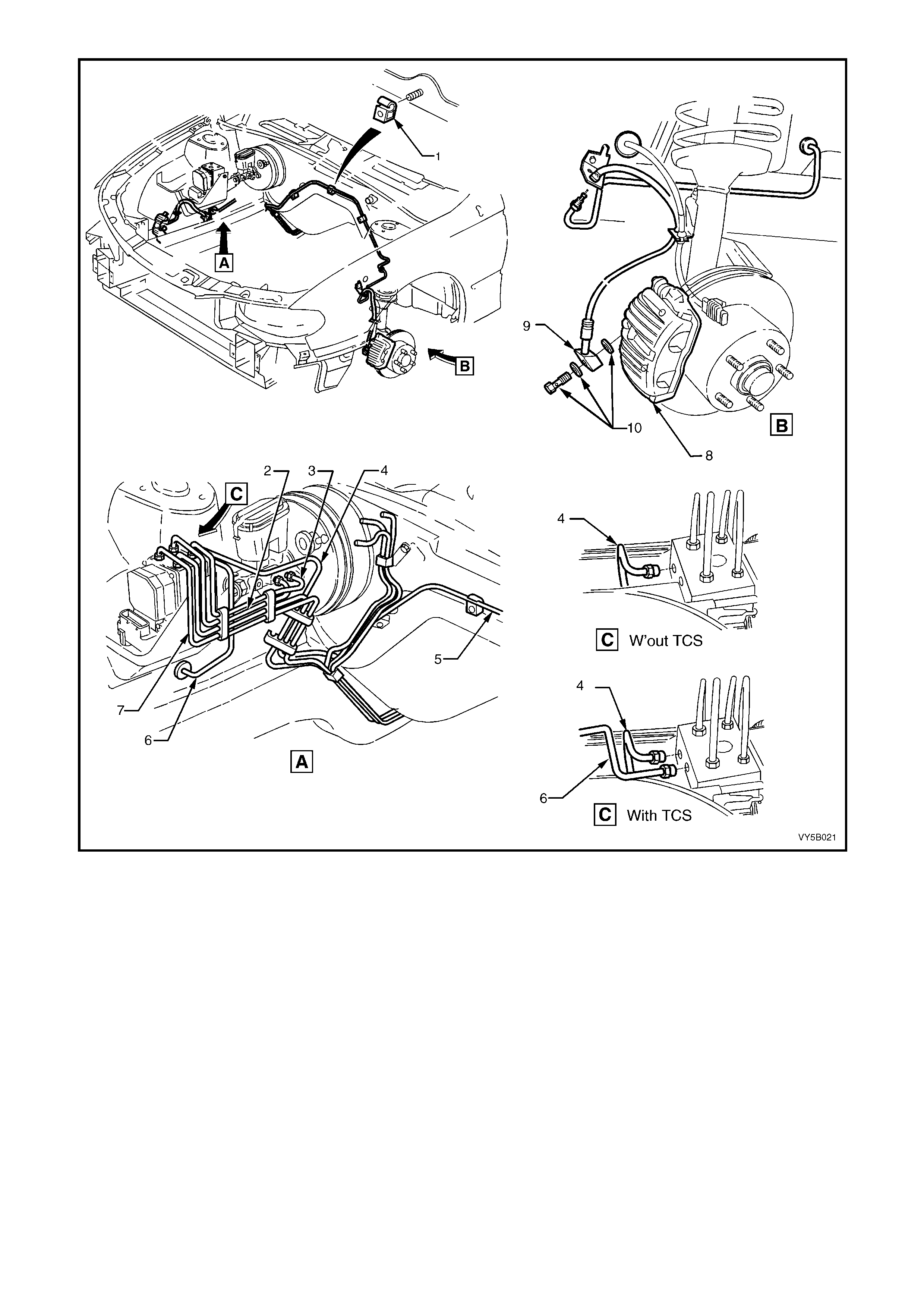
Figure 5B-35 – RHD Hydraulic Pipe Routing – All Engines
Legend
1. Clip – 3 places
2. Master Cylinder to Modulator Rear Pipe
3. Master Cylinder to Modulator Front Pipe
4. Modulator to Rear Brake Hose (With TCS)
5. Modulator to LHF Brake Hose
6. Modulator to RHF Brake Hose
7. Without TCS – Modulator to Rear Brake Pipes
With TCS – Modulator to LHR Brake Hose
8. Front Brake Caliper
9. Front Brake Hose
10. Brake Hose and Washers to Front Brake Caliper
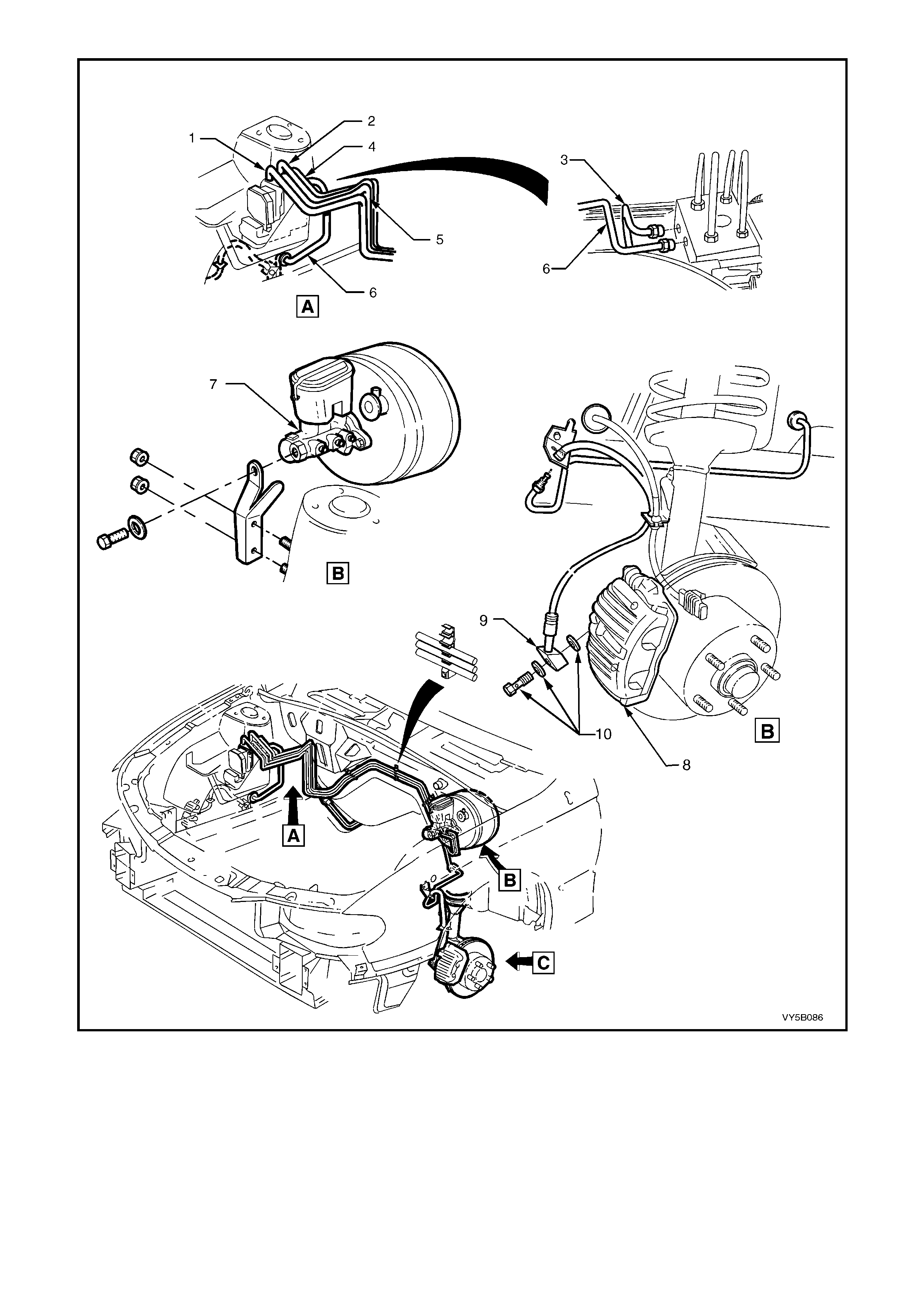
Figure 5B-36 – LHD ABS/TCS Hydraulic Pipe Routing – All Engines
Legend
1. Modulator to LHR Brake Hose
2. Master Cylinder to Modulator Rear Pipe
3. Modulator to RHR Brake Hose
4. Master Cylinder to Modulator Front Pipe
5. Modulator to LHF Brake Hose
6. Modulator to RHF Brake Ho se
7. Master Cylinder and Brake Booster
8. Front Brake Caliper
9. Front Brake Hose
10. Brake Hose and Washers to Front Brake Caliper
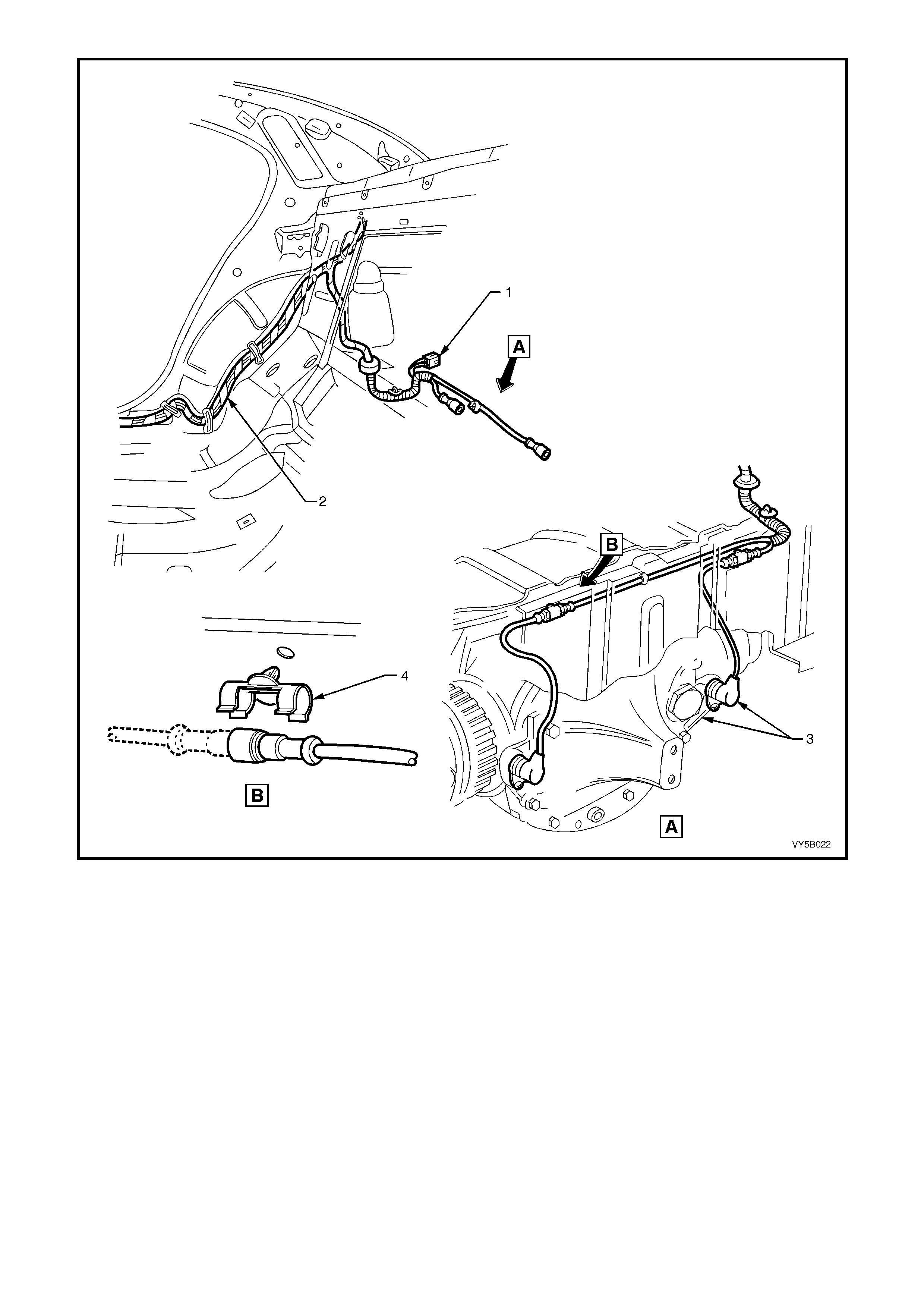
Figure 5B-37 – RHD & LHD Body Harness Installation for ABS & ABS/TCS –All Engines
Legend
1. Wiring Harness Connector, Modular Fuel Sender
2. Body Harness 3. Wheel Speed Sensor and Cable Assembly – Rear
4. Clip – Wheel Speed Senor Cable Retaining

2.5 ABS PRINCIPLES OF OPERATION – EXCLUDING ABS/TCS
NON-ANTI-LOCK BRAKING
Under normal braking conditions, the anti-lock braking system functions much like a conventional braking system .
Brake fluid pressure is provided by the brake master cylinder and the power booster.
For non-ant i-lock braking, h ydraulic pr essure is applied to the brak e calipers without any inter vention f rom the ABS
At this t ime, the hydraulic modulator establishes an open two-wa y f luid pat h from the m aster cylinder to the brake
calipers. Normal braking (no ABS) occurs when the wheel sensors do not detect wheel lock-up tendencies.
However, even thr ough t he AB S is pas sive duri ng nor m al braking, th e ABS c ontrol module is c onstant ly monitor in g
for rapid deceleration of any of the wheels and a sign al from the brak e switch (brakes applied input). Rapid whee l
deceleration during a braking operation could indicate wheel lock-up.
ANTI-LOCK BR AKING
When the ABS senses any tendency for wheel lock-up, it enters the anti-lock mode. During anti-lock braking, the
ABS m odulates h ydraulic pr essure in the brak e circ uits to control whee l slip to 10 – 20%. F or anti-lock braking, the
ABS control module controls current flow to the hydraulic modulator solenoid valves to control (by maintaining,
decreasing or increasing) hydraulic pressure in the brake circuits.
NOTE: The hydraulic modulator cannot increase brake circuit hydraulic pressure above the pressure supplied by
the brake master cylinder.
ABS CONTROL MODULE OPERATION
Inputs
The following ABS components send signals to the ABS contro l module where the y are evaluated in order for the
module to maintain and control wheel slip.
1. Ignition on input, (via fusible link F103, ignition switch S149, fuse F27) – ABS control module A37, terminal
X1 15.
2. Wheel speed sensor inputs – ABS control module A37 terminals X1 1 and 2 (RHR), X1 4 and 5 (RHF), X1 6
and 7 (LHF) and X1 8 and 9 (LHR).
3. Brakes applied input (from brake lamp switch) – ABS control module 37, terminal X1 14.
4. Battery voltage – ABS control module A37 terminals X1 17 and 18.
5. Serial data (input and output) – ABS control module A37, terminal X1 11.
Outputs
To control the anti-lock braking system, the ABS control module sends command signals to the following
components.
1. Valve relay/solenoid valves – internal control.
2. Pump relay/pump motor – internal control.
3. Serial data (input and output) – ABS control module terminal No. 11.
4. Self diagnostic 'Flash Code Actuation' – ABS control module terminal No. 12.
5. ABS warning lamp – ABS control module terminal No. 21.
W ith the igniti on s witch in t he ON posit ion, b atter y volt age is appl ied to the A BS c ontrol m odule term inal N o. 15 via
fuse F27. This then enables the ABS control module and battery voltage is applied to the pump motor relay and
valve relay. Neither of the relays operate until they receive an earth from the ABS control module.
Also, batt ery vo ltage is suppli ed to the ABS war ning la mp via f use F13. T he warni ng lam p will not i lluminate until it
is earthe d by the AB S control m odule. If the A BS module is not conn ected, term inals 19, 20 a nd 21 will b e shorted
together within the connector and the ABS warning lamp will be illuminated.
Wheel speed sensors are located at each front wheel and at each final drive inner axle flange. When the vehicle
starts moving, all of the speed sensors create signals that are sensed by the ABS control module at terminals 1 and
2, 4 and 5, 6 and 7, 8 and 9. These signals are AC electrical pulses that are proportional (in frequency and
amplitude) to wheel rotational speed.
Once the vehicle has b een s tarted and dr iven o ver a pprox im ately 6 km /h, the cont rol m odule p erf orm s an ABS s elf
test. The control m odule test cycles each solenoid valve and the return pum p in the hydraulic modulator to check
component operation. The control module checks its own logic section and circuitry. If errors are detected during
this test, the control module will earth terminal 21, illuminating the ABS warning lamp to warn the driver of a
problem with the system. The ABS control module remains deactivated until the next ignition switch OFF to ON
cycle when the process is repeated and if errors are detected again, the ABS warning lamp will be illuminated.

The ABS self test occurs once each ignition cycle as follows:
1. After receiving an ignition 'ON' input, the control module earth’s and activates the valve relay.
2. When the vehicle reaches approximately 6 km/h, the control module tests the solenoid valves and the return
pump in the modulator. This test can usually be heard and/or felt by the driver.
3. If the pump or solenoid valves fail to operate, the ABS will be disabled and the ABS warning lamp will be
illuminated.
4. As soon as the ABS control module receives a signal from any of the wheel speed sensors, it checks wheel
speed sensor output. If any of th e wheel speed sensor signals are no t detected, or are incorrect, the ABS will
be disabled and the ABS warning lamp will be illuminated.
Once the vehicle is moving, the control module continuously monitors itself and the following components:
1. Solenoid valves.
2. Wheel speed sensors.
3. Wiring harness and relays.
4. Battery voltage.
If battery voltage drops below approximately 9 volts, the ABS will be disabled and the ABS warning lamp will be
illuminated.
During braking applications, if one or more wheels start to decelerate too quickly, the ABS is engaged and the
modulatio n proc ess b egins . W heel s peed inf orm ation s ent to th e AB S contro l m odule is proces sed and th e modu le
determines proper solenoid valve operation in the modulator. The modulator contains six solenoid valves; two for
each front wheel with the rear wheels both having two common solenoid valves.
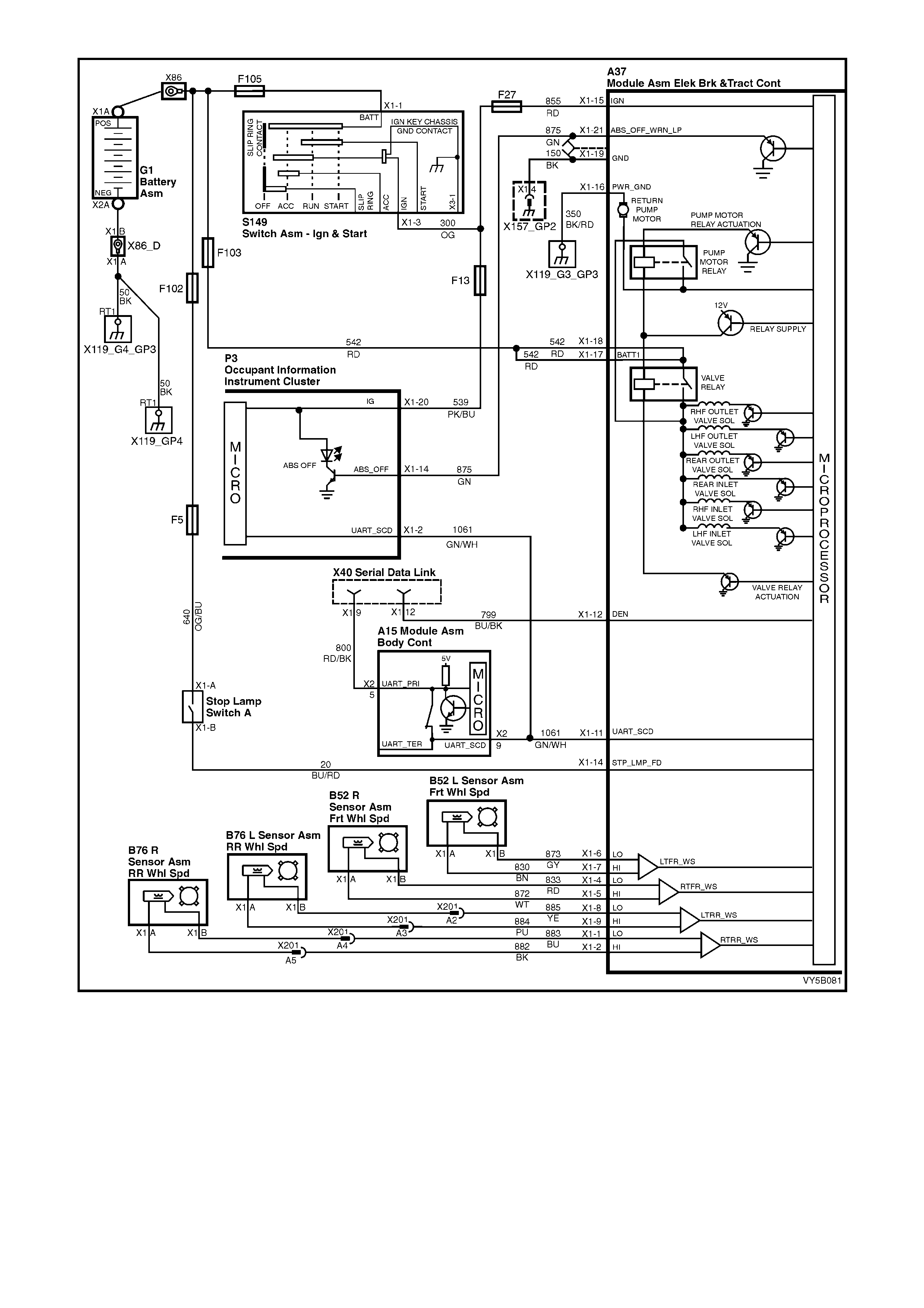
Figure 5B-38 – ABS Circuit – V6 Engines
HYDRAULIC MODULATOR OPERATION
The hydraulic modulator executes ABS control module commands using six solenoid valves. These solenoid
valves, located in the hydraulic modulator assembly, are in series with the brake master cylinder and the brake
circuits. The hydraulic modulator solenoid valves are activated separately by the ABS control module
corresponding to various ABS control phases:
1. Non-ABS Braking
2. Maintaining Pressure
3. Reducing Pressure
4. Increasing (Building-up) Pressure
The hydraulic modulator assembly contains six solenoid valves and a brake fluid return pump; however, for
explanat ion of the operation only one accum ulator and two solenoid valves will be described. The operation is the
same for all three circuits.
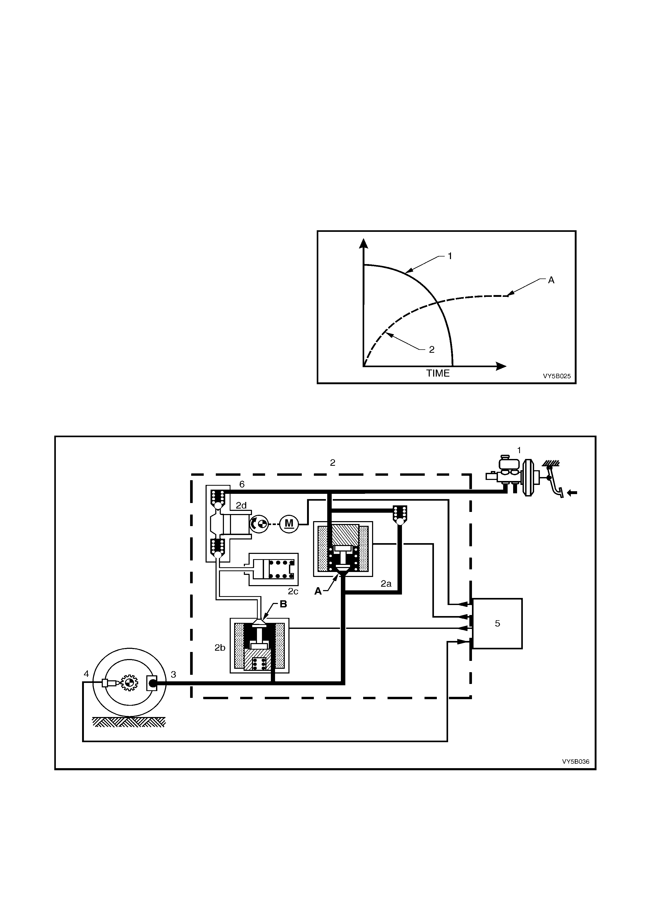
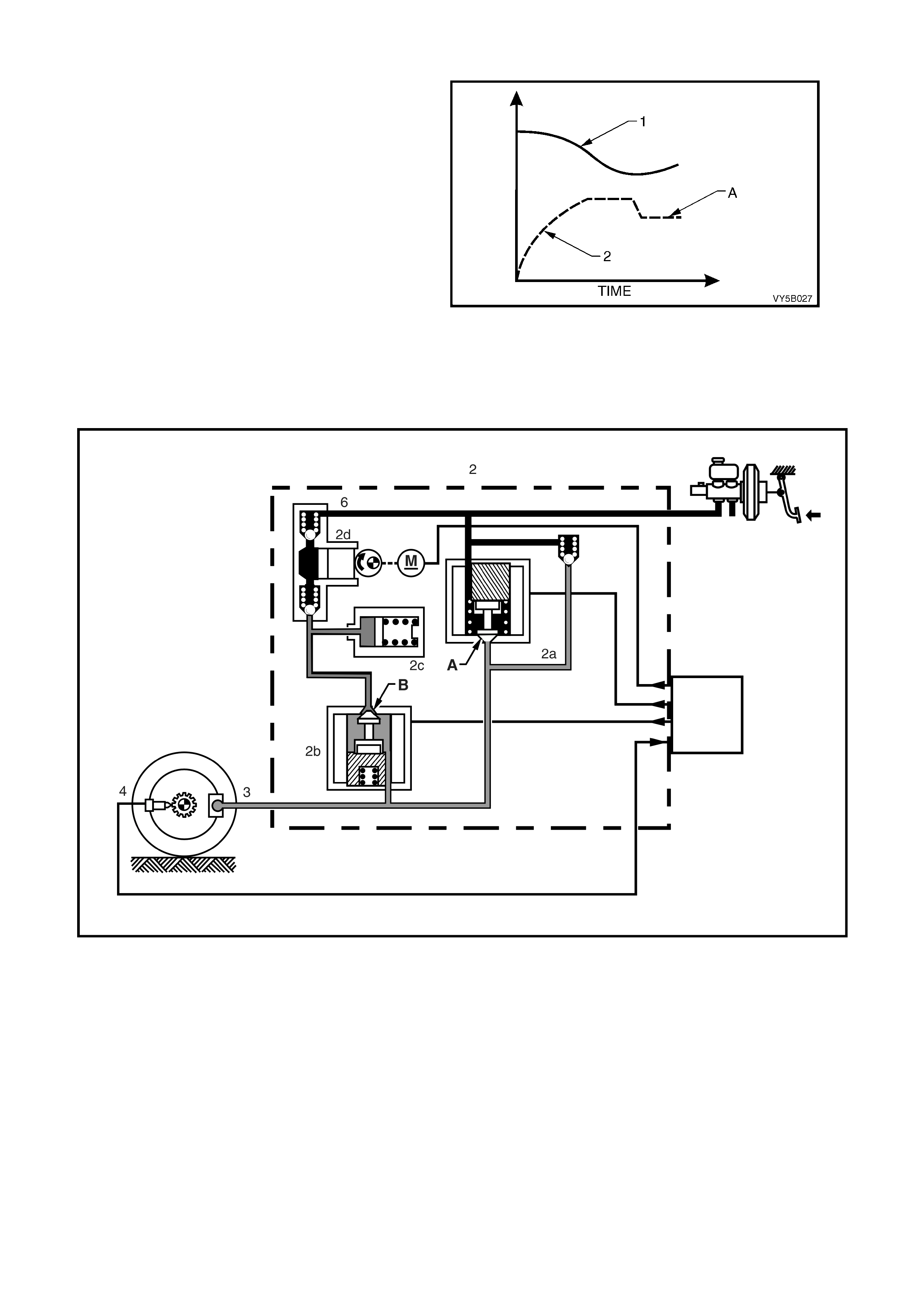
Non-ABS Braking
During this condition, the solenoid valves 2a and
2b are not activated. Valve 2a (pressure holding
(inlet) solenoid valve) is open (A). This allows
brake fluid to flow in either direction between the
brake master cylinder and the brake caliper,
providing for conventional non-ABS braking. The
solenoid valve 2b (pressure release (outlet)
solenoid valve) is closed (B), blocking off the
passage to the accumulator and the return pump.
This allows the maximum brak e apply pressure (2)
to be developed (‘A’), with the controlled
deceleration of wheel speed (1).
Figure 5B-39
The brake master cylinder (1) applies hydraulic pressure to the brake circuits (3). If the ABS control module (5)
does not detect any rapid wheel deceleration, the ABS will remain passive at this time.
Figure 5B-40
Legend
1. Brake Master Cylinder
2. Hydraulic Modulator
2a. Pressure Holding Inlet Solenoid Valve
2b. Pressure Releas e Outlet Solenoid Valve
2c. Accumulator
2d. Return Pump
3. Brake Caliper
4. Wheel Speed Sensor
5. ABS Control Module
6. Pulsation Damper
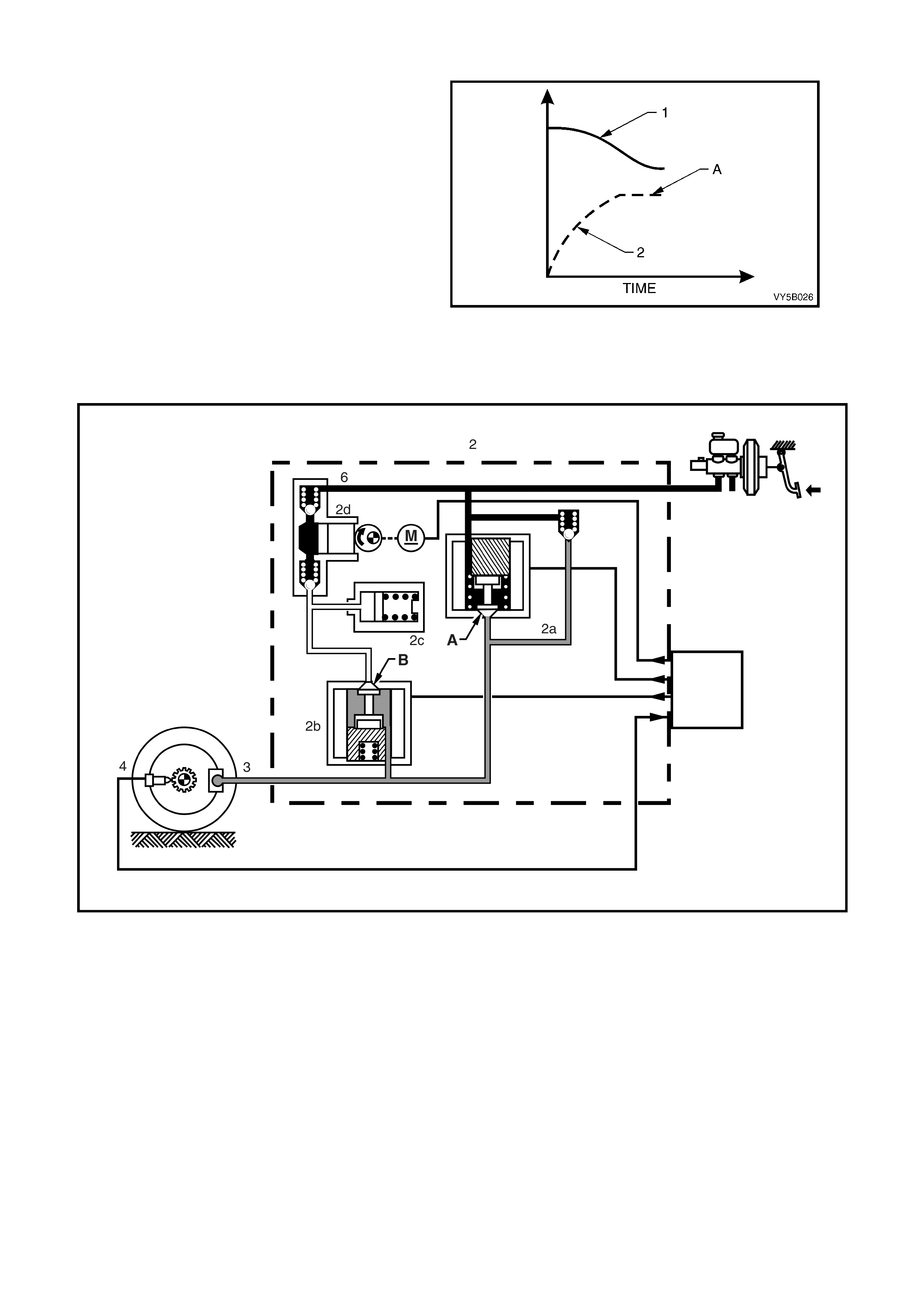
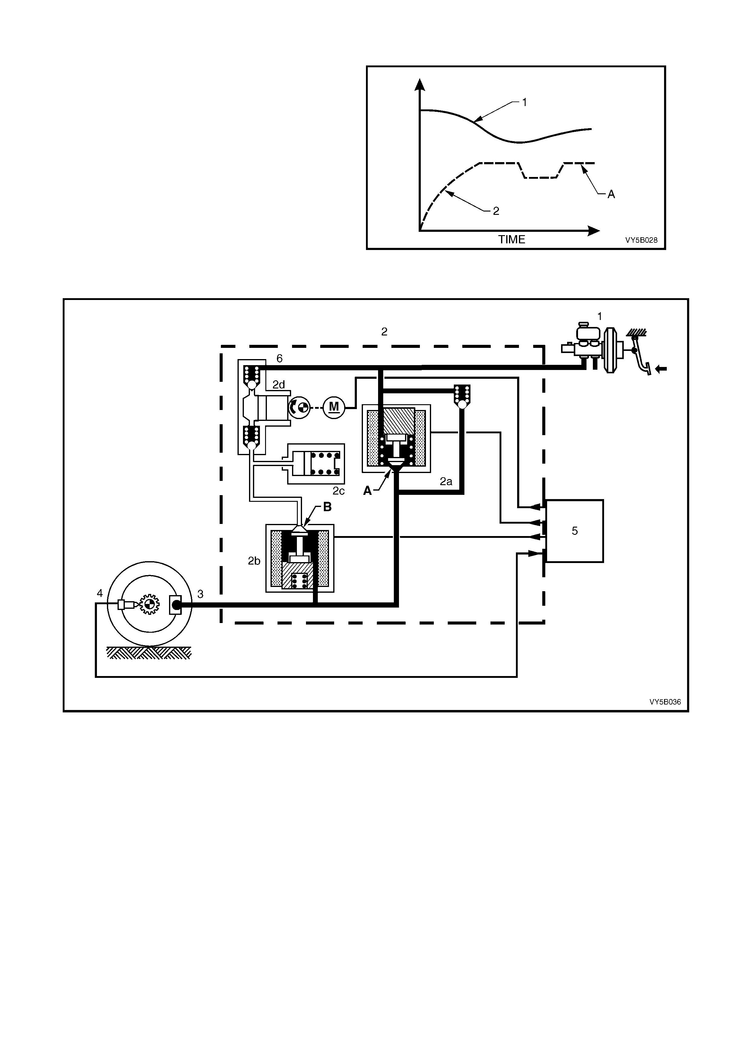
Maintaining Pres su re
When the ABS control module detects excessive
wheel deceleration (based on the wheel speed
sensor (4) signal), it commands the pressure
holding (inlet) solenoid valve (2a) to close,
maintaining brake circuit pressure (A). It does this
by earthing the respective circuit, therefore
allowing a current flow through the coil of solenoid
valve 2a. This causes the armature and valve to
mo ve downwar d, iso lating t he brak e circ uit (3) f rom
the master cylinder.
Solenoid valve 2b also remains closed (B).
Figure 5B-48 shows that, with a rapidly
decelerating wheel speed (1), the brake apply
pressure (2), is maintained (‘A’). This results in the
wheel speed deceleration rate slowing down.
Figure 5B-41
NOTE: With the brake circuit isolated, brake circuit pressure between the modulator and the brake caliper circuit
remains constant despite increased master cylinder hydraulic pressure.
Figure 5B-42
Legend
1. Brake Master Cylinder
2. Hydraulic Modulator
2a. Pressure Holding Inlet Solenoid Valve
2b. Pressure Releas e Outlet Solenoid Valve
2c. Accumulator
2d. Return Pump
3. Brake Caliper
4. Wheel Speed Sensor
5. ABS Control Module
Reducing Pres s ure
If isolation of a brake circuit between the brake
master cylinder and the brake caliper does not
reduce the excessive wheel deceleration, the ABS
control m odule ( 5) com m ands the pr essur e releas e
(outlet) solenoid valve (2b) to reduce hydraulic
brake pressure in the brake circuit.
During this phase, the ABS control module earths
the coil of the solenoid valve 2b, al lowing a current
flow through the coil windings. This causes the
armature and valve to move downward, opening a
passage (B) from the brake circuit to the
accumulator (2c) and the return pump inlet (2d).
At this stage, both solenoid valves (2a and 2 b) are
activated simultaneously.
Figure 5B-43
NOTE: At this tim e, the brak e circ uit is isol ated fr om the m aster cylinder b y the re turn p ump val ving an d the retur n
pump is energised.
This action sends brak e fluid f rom the brak e circuits back to the mas ter cylinder a gainst brak e pedal pres sure. The
return pump continues to operate during the rest of the anti-lock cycle.
Figure 5B-44
Legend
1. Brake Master Cylinder
2. Hydraulic Modulator
2a. Pressure Holding Inlet Solenoid Valve
2b. Pressure Releas e Outlet Solenoid Valve
2c. Accumulator
2d. Return Pump
3. Brake Caliper
4. Wheel Speed Sensor
5. ABS Control Module
Accumulators
During the 'Reducing Pressure' reduction phase of ABS modulation, the accumulators (2c) temporarily store fluid
from the brak e cir cuits. So m e road c onditions r equire the re lief of a lar ge vol um e of f luid fr om the br ake c aliper s. In
such cond itions, the ac cumulat or guarantees pr essure reduc tion. As soo n as the s olenoid valve ( 2b) moves to the
'Reduction Pressure' pos ition, brak e fluid from the brak e circuit flows into the ac cumulator. T hus, before t he return
pump ( 2d) starts opera tion, the accumulator allows an im mediate pres sure reduct ion in the br ake circuit. T he fr ont
brak e cir cuits s hare a common acc um ulator. T he r ear br ake circuit us es a s epar ate acc umulator . T he ac c umulators
are spring-loaded and designed to operate at less than 1,000 kPa.
Increasing (Building-up) Pressure
The wheel accelerates again as a result of the
reduced braking pressure. Upon reaching a
specific limit, the ABS control module registers the
fact that the wheel is now not being braked
sufficiently.
The ABS control module then de-energises both
solenoid valves and the for merly reduced pressure
is then increased so that the wheel is again
decelerated. The ABS control cycle begins again.
There are approximately 4 to 6 control cycles per
second, depending on the state of the road
surface.
NOTE: Circuit pressure cannot increase above
master cylinder pressure.
Figure 5B-45
Figure 5B-46
Legend
1. Brake Master Cylinder
2. Hydraulic Modulator
2a. Pressure Holding Inlet Solenoid Valve
2b. Pressure Releas e Outlet Solenoid Valve
2c. Accumulator
2d. Return Pump
3. Brake Caliper
4. Wheel Speed Sensor
5. ABS Control Module
6. Pulsation Damper
MASTER CYLINDER OPERATION
The operation of the master cylinder assembly used on vehicles with ABS is the same as the assembly used on
vehicles without A BS ; r ef er to Section 5A SERVICE AND PAR K BRAKING SYSTEMS in the MY 2003 VY and V2
Series Service Information for details.
OPERA TION AND TESTING OF THE ABS WARNING LAMP
Should a ve hicle equip ped with ABS co me into the work shop with one of the f ollowing custom er comp laints, mak e
sure of the circumstances before checking the complete ABS with the Tech 2 diagnostic scan tool.
1. Warning lamp does not illuminate after switching on the ignition.
2. Warning lamp does not go out after engine has started.
3. Warning lamp illuminates again while driving or illuminates occasionally.
The following gives information about the functioning and malfunctioning of the ABS warning lamp.
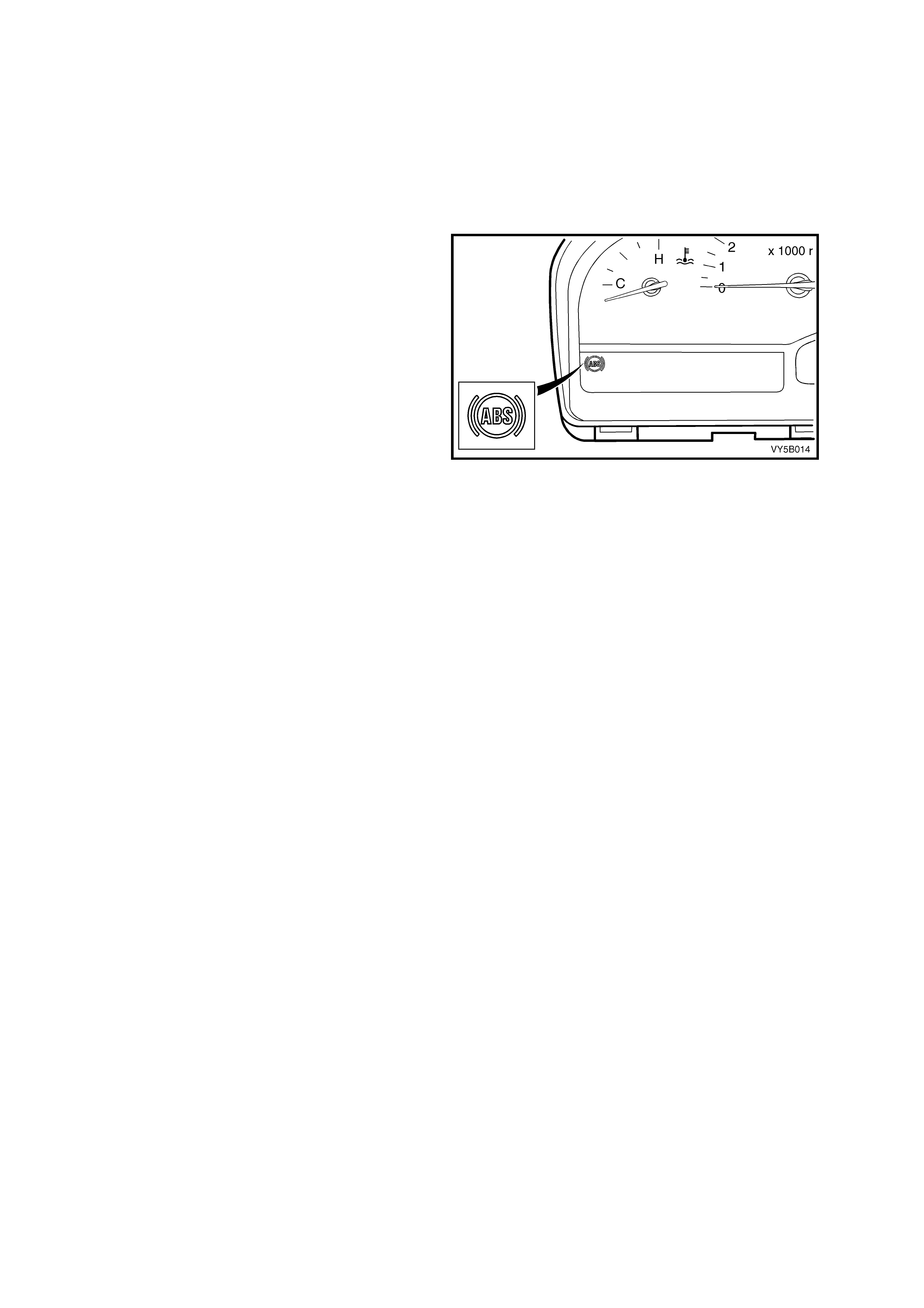
ABS Warning Lamp
W hen the ignit ion is s witched o n, the warning lam p
illuminates for approximately 2 seconds. During
this period of time, the ABS control module
performs a check of the ABS system wiring.
On all vehicles with ABS, as soon as all four
wheels of the vehicle exceed a speed of
approximately 6 km/h for the first time after
starting, the ABS system tests itself automatically
(ABS 'Self-Test'). The ABS control module cycles
each solenoid valve and the return pump motor to
check component operation. The ABS control
module also checks its own circuitry.
This procedure is repeated every time the ignition
is s witched O FF and t he e ngine is star ted again. In
addition, the ABS constantly tests itself while the
ve hicle is travelling.
The warning lamp is also used for self diagnosis
purposes.
Figure 5B-47
Incorrect Warning Lamp Indications
1. Warning lamp does not illuminate after switching ignition ON.
2. Warning lamp does not go out after approximately 2 seconds.
3. Warning lamp illuminates when driving or illuminates occasionally.
Illumination of the ABS warning lamp indicates to the driver that the ABS is defective.
When the ABS warning lamp is activated, the vehicle reverts to normal braking as in vehicles without ABS fitted
(i.e. under emergency braking, wheel/s may lock).
Occas ional il lumination of the warning lamp ma y be brought about throu gh the ba ttery being insuf f icient l y charged.
The lamp lights up only as long as there is a low voltage, eg. after switching on electrical components at idle.
The c auses of any m alfunctions can be determined with the assis tance of the T ech 2 diagnostic scan tool a nd the
appropriate diagnostic table.

2.6 ABS/TCS PRINCIPLES OF OPERATION - EXCLUDING ABS
NON-ANTI-LOCK BRAKING / NON-TRACTION CONTROL
Under normal braking and driving conditions, the anti-lock braking system functions much like a conventional
braking system. Brake fluid pressure is provided by the brake master cylinder and the power booster.
For non-ant i-lock br aking, hydraul ic pressure is applied to the brak e caliper with out any interve ntion from the ABS.
At this t ime, the hydraulic modulator establishes an open two-wa y f luid pat h from the m aster cylinder to the brake
caliper. Non-anti-lock braking occurs when the wheel sensors do not detect wheel lock-up tendencies. However,
even though the ABS is passive during normal braking, the ABS/TCS module is constantly monitoring for rapid
acceleration (wheel slip) and deceleration (wheel lock) of any of the wheels and a signal from the brake switch
(brakes applied input).
ANTI-LOCK BR AKING
When the ABS senses any tendency for wheel lock-up, it enters the anti-lock mode. During anti-lock braking, the
ABS m odulates hydraulic pressur e in the brake circ uits to control wheel sli p to 10 - 20%. For anti-l ock brak ing, the
ABS control module controls current flow to the hydraulic modulator solenoid valves to control (by maintaining,
decreasing or increasing) hydraulic pressure in the brake circuits.
NOTE: The hydraulic modulator cannot increase brake circuit hydraulic pressure above the pressure supplied by
the brake master cylinder during anti-lock braking.
ELECTRONIC TRACTION CONTROL
W hen the ABS/TCS control module s enses spin fr om the dr ive wheels du e to too much engine tor que for the road
conditions, it enters the traction control mode. While the ABS/TCS module monitors both front and rear wheel
speeds through the wheel speed sensors, the action taken will change, depending on the engine fitted to the
vehicle.
V6 Engined Veh ic les
During acceleration, if the ABS/TCS module detects drive wheel slip at any time, it will request (on the Torque
Request circuit) the Powertrain Control Module (PCM) to bring engine torque into a specific range. This is
accomplished via two high speed Pulse Width Modulated (PWM) circuits between the ABS/TCS module and the
PCM. The PCM wi ll the n adj ust spar k firing and a ir/fuel r atio, alterin g boos t dut y c ycle ( Superc harged engin e onl y),
and shutting OFF up to five (5) injectors (if necessary), and report the modified torque value (on the Torque
Achieved circuit) back to the ABS/TCS module. Simultaneous with engine torque management, the ABS/TCS
module will activa te the ABS isolation valves, turn on the ABS pum p motor and supply brake pressure to the over
spinning wheel(s).
GEN III V8 Engined Ve hicl es
If at any time during acceleration, the ABS/TCS module detects drive wheel slip, it will request:
• The PCM, via the spark retard circuit, to retard the amount of spark advance.
• The throttl e r el axer c ontro l module to r e duce the engine thr ott le ope ni ng by a cer t ain perc ent age to bring en g ine
torque into a specific range.
The throttle relaxer control module accomplishes this by commanding the throttle relaxer to override the
accelerator pedal cable and physically reduce the throttle body butterfly opening by winding the throttle cable
back.
T his is achieved via two hi gh speed Pulse Width Mod ulated (PW M) circuits between the AB S/TCS m odule and
the throttl e r e laxer c on tr ol module. T he A BS/TCS c o n tr ol module s ends a mes s age to the thr ot tle r el axe r c o ntr ol
module on the requested throttle position (DKR) circuit. The throttle relaxer control module then reports the
modified throttle position opening back to the ABS/TCS control module via the actual throttle position (DKI)
circuit.
Simultaneously with eng ine s par k retard and throttl e p os ition i nter vent io n, th e A B S/TCS contr ol module will ac tiv ate
the ABS isolation valves, turn on the ABS pump motor and supply brake pressure to the over spinning wheel(s).
The isolation valves isolate the front brake hydraulic circuits from the master cylinder and rear brake hydraulic
circuits. Once the rear brake hydraulic circuits are isolated, pressure can be applied to the rear wheels without
aff ecting an y other brak e hydraul ic circuits . The AB S/T CS hydraulic module opens the priming valve, a llowing f luid
to be drawn from the master cylinder to the pum p motor, which is then activated, building pressure. The hydraulic
module, in let and outlet va lves begin c ycli ng and the switchi ng valve clos es, ensuring f luid is direct ed to the wheel
and not back into the master cylinder.
The inlet and outlet valve cycling assists in obtaining maximum road surface traction in the same manner as the
Anti-Lock Brake mode. The difference between Traction Control and Anti-Lock Brake mode is that brake fluid
pressure is increased to lesson wheel spin (Traction Control mode), rather then reduced to allow greater wheel spin
(Anti-Lock Brake mode).
If at any time during Traction Control mode, the brakes are manually applied, the brake switch signals the
ABS/TCS module to inhibit brake intervention and allow for manual braking. However, engine intervention (V6
engines) or, throttle reduction and spark retard intervention (GEN III V8), can still occur if necessary.

ABS/TCS CONTROL MODULE OPERATION
Inputs
The f ollowing com ponents, send signals to the AB S/TCS contr ol m odule, where t hey are eva luated in ord er for the
module to maintain and control wheel slip/spin.
1. Ignition on input, (via fusible link F105, ignition switch, fuse F27) - ABS/TCS module terminal X1- 15.
2. W heel speed sensor inputs - ABS/TCS module terminal No’s. LHF X1-6 and X1-7, RHF X1-4 and X1-5, LHR
X1-8 and X1-9, and RHR X1-1 and X1-2.
3. Brakes applied input (from brake lamp switch) - ABS/TCS module terminal X1- 14.
4. Batt er y volta ge - AB S/T C S module term inals X1- 17 an d X1-18.
5. V6 Engines: Actual Torque (torque acknowledgment) - ABS/TCS module terminal X1-27.
GEN III V8 Engine: Actual throttle position (DKI) - ABS/TCS control module X1-27.
6. Engine speed signal - ABS/TCS module terminal X1-30.
7. TCS disable switch (TRAC CTRL) - ABS/TCS module terminal X1-31.
8. GEN III V8 Engine: Serial data (input and output) - ABS/TCS control module terminal X1-11.
Outputs
To c ontrol the anti- lock brak ing system and tr action contr ol system , the ABS/TCS c ontrol modul e sends com mand
signals to the following components.
1. Valve relay/solenoid valves – internal control.
2. Pump relay/pump motor – internal control.
3. Serial data – ABS/TCS module terminal X1-11.
4. Self diagnostic 'Flash Code Actuation' – ABS/TCS module terminal X1-12.
5. V6 Engines: Torque requested – ABS/TCS module terminal X1-13.
GEN III V8 Engine: Requested throttle position – ABS/TCS control module terminal X1-13.
6. TCS warning lamp (TRAC OFF, LOW TRAC) – ABS/TCS module terminal X1-20.
7. ABS warning lamp – ABS/TCS module terminal X1-21.
8. GEN III V8 Engine: Requested spark retard – ABS/TCS control module terminal X1-28.
W ith the igniti on sw itch in the o n pos ition, bat ter y volt age is applie d to the ABS /TCS c ontr ol m odule t erm inal X1 -15
via fuse F27. Batter y voltage is also applied to the pum p motor relay and valve rela y via fusible link F103. Neither
of the relays operate until they receive an earth from the ABS/TCS control module.
Also, battery voltage is supplied to the ABS and TCS warning lamps via fuse F13. The LOW TRAC and ABS
warning lamps will n ot ill um inat e un ti l th e y are ear t hed b y AB S/T CS c ontr o l module. If the AB S/T CS c ontr o l module
wiring harn es s connec tor A 37, is not c on nec te d to the c ontrol module, t er minals 19, 20 an d 21 ar e s horte d to geth e r
by a shorting b ar , a nd the LOW TRAC and A BS warn in g l amps will be i lluminat ed. The T RAC O F F war ni ng la mp is
defaulted to the ON position and is turned off via a serial data message from the ABS/TCS control module when
the ignition is turned on (provided the system is OK).
Wheel speed sensors are located at each front wheel and at each final drive inner axle flange. When the vehicle
starts moving, all of the speed sensors create signals that are input to the ABS/TCS control module at terminals
X1-1 and X1-2, X1-4 and X1-5, X1-6 and X1-7, X1-8 and X1-9. These signals are AC electrical pulses that are
proportional (in frequency and amplitude) to wheel rotational speed.
Once the vehicle has been started and driven over approximately 6 km/h, the control module performs an
ABS/TCS self test. The control module test cycles each solenoid valve and the return pump in the hydraulic
modulator to check component operation. The control module checks its own logic section and circuitry. If errors
are detected during this test, the control module earths terminal 20, and illuminates the ABS warning lamp, while
the ABS/TCS control module sends a message, via the serial data circuit, commanding the TRAC OFF warning
lamp to be illuminated. The ABS and/or TCS warning lamp/s are illuminated to warn the driver of a problem with the
system/s. The ABS/TCS control module remains deactivated until the next ignition switch OFF to ON cycle when
the process is repeated and the ABS and/or TRAC warning lamp/s will be illuminated.
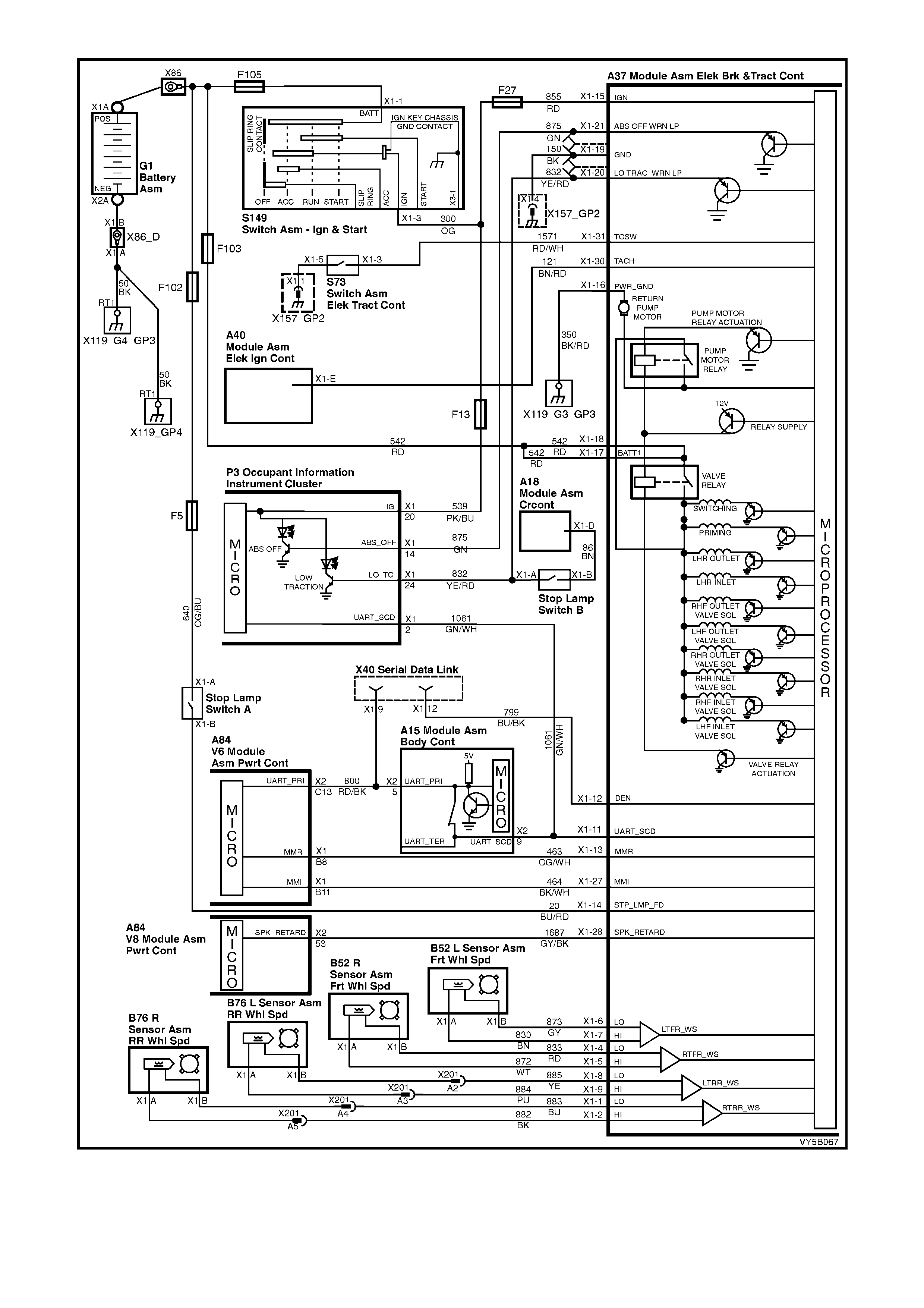
Figure 5B-48 – ABS/TCS – All Engines

The ABS self test occurs once each ignition cycle as follows:
1. After receiving an ignition ON input, the control module earths and activates the valve relay.
2. As soon as the ABS/TCS control module receives a signal from any of the wheel speed sensors, it checks
wheel speed sensor output. If any of the wheel speed sensor signals are not detected, or are incorrect, the
ABS/TCS system will be disabled and the warning lamps will be illuminated.
3. When the vehicle reaches approximately 6 km/h, the control module tests the solenoid valves and the return
pump in the modulator. This test can usually be heard and/or felt by the driver.
4. If the pump or solenoid va lves fail to operate, th e ABS/T CS system will be disabl ed and the war ning lam ps will
be illuminated.
Once the vehicle is moving (above 6 km/h), the control module continuously monitors itself and the following
components:
1. Solenoid valves.
2. Wheel speed sensors.
3. Wiring harness and relays.
4. Battery voltage.
If battery voltage drops below approximately 9 volts, the ABS/TCS will be disabled and the ABS and TRAC OFF
warning lamps will be illuminate d.
During braking applications, if one or more wheels start to decelerate too quickly, the ABS is engaged and the
modulation process begins. Wheel speed information sent to the ABS/TCS control module is processed and the
module determines proper solenoid valve operation in the modulator. The modulator contains ten solenoid valves;
one inlet and one outlet valve for each wheel.
When wheel spin is detected and traction control mode begins, the ABS/TCS control module also engages ABS
through the modulation process. Additionally, the ABS/TCS control module simultaneously changes the engine
torque conditions through the use of engine torque management.
HYDRAULIC MODULATOR OPERATION
The hydraulic modulator executes ABS control module commands using ten solenoid valves. These solenoid
valves, located in the hydraulic modulator assembly, are in series with the brake master cylinder and the brake
circuits. The hydraulic modulator solenoid valves are activated separately by the ABS/TCS control module
corresponding to various ABS or TCS control phases:
1. Non-ABS Braking (ABS and TCS phases)
2. Maintaining Pressure (ABS phase)
3. Reducing Pressure (ABS phase)
4. Increasing (Building-up) Pressure (ABS phase)
5. Normal condition (ABS and TCS phases – brakes off)
6. Applying (TCS phase)
The hydraulic modulator assembly contains ten solenoid valves and a brake fluid return pump; however, for
explanation of the operation only one accumulator and four solenoid valves will be described (rear brakes). The
operation is the same for all four circuits.
Non-ABS Braking (ABS and TCS phases)

Condition Description
During this normal brake application, brake apply
pressure (2) reaches maximum level (‘A’), causing
the wheel speed (1) to decelerate at the m aximum
optimum level.
Control Action
During normal brake application, the inlet and
outlet valves are not activated. The inlet valve
(pressure holding solenoid valve) is open. This
allows brake fluid to flow in either direction
between the brake master cylinder and the brake
caliper, providing for conventional non-ABS
braking. The outlet valve (pressure release outlet
solenoid valve) is closed, blocking off the passage
to the accumulator and the return pump.
The brake master cylinder hydraulic pressure is
applied to the brake circuits (caliper). If the
ABS/TCS control module (not shown) does not
detect any rapid wheel deceleration, the ABS will
remain passive at this time.
Figure 5B-49
Hydraulic modulator status:
LH inlet valve... Open LH outlet valve Closed
RH inlet valve.. Open RH outlet valve Closed
Priming valve... Closed Switching valve Open
Motor............... OFF
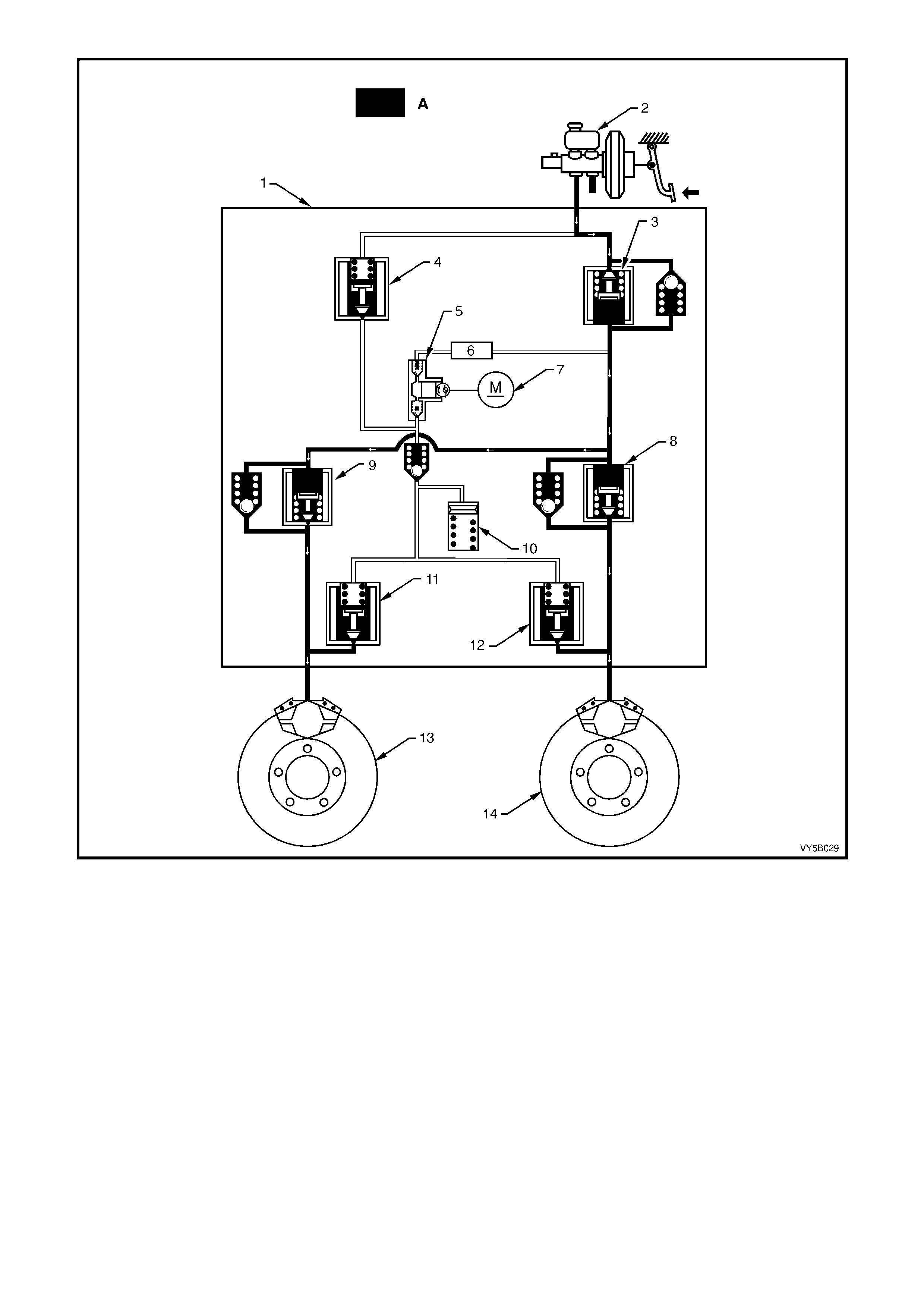
Figure 5B-50 – Rear Hydraulic System Only
Legend
A Pressurised Flow of Fluid
1. ABS/TCS Hydraulic Module
2. Brake Master Cylinder
3. Switching Valve
4. Priming Valve
5. Pump Assembly
6. Damper
7. Motor
8. Inlet Valve – Right
9. Inlet Valve – Left
10. Accumulator
11. Outlet Valve – Left
12. Outlet Valve – Right
13. Left Driven Wheel
14. Right Driven Wheel

Maintaining Pressure (ABS phase)
NOTE: The following diagram and explanation
assumes the right hand rear wheel is having a
tendenc y to lock .
Condition Description
When the ABS/TCS control module detects
excessive wheel deceleration (based on the wheel
speed sensor signal) indicating a wheel speed
deceleration (1) outside programming parameters,
it will com m and the h ydraulic modulat or to le vel out
the brake apply hydraulic pressure (2) and
maintain at that level (‘A’).
Control Action
it commands the right hand inlet valve (pressure
holding solenoid valve) to maintain brake circuit
pressure. It does this by earthing the respective
circuit (RH in this case), therefore allowing a
current flow through the coil of inlet valve. This
causes the ar m ature and val ve to move do wnwar d,
isolating the brake circuit (caliper) from the master
cylinder.
Figure 5B-51
NOTE: W ith the brake circuit iso lated, brake c ircuit
pressure between the modulator and the brake
caliper circuit remains constant despite increased
master cylinder hydraulic pressure.
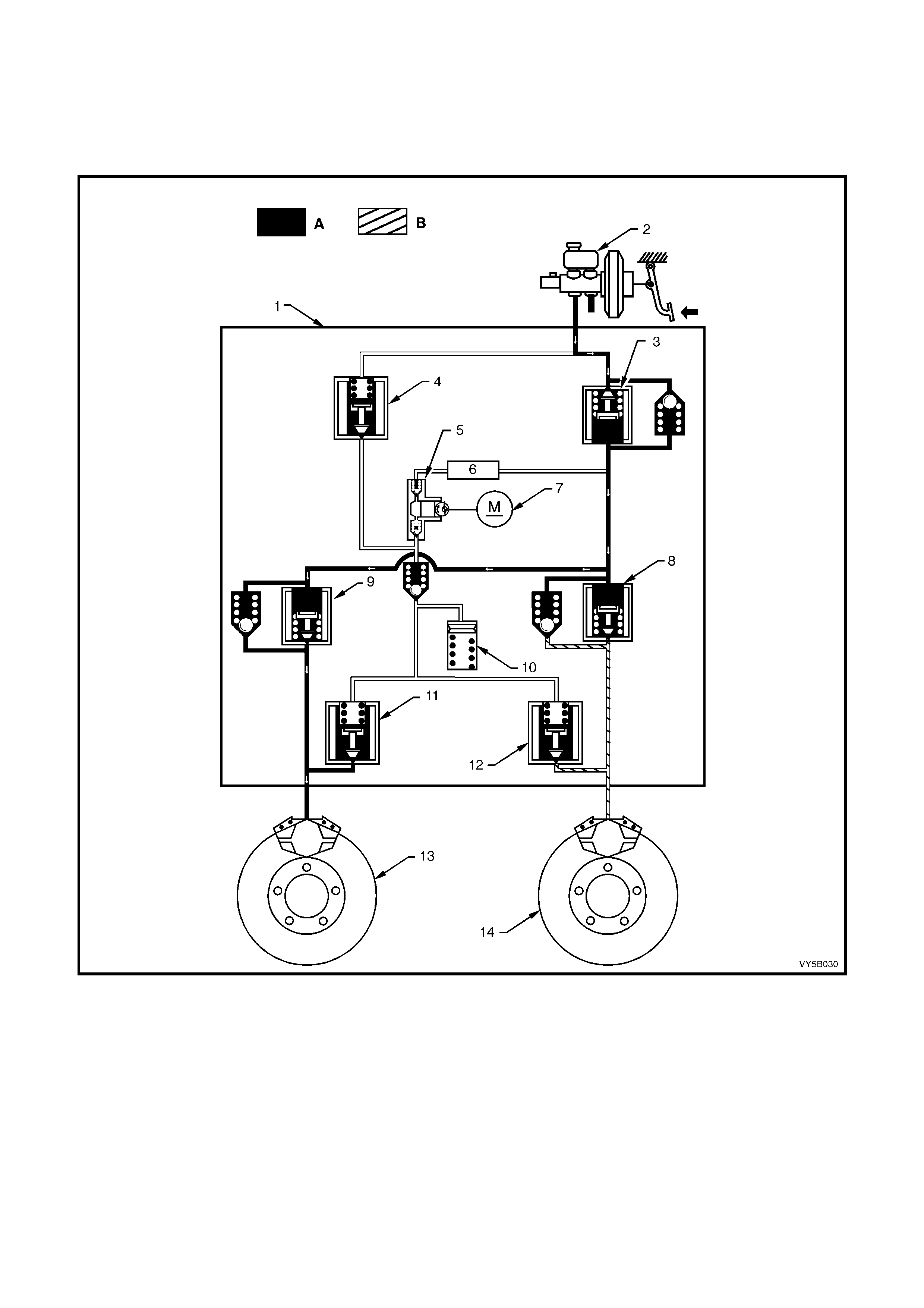
Hydraulic modulator status:
LH inlet valve... Open LH outlet valve. Closed
RH inlet valve.. Closed RH outlet valve Closed
Priming valve... Closed Switching valve Open
Motor............... OFF
Figure 5B-52 – Rear Hydraulic System Only
Legend
A Pressurised Flow of Fluid
B Pressure Hold (ABS Mode)
1. ABS/TCS Hydraulic Module
2. Brake Master Cylinder
3. Switching Valve
4. Priming Valve
5. Pump Assembly
6. Damper
7. Motor
8. Inlet Valve – Right
9. Inlet Valve – Left
10. Accumulator
11. Outlet Valve – Left
12. Outlet Valve – Right
13. Left Driven Wheel
14. Right Driven Wheel

Reducing Pressure (ABS phase)
NOTE: The following diagram and explanation
assumes the right hand rear wheel is having a
tendenc y to lock .
Condition Description
If isolation of a brake circuit between the brake
master cylinder and the brake caliper does not
reduce the excessive wheel deceleration (1), the
ABS/TCS control module commands the hydraulic
modulator to reduce the brake apply pressure (2)
to a reduced level (‘A’).
Control Action
From an ABS/TCS control module command, the
modulator reduces hydraulic brake pressure in the
brake circuit (RH outlet valve in this case), by
openin g the ou tlet v alve (pr ess ure rele ase s oleno id
valve). During this phase, the ABS/TCS control
module earth’s the coil of the RH outlet valve,
allowing a current flow through the coil windings.
This causes the armature and valve to move
downward, opening a passage from the brake
circuit to the accumulator and the pump assembly
inlet.
Figure 5B-53
At this stage, both the RH inlet and RH outlet
valves are activated simultaneously.
Because the brake pedal is still being depressed
during this phase, the released pressure from the
caliper has to be greater than that of the pressure
of the normal (non-ABS) brake circuit. To do this,
the pump motor is energised and the pump
becomes operational. This will increase the return
flow pressure from the caliper, thus allowing the
fluid released from the caliper to be returned back
to the master cylinder. The pump will continue to
operate during the rest of the anti-lock brake cycle.
Hydraulic modulator status:
LH inlet valve... Open LH outlet valve.Closed
RH inlet valve..Closed RH outlet valve Open
Priming valve... Closed Switching valve Open
Motor............... ON
NOTE: Motor will remain operational until ABS
mode is exited.
Accumulators
During the 'Reducing Pressure' reduction phase of
ABS m odulat ion, th e accu m ulators (2c) tempor arily
store fluid from the brake circuits. Some road
conditions require the relief of a large volume of
fluid fr om the brak e caliper. In suc h conditio ns, the
accumulator guarantees pressure reduction. As
soon as the solenoid valve (2b) moves to the
'Reduction Pressure' position, brake fluid from the
brake circuit flows into the accumulator. Thus,
before the return pump (2d) starts operation, the
accumulator allows an immediate pressure
reduction in the brake circuit. The front brake
circuits share a common accumulator. The rear
brake circuit uses a separate accumulator. The
accumulators are spring-loaded and designed to
operate at less than 1,00 0 kPa.
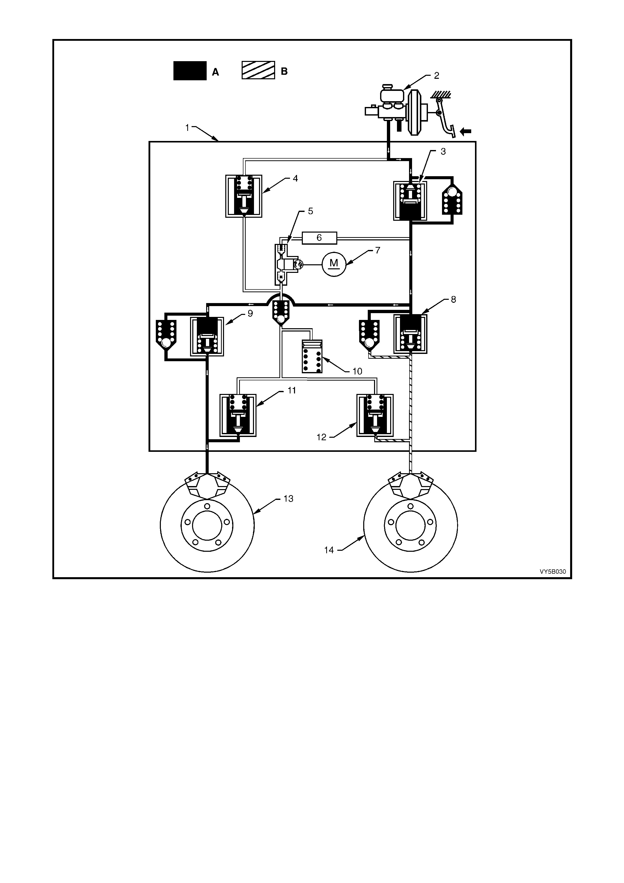
Figure 5B-54 – Rear Hydraulic System Only
Legend
A Pressurised Flow of Fluid
B Pressure Hold (ABS Mode)
1. ABS/TCS Hydraulic Module
2. Brake Master Cylinder
3. Switching Valve
4. Priming Valve
5. Pump Assembly
6. Damper
7. Motor
8. Inlet Valve – Right
9. Inlet Valve – Left
10. Accumulator
11. Outlet Valve – Left
12. Outlet Valve – Right
13. Left Driven Wheel
14. Right Driven Wheel

Increasing (Building-up) Pressure (ABS Phase)
NOTE: The following diagram and explanation
assumes the right hand rear wheel is having a
tendenc y to lock .
Condition Description
The wheel begins to accelerate again (1), as a
result of the reduced braking pressure (2). Upon
reaching a specific limit, the ABS control module
registers the fact that the wheel is now not being
braked sufficiently and commands the hydraulic
modulator to increase the brake apply pressure
(‘A’).
Control Action
The ABS control module then de-energises both
the RH inlet and RH outlet valves and the formerly
reduced pressure is then increased so that the
wheel is again decelerated. The ABS control cycle
begins again. There is approximately 4 – 6 control
cycles per second, depending on the state of the
road surface.
Figure 5B-55
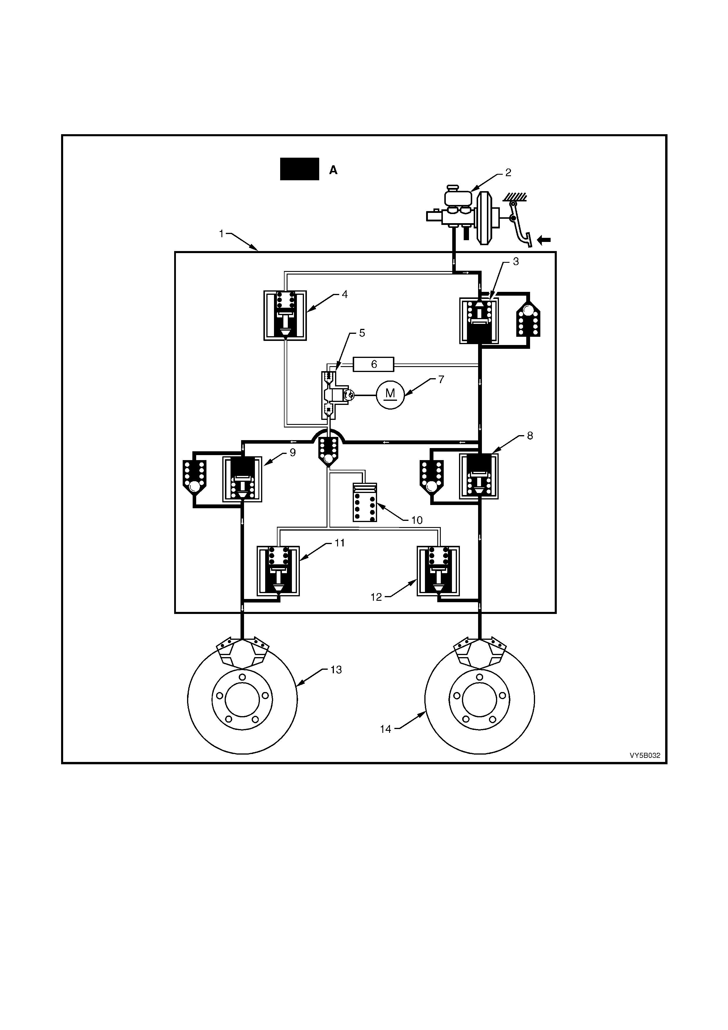
Hydraulic modulator status:
LH inlet valve... Open LH outlet valve ... Closed
RH inlet valve.. Open RH outlet valve... Closed
Priming valve... Closed Switching valve .. Open
Motor............... ON
Figure 5B-56– Rear Hydraulic System Only
Legend
A Pressurised Flow of Fluid
1. ABS/TCS Hydraulic Module
2. Brake Master Cylinder
3. Switching Valve
4. Priming Valve
5. Pump Assembly
6. Damper
7. Motor
8. Inlet Valve – Right
9. Inlet Valve – Left
10. Accumulator
11. Outlet Valve – Left
12. Outlet Valve – Right
13. Left Driven Wheel
14. Right Driven Wheel
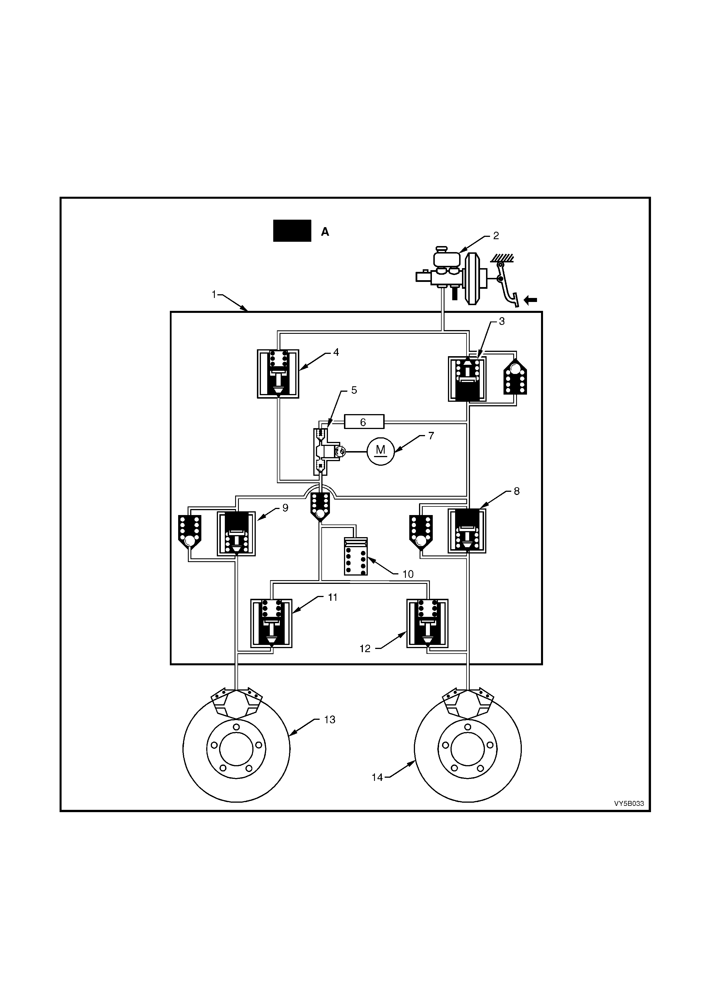
TCS Normal Condition (ABS and TCS Phases)
In the n ormal condit ion, ther e is no brak e interventio n. All t he valves in the hydr aulic m odulator are in t heir nor mal
rest positions, allowing for uninterrupted flow for a normal braking condition. The schematic below depicts no
pressure in the system, therefore no application of brakes.
Hydraulic modulator status:
LH inlet valve... Open LH outlet valve. Closed
RH inlet valve.. Open RH outlet valve Closed
Priming valve... Closed Switching valve Open
Motor............... OFF
Figure 5B-57 – Rear Hydraulic System Only
Legend
A Pressurised Flow of Fluid
1. ABS/TCS Hydraulic Module
2. Brake Master Cylinder
3. Switching Valve
4. Priming Valve
5. Pump Assembly
6. Damper
7. Motor
8. Inlet Valve – Right
9. Inlet Valve – Left
10. Accumulator
11. Outlet Valve – Left
12. Outlet Valve – Right
13. Left Driven Wheel
14. Right Driven Wheel
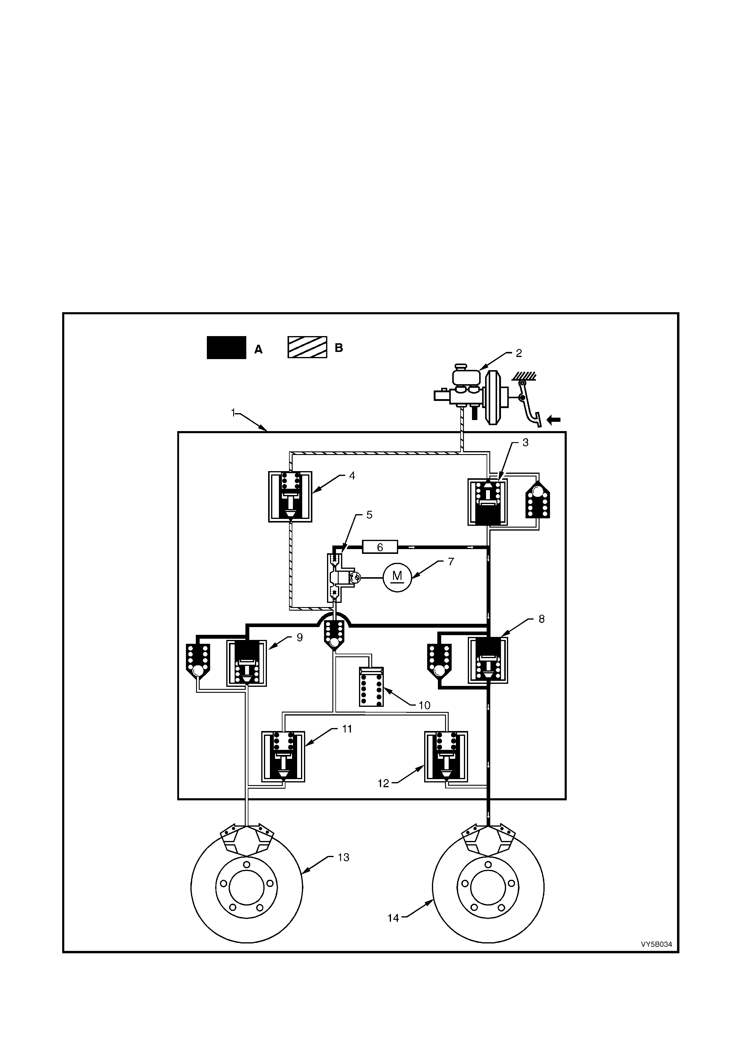
TCS in Operation (TCS Phase)
NOTE: The following diagram and explanation assumes the right hand rear wheel is having a tendency to spin.
Brake Intervention
In the next schematic, the right hand wheel speed sensor has detected that the wheel is about to enter into a
situation where wheel slippage is about to occur from excess engine torque for the road condition.
The ABS/TCS control module commands the priming valve open, allowing fluid to be drawn from the master
cylinder b y the pum p as sem bly. The switc hing va lve is closed, ens uring f luid is d irected to th e whe els an d not bac k
to the master cylinder.
With the right wheel tending to spin, the left inlet valve closes, allowing the brakes to be applied only to the right
wheel. This will transfer the torque to the left wheel. This operation can be applied approximately 4 – 6 times a
second and can function on either of the driven wheels, or both.
Hydraulic modulator status:
LH inlet valve... Closed LH outlet valve... Closed
RH inlet valve.. Open RH outlet valve .. Closed
Priming valve... Open Switching valve.. Closed
Motor............... ON
Figure 5B-58 – Rear Hydraulic System Only

Legend for Figure 5B-52
A Fluid Being Drawn From the Master Cylinder
B Pressurised Flow of Fluid
1. ABS/TCS Hydraulic Module
2. Brake Master Cylinder
3. Switching Valve
4. Priming Valve
5. Pump Assembly
6. Damper
7. Motor
8. Inlet Valve – Right
9. Inlet Valve – Left
10. Accumulator
11. Out l et Val ve – Left
12. Out l et V al ve – Right
13. Left Driven Wheel
14. Right Driven Wheel
Engine Torque Management – V6 Engines Only
At the same time the ABS/TCS control module initiates brake intervention, it also communicates with the
Powertrain Control Module (PCM), requesting the PCM to bring the engine torque into a specific range.
With the ignition on and the engine not running, the ABS/TCS control module constantly sends a Pulse Width
Modulat ed (PW M) signal with a duty cyc le of 93% to t he PCM. T he PCM respon ds with a PW M signal with a dut y
cycle of 5%. When the engine is started, the duty cycle of the torque acknowledgment signal will increase to
approximately 30% at idle. When the ABS/TCS control module determines that a reduction in engine torque is
required, the torque requested signal will decrease from 93% (no torque reduction) to 30% (maximum torque
reductio n) the PCM will the n reduce the engin e torque to the req uired am ount by adjusting s park firing and a ir/fuel
ratio, alt ering boost dut y cycle (Superc harged V6 e ngine only) and sh utting OFF up to f ive injector s (if necess ary).
During trac tion control, the duty cycle of the torque ack nowledgm ent signal s hould be sim ilar to and follo w the duty
cycle of the torque requested signal.
Engine Spark and Throttle Position Intervention – GEN III V8 Engine Only
At the same time the ABS/TCS control module initiates brake intervention, it also communicates with the
Powertrain Control Module (PCM) and the throttle relaxer control module requesting the PCM to retard the spark
advance and for the throttle relaxer control module to reduce the throttle opening.
With the engine running, the PCM continually supplies and monitors a 12 volt pull-up voltage to the spark retard
circuit. T he ABS/T CS co ntrol m odule re quests sp ark retard by p ulling this voltage low. T he PCM th en res ponds b y
reducing the spark advance of the engine.
The AB S/TC S contr ol m odule constan tl y sends a Pu lse Width Modulated (PWM) signal a t 90% with a fr equenc y of
100Hz to th e throttle rel ax e r c ontr ol module on th e req ues ted throttle pos it io n li ne ( DKR) T his s ignal is to i ndi c ate to
the throttle relaxer control module that the traction control system (TCS) is in a state of readiness.
With the engine running, the ABS/TCS control module constantly sends a Pulse Width Modulated (PWM) signal
with a duty cycle of 90% to the throttle relaxer control module via the requested throttle position line (DKR). The
throttle relaxer control module responds on the actual throttle position line (DKI) with a PWM signal with a duty
cycle of 9%.
When the ABS/TCS control module determines that a reduction in throttle is required, it reduces the PWM signal on
the requested throttle position line (DKR), from 90% (no throttle reduction) to as low as approximately 14%
(maximum throttle reduction). The throttle relaxer control module then drives the throttle relaxer motor, overriding
the accelerator pedal command (drivers foot), pulling the throttle cable back, and thus, closing the amount of
throttle opening.
MASTER CYLINDER OPERATION
The operation of the master cylinder assembly used on vehicles with ABS is the same as the assembly used on
vehicles wit hout ABS, refer to Section 5A SERVICE AND PARK BR AKING SY STEM in the MY 2003 VY and V2
Series Service Information for details.
OPERA TION AND TESTING OF THE ABS AND ‘TRAC OFF’ WARNING LAMPS
Should a vehicle equipped with ABS/TCS come into the workshop with one of the following customer complaints,
make sure of the circumstances before checking the complete ABS/TCS with the Tech 2 diagnostic scan tool.
1. Warning lamp(s) does not illuminate after switching the ignition on.
2. Warning lamp(s) does not go out after engine has started.
3. Warning lamp(s) illuminates again while driving or illuminates occasionally.
The following information describes the functioning and malfunctioning of the ‘ABS’ and ‘TRAC OFF’ warning
lamps.
‘ABS’ and ‘TRAC OFF’ Warning Displays
When the ignition is switched on, the ‘ABS’ warning display is activated for approximately two seconds and the
‘TRAC O FF ’ warn in g l amp for appr oximately fiv e s econds ( with eng ine r unn in g, ‘TRAC OF F ’ dis p lay is activat ed for
only two s econds als o). During t his per iod of tim e, the AB S/TCS contr ol m odule per forms a c heck of the ABS/TCS
system wiring.
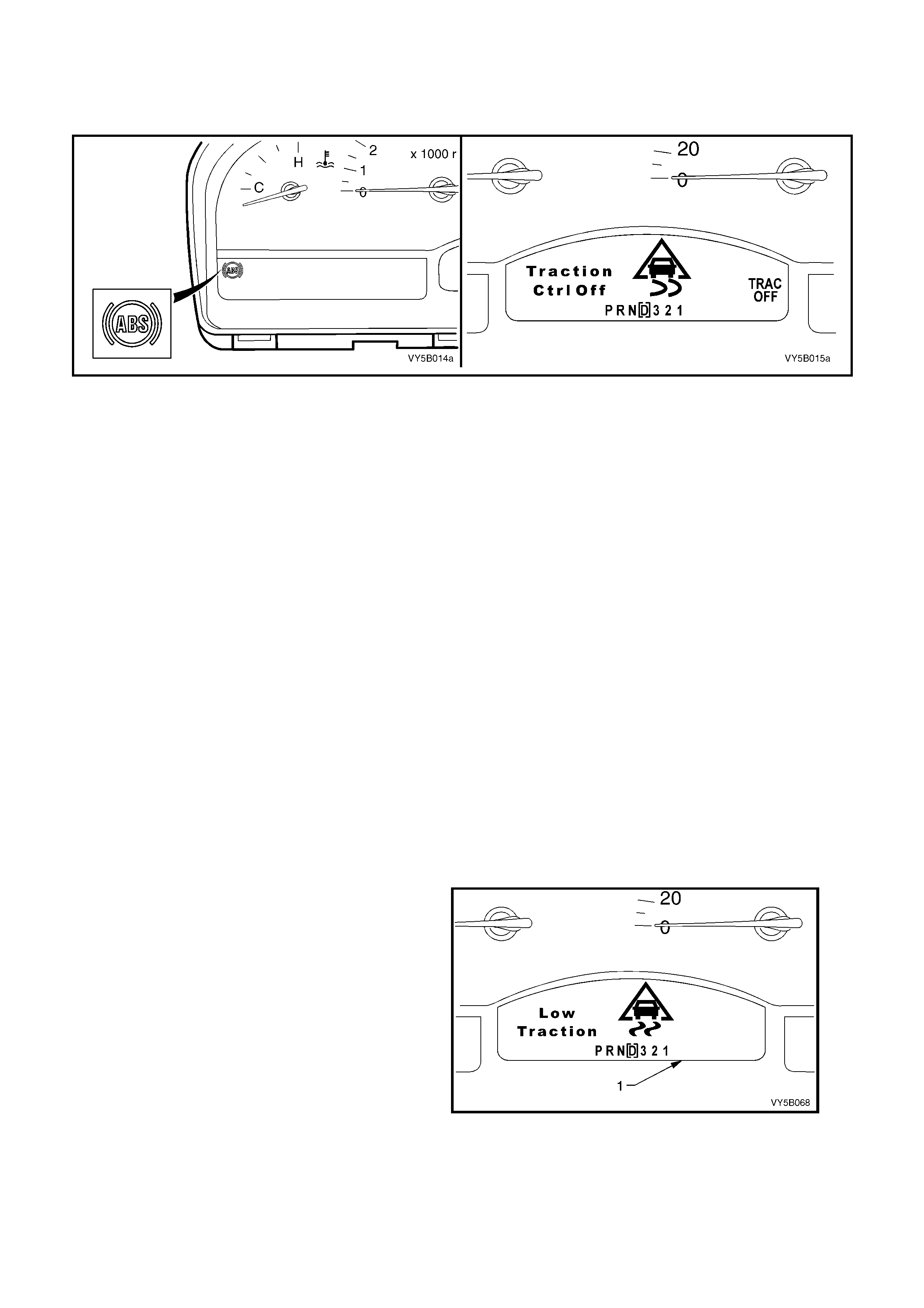
On all vehicles with ABS/TCS, as soon as all four wheels of the vehicle exceed a speed of approximately 6 km/h for
the first time after starting, the ABS/TCS system tests itself automatically (ABS/TCS 'Self-Test'). The ABS/TCS
control module cycles each solenoid valve and the return pump motor in the hydraulic modulator to check
component operation. The ABS/TCS control module also checks its own circuitry.
Figure 5B-59
This procedure is repeated every time the ignition is switched off and the engine is started again.
In addition, the ABS/TCS system constantly tests itself while the vehicle is travelling. The warning display is also
used for self diagnosis purposes.
NOTE: The ‘TRAC OFF’ warning display will also be activated if the ‘T/C’ button has been pressed. The ‘TRAC
OFF’ light will then stay activated until either the ignition is switched off or the ‘T/C’ button is pressed again.
Incorrect Warning Lamp Indications (‘ABS’ and ‘TRAC
OFF’)
1. Warning display(s) is not activated after switching ignition ON.
2. Warning display(s) is not de-activated after approximately 2 seconds.
3. Warning display(s) is activated when driving or is activated occasionally.
NOTE: The ‘T RAC OFF’ warnin g displa y will be acti vated if the s ystem is manually s witched of f b y the ‘T /C’ s witch
located in t he console and the ‘LOW TRAC’ warning display will flash if the TCS system is functioning (in a whee l
spin situation). If either of these displays are activated under these conditions, the system is functioning correctly.
Activat ion of the ABS warni ng lamp indica tes to the dri ver that the AB S is defecti v e.
Activation of the ‘TRAC OFF’ warning display indicates to the driver that the TCS system is either manually
disabled or defective.
When the ABS warning lamp is activated, the vehicle reverts to normal braking as in vehicles without ABS fitted
(e.g. under emergency braking, wheel/s may lock).
When the ‘TRAC OFF’ warning display is activated, the ABS still functions correctly.
Occasional activation of the warning lamps may be brought about through the battery being insufficiently charged.
The display is only activated as long as there is a low voltage, e.g. after switching on electrical components at idle.
The causes of any malfunction can be determined with the assistance of the Tech 2 diagnostic scan tool.
‘LOW TRAC’ Warning Display
The ‘LOW TRAC’ display in the Multi-Function
Display (MFD) (1), is used to inform the driver that
the vehicle is in a critical driving situation and that
the TCS system has been engaged to control
wheel spin.
Figure 5B-60

3. SERVICE OPERATIONS
3.1 SAFETY AND PRECAUTIONARY MEASURES
The f ollowing infor m ation is gener al saf ety and prec aut ionar y meas ures tha t m ust be o bser ved when ser vicin g and
diagnosing the ABS or ABS/TCS system.
BEFORE TESTING FOR AN ABS OR ABS/TCS FAULT, ENSURE THAT CONVENTIONAL BRAKES ARE
WORKING CORRECTLY.
ABS and ABS/TCS are basically maintenance-free, however, when working on a vehicle with either of these
systems, the following points must be observed:
1. Whenever welding with electric welding equipment, disconnect wiring harness plug from the ABS or ABS/TCS
control module.
2. W henever painting a vehicl e using dr yin g techniques t hat put the tem perature ab ove +85°C f or mor e than one
hour, remove the ABS or ABS/TCS control module from the vehicle.
3. During any service operation that requires the replacement of the hydraulic modulator, the ABS or ABS/TCS
control module, wheel speed sensors, wiring harness, as well as after work procedures in which contact is
made with the various A BS and TCS assemblies (eg. accident repair), the com plete ABS or ABS/TCS system
MUST be checked, refer to 4.4, ABS, ABS/TCS FUNCTION AL CHECK in this Section.
Make sure that the brake lines, wheel speed sensor connections on the ABS control module, and the wheel
speed se ns or wiring harness c onnec tions ar e ass igne d c orr ec tl y (ref er to AB S an d AB S/TCS wiring di agr am, in
Section 12P WIRING DIAGRAMS in this Service Inform ation.
4. After any work is carried out on the brake system, the brake system must be bled and a high-pressure test
conducted. All junctions must be tested for leakage.
5. Be sure to properly tighten the battery cable terminals on the terminal posts of the battery.
6. Do not use a fast charger for starting the vehicle.
7. Never disconnect the battery from the vehicle electrical system while the engine is running.
8. Disconnect the battery from the vehicle electrical system before charging.
9. Make sure that all connectors of the wiring harness are seated correctly.
10. Never disconnect or connect the ABS or ABS/TCS control module wiring harness connector when the battery is
connecte d or the igniti on is turned on.
11. Always use suitable wiring harness test leads (such as those in KM-609) when carrying out any test on the
ABS or ABS/TCS control module wiring harness connector to avoid terminal damage.
12. Always caref ully note th e routing, pos iti on, mount ing a nd loc at ion of A BS or A BS/T CS wir in g, co nnec t or s , cli ps ,
brackets. As ABS and ABS/TCS components are extremely sensitive to EMI (Electro-Magnetic Interference).
Proper mounting is critical when servicing ABS or ABS/TCS components.
13. Do not hang the suspension components by the wheel speed sensor cables; these cables are delicate.
14. Some components of the ABS or ABS/TCS are not serviced separately and must be replaced as assemblies.
15. F or saf ety reaso ns, th e h ydraulic m odul ator and / or c ontro l m odule m ust never be repa ired. Rep air of eith er of
these two units is b y rep lacement only. Apart from the brak e line connections a nd the six screws securing the
control module to the hydraulic modulator, no screws at the hydraulic modulator may be loosened. Once they
are loosened, it is impossible to make the brake circuits leak-free ever again!
16. Special wiring repair procedures have been developed for use on the ABS and ABS/TCS due to
the sensitive nature of the circuitry. These specific procedures and instructions are detailed in
Section 12P WIRING DIAGRAMS in this Service Information. THE PROCEDURES DETAILED IN THIS
INFORMATION ARE THE ONLY RECOMMENDED AND APPROVED ABS OR ABS/TCS WIRING REPAIR
METHODS.
DANGER OF FATAL ACCIDENT
Caution when handling brake fluid
A. Even the slightest trace of mineral oil leads to failure of the brake system. Special care must be taken with
colourless or yellow-tinted brake fluid, since the danger of a mix-up is greatest with such fluid. If mineral oil is
found in the brake system or there is a suspic ion of mineral oil being in the brake system, the complete brake
system must be thoroughly flushed out with the correct type of brake fluid (only use fluid to Super Dot 4 Plus
specification). In addition to this, the master cylinder must be replaced.
B. Do not allow brake fluid to come in contact with paintwork of the vehicle, since the fluid attacks the paint.
C. Brake f luid is ex c eedingly hygros copic; ie. a bs or bs moisture from the air , thus r ed uc ing i ts boi li ng po int . For this
reason, brake fluid must be stored only in well-sealed storage containers.

NOTE: As the operation time progresses, the boiling point of the brake fluid drops owing to the brake fluid
permanently absorbing m oisture from the atmosphere. If the brakes are subjected to very severe loading, this can
lead to vapour-bubble formation in the brake system.
Therefore, the brake fluid must be replaced at the time or distance intervals as specified in Section 0B
LUBRICATION AND SERVICE in the MY 2003 VY and V2 Series Service Information.
IMPORTANT: ABS AND ABS/TCS ARE VEHICLE SAFETY SYSTEMS. WORK ON THESE SYSTEMS
PRESUPPOSES DETAILED SYSTEM KNOWLEDGE.
The above precautions are not exhaustive and are to be followed when working on an ABS or ABS/TCS
equipped vehicle. Become familiar with the ABS or ABS/TCS and how it may be interrelated to other
components on the vehicle when performing service work.

3.2 BRAKE SYSTEM BLEED
General brake bleeding for the ABS and ABS/TCS systems are the same as for the standard braking system. Refer
2.4 Brak e System Bleed, i n Section 5 A SERVI CE AND P ARK BRAKING SY STEMS, in th e MY 2003 VY and V2
Series Service Information.
However, when bleeding operations involve the ABS Hydraulic Control Module, specific procedures must be
followed, that require the use of Tech 2. Refer F4: Miscellaneous Tests, in 4.8 TECH 2 TEST MODES AND
SCREEN DISPLAYS FOR ABS AND TCS DIAGNOSIS, in this Section.
Techline
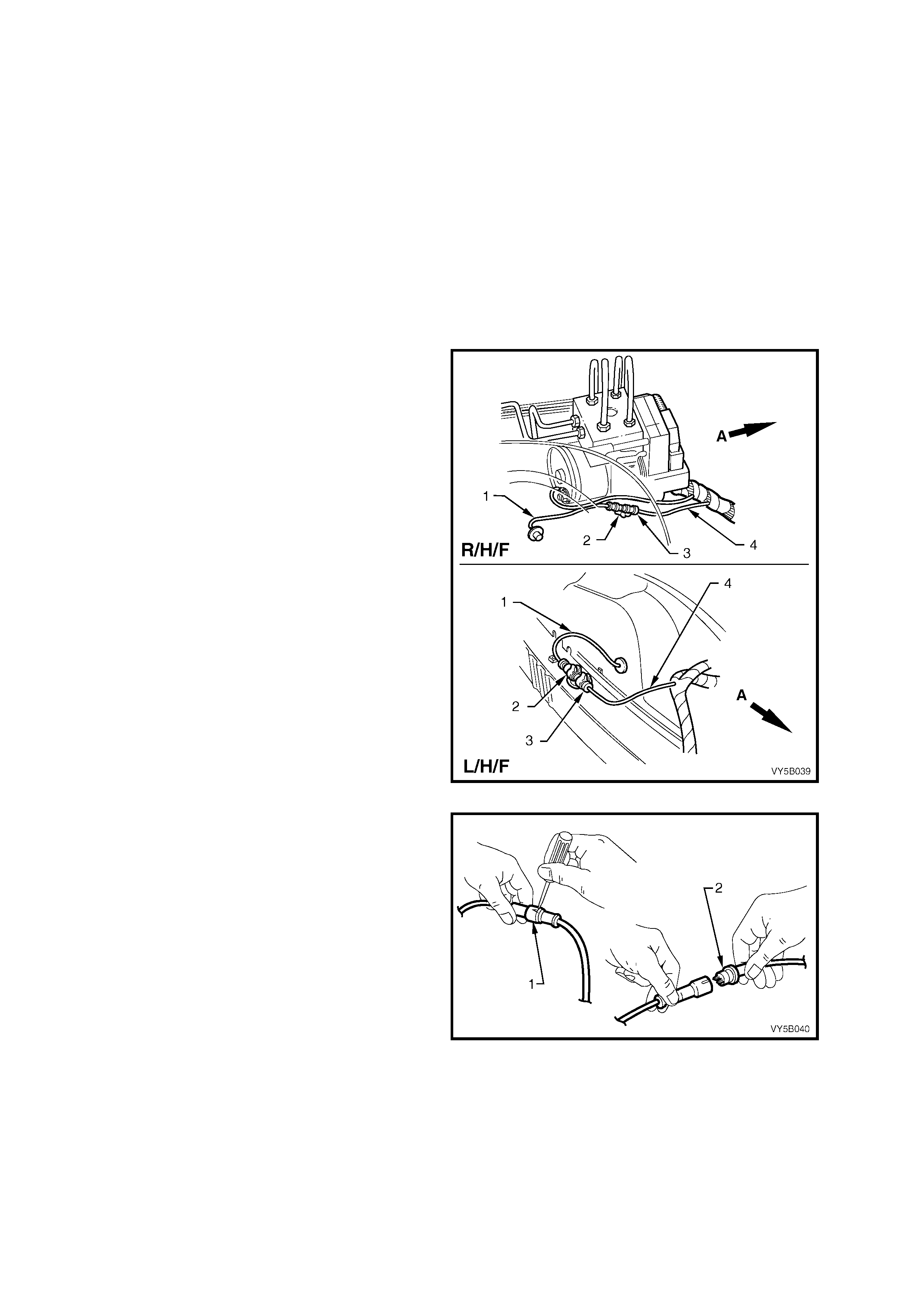
3.3 FRONT WHEEL SPEED SENSOR LEAD
LT Section No. – 04-730
REMOVE
1. Raise front of vehicle and support on safety
stands. Observe jacking precautions as
outlined in Section 3 FRONT SUSPENSION
in the MY 2003 VY and V2 Series Service
Information.
2. Remove appropriate wheel cover (steel
wheels) or wheel nut decorative caps (alloy
wheels).
3. Mark relationship of wheel to hub or brake
disc. Remove wheel attaching nuts and
remove wheel.
4. From engine compartment, pull appropriate
sensor connector (3) from retaining clip (2) at
fender inner panel.
Legend:
1. Sensor Lead
2. Retaining Clip
3. Connector
4. Main Wiring Harness
Figure 5B-61
5. From the engine compartment, disconnect the
sensor harness connector (2) from main wiring
harness connector by levering out with a small
screwdriver.
6. Check that the O-ring (2) is undamaged.
Figure 5B-62
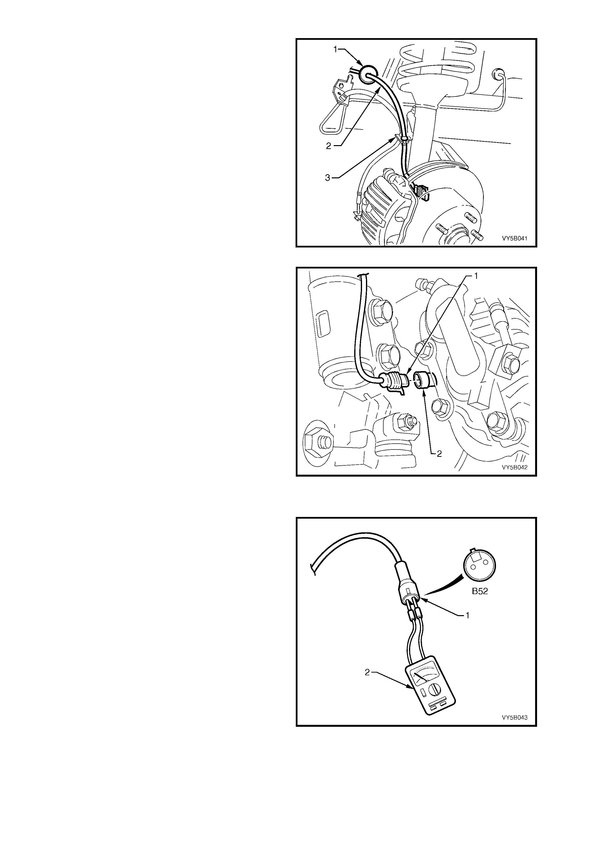
7. Pull the sensor lead (2) an d fender in ner panel
grommet (1) in the inner wheelhouse.
8. Disconnect sensor lead (2) from the front strut
mounting (3), taking note of lead routing.
Figure 5B-63
9. From behind steering knuckle, lift the wheel
speed sensor lead connector retaining tang,
then gentl y pull on the co nnector (1) to rem ove
from the wheel speed sensor (2).
10. Remove the sensor lead from the vehicle.
Figure 5B-64
TEST
Probe the two Ohmmeter (2) leads into the two
terminals of connector B52 (front wheel speed
sensor) or B76 (rear wheel speed sensor) (1) and
check for continuity. W ith the lead disconnected at
both ends, there should be no continuity between
the terminals (open circuit).
NOTE: Ensure that your skin is not contacting the
terminals of the sensor lead or multimeter leads
while checking res istanc e b et ween the ter minals as
your skin will serve as a conductor.
A good sensor lead will have a resistance value of
infinity (open circuit indication), between the
terminals. If you measure a resistance value other
than infinity, replace the lea d ass embly.
Figure 5B-65
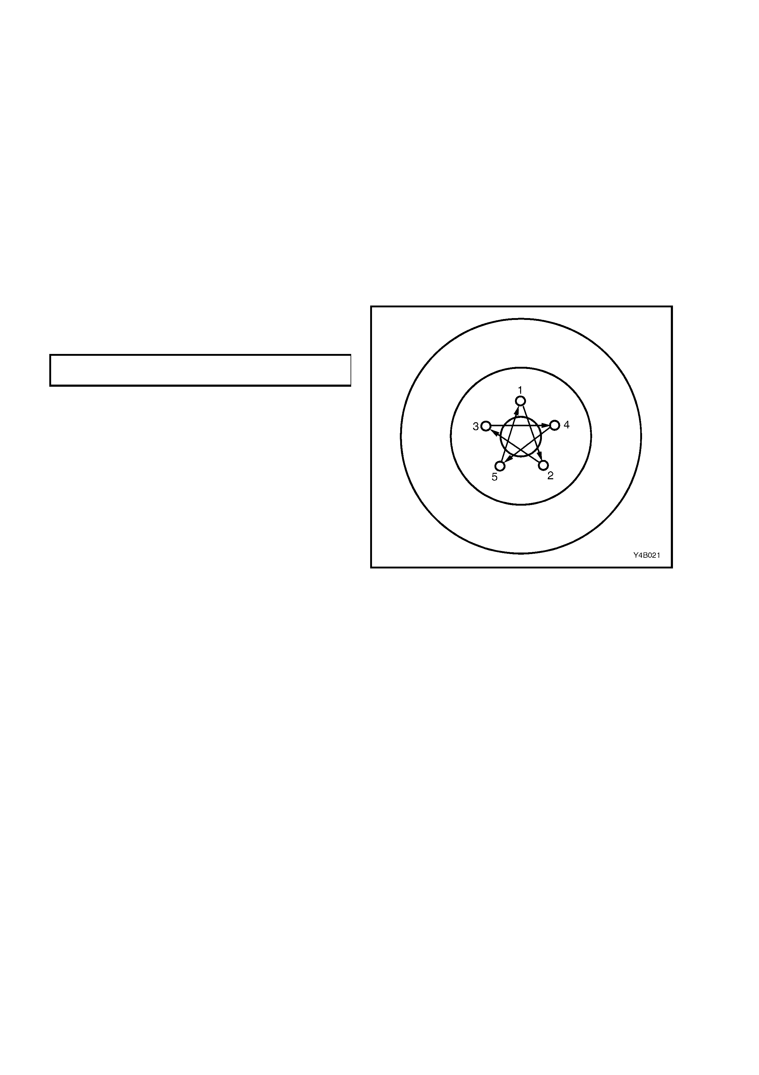
REINST ALL
Installation of the front wheel sensor lead is the
reverse of removal procedures, noting the following
points:
1. Refit wheel speed sensor lead connector to
sensor and steering knuckle. Push connector
into the sensor until the retaining clip snaps
into place.
2. Install sensor lead into inner wheelhouse and
front strut mountings, taking care that lead
routing is correct and not crossed up with
brake caliper hydraulic hose. For lead routing,
refer to Figure 5B-34 in this Section.
3. Install the road wheel, aligning marks made
prior to rem oval, ins ta ll attaching nuts .
4. Remove jack stands and lower vehicle.
5. Progressively tighten the wheel attaching nuts
in a ‘star’ pattern as shown, to the correct
torque specification.
ROAD WHEEL ATTACHING NUT
TORQUE SPECIFICATION 110 – 140 Nm
6. Reinstall wheel centre cap or wheel nut
decorative caps.
7. Check ABS operation, refer to
4.4 FUNCTIONAL CHECK in this Section.
Figure 5B–66
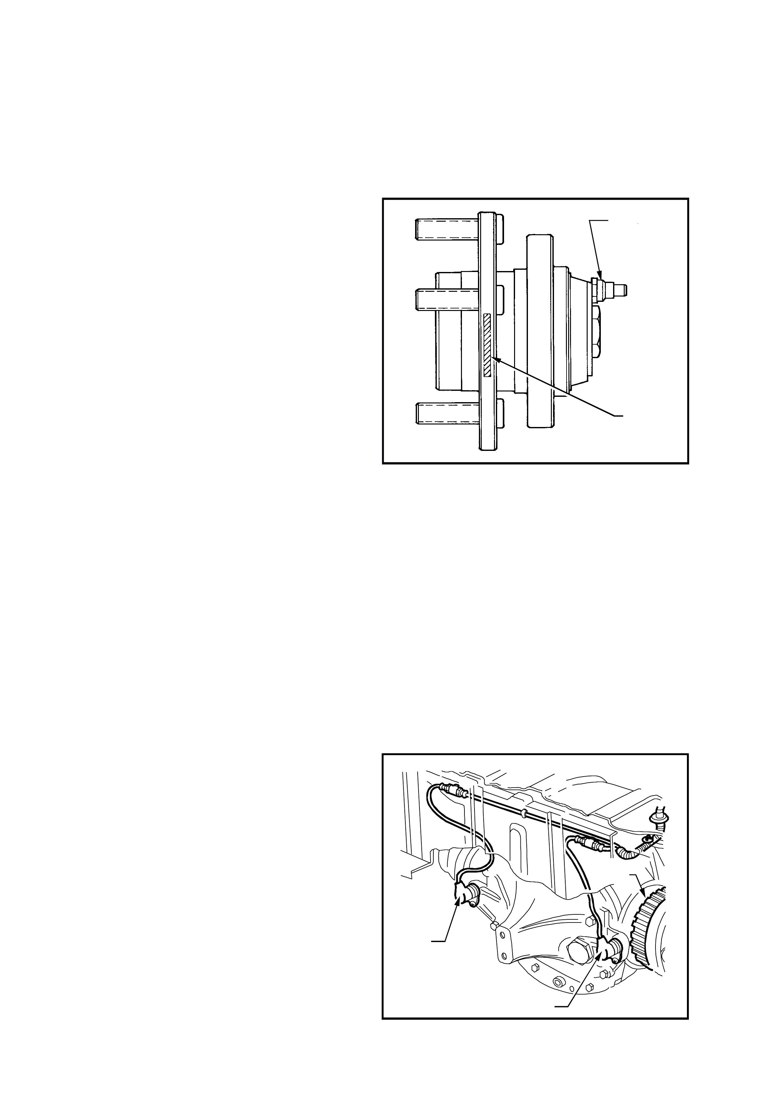
3.4 WHEEL SPEED SENSORS
LT Section No. – 04-730
FRONT WHEEL SPEED SENSOR
NOTE: The front wheel speed sensors are incorporated as part of the front suspension front wheel hub assembly.
Apart from wheel stud replacement, there are no serviceable items in the front wheel hub assembly.
With the unit being a 'sealed for life' assembly, there are no requirements for wheel speed sensor and/or bearing
adjustments. Should a non-standard condition develop, then the hub assembly must be replaced as a complete
unit.
There are three specific front wheel hub
assemblies available. For vehicles with ABS or
ABS/TCS, there is a right and left, which
incorporates the wheel speed sensor and a 48
tooth magnet impulse ring. For non ABS vehicles, a
common hub is used for both sides.
Identification of the front wheel hub assemblies is
by the assembly part number etched on the outer
surface (1) of the hub wheel flange or by simply
noting whether a wheel speed sensor cap is fitted
to the hub (2).
CAUTION: During any service operation that
requires the replacement of the front hub
assembly on a vehicle equipped with ABS/TCS,
ensure that the correct replacement hub
assembly is installed, otherwise malfunctioning
of the ABS or ABS/TCS will occur.
NOTE 1: Always refer to the latest spare parts
information (PartFinder®) for the correct front
wheel hub assembly part numbers.
NOTE 2: Apart f rom wheel stud r eplacem ent, there
are no serviceable items in the front wheel hub
assembly. With the unit being a ‘sealed for life’
assembly, there are no requirements for wheel
speed sensor and/or bearing adjustments. Should
a non-standard condition develop, then the hub
assembly must be replaced as complete unit.
T212L004
2
1
Figure 5B–67
For front wheel hub checking procedures, other than wheel speed sensor checking, refer to
Section 3 FRONT SUSPENSION in the M Y 2003 VY and V2 Seri es Serv ic e Infor mation.
For front wheel hub removal and reinstallation procedures, refer to Section 3 FRONT SUSPENSION in the MY
2003 VY and V2 S eries Service Inf ormation. T he procedure detaile d there, relates to both AB S and non ABS f ront
hubs.
REAR WHEEL SPEED SE NSOR
Remove
1. Raise the rear of the vehicle and support,
using safety stands under trailing
arms to support weight of vehicle. Refer to
Section 0A GENERAL INFORMATION in the
MY 2003 VY and V2 Series Service
Information for location of jacking points.
2. Pull appropriate sensor lead connector from
underbody retaining clip. Separate sensor
connector from body harness connector by
leveri ng out with a scr e wdriver .
3. Remove sensor attaching screw from the final
drive rear cover outrigger bracket, then gently
pull on the s ensor (1) with a twisting m otion, to
remove.
T212L008
2
1
1
Figure 5B-68

Reinstall
1. Before reinstalling sensor, check sensor for any signs of damage.
IMPORTANT: A replacement wheel sensor must only be taken out its packaging immediately before installing on
the vehicle.
2. Clean all traces of foreign matter from sensor and mounting bracket mating hole.
3. Reinstall sensor into mounting bracket and tighten attaching screw to the correct torque specification.
WHEEL SPEED SENSOR
ATTACHING SCREW
TORQUE SPECIFICATION 6 – 14 Nm
4. Connect sensor lead connector to body harness connector and secure to underbody retaining clip.
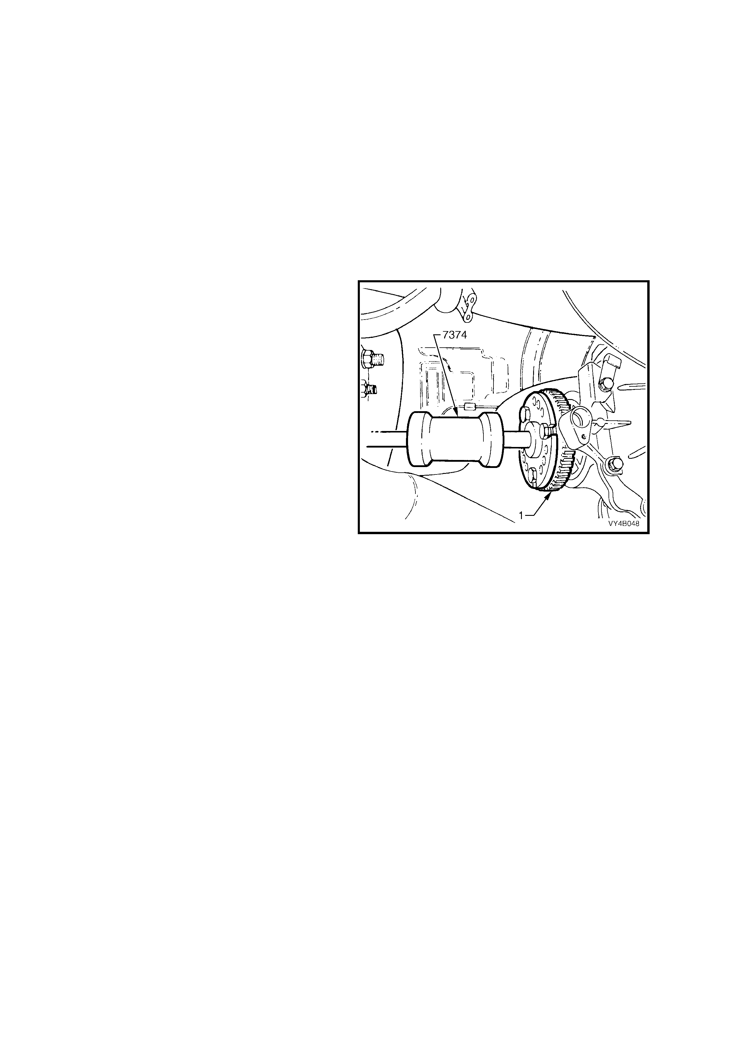
3.5 PULSE RINGS
LT Section No. – 05-290
NOTE: The rear whee l pulse rings are part of the final drive inner axle flanges and ar e a press fit onto each of the
rear axle s hafts . Ther efor e, the followin g servic e opera tion des cribes the re placement pr ocedures for the pulse rin g
and inner axle shaft assembly.
REMOVE
1. Using a f loor jac k under centr e of dif fer ential c arrier, j ack up rear of ve hicl e and th en place s afet y stands und er
body rear jacking points. Refer to Section 0A GENERAL INFORMATION in this Service Information for
location of jacking points.
2. Remove drive shaft from side of vehicle which inner axle shaft is to be removed, refer to 2.7 Drive Shaft
Assembly – Remove, in Section 4B FINAL DRIVE AND DRIVE SHAFTS in the MY 2003 VY and V2 Series
Service Information.
NOTE: During drive shaft removal, keep drive shaft supported so that it does not hang on one end, as drive shaft
deflection must be kept to a minimum.
3. Remove wheel speed sensor from the side
being worked on. Refer Rear Wheel Speed
Sensor, in 3.4 WHEEL SPEED SENSORS in
this Section.
4. Remove inner axle shaft (1) by installing a slide
hammer, T ool No. 7 374 wit h thr ee su it abl e si ze
bolts to axle flange. Use slide hammer to
release axle shaft spring clip.
As the axle shaft is removed, a small amount
of lubricant may leak from differential carrier.
IMPORTANT: If a 3.08:1 ratio final drive is fitted
with LSD, do not rotate the opposite axle shaft,
as side gear and clutch cone splines will
become misaligned. Then the axle shaft cannot
be reinstalled without removing differential
case, dismant ling and realigning g ear and con e
splines.
NOTE: The above ‘Important’ note does not apply
to either the 3.07:1 or 3.46:1 ratio final drives,
because the side gear and LSD cone is an
integrated component.
5. Clean around seal bore and housing area to
make sure that no foreign matter enters axle
shaft needle bearing in the sc r ew adjuster .
Figure 5B-69
REINST ALL
NOTE 1: The left hand in n er axle s h af t is s horter i n
length than the right hand shaft.
NOTE 2: Check spring clip in end of axle shaft to
ensure that it is not damaged and moves freely in
groove. Replace spring clip if necessary, by
expanding ends of clip and removing from shaft.
Only expand the ends of a new clip sufficiently to
allow installation into shaft groove.
1. Lubricate inner axle shaft seal lips with lithium
soap grease.

2. Reinstall inner axle shaft (1), aligning splines
with clutch cone (if fitted with a 3.08:1 Limited
Slip Differential) and side gear.
NOTE: To avoid premature seal failure, ensure
axle shaft splines or securing clip do not score or
damage the seal lips during installation.
3. Lig htly hit on e nd of axle shaft f lange (1) wit h a
soft faced hammer (2) to compress spring clip
on shaft in to cl utch con e and s ide g ear spl ines.
Fully engage shaft (1) until clip sna ps into side
gear groove.
4. Reinstall drive shaft, refer to 2.7 Drive Shaft
Assembly in Section 4B FINAL DRIVE AND
DRIVE SH AFTS in MY 200 3 VY and V2 S eries
Service Information.
5. Reinst all wheel s peed sens or to the s ide being
worked on. Refer Rear Wheel Speed Sensor,
in 3.8 WHEEL SPEED SENSORS in this
Section.
6. Remove safety stands and lower vehicle.
7. Check and fil l dif fer ential c arr ier to c orrec t le vel
with specified lubricant. Refer to 2.2 Check ing
Differential Carrier Lubricant Level in
Section 4B FINAL DRIVE AND DRIVE
SHAFTS in the MY 2003 VY and V2 Series
Service Information.
8. After carrying out repairs, check ABS
operation, refer to 4.4 FUNCTIONAL CHECK
in this Section.
Figure 5B-70
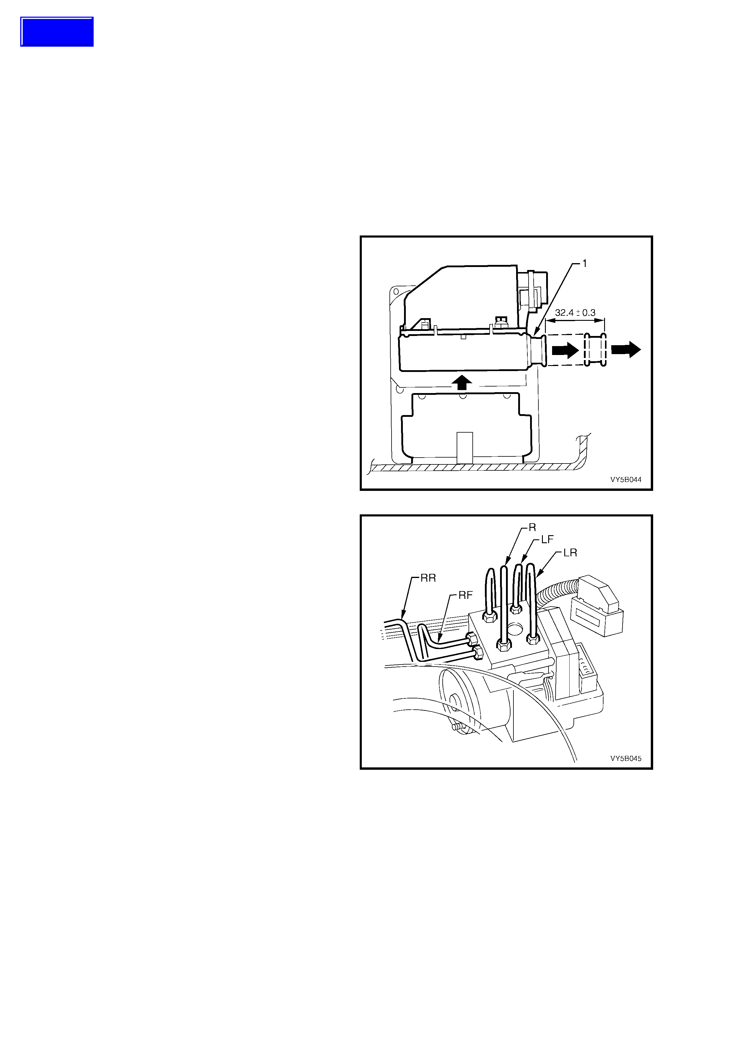
3.6 HYDRAULIC MODULATOR AND CONTROL MODULE ASSEMBLY
LT Section No. – 04-730
NOTE: 1. For safety reasons, the hydraulic modulator and / or control module must never be repaired. Repair of
either of these two units is by replacem ent onl y. Apart fr om the brake line c onnections an d the six sc rews securing
the control module to the hydraulic modulator, no screws at the hydraulic modulator m ay be loosened. Once they
are loosened, it is impossible to make the brake circuits leak-free ever again!
Replacem ent hydraulic m odulator assem blies are supplied pre-filled with brak e fluid. Do not rem ove sealing plugs
from modulator ports until ready to install brake line connections.
NOTE: 2. Once replacement modulator has been fitted, the sealing plugs must be fitted to original modulator to
prevent dirt and moisture entry.
REMOVE
1. Disc onnec t batt er y earth le ad.
2. Pull out the release bar (1) on the control
module wiring harness connector
(approximately 32.4 mm) and remove wiring
harness connector from control module, as
shown.
NOTE: The wiring harness connector will
automatically lift at the same time the release bar is
withdrawn.
3. Fold back wiring harness connector and wiring
away from the hydraulic modulator and control
module assembly.
Figure 5B-71
4. Place protective covers over vehicle exterior
panels to prevent paint damage from any
possible brake fluid spillage.
5. To aid in reassembly, tag all brake lines at
modulator. When tagging brake lines, make
sure the lines are marked in accordance with
the markings on the hydraulic modulator ports.
WARNING: If brake lines are incorrectly fitted
on reassembly, wheel lock-up will occur and
personal injury may result.
Markings on modulator, refer to Fig. 5B-66 are:
LF = Connection for brake line, front left.
LR = Connection for brake line, rear left and
right (ABS) or rear left only (ABS/TCS).
F = Front brake circuit from master cylinder.
R = Rear brake circuit from master cylinder.
RF = Connection for brake line, front right.
RR = Connection for brake line, rear right
(vehicles with T CS only).
6. Place shop rags around and beneath
modulator, then loosen and disconnect brake
lines from modulator.
Figure 5B-72
Techline
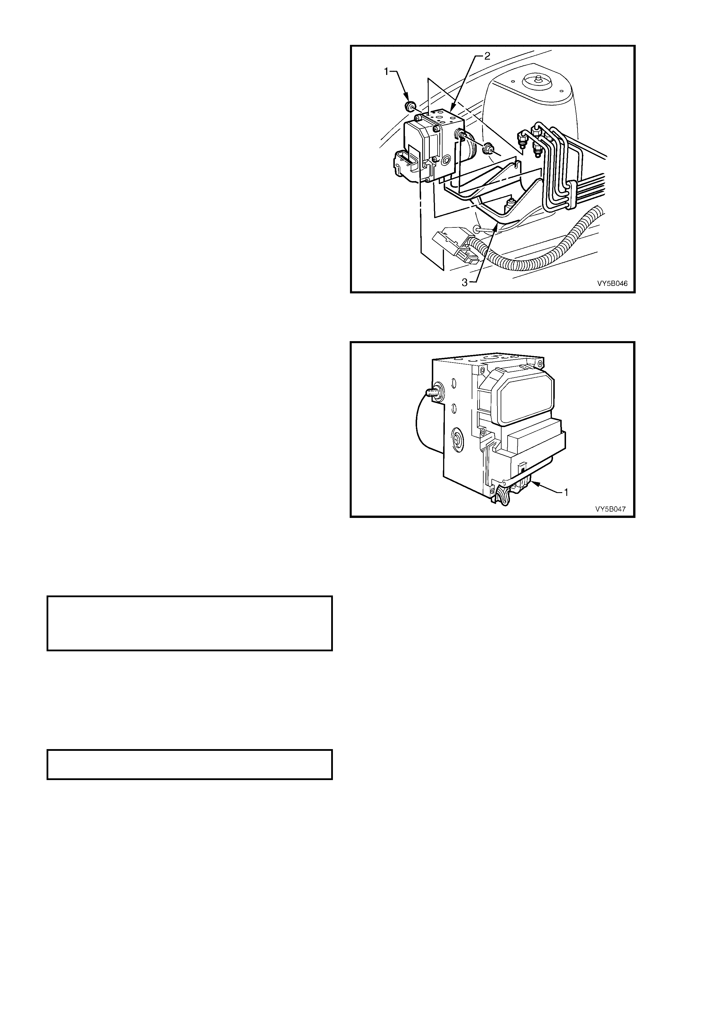
IMPORTANT: Imm ediately seal of f brake lines and
connections with dummy plugs to prevent the loss
of brake fluid and the ingress if foreign matter. If
necessary, gently push brake lines away from
modulator assembl y ports, tak ing extreme c are not
to damage or kink the brake lines in any way.
7. Loosen or remove the two nuts (1) securing the
hydraulic modulator and control module
assembly (2) to the mounting bracket (3).
8. Lift hydraulic modulator and control module
assembly (2) up and out of mounting bracket
(3).
Figure 5B-73
REINST ALL
Reinstallation of the hydraulic modulator and
control module assembly is the reverse of removal
procedures noting the following points:
1. Before installing hydraulic modulator and
control module assembly, clean any traces of
brake fluid from within mounting bracket.
2. If necessary, transfer bumpers to mounting
studs on replacement hydraulic modulator and
control module assembly.
3. Ensure the hydraulic modulator motor wiring
harness connector (1) is connected to the
control module, refer to Figure 5B-68.
4. Reinstall hydraulic modulator and control
module into mounting bracket and tighten
securing nuts to the correct torque
specification.
Figure 5B-74
HYDRAULIC MODULATOR
AND CONTROL MODULE
SECURING NUT
TORQUE SPECIFICATION 5.0 – 12.0 Nm
5. Rem ove plugs from hydraulic modulator ports and reinstall brake lines, using tags fitted on removal to ensure
correct fitment of each pipe to the correct port on the modulator.
CAUTION: M ake sure the brake l ines a re co rre ctl y connected to the modulator. If brake l ines are inco r rectl y
fitted, wheel lock-up will occur and personal injury may result. The only ways that this condition can be
detected are by using Tech 2 or by performing an ABS stop.
6. Tighten brake line connections to the correct torque specification.
BRAKE LINE CONNECTION
TORQUE SPECIFICATION 8 – 11 Nm
NOTE: If a r eplacem ent hydraulic m odulator a nd con trol m odule ha s been f itted, t he sea ling p lugs m ust be fitted t o
the original unit to prevent dirt and moisture entry.
7. Bleed brake system at the hydraulic control module, all brake calipers and test for leaks, refer to
3.2 BRAKE SYSTEM BLEED, in this Section.
NOTE: Use brake fluid to Super DOT 4 Plus specification only.
8. After carrying all out repairs, check ABS or ABS/TCS operation, refer to 4.4 FUNCTIONAL CHECK in this
Section.

3.7 CONTROL MODULE
LT Section No. – 04-730
NOTE: Remove the new control module from it’s protective package only when it is ready to be fitted to the
hydraulic modulator.
REMOVE
1. Disc onnect batter y ground l ead.
2. Remove hydraulic modulator and
control module assembly, refer to
3.6 HYDRAULIC MODULATOR AND
CONTROL MODULE ASSEMBLY in this
Section.
NOTE 1: While it is possible to replace the control
module assembly without first removing the
hydraulic modulator, for ease of fitment and to
ensure the correct installation of the replacement
control module, it is s tr o ngly r ecomm ended that the
complete assembly be removed from the vehicle,
prior to disassembly.
NOTE 2: Ensure blanking plugs are fitted to the
pipe connections of the hydraulic modulator to
avoid excess drainage and contamination of the
brake fluid.
3. Disconnect hydraulic modulator motor wiring
harness connector (1) from the control module
(2) and press the motor wiring out of the
retainer on the control module (3), refer to
Figure 5B-6 9.
Figure 5B-75
4. Support the hydraulic modulator and control
module assem bly so that the control m odule is
facing upwards, in a horizontal position, as
shown.
5. Using a T-20H Torx bit, remove the 6 Torx
screws (1) securing the control module (2) to
the hydraulic modulator (3). Lift the control
module (2) upwards and remove from the
hydraulic modulator (3).
6. Cover the valve body of the hydraulic
modulator to protect it from damage and
prevent any foreign matter from entering the
unit.
Figure 5B-76
INSPECT
Inspect the sealing su rf ac e of the h ydraul ic m odula tor f or c lean lin es s or damage. If the s ealin g s urf ac e is damaged ,
the surf ace cannot be m echanical ly rework ed and therefor e, the complete hydraulic m odulator and c ontrol m odule
assembly must be replaced.
NOTE: The use of chemical solvents is not permitted for cleaning.
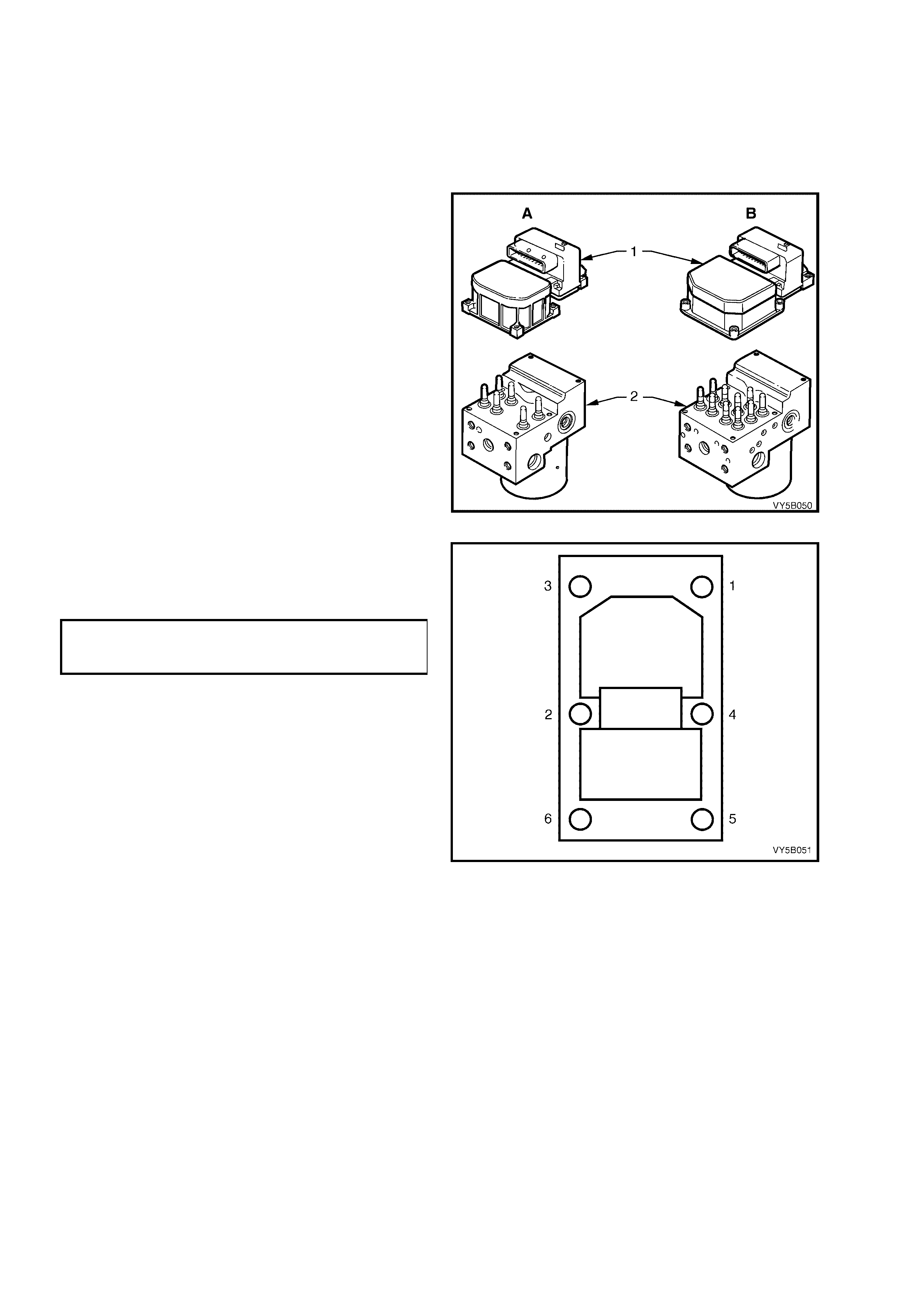
REINSTALL
1. Before installing a new control module, ensure
that the correct type is fitted (e.g. ‘A’ is for an
ABS unit, while ‘B’ is for the ABS/TCS
module). Always refer to the latest spare parts
information (PartFinder®) for the correct ABS
or ABS/TCS control module part numbers.
2. Position the hydraulic modulator assembly (2)
so that the control module face is facing
upwards.
3. Remove the new control module (1) from the
protective packaging and, using the new
screws supplied, place screws in the new
control module and set the control module into
position.
Figure 5B-77
4. Tighten the six Torx screws securing the
control module to the hydraulic modulator in
the sequence shown in Figure to 5B-72 and to
the recommended torque specification.
CONTROL MODULE TO HYDRAULIC
MODULATOR TORX SCREW
TORQUE SPECIFICATION 3 Nm
5. Visually inspect the hydraulic modulator and
control m odule assembly to ensure there is no
gap between control module and the hydraulic
modulator and to ensure Torx screws are
contacting control module correctly.
6. Connect the hydraulic modulator motor wiring
harness connector to the control module and
press the motor wiring into the retainer on the
control module.
7. Reinstall the hydraulic modulator and control
module assembly, refer to 3.6 HYDRAULIC
MODULATOR AND CONTROL MODULE
ASSEMBLY in this Section.
8. Reconnect battery earth lead.
9. After carrying out all repairs, check ABS
or ABS/TCS operation, refer to
4.4 FUNCTIONAL CHECK in this Section.
Figure 5B-78

3.8 MASTER CYLINDER
REMO VE AND R EINST ALL
Remo val a nd installat ion in s tr uc tions f or the mast er cylinder on A BS eq ui ppe d vehicles is the s ame as f or non -AB S
vehicles an d is as des cribe d in 3 .1 Mas ter Cylinder , i n Se ction 5 A SERVIC E AND P ARK BR AKING SY ST EM S in
the MY 2003 VY and V2 Series Service Information.
NOTE: If installing a new master cylinder assembly to an ABS or ABS/TCS equipped vehicle, ensure that the screw
in blanking plug is installed and tightened into the lower of the two front brake outlets in the master cylinder.
OVERHAUL
Master cylinder overhaul instructions are the same as described in 3.1 Master Cylinder, in
Section 5A SERVICE AND PARK BRAKING SYSTEMS in the MY 2003 VY and V2 Series Service Information.
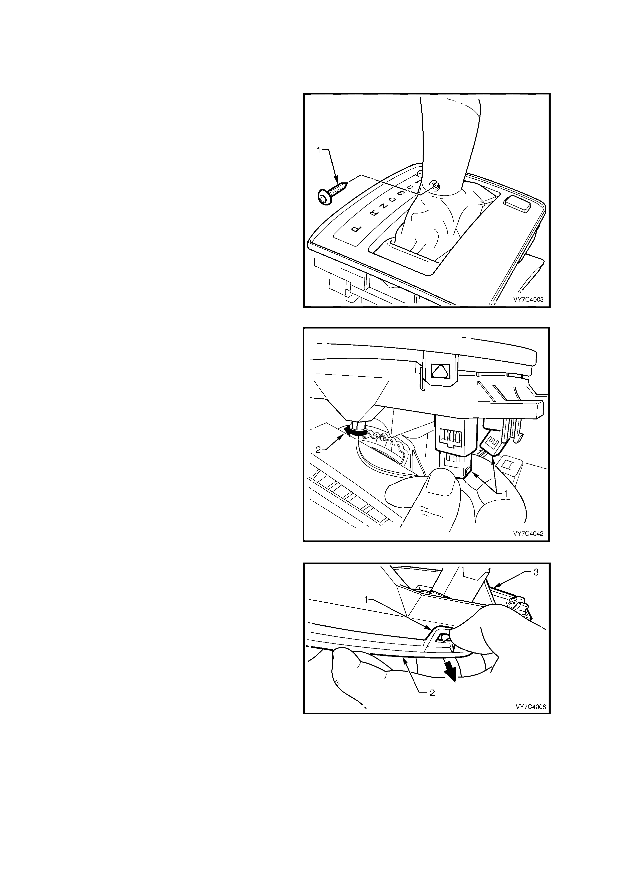
3.9 TRACTION CONTROL SWITCH (T/C)
REMOVE
Automatic Transmission Vehicles
1. If the selector control lever is of the BTSI
design, manually release the shift lever from
the Park position. refer to Step 1 of
3.3 Selector Control Lever Assembly,
Disassemble, in Section 7C4 A/T ON-
VEHICLE S ERVI CE O PE R ATIONS.
2. Remove centre console assembly, refer to
Section 1A3 INSTRUMENT PANEL AND
CONSOLE.
3. Move the selector lever to the Drive position.
4. Using a c om mer ciall y a vail abl e T X 20 Torx Plus
and suitable equipment, remove the screw (1)
securing the selector lever knob to the shaft.
NOTE: While the view shown, indicates that the
selector control lever assembly must be removed
from the vehicl e, t his is no t the c as e f o r this s ervice
operation.
Figure 5B-79
5. Carefully lift the lower housing assembly from
the base, dis lodg ing the thr ee locat ing lu gs. Lif t
the lower ho using up enou gh to gain acces s to
the switch connectors.
6. Depress the connec tor locking tab and rem ove
the connector (1) from the switch. Repeat for
the ‘PW R ’ switch.
7. Disconnect the selector lamp holder (2) from
the lower housing by turning to the left
(counter- c loc kwise). Pu ll t o remove.
8. Lift the lower housing, upper cover, gearshift
lever, knob and boot assembly from the shift
lever.
Figure 5B-80
9. While holding the lower housing in an inverted
position, gently prise each of the four securing
lugs (1) to free the cover (2) from the lower
housing (3). Lift the lower housing (3) and
switches from the gearshift selector k nob, boot
and upper cover assembly (2). Carefully set
the knob, boot and upper cover to one side.
NOTE: If the lower housing assembly is not
inverted before separation, then the boot will
probabl y becom e dis lodged from the locati ng tangs
in the upper cover.
Figure 7C4-81
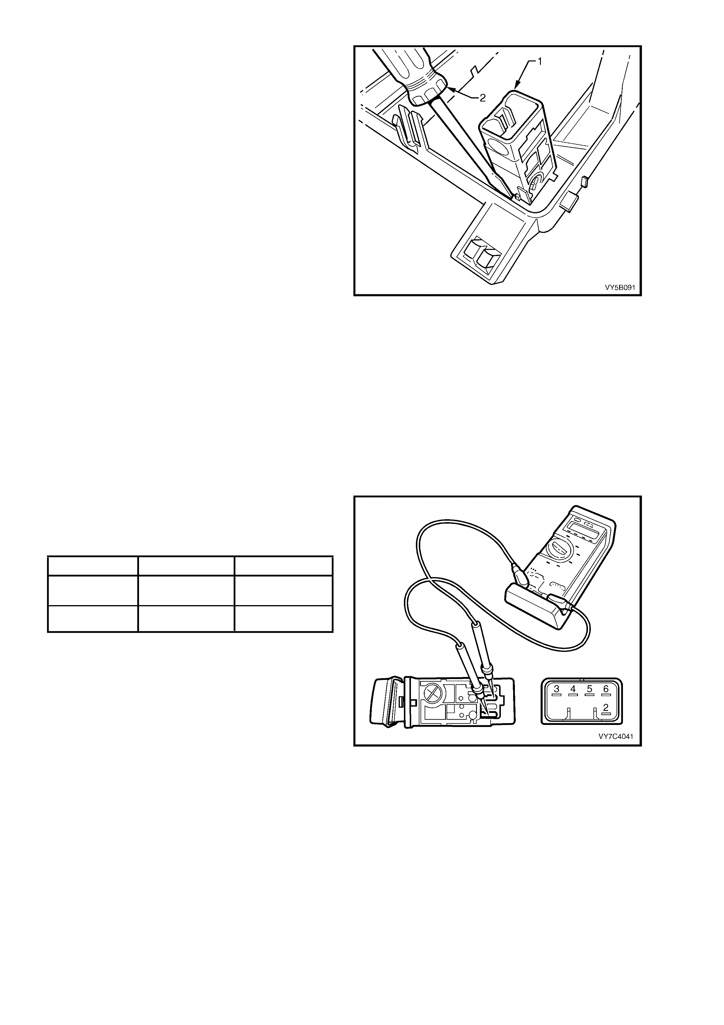
10. T o rem ove the T /C and/ or PW R s witch (1), use
a sm all bladed sc rewdriv er (2) and lever one of
the switch retain ing tangs fr om under the l ower
housing to free the particular switch, cock to
one side, release the second tang and then
remove the switch from above.
IMPORTANT: Take note of the locating lug on the
switch body that ensures the correct orientation of
the switch when reinstalled.
Figure 7C4-82
Manual Transmission Vehicles
1. Remove the centre console cap. Refer
Section 1A3 INSTRUMENT PANEL AND
CONSOLE, in the MY 2003 VY and V2 Series
Service Information.
2. Remove the auxiliary switch bezel from the
centre console cap, then remove the switch
from the bezel. Refer Section 1A3
INSTRUMENT PANEL AND CONSOLE for
specific details.
TEST
1. Using an ohmm eter, check the switch contacts
across the terminals detailed in the next table,
with the switch released and in the depressed
position. If any test fails, replace the switch.
Terminals Switch Button Result
3 and 4 Out Continuity
In Open Circuit
3 and 5 In Continuity
Out Open Circuit
2. If required the ‘PWR’ switch can be tested in
the same way.
NOTE: There should be a nominal resistance
across switch terminals 2 and 6, as this would
indicate that the illumination globe was OK.
Figure 5B-83
REINST ALL
Automatic Transmission Vehicles
As there are some critical aspects to the
reassem bl y process, ref er to Lower Housing, i n 3.3
Selector Control Lever Assembly, Reassemble, in
Section 7C4 A/T ON-VEHICLE SERVICE
OPERATIONS
Manual Transmission Vehicles
Refer to Section 1 A3 INSTRUM ENT PANEL AND
CONSOLE for T/C switch and console cap
reinstallation procedures.
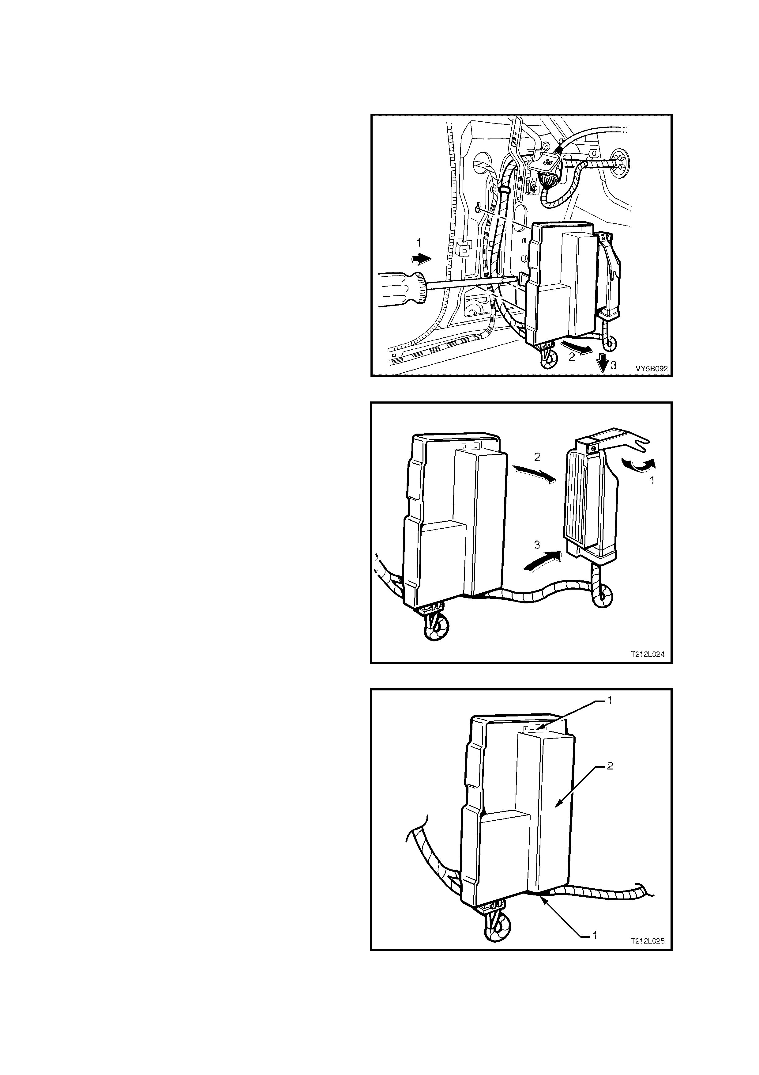
3.10 THROTTLE RELAXER CONTROL MODULE (GEN III V8 ONLY)
LT Section No. – 04-730
REMOVE
1. Disc onnec t batt er y earth le ad.
2. Remove left hand front shroud panel lower
trim assembly (kick panel trim), refer to
Section 1A8 HEADLINING AND INTERIOR
TRIM in the MY 2003 VY and V2 Series
Service Information.
3. Using a flat bladed screw driver, push the
lower retaining tab (between the shroud lower
panel and the back of the throttle relaxer
control module mounting bracket) forward (1)
while lifting the base of the mounting bracket
outwards (2), approx imately two cent imetr es .
With the lower retaining tab disengaged, pull
the mounting bracket assem bly downwards (3)
to disengage the top retaining tab.
Figure 5B-84
4. Disconnect the throttle relaxer control module
connector by:
a. Lift the locking lever on the control module
connector (1).
b. Pull the top of connector away from control
module (2).
c. Lift connector upwards, disengaging the base
of the connector from the control module (3).
Figure 5B–85
5. Lift the two retaining tabs (1) on the mounting
bracket and slide the throttle relaxer control
module (2) out of mounting bracket.
Figure 5B–86

REINST ALL
Reinstallation of the throttle relaxer control module is the reverse of the removal procedure, noting the following:
1. To reconnect the throttle relaxer control module wiring harness connector, use the following procedure:
a. Hook base of connector into throttle relaxer control module.
b. Push top edge of connector into throttle relaxer control module using the base as a pivot.
c. Push locking lever down and towards the throttle relaxer control module.
d. Ensure lever seats flush with top of connector housing.
2. Turn ignition ON and observe the ‘ABS’ warning lamp. The lamp should illuminate for approximately
2 – 5 seconds and then turn off. If the warning lamp remains activated, refer to 4.4 ABS OR ABS/TCS
FUNCTIONAL CHECK in this Section.


4. ABS, & ABS/TCS DIAGNOSIS
CAUTION: Certain components in the Anti-lock Brake System and Electronic Traction Control system are
not intended to be serviced individually. Attempting to remove or disconnect certain system components,
such as the solenoid valves or pump motor from the hydraulic modulator, may result in personal injury
and/or improper system operation. Only those components with approved removal and reinstallation
procedures described in 3. SERVICE OPERATIONS in this Section should be serviced.
Before attempting any diagnostic work on the ABS, refer to and read the 'SAFETY AND PRECAUTIONARY
MEASURES' as described in 3. SERVIC E OPERATIO NS in this Section.
4.1 GENERAL DESCRIPTION
The following information is necessary when diagnosing any Anti-lock Braking System problem or failure,
specifically it should be used to diagnose conditions that may cause the illumination of the ABS or TRAC OFF
warning displays in the instrument cluster.
Should conditions exist with the conventional (non ABS) portion of the braking system which cause the BRAKE
FAILURE warning lamp to illuminate (also in the instrument cluster), or there is some other obvious brake
mechanical problem, such as brake noise, brake pulsation (pedal or vehicle vibration during normal brake
application), brake pull or a parking brake problem, then these problems must be corrected before attempting to
rectify any suspected ABS problem. Refer to Section 5A SERVICE AND PARK BRAKING SYSTEMS in the MY
2003 VY and V2 Series Service information for diagnosis and repair of the conventional braking system.

4.2 BASIC KNOWLEDGE REQUIRED
Before attem pting to diagnose the Anti-lock Brake System or Electronic Traction Control system , you m ust have a
good understanding of electrical system basics and the use of circuit testing tools. W ithout this basic knowledge it
will be difficult to use the diagnostic procedures detailed in this Section.
Some elec trical basics , troubl eshootin g procedur es a nd hints as well as the use of cir cuit testi ng tools are c overed
in Section 12P WIRING DIAGRAMS in MY 2003 VY and V2 Series Service Information.
Basic Electrical Circuits - You should understand the basic theory of electricity, series and parallel circuits, and
voltage drops across series resistors. You should know the meaning of voltage (volts), current (amps), and
resistanc e (o hms ) . You sho uld un der s tan d what ha ppe ns in a c irc uit with an op en or shor te d wir e (s hor t ed ei t her to
voltage or ground). You should also be able to read and understand a wiring diagram.
Use of Circuit Testing Tools – You should k now how t o use a jum per lead t o test c ircuits. You s hould be fam iliar
with the use of a hi gh inp ut impedanc e (10 Meg ohm ) digita l t ype multim eter such as tool No. J 3920 0 or eq uivalent
and be abl e to measure v oltage, curr ent, and resis tance. You s hould be fam iliar with t he proper us e of the Tec h 2
Diagnostic Sc an Tool .
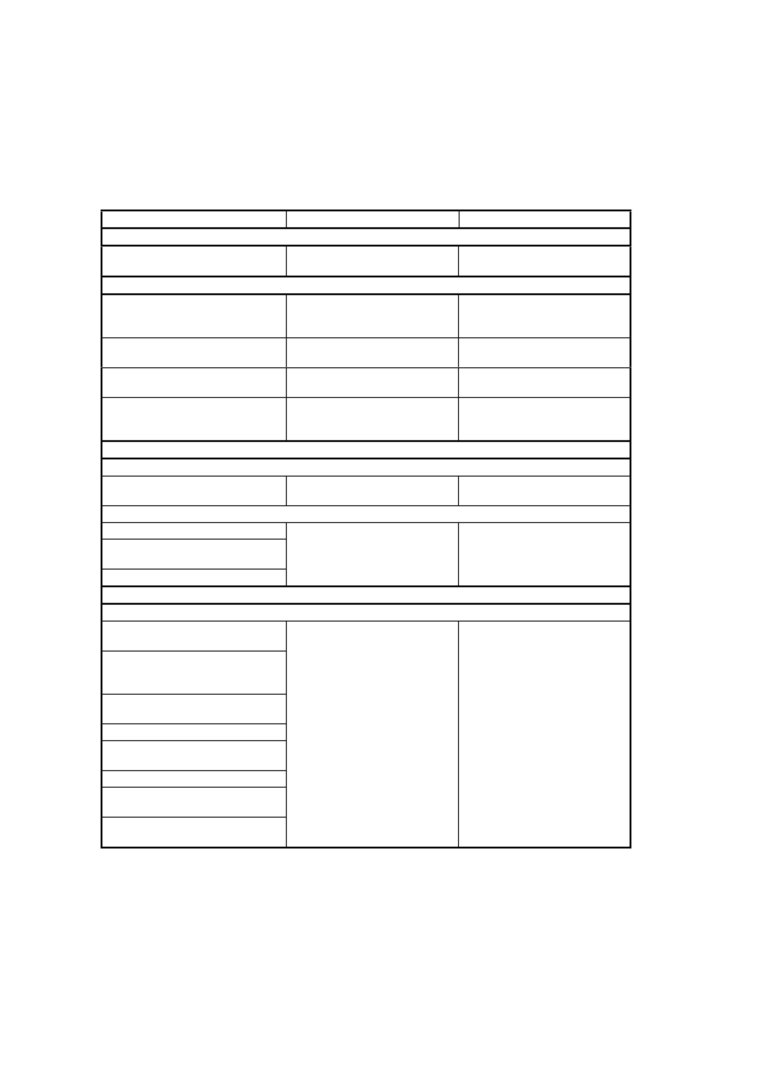
4.3 VISUAL INSPECTION
When investigating any complaint of an ABS or ABS/TCS system problem or malfunction, start diagnosis with an
ABS, ABS/TCS visua l ins p ec tion .
The ABS, ABS/TCS visual inspection is an examination of easily accessible components that could cause
problems with the system. The visual inspection procedure may quickly identify the cause and elim inate the need
for additional diagnosis.
If the complaint condition cannot be resolved by a visual check of the system components, then proceed to the
ABS, ABS/TCS Functional Check following on after the Visual Inspection Chart.
ABS, ABS/TCS VISUAL INSPECTION CHART
ITEM INSPECT FOR CORRECTIVE ACTION
GENERAL
Wheel and Tyres Recommended tyre and wheel
size fitted to vehicle Fit recommended size tyres
and wheels
BRAKE SYSTEM COMPONENTS
Master Cylinder Fluid Reservoir Low fluid level Add fluid as required.
Determine cause of fluid loss
and repair
Hydraulic Modulator External leaks If leakage is excessive,
replace modulat or
Brake Booster And Master
Cylinder Correct instal lati on and
assembly Reinstall or reposition
components correctly
Park Brake Mechanism Mechanism fully releasing Operate lever to verify release.
Adjust cable or repair release
system as required
FUSES
ENGINE COMPARTMENT
ABS Fusible Link F103 Blown fusible link Replace fusible link. Inspect
for cause of failure
PASSENGER COMPARTMENT
ABS Fuse F27 Blown fuse Replace fuse. Inspect for
Warning Lamp Fuse F13
(Ignition Circuit) cause of fuse failure
Stop Lamp Fuse F5
WIRING CONNECTIONS
ENGINE COMPARTMENT
ABS or ABS/TCS control module
Wiring Harness Connector
In all cases, inspect for:
Main Wiring Harness To Front
Wheel Speed Sensor
Connections
Proper engagement.
Loose wires or terminals.
Ensure proper engagement
Repair as required
Hydraulic modulator pump motor
wiring harness connector Corroded or broken
connections
PASSENGER COMPARTMENT
Main Wiring Harness To Body
Harness Connectors
UNDER VEHICLE
Front Wheel Speed Sensor Lead
To Front Wheel Hub Connections
Body Harness To Rear Wheel
Speed Sensor Connections

4.4 ABS & ABS/TCS FUNCTIONAL CHECK
If the source of the system problem or malfunction was not isolated during the ABS, ABS/TCS visual inspection,
carry out the following ABS, ABS/TCS functional check. Also, use the check to verify normal ABS or ABS/TCS
operation during diagnosis or after making any system repairs.
ABS & ABS/TCS FUNCTIONAL CHECK CHART
STEP ACTION YES NO
1 Has ABS, ABS/TCS Visual Inspection been performed?
Go to Step 2. Perform ABS, ABS/TCS
Visual Inspection – refer
4.3 in this Section before
proceeding.
2. While observing the Brake Failure warning lamp, turn the
ignition to the Bulb Check position (engine cranking position).
Does the Brake Failure warning lamp illuminate?
Go to Step 3. Check warning lamp
circuit, refer to Section
12C in the MY 2003 VY
and V2 Series Service
Information.
3. 1. Turn ignition OFF.
2. Turn ignition ON whilst observing ABS or ABS and TRAC
OFF warning display.
3. Do warning displays activate for approximately 3 seconds
(5 seconds for TRAC OFF display) then turn OFF?
NOTE: If engine is started, warning displays will activate for
only 2 seconds
Go to Step 6. Go to Step 4.
4. 1. Install Tech 2 to DLC.
2. Select Chassis / ABS/TCS and press CONFIRM.
3. Does Tech 2 communicate with the ABS by displaying the
System Identification Information?
Go to Step 5. Refer to DTC 72 -
SERIAL DATA FAULT
Diagnosis in this Section.
5. 1. With Tech 2 still connected, select Diagnostic Trouble
Codes / Read DTCs.
2. Are any DTCs set?
Go to Step 6. Refer to Charts A1, A2
(WARNING DISPLAYS
INOP) or CHARTS C1,
C2 (WARNING
DISPLAYS ACTIVATED
CONTINUOUSLY) in this
Section.
6. 1. Select relevant DTC Function Key.
2. Are the ignition cycles zero (0)? Refer to relevant ABS
or ABS/TCS DTC chart
in this Section.
Refer to 4.5
INTERMITTENT
FAILURES in this
Section.
7. 1. Road test vehicle, ensuring to achieve at least a speed of
35 km/h.
2. Did the ABS warning display turn on during the road test?
Go to Step 5. Go to Step 8.
8. During the road test, did the vehicle exhibit any symptoms or
improper operation that may be mechanical in nature and/or
did the Brake Failure warning lamp turn ON?
Refer to Section 5A
SERVICE AND
PARKING SYSTEMS
MY 2003 VY and V2
Series Service
Information for repair
details.
Go to Step 9.
9. 1. Install Tech 2 to DLC and turn ignition ON.
2. Check for any ABS History DTCs.
3. Are any History DTCs present (1 or more ignition cycles)?
Refer to relevant ABS
or ABS/TCS DTC
diagnostic chart in this
Section. Chart may be
used to identify and
isolate suspected
failures. Also, refer to
4.5, INTERMITTENT
FAILURES in this
Se ction for m ore
information on isolating
suspected failures.
Clear all DTCs and
repeat this function al
check.
If a failure is still
suspected, refer to 4.5,
INTERMITTENT
FAILURES in this
Section.
If not, system check OK.
WHEN ALL DIAGNOSIS AND REPAIRS ARE COMPLETED, CLEAR ALL DTCs AND VERIFY CORRECT OPERATION

4.5 INTERMITTENT FAILURES
As with most electronic systems, intermittent failures may be difficult to accurately diagnose. The following is a
method to try to isolate an i ntermittent fail ur e, es pecia ll y whee l spee d circui try failures .
If the control module detects an ABS fault, the ABS warning display will activate during the ignition cycle in which
the fault was detected and a Diagnostic Trouble Code (DTC) will be logged in memory of the control module.
If an TCS f ault occurs, either the TRAC OFF and /or ABS warni ng displa y will activate, if the fault is spec ific to the
TCS system, both the TRAC OFF and the ABS warning displays will activate, if the fault is common to both
systems.
If an interm ittent problem occurs, the TRAC O FF and/or ABS warni ng display will go out (if the fault cor rects itself )
after the ignition has been cycled off and on. Also stored in the control module mem ory, will be the histor y data of
the DTC at the time the fault occurred. This history data includes the number of Ignition Cycles since the DTC
occurred, if the Ignition Cycle is zero, then the DTC is Current, if the Ignition C ycles is greater than zero, then the
DTC is a history DTC. Tech 2 can be used to read ABS or ABS/TCS data;
1. If a s ystem fault has bee n detecte d, rec ord a ll cur rent tr ouble co des a nd tr ouble c ode his tor y infor m ation. Als o,
if available, record any specific driving condition during which the problem or failure occurs. This information
can help in duplic a tin g th e condition.
2. Clear any trouble codes that are stored in the control module memory, refer 'CLEARING DTCs' in this Section.
3. Using the Tech 2 in Snapshot mode while test-driving the vehicle, try to duplicate the condition in which the
problem or fault occurs. Refer to 4.7 TECH 2 DIAGNOSTICS in this Section for additional information on the
use of Tech 2.
NOTE: IN CERT AIN DIAGNOSTIC MODES, THE ANTI-LOCK BRAKING SYSTEM IS DISABLED WHILE T ECH
2 IS COMMUNICATING WITH THE ABS OR ABS/TCS CONTROL MODULE.
If an intermittent condition is still undetected, or not related to the wheel speed circuitry, go to the appropriate
Diagnostic Trouble Code (DTC) or symptom chart in this Section. Follow through the Chart while moving or
wiggling the associated ABS or ABS/TCS wiring harnesses and connectors, and at the same time looking for
intermittent type failures in the circuitry.
Most intermittent problems are caused by faulty electrical connections or wiring. When an intermittent failure is
encountered, check suspect circuits for:
1. Poor mating of connector body halves or terminals not fully seated in the connector body (backed out).
2. Improperly formed or damaged terminals. If damaged, carefully reform terminals in a suspected circuit.
3. Poor terminal to wire connection . This requires rem oving the term inal from the connector bo dy to inspect (ref er
to Section 12P WIRING DIAGRAMS in the MY 2003 VY and V2 Series Service Information).
Also, du e to the sensitivity of ABS or ABS/TCS components to Electro-Magnetic Interference (EMI), the follo wing
checks should be performed if an intermittent malfunction is suspected:
1. Check for proper installation of wiring harnesses resulting from add-on options such as a CB radio or cellular
telephone etc .
2. Visually inspect wheel speed sensors and pulse rings for looseness, damage, foreign material accumulation
and proper mounting. Replace damaged components, remove any foreign material and/or properly attach all
components.
3. Check for proper routing of front wheel speed sensor wiring near spark plug leads. Refer to IGNITION
SYST EM, in 6C1-3 (V6), 6C2-3 or 6C3-3 (GEN III V8) for spark plug lead routing.
4. Measure resistance of spark plug leads (refer to IGNITION SYSTEM, in 6C1-3 (V6), 6C2-3 or
6C3-3 (GEN III V8) for details) Replace any leads if not to specification.
5. While test driving vehicle, monitor wheel speeds using Tech 2. If any wheel speed drops or displays erratic
speed, refer to the appropriate wheel speed DTC chart in this Section.
If detected, ABS failures will disable the anti-lock brake function of an entire ignition cycle, even if the condition
clears itself before the ignition is switched off. However, the clearing of low voltage failure conditions during an
ignition cycle will allow ABS operation to resume.
If an TCS failure is detected, both the anti-lock braking and traction control functions will be disabled for an entire
ignition cycle, even if the condition clears itself before the ignition is switched off. However, the clearing of low
voltage failure conditions during an ignition cycle will allow ABS and TCS operation to resume.
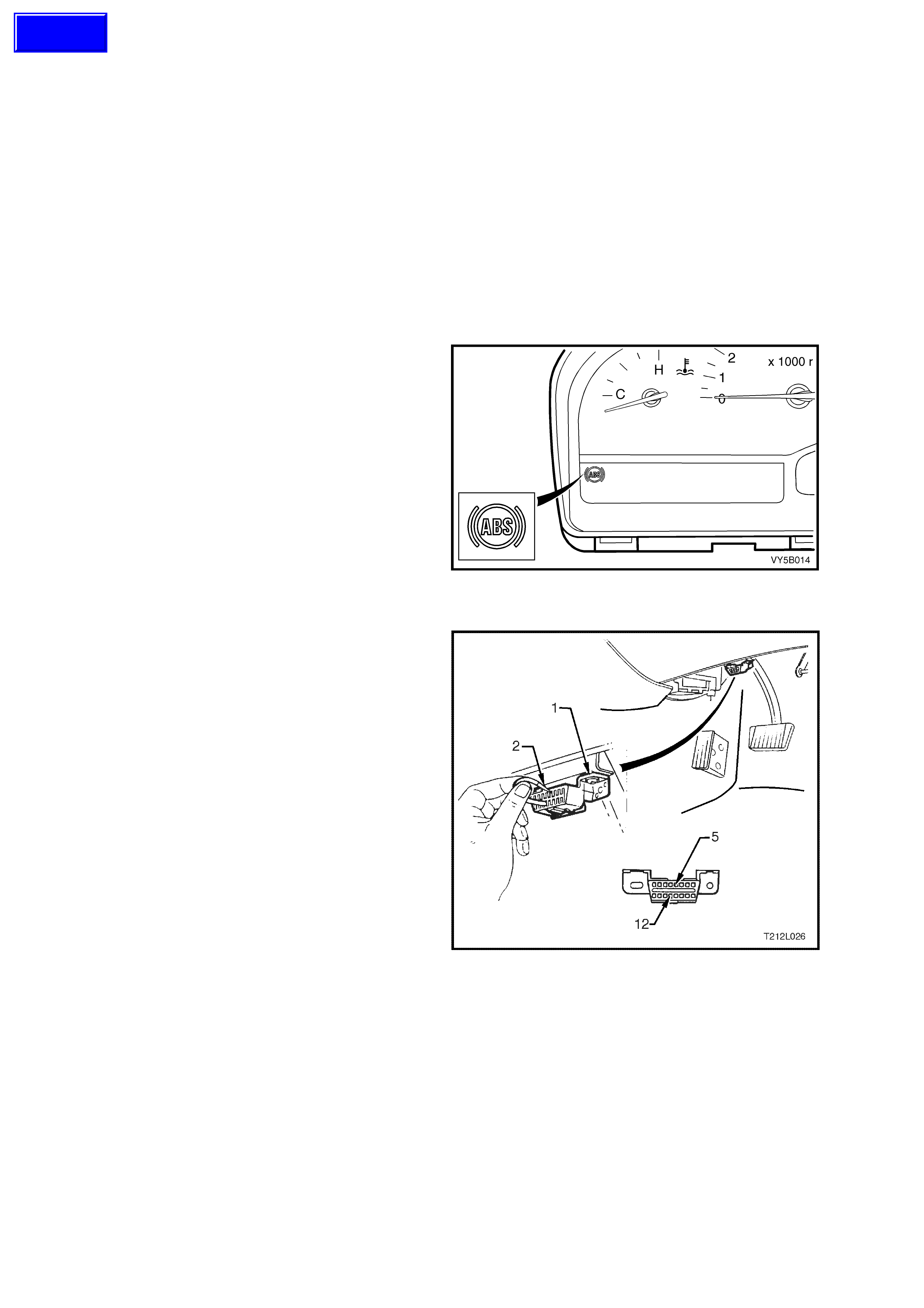
4.6 ABS & ABS/TCS SELF DIAGNOSTICS
DIAGNOSTIC TROUBLE CODES
The ABS and ABS/TCS control modules are equipped with a self diagnostic capability that can detect and isolate
ABS and ABS/TCS problems or failures. When a problem or failure is detected, the ABS or ABS/TCS control
module sets a diagnostic trouble code (DTC) that represents that particular problem or failure. There are twenty
one DTCs on ABS an d twe nty nin e on A BS/T CS s ystem s that m ay be set b y the ABS or ABS/T CS contr ol m odule.
Depending on the DTC set, either the ABS, TCS or both ABS and TCS systems will be disabled. If the ABS is
disabled, it will allow for conventional non ABS braking only and the ABS warning display will be activated.
NOTE: Warning display will activate whilst fault is active. If a fault has occurred and is not active, the display will
not be activated and a fault code will be stored.
The control module performs an automatic test once during each ignition cycle when the vehicle reaches
approximately 6 km/h. The automatic test cycles each solenoid valve and the pump motor to check component
operation. If any error is detected during this test, the ABS or ABS/TCS control module will set a DTC. This test
may be heard and felt while it is taking place and is a normal mode of operation.
The ABS or ABS/TCS control module can display
the DTCs via the ABS warning display only when
the 'Diagnostic Service Mode' has been entered.
Entering the diagnostic service mode is
accomplished by either grounding terminal 12 of
the Data Link Connector (DLC) using a test lead
fitted with suitable terminals and using
ABS warning display to flash system DTCs as
described under Flash Code Diagnostics Display
in this Section or by using Tech 2 (refer to
4.7 TECH 2 DIAGNOSTICS in this Section).
Figure 5B-87
FLASH CODE DIAGNOSTICS DISPLAY
To enable th e ABS warnin g display to f lash system
DTCs, the vehicle must be stopped (vehicle speed
is less than 10 km/h), terminal ‘12’ of the DLC (1)
grounded (DLC terminal ‘5’) using a test lead (2)
fitted with suitable terminals and then the ignition
turned on. The flash code diagnostics will remain
enable d as long as term inal ‘12’ is grou nded, serial
data line communication has not been initiated or
until any wheel speed is greater than 10 km/h.
Approximately 3 seconds after grounding terminal
‘12’ of the DLC, the ABS or ABS/TCS control
module will begin flashing the ABS warning display.
The flash sequence will begin with DTC 12 to
signal the b eginning of the flash code displa y. DTC
12 will f lash t hree tim es . Eac h stored code will then
be displa yed thr ee tim es . After all codes h ave be en
displayed, the sequence will repeat, starting with
DTC 12.
The c harts on the next pag e set out all th e possi ble
diagnostic trouble codes.
NOTE: Flash code diagnosis is not fully supported
on certain trouble codes involving the solenoid
valves or motor due to the valve relay inside the
control unit being disabled. Trouble codes 41, 42,
45, 46, 47, 48, 55, 56, 61 and 63 will prevent the
ABS warning display from turning off. These faults
can only be read through the DLC using Tech 2.
Figure 5B-88
Techline
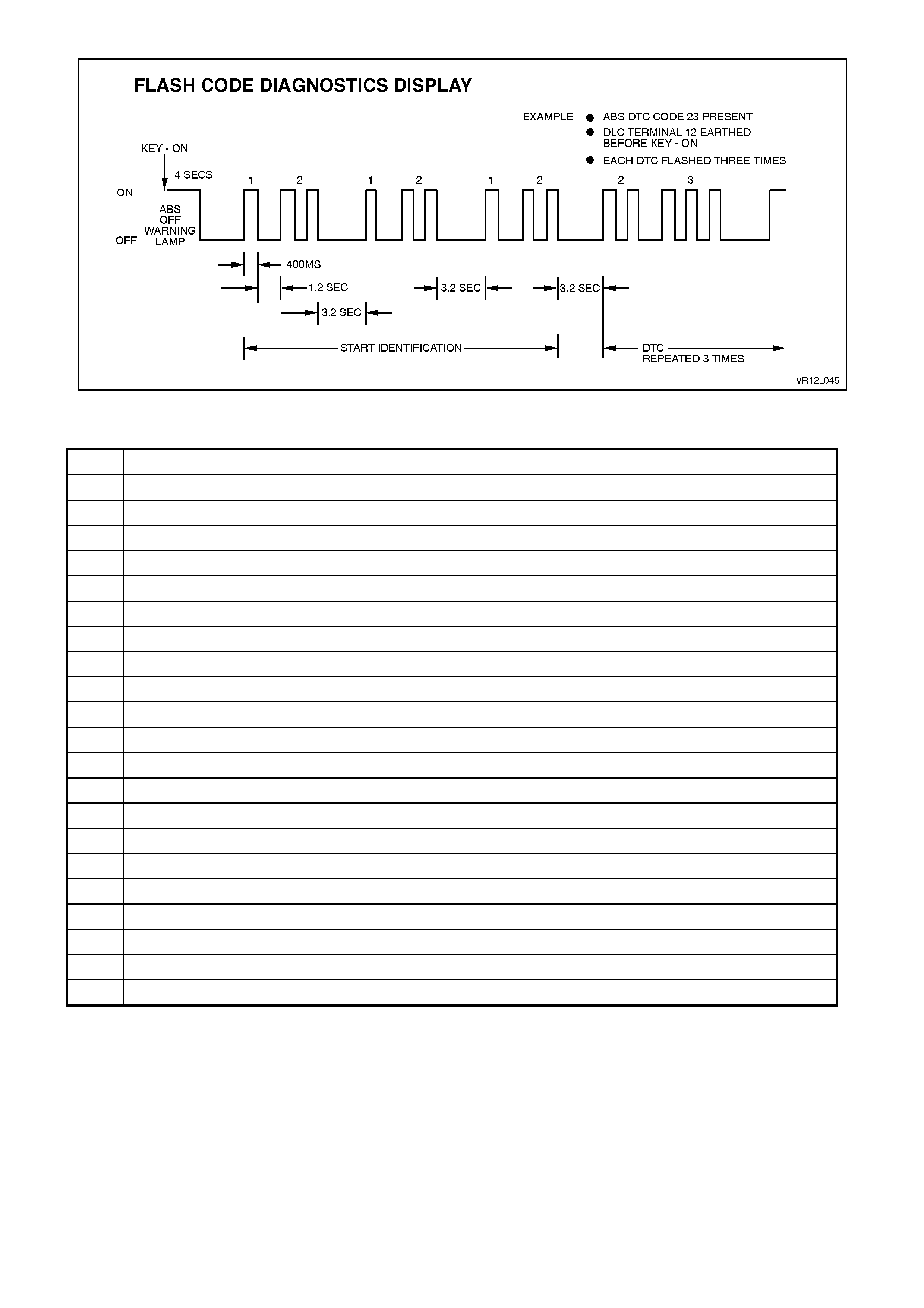
Figure 5B-89
ABS DIAGNOSTIC TROUBLE CODES
DTC CODE DESCRIPTION
12 No Fault
21 Front Right Wheel Speed Sensor Incorrect Signal
23 Front Right Wheel Speed Sensor Short Circuit or Open Circuit
25 Front Left Wheel Speed Sensor Incorrect Signal
27 Front Left Wheel Speed Sensor Short Circuit or Open Circuit
28 Wheel Speed Sensor Frequency Error
31 Rear Right Wheel Speed Sensor Incorrect Signal
33 Rear Right Wheel Speed Sensor Short Circuit or Open Circuit
35 Rear Left Wheel Speed Sensor Incorrect Signal
37 Rear Left Wheel Speed Sensor Short Circuit or Open Circuit
41 Front Right Inlet Valve Solenoid Fault
42 Front Right Outlet Valve Solenoid Fault
45 Front Left Inlet Valve Solenoid Fault
46 Front Left Outlet Valve Solenoid Fault
55 Rear Axle Inlet Valve Solenoid Fault
56 Rear Axle Outlet Valve Solenoid Fault
61 Pump Motor or Relay Fault
63 Valve Solenoid Relay Cir cuit Fault
67 Stop Lamp Switch Circuit Fault
71 Control Module Internal Fault
85 System Voltage Too Low

ABS/TCS DIAGNOSTIC TROUBLE CODES
DTC CODE DESCRIPTION
12 No Fault
21 Front Right Wheel Speed Sensor Incorrect Signal
23 Front Right Wheel Speed Sensor Short Circuit or Open Circuit
25 Front Left Wheel Speed Sensor Incorrect Signal
27 Front Left Wheel Speed Sensor Short Circuit or Open Circuit
28 Wheel Speed Sensor Frequency Error
31 Rear Right Wheel Speed Sensor Incorrect Signal
33 Rear Right Wheel Speed Sensor Short Circuit or Open Circuit
35 Rear Left Wheel Speed Sensor Incorrect Signal
37 Rear Left Wheel Speed Sensor Short Circuit or Open Circuit
41 Front Right Inlet Valve Solenoid Fault
42 Front Right Outlet Valve Solenoid Fault
45 Front Left Inlet Valve Solenoid Fault
46 Front Left Outlet Valve Solenoid Fault
47 Priming Valve Solenoid Fault
48 Switching Valve Solenoid Fault
51 Rear Right Inlet Valve Solenoid Fault
52 Rear Right Outlet Valve Solenoid Fault
55 Rear Left Inlet Valve Solenoid Fault
56 Rear Left Outlet Valve Solenoid Fault
58 Throttle Relaxer PWM (Pulse Width Modulation) Interface Fault
61 Pump Motor or Relay Fault
62 RPM Signal Fault (refer diagnostic charts in both the V6 and GEN III V8 Sections
63 Valve Solenoid Relay Cir cuit Fault
64 Throttle Relaxer Control Module Position Fault
65 Throttle Relaxer Motor Fault
66 Throttle Relaxer Control Fault
67 Stop Lamp Switch Circuit Fault
68 TPS (Throttle Position Sensor) Monitoring Fault
71 Control Module Internal Fault
72 Serial Data Fault (refer diagnostic charts in both the V6 and GEN III V8 Sections)
73 Spark Retard Monitoring Fault (refer diagnostic charts in both the V6 and GEN III V8 Sections)
73 Requested Torque Cir c uit F ault – V6 Eng in es Onl y
74 Actual Torque Circuit Fault – V6 Engines Only
78 Incorrect Option Coding
85 System Voltage Too Low
NOTE: Regardless of the engine fitted to the vehicle, for those DTCs displayed in normal text, refer to
4.9 DIAGNOSTIC CHARTS – V6 Engines, in this Section. For those DTCs displayed in bold text, refer to
5.9 DIAGNOSTIC CHARTS – GEN III V8 Engine, also in this Section. Exceptions to this general rule are; DTCs,
62, 72 73 a nd 74, wher e th e di agn os tic c har ts s h oul d be f oll o wed f or the specif ic eng ine f itt ed i.e . th e V 6 or GEN III
V8 engine.
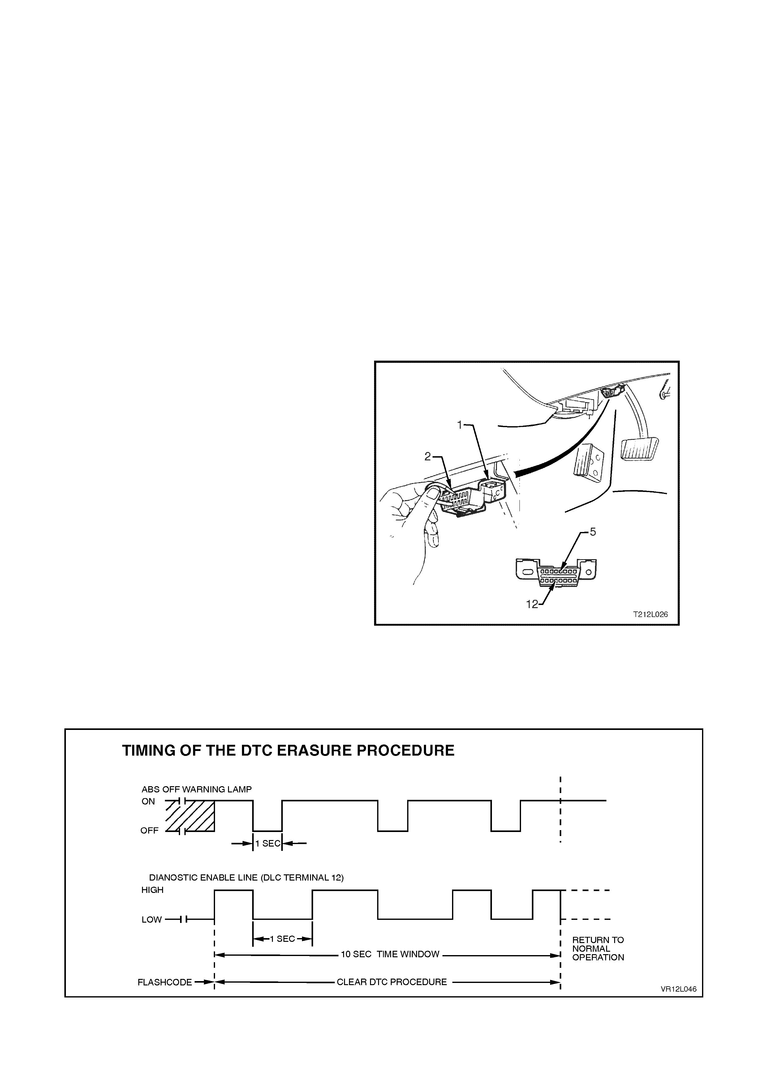
CLEARING DTCs
Any DTCs stored in the ABS or ABS/TCS control
module's memory can be erased in one of three
ways:
1. Diagnostic Request Line Procedure.
2. Tech 2 Clear Codes Selection.
3. Ignition Cycle Default.
These three methods are detailed as follows.
IMPORTANT: Whichever method is used, be
sure to verify proper system operation and
absence of any DTCs when clearing procedure
is completed. The ABS or ABS/TCS control
module will not permit DTC clearing until all of
the codes have been displayed. Also, DTCs
cannot be cleared by unplugging the ABS or
ABS/TCS control module, disconnecting the
battery cables, or turning the ignition OFF
(except on an ignition cycle default).
Diagnostic Request Line Procedure
To clear trouble codes via the DLC (1) diagnostic
request line, terminal 12 (12), go through the
follo wing proc ed ur e.
1. Turn ignition OFF.
2. Connect a test lead (2) fitted with suitable
terminals between DLC terminal 5, circuit 155,
black/yellow wire (5) and terminal 12, circuit
863, blue/black wire (12).
3. Turn ignition on (this will enable Flash Code
Diagnostics Display) and allow all codes to be
displayed.
4. Disconnect one end of test lead from DLC for
approximately one second then reconnect for
no less than one second. Repeat this step at
least two more times within 10 seconds,
leaving test lead connected to DLC upon
completion of final connection.
Observe flashing ABS warning display. Only DTC
12 should b e f las hed . If not , tr oub le cod es hav e no t
been properly cleared. Begin clearing code
procedure again at Step 1. If DTCs are cleared,
wait at least 15 seconds before turning ignition
'OFF'.
Figure 5B-90
Figure 5B-91

TECH 2 Clear Codes Procedure
Before clearing DTCs, check and note any history code data, as this information will also be cleared.
Select the appropriate menu, and select the Clear Codes function. Verify that DTCs have been cleared by using the
Tec h 2 to read ABS or ABS/T CS tr ouble cod es. If any are pres ent, e ither the DT Cs were not clear ed, or an ABS or
ABS/TCS fault still exists.
Ignition Cycle Default
If the ig nition is c ycled 100- tim es without a pa rticular f ault reap pearing, that fault code wil l be erased f rom the A BS
or ABS/TCS control module memory, and the ignition cycle counter inside the control module will be reset to zero.
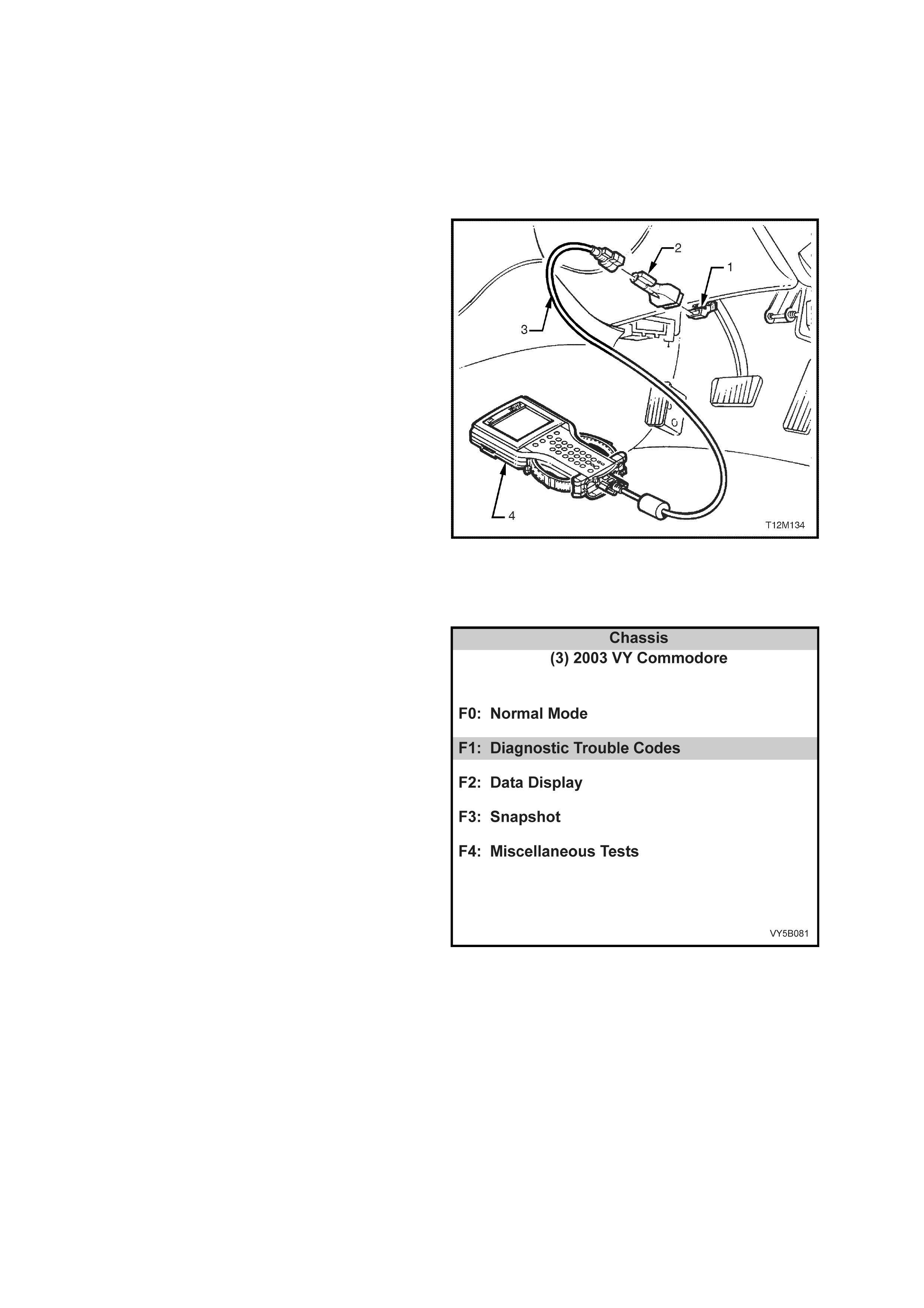
4.7 TECH 2 DIAGNOSTICS
IMPORTANT: When using the Tech 2 in certain diagnostic modes for ABS or ABS/TCS diagnosis, the Anti-lock
Brak e System is disable d by the A BS or AB S/TCS co ntrol m odule while it is c omm unicating with Tech 2. T he ABS
warning display in the instrument cluster will be activated, indicating only conventional (non ABS) braking is
possible.
NOTE: Within this Section, the Anti Lock Braking System/Traction Control System (ABS/TCS) is shown on the
Tech 2 screen, as “ABS/ETC” (Anti Lock Braking System/Electronic Traction Control). These systems are to be
regarded as being one and the same for the purposes of diagnosis.
W hen connected to t he Dat a Link Connector (DLC)
with the ap pr opri ate s of twa re, c abl es and ada ptor s ,
Tech 2 is capable of reading ABS or ABS/ETC
serial data. The DLC is connected to the
instrument panel lower right hand trim, to the right
of the steering column.
For additional general information on connecting
and operat ing T ech 2, refer to Section 0C T ECH 2
in the MY 2003 VY and V2 Series Service
Information.
Legend:
1. Data Link Connector (DLC)
2. DLC ADAPTOR
3. DLC CABLE
4. Tech 2 Scan Tool
Figure 5B-92
The Tech 2 has five test modes for diagnosin g the
Anti-lock Brake System and Electronic Traction
Control system. The five test modes are as follows:
MODE F0: NORMAL MODE
In this mode, the Tech 2 monitors the constant
communication between control modules on the
serial data line. The information displayed on the
Tech 2 screen in this mode is what the ABS or
ABS/ETC control module is communicating to the
other modules via the serial data line.
MODE F1: DIAGNOSTIC TROUBLE CODES
In this mode, Tech 2 will display a DTC selection
list. When the appropriate function key is selected,
the Tech 2 will display a DTC Data List. The Data
List contains relevant information relating to the
DTC.
MODE F2: DATA DISPLAY
In this test mode, the operator of Tech 2 has the
option of selecting an Active or Disabled data
stream that they can use to constantly monitor the
status of inputs and outputs of the ABS or
ABS/ETC system.
Figure 5B-93
MODE F3: SNAPSHOT
In this test mode, the Tech 2 captures ABS or
ABS/ETC data before and after a forced manual
trigger.
MODE F4: MISCELLANEOUS TESTS
In this test mode, the Tech 2 performs system
functiona l tests to as s is t in pr oblem is olat ion du rin g
troubleshooting. Each test mode has specific
diagnosis capabilities that depend upon various
function key entry on the Tech 2. Also, included in
the MISCELLANEOUS TESTS is a procedure for
ABS or ABS/ETC brake bleeding.
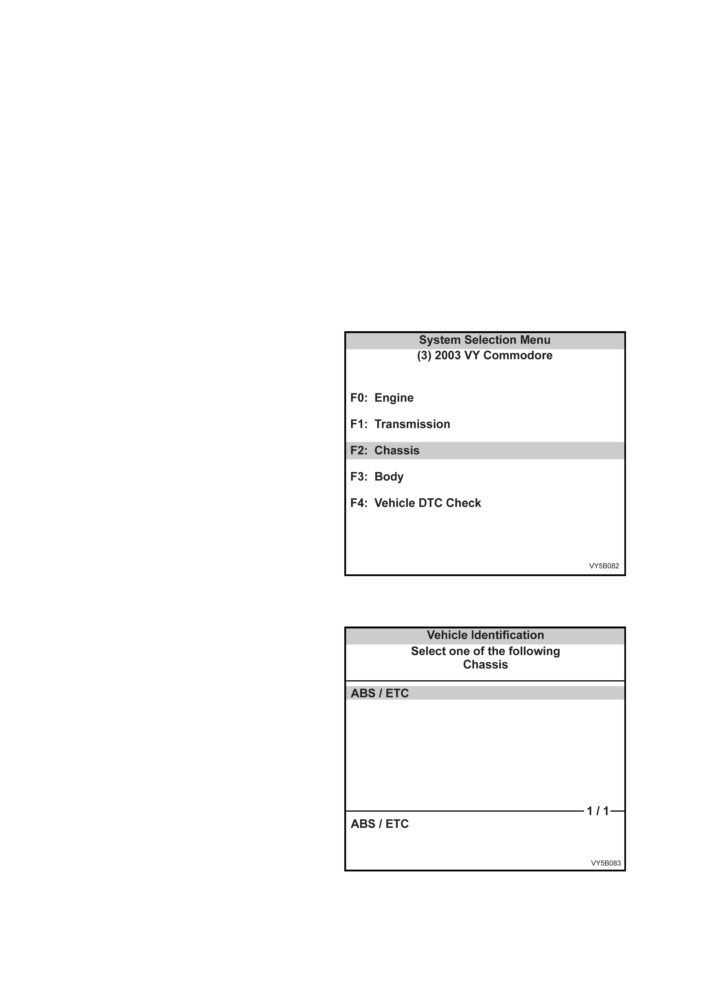
4.8 TECH 2 TEST MODES AND SCREEN DISPLAYS FOR ABS & TCS DIAGNOSIS
CAUTION: When using Tech 2 for ABS and
ABS/TCS diagnosis, in certain diagnostic
modes, the system will be disabled.
NOTE: Where Tech 2 is concerned, the
terminology quoted, reflects Tech 2 language; e.g.
ABS/TCS will be displayed on the Tech 2 screen,
as ‘ABS/ETC’. Therefore the diagnostic tables will
also reflect this usage.
As a prerequisite to this diagnostic section, the
user must be familiar with the proper use of Tech
2, as the following pages illustrate only the major
Tech 2 screen displays and provide a brief
explanation of their function for diagnosing the
ABS or A BS/TC S system s . If additio nal inf orm ation
is required on the operation of Tech 2, refer to
Section 0C T ECH 2 or the TECH 2 OPERAT OR’S
MANUAL.
SYSTEM SELECT MENU
With Tech 2 connected to the DLC and ‘F0:
Diagnostics’ selected from the ‘Main Menu’, the
correct ‘Model Year’ and ‘Vehicle Type’ must then
be selected to access the System Select Menu, as
shown.
Select ‘F2: Chassis’ and press ‘Enter’ to continue.
NOTE: If DTC Check is selected, Tech 2 will
displa y inform ation advis ing if any DT Cs are set by
any modu le. (If DTCs are set f rom another m odule,
refer to the relevant Section in the MY 2003 VY
and V2 Series Ser v ice Infor mation) .
Figure 5B-94
VEHICLE IDENT IF ICATION M ENU
After ‘F2: Chassis’ has been selected from the
System Select Menu, the only available option to
select is, ‘ABS/ETC’.
When ‘ABS/ETC’ is selected, several further
screens will then be presented, that require some
action on the part of the Tech 2 operator.
Figure 5B-95
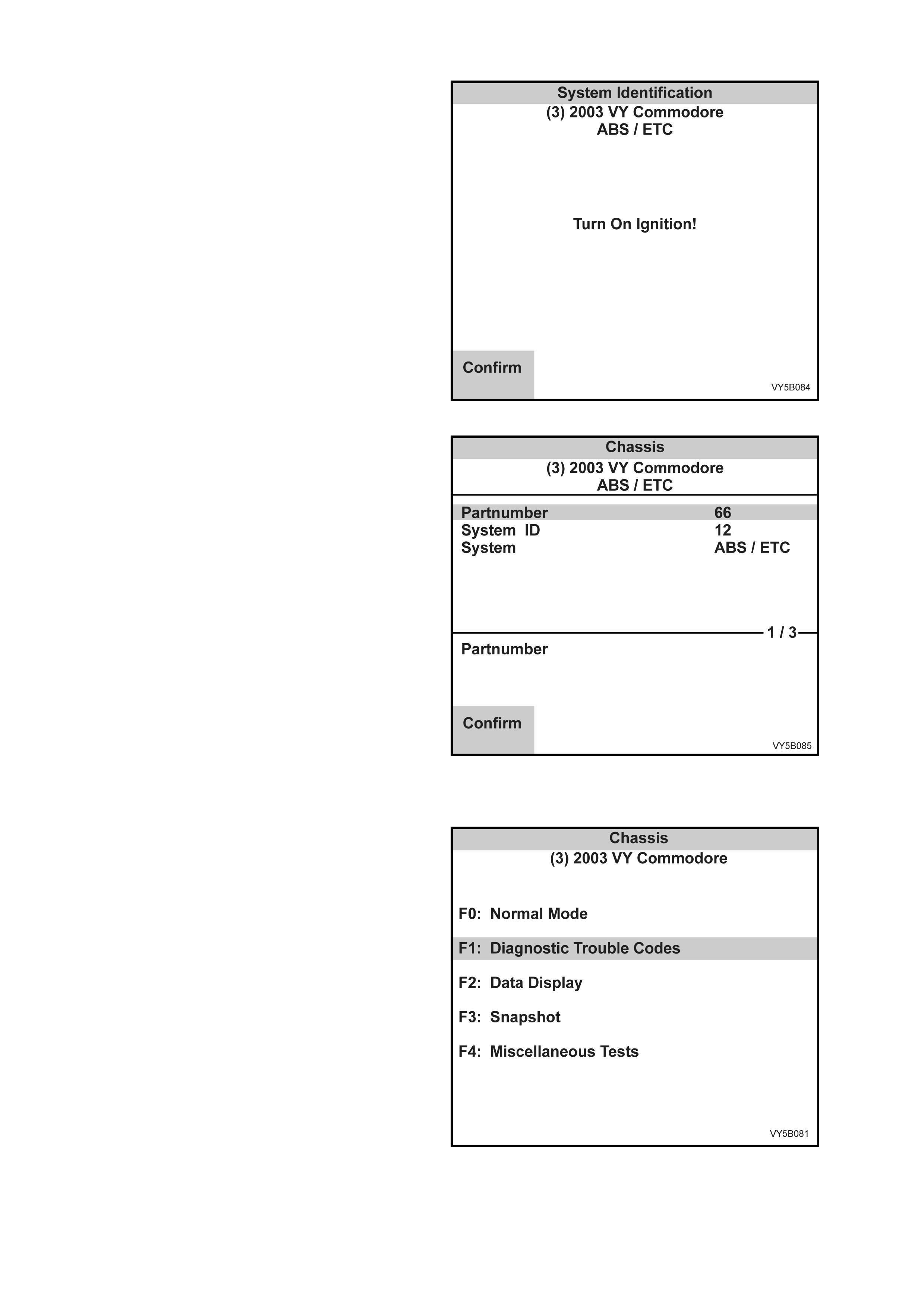
SYSTEM IDENTIFICATION
Turn the ignition ‘On’ (as r equested) and press the
‘Confirm’ soft key to continue.
Figure 5B-96
The ‘Chassis’ screen will then display the control
module part number and system identification.
Press the Confirm soft key to continue to the
‘Chassis’ function choices, screen.
Figure 5B-97
ABS/ETC FUNCTION CHOICES MENU
The following functions are now available:
F0: Normal Mode
F1: Diagnostic Trouble Codes
F2: Data Display
F3: Snapshot
F4: Miscella neous Tests
Figure 5B-98
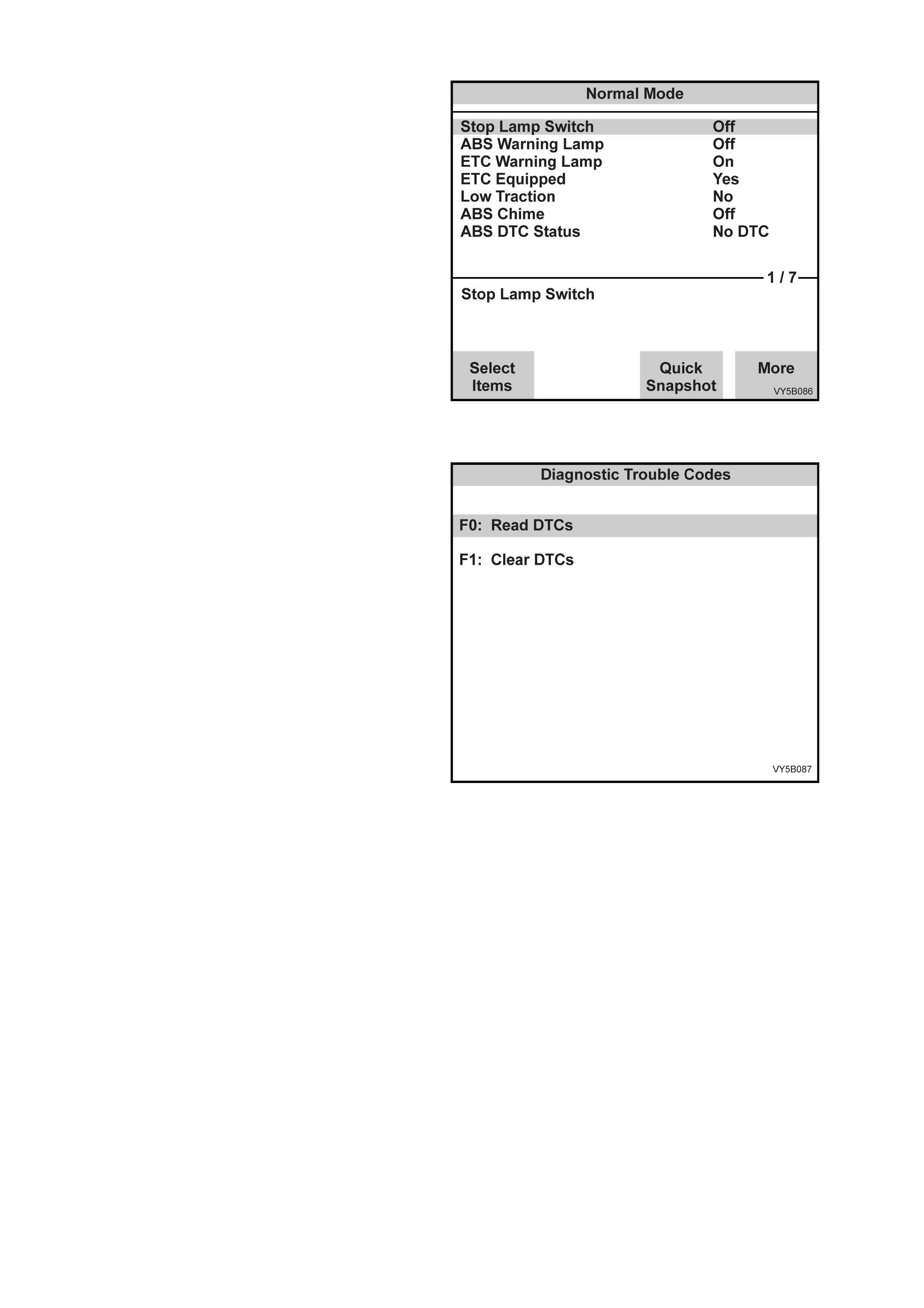
F0: Normal Mode
In the ‘F0: Norm al Mode’, information that the ABS
or ABS/ETC control module is communicating to
other control modules, is displayed via the serial
data line.
For example; as shown, the ETC Warning display
status is On. This means the ABS or ABS/ETC
control module is communicating with the
instruments requesting the ‘TRAC OFF’ warning
displa y to be activate d.
Figure 5B-99
F1: Diagnostic Trouble Codes
If the F0: Read DT Cs is selec ted from this mode, a
listing of all (if any) DTCs numbers that have been
set by the ABS or ABS/ETC control m odule will be
displayed. To obtain further information about a
particu lar DTC, pres s the rele vant f unction k ey and
a DTC data list will be displayed. From the
information provided in this data list, you can
determine when the DTC occurred and the
operating conditions of the system at the time.
For a listing of all DTCs, refer to
4.6 ABS & ABS/TCS SEL F DIAGNOST ICS in this
Section.
DTCs c an be cleared by sim ply selec ting ‘F1 Clear
DTCs’ and pressing the Enter key on the Tech 2
keyboard.
NOTE: If any DTCs are set, reference should be
made to the relevant diagnostic charts in this
section.
Figure 5B-100
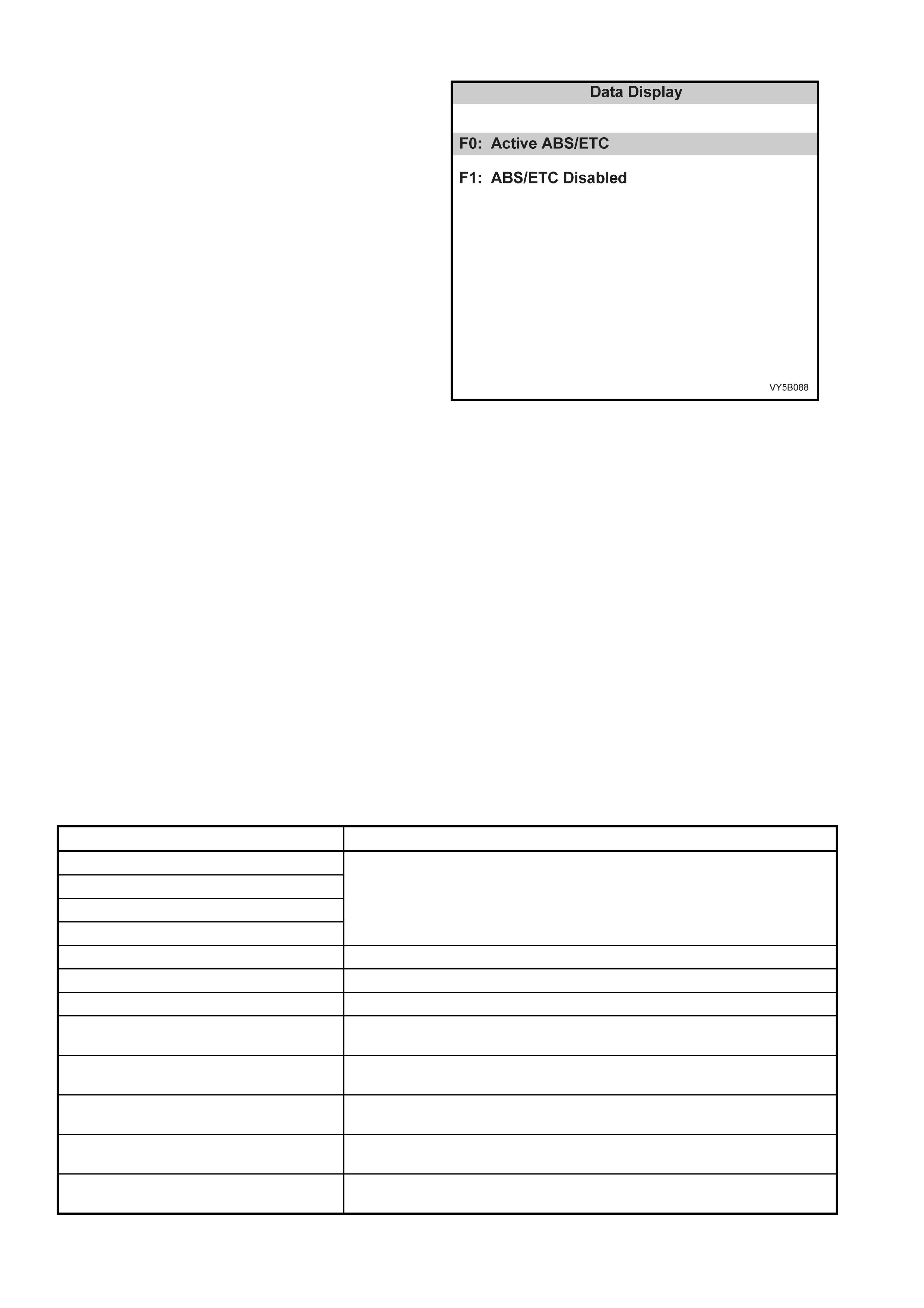
F2: Data Display
If the F2: DATA DISPLAY mode is selected, an
additional application menu will appear giving the
operator the option of selecting ABS or ABS/ETC
data while the system is either active or disabled.
F0: Active ABS/ETC
F1: ABS/ETC Disabled
If the disabled data list is selected, the ABS
warning display will be activated and the system
will become disabled.
While the two data lists offer similar information,
the active data list has the advantage of monitoring
the ABS or ABS/TCS systems while either system
is operational, assisting in the diagnosis of
intermittent faults.
When monitoring speed data, the Tech 2 screen
displays the signals being sent from the wheel
speed sensors to the control module. In F0: Active
ABS/TCS display mode, the vehicle can be driven
while the Tech 2 dis p lays whee l speed dat a. At th is
time, the readings may be compared with vehicle
speed to check proper operation. Wheel speed
signals can also be compared with each other to
determine whether they are within specification.
If one wheel speed signal differs greatly from the
other signals, improper operation of that particular
sensor may be indicated. Intermittent wheel speed
signals can be detected in this mode by looking f or
signals that vary for no apparent reason.
Figure 5B-101
This variation can occur during vehicle operation
and can be captured during F3: SNAPSHOT test
mode.
For additional information regarding the soft keys
while in the DATA DISPLAY mode, refer to
Section 0C TECH 2 in the MY 2003 VY and V2
Series Service Information.
The table below lists each item contained in the
data stream for both active and disabled lists
together with a brief description of their meanings.
ACTI V E ABS/ E TC
DATA STREAM / SCREEN DISPLAY DESCRIPTION
FR Wheel Speed (Front Right)
FL Wheel Speed (Front Left)
RR Wheel Speed (Rear Right)
RL Wheel Speed (Rear Left)
Displays wheel speed sensor input (km/h) to the control module.
Pump Motor Displays current status of pump motor – either ON or OFF.
Pump Relay Displays current status of pump relay – either ON or OFF.
Valve Relay Displays current status of valve relay – either OPEN or Closed.
ETC Switch Displays current status of switch – will display OPEN when switch is in the
rest position and CLOSED when held down (TCS Only).
Requested Torque (V6 Engines Only) Displays the amount of torque the ABS/TCS control module is requesting the
engine to deliver (TCS Only).
Actual Torque (V6 Engines Only) Displays the calibrated torque (in Nm) that the engine is delivering (TCS
Only).
Requested Throttle (GEN III V8 Engine
Only) Displays the percentage of throttle opening the ABS/TCS control module has
requested the throttle relaxer control module to supply.
Actual Throttle Position (GEN III V8 Engine
Only) Display the actual percentage the throttle body valve is open.
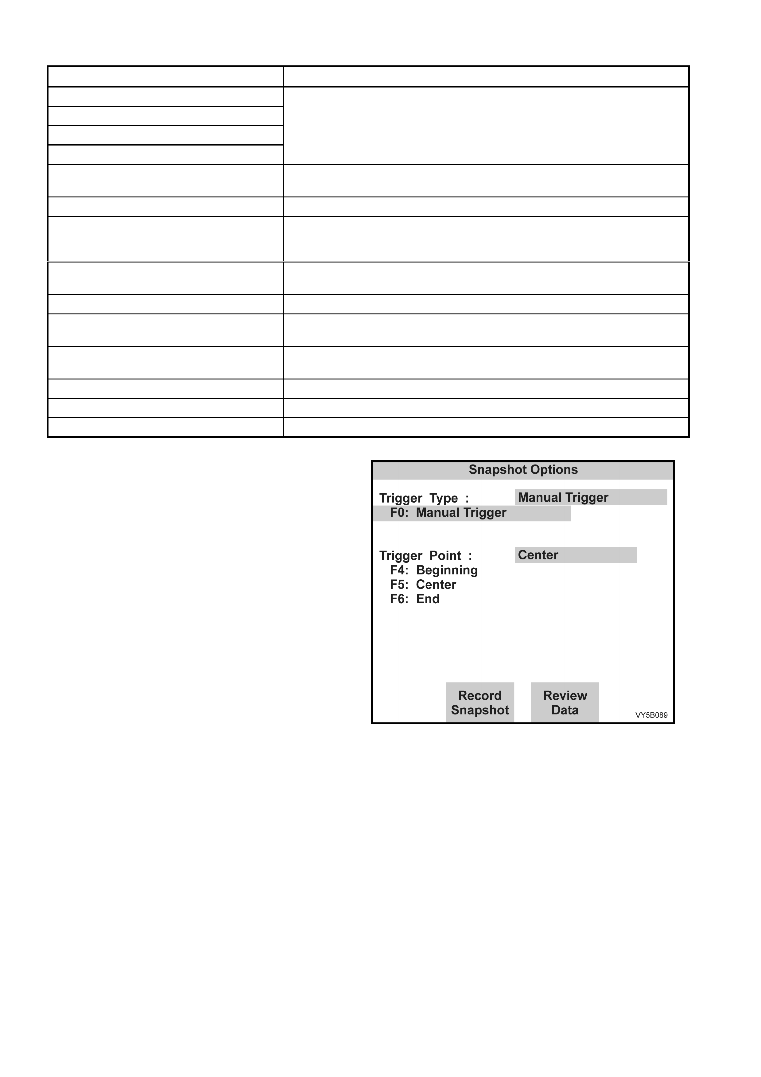
ABS/TCS DISABLED
DATA STREAM / SCREEN DISPLAY DESCRIPTION
FR Wheel Speed (Front Right)
FL Wheel Speed (Front Left)
RR Wheel Speed (Rear Right)
RL Wheel Speed (Rear Left)
Displays wheel speed sensor input (km/h) to the control module.
Stop Lamp Switch Displays current status of switch - displays OFF when switch is in the rest
position and ON when brake pedal is depressed.
Pump Monitor Will always display OFF as ABS and TCS are disabled in this mode.
Valve Relay Displays current status of valve relay - either OPEN or CLOSED.
NOTE: If OPEN is displayed in this mode, there is a fault in the valve relay
circuit.
ETC Switch Displays current status of switch - displays OPEN when switch is in the rest
position and CLOSED when held down (TCS Only).
Engine Speed Displays the current engine speed in RPM (TCS Only).
Requested Torque (V6 Engines Only) Displays the amount of torque (in Nm) the ABS/TCS control module is
requesting the engine to deliver (TCS Only).
Actual Torque (V6 Engines Only) Displays the calibrated torque (in Nm) that the engine is delivering (TCS
Only).
Engine Speed (GEN III V8 Engine Only) Displays the current engine speed in RPM.
Throttle Position (GEN III V8 Engine Only) Displays the current throttle position( percentage of throttle valve opening).
System ID Displays control module internal software identification number.
F3: Snapshot
The snapshot mode will help to identify problems
caused by speed sensor signals that may cause
intermittent operation of the ABS or ABS/ETC
systems.
The SNAPSHOT mode captures data before and
after a forced manual trigger condition.
Figure 5B-102

F4: MISCELLANEOUS TESTS
In the Miscellaneous tests mode, functional tests
are avai lable on t he ABS or ABS/ET C s ystems that
will help identify proper operation. In this mode,
error conditions can be further identified by testing
and observing the test results.
Additionally, in this mode, the hydraulic modulator
can be bled (F2: BRAK E B LE ED).
In the MISCELLANEOUS TESTS mode the
following tests can be performed:
F0: Solenoid
This test indica tes whether specif ic soleno id va lves
in the hydraulic modulator release pressure to
assigned hydraulic wheel circuits and hold
pressur e in assign ed h ydr a ulic wheel circu its .
NOTE: Use this procedure in conjunction with the
information displayed on the Tech 2 screen in the
F0: SOLENOID test mode.
The PRESSURE RELEASE part of the test
activates a selected hydraulic wheel circuit valve,
placing it in the pressure release position. Valve
action can then be verified by checking the
appropriate wheel for proper brake action.
Figure 5B-103
The PRE SSURE HOLD part of the test ac tivates a select ed hydrau lic whee l circuit valve, p lacing it in the pr essur e
hold position. Valve action can then be verified by checking the appropriate wheel for proper brake action.
These tests completely check each solenoid valve. W ith an assistant, the pressure release and hold tests can be
verified as follows:
1. Ignition OFF.
2. Raise vehicle such that the wheels are at least 150 mm off the floor.
3. Install Tech 2 to the DLC.
4. Select Diagnostics / Chassis / ABS/ETC and turn ignition on and confirm System Identification information as
instructed.
5. Select Miscellaneous Tests / Solenoids.
6. Select the relevant solenoid to be tested and press ENTER.
7. Follow instructions on the Tech 2 display screen while getting an assistant to try to spin the road wheel being
tested when requested by Tech 2.
NOTE: This test verifies the ability of the solenoid valves to control the hydraulic functioning of the system. The
electrical function is verified by the constant monitoring of the circuits by the ABS/ETC control module during
normal operation of the system. If the control module detects an electrical problem, such as a solenoid open or
short to ground, a DTC will be set and the system disabled.
F1: Auto Test
The AUT O test is performed automatically by the control module once during each ignition cycle when the vehicle
reaches approxim ately 6 km/h. The Tech 2 will perform this test automatically during the ABS TESTS mode. The
AUTO test cycles each solenoid valve and the pump motor briefly to check component operation. If any error is
detected dur ing this tes t, the control m odule will set a DT C and the ABS and or TRAC OF F warning dis play will b e
activated. Perform the test as follows:
NOTE 1: Use th is proce dure i n conjunc tion with the inf orm ation displa yed on t he Tec h 2 SCREEN while in the F1:
AUTO TEST, test mode.
NOTE 2: If there are any DTCs set, they will have to be cleared before this test can be performed.
Procedure
1. Turn ignition OFF.
2. Install Tech 2 to the DLC.
3. Select Diagnostics / Chassis / ABS/ETC and turn ignition on and confirm System Identification information as
instructed.
4. Select M iscellan eous T ests / Auto T est and pres s the CONT INUE sof t k ey on Te ch 2 to s tart test (ret urn p um p
will be heard to run for short period).
5. Note any DTCs that are set when test is completed.

F2: Brake Bleed
This test prompts the Technician to b leed the brak e system . The test is divided into t wo parts; a pr imar y bleed and
a second ar y b lee d. A primar y blee d is a manua l bleed of each hydraul ic cir cui t. D ur ing a s ec ondar y bleed, the A B S
or ABS/TCS control module activates the solenoid and pump motor so that any air in these components is
expelled.
NOTE: The AUTO TEST must be carried out before conducting the brake bleed procedure. If the automatic test
has not been conducted, carry out this test, as described under F1: AUTO TEST, in this Section.
The brake bleed procedure is as follows:
1. Instal l brake bleed ing equipm ent to vehic le as recom mended in Se ction 5 A SERVICE AND PARK BR AKI NG
SYSTEMS in the MY 2003 VY and V2 Series Service Information.
2. Turn ignition OFF.
3. Install Tech 2 to DLC.
4. Select Diagnostics / Chassis / ABS/ETC and turn ignition on. Confirm System Identification information as
instructed.
5. Select Miscellaneous Tests / Brake Bleed and follow instructions on the Tech 2 display screen.
NOTE: The Tec h 2 scr een will disp la y “RUN AUT O TEST PRIOR T O BRAKE BL EED. DONE?” Sel ect YES or NO .
The AUT OMATI C TEST must be carr ied out prior to conduc ting the br ake bleed pr ocedure. If the aut o test has not
been conducted, select NO and carry out test as described under F1: AUTO TEST.
If the auto test has been completed, select YES and continue.
The procedure will begin with a manual bleed at the right hand rear brake caliper. Ensure a suitable size plastic
hose is installed over the bleed screw and that it leads into a container of brake fluid.
W hile fo llo wing t he b lee d proc edur e, as per Tech 2 ins t r uct ions, ens ur e t hat f lui d is c ontinu ous ly fed int o the m ast er
cylinder especially while the secondary circuit is being bled.

4.9 DIAGNOSTIC CHARTS – V6 ENGINES
INTRODUCTION
The following diagnostic charts are designed to provide fast and efficient fault location of the ABS or ABS/TCS
systems. Each diagnostic chart consists of: a ‘diagnostic chart’, connector body terminal assignments for
connectors relevant t o that par ticular d iagnostic c hart, and pertinent inform ation inc luding Dia gnostic T rouble Code
(DTC) setting parameters and circuit diagrams.
The following figures illustrate the term inal layout of the various connectors used in the system. This figure should
be used in conjunction with the diagnostic chart circuit diagrams when checking circuit faults if the connector
diagram is not included in the chart.
When carrying out wiring checks as directed to by the diagnostic charts, rather than probe terminals and
connectors with incorrect sized multimeter connections, use the adaptors contained in connector test adaptor kit
KM-609. T his will pre ven t an y possib ilit y of spread ing or dam aging wir ing har ness terminals.
On-Vehicle Service
When a diagnostic chart in this Section makes reference to removing/reinstalling or checking a component for
proper mounting or operation, refer to the appropriate service operation in this Section. After all diagnosis and
repairs ar e c ompleted, ro ad - tes t the ve hic l e to e ns ure pr oper A BS a nd AB S/TCS oper at io n and t he A BS a nd TRAC
OFF warning d ispla ys do not com e on, refer to 4.4 FUNCTIONAL CHECK in this Sectio n. If the Tech 2 was used
for diag nos is , disc onn ec t it f r om the DLC and turn the i gnit io n O FF f or at leas t 10 s ec onds bef or e road testi n g. This
is necessary to reset the ABS or ABS/TCS control module as it is disabled during most Tech 2 diagnostic
procedures, and does not reset until serial data communication is stopped and ignition power is lost.
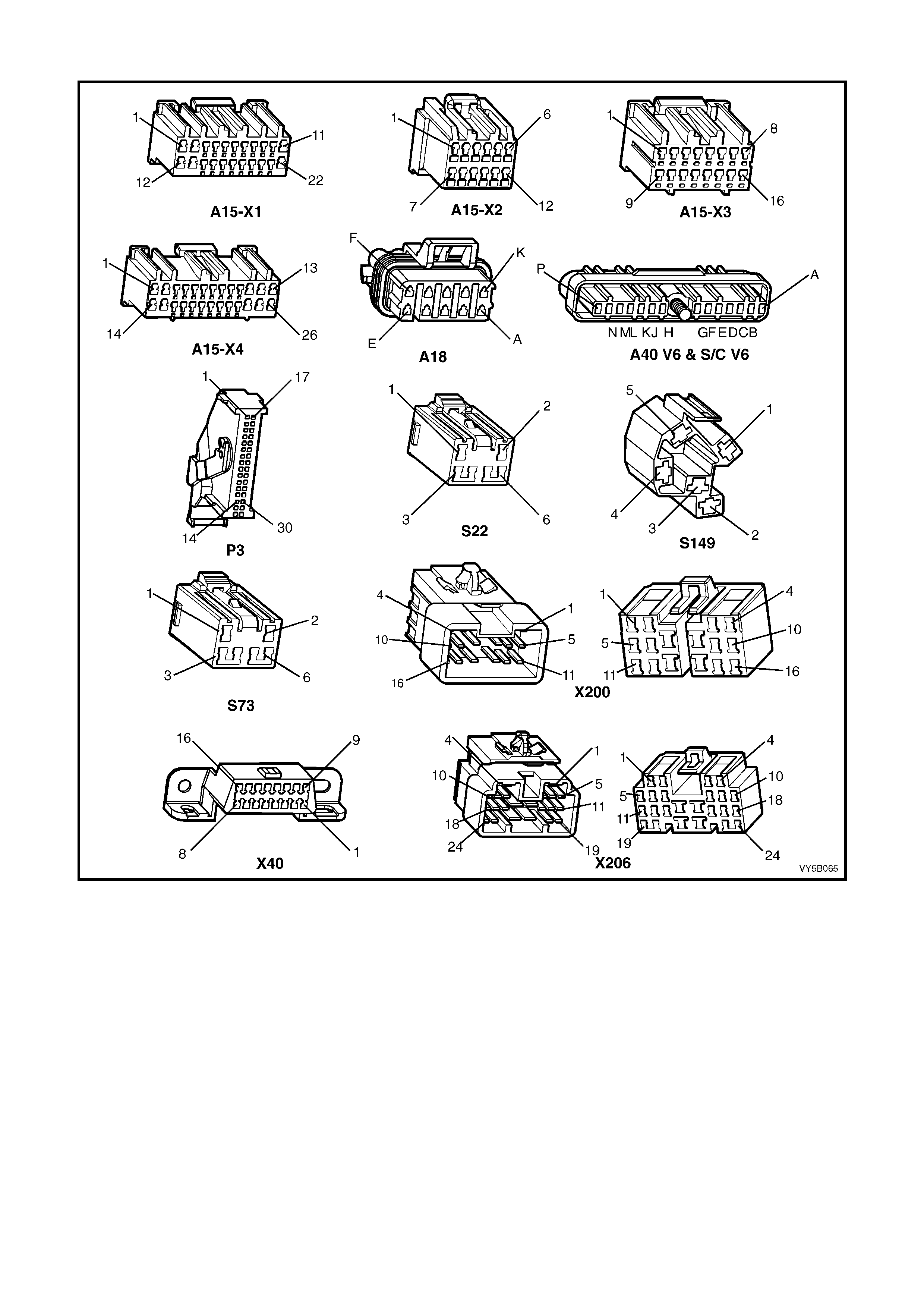
Wiring Harness Connectors
Figure 5B-104 – V6 and V6 Supercharged Engines, Wiring Harness Connectors
Legend
A15 Body Control Module
A18 Cruise Control Module
A40 DIS Ignition Module
P3 Instrument Cluster
S22 Automatic Transmission Shift
S73 TCS Control Module
S149 Ignition & Start Switch
X40 Data Link Connector (DLC)
X200 Body Wiring Harness to Main
Wiring Harness
X206 Main Wiring Harness to Powertrain
Wiring Harness
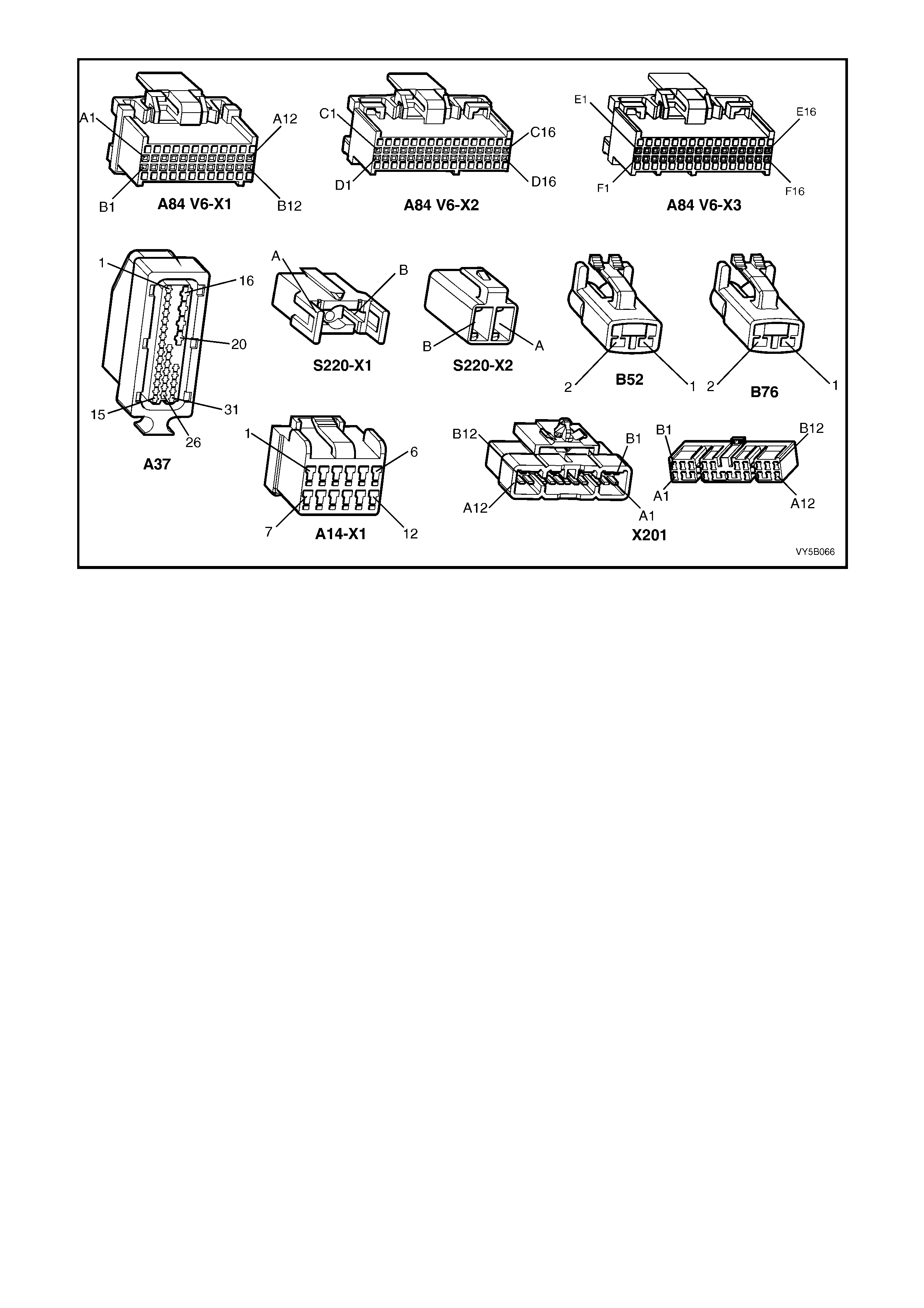
Figure 5B-105 – V6 and V6 Supercharged Engines, Wiring Harness Connectors
Legend
A84 Powertrain Control Module – V6 and V6 S/C Engines
A37 ABS & ABS/TCS Control Module
A14 Blower Motor and A/C Compressor
S220 Stop Lamp, plus Torque Converter Clutch and
Cruise Control Release
X
201 Body Wiring Harness to Main Wiring
Harness
B
52 Wheel Speed Sensor – Front
B
76 Wheel Speed Sensor – Rear
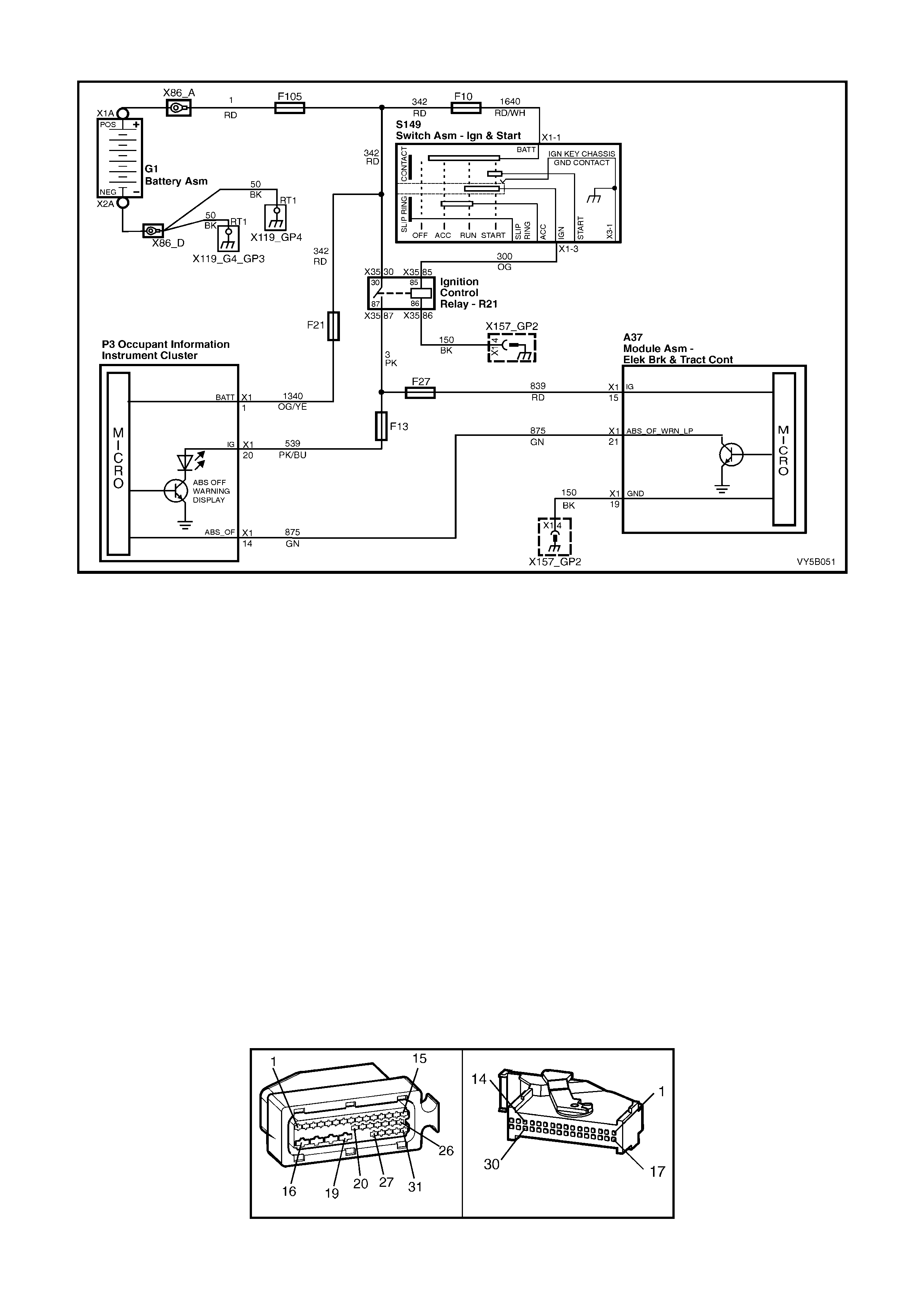
CHART A1 – ABS WARNING DISPLAY INOPERATIVE
Figure 5B-106
CIRCUIT DESCRIPTION:
Batter y voltage is supplied to the ABS O FF warning d ispla y with the ign ition switc h in the IGN or ST ART pos itions,
via the ignition control relay (R21) and through fuse F13 (located in the interior electrical centre).
The warning display can only be activated by the ABS or ABS/TCS control module A37 internally by supplying a
ground to terminal X1-21 or via the shorting bar in the ABS or ABS/TCS control m odule connector A37 when it is
disconnected from the control module.
TEST DESCRIPTION:
The numbers below refer to step numbers in diagnostic chart A1.
1. This test checks for any DTCs that may cause the ABS warning display to be inopera tive.
2. This test verifies an inoperative warning display condition.
3. This test checks each of the circuit protection devices.
4. This test checks if fault is within control module. Connector shorting pins in connector A37-X1 should cause
warning displa y to be activated.
5. This test checks for a faulty voltage supply to the instruments.
6. Checks circuit 300 (Orange wire).
7. Checks continuity through ignition control relay, R21.
8. Checks circuit 875 (Green wire).
9. Checks the warning display ground circuit to the ABS or ABS/TCS control module.
NOTES ON DIAGNOSTIC CHART:
1. Refer to 4.7 TECH 2 DIAGNOSTICS in this Section for connecting and using Tech 2.
2. Refer to Section 12P WIRING DIAGRAMS in the MY 2003 VY and V2 Series Service Information for
procedures on checking wiring faults.
A37 P3
Figure 5B-107

CHART A1 - ABS WARNING DISPLAY INOPERATIVE
STEP ACTION VALUE YES NO
1. Was the ABS or ABS/TCS Functional Check Carried
out? Go to Step 2 Go to 4.4 ABS or
ABS/TCS
Functional Check
2. 1. Install Tech 2 to DLC and select Diagnostics /
Chassis / Diagnostic Trouble Codes / Read DTCs
(refer to NOTE 1 above).
Are any DTCs set?
Repair conditi ons
which set DTCs,
recheck and
verify repair.
Go to Step 3
3. 1. Disconnect Tech 2 from DLC.
2. Turn ignition on while observing ABS warning
display.
Is warning display visible for approximately 2 seconds
then turn off?
NOTE: If battery voltage is below 9 Volts, display may
stay on.
No fault found.
Go to Step 1 Go to Step 4
4. 1. Check fusible link F105 and fuses F10 and F13.
Does continuity exist through each?
Go to Step 5 Replace as
required.
5. 1. Turn ignition off.
2. Disconnect ABS or ABS/TCS control module
connector A37 from control module.
3. Turn ignition on.
Is ABS warning display visible?
Check control
module
connector A37
X1 terminals for
correct sizing &
condition. If OK,
replace control
module.
Go to Step 6
6. 1. With instrument cluster removed, switch ignition on
and measure voltage between connector P3,
terminal X1-20, circuit 539 (Pink/Blue wire) and
ground (refer to ‘Notes on Diagnostic Chart’, No. 2
above).
Is voltage as specified?
Battery + Go to Step 9 Go to Step 7
7. 1. Check wiring between ignition switch connector
S149, terminal X1-3, circuit 300 (Orange wire) and
interior electrical centre connector X129, terminal
X35-85 (ignition control relay R21) refer to ‘Notes on
Diagnostic Chart’, No. 2 above).
Does continu ity ex ist?
Go to Step 8 Check and repair
open in circuit
300, recheck and
verify repair.
8. 1. With the ignition switched on, check voltage from
interior electrical centre connector X129, terminal
X35-86 (ignition control relay R21) and a sound
ground.
Is voltage as specified ?
Battery + Go to Step 9 Replace ignition
control relay,
recheck and
verify repair.
9. 1. Check for continuity between instrument cluster
connector P3, term inal X1-14 and ABS or ABS/TCS
control module connector A37, terminal X1-21,
circuit 875 (Green wire) (refer to ‘Notes on
Diagnostic Chart’, No. 2 above).
Does continuity exist ?
Go to Step 10 Check and repair
open in circuit
875, recheck and
verify repair.
10. 1. Check for continuity between ground location GP2
(RH inner fender) and ABS or ABS/TCS control
module connector A37, terminal X1-19, circuit 150
(Black wire) (refer ‘Notes on Diagnostic Chart’, No. 2
above).
Ground circuit OK?
Replace
instrument
cluster, refer
Section 12C
INSTRUMENTS
Repair circuit as
required, recheck
circuit to verify
repair.
WHEN ALL DIAGNOSIS AND REPAIRS ARE COMPLETED, CLEAR ALL DTCs AND VERIFY CORRECT OPERATION
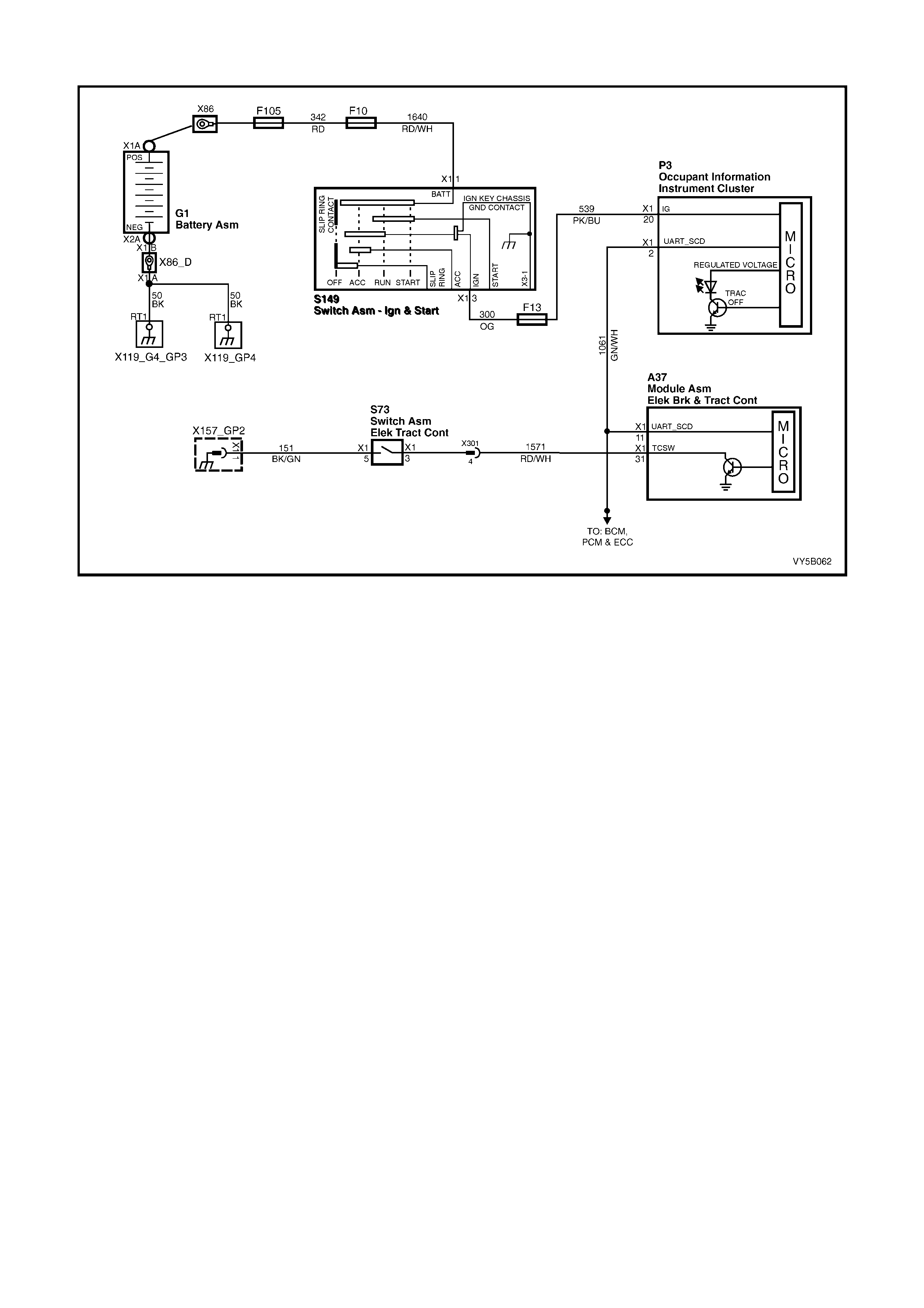
CHART A2 – TRAC OFF WARNING DISPLAY INOPERATIVE
Figure 5B-108
CIRCUIT DESCRIPTION:
Batter y vol tag e is supp l ied t o the TRAC OF F warn ing d is play with t he ig n ition switc h in t he IGN or START pos itions
through fuse F13 (located in the inter ior electrical centre). T he instrument cluster m onitors circuit 1061 for a serial
data mes sage from the AB S/TCS contro l module. If th e instrum ent cluster does n ot receive a ser ial data m essage
from the ABS/TCS control module, the instrument cluster will activate the TRAC OFF warning display.
The TRAC OFF warning display will be activated whenever the system is disabled; either manually through the
TRAC CTRL switch or du e to a f ault be ing l ogg ed i n th e contr ol module. When activated, the purp os e of the dis play
is to alert the driver that the TCS system has been disabled.
TEST DESCRIPTION:
The numbers below refer to step numbers in diagnostic chart A2.
1. This test checks for any DTCs that may cause the TRAC OFF warning display to be inoperative.
2. This test determines if the ABS/TCS control module is faulty by using Tech 2 to drive the warning display on.
3. This is a simple test to determine if power is being supplied to the instrument cluster warning displays (the
TRAC OFF and ABS warning displays share a common power source).
4. This step determines if the warning display is defective.
5. This test checks for a faulty voltage supply to the warning display.
NOTES ON DIAGNOSTIC CHART:
1. Refer to 4.7, TECH 2 DIAGNOSTICS in this Section for connecting and using Tech 2.
2. Refer to Section 12P WIRING DIAGRAMS in the MY 2003 VY and V2 Series Service Information for
procedures on checking wiring faults.
DIAGNOSTIC AIDS:
If the TRAC CTRL button is depressed and held for ten or more seconds (or there is a short to ground in circuit
1429), the ABS/TCS control module will see this as a short circuit to ground and the TCS will be permanently
enabled and the TRAC OFF warning display deactivated until the ignition is switched off and the engine restarted.

A37 P3
Figure 5B-109
CHART A2 - TRAC OFF WARNING DISPLAY INOPERATIVE
STEP ACTION VALUE YES NO
1. Was the ABS or ABS/TCS Functional Check Carried
out? Go to Step 2 Go to 4.4 ABS or
ABS/TCS
Functional Check
2. 1. Install Tech 2 to DLC.
2. Select Diagnostics / Chassis / Diagnostic Trouble
Codes / Read DTCs (refer to NOTE 1 above).
Are any DTCs set?
Repair conditions
which set DTCs,
recheck and
verify repair.
Go to Step 3
3. 1. With Tech 2 still connected, exit Chassis and select
Body / Instruments / Miscellaneous Tests / Status
Indicators / Traction Control and command the
traction display ON and OFF.
Does the display change from ON to OFF when
commanded?
Replace
ABS/TCS control
module, refer to
3.6 CONTROL
MODULE in this
Section, recheck
circuit to verify
repair.
Go to Step 4
4. 1. Disconnect Tech 2 from DLC.
2. Turn ignition ON while observing the Instrument,
Multi Function Display (MFD).
Does the Instrument MFD display “System Check OK!”?
No fault found.
Go to Step 1 Go to Step 5
5. 1. Check fusible link F105 and fuses F10 and F13.
Does continuity exist through each? Go to Step 5 Replace
defective parts.
Go to Step 1.
6. 1. Remove instrument cluster, refer to 12C
INSTRUMENTS.
2. Switch ignition on and measure voltage between
connector P3, terminal X1-20, circuit 539 (Pink/Blue
wire) and ground (refer to Notes on Diagnostic Chart
No. 2 above).
Is voltage as specified?
Battery + Go to Step 9 Go to Step 7
7. 1. Check wiring between ignition switch connector
S149, terminal X1-3, circuit 300 (Orange wire) and
interior electrical centre connector X129, terminal
X34-85 (relay R20) refer to Notes on Diagnostic
Chart No. 2 above).
Does continu ity ex ist?
Go to Step 8 Check and repair
open in circuit
300, recheck and
verify repair.
8. 1. With the ignition switched on, check voltage from
interior electrical centre connector X129, terminal
X34-86 (relay R20) and a sound ground.
Is voltage as specified ?
Battery + Go to Step 9 Replace relay,
recheck and
verify repair.
9. 1. Check for continuity between instrument cluster
connector P3, term inal X1-24 and ABS or ABS/TCS
control module connector A37, terminal X1-20,
circuit 832 (Yellow/Red wire) (refer to Notes on
Diagnostic Chart No. 2 above).
Does continuity exist ?
Go to Step 10 Check and repair
open in circuit
875, recheck and
verify repair.
10. 1. Check for continuity between ground location E3
(RH inner fender) and ABS or ABS/TCS control
module connector A37, terminal X1-19, circuit 150
(Black wire) (refer to Notes on Diagnos tic Chart No.
2 above).
Ground circuit OK?
Replace
instrument
cluster, refer
Section 12C
INSTRUMENTS.
Repair circuit as
required, recheck
circuit to verify
repair.
WHEN ALL DIAGNOSIS AND REPAIRS ARE COMPLETED, CLEAR ALL DTCs AND VERIFY CORRECT OPERATION
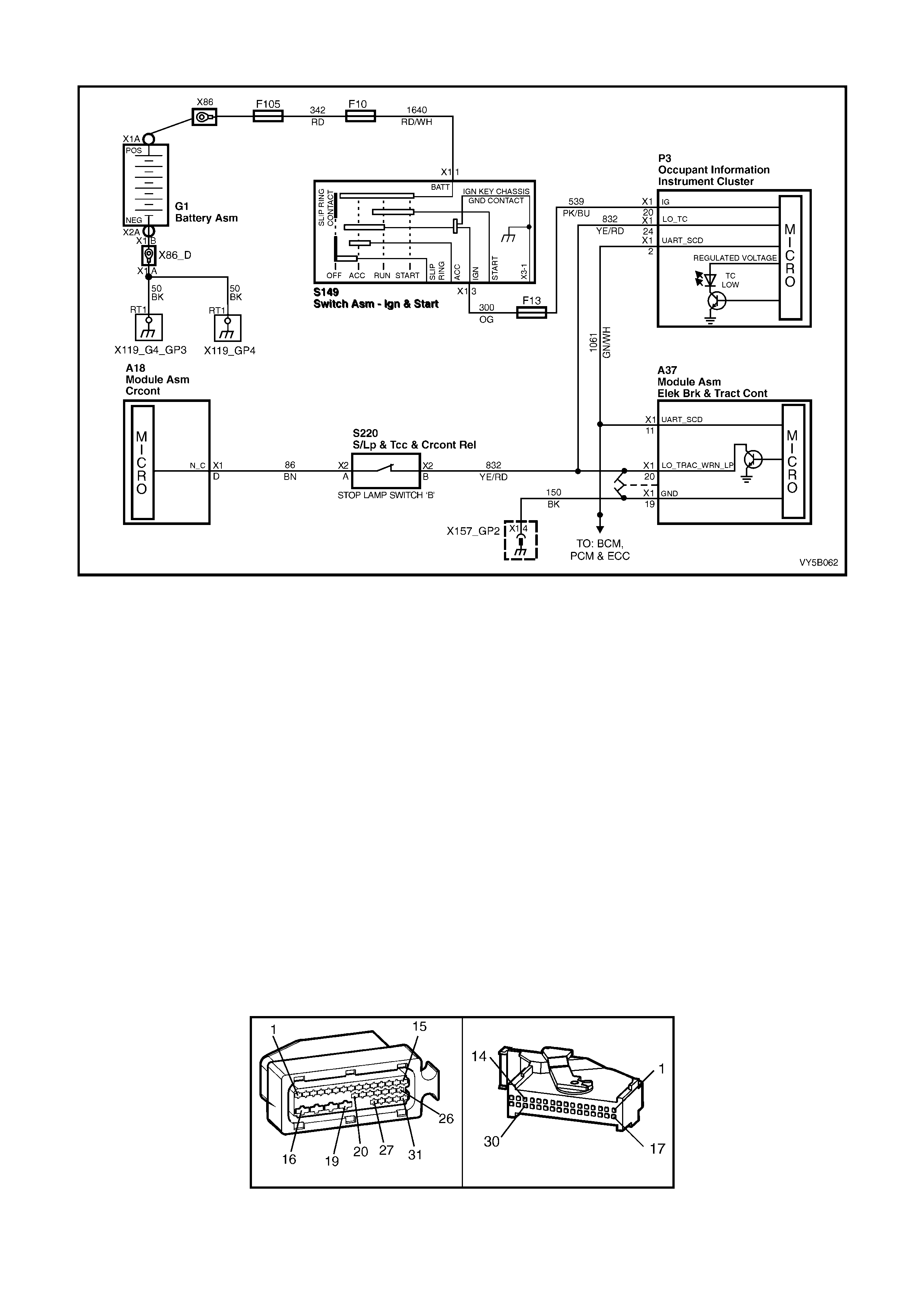
CHART A3 - LOW TRAC WARNING DISPLAY INOPERATIVE
Figure 5B-110
CIRCUIT DESCRIPTION:
Battery voltage is supplied to the LOW TRAC warning display with the ignition switch in the IGN or START
positions through fuse F13 (located in the interior electrical centre).
The warning display is activated by the ABS/TCS control module internally by supplying ground to terminal X1-20
when the tr ac t ion control s ys tem (T CS) is ac tivated, or vi a a s hort ing b ar i n t he A B S/T CS c ontr ol module c o nn ec tor
A37, when it is disconnected from the control module.
TEST DESCRIPTION:
The numbers below refer to step numbers in diagnostic chart A3.
1. This test checks for any DTCs that may cause the LOW TRAC warning display to be inopera tive.
2. This test verifies an inoperative warning display condition.
3. This test checks if fault is within control module.
4. This step determines if the warning display bulb or socket is defective.
5. This test checks for a faulty voltage supply to the warning display.
6. Checks circuit 88.
7. Checks the warning displays ground circuit to the ABS/TCS control module.
NOTES ON DIAGNOSTIC CHART:
1. Refer to 4.7 TECH 2 DIAGNOSTICS in this Section for connecting and using Tech 2.
2. Refer to Section 12P WIRING DIAGRAMS in the MY 2003 VY and V2 Series Service Information for
procedures on checking wiring faults.
A37 P3
Figure 5B-111

CHART A3 - LOW TRAC WARNING DISPLAY INOPERATIVE
STEP ACTION VALUE
YES NO
1. Was the ABS or ABS/TCS Functional Check Carried
out? Go to Step 2 Go to 4.4 ABS or
ABS/TCS
Functional Check
2. 1. Install Tech 2 to DLC select Diagnostics / Chassis /
Diagnostic Trouble Codes / Read DTCs (refer to
NOTE 1 above).
Are any DTCs set ?
Repair conditi ons
which set DTCs,
recheck and
verify repair.
Go to Step 3
3. 1. Disconnect Tech 2 from DLC.
2. Turn ignition on whilst observing the Instrument
Multi Function Display (MFD).
Does the Instrument MFD display “System Check OK!”?
No fault found.
Go to Step 1 Go to Step 4
4. 1. Turn ignition OFF.
2. Disconnect ABS/TCS control module connector A37
from control mod ule.
3. Turn ignition ON.
Does “TC LOW” warning display activate in the
Check ABS/TCS
control modu le
connector
terminal for
correct sizing &
condition. If all
OK, replace
control modu le.
Go to Step 5
5. 1. Check fusible link F105 and fuses F10 and F13.
Does continuity exist through each?
Go to Step 6 –
6. 1. Remove instrument cluster, refer to 12C
INSTRUMENTS.
2. Switch ignition ON and measure voltage between
connector S149, terminal X1-3, circuit 300 (Orange
wire) and ground (refer NOTE 2 above).
Is voltage as specified ?
3. With instrument cluster removed, switch ignition on
and measure voltage between connector P3,
terminal X1-20, circuit 539 (Pink/Blue wire) and
ground (refer to Note 2 above).
Is voltage as specified?
Battery + Go to Step 7 Check fusible link
F105 and fuse
F13. Check
wiring betwe en
ignition sw itch
and instrument
cluster
connectors S149
and P3. Check
ignition sw itch
contacts, recheck
circuit to verify
repair.
7. 1. Check for continuity between instrument cluster
connector P3, terminal X1-24 and ABS/TCS control
module connector A37, terminal X1-20, circuit 832
(Yellow/Red wire) (refer to Note 2 above).
Does continuity exist ?
Go to Step 8 Check and repair
open in circuit
832, recheck and
verify repair.
8. 1. Check for continuity between ground location X157-
G2 (RH inner fender) and ABS/TCS control module
connector A37, terminal X1-19, circuit 150 (Black
wire) (refer to NOTE 2 above).
Ground circuit OK?
Replace
instrument
cluster, refer
Section 12C
INSTRUMENTS.
Repair circuit as
required, recheck
circuit to verify
repair.
WHEN ALL DIAGNOSIS AND REPAIRS ARE COMPLETED, CLEAR ALL DTCs AND VERIFY CORRECT OPERATION
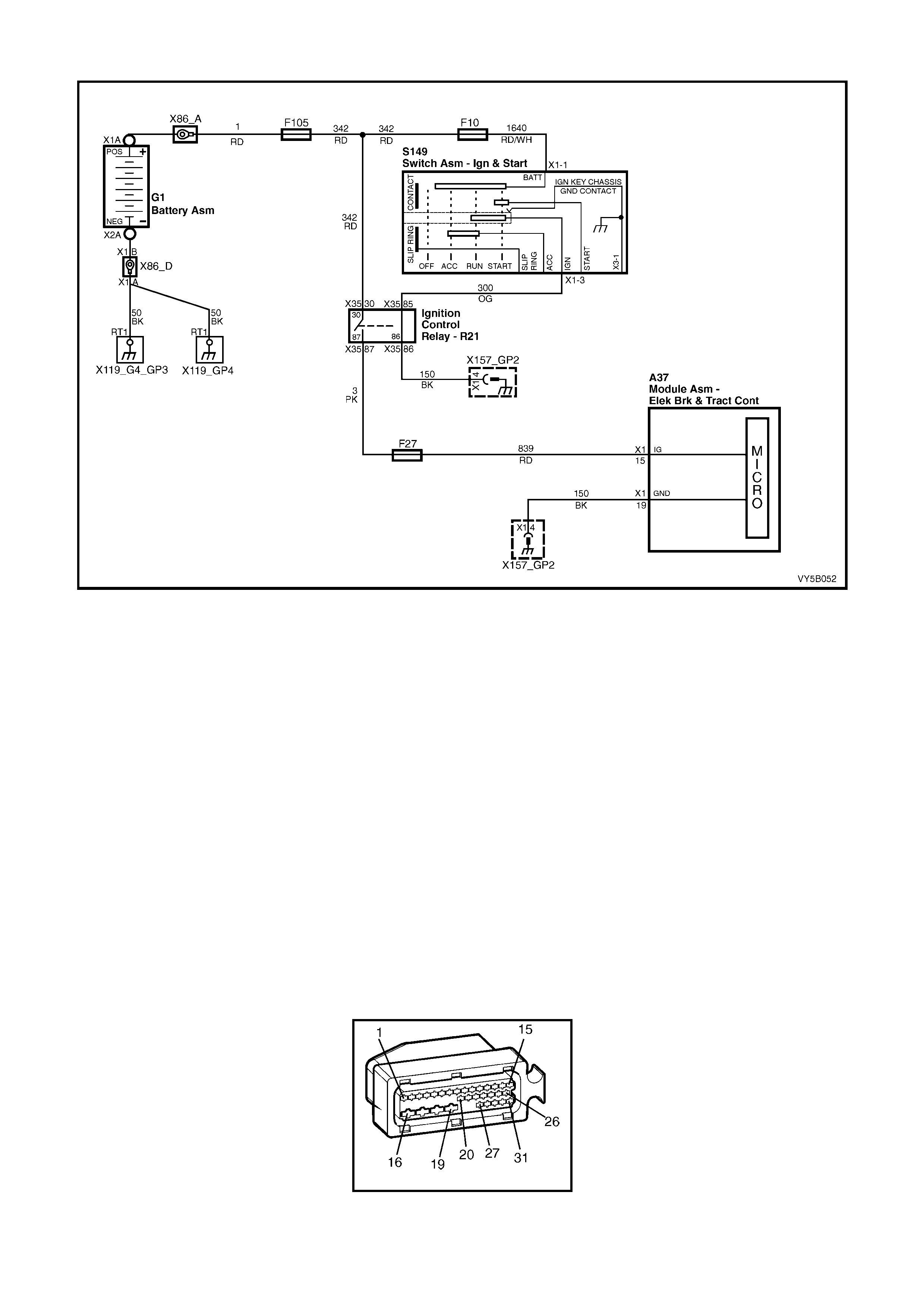
CHART B - POWER SUPPLY TO CONTROL MODULE (NO DTCs STORED)
Figure 5B-112
CIRCUIT DESCRIPTION:
Battery voltage is supplied to the ABS or ABS/TCS control module terminal X1-15 with the ignition switch in the
IGN or START positions, via ignition control relay R21 and fuse F27 (both located in the interior electrical centre).
TEST DESCRIPTION:
The numbers below refer to the number/s in diagnostic chart B.
1. This test checks that there is sufficient battery voltage supply available.
2. This test checks the voltage supply to the ABS or ABS/TCS control module.
3. This test checks all fuses in the supply circuit.
4. This tests for open circuits in either of the power supply circuits.
5. Checks for soundness of the ignition switch internal contacts
6. Checks for an open circuit in circuit 300.
7. Checks the ground circuit and connections for the ignition control relay.
8. Checks the soundness of the relay switching, when activated.
9. Checks for an open circuit in circuits 3 and 839, including fuse F27.
10. This test checks the ground connections to the ABS or ABS/TCS control module.
NOTES ON DIAGNOSTIC CHART:
1. Refer to Section 12P WIRING DIAGRAMS in the MY 2003 VY and V2 Series Service Information for
procedures on checking wiring faults.
A37
Figure 5B-113

CHART B - POWER SUPPLY TO CONTROL MODULE (NO DTCs STORED)
STEP ACTION VALUE YES NO
1. Was the ABS or ABS/TCS Functional Check Carried
out? Go to Step 2 Go to 4.4 ABS or
ABS/TCS
Functional Check
2. 1. Measure voltage across battery terminals.
Is it voltage as specified ? 10 – 16 Volts Go to Step 3 Check battery
condition. Refer
to 12A BATTERY
AND CABLES.
Check charging
system, refer to
6D1-1 (V6),
6D2- 1 (V6 S/C)
or 6D3-1 (GEN III
V8).
3. 1. Rem ove wiring harness connector A37 from ABS or
ABS/TCS control module.
2. Switch ignition ON.
3. Measure voltage at connector A37, terminal X1-15,
circuit 839 (Red wire).
Is voltage as specified ?
Approx.
12 Volts Go to Step 11 Go to Step 4
4. 1. Check fusible link F105 and fuses F10 and F27.
Are fusible link and fuses OK? Go to Step 5 Replace
defective fusible
link F105 and/or
fuses F10/F27.
Investigate cau se
of blown link or
fuse, recheck
circuit to verify
repair.
5. 1. Check wiring in circuits 342 (Red wire) to the ignition
control relay R21, terminal X35-30 and 1640
(Red/White wire) to the ignition switch S149,
terminal X1-1 for an open circuit.
Are both circuits OK?
Go to Step 6 Repair/replace
wiring as
necessary,
recheck circuit to
verify repair.
6. 1. Check ignition switch contacts by checking voltage
at ignition switch S149, terminal X1-3 and a sound
ground, with the ignition switched ON.
Is the voltage as specified?
Approx.
12 Volts Go to Step 7 Replace ignition
switch and verify
repair.
7. 1. Check wiring in circuit 300 (Orange wire) between
the ignition switch S149, terminal X1-3 and the
ignition control relay R21, terminal X3-86 for an
open circuit .
Is the circuit OK?
Go to Step 8 Repair/replace
wiring as
necessary,
recheck circuit to
verify repair.
8. 1. Check the resistance of circuit 150 (Black wire)
between the ignition control relay R21, terminal X35-
86 and the ground point X157_GP2, located at the
RHF inner fender.
Is the resistance as specified?
0 – 5 Ω Go to Step 9 Repair circuit as
required, recheck
circuit to verify
repair.
9. 1. With the ignition switched ON, use a DMM set to
volts and check between ignition relay R21, terminal
X35-87 and a sound ground point.
Is the voltage as specified?
Approx.
12 Volts Go to Step 10 Replace ignition
control relay R21,
recheck and
verify repair.
10. 1. Check wiring in circuit 3 (Pink wire) between the
ignition control relay R21, terminal X3-87 and A37,
terminal X1-15, for an open circuit.
Is the circuit OK?
Go to Step 11 Repair circuit as
required, recheck
circuit to verify
repair.
11. 1. Check for continuity between ABS or ABS/TCS
control module connector A37, terminal X1-19,
circuit 150 (Black wire) and the ground location
X157_GP2 (RH inner fender).
Is the ground circuit OK ?
Check ABS or
ABS/TCS control
module
connector A37
terminals for
correct sizing &
condition.
If all OK, replace
control modu le.
Repair circuit as
required, recheck
circuit to verify
repair.
WHEN ALL DIAGNOSIS AND REPAIRS ARE COMPLETED, CLEAR ALL DTCs AND VERIFY CORRECT OPERATION
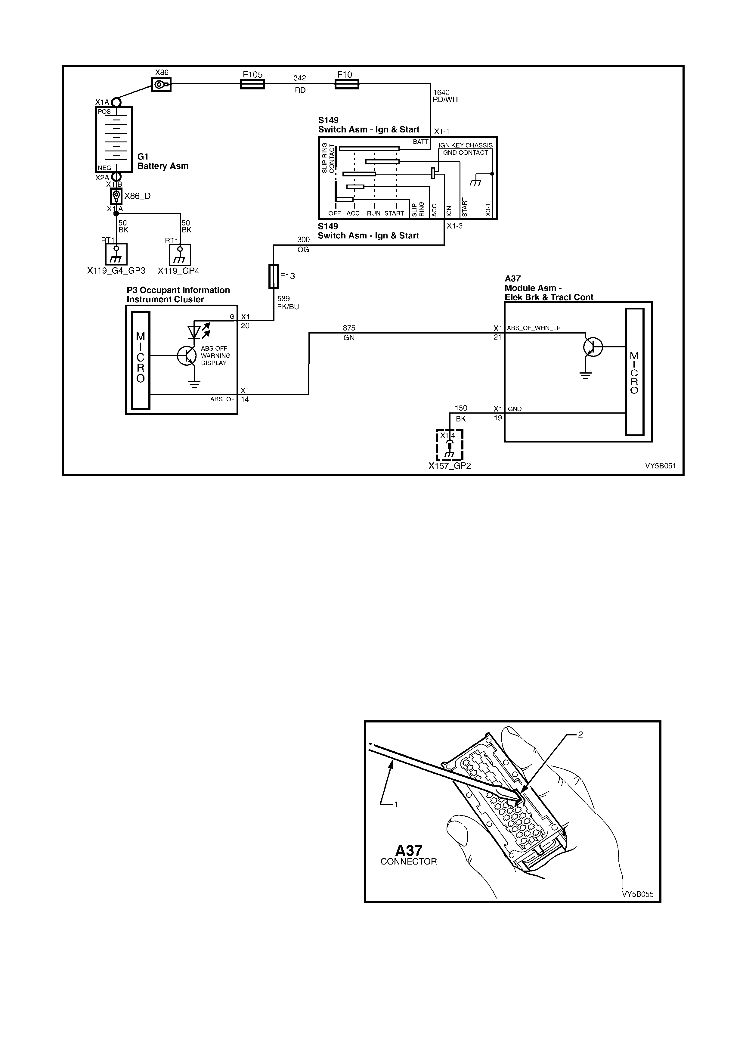
CHART C1 – ABS ‘OFF’ WARNING DISPLAY ACTIVATED CONTINUOUSLY - (NO DTCs STORED)
Figure 5B-114
CIRCUIT DESCRIPTION:
Batter y volta ge is suppl ied to the A BS OFF warni ng displa y with the i gnition sw itch in the IGN or START pos itions
through f use F13 ( locat ed in the inter ior el ectric al ce ntr e). T he warning disp la y can only be acti vated b y the ABS or
ABS/TCS control module internally by supplying ground to terminal X1-21 or via the shorting bar in the ABS or
ABS/TCS control module connector A37 when it is disconnected from the control module.
TEST DESCRIPTION:
The numbers below refer to the Step numbers in diagnostic chart C1.
1. Uses Tech 2 to check for logged DTCs that are causing the warning display to activate.
2. This test checks whether the fault is caused by the ABS or ABS/TCS control module or a short to ground on
circuit 875 (Green wire).
3. This test checks for a short to ground in the wiring between the instrument cluster and the ABS or ABS/TCS
control module.
NOTES ON DIAGNOSTIC CHART:
4. Using a plastic lever (1), hold shorting bar (2)
away from terminals in connector A37, as
shown.
5. Refer to 4.7 TECH 2 DIAGNOSTICS in this
Section for connecting and using Tech 2.
6. Refer to Section 12P WIRING DIAGRAMS in
the MY 2003 VY and V2 Series Service
Information for procedures on checking wiring
faults.
Figure 5B-115

A37 P3
Figure 5B-116
CHART C1 – ABS WARNING DISPLAY ACTIVATED CONTINUOUSLY (NO DTCs STORED)
STEP ACTION VALUE YES NO
1. Was the ABS or ABS/TCS Functional Check Carried
out? Go to Step 2 Go to 4.4 ABS or
ABS/TCS
Functional Check
2. 1. Install Tech 2 to DLC.
2. Select Diagnostics / Chassis / Diagnostic Trouble
Codes / Read DTCs (refer to NOTE 1 above).
Are any DTCs set ?
Repair conditi ons
which set DTCs,
recheck and
verify repair.
Go to Step 3
3. 1. Disconnect Tech 2 from DLC.
2. Remove wiring harness connector A37 from ABS or
ABS/TCS control module.
3. Hold shorting bar away from terminals X1-20 and
X1-21 in connector A37 (refer to NOTE 1 above).
4. Switch ignition ON.
Is the warning display constantly activated ?
Go to Step 4 Replace ABS or
ABS/TCS control
module, refer to
3.6 CONTROL
MODULE in this
Section, recheck
circuit to verify
repair.
4. 1. Check circuit 875 (Green wire) and the instrument
cluster P3 for short to ground between the ABS or
ABS/TCS control module connector A37, terminal
X1-21 (Green wire) and connector P3, terminal X1-
14 (Green wire) (refer to NOTE 3 above).
Is all OK?
Replace
instrument
cluster, refer to
Section 12C
INSTRUMENTS.
Repair circuit as
required, recheck
circuit to verify
repair.
WHEN ALL DIAGNOSIS AND REPAIRS ARE COMPLETED, CLEAR ALL DTCs AND VERIFY CORRECT OPERATION

CHART C2 - TRAC OFF WARNING DISPLAY ACTIVATED CONTINUOUSLY – (NO DTCs STORED)
Figure 5B-117
CIRCUIT DESCRIPTION:
Battery voltage is supplied to the TRAC OFF warning display with the ignition switch in the 'IGN' or 'START'
positions thro ugh f use F13 ( located in t he pa ssenger com par tment f use panel) . The warning disp la y is act ivated b y
the ABS/T CS c ontrol m odule send ing a s ignal to t he in str ument clus ter via the s er ial data b us. T he warnin g dis pla y
will be activated whenever the system becomes disabled either because of a fault in the system or from being
manually turned off by the Traction Control (T/C) switch, located near the transmission shift selector.
TEST DESCRIPTION:
The numbers below refer to the Step numbers in diagnostic chart C2.
1. Uses Tech 2 to check for logged DTCs that are causing the warning display to activate.
2. Checks whether the fault is within the instrument cluster or ABS/TCS control module.
NOTES ON DIAGNOSTIC CHART:
1. Refer to 4.7, TECH 2 DIAGNOSTICS in this Section for connecting and using Tech 2.
DIAGNOSTIC AIDS:
If the T/C button is depressed and held for ten or more seconds (or there is a short to ground in circuit 1571) the
ABS/T CS c ontr ol modul e wil l s ee th is as a s hor t c ir cuit to groun d a nd the TCS will be per manentl y ena bl ed a nd t he
TRAC OFF warning display deactivated until the ignition is switched off and the engine restarted.
Theref ore, a short c ircuit in circuit 1 571, inclu ding T /C switch will not activa te the warning displ ay cont inuousl y, but
it could cause the display to activate for ten seconds after the ignition is switched on.

CHART C2 - TRAC OFF WARNING DISPLAY ACTIVATED CONTINUOUSLY (NO DTCS STORED)
STEP ACTION VALUE YES NO
1. Was the ABS or ABS/TCS Functional Check Carried
out? Go to Step 2 Go to 4.4 ABS or
ABS/TCS
Functional Check
2. 1. Install Tech 2 to DLC.
2. Select Diagnostics / Chassis / Diagnostic Trouble
Codes / Read DTCs (refer to NOTE 1 above).
Are any DTCs set ?
Repair conditi ons
which set DTCs,
recheck and
verify repair.
Go to Step 3
3. 1. With Tech 2 still connected, exit Chassis and select
Body / Instruments / Miscellaneous Tests / Status
Indicators / Traction Control and command the
traction display ON and OFF.
Does the display change from ON to OFF when
commanded?
Replace
ABS/TCS control
module, refer to
3.6 CONTROL
MODULE in this
Section, recheck
circuit to verify
repair.
Replace
instrument
cluster, refer to
Section 12C
INSTRUMENTS.
WHEN ALL DIAGNOSIS AND REPAIRS ARE COMPLETED, CLEAR ALL DTCs AND VERIFY CORRECT OPERATION
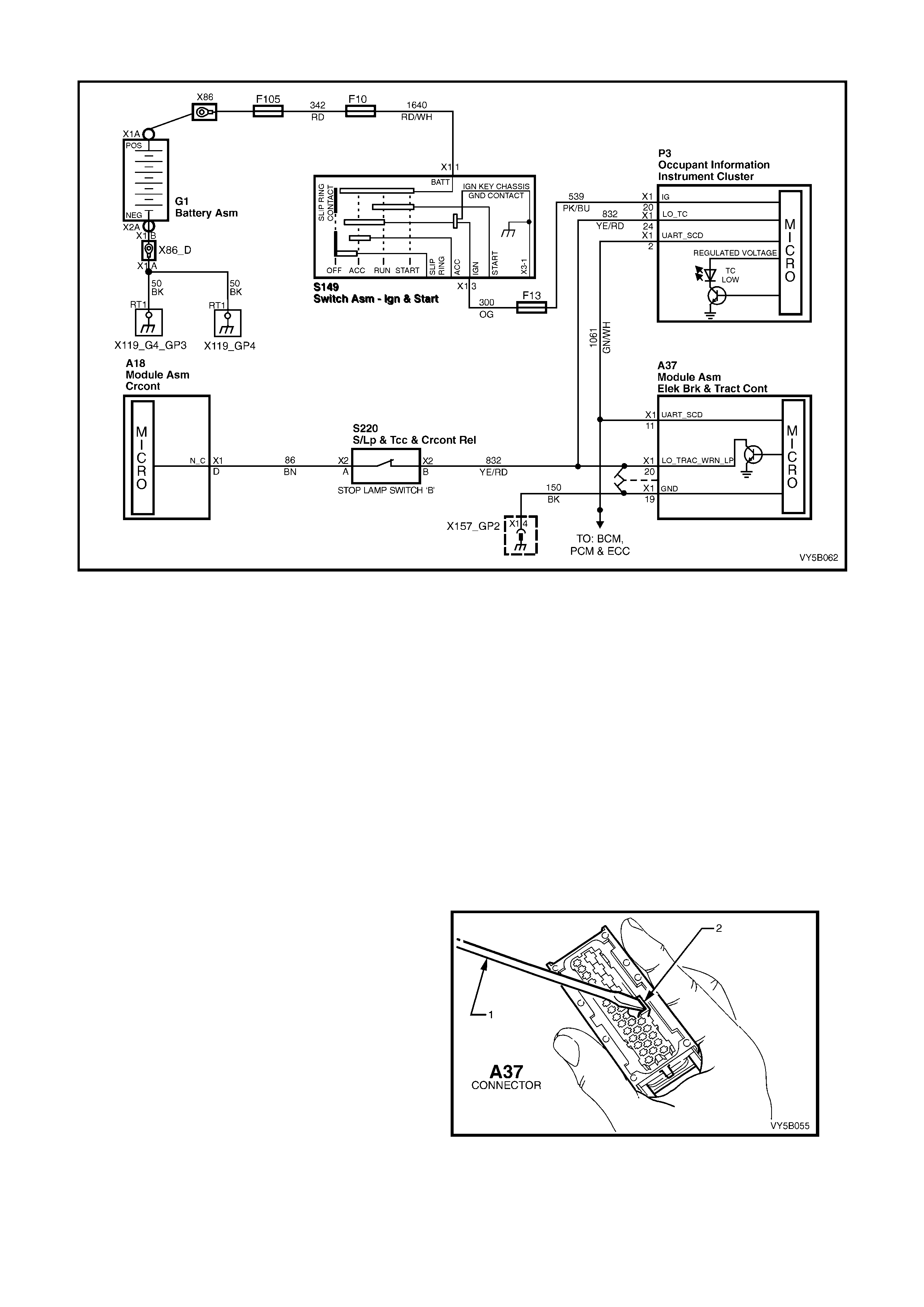
CHART C3 – LOW TRAC WARNING DISPLAY ACTIVATED CONTINUOUSLY – (NO DTCs STORED)
Figure 5B-118
CIRCUIT DESCRIPTION:
Battery voltage is supplied to the LOW TRAC warning display with the ignition switch in the IGN or START
positions through fuse F13 (located in the interior electrical centre) and circuit 539 (Pink/Blue wire). The warning
displa y can only be acti vate d b y the A BS or ABS /TCS c ontrol module i nter n all y b y supplying grou nd to ter minal X 1-
20 or via the shorting bar in the ABS or ABS/TCS control module connector A3 7 when it is disconnected from the
control m odule. If the ABS or ABS/T CS control m odule activates traction control, it will send a signa l to the cruise
control module A18, via circuit 86 (Brown wire), requesting the cruise control module to turn off.
TEST DESCRIPTION:
The numbers below refer to the Step numbers in diagnostic chart C3.
1. Uses Tech 2 to check for logged DTCs that are causing the warning display to activate.
2. This test checks whether the fault is caused by the ABS or ABS/TCS control module.
3. This test checks ci rcuit 96, including stop display switch B.
4. This test checks for a short to ground in the wiring between the warning display, ABS or ABS/TCS control
module and the stop display switch connector.
NOTES ON DIAGNOSTIC CHART:
1. Using a plastic lever (1), hold shorting bar (2)
away from terminals in connector A37, as
shown.
2. Refer to 4.7, TECH 2 DIAGNOSTICS in this
Section for connecting and using Tech 2.
3. Refer to Section 12P WIRING DIAGRAMS in
the MY 2003 VY and V2 Series Service
Information for procedures on checking wiring
faults.
Figure 5B-119

A37 S220 X2 P3
Figure 5B-120
CHART C3 - LOW TRAC WARNING DISPLAY ACTIVATED CONTINUOUSLY (NO DTCs STORED)
STEP ACTION VALUE YES NO
1. Was the ABS or ABS/TCS Functional Check Carried
out? Go to Step 2 Go to 4.4 ABS or
ABS/TCS
Functional Check
2. 1. Install Tech 2 to DLC.
2. Select Diagnostics / Chassis / Diagnostic Trouble
Codes / Read DTCs (refer to NOTE 2 above).
Are any DTCs set?
Repair conditions
which set DTCs,
recheck and
verify repair.
Go to Step 3
3. 1. Disconnect Tech 2 from DLC.
2. Remove wiring harness connector A37 from ABS or
ABS/TCS control module.
3. Hold shorting bar away from terminals X1-19 and
X1-20 in connector A37 (refer to NOTE 1 above).
4. Switch ignition ON.
Is the warning display constantly activated?
Go to Step 4 Replace
ABS/TCS control
module, refer to
3.6 CONTROL
MODULE in this
Section, recheck
circuit to verify
repair.
4. 1. With connector A37 moved from the ABS or
ABS/TCS control module and the shorting bars held
away from terminals X1-19 and X1-20 in connector
A37, disconnect the stop lamp switch connector
S220 X2 (refer NOTE 1 above).
2. Switch ignition ON.
Is the warning display constantly activated?
Go to Step 5 Check for short
to ground in
circuit 86 and/or
check and adju st
or repair stop
display switch B,
as necessary
(refer to
Section 12B
LIGHTING
SYSTEM.
5. 1. Check circuit 832 (Yellow/Red wire) for short to
ground between the ABS or ABS/TCS control
module connector A37, terminal X1-20 and
connector P3, terminal X1-24 and stop lamp
connector S220 X2 (Yellow/Red wire) (refer NOTE 3
above).
Is all OK?
Replace
instrument
cluster, refer to
Section 12C
INSTRUMENTS.
Repair circuit as
required, recheck
circuit to verify
repair.
WHEN ALL DIAGNOSIS AND REPAIRS ARE COMPLETED, CLEAR ALL DTCs AND VERIFY CORRECT OPERATION

DTC 21 - FRONT RIGHT WHEEL SPEED SENSOR INCORRECT SIGNAL
Figure 5B-121
CIRCUIT DESCRIPTION:
The toothed pulse ring wheel inside the front hub ass embly generates a volt age pulse as it m oves past the whee l
speed sensor; each tooth – gap – tooth on the pulse ring generates these pulses.
The frequency of these pulses is used by the ABS or ABS/TCS control module to determine wheel speed.
DTC 21 will set if vehicle speed is approximately 12 km/h and the control module detects a low right hand front
wheel speed sensor output voltage.
If a failure is detected which causes DTC 21 to set, the ABS or ABS/TCS system is disabled and the control
module activates the ABS or ABS and TRAC OFF warning displays for the remainder of the ignition cycle. If the
failure is intermittent, t he control m odule will enable the s ystem at the next igniti on cycle and a hist ory DTC 21 will
be set.
TEST DESCRIPTION:
The numbers below refer to Step numbers in the diagnostic chart for DTC 21.
1. This test checks if there is a speed signal o utput from the sensor.
2. This test checks for connector or wiring problems which may cause an intermittent condition.
3. This test determines whether the DTC was set by an intermittent condition or a control module fault.
4. This check is a visual inspection of the speed sensor, wiring and the pulse ring.
5. If repairs are necessary, the speed sensor output must be rechecked to verify the repair.
6. This test checks for a voltage drop in the wheel speed sensor wiring which could cause lower than specified
sensor output voltage.
NOTES ON DIAGNOSTIC CHART:
1. Refer to 4.7 TECH 2 DIAGNOSTICS in this Section for connecting and using Tech 2.
2. For all wiring checking procedures, refer to Section 12P WIRING DIAGRAMS in the MY 2003 VY and V2
Series Service Information.
DIAGNOSTIC AIDS:
For additional information on testing the front wheel speed sensor, refer to 3.3 FRONT WHEEL SPEED SENSOR
LEAD in this Section.
B52 R
Figure 5B-122

DTC 21 – FRONT RIGHT WHEEL SPEED SENSOR INCORRECT SIGNAL
STEP ACTION VALUE YES NO
1. Was the ABS or ABS/TCS Functional Check Carried
out? Go to Step 2 Go to 4.4 ABS or
ABS/TCS
Functional Check
2. 1. Jack up front of vehicle and support on safety
stands. Refer to Section 0A GENERAL
INFORMATION in the MY 2003 VY and V2 Series
Service Information, for the location of jacking and
support points.
2. Install Tech 2 to DLC.
3. Select Diagnostics / Chassis / ABS/TCS/ Data List /
Active ABS (refer to NOTE 1 above).
4. Check right hand front wheel speed sensor output
signal by rotating wheel by hand.
(Alternatively, connect an oscilloscope (Tech 31) to
the wheel speed sensor connector B52 R, between
circuit 872 (White wire) and circuit 833 (Red wire),
rotate right hand front wheel by hand and compare
oscilloscope patterns with those shown below.
Repair as necessary or go to Step 2).
Does speed signal change as wheel is turned faster?
Go to Step 3 Go to Step 5
3. 1. Visually inspect sensor lead wiring and connections.
2. Check wiring for intermittent open or short circuit
(refer to NOTE 2 above).
Is all OK?
Go to Step 4 Repair fault with
sensor lead
wiring o r
connections,
recheck circuit to
verify repair.
4. 1. Clear all stored DTCs (refer to NOTE 1 above) and
road test vehicle .
Does DTC 21 set again?
Replace ABS or
ABS/TCS control
module, refer to
3.6 CONTROL
MODULE in this
Section, recheck
circuit to verify
repair.
Fault not present.
Check all system
wiring harness
connect ors and
terminals, in
particular the
ABS or ABS/TCS
control modu le
connector
terminals.
5. 1. Visually inspect sensor lead wiring, mountings and
connections.
Is all OK?
Go to Step 7 Go to Step 6
6. 1. Make repairs as necessary. Retest speed sensor
output.
Is output now OK?
Go to Step 4 Go to Step 7
7. 1. Check circuits 872 (White wire) and 833 (Red wire)
for continuity (refer to NOTE 2 above).
2. Inspect Main Wiring Harness to sensor lead
connector B52 R and sensor connector at front
wheel hub assembly.
Are connectors and wiring OK?
Replace front
hub & wheel
speed sensor
assembly, refer
to 3.3 WHEEL
SPEED
SENSOR in this
Section, recheck
circuit to verify
repair.
Repair wiring as
necessary,
recheck circuit to
verify repair.
WHEN ALL DIAGNOSIS AND REPAIRS ARE COMPLETED, CLEAR ALL DTCs AND VERIFY CORRECT OPERATION
OSCILLOSCOPE PATTERNS (SIMULATED ONLY)
Normal view Possibl e inc reasi ng and decreas i ng dist ance
between wheel speed sensor and pulse ring Possible chipped or damaged teeth
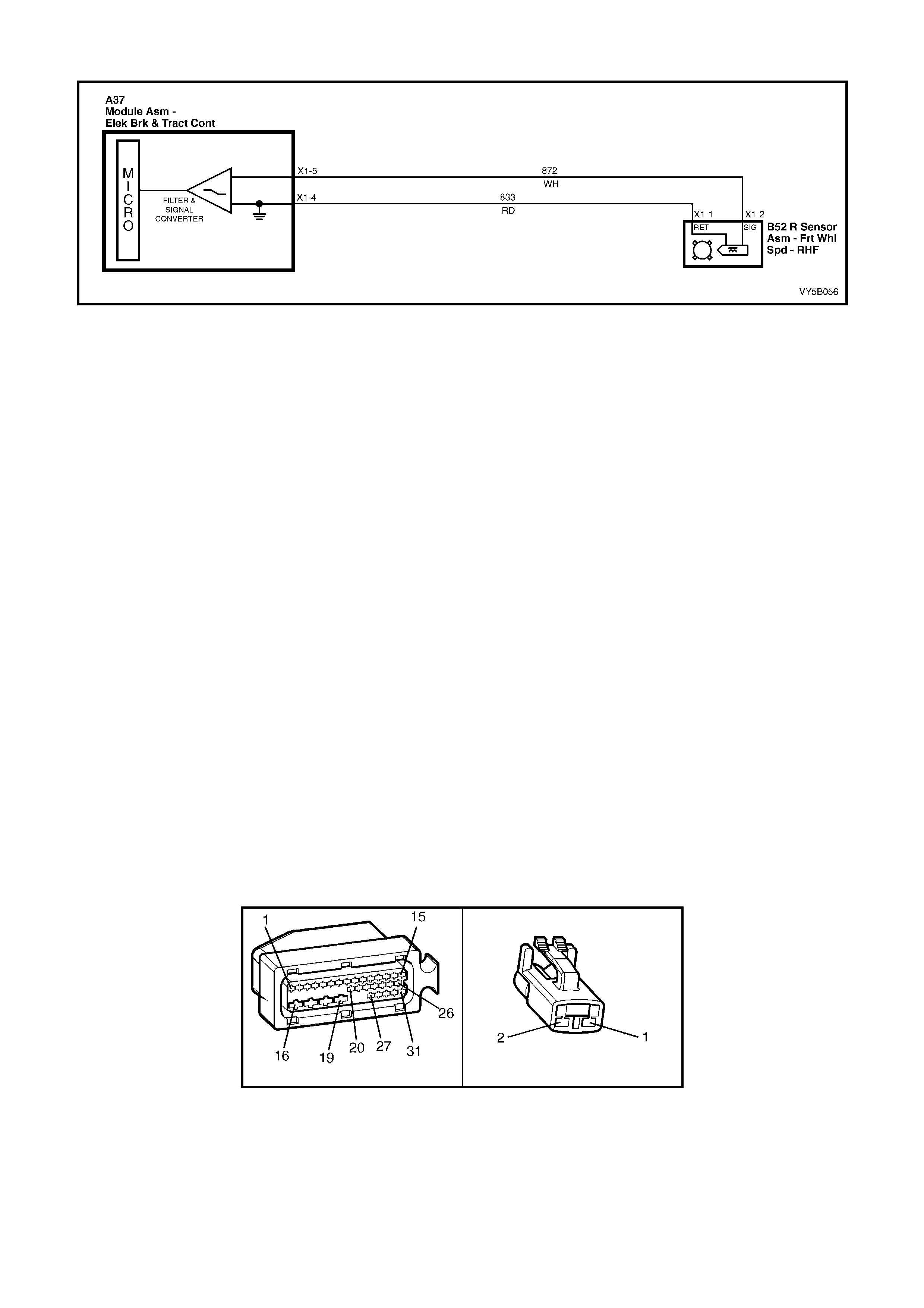
DTC 23 - FRONT RIGHT WHEEL SPEED SENSOR SHORT OR OPEN CIRCUIT
Figure 5B-123
CIRCUIT DESCRIPTION:
The toothed pulse ring wheel inside the front hub ass embly generates a volt age pulse as it m oves past the whee l
speed sensor; each tooth – gap – tooth on the pulse ring generates these pulses.
The frequency of these pulses is used by the ABS or ABS/TCS control module to determine wheel speed.
DTC 23 will s et when t he ig nition is switc hed on an d the c ontrol m odule detec ts a continuity pro blem in cir cuits 872
and 833, or no wheel speed signal is generated by the sensor.
If a failure is detected which causes DTC 23 to set, the ABS or ABS/TCS system is disabled and the control
module activates the ABS or ABS and TRAC OFF warning displays for the remainder of the ignition cycle. If the
failure is intermittent, t he control m odule will enable the s ystem at the next igniti on cycle and a hist ory DTC 23 will
be set.
TEST DESCRIPTION:
The numbers below refer to Step numbers in the diagnostic chart for DTC 23.
1. Begin rectification of this DTC by visually inspecting right hand front wheel speed sensor wiring for a fault
condition.
2. This test is a usual check for connector or wiring problems which may cause an intermittent condition.
3. This test checks for correct resistance reading of the sensor coil .
4. This test checks for continuity of right hand front wheel speed sensor wiring.
5. This test checks for short circuit between wheel speed sensor wi ring.
6. This test checks for open circuit in right hand front wheel speed sensor wiring.
7. This test checks for short to ground or B+ in circuits 872 and 833.
8. This test determines whether the DTC was set by an intermittent condition or a control module fault.
NOTES ON DIAGNOSTIC CHART:
1. Refer to 4.7 TECH 2 DIAGNOSTICS in this Section for connecting and using Tech 2.
2. For all wiring checking procedures, refer to Section 12P WIRING DIAGRAMS in the MY 2003 VY and V2
Series Service Information.
For additional information on testing the front wheel speed sensor, refer to 3.3 FRONT WHEEL SPEED SENSOR
LEAD in this Section.
A37 B52 R
Figure 5B-124

DTC 23 - FRONT RIGHT WHEEL SPEED SENSOR SHORT CIRCUIT OR OPEN CIRCUIT
STEP ACTION VALUE YES NO
1. Was the ABS or ABS/TCS Functional Check Carried
out? Go to Step 2 Go to 4.4 ABS or
ABS/TCS
Functional Check
2. 1. Ensure that right hand front wheel speed sensor
lead is not visibly damaged and that it is properly
secured at all places.
2. If the sensor lead is damaged or not correctly
mounted and retained, replace the lead and/or
properly install it.
3. Install Tech 2 to DLC and select Diagnostics /
Chassis / ABS/TCS / Diagnostic Trouble Codes /
Clear DTCs and clear all DTCs (refer to NOTE 1
above).
Road test vehicle, does DTC 23 set again ?
Go to Step 4 Go to Step 3
3. 1. Inspect all system wiring and connections that could
ca us e s in te rm it t e n t fa ul t s . Ch ec k al l wi r in g is in go od
condition, terminals are clean and tight and making
good contact (refer to NOTE 2 above).
Is all OK?
Fault not present.
Check all system
wiring harness
connect ors and
terminals, in
particular the
ABS or ABS/TCS
control modu le
connector
terminals.
Make repairs as
necessary,
recheck circuit to
verify repair.
4. 1. Turn ignition OFF.
2. Disconnect sensor lead connector B52 R from Main
Wiring Harness connector.
3. Using digital multimeter, measure sensor and lead
resistance.
Is value as specified?
1,300
Ohms Go to Step 6 Go to Step 5
5. 1. Remove sensor lead and check continuity of lead
wiring.
Is continuity OK?
Wheel speed
sensor faulty.
Replace front
hub assembly,
refer to 3 FRONT
SUSPENSION.
Recheck circuit
to verify repair.
Replace faulty
lead. Refer to 3.3
FRONT WHEEL
SPEED
SENSOR LEAD
in this Section,
recheck circuit to
verify repair.
6. 1. Disconnect the ABS or ABS/TCS control module
connector A37.
2. With sensor lead connector B52 R still
disconnected, check continuity between ABS or
ABS/TCS control module connector A37, terminals
X1-4 and X1-5 (refer to NOTE 2 above).
Does continu ity ex ist?
Eliminate short
circuit in wiring
between circ uits
872 (White wire)
and 833 (Red
wire), recheck
circuit to verify
repair.
Go to Step 7
7. 1. Check circuits 872 (White wire) and 833 (Red wire)
for open circuit between sensor connector B52 R
and ABS or ABS/TCS control module connector A37
(refer to NOTE 2 above).
Is there continuity in both circuits ?
Go to Step 8 Eliminate open
circuit in wiring,
recheck circuit to
verify repair.
8. 1. Check circuits 872 and 833 for short to ground or B+
(refer to NOTE 2 above).
Are both circuits OK ?
Go to Step 9 Eliminate short to
ground or B+ in
wiring, recheck
circuit to verify
repair.
(Approx.)

STEP ACTION VALUE YES NO
9. 1. Install Tech 2 to DLC and select Diagnostics /
Chassis / ABS/TCS / Diagnostic Trouble Codes /
Clear DTCs and clear all DTCs (refer to NOTE 1
above).
2. Road test vehicle.
Does DTC 23 set again?
Replace ABS or
ABS/TCS control
module, refer to
3.6 CONTROL
MODULE in this
Section, recheck
circuit to verify
repair.
Fault not present.
Check all system
wiring harness
connect ors and
terminals, in
particular the
ABS or ABS/TCS
control modu le
connector
terminals.
WHEN ALL DIAGNOSIS AND REPAIRS ARE COMPLETED, CLEAR ALL DTCs AND VERIFY CORRECT OPERATION
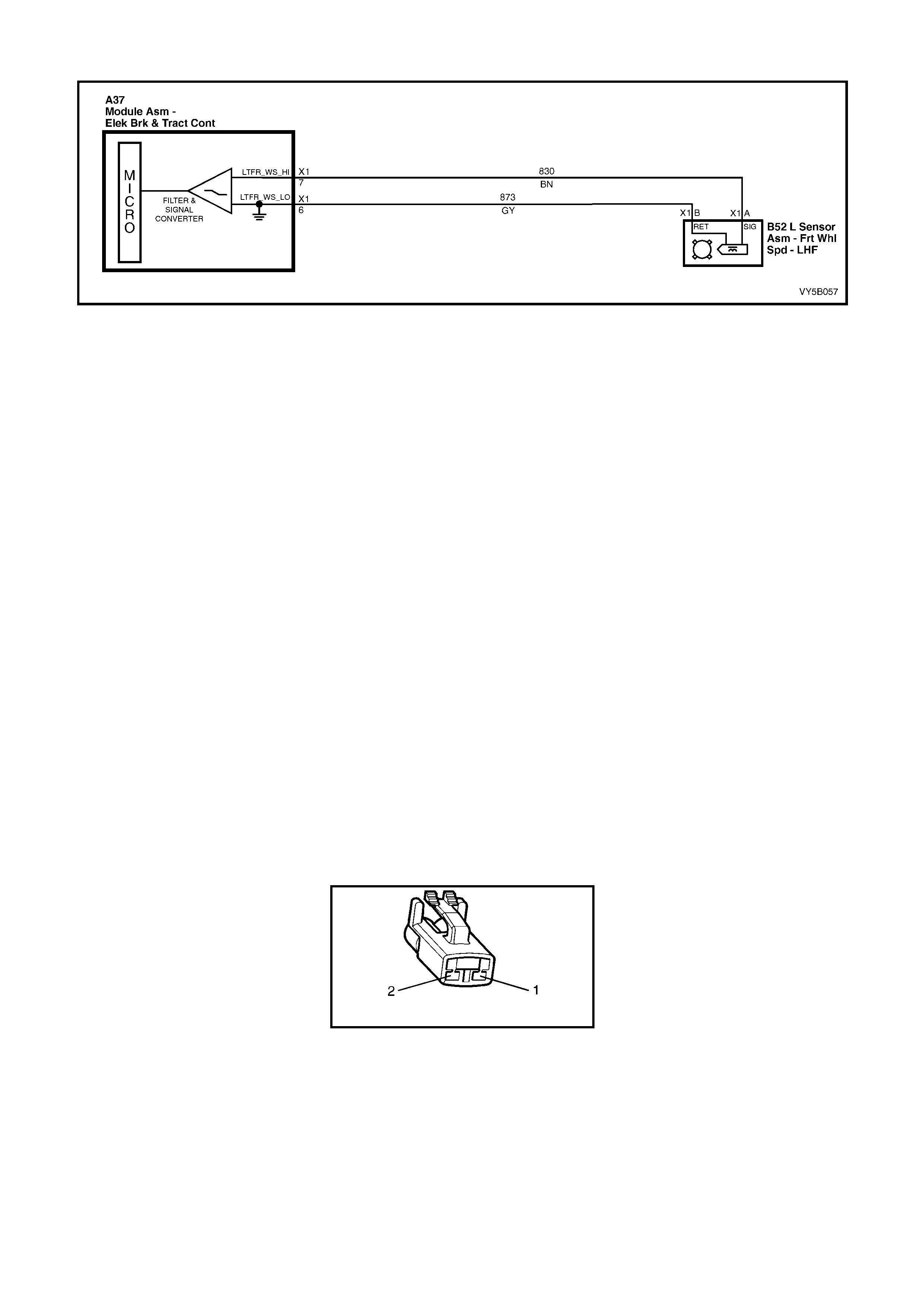
DTC 25 - FRONT LEFT WHEEL SPEED SENSOR INCORRECT SIGNAL
Figure 5B-125
CIRCUIT DESCRIPTION:
The toothed pulse ring wheel inside the front hub ass embly generates a volt age pulse as it m oves past the whee l
speed sensor; each tooth - gap - tooth on the pulse ring generates these pulses.
The frequency of these pulses is used by the ABS or ABS/TCS control module to determine wheel speed.
DTC 25 will set if vehicle speed is approximately 12 km/h and the control module detects a low left hand front
wheel speed sensor output voltage.
If a failure is detected which causes DTC 25 to set, the ABS or ABS/TCS system is disabled and the control
module activates the ABS, or ABS and TRAC OFF warning displays for the remainder of the ignition cycle. If the
failure is intermittent, t he control m odule will enable the s ystem at the next igniti on cycle and a hist ory DTC 25 will
be set.
TEST DESCRIPTION:
The numbers below refer to Step numbers in the diagnostic chart for DTC 25.
1. This test checks if there is a speed signal o utput from the sensor.
2. This test checks for connector or wiring problems which may cause an intermittent condition.
3. This test determines whether the DTC was set by an intermittent condition or a control module fault.
4. This check is a visual inspection of the speed sensor, wiring and the pulse ring.
5. If repairs are necessary, the speed sensor output must be rechecked to verify the repair.
6. This test checks for a voltage drop in the wheel speed sensor wiring which could cause lower than specified
sensor output voltage.
NOTES ON DIAGNOSTIC CHART:
1. Refer to 4.7 TECH 2 DIAGNOSTICS in this Section for connecting and using Tech 2.
2. For all wiring checking procedures, refer to Section 12P WIRING DIAGRAMS in the MY 2003 VY and V2
Series Service Information.
DIAGNOSTIC AIDS:
For additional information on testing the front wheel speed sensor, refer to 3.3 FRONT WHEEL SPEED SENSOR
LEAD in this Section.
B52_L
Figure 5B-126

DTC 25 - FRONT LEFT WHEEL SPEED SENSOR INCORRECT SIGNAL
STEP ACTION VALUE YES NO
1. Was the ABS or ABS/TCS Functional Check Carried
out? Go to Step 2 Go to 4.4 ABS or
ABS/TCS
Functional Check
2. 1. Jack up front of vehicle and support on safety
stands. Refer to Section 0A GENERAL
INFORMATION in the MY 2003 VY and V2 Series
Service Information, for the location of jacking and
support points.
2. Install Tech 2 to DLC.
3. Select Diagnostics / Chas sis / ABS/TCS / Data List /
Active ABS (refer to NOTE 1 above).
4. Check left hand front wheel speed sensor output
signal by rotating wheel by hand.
(Alternatively, connect an oscilloscope (Tech 31) to
the wheel speed sensor connector B52 L, between
circuit 830 (Brown wire) and circuit 873 (Grey wire),
rotate left hand front wheel by hand and compare
oscilloscope patterns with those shown below.
Repair as necessary or go to Step 2).
Does speed signal change as wheel is turned faster?
Go to Step 3 Go to Step 5
3. 1. Visually inspect sensor lead wiring and connections.
2. Check wiring for intermittent open or short circuit
(refer to NOTE 2 above).
Is all OK ?
Go to Step 4 Repair fault with
sensor lead
wiring o r
connections,
recheck circuit to
verify repair.
4. 1. Install Tech 2 to DLC and select Diagnostics /
Chassis / ABS/TCS / Diagnostic Trouble Codes /
Clear DTCs and clear all DTCs (refer to NOTE 1
above).
2. Road test vehicle.
Does DTC 25 set again ?
Replace ABS or
ABS/TCS control
module, refer to
3.6 CONTROL
MODULE in this
Section, recheck
circuit to verify
repair.
Fault not present.
Check all system
wiring harness
connect ors and
terminals, in
particular the
ABS or ABS/TCS
control modu le
connector
terminals.
5. 1. Visually inspect sensor lead wiring, mountings and
connections.
Is all OK?
Go to Step 7 Go to Step 6
6. 1. Make repairs as necessary. Retest speed sensor
output.
Is output now OK ?
Go to Step 4 Go to Step 7
7. 1. Check circuits 830 (Brown wi re) and 873 (Grey wi re)
for continuity (refer to NOTE 2 above).
2. Inspect Main Wiring Harness to sensor lead
connector and sensor connector B52 L at front
wheel hub assembly.
Are connectors and wiring OK ?
Replace front
hub & wheel
speed sensor
assembly, refer
to Section 3.
FRONT
SUSPENSION.
Recheck circuit
to verify repair.
Repair wiring as
necessary,
recheck circuit to
verify repair.
WHEN ALL DIAGNOSIS AND REPAIRS ARE COMPLETED, CLEAR ALL DTCs AND VERIFY CORRECT OPERATION
OSCILLOSCOPE PATTERNS (SIMULATED ONLY)
Normal view Possibl e inc reasi ng and decreas i ng dist ance
between wheel speed sensor and pulse ring Possible chipped or damaged teeth
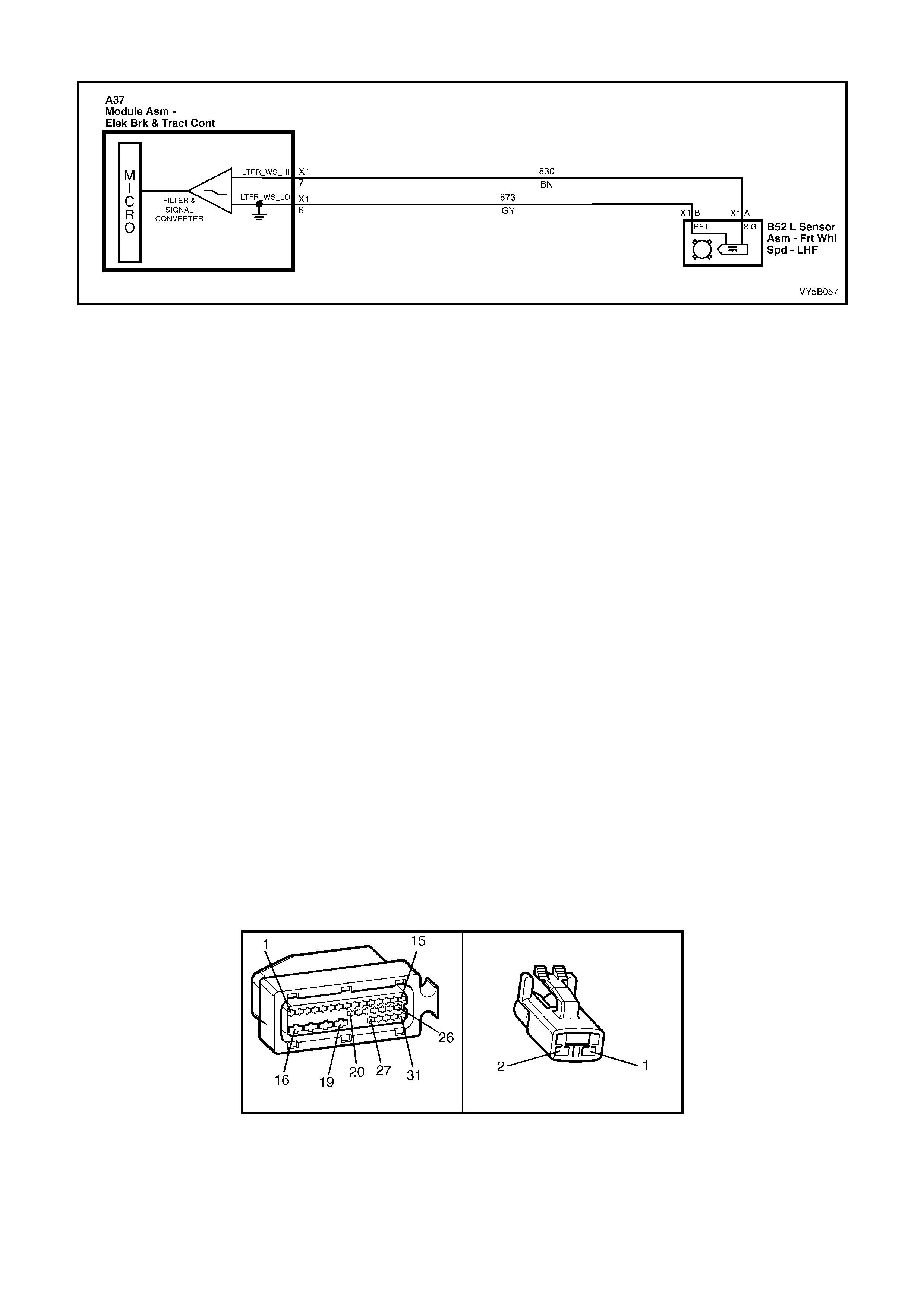
DTC 27 – FRONT LEFT WHEEL SPEED SENSOR SHORT OR OPEN CIRCUIT
Figure 5B-127
CIRCUIT DESCRIPTION:
The toothed pulse ring wheel inside the front hub ass embly generates a volt age pulse as it m oves past the whee l
speed sensor; each tooth – gap – tooth on the pulse ring generates these pulses.
The frequency of these pulses is used by the ABS or ABS/TCS control module to determine wheel speed.
DTC 27 will s et when t he ig nition is switc hed on an d the c ontrol m odule detec ts a continuity pro blem in cir cuits 830
and 873, or no wheel speed signal is generated by the sensor.
If a failure is detected which causes DTC 27 to set, the ABS or ABS/TCS system is disabled and the control
module activates the ABS or ABS and TRAC OFF warning displays for the remainder of the ignition cycle. If the
failure is intermittent, t he control m odule will enable the s ystem at the next igniti on cycle and a hist ory DTC 27 will
be set.
TEST DESCRIPTION:
The numbers below refer to Step numbers in the diagnostic chart for DTC 27.
1. Begin rectification of this DTC by visually inspecting left hand front wheel speed sensor wiring for a fault
condition.
2. This test checks for connector or wiring problems which may cause an intermittent condition.
3. This test checks for correct resistance reading of the sensor coil .
4. This test checks for continuity of left hand front wheel speed sensor wiring.
5. This test checks for short circuit between wheel speed sensor wi ring.
6. This test checks for open circuit in left hand front wheel speed sensor wiring.
7. This test checks for short to ground or B+ in circuits 830 and 873.
8. This test determines whether the DTC was set by an intermittent condition or a control module fault.
NOTES ON DIAGNOSTIC CHART:
1. Refer to 4.7 TECH 2 DIAGNOSTICS in this Section for connecting and using Tech 2.
2. For all wiring checking procedures, refer to Section 12P WIRING DIAGRAMS in the MY 2003 VY and V2
Series Service Information.
DIAGNOSTIC AIDS:
For additional information on testing the front wheel speed sensor, refer to 3.3 FRONT WHEEL SPEED SENSOR
LEAD in this Section.
A37 B52 L
Figure 5B-128

DTC 27 - FRONT LEFT WHEEL SPEED SENSOR SHORT OR OPEN CIRCUIT
STEP ACTION VALUE YES NO
1. Was the ABS or ABS/TCS Functional Check Carried
out? Go to Step 2 Go to 4.4 ABS or
ABS/TCS
Functional Check
2. 1. Ensure that left hand front wheel speed sensor lead
is not visibly damaged and that it is properly secured
at all places .
2. If the sensor lead is damaged or not correctly
mounted and retained, replace the lead and/or
properly install it.
3. Install Tech 2 to DLC and select Diagnostics /
Chassis / ABS/TCS / Diagnostic Trouble Codes /
Clear DTCs and clear all DTCs (refer to NOTE 1
above).
Road test vehicle, does DTC 27 set again ?
Go to Step 4 Go to Step 3
3. 1. Inspect all system wiring and connections that could
cause intermittent faults. Check all wiring is in good
condition, terminals are clean and tight and making
good contact (refer to NOTE 2 above).
Is all OK ?
Fault not present.
Check all system
wiring harness
connect ors and
terminals, in
particular the
ABS or ABS/TCS
control modu le
connector
terminals.
Make repairs as
necessary,
recheck circuit to
verify repair.
4. 1. Turn ignition OFF.
2. Disconnect sensor lead connector B52 L from Main
Wiring Harness connector.
3. Using digital multimeter, measure sensor and lead
resistance.
Is value as specified ?
1,300
Ohms Go to Step 6 Go to Step 5
5. 1. Remove sensor lead and check continuity of lead
wiring.
Is continuity OK ?
Wheel speed
sensor faulty.
Replace front
hub assembly,
refer to 3 FRONT
SUSPENSION.
Recheck circuit
to verify repair.
Replace faulty
lead. Refer to 3.3
FRONT WHEEL
SPEED
SENSOR LEAD
in this Section,
recheck circuit to
verify repair.
6. 1. Disconnect ABS or ABS/TCS control module
connector A37.
2. With sensor lead connector B52 L still disconnected,
check continuity between ABS or ABS/TCS control
module connector A37, terminals X1-6 and X1-7
(refer NOTE 2 above).
Does continuity exist ?
Eliminate short
circuit in wiring
between circ uits
873 (Grey wire)
and 830 (Brown
wire), recheck
circuit to verify
repair.
Go to Step 7
7. 1. Check circuits 830 (Brown wi re) and 873 (Grey wi re)
for open circuit between sensor connector B52 L
and ABS or ABS/TCS control module connector A37
(refer NOTE 2 above).
Is there continuity in both circuits ?
Go to Step 8 Eliminate open
circuit in wiring,
recheck circuit to
verify repair.
8. 1. Check circuits 830 and 873 for short to ground or B+
(refer to NOTE 2 above).
Are both circuits OK ?
Go to Step 9 Eliminate short to
ground or B+ in
wiring, recheck
circuit to verify
repair.
(Approx.)

STEP ACTION VALUE YES NO
9. 1. Install Tech 2 to DLC and select Diagnostics /
Chassis / ABS/TCS / Diagnostic Trouble Codes /
Clear DTCs and clear all DTCs (refer to NOTE 1
above).
2. Road test vehicle.
Does DTC 27 set again ?
Replace ABS or
ABS/TCS control
module, refer to
3.6 CONTROL
MODULE in this
Section, recheck
circuit to verify
repair.
Fault not present.
Check all system
wiring harness
connect ors and
terminals, in
particular the
ABS or ABS/TCS
control modu le
connector
terminals.
WHEN ALL DIAGNOSIS AND REPAIRS ARE COMPLETED, CLEAR ALL DTCs AND VERIFY CORRECT OPERATION
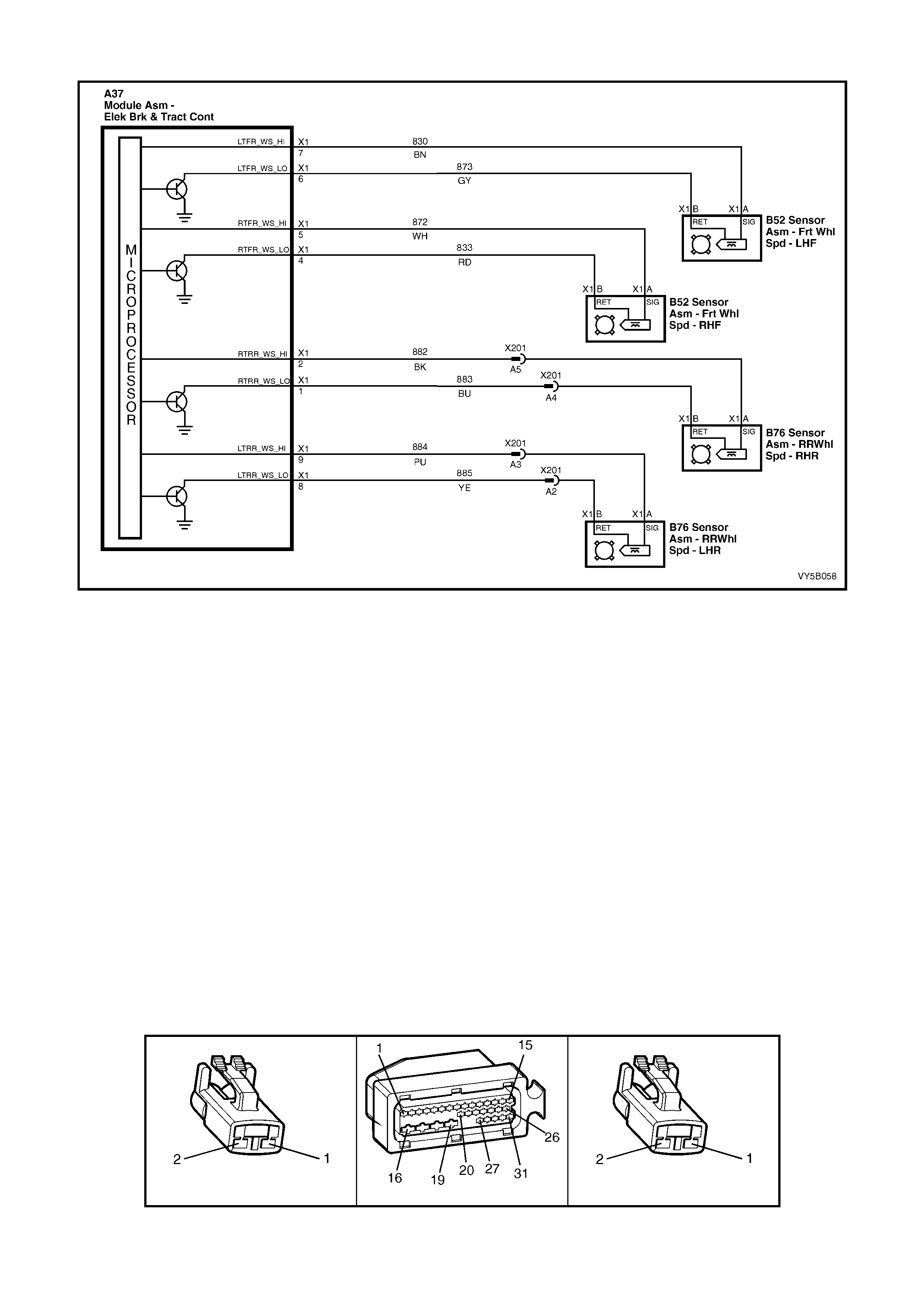
DTC 28 - WHEEL SPEED SENSOR FREQUENCY ERROR
Figure 5B-129
CIRCUIT DESCRIPTION:
The toothed pulse ring generates a voltage pulse as it moves past the wheel speed sensor. Each tooth – gap –
tooth on the pulse ring generates these pulses.
The frequency of these pulses is used by the ABS or ABS/TCS control module to determine wheel speed. The ABS
or ABS/TCS control module will calculate the wheel speed by the number of teeth on the pulse ring.
DTC 28 will set if an incorrect number of teeth or damaged teeth are present on a pulse ring. If the ABS or
ABS/TCS control module could define the specific wheel speed sensor causing the malfunction, the DTC
associated with the sensor (21, 25, 31 or 35) will be set instead of DTC 28.
If a failure is detected which causes DTC 28 to set, the ABS or ABS/TCS system is disabled and the control
module activates the ABS or ABS and TRAC OFF warning displays for the remainder of the ignition cycle. If the
failure is intermittent, t he control m odule will enable the s ystem at the next igniti on cycle and a hist ory DTC 28 will
be set.
NOTE: If DTC 28 s ets, the ABS or A BS/TCS contr ol modu le does not or c annot deter mine which s ensor ass em bly
is at fault. All the wheel speed sensors will need to be checked to determine which is setting the DTC.
TEST DESCRIPTION:
The numbers below refer to Step numbers in the diagnostic chart for DTC 28.
1. Begin rectification of this DTC by visually inspecting both front wheel speed sensors wiring for a fault condition.
2. This test checks for any front wheel speed sensor wiring or connector problem that could cause DTC 28 to set.
3. This test checks tha t rear sensors are correctly installed.
4. This test checks that the rear wheel pulse rings are correctly mounted.
5. This test checks for any re ar wheel speed sensor wiring or connector problem that could cause DTC 28 to set.
B52 R & L A37 B76 R & L
Figure 5B-130

DTC 28 - WHEEL SPEED SENSOR FREQUENCY ERROR
STEP ACTION VALUE YES NO
FOR FRONT WHEEL SPEED SENSORS ONLY
1. Was the ABS or ABS/TCS Functional Check Carried
out? Go to Step 2 Go to 4.4 ABS or
ABS/TCS
Functional Check
2. 1. Visually inspect sensor lead wiring mountings and
connections.
Is all OK ?
Go to Step 3 Repair or replace
components as
necessary,
recheck circuit to
verify repair.
3. 1. Check system wiring for faults between ABS or
ABS/TCS control module connector A37 and front
wheel speed sensor lead connections at the front
wheel hub connections, B52 L and B52 R, as
detailed in steps 3 to 7 in diagnostic charts DTC 23
and/or DTC 27 in this Section.
Is all OK ?
Go to Step 4 Repair or replace
wiring as
necessary,
recheck circuit to
verify repair.
FOR REAR WHEEL SPEED SENSORS ONLY
4. 1. Check that the sensors are correctly mounted and
that the retaining bolt is tightened to the correct
torque specif ication.
Is all OK ?
Go to Step 5 Properly mount
and attach
sensor, recheck
circuit to verify
repair.
5. 1. Check that pulse ring is correctly mounted to inner
axle shaft and is in line with sensor.
Is all OK ?
Ensure that the
number of puls e
ring teeth
correspond to
specification (48),
and are not
damaged. If all
OK, go to Step 6.
Replace inner
axle shaft, refer
to 3.5 PULSE
RINGS in this
Section, recheck
circuit to verify
repair.
6. 1. Check system wiring for faults between ABS or
ABS/TCS control module connector A37 and rear
wheel speed sensor lead connectors B76 L and B76
R, as detailed in steps 3 to 6 in diagnostic charts
DTC 33 and/or DTC 37 in this Section.
Is all OK ?
Check all system
wiring harness
connector
terminals, in
particular the
ABS or ABS/TCS
control modu le
connector
terminals.
Repair or replace
wiring as
necessary,
recheck circuit to
verify repair.
WHEN ALL DIAGNOSIS AND REPAIRS ARE COMPLETED, CLEAR ALL DTCs AND VERIFY CORRECT OPERATION
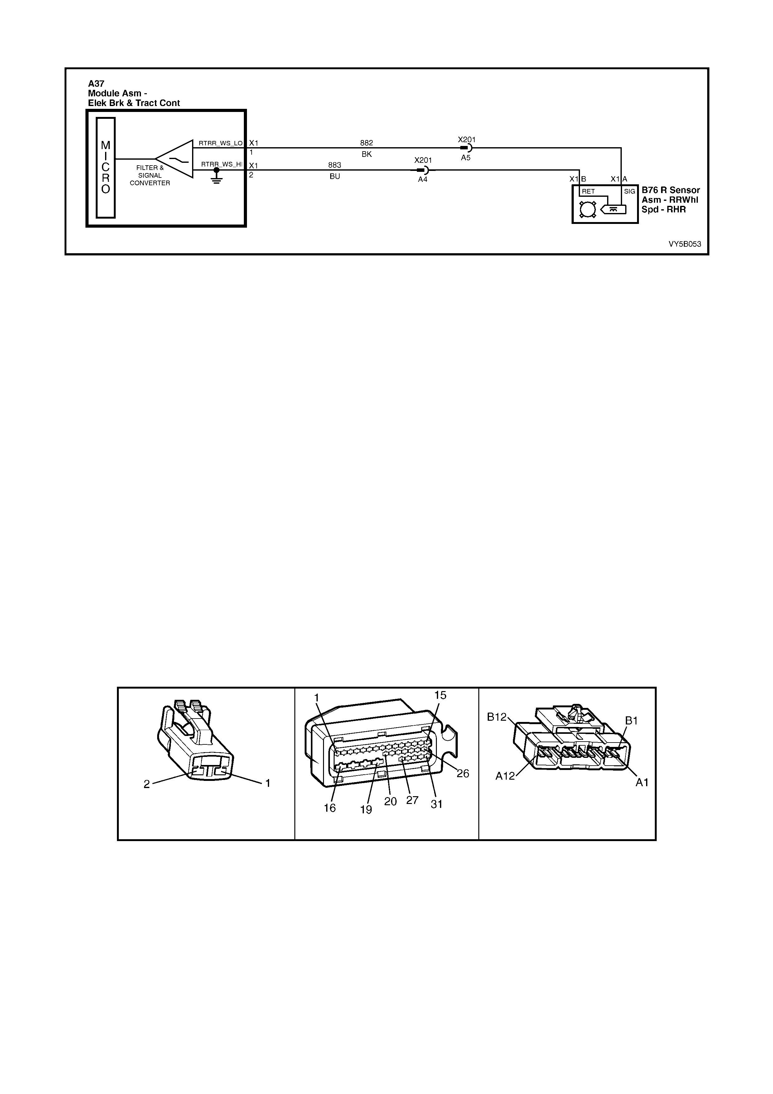
DTC 31 – REAR RIGHT WHEEL SPEED SENSOR INCORRECT SIGNAL
Figure 5B-131
CIRCUIT DESCRIPTION:
The toothed pulse ring wheel on the inner right rear axle flange generates a voltage pulse as it moves past the
wheel speed sensor; each tooth – gap – tooth on the pulse ring generates these pulses.
The frequency of these pulses is used by the ABS or ABS/TCS control module to determine wheel speed.
DTC 31 will set if vehicle speed is approximately 12 km/h and the control module detects a low right hand rear
wheel speed sensor output voltage.
If a failure is detected which causes DTC 31 to set, the ABS or ABS/TCS system is disabled and the control
module activates the ABS or ABS and TRAC OFF warning displays for the remainder of the ignition cycle. If the
failure is intermittent, t he control m odule will enable the s ystem at the next igniti on cycle and a hist ory DTC 31 will
be set.
TEST DESCRIPTION:
The numbers below refer to Step numbers in the diagnostic chart for DTC 31.
1. This test checks if there is a speed signal o utput from the sensor.
2. This test checks for connector or wiring problems which may cause an intermittent condition.
3. This test determines whether the DTC was set by an intermittent condition or a control module fault.
4. This check is a visual inspection of the speed sensor, wiring and the pulse ring.
5. If repairs are necessary, the speed sensor output must be rechecked to verify the repair.
6. This test checks for voltage drops in the wheel speed sensor wiring which could cause lower than specified
sensor output voltage.
NOTES ON DIAGNOSTIC CHART:
1. Refer to 4.7 TECH 2 DIAGNOSTICS in this Section for connecting and using Tech 2.
2. For all wiring checking procedures, refer to Section 12P WIRING DIAGRAMS in the MY 2003 VY and V2
Series Service Information.
B76 R P3 X201
Figure 5B-132

DTC 31 - REAR RIGHT WHEEL SPEED SENSOR INCORRECT SIGNAL
STEP ACTION VALUE YES NO
1. Was the ABS or ABS/TCS Functional Check Carried
out? Go to Step 2 Go to 4.4 ABS or
ABS/TCS
Functional Check
2. 1. Raise rear of vehicle and support on safety stands.
Refer to 0A GENERAL INFORMATION in the MY
2003 VY and V2 Series Service Information, for the
location of jacking and support points.
2. Install Tech 2 to DLC (refer to NOTE 1 above).
3. Select Diagnostics / Chas sis / ABS/TCS / Data List /
Active ABS
4. Check right hand rear wheel speed sensor output
signal by rotating wheel by hand.
(Alternatively, connect an oscilloscope (Tech 31) to
the wheel speed sensor connector B76 R, between
circuit 882 (Black wire) and circuit 883 (Blue wire),
rotate right hand rear wheel by hand and compare
oscilloscope patterns with those shown below.
Repair as necessary or go to Step 2).
Does speed signal change as wheel is turned faster?
Go to Step 3 Go to Step 5
3. 1. Visually inspect sensor lead wiring and connections.
2. Check wiring for intermittent open or short circuit
(refer to NOTE 2 above).
Is all OK ?
Go to Step 4 Repair fault with
sensor lead
wiring or replace
sensor, recheck
circuit to verify
repair.
4. 1. Install Tech 2 to DLC and select Diagnostics /
Chassis / ABS/TCS / Diagnostic Trouble Codes /
Clear DTCs and clear all DTCs (refer to NOTE 1
above).
2. Road test vehicle.
Does DTC 31 set again?
Replace ABS or
ABS/TCS control
module, refer to
3.6 CONTROL
MODULE in this
Section, recheck
and verify repair.
Fault not present.
Check all system
wiring harness
connect ors and
terminals, in
particular the
ABS or ABS/TCS
control modu le
connector
terminals.
5. 1. Visually inspect sensor end for any signs of
damage.
2. Check that the pulse ring is secured to the inner
axle shaft and is positioned in line with the sensor.
3. Inspect pulse ring teeth for any signs of damage.
Is all OK ?
Go to Step 7 Go to Step 6
6. 1. Make repairs as necessary. Retest speed sensor
output.
Is output now OK ?
Go to Step 4 Go to Step 7
7. 1. Check circuits 882 (Black wire) and 883 (Blue wire)
for continuity (refer to NOTE 2 above).
2. Inspect body harness to sensor connector B76 R,
body harness to Main Wiring Harness connector
X201 and ABS or ABS/TCS control module
connector A37.
Are connectors and wiring OK ?
Replace rear
wheel speed
sensor asm, refer
to 3.4 WHEEL
SPEED
SENSORS in this
Section. Recheck
circuit to verify
repair.
Repair wiring as
necessary,
recheck circuit to
verify repair.
WHEN ALL DIAGNOSIS AND REPAIRS ARE COMPLETED, CLEAR ALL DTCs AND VERIFY CORRECT OPERATION
OSCILLOSCOPE PATTERNS (SIMULATED ONLY)
Normal view Possibl e inc reasing and decreasing distance
between wheel speed sensor and pulse ring Possibl e chipped or damaged teeth
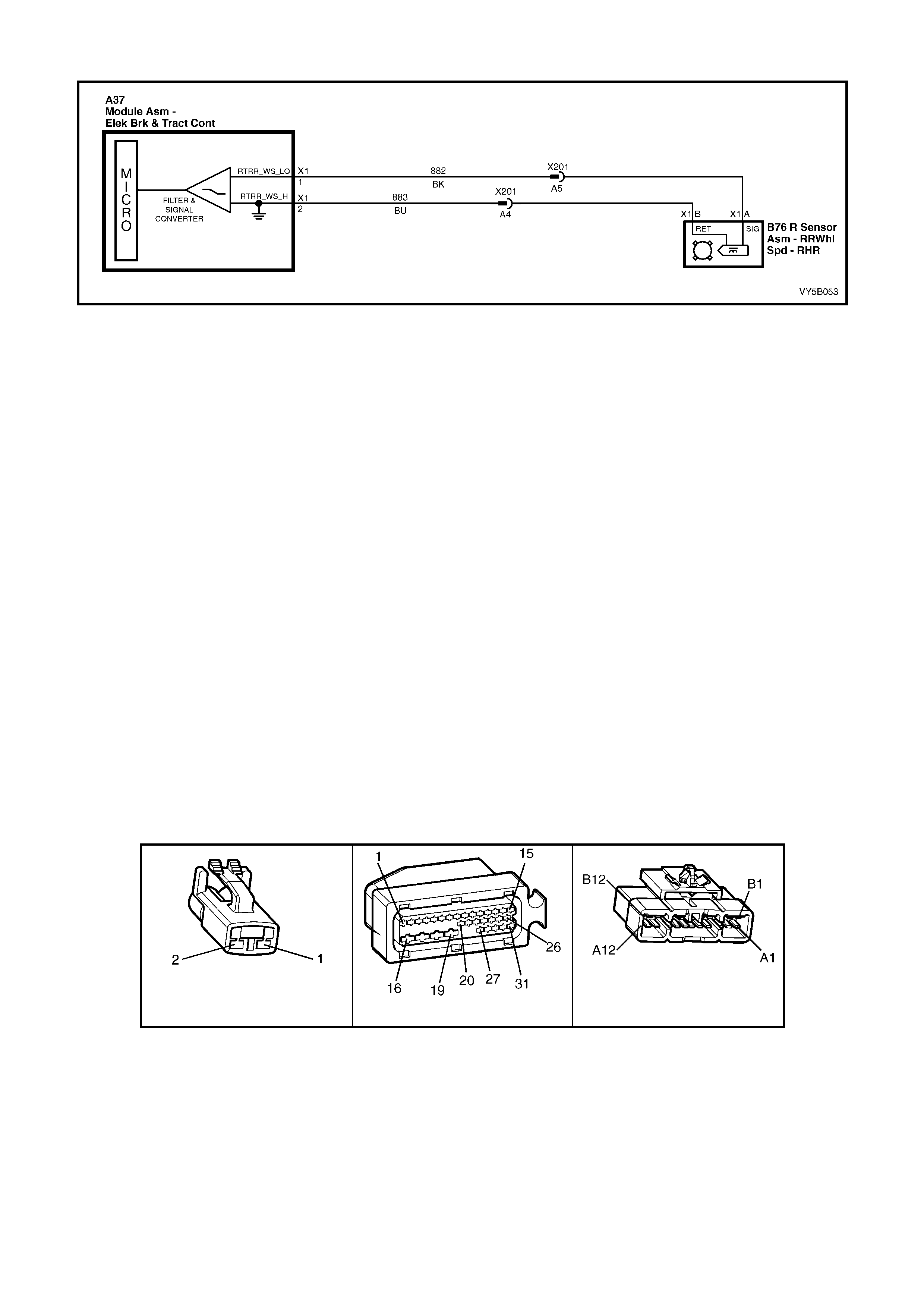
DTC 33 – REAR RIGHT WHEEL SPEED SENSOR SHORT OR OPEN CIRCUIT
Figure 5B-133
CIRCUIT DESCRIPTION:
The toothed pulse ring wheel on the inner right rear axle flange generates a voltage pulse as it moves past the
wheel speed sensor; each tooth – gap – tooth on the pulse ring generates these pulses.
The frequency of these pulses is used by the ABS or ABS/TCS control module to determine wheel speed.
DTC 33 will s et when t he ig nition is switc hed on an d the c ontrol m odule detec ts a continuity pro blem in cir cuits 882
and 883, or no wheel speed signal is generated by the sensor.
If a failure is detected which causes DTC 33 to set, the ABS or ABS/TCS system is disabled and the control
module activates the ABS or ABS and TRAC OFF warning displays for the remainder of the ignition cycle. If the
failure is intermittent, t he control m odule will enable the s ystem at the next igniti on cycle and a hist ory DTC 33 will
be set.
TEST DESCRIPTION:
The numbers below refer to Step numbers in the diagnostic chart for DTC 33.
2. Begin rectification of this DTC by visually inspecting right hand rear wheel speed sensor wiring for a fault
condition.
3. This test is a usual check for connector or wiring problems which may cause an intermittent condition.
4. This test checks for correct resista nce reading of the sensor coil.
5. This test checks for short circuit in right hand rear wheel speed sensor wiring.
6. This test checks for open circuit in right hand rear wheel speed sensor wiring.
7. This test checks for short to ground or B+ in circuits 882 a nd 883.
8. This test determines whether the DTC was set by an intermittent condition or a control module fault.
NOTES ON DIAGNOSTIC CHART:
9. Refer to 4.7 TECH 2 DIAGNOSTICS in this Section for connecting and using Tech 2.
10. For all wiring checking procedures, refer to Section 12P WIRING DIAGRAMS in the MY 2003 VY and V2
Series Service Information.
B76 R P3 X201
Figure 5B-134

DTC 33 – REAR RIGHT WHEEL SPEED SENSOR SHORT CIRCUIT OR OPEN CIRCUIT
STEP ACTION VALUE YES NO
1. Was the ABS or ABS/TCS Functional Check Carried
out? Go to Step 2 Go to 4.4 ABS or
ABS/TCS
Functional Check
2. 1. Ensure that right hand rear wheel speed sensor lead
is not visibly damaged and that it is properly secured
at all places .
2. If the sensor lead is damaged or not correctly
mounted and retained, replace the lead and/or
properly install it.
3. Install Tech 2 to DLC and select Diagnostics /
Chassis / ABS/TCS / Diagnostic Trouble Codes /
Clear DTCs and clear all DTCs (refer to NOTE 1
above).
Road test vehicle; does DTC 33 set again ?
Go to Step 4 Go to Step 3
3. 1. Inspect all system wiring and connections that could
ca us e s in te rm it t e n t fa ul t s . Ch ec k al l wi r i ng is in go od
condition, terminals are clean and tight and making
good contact (refer to NOTE 2 above).
Is all OK ?
Fault not present.
Check all system
wiring harness
connect ors and
terminals, in
particular the
modulator and
ABS or ABS/TCS
control modu le
connector
terminals.
Make repairs as
necessary,
recheck circuit to
verify repair.
4. 1. Turn ignition OFF.
2. Disconnect sensor lead connector B76 R from body
harness connec tor X 201.
3. Using digital multimeter, measure sensor and lead
resistance.
Is value as specified ?
1440 – 1760
Ohms Go to Step 5 Replace rear
wheel speed
sensor asm, refer
to 3.4 WHEEL
SPEED
SENSORS in this
Section. Recheck
circuit to verify
repair.
5. 1. Disconnect ABS or ABS/TCS control module
connector A37.
2. With sensor lead connector B76 R still
disconnected, check continuity between ABS or
ABS/TCS control module connector A37, terminals
X1-1 and X1-2 (refer to NOTE 2 above).
Does continuity exist ?
Eliminate short
circuit in wiring
between circ uits
882 (Black wire)
and 883 (Blue
wire), recheck
circuit to verify
repair.
Go to Step 6
6. 1. Check circuits 882 (Black wire) and 883 (Blue wire)
for open circuit between sensor connector B76 R
and ABS control module connector A37 (refer to
NOTE 2 above).
Is there continuity in both circuits ?
Go to Step 7 Eliminate open
circuit in wiring,
recheck circuit to
verify repair.
7. 1. Check circuits 882 and 883 for short to ground or B+
(refer to NOTE 2 above).
Are both circuits OK ?
Go to Step 8 Eliminate short to
ground or B+ in
wiring, recheck
circuit to verify
repair.
8. 1. Install Tech 2 to DLC and select Diagnostics /
Chassis / ABS/TCS / Diagnostic Trouble Codes /
Clear DTCs and clear all DTCs (refer to NOTE 1
above).
2. Road test vehicle.
Does DTC 33 set again ?
Replace ABS or
ABS/TCS control
module, refer to
3.6 CONTROL
MODULE in this
Section, recheck
and verify repair.
Fault not present.
Check all system
wiring harness
connect ors and
terminals, in
particular the
modulator and
ABS or ABS/TCS
control modu le
connector
terminals.
WHEN ALL DIAGNOSIS AND REPAIRS ARE COMPLETED, CLEAR ALL DTCs AND VERIFY CORRECT OPERATION
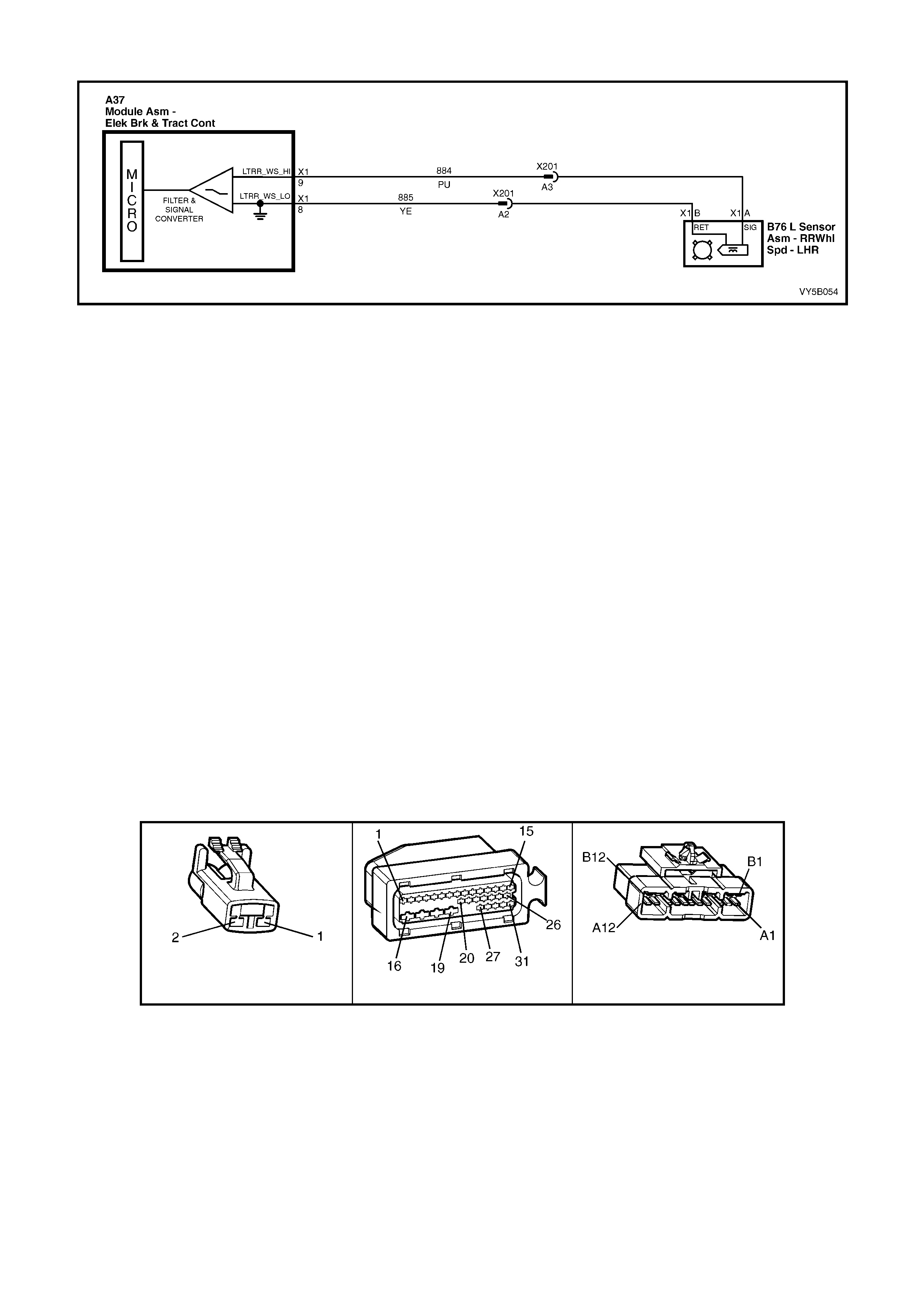
DTC 35 - REAR LEFT WHEEL SPEED SENSOR INCORRECT SIGNAL
Figure 5B-135
CIRCUIT DESCRIPTION:
The toothed pulse ring wheel on the inner left rear axle flange generates a voltage pulse as it moves past the wheel
speed sensor; each tooth – gap – tooth on the pulse ring generates these pulses.
The frequency of these pulses is used by the ABS or ABS/TCS control module to determine wheel speed.
DTC 35 will s et if veh icle s p eed is a pprox imately 12 km/h and t he c ontrol module d etect s a lo w lef t han d r ear whee l
speed sensor output voltage.
If a failure is detected which causes DTC 35 to set, the ABS or ABS/TCS system is disabled and the control
module activates the ABS, or ABS and TRAC OFF warning displays for the remainder of the ignition cycle. If the
failure is intermittent, t he control m odule will enable the s ystem at the next igniti on cycle and a hist ory DTC 35 will
be set.
TEST DESCRIPTION:
The numbers below refer to Step numbers in the diagnostic chart for DTC 35.
1. This test checks if there is a speed signal o utput from the sensor.
2. This test checks for connector or wiring problems which may cause an intermittent condition.
3. This test determines whether the DTC was set by an intermittent condition or a control module fault.
4. This check is a visual inspection of the speed sensor, wiring and the pulse ring.
5. If repairs are necessary, the speed sensor output must be rechecked to verify the repair.
6. This test checks for voltage drops in the wheel speed sensor wiring which could cause lower than specified
sensor output voltage.
NOTES ON DIAGNOSTIC CHART:
1. Refer to 4.7 TECH 2 DIAGNOSTICS in this Section for connecting and using Tech 2.
2. For all wiring checking procedures, refer to Section 12P WIRING DIAGRAMS in the MY 2003 VY and V2
Series Service Information.
B76 R P3 X201
Figure 5B-136

DTC 35 - REAR LEFT WHEEL SPEED SENSOR INCORRECT SIGNAL
STEP ACTION VALUE YES NO
1. Was the ABS or ABS/TCS Functional Check Carried
out? Go to Step 2 Go to 4.4 ABS or
ABS/TCS
Functional Check
2. 1. Raise rear of vehicle and support on safety stands.
Refer to 0A GENERAL INFORMATION in the MY
2003 VY and V2 Series Service Information, for the
location of jacking and support points.
2. Install Tech 2 to DLC and turn ignition ON (refer to
NOTE 1 above).
3. Select Diagnostics / Chassis / ABS/TCS/ Data List /
Active ABS.
4. Check left hand rear wheel speed sensor output
signal by rotating wheel by hand.
5. Alternatively, connect an oscilloscope (Tech 31) to
the wheel speed sensor connector B76 L, between
circuit 884 (Purple w ire) and circuit 885 (Y ellow
wire), rotate left hand front wheel by hand and
compare oscilloscope patterns with those shown
below. Repair as necessary or go to Step 2).
Does speed signal change as wheel is turned faster?
Go to Step 3 Go to Step 5
3. 1. Visually inspect sensor lead wiring and connections.
2. Check wiring for intermittent open or short ci rcuit
(refer NOTE 2 above).
Is all OK ?
Go to Step 4 Repair fault with
sensor lead
wiring or replace
sensor, recheck
and verify repair.
4. 1. Install Tech 2 to DLC and select Diagnostics /
Chassis / ABS/TCS / Diagnostic Trouble Codes /
Clear DTCs and clear all DTCs (refer to NOTE 1
above).
2. Road test vehicle.
Does DTC 35 set again ?
Replace ABS or
ABS/TCS control
module, refer to
3.6 CONTROL
MODULE in this
Section, recheck
and verify repair.
Fault not present.
Check all system
wiring harness
connect ors and
terminals, in
particular the
ABS or ABS/TCS
control modu le
connector
terminals.
5. 1. Visually inspect sensor end for any signs of
damage.
2. Check that the pulse ring is secured to the inner
axle shaft and is positioned in line with the sensor.
3. Inspect pulse ring teeth for any signs of damage.
Is all OK ?
Go to Step 7 Go to Step 6
6. 1. Make repairs as necessary. Retest speed sensor
output.
Is output now OK ?
Go to Step 4 Go to Step 7
7. 1. Check circuits 884 (Purple wire) and 885 (Yellow
wire) for continuity (refer to NOTE 2 above).
2. Inspect body harness to sensor connector B76 L,
body harness to Main Wiring Harness connector
X201 and ABS or ABS/TCS control module
connector A37.
Are connectors and wiring OK ?
Replace rear
wheel speed
sensor, refer 3.4
W HEEL SPEED
SENSORS in this
Section. Recheck
and verify repair.
Repair wiring as
necessary,
recheck and
verify repair.
WHEN ALL DIAGNOSIS AND REPAIRS ARE COMPLETED, CLEAR ALL DTCs AND VERIFY CORRECT OPERATION
OSCILLOSCOPE PATTERNS (SIMULATED ONLY)
Normal view Possi bl e inc reasi ng and decreas i ng dist ance
between wheel speed sensor and pulse ring Possible chi pped or damaged teeth
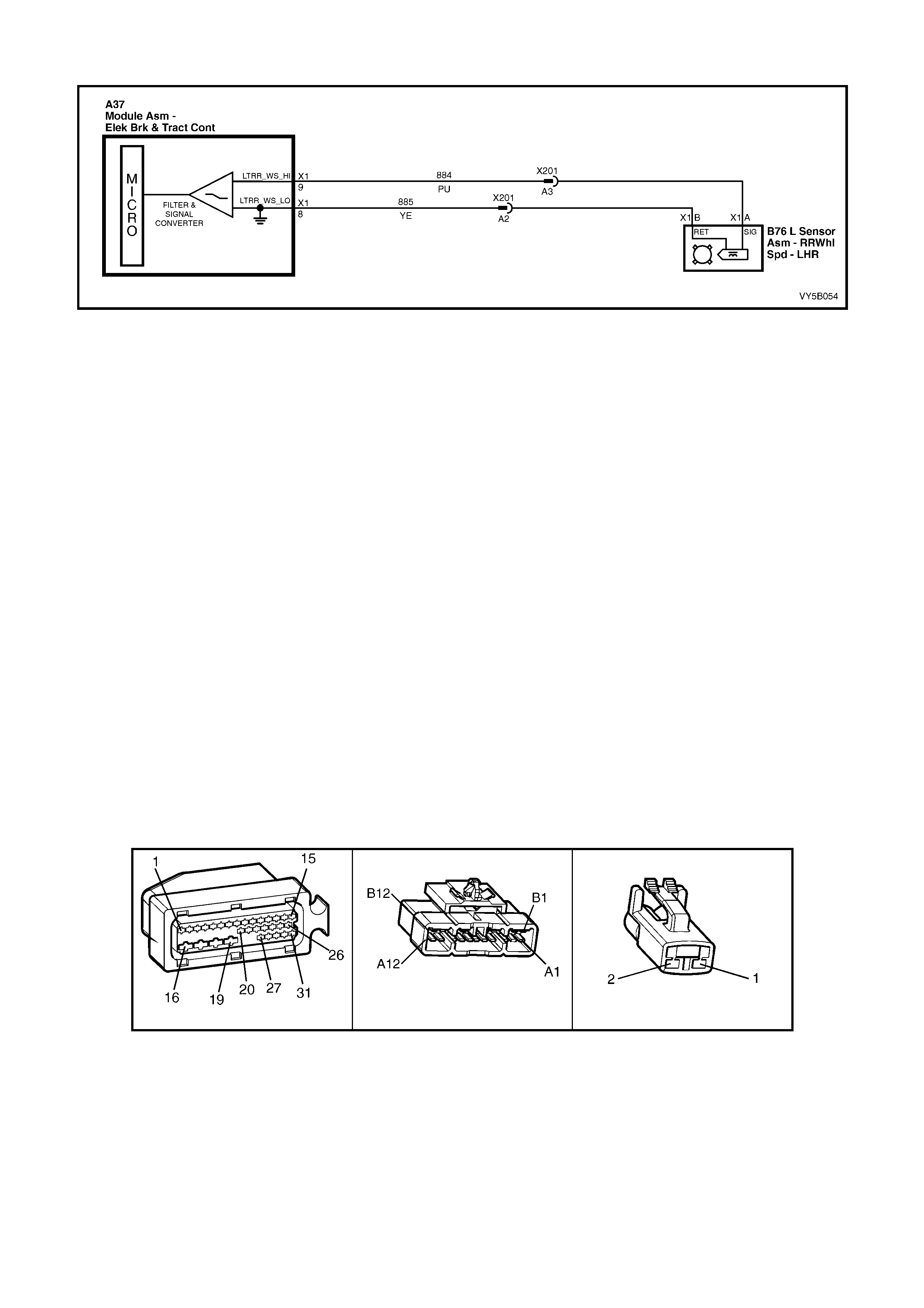
DTC 37 - REAR LEFT WHEEL SPEED SENSOR SHORT OR OPEN CIRCUIT
Figure 5B-137
CIRCUIT DESCRIPTION:
The toothed pulse ring wheel on the inner left rear axle flange generates a voltage pulse as it moves past the wheel
speed sensor; each tooth – gap – tooth on the pulse ring generates these pulses.
The frequency of these pulses is used by the ABS or ABS/TCS control module to determine wheel speed.
DTC 37 will s et when t he ig nition is switc hed on an d the c ontrol m odule detec ts a continuity pro blem in cir cuits 884
and 885, or no wheel speed signal is generated by the sensor.
If a failure is detected which causes DTC 37 to set, the ABS or ABS/TCS system is disabled and the control
module activates the ABS, or ABS and TRAC OFF warning displays for the remainder of the ignition cycle. If the
failure is intermittent, t he control m odule will enable the s ystem at the next igniti on cycle and a hist ory DTC 37 will
be set.
TEST DESCRIPTION:
The numbers below refer to Step numbers in the diagnostic chart for DTC 37.
1. Begin rectification of this DTC by visually inspecting left hand rear wheel speed sensor wiring for a fault
condition.
2. This test is a usual check for connector or wiring problems which may cause an intermittent condition.
3. This test checks for correct resistance reading of the sensor coil .
4. This test checks for continuity of left hand rear wheel speed sensor wiring.
5. This test checks for open circuit in left hand rear wheel speed sensor wiring.
6. This test checks for short to ground or B+ in circuits 884 and 885.
7. This test determines whether the DTC was set by an intermittent condition or a control module fault.
NOTES ON DIAGNOSTIC CHART:
1. Refer to 4.7 TECH 2 DIAGNOSTICS in this Section for connecting and using Tech 2.
2. For all wiring checking procedures, refer to Section 12P WIRING DIAGRAMS in the MY 2003 VY and V2
Series Service Information.
A37 X201 B76_L
Figure 5B-138

DTC 37 - REAR LEFT WHEEL SPEED SENSOR SHORT OR OPEN CIRCUIT
STEP ACTION VALUE YES NO
1. Was the ABS or ABS/TCS Functional Check Carried
out? Go to Step 2 Go to 4.4 ABS or
ABS/TCS
Functional Check
2. 1. Ensure that left hand rear wheel speed sensor lead
is not visibly damaged and that it is properly secured
at all places .
2. If the sensor lead is damaged or not correctly
mounted and retained, replace the lead and/or
properly install it.
3. Install Tech 2 to DLC and select Diagnostics /
Chassis / ABS/TCS / Diagnostic Trouble Codes /
Clear DTCs and clear all DTCs (refer to NOTE 1
above).
Road test vehicle, does DTC 37 set again?
Go to Step 4 Go to Step 3
3. 1. Inspect all system wiring and connections that could
cause intermittent faults. Check all wiring is in good
condition, terminals are clean and tight and making
good contact (refer NOTE 2 above).
Is all OK?
Fault not present.
Check all system
wiring harness
connect ors and
terminals, in
particular the
modulator and
ABS or ABS/TCS
control modu le
connector
terminals.
Make repairs as
necessary and
recheck circuit to
verify repair.
4. 1. Turn ignition OFF.
2. Disconnect sensor lead connector B76 L from body
harness connec tor X 201.
3. Using digital multimeter, measure sensor and lead
resistance.
Is value as specified?
1440 – 1760
Ohms Go to Step 5 Replace rear
wheel speed
sensor asm, refer
to 3.4 WHEEL
SPEED
SENSORS in this
Section, recheck
circuit to verify
repair.
5. 1. Disconnect ABS control module connector A37.
2. With sensor lead connector B76 L still disconnected,
check continuity between ABS or ABS/TCS control
module connector A37, terminals X1-8 and X1-9
(refer to NOTE 2 above).
Does continu ity ex ist?
Eliminate short
circuit in wiring
between circ uits
884 (Purple wire)
and 885 (Yellow
wire), recheck
circuit to verify
repair.
Go to Step 6
6. 1. Check circuits 884 (Purple wire) and 885 (Yellow
wire) for open circuit between sensor connector B76
L and ABS or ABS/TCS control module connector
A37 (refer to NOTE 2 above).
Is there continuity in both circuits?
Go to Step 7 Eliminate open
circuit in wiring,
recheck circuit to
verify repair.
7. 1. Check circuits 884 and 885 for short to ground or B+
(refer NOTE 2 above).
Are both circuits OK?
Go to Step 8 Eliminate short to
ground or B+ in
wiring, recheck
circuit to verify
repair.
8. 1. Install Tech 2 to DLC and select Diagnostics /
Chassis / ABS/TCS / Diagnostic Trouble Codes /
Clear DTCs and clear all DTCs (refer to NOTE 1
above).
2. Road test vehicle.
Does DTC 37 set again?
Replace ABS or
ABS/TCS control
module, refer to
3.6 CONTROL
MODULE in this
Section, recheck
and verify repair.
Fault not present.
Check all system
wiring harness
connect ors and
terminals, in
particular the
modulator and
ABS or ABS/TCS
control modu le
connector
terminals.
WHEN ALL DIAGNOSIS AND REPAIRS ARE COMPLETED, CLEAR ALL DTCs AND VERIFY CORRECT OPERATION
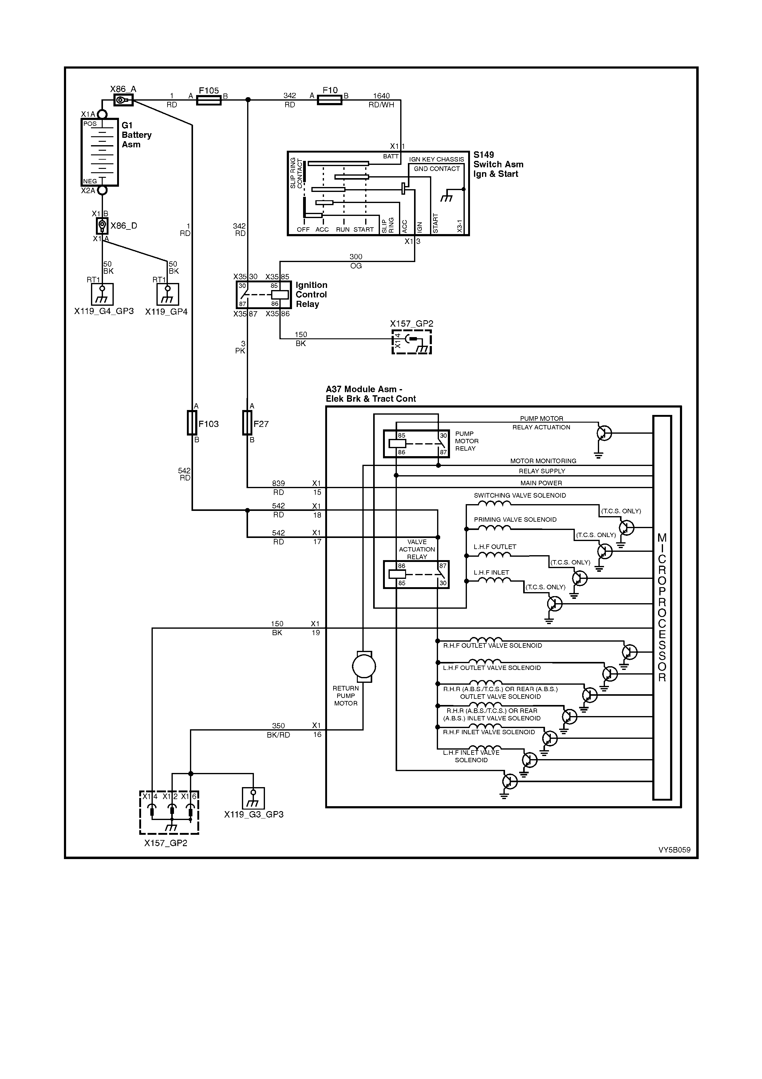
DTCs: 41, 42, 45, 46, 47, 48, 51, 52, 55 & 56 – SOLENOID VALVE CIRCUIT FAULTS
Figure 5B-139
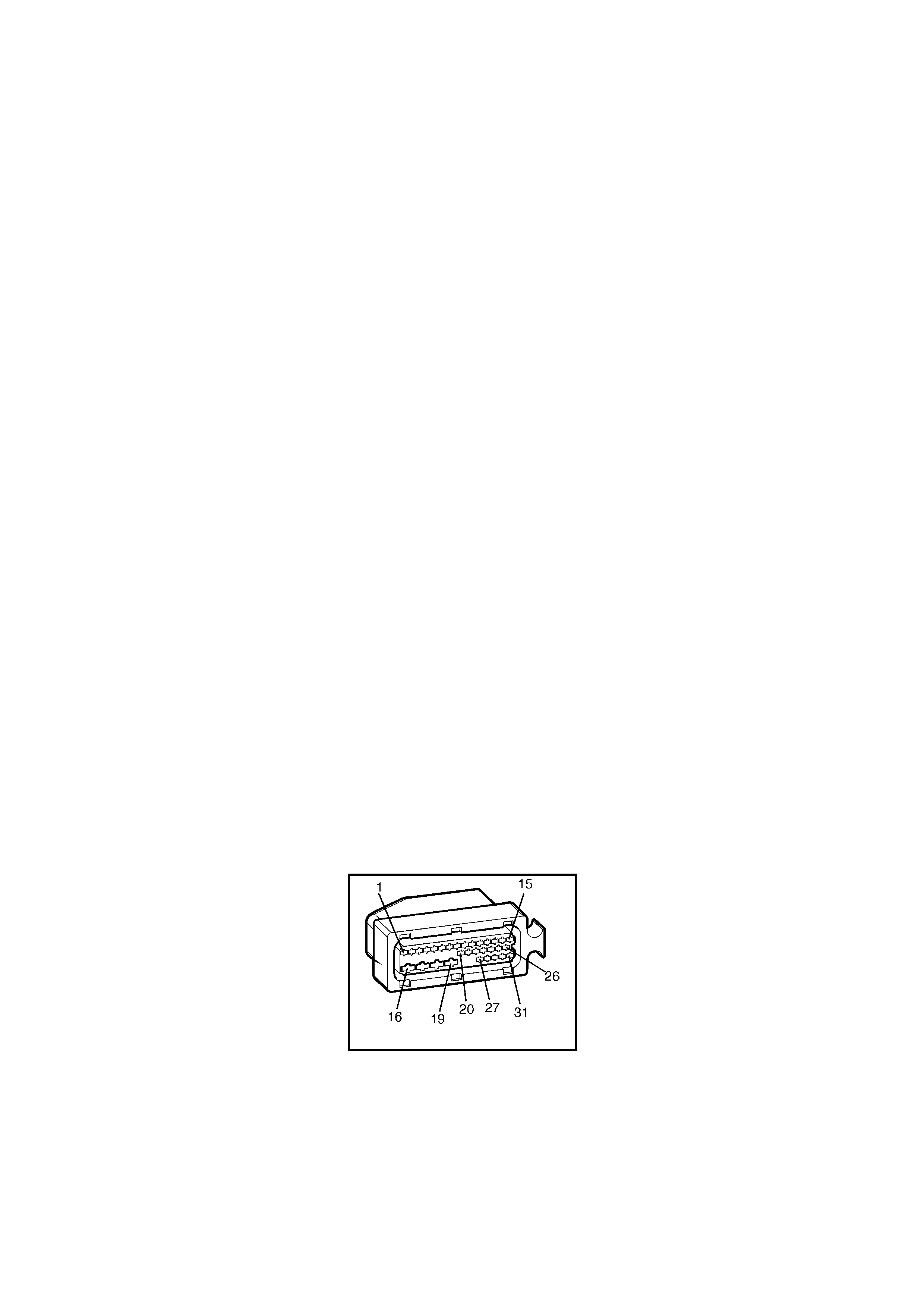
The components relating to these DTCs are all part of the hydraulic modulator assembly and share a common
ground and power supply.
• DTC 41 Front Right Inlet Valve Solenoid Fault
• DTC 42 Front Right Outlet Valve Solenoid Fault
• DTC 45 Front Left Inlet Valve Solenoid Fault
• DTC 46 Front left Outlet Valve Solenoid Fault
• DTC 47 Priming Valve Solenoid Fault (ABS/TCS Only)
• DTC 48 Switching Valve Solenoid Fault (ABS/TCS Only)
• DTC 51 Rear Right Inlet Valve Solenoid Fault (ABS/TCS Only)
• DTC 52 Rear Right Outlet Valve Solenoid Fault (ABS/TCS Only)
• DTC 55 Rear Left Inlet Valve Solenoid Fault (ABS/TCS Only) or Rear Axle Inlet Solenoid Valve Fault (ABS
Only)
• DTC 56 Rear Left Outlet Valve Solenoid Fault (ABS/TCS Only) or Rear Axle Outlet Valve Solenoid Fault (ABS
Only)
CIRCUIT DESCRIPTION:
The h ydraul ic modulator a n d c ontro l module as s embly ar e supplied with c o ns tant po wer f rom the battery via fusible
link F103 and, when the ignition is switched ON, via fuse F27. The solenoid valves are activated by the control
module internally supplying ground via terminals X1-16 and X1-19.
If the ABS or ABS/TCS control module senses a fault such as an open circuit or a short circuit in the wiring or
solenoid valve, the valve relay will be de-energised. The ABS, or ABS and TRAC OFF warning displays will be
activated and the relevant DTC/S will be set.
If a failure is detected which causes DTCs 41, 42, 45, 46, 47, 48, 51, 52, 55 or 56 to set, the ABS or ABS/TCS
system is disabled and the control module activates the ABS, or ABS and TRAC OFF warning displays for the
remainder of the ignition cycle. If the failure is intermittent, the control module will enable the system at the next
ignition cycle and the relevant history DTC will be set.
TEST DESCRIPTION:
The numbers below refer to Step numbers in the following diagnostic chart.
3. T his step determ ines if there is a comm on power or ground s upply fault to t he hydraulic modulator and c ontrol
module assembly.
4. This test uses Tech 2 to check for proper solenoid valve operation.
5. Checks for constant battery voltage to the control module A37 at terminals X1-17 and X1-18.
6. Checks for battery voltage to the control module A37 at terminal X1-15 when the ignition is switched on.
7. Checks for continuity in ground circuit 350.
8. Checks for continuity in ground circuit 150.
NOTES ON DIAGNOSTIC CHART:
9. Refer to 4.7, TECH 2 DIAGNOSTICS in this Section for connecting and using Tech 2.
10. For all wiring checking procedures, refer to Section 12P, WIRING DIAGRAMS in the MY 2003 VY and V2
Series Service Information.
A37
Figure 5B-140

DTCs 41, 42, 45, 46, 47, 48, 51, 52, 55 & 56 – SOLENOID VALVE CIRCUIT FAULTS
STEP ACTION VALUE YES NO
1. Was the ABS or ABS/TCS Functional Check Carried
out? Go to Step 2 Go to 4.4 ABS or
ABS/TCS
Functional Check
2. 1. Install Tech 2 to DLC and select Diagnostics /
Chassis / ABS/TCS / Diagnostic Trouble Codes /
Read DTCs (refer to NOTE 1 above).
Is there more than one DTC set ?
Go to Step 4 Go to Step 3
3. 1. With Tech 2 connected, select Diagnostics / Chassis
/ ABS/TCS / Miscellaneous Tests / Solenoids.
2. Depending on the DTC set, conduct the relevant
solenoid test (ie. if DTC 41 is set, select Front Right
Solenoid Valve Test) and conduct solenoid test
(refer to NOTE 1 above)
Does test confirm that relevant solenoid is OK ?
Fault not present.
Check all system
wiring harness
connect ors and
terminals, in
particular the
ABS or ABS/TCS
control modu le
connector
terminals.
Replace
hydraulic
modulator asm,
refer to 3.5
HYDRAULIC
MODULATOR
AND CONTROL
MODULE
ASSEMBLY in
this Section.
4. 1. Turn ignition Off.
2. Disconnect contr ol mod ule connector A37.
3. Check for voltage at control module connector A37
terminals X1-17 and then X1-18, circuit 542 (Red
wire) to ground (refer to NOTE 2 above).
Is voltage as specified at each terminal?
Approx.
12 Volts Go to Step 5 Check and repair
open or short in
circuit 542,
recheck and
verify repair.
5. 1. Ignition ON.
2. With connector A37 still disconnected from control
module , check for voltage between terminal X1-15,
circuit 839 (Red wire) and ground (refer NOTE 2
above).
Is voltage as specified?
Approx.
12 Volts Go to Step 6 Check and repair
open or short in
circuit 839
(including fuse
F27), recheck
and verify repair.
6. 1. With control module connector A37 still
disconnected, check for continuity between control
module connector A37, terminal X1-16, circuit 350
(Black/Red wire) and ground location
X119_G3_GP3 (ABS bracket in engine
compartment).
Does continuity exist ?
Go to Step 7 Check and repair
open in circuit
350, recheck and
verify repair.
7. 1. With control module connector A37 still
disconnected, check for continuity between control
module connector A37, terminal X1-19, circuit 150
(Black wire) and ground location X157_GP2.
Does continuity exist ?
Replace
hydraulic
modulator asm,
refer to
3.5 HYDRAULIC
MODULATOR
AND CONTROL
MODULE ASM in
this Section.
Check and repair
open in circuit
150, recheck and
verify repair.
WHEN ALL DIAGNOSIS AND REPAIRS ARE COMPLETED, CLEAR ALL DTCs AND VERIFY CORRECT OPERATION

DTC 61 - PUMP MOTOR OR RELAY FAULT
Figure 5B-141

CIRCUIT DESCRIPTION:
When the pump motor relay is grounded by the ABS control module, it provides B+ to operate the modulator’s
return p ump. Onc e the pum p motor circuit is en ergis ed, a 'Pum p On' signa l is sent t o the AB S or AB S/TCS contr ol
module to verify pum p motor opera tio n.
DTC 61 will set if 12 vo lts is pres ent at the pum p motor wit hout relay acti vation, or if batter y voltage is not pres ent
at the pump motor when the relay is activated.
If the ABS or ABS/TCS control module senses a fault such as an open circuit or a short circuit in the wiring or pump
motor, the pump relay will be de-energised. The ABS or ABS and TRAC OFF warning displays will be activated
and the relevant DTC/S will be set.
If a failure is detected which causes DTC 61 to set, the ABS or ABS/TCS system is disabled and the control
module activates the ABS, or ABS and TRAC OFF warning displays for the remainder of the ignition cycle. If the
failure is intermittent, the control module will enable the system at the next ignition cycle and the relevant history
DTC will be set.
TEST DESCRIPTION:
The numbers below refer to Step numbers in the diagnostic chart for DTC 61.
1. T his step determ ines if there is a co mmon power or ground s upply fault t o the hydraulic modulator and c ontrol
module assembly.
2. This test uses Tech 2 to check for proper pump operation.
3. Inspection of hydraulic modulator motor connector.
4. Checks for constant battery voltage to the control module at terminals X1-17 and X1-18.
5. Checks for battery voltage to the control module A37 at terminal X1-15 when the ignition is switched on.
11. Checks for continuity in ground circuit 350.
12. Checks for continuity in ground circuit 150.
NOTES ON DIAGNOSTIC CHART:
13. Refer to 4.7 TECH 2 DIAGNOSTICS in this Section for connecting and using Tech 2.
14. For all wiring checking procedures, refer to Section 12P WIRING DIAGRAMS in MY 2003 VY and V2 Series
Service Information.
A37
Figure 5B-142

DTC 61 - PUMP MOTOR OR RELAY FAULT
STEP ACTION VALUE YES NO
1. Was the ABS or ABS/TCS Functional Check Carried
out? Go to Step 2 Go to 4.4 ABS or
ABS/TCS
Functional Check
2. 1. Install Tech 2 to DLC and select Diagnostics /
Chassis / ABS/TCS / Diagnostic Trouble Codes /
Read DTCs (refer to NOTE 2 above).
Is DTC 61 the only DTC set ?
Go to Step 5 Go to Step 3
3. 1. With Tech 2 connected, Diagnostics / Chassis /
ABS/TCS / Miscellaneous Tests / Auto Test and
conduct test (refer to NOTE 2 above).
Does the pump motor run?
NOTE: The pump motor should be heard to run for
approximately 1 to 2 seconds while conducting test.
Fault not present.
Check all system
wiring harness
connect ors and
terminals, in
particular the
modulator and
ABS or ABS/TCS
control modu le
connector
terminals.
Go to Step 4
4. 1. Check that the ground connection is sound and that
the female connector terminals have not been
distorted.
2. Inspect the hydraulic modulator pump motor
connector (located at the front of the modulator and
control module assembly, under control module
connector A37) to ensure it is firmly connected.
Are connections OK and the connector correctly
installed?
Replace
hydraulic
modulator asm,
refer to 3.5
HYDRAULIC
MODULATOR
AND CONTROL
MODULE
ASSEMBLY in
this Section.
Ensure secure
connection,
recheck and
verify repair.
5. 1. Turn ignition OFF.
2. Disconnect contr ol mod ule connector A37.
3. Check for voltage at control module connector A37,
terminals X1-17 and then X1-18, circuit 542 (Red
wire) to ground (refer NOTE 2 above).
Is voltage as specified at each terminal?
Approx.
12 Volts Go to Step 6 Check and repair
open or short in
circuits 542,
recheck and
verify repair.
6. 1. Turn ignition ON.
2. With control module connector A37 still
disconnected, check for voltage between terminal
X1-15, circuit 839 (Red wire) and ground (refer to
NOTE 2 above).
Is voltage as specified ?
Approx.
12 Volts Go to Step 7 Check and repair
open or short in
circuit 839
(including fuse
F27), recheck
and verify repair.
7. 1. Ignition OFF.
2. With control module connector A37 still
disconnected, check for continuity between control
module connector A37, terminal X1-16, circuit 350
(Black/Red wire) and ground locations
X119_G3_GP3 and X157_GP2 (refer to NOTE 2
above).
Does continuity exist ?
Go to Step 8 Check and repair
open in circuit
350, recheck and
verify repair.
8. 1. With control module connector A37 still
disconnected, check for continuity between control
module connector A37, terminal X1-19, circuit 150
(Black wire) and ground location X157_GP2 (refer
NOTE 2 above).
Does continuity exist ?
Replace
hydraulic
modulator asm,
refer to
3.5 HYDRAULIC
MODULATOR
AND CONTROL
MODULE
ASSEMBLY in
this Section.
Check and repair
open in circuit
150, recheck and
verify repair.
WHEN ALL DIAGNOSIS AND REPAIRS ARE COMPLETED, CLEAR ALL DTCs AND VERIFY CORRECT OPERATION
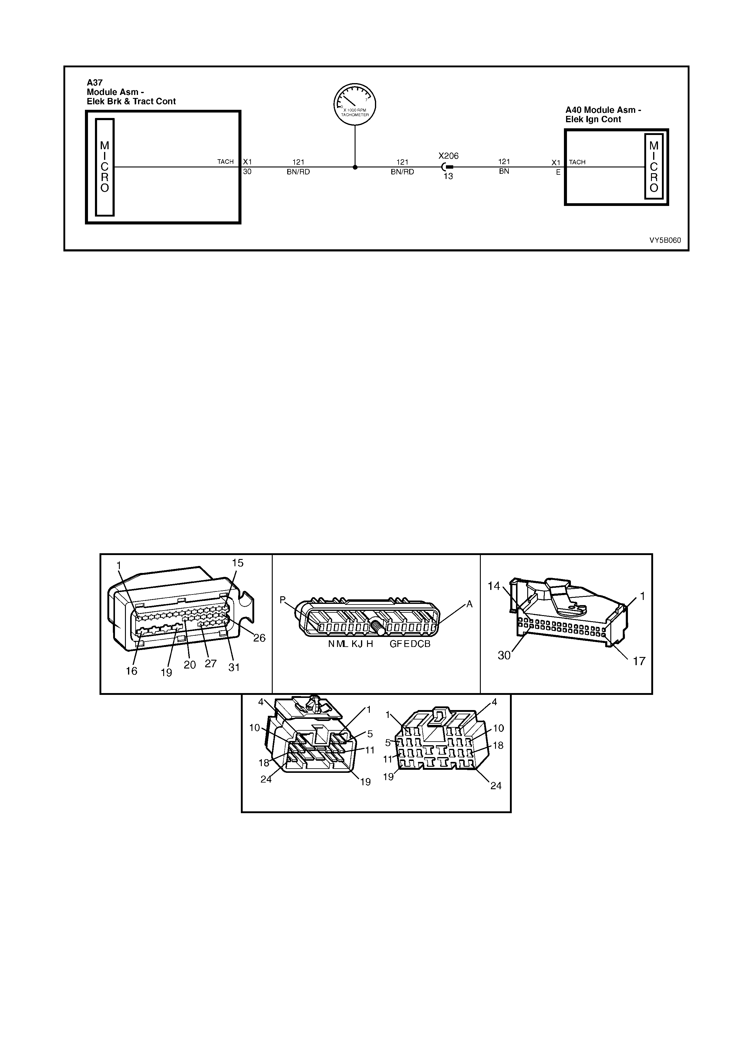
DTC 62 – RPM SIGNAL FAULT
Figure 5B-143
CIRCUIT DESCRIPTION:
To determine the requested torque signal and prevent the engine stalling, the ABS/TCS control module monitors
the engine s peed. An engi ne RPM signal is sent to terminal X 1-30 of the ABS/T CS control m odule from the Direct
Ignition System (DIS) module. This signal has a fixed duty cycle and a frequency that will vary with changing
engine RPM.
DTC 62 will s et if an RPM signal ( engine speed sig nal) is not r eceived b y the A BS/TCS contr ol module at te rminal
30, provided the engine speed is greater than 480 RPM.
If the ABS/T CS contro l module sens es this f ault, only the T CS system will be dis abled (ABS will operate n orm ally),
the TRAC O FF warn ing displa y will b e activated and t he relevant DTC will be set. T he TRAC O FF warnin g displa y
will remain activated for the remainder of the ignition cycle. If the failure is intermittent, the control module will
enable the system at the next ignition cycle and the relevant history DTC will be set.
TEST DESCRIPTION:
The numbers below refer to Step numbers in the diagnostic chart for DTC 62.
1. Checks for continuity in circuit 121.
NOTES ON DIAGNOSTIC CHART:
1. For all wiring checking procedures, refer to Section 12P WIRING DIAGRAMS in the MY 2003 VY and V2
Series Service Information.
A37 A40 P3
X206
Figure 5B-144

DTC 62 – RPM SIGNAL FAULT
STEP ACTION VALUE YES NO
1. Was the ABS or ABS/TCS Functional Check Carried
out? Go to Step 2 Go to 4.4 ABS or
ABS/TCS
Functional Check
2. 1. Check continuity of circuit 121 between ABS/TCS
control module connector A37 terminal X1-30 and
connector X206 terminal 13 (Brown/Red wire). (refer
to NOTE 1 above).
Does continu ity ex ist?
Go to Step 3 Check and repair
open in circuit
121. Recheck
and verify repair.
3. 1. Check continuity of circuit 121 between ABS/TCS
control module connector A37 terminal X1-30 and
Instrument connector P3 terminal 6 (Brown/Red
wire).
Does continu ity ex ist?
Replace ABS/TCS
control modu le,
refer to 3.6
CONTROL
MODULE in this
Section, recheck
and verify repair.
Check and repair
open in circuit
121. Recheck
and verify repair.
4. 1. Check continuity of circuit 121 between DIS control
module connector A40 terminal X1-E and connector
X206 terminal 13 (Brown wire).
Does continu ity ex ist?
Replace DIS control
module, refer to
6C1-3 (V6) or 6C2-
3 V6 S/C
POWERTRAIN
CONTROL
MODULE.
Check and repair
open in circuit
121. Recheck
and verify repair.
WHEN ALL DIAGNOSIS AND REPAIRS ARE COMPLETED, CLEAR ALL DTCs AND VERIFY CORRECT OPERATION
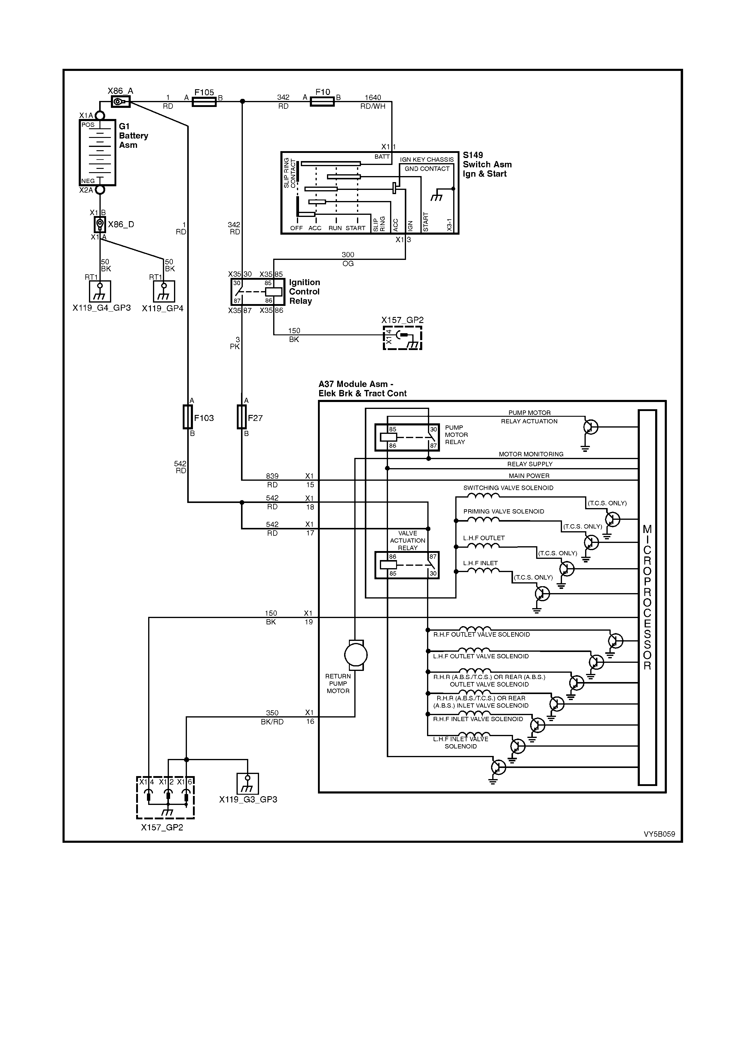
DTC 63 - VALVE SOLENOID RELAY CIRCUIT FAULT
Figure 5B-145
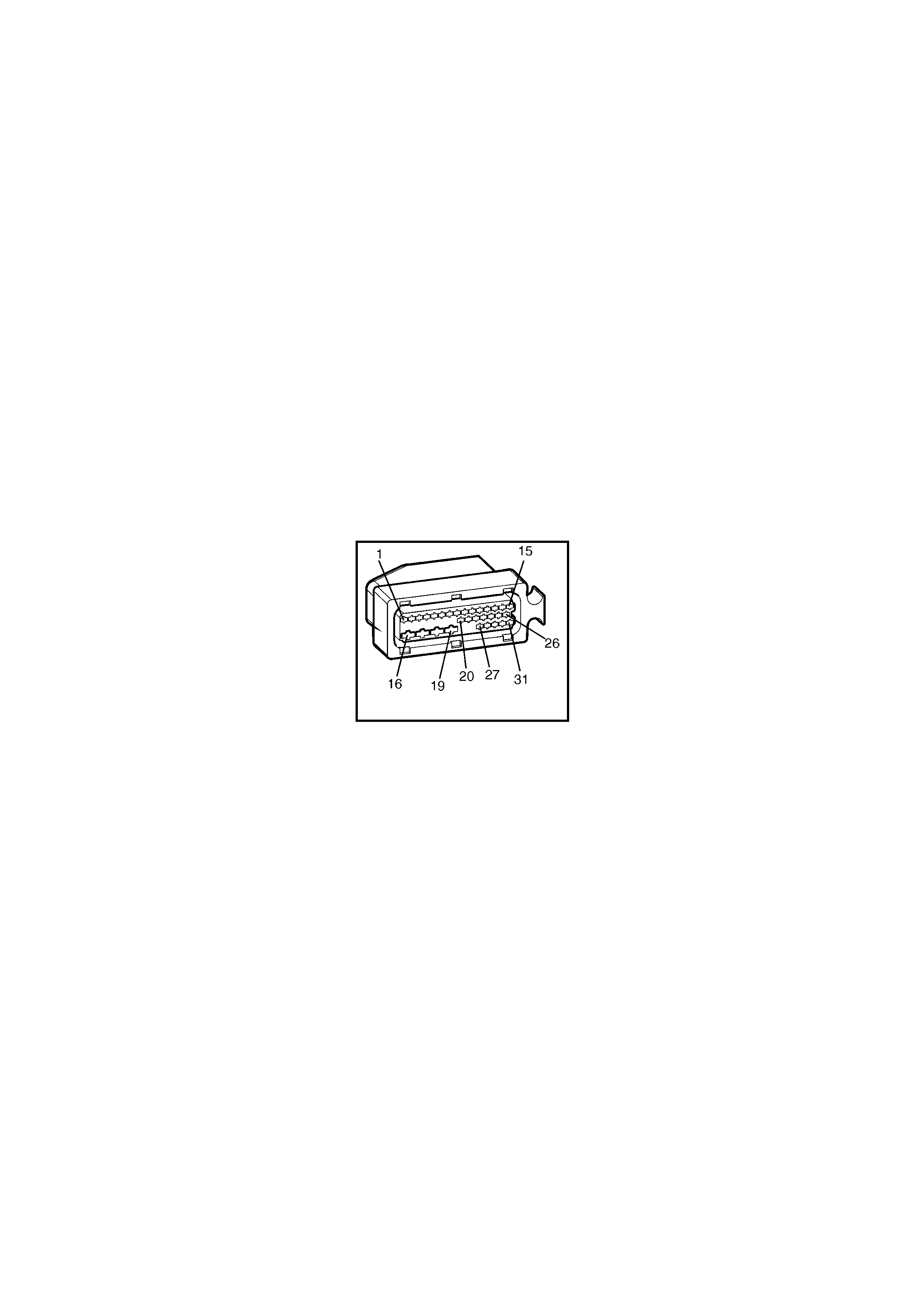
CIRCUIT DESCRIPTION:
When the ABS or ABS/TCS is active (ignition on), the valve relay provides voltage to actuate the six (ABS) or 10
(ABS/TCS) solenoid valves. However, the solenoid valves do not use this voltage unless the ABS or ABS/TCS
control module provides the ground for each solenoid.
DTC 63 will set if the va lve rela y voltage is low or if the r elay sup ply line is at 12 volts when the ABS or ABS/T CS
control module is not requesting it to be; this would make the relay constantly energised.
Also, DTC 63 will set if the ABS or ABS/TCS control m odule detects if three or m ore of the solenoid va lve circuits
between the valve relay terminal 30 and the control module are open circuited or shorted during the self test.
If a failure is detected which causes DTC 63 to set, the ABS or ABS/TCS system is disabled and the control
module activates the ABS or ABS and TRAC OFF warning display/s for the remainder of the ignition cycle. If the
failure is intermittent, t he control m odule will enable the s ystem at the next igniti on cycle and a hist ory DTC 63 will
be set.
TEST DESCRIPTION:
The numbers below refer to Step numbers in the diagnostic chart for DTC 63.
1. This test uses Tech 2 to check valve relay operation.
2. Checks for constant battery voltage to the control module at terminals X1-17 and X1-18.
3. Checks for battery voltage to the control module at terminal 15 when the ignition is switched on.
4. Checks for continuity in ground circuit 350.
5. Checks for continuity in ground circuit 150.
NOTES ON DIAGNOSTIC CHART:
1. Refer to 4.7 TECH 2 DIAGNOSTICS in this Section for connecting and using Tech 2.
2. For all wiring checking procedures, refer to Section 12P WIRING DIAGRAMS in the MY 2003 VY and V2
Series Service Information.
A37
Figure 5B-146

DTC 63 - VALVE SOLENOID RELAY CIRCUIT FAULT
STEP ACTION VALUE YES NO
1. Was the ABS or ABS/TCS Functional Check Carried
out? Go to Step 2 Go to 4.4 ABS or
ABS/TCS
Functional Check
2. 1. Install Tech 2 to DLC.
2. Select Diagnosis / Chassis / ABS/TCS /
Miscellaneous Tests / Solenoid.
3. Conduct solenoid test on any one of the solenoid
valves (refer to NOTE 1 above).
Does test confirm that solenoid valve tested is OK ?
Fault not present.
Check all system
wiring harness
connect ors and
terminals, in
particular the
modulator and
ABS or ABS/TCS
control modu le
connector
terminals.
Go to Step 3
3. 1. Turn ignition OFF.
2. Back probe control module connector A37, terminals
X1-17 and then X1-18, circuit 542 (Red wire) with a
voltmeter to ground (refer NOTE 1 above).
Is voltage as specified at each terminal ?
Approx. 12
Volts Go to Step 4 Check and repair
open or short in
circuits 542,
recheck and
verify repair.
4. 1. Turn ignition ON.
2. Back probe control module connector A37, terminal
X1-15 circuit 839 (Red wire) with a voltmeter to
ground (refer to NOTE 2 above)
Is voltage as specified ?
Approx. 12
Volts Go to Step 5 Check and repair
open or short in
circuit 839
(including fuse
F27), recheck
and verify repair.
5. 1. Disconnect contr ol mod ule co nnec tor A37.
2. Check for continuity between control module
connector A37, terminal X1-16, circuit 350
(Black/Red wire) and ground locations X157_GP2
and X119_G3_GP3 (RH inner fender and ABS
bracket in engine compartment).
Does continuity exist ?
Go to Step 6 Check and repair
open in circuit
350, recheck and
verify repair.
6. 1. With control module connector A37 still
disconnected, check for continuity between control
module connector A37, terminal X1-19, circuit 150
(Black wire) and ground location X157_GP2 (RH
inner fender).
Does continuity exist ?
Replace ABS or
ABS/TCS control
module, refer to
3.6 CONTROL
MODULE in this
Section, recheck
and verify repair.
Check and repair
open in circuit
150, recheck and
verify repair.
WHEN ALL DIAGNOSIS AND REPAIRS ARE COMPLETED, CLEAR ALL DTCs AND VERIFY CORRECT OPERATION
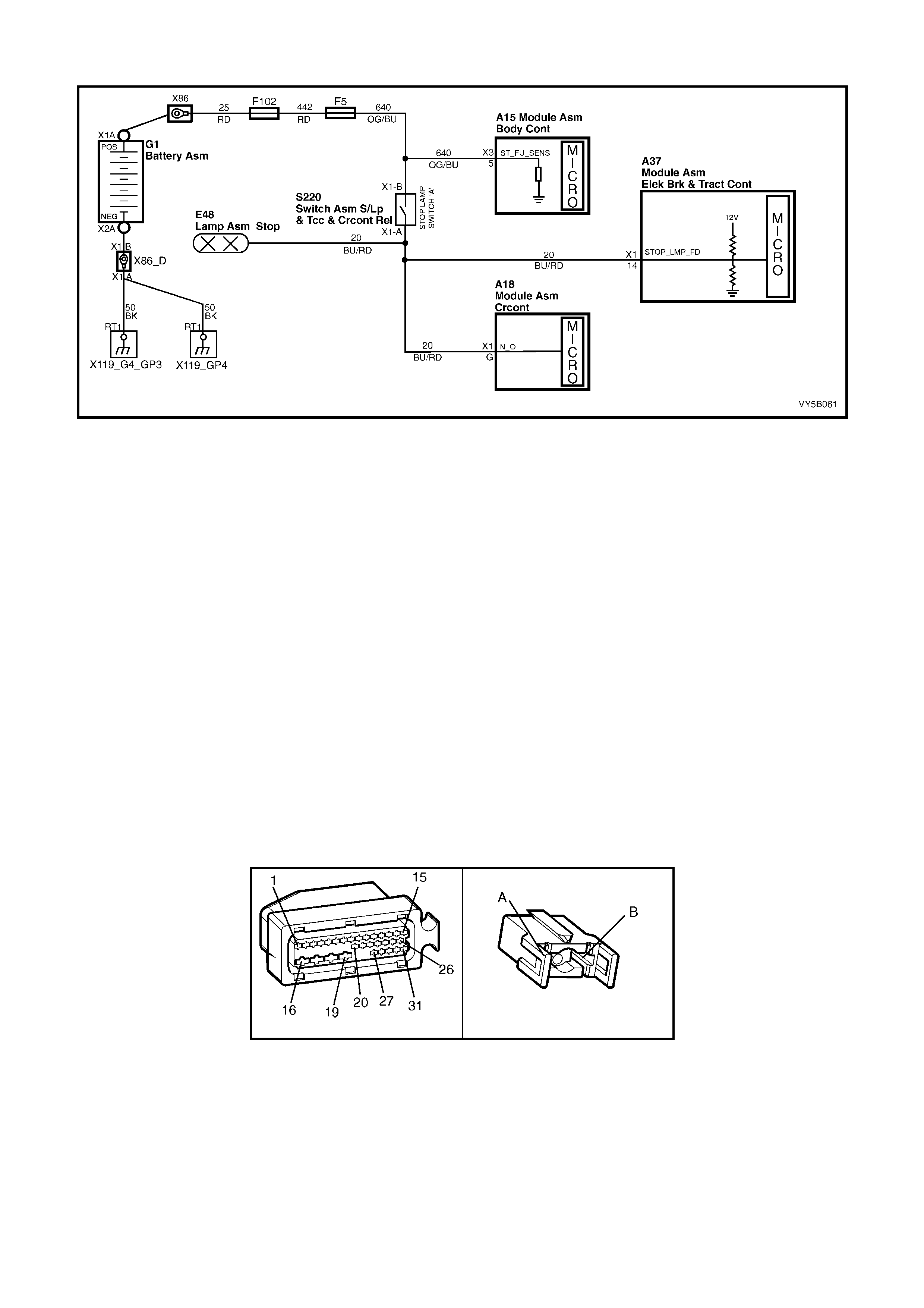
DTC 67 – STOP LAMP SWITCH CIRCUIT FAULT
Figure 5B-147
CIRCUIT DESCRIPTION:
The ABS or ABS/TCS control module monitors the stop lamp switch signal at terminal X1-14 to determine if the
brakes are being manually applied.
DTC 67 will set if the voltage monitored at terminal X1-14 goes out of range; between approximately 6 and 9 volts.
If the ABS or AB S/T C S control module s ens es this f aul t, the A BS will op erate nor mall y, ho wever, it’s r espons e time
will be marginally slower (approx 10 milliseconds) to react than if this input was available. The TCS brake
intervention will be disabled immediately, while the TCS engine intervention will become disabled after the
operation. The TRAC OFF warning display will be activated and the relevant DTC will be set. The TRAC OFF
warning disp lay will remain activated for the remainder of the ignition cycle. If the failure is intermittent, the control
module will enable the system at the next ignition cycle and the relevant history DTC will be set.
TEST DESCRIPTION:
The numbers below refer to Step numbers in the diagnostic chart for DTC 67.
1. Checks for voltage at control module terminal X1-14 when brakes are applied.
2. Checks stop lamps to see if they activate when brakes applied.
3. Checks for continuity in circuit 20.
4. Checks circuit 640 for power to stop lamp switch.
5. Checks stop lamp switch.
NOTES ON DIAGNOSTIC CHART:
1. For all wiring checking procedures, refer to Section 12P WIRING DIAGRAMS in the MY 2003 VY and V2
Series Service Information.
A37 S220 X1
Figure 5B-148

DTC 67 - STOP LIGHT SWITCH CIRCUIT FAULT
STEP ACTION VALUE YES NO
1. Was the ABS or ABS/TCS Functional Check Carried
out? Go to Step 2 Go to 4.4 ABS or
ABS/TCS
Functional Check
2. 1. Back probe control module connector A37, terminal
X1-14, circuit 20 (Blue/Red wire) with a voltmeter to
ground (refer to NOTE 1 above).
2. Apply brakes (brake switch closed).
Is voltage as specified ?
B+ Volts Replace ABS or
ABS/TCS control
module, refer to
3.6 CONTROL
MODULE in this
Section, recheck
and verify repair.
Go to Step 3
3. 1. Apply brakes and check stop lamp operation.
Do stop lamps activate ? Go to Step 4 Go to Step 5
4. 1. Disconnect control module connector A37 and stop
lamp switch A, connector S220 X1.
2. Check for continuity between control module
connector A37, terminal X1-14 and stop lamp switch
connector S220 X1-A, circuit 20 (Blue/Red wire)
(refer to NOTE 1 above).
Does continuity exist ?
Fault not present.
Check all system
wiring harness
connect ors and
terminals, in
particular the
modulator and
ABS or ABS/TCS
control modu le
connector
terminals.
Check and repair
open in circuit 20,
recheck and
verify repair.
5. 1. Back probe stop lamp switch connector S220 X1-B,
circuit 640 (Orange/Blue wire) with a voltmeter to
ground (refer to NOTE 1 above).
Is voltage as specified ?
B+ Volts Go to Step 6 Check and repair
open or short in
circuit 640
(including fuse
F5), recheck and
verify repair.
6. 1. Back probe stop lamp switch A, connector S220 X1-
A, circuit 20 (Blue/Red wire) with a voltmeter to
ground (refer to NOTE 1 above).
2. Apply brakes (brake switch closed).
Is voltage as specified ?
B+ Volts System OK. Check and adjust
or replace stop
lamp switch A,
refer to
Section 12B
LIGHTING
SYSTEM.
WHEN ALL DIAGNOSIS AND REPAIRS ARE COMPLETED, CLEAR ALL DTCs AND VERIFY CORRECT OPERATION
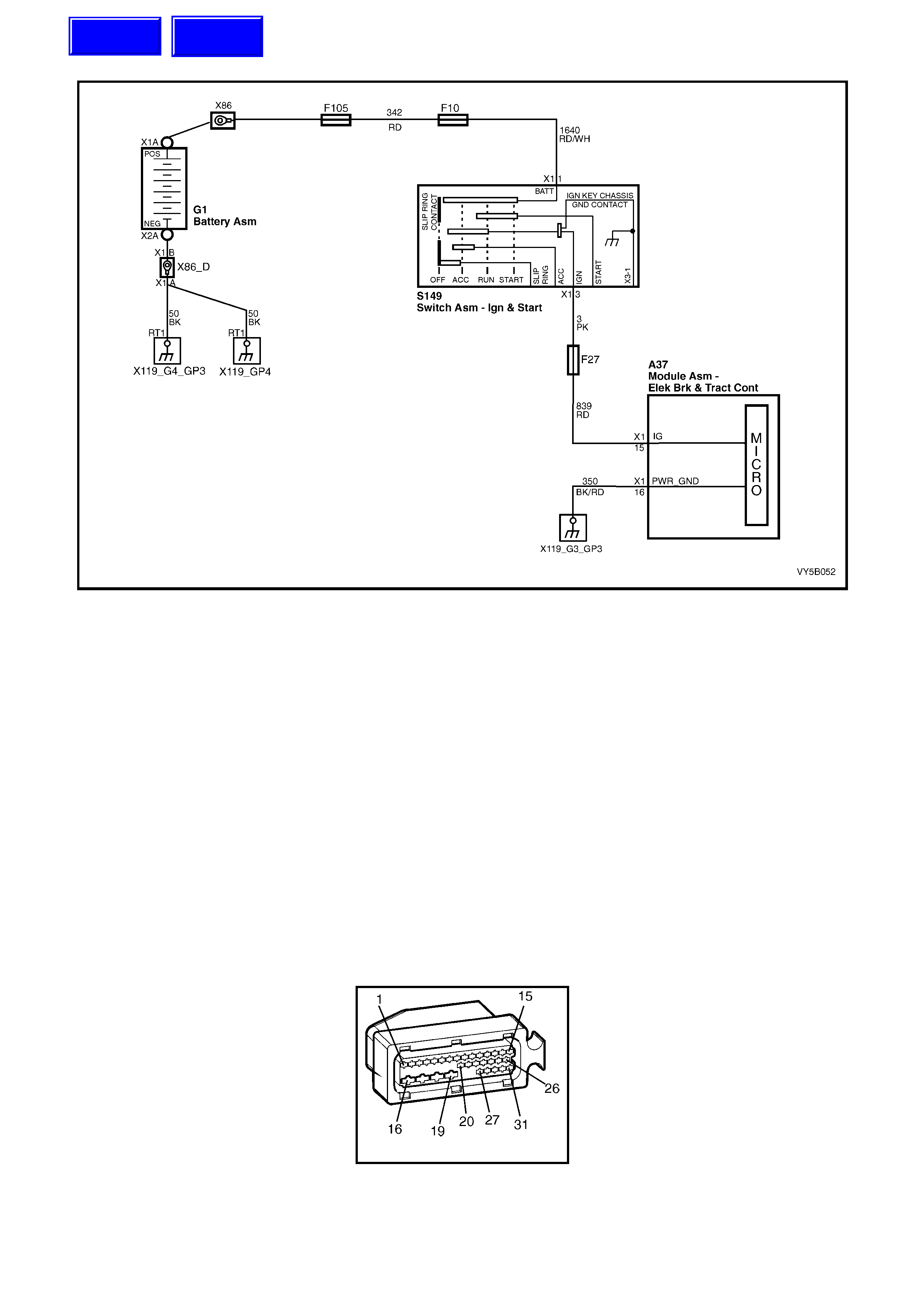
DTC 71 – CONTROL MODULE INTERNAL FAULT
Figure 5B-149
CIRCUIT DESCRIPTION:
The ABS or ABS/T CS c ontr ol m odule perf orms variou s diagnos tic c heck s on itse lf. If the control m odule detec ts an
internal fault, DT C 71 will be set.
If a failure is detected which causes DTC 71 to set, the ABS or ABS/TCS is disabled and the control module
activates the ABS or ABS and TRAC OFF warning lamps for the remainder of the ignition cycle. If the failure is
intermittent, the control module will enable the system at the next ignition cycle and a history DTC 71 will be set.
TEST DESCRIPTION:
The numbers below refer to Step numbers in the diagnostic chart for DTC 71.
1. This test checks for any additional system faults that may be causing DTC 71 to set.
2. Determines whether the DTC is set by an internal fault with the control module or by a faulty wiring connection.
3. This test checks the minimum supply voltage and integrity of the control module ground circuit.
4. This test checks for intermittent connections of the ABS control module connector and terminals to the module.
NOTES ON DIAGNOSTIC CHART:
1. Refer to 4.7 TECH 2 DIAGNOSTICS in this Section for connecting and using Tech 2.
DIAGNOSTIC AIDS:
If circuit 839 (Red wire) or circuit 150 (Black wire) are open circuited, Tech 2 screen will display "NO DATA
RECEIVED FROM ABS".
A37
Figure 5B-150
Techline
Techline

DTC 71 - CONTROL MODULE INTERNAL FAULT
STEP ACTION VALUE YES NO
1. Was the ABS or ABS/TCS Functional Check Carried
out? Go to Step 2 Go to 4.4 ABS or
ABS/TCS
Functional Check
2. 1. Install Tech 2 to DLC.
2. Select Diagnostics / Chassis / Diagnostic Trouble
Codes / Read DTCs (refer NOTE 1 above).
Are any other DTCs set?
Repair problems
ca usi ng other
DTCs to set. Go
to Step 2.
Go to Step 3
3. 1. With Tech 2 connected and Diagnostic Trouble
Codes selected, select Clear DTCs (refer to NOTE 1
above)
2. Road test vehicle.
Does DTC 71 set again ?
Go to Step 4 Fault not present.
Check all system
wiring harness
connect ors and
terminals, in
particular the
modulator and
ABS or ABS/TCS
control modu le
connector
terminals.
4. 1. Disconnect contr ol mod ule co nnec tor A37.
2. Switch ignition ON and measure voltage between
connector A37, terminals X1-15 circuit 839 (Red
wire) and X1-19, circuit 150 (Black wire).
Is voltage as specified ?
At least 10
Volts Go to Step 5 Check voltage
supply and
ground
connections to
ABS or ABS/TCS
control modu le.
Refer Chart B –
POWER
SUPPLY TO
CONTROL
MODULE in this
Section, recheck
circuit to verify
repair.
5. 1. Check ABS control module connector A37 carefully
to ensure good electrical connection will all
terminals and that the connector is properly retained
when connected.
Is all OK?
Go to Step 6 Repair connector
and/or connector
retention,
recheck circuit to
verify repair.
6. 1. No fault found, Install Tech 2 to DLC and select
Diagnostics / Chassis / ABS/TCS / Diagnostic
Trouble Codes / Clear DTCs and clear all DTCs
(refer NOTE 1 above).
2. Road test vehicle.
Does DTC 71 set again ?
Replace ABS or
ABS/TCS control
module, refer to
3.6 CONTROL
MODULE in this
Section, recheck
and verify repair.
System OK.
WHEN ALL DIAGNOSIS AND REPAIRS ARE COMPLETED, CLEAR ALL DTCs AND VERIFY CORRECT OPERATION
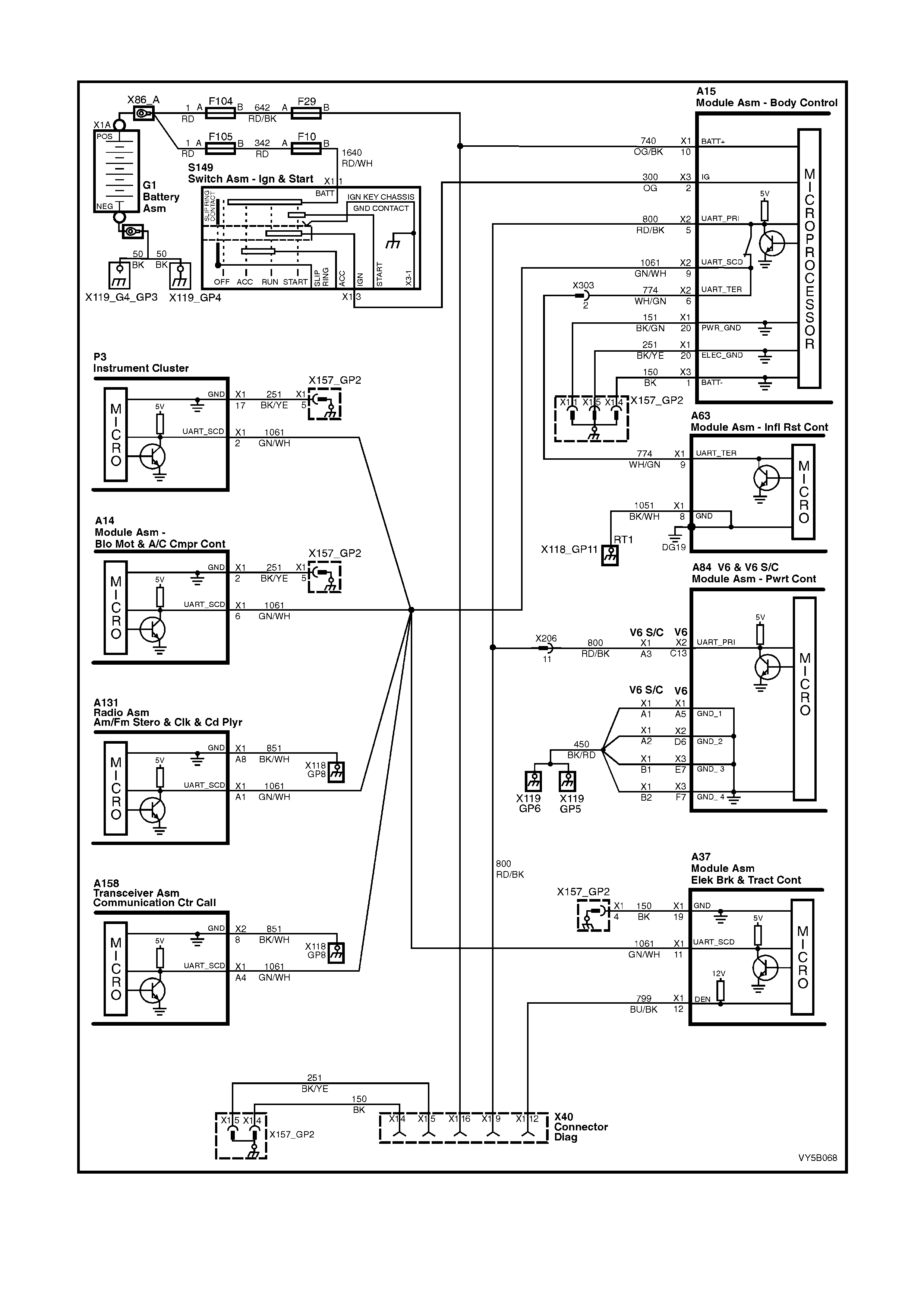
DTC 72 - SERIAL DATA FAULT
Figure 5B-151
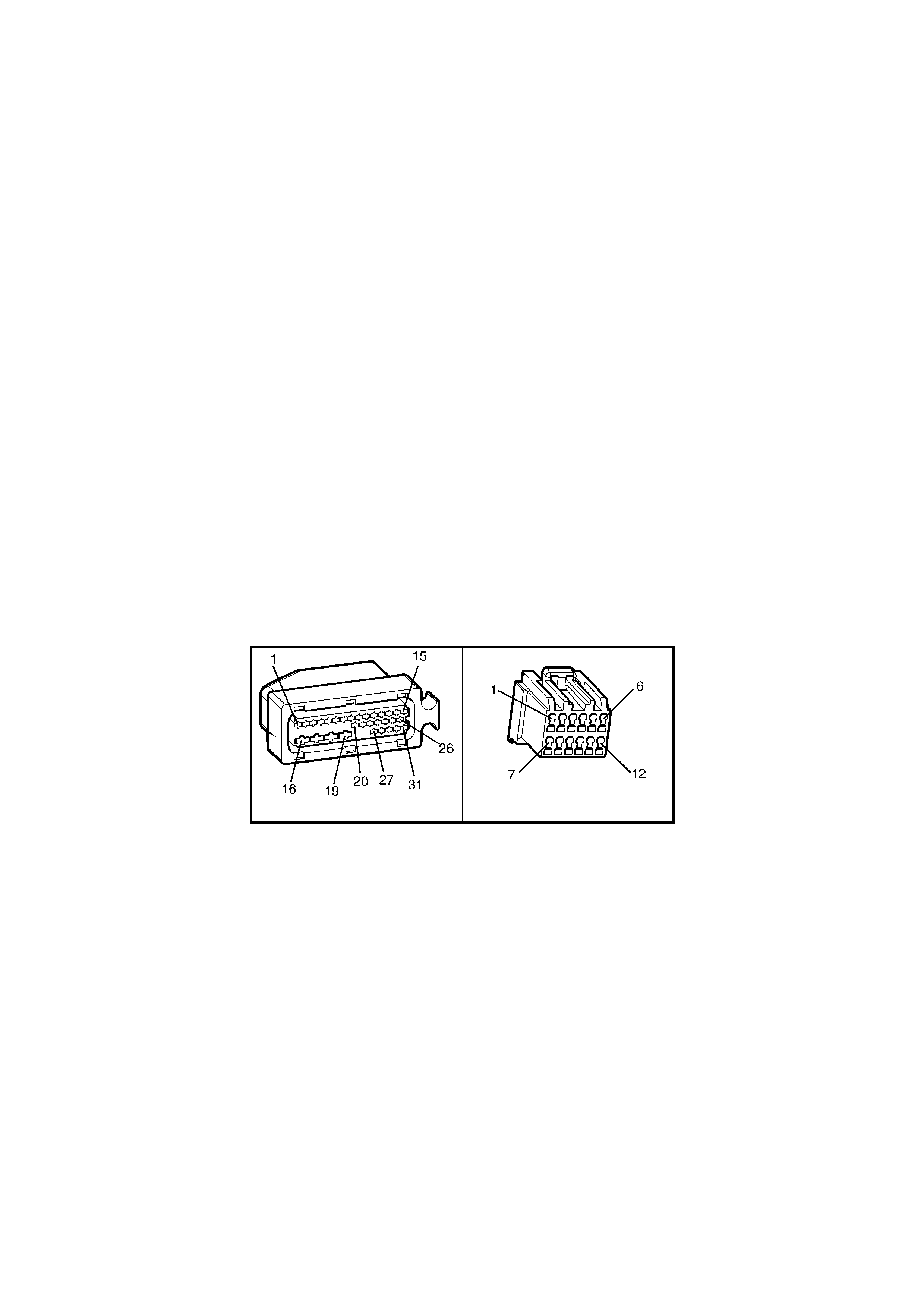
CIRCUIT DESCRIPTION:
W ith the ignitio n ON, the A BS or ABS/T CS control m odule will be able to com municate wit h other contr ol modules
via the s erial d ata line , circuit 1061 (G reen/W hite wire ). If com municatio n bet ween the m odules is disr upted due to
a short or open circuit, DTC 72 will be set.
If the ABS/T CS control m odule senses this f ault, only the TC S system will be disabled (ABS op eration will o perate
normally), the TRAC OFF warning display will be activated and the relevant DTC will be set. The TRAC OFF
warning disp lay will remain activated for the remainder of the ignition cycle. If the failure is intermittent, the control
module will enable the system at the next ignition cycle and the relevant history DTC will be set.
There ar e severa l other control modules that are connec ted to the serial data circ uit (PCM , BCM, ABS/TC S, OCC,
SRS, and Instrument). Any of these control modules could cause a fault in the serial data line. This fault could
result in Tech 2 not being able to display serial data.
TEST DESCRIPTION:
The numbers below refer to Step numbers in the diagnostic chart for DTC 72.
1. This test determines if fault is current or not.
2. This test checks for connector or wiring problems which may cause an intermittent fault.
3. Determines if fault is in wiring or ABS/TCS control module.
4. Determines if fault is with BCM serial data communication (bus master).
5. Checks if fault is caused by other control modules that are communicating on the serial data line.
6. Checks circuit 1061 and determines if fault is in wiring or control module.
7. Checks for continuity in circuit 1061.
NOTES ON DIAGNOSTIC CHART:
1. Refer to 4.7 TECH 2 DIAGNOSTICS in this Section for connecting and using Tech 2.
2. For all wiring checking procedures, refer to Section 12P WIRING DIAGRAMS in the MY 2003 VY and V2
Series Service Information.
DIAGNOSTIC AIDS:
A fault with the ser ial d ata cir cuit coul d be ca used b y one or m ore of the sever al control lers connec ted to this serial
data circuit. Isolate the fault by disconnecting each controller one at a time until serial data communication is
restored.
A37 A15 X2
Figure 5B-152

DTC 72 - SERIAL DATA FAULT
STEP ACTION VALUE YES NO
1. Was the ABS or ABS/TCS Functional Check Carried
out? Go to Step 2 Go to 4.4 ABS or
ABS/TCS
Functional Check
2. 1. Install Tech 2 to DLC.
2. Select Diagnostics / Chassis / ABS/TCS / Diagnostic
Trouble Codes / Clear DTCs and clear all DTCs
(refer to NOTE 2 above).
3. Road test vehicle.
Does DTC 72 set again ?
NOTE: Go to Step 4 if Tech 2 will not communicate with
the ABS/TCS control module.
Go to Step 4 Go to Step 3
3. 1. Inspect all system wiring and connections that could
cause intermittent faults. Check all wiring is in good
condition, terminals are clean and tight and making
good contact (refer NOTE 2 above).
Is wiring OK ?
NOTE: Other control modules (SRS, Instruments, OCC,
BCM, PCM) that are connected to the serial data circuit
could cause DTC 72 to set, therefore, check wiring and
connect ors that cou ld cau se in termit tent faults at these
control modu le s also.
Fault not present.
Check all system
wiring harness
connect ors and
terminals, in
particular the
modulator and
ABS/TCS control
module
connector
terminals.
Make repairs as
necessary,
recheck and
verify repair.
4.
In step 1, was Tech 2 able to communicate with the
ABS/TCS control module (refer NOTE 1 above)?
Go to Step 5 Replace
ABS/TCS control
module, refer to
3.6 CONTROL
MODULE in this
Section, recheck
circuit to verify
repair.
5. 1. With Tech 2 connected, select Diagnostics / Body /
Body Control Module and turn ignition on as
requested (refer NOTE 1 above).
Does Tech 2 display BCM system identification
information?
Go to Step 6 Refer to BCM
Serial Data
Communication
diagnostics in
Section 12J
BODY
CONTROL
MODULE.
6. 1. Using Tech 2, check for similar DTCs (Serial Data
faults) that have been set by other control modules;
instruments, SRS, and OCC if applicable to model
variant (refer NOTE 1 above).
Have similar DTCs been set by other control modules ?
Go to Step 7 Go to Step 8
7. 1. Check circuit 1061 for open, short to ground or short
to voltage between BCM and individual control
modules (refer NOTE 2 above).
Is circuit 1061 OK?
NOTE: Disconnect each controller in circuit 1061 one at
a time to isolate the fault in the circuit or to identify
control modu le cau sin g fault.
Replace faulty
module, refer to
relevant Section
in the MY 2003
VY and V2
Series Service
Information.
Recheck and
verify repair.
Make repairs as
necessary,
recheck and
verify repair.
8. 1. Disconnect BCM connector A15 BCM and ABS/TCS
control modu le con nect or A37.
2. Check for continuity between BCM connector A15
terminal X2-9 and ABS/TCS control module
connector A37, terminal X1-11, circuit 1061
(Green/White wire) (refer to NOTE 2 above).
Does continuity exist ?
Replace
ABS/TCS control
module, refer to
3.6 CONTROL
MODULE in this
Section, recheck
circuit to verify
repair.
Check and repair
open in circuit
1220 between
BCM and
ABS/TCS control
module, recheck
and verify repair.
WHEN ALL DIAGNOSIS AND REPAIRS ARE COMPLETED, CLEAR ALL DTCs AND VERIFY CORRECT OPERATION
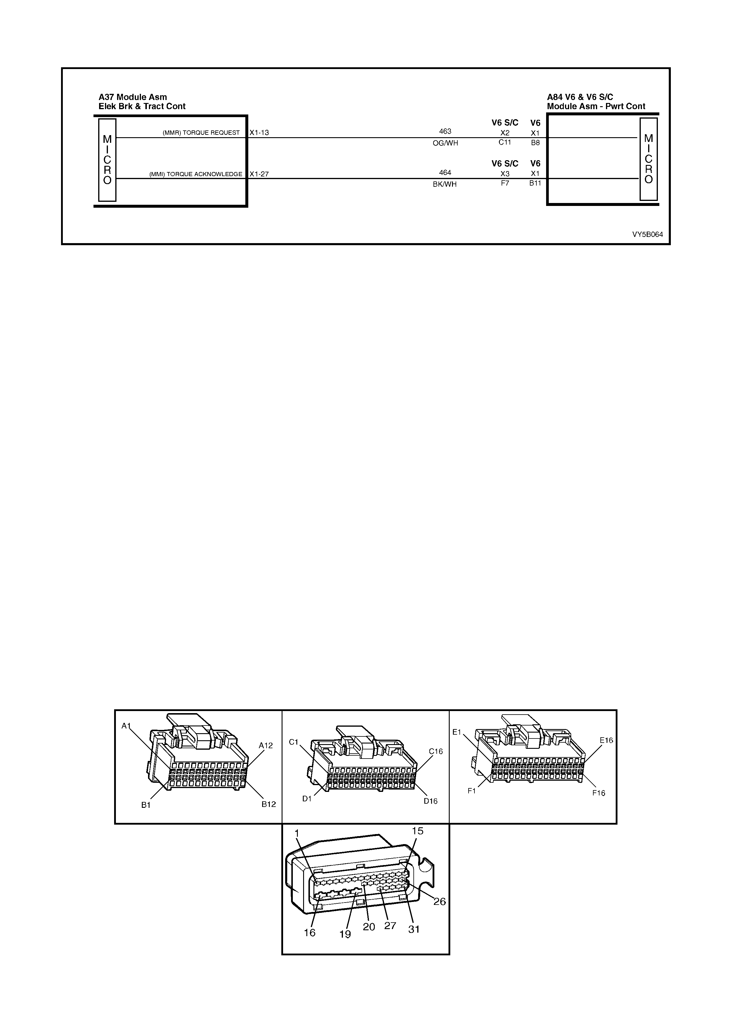
DTC 73 – REQUESTED TORQUE CIRCUIT FAULT
Figure 5B-153
CIRCUIT DESCRIPTION:
W ith the ignition o n, the ABS/T CS c ontrol m odule c ons tantl y sends a Puls e W idth Modulat ed ( PW M) signal at 93%
with a f requenc y of 100 H z to the PCM via ter m inal X1 -13, on circ uit 4 63 (Orang e/White wire). This is to indic ate to
the PCM th at the trac tion control system ( TCS) is in a state of readiness. If the ABS/T CS contro l module re quests
traction control, engine intervention, it signals the PCM to reduce engine torque by varying the duty cycle of this
P WM signal.
DTC 73 will set if this frequency output signal deviates outside a frequency specification (95 – 105 Hz) or if the
signal stops for more than 50 milliseconds.
If the ABS/TCS control module senses this fault, the TCS system will be disabled (ABS operation will operate
norm ally), the T RAC OFF war ning lam p will b e acti vated and DT C 73 will be s et. T he TRAC O FF warning la m p will
remain activated for the rem ainder of the ignition cycle. If the failure is intermittent, the control m odule will enable
the system at the next ignition cycle and the logged DTC will become history.
TEST DESCRIPTION:
The numbers below refer to Step numbers in the diagnostic chart for DTC 73.
1. Checks if ABS/TCS control module is sending signal to PCM.
2. Checks circuit 463.
3. Checks if PCM is returning message to ABS/TCS control module.
4. Checks circuit 464.
5. Determines if fault is within ABS/TCS control module or whether fault is intermittent.
NOTES ON DIAGNOSTIC CHART:
1. Refer to 4.7, TECH 2 DIAGNOSTICS in this Section for connecting and using Tech 2.
2. For all wiring checking procedures, refer to Section 12P, WIRING DIAGRAMS in the MY 2003 VY and V2
Series Service Information.
DIAGNOSTIC AIDS:
If DTC 74 [PCM / TCS INT ERFACE FA ULT ( MMI - T ORQ UE AC KNOWLEDGMENT )] is logge d as wel l as DT C 73,
always perform diagnostics for DTC 73 first.
When DTCs 73 and 74 are logged by the ABS/TCS control module, the PCM will also log it’s own DTC, P1571 (V6)
or 95 (V6 S/C).
A84-X1 V6 & V6 S/C A84-X2 V6 & V6 S/C A84-X3 V6 & V6 S/C
A37
Figure 5B-154

DTC 73 - REQUESTED TORQUE CIRCUIT FAULT
STEP ACTION VALUE YES NO
1. Was the ABS or ABS/TCS Functional Check Carried
out? Go to Step 2 Go to 4.4 ABS or
ABS/TCS
Functional Check
2. 1. Turn ignition ON.
2. Back probe ABS/TCS control module connector
A37, terminal X1 -13, circuit 463 (Orange/White wire)
with a digital multimeter to ground (refer NOTE 2
above).
Is value as specified ?
95 – 105 Hz &
4.2 – 4.8
Volts
Go to Step 3 Replace
ABS/TCS control
module, refer to
3.6 CONTROL
MODULE in this
Section, recheck
circuit to verify
repair.
3. 1. Turn ignition ON.
2. Back probe PCM connector A84, terminal X1-B8
(V6) or X2-C11 (V6 S/C), circuit 463 (Orange/White
wire) with a digital multimeter to ground (refer to
NOTE 2 above).
Is value as specified?
95 – 105 Hz &
4.2 – 4.8
Volts
Go to Step 4 Check and repair
open or short in
circuit 463,
recheck and
verify repair.
4. 1. Turn ignition ON.
2. Back probe PCM connector A84, terminal X1-B11
(V6) or X3-F7 (V6 S/C), circuit 464 (Black/White
wire) with a digital multimeter to ground (refer NOTE
2 above).
Is value as specified?
95 – 105 Hz &
0.1 – 1.0
Volts
Go to Step 5 Replace PCM,
refer to
6C1-3 (V6)
POWERTRAIN
MANAGEMENT
or
6C2-3 (V6 S/C)
POWERTRAIN
MANAGEMENT
5. 1. Turn ignition ON.
2. Back probe ABS/TCS control module connector A37
terminal X1-27, circuit 464 (Black/W hite wire) with a
digital multimeter to ground (refer to NOTE 2
above).
Is value as specified ?
95 – 105 Hz &
0.1 – 1.0
Volts
Go to Step 6 Check and repair
open or short in
circuit 464,
recheck and
verify repair.
6. 1. Install Tech 2 to DLC.
2. Select Diagnostics / Chassis / ABS/TCS / Diagnostic
Trouble Codes/ Clear DTCs and clear all DTCs
(refer NOTE 1 above).
3. Road test vehicle.
Does DTC 73 set again ?
Replace
ABS/TCS control
module, refer to
3.6 CONTROL
MODULE in this
Section, recheck
circuit to verify
repair.
Fault not present.
Check all system
wiring harness
connect ors and
terminals, in
particular the
modulator and
ABS/TCS control
module
connector
terminals.
WHEN ALL DIAGNOSIS AND REPAIRS ARE COMPLETED, CLEAR ALL DTCs AND VERIFY CORRECT OPERATION
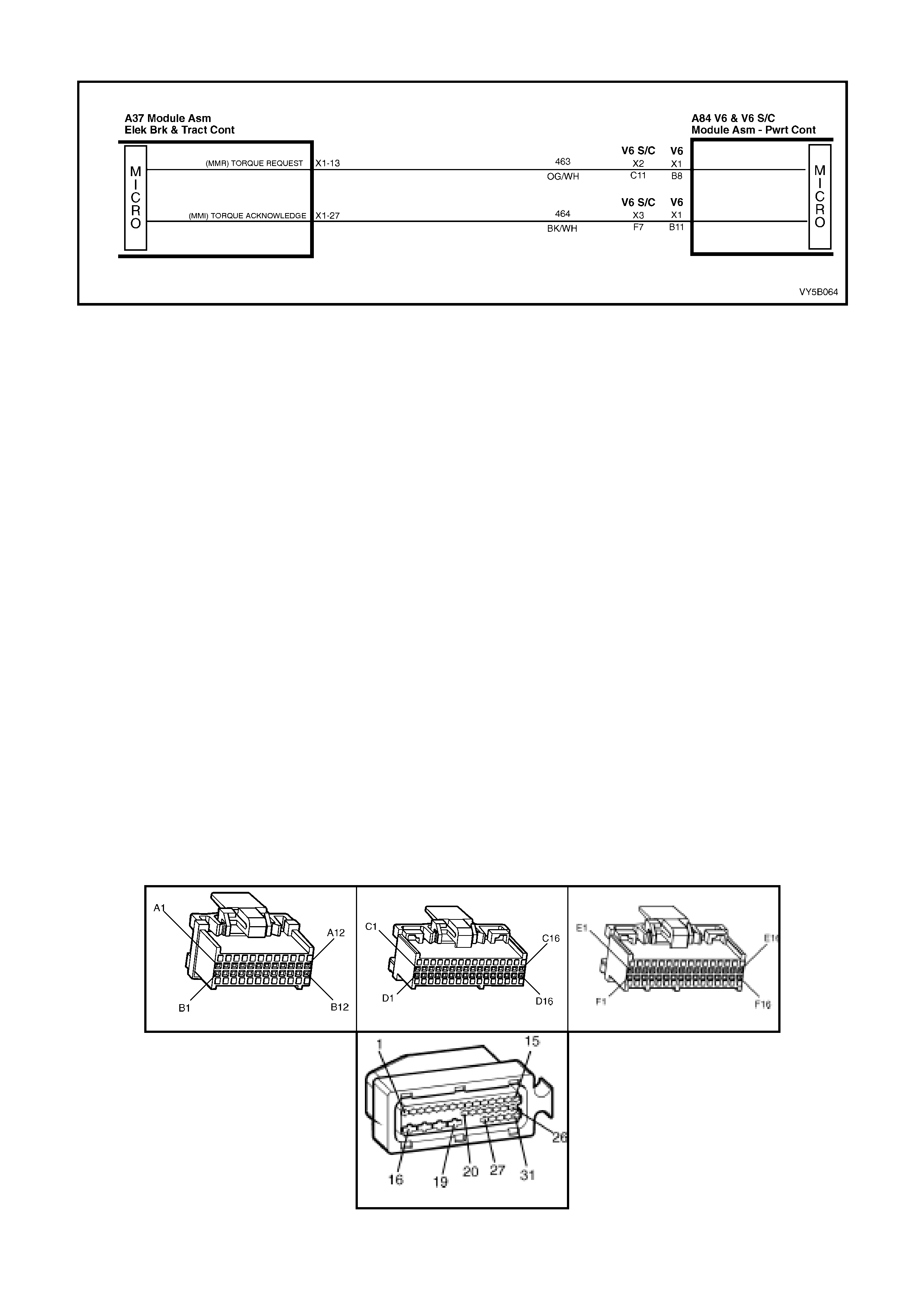
DTC 74 - ACTUAL TORQUE CIRCUIT FAULT
Figure 5B-155
CIRCUIT DESCRIPTION:
On receiving the request torque signal, the PCM will modify the output of the engine and then send an actual
torque s ignal to th e ABS/TCS c ontrol m odule, v ia circuit 4 64, which is a Pu lse Width Mo dulated ( PWM) signal with
a frequency of 100 Hz. The duty cycle of the torque acknowledgment signal will vary depending on the torque
reduction achieved, ie. The actual torque of the engine.
Provided the engine speed is above 480 RPM, DTC 74 will set if this frequency deviates outside the frequency
specification (95 – 105 Hz) or if the signal stops for more than 100 milliseconds.
If the ABS/TCS control module senses this fault, the TCS system will be disabled (ABS operation will operate
norm ally), the T RAC OFF war ning lam p will b e acti vated and DT C 74 will be s et. T he TRAC O FF warning la m p will
remain activated for the rem ainder of the ignition cycle. If the failure is intermittent, the control m odule will enable
the system at the next ignition cycle and the relevant history DTC will be set.
TEST DESCRIPTION:
The numbers below refer to Step numbers in the diagnostic chart for DTC 74.
1. Checks if ABS/TCS control module is receiving a signal from the PCM.
2. Checks circuit 464.
3. Checks if PCM is at fault and not sending message to ABS/TCS control module.
4. Checks circuit 463.
5. Determines if fault is within ABS/TCS control module or whether fault is intermittent.
NOTES ON DIAGNOSTIC CHART:
1. Refer to 4.7 TECH 2 DIAGNOSTICS in this Section for connecting and using Tech 2.
2. For all wiring checking procedures, refer to Section 12P WIRING DIAGRAMS in the MY 2003 VY and V2
Series Service Information.
DIAGNOSTIC AIDS:
If DTC 74 [PCM / TCS INT ERFACE FA ULT ( MMI - T ORQ UE AC KNOWLEDGMENT )] is logge d as wel l as DT C 73,
always perform diagnostics for DTC 73 first.
When DTCs 73 and 74 are logged by the ABS/TCS control module, the PCM will also log it’s own DTC of P1571
(V6) or 95 (V6 S/C).
A84-X1 V6 & V6 S/C A84-X2 V6 & V6 S/C A84-X3 V6 & V6 S/C
A37
Figure 5B-156

DTC 74 - ACTUAL TORQUE CIRCUIT FAULT
STEP ACTION VALUE YES NO
1. Was the ABS or ABS/TCS Functional Check Carried
out? Go to Step 2 Go to 4.4 ABS or
ABS/TCS
Functional Check
2. 1. Turn ignition ON.
2. Back probe ABS/TCS control module connector
A37, terminal X1-27, circuit 464 (Black/White wire)
with a digital multimeter to ground (refer to NOTE 2
above).
Is value as specified ?
95 – 105 Hz &
0.1 – 1.0
Volts
Go to Step 6 Go to Step 3
3. 1. Turn ignition ON.
2. Back probe PCM connector A84, terminal X1-B11
(V6) or X3-F7 (V6 S/C), circuit 464 (Black/White
wire) with a digital multimeter to ground (refer NOTE
2 above).
Is value as specified?
95 – 105 Hz &
0.1 – 1.0
Volts
–
Check and repair
open or short in
circuit 464,
recheck and
verify repair.
Go to Step 4
4. 1. Turn ignition ON.
2. Back probe PCM connector A84, terminal X1-B11
(V6) or X3-F7 (V6 S/C), circuit 464 (Black/White
wire) with a digital multimeter to ground (refer NOTE
2 above).
Is value as specified?
95 – 105 Hz &
4.2 – 4.8
Volts
Go to Step 5 Replace PCM,
refer to
6C1-3 (V6), or
6C2-3 (V6 S/C)
POWERTRAIN
MANAGEMENT.
5. 1. Turn ignition ON.
2. Back probe ABS/TCS control module connector A37
terminal X1-27, circuit 464 (Black/White wire) with a
digital multimeter to ground (refer to NOTE 2
above).
Is value as specified?
95 – 105 Hz &
4.2 – 4.8
Volts
Check and repair
open or short in
circuit 464,
recheck and
verify repair.
Replace
ABS/TCS control
module, refer to
3.6 CONTROL
MODULE in this
Section, recheck
circuit to verify
repair.
6. 1. Install Tech 2 to DLC.
2. Select Diagnostics / Chassis / ABS/TCS / Diagnostic
Trouble Code s/ Clear DTCs and clear all DTCs
(refer NOTE 1 above).
3. Road test vehicle.
Does DTC 74 set again ?
Replace
ABS/TCS control
module, refer 3.6
CONTROL
MODULE in this
Section, recheck
circuit to verify
repair.
Fault not present.
Check all system
wiring harness
connect ors and
terminals, in
particular the
modulator and
ABS/TCS control
module
connector
terminals.
WHEN ALL DIAGNOSIS AND REPAIRS ARE COMPLETED, CLEAR ALL DTCs AND VERIFY CORRECT OPERATION

DTC 78 – INCORRECT OPTION CODING
CIRCUIT DESCRIPTION:
This DTC relates to a difference in the interfacing of the ABS/TCS control module and other control modules and is
only applicable to the ABS/TCS system, not the ABS only system.
Control modules are specifically designed for a particular vehicle option; i.e. V6 or V6 Supercharged. If any module
that communicates with the ABS/TCS control module is for an incorrect application, including the ABS/TCS control
module, DTC 78 will be set.
If the ABS/TCS control module senses this fault, only the TCS system will be disabled (ABS operation will operate
normally), the TRAC OFF warning display will be activated and the relevant DTC will be set. The TRAC OFF
warning display will remain activated for the remainder of the ignition cycle. If the failure is intermittent, the control
module will enable the system at the next ignition cycle and the relevant history DTC will be set.
TEST DESCRIPTION:
The numbers below refer to Step numbers in the diagnostic chart for DTC 78.
1. Physical check to determine if correct control modules are fitted to the vehicle.
2. Checks for other DTCs logged that may cause DTC 78 to log.
3. Checks if fault is intermittent or in ABS/TCS control module.
NOTES ON DIAGNOSTIC CHART:
1. Refer to 4.7, TECH 2 DIAGNOSTICS in this Section for connecting and using Tech 2.
2. There are different control modules used in the MY 2003 VY and V2 Series vehicles for ABS and ABS/TCS
systems. It is physically impossible to fit an ABS control module to an ABS/TCS hydraulic modulator or an
ABS/TCS control module to a ABS hydraulic modulator. However, if replacing either an ABS or ABS/TCS
control module, always refer to the latest PartFinder® Parts Information for the correct ABS control module part
numbers.
DTC 78 - INCORRECT OPTION CODING
STEP ACTION VALUE YES NO
1. Was the ABS or ABS/TCS Functional Check Carried
out? Go to Step 2 Go to 4.4 ABS or
ABS/TCS
Functional Check
2.
Are the correct control modules that communicate with
the ABS/TCS control module, including the ABS/TCS
control module, installed in the vehicle (ABS/TCS and
PCM) (refer to NOTE 2 above)?
Go to Step 3 Replace control
module with
control modu le
that matches
vehicle
specifications,
recheck and
verify repair.
3. 1. Install Tech 2 to DLC and check if other system
DTCs are set (refer to NOTE 1 above).
Are other codes present ?
Repair problems
ca usi ng DTC to
set.
Go to Step 4
4. 1. With Tech 2 connected, Select Diagnostics /
Chassis / ABS/TCS / Diagnostic Trouble Codes/
Clear DTCs and clear all DTCs (refer NOTE 1
above).
2. Road test vehicle.
Does DTC 78 set again?
If correct control
modules are
installed in the
vehicle, repl ace
ABS/TCS control
module, refer to
3.6 CONTROL
MODULE in this
Section, recheck
circuit to verify
repair.
Fault not present.
Check all system
wiring harness
connect ors and
terminals, in
particular the
modulator and
ABS/TCS control
module
connector
terminals.
WHEN ALL DIAGNOSIS AND REPAIRS ARE COMPLETED, CLEAR ALL DTCs AND VERIFY CORRECT OPERATION
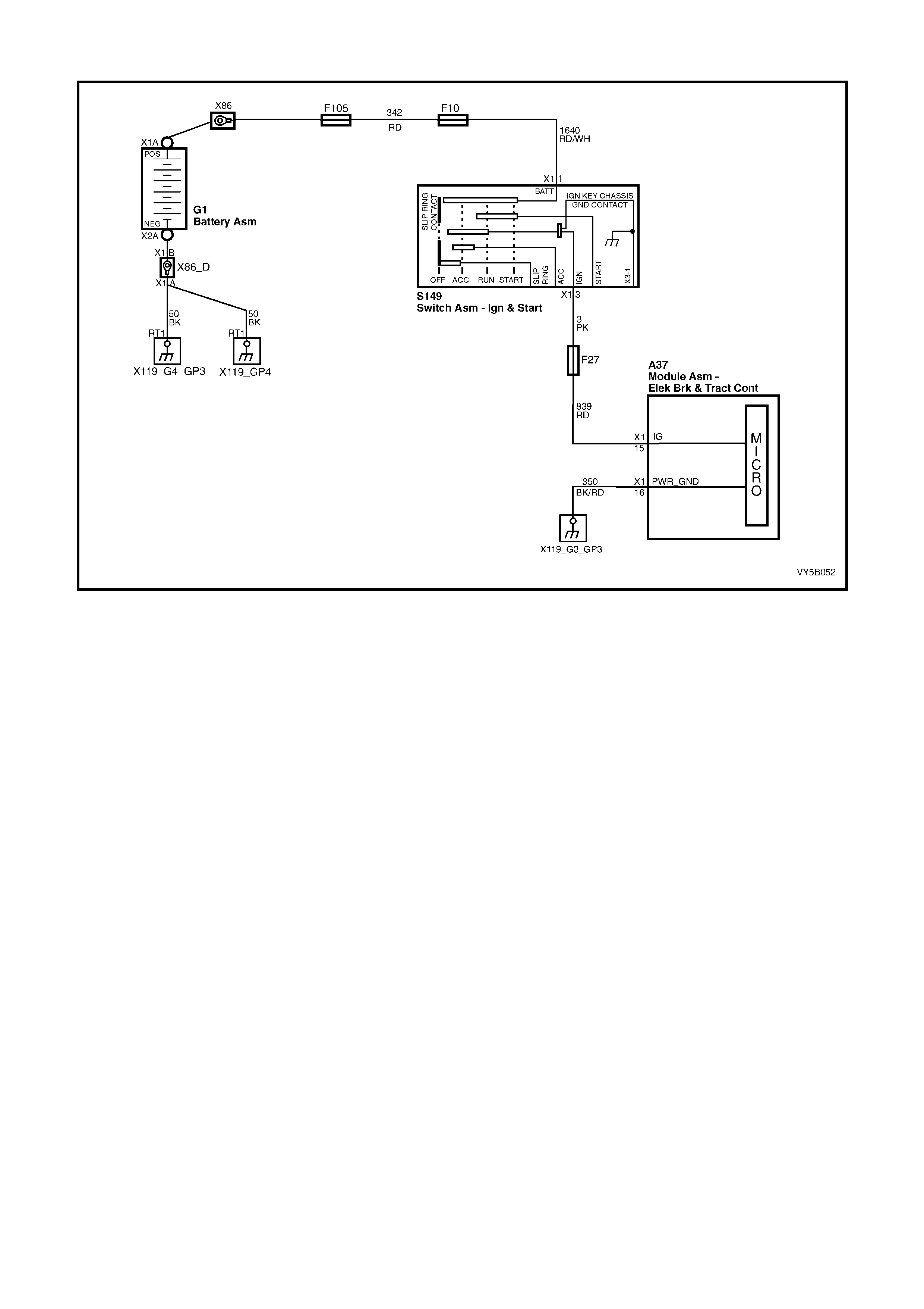
DTC 85 – SYSTEM VOLTAGE TOO LOW
Figure 5B-157
CIRCUIT DESCRIPTION:
The ABS or ABS/TCS control module (A37) is supplied with power to terminal X1-15, circuit 839 (Red wire) from
the battery via fuse F27 when the ignition is in the IGN or START positions.
DTC 85 will s e t if th e AB S or A BS/T C S co ntr ol modul e det ec ts a vo ltage of 1 0 vo lts or les s on terminal X 1- 15 wh en
the ignition is in the IGN or START positions.
If a failure is detected which causes DTC 85 to set, the ABS or ABS/TCS system is disabled and the control
module activates the ABS or ABS and TRAC OFF warning displays for the remainder of the ignition cycle. If the
failure is intermittent, t he control m odule will enable the s ystem at the next igniti on cycle and a hist ory DTC 85 will
be set.
TEST DESCRIPTION:
The numbers below refer to Step numbers in the diagnostic chart for DTC 85.
11. Uses T ech 2 to deter m ine if the AB S or A BS/TC S cont rol m odule is recei ving nor m al battery vol tage, ab ove 10
volts.
12. Checks to see if the low voltage reading is due to the generator. If the voltage is below 10 volts, the ABS or
ABS/TCS control module is OK.
13. Checks for open in circuit 839.
14. Checks if low reading is due to faulty connection in circuit 839 or faulty ABS or ABS/TCS control module.
NOTES ON DIAGNOSTIC CHART:
15. Refer to 4.7 TECH 2 DIAGNOSTICS in this Section for connecting and using Tech 2.
16. For all wiring checking procedures, refer to Section 12P WIRING DIAGRAMS in the MY 2003 VY and V2
Series Service Information.
DIAGNOSTIC AIDS:
If DTC 85 sets when an accessory is operated, check for poor connections or excessive current draw.

A37
Figure 5B-158
DTC 85 – SYSTEM VOLTAGE TOO LOW
STEP ACTION VALUE YES NO
1. Was the ABS or ABS/TCS Functional Check Carried
out? Go to Step 2 Go to 4.4 ABS or
ABS/TCS
Functional Check
2. 1. Install Tech 2 to DLC
2. Select Diagnostics / Body / Body Control Module /
Data List and scroll to BATTERY VOLTAGE (refer to
NOTE 1 above).
3. Engine running (idle).
Is battery voltage shown on Tech 2 above specified
value?
10 Volts Fault not present.
If no additional
DTCs were
stored, refer to
Diagnostic Aids
above.
Go to Step 3
3. 1. Measure voltage across battery terminals.
Is voltage equal to or above specified value ? 10 Volts Go to Step 4 Check generator
operation, refer
to 6D1-1 (V6) or
6D2-1 (V6 S/C)
CHARGING
SYSTEM.
4. 1. Ignition OFF.
2. Disconnect contr ol mod ule connector A37.
3. Switch ignition ON and measure voltage between
connector A37, terminals X1-15 and ground (refer to
NOTE 2 above).
Is voltage equal to or above specified value ?
10 Volts Go to Step 5 Check and repair
open in circuit
839 (Red wire)
(including fuse
F27), recheck
and verify repair.
5. 1. Check for faulty ABS or ABS/TCS control module
connection for circ uit 839.
Was a fault found ?
Repair fault as
necessary,
recheck and
verify repair.
Replace ABS or
ABS/TCS control
module, refer to
3.6 CONTROL
MODULE in this
Section, recheck
and verify repair.
WHEN ALL DIAGNOSIS AND REPAIRS ARE COMPLETED, CLEAR ALL DTCs AND VERIFY CORRECT OPERATION

5. ABS/TCS DIAGNOSIS – GEN III V8 ENGINE ONLY
CAUTION: Certain components in the Anti-lock Brake System and Electronic Traction Control system are
not intended to be serviced individually. Attempting to remove or disconnect certain system components,
such as the solenoid valves or pump motor from the hydraulic modulator, may result in personal injury
and/or improper system operation. Only those components with approved removal and reinstallation
procedures described in 3. SERVICE OPERATIONS in this Section, should be serviced.
Before attempting any diagnostic work on the ABS, refer to and read the 'SAFETY AND PRECAUTIONARY
MEASURES' as described in 3. SERVIC E OPERATIO NS, in this Section.
5.1 GENERAL DESCRIPTION
Diagnostic information in this Section relates only to ABS/TCS systems on vehicles with GEN III V8 engines.
Addition all y, only diag nosti c inf orm ation that dif fer s from the AB S/T CS s ystem used on M Y 2003 VY and V2 Ser ies
models with V6 engines is detailed. For diagnostic information that is not detailed in this Section, refer to
4. ABS, ABS/T CS DIAGNOSIS in this Sec ti on.
The following information is necessary when diagnosing any Anti-lock Braking System problem or failure,
specifically it should be used to diagnose conditions that may cause the illumination of the ABS or TRAC OFF
warning displays in the Instrument.
Should conditions exist with the conventional (non ABS) portion of the braking system which cause the BRAKE
FAILURE warning lamp to illuminate (also in the Instrument), or there is some other obvious brake mechanical
problem, such as brake noise, brake pulsation (pedal or vehicle vibration during normal brake application), brake
pull or a park ing brak e problem , then these problem s m ust be corrected bef ore attem pting to rectif y any suspected
ABS/TCS problem. Refer to Section 5A SERVICE AND PARK BRAKING SYSTEMS for diagnosis and repair of
the conventional braking system.

5.3 VISUAL INSPECTION
W hen inves tig ati ng any complaint of an ABS/TCS system pr oblem or m a lf unction, star t di agn os is with an ABS/TCS
visual ins pec t ion .
The ABS/T CS visua l inspe ction is an exam ination of easil y acc essible c omponent s that could caus e problem s with
the system. The visual inspection procedure may quickly identify the cause and eliminate the need for additional
diagnosis.
If the complaint condition cannot be resolved by a visual check of the system components, then proceed to the
ABS/TCS Functional Check, detailed after the Visual Inspection Chart.
ABS/TCS VISUAL INSPECTION CHART
ITEM INSPECT FOR CORRECTIVE ACTION
GENERAL
Wheel and Tyres Recommended tyre and
wheel size fitted to vehicle Fit recomm ended size t yres
and wheels
BR AKE SYST EM COM PONENTS
Master Cylinder Fluid
Reservoir Low fluid level Add fluid as required.
Determine cause of fluid
loss and repair
Hydraulic Modulator External leaks If leakage is excessive,
replace modulator
Brake Booster And Master
Cylinder Correct installation and
assembly Reinstall or reposition
components correctly
Park Brake Mechanism Mechanism fully releasing Operate lever to verify
release. Adjust cable or
repair release mechanism
as required
FUSES
ENGINE COMPARTMENT
ABS Fusible Link F103 Blown fusible link Replace fusible link. Inspect
for cause of failure
PASSENGER
COMPARTMENT
Throttle Relaxer Fuse F36 Blown fuse Replace fuse. Inspect for
ABS Fuse F27 cause of fuse failure
Warning Lamp Fuse F13
(Ignition Circuit)
Stop Lamp Fuse F5
WIRING CONNECTIONS
ENGINE COMPARTMENT
ABS/TCS Control Module
Wiring Harness Connector.
In all cases, inspect for:
Main Wiring Harness to Front
Wheel Speed Sensor
Connections.
Proper engagement.
Loose wires or terminals.
Ensure proper engagement
Repair as required
Hydraulic modulator pump
motor wiring harness
connector
Corroded or broken
connections
PASSENGER
COMPARTMENT
Main Wiring Harness to Body
Harness Connectors
UNDER VEHICLE
Front Wheel Speed Sensor
Lead to Front Wheel Hub
Connections
Body Harness to Rear Wheel
Speed Sensor Con necti ons

5.4 ABS/TCS FUNCTIONAL CHECK
If the source of the system problem or malfunction was not isolated during the ABS, ABS/TCS visual inspection,
carry out the following ABS, ABS/TCS functional check. Also, use the check to verify normal ABS/TCS operation
during diagnosis or after making any system repairs.
ABS OR ABS/TCS FUNCTIONAL CHECK CHART
STEP ACTION YES NO
1. Has ABS/TCS Visual Inspection been performed?
Go to Step 2. Perform ABS, ABS/TCS
Visual Inspection as
detailed in 5.3 in this
Section before
proceeding.
2. 1. While observing the Brake Failure warning display, turn
the ignition to the Bulb Check position (engine cranking
position).
Is the Brake Failure warning lamp activated?
Go to Step 3. Check warning lamp
circuit, refer to
Section 12C
INSTRUMENTS.
3. 1. Turn ignition OFF.
2. Turn ignition ON whilst observing ABS or ABS and
TRAC OFF warning displays.
Are the warning displays activated for approximately three
seconds (five seconds for TRAC OFF lamp) then turn OFF?
NOTE: If the engine is started, the warning displays will only
be activated for 2 seconds
Go to Step 7. Go to Step 4.
4. 1. Install Tech 2 to DLC.
2. Select Chassis / ABS/TCS and press CONFIRM.
Does Tech 2 communicate with the ABS by displaying the
System Identification Information?
Go to Step 5. Refer to DTC 72 -
SERIAL DATA FAULT
Diagnosis in t his Section.
5. 1. With Tech 2 still connected, select Diagnostic Trouble
Codes / Read DTCs.
Are any DTCs set?
Go to Step 6. Refer to Charts A1, A2
(WARNING DISPLAY
INOP.) or CHARTS C1,
C2 (WARNING DISPLAY
ILLUMINATED
CONTINUOUSLY) in 4.9
DIAGNOSTIC CHARTS,
in this Section.
6. 1. Select relevant DTC Function Key.
Are the ignition cycles zero (0)? Refer to relevant
ABS/TCS DTC chart in
this Section or in 4.9
DIAGNOSTIC CHARTS,
in this Section.
Refer to
5.5 INTERMITTENT
FAILURES
in this Section.
7. 1. Road test vehicle, ensuring to achieve at least a speed
of 35 km/h.
Did the ABS warning lamp turn on during the road test ?
NOTE: Ensure Tech 2 is disconnected during road test.
Go to Step 5. Go to Step 8.
8. During the road test, did the vehicl e exhibit any symptoms or
improper operation that may be mechanical in nature and/or
did the Brake Failure warning display activate?
Refer to
5A SERVICE AND
PARK BRAKING
SYSTEMS
for conventional braking
system repair details.
Go to Step 9.
9. 1. Install Tech 2 to DLC and turn ignition ON.
2. Check for any ABS History DTCs.
Are any History DTCs present (1 or more ignition cycles)?
Refer to relevant
ABS/TCS DTC
diagnostic chart in this
Section or in 4.9
DIAGNOSTIC CHARTS.
Chart may be used to
identify and isolate
suspected failures. Also,
refer to 4.5,
INTERMITTENT
FAILURES in this
Se ction for m ore
information on isolating
suspected failures.
Clear all DTCs and
repeat this function al
check.
System OK, however, if
a fault is still suspected,
refer to
4.5, INTERMITTENT
FAILURES
in this Section.
WHEN ALL DIAGNOSIS AND REPAIRS ARE COMPLETED, CLEAR ALL DTCs AND VERIFY CORRECT OPERATION


5.9 DIAG NOS TIC CHARTS
INTRODUCTION
The f ollowing diag nostic c har ts are d esig ned to provi de f ast and eff icient fau lt loc atio n of th e AB S/T CS s ystem s f or
vehicles with GEN III V8 engines. Each diagnostic chart consists of: a ‘diagnostic chart’, connector body terminal
assignments for connectors relevant to that particular diagnostic chart, and pertinent information including
Diagnostic Trouble Code (DTC) setting parameters and circuit diagrams.
NOTE 1: For diagnostic charts not published in this Section, refer to 4.9 DIAGNOSTIC CHARTS – V6 ENGINES.
NOTE 2: Always refer to Section 12P WIRING DIAGRAMS when stated in the diagnostic charts in this Section.
The follo wing figures illus trate the terminal l ayout of the various connectors used in the GEN III V8 engin e system .
These figures should be used in conjunction with the diagnostic chart circuit diagrams, when checking circuit faults.
When carrying out wiring checks as directed b y the diagnostic charts, rather than probe t erminals and con nectors
with incorr ect sized m ultimeter connect ions, use the adapt ors contained in c onnector test adapt or kit, suc h as KM-
609. This will prevent any possibility of spreading or damaging wiring harness terminals.
Diagnostic Ai d
It is ver y important that before an y c omponent be replaced, when recomm ended in a diagnostic procedure, that a
thorough inspection of the wiring and connectors be performed. Terminals should be checked for corrosion and
correct sizing. Failure to carefully and fully inspect wiring and connectors may result in misdiagnosis, causing
unnecessary part replacement with reappearance of the malfunction.
On-Veh ic le Ser vic e
When a diagnostic chart in this Section makes reference to removing/reinstalling or checking a component for
proper mounting or operation, refer to the appropriate service operation in 3. SERVICE OPERATIONS in this
Section.
After all diagnosis and repairs are completed, road-test the vehicle to ensure proper ABS/TCS operation and the
ABS and T RAC O FF warn ing disp la ys are not ac tivate d, refe r to 5.4 FUNCTION AL CHECK in this Section. If Tech
2 was used for diagnosis, d isconnect it f rom the DLC and turn the ignition OFF for at least 10 sec onds before road
testing. This is necessary to reset the ABS/TCS control module as it is disabled during most Tech 2 diagnostic
procedures, and does not reset until serial data communication is stopped and ignition power is lost.
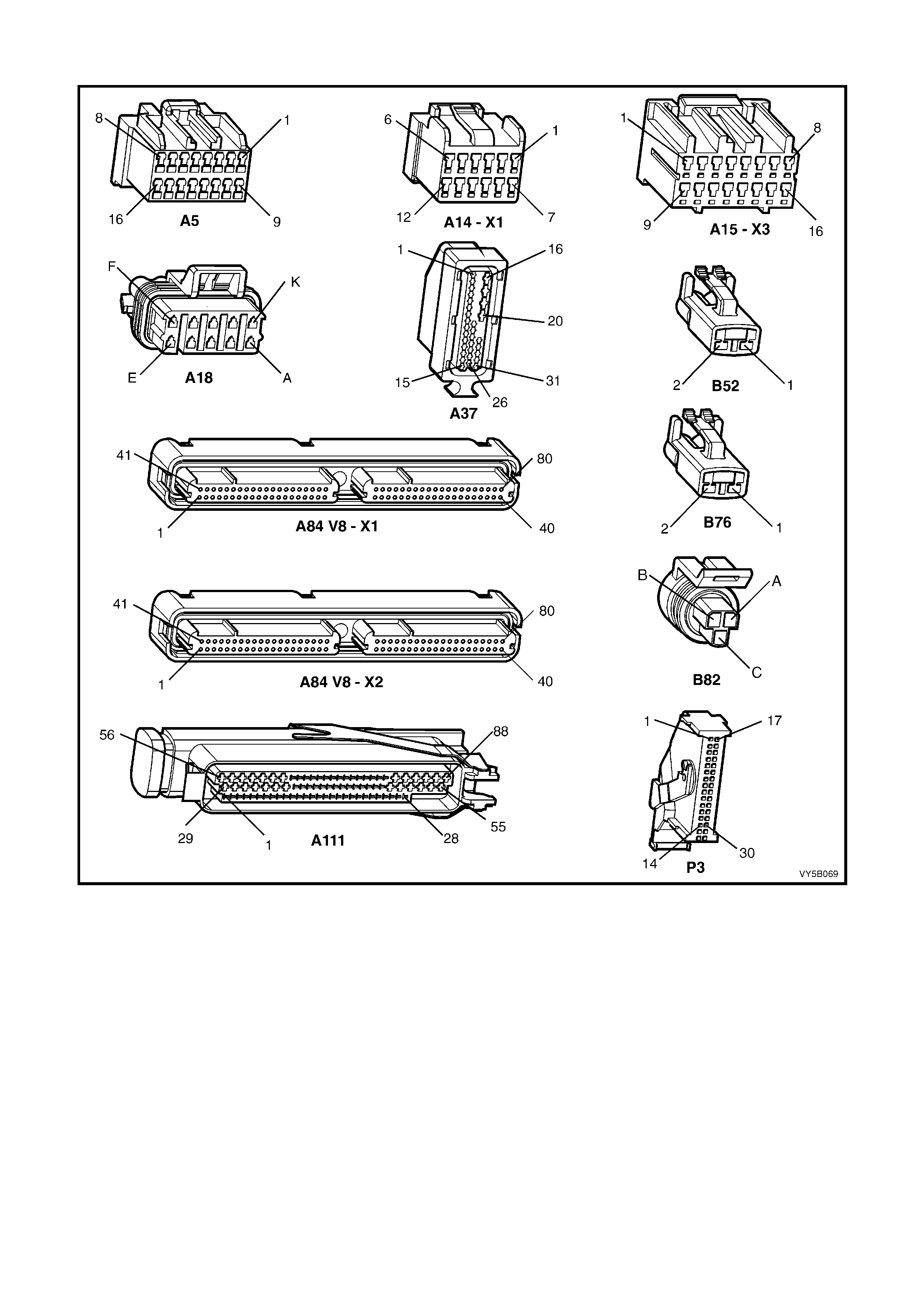
Wiring Harness Connectors
Figure 5B-159 – GEN III V8 Wiring Harness Connectors
Legend
A5 Powertrain Interface Module (PIM)
A14-X1 Blower Motor & A/C Compressor
A15-X3 Body Control Module
A18 Cruise Control Module
A37 ABS & ABS/TCS Control Module
A84 V8-X1 Powertrain Control Module – GEN III V8 Engine
A84 V8-X2 Powertrain Control Module – GEN III V8
Engine
A111 Throttle Relaxer Control Module
B52 Wheel Speed Sensor – Front
B76 Wheel Speed Sensor – Rear
B82 Throttle Position Sensor
P3 Instrument Cluster
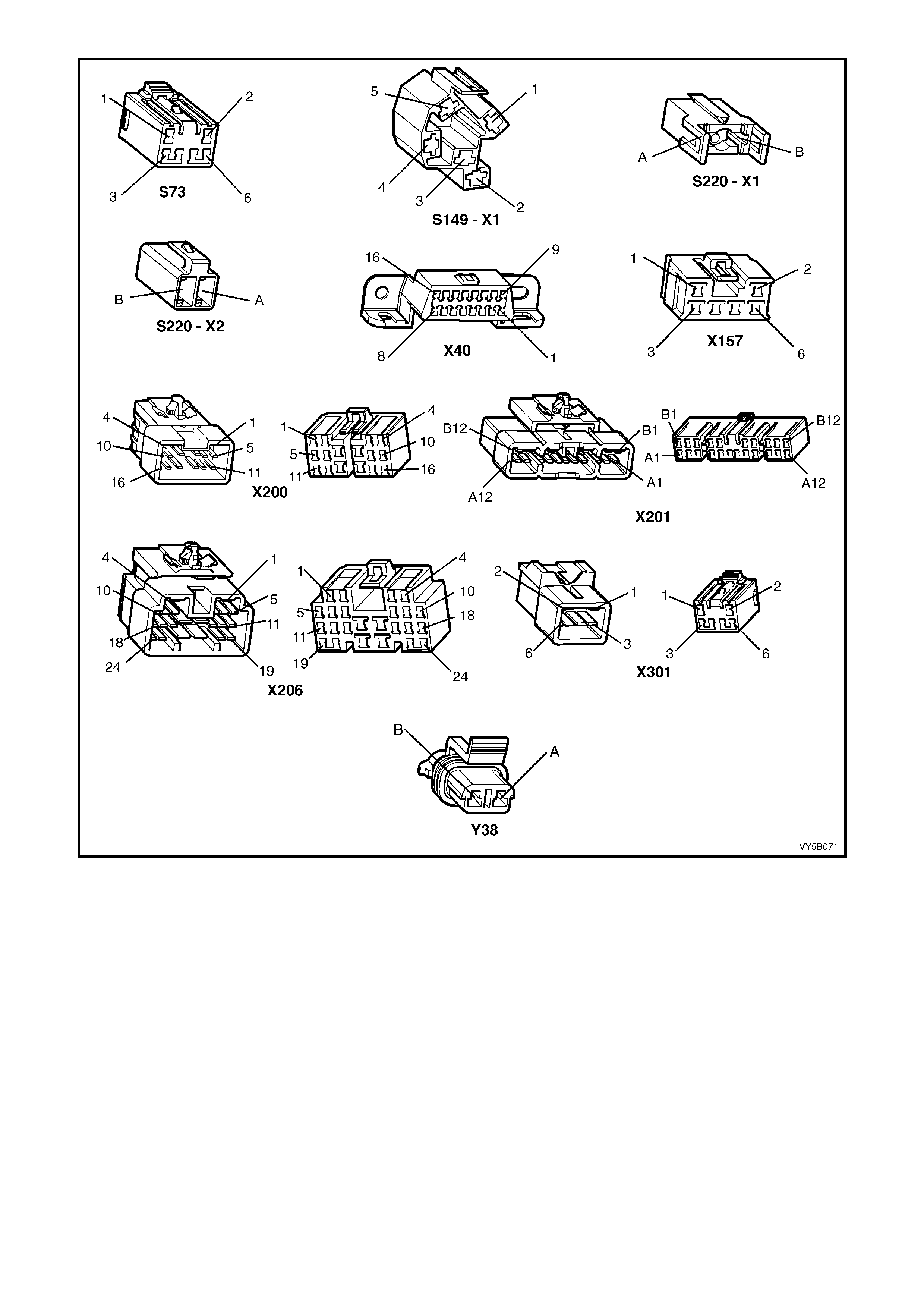
Figure 5B-160 – GEN III V8 Wiring Harness Connectors
Legend
S73 Traction Control Switch
S149-X1 Ignition and Start Switch
S220-X1 Stop Lamp & Traction Control Switch
S220-X2 Stop Lamp & Traction Control Switch
X40 Data Link Connector (DLC)
X157 Ground Connector
X200 Body Wiring Harness to Main Wiring Harness
X201 Body Wiring Harness to Main Wiring Harness
X206 Main Wiring Harness to Powertrain Wiring Harness
X301 Transmission Switch to Main Wiring Harness
Y38 Throttle
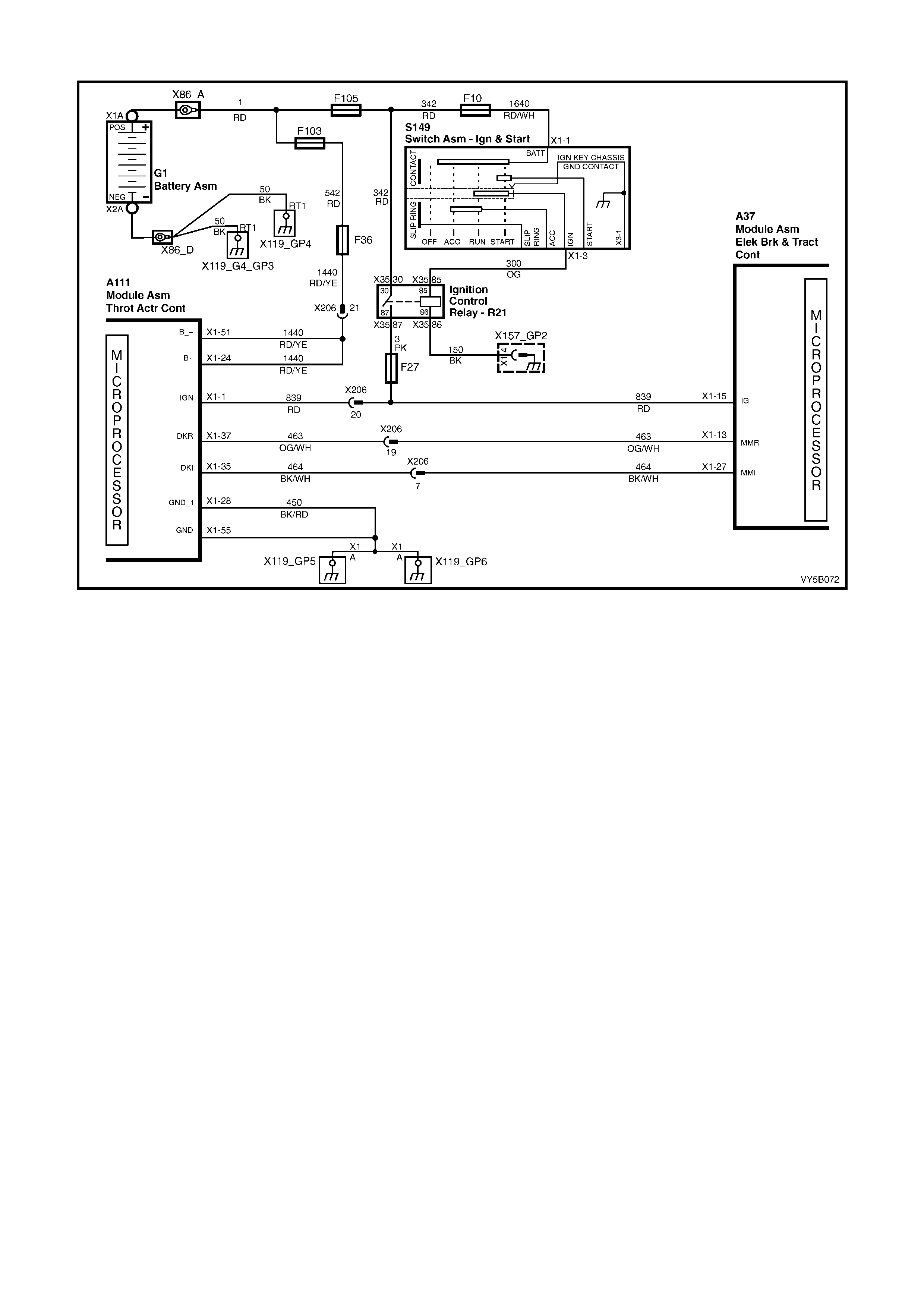
DTC 58 – THROTTLE RELAXER PWM INTERFACE FAULT
Figure 5B-161
CIRCUIT DESCRIPTION:
W ith the ignition o n, the ABS/T CS c ontrol m odule c ons tantl y sends a Puls e W idth Modulat ed ( PW M) signal at 90%
with a frequency of 100 Hz to the throttle relaxer control module on the requested throttle position line (DKR), via
term inal X1-13, circui t 463 (Or ange/W hite wire). T his signal is to indicat e to the throttle r elaxer contro l module t hat
the traction control system (TCS) is in a state of readiness. If the ABS/TCS control module requests traction
control, throttle reduction, it signals to the throttle relaxer control module to reduce the throttle opening b y varying
the duty cycle of this PWM signal.
DTC 58 will set if this frequency output signal deviates outside a frequency specification (95 – 105 Hz) or if the
signal stops for more than 50 milliseconds. The throttle relaxer control module A111 monitors this line and, if the
above cond it ions ar e d etec t ed, the t hr ott le rel ax er c ontr ol module sends a PWM signal of 93% on the actu al throttl e
position line (D KI), circuit 464 (Black/White wire) back to the ABS/TCS control module A37. The ABS/TCS control
module interprets this signal (or if no PWM signal is returned) as a DKR of throttle relaxer control module fault.
If the ABS/TCS control module senses this fault, the TCS system will be disabled (ABS operation will operate
norm all y), the T RAC O FF warni ng dis p lay will be ac tivated and DTC 58 will be s et. T he TRAC O FF warning dis play
will remain activated for the remainder of the ignition cycle. If the failure is intermittent, the control module will
enable the system at the next ignition cycle and the relevant history DTC will be set.
TEST DESCRIPTION:
The numbers below refer to Step numbers in the diagnostic chart for DTC 58.
1. Checks for continuity in ground circuit 450.
2. Checks for continuity in ground circuit 450.
3. Checks circuit 839 for an open or high resistance.
4. Checks circuit 463 for an open, short to ground or short to voltage.
5. Checks circuit 464 for an open, short to ground or short to voltage.
NOTES ON DIAGNOSTIC CHART:
1. For all wiring checking procedures, refer to Section 12P WIRING DIAGRAMS in the MY 2003 VY and V2
Series Service Information.

A111 A37
Figure 5B-162
DTC 58 - THROTTLE RELAXER PWM INTERFACE FAULT
STEP ACTION VALUE YES NO
1. Was the ABS or ABS/TCS Functional Check Carried out? Go to Step 2 Go to 5.4 ABS or
ABS/TCS
Functional
Check
2. 1. Disconnect the throttle relaxer control module
connector A111.
2. Check resistance between connector A111, terminal
X1-28, circuit 450 (Black/Red wire) and ground
location X119_GP5/GP6 (engine block) (refer NOTE 1
above).
Is value as specified?
0 – 5 Ohms Go to Step 3 Repair circuit
450 as
necessary,
recheck and
verify repair.
3. 1. With connector A111 disconnected, check resistance
between connector A111, terminal X1-55, circuit 450
(Black/Red wire) and ground location X119_GP5/GP6
(refer to NOTE 1 above).
Is value as specified?
0 – 5 Ohms Go to Step 4 Repair circuit
450 as
necessary,
recheck and
verify repair.
4. 1. With connector A111 disconnected, turn the ignition
switch to the ON position.
2. Measure voltage between the throttle relaxer control
module connector A111, terminals X1-1 and X1-28
(refer to NOTE 1 above).
Is voltage as specified?
Battery + Go to Step 5 Repair circuit
839 as
necessary,
recheck and
verify repair.
5. 1. With connector A111 disconnected, disconnect the
ABS/TCS control module connector A37.
2. Check integrity (open, short to ground and short to
voltage) of circuit 463 (Orange/White wire) between
connector A37 terminal X1-13 and connector A111
terminal X1-37 (refer to NOTE 1 above).
Is integrity of circuit 463 OK?
Go to Step 6 Repair circuit
463 as
necessary,
recheck and
verify repair.
6. 1. With connectors A111 and A37 disconnected, check
integrity (open, short to ground and short to voltage) of
circuit 464 (Black/White wire) between connector A37
terminal X1-27 and connector A111 terminal X1-35
(refer to NOTE 1 above).
Is integrity of circuit 464 OK?
Replace throttle
relaxer control
module, refer
3.9 THROTTLE
RELAXER
CONTROL
MODULE in this
Section.
Recheck and
verify repair.
Repair circuit
464 as
necessary,
recheck and
verify repair.
WHEN ALL DIAGNOSIS AND REPAIRS ARE COMPLETED, CLEAR ALL DTCs AND VERIFY CORRECT OPERATION
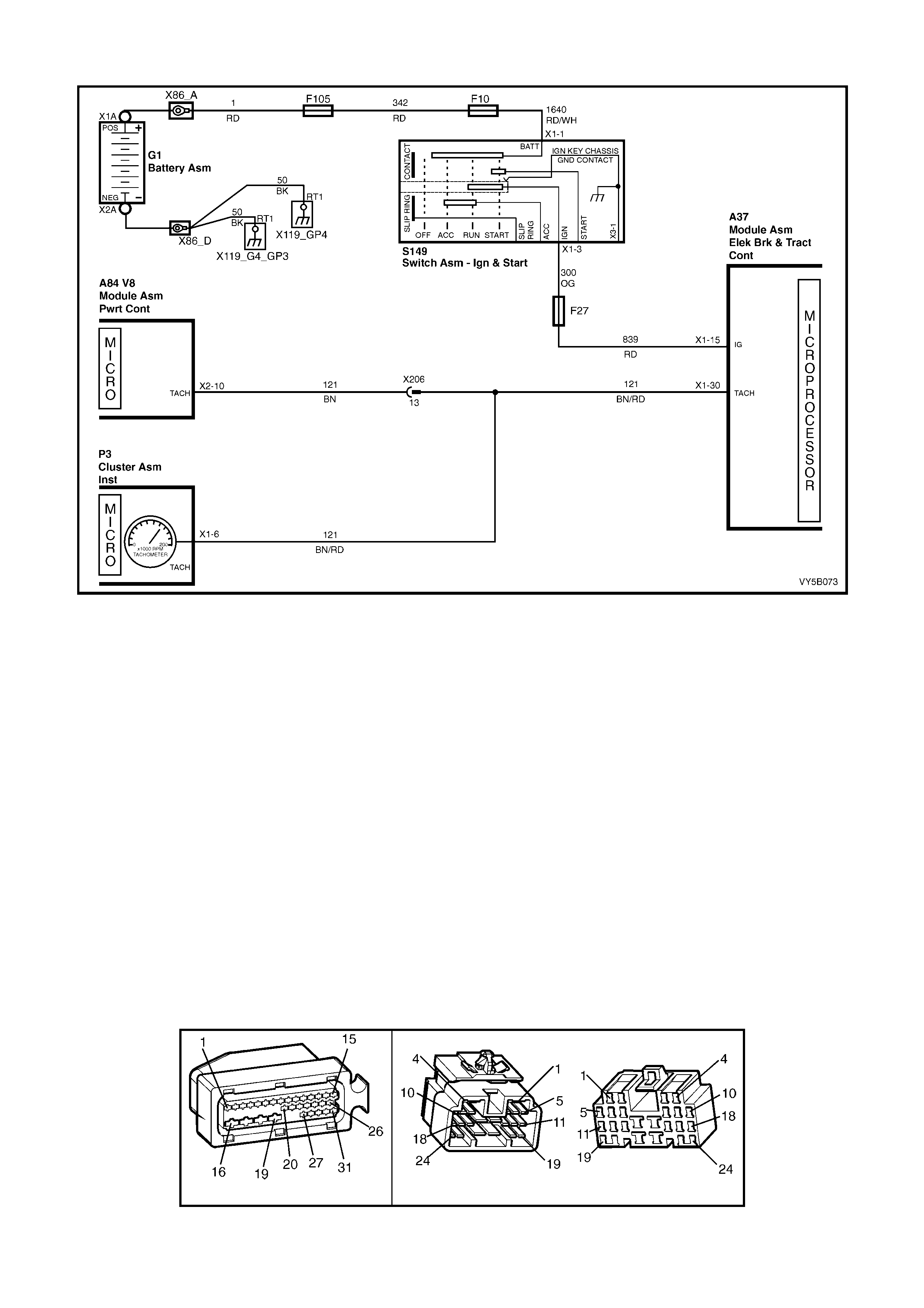
DTC 62 – RPM SIGNAL FAULT
Figure 5B-163
CIRCUIT DESCRIPTION:
To determine the requested amount of spark retard, and prevent the engine from stalling, the ABS/TCS control
module monitors the engine speed. An engine RPM signal is sent to terminal X1-30 of the ABS/TCS control module
A37 from the PCM A84. This signal has a fixed duty cycle and a frequency that will vary with changing engine
RPM.
DTC 62 will s et if an RPM signal ( engine speed sig nal) is not r eceived b y the A BS/TCS contr ol module at te rminal
X1-30, provided the engine speed is greater than 480 RPM.
If the ABS/T CS contro l module sens es this f ault, only the T CS system will be dis abled (ABS will operate n orm ally),
the TRAC OFF warning l amp will be i lluminated a nd the relevant DT C will be set . The TRAC OF F warning display
will remain activated for the remainder of the ignition cycle. If the failure is intermittent, the control module will
enable the system at the next ignition cycle and the relevant history DTC will be set.
TEST DESCRIPTION:
The numbers below refer to Step numbers in the diagnostic chart for DTC 62.
1. Checks for continuity in circuit 121.
NOTE: The diagnostic procedure for this DTC assumes that the tachometer is functioning correctly. If the
tachometer is not functioning correctly, or PCM DTC P0654 is set, refer to Section 6C3-2A DIAGNOSTIC
TABLES – GEN III V8 ENGINE.
NOTES ON DIAGNOSTIC CHART:
1. For all wiring checking procedures, refer to Section 12P WIRING DIAGRAMS in the MY 2003 VY and V2
Series Service Information.
A37 X206
Figure 5B-164

DTC 62 – RPM SIGNAL FAULT
STEP ACTION VALUE YES NO
1. Was the ABS or ABS/TCS Functional Check Carried out? Go to Step 2 Go to 5.4 ABS or
ABS/TCS
Functional
Check
2. 1. Disconnect ABS/TCS control module connector A37
and engine harness connector X206.
2. Check continuity of circuit 121 (Brown/Red wire)
between ABS/TCS control module connector A37,
terminal X1-30 and engine harness connector X206,
terminal 19 (refer to NOTE 1 above).
Does continu ity ex ist?
Replace
ABS/TCS control
module, refer 3.6
CONTROL
MODULE, in this
Section.
Recheck and
verify repair.
Check and
repair open in
circuit 121.
Recheck and
verify repair.
WHEN ALL DIAGNOSIS AND REPAIRS ARE COMPLETED, CLEAR ALL DTCs AND VERIFY CORRECT OPERATION
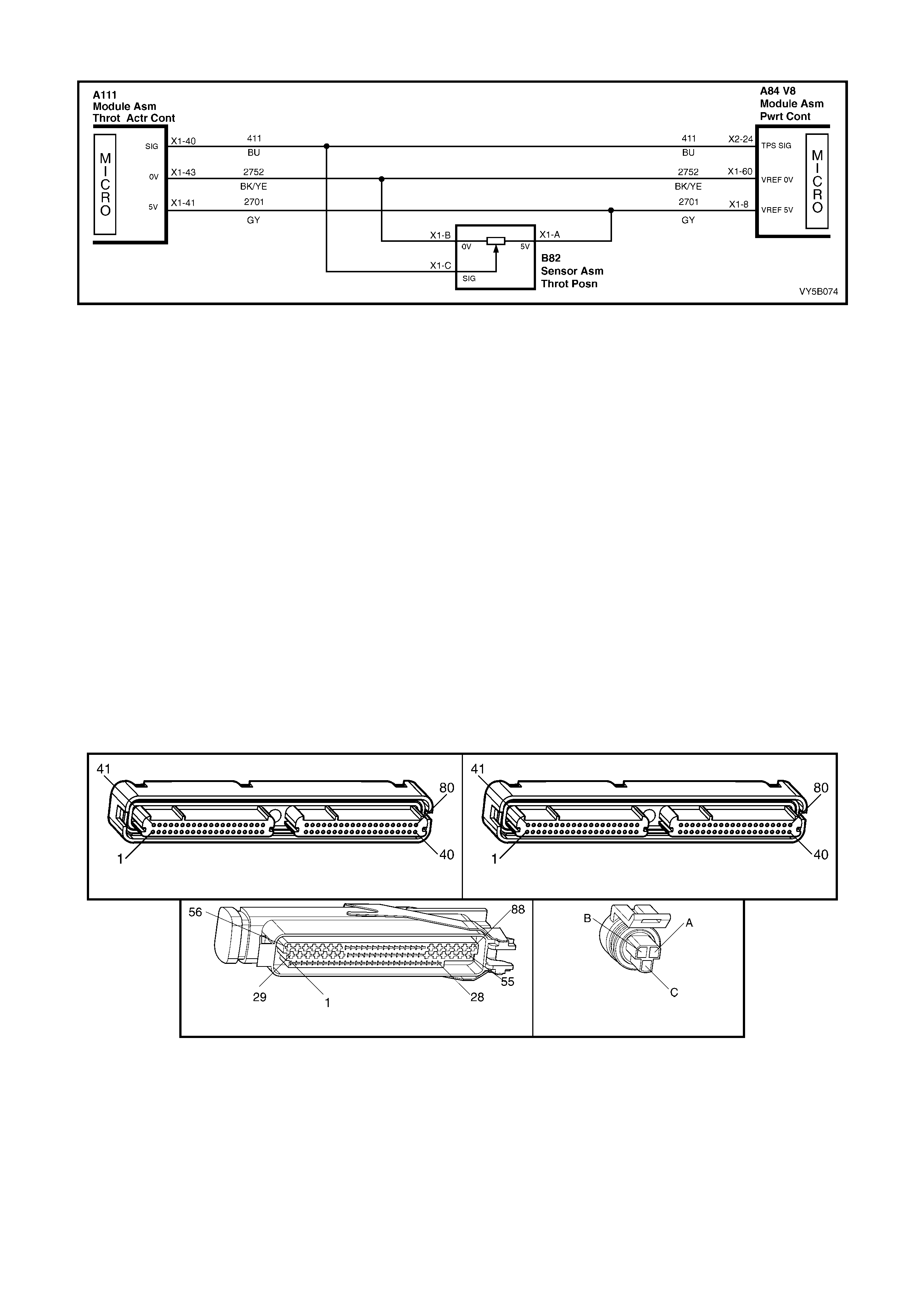
DTC 64 – THROTTLE RELAXER CONTROL MODULE POSITION FAULT
Figure 5B-165
CIRCUIT DESCRIPTION:
The ABS/TCS control module continuously receives a throttle position message every 200 milliseconds, via the
actual throttle position line (DKI), circuit 464 (Black/White wire).
DTC 64 wil l set if a mes s age is not r ec eive d f r om the t hrottl e p os ition s ens or f or more than s ix s ec o nds. If this DTC
is set, there will probably be a PCM DTC set also. If a PCM DTC is set, remedy this fault first.
If the ABS/T CS contro l module sens es this f ault, only the T CS system will be dis abled (ABS will operate n orm ally),
the TRAC OFF warning display will be activated and the relevant DTC will be set. The TCS system will remain
disabled and TRAC OFF warning display will remain activated until the ABS/TCS control module receives five
consecutive throttle position messages. After five consecutive messages are received by the ABS/TCS control
module, the control module will enable the system, and the relevant history DTC will be set.
TEST DESCRIPTION:
The numbers below refer to Step numbers in the diagnostic chart for DTC 64.
1. Determines if fault is related to the ABS/TCS system of the powertrain management system.
2. Checks circuit 411 for open or high resistance.
3. Checks circuit 2701 for open or high resistance.
4. Checks circuit 2752 for open or high resistance.
NOTES ON DIAGNOSTIC CHART:
1. For all wiring checking procedures, refer to Section 12P WIRING DIAGRAMS in the MY 2003 VY and V2
Series Service Information.
2. Refer to 4.7 TECH 2 DIAGNOSTICS, in this Section for connecting and using Tech 2.
A84–X1 (BLUE) A84-X2 (RED)
A111 B82
Figure 5B-166

DTC 64 – THROTTLE RELAXER CONTROL MODULE POSITION FAULT
STEP ACTION VALUE YES NO
1. Was the ABS or ABS/TCS Functional Check Carried out? Go to Step 2 Go to 5.4 ABS or
ABS/TCS
Functional
Check
2. 1. Install Tech 2 to the DLC (refer NOTE 2 above).
2. Select Diagnosis / Engine / GEN III V8 / Diagnostic
Trouble Codes / Read DTC Info Ordered Priority.
Are any PCM DTCs set (in particular DTCs related to the
throttle position switch)?
Rectify fault
ca usi ng PC M
DTC to set, refer
to 6C3-2A
DIAGNOSTIC
TABLE – GEN III
V8.
Go to Step 3
3. 1. Disconnect throttle relaxer control module wiring
harness connector A111, the throttle position sensor
wiring harness connector B82 and the PCM wiring
harness connector A84-X2 (RED).
2. Measure resistance between connector A111, terminal
X1-40 and connector B82, terminal X1-C, circuit 411
(Blue wire) (refer to NOTE 1 above).
Is resistance as specified?
0 – 5 Ohms Go to Step 5 Check and
repair open or
high resistance
in circuit 411
between
connector A111
and B82.
Recheck circuit
to verify repair.
4. 1. With connectors A111, B82 and A84 X1 (BLUE)
disconnected, measure resistance between connector
A111, terminal X1-41 and connector B82 terminal X1-
A, circuit 2701 (Grey wire) (refer NOTE 1 above).
Is resistance as specified?
0 – 5 Ohms Go to Step 5 Check and
repair open or
high resistance
in circuit 2701
between
connector
YB170 and
YE30. Recheck
circuit to verify
repair.
5. 1. With connectors A111, B82 and A84 X1 (BLUE)
disconnected, measure resistance between connector
A111, terminal X1-43 and connector B82 terminal X1-
B, circuit 2752 (Black/Yellow wire) (refer NOTE 1
above).
Is resistance as specified?
0 – 5 Ohms Replace throttle
relaxer control
module, refer
3.9 THROTTLE
RELAXER
CONTROL
MODULE in this
Section.
Recheck and
verify repair.
Check and
repair open or
high resistance
in circuit 2752
between
connector A111
and B82.
Recheck circuit
to verify repair.
WHEN ALL DIAGNOSIS AND REPAIRS ARE COMPLETED, CLEAR ALL DTCs AND VERIFY CORRECT OPERATION
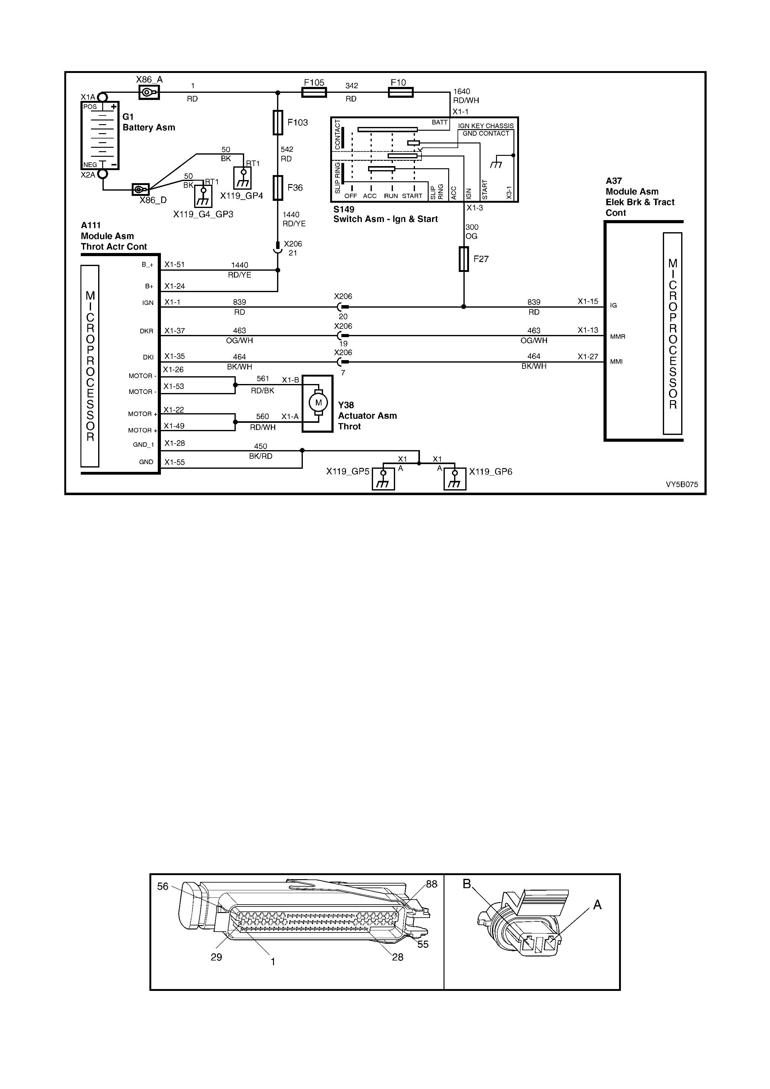
DTC 65 – THROTTLE RELAXER MOTOR FAULT
Figure 5B-167
CIRCUIT DESCRIPTION:
The throttle relaxer Y38 is controlled at a commanded current rate by the throttle relaxer control module A111.
DTC 65 will set if the throttle relaxer motor or circuit is open, shorted to ground or shorted to voltage.
If the ABS/TCS control module A37 senses this fault, only the TCS system will be disabled (ABS will operate
normally), the TRAC OFF warning lamp will be illuminated and the relevant DTC will be set. The TRAC OFF
warning lamp will rem ain illum inated for th e remainder of the ignition cycle. If th e failure is interm ittent, the control
module will enable the system at the next ignition cycle and the relevant history DTC will be set.
TEST DESCRIPTION:
The numbers below refer to Step numbers in the diagnostic chart for DTC 65.
1. – 2. Checks continuity of circuit 450.
3. – 4. Checks integrity (open or short to ground) of circuit 1440 (including fuse F36).
5. Determines if the throttle relaxer motor Y38 is faulty.
6. – 7. Checks for open in circuit 560.
8. – 9. Checks for open in circuit 561.
10. Checks for short to ground in circuit 560.
11. Checks for short to ground in circuit 561.
12. Checks for short to voltage in circuit 560.
13. Checks for short to voltage in circuit 561.
NOTES ON DIAGNOSTIC CHART:
1. For all wiring checking procedures, refer to Section 12P WIRING DIAGRAMS.
A111 Y38
Figure 5B-168

DTC 65 – THROTTLE RELAXER MOTOR FAULT
STEP ACTION VALUE YES NO
1. Was the ABS or ABS/TCS Functional Check Carried out? Go to Step 2 Go to 5.4 ABS or
ABS/TCS
Functional
Check
2. 1. Disconnect the throttle relaxer control module
connector A111.
2. Check resistance between connector A111, terminal
X1-28, circuit 450 (Black/Red wire) and ground
location X119_GP5/GP6 (engine block) (refer NOTE 1
above).
Is value as specified?
0 – 5 Ohms Go to Step 3 Repair circuit
450 as
necessary,
recheck and
verify repair.
3. 1. With connector A111 disconnected, check resistance
between connector A111, terminal X1-55, circuit 450
(Black/Red wire) and ground location X119_GP5/GP6
(refer to NOTE 1 above).
Is value as specified?
0 – 5 Ohms Go to Step 4 Repair circuit
450 as
necessary,
recheck and
verify repair.
4. 1. With connector A111 disconnected, measure voltage
between the throttle relaxer control module connector
A111, terminals X1-51 and X1-28 (refer to NOTE 1
above).
Is voltage as specified?
Battery + Go to Step 5 Repair circuit
1440 (including
fuse F36) as
necessary,
recheck and
verify repair.
5. 1. With connector A111 disconnected, measure voltage
between the throttle relaxer control module connector
A111, terminals X1-24 and X1-28 (refer to NOTE 1
above).
Is voltage as specified?
Battery + Go to Step 6 Repair circuit
1440 as
necessary,
recheck and
verify repair.
6. 1. With the ignition switch in the OFF position, disconnect
throttle relaxer connector Y38.
2. Disconnect all cables from the throttle relaxer pulleys.
Refer 6C3-3 SERVICE OPERATIONS.
3. Rotate pulleys on the throttle relaxer by hand fully then
release, allowing the pulleys to return to the stop.
Repeat this procedure three times.
4. Check resistance between the throttle relaxer
terminals X1-A and X1-B (refer to NOTE 1 above).
Is the resistance within the range as specified?
0.5 – 10
Ohms Go to Step 7 Replace the
throttle relaxer
assembly, refer
to 6C3-3
SERVICE
OPERATIONS.
Recheck and
verify repair
7. 1. With the throttle relaxer connector Y38 disconnected,
disconnect throttle relaxer control module connector
A111.
2. Check resistance of circuit 560 (Red/White wire)
between connector A111 terminals X1-22 and
connector Y38 terminal X1-A (refer to NOTE 1 above).
Is resistance value as specified?
0 – 5 Ohms Go to Step 8 Repair open in
circuit 560,
recheck and
verify repair.
8. 1. With the throttle relaxer connector Y38 disconnected,
disconnect throttle relaxer control module connector
A111.
2. Check resistance of circuit 560 (Red/White wire)
between connector A111 terminal X1-49 and
connector Y38 terminal X1-A (refer to NOTE 1 above).
Is resistance value as specified?
0 – 5 Ohms Go to Step 9 Repair open in
circuit 560,
recheck and
verify repair.
9. 1. W ith the throttle relaxer connector Y38 and the throttle
relaxer control module connector A111 disconnected,
check resistance of circuit 561 (Red/Black wire)
between connector A111 terminal X1-26 and
connector Y38 terminal X1-B (refer to NOTE 1 above).
Is resistance value as specified?
0 – 5 Ohms Go to Step 10 Repair open in
circuit 561,
recheck and
verify repair.
10. 1. W ith the throttle relaxer connector Y38 and the throttle
relaxer control module connector A111 disconnected,
check resistance of circuit 561 (Red/Black wire)
between connector A111 terminal X1-53, and
connector Y38 terminal X1-B (refer to NOTE 1 above).
Is resistance value as specified?
0 – 5 Ohms Go to Step 11 Repair open in
circuit 561,
recheck and
verify repair.

STEP ACTION VALUE YES NO
11. 1. Reconnect the throttle relaxer connector Y38.
2. Check resistance between the throttle relaxer control
module connector A111, terminals X1-22, circuit 560
(Red/White wire) and X1-28, circuit 450 (Black/Red
wire) on the throttle relaxer control module connector
A111 (refer to NOTE 1 above).
Is resistance value as specified?
Infinite ohms
(Open
Circuit)
Go to Step 12 Repair short to
ground in circuit
560, recheck
and verify repair.
12. 1. Check resistance between the throttle relaxer control
module connector A111, terminals X1-26, circuit 561
(Red/Black wire) and X1-28, circuit 450 (Black/Red
wire) on the throttle relaxer control module connector
A111 (refer to NOTE 1 above).
Is resistance value as specified?
Infinite ohms
(Open
Circuit)
Go to Step 13 Repair short to
ground in circuit
561, recheck
and verify repair.
13. 1. Reconnect the throttle relaxer control module
connector A111.
2. Disconnect the throttle relaxer connector Y38.
3. Turn the ignition switch to the ON position.
4. Using a DMM set to Volts DC, check voltage at
connector Y38, terminal X1-A, circuit 560 (Red/White
wire) (refer to NOTE 1 above).
Is voltage as specified?
Greater than
1 Volt Repair short to
voltage in circuit
560, recheck
and verify repair.
Go to Step 14
14. 1. With the throttle relaxer connector Y38 disconnected,
and the ignition switch in the ON position, check
voltage at connector Y38, terminal X1-B, circuit 561
(Red/Black wire) and terminal X1-28 of connector
A111 (refer to NOTE 1 above).
Is voltage as specified?
Greater than
1 Volt Repair short to
voltage in circuit
561, recheck
and verify repair.
Replace throttle
relaxer control
module, refer
3.9 THROTTLE
RELAXER
CONTROL
MODULE in this
Section.
Recheck and
verify repair.
WHEN ALL DIAGNOSIS AND REPAIRS ARE COMPLETED, CLEAR ALL DTCs AND VERIFY CORRECT OPERATION

DTC 66 – THROTTLE RELAXER CONTROL FAULT
CIRCUIT DESCRIPTION:
DTC 66 is a throttle position control failure that is most likely due to a mechanical fault caused by a jammed or
binding throttle relaxer motor, throttle cable. DTC 66 can only be detected when the ABS/TCS control module is
modulating (or attempting to modulate) the throttle position.
If the throttle relaxer con trol module is unable to adjust the throttle p osition, as requested by the ABS/TCS control
module, via the requested throttle position line (DKR), the throttle relaxer control module will try to reduce the
throttle o pening b y inc reasing th e current sup plied to the thro ttle relaxer . This curr ent will rise to a maxim um value
and if it sta ys there f or m ore th an thr ee seco nds, a m essage is se nt to th e AB S/TCS c ontr ol m odule a nd a D TC 66
is set.
If the ABS/T CS contro l module sens es this f ault, only the T CS system will be dis abled (ABS will operate n orm ally),
the TRAC O FF warn ing displa y will b e activated and t he relevant DTC will be set. T he TRAC O FF warnin g displa y
will remain activated for the remainder of the ignition cycle. If the failure is intermittent, the control module will
enable the system at the next ignition cycle and the relevant history DTC will be set.
ACTION:
If DTC 66 sets, visually and physically check the following components:
• Check accelerator pedal, throttle and (if fitted) cruise control cables for binding or fouling.
• Remove the accelerator pedal, throttle and (if fitted) cruise control cables from the throttle relaxer. Check
operation of the throttle relaxer pulleys to ensure they rotate freely without binding or sticking.
Repair or replace components as necessary. Ensure all cables are routed correctly. Clear all DTCs and verify
correct operation.
NOTE 1: The throttle relaxer is a non serviceable component. If the throttle relaxer pulleys are found to be faulty,
replace the thrott le r elax er as s em bly.
NOTE 2: To remove, reinstall and adjust the cables and throttle relaxer assembly, refer to
Section 6C3-3 SERVICE O PERATIONS – GEN III V8.
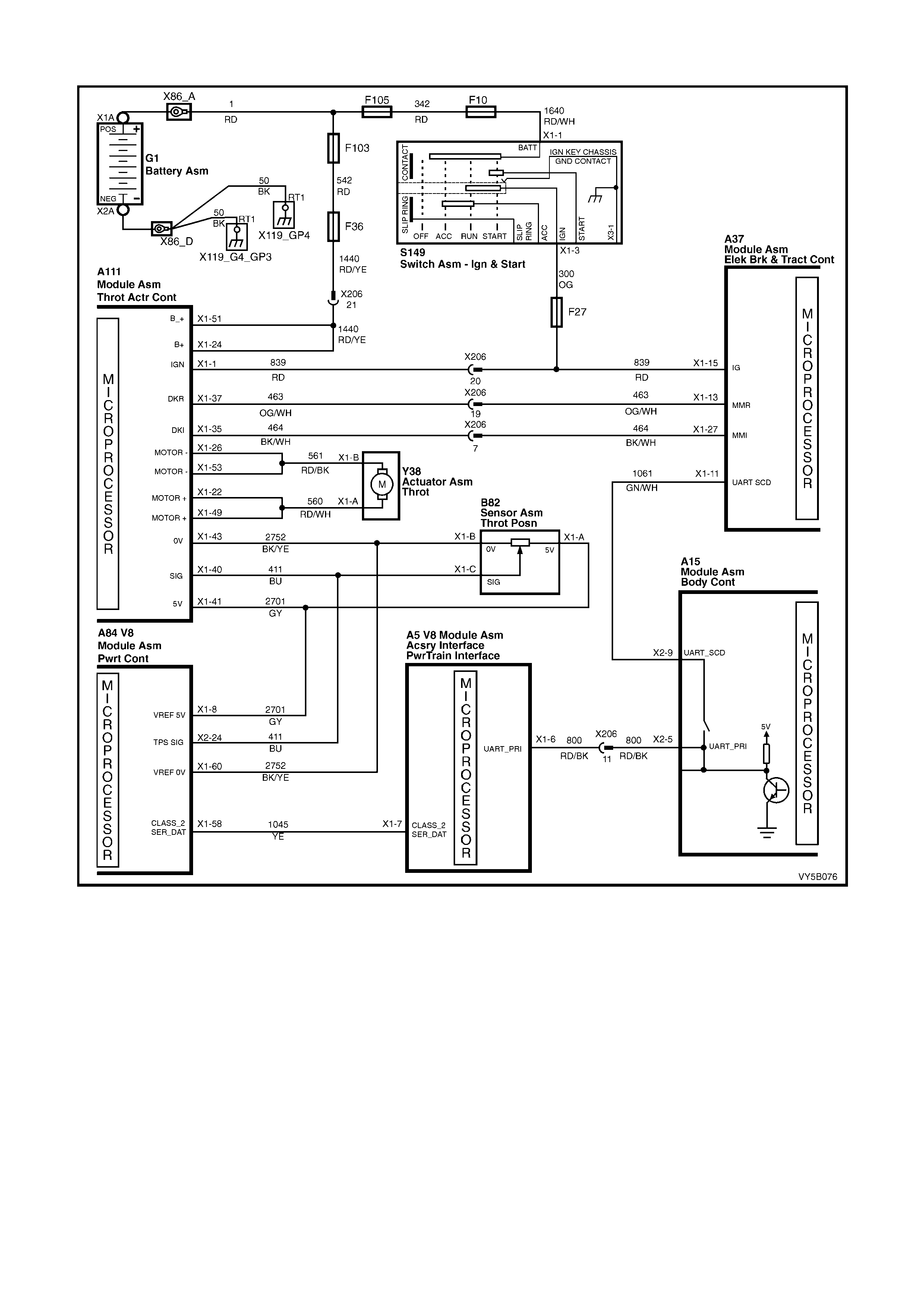
DTC 68 – THROTTLE POSITION SENSOR MONITORING FAULT
Figure 5B-169
CIRCUIT DESCRIPTION:
The ABS/T CS contro l module m onitors the throt tle po sition, when set by the thro ttle relax er control m odule, vi a the
actual throttle position (DKI) input, circuit 464 (Black/White wire). At the same time, the ABS/TCS control module
monitor s the throttle pos ition, as r ead by the Throttl e Position Se nsor (T PS), and comm unicated on the s erial data
line (circuit 1061, Green/White wire) by the PCM/PIM, via the Body Control Module and the UART Primary serial
data (circuit 800). If the values from the two inputs do not correlate with each other, the ABS/TCS control module
will set DTC 68.
If the ABS/T CS contro l module sens es this f ault, only the T CS system will be dis abled (ABS will operate n orm ally),
the TRAC O FF warn ing displa y will b e activated and t he relevant DTC will be set. T he TRAC O FF warnin g displa y
will remain activated for the remainder of the ignition cycle. If the failure is intermittent, the control module will
enable the system at the next ignition cycle and the relevant history DTC will be set.
TEST DESCRIPTION:
The numbers below refer to Step numbers in the diagnostic chart for DTC 68.
1. Determines if fault is related to the ABS/TCS system of the powertrain management system.
2. Checks if ABS/TCS control module is receiving the correct signal.

NOTES ON DIAGNOSTIC CHART:
1. For all wiring checking procedures, refer to Section 12P WIRING DIAGRAMS.
2. Refer to 4.7 TECH 2 DIAGNOSTICS in this Section for connecting and using Tech 2.
A111 A37
Figure 5B-170
DTC 68 – THROTTLE POSITION SENSOR MONITORING FAULT
STEP ACTION VALUE YES NO
1. Was the ABS or ABS/TCS Functional Check Carried out? Go to Step 2 Go to 5.4 ABS or
ABS/TCS
Functional
Check
2. 1. Install Tech 2 to the DLC (refer NOTE 2 above).
2. Select Diagnosis / Engine / GEN III V8 / Diagnostic
Trouble Codes / Read DTC Info Ordered Priority.
Are any PCM DTCs set?
Rectify fault
ca usi ng PC M
DTC to set, refer
to 6C3-2A
DIAGNOSTIC
TABLES - GEN
III V8.
Go to Step 3
3. 1. With the throttle relaxer control module connector
A111 installed, Back probe ABS/TCS control module
connector A37, terminal X1-27, circuit 464 (Black/
White wire) with a volt meter to ground (refer NOTE 1
above).
2. Turn ignition ON.
3. Vary the position of the throttle opening, while taking
note of voltage reading.
Is voltage as specified?
Throttle
closed -
approx. 1
Volt
WOT
approx. 10
Volts
Replace
ABS/TCS control
module, refer
3.6 CONTROL
MODULE,
in this Section.
Recheck and
verify repair.
Replace throttle
relaxer control
module, refer
3.9 THROTTLE
RELAXER
CONTROL
MODULE
in this Section.
Recheck and
verify repair.
WHEN ALL DIAGNOSIS AND REPAIRS ARE COMPLETED, CLEAR ALL DTCs AND VERIFY CORRECT OPERATION

DTC 72 - SERIAL DATA FAULT
Figure 5B-171
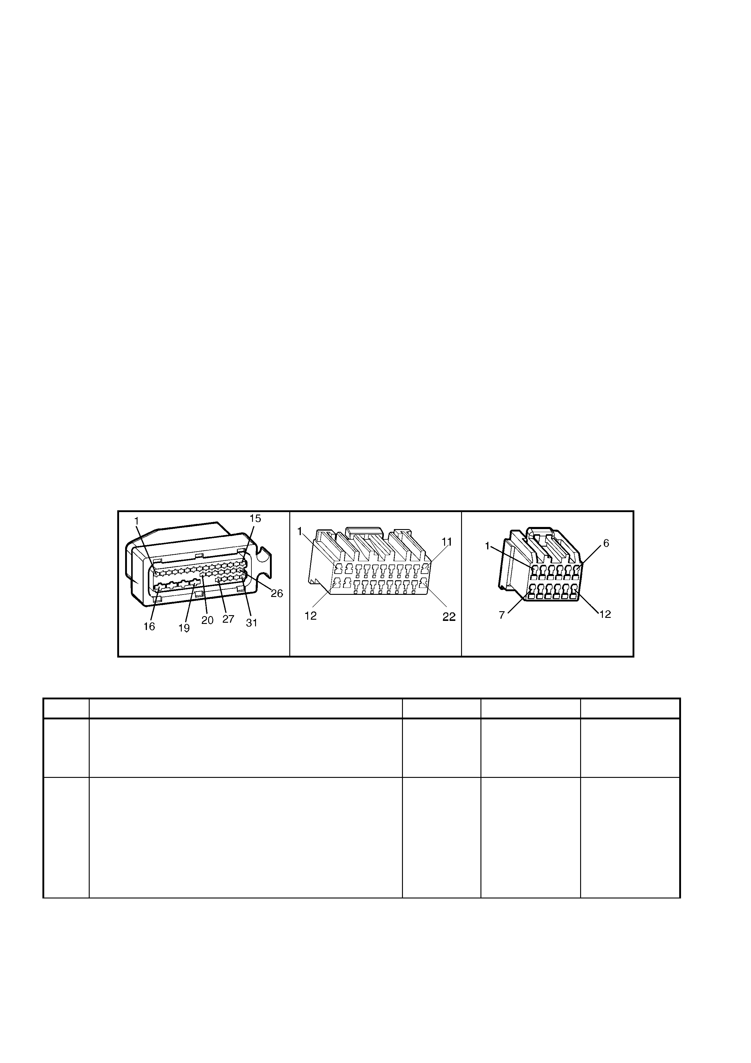
CIRCUIT DESCRIPTION:
W ith the ignition ON, the ABS/T CS control module will be ab le to comm unicate with other control m odules via the
UART, Secondary (UART_SCD) serial data lines, on circuit 1061 (Green/White wire). If communication between
the modules is disrupted due to a short or open circuit, DTC 72 will be set.
If the ABS/T CS control m odule senses this f ault, only the TC S system will be disabled (ABS op eration will o perate
normally), the TRAC OFF warning display will be activated and the relevant DTC will be set. The TRAC OFF
warning disp lay will remain activated for the remainder of the ignition cycle. If the failure is intermittent, the control
module will enable the system at the next ignition cycle and the relevant history DTC will be set.
There are a number of control modules that are connected to this serial data circuit (BCM, ABS/TCS, A/C Blower
Motor, Telematics and the Instrument). Any of these c ontrol modules could caus e a fault in the UART_SCD serial
data line. This fault could result in Tech 2 not being able to display serial data.
TEST DESCRIPTION:
The numbers below refer to Step numbers in the diagnostic chart for DTC 72.
1. This test determines if fault is current or not.
2. This test checks for connector or wiring problems which may cause an intermittent fault.
3. Determines if fault is in wiring or ABS/TCS control module.
4. Determines if fault is with BCM serial data communication (bus master).
5. Checks if fault is caused by other control modules that are communicating on the serial data line.
6. Checks circuit 1061 and determines if fault is in wiring or control module.
7. Checks for continuity in circuit 1061.
NOTES ON DIAGNOSTIC CHART:
1. For all wiring checking procedures, refer to Section 12P WIRING DIAGRAMS.
2. Refer to 4.7 TECH 2 DIAGNOSTICS in this Section for connecting and using Tech 2.
DIAGNOSTIC AIDS:
A fault with the s erial da ta circ uit could b e caused by one or m ore of the s everal control m odules c onnected to the
serial data c ircuit. Is olate the f ault by disconn ecting ea ch controll er one at a tim e until seria l data com munication is
restored.
A37 A15 X1 A15 X2
Figure 5B-172
DTC 72 – SERIAL DATA FAULT
STEP ACTION VALUE YES NO
1. Was the ABS or ABS/TCS Functional Check Carried out? Go to Step 2 Go to 5.4 ABS or
ABS/TCS
Functional
Check
2. 1. Install Tech 2 to DLC.
2. Select Diagnostics / Chassis / ABS/TCS / Diagnostic
Trouble Codes / Clear DTCs and clear all DTCs (refer
to NOTE 2 above).
3. Road test vehicle.
Does DTC 72 set again ?
NOTE: Go to Step 4 if Tech 2 will not communicate with
the ABS/TCS control module.
Go to Step 4 Go to Step 3

STEP ACTION VALUE YES NO
3. 1. Inspect all system wiring and connections that could
cause intermittent faults. Check all wiring is in good
condition, terminals are clean and tight and making
good contact (refer NOTE 1 above).
Is wiring OK?
NOTE: Other control modules (SRS, Instruments, OCC,
BCM, PCM) that are connected to the serial data circuit
could cause DTC 72 to set. Therefore, check wiring and
connectors that could cause intermittent faults at these
control modules as well.
Fault not
present. Check
all system w iring
harness
connect ors and
terminals, in
particular the
modulator and
ABS/TCS control
module
connector
terminals.
Make rep airs as
necessary,
recheck and
verify repair.
4.
In step 1, was Tech 2 able to communicate with the
ABS/TCS control module (refer NOTE 2 above)?
(With the ignition ON and Chassis / ABS/TCS selected,
Tech 2 should display the ABS/TCS control module part
number, system identif ic ation and actual system .)
Go to Step 5 Replace
ABS/TCS control
module, refer
3.6 CONTROL
MODULE,
in this Section.
Recheck and
verify repair.
5. 1. With Tech 2 connected, select Diagnostics / Body /
Body Control Module and turn ignition on as requested
(refer NOTE 2 above).
Does Tech 2 display BCM system identification information
(BCM level and type) ?
Go to Step 6 Refer to BCM
Serial Data
Communication
diagnostics in
12J BODY
CONTROL
MODULE.
6. 1. Using Tech 2, check for similar DTCs (Serial Data
faults) that have been set by other control modules;
instruments, SRS, and OCC if applicable to model
variant (refer NOTE 2 above).
Have similar DTCs been set by other control modules?
Go to Step 7 Go to Step 8
7. 1. Check circuit 1061 (Green/White wire) for open, short
to ground or short to voltage between BCM and the
following modules; Instrument (P3), A/C Blower Motor
(A14) and ABS/TCS (A37) (refer NOTE 1 above).
Is circuit 1061 OK ?
NOTE: Disconnect each controller in circuit 1061, one at a
time, to isolate the fault in the circuit or to identify control
module causin g fault.
Replace faulty
module, refer to
relevant Section
in the MY 2003
VY and V2
Series Service
Information,
recheck and
verify repair.
Make rep airs as
necessary,
recheck and
verify repair.
8. 1. Disconnect BCM connector A15 and ABS/TCS control
module connector A37.
2. Check for continuity between BCM connector A15
terminal X2-9 and ABS/TCS control module connector
A37, terminal X2-11, circuit 1061 (Green/White wire)
(refer to NOTE 1 above).
Does continu ity ex ist?
Replace
ABS/TCS control
module, refer
3.6 CONTROL
MODULE,
in this Section.
Recheck and
verify repair.
Check and
repair open in
circuit 1061
between BCM
and ABS/TCS
control modu le,
recheck and
verify repair.
WHEN ALL DIAGNOSIS AND REPAIRS ARE COMPLETED, CLEAR ALL DTCs AND VERIFY CORRECT OPERATION
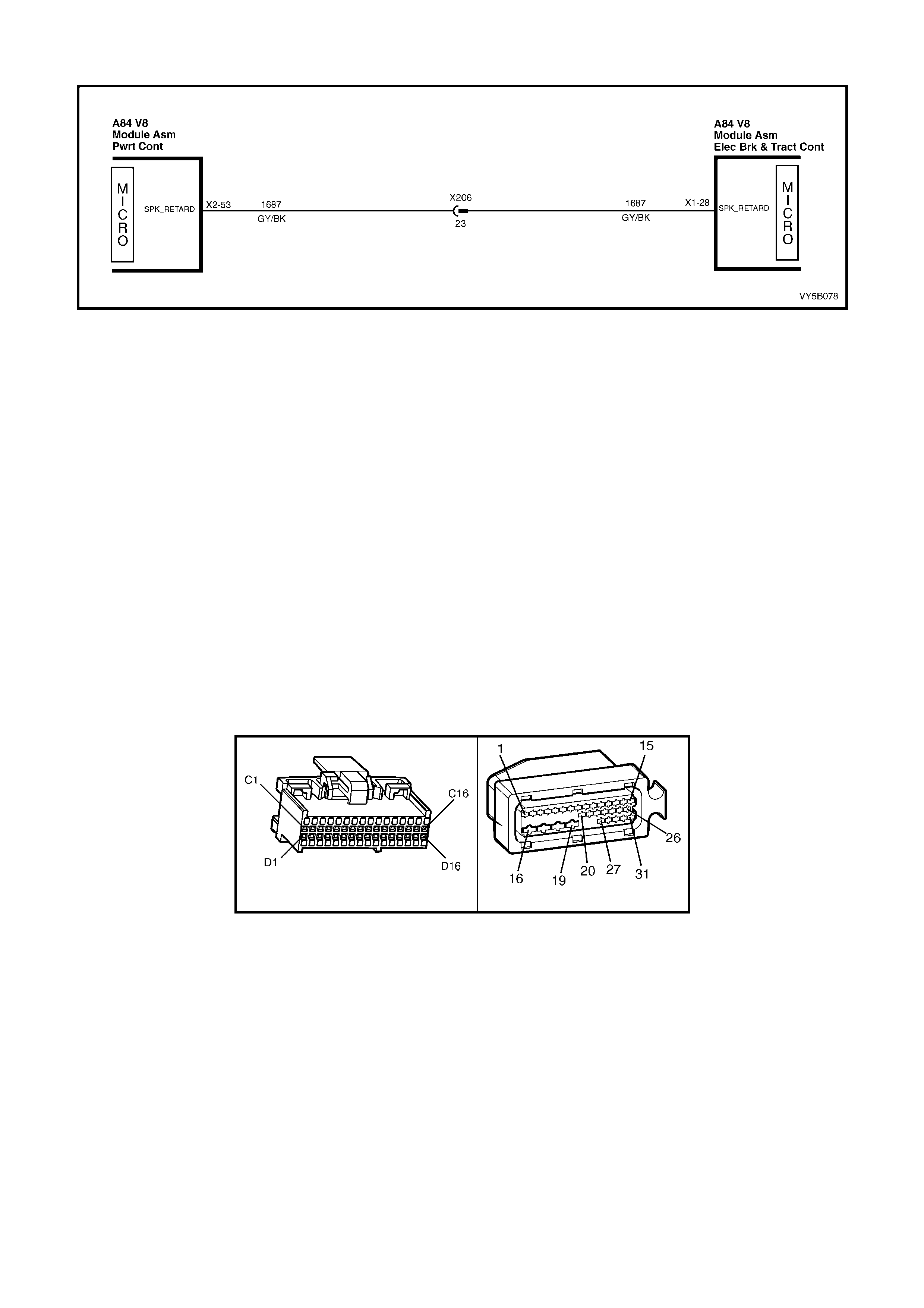
DTC 73 – SPARK RETARD MONITORING FAULT
Figure 5B-173
CIRCUIT DESCRIPTION:
Spark retard is simultaneously controlled by the ABS/TCS control module and the PCM. The PCM supplies a 12
volt pull-up voltage. This voltage is monitored by the PCM, as the ABS/TCS control module requests spark retard
by pulling this vo ltage lo w.
The AB S/TC S contr ol m odule cont inual ly moni tors c ir cuit 1687 . If the ABS/T CS c ontrol m odule detects a c ontin uity
problem in circuit 1687 it will set a DTC 73.
If the ABS/T CS contro l module sens es this f ault, only the T CS system will be dis abled (ABS will operate n orm ally),
the TRAC O FF warn ing displa y will b e activated and t he relevant DTC will be set. T he TRAC O FF warnin g displa y
will remain activated for the remainder of the ignition cycle. If the failure is intermittent, the control module will
enable the system at the next ignition cycle and the relevant history DTC will be set.
TEST DESCRIPTION:
The numbers below refer to Step numbers in the diagnostic chart for DTC 73.
1. Checks for 12 volt pull up from PCM.
2. Checks for short to voltage in circuit 1687.
3. Checks for open and short to ground in circuit 1687.
NOTES ON DIAGNOSTIC CHART:
1. For all wiring checking procedures, refer to Section 12P WIRING DIAGRAMS.
2. Refer to GEN III V8 PCM Pow ertrain OBD System Check, in Secti on 6C3-2 A DIAGNOST IC TABLE S – GEN
III V8, before replacing PCM.
A84 V8 X2 A37
Figure 5B-174

DTC 73 – SPARK RETARD MONITORING FAULT
STEP ACTION VALUE YES NO
1. Was the ABS or ABS/TCS Functional Check Carried out? Go to Step 2 Go to 5.4 ABS or
ABS/TCS
Functional
Check
2. 1. Disconnect ABS/TCS control module connector A37.
2. Start engine.
3. Check voltage at ABS/TCS control module connector
A37, terminal X1-28, circuit 1687 (Grey/Black wire).
Is voltage as specified?
Battery + Go to Step 3 Go to Step 4
3. 1. With connector A37 disconnected, disconnect the
PCM connector A84-X2.
2. Turn ignition ON.
3. Check circuit 1687 for short to voltage at terminal X2-
53 (refer to NOTE 1 above).
Is circuit 1687 OK?
Replace
ABS/TCS control
module, refer
3.6 CONTROL
MODULE
in this Section.
Recheck and
verify repair.
Repair short to
voltage in circuit
1687, recheck
and verify repair.
4. 1. With connector A37 disconnected, disconnect the
PCM connector A84-X2.
2. Turn ignition OFF.
3. Check circuit 1687 for an open of short to ground at
terminal X2-53 (refer NOTE 1 above).
Is circuit 1687 OK?
Check and, if
necessary,
replace PCM.
Refer 6C3-3
SERVICE
OPERATIONS.
Repair short to
ground or open
in circuit 1687,
recheck and
verify repair.
WHEN ALL DIAGNOSIS AND REPAIRS ARE COMPLETED, CLEAR ALL DTCs AND VERIFY CORRECT OPERATION

6. SPECIFICATIONS
WHEEL SPEED SENSORS
Winding resistance at ambient temperature
Front wheels............................................................ 1600 - 1800 Ohms
Rear wheels ............................................................ 1440 - 1760 Ohms
Wheel speed sensor air gap ...................................... Non-adjustable
Wheel speed sensor pulse rings................................ 48 teeth
Brake Fluid ................................................................. Super Dot 4
Control Module........................................................... ABS and ABS/TCS control modules are not
interchangeable. If replacing an ABS or an
ABS/TCS control module, always refer to the
latest PartFinder® Parts Catalogue for the correct part.

7. TORQUE WRENCH SPECIFIC ATIONS
Nm
Brake line connection ........................................................... 8 – 11
Control module to hydraulic modulator................................. 3
Hydraulic modulator and control module securing nut ......... 5 – 12
Rear wheel speed sensor attaching screw........................... 6 – 14
Road wheel attaching nuts ................................................... 110 – 140
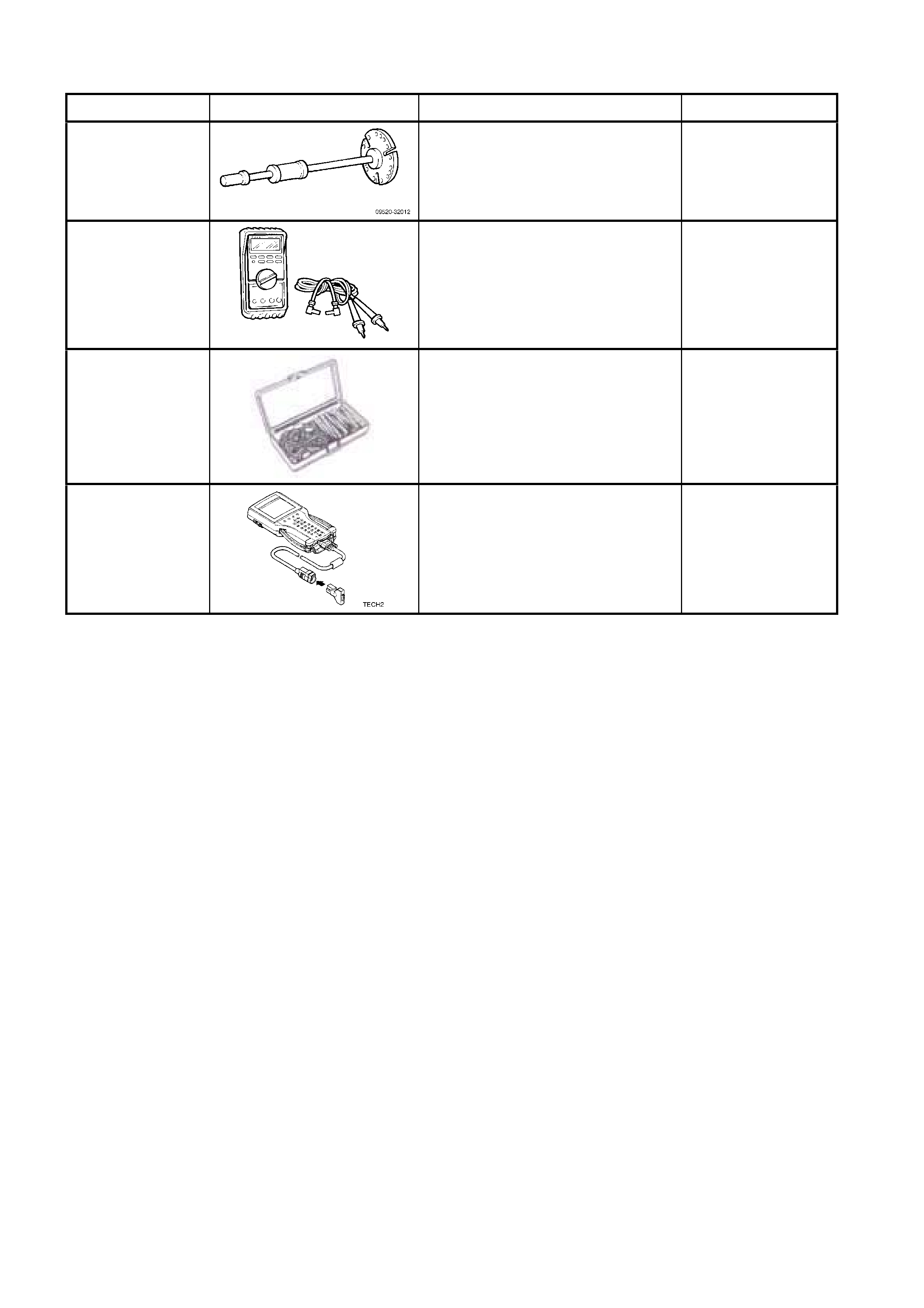
8. SPECIAL TOOLS
TOOL NUMBER ILLUSTRATION DESCRIPTION CLASSIFICATION
7374
SLIDE HAMMER & PLATE
Used to remove inner axle shafts from
the final drive assembly
Desirable
3588
DIGITAL MULTIMETER
Also Previously released as J39200 (or
use commer cia l equiv al ent).
NOTE: The instrument must have 10
Megohms im pedance and be capable
of reading frequencies.
Available
J35616-A
CONNECTOR ADAPTOR KIT
Used when carrying out electrical
diagnost ic cir cui t chec ks.
Desirable
TECH 2
DIAGNOSTIC SCAN TOOL
Previously released.
Mandatory