
SECTION 6A2 - ENGINE MECHANI CAL -
V6 SUPERCHARGED ENGINE
IMPORTANT
Before performing any Service Operation or other procedure described in this Section, refer to Section 00
CAUTIONS AND NOTES for correct workshop practices with regard to safety and/or property damage.
CONTENTS
1. GENERAL INFORMATION
1.1 GENERAL DESCRIPTION
1.2 SYSTEM COMPONENTS
SUPERCHARGER ASSEMBLY
SUPERCHARGER DRIVE BELT TENSIONER
BALANCE SHAFT
CAMSHAFT SPROCKET
CRANKSHAFT BALANCER
ROCKER COVERS AND GASKETS
CONNECTING RODS
PISTONS AND PINS
CYLINDER HEADS AND GASKETS
FUEL INJECTORS
LOWER INTAKE MANIFOLD AND GASKETS
THROTTLE BODY ADAPTOR
FUEL RAIL
BYPASS VALVE ACTUATOR
BOOST CONTROL SOLENOID VALVE
WATER OUTLET HOSE AND RADIATOR
INLET PIPE
SUPERCHARGER DRIVE BELT IDLER
PULLEY AND BELT TENSIONER
FLEXPLATE
PCM CALIBRATION
HIGH TENSION LEADS
DIS COILS AND SPARK PLUGS
2. SERVICE OPERATIONS
2.1 SUPERCHARGER OIL LEVEL CHECK
2.2 SUPERCHARGER AND GASKET
REMOVE
REINSTALL
2.3 BYPASS SOLENOID HARNESS ASSEMBLY
REPLACE
2.4 THROTTLE BODY
REMOVE
REINSTALL
2.5 THROTTLE BODY ADAPTOR
REMOVE
REINSTALL
2.6 ENGINE VENTILATION SYSTEM
2.7 FUNCTIONAL CHECK OF CRANKCASE
VENTILATION VALVE
2.8 CRANKCASE VENTILATION VALVE
REPLACE
2.9 SUPERCHARGER DRIVE BELT
TENSION CHECK
INSPECT
REMOVE
REINSTALL
2.10 SUPERCHARGER DRIVE BELT TENSIONER
ASSEMBLY
REMOVE
REINSTALL
3. SPECIFICATIONS
4. TORQUE WRENCH SPECIFICATIONS
5. SPECIAL TOOLS
Techline
Techline
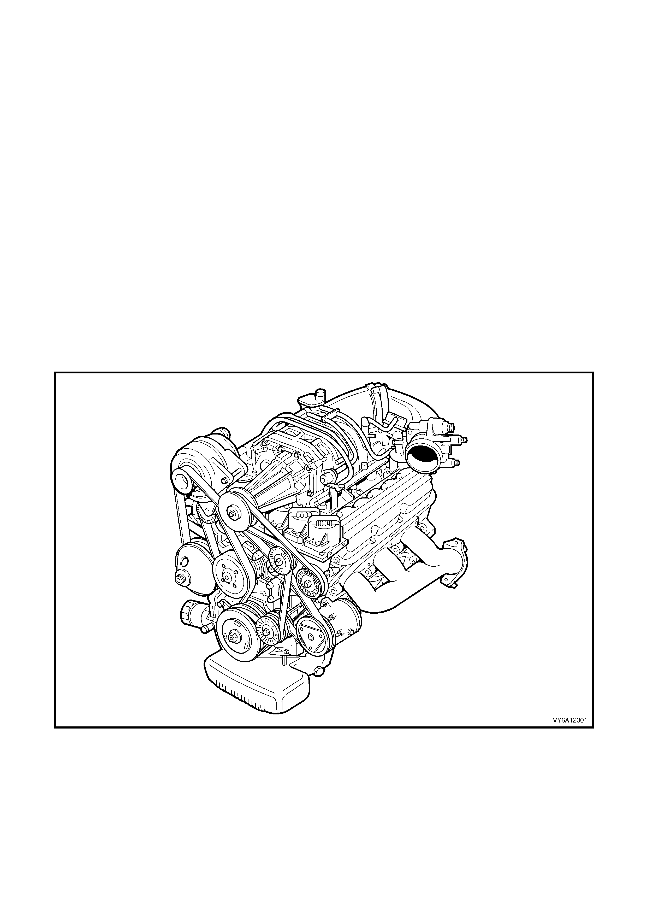
1. GENERAL INFORMA TION
A supercharged engine is available as an option on some MY 2003 VY and V2 Series model vehicles. The
superchar ged engi ne gives the benefit of muc h impr oved power and tor que at l arge throttle op enings e quiva lent to
having a lar ger c apacit y engin e. Fu el ec onomy is better tha n a larger capac it y en gine as the sup erchar ger b oost is
cut at low throttle openings, where the engine performs similarly to its normally aspirated counterpart. The
supercharger does not suffer from the lag that a turbocharger exhibits, and because of its more friendly
operating environment, it is more reliable than a turbocharger. For supercharger diagnosis, refer to
Section 6C2 POWERTRAIN MANAGEMENT – V6 S/C ENGINE in the MY 2003 VY and V2 Series Service
Information.
1.1 GENERAL DESCRIPTION
The supercharger is a positive d isplacement pum p that consists of t wo counter-rotating ro tors in a housi ng with an
inlet port and outlet port. The rot ors are designed with three lobes and a helical t wist. An air bypass circuit is built
into the housing.
Rotors in the supercharger are designed to run at a minimal clearance, not in contact with each other or the
housing. The rotors are timed to each other by a pair of precision spur gears which are pressed onto the rotor
shafts . The f orward end of the rotors ar e held in posit ion by deep groo ve ball bearings . The back end of the rotors
are supported by sealed roller bearings.
The gears and ball bearings are lubricated by a synthetic oil from the oil reservoir in the supercharger and do not
rely on eng ine oil f or lubr icatio n. The cov er on the su percharger c ontains the inp ut shaft which is sup ported by two
deep groove ball bearings and coupled at one end to the rotor drive gears. A pulley is pressed onto the other end of
the input shaft. The bearings for the input shaft are also lubricated by the synthetic oil.
Engine m echanical s ervice opera tions f or the V6 Sup ercharged en gine carr y over in general f rom those de scribed
for the non-supercharged V6 engine in Section 6 A1-1 ENGINE MECH ANIC AL – V6 ENGIN E.
Figure 6A2-1
1.2 SYSTEM COMPONENTS
SU PE R C HAR G E R ASS E MB LY
The supercharger is designed to pump more air than the naturally aspirated engine would normally use. This air
creates a boost pressure in the intake manifold.
Maximum boost can range from 50 - 75 kPa. Since the supercharger is a positive displacement pump and is
directl y driven from the engine accessor y drive system, boost pressure is a vailable at all driving conditions. When
boost is n ot desired, suc h a s during idle a nd l ig ht thrott l e c r uising , the ex c ess air th at the s u perc har ger is producing
is recirculated via the bypass passage between the lower intake manifold and the supercharger inlet.
This bypass c ircuit is regu lated by a b ypass valve whi ch is s im ilar to a th rottle p late. T he b ypass v alve is con troll ed
by a vacuum actuator which is connected to the vacuum source between the throttle and the supercharger inlet.
Spring force from the actuator holds the valve closed to create boost and vacuum pulls the valve open when the
throttle closes.
The open bypass valve reduces pumping loss thereby increasing fuel efficiency. A PCM controlled solenoid valve is
used to reduce boost in the event of engine overheating as signalled by excessive coolant temperature.
For additional information on supercharger and boost control operation, refer to Section 6C2 POWERTRAIN
MANAGEMENT – V6 S/C ENGINE MY 2003 VY and V2 Series Service Information.
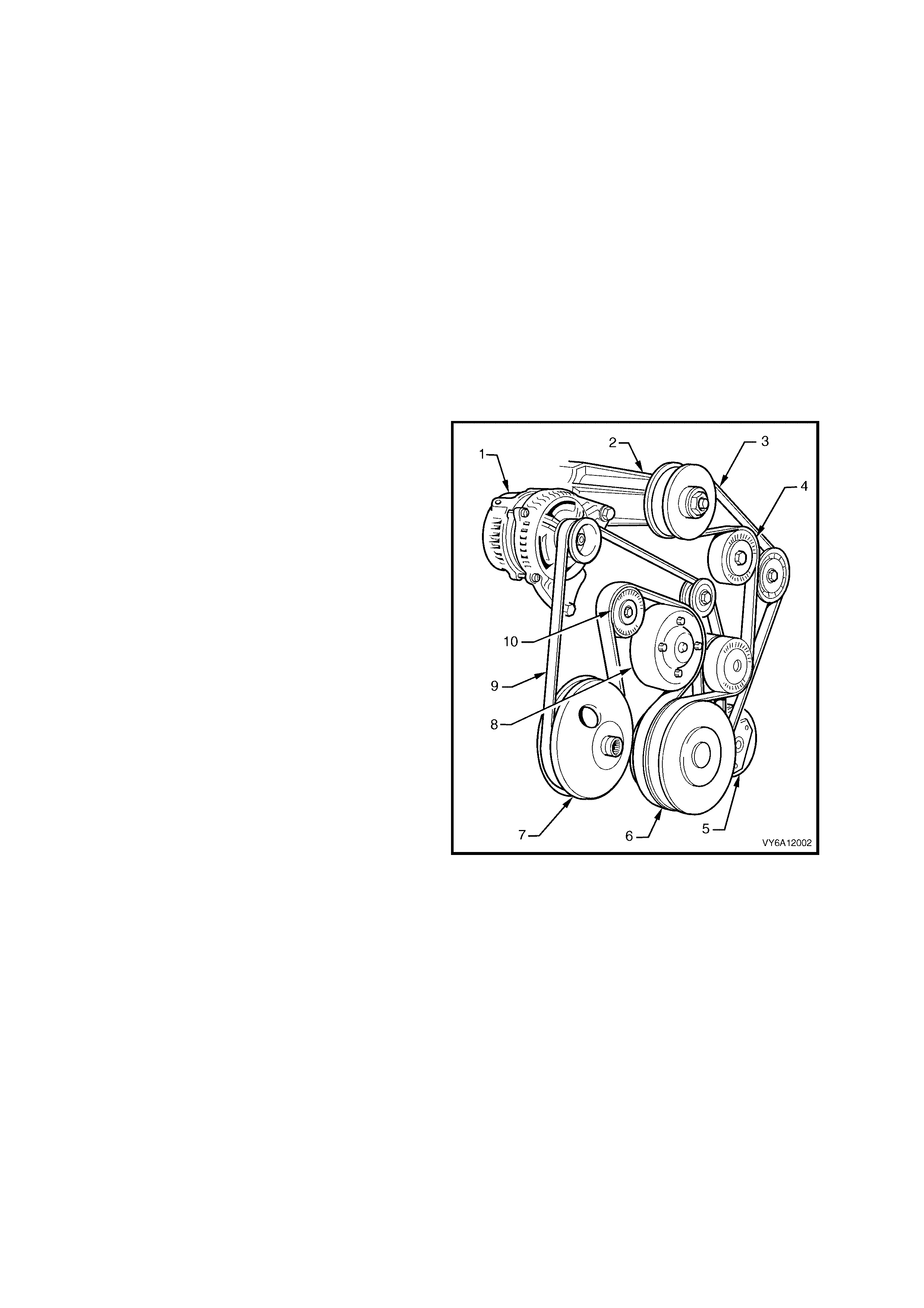
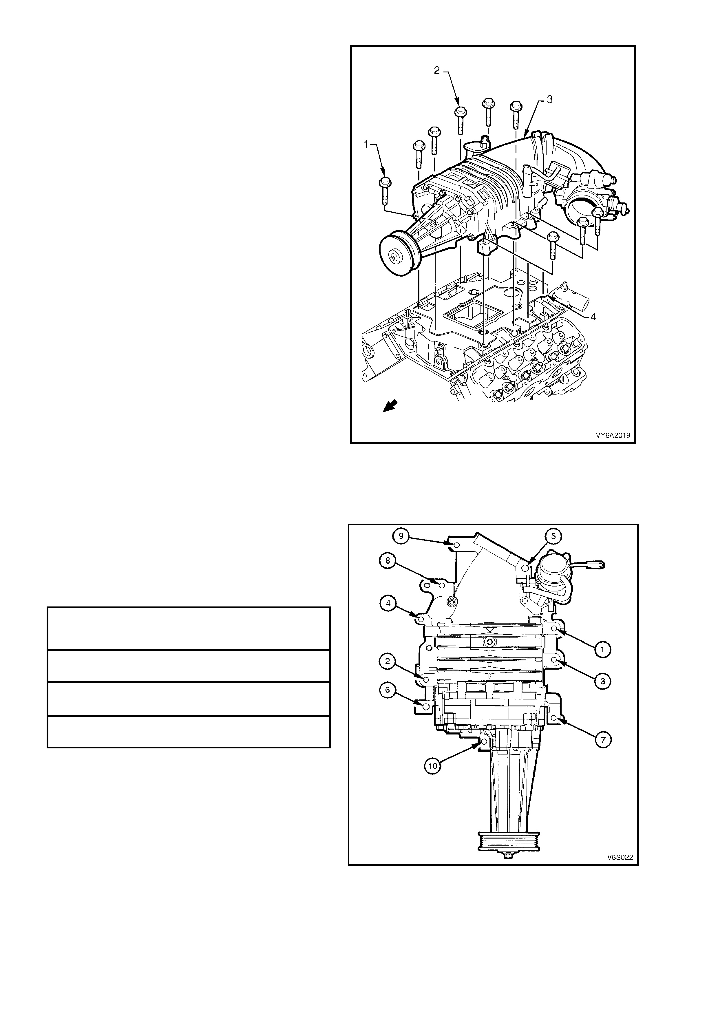
SUPERCHARGER DRIVE BELT TENSIONER
The supercharged engine uses two accessory
drive belts. The inner belt (9) drives the generator
(1), water pump (8), air conditioning compressor
(5) and power s teering pum p (7). The outer belt ( 3)
drives the supercharger (2). All belt driven
accessories are rigidly mounted to the engine.
Drive belt tension is maintained by the spring
loaded belt tens ioners (4 and 10). Eac h be lt has its
own tensioner.
A belt squeak when the engine is started or
stopped is normal and has no effect on belt
durability.
The drive belt tensioner can control belt tension
over a broad range of belt lengths due to
stretching; however, there are limits to the
tensioners ability to compensate. Using the
tensioner outside of its operating range can result
in poor tension control and/or damage to the
tensioner. The belt should be replaced when this
condition occurs.
Legend:
1. Generator
2. Supercharger
3. Supercharger Drive Belt (Outer)
4. Outer Drive Belt Tensioner Assembly
5. Air Conditioning Compressor
6. Crankshaft Balancer Assembly
7. Power Steering Pump Pulley
8. Coolant Pump
9. Accessory Drive Belt (Inner)
10. Inner Drive Belt Tensioner Assembly
Figure 6A2-2
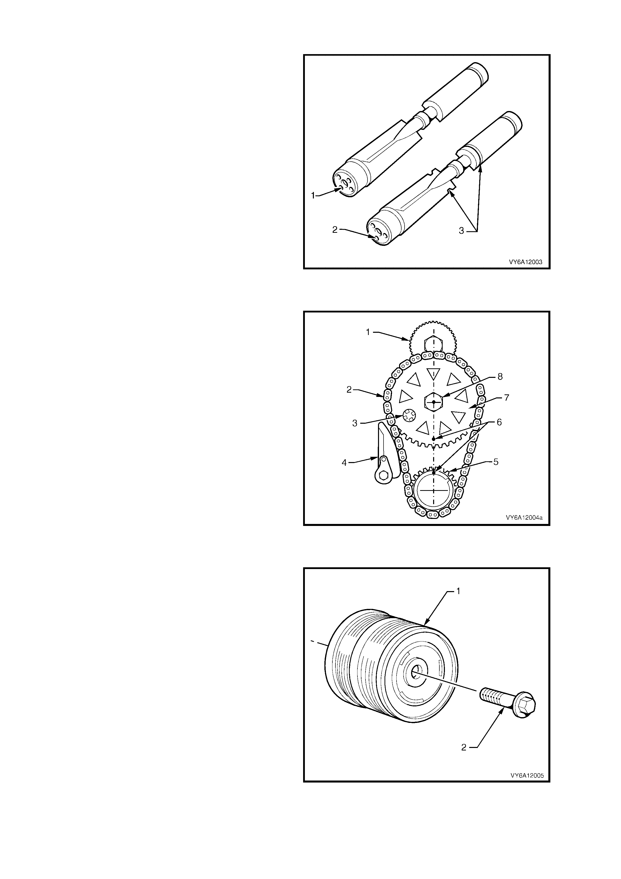
BALANCE SHAFT
The supercharged engine balance shaft has
revised balance specifications and can be
identified by the four lubrication holes (1) at the
rear bushing end of the shaft.
By contrast, the non-supercharged engine, can be
identif ied by the thre e holes (2) at the r ear bushing
end and the two groves (3).
Figure 6A2-3
CAMSHAFT SPROCKET
The camshaft sprocket (7) for the supercharged
engine can be identified by triangular holes while
the standard sprocket retains round holes.
Legend:
1. Balance Shaft Drive Gear
2. Timing Chain Assembly
3. Magnet Assembly
4. Dampener Assembly
5. Crankshaft Sprocket
6. Timing Marks
7. Camshaft Sprocket
8. Camshaft Sprocket Retaining Bolt
Figure 6A2-4
CRANKSHAFT BALANCER
The crankshaft balancer (1) is a twin track type
with balance compensation specifically for the
supercharged engine.
The balancer is secured to the end of the
crankshaft by a bolt (2).
Figure 6A2-5
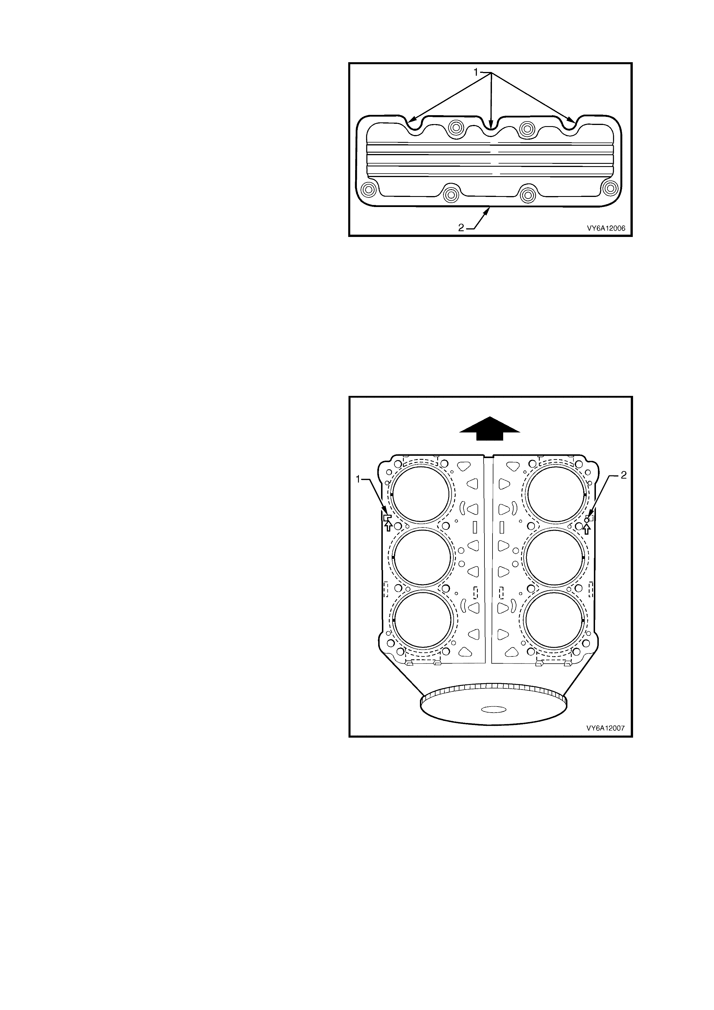
ROCKER COVERS & GASKETS
Rocker covers (2) and gaskets are modified with
cut outs (1) to suit relocation of the injectors in the
cylinder head inlet ports for the supercharged
engine.
Figure 6A2-6
CONNECTING RODS
The connecting rods have larger pin bush internal diameter and the big end/little end centre distance has been
revised.
PISTO NS AND PINS
Pistons and pins have been revised with a compression height of 30.6 mm and a larger floating piston pin of 23 mm
nominal diameter.
CYLINDER HEADS AND GASKETS
Cylinder heads have been machined for the
changed location of in-head fuel injectors. The
cylinder head gaskets feature revised material and
construction and are specific to each bank.
The arrows punched in each gasket must face the
engine front, as shown by the indicators, ‘1’ and ‘2’.
Figure 6A2-7
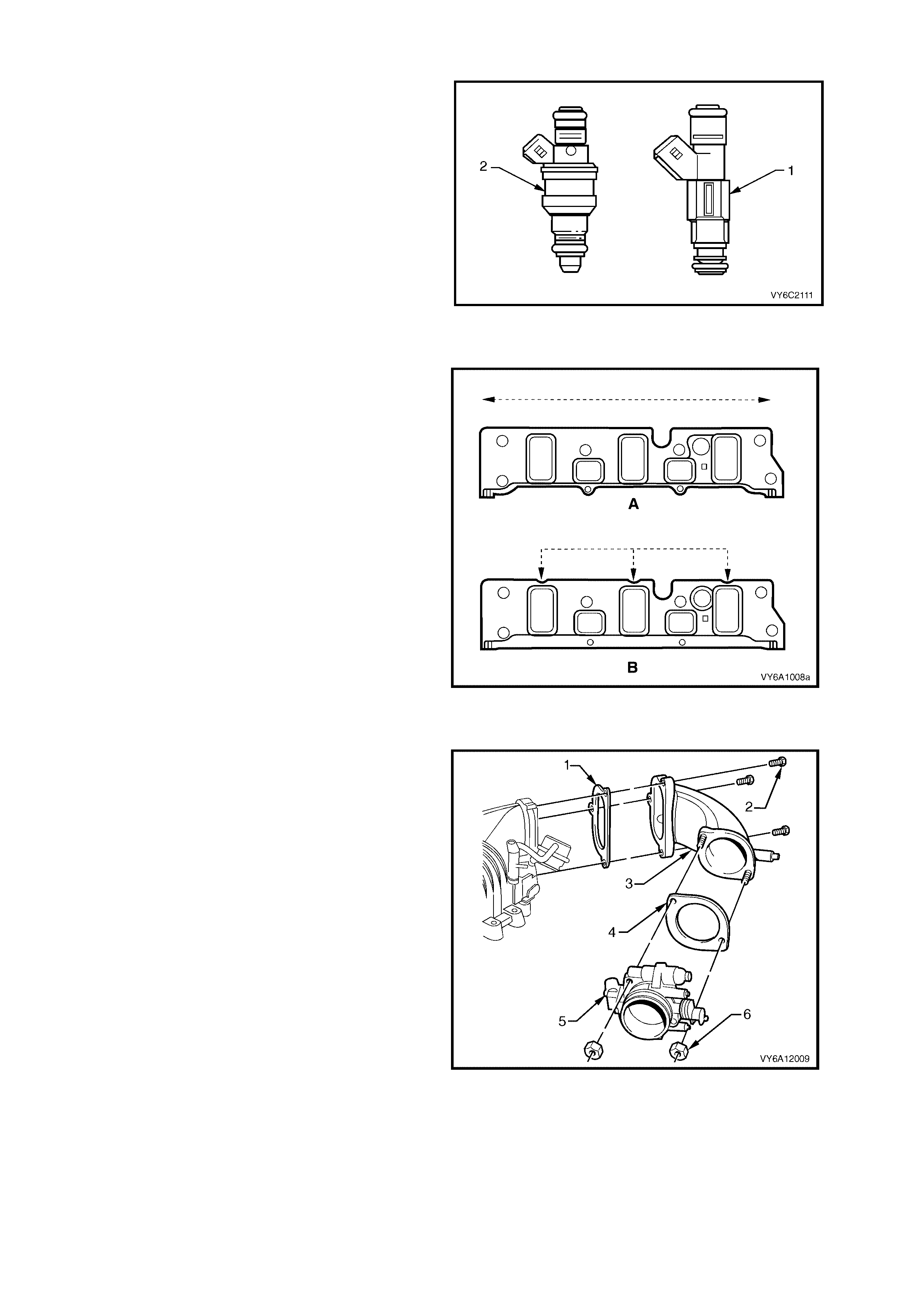
FUEL INJECTORS
Fuel injectors for the V6 Supercharged engine are
unique to this engine type and are of the high
capacity type.
Physically they are identified by (1), compared to
the naturally aspirated V6 i nj ec tor s (2) .
Figure 6A2-8
LOWER INTAKE MANIFOLD AND GASKETS
The lo wer int ake m anif old i s a machined alum inium
casting inc or por at ing th e lo wer s ect ion of the intake
ports, coolant and PCV passages. The top face is
machined flat to accommodate the supercharger
but, with the fuel injectors located in the cylinder
heads, cut-outs in view ‘B’ have b een incorporated
in the manifold gaskets for the injectors.
View ‘A’ shows the flat section on the non-
supercharged intake manifold.
Figure 6A2-9
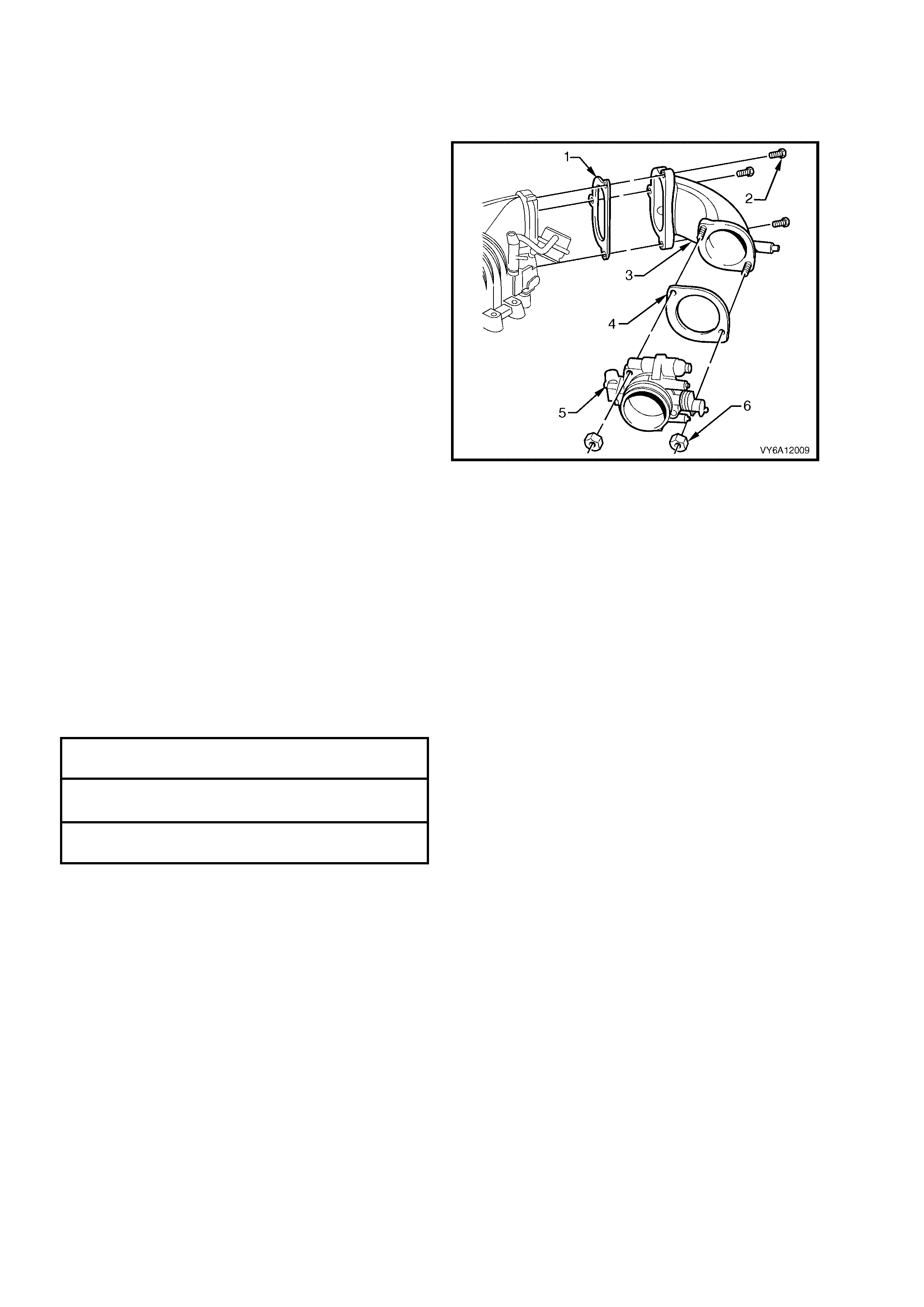
THROTTLE BODY ADAPTOR
The throttle b ody adaptor is a machined a luminium
casting which connects the remote throttle body to
the supercharger. The throttle body adaptor
includes br ak e boost er and heater vacuum nippl es,
cable bracket and mounting studs to suit the
superchar ger inlet.
Legend:
1. Adaptor Gasket
2. Bolts (3 places)
3. Throttle Body to Supercharger Adaptor
4. Throttle Body Gasket
5. Throttle Body Assembly
6. Nuts (2 places)
Figure 6A2-10
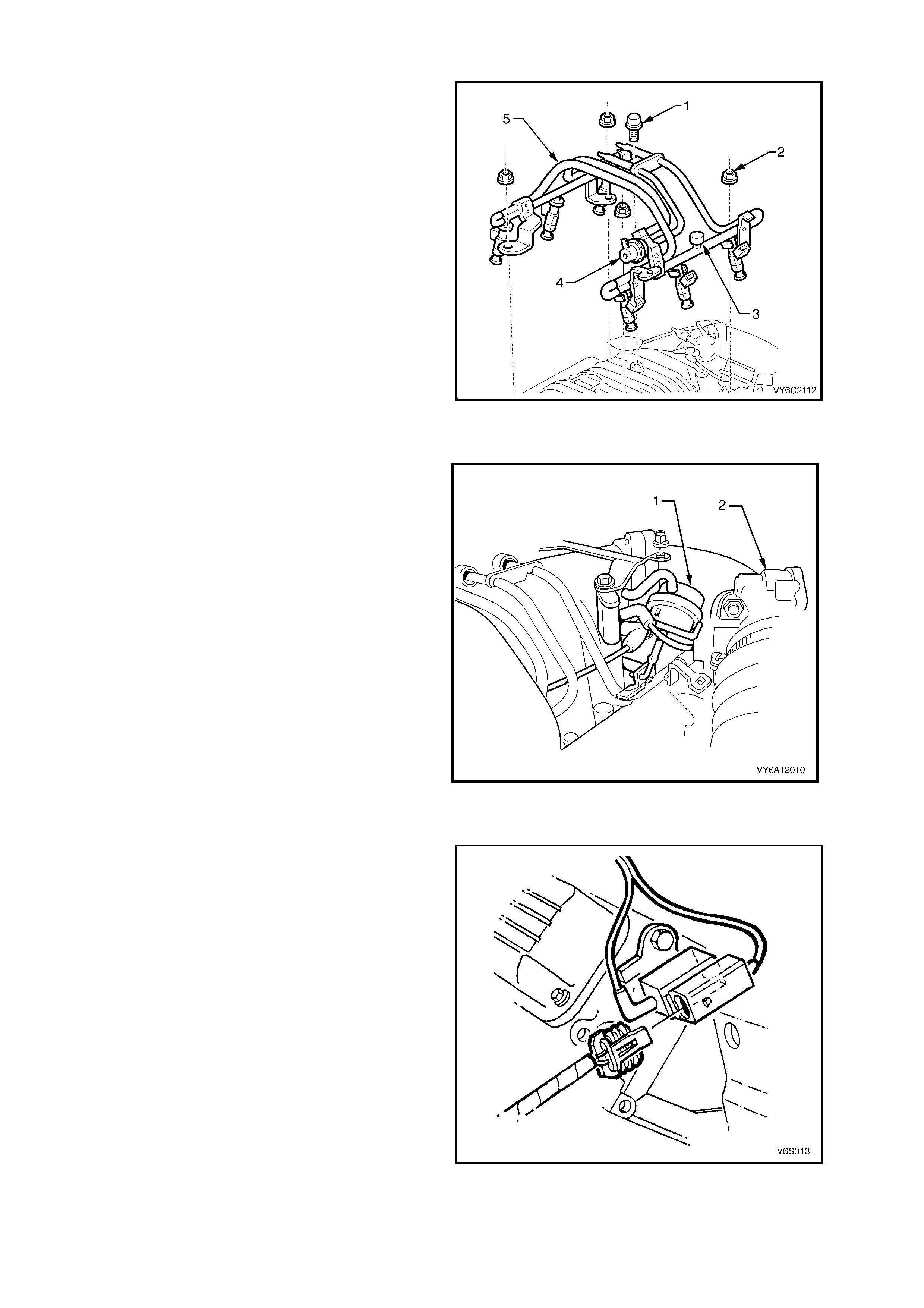
FUEL RAIL
The fuel rail assembly (5) is a steel tube type and
specif ic to t he su percharg ed en gine. Secur ed t o the
supercharger body with four nuts (2) and one bolt
(1), the fuel rail incorporates the fuel pressure
regulator (4) and a Schraeder valve (3) to enable
easy connection of a fuel pressure gauge. The fuel
pressure regulator (4) is not serviced separately
from the fuel rail.
Figure 6A2-11
BYPASS VALVE ACTUATOR
The supercharger bypass valve actuator (1)
operates a valve which can cut boost at idle or at
low throttle openings by diverting intake air around
the supercharger.
For additional information on bypass actuator
operation, refer to Section 6C2 POWERTRAIN
MANAGEMENT – V6 SUPERCHARGED
ENGINE in the MY 2003 V Y and V2 Ser ies Ser vice
Information.
Legend:
1. Supercharger Bypass Valve Actuator
2. Throttle Body
Figure 6A2-12
BOOST CONTROL SOLENOID VALVE
A boost control solenoid valve, located at the rear of
the left hand cylinder head is a PCM controlled
engine protec tion de vice which red uces boost in the
event of excessive coolant temperature.
Boost press ure is reduc ed by routing bo ost air from
the superch ar ger outlet v ia the sol eno id t o the lower
chamber of the bypass actuator, which then opens
the bypass valve.
NOTE: Electrical connection must always be
maintained to the boost control solenoid value as
no voltage will trigger boost reduction even under
normal coolant temperature operation.
Figure 6A2-13
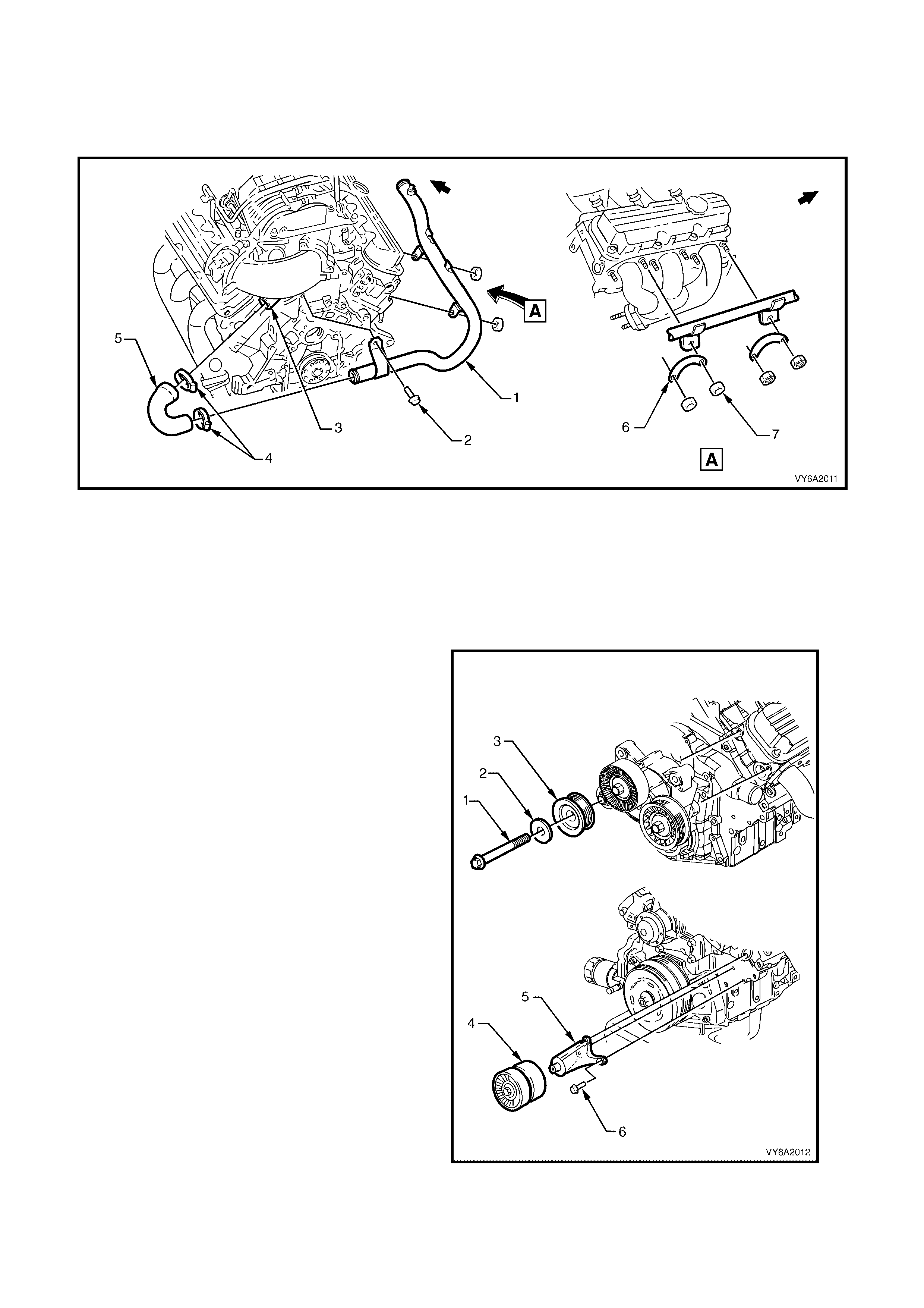
WATER OUTLET HOSE AND RADIATOR INLET PIPE
The water outlet hose connects the thermostat hosing outlet port to the radiator inlet pipe to convey the engine
coolant f rom the bac k of the intak e manifold t o the radiat or inlet port. T he therm ostat housing c over is a m achined
aluminium casting which includes the cooling system bleeder valve. The therm ostat housing is located at the rear
of the intake manifold.
Figure 6A2-14
Legend
1. Radiator Inlet Pipe
2. Bolt
3. Coolant Outlet
4. Hose Clamps (2 places)
5. Coolant Outlet Hose
6. Plate
7. Nut
SUPERCHARGER DRIVE BELT IDLER PULLEY & BELT TENSIONER
There are two flat idler pulleys (4) for accessory
drive and supercharger drive, mounted on an
aluminium bracket (5) adjacent to the crankshaft
balancer and DIS coil pack.
Legend:
1. Bolt
2. Cover
3. Grooved Tensioner Pulley
4. Twin, Flat Idler Pulleys
5. Bracket
6. Bolt
Figure 6A2-15
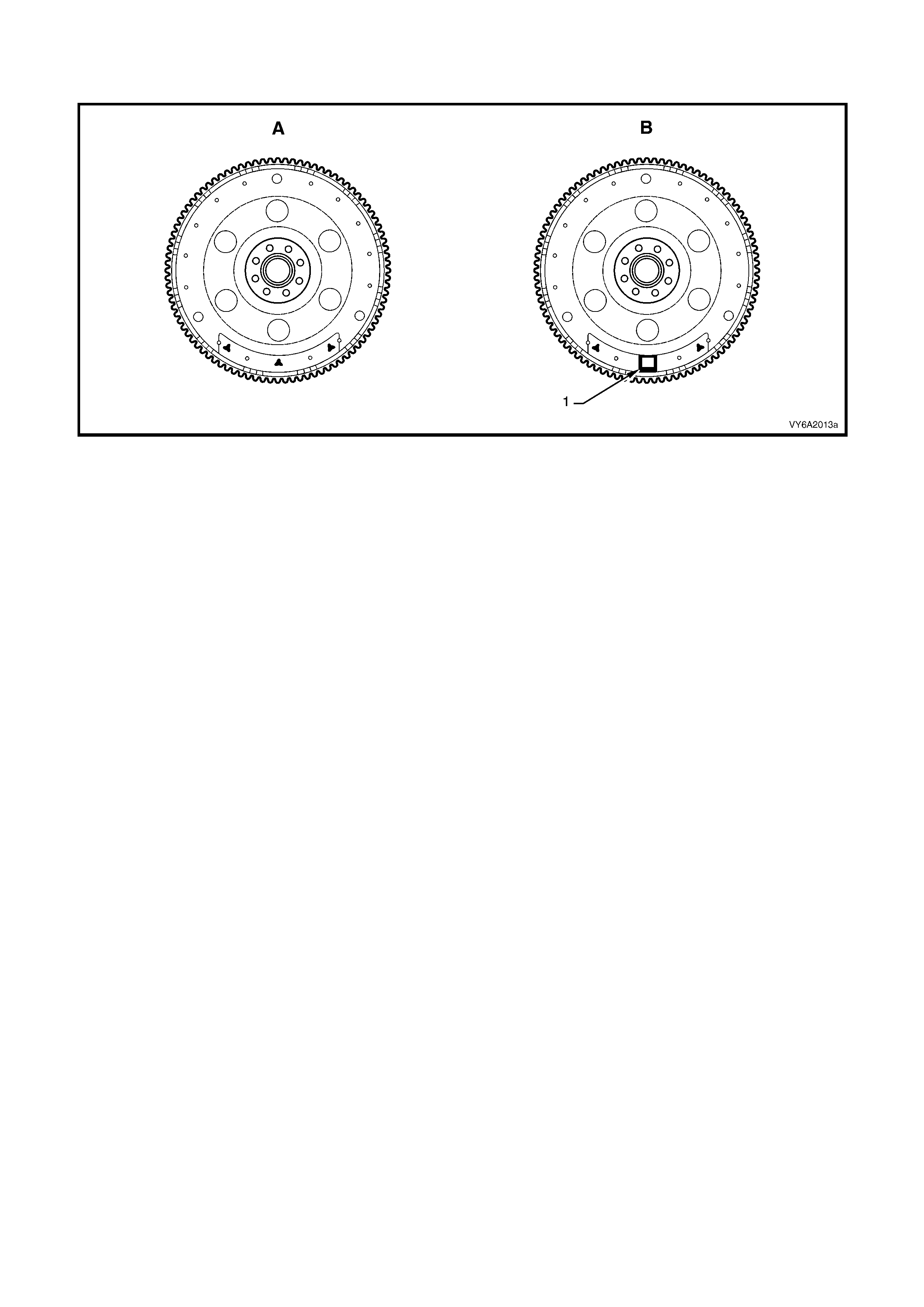
FLEXPLATE
The flexplate for the supercharged engine has revised balancing, as shown by ‘1’ in view ‘B’.
Figure 6A2-16
Legend
A V6 N on-Supercharg ed Engine
B V6 Supercharged Engine
1. V6 Supercharged Engine Balance Weight
PCM CALIBRATION
The supercharged engine PROM has revised calibration. For further information, refer to
Section 6C 2 POWERT RAIN M ANAGEMENT - V6 SUPERCH ARGED ENGINE in the M Y 2003 VY an d V2 Series
Service Information.
HIGH TENSION LEADS
The high tension leads are of low impedance for high energy coils with specific routing and retention. For high
tension lead routing, refer to Section 6C2-3 SERVICE OPERATIONS in Section 6C2 POWERTRAIN
MANAGEMENT - V6 SUPERCHARGED ENGINE in the MY 2003 VY and V2 Series Service Information.
DIS COILS & SPARK PLUGS
The coil and module assem bly is a Delco-high energy unit with specific bracketing. The spark plugs are a specific
heat range and design for the supercharged engine.
2. SERVICE OPERATIONS
LT Section No. – 00-375
2.1 SUPERCHARGER OIL LEVEL CHECK
NOTE: A small amount of oil weepage thro ugh the front seal, (behind the pulley) of the supercharger assembly is
normal. This oil weepage is caused by minute traces of oil escaping around the seal. A build up of airborne dust
can adhere to the thin oil film which causes oil weepage to appear worse than it really is. The supercharger
assembly should not be replaced due to weepage. If supercharger oil is visually dripping or puddling from the
supercharger front seal, the supercharger assembly will need to be replaced. Refer to
2.2 SUPERCHARGER AND GASKET in this Section.
CAUTION: Do not remove the oil plug when engine is warm. Engine should be cool to the touch.
Appro ximately 2 – 3 hours after running. Removing oil plug at warm engine temperatures can cause hot oil
to overflow. This could result in oil loss and possible personal injury.
Lubricant level is to be checked at the specified service intervals outlined in the MY 2003 VY and V2 Series,
Owner’s Handbook.
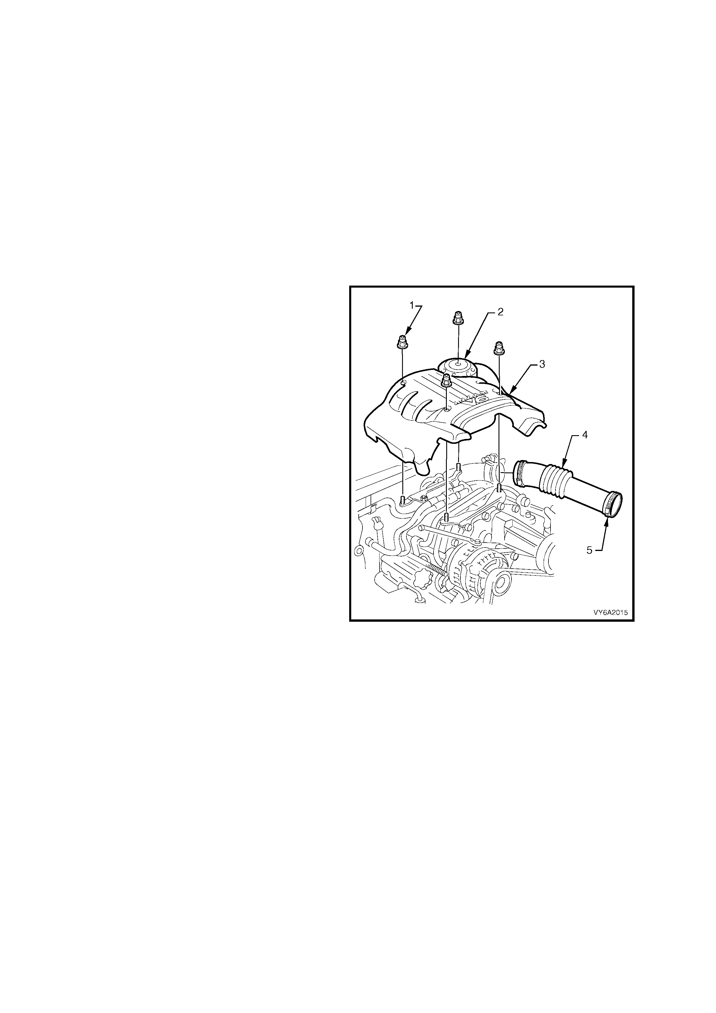
1. Remove the four dome nuts (1) securing the
engine dress cover assembly (3) to the
mounting br ack et studs , then rem ove th e cov er
assembly.
2. Loosen the two hose clamps (5), then remove
the air intake duct (4) from the mass air flow
sensor and thrott le body.
Figure 6A2-17
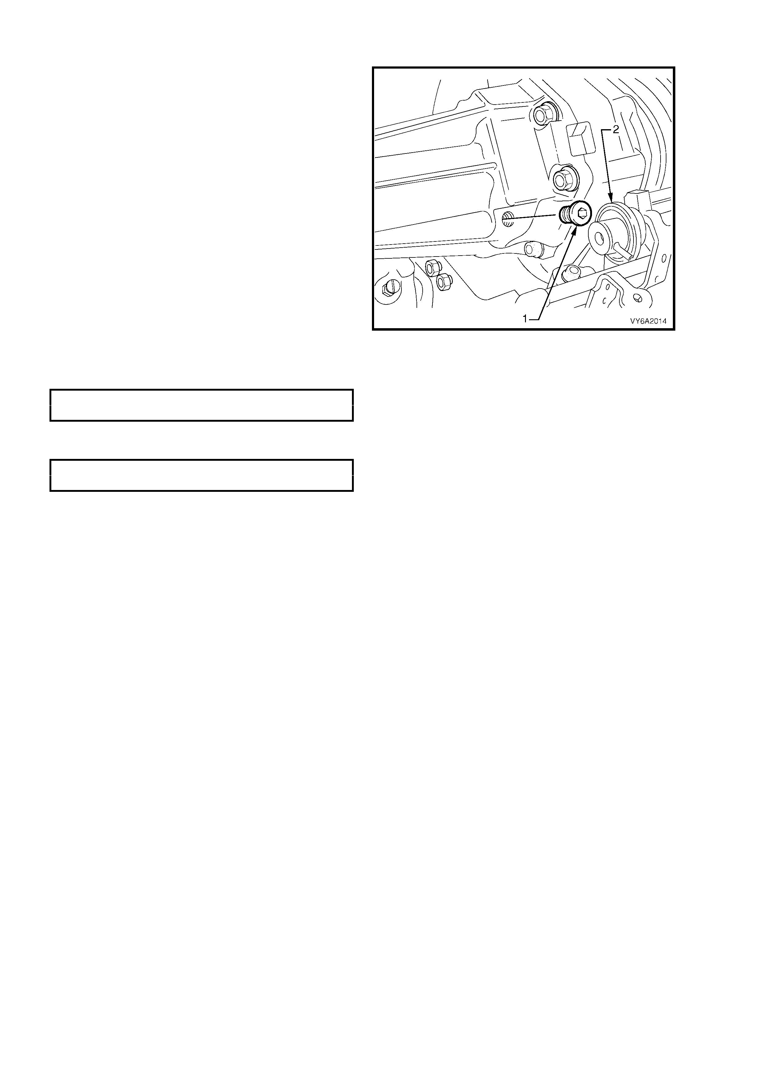
NOTE: To prevent contamination of the
superchar ger oil, cl ean the ar ea around the oi l filler
plug before removing.
3. Using a 3/16 inch Allen key socket, remove
supercharger filler plug (1).
4. Check oil level, which should be maintained to
a level at the bottom of the threads in the oil
filler plug inspection hole in the supercharger
housing.
IMPORTANT: Do not us e petrole um bas ed oil. Use
only GM P/N 12345982 synthetic oil. Use of other
lubricant may cause supercharger failure.
Figure 6A2-18
5. Reins tall the o il filler plu g, ensuring s ealing cap O –ring is in p lace on plug. T ighten the f iller plug to th e correct
torque specification.
SUPERCHARGER OIL FILL ER
PLUG TORQUE SPECIFICATION 10 Nm
6. Reins tall engin e dress cover to the mounting br ackets, ensur ing that stud grom mets in the dress cover re main
in place. Tighten securing dome nuts to the correct torque specification.
ENGINE DRESS COVER DOME
NUT TORQUE SPECIFICATION 5 Nm
2.2 SUPERCHARGER AND GASKET
LT Section No. – 00-375
REMOVE
NOTE: Servicing of the supercharger unit itself is
limited to replacement only. No attempt should be
made to disassemble the supercharger as parts
damage may result.
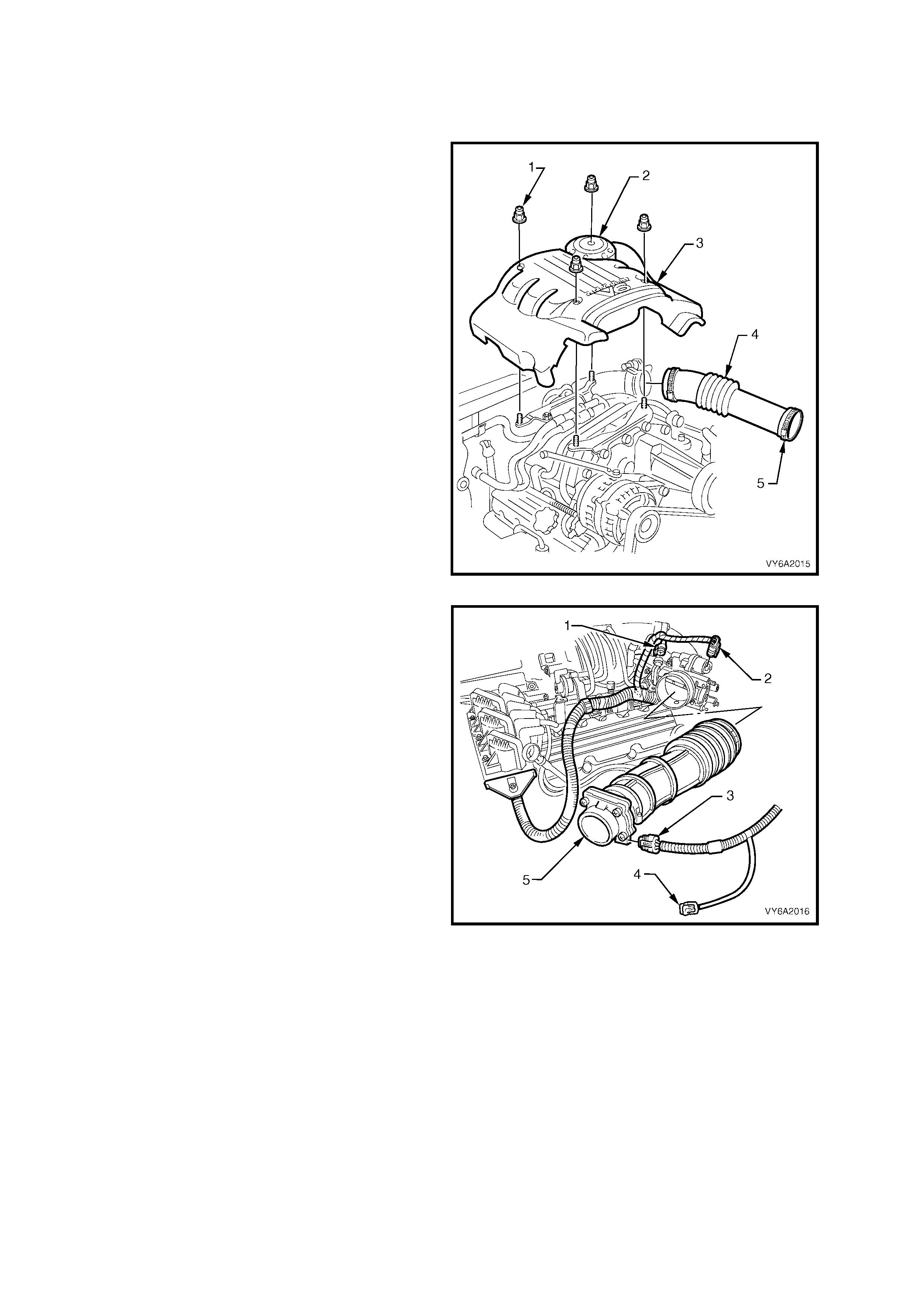
1. Remove the four dome nuts (1) securing the
engine dress cover assembly (3) to the
mounting br ack et studs , then rem ove th e cov er
assembly.
2. Loosen the two hose clamps (5), then remove
the air intake duct (4) from the mass air flow
sensor and thrott le body.
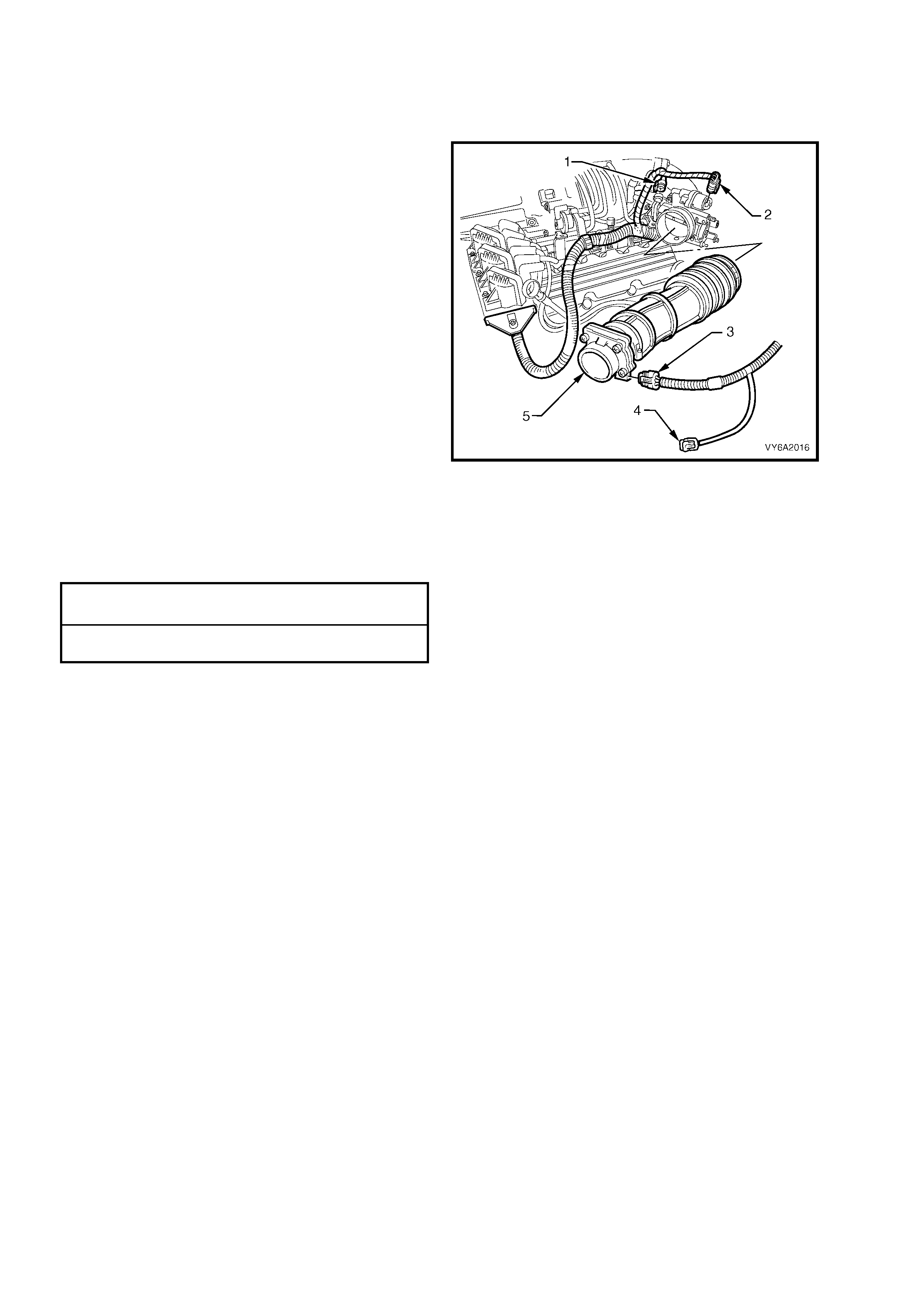
Figure 6A2-19
3. Disconnect the electrical connectors from the
TP sensor (1) IAC valve (2), MAF (3) and IAT
(4) sensors, then place harness to one side.
4. Rem ove the clamps securing air intake duct to
the throttle body and mass air flow sensor to
air filter, removing duct and sensor assembly.
Figure 6A2-20
5. Remove the screws securing rear dress cover
bracket and boost solenoid harness.
6. Disconnect supercharger vacuum connections
from heating/ventilation system (3), throttle
body (2), fuel pressure regulator, boost
solenoid harness and engine ventilation hose.
7. Remove bypass solenoid harness, refer to
2.3 BYPASS SOLENOID HARNESS
ASSEMBLY in this Section, and BYPASS
VALVE ACTUATOR in Section 6C2-3
POWERTRAIN MANAGEMENT – V6
SUPERCHARGED ENGINE in the MY 2003
VY and V2 Series Service Information.
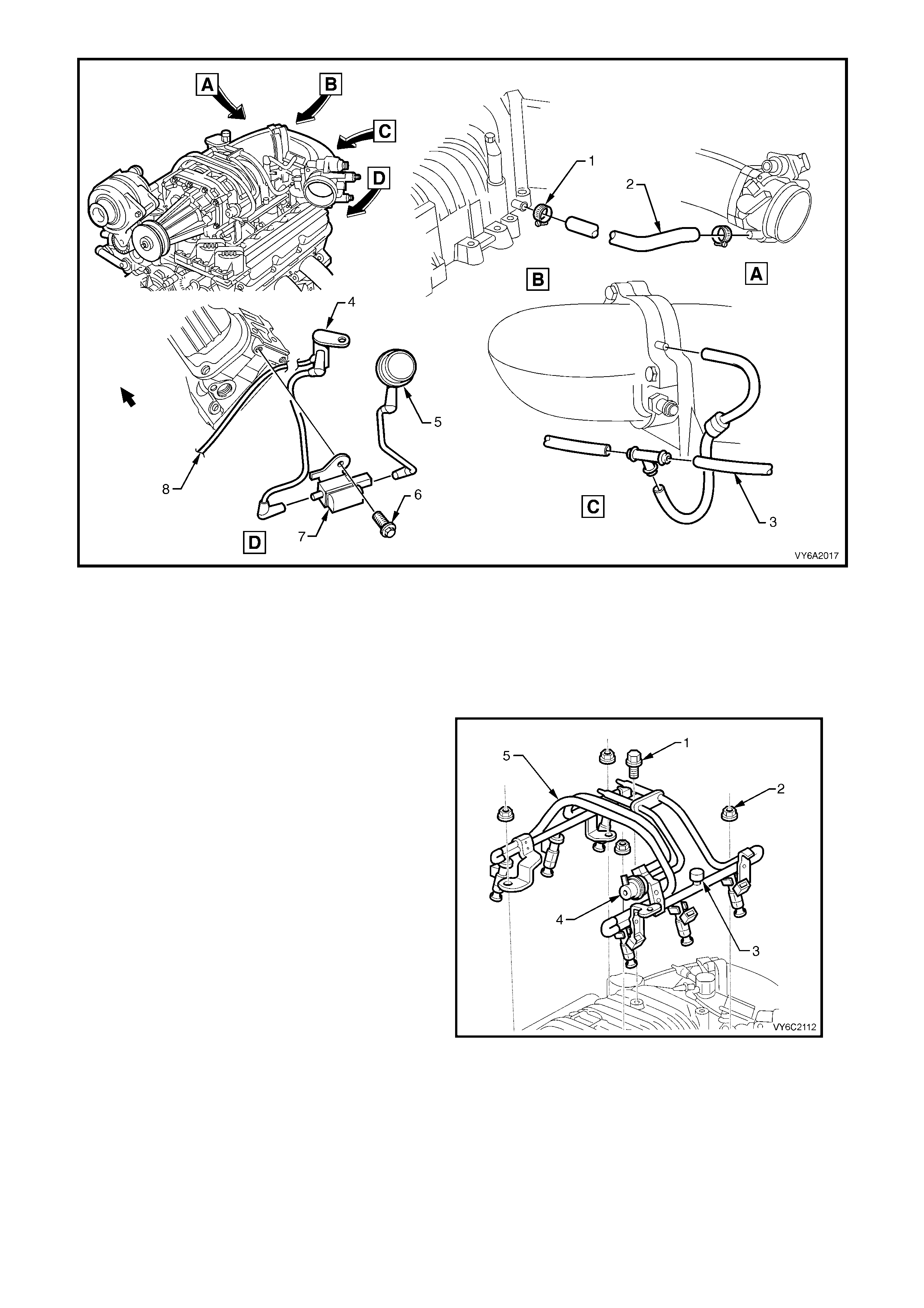
Figure 6A2-21
Legend
1. Hose Clamp ( 2 places)
2. Hose – Throttle Body to Intake Manifold
3. Hoses – Heater Control, Vacuum Supply
4. Harness – Boost Control Solenoid
5. Bypass Actuator
6. Screw
7. Solenoid Valve – Boost Control
8. Hose – to Pressure Regulator
9. Depressurise the fuel rail, refer to
Section 6C2-3 SERVICE OPERATIONS in
Section 6C2 POWERTRAIN MANAGEMENT –
V6 SUPERCHARGED ENGINE in the MY 2003
VY and V2 Series Service Information and
disconnect the electrical connectors from
injectors.
10. Remove the generator support bracket.
11. Disconnect the fuel lines from the fuel rail
assembly and remove the fuel rail, refer to
Section 6C2-3 SERVICE OPERATIONS in
Section 6C2 POWERTRAIN MANAGEMENT –
V6 SUPERCHARGED ENGINE.
Legend:
1. Bolt
2. Nut (4 places)
3. Pressure Relief Schraeder Valve
4. Fuel Pressure Regulator
5. Fuel Rail
Figure 6A2-22
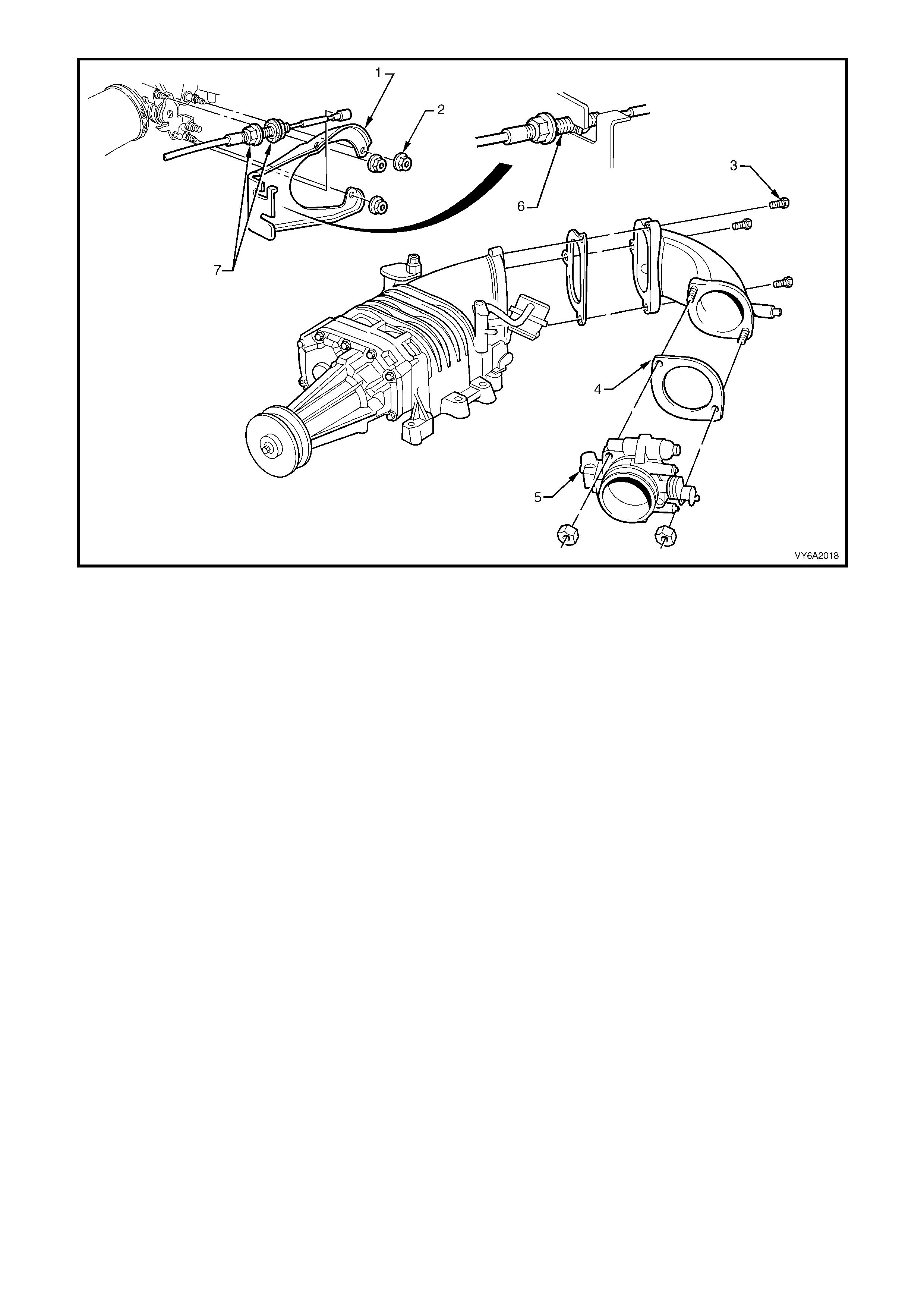
Figure 6A2-23
Legend
1. Mounting Bracket
2. Mounting Bracket Nuts (3 places)
3. Adaptor Assembly Attaching Bolts
4. Throttle Body to Adaptor Gasket
5. Throttle Body
6. Outer Throttle Cable Position
7. Throttle Cable Adjusting Nuts (Not to be removed)
8. Disconnect throttle cable and where fitted, the cruise control cable.
9. Remove throttle body from throttle body adaptor, refer to 2.4 THROTTLE BODY in this Section.
10. Remove the drive belt from supercharger
pulley, refer to 2.9 SUPERCHARGER DRIVE
BELT in this Section.
11. Remove supercharger to intake manifold bolts
(1 and 2), then remove the supercharger
assembly (3).
CAUTION: Do not place fingers or foreign
objects near supercharger vanes as personal
injury or damage to supercharger vanes can
result.
12. Remove supercharger gasket and O-rings (4).
Figure 6A1-24
REINST ALL
Installation of the supercharger is the reverse of
removal operations noting the following points:
1. Ensure that all mating surfaces are clean.
2. Sup ercharger to in take manifold g asket and O-
rings must be replaced.
3. The tightening sequence shown, and the
torque specification must be maintained.
SUPERCHARGER ATTACHING BOLT
TORQUE SPECIFICATION Stage 1 15 Nm
Stage 2 25 Nm
FUEL RAIL ATTACHING BOLT
TORQUE SPECIFICATION 25 Nm
FUEL RAIL ATTACHING NUT
TORQUE SPECIFICATION 10 Nm
ENGINE DRESS COVER NUT
TORQUE SPECIFICATION 5 Nm
Figure 6A2-25
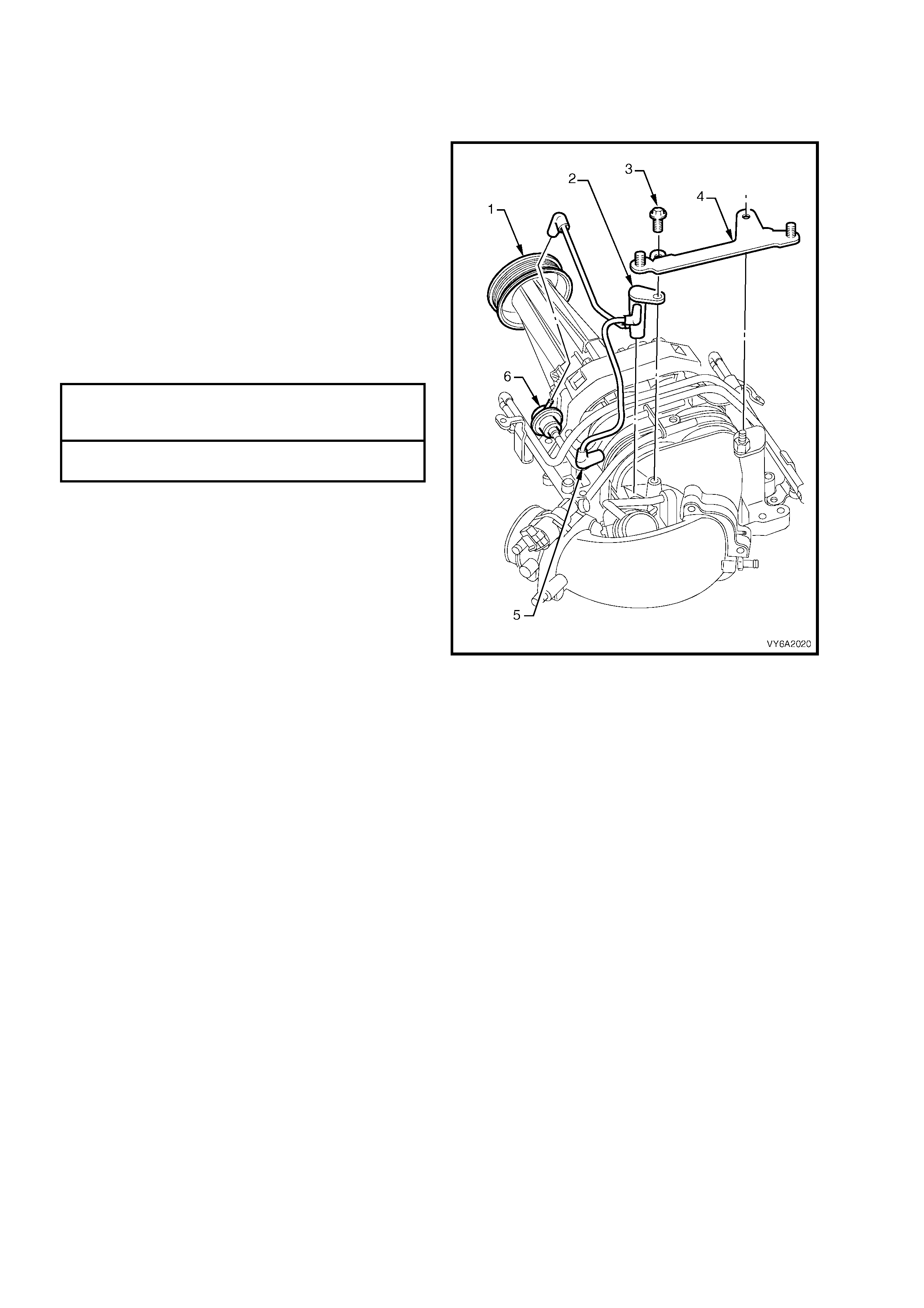
2.3 BYPASS SOLENOID HARNESS ASSEMBLY
LT Section No. – 03-300
REPLACE
1. Ensure that the ignition switch is turned to the
OFF position.
2. Remove the four engine dress cover dome
nuts and remove the cover.
3. Rem ove the sc rews ( 3) sec uring the re ar dres s
cover bracket (4) and boost control solenoid
harness (2).
4. Disconnect vacuum connections from fuel
pressure regulator (6) and bypass solenoid (5).
5. Reinstallation is the reverse of the above
removal operations, apart from tightening all
fasteners to the correct torque specifications.
ENGINE DRESS COVER
BRACKET BOLT/NUT
TORQUE SPECIFICATION 18 Nm
ENGINE DRESS COVER NUT
TORQUE SPECIFICATION 5 Nm
Legend:
1. Supercharger Assembly
2. Boost Control Solenoid Harness
3. Screw (2 places)
4. Engine Dress Cover, Rear Mounting Bracket
5. Vacuum Connection to Boost Control Solenoid
6. Fuel Pressure Regulator
Figure 6A2-26
2.4 THROTTLE BODY
LT Section No. – 03-300
REMOVE
1. Ensure that the ignition switch is turned to the
OFF position.
2. Disconnect the electrical connectors from the
TP sensor (1) IAC valve (2), MAF (3) and IAT
(4) sensors, then place harness to one side.
3. Rem ove the clamps securing air intake duct to
the throttle body and mass air flow sensor to
air filter, removing duct and sensor assembly.
4. Remove the t wo nuts s ec ur ing t he t hr ott le body
assembly to the throttle body adaptor and
remove the assembly.
Figure 6A2-27
REINST ALL
Apart from a requirement to tighten fasteners to the
correct torque specifications, reinstallation is the
reverse to removal operations.
THROTTLE BODY NUT
TORQUE SPECIFICATION 18 Nm
ENGINE DRESS COVER NUT
TORQUE SPECIFICATION 5 Nm
2.5 THROTTLE BODY ADAPTOR
LT Section No. – 03-300
REMOVE
1. Ensure that the ignition switch is turned to the
OFF position.
2. Remove the four engine dress cover dome
nuts and remove the cover.
3. Remove the throttle body (5), refer to
2.4 THROTTLE BODY in this Section.
4. Remove the bypass solenoid harness and
bypass valve actuator, refer to 2.3 BYPASS
SOLENOID HARNESS ASSEMBLY in this
Section.
5. Disconnect the vacuum lines from the throttle
body adaptor.
6. Rem ove the b olts ( 2) sec uring the thr ottle b od y
adaptor (3) to the supercharger.
7. Remove the adaptor to supercharger gasket
(1) and discard.
Figure 6A2-28
REINST ALL
1. Apart from a requirement to tighten fasteners
to the correct torque specifications,
reinstallation is the reverse to removal
operations, except for the following:
a. Ensure bypass valve actuator preload is
adjusted correctly. Refer 6.5 BY-PASS
VALVE ACTUATOR, in Section 6C2-3
SERVICE OPERATIONS, in the MY 2003
VY and V2 Series Service Information.
b. Ensure all vacuum lines are connected
correctly.
THROTTLE BODY ADAPTOR
BOLT TORQUE SPECIFICATION 25 Nm
THROTTLE BODY NUT
TORQUE SPECIFICATION 18 Nm
ENGINE DRESS COVER NUT
TORQUE SPECIFICATION 5 Nm

2.6 ENGINE VENTILATION SYSTEM
The engine ventilation system, utilises engine vacuum to draw blow-by gasses into the combustion chambers
where they are recycled through the combustion process. The ventilation system should be checked at the
specified time or distance intervals in the MY 2003 VY and V2 Series, Owner’s Handbook.

2.7 FUNCTIONAL CHECK OF CRANKC ASE VE NTILATION VALVE
If an engine is idling rough, check for a clogged crankcase ventilation valve. Replace as required using the
follo wing proc ed ur e:
1. Remove crankcase ventilation valve from rear of supercharger, refer to 2.8 CRANKCASE VENTILATION
VALVE in this Section.
2. Shake valve and listen for the rattle of needle inside valve. If valve does not rattle, replace valve.
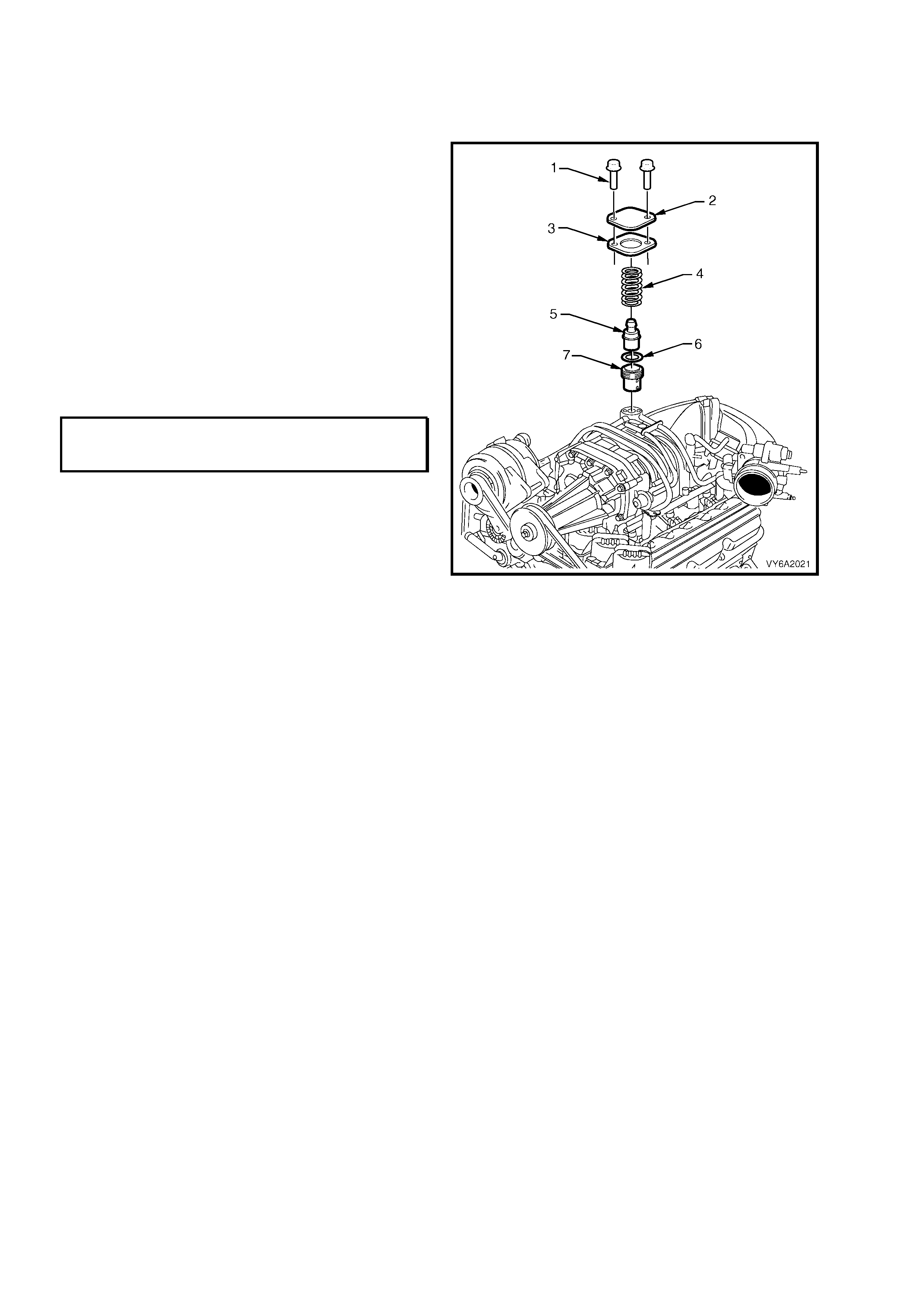
2.8 CRANKCASE VENTILATION VALVE
LT Section No. – 00-249
REPLACE
1. Remove the four engine dress cover dome
nuts and remove the cover.
2. Hold down the crankcase ventilation valve
cover (2) and remove the two cover retainer
screws (1).
3. Remove the crankcase ventilation valve cover
(2), gasket (3), crankcase ventilation valve (5),
spring (4) O-ring (6) and oil separation
baffle (7).
4. Reverse r em oval op eration s using new O -rin gs
and gasket, as necessary and tightening
fasteners to the specified torque specification.
NOTE: The holes in the oil separatio n baffle are to
be aligned at 90° to the engine centreline
CRANKCASE VENTILATION VALVE
COVER SCREW
TORQUE SPECIFICATION 5.0 Nm
Figure 6A2-29
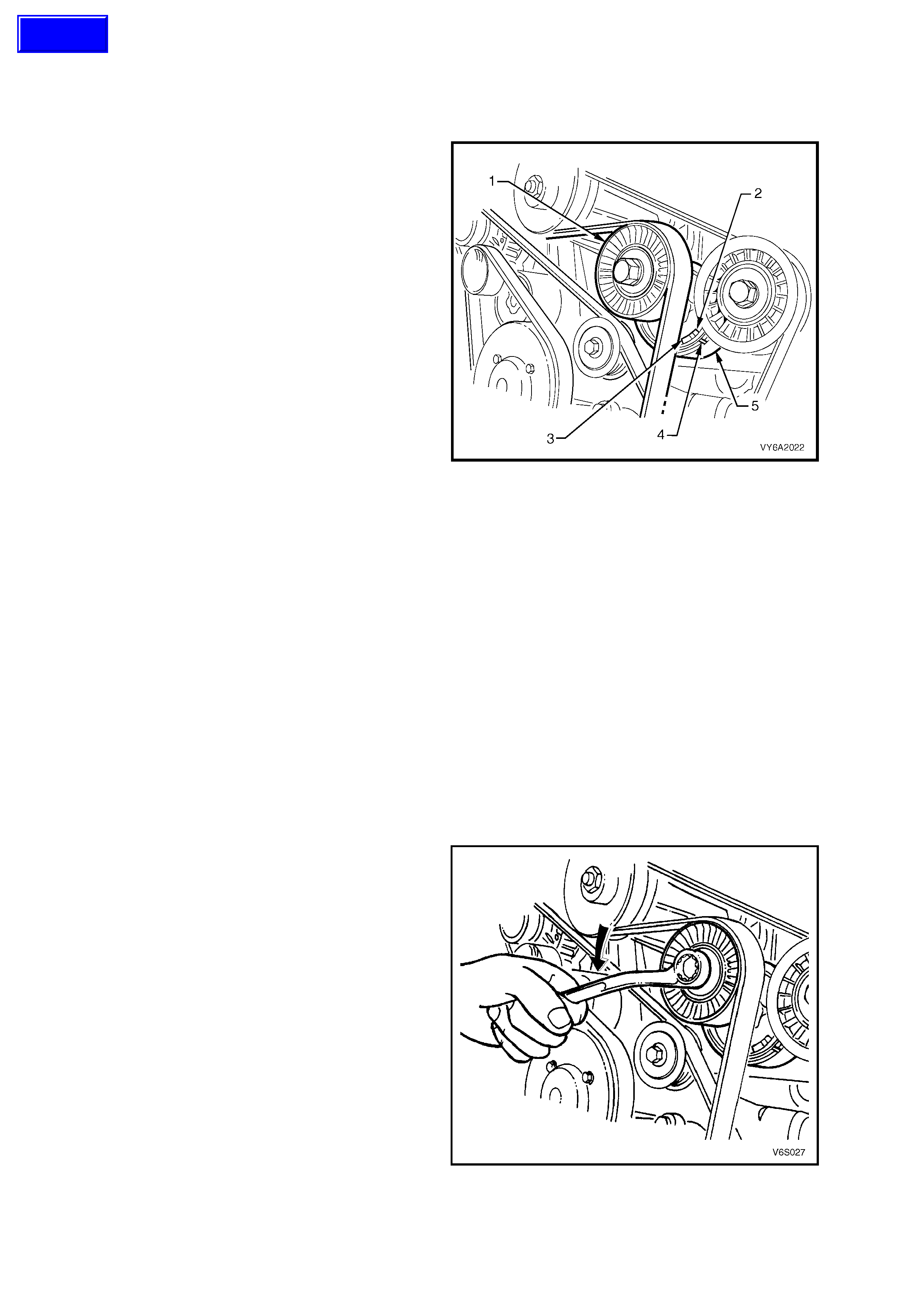
2.9 SUPERCH ARGER DRIVE BE LT
LT Section No. – 01-003
TENSION CHECK
1. Inspect tensioner markings to see if belt is
within operating limits. Replace belt if
excessively worn or outside the tensioner
operating range.
2. Run th e e ngi ne unt il warmed up. S witc h e ngi ne
off and read belt tension with Belt tensioner
tool BT3373-F placed between the
supercharger and upper idler pulley (bold
arrow). Remove tension gauge.
NOTE: Before carrying out drive belt tension,
check the calibration of Tool No. BT3373-F.
3. Run the e ngine again, allowing the drive belt to
stabilis e for 15 s econds. T urn engine off . Then,
using a 15 mm ring spanner, apply clockwise
force (tighten) to tensioner pulley (1) bolt.
Remove ring spanner and immediately take a
tension reading with Tool No. BT3373-F
without disturbing the belt tensioner assembly.
4. Using a 15 mm ring spanner, apply an anti-
clockwise force to tensioner pulley (1) bolt and
raise pulley to 'belt install' position. Slowly
lower pulley to 'at rest' position and take a
tension reading without disturbing belt
tensioner position. Recor d reading and rem ove
tool.
5. Average the three readings (add them
together, then divide by three). If the average
of the three readings is lower than 250 N and
the belt is within tensioner operating range,
replace be lt tens io ner.
Figure 6A2-30
Legend:
1. Tensioner Pulley
2. Minimum Tension Limit
3. Maximum Tension Limit
4. Indicator
5. Spring Loaded Tension Arm
INSPECT
This process is the same as that detailed for
the inner accessory drive belt. Refer to
2.7 DRIVE BELT, in Section 6A1-1 ENGINE
MECHANIC AL – V6 ENGI NE.
REMOVE
1. Disconnect the negative cable from the battery
terminal.
2. Remove the four engine dress cover dome
nuts and remove the cover.
3. Using a 15 mm ring spanner on supercharger
drive belt tensioner pulley pivot bolt, rotate
tensioner pulley assembly anti-clockwise and
remove drive belt from supercharger. Release
tensioner pulley assembly and remove drive
belt from remaining drive pulleys.
Figure 6A2-31
Techline
REINST ALL
1. Inspect dr ive belt c ondit ion, which is the sam e proc ess as that detailed f or the in ner acces sor y drive belt. Ref er
to 2.7 DRIVE BELT, in Section 6A1-1 ENGINE MECHANICAL – V6 ENGINE.
NOTE: Ensure drive belt ribs are aligned into all pulleys and crankshaft balancer drive belt grooves.
2. Us ing a 15 mm ring spanner , rotate super charger driv e belt tensi oner pulle y ant i-clockwise a nd feed dri ve b elt
over supercharger pulley. Return tensioner to its normal position.
3. Reconnect battery ground cable, start engine and check drive belt operation.
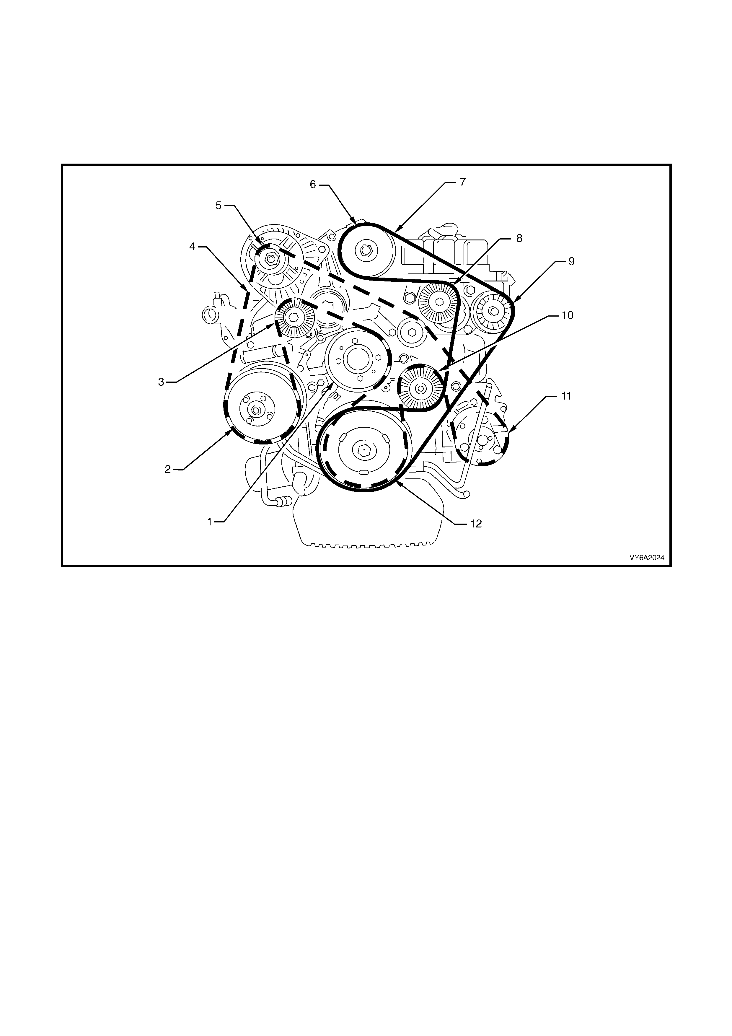
Figure 6A2-32
Legend
1. Coolant Pump
2. Power Steering Pump Pulley
3. Inner Drive Belt Tensioner Pulley
4. Generator
5. Inner Drive Belt
6. Supercharger
7. Outer Drive Belt
8. Outer Drive Belt Tensioner Pulley
9. Outer Drive Belt, Upper Idler Pulley
10. Outer Drive Belt, Lower Idler Pulley
11. Air Conditioning Compressor Pulley
12. Crankshaft Balancer Pulley
2.10 SUPERCHARGER DRIVE BELT TENSIONER ASSEMBLY
LT Section No. – 01-030
REMOVE
1. Disconnect the ground cable from the battery
terminal.
2. Rem ove the f our engi ne dr ess c over dom e nuts
and remove the cover.
3. Using a 15 mm ring spanner on supercharger
drive belt tensioner pulley pivot bolt, rotate
tensioner pulley assembly anti-clockwise and
remove drive belt from supercharger. Release
tensioner pulley assembly and remove drive
belt from remaining drive pulleys.
Figure 6A2-33
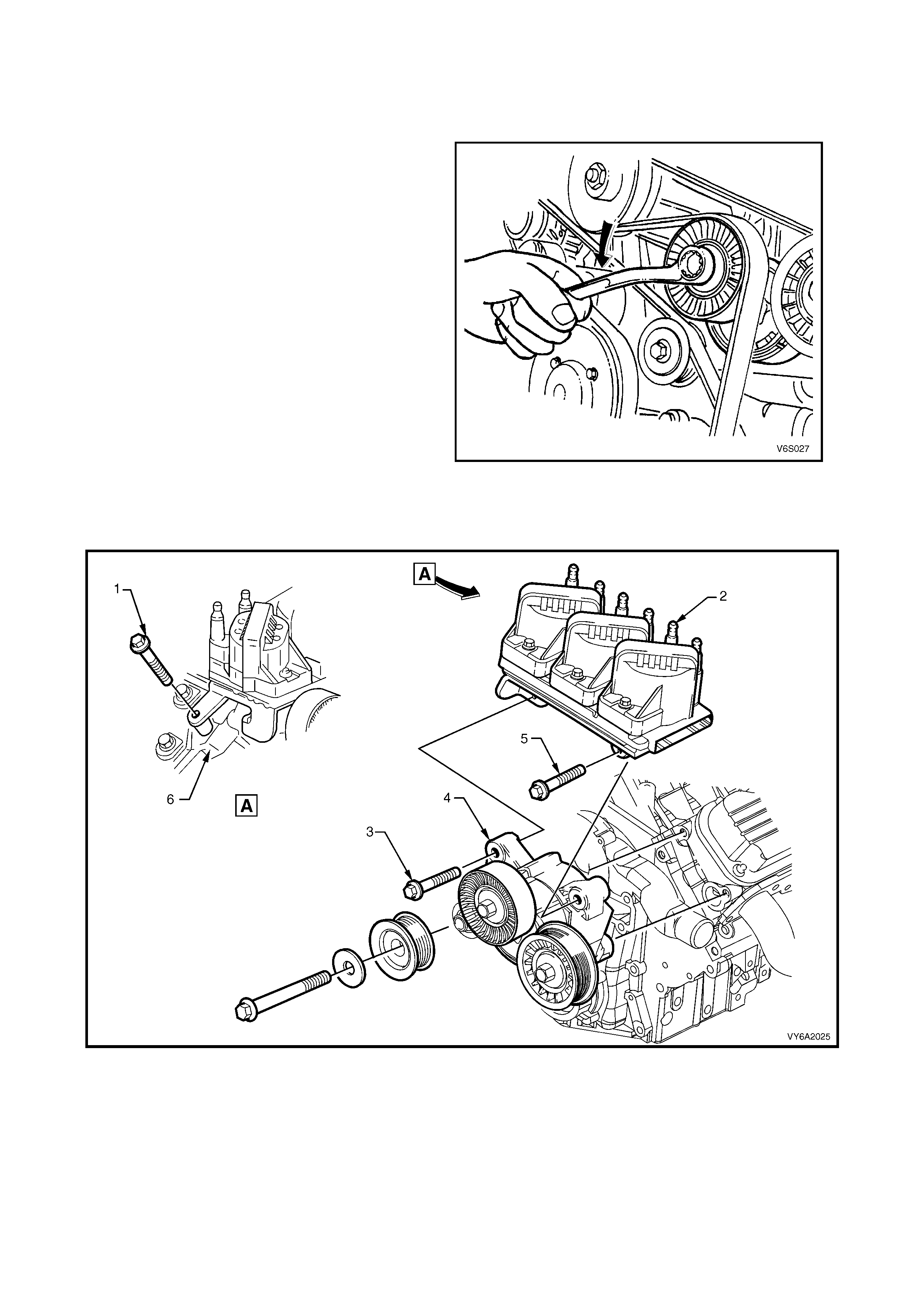
4. Remove the bolts securing the coil pack to the drive belt tensioner assembly.
5. Remove the bolts securing the drive belt tensioner assembly to the cylinder head.
NOTE: If the drive belt tension pulley is to be removed, the securing bolt has a left hand thread.
Figure 6A2-34
Legend
1. Bolt – Ignition Module Mounting Bracket
2. Ignition Module, Coil and Bracket Assembly
3. Bolt – Ignition Module and Drive Belt Tensioner
4. Drive Belt Tensioner Bracket Assembly
5. Bolt – Ignition Module and Drive Belt Tensioner
6. Le ft Hand Cylinder Head

REINST ALL
1. Ensure all fasteners are tightened to the correct torque specification, refer to 4. TORQUE WRENCH
SPECIFICATIONS in this Se ct ion .
NOTE: The DIS module and coil assembly attaching bolts must be tightened in the sequence ‘A’, ‘B’ and ‘C’ as
indicated in Figure 6A2-34.
2. Start engine and check drive belt operation.

3. SPECIFICATIONS
NOTE: Refer to Section 6A1-1 ENGINE MECHANICAL – V6 ENGINE for specifications not quoted here.
GENERAL
Engine Type............................................................... 90 degree V6 supercharged, OHV
Piston Displacement (Nominal).................................. 3791 cm3
Compression Ratio..................................................... 8.5:1
Number of Cylinders .................................................. 6
Bore x Stroke - mm .................................................... 96.5 X 86.3
Taxable HP RAC or SAE ........................................... 34
Power DIN @ RPM .................................................... 171 kW @ 5,200 rpm
Torque DIN @ RPM................................................... 375 Nm @ 3,000 rpm

4. TORQUE WRENCH SPECIFIC ATIONS
NOTE: Refer to Section 6A1-1 ENGINE MECHANICAL – V6 ENGINE for specifications not quoted here.
Nm
Boost reduction solenoid bolt................................................ 35
Bypass actuator solenoid valve attaching bolts.................... 35
Bypass harness attaching bolt.............................................. 18
Bypass valve actuator attaching bolts .................................. 26
Crankshaft balancer attaching bolt....................................... 300
Crankcase ventilation valve cover retainer screws............... 5
DIS Module attaching bolts (in sequence)............................ 45
Engine dress cover attaching nut ......................................... 5
Engine dress cover bracket attaching bolt/nut...................... 18
Fuel rail attaching bolt........................................................... 25
Fuel rail attaching nut ........................................................... 10
Radiator inlet pip e attac hin g bolt .......................................... 25
Supercharger attaching bolts (in sequence) – Stage 1....... 15
– Stage 2....... 25
Supercharger drive belt tensioner attaching bolt.................. 45
Supercharger drive belt tensioner pulley bolt....................... 45
Supercharger drive belt idler pulley bolt ............................... 50
Supercharger drive belt idler pulley bracket bolt .................. 30
Supercharger oil filler plug.................................................... 10
Throttle bod y adaptor attac hin g bolts ................................... 25
Throttle body attaching nuts ................................................. 18
Thermostat housing water outlet hose clamp....................... 3
Throttle body to intake manifold hose clamp........................ 3
Throttle cable adjusting nuts................................................. 3
