
SECTION 6B1 - ENGINE COOLING – V6 ENGINE
IMPORTANT
Before performing any Service Operation or other procedure described in this Section, refer to Section 00
CAUTIONS AND NOTES for correct workshop practices with regard to safety and/or property damage.
CONTENTS
1. GENERAL DESCRIPTION
2. GENERAL INFORMATION
2.1 RADIATOR
2.2 COOLING FANS – STANDARD SPECIFICATION
GENERAL DESCRIPTION
OPERATION
2.3 COOLING FANS – HIGH PO WER
SPECIFICATION
GENERAL DESCRIPTION
OPERATION
2.4 COOLING SYSTEM COMPONENTS
3. SERVICE OPERATIONS
3.1 SERVICE NOTES
3.2 COOLANT MAINTENANCE
TOPPING UP THE COOLING SYSTEM
TESTING COOLANT CONCENTRATION
3.3 CHECKING AND FILLING COOLING SYSTEM
FILLING COOLING SYSTEM WITH TOOL
AU425
FILLING COOLING SYSTEM WITHOUT
TOOL AU425
3.4 CLEANING COOLING SYSTEM
COOLING SYSTEM FLUSH
3.5 DRIVE BELT TENSION
3.6 COOLANT HOSES
3.7 PRESSURE TESTING
RADIATOR CAP TESTING
COOLING SYSTEM PRESSURE TESTING
3.8 THERMOSTAT
REMOVE
TEST
REINSTALL
3.9 COOLANT RECOVERY RESERVOIR
REMOVE
INSPECT
REINSTALL
3.10 AIR BAFFLE
REPLACE
3.11 COOLANT PUMP
REMOVE
REINSTALL
3.12 COOLING FAN AND SHROUD ASSEMBLY
REMOVE
REINSTALL
DISASSEMBLE
REASSEMBLE
3.13 FLEXIBLE TRANSMISSION COOLER HOSE
REPLACE
3.14 RADIATOR
REMOVE
REINSTALL
RADIATOR REPAIR PROCEDURE
4. ENGINE COOLING SYSTEM DIAGNOSIS
5. SPECIFICATIONS
6. TORQUE WRENCH SPECIFICATIONS
7. SPECIAL TOOLS

1. GENERAL DESCRIPTION
The cooling system for MY 2003 VY and V2 Series models with the V6 engine has been completely re-designed.
With the standard system, two, single speed electric cooling fans are mounted on the shroud, that is attached
behind the radiator. When operating on stage 1, only the right (smaller) fan motor is enabled. When stage 2 is
required, the left (larger) fan is also activated. For stage 1 then, only one fan m otor is operational but for stage 2,
both fan motors operate.
Dependent on vehicle specification, a high power cooling fan arrangement may be fitted to the vehicle. In this
situation, while the fan diameters are the same, each fan motor is dual speed and has a different power rating. Both
fan motors fitted, operate either on low speed (1st stage) or high speed (2nd stage).
Regardless of the system f itted, operat ion of the coolin g fans is depende nt on engine coolan t temperature, ve hicle
speed, A/C request (where fitted) and A/C system pressure. Refer to Section 6C1-1 POWERTRAIN
MANAGEMENT - V6 ENGINE in the MY 2003 VY and V2 Series Service Information for further information.
Also dependent on vehicle specification, is the t ype of coolant used. As requirements can change, always ref er to
the MY 2003 VY and V2 Series Owners Handbook for specific information regarding the particular vehicle being
serviced. As both coolant types are discussed in this Section, refer to the coolant applicable.

2 GENERAL INFORM ATION
2.1 RADIATOR
The radiat or util ises an al um inium cor e and is of the cros s-flow design, with a r adiator ca p locate d on the lef t hand
side tank. Plastic side tanks are attached to the core by the use of clinch tabs. The clinch tabs are formed as part of
the core assembly.
A high temperature rubber seal is used to seal the mating surface between the core and each side tank. The
seal(s) must be replaced any time the side tank is removed from the core.
IMPORTANT: T he radiator c ore side tank s or transm ission oi l coo ler CANNO T be r eplaced s epar atel y. If there is a
fault with any of these components, the radiator assembly must be replaced. Small core repairs may be made,
using an Aluminised Silicon based liquid repair agent, refer to 3.14 RADIATOR - RADIATOR REPAIR
PROCEDURE in this Section.
For ve hicl es with a utomatic trans miss ion, a tra ns mis sion oil cool er is loc at ed in th e left hand s id e r ad iat or tan k. The
cooler p ipes from and to the transm ission ar e connected to th e oil coo ler flexib le hoses b y means of quick connec t
fittings.
When air conditioning is fitted, the air conditioning condenser is mounted, by means of clips and brackets, to the
front of the radiator. The air conditioning receiver drier also forms a part of the complete assembly.
Pegs are attached to the lower frame and the upper area of each side tank. These pegs are used to support the
radiator in four rubber mounts. The assembly is held in position by two spring clips at the upper mounting locations.
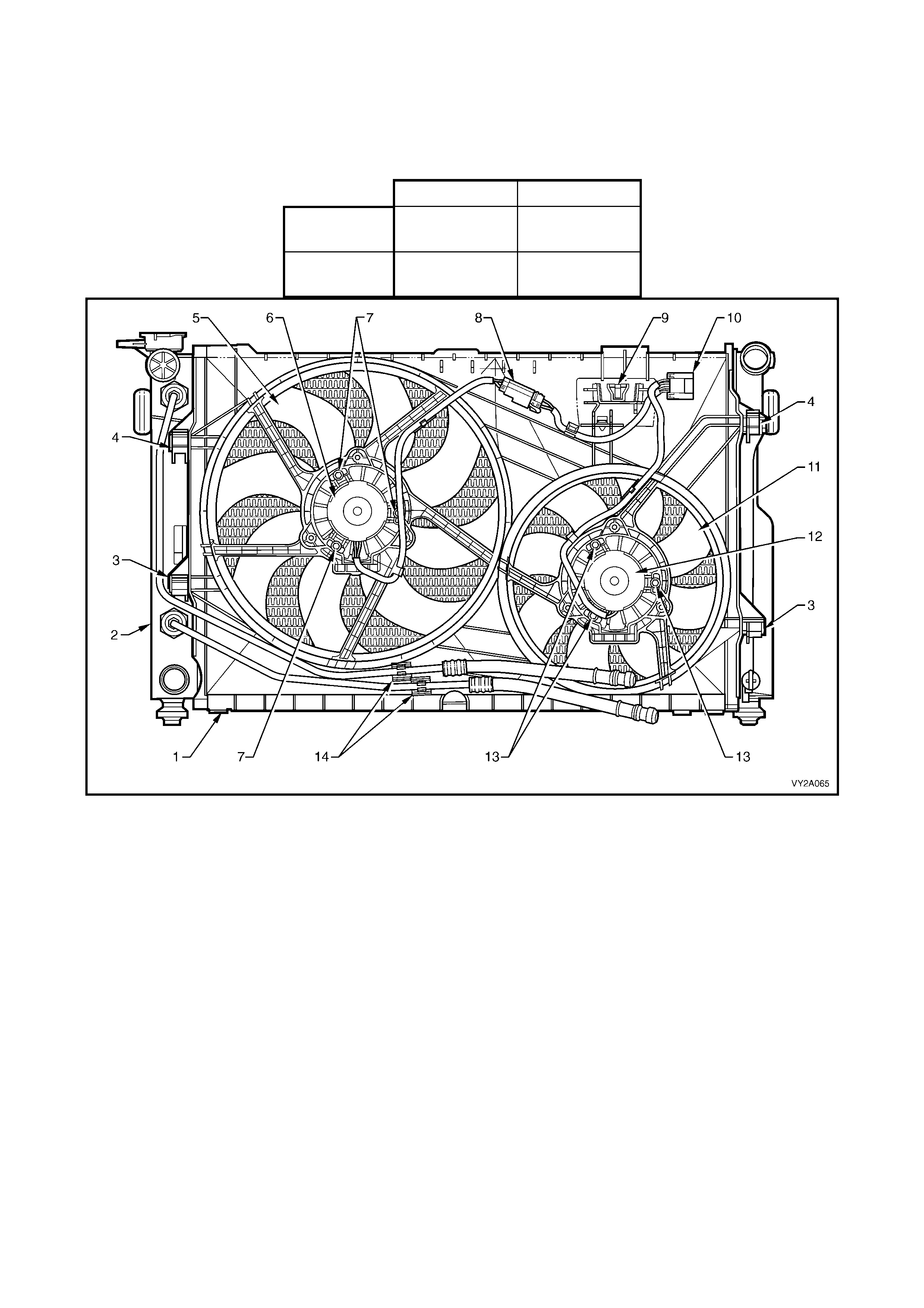
2.2 COOLING FANS – STANDARD SPECIFICATION
GENERA L DESCRIPTION
Two, si ngle speed, en gine cooling f an m otors are used. T he smaller , right fan is 268 mm in diameter with a m otor
rated at 120 Watts, while the larger, left fan is 370 mm in diameter with a motor power rating of 160 Watts.
With 12 volts applied and the fans mounted to the radiator with a condenser fitted, the operating speeds are:
Stage 1 Stage 2
Large Fan 1,900 ± 150
rpm 1,900 ± 150
rpm
Small Fan Inoperati ve 2,350 ± 150
rpm
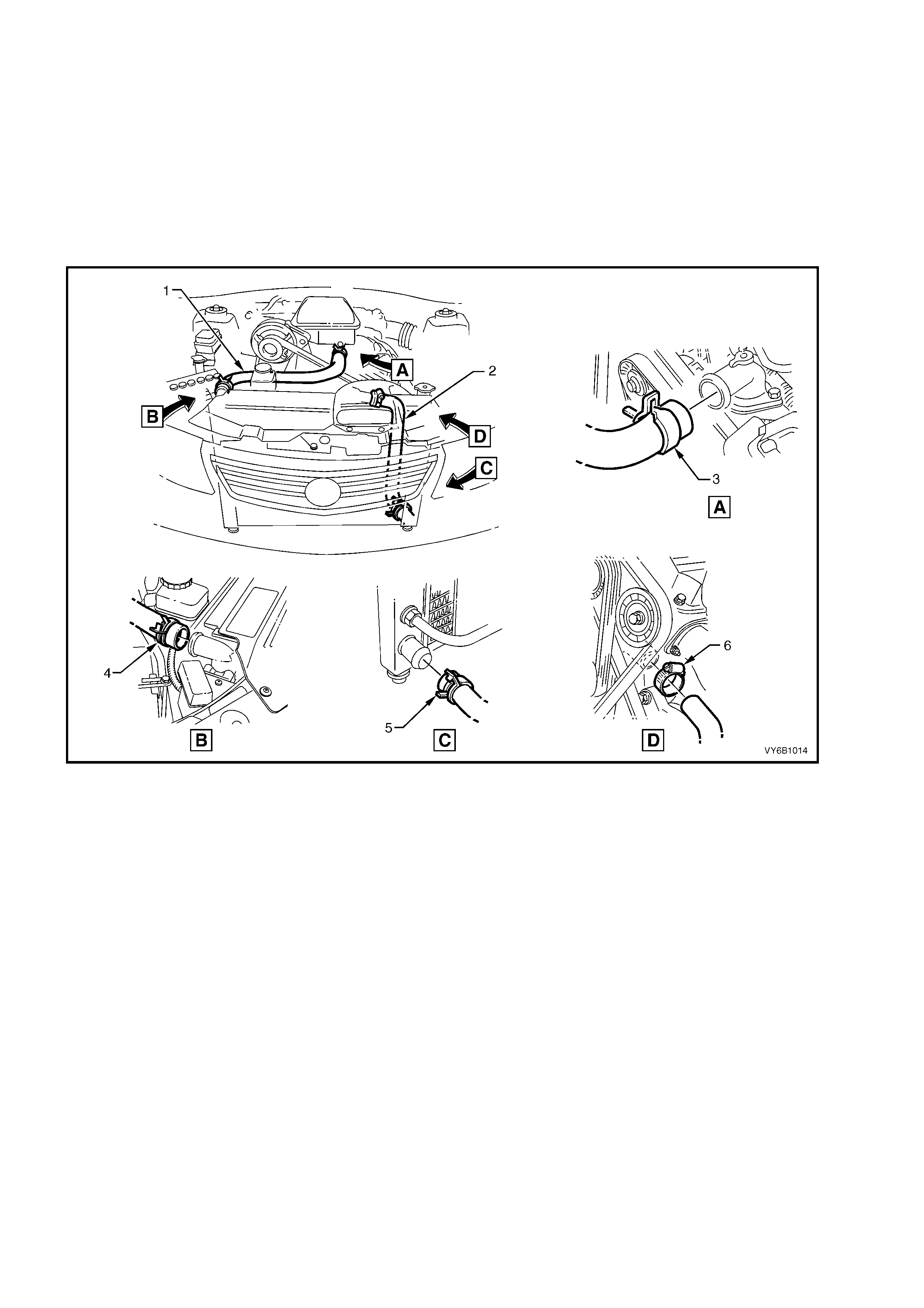
Figure 6B1-1 – Cooling Fans, V6 Engine Standard Specification
Legend
1. Fan Shroud
2. Radiator
3. Fan Shroud Lower Support
4. Fan Shroud Upper Support/Locking Retainer
5. Large, Left Fan – 8 Blade, 370 mm Diameter
6. Left Fan Motor – 160 Watt, Single Speed
7. Left Fan Motor Securing Screws (3 places)
8. Left Fan Motor Harness Connector (2 terminal)
9. Power Steering Reservoir Mount
10. Left and Right Fan Motor Harness Connector (4 terminal)
11. Small, Right Fan – 8 Blade, 268 mm Diameter
12. Right Fan Motor – 120 Watt, Single Speed
13. Right Fan Motor Securing Screws (3 places)
14. Automatic Transmission Cooling Line Retaining Clips

OPERATION
On MY 2 003 VY a nd V2 S eries m odels with V6 engi nes and s tandard s pecific ation fan m otors, eac h of the engine
cooling fan motors has two terminals; one positive and one negative. The positive terminals are permanently
connected to battery voltage, via fusible links F101 (large fan) and F107 (small fan).
W hen the negat ive t erm inal is co nnecte d to groun d
through engine cooling fan relay 1 (R7), the large
cooling fan (left) will operate. When the negative
terminal is connected to earth via the engine
cooling fan relay 2 (R5), both cooling fans will
operate.
The large (left) cooling fan operation is enabled
when the engine cooling f an relay 1 (located in the
underhood electrical centre) is energised by the
Body Contr ol Mo du le (BCM ) , via a r equest f r om the
Powertrain Control Module (PCM). The PCM will
request low speed fan enable or disable, via the
serial data Normal Mode Message to the BCM on
circuit 800 (Red/Black wire). After the PCM
requests a change in the state of the engine
cooling fan relay 1 (i.e. OFF to ON or ON to OFF),
the BCM will sen d a serial data respons e m essage
back to the PCM confirming it received the
message.
Should a response from the BCM fail to occur, a
PCM DTC P1064, will set.
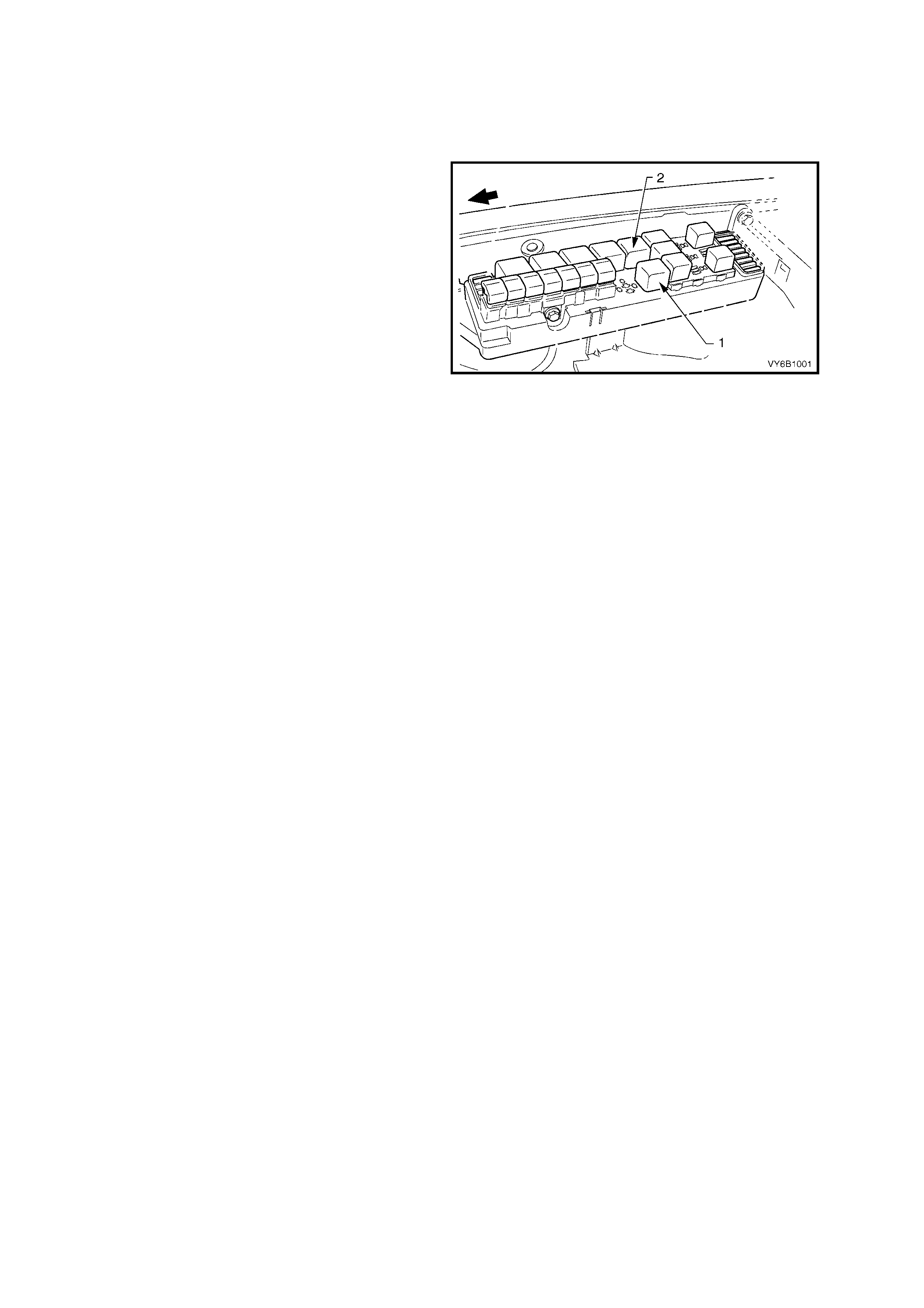
Figure 6B1-2 – Underhood Fuse & Relay Centre
The PCM d etermines whe n to enable t he engine co oling fan rela y 1, bas ed on inputs f rom the A/C re quest signal,
Engine Coolant Temperature (ECT) sensor and the Vehicle Speed Sensor (VSS).
There are also suppression capacitors incorporated into the fan motor, located on the brush holders. These
suppression capacitors help eliminate fan motor noise through the radio speakers. As these capacitors are not
serviced separately, should a problem occur with either capacitor, then the motor assembly must be replaced.
Stage One Fan Operation
1. The engine cooling fan relay 1 will be turned ON when:
• Air conditioning request indicated (YES) and the vehicle speed is less than 30 km/h or:
• Air conditioning pressure is greater than 1,500 kPa or:
• Coolant temperature is greater than 104° C or:
• An engine coolant temperature sensor failure is detected by the PCM, refer to
Section 6C1 POWERTRAIN MANAGEMENT – V6 ENGINE for additional information.
• When the ignition switch is turned from ON to OFF and the engine coolant temperature is above 117° C,
the BCM will continue to energise the engine cooling fan micro relay 1 for approximately four minutes.
2. The PCM will reques t the BCM to s witch of f the engine coo ling fan r elay 1 when th e following c onditions h ave
been met:
• Air conditioning request not indicated (NO) and the coolant temperature is less than 99° C or:
• Air co nditioning r equest indic ated (YES) with pres sure less than 1,170 k Pa, vehicle sp eed greater t han 5 0
km/h and coolant temperature less than 99° C.
Stage Two Fan Operation
The PCM determines when to enable the engine cooling fan relay 2, based on inputs from the ECT sensor.
1. The engine coolin g fan relay 2 will be turne d ON if the engine coolin g fan relay 1 has be en energised for one
second and the following conditions have been met:
• If there is a BCM message response fault, setting a DTC P1064 or:
• An engine coolant temperature sensor failure is detected by the PCM, refer to
Section 6C1 POWERTRAIN MANAGEMENT – V6 ENGINE for additional information or:
• Engine coolant temperature is above 108° C or:
• Air conditioning pressure is greater than 2,000 kPa.
NOTE: If the lar g e en gi ne cooling f an is of f when th e cr iteri a f o r tur n ing the s mall e ngine c o ol ing f an on ar e f irst
met, the small engine cooling fan will turn on 5 seconds after the large engine cooling fan is switched on.
2. If both the large and small cooling fans are enabled, the PCM will turn the small cooling fan OFF when:
• The engine coolant temperature is less than 103° C and:
• Air conditioning request is not indicated (NO) or:
• Air conditioning request is indicated (YES) and the pressure is less than 1,500 kPa.
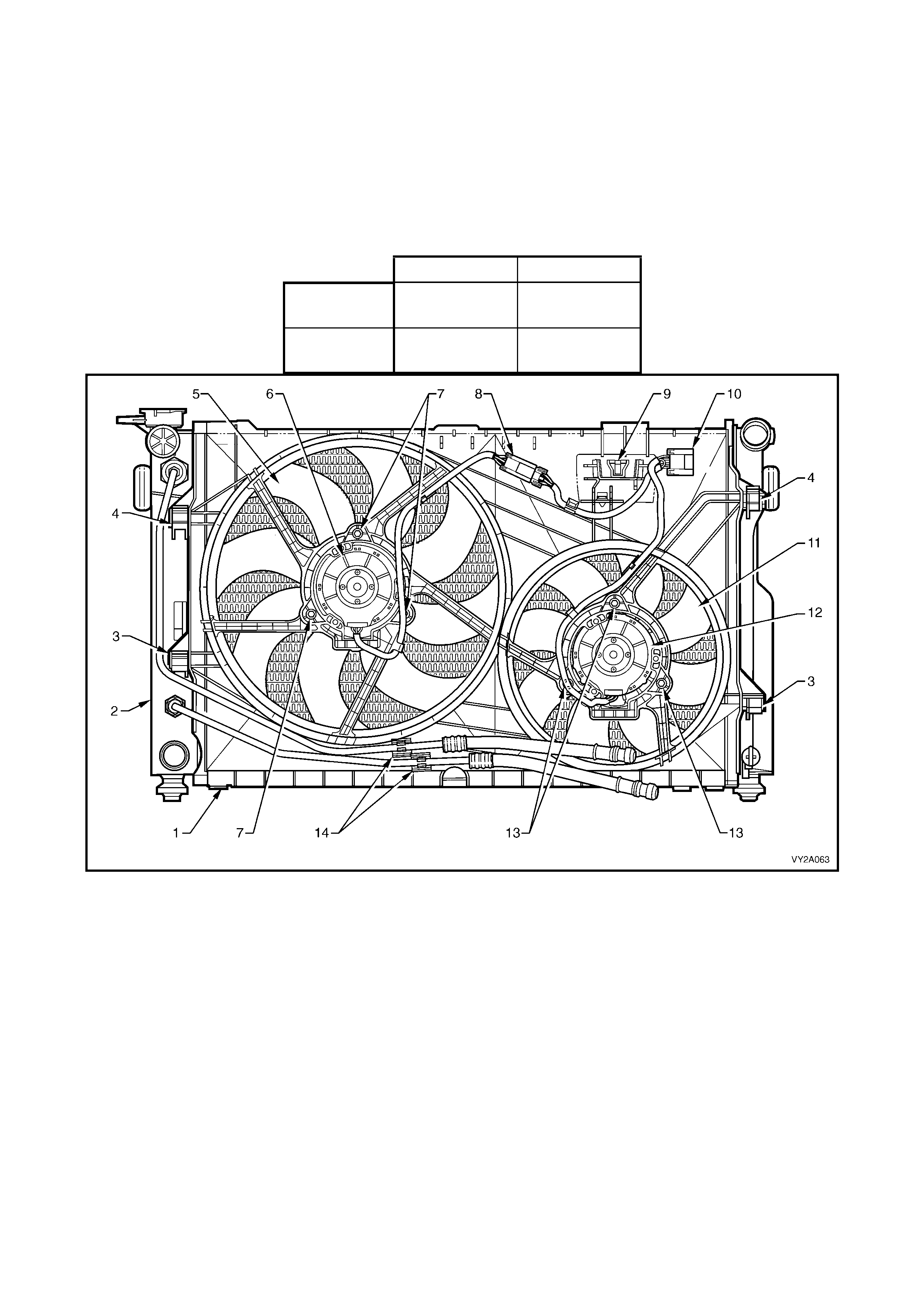
2.3 COOLING FANS – HIGH POWER SPECIFICATION
GENERA L DESCRIPTION
Some MY 2003 VY and V2 Ser ies vehicl e specific ations m ay require the fitm ent of a high power ver sion of the t wo
fans. When this is the c as e , t wo, double s p eed, en gi n e c oo lin g f an motors ar e f itt ed. T he s mall, ri ght f an is 2 68 mm
in diam eter and has a m otor rated at 18 0 W atts, while the left f an is 370 mm in diameter with a motor power rating
of 220 Watts.
While both the standard a nd high power assemblies have the sam e diameter fans, the power rating of the electric
motors, changes and can be seen visually by the larger diameter motor for the high power assemblies.
With 12 volts applied and the fans mounted to the radiator with a condenser fitted, the operating speeds are:
Stage 1 Stage 2
Large Fan 2,000 ± 150
rpm 2,300 ± 150
rpm
Small Fan 2,350 ± 150
rpm 2,700 ± 150
rpm
Figure 6B1-3 – Cooling Fans, V6 Engine High Power Specification
Legend
1. Fan Shroud
2. Radiator
3. Fan Shroud Lower Support
4. Fan Shroud Upper Support/Locking Retainer
5. Large, Left Fan – 8 Blade, 370 mm Diameter
6. Large, Left Fan Motor – 220 Watt, Double Speed
7. Large, Left Fan Motor Securing Screws (3 places)
8. Left Fan Motor Harness Connector (3 terminal)
9. Power Steering Reservoir Mount
10. Left and Right Fan Motor Harness Connector (5
terminal)
11. Small, Right Fan – 8 Blade, 268 mm Diameter
12. Small, Right Fan Motor – 180 Watt, Double Speed
13. Small, Right Fan Motor Securing Screws (3 places)
14. Automatic Transmission Cooling Line Retaining Clips
OPERATION
The electrical circuitry for the high power specification cooling fans is completely different to that used for the
standard specification system. Each high power fan m otor has three wires; One wire (Orange/Blue), is connected
to the battery via fusible links F101 or F107, a Low/High speed negative wire (Blue/Yellow), is grounded by the
engine coo li ng f an r elay 1 and a third , Hig h s peed n eg ati ve wire (O ra n ge Yello w) i s grounded by the eng in e c ool ing
fan relay 2. Both fusible links and the two relays are located in the underhood electrical centre.
The fan motors are also connected electrically, as follows;
• The Low/Hi gh speed nega tive wir es from each motor go thr ough the rad iator fan c onnector s eparatel y and are
spliced together in the main wiring harness before reaching engine cooling fan relay 1.
• The High speed wires from each m otor are spliced together before the radiator fan connector and go through
the connector as one circuit, to engine cooling fan relay 2.
When the High/Low negative terminal from each
motor is connected to ground via engine cooling
fan relay 1, both cooling fans will operate at stage
1 (Large f an at 2, 00 0 ± 150 rpm, Small fan at 2,350
± 150 rpm). With engine cooling fan relay 1 still
activated, when the high speed negative terminal
from eac h motor is c onnected to gro und via eng ine
cooling fan relay 2, both fans operate at stage 2
(Large fan at 2,300 rpm ± 150 rpm, Small fan at
2,700 ± 150 rpm). .
Stage 1 cooling fan operation is enabled when the
engine cooling fan micro relay 1 (located in the
underhood electrical centre) is energised by the
Body Contr ol Mo du le (BCM ) , via a r equest f r om the
Powertrain Control Module (PCM).
The PCM will request stage 1 enable or disable,
via the serial data Normal Mode Message to the
BCM on circui t 800 (Red/Black wire).
Figure 6B1-4 – Underhood Fuse & Relay Centre
After the PCM reques ts a change in the state of the low sp eed rela y ( i.e. OFF to ON or ON to OFF), the BCM will
send a serial data response message back to the PCM confirming it received the message. Should a response
from the BCM fail to occur, a PCM DTC P1064, will set.
The PCM determines when to enable stage 1, based on inputs from the A/C request signal, Engine Coolant
Temperature (ECT) sensor and the Vehicle Speed Sensor (VSS).
There are also suppression capacitors incorporated into the fan motor, located on the brush holders. These
suppression capacitors help eliminate fan motor noise through the radio speakers. As these capacitors are not
serviced separately, should a problem occur with either capacitor, then the motor assembly must be replaced.
Stage One Fan Operation
1. The cooling fan relay 1 will be turned ON when:
• Air conditioning request indicated (YES) and the vehicle speed is less than 30 km/h or:
• Air conditioning pressure is greater than 1,500 kPa or:
• Coolant temperature is greater than 104° C or:
• An engine coolant temperature sensor failure is detected by the PCM, refer to
Section 6C1 POWERTRAIN MANAGEMENT – V6 ENGINE for additional information.
• When the ignition switch is turned from ON to OFF and the engine coolant temperature is above 117° C,
the BCM will continue to energise engine cooling fan micro relay 1 for approximately four minutes.
2. The PCM will requ es t the B CM to s witc h of f engine c o oli ng f an re lay 1 when the fo llo wing c ond it ions ha ve b e en
met:
• Air conditioning request not indicated (NO) and the coolant temperature is less than 99° C or:
• Air co nditioning r equest indic ated (YES) with pres sure less than 1,170 k Pa, vehicle sp eed greater t han 5 0
km/h and coolant temperature less than 99° C.
Stage Two Fan Operation
The PCM determines when to enable the engine cooling fan relay 2, based on inputs from the ECT sensor.
1. Engine cooling fan relay 2 will be turned ON if the engine cooling fan relay 1 has been energised for one
second and the following conditions have been met:
• If there is a BCM message response fault, setting a PCM DTC P1064 or:
• An engine coolant temperature sensor failure is detected by the PCM, refer to
Section 6C1 POWERTRAIN MANAGEMENT – V6 ENGINE for additional information or:
• Engine coolant temperature is above 108° C or:
• Air conditioning pressure is greater than 2,000 kPa.
2. If stage 2 has been enabled, the PCM will revert to stage 1 operation when:
• The engine coolant temperature is less than 103° C and:
• Air conditioning request is not indicated (NO) or:
• Air conditioning request is indicated (YES) and the pressure is less than 1,500 kPa.
2.4 COOLING SYSTEM COMPONENTS
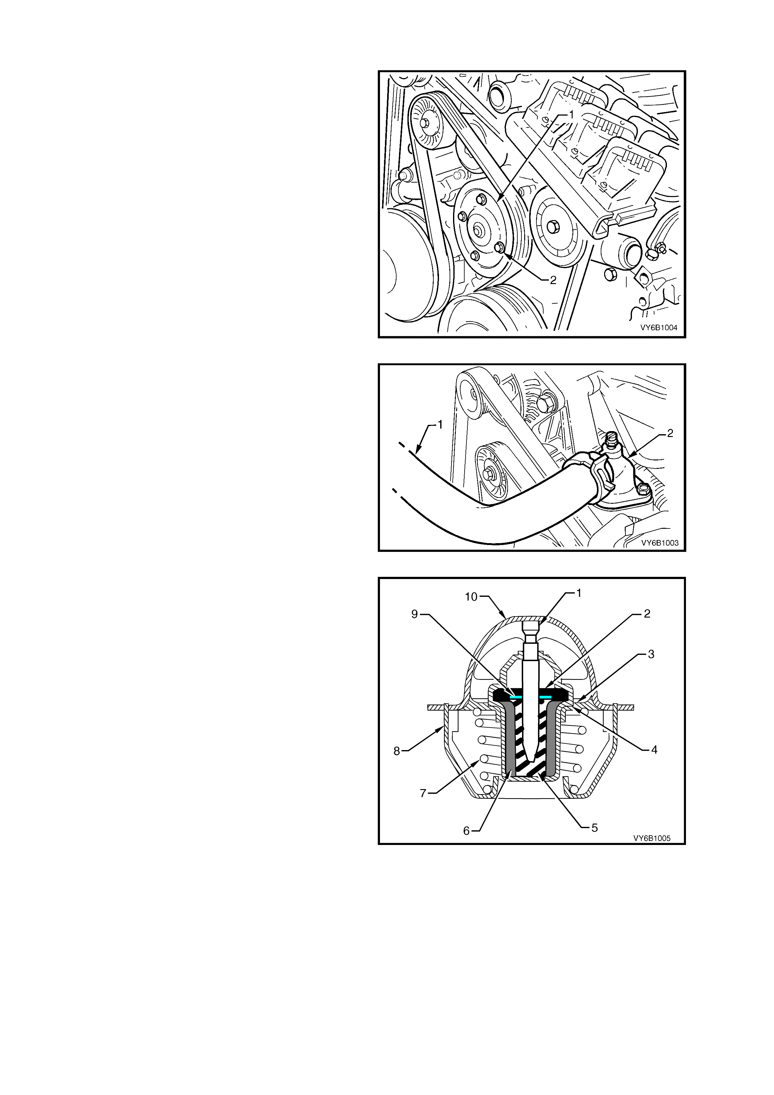
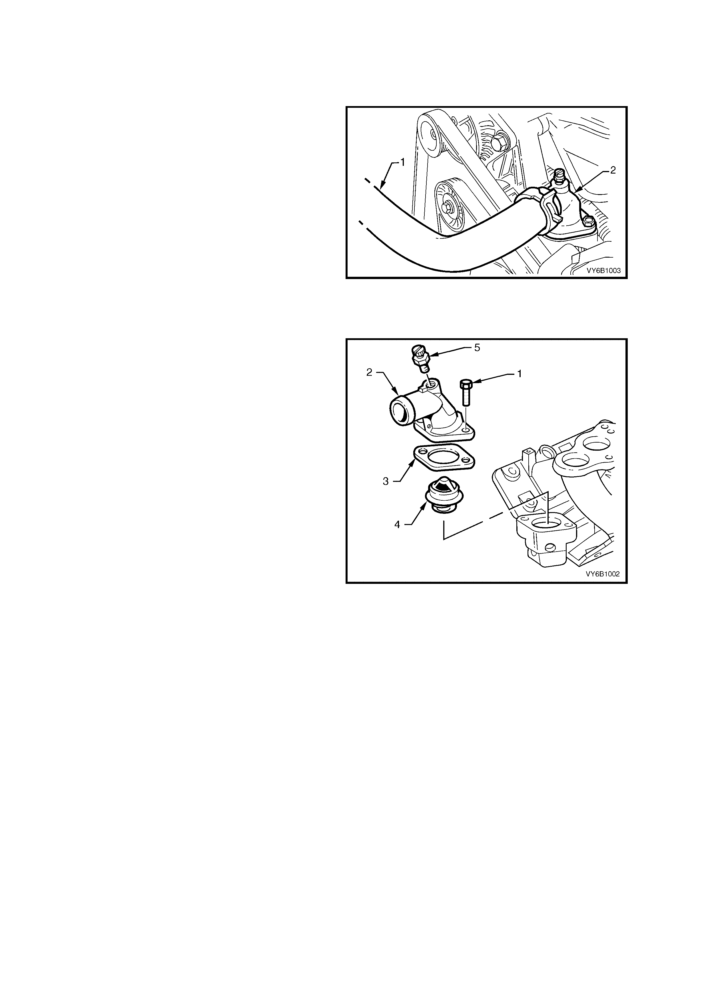
The coolant pump (1) is mounted to the engine
front cover and is driven by the multi-ribbed drive
belt, turning the pump pulley, bolted (2) to the
coolant pump flange. Coolant passes through the
engine from the coolant pump inlet at the engine
front c over and exits via th e ther mos tat and coolant
outlet at the front of the intake manifold.
Figure 6B1-5
The coolant outlet (2) is located at the front of the
intake manifold.
The thermostat is housed between the coolant
outlet and the intake manifold.
Figure 6B1-6
A wax pellet type therm ostat is used in the coolant
outlet passage to control the flow of coolant,
providing fast engine warm up and regulating
coolant temperature. The wax pellet or power
element in the thermostat, expands when heated
and contracts when cooled. The wax pellet is
connected through a piston to a valve and when
the pellet is heated, pressure is exerted against a
metal valve which is forced to open.
As the pellet is cooled, the contraction allows a
spring to close the valve. Thus, the valve remains
closed while the coolant is cold, preventing
circulation of coolant through the radiator, but
allowing the coolant to circulate throughout the
engine to warm it quickly and evenly.
As the engine becomes warm, the pellet expands
and the th erm os tat opens, perm itting the coo lant to
flow through to the radiator where heat is
transferred to the surrounding air, through the
radiator walls .
This opening and closing of the thermostat valve
permits enough coolant to enter the radiator to
keep the engine within specified temperature limits.
Legend
Figure 6B1-7
1. Piston
2. Flange Seal
3. Valve Seat
4. Valve
5. Rubber Diaphragm
6. Wax Pellet
7. Spring
8. Frame
9. Teflon Seal
10. Flange
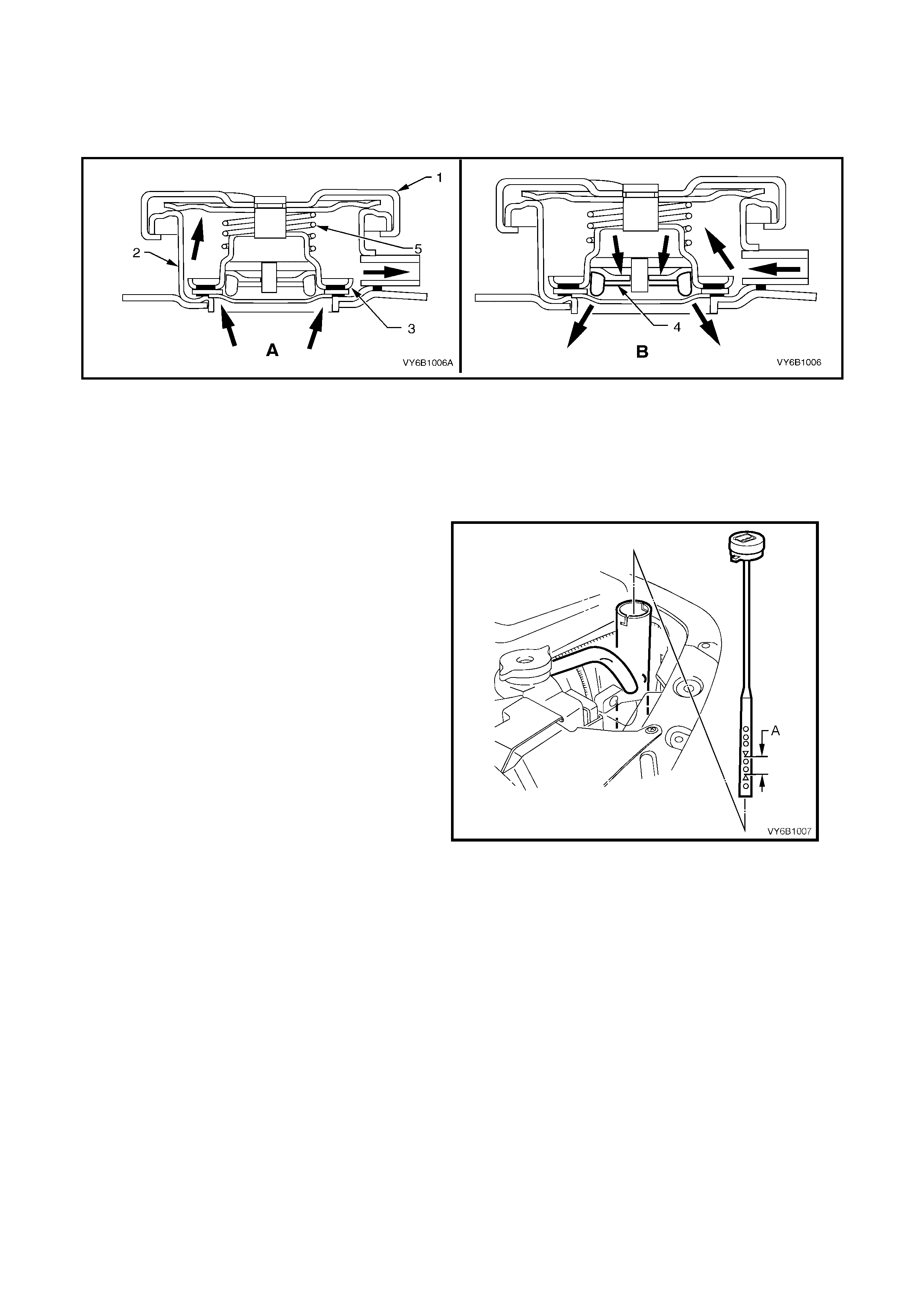
A radiator cap (1), fitted to the radiator filler neck (2), causes the cooling system to operate at higher than
atmospheric pressure. The higher pressure, raises the boiling point of the coolant, resulting in increased engine
cooling efficiency. The radiator cap contains a pressure valve (3) and a vacuum (atmospheric) valve (4).
Referring to view ‘A’, The pressure valve is held against its seat by a spring (5), which determines the maximum
operating pressure of the cooling system (135 kPa for V6 engine).
Figure 6B1-8
Referring to view ‘B’, The vacuum valve (4) is held against its seat by a light spring (not illustrated) and opens
during cool down because of the drop in pressure with contraction of the coolant volume. This pressure drop over-
comes the spring force and the valve is opened, preventing the radiator hoses from collapsing. In addition, coolant
can also flow back into the cooling system, from the coolant reservoir, while this valve is open.
NOTE: Should the radiator pressure cap require replacement, only fit the correct pressure rating cap for this
engine. Refer to the current release of PartFinder® for this information.
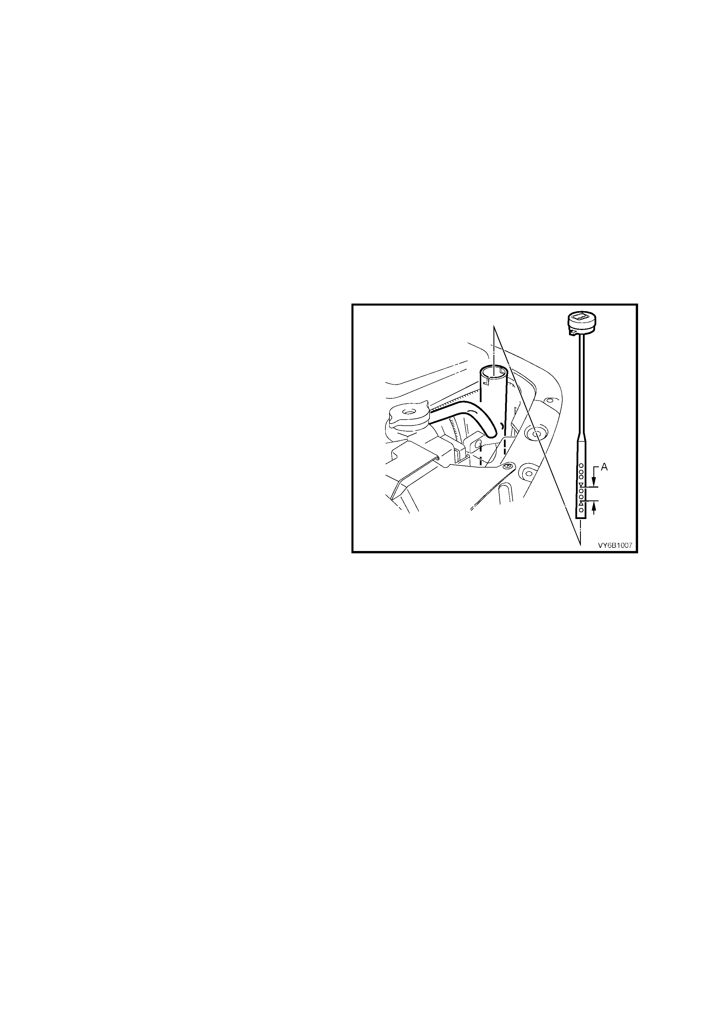
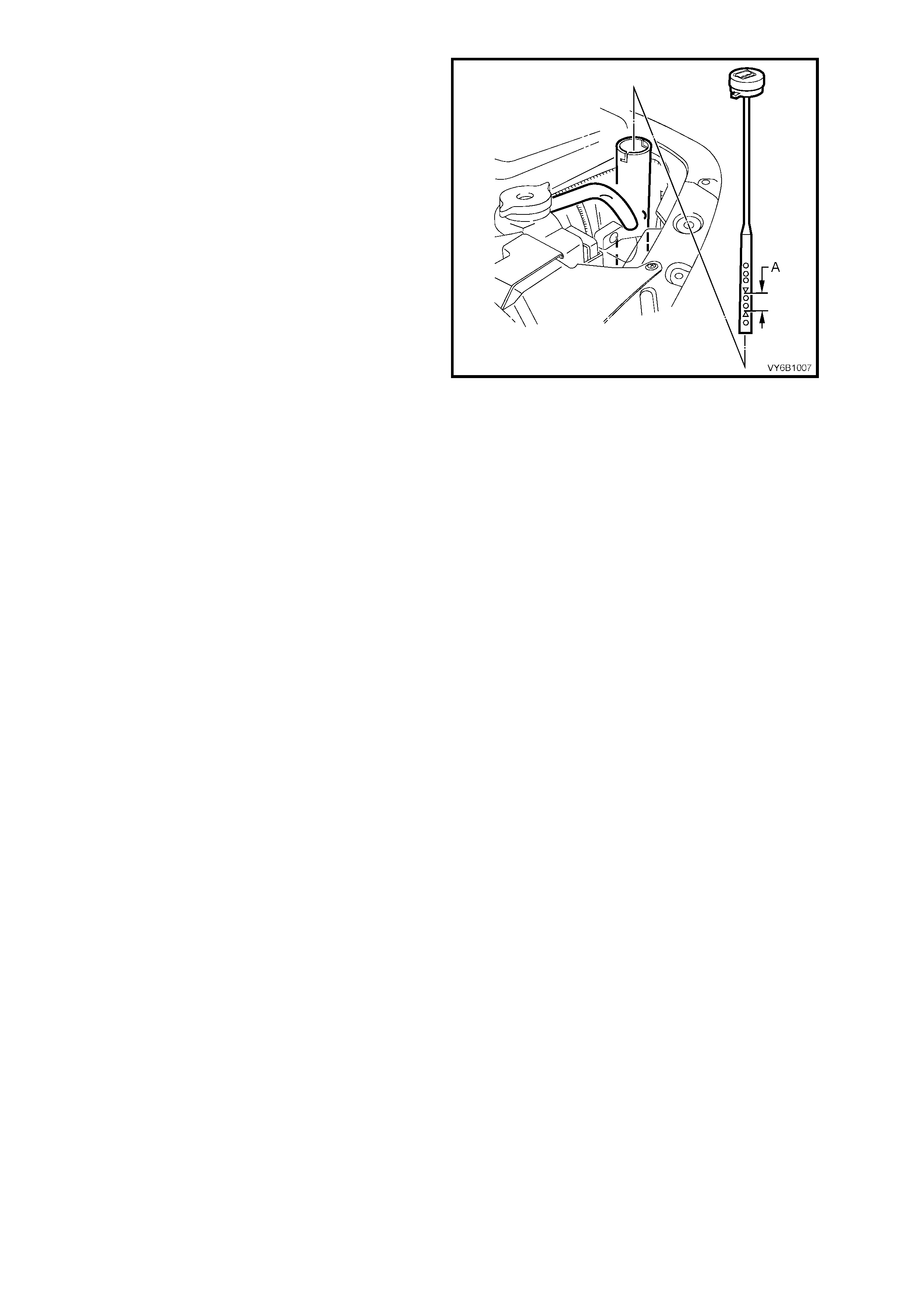
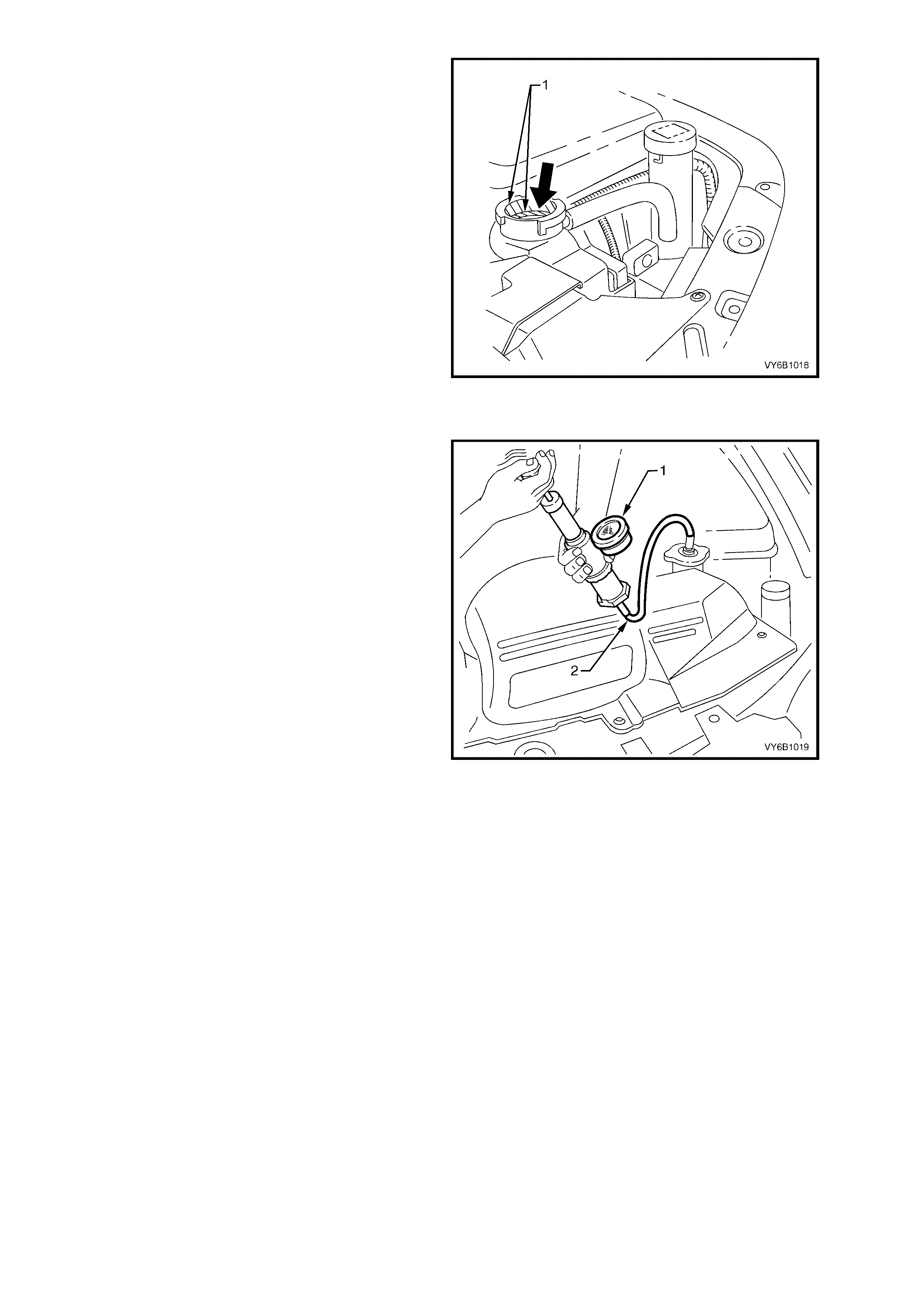
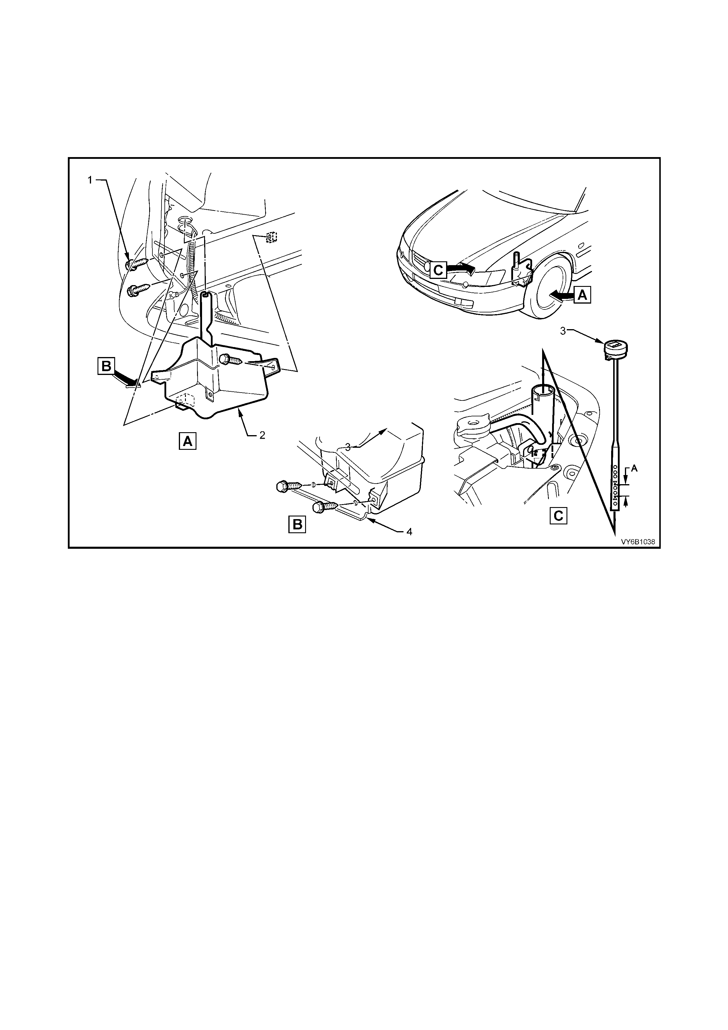
The coolant is maintained at the ideal level in the
radiator by the radiator cap and the coolant
recovery reservoir, resulting in increased cooling
efficiency.
The c oolant r ec ov ery reser vo ir is loc a ted on t he lef t
hand fr ont of the e ng ine c o mpartm ent, bet ween th e
radiator support panel and air cleaner assembly.
The coolant recovery reservoir is connected to the
radiator overflow connection by a hose.
As the engine temperature rises, the coolant is
heated and expands. The fluid displaced by
expansion f lows from the radiator into the recover y
reservoir.
When the engine is turned 'OFF', the coolant
contracts as it cools. Coolant is then drawn back
into the radiator through the radiator cap
atmospheric valve.
Coolant level should be maintained between
indicator arrows (‘A’) on the coolant recovery
reservoir di ps tic k when the eng ine is cold.
Figure 6B1-9
The cooling system is designed to use a coolant (a mixture of ethylene glycol antifreeze and corrosion inhibitors
and water), rather than plain water to maintain the integrity of the cooling system, and to prevent oxidation
occurring within the engine.
NOTE: Some MY 2003 VY and V2 Series vehicle mark ets may call for an alternative coolant, known as exte nded
life anti-freeze coolant, conforming to GM6277M. If in doubt regarding the correct coolant to be used, refer to the
MY 2003 VY and V2 Series Owner’s Handbook.
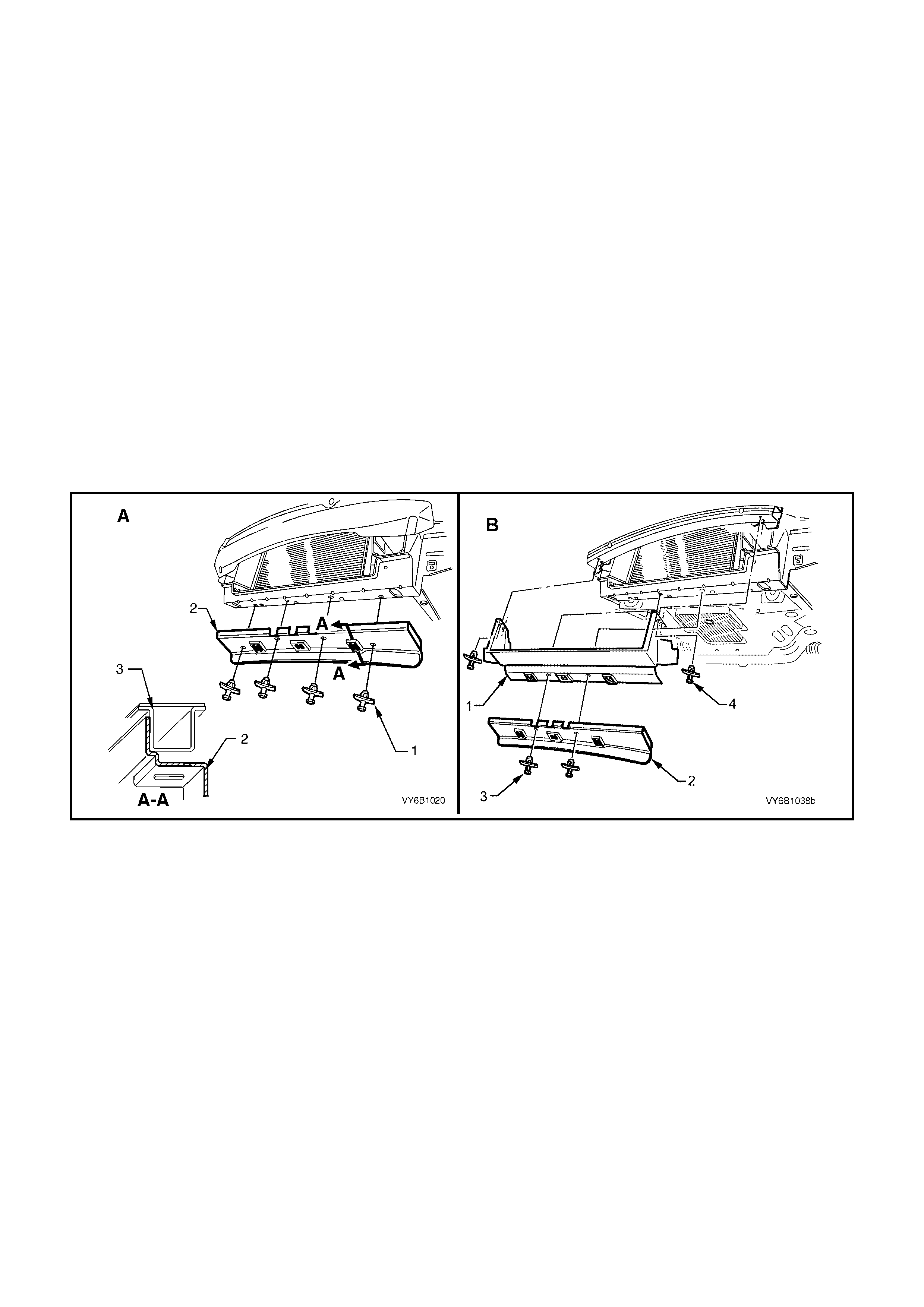
An air baffle and side chutes are fitted to the front end of the vehicle to direct and promote air flow through the
radiator to provide maximum cooling. With ‘S’ pack series vehicles (except Utility), a front duct is fitted that is in
addition to the air baffle, refer to Figure 6B1-11 for details.
The purpose of the air baffle is to create a low pressure area behind the radiator whilst the vehicle is at speed.
This enables additional air flow through the radiator core to maintain the desired engine cooling.
The air baf f le or side c hute s s hould ne ver be r em oved unl ess f or s ervice work. If either the a ir baff le or sid e c hutes
are damaged, this will reduce the cooling system efficiency, and therefore they must be replaced.
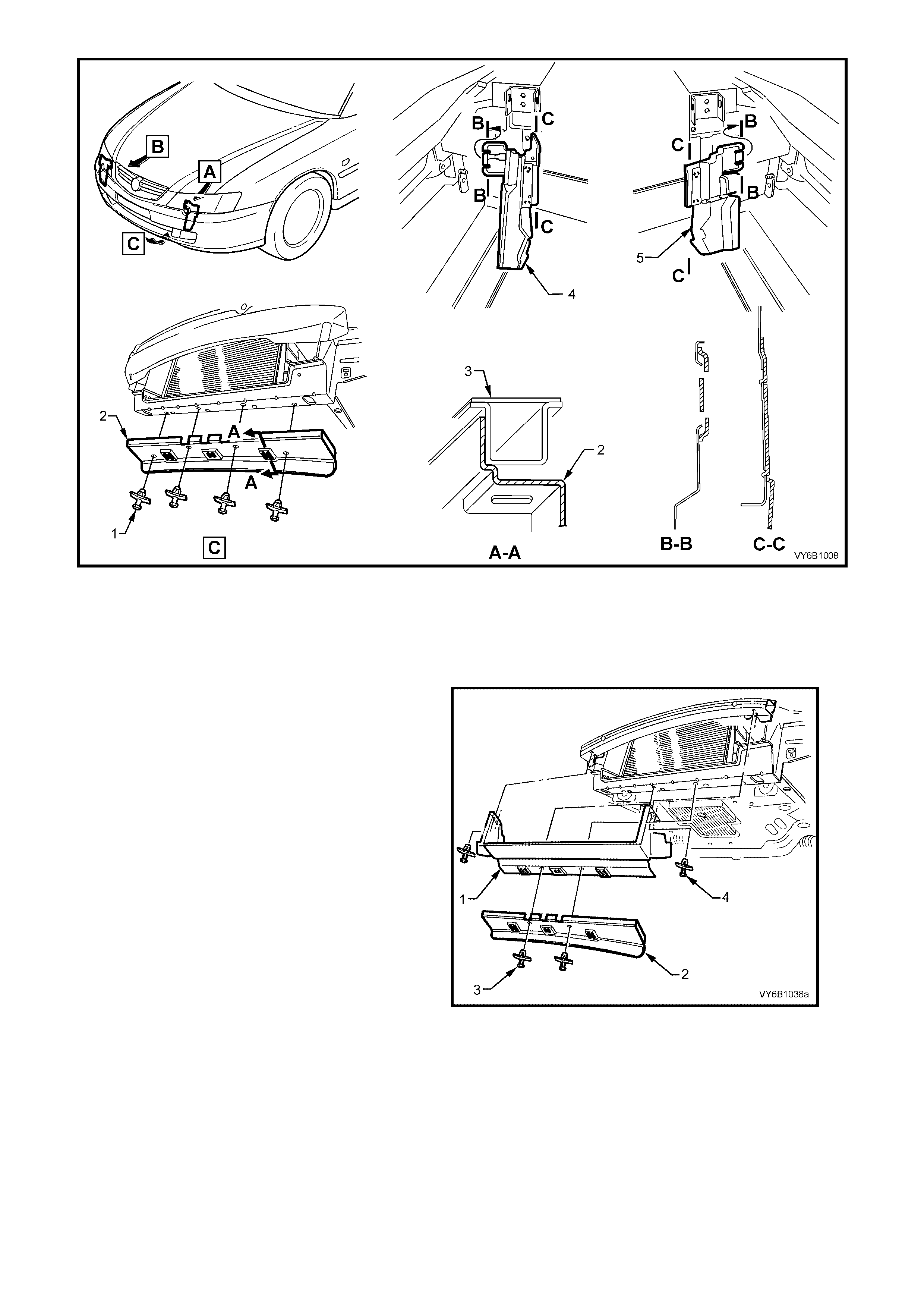
Figure 6B1-10
Legend
1. Plastic Fastener ( 4 places
2. Lower Air chute Baffle 3. Front Crossmember
4. Right Side Air chute
5. Left Side Air chute
‘S’ pack vehicles (except Utility) have a front air
duct (1) fitted, in addition to the lower air chute
baffle (2), to concentrate more air flow through the
radiator core.
The two central ‘scrivets’ (3), secure both the air
duct and the lower air chute baffle to the front
crossmember, while the two outer scrivets (4)
attach the air duct to the front upper panel
assembly.
Figure 6B1-11
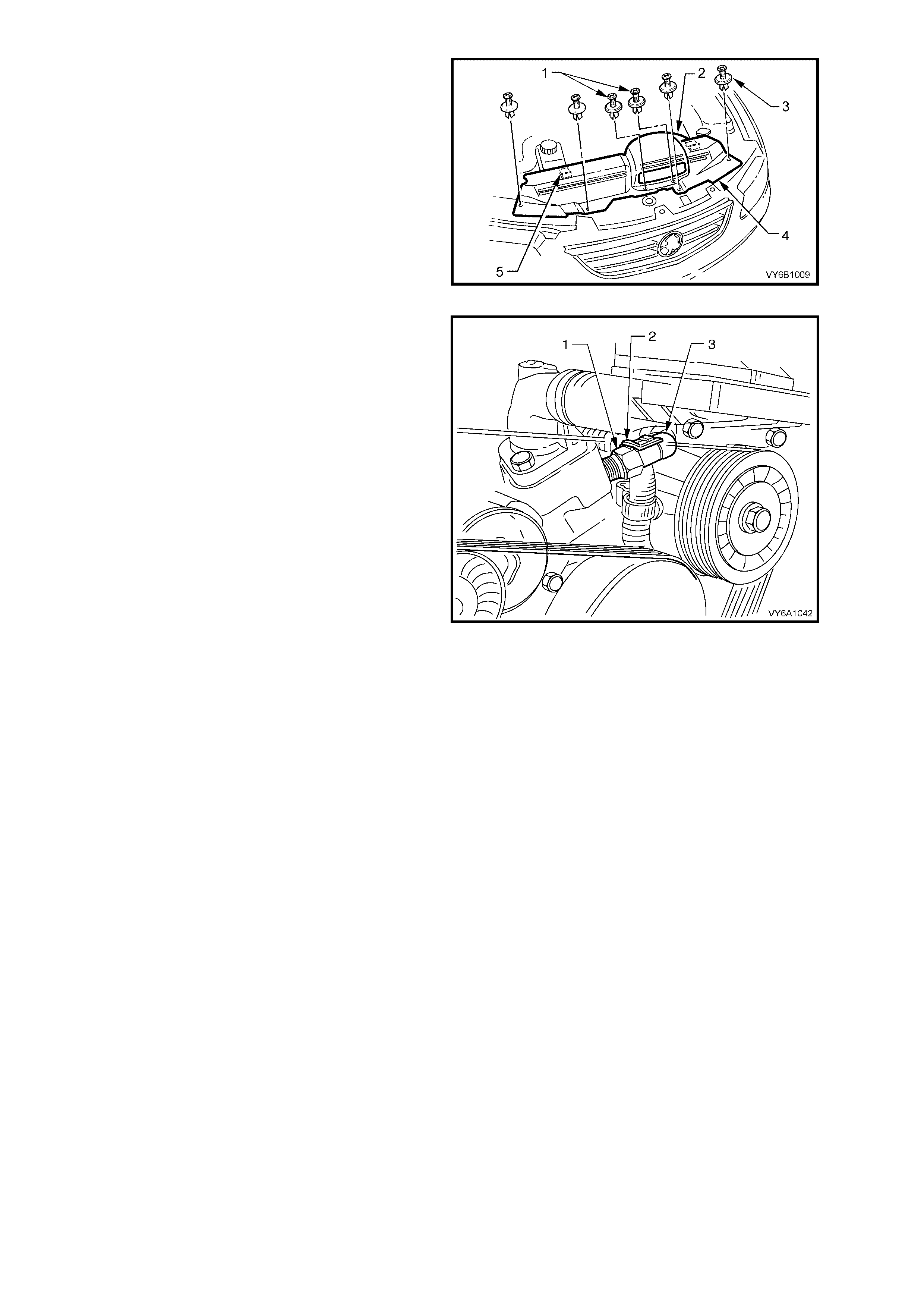
An upper radiator shroud (4) is fitted between the
upper radiator support panel and the radiator
assembly, to minimise the recirculation of hot air
from the rear of the radiator back over the core.
The shroud (4) is held in place by four plastic
‘scrivet' fasteners (3) and by two locating tabs (5).
A inlet air duct (2) is mounted to the shroud with
two plastic fasteners (1)
Figure 6B1-12
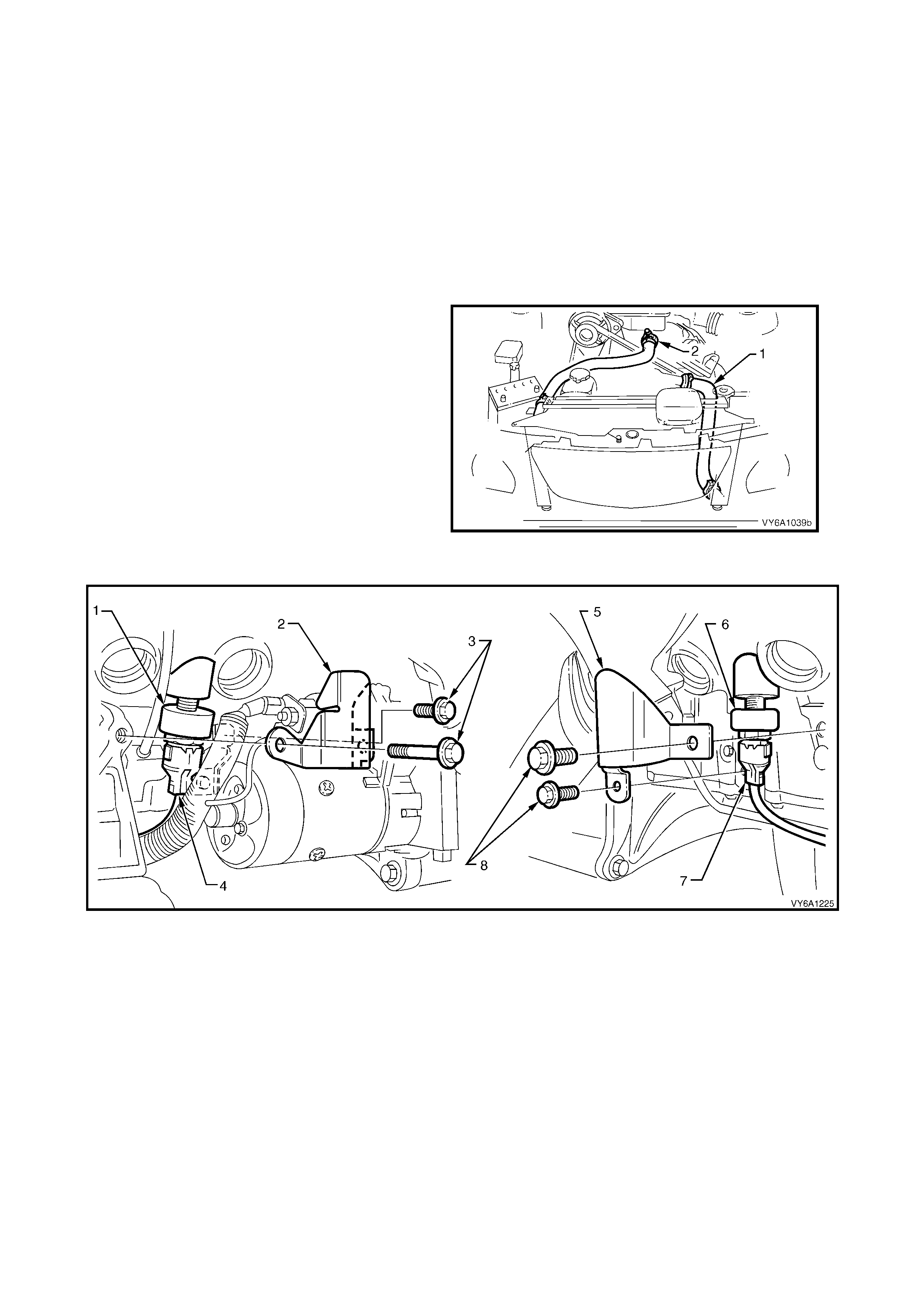
A coolant tem perature s ensor ( 1) is mounted in th e
front of the intake manifold. The coolant
temperature sensor is used in conjunction with the
instrument panel temperature gauge. The coolant
temperature sensor generates a signal which is
used by the engine management PCM/BCM for
calculation of the various engine management
functions.
Figure 6B1-1 3 shows the wirin g harness conn ector
(3) installed to the sensor (1) and retained in
position by the locking tang 2.
Figure 6B1-13

3. SERVICE OPERATIONS
3.1 SERVICE NOTES
CAUTION: TO AVOID SE RIOUS PER SON AL INJU RY, NEVER REMOVE T HE R ADIATOR C AP OR OP EN THE
AIR VENT VALVE ON THE COOLANT OUTLET WHEN THE ENGINE IS HOT, EVEN IF THE COOLING
SYSTEM SHOULD REQUIRE FILLING. SUDDEN RELEASE OF COOLING SYSTEM PRESSURE IS VERY
DANGEROUS.
1. Before removing the radiator cap, allow the engine to cool, then place a shop rag over the radiator cap and
then slowly turn the cap anti-clock wise, without pressing down until t he cap reaches the first 'stop'. This is the
pressur e relief stop, which will al low any rem aining pr essure within the s ystem to escape. T hen press down on
cap and continue to rotate it anti-clockwise until it can be removed.
2. The vehicle is fitted with radiator electric cooling f ans. W hen working around the engine com partment with the
engine ru nning or with the ignit ion 'ON', k eep clear of the f an as the lar ge (or bot h) ma y start operating without
warning.
3. The cooling system requires little care except for maintaining the coolant to the correct level in the recovery
reservoir an d periodic servicing at the time or distance intervals as outlined in the MY 2003 VY and V2 Series
Owner's Handbook.
Periodic servicing includes
a. Checking coolant level, refer to 3.3 CHECKING AND FILLING COOLING SYSTEM this Section.
b. Checking coolant concentration, refer to 3.2 COOLANT MAINTENANCE - TESTING COOLANT
CONCENTRATION this Section.
c. Pressure test cooling system and radiator cap, refer to 3.7 PRESSURE TEST ING in this Section.
d. Tighten h ose clam ps and inspec t all hoses , refer to 3. 6 COOL ANT HOS ES in this Section. Re place hose s
if swollen or deteriorated.
CAUTION: Always wear protective safety glasses when working with spring type hose clamps.
Failure to do so could result in eye injury.
e. Clean out cooling system, refer to 3.4 CLEANING COOLING SYSTEM - COOLING SYSTEM FLUSH, in
this Section and refill cooling system, refer to 3.3 CHECKING AND FILLING COOLING SYSTEM in this
Section.
4. To reduce environmental im pact and maintenance cost, whene ver the coolant is drained f rom an y eng ine, the
service records are to be checked to determine when the coolant was last changed. If more than six months life
is left before the next coolant change, then the following procedure is to be followed:
a. When drai ning the cool ant fr om the en gine, use a clean co ntainer of at least 1 2 litres ca pacity and ensure
that the coolant is not contaminated in the draining process.
b. After repairs have been completed, refill the engine cooling system with the drained coolant.
c. Top up as required , using a 50/50 m ix of clean water and the recommended coola nt, which is either ‘New
Formula Long Life All Seasons Coolant’ (to HN2043 Specification or equivalent) or extended life
anti-freeze coolant, conforming to GM6277M. Refer to 3.2 COOLANT MAINTENANCE and
2.3 CHECKING AND FILLING COOLING SYSTEM in this Section, for the necessary procedures and
further information.
3.2 COOLANT MAINTENANCE
IMPORTANT: Do not mix different types of anti-freeze or corrosion inhibitors as they may be incompatible. If a
different type has been used in the cooling system, flush the system with clean water, refer to
3.4 CLEANING COOLING SYSTEM - COOLING SYSTEM FLUSH in this Section and refill cooling system with the
correct coolant, refer to 3.3 CHECKING AND FILLING COOLING SYSTEM in this Section.
The cooling system is designed to use a coolant (a mixture of ethylene glycol antifreeze with added corrosion
inhibitors, and water), rather than plain water. The use of glycol also raises the boiling point and increases the
cooling system efficiency. For this reason, it is of the utmost importance that the correct concentration level of
ethylene glycol in the cooling system is maintained.
Addition of plain water into the cooling system when 'topping-up' may dilute the coolant mixture to a point where the
antifreeze/anti-boil and corrosion inhibitor properties of ethylene glycol become ineffective.
The coolant should comprise of a mixture 50% ethylene glycol antifreeze/inhibitor with 50% clear, clean water.
Ethylene glycol conforming to the correct specification is either named 'New Formula Long Life All Seasons
Coolant' (to HN2043 Specification or equivalent) or, extended life anti-freeze coolant, conforming to GM6277M,
both available in a number of different quantities. Check the current release of PartFinder® for specific details.
TOPPING UP THE COOLING SYSTEM
Under normal operating conditions, the cooling
system should not be topped up at the radiator filler
cap. The level can be checked at the coolant
recovery reservoir, and coolant (in the correct
concentration with clear, clean water) added as
necessary to bring the level to between the
indicator arrows (‘A’) on the coolant recovery
reservoir di ps tic k when the eng ine is cold.
Figure 6B1-14
TESTING COOLANT CONCENTRATION
To ensure the specified ethylene glycol concentration is maintained in the engine coolant, the coolant concentration
must be checked at the time or distance intervals outlined in the MY 2003 VY and V2 Series Owner's Handbook.
NOTE 1: W hile a number of coolant concentrat ion m easuring devices are availab le, the two pref erred types ar e as
described.
NOTE 2: The procedures detailed, apply to either coolant type used.
Method 1 - Refractometer
NOTE 1: Coolant tester, Tool No. J 26568, automatically compensates for temperature.
NOTE 2: Ensure that the eyepiece of the tester is free of coolant before looking through it.
NOTE 3: Before each use, swing back the plastic cover at the slanted end of the coolant tester, exposing the
measuring window and the bottom of the plastic cover. Carefully wipe the measuring window dry with a tissue or
clean, soft cloth. Close the plastic cover.
1. Check the calibration of the coolant tester as follows:
a. Place a few drops of distilled water (between 21 – 29° C) onto the measuring window, then close the
plastic cover.
b. Point the tester toward any light source, look into the eyepiece and check that the indicated reading is zero.
If not, then re-calibrate the tester as detailed at the end of this Test Method; CALIBRATING THE TESTER.
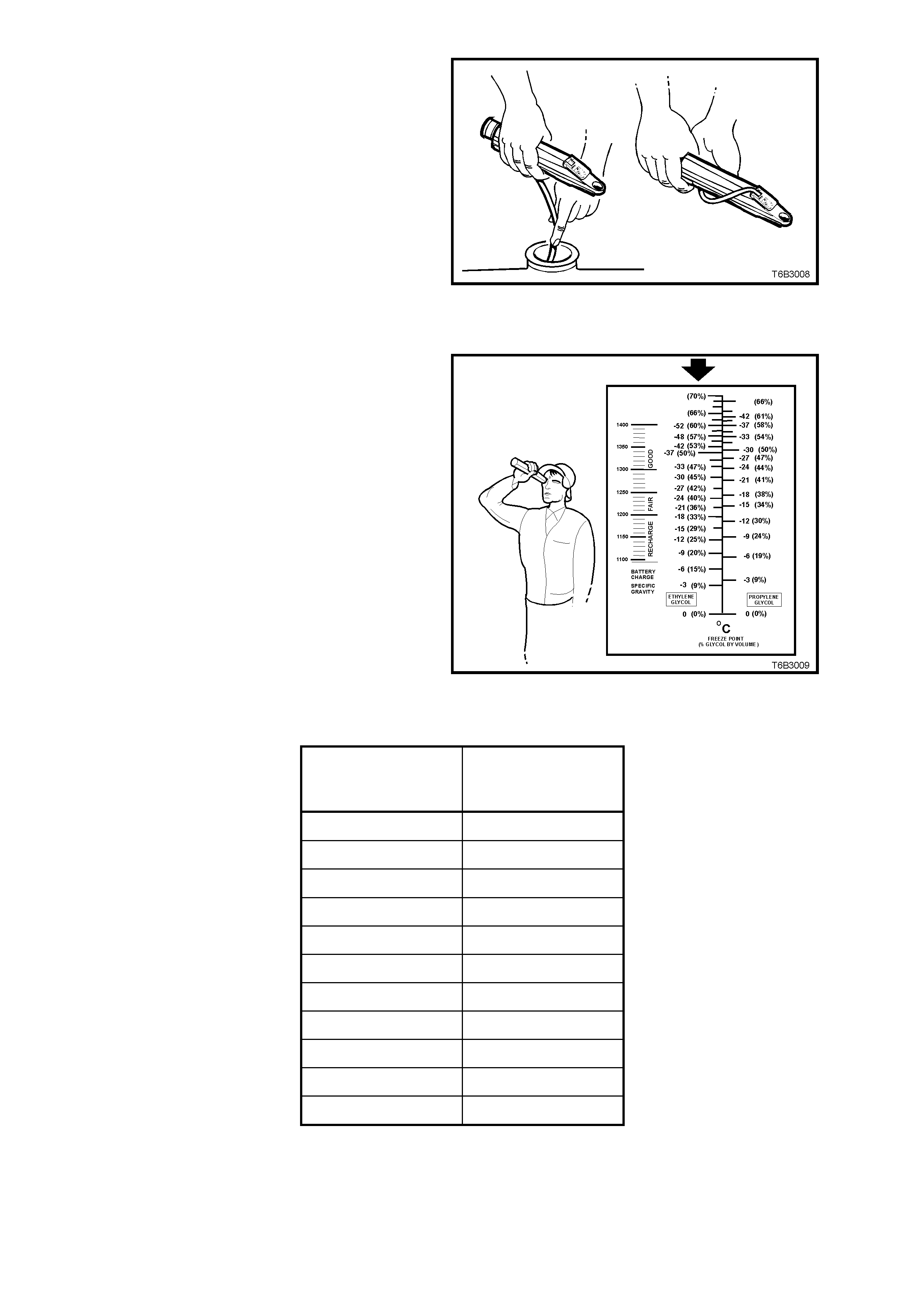
2. Release the tip of the bulb pump from under
the refractometer body. It is not necessary to
remove the complete pump from the tool.
3. Carefully remove the radiator cap.
CAUTION: Refer to 3.1 SERVICE NOTES in
this Section, for important safety items.
4. Insert the tube of the pump into the coolant,
then press the bulb to obtain a sample.
5. Bend the tube around and insert the end into
the cover plate opening.
6. Press the pump bulb to deposit a few drops of
coolant onto the measuring surface. Do not
open the plastic cover when taking readings,
as moisture evaporation will change the
reading obta ined.
Figure 6B1-15
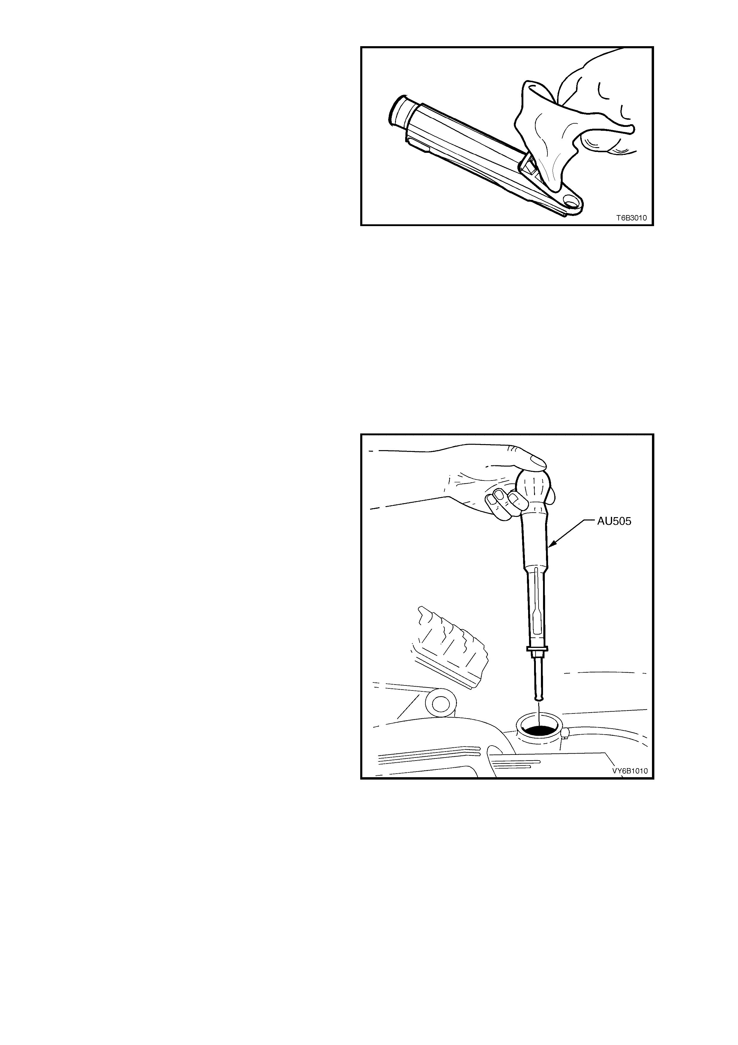
7. Point the coolant tester toward any light
source, looking into the eyepiece.
a. The coolant protection reading is at the
point where the dividing line between the
light and dark, crosses the scale.
b. The scale for ethylene glycol (bold arrow)
is the reference scale for either 'New
Formula Long Life All Seasons' (to
HN2043 Specification or equivalent) or
extended life anti-freeze coolant,
conforming to GM6277M.
NOTE: The temperature scale is reversed from
that of a conventional thermometer. Below zero
readings are on the upper half of the scale.
8. A reading between -30 and -52° C
(corresponding to a coolant concentration
between 45 - 60%), is satisfactory for the V6
engine cooling system.
Figure 6B13-16
CONCENTRATION
READING % LITRES OF
COOLANT TO BE
ADDED
0 6.0
5 5.7
10 5.3
15 4.9
20 4.5
25 4.0
30 3.4
35 2.8
40 2.0
45 1.1
50 0
Table 1
NOTE: If the reading is not clear, then properly
clean and dr y the m easuring sur face, then conduct
another test. Also ensure that there is sufficient
fluid on the measuring prism.
2. If the reading shows that the concentration
level of the coolant is inadequate, refer to the
previous table to determine the amount of
coolant that needs to be added to the coolant
reservoir tank.
3. Start and run the e ngine until n ormal operat ing
temperature is reached, to allow the added
coolant to be distributed throughout the engine
cooling system.
Figure 6B3-17
Calibrating the Tester
While the coolant tester calibration is checked at manufacture, if the calibration check detailed in Step 1 of this
method shows that the instrument is not reading correctly, then conduct the following re-calibration procedure;
1. Remove the sealant covering the adjustment screw on the underneath of the tester.
2. With a distilled water sample on the measuring surface, carefully adjust the screw until a zero reading is
obtained.
NOTE: DO NOT completely remove the screw.
3. After re-calibration, reseal the screw with a small amount of silicone sealant.
Method 2: – Hydrometer
1. The cooling system should be at or close to ambient temperature.
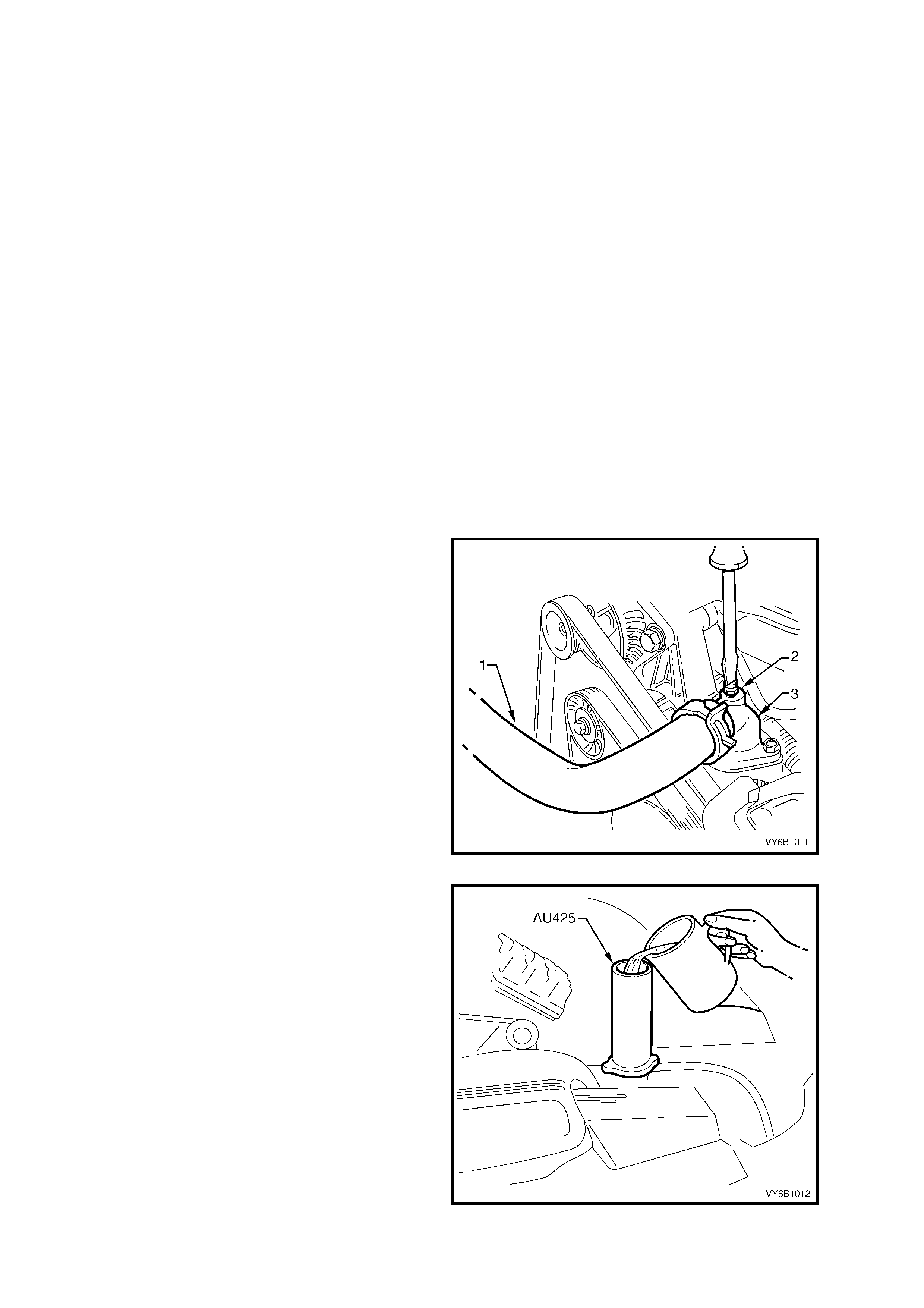
2. Carefully remove the radiator pressure cap
from the radiator and, while holding the rubber
bulb squeezed, insert nozzle of coolant tester
hydrometer, Tool No. AU505 into coolant.
Releasing the rubber bulb will then draw
sufficient coolant into the tester to float
hydrometer bulb freely.
3. Hold tester at eye level and read scale on
hydrometer bulb at coolant level.
The reading shows the percentage of ethylene
glycol antifreeze contained in the engine
coolant.
4. The hydrometer reading should show 50% if
the coolant concentration is correct.
If a reading of less than 50% is achieved, the
cooling system requires topping up with either
'New Formula Long Life All Seasons Coolant'
(to HN2043 Specification or equivalent) or
extended life anti- free ze coolant, c onform ing to
GM6277M.
Refer to the chart shown for the previous
method to determine how much coolant
additive of either type is required to be added
to the cooling system to bring the coolant to the
specified concentration.
5. Drain suf ficient quantit y of coola nt from coolin g
system to allow top-up with coolant additive,
then add the required amount of the correct
additive. Reinstall pressure cap to the radiator.
6. Start and run the e ngine until n ormal operat ing
temperature is reached. This will allow the
added coolant to be distributed throughout the
engine cooling system.
Figure 6B3-18
3.3 CHECKING AND FILLING COOLING SYSTEM
During any service operation that requires the cooling system to be partly or completely drained, the following
instructions must be followed when refilling the cooling system, to ensure that all air is bleed from system.
FILLING COOLING SYSTEM WITH TOOL AU425
The f ollowing proce dure re quires the us e of T ool No. AU425 to f ill the c ooling s ystem . An alternative procedur e for
filling the cooling system is also given, should Tool No. AU425 not be available.
1. Set heater control to maximum.
2. Make up a mixture consisting 50% of either 'New Formula Long Life All Seasons Coolant' (to HN2043
Specification or equivalent) (or extended life anti-freeze coolant, conforming to GM6277M) with 50% clear,
clean water.
IMPORTANT: Do not mix different types of anti-freeze or corrosion inhibitors as they may be incompatible.
Always check which coolant is to be added to the particular vehicle being serviced. If a different type has
been used in the cooling system (or is added accidentally), flush the system with clean water, refer to
3.4 CLEANING COOLING SYSTEM - COOLING SYSTEM FLUSH in this Section.
3. If the cooling system was completely drained, add a pack of pellets (three pellets), P/N M40124 to cooling
system by disconnecting radiator upper hose from engine coolant outlet and placing pellets inside radiator
hose. If cooling system was only partially drained, add one pellet for every four litres of coolant replaced.
IMPORTANT: Pellets are not to be used when the specified coolant is extended life anti-freeze coolant,
conforming to GM6277M.
CAUTION: Always wear protective safety glasses when working with spring type hose clamps. Failure
to do so could result in eye injury.
Refit hose to coolant outlet and tighten hose clamp.
4. Remove radiator cap and install Tool No. AU425 to radiator filler neck.
5. Using a screwdriver, open air vent valve (2) at
coolant outlet (3), to which is fitted the top
radiator hose (1).
Figure 6B1-19
6. Fill cooling system using coolant mixture via
Tool No. AU425 until coolant flows from air
vent opening and all air is expelled.
7. Close air vent valve and remove AU425 from
radiator.
Figure 6B1-20
8. If necessary, remove cap from coolant
recovery reservoir and fill to between the
indicator arrows (‘A’) on the coolant recovery
reservoir di ps tic k when the eng ine is cold.
Figure 6B1-21
9. Pressure test cooling system, refer to 3.7 PRESSURE TESTING in this Section.
10. Refit radiator cap.
FILLING COOLING SYSTEM WITHOUT TOOL AU425
Should Tool No. AU425 not be available, an alternative method of filling the cooling system is detailed next.
1. Set heater control to maximum.
2. Make up a mixture consisting 50% of either 'New Formula Long Life All Seasons Coolant' (to HN2043
Specification or equivalent) (or extended life anti-freeze coolant, conforming to GM6277M) with 50% clear,
clean water.
IMPORTANT: Do not m ix diff erent types of ant i-fr eeze or cor rosion inhibit ors as the y may be inc ompatib le. Alwa ys
check which coolant is to be added to the particular vehicle being serviced. If a different type has been used
in the cooling system (or is added accidentally), flush the system with clean water, refer to
3.4 CLEANING COOLING SYSTEM - COOLING SYSTEM FLUSH in this Section.
3. Remove radiator cap and fill cooling system with as much coolant mixture as possible.
4. Replace radiator cap.
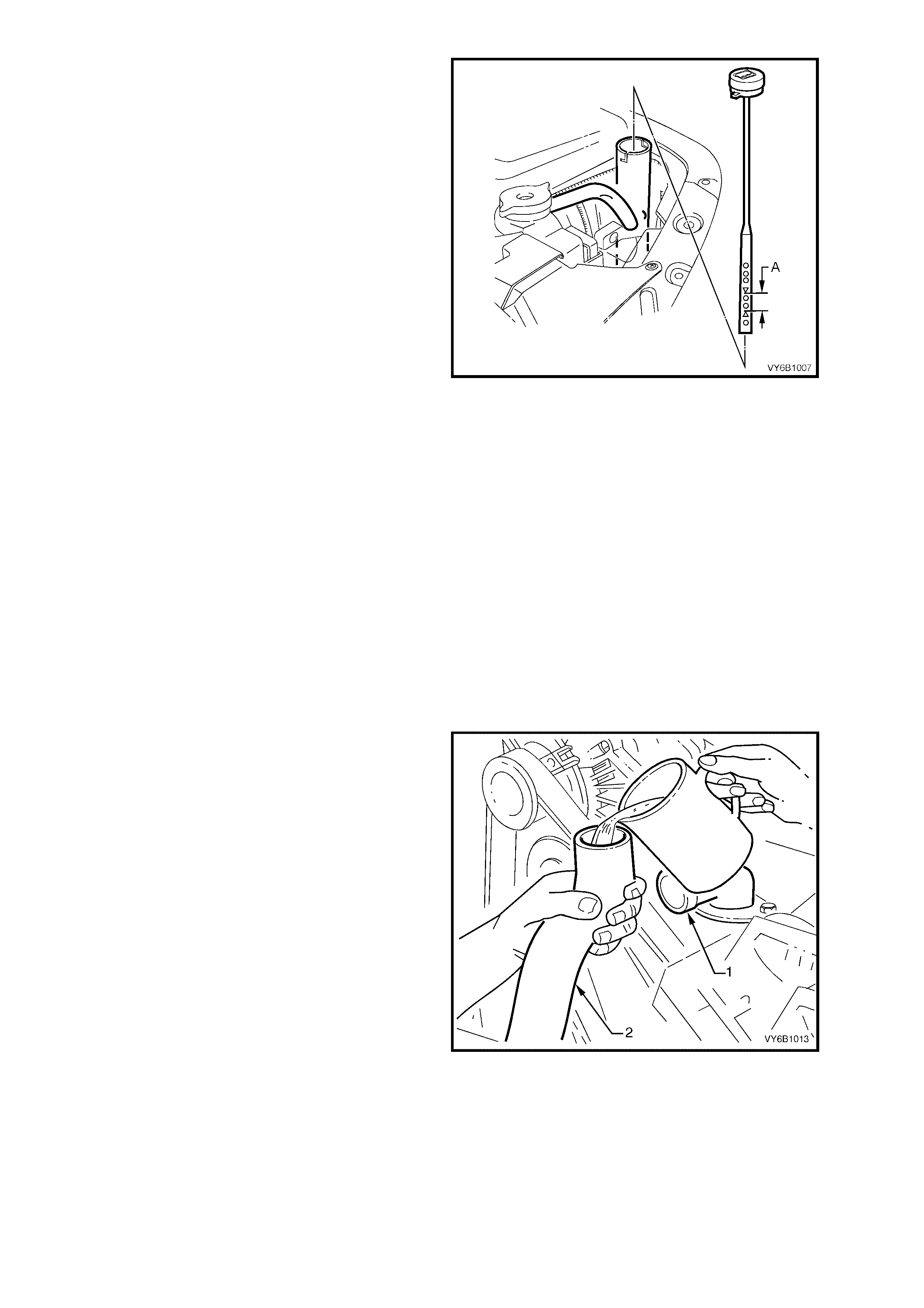
5. Loosen radiator upper hose clamp at coolant
outlet (1) and remove hose (2) from engine
coolant outlet.
CAUTION: Always wear protective safety
glasses when working with spring type hose
clamps. Failure to do so could result in eye
injury.
6. Holding disconnected end of radiator upper
hose (2) upward, fill cooling system using
coolant mixture via open end of radiator upper
hose until coolant starts to flow from coolant
outlet (1).
Figure 6B1-22
7. If cooling system was completely drained, add a pack of pellets (three pellets), P/N M40124 b y placing pellets
inside rad iator hose. If cooling system was onl y partially drained, add one pellet for every four litres of coolant
replaced.
IMPORTANT: Do not use the pack of pellets, if the specified coolant is extended life anti-freeze coolant,
conforming to GM6277M.
8. Quickly install radiator upper hose onto engine coolant outlet, ensuring that neither the pellets nor a large
amount of coolant is spilled. Reinstall hose clamp at coolant outlet connection.
9. Pressure test cooling system, refer to 3.7 PRESSURE TESTING in this Section.
10. Remove cap from recovery reservoir and fill
with coolant to a level approximately 25 mm
ABOVE the indicator arrows (‘A’) on the
coolant recovery reservoir dipstick, refit
dipstick.
NOTE: This condition only applies when the
cooling s ystem is first being filled af ter a maj or loss
of coolant. The level of coolant in the reservoir will
then drop, once the engine is started and normal
operating temperature is reached. The coolant
level sh ould then be m aint ained at the c orrect le vel
(between the two dipstick arrows (‘A’).
Figure 6B1-23
3.4 CLEANING COOLING SYSTEM
A cleaning solution should be used to loosen the rust and scale before performing a cooling system flush. Use
radiator cleaner, such as M39304 (500 ml). Follow the instructions on the container.
COOLING SYSTEM FLUSH
IMPORTANT: This operation should only be carried out when the engine and radiator are at ambient temperature.
NOTE: When using specialised cooling system flushing equipment, connect in accordance with the manufactures
recommendations.
CAUTION: Apply air pressure gradually as the radiator will only withstand a maximum pressure of 150 kPa.
1. Place drain tray beneath vehicle.
2. Remove coolant outlet and thermostat from front of intake manifold, refer to 3.8 THERMOSTAT – REMOVE in
this Section. Refit coolant outlet (without thermostat).
3. Remove radiator lower hose (1) at the engine
front cover connection.
4. Remove radiator upper hose (2) at radiator
connection.
CAUTION: Always wear protective safety
glasses when working with spring type hose
clamps. Failure to do so could result in eye
injury.
Figure 6B1-24
5. Referring to Figure 6B1-24, remove both knock sensors (1 & 6) from each side of cylinder block.
Figure 6B1-25
Legend
1. Lef t Hand Kn ock Senso r
2. Knock Sensor Shield LHS
3. Attaching Bolts
4. Wiring Harness Connector
5. Knock Sensor Shield RHS.
6. Right Hand Knock Sensor
7. Wiring Harness Connector
8. Attaching Bolts
6. Place coolant hose into upper radiator hose fitting, turn on water pressure and flush until water coming from
radiator lower hose connection (front cover) is clear.
7. Place coolant hose into front cover radiator lower hose connection and flush, until water coming from upper
hose is clear.
8. Place coolant hose into radiator lower hose fitting and flush out radiator in reverse direction of normal coolant
flow, until water coming from radiator upper hose connection is clear.
9. Remove coolant recovery reservoir, refer to 3.9 COOLANT RECOVERY RESERVOIR - REMOVE in this
Section. Flush out reservoir with clean water.
10. With cooling system flushed clean, refit all cooling system components. For reinstallation of thermostat and
coolant outlet housing, refer to 3.8 THERMOSTAT - REINSTALL in this Section.
NOTE: If reinstalling original knock sensor, use a wire brush to clean thread sealant residue from the sensors.
Then apply a light coating of thread sealant such as Loctite 24 2 or equivalent to the threads of the k nock sensors
and tighten to t he correct torque specification. If a new sensor is f itted, do not apply sealant to thre ads as threads
are coated with a sealant during manufacture. Applying additional sealant will affect the sensor's ability to detect
engine knock.
KNOCK SENSOR
TORQUE SPECIFICATION 20 Nm
11. Fill cooling system with coolant to the correct concentration level, refer to 3.3 CHECKING AND FILLING
COOLING SYSTEM and pressure test system, refer to 3.7 PRES SURE TEST ING in this Section.
3.5 DRIVE BE LT TENSION
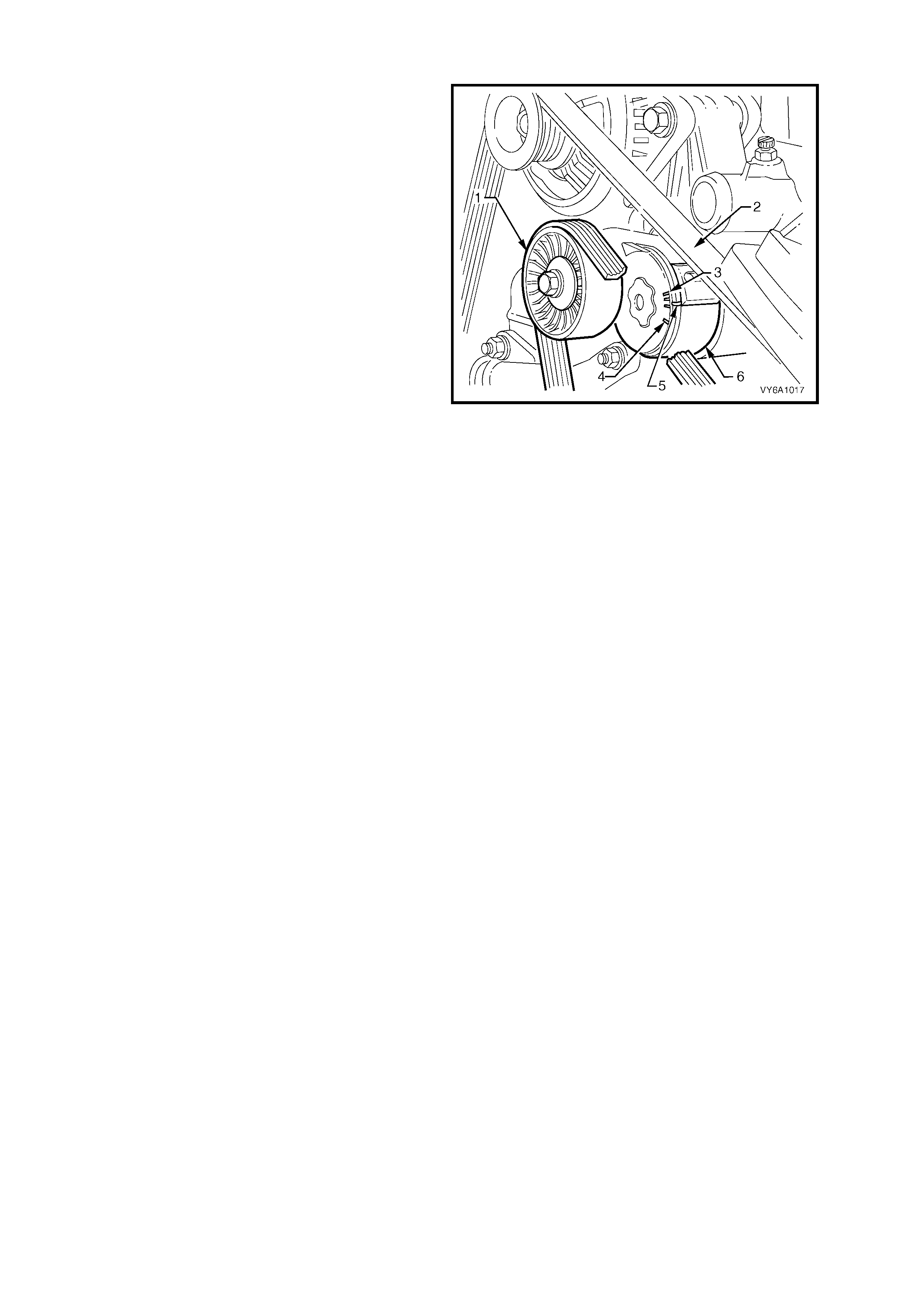
Drive belt tension is provided by an automatic
tensioner as sembl y. The tens ion er is an idler pul ley
mounted on a s pring- load ed arm that m aintains th e
drive belt at the proper tension, without imposing
undue loads on the various components.
Throughout its functional travel, the tensioner
mechanis m will m aintain correc t belt tension, usin g
a pulley (1) mounted to a spring loaded arm (6),
that compensating for increases in belt wear and
stretch.
W hen the indicator poin ter (5) on the tension er has
reached minimum tension range (4), the tensioner
has reached the full extent of its travel and
replacement of the belt (2) is necessary.
The maximum tension range is shown as (3).
When the indicator pointer on the tensioner has
reached m inimum tension r ange, the tension er has
reached the full extent of its travel and belt
replacement is necessary.
Drive belt tension can be checked using Tool No.
BT3373-F, refer to Section 6A1-1 ENGINE
MECHANICAL - V6 ENGINE in the MY 2003 VY
and V2 Series Ser v ice Infor mation.
Figure 6B1-26
3.6 COOLANT HOSES
LT Section No. – 01-160
Coolant hoses are installed as shown in the f ollowing illustrations, taking note that there are a number of variants,
depend ing on a specif ic ve hic le spec if ic ation.
Hose connections should be thoroughly cleaned before installing any new hose.
After all hoses are fitted, always refill the cooling system with correct concentration of coolant, refer to
3.3 CHECKING AND FILLING COOLING SYSTEM and pressure test cooling system, refer to
3.7 PRESSURE T EST ING in this Section.
CAUTION: Always wear protective safety glasses when working with spring type hose clamps. Failure to
do so could result in eye injury.
Figure 6B1-27
Legend
1. Radiator Hose – Upper
2. Radiator Hose – Lower
3. Hose Clamp – Upper Hose to Engine Outlet
4. Hose Clamp – Upper Hose to Radiator Inlet
5. Hose Clamp – Lower Hose to Radiator Outlet
6. Hose Clamp – Lower Hose to Engine Front Cover
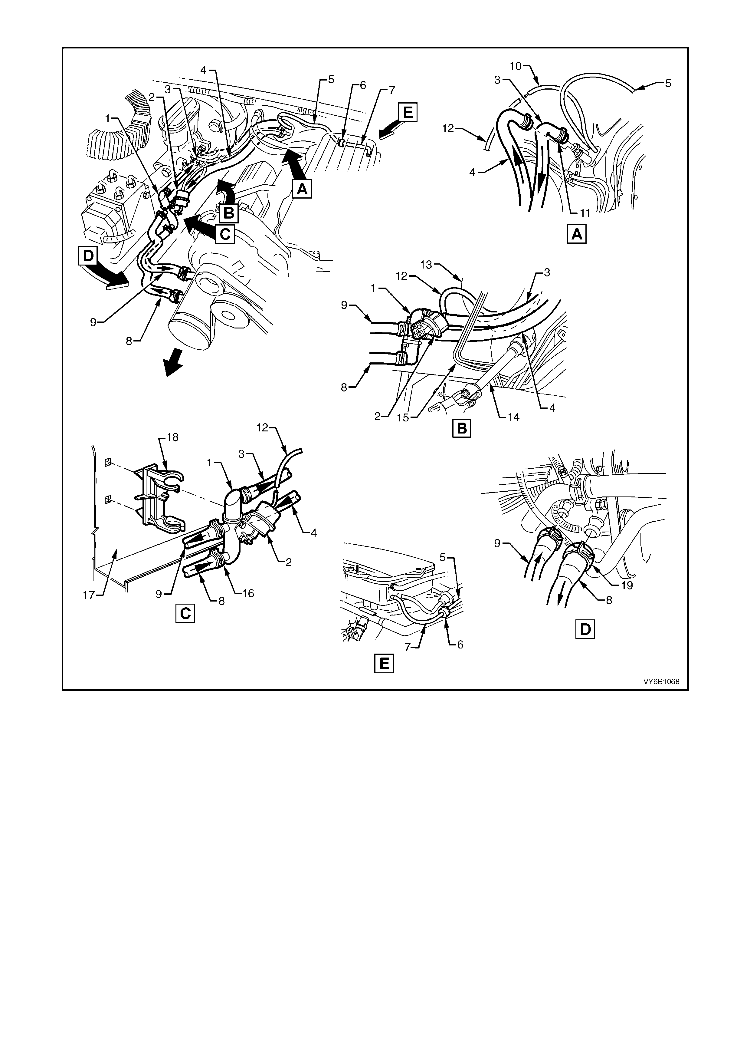
Figure 6B1-28 – Coolant and Vacuum Hose Routing – V6 RHD
Legend
1. Heater Coolant Valve
2. Coolant Valve Actuator
3. Heater Hose to Cabin
4. Heater Hose from Cabin
5. Vacuum Hose – HVAC Supply
6. One-Way Check Valve
7. Vacuum Hose to Intake Manifold
8. Heater Hose to Engine
9. Heater Hose from Engine
10. Vacuum Hose from Internal Control
11. Heater Core Hose Clamps (2 places)
12. Vacuum Hose – Coolant Valve Actuator
13. Brake Booster
14. Steering Shaft
15. Brake Hydraulic Pipes
16. Coolant Valve Hose Clamps (4 places)
17. Wheel House RHS
18. Mounting Clip for Heater Coolant Valve
19. Hose Clamps to Engine (2 places)
NOTE: Heater and vacuum hoses to be routed under brake hydraulic pipes. Refer view B
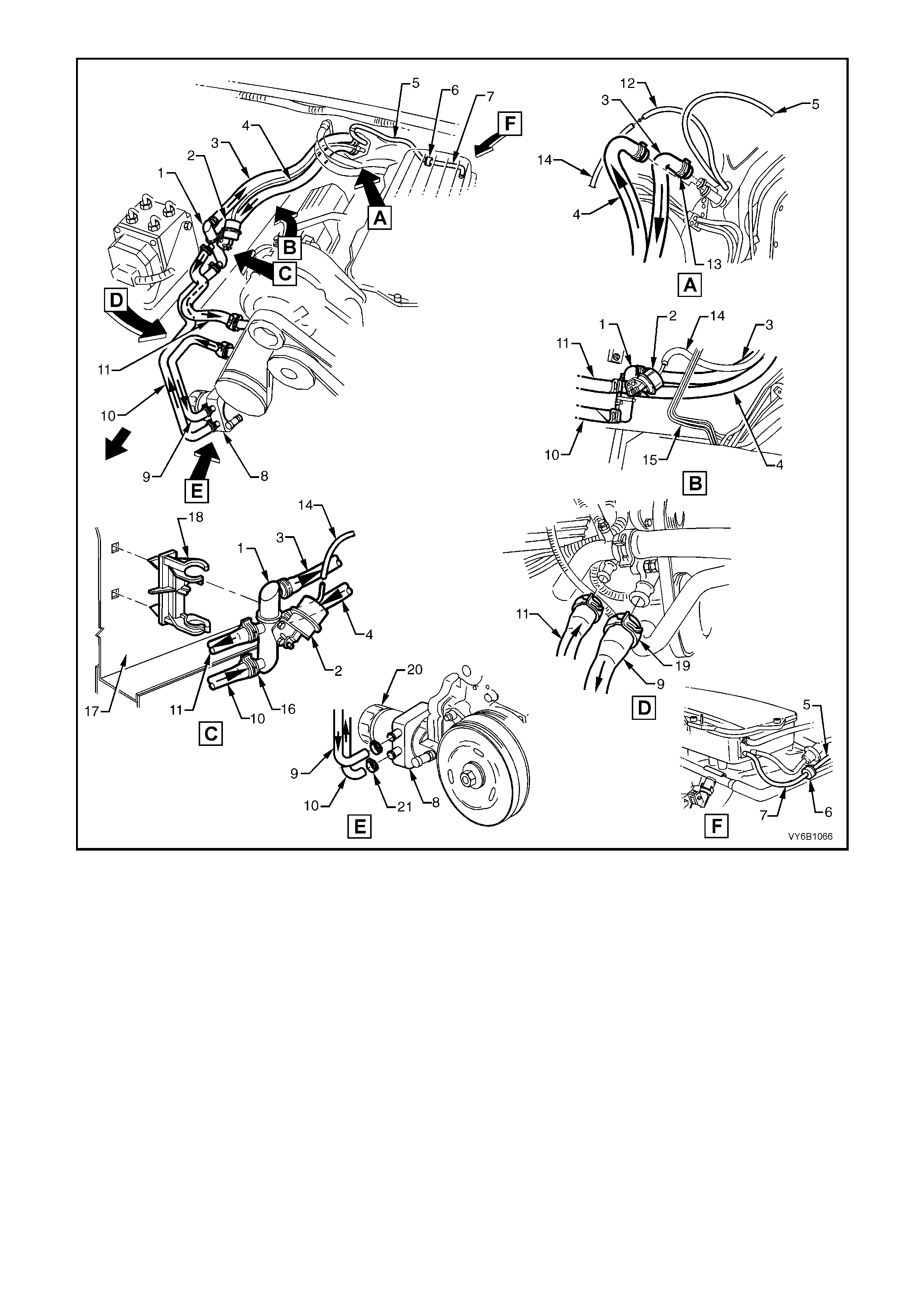
Figure 6B1-29 – Coolant and Vacuum Hose Routing – V6 LHD With Oil Cooler
Legend
1. Heater Coolant Valve
2. Coolant Valve Actuator
3. Heater Hose to Cabin
4. Heater Hose from Cabin
5. Vacuum Hose – HVAC Supply
6. One-Way Check Valve
7. Vacuum Hose to Intake Manifold
8. Engine Oil Cooler
9. Heater Hose – Engine
10. Heater Hose – Oil Cooler
11. Heater Hose from Engine
12. Vacuum Hose from Internal Control
13. Heater Hose Clamps (2 places)
14. Vacuum Hose – Coolant Valve Actuator
15. Brake Hydraulic Pipes
16. Coolant Valve Hose Clamps (4 places)
17. Wheel House RHS
18. Mounting Clip for Heater Coolant Valve
19. Hose Clamps to Engine (2 places)
20. Engine Oil Filter
21. Hose Clamps – Oil Cooler (2 places)
NOTE: Heater and vacuum hoses to be routed under brake hydraulic pipes. Refer view B
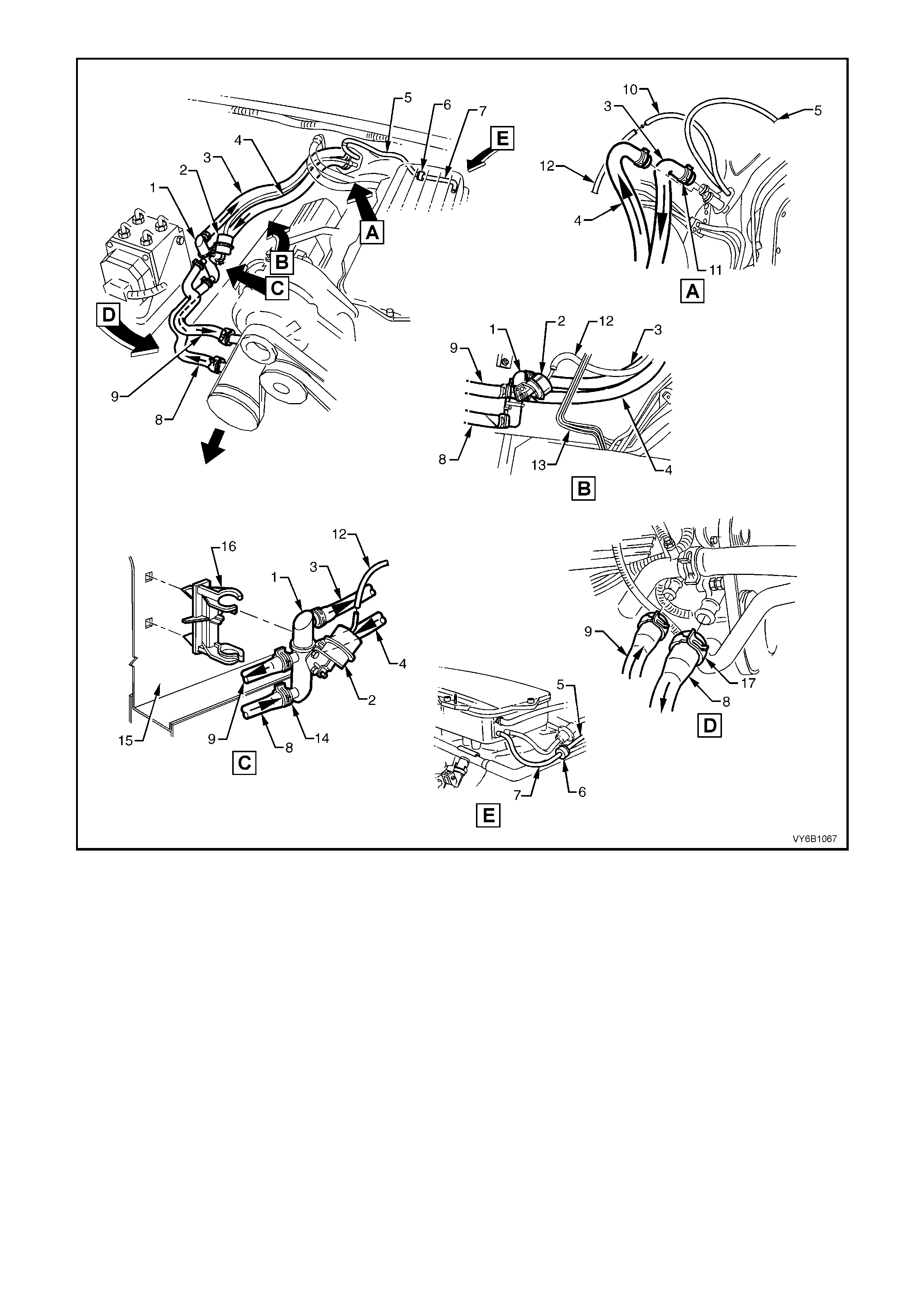
Figure 6B1-30 – Coolant and Vacuum Hose Routing – V6 LHD – Without Oil Cooler
Legend
1. Heater Coolant Valve
2. Coolant Valve Actuator
3. Heater Hose to Cabin
4. Heater Hose from Cabin
5. Vacuum Hose – HVAC Supply
6. One-Way Check Valve
7. Vacuum Hose to Intake Manifold
8. Heater Hose to Engine
9. Heater Hose from Engine
10. Vacuum Hose from Internal Control
11. Heater Core Hose Clamps (2 places)
12. Vacuum Hose – Coolant Valve Actuator
13. Brake Hydraulic Pipes
14. Coolant Valve Hose Clamps (4 places)
15. Wheel House RHS
16. Mounting Clip for Heater Coolant Valve
17. Hose Clamps to Engine (2 places)
NOTE: Heater and vacuum hoses to be routed under brake pipes. Refer View B.
3.7 PRESSURE TESTING
RADIATOR CAP TESTING
1. Allow engine to cool to ambient temperature
(less than 50° C), then remove radiator cap.
CAUTION: Do not remove radiator cap while the
engine coolant temperature is above 50°
°°
° C, as
personal injury may result.
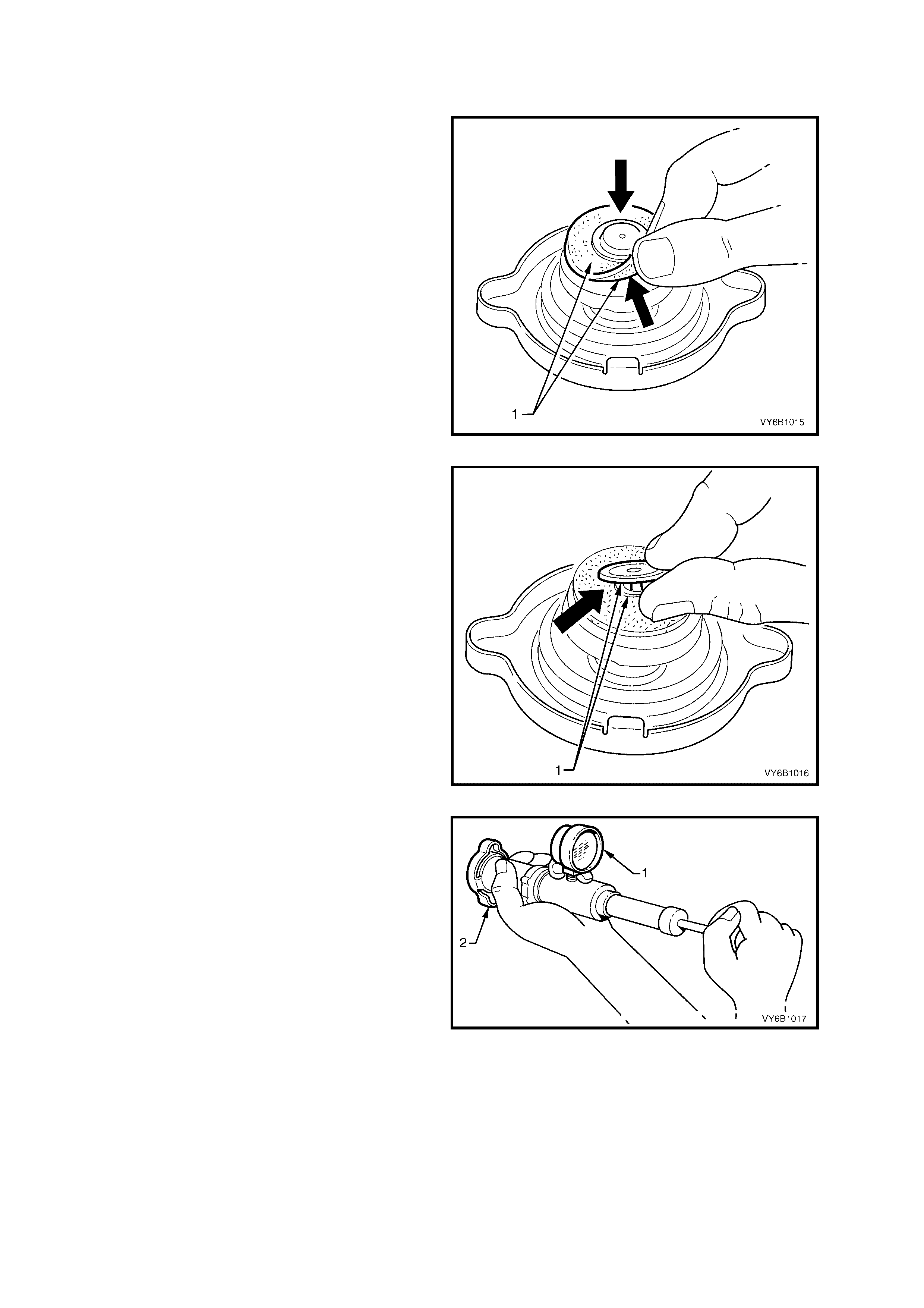
2. Clean both sid es ( 1) of radiator c ap g asket with
a wet cloth.
NOTE: Use only water to wet cleaning cloth.
Figure 6B1-31
3. Lift centre valve and clean gasket area under
valve (1).
Figure 6A1-1-32
4. Attach radiator cap (2) to a commercially
available cooling system pressure tester (1).
Slowly pressurise cap to 120 – 150 kPa. The
cap is serviceable if it unloads slightly above
this pressure range and holds pressure at 120
kPa. Should cap fail to reach or hold the
specified pressure, replace cap.
Figure 6B1-33
5. Pr ior t o reins talli ng radiat or cap ensur e radi ator
filler neck cap seating surface (1) is clean and
free from obstruction.
Figure 6A1-1-34
COOLING SYSTEM PRESSURE TESTING
1. Allow engine to cool to ambient temperature
(less than 50° C), then remove radiator cap.
CAUTION: Do not remove radiator cap while the
engine coolant temperature is above 50°
°°
° C, as
personal injury may result.
2. Ensure coolant level is correct.
3. Connect a commercially available cooling
system pr es sur e tes ter ( 1) to r adiator f il ler nec k
by using the hose supplied (2) or other
arrangement and using compressed air, blow
dry any spilled coolant around radiator filler
neck. Pressurise cooling system to 120–150
kPa and check for leaks at the following points:
a. All hoses and hose connections.
b. Overflow hose connection at radiator.
c. Radiator seams and core.
d. Corroded or faulty engine welch plugs or drain
plugs.
e. Coolant pump and gask et.
f. Vehicle heater system.
g. Check engine oil dipstick for evidence of
engine oil cont aminatio n wi th coolant .
4. If pressure will not hold, there is a leak in the
cooling system. Repair as necessary.
Figure 6B1-35
3.8 THERMOSTAT
LT Section No. – 00-350
REMOVE
1. Allow the engine to cool to an ambient
temperature (less than 50° C), then remove
radiator cap.
CAUTION: Do not remove radiator cap while the
engine coolant temperature is above 50°
°°
° C, as
personal injury may result.
2. Remove engine decorative cover.
3. Disconnect radiator upper hose (1) from
coolant outlet (2) at front of intake manifold.
CAUTION: Always wear protective safety
glasses when working with spring type hose
clamps. Failure to do so could result in eye
injury.
Figure 6B1-36
4. Remove coolant outlet to inlet manifold
attaching bolts (1). If Required remove the
bleeder screw and lock nut (5).
5. Pull coolant outlet (2) from intake manifold,
remove and discard gasket (3).
6. Remove thermostat (4) from intake manifold.
Figure 6B1-37
TEST
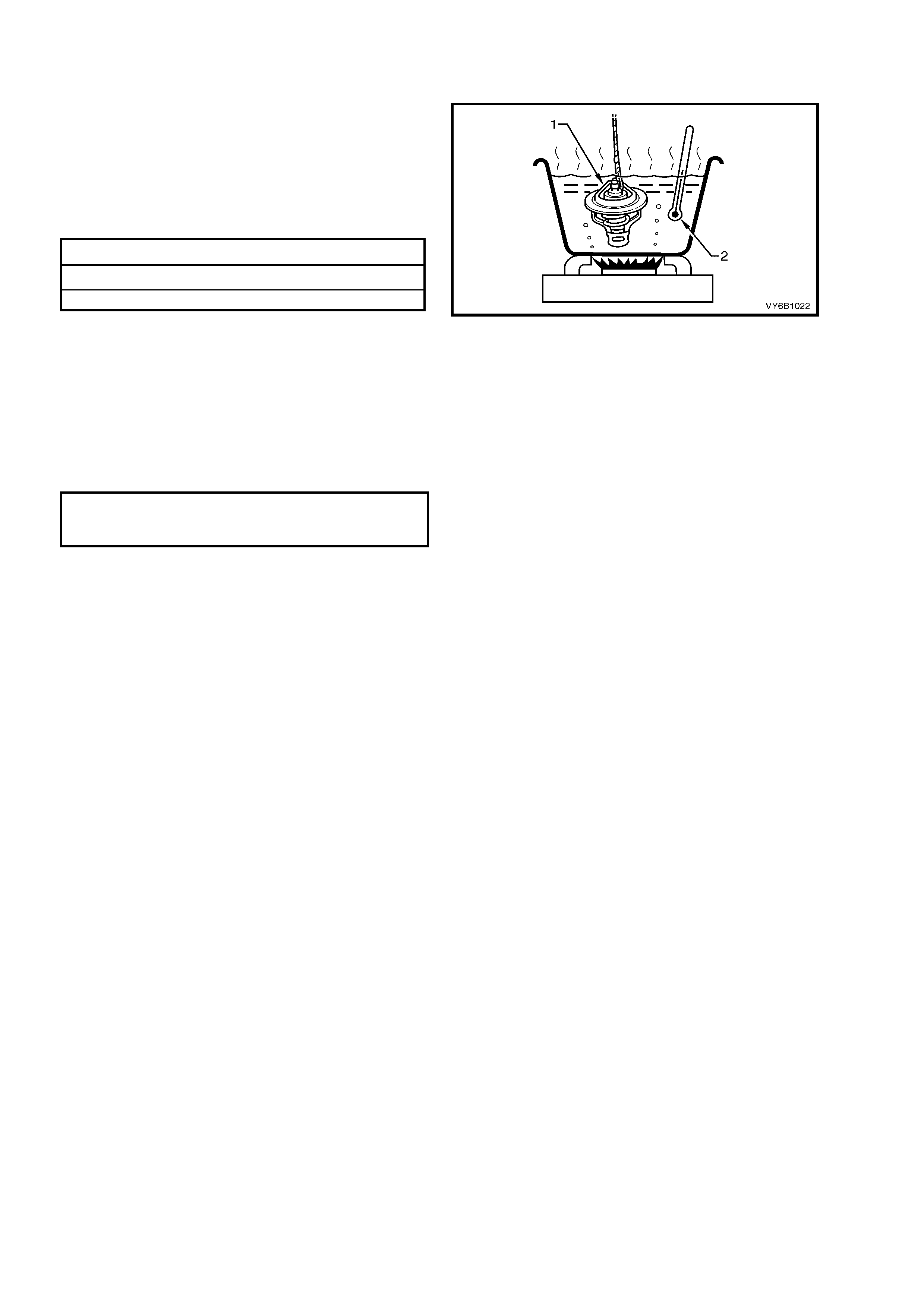
1. Suspend thermostat (1) and a suitable thermometer (2) in a container of 50/50 glycol/water.
2. Heat container until thermostat (1) begins to
open. Agitate solution to ensure uniform
temperature. Note temperature (2) and ensure
thermostat opens within specified temperature
range.
3. Replace thermostat if it does not meet these
operating conditions.
Thermostat Opening Specifications
OPENING TEMPERATURE RANGE 89 – 93° C
FULLY OPEN TEMPERATURE 106° C
IMPORTANT: Neither the thermostat (1) nor the
thermometer (2) should rest on the bottom of the
container because of uneven conce ntration of heat
at this point when the container is heated.
Figure 6B1-38
REINST ALL
1. Reinstall thermostat, new gasket and coolant outlet into inlet manifold.
2. Reinstall coolant outlet to intake manifold attaching bolts and tighten to the correct torque specification.
COOLANT OUTLE T TO I NTAKE
MANIFOLD ATTACHING BOLT
TORQUE SPECIFICATION 28 Nm
3. Refit radiator upper hose and clamp to outlet housing.
4. Refill cooling system, refer to 3.3 CHECKING AND FILLING COOLING SYSTEM in this Section.
5. Check for cooling system leaks, refer to 3.7 PRES SUR E TESTING in this Section.
3.9 COOLANT RECOVERY RESERVOIR
LT SECTION NO. – 01-140
REMOVE
1. Remove the radiator overflow hose from the radiator assembly neck and remove the reservoir tube from the
reservoir body assembly (twist and pull).
2. Remove reservoir assembly attaching screws, remove rese rvoir assembly from the veh icle.
Figure 6B1-39
Legend
1. Screw (3 places)
2. Reservoir 3. Reinstall dipstick and rotate to eth right toe retain
4. Console Front Panel
INSPECT
1. Drain contents from reservoir assembly.
2. Clean reservoir ass embl y with water and dry using co mpress ed air.
3. Check reservoir and assembly for damage, e.g. abrasions, cracks, or distortion. Replace if required.
REINST ALL
Reinstallation of the reservoir assembly is the reverse of removal procedures, noting the following points:
1. Refill cooling recovery reservoir and cooling system with the correct concentration of coolant, refer to
3.3 CHECKING AND FILLING COOLING SYSTEM in this Section.
2. Check cooling system for leaks.
3.10 AI R BAFFLE
LT Section No. –
REPLACE
1. Raise front of ve hic l e a nd s uppor t on s af et y sta nds . R ef er to Section 0 A GENERAL INFORMATION in the MY
2003 VY and V2 Series Service Information, for the location of jacking and support points.
All Models Except ‘S’ Pack (View ‘A’)
2. Remove lower front baffle (2) to crossmember fasteners (1) (four places), slide the front air chute baffle (1)
forward to release the tangs, then remove from the vehicle.
‘S’ Pack Models, Except Utility (View ‘B’)
3. Remove the front bumper bar, refer to Section 1D BUMPER BARS.
NOTE: W hile the air duc t c an be rem oved without f irst rem oving t he bumper bar, ex cess ive distor tion of the duct is
required, both on removal and reinstallation. Also the reinstallation of the two upper scrivets is extremely difficult.
4. Remove the two scrivet fasteners (3) securing both the lower front baffle (2) and the duct (1) to the front
suspension crossmember, then remove the lower front baffle from the vehicle.
5. Rem ove the t wo scrivet fastener s (4) sec uring t he air duc t (1), to th e front u pper pane l assem bly, then r emove
the duct from the vehicle.
6. Reinstallation is the reverse to removal procedures.
NOTE 1: Do not overtighten any of the fasteners.
In Figure 6B1-40, view ‘A’ shows the standard air baffle, while view ‘B’ shows the ‘S’ pack arrangement (except
Utility).
Figure 6B1-40
3.11 COOLANT PUMP
LT Section No. – 00-325
REMOVE
NOTE: The coolant pump cannot be disassembled and therefore can only be replaced as an assembly.
1. Allow engine to cool to ambient temperature (less than 50° C), then remove radiator cap.
CAUTION: Do not remove radiator cap while the engine coolant temperature is above 50°
°°
° C, as personal
injury may result.
2. Disconnect battery ground lead.
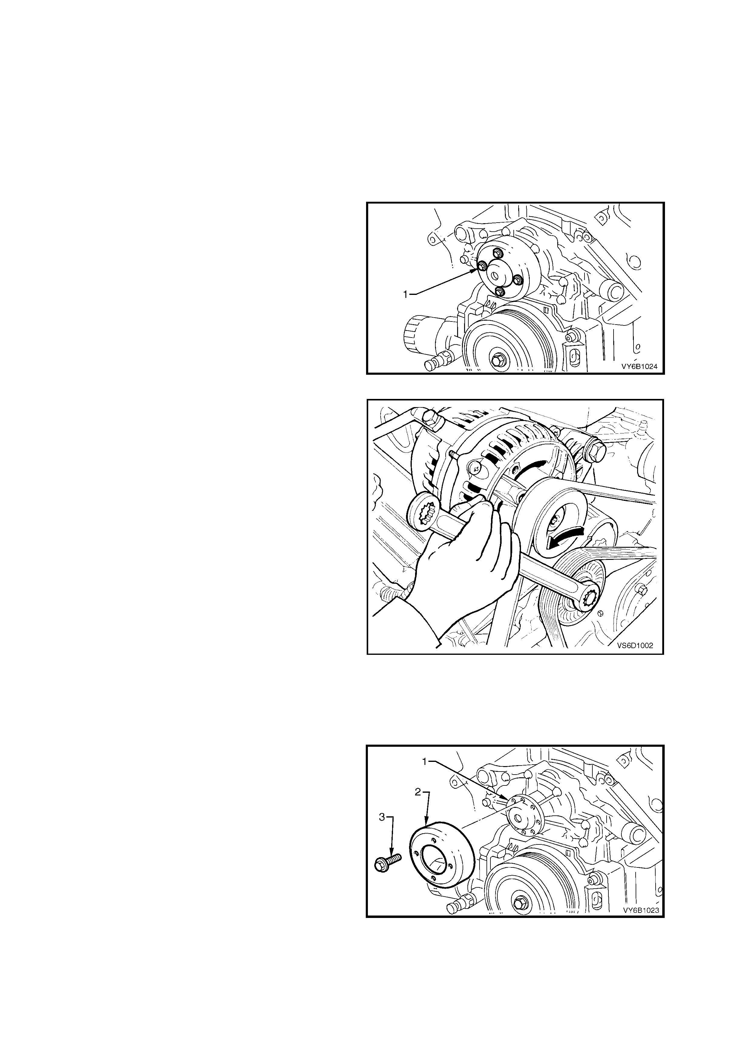
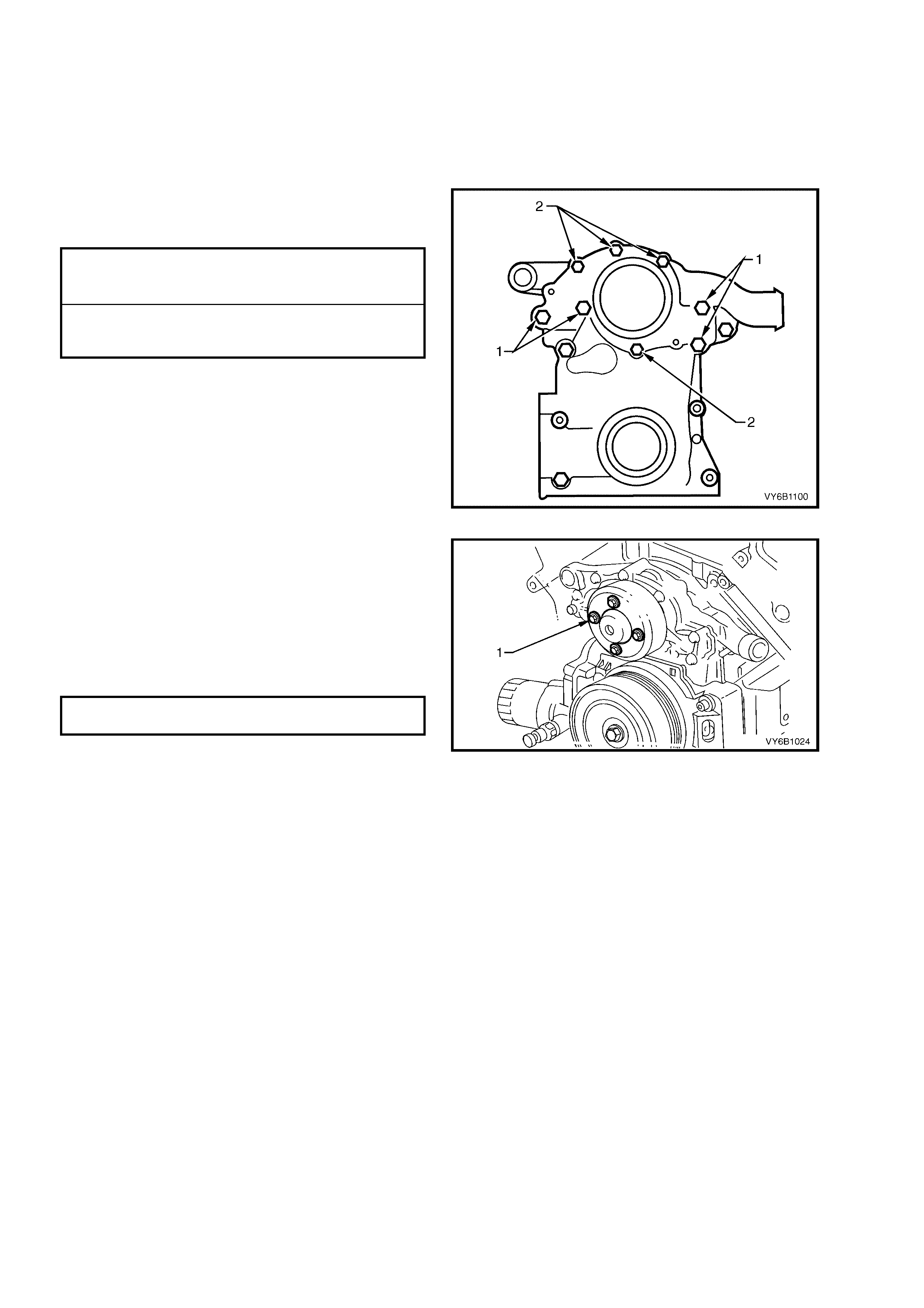
3. Loosen coolant pump pulley to hub bolts (1).
NOTE: While the view shows the drive belt
removed, it will be easier to loosen the four pulley
bolts, with the belt installed.
Figure 6B1-41
4. Using an 15 mm ring spanner on drive belt
tensioner pulley pivot bolt, rotate tensioner
pulley assembly anti-clockwise (arrow) and
remove drive belt from coolant pump pulley.
Figure 6B1-42
5. Remove radiator lower hose clamp at engine front cover connection, disconnect hose from front cover and
allow coolant to drain into a suitable splash tray.
CAUTION: Always wear protective safety glasses when working with spring type hose clamps. Failure to
do so could result in eye injury.
6. Remove coolant pump pulley (2) to hub (1)
attaching bo lts ( 3), then re move pulley fr om the
pulley.
Figure 6B1-43
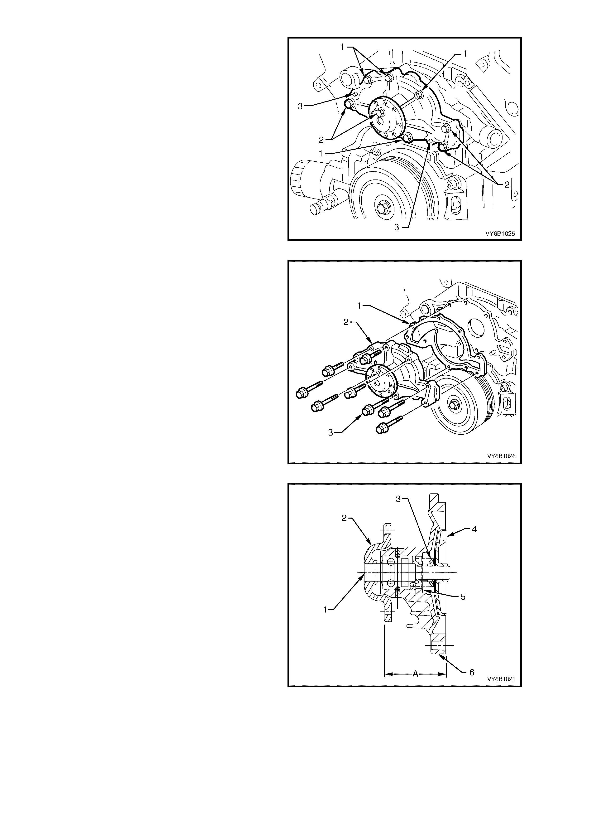
7. Remove coolant pump to front cover (1) and
cylinder block (2) attaching bolts.
NOTE: The coolant pump is located by two dowel
pins (3).
Figure 6B1-44
8. Using a soft faced hammer, lightly tap coolant
pump housing to separate it from front cover.
9. Remove coolant pump to front cover gasket
and discard.
Figure 6B1-45
10. Check coolant pump bearing for excessive
end-play, or rough operation by rotating
bearing pulley hub. Replace coolant pump if
faulty.
Legend:
1 Shaft and Bearing Assembly
2 Coolant Pump Hub
3 Seal Assembly
4 Impeller (Installed from 0.38 mm Proud to 0.13
mm Below Housing)
5 Seal Flange Seats Against this Surface
6 Coolant Pump Housing
A Hub Flange to rear of Pump Housing, 54.7 ±
0.25 mm
Figure 6B1-46
REINST ALL
1. Ensure that coolant pump and front cover mating surfaces are clean and dry.
2. Reinstall new gasket to front cover dowel pins.
3. Clean threads of coolant pump to front cover and cylinder block attaching bolts. Coat threads of bolts with
Loctite 242 sealant or equivalent.
NOTE: Do not apply sealant to the first 1-2 threads of each bolt.
4. Reinstall coolant pump and attaching bolts.
Tighten all bolts to the correct torque
specification.
COOLANT PUMP TO
CYLINDER BLOCK BOLT (‘1’)
TORQUE SPECIFICATION 30 Nm
COOLANT PUMP TO
FRONT COVER BOLT (‘2’)
TORQUE SPECIFICATION 10 Nm
Figure 6B1-47
5. Reinstall coolant pump pulley and attaching
bolts (1).
6. Reinstall drive belt (reverse to removal
procedures) and ensure that drive belt is
aligned with all accessory pulleys and
crankshaft balancer drive belt grooves.
7. Tighten cool ant pump pulle y attach ing bolts (1)
to the correct torque specification.
COOLANT PUMP PULLEY TO HUB
BOLT TORQUE SPECIFICATION 14 Nm
8. Refit radiator lower hose and clamp to front
cover connection.
9. Refill cooling system, refer to 3.3 CHECKING
AND FILLING COOLING SYSTEM in this
Section.
10. Check for coolant leaks, refer to
3.7 PRESSURE T EST ING in this Section.
11. Reconn ec t batter y ground l ead.
Figure 6B1-48
3.12 COOLING FAN AND SHROUD ASSEMBLY
LT Section No. – 01-105
REMOVE
1. Disconnect battery ground lead.
IMPORTANT: Disconnection of the battery affects certain vehicle electronic systems. Refer to Section 00
CAUTIONS, 5. Battery Disconnection Procedures before disconnecting the battery.
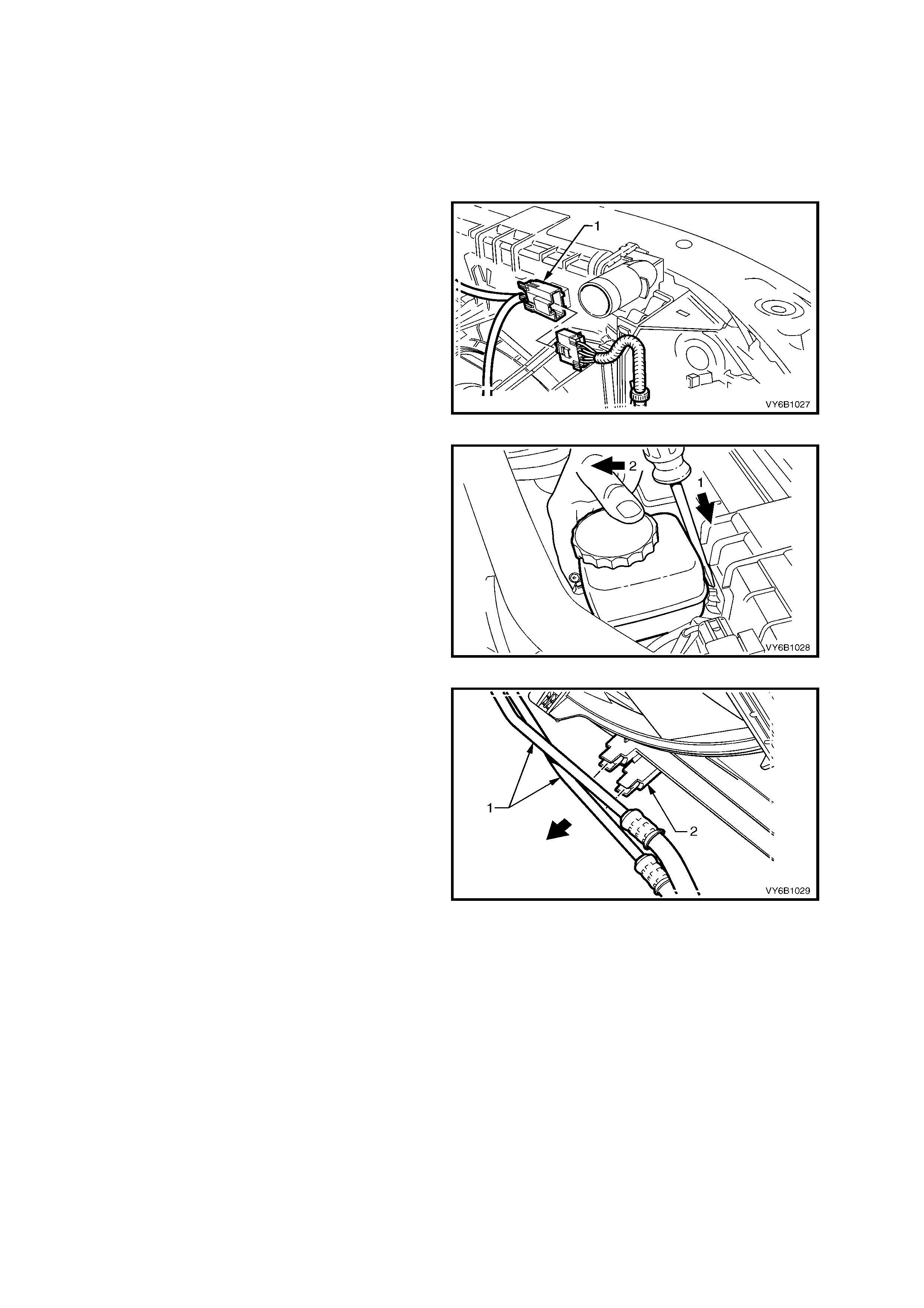
2. Depress tang on main wiring harness to
cooling fan motor wiring harness connector
and separate connector.
Figure 6B1-49
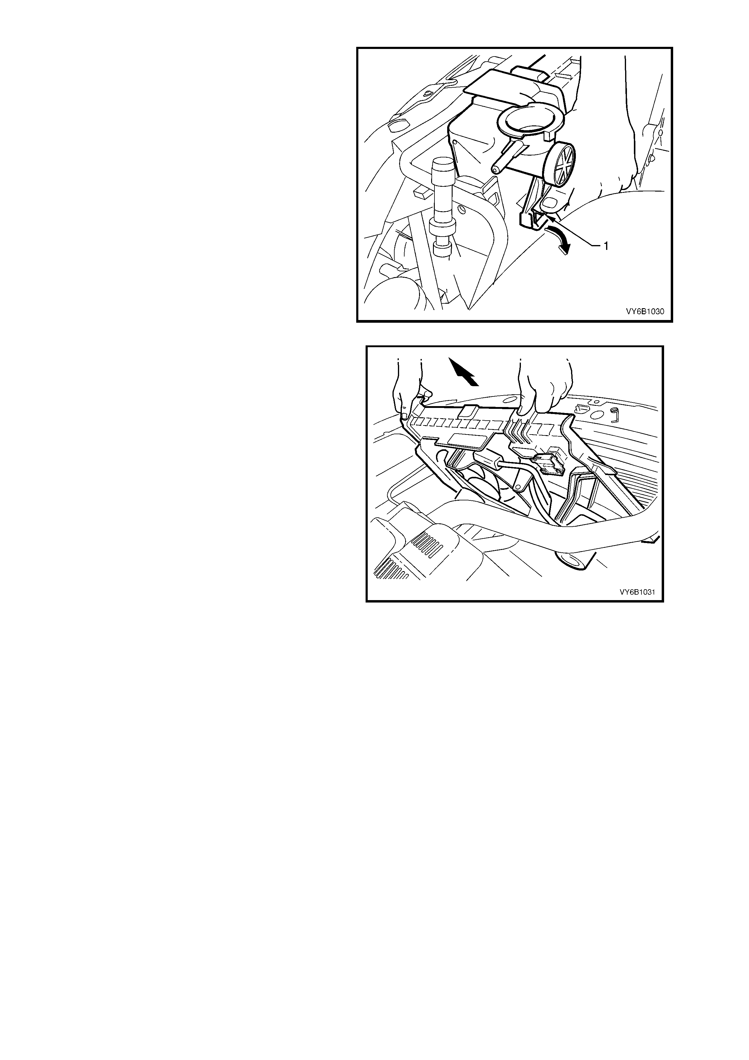
3. Remove the power steering pump reservoir
from its clip on the radiator shroud, using a
screwdriver to lever the clip lock, enabling
removal of the reservoir. Lay the reservoir and
hoses to one side.
Figure 6B1-50
4. Release each of the automatic transmission
cooling p ip es ( if f itted) from the integral cl ips o n
the fan shroud.
Figure 6B1-51
5. Release the fan shroud to radiator clips by
holding one of the lugs (1) out with the fingers
of one hand while lifting the shroud with the
other. Repeat this operation to release the
second side.
Figure 6B1-52
6. Lift the fans and shroud assembly from the
engine bay.
IMPORTANT: Do not lift the assembly clear by
lifting on the fan rings, as this will bend the fan
motor shaft and create an unnecessary vibration.
Figure 6B1-53
REINST ALL
Reinstallation of the cooling fan and shroud assembly is the reverse of removal procedures, noting the following
points:
1. Ensure that fan and shroud assembly to radiator attaching clips are fully engaged.
2. Ensure that both automatic transmission cooling pipes (if fitted) are reinstalled to the shroud clips.
3. Check cooling fan operation, refer to Section 6C1 POWERTRAIN - V6 ENGINE. Also check rotation
direction of cooling fans.

DISASSEMBLE
1. Remove cooling fan and shroud assembly as previously described.
IMPORTANT: Neither fan (2) is to be separated
from its fan motor. The assembly is carefully
balanced during manufacture and, duplicating this
balance on reassembly, is not possible.
1. Remove the m otor as sembly wiring harnes s (1)
from the integral clips that form a part of the
shroud (3).
NOTE: Separate the intermediate wiring harness
connector (5).
2. Remove screws (4) attaching the motor
assem bly (to the shr oud (3), then r emove each
motor, fan and wiring (2) assembly from the
shroud (3).
Figure 6B1-54
REASSEMBLE
Reassembly is the reverse of disassembly procedures, noting the following points:
1. After r einstalling the f an motor and f an assem bly to t he shroud, reins tall and t ighten motor to s hroud attac hing
screws securely but do not over-tighten.
2. Reinstall motor wiring harness to shroud attaching clips. Reinstall the intermediate connector.
3. Reinstall cooling fan and shroud assembly to the radiator, as previously described.
3.13 FLEXIBLE TRANSMISSION COOLER HOSE
LT Section No. – 04-150
REPLACE
NOTE: The flexible hoses are not serviced separately. Therefore, should a hose require replacement, then the
hose and radiator to hose cooler pipe assembly must be fitted.
1. Place a drip tray beneath the engine and radiator section.
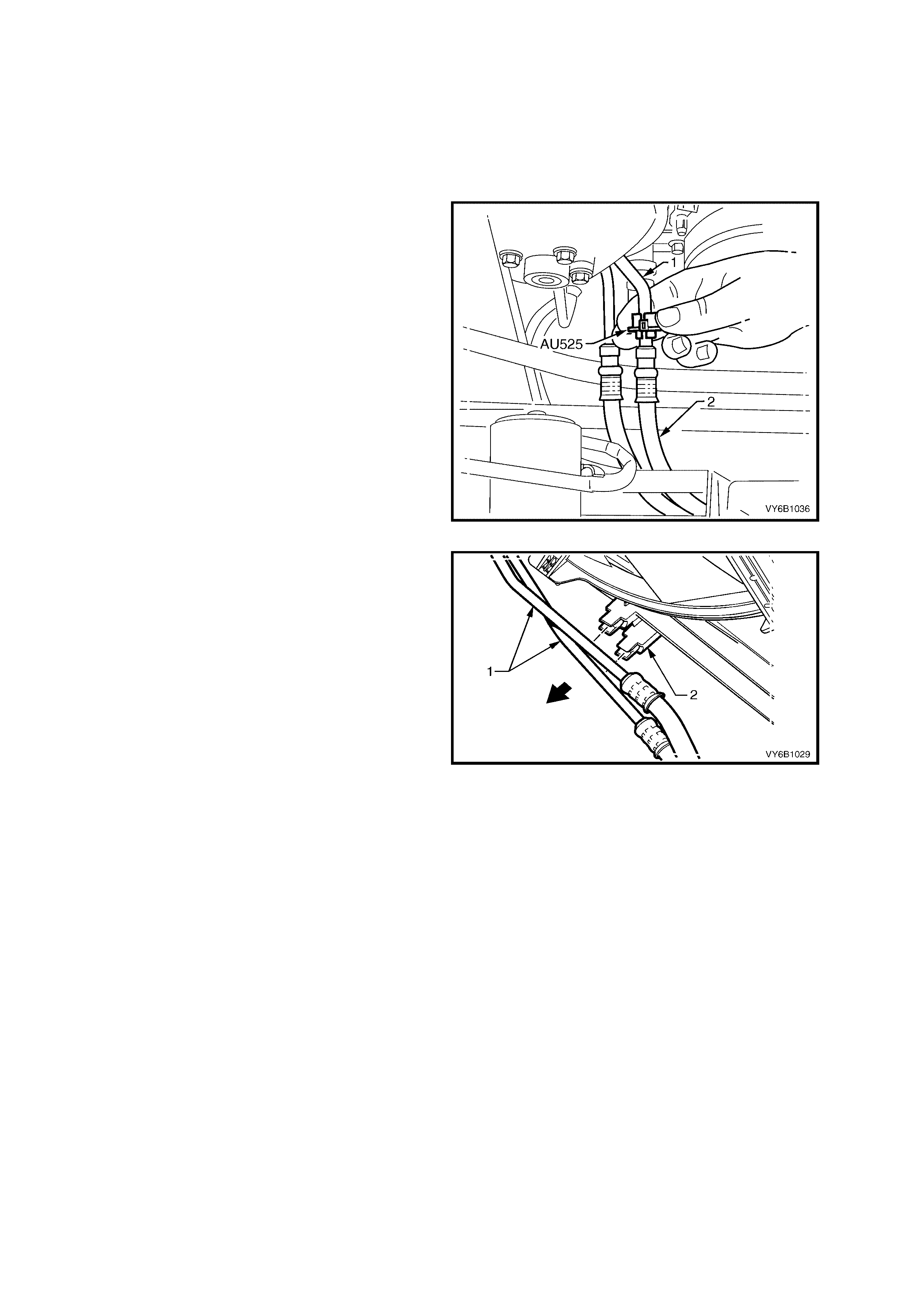
2. Disconnect the transm ission cooler p ipe/s from
the flexible hose/s, using Tool No. AU525:
a. Open release tool AU525, then close and
clip around the pipe to be disconnected.
b. While hold ing t he flex ibl e h ose (2) with one
hand, push the tool into connection, to
release, then pull back on the pipe (or
hose).
c. Repeat for the second fitting, if required.
Plug both pipe openings and hoses to minimise
fluid loss and prevent foreign matter entry.
Figure 6B1-55
3. Release each of the automatic transmission
cooling p ipe/s (1) fr om the integral c lip/s on the
fan shroud (2).
Figure 6B1-56

4. Us ing a s uita ble s et span ner , loosen th e cooler
pipe tube nut (1), then remove, taking care not
to lose the sealing washer (3). Plug both open
ends to prevent fluid loss and/or dirt entry.
IMPORTANT: W hen carrying out this operation on
LHD V6 engined vehicles with automatic
transmission, a back-up spanner must be used on
the larger cooler, flare nut fitting to prevent it from
loosening.
5. Repeat for the second pipe/hose assembly.
6. Before reinstalling each pipe (2) to the cooler,
carefully inspect the pipe sealing washer (3). If
the centre, silicone portion shows signs of
distress or damage, it must be replaced.
7. Remove the plugging from the pipe and fittings,
fit the sealing washer (3) to the cleaned pipe
(2) and reinstall into the cooler.
8. Reinstall the tube nut (1) and tighten to the
correct torque specification.
COOLER PIPE TUBE NUT
TORQUE SPECIFICATION 25 Nm
NOTE: On LHD V6 engined vehicles with
automatic transmission, always use a back-up
spanner to prevent the turning of the fluid cooler
flare nut fitting.
9. Check the transmission fluid level. Refer to
2.1 FLUID LEVEL CHECK, in S ectio n 7C4 A/T
ON-VEHICLE SERVICING.
Figure 6B1-57
3.14 RADIATOR
LT Section No. – 01-105
REMOVE
1. Allow engine to cool to ambient temperature (less than 50° C), then remove radiator cap.
CAUTION: Do not remove radiator cap while the engine coolant temperature is above 50°
°°
° C, as personal
injury may result.
2. Disconnect battery ground lead.
IMPORTANT: Disconnection of the battery affects certain vehicle electronic systems. Refer to Section 00
CAUTIONS, 5. Battery Disconnection Procedures before disconnecting the battery.
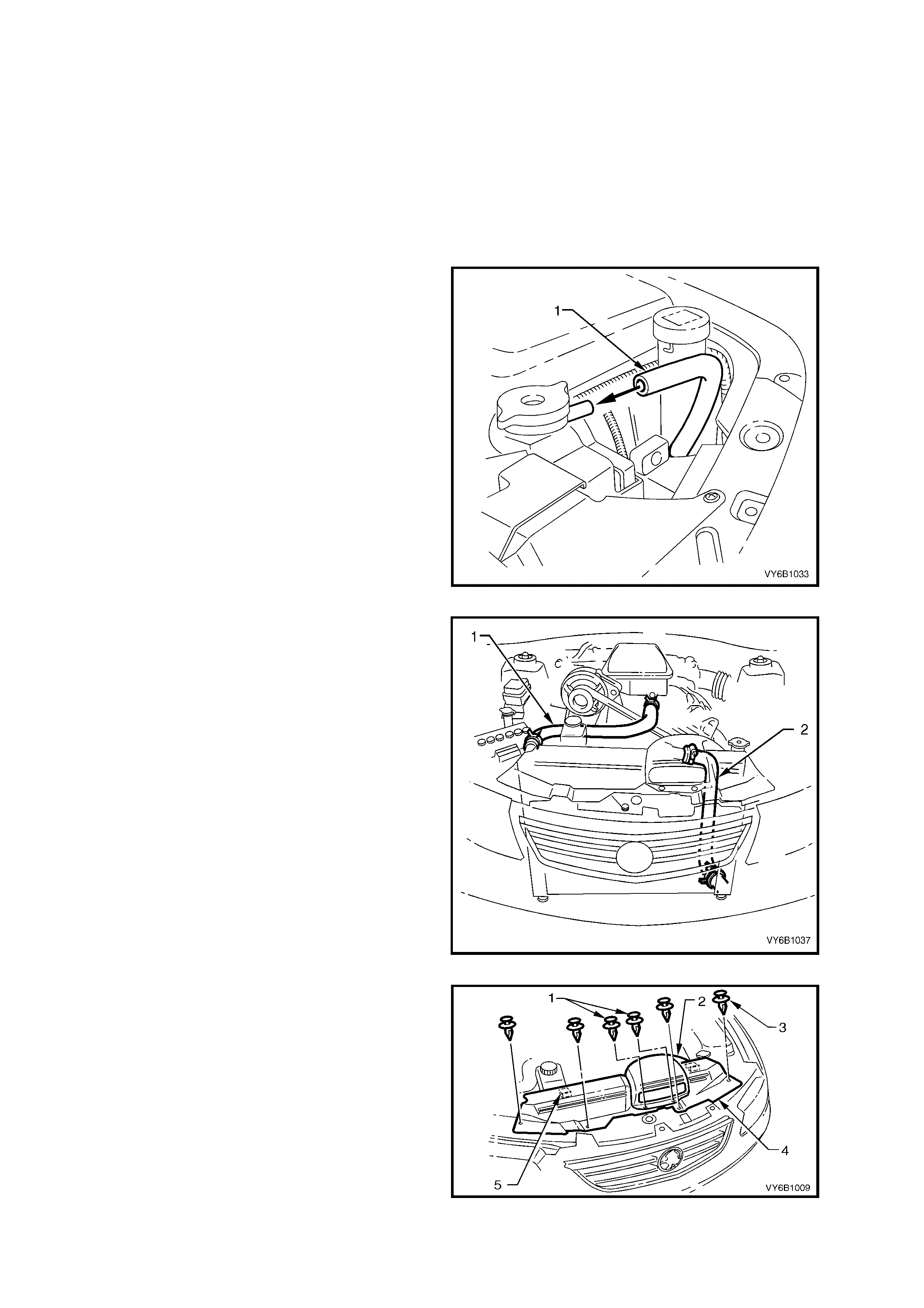
3. Remove coolant overflow hose (1) from
radiator filler neck connection.
Figure 6B1-58
4. Remove radiator lower hose (2) from radiator
connection, allowing the coolant to drain into a
suitable sized and clean drain tray.
IMPORTANT: Refer to ITEM NO. 4 in 3.1
SERVICE NOTES in this Section regarding the
collection of the drained coolant.
CAUTION: Always wear protective safety
glasses when working with spring type hose
clamps. Failure to do so could result in eye
injury.
5. Remove radiator upper hose (1) from radiator.
Figure 6B1-59
6. Remove the cold air intake duct and radiator
upper shroud retainers (1 and 2). Remove the
cold air intake duct (2), then disengage the
shroud locating tabs (5) by pulling the shroud
(4) towards front of vehicle, prior to removal.
7. If fitted with air conditioning, disconnect the
retainer clip securing the high pressure air
conditioning pipe to the top of the front upper
panel assembly on the left hand side.
Figure 6B1-60
NOTE: If fitted with a ir conditioning, the condenser
must be separated from the radiator assembly.
This action will allow the radiator removal without
having to open any refrigerant lines.
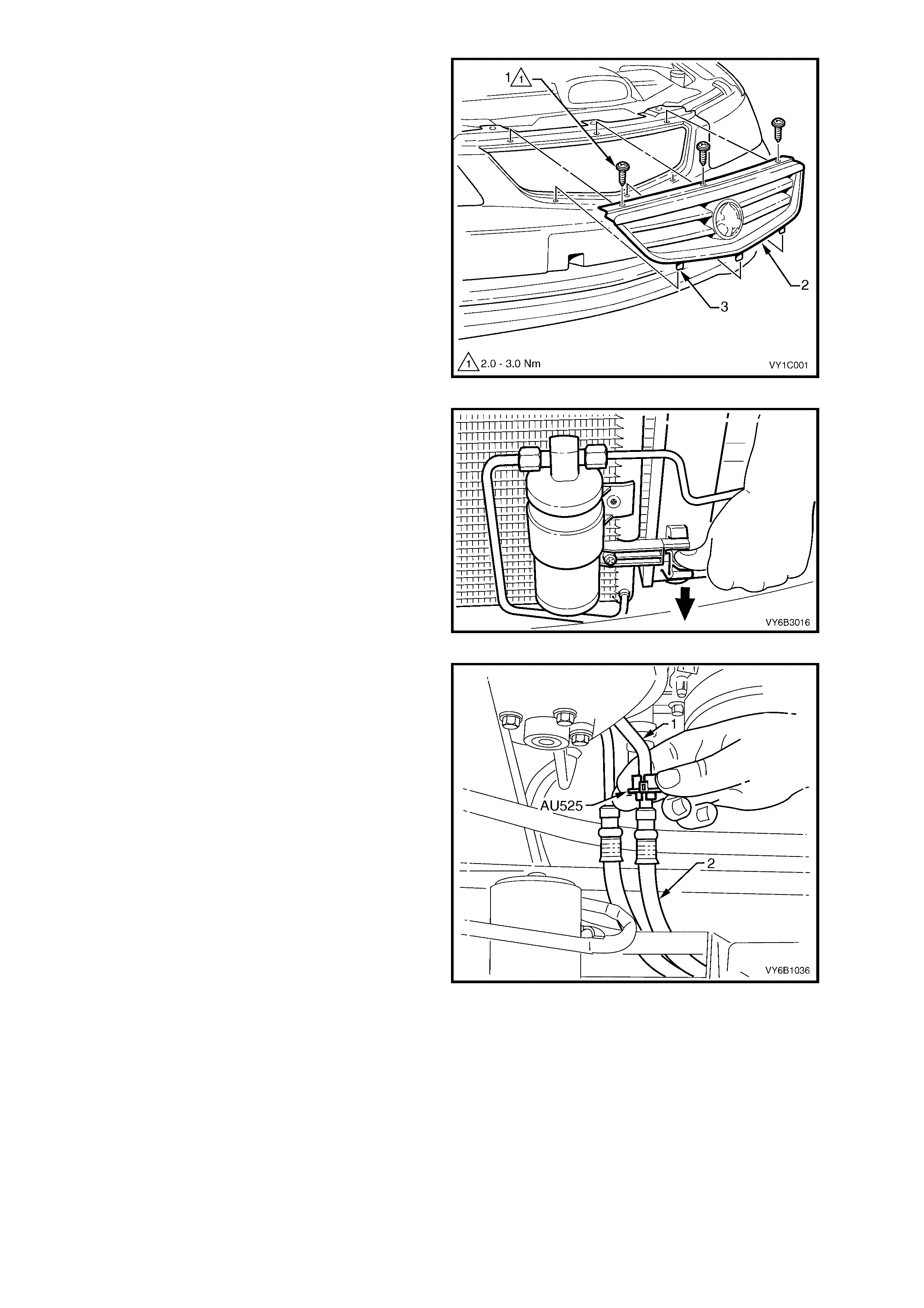
8. Remove the three screws (1) attaching the
radiator grille assembly (2) to the bumper
fascia.
9. Tilt the top of the grille assembly forward
slightly and lift it out of the bumper fascia to
release the three pins (3) along the lower edge.
NOTE: The grille on ‘S’ Sedan and ‘SS’ model
vehicles is s ecured i n a si m ilar m anner but ha s two
lugs on the lower edge rather than three pins.
Figure 6B1-61
10. Working through the grille opening, release
one of the clips securing the condenser to the
radiator (bold arro w). Do th is by pres sing down
on the lug with the fingers of one hand, while
lifting the condenser assembly with the other.
Repeat for the other side.
11. Once released, pull the condenser assembly
forward to clear the radiator mounting lugs.
Figure 6B1-62
12. If vehicle is equipped with an automatic
transmission, disconnect the transmission oil
cooler line quick connect fittings, using Tool
No. AU525:
a. Open release tool AU525, then close and
clip around the pipe to be disconnected.
b. While hold ing t he flex ibl e h ose (2) with one
hand, push the tool into connection, to
release, then pull back on the pipe.
NOTE: If Tool No. AU525 is not available, the
cooler pipes can be disconnected from the cooler,
in the left side radiator tank. Refer to
3.13 FLEXIBLE TRANSMISSION COOLER
HOSE, in this Section, for important information
regarding this procedure.
c. Plu g all op enings to m inim ise fluid loss and
prevent dirt entry.
Figure 6B1-63
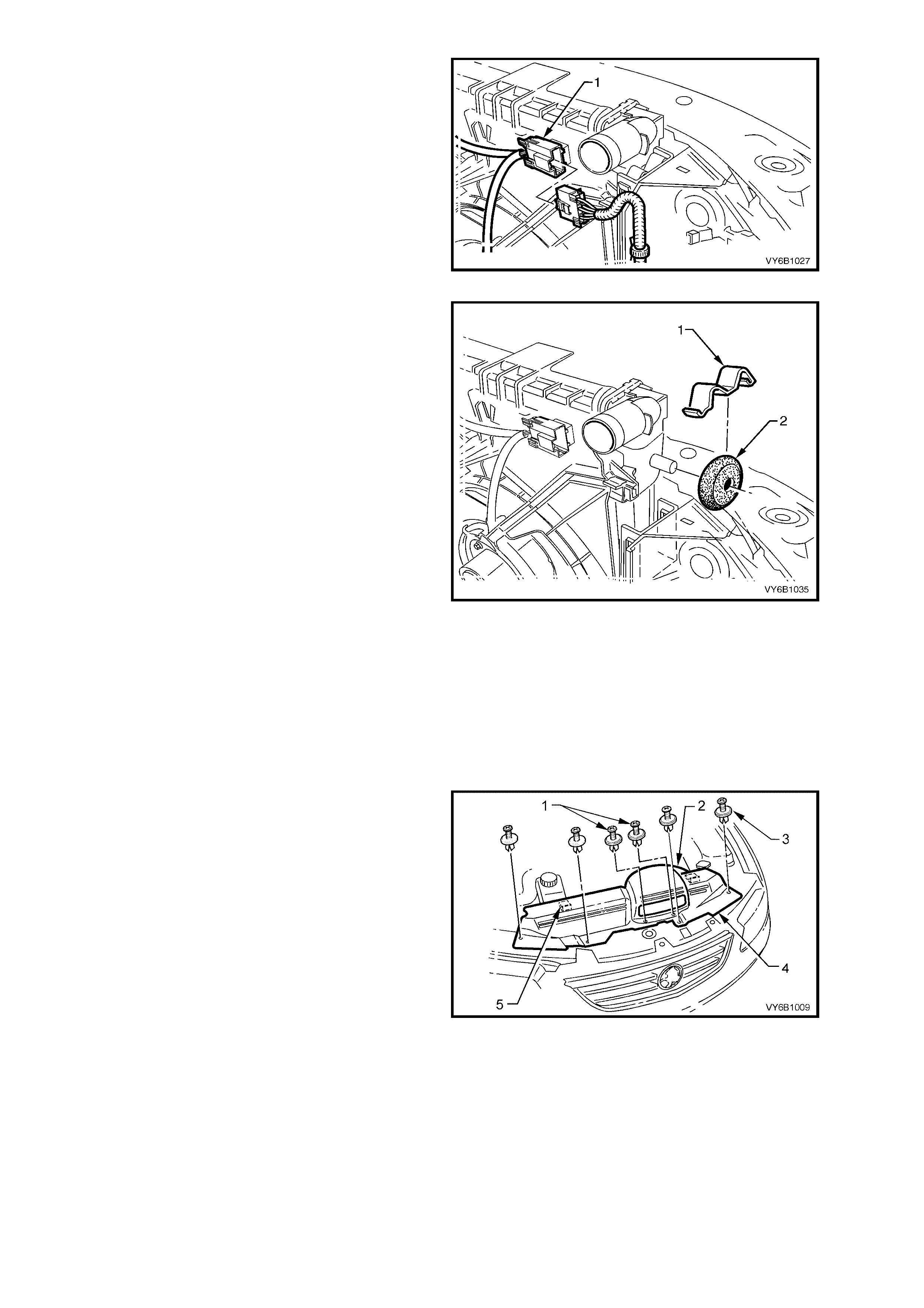
13. Depress tang on main wiring harness to
cooling fan motor wiring harness connector (1)
and separate connector.
Figure 6B1-64
14. Using a screwdriver, compress and lever out
radiator retaining clips (1) from radiator upper
mounting brackets.
15. Lift radiator upwards out of lower insulators
and remove radiator from vehicle.
IMPORTANT: If removing the fan and shroud as
an assembly to the radiator, do not use the fan
outer rings, as lifting devices, as this will bend the
fan motor shafts causing unnecessary vibration,
when the vehicl e is pl aced bac k in service.
16. Remove upper (2) and lower insulators from
the radiator.
17. If required, separate the fan and shroud
assembly from the radiator by releasing the
two locking tangs at the upper locations, then
slide the fan shroud up and clear from the
radiator.
Figure 6B1-65
REINST ALL
Reinstallation of the radiator is the reverse of removal procedures, noting the following points:
1. Before ins talling radiator , inspect cor e to ensure that there is no for eign matter in core f ins. Clean out bet ween
core fins with compressed air, blowing from rear to front.
2. Ensure that radiator lower mounting pins are correctly located in lower insulators.
3. Ensure that upper insulators are installed on upper mounting pins and radiator retainers are installed.
4. Reinstall radiator upper shroud (4) by first
locating each of the two locating tabs (5), then
securing with four plastic ‘scrivet’ fasteners (3).
5. Reinstall the cold air intake duct to the lower
air cleaner body, securing with two plastic
fasteners (1).
Figure 6B1-66
6. Refill cooling system, refer to 3.3 CHECKING
AND FILLING COOLING SYSTEM in this
Section.
7. Check for coolant leaks, refer to
3.7 PRESSURE T EST ING in this Section.
8. Check cooling fan operation, refer to
Section 6C1 POWERTRAIN MANAGEMENT
- V6 ENGINE, including fan rotation direction.
RADIATOR REPAIR PROCEDURE
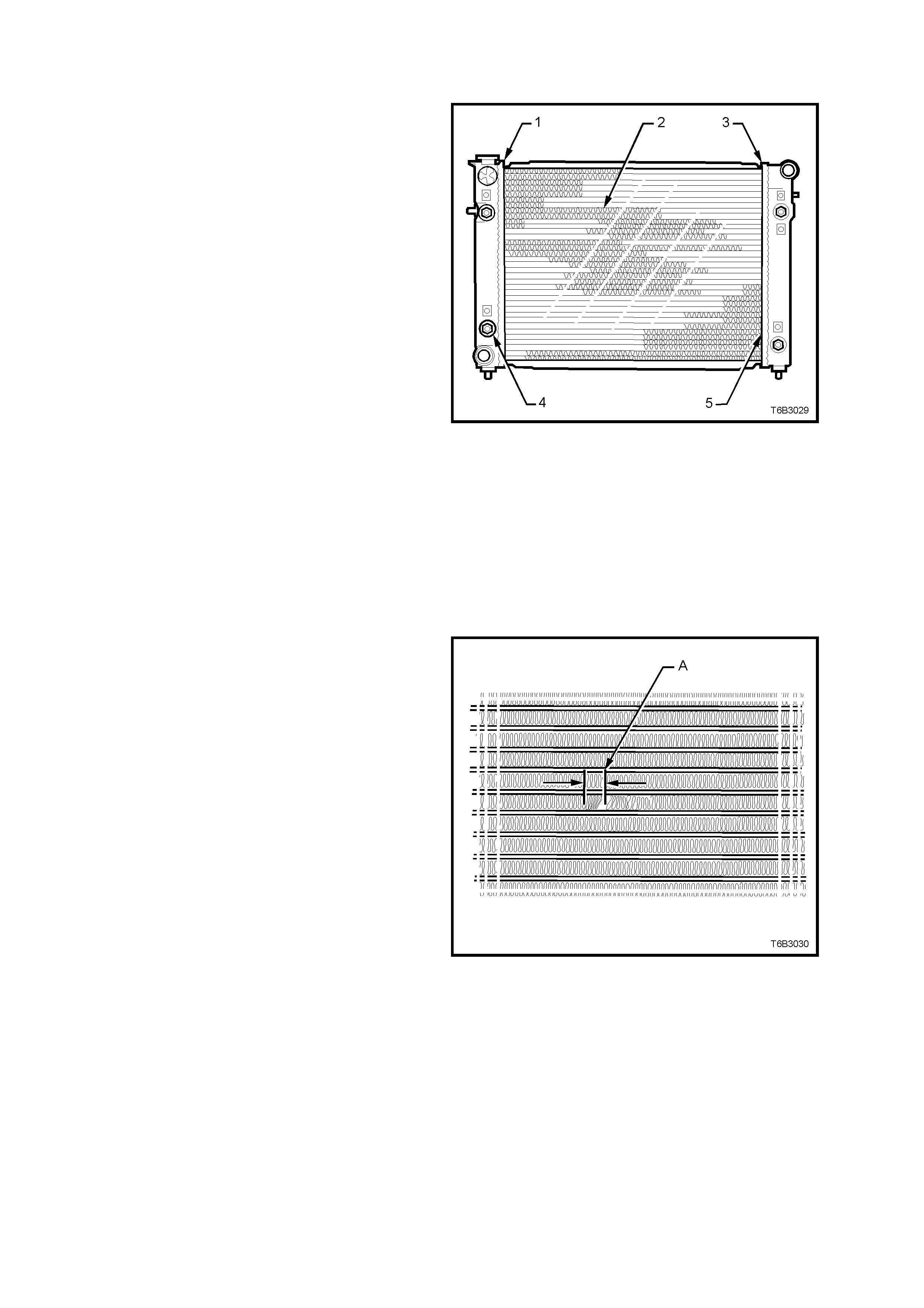
Repairable Leaks
There are two types of leaks that can be repaired
on the aluminium-plastic radiator; core leaks and
automatic transmission oil cooler seal leaks. Leaks
in the plastic tanks or the seals between the side
tanks and the headers cannot be repaired,
therefore the radiator must be replaced.
Core leaks may occur in a tube or in the joints
between the tubes and the headers. Seal leaks
may occur in the joints between the plastic tanks
and the headers or in the joints between the oil
cooler fittings and the tank (vehicles with automatic
transmission).
While some leaks can be repaired while the
radiator is installed in the vehicle, it is strongly
recommended that the radiator is first removed
from the vehicle.
Legend:
1. Side Tank Seal
2. Core Tubes
3. Side Tank Seal
4. Oil Cooler Pipe Fittings
5. Joint Between Tube and Header
NOTE: Minor damage to tubes, or tube to header
joint (holes up to 1mm diameter max.) can be
repaired. Core replacement is necessary if damage
is any greater.
Figure 6B1-67
Repair Method
Repairs to the aluminium radiator core should only
be made using the recommended 'Aluminised
Silicon' based liquid repair agent, in accordance
with the recommended procedure outlined in
GENERAL CORE REPAIR in this Section. Refer to
the current PartFinder® for Aluminised Silicon base
liquid part number.
For damaged areas that are between the cooling
fins, it may be necessary to remove some of the
fins. Do not remove more fins than is necessary.
Usually 6 mm (distance ‘A’) beyond the leak or
damage area, up to a maximum of 25 mm of total
fin material, is enough to make an effective repair.
Figure 6B1-68
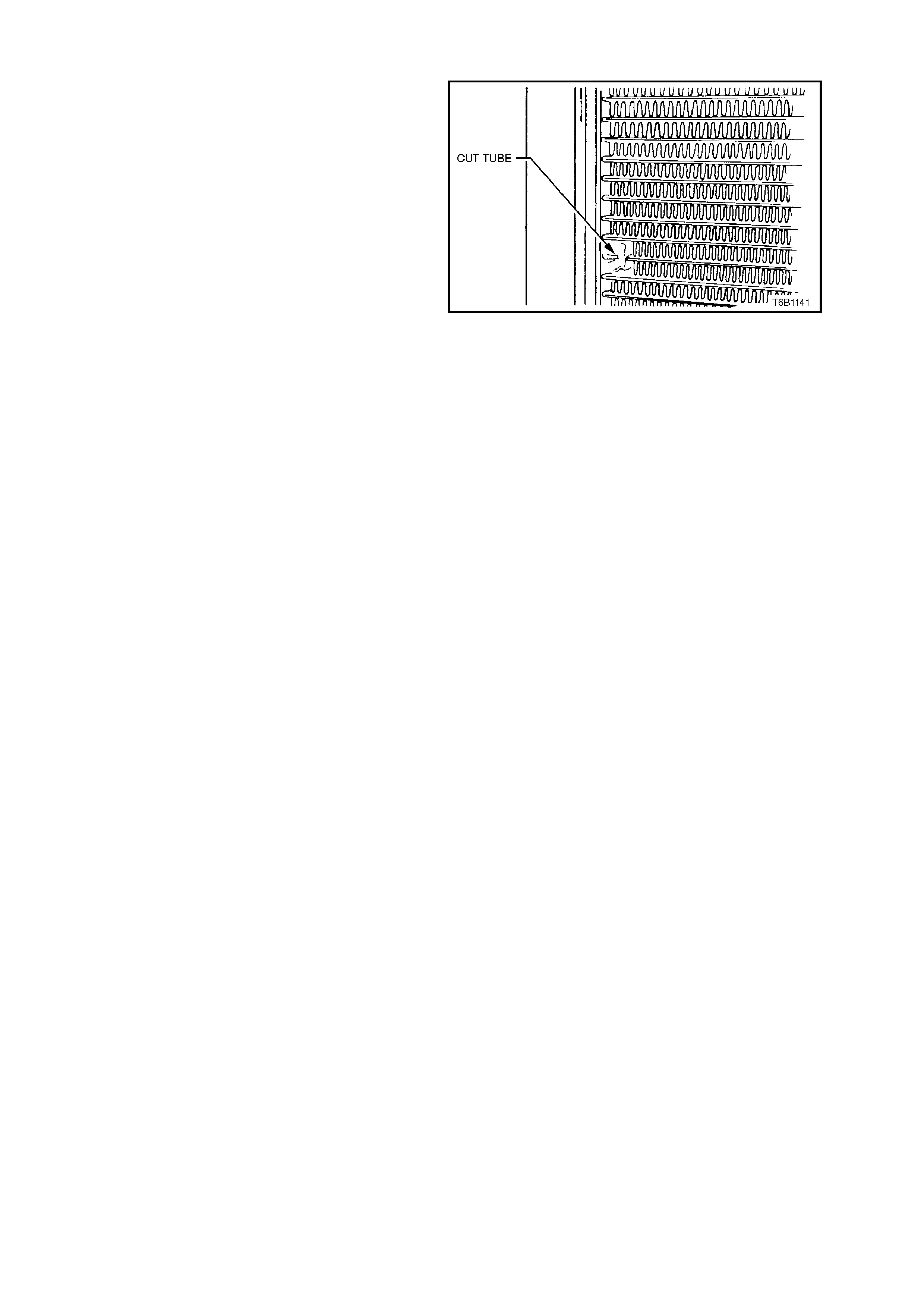
Tube Blocking
If a tube is severely damaged, it can be blocked
off.
NOTE: Do not block off more than two tubes in a
radiator. Blocking off more than two tubes will
reduce the cooling capacity of the system.
The tube should be cut off 6 mm from the header
and pinched shut before it is cleaned and sealed,
refer to GENERAL CORE REPAIR in this Section.
Figure 6B1-69
Header Repair
If the header or a tube near the header requires a repair, the side tank does not have to be removed.
General Core Repair
The need for careful preparation of the surface in the repair area cannot be over-emphasised. If the leak area
surface is not clean, the repair material will not adhere to the surface.
1. Remove and drain radiator, refer to 3.14 RADIATOR - REMOVE in this Section.
2. If necessary, carefully cut away fins to expose the damaged area.
NOTE: Do not cut away more than 25 mm total fin material.
3. Clean away dirt etc. with water. Dry the affected area using hot air from a hair drier.
NOTE: Do not apply flame to dry damaged area.
4. Clean affected area with petrol to remove any traces of oil.
5. Thoroughly stir contents of repair agent.
NOTE: In cases of extended shelf life, the silicon in solution may separate from the thinner base. Should this
occur, mix contents well until agent is again homogeneous.
6. Apply repair agent sparingly to damaged area. Do not apply excessive amount, as this will cause blockage of
the radiator tube.
NOTE: Use a clean, dry wooden applicator to 'DRIP' agent onto damaged area of radiator.
7. Allow radi ator t o s tan d i n a c lean, dr y ar ea f or a minimum of 3 hour s ( at ambient t emperatur e of 20 - 3 0 °C) with
adequate ventilation.
NOTE: Do not apply heat or flame to promote drying.
8. Refit radiator, refer to 3.14 RADIATOR - REINSTALL in this Section.
Transmission Oil Cooler L eak Test
If the transmission oil cooler is suspected of leaking oil, test it before the radiator is replaced, as follows:
1. Disconnect oil cooler pipes at the flexible hose connections. Refer to
3.13 FLEXIBLE TRANSMISSION COOLER HOSE, in this Section.
2. Plug one of the connections, using a blocked pipe fitting and attach an air supply to the other flexible hose.
3. Remove radiator cap and check that the coolant is filled to the radiator cap filler neck.
4. APPLY AIR PRESSURE GRADUALLY, increasing up to an absolute maximum of 103 kPa. If bubbles appear
in radiator neck, the oil cooler is leaking and the radiator assembly must be replaced.

4. ENGINE COOLING SYSTEM DIAGNOSIS
1. POOR HEATER OPERATION
Little or no heat coming from the heater, especially at idle, could be an indication of a cooling system problem.
As the c oolant lev el begins to get lower than norm al, air enter s the s ystem to replace the mis sing coolant. The
heater core is one of the highest parts of the cooling system and therefore, the first area to lose coolant.
At first, with a small amount of coolant loss, lack of heat will be most noticeable at idle. As driving speed
increases, the engine pumps more coolant and more heat is now able to pass through the heater core.
If coolant level drops even lower, heater operation will become less effective, even during normal driving.
Cooling and engine systems can be adversely affected if problem is not corrected.
2. LEAKING CYLINDER HEAD GASKET
Combus tion gas es leak ing pas t the cylinder he ad gas k et c an pres sur ise the c ool in g s ystem, f orc ing c oolan t o ut
of the system and into the coolant recovery reservoir.
Indications are air bubbles in the coolant or an overflow condition of the recovery reservoir.
3. QUESTION THE CUSTOMER
To avoid needless tim e and cost in di agnosing co oling system complaints , the custom er should be questi oned
about driving conditions that place abnormal loads on the cooling system.
1. IS OVERHEATING OCCURRING AFTER PROLONGED IDLE, IN GEAR, WITH AIR CONDITIONING
SYSTEM OPERATING?
If answer is YES - instruct owner on driving techniques that would avoid overheating such as:-
a. Idle in ne utral as m uch as pos sible – inc rease engine rpm to get hig her air flo w (due to an increase in
voltage to the fan) and coolant flow through radiator.
b. Turn air conditioning system off during extended idling periods if overheating is indicated on
temperature gauge. Further diagnostic checks should not be required.
2. IS OVERHEATING OCCURRING AFTER PROLONGED DRIVING IN SLOW CITY TRAFFIC, TRAFFIC
JAMS, PARADES, ETC?
If answer is YES, explain driving technique to the customer, that would avoid overheating – same as for
prolonged idle - No.1. Further diagnostic checks should not be required.
4. DIAGNOSTIC CHART
If none of the above conditions apply, refer to the following Diagnosis Chart.
To effectively use this chart, question the customer to determine which of the following three categories apply to the
complaint:-
A. IF COMPLAINT IS HOT INDICATION ON TEMPERATURE GAUGE.
Was temperature reading accompanied by boiling? If answer is YES, go to overheating on diagnosis chart. If
answer is NO, check temperature gauge and sender.
B. IF COMPLAINT IS BOILING - go to overheating on diagnosis chart.
C. IF COMPLAINT IS COOLANT LOSS.
Determine if customer is filling the system correctly.
If incorrect filling is not the problem, go to coolant loss in the diagnosis chart.
WARNING: THE COOLING SYSTEM IS DESIGNED TO OPERATE AT 120-150 kPa AND TEMPERATURES
NOT EXCEEDING 130°
°°
° C.
Refer to the WARNING in 3.1 SERVICE NOTES in this Section before removing the radiator cap or servicing the
system.

COOLING SYSTEM DIAGNOSIS
STEP ACTION RESULT IF YES IF NO
1. • Check Temperature gauge reading High Temp.
Low Temp. Go to Step 3
Go to Step 6 –
2. • Check drive belt Belt Present Go to Step 3 –
3. • Check coolant Boiling Go to Step 4 Go to Step 5
4. • Check coolant level Low Go to Step 10 Go to Step 6
5. • Check Radiator cap. Refer to 2.7 in this Section OK? Go to Step 8 Replace
Radiator cap
6. • Check thermostat. Refer to 2.8 in this Section OK? Go to Step 9 Go to Step 13
7. • Check Temperature Gauge Faulty Replace Go to Step 12
8. • Check cooling fan operation. Refer to Section 6C1-1
GENERAL INFORMATION. Operational Go to Step 10 Repair
9. • Check for collapsed upper or lower radiator hose. Collapsed Replace Go to Step 13
10. • Visual system check Leaks Go to Step 13 Go to Step 11
11. • Check coolant concentration. Refer to Testing
Coolant Concentration, in 3.2 GLYCOL COOLANT
MAINTENANCE.
To
Specification Go to Step 12 Correct
Concentration
Level
12. • Check radiator core for bent fins, dirt, bugs or other
obstructions. Obstructed Clean or
straighten Go to Step 14
13. • Pressure Test cooling system, Refer to 2.7 in this
section. Leaks Repair System OK
14. • If none of the above require repair, the problem is out
of ordinary or of a major nature. Listed below are two
groups of problem areas that should be checked in
the order as shown.
A. PROBLEMS NOT REQUIRING DISASSEMBLY OF COOLING SYSTEM
1. Large obstructions blocking radiator or condenser airflow.
a. Auxiliary oil coolers.
b. License plate.
c. Obstruction of radiator grille, i.e. mud.
2. Loose, damaged or missing air chute side panels.
3. Missing or damaged air baffle.
4. Cracked or loose coolant recovery system hose.
B. PROBLEMS REQUIRING DISA SSEMBLY OF COOLING SYSTEM
1. Damaged cooling fan or faulty motor operation.
2. Pressure test cooling system.
3. Defective coolant pump.
a. Eroded or broken impeller vanes.
b. Failed bearing or seal - check for shaft or bearing end play.
4. Internally blocked radiator core.
5. Obstruction of coolant recovery system.
6. Internal system leaks.
a. Head gaskets.
b. Cracked cylinder block.
c. En gine front cover.
d. Intake manifold gaskets.
7. Blocked coolant passages in cylinder heads or block - remove cylinder heads and check.

C. BLACK LIGHT AND DYE LEAK DIAGNOSIS METHOD
It is strongly recommended that this diagnostic method is used to diagnose fluid leaks. This method is a proven and
reliable method that identifies the specific leak source.
The black light kit can be used for the leak detection of a number of fluids, when used with the appropriate tracer
dye.
Examples are; Coolant, Engine Oil, Automatic Transmission Fluid and Air Conditioning Refrigerant (R134A).
The following is a summary of the steps involved in detecting a cooling system fluid leak using black light and dye.
1. Pour specified amount of dye into the radiator.
2. Road test the vehicle under normal operating conditions.
3. Direct the lig ht towards the s uspect ar ea. The f luid lea k will a ppear as a brig htl y coloured p ath lead ing f rom the
source.
4. Repair fluid leak and recheck to ensure that leak has been rectified.
5. Refer to the manufacturer’s directions when using this method.

5. SPECIFICATIONS
GENERAL
Radiator Cap Pressure Rating................................... 135 kPa
Cooling System Capacity........................................... 12 Litres
Coolant Corrosion Inhibitor and Quantity .................. Approx. 6.0 litres required when changing coolant.
THERMOSTA T
Type ........................................................................ Power element (wax pellet)
Start to open at........................................................ 89° - 93° C
Fully open at............................................................ 106° C max.
COOLANT PUMP
Type ........................................................................ Centrifugal
Drive........................................................................ Multi-V ee Serp ent ine Be lt
Bearing Type........................................................... Double Row Ball Bearing
RADIATOR
Core type................................................................. Aluminium crossflow core
Overall width ........................................................... 847 mm
Core width............................................................... 674 mm
Overall height.......................................................... 507 mm
Core height.............................................................. 430.5 mm
Core thickness ........................................................ 16 mm
Plastic tanks............................................................ Nylon 6.6 (30% Glass Filled)
RADIATOR HOSES
Lower
Number and type ............................................... One, Moulded
Inside diameter .................................................. 38.5 mm
Upper
Number and type ............................................... One, Moulded
Inside diameter .................................................. 34.0 mm
SMALL ENGINE COOLING FAN (Right).................. Standard High Power
Number of blades.................................................... 8 8
Spacing ................................................................... Symmetrical
Material.................................................................... Nylon 6.6 (25% Glass Filled)
Diameter.................................................................. 268 mm 268 mm
Electric motor drive (Nominal Power Rating).......... 120 Watts 180 Watts
Speed (with 12 volts applied, Radiator and
Condenser installed – Stage 1...................... OFF 2,350 ± 150 rpm
– Stage 2...................... 2,350 ± 150 rpm 2,700 ± 150 rpm
LARGE ENGINE COOLING FAN (Left)
Number of blades.................................................... 8 8
Spacing ................................................................... Symmetrical
Material.................................................................... Nylon 6.6 (25% Glass Filled)
Diameter.................................................................. 370 mm 370 mm
Electric motor drive (Nominal Power Rating).......... 160 Watts 220 Watts
Speed (with 12 volts applied, Radiator and
Condenser installed – Stage 1...................... 1,900 ± 150 rpm 2,000 ± 150 rpm
– Stage 2...................... 1,900 ± 150 rpm 2,300 ± 150 rpm

6. TORQUE WRENCH SPECIFIC ATIONS
Nm
Cylinder Block Drain Plugs................................................... 32
Coolant Outlet to Inlet Manifold Attaching Bolts................... 28
Coolant Pump to Front Cover Bolts...................................... 10
Coolant Pump to Cylinder Block Bolts.................................. 30
Coolant Pum p Pull e y Attachin g Bolts................................... 15
Oil Cooler To Side Tank Nut................................................. 25
Knock Sensor........................................................................ 20
Oil Cooler Pipe to Oil Cooler................................................. 25
Oil Cooler Pipe to Side Tank Adaptor (V6 LHD and A/T)..... 30
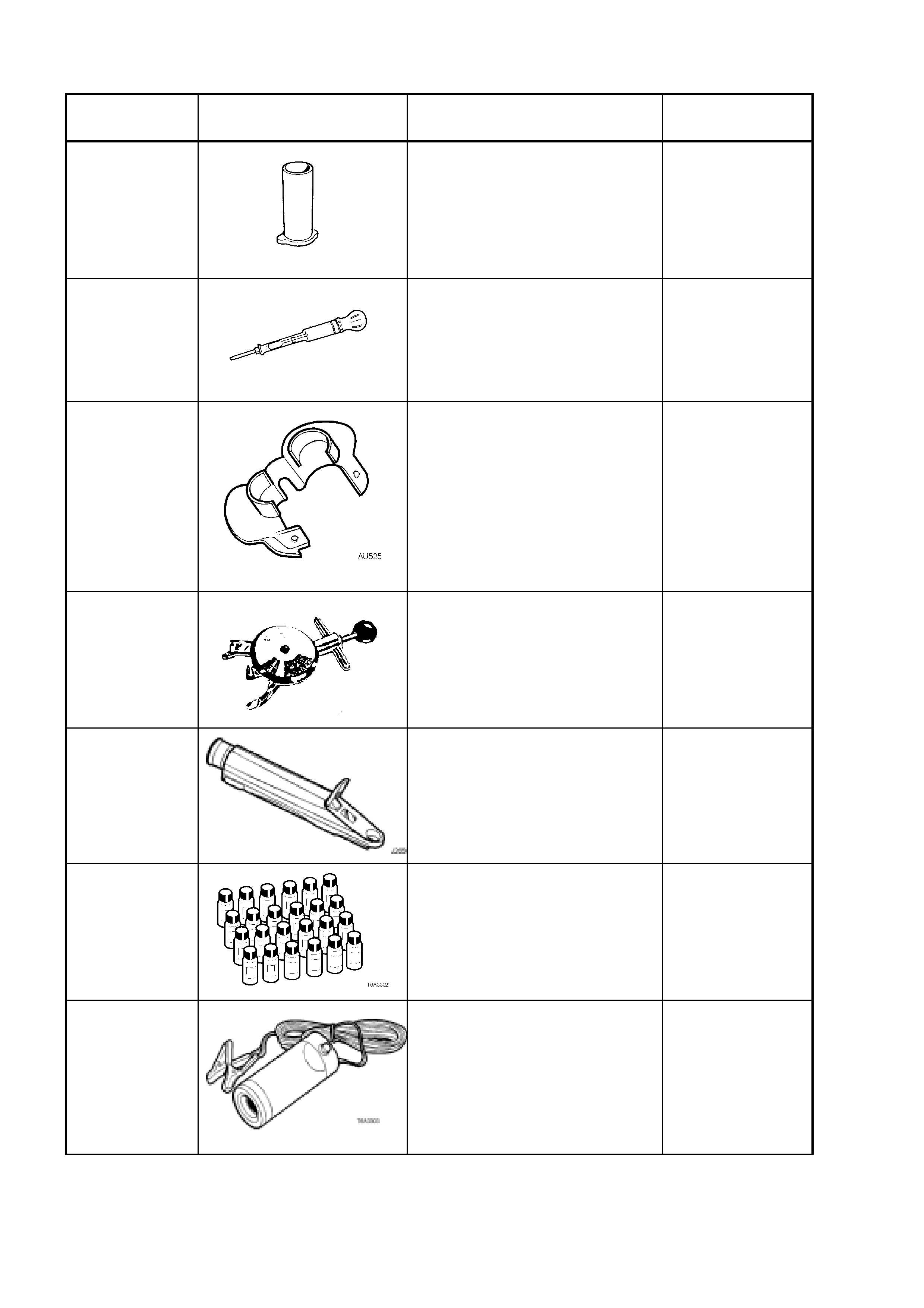
7. SPECIAL TOOLS
TOOL
NUMBER ILLUSTRATION DESCRIPTION CLASSIFICATION
AU425
COOLING SYSTEM FILLER
TUBE
Used to ensure the coolant level is
correct
Previously released.
Mandatory
AU505
COOLANT TESTER
Used for testing the coolant
concentration level.
Previously released.
Mandatory
AU525
QUICK CONNECT RELEASE
TOOL
Used to release the quick connect
fittings on the automatic
transmission fluid cooler lines at
the radiator end, when the veh ic le
is so equipped.
Previously released.
Mandatory
BT3373-F BELT TENSION GAUGE
Used when check ing dr ive and
accessory belt tension and
adjustments.
Previously released.
Desirable
J 26568 REFRACTOMETER
Used for testing coolant
concentration level. Previously
released, as AU 435.
Mandatory
J28431-B
FLUID DYE
Available in 24 x 1 ounce bottles
Used in conjunction with a black
light such as J42220 to locate the
source of various fluid leaks.
Previously released.
Desirable
J42220 BLACK LIGHT, LEAK
DETECTION LAMP
Used with dye, J28431-B to locate
the source of various vehicle fluid
leaks.
Previously released.
Desirable
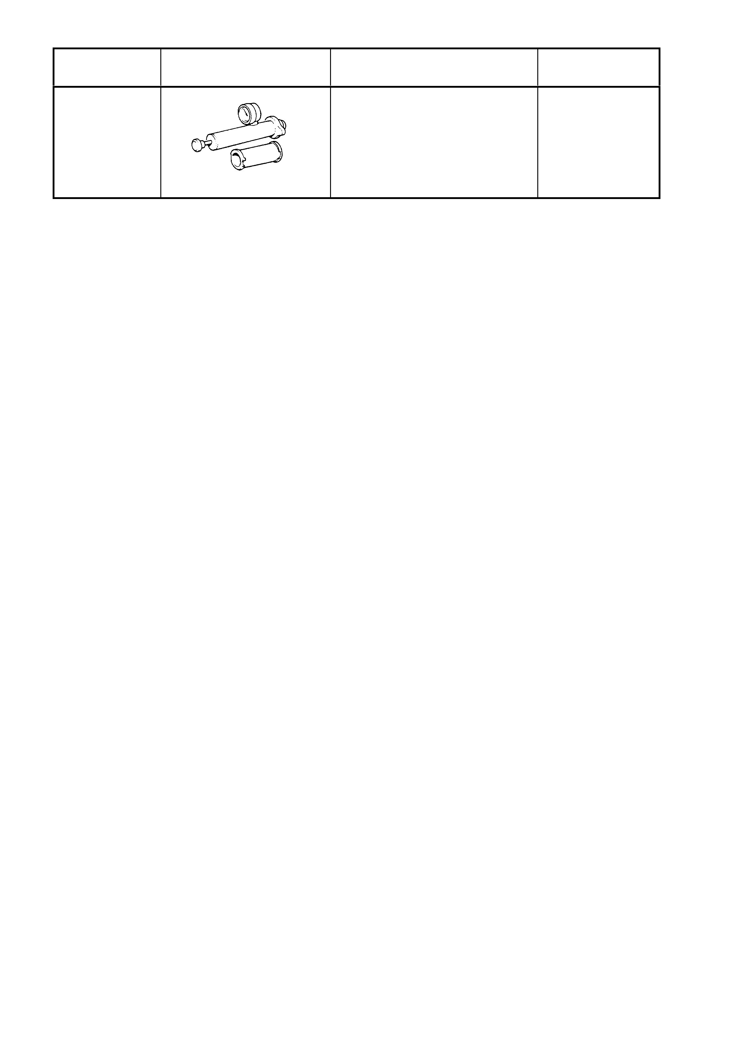
TOOL
NUMBER ILLUSTRATION DESCRIPTION CLASSIFICATION
N/A
COOLING SYSTEM PRESSURE
TESTER
Previously released.
Commercially available.
Mandatory